JP3105523U - Rewinding tool - Google Patents
Rewinding tool Download PDFInfo
- Publication number
- JP3105523U JP3105523U JP2004002981U JP2004002981U JP3105523U JP 3105523 U JP3105523 U JP 3105523U JP 2004002981 U JP2004002981 U JP 2004002981U JP 2004002981 U JP2004002981 U JP 2004002981U JP 3105523 U JP3105523 U JP 3105523U
- Authority
- JP
- Japan
- Prior art keywords
- bearing
- rotating drum
- wire
- outer case
- winding
- Prior art date
- Legal status (The legal status is an assumption and is not a legal conclusion. Google has not performed a legal analysis and makes no representation as to the accuracy of the status listed.)
- Expired - Lifetime
Links
Images


Landscapes
- Storing, Repeated Paying-Out, And Re-Storing Of Elongated Articles (AREA)
Abstract
【課題】 デザイン性と機能性に優れたフィッシング用に適する巻き取り具を提供する。
【解決手段】 円筒状収容部14を備え、この円筒状収容部14の一方の面に軸受け固定孔18を有し他方の面を解放した外ケース12を備える。回転ドラム22は、円筒状収容部14に収容され、軸受け固定孔18に固定される軸受け36により回転可能に支持され、外ケース12の解放面側に外フランジ24の外側面を露出させる。ワイヤ60は、回転ドラム22の胴部26に一端を固定して巻き付けられ、外ケース12のガイド孔21から引き出される。ゼンマイばね62は、軸受け36に巻き始め端68を固定し、回転ドラム22の胴部26に巻き終わり端69を固定し、回転ドラム22に対して、ワイヤ60の引き出しに抗する方向に向かって回転力を与える。
【選択図】図1PROBLEM TO BE SOLVED: To provide a winding tool excellent in design and functionality suitable for fishing.
SOLUTION: An outer case 12 having a cylindrical accommodation portion 14 and having a bearing fixing hole 18 on one surface of the cylindrical accommodation portion 14 and opening the other surface is provided. The rotary drum 22 is housed in the cylindrical housing portion 14, is rotatably supported by a bearing 36 fixed to the bearing fixing hole 18, and exposes the outer surface of the outer flange 24 to the open surface side of the outer case 12. The wire 60 is wound around the body 26 of the rotating drum 22 with one end fixed and pulled out from the guide hole 21 of the outer case 12. The mainspring spring 62 fixes the winding start end 68 to the bearing 36, fixes the winding end end 69 to the body 26 of the rotating drum 22, and faces the rotating drum 22 in a direction against pulling out the wire 60. Give rotation force.
[Selection diagram] Fig. 1
Description
本考案は、衣服等に固定して、伸縮式のワイヤ先端に任意の小物を連結し、小物の脱落や紛失を防止する等の目的で使用される、巻き取り具に関する。 The present invention relates to a winding device that is fixed to clothes or the like and is used for connecting an arbitrary accessory to a tip of a telescopic wire to prevent the accessory from falling off or being lost.
例えば、魚釣りをするときには、針、錘、浮き、テグス等の様々な小物を所持しなければならない。これらの小物を入れた各種のケースが、足場の悪い釣り場で下に落ちて紛失しないように、衣服に工夫をした技術が公開されている。(特許文献1)
衣服にケースを固定するためのものとして、上記のほかに、ワイヤーをスプリングの力で巻き込む、コンベックスのような機能を持つ巻き取り具が利用されている。従来の巻き取り具は、ケース中に収納されたドラムにワイヤが巻き付けられた構造をしている。ケースの孔からワイヤを引き出すと、その先端に連結した小物を、ワイヤの長さだけたぐり寄せることができる。また、手を離すと、ゼンマイばねの力でワイヤがケース中に巻き込まれて、ケースとともに小物が衣服に密着した状態になる。しかしながら、ワイヤには頻繁に張力や衝撃が加わるために、ワイヤが切断し易いという問題があった。しかも、組み立て時にワイヤがケースの蓋やばねに挟まれて傷つくことがあった。また、ワイヤを巻き付けたドラムはケース内部に収納されており、ケースの分解も容易でないことから、点検や調整も難しいという問題があった。
本考案は以上の点に着目してなされたもので、堅牢で耐久性があり、修理が容易でデザイン性にも優れた巻き取り具を提供することを目的とする。
In addition to the above, a winding device having a function like a convex, which winds a wire by the force of a spring, is used for fixing a case to clothes. The conventional winding device has a structure in which a wire is wound around a drum housed in a case. When the wire is pulled out of the hole of the case, the small object connected to the tip can be pulled by the length of the wire. When the hand is released, the wire is wound into the case by the force of the mainspring, and the accessory comes into close contact with the clothes together with the case. However, there is a problem that the wire is easily cut because tension and impact are frequently applied to the wire. In addition, the wire may be caught between the lid and the spring of the case during assembly, and may be damaged. Further, since the drum around which the wire is wound is housed inside the case, and the case is not easily disassembled, there is a problem that inspection and adjustment are difficult.
The present invention has been made in view of the above points, and an object of the present invention is to provide a winding device that is robust, durable, easy to repair, and excellent in design.
本考案の各実施例においては、それぞれ次のような構成により上記の課題を解決する。
〈構成1〉
円筒状収容部14を備え、この円筒状収容部14の一方の面に軸受け固定孔18を有し他方の面を解放した外ケース12と、上記円筒状収容部14に収容され、上記軸受け固定孔18に固定される軸受け36により回転可能に支持され、上記外ケース12の解放面側に外フランジ24の外側面を露出させた回転ドラム22と、上記回転ドラム22の胴部26に一端を固定して巻き付けられ、上記外ケース12のガイド孔21から引き出されるワイヤ60と、上記軸受け36に巻き始め端68を固定し、上記回転ドラム22の胴部26に巻き終わり端69を固定し、上記回転ドラム22に対して、上記ワイヤ60の引き出しに抗する方向に向かって回転力を与える、ゼンマイばね62を備えたことを特徴とする巻き取り具。
In each embodiment of the present invention, the above-described problem is solved by the following configurations.
<Configuration 1>
An
回転ドラム22へのワイヤ60の巻き付けや、軸受け36へのゼンマイばね62の巻き付けを終えてから、軸受け36を軸受け固定孔18に固定するようにして組み立てることができる。軸受け36は片持ち状態で回転ドラム22を支持する。従って、各部に無理な力を加えずに組み立てができる。また、ワイヤ60の両端を確実に胴部26と端金具58に固定して、堅牢で故障を減少させることができる。さらに、回転ドラム22の外側面が露出しており、回転ドラム22の回転が外部から見えるので、装飾効果を呈するという効果がある。
After the winding of the
〈構成2〉
構成1に記載の巻き取り具において、上記外フランジ24の外側面には、任意の装飾66を施したことを特徴とする巻き取り具。
<Configuration 2>
The winding device according to Configuration 1, wherein an
ワイヤ60の引き出しや収納時に回転ドラム22が回転する。このとき、外ケース12の解放面から回転ドラム22の外フランジ24が回転するところを観察できる。外フランジ24の外側面に装飾を施してその装飾が回転すると、使用者の目を楽しませる効果がある。即ち、組み立てやメンテナンスを容易にするために外ケース12から回転ドラム22の外フランジ24を露出させたが、その結果、回転ドラム22の外フランジ24に施された装飾66による趣味的効果が発揮される。
The rotating
〈構成3〉
構成1に記載の巻き取り具において、回転ドラム22を軸受け36により支持して、その軸受け36に対して上記回転ドラム22が自由回転するように、上記軸受け36を上記回転ドラム22に設けた軸孔35に固定する固定手段と、上記軸受け36の一端を、外ケース12の軸受け固定孔18に対して、上記軸受け36と外ケース12とを一体化するように固定する固定手段を備えたことを特徴とする巻き取り具。
<Configuration 3>
In the winding device described in the configuration 1, the rotating
軸受け36に対して回転ドラム22が自由回転するように、軸受け36を回転ドラム22に設けた軸孔35に固定するので、外ケース12の組み立て前に、軸受け36にゼンマイばね62を最適な状態で巻き付けることができる。また、軸受け36の一端を、外ケース12の軸受け固定孔18に固定するときに、ゼンマイばね62がワイヤ60に及ぼす回転力を最適値に自由に調整できる。
Since the
以下、本考案の実施の形態を実施例ごとに詳細に説明する。 Hereinafter, embodiments of the present invention will be described in detail for each example.
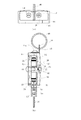
図1(a)は、実施例1の巻き取り具の上面図、(b)は縦断面図である。また、図2は、巻き取り具の正面図である。
図の巻き取り具は、外ケース12に回転ドラム22を収容したものである。外ケース12は、回転ドラム22を収納するための円筒状収容部14を備える。この円筒状収容部14の一方の面は、軸受け固定孔18を有し、他方の面は解放されている。換言すれば、蓋のない筒状をしている。
FIG. 1A is a top view of the winding device of Example 1, and FIG. 1B is a longitudinal sectional view. FIG. 2 is a front view of the winding device.
The take-up device shown in the figure has a rotating
図3(a)は外ケース12の正面図、(b)は軸受け36の分解側面図、(c)は軸受け36の左端面図、(d)は軸受け36の右端面図である。
図のように、外ケース12の中央には円筒状収容部14が設けられ、その一方の面の中央に、軸受け36を固定するための軸受け固定孔18が設けられている。また、上側壁には、固定金具50を固定するための一対の軸受け固定孔18が設けられている。軸受け36は一方の端に雌ねじ部38を備え、他方の端に雄ねじ部42を備える。
3 (a) is a front view of the
As shown in the figure, a
雌ねじ部38にはビス44がねじ込まれる。雄ねじ部42にはナット46がねじ込まれる。軸受け36は、雄ねじ部42を外ケース12の軸受け固定孔18に挿入して、ナット46を用いて固定される。即ち、ナット46は、軸受け36と外ケース12とを一体化するように固定する固定手段として機能する。なお、軸受け36には、後で説明するように、ゼンマイばね62の巻き始め端68を接続固定するバネ係止スリット40が設けられている。
A
なお、上記のビス44は、回転ドラム22を軸受け36により支持して、その軸受け36に対して回転ドラム22が自由回転するように、軸受け36を回転ドラム22に設けた軸孔35に固定する固定手段として機能する。従って、雌ねじ部38の長さは回転ドラム22の外フランジ24の厚みより若干長く選定され、雌ねじ部38の外径は回転ドラム22の軸孔35の内径よりも若干小さく選定されている。ビス44は、回転ドラム22の脱落防止のため軸孔35の内径よりも十分に大きな外形のねじ頭を持つ。
The
一方、回転ドラム22は、外ケース12の軸受け固定孔18に固定される軸受け36により回転可能に支持され、外ケース12の解放面側に外フランジ24の外側面を露出させている。ワイヤ60は、回転ドラム22の胴部26に一端を固定して巻き付けられ、外ケース12のガイド孔21から引き出される。ゼンマイばね62は、軸受け36に巻き始め端68を固定し、回転ドラム22の胴部26に巻き終わり端69を固定し、回転ドラム22に対して、ワイヤ60の引き出しに抗する方向に向かって回転力を与える機能を持つ。
On the other hand, the rotating
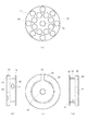
図4の(a)は回転ドラム22の正面図、(b)は右側面図、(c)は裏面図、(d)は左側面図である。
回転ドラム22は、図の(b)に示すように外フランジ24と内フランジ25で胴部26を挟んだ構成をしている。外フランジ24の外側に露出される表面には、図の(a)のような様々な任意の装飾を施すことができる。この例では、フライフィッシングに使われるリールに似せた模様が描かれている。従って、釣り愛好者が利用する場合に、デザイン的に非常に魅力ある商品になる。もちろん様々な模様を付けて、外フランジ24の回転を外部から確認できるようにしてよい。なお、装飾66は、この例では、外フランジ24の表面に描いた平坦な模様ではなく、切削加工された多数の穴により構成されている。
4A is a front view of the
The
胴部26には、引き延ばしたり、巻き取ったりすることのできるワイヤ60(図1)が巻き付けられる。このワイヤ60の一端は、図4(d)に示すワイヤ端係止孔34で固定される。すなわち、ワイヤ端係止孔34にワイヤ60の端を通してゼンマイ収納部28側にストッパーになるような結び目を作れば、ワイヤ60の端がしっかりと固定される。その状態で胴部26の周りにワイヤ60を巻き付ける。
A wire 60 (FIG. 1) that can be stretched or wound is wound around the
胴部26の内側には、ゼンマイ収納部28が設けられている。ここにゼンマイばね62(図1)が巻き込まれる。図4(a)に示すように、回転ドラム22の軸部には、軸孔35が設けられている。ここに既に説明した軸受け36(図3(b))の雌ねじ部38を差し込む。胴部26には、バネ端係止孔32が設けられている。これは、ゼンマイ収納部28に巻き込まれるゼンマイばね62の端を固定するためのものである。
A
図5の(a)は、ゼンマイばね62を巻き込んだ状態の回転ドラム22を示す平面図、(b)は、ゼンマイばね62の平面図、(c)は、端金具58とゴムブッシュ59の側面図、(d)は端金具58の別の方向から見た側面図である。
図5(a)に示すように、回転ドラム22の中心には、軸受け36が固定される。軸受け36は既に説明した通り、外ケース12(図1)と一体化されており外ケース12は回転しない。従って、回転ドラム22は軸受け36によって自由に回転するように支持されている。
5A is a plan view showing the
As shown in FIG. 5A, a
この軸受け36のバネ係止スリット40に、ゼンマイばね62の巻き始め端68をはめ込んで固定する。そして、ゼンマイばね62を軸受け36に巻き付けるように渦巻き状にして、回転ドラム22のゼンマイ収納部28に収納する。ゼンマイばね62の巻き終わり端69は、最も外側に配置される。これが内フランジ25の切り欠き30を通って胴部26の外周部分に引き出される。さらに、巻き終わり端69の末端にある係止端70を、回転ドラム22のバネ端係止孔32に通して、ゼンマイ収納部28側に配置する。
The winding start end 68 of the
これによってゼンマイばね62の巻き終わり端69が回転ドラム22の胴部26側にしっかりと固定される。この状態で回転ドラム22を矢印Bの方向にさせると、ゼンマイばね62が軸受け36の外周に全体としてさらに小さい半径に巻き付けられるよう変形する。その後、回転ドラム22をはなすと、ゼンマイばね62の反発力によって回転ドラム22が矢印A方向に回転する。
Thereby, the winding
従って、ワイヤ60を回転ドラム22の胴部26に巻き付け、ワイヤ60を引き出した時に回転ドラム22をB方向に回転させると、ワイヤ60には常に矢印A方向へ巻き戻そうとする力が加わる。ワイヤ60を引き出す力を解放すれば、ワイヤ60は、再び回転ドラム22の胴部26に巻き付けられるよう引き戻される。こうした作業を繰り返し行うと、従来の装置は、頻繁にワイヤ60と回転ドラム22との固定部分が外れたり、ワイヤ60自体が切断したりした。この考案では、さらにワイヤ60の耐久性を高めるために、組み立てや分解時にワイヤ60に無理な力が加わらないようにし、両端の固定方法も改善した。
Accordingly, when the
例えば、図5(c)に示すように、ワイヤ60のケース外側の端は、端金具58に設けられた端止孔73の内部で固定される。ワイヤ60の一端には、大径部74のような結び目が形成され、端金具58の端止孔73からの抜けが防止される。ゴムブッシュ59の透孔75を貫くようにしてワイヤ60が外ケース12の内部に巻き込まれる。連結孔57は、端金具58をその長手方向と交差する方向に貫くもので、ここに図1に示したような連結環56を取り付けて、例えば、鍵や財布、その他様々な小物や道具を結び付ける。ゴムブッシュ59は、ゴムやプラスティックなどの弾性体で製造され、端金具58が外ケース12に衝突した時のショックを和らげる機能を持つ。
For example, as shown in FIG. 5C, the outer end of the
以上説明をした巻き取り具は、ゼンマイばね62のばね力の調整作業が、回転ドラム22を外ケース12に収納した後で行うことができる。回転ドラム22を外ケース12に収納する前の工程で、ゼンマイばね62を軸受け36に取り付けてしまうことができるので、組み立て時にワイヤ60をゼンマイばね62のエッジで傷付けるおそれがない。また、外ケース12に全体を密封して収納する構成でないので、ワイヤ60を回転ドラム22と外ケース12の間に挟み込んで傷を付けるといった事故も防止できる。故に、巻き取り具の耐久性が向上する。
In the winding device described above, the adjustment of the spring force of the
すなわち、組み立て工程では、図5に示したように、まず、回転ドラム22に軸受け36を取り付け、その後、ゼンマイばね62をゼンマイ収納部28の内部に収納する。この作業は、ゼンマイばね62の巻き始め端68を軸受け36に固定し、その後巻き終わり端69を回転ドラム22のバネ端係止孔32に固定するという手順が採用できる。回転ドラム22やゼンマイばね62に無理な力を加えることなく、簡単な作業で図5(a)に示したような状態の半製品が出来上がる。
That is, in the assembling process, as shown in FIG. 5, first, the
その後に、ワイヤ60の一端を図4の(d)に示したワイヤ端係止孔34に固定し、胴部26の外周に巻き付ける。ワイヤ60の巻き付けは、ゼンマイばね62の組み込みが終了した後でよいから、ゼンマイばね62のエッジで傷付けられるのが防止できる。次に、図3(a)に示した外ケース12と組み合わせる。予め、回転ドラム22の胴部26に巻き付けられたワイヤ60の先端を、外ケース12のガイド孔21から引き出す。そして、図5(c)に示したように、ゴムブッシュ59と端金具58を装着する。
Thereafter, one end of the
この時もワイヤ60に特に強い力を与えたりする必要はない。ワイヤ60を外ケース12のガイド孔21から引き出し、ワイヤ60にねじれや張力を加えることなく、回転ドラム22を外ケース12の円筒状収容部14にはめ込むことができる。このとき、軸受け36の雄ねじ部42を外ケース12の軸受け固定孔18にはめ込む。次に雄ねじ部42にナット46をねじ込んで、図1(b)に示したような状態にする。
At this time, it is not necessary to apply a particularly strong force to the
ここで、ナット46をしっかりと締め付けることによって軸受け36と外ケース12とを一体化する。その時、回転ドラム22の外フランジ24に手を添えて外ケース12に対し、ビス44の回転角を調整しながらナット46を締め付ける。この作業によって、ゼンマイばね62のバネ力を調整する。このバネ力調整の際にも、ワイヤ60に無理な力が加わることがない。また、ゼンマイばね62は、軸受け36に巻き始め端68を固定し、ゼンマイ収納部28の内部に正常な形で収納されているので、ゼンマイばね62に対しても無理な力やねじれが加わることがない。
Here, the
以上のような組み立て工程を採用できるので、全体として耐久性の強い装置が完成する。また、使用開始後に、ワイヤ60の引き込み力に狂いが生じたときは、本体を分解する必要はない。ナット46の締め付けを緩めて、軸受け36の回転角を調整しながら再びナット46を締め付ければ、調整が完了する。装置の分解を必要としないからその後もワイヤ60を傷付けることがなく、装置の耐久性に影響を及ぼさない。また、図2に示したように、任意の形状の固定金具50を外ケース12に対し固定ネジ54等で固定し、固定金具50の貫通孔52にはめ込んだ固定輪48で、衣服などに巻き取り具を固定すると、装置を丈夫に安定に、衣服等に固定できるという効果がある。
Since the above-described assembling process can be adopted, a device having high durability as a whole is completed. Further, when the pulling force of the
12 外ケース
14 円筒状収容部
16 開口
18 軸受け固定孔
20 ねじ孔
21 ガイド孔
22 回転ドラム
24 外フランジ
25 内フランジ
26 胴部
28 ゼンマイ収納部
30 切り欠き
32 バネ端係止孔
34 ワイヤ端係止孔
35 軸孔
36 軸受け
38 雌ねじ部
40 バネ係止スリット
42 雄ねじ部
44 ビス
46 ナット
48 固定輪
50 固定金具
52 貫通孔
54 固定ネジ
56 連結環
57 連結孔
58 端金具
59 ゴムブッシュ
60 ワイヤ
62 ゼンマイばね
12
Claims (3)
前記円筒状収容部14に収容され、前記軸受け固定孔18に固定される軸受け36により回転可能に支持され、前記外ケース12の解放面側に外フランジ24の外側面を露出させた回転ドラム22と、
前記回転ドラム22の胴部26に一端を固定して巻き付けられ、前記外ケース12のガイド孔21から引き出されるワイヤ60と、
前記軸受け36に巻き始め端68を固定し、前記回転ドラム22の胴部26に巻き終わり端69を固定し、前記回転ドラム22に対して、前記ワイヤ60の引き出しに抗する方向に向かって回転力を与える、ゼンマイばね62を備えたことを特徴とする巻き取り具。 An outer case 12 having a cylindrical housing portion 14 and having a bearing fixing hole 18 on one surface of the cylindrical housing portion 14 and opening the other surface;
A rotary drum 22 housed in the cylindrical housing portion 14, rotatably supported by a bearing 36 fixed to the bearing fixing hole 18, and exposing an outer surface of an outer flange 24 on a release surface side of the outer case 12. When,
A wire 60 fixedly wound at one end to the body 26 of the rotating drum 22 and pulled out from the guide hole 21 of the outer case 12;
The winding start end 68 is fixed to the bearing 36, the winding end end 69 is fixed to the body 26 of the rotating drum 22, and the winding is rotated in the direction against the drawing of the wire 60 with respect to the rotating drum 22. A take-up device provided with a mainspring spring 62 for applying a force.
前記外フランジ24の外側面には、任意の装飾66を施したことを特徴とする巻き取り具。 The winding device according to claim 1,
A winding tool, wherein an arbitrary decoration 66 is provided on an outer surface of the outer flange 24.
回転ドラム22を軸受け36により支持して、その軸受け36に対して前記回転ドラム22が自由回転するように、前記軸受け36を前記回転ドラム22に設けた軸孔35に固定する固定手段と、
前記軸受け36の一端を、外ケース12の軸受け固定孔18に対して、前記軸受け36と外ケース12とを一体化するように固定する固定手段を備えたことを特徴とする巻き取り具。 The winding device according to claim 1,
Fixing means for supporting the rotating drum 22 by a bearing 36 and fixing the bearing 36 to a shaft hole 35 provided in the rotating drum 22 so that the rotating drum 22 freely rotates with respect to the bearing 36;
A winding device comprising a fixing means for fixing one end of the bearing to the bearing fixing hole of the outer case so as to integrate the bearing with the outer case.
Priority Applications (1)
| Application Number | Priority Date | Filing Date | Title |
|---|---|---|---|
| JP2004002981U JP3105523U (en) | 2004-05-27 | 2004-05-27 | Rewinding tool |
Applications Claiming Priority (1)
| Application Number | Priority Date | Filing Date | Title |
|---|---|---|---|
| JP2004002981U JP3105523U (en) | 2004-05-27 | 2004-05-27 | Rewinding tool |
Publications (1)
| Publication Number | Publication Date |
|---|---|
| JP3105523U true JP3105523U (en) | 2004-11-18 |
Family
ID=43258883
Family Applications (1)
| Application Number | Title | Priority Date | Filing Date |
|---|---|---|---|
| JP2004002981U Expired - Lifetime JP3105523U (en) | 2004-05-27 | 2004-05-27 | Rewinding tool |
Country Status (1)
| Country | Link |
|---|---|
| JP (1) | JP3105523U (en) |
-
2004
- 2004-05-27 JP JP2004002981U patent/JP3105523U/en not_active Expired - Lifetime
Similar Documents
| Publication | Publication Date | Title |
|---|---|---|
| JP2005508240A (en) | Hairappa | |
| JP2007275203A (en) | Strap retainer for cellular phone | |
| KR20070012584A (en) | Apparatus for winding of rope | |
| JP3105523U (en) | Rewinding tool | |
| JP3132197U (en) | Fishing reel | |
| CN111903629A (en) | Fishing vessel threading tool | |
| US5845858A (en) | Fishing spinning reel | |
| US3823502A (en) | Reel assembly | |
| JP6025032B2 (en) | Fishing line connection aid | |
| US4682968A (en) | Figure toy with rapidly retractable trap element | |
| KR200448453Y1 (en) | Xylophone for preventing loss | |
| KR102118292B1 (en) | Apparetus to fix handle for preventing release of fishing reel | |
| JP2014057548A5 (en) | ||
| US20080289770A1 (en) | Adhesive tape cutting device | |
| US6322419B1 (en) | Combination spinning top and yo-yo | |
| US8133122B2 (en) | Miniature spool | |
| CN210671766U (en) | Fishing vessel threading tool | |
| JP4387208B2 (en) | Fishing line guide and fishing rod equipped with the same. | |
| JP2004043137A (en) | Winding device | |
| JPH0833726A (en) | Safety belt | |
| JP4050111B2 (en) | Fishing rod guide | |
| KR200193007Y1 (en) | Linesman flag | |
| JPS6224460Y2 (en) | ||
| JP2001269084A (en) | Fishing rod | |
| JP2001352864A (en) | Fishing rod |
Legal Events
| Date | Code | Title | Description |
|---|---|---|---|
| R150 | Certificate of patent or registration of utility model |
Free format text: JAPANESE INTERMEDIATE CODE: R150 |
|
| R250 | Receipt of annual fees |
Free format text: JAPANESE INTERMEDIATE CODE: R250 |
|
| FPAY | Renewal fee payment (event date is renewal date of database) |
Free format text: PAYMENT UNTIL: 20100908 Year of fee payment: 6 |
|
| S531 | Written request for registration of change of domicile |
Free format text: JAPANESE INTERMEDIATE CODE: R323532 |
|
| FPAY | Renewal fee payment (event date is renewal date of database) |
Free format text: PAYMENT UNTIL: 20100908 Year of fee payment: 6 |
|
| R360 | Written notification for declining of transfer of rights |
Free format text: JAPANESE INTERMEDIATE CODE: R360 |
|
| FPAY | Renewal fee payment (event date is renewal date of database) |
Free format text: PAYMENT UNTIL: 20100908 Year of fee payment: 6 |
|
| S531 | Written request for registration of change of domicile |
Free format text: JAPANESE INTERMEDIATE CODE: R323531 |
|
| FPAY | Renewal fee payment (event date is renewal date of database) |
Free format text: PAYMENT UNTIL: 20100908 Year of fee payment: 6 |
|
| R370 | Written measure of declining of transfer procedure |
Free format text: JAPANESE INTERMEDIATE CODE: R370 |
|
| FPAY | Renewal fee payment (event date is renewal date of database) |
Free format text: PAYMENT UNTIL: 20100908 Year of fee payment: 6 |
|
| R350 | Written notification of registration of transfer |
Free format text: JAPANESE INTERMEDIATE CODE: R350 |
|
| EXPY | Cancellation because of completion of term | ||
| FPAY | Renewal fee payment (event date is renewal date of database) |
Free format text: PAYMENT UNTIL: 20100908 Year of fee payment: 6 |