JP3101034U - Filter change device in air conditioner - Google Patents
Filter change device in air conditioner Download PDFInfo
- Publication number
- JP3101034U JP3101034U JP2003272535U JP2003272535U JP3101034U JP 3101034 U JP3101034 U JP 3101034U JP 2003272535 U JP2003272535 U JP 2003272535U JP 2003272535 U JP2003272535 U JP 2003272535U JP 3101034 U JP3101034 U JP 3101034U
- Authority
- JP
- Japan
- Prior art keywords
- filter
- frame
- filter cartridge
- replacement
- mounting frame
- Prior art date
- Legal status (The legal status is an assumption and is not a legal conclusion. Google has not performed a legal analysis and makes no representation as to the accuracy of the status listed.)
- Expired - Fee Related
Links
Images


Landscapes
- Air Filters, Heat-Exchange Apparatuses, And Housings Of Air-Conditioning Units (AREA)
Abstract
【課題】フィルター取り付け枠の外側に枠板の左右側端にそれぞれ外側に開閉する蓋を有するフィルター収納室が設けられ、交換作業の能率向上したフィルター交換用装置を提供。
【解決手段】枠体には、その略左右側両端にそれぞれ外側に開閉する蓋を有するフィルター収納室を設け、その収納室上下にフィルターカートリッジ軸が、押圧・引圧により着脱自在な嵌合軸受を設け、その軸受けにフィルターカートリッジの軸を着脱し、容易にフィルターカートリッジの交換がきる装置とその枠体の一端に動力とその制御装置を設け、枠体の両側端に設けたボルト孔にボルトを通し、その枠体を既存の空基調和機のフィルターを取除いたフィルター取付枠の外側に当て、フィルター取付枠を挟み込むようにしての内側に上下2個のボルト孔を設けた帯板に前記ボルトを通して螺子止めしてなることを特徴とするフィルター交換装置である。
【選択図】図1Provided is a filter replacement device in which a filter storage chamber having lids that open and close outward is provided at right and left ends of a frame plate outside a filter mounting frame, and the efficiency of the replacement operation is improved.
A frame has a filter storage chamber having lids that open and close outward at substantially right and left ends thereof, and a filter cartridge shaft is detachably mounted on the upper and lower sides of the storage chamber by pressing / pulling. The filter cartridge shaft is attached to and detached from the bearing, and the filter cartridge can be easily replaced.A power and control device are provided at one end of the frame, and bolts are provided in the bolt holes provided at both ends of the frame. Through the frame, apply the frame body to the outside of the filter mounting frame from which the filter of the existing air-conditioner has been removed, and attach the upper and lower bolt holes inside the filter mounting frame so as to sandwich the filter mounting frame. A filter exchanging device characterized by being screwed through the bolt.
[Selection diagram] Fig. 1
Description
本考案は、空気調和機におけるフィルター交換装置に関するものである。 The present invention relates to a filter replacement device in an air conditioner.
空気調和機は、主として天井或いは壁の高い場所に設置されおり、そのフィルター交換は、設置された空気の汚れ具合にもよるが、場合によっては週に2度3度と頻繁にフィルターの交換をする必要がある。
しかし、フィルターを交換するには、その調和機が比較的高い場所にあるため、その回数を減少することが先決問題である。
そして、新旧のフィルターを交換するには、毎回数多くの螺子を取りはずし、枠を取除く等、交換作業に手間隙を要しており、フィルターの交換装置の簡易化が望まれている。Air conditioners are installed mainly on high places such as ceilings or walls, and filter replacement may depend on the degree of contamination of the installed air. There is a need to.
However, reducing the number of filter replacements is a prerequisite problem because the conditioner is at a relatively high place.
In order to replace the old and new filters, a large amount of screws are removed and the frame is removed every time, and the replacement operation requires a time gap. Therefore, simplification of a filter replacement device is desired.
従来からの技術として公開されたフィルター交換装置に係る主な天井取付型の空調装置としては、図10乃至図13及び次に示すものがある。
しかし、上記いずれの天井取付型の空調機に係るフィルター交換装置は、複雑でありフィルター交換作業に技術を必要としているなどの問題点がある。 However, any of the above-mentioned filter replacement devices for ceiling-mounted air conditioners is complicated and has problems such as requiring technology for filter replacement work.
この考案に係るフィルターの交換装置は、枠体上に左右両側に外側に開閉するフィルターカートリッジ収納室が設けられ、その収納室内の上下にフィルターカートリッジの各軸が嵌合する嵌合軸受けが設けられ、その枠体の一端に動力とその運転作業を操作する制御装置が、設置されているものである。 The filter replacement device according to the present invention is provided with a filter cartridge storage chamber that opens and closes outward on both sides on the left and right sides of the frame body, and a fitting bearing with which each shaft of the filter cartridge fits above and below the storage chamber. At one end of the frame, a control device for operating the power and the driving operation is installed.
その枠体は、従来の空気調和機の装置からフィルターの部分を取り除きフィルター取り付け部分の内側に2本の帯板金を上下に当て、そのフィルター取り付け部分を挟むようにその外側に上記枠体を螺子により設置するものである。 The frame body is obtained by removing the filter part from the conventional air conditioner device, applying two strips of metal vertically to the inside of the filter attachment part, and screwing the frame body on the outside so as to sandwich the filter attachment part. It is installed by.
そして、設置された枠体の左右に設けられた収納室の蓋を開閉して、収納室内の各嵌合受軸にフィルターカートリッジの各軸を押圧して嵌合させることにより、空気調和機の準備が完了する。動力の運転作業計画は、2日に一回にするか、3日に一回にするかは、部屋の空気の汚れ具合によるが、予め部屋の空気を検査して決め、制御装置に記録され、その計画に基づいて運転される。 Then, the lids of the storage chambers provided on the left and right sides of the installed frame body are opened and closed, and each shaft of the filter cartridge is fitted by pressing each shaft of the filter cartridge to each fitting receiving shaft in the storage room. Preparation is complete. Whether the power operation work plan is once every two days or once every three days depends on the degree of contamination of the air in the room, but is determined by inspecting the air in the room in advance and recorded in the control device. , Based on the plan.
解決しようとする問題点は、フィルターを交換するには、その調和機が比較的高い場所にあるので、脚立を用意する回数を減少させてフィルターカートリッジを用いて交換作業能率を向上させる点であり、フィルター交換のための簡易装置が望まれているものである。 The problem to be solved is that, in order to replace the filter, since the conditioner is located at a relatively high place, the number of stepladder preparations is reduced and the replacement work efficiency is improved using a filter cartridge. What is desired is a simple device for replacing filters.
上記目的を有する本考案は、従来の天井取付型空気調和機を大幅に改造することなく多少の部品を取り付けることにより、以後、新旧フィルターの交換を簡単に行う装置を設けことを特徴とする空気調和機におけるフィルター交換装置である。 The present invention having the above object is characterized by providing a device for easily replacing a new and an old filter by attaching some components without largely modifying a conventional ceiling-mounted air conditioner. It is a filter exchange device in a harmony machine.
フィルター交換装置枠体には、その略左右側両端にそれぞれ外側に開閉する蓋を有するフィルター収納室を設け、その収納室上下にフィルターカートリッジ軸が押圧・引圧により着脱自在な嵌合軸受を設け、その軸受けにフィルターカートリッジの軸を着脱し、容易にフィルターカートリッジの交換がきる装置と、その枠体の一端に動力とその制御装置を設け、枠体2の両側端に設けたボルト孔にボルトを通し、その枠体を既存の空基調和機のフィルターを取除いたフィルター取付枠の外側にあて、フィルター取付枠を挟み込むようにしての内側に上下2個のボルト孔を設けた帯板に前記ボルトを通して螺子止めしてなることを特徴とするフィルター交換装置である。 The filter exchange device frame is provided with filter storage chambers with lids that open and close outward on both sides of the left and right sides of the filter exchange device. A device for attaching and detaching the filter cartridge shaft to and from the bearing, allowing easy replacement of the filter cartridge, a power and control device provided at one end of the frame, and bolts provided in both side ends of the
そして、前記フィルターカートリッジを収納する収納室を有する枠体の一部には、フィルター設置室の空気の汚れ具合により、フィルターの交換を2日に1度にするか3日に1度にするかの調節を設定する制御装置とその動力装置を備えてなることを特徴とするフィルター交換装置である。 Depending on the degree of contamination of the air in the filter installation chamber, the filter may be replaced once every two days or once every three days in a part of the frame having a storage chamber for storing the filter cartridge. A filter exchange device comprising a control device for setting the adjustment of the pressure and a power device therefor.
以上、説明したように、本考案のフィルター交換装置は、1度設置すれば交換用フィルターカートリッジの交換のみで済み、しかも、その交換も20日乃至30日に1度の交換作業は、古いフィルターカートリッジを引き抜き、変わりに新しいフィルターカートリッジを押圧して差し込むだけであり、その操作は極めて簡単である。 As described above, the filter replacement device of the present invention requires only replacement of the replacement filter cartridge once it is installed, and the replacement operation is performed only once every 20 to 30 days. Simply pull out the cartridge and instead press and insert a new filter cartridge, the operation is extremely simple.
したがって、本考案のフィルター交換は、1度に50cm乃至60cmの移動で、制御装置設定により変動し、その周期は、その部屋の汚れ具合により、2日に1度或いは3日に1度と制御装置の設定により簡単に行うことができるものであり、その設置効果は抜群であり、耐久性に優れているものである。 Therefore, the filter replacement according to the present invention is moved by 50 cm to 60 cm at a time, and fluctuates depending on the setting of the control device, and the cycle is controlled once every two days or once every three days depending on the degree of contamination of the room. It can be easily performed by setting the device, the installation effect is remarkable, and the durability is excellent.
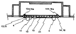
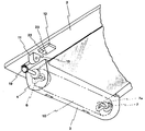
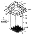
図1は、本考案の空気調和機におけるフィルター交換装置を設置する状態を示す斜視図であり、図2は、図1の本考案の空気調和機を設置した状態の一部を切り欠いた中央断面図説明である。
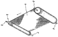
図3は、本考案の交換用フィルターカートリッジの斜視図であり、図4は、図3の本考案の交換用フィルターカートリッジを交換作業のため開いた状態の斜視図である。
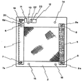
図5は、本考案の枠体に設けられた嵌合受け軸に交換用フィルターカートリッジの軸が嵌合した状態を示す一部を切り欠いた中央断面図説明である。
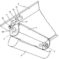
図6及び図7は、本考案の枠体に設けられた嵌合受け軸を有する交換用フィルターカートリッジ収納室の扉を開放及び閉鎖した状態を示し、動力からウォム歯車を介してフィルターカートリッジを駆動する状態を2点鎖線で示した説明斜視図である。
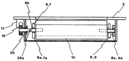
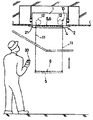
図8は、本考案の枠体に設けられた嵌合受け軸を有する交換用フィルターカートリッジ収納室にフィルターカートリッジを収納した状態を点線で示した側面説明図であり、図9は、図8の平面図説明図である。
図10乃至図13は、従来技術で示された「特許文献1乃至4」の各発明に係る「図1」の説明図である。FIG. 1 is a perspective view showing a state in which a filter replacement device is installed in the air conditioner of the present invention, and FIG. 2 is a central view of the air conditioner of FIG. It is sectional drawing description.
FIG. 3 is a perspective view of the replacement filter cartridge of the present invention, and FIG. 4 is a perspective view of the replacement filter cartridge of FIG. 3 opened for replacement.
FIG. 5 is a partially cutaway central cross-sectional view showing a state in which the shaft of the replacement filter cartridge is fitted to the fitting receiving shaft provided on the frame of the present invention.
6 and 7 show a state in which the door of the replacement filter cartridge storage chamber having the fitting receiving shaft provided on the frame body of the present invention is opened and closed, and the filter cartridge is driven from the power via the worm gear. FIG. 4 is an explanatory perspective view showing a state of the dashed line by a two-dot chain line.
FIG. 8 is a side view showing a state where the filter cartridge is stored in a replacement filter cartridge storage chamber having a fitting receiving shaft provided on the frame body of the present invention by a dotted line, and FIG. 9 is a side view of FIG. It is a top view explanatory drawing.
FIG. 10 to FIG. 13 are explanatory diagrams of FIG. 1 according to the inventions of “
以下、本考案に係る考案について、図面に基づいて説明します。図1本考案の枠体2の状態は、従来天井に取り付けられていた空気調和機の装置の鍵24,25を解除し、従来のフィルターを取り除き取り付け枠を開いた状態で本考案の枠体2の取付状態を示すものである。 Hereinafter, the device according to the present invention will be described with reference to the drawings. Fig. 1 The state of the
図1、2に示す本考案に係る枠体2は、従来の空気調和機の装置からフィルターの部分を取り除きフィルター取り付け部分21の内側に2個の帯板金17,18を上下に当て、そのフィルター取り付け部分21を挟むようにその外側に上記枠体2を当て、枠体2に設けられたボルト孔13,14,15,16にボルト13a,14a,15a,16aを通し、更に、このボルトをフィルター取付部分21を介して、帯板金17,18のボルト孔13,14,15,16に通して,螺子により設置するものである。 The
そして、設置された枠体2の左右に設けられた箱体4,5の蓋3を開閉して、収納室4,5の各嵌合受軸6,7,8,9にフィルターカートリッジの各軸6a,7a,8a,9aを押圧して嵌合させたり、引きぬいたりしてフィルターカートリッジ10の交換作業を行うものである。 Then, the
動力の運行作業計画は、2日に一回にするか、3日に一回にするかは、部屋の空気の汚れ具合によるが、予め部屋の空気を検査して2日に一回にするか、3日に一回にするかを決め、制御装置11にセットされ、その計画に基づいて自動的に運転される。 The power operation work plan should be once every two days or once every three days, depending on how dirty the air in the room is. Or once every three days, set in the
フィルターカートリッジ10は、全長の500mmで1回の運転距離は50mmで10回使用できるが、3日に1度の運転計画によれば1個のフィルターカートリッジで1ヶ月使用できるものであります。そして、その終期を知らせる装置として制御装置には、9回目に達すると橙色のランプ21が点灯し、最後の10回目に達すると赤色のランプ22が点灯して終期を知らせるものである。 The
更に、詳細にフィルターカートリッジ10の交換作業を説明すると、枠体2には、その略左右側両端に、それぞれ外側に開閉する蓋3を設けてなるフィルター収納室4,5が設けられている。その収納室4,5の上下には、フィルターカートリッジ軸が嵌合する軸受6,7,8,9が設けられ、その軸受けにフィルターカートリッジ10の軸6a,7a,8a,9aを嵌合押圧して、嵌合軸受6,7,8,9にフィルターカートリッジ10を装着する。その際、フィルターカートリッジ10軸6aの先端の一部は、図4に示すよう平たくマイナス型6bに設けられている。 Further, the replacement operation of the
このマイナス型6bの先端部分は、動力装置11からウォム歯車19で連動する駆動軸20の先端部分20aのマイナス型切れ目になっていて、そこに装着される。これによりフィルターカートリッジ10は、動力の働きで駆動するものである。 The distal end of the
フィルターカートリッジ10の交換は、古いフィルターカートリッジ10を嵌合受軸6,7,8,9引き抜き、新しいフィルターカートリッジ10の各軸6a,7a,8a,9aを嵌合受軸6,7,8,9に押圧すると同じに駆動軸20の先端部分20aのマイナス型切れ目にフィルターカートリッジ10軸6aの先端マイナス型6bの先端部分を差し込み、各収納室4,5の蓋3を閉じてその作業を終了するものである。 To replace the
フィルターカートリッジ10を収納する収納室を有する枠体の一部にフィルター設置室の空気の汚れ具合により、フィルターの交換を2日に1度にするか3日に1度にするかの調節を設定する制御装置12とその動力装置11により運転されるもので、そこ効果は抜群である。 Depending on the degree of contamination of the air in the filter installation room, the filter can be replaced once every two days or once every three days, depending on the degree of air contamination in the filter installation room. It is operated by the
1 空気調和機におけるフィルター交換装置
2 枠体
3 蓋
4,5 フィルター収納室
6,7,8,9 嵌合軸受
6a,7a,8a,9a フィルターカートリッジ10の軸
11 動力
12 制御装置
13,14,15,16 ボルト孔
17,18 帯板
21 フィルター取付枠DESCRIPTION OF
Claims (2)
Priority Applications (1)
| Application Number | Priority Date | Filing Date | Title |
|---|---|---|---|
| JP2003272535U JP3101034U (en) | 2003-10-15 | 2003-10-15 | Filter change device in air conditioner |
Applications Claiming Priority (1)
| Application Number | Priority Date | Filing Date | Title |
|---|---|---|---|
| JP2003272535U JP3101034U (en) | 2003-10-15 | 2003-10-15 | Filter change device in air conditioner |
Publications (1)
| Publication Number | Publication Date |
|---|---|
| JP3101034U true JP3101034U (en) | 2004-06-03 |
Family
ID=43254627
Family Applications (1)
| Application Number | Title | Priority Date | Filing Date |
|---|---|---|---|
| JP2003272535U Expired - Fee Related JP3101034U (en) | 2003-10-15 | 2003-10-15 | Filter change device in air conditioner |
Country Status (1)
| Country | Link |
|---|---|
| JP (1) | JP3101034U (en) |
Cited By (1)
| Publication number | Priority date | Publication date | Assignee | Title |
|---|---|---|---|---|
| WO2008096546A1 (en) * | 2007-02-09 | 2008-08-14 | Daikin Industries, Ltd. | Indoor unit for air conditioner |
-
2003
- 2003-10-15 JP JP2003272535U patent/JP3101034U/en not_active Expired - Fee Related
Cited By (2)
| Publication number | Priority date | Publication date | Assignee | Title |
|---|---|---|---|---|
| WO2008096546A1 (en) * | 2007-02-09 | 2008-08-14 | Daikin Industries, Ltd. | Indoor unit for air conditioner |
| US8034138B2 (en) | 2007-02-09 | 2011-10-11 | Daikin Industries, Ltd. | Indoor unit of air conditioner |
Similar Documents
| Publication | Publication Date | Title |
|---|---|---|
| JP4772096B2 (en) | Embedded ceiling air conditioner | |
| JP3101034U (en) | Filter change device in air conditioner | |
| KR20170046117A (en) | Ventilation Apparatus of Hinge Door | |
| KR101416074B1 (en) | Window Open and close Device with Detachable Structure by Sub-assembly Module | |
| KR100890932B1 (en) | Building Ventilator | |
| CN216974556U (en) | Window frame member and window frame device | |
| CN214198949U (en) | Top cover assembly, outdoor unit and air conditioning system | |
| CN109323331B (en) | An air conditioner indoor unit | |
| CN208184605U (en) | It is a kind of to take a breath, filter integral type shutter fan | |
| CN213880752U (en) | Novel people's air defense ventilation mode signal control case | |
| CN214501550U (en) | Wisdom campus classroom is with convenient to detach's breather | |
| CN211029064U (en) | A profile cutting device for the production of metal doors and windows | |
| CN110207268B (en) | Dust collecting box device, air conditioner indoor unit and control method | |
| CN207960397U (en) | Curtain wall door and window convenient for air purification | |
| CN113357504A (en) | Self-adaptive dynamic scheduling device for semiconductor production line | |
| JP2001349154A (en) | Pull sash | |
| CN219889102U (en) | Indoor monitoring convenient to overhaul | |
| CN109184484B (en) | Window capable of being opened in three dimensions and indoor ventilation method | |
| CN223423857U (en) | A motor-hidden automatic window | |
| CN220582621U (en) | Glass curtain wall ventilator | |
| CN112178891A (en) | Air conditioning system control method based on data mining | |
| CN217633168U (en) | Axial-flow type fire-fighting smoke exhaust fan | |
| CN223190347U (en) | Venetian blind and adjusting mechanism | |
| CN216643675U (en) | Wisdom campus is with student's attendance device of checking card | |
| CN222123451U (en) | Air quantity adjustable filtering air supply outlet |
Legal Events
| Date | Code | Title | Description |
|---|---|---|---|
| LAPS | Cancellation because of no payment of annual fees |