JP3100124U - Prefabricated unit furniture - Google Patents
Prefabricated unit furniture Download PDFInfo
- Publication number
- JP3100124U JP3100124U JP2003270850U JP2003270850U JP3100124U JP 3100124 U JP3100124 U JP 3100124U JP 2003270850 U JP2003270850 U JP 2003270850U JP 2003270850 U JP2003270850 U JP 2003270850U JP 3100124 U JP3100124 U JP 3100124U
- Authority
- JP
- Japan
- Prior art keywords
- fixing
- furniture
- fixed
- pillars
- corner
- Prior art date
- Legal status (The legal status is an assumption and is not a legal conclusion. Google has not performed a legal analysis and makes no representation as to the accuracy of the status listed.)
- Expired - Fee Related
Links
Images


Abstract
【課題】飾り棚、テーブル、チェスト、キャビネットなどの家具モジュールを、使用者が容易に分解、組立てができると共に、増設や組み合わせの変更を容易に行うことができる組立式ユニット家具を提供する。
【解決手段】立設された複数の柱間に棚板2、天板3、チェスト4、キャビネット5などの家具モジュールを分解、組立可能に取り付けてなる組立式ユニット家具である。家具の隅位置に立設され、内側に固定金具10を固定するための固定凹部6aを設けた金属製の隅柱6と、家具の中寄りに立設され、内側に固定金具10を固定するための固定凹部7aを設けた金属製の中柱7と、柱の固定凹部6a,7aに固定ねじ18で締付固定される第一固定部11と家具モジュールに固定凸部による嵌合または固定ねじにより固定される第二固定部12を有したL形の固定金具10と、を備えている。
【選択図】図1
The present invention provides an assembling unit furniture that allows a user to easily disassemble and assemble a furniture module such as a cabinet, a table, a chest, a cabinet, and the like, and to easily add or change a combination.
Kind Code: A1 A modular unit furniture in which furniture modules such as a shelf plate 2, a top plate 3, a chest 4, and a cabinet 5 are disassembled and assembled between a plurality of upright columns. A metal corner post 6 erected at a corner position of furniture and provided with a fixing recess 6a for fixing the fixing bracket 10 inside, and a metal fixture 6 erected near the center of the furniture to fix the fixing bracket 10 inside. And a first fixing portion 11 which is fastened and fixed to the fixing recesses 6a, 7a of the pillars with fixing screws 18, and which is fitted or fixed to the furniture module by a fixing convex portion. An L-shaped fixing bracket 10 having a second fixing portion 12 fixed by screws.
[Selection diagram] Fig. 1
Description
本考案は、組立て式のユニット家具に関し、特に飾り棚、テーブル、チェストなどの家具モジュールを、簡単に充分な強度を持って組み立てることができ、各種の大きさや形状の部材を用意すれば、使用者が部屋の大きさにあった任意の大きさや形状の家具を組み立てることができる組立式ユニット家具に関する。 The present invention relates to prefabricated unit furniture. In particular, furniture modules such as display cabinets, tables, and chests can be easily assembled with sufficient strength, and if members of various sizes and shapes are prepared, the user can use it. Relates to an assembling unit furniture capable of assembling furniture of an arbitrary size and shape suitable for the size of a room.
従来、飾り棚、テーブル、チェスト、キャビネットなどの家具モジュールを、組み立てて一体に形成する組立て式のユニット家具として、例えば、下記特許文献1に示すようなユニット家具が提案されている。
しかし、上記のユニット家具は、2本の柱を基本構成とし、下部に設置したキャビネットやチェストの両側に2本の柱を立設し、柱の上部に飾り棚などの上部棚を固定する構造である。このため、上部棚の荷重が2本の柱に不安定にかかり易く、上部棚と柱の固定は大形の固定金具と固定ボルトにより大きな強度をもって行う必要があり、このために、専用の工具と熟練した組立て技術を必要としていた。 However, the unit furniture described above has a basic structure consisting of two pillars, two pillars standing on both sides of a cabinet or chest installed at the lower part, and an upper shelf such as a display cabinet fixed at the upper part of the pillar. is there. For this reason, the load on the upper shelf tends to be unstable on the two columns, and it is necessary to fix the upper shelf and the columns with large strength by using large fixing brackets and fixing bolts. And required skilled assembly techniques.
これにより、上記のユニット家具は、使用者が簡単に組み立てたり分解することが難しく、この種のユニット家具を購入した使用者が、部屋の模様替えなどの際に、家具の移動を行う場合、或いは家具の増設を行おうとした場合、容易にユニット家具を分解することができず、その分解や組立てを専門業者に依頼しなければならないという問題があった。 This makes it difficult for the user to easily assemble or disassemble the unit furniture, and when the user who purchases this kind of unit furniture moves furniture when changing the style of a room, or When an attempt is made to add furniture, unit furniture cannot be easily disassembled, and there has been a problem that the disassembly and assembly must be requested to a specialized contractor.
本考案は、上述の課題を解決するものであり、飾り棚、テーブル、チェスト、キャビネットなどの家具モジュールを、使用者が容易に分解、組立てができると共に、増設や組み合わせの変更を容易に行うことができる組立式ユニット家具を提供することを目的とする。 The present invention is intended to solve the above-described problem, and a user can easily disassemble and assemble furniture modules such as a cabinet, a table, a chest, and a cabinet, and can easily add or change a combination. It is an object of the present invention to provide a prefabricated unit furniture that can be used.
本考案に係る組立式ユニット家具は、立設された複数の柱間に棚板、天板、チェスト、キャビネットなどの家具モジュールを分解、組立可能に取り付けてなる組立式ユニット家具であって、家具の隅位置に立設され、内側に固定金具を固定するための固定凹部を設けた金属製の隅柱と、家具の中寄りに立設され、内側に固定金具を固定するための固定凹部を設けた金属製の中柱と、該柱の固定凹部に固定ねじで締付固定される第一固定部と該家具モジュールに固定凸部による嵌合または固定ねじにより固定される第二固定部を有したL形の固定金具と、を備え、該固定金具は柱に対し平面内で所定の傾斜角度を持って内側を向けて固定されることを特徴とする。 The modular unit furniture according to the present invention is a modular unit furniture in which furniture modules such as a shelf, a top plate, a chest, and a cabinet are disassembled and assembled between a plurality of standing pillars. A metal corner post that is erected at the corner position and provided with a fixing recess for fixing the fixing bracket inside, and a fixing recess that is erected near the center of the furniture and fixes the fixing bracket inside. The provided metal middle pillar, the first fixed part which is fastened and fixed to the fixed concave part of the pillar with a fixing screw, and the second fixing part which is fixed to the furniture module by fitting with the fixing convex part or by the fixing screw. And an L-shaped fixture having a predetermined inclination angle in a plane with respect to the column and fixed inwardly.
本考案に係る組立式ユニット家具は、例えば四隅に隅柱を立設し、前後の隅柱間に例えば2対の中柱を立設する。各隅柱と各中柱には高さ方向に所定の間隔をおいて又は連続して固定凹部が設けられている。棚板、天板、チェスト、キャビネットなどの家具モジュールを固定する柱の高さ位置に、予めL形の固定金具をその固定凹部に嵌め込み、固定ねじで固定しておく。高さ方向に連続して形成された固定凹部の場合、各固定金具は任意の高さ位置にナット金具と固定ねじを用いて簡単に固定することができる。また、各固定金具は、柱に対し各棚板、天板などが装着される水平位置の平面内で内側を向けて所定の傾斜角度で固定される。 組 立 In the modular unit furniture according to the present invention, corner pillars are erected at four corners, for example, and two pairs of middle pillars are erected between the front and rear corner pillars. Each corner post and each middle post are provided with fixed recesses at predetermined intervals or continuously in the height direction. An L-shaped fixture is previously fitted in a fixing recess at a height of a pillar for fixing a furniture module such as a shelf board, a top board, a chest, or a cabinet, and is fixed with a fixing screw. In the case of the fixing concave portion formed continuously in the height direction, each fixing metal can be easily fixed at an arbitrary height position using a nut metal and a fixing screw. Further, each fixing bracket is fixed at a predetermined inclination angle toward the inside in a plane at a horizontal position where each shelf plate, a top plate and the like are mounted on the pillar.
したがって、棚板、天板などはその四隅をそれらの固定金具上に載置し、固定凸部の嵌め込みにより、又は固定ねじの締付により固定金具の第二固定部を棚板や天板に簡単に固定することができる。チェスト、キャビネットなども、その上部と下部の四隅を固定金具の第二固定部に固定して、4隅の隅柱または中間位置の中柱に対し、簡単に固定することができる。また、各種の長さの柱、各種の大きさの棚板、天板などを製作しておけば、使用者は、家具を入れる部屋の大きさに合わせて柱や棚板などを選択して、部屋の広さに応じて、収納する品物や家具の用途に応じて、様々な形状で大きさの家具を組立てにより作ることができ、さらに、家具の分解も固定金具を外せば簡単に行うことができるから、家具の移動も容易に行なうことができる。 Accordingly, the four corners of the shelf board, the top board, etc. are placed on the fixtures, and the second fixing portion of the fixture is attached to the shelf board or the top board by fitting the fixing protrusions or tightening the fixing screws. Can be easily fixed. Chests, cabinets, and the like can also be easily fixed to the four corners or the middle post at the four corners by fixing the upper and lower four corners to the second fixing part of the fixture. In addition, if you make pillars of various lengths, shelves of various sizes, top plates, etc., the user can select columns and shelves etc. according to the size of the room where furniture is to be put Depending on the size of the room, it can be made by assembling furniture of various shapes and sizes according to the goods to be stored and the use of the furniture, and the furniture can be easily disassembled by removing the fixing bracket Therefore, furniture can be easily moved.
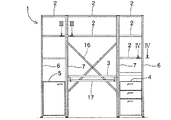
以下、本考案の一実施形態を図面に基づいて説明する。図1は組立式ユニット家具の正面図を示し、図2はその左側面図を示している。このユニット家具1は、四隅に立設された4本の隅柱6と、それらの隅柱6の間に立設された4本の中柱7と、隅柱6及び中柱7の任意の位置に水平に装着された複数の棚板2と、中央位置の中柱7間に水平に装着された机用の天板3と、正面に向って右側下部の隅柱6と中柱7間に装着されたチェスト4と、正面に向って左側下部の隅柱6と中柱7間に装着されたキャビネット5と、を備えて組立可能に構成される。
Hereinafter, an embodiment of the present invention will be described with reference to the drawings. FIG. 1 shows a front view of the modular unit furniture, and FIG. 2 shows a left side view thereof. The unit furniture 1 has four
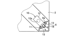
隅柱6は、図4の断面図に示すように、アルミニウムなどの軽金属を一定の断面を有し内部空間を有した柱状に成形されたもので、平面視において、正面と側面の直角の2面が平面状に形成され、内側に円弧状の曲面が形成されている。この内側の曲面に固定金具10を固定するための固定凹部6aが上下方向に連続して形成されている。固定凹部6aの向きは、平面視で正面に対し内側に、つまり平面上で斜め45度内側に向けて形成されている。したがって、固定金具10は平面上で斜め45度内側に向けて固定されることになる。また、この固定凹部6aの奥の柱の内側に、隔壁を介してナット金具13を保持する部分が形成され、この部分にナット金具13が収納保持される。
As shown in the cross-sectional view of FIG. 4, the
ナット金具13は帯状金属板にねじ孔を穿設して形成され、隅柱6の固定凹部6aに固定金具10の第一固定部11が嵌入された状態で、外側から固定ねじ18が第一固定部11からナット金具13のねじ孔にねじ込まれ、これによって、固定金具10が隅柱6に対し固定される。
The
中柱7は、図3の断面図に示すように、アルミニウムなどの軽金属を一定の断面を有し内部空間を有した柱状に成形されたもので、平面視において、半円形状に形成され、外側に平坦面が形成され、内側に円弧状の曲面が形成されている。2つの固定凹部7aの向きは、平面視で正面に対し内側に、つまり平面上で斜め45度内側に向けて形成されている。したがって、固定金具10は家具モジュールの平面上で斜め45度内側に向けて固定されることになる。この内側の曲面の2箇所に固定金具10を固定するための固定凹部7aが上下方向に連続して形成されている。また、この固定凹部6aの奥に、隔壁を介してナット金具13を保持する部分が形成され、この部分にナット金具13が収納保持される。
As shown in the cross-sectional view of FIG. 3, the
ナット金具13は帯状金属板にねじ孔を穿設して形成され、中柱7の固定凹部7aに固定金具10の第一固定部11が嵌入された状態で、外側から固定ねじ18が第一固定部11からナット金具13のねじ孔にねじ込まれ、これによって、固定金具10が中柱7に対し固定される。図3に示すように、中柱7には平面視で2方向の固定金具10が、正面に対し斜め45度内側に向け、相互に90度の間隔を開いて固定されることになる。
The
なお、上記のナット金具13は、通常の六角筒形のナット金具とすることもでき、この場合には、隅柱6の固定凹部6aまたは中柱7の固定凹部7aに穿設した孔にナット金具を嵌め込むようにすればよい。このように、固定凹部6a,7a内の適当な高さ位置に、固定ねじを挿入するための挿入孔を適当な間隔で穿設しておけば、柱の略任意の高さ位置に固定金具10を固定することができる。
The
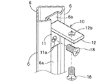
固定金具10は、図5、6に示すように、L形に形成され、一端が第一固定部11として隅柱6の固定凹部6aまたは中柱7の固定凹部7aに挿入可能に形成され、他端が第二固定部12として棚板2、天板3、チェスト4などの家具モジュールの底部又は底面に固定可能に形成される。第二固定部12には、図5に示すように、固定凸部12aが上方に突出して形成され、固定凸部12aが嵌合する嵌合孔が棚板2或いは天板3などの底面に形成される。
As shown in FIGS. 5 and 6, the
なお、図6に示すように、固定金具10の第二固定部12には、固定孔12bを穿設することもでき、固定孔12bを穿設した場合は、下側又は上側から差し込んだ固定ねじ18により、棚板2、天板3、チェスト4などの家具モジュールの上面または底面に固定する。さらに、隅柱6と中柱7の底部には、図5に示すように、高さ調整具14がねじ込まれ、柱の高さが調整可能とされる。
As shown in FIG. 6, a
このように構成された組立式ユニット家具は、例えば図1,2に示すように、四隅に隅柱6を立設し、前後の隅柱6間に2対の中柱7を立設する。そして、各隅柱6と各中柱7には、高さ方向に所定の間隔をおいて、多数の固定金具10が柱の固定凹部6a,7aに第一固定部11を嵌め込んで固定される。つまり、それらの固定金具10は、棚板2、天板3、チェスト4、キャビネット5などの家具モジュールを固定する柱の高さ位置に、予めL形の固定金具10の第一固定部11をその固定凹部6a,7aに嵌め込み、図5、6のように、固定ねじ18で固定しておく。高さ方向に連続して形成された固定凹部6a,7aの場合、各固定金具10は任意の高さ位置にナット金具13と固定ねじ18を用いて簡単に固定することができる。また、各固定金具10は、隅柱6、中柱7に対し各棚板2、天板3などが装着される水平位置の平面内で内側を向けて所定の傾斜角度(ここでは45度)で固定される。
組 立 In the assembled unit furniture configured as described above, for example, as shown in FIGS. 1 and 2,
そして、これらの固定金具10の第二固定部12の上に、棚板2、天板3、チェスト4、キャビネット5などの家具モジュールが載置され、固定される。固定金具10は、その第二固定部12が内側で中央をむけて平面内に配設されているため、簡単に且つ安定して家具モジュールを組み付け固定することができる。
家具 Furniture modules such as the
そして、これらの棚板2、天板3、チェスト4、キャビネット5などの家具モジュールを隅柱6または中柱7間に配置して固定することにより、各隅柱6と中柱7は所定の位置に立設されることとなる。また、図2に示すように、隅柱6と隅柱6の任意の位置に、サイド板15がガードパネルなどとして取り付けられるが、このようなサイド板15は、図7に示すように、隅柱6の固定凹部6aに嵌入可能で且つ両側に挿入固定部19aを設けたサイド板固定具19を使用して、隅柱6と隅柱6間に取り付けることができる。さらに、中央に位置する中柱7と中柱7間に補強フレーム16がクロス状にそれらを連結するように取り付けられる。また、天板3の下側に、キーボード用天板17が引出し可能に取り付けられる。
Furniture modules such as the
このように、本ユニット家具は、棚板2、天板3、チェスト4などの家具モジュールを隅柱6と隅柱6間、隅柱6と中柱7間、または中柱7と中柱7間に配置して、固定金具10によりそれらを相互に固定するように構成されるから、使用する各家具モジュール、隅柱6、中柱7の数や大きさに応じて、小形から大形まで各種の大きさのユニット家具を、固定金具10と固定ねじ18を用いて簡単に組み立てることができる。また、各種の長さの柱、各種の大きさの棚板、天板などを製作しておけば、使用者は、家具を入れる部屋の大きさに合わせて柱や棚板などを選択して、部屋の広さに応じて、収納する品物や家具の用途に応じて、様々な形状で大きさの家具を組立てにより作ることができる。
As described above, the present unit furniture includes furniture modules such as the
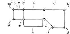
図8〜図10は他の実施形態のユニット家具を示し、このユニット家具は、高さの低い隅柱26、中柱27を使用して、高さの低い家具を構成している。即ち、図8〜10に示すように、このユニット家具は、正面にデスク用の天板22が配置され、向って右側にコーナー用の天板23が配置され、向って左側にチェスト用の天板24が配設され、その天板24の下方にチェスト25が装着され、それらの天板22,23,23、及びチェスト25の各家具モジュールが隅柱26と中柱27との間で固定されている。
FIGS. 8 to 10 show a unit furniture according to another embodiment. The unit furniture uses low-
コーナー用の天板23は、異形の五角形に形成され、そのうちの3個のコーナー部に、高さの低い隅柱26が立設され、左側に中柱27が立設され、上記と同様の固定金具10を使用して、各隅柱26と中柱27に対し天板23が固定される。また、コーナー用の天板23の下側に、棚板28,28が水平に装着され、これらの棚板28,28も上記の固定金具10により各隅柱26と中柱27間に固定される。また、中央のデスク用の天板22は、その四隅が対応位置に立設された中柱27に上記の固定金具10よって固定支持され、天板22の下側にキーボード用天板37が引出し可能に装着される。
The
この天板22も、上記と同様の固定金具10と固定ねじ18を用いて、各隅柱26と中柱27間に簡単に固定することができる。さらに、チェスト用の天板24は、矩形形状に形成され、その左側の2個のコーナー部に、高さの低い隅柱26が立設され、右側に2本の中柱27が立設され、上記と同様に固定金具10と固定ねじ18を使用して、その天板24は各隅柱26と中柱27間に水平に固定される。チェスト用の天板24の下側には、チェスト25が、やはり上記の固定金具10と固定ねじ18により、各隅柱26と中柱27間に固定される。
天 The
このように、高さの低い隅柱26と中柱27を用いて、全体に高さの低いユニット家具21を形成することができ、このユニット家具21も、上記と同様に、固定金具10を隅柱26と中柱27の固定凹部の任意の位置に固定ねじ18で固定しておき、そこに天板22〜24、チェスト25、棚板28などを、簡単に固定することができる。
As described above, the
このように、棚板、天板、チェスト、キャビネットなどの家具モジュールは、家具の四隅などに立設された隅柱または中柱に対し固定金具と固定ねじを用いて固定することにより、ユニット家具を組み立てることができるから、各種の大きさの棚板、天板などを製作しておけば、使用者は、家具を入れる部屋の大きさに合わせて柱や棚板などを選択して、部屋の広さに応じて、収納する品物や家具の用途に応じて、様々な形状で大きさの家具を組立てにより作ることができる。さらに、各家具モジュールは、固定金具と固定ねじを外せば、簡単に分解することができ、分解によって家具の移動も容易に行なうことができる。 As described above, furniture modules such as shelf boards, top boards, chests, and cabinets are fixed to corner pillars or center pillars erected at four corners of furniture using fixing brackets and fixing screws, so that the unit furniture is fixed. If you make shelves and top boards of various sizes, the user can select columns and shelves according to the size of the room where the furniture is to be placed, and Furniture of various shapes and sizes can be produced by assembling according to the size of the product and the use of the stored goods and furniture. Further, each furniture module can be easily disassembled by removing the fixing bracket and the fixing screw, and the disassembly can easily move the furniture.
なお、上記実施形態では、固定ねじを締め付けるために、板状のナット金具を柱の固定凹部に取り付けたが、そのナット金具に代えて、カシメ固定用のナットを、固定凹部に設けた孔にカシメ固定することもできる。 In the above-described embodiment, a plate-shaped nut fitting is attached to the fixing recess of the pillar in order to tighten the fixing screw, but instead of the nut fitting, a nut for caulking fixation is provided in a hole provided in the fixing recess. It can also be fixed by caulking.
1,21−ユニット家具
2−棚板
3−天板
4−チェスト
5−キャビネット
6−隅柱
6a−固定凹部
7−中柱
7a−固定凹部
10−固定金具
11−第一固定部
12−第二固定部
13−ナット金具
1,21-unit furniture 2-shelf board 3-top board 4-chest 5-cabinet 6-
Claims (1)
家具の隅位置に立設され、内側に固定金具を固定するための固定凹部を設けた金属製の隅柱と、
家具の中寄りに立設され、内側に固定金具を固定するための固定凹部を設けた金属製の中柱と、
該柱の固定凹部に対し固定ねじで締付固定される第一固定部と該家具モジュールに対し固定凸部による嵌合または固定ねじにより固定される第二固定部を有したL形の固定金具と、
を備え、該固定金具は柱に対し平面内で所定の傾斜角度を持って内側に向けて固定されることを特徴とする組立式ユニット家具。 Assembled unit furniture in which furniture modules such as a shelf board, a top board, a chest, and a cabinet are disassembled and assembled so as to be assembled between a plurality of upright pillars,
A metal corner post that is erected at the corner position of the furniture and has a fixing recess inside for fixing the fixing bracket,
A metal pillar that stands upright in the middle of the furniture and has a fixing recess inside to fix the fixing bracket,
An L-shaped fixture having a first fixing portion that is fastened and fixed to a fixing recess of the pillar with a fixing screw and a second fixing portion that is fitted to the furniture module by a fixing protrusion or fixed by a fixing screw. When,
Wherein the fixing bracket is fixed inwardly at a predetermined inclination angle in a plane with respect to the column, and is fixed inwardly.
Priority Applications (1)
| Application Number | Priority Date | Filing Date | Title |
|---|---|---|---|
| JP2003270850U JP3100124U (en) | 2003-08-28 | 2003-08-28 | Prefabricated unit furniture |
Applications Claiming Priority (1)
| Application Number | Priority Date | Filing Date | Title |
|---|---|---|---|
| JP2003270850U JP3100124U (en) | 2003-08-28 | 2003-08-28 | Prefabricated unit furniture |
Publications (1)
| Publication Number | Publication Date |
|---|---|
| JP3100124U true JP3100124U (en) | 2004-04-30 |
Family
ID=43253784
Family Applications (1)
| Application Number | Title | Priority Date | Filing Date |
|---|---|---|---|
| JP2003270850U Expired - Fee Related JP3100124U (en) | 2003-08-28 | 2003-08-28 | Prefabricated unit furniture |
Country Status (1)
| Country | Link |
|---|---|
| JP (1) | JP3100124U (en) |
-
2003
- 2003-08-28 JP JP2003270850U patent/JP3100124U/en not_active Expired - Fee Related
Similar Documents
| Publication | Publication Date | Title |
|---|---|---|
| US20100090567A1 (en) | Storage furniture system and methods for assembling the storage furniture system | |
| US7243887B2 (en) | Suspension system | |
| CA2446451A1 (en) | Modular worktable and shelving unit | |
| US20220378195A1 (en) | Combined type shelf | |
| JPH0870940A (en) | Assembly type book shelf | |
| JP3100124U (en) | Prefabricated unit furniture | |
| RU2019109458A (en) | MODULAR KITCHEN SET | |
| JP5532757B2 (en) | Cabinet equipment | |
| JP4968777B2 (en) | Desk with side panel | |
| JP2002065364A (en) | Desk with panel | |
| KR200315595Y1 (en) | bookcase | |
| KR101217812B1 (en) | Assembling show stands | |
| KR200464948Y1 (en) | Assembly type display case | |
| EP1656049A1 (en) | A system for detachable suspension of shelves | |
| JP5337003B2 (en) | desk | |
| KR200321265Y1 (en) | Chest for adjusted crosspiece's height | |
| JPS6211470Y2 (en) | ||
| CN211794931U (en) | Angle-adjustable foot rest and bar counter | |
| KR200316973Y1 (en) | An exhibition display stand enabling shelves to widen | |
| JP2002034670A (en) | Furniture with shelf for corner of room | |
| KR102235203B1 (en) | A shelf for desks used at internet cafe | |
| JP3121569U (en) | shelf | |
| JP2961600B2 (en) | Office furniture systems | |
| JPH0122530Y2 (en) | ||
| JP2000004960A (en) | Collapsible book stand |
Legal Events
| Date | Code | Title | Description |
|---|---|---|---|
| LAPS | Cancellation because of no payment of annual fees |