JP3098705U - Buff intermediate mount - Google Patents
Buff intermediate mount Download PDFInfo
- Publication number
- JP3098705U JP3098705U JP2003003664U JP2003003664U JP3098705U JP 3098705 U JP3098705 U JP 3098705U JP 2003003664 U JP2003003664 U JP 2003003664U JP 2003003664 U JP2003003664 U JP 2003003664U JP 3098705 U JP3098705 U JP 3098705U
- Authority
- JP
- Japan
- Prior art keywords
- buff
- hole
- mount
- hook
- loop fastener
- Prior art date
- Legal status (The legal status is an assumption and is not a legal conclusion. Google has not performed a legal analysis and makes no representation as to the accuracy of the status listed.)
- Expired - Lifetime
Links
Images


Abstract
【課題】自動車の表面の塗装仕上げをする場合、スポンジで出来たバフ1をバフ取付台2に面ファスナーで接着し、それをポリッシャー3に取り付けて電動で回転させて磨きをかけるという作業を行うが、バフ1が薄くなると、硬化ゴムで出来ているバフ取付台2が塗装表面に接触して傷をつける。そこで、バフ1は、それほど薄くならないうちに廃棄していた。
【解決手段】バフ1とバフ取付台2との間に介在させる、次のような構造のバフ中間取付台4を提案する。即ち、中央に穴1Bを開けた円柱状の柔らかいスポンジ1Aを主体とし、その上面に面ファスナー4Eを貼り、下面に面ファスナー4Cを貼ったという構造のものである。これを介在させると、バフ1を薄くなるまで使ってもバフ中間取付台4の厚み分だけは離れているから、バフ取付台2が塗装表面を傷つけることがない。
【選択図】 図1When a paint finish is applied to the surface of an automobile, a buff 1 made of sponge is bonded to a buff mount 2 with a hook-and-loop fastener, and the buff is attached to a polisher 3 and is electrically rotated to polish. However, as the buff 1 becomes thinner, the buff mount 2 made of cured rubber comes into contact with the painted surface and damages it. Therefore, Buff 1 was discarded before it became too thin.
A buff intermediate mount 4 having the following structure interposed between a buff 1 and a buff mount 2 is proposed. That is, it has a structure in which a columnar soft sponge 1A having a hole 1B formed in the center is the main body, a hook-and-loop fastener 4E is stuck on the upper surface, and a hook-and-loop fastener 4C is stuck on the lower surface. When this is interposed, even if the buff 1 is used until it becomes thin, it is separated only by the thickness of the buff intermediate mount 4, so that the buff mount 2 does not damage the painted surface.
[Selection diagram] Fig. 1
Description
【0001】
【考案の属する技術分野】
本考案は、板金塗装仕上げ時等に磨きをかけるためのバフを、ポリッシャーに取り付ける際に使用するバフ中間取付台に関するものである。
【0002】
【従来の技術】
自動車の塗装をした後の仕上げ時等には、バフを電動工具であるポリッシャーに取り付け、高速回転させて塗装表面を磨きあげることが行われている。
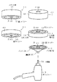
図3は、バフをポリッシャーに取り付けるための従来の部品を示す図である。図3において、1はバフ、1Aはスポンジ体、1Bは穴、1Cは面ファスナー、1Dは穴、2はバフ取付台、2Aはパッド、2Bは面ファスナー、2Cは穴、2Dは連結部、3はポリッシャー、3Aは回転軸、3Bは電源スイッチである。
1−1は、下面が分かるように描いたバフ1である。
【0003】
バフ1は、全体として円柱状をしており、その主体をなしているのはスポンジ体1Aである。スポンジ体1Aの中央には穴1Bが開けられている。スポンジ体1Aの下面には、面ファスナー1Cが貼り付けられており、その中央には穴1Dが開けられている。
ポリッシャー3は電動工具であり、電源スイッチ3Bをオンにすれば、内蔵されているモータが回り、回転軸3Aが回転する。
【0004】
バフ取付台2は、パッド2Aと、その上面に貼り付けられた面ファスナー2Bと、パッド2Aの下部に取り付けられた連結部2Dとから成っている。
パッド2Aは、硬化ゴム等で作られており、上面は円形の平面とされ、下面の中央部はやや盛り上げられた形状とされている。面ファスナー2Bは、バフ1の面ファスナー1Cと着脱するために貼り付けられている。面ファスナー2Bの中央部には、穴2Cが設けられているが、これはバフ1を接着する際、位置合わせの目印とするためのものである。連結部2Dは、ポリッシャー3の回転軸3Aと連結するための部分である。
【0005】
穴1Bは、スポンジ体1Aの上面から下面に至るまで、同じ大きさで開けられている。穴1Dは、面ファスナー1Cの中央に開けられている穴であり、穴1Bよりも小さくされている。
穴1B,1Dが設けてある理由は、バフ1をバフ取付台2に接着する際、バフ取付台2の上面中央にきちんと接着し得るよう、位置合わせをするためである。即ち、バフ1を手に持ち、穴1Bから下を覗けば、穴1Bより小さい穴1Dが見えるが、その穴1Dが穴2Cの中央に位置するように接着する。そうすれば、バフ取付台2の上面の中央に接着でき、ポリッシャー3でバフ1を回転させる際、バフ1が偏心することなくバランスよく回転させることが出来る。
【0006】
穴1Dには、スポンジ体1Aを冷却するという役割もある。バフ1使用中は、塗装表面との摩擦により、スポンジ体1Aには摩擦熱が発生するが、穴1Dはその摩擦熱を放出し、スポンジ体1Aを冷却してくれる。冷却という観点から見れば、穴1Bは大きい程よいわけであるが、あまり大きいと磨きの機能に支障を来すから、あまり大きくは出来ない。
穴1Dは、そこから下方が見えて(穴2Cを視認するため)、いちあわせの目印になりさえすればよいから、穴1Bに比べて小さくてよい。
【0007】
図4は、バフ1をポリッシャー3に取り付けた状況を示す図である。図4(1)は、バフ1がまだ新品に近い時の状況を示し、図4(2)は、相当使用してバフ1が擦り減って来ている時の状況を示している。
バフ1は新品の時は、図4(1)に示すように厚さT1 (数センチ)を有している。このようなバフで塗装した車体を磨く場合には、コンパウンド等の磨き剤を付け、バフ1を高速回転させて磨く。しかし、このような磨き作業を何週間か行っていると、バフ1は徐々に擦り減って来て、やがて図4(2)に示すように、厚さT2 と薄くなって来る。
【0008】
【考案が解決しようとする課題】
(問題点)
バフ1は、まだそれほど薄くならないうちに廃棄処分としなければならないという問題点があった。
(問題点の説明)
バフ1は、薄くなってもスポンジ体で出来ていることに変わりはないから、理屈の上からは使用を続けることが出来る。しかし、磨き作業の途中においては、バフ1の面を傾けて車体に押しつけながら磨かなければならない場面がある。
【0009】
そういう場面では、薄くなっているバフ1は圧縮されて更に一層薄くされる結果、バフ取付台2が塗装表面に当たってしまうことがある。そうすると、バフ取付台2は硬化ゴム等の硬い材料で出来ているから、塗装表面を傷つけてしまうことになる。
そのようなことが起こるのを避けるため、バフ1はあまり薄くならないうちに廃棄処分としているのが実情であり、省資源の観点からも好ましくなく、廃棄物を減らすという環境保護の観点からも好ましくないことであった。
本考案は、以上のような問題点を解決することを課題とするものである。
【0010】
【課題を解決するための手段】
前記課題を解決するため、本考案ではバフ中間取付台なるものを新たに提供する。そのバフ中間取付台とは、中央部に第1の穴が開けられた円柱状のスポンジ体と、該スポンジ体の上面の部分であって外周より内側で且つ前記第1の穴より外側の部分に接着された第1の面ファスナーと、中央に第2の穴を有し、前記スポンジ体の下面の外周より内側の部分に接着された第2の面ファスナーとを具えた構成とし、バフ取付台の面ファスナーに前記第2の面ファスナーを着脱自在に接着し、前記第1の面ファスナーにバフの面ファスナーを着脱自在に接着して使用するというものである。
【0011】
(作 用)
本考案のバフ中間取付台は、塗装仕上げに使用するバフをバフ取付台に取り付ける場合、バフとバフ取付台との間に取り付けられる。従って、バフが擦り減り薄くなって来ても、バフとバフ取付台とは、なおバフ中間取付台の厚み分だけ離隔されている。そして、バフ中間取付台で、磨き作業中に外側に露出しているのは、柔らかいスポンジ体である。
そのため、バフ中間取付台が塗装表面に接触しても、表面を傷つけたりする恐れがなくなり、バフを薄くなるまで使用することが可能となる。
【0012】
【考案の実施の形態】
以下、本考案の実施形態を図面に基づいて詳細に説明する。
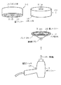
図1は、本考案のバフ中間取付台を用いてバフをポリッシャーに取り付けるための部品を示す図である。符号は図3のものに対応し、4はバフ中間取付台、4Aはスポンジ体、4Bは穴、4Cは面ファスナー、4Dは穴、4Eは面ファスナーである。4−1は、下面が分かるように描いたバフ中間取付台である。
図3と同じ符号の部分は、図3のものと同様のものであるので、それらについての説明は省略する。
【0013】
図3の従来例と相違する点は、バフ1とバフ取付台2との間に、バフ中間取付台4を介在させて取り付けるようにしたという点である。
バフ中間取付台4は、中央に穴4Bが開けられたスポンジ体4Aと、該スポンジ4Aの上面の部分であって、外周より内側で且つ穴4Bより外側の部分に接着されている面ファスナー4Eと、中央に穴4Dが開けられた面ファスナー4Cとから成っている。
【0014】
スポンジ体4Aは、スポンジ体1Aと同じ材料のものが最も良いが、同じでなくとも、回転して塗装表面に接した場合に、該表面を傷つけない材料のものであればよい。穴4Bは、穴1Bと同じ機能(冷却機能,位置合わせ機能)を果たさせるための穴である。
面ファスナー4Cは、バフ取付台2の面ファスナー2Bと着脱するためのものであり、面ファスナー1Cと同様のものとする。面ファスナー4Cの中央に開けられた穴4Dは、バフ1の穴1Dと同様の機能(位置合わせ機能)を果たさせるための穴である。
面ファスナー4Eは、バフ1の面ファスナー1Cと着脱するためのものであり、面ファスナー2Bと同様のものとする。
【0015】
図1の各部品の接着,連結は、次のようにする。
▲1▼先ず、バフ取付台2の上面に、次の要領でバフ中間取付台4を接着する。穴4Bから下方を覗き、穴4Dが穴2Cの中央に位置するようにして、面ファスナー2Bと面ファスナー4Cとを接着する。
▲2▼次に、バフ中間取付台4の上面に、次の要領でバフ1を接着する。穴1Bから下方を覗き、穴1Dが穴4Bの中央に位置するようにして、面ファスナー4Eと面ファスナー1Cとを接着する。
▲3▼ポリッシャー3の回転軸3Aを、バフ取付台2の連結部2Dに連結する。
【0016】
図2は、バフ1を本考案のバフ中間取付台4を介してポリッシャー3に取り付けた状況を示す図である。符号は図4のものに対応しており、tはバフ中間取付台4の厚さである。
図2(1)は、バフ1がまだ新品に近い時の状況を示し、図2(2)は、相当使用してバフ1が擦り減って来ている時の状況を示している。
【0017】
バフ1が新品の時は、図2(1)に示すように、高速回転して接触しても車体表面を傷つけないところのスポンジ体材の厚みは、バフ1の厚さT1 とバフ中間取付台4の厚さtの合計である(T1 +t)もある。厚さT1 でも充分なのに、それ以上あるわけであるから、バフ1を塗装表面に対して傾けて接触させても、バフ取付台2が塗装表面に接触する恐れは勿論ない。
【0018】
一方、使用しているうちにバフ1の厚さがT2 に減少して来た図2(2)の場合、その段階でも、スポンジ体材の厚みは、バフ1の厚さT2 とバフ中間取付台4の厚さtの合計である(T2 +t)だけ残っている。従って、厚さT2 が相当小になってもスポンジ体合計の厚さは(T2 +t)あるから、バフ1を塗装表面に対して傾けて接触させても、バフ取付台2が塗装表面に接触する恐れはない。バフ中間取付台4の厚さtの値は、新品のバフ1の厚さがT1 であることを考慮すれば、その厚さT1 よりやや小の値としておけばよい。そうすれば、バフ1を、そのスポンジ体1Aが殆ど擦り減ってしまうところまで使い切ることが可能となる。
【0019】
なお、図2では、バフ中間取付台4として、厚さがtのもの1種類のみを示しているが、いろいろな厚さのものとすることが出来る。厚さが違う幾つかの種類のバフ中間取付台4を用意しておき、バフ1の擦り減り状況に応じて、それらを使い分けるようにしてもよい。
例えば、薄いものから順にt1 ,t2 ,t3 の厚さの3種類のバフ中間取付台4を用意しておき、バフ1が新品の時は1番薄いt1 のバフ中間取付台4を使用し、バフ1が少し擦り減って来た時は中間の厚さt2 のバフ中間取付台4を使用し、酷く擦り減って来た時は最も厚いt3 のバフ中間取付台4を使用するという具合に使い分ける。
このようにすれば、バフ1とバフ中間取付台4との合計の厚さが、いつも新品のバフ1の厚さT1 に比較的近い厚さに保たれるので、作業員にとって使い勝手がよくなる。
【0020】
【考案の効果】
以上述べた如く、本考案のバフ中間取付台によれば、バフを従来より遙かに薄くなるまで使用することが可能となる。このことにより、バフという商品(資源)を使えるところまでは使い切ることが出来、省資源化が図れると共に、ゴミとして廃棄する量を減らして環境保護に資することも出来る。
【図面の簡単な説明】
【図1】本考案のバフ中間取付台を用いてバフをポリッシャーに取り付けるための部品を示す図
【図2】バフを本考案のバフ中間取付台を介してポリッシャーに取り付けた状況を示す図
【図3】バフをポリッシャーに取り付けるための従来の部品を示す図
【図4】バフをポリッシャーに取り付けた状況を示す図
【符号の説明】
1…バフ、1A…スポンジ体、1B…穴、1C…面ファスナー、1D…穴、2…バフ取付台、2A…パッド、2B…面ファスナー、2C…穴、2D…連結部、3…ポリッシャー、3A…回転軸、4…バフ中間取付台、4A…スポンジ体、4B…穴、4C…面ファスナー、4D…穴、4E…面ファスナー[0001]
[Technical field to which the invention belongs]
The present invention relates to a buff intermediate mount used for attaching a buff to a polisher for polishing at the time of sheet metal painting finish or the like.
[0002]
[Prior art]
At the time of finishing after painting an automobile, a buff is attached to a polisher, which is an electric tool, and is rotated at a high speed to polish a painted surface.
FIG. 3 is a diagram showing a conventional component for attaching a buff to a polisher. In FIG. 3, 1 is a buff, 1A is a sponge body, 1B is a hole, 1C is a hook-and-loop fastener, 1D is a hole, 2 is a buff mount, 2A is a pad, 2B is a hook-and-loop fastener, 2C is a hole, 2D is a connecting part, 3 is a polisher, 3A is a rotating shaft, and 3B is a power switch.
1-1 is a
[0003]
The
The
[0004]
The
The pad 2A is made of a cured rubber or the like, has an upper surface formed into a circular flat surface, and a central portion of the lower surface formed into a slightly raised shape. The hook-and-
[0005]
The hole 1B is formed in the same size from the upper surface to the lower surface of the sponge body 1A. The hole 1D is a hole formed in the center of the hook-and-loop fastener 1C, and is smaller than the hole 1B.
The reason why the
[0006]
The hole 1D also has a role of cooling the sponge body 1A. During use of the
The hole 1D may be smaller than the hole 1B since the lower part can be seen from there (to visually recognize the hole 2C) and only needs to be a landmark.
[0007]
FIG. 4 is a diagram illustrating a state in which the
When new, the
[0008]
[Problems to be solved by the invention]
(problem)
(Explanation of the problem)
Even if the
[0009]
In such a situation, the
In order to avoid such a situation, it is a fact that the
An object of the present invention is to solve the above problems.
[0010]
[Means for Solving the Problems]
In order to solve the above problem, the present invention newly provides a buff intermediate mounting base. The buff intermediate mount includes a column-shaped sponge body having a first hole formed in a central portion, and a portion of an upper surface of the sponge body, which is inside the outer periphery and outside the first hole. And a second hook-and-loop fastener having a second hole in the center and a second hook-and-loop fastener bonded to a portion inside the outer periphery of the lower surface of the sponge body. The second hook-and-loop fastener is detachably adhered to the hook-and-loop fastener of the table, and the buff hook-and-loop fastener is detachably adhered to the first hook-and-loop fastener for use.
[0011]
(Operation)
The buff intermediate mount of the present invention is mounted between the buffs and the buff mount when a buff to be used for painting is mounted on the buff mount. Therefore, even if the buff is worn down and thinned, the buff and the buff mount are still separated by the thickness of the buff intermediate mount. What is exposed on the buff intermediate mount to the outside during the polishing operation is a soft sponge body.
Therefore, even if the buff intermediate mount comes into contact with the painted surface, there is no risk of damaging the surface, and the buff can be used until it becomes thin.
[0012]
[Embodiment of the invention]
Hereinafter, embodiments of the present invention will be described in detail with reference to the drawings.
FIG. 1 is a diagram showing parts for attaching a buff to a polisher using the buff intermediate attachment base of the present invention. The reference numerals correspond to those in FIG. 3, 4 is a buffing intermediate mount, 4A is a sponge body, 4B is a hole, 4C is a surface fastener, 4D is a hole, and 4E is a surface fastener. Reference numeral 4-1 denotes a buff intermediate mounting base drawn so that the lower surface can be seen.
3 are the same as those in FIG. 3, and the description thereof will be omitted.
[0013]
The difference from the conventional example of FIG. 3 is that a buff
The buff
[0014]
The sponge body 4A is best made of the same material as that of the sponge body 1A, but may be any material that does not damage the surface of the sponge body when the sponge body rotates and comes into contact with the surface. The hole 4B is a hole for performing the same function (cooling function, positioning function) as the hole 1B.
The hook-and-loop fastener 4C is for attaching and detaching to and from the hook-and-loop fastener 2B of the
The hook-and-loop fastener 4E is for attaching and detaching to and from the hook-and-loop fastener 1C of the
[0015]
Adhesion and connection of each component in FIG. 1 are performed as follows.
{Circle around (1)} First, the buff
(2) Next, the
(3) The rotating shaft 3A of the
[0016]
FIG. 2 is a diagram showing a state in which the
FIG. 2 (1) shows a situation when the
[0017]
When
[0018]
On the other hand, in the case of FIG. 2 (2) the thickness of the
[0019]
In FIG. 2, only one type having a thickness of t is shown as the buff
For example, three types of buffing
In this way, the total thickness of the
[0020]
[Effect of the invention]
As described above, according to the buff intermediate mount of the present invention, it is possible to use the buff until it is much thinner than before. As a result, the products (resources) called buffs can be used up to the point where they can be used, and resources can be saved, and the amount discarded as garbage can be reduced to contribute to environmental protection.
[Brief description of the drawings]
FIG. 1 is a diagram showing parts for attaching a buff to a polisher using the buff intermediate mounting base of the present invention. FIG. 2 is a diagram showing a situation where the buff is mounted on a polisher via the buff intermediate mounting base of the present invention. FIG. 3 is a diagram showing a conventional part for attaching a buff to a polisher. FIG. 4 is a diagram showing a situation where a buff is attached to a polisher.
DESCRIPTION OF
Claims (1)
該スポンジ体の上面の部分であって外周より内側で且つ前記第1の穴より外側の部分に接着された第1の面ファスナーと、
中央に第2の穴を有し、前記スポンジ体の下面の外周より内側の部分に接着された第2の面ファスナーと
を具えた構成とし、
バフ取付台の面ファスナーに前記第2の面ファスナーを着脱自在に接着し、前記第1の面ファスナーにバフの面ファスナーを着脱自在に接着して使用する
ことを特徴とするバフ中間取付台。A cylindrical sponge body having a first hole in the center,
A first hook-and-loop fastener bonded to a portion of the top surface of the sponge body, which is inside the outer periphery and outside the first hole,
Having a second hole in the center, and a second hook-and-loop fastener bonded to a portion inside the outer periphery of the lower surface of the sponge body;
A buff intermediate mounting base, wherein the second surface fastener is detachably adhered to the surface fastener of the buff mounting stand, and the buff surface fastener is detachably adhered to the first surface fastener for use.
Priority Applications (1)
| Application Number | Priority Date | Filing Date | Title |
|---|---|---|---|
| JP2003003664U JP3098705U (en) | 2003-06-20 | 2003-06-20 | Buff intermediate mount |
Applications Claiming Priority (1)
| Application Number | Priority Date | Filing Date | Title |
|---|---|---|---|
| JP2003003664U JP3098705U (en) | 2003-06-20 | 2003-06-20 | Buff intermediate mount |
Publications (1)
| Publication Number | Publication Date |
|---|---|
| JP3098705U true JP3098705U (en) | 2004-03-11 |
Family
ID=43252455
Family Applications (1)
| Application Number | Title | Priority Date | Filing Date |
|---|---|---|---|
| JP2003003664U Expired - Lifetime JP3098705U (en) | 2003-06-20 | 2003-06-20 | Buff intermediate mount |
Country Status (1)
| Country | Link |
|---|---|
| JP (1) | JP3098705U (en) |
-
2003
- 2003-06-20 JP JP2003003664U patent/JP3098705U/en not_active Expired - Lifetime
Similar Documents
| Publication | Publication Date | Title |
|---|---|---|
| US6746311B1 (en) | Polishing pad with release layer | |
| WO2002006010A9 (en) | Polishing device | |
| JP2001287145A (en) | Hand-held electric grinding machine, abrasive carrier used for grinding plate of it | |
| US20170057046A1 (en) | Sanding Plate of a Hand-Guided Electric Power Tool, and Electric Power Tool System | |
| JP3098705U (en) | Buff intermediate mount | |
| JP2004276197A (en) | Disk-shaped grinding wheel | |
| KR20090077241A (en) | Jig for fixing grinder band | |
| JPH0711887Y2 (en) | Rotary polishing tool | |
| JP2002192447A (en) | Recessed tray handling jig | |
| JP6373595B2 (en) | Polishing system | |
| JPH068147A (en) | Support method for elastic grinding wheel, and grinding wheel support | |
| CN215147956U (en) | Grinding wheel assembly for double-side polishing | |
| JP2009142944A (en) | Buffing machine to be used for rotary grinding machine grinder | |
| JPH09239666A (en) | Smoothing tool | |
| JP2002301651A (en) | Grinding machine for timber flat finish | |
| CN212420891U (en) | Disc abrasive paper for polishing | |
| JP3181759U (en) | Polishing machine | |
| JP2004154925A (en) | Sandpaper | |
| KR20050067868A (en) | Quart'z wafer ring polishing zig | |
| JPH0345702Y2 (en) | ||
| JP4405603B2 (en) | Abrasive material, polishing tool and polishing method | |
| JP2003048143A (en) | Lens sucking tool | |
| JP3100941U (en) | Rotary abrasive for easy work | |
| JPH0731260U (en) | Object to be polished | |
| JP3131776U (en) | Abrasive disc provided with a reinforcing plate to which a cushion member is crimped |
Legal Events
| Date | Code | Title | Description |
|---|---|---|---|
| R250 | Receipt of annual fees |
Free format text: JAPANESE INTERMEDIATE CODE: R250 |
|
| FPAY | Renewal fee payment (event date is renewal date of database) |
Free format text: PAYMENT UNTIL: 20071008 Year of fee payment: 4 |
|
| FPAY | Renewal fee payment (event date is renewal date of database) |
Free format text: PAYMENT UNTIL: 20081008 Year of fee payment: 5 |
|
| FPAY | Renewal fee payment (event date is renewal date of database) |
Free format text: PAYMENT UNTIL: 20081008 Year of fee payment: 5 |
|
| FPAY | Renewal fee payment (event date is renewal date of database) |
Free format text: PAYMENT UNTIL: 20091008 Year of fee payment: 6 |
|
| EXPY | Cancellation because of completion of term | ||
| FPAY | Renewal fee payment (event date is renewal date of database) |
Free format text: PAYMENT UNTIL: 20091008 Year of fee payment: 6 |