JP2025517536A - Footwear assembly having a 3D printed sole assembly - Google Patents
Footwear assembly having a 3D printed sole assembly Download PDFInfo
- Publication number
- JP2025517536A JP2025517536A JP2024569851A JP2024569851A JP2025517536A JP 2025517536 A JP2025517536 A JP 2025517536A JP 2024569851 A JP2024569851 A JP 2024569851A JP 2024569851 A JP2024569851 A JP 2024569851A JP 2025517536 A JP2025517536 A JP 2025517536A
- Authority
- JP
- Japan
- Prior art keywords
- sole assembly
- insole
- lattice
- midsole
- assembly
- Prior art date
- Legal status (The legal status is an assumption and is not a legal conclusion. Google has not performed a legal analysis and makes no representation as to the accuracy of the status listed.)
- Pending
Links
Images


Classifications
-
- A—HUMAN NECESSITIES
- A43—FOOTWEAR
- A43B—CHARACTERISTIC FEATURES OF FOOTWEAR; PARTS OF FOOTWEAR
- A43B13/00—Soles; Sole-and-heel integral units
- A43B13/02—Soles; Sole-and-heel integral units characterised by the material
- A43B13/12—Soles with several layers of different materials
- A43B13/125—Soles with several layers of different materials characterised by the midsole or middle layer
-
- A—HUMAN NECESSITIES
- A43—FOOTWEAR
- A43B—CHARACTERISTIC FEATURES OF FOOTWEAR; PARTS OF FOOTWEAR
- A43B1/00—Footwear characterised by the material
- A43B1/0009—Footwear characterised by the material made at least partially of alveolar or honeycomb material
-
- A—HUMAN NECESSITIES
- A43—FOOTWEAR
- A43B—CHARACTERISTIC FEATURES OF FOOTWEAR; PARTS OF FOOTWEAR
- A43B13/00—Soles; Sole-and-heel integral units
- A43B13/14—Soles; Sole-and-heel integral units characterised by the constructive form
- A43B13/18—Resilient soles
- A43B13/181—Resiliency achieved by the structure of the sole
-
- A—HUMAN NECESSITIES
- A43—FOOTWEAR
- A43B—CHARACTERISTIC FEATURES OF FOOTWEAR; PARTS OF FOOTWEAR
- A43B13/00—Soles; Sole-and-heel integral units
- A43B13/28—Soles; Sole-and-heel integral units characterised by their attachment, also attachment of combined soles and heels
-
- B—PERFORMING OPERATIONS; TRANSPORTING
- B33—ADDITIVE MANUFACTURING TECHNOLOGY
- B33Y—ADDITIVE MANUFACTURING, i.e. MANUFACTURING OF THREE-DIMENSIONAL [3-D] OBJECTS BY ADDITIVE DEPOSITION, ADDITIVE AGGLOMERATION OR ADDITIVE LAYERING, e.g. BY 3-D PRINTING, STEREOLITHOGRAPHY OR SELECTIVE LASER SINTERING
- B33Y80/00—Products made by additive manufacturing
Landscapes
- Chemical & Material Sciences (AREA)
- Engineering & Computer Science (AREA)
- Materials Engineering (AREA)
- Manufacturing & Machinery (AREA)
- Footwear And Its Accessory, Manufacturing Method And Apparatuses (AREA)
Abstract
アッパーの下側部分に固着されたソールアセンブリを備える履物。ソールアセンブリは、少なくとも部分的に付加製造プロセスによって作られている。ソールアセンブリは、プラットフォーム層、及び、少なくとも前足及び踵部分においてプラットフォーム層から離れて延びる相互接続されたラスを含む格子を有する。格子及びプラットフォーム層は装着者の足を支持し、格子内のラスは足に対して緩衝作用を提供する。プラットフォーム層から離れて延び、ソールアセンブリ内で空隙を画定する、間隔を空けた複数の内部支持構造。内部支持構造もまた、装着者の足に対して緩衝作用を提供する。ソールアセンブリは、ソールアセンブリ内に結合された周辺部分を有し、一体アンカー機構は、周辺部分に隣接し、空隙のうちの少なくとも1つに隣接している。アッパーは、空隙内に貫通することなくアンカー機構にしっかりと係合して固着された留め付け機構を用いて周辺部分に留め付けられている。アウトソール部分は、ソールアセンブリの底部に接続され、地面係合面を形成する。
Footwear comprising a sole assembly secured to a lower portion of an upper. The sole assembly is at least partially made by an additive manufacturing process. The sole assembly has a platform layer and a lattice including interconnected laths extending away from the platform layer at least in a forefoot and heel portion. The lattice and platform layer support a wearer's foot, and the laths in the lattice provide cushioning for the foot. A plurality of spaced apart internal support structures extending away from the platform layer and defining voids within the sole assembly. The internal support structures also provide cushioning for the wearer's foot. The sole assembly has a peripheral portion coupled within the sole assembly, and an integral anchoring mechanism is adjacent the peripheral portion and adjacent at least one of the voids. The upper is secured to the peripheral portion with a fastening mechanism that is securely engaged and secured to the anchoring mechanism without penetrating into the void. An outsole portion is connected to a bottom of the sole assembly and forms a ground-engaging surface.
Description
[関連出願の相互参照]
本非仮特許出願は、2022年5月25日に出願された、FOOTWEAR ASSEMBLY WITH 3-D PRINTED SOLE ASSEMBLYと題する米国仮特許出願第63/345,833号の利益及びそれに対する優先権を主張し、これは、その全体が参照により本明細書に組み込まれている。
CROSS-REFERENCE TO RELATED APPLICATIONS
This non-provisional patent application claims the benefit of and priority to U.S. Provisional Patent Application No. 63/345,833, entitled FOOTWEAR ASSEMBLY WITH 3-D PRINTED SOLE ASSEMBLY, filed May 25, 2022, which is incorporated by reference herein in its entirety.
本特許出願は、概して、履物に、より具体的には、3D印刷又は付加製造された構造を有する履物を対象とする。 This patent application is directed generally to footwear, and more specifically to footwear having a 3D printed or additively manufactured structure.
通常、履物は、いくつかの別個の層(例えば、インソール、ミッドソール、及びアウトソール)を一緒に結合又は固着することによって組み立てられ、積層方法に依存することによってアッパーがソールに取り付けられ、ミッドソール及びアウトソール、又はミッドソール及びインソールの間に嵌められている。アッパーはユーザの足の上及び側面を覆い、ソールは、ユーザの足の底部を覆い、地面との接触をなす。アッパー及びソールコンポーネント、及び/又はその部品は、各コンポーネントの製造中又は製造後に一緒に組み立てられ得る。従来の履物は、最終製品へと作成、完成、及び組み立てられなければならない多数のコンポーネントを有する。結果として、これらの多くの部品の各々は、組み立ての間に取り扱われなければならず、これは、組み立てプロセスを労働集約的なものにし得る。さらに、多数のコンポーネントにより、管理されなければならない大規模な部品の在庫をもたらす。さらに、これらの層を一緒に結合させるために使用されるセメントにより、リサイクリングのための製品の解体が妨げられる。そのような多くのコンポーネントを有する履物の作成、ラスティング、組み立て、及び完成のプロセスは、労働集約的であり、これにより、従来の履物を構築する複雑さが高まり、一方で、労働コストが低い地域へとその製造を移す必要が生じる。先進的な経済圏内のより高い労働コストに適応し、かつ依然として、よりファッション性が高く、機能的で耐久性のある快適な製品を提供しながら、迅速に、容易に、かつ安く作って組み立てることができる、著しくより少ないコンポーネントを有する履物アセンブリが必要とされている。 Typically, footwear is assembled by bonding or gluing together several separate layers (e.g., insole, midsole, and outsole), with the upper attached to the sole and fitted between the midsole and outsole or midsole and insole depending on the lamination method. The upper covers the top and sides of the user's foot, and the sole covers the bottom of the user's foot and makes contact with the ground. The upper and sole components and/or parts thereof may be assembled together during or after the manufacture of each component. Traditional footwear has numerous components that must be created, completed, and assembled into a final product. As a result, each of these many parts must be handled during assembly, which can make the assembly process labor-intensive. Additionally, the large number of components results in a large inventory of parts that must be managed. Additionally, the cement used to bond these layers together prevents dismantling of the product for recycling. The process of making, lasting, assembling, and finishing such multi-component footwear is labor intensive, increasing the complexity of constructing conventional footwear while necessitating the relocation of manufacturing to regions with lower labor costs. There is a need for footwear assemblies with significantly fewer components that can be made quickly, easily, and cheaply, while accommodating higher labor costs in developed economies, and still providing a more fashionable, functional, durable, and comfortable product.
本明細書で開示される履物アセンブリ及び関連する方法は、従来技術の欠点を克服し、追加の利益を提供する。本技術の一実施形態は、装着者の足を受容するように構成された内部エリアを画定するアッパーを備える履物アセンブリを提供する。ソールアセンブリは、アッパーの下側部分に固着されている。ソールアセンブリは、付加製造プロセスによって作られている。ソールアセンブリは、踵部分及び前足部分を有する。ソールアセンブリは、プラットフォーム層、及び少なくとも前足及び踵部分においてプラットフォーム層から離れて延びる相互接続されたラスを有する格子を含むインソール部分を有する。格子及びプラットフォーム層は、ソールアセンブリ上で装着者の足を支持するように位置決めされ、格子内のラスは、屈曲するか又は撓んで、装着者の足に対して第1の緩衝作用を提供するように構成されている。ソールアセンブリは、プラットフォーム層から離れて下向きに延び、かつソールアセンブリ内で空隙を画定する、間隔を空けた複数の内部支持構造を有する。内部支持構造は、少なくとも踵部分又は前足部分内に位置しており、支持構造は、屈曲するか又は撓んで、装着者の足に対して第2の緩衝作用を提供するように構成されている。ソールアセンブリは、ソールアセンブリ内に結合された周辺部分を有し、ソールアセンブリは、周辺部分に隣接して、かつ空隙のうちの少なくとも1つに隣接して位置決めされた複数の一体アンカー機構を有する。アッパーの下側部分は、空隙内に貫通することなくアンカー機構にしっかりと係合して固着された留め付け機構を持ちってソールアセンブリの周辺部分に留め付けられている。ソールアセンブリは、ソールアセンブリの底部に接続し、かつ地面係合面を形成するアウトソール部分を有し、アウトソール部分は、ソールアセンブリ内の空隙を閉じて封止するように位置決めされている。 The footwear assembly and related methods disclosed herein overcome the shortcomings of the prior art and provide additional benefits. One embodiment of the present technology provides a footwear assembly including an upper defining an interior area configured to receive a wearer's foot. A sole assembly is affixed to a lower portion of the upper. The sole assembly is made by an additive manufacturing process. The sole assembly has a heel portion and a forefoot portion. The sole assembly has a platform layer and an insole portion including a lattice having interconnected laths extending away from the platform layer at least in the forefoot and heel portions. The lattice and platform layer are positioned to support the wearer's foot on the sole assembly, and the laths in the lattice are configured to flex or flex to provide a first cushioning effect to the wearer's foot. The sole assembly has a plurality of spaced apart interior support structures extending downwardly away from the platform layer and defining voids within the sole assembly. The internal support structure is located within at least the heel or forefoot portion, and the support structure is configured to flex or deflect to provide a second cushioning effect to the wearer's foot. The sole assembly has a peripheral portion coupled within the sole assembly, and the sole assembly has a plurality of integral anchor mechanisms positioned adjacent the peripheral portion and adjacent at least one of the voids. The lower portion of the upper is fastened to the peripheral portion of the sole assembly with fastening mechanisms that securely engage and are secured to the anchor mechanisms without penetrating into the void. The sole assembly has an outsole portion that connects to the bottom of the sole assembly and forms a ground-engaging surface, and the outsole portion is positioned to close and seal the void within the sole assembly.
いくつかの実施形態において、ソールアセンブリは、1つ又は複数の一体的な第1の取り付け機構を有するミッドソール部分に一体的に接続されたインソール部分を備える。アウトソール部分は、第1の取り付け機構に嵌合可能に係合し、かつアウトソール部分をミッドソール部分の底部に固定して取り付けて、空隙をミッドソール部分内で取り囲む1つ又は複数の第2の取り付け機構を有する。これにより、ミッドソール部分に対してアウトソール部分の迅速、容易、かつ正確に組み立てて、ミッドソール部分内の空隙を閉じて封止することが可能になる。 In some embodiments, the sole assembly includes an insole portion integrally connected to a midsole portion having one or more integral first attachment mechanisms. The outsole portion has one or more second attachment mechanisms that matingly engage the first attachment mechanisms and fixedly attach the outsole portion to a bottom of the midsole portion to enclose a void within the midsole portion. This allows for quick, easy, and accurate assembly of the outsole portion to the midsole portion to close and seal the void within the midsole portion.
本技術の別の実施形態は、アッパー、及びアッパーの下側部分に固着されたソールアセンブリを備える履物アセンブリを提供する。ソールアセンブリは、付加製造プロセスによって作られている。ソールアセンブリは、踵部分、前足部分、及び踵及び前足部分の周りの周辺部分を有する。ソールアセンブリは、ミッドソール部分、ミッドソール部分の上にあるインソール部分、及びミッドソール部分の底部に接続されたアウトソール部分を有する。インソール部分は、複数の相互接続されたラスを有する格子を含む。格子は、少なくとも前足及び踵部分に位置決めされている。格子は、装着者の足を支持するように位置決めされ、格子内のラスは、屈曲し、装着者の足に対して緩衝作用を提供するように構成されている。ソールアセンブリは、格子に対して下向き延び、かつソールアセンブリ内で空隙を画定する複数の内部支持構造を有する。内部支持構造は、少なくとも踵部分又は前足部分に位置しており、支持構造は、使用中に装着者の足から加えられる負荷に応じて屈曲するように構成されている。ソールアセンブリは、空隙及び支持構造の半径方向に外向きに位置決めされた複数の一体アンカー機構を有する。アッパーの下側部分は、アンカー機構に埋め込まれた留め付け機構を用いてソールアセンブリの周辺部分に留め付けられている。アウトソール部分は、ソールアセンブリ内の空隙の少なくとも一部を閉じ、地面係合面を形成するように位置決めされている。 Another embodiment of the present technology provides a footwear assembly comprising an upper and a sole assembly secured to a lower portion of the upper. The sole assembly is made by an additive manufacturing process. The sole assembly has a heel portion, a forefoot portion, and a peripheral portion around the heel and forefoot portions. The sole assembly has a midsole portion, an insole portion overlying the midsole portion, and an outsole portion connected to a bottom of the midsole portion. The insole portion includes a lattice having a plurality of interconnected laths. The lattice is positioned at least in the forefoot and heel portions. The lattice is positioned to support the wearer's foot, and the laths in the lattice are configured to flex and provide cushioning to the wearer's foot. The sole assembly has a plurality of internal support structures extending downwardly relative to the lattice and defining voids within the sole assembly. The internal support structures are located at least in the heel portion or the forefoot portion, and the support structures are configured to flex in response to loads applied from the wearer's foot during use. The sole assembly has a plurality of integral anchor mechanisms positioned radially outwardly of the voids and the support structures. The lower portion of the upper is fastened to the periphery of the sole assembly using fastening mechanisms embedded in the anchoring mechanisms. The outsole portion is positioned to close at least a portion of the void in the sole assembly and form a ground-engaging surface.
本技術の別の実施形態は、付加製造プロセスによって一元構造として形成されたインソール部分及びミッドソール部分を備える履物ソールアセンブリを提供する。アウトソール部分はミッドソール部分に取り付けられている。ソールアセンブリは、踵部分、前足部分、及び踵及び前足部分の周りの周辺部分を有し、周辺部分は、アッパーの下側部分に接続されるために構成されている。インソール部分は、プラットフォーム層及び格子を含み、プラットフォーム層はミッドソール部分の上方にある。格子は、プラットフォーム層から離れて延びる複数の相互接続されたラスを有する。格子は、少なくとも前足及び踵部分に位置決めされている。格子内のラスは、屈曲して、装着者の足に対して緩衝作用を提供するように構成されている。ミッドソール部分は、プラットフォーム層に対して下向き延び、かつミッドソール部分内で空隙を画定する複数の内部支持構造を有する。内部支持構造は、少なくとも踵部分又は前足部分に位置している。支持構造は、使用中に装着者の足から加えられる負荷に応じて屈曲するように構成されている。アッパーインソール部分又はミッドソール部分は、空隙及び支持構造の半径方向に外向きに位置銀された複数の一体アンカー機構を有する。ソールアセンブリの周辺部分は、アンカー機構に埋め込まれた留め付け機構を用いてアッパーの下側部分に取り付けられるように構成されている。アウトソール部分は、ソールアセンブリ内の空隙の少なくとも一部を閉じて地面係合面に形成するように位置決めされている。 Another embodiment of the present technology provides a footwear sole assembly including an insole portion and a midsole portion formed as a unitary structure by an additive manufacturing process. The outsole portion is attached to the midsole portion. The sole assembly has a heel portion, a forefoot portion, and a peripheral portion about the heel and forefoot portions, the peripheral portion configured to be connected to a lower portion of the upper. The insole portion includes a platform layer and a lattice, the platform layer being above the midsole portion. The lattice has a plurality of interconnected laths extending away from the platform layer. The lattice is positioned at least in the forefoot and heel portions. The laths in the lattice are configured to flex to provide cushioning to the wearer's foot. The midsole portion has a plurality of internal support structures extending downwardly relative to the platform layer and defining voids within the midsole portion. The internal support structures are located at least in the heel portion or the forefoot portion. The support structures are configured to flex in response to loads applied by the wearer's foot during use. The upper insole or midsole portion has a plurality of integral anchor mechanisms located radially outward of the void and support structure. The peripheral portion of the sole assembly is configured to be attached to the lower portion of the upper using fastening mechanisms embedded in the anchor mechanisms. The outsole portion is positioned to close at least a portion of the void in the sole assembly to form a ground-engaging surface.
本技術の別の実施形態は、アッパーを有する履物のためのソールアセンブリを提供する。ソールアセンブリは、付加製造によって形成され、インソール部分、ミッドソール部分、及びアウトソール部分を有する。ミッドソール部分及びアウトソール部分は一元構造として一緒に形成され、アッパーインソール部分はミッドソール部分の上に取り付けられている。ソールアセンブリは、踵部分、前足部分、及び踵及び前足部分の周りの周辺部分を有する。インソール部分は、ミッドソール部分の上方にあり、プラットフォーム層及び格子を備える。格子は、プラットフォーム層から離れて延びる複数の相互接続されたラスを有する。格子は、少なくとも前足及び踵部分に位置決めされ、格子内のラスは、屈曲して、装着者の足に対して緩衝作用を提供するように構成されている。ミッドソール部分は、プラットフォーム層に対して下向き延び、かつミッドソール部分内で空隙を画定する複数の内部支持構造を有する。内部支持構造は、少なくとも踵部分又は前足部分に位置している。支持構造は、使用中に装着者の足から加えられる負荷に応じて屈曲するように構成されている。アッパーインソール部分又はミッドソール部分は、空隙及び支持構造の半径方向に外向きに位置決めされた複数の一体アンカー機構を有し、ソールアセンブリは、アンカー機構に埋め込まれた留め付け機構を用いてアッパーの下側部分に取り付けられるように構成されている。インソール部分は、ミッドソール部分に取り付けられたときにソールアセンブリの空隙の少なくとも一部を閉じるように位置決めされている。 Another embodiment of the present technology provides a sole assembly for footwear having an upper. The sole assembly is formed by additive manufacturing and includes an insole portion, a midsole portion, and an outsole portion. The midsole portion and the outsole portion are formed together as a unitary structure, and the upper insole portion is attached over the midsole portion. The sole assembly includes a heel portion, a forefoot portion, and a peripheral portion around the heel and forefoot portions. The insole portion is above the midsole portion and includes a platform layer and a lattice. The lattice has a plurality of interconnected laths extending away from the platform layer. The lattice is positioned at least in the forefoot and heel portions, and the laths in the lattice are configured to flex to provide cushioning to the wearer's foot. The midsole portion includes a plurality of internal support structures extending downwardly relative to the platform layer and defining voids within the midsole portion. The internal support structures are located at least in the heel portion or the forefoot portion. The support structures are configured to flex in response to loads applied by the wearer's foot during use. The upper insole or midsole portion has a plurality of integral anchor mechanisms positioned radially outward of the void and support structure, and the sole assembly is configured to be attached to the lower portion of the upper using fastening mechanisms embedded in the anchor mechanisms. The insole portion is positioned to close at least a portion of the void of the sole assembly when attached to the midsole portion.
本技術の別の実施形態は、アッパー及びソールアセンブリを有する履物アセンブリを製造する方法を提供する。方法は、付加製造を介してソールアセンブリを形成する段階を備える。ソールアセンブリは、アウトソール部分、ミッドソール部分、及びインソール部分を含む。アウトソール部分は、ミッドソール部分の底部に連結されており、インソール部分はミッドソール部分の上に位置決めされている。ソールアセンブリは、踵部分、前足部分、及び踵及び前足部分の周りの周辺部分を有し、周辺部分は、アッパーの下側部分に接続されるために構成されている。インソール部分は、複数の相互接続されたラスを含む格子を有する。格子は、少なくとも前足及び踵部分に位置決めされており、格子は、装着者の足を支持するように位置決めされている。格子内のラスは、屈曲して、装着者の足に対して緩衝作用を提供するように構成されている。ミッドソール部分は、格子に対して下向きに延び、かつソール内で空隙を画定する、間隔を空けた複数の内部支持構造を有する。内部支持構造は、少なくとも踵部分又は前足部分に位置している。支持構造は、使用中に装着者の足から加えられる負荷に応じて屈曲するように構成されている。ミッドソール部分は1つ又は複数の第1の取り付け機構を有し、インソール部分又はアウトソール部分は、第1の取り付け機構に嵌合可能に接続する1つ又は複数の第2の取り付け機構を有する。インソール又はアウトソール部分の他方は、ミッドソール部分と一体的に形成されている。ソールアセンブリは、空隙及び支持構造の半径方向に外向きに位置決めされた複数の一体アンカー機構を有する。方法はまた、第1及第2の取り付け機構を嵌合可能に相互接続することによってインソール又はアウトソール部分のうちの他方をソール部分に接続する段階を含む。方法はまた、アッパーをソールアセンブリに取り付ける段階を含む。 Another embodiment of the present technology provides a method of manufacturing a footwear assembly having an upper and a sole assembly. The method includes forming a sole assembly via additive manufacturing. The sole assembly includes an outsole portion, a midsole portion, and an insole portion. The outsole portion is coupled to a bottom of the midsole portion, and the insole portion is positioned over the midsole portion. The sole assembly includes a heel portion, a forefoot portion, and a peripheral portion about the heel and forefoot portions, the peripheral portion configured to be connected to a lower portion of the upper. The insole portion includes a lattice including a plurality of interconnected laths. The lattice is positioned at least in the forefoot and heel portions, and the lattice is positioned to support a wearer's foot. The laths in the lattice are configured to flex to provide cushioning to the wearer's foot. The midsole portion includes a plurality of spaced apart internal support structures extending downwardly relative to the lattice and defining voids within the sole. The internal support structures are located at least in the heel portion or the forefoot portion. The support structures are configured to flex in response to loads applied from the wearer's foot during use. The midsole portion has one or more first attachment features, and the insole portion or the outsole portion has one or more second attachment features that matably connect to the first attachment features. The other of the insole or outsole portion is integrally formed with the midsole portion. The sole assembly has a plurality of integral anchor features positioned radially outward of the void and the support structure. The method also includes connecting the other of the insole or outsole portion to the sole portion by matably interconnecting the first and second attachment features. The method also includes attaching an upper to the sole assembly.
本明細書で導入される履物アセンブリ及び製造プロセスの実施形態は、添付図面と併せて以下の詳細な説明参照することによってより良好に理解され得、添付図面において、同様の参照番号は同一又は機能的同様の要素を示している。 Embodiments of the footwear assemblies and manufacturing processes introduced herein may be better understood by reference to the following detailed description in conjunction with the accompanying drawings, in which like reference numbers indicate identical or functionally similar elements.
本明細書で導入される履物アセンブリ及び製造プロセスの実施形態は、添付図面と併せて以下の詳細な説明参照することによってより良好に理解され得、添付図面において、同様の参照番号は同一又は機能的同様の要素を示している。 Embodiments of the footwear assemblies and manufacturing processes introduced herein may be better understood by reference to the following detailed description in conjunction with the accompanying drawings, in which like reference numbers indicate identical or functionally similar elements.
本明細書で提供される見出しは、便宜上のみのためのものであり、特許請求される実施形態の範囲又は意味に必ずしも影響を及ぼさない。更に、図面は必ずしも縮尺通りに描かれていない。例えば、図中の要素のいくつかの寸法は、実施形態の理解の向上に役立たせるために拡大又は縮小され得る。また、開示される技術は様々な変更及び代替的な形態に順応可能であるものの、図面においては具体的な実施形態が例により示されており、以下で詳細に説明される。しかしながら、説明される実施形態を限定することを意図するものではない。対照的に、実施形態は、実施形態の範囲内に含まれる全ての修正、等価物、及び代替物を網羅することを意図している。 Headings provided herein are for convenience only and do not necessarily affect the scope or meaning of the claimed embodiments. Moreover, the drawings are not necessarily drawn to scale. For example, the dimensions of some of the elements in the figures may be expanded or reduced to help improve understanding of the embodiments. Also, while the disclosed technology is amenable to various modifications and alternative forms, specific embodiments are shown by way of example in the drawings and are described in detail below. However, they are not intended to be limiting of the described embodiments. To the contrary, the embodiments are intended to cover all modifications, equivalents, and alternatives falling within the scope of the embodiments.
上で導入された履物アセンブリの様々な例についてここで更に詳細に説明する。以下の説明は、これらの例の十分な理解及びそれらを可能にする説明のための具体的な詳細を提供する。しかしながら、当業者であれば、本明細書で論述される技法がこれらの詳細の多くを伴わずに実践され得ることを理解するであろう。同様に、当業者であれば、本技術が、本明細書で詳細に説明されていない多くの他の特徴を含み得ることも理解するであろう。更に、関連する説明を不必要に曖昧にすることを回避するために、いくつか周知の構造又は機能は以下で詳細に示されない又は説明されない場合がある。論述を簡潔にする目的のために、図に示される実施形態の空間配向に対して、頂部及び底部、上側及び下側、上方及び下方、及び/又は左又は右を参照して、履物アセンブリについて本明細書で説明する。しかしながら、履物アセンブリは、システムの構造を変更することなく異なる空間配向に移動され得る、又はそこで使用され得ることが理解されるべきである。 Various examples of footwear assemblies introduced above will now be described in more detail. The following description provides specific details for a thorough understanding of these examples and their enabling explanations. However, those skilled in the art will understand that the techniques discussed herein may be practiced without many of these details. Similarly, those skilled in the art will understand that the present technology may include many other features not described in detail herein. Furthermore, in order to avoid unnecessarily obscuring the relevant description, some well-known structures or functions may not be shown or described in detail below. For purposes of brevity of discussion, footwear assemblies are described herein with reference to top and bottom, upper and lower, up and down, and/or left or right relative to the spatial orientation of the embodiments shown in the figures. However, it should be understood that the footwear assemblies may be moved to or used in different spatial orientations without changing the structure of the system.
以下で使用される用語は、それが実施形態のいくつかの具体的な例の詳細な説明と併せて使用されていても、その最も広い合理的な様式で解釈されるべきである。実際、いくつかの用語は以下で更には強調されている場合があるが、任意の制限的な様式で解釈されることを意図するいかなる用語も、このセクションにおいてそのように明らかに、かつ具体的に定義される。 The terms used below should be interpreted in their broadest reasonable manner, even when used in conjunction with the detailed description of some specific examples of embodiments. Indeed, although some terms may be further emphasized below, any terms intended to be interpreted in any restrictive manner are clearly and specifically defined as such in this section.
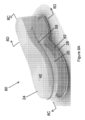
図1A及び1Bは、本技術の1つ又は複数の実施形態による履物アセンブリ10を示す。履物アセンブリ10は、装着者の足を受容するように構成された内部エリア16を画定するために、ソールアセンブリ14に取り付けられたアッパー12を有する。アッパー12は、ソールアセンブリ14の上に延びて内部エリア16の頂部を形成するつま革部分20に一体的に連結された下側部分18を有する。図1A及び1Bに示される履物アセンブリ10はそれぞれ、木靴及びスライド式の靴である。これらは、本技術を含み得る履物のスタイルの2つの例に過ぎない。本技術の履物アセンブリ10は、他の履物スタイル、例えば、ヒールストラップ、取り囲まれたヒールカップ、オープントゥ構成、又は他の構成を有し得るスタイルを含み得ることが理解されるべきである。更に、本技術による履物アセンブリ10は、靴、ブーツ、サンダル、又は他のスタイルの履物であり得る。
1A and 1B show a
ソールアセンブリ14は、アッパー12の下側部分18に固着されているか、又は別様に連結されている。図1A及び1Bの実施形態において、アッパー12の下縁は、ソールアセンブリの周辺22の部分に固定されている。他の実施形態において、アッパー12の下側部分18は、アッパー12の実際の縁部エリアがソールアセンブリ10の部分の上又はその中で捕捉され得るように、ソールアセンブリの一部の周りに巻き付いてよく、これについては以下でより詳細に論述される。アッパー12は、ステープル、ネイル、リベット、縫製などの留め金具23を用いて、又は接着剤を介して、又は固定技法の組み合わせによってソールアセンブリ14に取り付けられ得る。
The
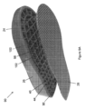
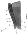
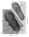
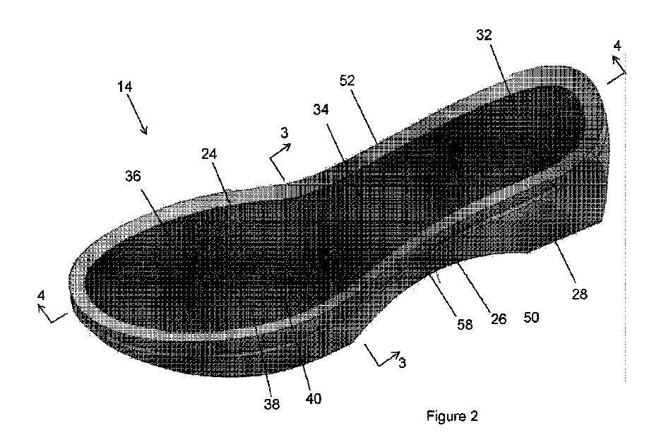
図2は、アッパーが取り外された状態で示されたソールアセンブリ14の等角図であり、図3及び4はそれぞれ、実質的に線3-3及び線4-4に沿って取られた図2のソールアセンブリの断面図である。ソールアセンブリ14は、ミッドソール部分26に連結されたインソール部分24の上で装着者の足を支持するように構成されている。アウトソール部分28は、ミッドソール部分26の底部エリアに連結され、耐久性のある地面係合底面を画定する。いくつかの実施形態において、中敷き30(図1B)は、インソール部分24の上に位置決めされて、装着者の足に係合する上面を形成し得る。例示されている実施形態において、ソールアセンブリ14は、踵部分32、踵部分の前方にある土踏まず部分34、及び土踏まず部分の前方にある前足部分36を有する足全体のアセンブリである。他の実施形態において、ソールアセンブリ10は、踵セクションがスパニングアーチ構造などを介して1つ又は複数の前足セクションに連結されているセクション構造を有し得る。
2 is an isometric view of the
インソール部分24、ミッドソール部分26、及び/又はアウトソール部分28は、3D印刷及び/又は他の付加製造プロセスを介して作られ得る。以下でより詳細に論述されるように、インソール部分24、ミッドソール部分26、及びアウトソール部分28は、選択的レーザ溶融(selective laser melting:SLM)、選択的レーザ焼結(selective laser sintering:SLS)、電子ビーム溶融(electron beam melting:EBM)、又は他の粉末床溶融結合技法、又は、一体型の一元ソールアセンブリ14を形成するための他の付加製造技法などの付加製造を介して作られ得る。ソールアセンブリ14は、リサイクルされた、及び/又はリサイクル可能な材料で作られ得る。以下で論述されるいくつかの実施形態において、インソール部分24及びミッドソール部分26は一緒に形成されるか又は別様に一緒に作られており、付加製造を介して別個に作られたアウトソール部分28と共に組み立てられた一元コンポーネントとして互いに一体的に接続されている。以下で論述される他の実施形態において、ミッドソール部分26は、アウトソール部分28と共に一元コンポーネントとして一体的に形成されて接続されており、インソール部分24は、別個に形成されて、組み立ての間にミッドソール部分26の頂部に取り付けられる。この製造プロセスにより、ソールアセンブリ14を構築するのに組み立てる必要がある別個の部品の数が減少し、これにより、組み立てプロセスが単純化し、アセンブリのための部品の数が減少し、組み立て時間が低減され、履物アセンブリ10のコストが減少する(図1)。
The
図3及び4に見られるように、例示されている実施形態のインソール部分24は、プラットフォーム層40に連結された一体格子38を有する。格子38は、プラットフォーム層40から離れて延びる複数の相互接続されたラス42を備える。ラス42は、格子38及びプラットフォーム層40がインソール部分24の上で装着者の足を支持するように、少なくとも踵部分32及び前足部分36(図4)に設けられている。ラス42は、屈曲するか又は撓んで、インソール部分42において装着者の足に対して緩衝作用を提供するように構成されている。例示されている実施形態において、インソール部分24は、踵、土踏まず、及び前足部分32、34、及び36(図4)にわたって、足全体の格子38及びプラットフォーム層40構造を有する。プラットフォーム層40は、単一の一体コンポーネントであってよく、又は、踵、土踏まず、又は前足部分32、34、及び36において複数のセグメントによって形成されてよい。いくつかの実施形態において、プラットフォーム層40は、踵部分32のみ、又は土踏まず部分34、又は前足部分36、又はこれらの部分の任意の組み合わせに設けられてよい。
As seen in Figures 3 and 4, the
プラットフォーム層40は、中身が詰まっていてよく、又は、それは複数の孔を有してよく、これにより、重量が低減され、付加製造プロセスにおいて使用された粉末又は他の材料などの余材の除去が容易になる。例えば、プラットフォーム層40及び/又は格子38は、ソールアセンブリ14及び/又は履物アセンブリ10の最終組み立ての前に加圧空気又は他の洗浄用媒体がインソール部分24から余材を除去することを可能にするように構成されている(図1B)。例示されている実施形態は、格子38が装着者の足及びプラットフォーム層40の間になるように、プラットフォーム層40から上向きに延びる格子38を有する。それに応じて、プラットフォーム層40がミッドソール部分26上で支持される。以下で論述される他の実施形態において、インソール部分24は、ラス42がプラットフォームから離れてミッドソール部分26に向けて下向き延びるように、プラットフォーム層40が格子38の上方にあるように逆さにされてよい。
The
いくつかの実施形態において、装着者の足が格子38の上に直接載置されるように、格子38はソールアセンブリ14の最上面を画定し得る。他の実施形態において、中敷き30(図1B)は、格子38を覆い、ソールアセンブリ14に固定され得る。中敷き30は、付加製造によって作られ得るが、他の実施形態において、中敷きは、他の材料、例えばレザー、布、合成材料などで作られ得る。中敷き30は、中敷き30の少なくとも一部がアッパーの縁部部分及びソールアセンブリ14の周辺部分56の間に捕捉されるように、ソールアセンブリ14の周辺部分に固定されている。他の実施形態において、インソール部分24は、インソール部分の上で、例えば、格子38上で、及び/又はプラットフォーム層上で、中敷き30を捕捉する1つ又は複数の保持機構52を有し得る。保持機構52は、中敷き30と重なり、かつリップ、及び装着者の足を支持しているインソール部分24の表面の間で中敷きの縁部を捕捉するインソール部分24の周辺にリップを含み得る。いくつかの実施形態において、中敷き30は、捕捉されて、接着剤又は他の留め付け技法を介して保持機構52の下方で定位置に保持され得る。
In some embodiments, the
図3に見られるように、ソールアセンブリのミッドソール部分26は、インソール部分24及びアウトソール部分28の間で延びる複数の内部支持44を有する。内部支持44は、互いから間隔を空けて、ソールアセンブリ14の内部内で空隙46を画定する。内部支持44は、少なくとも踵部分32及び/又は前足部分36に位置決めされており、インソール部分24の部分を支持するように構成されている。例示されている実施形態の内部支持44は、実質的に鉛直に方向付けられており、ミッドソール部分の横方向及び中心の側壁48及び50の間で延びる。他の実施形態において、内部支持44のうちの一部又は全てが前後方向に延び得る。内部支持44は、それらがまた撓むか又は屈曲して、格子38からの緩衝作用に加えて装着者の足に対して追加の緩衝作用を提供し得るように、形状決めされ、サイズ決めされ、配置されている。ミッドソール部分26及び内部支持40は、異なるレベルの緩衝作用を提供するために、ミッドソール部分26の異なる部分において異なる構成を有し得る。例えば、踵部分32における内部支持44は、歩行サイクルの踵接地フェーズ中の負荷に適応するために、踵部分32においてより大きい度合いの緩衝作用を提供するように構成されてよく、前足部分36における内部支持44は、より少ない緩衝作用を提供してよい。いくつかの実施形態において、内部支持44は、踵接地中の緩衝作用のための踵部分32にのみ提供され得る。
As seen in FIG. 3, the
内部支持44及び空隙46は、装着者が歩行するか又は走るときに歩行サイクルにわたってソールアセンブリ14の屈曲を制御するのに役立つように位置し得る。内部支持44及び空隙46は、前足部分28上の中足エリアにおいてなど、装着者の足の選択部分に対応する位置におけるソールアセンブリ14の制御された撓みのための屈曲溝を形成し得る。空隙46は、軽量ソールアセンブリ14のためにミッドソール部分26内に一体中空エリアを提供し得る。それに応じて、履物アセンブリ10は、通常は重く、柔軟でなく、かつ緩衝作用をほとんど提供しない木靴などの靴スタイルの外観を有し得る。しかしながら、本技術のソールアセンブリ14は、ソールアセンブリ14が、依然として軽量で柔軟であり、制御された柔軟性を有しながら、木靴のように見えるように3D印刷されることを可能にする。
The internal supports 44 and voids 46 may be positioned to help control the flexion of the
図3に見られるように、例示されている実施形態のソールアセンブリ14は、ソールアセンブリ10の周辺部分56の周りに位置する複数の内部アンカー機構54を有する。例示されている実施形態において、アンカー機構54は、ミッドソール部分26の側壁及び/又はインソール部分24の周辺に隣接して内向きに位置決められている。アンカー機構54は、側壁に内向きに隣接するミッドソールの部分が中空であっても、アッパー12(図1A)がソールアセンブリ14にしっかりと留め付けられることを可能にするように構成されている。アンカー機構54は、その中に留め金具23(図1B)、例えばステープル、ネイル、又はリベットなどが、空隙46内に貫通することなく埋め込まれ得る一体的な内部構造を提供する。例示されている実施形態において、アンカー機構54は、プラットフォーム層40の下でインソール部分の周辺に一体的に接続されている。別の実施形態において、アンカー機構54は、留め金具23が、ミッドソールの側壁を通し、アッパーの材料を通して延びてアンカー機構54内に完全に埋め込まれることによってアッパー12(図1A)の下側部分18をソールアセンブリ14に固定し得るように、ミッドソールの側壁の内面に一体的に接続されてよい。さらに他の実施形態において、一体アンカー機構54は、インソール部分24の周辺に連結されて、アッパーの下側部分がインソール部分24に縫いつけられることを可能にし得る。他の実施形態において、直接、又はソールアセンブリの内部空所を介して、又は以下でより詳細に論述されるアンカー機構を介して、取り付けに張力を付与するために、アッパー12は、ひも又はケーブルを介してソールアセンブリ14の少なくとも一部に取り付けられてよい。いくつかの実施形態において、アッパーは、ひも又はケーブル又は他の張力付与用の線が、ソールアセンブリの関連付けられる部分の上でアッパーに対してオーバーラスト(overlast)するように構成されるように、「ストリングラスティング」によってソールアセンブリの少なくとも一部に取り付けられ得る。ストリングラスティングの態様は、2021年4月23日に出願された、System and Methods for Lasting an Upper to a 3D Printed Platformと題する米国特許出願公開第2021/033003号に開示されており、これは、その全体が参照により本明細書に組み込まれている。本技術のいくつかの実施形態において、アッパーは、ストローベルステッチされ、その後、以下で論述されるソールアセンブリに対して格子上のインソールのラスを介して直接ストリングラスティングされてよい。代替的には、アッパーは、ソールアセンブリ上に形成された内部又は外部チャネル及び空所と組み合わせた、ひも(又は他の張力付与用の線)での係合を介してソールアセンブリに対してオーバーラストされてよい。他の実施形態は、これらの技法の組み合わせを利用し得る。
As seen in FIG. 3, the illustrated embodiment of the
図1A、2、及び3に見られるように、ソールアセンブリ10は、アッパー12の下側部分18を受容し、それをソールアセンブリの選択部分に沿って、かつアンカー機構54(図3)に隣接して位置合わせするように構成された1つ又は複数の位置合わせ機構58を有する。それに応じて、アッパー12の下側部分18は、ソールアセンブリに対して容易かつ迅速に位置決めされ、位置合わせ機構58と位置合わせされ得、その結果、留め金具23(図1A)が、アンカー機構に取り付けられて埋め込まれることができ、これにより、アッパー12をソールアセンブリ14にしっかりと固着させる。例示されている実施形態において、位置合わせ機構58は、インソール部分24の周辺エリアの少なくとも一部において一体的に形成されているため、アッパー12の縁部は、アンカー機構54と横方向に位置合わせされる。他の実施形態において、位置合わせ機構58は、ミッドソール部分26上に、又はインソール及びミッドソール部分24及び26の両方に設けられてよい。位置合わせ機構58は、インソール又はミッドソール部分24又は26の外面に設けられてよく、又は、位置合わせ機構58は、インソール又はミッドソール部分24又は26の内側部分に形成され、ソールアセンブリ14との接続のためにアッパー12と位置合わせされるように構成されてよい。
1A, 2, and 3, the
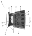
図5及び6は、図2に示されるソールアセンブリ14の代替的な実施形態によるソールアセンブリ60の断面及び分解等角図である。図7A~7Dは、図5のソールアセンブリ60の追加の図である。このソールアセンブリ60は、一例として、付加製造を介してミッドソール部分26と一体的に形成されたインソール部分24を有する。ミッドソール部分26は、インソール部分24から下向きに延び、かつ間隔を空けて空隙46を画定する内部支持44を有する。図6に見られるように、内部支持44は、ハニカム形状の空隙を形成するように配置され得るが、内部支持44は、対称的又は均一であってもなくてもよい他の形状を有する空隙を形成するように位置されることができる。
Figures 5 and 6 are cross-sectional and exploded isometric views of a
アウトソール部分28は、付加製造又は別の製造技法などを介して、一体のインソール及びミッドソール部分24/26とは別個のコンポーネントとして形成される。アウトソール部分28は、アウトソール部分28が空隙46の上に延びてそれを閉じるように、ミッドソール部分26の底部部分に固定して取り付けられるように構成されている。この構造は、ソールアセンブリ10の重量を制御し、また、付加製造プロセスにおいて使用された粉末又は他の材料などの余材の除去のための洗浄プロセスにおける空気又は他の媒体の流れを制御するように設計されている。例えば、一体インソール/ミッドソール部分24/26は、加圧空気又は他の洗浄用媒体がソールアセンブリコンポーネント内に、及びそれを通って流れて、インソール部分28がミッドソール部分26の底部の上に組み立てられる前に容易かつ迅速にソールアセンブリから過剰な粉末又は他の材料を取り除くことを可能にするように構成されている。他の実施形態において、ミッドソール/インソール部分24/26は、吸引又は他の真空技法を使用して洗浄され得る。ミッドソール部分26の構造はまた、空隙46内に、フォーム、非ニュートン性材料、又は他の緩衝作用又はエネルギーリターン材料などの別個の材料を受容するように構成され得る。この緩衝作用又はエネルギーリターン材料、又はその両方の組み合わせは、アウトソール部分28が取り付けられ、空隙46が閉じて封止される前に、ミッドソール部分26内の選択された場所で、例えば踵又は前足部分32又は36において付加され得る。
The
例示されている実施形態において、アウトソール部分28及びミッドソール部分26の底部は、それらのそれぞれの周辺の少なくとも一部の周りに延びる嵌合取り付け機構62及び64を有する。例えば、アウトソール部分28の周りの取り付け機構62は、アウトソール部分28の表面から上向きに延びる突起66を含む。突起66は、連続した突起、又はアウトソール部分28の周りに位置決めされた複数のセグメントであり得る。ミッドソール部分26の底部の取り付け機構64は、嵌合する実はぎ式の係合で突起66をしっかりと受容する溝68を有する。例示されている実施形態は、アウトソール部分28上の突起66及びミッドソール部分26上の溝68を示しているが、他の実施形態において、突起66は、ミッドソール部分26の底部にあってよく、溝68は、アウトソール部分28上にあってよい。
In the illustrated embodiment, the bottom of the
嵌合機構62/64は、容易かつ迅速な組み立てのためにアウトソール部分28をミッドソール部分26と正確に位置合わせするように作用する。いくつかの実施形態において、図5に示されるように、内部支持44は、下部エッジ70がアウトソール部分28の頂部に形成された複数のチャネル72内に受容されるように形状決め、サイズ決め、及び位置決めされている。嵌合機構62/64及び/又は内部支持44及びチャネル72は、接着剤、締まり摩擦嵌め、物理的な機械的取り付け、又は取り付け技法の組み合わせを介して互いに対して固着され得る。別の実施形態において、図7A~7Dに見られるように、ミッドソール部分26の内部支持44は、それらの下部エッジ70が、嵌合チャネルへと嵌められることなく頂面アウトソール部分28に係合するように形状決め、サイズ決め、及び位置決めされている。
The mating features 62/64 act to precisely align the
図7A~7Dに示される実施形態において、ミッドソール部分と一体的に形成されたインソール部分24は、足支持面を形成するために、プラットフォーム層40の上に格子38を有するプラットフォーム層40を含み得る。他の実施形態において、インソール部分24は、例えば図5に示されるように、格子を含まなくてよい。インソール部分24のアッパーの周辺部は、アッパー12の下側部分18(図示せず)を受容する、一対のフランジ78の間の溝76などの取り付け機構75を含み得る。この取り付け機構75は、格子上でインソール部分に中敷きを固着させるのに使用され得る。中敷きは、縫製、接着剤、留め金具、又は他の取り付け技法を介してインソール部分24に留め付けられ得る。この構造により、インソール部分24への中敷きの非常に強く迅速かつ安価な設置が提供される。図7A及び7Dに見られるように、ミッドソール部分26は、留め金具がアッパー通して、ミッドソールの側壁を通して延び、空隙46内に突出することなくアンカー機構54(図7D)内に埋め込まれ得るように、ソールアセンブリ14上でアッパー12を受容し、位置合わせするように構成された位置合わせ機構58を有する。
In the embodiment shown in Figures 7A-7D, the
図8A~8Dは、本技術の別の実施形態によるソールアセンブリ80の部分分解等角図及び断面図である。ソールアセンブリ80は、別個のアウトソール部分28に取り付けられる一体的な一元のインソール部分24及びミッドソール部分26を有する、上で論述されたようなソールアセンブリ60と同様の構造を有する。しかしながら、これらの実施形態の間の主要な相違点は、インソール部分24の構造である。この実施形態において、一体のインソール部分24は、格子38の上方にプラットフォーム層40を有するように構築されている。格子38のラス42(図8C及び8D)は、下向きに延び、内部支持44によるものを含め、ミッドソール部分26の上で支持されている。プラットフォーム層40は、その頂面が装着者の足を支持するように構成されるように構築され得る。したがって、インソール部分24が、図7A及び7Dに示される溝及びフランジ74及び76などの取り付け機構をインソール部分24の周辺の周りに含まないように、中敷きはインソール部分の上で組み立てられない場合がある。
8A-8D are partially exploded isometric and cross-sectional views of a
図9A~9Dは、本技術の一実施形態のソールアセンブリ90の部分分解等角図及び断面図である。図10は、非分解図における図9Bのソールアセンブリ90の断面図である。この実施形態において、ソールアセンブリ90のインソール及びミッドソール部分24及び26はそれぞれ、一体的に印刷されるか又は別様に一元構造として付加的に製造され、アウトソール部分28は、別個に印刷されるか又は別様に形成される。それに応じて、ミッドソール部分26の底部は、アウトソール部分28が取り付けられる前は、最初は開放されてアクセス可能であり、そのため、付加製造プロセスにおいて使用された任意の過剰な粉末又は、加圧空気又は他の流体などを介して、又は吸引又は他の真空技法によって、他の材料が空隙46及び/又は格子から除去され得る。アウトソール部分28は、それぞれミッドソール及びアウトソール部分26及び28の周辺部の周りに位置決めされた嵌合取り付け機構92(図9B及び9D)を介してミッドソール部分の底部に接合されている。例示されている実施形態において、アウトソール部分28上の取り付け機構92は、アウトソール部分28の上面から上向きに延びる複数のフックフランジ94によって形成されている。例示されている実施形態において、フックフランジ94は、アウトソール部分28の周辺部の周りに位置決めされた複数のフックフランジセグメントを備える。他の実施形態において、フックフランジ94は、アウトソールの周辺部の周りにある単一の一元機構であり得る。
9A-9D are partially exploded isometric and cross-sectional views of a
ミッドソール部分26の底部にある嵌合取り付け機構は、図10に示されるように、フックフランジ94の上に延びてそれによって捕捉されるように構成されたフック状リップ96である。アウトソール部分28がインソール/ミッドソール部分と共に組み立てられているとき、アウトソール部分28及びミッドソール部分26は一緒に位置合わせされ互いに押し付けられる。フック状リップ96はフックフランジ94上でスライドし、それにより、フックフランジ94は僅かに屈曲させられ、その後、フック状リップ96上で定位置にスナップ嵌めさせられ、これにより、フック状リップがフランジ94のフック部分の下に捕捉される。それに応じて、アウトソール部分26は、アウトソール部分28を手動で又は自動化器具を介して定位置にスナップ嵌めすることによって迅速かつ容易にインソール/ミッドソール部分24/26と共に組み立てられ得る。例示されている実施形態は嵌合フック構成を利用しているが、ソールアセンブリ90の形成中にアウトソール部分28をミッドソール部分26の底部に容易かつ迅速に接続するために他の取り付け機構が使用され得る。
The mating attachment mechanism at the bottom of the
図9A及び9Dに見られるように、ソールアセンブリ90は、インソール/ミッドソール部分24/26への取り付けのために、アッパー12の下側部分(図示せず)を受容して位置合わせするように構成された内部位置合わせ機構98を有する。例示されている実施形態において、インソール部分24及びミッドソール部分26は、インソール部分24の縁部及びミッドソール部分26の側壁の間に開放スロット100を提供するように構成されている。スロット100は、最終的な取り付けのためにソールアセンブリに対してアッパーを位置合わせするために、アッパーの部分を受容し得る。ミッドソール部分26の底部はまた、アッパーがスロット98を通して延び、ミッドソール部分26の周りに巻き付き、凹領域102内に受容されるように、アッパーの縁部を受容して位置合わせする凹領域102又は他の形状の部分を有し得る。位置合わせされたアッパーは、その後、留め金具、接着剤、又は他の好適な接合技法などによって定位置にしっかりと固定され得る。いったんアッパーがインソール/ミッドソール部分24/26に取り付けられると、アウトソール部分28は、上で論述されたように、ミッドソール部分26の底部にスナップ嵌めされ得る。スロット100及び凹領域102を含むこの構造は、サンダル、スライド、又は他のオープントゥスタイルの履物など、ストラップにより形成されたアッパーの場合に特によく適している。しかしながら、この構造は、他のアッパー構成又はスタイルの履物のために使用され得る。
As seen in FIGS. 9A and 9D, the
図11A~11Dは、本技術の別の実施形態によるソールアセンブリ110の部分分解等角図及び断面図である。この実施形態において、ミッドソール部分26は、アウトソール部分28と一体的に印刷されるか又は別様に付加的に製造され得、インソール部分24は別個に印刷されるか又は別様に形成される。ミッドソール部分26の空隙46の底部はアウトソール部分28によって閉じられており、空隙46の頂部は、ミッドソール部分26の上にインソール部分24が取り付けられるまで開放されている。例示されている実施形態において、空隙46はハニカム形状を有するが、他の実施形態における空隙46は異なる形状、サイズ、又は構成であり得る。例示されている実施形態において、別個のインソール部分24が、プラットフォーム層40から下向きに延びる格子38(図11C))を含んで構築され、ミッドソール部分26の内部支持44の上に支持されている。他の実施形態において、インソール部分24は、格子38がプラットフォーム層40から上向き延びている逆の構成を有し得る。インソール及びミッドソール部分24及び26が接合される前の開放空隙46及び格子38へのアクセスにより、それぞれミッドソール部分26の頂部及びインソール部分24の底部を通した過剰な粉末又は他の材料の容易かつ迅速な除去が可能になる。
11A-11D are partially exploded isometric and cross-sectional views of a
インソール部分24及びミッドソール部分26は、インソール部分を一体ミッドソール/アウトソール部分26/28にしっかりと相互接続して、組み立てられたソールアセンブリ110を形成するために、それらの周辺の一部又は全部の周りに嵌合取り付け機構112を有する。図11Dに見られるように、嵌合取り付け機構112は、プラットフォーム層40の周辺部から下向きに延びるフランジ114、及びミッドソール部分26の頂部の周りにある嵌合溝116を含む。それに応じて、取り付け機構112は、コンポーネント間のセキュアな相互接続のためにインソール及びミッドソール部分24及び26の間に実はぎ接続を提供する。他の実施形態において、取り付け機構112の実はぎ構成は、フランジ114がミッドソール部分26の周りで上向きに延びる逆の構成であってよく、溝116はインソール部分24の周りに設けられてよい。例示されている実施形態において、取り付け機構112は、インソール及びミッドソール部分24及び26の周辺部の周りで実質的に連続的であるが、取り付け機構92は、インソール及びミッドソール部分の周辺部の周りに位置決めされた複数の取り付け機構セグメントを含んでセグメント化されてよい。インソール及びミッドソール部分24及び26の取り付け機構112は、接着剤、縫製、留め金具、溶接、又は他の好適な接続技法を用いて永久に一緒に接続され得る。
The
図11Dに見られるように、例示されている実施形態のインソール部分24は、格子38及び/又はプラットフォーム層40から下向き延びる一体アンカー機構54を含む。アンカー機構54は、ミッドソール部分26の開放された頂部に延び、ミッドソール部分26の側壁上の位置合わせ機構58の横方向で内向きに位置決めされている。それに応じて、インソール部分24がミッドソール部分26と共に組み立てられるとき、アッパー(図示せず)は、位置合わせ機構58内に配置され、アッパー、ミッドソールの側壁を通して延びてアンカー機構54内に固定して埋め込まれたステープル、ネイル、リベット、縫製、又は他の留め金具を用いてソールアセンブリ110に接合される。他の実施形態において、取り付け機構54は、位置合わせ機構58の内向きなど、ミッドソール部分26内に一体的に形成され得る。
11D, the
図12A~12Dは、本技術の一実施形態のソールアセンブリ120の部分分解平面図及び断面図である。図13A及び13Bは、非分解構成にあるソールアセンブリ120の平面図及び断面図である。上で論述され、図11A~11Dに示される実施形態と同様に、この実施形態のミッドソール部分26は、アウトソール部分28と一体的に印刷されるか又は別様に付加的に製造され、インソール部分24は別個に印刷されるか又は別様に形成される。ミッドソール部分26の空隙46及びインソール部分24の格子38の頂部は、インソール部分24がミッドソール部分26の上に取り付けられるまで開放されており、これにより、上で論述されたように、組み立て中の過剰な製造材料の容易かつ早急な除去が可能になる。
12A-12D are partially exploded plan and cross-sectional views of a
インソール部分24及びミッドソール部分26は、インソール部分を一体ミッドソール/アウトソール部分26/28にしっかりと相互接続して、組み立てられたソールアセンブリ120を形成するために、それらの周辺の一部又は全部の周りに嵌合取り付け機構58を有する。例示されている実施形態において、インソール部分24上の嵌合取り付け機構は、ミッドソール部分26のアッパー周辺部の全部又は一部の周りに形成された、形状決めされた保持チャネル124内に嵌まるフック状の底部縁部を含むフックフランジ122である。インソール部分24がミッドソール/アウトソール部分26/28と共に組み立てられるとき、インソール部分24は、格子38が内部支持44の上方にありそれにより支持されるように、ミッドソールの空隙46の上に位置決めされる。フック状フランジ122は、フック状の底部縁部がチャネル124内で定位置にスナップ嵌めされるまで、フック状フランジが僅かに屈曲するように、保持チャネル124内に押し込まれる。それに応じて、取り付け機構122は、コンポーネント間のセキュアな相互接続のために、それぞれインソール及びミッドソール部分24及び26の間の係止フック係合を提供する。他の実施形態において、係止フック構成は、逆さにされて、フックフランジ122がミッドソール部分26の周りで上向きに延び、保持チャネル124がインソール部分24の周りに設けられてよい。係止フック構成は、連続的であるか、又はインソール及びミッドソール部分24及び26の周りでセグメント化されてよい。
The
例示されている実施形態は、図9A~9D及び10の実施形態と類似して、開放スロット126及び受容チャネル128を含む位置合わせ機構98を有する。しかしながら、この実施形態において、インソール部分24及び/又はミッドソール部分26の横方向及び/又は中心の側面は、インソール部分24がミッドソール部分26上で定位置にスナップ嵌めされたときにコンポーネント間に開放スロット126を形成するような外形を有している。開放スロット126は、ミッドソール部分の中心及び横方向の側面において一体的に形成された受容チャネル128(図12D)と位置合わせされている。スロット126及び受容チャネル128は、アッパーがスロット126を通して受容チャネル128内に延びるように、アッパーの下部エリアを受容するように構成されている。アッパーは、その後、接着剤、留め金具、又は他の保持技法を介してソールアセンブリ120に固着され得る。別の実施形態において、スロット126及び受容チャネル128は、アッパーがそれ自体にステープル留めされるか又は別様に接合されて、スロット及びミッドソール部分のコアを通して供給されるバンドを形成することを可能にするように構成されている。これらの構造は、サンダル、スライド、又は他のオープントゥスタイルの履物に特に適用可能であり得る。しかしながら、構造は、クローズドトゥスタイルを含む他の履物スタイルのために使用され得る。
The illustrated embodiment has an
図14A~14Cは、本技術の別の実施形態のソールアセンブリ140の等角図及び断面図である。この実施形態において、ソールアセンブリ140は、3D印刷又は他の付加製造プロセスを介して作られた、一体的に形成されたインソール、ミッドソール、及びアウトソール部分を含む一元部材である。例示されている実施形態のソールアセンブリ140は、サンダル構成に特に好適であるが、同様の構造は異なるスタイルの履物アセンブリのために使用され得る。例示されている実施形態において、ソールアセンブリ140は、ミッドソール部分26及び/又はインソール部分24の側面に一体的に接続され、かつそこから上向きに延びる取り付けフラップ142を有する。取り付けフラップ142は、フラップにリベット締めされた、接着された、留め付けられた、又は別様に取り付けられた、ストラップによって、又はつま革部分によって形成されたアッパーに取り付けられるように構成されている。インソール部分24はまた、中敷きが格子38の縁部エリアに位置決めされたスカラップ上の保持機構52の下で定位置に保持され得るように、格子38のエリア上に位置決めされたスカラップ形状の保持機構52を有する。例示されている実施形態において、保持機構52は、それを定位置に保持するために中敷きに接着されるか又は別様に接続され得る。他の実施形態は、異なる形状又は構成を有する保持機構52を有し得る。
14A-14C are isometric and cross-sectional views of a
図14B及び14Cに見られるように、例示されている実施形態のミッドソール部分26は、特に、装着者の歩行サイクルの踵接地フェーズ中に装着者の足のための何らかの追加の緩衝作用及び衝撃吸収を提供するために、少なくとも踵エリアに形成された一体的な内部支持44及び空隙46を有する。ソールアセンブリ140は、かなり低いプロファイルを有するため、内部支持44及び空隙46は前足エリアに設けられていない。しかしながら、他の実施形態は、図15Aに示されるように、ソールアセンブリ140の前足エリアに内部支持44及び空隙46を含み得る。
14B and 14C, the
図15A及び15Bは、本技術の別の実施形態のソールアセンブリ150の部分分解上面及び底面等角図である。図15Aに見られるように、ソールアセンブリ150は、アウトソール部分28と一体的に3D印刷されたか又は別様に付加的に製造されたミッドソール部分24を有し、インソール部分24は別個に印刷されるか又は別様に形成される。ミッドソール部分はまた、図14A~14Cと関連して上で論述されたように、アッパーへの接続のための一体的な取り付けフラップ142を有する。インソール部分24は、格子38(図15B)がプラットフォーム層40から下向きに延びるように構築されている。それに応じて、インソール部分24の格子138(図15B)及びミッドソール部分26の空隙46(図15A)は、ミッドソール/インソール部分26/28とのインソール部分24の最終組み立ての前に余材を除去され得る。インソール部分24は、ミッドソール部分26の上へのインソール部分24の位置合わせ及び固定した取り付けのために、図11A~11D、12A~12Dにおいて論述されて示された構成と同様の相互接続構成、又は他の相互接続システムを用いてミッドソール部分26に固着され得る。
15A and 15B are partially exploded top and bottom isometric views of a
図16A及び16Bは、本技術の別の実施形態のソールアセンブリ160の等角図及び断面図である。この実施形態のソールアセンブリ160はまた、図1Bの履物10のためなどの、低プロファイル構造である。示されているソールアセンブリ160は、踵エリア32におけるミッドソール部分26に空隙46(図16B)及び内部支持44を有する。例示されている実施形態において、ソールアセンブリ160は、一体的に形成されたミッドソール、インソール、及びアウトソール部分26、24、及び28を含む一元部材である。インソール部分24は、ミッドソール部分26から上向きに突出する一体格子38を有する。インソール部分24は、その周辺部の周りで横方向に延びる取り付けフランジ162を有する。取り付けフランジ162は、ソールアセンブリ160の一部又は全部の周りでアッパーに接続するために使用され得る。例えば、アッパーの下縁が、縫製、接着剤、ステープル、リベット、及び/又は任意の他の好適な取り付け技法によってフランジ162に取り付けられ得る。いくつかの実施形態において、中敷きはまた、それがアッパー及びフランジの間で捕捉されるように、格子38上に位置決めされ、取り付けフランジ162に取り付けられ得る。他の実施形態は、本技術による履物のための一元の低プロファイルソールアセンブリ160を提供する他の構成を有し得る。
注意
16A and 16B are isometric and cross-sectional views of a
Note
上記の説明及び図面は、例示的であり、限定的なものとして解釈されるべきではない。本開示の十分な理解を提供するために数々の具体的な詳細について説明している。しかしながら、いくつかの事例において、説明を曖昧にすることを回避するために周知の詳細は説明されていない。更に、実施形態の範囲から逸脱することなく様々な変更がなされ得る。 The above description and drawings are illustrative and should not be construed as limiting. Numerous specific details have been set forth to provide a thorough understanding of the present disclosure. However, in some instances, well-known details have not been described to avoid obscuring the description. Moreover, various changes may be made without departing from the scope of the embodiments.
本明細書における「1つの実施形態」又は「一実施形態」への言及は、実施形態に関連して説明される特定の特徴、構造、又は特性が本開示の少なくとも1つの実施形態に含まれることを意味する。本明細書の様々な箇所における「1つの実施形態において」という表現の出現は、必ずしも全てが同じ実施形態を指しているのではなく、また、他の実施形態と相互排他的な別個の又は代替の実施形態でもない。また、いくつかの実施形態によって提示され得るが、他の実施形態では提示されない様々な特徴が説明される。同様に、いくつかの実施形態では要件であり得るが、他の実施形態ではそうではない様々な要件が説明される。 References herein to "one embodiment" or "an embodiment" mean that a particular feature, structure, or characteristic described in connection with the embodiment is included in at least one embodiment of the present disclosure. The appearances of the phrase "in one embodiment" in various places in this specification do not necessarily all refer to the same embodiment, nor to separate or alternative embodiments that are mutually exclusive of other embodiments. Also, various features are described that may be exhibited by some embodiments but not by other embodiments. Similarly, various requirements are described that may be requirements in some embodiments but not in other embodiments.
本明細書で使用される用語は、一般に、本開示の文脈内で及び各用語が使用される文脈において、当技術分野におけるそれらの通常の意味を有する。同じものが1つより多くの方法で説明され得ることが理解される。結果的に、本明細書で論述される用語のうちのいずれか1つ又は複数について、代替の言語及び同義語が使用され得、用語が本明細書で詳述又は論述されたかどうかに関して任意の特別な優位性が置かれるものではない。いくつかの用語の同義語が提供される。1つ又は複数の同義語の引用は、他の同義語の使用を排除するものではない。本明細書のあらゆる箇所の例の使用は、本明細書で論述される任意の用語の例を含め、単に例示であり、本開示の又は任意の例示される用語の範囲及び意味を更に限定することは意図していない。同様に、本開示は、本明細書において与えられる様々な実施形態に限定されるものではない。別途定義されない限り、本明細書で使用される全ての技術的及び科学的用語は、本開示が属する分野の当業者によって一般に理解されるのと同じ意味を有する。矛盾が生じる場合には、定義を含む本文書が優先される。 The terms used herein generally have their ordinary meaning in the art, within the context of this disclosure and in the context in which each term is used. It is understood that the same thing may be described in more than one way. Consequently, for any one or more of the terms discussed herein, alternative language and synonyms may be used, and no particular preference is placed on whether a term has been detailed or discussed herein. Synonyms of some terms are provided. The recitation of one or more synonyms does not exclude the use of other synonyms. The use of examples anywhere in this specification, including examples of any term discussed herein, is merely illustrative and is not intended to further limit the scope and meaning of the disclosure or of any exemplified term. Similarly, this disclosure is not limited to the various embodiments provided herein. Unless otherwise defined, all technical and scientific terms used herein have the same meaning as commonly understood by one of ordinary skill in the art to which this disclosure belongs. In the event of a conflict, the present document, including definitions, will control.
Claims (20)
前記アッパーの前記下側部分に固着されたソールアセンブリ、前記ソールアセンブリの少なくとも一部は付加製造プロセスによって作られ、前記ソールアセンブリは踵部分及び前足部分を有し、前記ソールアセンブリは、プラットフォーム層、及び少なくとも前記前足部分及び踵部分において前記プラットフォーム層から離れて延びる相互接続されたラスを含む格子を有し、前記格子及びプラットフォーム層は、前記装着者の前記足を前記ソールアセンブリ上で支持するように位置決めされており、前記格子中の前記ラスは、屈曲するか又は撓んで前記装着者の前記足に対して第1の緩衝作用を提供するように構成されている
を備え、
前記ソールアセンブリは、前記プラットフォーム層から離れて下向きに延び、かつ前記ソールアセンブリ内で空隙を画定する、間隔を空けた複数の内部支持構造を有し、前記内部支持構造は、少なくとも前記踵部分又は前記前足部分に位置しており、前記内部支持構造は、屈曲するか又は撓んで、前記装着者の前記足に対して第2の緩衝作用を提供するように構成されており;
前記ソールアセンブリは、前記ソールアセンブリ内に結合された周辺部分を有し、前記ソールアセンブリは、前記周辺部分に隣接して、かつ前記空隙のうちの少なくとも1つに隣接して位置決めされた複数の一体アンカー機構を有し、前記アッパーの前記下側部分は、前記空隙内に貫通することなく前記複数の一体アンカー機構にしっかりと係合して固着された留め付け機構を用いて前記ソールアセンブリの前記周辺部分に留め付けられており;
前記ソールアセンブリは、前記ソールアセンブリの底部に接続され、かつ地面係合面を形成するアウトソール部分を有し、前記アウトソール部分は、前記ソールアセンブリ内の前記空隙を閉じて封止するように位置決めされている
履物アセンブリ。 an upper defining an interior area configured to receive a wearer's foot, said upper having a lower portion;
a sole assembly secured to the lower portion of the upper, at least a portion of the sole assembly being fabricated by an additive manufacturing process, the sole assembly having a heel portion and a forefoot portion, the sole assembly having a platform layer and a lattice including interconnected laths extending away from the platform layer at least in the forefoot portion and the heel portion, the lattice and platform layer positioned to support the foot of the wearer on the sole assembly, the laths in the lattice being configured to flex or flex to provide a first cushioning effect to the foot of the wearer;
the sole assembly having a plurality of spaced apart internal support structures extending downwardly away from the platform layer and defining voids within the sole assembly, the internal support structures being located in at least the heel portion or the forefoot portion, the internal support structures being configured to flex or flex to provide a second cushioning effect to the foot of the wearer;
the sole assembly has a peripheral portion coupled therein, the sole assembly having a plurality of integral anchor mechanisms positioned adjacent the peripheral portion and adjacent at least one of the voids, the lower portion of the upper being fastened to the peripheral portion of the sole assembly with fastening mechanisms that securely engage and are secured to the plurality of integral anchor mechanisms without penetrating into the void;
The sole assembly has an outsole portion connected to a bottom of the sole assembly and forming a ground-engaging surface, the outsole portion positioned to close and seal the void within the sole assembly.
前記アッパーの前記下側部分に固着されたソールアセンブリ、前記ソールアセンブリの少なくとも一部は付加製造プロセスによって作られ、前記ソールアセンブリは、踵部分、前足部分、及び前記踵部分及び前足部分の周りの周辺部分を有する、
を備え、
前記ソールアセンブリは、ミッドソール部分、前記ミッドソール部分の上にあるインソール部分、及び前記ミッドソール部分の底部に接続されたアウトソール部分を有し、前記インソール部分は、複数の相互接続されたラスを有する格子を含み、前記格子は、少なくとも前記前足部分及び踵部分内に位置決めされており、前記格子は、装着者の足を支持するように位置決めされており、前記格子内の前記ラスは、屈曲して、前記装着者の前記足に対して緩衝作用を提供するように構成されており;
前記ソールアセンブリの前記ミッドソール部分は、前記格子に対して下向きに延び、かつ前記ソールアセンブリ内の空隙を画定する、間隔を空けた複数の内部支持構造を有し、前記内部支持構造は、少なくとも前記踵部分又は前記前足部分に位置しており、前記内部支持構造は、使用中に前記装着者の足から加えられた負荷に応じて屈曲するように構成されており;
前記ソールアセンブリは、前記空隙及び前記内部支持構造の半径方向に外向きに位置決めされた複数の一体アンカー機構を有し、前記アッパーの前記下側部分は、前記空隙内に貫通することなく前記複数の一体アンカー機構を貫通する留め付け機構を用いて前記ソールアセンブリの前記周辺部分に留め付けられており;
前記アウトソール部分は、前記ソールアセンブリ内の前記空隙の少なくとも一部を閉じて地面係合面を形成するように位置決めされている
履物アセンブリ。 an upper having a lower portion; and a sole assembly secured to the lower portion of the upper, at least a portion of the sole assembly being fabricated by an additive manufacturing process, the sole assembly having a heel portion, a forefoot portion, and a peripheral portion about the heel portion and the forefoot portion.
Equipped with
the sole assembly having a midsole portion, an insole portion overlying the midsole portion, and an outsole portion connected to a bottom of the midsole portion, the insole portion including a lattice having a plurality of interconnected laths, the lattice being positioned within at least the forefoot and heel portions, the lattice being positioned to support a wearer's foot, the laths within the lattice being configured to flex and provide cushioning to the wearer's foot;
the midsole portion of the sole assembly having a plurality of spaced apart internal support structures extending downwardly relative to the lattice and defining voids within the sole assembly, the internal support structures being located in at least the heel portion or the forefoot portion, the internal support structures being configured to flex in response to loads applied by the wearer's foot during use;
the sole assembly having a plurality of integral anchor mechanisms positioned radially outward of the void and the internal support structure, the lower portion of the upper being fastened to the peripheral portion of the sole assembly using fastening mechanisms that pass through the plurality of integral anchor mechanisms without passing into the void;
The outsole portion is positioned to close at least a portion of the void in the sole assembly to form a ground-engaging surface.
アッパーインソール部分、前記アッパーインソール部分に取り付けられたミッドソール部分、及び前記ミッドソール部分に取り付けられたアウトソール部分、ここで、前記ミッドソール部分は、前記アッパーインソール部分又は前記アウトソール部分と一元構造として形成されている、
を備え、
前記ソールアセンブリは、踵部分、前足部分、及び前記踵部分及び前足部分の周りの周辺部分を有し、前記周辺部分は、前記アッパーの下側部分に接続されるために構成されており、
前記アッパーインソール部分は、プラットフォーム層及び格子を有し、前記プラットフォーム層は前記ミッドソール部分の上方にあり、前記格子は、前記プラットフォーム層から離れて延びる複数の相互接続されたラスを含み、前記格子は、少なくとも前記前足部分及び踵部分内に位置決めされており、前記格子内の前記ラスは、屈曲して、装着者の足に緩衝作用を提供するように構成されており、
前記ミッドソール部分は、前記プラットフォーム層に対して下向き延び、かつ前記ミッドソール部分内で空隙を画定する複数の内部支持構造を有し、前記内部支持構造は、少なくとも前記踵部分又は前記前足部分内に位置しており、前記内部支持構造は、使用中に前記装着者の足から加えられた負荷に応じて屈曲するように構成されており;
前記アッパーインソール部分又は前記ミッドソール部分は、前記空隙及び前記内部支持構造の半径方向に外向きに位置決めされた複数の一体アンカー機構を有し、前記ソールアセンブリの前記周辺部分は、前記複数の一体アンカー機構にしっかりと係合する留め付け機構を用いて前記アッパーの前記下側部分に取り付けられるように構成されており;
前記アウトソール部分は、前記ソールアセンブリ内で前記空隙の少なくとも一部を閉じて、地面係合面を形成するように位置決めされている
ソールアセンブリ。 1. A sole assembly for footwear having an upper, the sole assembly comprising:
an upper insole portion, a midsole portion attached to the upper insole portion, and an outsole portion attached to the midsole portion, wherein the midsole portion is formed as a unitary structure with the upper insole portion or the outsole portion;
Equipped with
the sole assembly having a heel portion, a forefoot portion, and a peripheral portion about the heel portion and the forefoot portion, the peripheral portion configured to be connected to a lower portion of the upper;
the upper insole portion has a platform layer and a lattice, the platform layer overlying the midsole portion, the lattice including a plurality of interconnected laths extending away from the platform layer, the lattice being positioned within at least the forefoot and heel portions, the laths within the lattice being configured to flex to provide cushioning to a wearer's foot;
the midsole portion having a plurality of internal support structures extending downwardly relative to the platform layer and defining voids within the midsole portion, the internal support structures being located within at least the heel portion or the forefoot portion, the internal support structures being configured to flex in response to loads applied by the wearer's foot during use;
the upper insole portion or the midsole portion has a plurality of integral anchor mechanisms positioned radially outward of the void and the internal support structure, and the peripheral portion of the sole assembly is configured to be attached to the lower portion of the upper using a fastening mechanism that securely engages the plurality of integral anchor mechanisms;
The outsole portion is positioned within the sole assembly to close at least a portion of the void to form a ground-engaging surface.
Applications Claiming Priority (3)
| Application Number | Priority Date | Filing Date | Title |
|---|---|---|---|
| US202263345833P | 2022-05-25 | 2022-05-25 | |
| US63/345,833 | 2022-05-25 | ||
| PCT/US2023/023280 WO2023230095A1 (en) | 2022-05-25 | 2023-05-23 | Footwear assembly with 3-d printed sole assembly |
Publications (1)
| Publication Number | Publication Date |
|---|---|
| JP2025517536A true JP2025517536A (en) | 2025-06-05 |
Family
ID=88877965
Family Applications (1)
| Application Number | Title | Priority Date | Filing Date |
|---|---|---|---|
| JP2024569851A Pending JP2025517536A (en) | 2022-05-25 | 2023-05-23 | Footwear assembly having a 3D printed sole assembly |
Country Status (4)
| Country | Link |
|---|---|
| US (1) | US12336592B2 (en) |
| EP (1) | EP4531622A1 (en) |
| JP (1) | JP2025517536A (en) |
| WO (1) | WO2023230095A1 (en) |
Families Citing this family (6)
| Publication number | Priority date | Publication date | Assignee | Title |
|---|---|---|---|---|
| USD1020190S1 (en) * | 2021-10-07 | 2024-04-02 | Pikolinos Diseño S.L.U. | Shoe |
| USD1026418S1 (en) * | 2021-10-07 | 2024-05-14 | Pikolinos Diseño S.L.U. | Shoe |
| USD1027414S1 (en) * | 2023-12-05 | 2024-05-21 | Qiying Lang | Sole for footwear |
| USD1027408S1 (en) * | 2023-12-05 | 2024-05-21 | Qiying Lang | Sole for footwear |
| CN119235080B (en) * | 2024-12-03 | 2025-02-28 | 泉州匹克鞋业有限公司 | A symmetrical lattice 3D printed running shoe with high cushioning performance |
| USD1106660S1 (en) * | 2025-02-12 | 2025-12-23 | Skechers U.S.A., Inc. Ii | Midsole periphery |
Citations (5)
| Publication number | Priority date | Publication date | Assignee | Title |
|---|---|---|---|---|
| US6857202B2 (en) * | 2003-05-05 | 2005-02-22 | Phoenix Footwear Group, Inc. | Footwear construction |
| JP2010284967A (en) * | 2009-05-14 | 2010-12-24 | Hyogo System Kk | Shoe manufacturing kit |
| US20150351493A1 (en) * | 2012-12-19 | 2015-12-10 | New Balance Athletic Shoe, Inc. | Footwear with traction elements |
| JP2018149367A (en) * | 2012-10-30 | 2018-09-27 | アッテイ,グレイム・スコット | Improvement in footwear |
| JP2019080988A (en) * | 2015-06-29 | 2019-05-30 | アディダス アーゲー | Soles for sport shoes |
Family Cites Families (7)
| Publication number | Priority date | Publication date | Assignee | Title |
|---|---|---|---|---|
| US6226894B1 (en) * | 1998-05-11 | 2001-05-08 | R. G. Barry Corporation | Slipper and method for manufacturing slipper |
| US7032328B2 (en) * | 2004-01-20 | 2006-04-25 | Supracor, Inc. | Multi-layer honeycomb sole |
| GB2517403B (en) * | 2013-06-24 | 2016-02-03 | Natalie Lee-Sang | An article of footwear |
| US10143266B2 (en) * | 2015-02-25 | 2018-12-04 | Nike, Inc. | Article of footwear with a lattice sole structure |
| US10039343B2 (en) | 2015-05-08 | 2018-08-07 | Under Armour, Inc. | Footwear including sole assembly |
| US11071348B2 (en) | 2018-09-20 | 2021-07-27 | Nike, Inc. | Footwear sole structure |
| CA3180969A1 (en) | 2020-04-24 | 2021-10-28 | Hilos, Inc. | System and methods for lasting an upper to a 3d printed platform |
-
2023
- 2023-05-23 EP EP23812478.8A patent/EP4531622A1/en active Pending
- 2023-05-23 US US18/322,529 patent/US12336592B2/en active Active
- 2023-05-23 JP JP2024569851A patent/JP2025517536A/en active Pending
- 2023-05-23 WO PCT/US2023/023280 patent/WO2023230095A1/en not_active Ceased
Patent Citations (5)
| Publication number | Priority date | Publication date | Assignee | Title |
|---|---|---|---|---|
| US6857202B2 (en) * | 2003-05-05 | 2005-02-22 | Phoenix Footwear Group, Inc. | Footwear construction |
| JP2010284967A (en) * | 2009-05-14 | 2010-12-24 | Hyogo System Kk | Shoe manufacturing kit |
| JP2018149367A (en) * | 2012-10-30 | 2018-09-27 | アッテイ,グレイム・スコット | Improvement in footwear |
| US20150351493A1 (en) * | 2012-12-19 | 2015-12-10 | New Balance Athletic Shoe, Inc. | Footwear with traction elements |
| JP2019080988A (en) * | 2015-06-29 | 2019-05-30 | アディダス アーゲー | Soles for sport shoes |
Also Published As
| Publication number | Publication date |
|---|---|
| EP4531622A1 (en) | 2025-04-09 |
| US12336592B2 (en) | 2025-06-24 |
| US20230380541A1 (en) | 2023-11-30 |
| WO2023230095A1 (en) | 2023-11-30 |
Similar Documents
| Publication | Publication Date | Title |
|---|---|---|
| JP2025517536A (en) | Footwear assembly having a 3D printed sole assembly | |
| CN114468464B (en) | Footwear having traction lugs incorporated into the midsole | |
| CN108601422B (en) | Article of manufacture having a spiked sole assembly | |
| EP1758478B1 (en) | Article of footwear with a removable midsole element | |
| US8051581B2 (en) | Article of footwear construction with binding portions | |
| CN109068792B (en) | Tensioning system for an article of footwear | |
| US20080168681A1 (en) | Modular shoe construction | |
| US20190116916A1 (en) | Footwear with removable bootie | |
| US20170303631A1 (en) | Footwear With Removable Midsole And Outsole | |
| EP1857004A1 (en) | Footwear construction | |
| JP2004160234A (en) | Footwear product upper, footwear structure and footwear upper, method of manufacturing footwear | |
| US12268278B2 (en) | System and methods for lasting an upper to a 3D printed platform | |
| WO2007149217A2 (en) | Modular article of footwear | |
| CN101836778A (en) | Sole construction and related method of manufacture | |
| US12458106B2 (en) | Article of footwear including a sole structure | |
| US8141271B2 (en) | Shoe with improved construction | |
| EP2720568A1 (en) | Method for assembling a tongue for an article of footwear | |
| US12490800B2 (en) | Footwear assembly with 3-D printed, modular sole assembly | |
| US20250311805A1 (en) | Article of footwear including a sole structure | |
| KR102840381B1 (en) | assemblable shoes | |
| WO2025212644A1 (en) | Article of footwear including a sole structure | |
| CN116249461A (en) | Shoe assembly with duplex innersole plate and related methods | |
| HK40008149A (en) | Footwear with removable bootie |
Legal Events
| Date | Code | Title | Description |
|---|---|---|---|
| A621 | Written request for application examination |
Free format text: JAPANESE INTERMEDIATE CODE: A621 Effective date: 20250114 |
|
| A977 | Report on retrieval |
Free format text: JAPANESE INTERMEDIATE CODE: A971007 Effective date: 20251222 |
|
| A01 | Written decision to grant a patent or to grant a registration (utility model) |
Free format text: JAPANESE INTERMEDIATE CODE: A01 Effective date: 20260106 |
|
| A601 | Written request for extension of time |
Free format text: JAPANESE INTERMEDIATE CODE: A601 Effective date: 20260204 |