JP2025063243A - PLANT RELIABILITY EVALUATION SYSTEM, PLANT RELIABILITY EVALUATION METHOD, AND PLANT RELIABILITY EVALUATION PROGRAM - Google Patents
PLANT RELIABILITY EVALUATION SYSTEM, PLANT RELIABILITY EVALUATION METHOD, AND PLANT RELIABILITY EVALUATION PROGRAM Download PDFInfo
- Publication number
- JP2025063243A JP2025063243A JP2025008228A JP2025008228A JP2025063243A JP 2025063243 A JP2025063243 A JP 2025063243A JP 2025008228 A JP2025008228 A JP 2025008228A JP 2025008228 A JP2025008228 A JP 2025008228A JP 2025063243 A JP2025063243 A JP 2025063243A
- Authority
- JP
- Japan
- Prior art keywords
- plant
- reactor
- equipment
- reliability evaluation
- unit
- Prior art date
- Legal status (The legal status is an assumption and is not a legal conclusion. Google has not performed a legal analysis and makes no representation as to the accuracy of the status listed.)
- Granted
Links
Images


Classifications
-
- G—PHYSICS
- G21—NUCLEAR PHYSICS; NUCLEAR ENGINEERING
- G21D—NUCLEAR POWER PLANT
- G21D3/00—Control of nuclear power plant
- G21D3/04—Safety arrangements
-
- G—PHYSICS
- G21—NUCLEAR PHYSICS; NUCLEAR ENGINEERING
- G21C—NUCLEAR REACTORS
- G21C17/00—Monitoring; Testing ; Maintaining
- G21C17/02—Devices or arrangements for monitoring coolant or moderator
- G21C17/022—Devices or arrangements for monitoring coolant or moderator for monitoring liquid coolants or moderators
-
- G—PHYSICS
- G21—NUCLEAR PHYSICS; NUCLEAR ENGINEERING
- G21C—NUCLEAR REACTORS
- G21C17/00—Monitoring; Testing ; Maintaining
- G21C17/017—Inspection or maintenance of pipe-lines or tubes in nuclear installations
-
- G—PHYSICS
- G21—NUCLEAR PHYSICS; NUCLEAR ENGINEERING
- G21C—NUCLEAR REACTORS
- G21C17/00—Monitoring; Testing ; Maintaining
- G21C17/02—Devices or arrangements for monitoring coolant or moderator
- G21C17/022—Devices or arrangements for monitoring coolant or moderator for monitoring liquid coolants or moderators
- G21C17/0225—Chemical surface treatment, e.g. corrosion
-
- Y—GENERAL TAGGING OF NEW TECHNOLOGICAL DEVELOPMENTS; GENERAL TAGGING OF CROSS-SECTIONAL TECHNOLOGIES SPANNING OVER SEVERAL SECTIONS OF THE IPC; TECHNICAL SUBJECTS COVERED BY FORMER USPC CROSS-REFERENCE ART COLLECTIONS [XRACs] AND DIGESTS
- Y02—TECHNOLOGIES OR APPLICATIONS FOR MITIGATION OR ADAPTATION AGAINST CLIMATE CHANGE
- Y02E—REDUCTION OF GREENHOUSE GAS [GHG] EMISSIONS, RELATED TO ENERGY GENERATION, TRANSMISSION OR DISTRIBUTION
- Y02E30/00—Energy generation of nuclear origin
- Y02E30/30—Nuclear fission reactors
Landscapes
- Physics & Mathematics (AREA)
- Engineering & Computer Science (AREA)
- Plasma & Fusion (AREA)
- General Engineering & Computer Science (AREA)
- High Energy & Nuclear Physics (AREA)
- Business, Economics & Management (AREA)
- Emergency Management (AREA)
- Monitoring And Testing Of Nuclear Reactors (AREA)
- Measurement Of Radiation (AREA)
Abstract
Description
本発明は、プラントの信頼性評価システム、プラントの信頼性評価方法、および、プラントの信頼性評価プログラムに関する。 The present invention relates to a plant reliability evaluation system, a plant reliability evaluation method, and a plant reliability evaluation program.
原子力プラント、福島廃止措置及び再処理設備などの原子力設備に向けて、系統及び機器の信頼性をベースとした保全手法が求められている。 Maintenance methods based on the reliability of systems and equipment are required for nuclear facilities such as nuclear power plants, Fukushima decommissioning, and reprocessing facilities.
特許文献1には、テンプレート内容の見直しにより、利便性の高い運用が期待できる設備管理支援システムの発明が記載されている。 Patent document 1 describes an invention for a facility management support system that is expected to enable highly convenient operation by revising template content.
米国で用いられている手法では、供用期間中検査(ISI:In Service Inspection)の結果を反映した系統及び機器の劣化評価に長期間と大きなリソースが払われるという課題がある。 The method used in the United States has the problem that it requires a long period of time and a large amount of resources to evaluate the deterioration of systems and equipment based on the results of in-service inspections (ISI).
震災後に原子炉規制委員会が参照する米国の原子炉監督プロセス(ROP:Reactor Oversight Process)では、原子力発電所全体の健全性を常時監視することが必要となる。40年を超える運転に向けては、従来の機器だけでなく構造材、溶接線など大型構造物の信頼性の常時監視が必要である。 The US Reactor Oversight Process (ROP), which the Nuclear Regulatory Commission referenced after the earthquake, requires constant monitoring of the integrity of the entire nuclear power plant. In order to operate for more than 40 years, constant monitoring of the reliability of not only conventional equipment but also large structures such as structural materials and weld lines is necessary.
そこで、本発明は、供用期間中検査と原子力設備の運転パラメータを同時に活用することにより、従来の機器だけでなく構造材、溶接線などの大型構造物を含む機器の信頼性(ER:Equipment Reliability)を向上させることを課題とする。 The present invention aims to improve the equipment reliability (ER), including not only conventional equipment but also large structures such as structural materials and weld lines, by simultaneously utilizing in-service inspections and the operating parameters of nuclear facilities.
前記した課題を解決するため、本発明のプラントの信頼性評価システムは、原子炉の下部プレナム領域の水質における腐食電位を測定する腐食電位センサと、前記原子炉のドレン配管にサンプリング配管によって接続され、炉水中の水素濃度を測定する第1の水質測定装置と、前記原子炉の配管の線量率を測定する線量率モニタと、前記腐食電位センサ、前記第1の水質測定装置及び前記線量率モニタの測定データを運転中のプラントの環境情報として取り込む検知部と、前記原子炉を構成する材料組成、材料の劣化データ、検査結果を記憶した記憶部と、米国の原子力発電運転協会(INPO: Institute of Nuclear Power Operations)が規定する機器の信頼性評価には取り込まれていない前記運転中のプラントの環境情報である、前記腐食電位、前記水素濃度、及び前記線量率、並びに前記材料組成、材料の劣化データ、検査結果に基づき、当該プラントを構成する前記機器の健全性を常時監視する健全性監視部と、前記健全性監視部による機器の健全性評価結果に基づき、プラントに対する修繕計画を立案し、ライフサイクルマネジメントを行うライフサイクルマネジメント部と、を備える。 In order to solve the above-mentioned problems, the plant reliability evaluation system of the present invention comprises a corrosion potential sensor that measures the corrosion potential of the water quality in the lower plenum area of the reactor, a first water quality measurement device that is connected to the drain piping of the reactor by a sampling piping and measures the hydrogen concentration in the reactor water, a dose rate monitor that measures the dose rate of the piping of the reactor, a detection unit that takes in the measurement data of the corrosion potential sensor, the first water quality measurement device, and the dose rate monitor as environmental information of the plant in operation, a memory unit that stores the material composition, material degradation data, and inspection results that make up the reactor, a health monitoring unit that constantly monitors the health of the equipment that makes up the plant based on the corrosion potential, the hydrogen concentration, and the dose rate, as well as the material composition, material degradation data, and inspection results, which are environmental information of the plant in operation that is not taken into account in the reliability evaluation of equipment specified by the Institute of Nuclear Power Operations (INPO) in the United States, and a life cycle management unit that develops a repair plan for the plant and performs life cycle management based on the results of the equipment health evaluation by the health monitoring unit.
本発明のプラントの信頼性評価方法は、腐食電位センサが、原子炉の下部プレナム領域の水質における腐食電位を測定するステップと、第1の水質測定装置が、前記原子炉のドレン配管にサンプリング配管によって接続され、炉水中の水素濃度を測定するステップと、線量率モニタが、前記原子炉の配管の線量率を測定するステップと、記憶部が、前記原子炉を構成する材料組成、材料の劣化データ、検査結果を記憶するステップと、検知部が、前記腐食電位センサ、前記第1の水質測定装置及び前記線量率モニタの測定データを運転中のプラントの環境情報として取り込むステップと、健全性監視部が、米国の原子力発電運転協会(INPO: Institute of Nuclear Power Operations)が規定する機器の信頼性評価には取り込まれていない前記運転中のプラントの環境情報である、前記腐食電位、前記水素濃度、及び前記線量率、並びに前記材料組成、材料の劣化データ、検査結果に基づき、当該プラントを構成する前記機器の健全性を常時監視するステップと、ライフサイクルマネジメント部が、前記健全性監視部による機器の健全性評価結果に基づき、前記プラントに対する修繕計画を立案し、ライフサイクルマネジメントを行うステップと、を実行する。 The method for evaluating the reliability of a plant of the present invention includes the steps of: a corrosion potential sensor measuring the corrosion potential of the water quality in the lower plenum region of the reactor; a first water quality measuring device connected to the drain pipe of the reactor by a sampling pipe and measuring the hydrogen concentration in the reactor water; a dose rate monitor measuring the dose rate of the piping of the reactor; a memory unit storing the material composition constituting the reactor, material deterioration data, and inspection results; a detection unit acquiring the measurement data of the corrosion potential sensor, the first water quality measuring device, and the dose rate monitor as environmental information of the plant during operation; The system includes a step of constantly monitoring the health of the equipment constituting the plant based on the corrosion potential, the hydrogen concentration, and the dose rate, as well as the material composition, material degradation data, and inspection results, which are environmental information of the operating plant that is not incorporated into the equipment reliability evaluation specified in the International Standards for Nuclear Safety Operations, and a step of the life cycle management unit formulating a repair plan for the plant and performing life cycle management based on the equipment health evaluation results by the health monitoring unit.
本発明のプラントの信頼性評価プログラムは、コンピュータが、腐食電位センサにより、原子炉の下部プレナム領域の水質における腐食電位を測定する手順、前記原子炉のドレン配管にサンプリング配管によって接続される第1の水質測定装置により、前記原子炉の炉水中の水素濃度を測定する手順、線量率モニタにより、前記原子炉の配管の線量率を測定する手順、前記腐食電位センサ、前記第1の水質測定装置及び前記線量率モニタの測定データを運転中のプラントの環境情報として取り込む手順、記憶部に、前記原子炉を構成する材料組成、材料の劣化データ、検査結果を記憶する手順、米国の原子力発電運転協会(INPO: Institute of Nuclear Power Operations)が規定する機器の信頼性評価には取り込まれていない前記運転中のプラントの環境情報である、前記腐食電位、前記水素濃度、及び前記線量率、並びに前記材料組成、材料の劣化データ、検査結果に基づき、当該プラントを構成する前記機器の健全性を常時監視する手順、前記機器の健全性評価結果に基づき、前記プラントに対する修繕計画を立案し、ライフサイクルマネジメントを行う手順、を実行するためのものである。
その他の手段については、発明を実施するための形態のなかで説明する。
the corrosion potential sensor, the first water quality measuring device, and the dose rate monitor as environmental information of the plant in operation; storing in a memory unit, in a storage unit, the material composition, material degradation data, and inspection results of the material constituting the reactor; constantly monitoring the integrity of the equipment constituting the plant based on the corrosion potential, the hydrogen concentration, and the dose rate, as well as the material composition, material degradation data, and inspection results of the material constituting the plant in operation, which are environmental information of the plant in operation that are not incorporated in the reliability evaluation of equipment defined by the Institute of Nuclear Power Operations (INPO); and, based on the results of the equipment integrity evaluation, formulating a repair plan for the plant and performing life cycle management.
Other means will be described in the description of the embodiment of the invention.
本発明によれば、供用期間中検査と原子力設備の運転パラメータを同時に活用することにより、従来の機器だけでなく構造材、溶接線などの大型構造物を含む機器の信頼性を向上させることができる。 According to the present invention, by simultaneously utilizing in-service inspections and the operating parameters of nuclear facilities, it is possible to improve the reliability of equipment including not only conventional equipment but also large structures such as structural materials and weld lines.
以降、比較例を実施するための形態を図9と図10を参照して説明し、本発明を実施するための形態を、図1から図8を参照して説明する。なお、以下の説明において、同一の構成については、同一の符号を付して説明を適宜省略する。 The following describes a comparative example with reference to Figs. 9 and 10, and the following describes a comparative example with reference to Figs. 1 to 8. Note that in the following description, the same components are denoted by the same reference numerals and descriptions thereof will be omitted as appropriate.
《比較例の動作》
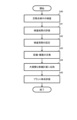
図9は、比較例の定期点検の処理を示すフローチャートである。この定期点検の処理は、原子力プラントの運転を停止して行われる。
検査者は、定期点検中の検査を開始する(ステップS40)。比較例では、原子炉の健全性に関わる構造材、溶接線などは別途に検査して評価している。検査者は、検査結果を評価して(ステップS41)、検査周期を設定する(ステップS42)。
Operation of Comparative Example
9 is a flow chart showing a routine inspection process according to a comparative example, which is carried out with the nuclear power plant shut down.
The inspector starts the inspection during the periodic inspection (step S40). In the comparative example, structural materials, weld lines, etc. related to the soundness of the reactor are inspected and evaluated separately. The inspector evaluates the inspection results (step S41) and sets the inspection cycle (step S42).
次に検査者は、設備/機器を交換して(ステップS43)、大規模な修繕計画に反映する(ステップS44)。最後に検査者は、プラント寿命を評価すると(ステップS45)、図9の処理を終了する。 The inspector then replaces the facility/equipment (step S43) and reflects this in the large-scale repair plan (step S44). Finally, the inspector evaluates the plant life (step S45) and ends the process in Figure 9.
図10は、比較例の原子力発電プラントの機器の信頼性とライフサイクルマネジメントを示す図であり、米国の原子力発電運転協会のAP-913に基づくものである。AP-913は、発電用原子炉における運転に関わる機器・設備の信頼性、プラントのライフサイクルをマネジメントするための処理を示す図である。 Figure 10 shows the reliability and life cycle management of equipment in a comparative example nuclear power plant, and is based on AP-913 of the Nuclear Power Operations Association in the United States. AP-913 is a diagram showing the process for managing the reliability of equipment and facilities related to the operation of a power generating nuclear reactor, and the life cycle of the plant.
最初、管理システムは、重要度を分類すると(ステップS50)、この重要度に応じてパフォーマンスを監視する(ステップS51)。そして管理者は、この重要度に応じて継続的な機器の信頼性の改善を行う(ステップS53)。管理者は、設備/機器の予防保全を実行する(ステップS54)。予防保全が実行された設備/機器は、パフォーマンス監視処理(ステップS51)の対象となる。 First, the management system classifies the importance (step S50) and monitors performance according to this importance (step S51). Then, the administrator continuously improves the reliability of the equipment according to this importance (step S53). The administrator performs preventive maintenance of the facility/equipment (step S54). The facility/equipment for which preventive maintenance has been performed becomes the subject of the performance monitoring process (step S51).
管理者は、パフォーマンスの監視結果に基づき、設備/機器の是正措置を行う(ステップS52)。そして、是正措置の結果はパフォーマンスの監視処理(ステップS51)と、継続的な機器の信頼性の改善処理(ステップS53)にフィードバックされる。 The administrator takes corrective measures for the facility/equipment based on the performance monitoring results (step S52). The results of the corrective measures are then fed back to the performance monitoring process (step S51) and the process of continuously improving the reliability of the equipment (step S53).
最後に、継続的な機器の信頼性の改善処理(ステップS53)と、是正措置(ステップS52)と、パフォーマンスの監視処理(ステップS51)に基づき、管理者はライフサイクルマネジメントを実行する(ステップS55)。 Finally, based on the continuous equipment reliability improvement process (step S53), corrective measures (step S52), and performance monitoring process (step S51), the administrator performs life cycle management (step S55).
《本実施形態の動作と構成》
本実施形態では、従来のAP913の考え方に構造材や大型構造物の健全性評価を導入し、発電所全体の信頼性を可視化する。
Operation and Configuration of the Present Embodiment
In this embodiment, the reliability of the entire power plant is visualized by introducing a soundness assessment of structural materials and large structures into the conventional AP913 concept.
40年を超える運転に向けては、従来の機器だけでなく構造材、溶接線など大型構造物の信頼性の常時監視が可能であり、最適な検査、設備交換、修繕の大規模工事に反映して、信頼性を担保しつつコストを最適化することができる。 In preparation for more than 40 years of operation, it will be possible to constantly monitor the reliability of not only conventional equipment but also large structures such as structural materials and weld lines. This will be reflected in optimal inspections, equipment replacement, and large-scale repair work, optimizing costs while ensuring reliability.
図1は、本実施形態に係る原子力発電プラントの機器の信頼性とライフサイクルマネジメントを示す図である。
図2に示す信頼性評価システムSは、構造物を重要度で分類する(ステップS10)。構造物の重要度は、炉内の安全系と、炉内燃料の健全性と、放射性物質の系統外への放出に影響する、また構造物の重要度には、法律で決まっているものだけでなく、従来の点検結果や、運転条件において、接触する流体、運転中の原子炉圧力容器の炉水に含まれる化学物質の種類及び濃度などを影響因子とする。
FIG. 1 is a diagram showing reliability and life cycle management of equipment in a nuclear power plant according to this embodiment.
The reliability evaluation system S shown in Fig. 2 classifies structures by their importance (step S10). The importance of a structure is determined based on factors that affect the safety system in the reactor, the integrity of the fuel in the reactor, and the release of radioactive materials outside the system, and is determined not only by legal requirements but also by the results of conventional inspections, the fluids that the structure comes into contact with under operating conditions, and the types and concentrations of chemical substances contained in the reactor water in the reactor pressure vessel during operation.
ステップS10にて分類された構造物の種類には、原子炉圧力容器、シュラウド、シュラウドサポート、ジェットポンプ、格子板など炉内構造物と制御棒の挿入に関連する機器、タービンの車室、軸受け、復水器、発電機及び水素供給設備、旧復水系の熱交換器、燃料支持板、安全重要度、及び、発電重要度が閾値よりも高い設備同士をつなぐ主要配管などがある。なお原子力施設には、燃料加工工場、核燃料サイクル工場、放射性廃棄物処分場などが含まれる。 The types of structures classified in step S10 include reactor pressure vessels, shrouds, shroud supports, jet pumps, lattice plates and other reactor internal structures, equipment related to the insertion of control rods, turbine casings, bearings, condensers, generators and hydrogen supply equipment, heat exchangers of the old condensate system, fuel support plates, and main piping connecting equipment whose safety importance and power generation importance are higher than the threshold. Nuclear facilities include fuel processing plants, nuclear fuel cycle plants, radioactive waste disposal sites, etc.
ステップS11にて、信頼性評価システムSは、構造物の健全性を監視する。健全性の監視とは、以前の検査結果とプラントPの運用状態、維持規格、基準、論文などの従来の知見から、構造物の現在の信頼性を評価するものである。信頼性評価システムSは更に、プラントPの定期点検情報に基づき、構造物の健全性を監視してもよい。 In step S11, the reliability assessment system S monitors the soundness of the structure. Health monitoring involves evaluating the current reliability of the structure based on previous inspection results and conventional knowledge such as the operational status of the plant P, maintenance specifications, standards, and papers. The reliability assessment system S may further monitor the soundness of the structure based on regular inspection information of the plant P.
ステップS10にて分類された構造物の種類に基づき、信頼性評価システムSは、継続的に機器の信頼性を改善する(ステップS13)。具体的にいうと、信頼性評価システムSは、検査と緩和を実行する(ステップS14)。信頼性評価システムSは、検査にて、検査結果、維持規格、法律、定期点検の工程を踏まえて、信頼性を確保しつつコストを最小化する点検頻度と、検査手法を選定する。信頼性評価システムSは、緩和にて、作業員の端末6に対して、応力緩和または/および環境緩和を指示する(ステップS14)。これを受けて作業員は、構造物に対して応力緩和または/および環境緩和を実行する。
Based on the type of structure classified in step S10, the reliability evaluation system S continuously improves the reliability of the equipment (step S13). Specifically, the reliability evaluation system S performs inspection and mitigation (step S14). In the inspection step, the reliability evaluation system S selects an inspection frequency and inspection method that minimizes costs while ensuring reliability, taking into account the inspection results, maintenance standards, laws, and regular inspection processes. In the mitigation step, the reliability evaluation system S instructs the worker's
信頼性評価システムSは、構造物の健全性の監視結果に基づき、運用方法を対策する(ステップS12)。ここで運用方法の対策とは、プラントPの運転及び運用方法の改善、サンプリング強化、緩和技術の運転変更などをいう。 The reliability assessment system S takes measures for operational methods based on the results of monitoring the soundness of the structure (step S12). Here, measures for operational methods refer to improvements in the operation and operational methods of the plant P, enhanced sampling, changes in the operation of mitigation techniques, etc.
信頼性評価システムSは、健全性の監視結果と、運用方法の対策結果と、継続的な構造物の信頼性改善結果に基づき、修繕計画を適正化する(ステップS15)。ここで修繕計画の適正化とはライフサイクルマネジメントであり、大規模な工事や点検が必要になる。そのため、信頼性評価システムSは、長期的な定期点検工程を踏まえて、構造物の信頼性を確保しつつ、コストが最小化するように適正化を行う。 The reliability assessment system S optimizes the repair plan based on the results of the health monitoring, the results of the countermeasures for the operation method, and the results of the continuous improvement of the reliability of the structure (step S15). Here, optimizing the repair plan means life cycle management, which requires large-scale construction and inspection. Therefore, the reliability assessment system S optimizes the plan to minimize costs while ensuring the reliability of the structure, taking into account the long-term regular inspection process.
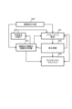
図2は、原子力発電のプラントPに対する信頼性評価システムSの構成図である。
信頼性評価システムSは、サーバ5と、使用環境情報センサ58と、腐食電位センサ4と、複数の端末6を含んで構成される。
FIG. 2 is a configuration diagram of a reliability evaluation system S for a nuclear power plant P.
The reliability evaluation system S includes a
サーバ5は、信頼性評価システムSの機能部を具現化するコンピュータである。端末6は、サーバ5にアクセスするための入出力機器である。使用環境情報センサ58は、プラントPを構成する機器の使用環境を検知するセンサである。腐食電位センサ4は、プラントPを構成する機器の腐食環境情報を検知するセンサである。
The
図3は、原子力発電のプラントPの構成図である。
プラントPは、沸騰水型の原子力発電プラントであり、原子炉圧力容器20、原子炉格納容器21、タービン22、再循環系配管23、原子炉浄化系24および複数の腐食電位測定装置を備えている。原子炉格納容器21内に設置された原子炉圧力容器20は内部に複数の燃料集合体(図示せず)を装荷した炉心25を配置している。
FIG. 3 is a configuration diagram of a nuclear power plant P.
The plant P is a boiling water nuclear power plant, and includes a reactor pressure vessel 20, a reactor containment vessel 21, a turbine 22, a recirculation system piping 23, a reactor cleanup system 24, and a plurality of corrosion potential measuring devices. The reactor pressure vessel 20 installed inside the reactor containment vessel 21 has a core 25 therein loaded with a plurality of fuel assemblies (not shown).
2系統の再循環系は、それぞれ、再循環系配管23および再循環ポンプ26を有する。原子炉圧力容器20に接続された主蒸気配管27が、タービン22に接続される。タービン22に連絡される復水器28が、復水配管29の後、給水配管30により原子炉圧力容器20に接続される。オフガス系配管31が復水器28に接続される。オフガス系配管31が復水配管29に接続され、線量率モニタ32が主蒸気配管27の近傍に設置される。 Each of the two recirculation systems has a recirculation system pipe 23 and a recirculation pump 26. A main steam pipe 27 connected to the reactor pressure vessel 20 is connected to the turbine 22. A condenser 28 connected to the turbine 22 is connected to the reactor pressure vessel 20 via a condensate pipe 29 and then a feedwater pipe 30. An off-gas system pipe 31 is connected to the condenser 28. The off-gas system pipe 31 is connected to the condensate pipe 29, and a dose rate monitor 32 is installed near the main steam pipe 27.
原子炉浄化系24は、再循環系配管23に接続された配管並びに原子炉圧力容器20の底部に接続されたドレン配管33を有し、浄化装置(図示せず)を系内に有する。原子炉浄化系24は給水配管30に接続される。 The reactor cleanup system 24 has piping connected to the recirculation system piping 23 and a drain piping 33 connected to the bottom of the reactor pressure vessel 20, and has a cleanup device (not shown) within the system. The reactor cleanup system 24 is connected to the feedwater piping 30.
水質測定装置34aがサンプリング配管35aによってドレン配管33に接続され、水質測定装置34bがサンプリング配管35bによって原子炉浄化系24に接続される。水質測定装置34cがサンプリング配管35cによって給水配管30に接続され、水質測定装置34dがサンプリング配管35dによって主蒸気配管27に接続される。 Water quality measuring device 34a is connected to drain pipe 33 by sampling pipe 35a, and water quality measuring device 34b is connected to reactor cleanup system 24 by sampling pipe 35b. Water quality measuring device 34c is connected to feedwater pipe 30 by sampling pipe 35c, and water quality measuring device 34d is connected to main steam pipe 27 by sampling pipe 35d.
腐食電位センサ4は、局所出力領域モニタ外筒管1を用いて沸騰水型原子力プラントの該当箇所に設置される。腐食電位センサ4は、原子炉圧力容器20の下部の下部プレナム36内の水質を測定するために、下部プレナム36内の対応する位置に設置されている。この場合は圧力容器下鏡8付近の腐食電位を測定するために、圧力容器下鏡付近の高さに腐食電位センサ4が設置され、その高さに腐食電位測定窓が開孔されている(図示せず)。
The corrosion
局所出力領域モニタを利用した腐食電位測定では、酸素、過酸化水素などのサンプリングした水質との直接的な対応が得られない。しかし、上記のような圧力容器下鏡8付近の腐食電位測定の場合には、サンプリング配管35aを用いて炉水を採取し、水質測定装置34aで測定することができる。 When measuring corrosion potential using a local power range monitor, it is not possible to obtain a direct correspondence with the sampled water quality, such as oxygen or hydrogen peroxide. However, when measuring corrosion potential near the pressure vessel bottom head 8 as described above, reactor water can be sampled using sampling pipe 35a and measured with water quality measuring device 34a.
このような腐食電位の測定により、下部プレナム36内での腐食電位が目標とする値にまで低下するように、水素注入装置であるオフガス系配管31から給水に注入する水素量を調節する。原子炉圧力容器20内の炉水に注入した水素の余剰分は、主蒸気配管27、タービン22および復水器28を経てオフガス系配管31に排気される。オフガス系配管31に排気された水素の余剰分は、オフガス系配管31に設けられた再結合器(図示せず)で酸素と結合されて処理される。 By measuring the corrosion potential in this way, the amount of hydrogen injected into the feedwater from the off-gas system piping 31, which is a hydrogen injection device, is adjusted so that the corrosion potential in the lower plenum 36 falls to a target value. The excess hydrogen injected into the reactor water in the reactor pressure vessel 20 is exhausted to the off-gas system piping 31 via the main steam piping 27, the turbine 22, and the condenser 28. The excess hydrogen exhausted to the off-gas system piping 31 is combined with oxygen in a recombiner (not shown) installed in the off-gas system piping 31 and treated.
給水の水素濃度は、サンプリング配管35cでサンプリングされた給水を水質測定装置34cで測定することによって得られる。また、水素注入時の主蒸気配管27の線量率は線量率モニタ32で監視される。 The hydrogen concentration of the feedwater is obtained by measuring the feedwater sampled through the sampling pipe 35c with the water quality measuring device 34c. In addition, the dose rate of the main steam pipe 27 during hydrogen injection is monitored by the dose rate monitor 32.
この方法では複数の腐食電位センサ4を局所出力領域モニタ外筒管1上に配置できるので、沸騰水型原子力プラントの複数の箇所に設置することによって、沸騰水型原子力プラントの構造部材に応力腐食割れ(SCC:Stress Corrosion Cracking)が発生する腐食環境を下部プレナム36内で立体的にマッピングすることができる。その結果、原子力プラントの長期的な安全性、健全性および信頼性を確保するための保全策を提供することができる。
This method allows multiple corrosion
図4は、サーバ5のハードウェア構成図である。
サーバ5は、例えば、データセンタに設置されたコンピュータである。サーバ5は、CPU(Central Processing Unit)51、記憶部57、ROM(Read Only Memory)52、RAM(Random Access Memory)53、操作部54、表示部55及び通信部56を含んで構成される。
FIG. 4 is a diagram showing the hardware configuration of the
The
CPU51は、中央処理装置であり、記憶部57に格納されたプログラム571を実行する。プログラム571は、CPU51によって実行されて、図1に示す各処理を実行するプログラムである。
CPU61は、プログラム571を実行することにより、図6に示した各機能部を具現化する。なお、CPU61が実行する各処理については、図1と図7と図8を用いて後述する。
The
The
記憶部57は、大容量の記憶装置であり、例えば、ハードディスクドライブ(Hard Disk Drive)やフラッシュメモリなどで構成される。
The
RAM53は揮発性メモリであり、CPU51で実行可能な各種プログラム、入力データ、出力データ、及びパラメータ等を一時的に記憶するワークエリアとして機能する。ROM52は不揮発性メモリであり、例えばBIOS(Basic I/O System)などが格納されている。
操作部54は、カーソルキー、数字入力キー、及び各種機能キーなどを備えたキーボードと、マウスなどのポインティングデバイスを備えて構成される。操作部54は、キーボードで押下操作されたキーの押下信号やマウスによる操作信号を検知する。CPU51は、操作部54からの操作信号に基づいて、各種処理を実行する。
The
表示部55は、例えば、LCD(Liquid Crystal Display)等のモニタディスプレイを備えて構成される。表示部55は、CPU51から入力される表示信号により各種画面を表示する。また、表示部55、及び操作部54は、タッチパネルディスプレイを採用することもできる。
The
図5は、端末6のハードウェア構成図である。
端末6は、例えば、各作業者が有するタブレット端末である。端末6は、CPU61、記憶部67、ROM62、RAM63、タッチパネルディスプレイ64及び通信部66を含んで構成される。
FIG. 5 is a diagram showing the hardware configuration of the
The
CPU61は、中央処理装置であり、記憶部67に格納されたプログラム671を実行する。プログラム671は、例えばブラウザであり、CPU61によって実行されて、サーバ5との間の入出力処理を実現する。
The
記憶部67は、大容量の記憶装置であり、例えば、ハードディスクドライブ(Hard Disk Drive)やフラッシュメモリなどで構成される。
The
RAM63は揮発性メモリであり、CPU61で実行可能な各種プログラム、入力データ、出力データ、及びパラメータ等を一時的に記憶するワークエリアとして機能する。ROM62は不揮発性メモリであり、例えばBIOSなどが格納されている。
タッチパネルディスプレイ64は、LCD等のディスプレイ上に透明なタッチパネルが重畳されたものである。タッチパネルディスプレイ64は、タッチパネルで押下操作された押下信号を検知する。CPU61は、タッチパネルディスプレイ64からの操作信号に基づいて、各種処理を実行する。そして、タッチパネルディスプレイ64は、CPU61から入力される表示信号により各種画面を表示する。
The
図6は、原子力発電プラントの信頼性評価システムSの機能ブロック図である。
信頼性評価システムSは、検知部511、重要度分類部512、定期点検情報受付部513、健全性監視部514、予防保全部515、ライフサイクルマネジメント部516を備える。
検知部511は、運転中のプラントPの環境情報を検知する。検知部511が検知する環境情報は、運転中の原子炉圧力容器の炉水に含まれる化学物質の種類及び濃度、材料の種類、並びに、建設時の施工データのうち何れかを含む。
FIG. 6 is a functional block diagram of a reliability evaluation system S for a nuclear power plant.
The reliability evaluation system S includes a
The
健全性監視部514は、運転中のプラントPの環境情報、このプラントPを構成する機器の重要性情報に基づき、プラントPを構成する機器の健全性を常時監視する。なお、健全性監視部514は、更にプラントPの定期点検情報および/または規格基準情報に基づいて、プラントPを構成する機器の健全性を常時監視してもよく、限定されない。
The
予防保全部515は、健全性監視部514による運転中のプラントPを構成する機器の健全性評価結果に基づき、各機器に対する予防保全を指示する。
ライフサイクルマネジメント部516は、予防保全部515による機器の腐食に対する予防保全指示、および、健全性監視部514による機器の健全性評価結果に基づき、プラントPに対する修繕計画を立案する。
The
The life
定期点検情報受付部513は、プラントPの定期点検情報および/または規格基準情報の入力を受け付ける。なお、この定期点検情報受付部513は、必須の構成要素ではない。
The periodic inspection
重要度分類部512は、プラントPを構成する機器の重要性を分類する。なお、この重要度分類部512は必須の構成要素ではなく、機器の重要性は、手作業で分類されてもよい。
The
図7は、原子力発電プラントの溶接線の信頼性とライフサイクルマネジメントを示す図である。
溶接線の種類には、原子炉圧力容器、シュラウド、シュラウドサポート、ジェットポンプ、格子板など炉内構造物と制御棒の挿入に関連する機器、タービンの車室、軸受け、復水器、発電機及び水素供給設備、旧復水系の熱交換器などの構造物や配管の接合部分などがある。
FIG. 7 is a diagram showing reliability and life cycle management of weld lines in a nuclear power plant.
Types of weld lines include those found on reactor pressure vessels, shrouds, shroud supports, jet pumps, lattice plates and other reactor internal structures, equipment related to the insertion of control rods, turbine casings, bearings, condensers, generators and hydrogen supply equipment, and the joints between structures and piping such as heat exchangers in the old condensate system.
信頼性評価システムSは、溶接線を重要度で分類する(ステップS20)。溶接線の重要度は、炉内の安全系、炉内燃料の健全性、放射性物質の系統外への放出に影響するか否か、法律で決まっているか否か、従来の知見、溶接方法、溶接の種類、溶接に用いた金属、溶接後の研磨などの後工程などで長期的な健全性評価に影響を与える因子、接触する流体、運転中の原子炉圧力容器の炉水に含まれる化学物質の種類及び濃度などの影響因子で決定される。 The reliability evaluation system S classifies the weld lines by their importance (step S20). The importance of the weld line is determined by influencing factors such as the safety system inside the reactor, the integrity of the fuel inside the reactor, whether it affects the release of radioactive materials outside the system, whether it is determined by law, conventional knowledge, factors that affect long-term integrity evaluation such as the welding method, the type of welding, the metal used in welding, post-processing such as polishing after welding, the fluid that comes into contact, and the type and concentration of chemicals contained in the reactor water in the reactor pressure vessel during operation.
信頼性評価システムSは、溶接線の健全性を監視する(ステップS21)。具体的にいうと、溶接線の健全性監視とは、以前の検査結果とプラントPの運用状態、維持規格、基準、論文などの従来の知見から、溶接線の現在の信頼性を評価するものである。 The reliability evaluation system S monitors the soundness of the weld line (step S21). Specifically, the monitoring of the soundness of the weld line involves evaluating the current reliability of the weld line based on previous inspection results and conventional knowledge such as the operational status of the plant P, maintenance specifications, standards, and papers.
ステップS20にて分類された溶接線の種類に基づき、信頼性評価システムSは、継続的に機器の信頼性を改善する(ステップS23)。具体的にいうと、信頼性評価システムSは、検査と緩和を実行する(ステップS24)。信頼性評価システムSは、検査にて、検査結果、維持規格、法律、定期点検の工程を踏まえて、信頼性を確保しつつコストを最小化する点検頻度と、検査手法を選定する。そして信頼性評価システムSは、緩和にて、応力緩和または/および環境緩和を指示する(ステップS24)。これを受けて作業員は、溶接線に対して応力緩和または/および環境緩和を実行する。 Based on the type of weld line classified in step S20, the reliability evaluation system S continuously improves the reliability of the equipment (step S23). Specifically, the reliability evaluation system S performs inspection and mitigation (step S24). In the inspection, the reliability evaluation system S selects an inspection frequency and inspection method that minimizes costs while ensuring reliability, taking into account the inspection results, maintenance standards, laws, and regular inspection processes. Then, in the mitigation, the reliability evaluation system S instructs stress relaxation and/or environmental mitigation (step S24). In response, the worker performs stress relaxation and/or environmental mitigation on the weld line.
信頼性評価システムSは、溶接線の健全性の監視結果に基づき、運用方法を対策する(ステップS22)。ここで運用方法の対策とは、プラントPの運転及び運用方法の改善、サンプリング強化、緩和技術の運転変更などをいう。 The reliability evaluation system S takes measures for operational methods based on the monitoring results of the soundness of the weld line (step S22). Here, measures for operational methods refer to improvements in the operation and operational methods of the plant P, enhanced sampling, changes in the operation of mitigation techniques, etc.
信頼性評価システムSは、健全性の監視結果と、運用方法の対策結果と、継続的な機器の信頼性改善結果に基づき、修繕計画を適正化する(ステップS25)。ここで修繕計画の適正化とはライフサイクルマネジメントであり、大規模工事や点検が必要になる。そのため、信頼性評価システムSは、長期的な定期点検工程を踏まえて、設備と機器の信頼性を確保しつつ、コストが最小化するように適正化を行う。 The reliability evaluation system S optimizes the repair plan based on the results of the health monitoring, the results of the countermeasures for the operation method, and the results of the continuous improvement of the equipment reliability (step S25). Here, optimizing the repair plan means life cycle management, and large-scale construction and inspections are required. Therefore, the reliability evaluation system S optimizes the plan to minimize costs while ensuring the reliability of the facilities and equipment, taking into account the long-term regular inspection process.
図8は、原子力発電プラントの配管の信頼性とライフサイクルマネジメントを示す図である。
配管の種類には、その配管を流れる流体の種類、材質、原子炉側、タービン側、ラド設備に設置されるか否かが有る。液体の種類とは、水、水蒸気、化学物質を含むか否かである。
FIG. 8 is a diagram showing the reliability and life cycle management of piping in a nuclear power plant.
The type of piping includes the type of fluid that flows through it, its material, whether it is installed on the reactor side, turbine side, or rad equipment. The type of liquid includes whether it contains water, steam, or chemicals.
信頼性評価システムSは、配管を重要度で分類する(ステップS30)。配管の重要度分類は、炉内の安全系、炉内燃料の健全性、放射性物質の系統外への放出に影響するか否か、法律や社内規定、規格基準で決まっているか否か、放射性物質の濃度、化学物質の種類及び濃度などの環境因子などで決定される。 The reliability evaluation system S classifies the piping by its importance (step S30). The importance of the piping is classified based on the safety system inside the reactor, the integrity of the fuel inside the reactor, whether it affects the release of radioactive materials outside the system, whether it is determined by law, company regulations, or standards, and environmental factors such as the concentration of radioactive materials and the type and concentration of chemical substances.
信頼性評価システムSは、配管の健全性を監視する(ステップS31)。具体的にいうと、配管の健全性監視とは、以前の検査結果とプラントの運用状態、維持規格、基準、論文などの従来の知見から、配管の現在の信頼性を評価する。 The reliability evaluation system S monitors the integrity of the piping (step S31). Specifically, piping integrity monitoring involves evaluating the current reliability of the piping based on previous inspection results, the plant's operating status, maintenance specifications, standards, papers, and other conventional knowledge.
ステップS30にて分類された溶接線の種類に基づき、信頼性評価システムSは、継続的に機器の信頼性を改善する(ステップS33)。具体的にいうと、信頼性評価システムSは、検査と緩和を実行する(ステップS34)。信頼性評価システムSは、検査にて、検査結果、維持規格、法律、定期点検の工程を踏まえて、信頼性を確保しつつコストを最小化する点検頻度と、検査手法を選定する。そして信頼性評価システムSは、緩和にて、応力緩和または/および環境緩和を実行する。 Based on the type of weld line classified in step S30, the reliability evaluation system S continuously improves the reliability of the equipment (step S33). Specifically, the reliability evaluation system S performs inspection and mitigation (step S34). In the inspection step, the reliability evaluation system S selects an inspection frequency and inspection method that minimizes costs while ensuring reliability, taking into account the inspection results, maintenance standards, laws, and regular inspection processes. Then, in the mitigation step, the reliability evaluation system S performs stress relaxation and/or environmental mitigation.
信頼性評価システムSは、溶接線の健全性の監視結果に基づき、運用方法を対策する(ステップS32)。ここで運用方法の対策とは、プラントPの運転及び運用方法の改善、サンプリング強化、緩和技術の運転変更などをいう。 The reliability evaluation system S takes measures for operational methods based on the monitoring results of the soundness of the weld line (step S32). Here, measures for operational methods refer to improvements in the operation and operational methods of the plant P, enhanced sampling, changes in the operation of mitigation techniques, etc.
信頼性評価システムSは、健全性の監視結果と、運用方法の対策結果と、継続的な機器の信頼性改善結果に基づき、修繕計画を適正化する(ステップS35)。ここで修繕計画の適正化とはライフサイクルマネジメントであり、大規模工事や点検が必要になる。そのため、信頼性評価システムSは、長期的な定期点検工程を踏まえて、設備の信頼性を確保しつつ、コストが最小化するように適正化を行う。 The reliability evaluation system S optimizes the repair plan based on the results of the health monitoring, the results of the countermeasures for the operation method, and the results of the continuous improvement of the reliability of the equipment (step S35). Here, optimizing the repair plan means life cycle management, and large-scale construction and inspections are required. Therefore, the reliability evaluation system S optimizes the plan to minimize costs while ensuring the reliability of the equipment, taking into account the long-term regular inspection process.
米国の原子力発電運転協会(INPO:Institute of Nuclear Power Operations)が規定する機器の信頼性になく、供用期間中検査で行っていた腐食環境、材料組成、材料の劣化データ、検査結果を機器の信頼性に取り込むことで、常時、構造物、機器、系統の劣化状況の監視を行うことが可能になり、プラントPの健全性の常時監視と、プラントライフサイクルの評価が容易となる。 By incorporating the corrosion environment, material composition, material deterioration data, and inspection results that were previously conducted during in-service inspections into the equipment reliability defined by the Institute of Nuclear Power Operations (INPO) in the United States, it will be possible to constantly monitor the deterioration status of structures, equipment, and systems, making it easier to constantly monitor the health of Plant P and evaluate the plant life cycle.
《変形例》
本発明は上記した実施形態に限定されるものではなく、様々な変形例が含まれる。例えば上記した実施形態は、本発明を分かりやすく説明するために詳細に説明したものであり、必ずしも説明した全ての構成を備えるものに限定されるものではない。ある実施形態の構成の一部を他の実施形態の構成に置き換えることが可能であり、ある実施形態の構成に他の実施形態の構成を加えることも可能である。また、各実施形態の構成の一部について、他の構成の追加・削除・置換をすることも可能である。
<<Variation>>
The present invention is not limited to the above-described embodiment, and includes various modified examples. For example, the above-described embodiment has been described in detail to clearly explain the present invention, and is not necessarily limited to those having all of the configurations described. It is possible to replace a part of the configuration of one embodiment with the configuration of another embodiment, and it is also possible to add the configuration of another embodiment to the configuration of one embodiment. In addition, it is also possible to add, delete, or replace a part of the configuration of each embodiment with another configuration.
上記の各構成、機能、処理部、処理手段などは、それらの一部または全部を、例えば集積回路などのハードウェアで実現してもよい。上記の各構成、機能などは、プロセッサがそれぞれの機能を実現するプログラムを解釈して実行することにより、ソフトウェアで実現してもよい。各機能を実現するプログラム、テーブル、ファイルなどの情報は、メモリ、ハードディスク、SSD(Solid State Drive)などの記録装置、または、フラッシュメモリカード、DVD(Digital Versatile Disk)などの記録媒体に置くことができる。 The above configurations, functions, processing units, processing means, etc. may be realized in part or in whole by hardware such as an integrated circuit. The above configurations, functions, etc. may be realized by software by a processor interpreting and executing a program that realizes each function. Information such as the programs, tables, and files that realize each function can be stored in a recording device such as a memory, a hard disk, or an SSD (Solid State Drive), or on a recording medium such as a flash memory card or a DVD (Digital Versatile Disk).
各実施形態に於いて、制御線や情報線は、説明上必要と考えられるものを示しており、製品上必ずしも全ての制御線や情報線を示しているとは限らない。実際には、殆ど全ての構成が相互に接続されていると考えてもよい。 In each embodiment, the control lines and information lines are those that are considered necessary for the explanation, and not all control lines and information lines in the product are necessarily shown. In reality, it can be considered that almost all components are interconnected.
S 信頼性評価システム
1 局所出力領域モニタ外筒管
20 原子炉圧力容器
21 原子炉格納容器
22 タービン
23 再循環系配管
24 原子炉浄化系
25 炉心
26 再循環ポンプ
27 主蒸気配管
28 復水器
29 復水配管
30 給水配管
31 オフガス系配管
32 線量率モニタ
33 ドレン配管
34a~34d 水質測定装置
35a~35c サンプリング配管
35d サンプリング配管
4 腐食電位センサ
5 サーバ
51 CPU
511 検知部
512 重要度分類部
513 定期点検情報受付部
514 健全性監視部
515 予防保全部
516 ライフサイクルマネジメント部
52 ROM
53 RAM
54 操作部
55 表示部
56 通信部
57 記憶部
58 使用環境情報センサ
6 端末
61 CPU
62 ROM
63 RAM
64 タッチパネルディスプレイ
66 通信部
67 記憶部
S Reliability assessment system 1 Local power range monitor outer cylinder pipe 20 Reactor pressure vessel 21 Reactor containment vessel 22 Turbine 23 Recirculation system piping 24 Reactor cleanup system 25 Reactor core 26 Recirculation pump 27 Main steam piping 28 Condenser 29 Condensate piping 30 Feed water piping 31 Off-gas system piping 32 Dose rate monitor 33 Drain piping 34a to 34d Water quality measuring device 35a to 35c Sampling piping 35d Sampling piping 4
53 RAM
54
62 ROM
63 RAM
64
Claims (10)
前記原子炉のドレン配管にサンプリング配管によって接続され、炉水中の水素濃度を測定する第1の水質測定装置と、
前記原子炉の配管の線量率を測定する線量率モニタと、
前記腐食電位センサ、前記第1の水質測定装置及び前記線量率モニタの測定データを運転中のプラントの環境情報として取り込む検知部と、
前記原子炉を構成する材料組成、材料の劣化データ、検査結果を記憶した記憶部と、
米国の原子力発電運転協会(INPO: Institute of Nuclear Power Operations)が規定する機器の信頼性評価には取り込まれていない前記運転中のプラントの環境情報である、前記腐食電位、前記水素濃度、及び前記線量率、並びに前記材料組成、材料の劣化データ、検査結果に基づき、当該プラントを構成する前記機器の健全性を常時監視する健全性監視部と、
前記健全性監視部による機器の健全性評価結果に基づき、プラントに対する修繕計画を立案し、ライフサイクルマネジメントを行うライフサイクルマネジメント部と、
を備えることを特徴とするプラントの信頼性評価システム。 a corrosion potential sensor for measuring the corrosion potential of the water chemistry in the lower plenum region of the reactor;
a first water quality measuring device connected to a drain pipe of the reactor by a sampling pipe and configured to measure a hydrogen concentration in the reactor water;
a dose rate monitor for measuring a dose rate in the reactor piping;
a detection unit that acquires measurement data of the electrochemical corrosion potential sensor, the first water quality measurement device, and the dose rate monitor as environmental information of an operating plant;
A memory unit that stores the composition of materials constituting the reactor, deterioration data of the materials, and inspection results;
a health monitoring unit that constantly monitors the health of the equipment constituting the plant based on the corrosion potential, the hydrogen concentration, and the dose rate, as well as the material composition, material deterioration data, and inspection results, which are environmental information of the plant during operation that is not incorporated into the equipment reliability evaluation defined by the Institute of Nuclear Power Operations (INPO) of the United States;
a life cycle management unit that develops a repair plan for the plant and performs life cycle management based on the result of the equipment health evaluation by the health monitoring unit;
A plant reliability evaluation system comprising:
前記原子炉の給水配管にサンプリング配管によって接続され、水素濃度を測定する第3の水質測定装置と、
前記原子炉の主蒸気配管にサンプリング配管によって接続され、水素濃度を測定する第4の水質測定装置と、
を更に備えることを特徴とする請求項1に記載のプラントの信頼性評価システム。 a second water quality measuring device connected to the purification system of the reactor by a sampling pipe and configured to measure a hydrogen concentration;
a third water quality measuring device connected to the reactor water supply pipe by a sampling pipe and measuring a hydrogen concentration;
a fourth water quality measurement device connected to the main steam pipe of the reactor by a sampling pipe and configured to measure a hydrogen concentration;
2. The plant reliability evaluation system according to claim 1, further comprising:
ことを特徴とする請求項1に記載のプラントの信頼性評価システム。 The plant is a power plant including a nuclear reactor pressure vessel.
2. The plant reliability evaluation system according to claim 1 .
ことを特徴とする請求項3に記載のプラントの信頼性評価システム。 The equipment is related to control rod insertion and reactor internals.
4. The plant reliability evaluation system according to claim 3.
ことを特徴とする請求項3に記載のプラントの信頼性評価システム。 The equipment is any one of a reactor pressure vessel, a shroud, a shroud support, a jet pump, a lattice plate, a fuel support plate, and a main piping connecting equipment whose safety importance and power generation importance are higher than a threshold value;
4. The plant reliability evaluation system according to claim 3.
ことを特徴とする請求項3に記載のプラントの信頼性評価システム。 The equipment includes any one of a structure, a welded line, and a pipe.
4. The plant reliability evaluation system according to claim 3.
を更に備え、
前記健全性監視部は、運転中の前記環境情報、前記プラントの定期点検情報または/および規格基準情報に基づき、当該プラントを構成する前記機器の健全性を常時監視する、
ことを特徴とする請求項1に記載のプラントの信頼性評価システム。 a regular inspection information receiving unit that receives input of regular inspection information and/or standard information of the plant;
Further comprising:
The health monitoring unit constantly monitors the health of the equipment constituting the plant based on the environmental information during operation, periodic inspection information and/or standard information of the plant.
2. The plant reliability evaluation system according to claim 1 .
を更に備えることを特徴とする請求項1に記載のプラントの信頼性評価システム。 an importance classification unit that classifies the importance of equipment constituting the plant;
2. The plant reliability evaluation system according to claim 1, further comprising:
第1の水質測定装置が、前記原子炉のドレン配管にサンプリング配管によって接続され、炉水中の水素濃度を測定するステップと、
線量率モニタが、前記原子炉の配管の線量率を測定するステップと、
記憶部が、前記原子炉を構成する材料組成、材料の劣化データ、検査結果を記憶するステップと、
検知部が、前記腐食電位センサ、前記第1の水質測定装置及び前記線量率モニタの測定データを運転中のプラントの環境情報として取り込むステップと、
健全性監視部が、米国の原子力発電運転協会(INPO: Institute of Nuclear Power Operations)が規定する機器の信頼性評価には取り込まれていない前記運転中のプラントの環境情報である、前記腐食電位、前記水素濃度、及び前記線量率、並びに前記材料組成、材料の劣化データ、検査結果に基づき、当該プラントを構成する前記機器の健全性を常時監視するステップと、
ライフサイクルマネジメント部が、前記健全性監視部による機器の健全性評価結果に基づき、前記プラントに対する修繕計画を立案し、ライフサイクルマネジメントを行うステップと、
を実行することを特徴とするプラントの信頼性評価方法。 a corrosion potential sensor measuring a corrosion potential in a water chemistry in a lower plenum region of the nuclear reactor;
a first water quality measuring device connected to a drain pipe of the reactor by a sampling pipe and measuring a hydrogen concentration in the reactor water;
a dose rate monitor measuring a dose rate in a piping of the nuclear reactor;
A step in which a memory unit stores a material composition constituting the reactor, deterioration data of the material, and an inspection result;
a detection unit acquiring measurement data from the electrochemical corrosion potential sensor, the first water quality measurement device, and the dose rate monitor as environmental information of the plant in operation;
a health monitoring unit constantly monitoring the health of the equipment constituting the plant based on the corrosion potential, the hydrogen concentration, and the dose rate, which are environmental information of the plant during operation that is not incorporated in the equipment reliability evaluation defined by the Institute of Nuclear Power Operations (INPO), as well as the material composition, material deterioration data, and inspection results;
A life cycle management unit develops a repair plan for the plant based on the equipment health evaluation result by the health monitoring unit, and performs life cycle management;
A plant reliability evaluation method comprising the steps of:
腐食電位センサにより、原子炉の下部プレナム領域の水質における腐食電位を測定する手順、
前記原子炉のドレン配管にサンプリング配管によって接続される第1の水質測定装置により、前記原子炉の炉水中の水素濃度を測定する手順、
線量率モニタにより、前記原子炉の配管の線量率を測定する手順、
前記腐食電位センサ、前記第1の水質測定装置及び前記線量率モニタの測定データを運転中のプラントの環境情報として取り込む手順、
記憶部に、前記原子炉を構成する材料組成、材料の劣化データ、検査結果を記憶する手順、
米国の原子力発電運転協会(INPO: Institute of Nuclear Power Operations)が規定する機器の信頼性評価には取り込まれていない前記運転中のプラントの環境情報である、前記腐食電位、前記水素濃度、及び前記線量率、並びに前記材料組成、材料の劣化データ、検査結果に基づき、当該プラントを構成する前記機器の健全性を常時監視する手順、
前記機器の健全性評価結果に基づき、前記プラントに対する修繕計画を立案し、ライフサイクルマネジメントを行う手順、
を実行するためのプラントの信頼性評価プログラム。 The computer
A procedure for measuring the corrosion potential in the water quality of the lower plenum region of a nuclear reactor by means of an electrochemical corrosion potential sensor;
measuring a hydrogen concentration in reactor water of the reactor by a first water quality measuring device connected to a drain pipe of the reactor by a sampling pipe;
measuring a dose rate in said reactor piping with a dose rate monitor;
a step of acquiring measurement data of the electrochemical corrosion potential sensor, the first water quality measuring device, and the dose rate monitor as environmental information of the plant in operation;
a step of storing in a storage unit the composition of materials constituting the reactor, deterioration data of the materials, and inspection results;
a procedure for constantly monitoring the soundness of the equipment constituting the plant based on the corrosion potential, the hydrogen concentration, and the dose rate, which are environmental information of the plant during operation that is not incorporated in the equipment reliability evaluation stipulated by the Institute of Nuclear Power Operations (INPO), as well as the material composition, material deterioration data, and inspection results;
A procedure for formulating a repair plan for the plant and performing life cycle management based on the results of the equipment health assessment;
A plant reliability assessment program to carry out.
Priority Applications (1)
| Application Number | Priority Date | Filing Date | Title |
|---|---|---|---|
| JP2025008228A JP7825749B2 (en) | 2022-02-28 | 2025-01-21 | Plant reliability evaluation system, plant reliability evaluation method, and plant reliability evaluation program |
Applications Claiming Priority (2)
| Application Number | Priority Date | Filing Date | Title |
|---|---|---|---|
| JP2022029812A JP7625547B2 (en) | 2022-02-28 | 2022-02-28 | PLANT RELIABILITY EVALUATION SYSTEM, PLANT RELIABILITY EVALUATION METHOD, AND PLANT RELIABILITY EVALUATION PROGRAM |
| JP2025008228A JP7825749B2 (en) | 2022-02-28 | 2025-01-21 | Plant reliability evaluation system, plant reliability evaluation method, and plant reliability evaluation program |
Related Parent Applications (1)
| Application Number | Title | Priority Date | Filing Date |
|---|---|---|---|
| JP2022029812A Division JP7625547B2 (en) | 2022-02-28 | 2022-02-28 | PLANT RELIABILITY EVALUATION SYSTEM, PLANT RELIABILITY EVALUATION METHOD, AND PLANT RELIABILITY EVALUATION PROGRAM |
Publications (2)
| Publication Number | Publication Date |
|---|---|
| JP2025063243A true JP2025063243A (en) | 2025-04-15 |
| JP7825749B2 JP7825749B2 (en) | 2026-03-06 |
Family
ID=87765538
Family Applications (2)
| Application Number | Title | Priority Date | Filing Date |
|---|---|---|---|
| JP2022029812A Active JP7625547B2 (en) | 2022-02-28 | 2022-02-28 | PLANT RELIABILITY EVALUATION SYSTEM, PLANT RELIABILITY EVALUATION METHOD, AND PLANT RELIABILITY EVALUATION PROGRAM |
| JP2025008228A Active JP7825749B2 (en) | 2022-02-28 | 2025-01-21 | Plant reliability evaluation system, plant reliability evaluation method, and plant reliability evaluation program |
Family Applications Before (1)
| Application Number | Title | Priority Date | Filing Date |
|---|---|---|---|
| JP2022029812A Active JP7625547B2 (en) | 2022-02-28 | 2022-02-28 | PLANT RELIABILITY EVALUATION SYSTEM, PLANT RELIABILITY EVALUATION METHOD, AND PLANT RELIABILITY EVALUATION PROGRAM |
Country Status (4)
| Country | Link |
|---|---|
| US (1) | US20250166858A1 (en) |
| EP (1) | EP4489025A4 (en) |
| JP (2) | JP7625547B2 (en) |
| WO (1) | WO2023162419A1 (en) |
Citations (4)
| Publication number | Priority date | Publication date | Assignee | Title |
|---|---|---|---|---|
| JPH07174883A (en) * | 1993-12-20 | 1995-07-14 | Hitachi Ltd | Corrosion potential detection method, reaction rate potential characteristic simulation method, and plant monitoring system using these |
| JPH09159795A (en) * | 1996-09-06 | 1997-06-20 | Hitachi Ltd | Boiling water reactor primary cooling system |
| JP2001091688A (en) * | 1999-09-27 | 2001-04-06 | Toshiba Corp | Nuclear power plant |
| JP2015114251A (en) * | 2013-12-13 | 2015-06-22 | 日立Geニュークリア・エナジー株式会社 | Method for measuring dissolved hydrogen concentration, device for measuring dissolved hydrogen concentration, and method for operating nuclear power plant |
Family Cites Families (7)
| Publication number | Priority date | Publication date | Assignee | Title |
|---|---|---|---|---|
| JP2743717B2 (en) * | 1991-07-23 | 1998-04-22 | 株式会社日立製作所 | Sensitivity detection method for structural materials and water quality control system for nuclear power plant |
| JP2687780B2 (en) * | 1991-10-14 | 1997-12-08 | 株式会社日立製作所 | Reactor hydrogen injection facility |
| JP3147586B2 (en) * | 1993-05-21 | 2001-03-19 | 株式会社日立製作所 | Plant monitoring and diagnosis method |
| JP4105052B2 (en) | 2003-07-22 | 2008-06-18 | 日立Geニュークリア・エナジー株式会社 | A method for mitigating stress corrosion cracking in nuclear plant structural materials. |
| JP2008191026A (en) | 2007-02-06 | 2008-08-21 | Toshiba Corp | Method and apparatus for reducing radiation dose rate of turbine system |
| JP2016189088A (en) | 2015-03-30 | 2016-11-04 | 株式会社日立製作所 | Equipment management support system |
| JP2021060257A (en) * | 2019-10-04 | 2021-04-15 | 日立Geニュークリア・エナジー株式会社 | Exposure reduction method |
-
2022
- 2022-02-28 JP JP2022029812A patent/JP7625547B2/en active Active
- 2022-12-14 US US18/834,390 patent/US20250166858A1/en active Pending
- 2022-12-14 WO PCT/JP2022/046095 patent/WO2023162419A1/en not_active Ceased
- 2022-12-14 EP EP22928936.8A patent/EP4489025A4/en active Pending
-
2025
- 2025-01-21 JP JP2025008228A patent/JP7825749B2/en active Active
Patent Citations (4)
| Publication number | Priority date | Publication date | Assignee | Title |
|---|---|---|---|---|
| JPH07174883A (en) * | 1993-12-20 | 1995-07-14 | Hitachi Ltd | Corrosion potential detection method, reaction rate potential characteristic simulation method, and plant monitoring system using these |
| JPH09159795A (en) * | 1996-09-06 | 1997-06-20 | Hitachi Ltd | Boiling water reactor primary cooling system |
| JP2001091688A (en) * | 1999-09-27 | 2001-04-06 | Toshiba Corp | Nuclear power plant |
| JP2015114251A (en) * | 2013-12-13 | 2015-06-22 | 日立Geニュークリア・エナジー株式会社 | Method for measuring dissolved hydrogen concentration, device for measuring dissolved hydrogen concentration, and method for operating nuclear power plant |
Also Published As
| Publication number | Publication date |
|---|---|
| EP4489025A4 (en) | 2026-03-04 |
| US20250166858A1 (en) | 2025-05-22 |
| WO2023162419A1 (en) | 2023-08-31 |
| JP7625547B2 (en) | 2025-02-03 |
| JP2023125610A (en) | 2023-09-07 |
| EP4489025A1 (en) | 2025-01-08 |
| JP7825749B2 (en) | 2026-03-06 |
Similar Documents
| Publication | Publication Date | Title |
|---|---|---|
| Andresen et al. | Life prediction by mechanistic modeling and system monitoring of environmental cracking of iron and nickel alloys in aqueous systems | |
| Beal et al. | Modeling nuclear power plant piping reliability by coupling a human reliability analysis-based maintenance model with a physical degradation model | |
| Uchida et al. | Improvement of plant reliability based on combining of prediction and inspection of crack growth due to intergranular stress corrosion cracking | |
| JP7625547B2 (en) | PLANT RELIABILITY EVALUATION SYSTEM, PLANT RELIABILITY EVALUATION METHOD, AND PLANT RELIABILITY EVALUATION PROGRAM | |
| Nyman et al. | Reliability of piping system components. framework for estimating failure parameters from service data | |
| Huang et al. | Probabilistic fracture analysis for boiling water reactor pressure vessels subjected to low temperature over-pressure event | |
| Simonen et al. | Life prediction and monitoring of nuclear power plant components for service-related degradation | |
| Tomkins | A Historical Perspective of Materials Related Structural Integrity Issues in the Nuclear Industry | |
| Duan et al. | Benchmarking PRAISE-CANDU 1.0 with nuclear risk based inspection methodology project fatigue cases | |
| Chaudhry et al. | Components of BWRs and PHWRS for Long Term Operation | |
| Chioese et al. | OECD/NEA Multi-Lateral Cooperation in the Areas of Piping Structural Integrity & Operating Experience | |
| Danko et al. | An overview of boiling water reactor pipe cracking | |
| Vrbanić et al. | Editorial of the Special Issue of the 13th International Conference of the Croatian Nuclear Society | |
| Cronvall et al. | Applications Concerning OECD Pipe Failure Database OPDE | |
| O'Donnell et al. | Emerging technology for component life assessment | |
| Danko | Status of boiling water reactor owners group research program | |
| Doctor et al. | Uncertainties in NDE Reliability and Assessing the Impact on RI-ISI | |
| Cronvall et al. | 7.4 RI-ISI analyses and inspection reliability of piping systems (RAIPSYS) | |
| Schulz | Limitations of the inspection and testing concepts for pressurised components from the viewpoint of operating experience | |
| CN115392779A (en) | Loop pressure boundary leakage trend analysis and early warning method and device | |
| Eom et al. | Canadian Regulatory Perspective on the Design and Aging Management for Reactor Pressure Vessel (RPV) in Boiling Water Reactors (BWR) and Pressurized Water Reactors (PWR) | |
| Cho | Linking Radionuclides Release and Source Terms to MACCS'2 Code, Coupled with the Results of PSA Levels l!, 2 & 3, and Interfaced with a New Algorithm of Nuclear Consequence Measure (NCM) | |
| Johnson et al. | Program plan for acquiring and examining naturally aged materials and components from nuclear reactors | |
| Viglaski et al. | The OECD Pipe Failure Data Exchange Project: Validation of Canadian Data | |
| Lydell | International databases on piping failures: Do they exist-are they needed? |
Legal Events
| Date | Code | Title | Description |
|---|---|---|---|
| A621 | Written request for application examination |
Free format text: JAPANESE INTERMEDIATE CODE: A621 Effective date: 20250121 |
|
| A977 | Report on retrieval |
Free format text: JAPANESE INTERMEDIATE CODE: A971007 Effective date: 20251030 |
|
| A131 | Notification of reasons for refusal |
Free format text: JAPANESE INTERMEDIATE CODE: A131 Effective date: 20251111 |
|
| A521 | Request for written amendment filed |
Free format text: JAPANESE INTERMEDIATE CODE: A523 Effective date: 20260107 |
|
| TRDD | Decision of grant or rejection written | ||
| A01 | Written decision to grant a patent or to grant a registration (utility model) |
Free format text: JAPANESE INTERMEDIATE CODE: A01 Effective date: 20260127 |
|
| A61 | First payment of annual fees (during grant procedure) |
Free format text: JAPANESE INTERMEDIATE CODE: A61 Effective date: 20260224 |
|
| R150 | Certificate of patent or registration of utility model |
Ref document number: 7825749 Country of ref document: JP Free format text: JAPANESE INTERMEDIATE CODE: R150 |