JP2025041242A - Method for processing workpiece - Google Patents
Method for processing workpiece Download PDFInfo
- Publication number
- JP2025041242A JP2025041242A JP2023148418A JP2023148418A JP2025041242A JP 2025041242 A JP2025041242 A JP 2025041242A JP 2023148418 A JP2023148418 A JP 2023148418A JP 2023148418 A JP2023148418 A JP 2023148418A JP 2025041242 A JP2025041242 A JP 2025041242A
- Authority
- JP
- Japan
- Prior art keywords
- grinding
- workpiece
- grinding wheel
- ground
- cutting groove
- Prior art date
- Legal status (The legal status is an assumption and is not a legal conclusion. Google has not performed a legal analysis and makes no representation as to the accuracy of the status listed.)
- Pending
Links
Images


Landscapes
- Grinding Of Cylindrical And Plane Surfaces (AREA)
- Grinding And Polishing Of Tertiary Curved Surfaces And Surfaces With Complex Shapes (AREA)
- Mechanical Treatment Of Semiconductor (AREA)
Abstract
Description
本発明は、ウェーハのような板状の被加工物を加工する際に適用される被加工物の加工方法に関する。 The present invention relates to a method for processing a workpiece that is applied when processing a plate-shaped workpiece such as a wafer.
小型で軽量なデバイスチップを実現するために、集積回路等のデバイスが表面側に設けられたウェーハを薄く加工する機会が増えている。例えば、ウェーハの表面側をチャックテーブルで保持し、砥粒を含む研削砥石が固定された研削ホイールと、チャックテーブルと、を互いに回転させて、純水等の液体を供給しながらウェーハの裏面側に研削砥石を押し当てることで、このウェーハが研削され薄くなる。 In order to realize small and lightweight device chips, there are increasing opportunities to thin wafers that have integrated circuits and other devices on their front side. For example, the front side of the wafer is held by a chuck table, and the chuck table and a grinding wheel with a grinding wheel containing abrasive grains fixed to it are rotated relative to each other, and the grinding wheel is pressed against the back side of the wafer while a liquid such as pure water is supplied, thereby grinding the wafer to make it thinner.
ところで、上述の方法によりウェーハの全体が薄くなると、ウェーハの剛性も大幅に低下して、後の工程でのウェーハの取り扱いが難しくなる。そこで、ウェーハの半径よりも直径の小さい研削ホイールを用いて、デバイスが設けられたウェーハの中央側(内側)の領域を裏面側から研削し、外縁側(外側)の領域を研削せずにそのまま残すことで、研削後のウェーハの剛性を高く保つ技術が提案されている(例えば、特許文献1参照)。 However, when the entire wafer is thinned by the above-mentioned method, the rigidity of the wafer is also significantly reduced, making it difficult to handle the wafer in subsequent processes. Therefore, a technology has been proposed in which a grinding wheel with a diameter smaller than the radius of the wafer is used to grind the central (inner) area of the wafer where the devices are provided from the backside, and the outer edge (outer) area is left as is without being ground, thereby maintaining high rigidity of the wafer after grinding (see, for example, Patent Document 1).
この技術では、まず、ある程度に大きな砥粒を含む研削砥石が固定された研削ホイールでウェーハの中央側の領域が粗く研削され、円板状の薄板部と、薄板部を囲む環状の厚板部と、がウェーハに形成される。このように、大きな砥粒を含む研削砥石が固定された研削ホイールを用いれば、小さな砥粒を含む研削砥石が固定された研削ホイールを用いる場合に比べて、ウェーハの研削に要する時間が短くなる。 In this technique, the central area of the wafer is first roughly ground with a grinding wheel to which a grinding stone containing relatively large abrasive grains is attached, forming a disk-shaped thin plate portion and an annular thick plate portion surrounding the thin plate portion on the wafer. In this way, by using a grinding wheel to which a grinding stone containing large abrasive grains is attached, the time required to grind the wafer is shorter than when a grinding wheel to which a grinding stone containing small abrasive grains is used.
一方で、大きな砥粒を含む研削砥石が固定された研削ホイールを用いてウェーハを粗く研削すると、この研削砥石に起因した傷や歪を含むダメージ層が被研削面側に形成され、薄板部の力学的な強度(抗折強度等)が不足し易い。そこで、ウェーハを粗く研削した後には、相対的に小さな砥粒を含む研削砥石が固定された研削ホイールを用いて薄板部を更に研削することで、ダメージ層が除去されている。 On the other hand, when a wafer is roughly ground using a grinding wheel with a grinding stone containing large abrasive grains, a damage layer containing scratches and distortions caused by the grinding stone is formed on the ground surface, and the mechanical strength (transverse strength, etc.) of the thin plate portion is likely to be insufficient. Therefore, after the wafer is roughly ground, the thin plate portion is further ground using a grinding wheel with a grinding stone containing relatively small abrasive grains to remove the damage layer.
ところで、薄板部を更に研削してダメージ層を除去する際に、厚板部の内側の側面に研削ホイールが接触すると、この厚板部が欠けてしまうことがある。よって、ダメージ層を除去する際には、研削ホイールを厚板部に接触させないように、薄板部の中央側の領域だけが研削されていた。しかしながら、この方法では、薄板部の外縁側の領域(厚板部との境界に近い領域)にダメージ層が残り、薄板部の外縁側の領域を製品に使用できない。 However, when further grinding the thin plate portion to remove the damaged layer, if the grinding wheel comes into contact with the inner side of the thick plate portion, this thick plate portion may be chipped. Therefore, when removing the damaged layer, only the central area of the thin plate portion is ground so that the grinding wheel does not come into contact with the thick plate portion. However, with this method, the damaged layer remains in the outer edge area of the thin plate portion (the area close to the boundary with the thick plate portion), and the outer edge area of the thin plate portion cannot be used for the product.
よって、本発明の目的は、円板状の被加工物を研削して薄板部と厚板部とを形成する際に、従来の方法に比べて大幅に長い時間を要することなく、製品に使用できる有効領域が十分に確保される被加工物の加工方法を提供することである。 The object of the present invention is to provide a method for machining a workpiece that can grind a disk-shaped workpiece to form a thin plate portion and a thick plate portion without taking a significantly longer time than conventional methods, and that can ensure a sufficient effective area that can be used for the product.
本発明の一側面によれば、円形状の第1面と、該第1面とは反対側の円形状の第2面と、を有する被加工物を加工して、円板状の薄板部と、該薄板部を囲み該薄板部よりも厚い環状の厚板部と、を形成する際に適用される被加工物の加工方法であって、環状の切削ブレードを回転させた状態で、該被加工物の該第2面の外周よりも該第2面の中心側に位置し該第2面の該中心を囲む環状の部分に該切削ブレードを切り込ませ、該被加工物の該環状の部分に切削溝を形成することにより、該切削溝よりも該中心側に位置する円板状の第1研削予定部と、該切削溝よりも該外周側に位置する環状の該厚板部と、を該被加工物に形成する切削溝形成ステップと、該切削溝形成ステップの後に、それぞれが砥粒を含む複数の第1研削砥石が該被加工物の半径よりも小さい直径を持つ円形状の領域に配列された第1研削ホイールと、該被加工物と、を回転させて該第1研削予定部を複数の該第1研削砥石により該切削溝の底に至らない深さまで研削することにより、該第1研削予定部よりも薄い円板状の第2研削予定部を形成する第1研削ステップと、それぞれが該第1研削砥石に含まれる砥粒に比べて小さな砥粒を含む複数の第2研削砥石が該被加工物の半径よりも小さい直径を持つ円形状の領域に配列された第2研削ホイールと、該被加工物と、を回転させて該第2研削予定部を複数の該第2研削砥石により該切削溝の底に至る深さまで研削することにより、該第2研削予定部よりも薄い円板状の該薄板部を形成する第2研削ステップと、を含む被加工物の加工方法が提供される。 According to one aspect of the present invention, a method for processing a workpiece, which is applied when processing a workpiece having a circular first surface and a circular second surface opposite to the first surface to form a disk-shaped thin plate portion and an annular thick plate portion that surrounds the thin plate portion and is thicker than the thin plate portion, includes a cutting groove forming step in which, while rotating an annular cutting blade, the cutting blade is cut into an annular portion of the second surface of the workpiece that is located closer to the center of the second surface than the outer periphery of the second surface and surrounds the center of the second surface, thereby forming a cutting groove in the annular portion of the workpiece, a disk-shaped first portion to be ground that is located closer to the center than the cutting groove, and the annular thick plate portion that is located closer to the outer periphery than the cutting groove, and a cutting groove forming step in which, after the cutting groove forming step, a plurality of first grinding wheels each containing abrasive grains are cut into the workpiece. A method for processing a workpiece is provided, which includes a first grinding step in which a first grinding wheel arranged in a circular area having a diameter smaller than the radius of the workpiece and the workpiece are rotated to grind the first grinding portion with a plurality of the first grinding wheels to a depth that does not reach the bottom of the cutting groove, thereby forming a disk-shaped second grinding portion thinner than the first grinding portion; and a second grinding step in which a second grinding wheel arranged in a circular area having a diameter smaller than the radius of the workpiece and a plurality of second grinding wheels each containing abrasive grains smaller than those contained in the first grinding wheels are rotated to grind the second grinding portion with a plurality of the second grinding wheels to a depth that reaches the bottom of the cutting groove, thereby forming a disk-shaped thin plate portion thinner than the second grinding portion.
好ましくは、該切削溝の幅は、400μm以上である。 Preferably, the width of the cutting groove is 400 μm or more.
好ましくは、該第2研削ステップでは、該第2研削予定部を該第2面側から研削する際に、該切削溝の底の一部を該第2研削砥石で研削する。 Preferably, in the second grinding step, when the second grinding target portion is ground from the second surface side, a portion of the bottom of the cutting groove is ground with the second grinding wheel.
本発明の一側面にかかる被加工物の加工方法では、環状の厚板部の内縁を規定する環状の切削溝を、第1研削砥石を用いる研削に比べて原理的にダメージ層が生じにくい切削ブレードを用いる切削により形成する。これにより、環状の切削溝の底には、少なくとも第1研削砥石を用いる場合に生じるようなダメージ層が生じない。よって、本発明の一側面にかかる被加工物の加工方法では、環状の溝の底の全てを、後に完成する円板状の薄板部の有効領域として取り扱うことができる。 In a method for processing a workpiece according to one aspect of the present invention, an annular cut groove that defines the inner edge of the annular thick plate portion is formed by cutting using a cutting blade that, in principle, is less likely to produce a damaged layer compared to grinding using a first grinding wheel. As a result, at least the bottom of the annular cut groove does not produce a damaged layer, as occurs when using the first grinding wheel. Therefore, in a method for processing a workpiece according to one aspect of the present invention, the entire bottom of the annular groove can be treated as the effective area of the disk-shaped thin plate portion that will be completed later.
また、環状の切削溝を形成する際に切削ブレードを用いて被加工物から除去される部分の体積は、第1研削砥石及び第2研削砥石を用いて被加工物から除去される部分の体積に比べて著しく小さい。このため、環状の溝を形成する際に要する時間は、被加工物の研削が完了するまでに要する時間に比べて十分に短くなる。つまり、本発明の一側面にかかる被加工物の加工方法では、被加工物の加工が完了するまでに要する時間が、従来の方法に比べて大幅に長くならない。 In addition, the volume of the portion removed from the workpiece using the cutting blade when forming the annular cutting groove is significantly smaller than the volume of the portion removed from the workpiece using the first grinding wheel and the second grinding wheel. Therefore, the time required to form the annular groove is sufficiently shorter than the time required to complete grinding of the workpiece. In other words, with the method for processing a workpiece according to one aspect of the present invention, the time required to complete processing of the workpiece is not significantly longer than with conventional methods.
このように、本発明の一側面にかかる被加工物の加工方法によれば、円板状の被加工物を研削して薄板部と厚板部とを形成する際に、製品に使用できる有効領域が十分に確保される。また、本発明の一側面にかかる被加工物の加工方法では、被加工物の研削が完了するまでに、従来の方法に比べて大幅に長い時間を要することもない。 Thus, according to the method for processing a workpiece according to one aspect of the present invention, when grinding a disk-shaped workpiece to form a thin plate portion and a thick plate portion, a sufficient effective area is secured that can be used for the product. Furthermore, according to the method for processing a workpiece according to one aspect of the present invention, it does not take a significantly longer time to complete grinding of the workpiece than conventional methods.
以下、添付図面を参照しながら、本発明の実施形態について説明する。まず初めに、本実施形態にかかる被加工物の加工方法により加工される被加工物について説明する。図1は、被加工物11に保護部材21が貼付される様子を模式的に示す斜視図である。
Hereinafter, an embodiment of the present invention will be described with reference to the attached drawings. First, a workpiece to be processed by the workpiece processing method according to this embodiment will be described. Figure 1 is a perspective view showing a schematic diagram of a
図1に示されるように、被加工物11は、例えば、シリコン(Si)等の半導体で構成される円板状のウェーハである。つまり、被加工物11は、円形状の表面(第1面)11aと、表面11aとは反対側の円形状の裏面(第2面)11bと、を有している。被加工物11の表面11a側は、互いに交差する複数のストリート(分割予定ライン)13で複数の小領域に区画されており、各小領域には、集積回路(IC:Integrated Circuit)等のデバイス15が形成されている。
As shown in FIG. 1, the
本実施形態では、この被加工物11のデバイス15が形成された領域(デバイス領域)23に対応する部分が、裏面11b側から研削され、薄くなる一方で、残りの環状の領域(外周余剰領域)25は、研削されずにそのまま残る。つまり、被加工物11は、裏面11b側から凹状に加工される。
In this embodiment, the portion of the
なお、本実施形態では、シリコン等の半導体で構成される円板状のウェーハが被加工物11として用いられるが、被加工物11の材質、形状、構造、大きさ等は、必ずしもこの態様に制限されない。例えば、他の半導体、セラミックス、樹脂、金属等の材料で構成される基板等が被加工物11として用いられ得る。同様に、被加工物11に形成されるデバイス15の種類、数量、形状、構造、大きさ、配置等も、上述の態様に制限されない。被加工物11には、デバイス15が形成されていなくてもよい。
In this embodiment, a disk-shaped wafer made of a semiconductor such as silicon is used as the
被加工物11に貼付される保護部材21は、代表的には、被加工物11と概ね同等の直径を持つ円形状のテープ(フィルム)、樹脂基板、被加工物11と同種又は異種のウェーハ等である。この保護部材21は、円形状の表面21aと、表面21aとは反対側の円形状の裏面21bと、を有している。
The
例えば、保護部材21の表面21a側には、被加工物11に対する接着力を示す接着層が設けられる。この場合には、図2に示されるように、保護部材21の表面21a側を被加工物11の表面11aに密着させることで、保護部材21は、被加工物11の表面11aに貼付される。これにより、被加工物11を裏面11b側から研削する際に表面11aに加わる衝撃が保護部材21により緩和され、被加工物11のデバイス15等が保護される。
For example, an adhesive layer that exhibits adhesive strength to the
ただし、被加工物11にデバイス15が形成されていない場合等には、必ずしも被加工物11に保護部材21が貼付されなくてよい。また、本実施形態の一連の工程における被加工物11の取り扱い易さを高めるために、被加工物11よりも直径が大きなテープ等の保護部材21が使用され、この保護部材21の外縁部に、被加工物11を囲む環状のフレームが固定されてもよい。
However, in cases where the
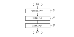
次に、本実施形態にかかる被加工物11の加工方法について説明する。図2は、本実施形態にかかる被加工物の加工方法のフロー図である。図2に示されるように、本実施形態にかかる被加工物の加工方法は、切削溝形成ステップS1と、第1研削ステップS2と、第2研削ステップS3と、を含む。
Next, the method for machining the
切削溝形成ステップS1では、上述した保護部材21が貼付された被加工物11が裏面11b側から切削され、被加工物11のデバイス15が形成された領域23の外縁に対応する部分に環状の切削溝が形成される。
In the cutting groove forming step S1, the
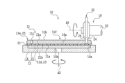
図3は、切削溝形成ステップS1において被加工物11が切削される様子を模式的に示す断面図である。図3に示されるように、この切削溝形成ステップS1では、切削装置10が使用される。
Figure 3 is a cross-sectional view that shows a schematic diagram of how the
切削装置10は、保護部材21が貼付された被加工物11を保持できるように構成されたチャックテーブル12を備えている。チャックテーブル12は、例えば、セラミックス等を用いて形成された円板状の枠体14を含む。枠体14の上面側には、円形状の開口を上端に持つ凹部14aが形成されている。この凹部14aには、セラミックス等を用いて多孔質の円板状に形成された保持板16が固定されている。
The
保持板16の上面16aは、被加工物11等を保持する保持面として機能する。本実施形態では、この保持板16の上面16aに、保護部材21の裏面21bが接触する。
The
保持板16の下面側は、枠体14の内部に設けられた流路14bや、枠体14の外部に配置されたバルブ(不図示)等を介して、エジェクタ等の吸引源(不図示)に接続されている。そのため、保持板16の上面16aに保護部材21の裏面21bを接触させた状態で、バルブを開き、吸引源の負圧を保持板16の上面16aに作用させると、保護部材21の裏面21bがチャックテーブル12により吸引される。
The lower side of the holding
すなわち、被加工物11は、裏面11bが上方に露出するように、保護部材21を介してチャックテーブル12に保持される。なお、被加工物11の表面11aに保護部材21が貼付されていない場合には、保持板16の上面16aに被加工物11の表面11aを直に接触させた上で、保持板16の上面16aに吸引源の負圧を作用させるようにバルブが開かれる。
That is, the
枠体14の下部には、モーター等の回転駆動源(不図示)が連結されている。チャックテーブル12は、この回転駆動源が生じる力によって、保持板16の上面16aの中心が回転の中心となるように、鉛直方向に対して平行な又は僅かに傾いた回転軸A2の周りに回転する。
A rotational drive source (not shown), such as a motor, is connected to the bottom of the
また、チャックテーブル12は、モーター等の回転駆動力を直線駆動力に変換するためのボールねじを備えたボールねじ式のチャックテーブル移動機構(不図示)により支持されている。チャックテーブル12は、このチャックテーブル移動機構の直線駆動力により、保持板16の上面16aに対して概ね平行な方向に沿って移動する。
The chuck table 12 is supported by a ball screw type chuck table movement mechanism (not shown) equipped with a ball screw for converting the rotational driving force of a motor or the like into a linear driving force. The chuck table 12 moves in a direction generally parallel to the
図3に示されるように、切削装置10は、チャックテーブル12の上方に配置された切削ユニット18を有する。切削ユニット18は、チャックテーブル12の上面16aに対して概ね平行な方向に沿って所定の長さを持つスピンドル20と、スピンドル20の先端に装着された切削ブレード22と、を有する。
As shown in FIG. 3, the cutting
スピンドル20は、モーター等の回転駆動源(不図示)に接続されている。スピンドル20は、この回転駆動源が生じる力によって、スピンドル20の中心を通り、スピンドル20の長さに沿う方向に平行な回転軸A5の周りに回転する。このスピンドル20とともに、スピンドル20の先端に装着された切削ブレード22も回転する。
The
切削ブレード22は、例えば、ステンレス等の金属により構成される環状の基台24と、環状の基台24の周縁部に設けられた環状の切刃26と、を有する。切刃26は、例えば、ダイヤモンド等でなる砥粒が、樹脂や金属等でなる結合材によって分散、固定されたものである。
The
切削ユニット18は、切削ユニット移動機構(不図示)に接続されている。切削ユニット18は、切削ユニット移動機構により、スピンドル20の回転軸A5に対して概ね平行な方向及びチャックテーブル12の回転軸A2に対して概ね平行な方向(鉛直方向)に沿って移動することができる。
The cutting
切削装置10は、上述した保護部材21が貼付された被加工物11をチャックテーブル12等へと搬送できる一又は複数の搬送機構(不図示)を有する。搬送機構は、例えば、ロボットアームである。保護部材21が貼付された被加工物11は、この搬送機構により、被加工物の裏面11b側が露出するようにチャックテーブル12に搬入される。また、保護部材21が貼付された被加工物11は、搬送機構により、チャックテーブル12から、チャックテーブル12の外部へ搬出される。
The cutting
切削溝形成ステップS1では、被加工物11が保護部材21を介してチャックテーブル12により保持される。具体的には、上述した搬送機構により、保護部材21が貼付された被加工物11の裏面11b側が露出するように、保護部材21の裏面21b側がチャックテーブル12に載置される。
In the cutting groove forming step S1, the
その後、保持板16の上面16aに吸引源の負圧を作用させると、保護部材21の裏面21bは、チャックテーブル12に吸引される。すなわち、保護部材21が貼付された被加工物11は、保護部材21を介してチャックテーブル12により保持される。なお、保護部材21が貼付された被加工物11は、オペレータ等によって手動でチャックテーブル12に載せられてもよい。
Then, when negative pressure from the suction source is applied to the
次に、切削ユニット18の切削ブレード22と被加工物11と、の位置の関係が調整される。具体的には、切削ブレード22が被加工物11のデバイス15が形成された領域23の外縁に対応する部分の上部に位置付けられるよう、被加工物11の位置がチャックテーブル移動機構及び切削ユニット移動機構により調整される。
Next, the positional relationship between the cutting
切削ブレード22と被加工物11と、の位置の関係が調整された後には、図3に示されるように、回転駆動源であるモーターが切削ブレード22を回転軸A5の周りに回転させた上で、切削ユニット移動機構が切削ブレード22を下降させる。また、チャックテーブル12に接続された回転駆動源が、切削ブレード22の下降に合わせてチャックテーブル12を回転軸A2の周りに回転させる。
After the positional relationship between the cutting
この様に、回転する切削ブレード22を下降させながら、チャックテーブル12を回転軸A2の周りに回転させることにより、被加工物11のデバイス15が形成された領域23の外縁に対応する部分に切削ブレード22の下端を切り込ませ、環状の切削溝が形成される。つまり、被加工物11の裏面11bの外周よりも裏面11bの中心側に位置し裏面11bの中心を囲む環状の部分に切削溝が形成される。
In this manner, by rotating the chuck table 12 around the rotation axis A2 while lowering the
切削ブレード22が目標の切り込み深さ(所定の高さ)に達すると、切削ユニット移動機構は、切削ブレード22の下降を停止させる。一方で、チャックテーブル12に接続された回転駆動源は、切削ブレード22の下降が停止した後に、チャックテーブル12を1周以上回転させる。
When the
このようにして被加工物11の上記環状の部分が裏面11bから表面11aに向かって所定の深さだけ切削ブレード22により切削され、除去されることにより、被加工物11に環状の切削溝11cが形成される。なお、切削ブレード22が下降するのではなく、チャックテーブル12が上昇することにより、切削ブレード22の下端が被加工物11の所定の深さまで切り込むようにしても良い。
In this way, the annular portion of the
例えば、切削ブレード22を下降させる速度(Z軸送り速度)は、0.001mm/s以上0.03mm/s以下に、チャックテーブル12の回転速度は、1deg/s以上10deg/s以下に、スピンドル20の回転速度は、10000rpm以上40000rpm以下に、それぞれ設定される。
For example, the speed at which the
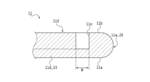
図4は、環状の切削溝11cが形成された後の被加工物11の一部を模式的に示す断面図である。上述した切削溝形成ステップS1により、被加工物11には、図4に示されるような切削溝11cが形成される。
Figure 4 is a cross-sectional view showing a schematic of a portion of the
図4に示されるように、本実施形態では、切削溝11cの底の高さが、最終的に得られる円板状の薄板部11dの上面の少なくとも一部の高さと一致するように、切削溝11cの目標の深さが決定される。この目標の深さに基づき、切削ブレード62の切り込み深さが決定される。これにより、切削溝11cの底の一部が、円板状の薄板部11dの上面(裏面11b側の面)の一部となる。
As shown in FIG. 4, in this embodiment, the target depth of the cutting
また、この切削溝11cの外側の側壁によって、環状の厚板部11eの内縁が規定される。そして、被加工物11の切削溝11cよりも内側の部分は、後の工程で研削される円板状の第1研削予定部11fとなる。
The outer side wall of the cutting
よって、切削ブレード22の厚みと実質的に同じになる切削溝11cの幅Wは、後の工程における研削の精度(研削される位置の精度)に合わせて、厚板部11eの内縁(切削溝11cの外側の側壁)に研削ホイール(研削砥石)が接触しない範囲で設定される。Wは、例えば、400μm以上800μm以下である。
Therefore, the width W of the cutting
このように、本実施形態の切削溝形成ステップS1では、裏面11bの中心を囲む環状の切削溝11cを被加工物11に形成することにより、切削溝11cよりも中心側に位置し、後に更に研削されることになる円板状の第1研削予定部11fと、切削溝11cよりも外周側に位置し、第1研削予定部11fを囲む環状の厚板部11eと、が得られる。
In this way, in the cutting groove forming step S1 of this embodiment, a ring-shaped
切削溝形成ステップS1の後に、第1研削ステップS2が実行される。第1研削ステップS2では、第1研削予定部11fを薄くするために、裏面11b側から第1研削予定部11fが粗研削される。図5は、第1研削ステップS2において被加工物11が研削される様子を模式的に示す断面図である。
After the cutting groove forming step S1, the first grinding step S2 is performed. In the first grinding step S2, the first grinding
図5に示されるように、研削装置2は、被加工物11を保持できるように構成されたチャックテーブル4を備えている。チャックテーブル4は、例えば、セラミックス等を用いて形成された円板状の枠体6を含む。枠体6の上面側には、円形状の開口を上端に持つ凹部6aが形成されている。この凹部6aには、セラミックス等を用いて多孔質の円板状に形成された保持板8が固定されている。
As shown in FIG. 5, the grinding device 2 is equipped with a chuck table 4 configured to hold a
保持板8の上面8aは、例えば、円錐の側面に相当する形状に構成されており、被加工物11等を保持する保持面として機能する。なお、円錐の頂点に相当する保持板8の上面8aの中心8bと、保持板8の上面8aの外縁と、の高さの差(高低差)は、一般的に、10μm以上30μm以下である。本実施形態では、この保持板8の上面8aに、保護部材21の裏面21bが接触する。
The
保持板8の下面側は、枠体6の内部に設けられた流路6bや、枠体6の外部に配置されたバルブ(不図示)等を介して、エジェクタ等の吸引源(不図示)に接続されている。そのため、保持板8の上面8aに保護部材21の裏面21bを接触させた状態で、バルブを開き、吸引源の負圧を保持板8の上面8aに作用させると、保護部材21の裏面21bがチャックテーブル4により吸引される。
The lower side of the holding
すなわち、被加工物11は、裏面11bが上方に露出するように、保護部材21を介してチャックテーブル4に保持される。なお、被加工物11の表面11aに保護部材21が貼付されていない場合には、保持板8の上面8aに被加工物11の表面11aを直に接触させた上で、保持板8の上面8aに吸引源の負圧を作用させるようにバルブが開かれる。
That is, the
枠体6の下部には、モーター等の回転駆動源(不図示)が連結されている。チャックテーブル4は、この回転駆動源が生じる力によって、上面8aの中心8bが回転の中心となるように、鉛直方向に対して平行な又は僅かに傾いた回転軸A1の周りに回転する。また、枠体6は、チャックテーブル移動機構(不図示)によって支持されており、チャックテーブル4は、このチャックテーブル移動機構が生じる力によって、水平方向に移動する。
A rotational drive source (not shown) such as a motor is connected to the bottom of the frame 6. The force generated by this rotational drive source rotates the chuck table 4 around a rotation axis A1 that is parallel to or slightly tilted from the vertical direction, so that the
図5に示されるように、研削装置2のチャックテーブル4よりも上方の位置には、第1研削ユニット(粗研削ユニット)30が配置されている。第1研削ユニット30は、例えば、筒状のスピンドルハウジング(不図示)を含む。スピンドルハウジングの内側の空間には、柱状のスピンドル32が収容されている。
As shown in FIG. 5, a first grinding unit (rough grinding unit) 30 is disposed above the chuck table 4 of the grinding device 2. The
スピンドル32の下端部には、例えば、被加工物11よりも小さな直径を持つ円板状のマウント34が設けられている。マウント34の下面には、マウント34と概ね直径が等しい円環状の第1研削ホイール(粗研削ホイール)36が、ボルト(不図示)等で固定されている。
At the lower end of the
第1研削ホイール36は、ステンレス鋼やアルミニウム等の金属を用いて形成された円環状のホイール基台38を含む。ホイール基台38の円環状の下面には、このホイール基台38の周の方向に沿って、複数の第1研削砥石(粗研削砥石)40が固定されている。
The
具体的には、複数の第1研削砥石40は、被加工物11の裏面11bの半径よりも小さな直径の円形状の領域(円周に沿った領域、又は円周よりも内側の領域)に配列されている。第1研削砥石40の幅(第1研削ホイール36の直径に沿った方向での長さ)は、例えば、1mm以上5mm以下、代表的には、3mmである。ただし、第1研削砥石40の幅は、必ずしもこの範囲に制限されない。
Specifically, the multiple
各第1研削砥石40は、例えば、ダイヤモンド等でなる砥粒が樹脂等でなる結合剤中に分散された構造を有している。本実施形態では、例えば、日本工業規格(JIS:Japanese Industrial Standards)R6001で定められる♯280~♯1000の粒度の砥粒を含む第1研削砥石40が使用される。なお、第1研削砥石40に含まれる砥粒の大きさ(粒度)は、これに限定されない。
Each
スピンドル32の上端側には、モーター等の回転駆動源(不図示)が連結されている。第1研削ホイール36は、この回転駆動源が生じる力によって、鉛直方向に対して平行な又は僅かに傾いた回転軸A3の周りに回転する。スピンドルハウジングは、例えば、第1研削ユニット移動機構(不図示)により支持されており、第1研削ユニット30は、この第1研削ユニット移動機構が生じる力で、鉛直方向に移動する。
A rotary drive source (not shown) such as a motor is connected to the upper end of the
第1研削ホイール36の傍又は第1研削ホイール36の内部には、被加工物11や第1研削砥石40等に対して研削用の液体(代表的には、水)を供給できるように構成されたノズル(不図示)が設けられている。被加工物11を研削する際には、このノズルから供給される研削用の液体により、第1研削砥石40が冷却され、また、被加工物11や第1研削砥石40から発生する屑が被加工物11の外部に排出される。
A nozzle (not shown) is provided next to or inside the
研削装置2は、上述した保護部材21が貼付された被加工物11をチャックテーブル4等へと搬送できる一又は複数の搬送機構(不図示)を有する。搬送機構は、例えば、ロボットアームである。保護部材21が貼付された被加工物11は、この搬送機構により、被加工物の裏面11b側が露出するようにチャックテーブル4に搬入される。また、保護部材21が貼付された被加工物11は、搬送機構により、チャックテーブル4から、チャックテーブル4の外部へ搬出される。
The grinding device 2 has one or more transport mechanisms (not shown) that can transport the
第1研削ステップS2では、被加工物11が保護部材21を介してチャックテーブル4により保持される。具体的には、上述した搬送機構により、保護部材21が貼付された被加工物11の裏面11b側が露出するように、保護部材21の裏面21b側がチャックテーブル4に載置される。
In the first grinding step S2, the
その後、裏面21bに吸引源の負圧を作用させると、保護部材21の裏面21bは、チャックテーブル4に吸引される。すなわち、保護部材21が貼付された被加工物11は、保護部材21を介してチャックテーブル4により保持される。なお、保護部材21が貼付された被加工物11は、オペレータ等によって手動でチャックテーブル4に載せられてもよい。
Then, when negative pressure from the suction source is applied to the
次に、第1研削ユニット30の直下にチャックテーブル4が移動する。より具体的には、全ての第1研削砥石40が切削溝11c又は第1研削予定部11fの直上に配置されるように、第1研削ホイール36と、チャックテーブル4(及び被加工物11)と、の位置の関係がチャックテーブル移動機構により調整される。
Next, the chuck table 4 moves directly below the first grinding
その後、チャックテーブル4と第1研削ホイール36とがそれぞれ回転し、第1研削ユニット30(第1研削ホイール36)が下降する。つまり、第1研削ホイール36と被加工物11とが相互に回転しながら、被加工物11の裏面11bと交差する方向に相対的に移動する。また、この際には、ノズルから被加工物11や第1研削砥石40等に液体が供給される。
Then, the chuck table 4 and the
これにより、図5に示されるように、第1研削砥石40が裏面11b側から被加工物11の第1研削予定部11fに接触し、この第1研削予定部11fの研削が開始される。本実施形態では、第1研削砥石40の下端が切削溝11cの底の位置よりも高い目標の高さの位置に達するまで、第1研削ユニット30(第1研削ホイール36)が下降する。つまり、本実施形態では、切削溝11cの底が第1研削砥石40により研削されない。
As a result, as shown in FIG. 5, the
なお、具体的な研削の条件に大きな制限はない。例えば、効率の良い第1研削予定部11fの研削を実現するためには、チャックテーブル4の回転数が、100rpm以上600rpm以下、代表的には、300rpmに設定され、第1研削ホイール36の回転数が、1000rpm以上7000rpm以下、代表的には、4500rpmに設定され、第1研削ユニット30の下降の速さ(研削送り速度)が、0.8μm/s以上10μm/s以下、代表的には、6μm/sに設定される。
There are no significant limitations on the specific grinding conditions. For example, to achieve efficient grinding of the first grinding
図6は、粗研削された後の被加工物11の一部を模式的に示す断面図である。図6に示されるように、第1研削予定部11fが研削されることによって、後の工程で更に研削される円板状の第2研削予定部11gが得られる。また、第2研削予定部11gの上面(裏面11b側の面、被研削面)側の部分には、傷又は歪を含むダメージ層11hが生じる。
Figure 6 is a cross-sectional view showing a schematic of a portion of the
なお、本実施形態では、第2研削予定部11g(ダメージ層11h)の上面(裏面11b側の面)が、例えば、切削溝11cの底から20μm以上100μm以下の高さ(距離)の位置、代表的には、切削溝11cの底から40μmの高さ(距離)の位置に形成されるように、被加工物11が研削される。これにより、後の仕上げ研削で除去される被加工物11の量が少なくなるので、研削の終了までに要する時間も短くなる。
In this embodiment, the
第1研削ステップS2の後に、第2研削ステップS3が実行される。第2研削ステップS3では、第2研削予定部11gに発生したダメージ層11hを除去するために、第2研削予定部11gが裏面11b側から仕上げ研削される。図7は、第2研削ステップS3において被加工物11が研削される様子を模式的に示す断面図である。
After the first grinding step S2, the second grinding step S3 is performed. In the second grinding step S3, the second grinding
図7に示されるように、研削装置2のチャックテーブル4よりも上方の位置には、第1研削ユニット30とは別の第2研削ユニット(仕上げ研削ユニット)50が配置されている。第2研削ユニット50は、例えば、筒状のスピンドルハウジング(不図示)を含む。スピンドルハウジングの内側の空間には、柱状のスピンドル52が収容されている。
As shown in FIG. 7, a second grinding unit (finish grinding unit) 50, which is separate from the first grinding
スピンドル52の下端部には、例えば、被加工物11よりも小さな直径を持つ円板状のマウント54が設けられている。マウント54の下面には、マウント54と概ね直径が等しい円環状の第2研削ホイール(仕上げ研削ホイール)56が、ボルト(不図示)等で固定されている。
At the lower end of the
第2研削ホイール56は、ステンレス鋼やアルミニウム等の金属を用いて形成された円環状のホイール基台58を含む。ホイール基台58の円環状の下面には、このホイール基台58の周の方向に沿って、複数の第2研削砥石(仕上げ研削砥石)60が固定されている。
The
具体的には、複数の第2研削砥石60は、被加工物11の裏面11bの半径よりも小さな直径の円形状の領域(円周に沿った領域、又は円周よりも内側の領域)に配列されている。第2研削砥石60の幅(第2研削ホイール56の直径に沿った方向での長さ)は、例えば、1mm以上5mm以下、代表的には、3mmである。ただし、第2研削砥石60の幅は、必ずしもこの範囲に制限されない。
Specifically, the multiple
各第2研削砥石60は、例えば、ダイヤモンド等でなる砥粒が樹脂等でなる結合剤中に分散された構造を有している。本実施形態では、例えば、日本工業規格(JIS:Japanese Industrial Standards)R6001で定められる♯2000~♯8000の粒度の砥粒を含む第2研削砥石60が使用される。
Each
すなわち、第2研削砥石60に含まれる砥粒の大きさ(平均粒径)は、第1研削砥石40に含まれる砥粒の大きさ(平均粒径)よりも小さい。なお、本明細書では、レーザー回折・散乱法によって測定される粒子径分布の積算50%における粒径(メディアン径、d50径、50%径)を平均粒径と呼ぶ。
That is, the size (average particle size) of the abrasive grains contained in the
このような第2研削砥石60を含む第2研削ホイール56で被加工物11が研削されると、第1研削ホイール36で被加工物11が研削される場合に比べて、単位時間当たりに被加工物11を除去できる量は少なくなるが、ダメージ層は生じ難い。一方で、第2研削砥石60に含まれる砥粒の大きさは、必ずしも上述の範囲に制限されない。第2研削砥石60は、少なくとも、第1研削砥石40に含まれる砥粒に比べて小さな粒径の砥粒を含んでいればよい。言い換えれば、第2研削砥石60は、少なくとも、第1研削砥石40に含まれる砥粒に比べて大きな砥粒を含まなければよい。
When the
スピンドル52の上端側には、モーター等の回転駆動源(不図示)が連結されている。第2研削ホイール56は、この回転駆動源が生じる力によって、鉛直方向に対して平行な又は僅かに傾いた回転軸A4の周りに回転する。スピンドルハウジングは、例えば、第2研削ユニット移動機構(不図示)により支持されており、第2研削ユニット50は、この第2研削ユニット移動機構が生じる力で、鉛直方向に移動する。
A rotary drive source (not shown) such as a motor is connected to the upper end of the
第2研削ホイール56の傍又は第2研削ホイール56の内部には、被加工物11や第2研削砥石60等に対して研削用の液体(代表的には、水)を供給できるように構成されたノズル(不図示)が設けられている。被加工物11を研削する際には、このノズルから供給される研削用の液体により、第2研削砥石60が冷却され、また、被加工物11や第2研削砥石60から発生する屑が被加工物11の外部に排出される。
A nozzle (not shown) is provided next to or inside the
第2研削ユニット50(第2研削ホイール56)で第2研削予定部11gを研削する際には、まず、第2研削ユニット50の直下にチャックテーブル4が移動する。より具体的には、全ての第2研削砥石60が切削溝11c又は第2研削予定部11gの直上に配置されるように、第2研削ホイール56と、チャックテーブル4(及び被加工物11)と、の位置の関係がチャックテーブル移動機構により調整される。
When grinding the second portion to be ground 11g with the second grinding unit 50 (second grinding wheel 56), the chuck table 4 first moves to a position directly below the second grinding
その後、チャックテーブル4と第2研削ホイール56とがそれぞれ回転し、第2研削ユニット50(第2研削ホイール56)が下降する。つまり、第2研削ホイール56と被加工物11とが相互に回転しながら、被加工物11の裏面11bと交差する方向に相対的に移動する。また、この際には、ノズルから被加工物11や第2研削砥石60等に液体が供給される。
Then, the chuck table 4 and the
これにより、図7に示されるように、第2研削砥石60が裏面11b側から被加工物11の第2研削予定部11gに接触し、この第2研削予定部11gの研削が開始される。本実施形態では、第2研削砥石60の下端が切削溝11cの底と同じ程度の高さの位置に達するまで、第2研削ユニット50(第2研削ホイール56)が下降する。なお、切削溝11cの底は、第2研削砥石60によりわずかに研削されてもよい。もちろん、切削溝11cの底の一部は、第2研削砥石60により研削されなくても良い。
As a result, as shown in FIG. 7, the
なお、具体的な研削の条件に大きな制限はない。例えば、効率が良く精度の高い被加工物11の研削を実現するためには、チャックテーブル4の回転数が、100rpm以上600rpm以下、代表的には、300rpmに設定され、第2研削ホイール56の回転数が、1000rpm以上7000rpm以下、代表的には、4000rpmに設定され、第2研削ユニット50の下降の速さ(研削送り速度)が、0.1μm/s以上0.8μm/s以下、代表的には、0.5μm/sに設定される。
There are no significant limitations on the specific grinding conditions. For example, to achieve efficient and highly accurate grinding of the
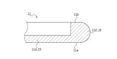
図8は、仕上げ研削された後の被加工物11の一部を模式的に示す断面図である。図8に示されるように、第2研削予定部11gが研削されることによって、ダメージ層11hが除去され、円板状の薄板部11dが完成する。上述のように、円板状の薄板部11dは、その上面の一部に切削溝11cの底を含んでいる。
Figure 8 is a cross-sectional view showing a schematic of a portion of the
以上のように、本実施形態にかかる被加工物の加工方法では、環状の厚板部11eの内縁を規定する環状の切削溝11cを、第1研削砥石40を用いる研削に比べて原理的にダメージ層が生じにくい切削ブレード22を用いる切削により形成する。このため、環状の切削溝11cの底には、少なくとも第1研削砥石40を用いる場合に生じるようなダメージ層11hが生じない。よって、環状の切削溝11cの底の全てを、円板状の薄板部11dの有効領域として取り扱うことができる。
As described above, in the method for processing the workpiece according to this embodiment, the
また、環状の切削溝11cを形成する際に切削装置10を用いて被加工物11から除去される部分の体積は、第1研削砥石40及び第2研削砥石60を用いて被加工物11から除去される部分の体積に比べて著しく小さい。このため、環状の切削溝11cを形成する際に要する時間は、被加工物11の研削が完了するまでに要する時間に比べて十分に短くなる。つまり、本実施形態にかかる被加工物の加工方法では、被加工物11の研削が完了するまでに要する時間が、従来の方法に比べて大幅に長くならない。
In addition, the volume of the portion removed from the
なお、本発明は、上述した実施形態の記載に制限されず種々変更して実施され得る。例えば、上述した実施形態では、第1研削ユニット30と第2研削ユニット50とを備える1台の研削装置2で被加工物11が研削されているが、被加工物11は、別の構造の1台又は複数台の研削装置で研削されてもよい。
The present invention is not limited to the above-described embodiment, and may be modified in various ways. For example, in the above-described embodiment, the
その他、上述した実施形態及び各変形例にかかる構造、方法等は、本発明の目的の範囲を逸脱しない限りにおいて適宜変更して実施され得る。 In addition, the structures, methods, etc. of the above-described embodiments and each modified example may be modified as appropriate without departing from the scope of the present invention.
11 :被加工物
11a :表面(第1面)
11b :裏面(第2面)
11c :切削溝
11d :薄板部
11e :厚板部
11f :第1研削予定部
11g :第2研削予定部
11h :ダメージ層
13 :ストリート(分割予定ライン)
15 :デバイス
21 :保護部材
21a :表面
21b :裏面
23 :デバイス領域
25 :外周余剰領域
2 :研削装置
4 :チャックテーブル
6 :枠体
6a :凹部
6b :流路
8 :保持板
8a :上面
8b :中心
10 :切削装置
12 :チャックテーブル
14 :枠体
14a :凹部
14b :流路
16 :保持板
16a :上面
18 :切削ユニット
20 ;スピンドル
22 :切削ブレード
24 :基台
26 :切刃
30 :第1研削ユニット(粗研削ユニット)
32 :スピンドル
34 :マウント
36 :第1研削ホイール(粗研削ホイール)
38 :ホイール基台
40 :第1研削砥石(粗研削砥石)
50 :第2研削ユニット(仕上げ研削ユニット)
52 :スピンドル
54 :マウント
56 :第2研削ホイール(仕上げ研削ホイール)
58 :ホイール基台
60 :第2研削砥石(仕上げ研削砥石)
A1 :回転軸
A2 :回転軸
A3 :回転軸
A4 :回転軸
A5 :回転軸
11:
11b: Back side (second side)
11c: Cut
15: Device 21:
32: Spindle 34: Mount 36: First grinding wheel (rough grinding wheel)
38: Wheel base 40: First grinding wheel (rough grinding wheel)
50: Second grinding unit (finish grinding unit)
52: Spindle 54: Mount 56: Second grinding wheel (finish grinding wheel)
58: Wheel base 60: Second grinding wheel (finishing grinding wheel)
A1: Rotation axis A2: Rotation axis A3: Rotation axis A4: Rotation axis A5: Rotation axis
Claims (3)
環状の切削ブレードを回転させた状態で、該被加工物の該第2面の外周よりも該第2面の中心側に位置し該第2面の該中心を囲む環状の部分に該切削ブレードを切り込ませ、該被加工物の該環状の部分に切削溝を形成することにより、該切削溝よりも該中心側に位置する円板状の第1研削予定部と、該切削溝よりも該外周側に位置する環状の該厚板部と、を該被加工物に形成する切削溝形成ステップと、
該切削溝形成ステップの後に、それぞれが砥粒を含む複数の第1研削砥石が該被加工物の半径よりも小さい直径を持つ円形状の領域に配列された第1研削ホイールと、該被加工物と、を回転させて該第1研削予定部を複数の該第1研削砥石により該切削溝の底に至らない深さまで研削することにより、該第1研削予定部よりも薄い円板状の第2研削予定部を形成する第1研削ステップと、
それぞれが該第1研削砥石に含まれる砥粒に比べて小さな砥粒を含む複数の第2研削砥石が該被加工物の半径よりも小さい直径を持つ円形状の領域に配列された第2研削ホイールと、該被加工物と、を回転させて該第2研削予定部を複数の該第2研削砥石により該切削溝の底に至る深さまで研削することにより、該第2研削予定部よりも薄い円板状の該薄板部を形成する第2研削ステップと、を含む被加工物の加工方法。 A method for processing a workpiece, the method being adapted for forming a disk-shaped thin plate portion and an annular thick plate portion surrounding the thin plate portion and thicker than the thin plate portion, by processing a workpiece having a circular first surface and a circular second surface opposite to the first surface, the method comprising:
a cutting groove forming step in which, while rotating an annular cutting blade, the cutting blade is cut into an annular portion of the second surface of the workpiece that is located closer to the center of the second surface than the outer periphery of the second surface and surrounds the center of the second surface, thereby forming a cutting groove in the annular portion of the workpiece, a disk-shaped first grinding portion located closer to the center than the cutting groove, and an annular thick plate portion located closer to the outer periphery than the cutting groove, in the workpiece;
a first grinding step of rotating a first grinding wheel, in which a plurality of first grinding stones each containing abrasive grains are arranged in a circular area having a diameter smaller than a radius of the workpiece, and the workpiece, and grinding the first portion to be ground with the plurality of first grinding stones to a depth not reaching the bottom of the cut groove, thereby forming a disk-shaped second portion to be ground that is thinner than the first portion to be ground;
a second grinding wheel in which a plurality of second grinding wheels, each containing smaller abrasive grains than the abrasive grains contained in the first grinding wheel, are arranged in a circular area having a diameter smaller than the radius of the workpiece; and a second grinding step of rotating the workpiece and grinding the second portion to be ground with the plurality of second grinding wheels to a depth reaching the bottom of the cutting groove, thereby forming a disk-shaped thin plate portion thinner than the second portion to be ground.
Priority Applications (1)
| Application Number | Priority Date | Filing Date | Title |
|---|---|---|---|
| JP2023148418A JP2025041242A (en) | 2023-09-13 | 2023-09-13 | Method for processing workpiece |
Applications Claiming Priority (1)
| Application Number | Priority Date | Filing Date | Title |
|---|---|---|---|
| JP2023148418A JP2025041242A (en) | 2023-09-13 | 2023-09-13 | Method for processing workpiece |
Publications (1)
| Publication Number | Publication Date |
|---|---|
| JP2025041242A true JP2025041242A (en) | 2025-03-26 |
Family
ID=95105056
Family Applications (1)
| Application Number | Title | Priority Date | Filing Date |
|---|---|---|---|
| JP2023148418A Pending JP2025041242A (en) | 2023-09-13 | 2023-09-13 | Method for processing workpiece |
Country Status (1)
| Country | Link |
|---|---|
| JP (1) | JP2025041242A (en) |
-
2023
- 2023-09-13 JP JP2023148418A patent/JP2025041242A/en active Pending
Similar Documents
| Publication | Publication Date | Title |
|---|---|---|
| JP4913517B2 (en) | Wafer grinding method | |
| JP6791579B2 (en) | Wafers and wafer processing methods | |
| KR20220139232A (en) | Method for processing workpiece | |
| JP2021150347A (en) | Grinding method | |
| CN115194581A (en) | Grinding method | |
| CN115246087A (en) | Grinding method | |
| US20230398654A1 (en) | Workpiece grinding method | |
| JP6120597B2 (en) | Processing method | |
| JP2025041242A (en) | Method for processing workpiece | |
| JP7828185B2 (en) | Grinding Method | |
| JP2024130077A (en) | Method for grinding a workpiece | |
| JP7704634B2 (en) | Method for grinding a workpiece | |
| JP7718825B2 (en) | Grinding method for workpiece | |
| JP7614711B2 (en) | Method for processing workpiece | |
| JP2024111879A (en) | Method for processing workpiece | |
| JP7684178B2 (en) | Method for grinding a workpiece | |
| TWI916532B (en) | Grinding methods | |
| TWI913439B (en) | Processing method of workpiece | |
| JP2024059330A (en) | Grinding wheel and work-piece grinding method | |
| JP2012182366A (en) | Method of removing chamfering portion of wafer | |
| JP2024062729A (en) | Grinding method for work-piece | |
| JP6980341B2 (en) | How to process the protective member | |
| JP2024021601A (en) | Grinding method of workpiece | |
| JP2014154773A (en) | Processing method |