JP2025041228A - Failure probability evaluation device - Google Patents
Failure probability evaluation device Download PDFInfo
- Publication number
- JP2025041228A JP2025041228A JP2023148400A JP2023148400A JP2025041228A JP 2025041228 A JP2025041228 A JP 2025041228A JP 2023148400 A JP2023148400 A JP 2023148400A JP 2023148400 A JP2023148400 A JP 2023148400A JP 2025041228 A JP2025041228 A JP 2025041228A
- Authority
- JP
- Japan
- Prior art keywords
- failure probability
- damage
- evaluation device
- time
- sensor
- Prior art date
- Legal status (The legal status is an assumption and is not a legal conclusion. Google has not performed a legal analysis and makes no representation as to the accuracy of the status listed.)
- Pending
Links
Images


Classifications
-
- G—PHYSICS
- G05—CONTROLLING; REGULATING
- G05B—CONTROL OR REGULATING SYSTEMS IN GENERAL; FUNCTIONAL ELEMENTS OF SUCH SYSTEMS; MONITORING OR TESTING ARRANGEMENTS FOR SUCH SYSTEMS OR ELEMENTS
- G05B23/00—Testing or monitoring of control systems or parts thereof
- G05B23/02—Electric testing or monitoring
- G05B23/0205—Electric testing or monitoring by means of a monitoring system capable of detecting and responding to faults
- G05B23/0259—Electric testing or monitoring by means of a monitoring system capable of detecting and responding to faults characterized by the response to fault detection
- G05B23/0283—Predictive maintenance, e.g. involving the monitoring of a system and, based on the monitoring results, taking decisions on the maintenance schedule of the monitored system; Estimating remaining useful life [RUL]
Landscapes
- Physics & Mathematics (AREA)
- General Physics & Mathematics (AREA)
- Engineering & Computer Science (AREA)
- Automation & Control Theory (AREA)
- Management, Administration, Business Operations System, And Electronic Commerce (AREA)
- Testing And Monitoring For Control Systems (AREA)
Abstract
Description
本発明は、複数の機械で使用された部品を対象とし、部品の故障確率を機械毎に評価する故障確率評価装置に関する。 The present invention relates to a failure probability evaluation device that targets parts used in multiple machines and evaluates the failure probability of parts for each machine.
発電、輸送、又はその他の産業用の機械において、所望の機能を発揮するために、各部品の故障リスクを把握し、各部品の保全(詳細には、修理や交換等)を適切なタイミングで実施することが重要である。特許文献1は、複数の機械で使用された部品を対象とし、部品の故障確率を機械毎に評価する故障確率評価システムを開示する。 In power generation, transportation, or other industrial machinery, in order to perform the desired functions, it is important to understand the failure risk of each part and perform maintenance (more specifically, repair, replacement, etc.) of each part at the appropriate time. Patent Document 1 discloses a failure probability evaluation system that targets parts used in multiple machines and evaluates the failure probability of each part for each machine.
特許文献1の故障確率評価システムは、複数の機械における部品の故障履歴データを記憶する故障履歴データベースと、複数の機械のセンサで時系列的に取得された稼動データを記憶する稼動データベースと、故障履歴データベース及び稼動データベースを用いて部品の故障確率関数を同定し、同定された故障確率関数を用いて部品の故障確率を機械毎に演算する演算部とを備える。 The failure probability evaluation system of Patent Document 1 includes a failure history database that stores failure history data of parts in multiple machines, an operation database that stores operation data acquired in time series by sensors of multiple machines, and a calculation unit that identifies a failure probability function of the parts using the failure history database and the operation database, and calculates the failure probability of the parts for each machine using the identified failure probability function.
演算部は、部品の故障履歴データから、部品の故障時間(詳細には、機械の初期又は前回の故障時から今回の故障時までの稼動時間)又は生存時間(機械の初期又は前回の故障時から現在までの稼動時間)を取得する。そして、稼動データをパラメータとするダメージモデルに対し、部品の故障時間又は生存時間に対応する期間で取得された稼動データを代入することにより、部品の累積ダメージを演算し、累積ダメージを説明変数とする故障確率関数を同定する。 The calculation unit obtains the part's failure time (more specifically, the operating time from the time of the machine's initial or previous failure to the time of the current failure) or survival time (the operating time from the time of the machine's initial or previous failure to the present) from the part's failure history data.The calculation unit then calculates the part's cumulative damage by substituting the operation data obtained for the period corresponding to the part's failure time or survival time into a damage model that uses the operation data as a parameter, and identifies a failure probability function that uses the cumulative damage as an explanatory variable.
特許文献1の故障確率評価システムでは、稼動データから得られた部品の累積ダメージを用いることにより、機械毎に異なる部品の負荷を考慮することで、部品の故障確率の評価精度を高めることが可能である。 The failure probability assessment system in Patent Document 1 uses the cumulative damage of parts obtained from operational data, and by taking into account the load on parts, which differs from machine to machine, it is possible to improve the accuracy of the assessment of the failure probability of parts.
ところで、機械においては、何らかの理由により、初期に設置されなかったセンサを追加する場合がある。この場合、追加のセンサで取得された稼動データは、センサの設置後に存在するものの、センサの設置前に存在しない。 However, for some reason, a sensor that was not initially installed may be added to a machine. In this case, the operational data acquired by the additional sensor exists after the sensor is installed, but does not exist before the sensor is installed.
例えば、部品の故障がセンサの設置前に発生し、その後、部品を保全して現在まで故障が発生しない場合、部品の故障時間として、機械の初期から部品の故障時までの時間が得られ、部品の生存時間として、部品の故障時から現在までの時間が得られる。追加のセンサで取得された稼動データは、前述した部品の故障時間に対応しないし、前述した部品の生存時間の一部に対応しない。そのため、追加のセンサで取得された稼動データを活用することができない。したがって、故障確率関数の同定精度の点で改善の余地がある。 For example, if a part failure occurs before the sensor is installed, and the part is subsequently maintained and no failure occurs to date, the part failure time is the time from the start of the machine to the time of part failure, and the part survival time is the time from the time of part failure to the present. The operation data acquired by the additional sensor does not correspond to the aforementioned part failure time, nor does it correspond to a part of the aforementioned part survival time. Therefore, the operation data acquired by the additional sensor cannot be utilized. Therefore, there is room for improvement in terms of the accuracy of identifying the failure probability function.
本発明は、上記事柄に鑑みてなされたものであり、その目的は、部品の故障確率関数の同定精度を向上して、部品の故障確率の評価精度を向上することができる故障確率評価装置を提供することにある。 The present invention has been made in consideration of the above, and its purpose is to provide a failure probability evaluation device that can improve the accuracy of identifying the failure probability function of a part and improve the evaluation accuracy of the failure probability of the part.
上記目的を達成するために、本発明は、複数の機械で使用された部品を対象とし、前記部品の故障確率を前記機械毎に評価する故障確率評価装置において、前記複数の機械における前記部品の保全履歴データを記憶する保全履歴データベースと、前記複数の機械のセンサで時系列的に取得された稼動データを記憶する稼動データベースと、前記保全履歴データベース及び前記稼動データベースを用いて前記部品の故障確率関数を同定し、同定された前記故障確率関数を用いて前記部品の故障確率を前記機械毎に演算する演算装置とを備え、前記演算装置は、前記稼動データをパラメータとするダメージモデルを用いて、前記センサの設置後の前記部品のダメージの推移を演算し、前記センサの設置後の前記部品のダメージの推移を学習して、前記センサの設置前の前記部品のダメージの推移を推定し、前記センサの設置後の前記部品のダメージの推移と前記センサの設置前の前記部品のダメージの推移のうちの少なくとも一方に基づき、前記部品の累積ダメージを演算し、前記累積ダメージを用いて、前記故障確率関数を同定する。 In order to achieve the above object, the present invention provides a failure probability evaluation device for evaluating the failure probability of a part used in a plurality of machines for each of the machines, the failure probability evaluation device comprising: a maintenance history database for storing maintenance history data of the part in the plurality of machines; an operation database for storing operation data acquired in a time series manner by a sensor of the plurality of machines; and a calculation device for identifying a failure probability function of the part using the maintenance history database and the operation database, and calculating the failure probability of the part for each of the machines using the identified failure probability function. The calculation device calculates the progress of damage to the part after the sensor is installed using a damage model with the operation data as a parameter, learns the progress of damage to the part after the sensor is installed, estimates the progress of damage to the part before the sensor is installed, calculates the cumulative damage to the part based on at least one of the progress of damage to the part after the sensor is installed and the progress of damage to the part before the sensor is installed, and identifies the failure probability function using the cumulative damage.
本発明によれば、部品の故障確率関数の同定精度を向上して、部品の故障確率の評価精度を向上することができる。 The present invention improves the accuracy of identifying the component failure probability function, thereby improving the accuracy of evaluating the component failure probability.
上述した以外の課題、構成及び効果は、以下の説明によって明らかにされる。 Other issues, configurations and advantages will become clearer in the following explanation.
本発明の一実施形態を、図面を参照しつつ説明する。 One embodiment of the present invention will be described with reference to the drawings.
図1は、本実施形態における故障確率評価装置の構成を表すブロック図である。 Figure 1 is a block diagram showing the configuration of the failure probability evaluation device in this embodiment.
本実施形態の故障確率評価装置100は、複数の機械1(本実施形態では風力発電機)で使用された部品を対象とし、部品の故障確率を機械1毎に評価するものである。故障確率評価装置100は、保全履歴データベース11、稼動データベース12、演算装置13、入力装置14、及び通信装置15を備える。
The failure
保全履歴データベース11及び稼動データベース12は、ハードディスク等の記憶装置で構成されている。演算装置13は、プログラムに基づいて処理を実行するプロセッサと、処理の中間結果又は最終結果を一次的に記憶するメモリとを有する。入力装置14は、キーボード及びディスプレイ等の入出力インターフェイスで構成されている。通信装置15は、複数の機械1との通信ネットワーク(詳細には、衛星通信ネットワーク、インターネット、又はイントラネット等)に接続する通信インターフェイスで構成されている。
The maintenance history database 11 and the
保全履歴データベース11は、入力装置14を介し入力された複数の機械1における部品の保全履歴データを記憶する。なお、機械1が部品の故障を検出してそれに関する情報を保全履歴データとして送信する機能を有すれば、保全履歴データベース11は、通信装置15で受信された複数の機械1における部品の保全履歴データを記憶してもよい。
The maintenance history database 11 stores maintenance history data of parts in multiple machines 1 that is input via the
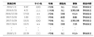
保全履歴データは、例えば図2で示すように、データ項目として、保全実施日時、機械1の設置サイト(サイト名)、機械1の識別番号(号機)、保全対象の部品(部品名)、保全動機(事象)、及び保全内容を有し、それらの情報の組合せであるレコードで構成されている。保全内容の「事後保全」は、部品の故障や異常が発生して保全したことを意味し、保全内容の「事前保全」は、部品の故障や異常が発生しなくても保全したことを意味する。保全履歴データは、保全内容が「事後保全」であるレコード(言い換えれば、故障履歴データ)だけでなく、保全内容が「事前保全」であるレコードを含んでおり、それらを活用することにより、後述する故障確率関数の同定精度を高めることが可能である。 As shown in FIG. 2, for example, the maintenance history data has the following data items: date and time of maintenance, installation site of machine 1 (site name), identification number of machine 1 (unit number), part to be maintained (part name), motivation for maintenance (event), and maintenance content, and is composed of records that are combinations of this information. Maintenance content of "reactive maintenance" means that maintenance was performed after a part failure or abnormality occurred, and maintenance content of "proactive maintenance" means that maintenance was performed even if no part failure or abnormality occurred. Maintenance history data includes not only records with "reactive maintenance" maintenance content (in other words, failure history data) but also records with "proactive maintenance" maintenance content, and by utilizing them, it is possible to improve the accuracy of identifying the failure probability function described below.
複数の機械1は、例えば温度、風速、及び発電量等をセンサで時系列的に取得し、それらを稼動データとして送信する。稼動データベース12は、通信装置15で受信された複数の機械1の稼働データを記憶する。
The multiple machines 1 use sensors to acquire, for example, temperature, wind speed, and power generation amount in chronological order and transmit them as operation data. The
稼動データは、センサの計測値で構成されてもよいが、データ量の低減のため、所定時間(例えば1日)毎の統計値(例えば最大値、最小値、平均値、又は標準偏差等)で構成されてもよい。あるいは、後述するダメージモデルのパラメータとして用いやすいように、センサの計測値に基づいて演算された演算値で構成されてもよい。 The operational data may be composed of sensor measurement values, but may also be composed of statistical values (e.g., maximum values, minimum values, average values, standard deviations, etc.) for a given period of time (e.g., one day) to reduce the amount of data. Alternatively, the operational data may be composed of calculated values calculated based on the sensor measurement values so that they can be easily used as parameters for the damage model described below.
演算装置13は、上述した保全履歴データベース11及び稼動データベース12を用いて部品の故障確率関数を同定する機能を有する。演算装置13は、前述した機能に係わる構成として、保全時間・生存時間演算部16、ダメージモデル同定部17、ダメージ演算・推定部18、累積ダメージ演算部19、及び故障確率関数同定部20を有する。また、演算装置13は、同定された故障確率関数を用いて部品の故障確率を機械1毎に演算する機能を有する。演算装置13は、前述した機能に係わる構成として、故障確率演算部21及び累積ダメージ予測部22を有する。
The
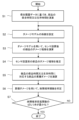
まず、故障確率関数を同定する機能について、図3を用いて説明する。図3は、本実施形態における故障確率関数を同定する処理の手順を表すフローチャートである。 First, the function of identifying the failure probability function will be described with reference to FIG. 3. FIG. 3 is a flowchart showing the procedure for identifying the failure probability function in this embodiment.
ステップS1にて、保全時間・生存時間演算部16は、対象の部品を設定する。そして、保全履歴データベース11で記憶された保全履歴データのうち、設定された部品名を含むレコードを抽出し、抽出されたレコードを機械1毎(詳細には、サイト名と号機の組合せ毎)に分類する。そして、機械1毎に分類されたレコードに含まれた保全実施日時に基づき、部品の事後保全時間(詳細には、機械1の初期又は前回の保全時から今回の事後保全時までの稼動時間)、事前保全時間(詳細には、機械1の初期又は前回の保全時から今回の事前保全時までの稼動時間)、又は生存時間(前回の保全時から現在までの稼動時間)を演算する。いずれかの機械1に対してレコード(言い換えれば、保全履歴)が存在しなければ、部品の生存時間として、機械1の初期から現在までの稼動時間を演算する。なお、以降、事後保全時間は、保全時間と称し、生存時間は、事前保全時間を含むものとして説明する。
In step S1, the maintenance time/survival
ステップS2にて、ダメージモデル同定部17は、設定された部品に関するダメージモデルd(Xt)の係数を設定する。ダメージモデルd(Xt)は、時間tでの稼働データXtをパラメータとして、単位時間あたりのダメージを算出するものである。時間tでの稼働データXtは、時間tでの値x1,x2,…,xmからなると仮定すれば、ダメージモデルd(Xt)は、例えば下記の式(1)で示すように、値x1,x2,…,xmを線形結合した式で表されてもよい。この場合、ダメージモデル同定部17は、係数c1,c2,…,cmを設定する。なお、ダメージモデルd(Xt)は、式(1)に限定されず、他の式(詳細には、稼動データが温度を含んでいれば、例えばアレニウスの式を組み込んだ式)で表されてもよい。
In step S2, the damage
![]()
![]()
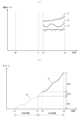
ステップS3に進み、ダメージ演算・推定部18は、稼動データベース12で記憶された各機械1の稼動データを上述したダメージモデルに代入することにより、各機械1の部品のダメージの推移を演算する。ここで、いずれかの機械1において、何らかの理由により、初期に設置されなかったセンサを追加している場合を想定する。この場合、図4(a)で示すように、追加のセンサで取得された値x1,x2,x3は、センサの設置時t2以降に存在するものの、それ以前に存在しない。そのため、図4(b)で示すように、値x1,x2,x3を含む稼動データをダメージモデルに代入して得られた部品のダメージの推移Aは、センサの設置時t2以降に存在するものの、それ以前に存在しない。
Proceeding to step S3, the damage calculation/
ステップS4に進み、ダメージ演算・推定部18は、センサの設置時t2以降の部品のダメージの推移Aを回帰分析又は時系列解析等で学習して、センサの設置時t2以前の部品のダメージの推移B(図4(b)参照)を推定する。
Proceeding to step S4, the damage calculation/
ステップS5に進み、累積ダメージ演算部19は、センサの設置後の部品のダメージの推移とセンサの設置前の部品のダメージの推移のうちの少なくとも一方に基づき、部品の保全時間又は生存時間に対応する部品の累積ダメージを演算する。図4(b)を用いて、具体的に説明する。
The process proceeds to step S5, where the cumulative
部品の事後保全がセンサの設置前に実施されていれば、部品の保全時間として、機械1の初期t0から部品の事後保全時t1までの時間が得られ、部品の生存時間として、部品の事後保全時t1から現在t3までの時間が得られる。累積ダメージ演算部19は、センサの設置時t2以前の部品のダメージの推移Bに基づき、機械1の初期t0から部品の事後保全時t1までの累積ダメージD01を演算し、それを前述した部品の保全時間に対応する累積ダメージとする。また、累積ダメージ演算部19は、センサの設置時t2以前の部品のダメージの推移Bに基づき、部品の事後保全時t1からセンサの設置時t2までの累積ダメージD12を演算し、センサの設置時t2以降の部品のダメージの推移Aに基づき、センサの設置時t2から現在t3までの累積ダメージD23を演算し、累積ダメージD12と累積ダメージD23の和を前述した部品の生存時間に対応する累積ダメージとする。
If the post-maintenance of the part is performed before the sensor is installed, the time from the initial time t0 of the machine 1 to the time t1 of the post-maintenance of the part is obtained as the maintenance time of the part, and the time from the time t1 of the post-maintenance of the part to the present time t3 is obtained as the survival time of the part. The cumulative
ステップS6に進み、故障確率関数同定部20は、公知の最尤推定法又はベイズ推定法などにより、部品の保全時間に対応する累積ダメージと、部品の生存時間に対応する累積ダメージとを用いて、累積ダメージDをパラメータとした故障確率関数F(D)を同定する。最尤推定法では、下記の式(2)で定義される対数尤度和Lを最大化するように、故障確率関数の母数を探索する。式中のfは、故障確率関数F(D)を微分して得られた故障確率密度関数である。式の右辺第一項は、部品の保全時間に対応する累積ダメージについての尤度を、第二項は部品の生存時間に対応する累積ダメージについての尤度を表している。
Proceeding to step S6, the failure probability
![]()
![]()
ステップS7に進み、故障確率関数同定部20は、故障確率密度関数fのばらつきが所定値以下であるかどうかにより、故障確率密度関数fのばらつきが最小化されたかどうかを判定する。故障確率密度関数fのばらつきが最小化されていない場合、ステップS2に戻る。すなわち、故障確率関数同定部20は、ダメージモデルd(Xt)の係数を変更する指令をダメージモデル同定部17へ出力する。ダメージモデル同定部17は、前述した指令に応じてダメージモデルd(Xt)の係数を変更する。
Proceeding to step S7, the failure probability
その後、上述したステップS3~S6が行われ、ステップS7に移る。ステップS7にて、故障確率関数同定部20は、故障確率密度関数fのばらつきが所定値以下であるかどうかにより、故障確率密度関数fのばらつきが最小化されたかどうかを判定する。これは、故障確率密度関数fのばらつきが大きい(図5で示すように、故障確率関数のばらつきが大きい)ということは、故障発生予測区間に幅があることを意味しており、予測区間幅を極小化して次回故障発生日時を精度よく推定するためにはばらつきを小さくする必要があるからである。故障確率関数のばらつきは、変動係数(故障確率関数の標準偏差と平均値の比)により評価できる(特許文献1参照)。更に、故障確率密度関数fのばらつきが所定値以上であっても、ばらつきの変化率が所定値以下であるかどうかにより、故障確率密度関数fのばらつきが最小化されたかどうかを判定する。故障確率密度関数fのばらつきが最小化された場合、ダメージモデル同定部17によるダメージモデルd(Xt)の同定(係数の設定)や、故障確率関数同定部20による故障確率関数F(D)の同定が完了する。
After that, the above-mentioned steps S3 to S6 are performed, and the process proceeds to step S7. In step S7, the failure probability
本実施形態では、ダメージモデルd(Xt)を定義すると、それに伴いダメージ演算・推定部18が外挿により推定する累積ダメージ(図4(b)の累積ダメージD01や累積ダメージD12に相当)も変化する。一般的に外挿は内挿よりも推定精度が低下するが、本発明では、外挿結果を用いて故障確率関数を同定し、その故障確率密度関数fのばらつきを小さくすることで対象を故障に至らしめる真のメカニズムに基づく累積ダメージモデルに近づけていくことにより、外挿結果への補正機能が働くため、推定精度を担保可能となる。
In this embodiment, when the damage model d(Xt) is defined, the cumulative damage (corresponding to the cumulative damage D01 and cumulative damage D12 in FIG. 4(b)) estimated by the damage calculation/
次に、同定された故障確率関数F(D)を用いて部品の故障確率を機械1毎に演算する機能について、詳細を説明する。 Next, we will explain in detail the function of calculating the component failure probability for each machine 1 using the identified failure probability function F(D).
故障確率演算部21は、対象の機械1や部品を設定する。そして、現在の故障確率を演算する場合に累積ダメージ演算部19へ指令を出力する。累積ダメージ演算部19は、前述した指令に応じて、設定された機械1や部品に関し、現在までの累積ダメージDaを演算する。詳細には、部品の保全履歴がなければ、機械1の初期から現在までの累積ダメージDaを演算し、部品の保全履歴があれば、前回の保全時から現在までの累積ダメージDaを演算する。故障確率演算部21は、故障確率関数同定部20で同定された故障確率関数F(D)に対し、累積ダメージ演算部19で演算された現在までの累積ダメージDaを代入することにより、現在の故障確率Paを演算する。
The failure
故障確率演算部21は、将来(例えばユーザによって設定された期間Δt経過後)の故障確率を演算する場合に累積ダメージ演算部19及び累積ダメージ予測部22へ指令を出力する。累積ダメージ演算部19は、前述した指令に応じて、設定された機械1や部品に関し、現在までの累積ダメージDaを演算する。累積ダメージ予測部22は、前述した指令に応じて、設定された機械1や部品に関し、期間Δtの累積ダメージDbを予測する。詳細には、例えば、稼動データベース12で記憶された稼動データを回帰分析又は時系列解析等で学習して、期間Δtの稼動データを予測する。そして、ダメージモデル同定部17で同定されたダメージモデルに対し、期間Δtの稼動データを代入することにより、期間Δtの部品のダメージの推移を予測する。そして、期間Δtの部品のダメージの推移に基づき、期間Δtの累積ダメージDbを予測する。故障確率演算部21は、故障確率関数同定部20で同定された故障確率関数F(D)と、累積ダメージ演算部19で演算された現在までの累積ダメージDaと、累積ダメージ予測部22で予測された期間Δtの累積ダメージDbとを用いて、将来の故障確率Pbを演算する(下記の式(3)参照)。
The failure
![]()
![]()
以上のように、本実施形態の故障確率評価装置100は、機械1に追加されたセンサで取得された稼動データを活用して、部品の故障確率関数を同定することができる。したがって、部品の故障確率関数の同定精度を向上して、部品の故障確率の評価制度を向上することができる。
As described above, the failure
本実施形態の故障確率評価装置100は、演算装置13で演算された部品の故障確率を含むデータを、例えばユーザインターフェイス23、運用計画システム24、及び部品在庫管理システム25へ出力する。ユーザインターフェイス23は、例えば機械1の所有者、運用会社、又は保険会社が所有している。
The failure
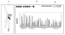
ユーザインターフェイス23は、例えば携帯端末であって、演算装置13と協働して動作する。ユーザインターフェイス23は、例えば図6で示す画面を表示する。この画面は、部品設定部31、期間設定部32、及び故障確率表示部33を有する。部品設定部31は、機械1の構成を模式的に示すと共に、対象の部品(例えば増速機)をユーザが設定可能である。期間設定部32は、現在からの期間Δtをユーザが設定可能である。故障確率表示部33は、部品設定部31で設定された部品に関し、期間設定部32で設定された期間Δt経過後の故障確率を表示する。
The
運用計画システム24は、部品の故障確率に応じて、機械1の運用計画を変更可能である。例えば、次回の定期点検時における部品の故障確率が想定より高ければ、部品の延命を図るため、機械1を積極的に停止させるか、若しくは、機械1の出力を抑制する。運用計画システム24は、運用計画を変更する場合にその情報を故障確率評価装置100へ出力する。演算装置13の累積ダメージ予測部22は、前述した情報に基づき、部品の累積ダメージの予測を変更する。これに伴い、演算装置13の故障確率演算部21は、将来の故障確率を変更して出力する。
The
なお、上記一実施形態において、故障確率評価装置100は、1つの演算装置13を備えた場合を例にとって説明したが、これに限られず、複数の演算装置を備えてもよい。すなわち、保全時間・生存時間演算部16、ダメージモデル同定部17、ダメージ演算・推定部18、累積ダメージ演算部19、故障確率関数同定部20、故障確率演算部21、及び累積ダメージ予測部22は、複数の演算装置で構成されてもよい。
In the above embodiment, the failure
また、上記一実施形態において、機械1は、風力発電機である場合を例にとって説明したが、これに限られないことは言うまでもない。 In the above embodiment, the machine 1 is described as a wind power generator, but it goes without saying that the present invention is not limited to this.
1 機械
11 保全履歴データベース
12 稼動データベース
13 演算装置
100 故障確率評価装置
Reference Signs List 1 Machine 11
Claims (6)
前記複数の機械における前記部品の保全履歴データを記憶する保全履歴データベースと、
前記複数の機械のセンサで時系列的に取得された稼動データを記憶する稼動データベースと、
前記保全履歴データベース及び前記稼動データベースを用いて前記部品の故障確率関数を同定し、同定された前記故障確率関数を用いて前記部品の故障確率を前記機械毎に演算する演算装置とを備え、
前記演算装置は、
前記稼動データをパラメータとするダメージモデルを用いて、前記センサの設置後の前記部品のダメージの推移を演算し、
前記センサの設置後の前記部品のダメージの推移を学習して、前記センサの設置前の前記部品のダメージの推移を推定し、
前記センサの設置後の前記部品のダメージの推移と前記センサの設置前の前記部品のダメージの推移のうちの少なくとも一方に基づき、前記部品の累積ダメージを演算し、
前記累積ダメージを用いて、前記故障確率関数を同定することを特徴とする故障確率評価装置。 1. A failure probability evaluation device for evaluating a failure probability of a part used in a plurality of machines for each of the machines, comprising:
a maintenance history database storing maintenance history data for the parts in the plurality of machines;
an operation database that stores operation data acquired in time series by sensors of the plurality of machines;
a calculation device that identifies a failure probability function of the part using the maintenance history database and the operation database, and calculates a failure probability of the part for each machine using the identified failure probability function,
The computing device includes:
Calculating a change in damage to the component after the sensor is installed using a damage model that uses the operational data as a parameter;
A change in damage to the component after the sensor is installed is learned, and a change in damage to the component before the sensor is installed is estimated;
calculating cumulative damage to the component based on at least one of a change in damage to the component after installation of the sensor and a change in damage to the component before installation of the sensor;
A failure probability evaluation apparatus, comprising: a failure probability function identification unit that identifies the failure probability function by using the cumulative damage.
前記演算装置は、前記ダメージモデルを同定することを特徴とする故障確率評価装置。 2. The failure probability evaluation device according to claim 1,
The failure probability evaluation device is characterized in that the calculation device identifies the damage model.
前記演算装置は、前記故障確率関数を微分して得られる故障確率密度関数のばらつきが最小化するように、前記ダメージモデルを同定することを特徴とする故障確率評価システム。 3. The failure probability evaluation device according to claim 2,
The failure probability evaluation system, wherein the calculation device identifies the damage model so as to minimize the variation of a failure probability density function obtained by differentiating the failure probability function.
現在からの期間を設定可能なユーザインターフェイスを備え、
前記演算装置は、同定された前記故障確率関数を用いて前記期間経過後の前記部品の故障確率を演算し、前記ユーザインターフェイスに表示させることを特徴とする故障確率評価装置。 2. The failure probability evaluation device according to claim 1,
It has a user interface that allows you to set the period from the present,
The failure probability evaluation device, wherein the calculation device calculates the failure probability of the part after the period has elapsed using the identified failure probability function and displays the calculated failure probability on the user interface.
前記演算装置は、
前記機械の初期又は前記部品の保全時から現在までの前記部品の累積ダメージを演算し、
前記稼動データを学習して前記期間の稼動データを予測し、前記ダメージモデルと前記期間の前記稼動データとを用いて前記期間の前記部品の累積ダメージを予測し、
同定された前記故障確率関数と、前記機械の初期又は前記部品の保全時から現在までの前記部品の累積ダメージと、前記期間の前記部品の累積ダメージとを用いて、前記期間経過後の前記部品の故障確率を演算することを特徴とする故障確率評価装置。 5. The failure probability evaluation device according to claim 4,
The computing device includes:
Calculating cumulative damage to the part from the time of initial maintenance of the machine or the part to the present;
predicting operation data for the period by learning the operation data, and predicting cumulative damage to the part for the period using the damage model and the operation data for the period;
A failure probability evaluation device characterized by calculating a failure probability of the part after the period has elapsed using the identified failure probability function, the cumulative damage of the part from the initial time of the machine or the time of maintenance of the part to the present, and the cumulative damage of the part during the period.
前記演算装置は、前記機械の運用計画を変更する運用計画システムからの情報に基づき、前記期間の前記部品の累積ダメージの予測を変更することを特徴とする故障確率評価装置。 6. The failure probability evaluation device according to claim 5,
A failure probability evaluation device characterized in that the calculation device changes the prediction of cumulative damage to the part for the period based on information from an operation planning system that changes the operation plan of the machine.
Priority Applications (3)
| Application Number | Priority Date | Filing Date | Title |
|---|---|---|---|
| JP2023148400A JP2025041228A (en) | 2023-09-13 | 2023-09-13 | Failure probability evaluation device |
| AU2024202349A AU2024202349B2 (en) | 2023-09-13 | 2024-04-11 | Failure probability evaluation apparatus |
| US18/657,991 US20250085704A1 (en) | 2023-09-13 | 2024-05-08 | Failure probability evaluation apparatus |
Applications Claiming Priority (1)
| Application Number | Priority Date | Filing Date | Title |
|---|---|---|---|
| JP2023148400A JP2025041228A (en) | 2023-09-13 | 2023-09-13 | Failure probability evaluation device |
Publications (2)
| Publication Number | Publication Date |
|---|---|
| JP2025041228A true JP2025041228A (en) | 2025-03-26 |
| JP2025041228A5 JP2025041228A5 (en) | 2026-02-12 |
Family
ID=94872420
Family Applications (1)
| Application Number | Title | Priority Date | Filing Date |
|---|---|---|---|
| JP2023148400A Pending JP2025041228A (en) | 2023-09-13 | 2023-09-13 | Failure probability evaluation device |
Country Status (3)
| Country | Link |
|---|---|
| US (1) | US20250085704A1 (en) |
| JP (1) | JP2025041228A (en) |
| AU (1) | AU2024202349B2 (en) |
Family Cites Families (2)
| Publication number | Priority date | Publication date | Assignee | Title |
|---|---|---|---|---|
| US11892830B2 (en) * | 2020-12-16 | 2024-02-06 | Uptake Technologies, Inc. | Risk assessment at power substations |
| US11635753B1 (en) * | 2022-08-15 | 2023-04-25 | Dimaag-Ai, Inc. | Remaining useful life prediction for machine components |
-
2023
- 2023-09-13 JP JP2023148400A patent/JP2025041228A/en active Pending
-
2024
- 2024-04-11 AU AU2024202349A patent/AU2024202349B2/en active Active
- 2024-05-08 US US18/657,991 patent/US20250085704A1/en active Pending
Also Published As
| Publication number | Publication date |
|---|---|
| AU2024202349A1 (en) | 2025-03-27 |
| US20250085704A1 (en) | 2025-03-13 |
| AU2024202349B2 (en) | 2025-09-11 |
Similar Documents
| Publication | Publication Date | Title |
|---|---|---|
| JP6865189B2 (en) | Failure probability evaluation system and method | |
| JP6276732B2 (en) | Equipment maintenance management system and equipment maintenance management method | |
| US11796992B2 (en) | Condition-based method for malfunction prediction | |
| JP7145821B2 (en) | Failure probability evaluation system and method | |
| JP2020173551A (en) | Failure prediction device, failure prediction method, computer program, computation model learning method and computation model generation method | |
| JP2019185422A (en) | Failure prediction method, failure prediction device, and failure prediction program | |
| JP5413240B2 (en) | Event prediction system, event prediction method, and computer program | |
| JP6702297B2 (en) | Abnormal state diagnosis method and abnormal state diagnosis device | |
| US20160110653A1 (en) | Method and apparatus for predicting a service call for digital printing equipment from a customer | |
| US12130250B2 (en) | Failure prediction system | |
| US20220405717A1 (en) | Maintenance plan assistance method and maintenance plan assistance devic | |
| JP2020160528A (en) | Deterioration estimation device, learning device, deterioration estimation method, learning method, deterioration estimation program, and learning program | |
| CN111768080B (en) | A method and system for evaluating the completion progress of products in process | |
| JP7339861B2 (en) | Failure probability evaluation system | |
| JP2024057316A (en) | Failure probability evaluation system and failure probability evaluation method | |
| JP2025041228A (en) | Failure probability evaluation device | |
| CN116384876A (en) | Dynamic Inventory of Spare Parts Based on Wiener Process-Production Control Method, System and Medium | |
| EP4315074B1 (en) | Computer-implemented method for updating a model parameter for a model | |
| JP2021082207A (en) | Waste carry-in amount prediction device, waste carry-in amount prediction method, and waste carry-in amount prediction program | |
| Ing et al. | Approach for integrating condition monitoring information and forecasting methods to enhance spare parts supply chain planning | |
| JP2024094823A (en) | Fault assessment system, fault assessment method, and fault assessment program | |
| JP7604341B2 (en) | Maintenance Support System | |
| JP2025030356A (en) | Information processing device and information processing method | |
| CN114868090A (en) | Information processing device, information processing method, and information processing program | |
| CN121190043A (en) | Equipment intelligent operation and maintenance method and system based on long-term and short-term memory network |
Legal Events
| Date | Code | Title | Description |
|---|---|---|---|
| A521 | Request for written amendment filed |
Free format text: JAPANESE INTERMEDIATE CODE: A523 Effective date: 20260203 |
|
| A621 | Written request for application examination |
Free format text: JAPANESE INTERMEDIATE CODE: A621 Effective date: 20260203 |