JP2025040407A - Accessory device having hidden internal button feature - Patents.com - Google Patents
Accessory device having hidden internal button feature - Patents.com Download PDFInfo
- Publication number
- JP2025040407A JP2025040407A JP2024145775A JP2024145775A JP2025040407A JP 2025040407 A JP2025040407 A JP 2025040407A JP 2024145775 A JP2024145775 A JP 2024145775A JP 2024145775 A JP2024145775 A JP 2024145775A JP 2025040407 A JP2025040407 A JP 2025040407A
- Authority
- JP
- Japan
- Prior art keywords
- button
- accessory device
- pillar
- sidewall
- lip
- Prior art date
- Legal status (The legal status is an assumption and is not a legal conclusion. Google has not performed a legal analysis and makes no representation as to the accuracy of the status listed.)
- Granted
Links
Images


Classifications
-
- A—HUMAN NECESSITIES
- A45—HAND OR TRAVELLING ARTICLES
- A45C—PURSES; LUGGAGE; HAND CARRIED BAGS
- A45C11/00—Receptacles for purposes not provided for in groups A45C1/00-A45C9/00
-
- H—ELECTRICITY
- H01—ELECTRIC ELEMENTS
- H01H—ELECTRIC SWITCHES; RELAYS; SELECTORS; EMERGENCY PROTECTIVE DEVICES
- H01H13/00—Switches having rectilinearly-movable operating part or parts adapted for pushing or pulling in one direction only, e.g. push-button switch
- H01H13/02—Details
- H01H13/12—Movable parts; Contacts mounted thereon
- H01H13/14—Operating parts, e.g. push-button
-
- A—HUMAN NECESSITIES
- A45—HAND OR TRAVELLING ARTICLES
- A45C—PURSES; LUGGAGE; HAND CARRIED BAGS
- A45C11/00—Receptacles for purposes not provided for in groups A45C1/00-A45C9/00
- A45C11/002—Receptacles for purposes not provided for in groups A45C1/00-A45C9/00 for storing portable handheld communication devices, e.g. pagers or smart phones
-
- H—ELECTRICITY
- H01—ELECTRIC ELEMENTS
- H01H—ELECTRIC SWITCHES; RELAYS; SELECTORS; EMERGENCY PROTECTIVE DEVICES
- H01H13/00—Switches having rectilinearly-movable operating part or parts adapted for pushing or pulling in one direction only, e.g. push-button switch
- H01H13/02—Details
-
- H—ELECTRICITY
- H01—ELECTRIC ELEMENTS
- H01H—ELECTRIC SWITCHES; RELAYS; SELECTORS; EMERGENCY PROTECTIVE DEVICES
- H01H13/00—Switches having rectilinearly-movable operating part or parts adapted for pushing or pulling in one direction only, e.g. push-button switch
- H01H13/02—Details
- H01H13/04—Cases; Covers
-
- H—ELECTRICITY
- H04—ELECTRIC COMMUNICATION TECHNIQUE
- H04B—TRANSMISSION
- H04B1/00—Details of transmission systems, not covered by a single one of groups H04B3/00 - H04B13/00; Details of transmission systems not characterised by the medium used for transmission
- H04B1/38—Transceivers, i.e. devices in which transmitter and receiver form a structural unit and in which at least one part is used for functions of transmitting and receiving
- H04B1/3827—Portable transceivers
- H04B1/3888—Arrangements for carrying or protecting transceivers
-
- A—HUMAN NECESSITIES
- A45—HAND OR TRAVELLING ARTICLES
- A45C—PURSES; LUGGAGE; HAND CARRIED BAGS
- A45C11/00—Receptacles for purposes not provided for in groups A45C1/00-A45C9/00
- A45C11/003—Receptacles for purposes not provided for in groups A45C1/00-A45C9/00 for storing portable computing devices, e.g. laptops, tablets or calculators
-
- A—HUMAN NECESSITIES
- A45—HAND OR TRAVELLING ARTICLES
- A45C—PURSES; LUGGAGE; HAND CARRIED BAGS
- A45C2200/00—Details not otherwise provided for in A45C
Landscapes
- Engineering & Computer Science (AREA)
- Computer Networks & Wireless Communication (AREA)
- Signal Processing (AREA)
- Casings For Electric Apparatus (AREA)
- Telephone Set Structure (AREA)
- Input From Keyboards Or The Like (AREA)
Abstract
Description
関連出願の相互参照
本出願は、2023年9月11日に出願された、「ACCESSORY DEVICE WITH CONCEALED INTERNAL BUTTONS FEATURES」と題する米国特許仮出願第63/537,802号の利益を主張するものであり、同出願の全体が参照により本明細書に援用される。
CROSS-REFERENCE TO RELATED APPLICATIONS This application claims the benefit of U.S. Provisional Patent Application No. 63/537,802, entitled "ACCESSORY DEVICE WITH CONCEALED INTERNAL BUTTONS FEATURES," filed Sep. 11, 2023, which is incorporated by reference in its entirety.
本出願は、デバイス用のボタンに関し、より詳細には、アクセサリデバイスと間接的に結合されており、ボタンの内部特徴を隠すための改変を含むボタンに関する。 This application relates to a button for a device, and more particularly to a button that is indirectly coupled to an accessory device and includes modifications to hide the internal features of the button.
電子デバイス用のアクセサリデバイス(例えば、ケース)は、電子デバイスボタンに対応する場所に位置するボタンを含む。ボタンが静止位置又は非作動位置にあるとき、ボタンのいくつかの内部特徴(例えば、ボタンピラー)が、分布にわたっていくつかの場所で可視である場合がある。その結果、ユーザは内部特徴を見ることができ、したがってアクセサリデバイスの全体的な美観を低下させることがある。1つの解決法は、アクセサリデバイスの壁を厚くすることである。しかしながら、これは、所望の機能のために(例えば、電子デバイスボタンを作動させるために)アクセサリデバイスボタン上で必要とされる最小限の移動を妨げる場合がある。 An accessory device (e.g., a case) for an electronic device includes buttons located at locations corresponding to the electronic device buttons. When the buttons are in a rest or non-activated position, some internal features of the buttons (e.g., button pillars) may be visible in several locations across the distribution. As a result, a user may be able to see the internal features, thus degrading the overall aesthetics of the accessory device. One solution is to thicken the walls of the accessory device. However, this may prevent the minimum travel required on the accessory device buttons for the desired functionality (e.g., to activate the electronic device buttons).
本願の技術の特定の特徴を、添付の特許請求の範囲に示している。しかしながら、説明を目的として、本願の技術のいくつかの実施形態を、以下の図に示している。 Particular features of the present technology are set forth in the appended claims. However, for purposes of illustration, some embodiments of the present technology are shown in the following figures.
以下に記載されている詳細な説明は、主題の技術の様々な構成の説明として意図されており、主題の技術が実施され得る唯一の構成を表すことは意図されていない。添付の図面は本明細書に組み込まれており、詳細な説明の一部を構成する。詳細な説明は、主題の技術の完全な理解を提供するために特定の詳細を含む。しかしながら、主題の技術は、本明細書において説明されている特定の詳細に限定されず、これらの特定の詳細なしに実施され得ることが当業者には明確であり、明らかであろう。いくつかの例では、主題の技術の概念を不明瞭にすることを避けるために、周知の構造体及び構成要素がブロック図の形態で示されている。 The detailed description set forth below is intended as a description of various configurations of the subject technology and is not intended to represent the only configurations in which the subject technology may be practiced. The accompanying drawings are incorporated in this specification and constitute a part of the detailed description. The detailed description includes specific details to provide a thorough understanding of the subject technology. However, it will be clear and apparent to those skilled in the art that the subject technology is not limited to the specific details described herein and may be practiced without these specific details. In some instances, well-known structures and components are shown in block diagram form to avoid obscuring the concepts of the subject technology.
本願の技術は、アクセサリデバイス及びアクセサリデバイス用のボタンに関する。本明細書に図示及び/又は記載される「ボタン」は、電子デバイスのスイッチ、トリガ、又は他の同様の機能を動作させる(例えば、作動させる)ことができる押しボタン、タッチセンサなどを含んでもよい。より詳細には、本願の技術は、アクセサリデバイスと間接的に結合されているボタンに関する。「間接的に結合さていれる」という句は、ボタンが、アクセサリデバイスの壁(例えば、側壁)を含むアクセサリデバイスに物理的に接触していない「浮遊」ボタンであるような、ボタン及びアクセサリデバイスの両方に結合している介在構造又は構造のアセンブリを指し得る。非限定的な例として、本明細書に記載のボタンは、プレート(例えば、溶接プレート)によってアクセサリデバイスに間接的に結合されていてもよい。 The technology of the present application relates to accessory devices and buttons for accessory devices. The "buttons" shown and/or described herein may include push buttons, touch sensors, etc. that can operate (e.g., activate) switches, triggers, or other similar functions of an electronic device. More specifically, the technology of the present application relates to buttons that are indirectly coupled to an accessory device. The phrase "indirectly coupled" may refer to an intervening structure or assembly of structures that are coupled to both the button and the accessory device, such that the button is a "floating" button that is not in physical contact with the accessory device, including the walls (e.g., side walls) of the accessory device. As a non-limiting example, the buttons described herein may be indirectly coupled to the accessory device by a plate (e.g., a welded plate).
加えて、本願の技術は、ボタンの内部特徴を隠す(hide)、隠す(conceal)、又は別様に覆い隠すために、ボタン及び/又はアクセサリデバイスを改変することに関する。例えば、ボタンは、複数のピラーと、隣接するピラーの間の圧縮性部材(例えば、発泡体)とを含んでもよい。圧縮性部材は、ピラーの形状に適合し、ボタンの望ましくない移動を最小限に抑えながら、ボタンを通る光漏れを防止する。他の例示的な実装形態において、アクセサリデバイスは、側壁上に位置する圧縮性層を含んでもよい。圧縮性層は、ボタン又はその付近に傾斜を形成してもよく、それによって、ボタンとアクセサリデバイスとの間の空間を減少させる。有益なことに、本明細書に記載されるボタン及び/又はアクセサリデバイスに対する改変は、ユーザの注意をアクセサリデバイスの外部の美的特徴に集中させ、一方で、ユーザの注意を内部特徴から遠ざけることができる。 Additionally, the technology of the present application relates to modifying a button and/or accessory device to hide, conceal, or otherwise obscure internal features of the button. For example, the button may include a plurality of pillars and a compressible member (e.g., foam) between adjacent pillars. The compressible member conforms to the shape of the pillars to prevent light leakage through the button while minimizing undesired movement of the button. In other exemplary implementations, the accessory device may include a compressible layer located on a sidewall. The compressible layer may form a slope at or near the button, thereby reducing the space between the button and the accessory device. Beneficially, the modifications to the button and/or accessory device described herein can focus a user's attention on the exterior aesthetic features of the accessory device while directing the user's attention away from the internal features.
図1~図12を参照して、これらの実施形態及び他の実施形態を以下に説明する。しかしながら、当業者であれば、これらの図に関して本明細書に与えられた発明を実施するための形態は説明を目的とするものに過ぎず、限定するものとして解釈されるべきではないことを容易に理解するであろう。 These and other embodiments are described below with reference to Figures 1-12. However, those skilled in the art will readily appreciate that the detailed description of the invention provided herein with respect to these figures is for illustrative purposes only and should not be construed as limiting.
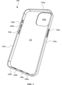
図1は、本開示の態様に係る、アクセサリデバイス100の斜視図を示す。アクセサリデバイス100は、非限定的な例として、スマートフォン及びタブレットコンピューティングデバイスなどの電子デバイスを含むモバイル無線通信デバイス用のケース又は保護カバーの形態をとってもよい。図示するように、アクセサリデバイス100は壁102を含む。壁102を底壁又は後壁と称する場合がある。アクセサリデバイス100は、壁102から延在するいくつかの壁を更に含んでもよい。例えば、アクセサリデバイス100は、壁104a、壁104b、壁104c、及び壁104dを含んでもよい。壁104a、104b、104c、及び104dの各々を、側壁と称する場合がある。集合的に、壁102並びに壁104a、104b、104c、及び104dは、モバイル無線通信デバイスを受容するための内部容積又は空間を形成するように組み合わされる。また、1つ以上の実装形態において、壁102並びに壁104a、104b、104c、及び104dは、非限定的な例として、織布又は編地から形成された織物層を含んでもよい。
FIG. 1 illustrates a perspective view of an
アクセサリデバイス100は、モバイル無線通信デバイスの1つ以上の特徴を収容するように設計されたいくつかの特徴を含んでもよい。例えば、アクセサリデバイス100は、ボタン106a、ボタン106b、及びボタン106cを含んでもよく、その各々は、作動/押下され、ボタン106a、106b、及び106cの各々がある壁に対してi移動するように設計されている。例えば、壁104a上にあるボタン106aは、壁104aに対して移動するように設計されている。また、モバイル無線通信デバイスがアクセサリデバイス100内に位置するとき、ボタン106a、106b、及び106cの各々は、モバイル無線通信デバイスの個別のボタンと整列してもよい。この点に関して、ボタン106a(ボタン106b及び106cの代表)の作動が、ボタン106aと整列した電子デバイスボタンの作動をもたらし得る。ボタン106aは壁104aに位置し、ボタン106b及び106cは壁104cに位置するが、ボタン106a、106b、及び106cは他の壁に位置してもよい。一般に、アクセサリデバイス100のボタンの数と場所は、モバイル無線通信デバイス上のボタンの数及び場所にそれぞれ対応してもよい。
The
アクセサリデバイス100は、モバイル無線通信デバイスを収容するように設計されたいくつかの追加の特徴を含んでもよい。例えば、アクセサリデバイス100は、画像センサ(例えば、カメラ)、カメラフラッシュなどのような特徴のための入力/出力機能のための周囲環境への妨げられないアクセス、並びに音、光、温度、圧力などを含むがこれらに限定されない電子デバイスのセンサ、コネクタ又は表面接触などによるデータ及び/又は電力の有線又は直接接触通信のための入力/出力ポートへの妨げられないアクセスを可能にするいくつかの開口部を含んでもよい。加えて、アクセサリデバイス100の開口部は、最適な性能のために周囲条件への非減衰、非消音、又は別様に非閉塞アクセスによって強化された電子デバイスの任意の他の部分又は部品へのアクセスを可能にし得る。図示するように、アクセサリデバイス100は、壁102に形成された開口部108aを含んでもよい。開口部108aは、モバイル無線通信デバイスの1つ以上のカメラ、カメラフラッシュ、及び/又はマイクロフォンを収容してもよい。アクセサリデバイス100は、壁104bに形成された開口部108b、開口部108c、及び開口部108dを更に含んでもよい。開口部108b、108c、及び108dの各々は、1つ以上のオーディオトランスデューサ(例えば、スピーカ、マイクロフォン)、及び/又はモバイル無線通信デバイスのバッテリの充電、及び/又はモバイル無線通信デバイスへの/からのデータ通信のために使用されるポートなどの、モバイル無線通信デバイスの特徴と整列してもよい。アクセサリデバイス100は、壁104cに形成された開口部108eを更に含んでもよい。開口部108eは、モバイル無線通信デバイスのスイッチ(例えば、スライダスイッチ)を収容してもよい。開口部108a、108b、108c、108d、及び108eは、別個の場所に示されているが、開口部108a、108b、108c、108d、及び108eは、一般に、モバイル無線通信デバイスの特徴を収容するためにアクセサリデバイス100上の任意の場所にあってもよい。
The
図2は、本開示の態様に係る、アクセサリデバイス100、及びアクセサリデバイス100内に位置する電子デバイス180の平面図を示す。電子デバイス180は、モバイル無線通信デバイスの形態をとってもよい。電子デバイス180は、ビジュアルコンテンツ(例えば、テキスト情報、静止画像、動画像)を提示するために設計されたディスプレイ182を含んでもよい。電子デバイス180は、例えば、ディスプレイ182上に提示されたオプションを選択すること、ディスプレイ182上のビジュアルコンテンツを変更すること、及び/又はディスプレイ182をアクティブ化/非アクティブ化することによって、ユーザがディスプレイ182と双方向作用できるように設計されたボタン184を更に含んでもよい。拡大図に示すように、アクセサリデバイス100のボタン106aは、ボタン184の場所と対応する場所にある。よって、ボタン106aは、ボタン184と整列されており、それを覆い、ボタン106aの作動は、ボタン184の対応する作動をもたらし得る。明示的に示されていないが、電子デバイス180は2つの追加のボタンを含んでもよく、アクセサリデバイス100のボタン106b及び106cは、2つのボタンの個別のボタンの対応する場所にあってもよい。
2 shows a plan view of an
図3は、本開示の態様に係る、ボタン106aの斜視図を示す。ボタン106aは、様々な材料から形成されていてもよい。例えば、1つ以上の実装形態において、ボタン106aは、金属(例えば、アルミニウム、ステンレス鋼、又はアルミニウム若しくはステンレス鋼を含む合金)から形成されている。ボタン106aは、表面110aを含んでもよい。ボタン106aがアクセサリデバイス(例えば、図1に示すアクセサリデバイス100)と一体化されている場合、表面110aは、ユーザが双方向作用し得る外部表面を表す。ボタン106aは、表面110aに対向する表面110bを更に含んでもよい。表面110a及び110bがボタン106aの一部であることに基づいて、表面110a及び110bの各々を、ボタン表面と称する場合がある。ボタン106aがアクセサリデバイスと一体化されている場合、表面110bは内部表面を表す。ボタン106aは、いくつかのピラーを更に含んでもよい。例えば、ボタン106aは、ピラー112a、ピラー112b、及びピラー112cを含んでもよく、これらの各々は、表面110bから延在している。ピラー112a、112b、及び112cは、モバイル無線通信デバイスボタン(図3に図示せず)を作動させることとともに使用されるボタン106aの延在部又は円柱を表し得る。1つ以上の実装形態において、ピラー112a、112b、及び112cの各々は、菱形形状に形成されている。ただし、他の形状が可能である。ピラー112a、112b、及び112cのサイズ及び/又は形状は、電子デバイスの対応するボタン又はセンサに従って変化し、特に、ボタン106aを作動又はトリガし得る、電子デバイスの対応するボタン又はセンサの機能に従って変化してもよい。また、ピラー112a、112b、及び112cは、概して、同じ形状を含むが、ピラー112b(ピラー112aと112cとの間にある)は、ピラー112a及び112cの各々のサイズ及び容積よりもそれぞれ大きいサイズ及び容積を含んでもよい。また、ピラー112a、112b、及び112cはボタン106aの3つのピラーを表しているが、ピラーの数は変化してもよい。例えば、1つ以上の実装形態において、2つのピラーがボタン106aから延在する。
FIG. 3 illustrates a perspective view of a
いくつかの圧縮性部材が、隣接又は連続するピラーの間でボタン106aと一体化されていてもよい。例えば、圧縮性部材114aは、ピラー112aとピラー112bとの間に位置してもよく、圧縮性部材114bは、ピラー112bとピラー112cとの間に位置してもよい。1つ以上の実装形態において、圧縮性部材114a及び114bの各々は発泡体を含む。この点に関して、圧縮性部材114a及び114bは、加えられた力に応じて変形するように設計されてもよい。ボタン106aがアクセサリデバイス100と一体化されている場合、圧縮性部材114a及び114bの各々は、アクセサリデバイス100が振られるか又は突然移動されるときにボタン106aの動きを制限又は防止し得る。有益なことに、圧縮性部材114a及び114bに基づいて、剛性材料(単数又は複数)(例えば、金属(単数又は複数))から形成されている場合があるボタン106aは、がたつきを受けにくく、望ましくないノイズを引き起こしにくい。
Some compressible members may be integrated with the
図4は、ボタン106aの平面図を示し、本開示の態様に係る、ボタン106aのピラー112a、112b、及び112cと、ピラー112a、112b、及び112cに対する圧縮性部材114a及び114bとを更に示す。1つ以上実装形態において、圧縮性部材114a及び114bの各々の形状は、複数のピラーの形状に適合するか、又は適応する。例えば、拡大図に示すように、ピラー112a及びピラー112bの各々は、それぞれ、凸面116a及び凸面116bを含む。よって、ピラー112a及び112b(並びにピラー112c)は、少なくとも1つの角丸を含んでもよい。ピラー112a及び112bのそれぞれの形状に適合するために、圧縮性部材114aは、凸面116a及び凸面116bにそれぞれ適合する凹面118a及び凹面118bを含む。圧縮性部材114aの凹面118a及び118bは、圧縮性部材114aが、ピラー112a及びピラー112bの各々と重なる、又は少なくとも部分的に重なることを可能にし得る。圧縮性部材114b並びにピラー112b及び112cは、互いに対して同様の関係を含み得る。この点に関して、矢印120によって表される方向に進行する光は、ピラー112a、112b、及び112cの間で、ボタン106aを通過することから遮断されるか、又は少なくとも実質的に遮断される。
4 shows a top view of
図5は、本開示の態様に係る、アクセサリデバイス100の壁104a、及び壁104aと結合するように設計されたボタン106aの斜視図を示す。図示するように、壁104aは、表面122a及び表面122bを含み、表面122bは、表面122aに対して面一以下(例えば、下)である。壁104aが側壁として特徴付けられることに部分的に起因して、表面122a及び122bの各々は、側壁表面として特徴付けら得る。壁104aは、表面122bを貫通して形成されたいくつかの開口部を更に含んでもよい。例えば、壁104aは、開口部124a、開口部124b、及び開口部124cを含む。1つ以上の実装形態において、開口部124a、開口部124b、及び開口部124cは、それぞれピラー112a、ピラー112b、及びピラー112cを受容するサイズ及び形状を含んでもよい。その結果、ボタン106aが壁104aと結合されていると、ピラー112a、ピラー112b、及びピラー112cは、それぞれ開口部124a、開口部124b、及び開口部124c内に位置するか、又は少なくとも部分的に位置する。
5 shows a perspective view of a
図6は、本開示の態様に係る、アクセサリデバイス100の壁104aと結合したボタン106aの断面図を示す。壁104aは、1つ以上の材料を含んでもよい。例えば、1つ以上の実装形態において、壁104aは、成形ポリマーシェルを含む。非限定的な例として、成形ポリマーシェルはポリエステルを含んでもよい。更に、壁104aは、成形ポリマーシェルを覆う織物層(例えば、織布、編地)を含んでもよい。また、圧縮性部材114a及び114bは、接着剤(図示されているが、符号は付されていない)によってボタン106aに固定されてもよい。
6 illustrates a cross-sectional view of
アクセサリデバイス100は、プレート126を含んでもよい。1つ以上の実装形態において、プレート126はシートメタルを含む。ボタン106aをアクセサリデバイス100に固定するために、プレート126をボタン106aに溶接されていてもよく、例えば、接着剤又は超音波溶接によってアクセサリデバイス100の壁104aにも結合されていてもよい。この点に関して、プレート126は、溶接プレートの形態をとってもよい。更に、壁104aは、プレート126と固定するように改変されてもよい。例えば、壁104aは、ボタン106aの周囲に延在するリップ128を含んでもよい。リップ128は、ボタン106aの内部特徴を隠す追加の材料を提供してもよい。図示するように、リップ128は、プレート126が壁104aにしっかり固定される表面を提供してもよい。また、ボタン106aは、ボタン106aの周囲に延在するレッジ129を含んでもよい。図示するように、レッジ129は、ボタン106aの他の特徴(例えば、ピラー112a、112b、及び112c)を越えて横方向に延在する追加の構造をボタン106aに提供してもよい。互いに向かって延在するリップ128及びレッジ129に基づいて、ボタン106aの内部特徴は更に、視界から隠され得る。溶接作業の跡又は他のしるしを覆うために、プレート126をラベル130で覆ってもよい。
The
図示するように、アクセサリデバイス100のボタン106aは、電子デバイス180のボタン184の上に位置する。この点に関して、ボタン106aが矢印132の方向に作動されるとき、ボタン106aは、ボタン184の作動を引き起こし得る。更に、アクセサリデバイス100及び/又は電子デバイス180の公差積み上げを低減するために、壁104aは、ボタン106aの周囲に延在するスタンドオフ134を更に含んでもよい。有利なことに、スタンドオフ134は、壁104aが比較的薄い壁を含むことを可能にし得る。また、スタンドオフ134は、アクセサリデバイス100から電子デバイス180を取り出すときに、ボタン184がアクセサリデバイス100に接触することも防止し得る。図示するように、スタンドオフ134は、リップ128に対して垂直であるか、又は少なくとも実質的に垂直である。スタンドオフ134は、非限定的な例として、成形ポリマー又はエラストマーを含んでもよい。
As shown, the
図7~図11は、アクセサリデバイス及び/又はアクセサリデバイスと一体化された特徴の代替例を示す及び/又は記載する。図7~図11に示され及び/又は記載されるアクセサリデバイスは、アクセサリデバイス100(図1~図6に示される)の少なくともいくつかの構造並びに関連する特徴及び機能を含んでもよい。また、1つ以上の実装形態において、アクセサリデバイス100は、図7~図11に示され及び/又は記載されるアクセサリデバイスの少なくともいくつかの構造並びに関連する特徴及び機能を含むように改変されてもよい。
FIGS. 7-11 show and/or describe alternative examples of accessory devices and/or features integrated therewith. The accessory devices shown and/or described in FIGS. 7-11 may include at least some of the structure and associated features and functionality of accessory device 100 (shown in FIGS. 1-6). Also, in one or more implementations,
図7は、本開示の態様に係る、ボタンに使用するためのシール240の斜視図を示す。図示するように、シール240は、リング又はリング状構造の形態をとってもよい。シール240は、非限定的な例として、ゴムなどの1つ以上の圧縮性材料から形成されていてもよい。図示するように、シール240は、部分242a及び部分242bを含む。
FIG. 7 illustrates a perspective view of a
図8は、本開示の態様に係る、アクセサリデバイス200用のボタン206の代替例の断面図を示し。ボタン206に結合したシール240を更に示す。図示するように、シール240の部分242aは、ボタン206の空洞(図示されているが、符号は付されていない)内に位置する。空洞は、非限定的な例として、Tカット操作などのボタン206に対する切断作業によって形成されていてもよい。部分242bは、ボタン206から延在する尾部の形態をとってもよい。シール240の位置、及び特にシール240の部分242bの位置に基づいて、シール240は、汚染物質及び/又は液体の侵入がアクセサリデバイス200内に位置する電子デバイス280に到達することを防止し得る。その上、シール240は、アクセサリデバイス200の少なくともいくつかの内部特徴(例えば、ボタン206の内部特徴)を隠す又は覆い隠してもよく、したがって、アクセサリデバイス200の内部特徴の可視性を低減する。
8 illustrates a cross-sectional view of an alternative example of a
更に図示するように、アクセサリデバイス200のボタン206は、電子デバイス280のボタン284と整列されている。ボタン206が矢印244の方向に作動されると、ボタン206は、ボタン284の対応する作動を引き起こし得る。シール240は、ボタン206とともに移動し、アクセサリデバイス200の壁204に接触し得るが、シール240は、それにもかかわらず、壁204に接触することに応答して圧縮及び/又は変形し得る。有利なことに、シール240は、ボタン206の移動に影響を与えることなく、壁204に比較的近接する位置にあってもよい。また、ボタン206とシール240は、異なる材料から形成されていてもよい。例えば、ボタン206は、剛性材料(例えば、金属)を含んでもよく、シール240は、非剛性材料(例えば、ゴム)を含んでもよい。
As further shown,
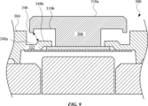
図9は、本開示の態様に係る、アクセサリデバイス300用のボタン306の代替例の断面図を示し、アクセサリデバイス300及びボタン306の両方に対する改変を示す。図示するように、ボタン306は、表面310aと、表面310aに対向する表面310bとを含む。ボタン306は、表面310bから延在する延在部346を更に含んでもよい。延在部346は、ボタン306の1つ以上の内部特徴を隠す又は覆い隠すために使用されるボタン306の追加材料を表し得る。また、延在部346は、ボタン306の周囲に延在してもよい。
9 illustrates a cross-sectional view of an alternative example of a
アクセサリデバイス300は、ボタン306の内部特徴を隠すための改変を含んでもよい。例えば、アクセサリデバイス300は、リップ332を含む壁304を含んでもよい。図示するように、リップ332は、異なる高さを有する異なるセクションを含む。例えば、リップ332は、ある高さのセクション348aと、セクション348aの高さとは異なる高さのセクション348bとを含んでもよい。図示するように、セクション348bは、セクション348aに対して高くなっている(例えば、より高い高さにある)。延在部346に対するリップ332のセクション348bの位置に基づいて、ギャップ(両側矢印によって表される)は、延在部又は高さのあるセクションを有さないアクセサリデバイスのギャップと比較して小さくなり得る。有利には、ギャップはより小さく、したがって、ボタン306の1つ以上の内部特徴を更に隠す。
The
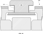
図10は、本開示の態様に係る、アクセサリデバイス400用のボタン406の代替例の断面図を示し、ボタン406に塗布されたコーティング450を示す。1つ以上の実装形態において、コーティング450は、コーティング450に入射する光の反射を最小限にするように設計された反射防止材料を含む。この点に関して、コーティング450は、入射光を受けて内部反射するように設計されたいくつかの小さな孔を含んでもよい。1つ以上の実装形態において、コーティング450は、コーティング450に入射する光を吸収するように設計された光吸収材料を含む。よって、コーティング450を、光吸収コーティングと称する場合がある。有益なことに、ボタン406上にコーティング450を実装することによって、ボタン406の少なくともいくつかの内部特徴をアクセサリデバイス400のユーザに可視性を低減させることをし得る。
FIG. 10 illustrates a cross-sectional view of an alternative example of a
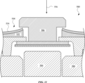
図11は、本開示の態様に係る、アクセサリデバイス500用のボタン506の代替例の断面図を示し、アクセサリデバイス500に塗布された圧縮性層552を示す。図示するように、アクセサリデバイス500は、圧縮性層552と織物層554とを含む壁504を含み、織物層554が圧縮性層552を覆っている。1つ以上の実装形態において、圧縮性層552は、非限定的な例として、独立気泡発泡体などの発泡体を含む。1つ以上の実装形態において、圧縮性層552は、比較的低いデュロメータを含むゴム又はプラスチックを含む。圧縮性層552は、(図11で方向づけられるように)ボタン506又はその下の場所において、傾斜し、厚さを変えてもよい(例えば、より厚くなる)。この点に関して、ボタン506と壁504との間のギャップは、減少し得、したがって、ボタン506の少なくともいくつかの内部特徴を隠す。圧縮性層552を隠すために、アクセサリデバイス500。1つ以上の実装形態において、織物層554は、織布又は編地を含む。
FIG. 11 illustrates a cross-sectional view of an alternative example of a
ボタン506を、矢印556の方向に作動させて、電子デバイス580のボタン584を作動させてもよい。結果として、ボタン506は、壁504(織物層554を含む)に係合してもよい。しかしながら、材料構成に基づいて、圧縮性層552は、圧縮され、サイズが縮小してもよく、したがって、ボタン506がボタン584を作動させることを可能にする。
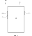
図12は、本開示の態様に係る、電子デバイス680の平面図を示す。電子デバイス680は、ディスプレイ682と、ディスプレイ682に結合したエンクロージャ686とを含んでもよい。電子デバイス680は、ボタン684a、ボタン684b、及びボタン684cなどのいくつかのボタンを更に含んでもよい。1つ以上の実装形態において、ボタン684a、684b、及び684cのうちの少なくとも1つは、本明細書で示す及び/又は記載するアクセサリデバイス(単数又は複数)用のボタンの1つ以上の特徴を含む。その結果、電子デバイス680は、アクセサリデバイス(単数又は複数)用の、本明細書で示す及び/又は記載するボタンの改変を受けるボタン684a、684b、及び684cのうちの1つ以上の少なくともいくつかの内部特徴を隠すように設計されてもよい。
12 illustrates a plan view of an
本開示の態様の様々な実施例は、便宜のための項目として以下に記載される。これらは例として提供されており、主題の技術を限定しない。 Various examples of aspects of the present disclosure are described below as a convenience section. These are provided as examples and are not intended to limit the subject technology.
項目A:アクセサリデバイスは、側壁を含んでもよい。アクセサリデバイスは、側壁に結合したボタンを更に含んでもよい。ボタンは、第1のボタン表面と、第1のボタン表面に対向する第2のボタン表面と、第2のボタン表面から延在する第1のピラーと、第2のボタン表面から延在する第2のピラーとを含んでもよい。アクセサリデバイスは、第1のピラーと第2のピラーとの間に位置する圧縮性部材を更に含んでもよい。 Item A: The accessory device may include a sidewall. The accessory device may further include a button coupled to the sidewall. The button may include a first button surface, a second button surface opposing the first button surface, a first pillar extending from the second button surface, and a second pillar extending from the second button surface. The accessory device may further include a compressible member located between the first pillar and the second pillar.
項目B:アクセサリデバイスは、側壁を含んでもよい。側壁は、第1の延在部と第2の延在部を含んでもよい。アクセサリデバイスは、側壁に結合したボタンを更に含んでもよい。ボタンは、第1のピラー、第2のピラー、及び第3のピラーを含んでもよい。第1の延在部は、第1のピラーと第2ピラーとの間に位置してもよく、第2の延在部は、第2のピラーと第3のピラーとの間に位置してもよい。 Item B: The accessory device may include a sidewall. The sidewall may include a first extension and a second extension. The accessory device may further include a button coupled to the sidewall. The button may include a first pillar, a second pillar, and a third pillar. The first extension may be located between the first pillar and the second pillar, and the second extension may be located between the second pillar and the third pillar.
項目C:アクセサリデバイスは、リップを含む側壁を含んでもよい。リップは、第1の高さにある第1のセクションと、第1の高さとは異なる第2の高さにある第2のセクションとを含んでもよい。アクセサリデバイスは、側壁に結合したボタンを含んでもよい。ボタンは、第1の表面と、第1の表面に対向する第2の表面と、第2の表面から延在する延在部を含んでもよい。延在部は、第1のセクションと整列してもよい。 Item C: The accessory device may include a sidewall including a lip. The lip may include a first section at a first height and a second section at a second height different from the first height. The accessory device may include a button coupled to the sidewall. The button may include a first surface, a second surface opposite the first surface, and an extension extending from the second surface. The extension may be aligned with the first section.
上記の項目のうちの1つ以上は、以下に記載される特徴のうちの1つ以上を含むことができる。以下のいずれかの項目は、互いに任意の組み合わせで組み合わされて、それぞれの独立した項目、例えば、A、B、又はCに含められてもよいことに留意されたい。 One or more of the above items may include one or more of the features described below. Please note that any of the following items may be combined with each other in any combination and included in each independent item, e.g., A, B, or C.
項目1:側壁は、第1の開口部と第2の開口部を含み、第1のピラー及び第2のピラーは、それぞれ、第1の開口部及び第2の開口部内に位置する。 Item 1: The sidewall includes a first opening and a second opening, and the first pillar and the second pillar are located within the first opening and the second opening, respectively.
項目2:側壁は、第1の側壁表面と、第1の側壁表面に対してほぼ面一である第2の側壁表面とを含む。第1の開口部及び第2の開口部は、第2の側壁表面に形成されていてもよい。 Item 2: The sidewall includes a first sidewall surface and a second sidewall surface that is substantially flush with the first sidewall surface. The first opening and the second opening may be formed in the second sidewall surface.
項目3:ボタン及び側壁に結合したプレートを更に含む。 Item 3: Further includes a plate attached to the button and the side wall.
項目4:第2の側壁表面はリップを画定し、プレートはリップに結合されている。 Item 4: The second sidewall surface defines a lip, and the plate is coupled to the lip.
項目5:圧縮性部材は、発泡体を含む。 Item 5: The compressible member includes a foam.
項目6:第1のピラーは第1の角丸を含み、第2のピラーは第2の角丸を含み、発泡体は第1の角丸と第2の角丸に適合する。 Item 6: The first pillar includes a first radius, the second pillar includes a second radius, and the foam fits between the first radius and the second radius.
項目7:ボタンと一体化されており、第2のボタン表面から延在するシールを更に含む。ボタンは、第1の材料を含んでもよく、シールは、第1の材料とは異なる第2の材料を含む。 Item 7: Further including a seal integral with the button and extending from the second button surface. The button may include a first material and the seal includes a second material different from the first material.
項目8:側壁は、第1の側壁表面と、第1の側壁表面に対して面一以下である第2の側壁表面とを更に含み、第1の延在部及び第2の延在部は、第2の側壁表面から延在する。 Item 8: The sidewall further includes a first sidewall surface and a second sidewall surface that is flush or less with the first sidewall surface, and the first extension and the second extension extend from the second sidewall surface.
項目9:側壁はリップを含み、ボタンは、リップを少なくとも部分的に覆うレッジを含む。 Item 9: The sidewall includes a lip and the button includes a ledge that at least partially covers the lip.
項目10:側壁はスタンドオフを更に含み、スタンドオフはリップに対して垂直である。 Item 10: The sidewall further includes a standoff, the standoff being perpendicular to the lip.
項目11:第1のピラーと第2のピラーとの間に位置する第1の圧縮性部材と、第2のピラーと第3のピラーとの間に位置する第2の圧縮性部材とを更に含む。 Item 11: Further includes a first compressible member located between the first pillar and the second pillar, and a second compressible member located between the second pillar and the third pillar.
項目12:第2のピラーは、第1のピラーと第3のピラーとの間に位置し、第1のピラー及び第3のピラーは、第1のサイズを含み、第2のピラーは、第1のサイズよりも大きい第2のサイズを含む。 Item 12: The second pillar is located between the first pillar and the third pillar, the first pillar and the third pillar include a first size, and the second pillar includes a second size that is larger than the first size.
項目13:ボタンの作動は、延在部に第1のセクションに向かって移動させる。 Item 13: Actuation of the button causes the extension to move toward the first section.
項目14:ボタンは、光吸収コーティングを含む。 Item 14: The button includes a light absorbing coating.
項目15:ボタンは、ピラーを更に含み、光吸収コーティングは、ピラー及び第2の表面上に位置する。 Item 15: The button further includes a pillar, and the light absorbing coating is located on the pillar and the second surface.
項目16:ピラーに適合する圧縮性部材を更に含む。 Item 16: Further includes a compressible member that fits into the pillar.
項目17:ボタンと第2のセクションに結合した溶接プレートを更に含む。 Item 17: Further includes a welded plate coupled to the button and the second section.
個人情報の使用は、ユーザのプライバシーを維持するための業界又は政府の要件を満たす又は超えるとして一般に認識されているプライバシーポリシー及びプラクティスに従うべきであることに十分に理解されている。特に、個人情報データは、意図されない又は認可されていないアクセス又は使用のリスクを最小にするように管理され取り扱われるべきであり、認可された使用の性質は、ユーザに明確に示されるべきである。 It is fully understood that use of personal information should comply with privacy policies and practices generally recognized as meeting or exceeding industry or government requirements for maintaining user privacy. In particular, personal information data should be managed and handled in a manner that minimizes the risk of unintended or unauthorized access or use, and the nature of authorized uses should be clearly indicated to users.
本明細書で使用するとき、一連の項目に先行する「少なくとも1つ」というフレーズは、項目のいずれかを分離する「及び」又は「又は」という用語とともに、リストの各要素(すなわち、各項目)ではなく、全体としてリストを修飾する。「少なくとも1つ」というフレーズは、リスト化された各項目の少なくとも1つの選択を必要とはせず、むしろ、そのフレーズは、項目のうちのいずれか1つの少なくとも1つ、及び/又は項目の任意の組み合わせのうちの少なくとも1つ、及び/又は項目のそれぞれのうちの少なくとも1つ、を含む意味を可能にする。例として、「A、B、及びCのうちの少なくとも1つ」又は「A、B、又はCのうちの少なくとも1つ」というフレーズは、それぞれが、Aのみ、Bのみ、又はCのみ、A、B、及びCの任意の組み合わせ、並びに/又は、A、B、及びCのそれぞれのうちの少なくとも1つを指す。 As used herein, the phrase "at least one" preceding a series of items, with the terms "and" or "or" separating any of the items, modifies the list as a whole, rather than each member (i.e., each item) of the list. The phrase "at least one" does not require the selection of at least one of each of the listed items; rather, the phrase allows for a meaning including at least one of any one of the items, and/or at least one of any combination of the items, and/or at least one of each of the items. By way of example, the phrases "at least one of A, B, and C" or "at least one of A, B, or C" refer, respectively, to only A, only B, or only C, any combination of A, B, and C, and/or at least one of each of A, B, and C.
「~ように構成された(configured to)」、「~ように動作可能な(operable to)」、及び「~ようにプログラムされた(programmed to)」という述語は、対象物の特有の有形又は無形の改変を意味するものではなく、むしろ交換可能に使用されることを意図している。1つ以上の実装形態では、動作若しくは構成要素を監視及び制御するように構成されたプロセッサとは、プロセッサが、動作を監視及び制御するようにプログラムされていること、又はプロセッサが、動作を監視及び制御するように動作可能であることも意味し得る。同様に、コードを実行するように構成されたプロセッサは、コードを実行するようにプログラムされた、又はコードを実行するように動作可能なプロセッサ、として解釈することができる。 The terms "configured to," "operable to," and "programmed to" do not imply any specific tangible or intangible modification of the subject matter, but rather are intended to be used interchangeably. In one or more implementations, a processor configured to monitor and control operations or components may also mean that the processor is programmed to monitor and control operations or that the processor is operable to monitor and control operations. Similarly, a processor configured to execute code may be interpreted as a processor programmed to execute code or operable to execute code.
ある要素が別の要素に「接続されている」又は「結合されている」と本明細書で言及されるとき、それらの要素は、他の要素に直接接続されている場合、又はそれらの要素の間に存在する介在要素を有し得ることを理解されたい。対照的に、要素が別の要素に「直接接続されている」又は「直接結合されている」と言及される場合、要素間の「直接」接続に介在要素が存在しないことを理解されたい。しかしながら、直接接続の存在は、介在要素が存在し得る他の接続を排除するものではない。 When an element is referred to herein as being "connected" or "coupled" to another element, it should be understood that the elements may be directly connected to the other element or may have intervening elements present between them. In contrast, when an element is referred to as being "directly connected" or "directly coupled" to another element, it should be understood that there are no intervening elements present in the "direct" connection between the elements. However, the presence of a direct connection does not exclude other connections in which intervening elements may be present.
一態様、その態様、別の態様、いくつかの態様、1つ以上の態様、一実装形態、その実装形態、別の実装形態、いくつかの実装形態、1つ以上の実装形態、一実施形態、その実施形態、別の実施形態、いくつかの実施形態、1つ以上の実施形態、一構成、その構成、別の構成、いくつかの構成、1つ以上の構成、主題の技術、開示、本開示、それらの他の変形、及び同様のフレーズは、便宜上のものであり、そのようなフレーズ(単数又は複数)に関する開示が主題の技術に不可欠であること、又はそのような開示が主題の技術のすべての構成に適用されること、の意味を含むものではない。そのようなフレーズ(単数又は複数)に関する開示は、すべての構成、又は1つ以上の構成に適用することができる。そのようなフレーズ(単数又は複数)に関する開示は、1つ以上の例を提供することができる。態様又はいくつかの態様などのフレーズは、1つ以上の態様を指すことができ、その逆も同様であり、これは他の前述のフレーズと同様に適用される。 The phrases "an aspect," "another aspect," "some aspects," "one or more aspects," "an implementation," "an implementation," "some implementation," "one or more implementations," "one embodiment," "another embodiment," "some embodiments," "one or more embodiments," "a configuration," "another configuration," "some configuration," "one or more configurations," the subject technology, the disclosure, the disclosure, other variations thereof, and similar phrases are used for convenience and do not imply that the disclosure of such phrase(s) is essential to the subject technology or that such disclosure applies to all configurations of the subject technology. The disclosure of such phrase(s) may apply to all configurations, or to one or more configurations. The disclosure of such phrase(s) may provide one or more examples. Phrases such as "aspect" or "some aspects" may refer to one or more aspects, and vice versa, as with the other aforementioned phrases.
単語「例示的(exemplary)」は、本明細書において、「例、事例、又は実例の役割を果たすこと」を意味するために使用される。「例示的」又は「例」として本明細書で説明されたいかなる実施形態も、必ずしも他の実施形態を超えて好ましい又は有利であると解釈されるべきではない。更に、「含む(include)」、「有する(have)」などの用語が明細書又は特許請求の範囲で使用される限りにおいて、そのような用語は、「含む/備える(comprise)」が特許請求の範囲において移行語として使用されるときに解釈されるように、「含む/備える」という用語と同様の方法で包括的であることを意図する。 The word "exemplary" is used herein to mean "serving as an example, instance, or illustration." Any embodiment described herein as "exemplary" or "example" is not necessarily to be construed as preferred or advantageous over other embodiments. Moreover, to the extent that terms such as "include," "have," and the like are used in the specification or claims, such terms are intended to be inclusive in a similar manner as the term "comprise" is interpreted when "comprise" is used as a transitional term in the claims.
当業者に知られているか又は後に知られるようになる、本開示を通じて説明される様々な態様のエレメントに対するすべての構造的及び機能的な均等物は、参照により明示的に本明細書に組み込まれ、かつ、特許請求の範囲に包含されるものと意図する。更に、本明細書で開示されたいかなるものも、そのような開示が特許請求の範囲に明白に列挙されているかどうかにかかわらず、公に供するものではない。いかなる特許請求の範囲のエレメントも、エレメントがフレーズ「手段(means for)」を使用して明示的に列挙するか、又は方法の請求項の場合には、エレメントがフレーズ「ステップ(step for)」を使用して列挙しない限り、米国特許法第112条第6パラグラフの規定に基づいて解釈されるべきではない。 All structural and functional equivalents to the elements of the various aspects described throughout this disclosure that are known or that later become known to those skilled in the art are expressly incorporated herein by reference and are intended to be encompassed by the claims. Furthermore, nothing disclosed herein is made public, regardless of whether such disclosure is expressly recited in the claims. No claim element is to be construed under the provisions of 35 U.S.C. 112, sixth paragraph, unless the element is expressly recited using the phrase "means for" or, in the case of a method claim, the element is recited using the phrase "step for."
前述の説明は、本明細書で説明した様々な態様を当業者が実施することを可能にするために提供される。これらの態様に対する様々な変更は、当業者には容易に明らかであり、本明細書で定義される一般的な原理は、他の態様にも適用することができる。それゆえ、請求項は、本明細書に示される態様への限定を意図しておらず、文言による請求項に合致した全範囲を認められるべきであり、単数形によるエレメントへの言及は、特に断りのない限り、「唯一の(one and only one)」を意味することを意図しておらず、むしろ、「1つ以上の(one or more)」を意味することを意図している。特記しない限り、「いくつかの(some)」という用語は、1つ以上のものを指す。男性形(例えば、彼)の代名詞は、女性及び中性の性別(例えば、彼女及びその)を含み、並びにその逆も同様である。もしあれば、見出し及び小見出しは、便宜上のみに使用され、本願の開示を限定するものではない。 The foregoing description is provided to enable one skilled in the art to practice the various aspects described herein. Various modifications to these aspects will be readily apparent to those skilled in the art, and the general principles defined herein may be applied to other aspects. Thus, the claims are not intended to be limited to the aspects set forth herein, but are to be accorded the full scope consistent with the claims as literalized, and references to elements in the singular are not intended to mean "one and only one" unless otherwise specified, but rather "one or more." The term "some" refers to one or more unless otherwise specified. Pronouns in the masculine (e.g., he) include the feminine and neuter genders (e.g., she and its), and vice versa. Headings and subheadings, if any, are used for convenience only and are not intended to limit the disclosure of this application.
Claims (20)
側壁と、
前記側壁に結合したボタンであって、前記ボタンは、
第1のボタン表面と、
前記第1のボタン表面に対向する第2のボタン表面と、
前記第2のボタン表面から延在する第1のピラーと、
前記第2のボタン表面から延在する第2のピラーと、を含む、ボタンと、
前記第1のピラーと前記第2のピラーとの間に位置する圧縮性部材と、を備えるアクセサリデバイス。 1. An accessory device, comprising:
A side wall;
a button coupled to the sidewall, the button comprising:
a first button surface;
a second button surface opposite the first button surface;
a first pillar extending from the second button surface;
a second pillar extending from the second button surface; and
a compressible member located between the first pillar and the second pillar.
第1の側壁表面と、
前記第1の側壁表面に対して面一以下である第2の側壁表面とを含み、
前記第1の開口部及び前記第2の開口部は、前記第2の側壁表面に形成されている、請求項2に記載のアクセサリデバイス。 The side wall is
a first sidewall surface;
a second sidewall surface that is flush or less with the first sidewall surface;
The accessory device of claim 2 , wherein the first opening and the second opening are formed in the second sidewall surface.
前記プレートは、前記リップに結合している、
請求項4に記載のアクセサリデバイス。 the second sidewall surface defines a lip;
The plate is coupled to the lip.
The accessory device of claim 4.
前記第2のピラーは、第2の角丸を含み、
前記発泡体は、前記第1の角丸及び前記第2の角丸に適合する、
請求項6に記載のアクセサリデバイス。 the first pillar includes a first radius;
the second pillar includes a second rounded corner;
the foam conforms to the first radius and the second radius;
The accessory device of claim 6.
前記ボタンは第1の材料を含み、
前記シールは、前記第1の材料とは異なる第2の材料を含む、請求項1に記載のアクセサリデバイス。 a seal integral with the button and extending from the second button surface;
the button comprises a first material;
The accessory device of claim 1 , wherein the seal comprises a second material that is different from the first material.
側壁であって、前記側壁は、
第1の延在部と、
第2の延在部と、を含む、側壁と、
前記側壁に結合したボタンと、を備え、前記ボタンは、
第1のピラーと、
第2のピラーと、
第3のピラーと、を含み、
前記第1の延在部は、前記第1のピラーと前記第2のピラーとの間に位置し、
前記第2の延在部は、前記第2のピラーと前記第3のピラーとの間に位置する、アクセサリデバイス。 1. An accessory device, comprising:
A side wall, the side wall comprising:
A first extension portion;
a sidewall including a second extension;
a button coupled to the side wall, the button comprising:
A first pillar;
A second pillar; and
a third pillar;
the first extension portion is located between the first pillar and the second pillar,
The accessory device, wherein the second extension portion is located between the second pillar and the third pillar.
第1の側壁表面と、
前記第1の側壁表面に対してほぼ面一である第2の側壁表面とを更に含み、前記第1の延在部及び前記第2の延在部が前記第2の側壁表面から延在する、
請求項9に記載のアクセサリデバイス。 The side wall is
a first sidewall surface;
a second sidewall surface that is generally flush with the first sidewall surface, the first extension and the second extension extending from the second sidewall surface.
10. The accessory device of claim 9.
前記ボタンは、前記リップを少なくとも部分的に覆うレッジを含む、請求項9に記載のアクセサリデバイス。 the sidewall includes a lip;
The accessory device of claim 9 , wherein the button includes a ledge that at least partially covers the lip.
前記スタンドオフは、前記リップに対して垂直である、
請求項11に記載のアクセサリデバイス。 the sidewall further comprises a standoff;
the standoff is perpendicular to the lip;
The accessory device of claim 11.
前記第2のピラーと前記第3のピラーとの間に位置する第2の圧縮性部材と、
を更に備える請求項9に記載のアクセサリデバイス。 a first compressible member located between the first pillar and the second pillar;
a second compressible member located between the second pillar and the third pillar;
The accessory device of claim 9 further comprising:
前記第1のピラー及び前記第3のピラーは、第1のサイズを含み、
前記第2のピラーは、前記第1のサイズよりも大きい第2のサイズを含む、
請求項9に記載のアクセサリデバイス。 the second pillar is located between the first pillar and the third pillar,
the first pillar and the third pillar include a first size;
the second pillar includes a second size greater than the first size.
10. The accessory device of claim 9.
リップを備える含む側壁であって、前記リップは、
第1の高さにある第1のセクションと、
前記第1の高さとは異なる第2の高さにある第2のセクションとを含む、側壁と、
前記側壁に結合したボタンと、を備え、前記ボタンは、
第1の表面と、
前記第1の表面に対向する第2の表面と、
前記第2の表面から延在する延在部とを含み、前記延在部は前記第1のセクションと整列されている、ボタンと、を備える、アクセサリデバイス。 1. An accessory device, comprising:
a sidewall including a lip, the lip comprising:
a first section at a first elevation;
a second section at a second elevation different from the first elevation; and
a button coupled to the side wall, the button comprising:
A first surface; and
a second surface opposite the first surface; and
a button including an extension extending from the second surface, the extension aligned with the first section.
前記光吸収コーティングは、前記ピラー及び前記第2の表面上に位置する、
請求項17に記載のアクセサリデバイス。 the button further comprises a pillar;
the light absorbing coating is located on the pillars and the second surface.
20. The accessory device of claim 17.
Applications Claiming Priority (4)
| Application Number | Priority Date | Filing Date | Title |
|---|---|---|---|
| US202363537802P | 2023-09-11 | 2023-09-11 | |
| US63/537,802 | 2023-09-11 | ||
| US18/427,687 US12557887B2 (en) | 2023-09-11 | 2024-01-30 | Accessory device with concealed internal buttons features |
| US18/427,687 | 2024-01-30 |
Publications (2)
| Publication Number | Publication Date |
|---|---|
| JP2025040407A true JP2025040407A (en) | 2025-03-24 |
| JP7846176B2 JP7846176B2 (en) | 2026-04-14 |
Family
ID=94691462
Family Applications (1)
| Application Number | Title | Priority Date | Filing Date |
|---|---|---|---|
| JP2024145775A Active JP7846176B2 (en) | 2023-09-11 | 2024-08-27 | Accessory device with hidden internal button feature |
Country Status (5)
| Country | Link |
|---|---|
| US (1) | US12557887B2 (en) |
| JP (1) | JP7846176B2 (en) |
| KR (1) | KR102942794B1 (en) |
| CN (1) | CN119601403A (en) |
| DE (1) | DE102024125943A1 (en) |
Citations (3)
| Publication number | Priority date | Publication date | Assignee | Title |
|---|---|---|---|---|
| CN108347510A (en) * | 2018-01-26 | 2018-07-31 | 维沃移动通信有限公司 | an electronic device |
| CN209002047U (en) * | 2018-11-01 | 2019-06-18 | 东莞市酷纳电子科技有限公司 | A kind of silica gel side switch of mobile phone |
| CN212627987U (en) * | 2020-09-07 | 2021-02-26 | 深圳市丰泽昕科技有限公司 | Waterproof type cell-phone volume key structure |
Family Cites Families (8)
| Publication number | Priority date | Publication date | Assignee | Title |
|---|---|---|---|---|
| US7623898B2 (en) * | 2006-06-28 | 2009-11-24 | Sony Ericsson Mobile Communications Ab | Cover for portable device |
| US8362381B2 (en) * | 2008-03-06 | 2013-01-29 | Nec Corporation | Switch mechanism and electronic device |
| US20220158681A1 (en) * | 2009-08-12 | 2022-05-19 | Vinci Brands Llc | Protective cases for mobile devices |
| US8498103B2 (en) * | 2011-03-31 | 2013-07-30 | Joseph A. Graneto, III | Cover for portable computing device |
| US10973293B2 (en) * | 2013-08-15 | 2021-04-13 | Urban Armor Gear, Llc | Composite protective case for phones, other portable electronic devices and other apparatus |
| US9161597B2 (en) * | 2013-09-12 | 2015-10-20 | Otter Products, Llc | Protective case with internal suspension system |
| US10884511B2 (en) * | 2016-06-21 | 2021-01-05 | Pixart Imaging Inc. | Input device with key input and touch input, and operating method thereof |
| KR20230154462A (en) * | 2021-03-11 | 2023-11-08 | 가부시키가이샤 한도오따이 에네루기 켄큐쇼 | Display devices, display modules, and electronic devices |
-
2024
- 2024-01-30 US US18/427,687 patent/US12557887B2/en active Active
- 2024-08-27 JP JP2024145775A patent/JP7846176B2/en active Active
- 2024-09-06 KR KR1020240121518A patent/KR102942794B1/en active Active
- 2024-09-10 CN CN202411261663.9A patent/CN119601403A/en active Pending
- 2024-09-10 DE DE102024125943.4A patent/DE102024125943A1/en active Pending
Patent Citations (3)
| Publication number | Priority date | Publication date | Assignee | Title |
|---|---|---|---|---|
| CN108347510A (en) * | 2018-01-26 | 2018-07-31 | 维沃移动通信有限公司 | an electronic device |
| CN209002047U (en) * | 2018-11-01 | 2019-06-18 | 东莞市酷纳电子科技有限公司 | A kind of silica gel side switch of mobile phone |
| CN212627987U (en) * | 2020-09-07 | 2021-02-26 | 深圳市丰泽昕科技有限公司 | Waterproof type cell-phone volume key structure |
Also Published As
| Publication number | Publication date |
|---|---|
| KR20250038167A (en) | 2025-03-19 |
| JP7846176B2 (en) | 2026-04-14 |
| CN119601403A (en) | 2025-03-11 |
| US12557887B2 (en) | 2026-02-24 |
| KR102942794B1 (en) | 2026-03-24 |
| DE102024125943A1 (en) | 2025-03-13 |
| US20250082078A1 (en) | 2025-03-13 |
Similar Documents
| Publication | Publication Date | Title |
|---|---|---|
| JP4584210B2 (en) | Electronics | |
| US11357302B2 (en) | Biometric and proximity sensor compatible protective case for mobile device | |
| US10165839B2 (en) | Protective cover for a portable electronic device | |
| TWI635410B (en) | Electronic device including a button incorporating a biometric sensor | |
| KR101020464B1 (en) | Electronics | |
| US20160065262A1 (en) | Mobile device case | |
| US20120302297A1 (en) | Adhesive case for a mobile communication device | |
| KR101083071B1 (en) | Metal Dome Switch Integrated Touch Window of Mobile Device | |
| US20180120893A1 (en) | Sensor assemblies for electronic devices | |
| US9400526B2 (en) | Bumper for a computing device and related assembly and method | |
| JP7846176B2 (en) | Accessory device with hidden internal button feature | |
| JP4932385B2 (en) | Portable electronic devices | |
| JP4767792B2 (en) | Electronics | |
| JP4767793B2 (en) | Electronics | |
| US20250088581A1 (en) | Accessory devices with textile-based walls | |
| JP4371895B2 (en) | Key switch structure | |
| JP4826576B2 (en) | Laminated structure of electronic device and wiring sheet | |
| JP2008136046A (en) | Electronics |
Legal Events
| Date | Code | Title | Description |
|---|---|---|---|
| A621 | Written request for application examination |
Free format text: JAPANESE INTERMEDIATE CODE: A621 Effective date: 20240903 |
|
| A977 | Report on retrieval |
Free format text: JAPANESE INTERMEDIATE CODE: A971007 Effective date: 20250707 |
|
| A131 | Notification of reasons for refusal |
Free format text: JAPANESE INTERMEDIATE CODE: A131 Effective date: 20250718 |
|
| A601 | Written request for extension of time |
Free format text: JAPANESE INTERMEDIATE CODE: A601 Effective date: 20251020 |
|
| A521 | Request for written amendment filed |
Free format text: JAPANESE INTERMEDIATE CODE: A523 Effective date: 20251023 |
|
| A131 | Notification of reasons for refusal |
Free format text: JAPANESE INTERMEDIATE CODE: A131 Effective date: 20251104 |
|
| A521 | Request for written amendment filed |
Free format text: JAPANESE INTERMEDIATE CODE: A523 Effective date: 20260202 |
|
| TRDD | Decision of grant or rejection written | ||
| A01 | Written decision to grant a patent or to grant a registration (utility model) |
Free format text: JAPANESE INTERMEDIATE CODE: A01 Effective date: 20260306 |
|
| A61 | First payment of annual fees (during grant procedure) |
Free format text: JAPANESE INTERMEDIATE CODE: A61 Effective date: 20260402 |
|
| R150 | Certificate of patent or registration of utility model |
Ref document number: 7846176 Country of ref document: JP Free format text: JAPANESE INTERMEDIATE CODE: R150 |