JP2024518722A - Intermittent catheter - Google Patents
Intermittent catheter Download PDFInfo
- Publication number
- JP2024518722A JP2024518722A JP2023564447A JP2023564447A JP2024518722A JP 2024518722 A JP2024518722 A JP 2024518722A JP 2023564447 A JP2023564447 A JP 2023564447A JP 2023564447 A JP2023564447 A JP 2023564447A JP 2024518722 A JP2024518722 A JP 2024518722A
- Authority
- JP
- Japan
- Prior art keywords
- catheter
- storage chamber
- cap
- chamber
- seal
- Prior art date
- Legal status (The legal status is an assumption and is not a legal conclusion. Google has not performed a legal analysis and makes no representation as to the accuracy of the status listed.)
- Pending
Links
- 230000013011 mating Effects 0.000 claims description 23
- -1 polypropylene Polymers 0.000 claims description 5
- 230000002485 urinary effect Effects 0.000 claims description 4
- 239000004743 Polypropylene Substances 0.000 claims description 3
- 229920001155 polypropylene Polymers 0.000 claims description 3
- 238000003860 storage Methods 0.000 abstract description 404
- 238000007789 sealing Methods 0.000 abstract description 192
- 239000000080 wetting agent Substances 0.000 description 223
- 230000037452 priming Effects 0.000 description 123
- 238000003780 insertion Methods 0.000 description 110
- 230000037431 insertion Effects 0.000 description 110
- 238000009736 wetting Methods 0.000 description 91
- 230000033001 locomotion Effects 0.000 description 88
- 230000007246 mechanism Effects 0.000 description 46
- 239000012530 fluid Substances 0.000 description 31
- 238000000034 method Methods 0.000 description 28
- 238000004891 communication Methods 0.000 description 19
- 230000008878 coupling Effects 0.000 description 18
- 238000010168 coupling process Methods 0.000 description 18
- 238000005859 coupling reaction Methods 0.000 description 18
- 239000000463 material Substances 0.000 description 15
- 230000001965 increasing effect Effects 0.000 description 13
- 230000007704 transition Effects 0.000 description 13
- 210000003708 urethra Anatomy 0.000 description 12
- 230000036512 infertility Effects 0.000 description 11
- 230000014759 maintenance of location Effects 0.000 description 11
- 230000009471 action Effects 0.000 description 9
- 230000000717 retained effect Effects 0.000 description 9
- 238000004806 packaging method and process Methods 0.000 description 8
- 230000002829 reductive effect Effects 0.000 description 8
- 230000015572 biosynthetic process Effects 0.000 description 7
- 238000005755 formation reaction Methods 0.000 description 7
- 230000006870 function Effects 0.000 description 7
- 238000005086 pumping Methods 0.000 description 6
- 230000001954 sterilising effect Effects 0.000 description 6
- 210000004204 blood vessel Anatomy 0.000 description 5
- 230000006835 compression Effects 0.000 description 5
- 238000007906 compression Methods 0.000 description 5
- 230000036961 partial effect Effects 0.000 description 5
- 230000008569 process Effects 0.000 description 5
- 238000004659 sterilization and disinfection Methods 0.000 description 5
- 230000002708 enhancing effect Effects 0.000 description 4
- 238000000926 separation method Methods 0.000 description 4
- 210000002700 urine Anatomy 0.000 description 4
- 230000009286 beneficial effect Effects 0.000 description 3
- 230000008901 benefit Effects 0.000 description 3
- 239000013536 elastomeric material Substances 0.000 description 3
- 230000000670 limiting effect Effects 0.000 description 3
- 230000004224 protection Effects 0.000 description 3
- XLYOFNOQVPJJNP-UHFFFAOYSA-N water Substances O XLYOFNOQVPJJNP-UHFFFAOYSA-N 0.000 description 3
- 239000004677 Nylon Substances 0.000 description 2
- 239000004698 Polyethylene Substances 0.000 description 2
- 230000004913 activation Effects 0.000 description 2
- 230000004323 axial length Effects 0.000 description 2
- 230000000903 blocking effect Effects 0.000 description 2
- 230000008859 change Effects 0.000 description 2
- 238000006243 chemical reaction Methods 0.000 description 2
- 238000010276 construction Methods 0.000 description 2
- 238000013461 design Methods 0.000 description 2
- 238000006073 displacement reaction Methods 0.000 description 2
- 230000000694 effects Effects 0.000 description 2
- 238000010894 electron beam technology Methods 0.000 description 2
- 239000003906 humectant Substances 0.000 description 2
- 229920001477 hydrophilic polymer Polymers 0.000 description 2
- 208000014674 injury Diseases 0.000 description 2
- 239000000314 lubricant Substances 0.000 description 2
- 229920001778 nylon Polymers 0.000 description 2
- 230000002093 peripheral effect Effects 0.000 description 2
- 229920000515 polycarbonate Polymers 0.000 description 2
- 239000004417 polycarbonate Substances 0.000 description 2
- 229920000573 polyethylene Polymers 0.000 description 2
- 229920001169 thermoplastic Polymers 0.000 description 2
- 239000004416 thermosoftening plastic Substances 0.000 description 2
- 239000011800 void material Substances 0.000 description 2
- 208000027418 Wounds and injury Diseases 0.000 description 1
- 238000004026 adhesive bonding Methods 0.000 description 1
- 230000003466 anti-cipated effect Effects 0.000 description 1
- 210000001124 body fluid Anatomy 0.000 description 1
- 239000003795 chemical substances by application Substances 0.000 description 1
- 239000011248 coating agent Substances 0.000 description 1
- 238000000576 coating method Methods 0.000 description 1
- 238000011109 contamination Methods 0.000 description 1
- 230000001276 controlling effect Effects 0.000 description 1
- 230000006378 damage Effects 0.000 description 1
- 230000003247 decreasing effect Effects 0.000 description 1
- 230000001627 detrimental effect Effects 0.000 description 1
- 238000011161 development Methods 0.000 description 1
- 230000018109 developmental process Effects 0.000 description 1
- 238000010586 diagram Methods 0.000 description 1
- 238000009826 distribution Methods 0.000 description 1
- 230000009977 dual effect Effects 0.000 description 1
- 238000001704 evaporation Methods 0.000 description 1
- 230000008020 evaporation Effects 0.000 description 1
- 230000005484 gravity Effects 0.000 description 1
- 230000005660 hydrophilic surface Effects 0.000 description 1
- 208000015181 infectious disease Diseases 0.000 description 1
- 238000001802 infusion Methods 0.000 description 1
- 230000003993 interaction Effects 0.000 description 1
- 239000007788 liquid Substances 0.000 description 1
- 239000004033 plastic Substances 0.000 description 1
- 229920003023 plastic Polymers 0.000 description 1
- 229920000642 polymer Polymers 0.000 description 1
- 230000005855 radiation Effects 0.000 description 1
- 230000001105 regulatory effect Effects 0.000 description 1
- 230000000452 restraining effect Effects 0.000 description 1
- 239000007779 soft material Substances 0.000 description 1
- 238000005728 strengthening Methods 0.000 description 1
- 239000000126 substance Substances 0.000 description 1
- 238000013519 translation Methods 0.000 description 1
- 230000008733 trauma Effects 0.000 description 1
- 238000003466 welding Methods 0.000 description 1
Images


Classifications
-
- A—HUMAN NECESSITIES
- A61—MEDICAL OR VETERINARY SCIENCE; HYGIENE
- A61M—DEVICES FOR INTRODUCING MEDIA INTO, OR ONTO, THE BODY; DEVICES FOR TRANSDUCING BODY MEDIA OR FOR TAKING MEDIA FROM THE BODY; DEVICES FOR PRODUCING OR ENDING SLEEP OR STUPOR
- A61M25/00—Catheters; Hollow probes
- A61M25/0017—Catheters; Hollow probes specially adapted for long-term hygiene care, e.g. urethral or indwelling catheters to prevent infections
-
- A—HUMAN NECESSITIES
- A61—MEDICAL OR VETERINARY SCIENCE; HYGIENE
- A61M—DEVICES FOR INTRODUCING MEDIA INTO, OR ONTO, THE BODY; DEVICES FOR TRANSDUCING BODY MEDIA OR FOR TAKING MEDIA FROM THE BODY; DEVICES FOR PRODUCING OR ENDING SLEEP OR STUPOR
- A61M25/00—Catheters; Hollow probes
- A61M25/002—Packages specially adapted therefor ; catheter kit packages
-
- A—HUMAN NECESSITIES
- A61—MEDICAL OR VETERINARY SCIENCE; HYGIENE
- A61M—DEVICES FOR INTRODUCING MEDIA INTO, OR ONTO, THE BODY; DEVICES FOR TRANSDUCING BODY MEDIA OR FOR TAKING MEDIA FROM THE BODY; DEVICES FOR PRODUCING OR ENDING SLEEP OR STUPOR
- A61M25/00—Catheters; Hollow probes
- A61M25/01—Introducing, guiding, advancing, emplacing or holding catheters
- A61M25/0105—Steering means as part of the catheter or advancing means; Markers for positioning
- A61M25/0111—Aseptic insertion devices
-
- A—HUMAN NECESSITIES
- A61—MEDICAL OR VETERINARY SCIENCE; HYGIENE
- A61M—DEVICES FOR INTRODUCING MEDIA INTO, OR ONTO, THE BODY; DEVICES FOR TRANSDUCING BODY MEDIA OR FOR TAKING MEDIA FROM THE BODY; DEVICES FOR PRODUCING OR ENDING SLEEP OR STUPOR
- A61M27/00—Drainage appliance for wounds or the like, i.e. wound drains, implanted drains
-
- A—HUMAN NECESSITIES
- A61—MEDICAL OR VETERINARY SCIENCE; HYGIENE
- A61M—DEVICES FOR INTRODUCING MEDIA INTO, OR ONTO, THE BODY; DEVICES FOR TRANSDUCING BODY MEDIA OR FOR TAKING MEDIA FROM THE BODY; DEVICES FOR PRODUCING OR ENDING SLEEP OR STUPOR
- A61M2210/00—Anatomical parts of the body
- A61M2210/10—Trunk
- A61M2210/1078—Urinary tract
- A61M2210/1089—Urethra
- A61M2210/1092—Female
Landscapes
- Health & Medical Sciences (AREA)
- Life Sciences & Earth Sciences (AREA)
- Hematology (AREA)
- Public Health (AREA)
- Engineering & Computer Science (AREA)
- Anesthesiology (AREA)
- Biomedical Technology (AREA)
- Heart & Thoracic Surgery (AREA)
- Veterinary Medicine (AREA)
- Animal Behavior & Ethology (AREA)
- General Health & Medical Sciences (AREA)
- Pulmonology (AREA)
- Biophysics (AREA)
- Epidemiology (AREA)
- Urology & Nephrology (AREA)
- Otolaryngology (AREA)
- Infusion, Injection, And Reservoir Apparatuses (AREA)
- Media Introduction/Drainage Providing Device (AREA)
- External Artificial Organs (AREA)
Abstract
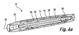
間欠式カテーテル(16)、好ましくは、女性用間欠式カテーテルは、アセンブリで提供される。アセンブリは、使用時にアセンブリの本体に取り付け可能であり得るキャップ(15)、及び/又は使用時にチャンバ壁及び可動インサートのシール面に対してずれているシールを含み得る。アセンブリは、2ステップの展開、及び/又はストレージチャンバから引き抜かれるシースを有し得る。内部ハウジング(14)及び外部ハウジング(12)はストレージチャンバを画定し得る。ハウジングは充填孔を有しており、及び/又はストレージチャンバは回転に応じて軸方向に移動するように構成されたインサートを有し得る。The intermittent catheter (16), preferably a female intermittent catheter, is provided in an assembly. The assembly may include a cap (15) that may be attachable to the body of the assembly in use, and/or a seal that is offset against the chamber wall and the sealing surface of the movable insert in use. The assembly may have a two-step deployment and/or a sheath that is withdrawn from the storage chamber. The inner housing (14) and the outer housing (12) may define a storage chamber. The housing may have a fill hole and/or the storage chamber may have an insert configured to move axially in response to rotation.
Description
本発明は間欠式カテーテル(例えば尿道カテーテル)に関する。 The present invention relates to intermittent catheters (e.g., urethral catheters).
カテーテルは、管腔、血管、通路または体腔に挿入して、そこから流体または物質の注入、排出または引き抜きを可能にするため、あるいは前記管、血管、通路などが開いたままになるように企図された中空のカテーテルチューブを有する医療デバイスである。尿道カテーテルは、膀胱を排出させるために、尿道を介して使用者の膀胱への挿入に使用するように設計されている。 A catheter is a medical device having a hollow catheter tube intended for insertion into a lumen, blood vessel, passageway or body cavity to allow for the infusion, drainage or withdrawal of fluids or substances therefrom, or to keep said tube, blood vessel, passageway, etc. open. A urinary catheter is designed for use in insertion through the urethra into the user's bladder to drain the bladder.
快適さを最大化し、外傷及び/又は感染のリスクを最小化するために、カテーテルチューブの外表面は、通常、使用者による挿入の前に、湿潤剤を使用して濡らされる。さらなる開発では、カテーテルチューブ自体が、湿潤剤の塗布時に摩擦をさらに減少させる役割を果たす親水性成分(例えば親水性ポリマ)を有するか、親水性成分と一体化されるか、または親水性成分でコーティングされる。 To maximize comfort and minimize the risk of trauma and/or infection, the outer surface of the catheter tube is typically wetted with a wetting agent prior to insertion by the user. In further developments, the catheter tube itself has, is integrated with, or is coated with a hydrophilic component (e.g., a hydrophilic polymer) that serves to further reduce friction upon application of the wetting agent.
カテーテルの中には、例えば、カテーテルが少なくとも部分的に包装内の湿潤剤内に浸漬されているような、包装内で予め濡れた状態で供給されるものもある。これによりカテーテルチューブは使用前に十分に濡れることを確かにするかもしれないが、この構成は、把持要素又は漏斗等のカテーテルチューブ以外のカテーテルの構成部品も濡れてしまう点で悪くなる。これは、ユーザの経験に悪影響を及ぼし、この場合、カテーテルチューブを保持すること及びカテーテルチューブを要求されるように向けることが困難になる可能性がある。これは、使用者が自己カテーテル留置を実行する場合に特に問題となる。さらに、カテーテルを水没させると、カテーテルの構成部品が長期間湿気にさらされるため、カテーテルの保存可能期間が実質的に短くなる可能性がある。 Some catheters are supplied pre-wet in the packaging, e.g., the catheter is at least partially immersed in a wetting agent in the packaging. While this may ensure that the catheter tube is adequately wetted prior to use, this arrangement suffers in that components of the catheter other than the catheter tube, such as the gripping element or funnel, also get wet. This can negatively impact the user's experience, in which case it may be difficult to hold the catheter tube and orient it as required. This is particularly problematic when the user is performing self-catheterization. Furthermore, submerging the catheter in water may substantially shorten the shelf life of the catheter, as the catheter components are exposed to moisture for extended periods of time.
したがって、使用時またはその直前に濡らすことができるカテーテルを提供することが有利であると考えられる。 It would therefore be advantageous to provide a catheter that can be wetted at or just prior to use.
これに対処する試みとして、いくつかのカテーテルは、包装内に破裂可能な容器又は小袋を含む包装で提供されており、使用者はこれを破裂させて湿潤剤を放出できる。典型的なのは、使用者が包装をぎゅっと握って容器や小袋を破壊することである。しかしながら、このような配置では、湿潤剤がカテーテルの他の構成部品と接触することが許容される場合に、上述したものと同様の問題が発生する。
このような配置はまた、使用前にカテーテルチューブが完全に濡れない、あるいはまったく濡れない可能性をもたらす。これはユーザにとって有害である。
In an attempt to address this, some catheters are provided in packaging that includes a rupturable container or pouch within the packaging that the user can burst to release the wetting agent. Typically, the user squeezes the packaging to break the container or pouch. However, such an arrangement creates problems similar to those described above if the wetting agent is allowed to come into contact with other components of the catheter.
Such an arrangement also introduces the possibility that the catheter tube may not be fully wetted, or may not be wetted at all, prior to use, which may be detrimental to the user.
したがって、湿潤剤をカテーテルチューブのみに供給する手段を含むカテーテルを提供し、ユーザ体験を向上させることが有利である。 It would therefore be advantageous to provide a catheter that includes means for delivering wetting agent only to the catheter tube, improving the user experience.
さらなる先行技術の解決策では、カテーテルは湿潤装置を含む包装内に包装されることがある。使用中、カテーテルが包装から取り出されると、カテーテルチューブは湿潤装置を通って移動し、そうすることでカテーテルチューブを湿潤させることができる。このようなカテーテルの例は、ConvaTec Limited名義のPCT出願番号PCT/IB2018/001539に示されている。 In a further prior art solution, the catheter may be packaged within a packaging which includes a wetting device. During use, when the catheter is removed from the packaging, the catheter tube is moved through the wetting device, thereby allowing the catheter tube to be wetted. An example of such a catheter is shown in PCT Application No. PCT/IB2018/001539 in the name of ConvaTec Limited.
しかしながら、包装上の制約から、このような湿潤装置に含有させることができる湿潤剤の量は少なく、したがって、特にカテーテルが保存期間の終わりに近く、溶液の一部が蒸発しているような場合には、このような溶液中でカテーテルチューブが完全に湿潤しない可能性が残る。 However, due to packaging constraints, such wetting devices can only contain a small amount of wetting agent, and therefore it remains possible that the catheter tube may not be completely wetted in such a solution, especially if the catheter is near the end of its shelf life and some of the solution has evaporated.
遠位端からカテーテルチューブを濡らす機構の場合、湿潤剤の量が不十分だと、先端が全く濡れない可能性があり、これは、先端が最初に尿道に導入されるため、使用前の濡れが不十分だと怪我を引き起こす可能性が最も高いので望ましくない。 In the case of mechanisms that wet the catheter tube from the distal end, an insufficient amount of wetting agent may result in the tip not being wetted at all, which is undesirable since the tip is introduced into the urethra first and insufficient wetting prior to use is most likely to cause injury.
さらに、規制当局の承認にはカテーテルの最小限の長さが必要であり、包装サイズへの影響を最小限に抑えながら、その長さが確実に濡れるようにすることが望ましい。 In addition, a minimum catheter length is required for regulatory approval, and it is desirable to ensure that length is wetted while minimizing impact on package size.
本発明の実施形態または実施形態の目的は、従来技術の1つ又は複数の問題を克服するか、または少なくとも部分的に軽減すること、及び/又は改善された間欠式カテーテルを提供することである。 It is an object of the present invention, or an embodiment of the present invention, to overcome or at least partially alleviate one or more problems of the prior art and/or to provide an improved intermittent catheter.
本発明は、添付の特許請求の範囲によるカテーテルアセンブリを提供する。 The present invention provides a catheter assembly according to the accompanying claims.
本開示の一態様は、本体とキャップとを有する外部ハウジングを有するカテーテルアセンブリを提供する。本体とキャップは、カテーテルを収容するための無菌キャビティを形成してもよい。カテーテルは、使用時に外部ハウジングから取り外せるように構成してもよい。本体は、開口端及び閉塞端を有する細長くてもよい。キャップと本体の閉塞端とは、キャップが本体の閉塞端に取り付け可能であるように、対応する合わせ面を有してもよい。 One aspect of the present disclosure provides a catheter assembly having an outer housing having a body and a cap. The body and cap may form a sterile cavity for receiving a catheter. The catheter may be configured to be removable from the outer housing during use. The body may be elongated having an open end and a closed end. The cap and the closed end of the body may have corresponding mating surfaces such that the cap is attachable to the closed end of the body.
本発明の一態様は、本体及びキャップを有する外部ハウジングを有するカテーテルアセンブリを提供し、本体は、開口端及び閉塞端を有する細長く、キャップ及び本体の閉塞端は、キャップが本体の閉塞端に取り付け可能であるように、対応する合わせ面を有する。 One aspect of the invention provides a catheter assembly having an outer housing having a body and a cap, the body being elongated with an open end and a closed end, the cap and the closed end of the body having corresponding mating surfaces such that the cap is attachable to the closed end of the body.
本体及びキャップは、カテーテルを収容するための無菌キャビティを形成してもよい。カテーテルは、使用時に外部ハウジングから取り外されるように構成されてもよい。 The body and cap may form a sterile cavity for receiving the catheter. The catheter may be configured to be removed from the outer housing when in use.
本発明の一態様は、本体とキャップとを有する外部ハウジングであって、本体とキャップとが、使用時に外部ハウジングから取り外されるように構成されたカテーテルを収容するための無菌キャビティを形成し、本体が、開口端と閉塞端とを有する細長い形状であり、本体のキャップと閉塞端とが、キャップが本体の閉塞端に取り付け可能であるように、対応する合わせ面を有する、カテーテルアセンブリを提供する。 One aspect of the present invention provides a catheter assembly having an outer housing having a body and a cap, the body and the cap forming a sterile cavity for receiving a catheter configured to be removed from the outer housing during use, the body being elongated in shape with an open end and a closed end, the cap and the closed end of the body having corresponding mating surfaces such that the cap can be attached to the closed end of the body.
本体の閉塞端に取り付け可能なキャップを提供することによって、カテーテルの使用中にキャップを保管するのに便利な場所を提供する。 Providing a cap that can be attached to the closed end of the body provides a convenient place to store the cap while the catheter is in use.
キャップは、カテーテルの使用中にケースの閉塞端に取り付けられるように構成されてもよい。それ故、使用時には、キャップを本体から取り外してカテーテルを露出させ、外部ハウジングから引き抜いて本体の閉塞端に置いてもよい。カテーテル使用中、キャップは本体の閉塞端に保持されてもよい。使用後、カテーテルを本体内に戻し、カテーテルを廃棄のために収容するようにキャップを置き換えてもよい。 The cap may be configured to be attached to the closed end of the case during use of the catheter. Thus, during use, the cap may be removed from the body to expose the catheter, which may be pulled out of the outer housing and placed on the closed end of the body. The cap may be retained on the closed end of the body while the catheter is in use. After use, the catheter may be replaced back into the body and the cap may be replaced to store the catheter for disposal.
本体へのキャップの一時的な取り付けは、カテーテルを取り外して使用する間に合理的に予想される量の取り扱いに耐えるだけの弾力性を持たせてもよい。例えば、カテーテルを使用する間、外部ハウジングを一時的に表面に置いてもよい。 The temporary attachment of the cap to the body may be resilient enough to withstand a reasonably anticipated amount of handling during removal and use of the catheter. For example, the outer housing may be temporarily placed on a surface while the catheter is in use.
合わせ面は、キャップを本体の閉塞端に保持可能に取り付けることができるものであれば何でもよい。合わせ面は、キャップの内表面と本体の外表面とによって提供されてもよい。 The mating surface may be any surface that allows the cap to be retentively attached to the closed end of the body. The mating surface may be provided by an inner surface of the cap and an outer surface of the body.
キャップの内表面は、1つの径方向突起を有してもよい。1つ又は複数の径方向突起は、リブであってもよいし、又はピップ、ピン、フィン等であってもよい。リブは長手方向に伸びていてもよい。径方向突起は嵌合面の少なくとも一部を提供してもよい。径方向突起は、本体にキャップを装着する際、本体の外表面に嵌合してもよい。径方向突起は、キャップと本体が無菌キャビティを形成しているときに、外部ハウジング内のカテーテルに係合するように配置されてもよい。径方向突起は、本体からキャップを取り外す際にカテーテルを回転させるように配置されてもよい。 The inner surface of the cap may have a radial projection. The radial projection or projections may be ribs or may be pips, pins, fins, etc. The ribs may extend longitudinally. The radial projection may provide at least a portion of a mating surface. The radial projection may mate with an outer surface of the body when the cap is attached to the body. The radial projection may be arranged to engage a catheter in the outer housing when the cap and body form a sterile cavity. The radial projection may be arranged to rotate the catheter when the cap is removed from the body.
合わせ面の一方又は両方は、オーバーモールド要素を有してもよい。オーバーモールド要素は、キャップの内表面上に配置された層、リング、又はインサートを有してもよい。オーバーモールド要素は、本体の外表面上に配置された層、リング、又は突起を有してもよい。オーバーモールド要素は、対応する合わせ面よりも柔らかい材料で構成してもよい(すなわち、キャップの内表面上に配置されるオーバーモールド要素は、本体よりも柔らかい材料で構成されてもよく、又は代替的に、本体の外表面上に配置されるオーバーモールド要素は、キャップよりも柔らかい材料で構成されてもよい)。 One or both of the mating surfaces may have an overmolded element. The overmolded element may have a layer, ring, or insert disposed on the inner surface of the cap. The overmolded element may have a layer, ring, or protrusion disposed on the outer surface of the body. The overmolded element may be constructed of a softer material than the corresponding mating surface (i.e., an overmolded element disposed on the inner surface of the cap may be constructed of a softer material than the body, or alternatively, an overmolded element disposed on the outer surface of the body may be constructed of a softer material than the cap).
合わせ面は、締り嵌めを介して係合してもよい。締り嵌めは、本体にキャップを保持するのに適した摩擦係合を可能にするために、合わせ面の間に適当な大きさの接触領域によって提供されてもよい。締り嵌めはレジスタンス・フィットと呼ばれることもある。 The mating surfaces may engage via an interference fit. The interference fit may be provided by a suitable amount of contact area between the mating surfaces to allow a frictional engagement suitable for retaining the cap on the body. An interference fit is sometimes referred to as a resistance fit.
キャップの内表面と本体の外表面との形状は互いに対応してもよい。合わせ面は、対応する先細り形状を有してもよい。先細り形状は、先細りの角度がその長さに沿って一定となるような均一な先細りであってもよい。 The shapes of the inner surface of the cap and the outer surface of the body may correspond to one another. The mating surfaces may have a corresponding tapered shape. The tapered shape may be a uniform taper such that the angle of taper is constant along its length.
外部ハウジングは間欠式カテーテルに適していてもよい。カテーテルは女性用間欠式カテーテルであってもよい。カテーテルの長さは90mmから200mmであってもよい。カテーテルは、100mmから150mm、例えば130mmから155mm、例えば約135mmの長さを有してもよい。カテーテルアセンブリは、カテーテルの長さに対応する長さを有してもよい。例えば、カテーテルアセンブリの長さ、すなわちケーシングの閉じた長さは、カテーテルの長さより2mmから20mmの間、例えば2mmから15mmの間、例えば2mmから10mm長くてもよい。カテーテルアセンブリ(閉塞したとき)は、10cmから25cmの長さを有してもよく、11cmから16cmの長さを有してもよく、例えば140mmから165mmの間、例えば142mmであってもよい。 The outer housing may be suitable for an intermittent catheter. The catheter may be a female intermittent catheter. The length of the catheter may be 90 mm to 200 mm. The catheter may have a length of 100 mm to 150 mm, such as 130 mm to 155 mm, such as about 135 mm. The catheter assembly may have a length corresponding to the length of the catheter. For example, the length of the catheter assembly, i.e. the closed length of the casing, may be between 2 mm and 20 mm, such as between 2 mm and 15 mm, such as 2 mm to 10 mm, longer than the length of the catheter. The catheter assembly (when closed) may have a length of 10 cm to 25 cm, or may have a length of 11 cm to 16 cm, such as between 140 mm to 165 mm, such as 142 mm.
外部ハウジングはカテーテルアセンブリに適していてもよい。外部ハウジングはカテーテルとは別に製造され、輸入され、販売されてもよい。カテーテルアセンブリはカテーテルを有してもよい。 The outer housing may be suitable for a catheter assembly. The outer housing may be manufactured, imported, and sold separately from the catheter. The catheter assembly may include the catheter.
本体及び/又はキャップは硬質であってもよい。本体とキャップの剛性は、本体の閉塞端にキャップの締り嵌めを助けるために弾力的に変形可能に構成されてもよい。 The body and/or cap may be rigid. The rigidity of the body and cap may be configured to be elastically deformable to aid in the tight fit of the cap onto the closed end of the body.
外部ハウジングはプラスチックで構成されてもよい。外部ハウジングは熱可塑性プラスチックで構成されてもよい。キャップと本体は、異なる素材で構成されてもよい。外部ハウジング(任意でキャップ又は本体)はポリカーボネートで構成されてもよく、外部ハウジング(任意でキャップ又は本体)はポリエチレンで構成されてもよく、外部ハウジング(任意でキャップ又は本体)はナイロンで構成されてもよい。好ましくは、外部ハウジング(任意でキャップ又は本体)はポリプロピレンで構成されてもよい。 The outer housing may be constructed of plastic. The outer housing may be constructed of thermoplastic. The cap and body may be constructed of different materials. The outer housing (optionally cap or body) may be constructed of polycarbonate, the outer housing (optionally cap or body) may be constructed of polyethylene, the outer housing (optionally cap or body) may be constructed of nylon. Preferably, the outer housing (optionally cap or body) may be constructed of polypropylene.
ある態様では、本開示は、キャップと本体とを有する外部ハウジングを有するカテーテルアセンブリを使用する方法を提供してもよい。本体は、使用前にキャップが密閉可能に取り付けられる第1端と、第2端を有してもよい。この方法は、本体の第1端からキャップを取り外してカテーテルを使用のために露出させるステップと、本体の第2端にキャップを取り付けるステップとを有してもよい。この方法は、本体の第2端に取り付ける前にキャップを反転させることをさらに有してもよい。本方法は、本体の第2端にキャップを取り付けた後(又は取り付ける前)に、本体からカテーテルを取り外すことをさらに有してもよい。本方法は、本体からのカテーテルの取り外しに続いて、本体内でカテーテルを置換することをさらに有してもよい。この方法は、本体の第2端からキャップを外し、本体の第1端にキャップを置換することをさらに有してもよい。この方法は、キャップをひねって本体から緩めるステップを有してもよい。キャップをひねるステップは、アセンブリ内でカテーテルを回転させてもよい。カテーテルはキャップの径方向突起によって回転させてもよく、この径方向突起は、カテーテル、例えばカテーテルの対応する径方向突起に係合してもよい。キャップの径方向突起は、キャップが本体の第2端に取り付けられているとき、さらに本体の第2端に係合してもよい。 In one aspect, the disclosure may provide a method of using a catheter assembly having an outer housing having a cap and a body. The body may have a first end to which the cap is sealably attached prior to use, and a second end. The method may include removing the cap from the first end of the body to expose the catheter for use, and attaching the cap to the second end of the body. The method may further include inverting the cap before attaching to the second end of the body. The method may further include removing the catheter from the body after (or before) attaching the cap to the second end of the body. The method may further include replacing the catheter within the body following removal of the catheter from the body. The method may further include unscrewing the cap from the second end of the body and replacing the cap on the first end of the body. The method may include twisting the cap to loosen it from the body. Twisting the cap may rotate the catheter within the assembly. The catheter may be rotated by a radial protrusion on the cap, which may engage a corresponding radial protrusion on the catheter, e.g., the catheter. The radial projection of the cap may further engage the second end of the body when the cap is attached to the second end of the body.
本開示の一態様は、長手軸を有するカテーテルアセンブリを提供する。カテーテルアセンブリは、カテーテルと湿潤剤ストレージチャンバとを有してもよい。湿潤剤ストレージチャンバは、チャンバ壁と可動インサートとを有してもよい。可動インサートは、第1位置と第2位置との間で、チャンバ壁に対して長手軸に沿って軸方向に移動するように構成されてもよい。 One aspect of the present disclosure provides a catheter assembly having a longitudinal axis. The catheter assembly may include a catheter and a wetting agent storage chamber. The wetting agent storage chamber may include a chamber wall and a movable insert. The movable insert may be configured to move axially along the longitudinal axis relative to the chamber wall between a first position and a second position.
第1位置は、ストレージチャンバがシール要素によってシールされている密閉形態に対応してもよい。シール要素はチャンバ壁と可動インサートとの間にあってもよい。シール要素は、チャンバ壁のシール面と、第1位置の可動インサートとを整列するように構成されてもよい。 The first position may correspond to a closed configuration in which the storage chamber is sealed by a sealing element. The sealing element may be between the chamber wall and the movable insert. The sealing element may be configured to align a sealing surface of the chamber wall with the movable insert in the first position.
第2位置は、シールがシール面の少なくとも1つと軸方向にずれるように構成された位置であってもよい。 The second position may be a position in which the seal is configured to be axially offset from at least one of the sealing surfaces.
本開示の一態様は、長手軸を有するカテーテルアセンブリを提供し、カテーテルアセンブリは、カテーテルと、湿潤剤ストレージチャンバとを有しており、湿潤剤ストレージチャンバは、チャンバ壁と可動インサートとを有しており、可動インサートは、第1位置と第2位置との間でチャンバ壁に対して長手軸に沿って軸方向に移動するように構成されており、第1位置において、ストレージチャンバは、チャンバ壁と可動インサートとの間に位置するシール要素によってシールされており、シール要素は、第1位置において、チャンバ壁及び可動インサートのシール面と整列するように構成されており、第2位置において、シールは、シール面の少なくとも1つと軸方向にずれるように構成されている。 One aspect of the present disclosure provides a catheter assembly having a longitudinal axis, the catheter assembly including a catheter and a wetting agent storage chamber, the wetting agent storage chamber having a chamber wall and a movable insert, the movable insert configured to move axially along the longitudinal axis relative to the chamber wall between a first position and a second position, in which in the first position the storage chamber is sealed by a sealing element located between the chamber wall and the movable insert, the sealing element configured to align with sealing surfaces of the chamber wall and the movable insert in the first position, and in which in the second position the seal is configured to be axially offset from at least one of the sealing surfaces.
有利なことに、リザーバを密閉するシールを設けることが、使用前に蒸発や漏れによって失われる湿潤剤の量を減少させる。
これは、賞味期限終了時に十分な湿潤剤が存在する確実性を高めるという点で有益である。また、マージンが少なくてすむため、ストレージチャンバに含まれる湿潤剤の量を少なくでき、その結果、リザーバが小さくなり、したがってパッケージ全体が小さくなる可能性もある。
Advantageously, providing a seal to enclose the reservoir reduces the amount of wetting agent that is lost through evaporation or leakage prior to use.
This is beneficial in that it increases the certainty that sufficient humectant will be present at the end of the shelf life, and because less margin is required, the storage chamber may contain less humectant, resulting in a smaller reservoir and therefore a smaller overall package.
第1位置のシール面と整列され、第2位置のシール面と位置ずれするように、構成可能なシール要素を用いてシールされるストレージチャンバを有するカテーテルアセンブリを提供することが、機能性を向上させたシールを提供する。 Providing a catheter assembly having a storage chamber that is sealed with a configurable sealing element that is aligned with the sealing surface in a first position and misaligned with the sealing surface in a second position provides a seal with improved functionality.
例えば、幾つかの実施形態では、湿潤剤が湿潤チャンバ又はプライミングチャンバなどの更なるチャンバに流れるための流路を作ることができるように、第2位置でシールを開口させてもよい。したがって、シール要素を、ストレージチャンバを開口させるためのバルブとして作用するように構成できる。 For example, in some embodiments, the seal may be open in the second position to allow a flow path for the wetting agent to flow to a further chamber, such as a wetting chamber or a priming chamber. Thus, the sealing element may be configured to act as a valve to open the storage chamber.
幾つかの実施形態では、ストレージチャンバが機能的にシールされたままであるが、シール要素によって及ぼされる接触圧力が低下するように、第2位置ではシールがそのまま残ってもよい。これにより、可動インサートは第2位置にあるとき、ストレージチャンバからより容易に引き抜かれ、一方で第1位置にあるときは、輸送及び保管の目的で、より厳重なシールを提供できる。 In some embodiments, the seal may remain in place in the second position such that the storage chamber remains functionally sealed, but the contact pressure exerted by the sealing element is reduced. This allows the movable insert to be more easily extracted from the storage chamber when in the second position, while providing a tighter seal for transport and storage purposes when in the first position.
シール要素は、エラストマー材料であってもよい。例えば、シールはゴムシール又は他の適切な材料であってもよい。シール要素は環状のシール要素であってもよい。シール要素はOリングを有してもよい。シール要素はXリングを有してもよい。シール要素はUカップを有してもよい。シール要素は、例えばカテーテルアセンブリの長手軸の法線平面のような径方向平面に位置してもよい。シール要素は、径方向に対向するシール面の間に延びてもよい。Oリングは、例えばカテーテルアセンブリの長手軸の法線平面のような径方向平面に位置してもよい。シール要素はガスケットの形態で提供されてもよい。 The sealing element may be an elastomeric material. For example, the seal may be a rubber seal or other suitable material. The sealing element may be an annular sealing element. The sealing element may comprise an O-ring. The sealing element may comprise an X-ring. The sealing element may comprise a U-cup. The sealing element may lie in a radial plane, e.g., a plane normal to the longitudinal axis of the catheter assembly. The sealing element may extend between diametrically opposed sealing surfaces. The O-ring may lie in a radial plane, e.g., a plane normal to the longitudinal axis of the catheter assembly. The sealing element may be provided in the form of a gasket.
シール要素は圧縮可能であってもよい。第1位置におけるシール要素の圧縮は、第2位置における圧縮よりも大きくてもよい。 The sealing element may be compressible. The compression of the sealing element in the first position may be greater than the compression in the second position.
シール要素は、チャンバ壁又は可動インサートのいずれかのシール要素ハウジングに配置されてもよい。シール要素ハウジングは、チャンバ壁又は可動インサート内に設けられた溝又はチャネルを有してもよい。溝又はチャネルは、径方向外壁、軸端壁、及び/又はストレージチャンバ内に設けられた1つ又は複数のカテーテルガイド機構によって部分的に提供されてもよい。シール要素は、ストレージチャンバ又は可動インサートの一体部品となるようにオーバーモールドされてもよい。シール面の1つ又は複数は、シール要素ハウジングによって提供されてもよい。少なくとも1つのシール面は、シール要素にスライド可能に対抗してもよい。少なくとも1つのシール面は、一次シール面と呼ばれることもある。 The sealing element may be disposed in a sealing element housing, either in the chamber wall or in the movable insert. The sealing element housing may have a groove or channel provided in the chamber wall or in the movable insert. The groove or channel may be provided in part by one or more catheter guide mechanisms provided in the radially outer wall, the axial end wall, and/or in the storage chamber. The sealing element may be overmolded to be an integral part of the storage chamber or the movable insert. One or more of the sealing surfaces may be provided by the sealing element housing. At least one sealing surface may slidably oppose the sealing element. The at least one sealing surface may be referred to as a primary sealing surface.
カテーテルアセンブリは、湿潤剤をさらに有してもよい。第2位置にあるとき、湿潤剤は、シール要素が(一次)シール面に隣り合う二次シール面とのシール接触を維持することによって、ストレージチャンバ内にシールされてもよい。代替的に、幾つかの実施形態では、第2位置にあるとき、湿潤剤がストレージチャンバから流出するように、シール面とシール要素との間に流路が設けられてもよい。 The catheter assembly may further include a wetting agent. When in the second position, the wetting agent may be sealed in the storage chamber by the sealing element maintaining sealing contact with a secondary sealing surface adjacent the (primary) sealing surface. Alternatively, in some embodiments, a flow path may be provided between the sealing surface and the sealing element to allow the wetting agent to flow out of the storage chamber when in the second position.
可動インサートとチャンバ壁の少なくとも一方は、シール要素の軸方向位置におけるチャンバ壁と可動インサートとの間の距離が第1位置にあるときに比べて第2位置にあるときに増大するように、第1位置と第2位置との間の移行時に、シール要素が通過する分岐部分を構成してもよい。この距離は、長手軸に対する径方向距離であってもよい。分岐部分は、シール面に隣り合うキャビティの拡幅を有してもよい。キャビティは、ストレージチャンバ及び/又は隣り合うチャンバのものであってもよい。隣り合うチャンバは本体内に設けられてもよい。隣り合うチャンバはカテーテルチューブを収容してもよい。隣り合うチャンバはプライミングチャンバ又は湿潤チャンバであってもよい。 At least one of the movable insert and the chamber wall may define a bifurcated portion through which the sealing element passes when transitioning between the first and second positions such that the distance between the chamber wall and the movable insert at the axial position of the sealing element is increased in the second position compared to the first position. This distance may be a radial distance relative to the longitudinal axis. The bifurcated portion may comprise a widening of the cavity adjacent the sealing surface. The cavity may be of a storage chamber and/or an adjacent chamber. The adjacent chamber may be provided within the body. The adjacent chamber may house a catheter tube. The adjacent chamber may be a priming chamber or a wetting chamber.
分岐部分は、シール面に隣り合う壁面における、段差、先細り、又は面取りを有してもよい。シール面は、第1直径を有する円筒状の表面を有してもよい。チャンバ壁又は可動インサートの隣り合う壁部分は、第1直径とは異なる第2直径を有してもよい。第1直径は第2直径よりも大きくてもよい。隣り合う壁部分はカテーテルの挿入端に近接していてもよい。隣り合う壁部分は、二次的な表面であってもよい。 The bifurcated portion may have a step, taper, or chamfer in the wall surface adjacent the sealing surface. The sealing surface may have a cylindrical surface having a first diameter. The adjacent wall portion of the chamber wall or the movable insert may have a second diameter different from the first diameter. The first diameter may be greater than the second diameter. The adjacent wall portion may be proximate the insertion end of the catheter. The adjacent wall portion may be a secondary surface.
少なくとも1つのシール面は、一次シール面であってもよい。第2直径を有するチャンバ壁又は可動インサートの部分は、二次シール面であってもよい。それ故、第2位置にあるとき、シール要素は二次シール面に接触し、シールしてもよい。二次シール面とシール要素の位置における可動インサートとチャンバ壁との間の間隔が大きくなるため、二次シール面とシール要素との間の接触圧力が低下してもよい。つまり、シール要素は第1位置において圧縮された状態で提供され、第2位置において減圧された状態で提供されてもよい。 At least one of the sealing surfaces may be a primary sealing surface. A portion of the chamber wall or the movable insert having a second diameter may be a secondary sealing surface. Thus, when in the second position, the sealing element may contact and seal with the secondary sealing surface. Due to the increased spacing between the movable insert and the chamber wall at the location of the secondary sealing surface and the sealing element, the contact pressure between the secondary sealing surface and the sealing element may be reduced. That is, the sealing element may be provided in a compressed state in the first position and in a decompressed state in the second position.
カテーテルはストレージチャンバ内に配置されてもよい。カテーテルは、ストレージチャンバ内に同軸状に入れ子であってもよい。カテーテルは、ストレージチャンバの一部を提供するように、チャンバ壁内に入れ子状であってもよい。カテーテルは、ストレージチャンバの軸方向に対向する端部の開口部を介して、チャンバ内を密封可能に延びてもよい。 The catheter may be disposed within the storage chamber. The catheter may be coaxially nested within the storage chamber. The catheter may be nested within a chamber wall to provide a portion of the storage chamber. The catheter may sealably extend within the chamber through openings at axially opposed ends of the storage chamber.
可動インサートは、チャンバ壁に対して、カテーテルを湿潤剤で濡らす第3位置まで移動するように構成されてもよい。可動インサートは、第1位置から第2位置へ、第2位置から第3の位置へ第1方向に移動するように構成されてもよい。第1方向は、回転方向及び/又は軸方向であってもよい。可動インサートは、第1位置から第2位置への第2方向と、第2位置から第3位置への第3方向に移動してもよい。第2方向と第3方向は、互いに反対であってもよい。第2方向と第3方向は、軸方向であってもよい。可動インサートは、回転方向と軸方向とに同時に動くように構成されてもよい。 The movable insert may be configured to move relative to the chamber wall to a third position where the catheter is wetted with the wetting agent. The movable insert may be configured to move in a first direction from the first position to the second position and from the second position to the third position. The first direction may be rotational and/or axial. The movable insert may move in a second direction from the first position to the second position and in a third direction from the second position to the third position. The second and third directions may be opposite to each other. The second and third directions may be axial. The movable insert may be configured to move simultaneously in a rotational and axial direction.
カテーテルアセンブリは、湿潤チャンバをさらに含んでもよい。湿潤チャンバはストレージチャンバの径方向内側に位置してもよい。カテーテルは、湿潤チャンバ内に同軸に入れ子であってもよい。外部ハウジング、ストレージチャンバ、湿潤チャンバ及びカテーテルは、長手軸上に同心に配置され、軸方向に整列されてもよい。 The catheter assembly may further include a wet chamber. The wet chamber may be located radially inward of the storage chamber. The catheter may be coaxially nested within the wet chamber. The outer housing, the storage chamber, the wet chamber, and the catheter may be concentrically disposed on the longitudinal axis and axially aligned.
カテーテルアセンブリは、プライミングチャンバをさらに含んでもよい。プライミングチャンバはストレージチャンバ及び湿潤チャンバとフロー系列にある。プライミングチャンバは、ストレージチャンバと湿潤チャンバの近位に位置してもよい。プライミングチャンバ及び/又は湿潤チャンバは、シール要素によってストレージチャンバから分離されていてもよい。プライミングチャンバは、湿潤剤を、湿潤チャンバに送り込まれる前にストレージチャンバから受け取ってもよい。 The catheter assembly may further include a priming chamber. The priming chamber is in flow series with the storage chamber and the wet chamber. The priming chamber may be located proximal to the storage chamber and the wet chamber. The priming chamber and/or the wet chamber may be separated from the storage chamber by a sealing element. The priming chamber may receive the wetting agent from the storage chamber prior to delivery to the wet chamber.
ストレージチャンバ及び湿潤チャンバは別のチャンバであってもよい。ストレージチャンバ及び湿潤チャンバは、内部ハウジングによって分離されていてもよい。内部ハウジングは、ストレージチャンバを提供するために、外部ハウジングの中に間隔をあけた関係で配置されてもよい。 The storage chamber and the wet chamber may be separate chambers. The storage chamber and the wet chamber may be separated by an inner housing. The inner housing may be disposed in a spaced apart relationship within the outer housing to provide the storage chamber.
ストレージチャンバは湿潤チャンバであってもよい。湿潤チャンバは、湿潤剤がカテーテルチューブの外表面に接触できる、カテーテルアセンブリ内のキャビティとして画定されてもよい。湿潤剤は、カテーテルチューブがストレージチャンバから引かれる際にカテーテルチューブに適用されてもよく、その場合、ストレージチャンバは湿潤チャンバとみなされてもよく又は湿潤チャンバを有してもよい。 The storage chamber may be a wet chamber. The wet chamber may be defined as a cavity within the catheter assembly in which a wetting agent can contact the outer surface of the catheter tube. The wetting agent may be applied to the catheter tube as it is withdrawn from the storage chamber, in which case the storage chamber may be considered to be or may include a wet chamber.
代替的に、ストレージチャンバ及び湿潤チャンバが別個のチャンバである場合、湿潤剤は、湿潤チャンバ及びカテーテルチューブの部分に流れ及び/又は該部分に沿ってポンプで送られてもよい。その場合、湿潤剤はシール要素を通過して流れてもよい。プライミングチャンバは、ストレージチャンバと湿潤チャンバとの間に位置してもよく、湿潤剤を、湿潤チャンバを通過する前に受け取ってもよい。プライミングチャンバは、外部ハウジングの本体の近位端に設けられてもよい。 Alternatively, if the storage chamber and the wet chamber are separate chambers, the wetting agent may flow into and/or be pumped along the wet chamber and portions of the catheter tube. In that case, the wetting agent may flow through the sealing element. A priming chamber may be located between the storage chamber and the wet chamber and may receive the wetting agent before it passes through the wet chamber. The priming chamber may be provided at the proximal end of the body of the outer housing.
第2位置にあるとき、シール要素はチャンバ壁と可動インサートとの間にシールを維持してもよい。第2位置にあるとき、シール要素は、湿潤剤がシール要素を通過する流路を設けるように、少なくとも1つのシール面から分離されてもよい。 When in the second position, the sealing element may maintain a seal between the chamber wall and the movable insert. When in the second position, the sealing element may be separated from at least one sealing surface to provide a flow path for the wetting agent to pass through the sealing element.
湿潤剤は、第2位置及び/又はプライミングチャンバにあるとき」、湿潤チャンバ内に設けられてもよい。 The wetting agent may be provided in the wetting chamber when in the second position and/or in the priming chamber.
可動インサートは内部ハウジングを有してもよい。内部ハウジングは、ストレージチャンバ及び湿潤チャンバを画定するハウジングであってもよい。 The movable insert may have an internal housing. The internal housing may be a housing that defines a storage chamber and a wet chamber.
カテーテルアセンブリは、複数のシールを有してもよい。複数のシールは、カテーテルの挿入端の近位にある近位シールを有してもよい。複数のシールは、第2シールを有してもよい。第2シールは、その遠位側で近位シールから軸方向に離間していてもよい。遠位シール及び近位シールは、可動インサートとチャンバ壁との間に径方向に位置してもよい。遠位シール及び近位シールは、それぞれの遠位シール要素及び近位シール要素とシール面とを有してもよい。 The catheter assembly may include a plurality of seals. The plurality of seals may include a proximal seal proximal to the insertion end of the catheter. The plurality of seals may include a second seal. The second seal may be axially spaced distally from the proximal seal. The distal and proximal seals may be located radially between the movable insert and the chamber wall. The distal and proximal seals may have respective distal and proximal seal elements and sealing surfaces.
遠位シールは、第1位置及び第2位置においてシール接触を維持してもよい。 The distal seal may maintain sealing contact in the first and second positions.
カテーテルアセンブリは、湿潤剤を湿潤チャンバに送り込むように構成されたポンプをさらに有してもよい。可動インサートはポンプを有してもよい。内部ハウジングはポンプを有してもよい。内部ハウジングは、1つ又は複数のポンプ強化機構を有してもよい。内部ハウジングは、周方向に延びる複数のフィンを有してもよい。可動インサートは第2位置から第1位置に移動可能であってもよく、湿潤剤を湿潤チャンバに送り込んでもよい。 The catheter assembly may further include a pump configured to pump the wetting agent into the wet chamber. The movable insert may include a pump. The internal housing may include a pump. The internal housing may include one or more pump strengthening features. The internal housing may include a plurality of circumferentially extending fins. The movable insert may be movable from a second position to a first position and may pump the wetting agent into the wet chamber.
カテーテルは、患者に挿入するための挿入端を提供するカテーテルチューブと、1つ又は複数の外部ハンドリング機構を有する出口端とを有してもよい。 The catheter may have a catheter tube providing an insertion end for insertion into a patient and an exit end having one or more external handling mechanisms.
可動インサートはカテーテルによって提供されてもよい。例えば、カテーテルの一部が可動インサートを提供してもよい。カテーテルの一部は、カテーテルチューブ以外の部分、例えば漏斗又は追加の本体であってもよい。ストレージチャンバはカテーテルの出口端に隣り合っていてもよい。 The movable insert may be provided by the catheter. For example, a portion of the catheter may provide the movable insert. The portion of the catheter may be a portion other than the catheter tube, for example a funnel or additional body. The storage chamber may be adjacent the outlet end of the catheter.
カテーテルアセンブリは、可動インサートをストレージチャンバに対して移動させるためのアクチュエータをさらに有してもよい。本明細書では、アクチュエータはプライミング機構として呼ばれることがある。アクチュエータは回転可能なアクチュエータを有してもよい。回転可能なアクチュエータを回転させることは、可動インサートがチャンバ壁に対して移動させてもよい。可動インサートの動きは、回転運動と軸方向動作のいずれか一方又は両方であってもよい。軸方向動作は、回転アクチュエータの回転によって誘発されてもよい。回転可能なアクチュエータの回転は、可動インサートとチャンバ壁との間の軸方向動作に変換されてもよい。 The catheter assembly may further include an actuator for moving the movable insert relative to the storage chamber. The actuator may be referred to herein as a priming mechanism. The actuator may include a rotatable actuator. Rotating the rotatable actuator may cause the movable insert to move relative to the chamber wall. The movement of the movable insert may be either or both of a rotational motion and an axial motion. The axial motion may be induced by rotation of the rotational actuator. The rotation of the rotatable actuator may be translated into an axial motion between the movable insert and the chamber wall.
カテーテルアセンブリは、回転可能なアクチュエータの回転を軸方向動作に変換するためのカムドライブをさらに有してもよい。カテーテルアセンブリは、回転可能なアクチュエータの回転を軸方向動作に変換するためのネジ山をさらに有してもよい。カムドライブは、ネジ山又はネジ山の一部を有してもよい。アクチュエータは、回転-軸方向動作を提供するために互いに駆動可能に係合する1つ又は複数の駆動面と1つ又は複数の対応する駆動要素とを有してもよい。 The catheter assembly may further include a cam drive for translating rotation of the rotatable actuator into axial motion. The catheter assembly may further include a thread for translating rotation of the rotatable actuator into axial motion. The cam drive may include a thread or a portion of a thread. The actuator may include one or more drive surfaces and one or more corresponding drive elements that drivingly engage with each other to provide rotational-axial motion.
カテーテルアセンブリは、取り外し可能なキャップを有する外部ハウジングをさらに有してもよい。回転可能なアクチュエータはキャップを有してもよい。 The catheter assembly may further include an outer housing having a removable cap. The rotatable actuator may include a cap.
キャップを回転させると可動インサートが回転するように、キャップは可動インサートに回転可能に係合してもよい。 The cap may be rotatably engaged with the movable insert such that rotating the cap rotates the movable insert.
可動インサートは、回転可能なアクチュエータの回転の際に往復運動するように構成されてもよい。 The movable insert may be configured to reciprocate upon rotation of the rotatable actuator.
第2位置は、カテーテルが湿潤剤によって湿潤されるように構成された湿潤位置であってもよい。それ故、第2位置にあるとき、湿潤剤はカテーテルチューブの外表面と流体連通してもよい。第2位置はプライミング位置であってもよい。プライミング位置にあるとき、カテーテルはストレージチャンバから引かれるように構成されてもよい。いくつかの実施形態では、プライミング位置は、湿潤剤が湿潤チャンバに送り込まれ又はその他の方法で移動させる、プレ-ポンプ形態に対応してもよい。 The second position may be a wetting position configured such that the catheter is wetted with a wetting agent. Thus, when in the second position, the wetting agent may be in fluid communication with an outer surface of the catheter tube. The second position may be a priming position. When in the priming position, the catheter may be configured to be withdrawn from the storage chamber. In some embodiments, the priming position may correspond to a pre-pump configuration in which the wetting agent is pumped or otherwise displaced into the wetting chamber.
本開示の一態様は、湿潤機構を有するカテーテルアセンブリを提供する。カテーテルアセンブリは少なくとも2ステップの展開を有してもよい。この2ステップの展開は、気密シールを破壊し、少なくとも湿潤機構をプライミングし、カテーテルアセンブリを漏れ防止プライミング形態にする第1ステップと、カテーテルチューブをカテーテルアセンブリから取り外す第2ステップとを有してもよい。第1段階及び/又は第2ステップは、さらにカテーテルチューブを濡らしてもよい。 One aspect of the present disclosure provides a catheter assembly having a wetting mechanism. The catheter assembly may have at least a two-step deployment. The two-step deployment may include a first step of breaking an airtight seal and priming at least the wetting mechanism to place the catheter assembly in a leak-proof primed configuration, and a second step of removing the catheter tube from the catheter assembly. The first and/or second steps may further wet the catheter tube.
本開示の一態様は、カテーテルと、カテーテルが収容される内部キャビティを有するハウジングとを備えたカテーテルアセンブリを提供する。ハウジングは外部ハウジングであってもよい。ハウジングは、使用前に内部キャビティの無菌性を保持するための気密シールを有してもよい。湿潤剤チャンバが内部キャビティに配置されてもよい。 One aspect of the present disclosure provides a catheter assembly including a catheter and a housing having an internal cavity in which the catheter is received. The housing may be an external housing. The housing may have an airtight seal to preserve sterility of the internal cavity prior to use. A wetting agent chamber may be disposed in the internal cavity.
本開示の態様は、カテーテルを有するカテーテルアセンブリを提供してもよい。カテーテルアセンブリは、カテーテルが収容される内部容積を有する外部ハウジングをさらに有してもよい。外部ハウジングは、使用前に内部容積の無菌性を保持するための気密シールを有してもよい。カテーテルアセンブリは湿潤剤チャンバを有してもよく、湿潤剤チャンバは、湿潤剤を湿潤剤チャンバ内に保持するための1つ又は複数の湿潤剤シールを有してもよい。カテーテルアセンブリは、気密シールがシールされ湿潤剤シールがシールされる、密閉形態と、気密シールが開口され1つ又は複数の湿潤剤シールがシールされる、プライミング形態とを有するように構成可能であってもよい。 Aspects of the present disclosure may provide a catheter assembly having a catheter. The catheter assembly may further include an outer housing having an interior volume in which the catheter is housed. The outer housing may have an airtight seal to maintain sterility of the interior volume prior to use. The catheter assembly may have a wetting agent chamber, which may have one or more wetting agent seals to maintain the wetting agent in the wetting agent chamber. The catheter assembly may be configurable to have a closed configuration in which the airtight seal is sealed and the wetting agent seal is sealed, and a priming configuration in which the airtight seal is opened and the one or more wetting agent seals are sealed.
本開示の一態様は、カテーテルアセンブリを提供し、該カテーテルアセンブリは、カテーテルと、カテーテルが収容される内部キャビティを有するハウジングであって、用前に該内部キャビティの無菌性を保持するための気密シールと内部キャビティ内に配置された湿潤剤チャンバとを有する、ハウジングとを備え、カテーテルアセンブリは、第1ステップとそれに続く第2ステップにカテーテルを展開するように構成されており、第1ステップは、気密シールを破壊し、湿潤剤チャンバをプライミングして、カテーテルアセンブリを、カテーテルが湿潤剤と濡れるように構成された漏れ防止プライミング形態にすることを含み、第2ステップは、カテーテルをハウジングから取り外すことを含む。 One aspect of the present disclosure provides a catheter assembly, comprising a catheter and a housing having an internal cavity in which the catheter is housed, the housing having an airtight seal for maintaining sterility of the internal cavity prior to use and a wetting agent chamber disposed within the internal cavity, the catheter assembly being configured to deploy the catheter in a first step followed by a second step, the first step including breaking the airtight seal and priming the wetting agent chamber to place the catheter assembly in a leak-proof primed configuration configured to wet the catheter with the wetting agent, and the second step including removing the catheter from the housing.
内部容積の無菌性が保持される密閉形態と、カテーテルアセンブリが潜在的に無菌ではないが漏れ防止プライミング形態に保持されるプライミング形態とを提供することにより、湿潤剤がカテーテルアセンブリから漏れるリスクなしにカテーテルの展開を中断することを可能とする。これは、ユーザが、カテーテルを引き抜く前であって気密シールを破壊した後に、カテーテルを一時的に置く必要がある場合に有利である。 Providing a sealed configuration in which the sterility of the internal volume is maintained, and a primed configuration in which the catheter assembly is potentially not sterile but is maintained in a leak-proof primed configuration allows catheter deployment to be interrupted without risk of wetting agent leaking from the catheter assembly. This is advantageous if the user needs to temporarily place the catheter before withdrawing it and after breaking the airtight seal.
ハウジングは外部ハウジングを有してもよい。外部ハウジングは、本体とキャップとを有してもよい。気密シールは、本体及び/又はキャップに取り付けられてもよい。気密シールはキャップを本体に取り付けてもよい。気密シールは、カテーテルアセンブリの外表面を有してもよい。それ故、外部ハウジングは、キャップと、本体と、気密シールとを有してもよい。気密シールは、キャップが手で取り外し可能であるように、使用中に破壊される開封帯(ティアストリップ)であってもよい。本体に対してキャップを回転させることによって、気密シールが破壊され、湿潤剤がプライミングされてもよい。 The housing may include an outer housing. The outer housing may include a body and a cap. The airtight seal may be attached to the body and/or the cap. The airtight seal may attach the cap to the body. The airtight seal may include an outer surface of the catheter assembly. Thus, the outer housing may include a cap, a body, and an airtight seal. The airtight seal may be a tear strip that is broken during use so that the cap is manually removable. By rotating the cap relative to the body, the airtight seal may be broken and the wetting agent may be primed.
第1ステップ及び/又は第2ステップは、カテーテルのカテーテルチューブをさらに濡らしてもよい。それ故、カテーテルアセンブリをプライミング形態に置くと、湿潤剤がカテーテルアセンブリの外部と流体連通になくても、カテーテルを濡らしてもよい。追加的に又は代替的に、漏れ防止状態は、湿潤剤と、使用時にユーザによって取り扱われるハンドリング面を構成するカテーテルの一部との間の流体連通を防止してもよい。それ故、カテーテルがハウジングから取り外される前に、ハンドリング面を乾燥状態に維持してもよい。ハンドリング面は、カテーテルの出口端によって提供されてもよい。 The first and/or second steps may further wet the catheter tube of the catheter. Thus, placing the catheter assembly in the priming configuration may wet the catheter even though the wetting agent is not in fluid communication with the exterior of the catheter assembly. Additionally or alternatively, the leak-proof condition may prevent fluid communication between the wetting agent and a portion of the catheter that constitutes a handling surface that is handled by the user in use. Thus, the handling surface may be maintained dry before the catheter is removed from the housing. The handling surface may be provided by the outlet end of the catheter.
カテーテルは間欠式カテーテルであってもよい。カテーテルは尿道カテーテルであってもよい。カテーテルは女性用間欠式カテーテルであってもよい。 The catheter may be an intermittent catheter. The catheter may be a urethral catheter. The catheter may be a female intermittent catheter.
カテーテルアセンブリは、プライミング機構をさらに有してもよい。本明細書では、プライミング機構はアクチュエータと呼ばれることがある。プライミング機構は、単一のユーザの操作で第1ステップを実行するように構成されてもよい。それ故、ユーザは、例えばカテーテルアセンブリの一部を移動させることによって、例えば回転し又は引っ張ることによって単一の作動又は動作でプライミング機構を操作して、気密シールを破壊してカテーテルアセンブリをプライミングしてもよい。第1ステップは、気密シールを破壊すると同時に、湿潤剤チャンバをプライミングしてカテーテルアセンブリを漏れ防止プライミング形態にすることを有してもよい。 The catheter assembly may further include a priming mechanism. The priming mechanism may be referred to herein as an actuator. The priming mechanism may be configured to perform a first step with a single user action. Thus, a user may operate the priming mechanism with a single actuation or motion, for example by moving a portion of the catheter assembly, for example by rotating or pulling, to break the airtight seal and prime the catheter assembly. The first step may include simultaneously breaking the airtight seal and priming the wetting agent chamber to place the catheter assembly in a leak-proof primed configuration.
ハウジングは外部ハウジングであってもよい。ハウジングは硬質であってもよい。ハウジングは、キャップと本体とを有してもよい。キャップと本体は、第1ステップの間に係合されたままであってもよい。キャップと本体との係合は、キャップが本体に直接又は間接的に取り付けられる機械的係合であってもよい。例えば、キャップは内部ハウジング又は他の中間部材を介して本体に取り付けられてもよい。 The housing may be an external housing. The housing may be rigid. The housing may have a cap and a body. The cap and body may remain engaged during the first step. The engagement between the cap and the body may be a mechanical engagement in which the cap is directly or indirectly attached to the body. For example, the cap may be attached to the body via an internal housing or other intermediate member.
プライミング機構はキャップを有してもよい。キャップは、キャップを駆動可能に回転させることにより気密シールを破壊し湿潤剤チャンバをプライミングするように、本体に対して駆動可能に回転可能であってもよい。 The priming mechanism may have a cap. The cap may be drivably rotatable relative to the body such that drivably rotating the cap breaks the airtight seal and primes the wetting agent chamber.
プライミング機構は、駆動面と、駆動面に係合する駆動要素とを有しており、駆動要素又は駆動面の回転運動によって駆動要素又は駆動面の他方が軸方向に並進し又はその逆であってもよい。 The priming mechanism has a drive surface and a drive element that engages the drive surface, and rotational movement of the drive element or the drive surface may cause the other of the drive element or the drive surface to translate axially, or vice versa.
駆動面は、軸方向及び周方向に延びてもよい。駆動面は、ランプ及び/又は螺旋面を有してもよい。駆動面は、径方向に突出するフランジ、リブ、ネジ山、トラック、又はレールによって提供される第1軸方向対向面、又は端壁面を有してもよい。 The drive surface may extend axially and circumferentially. The drive surface may have a ramp and/or helical surface. The drive surface may have a first axially opposing surface or end wall surface provided by a radially projecting flange, rib, thread, track, or rail.
駆動要素は、径方向に延びるフランジ、リブ、ネジ山、トラック、レール、又はピンの第2軸方向対向面、又は端壁面を有してもよい。 The drive element may have a second axially facing surface or end wall surface of a radially extending flange, rib, thread, track, rail, or pin.
端壁面はチャンバ壁の端壁面であってもよい。 The end wall surface may be the end wall surface of a chamber wall.
駆動要素と駆動面とを総称してカムドライブと呼ぶことがある。 The drive element and drive surface are sometimes collectively referred to as the cam drive.
プライミング機構は、湿潤剤チャンバを部分的に画定する可動インサートを有してもよい。可動インサートは、第1ステップの間に密閉形態とプライミング形態との間を移動するように構成されてもよい。可動インサートは、回転すると軸方向に移動するように構成されてもよい。 The priming mechanism may have a movable insert that partially defines the wetting agent chamber. The movable insert may be configured to move between the sealed configuration and the priming configuration during the first step. The movable insert may be configured to move axially upon rotation.
湿潤剤チャンバは湿潤剤ストレージチャンバを有してもよい。追加的に又は代替的に、湿潤剤チャンバは、湿潤チャンバ及び/又はプライミングチャンバを有してもよい。湿潤剤チャンバは、チャンバ壁と可動インサートとを有してもよい。 The wetting agent chamber may include a wetting agent storage chamber. Additionally or alternatively, the wetting agent chamber may include a wetting chamber and/or a priming chamber. The wetting agent chamber may include a chamber wall and a movable insert.
チャンバ壁又は可動インサートの何れか一方は、駆動要素又は駆動面を有してもよい。チャンバ壁及び可動インサートの他方は、駆動要素及び駆動面の他方を有してもよい。 Either the chamber wall or the movable insert may have a drive element or drive surface. The other of the chamber wall and the movable insert may have the other of the drive element and drive surface.
駆動要素は、孔を塞ぐためのプラグを有してもよい。孔は充填孔であってもよい。充填孔は、ハウジングの外壁に設けられてもよい。 The drive element may have a plug for blocking the hole. The hole may be a fill hole. The fill hole may be provided in an outer wall of the housing.
可動インサートは、回転すると軸方向に移動するように構成されてもよい。キャップを回転させると可動インサートが回転し軸方向に並進するように、キャップは可動インサートに回転可能に係合されてもよい。 The movable insert may be configured to move axially when rotated. The cap may be rotatably engaged to the movable insert such that rotation of the cap causes the movable insert to rotate and translate axially.
キャップと可動インサートの間の回転可能係合は、第1ステップに続いて外れてもよい。回転可能係合の外れは、キャップのさらなる回転によって誘発されてもよい。それ故、ユーザは、カテーテルアセンブリをプライミングするためにキャップを第1方向に回転させ、キャップを外すためにさらにキャップを第1方向に回転させてもよい。回転可能係合の外れにより、カテーテルを引き抜きのために露出するように、カテーテルアセンブリからの取り外しのためにキャップを構成してもよい。 The rotatable engagement between the cap and the movable insert may be disengaged following the first step. Disengagement of the rotatable engagement may be induced by further rotation of the cap. Thus, a user may rotate the cap in a first direction to prime the catheter assembly and further rotate the cap in the first direction to disengage the cap. Disengagement of the rotatable engagement may configure the cap for removal from the catheter assembly such that the catheter is exposed for withdrawal.
可動インサートは、カテーテルによって提供されてもよい(上記概説したように)。 The movable insert may be provided by a catheter (as outlined above).
可動インサートは、外部ハウジングの径方向内側に位置する内部ハウジングを有してもよい。カテーテルは、内部ハウジングの径方向内側に配置されてもよい。 The movable insert may have an inner housing located radially inward of the outer housing. The catheter may be disposed radially inward of the inner housing.
内部ハウジングは、外部ハウジングとの間にストレージチャンバを設けるように、外部ハウジング内に径方向に配置されてもよい。 The inner housing may be radially disposed within the outer housing to provide a storage chamber between the inner housing and the outer housing.
カテーテルアセンブリは、機械的フィードバックをユーザに提供するように構成されてもよい。機械的フィードバックは第1ステップの終わりの示しであってもよい。機械的フィードバックは第1ステップと第2ステップとの間にあってもよい。 The catheter assembly may be configured to provide mechanical feedback to the user. The mechanical feedback may be an indication of the end of the first step. The mechanical feedback may be between the first and second steps.
第1ステップは第1作動力を要求してもよく、第2ステップは第2作動力を要求してもよい。第1作動力と第2作動力は異なっていてもよい。それ故、第1作動力と第2作動力との間を移行することは、機械的フィードバックをユーザに提供してもよい。第1作動力及び第2作動力は、異なる方向及び異なる大きさの何れか一方又は両方であってもよい。 The first step may require a first actuation force and the second step may require a second actuation force. The first actuation force and the second actuation force may be different. Thus, transitioning between the first actuation force and the second actuation force may provide mechanical feedback to the user. The first actuation force and the second actuation force may be of different directions and/or magnitudes.
機械的フィードバックは、作動方向が変化することが要求される1つ又は複数のストップによって提供されてもよい。それ故、カテーテルアセンブリは、可動インサート又は可動インサートに関連するアクチュエータの動作を制限する1つ又は複数のリミッタを有してもよい。 Mechanical feedback may be provided by one or more stops at which a change in actuation direction is required. Thus, the catheter assembly may have one or more limiters that limit the movement of the movable insert or the actuator associated with the movable insert.
第1ステップ及び第2ステップに必要なカテーテルアセンブリの作動は、1つ又は複数の部品の移動及び/又は取り外しを要求してもよい。それ故、第1ステップは、カテーテルがユーザによって軸方向に引き抜かれる前に、その後取り外されるキャップを使用して作動させられてもよい。 The actuation of the catheter assembly required for the first and second steps may require the movement and/or removal of one or more parts. Thus, the first step may be actuated using a cap that is then removed before the catheter is axially withdrawn by the user.
湿潤剤チャンバは湿潤剤ストレージチャンバを有してもよい。幾つかの実施形態では、湿潤剤ストレージチャンバはカテーテルの一部を有してもよい。幾つかの実施形態では、湿潤剤チャンバは、ストレージチャンバ及び/又は湿潤チャンバ、及び/又はプライミングチャンバを有してもよい。 The wetting agent chamber may comprise a wetting agent storage chamber. In some embodiments, the wetting agent storage chamber may comprise a portion of the catheter. In some embodiments, the wetting agent chamber may comprise a storage chamber and/or a wetting chamber, and/or a priming chamber.
湿潤剤シールは、ストレージチャンバ、湿潤チャンバ、又はプライミングチャンバをシールするために使用される、任意の、シール又はシールの組み合わせであってもよい。湿潤剤シールは、本明細書に記載のシール要素及びシール面を有してもよい。 The wetting agent seal may be any seal or combination of seals used to seal a storage chamber, a wetting chamber, or a priming chamber. The wetting agent seal may have the sealing elements and sealing surfaces described herein.
幾つかの実施形態では、カテーテルアセンブリは、湿潤剤を湿潤チャンバに提供するように構成されてもよい。カテーテルアセンブリは、気密シールが開口しており、少なくとも1つの湿潤剤シールが開いている、第3形態を有してもよい。 In some embodiments, the catheter assembly may be configured to provide a wetting agent to the wetting chamber. The catheter assembly may have a third configuration in which the airtight seal is open and at least one wetting agent seal is open.
プライミング形態は、カテーテルがストレージチャンバ内から取り外される間に、その中に設けられた湿潤剤を通過できるように、プライミングされているストレージチャンバに関連してもよい。 The priming configuration may relate to the storage chamber being primed so as to allow passage of the wetting agent disposed therein while the catheter is removed from within the storage chamber.
外部ハウジングは、キャップと、キャップが取り付けられる本体とを有してもよい。取り付けは気密シールを介してであってもよい。本体に対してキャップを回転させることが、気密シールを破壊してもよい。 The outer housing may have a cap and a body to which the cap is attached. The attachment may be via an airtight seal. Rotating the cap relative to the body may destroy the airtight seal.
湿潤剤チャンバは、湿潤剤ストレージチャンバ壁と可動インサートとを有してもよい。湿潤剤シールは、湿潤剤ストレージチャンバ壁と可動インサートとの間に設けられてもよい。シールはシール要素を有してもよい。 The wetting agent chamber may have a wetting agent storage chamber wall and a movable insert. A wetting agent seal may be provided between the wetting agent storage chamber wall and the movable insert. The seal may have a sealing element.
カテーテルは挿入可能な部分を有してもよい。第1ステップの前に、挿入可能な部分が湿潤剤に接触しなくてもよい。 The catheter may have an insertable portion. The insertable portion may not be in contact with the wetting agent prior to the first step.
カテーテルの展開前、例えば出荷時及び保管時には、カテーテルの挿入可能部分が湿潤剤に接触していないことが有利である。カテーテルの挿入部分は、湿潤剤と相互作用する材料でできていることが多いが、この相互作用は使用直前にのみ起こるべきである。 Prior to deployment of the catheter, e.g., during shipping and storage, it is advantageous for the insertable portion of the catheter not to be in contact with the wetting agent. The insertable portion of the catheter is often made of a material that interacts with the wetting agent, but this interaction should only occur immediately prior to use.
カテーテルアセンブリは、湿潤チャンバをさらに有してもよい。カテーテルアセンブリがプライミング形態であるとき、湿潤剤は湿潤チャンバと流体連通していてもよい。湿潤剤は、第3位置にあるときに湿潤チャンバにあってもよい。 The catheter assembly may further include a wet chamber. The wetting agent may be in fluid communication with the wet chamber when the catheter assembly is in the priming configuration. The wetting agent may be in the wet chamber when in the third position.
カテーテルアセンブリは、ストレージチャンバと湿潤チャンバとの間に設けられた湿潤チャンバシールをさらに有してもよい。湿潤チャンバシールは、カテーテルアセンブリがプライミング形態であるときに開口することができる。 The catheter assembly may further include a wet chamber seal disposed between the storage chamber and the wet chamber. The wet chamber seal may be open when the catheter assembly is in the priming configuration.
可動インサートは、カテーテルが配置されている内部ハウジングであってもよい。可動インサートはカテーテルであってもよい。カテーテルアセンブリがプライミング形態にあるとき、カテーテルは湿潤剤チャンバ及び外部ハウジングから引き抜かれるように構成されてもよい。 The movable insert may be an inner housing in which the catheter is disposed. The movable insert may be a catheter. The catheter may be configured to be withdrawn from the wetting agent chamber and the outer housing when the catheter assembly is in the priming configuration.
カテーテルアセンブリは、可動インサートを湿潤剤チャンバ壁に対して移動させるためのアクチュエータをさらに有してもよい。アクチュエータは回転可能なアクチュエータを有してもよい。回転可能なアクチュエータの回転が、可動インサートとチャンバ壁との間の軸方向動作に変換されてもよい。 The catheter assembly may further include an actuator for moving the movable insert relative to the wetting agent chamber wall. The actuator may include a rotatable actuator. Rotation of the rotatable actuator may be translated into axial motion between the movable insert and the chamber wall.
カテーテルアセンブリは、回転可能なアクチュエータの回転を軸方向動作に変換するためのカムドライブをさらに有してもよい。カテーテルアセンブリは、回転可能なアクチュエータの回転を軸方向動作に変換するためのネジ山をさらに有してもよい。カテーテルアセンブリはさらにキャップを有してもよく、回転可能なアクチュエータはキャップを有する。キャップを回転させると可動インサートが回転するように、キャップは可動インサートと回転可能に係合されてもよい。 The catheter assembly may further include a cam drive for translating rotation of the rotatable actuator into axial motion. The catheter assembly may further include threads for translating rotation of the rotatable actuator into axial motion. The catheter assembly may further include a cap, and the rotatable actuator has a cap. The cap may be rotatably engaged with the movable insert such that rotating the cap rotates the movable insert.
キャップを回転させると可動インサートが回転するように、キャップは可動インサートと回転可能に係合されてもよい。キャップを回転させ又は引っ張ることが、気密シールを破壊してもよい。 The cap may be rotatably engaged with the movable insert such that rotating the cap rotates the movable insert. Rotating or pulling the cap may break the airtight seal.
さらにキャップを回転させ又はカテーテルを引き抜くことが、少なくとも一つの湿潤剤シールを開口させてもよい。キャップのさらなる回転は、気密シールを破壊する同じ回転であってもよい。 Further rotation of the cap or withdrawal of the catheter may open at least one wetting agent seal. Further rotation of the cap may be the same rotation that breaks the airtight seal.
本開示の一態様は、遠位出口端と近位挿入端とを有するカテーテルを有するカテーテルアセンブリを提供する。カテーテルアセンブリは、湿潤剤ストレージチャンバとハウジングとをさらに有してもよい。ハウジングは外部ハウジングであってもよい。外部ハウジングは、カテーテルとストレージチャンバとを少なくとも部分的に囲んでもよい。カテーテルアセンブリは、カテーテルとストレージチャンバとの間に接続されたシースをさらに含んでもよく、外部ハウジングからカテーテルを引き抜くと、シースを介してストレージチャンバが外部ハウジングから引き抜かれる。 One aspect of the present disclosure provides a catheter assembly having a catheter with a distal exit end and a proximal insertion end. The catheter assembly may further include a wetting agent storage chamber and a housing. The housing may be an external housing. The external housing may at least partially surround the catheter and the storage chamber. The catheter assembly may further include a sheath connected between the catheter and the storage chamber, such that retracting the catheter from the external housing retracts the storage chamber from the external housing via the sheath.
本開示の一態様は、遠位出口端及び近位挿入端を有するカテーテルと、湿潤剤ストレージチャンバと、外部ハウジングであって、外部ハウジングは、カテーテルおよびストレージチャンバを少なくとも部分的に囲んでいる、ものと、外部ハウジングからカテーテルを引き抜くと、シースを介してストレージチャンバが外部ハウジングから引き抜かれるように、カテーテルとストレージチャンバとの間に接続されたシースと、を備えるカテーテルアセンブリを提供する。 One aspect of the present disclosure provides a catheter assembly including a catheter having a distal exit end and a proximal insertion end, a wetting agent storage chamber, an outer housing at least partially enclosing the catheter and the storage chamber, and a sheath connected between the catheter and the storage chamber such that withdrawal of the catheter from the outer housing withdraws the storage chamber from the outer housing via the sheath.
カテーテルとストレージチャンバの間に接続されたシースを設けることは、カテーテルがストレージチャンバを通して引き抜かれた後、ストレージチャンバをカテーテルから取り外す便利な方法を提供する。それ故、患者に挿入可能なカテーテルチューブは、患者への挿入前にカテーテルチューブの無菌性の維持を助けるために、引き出されたカテーテルチューブを収める前/間のカテーテルがハウジングから引き出されている間、ストレージチャンバに収容されている湿潤剤で湿潤させられてもよい。さらに、カテーテルが尿道内に導入されると、湿潤剤ストレージチャンバを2回、通過して、カテーテルの表面の濡れを改善させてもよい。 Providing a sheath connected between the catheter and the storage chamber provides a convenient way to remove the storage chamber from the catheter after the catheter has been withdrawn through the storage chamber. Thus, the catheter tube insertable into the patient may be moistened with a wetting agent contained in the storage chamber while the catheter is withdrawn from the housing before/during storage of the withdrawn catheter tube to help maintain sterility of the catheter tube prior to insertion into the patient. Additionally, once the catheter is introduced into the urethra, it may be passed through the wetting agent storage chamber a second time to improve wetting of the surface of the catheter.
さらに、シースによって外部ハウジングから引き抜くことができる湿潤機構を設けることにより、ユーザがカテーテルチューブを汚染するリスクなしで、ストレージチャンバによって濡れたカテーテルチューブを取り扱うことを可能にする。このようにストレージチャンバを挿入ガイドとして提供することにより、外部ハウジングのスペースを効率的に使うことができ、湿潤剤の供給を増やすことができる。 Additionally, by providing a wetting mechanism that can be retracted from the outer housing by the sheath, the storage chamber allows the user to handle the wet catheter tube without risking contamination of the catheter tube. By providing the storage chamber as an insertion guide in this manner, space in the outer housing can be used more efficiently and the supply of wetting agent can be increased.
シースは格納式シースであってもよい。格納式シースは、格納形態において収納され、拡張構成に展開されてもよい。シースは、シースが出口端とストレージチャンバとの間に畳まれた格納形態から、シースが展開され、その中に配置されたカテーテルのカテーテルチューブを含む拡張形態まで展開可能であってもよい。 The sheath may be a retractable sheath. The retractable sheath may be stored in a stored configuration and deployed to an expanded configuration. The sheath may be deployable from a stored configuration in which the sheath is folded between the outlet end and a storage chamber to an expanded configuration in which the sheath is deployed and includes a catheter tube of a catheter disposed therein.
カテーテル及びストレージチャンバは、外部ハウジングからカテーテルを引き抜くために第1所定力が必要とされ、外部ハウジングから引き抜くためにストレージチャンバの係合を解除するために第2所定力が必要とされるように、外部ハウジング内に保持され(例えば、取り付けられ)てもよい。第1所定力と第2所定力とは、異なってもよい。第2所定力は、第1所定力より大きくてもよい。 The catheter and storage chamber may be held (e.g., attached) within the outer housing such that a first predetermined force is required to withdraw the catheter from the outer housing and a second predetermined force is required to disengage the storage chamber for withdrawal from the outer housing. The first and second predetermined forces may be different. The second predetermined force may be greater than the first predetermined force.
カテーテルアセンブリは、使用するためにカテーテルの挿入端に配備可能な挿入ガイドをさらに有してもよい。挿入ガイドは外部ハンドリング面を有してもよく、患者の尿道における挿入端の配置を補助されてもよい。ストレージチャンバは挿入ガイドを有してもよい。 The catheter assembly may further include an insertion guide deployable at the insertion end of the catheter for use. The insertion guide may have an exterior handling surface and may aid in placement of the insertion end in the patient's urethra. The storage chamber may include an insertion guide.
カテーテルアセンブリは、ストレージチャンバを解除可能に保持するように配置された解除機構をさらに有してもよい。 The catheter assembly may further include a release mechanism arranged to releasably retain the storage chamber.
解除機構は、外部ハウジングとストレージチャンバとの間の解除可能なカップリングを有してもよい。解除機構は、ユーザがカテーテル及び/又はストレージチャンバを引き抜くための機械的フィードバックを提供してもよい。それ故、解除機構は、解除可能なカップリングを作動させるために所定量の力を必要としてもよい。所定量の力は第2所定力であってもよい。 The release mechanism may have a releasable coupling between the outer housing and the storage chamber. The release mechanism may provide mechanical feedback for the user to withdraw the catheter and/or the storage chamber. Thus, the release mechanism may require a predetermined amount of force to actuate the releasable coupling. The predetermined amount of force may be a second predetermined force.
解除可能なカップリングは、外部ハウジング及び湿潤剤チャンバの何れか一方又は両方から延びる1つ又は複数の突起を有してもよい。突起は、外部ハウジング及び湿潤剤チャンバの他方に設けられた1つ又は複数の対応する凹部で受け入れられてもよい。 The releasable coupling may have one or more protrusions extending from either or both of the outer housing and the wetting agent chamber. The protrusions may be received in one or more corresponding recesses in the other of the outer housing and the wetting agent chamber.
解除可能な突起及び凹部は同数あってもよい。突起及び凹部は、第1所定力を受けるとき係合したままになり、第2所定力を受けると係合が外れるように構成されてもよい。 There may be an equal number of releasable projections and recesses. The projections and recesses may be configured to remain engaged when subjected to a first predetermined force and to disengage when subjected to a second predetermined force.
第1所定力及びび第2所定力は、軸方向の力であってもよい。軸方向の力は、カテーテルを介してユーザによって加えられてもよい。 The first and second predetermined forces may be axial forces. The axial forces may be applied by a user via a catheter.
突起は、長手軸を有する細長くてもよい。突起は、第2所定力が加えられたとき又は第2所定力を超えたとき、長手軸から離れてそれるように構成されてもよい。 The protrusion may be elongated having a longitudinal axis. The protrusion may be configured to deflect away from the longitudinal axis when a second predetermined force is applied or exceeded.
カテーテルは細長くてもよく、カテーテルアセンブリの主要な長手軸を画定してもよい。突起の長手軸は、主要な長手軸の方向に延びてもよい。 The catheter may be elongate and may define a major longitudinal axis of the catheter assembly. The longitudinal axes of the projections may extend in the direction of the major longitudinal axis.
カテーテルアセンブリは、主軸の周りに周方向に分布する複数の突起及び凹部を有してもよい。数の突起及び凹部は、組み合わさって環状のクラスプ(留め具)を提供してもよい。 The catheter assembly may have a number of projections and recesses circumferentially distributed about the main shaft. A number of projections and recesses may combine to provide an annular clasp.
突起の撓みは、径方向外向きであってもよい。 The deflection of the protrusion may be radially outward.
解除機構は、外部ハウジング及び湿潤剤チャンバの相対回転を防止するように構成されてもよい。それ故、ストレージチャンバ内で又はストレージチャンバの一部を形成する可動インサートを回転させることにより、ストレージチャンバと外部ハウジングとの間の相対的な回転をもたらさなくてもよい。 The release mechanism may be configured to prevent relative rotation of the outer housing and the wetting agent chamber. Thus, rotating a moveable insert within or forming part of the storage chamber may not result in relative rotation between the storage chamber and the outer housing.
カテーテルアセンブリはさらに、ストレージチャンバ内のシール要素と、ストレージチャンバ内で受け取られる可動インサートとをさらに有してもよい。シール要素は、ストレージチャンバと可動インサートとの間に配置されてもよく、径方向内側にあってもよく、複数の突起及び/又は凹部と軸方向に整列してもよい。シール要素と、ストレージチャンバをハウジングに対して位置決めする解除可能なカップリングとの軸方向の位置合わせは、シール要素によって提供されるシールを維持するのに役立ってもよい。 The catheter assembly may further include a sealing element in the storage chamber and a movable insert received in the storage chamber. The sealing element may be disposed between the storage chamber and the movable insert, may be radially inward, and may be axially aligned with the plurality of protrusions and/or recesses. Axial alignment of the sealing element with a releasable coupling that positions the storage chamber relative to the housing may help maintain a seal provided by the sealing element.
本開示の一態様は、カテーテルと、カテーテルが配置された湿潤剤ストレージチャンバとを有するカテーテルアセンブリを提供する。湿潤剤ストレージチャンバは、湿潤チャンバ内でカテーテルを案内するように構成された少なくとも1つの突起を有してもよい。 One aspect of the present disclosure provides a catheter assembly having a catheter and a wetting agent storage chamber in which the catheter is disposed. The wetting agent storage chamber may have at least one protrusion configured to guide the catheter within the wetting chamber.
少なくとも1つの突起は、カテーテルの引き抜き時に湿潤チャンバ内でカテーテルを案内してもよい。少なくとも1つの突起は、湿潤チャンバを通るカテーテルの再挿入時に、湿潤チャンバ内でカテーテルを案内してもよい。 The at least one protrusion may guide the catheter through the wet chamber upon withdrawal of the catheter. The at least one protrusion may guide the catheter through the wet chamber upon reinsertion of the catheter through the wet chamber.
本開示の一態様は、カテーテルと、カテーテルが配置される湿潤剤ストレージチャンバとを有するカテーテルアセンブリを提供し、湿潤剤ストレージチャンバは、湿潤チャンバ内でカテーテルを案内するように構成された少なくとも1つの突起を有しており、少なくとも1つの突起は、湿潤チャンバ内でシール要素を保持する。 One aspect of the present disclosure provides a catheter assembly having a catheter and a wetting agent storage chamber in which the catheter is disposed, the wetting agent storage chamber having at least one protrusion configured to guide the catheter within the wetting chamber, the at least one protrusion retaining a sealing element within the wetting chamber.
引き抜き時または再挿入時に湿潤チャンバ内にカテーテルを配置するための突起等の1つ又は複数の機構を有するストレージチャンバを提供することにより、カテーテルの位置決めを制御でき、これはカテーテルのカテーテルチューブの改善した湿潤を提供する。再挿入時に、また、カテーテルが湿潤チャンバに引っかからなくなることを確かにする。 By providing a storage chamber with one or more features, such as protrusions, for positioning the catheter within the wet chamber upon withdrawal or reinsertion, the positioning of the catheter can be controlled, which provides improved wetting of the catheter tube of the catheter. Upon reinsertion, it also ensures that the catheter does not get caught in the wet chamber.
本開示の一態様は、カテーテルと、カテーテルが配置された湿潤剤ストレージチャンバとを有するカテーテルアセンブリを提供する。湿潤剤ストレージチャンバは、シール要素を湿潤チャンバ内に保持するように構成された少なくとも一つの突起を有してもよい。少なくとも1つの突起は、カテーテルの引き抜き時にシール要素を湿潤剤ストレージチャンバ内に保持するように構成されてもよい。 One aspect of the present disclosure provides a catheter assembly having a catheter and a wetting agent storage chamber in which the catheter is disposed. The wetting agent storage chamber may have at least one protrusion configured to retain the sealing element within the wetting agent storage chamber. The at least one protrusion may be configured to retain the sealing element within the wetting agent storage chamber upon withdrawal of the catheter.
その中にシール要素を配置するための突起等の1つ又は複数の機構を有するストレージチャンバを提供することは、カテーテルのカテーテルチューブを引き抜き時にシール要素を配置し、カテーテルとの関係を維持する便利な方法を提供できる。これは、カテーテルを湿潤剤ストレージチャンバに再挿入する際にシール要素が正しく配置され、再挿入後のシールが維持されることを確かにするので有益である。また、尿道へのカテーテル挿入時に明らかに問題となるシール要素をカテーテル上で実施することも避けられる。 Providing a storage chamber having one or more features, such as protrusions, for positioning the sealing element therein can provide a convenient way of positioning the sealing element and maintaining its relationship with the catheter when the catheter tube of the catheter is withdrawn. This is beneficial because it ensures that the sealing element is correctly positioned when the catheter is reinserted into the wetting agent storage chamber and that the seal is maintained after reinsertion. It also avoids implementing a sealing element on the catheter, which can be obviously problematic when inserting the catheter into the urethra.
シール要素を湿潤チャンバ内に保持するように構成された少なくとも1つの突起は、湿潤チャンバ内でカテーテルを案内するように構成された少なくとも1つの突起であってもよい。 The at least one protrusion configured to retain the sealing element within the wet chamber may be at least one protrusion configured to guide the catheter within the wet chamber.
少なくとも1つの突起は、複数のリブまたはフィンであってもよい。複数のリブまたはフィンは、軸方向および径方向に延びてもよい。少なくとも1つの突起は、複数のピン又はフィンを有してもよい。少なくとも1つの突起は、複数の台座を有してもよい。少なくとも1つの突起は、複数のフランジを有してもよい。複数の突起は、リブ及び/又はフィン及び/又はピン及び/又は台座及び/又はフランジの任意の組み合わせを有してもよい。 At least one of the protrusions may have multiple ribs or fins. The multiple ribs or fins may extend axially and radially. At least one of the protrusions may have multiple pins or fins. At least one of the protrusions may have multiple seats. At least one of the protrusions may have multiple flanges. The multiple protrusions may have any combination of ribs and/or fins and/or pins and/or seats and/or flanges.
ストレージチャンバは、軸方向に延びる径方向外壁と、径方向に延びる少なくとも1つの端壁とを有してもよい。ストレージチャンバは、径方向に延びる第1端壁と、径方向に延びる第2端壁とを有してもよい。端壁は、そこから軸方向に延びる1つ又は複数の管状フランジを有してもよい。 The storage chamber may have an axially extending radial outer wall and at least one radially extending end wall. The storage chamber may have a radially extending first end wall and a radially extending second end wall. The end wall may have one or more tubular flanges extending axially therefrom.
複数の突起は、径方向外壁又は少なくとも1つの端壁の何れか一方又は両方から延びてもよい。複数の突起は、湿潤剤ストレージチャンバの径方向外壁から径方向内側に延びてもよい。複数の突起は、周方向に分布していてもよい。少なくとも2つの突起があってもよい。少なくとも3つの突起があってもよい。少なくとも4つの突起があってもよい。少なくとも6つの突起があってもよい。少なくとも8つの突起があってもよい。4つの突起があってもよい。 The plurality of protrusions may extend from either or both of the radially outer wall or the at least one end wall. The plurality of protrusions may extend radially inward from the radially outer wall of the wetting agent storage chamber. The plurality of protrusions may be distributed circumferentially. There may be at least two protrusions. There may be at least three protrusions. There may be at least four protrusions. There may be at least six protrusions. There may be at least eight protrusions. There may be four protrusions.
カテーテル及びストレージチャンバは同心に整列されてもよい。 The catheter and storage chamber may be concentrically aligned.
突起は、空隙を画定する形状であってもよい。空隙は、突起の不連続によって画定されてもよい。突起は、ストレージチャンバの軸範囲に沿って部分的にのみ延びてもよい。空隙は、突起の軸方向エッジによって部分的に画定されてもよい。空隙は、ストレージチャンバの端壁によって部分的に画定されてもよい。不連続は、第1量だけ径方向内側に延びる各突起の第1部分と、第2のより少ない量だけ径方向内側に延びる各突起の第2部分とによって設けられてもよい。 The projections may be shaped to define a gap. The gap may be defined by a discontinuity in the projection. The projections may extend only partially along the axial extent of the storage chamber. The gap may be partially defined by an axial edge of the projection. The gap may be partially defined by an end wall of the storage chamber. The discontinuity may be provided by a first portion of each projection extending radially inwardly a first amount and a second portion of each projection extending radially inwardly a second, lesser amount.
湿潤剤ストレージチャンバは、径方向に延びる少なくとも1つの端壁と、湿潤剤ストレージチャンバ内で軸方向に延びる少なくとも1つの突起とを有してもよく、少なくとも1つの突起は、空隙を画定するために端壁の手前で終端する。 The wetting agent storage chamber may have at least one radially extending end wall and at least one protrusion extending axially within the wetting agent storage chamber, the at least one protrusion terminating short of the end wall to define a gap.
カテーテルは長手軸を画定してもよく、複数の突起の各々は長手軸によって画定される平面内にあってもよい。複数の突起は、正反対に対をなして設けられることがある。 The catheter may define a longitudinal axis, and each of the plurality of protrusions may lie in a plane defined by the longitudinal axis. The plurality of protrusions may be provided in diametrically opposed pairs.
シール要素は、エラストマーであってもよい。シール要素は、環状であってもよい。シール要素は、Oリングであってもよい。シール要素は、Xリングであってもよい。シール要素は、Uカップシールであってもよい。 The sealing element may be elastomeric. The sealing element may be annular. The sealing element may be an O-ring. The sealing element may be an X-ring. The sealing element may be a U-cup seal.
Oリングは、空隙に配置されてもよい。空隙は、シール要素の座を画定してもよい。突起の軸方向エッジは、シール要素のための座を画定してもよい。座は、カテーテルの収納位置から湿潤位置への移行時に、シール要素を軸方向に拘束してもよい。座は、カテーテルの引き抜き時にシール要素を軸方向に拘束してもよい。これは、カテーテルを湿潤剤ストレージチャンバに再挿入する際にシール要素が正しく配置され、再挿入後のシールを維持することを確かにするので、有益である。また、尿道へのカテーテル挿入時に明らかに問題となるシール要素をカテーテル上で実施することも避けられる。 The O-ring may be disposed in the void. The void may define a seat for the sealing element. The axial edge of the projection may define a seat for the sealing element. The seat may axially restrain the sealing element during transition of the catheter from the stored position to the wetting position. The seat may axially restrain the sealing element during withdrawal of the catheter. This is beneficial as it ensures that the sealing element is correctly positioned when reinserting the catheter into the wetting agent storage chamber and maintains a seal after reinsertion. It also avoids implementing a sealing element on the catheter, which is obviously problematic during catheter insertion into the urethra.
ストレージチャンバは、カテーテルが通過し得るストレージチャンバの対向する軸端に配置された2つの開口部を有してもよい。突起は、2つの開口部の間にチャネルを画定してもよい。突起の径方向内側エッジは、カテーテルの引き抜き時、又は再通過/再挿入時に、カテーテルの通過をガイドするためのガイドを画定してもよい。 The storage chamber may have two openings located at opposite axial ends of the storage chamber through which the catheter may pass. The protrusion may define a channel between the two openings. The radially inner edge of the protrusion may define a guide for guiding the passage of the catheter upon withdrawal or repassage/reinsertion of the catheter.
突起の径方向内側エッジは、カテーテルの引き抜き、又は再通過/再挿入の際に、カテーテルの通過を案内するためのガイドを画定してもよい。ガイドは2つの開口部間の距離の少なくとも50%を延びてもよく、好ましくは、ガイドは2つの開口部間の距離の少なくとも80%を延びてもよい。ガイドは、2つの開口部間の距離の少なくとも40%を延びてもよい。ガイドは、2つの開口部間の距離の少なくとも50%を延びてもよい。ガイドは、2つの開口部間の距離の少なくとも60%を延びてもよい。ガイドは、2つの開口部間の距離の少なくとも70%を延びてもよい。 The radially inner edge of the protrusion may define a guide for guiding passage of the catheter during withdrawal or repassage/reinsertion of the catheter. The guide may extend at least 50% of the distance between the two openings, preferably the guide may extend at least 80% of the distance between the two openings. The guide may extend at least 40% of the distance between the two openings. The guide may extend at least 50% of the distance between the two openings. The guide may extend at least 60% of the distance between the two openings. The guide may extend at least 70% of the distance between the two openings.
隣り合う突起の径方向内側エッジ間の間隔は、カテーテルの直径より小さくてもよい。隣り合うプロテクションの径方向内側エッジ間の間隔をカテーテルの直径より小さくすることを確かにすることによって、カテーテルが突起によって画定された流路から逸脱するのを制限する。 The spacing between the radially inner edges of adjacent protrusions may be less than the diameter of the catheter. Ensuring that the spacing between the radially inner edges of adjacent protections is less than the diameter of the catheter limits deviation of the catheter from the flow path defined by the protrusions.
ガイドの直径は、湿潤チャンバの1つ又は複数の開口部の直径とほぼ等しくてもよい。 The diameter of the guide may be approximately equal to the diameter of one or more openings in the wet chamber.
ガイドの直径は、可動インサートのシール面の直径とほぼ等しくてもよい。ガイドの直径は、可動インサートのシール面の直径より大きくてもよい。 The diameter of the guide may be approximately equal to the diameter of the sealing surface of the movable insert. The diameter of the guide may be greater than the diameter of the sealing surface of the movable insert.
本発明の一態様は、外部ハウジングと、外部ハウジング内に配置されるカテーテルと、可動インサートとを有するカテーテルアセンブリを提供する。可動インサートは、外部ハウジングとカテーテルとの間に配置される内部ハウジングであってもよい。内部ハウジングの外表面と外部ハウジングの内表面は共に潤剤ストレージチャンバを画定してもよい。 One aspect of the present invention provides a catheter assembly having an outer housing, a catheter disposed within the outer housing, and a movable insert. The movable insert may be an inner housing disposed between the outer housing and the catheter. An outer surface of the inner housing and an inner surface of the outer housing together may define a lubricant storage chamber.
本発明の一態様は、外部ハウジングと、外部ハウジング内に配置されるカテーテルと、外部ハウジングとカテーテルとの間に配置される内部ハウジングとを有を有する可動インサートとを有するカテーテルアセンブリを提供し、内部ハウジングの外表面と外部ハウジングの内表面とが共に湿潤剤ストレージチャンバを画定する。 One aspect of the present invention provides a catheter assembly having an outer housing, a catheter disposed within the outer housing, and a movable insert having an inner housing disposed between the outer housing and the catheter, the outer surface of the inner housing and the inner surface of the outer housing together defining a wetting agent storage chamber.
外部ハウジングとカテーテルとの間に内部ハウジングを設けることで、湿潤剤の保管に有利な場所を提供してもよい。そのような場所は、湿潤剤にとって大きな容積を提供してもよい。さらに、外部ハウジングに隣り合う場所は、カテーテルアセンブリの組み立てに続いて、充填の目的に便利な場所を提供してもよい。内部ハウジングは、カテーテルの周囲に湿潤チャンバを設けるためにも有利に使用されてもよい。 Providing an internal housing between the external housing and the catheter may provide a convenient location for storage of the wetting agent. Such a location may provide a large volume for the wetting agent. Additionally, a location adjacent to the external housing may provide a convenient location for filling purposes following assembly of the catheter assembly. The internal housing may also be advantageously used to provide a wetting chamber around the catheter.
内部ハウジングは、細長い管状部材を有してもよい。細長い管状部材は、外部ハウジング内に同心状に取り付けられてもよい。 The inner housing may have an elongated tubular member. The elongated tubular member may be concentrically mounted within the outer housing.
内部ハウジングは、それらの間にストレージチャンバを設けるように、外部ハウジング内に径方向に間隔をあけて配置されてもよい。内部ハウジングと外部ハウジングとの何れか一方又は両方が、内部ハウジングと外部ハウジングとの間に延びる少なくとも一つの突起を有してもよい。 The inner housing may be radially spaced apart within the outer housing to provide a storage chamber therebetween. Either or both of the inner and outer housings may have at least one protrusion extending between the inner and outer housings.
少なくとも一つの突起は、細長いリブであってもよい。少なくとも1つの突起は、内部ハウジングの周囲を周方向に延びてもよい。 The at least one protrusion may be an elongated rib. The at least one protrusion may extend circumferentially around the inner housing.
少なくとも一つの突起は、そこを通る軸方向の流路を含んでもよい。少なくとも1つの突起は、内部ハウジングの周囲に部分的にのみ延びて、そこに軸方向の流路を提供してもよい。少なくとも1つの突起は、環状リブを有してもよい。環状リブは、そこに流路を設けるように、不連続であってもよい。軸方向流路は、ストレージチャンバの長さに沿って流体が依然として流れることを可能にしながら、外部ハウジング内での内部ハウジングの位置決めを助けるために、内部ハウジングと外部ハウジングとの間に突起が延びることを可能にする。追加的又は代替的に、流路は、内部ハウジングがポンプとして利用されてもよよいように、軸方向流れの範囲を制御してもよい。 At least one of the projections may include an axial flow passage therethrough. At least one of the projections may extend only partially around the circumference of the inner housing to provide an axial flow passage therethrough. At least one of the projections may have an annular rib. The annular rib may be discontinuous to provide a flow passage therethrough. The axial flow passage allows the projection to extend between the inner and outer housings to aid in positioning the inner housing within the outer housing while still allowing fluid to flow along the length of the storage chamber. Additionally or alternatively, the flow passage may control the extent of axial flow such that the inner housing may be utilized as a pump.
カテーテルアセンブリは、複数の突起を有してもよい。複数の突起は、内部ハウジング又は外部ハウジングの範囲に沿って軸方向に分布していてもよい。 The catheter assembly may have multiple protrusions. The multiple protrusions may be axially distributed along the extent of the inner housing or the outer housing.
少なくとも1つの突起は、外部ハウジングに対して移動可能なように、内部ハウジングから延びてもよい。内部ハウジングと突起を湿潤剤に対して長手軸に沿って軸方向に移動させると、少なくとも1つの突起が湿潤剤を進行方向に促す。それ故、少なくとも1つの突起は、内部ハウジングの軸方向動作の間に湿潤液をストレージチャンバから汲み上げるように構成されてもよい。 The at least one protrusion may extend from the inner housing such that it is movable relative to the outer housing. When the inner housing and the protrusion are moved axially along the longitudinal axis relative to the wetting agent, the at least one protrusion urges the wetting agent in an advancing direction. Thus, the at least one protrusion may be configured to pump the wetting liquid from the storage chamber during axial movement of the inner housing.
少なくとも1つの突起は、外部ハウジングと内部ハウジングとの間に最小限のクリアランスで延びてもよい。それ故、少なくとも1つの突起は、軸方向動作をその中に許容しながら内部ハウジングを径方向に配置するように構成されてもよい。 The at least one protrusion may extend with minimal clearance between the outer housing and the inner housing. Thus, the at least one protrusion may be configured to radially position the inner housing while permitting axial movement therein.
外部ハウジングは、ストレージチャンバに流体連通する充填孔を有してもよい。外部ハウジングは、キャップと本体とを有してもよい。充填孔は、本体の外壁に設けられてもよい。充填孔は、プラグを受け入れるように構成されてもよい。カテーテルアセンブリは、プラグをさらに有してもよい。 The outer housing may have a fill hole in fluid communication with the storage chamber. The outer housing may have a cap and a body. The fill hole may be provided in an outer wall of the body. The fill hole may be configured to receive a plug. The catheter assembly may further include a plug.
カテーテルアセンブリは、内部ハウジングを移動させるためのアクチュエータをさらに有してもよい。アクチュエータは、プライミング機構と呼ばれることもある。アクチュエータは、内部ハウジングを移動させるために駆動要素が作用する駆動面を有してもよい。駆動要素は、プラグを有してもよい。 The catheter assembly may further include an actuator for moving the inner housing. The actuator may be referred to as a priming mechanism. The actuator may include a drive surface against which the drive element acts to move the inner housing. The drive element may include a plug.
駆動要素又は駆動面の何れか一方は、ストレージチャンバのチャンバ壁又はチャンバ壁内で受け入れる可動インサートの何れか一方に提供されてもよい。駆動要素及び駆動面の他方は、チャンバ壁及び可動インサートの他方に提供されてもよい。駆動面及び駆動要素は、可動インサート及びチャンバ壁の相対回転によって可動インサート又はチャンバ壁の軸方向動作をもたらすように構成されてもよい。 Either the drive element or the drive surface may be provided on either the chamber wall of the storage chamber or the movable insert received within the chamber wall. The other of the drive element and the drive surface may be provided on the other of the chamber wall and the movable insert. The drive surface and the drive element may be configured to effect axial movement of the movable insert or the chamber wall upon relative rotation of the movable insert and the chamber wall.
カテーテルアセンブリは、ストレージチャンバ内に湿潤剤をさらに有してもよく、外部ハウジング及び内部ハウジングに接触させる。 The catheter assembly may further include a wetting agent in the storage chamber and in contact with the outer housing and the inner housing.
可動インサートは、密閉形態とプライミング形態との間を移動可能であってもよい。プライミング形態への移動時に、ストレージチャンバは、湿潤剤がストレージチャンバから出るための流路を提供するように開口してもよい。流路は、カテーテルが配置されるプライミングチャンバ又は湿潤チャンバ内へ延びてもよい。 The movable insert may be movable between a sealed configuration and a priming configuration. Upon movement to the priming configuration, the storage chamber may open to provide a flow path for the wetting agent to exit the storage chamber. The flow path may extend into the priming chamber or the wetting chamber in which the catheter is disposed.
カテーテルアセンブリは、1つ又は複数の通気孔を有してもよい。ストレージチャンバは、1つ又は複数の通気孔を有してもよい。1つ又は複数の通気孔は、ストレージチャンバから出る際に湿潤剤と置き換わるように、ストレージチャンバにガスが入ることを可能とするように構成された空気入口通気孔であってもよい。1つ又は複数の通気孔は、外部ハウジングの内部であってもよく、又は外部ハウジングの外部であってもよい。可動インサートの動作が、1つ又は複数の通気孔を開口させてもよい。可動インサートを密閉形態からオープン形態に移動させることが、1つ又は複数の通気孔を開口させてもよい。可動インサートを密閉形態からプライミング形態に移動させることがと、1つ以上の通気孔を開口させてもよい。1つ又は複数の通気孔と流路の開口部は、ストレージチャンバの軸方向に対向する端部に配置されてもよい。 The catheter assembly may have one or more vents. The storage chamber may have one or more vents. The one or more vents may be air inlet vents configured to allow gas to enter the storage chamber to replace the wetting agent upon exiting the storage chamber. The one or more vents may be internal to the outer housing or external to the outer housing. Movement of the movable insert may open the one or more vents. Moving the movable insert from a closed configuration to an open configuration may open the one or more vents. Moving the movable insert from a closed configuration to a priming configuration may open the one or more vents. The one or more vents and the flow passage openings may be located at axially opposite ends of the storage chamber.
流路は、ストレージチャンバを画定するシールを開口させることによって提供されてもよい。シールは、近位シールであってもよい。 The flow path may be provided by opening a seal that defines the storage chamber. The seal may be a proximal seal.
可動インサートの外表面は、外周面であってもよい。可動インサートの外表面は、外側円周面であってもよい。外部ハウジングの内表面は、内周面であってもよい。 The outer surface of the movable insert may be an outer peripheral surface. The outer surface of the movable insert may be an outer circumferential surface. The inner surface of the outer housing may be an inner peripheral surface.
本開示の一態様は、外部ハウジングを有するカテーテルアセンブリを提供し、外部ハウジングは、充填孔と湿潤剤ストレージチャンバとを有する。充填孔はストレージチャンバに流体連通していてもよい。充填孔は、ストレージチャンバが湿潤剤で充填される前に、カテーテルアセンブリが組み立てられることを可能にするように構成されてもよい。 One aspect of the present disclosure provides a catheter assembly having an outer housing, the outer housing having a fill hole and a wetting agent storage chamber. The fill hole may be in fluid communication with the storage chamber. The fill hole may be configured to allow the catheter assembly to be assembled before the storage chamber is filled with the wetting agent.
本開示の一態様は、外部ハウジングを有するカテーテルアセンブリを提供し、外部ハウジングは、充填孔と湿潤剤ストレージチャンバとを有しており、充填孔はストレージチャンバと流体連通しており、充填孔は、ストレージチャンバが湿潤剤で充填される前に、カテーテルアセンブリを組み立てることができるように構成される。 One aspect of the present disclosure provides a catheter assembly having an external housing, the external housing having a fill hole and a wetting agent storage chamber, the fill hole being in fluid communication with the storage chamber, and the fill hole being configured such that the catheter assembly can be assembled before the storage chamber is filled with the wetting agent.
外部ハウジングに充填孔部を設けることが、ストレージチャンバの充填に便利な位置を提供する。孔は、密封された無菌アセンブリを提供するように、充填処置の後に都合よく塞がれてもよい。 Providing a fill hole in the outer housing provides a convenient location for filling the storage chamber. The hole may be conveniently plugged after the filling procedure to provide a sealed, sterile assembly.
この本開示の一態様は、カテーテルアセンブリ(特に、例えば、直前に画定されたカテーテルアセンブリ)を組み立てる方法を提供してもよく、この方法は、a)外部ハウジングの内部キャビティにカテーテルチューブと湿潤剤ストレージチャンバとを挿入すること、b)外部ハウジングに配置された充填孔を介してストレージチャンバを湿潤剤で充填すること、c)外部ハウジングをシールすること、d)内部キャビティを滅菌することを有する。ステップa~dは、好ましくはこの順序で行われる。
もちろん、さらなるステップも含まれてもよい。外部ハウジングをシールすることは、充填孔にプラグを挿入することを有してもよい。プラグは、続いて、外部ハウジングに溶着されてもよい。
One aspect of the present disclosure may provide a method of assembling a catheter assembly (e.g., particularly a catheter assembly as defined immediately above), the method comprising: a) inserting a catheter tube and a wetting agent storage chamber into an internal cavity of an outer housing, b) filling the storage chamber with a wetting agent via a fill hole disposed in the outer housing, c) sealing the outer housing, and d) sterilizing the internal cavity, steps a-d preferably occurring in that order.
Of course, further steps may also be included. Sealing the outer housing may include inserting a plug into the fill hole. The plug may then be welded to the outer housing.
外部ハウジングをシールすることは、ハウジングにキャップを載置することを有してもよい。外部ハウジングをシールすることは、ハウジングを気密シールすることを有してもよい。 Sealing the outer housing may include placing a cap on the housing. Sealing the outer housing may include hermetically sealing the housing.
滅菌は、照射滅菌、例えばガンマ線滅菌、X線滅菌、又はEB(電子線)滅菌であってもよい。 Sterilization may be radiation sterilization, such as gamma sterilization, X-ray sterilization, or EB (electron beam) sterilization.
外部ハウジングは、キャップと本体とを有してもよい。外部ハウジングは、ストレージチャンバに流体連通する充填孔を有してもよい。外部ハウジングは、キャップと本体とを有してもよい。充填孔は、本体の外壁に設けられてもよい。充填孔は、プラグを受け入れるように構成されてもよい。カテーテルアセンブリは、プラグをさらに有してもよい。 The outer housing may have a cap and a body. The outer housing may have a fill hole in fluid communication with the storage chamber. The outer housing may have a cap and a body. The fill hole may be provided in an outer wall of the body. The fill hole may be configured to receive a plug. The catheter assembly may further include a plug.
カテーテルアセンブリは、内部ハウジングを動かすためのアクチュエータをさらに有してもよい。アクチュエータは、プライミング機構と呼ばれることもある。アクチュエータは、内部ハウジングを移動させるように駆動要素が作用する駆動面を有してもよい。駆動要素は、プラグを有してもよい。 The catheter assembly may further include an actuator for moving the inner housing. The actuator may be referred to as a priming mechanism. The actuator may include a drive surface against which a drive element acts to move the inner housing. The drive element may include a plug.
駆動要素又は駆動面の何れか一方は、ストレージチャンバのチャンバ壁又はチャンバ壁内で受け入れた可動インサートの何れか一方に提供されてもよく、駆動要素及び駆動面の他方は、チャンバ壁及び可動インサートの他方に提供される。駆動面及び駆動要素は、可動インサート及びチャンバ壁の相対回転により、可動インサート又はチャンバ壁の軸方向動作をもたらすように構成されてもよい。 Either the drive element or the drive surface may be provided on either the chamber wall of the storage chamber or the movable insert received within the chamber wall, and the other of the drive element and the drive surface is provided on the other of the chamber wall and the movable insert. The drive surface and the drive element may be configured such that relative rotation of the movable insert and the chamber wall results in axial movement of the movable insert or the chamber wall.
可動インサートはカテーテルであってもよい。 The movable insert may be a catheter.
カテーテルアセンブリは外部ハウジング内に内部ハウジングをさらに有してもよい。ストレージチャンバは外部ハウジング及び内部ハウジングの間に設けられて、外部ハウジング及び内部ハウジングによって画定されてもよい。内部ハウジングは、外部ハウジングに対して軸方向及び/又は回転方向に移動可能に構成された可動インサートであってもよい。 The catheter assembly may further include an inner housing within the outer housing. The storage chamber may be disposed between the outer housing and the inner housing and defined by the outer housing and the inner housing. The inner housing may be a movable insert configured to be axially and/or rotationally movable relative to the outer housing.
駆動面は、充填孔とストレージチャンバとの間の流路を提供するように少なくとも1つの駆動面出口を有してもよい。 The drive surface may have at least one drive surface outlet to provide a flow path between the fill hole and the storage chamber.
駆動面は少なくとも1つのレールを有してもよい。レールは、レールを通る流路を提供するための不連続性を有してもよい。 The drive surface may have at least one rail. The rail may have discontinuities to provide a flow path through the rail.
駆動面は、軸方向に間隔を置いた一対のレールを有してもよい。レール間の間隔は、駆動要素の直径に対応してもよい。 The drive surface may have a pair of axially spaced rails. The spacing between the rails may correspond to the diameter of the drive element.
内部ハウジングを、ストレージチャンバを提供するように外部ハウジング内に間隔をあけて配置してもよい。内部ハウジングは、内部ハウジングと外部ハウジングとの間に延びるように、その半径方向外壁に複数のリブを有してもよい。 The inner housing may be spaced apart within the outer housing to provide a storage chamber. The inner housing may have a plurality of ribs on its radially outer wall extending between the inner and outer housings.
リブは周方向に延びてもよい。各リブが、それを通る軸方向の流路を含んでもよい。 The ribs may extend circumferentially. Each rib may include an axial flow passage therethrough.
本開示の一態様は、長手軸を有するカテーテルアセンブリを提供してもよく、該カテーテルアセンブリは、カテーテルと、湿潤剤ストレージチャンバと、カテーテル及びストレージチャンバが収容される外部ハウジングとを有する。ストレージチャンバは、可動インサートが回転するときに外部ハウジングに対して長手軸に沿って軸方向に移動するように構成された可動インサートを有してもよい。 One aspect of the present disclosure may provide a catheter assembly having a longitudinal axis, the catheter assembly including a catheter, a wetting agent storage chamber, and an outer housing in which the catheter and the storage chamber are housed. The storage chamber may have a movable insert configured to move axially along the longitudinal axis relative to the outer housing when the movable insert rotates.
本開示の一態様は、長手軸を有するカテーテルアセンブリを提供してもよく、該カテーテルアセンブリは、カテーテルと、湿潤剤ストレージチャンバと、カテーテルおよびストレージチャンバが収容される外部ハウジングとを有しており、ストレージチャンバは、可動インサートが回転されるとき、外部ハウジングに対して長手軸に沿って軸方向に移動するように構成された可動インサートを有する。 One aspect of the present disclosure may provide a catheter assembly having a longitudinal axis, the catheter assembly including a catheter, a wetting agent storage chamber, and an outer housing in which the catheter and the storage chamber are housed, the storage chamber having a movable insert configured to move axially along the longitudinal axis relative to the outer housing when the movable insert is rotated.
回転すると軸方向に並進する可動インサートを設けることにより、ストレージチャンバが使用のために便利に構成されることを可能にする例えば、可動インサートを回転させることによって、ストレージチャンバを密閉形態からプライミング形態に変形させるように可動インサートが構成されてもよく、これにより、使用者の単一の操作でカテーテルアセンブリをプライミングすることを可能にする。 Providing a movable insert that translates axially upon rotation allows the storage chamber to be conveniently configured for use. For example, the movable insert may be configured such that rotating the movable insert transforms the storage chamber from a sealed configuration to a priming configuration, thereby allowing the catheter assembly to be primed with a single user action.
可動インサートは、密閉形態とプライミング形態との間で移動可能であってもよい。密閉形態は、カテーテルアセンブリが使用前にシールされる形態に対応してもよい。シールは、外部ハウジングの内部キャビティが無菌状態である密閉または無菌シールであってもよく、又は湿潤剤の漏出を防止するように湿潤剤が外部ハウジングの内部キャビティ内にシールされた漏れ防止密閉状態であってもよい。漏れ防止密封状態とは、湿潤剤がストレージチャンバ、湿潤チャンバ及びプライミンチャンバうちの1つ又は複数内にシールされていることを意味してもよい。漏れ防止密封状態とは、外部ハウジングからの漏出が防止されること、又は湿潤剤がカテーテルの1つ又は複数のハンドリング面に接触することが防止されることを意味してもよい。 The movable insert may be movable between a closed configuration and a priming configuration. The closed configuration may correspond to a configuration in which the catheter assembly is sealed prior to use. The seal may be a closed or sterile seal in which the internal cavity of the external housing is sterile, or a leak-proof sealed state in which the wetting agent is sealed within the internal cavity of the external housing to prevent leakage of the wetting agent. A leak-proof sealed state may mean that the wetting agent is sealed within one or more of the storage chamber, the wetting chamber, and the priming chamber. A leak-proof sealed state may mean that leakage from the external housing is prevented, or that the wetting agent is prevented from contacting one or more handling surfaces of the catheter.
プライミング形態は、カテーテルを湿潤させる準備ができた形態に対応してもよい。それ故、湿潤形態にあるとき、カテーテルはユーザにより引き抜かれるように構成されてもよい。幾つかの実施形態では、(例えば密閉形態では)シールがカテーテルを保持して引き抜きを制限/防止してもよい。プライミング形態では、保持シールによってカテーテルにかかる圧力が低下してカテーテルをストレージチャンバからシール可能に引き抜いてもよく、それによってカテーテルのカテーテルチューブが濡れる。幾つかの実施形態において、プライミング形態は、ストレージチャンバと後続のチャンバとの間の流路が開口されるようにストレージチャンバのシールの開口を有してもよい。 The priming configuration may correspond to a configuration in which the catheter is ready to be wetted. Thus, when in the wetted configuration, the catheter may be configured to be withdrawn by the user. In some embodiments, a seal may retain the catheter (e.g., in the sealed configuration) to limit/prevent withdrawal. In the priming configuration, the retaining seal may reduce pressure on the catheter to allow the catheter to be sealably withdrawn from the storage chamber, thereby wetting the catheter tube of the catheter. In some embodiments, the priming configuration may have an opening in the seal of the storage chamber such that a flow path between the storage chamber and the subsequent chamber is opened.
ストレージチャンバはチャンバ壁を有してもよい。可動インサート及びチャンバ壁は、シールを介してストレージチャンバをシールするようにシール可能に係合されてもよい。 The storage chamber may have a chamber wall. The movable insert and the chamber wall may be sealably engaged to seal the storage chamber via the seal.
可動インサートは、チャンバ壁の径方向内側に位置してもよい。シールは、可動インサート又はチャンバ壁によって保持されるシール要素と、可動インサートとチャンバ壁の他方によって提供される対向シール面とを有してもよい。 The movable insert may be located radially inward of the chamber wall. The seal may have a sealing element carried by the movable insert or the chamber wall and a counter sealing surface provided by the other of the movable insert and the chamber wall.
シール要素は、密閉形態にあるとき、シール面と整列するように適合されてもよい。シール要素は、プライミング形態にあるとき、シール面と軸方向にずれるように適合されてもよい。 The sealing element may be adapted to align with the sealing surface when in the sealed configuration. The sealing element may be adapted to be axially offset from the sealing surface when in the priming configuration.
シール要素はエラストマー材料を有してもよい。シール要素はOリングであってもよい。シール要素はXリングであってもよい。シール要素はUカップシールであってもよい。 The sealing element may have an elastomeric material. The sealing element may be an O-ring. The sealing element may be an X-ring. The sealing element may be a U-cup seal.
シール要素は、チャンバ壁又は可動インサートによって設けられたシール要素ハウジング内に配置されてもよい。 The sealing element may be located in a sealing element housing provided by the chamber wall or a movable insert.
可動インサート及びチャンバ壁の少なくとも一方は、密閉形態とプライミング形態との間を移行する際にシール要素が通過する分岐部分を有してもよい。このように、シール要素の軸方向位置におけるチャンバ壁と可動インサートとの間の距離は、プライミング形態にあるときに増大されてもよい。 At least one of the movable insert and the chamber wall may have a branched portion through which the seal element passes when transitioning between the sealed configuration and the priming configuration. In this manner, the distance between the chamber wall and the movable insert at the axial position of the seal element may be increased when in the priming configuration.
分岐部分は、シール面に隣り合う段差、先細り、又は面取りを有してもよい。 The bifurcated portion may have a step, taper, or chamfer adjacent to the sealing surface.
シール面は一次シール面であってもよい。カテーテルアセンブリは、二次シール面をさらに有してもよいシール要素は、プライミング形態にあるとき、二次シール面に対してシールしてもよい。 The sealing surface may be a primary sealing surface. The catheter assembly may further have a secondary sealing surface. The sealing element may seal against the secondary sealing surface when in the priming configuration.
チャンバ壁又は可動インサートは、1つ又は複数の軸方向及び周方向に延びる駆動面を有してもよい。チャンバ壁及び可動インサートの他方は、可動インサート及びチャンバ壁の相対回転時に可動インサートの軸方向動作を提供するように、駆動面に係合する駆動要素を有してもよい。 The chamber wall or the movable insert may have one or more axially and circumferentially extending drive surfaces. The other of the chamber wall and the movable insert may have a drive element that engages the drive surface to provide axial movement of the movable insert upon relative rotation of the movable insert and the chamber wall.
駆動面は、径方向に突出するフランジ、リブ、ネジ山、トラック、又はレールによって提供される第1の軸方向に面する表面、又はそれぞれの可動インサート又はチャンバ壁の端壁面を有してもよい。 The drive surface may have a first axially facing surface provided by a radially projecting flange, rib, thread, track, or rail, or an end wall surface of the respective movable insert or chamber wall.
駆動要素は、径方向に延びるフランジ、リブ、ネジ山、トラック、レール、又はピンの、第2の軸方向に面する表面、又はそれぞれの可動インサート又はチャンバ壁の端壁面を有してもよい。 The drive element may have a second axially facing surface of a radially extending flange, rib, thread, track, rail, or pin, or an end wall surface of the respective movable insert or chamber wall.
駆動要素は、孔を塞ぐためのプラグを有してもよい。孔は充填孔であってもよい。充填孔は、外部ハウジングの外壁に設けられてもよい。 The drive element may have a plug for blocking the hole. The hole may be a fill hole. The fill hole may be provided in the outer wall of the outer housing.
駆動面は、チャンバ壁によって設けられてもよい。駆動面は、チャンバ壁の端壁面によって提供されてもよい。 The drive surface may be provided by a chamber wall. The drive surface may be provided by an end wall surface of the chamber wall.
可動インサートは、プライミング形態と湿潤形態との間で移動可能であってもよい。 The movable insert may be movable between a priming configuration and a wetted configuration.
外部ハウジングは、本体とキャップとを有してもよい。キャップの回転が可動インサートを回転させて軸方向動作を提供するように、キャップは可動インサートに回転可能に係合してもよい。回転可能係合は、キャップを内部ハウジングに回転可能に結合する1つ又は複数のインターロックによって提供されてもよい。 The outer housing may have a body and a cap. The cap may rotatably engage the movable insert such that rotation of the cap rotates the movable insert to provide the axial movement. The rotatable engagement may be provided by one or more interlocks rotatably coupling the cap to the inner housing.
キャップを回転させることにより、可動インサートを密閉形態構成からプライミング形態に移行させてもよい。さらにキャップを回転させることにより、可動インサートをプライミング形態から湿潤形態に移行させてもよい。キャップを回転させることにより、可動インサートを密閉形態から湿潤形態に移行させてもよい。 Rotating the cap may transition the movable insert from the sealed configuration to the priming configuration. Rotating the cap may also transition the movable insert from the priming configuration to the wetted configuration. Rotating the cap may transition the movable insert from the sealed configuration to the wetted configuration.
可動インサートは、長手軸に沿って軸方向に往復運動するように構成されてもよい。可動インサートは、連続した共通方向に回転されながら往復運動するように構成されてもよい。往復運動は、遠位運動とそれに続く近位運動とを有してもよい。 The movable insert may be configured to reciprocate axially along the longitudinal axis. The movable insert may be configured to reciprocate while being rotated in a continuous common direction. The reciprocating motion may include a distal motion followed by a proximal motion.
キャップは、外部ハウジングシールを介して本体にシール可能に取り付けられてもよい。キャップ及びシールは、キャップが外部ハウジングシールを破壊するように構成されてもよい。外部ハウジングシールは気密シールであってもよい。 The cap may be sealably attached to the body via an external housing seal. The cap and seal may be configured such that the cap breaks the external housing seal. The external housing seal may be an airtight seal.
チャンバシールは基端シールであってもよい。カテーテルアセンブリは遠位(チャンバ)シールをさらに有してもよい。遠位シール及び近位シールは、湿潤剤のためのキャビティを画定するように、可動インサート及びチャンバ壁の長さに沿って軸方向に間隔が空いていてもよい。 The chamber seal may be a proximal seal. The catheter assembly may further include a distal (chamber) seal. The distal and proximal seals may be axially spaced apart along the length of the movable insert and the chamber wall to define a cavity for the wetting agent.
遠位シールは、遠位シール要素及び対向する遠位シール面を有してもよく、遠位シール面及び遠位シール要素は密閉形態及びプライミング形態においてシールされる。 The distal seal may have a distal seal element and an opposing distal seal surface, where the distal seal surface and the distal seal element are sealed in the closed and priming configurations.
可動インサートはカテーテルであってもよい。 The movable insert may be a catheter.
可動インサートは内部ハウジングを有してもよい。内部ハウジングは、少なくとも部分的にストレージチャンバを画定しており、カテーテルは内部ハウジング内に配置される。 The movable insert may have an inner housing that at least partially defines a storage chamber, and the catheter is disposed within the inner housing.
内部ハウジングは、それら間にストレージチャンバを設けるように、外部ハウジング内に径方向に配置されてもよい。 The inner housing may be radially disposed within the outer housing to provide a storage chamber therebetween.
カテーテルアセンブリは、可動インサート回転リミッタをさらに有してもよい。回転リミッタは、可動インサートの回転を所定量以下に制限するように構成されてもよい。 The catheter assembly may further include a movable insert rotation limiter. The rotation limiter may be configured to limit rotation of the movable insert to no more than a predetermined amount.
内部ハウジングは、トルク作動型解除装置のインターロックを介してキャップに回転可能に取り付けられてもよい。解除装置のインターロックは、可動インサート回転リミッタが係合しているときに可動インサートの回転が継続すると解除するように構成されてもよい。 The inner housing may be rotatably attached to the cap via a torque-activated release interlock. The release interlock may be configured to release upon continued rotation of the movable insert when the movable insert rotation limiter is engaged.
駆動面はトラックを有してもよい。トラックは余弦状であってもよい。 The drive surface may have a track. The track may be cosine shaped.
駆動面がトラックであるとき、トラックは第1端点と第2端点との間に延び、その間に中間点を有してもよい。第1端点及び第2端点は中間点に対して軸方向に遠位側であってもよい。第2端点は回転リミッタを有してもよい。 When the drive surface is a track, the track may extend between a first end point and a second end point and have an intermediate point therebetween. The first end point and the second end point may be axially distal to the intermediate point. The second end point may have a rotation limiter.
トラックは、少なくとも180度且つ360度未満にわたる周方向に延びてもよい。トラックは270度、周方向に延びてもよい。キャップは、270度の回転後に可動インサートから外れてもよい。キャップは、さらなる90度の回転後にカテーテルアセンブリから解除されてもよい。それ故、本体に対してキャップを一回転させるだけで、カテーテルアセンブリを密閉形態からプライミング形態へ、そしてカテーテルを取り外すことができるオープン形態/湿潤形態へと移行させてもよい。密閉形態からプライミング形態への移行は、さらに気密シールを破壊してもよい。 The track may extend circumferentially through at least 180 degrees and less than 360 degrees. The track may extend circumferentially through 270 degrees. The cap may disengage from the movable insert after 270 degrees of rotation. The cap may be released from the catheter assembly after an additional 90 degrees of rotation. Thus, a single rotation of the cap relative to the body may transition the catheter assembly from a sealed configuration to a priming configuration and to an open/wet configuration in which the catheter can be removed. Transitioning from the sealed configuration to the priming configuration may also disrupt the airtight seal.
カテーテルの外表面は、外部ハウジングの内表面とカテーテルの外表面との間に存在する湿潤チャンバに提供されてもよく、このような湿潤チャンバはシースによって画定されてもよく、又は湿潤チャンバ内にシースが設けられてもよい。 The outer surface of the catheter may be provided with a wet chamber present between the inner surface of the outer housing and the outer surface of the catheter, and such a wet chamber may be defined by a sheath, or the sheath may be provided within the wet chamber.
カテーテルアセンブリは、使用前の内部容積の無菌性を保持するための気密シールを有してもよい。 The catheter assembly may have an airtight seal to preserve sterility of the internal volume prior to use.
密閉形態にあるとき、気密シールは完全であってもよい。プライミング形態又は湿潤形態にあるとき、気密シールは、外部ハウジングの内部容積が少なくとも部分的に外気に開口され、無菌環境が破られたとみなされるように、破壊されてもよい。 When in the sealed configuration, the airtight seal may be intact. When in the priming or wet configuration, the airtight seal may be broken such that the interior volume of the outer housing is at least partially open to the atmosphere and the sterile environment is considered to be breached.
密閉形態にあるとき、湿潤剤チャンバは、1つ又は複数の湿潤剤シールによってシールされてもよい。湿潤剤ストレージチャンバは、湿潤剤ストレージチャンバ及び/又はプライミングチャンバ及び/又はカテーテルが湿潤されるように配置される湿潤チャンバを有してもよい。 When in the closed configuration, the wetting agent chamber may be sealed by one or more wetting agent seals. The wetting agent storage chamber may include a wetting chamber in which the wetting agent storage chamber and/or the priming chamber and/or the catheter are positioned to be wetted.
プライミング形態及び/又は湿潤形態にあるとき、湿潤剤シールは、漏れ防止態様でシールされるように完全であってもよく、それにより湿潤剤がカテーテルアセンブリの外部又は外部ハンドリング面を有するカテーテル出口端に漏出することを防止する。 When in the priming and/or wetting configuration, the wetting agent seal may be intact so as to be sealed in a leak-proof manner, thereby preventing the wetting agent from leaking to the exterior of the catheter assembly or to the catheter outlet end having an exterior handling surface.
カテーテルアセンブリは、気密シールが開口され、湿潤剤シールが開口される、第3の形態を有してもよい。湿潤剤シールが開いているとき、カテーテルは外部ハウジングから引き抜かれるように構成されてもよい。 The catheter assembly may have a third configuration in which the airtight seal is opened and the wetting agent seal is opened. When the wetting agent seal is open, the catheter may be configured to be withdrawn from the outer housing.
外部ハウジングは、キャップと、気密シールを介してキャップが取り付けられる本体とを有してもよい。気密シールは、キャップが手で取り外し可能なように、使用前に手で取り外される開封帯を有してもよい。気密シールは、本体に対するキャップの回転によって破壊されてもよい。 The outer housing may have a cap and a body to which the cap is attached via an airtight seal. The airtight seal may have a tear strip that is manually removed prior to use such that the cap is manually removable. The airtight seal may be broken by rotation of the cap relative to the body.
湿潤剤チャンバは、湿潤剤ストレージチャンバを有してもよい。ストレージチャンバは、チャンバ壁と可動インサートとを有してもよい。湿潤剤シールは、湿潤剤ストレージチャンバ壁と可動インサートとの間に設けられてもよい The wetting agent chamber may include a wetting agent storage chamber. The storage chamber may include a chamber wall and a movable insert. A wetting agent seal may be provided between the wetting agent storage chamber wall and the movable insert.
カテーテルアセンブリは湿潤チャンバをさらに有してもよい。湿潤剤は、カテーテルアセンブリがプライミング形態にあるとき、湿潤チャンバと流体連通してもよい。 The catheter assembly may further include a wetting chamber. The wetting agent may be in fluid communication with the wetting chamber when the catheter assembly is in the priming configuration.
カテーテルアセンブリは、ストレージチャンバと湿潤チャンバとの間に設けられた湿潤チャンバシールを有してもよい。湿潤チャンバシールは、カテーテルアセンブリがプライミング形態にあるとき開口してもよい。 The catheter assembly may have a wet chamber seal disposed between the storage chamber and the wet chamber. The wet chamber seal may be open when the catheter assembly is in the priming configuration.
可動インサートは、カテーテルが配置される内部ハウジングであってもよい。可動インサートはカテーテルであってもよい。 The movable insert may be an inner housing in which a catheter is placed. The movable insert may be a catheter.
カテーテルは、カテーテルアセンブリがプライミング形態にあるとき湿潤剤チャンバおよび外部ハウジングから引き抜かれるように構成されてもよい。 The catheter may be configured to be withdrawn from the wetting agent chamber and the outer housing when the catheter assembly is in the priming configuration.
密閉形態とプライミング形態との間の移行は、可動インサートを移動させることを有してもよい。可動インサートの移動は、可動インサートを回転させること及び/又は可動インサートを軸方向に移動させることを有してもよい。 The transition between the sealed configuration and the priming configuration may include moving the movable insert. The movement of the movable insert may include rotating the movable insert and/or moving the movable insert axially.
カテーテルアセンブリは可動インサートを移動させるためのアクチュエータを有してもよい。アクチュエータの任意の機構は本明細書で説明される。 The catheter assembly may have an actuator for moving the movable insert. Optional mechanisms for the actuator are described herein.
カテーテルはカテーテルチューブと出口本体とを有する。カテーテルは、患者に挿入するための挿入端と、使用中に流体が排泄される出口端とを有してもよい。出口端は、流れ方向に沿って分岐する漏斗等、1つ又は複数の流れを促進する機構を有してもよい。出口端は外部ハンドリング面を有してもよい。外部ハンドリング面は、キャップが取り外されるときユーザが取り扱うために露出されてもよい。外部ハンドリング面は、ユーザの把持を高めるための1つ又は複数の機構を有してもよい。1つ又は複数の表面の機構は1つ又は複数の溝を有してもよい。カテーテルチューブはその挿入端に尿を受け入れるための1つ又は複数の入口を有してもよい。 The catheter has a catheter tube and an outlet body. The catheter may have an insertion end for insertion into a patient and an outlet end through which fluid is drained during use. The outlet end may have one or more flow enhancing features, such as a funnel that branches along the flow direction. The outlet end may have an exterior handling surface. The exterior handling surface may be exposed for handling by a user when the cap is removed. The exterior handling surface may have one or more features to enhance a user's grip. The one or more surface features may include one or more grooves. The catheter tube may have one or more inlets at its insertion end for receiving urine.
カテーテルチューブは機能化されてもよい。例えば、親水性成分(親水性ポリマー等)を有してもよく、親水性成分を一体化されてもよく、又は親水性成分でコーティングされてもよい。親水性成分は、湿潤剤の追加時に摩擦をさらに低減させる役目を果たす。カテーテルチューブの少なくとも外面が機能化されていてもよく、例えば、親水性成分がカテーテルチューブの少なくとも外表面(使用時に尿道と接触する)に設けられてもよい。カテーテルは、尿を通過させるための主流路を構成してもよい。主流路は、カテーテルの長手軸に沿って延びて、該長手軸を画定してもよい。主流路はカテーテルチューブの壁によって設けられてもよい。主流路は、カテーテルの挿入端にある近位側入口と遠位側出口とを有してもよい。 The catheter tube may be functionalized, for example having a hydrophilic component (such as a hydrophilic polymer), integrated with a hydrophilic component, or coated with a hydrophilic component. The hydrophilic component serves to further reduce friction when a wetting agent is added. At least the outer surface of the catheter tube may be functionalized, for example a hydrophilic component may be provided on at least the outer surface of the catheter tube (which contacts the urethra in use). The catheter may define a main flow path for the passage of urine. The main flow path may extend along and define a longitudinal axis of the catheter. The main flow path may be provided by the wall of the catheter tube. The main flow path may have a proximal inlet at the insertion end of the catheter and a distal outlet.
カテーテルは出口本体を有してもよい。出口本体はカテーテルチューブの終端を組み込んでもよい。出口本体はカテーテルの外部ハンドリング面を有してもよい。出口本体はカテーテルチューブからの流れを補助する1つ又は複数の流れ強化機構を有してもよい。1つ又は複数の流れ強化機構は例えば漏斗を有してもよい。 The catheter may have an outlet body. The outlet body may incorporate a terminus of the catheter tube. The outlet body may comprise an exterior handling surface of the catheter. The outlet body may have one or more flow enhancing features to aid in flow from the catheter tube. The one or more flow enhancing features may include, for example, a funnel.
出口本体は、出口端、例えば漏斗及び/又は外部ハンドリング機構とカテーテルチューブとを接続するコネクタを有してもよく又はコネクタと呼ばれてもよい。 The outlet body may have or be referred to as a connector that connects the outlet end, e.g., a funnel and/or an external handling mechanism, to the catheter tube.
カテーテルの外表面は、外部ハウジングの内表面とカテーテルチューブの外表面との間に存在する湿潤チャンバ内に提供されてもよい。 The outer surface of the catheter may be provided within a wet chamber that resides between the inner surface of the outer housing and the outer surface of the catheter tube.
シースは格納式シースであってもよい。格納式シースは、挿入前にカテーテルチューブの周囲を一時的に取り囲むことを提供するように、カテーテルの挿入中に格納されるように構成されてもよい。 The sheath may be a retractable sheath. The retractable sheath may be configured to be retracted during insertion of the catheter to provide a temporary enclosure around the catheter tube prior to insertion.
シースは、カテーテルの近位端に挿入端に向かって設けられ、尿道の入口でカテーテルチューブを位置決めするために使用される、格納可能な挿入ガイド、のための拘束を提供してもよい。シースは、カテーテルチューブの引き抜きがシースを広げ、カテーテルが外部ハウジングから完全に引き抜かれると、挿入ガイド及び/又はストレージチャンバが外部ハウジングから引き抜かれるように、挿入ガイド及び/又はストレージチャンバをカテーテルの出口端に係止してもよい。 The sheath may be provided at the proximal end of the catheter towards the insertion end to provide a restraint for a retractable insertion guide used to position the catheter tube at the entrance to the urethra. The sheath may lock the insertion guide and/or storage chamber to the exit end of the catheter such that withdrawal of the catheter tube expands the sheath and, when the catheter is fully withdrawn from the outer housing, the insertion guide and/or storage chamber are withdrawn from the outer housing.
ストレージチャンバは挿入ガイドを有してもよい。挿入ガイドはストレージチャンバの近位端によって設けられてもよい。 The storage chamber may have an insertion guide. The insertion guide may be provided by a proximal end of the storage chamber.
カテーテルアセンブリは、シースによって画定されてもよい又はシースが設けられてもよい、湿潤チャンバを有してもよい。 The catheter assembly may have a wet chamber that may be defined by or provided with a sheath.
ストレージチャンバは、カテーテルが配置される環状チャンバを有してもよい。ストレージチャンバは、カテーテルの遠位端に配置されてもよい。ストレージチャンバは、カテーテルの出口端とカテーテルチューブとの間のカテーテルを取り囲んでもよい。カテーテル出口は接続部分によってカテーテルチューブに接続されてもよい。カテーテル、例えば、接続部分は、シール要素が使用時にシールする1つ又は複数のシール面を有してもよい。 The storage chamber may have an annular chamber in which the catheter is disposed. The storage chamber may be located at a distal end of the catheter. The storage chamber may surround the catheter between the outlet end of the catheter and the catheter tube. The catheter outlet may be connected to the catheter tube by a connecting portion. The catheter, e.g., the connecting portion, may have one or more sealing surfaces against which the sealing element seals in use.
ストレージチャンバは、チャンバ壁とカテーテルの表面とを有してもよい。カテーテルは可動インサートであってもよい。チャンバ壁は軸方向に延びる径方向外壁を有してもよい。チャンバ壁は、径方向外壁からカテーテルに向かって径方向内側に延びる端壁を有してもよい。端壁は、径方向に延びる部分とカテーテルに沿って延びる環状フランジとを有してもよい。環状フランジは、径方向外壁の半径に比べて減少した半径を有してもよい The storage chamber may have a chamber wall and a surface of the catheter. The catheter may be a movable insert. The chamber wall may have an axially extending radially outer wall. The chamber wall may have an end wall extending radially inward from the radially outer wall toward the catheter. The end wall may have a radially extending portion and an annular flange extending along the catheter. The annular flange may have a reduced radius compared to the radius of the radially outer wall.
ストレージチャンバは、カテーテルが通過するガイドチューブを画定する複数の突起を有してもよい。複数の突起は、同心度を維持するように、カテーテルの引き抜きの間にカテーテルをガイドしてもよい。複数の突起は、複数の軸方向に延びるリブを有してもよい。複数の突起は、ストレージチャンバ壁の遠位端壁から延びてもよい。複数の突起は、径方向外壁から径方向内側に延びてもよい。シールハウジングは、径方向外壁内に画定されてもよい。シールハウジングは、複数の突起とチャンバ壁の端壁とによって画定されてもよい。 The storage chamber may have a plurality of projections defining a guide tube through which the catheter passes. The plurality of projections may guide the catheter during withdrawal of the catheter to maintain concentricity. The plurality of projections may have a plurality of axially extending ribs. The plurality of projections may extend from a distal end wall of the storage chamber wall. The plurality of projections may extend radially inward from the radially outer wall. A seal housing may be defined within the radially outer wall. The seal housing may be defined by the plurality of projections and an end wall of the chamber wall.
ストレージチャンバは、密閉位置とプライミング位置とを有するように構成されてもよい。密閉位置及びプライミング位置は、密閉形態及びプライミング形態と呼ばれることもある。密閉位置は、一次シール面上にあるシール要素に対応してもよい。プライミング位置は、第2シール面上にあるシール要素に対応してもよい。シール接触圧は、密閉位置ではプライミング位置のシール接触圧より大きくてもよい。 The storage chamber may be configured to have a sealed position and a priming position. The sealed position and the priming position may also be referred to as a sealed configuration and a priming configuration. The sealed position may correspond to a sealing element on the primary sealing surface. The priming position may correspond to a sealing element on the secondary sealing surface. The sealing contact pressure may be greater in the sealed position than in the priming position.
シール形態は、カテーテルアセンブリが気密シールによって密閉してシールされる、カテーテルアセンブリの密閉形態に対応してもよい。 The seal configuration may correspond to a sealed configuration of the catheter assembly, in which the catheter assembly is hermetically sealed by an airtight seal.
ストレージチャンバは、遠位シール要素を有する遠位シールと近位シール要素を有する近位シールとを提供するように、カテーテルに沿って軸方向に離間している少なくとも2つのシール要素を有してもよい。 The storage chamber may have at least two seal elements axially spaced apart along the catheter to provide a distal seal having a distal seal element and a proximal seal having a proximal seal element.
遠位シール要素は、密閉形態と、プライミング形態及び/又は湿潤形態との間で一定の形状を有するシール面上に設けられてもよい。遠位シールシール面は、遠位シール要素が保持される凹部を画定する1つ又は複数の径方向突起によって画定されてもよい。遠位シール要素は、カテーテルが外部ハウジングから取り外されるとき、凹部内に保持されてもよい。 The distal seal element may be provided on a seal surface having a constant shape between a sealed configuration and a priming and/or wetted configuration. The distal seal surface may be defined by one or more radial projections that define a recess in which the distal seal element is retained. The distal seal element may be retained in the recess when the catheter is removed from the outer housing.
近位シールは近位シール面を有してもよい。近位シール面は、シール面の近位部分及び/又は遠位部分に対して隆起してもよい。それ故、近位シールは、シール要素の軸方向位置におけるチャンバ壁と可動インサートとの間の距離が湿潤形態にあるときに増大するように、密閉形態とプライミング形態及び/又は湿潤形態との間を移行するときにシール要素が通過する分岐部分を有してもよい。 The proximal seal may have a proximal seal surface. The proximal seal surface may be raised relative to the proximal and/or distal portions of the seal surface. Thus, the proximal seal may have a bifurcated portion through which the seal element passes when transitioning between the sealing configuration and the priming and/or wetted configuration such that the distance between the chamber wall and the movable insert at the axial position of the seal element increases when in the wetted configuration.
近位シールは近位シールハウジングに配置されてもよい。近位シールハウジングは径方向外壁内に設けられてもよい。近位シールハウジングは、複数の突起とチャンバ壁の端壁とによって設けられてもよい。 The proximal seal may be disposed in a proximal seal housing. The proximal seal housing may be provided within the radially outer wall. The proximal seal housing may be provided by a plurality of protrusions and an end wall of the chamber wall.
ストレージチャンバは、密閉位置と、1つ又は複数のプライミング位置と、湿潤位置とを有するように構成されてもよい。密閉位置、プライミング位置、及び湿潤位置は、形態として呼ばれてもよい。密閉形態とプライミング形態及び/又は湿潤形態との間の移行は、アクチュエータを使用して達成されてもよい。アクチュエータはプライミング機構と呼ばれることもある。 The storage chamber may be configured to have a sealed position, one or more priming positions, and a wetting position. The sealed position, priming position, and wetting position may be referred to as configurations. Transitions between the sealed configuration and the priming and/or wetting configurations may be accomplished using an actuator. The actuator may be referred to as a priming mechanism.
アクチュエータは、回転可能なアクチュエータを有してもよく、このアクチュエータでは、使用者がロータ、例えば、外部ハウジングまたはカテーテルのキャップを回転させて、カテーテルアセンブリ及び/又は湿潤剤チャンバ及び/又はストレージチャンバを、密閉形態、プライミング形態及び/又は湿潤形態の間で移行させる。回転可能なアクチュエータの回転は、可動インサートと湿潤剤ストレージチャンバのチャンバ壁との間の軸方向動作に変換されてもよい。 The actuator may include a rotatable actuator in which a user rotates a rotor, e.g., an outer housing or a cap of the catheter, to transition the catheter assembly and/or the wetting agent chamber and/or the storage chamber between the sealed configuration, the priming configuration and/or the wetting configuration. Rotation of the rotatable actuator may be translated into axial motion between the movable insert and the chamber wall of the wetting agent storage chamber.
アクチュエータは、駆動要素に駆動可能に係合する駆動面を有してもよい。駆動面は、可動インサートをストレージチャンバに対して軸方向に駆動するように、対応する駆動要素に対して付勢する1つ又は複数の螺旋状部材を有してもよい。螺旋状部材は、カテーテルの周囲を周方向及び軸方向に延びるフィンであってもよい。駆動面及び駆動要素は、カテーテルの出口端に向かって配置されてもよい。 The actuator may have a drive surface that drivingly engages the drive element. The drive surface may have one or more helical members that bias against a corresponding drive element to axially drive the movable insert relative to the storage chamber. The helical members may be fins that extend circumferentially and axially around the catheter. The drive surface and drive element may be disposed toward the exit end of the catheter.
駆動面は、長手軸の周りに部分的にのみ延びてもよい。例えば、駆動面は周囲90度を伸びてもよい。周方向に分散配置された複数の駆動面部材があってもよい。駆動面及び駆動要素は、回転可能なアクチュエータの回転を軸方向動作に変換するためのカムドライブと呼ばれてもよい。 The drive surface may extend only partially around the longitudinal axis. For example, the drive surface may extend 90 degrees around. There may be multiple drive surface members distributed circumferentially. The drive surface and drive elements may be referred to as a cam drive for converting rotation of a rotatable actuator into axial motion.
回転可能なアクチュエータはキャップを有してもよい。キャップは、キャップを回転させると可動インサートが回転するように、可動インサートに回転可能に係合してもよい。可動インサートはカテーテルであってもよい。 The rotatable actuator may have a cap. The cap may be rotatably engaged with the movable insert such that rotation of the cap rotates the movable insert. The movable insert may be a catheter.
キャップは、回転係合を提供するために、対応する径方向に延びるカテーテル出口端突起に係合する1つ又は複数の径方向に延びるキャップ突起を有してもよい。キャップ突起及びカテーテル出口突起の何れか一方又は両方が軸方向に延びる放射状フィンであってもよい。フィンのそれぞれは、長手軸によって画定される平面内にあってもよい。キャップとカテーテルとの間の回転可能係合は、キャップが所定の角度だけ回転した後に回転可能係合から軸方向に取り外せるように、軸方向動作を可能にするように構成されてもよい。 The cap may have one or more radially extending cap projections that engage corresponding radially extending catheter outlet end projections to provide the rotational engagement. Either or both of the cap projections and the catheter outlet projections may be axially extending radial fins. Each of the fins may lie in a plane defined by the longitudinal axis. The rotatable engagement between the cap and the catheter may be configured to allow axial movement such that the cap can be axially removed from the rotatable engagement after being rotated a predetermined angle.
可動インサートは内部ハウジングであってもよい。内部ハウジングは、回転可能なアクチュエータの回転時に軸方向に移動するように構成されてもよい。内部ハウジングは、回転可能なアクチュエータの回転時に往復運動するように構成されてもよい。それ故、回転可能なアクチュエータを回転させることにより、内部ハウジングを第1軸方向、続いて第2軸方向に移動させてもよい。回転するアクチュエータの回転方向は、同じ方向であってもよい。第1軸方向は、カテーテルの挿入端に対して遠位であってもよい。第2方向は近位であってもよい。 The movable insert may be an internal housing. The internal housing may be configured to move axially upon rotation of the rotatable actuator. The internal housing may be configured to reciprocate upon rotation of the rotatable actuator. Thus, rotating the rotatable actuator may move the internal housing in a first axial direction, followed by a second axial direction. The directions of rotation of the rotating actuator may be in the same direction. The first axial direction may be distal to the insertion end of the catheter. The second direction may be proximal.
駆動面は、駆動要素に係合するトラックを有してもよい。トラックはプランジャトラックとして呼ばれてもよい。トラックは、内部ハウジング又は外部ハウジングの本体の何れか一方に設けられてもよい。駆動要素は、内部ハウジング及び外部ハウジングの他方に設けられてもよい突起を有してもよい。 The drive surface may have a track that engages the drive element. The track may be referred to as a plunger track. The track may be provided on either the inner housing or the body of the outer housing. The drive element may have a protrusion that may be provided on the other of the inner and outer housings.
トラック及び駆動要素は、ストレージチャンバ内に設けられてもよい。駆動要素は、ストレージチャンバ用の充填オリフィス内に受容されるプラグを有してもよい。それ故、本体は、その外壁を貫通して延びる少なくとも1つの孔を有してもよく、孔は、湿潤液が孔を介して受け入れられてもよいように、ストレージチャンバへのアクセスを提供する。孔は、充填処置に続いて駆動要素を受け入れるように構成されてもよい。それ故、孔は駆動要素が受け入れられるガイドトラックに対向してもよい。 The track and the drive element may be provided in the storage chamber. The drive element may have a plug that is received in a filling orifice for the storage chamber. The body may therefore have at least one hole extending through its outer wall, the hole providing access to the storage chamber such that wetting fluid may be received through the hole. The hole may be configured to receive the drive element following the filling procedure. The hole may therefore be opposite the guide track in which the drive element is received.
トラックは、密閉形態に対応する第1端点から、プライミング形態に対応する中間点まで、湿潤形態に対応する第3端点まで延びてもよい。トラックは、第1端点と中間点との間で第1周方向及び第1軸方向に延びており、中間点と端点との間で第1周方向及び第2軸方向に延びている。第1軸方向及び第2軸方向は互いに反対であってもよい。第1軸方向は近位方向であってもよい。第2軸方向は遠位方向であってもよい。 The track may extend from a first end point corresponding to the sealed configuration, to an intermediate point corresponding to the priming configuration, to a third end point corresponding to the wetted configuration. The track extends in a first circumferential direction and a first axial direction between the first end point and the intermediate point, and in a first circumferential direction and a second axial direction between the intermediate point and the end point. The first axial direction and the second axial direction may be opposite to each other. The first axial direction may be a proximal direction. The second axial direction may be a distal direction.
トラックは、1つ又は複数のトラック壁を有してもよい。トラック壁は、トラックにおける湿潤剤のための出口を提供するように不連続であってもよい。それ故、トラックは、ストレージチャンバの内部容積に流入する前に、充填孔から湿潤剤を受け入れてもよい。 The track may have one or more track walls. The track walls may be discontinuous to provide an outlet for the wetting agent in the track. Thus, the track may receive the wetting agent from the fill hole before it flows into the interior volume of the storage chamber.
上記の任意の機構を、本発明のどの側面にも適用してもよい。それ故、例えば、カテーテルとアセンブリの好ましい長さは、上記で一度説明したが、すべての側面および側面と他の任意の機構の組み合わせに適用される。 Any of the features described above may be applied to any aspect of the invention. Thus, for example, the preferred length of the catheter and assembly, once described above, applies to all aspects and combinations of aspects with any other feature.
次に、本発明をより明確に理解するために、添付図面を参照して、その1つまたは複数の実施形態を例示的にのみ説明する。 In order that the invention may be more clearly understood, one or more embodiments thereof will now be described, by way of example only, with reference to the accompanying drawings, in which:
図1は本発明に係るカテーテルアセンブリ10の軸方向分解図を示す。カテーテルアセンブリは、外部ハウジング12と、内部ハウジング14と、カテーテル16とを有している。外部ハウジング12、内部ハウジング14、及びカテーテル16は、外部ハウジング12内に放射状に入れ子形態で位置する内部ハウジング14内にカテーテルが位置するように、同芯状に配置されている。
Figure 1 shows an axially exploded view of a
カテーテルアセンブリ10は、カテーテル16が外部ハウジング12から引き抜かれる前に湿潤化され得るように構成されてもよい。使用前にカテーテル16を湿潤させるのに使用される湿潤剤は、外部ハウジング12と内部ハウジング14との間に画定される湿潤剤ストレージチャンバに保持され得る。湿潤剤は、内部ハウジング14とカテーテルとの間に画定される湿潤チャンバを介してカテーテル16に送達され得る。湿潤剤は、ストレージチャンバから湿潤チャンバに汲み上げられ又は動かされ得る。湿潤剤は、該技術分野において周知であるように、水又は他の適切な剤であり得る。
The
図1a、図1b、図3、図4、図9b及び図9cを参照して、外部ハウジング12は、内部ハウジング14の一部分及びカテーテル16が収容される本体18と、カテーテルの使用前にユーザによって取り外し可能であるように着脱可能なキャップ20とを有している。キャップ20を取り外すことによって、カテーテル16は外部ハウジング12から引き抜くことができるように露出し得る。
Referring to Figures 1a, 1b, 3, 4, 9b and 9c, the
外部ハウジング12は、カテーテル16が使用前の保管及び輸送のために収容され得る、閉鎖容積を提供する。本体18及びキャップ20は、カテーテル16が位置する無菌キャビティを提供し得る。外部ハウジング12は、カテーテルアセンブリ10の主軸であり、また内部ハウジング14及びカテーテル16等の長手軸であるとみなすことができる長手軸22を有する一般に細長い形状である。本開示における長手軸、軸または半径方向への言及は、別段の記載がない限り、長手軸22への言及とみなされるべきである。
The
外部ハウジング12によって提供される閉鎖容積は、カテーテル16の挿入端24を受け入れる第1近位端13から、カテーテル出口端26が受け入れられる第2遠位端15まで延びる、ハウジング12の外壁によって画定されている。図示される本実施形態では、第2端15はキャップ20によって提供される。それ故、キャップ20を取り外すと、ユーザが使用のためにカテーテル16を把持してハウジング12から取り外すことができるように、カテーテル26の出口端26が露出する。
The closed volume provided by the
ハウジング12の外形は、審美的又は機能的目的のために必要な任意のものとでき、収納容器又はポケットへの挿入を助けるために第1端に向かって先細りになっており、例えばキャップ20の長さに沿って第2端に向かって先細りになっている、概して円筒である。
The exterior shape of the
キャップ20は、長手軸22に沿って同軸に延びる円周外壁と、キャップ20の終端及び外部ハウジング12に閉塞端を提供する半径方向に延び、軸方向に面する端壁とを有する、端部が開口した概して円筒の筐体を有する。キャップ20は本体18の遠位端に一致して、それによって本体18はキャップ20の開口端に受け入れられる。しかしながら、キャップ20は、いくつかの実施形態では、本体の開口端に受け入れられ得ることが理解される。
The
気密シールが、使用前に、キャップ20と本体18との間に提供されて、外部ハウジング12の内部容積の無菌状態を維持してもよい。説明される実施形態の気密シールは、図3及び図5に示される1つ又は複数(この場合では2つ)の内部シール66,68を有しており、さらに以下にて説明される。追加的に/代替的に、気密シールが本体18とキャップ20との間の不正開封防止の接続又はストリップによって提供されてもよい。
An airtight seal may be provided between the
外部ハウジング12は、すぐに使用できるカテーテル16を輸送するのに使用されてもよく、使用後のカテーテルを廃棄するためにも使用されてもよい。カテーテル16の使用中にキャップ20が置き忘れられ又は本体18から分離されるのを防止するため、また、衛生的な保管に適さない環境(公衆トイレなど)に保管するための追加の物品を有することを避けるため、キャップ20が本体18に一時的に取り付けられてもよい。それ故、キャップ20は、カテーテル16を取り外し及び使用のために露出させるように本体18の開口端から取り外されてもよく、本体18の閉塞端にとりつけられてもよい。カテーテル16が使用されると、カテーテル16を本体18内に戻し、使用済みカテーテル16を廃棄のためにその中に封入するようにキャップ20を本体18の開口端に再接続してもよい。
The
このプロセスは、図2aから図2cにおいて見られ、図2aはキャップ20が使用前に取り外し可能に取り付けられているカテーテルアセンブリ10を示しており、図2bはキャップ20が本体18から取り外されて反対側の端部に移動される(矢印によって図示されている)ことを示しており、図2cはキャップ20が本体18の反対側の端部に取り付けられていることを示している。カテーテル16は図示されていないが、存在するとき、図示されるように本体18の最上端において露出していることが理解される。
This process can be seen in Figures 2a-c, where Figure 2a shows the
キャップ20の本体18の閉塞端への一時的な取り付けを可能とするため、本体18の閉塞端の外表面及びキャップ20の内表面は対応する合わせ面を有してもよい。これらは、図2aにおいて本体18に関して符号21で示されており、キャップ20に関して図9cにおいて符号21’で示されている。合わせ面21,21’は、キャップ20と本体18の閉塞端との間の摩擦係合によってキャップ20を一時的に保持するのに十分である、締り嵌めを提供するように構成されてもよい。締り嵌めは、適切に形成された、本実施形態ではキャップ20の内表面と本体18の外表面との間に適切な広さの接触表面領域を提供することによって達成されてもよい。このように、本体18の外表面の軸方向部分がキャップ20の内表面に対応する形状を有してもよい。図2aから図2cに示される例では、該形状は、合わせ面に沿った先細りの角度が一定である、均一な先細りであってもよいが、他の形状も可能である。
To allow temporary attachment of the
キャップ20及び/又は本体18は、輸送時にカテーテル16の保護を提供し、閉鎖容積の完全性を保存して無菌性を維持するように、概して実質的に硬質である。しかしながら、キャップ20及び/又は本体18は、キャップ20と本体18との間の締り嵌めをアシストするように少量の変形を許容するのに十分に弾力的であってもよいことが理解される。
The
追加で、又は代替的に、キャップ20の内表面及び対応する形状を有する本体18の外表面に対して、キャップ20及び本体18の何れか一方又は両方が、キャップ20の本体18に対する締り嵌め及び/又は取り付けを提供し又は高める1つ以上の形態を有する合わせ面21,21’を有してもよい。例えば、キャップ20は、キャップ20が周方向に延びるリブ又は周方向に分散された多数のピップなどの1つ以上のインターロッキング機構に弾性的に係合するクリック嵌め係合を使用して、図15の実施形態に関連して後述されるリブ286bなどの径方向突起起を使用して、本体18の閉塞端に嵌合されてもよい。クリック嵌め係合は、ユーザにキャップ20がしっかりと取り付けられたことのフィードバックを提供するのに役立ってもよい。代替的に又は追加的に、キャップ20及び/又は本体18は、キャップ20と本体18との間の弾性、接触表面積、摩擦係数又は係合の1つ以上を高める、インサート、(柔らかい材料と共にオーバーモールドするような)被膜、ライナ、ネジ山、又は他の機構の1つ以上を有してもよい。
Additionally or alternatively, either or both of the
本体18及びキャップ20は、熱可塑性プラスチック、例えばポリプロピレン製であってもよい。ポリカーボネート、ポリエチレン、又はナイロン等の他のポリマーを使用することができる。同様に、キャップを本体に保持しやすくするために、キャップの内側または本体の外側の一部に柔らかい素材を使用したオーバーモールド設計を使用できる。
The
キャップ20は、ひっくり返されて本体18の閉塞端に軸方向に配置される前に、本体18から同じ軸方向に取り外されてもよい。キャップ20は、本体18から直線的に引っ張られてもよく、例えばキャップ20が例えばネジ山を介して取り付けられている場合には回転され又は捩じられてもよい。ネジ山62b,62aの一例が図9a及び図9cに見ることができる。
The
キャップ20の内表面の部分又はすべ得てが合わせ面21’を提供してもよい。図9cの実施形態は、個別の機能を提供する3つの部分を含んでいる。第1部分は、最も遠位に位置しており閉塞端から開口した近位端に向かって延びている合わせ面21’であり、キャップ20の内部の長さに沿って途中で終端している。第2部分はカテーテルアセンブリ10の内部ハウジング14に係合するネジ山62aであり、第3部分は回り止め機構60bを提供しており、これらは以下にてさらに説明される。キャップ20の他の形態が可能であり、様々な部分の提供及びそれぞれの位置が他の実施形態において異なる可能性があることが、理解される。
Part or all of the inner surface of the
上述したように、外部ハウジング12の形状が長手方向に先細りであってもよい。外表面のキャップ20の横断面形状は任意の所望のものであってよい。横断面形状は丸く、例えば円形または楕円形であってもよい。幾つかの実施形態では、横方向の形状は三角形又は四角形等の多角形であってもよい。図9bは、キャップ20の外表面20’が、作動及び/又は取り外しステップの間にキャップ20を回転させるためのユーザの把持を容易にするように丸み付けられた四角形である実施形態を示す。
As mentioned above, the shape of the
図1a、図3、及び図4を参照して、本体18は湿潤液(不図示)用のリザーバを画定する筐体を提供してもよい。リザーバは本体18と内部ハウジング14との間に形成される。それ故、内部ハウジング14は、外部ハウジング12との間にキャビティ28を画定するように、外部ハウジング12内に間隔を空けた関係で提供されてもよい。キャビティ28は、湿潤剤ストレージチャンバ28又は単にここではストレージチャンバ28として参照されてもよい。ストレージチャンバ28は、本体18によって提供される第1チャンバ壁と、内部ハウジング14によって提供される可動インサートとを有してもよい。内部ハウジング14は、したがって、第2ストレージチャンバ壁を提供してもよい。
1a, 3, and 4, the
ストレージチャンバ28は、第1形態では湿潤剤が内部に保持されるようにシールされており、第2形態では湿潤剤がカテーテル16のカテーテルチューブ32の外表面に流体連通し、幾つかの実施形態では直接に接触するように、キャビティ28から流出できるように開いている。
In a first configuration, the
オープン形態では、ストレージチャンバ28の内部容積は、湿潤剤がストレージチャンバ28から湿潤チャンバ39及びカテーテルチューブ32に流れることができるように、カテーテルが配置されている湿潤チャンバ30と流体連通していてもよい。幾つかの実施形態では、ストレージチャンバ28と湿潤チャンバ30との間の流体連通は、1つ又は複数のバルブ、入口チャネル、又は例えばプライミングチャンバ等の中間チャンバを介してであってもよい。プライミングチャンバの一例が以下にさらに説明される。
In the open configuration, the interior volume of the
図1a、図3、及び図4に示されるように、外部ハウジング12の閉鎖容積は、可動インサートとして参照されてもよい内部ハウジング14によって仕切られていてもよい。内部ハウジング14は、径方向外側に湿潤剤チャンバ28を画定し、径方向内側に湿潤剤チャンバ30を画定するように構成された、管状壁を有してもよい。
As shown in Figures 1a, 3, and 4, the enclosed volume of the
図4に最も示されているように、内部ハウジング14は、カテーテルアセンブリ10の主軸22に沿って長手方向に延びる細長い薄壁構造を有してもよい。内部ハウジング14は、カテーテル16の挿入端に対して遠位である第1端と、カテーテル16の挿入端24に対して近位であり取り囲んでもよい第2近位端とを有してもよい。内部ハウジング14の長さ及び内部ハウジング14の遠位端及び近位端それぞれの位置は、外部ハウジングチャンバ壁からの分離と同様に、実施形態によって異なってもよく、湿潤剤ストレージチャンバ28に適した容積を提供するように決定されてもよい。内部ハウジング14が湿潤手順の間に湿潤剤をストレージチャンバ28及び/又はプライミングチャンバから湿潤チャンバに汲み上げるためのポンプとして作用するように構成されている場合、さらなるデザイン上の検討が生じてもよい。
As best seen in FIG. 4, the
湿潤チャンバ30は、湿潤剤(不図示)が使用前にカテーテルチューブ32の外表面を湿潤化するために湿潤チャンバ30に提供され得るように、内部ハウジング14の内表面とカテーテルチューブ32の外表面との間に細長いキャビティを有する。湿潤チャンバ30は、内部ハウジング14の内表面、及び/又は、湿潤処置の間に内部ハウジング14内に位置しておりカテーテルチューブ32を取り囲むシース等の中間部材によって完全に又は部分的に画定されてもよい。
The
ストレージチャンバ28は、長手方向軸22及びカテーテルチューブ32を取り囲んでおり、第1遠位端と第2近位端との間を軸方向に延びる、細長い環状のキャビティであってもよい。キャビティは、1つ又は複数のシール36,38を使用して、第1端及び第2端においてシールされてもよい。シールは、対応するシール表面36b,38bの間に又は対向して配置されてもよいシール要素36a,38aを有してもよい。シール面36b,38bは、内部ハウジング14及び外部ハウジング12の対応する部分によって提供されてもよい。シール要素36a,38aは、例えばO-リング、X-リング、又はUカップシールの形態のエラストマーシールであってもよい。シール要素は、内部ハウジング14と本体18との間を径方向に延びてもよい。
The
ストレージチャンバ28を開くために、カテーテルアセンブリ10は、ストレージチャンバ28と湿潤チャンバ30とを流体的に接続させるように開口した1つ以上のバルブを組み込んでもよい。1つ以上のバルブを、可動インサート、例えば内部ハウジング14を動かすことによって作動させてもよい。可動インサートを、ユーザの手動からの直接操作によって又はキャップ20を作動させることによって動かしてもよい。例えば、キャップ20を回転させ又は引っ張ることによって1つ以上のバルブがストレージチャンバ28と湿潤チャンバ30とを流体的に接続するように開くようにしてもよく、それによって湿潤剤がストレージチャンバ28から湿潤チャンバ30及びカテーテルチューブ32の外表面に流れることができる。バルブは内部ハウジング14によって部分的に設けられてもよい。
To open the
内部ハウジング14は、カテーテルアセンブリ10の主軸22に沿って軸方向に動作可能であってもよい。それぞれのシール36,38の対向するシール要素36a,38a及びシール面36b,38bが整列したシール位置(又は閉塞位置)からずれた非シール位置(又は開口位置)まで移動するように、軸方向動作が、ストレージチャンバ28をシールする1つ又は複数のシール36,38における開口を含んでもよい。それ故、例えば、内部ハウジング14を本体18から部分的に引き出すことによって、それぞれの対向する面シール36が互いに対して軸方向に移動し、開口を提供するシール36を挟んで内部ハウジング14と外部ハウジング12との間隔を増大させてもよい。このように、1つ又は複数のシール36,38が上述したバルブとして作用してもよい。
The
この説明した実施形態においてバルブとして作用するように構成されたシール36は、ストレージチャンバ28の湿潤剤がストレージチャンバ28の近位端からハウジング12の本体18の閉塞端に流れることができるように、近位に配置されてもよい。これはプライミングチャンバとして参照されてもよい。そこから、流体が、カテーテルチューブ32の外側との流体連通において、直接に、又は湿潤チャンバ30に対する1つ又は複数の入口を介して、提供される。
The
また図3及び図4には、任意の挿入ガイド25も示されている。挿入ガイド25は、カテーテルチューブ32の近位端の周囲に配置される短い細長い環状のカフである。カテーテルチューブ32は、カテーテルチューブ32の挿入時に挿入ガイド25が遠位側に移動できるように、挿入ガイド25内に摺動可能に受容されている。これは以下により詳細に説明される。
3 and 4 also show an
上述したように、ストレージチャンバ28は、近位シール36及び遠位シール38によってシールされて湿潤液がカテーテル16から離れて収容される細長い環状のキャビティを提供する。この実施形態のシール36,38は、対向するシール面の間に位置するOリングの形態のエラストマーシールを有している。シール36,38は代替的な環状のシール、例えばXリングやUカップシールであってもよいことが理解される。シール面は、内部ハウジング14及び外部ハウジング12の対応する径方向対向部分によって提供される。より一般的には、カテーテルアセンブリ10およびストレージチャンバ28は特に、必要なシール機能を提供するように複数の遠位シール38又は近位シール36を備えてもよいことが理解される。
As mentioned above, the
シール面の一方は、シール要素36a,38aを保持し、シール要素36a,38aの軸方向動作を防止するシールハウジング36d,38dの一部を形成してもよい。幾つかの実施形態では、シールハウジング36d,38dは、シール36,38が内部ハウジング14または外部ハウジング12の壁部内に成形されるようにシール36,38をオーバーモールドすることによって提供されてもよい。図示の例では、シールハウジング36d,38dは内部ハウジング14の壁によって提供される。従って、シールハウジング36d,38dは、外部ハウジング12に対する内部ハウジング14の軸方向動作によって、シール36,38が外部ハウジング12の対向するシール面に沿って内部ハウジング14と共に摺動するように、シール要素36a,38aの軸方向端部を拘束する。シールハウジング36d,38dは、幾つかの実施形態では、外部ハウジング12によって提供されてもよいことが理解される。
One of the sealing surfaces may form part of a
上述したように、シール36の軸方向動作は、ストレージチャンバ28と湿潤チャンバ30との間の流体連通を可能にするための1つ又は複数の出口を露出させまたは提供してもよい。さらに、1つ又は複数のシールが1つ又は複数の通気孔を開口させてもよい。通気孔は、ガスがストレージチャンバ28から出るときに湿潤剤と置換するようにストレージチャンバ28に入ることができるように構成された空気入口として作用してもよい。通気孔は、ストレージチャンバ28を別の内部キャビティに開口するように内部にあってもよく、又はアセンブリ10の外部から直接に空気を引き込むように外部にあってもよい。
As mentioned above, axial movement of the
図4の実施形態に示されるように、近位シール36はストレージチャンバ28の分岐部分36cに隣接して配置されてもよい。分岐部分は、外部ハウジング12と内部ハウジング14との間の増大した間隔に対応し、これは、内部ハウジング14及び外部ハウジング12のそれぞれの表面の形状における段差または先細りによって提供されてもよい。それ故、ストレージチャンバ28のシール36はストレージチャンバ28の対向する壁の間の局所的な絞りに位置してもよい。
As shown in the embodiment of FIG. 4, the
分岐部分は、ストレージチャンバ28が開口しているときにシール36を移動させることができる空間を提供する。それ故、図4に示される内部ハウジング14を遠位側に(図示のように画像内で上昇するように)移動させると、シール36がより広いチャンバ部分に移動し、それによってストレージチャンバ28から本体18の近位端への流路が開口する。このように、シール36はバルブとして作動し、カテーテル16の挿入端24がストレージチャンバ28から流入する湿潤剤に浸漬されてもよい。図4に見ることができるように、内部ハウジング壁と外部ハウジング壁の両方がストレージチャンバ28の分岐に寄与する段差/テーパー部分を有するが、分離を提供するのは、シール要素36aが押し付けられて動くシール面36bを構成する壁である。
The bifurcated portion provides a space through which the
ストレージチャンバ28の遠位シール38は、近位シール36から内部ハウジング14に沿って軸方向に離間しており、近位シール36に関連して一定の位置に提供される。遠位シール38は、内部ハウジング14の軸方向動作が外部ハウジング12の長さに沿ったシール要素38aの並進をもたらすように、近位シール36のために提供されるものと同様のシールハウジング38dを含んでもよい。図4の実施形態における遠位シール38は、シール面が実質的に均一な間隔であり、シールハウジング38dとシール要素38aの活性シール面とに対向するシール面38bが、内部ハウジング14の変位時にシール要素38aと接触したままであるという点で、近位シール36とは異なっている。このように、遠位シール36は、内部ハウジング14が変位して近位シールバルブが開いても、そのままを維持している。上述したように、近位シール38の軸方向動作は1つ又は複数の通気孔の露出及び/又は開口をもたらしてもよい。
The
内部ハウジング14は湿潤剤を湿潤チャンバ30に汲み上げるためのポンプを提供するように構成されてもよい。このように、遠位シール38は、アセンブリが使用前に保管され輸送されるときにストレージチャンバ28の完全性を維持するように構成される近位シール36よりも高い圧力を維持するように構成されてもよい。図4に見ることができるように、遠位シール要素38aは近位シール要素36aよりも大きくてもよい。
The
図5に見ることができるように、ストレージチャンバ28の遠位シール38は本体18の開口した遠位端から軸方向に間隔を空けていてもよい。距離の程度は、湿潤操作又はプライミング操作を受けているときの内部ハウジング14の到達距離(軸方向動作)に対応するか又はそれよりも大きくてもよい。それ故、内部ハウジング14の全動作に続いて、遠位シール38が外部ハウジング12の壁に接触したままであってもよい。
As can be seen in FIG. 5, the
図7は、ネジ山14cによって結合された第1部分14c及び第2部分14bを有する内部ハウジング14の一実施形態に係る分解図を示している。内部ハウジング14の具体的な構造は様々であり、いくつかの実施形態では、プッシュフィット構造またはバヨネット構造などの代替方法を用いて結合される一体構造または部品によって提供されてもよいことが理解される。
Figure 7 shows an exploded view of one embodiment of an
図7から見ることができるように、1つ又は複数の通気孔40が内部ハウジング14の側壁に設けられてもよい。1つまたは複数の通気孔40は、湿潤剤が湿潤チャンバ30を上昇するときまたは湿潤チャンバ30に流入するときに湿潤チャンバ30から排出される空気が逃げることができるように、湿潤チャンバ30に出口を提供してもよい。
As can be seen from FIG. 7, one or
幾つかの実施形態では、ストレージチャンバ28の開口はカテーテルを湿潤させるのに十分である場合があり、この場合、湿潤チャンバ28が開口すると、使用のためにカテーテル16を引き出せば十分な場合がある(湿潤剤の十分な分配を確保するために、任意に、チャンバを開口させてからカテーテルを引き出すまでの間にアセンブリを反転させる)。幾つかの実施形態では、カテーテル16を湿潤させるための湿潤処置は、湿潤剤がストレージチャンバ28から湿潤チャンバ30内へ及び湿潤チャンバ30に沿って空気圧および/または油圧で追い込まれるポンピングまたはプランジング動作を含んでもよい。
In some embodiments, opening the
図1に図示される実施形態では、ポンピングアクションは外部ハウジング12内の内部ハウジング14の軸方向動作によってもたらされてもよい。内部ハウジング12は、可動インサートとして作動するが、軸方向に移動してストレージチャンバ28の容積を減少させ、それによってカテーテルを湿潤させるように、湿潤剤の流れを近位端および湿潤チャンバ30に圧送/追い込むように構成されてもよい。
In the embodiment illustrated in FIG. 1, the pumping action may be provided by axial movement of the
図6aから図6Cは、内部ハウジング14が第1位置から第2位置まで長手軸22に沿って遠位かつ軸方向に移動され、その結果、ストレージチャンバ28が開口され、その後、湿潤剤がカテーテルチューブ32に沿って遠位側に追い込む、カテーテルアセンブリ10の湿潤操作を示す。図6aから図6cは、キャップ20配置された状態でのアセンブリの作動を示しているが、いくつかの実施形態ではそうではなく、キャップ20が完全に取り外されていてもよいことが理解される。さらに、カテーテルアセンブリ10は水平であるように示されているが、アセンブリは垂直方向で操作されてもよい。
6a-6c show wetting operation of the
湿潤操作には3つの主要段階がある。図6aに示される第1段階は、キャップ20が保管及び輸送の目的でハウジング12の本体18に保持され、ストレージチャンバ28がシールされ、湿潤剤を含む、閉塞形態/位置又は密閉形態/位置である。図6bにおいて、キャップ20は本体18から解放され、内部ハウジング14は、近位シール36要素が本体18によって提供される対向シール面から離れるようにキャップ20を介して軸方向及び遠位方向に移動され、流路42が開口して、ストレージチャンバ28に保持された湿潤剤44が本体18の近位端に移動させられることを可能にする。これはプライミング段階または充填段階と呼ばれてもよく、湿潤チャンバ30又は関連するプライミング副チャンバ46は、カテーテルチューブ32に沿って追い込まれる準備が整った湿潤剤でプライミングされる。図6bはプライミング形態又はプライミング位置として呼ばれてもよい。
There are three main stages in the wetting operation. The first stage, shown in FIG. 6a, is a closed or sealed configuration/position in which the
可動インサートすなわち内部ハウジングがプライミング位置にあるとき、遠位シール38は、ストレージチャンバ28からカテーテルアセンブリ10の外部への湿潤剤の漏れが防止されるように、本体18の内壁との接触を維持することに留意されたい。しかしながら、ストレージチャンバ28の遠位端には、ストレージチャンバ28とカテーテルアセンブリ10の残りの部分との間の気体連通を可能にするように構成された1つ又は複数の通気孔を設けてもよく、内部ハウジングがプライミング位置にあるとき、ストレージチャンバ28と通気孔との間に配置された1つ以上のチャネルが開口されて、これによってガス(すなわち空気)がストレージチャンバに侵入して湿潤剤を動かすことができる。典型的には、アセンブリは垂直に又は少なくとも本体の閉塞端がキャップより低く保持され、それによって重力によって湿潤剤が本体の閉塞端とプライミングチャンバに移動することが補助される。後述される任意のリブ64も、湿潤剤がストレージチャンバ28からプライミングチャンバ室に移動するのを補助する。
It should be noted that when the movable insert or inner housing is in the priming position, the
湿潤剤44が本体18の閉塞端及びプライミングチャンバに移動すると、湿潤剤が内部ハウジング14とカテーテルチューブ32との間の湿潤チャンバ30への入口を介して流路48に押し上げられるように、内部ハウジング14が本体18に再挿入される。湿潤チャンバ30から排出された空気は、該移排出された空気をカテーテルアセンブリの外側に排出する適切な出口から出ることができる。図6c及び図7は、内部ハウジング壁に設けられ、外部に露出するように内部ハウジング14の遠位端と本体28の遠位端との間に位置する開口部40の形態の適切な排出口の例を提供する。図示される実施形態では2つの径方向に対向する開口部40があるが、2つの開口部40よりも少なくてもよく又は多くてもよい。サイズ、形状及び位置も異なってもよいことが理解される。本実施形態に示される開口部40は、軸方向長さが短くても開口部が大きくなるように、周方向に延びる長軸を有する楕円である。
Once the wetting
ストレージチャンバ28/プライミングチャンバ46から湿潤チャンバ30への入口は、内部ハウジング14とカテーテルチューブ32との間の間隔を介して提供されてもよい。図6aから図6cに図示される実施形態では、カテーテルチューブ32を取り囲んでおり、湿潤チャンバ30を形成し少なくとも部分的に画定し、又は湿潤チャンバ内に設けられた、シース34がある。この場合、湿潤チャンバへの入口は、カテーテルチューブ32とシース34との間に設けられてもよい。追加的に又は代替的に、挿入ガイド25が含まれている場合、入口は挿入ガイド25とカテーテルチューブ32との間の間隔によって決定されてもよい。さらなる代替的において、例えばシース34が無い場合、湿潤チャンバは内部ハウジング14の内表面によって少なくとも部分的に形成されて画定されてもよい。入口は、内部ハウジング14の底端とカテーテルチューブ32との間の間隔によって画定されてもよい。
The entrance to the
幾つかの実施形態では、内部ハウジング14をアクチュエータの回転時に往復運動させてもよく、その結果、数回、後退及び前進させてもよい。しかし、カテーテルチューブ32の十分な湿潤を作り出すには、典型的には、単一の遠位-近位サイクルを行うことで十分であり、これにより内部ハウジングをプランジャーとして使用する。
In some embodiments, the
上述したように、内部ハウジング14のプランジング動作は、外部ハウジング12を拘束しながら内部ハウジング14を引いたり押したりすることによって、使用者が内部ハウジング14を直線的な軸方向経路に沿って遠位側および近位側に直接操作するように、手動で達成されてもよい。しかしながら、幾つかの実施形態では、内部ハウジング14の動作をアクチュエータで駆動することが好ましい場合がある。
As discussed above, the plunging motion of the
アクチュエータは、プライミング機構として参照されるが、内部ハウジング14の要求される軸方向動作を引き起こすことができる任意の装置であってもよい。内部ハウジング14は、回転されると軸方向に移動するように構成されてもよい。幾つかの実施形態では、アクチュエータは、内部ハウジング14の回転運動が、本体18に対する内部ハウジング14の直線的な軸方向運動を駆動するために使用されるカムドライブ又はクランクを有してもよい。内部ハウジング14の回転運動は、例えば回転するキャップ20の形態における回転可能なアクチュエータによって提供さてもよい。
The actuator, referred to as a priming mechanism, may be any device capable of causing the desired axial movement of the
幾つかの実施形態では、キャップ20の回転は、内部ハウジング14の直線運動を駆動するのに使用されてもよく、本体18からキャップ20を取り外すのにも使用されてもよい。それ故、キャップ20の回転は第1段階及び第2段階を有してもよい。第1段階は、内部ハウジング14を駆動してストレージチャンバ28を開口させ、カテーテルチューブ32の周囲に湿潤液を送液することに対応してもよい。第2段階は、キャップ20を本体18から解放して、使用のためにカテーテル16を露出させることに対応してもよい。
In some embodiments, rotation of the
内部ハウジングの同時の回転および軸方向移動は、対応する駆動要素によって駆動される1つ又は複数の駆動面によって提供されてもよい。例えば、外部ハウジング又は内部ハウジングによって設けられるチャンバ壁は、1つ又は複数の軸方向及び周方向に延びる駆動面を有してもよい。チャンバ壁と可動インサートの他方は、可動インサートとチャンバ壁の相対回転時に可動インサートの軸方向動作動を提供するように駆動面に係合する駆動要素を有してもよい。駆動面は、径方向に突出するフランジ、リブ、ネジ山、トラック、又はレールによって提供される第1軸方向対向面を有してもよい。駆動要素は、径方向に延びるフランジ、リブ、ネジ山、トラック、レール、又はピンの第2軸方向対向面を有してもよい。駆動面及び駆動要素はカムドライブとして参照されてもよい。 The simultaneous rotation and axial movement of the inner housing may be provided by one or more drive surfaces driven by corresponding drive elements. For example, a chamber wall provided by the outer housing or the inner housing may have one or more axially and circumferentially extending drive surfaces. The other of the chamber wall and the movable insert may have a drive element that engages the drive surface to provide axial movement of the movable insert upon relative rotation of the movable insert and the chamber wall. The drive surface may have a first axially opposed surface provided by a radially projecting flange, rib, thread, track, or rail. The drive element may have a second axially opposed surface of a radially extending flange, rib, thread, track, rail, or pin. The drive surface and drive element may be referred to as a cam drive.
次に、駆動面及び駆動要素を有するアクチュエータ/プライミング機構の実施形態が、図7、図8a、及び図8bに関連して説明される。図7は上記で一部説明した内部ハウジング14の斜視分解図である。図8aは、内部ハウジングのプランジャトラック部分の形態の駆動面の側面図を示しており、図8bは、プランジャトラック50の概略的な平坦化された正面図を示しており、プランジャトラックが有し得る一般的な形状を示している。
An embodiment of an actuator/priming mechanism having a drive surface and drive element will now be described with reference to Figures 7, 8a, and 8b. Figure 7 is a perspective exploded view of the
図7は、内部ハウジング14の斜視図を示しており、この内部ハウジング14には、ハウジング14の対向する端部に設けられたストレージチャンバ28の近位シール36及び遠位シール38のそれぞれのシールハウジング36d及び38dを有する細長い薄肉筐体が設けられている。内部ハウジング14の外表面は、外部ハウジング12(不図示)に付設された対応する駆動要素52(図8a)に係合する、プランジャトラックとして参照され得るトラック50の形態の駆動面を有する。図示されるように、プランジャトラック50は、外部ハウジング12の内表面から延びる突起、例えばピン、又は中間部材、の形態の駆動要素52を受容するチャネルを含んでもよい。チャネルは、内部ハウジング14の外表面から延びる径方向に突出した壁50a,50bの形態の軸方向に離間した一対のガイドレールによって設けられてもよい。壁50a,50bは、平行であり、閉塞トラックを形成するように結合してもよい。しかしながら、幾つかの実施形態では、トラック50は、要求される作動方向にしたがって部分的な壁を有してもよい。すなわち、内部ハウジングが遠位方向に付勢されている場合、必要な駆動面を提供するように遠位壁のみが要求されてもよく、逆もまた同様である。
7 shows a perspective view of the
幾つかの実施形態では、トラック50は外部ハウジング12の内表面に設けられてもよく、これに対応して駆動要素52が内部ハウジング14の外面から付設されてもよいことが理解される。また、プランジャトラック50及び駆動要素52は、内部ハウジング14の回転運動を軸方向動作に変換する必要な駆動係合を可能にするための任意の適切な機構を含んでもよいことが理解される。それ故、トラック50駆動要素52は、駆動面及び駆動要素を提供するように、チャネル、溝、隆起、突起、凹部、切り欠き、軸受、及び歯車などの任意の組み合わせを有してもよい。
It is understood that in some embodiments, the
トラック50は、ストレージチャンバ28内に位置するように、遠位シール38の近位に設けられている。ストレージチャンバ28内にプランジャトラック50を設けることは任意であり、幾つかの実施形態では、遠位シール38及び近位シール36の遠位又は近位のいずれかに設けられてもよい。しかしながら、ストレージチャンバ28内にプランジャトラックを設けることは、アセンブリ10の全長をより短くすることを可能とする可能性があり、以下にさらに後述されるようにストレージチャンバ28を湿潤剤で満たすのに便利な点を提供してもよい。
The
幾つかの実施形態では、カテーテルアセンブリ10は、カテーテルアセンブリ10が組み立てられると湿潤剤がストレージチャンバ28に導入され得るように、外部ハウジングに充填孔を有してもよい。それ故、孔は、ストレージチャンバ28と流体連通するように設けられてもよい。図4に戻って、カテーテルアセンブリ10の外部にストレージチャンバへのアクセスを提供するように、外部ハウジング12、例えば本体18の壁を貫通して延びる孔52aが示されている。孔52aは、湿潤剤源に接続される任意の適切なノズル又はアタッチメントを受容するように構成されてもよく、ポートとして参照されてもよい。しかしながら、孔52aは従来の丸い貫通孔であってもよいことが理解される。
In some embodiments, the
説明した実施形態における充填孔52aの位置決めは、トラック50に重なるようになっており、充填処置に続いて、駆動ピン52が挿入されて(任意に所定の位置に溶着されて)充填孔52aを塞ぐ一方で駆動要素50の機能を果たすようにトラック50内に延びている。他の実施形態では、充填孔は単に塞がれていてもよく、プラグが可動インサートを動かすためのアクチュエータ用の駆動要素52を提供しなくてもよいことが理解される。
The positioning of the
図4に示されるように、内部ハウジング14は外部ハウジング12から概ね間隔を空けているが、内部ハウジング12は、トラック50及び/又はリブの外縁と外部ハウジング12の内表面との間に最小のクリアランスが存在するように、外部ハウジング12内にぴったりと受容されてもよい。最小のクリアランスを設けることによって、トラック50及び/又はリブ64が動かされるとき外部ハウジングに対して同芯状に内部ハウジングを維持することを可能にしてもよい。
As shown in FIG. 4, the
湿潤剤が孔52aからストレージチャンバ28に流入することを可能にするため、トラック50の近位レールが不連続な、例えば図7において概念的に見ることができる孔52bを有してもよい。「連結された」ガイドレールを提供するように、複数の不連続があってもよい。任意の孔又は不連続は、典型的には、内部ハウジング14の軸方向動作を作動させるために駆動要素52に接触する必要のない非駆動面に設けられることが理解される。幾つかの実施形態では、特に可動インサートを軸方向に並進させるための反力が駆動要素52の遠位側に要求される場合には、孔の近位側に駆動面がない場合がある。
To allow wetting agent to flow into the
図8bの概略図に最もよく見られるように、プランジャトラック50は細長く、閉塞形態又は閉塞位置に対応する第1端点54から、プライミング形態又はプライミング位置に対応する中間点56まで、およびプランジング後の湿潤形態又は湿潤位置に対応する第2端点58まで延びる。トラック50は、最も遠位の位置にある第1端54から、最も近位の位置にある第2点56まで、第1点から角度的に(円周方向に)間隔が空いた最も遠位の位置にある第3点58まで延びる、概ね余弦状又はU字状であってもよい。
As best seen in the schematic diagram of FIG. 8b, the
それぞれの隣接する点54,56,58間の距離は、内部ハウジング14を回転させるときに内部ハウジング14の軸方向動作を提供する。それ故、第1端点54と中間点56との間の部分55は、少なくとも部分的に、近位シール36が開口される内部ハウジング14のプライミング動作を画定する。中間点又はプライミング位置56と第2端又はプランジ後の湿潤位置58との間の終端部59は、内部ハウジング14がプライミングチャンバから湿潤チャンバ30へ湿潤剤を追い込むために再挿入されるポンピング動作に対応する。中間部57は、湿潤剤がプライミングチャンバ56に流入できるように近位シールが開いた状態で内部ハウジング14が外部ハウジング12から外側に延びる、プライミング位置に対応する。
The distance between each
トラック50は連続的に湾曲していてもよく、又は1つ又は複数の直線部分を有していてもよい。例えば、図8bに見ることができるように、トラック50は、内部ハウジング14の最も遠位である位置と最も近位である位置との間の遷移の大部分を占める最初の部分55と最後の部分59の直線部分を有する。トラック50の下部は、軸方向にほとんど変位することなく広く平坦であるので、内部ハウジング14をオープン形態で回転させて、湿潤液がストレージチャンバ28から本体18の近位端に設けられたプライミングチャンバ46に排出させるのに十分な時間を提供する滞留期間を提供する。
The
上記で使用された「直線部分」という用語は、図8bに提供されるように、トラック50を平坦化したときに取得される正面図によって明らかにされるようにトラック50の軸方向軌跡を参照することが理解される。トラック50自体は、長手軸22を中心に周方向に延びているので、連続的に湾曲する。
The term "straight portion" used above is understood to refer to the axial trajectory of the
トラック50の終端54,58は、長手軸22に沿った軸方向動作の速度が移動の開始時および終了時に低減されてユーザに改善された触覚体験を提供するように、軌道の変化を備えてもよい。つまり、加速と減速を抑えて作動に入り作動から出ることによって、作動の開始と終了がより唐突でなくなり、ユーザ体験が改善される可能性がある。さらに、より低い軸方向動作によって、シールによる軸方向操作に対する抵抗に対抗して、動きが始まるときに機械的な利点が得られる可能性がある。
The ends 54, 58 of the
使用時に、内部ハウジング14は、駆動要素52がトラック50に沿って移動するように回転される。駆動要素52が外部ハウジング12に対して静止関係に保持されているため、内部ハウジング14の回転はカテーテルアセンブリ10の長手軸22に沿った直線運動を結果として生じる。トラック50の近位に延びる部分における動作の初期段階は、上述したように近位シール36を開口させるように内部ハウジング14の遠位への移動を結果として生じる。そこから、駆動要素52は、湿潤剤44が軸方向動作量を減少させながらストレージチャンバ28から流出する回転部分57に入り、それから、内部ハウジングを遠位方向に、プライミングチャンバに向かって駆動するトラックの第3部分57が続く。
In use, the
トラック50の配置によって、内部ハウジング14を所定の角度範囲、すなわちキャップ20の所定の回転のために一方向に回転させると、完全な直線サイクルの動作が引き起こされる。所定の角度範囲は、キャップ20及びユーザ経験にとって適切と考えられる任意のものでよい。
The
トラックの終端58は、駆動要素52が閉塞端に接触すると内部ハウジングのさらなる回転が可能でないように閉塞端を備えている。このように、アクチュエータが、内部ハウジングの回転を制限する、機械的停止装置又は回転リミッタを備えてもよい。これは、カテーテルのプライミング段階及び/又は湿潤段階が達成されてカテーテルを取り外すことができることを示す機械的フィードバックをユーザに提供できる。機械的フィードバックに続いて、キャップ50を取り外すことができ、カテーテル16が使用のために引き抜かれる。
The
回転の範囲が内部ハウジングを移動させるのに要する力の量を決定することが理解される。それ故、例えば90度のような短い角度範囲では、例えば270度のような長い回転と比較して、内部ハウジングの移動が速くなり、より大きな力が必要となる。角度移動の範囲は90度から360度の間であってもよい。 It is understood that the range of rotation determines the amount of force required to move the inner housing. Thus, a shorter angular range, such as 90 degrees, will move the inner housing faster and require more force compared to a longer rotation, such as 270 degrees. The range of angular movement may be between 90 degrees and 360 degrees.
内部ハウジング14の本体18に対する回転がキャップ20を介して達成される態様では、キャップ20及び/又は内部ハウジングがキャップ20と内部ハウジング14とを回転方向に係合するための1つ又は複数のインターロックを有してもよい。キャップ20の内表面に周方向に分散された複数のインターロックがあってもよい。
In aspects where rotation of the
図9aから図9cを参照して、インターロックが、キャップ20の内表面の対応する凹部60b内に受容される、内部ハウジング14の外表面上のそれぞれの相互係合突起60aによって提供されてもよいことを見ることができる。見ることができるように、複数の係合点を提供するようにキャップ20及び内部ハウジング14の周囲周りに等しく分布した複数のインターロック60a,60bがあってもよい。本実施形態は4つのインターロックを示しているが、これよりもより多くてもよく又はより少なくてもよい。凹部60bが、近位エッジで最小の厚さを維持して必要なフープ強度を提供するようにキャップ20の厚い部分に設けられているように示されている。しかしながら、これは限定ではなく、凹部60bは異なる又は他の周方向位置に設けられてもよい。
9a-9c, it can be seen that the interlocks may be provided by
インターロック60a,60bは、キャップの回転トルクが所定の閾値に達すると、インターロックが解除され、キャップ20が内部ハウジング14に対して回転することを可能にするように、トルク作動型解除装置を有してもよい。それ故、駆動要素52の移動が駆動面の端に到達し、回転リミッタに係合すると、増大したトルクとキャップ20の継続回転が、インターロックを解消し、キャップ20が内部ハウジング14に対して回転することを可能にする。いったん解除されると、キャップ20のさらなる回転によってキャップ20を取り外すことを可能にしてもよい。
The
トルク作動型解除装置を提供するため、インターロックは所定のトルクを超えると係合解除するように構成された形状を有してもよい。突起60a及び凹部60bの形状は、凹部60bの表面が突起60aと密接な接触状態にもたらされるように、互いに対応してもよい。平面で見られるとき、接触面は、突起が三角形であるようにそれぞれの位置における接線に対して傾斜していることを見ることができる。このように接線方向に傾斜した接触面を設けることによって、インターロックが解除前に耐えられるトルク閾値を制御する便利な方法が提供され、駆動要素52がプランジャトラック50の終端58に到達したときにインターロックを解除することを可能にする。
To provide a torque-activated release device, the interlock may have a shape configured to disengage above a predetermined torque. The shapes of the
凹部60b及び突起60aは、内部ハウジング14とキャップ20との間の他の機構で提供される軸方向係合により、回転分離のみを防止するように構成されてもよい。それ故、図9cに示されるように、凹部60bは、開口端に隣り合うキャップ20の近位の縁に設けられてもよい。これは軸方向に沿った開口端を有する凹部60bを提供する。
The
キャップ20が内部ハウジング14から遠位方向に軸方向に引き抜かれるのを防止するために、キャップ20及び/又は内部ハウジング14は、キャップ20が回転している間、内部ハウジング14との相対的な軸方向位置を保持する軸方向保持機構を有してもよい。説明された実施形態では、軸方向保持機構は、内部ハウジング14の外表面上のネジ山62bに係合するネジ山62aによって提供される。ネジ山は、プランジング動作が完了してトルク閾値が克服されると、内部ハウジング14からキャップ20を取り外すために使用されてもよい。キャップ20をネジ山から取り外すことによって、ユーザが取り扱うカテーテルを露出させてもよい。
To prevent the
ネジ山62a,62bは、部分回転ネジまたは全回転ネジを有していてもよい。部分回転ネジは、例えば、内部ハウジング14から回転的に非係合になった後に、キャップ20の1/4回転に続いてキャップ20が取り外される、1/4回転ネジを有してもよい。
The
上述したように、キャップ20の回転は複数の段階を有してもよい。キャップ20の回転は、プライミングステップと取り外しステップとを有してもよい。プライミングステップ及び取り外しステップは一連であってもよく、キャップ20を同じ回転方向に回転させることによって達成されてもよい。第1ステップ及び第2ステップの合計は、湿潤したカテーテルを取り外し、キャップ20を取り外すのに要求される回転数に対応してもよい。例えば、キャップ20の全360°回転は、湿潤とキャップ20の取り外しとをもたらしてもよい。湿潤段階は270°又は3/4回転を有してもよく、キャップ20の取り外しはさらなる1/4回転を有してもよい。回転及び回転ステップの他の組合せが可能であってもよい。
As mentioned above, the rotation of the
駆動要素が、ストレージチャンバ28の充填オリフィス内に受容されるプラグを有してもよい。それ故、本体18は、外壁を貫通して延びる少なくとも1つの孔を有してもよく、該孔は、湿潤液が孔を介して受け入れられるようにストレージチャンバ28の内部容積へのアクセスを提供する。孔は、充填処置に続いて、駆動要素/プラグ52を受容するように構成されてもよい。それ故、孔はトラックの第1端54に対向してもよい。
The drive element may have a plug that is received in the fill orifice of the
カテーテルアセンブリの内部容積は、アセンブリに続いて滅菌されてもよい。内部容積の滅菌性を保持するため、カテーテルアセンブリは気密シールを有してもよい気密シールは、カテーテルアセンブリの外表面を有してもよく、又はキャップ20及び/又は本体18内に位置する1つ又は複数のシールを有してもよい。気密シールは本体に対するキャップの回転によって破壊されてもよい。図5に戻って、本体18とキャップ20との間の結合の何れか一方に設けられた気密シール66,68が示されている。シール66,68は、本明細書で説明される他のシールと同様であってもよく、シールハウジング内に保持されるエラストマーシール要素を有してもよい。
The interior volume of the catheter assembly may be sterilized following assembly. To maintain sterility of the interior volume, the catheter assembly may have an airtight seal. The airtight seal may have an outer surface of the catheter assembly or may have one or more seals located within the
気密シール66,68は、キャップ20が本体18から取り外されるときに破壊されてもよい。それ故、密閉形態をプライミング形態への変換を開始するためにキャップ20を回転させることが、シール66,68を破壊(開口させる)してもよい。内部ハウジング14がキャップ20の回転により遠位方向に移動する場合、シール68は最初に開口するので、それによってキャップ20が内部ハウジングから実際に分離される前に気密シールを破壊する。しかしながら、遠位シール38は、湿潤剤がストレージチャンバの遠位端を離れることを防止するので、それによってカテーテルアセンブリを漏れ防止形態によるプライミング状態にする。これは、カテーテルアセンブリ10をいったんプライミングした後、カテーテルを外部ハウジングから取り外す前に、例えば、位置及び/又は衣服を調節するためにカテーテルを短時間脇に置くことができるように(又は、カテーテル操作に戻る前に、例えば、取り次ぎに出るためにさらに長く)、カテーテルアセンブリ10を一時的に放置することを可能にするので有利である。
The airtight seals 66, 68 may be broken when the
図7に戻って、内部ハウジング14が任意のリブ64を備えてもよいことを見ることができる。リブ64は、内部ハウジング14とストレージチャンバ28を画定する外部ハウジング12との距離を維持するために含まれてもよい。それ故、リブ64は、内部ハウジング14を軸方向及び回転方向に移動させる際のガイドを補助してもよい。リブ64は、内部ハウジング14が外部ハウジング12に再挿入される際の内部ハウジング14のポンプ動作を補助してもよい。それ故、リブ64は、湿潤剤を閉塞端に追い込んで湿潤チャンバ30に上昇させるように作用してもよい。
Returning to FIG. 7, it can be seen that the
リブ64は、内部ハウジング14の周りに周方向に延びてもよい。リブ64は、流路が隣り合うリブ64の間で維持され得るように周方向において不連続であってもよい。見られるように、リブ64は内部ハウジング14の長さに沿って設けられてもよい。図示される実施形態では、内部ハウジング14の長さに沿って一定の間隔で配置された3組のリブ64がある。リブ64の各セットは、同じ角度長さを有するリブで周方向ラインの上方の共通の軸方向位置に設けられた4つの個別の周方向サブリブを含んでいる。リブの具体的な配置が他の実施形態において異なってもよいことが理解される。
The
一連のプライミング、湿潤化、及びキャップの取り外し回転が図10aから10fに図示されており、図10aから図10fは、カテーテルを一実施形態に係るカテーテルアセンブリから取り外す主要なステップを示している。 The sequence of priming, wetting, and cap removal rotation is illustrated in Figures 10a through 10f, which show the main steps of removing the catheter from a catheter assembly according to one embodiment.
図10aは、閉塞した活性化前の形態におけるカテーテルアセンブリ10を示しており、この形態では気密シールが完全なままであり、外部ハウジング12の内側キャビティが滅菌される。図10bは、キャップ20が初期回転段階を経て回転される第1ステップを示している。キャップ20の初期回転は、内部ハウジング14をインターロック60a,60bによって提供される回転係合を介して回転させる。内部ハウジング14を回転させることによって、トラック50及び駆動要素52によって設けられる駆動面が内部ハウジング14をキャップ20と共に軸方向の遠位方向に移動させる。図10cに見られるように、内部ハウジング14の遠位方向への動作が、図10dにみられるように、湿潤剤のための流路を開口させるように、気密シール68及び分岐部分の近位シール要素36aの遷移を開口させる。この時点で、湿潤剤が本体18の近位端にあるプライミングチャンバ44に流れ込み、カテーテルアセンブリがプライミングされる。キャップ20の回転を続けると、内部ハウジング14が本体18内に戻り、その時点でリブ64がプライミングチャンバ44から、内部ハウジングおよび挿入ガイド(存在する場合)とカテーテルチューブ32との間に設けられた湿潤チャンバ入口まで湿潤剤を送り込む。駆動要素52がトラック50によって設けられた駆動面の端に到達すると、さらなる回転がトルクの増大無しでは可能ではない。それ故、ユーザは、カテーテル16が湿潤されたことの何らかの機械的フィードバックで提供される。上記動作は、単一のユーザの動作、つまりキャップ20を実質的に一定のトルクを用いて共通の方向に回転させることにより実行される。
10a shows the
キャップ20のこの第1回転ステップに続いて、キャップ20はさらに回転され、トルク作動型解除装置のインターロックを解除し、それによってキャップ20がネジ山62a,62bを介して内部ハウジング12に対して移動できることを可能にする。キャップ20の取り外しに続いて、カテーテル16の出口端26の外部ハンドリング面によってカテーテル16を把持し、軸方向に引き出して使用できるようにしてもよい。シース34が採用される場合、操作中のカテーテル16の無菌性を保持するため、シース34はその中にカテーテル16が配置された状態で展開位置にあることになる。
Following this first rotation step of the
図1及び図3を参照して、カテーテル16は当該技術において既知の任意の適切なカテーテルであってもよい。示されるように、カテーテル16はカテーテルチューブ32と漏斗26とを有してもよい。
With reference to Figures 1 and 3, the
カテーテルチューブ32は、カテーテルアセンブリ10の主軸22に沿って長手方向に延びる細長い薄壁構造であってもよい。カテーテルチューブ32は、柔軟な材料で構成されてもよい。カテーテルチューブ32の第1端は、半球面状キャップで閉塞されてもよく、カテーテル16の挿入端24を形成してもよく、半球面形状は挿入を補助する。
The
挿入端24に近接して、1つ以上の排水孔33が設けられてもよく、この実施形態では、排水孔33は、長軸が主軸22に平行な楕円形である。排水孔33のサイズ及び形状は異なってもよいことが理解される。
Proximate the
カテーテルチューブ32の外表面が、湿潤剤により湿潤化されるときにカテーテルチューブ32の摩擦係数が減少するように、当該技術において既知であるように、機能化されてもよい。カテーテルチューブ32の外表面が、機能化された材料で構成され又はコーティングされてもよく、例えばカテーテルチューブ32の外表面は親水性を有していてもよい。親水性は、湿潤剤が導入されたときの外表面の摩擦係数を下げる役割を果たす。
The outer surface of the
カテーテル16の挿入端24より遠位側の端部は、カテーテル出口端26を備えている。この実施形態では、カテーテル出口端26は漏斗26として設けられており、カテーテルチューブとは別個の部品であるが、他の実施形態では、これらは一体的に形成されてもよい。漏斗は、第1開口端及び第2開口端を有する円筒形である。第1開口端は、挿入端24の遠位端によってカテーテルチューブ32を受け入れるように構成されている。カテーテル16は、排水孔33とカテーテル出口端26との間に流体連通を提供するように構成されている。
The end of the
漏斗26の外表面から半径方向に突出する1つ以上の突出リブがあってもよい。図4の実施形態では、2つの突出リブが設けられており、第1リブ35aは漏斗の第2端に近接して配置されており、第2リブ35bは第1リブ35aと漏斗の第1端との間に配置されている。第2リブ35bは、その外径が内部ハウジング14の遠位端の内径に対応するような大きさである。第1リブ35aは、その外径が内部ハウジング14の遠位端の内径よりも大きく、キャップ20の開口端の内径よりも小さくなるような大きさである。2つの突出リブ35a,35bの配置は、内部ハウジング14に対するカテーテル16の位置を維持するように設けられてもよく、第2リブ35bはカテーテル16と内部ハウジング14とが同軸に配置されることを確かにし、第1リブ35aはカテーテル16が主軸22に沿って内部ハウジング14内に近位に挿入できる範囲を制限する。
There may be one or more protruding ribs projecting radially from the outer surface of the
漏斗の第2端と第1リブ35aとの間の漏斗の外表面の領域は、ユーザに把持面を提供するようにテクスチャー加工されていてもよい。漏斗の第2端と第1リブ35aとの間の漏斗の外表面が把持面として使用される場合、突出リブ35は、ユーザの指と(湿潤された)カテーテルチューブ32との間の間隔を提供するという付加的な機能を果たす。
The area of the funnel's outer surface between the second end of the funnel and the
上述したように、図1と図3には任意のシース34も示されている。シースは可撓性材料で形成され、カテーテルチューブ32を取り囲むように配置される。シースは、第1端において漏斗の第1開口端に近接して漏斗に結合されており、第2端において挿入ガイド25に結合されている。挿入ガイド25又はその一部は、弾性的に変形可能な材料製である。
As mentioned above, an
使用時、湿潤サイクルを完了させキャップ20を取り外した後、ユーザは湿潤化されたカテーテル16をカテーテルアセンブリ10から引き抜く。漏斗26の把持面および存在する場合に挿入ガイド25を保持して、ユーザが、管路、血管、通路、体腔などから流体を除去するために、カテーテルチューブ32を管路、血管、通路、体腔などに挿入する。
In use, after completing the wetting cycle and removing the
シース34及び挿入ガイド25がある場合、ユーザは挿入ガイド25を把持してカテーテルチューブ32をガイドする。ユーザは、挿入ガイド25を握り、カテーテルチューブ32に係合するように変形させ、挿入ガイド25を介してカテーテルチューブ32の軸方向の動きを制限し、シース34内から露出したカテーテルチューブ32の第1部分を管腔、血管、通路、体腔などに挿入する。カテーテルチューブ32の第1部分が挿入されると、ユーザは挿入ガイド25のグリップを緩めて元の形状に戻し、挿入ガイド25をカテーテルチューブ16に沿って挿入端24から離れる方向にスライド可能に引き抜き、シース34の一部を毛羽立たせ、カテーテルチューブ16の第2部分を露出させる。その後、ユーザが挿入ガイド25を握ってカテーテルチューブ16に対する挿入ガイド25の動きを制限し、カテーテルチューブの第2部分を挿入する、というプロセスを繰り返す。このプロセスは、カテーテルチューブが管腔、血管、通路、体腔などに十分に挿入されるまで繰り返される。
With the
図11は、本発明に係るカテーテルアセンブリ210の軸方向分解図を示す。図12は、密閉形態のカテーテルアセンブリ210の外観図を示す。カテーテルアセンブリ210は、外部ハウジング212、湿潤剤ストレージチャンバ228、及びカテーテル216を有する。外部ハウジング212、湿潤剤ストレージチャンバ228、及びカテーテル216は、カテーテル216が外部ハウジング212内に放射状に入れ子状に配置されたストレージチャンバ228内に位置するように同心状に配置されている。
Figure 11 shows an axial exploded view of a
外部ハウジング212は、ストレージチャンバ228およびカテーテル216の少なくとも一部が収容される本体218と、使用前にユーザが取り外せるように着脱可能なキャップ220とを有する。キャップ220を取り外すとカテーテル216が露出し、外部ハウジング212から取り出して使用することができる。
The
本体218は、カテーテルチューブ部219とストレージチャンバ部221とをさらに有してもよい。カテーテルチューブ部221には、カテーテル216のカテーテルチューブ232が収納されている。ストレージチャンバ部221はストレージチャンバ230を収容する。カテーテルチューブ部219及びストレージチャンバ部221は、本体部218を提供するように一緒に取り付けられる別個の部品を有してもよく、又は一体構造の部品によって提供されてもよい。ストレージチャンバ部219の一部にはカテーテルチューブ232の一部が収納され、カテーテルチューブ部221にはストレージチャンバ228の一部が収納されることが理解される。典型的には、カテーテルチューブ部221がハウジング212の末端近位端を提供する。
The
外部ハウジング212は、使用前にカテーテル216を保管及び輸送のために収容することができる閉鎖容積を提供する。本体218及びキャップ220は、カテーテル216が配置される無菌キャビティを提供してもよい。外部ハウジング212は概して細長く、ストレージチャンバ228およびカテーテル216の長手軸と同軸であるカテーテルアセンブリ210の主軸とみなすことができる長手軸222を有する。
The
外部ハウジング212によって提供される閉鎖容積は、カテーテル216の挿入端224を受容する第1近位端213から、カテーテル出口端226が受容される第2遠位端215まで延びるハウジング212の外壁によって画定される。図示の実施形態では、第2端部215はキャップ220によって提供されている。それ故、キャップ220を取り外すと、カテーテル216の出口端226が露出し、ユーザがカテーテル216を把持してハウジング212から取り外して使用できるようになる。
The closed volume provided by the
ハウジング212の外形は、審美的または機能的目的のために必要な任意のものとすることができ、上述した外部ハウジング12と同様の外形特徴を組み込んでもよい。それ故、外部ハウジング212は、概して円筒形であってもよく、例えば、収納容器またはポケットへの挿入を補助するために第1端に向かって先細りとなり、キャップ220の長さに沿って第2端に向かって先細りとなる。さらに、図2aから図2cに示されるように、キャップ220を外部ハウジング212の反対の端部に一時的に収納してもよい。
The exterior shape of the
使用前に、外部ハウジング212の内部容積の無菌性を保持するために、キャップ220と本体218との間に気密シールが設けられてもよい。気密シールは、図13に最もよく見られるように、本体218とキャップ220との間に設けられたOリングシール297b等のシール要素を有してもよく、この場合、Oリングシールは、本体218の外側の周方向シール面に着座し、キャップ220がシールされると、キャップの内側の対応する周方向シール面に対向する。
To maintain sterility of the interior volume of the
代替的案では、本体218とキャップ220との間の不正開封防止接続又はストリップによって気密シールが設けられてもよい。図12には、不正開封防止ストリップとして形成された気密シール297aの例が提供されている。シール297aは、外部ハウジング212の外表面の一部を有する。このように、外部ハウジング212は、本体218、キャップ220、及び気密シール297aを有してもよい。密閉シール297a/気密シール297bは、キャップ220を回転させるとシール297aが破壊されるように構成されてもよい。シール297a/シール297bを破壊することは、カテーテルアセンブリをプライミング形態にするプライミングステップの間に行ってもよい。
Alternatively, the airtight seal may be provided by a tamper-evident connection or strip between the
ストレージチャンバ228は、カテーテルチューブ232の湿潤化前に湿潤剤を貯蔵するためのリザーバを提供する。ストレージチャンバ228はカテーテルチューブ232の遠位端に設けられており、それによって、カテーテルがハウジング212から引き出される際に、カテーテルチューブ232がストレージチャンバ228内に保持された湿潤剤を介して引き抜かれてもよい。代替的または追加的に、ストレージチャンバ228を開口させる際に、湿潤剤は、カテーテルチューブ232の外表面(前の実施形態と同様に、親水性になるように機能化されていてもよい)を本体218の閉塞端に向かって流下してもよい。
The
図13を参照すると、ストレージチャンバ228はカテーテル216を取り囲んでおり、カテーテル216に設けられたシール面239、241に対してシールするチャンバ壁231、235を有しており、使用前に湿潤剤が貯蔵される環状の閉鎖容積を提供する。ストレージチャンバ壁231,235は、軸方向に離間しており、ストレージチャンバ228の遠位端及び近位端に設けられてもよい第1シール233及び第2シール237を用いてカテーテル216に対してシールされる。カテーテル216はストレージチャンバ228をシールしているので、ストレージチャンバ228の一部を形成していると考えてもよい。
13, the
カテーテル216は、したがってストレージチャンバ壁231に対して移動できるように可動インサートを有する。カテーテル216は、回転時に軸方向に移動可能であるように構成されてもよい。カテーテル216の回転は、キャップ220を回転させることを介して達成されてもよい。このように、キャップ220とカテーテル216は回転可能に係合してもよい。
The
チャンバ壁231、235は、カテーテル216に対してシールされた閉鎖容積を提供するシールされた外壁を提供するために一緒に接合される複数の部品を有してもよい。
The
ストレージチャンバ部219は、ストレージチャンバ228の相対回転を防止するように構成されてもよい。それ故、カテーテル216がストレージチャンバ228内で回転するよう付勢されるとき、ストレージチャンバ部219はストレージチャンバ228が長手軸222を中心に回転するのを防止する。このように、ストレージチャンバ228を通過するカテーテル216は、解除処置及び/又は湿潤処置の間にハウジング212及びストレージチャンバ228に対して回転させることができる。
The
ストレージチャンバ部219はまた、解除処置及び/又は湿潤処置の間に、ストレージチャンバ228の軸方向動作を防止するように構成されてもよい。ストレージチャンバ228の軸方向の保持は、所定の閾値を超える軸方向の引っ張り力が達成されるときにストレージチャンバ228がハウジング212から解除され軸方向に移動できるように、所定の閾値未満に制限されてもよい。
The
図13から分かるように、ストレージチャンバ228は、湿潤剤が貯蔵され得る環状キャビティを画定するように長手軸222に沿って同軸に延びる細長い構造であってもよい。環状キャビティは、径方向外壁とカテーテル216との間に延びる軸方向対向端壁と共に、径方向外壁によって画定される。端壁は、長手軸222の法線面内で径方向外壁の端部から延びていてもよいが、これは限定ではなく、他の形態も想定される。端壁は、ストレージチャンバのいずれか一方又は両方の端部において、軸方向に延びる環状フランジにおける径方向内側の縁部に有してもよく又は終端してもよい。これらの実施形態について、以下にさらに詳しく説明する。
As can be seen in FIG. 13, the
上述したように、可動インサートは、チャンバ壁231に対して長手軸222に沿って軸方向に移動するように構成されている。カテーテル216の移動は、カテーテル216を第1位置と第2位置との間で移行させてもよい。第1位置では、ストレージチャンバ228は、チャンバ壁231とカテーテル216との間に位置するシール要素233aによってシールされる。シール要素233aは、第1位置でシール面233bと整列している。第2位置では、シール要素233aはシール面233bで軸方向にずれるように構成されている。このようにして、シール233を第2位置で開口させることができ、又は以下に説明するように、シール要素233aの圧縮を減少させて、ストレージチャンバ228はシールされたままであるが、カテーテル216をより容易に引き出してカテーテルチューブ232の湿潤を効果的にさせてもよい。シール要素233a及びシール面233bはそれぞれチャンバ壁231及びカテーテル本体243上に配置されているように示されているが、そうではなく、逆であってもよい。
As described above, the movable insert is configured to move axially along the
第1シール233及び第2シール237は軸方向に離れており、カテーテル216の一部に対してシールする。可動インサート、例えばカテーテル216の一部分、及びチャンバ壁231の少なくとも1つは、第1のシール位置と第2のプライミング位置との間を移行する際にシール要素233aが通過する分岐部分を有してもよい。分岐部分は、第2のプライミング位置にあるとき、シール要素233aの軸方向位置におけるチャンバ壁231と可動インサートとの間の距離が増大するようになっている。この距離は、長手軸222に対する径方向の距離であってもよい。分岐部分は、シール面233aに隣り合うキャビティの拡がりを有してもよい。分岐が、シール面に隣り合う段差又は先細りによって提供されてもよい。
The
図14a及び図14bは、第1シール233と第2シール237が断面で示されたカテーテル216の側面図を示す。図14aは密閉形態/収納形態にあるカテーテル216の位置を示しており、図14bはプライミング形態にあるカテーテル216を示す。プライミング形態は、カテーテル216が、カテーテル216が展開している第2段階(第1段階はプライミング)の間に外部ハウジングから取り外されるように構成されたものである。
Figures 14a and 14b show side views of
図13、図14a及び図14bを参照して、第1シール233及び第2シール237は、カテーテル216上の対向するシール面233b及び237bに対して配置されるそれぞれのシール要素233a及び237aによって提供されてもよい。シール面233b及び237bは一次シール面であると考えられてもよい。
13, 14a and 14b, the
説明した実施形態では、シール面233b及び237bはカテーテル本体243によって提供される。したがって、本体243は、可動インサートを構成し、カテーテル216の出口端236とカテーテルチューブ232との間に設けられる。図示されるように、カテーテル本体243はカテーテルチューブ232に比べて半径が大きく、シール面233b及び237bを提供するように輪郭を描かれている。
In the illustrated embodiment, the sealing surfaces 233b and 237b are provided by the
カテーテル本体243は、カテーテル216の遠位端まで延びてもよく、その延長部であってもよい。カテーテル本体243の遠位端は、カテーテル216の出口を提供してもよく、この出口は、外部ハンドリング面及び内部流れ向上機構を提供するように、外部及び内部に形状付けられてもよい。それ故、カテーテル本体243の外側には、ユーザの指先によるカテーテルの取り扱いを補助する複数の溝を含む外部ハンドリング面を含んでもよい。内表面は、流れ方向に分岐する漏斗も含んでもよい。カテーテル216のこれらの特徴については、図1及び図3に関連して説明したので、ここではこれ以上説明しない。
The
第1シール面233bは、カテーテル本体243およびストレージチャンバ228の近位端に設けられており、密閉形態にあるときにシール要素233aが当接する隆起部分を提供する。隆起部分は、カテーテル本体243の近位側及び任意に遠位側の隣り合う部分の直径d233よりも大きい第1直径D233を含む。このように、シール面233bは、カテーテル本体243の形状における段差又はチャンバによって分離されている。
The
図示の例では、シール面233b及び隣り合う部分は円筒形として示されている。それ故、シール面233bは第1半径を有する円筒状の表面を有しており、隣り合う近位面は第1半径よりも小さい第2半径によって提供される。それ故、図14bによって示されるように、カテーテル216とストレージチャンバ228によって保持されるシール要素233aとの間の相対的な軸方向動作は、直径d233によって画定される近位の隣り合う表面上のシール面233bから離れ、シール要素233aと隣り合う表面との間の間隔、又はストレージチャンバはシールされるがカテーテルはより容易に引き出されることを可能にする減少した接触のいずれかが存在する。図14bに示されるように、シール接触が圧縮力で維持されるので、カテーテル本体243及びカテーテル216上の軸方向の保持力が減少する。この点で、カテーテル本体243の近位シャフトは、二次的な近位シール面233cを提供してもよい。それ故、密閉形態では、シール233が、ストレージチャンバ228からの蒸発損失を減少させるのに役立つ増加したシール圧力を提供するように作用してもよい。
In the illustrated example, the sealing
遠位シール237は、カテーテル本体243が備えるシール面237bに対してシール可能に配置される遠位シール要素237aを有する。近位シール233とは対照的に、遠位シール面237bは、カテーテル216とストレージチャンバ228との間に相対的な軸方向動作があるとき一定のシール237が維持されるように、一定の断面によって提供される。
The
図示されるように、遠位シール面237bは、カテーテル本体243の画定された軸方向範囲でシール要素237aを位置決めする径方向起立部によって画定されてもよい。径方向起立部を、カテーテル本体237の表面内の溝の一部、1つ又は複数のフランジ、又はカテーテル本体243の直径の増大として設けてもよい。図14a及び図14bは、右側の近位側に設けられた径方向フランジと、左側の遠位側に設けられた直径の増大との組み合わせを有する遠位シール面237bを示しており、シール面237bの座部は、第1シール233と第2シール237との間に延びるカテーテル本体243シャフトの表面の溝として設けられている。
As shown, the
図13及び図14bに見られるように、カテーテル216をハウジング212から引き抜くように遠位側に移動させると(カテーテル本体243の中心に矢印で示されるように)、遠位シール要素237aは、カテーテル本体243の周囲に保持されるように径方向起立部によって保持される。近位シール要素233aは、カテーテルが引き抜かれる際、ストレージチャンバ228によって保持される。
13 and 14b, when the
ストレージチャンバ228は、シール要素233a及び237aを所定位置に保持し、シールを提供するようにシール要素233a及び237aを径方向内側に付勢する機構を含んでもよいことが理解される。例えば、シール237a,233aはシールハウジングによって保持され、オーバーモールドされてもよい。シール要素233aの保持に関する具体的な実施形態は、図16aに関連して以下に提供される。
It is understood that the
シール要素233a,237aは異なるサイズであってもよい。より具体的には、近位シール233は、第1の密閉形態にあるとき、増大した圧縮およびシール面233bとの増大した接触面積を可能にするために、より大きなシール要素233aを有してもよい。
シール要素233a及び/又はシール要素237aは、エラストマー材料を有してもよい。シール要素233a,237bはOリングであってもよい。代替的に、シール要素233a、237bはXリング、又はUカップシールであり得る。
カテーテル216は、外部ハウジング212及びストレージチャンバ228に対して軸方向に移動するように構成されている。これにより、カテーテル216を使用のために外部ハウジング212から引き抜くことを可能にするだけでなく、カテーテルチューブ232がストレージチャンバ228に収容された湿潤剤を通過することを可能にする。それ故、カテーテル216は、密閉(又はストレージ)形態と、カテーテル216が引き抜かれ湿潤されるプライミング形態とを有する。カテーテルアセンブリ210及びカテーテル216の密閉形態が図2及び図14aにそれぞれ示されている。上述したように、カテーテル216の引き抜き前のプライミング形態が図13及び図14bに示されている。
The
カテーテル216の密閉形態からプライミング形態への移動は、ユーザがカテーテル216を遠位方向に軸方向に引き抜くことによって達成されてもよい。引き抜きは、ユーザがカテーテルの出口端226を直接に把持するか、又は例えばキャップ220を介して間接的に把持することによって達成されてもよい。
Moving the
軸方向の引き抜きは、アクチュエータを使用して達成されてもよい。アクチュエータはプライミング機構と呼ばれることもある。プライミング機構は、外部ハウジング212及びストレージチャンバ228に対してカテーテル216の必要な軸方向動作を引き起こすことができる任意の装置を有する。幾つかの実施形態では、プライミング機構は、回転が軸方向動作を誘発するように回転可能に構成されたカテーテルを有してもよい。プライミング機構は、駆動要素又は駆動面の相対回転が本体218に対するカテーテル216の軸方向動作をもたらすように、駆動面が駆動要素に係合するカムドライブ又はクランクを有してもよい。回転運動は、可動インサートとしてのカテーテル216に回転係合するキャップ220等の回転可能なアクチュエータによって提供されてもよい。
Axial withdrawal may be accomplished using an actuator, sometimes referred to as a priming mechanism. The priming mechanism includes any device capable of causing the necessary axial movement of the
図15は、カテーテル本体243がカムドライブ部281を備える実施形態を示す。カムドライブは、ストレージチャンバ壁231の軸方向に面する端壁面によって提供されるランプ構成物の形態の駆動面と、ネジ山/カムとして機能する螺旋状突起を提供するように軸方向及び周方向に延びる周方向延在フィン282を有する駆動要素とを有する。フィン282は、カテーテル216を回転させるとフィン282がランプ構成物284に沿って移動し、カテーテル216をストレージチャンバ228に対して遠位側に付勢するように、ストレージチャンバ228に設けられた対応するランプ構成物284に係合する。
15 shows an embodiment in which the
カテーテル216を遠位側に付勢すると、図14a及び図14bに関連して上述したように、ストレージチャンバシール233,237に対するカテーテル216の軸方向スライドと、近位シール要素233a及び関連するシール面233bの移動が生じる。
Forcing the
カテーテル216の回転は、ユーザがカテーテル出口端226の外部ハンドリング面を把持して回転させるか、又はキャップ220の回転を介して達成されてもよい。キャップ220を回転させることは、キャップ220とカテーテル本体243との間に回転係合を設けることによって達成されてもよい。
Rotation of the
図13および図15に見られるように、回転係合は、カテーテル本体243及びキャップ220の内部の対応する径方向突起286a,286bを介して提供されてもよい突起は、任意の適切な形態をとってもよく、上述したように、リブ、フランジ、突起、ピン、台座等の形態の径方向に延びる部材を有してもよく、突起は、カテーテル挿入中にキャップ220を本体218の基部に保持するのを補助する二重の目的も果たしてもよい。
As seen in Figures 13 and 15, the rotational engagement may be provided via corresponding
図11及び図15を参照して、キャップ220はまた、キャップ220を本体218に解除可能に取り付けることができるように、本体218の遠位端の外側に設けられた対応するネジ山288bに係合するネジ山288aを含むものとして示されている。
With reference to Figures 11 and 15, the
カテーテル216がキャップ220に回転可能に係合しているので、ネジ山288a,288bを介して本体218から取り外すためにキャップ220を回転させることにより、カテーテル216が回転し、カムドライブ281を介してストレージチャンバ228から引き抜かれる。それ故、本体218に対するキャップ220の回転は、カテーテル216の回転をもたらす。このことから、カムドライブリブ/ランプ構成物のピッチは、ネジ山288a,288bのピッチと同じであることが理解される。
Because the
ネジ山288a,288bが外れるようにキャップ220の回転が完了すると、突起286a,286bが軸方向に分離した状態で、キャップ220を本体218から軸方向に取り外すことができる。カテーテル216の回転が完了すると、フィン282はランプ構成物の端部を周方向に移動し、それ以上の軸方向動作は生じない。
Once rotation of the
図15に示されるプライミング機構は、ストレージチャンバ228上の対応する数のランプ構成物284に係合する複数の螺旋状フィン282、例えば2つを有しているが、駆動面/駆動要素の数は変えてもよいことが理解される。さらに、カム状作用を提供する螺旋面は、任意の適切な構成物によって提供されてもよく、フィン及びランプ構成物の実施形態は例として提供されているに過ぎない。例えば、ストレージチャンバ228及びカテーテル216の両方に、ランプ構成物及び/又はフィン、又はそれらの組み合わせを設けることができる。キャップ220及び本体218の係合のために設けられたものと同様のネジ山等、回転運動を直線的な軸方向動作に変換する他のカム状配置が提供されてもよい。
15 has a number of
図13、図16a、及び図16bは、ストレージチャンバ228がどのように構成されるかの実施形態をより詳細に示している。それ故、第1部品231と第2部品235が接合されてストレージチャンバ壁を提供する多部品構造によって提供されるストレージチャンバ228が示されている。図13は、第1遠位部231が第2近位部235に嵌合されている2部品構造を示している。近位部235は、径方向に延びる壁を有しており、この壁は、湿潤剤の大部分が配置されるストレージチャンバ区画の軸方向末端壁を提供する。遠位部231は、ストレージチャンバ区画の遠位端壁と径方向外壁とを有する。
13, 16a, and 16b show in more detail an embodiment of how the
ストレージチャンバ壁の内表面は、フィン290の形態の複数の径方向突起を有する。フィン290は、長手軸222を中心として互いに角度的に離間するように周方向に分布している。フィン290は、カテーテルアセンブリの長手軸222によって画定される平面内に位置するように、軸方向及び径方向に延びている。フィン290は、直径方向に対向する対で設けられてもよい。
The inner surface of the storage chamber wall has a plurality of radial protrusions in the form of
見られるように、フィン290の径方向内側エッジ291は、カテーテル216の中心長手軸222から共通の半径方向距離に設けてもよく、その結果、フィン290の径方向内側エッジ291は、同芯状に整列されたカテーテル216とストレージチャンバ228とを維持するためのガイドチューブを提供する。ガイドチューブの半径は、シール面233bが同心性を維持しながらそこを支障なく通過できるように、近位シール面233bに対応するか、それよりも大きくてもよい。
As can be seen, the radially
フィン290の軸方向範囲を画定するフィン290の近位軸方向エッジ292は、近位シール要素233aを設けることができる空隙を画定するエッジ292を提供するように、ストレージチャンバ228の近位端壁の手前で終端してもよい。それ故、フィン290の近位軸方向エッジ292は、組み合わせで、ストレージチャンバ228の組立中及び使用中にもシール要素233aが配置され得る座部を提供し、それによって、カテーテル216の収納位置から湿潤位置への移行中及びカテーテル216の引き抜き中に近位シールが軸方向に拘束される。
The proximal
図16aには、断面図において4つのフィン290のみが示されているが、より少ない数又はより多い数のフィン290が使用されてもよいことが理解される。また、フィン290は、カテーテルのガイド及び/又はシール座の提供に適切な強度と表面領域を提供する一方で、湿潤剤をその間に貯蔵することができる便利な構造を提供するが、他の形態を使用してもよいことが理解される。例えば、該形態は、リブ、ピン、台座、又はフランジ等の突起の任意の組み合わせによって提供されてもよい。
16a shows only four
上述したように、ストレージチャンバ228の遠位端は、プライミング機構281の一部として使用される1つ又は複数の機構を備えてもよい。それ故、見られるように、図16a及び図16bのストレージチャンバ228の遠位端は、カテーテル本体243に設けられた螺旋状フィン282に係合するランプ構成物284を有する。
As mentioned above, the distal end of the
ランプ構成物282は、主ストレージ区画から延びる環状フランジ293の末端に設けられている。図示される実施形態では、ランプ構成物282は、環状フランジ282の三角形切り込みによって提供され、三角形の斜辺が係合面を提供する。環状フランジ282の使用により、ランプ構成物をカテーテル216に対して径方向に近接して配置することを可能とし、これにより対応するフィン282をより小さくすることを可能にする。環状フランジ282はまた、ランプ構成物284とストレージチャンバ228の主ストレージ区画の遠位径方向壁との間に存在する遠位シール237のための便利な位置を提供する。
The
ストレージチャンバ228の第1部分231及び第2部分235の取り付けは、締り嵌め等、例えばプッシュフィット又はクリックフィットを介して、例えば接着、溶着、ネジ山、又はクランプによって行うことができる。図13、図16a及び図16bの実施形態は、周方向リブが対応する溝内に位置するように部品231,235が押されてクリックされるクリックフィット取り付けであるように示されている。
Attachment of the first and
近位部235の外表面は、挿入ガイド225を提供するように構成されている。それ故、外表面は、挿入ガイド225を尿道の入口に快適に位置させるために利用できるように、丸みを帯び及び/又は先細りにされてもよい。
The outer surface of the
より詳細には、幾つかの実施形態では、挿入ガイド225(グリッパーと呼ばれることもある)は、収納時にカテーテルチューブ232又はカテーテル本体243の径方向外側に位置する環状部材であってもよい。挿入ガイド225の径方向外側表面は、ユーザの指によって把持されるように構成されてもよく、把持及びユーザの器用さを向上させるための環状溝(不図示)等の1つ又は複数の表面の機構を含んでもよい。
More specifically, in some embodiments, the insertion guide 225 (sometimes referred to as a gripper) may be an annular member that is located radially outward of the
挿入ガイド225は、カテーテルチューブ232が挿入されても尿道の外側に留まるように構成されているため、収納可能である。それ故、カテーテルチューブ232は、挿入中に挿入ガイド225が出口端226に向かって後方に移動するように、挿入ガイド225を通過することができる。完全に引き込まれると、挿入ガイド225はカテーテル本体243の遠位端に突き当たってもよい。
The
それ故、ストレージチャンバが挿入ガイド225を有する場合、カテーテル216が引き抜かれるとき、挿入ガイド225を備えたストレージチャンバ228が外部ハウジングから解除されてもよい。
Therefore, if the storage chamber has an
カテーテル216の挿入及び挿入ガイド225に関する一般的な処置は前述したので、ここでは繰り返さない。
The general procedure for inserting the
挿入ガイド225が(図11に示すように)使用準備の整ったカテーテルの挿入端226に正しく配置されるようにするため、カテーテル216が取り外され、カテーテルチューブ232の近位端が挿入ガイド225に整列される間に、ストレージチャンバ228が外部ハウジング212内に保持されてもよい。挿入ガイド225をカテーテル216と共にハウジング212から簡便に引き抜くために、カテーテル配置210は、カテーテルチューブ232の径方向外側に位置する任意の格納式シース234を有してもよい。代替的に、挿入ガイドを単に手で引き抜くこともできる。
To ensure that the
図11及び図19は、格納形態の格納式シース234を示す。シース234は、カテーテル本体243上の取付部234aから、ストレージチャンバ228の遠位側の取付部234bまで延びている。シース234は可撓性を有し、挿入ガイド225と共に格納可能である。それ故、カテーテル216及び挿入ガイド225がハウジング212内に配置されているとき、シース234は、図11に図示された格納形態で提供され、カテーテル216が引き抜かれると、シースは、格納形態から完全に伸長した展開形態に展開し、シース234の引き続く引き抜きがストレージチャンバ及び挿入ガイド225の引き抜きをもたらすように、ストレージチャンバをカテーテルに係止するように作用する。
11 and 19 show the
挿入ガイド225が設けられていない実施形態では、ストレージチャンバ228は、近位部235の一部を形成する近位環状フランジを有しなくてもよく、カテーテル216が取り外されたときにハウジング212内に保持されなくてもよいことが理解される。このような場合、シース234もまた省略されてもよい。
It will be appreciated that in embodiments where the
その取り外しを可能にするために、ストレージチャンバ228は、解除可能なカップリング295によって外部ハウジング212内に保持されてもよい(図18に最もよく見られ、以下に説明される)。解除可能なカップリング295は、所定量の軸方向張力、すなわちストレージチャンバ上の引き抜き力が加えられるか又は超過すると、ストレージチャンバ228を解放してもよい。所定量の軸方向張力が加えられるか又は超過すると、ストレージチャンバは解除可能なカップリングによって解除され、外部ハウジングから引き抜かれる。
To allow for its removal, the
軸方向張力は、ストレージチャンバ228に直接に又は間接的に加えることができる。従って、幾つかの実施形態では、ユーザは、ストレージチャンバ228又はその一部を把持し、カテーテル216と共にストレージチャンバ228を引き抜いてもよい。幾つかの実施形態では、カテーテル216を引き抜くとストレージチャンバ228が外部ハウジング212から引き抜かれるように、ストレージチャンバ228及びカテーテル216が結合されてもよい。幾つかの実施形態では、ストレージチャンバとカテーテルとの間の結合は、格納式シース234等の係止によって提供されてもよい。
Axial tension can be applied directly or indirectly to the
密閉形態とプライミング形態との間の移行中にカテーテル216と共にストレージチャンバ228が回転するのを防止するために、ストレージチャンバ228を本体218に対して回転可能に固定してもよい。相対回転を防止するように構成されたカップリング295の実施形態は、ストレージチャンバ228の外観を示す図16b、ストレージチャンバ228がその中に収容されていないストレージチャンバ部219を示す図17、及びストレージチャンバ228とストレージチャンバ部219とを組み合わせた状態を示す図18に関連して説明される。後述するように、カップリング295は、軸方向において所定の力の閾値を超えるとカップリング295が解除されるように、解除可能なカップリングであるように構成されてもよい。
To prevent rotation of the
ストレージチャンバ228の外部は、説明された実施形態では、概して円筒形である外表面294によって提供されてもよい。外表面294は、1つ又は複数の凹部等の1つ又は複数の回転防止及び/又は軸方向保持機構を有してもよい。ゆるみ止めの溝を付けた環状溝296によって提供されるような複数の周方向凹部が提供されてもよい。
The exterior of the
ストレージチャンバ部219は、近位端から遠位端まで延びる細長い管状部材を有してもよい。ストレージ部材部219の外表面は、外部ハウジング212の外表面の一部、及び/又は、前述のネジ山288b等のキャップ220を本体218に取り付けるための1つ又は複数の機構、及び/又は、キャップ220及び本体218の対応する終端間に設けられ、キャップ220が取り外されるにつれて不可逆的に取り外されまたは破壊される、図11に示される気密シール297aを受容するための1つ又は複数の機構297を提供してもよく、当該技術分野において周知である。
The
ストレージチャンバ部219の内部は、ストレージチャンバ228が受容される円筒形のキャビティ219aを有しており、ハウジング212に対するストレージチャンバ228の軸方向動作及び/又は径方向動作を防止するために、ストレージチャンバ228に係合するためのカップリング295の1つ又は複数の機構を含んでもよい。
The interior of the
ストレージチャンバ部219によって提供される連結部295部分は、周方向に配された複数のプロング(先のとがった突起部)298を有しており、このプロング298は、環状回り止め溝付き溝296に係合したときに、それらが組み合わされてストレージチャンバの回転を防止するように作用する程度に実質的に回転方向に硬質であり、かつ、ストレージチャンバ228とチャンバストレージ部219とが軸方向に離れるように付勢されたときに、プロング298が外側に撓み、それによってストレージチャンバ228を解除するように径方向に適合性を有する。所定の軸力閾値の下では、プロング298はストレージチャンバ壁の外表面295上のゆるみ止め溝付き溝296に係合したままである。
The
図17及び図18の突起の数は8である。しかしながら、幾つかの実施形態では、数はこれより多くても少なくてもよい。 The number of protrusions in Figures 17 and 18 is eight. However, in some embodiments, the number may be more or less.
ゆるみ止め溝付き溝296は、ストレージチャンバ228の外表面294の周囲に延びる環状溝を有しており、プロング298の先端を受容できる円形配列の凹部を提供するように仕切られている。他の実施形態では、凹部は図示よりも数が少なく、より分散していてもよいことが理解される。
The locking
プロング298は、リム298aと先端部298bとを有する突起を有する。リム298aは、ストレージチャンバ部219の径方向に延びる内表面から本体218の近位端に向かって軸方向に延びている。リム298aは遠位の固定端から近位の自由端まで延びている。自由端は、径方向内側に延びる先端部分298bを含み、留め具を提供するようにストレージチャンバの外表面294の凹部に受容されるフックを提供する。ストレージチャンバ228を受容するストレージチャンバ部の径方向内表面は、ストレージチャンバが受容される円筒形ハウジングの内表面と面一である。
The
長手軸に沿って遠位方向に見たとき、プロング先端部分298bの近位端の径方向内側エッジは、ストレージチャンバ228が長手軸に沿ってストレージチャンバ部219に挿入されるとき、プロング298がストレージチャンバ228をより容易に受容し、ストレージチャンバ228によって付勢され得るように、先細りである。
When viewed distally along the longitudinal axis, the radially inner edge of the proximal end of the
前述のように、解除可能なカップリングは、作動させるために増大した軸力を必要とする。この力の増大により、ストレージチャンバ228/挿入ガイド225が挿入端に対して正しい位置にあり且つ格納式シースが完全に伸長するように、カテーテルチューブが完全に引き抜かれることを確かにする。また、カテーテルが完全に引き抜かれ、必要に応じて再挿入できることを示す機械的フィードバックをユーザに提供してもよい。
As previously discussed, the releasable coupling requires increased axial force to actuate. This increased force ensures that the catheter tube is fully withdrawn so that the
幾つかの実施形態では、カテーテル216の引き抜きに続いてストレージチャンバ228がハウジング212内に残されるとき、ストレージチャンバ228はハウジング212に取り付けられるか、又はハウジング212の一部を形成してもよく、連結部295が必要とされなくてもよい。
In some embodiments, when the
使用時に、図2に示されるカテーテルアセンブリを参照すると、ユーザはキャップ220を回転させて気密シール297a/297bを破壊してもよい。キャップ220の回転により、径方向突起286a,286bによって設けられる回転係合を介してカテーテル216の回転をもたらす。カテーテル216の回転により、カムドライブ281によって提供される駆動面及び駆動要素がストレージチャンバ228及びカテーテル216を軸方向に離間させ、近位シール要素233aが軸方向に摺動してカテーテルアセンブリがプライミング形態に提供される。これは、ユーザの単一の操作すなわちキャップ220の第1方向への回転により、カテーテルアセンブリを密閉形態からプライミング形態に移行させる第1ステップを要求する。
In use, referring to the catheter assembly shown in FIG. 2, a user may rotate the
シール233の分離に続いて、カテーテル216は、引き抜き中に湿潤チャンバとして機能的に作用するストレージチャンバ228を通して軸方向に引き抜いてもよい。必要であれば、カテーテルをストレージチャンバ228に再挿入してもよく、複数回引き抜いて取り外す前にカテーテルチューブ232の完全な濡れを確かにしてもよい。
Following separation of the
カテーテル216が挿入ガイド225を組み込む場合、挿入ガイド225は、ストレージチャンバ228の一部を形成してもよく、カテーテル216と共にハウジング212から取り外されてもよい。
If the
カテーテルが、部分的又は完全にストレージチャンバのシールを軸方向に解除するために回転される可動インサートを含む上述した実施形態は、プライミング機構を使用することの機械的利点によりシールをより強固にすることができるので有利であることが理解される。プライミング機構による機械的な利点がなければ、よりタイトでより効果的なシールは、特に力の弱いユーザや体の弱いユーザにとって、手でずらすのは難しくなる。 It will be appreciated that the above-described embodiments in which the catheter includes a movable insert that is rotated to axially release the seal of the storage chamber, either partially or completely, are advantageous because the mechanical advantage of using a priming mechanism can make the seal tighter. Without the mechanical advantage of the priming mechanism, a tighter, more effective seal would be more difficult to displace by hand, especially for weaker or frail users.
本発明のさらなる実施形態によれば、カテーテルアセンブリ310が提供される。
According to a further embodiment of the present invention, a
図20、図 21a、図21b、及び図21cを参照すると、カテーテルアセンブリ310は外部ハウジング312とカテーテル316とを有している。カテーテル316はカテーテルチューブ332とシース334とを有する。外部ハウジング312及びカテーテル316は、カテーテル316が外部ハウジング312内に径方向に入れ子状に位置するように同心状に配置される。
20, 21a, 21b, and 21c, the
カテーテルアセンブリ310は、カテーテル316が外部ハウジング312から引き抜かれる前に湿潤化されるように構成されてもよい。使用前にカテーテル316を湿潤化するために使用される湿潤剤は、外部ハウジング312とカテーテル316の第1部分との間に画定される湿潤剤ストレージチャンバ内に保持されてもよい。湿潤剤は、外部ハウジング312とカテーテル316の第2部分との間に画定される湿潤チャンバを介してカテーテル316に送達されてもよい。カテーテル316は可動式であってもよく、可動インサートを有してもよい。
The
再度、図20、図21a、図21b、及び図21cを参照すると、外部ハウジング312は、カテーテル316の一部が収容される本体318と、キャップ320とを有しており、キャップ320は、カテーテル316の一部、すなわちカテーテル挿入中及び身体からの尿の放出中であってもカテーテルと一体的なままである部分を有している。
Referring again to Figures 20, 21a, 21b, and 21c, the
外部ハウジング312は、使用前の保管及び輸送のためにカテーテル316を収容できる閉鎖容積を提供する。本体318及びキャップ320は、カテーテル316が配置される無菌キャビティを提供してもよい。外部ハウジング312は概して細長く、カテーテルアセンブリ310の主軸とみなすことができる長手軸322を有する。本実施形態では、軸方向または半径方向は、特に断りのない限り、長手軸322を基準とする。
The
外部ハウジング312によって提供される閉鎖容積は、カテーテル316の挿入端324を受容する第1近位端313から、カテーテル出口端326が受容される第2遠位端315まで延びるハウジング312の外壁によって画定される。図示の実施形態では、第2端315は、カテーテル316の一部を有するキャップ320と、出口端326とによって提供される。キャップ320は、ユーザが本体318からカテーテル316を引き抜くための外部ハンドリング面を提供してもよい。
The enclosed volume provided by the
ハウジング312の外形は、審美的または機能的な目的のために必要な任意のものとすることができ、図示の例では、一般に円筒形であり、例えば、収納容器またはポケットへの挿入を助けるために第1端に向かって先細りであり、キャップ320の長さに沿って第2端に向かって先細りである。
The exterior shape of the
キャップ320は、長手軸322に沿って同軸に延びる周方向外壁を有する、両端が開口した概ね円筒形の本体を有する。キャップ320は本体318の遠位端に嵌合され、それによってキャップ320が本体318の開口した遠位端内に受容される。しかしながら、キャップ320は、幾つかの実施形態において、本体318の開口端を受容し得ることが理解される。
The
外部ハウジング312は、使用準備が整ったカテーテル316を輸送するため、また使用後にカテーテル316を廃棄するために使用されてもよい。
The
図20、図22a及び図22bを参照すると、キャップ320は、湿潤剤(不図示)のための湿潤剤ストレージチャンバ321を画定する筐体を提供してもよい。湿潤剤ストレージチャンバ321は、キャップ320と可動インサートとの間に形成されており、該可動インサートは、この実施形態では、カテーテル316の一部を有するコネクタ323によって提供されており、以下で詳細に説明されるように、カテーテルチューブ332をカテーテル出口326に接続する。それ故、コネクタ323は、それらの間にキャビティ321を画定するように、間隔を置いた関係で外部ハウジング312内に設けられてもよい。
20, 22a and 22b, the
湿潤剤ストレージチャンバ321の軸方向の境界は、キャップ320の内壁から突出する第1径方向突出壁327と第2径方向突出壁329とによって画定されてもよい。第1壁327は第2壁329よりもカテーテル316の挿入端324に近接して配置されてもよく、第2壁329は本体の第2遠位端315に近接して配置されてもよい。
The axial boundary of the wetting
第1壁327及び第2壁329は、1つ又は複数の段差を有してもよい。図22a及び図22cに示されるように、第1壁327は、キャップ320の残りの部分とは別の部品として形成されており、第1段差327a及び第2段差327bの2つの段差を有しており、第2段差327bは、径方向内側且つ第1段差327aの挿入端324に向かう軸方向に配置される。第1壁の両段差は、径方向内側に突出する第1部分と、挿入端324に向かって軸方向に延びる第2部分とを有しており、それ故、キャップ320と同軸に配置された2つの管状部分を形成する。第2の管状部327b’は、湿潤剤ストレージチャンバ321をシールするための第1シール面327b’を形成してもよい(以下で詳細に説明する)。第2壁329は、1つ以上の段差を有してもよい。図22a,22bに示されるように、第2壁329は、キャップ320の内壁から径方向内側に突出する第1部分329aと、キャップ320に対して同軸かつ径方向内側に配置された管状部を形成するように第1部分329aに対して垂直且つ挿入端324に向かって軸方向に延びる第2部分329bとを有する、単一の段差を有する。第2壁の第2部分329bは、湿潤剤ストレージチャンバ321をシールするための第2シール面329bを形成してもよい(以下で詳細に説明する)。キャビティは、湿潤剤ストレージチャンバ321又はリザーバ321と呼ばれることがある。
The
湿潤剤ストレージチャンバ321は、湿潤剤がその中に保持されるように(図22aに示すように)第1形態ではシールされており、湿潤剤が湿潤剤ストレージチャンバ321から流出してカテーテルチューブ332に接触できるように(図22bに示すように)第2形態では開口している。オープン形態にあるとき、湿潤剤ストレージチャンバ321の内部容積は、湿潤剤が湿潤剤ストレージチャンバ321から湿潤チャンバ330、ひいてはカテーテルチューブ332へと流れることができるように、カテーテルチューブ332が配置された湿潤チャンバ330と流体連通してもよい。
The wetting
図22a,図22bを参照すると、コネクタ323はキャップ320内に径方向に入れ子になっており、この2つの部品が湿潤剤ストレージチャンバ321を画定している。コネクタ323は、その径方向外側に湿潤剤ストレージチャンバ321の一部を画定し、その径方向内側に排水路(以下に詳述する)の一部を画定するように構成された管状壁を有してもよい。
22a-b, the
コネクタ323は、カテーテルアセンブリ310の主軸322に沿って長手方向に延びる細長い薄壁構造を有してもよい。コネクタ323は、カテーテルチューブ332を受容するように構成された開口した第1端と、出口端326に近接した閉塞した第2端とを有する。コネクタの第2端は、ドレイン331、端壁337、及びドレイン331を開口させるためのタブ339を有してもよい。端壁337は、コネクタ323の第2端を閉塞する第1面と、第1面の反対側の第2面とを有する、径方向に延び、軸方向に対向するディスクであってもよい。端壁337の第2面には、リングプルの形態で端壁337にフレキシブルに接合されたタブ339を配置してもよい。端壁337に近接するコネクタ323には、ドレイン331を形成する1つ又は複数の孔が配置されており、コネクタ323の内部とカテーテルアセンブリ310の外部との間の流体接続を提供する。
The
前述したように、コネクタ323は、キャップ320内に径方向に配置されており、これを容易にするために、第1の開口端に近接するコネクタの径方向外表面は、キャップの第2の管状部327b’内に静止するような形状および大きさであってもよく、第1のシール面の対応する部分を形成する。湿潤剤ストレージチャンバのシールを向上させるために、シール要素370等のシール手段を設けてもよい。図示される実施形態では、シール要素は、コネクタ323に対するOリング370の動きを制限するための凹部371内で、コネクタの径方向外表面に配置されたOリング370の形態で提供される。シール要素は、第1壁327にも、又はコネクタ323及び第1壁327の両方に設けられてもよいことが、当業者には理解される。
As previously mentioned, the
湿潤剤ストレージチャンバ321が輸送および保管中にシールされたままであることを確実にし、第2形態に誤って展開されないことを確実にするために、コネクタ323及び第1壁327はまた保持機構380を有してもよい。保持機構380は、第1シール面327b’内に円周方向に配置され径方向内側に突出する保持クリップ380aと、コネクタ323の径方向外表面に配置された対応する溝380bとを有する。所定の力が加えられたときに保持機構380が確実に外れるように、保持機構380の形状、及び任意に材料を選択できることが理解される。
To ensure that the wetting
キャップ320及びコネクタ323の配置をさらに容易にするために、コネクタ323は、コネクタの外表面の周部の周りに径方向外側に突出する複数の突出リブ345を備えてもよい。図22a及び図22bに見られるように、3つのリブ345が設けられており、第1リブ345aはコネクタ323の軸方向長さのほぼ半分に沿って配置されており、第2リブ345b及び第3リブ345cは第1リブ345とドレイン331の間に配置されている。第1リブ345aは、その径方向の直径が第2シール面329bの径方向の内径よりも大きくなるように延びている。第2リブ345b及び第3リブ345cは、第2シール面内で軸方向に摺動可能に移動できるように構成されている。
To further facilitate positioning of the
第1の大きなストップリブ345aと2つの小さなガイドリブ345b,345cの組み合わせは、多くの機能を提供する。第1に、保管中および輸送中にカテーテルアセンブリ310から湿潤剤が漏れるのを防止するシールを提供する。第2に、ガイドリブ345b,345cは、第3リブ345cが第2シール面329bに対して配置される密閉形態(図22aに示される)と、第2リブ345bが第2シール面329bに対して配置されるオープン形態(図22bに示される)との間で、コネクタの動きをガイドする。ストップリブ345aは、コネクタ323及びカテーテルチューブ332の遠位側への軸方向動作の範囲を制限するので、コネクタ323及びカテーテルチューブ323を、オープン形態を越えて移動してキャップ320から引き抜くことができない。
The combination of the first
使用時に、ユーザはタブ339を引き、所定の力が加えられると、保持機構380が外れ、コネクタ323およびカテーテルチューブ332がキャップ320に対して遠位側に軸方向に移動し、湿潤剤ストレージチャンバ321を密閉形態からオープン形態に移動させる。Oリング370は、第1シール面327b’から軸方向に離れ、湿潤剤ストレージチャンバ321のシールを破壊する。
In use, the user pulls the
コネクタ323がキャップ320を通って軸方向に移動すると、第2リブ345b及び第3リブ345cによってアライメントが維持され、少なくとも1つが常に第2シール面329bに対向するように配置される。湿潤剤ストレージチャンバが開口可能な範囲は、第1リブ345aが第2シール面329bに接触することによって画定される。
As the
カテーテル316がオープン形態になると、湿潤剤は湿潤剤ストレージチャンバ321から湿潤チャンバ330に放出され、後述するようにカテーテル316を湿潤させる。
When the
図21及び図22Aa図22cを参照すると、カテーテル316は、当技術分野で知られている任意の適切なカテーテルであってもよい。この実施形態では、キャップ320はカテーテル316の一部を有しており、キャップ320は湿潤剤ストレージチャンバの径方向外壁を画定する上部キャップ320aと第1壁327を形成する下部キャップ327との2つの部分に形成されている。
21 and 22Aa-c, the
図示されているように、カテーテル316はカテーテルチューブ332も含んでいる。
As shown, the
カテーテルチューブ332は、カテーテルアセンブリ310の主軸322に沿って長手方向に延びる細長い薄壁構造であってもよい。カテーテルチューブ332を可撓性材料で構成してもよい。カテーテルチューブ332の第1端は半球形状で閉塞されてもよく、カテーテル316の挿入端324を形成してもよく、半球形状は挿入を助ける。
The
挿入端324に近接して、患者の膀胱から尿を受け入れるための入口として作用する1つ又は複数の排水孔333が設けられてもよい。この実施形態では、排水孔333は、長軸が主軸322に平行な楕円形である。排水孔333の大きさ及び形状は異なっていてもよいことが理解される。
Proximate the
カテーテルチューブ332の外表面は、先の実施形態で概説したように、湿潤剤によって濡れたときにカテーテルチューブ332の摩擦係数が低下するように機能化させてもよい。
The outer surface of the
カテーテル316の挿入端324より遠位側の端には、カテーテル出口端326が設けられている。この実施形態では、カテーテル出口端326はコネクタの一部として設けられているが、他の実施形態ではこれらは別個の部品であってもよい。カテーテル316は、排水孔333とドレイン331との間に流体連通を提供するように構成されている。
At the end of the
図20、及び図21c、及び図22a、及び図22bには、任意のシース334も示されている。シースは可撓性材料で形成されており、カテーテルチューブ332を取り囲むように配置される。シースは、第1端がキャップ320の第1壁327に結合され、第2端が挿入ガイド325に結合されている。挿入ガイド325又はその一部は、弾性変形可能な材料で構成されている。
20, 21c, 22a, and 22b also show an
使用時に、上述したように湿潤サイクルを完了した後、ユーザはカテーテルアセンブリ310から湿潤されたカテーテル316を引き抜く。キャップ320の把持面を持ち、挿入ガイド325がある場合にはユーザはカテーテルチューブ332を管路、血管、通路、体腔等に導き、そこから流体を除去する。
In use, after completing the wetting cycle as described above, the user withdraws the wetted
シース334及び挿入ガイド325がある場合にはユーザは挿入ガイド325を把持してカテーテルチューブ332をガイドする。ユーザは挿入ガイド325を握り、カテーテルチューブ332に係合するように変形させ、挿入ガイド325を介してカテーテルチューブ332の軸方向の動きを制限し、シース334内から露出したカテーテルチューブ332の第1部分を管腔、血管、通路、体腔等に挿入する。カテーテルチューブ332の第1部分が挿入されると、ユーザは挿入ガイド325のグリップを緩めて元の形状に戻し、挿入ガイド325をカテーテルチューブ316に沿って挿入端324から離れる方向にスライド可能に引き、シース334の一部を毛羽立たせ、カテーテルチューブ316の第2部分を露出させる。その後、ユーザが挿入ガイド325を絞って、カテーテルチューブ316に対する挿入ガイド325の動きを制限し、その後、カテーテルチューブの第2部分を挿入するというプロセスが繰り返される。このプロセスは、カテーテルチューブ316が管腔、血管、通路、体腔等に十分に挿入されるまで繰り返される。
If there is a
この実施形態では、カテーテル316は女性用導尿カテーテル316であり、カテーテルは尿道を介して女性患者の膀胱に挿入されるように構成されている。患者の膀胱に挿入されると、体液は排水孔333を介してカテーテルチューブ16の内部に入り、カテーテル316を通って流れてドレイン326において排液される。
In this embodiment, the
膀胱が排出されると、カテーテル316は膀胱及び尿道から引き抜かれ、本体318内に戻され、上記のように廃棄される。
Once the bladder is emptied, the
1つ又は複数の実施形態は、例示のためにのみ上述されている。添付の特許請求の範囲によって与えられる保護範囲から逸脱することなく、多くの変形が可能である。 One or more embodiments have been described above by way of example only. Many variations are possible without departing from the scope of protection afforded by the appended claims.
例えば、実施形態はすべて女性用間欠式導尿カテーテルであり、例示的な長さは90mmから200mm、例えば135mm等、130mmと155mmの間であり、カテーテルアセンブリはカテーテルの長さに対応する長さ、例えばケーシングの閉じた長さがカテーテルの長さより2mmから10mm長く(例えば10から25cm;140mmから165mm、例えば142mm)、教示は男性用尿道間欠式カテーテル(一般的に長い)、又は他のタイプのカテーテルにも適用できると考えられる。同様に、実施形態は、水などの湿潤剤で濡れると滑りやすくなる機能化された親水性表面を有するが、湿潤剤は代わりに潤滑剤でもよい。 For example, all of the embodiments are female intermittent urinary catheters, with exemplary lengths between 130 mm and 155 mm, such as 90 mm to 200 mm, e.g., 135 mm, and the catheter assembly has a length corresponding to the length of the catheter, e.g., the closed length of the casing is 2 mm to 10 mm longer than the length of the catheter (e.g., 10 to 25 cm; 140 mm to 165 mm, e.g., 142 mm), and the teachings are believed to be applicable to male intermittent urethral catheters (which are generally longer), or other types of catheters. Similarly, the embodiments have a functionalized hydrophilic surface that becomes slippery when wetted with a wetting agent such as water, although the wetting agent may alternatively be a lubricant.
Claims (21)
本体及びキャップを有する外部ハウジングを
を備え、
前記本体は、開口端及び閉塞端を有する細長い形状であり、
前記キャップ及び前記本体の前記閉塞端は、前記キャップが前記本体の前記閉塞端に取り付け可能であるように、対応する合わせ面を有する、カテーテルアセンブリ。 1. A catheter assembly comprising:
an outer housing having a body and a cap;
the body is elongated in shape having an open end and a closed end;
A catheter assembly, wherein the cap and the closed end of the body have corresponding mating surfaces such that the cap is attachable to the closed end of the body.
請求項1に記載のカテーテルアセンブリ。 The body and the cap form a sterile cavity for receiving a catheter.
The catheter assembly of claim 1.
請求項2に記載のカテーテルアセンブリ。 The catheter is configured to be removed from the outer housing during use.
The catheter assembly of claim 2.
請求項1~3の何れか1つに記載のカテーテルアセンブリ。 The cap is configured to be attached to the closed end of the body when the catheter is in use.
A catheter assembly according to any one of claims 1 to 3.
請求項1~4の何れか1つに記載のカテーテルアセンブリ。 the mating surfaces engage one another via an interference fit;
A catheter assembly according to any one of claims 1 to 4.
請求項5に記載のカテーテルアセンブリ。 The mating surfaces have corresponding tapered portions.
The catheter assembly of claim 5.
請求項1~6の何れか1つに記載のカテーテルアセンブリ。 the mating surfaces being provided by an inner surface of the cap and an outer surface of the body, respectively;
A catheter assembly according to any one of claims 1 to 6.
請求項7に記載のカテーテルアセンブリ。 the inner surface of the cap has one or more ribs, the ribs comprising at least a portion of the mating surface;
The catheter assembly of claim 7.
請求項1~8の何れか1つに記載のカテーテルアセンブリ。 The outer housing is for an intermittent catheter.
A catheter assembly according to any one of claims 1 to 8.
請求項1~9の何れか1つに記載のカテーテルアセンブリ。 Further comprising a catheter.
A catheter assembly according to any one of claims 1 to 9.
請求項9に記載のカテーテルアセンブリ。 The catheter is a female catheter.
10. A catheter assembly as claimed in claim 9.
請求項10又は11に記載のカテーテルアセンブリ。 It is an intermittent catheter.
A catheter assembly according to claim 10 or 11.
請求項10~12の何れか1つに記載のカテーテルアセンブリ。 A urinary catheter
A catheter assembly according to any one of claims 10 to 12.
請求項1~13の何れか1つに記載のカテーテルアセンブリ。 The body and/or cap are rigid;
A catheter assembly according to any one of claims 1 to 13.
請求項1~14の何れか1つに記載のカテーテルアセンブリ。 The body and/or the cap are made of polypropylene.
A catheter assembly according to any one of claims 1 to 14.
請求項1~15の何れか1つに記載のカテーテルアセンブリ。 one or both of the mating surfaces have an overmolded element;
A catheter assembly according to any one of claims 1 to 15.
請求項1~16の何れか1つに記載のカテーテルアセンブリ。 The catheter is between 90 mm and 200 mm in length.
A catheter assembly according to any one of claims 1 to 16.
請求項17に記載のカテーテルアセンブリ。 The catheter is between 130 mm and 155 mm in length.
18. A catheter assembly as described in claim 17.
請求項1~18の何れか1つに記載のカテーテルアセンブリ。 The assembly has a length that is 2 mm to 10 mm longer than the length of the catheter.
A catheter assembly according to any one of claims 1 to 18.
請求項1~19の何れか1つに記載のカテーテルアセンブリ。 10 to 25 cm in length,
A catheter assembly according to any one of the preceding claims.
請求項1~20の何れか1つに記載のカテーテルアセンブリ。 The length is between 140 mm and 165 mm.
A catheter assembly according to any one of claims 1 to 20.
Applications Claiming Priority (3)
| Application Number | Priority Date | Filing Date | Title |
|---|---|---|---|
| GB2105817.7 | 2021-04-23 | ||
| GBGB2105817.7A GB202105817D0 (en) | 2021-04-23 | 2021-04-23 | Intermittent catheter |
| PCT/GB2022/051010 WO2022223978A1 (en) | 2021-04-23 | 2022-04-22 | Intermittent catheter |
Publications (1)
| Publication Number | Publication Date |
|---|---|
| JP2024518722A true JP2024518722A (en) | 2024-05-02 |
Family
ID=76193508
Family Applications (1)
| Application Number | Title | Priority Date | Filing Date |
|---|---|---|---|
| JP2023564447A Pending JP2024518722A (en) | 2021-04-23 | 2022-04-22 | Intermittent catheter |
Country Status (8)
| Country | Link |
|---|---|
| US (1) | US20240050692A1 (en) |
| EP (1) | EP4326374A1 (en) |
| JP (1) | JP2024518722A (en) |
| CN (1) | CN117202959A (en) |
| AU (1) | AU2022260701A1 (en) |
| CA (1) | CA3216447A1 (en) |
| GB (1) | GB202105817D0 (en) |
| WO (1) | WO2022223978A1 (en) |
Family Cites Families (5)
| Publication number | Priority date | Publication date | Assignee | Title |
|---|---|---|---|---|
| AU2007207237A1 (en) * | 2006-01-20 | 2007-07-26 | Coloplast A/S | Container for medical devices |
| EP2043721B1 (en) * | 2006-07-18 | 2019-03-13 | Coloplast A/S | A packaging for a urinary catheter and a urinary catheter in such a packaging |
| EP2968833B1 (en) * | 2013-03-14 | 2021-05-26 | Hollister Incorporated | Compact urinary catheters |
| WO2018001539A1 (en) | 2016-06-30 | 2018-01-04 | Knauf Gips Kg | Drywall construction system with spring rail |
| EP3701993A1 (en) * | 2019-02-27 | 2020-09-02 | Dentsply IH AB | Urinary catheter assembly with integrated pivotable handle |
-
2021
- 2021-04-23 GB GBGB2105817.7A patent/GB202105817D0/en not_active Ceased
-
2022
- 2022-04-22 CA CA3216447A patent/CA3216447A1/en active Pending
- 2022-04-22 WO PCT/GB2022/051010 patent/WO2022223978A1/en active Application Filing
- 2022-04-22 EP EP22720751.1A patent/EP4326374A1/en active Pending
- 2022-04-22 JP JP2023564447A patent/JP2024518722A/en active Pending
- 2022-04-22 CN CN202280030377.4A patent/CN117202959A/en active Pending
- 2022-04-22 AU AU2022260701A patent/AU2022260701A1/en active Pending
-
2023
- 2023-10-23 US US18/492,064 patent/US20240050692A1/en active Pending
Also Published As
| Publication number | Publication date |
|---|---|
| GB202105817D0 (en) | 2021-06-09 |
| CA3216447A1 (en) | 2022-10-27 |
| AU2022260701A1 (en) | 2023-10-05 |
| EP4326374A1 (en) | 2024-02-28 |
| US20240050692A1 (en) | 2024-02-15 |
| CN117202959A (en) | 2023-12-08 |
| WO2022223978A1 (en) | 2022-10-27 |
Similar Documents
| Publication | Publication Date | Title |
|---|---|---|
| JP6290889B2 (en) | Apparatus and method of use for preventing blood reflux | |
| EP2854932A1 (en) | Male medical implement cleaning device | |
| US20210346648A1 (en) | Wetting Mechanism For A Catheter | |
| JP2024518722A (en) | Intermittent catheter | |
| JP2024516155A (en) | Intermittent catheter | |
| JP2024518891A (en) | Intermittent catheter | |
| US20240050693A1 (en) | Intermittent catheter | |
| US20240050691A1 (en) | Intermittent catheter | |
| US20230077075A1 (en) | Intermittent catheter | |
| US20240050694A1 (en) | Intermittent catheter | |
| US20230073264A1 (en) | Intermittent catheter | |
| WO2024089395A1 (en) | Intermittent catheter |