JP2024518570A - Sensor simulation with integrated multi-sensor view - Google Patents
Sensor simulation with integrated multi-sensor view Download PDFInfo
- Publication number
- JP2024518570A JP2024518570A JP2023570224A JP2023570224A JP2024518570A JP 2024518570 A JP2024518570 A JP 2024518570A JP 2023570224 A JP2023570224 A JP 2023570224A JP 2023570224 A JP2023570224 A JP 2023570224A JP 2024518570 A JP2024518570 A JP 2024518570A
- Authority
- JP
- Japan
- Prior art keywords
- sensor
- simulated
- view
- data
- generating
- Prior art date
- Legal status (The legal status is an assumption and is not a legal conclusion. Google has not performed a legal analysis and makes no representation as to the accuracy of the status listed.)
- Pending
Links
- 238000004088 simulation Methods 0.000 title abstract description 240
- 238000000034 method Methods 0.000 claims abstract description 172
- 230000008569 process Effects 0.000 claims description 59
- 230000033001 locomotion Effects 0.000 claims description 38
- 238000005266 casting Methods 0.000 claims description 32
- 239000000463 material Substances 0.000 claims description 23
- 238000003860 storage Methods 0.000 claims description 16
- 238000009877 rendering Methods 0.000 abstract description 90
- 230000002123 temporal effect Effects 0.000 abstract description 23
- 230000001419 dependent effect Effects 0.000 abstract description 7
- 238000004458 analytical method Methods 0.000 abstract description 6
- 238000010237 hybrid technique Methods 0.000 abstract 1
- 238000004422 calculation algorithm Methods 0.000 description 38
- 230000000704 physical effect Effects 0.000 description 36
- 238000012545 processing Methods 0.000 description 25
- 230000015654 memory Effects 0.000 description 21
- 238000005070 sampling Methods 0.000 description 19
- 238000004891 communication Methods 0.000 description 18
- 239000003795 chemical substances by application Substances 0.000 description 16
- 230000006870 function Effects 0.000 description 16
- 230000000007 visual effect Effects 0.000 description 15
- 238000012360 testing method Methods 0.000 description 14
- 230000004807 localization Effects 0.000 description 11
- 238000010801 machine learning Methods 0.000 description 11
- 230000008859 change Effects 0.000 description 9
- 238000013507 mapping Methods 0.000 description 9
- 230000008447 perception Effects 0.000 description 9
- 238000012805 post-processing Methods 0.000 description 9
- 230000003190 augmentative effect Effects 0.000 description 8
- 238000007781 pre-processing Methods 0.000 description 8
- 238000013528 artificial neural network Methods 0.000 description 7
- 238000005516 engineering process Methods 0.000 description 5
- 238000012986 modification Methods 0.000 description 5
- 230000004048 modification Effects 0.000 description 5
- 230000000712 assembly Effects 0.000 description 4
- 238000000429 assembly Methods 0.000 description 4
- 238000004364 calculation method Methods 0.000 description 4
- 238000005315 distribution function Methods 0.000 description 4
- 238000011156 evaluation Methods 0.000 description 4
- 238000002156 mixing Methods 0.000 description 4
- 230000003068 static effect Effects 0.000 description 4
- 238000003491 array Methods 0.000 description 3
- 238000013473 artificial intelligence Methods 0.000 description 3
- 230000002457 bidirectional effect Effects 0.000 description 3
- 238000010586 diagram Methods 0.000 description 3
- 230000003993 interaction Effects 0.000 description 3
- 230000000873 masking effect Effects 0.000 description 3
- 230000003287 optical effect Effects 0.000 description 3
- 238000005457 optimization Methods 0.000 description 3
- 238000002310 reflectometry Methods 0.000 description 3
- 230000004044 response Effects 0.000 description 3
- 230000008901 benefit Effects 0.000 description 2
- 238000013527 convolutional neural network Methods 0.000 description 2
- 238000003066 decision tree Methods 0.000 description 2
- 238000001514 detection method Methods 0.000 description 2
- 230000002708 enhancing effect Effects 0.000 description 2
- 230000007613 environmental effect Effects 0.000 description 2
- 238000010304 firing Methods 0.000 description 2
- 238000010348 incorporation Methods 0.000 description 2
- 230000000670 limiting effect Effects 0.000 description 2
- 238000005259 measurement Methods 0.000 description 2
- 230000007246 mechanism Effects 0.000 description 2
- 239000000203 mixture Substances 0.000 description 2
- 238000012856 packing Methods 0.000 description 2
- 238000010238 partial least squares regression Methods 0.000 description 2
- 238000000513 principal component analysis Methods 0.000 description 2
- 238000012628 principal component regression Methods 0.000 description 2
- 238000006467 substitution reaction Methods 0.000 description 2
- 238000012706 support-vector machine Methods 0.000 description 2
- 230000001360 synchronised effect Effects 0.000 description 2
- 238000010200 validation analysis Methods 0.000 description 2
- UFHFLCQGNIYNRP-UHFFFAOYSA-N Hydrogen Chemical compound [H][H] UFHFLCQGNIYNRP-UHFFFAOYSA-N 0.000 description 1
- 230000002159 abnormal effect Effects 0.000 description 1
- 230000001133 acceleration Effects 0.000 description 1
- 230000009471 action Effects 0.000 description 1
- 230000003044 adaptive effect Effects 0.000 description 1
- 238000007792 addition Methods 0.000 description 1
- 230000002411 adverse Effects 0.000 description 1
- 230000002776 aggregation Effects 0.000 description 1
- 238000004220 aggregation Methods 0.000 description 1
- 238000013459 approach Methods 0.000 description 1
- 230000006399 behavior Effects 0.000 description 1
- 230000010267 cellular communication Effects 0.000 description 1
- 239000003086 colorant Substances 0.000 description 1
- 238000002485 combustion reaction Methods 0.000 description 1
- 230000000295 complement effect Effects 0.000 description 1
- 238000010276 construction Methods 0.000 description 1
- 238000001816 cooling Methods 0.000 description 1
- 238000012937 correction Methods 0.000 description 1
- 238000007405 data analysis Methods 0.000 description 1
- 238000013135 deep learning Methods 0.000 description 1
- 230000007547 defect Effects 0.000 description 1
- 238000011161 development Methods 0.000 description 1
- 230000018109 developmental process Effects 0.000 description 1
- 238000009826 distribution Methods 0.000 description 1
- 238000009499 grossing Methods 0.000 description 1
- 229910052739 hydrogen Inorganic materials 0.000 description 1
- 239000001257 hydrogen Substances 0.000 description 1
- 230000006872 improvement Effects 0.000 description 1
- 238000012417 linear regression Methods 0.000 description 1
- 238000007477 logistic regression Methods 0.000 description 1
- 230000001537 neural effect Effects 0.000 description 1
- 238000013488 ordinary least square regression Methods 0.000 description 1
- 230000000737 periodic effect Effects 0.000 description 1
- 238000007637 random forest analysis Methods 0.000 description 1
- 230000009467 reduction Effects 0.000 description 1
- 230000002829 reductive effect Effects 0.000 description 1
- 230000011218 segmentation Effects 0.000 description 1
- 230000011664 signaling Effects 0.000 description 1
- 238000009987 spinning Methods 0.000 description 1
- 239000000725 suspension Substances 0.000 description 1
- 230000003936 working memory Effects 0.000 description 1
Images


Classifications
-
- G—PHYSICS
- G06—COMPUTING; CALCULATING OR COUNTING
- G06T—IMAGE DATA PROCESSING OR GENERATION, IN GENERAL
- G06T15/00—3D [Three Dimensional] image rendering
- G06T15/10—Geometric effects
-
- G—PHYSICS
- G06—COMPUTING; CALCULATING OR COUNTING
- G06T—IMAGE DATA PROCESSING OR GENERATION, IN GENERAL
- G06T15/00—3D [Three Dimensional] image rendering
- G06T15/10—Geometric effects
- G06T15/20—Perspective computation
-
- G—PHYSICS
- G06—COMPUTING; CALCULATING OR COUNTING
- G06T—IMAGE DATA PROCESSING OR GENERATION, IN GENERAL
- G06T15/00—3D [Three Dimensional] image rendering
- G06T15/06—Ray-tracing
-
- G—PHYSICS
- G06—COMPUTING; CALCULATING OR COUNTING
- G06T—IMAGE DATA PROCESSING OR GENERATION, IN GENERAL
- G06T19/00—Manipulating 3D models or images for computer graphics
-
- G—PHYSICS
- G07—CHECKING-DEVICES
- G07C—TIME OR ATTENDANCE REGISTERS; REGISTERING OR INDICATING THE WORKING OF MACHINES; GENERATING RANDOM NUMBERS; VOTING OR LOTTERY APPARATUS; ARRANGEMENTS, SYSTEMS OR APPARATUS FOR CHECKING NOT PROVIDED FOR ELSEWHERE
- G07C5/00—Registering or indicating the working of vehicles
- G07C5/08—Registering or indicating performance data other than driving, working, idle, or waiting time, with or without registering driving, working, idle or waiting time
- G07C5/0808—Diagnosing performance data
Landscapes
- Engineering & Computer Science (AREA)
- Physics & Mathematics (AREA)
- General Physics & Mathematics (AREA)
- Theoretical Computer Science (AREA)
- Computer Graphics (AREA)
- Geometry (AREA)
- Computing Systems (AREA)
- Computer Hardware Design (AREA)
- General Engineering & Computer Science (AREA)
- Software Systems (AREA)
- Processing Or Creating Images (AREA)
- Control Of Driving Devices And Active Controlling Of Vehicle (AREA)
Abstract
センサシミュレーションシステムは、3次元シミュレートされた環境の2次元ビューをレンダリングすることによって、シミュレーションで使用するためのセンサデータを生成し得る。様々な例では、センサシミュレーションシステムは、センサ依存性データを使用して、シミュレーション中の異なる時間に再レンダリングされる特定のビューを決定する。センサシミュレーションシステムはまた、異なるセンサタイプによる消費のために、2次元ビューの各領域(例えば、ピクセル)でマルチセンサデータを有する統合されたビューを生成し得る。ハイブリッド技術は、ラスタライズがビューを生成するために使用され、その後、レイトレーシングがビューを特定のセンサと整列させるために使用されるいくつかの実装で使用され得る。空間および時間アップサンプリング技術はまた、シミュレートされたオブジェクトのための深度認識および速度認識分析を含めて使用され、ビュー解像度を改善し、ビューを再レンダリングする頻度を低減し得る。The sensor simulation system may generate sensor data for use in the simulation by rendering a two-dimensional view of a three-dimensional simulated environment. In various examples, the sensor simulation system uses sensor-dependent data to determine the particular views to be re-rendered at different times during the simulation. The sensor simulation system may also generate integrated views with multi-sensor data at each region (e.g., pixel) of the two-dimensional view for consumption by different sensor types. Hybrid techniques may be used in some implementations where rasterization is used to generate the views and then ray tracing is used to align the views with particular sensors. Spatial and temporal upsampling techniques may also be used, including depth-aware and velocity-aware analysis for simulated objects, to improve view resolution and reduce the frequency of re-rendering the views.
Description
本発明は、統合されたマルチセンサビューによるセンサシミュレーションに関する。 The present invention relates to sensor simulation with an integrated multi-sensor view.
本出願は、2021年5月14日に出願され、「SENSOR SIMULATION WITH UNIFIED MULTI-SENSOR VIEWS」と題された米国特許出願第17/321,205号の優先権を主張し、その内容全体が、あらゆる目的のために参照により本明細書に組み込まれる。 This application claims priority to U.S. Patent Application No. 17/321,205, filed May 14, 2021, and entitled "SENSOR SIMULATION WITH UNIFIED MULTI-SENSOR VIEWS," the entire contents of which are incorporated herein by reference for all purposes.
シミュレートされたデータおよびシミュレーションを使用して、(例えば、安全性の懸念、時間の制限、再現性などによる)現実世界でテストすることが不可能であり得る特徴および機能性を含む、システムの特徴および機能性をテストおよび検証することができる。例えば、自律車両および他の移動車両は、ドライビングシミュレーションを使用して、乗客の安全性、車両の意思決定、センサデータ分析、およびルート最適化をテストおよび改善し得る。しかしながら、そのようなシミュレーションを作成するために使用されるデータは、ノイズが多い、一貫性がない、および/または不完全であり得るため、現実世界のシナリオを正確に反映するドライビングシミュレーションを作成することは困難であり得る。さらに、ドライビングシミュレーションは、リアルタイムのシミュレートされた環境で相互作用する複数の異なるシステムおよびコンポーネントを含み得、これは、リソースおよび計算上高価であり得る。 Simulated data and simulations can be used to test and validate system features and functionality, including features and functionality that may be impossible to test in the real world (e.g., due to safety concerns, time limitations, repeatability, etc.). For example, autonomous vehicles and other mobile vehicles may use driving simulations to test and improve passenger safety, vehicle decision-making, sensor data analysis, and route optimization. However, it can be difficult to create driving simulations that accurately reflect real-world scenarios because the data used to create such simulations can be noisy, inconsistent, and/or incomplete. Additionally, driving simulations may involve multiple different systems and components interacting in a real-time simulated environment, which can be resource and computationally expensive.
詳細な説明は添付の図面を参照して説明される。図面において、参照番号の左端の数字は参照番号が最初に現れる図を特定している。異なる図面における同じ参照番号の使用は、類似または同一のコンポーネントまたは特徴を示す。
本開示は、センサデータを生成し、センサデータをソフトウェアベースのシミュレーション内で動作するセンサに提供するための技術に関する。センサシミュレーションシステム(センサエンジンとも呼ばれ得る)は、3次元(3D)シミュレートされた環境に基づいて2次元(2D)ビューをレンダリングし得、2Dビューを使用して、シミュレーション内のシミュレートされたセンサのセンサ位置、向き、および/または視野に基づいて、シミュレートされたセンサのセンサデータを決定し得る。本明細書に記載される様々な例は、自律車両のためのドライビングシミュレーションの実行に関するものであり、シミュレートされた自律車両は、車両上の異なる位置に搭載された複数の異なるシミュレートされたセンサを含み、シミュレートされたセンサは、シミュレートされた環境からの異なるタイプの入力データを検出および処理するように構成される。シミュレートされた車両がシミュレートされた環境を横断するとき、シミュレートされたセンサは、車両の動きに基づいて、および/または車両とは独立して移動し得る。シミュレートされた環境内のシミュレートされたエージェントおよび他の動的オブジェクトもまた、シミュレートされた車両およびセンサに対して移動し得る。本明細書で説明される様々な技術は、正確で、効率的で、高解像度のセンサデータを生成し、リアルタイムまたはオフラインドライビングシミュレーション中に、センサデータをシミュレートされた車両のシミュレートされたセンサへの入力として提供することに関する。 The present disclosure relates to techniques for generating sensor data and providing the sensor data to sensors operating within a software-based simulation. A sensor simulation system (which may also be referred to as a sensor engine) may render a two-dimensional (2D) view based on a three-dimensional (3D) simulated environment and may use the 2D view to determine sensor data for the simulated sensors based on the sensor position, orientation, and/or field of view of the simulated sensors within the simulation. Various examples described herein relate to performing a driving simulation for an autonomous vehicle, where the simulated autonomous vehicle includes a plurality of different simulated sensors mounted at different locations on the vehicle, and the simulated sensors are configured to detect and process different types of input data from the simulated environment. As the simulated vehicle traverses the simulated environment, the simulated sensors may move based on the motion of the vehicle and/or independently of the vehicle. Simulated agents and other dynamic objects within the simulated environment may also move relative to the simulated vehicle and sensors. Various techniques described herein relate to generating accurate, efficient, and high-resolution sensor data and providing the sensor data as input to the simulated sensors of the simulated vehicle during real-time or offline driving simulations.
ドライビングシミュレーションの目的は、後に現実世界で使用するために、様々な異なるシミュレーションシナリオに対するシミュレーション車両の応答をテストおよび検証することであり得る。例えば、ドライビングシミュレーションは、様々なシミュレートされた環境およびシミュレートされたオブジェクトまたはエージェントを使用して、正常または異常な運転条件および/または車両条件をモデル化し得る。ドライビングシミュレーションは、様々な異なる交通状況、環境条件、道路障害物、事故などをモデル化して、乗客の安全性、車両のルーティング、意思決定、効率性などをテストおよび検証し得る。特定のドライビングシミュレーションは、車両上の欠陥および/または不具合センサに対するシミュレートされた車両の応答をテストし得る。いくつかのドライビングシミュレーションは、シミュレートされた車両の個々のコンポーネントまたはシステム(例えば、知覚コンポーネント、意思決定または計画コンポーネントなど)をテストするために使用され得る。同じまたは異なるドライビングシミュレーションは、車両の様々なコンポーネントまたはシステム間の相互作用を含む全体としてシミュレートされた車両をテストし得る。シミュレーションは、他のオブジェクトとの衝突、交通ルールの違反など、現実世界ではめったに起こらないシナリオを含み得るが、それでもなお安全な動作を検証するためのテストを必要とし、他の要因を一定に保つ制御アルゴリズムのバリエーションを一貫してテストするためのメカニズムを提供し得る。シミュレーションには、他の物体との衝突や交通ルール違反など、現実世界ではめったに起こらないようなシナリオが含まれることがありますが、それでもなお、安全な運転を検証するためのテストが必要であり、また、他の要因を一定に保ったまま制御アルゴリズムのバリエーションを一貫してテストするメカニズムを提供する必要があります。 The purpose of a driving simulation may be to test and validate the response of a simulated vehicle to a variety of different simulation scenarios for later use in the real world. For example, a driving simulation may use various simulated environments and simulated objects or agents to model normal or abnormal driving and/or vehicle conditions. A driving simulation may model a variety of different traffic situations, environmental conditions, road obstacles, accidents, etc. to test and validate passenger safety, vehicle routing, decision-making, efficiency, etc. A particular driving simulation may test the response of a simulated vehicle to defects and/or malfunctioning sensors on the vehicle. Some driving simulations may be used to test individual components or systems of a simulated vehicle (e.g., perception components, decision-making or planning components, etc.). The same or different driving simulations may test the simulated vehicle as a whole, including interactions between the various components or systems of the vehicle. A simulation may include scenarios that rarely occur in the real world, such as collisions with other objects, violations of traffic rules, etc., but still require testing to validate safe operation, and may provide a mechanism for consistently testing variations of control algorithms holding other factors constant. Although simulations may include scenarios that rarely occur in the real world, such as collisions with other objects or violations of traffic rules, they still require testing to verify safe operation and must provide a mechanism to consistently test variations in control algorithms while holding other factors constant.
様々なドライビングシミュレーションでは、シミュレートされた車両は、シミュレートされた環境内で追加のシミュレートされたエージェントおよび/または他のオブジェクトと相互作用し得る。このようなシミュレーションでは、環境内のシミュレートされたエージェントおよび/またはオブジェクトには、シミュレートされた車両の動作に反応できる人工知能および/または他のアルゴリズムに基づいて制御されるソフトウェアベースのオブジェクトが含まれる場合があり、同時にシミュレートされた車両もシミュレートされたエージェント/オブジェクトおよびシミュレートされた環境の条件に反応する。ドライビングシミュレーションは、シミュレートされた環境内ですべてのシミュレートされたコンポーネント(例えば、シミュレートされた車両、オブジェクト、および環境)を同時に実行し、シミュレートされたコンポーネント間の通信および相互作用をサポートすることによって、現実世界の運転シナリオに対して非常に現実的なテストおよび検証を提供する。 In various driving simulations, the simulated vehicle may interact with additional simulated agents and/or other objects in the simulated environment. In such simulations, the simulated agents and/or objects in the environment may include software-based objects controlled based on artificial intelligence and/or other algorithms that can react to the behavior of the simulated vehicle, while the simulated vehicle also reacts to the simulated agents/objects and conditions of the simulated environment. Driving simulations provide highly realistic testing and validation against real-world driving scenarios by simultaneously running all simulated components (e.g., simulated vehicle, objects, and environment) within the simulated environment and supporting communication and interaction between the simulated components.
しかしながら、仮想ドライビングシミュレーション中に現実的な、正確な、および高解像度の入力データを生成し、センサに提供することは、リソース集約的であり、計算上高価であり得る。これらの制限により、特定のコンピューティング環境で実行できるシミュレーションシナリオの数が制限されたり、現実的にシミュレートできる異なるセンサの数が制限されたり、特定のシミュレーションをリアルタイムで実行できない場合があります。例えば、仮想ドライビングシミュレーション環境を実行するとき、シミュレーションシステムは、シミュレーション内のシミュレートされたセンサごとに別々にセンサデータを連続的に生成および提供し得る。各センサデータ生成は、センサエンジンおよび/またはシミュレーションシステムによる重要な計算リソースを伴い得る新しいビューをレンダリングすることを必要とし得る。 However, generating and providing realistic, accurate, and high-resolution input data to sensors during a virtual driving simulation can be resource intensive and computationally expensive. These limitations may limit the number of simulation scenarios that can be run in a particular computing environment, limit the number of different sensors that can be realistically simulated, or prevent a particular simulation from running in real time. For example, when running a virtual driving simulation environment, the simulation system may continuously generate and provide sensor data separately for each simulated sensor in the simulation. Each sensor data generation may require rendering a new view, which may involve significant computational resources by the sensor engine and/or the simulation system.
3Dシミュレートされた環境に基づいてセンサデータを生成および提供するための従来のシステムの制限に対処するために、本明細書に記載される特定の技術は、センサ依存性データを使用して、シミュレーション中の異なる時間にレンダリングされる特定のビュー(画像ビューとも呼ばれ得る)を決定することに関する。本明細書に記載の追加の技術は、ビューの各領域(例えば、ピクセル)に関連付けられた複数のタイプのセンサデータ(例えば、画像データ、深度データ、ライダーデータ、レーダーデータなど)を含む「統合された」二次元ビューを生成することに関する。これは、シミュレートされた環境内の異なるタイプのセンサのセンサデータを提供するために使用され得る。追加の技術は、ドライビングシミュレーション(または他のシミュレーション)を実行するために協働して動作するGPUおよびCPUを含むハイブリッドシステムに関するものであり、GPUは、シミュレートされた環境の2Dビューをレンダリングするために(例えば、ラスタライズを介して)使用され、特定のシミュレートされたセンサの位置、角度、および視野のビューを空間的および/または時間的に整列および/またはアップサンプリングするためにレイトレーシングを実行し、CPUは、GPUによってレンダリングされるビューを決定し、追加のセンサデータの後処理および他のシミュレーション計算機能を提供するために使用される。本明細書に記載のさらなる技術は、シミュレーション内の深度データ、オブジェクト識別子、および/または速度に基づいたアップサンプリングを含む空間的および/または時間的アップサンプリングを実行し、ビュー解像度を改善し、画像が再レンダリングされる頻度を低減することに関する。以下の様々な例で説明されるように、本明細書で説明される技術およびコンポーネントは、シミュレートされた環境で実行されるセンサに現実的で高解像度の入力データをより効率的かつ正確に提供するために、個別にまたは組み合わせて実装され得る。 To address the limitations of conventional systems for generating and providing sensor data based on a 3D simulated environment, certain techniques described herein relate to using sensor-dependent data to determine specific views (which may also be referred to as image views) to be rendered at different times during a simulation. Additional techniques described herein relate to generating a "integrated" two-dimensional view that includes multiple types of sensor data (e.g., image data, depth data, lidar data, radar data, etc.) associated with each region (e.g., pixel) of the view. This may be used to provide sensor data for different types of sensors in the simulated environment. Additional techniques relate to hybrid systems including a GPU and a CPU working in concert to perform a driving simulation (or other simulation), where the GPU is used to render a 2D view of the simulated environment (e.g., via rasterization) and perform ray tracing to spatially and/or temporally align and/or upsample the views for a particular simulated sensor position, angle, and field of view, and the CPU is used to determine the views to be rendered by the GPU and provide additional sensor data post-processing and other simulation computational functions. Further techniques described herein relate to performing spatial and/or temporal upsampling, including upsampling based on depth data, object identifiers, and/or velocity within a simulation, to improve view resolution and reduce the frequency with which images are re-rendered. As described in various examples below, the techniques and components described herein may be implemented individually or in combination to more efficiently and accurately provide realistic, high-resolution input data to sensors running in a simulated environment.
図1は、シミュレートされた環境の2Dビューを生成および使用して、2Dビューを使用して、シミュレートされた環境内のシミュレートされたセンサに入力として提供するセンサデータを生成する例示的なプロセス100を示す。様々な例では、例示的なプロセス100のいくつかまたはすべての動作は、ドライビングシミュレーションシステム(例えば、仮想運転シミュレータ)、他のタイプのシミュレーションシステム、および/またはシミュレーションシステムにセンサ入力データを生成および提供するように構成されたセンサエンジンとして構成されたコンピューティングデバイスによって実行され得る。プロセス100、および本明細書の様々な他の例は、1つまたは複数のセンサを有するシミュレートされた車両がシミュレートされた環境を横断するドライビングシミュレーションを参照して説明される。シミュレーション中、車両センサには、シミュレートされた環境およびその中のシミュレートされたエージェント/オブジェクトを表すセンサ入力データが提供され、シミュレートされた車両は、車両を制御することによってセンサ入力データに応答する。しかしながら、本開示の文脈から、本明細書に記載される技術は、ドライビングシミュレーションシステムに限定されず、ビデオゲームシステム、仮想現実システム、非ドライビングシミュレーションシステム(例えば、フライトシミュレータ)、および/または物理的(例えば、非シミュレーション)環境で動作する画像/センサデータ処理システムを含むが、これらに限定されない他のシステム内で類似または同一の方法で実装され得ることが理解され得る。
FIG. 1 illustrates an
動作102において、センサエンジンは、シミュレーション中に動作するシミュレートされたセンサのセンサ依存性に基づいて、シミュレーション中の特定の時間にレンダリングされる3Dシミュレートされた環境の1つまたは複数の2Dビューを決定する。以下により詳細に説明されるセンサエンジンは、ドライビングシミュレーションシステムに関連付けられた1つまたは複数のコンピューティングデバイス(例えば、コンピューティングデバイス202および/または932)を含み得る。場合によっては、シミュレートされたセンサは、ドライビングシミュレーション内で実行するシミュレートされた車両のセンサシステムを指し得る。シミュレートされたセンサは、シミュレートされた環境からセンサデータを検出または受信するように構成された様々な異なるタイプのセンサシステム(例えば、カメラ、ライダーセンサ、レーダーセンサなど)を含み得る。動作102において、センサエンジンは、シミュレートされた環境内の各センサについて、シミュレートされた環境に対してセンサに提供される入力データを識別するセンサ依存性データのセットを取得し得る。例えば、センサ依存性データは、シミュレートされた環境内のセンサの位置、向き角度、および/または視野を含み得る。これらの要因は、センサへの入力として提供するセンサデータの生成にどの2Dビューを使用することができか、使用することができないかを決定し得る。さらに、センサ依存性データは、センサが検出するように構成されているデータのタイプを含み得、シミュレートされた環境内のオブジェクトの物理的特性の任意の組み合わせを含み得る。例えば、画像センサ(例えば、カメラ)は、シミュレートされた環境からの光および色データを検出するように構成され得、レーダーセンサは、センサからのオブジェクトの距離(センサの視点からの深さと呼ばれ得る)および/またはオブジェクト速度データを検出するように構成され得、ライダーセンサは、データ、材料特性(例えば、材料タイプ/組成、反射率、粗さなど)を検出するように構成され得る。他のタイプのセンサは、熱、明るさ、音、動き、風、湿気などのオブジェクトの(またはオブジェクトから発せられる)追加的または代替的な物理的特性を検出するように構成され得る。
In
センサ依存性データと共に、動作102のセンサエンジンは、シミュレーション内で現在または以前にレンダリングされた2Dビューに関連するデータを取得し得る。2Dビューに関連するデータは、2Dビューの焦点および/または角度若しくは向きなどの3Dシミュレートされた環境内の2Dビューの「位置」、ならびに2Dビューに格納されるデータのタイプ(例えば、光、色、深さ、オブジェクトID、速度、材料データなどのセンサデータのタイプ)を含み得る。さらに、ボックス104に示されるように、センサは、シミュレーションの実行中にビューにマッピングされてもよく、またはそうでなければビューに関連付けられてもよく、動作102で取得されたビューデータは、入力データを様々なセンサに提供するために使用される(または使用され得る)ビューを識別するデータを含んでもよい。
Along with the sensor-dependent data, the sensor engine of
センサエンジンはまた、現在のシミュレーションのコンテキスト内で、動作102における様々なタイミングデータおよび/またはシミュレートされたオブジェクトの動きを取得および分析し得る。例えば、関連するタイミングデータは、シミュレーションで動作する各センサのセンサ実行レート(サンプリングレートまたは発火頻度とも呼ばれ得る)、およびシミュレーションのために生成された異なる2Dビューに関連付けられたレンダリング時間/レートを含み得る。センサエンジンはまた、2Dビューをレンダリングするための利用可能なGPUまたは他のプロセッサの容量(例えば、コア、GPU速度、ストレージ、現在のレンダリングバックログ、レイテンシー、ネットワーク速度)および/またはGPUによるビューのレンダリングおよびセンサデータの生成に関連して前処理および後処理動作を実行するための利用可能なCPUまたは他のプロセッサの容量を決定してもよい。さらに、センサエンジンは、動作102において、シミュレートされた車両の移動の速度および方向、ならびにシミュレーションにおける他のシミュレートされたエージェント/オブジェクトの速度および方向を含む、オブジェクト移動データを受信し得る。
The sensor engine may also obtain and analyze various timing data and/or simulated object movement in
動作102におけるセンサ依存性データおよび/または他のシミュレーションデータに基づいて、センサエンジンは、1つまたは複数のヒューリスティックベースのアルゴリズムおよび/または機械学習モデルを適用して、シミュレーション中に様々な異なる時間にどのビューがレンダリングされるかを決定し得る。いくつかの例では、センサエンジンは、動作102でレンダリングする単一のビューを決定してもよく、またはセンサの依存関係、ビューデータ、マッピングデータなどに基づいて、作成される既存のビューおよび/または新しいビューの優先順位リストを決定してもよい。センサエンジンによって選択されたビューは、レンダリングのためにGPUに提供され得、その後、更新されたレンダリングされたビューは、シミュレーションシステムに組み込まれ得、シミュレートされたセンサによって入力データとして使用され得る。
Based on the sensor dependency data and/or other simulation data in
一例として、動作102において、センサエンジンは、最大数のセンサおよび/または最高優先度のセンサに対してセンサ入力データを提供する既存の2Dビューをレンダリング(または更新/再レンダリング)するために選択するアルゴリズムを適用し得る。別の例として、センサエンジンのアルゴリズムは、少なくとも1つのセンサのセンサ入力データを提供する既存の2Dビューを再レンダリングするために選択し得、最も古い生成された(例えば、最も古い)現在のビューの順序で2Dビューに優先順位を付け得る。さらに他の例では、センサエンジンのアルゴリズムは、既存の2Dビューの再レンダリングを回転させてもよく、ビューにマッピングされたセンサの数、各ビューに向かってまたは離れてシミュレートされた車両の動きの方向、各ビュー内のシミュレートされたエージェントおよび/または他の動的オブジェクトの数などに基づいてビューをスキップまたは重み付けしてもよい。これらの例示的なアルゴリズムは、センサエンジンによって個別にまたは任意の組み合わせで適用され得、本明細書で説明されるセンサおよび/またはビュー関連付けられた任意の追加の要因に基づいて修正され得ることが理解され得る。
As an example, in
さらに、いくつかの例では、動作102のセンサエンジンは、レンダリングのためにスケジュールされたビュー(例えば、ビューを更新するための初期レンダリングまたは再レンダリング)が、ビューがシミュレートされた環境に統合されるように投影されるときに同じ値または関連性を有するかどうかを決定するために、シミュレーションのための時間ベースの分析を実行し得る。例えば、センサエンジンは、ビューを生成するための予想されるレンダリングレイテンシー(例えば、GPUレンダリング時間+前処理および後処理)を決定し得、シミュレートされた車両および/またはセンサの動きに基づいて、どのセンサがレンダリングされた後に更新されたビューを使用するかを決定し得る。
Furthermore, in some examples, the sensor engine of
動作106において、センサエンジンは、シミュレートされた環境の異なる物理的特性に対応する複数の異なるタイプのセンサデータを含む、シミュレートされた3D環境の統合された2Dビューを生成し得る。いくつかの例では、生成された2Dビューは、動作102でセンサエンジンによって選択されたビューに対応し得る。本明細書で使用される場合、「統合された」2Dビューは、2Dビューの各領域(例えば、ピクセル)に関連付けられた複数のタイプのセンサデータを含む、シミュレートされた環境の2Dビューを指し得る。例えば、動作106は、ビューの各ピクセルについての画像データ(例えば、光および色データ)、深度データ、オブジェクト識別子、速度データ、材料データなどを含む2Dビュー(例えば、ボックス108)を生成することを含み得る。いくつかの例では、センサエンジンは、GPU上でラスタライズプロセスを開始し、視覚画像データおよび深度データを生成し得、シミュレートされた環境内のシミュレートされたオブジェクトデータにアクセスして分析し、オブジェクト識別子、速度、材料データ、反射率、粗さなどを決定し得る。統合された2Dビュー内の各個別領域(例えば、ピクセルまたは他の所定の領域)について、センサエンジンは、領域についてのマルチセンサデータを格納することができるアレイ、データ構造、または他のストレージ構成を生成し得る。いくつかの例では、統合された2Dビューは、異なる属性(例えば、物理的特性)が構造の異なる層に格納される多層データ構造として格納され得る。
In
動作110において、センサエンジンは、動作106で生成された2Dビューを再投影して、2Dビューを特定のセンサと空間的に整列させ得る。例えば、センサエンジンは、シミュレーション内の特定のセンサについて、センサの位置および/または向きの角度が、センサが入力データを受信する2Dビューの焦点および/または向きの角度に対応しないと決定し得る。動作110は、2Dビューがその対応するセンサと整列しているかどうかを最初に決定することを含み得、センサが2Dビューの空間的および/または時間的閾値内で整列している場合、いくつかの例では再投影は必要とされない場合がある。しかしながら、車両上の異なる位置にあるマルチセンサが同じ2Dビューにマッピングされ得るため、場合によっては、センサエンジンは、共有ビューにマッピングされたセンサのうちの少なくとも1つに固有の共有2Dビューの再投影を生成し得る。
In
いくつかの例では、センサエンジンは、レイキャスティングおよび/またはレイトレーシング技術を使用して、動作110における特定のセンサの2Dビューの再投影を生成し得る。例えば、動作106で2Dビューおよび深度バッファをラスタライズした後、センサエンジンは、シミュレートされた環境内のセンサの位置から2Dビューに向かって光線を投射し得、これは、光線交点で2Dビューと交差し得る。光線を投射した後、センサエンジンは、2Dビューに関連付けられた深度データ(例えば、深度バッファフィールド)に光線行進を適用し、光線交点での深度値を決定し得る。場合によっては、センサエンジンは、シミュレーション中の2つの異なる時間におけるセンサの異なる位置に基づいて光線を投射し、深度データ内の光線交点を決定し得る。センサエンジンは、深度データと交点から1つまたは複数の二次光線を投射して、シミュレーション内の様々な視覚効果をシミュレートするために使用することができるシャドウイングおよびマスキング情報を計算し得る。再帰的レイキャスティングはまた、いくつかの実装形態で使用されてもよい。
In some examples, the sensor engine may use ray casting and/or ray tracing techniques to generate a reprojection of the 2D view of a particular sensor in
動作110でビューを再投影することは、統合された2Dビューに格納された属性/物理的特性に基づいて、点群を生成することおよび/または画像を生成することを含み得る。例えば、特定のタイプのセンサ(例えば、ライダー、レーダーなど)は、センサの観点から環境の点群表現112を受信するように構成され得るが、他のタイプのセンサ(例えば、カメラ)は、画像データを受信するように構成され得る。したがって、動作110のセンサエンジンは、2Dビューが再投影されているシミュレートされたセンサの時間を決定し得、再投影は、(例えば、ライダーセンサのための)統合された2Dビューに基づいてライダー点群、(例えば、レーダーセンサのための)統合された2Dビューに基づいてレーダー点群、(例えば、カメラセンサのための)2D画像ビューなどを生成することを含み得る。いくつかの実施態様では、動作110における再投影は、特定のセンサタイプについてスキップされてもよい。例えば、センサがカメラである場合、センサエンジンは、画像再投影を生成しないことができるが、画像センサ入力データのために2Dビューのラスタライズされた画像を使用し得る。
Reprojecting the view in
上述したように、レイトレーシング/レイキャスティングは、動作106において2Dビューを再投影するために使用されてもよい。例えば、レイトレーシングは、シミュレーション中のある時点でシミュレートされたセンサおよび2Dビューを空間的に整列させる点群を生成するために使用され得る。さらに、ドライビングシミュレーションの実行中に、シミュレートされたセンサは、車両の動きに基づいて移動し得、および/または車両(例えば、スピニングカメラ、ライダー、またはレーダーセンサ)とは独立して移動し得る。センサエンジンは、時間間隔でのセンサの更新された位置および/または向きに基づいて、2Dビューの生成の後に周期的な時間間隔で光線を投射するように構成され得る。各時間間隔で投射された光線を使用して、センサエンジンは、更新されたセンサ位置および角度に対応するように2Dビューを再整列させるために、2Dビューの再投影(例えば、点群および/または画像)を生成し得る。レイキャスティングを実行するために、センサエンジンは、様々な時間間隔でシミュレートされた車両のポーズを決定し得、以前の時間間隔から現在の車両ポーズにポーズを補間し得る。センサエンジンはまた、前の時間間隔と現在の状態との間の任意のセンサの動き(例えば、回転)を含む、シミュレートされた車両センサの更新された状態を決定し得る。
As described above, ray tracing/ray casting may be used to reproject the 2D view in
動作114において、センサエンジンは、生成された2Dビューおよび/または生成されたビューの再投影に対して空間的および/または時間的アップサンプリング技術を実行して、シミュレートされたセンサにセンサデータとして提供し得る。本明細書に記載のアップサンプリング技術は、2Dビューのレンダリング解像度を強化および/または増加させることによって、視覚画像データおよび/または非視覚センサデータの両方を含む、2Dビューの様々な態様を強化するために使用され得る。様々なタイプのアップサンプリング技術およびアルゴリズムが使用され得、これは、様々な実装態様においてGPUによって実行され得る。特定の従来のアップサンプリング技術とは対照的に、動作114のセンサエンジンは、シミュレーション内の深度データ、オブジェクト識別子、および/またはオブジェクト速度に基づいて、ブレンドおよび/または線形補間アプローチを適用するかどうかを決定し得る。
In
いくつかの例では、センサエンジンは、深度認識画像空間アップサンプリング技術を適用し得る。ボックス116は、ボックス108に示される2Dビューに対応する深度データ118の例を示す。この例では、深度データの異なる部分は、環境の点群および/または画像表現内の異なるオブジェクトを表し得る。深度データの異なる部分は、再投影で表される異なるオブジェクトに対応し得る。ポイントクラウドまたは画像表現の背景のオブジェクトは、より少ないピクセルを割り当てられ得、ビューの前景の他のオブジェクトよりも低い解像度でレンダリングされ得る。オブジェクトの解像度を改善するための空間アップサンプリングのために、センサエンジンは、深度認識空間アップサンプリング技術を実行し得る。例えば、センサエンジンは、低解像度オブジェクトの境界ボックスに光線を投射し、深度データ内の光線交点を決定し得る。隣接する深度値のセットを深度データから取得し、分析して、光線交点が比較的平面上にあるかどうかを決定し得る。
In some examples, the sensor engine may apply depth-aware image spatial upsampling techniques.
センサエンジンによって実行される追加のアップサンプリング技術は、2Dビュー(例えば、点群または画像)の再投影に示されるシミュレートされた車両、センサ、および/または他のシミュレートされたオブジェクトの動きに基づいて、動きを認識する時間的なアップサンプリングを含み得る。例えば、センサエンジンは、シミュレーション中に2つの異なる時間に、センサ位置から光線120および122を投射し得る。シミュレーションにおける第1の時間(例えば、t1)および第2の時間(例えば、t2)において、センサエンジンは、センサの位置からおよびセンサの向きに光線を投射し得る。時間t1とt2との間で、シミュレートされた車両は、シミュレートされた環境を横断するときに位置および向きを変更し得、および/またはセンサは、車両に対して移動(例えば、回転)し得る。シミュレーション内の他の動的オブジェクトも、シミュレートされた環境内の時間t1とt2との間を移動することができる。これらの例では、センサエンジンは、光線交点に関連付けられた深さ、オブジェクト識別子、および/または速度を分析し、線形補間または異なるアップサンプリング技術を実行するかどうかを決定し得る。
Additional upsampling techniques performed by the sensor engine may include temporal upsampling that recognizes motion based on the motion of the simulated vehicle, sensor, and/or other simulated objects shown in the reprojection of the 2D view (e.g., point cloud or image). For example, the sensor engine may cast
動作124において、センサエンジンは、シミュレーションシステム内で実行するシミュレートされたセンサ(例えば、ドライビングシミュレーション内のシミュレートされた車両センサ)への入力としてセンサデータを提供する。動作106で生成された2Dビューの動作110で生成された再投影は、シミュレートされた車両センサに提供されるセンサデータとして使用され得る。様々な例では、再投影は、動作114で実行される空間的および/または時間的アップサンプリング技術に基づいた修正を含んでも、または含まなくてもよい。
In operation 124, the sensor engine provides sensor data as input to simulated sensors executing in the simulation system (e.g., simulated vehicle sensors in a driving simulation). The reprojection generated in
図1および様々な例示によって示されるように、本明細書で説明される技術は、センサデータを生成し、シミュレートされた環境のビューをレンダリングし、および他のタイプのシミュレーションと同様にドライビングシミュレーションを実行するための改善および技術的利点を提供する。例えば、GPUベースのラスタライズに続いて再投影および/またはアップサンプリングを含むマルチセンサ統合2Dビューを生成および使用することは、速度を増加させ、ビューのレンダリングのためのGPUレイテンシーを短縮する、より効率的なリアルタイムシミュレーションパフォーマンスを提供する。これらの技術は、センサをビューから効果的に分離するために使用され得、したがって、シミュレーション中に生成される全体的なビューをより少なくすることを必要とする一方で、改善された空間的および/または時間的なアライメントおよび/またはアップサンプリングを備えた高品質のセンサ入力データを提供する。さらに、本明細書に記載の技術は、シミュレーション中に観察されるGPU容量およびレイテンシーに応じて、解像度、ジッタなどのシミュレーション要件に準拠するように、GPUレンダリングレートおよび/またはビュー解像度の動的再構成をサポートする。ビューをレンダリングおよび更新するためにGPUリソースをより効率的に管理することによって、これらの技術はまた、より高い解像度または発火頻度を有する追加の数のセンサおよび/またはセンサを含むリアルタイムシミュレーションを実行することにおいて利点を提供する。 As shown by FIG. 1 and various illustrations, the techniques described herein provide improvements and technical advantages for generating sensor data, rendering views of a simulated environment, and performing driving simulations as well as other types of simulations. For example, generating and using a multi-sensor integrated 2D view including GPU-based rasterization followed by reprojection and/or upsampling provides more efficient real-time simulation performance that increases speed and reduces GPU latency for rendering of the view. These techniques can be used to effectively separate the sensor from the view, thus providing higher quality sensor input data with improved spatial and/or temporal alignment and/or upsampling while requiring fewer overall views to be generated during the simulation. Furthermore, the techniques described herein support dynamic reconfiguration of the GPU rendering rate and/or view resolution to comply with simulation requirements such as resolution, jitter, etc., depending on the GPU capacity and latency observed during the simulation. By more efficiently managing GPU resources to render and update the view, these techniques also provide advantages in performing real-time simulations including additional numbers of sensors and/or sensors with higher resolution or firing frequency.
図2は、1つまたは複数のコンピューティングデバイス202と、シミュレートされた環境の2Dビューを生成し、2Dビューに基づいてセンサ入力データを生成して、シミュレーション内で動作するシミュレートされたセンサに提供するように構成されたコンポーネントとを含む例示的なシステム200を示す。この例では、コンピューティングデバイス202Aおよび202B(コンピューティングデバイス202として個別にまたは集合的に参照され得る)は、運転シミュレータ他のシミュレーションシステム上で実行されるシミュレーションを監視し、シミュレートされたセンサに入力データとして提供されるセンサデータを生成するように構成されたコンポーネントを含むセンサエンジンとして実装され得る。様々な例では、コンピューティングデバイス202は、1つまたは複数のシミュレーションシステム(例えば、ドライビングシミュレーションシステム234)上で現在実行されているシミュレーションに関連するセンサ依存性データ204およびシミュレーションビューデータ206を受信する。この例に示されるように、センサ依存性データ204は、シミュレーション内の異なるセンサ(例えば、センサ208およびセンサ210)に対して異なってもよく、シミュレートされた環境内のセンサの位置、センサの向き、センサの視野、センサが検出するように構成されているデータのタイプ、およびセンサ実行時間/レートなどのデータを含んでもよい(ただし、これらに限定されない)。特定のセンサデータ(例えば、センサの位置、向き、現在の動作状態および/または特性)は、シミュレーションの過程中に変化し得、したがって、そのようなセンサに対するセンサ依存性データ204もシミュレーション中に変化し得る。
FIG. 2 illustrates an
コンピューティングデバイス202はまた、シミュレーション内で現在レンダリングされている複数の異なる2Dビュー(例えば、参照212によって示されるビュー1および参照214によって示されるビュー2)に関連付けられたシミュレーションビューデータ206を受信し得る。シミュレーションビューデータ206は、ビューの位置(例えば、焦点)、ビューの向き(例えば、角度)、ビューの個別領域(例えば、ピクセル)に格納されたデータのタイプ、ビューに関連付けられたレンダリング時間/レート、解像度、および/またはビューの境界を含み得る(しかしながら、これらに限定されない)。
Computing device 202 may also receive simulation view data 206 associated with multiple different 2D views currently being rendered within the simulation (e.g., view 1 indicated by
センサ依存性データ204およびシミュレーションビューデータ206と共に、コンピューティングデバイス202は、レンダリング/処理能力およびレイテンシーなどのGPU動作データを格納および/または取得するように構成され得、これは、シミュレーション中にビューレンダリングレートを決定および最適化するために使用され得る。コンピューティングデバイス202はまた、シミュレーション内のシミュレートされた環境ならびに静的および動的オブジェクトの特性を決定することを含む、ドライビングシミュレーションシステム234によって実行される1つまたは複数のシミュレーションを監視し得る。本明細書の様々な例で説明されるように、シミュレーションにおけるエージェントおよびオブジェクトの数、タイプ、位置、速度、および他の特性は、コンピューティングデバイス202の様々なコンポーネントによって使用され、異なる時間でのビューのレンダリングを決定およびスケジューリングし、ビューをセンサと更新および整列させ、ビューに基づいて提供されるセンサデータの品質を改善するために空間的および/または時間的アップサンプリングを実行し得る。
Along with the
センサエンジンまたはセンサシミュレーションシステムとも呼ばれ得るコンピューティングデバイス202内で、ビューセレクタコンポーネント216は、シミュレーション中に異なる時間にシミュレートされた環境のどの2Dビューをレンダリングするかを決定するように構成され得る。この例に示されるように、ビューセレクタコンポーネント216は、コンピューティングデバイス202内のCPU218上で実行され得る。動作102を参照して上述したように、ビューセレクタコンポーネント216は、センサ依存性データ204、シミュレーションビューデータ206、および/または様々な追加のシミュレーション関連データ(例えば、GPU容量およびレイテンシーデータ、シミュレートされた車両状態、シミュレーションエージェント/オブジェクト状態など)を受信し、分析し得る。これらのデータを使用して、ビューセレクタコンポーネント216は、ヒューリスティックベースのアルゴリズムおよび/または機械学習モデルを適用して、シミュレーション中に様々な異なる時間にどのビューがレンダリングされるかを決定し得る。
Within the computing device 202, which may also be referred to as a sensor engine or sensor simulation system, a
シミュレーション中の特定の時間にレンダリングされるべき2Dビューを決定した後、ビューセレクタコンポーネント216は、レンダリングされるべきビュー(および/または要求されたビューレンダリング出力時間)を識別するデータをGPU入力キュー220に提供し得る。いくつかの例では、要求されたビューをGPU入力キュー220に提供するとき、コンピューティングデバイス202はまた、ビューに関連する1つまたは複数のスレッド/プロセスを非アクティブ状態(例えば、スリープ状態)にして、要求されたビューがGPU224によってレンダリングされたという指示を受信したときに起こされ得る。例えば、コンピューティングデバイス202は、1つまたは複数のGPU/GPUフェンスおよび/またはGPU/CPUフェンスを実装し、本明細書に記載の処理パイプラインを通るレンダリングされたビューの流れを制御し得る。
After determining the 2D view to be rendered at a particular time during the simulation, the
要求されたビューがGPU入力キュー220に配置されるとき、ビュージェネレータコンポーネント222は、レンダリングされるビューのためのシミュレーションビューデータ206、シミュレートされた車両(および/またはセンサ)の現在の位置、ならびにシミュレートされた環境および環境内の他のシミュレートされたエージェント/オブジェクトの現在の状態など、生成されるビューに関連付けられたデータを取得し得る。ビュージェネレータコンポーネント222は、要求されたビューをレンダリングするように構成され得るGPU224にデータを提供し得る。いくつかの例では、GPU224は、1つまたは複数のラスタライズプロセスを実行し、2D画像データビュー、2D深度ビュー、および2Dビューの各ピクセルまたは他の領域についての視覚データ、深度データ、および/または様々な追加データ(例えば、オブジェクト識別子、速度、材料特性など)を含む統合された2Dビューにレイヤとして組み合わされ得る1つまたは複数の他の2Dビューを含む、要求された2Dビューをレンダリングし得る。
When a requested view is placed in the
3Dシミュレートされた環境の2Dビューを生成した後、再投影コンポーネント226は、GPU224を使用して、シミュレーションで動作する特定のシミュレートされたセンサと空間的および/または時間的に整列された再投影(例えば、修正された2Dビュー)を生成するように構成され得る。いくつかの例では、再投影コンポーネント226は、動作110を参照して上述した動作の一部またはすべてを実行し得る。例えば、再投影コンポーネント226は、レイキャスティングおよび/またはレイトレーシングを使用して、シミュレートされた環境内のセンサの位置から2Dビューに向かって光線投射して、光線交点を決定することによって、レンダリングされた2Dビューの再投影を生成し得る。光線交点に関連付けられた視覚データおよび/または深度データは、2Dビューを整列させ、シャドウイングおよびマスキング情報を計算し、様々な視覚効果をシミュレートするために使用され得る。さらに、再投影が生成されるシミュレートされたセンサのタイプに応じて、再投影コンポーネント226は、点群および/または2Dビューの視覚的表現を生成し得る。例えば、センサ入力データとして点群を受信するように構成されたライダーまたはレーダーシミュレートされたセンサについて、再投影コンポーネント226は、点群を生成し得る。光および/または視覚入力データを受信するように構成されたカメラおよび他のシミュレートされたセンサについて、再投影コンポーネント226は、2D画像ビュー表現を生成し得る。
After generating the 2D view of the 3D simulated environment, the
アップサンプリングコンポーネント228は、再投影コンポーネント226によって生成された2Dビューの再投影された表現に対して、GPU224を使用して、空間的および/または時間的アップサンプリング技術を実行するように構成され得る。アップサンプリング技術は、統合された2Dビューの再投影された表現に対して実行され得るので、アップサンプリングコンポーネント228は、画像および/または点群表現の両方で本明細書に記載される空間的および/または時間的アップサンプリング技術を実行するように構成され得る。以下により詳細に説明されるように、空間的アップサンプリングは、2Dビューに基づいて、シミュレートされたセンサに提供されるセンサデータの解像度を強化および/または増加し得る。例えば、以下に説明するように、空間的アップサンプリング技術は、ビュー再投影の領域/ピクセルの間にある光線交点に関連付けられたセンサデータ値を決定し得る。空間的に中間のセンサデータ値(例えば、統合された2Dビュー内のピクセル間の位置に対応するセンサデータ値)は、周囲のピクセルのセンサデータ値に基づいて補間を使用して、および/またはサンプリングが中間位置におけるセンサデータのより正確な表現を提供すると決定するときに、近くのピクセルのうちの1つからのサンプリングに基づいて決定され得る。
The
対照的に、時間的アップサンプリングは、ビューがレンダリングおよび/または再投影される離散的な時間の前または後に、シミュレーション内の時間において、シミュレートされた環境をより正確に表すセンサデータを生成するために使用され得る。例えば、シミュレーション中に、センサエンジンは、第1のシミュレーション時間にビューの第1のレンダリングを生成し得、第2のシミュレーション時間にビューの第2の更新されたレンダリングを生成し得る。両方のレンダリングされたビューは、それぞれ第1のシミュレーション時および第2のシミュレーション時に、特定のシミュレートされたセンサに対して再投影され得る。しかしながら、シミュレートされたセンサは、第1および第2のシミュレーション時よりも高い周波数(またはより高いレート)で、センサ入力データを受信および処理する間に、実行(または発火)してもよく、またはビューの生成および再投影と同期して実行しなくてもよい。そのような例では、アップサンプリングコンポーネント228は、時間的アップサンプリングを実行し、第1と第2のシミュレーション時間との間の時間にシミュレートされたセンサに提供するセンサデータを決定し得る。以下により詳細に説明されるように、場合によっては、アップサンプリングコンポーネント228は、第1および第2のシミュレーション時間におけるビュー再投影に基づいて補間し、第1と第2のシミュレーション時間との間の中間シミュレーション時間についてセンサデータを決定し得る。他の場合では、アップサンプリングコンポーネント228は、サンプリングが中間時間でセンサデータのより正確な表現を提供すると決定する場合、第1のシミュレーション時間でのビュー再投影または第2のシミュレーション時間でのビュー再投影のいずれかからサンプリングし得る。
In contrast, temporal upsampling may be used to generate sensor data that more accurately represents the simulated environment at times within the simulation before or after the discrete times at which the view is rendered and/or reprojected. For example, during a simulation, the sensor engine may generate a first rendering of the view at a first simulation time and a second updated rendering of the view at a second simulation time. Both rendered views may be reprojected to a particular simulated sensor at the first and second simulation times, respectively. However, the simulated sensor may execute (or fire) while receiving and processing the sensor input data at a higher frequency (or higher rate) than during the first and second simulation times, or may not execute synchronously with the generation and reprojection of the view. In such an example, the
いくつかの例では、アップサンプリングコンポーネント228は、動作114を参照して上述した動作の一部またはすべてを実行し得る。例えば、アップサンプリングコンポーネント228は、深度認識である空間的および/または時間的アップサンプリングを実行し、および/またはオブジェクト識別子、速度データ、材料データなどの統合された2Dビューからの追加データを使用し、2Dビューに適用される特定のアップサンプリング技術を決定し得る。例えば、低解像度のオブジェクトおよび/または移動するオブジェクト上の光線投射を使用して、アップサンプリングコンポーネント228は、比較的平坦な表面上、または2Dビュー内の隣接する領域と同じオブジェクト上の光線交点に対して線形補間を適用し得る。対照的に、他の技術(例えば、サンプリング)は、比較的平坦な表面上にない、および/またはそれらの隣接する領域と同じオブジェクト上にない光線交点に適用され得る。
In some examples, the
GPU224を使用してレンダリングされたビューを生成し、ビューのセンサ固有の再投影を生成し、および/または再投影されたビューに対してアップサンプリングを実行した後、コンピューティングデバイス202は、出力ビューをGPU出力キュー230に提供し得る。レンダリングされたビューがGPU出力キュー230に配置されるとき、コンピューティングデバイス202は、1つまたは複数の後処理コンポーネントを開始して、シミュレートされたセンサへの入力データとして使用するためにレンダリングされたビューデータを取得して提供し得る。例えば、センサデータコンバータコンポーネント232は、GPU出力キュー230から画像および/または点群表現を取得し、画像/ポイント表現をシミュレートされたセンサに関連付けられたメッセージングフォーマットに変換し、データをドライビングシミュレーションシステム234に送信するように構成され得る。センサデータがドライビングシミュレーションシステム234によって受信されると、それは、ドライビングシミュレーション内で実行されるシミュレートされた自律車両の1つまたは複数のセンサにセンサ入力として提供され得る。いくつかの例では、センサエンジンは、別個のスレッドを使用してビュー/センサデータ生成タスクをGPU入力キュー220にプッシュしてもよく、追加の別個のスレッドを使用してセンサデータ(例えば、画像、点群など)をGPU出力キュー230からプルしてもよい。
After generating a rendered view using the GPU 224, generating a sensor-specific reprojection of the view, and/or performing upsampling on the reprojected view, the computing device 202 may provide the output view to the
この例に示されるように、コンピューティングデバイス202は、別個のコンピューティング環境内および/または別個のネットワーク上で動作する別個のコンピューティングデバイス202Aおよび202Bとして実装され得る。他の例では、コンピューティングデバイス202は、シミュレーションシステムに関連付けられた単一のコンピューティングデバイスまたはサーバに統合され得る。いくつかの実装形態では、CPU218およびGPU224の使用は、GPU224が、レンダリングされたビューを生成するためのラスタライズ、レンダリングされた2Dビューを整列させるためのレイトレーシング/レイキャスティング、シミュレートされたセンサに提供されるセンサデータを生成するための空間的および/または時間的アップサンプリングなどを実行するように構成されるように調整および管理され得る。CPU218は、ビューの選択およびスケジューリング、GPU出力キューからのセンサデータの取得、メッセージのフォーマットおよびパッキング、ならびにシミュレートされたセンサへのセンサデータの配信などの別個の前処理および後処理機能を実行するように構成され得る。これらの実装では、コンピューティングデバイス202は、実行リアルタイムシミュレーションをより効率的に管理するために、GPU224およびCPU218によって実行されるそれぞれのタスクに関連付けられた速度、パフォーマンス、容量、およびレイテンシーを監視し得る。例えば、コンピューティングデバイス202は、更新された2Dビューを生成するためのレンダリングレートを動的に増加または減少させてもよく、および/または、GPU224のレイテンシーなどに基づく現在の容量、レイテンシー、およびパフォーマンスに基づいて、レイトレーシングアライメントおよびアップサンプリングの品質および量を増加または減少させてもよい。
As shown in this example, the computing device 202 may be implemented as separate computing devices 202A and 202B operating in separate computing environments and/or on separate networks. In other examples, the computing device 202 may be integrated into a single computing device or server associated with the simulation system. In some implementations, the use of the
図3は、シミュレートされた環境の統合されたマルチセンサデータ2Dビュー302を生成するための例示的な技術300を示す。いくつかの例では、この例で描写される技術は、単独で、またはコンピューティングデバイス202のGPU224および/またはCPU218によって実行される追加のコンポーネントと組み合わせて、GPU224によって実行されてもよい。例えば、GPU224は、視覚画像データ304を含む第1の2Dビュー、および深度データ306を含む第2の2Dビューを生成し得る。画像データ304および深度データ306は、シミュレーション内の選択された位置(例えば、シミュレートされた車両の現在の位置)および選択された方向に基づいて、3Dシミュレートされた環境をラスタライズすることによって生成され得る。この例では、画像データ304および深度データ306の2Dビューは、シミュレートされた環境を横断するシミュレートされた車両の視点からの前向きのビューに対応し得る。
3 illustrates an
コンピューティングデバイス202はまた、画像データ304および深度データ306の2Dビューに示されるシミュレーションの同じ領域に対応する追加のシミュレートされた環境/オブジェクトデータ308を取得し得る。例えば、コンピューティングデバイス202は、画像データ304および深度データ306のラスタライズされた2Dビュー内に描写される任意のオブジェクトについての対応するオブジェクト識別子、速度、および材料特性を含むシミュレーションデータを監視し、および/またはシミュレーションデータを取得し得る。コンピューティングデバイス202はまた、シミュレートされた環境のシミュレーション光データおよび/または他の特性を取得し得る。 The computing device 202 may also obtain additional simulated environment/object data 308 corresponding to the same regions of the simulation shown in the 2D view of the image data 304 and depth data 306. For example, the computing device 202 may monitor and/or obtain simulation data including corresponding object identifiers, velocities, and material properties for any objects depicted within the rasterized 2D view of the image data 304 and depth data 306. The computing device 202 may also obtain simulation light data and/or other properties of the simulated environment.
視覚画像データ304および深度データ306を包含する2Dビューは、シミュレートされた環境/オブジェクトデータ308とアレイまたは他のストレージ構成で結合され、統合された2Dビュー302を構築することができる。この例に示されるように、統合された2Dビュー302は、各ピクセル(または2Dビュー内の他の個別領域)についての複数のレイヤ内のデータを含み得、ピクセルデータ310は、オブジェクト識別子、色、明るさ、深さ、速度、材料、反射率、および/または特定のピクセルに関連付けられた他の物理的特性を含む。
The 2D view, including visual image data 304 and depth data 306, can be combined with simulated environment/object data 308 in an array or other storage configuration to construct an integrated 2D view 302. As shown in this example, the integrated 2D view 302 can include data in multiple layers for each pixel (or other discrete region within the 2D view), with
この例では示されていないが、コンピューティングデバイス202は、本明細書で説明される統合された2Dビューを生成および/または修正するために使用される1つまたは複数の追加のコンポーネントを含み得る。例えば、コンピューティングデバイス202は、画像データ304内の1つまたは複数の影を検出するように訓練された機械学習アルゴリズムを実行するように構成された影識別コンポーネントを含み得る。場合によっては、影識別コンポーネントは、シミュレートされた環境の幾何学的情報、および画像データ内の1つまたは複数の影を検出するためのアルゴリズムへの入力としての光源の位置を受信することができる。 Although not shown in this example, computing device 202 may include one or more additional components used to generate and/or modify the integrated 2D view described herein. For example, computing device 202 may include a shadow identification component configured to execute a machine learning algorithm trained to detect one or more shadows in image data 304. In some cases, the shadow identification component may receive geometric information of the simulated environment and the position of the light source as input to the algorithm for detecting one or more shadows in the image data.
コンピューティングデバイス202はまた、例えば、画像データ内の特徴に基づいて領域をマップするなど、画像のセット内の対応する領域を識別するように構成された領域識別コンポーネントを含み得る。いくつかの例では、領域識別コンポーネントは、環境の3Dメッシュに投影されている画像データ304に基づいて領域を識別し得る。いくつかの例では、コンピューティングデバイス202は、複数の画像からの画像データ304の領域を組み合わせるように構成されたブレンドコンポーネントを含み、最小化または省略された影の寄与を伴う画像データの更新された領域を生成し得る。コンピューティングデバイス202はまた、特定の領域または位置で画像データを置き換えるために使用される画像データ304のソースを識別するように構成された複製コンポーネントを含み得る。例えば、デスティネーション領域は、画像の影領域に対応することができ、ソース領域は、別の画像の対応する領域から照射される(例えば、影を含まない)画像データに対応することができる。いくつかの例では、ソース領域は、同様の色値、セマンティック情報、LIDAR強度などを有する画像データに基づくことができる。 The computing device 202 may also include a region identification component configured to identify corresponding regions in the set of images, such as, for example, mapping the regions based on features in the image data. In some examples, the region identification component may identify regions based on image data 304 being projected onto a 3D mesh of the environment. In some examples, the computing device 202 may include a blending component configured to combine regions of image data 304 from multiple images to generate an updated region of image data with minimized or omitted shadow contribution. The computing device 202 may also include a duplication component configured to identify a source of image data 304 to be used to replace image data at a particular region or location. For example, a destination region may correspond to a shadow region of an image, and a source region may correspond to image data illuminated (e.g., not including a shadow) from a corresponding region of another image. In some examples, a source region may be based on image data having similar color values, semantic information, LIDAR intensity, etc.
いくつかの例では、コンピューティングデバイス202は、3Dメッシュの一部に画像データをマッピングまたは投影するように構成された3Dマッピングコンポーネントを含み得る。すなわち、3Dマッピングコンポーネントは、画像センサによってキャプチャされた画像データを、画像データに表される環境に対応する環境の3Dメッシュに投影することができる。そのような例では、3Dメッシュコンポーネントは、シミュレートされた車両からログファイル(またはセンサデータ)を受信し得、環境のマップを生成または更新することができる。いくつかの例では、3Dメッシュコンポーネントは、1つまたは複数のLIDARセンサ(または他のセンサ)、例えば、深度データ306によってキャプチャされたセンサデータに基づいて、環境の3Dメッシュ(または他の表現、例えば、符号付き距離関数、ボクセル、ボクセルハッシュなど)を生成することができる。3Dマップの表面は、1つまたは複数のポリゴンで表すことができる。いくつかの例では、オブジェクトは、ボクセル、ヒストグラム、または分布関数によって表すことができる。いくつかの例では、3Dマップの表面は、パラメータ化されたエンティティ(例えば、NURBS)によって表すことができる。いくつかの例では、3Dメッシュコンポーネントは、セマンティック情報を3Dメッシュの個々のポリゴンに関連付けることができる。 In some examples, the computing device 202 may include a 3D mapping component configured to map or project image data onto a portion of a 3D mesh. That is, the 3D mapping component may project image data captured by an image sensor onto a 3D mesh of the environment corresponding to the environment represented in the image data. In such examples, the 3D mesh component may receive log files (or sensor data) from a simulated vehicle and generate or update a map of the environment. In some examples, the 3D mesh component may generate a 3D mesh (or other representation, e.g., signed distance function, voxels, voxel hash, etc.) of the environment based on sensor data captured by one or more LIDAR sensors (or other sensors), e.g., depth data 306. The surface of the 3D map may be represented by one or more polygons. In some examples, objects may be represented by voxels, histograms, or distribution functions. In some examples, the surface of the 3D map may be represented by parameterized entities (e.g., NURBS). In some examples, the 3D mesh component may associate semantic information with individual polygons of the 3D mesh.
コンピューティングデバイス202はまた、画像データ304に関連付けられた光源を決定する機能を含む光源コンポーネントを含み得る。いくつかの例では、光源コンポーネントは、画像データ(例えば、緯度、経度、標高など)、時刻、日付などで表される環境の位置を受信して、画像をキャプチャするときに光源がどこにあるかを決定することができる。別の例では、光源コンポーネントは、3Dメッシュの一部を照らすために必要な(例えば、影によって遮られていない表面の画像データを検索するために)3Dメッシュに対する光源の位置を決定するために使用することができる。光シーン(scene)評価コンポーネントは、環境を表す画像データに関して、シーン内に存在する光のタイプを決定する機能を含み得る。いくつかの例では、光シーン評価コンポーネントは、曇りの日などの拡散光のシーンを検出するように訓練された機械学習アルゴリズムを含むことができる。いくつかの例では、光シーン評価コンポーネントは、位置に関連付けられた気象データにアクセスし、1つまたは複数の画像をキャプチャするときに存在する気象条件を決定することができる。いくつかの例では、光シーン評価コンポーネントは、領域または画像内に存在する光の拡散品質を示す画像または画像の個々の領域に関連付けられたスコアを生成することができる。 The computing device 202 may also include a light source component that includes functionality for determining a light source associated with the image data 304. In some examples, the light source component may receive the location of the environment represented in the image data (e.g., latitude, longitude, elevation, etc.), time, date, etc. to determine where the light source is at the time of capturing the image. In another example, the light source component may be used to determine the location of a light source relative to a 3D mesh needed to illuminate a portion of the 3D mesh (e.g., to search the image data for surfaces that are not obscured by shadows). A light scene evaluation component may include functionality for determining the type of light present in the scene with respect to the image data representing the environment. In some examples, the light scene evaluation component may include a machine learning algorithm trained to detect diffuse light scenes, such as an overcast day. In some examples, the light scene evaluation component may access weather data associated with the location and determine the weather conditions present at the time of capturing one or more images. In some examples, the light scene evaluation component may generate a score associated with the image or individual regions of the image that indicates the diffuse quality of light present in the region or image.
コンピューティングデバイスはまた、表面角度に対する表面の反射率を決定する機能を含む反射率コンポーネントを含み得る。いくつかの例では、反射率コンポーネントは、表面上のポイント点についてのLIDARビームの入射角に関するLIDAR強度データを決定することができる。いくつかの例では、反射率コンポーネントは、環境内の1つまたは複数の点または表面(および/または双方向散乱面反射率分布関数(BSSRDF))の双方向反射率分布関数(BRDF)を決定することができる。いくつかの例では、環境内の個々の点および/または表面は、ランバート面(例えば、マット、ディフューズなど)、鏡面(例えば、光沢のある)、鏡面などとして分類することができる。いくつかの例では、反射率特性は、双方向反射率分布関数(BRDF)を含むことができる。いくつかの例では、反射率コンポーネントは、3Dメッシュの各ポリゴンについて、および/または3Dメッシュに関連付けられた画像の各ピクセルについて、BRDFチャネルを生成することができる。いくつかの例では、ドライビングシミュレーションシステム234は、影が省略された3Dマップを受信し、光源を任意の位置から3Dマップに投影して、環境の3D形状に基づいて人工的な影を生成する機能を含み得る。いくつかの例では、3Dマップが様々な表面のBRDF情報を含むとき、ドライビングシミュレーションシステム234は、様々な表面の反射率に基づいて光の反射を表すことができる。いくつかの例では、ドライビングシミュレーションシステム234は、影が除去されたテクスチャ付き3Dマップから環境の写実的な画像をシミュレートすることができる。 The computing device may also include a reflectance component that includes functionality for determining the reflectance of a surface versus a surface angle. In some examples, the reflectance component may determine LIDAR intensity data relative to the angle of incidence of the LIDAR beam for a point on the surface. In some examples, the reflectance component may determine a bidirectional reflectance distribution function (BRDF) of one or more points or surfaces in the environment (and/or a bidirectional scattering surface reflectance distribution function (BSSRDF)). In some examples, individual points and/or surfaces in the environment may be classified as Lambertian (e.g., matte, diffuse, etc.), specular (e.g., glossy), specular, etc. In some examples, the reflectance characteristics may include a bidirectional reflectance distribution function (BRDF). In some examples, the reflectance component may generate a BRDF channel for each polygon of the 3D mesh and/or for each pixel of an image associated with the 3D mesh. In some examples, the driving simulation system 234 may include functionality for receiving a 3D map with shadows omitted and projecting light sources from arbitrary positions onto the 3D map to generate artificial shadows based on the 3D shape of the environment. In some examples, when the 3D map includes BRDF information for various surfaces, the driving simulation system 234 can represent light reflections based on the reflectance of the various surfaces. In some examples, the driving simulation system 234 can simulate a photorealistic image of the environment from a textured 3D map with shadows removed.
統合された2Dビュー302の生成および修正を補助するためにコンピューティングデバイス202に組み込まれ得るこれらおよび他の様々なコンポーネントの例は、例えば、2020年6月30日に発行された「Generating Maps Without Shadows」と題された米国特許第10,699,477号に見出すことができ、これはそれぞれ、すべての目的のためにその全体が参照により本明細書に組み込まれる。 Examples of these and various other components that may be incorporated into the computing device 202 to assist in generating and modifying the integrated 2D view 302 can be found, for example, in U.S. Patent No. 10,699,477, entitled "Generating Maps Without Shadows," issued June 30, 2020, each of which is incorporated by reference herein in its entirety for all purposes.
図4A~図4Cは、それぞれがシミュレートされた車両と、シミュレートされた車両に関連付けられたシミュレートされたセンサのためのセンサデータを提供するためにレンダリングされたいくつかのビューとを含む、3つのシミュレートされた環境の例を示す。これらの例は、シミュレートされた車両上のシミュレートされたセンサの様々な構成、ならびにシミュレートされたセンサにセンサデータを提供するためにレンダリングされた2Dビューの様々な構成を示す。以下でより詳細に説明されるように、図4Aは、車両のシミュレートされたセンサごとに異なる2Dビューが生成される例を示す。図4Bは、シミュレートされた車両の周りに4つの異なる2Dビューが生成し、車両のシミュレートされたセンサのいずれかまたはすべてについて360度のセンサデータを提供する例を示し、図4Cは、車両上のシミュレートされたセンサの構成を4つの異なる2Dビューにマッピングする例を示す。 Figures 4A-4C show three example simulated environments, each including a simulated vehicle and several views rendered to provide sensor data for simulated sensors associated with the simulated vehicle. The examples show various configurations of simulated sensors on the simulated vehicle, as well as various configurations of 2D views rendered to provide sensor data for the simulated sensors. As described in more detail below, Figure 4A shows an example in which a different 2D view is generated for each simulated sensor of the vehicle. Figure 4B shows an example in which four different 2D views are generated around the simulated vehicle to provide 360 degrees of sensor data for any or all of the vehicle's simulated sensors, and Figure 4C shows an example of mapping a configuration of simulated sensors on the vehicle to four different 2D views.
図4Aは、ドライビングシミュレーション中に環境を横断するシミュレートされた車両402を含む、例示的なシミュレートされた環境400を示す。この例では、シミュレートされた車両402は、シミュレートされた車両402の外面に設置された、いくつかのセンサ404~418を含み、これらは、シミュレートされた環境400からのセンサデータを検出および処理するように構成される。センサ404~418のそれぞれについて、図4Aは、シミュレートされた車両402上のその位置に対するセンサの向きおよびセンサの視野を示す。図4Aは、シミュレートされた車両のセンサ404~418が、3Dシミュレートされた環境に基づいてレンダリングされた2Dビュー420~434と1対1でマッピングされる例を提供する。すなわち、この例では、各シミュレートされたセンサ404~418は、そのセンサに入力データを提供するために生成され、使用される固有の2Dビューに関連付けられる。センサ404は、ビュー420に基づいて入力データを受信し、センサ406は、ビュー422に基づいて入力データを受信する。上述したように、シミュレートされたセンサ404~418は、様々な異なるタイプのセンサ(例えば、カメラ、レーダー、ライダなど)を含み得、それぞれのビュー420~434のそれぞれは、関連付けられたセンサについてのデータの適切なタイプおよび量を含む点群および/または画像として生成され得る。
FIG. 4A illustrates an exemplary
図4Bは、別の例示的なシミュレートされた環境436を示し、センサエンジンは、シミュレートされた車両402に関連付けられたビュー焦点438を決定し、ビュー焦点438に基づいて4つの別個のビュー440~446を生成する。4つの別個のビュー440~446は、この例では互いに直角に配置され、シミュレートされた車両402に関して360度の視界を提供する。他の例では、より多いまたはより少ない数のビューがレンダリングされ得、そこから入力データをシミュレートされた車両402上のシミュレートされたセンサに提供する。いくつかの場合では、車両センサのいずれも、シミュレーション中の期間にわたって特定の方向に配向されていない場合、センサエンジンは、その期間中にその方向をカバーするビューをレンダリングする必要はない。
FIG. 4B illustrates another example
各ビュー440~446は、シミュレートされた車両402上のシミュレートされたセンサの数、タイプ、位置、および向きに応じて、ゼロ、1つ、または複数の異なるシミュレートされたセンサにマッピングされてよい(例えば、センサを提供してよい)。したがって、各ビュー440~446は、異なるタイプのセンサにサービスを提供するために使用することができる異なるタイプのデータ(例えば、画像データ、深度データなど)を含む統合された2Dビューとして生成され得る。いくつかの場合では、ビュー440~446のうちの特定のものは、シミュレーションの期間中にそのビューにマッピングされたセンサのデータ要件に基づいて、特定のタイプのセンサデータのみを含み、他のタイプのセンサタイプを含まないように生成され得る。一例として、シミュレーション中のある期間にビュー442に面した唯一のセンサが画像センサ(例えば、カメラ)である場合、センサエンジンは、ビュー442を生成して、他の統合された2Dビュー(例えば、ライダーデータ、レーダーデータなど)に含まれ得る追加のタイプのセンサデータではなく、画像データのみを含み得る。
Each view 440-446 may be mapped to (e.g., serve) zero, one, or multiple different simulated sensors, depending on the number, type, location, and orientation of the simulated sensors on the
図4Cは、別の例示的なシミュレートされた環境448を示し、いくつかのセンサがシミュレートされた車両402上に描かれ、各センサが図4Bを参照して上述したビュー440~446のうちの1つまたは複数にマッピングされる。この例では、シミュレートされた車両402は、ドライビングシミュレーション中に環境を横断することが示されている。シミュレートされた車両402は、シミュレートされた車両402の外部上の異なる構成のセンサ450~462の位置を含み、センサ450~462の各々について、図4Cは、シミュレートされた車両402上のその位置に対するセンサの向きおよび視野を示す。上記のように、いくつかの例では、シミュレートされたセンサは、ビューから切り離され得、逆もまた同様である。図4Cは、シミュレートされた環境448でレンダリングされた2Dビュー440~446からセンサ450~462を切り離す例を提供する。すなわち、この例では、センサ450~462のそれぞれと、センサに入力データを提供するために使用される2Dビュー440~446との間に1対1の関係はない。センサ450および452はビュー440から入力データを受信し、センサ454および456はビュー442から入力データを受信し、センサ458はビュー444からデータを受信し、センサ460および462はビュー446からデータを受信する。したがって、この例では、ビューはマルチセンサによって共有されるため、シミュレーションによって全体的に必要とされるビューが少なくなり得る。
FIG. 4C illustrates another exemplary
場合によっては、単一のシミュレートされたセンサは、複数の異なるビューに基づいてセンサデータを受信し得る。例えば、シミュレートされたセンサ456は、ビュー442およびビュー444の両方を含む視野を有することが示されている。この例では、センサエンジンは、別個のビュー442および444をレンダリング、再投影、および/またはアップサンプリングし、次いでビュー442および444の関連部分を組み合わせ、組み合わされたセンサデータをセンサ456に提供することによって、センサ456をシミュレートするためのセンサデータを生成し得る。他の例では、センサエンジンは、1つまたは複数のビューを再配向および再レンダリングすることによって、複数のビューにマッピングされるセンサのインスタンスに動的に応答し、各センサ450~462が単一のビューにマッピングされ得る。
In some cases, a single simulated sensor may receive sensor data based on multiple different views. For example,
シミュレートされた環境448は、ドライビングシミュレーション中の単一の時点でのシミュレートされた車両402を示す。シミュレーションが進むにつれて、シミュレートされた車両402および/またはセンサ450~462の位置および/または向きは、ビュー440~446に対して変化し得ることが理解され得る。例えば、シミュレートされた車両402は、シミュレートされた環境448内で移動および/または回転し得、センサ450~462のそれぞれは、対応する位置および向きの変化を示し得る。さらに、センサ450~462のうちの特定のセンサは、シミュレートされた車両402に対して回転するように構成され得る。
The
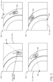
図5は、シミュレーション中の4つの異なる時点に対応する4つの異なるシミュレートされた環境500~506を含む、別の例示的なドライビングシミュレーションを示す。この例では、シミュレートされた車両508が、カーブした道路に沿って前方に移動する様子が示されている。シミュレートされた車両508は、単一のシミュレートされたセンサを含み、これは、回転するライダーセンサ(および/または車両とは独立して向きを変更するように構成された任意の他のセンサ)であり得る。この例に示されるように、シミュレートされた環境500(例えば、時間t1)おいて、センサは、ビュー510に向けられ、点512でビュー510と交差する光を放射する。車両が環境を横断するにつれて、車両の向きおよびセンサの向きが変化する。シミュレートされた環境502(例えば、時間t2)において、センサは、ビュー514に向けられ、点516でビュー514と交差する光を放射する。シミュレートされた環境504(例えば、時間t3)において、センサは、ビュー518に向けられ、点520でビュー518と交差する光を放射する。シミュレートされた環境506(例えば、時間t4)では、センサは、ビュー522に向けられ、点524でビュー522と交差する光を放射する。
FIG. 5 illustrates another exemplary driving simulation, including four different simulated environments 500-506 corresponding to four different times during the simulation. In this example, a
この例が示すように、シミュレーション中に、シミュレートされた車両および/またはセンサの位置および/または向きは、シミュレーションのためにレンダリングされたビューに対して変化し得る。センサの位置および/または向きの変化に応答して、センサエンジンは、いくつかのビューに基づいて再投影を生成してもよく、特定のビューを再生成してもよく、ビューを再配向してもよく、および/またはセンサとビューとの間の更新されたマッピングを決定してもよい。 As this example illustrates, during a simulation, the position and/or orientation of the simulated vehicle and/or sensors may change relative to the views rendered for the simulation. In response to changes in the position and/or orientation of the sensors, the sensor engine may generate reprojections based on some views, may regenerate certain views, may reorient views, and/or may determine updated mappings between sensors and views.
図6Aおよび図6Bは、シミュレートされた環境における深度認識光線投射技術の2つの例を示す。様々な例では、図6Aおよび図6Bに記載の技術は、シミュレーションの過程でシミュレートされたセンサが移動したシミュレーションシナリオにおける光線投射を含み、第1のシミュレーション時間に第1の光線を投射し、第2のシミュレーション時間に第2の光線を投射する。図6Aおよび図6Bの両方において、複数の光線は、異なる時間にセンサによって、シミュレートされたセンサがマッピングされる統合された2Dビューに関連付けられた深度データ602に投射される。本明細書に記載の技術は、図1の動作110を参照し、図2の再投影コンポーネント226を参照して上述したように、特定のセンサに関して生成されたビューを一時的に整列および/またはアップサンプリングするために適用され得る。追加的または代替的に、本明細書に記載の技術は、図1の動作114を参照し、図2のアップサンプリングコンポーネント228を参照して上述したように、空間的および/または時間的アップサンプリングに適用され得る。
6A and 6B show two examples of depth-aware ray casting techniques in a simulated environment. In various examples, the techniques described in FIGS. 6A and 6B include ray casting in a simulation scenario in which a simulated sensor has moved over the course of the simulation, casting a first ray at a first simulation time and a second ray at a second simulation time. In both FIGS. 6A and 6B, multiple rays are cast by the sensor at different times into
図6Aは、センサの位置が時間t1における位置604から時間t2における位置606に移動したシナリオを示す。図6Aのセンサの動きは、シミュレートされた環境を横断する車両の動きに対応し得る。この例では、位置604でセンサから投射された光線は、光線交点608で深度データ602(統合された2Dビューに対応するラスタライズされた深度ビューであり得る)と交差し、位置606でセンサから投射された光線は、光線交点610で深度データと交差する。この例における光線交点608および610は、光線交点608と610との間の非平面表面(および/または異なるシミュレートされたオブジェクト)を示す、深度値において比較的大きな差を有する。この例では、光線交点608と610との間の深度差に基づいて、センサエンジンは、線形補間技術ではなくサンプリング技術をアライメントおよび/またはアップサンプリングに使用することを決定し得る。例えば、時間t1とt2との間のシミュレーション内の時間に使用されるセンサデータを決定するために、ポイント608および610に基づく線形補間を使用するのではなく、センサエンジンは、シミュレーション内の時間が時間t1または時間t2に近いかどうかに基づいて、ポイント608または610のいずれかのサンプルを選択し得る。
FIG. 6A illustrates a scenario in which the position of the sensor has moved from position 604 at time t1 to position 606 at time t2. The sensor movement in FIG. 6A may correspond to the movement of a vehicle across a simulated environment. In this example, a ray cast from the sensor at position 604 intersects with the depth data 602 (which may be a rasterized depth view corresponding to the integrated 2D view) at
図6Bは、シミュレートされたセンサの位置が移動していないが、センサの向きが時間t1のセンサ角度612から時間t2のセンサ角度614に移動した別のシナリオを示す。図6Bのセンサの動きは、シミュレートされた環境における車両の旋回および/または車両に対するセンサの回転に対応し得る。この例では、センサ角度612に沿ってセンサから投射された光線は、光線交点616で深度データ602と交差し、センサ角度614から投射された光線は、光線交点618で深度データと交差する。光線交点608および610とは異なり、この例では、光線交点616および618は、深度値の小さな差があり、光線交点616と616との間の比較的平坦な表面(および/または同じシミュレートされたオブジェクトの可能性が高い)を示している。光線交点616と618との間のより小さな深度差に基づいて、この例におけるセンサエンジンは、サンプリング技術ではなく線形補間技術をアライメントおよび/またはアップサンプリングに使用することを決定し得る。例えば、時間t1とt2との間のシミュレーションである時間に使用されるセンサデータを決定するために、センサエンジンは、ポイント616および618に対応するセンサデータ値に基づいて線形補間を使用し得、色、速度、明るさ、材料などを効果的にブレンドする。
6B illustrates another scenario in which the simulated sensor position has not moved, but the sensor orientation has moved from sensor angle 612 at time t1 to sensor angle 614 at time t2. The sensor movement in FIG. 6B may correspond to a vehicle turning and/or a sensor rotation relative to the vehicle in the simulated environment. In this example, a ray cast from the sensor along sensor angle 612 intersects the
深度データ602はこの例で使用されるが、他の例では、類似の技術は、シミュレーション中に異なる時点で2Dビューに光線を投射し、次いで、光線交点でのオブジェクトIDが一致するかどうか、または光線交点での速度値が所定の閾値内にあるかどうかなどに基づいて、好ましいアライメントおよび/またはアップサンプリング技術を決定することによって実行され得る。
Although
図7は、シミュレートされた環境におけるシミュレートされたセンサのための例示的な深度認識空間アップサンプリング技術を示す。上述のように、いくつかの例では、センサエンジンは、ビューの再投影の生成中または後に、空間アップサンプリング技術を実行して、シミュレートされたセンサに提供されるセンサデータのビューの品質および/または解像度を向上させ得る。この例では、空間アップサンプリングは、光線交点に関連付けられた深度データに基づいてアップサンプリング技術(例えば、線形補間またはサンプリング)を選択することによって、視覚データおよび/または非視覚データ(例えば、画像および点群)の両方の品質および解像度を改善するために使用され得る。上記のように、この例は、深度データを使用する深度認識アップサンプリング技術を説明するが、他の例では、類似または同一の技術は、深度データの代わりに、または深度データと組み合わせて、オブジェクト識別子データおよび/または速度データを使用し得る。 FIG. 7 illustrates an example depth-aware spatial upsampling technique for a simulated sensor in a simulated environment. As mentioned above, in some examples, the sensor engine may perform a spatial upsampling technique during or after generation of the view reprojection to improve the quality and/or resolution of the view of the sensor data provided to the simulated sensor. In this example, spatial upsampling may be used to improve the quality and resolution of both visual and/or non-visual data (e.g., images and point clouds) by selecting an upsampling technique (e.g., linear interpolation or sampling) based on depth data associated with ray intersections. As mentioned above, this example describes a depth-aware upsampling technique that uses depth data, but in other examples, similar or identical techniques may use object identifier data and/or velocity data instead of or in combination with depth data.
この例では、画像700は、シミュレートされた環境のレンダリングされた2Dビューの深度データ702を含む。境界ボックス704は、深度データ702の画像の背景にある低解像度オブジェクトを識別する。境界ボックス704内のオブジェクトは画像の背景にあるため、それに割り当てられるピクセルが少なくてもよく、統合された2Dビューの可視データおよび不可視データの両方について比較的低い解像度でレンダリングされてもよい。本明細書に記載の空間アップサンプリング技術は、オブジェクトに関連付けられた境界ボックス704に1つまたは複数の光線を投射することと、オブジェクトの領域における2Dビューの解像度を改善するために光線交点のセンサデータ値を決定することとを含む。この例では、光線は、光線交点706で2Dビューと交差する2Dビューの深度データ702に投射する。サンプルポイント708~716を含む領域は、2Dビューの隣接するピクセル(または他の個別領域)を表し、隣接する領域のそれぞれは、特定の領域(例えば、オブジェクト識別子、色、明るさ、深さ、速度、材料など)に関連付けられた統合されたマルチセンサデータのセットを含み得る。 In this example, image 700 includes depth data 702 of a rendered 2D view of a simulated environment. Bounding box 704 identifies a low-resolution object in the background of the image of depth data 702. Because an object within bounding box 704 is in the background of the image, it may be assigned fewer pixels and may be rendered at a relatively low resolution for both the visible and non-visible data of the integrated 2D view. The spatial upsampling technique described herein includes casting one or more rays into bounding box 704 associated with the object and determining sensor data values of a ray intersection to improve the resolution of the 2D view in the region of the object. In this example, the ray is cast into depth data 702 of the 2D view that intersects with the 2D view at ray intersection 706. The regions including sample points 708-716 represent adjacent pixels (or other distinct regions) of the 2D view, and each of the adjacent regions may include a set of integrated multi-sensor data associated with a particular region (e.g., object identifier, color, brightness, depth, speed, material, etc.).
様々なアルゴリズムは、光線交点706に隣接する領域を評価するために使用され、光線交点706が比較的均一で平面的な表面上にある可能性が高いか、および/またはシミュレートされた環境内の同じオブジェクト上にある可能性が高いかを決定し得る。一例では、センサエンジンは、光線交点706に最も近い3つのサンプルの深さを識別し、評価し得る。この例における3つの最も近いサンプルポイントは、光線交点706の周りに三角形を形成するサンプルポイント710、712、および714であってよい。この例では、3つの最も近いサンプルポイント710、712、および714の深さが同じオブジェクト識別子を有する場合、センサエンジンは、光線交点706が同じオブジェクト上にあると仮定し得、サンプルポイント710、712、および714での対応するセンサデータに基づいて、線形補間を使用し、光線交点706のセンサデータを決定し得る。それ以外の場合、センサエンジンは、サンプルポイント710、712、および714によって形成された三角形が、サンプルポイント708、714、および716によって形成された三角形に対して十分に平面であるかどうかを決定し得る。いくつかの例では、曲率誤差パラメータを使用して、これらの三角形(または他の隣接する領域)が十分に平面であるかどうかを決定し得る。2つの三角形が十分に平面である場合、センサエンジンは、線形補間を使用して、サンプルポイント710、712、714、および716での対応するセンサデータに基づいて、光線交点706のセンサデータを決定し得る。それ以外の場合、センサエンジンは、サンプリングが線形補間の代わりに使用されるべきであると決定し得、最も近いサンプル(例えば、サンプルポイント708)についての対応するセンサデータに基づいて、光線交点706についてのセンサデータを決定し得る。この例は、オブジェクト識別子および深度データに基づいて空間アップサンプリングを実行するための1つのアルゴリズムを説明するが、本明細書に記載のサンプリング技術、閾値、および/または統合されたマルチセンサデータの任意の組み合わせに基づいて、他のアルゴリズムが他の例で使用され得ることが本開示の文脈から理解され得る。
Various algorithms may be used to evaluate the area adjacent to the ray intersection 706 to determine whether the ray intersection 706 is likely to be on a relatively uniform, planar surface and/or on the same object in the simulated environment. In one example, the sensor engine may identify and evaluate the depths of the three samples closest to the ray intersection 706. The three closest sample points in this example may be
図8は、GPUを使用してシミュレートされた環境のビューをレンダリングするための例示的なシステム800を示す。上述のように、いくつかの例では、センサエンジンは、シミュレーション中にセンサ入力データを生成するために使用される2Dビューを選択、レンダリング、アライニング、および/またはアップサンプリング(例えば、強化)するときに、1つまたは複数のGPUおよびCPUの使用を調整および管理し得る。いくつかの場合では、GPUは、センサデータを生成(例えば、3Dシミュレートされた環境の2Dビュー、レイトレーシング、再投影、アップサンプリングなどをラスタライズすることによって)するために使用され、CPUは、センサデータをシミュレーションに提供するために、センサデータの様々な前処理(例えば、ビュー選択)および/または後処理(例えば、メッセージのフォーマットおよびパッキング、ならびにシミュレートされたセンサへのセンサデータの配信)に使用され得る。この例では、システム800は、ビューレンダリングを実行するように構成されたGPUと、前処理および後処理機能を実行するように構成された1つまたは複数のCPUとを含む、2Dビューをレンダリングするための処理パイプラインを示す。
8 illustrates an
この例では、センサエンジンは、各クロック間隔802~806において、シミュレーションのための新しい/更新された2Dビューのレンダリングを選択し、開始する。例えば、クロック間隔802で開始して、入力コンポーネントは、処理ブロック808で実行され、前処理は、CPUによって実行され、ビューは、ブロック810でGPUによってレンダリングされ、後処理は、CPUによって実行され、レンダリングされた2Dビューは、処理ブロック812でシミュレートされたセンサに出力される。同様の処理パイプラインは、処理ブロック814から進むクロック間隔804で開始され、処理ブロック816でのGPUレンダリングを含み、処理ブロック818でレンダリングされた2Dビューを出力し、別の同様の処理パイプラインは、処理ブロック820、822、および824を含むクロック間隔806で開始される。
In this example, the sensor engine selects and begins rendering a new/updated 2D view for the simulation at each clock interval 802-806. For example, beginning at
この例に示されるように、システム800の2Dビューレンダリングパイプラインは、CPUおよびGPU機能に関して非同期的かつ独立して動作し得る。例えば、処理ブロック820は、GPUが処理ブロック816における前の2Dビューのレンダリングを完了する前に、新しい2Dビューの生成を開始し、CPU前処理機能を実行する。この例の非同期動作は、GPUダウンタイムを最小限に抑え、シミュレーション中の2Dビューのレンダリングの速度および効率を最大化します。さらに、この例におけるGPUおよびCPUの非同期および独立した動作は、望ましくないドロップフレームを防止する。
As shown in this example, the 2D view rendering pipeline of
様々な実装では、システム800の2Dビューレンダリングパイプラインはまた、シミュレーション中にビューレンダリング機能を動的に更新するために使用され得る。例えば、GPUのラスタライズおよび/またはレイトレーシング動作が処理のボトルネックであると決定されるとき、センサエンジンは、GPUの処理負荷を低減し、ボトルネックを軽減するために、レンダリングレートを低減し、ビュー解像度を低減し、および/または複数のセンサによって共有され得るビューを決定し得る。いくつかの場合では、GPUによってレンダリングされるビューの低減されたレンダリングレートおよび/または低い解像度を補償するために、センサエンジンは、追加のレイトレーシング/レイキャスト動作を実行し得、これは、GPUの処理負荷を低減しながら、改善されたセンサ入力データをもたらす時間/空間アライニングおよび/またはアップサンプリングを改善し得る。他の例では、センサエンジンは、GPUによって実行されるレイトレーシング/レイキャスティングを低減し、より高いレンダリングレートおよび/またはより高い解像度で補償し得る。
In various implementations, the 2D view rendering pipeline of
図9は、本明細書で説明される技術を実装するための例示的なシステム900のブロック図を示す。少なくとも1つの例では、システム900は、車両902を含むことができ、車両902は、図4および図5を参照して上述したシミュレートされた車両402および508と同じ車両とすることができる。システム900はまた、1つまたは複数のコンピューティングデバイス932を含むことができ、コンピューティングデバイス932は、ドライビングシミュレーションシステムおよび/またはセンサエンジンとして実装され、図2を参照して上述したコンピューティングデバイス202Aおよび/または202Bと同じまたは類似し得る。
9 illustrates a block diagram of an
車両902は、物理環境を横断する物理的な自律車両、および/または仮想および/またはログベースのシミュレーション内で動作するシミュレーション車両に対応し得る。実車両およびシミュレートされた車両を含む実装の両方について、車両902は、自律車両の様々なソフトウェアベースおよび/またはハードウェアベースのコンポーネントを含み得、物理的またはシミュレートされた環境を横断する自律車両を制御するために使用され得る。 Vehicle 902 may correspond to a physical autonomous vehicle traversing a physical environment and/or a simulated vehicle operating within a virtual and/or log-based simulation. For both implementations involving real and simulated vehicles, vehicle 902 may include various software-based and/or hardware-based components of an autonomous vehicle and may be used to control the autonomous vehicle traversing a physical or simulated environment.
車両902は、運転者(または乗員)がいつでも車両を制御することを期待されない状態で、全走行に対してすべての安全上重要な機能を実行することができる車両を説明する、米国運輸省道路交通安全局によって発行されたレベル5分類に従って動作するように構成された自律車両などの、無人車両のためのハードウェアベースおよび/またはソフトウェアベースのコントローラであり得る。いくつかの例では、車両制御システムは、任意の他のレベルまたは分類を有する完全または部分的自律車両などの実際の関連付けられた車両内で動作し得る。場合によっては、本明細書に記載の技術は、非自律走行車両によっても使用可能であり得る。追加的または代替的に、車両902は、例えば、車両902の開発、テスト、および検証プロセス中にコンピューティング環境で実行するシミュレートされた車両のハードウェアおよびソフトウェアベースのコントローラとして、物理的な車両から独立して動作し得る。さらに、本明細書に記載の車両902の実装は、自律車両、半自律車両、または非自律車両の制御システムをシミュレートすることを含み得るが、技術のいくつかは、シミュレートされた車両を使用して、シミュレートされた環境にあり得る。 Vehicle 902 may be a hardware- and/or software-based controller for an unmanned vehicle, such as an autonomous vehicle configured to operate according to a Level 5 classification issued by the National Highway Traffic Safety Administration, which describes a vehicle capable of performing all safety-critical functions for the entire journey with no driver (or passenger) expected to control the vehicle at any time. In some examples, the vehicle control system may operate within an actual associated vehicle, such as a fully or partially autonomous vehicle having any other level or classification. In some cases, the techniques described herein may also be usable by non-autonomous vehicles. Additionally or alternatively, vehicle 902 may operate independently of a physical vehicle, for example, as a hardware- and software-based controller of a simulated vehicle running in a computing environment during the development, testing, and validation process of vehicle 902. Furthermore, implementations of vehicle 902 described herein may include simulating the control system of an autonomous, semi-autonomous, or non-autonomous vehicle, although some of the techniques may be in a simulated environment using a simulated vehicle.
車両902は、例えば、バン、スポーツユーティリティ車両、クロスオーバー車両、トラック、バス、農業車両、および/または建設車両などの実際のまたはシミュレートされた車両の任意の構成に使用することができる。例えば、車両902のための関連付けられた車両は、1つまたは複数の内燃機関、1つまたは複数の電気モーター、水素動力、それらの任意の組み合わせ、および/または任意の他の適切な動力源によって駆動され得る。関連付けられた車両は4つの車輪を有し得るが、本明細書で説明される車両902および関連付けられた技術は、より少ないまたはより多い数の車輪、および/またはタイヤを有する車両に組み込むことができる。車両902は、4輪ステアリングを有する車両を制御するシステムを含むことができ、例えば、車両の第1の端部が第1の方向に移動するときに車両の前端部であるように、および第1の端部が反対方向に移動するときに車両の後端部になるように、すべての方向で同等または同様の性能特性で一般的に動作することができる。同様に、第2の方向に移動するときに、車両の第2の端部は、車両の前端部であり、および反対方向に移動するときに、第2の端部は、車両の後端部になる。これらの例示の特徴は、例えば、駐車場および/または市街地のような狭い空間または混雑した環境において、より優れた操縦性を容易にすることができる。 The vehicle 902 can be used in any configuration of real or simulated vehicles, such as, for example, a van, a sports utility vehicle, a crossover vehicle, a truck, a bus, an agricultural vehicle, and/or a construction vehicle. For example, the associated vehicle for the vehicle 902 can be driven by one or more internal combustion engines, one or more electric motors, hydrogen power, any combination thereof, and/or any other suitable power source. Although the associated vehicle can have four wheels, the vehicle 902 and associated technology described herein can be incorporated into vehicles having a fewer or greater number of wheels and/or tires. The vehicle 902 can include a system for controlling a vehicle having four-wheel steering and can generally operate with equal or similar performance characteristics in all directions, for example, such that a first end of the vehicle is the front end of the vehicle when moving in a first direction, and such that the first end is the rear end of the vehicle when moving in the opposite direction. Similarly, when moving in a second direction, the second end of the vehicle is the front end of the vehicle, and when moving in the opposite direction, the second end is the rear end of the vehicle. These example features can facilitate greater maneuverability in tight spaces or crowded environments, such as parking lots and/or city streets, for example.
いくつかの例では、車両902は、車両コンピューティングデバイス904、1つまたは複数のセンサシステム906、1つまたは複数のエミッター908、1つまたは複数の通信接続910、少なくとも1つの直接接続部912、および1つまたは複数の駆動アセンブリ914を含むことができる。車両コンピューティングデバイス904は、1つまたは複数のプロセッサ916および1つまたは複数のプロセッサ916と通信可能に結合されたメモリ918を含むことができる。図示の例では、車両902は、自律車両であるが、車両902は、任意の他のタイプの車両、または1つまたは複数のセンサシステムを有する任意の他のシステムであり得る。図示の例では、車両コンピューティングデバイス904のメモリ918は、ローカリゼーションコンポーネント920、知覚コンポーネント922、プランニングコンポーネント924、1つまたは複数のシステムコントローラ926、および1つまたは複数のマップ928を格納する。例示的な目的のためにメモリ918に存在するものとして図9に示されているが、ローカリゼーションコンポーネント920、知覚コンポーネント922、プランニングコンポーネント924、1つまたは複数のシステムコントローラ926、および1つまたは複数のマップ928は、追加的に、または代替的に、車両902にアクセス可能であり得る(例えば、遠隔に格納され得る)ことが企図される。
In some examples, the vehicle 902 can include a vehicle computing device 904, one or more sensor systems 906, one or more emitters 908, one or
少なくとも1つの例示において、ローカリゼーションコンポーネント920は、センサシステム906からデータを受信する機能を含み、車両902の位置を決定することができる。例えば、ローカリゼーションコンポーネント920は、環境のマップを含むことが可能であり、および/またはそれを要求/受信することが可能であり、マップ内で自律車両の位置を継続的に決定することが可能である。いくつかの例では、ローカリゼーションコンポーネント920は、SLAM(simultaneous localization and mapping)またはCLAMS(calibration, localization and mapping, simultaneously)を利用して、画像データ、LIDARデータ、レーダーデータ、IMUデータ、GPSデータ、ホイールエンコーダデータなどを受信し、自律車両の位置を正確に決定することができる。いくつかの例では、ローカリゼーションコンポーネント920は、本明細書で説明されるように、車両902の様々なコンポーネントにデータを提供して、候補軌道を生成するための自律車両の初期位置を決定することができる。 In at least one example, the localization component 920 can include functionality for receiving data from the sensor system 906 to determine the location of the vehicle 902. For example, the localization component 920 can include and/or request/receive a map of the environment and can continually determine the location of the autonomous vehicle within the map. In some examples, the localization component 920 can utilize simultaneous localization and mapping (SLAM) or calibration, localization and mapping, simultaneously (CLAMS) to receive image data, LIDAR data, radar data, IMU data, GPS data, wheel encoder data, etc. to accurately determine the location of the autonomous vehicle. In some examples, the localization component 920 can provide data to various components of the vehicle 902 to determine an initial location of the autonomous vehicle for generating candidate trajectories, as described herein.
場合によっては、知覚コンポーネント922は、オブジェクトの検出、セグメンテーション、および/または分類を実行するための機能を含むことができる。いくつかの例では、知覚コンポーネント922は、車両902に近接するエンティティの存在および/またはエンティティタイプ(例えば、自動車、歩行者、サイクリスト、動物、建物、樹木、路面、縁石、歩道、不明なものなど)としてエンティティの分類を示す処理されたセンサデータを提供することができる。追加的および/または代替的な例では、知覚コンポーネント922は、検出されたエンティティおよび/またはエンティティが位置する環境に関連付けられた1つまたは複数の特性を示す処理されたセンサデータを提供することができる。いくつかの例では、エンティティに関連付けられた特性は、x位置(グローバル位置)、y位置(グローバル位置)、z位置(グローバル位置)、方向、エンティティタイプ(例えば、分類など)、エンティティの速度、エンティティの範囲(サイズ)などを含むことができるが、これらに限定されない。環境に関連付けられた特性は、環境内の別のエンティティの存在、環境内の別のエンティティの状態、時刻、曜日、季節、気象条件、暗さ/明るさの表示などを含むことができるが、これらに限定されない。
In some cases, the
一般に、プランニングコンポーネント924は、環境を横断するために車両902が従うべき経路を決定することができる。例えば、プラニングコンポーネント924は、さまざまなルートおよび軌道、ならびにさまざまな詳細レベルを決定することができる。例えば、プランニングコンポーネント924は、第1の位置(例えば、現在の位置)から第2の位置(例えば、目標の位置)へ走行するルートを決定することができる。この説明の目的上、ルートは、2つの位置の間を走行するための一連のウェイポイントとすることができる。非限定的な例として、ウェイポイントは、道路、交差点、全地球測位システム(GPS)座標などが含まれる。さらに、プランニングコンポーネント924は、第1の位置から第2の位置へのルートの少なくとも一部に沿って自律車両を誘導するための命令を生成できる。少なくとも1つの例では、プランニングコンポーネント924は、一連のウェイポイントの第1のウェイポイントから一連のウェイポイントの第2のウェイポイントまで自律走行車をどのように誘導するかを決定することができる。いくつかの例では、命令は軌道または軌道の一部とすることができる。いくつかの例では、複数の軌道は、後退地平線技術(recessing horizon technique)に従って、実質的に同時に(例えば、技術的許容範囲内で)生成することができる。
In general, the
少なくとも1つの例では、車両コンピューティングデバイス904は、1つまたは複数のシステムコントローラ926を含むことができ、これは、車両902のステアリング、推進、ブレーキ、安全性、エミッター、通信、および他のシステムを制御するよう構成することができる。これらのシステムコントローラ926は、駆動アセンブリ914および/または車両902の他のコンポーネントの対応するシステムと通信および/または制御することができる。
In at least one example, the vehicle computing device 904 can include one or
メモリ918は、環境内をナビゲートするために車両902によって使用され得る1つまたは複数のマップ928をさらに含むことができる。この説明の目的上、マップは、トポロジ(交差点など)、通り、山脈、道路、地勢、および環境全般などの、環境に関する情報を提供することができる、2次元、3次元、またはN次元にモデル化された任意の数のデータ構造であることが可能であるが、これに限定されない。一例では、マップは、本明細書で論じられる技術を使用して生成された3次元メッシュを含むことができる。いくつかの例では、マップは、マップの個々のタイルが環境の別個の部分を表すようにタイル化されたフォーマットで記憶されることが可能であり、必要に応じて作業メモリにロードされることが可能である。少なくとも1つの例では、1つまたは複数のマップ928は、本明細書で論じられる技術に従って生成された少なくとも1つのマップ(例えば、画像および/またはメッシュ)を含み得る。いくつかの例では、車両902は、マップ928に少なくとも部分的に基づいて制御され得る。すなわち、マップ928は、ローカリゼーションコンポーネント920、知覚コンポーネント922、および/またはプランニングコンポーネント924に関連して使用され、車両902の位置を決定し、環境内のオブジェクトを識別し、および/または環境内をナビゲートするためのルートおよび/または軌道を生成し得る。
The
いくつかの例では、1つまたは複数のマップ928は、ネットワーク/トランスポートコンポーネント930を介してアクセス可能なリモートコンピューティングデバイス(コンピューティングデバイス932など)に格納され得る。いくつかの例では、複数のマップ928は、例えば、特性(例えば、エンティティのタイプ、時刻、曜日、その年の季節など)に基づいて格納され得る。複数のマップ928を格納することは、同様のメモリ要件を有し得るが、ヒートマップにおけるデータがアクセスされ得る速度を増加させる。
In some examples, one or
いくつかの例では、本明細書で説明されるコンポーネントのいくつかまたは全ての態様は、任意のモデル、アルゴリズム、および/または機械学習アルゴリズムを含み得る。例えば、いくつかの例では、メモリ918(および以下で説明されるメモリ936)の内のコンポーネントは、ニューラルネットワークとして実装され得る。 In some examples, some or all aspects of the components described herein may include any models, algorithms, and/or machine learning algorithms. For example, in some examples, components within memory 918 (and memory 936 described below) may be implemented as neural networks.
本明細書で説明するように、例示的なニューラルネットワークは、入力データを一連の接続されたレイヤに通して出力を生成する生物学的に着想を得たアルゴリズムである。ニューラルネットワークにおけるそれぞれのレイヤはまた、別のニューラルネットワークを含んでよく、または(畳み込みか否かには関係なく)任意の数のレイヤを含んでもよい。本開示の文脈において理解されるように、ニューラルネットワークは、機械学習を利用してよく、これは、学習したパラメータに基づいて出力が生成されるようなアルゴリズムの広範囲のクラスを指してもよい。 As described herein, an exemplary neural network is a biologically inspired algorithm that passes input data through a series of connected layers to generate an output. Each layer in a neural network may also include another neural network, or may include any number of layers (whether convolutional or not). As understood in the context of this disclosure, a neural network may utilize machine learning, which may refer to a broad class of algorithms in which an output is generated based on learned parameters.
ニューラルネットワークの脈絡で説明されるものの、任意のタイプの機械学習は、本開示と整合するように用いられてよい。例えば、機械学習アルゴリズムは、限定はされないが、回帰アルゴリズム(例えば、通常最小二乗回帰(OLSR)、線形回帰、ロジスティック回帰、段階的回帰、MARS(multivariate adaptive regression splines)、LOESS(locally estimated scatterplot smoothing))、インスタンスベースアルゴリズム(例えば、リッジ回帰、LASSO(least absolute shrinkage and selection operator)、Elastic net、LARS(least-angle regression))、決定木アルゴリズム(例えば、分類および回帰木(CART)、ID3(iterative dichotomiser 3)、カイ二乗自動相互作用検出(CHAID)、決定切り株、条件付き決定木)、ベイジアンアルゴリズム(例えば、ナイーブベイズ、ガウスナイーブベイズ、多項ナイーブベイズ、AODE(average one-dependence estimators)、ベイジアンビリーフネットワーク(BNN)、ベイジアンネットワーク)、クラスタリングアルゴリズム(例えば、k平均、kメジアン、期待値の最大化(EM)、階層的クラスタリング)、相関ルール学習アルゴリズム(例えば、パーセプトロン、誤差逆伝搬、ホップフィールドネットワーク、RBFN(Radial Basis Function Network))、深層学習アルゴリズム(例えば、深層ボルツマンマシン(DBM)、深層ビリーフネットワーク(DBN)、畳み込みニューラルネットワーク(CNN)、積層オートエンコーダ)、次元縮小アルゴリズム(例えば、主成分分析(PCA)、主成分回帰(PCR)、部分最小二乗回帰(PLSR)、サモンマッピング、多次元尺度構成法(MDS)、射影追跡、線形判別分析(LDA)、混合判別分析(MDA)、二次判別分析(QDA)、柔軟判別分析(FDA))、アンサンブルアルゴリズム(例えば、ブースティング、ブートストラップアグリゲーション(バギング)、アダブースト、積層ジェネラリゼーション(ブレンディング)、勾配ブースティングマシン(GBM)、勾配ブースト回帰木(GBRT)、ランダムフォレスト)、SVM(サポートベクタマシン)、教師あり学習、教師なし学習、半教師あり学習などを含むことができる。 Although described in the context of neural networks, any type of machine learning may be used consistent with the present disclosure. For example, machine learning algorithms may include, but are not limited to, regression algorithms (e.g., ordinary least squares regression (OLSR), linear regression, logistic regression, stepwise regression, multivariate adaptive regression splines (MARS), locally estimated scatterplot smoothing (LOESS)), instance-based algorithms (e.g., ridge regression, least absolute shrinkage and selection operator (LASSO), elastic net, least-angle regression (LARS)), decision tree algorithms (e.g., classification and regression trees (CART), iterative dichotomiser 3 (ID3), chi-squared automated interaction detection (CHAID), decision stump, conditional decision tree), Bayesian algorithms (e.g., naive Bayes, Gaussian naive Bayes, multinomial naive Bayes, average one-dependence estimators), Bayesian belief networks (BNN), Bayesian networks), clustering algorithms (e.g., k-means, k-median, expectation maximization (EM), hierarchical clustering), association rule learning algorithms (e.g., perceptron, backpropagation, Hopfield network, RBFN (Radial Basis Function Network), deep learning algorithms (e.g., deep Boltzmann machines (DBM), deep belief networks (DBN), convolutional neural networks (CNN), stacked autoencoders), dimensionality reduction algorithms (e.g., principal component analysis (PCA), principal component regression (PCR), partial least squares regression (PLSR), Sammon mapping, multidimensional scaling (MDS), projection pursuit, linear discriminant analysis (LDA), mixed discriminant analysis (MDA), quadratic discriminant analysis (QDA), flexible discriminant analysis (FDA)), ensemble algorithms (e.g., boosting, bootstrap aggregation (bagging), AdaBoost, stacked generalization (blending), gradient boosting machines (GBM), gradient boosted regression trees (GBRT), random forests), SVM (support vector machines), supervised learning, unsupervised learning, semi-supervised learning, etc.
アーキテクチャの追加例は、ResNet70、ResNet101、VGG、DenseNet、PointNet、およびこれらの類するものなどのニューラルネットワークを含む。 Additional examples of architectures include neural networks such as ResNet70, ResNet101, VGG, DenseNet, PointNet, and the like.
少なくとも1つの例において、センサシステム906は、LiDARセンサ、レーダーセンサ、超音波トランスデューサ、ソナーセンサ、位置センサ(例えば、GPS、COMPASS、その他)、慣性センサ(例えば、慣性測定ユニット(IMU)、加速度計、磁力計、ジャイロスコープ、その他)、カメラ(例えば、RGB、IR、強度、深度、飛行時間、その他)、マイクロホン、ホイールエンコーダ、環境センサ(例えば、温度センサ、湿度センサ、光センサ、圧力センサ、その他)、その他を含むことができる。センサシステム906は、これらまたは他のタイプのセンサのそれぞれの複数のインスタンスを含むことができる。例えば、LIDARセンサは、車両902の角、前部、後部、側面、および/または上部に配置された個々のLIDARセンサを含むことができる。別の例として、カメラセンサは、車両902の外部および/または内部の周りの様々な位置に配置された複数のカメラを含むことができる。センサシステム906は、車両コンピューティングデバイス904に入力を提供することができる。追加的または代替的に、センサシステム906は、所定の期間の経過後、ほぼリアルタイムなどで、1つまたは複数のネットワーク/トランスポートコンポーネント930を介して、センサデータを特定の周波数で1つまたは複数のコンピューティングデバイスに送信できる。 In at least one example, the sensor system 906 can include LiDAR sensors, radar sensors, ultrasonic transducers, sonar sensors, position sensors (e.g., GPS, COMPASS, etc.), inertial sensors (e.g., inertial measurement units (IMUs), accelerometers, magnetometers, gyroscopes, etc.), cameras (e.g., RGB, IR, intensity, depth, time of flight, etc.), microphones, wheel encoders, environmental sensors (e.g., temperature sensors, humidity sensors, light sensors, pressure sensors, etc.), etc. The sensor system 906 can include multiple instances of each of these or other types of sensors. For example, the LIDAR sensors can include individual LIDAR sensors located at the corners, front, rear, sides, and/or top of the vehicle 902. As another example, the camera sensors can include multiple cameras located at various locations around the exterior and/or interior of the vehicle 902. The sensor system 906 can provide input to the vehicle computing device 904. Additionally or alternatively, the sensor system 906 can transmit the sensor data at a particular frequency to one or more computing devices via one or more network/transport components 930 after a predetermined period of time, in near real-time, or the like.
また、車両902は、上記のように、光および/または音を発する1つまたは複数のエミッター908を含むことができる。この例において、エミッター908は、内部オーディオおよび視覚エミッターを含み、車両902の乗客と通信する。例示の目的で、限定ではなく、内部エミッターは、スピーカー、光、記号、ディスプレイ画面、タッチ画面、触覚エミッター(例えば、振動および/またはフォースフィードバック)、機械的アクチュエータ(例えば、シートベルトテンショナー、シートポジショナー、ヘッドレストポジショナーなど)などを含むことができる。この例において、エミッター908はまた、外部エミッターを含むことができる。限定ではなく例として、この例示の外部エミッターは、走行の方向または車両の作動の他のインジケータ(例えば、インジケータライト、標識、ライトアレイなど)を信号で送るためのライト、および音響ビームステアリング技術を備える1つまたは複数の歩行者または他の近くの車両と音声で通信するための1つ以上のオーディオエミッタ(例えば、スピーカー、スピーカーアレイ、ホーンなど)を含む。 The vehicle 902 may also include one or more emitters 908 that emit light and/or sound, as described above. In this example, the emitters 908 include interior audio and visual emitters to communicate with passengers of the vehicle 902. By way of example, and not by way of limitation, the interior emitters may include speakers, lights, symbols, display screens, touch screens, tactile emitters (e.g., vibration and/or force feedback), mechanical actuators (e.g., seat belt tensioners, seat positioners, head rest positioners, etc.), and the like. In this example, the emitters 908 may also include exterior emitters. By way of example, and not by way of limitation, the exterior emitters in this example may include lights for signaling the direction of travel or other indicators of the operation of the vehicle (e.g., indicator lights, signs, light arrays, etc.), and one or more audio emitters (e.g., speakers, speaker arrays, horns, etc.) for audibly communicating with one or more pedestrians or other nearby vehicles with acoustic beam steering technology.
車両902はまた、車両902と1つまたは複数の他のローカルまたはリモートコンピューティングデバイスとの間の通信を可能にする1つまたは複数の通信接続部910を含むことができる。例えば、通信接続部910は、車両902および/または駆動アセンブリ914上の他のローカルコンピューティングデバイスとの通信を容易にすることができる。また、通信接続部910は、車両が他の近くのコンピューティングデバイス(例えば、他の近くの車両、交通信号など)と通信することを可能にすることができる。通信接続部910はまた、車両902が遠隔操作コンピューティングデバイスまたは他の遠隔サービスと通信することを可能にする。
The vehicle 902 may also include one or
通信接続部910は、車両コンピューティングデバイス904を別のコンピューティングデバイスまたはネットワーク/トランスポートコンポーネント930などのネットワークに接続するための物理的および/または論理的インターフェースを含むことができる。例えば、通信接続部910は、IEEE802.11標準によって定義された周波数、ブルートゥース(登録商標)などの短距離無線周波数、セルラー通信(例えば、2G、3G、4G、4G LTE、5Gなど)、または、それぞれのコンピューティングデバイスが他のコンピューティングデバイスとインターフェースすることを可能にする任意の適切な有線もしくは無線通信プロトコルなどを介した、Wi-Fiベースの通信を可能にすることができる。ネットワーク/トランスポートコンポーネント930は、本明細書に記載される通信ネットワークの1つまたは任意の組み合わせを含み得る。いくつかの例では、ネットワーク/トランスポートコンポーネント930は、通信ネットワークに加えて、または通信ネットワークの代替として、共有メモリ、プロセス内通信、および/または同じ物理ハードウェアの共有使用などの他の技術を使用して通信を提供し得る。
The
少なくとも1つの例示において、車両902は、1つまたは複数の駆動アセンブリ914を含むことができる。いくつかの例では、車両902は、単一の駆動アセンブリ914を有することができる。少なくとも1つの例では、車両902が複数の駆動アセンブリ914を有する場合、個々の駆動アセンブリ914は、車両902の反対側の端部(例えば、前部および後部など)に配置され得る。少なくとも1つの例示では、駆動アセンブリ914は、1つまたは複数のセンサシステムを含み、駆動アセンブリ914および/または車両902の周囲の状態を検出することができる。限定ではなく例として、センサシステムは、駆動アセンブリのホイールの回転を感知するための1つまたは複数のホイールエンコーダ(例えばロータリーエンコーダー)、駆動アセンブリの向きおよび加速度を測定するための慣性センサ(例えば、慣性測定ユニット、加速度計、ジャイロスコープ、磁力計など)、カメラまたは他の画像センサ、駆動アセンブリの周囲のオブジェクトを音響的に検出するための超音波センサ、LIDARセンサ、レーダーセンサなど、を含むことができる。ホイールエンコーダなどのいくつかのセンサは、駆動アセンブリ914に固有であり得る。場合によっては、駆動アセンブリ914上のセンサシステムは、車両902の対応するシステム(例えば、センサシステム906)と重複または補完することができる。
In at least one example, the vehicle 902 can include one or
駆動システム914は、高電圧バッテリー、車両を推進するモーター、バッテリーからの直流を他の車両システムで使用する交流に変換するインバーター、ステアリングモーターおよびステアリングラック(電動とすることができる)を含むステアリングシステム、油圧又は電気アクチュエータを含むブレーキシステム、油圧および/又は空気圧コンポーネントを含むサスペンションシステム、トラクションの損失を軽減し制御を維持するブレーキ力分散用の安定性制御システム、HVACシステム、照明(例えば車両の外部環境を照らすヘッド/テールライトなどの照明)、および1つ又は複数の他のシステム(例えば、冷却システム、安全システム、車載充電システム、DC/DCコンバーター、高電圧ジャンクション、高電圧ケーブル、充電システム、充電ポートなどのその他の電子コンポーネント)を含む多くの車両システムを含むことができる。さらに、駆動システム914は、センサシステムからデータを受信し事前処理し、様々な車両システムの動作を制御できる駆動システムコントローラを含むことができる。いくつかの例では、駆動システムコントローラは、1つまたは複数のプロセッサ、および1つまたは複数のプロセッサと通信可能に結合されたメモリを含むことができる。メモリは、1つまたは複数のプログラムまたは命令を格納し、駆動アセンブリ914の様々な機能を実行することができる。さらに、駆動システム914はまた、それぞれの駆動システムによる1つまたは複数の他のローカル又はリモートコンピューティングデバイスとの通信を可能にする1つまたは複数の通信接続部を含む。
The
少なくとも1つの例示において、ローカリゼーションコンポーネント920、知覚コンポーネント922、および/またはプランニングコンポーネント924は、上述したように、センサデータを処理することができ、1つまたは複数のネットワーク/トランスポートコンポーネント930を介して、それらのそれぞれの出力を1つまたは複数のコンピューティングデバイス932に送信することができる。少なくとも1つの例では、ローカリゼーションコンポーネント920、知覚コンポーネント922、および/またはプランニングコンポーネント924は、特定の頻度で、所定の期間の経過後、ほぼリアルタイムなどで、それらのそれぞれの出力を1つまたは複数のコンピューティングデバイス932に送信することができる。
In at least one example, the localization component 920, the
図1~図8を参照して上述したように、また本開示全体を通して議論したように、車両902は、ネットワーク/トランスポートコンポーネント930を介して、1つまたは複数のコンピューティングデバイス932にセンサデータを送信することができる。いくつかの例では、車両902は未処理のセンサデータをコンピューティングデバイス932に送信することができる。他の例示において、車両902は、処理済みセンサデータおよび/またはセンサデータの表現をコンピューティングデバイス932に送信することができる。いくつかの例では、車両902は、特定の頻度で、所定の期間の経過後、ほぼリアルタイムで、センサデータをコンピューティングデバイス932に送信することができる。いくつかの例では、車両902は(未処理または処理済み)センサデータを1つまたは複数のログファイルとしてコンピューティングデバイス932に送信できる。 1-8, and as discussed throughout this disclosure, the vehicle 902 can transmit sensor data to one or more computing devices 932 via the network/transport component 930. In some examples, the vehicle 902 can transmit raw sensor data to the computing device 932. In other examples, the vehicle 902 can transmit processed sensor data and/or representations of the sensor data to the computing device 932. In some examples, the vehicle 902 can transmit sensor data at a particular frequency, after a predetermined period of time, in near real-time, or in other examples. In some examples, the vehicle 902 can transmit the sensor data (raw or processed) to the computing device 932 as one or more log files.
ドライビングシミュレーションの間、コンピューティングデバイス932は、シミュレートされた環境および/またはシミュレートされたエージェント/オブジェクトを含むシミュレーションを実行することができる。コンピューティングデバイス932は、車両のセンサシステム906によって検出および処理されるセンサデータの形態で、シミュレーションデータを車両902に提供し得る。シミュレーション中、車両902は、コンピューティングデバイス932によって提供されるセンサ入力に応答し得、一方、シミュレーション環境およびコンピューティングデバイス932上で実行されるエージェント/オブジェクトは、車両902によって実行される動きおよび他のアクションを制御する、車両902によって(例えば、システムコントローラ926を介して)出力される車両制御コマンドを検出し、応答することができる。 During a driving simulation, the computing device 932 may execute a simulation including a simulated environment and/or simulated agents/objects. The computing device 932 may provide simulation data to the vehicle 902 in the form of sensor data detected and processed by the vehicle's sensor system 906. During the simulation, the vehicle 902 may respond to sensor inputs provided by the computing device 932, while the simulated environment and agents/objects executing on the computing device 932 may detect and respond to vehicle control commands output by the vehicle 902 (e.g., via the system controller 926) that control movement and other actions performed by the vehicle 902.
少なくとも1つの例では、コンピューティングデバイス932は、1つ又は複数のプロセッサ934および1つ又は複数のプロセッサ934と通信可能に結合されたメモリ936を含むことができる。図示の例では、コンピューティングデバイス932のメモリ936は、ビューセレクタコンポーネント216、ビュージェネレータコンポーネント222、再投影コンポーネント226、アップサンプリングコンポーネント228、およびドライビングシミュレーションシステム234を格納する。少なくとも1つの例では、コンピューティングデバイス932は、図2のコンピューティングデバイス202に対応することができ、コンピューティングデバイス932内に描写されるコンポーネントは、図2に関連して上述した対応するコンポーネントと類似または同一であり得る。
In at least one example, the computing device 932 can include one or more processors 934 and a memory 936 communicatively coupled to the one or more processors 934. In the illustrated example, the memory 936 of the computing device 932 stores the
車両902のプロセッサ916およびコンピューティングデバイス932のプロセッサ934は、本明細書に記載されるように、データを処理し、動作を実行するための命令を実行することができる任意の適切なプロセッサであり得る。限定ではなく例として、プロセッサ916および934は、1つまたは複数の中央処理装置(CPU)、グラフィック処理装置(GPU)、または電子データを処理して当該電子データをレジスタおよび/またはメモリに格納できる他の電子データに変換する任意の他のデバイス若しくはデバイスの一部を含むことができる。いくつかの例では、集積回路(例えば、ASICなど)、ゲートアレイ(例えば、FPGAなど)、および他のハードウェアデバイスはまた、それらが符号化された命令を実装するよう構成される限り、プロセッサと見なすことができる。
The
メモリ918およびメモリ936は、非一時的なコンピュータ可読媒体の例である。メモリ918およびメモリ936は、オペレーティングシステムおよび1つまたは複数のソフトウェアアプリケーション、命令、プログラム、および/またはデータを格納して、本明細書に記載の方法および様々なシステムに起因する機能を実装できる。様々な実装では、メモリは、スタティックランダムアクセスメモリ(SRAM)、シンクロナスダイナミックRAM(SDRAM)、不揮発性/フラッシュタイプメモリ、または情報を格納可能な他の任意のタイプのメモリなど、適切なメモリ技術を用いて実装できる。本明細書で説明されるアーキテクチャ、システム、および個々の要素は、多くの他の論理的、プログラム的、および物理的なコンポーネントを含むことができ、それらの添付図面に図示されるものは、本明細書での説明に関連する単なる例にすぎない。
図9は分散システムとして示されているが、代替の例では、車両902のコンポーネントは、コンピューティングデバイス932に関連付けられ得、および/またはコンピューティングデバイス932のコンポーネントは、車両902に関連付けられ得ることに留意されたい。すなわち、車両902は、コンピューティングデバイス932に関連付けられた1つまたは複数の機能を実行でき、逆もまた同様である。 Note that while FIG. 9 is shown as a distributed system, in alternative examples, components of the vehicle 902 may be associated with the computing device 932 and/or components of the computing device 932 may be associated with the vehicle 902. That is, the vehicle 902 may perform one or more functions associated with the computing device 932, and vice versa.
図10~14は、本開示の例による例示的なプロセスを示す。これらのプロセスは、論理フローグラフとして示され、このそれぞれの動作は、ハードウェア、ソフトウェア、またはそれらの組み合わせにおいて実装できる一連の動作を表現する。ソフトウェアのコンテキストにおいては、動作は、1つまたは複数のプロセッサで実行したときに、列挙した動作を実行する1つまたは複数のコンピュータ可読記録媒体に格納されたコンピュータ実行可能命令を表す。一般に、コンピュータ実行可能命令は特定の機能を実行する、又は特定の抽象的データタイプを実装するルーチン、プログラム、物体、コンポーネント、データ構造などを含む。動作が記載される順序は限定して解釈されることを意図するものではなく、任意の数の記載される動作を任意の順序でおよび/又は並行し結合して、プロセスを実装することができる。 10-14 illustrate exemplary processes according to examples of the present disclosure. These processes are illustrated as logical flow graphs, each operation of which represents a sequence of operations that can be implemented in hardware, software, or a combination thereof. In the context of software, the operations represent computer-executable instructions stored on one or more computer-readable recording media that, when executed on one or more processors, perform the recited operations. Generally, computer-executable instructions include routines, programs, objects, components, data structures, etc. that perform a particular function or implement a particular abstract data type. The order in which the operations are described is not intended to be construed as limiting, and any number of the described operations can be combined in any order and/or in parallel to implement a process.
図10は、シミュレートされた環境のマルチセンサビューを生成し、使用して、シミュレートされたセンサにデータを提供するための例示的なプロセス1000を示す。プロセス1000において説明される動作の一部または全ては、ビューセレクタコンポーネント216、ビュージェネレータコンポーネント222、および/またはセンサシミュレーションシステム(またはセンサエンジン)を実装する1つまたは複数のコンピューティングデバイス202を備える他のコンポーネントなどの、図1~図9における1つまたは複数のコンポーネントによって実行され得る。
FIG. 10 illustrates an
動作1002において、センサエンジンは、ドライビングシミュレーションに関連付けられた3Dシミュレートされた環境を表すデータを受信し得る。3Dシミュレートされた環境は、いくつかの静的および/または動的オブジェクト(例えば、エージェント)を含み得、これは、人工知能および/または他のアルゴリズムに基づいて、シミュレートされた環境内で制御されるソフトウェアベースのオブジェクトを含み得る。
In
動作1004において、センサエンジンは、3Dシミュレートされた環境に基づいて、マルチセンサ2Dビューを生成し得る。いくつかの例では、動作1004は、シミュレートされた車両の視点位置から3Dシミュレートされた環境をラスタライズすることによって2Dビューをレンダリングするように構成されたGPUを使用して、ビュージェネレータコンポーネント222によって実行され得る。生成された2Dビューは、2Dビューの各領域(例えば、ピクセル)に関連付けられた複数のタイプのセンサデータを含み得、これには、ビューの各ピクセルについての画像データ(例えば、光および色データ)、深度データ、オブジェクト識別子、速度データ、材料データなどが含まれるが、これらに限定されない。2Dビュー内の各個別ピクセルまたは他の領域について、センサエンジンは、領域についてのマルチセンサデータを格納することができるアレイ、データ構造、または他のストレージ構成を生成し得る。
In
動作1006において、センサエンジンは、シミュレートされた環境で動作するセンサに関連付けられた視野および/またはデータ要件を含むセンサ依存性データを決定し得る。センサの視野は、シミュレートされた環境内のセンサの位置および配向角度に基づいてよい。さらに、センサのデータ要件は、センサが検出するように構成されているデータの種類に対応し得、シミュレートされた環境内のオブジェクトの物理的特性の任意の組み合わせを含み得る。例えば、画像センサ(例えば、カメラ)は、シミュレートされた環境からの光および色データを検出するように構成され得、レーダーセンサは、センサからのオブジェクトの距離(センサの視点からの深さと呼ばれ得る)および/またはオブジェクト速度データを検出するように構成され得、ライダーセンサは、データ、材料特性(例えば、材料タイプ/組成、反射率、粗さなど)を検出するように構成され得る。
In
動作1008で、センサエンジンは、動作1004で生成された2Dビューが、動作1006でセンサについて決定された視野およびデータ要件と一致するかどうかを決定し得る。センサエンジンは、センサの視野が2Dビューによってカバーされているかどうか、および2Dビューに格納されたデータのタイプがセンサのデータ要件に対応するかどうかを決定することによって、2Dビューとシミュレートされたセンサとの間の一致を決定し得る。
At
2Dビューがセンサ依存性データと一致しない場合(1008:いいえ)、プロセス1000は、動作1004に戻る前に、センサエンジンがセンサに関連付けられた更新されたマルチセンサ2Dビューを生成する動作1010に進む。それ以外の場合、2Dビューがセンサ依存性データと一致する場合(1008:はい)、プロセス1000は、センサエンジンがビューに対するセンサの位置および/または配向角度に基づいて2Dビューを整列させる、動作1012に進む。
If the 2D view does not match the sensor dependency data (1008: no), the
動作1014において、2Dビューをシミュレートされたセンサと整列させた後、センサエンジンは、整列された2Dビューのデータをシミュレートされたセンサの入力データとして出力し得る。いくつかの例では、センサエンジンは、2Dビューをドライビングシミュレーションシステム234に提供し、これは、更新されたビューを実行中のシミュレーションに統合し得、その後、シミュレートされたセンサは、更新されたビューに基づいて入力データを受信し得る。
In
図11は、シミュレートされたセンサにデータを提供するために、シミュレートされた環境の2Dビューを生成および再投影するための例示的なプロセス1100を示す。プロセス1000において説明される動作の一部または全ては、ビュージェネレータコンポーネント222、再投影コンポーネント226、および/またはセンサシミュレーションシステム(またはセンサエンジン)を実装する1つまたは複数のコンピューティングデバイス202を備える他のコンポーネントなど、図1~図9における1つまたは複数のコンポーネントによって実行され得る。
FIG. 11 illustrates an
動作1002において、センサエンジンは、ドライビングシミュレーションに関連付けられた3Dシミュレートされた環境を表すデータを受信し得る。3Dシミュレートされた環境は、いくつかの静的および/または動的オブジェクト(例えば、エージェント)を含み得、これは、人工知能および/または他のアルゴリズムに基づいて、シシミュレートされた環境内で制御されるソフトウェアベースのオブジェクトを含み得る。
In
動作1004において、センサエンジンは、3Dシミュレートされた環境に基づいて、マルチセンサ2Dビューを生成し得る。いくつかの例では、動作1004は、シミュレートされた車両の視点位置から3Dシミュレートされた環境をラスタライズすることによって2Dビューをレンダリングするように構成されたGPUを使用して、ビュージェネレータコンポーネント222によって実行され得る。生成された2Dビューは、2Dビューの各領域(例えば、ピクセル)に関連付けられた複数のタイプのセンサデータを含み得、これには、ビューの各ピクセルについての画像データ(例えば、光および色データ)、深度データ、オブジェクト識別子、速度データ、材料データなどが含まれるが、これらに限定されない。2Dビュー内の各個別ピクセルまたは他の領域について、センサエンジンは、領域についてのマルチセンサデータを格納することができるアレイ、データ構造、または他のストレージ構成を生成し得る。
In
動作1106において、センサエンジンは、シミュレーションで動作するセンサの位置、配向角度、および/または移動データを決定し得る。センサの位置および配向角度は、2Dビューに対して決定され得る。さらに、センサの移動は、2Dビューがレンダリングされた時間に対して決定され得、したがって、2Dビューが生成されたので、センサが(例えば、位置的および/または回転的に)移動したかどうかを示し得る。
In
動作1108において、センサエンジンは、動作1104で生成された2Dビューと、動作1106でセンサについて決定されたセンサアライメントデータとの間に任意の空間的および/または時間的差異が存在するかどうかを決定し得る。センサエンジンは、センサの位置、角度、および/または所定のアライメント閾値と比較することによって、2Dビューとシミュレートされたセンサとの間の一致を決定し得る。
In
シミュレートされたセンサのアライメントと2Dビューとの間に有意差が決定されない場合(1108:いいえ)、プロセス1100は、センサエンジンがアライメントされた2Dビューのデータをシミュレートされたセンサの入力データとして出力する動作1112に進み得る。この場合、センサエンジンは、センサおよびセンサがマッピングされる2Dビューが十分に整列されており、2Dビューを再投影する必要がないと決定する。
If no significant difference is determined between the alignment of the simulated sensor and the 2D view (1108: NO),
それ以外の場合、センサエンジンが、シミュレートされたセンサの位置、角度、および/または動きが2Dビューと十分に整列していないと決定すると(1108:はい)、プロセス1100は、動作1110に進み、センサエンジンは、2Dビューに対するセンサの位置、角度、および/または動きに基づいて、時間的および/または空間的に2Dビューを整列させるために再投影動作を開始する。いくつかの例では、再投影コンポーネント226は、レイキャスティングおよび/またはレイトレーシングを使用して、シミュレートされた環境内のセンサの位置から2Dビューに向かって光線を投射して、光線交点を決定することによって、レンダリングされた2Dビューを再投影し得る。光線交点に関連付けられた視覚データおよび/または深度データは、2Dビューを整列させ、シャドウイングおよびマスキング情報を計算し、様々な視覚効果をシミュレートするために使用され得る。
Otherwise, if the sensor engine determines that the simulated sensor position, angle, and/or motion is not sufficiently aligned with the 2D view (1108: yes), the
動作1112において、2Dビューをシミュレートされたセンサと整列させるために再投影が生成された後、センサエンジンは、整列された2Dビューのデータをシミュレートされたセンサの入力データとして出力し得る。いくつかの例では、センサエンジンは、2Dビューをドライビングシミュレーションシステム234に提供し、これは、更新されたビューを実行中のシミュレーションに統合し得、その後、シミュレートされたセンサは、更新されたビューに基づいて入力データを受信し得る。
In
図12は、深度認識空間アップサンプリングのための例示的なプロセス1200を示し、ここで、線形補間および/またはサンプリングは、シミュレートされた環境の2Dビューを強化するために使用される。プロセス1200において説明される動作の一部または全ては、ビュージェネレータコンポーネント222、アップサンプリングコンポーネント228、および/またはセンサシミュレーションシステム(またはセンサエンジン)を実装する1つまたは複数のコンピューティングデバイス202を備える他のコンポーネントなど、図1~図9における1つまたは複数のコンポーネントによって実行され得る。
FIG. 12 illustrates an
動作1202において、センサエンジンは、シミュレートされた環境の2Dビューを受信し得る。いくつかの例では、2Dビューは、ビューの各領域(例えば、ピクセル)に関連付けられたマルチセンサ画像データ(例えば、視覚データ、深度データ、オブジェクト識別子、速度データ、材料データなど)を有する「統合された」2Dビューを含み得る。
At
動作1204において、センサエンジンは、2Dビューの1つまたは複数の低解像度部分を決定してよい。例えば、2Dビューの距離/背景内の小さなオブジェクトは、それに割り当てられるピクセルが少なくてもよく、したがって、2Dビューの可視データおよび不可視データの両方について比較的低い解像度でレンダリングされてもよい。
In
動作1206において、センサエンジンは、1つまたは複数の光線を2Dビューの低解像度領域に投射してもよい。例えば、光線は、2Dビューの低解像度部分に関連付けられた境界ボックスに投射され得、光線投射は、2Dビューの深度データ(例えば、深度画像または深度バッファ)内の光線交点を決定するために使用され得る。
In
動作1208において、センサエンジンは、2Dビューの隣接領域および/または他の近傍領域の深度データを評価して、光線交点が比較的平坦な表面に関連付けられているかどうかを決定する。様々な例では、センサエンジンは、様々な異なる技術およびアルゴリズムを使用して、隣接する領域(例えば、ピクセル)の深度データを評価し得る。例えば、センサエンジンは、曲率誤差パラメータに関して1つまたは複数の三角形を評価して、三角形(または光線交差点を取り囲むまたは隣接する他の領域)が十分に平面であることを決定し得る。
In
光線交点がシミュレートされた環境内の比較的平面上にないと決定するとき(1208:いいえ)、動作1210において、センサエンジンは、光線交点に最も近いサンプルに基づいて、光線交点に関連付けられたセンサデータを決定する。それ以外の場合、光線交点がシミュレートされた環境内の比較的平面上にあると決定するとき(1210:いいえ)、動作1212において、センサエンジンは、隣接または周囲のピクセルからのセンサデータを使用して線形補間動作を実行し、光線交点に関するセンサデータを決定する。
When it is determined that the ray intersection is not on a relatively flat surface in the simulated environment (1208: NO), in
動作1214において、センサエンジンは、拡張された2Dビューをシミュレートされたセンサに出力する。いくつかの例では、センサエンジンは、2Dビューをドライビングシミュレーションシステム234に提供し、これは、拡張されたビューを実行中のシミュレーションに統合し得、その後、シミュレートされたセンサは、拡張されたビューに基づいて入力データを受信し得る。拡張された2Dビューは、本明細書に記載の深度認識アップサンプリングを使用して決定された追加のセンサデータの組み込みに基づいて、ビューの一部またはすべてにわたってより高い解像度を有するビューに対応し得る。さらに、この例は、深度データを使用するアップサンプリング技術を説明するが、他の例では、類似または同一のアップサンプリング技術は、深度データの代わりに、または深度データと組み合わせて、オブジェクト識別子データおよび/または速度データを使用し得る。
At
図13は、例示的なプロセス1200のオブジェクト認識および速度認識の時間アップサンプリングを示し、線形補間および/またはサンプリングが、時間間隔の間にセンサ入力データを生成するために使用される。プロセス1300において説明される動作の一部または全ては、ビュージェネレータコンポーネント222、アップサンプリングコンポーネント228、および/またはセンサシミュレーションシステム(またはセンサエンジン)を実装する1つまたは複数のコンピューティングデバイス202を備える他のコンポーネントなど、図1~図9における1つまたは複数のコンポーネントによって実行され得る。
13 illustrates an
動作1302において、センサエンジンは、第1の時間にシミュレーション内で動作するセンサの位置および配向角度を決定する。動作1304において、センサエンジンは、第1の時間におけるセンサの位置および向きに基づいて、センサからの光線を関連付けられた2Dビューに投射する。
In
動作1306において、センサエンジンは、第2の時間にシミュレーション内で動作するセンサの位置および配向角度を決定する。動作1308において、センサエンジンは、第1の時間におけるセンサの位置および向きに基づいて、センサからの光線を関連付けられた2Dビューに投射する。いくつかの例では、センサの位置および/または向きは、第1の時間と第2の時間との間で変化し得る。上述したように、場合によっては、センサの位置および/または向きは、シミュレーション中に環境を横断するときのシミュレートされた車両の動きに基づいて変化し得る。追加的または代替的に、センサは、シミュレートされた車両とは独立して移動および/または回転するように構成され得る。
In
動作1310において、センサエンジンは、動作1304および1308で決定された光線交点に関連付けられた深さおよび/またはオブジェクト識別子を比較し得る。この例では、第1の時間および第2の時間にセンサのために決定された光線交点が同じオブジェクト識別子および/または比較的平面上に関連付けられている場合(1310:はい)、動作1312において、センサエンジンは、2つの光線交点に関連付けられたセンサデータを使用して、線形補間動作を実行して、第1の時間と第2の時間との間の中間シミュレーション時間に関連付けられたセンサデータを決定し得る。
In
それ以外の場合、第1の時間および第2の時間にセンサのために決定された光線交点が異なるオブジェクト識別子に関連付けられ、および/または比較的平面上に配置されていない場合(1310:いいえ)、動作1314において、センサエンジンは、光線交点に関連付けられた速度データをさらに評価して、第1の時間および第2の時間の両方の光線交点が非移動オブジェクト上にあるかどうかを決定し得る。この例では、センサエンジンが、両方の光線交点が環境内の非移動オブジェクトに配置されていると決定する場合(1314:はい)、動作1316において、センサエンジンは、中間シミュレーション時間に時間的に最も近い光線交点からサンプリングする中間シミュレーション時間に中間シミュレーション時間のセンサデータ値を決定し得る。例えば、第1の時間が0.0秒であり、第2の時間が1.0秒である場合、動作1316では、0.4秒の中間シミュレーション時間に関連付けられたセンサデータが第1の時間に対応するセンサデータ値に割り当てられ、0.6秒の中間シミュレーション時間に関連付けられたセンサデータが第2の時間に対応するセンサデータ値に割り当てられる。これらの解決策は、動作1312で実行される線形補間とは対照的であり、動作1312では、中間シミュレーション時間に関連付けられたセンサデータが、第1および第2の時間の両方でセンサデータ値に基づいて生成される。
Otherwise, if the ray intersections determined for the sensor at the first and second times are associated with different object identifiers and/or are not located on a relatively flat surface (1310: no), in
この例を続けると、センサエンジンは、動作1314において、光線交点のうちの1つまたは両方が移動オブジェクト上に配置されていることを決定し(1314:いいえ)、次いで動作1318において、センサエンジンは、動作1316において光線交点からサンプリングする前に、サンプリング重み係数を決定し、適用し得る。動作1318で決定されたサンプリング重み係数は、移動しているシミュレートされたオブジェクト上のどの光線交点にあるか、ならびに移動しているシミュレートされたオブジェクトの速度および方向に基づいてよい。例えば、第1の時間に検出された小さなおよび/または速く動くオブジェクトは、中間シミュレーション時間中に離れて移動した可能性が高くなり得、したがって、サンプリング重み係数は、第1の時間と第2の時間との間の半分(例えば、0.5秒)のニューラル重み係数をより低い値(例えば、0.3秒)にシフトさせ得、これは、第1の光線交点よりも頻繁に第2の光線交点に基づいてセンサエンジンにサンプリングさせ得る。
Continuing with this example, in
動作1320において、センサエンジンは、拡張された2Dビューをシミュレートされたセンサに出力する。いくつかの例では、センサエンジンは、2Dビューをドライビングシミュレーションシステム234に提供し、これは、拡張されたビューを実行中のシミュレーションに統合し得、その後、シミュレートされたセンサは、拡張されたビューに基づいて入力データを受信し得る。拡張された2Dビューは、本明細書に記載の時間的アップサンプリングを使用して決定された追加のセンサデータの組み込みに基づいて、より高いレンダリングレートを有するビューに対応し得る。さらに、この例は、オブジェクト識別子、深度データ、および速度に基づいて特定のアルゴリズムを使用するアップサンプリング技術を説明するが、他の例では、類似または同一の時間的アップサンプリング技術は、他の組み合わせで様々なアルゴリズムを有する他の統合ビューデータを使用し得る。
In
図14は、センサ依存性データ、ビューデータ、およびGPUスケジューリングデータを使用して、シミュレートされた環境内でレンダリングするためのビューを決定する例示的なプロセス1400を示す。プロセス1200において説明される動作の一部または全ては、ビューセレクタコンポーネント216、および/またはセンサシミュレーションシステム(またはセンサエンジン)を実装する1つまたは複数のコンピューティングデバイス202を備える他のコンポーネントなど、図1~図9における1つまたは複数のコンポーネントによって実行され得る。
FIG. 14 illustrates an
動作1402において、センサエンジンは、シミュレートされた環境で動作する1つまたは複数のセンサについてのセンサ依存性データを受信し得る。様々な例では、センサ依存性データは、センサが検出するように構成されているデータのタイプと共に、シミュレートされた環境内のセンサの位置、配向角度、および/または視野を含み得る。
In
動作1404において、センサエンジンは、シミュレートされた環境内の1つまたは複数のレンダリングされたビューに関連付けられたビューデータを受信し得る。シミュレーションビューデータは、シミュレーションでレンダリングされたビューごとに、ビューの位置(例えば、焦点)、ビューの向き(例えば、角度)、ビューの個別領域(例えば、ピクセル)に格納されたデータのタイプ、およびビューに関連付けられたレンダリング時間/レートを含み得る。
At
動作1406において、センサエンジンは、ドライビングシミュレーションに関連付けられた1つまたは複のGPUおよび/またはCPUについてのスケジューリングおよび/またはパフォーマンスデータを受信または決定し得る。CPU218およびGPU224のスケジューリングおよびパフォーマンスデータは、2Dビューをレンダリングするための利用可能なGPUの容量(例えば、コア、GPU速度、ストレージ、現在のレンダリングバックログ、レイテンシー、ネットワーク速度)および/またはGPUによる新しいビューのレンダリングに関連して前処理および後処理動作を実行するための利用可能なCPUの容量を含み得る。
In
動作1408において、センサエンジンは、ビューを選択し、GPUを介して選択されたビューの更新されたレンダリングを開始し得る。上述のように、様々な異なる実装では、ビューセレクタコンポーネント216は、動作1402~1406で受信されたデータの異なる組み合わせを使用し得、本明細書に記載の様々なヒューリスティックベースのアルゴリズムおよび/または機械学習モデルのいずれかを適用して、シミュレーション中の現在の時間にどのビューがレンダリングされるかを決定し得る。
In
動作1410において、センサエンジンは、シミュレーションおよびコンピューティングリソース(例えば、GPUおよびCPU)の性能を分析して、GPUによってレンダリングされる2Dビューについてのビュー解像度および/またはレンダリングレートを調整するか、および/またはCPUによって実行されるビューセンサアライメントおよび/またはアップサンプリングを調整するかを決定し得る。例えば、センサエンジンは、1つまたは複数の動作(例えば、GPUによるラスタライズ、CPUによるレイトレーシング)を、シミュレーション性能に悪影響を及ぼし得る処理ボトルネックとして識別し得る。いくつかの例では、センサエンジンは、1つまたは複数のアルゴリズムまたは機械学習モデルを適用して、GPUの処理負荷を低減し、ボトルネックを軽減するために、最適なレンダリングレート、ビュー構成、ビュー解像度を決定し得る。追加的または代替的に、センサエンジンは、1つまたは複数のアルゴリズムまたは機械学習モデルを適用して、センサ/ビューアライメントを改善し、CPUによるセンサ入力データの時間的/空間的改良を実行するために使用されるレイトレーシングおよび/またはアップサンプリング動作のための最適なタイミングおよび構成を決定し得る。
In
センサエンジンが、GPUビューレンダリング機能(例えば、ビュー解像度および/またはレンダリングレート)またはCPUビュー処理機能(例えば、ビューセンサアライメントおよび/またはアップサンプリング構成)への調整を含む最適化を決定すると(1410:はい)、動作1412において、センサエンジンは、ビュージェネレータコンポーネント222、再投影コンポーネント226、および/またはアップサンプリングコンポーネント228を再構成して、調整されたビュー解像度、レンダリングレート、およびアライメントおよび/またはアップサンプリング構成を実装し得る。それ以外の場合、センサエンジンが、ビュー解像度、レンダリングレート、アライメント、および/またはアップサンプリング構成への調整を含む最適化を決定しないとき(1410:いいえ)、プロセス1400は、動作1402に戻り、レンダリングする次のビューを決定し得る。
If the sensor engine determines optimizations including adjustments to the GPU view rendering capabilities (e.g., view resolution and/or rendering rate) or CPU view processing capabilities (e.g., view sensor alignment and/or upsampling configuration) (1410: yes), then in
例示的な条項
A.1つまたは複数のプロセッサと、実行されると、1つまたは複数のプロセッサに、動作を実行させるコンピュータ実行可能命令を格納する1つまたは複数のコンピュータ可読媒体と、を備えるシステムであって、命令は、ドライビングシミュレーションに関連付けられた3次元環境を表すデータを決定することと、3次元環境内のシミュレートされた車両に関連付けられた位置を決定することと、シミュレートされた車両の位置に少なくとも部分的に基づいて、3次元環境の2次元ビューを生成することとであって、2次元ビューは、2次元ビューの領域に関連付けられた第1の物理的特性を示す第1のデータと、領域に関連付けられた第2の物理的特性を示す第2のデータである2次元ビューを生成することと、2次元ビューに少なくとも部分的に基づいて第1のセンサデータを生成することであって、第1のセンサデータは第1のデータを含み、第1のセンサデータはシミュレートされた車両の第1のシミュレートされたセンサに関連付けられる第1のセンサデータを生成することと、2次元ビューに少なくとも部分的に基づいて第2のセンサデータを生成することであって、第2のセンサデータは第2のデータを含み、第2のセンサデータは、シミュレートされた車両の第2のシミュレートされたセンサに関連付けられる第2のセンサデータを生成することと、ドライビングシミュレーション中に第1のセンサデータおよび第2のセンサデータをシミュレートされた車両に提供することと、を備えたシステム。
Exemplary Provisions A. A system comprising one or more processors and one or more computer-readable media storing computer-executable instructions that, when executed, cause the one or more processors to perform operations, the instructions including: determining data representative of a three-dimensional environment associated with a driving simulation; determining a position associated with a simulated vehicle within the three-dimensional environment; and generating a two-dimensional view of the three-dimensional environment based at least in part on the position of the simulated vehicle, the two-dimensional view being first data indicative of a first physical characteristic associated with a region of the two-dimensional view and second data indicative of a second physical characteristic associated with the region. generating first sensor data based at least in part on the two-dimensional view, the first sensor data including first data, the first sensor data associated with a first simulated sensor of the simulated vehicle; generating second sensor data based at least in part on the two-dimensional view, the second sensor data including second data, the second sensor data associated with a second simulated sensor of the simulated vehicle; and providing the first sensor data and the second sensor data to the simulated vehicle during a driving simulation.
B.第1のセンサデータを生成することは、第1のシミュレートされたセンサに関連付けられた第1のセンサ位置に少なくとも部分的に基づいて、2次元ビューの第1の再投影を生成することを含み、第2のセンサデータを生成することは、シミュレートされた車両の位置に対して、第2のシミュレートされたセンサに関連付けられた第2のセンサ位置に少なくとも部分的に基づいて、2次元ビューの第2の再投影を生成することを含み、第1のセンサ位置は、第2のセンサ位置とは異なる、段落Aに記載のシステム。 B. The system of paragraph A, wherein generating the first sensor data includes generating a first reprojection of the two-dimensional view based at least in part on a first sensor position associated with the first simulated sensor, and generating the second sensor data includes generating a second reprojection of the two-dimensional view based at least in part on a second sensor position associated with the second simulated sensor, relative to the simulated vehicle position, the first sensor position being different from the second sensor position.
C.第1のシミュレートされたセンサは、カメラを含み、第1のセンサデータは、2次元ビューの領域に関連付けられた光データを含み、第2のシミュレートされたセンサは、ライダーセンサまたはレーダーセンサのうちの少なくとも1つを含み、第2のセンサデータは、2次元ビューの領域に関連付けられた速度データまたは材料データのうちの少なくとも1つを含む、段落Aに記載のシステム。 C. The system of paragraph A, wherein the first simulated sensor includes a camera, and the first sensor data includes light data associated with the area of the two-dimensional view, and the second simulated sensor includes at least one of a lidar sensor or a radar sensor, and the second sensor data includes at least one of speed data or material data associated with the area of the two-dimensional view.
D.第1のセンサデータを生成することは、第1のシミュレートされたセンサに関連付けられた第1のセンサポーズを決定することと、第1のセンサに関連付けられた第1のセンサシミュレーション時間を決定することと、第1のセンサポーズおよび第1のセンサシミュレーション時間に少なくとも部分的に基づいて、第1のシミュレートされたセンサの2次元ビューの再投影を生成することと、を含む、段落Aに記載のシステム。 D. The system of paragraph A, wherein generating the first sensor data includes determining a first sensor pose associated with the first simulated sensor, determining a first sensor simulation time associated with the first sensor, and generating a reprojection of a two-dimensional view of the first simulated sensor based at least in part on the first sensor pose and the first sensor simulation time.
E.3次元環境の2次元ビューを生成することは、ラスタライズプロセスを実行することを含み、第1のセンサデータを生成することは、レイキャスティングプロセスを実行することを含み、2次元ビューの第1の再投影を生成する、段落Dに記載のシステム。 E. The system of paragraph D, wherein generating a two-dimensional view of the three-dimensional environment includes performing a rasterization process and generating the first sensor data includes performing a ray casting process to generate a first reprojection of the two-dimensional view.
F.方法であって、3次元シミュレートされた環境を表すデータを受信するステップと、3次元シミュレートされた環境の2次元ビューを生成するステップと、2次元ビューの領域に関連付けられた第1のメタデータおよび第2のメタデータを決定するステップと、2次元ビューに少なくとも部分的に基づいて第1のセンサデータを決定するステップであって、第1のセンサデータは第1のメタデータを含む第1のセンサデータを決定するステップと、第1のメタデータを検出するように構成された第1のシミュレートされたセンサに第1のセンサデータを提供するステップと、2次元ビューに少なくとも部分的に基づいて第2のセンサデータを決定するステップであって、第2のセンサデータは第2のメタデータを含む第2のセンサデータを決定するステップと、第2のメタデータを検出するように構成された第2のシミュレートされたセンサに第2のセンサデータを提供するステップと、を含む方法。 F. A method, the method including: receiving data representing a three-dimensional simulated environment; generating a two-dimensional view of the three-dimensional simulated environment; determining first and second metadata associated with a region of the two-dimensional view; determining first sensor data based at least in part on the two-dimensional view, the first sensor data including the first metadata; providing the first sensor data to a first simulated sensor configured to detect the first metadata; determining second sensor data based at least in part on the two-dimensional view, the second sensor data including the second metadata; and providing the second sensor data to a second simulated sensor configured to detect the second metadata.
G.第1のセンサデータを決定するステップは、3次元シミュレートされた環境内の第1のシミュレートされたセンサの第1のセンサ位置に少なくとも部分的に基づいて、2次元ビューの第1の再投影を生成するステップを含み、第2のセンサデータを決定するステップは、3次元シミュレートされた環境内の第2のシミュレートされたセンサの第2のセンサ位置に少なくとも部分的に基づいて、2次元ビューの第2の再投影を生成するステップを含み、第1のセンサ位置は、第2のセンサ位置とは異なる、段落Fに記載の方法。 G. The method of paragraph F, wherein determining the first sensor data includes generating a first reprojection of the two-dimensional view based at least in part on a first sensor position of a first simulated sensor in the three-dimensional simulated environment, and determining the second sensor data includes generating a second reprojection of the two-dimensional view based at least in part on a second sensor position of a second simulated sensor in the three-dimensional simulated environment, the first sensor position being different from the second sensor position.
H.第1のセンサデータを生成するステップは、第1のシミュレートされたセンサに関連付けられた第1のシミュレートされたセンサ時間に少なくとも部分的に基づいて、2次元ビューの第1の再投影を生成するステップを含み、第2のセンサデータを生成するステップは、第2のシミュレートされたセンサに関連付けられた第2のシミュレートされたセンサ時間に少なくとも部分的に基づいて、2次元ビューの第2の再投影を生成するステップを含み、第1のシミュレートされたセンサ時間は、第2のシミュレートされたセンサ時間とは異なる、段落Fに記載の方法。 H. The method of paragraph F, wherein generating the first sensor data includes generating a first reprojection of the two-dimensional view based at least in part on a first simulated sensor time associated with the first simulated sensor, and generating the second sensor data includes generating a second reprojection of the two-dimensional view based at least in part on a second simulated sensor time associated with the second simulated sensor, and the first simulated sensor time is different from the second simulated sensor time.
I.第1のシミュレートされたセンサは、カメラを含み、第1のメタデータは、2次元ビューの領域に関連付けられた光データを含み、第2のシミュレートされたセンサは、ライダーセンサまたはレーダーセンサのうちの少なくとも1つを含み、第2のメタデータは、2次元ビューの領域に関連付けられた速度データまたは材料データのうちの少なくとも1つを含む、段落Fに記載の方法。 I. The method of paragraph F, wherein the first simulated sensor includes a camera, the first metadata includes light data associated with the area of the two-dimensional view, and the second simulated sensor includes at least one of a lidar sensor or a radar sensor, and the second metadata includes at least one of speed data or material data associated with the area of the two-dimensional view.
J.第1のセンサデータを生成するステップは、3次元シミュレートされた環境内の第1のシミュレートされたセンサに関連付けられた第1のセンサ位置を決定するステップと、第1のセンサ位置と2次元ビューに関連付けられたビュー焦点位置との間の差に少なくとも部分的に基づいて、2次元ビューの再投影を生成するステップとを含み、2次元ビューを生成するステップは、ラスタライズプロセスを実行するステップを含み、2次元ビューの再投影を生成するステップは、レイキャスティングプロセスを実行するステップを含む、段落Fに記載の方法。 J. The method of paragraph F, wherein generating the first sensor data includes determining a first sensor position associated with a first simulated sensor within the three-dimensional simulated environment and generating a reprojection of the two-dimensional view based at least in part on a difference between the first sensor position and a view focus position associated with the two-dimensional view, wherein generating the two-dimensional view includes performing a rasterization process and generating the reprojection of the two-dimensional view includes performing a ray casting process.
K.第1のセンサデータを決定するステップは、第1のシミュレートされたセンサに関連付けられた第1のシミュレートされたセンサ時間を決定するステップと、第1のシミュレートされたセンサ時間と2次元ビューを生成するステップに関連付けられた時間との間の時間差に少なくとも部分的に基づいて、2次元ビューの再投影を生成するステップとを含み、2次元ビューを生成するステップは、ラスタライズプロセスを実行するステップを含み、2次元ビューの再投影を生成するステップは、レイキャスティングプロセスを実行するステップを含む、段落Fに記載の方法。 K. The method of paragraph F, wherein the step of determining the first sensor data includes determining a first simulated sensor time associated with the first simulated sensor and generating a reprojection of the two-dimensional view based at least in part on a time difference between the first simulated sensor time and a time associated with the step of generating the two-dimensional view, wherein the step of generating the two-dimensional view includes performing a rasterization process and the step of generating a reprojection of the two-dimensional view includes performing a ray casting process.
L.時間差に関連付けられた時間期間中に3次元シミュレートされた環境内の第1のシミュレートされたセンサの第1の動きを決定するステップと、時間期間中に2次元ビュー内で表されるシミュレートされたオブジェクトの第2の動きを決定するステップと、をさらに含み、2次元ビューの再投影を生成するステップは、第1の動きおよび第2の動きに少なくとも部分的に基づいている、段落Kに記載の方法。 L. The method of paragraph K, further comprising: determining a first movement of a first simulated sensor within the three-dimensional simulated environment during a time period associated with the time difference; and determining a second movement of a simulated object represented in the two-dimensional view during the time period, wherein generating a reprojection of the two-dimensional view is based at least in part on the first movement and the second movement.
M.2次元ビューを生成するステップは、領域に関連付けられた第1のストレージ場所にカメラデータを格納するステップと、領域に関連付けられた第2のストレージ場所にライダーデータを格納するステップと、領域に関連付けられた第3のストレージ場所にレーダーデータを格納するステップと、領域に関連付けられた第4のストレージ場所にオブジェクト識別子を格納するステップとを含む、段落Fに記載の方法。 M. The method of paragraph F, wherein generating the two-dimensional view includes storing the camera data in a first storage location associated with the region, storing the lidar data in a second storage location associated with the region, storing the radar data in a third storage location associated with the region, and storing the object identifier in a fourth storage location associated with the region.
N.プロセッサによって実行可能な命令を格納する1つまたは複数の非一時的なコンピュータ可読媒体であって、実行されると、プロセッサに動作を実行させる命令は、3次元シミュレートされた環境を表すデータを受信することと、3次元シミュレートされた環境の2次元ビューを生成することと、2次元ビューの領域に関連付けられた第1のメタデータおよび第2のメタデータを決定することと、2次元ビューに少なくとも部分的に基づいて第1のセンサデータを決定することであって、第1のセンサデータは第1のメタデータを含む第1のセンサデータを決定することと、第1のセンサデータを第1のメタデータを検出するように構成された第1のシミュレートされたセンサに提供することと、2次元ビューに少なくとも部分的に基づいて第2のセンサデータを決定することであって、第2のセンサデータは第2のメタデータを含む第2のセンサデータを決定することと、第2のセンサデータを第2のメタデータを検出するように構成された第2のシミュレートされたセンサに提供することと、を含む非一時的なコンピュータ可読媒体。 N. One or more non-transitory computer-readable media storing instructions executable by a processor, the instructions, when executed, causing the processor to perform operations including: receiving data representing a three-dimensional simulated environment; generating a two-dimensional view of the three-dimensional simulated environment; determining first and second metadata associated with an area of the two-dimensional view; determining first sensor data based at least in part on the two-dimensional view, the first sensor data including the first metadata; providing the first sensor data to a first simulated sensor configured to detect the first metadata; determining second sensor data based at least in part on the two-dimensional view, the second sensor data including the second metadata; and providing the second sensor data to a second simulated sensor configured to detect the second metadata.
O.第1のセンサデータを決定することは、3次元シミュレートされた環境内の第1のシミュレートされたセンサの第1のセンサ位置に少なくとも部分的に基づいて、2次元ビューの第1の再投影を生成することを含み、第2のセンサデータを決定することは、3次元シミュレートされた環境内の第2のシミュレートされたセンサの第2のセンサ位置に少なくとも部分的に基づいて、2次元ビューの第2の再投影を生成することを含み、第1のセンサ位置は、第2のセンサ位置とは異なる、段落Nに記載の1つまたは複数の非一時的なコンピュータ可読媒体。 O. The one or more non-transitory computer-readable media of paragraph N, wherein determining the first sensor data includes generating a first reprojection of the two-dimensional view based at least in part on a first sensor position of a first simulated sensor within the three-dimensional simulated environment, and determining the second sensor data includes generating a second reprojection of the two-dimensional view based at least in part on a second sensor position of a second simulated sensor within the three-dimensional simulated environment, the first sensor position being different from the second sensor position.
P.第1のセンサデータを生成することは、第1のシミュレートされたセンサに関連付けられた第1のシミュレートされたセンサ時間に少なくとも部分的に基づいて、2次元ビューの第1の再投影を生成することを含み、第2のセンサデータを生成することは、第2のシミュレートされたセンサに関連付けられた第2のシミュレートされたセンサ時間に少なくとも部分的に基づいて、2次元ビューの第2の再投影を生成することを含み、第1のシミュレートされたセンサ時間は、第2のシミュレートされたセンサ時間とは異なる、段落Nに記載の1つまたは複数の非一時的なコンピュータ可読媒体。 P. The one or more non-transitory computer-readable media of paragraph N, wherein generating the first sensor data includes generating a first reprojection of the two-dimensional view based at least in part on a first simulated sensor time associated with the first simulated sensor, and generating the second sensor data includes generating a second reprojection of the two-dimensional view based at least in part on a second simulated sensor time associated with the second simulated sensor, the first simulated sensor time being different from the second simulated sensor time.
Q.第1のシミュレートされたセンサは、カメラを含み、第1のメタデータは、2次元ビューの領域に関連付けられた光データを含み、第2のシミュレートされたセンサは、ライダーセンサまたはレーダーセンサのうちの少なくとも1つを含み、第2のメタデータは、2次元ビューの領域に関連付けられた速度データまたは材料データのうちの少なくとも1つを含む、段落Nに記載の1つまたは複数の非一時的なコンピュータ可読媒体。 Q. One or more non-transitory computer-readable media described in paragraph N, wherein the first simulated sensor includes a camera, the first metadata includes light data associated with the area of the two-dimensional view, and the second simulated sensor includes at least one of a lidar sensor or a radar sensor, and the second metadata includes at least one of speed data or material data associated with the area of the two-dimensional view.
R.第1のセンサデータを生成することは、3次元シミュレートされた環境内の第1のシミュレートされたセンサに関連付けられた第1のセンサ位置を決定することと、第1のセンサ位置と2次元ビューに関連付けられたビュー焦点位置との間の差に少なくとも部分的に基づいて、2次元ビューの再投影を生成することと、を含み、2次元ビューを生成することは、ラスタライズプロセスを実行することを含み、2次元ビューの再投影を生成することは、レイキャスティングプロセスを実行することを含む、段落Nに記載の1つまたは複数の非一時的なコンピュータ可読媒体。 R. One or more non-transitory computer-readable media as described in paragraph N, wherein generating the first sensor data includes determining a first sensor position associated with a first simulated sensor within the three-dimensional simulated environment and generating a reprojection of the two-dimensional view based at least in part on a difference between the first sensor position and a view focus position associated with the two-dimensional view, wherein generating the two-dimensional view includes performing a rasterization process and generating the reprojection of the two-dimensional view includes performing a ray casting process.
S.第1のセンサデータを決定することは、第1のシミュレートされたセンサに関連付けられた第1のシミュレートされたセンサ時間を決定することと、第1のシミュレートされたセンサ時間と2次元ビューの生成することに関連付けられた時間との間の時間差に少なくとも部分的に基づいて、2次元ビューの再投影を生成することとを含み、2次元ビューを生成することは、ラスタライズプロセスを実行することを含み、2次元ビューの再投影を生成することは、レイキャスティングプロセスを実行することを含む、段落Nに記載の1つまたは複数の非一時的なコンピュータ可読媒体。 S. One or more non-transitory computer-readable media as described in paragraph N, wherein determining the first sensor data includes determining a first simulated sensor time associated with the first simulated sensor and generating a reprojection of the two-dimensional view based at least in part on a time difference between the first simulated sensor time and a time associated with generating the two-dimensional view, wherein generating the two-dimensional view includes performing a rasterization process and generating the reprojection of the two-dimensional view includes performing a ray casting process.
T.動作は、時間差に関連付けられた時間期間中に、3次元シミュレートされた環境内の第1のシミュレートされたセンサの第1の動きを決定することと、時間期間中に、2次元ビュー内で表されるシミュレートされたオブジェクトの第2の動きを決定することと、をさらに含み、2次元ビューの再投影を生成することは、第1の動きおよび第2の動きに少なくとも部分的にさらに基づいている、段落Sに記載の1つまたは複数の非一時的なコンピュータ可読媒体。 T. The one or more non-transitory computer-readable media described in paragraph S, wherein the operations further include determining a first movement of a first simulated sensor within the three-dimensional simulated environment during a time period associated with the time difference and determining a second movement of a simulated object represented in the two-dimensional view during the time period, and generating a reprojection of the two-dimensional view is further based at least in part on the first movement and the second movement.
U.1つまたは複数のプロセッサと、実行されると、1つまたは複数のプロセッサに、動作を実行させるコンピュータ実行可能命令を格納する1つまたは複数のコンピュータ可読媒体と、を備えるシステムであって、命令は、シミュレートされた環境を表すデータを受信することと、シミュレートされた環境の2次元ビューを生成することであって、2次元ビューは、シミュレートされた環境内のビュー焦点位置に関連付けられている2次元ビューを生成することと、シミュレートされた環境内の第1のシミュレートされたセンサに関連付けられた第1のセンサ位置と、シミュレートされた環境内の第2のシミュレートされたセンサに関連付けられた第2のセンサ位置とを決定することであって、第2のセンサ位置は第1のセンサ位置とは異なるセンサ位置とを決定することと、シミュレートされた環境内のビュー焦点位置と第1のセンサ位置との間の第1の空間差を決定することと、シミュレートされた環境内のビュー焦点位置と第2のセンサ位置との間の第2の空間差を決定することと、2次元ビューおよび第1の空間差に少なくとも部分的に基づいて第1の再投影を生成することと、2次元ビューおよび第2の空間差に少なくとも部分的に基づいて第2の再投影を生成することと、第1の再投影に少なくとも部分的に基づいて、第1のシミュレートされたセンサに関連付けられた第1のセンサデータを決定することと、第2の再投影に少なくとも部分的に基づいて、第2のシミュレートされたセンサに関連付けられた第2のセンサデータを決定することと、を備えたシステム。 U. A system comprising one or more processors and one or more computer-readable media storing computer-executable instructions that, when executed, cause the one or more processors to perform operations, the instructions including: receiving data representing a simulated environment; generating a two-dimensional view of the simulated environment, the two-dimensional view being associated with a view focal position within the simulated environment; determining a first sensor position associated with a first simulated sensor within the simulated environment and a second sensor position associated with a second simulated sensor within the simulated environment, the second sensor position being different from the first sensor position. A system comprising: determining a first spatial difference between a view focus position and a first sensor position in the simulated environment; determining a second spatial difference between a view focus position and a second sensor position in the simulated environment; generating a first reprojection based at least in part on the two-dimensional view and the first spatial difference; generating a second reprojection based at least in part on the two-dimensional view and the second spatial difference; determining first sensor data associated with the first simulated sensor based at least in part on the first reprojection; and determining second sensor data associated with the second simulated sensor based at least in part on the second reprojection.
V.動作は、第1のシミュレートされたセンサに関連付けられた第1の実行レートを決定することと、第2のシミュレートされたセンサに関連付けられた第2の実行レートを決定することとをさらに含み、第1の実行レートは、第2の実行レートとは異なる、段落Uに記載のシステム。 V. The system of paragraph U, wherein the operations further include determining a first execution rate associated with the first simulated sensor and determining a second execution rate associated with the second simulated sensor, the first execution rate being different from the second execution rate.
W.動作は、シミュレートされた環境の第2の2次元ビューを生成することであって、2次元ビューは、第1の角度で配向され、第2の2次元ビューは、第1の角度とは異なる第2の角度で配向され、第2の2次元ビューは、第2のビュー焦点位置に関連付けられる第2の2次元ビューを生成することと、第2のビュー焦点位置とシミュレートされた環境内の第1のセンサ位置との間の第3の空間差を決定することと、第2の2次元ビューおよび第3の空間差に少なくとも部分的に基づいて第3の再投影を生成することと、をさらに含み、第1のセンサデータの第1の部分は、2次元ビューの第1の再投影に基づいて決定され、第1のセンサデータの第2の部分は、第2の2次元ビューの第3の再投影に基づいて決定される、段落Uに記載のシステム。 W. The system of paragraph U, further comprising: generating a second two-dimensional view of the simulated environment, the two-dimensional view being oriented at a first angle, the second two-dimensional view being oriented at a second angle different from the first angle, the second two-dimensional view being associated with a second view focal position; determining a third spatial difference between the second view focal position and a first sensor position in the simulated environment; and generating a third reprojection based at least in part on the second two-dimensional view and the third spatial difference, wherein a first portion of the first sensor data is determined based on the first reprojection of the two-dimensional view and a second portion of the first sensor data is determined based on the third reprojection of the second two-dimensional view.
X.動作は、シミュレーション中の第1の時間における第1のシミュレートされたセンサの第1の方向を決定することであって、2次元ビューの第1の再投影を生成することは、第1の方向に少なくとも部分的に基づいている第1の方向を決定することと、第1の時間後のシミュレーション中の第2の時間における第1のシミュレートされたセンサの第2の方向を決定することと、第2の方向に少なくとも部分的に基づいて、第2の2次元ビューを決定することと、第2の2次元ビューの第3の再投影に少なくとも部分的に基づいて、第1のシミュレートされたセンサに関連付けられた第3のセンサデータを決定することと、第2の時間に関連付けられたシミュレーション中の時間において、第1のシミュレートされたセンサに関連付けられた第3のセンサデータを決定することと、をさらに含む、段落Uに記載のシステム。 X. The system described in paragraph U, wherein the operations further include determining a first orientation of the first simulated sensor at a first time during the simulation, the first orientation being based at least in part on the first orientation, determining a second orientation of the first simulated sensor at a second time during the simulation after the first time, determining a second two-dimensional view based at least in part on the second orientation, determining third sensor data associated with the first simulated sensor based at least in part on a third reprojection of the second two-dimensional view, and determining third sensor data associated with the first simulated sensor at a time during the simulation associated with the second time.
Y.動作は、2次元ビューを生成することに関連付けられたレンダリング時間を決定することと、第1のシミュレートされたセンサに関連付けられたシミュレートされたセンサ時間を決定することと、をさらに含み、第1の再投影を生成することは、2次元ビューを生成することに関連付けられたレンダリング時間と第1のシミュレートされたセンサに関連付けられたシミュレートされたセンサ時間との間の時間差に少なくとも部分的に基づいている、段落Uに記載のシステム。 Y. The system described in paragraph U, wherein the operations further include determining a rendering time associated with generating the two-dimensional view and determining a simulated sensor time associated with the first simulated sensor, and generating the first reprojection is based at least in part on a time difference between the rendering time associated with generating the two-dimensional view and the simulated sensor time associated with the first simulated sensor.
Z.方法であって、シミュレートされた環境を表すデータを受信するステップと、シミュレートされた環境内の第1のシミュレートされたセンサの第1の視野を決定するステップと、第1の視野に少なくとも部分的に基づいて第1のシミュレートされたセンサの第1のセンサデータを生成するステップと、シミュレートされた環境内の第2のシミュレートされたセンサの第2の視野を決定するステップを含み、第2の視野は、第1の視野と少なくとも部分的に重複するステップと、第2の視野に少なくとも部分的に基づいて第2のシミュレートされたセンサの第2のセンサデータを生成するステップであって、第2のセンサデータは、第1のセンサデータに少なくとも部分的に基づいているステップと、を含む方法。 Z. A method, comprising: receiving data representing a simulated environment; determining a first field of view of a first simulated sensor in the simulated environment; generating first sensor data for the first simulated sensor based at least in part on the first field of view; determining a second field of view of a second simulated sensor in the simulated environment, the second field of view at least partially overlapping the first field of view; and generating second sensor data for the second simulated sensor based at least in part on the second field of view, the second sensor data being based at least in part on the first sensor data.
AA.ラスタライズプロセスを使用して、シミュレートされた環境の2次元ビューを生成するステップをさらに含み、第1のセンサデータを生成するステップは、第1の視野に少なくとも部分的に基づいて、2次元ビューの第1の再投影を生成するステップを含み、第2のセンサデータを生成するステップは、第2の視野に少なくとも部分的に基づいて、2次元ビューの第2の再投影を生成するステップを含む、段落Zに記載の方法。 AA. The method of paragraph Z, further comprising using a rasterization process to generate a two-dimensional view of the simulated environment, wherein generating the first sensor data comprises generating a first reprojection of the two-dimensional view based at least in part on the first field of view, and generating the second sensor data comprises generating a second reprojection of the two-dimensional view based at least in part on the second field of view.
AB.第1の再投影を生成するステップは、2次元ビュー内に格納された光データに少なくとも部分的に基づいて画像を生成するステップを含み、第2の再投影を生成するステップは、2次元ビュー内に格納された深度データに少なくとも部分的に基づいて点群を生成するステップを含む、段落AAに記載の方法。 AB. The method of paragraph AA, wherein generating the first reprojection includes generating an image based at least in part on the light data stored in the two-dimensional view, and generating the second reprojection includes generating a point cloud based at least in part on the depth data stored in the two-dimensional view.
AC.2次元ビューは、シミュレートされた環境内のビュー焦点位置に関連付けられ、第1の再投影を生成するステップは、ビュー焦点位置とシミュレートされた環境内の第1のセンサポーズとの間の第1の空間差を決定するステップと、第1の空間差に少なくとも部分的に基づいて第1のレイキャストプロセスを実行するステップとを含み、第2の再投影を生成するステップは、ビュー焦点位置とシミュレートされた環境内の第2のセンサポーズとの間の第2の空間差を決定するステップと、第2の空間差に少なくとも部分的に基づいて第2のレイキャストプロセスを実行するステップを含む、段落AAに記載の方法。 AC. The method of paragraph AA, wherein the two-dimensional view is associated with a view focal position in the simulated environment, and generating the first reprojection includes determining a first spatial difference between the view focal position and a first sensor pose in the simulated environment and performing a first raycast process based at least in part on the first spatial difference, and generating the second reprojection includes determining a second spatial difference between the view focal position and a second sensor pose in the simulated environment and performing a second raycast process based at least in part on the second spatial difference.
AD.第1のセンサデータに関連付けられた第1のシミュレーション時間を決定するステップと、第2のセンサデータに関連付けられた第2のシミュレーション時間を決定するステップと、をさらに含み、第1のシミュレーション時間は、第2のシミュレーション時間とは異なる、段落Zに記載の方法。 AD. The method of paragraph Z, further comprising determining a first simulation time associated with the first sensor data and determining a second simulation time associated with the second sensor data, the first simulation time being different from the second simulation time.
AE.シミュレートされた環境の2次元ビューをレンダリングするステップであって、2次元ビューは、シミュレーション内のレンダリング時間に関連付けられ、第1のセンサデータを生成するステップは、レンダリング時間および第1のシミュレーション時間に少なくとも部分的に基づいて、2次元ビューの第1の再投影を生成するステップを含み、第2のセンサデータを生成するステップは、レンダリング時間および第2のシミュレーション時間に少なくとも部分的に基づいて、2次元ビューの第2の再投影を生成するステップを含む、段落ADに記載の方法。 AE. The method of paragraph AD, comprising: rendering a two-dimensional view of a simulated environment, the two-dimensional view being associated with a rendering time within the simulation; generating first sensor data including generating a first reprojection of the two-dimensional view based at least in part on the rendering time and the first simulation time; and generating second sensor data including generating a second reprojection of the two-dimensional view based at least in part on the rendering time and the second simulation time.
AF.シミュレートされた環境の第1のビューをレンダリングするステップであって、第1のビューは、第1の角度で配向され、シミュレートされた環境内の第1の焦点位置に関連付けられる第1のビューをレンダリングするステップと、シミュレートされた環境の第2のビューをレンダリングするステップであって、第2のビューは、第2の角度で配向され、シミュレートされた環境内の第2の焦点位置に関連付けられ、第1のセンサデータを生成するステップは、第1のビューに基づいて第1のセンサデータの第1の部分を決定するステップと、第2のビューに基づいて第1のセンサデータの第2の部分を決定するステップと、を含む第2のビューをレンダリングするステップと、をさらに含む、段落Zに記載の方法。 AF. The method of paragraph Z, further comprising: rendering a first view of the simulated environment, the first view being oriented at a first angle and associated with a first focal position within the simulated environment; and rendering a second view of the simulated environment, the second view being oriented at a second angle and associated with a second focal position within the simulated environment, and the generating first sensor data includes determining a first portion of the first sensor data based on the first view; and determining a second portion of the first sensor data based on the second view.
AG.第1のセンサデータを生成するステップは、ラスタライズプロセスを使用して、シミュレートされた環境の2次元ビューをレンダリングするステップであって、2次元ビューは、シミュレートされた環境内のビュー焦点位置およびレンダリング時間に関連付けられている、レンダリングするステップと、ビュー焦点位置と第1のセンサに関連付けられた第1のセンサポーズとの間の空間差を決定するステップと、レンダリング時間と第1のセンサに関連付けられた第1のシミュレーション時間との間の時間差を決定するステップと、空間差および時間差に少なくとも部分的に基づいて、2次元ビューの再投影を生成するステップと、を含む、段落Zに記載の方法。 AG. The method of paragraph Z, wherein the step of generating the first sensor data includes the steps of: rendering a two-dimensional view of the simulated environment using a rasterization process, the two-dimensional view being associated with a view focus position and a rendering time in the simulated environment; determining a spatial difference between the view focus position and a first sensor pose associated with the first sensor; determining a time difference between the rendering time and a first simulation time associated with the first sensor; and generating a reprojection of the two-dimensional view based at least in part on the spatial difference and the time difference.
AH.プロセッサによって実行可能な命令を格納する1つまたは複数の非一時的なコンピュータ可読媒体であって、実行されると、プロセッサに動作を実行させる命令は、シミュレートされた環境を表すデータを受信することと、シミュレートされた環境内の第1のシミュレートされたセンサの第1の視野を決定することと、第1の視野に少なくとも部分的に基づいて第1のシミュレートされたセンサの第1のセンサデータを生成することと、シミュレートされた環境内の第2のシミュレートされたセンサの第2の視野を決定することであって、第2の視野は第1の視野と少なくとも部分的に重複する第2の視野を決定することと、第2の視野に少なくとも部分的に基づいて第2のシミュレートされたセンサの第2のセンサデータを生成することであって、第2のセンサデータは、第1のセンサデータに少なくとも部分的に基づいている第2のセンサデータを生成することと、を含む1つまたは複数の非一時的なコンピュータ可読媒体。 AH. One or more non-transitory computer-readable media storing instructions executable by a processor, the instructions, when executed, causing the processor to perform operations including: receiving data representing a simulated environment; determining a first field of view of a first simulated sensor in the simulated environment; generating first sensor data for the first simulated sensor based at least in part on the first field of view; determining a second field of view of a second simulated sensor in the simulated environment, the second field of view at least partially overlapping with the first field of view; and generating second sensor data for the second simulated sensor based at least in part on the second field of view, the second sensor data being based at least in part on the first sensor data.
AI.動作は、ラスタライズプロセスを使用して、シミュレートされた環境の2次元ビューを生成することであって、第1のセンサデータを生成することは、第1の視野に少なくとも部分的に基づいて、2次元ビューの第1の再投影を生成することを含み、第2のセンサデータを生成することは、第2の視野に少なくとも部分的に基づいて、2次元ビューの第2の再投影を生成することを含む2次元ビューを生成すること、をさらに含む、段落AHに記載の1つまたは複数の非一時的なコンピュータ可読媒体。 AI. One or more non-transitory computer-readable media as described in paragraph AH, further comprising: generating a two-dimensional view of the simulated environment using a rasterization process, wherein generating the first sensor data includes generating a first reprojection of the two-dimensional view based at least in part on the first field of view, and generating the second sensor data includes generating a second reprojection of the two-dimensional view based at least in part on the second field of view.
AJ.第1の再投影を生成することは、2次元ビュー内に格納された光データに少なくとも部分的に基づいて画像を生成することを含み、第2の再投影を生成することは、2次元ビュー内に格納された深度データに少なくとも部分的に基づいて点群を生成することを含む、段落AIに記載の1つまたは複数の非一時的なコンピュータ可読媒体。 AJ. One or more non-transitory computer-readable media as described in paragraph AI, wherein generating the first reprojection includes generating an image based at least in part on the light data stored in the two-dimensional view, and generating the second reprojection includes generating a point cloud based at least in part on the depth data stored in the two-dimensional view.
AK.2次元ビューは、シミュレートされた環境内のビュー焦点位置に関連付けられ、第1の再投影を生成することは、ビュー焦点位置とシミュレートされた環境内の第1のセンサポーズとの間の第1の空間差を決定することと、第1の空間差に少なくとも部分的に基づいて第1のレイキャストプロセスを実行することとを含み、第2の再投影を生成することは、ビュー焦点位置とシミュレートされた環境内の第2のセンサポーズとの間の第2の空間差を決定することと、第2の空間差に少なくとも部分的に基づいて第2のレイキャストプロセスを実行することと、を含む、段落AIに記載の1つまたは複数の非一時間的なコンピュータ可読媒体。 AK. One or more non-temporal computer-readable media as described in paragraph AI, wherein the two-dimensional view is associated with a view focal position within the simulated environment, generating the first reprojection includes determining a first spatial difference between the view focal position and a first sensor pose within the simulated environment and performing a first raycast process based at least in part on the first spatial difference, and generating the second reprojection includes determining a second spatial difference between the view focal position and a second sensor pose within the simulated environment and performing a second raycast process based at least in part on the second spatial difference.
AL.動作は、第1のセンサデータに関連付けられた第1のシミュレーション時間を決定することと、第2のセンサデータに関連付けられた第2のシミュレーション時間を決定することとをさらに含み、第1のシミュレーション時間は、第2のシミュレーション時間とは異なる、段落AHに記載の1つまたは複数の非一時的なコンピュータ可読媒体。 AL. The one or more non-transitory computer-readable media of paragraph AH, wherein the operations further include determining a first simulation time associated with the first sensor data and determining a second simulation time associated with the second sensor data, the first simulation time being different from the second simulation time.
AM.動作は、シミュレートされた環境の2次元ビューをレンダリングすることをさらに含み、2次元ビューは、シミュレーション内のレンダリング時間に関連付けられ、第1のセンサデータを生成することは、レンダリング時間および第1のシミュレーション時間に少なくとも部分的に基づいて、2次元ビューの第1の再投影を生成することを含み、第2のセンサデータを生成することは、レンダリング時間および第2のシミュレーション時間に少なくとも部分的に基づいて、2次元ビューの第2の再投影を生成することを含む、段落ALに記載の1つまたは複数の非一時的なコンピュータ可読媒体。 AM. The one or more non-transitory computer-readable media of paragraph AL, wherein the operations further include rendering a two-dimensional view of the simulated environment, the two-dimensional view being associated with a rendering time within the simulation, and generating the first sensor data includes generating a first reprojection of the two-dimensional view based at least in part on the rendering time and the first simulation time, and generating the second sensor data includes generating a second reprojection of the two-dimensional view based at least in part on the rendering time and the second simulation time.
AN.動作は、シミュレートされた環境の第1のビューをレンダリングすることであって、第1のビューは、第1の角度で配向され、シミュレートされた環境内の第1の焦点位置に関連付けられレンダリングすることと、シミュレートされた環境の第2のビューをレンダリングすることであって、第2のビューは、第2の角度で配向され、シミュレートされた環境内の第2の焦点位置に関連付けられ、第1のセンサデータを生成することは、第1のビューに基づいて第1のセンサデータの第1の部分を決定することと、第2のビューに基づいて第1のセンサデータの第2の部分を決定することと、をさらに含む、段落AMに記載の1つまたは複数の非一時的なコンピュータ可読媒体。 AN. The one or more non-transitory computer-readable media of paragraph AM, wherein the operations further include rendering a first view of the simulated environment, the first view being oriented at a first angle and associated with a first focal position within the simulated environment, and rendering a second view of the simulated environment, the second view being oriented at a second angle and associated with a second focal position within the simulated environment, and generating the first sensor data further includes determining a first portion of the first sensor data based on the first view, and determining a second portion of the first sensor data based on the second view.
AO.1つまたは複数のプロセッサと、実行されると、1つまたは複数のプロセッサに、動作を実行させるコンピュータ実行可能命令を格納する1つまたは複数のコンピュータ可読媒体と、を備えるシステムであって、命令は、シミュレートされた環境に関連付けられた2次元ビューを受信することと、シミュレートされた環境内のシミュレートされたセンサに関連付けられたセンサポーズを決定することと、レイキャストプロセスを使用して、センサポーズに少なくとも部分的に基づいて、2次元ビュー内の光線交点を決定することと、光線交点に少なくとも部分的に基づいて、2次元ビューと、2次元ビューから、第1の領域に関連付けられた第1の深度値および第2の領域に関連付けられた第2の深度値を受信することと、第1の深度値と第2の深度値との間の比較に少なくとも部分的に基づいて、光線交点に関連付けられた物理的特性を決定することと、センサデータをシミュレートされた環境内のシミュレートされた車両に提供することであって、センサデータは光線交点に関連付けられた物理的特性を含む、提供することを備えたシステム。 AO. A system comprising one or more processors and one or more computer-readable media storing computer-executable instructions that, when executed, cause the one or more processors to perform operations, the instructions comprising: receiving a two-dimensional view associated with a simulated environment; determining a sensor pose associated with a simulated sensor in the simulated environment; determining ray intersections in the two-dimensional view based at least in part on the sensor pose using a ray casting process; receiving the two-dimensional view based at least in part on the ray intersections, and a first depth value associated with a first region and a second depth value associated with a second region from the two-dimensional view; determining a physical property associated with the ray intersections based at least in part on a comparison between the first depth value and the second depth value; and providing sensor data to a simulated vehicle in the simulated environment, the sensor data including the physical property associated with the ray intersections.
AP.光線交点に関連付けられた物理的特性を決定することは、第1の領域に関連付けられた物理的特性の第1のサンプルを決定することと、第2の領域に関連付けられた物理的特性の第2のサンプルを決定することと、第1の深さ値と第2の深さ値との間の差を閾値と比較することと、差が閾値未満であるときに、第1のサンプルおよび第2のサンプルに少なくとも部分的に基づいて線形補間処理を使用して光線交点に関連付けられた物理的特性を決定することと、差が閾値を満たすか、または超えるときに、第1のサンプルまたは第2のサンプルのうちの1つを選択して光線交点に関連付けられた物理的特性を決定することと、を含む、段落AOに記載のシステム。 AP. The system described in paragraph AO, wherein determining a physical characteristic associated with the ray intersection includes determining a first sample of a physical characteristic associated with the first region, determining a second sample of a physical characteristic associated with the second region, comparing a difference between the first depth value and the second depth value to a threshold, determining a physical characteristic associated with the ray intersection using a linear interpolation process based at least in part on the first sample and the second sample when the difference is less than the threshold, and selecting one of the first sample or the second sample to determine the physical characteristic associated with the ray intersection when the difference meets or exceeds the threshold.
AQ.動作は、第1の領域に関連付けられた第1のオブジェクト識別子を決定することと、第2の領域に関連付けられた第2のオブジェクト識別子を決定することとをさらに含み、光線交点に関連付けられた物理的特性を決定することは、第1のオブジェクト識別子と第2のオブジェクト識別子との間の第2の比較に少なくとも部分的に基づいている、段落AOに記載のシステム。 AQ. The system of paragraph AO, wherein the operations further include determining a first object identifier associated with the first region and determining a second object identifier associated with the second region, and wherein determining the physical property associated with the ray intersection is based at least in part on a second comparison between the first object identifier and the second object identifier.
AR.動作は、シミュレートされた環境内のシミュレートされたセンサの第2のセンサポーズを決定することであって、センサポーズは、シミュレーション中の第1の時間に関連付けられ、第2のセンサポーズは、シミュレーション中の第1の時間の後の第2の時間に関連付けられ、決定することと、第2のセンサポーズに少なくとも部分的に基づいて、第2のレイキャストプロセスを用いて、2次元ビュー内の第2の光線交点を決定することであって、第1の領域は、光線交点に関連付けられ、第2の領域は、第2の光線交点に関連付けられ、決定することと、をさらに含む、段落AOに記載のシステム。 AR. The system of paragraph AO, further comprising: determining a second sensor pose of a simulated sensor in a simulated environment, the sensor pose being associated with a first time during the simulation, the second sensor pose being associated with a second time after the first time during the simulation; and determining a second ray intersection in the two-dimensional view using a second raycast process based at least in part on the second sensor pose, the first region being associated with the ray intersection, and the second region being associated with the second ray intersection.
AS.動作は、第1の領域に関連付けられた2次元ビューの第1のストレージから第1のサンプルを取り出すことによって、第1の領域に関連付けられた物理的特性の第1のサンプルを決定することと、第1の領域に関連付けられた2次元ビューの第2のストレージから第2のサンプルを取り出すことによって、第2の領域に関連付けられた物理的特性の第2のサンプルを決定することであって、物理的特性が、光特性、速度特性、材料特性、または反射特性のうちの少なくとも1つを含む、段落AOに記載のシステム。 AS. The system of paragraph AO, wherein the operation includes determining a first sample of a physical property associated with the first region by retrieving a first sample from a first storage of a two-dimensional view associated with the first region, and determining a second sample of a physical property associated with the second region by retrieving a second sample from a second storage of a two-dimensional view associated with the first region, the physical property including at least one of an optical property, a velocity property, a material property, or a reflectance property.
AT.方法であって、シミュレートされた環境に関連付けられた2次元ビューを受信するステップと、シミュレートされた環境内のシミュレートされたセンサのセンサポーズを決定するステップと、センサポーズに少なくとも部分的に基づいて、レイキャストプロセスを使用して、2次元ビュー内の光線交点を決定するステップと、光線交点に関連付けられた2次元ビューの領域を決定するステップと、2次元ビューの領域に関連付けられた属性値を決定するステップを含み、属性値は、深度値、オブジェクト識別子、または速度値のうちの少なくとも1つを含むステップと、属性値に少なくとも部分的に基づいて、光線交点に関連付けられた物理的特性の値を決定するステップと、シミュレートされたセンサに関連付けられたセンサデータを決定するステップであって、センサデータは、物理的特性の値を含むステップと、を含む方法。 AT. A method comprising: receiving a two-dimensional view associated with a simulated environment; determining a sensor pose of a simulated sensor in the simulated environment; determining ray intersections in the two-dimensional view using a ray casting process based at least in part on the sensor pose; determining a region of the two-dimensional view associated with the ray intersections; determining attribute values associated with the region of the two-dimensional view, the attribute values including at least one of a depth value, an object identifier, or a velocity value; determining values of physical properties associated with the ray intersections based at least in part on the attribute values; and determining sensor data associated with the simulated sensor, the sensor data including values of the physical properties.
AU.2次元ビューの第2の領域を決定するステップと、2次元ビューの第2の領域に関連付けられた第2の属性値を決定するステップとをさらに含み、光線交点に関連付けられた物理的特性の値を決定するステップは、領域に関連付けられた属性値と第2の領域に関連付けられた第2の属性値とを比較するステップに少なくとも部分的に基づく、段落ATに記載の方法。 AU. The method of paragraph AT, further comprising determining a second region of the two-dimensional view and determining a second attribute value associated with the second region of the two-dimensional view, wherein determining a value of a physical property associated with the ray intersection is based at least in part on comparing the attribute value associated with the region and the second attribute value associated with the second region.
AV.属性値と第2の属性値との間の差が閾値未満であると決定するステップと、差が閾値未満であると決定するステップに基づいて、領域に関連付けられた物理的特性の第2の値を決定するステップと、第2の領域に関連付けられた物理的特性の第3の値を決定するステップと、少なくとも第2の値および第3の値を含む線形補間プロセスを実行するステップと、をさらに含み、光線交点に関連付けられた物理的特性の値は、線形補間プロセスに基づいて決定される、段落AUに記載の方法。 AV. The method of paragraph AU, further comprising: determining that a difference between the attribute value and the second attribute value is less than a threshold; determining a second value of a physical property associated with the region based on determining that the difference is less than the threshold; determining a third value of a physical property associated with the second region; and performing a linear interpolation process including at least the second value and the third value, wherein the value of the physical property associated with the ray intersection is determined based on the linear interpolation process.
AW.属性値と第2の属性値と間の差が閾値を満たすか、または超えると決定するステップと、差が前記閾値を満たすか、または超えると決定するステップに基づいて、領域または第2の領域のいずれかを、2次元ビュー内の光線交点に空間的に近い領域として決定するステップと、空間的に近い領域に関連付けられた物理的特性の第2の値を決定するステップと、光線交点に関連付けられた物理的特性の値を、空間的に近い領域に関連付けられた物理的特性の第2の値として決定するステップと、をさらに含む、段落AUに記載の方法。 AW. The method of paragraph AU, further comprising: determining that a difference between the attribute value and the second attribute value meets or exceeds a threshold; determining either the region or the second region as a region spatially close to a ray intersection in the two-dimensional view based on determining that the difference meets or exceeds the threshold; determining a second value of a physical property associated with the spatially close region; and determining the value of the physical property associated with the ray intersection as the second value of the physical property associated with the spatially close region.
AX.シミュレートされた環境内のシミュレートされたセンサの第2のセンサポーズを決定するステップであって、センサポーズは、シミュレーション中の第1の時間に関連付けられ、第2のセンサポーズは、シミュレーション中の第1の時間の後の第2の時間に関連付けられる、決定するステップと、第2のセンサポーズに少なくとも部分的に基づいて、第2のレイキャストプロセスを使用して、2次元ビュー内の第2の光線交点を決定するステップであって、領域は、光線交点に関連付けられ、第2の領域は、第2の光線交点に関連付けられる、決定するステップと、をさらに含む、段落AUに記載の方法。 AX. The method of paragraph AU, further comprising: determining a second sensor pose of a simulated sensor in a simulated environment, the sensor pose being associated with a first time during the simulation, the second sensor pose being associated with a second time after the first time during the simulation; and determining a second ray intersection in the two-dimensional view using a second raycast process based at least in part on the second sensor pose, the region being associated with the ray intersection, and the second region being associated with the second ray intersection.
AY.光線交点と第2の光線交点との間の2次元ビュー内の距離を決定するステップをさらに含み、光線交点に関連付けられた物理的特性の値を決定するステップは、距離に少なくとも部分的に基づいている、段落AXに記載の方法。 AY. The method of paragraph AX, further comprising determining a distance in the two-dimensional view between the ray intersection and a second ray intersection, wherein determining a value of a physical property associated with the ray intersection is based at least in part on the distance.
AZ.2次元ビューの第2の領域を決定するステップであって、第2の領域は領域に隣接する、決定するステップと、第2の領域に関連付けられた第2の属性値を決定するステップと、2次元ビューの第3の領域を決定するステップであって、第3の領域は第2の領域とは異なる側の領域に隣接する、決定するステップと第3の領域に関連付けられた第3の属性値を決定するステップであって、光線交点に関連付けられた物理的特性の値を決定するステップは、属性値、第2の属性値、第3の属性値を比較することに少なくとも部分的に基づいている、段落ATに記載の方法。 AZ. The method of paragraph AT, further comprising steps of determining a second region of the two-dimensional view, the second region being adjacent to the region, determining a second attribute value associated with the second region, and determining a third region of the two-dimensional view, the third region being adjacent to the region on a different side than the second region, and determining a third attribute value associated with the third region, wherein determining a value of a physical property associated with the ray intersection is based at least in part on comparing the attribute value, the second attribute value, and the third attribute value.
BA.領域に関連付けられた物理的特性の第2の値を決定するステップであって、物理的特性は、光特性、速度特性、材料特性、または反射特性のうちの少なくとも1つを含み、光線交点に関連付けられた物理的特性の値を決定するステップは、領域に関連付けられた物理的特性の第2の値に少なくとも部分的に基づく、決定するステップをさらに含む、段落ATに記載の方法。 BA. The method of paragraph AT, further comprising determining a second value of a physical property associated with the region, the physical property including at least one of an optical property, a velocity property, a material property, or a reflectance property, and determining a value of the physical property associated with the ray intersection is based at least in part on the second value of the physical property associated with the region.
BB.プロセッサによって実行可能な命令を格納する1つまたは複数の非一時的なコンピュータ可読媒体であって、実行されると、プロセッサに動作を実行させる命令は、シミュレートされた環境に関連付けられた2次元ビューを受信することと、シミュレートされた環境内のシミュレートされたセンサのセンサポーズを決定することと、センサポーズに少なくとも部分的に基づいて、レイキャストプロセスを使用して、2次元ビュー内の光線交点を決定することと、光線交点に関連付けられた2次元ビューの領域を決定することと、2次元ビューの領域に関連付けられた属性値を決定することであって、属性値は、深度値、オブジェクト識別子、または速度値のうちの少なくとも1つを含むことと、属性値に少なくとも部分的に基づいて、光線交点に関連付けられた物理的特性の値を決定することと、シミュレートされたセンサに関連付けられたセンサデータを決定することであって、センサデータは、物理的特性の値を含む1つまたは複数の非一時的なコンピュータ可読媒体。 BB. One or more non-transitory computer-readable media storing instructions executable by a processor, the instructions, when executed, causing the processor to perform operations including: receiving a two-dimensional view associated with a simulated environment; determining a sensor pose of a simulated sensor in the simulated environment; determining ray intersections in the two-dimensional view using a ray casting process based at least in part on the sensor pose; determining a region of the two-dimensional view associated with the ray intersections; determining attribute values associated with the region of the two-dimensional view, the attribute values including at least one of a depth value, an object identifier, or a velocity value; determining values of physical properties associated with the ray intersections based at least in part on the attribute values; and determining sensor data associated with the simulated sensor, the sensor data including values of the physical properties.
BC.動作は、2次元ビューの第2の領域を決定することと、2次元ビューの第2の領域に関連付けられた第2の属性値を決定することとをさらに含み、光線交点に関連付けられた物理的特性の値を決定することは、領域に関連付けられた属性値と第2の領域に関連付けられた第2の属性値とを比較することに少なくとも部分的に基づく、段落BBに記載の1つまたは複数の非一時的なコンピュータ可読媒体。 BC. The one or more non-transitory computer-readable media of paragraph BB, wherein the operations further include determining a second region of the two-dimensional view and determining a second attribute value associated with the second region of the two-dimensional view, and determining a value of the physical property associated with the ray intersection is based at least in part on comparing the attribute value associated with the region and the second attribute value associated with the second region.
BD.動作は、属性値と第2の属性値との間の差が閾値未満であると決定することと、差が閾値未満であると決定することに基づいて、領域に関連付けられた物理的特性の第2の値を決定することと、第2の領域に関連付けられた物理的特性の第3の値を決定することと、少なくとも第2の値および第3の値を含む線形補間プロセスを実行することとをさらに含み、光線交点に関連付けられた物理的特性の値は、線形補間プロセスに基づいて決定される、段落BCに記載の1つまたは複数の非一時的なコンピュータ可読媒体。 BD. The one or more non-transitory computer-readable media of paragraph BC, wherein the operations further include determining that a difference between the attribute value and the second attribute value is less than a threshold value, determining a second value of a physical property associated with the region based on determining that the difference is less than the threshold value, determining a third value of a physical property associated with the second region, and performing a linear interpolation process involving at least the second value and the third value, wherein the value of the physical property associated with the ray intersection is determined based on the linear interpolation process.
BE.動作は、属性値と第2の属性値との間の差が閾値を満たすか、または超えることを決定することと、差が閾値を満たすか、または超えることを決定することに基づいて、領域または第2の領域のいずれかを、2次元ビュー内の光線交点に空間的に近い領域として決定することと、空間的に近い領域に関連付けられた物理的特性の第2の値を決定することと、光線交点に関連付けられた物理的特性の値を、空間的に近い領域に関連付けられた物理的特性の第2の値として決定することと、をさらに含む、段落BCに記載の1つまたは複数の非一時的なコンピュータ可読媒体。 BE. The one or more non-transitory computer-readable media of paragraph BC, wherein the operations further include: determining that a difference between the attribute value and the second attribute value meets or exceeds a threshold; determining either the region or the second region as a region spatially near a ray intersection in the two-dimensional view based on determining that the difference meets or exceeds the threshold; determining a second value of a physical property associated with the spatially near region; and determining the value of the physical property associated with the ray intersection as the second value of the physical property associated with the spatially near region.
BF.動作は、シミュレートされた環境内のシミュレートされたセンサの第2のセンサポーズを決定することであって、センサポーズは、シミュレーション中の第1の時間に関連付けられ、第2のセンサポーズは、シミュレーション中の第1の時間の後の第2の時間に関連付けられる、決定することと、第2のセンサポーズに少なくとも部分的に基づいて、第2のレイキャストプロセスを使用して、2次元ビュー内の第2の光線交点を決定することであって、領域は、光線交点に関連付けられ、第2の領域は、第2の光線交点に関連付けられる、決定することと、をさらに含む、段落BCに記載の1つまたは複数の非一時的なコンピュータ可読媒体。 BF. The one or more non-transitory computer-readable media of paragraph BC, further comprising: determining a second sensor pose of a simulated sensor in a simulated environment, the sensor pose being associated with a first time during the simulation, the second sensor pose being associated with a second time after the first time during the simulation; and determining a second ray intersection in the two-dimensional view using a second raycast process based at least in part on the second sensor pose, the region being associated with the ray intersection, and the second region being associated with the second ray intersection.
BG.動作は、光線交点と第2の光線交点との間の2次元ビュー内の距離を決定することをさらに含み、光線交点に関連付けられた物理的特性の値を決定することは、距離に少なくとも部分的にさらに基づいている、段落BFに記載の1つまたは複数の非一時的なコンピュータ可読媒体。 BG. The one or more non-transitory computer-readable media described in paragraph BF, wherein the operations further include determining a distance in the two-dimensional view between the ray intersection and a second ray intersection, and determining a value of a physical property associated with the ray intersection is further based at least in part on the distance.
BH.動作は、2次元ビューの第2の領域を決定することであって、第2の領域が領域に隣接している、決定することと、第2の領域に関連付けられた第2の属性値を決定することと、2次元ビューの第3の領域を決定することであって、第3の領域が領域と第2の領域とは異なる側の領域に隣接している、決定することと、第3の領域に関連付けられた第3の属性値を決定することであって、光線交点に関連付けられた物理的特性の値を決定することは、属性値、第2の属性値、第3の属性値を比較することに少なくとも部分的に基づく、決定することと、をさらに含む、段落BBに記載の1つまたは複数の非一時的なコンピュータ可読媒体。 BH. The one or more non-transitory computer-readable media of paragraph BB, further comprising: determining a second region of the two-dimensional view, the second region being adjacent to the region; determining a second attribute value associated with the second region; determining a third region of the two-dimensional view, the third region being adjacent to the region on a different side than the region; and determining a third attribute value associated with the third region, the determining a value of the physical property associated with the ray intersection being based at least in part on comparing the attribute value, the second attribute value, and the third attribute value.
BI.1つまたは複数のプロセッサと、実行されると、1つまたは複数のプロセッサに、動作を実行させるコンピュータ実行可能命令を格納する1つまたは複数のコンピュータ可読媒体と、を備えるシステムであって、命令は、ドライビングシミュレーションに関連付けられた3次元シミュレートされた環境を表すデータを受信することと、3次元シミュレートされた環境内のシミュレートされた車両に関連付けられた第1のセンサおよび第2のセンサを決定することと、第1のセンサは、3次元シミュレートされた環境内の第1の位置および第1の方向を有し、第2のセンサは、第1の位置とは異なる第2の位置と、3次元シミュレートされた環境内の第1の方向とは異なる第2の方向とを有することと、第1の位置および第1の方向に少なくとも部分的に基づいて、第1のセンサに関連付けられた3次元シミュレートされた環境の第1のビューを決定することと、第2の位置および第2の方向に少なくとも部分的に基づいて、第2のセンサに関連付けられた3次元シミュレートされた環境の第2のビューを決定することと、第1のセンサに関連付けられた第1のデータ要件および第1のシミュレーション時間を決定することと、第2のセンサに関連付けられた第2のデータ要件および第2のシミュレーション時間を決定することと、ドライビングシミュレーションに関連付けられたグラフィックスプロセッシングユニット(GPU)のレンダリング時間を決定することと、レンダリング時間に関連付けられた時間に更新されるビューを決定することであって、更新されるビューは、第1のビューまたは第2のビューのうちの1つであり、第1のデータ要件、第2のデータ要件、第1のシミュレーション時間、および第2のシミュレーション時間に少なくとも部分的に基づいている、決定することと、レンダリング時間に関連付けられた時間に、GPUを使用して、更新されるビューの更新されたレンダリングを生成することと、を備えたシステム。 BI. A system comprising one or more processors and one or more computer readable media storing computer executable instructions that, when executed, cause the one or more processors to perform operations, the instructions including: receiving data representing a three dimensional simulated environment associated with a driving simulation; determining a first sensor and a second sensor associated with a simulated vehicle within the three dimensional simulated environment, the first sensor having a first position and a first orientation within the three dimensional simulated environment, the second sensor having a second position different from the first position and a second orientation different from the first orientation within the three dimensional simulated environment; determining a first view of the three dimensional simulated environment associated with the first sensor based at least in part on the first position and the first orientation; and determining a second view of the three dimensional simulated environment associated with the first sensor based at least in part on the second position and the second orientation. A system comprising: determining a second view of a three-dimensional simulated environment associated with a second sensor; determining a first data requirement and a first simulation time associated with the first sensor; determining a second data requirement and a second simulation time associated with the second sensor; determining a rendering time of a graphics processing unit (GPU) associated with the driving simulation; determining an updated view at a time associated with the rendering time, the updated view being one of the first view or the second view, and based at least in part on the first data requirement, the second data requirement, the first simulation time, and the second simulation time; and generating an updated rendering of the updated view using the GPU at a time associated with the rendering time.
BJ.第1のセンサに関連付けられた第1のデータ要件を決定することは、第1のセンサが受信するように構成された第1のタイプのセンサデータを決定することを含み、第2のセンサに関連付けられた第2のデータ要件を決定することは、第2のセンサが受信するように構成された第2のタイプのセンサデータを決定することを含み、第2のタイプのセンサデータは、第1のタイプのセンサデータとは異なる段落BIに記載のシステム。 BJ. The system of paragraph BI, wherein determining a first data requirement associated with a first sensor includes determining a first type of sensor data that the first sensor is configured to receive, and determining a second data requirement associated with a second sensor includes determining a second type of sensor data that the second sensor is configured to receive, the second type of sensor data being different from the first type of sensor data.
BK.動作は、3次元シミュレートされた環境内のシミュレートされた車両の移動方向を決定することをさらに含み、更新されるビューを決定することは、第1の方向、第2の方向、および移動方向にさらに基づく、段落BIに記載のシステム。 BK. The system described in paragraph BI, wherein the operations further include determining a direction of movement of the simulated vehicle within the three-dimensional simulated environment, and determining the updated view is further based on the first direction, the second direction, and the direction of movement.
BL.更新されるビューを決定することは、第1のセンサに関連付けられた第1のセンサ視野を決定することと、第2のセンサに関連付けられた第2のセンサ視野を決定することと、更新されるビューが第1のセンサ視野および第2のセンサ視野の両方を含むことを決定することとを備えた段落BIに記載のシステム。 BL. The system of paragraph BI, wherein determining the updated view comprises determining a first sensor field of view associated with the first sensor, determining a second sensor field of view associated with the second sensor, and determining that the updated view includes both the first sensor field of view and the second sensor field of view.
BM.更新されるビューを決定することは、第1のビューに表される第1の数の動的シミュレートされたオブジェクトを第2のビューに表される第2の数の動的シミュレートされたオブジェクトと比較すること、または第1のビューに表される第1のシミュレートされたオブジェクトの第1の速度を第2のビューに表される第2のシミュレートされたオブジェクトの第2の速度と比較することのうちの少なくとも1つを備えた段落BIに記載のシステム。 BM. The system of paragraph BI, wherein determining the view to be updated comprises at least one of comparing a first number of dynamic simulated objects represented in the first view to a second number of dynamic simulated objects represented in the second view, or comparing a first velocity of a first simulated object represented in the first view to a second velocity of a second simulated object represented in the second view.
BN.方法であって、3次元シミュレートされた環境の第1のビューに関連付けられた第1のセンサを決定するステップと、3次元シミュレートされた環境の第2のビューに関連付けられた第2のセンサを決定するステップと、第1のセンサに関連付けられた第1のデータ要件および第1のシミュレーション時間を決定するステップと、第2のセンサに関連付けられた第2のデータ要件および第2のシミュレーション時間を決定するステップと、3次元シミュレートされた環境に関連付けられたGPUのレンダリング時間を決定するステップと、レンダリング時間に関連付けられた時間に更新されるビューを決定するステップを含み、更新されるビューは第1のビューまたは第2のビューのうちの1つであり、ビューを決定するステップは、第1のデータ要件、第2のデータ要件、第1のシミュレーション時間、および第2のシミュレーション時間に少なくとも部分的に基づいている決定するステップと、レンダリング時間に関連付けられた時間にGPUを使用して、更新されるビューを生成するステップと、を含む方法。 BN. A method, comprising: determining a first sensor associated with a first view of a three-dimensional simulated environment; determining a second sensor associated with a second view of the three-dimensional simulated environment; determining a first data requirement and a first simulation time associated with the first sensor; determining a second data requirement and a second simulation time associated with the second sensor; determining a rendering time of a GPU associated with the three-dimensional simulated environment; determining an updated view at a time associated with the rendering time, the updated view being one of the first view or the second view, the determining the view being based at least in part on the first data requirement, the second data requirement, the first simulation time, and the second simulation time; and generating the updated view using the GPU at a time associated with the rendering time.
BO.第1のセンサに関連付けられた第1のデータ要件を決定するステップは、3次元シミュレートされた環境内の第1のセンサの第1の位置および第1の方向に少なくとも部分的に基づいて第1のセンサ視野を決定するステップを含み、第2のセンサに関連付けられた第2のデータ要件を決定するステップは、3次元シミュレートされた環境内の第2のセンサの第2の位置および第2の方向に少なくとも部分的に基づいて第2のセンサ視野を決定するステップを含み、第2のセンサ視野は、第1のセンサ視野とは異なる段落BNに記載の方法。 BO. The method of paragraph BN, wherein determining a first data requirement associated with a first sensor includes determining a first sensor field of view based at least in part on a first position and a first orientation of the first sensor within the three-dimensional simulated environment, and determining a second data requirement associated with a second sensor includes determining a second sensor field of view based at least in part on a second position and a second orientation of the second sensor within the three-dimensional simulated environment, the second sensor field of view being different from the first sensor field of view.
BP.第1のセンサに関連付けられた第1のデータ要件を決定するステップは、第1のセンサが受信するように構成された第1のタイプのセンサデータを決定するステップを含み、第2のセンサに関連付けられた第2のデータ要件を決定するステップは、第2のセンサが受信するように構成された第2のタイプのセンサデータを決定するステップを含み、第2のタイプのセンサデータは、第1のタイプのセンサデータとは異なる段落BNに記載の方法。 BP. The method of paragraph BN, wherein determining a first data requirement associated with the first sensor includes determining a first type of sensor data that the first sensor is configured to receive, and determining a second data requirement associated with the second sensor includes determining a second type of sensor data that the second sensor is configured to receive, the second type of sensor data being different from the first type of sensor data.
BQ.3次元シミュレートされた環境内の第1のセンサの第1の配向角度、および3次元シミュレートされた環境内の第2のセンサの第2の配向角度を決定するステップと、3次元シミュレートされた環境内の第1のセンサおよび第2のセンサのうちの少なくとも1つの移動方向を決定するステップと、をさらに含み、更新されるビューを決定するステップは、第1の配向角度、第2の配向角度、および移動方向にさらに基づく段落BNに記載の方法。 BQ. The method of paragraph BN further comprising: determining a first orientation angle of a first sensor within the three-dimensional simulated environment and a second orientation angle of a second sensor within the three-dimensional simulated environment; and determining a direction of movement of at least one of the first sensor and the second sensor within the three-dimensional simulated environment, wherein the step of determining the updated view is further based on the first orientation angle, the second orientation angle, and the direction of movement.
BR.第1のセンサに関連付けられた第1の実行レート、および第2のセンサに関連付けられた第2の実行レートを決定するステップと、GPUに関連付けられたレンダリングレートを決定するステップと、をさらに含み、更新されるビューを決定するステップは、第1の実行レート、第2の実行レート、およびGPUに関連付けられたレンダリングレートにさらに基づく段落BNに記載の方法。 BR. The method of paragraph BN, further comprising determining a first execution rate associated with the first sensor and a second execution rate associated with the second sensor, and determining a rendering rate associated with the GPU, wherein the step of determining the view to be updated is further based on the first execution rate, the second execution rate, and the rendering rate associated with the GPU.
BS.GPUに関連付けられたGPUレイテンシーを決定するステップをさらに含み、更新されるビューを決定するステップは、GPUレイテンシーにさらに基づく段落BRに記載の方法。 BS. The method of paragraph BR, further comprising determining a GPU latency associated with the GPU, and determining the view to be updated is further based on the GPU latency.
BT.更新されるビューを決定するステップは、第1のセンサに関連付けられた第1のセンサ視野を決定するステップと、第2のセンサに関連付けられた第2のセンサ視野を決定するステップと、更新されるビューが第1のセンサ視野および第2のセンサ視野の両方を含むことを決定するステップとを含む段落BNに記載の方法。 BT. The method of paragraph BN, wherein the step of determining the view to be updated includes the steps of determining a first sensor field of view associated with the first sensor, determining a second sensor field of view associated with the second sensor, and determining that the view to be updated includes both the first sensor field of view and the second sensor field of view.
BU.更新されるビューを決定するステップは、第1のビューに表される第1の数の動的シミュレートされたオブジェクトを第2のビューに表される第2の数の動的シミュレートされたオブジェクトと比較するステップ、または第1のビューに表される第1のシミュレートされたオブジェクトの第1の速度を第2のビューに表される第2のシミュレートされたオブジェクトの第2の速度と比較するステップのうちの少なくとも1つを含む段落BNに記載の方法。 BU. The method of paragraph BN, wherein the step of determining the view to be updated includes at least one of the steps of comparing a first number of dynamic simulated objects represented in the first view with a second number of dynamic simulated objects represented in the second view, or comparing a first velocity of a first simulated object represented in the first view with a second velocity of a second simulated object represented in the second view.
BV.プロセッサによって実行可能な命令を格納する1つまたは複数の非一時的なコンピュータ可読媒体であって、実行されると、プロセッサに動作を実行させる命令は、3次元シミュレートされた環境の第1のビューに関連付けられた第1のセンサを決定することと、3次元シミュレートされた環境の第2のビューに関連付けられた第2のセンサを決定することと、第1のセンサに関連付けられた第1のデータ要件および第1のシミュレーション時間を決定することと、第2のセンサに関連付けられた第2のデータ要件および第2のシミュレーション時間を決定することと、3次元シミュレートされた環境に関連付けられたGPUのレンダリング時間を決定することと、レンダリング時間に関連付けられた時間に更新されるビューを決定することであって、更新されるビューは、第1のビューまたは第2のビューのうちの1つであり、ビューを決定することは、第1のデータ要件、第2のデータ要件、第1のシミュレーション時間、および第2のシミュレーション時間に少なくとも部分的に基づいている、決定することと、レンダリング時間に関連付けられた時間にGPUを使用して、更新されるビューを生成することと、を含む、1つまたは複数の非一時的なコンピュータ可読媒体。 BV. One or more non-transitory computer readable media storing instructions executable by a processor, the instructions, when executed, causing the processor to perform operations including: determining a first sensor associated with a first view of the three-dimensional simulated environment; determining a second sensor associated with a second view of the three-dimensional simulated environment; determining a first data requirement and a first simulation time associated with the first sensor; determining a second data requirement and a second simulation time associated with the second sensor; determining a rendering time of a GPU associated with the three-dimensional simulated environment; determining an updated view at a time associated with the rendering time, the updated view being one of the first view or the second view, and determining the view based at least in part on the first data requirement, the second data requirement, the first simulation time, and the second simulation time; and generating the updated view using the GPU at a time associated with the rendering time.
BW.第1のセンサに関連付けられた第1のデータ要件を決定することは、3次元シミュレートされた環境内の第1のセンサの第1の位置および第1の方向に少なくとも部分的に基づいて第1のセンサ視野を決定することを含み、第2のセンサに関連付けられた第2のデータ要件を決定することは、3次元シミュレートされた環境内の第2のセンサの第2の位置および第2の方向に少なくとも部分的に基づいて第2のセンサ視野を決定することを含み、第2のセンサ視野は、第1のセンサ視野とは異なる、段落BVに記載の1つまたは複数の非一時的なコンピュータ可読媒体。 BW. One or more non-transitory computer-readable media as described in paragraph BV, wherein determining a first data requirement associated with a first sensor includes determining a first sensor field of view based at least in part on a first position and a first orientation of the first sensor within the three-dimensional simulated environment, and determining a second data requirement associated with a second sensor includes determining a second sensor field of view based at least in part on a second position and a second orientation of the second sensor within the three-dimensional simulated environment, the second sensor field of view being different from the first sensor field of view.
BX.第1のセンサに関連付けられた第1のデータ要件を決定することは、第1のセンサが受信するように構成された第1のタイプのセンサデータを決定することを含み、第2のセンサに関連付けられた第2のデータ要件を決定することは、第2のセンサが受信するように構成された第2のタイプのセンサデータを決定することを含み、第2のタイプのセンサデータは、第1のタイプのセンサデータとは異なる、段落BVに記載の1つまたは複数の非一時的なコンピュータ可読媒体。 BX. One or more non-transitory computer-readable media as described in paragraph BV, wherein determining a first data requirement associated with a first sensor includes determining a first type of sensor data that the first sensor is configured to receive, and determining a second data requirement associated with a second sensor includes determining a second type of sensor data that the second sensor is configured to receive, the second type of sensor data being different from the first type of sensor data.
BY.動作は、3次元シミュレートされた環境内の第1のセンサの第1の配向角度、および3次元シミュレートされた環境内の第2のセンサの第2の配向角度を決定することと、3次元シミュレートされた環境内の第1のセンサおよび第2のセンサのうちの少なくとも1つの移動方向を決定することと、をさらに含み、更新されるビューを決定することは、第1の配向角度、第2の配向角度、および移動方向にさらに基づく、段落BVに記載の1つまたは複数の非一時的なコンピュータ可読媒体。 BY. The one or more non-transitory computer-readable media described in paragraph BV, wherein the operations further include determining a first orientation angle of a first sensor within the three-dimensional simulated environment and a second orientation angle of a second sensor within the three-dimensional simulated environment, and determining a direction of movement of at least one of the first sensor and the second sensor within the three-dimensional simulated environment, and determining the updated view is further based on the first orientation angle, the second orientation angle, and the direction of movement.
BZ.動作は、第1のセンサに関連付けられた第1の実行レート、および第2のセンサに関連付けられた第2の実行レートを決定することと、GPUに関連付けられたレンダリングレートを決定することと、をさらに含み、更新されるビューを決定することは、GPUに関連付けられた第1の実行レート、第2の実行レート、およびレンダリングレートにさらに基づく、段落BVに記載の1つまたは複数の非一時的なコンピュータ可読媒体。 BZ. The one or more non-transitory computer-readable media described in paragraph BV, wherein the operations further include determining a first execution rate associated with the first sensor and a second execution rate associated with the second sensor, and determining a rendering rate associated with the GPU, and determining the view to be updated is further based on the first execution rate, the second execution rate, and the rendering rate associated with the GPU.
CA.更新されるビューを決定することは、第1のセンサに関連付けられた第1のセンサ視野を決定することと、第2のセンサに関連付けられた第2のセンサ視野を決定することと、更新されるビューが第1のセンサ視野および第2のセンサ視野の両方を含むことを決定することと、を含む、段落BVに記載の1つまたは複数の非一時的なコンピュータ可読媒体。 CA. One or more non-transitory computer-readable media as described in paragraph BV, wherein determining the updated view includes determining a first sensor field of view associated with a first sensor, determining a second sensor field of view associated with a second sensor, and determining that the updated view includes both the first sensor field of view and the second sensor field of view.
CB.更新されるビューを決定することは、第1のビューに表される第1の数の動的シミュレートされたオブジェクトを第2のビューに表される第2の数の動的シミュレートされたオブジェクトと比較すること、または第1のビューに表される第1のシミュレートされたオブジェクトの第1の速度を第2のビューに表される第2のシミュレートされたオブジェクトの第2の速度と比較することのうちの少なくとも1つを含む、段落BVに記載の1つまたは複数の非一時的なコンピュータ可読媒体。 CB. The one or more non-transitory computer-readable media of paragraph BV, wherein determining the view to be updated includes at least one of comparing a first number of dynamic simulated objects represented in the first view to a second number of dynamic simulated objects represented in the second view, or comparing a first velocity of a first simulated object represented in the first view to a second velocity of a second simulated object represented in the second view.
上述した例示的な条項は特定の実装に関して説明されているが、本明細書の文脈において、例示的な条項の内容は、方法、デバイス、システム、コンピュータ可読媒体、および/または別の実装を介して実装され得ることを理解されたい。さらに、例示的なA-CBのいずれかは、単独で、または例示的なA-CBのいずれかの他の1つまたは複数と組み合わせて実装されてもよい。
まとめ
本明細書で説明する技術の1つまたは複数の例について説明したが、様々な変更、追加、置換、およびそれらの同等物が、本明細書で説明する技術の範囲内に含まれる。
Although the example provisions above are described with respect to particular implementations, it should be understood in the context of this specification that the contents of the example provisions may be implemented via a method, device, system, computer readable medium, and/or another implementation. Further, any of the example A-CBs may be implemented alone or in combination with one or more of any other of the example A-CBs.
Summary Although one or more examples of the technology described herein have been described, various modifications, additions, permutations, and equivalents thereof fall within the scope of the technology described herein.
例示の説明では、本明細書の一部を形成する添付の図面を参照するが、これは例示として請求される主題の具体的な例を示す。他の例を使用されてもよく、構造的変更などの変更または代替を行うことできることを理解されたい。そのような例示、変更または代替は、意図して請求される主題に関する範囲から必ずしも逸脱するものではない。本明細書におけるステップは、特定の順序で提示され得るが、場合によっては、順序が変更され得ることによって、説明されるシステムおよび方法の機能を変更することなく、特定の入力が異なる時間または異なる順序で提供される。開示された手順はまた異なる順序で実行できる。さらに、本明細書における様々な計算は、開示される順序で実行される必要はなく、計算の代替の順序を用いる他の例が容易に実装されることが可能である。並べ替えるだけでなく、計算は、同じ結果を有するサブ計算に分解されることも可能である。 In the illustrative description, reference is made to the accompanying drawings, which form a part hereof, showing by way of example specific examples of the claimed subject matter. It is to be understood that other examples may be used and modifications or substitutions, such as structural changes, may be made. Such examples, modifications or substitutions do not necessarily depart from the scope of the intended claimed subject matter. Although steps herein may be presented in a particular order, in some cases the order may be changed such that certain inputs are provided at different times or in a different order without changing the functionality of the systems and methods described. The disclosed procedures may also be performed in different orders. Furthermore, the various calculations herein need not be performed in the order disclosed, and other examples using alternative orders of calculations may be readily implemented. In addition to reordering, calculations may also be decomposed into sub-calculations that have the same results.
発明主題は、構造的特徴および/または方法論的動作に特有の言語で説明してきたが、添付の特許請求の範囲で定義される発明主題は、必ずしも説明してきた特定の特徴または動作に限定されるものではないことを理解されたい。むしろ、特定の特徴、および動作は、特許請求の範囲を実施する例示的形態として開示される。 Although the inventive subject matter has been described in language specific to structural features and/or methodological acts, it is to be understood that the inventive subject matter defined in the appended claims is not necessarily limited to the particular features or acts described. Rather, the particular features and acts are disclosed as example forms of implementing the claims.
本明細書で説明されるコンポーネントは、任意のタイプのコンピュータ可読媒体に格納し得、ソフトウェアおよび/またはハードウェアにおいて実装され得る命令を表す。上述の方法およびプロセスの全ては、1つもしくは複数のコンピュータまたはプロセッサ、ハードウェア、またはそれらのいくつかの組み合わせによって実行されるソフトウェアコードおよび/またはコンピュータ実行可能命令を介して具体化され、それらを介して完全に自動化され得る。あるいは、方法のうちの一部または全ては、専門のコンピュータハードウェアで具現化し得る。 The components described herein represent instructions that may be stored on any type of computer-readable medium and implemented in software and/or hardware. All of the methods and processes described above may be embodied and fully automated via software code and/or computer-executable instructions executed by one or more computers or processors, hardware, or some combination thereof. Alternatively, some or all of the methods may be embodied in specialized computer hardware.
そうではないと特に明記されていない限り、特に「可能である」、「できる」、「得る」、または「してよい」などの条件付きの用語は、とりわけ、他の例示が含まないある特徴、要素および/またはステップをある例示が含むことを提示するための文脈内で理解される。したがって、そのような条件付きの用語は、一般に、ある特徴、要素および/またはステップが、1つまたは複数の例示に任意の方法で要求されるか、またはその1つまたは複数の例示が、ユーザのインプット、またはプロンプトを用いて、または用いずに、ある特徴、要素および/またはステップが任意の具体的な例示に含まれるか、または実行されるべきであるかを判断するための論理を必ずしも含むことを暗示することは意図されていない。 Unless expressly stated otherwise, conditional terms such as "can," "can," "may," or "may" are understood in the context to, among other things, present that an example includes certain features, elements, and/or steps that other examples do not include. Thus, such conditional terms are not generally intended to imply that a certain feature, element, and/or step is required in any way in one or more examples, or that one or more examples necessarily include logic for determining whether a certain feature, element, and/or step is included in or should be performed in any particular example, with or without user input or prompting.
「X、Y、またはZのうちの少なくとも1つ」という句などの接続言語は、そうではないと特に明記されていない限り、項目、用語などがX、Y、またはZのいずれか、またはそれぞれの要素の集合を含む、それらの任意の組み合わせであってよいと理解されるべきである。単数として明示的に記載されていない限り、「a」は、単数および複数を意味する。 Connecting language such as the phrase "at least one of X, Y, or Z" should be understood to mean that the item, term, etc. may be either X, Y, or Z, or any combination thereof, including collections of each of the elements, unless expressly stated to the contrary. "a" means singular and plural, unless expressly stated as singular.
本明細書に記載され、および/または添付の図に示されるフロー図内の任意のルーチンの説明、要素、またはブロックは、ルーチン内の特定の論理機能または要素を実装するための1つまたは複数のコンピュータ実行可能命令を含むコードのブロック、セグメント、または部分を潜在的に表すものとして理解されるべきである。代替的な実装は、本明細書に説明される例示の範囲内に含まれ、その中で、要素または機能は、当業者によって理解されるように、関係する機能に応じて、要素または機能を削除したり、実質的に同期、逆順、追加動作、または動作の省略を含め、図示されたもの、または説明されたものとは異なる順序で実行したりする代替実施例も含まれる。 Any routine description, element, or block in the flow diagrams described herein and/or shown in the accompanying figures should be understood as potentially representing a block, segment, or portion of code that includes one or more computer-executable instructions for implementing a particular logical function or element in the routine. Alternative implementations are included within the scope of the examples described herein, in which elements or functions are performed in a different order than that shown or described, including removing elements or functions, performing substantially synchronized, reversed, additional operations, or omitting operations, depending on the functionality involved, as understood by those skilled in the art.
上記の例に対して多くの変形例および修正例がなされ得、これらの要素は、他の許容される例の中にあるものとして理解されるべきである。そのようなすべての修正および変形は、本開示の範囲内に本明細書に含まれ、以下の特許請求の範囲によって保護されることが意図される。 Many variations and modifications may be made to the above examples, and these elements should be understood to be among the other acceptable examples. All such modifications and variations are intended to be included herein within the scope of this disclosure and protected by the following claims.
Claims (15)
コンピュータ実行可能命令を格納する1つまたは複数のコンピュータ可読媒体と、
を備えたシステムであって、
前記コンピュータ実行可能命令は、実行されると、前記1つまたは複数のプロセッサに、
3次元シミュレートされた環境を表すデータを受信することと、
前記3次元シミュレートされた環境の2次元ビューを生成することと、
前記2次元ビューの領域に関連付けられた第1のメタデータおよび第2のメタデータを決定することと、
前記2次元ビューに少なくとも部分的に基づいて第1のセンサデータを決定することであって、前記第1のセンサデータは前記第1のメタデータを含む、ことと、
前記第1のセンサデータを前記第1のメタデータを検出するように構成された第1のシミュレートされたセンサに提供することと、
前記2次元ビューに少なくとも部分的に基づいて第2のセンサデータを決定することであって、前記第2のセンサデータは前記第2のメタデータを含む、ことと、
前記第2のセンサデータを第2のメタデータを検出するように構成された第2のシミュレートされたセンサに提供することと、
を含む動作を実行させる、システム。 one or more processors;
one or more computer readable media storing computer executable instructions;
A system comprising:
The computer-executable instructions, when executed, cause the one or more processors to:
receiving data representative of a three-dimensional simulated environment;
generating a two-dimensional view of the three-dimensional simulated environment;
determining first and second metadata associated with a region of the two-dimensional view;
determining first sensor data based at least in part on the two-dimensional view, the first sensor data including the first metadata;
providing the first sensor data to a first simulated sensor configured to detect the first metadata;
determining second sensor data based at least in part on the two-dimensional view, the second sensor data including the second metadata; and
providing the second sensor data to a second simulated sensor configured to detect second metadata;
A system that causes a system to perform an operation including
前記第2のセンサデータを決定することは、前記3次元シミュレートされた環境内の前記第2のシミュレートされたセンサの第2のセンサ位置に少なくとも部分的に基づいて、前記2次元ビューの第2の再投影を生成することを備え、前記第1のセンサ位置は、前記第2のセンサ位置とは異なる、請求項1に記載のシステム。 determining the first sensor data comprises generating a first reprojection of the two-dimensional view based at least in part on a first sensor position of the first simulated sensor within the three-dimensional simulated environment;
2. The system of claim 1, wherein determining the second sensor data comprises generating a second reprojection of the two-dimensional view based at least in part on a second sensor position of the second simulated sensor within the three-dimensional simulated environment, the first sensor position being different from the second sensor position.
前記第2のセンサデータを生成することは、前記第2のシミュレートされたセンサに関連付けられた第2のシミュレートされたセンサ時間に少なくとも部分的に基づいて、前記2次元ビューの第2の再投影を生成することを備え、前記第1のシミュレートされたセンサ時間は、前記第2のシミュレートされたセンサ時間とは異なる、請求項1または2に記載のシステム。 generating the first sensor data comprises generating a first reprojection of the two-dimensional view based at least in part on a first simulated sensor time associated with the first simulated sensor;
3. The system of claim 1, wherein generating the second sensor data comprises generating a second reprojection of the two-dimensional view based at least in part on a second simulated sensor time associated with the second simulated sensor, the first simulated sensor time being different from the second simulated sensor time.
前記第2のシミュレートされたセンサはライダーセンサまたはレーダーセンサのうちの少なくとも1つを含み、前記第2のメタデータは、前記2次元ビューの前記領域に関連付けられた速度データまたは材料データのうちの少なくとも1つを含む、請求項1乃至3のいずれか一項に記載のシステム。 the first simulated sensor includes a camera, and the first metadata includes light data associated with the area of the two-dimensional view;
4. The system of claim 1, wherein the second simulated sensor includes at least one of a lidar sensor or a radar sensor, and the second metadata includes at least one of speed data or material data associated with the region of the two-dimensional view.
前記3次元シミュレートされた環境内の前記第1のシミュレートされたセンサに関連付けられた第1のセンサ位置を決定することと、
前記第1のセンサ位置と前記2次元ビューに関連付けられたビュー焦点位置との間の差に少なくとも部分的に基づいて、前記2次元ビューの再投影を生成することと、
を備え、
前記2次元ビューを生成することは、ラスタライズプロセスを実行することを備え、
前記2次元ビューの再投影を生成することは、レイキャスティングプロセスを実行することを備えた、請求項1乃至4のいずれか一項に記載のシステム。 Generating the first sensor data includes:
determining a first sensor position associated with the first simulated sensor within the three-dimensional simulated environment;
generating a reprojection of the two-dimensional view based at least in part on a difference between the first sensor position and a view focus position associated with the two-dimensional view;
Equipped with
generating the two-dimensional view comprises performing a rasterization process;
The system of claim 1 , wherein generating a reprojection of the two-dimensional view comprises performing a ray casting process.
前記第1のシミュレートされたセンサに関連付けられた第1のシミュレートされたセンサ時間を決定することと、
前記第1のシミュレートされたセンサ時間と前記2次元ビューを生成することに関連付けられた時間との間の時間差に少なくとも部分的に基づいて、前記2次元ビューの再投影を生成することと、
を備え、
前記2次元ビューを生成することは、ラスタライズプロセスを実行することを備え、
前記2次元ビューの前記再投影を生成することは、レイキャスティングプロセスを実行することを備えた、請求項1乃至5のいずれか一項に記載のシステム。 Determining the first sensor data includes:
determining a first simulated sensor time associated with the first simulated sensor;
generating a reprojection of the two-dimensional view based at least in part on a time difference between the first simulated sensor time and a time associated with generating the two-dimensional view;
Equipped with
generating the two-dimensional view comprises performing a rasterization process;
The system of claim 1 , wherein generating the reprojection of the two-dimensional view comprises performing a ray casting process.
前記時間差に関連付けられた時間期間中に前記3次元シミュレートされた環境内の前記第1のシミュレートされたセンサの第1の動きを決定することと、
前記時間期間中に前記2次元ビュー内で表されるシミュレートされたオブジェクトの第2の動きを決定することと、
をさらに備え、
前記2次元ビューの前記再投影を生成することは、前記第1の動きおよび前記第2の動きに少なくとも部分的にさらに基づいている、請求項6に記載のシステム。 The operation includes:
determining a first movement of the first simulated sensor within the three-dimensional simulated environment during a time period associated with the time difference;
determining a second movement of a simulated object represented in the two-dimensional view during said time period;
Further equipped with
The system of claim 6 , wherein generating the reprojection of the two-dimensional view is further based at least in part on the first motion and the second motion.
前記領域に関連付けられた第1のストレージ位置にカメラデータを格納することと、
前記領域に関連付けられた第2のストレージ位置にライダーデータを格納することと、
前記領域に関連付けられた第3のストレージ位置にレーダーデータを格納することと、
前記領域に関連付けられた第4のストレージ位置にオブジェクト識別子を格納することと、
を備えた、請求項1乃至7のいずれか一項に記載のシステム。 Generating the two-dimensional view includes:
storing the camera data in a first storage location associated with the region;
storing the lidar data in a second storage location associated with the region; and
storing the radar data in a third storage location associated with the region; and
storing an object identifier in a fourth storage location associated with the region; and
The system according to any one of claims 1 to 7, comprising:
3次元シミュレートされた環境を表すデータを受信するステップと、
前記3次元シミュレートされた環境の2次元ビューを生成するステップと、
前記2次元ビューの領域に関連付けられた第1のメタデータおよび第2のメタデータを決定するステップと、
前記2次元ビューに少なくとも部分的に基づいて第1のセンサデータを決定するステップであって、前記第1のセンサデータは前記第1のメタデータを含む、ステップと、
前記第1のセンサデータを前記第1のメタデータを検出するように構成された第1のシミュレートされたセンサに提供するステップと、
前記2次元ビューに少なくとも部分的に基づいて第2のセンサデータを決定するステップであって、前記第2のセンサデータは前記第2のメタデータを含む、ステップと、
前記第2のセンサデータを第2のメタデータを検出するように構成された第2のシミュレートされたセンサに提供するステップと、
を含む方法。 1. A method comprising:
receiving data representative of a three-dimensional simulated environment;
generating a two-dimensional view of the three-dimensional simulated environment;
determining first and second metadata associated with a region of the two-dimensional view;
determining first sensor data based at least in part on the two-dimensional view, the first sensor data including the first metadata;
providing the first sensor data to a first simulated sensor configured to detect the first metadata;
determining second sensor data based at least in part on the two-dimensional view, the second sensor data including the second metadata;
providing the second sensor data to a second simulated sensor configured to detect second metadata;
The method includes:
前記第2のセンサデータを決定するステップは、前記3次元シミュレートされた環境内の前記第2のシミュレートされたセンサの第2のセンサ位置に少なくとも部分的に基づいて、前記2次元ビューの第2の再投影を生成するステップを含み、前記第1のセンサ位置は、前記第2のセンサ位置とは異なる、請求項9に記載の方法。 determining the first sensor data includes generating a first reprojection of the two-dimensional view based at least in part on a first sensor position of the first simulated sensor within the three-dimensional simulated environment;
10. The method of claim 9, wherein determining the second sensor data includes generating a second reprojection of the two-dimensional view based at least in part on a second sensor position of the second simulated sensor within the three-dimensional simulated environment, the first sensor position being different from the second sensor position.
前記第2のセンサデータを生成するステップは、前記第2のシミュレートされたセンサに関連付けられた第2のシミュレートされたセンサ時間に少なくとも部分的に基づいて、前記2次元ビューの第2の再投影を生成するステップを含み、前記第1のシミュレートされたセンサ時間は、前記第2のシミュレートされたセンサ時間とは異なる、請求項9または10に記載の方法。 generating the first sensor data includes generating a first reprojection of the two-dimensional view based at least in part on a first simulated sensor time associated with the first simulated sensor;
11. The method of claim 9 or 10, wherein generating the second sensor data comprises generating a second reprojection of the two-dimensional view based at least in part on a second simulated sensor time associated with the second simulated sensor, the first simulated sensor time being different from the second simulated sensor time.
前記第2のシミュレートされたセンサはライダーセンサまたはレーダーセンサのうちの少なくとも1つを含み、前記第2のメタデータは、前記2次元ビューの前記領域に関連付けられた速度データまたは材料データのうちの少なくとも1つを含む、請求項9乃至11のいずれか一項に記載の方法。 the first simulated sensor includes a camera, and the first metadata includes light data associated with the area of the two-dimensional view;
12. The method of claim 9, wherein the second simulated sensor includes at least one of a lidar sensor or a radar sensor, and the second metadata includes at least one of speed data or material data associated with the region of the two-dimensional view.
前記3次元シミュレートされた環境内の前記第1のシミュレートされたセンサに関連付けられた第1のセンサ位置を決定するステップと、
前記第1のセンサ位置と前記2次元ビューに関連付けられたビュー焦点位置との間の差に少なくとも部分的に基づいて、前記2次元ビューの再投影を生成するステップと、
を含み、
前記2次元ビューを生成するステップは、ラスタライズプロセスを実行するステップを含み、
前記2次元ビューの再投影を生成するステップは、レイキャスティングプロセスを実行するステップを含む、請求項9乃至12のいずれか一項に記載の方法。 The step of generating the first sensor data includes:
determining a first sensor position associated with the first simulated sensor within the three-dimensional simulated environment;
generating a reprojection of the two-dimensional view based at least in part on a difference between the first sensor position and a view focus position associated with the two-dimensional view;
Including,
generating the two-dimensional view includes performing a rasterization process;
The method of claim 9 , wherein generating a reprojection of the two-dimensional view comprises performing a ray casting process.
前記第1のシミュレートされたセンサに関連付けられた第1のシミュレートされたセンサ時間を決定するステップと、
前記第1のシミュレートされたセンサ時間と前記2次元ビューを生成することに関連付けられた時間との間の時間差に少なくとも部分的に基づいて、前記2次元ビューの再投影を生成するステップとを含み、
前記2次元ビューを生成するステップは、ラスタライズプロセスを実行するステップを含み、
前記2次元ビューの前記再投影を生成するステップは、レイキャスティングプロセスを実行するステップを含む、請求項9乃至13のいずれか一項に記載の方法。 The step of determining the first sensor data includes:
determining a first simulated sensor time associated with the first simulated sensor;
generating a reprojection of the two-dimensional view based at least in part on a time difference between the first simulated sensor time and a time associated with generating the two-dimensional view;
generating the two-dimensional view includes performing a rasterization process;
The method of claim 9 , wherein generating the reprojection of the two-dimensional view comprises performing a ray casting process.
Applications Claiming Priority (3)
| Application Number | Priority Date | Filing Date | Title |
|---|---|---|---|
| US17/321,205 | 2021-05-14 | ||
| US17/321,205 US11741661B2 (en) | 2021-05-14 | 2021-05-14 | Sensor simulation with unified multi-sensor views |
| PCT/US2022/029044 WO2022241149A1 (en) | 2021-05-14 | 2022-05-12 | Sensor simulation with unified multi-sensor views |
Publications (1)
| Publication Number | Publication Date |
|---|---|
| JP2024518570A true JP2024518570A (en) | 2024-05-01 |
Family
ID=83998708
Family Applications (1)
| Application Number | Title | Priority Date | Filing Date |
|---|---|---|---|
| JP2023570224A Pending JP2024518570A (en) | 2021-05-14 | 2022-05-12 | Sensor simulation with integrated multi-sensor view |
Country Status (5)
| Country | Link |
|---|---|
| US (1) | US11741661B2 (en) |
| EP (1) | EP4337506A1 (en) |
| JP (1) | JP2024518570A (en) |
| CN (1) | CN117295647A (en) |
| WO (1) | WO2022241149A1 (en) |
Families Citing this family (2)
| Publication number | Priority date | Publication date | Assignee | Title |
|---|---|---|---|---|
| US11336887B2 (en) * | 2019-09-03 | 2022-05-17 | Facebook Technologies, Llc | Adaptive shading and reprojection |
| US11715257B2 (en) | 2021-05-14 | 2023-08-01 | Zoox, Inc. | Simulation view generation based on simulated sensor operations |
Family Cites Families (21)
| Publication number | Priority date | Publication date | Assignee | Title |
|---|---|---|---|---|
| US7952583B2 (en) | 2000-06-19 | 2011-05-31 | Mental Images Gmbh | Quasi-monte carlo light transport simulation by efficient ray tracing |
| GB201305402D0 (en) | 2013-03-25 | 2013-05-08 | Sony Comp Entertainment Europe | Head mountable display |
| US9996976B2 (en) * | 2014-05-05 | 2018-06-12 | Avigilon Fortress Corporation | System and method for real-time overlay of map features onto a video feed |
| US20160210775A1 (en) | 2015-01-21 | 2016-07-21 | Ford Global Technologies, Llc | Virtual sensor testbed |
| JP6643775B2 (en) | 2015-01-29 | 2020-02-12 | 株式会社バンダイナムコエンターテインメント | Game machine, game system and program |
| US10086955B2 (en) | 2015-10-23 | 2018-10-02 | The Boeing Company | Pattern-based camera pose estimation system |
| US10909721B2 (en) | 2016-06-29 | 2021-02-02 | Seeing Machines Limited | Systems and methods for identifying pose of cameras in a scene |
| US10555132B2 (en) | 2017-06-23 | 2020-02-04 | Here Global B.V. | Metric for evaluating indoor positioning systems |
| US20190278698A1 (en) * | 2018-03-07 | 2019-09-12 | RightHook, Inc. | Autonomous Vehicle Simulation And Testing |
| CN108470323B (en) | 2018-03-13 | 2020-07-31 | 京东方科技集团股份有限公司 | Image splicing method, computer equipment and display device |
| CN109271893B (en) | 2018-08-30 | 2021-01-01 | 百度在线网络技术(北京)有限公司 | Method, device, equipment and storage medium for generating simulation point cloud data |
| JP2021508027A (en) | 2018-11-16 | 2021-02-25 | ベイジン ディディ インフィニティ テクノロジー アンド ディベロップメント カンパニー リミティッド | Systems and methods for positioning vehicles under poor lighting conditions |
| US11170299B2 (en) | 2018-12-28 | 2021-11-09 | Nvidia Corporation | Distance estimation to objects and free-space boundaries in autonomous machine applications |
| EP3948794B1 (en) | 2019-03-23 | 2023-01-25 | Uatc, Llc | Systems and methods for generating synthetic sensor data via machine learning |
| JP6697115B2 (en) | 2019-06-14 | 2020-05-20 | 株式会社カンデラジャパン | Image generating / recording / displaying device for moving body and program |
| US11249479B2 (en) | 2019-07-18 | 2022-02-15 | Nissan North America, Inc. | System to recommend sensor view for quick situational awareness |
| US11126891B2 (en) * | 2019-09-11 | 2021-09-21 | Toyota Research Institute, Inc. | Systems and methods for simulating sensor data using a generative model |
| US11663377B2 (en) * | 2019-09-27 | 2023-05-30 | Woven Planet North America, Inc. | Sensor arrangement validation using simulated environments |
| US11308682B2 (en) | 2019-10-28 | 2022-04-19 | Apical Limited | Dynamic stereoscopic rendering method and processor |
| US11494995B2 (en) * | 2019-10-29 | 2022-11-08 | Magic Leap, Inc. | Systems and methods for virtual and augmented reality |
| US11409927B2 (en) * | 2020-09-22 | 2022-08-09 | Beijing Voyager Technology Co., Ltd. | Architecture for configurable distributed system simulation timing |
-
2021
- 2021-05-14 US US17/321,205 patent/US11741661B2/en active Active
-
2022
- 2022-05-12 JP JP2023570224A patent/JP2024518570A/en active Pending
- 2022-05-12 CN CN202280034685.4A patent/CN117295647A/en active Pending
- 2022-05-12 EP EP22808364.8A patent/EP4337506A1/en active Pending
- 2022-05-12 WO PCT/US2022/029044 patent/WO2022241149A1/en active Application Filing
Also Published As
| Publication number | Publication date |
|---|---|
| CN117295647A (en) | 2023-12-26 |
| US20220366636A1 (en) | 2022-11-17 |
| WO2022241149A1 (en) | 2022-11-17 |
| EP4337506A1 (en) | 2024-03-20 |
| US11741661B2 (en) | 2023-08-29 |
Similar Documents
| Publication | Publication Date | Title |
|---|---|---|
| US20210201145A1 (en) | Three-dimensional intersection structure prediction for autonomous driving applications | |
| JP2023507390A (en) | Top-down scene prediction based on object motion | |
| WO2021262603A1 (en) | Sensor fusion for autonomous machine applications using machine learning | |
| US10504282B2 (en) | Generating maps without shadows using geometry | |
| US20220138568A1 (en) | Model-based reinforcement learning for behavior prediction | |
| US11715257B2 (en) | Simulation view generation based on simulated sensor operations | |
| US11544896B2 (en) | Spatial and temporal upsampling techniques for simulated sensor data | |
| CN113496290A (en) | Training machine learning models using images augmented with simulated objects | |
| US11275673B1 (en) | Simulated LiDAR data | |
| US11390301B2 (en) | Tensor-based driving scenario characterization | |
| US11977386B2 (en) | Adversarial scenarios for safety testing of autonomous vehicles | |
| US20200003897A1 (en) | Multi-Resolution Maps for Localization | |
| WO2022182556A1 (en) | Graph neural networks with vectorized object representations | |
| JP2024518570A (en) | Sensor simulation with integrated multi-sensor view | |
| US20210150226A1 (en) | Way to generate tight 2d bounding boxes for autonomous driving labeling | |
| US20230311932A1 (en) | Merging object and background radar data for autonomous driving simulations | |
| CN116048060A (en) | 3D surface structure estimation based on real world data using neural networks for autonomous systems and applications | |
| US20230159027A1 (en) | Boundary aware top-down prediction | |
| JP2023024276A (en) | Action planning for autonomous vehicle in yielding scenario | |
| WO2023192397A1 (en) | Capturing and simulating radar data for autonomous driving systems | |
| US20230213945A1 (en) | Obstacle to path assignment for autonomous systems and applications | |
| JP2023066377A (en) | Three-dimensional surface reconfiguration with point cloud densification using artificial intelligence for autonomous systems and applications | |
| US11430177B1 (en) | Mapping simulated sensors to simulated environment views | |
| US11928399B1 (en) | Simulating object occlusions | |
| US11884282B1 (en) | Machine-learned model variance compensation |