JP2024518344A - ENERGY STORAGE SYSTEM AND ENERGY STORAGE DEVICE - Google Patents
ENERGY STORAGE SYSTEM AND ENERGY STORAGE DEVICE Download PDFInfo
- Publication number
- JP2024518344A JP2024518344A JP2023566621A JP2023566621A JP2024518344A JP 2024518344 A JP2024518344 A JP 2024518344A JP 2023566621 A JP2023566621 A JP 2023566621A JP 2023566621 A JP2023566621 A JP 2023566621A JP 2024518344 A JP2024518344 A JP 2024518344A
- Authority
- JP
- Japan
- Prior art keywords
- fluid
- energy storage
- phase change
- change material
- vessel
- Prior art date
- Legal status (The legal status is an assumption and is not a legal conclusion. Google has not performed a legal analysis and makes no representation as to the accuracy of the status listed.)
- Pending
Links
- 238000004146 energy storage Methods 0.000 title claims abstract description 174
- 239000012530 fluid Substances 0.000 claims abstract description 401
- 239000012782 phase change material Substances 0.000 claims abstract description 120
- 238000002844 melting Methods 0.000 claims abstract description 16
- 230000008018 melting Effects 0.000 claims abstract description 16
- 239000002775 capsule Substances 0.000 claims description 27
- 238000000034 method Methods 0.000 claims description 17
- 238000012546 transfer Methods 0.000 claims description 14
- 239000012071 phase Substances 0.000 description 37
- 239000000446 fuel Substances 0.000 description 20
- XLYOFNOQVPJJNP-UHFFFAOYSA-N water Substances O XLYOFNOQVPJJNP-UHFFFAOYSA-N 0.000 description 18
- 239000002131 composite material Substances 0.000 description 5
- 239000000463 material Substances 0.000 description 5
- 238000010586 diagram Methods 0.000 description 4
- 239000007789 gas Substances 0.000 description 4
- 238000010438 heat treatment Methods 0.000 description 4
- 239000007791 liquid phase Substances 0.000 description 4
- 239000007790 solid phase Substances 0.000 description 4
- 239000002828 fuel tank Substances 0.000 description 3
- 239000007788 liquid Substances 0.000 description 3
- 239000012074 organic phase Substances 0.000 description 3
- 239000007787 solid Substances 0.000 description 3
- 230000004308 accommodation Effects 0.000 description 2
- 238000004891 communication Methods 0.000 description 2
- 238000011109 contamination Methods 0.000 description 2
- 238000005265 energy consumption Methods 0.000 description 2
- 230000005496 eutectics Effects 0.000 description 2
- 239000005431 greenhouse gas Substances 0.000 description 2
- 229920006395 saturated elastomer Polymers 0.000 description 2
- 238000000926 separation method Methods 0.000 description 2
- 238000011144 upstream manufacturing Methods 0.000 description 2
- 239000011800 void material Substances 0.000 description 2
- WNEODWDFDXWOLU-QHCPKHFHSA-N 3-[3-(hydroxymethyl)-4-[1-methyl-5-[[5-[(2s)-2-methyl-4-(oxetan-3-yl)piperazin-1-yl]pyridin-2-yl]amino]-6-oxopyridin-3-yl]pyridin-2-yl]-7,7-dimethyl-1,2,6,8-tetrahydrocyclopenta[3,4]pyrrolo[3,5-b]pyrazin-4-one Chemical compound C([C@@H](N(CC1)C=2C=NC(NC=3C(N(C)C=C(C=3)C=3C(=C(N4C(C5=CC=6CC(C)(C)CC=6N5CC4)=O)N=CC=3)CO)=O)=CC=2)C)N1C1COC1 WNEODWDFDXWOLU-QHCPKHFHSA-N 0.000 description 1
- 230000002528 anti-freeze Effects 0.000 description 1
- 229910010293 ceramic material Inorganic materials 0.000 description 1
- 150000001875 compounds Chemical class 0.000 description 1
- 239000004020 conductor Substances 0.000 description 1
- 239000000470 constituent Substances 0.000 description 1
- 238000001816 cooling Methods 0.000 description 1
- 230000000694 effects Effects 0.000 description 1
- 238000012423 maintenance Methods 0.000 description 1
- 239000000155 melt Substances 0.000 description 1
- 239000012528 membrane Substances 0.000 description 1
- 150000002736 metal compounds Chemical class 0.000 description 1
- 239000007769 metal material Substances 0.000 description 1
- 239000000203 mixture Substances 0.000 description 1
- 238000012986 modification Methods 0.000 description 1
- 230000004048 modification Effects 0.000 description 1
- 239000012466 permeate Substances 0.000 description 1
- 150000003839 salts Chemical class 0.000 description 1
- 239000002918 waste heat Substances 0.000 description 1
Images


Classifications
-
- B—PERFORMING OPERATIONS; TRANSPORTING
- B63—SHIPS OR OTHER WATERBORNE VESSELS; RELATED EQUIPMENT
- B63J—AUXILIARIES ON VESSELS
- B63J2/00—Arrangements of ventilation, heating, cooling, or air-conditioning
- B63J2/12—Heating; Cooling
-
- F—MECHANICAL ENGINEERING; LIGHTING; HEATING; WEAPONS; BLASTING
- F28—HEAT EXCHANGE IN GENERAL
- F28D—HEAT-EXCHANGE APPARATUS, NOT PROVIDED FOR IN ANOTHER SUBCLASS, IN WHICH THE HEAT-EXCHANGE MEDIA DO NOT COME INTO DIRECT CONTACT
- F28D20/00—Heat storage plants or apparatus in general; Regenerative heat-exchange apparatus not covered by groups F28D17/00 or F28D19/00
- F28D20/02—Heat storage plants or apparatus in general; Regenerative heat-exchange apparatus not covered by groups F28D17/00 or F28D19/00 using latent heat
- F28D20/021—Heat storage plants or apparatus in general; Regenerative heat-exchange apparatus not covered by groups F28D17/00 or F28D19/00 using latent heat the latent heat storage material and the heat-exchanging means being enclosed in one container
-
- F—MECHANICAL ENGINEERING; LIGHTING; HEATING; WEAPONS; BLASTING
- F28—HEAT EXCHANGE IN GENERAL
- F28D—HEAT-EXCHANGE APPARATUS, NOT PROVIDED FOR IN ANOTHER SUBCLASS, IN WHICH THE HEAT-EXCHANGE MEDIA DO NOT COME INTO DIRECT CONTACT
- F28D20/00—Heat storage plants or apparatus in general; Regenerative heat-exchange apparatus not covered by groups F28D17/00 or F28D19/00
- F28D20/02—Heat storage plants or apparatus in general; Regenerative heat-exchange apparatus not covered by groups F28D17/00 or F28D19/00 using latent heat
- F28D20/023—Heat storage plants or apparatus in general; Regenerative heat-exchange apparatus not covered by groups F28D17/00 or F28D19/00 using latent heat the latent heat storage material being enclosed in granular particles or dispersed in a porous, fibrous or cellular structure
-
- B—PERFORMING OPERATIONS; TRANSPORTING
- B63—SHIPS OR OTHER WATERBORNE VESSELS; RELATED EQUIPMENT
- B63J—AUXILIARIES ON VESSELS
- B63J2/00—Arrangements of ventilation, heating, cooling, or air-conditioning
- B63J2/12—Heating; Cooling
- B63J2002/125—Heating; Cooling making use of waste energy
-
- F—MECHANICAL ENGINEERING; LIGHTING; HEATING; WEAPONS; BLASTING
- F28—HEAT EXCHANGE IN GENERAL
- F28D—HEAT-EXCHANGE APPARATUS, NOT PROVIDED FOR IN ANOTHER SUBCLASS, IN WHICH THE HEAT-EXCHANGE MEDIA DO NOT COME INTO DIRECT CONTACT
- F28D20/00—Heat storage plants or apparatus in general; Regenerative heat-exchange apparatus not covered by groups F28D17/00 or F28D19/00
- F28D2020/0004—Particular heat storage apparatus
- F28D2020/0026—Particular heat storage apparatus the heat storage material being enclosed in mobile containers for transporting thermal energy
Landscapes
- Engineering & Computer Science (AREA)
- Mechanical Engineering (AREA)
- Physics & Mathematics (AREA)
- Thermal Sciences (AREA)
- General Engineering & Computer Science (AREA)
- Chemical & Material Sciences (AREA)
- Combustion & Propulsion (AREA)
- Ocean & Marine Engineering (AREA)
- Dispersion Chemistry (AREA)
- Engine Equipment That Uses Special Cycles (AREA)
- Filling Or Discharging Of Gas Storage Vessels (AREA)
Abstract
船舶のエネルギー貯蔵システムが開示され、エネルギー貯蔵システムは、船舶の第1のシステムから第1の流体を受け入れるための第1の流体入口と、船舶の第2のシステムに第2の流体を供給するための第2の流体出口と、を備える。エネルギー貯蔵システムはさらに、大気圧で0℃を上回る融解温度を有する相変化材料を備え、相変化材料は、第1のシステムから第1の流体入口を介して受け入れた第1の流体から、熱エネルギーを受け取って貯蔵し、第2の流体出口を介して第2のシステムに供給する第2の流体に、熱エネルギーを供給する。【選択図】図2A marine energy storage system is disclosed, the energy storage system comprising a first fluid inlet for receiving a first fluid from a first system of the marine vessel and a second fluid outlet for supplying a second fluid to a second system of the marine vessel. The energy storage system further comprises a phase change material having a melting temperature above 0° C. at atmospheric pressure, the phase change material receiving and storing thermal energy from the first fluid received from the first system via the first fluid inlet and supplying the thermal energy to a second fluid supplied to the second system via the second fluid outlet. [Selected Figure]
Description
本発明は、船舶のエネルギー貯蔵デバイス及びエネルギー貯蔵システムに関する。 The present invention relates to an energy storage device and an energy storage system for a ship.
コンテナ船などの船舶は、例えば船舶における乗員収容設備、給水設備、エンジン、燃料配管、及び/または燃料貯蔵タンクを加熱するために、熱を必要とするシステムを有する。このようなシステムのための熱は、通常、船舶のボイラ及び/または電力システムにより生成され、いくつかの実施例では燃料を消費することにより生成される。 Ships, such as container ships, have systems that require heat, for example to heat the ship's crew accommodations, water supplies, engines, fuel lines, and/or fuel storage tanks. Heat for such systems is typically generated by the ship's boilers and/or power systems, and in some embodiments by consuming fuel.
本発明の第1の態様は、船舶のエネルギー貯蔵システムであって、船舶の第1のシステムから第1の流体を受け入れるための第1の流体入口と、船舶の第2のシステムに第2の流体を供給するための第2の流体出口と、大気圧で0℃を上回る融解温度を有する相変化材料であって、第1のシステムから第1の流体入口を介して受け入れた第1の流体から、熱エネルギーを受け取って貯蔵し、第2の流体出口を介して第2のシステムに供給する第2の流体に、熱エネルギーを供給するための相変化材料と、を備える。 A first aspect of the present invention is an energy storage system for a ship, comprising a first fluid inlet for receiving a first fluid from a first system of the ship, a second fluid outlet for supplying a second fluid to a second system of the ship, and a phase change material having a melting temperature above 0°C at atmospheric pressure for receiving and storing thermal energy from the first fluid received from the first system via the first fluid inlet, and supplying the thermal energy to the second fluid supplied to the second system via the second fluid outlet.
このようにして、船舶は、船舶から既存の熱を捕集し、この熱を使用して第2のシステムを加熱することができる。これにより、船舶からの温室効果ガスの排出が削減されるなど、船舶の総エネルギー消費が削減され得る。 In this way, the vessel can capture existing heat from the vessel and use this heat to heat the second system. This may reduce the vessel's total energy consumption, including reducing greenhouse gas emissions from the vessel.
言い換えれば、相変化材料は、水ではない。任意で、相変化材料は、水よりも高い比潜熱を有する。すなわち、1kgの相変化材料を相変化させるには、1kgの水を相変化させるのに必要な熱エネルギーよりも、多くの熱エネルギーが必要とされる。このように、エネルギー貯蔵システムは、相変化材料として水を備えるエネルギー貯蔵システムよりも、汎用性が高く、コンパクトであり得る。
In other words, the phase change material is not water. Optionally, the phase change material has a higher specific latent heat than water. That is, more heat energy is required to
任意で、相変化材料の融解温度は、大気圧で80℃を上回る。任意で、相変化材料の融解温度は、大気圧で125℃以下である。任意で、相変化材料が第1の流体から熱エネルギーを受け取って貯蔵するときに、固体から液体へと相変化するような融解温度を有する相変化材料が選択される。 Optionally, the melting temperature of the phase change material is greater than 80° C. at atmospheric pressure. Optionally, the melting temperature of the phase change material is less than or equal to 125° C. at atmospheric pressure. Optionally, the phase change material is selected to have a melting temperature such that the phase change material changes phase from a solid to a liquid when it receives and stores thermal energy from the first fluid.
任意で、エネルギー貯蔵システムは、船舶の航行中に、第1のシステムからの熱エネルギーを貯蔵するように構成される。任意で、エネルギー貯蔵システムは、港滞在の間または直前または直後など、船舶がドックされた状態であるとき、貯蔵した熱エネルギーを第2のシステムに供給するように構成される。このようにして、船舶は、例えば港滞在中にエンジンを作動させて第2のシステムの第2の流体を加熱することを回避するために、航行中に第1のシステムから捕集したエネルギーを使用して第2のシステムの第2の流体を加熱することができる。これにより、船舶の総エネルギー消費が削減され、港滞在中のCO2及び他の温室効果ガスなどの船舶により放出される排気ガスが削減され得る。 Optionally, the energy storage system is configured to store thermal energy from the first system while the vessel is underway. Optionally, the energy storage system is configured to provide the stored thermal energy to the second system when the vessel is docked, such as during or immediately before or after a port stay. In this way, the vessel can use energy captured from the first system while underway to heat the second fluid in the second system, for example to avoid running engines to heat the second fluid in the second system while in port. This may reduce the vessel's total energy consumption and reduce emissions emitted by the vessel, such as CO2 and other greenhouse gases, while in port.
任意で、エネルギー貯蔵システムは、第1の流体入口を選択的に開閉するための第1の流体入口バルブを備え、第2の流体出口を選択的に開閉するための第2の流体出口バルブを備える。 Optionally, the energy storage system includes a first fluid inlet valve for selectively opening and closing the first fluid inlet and a second fluid outlet valve for selectively opening and closing the second fluid outlet.
このようにして、エネルギー貯蔵システム内での第1の流体と第2の流体の混合を防止することが可能となる。さらに、第1の流体と相変化材料との間、及び第2の流体と相変化材料との間の熱伝達のより良い制御を達成することが可能となる。 In this way, it is possible to prevent mixing of the first and second fluids in the energy storage system. Furthermore, it is possible to achieve better control of the heat transfer between the first fluid and the phase change material, and between the second fluid and the phase change material.
任意で、エネルギー貯蔵システムは、第1の流体入口が開放状態であり、第2の流体出口が閉鎖状態である第1の構成と、第2の流体出口が開放状態であり、第1の流体入口が閉鎖状態である第2の構成と、に構成可能である。 Optionally, the energy storage system is configurable in a first configuration in which the first fluid inlet is open and the second fluid outlet is closed, and in a second configuration in which the second fluid outlet is open and the first fluid inlet is closed.
このように、第1の構成では、第1の流体から相変化材料へ熱を伝達可能であり、第2の構成では、相変化材料から第2の流体へ熱を伝達可能である。 Thus, in the first configuration, heat can be transferred from the first fluid to the phase change material, and in the second configuration, heat can be transferred from the phase change material to the second fluid.
任意で、エネルギー貯蔵システムは、チャンバを備え、第1の流体入口及び第2の流体出口は、チャンバに流体連結された状態である、または流体連結可能である。 Optionally, the energy storage system comprises a chamber, and the first fluid inlet and the second fluid outlet are in or can be in fluid communication with the chamber.
このようにして、使用時に、第1の流体及び第2の流体は、チャンバを通り得る。 In this way, in use, the first fluid and the second fluid can pass through the chamber.
任意で、エネルギー貯蔵システムは、第2のシステムから第2の流体を受け入れるための第2の流体入口を備える。任意で、第1の構成では、第2の流体入口は、チャンバから流体分離された状態である。任意で、第2の構成では、第2の流体入口は、チャンバに流体連結された状態である。 Optionally, the energy storage system includes a second fluid inlet for receiving a second fluid from a second system. Optionally, in the first configuration, the second fluid inlet is fluidly isolated from the chamber. Optionally, in the second configuration, the second fluid inlet is fluidly coupled to the chamber.
任意で、エネルギー貯蔵システムは、第1の流体出口を備える。任意で、第1の流体出口は、第1のシステムに第1の流体を供給するためのものである。 Optionally, the energy storage system includes a first fluid outlet. Optionally, the first fluid outlet is for supplying the first fluid to the first system.
任意で、エネルギー貯蔵システムは、第2の流体入口を選択的に開閉するための第2の流体入口バルブを備え、第1の流体出口を選択的に開閉するための第1の流体出口バルブを備える。 Optionally, the energy storage system includes a second fluid inlet valve for selectively opening and closing the second fluid inlet, and a first fluid outlet valve for selectively opening and closing the first fluid outlet.
任意で、第1の構成では、第1の流体出口は、チャンバに流体連結された状態である。任意で、第2の構成では、第1の流体出口は、チャンバから流体分離された状態である。 Optionally, in the first configuration, the first fluid outlet is fluidly coupled to the chamber. Optionally, in the second configuration, the first fluid outlet is fluidly isolated from the chamber.
任意で、エネルギー貯蔵システムは、相変化材料と、第1の流体及び第2の流体のうちの一方または両方との間で熱エネルギーを伝達するように第3の流体が流動可能な導管を備える。 Optionally, the energy storage system includes a conduit through which a third fluid can flow to transfer thermal energy between the phase change material and one or both of the first and second fluids.
任意で、使用時に、第3の流体が第1の流体から熱エネルギーを受け取り、第1の流体から受け取った熱エネルギーを相変化材料に供給するように、導管は構成される。任意で、使用時に、第3の流体が相変化材料から熱エネルギーを受け取り、相変化材料から受け取った熱エネルギーを第2の流体に供給するように、導管は構成される。 Optionally, the conduit is configured such that, in use, the third fluid receives thermal energy from the first fluid and provides the thermal energy received from the first fluid to the phase change material. Optionally, the conduit is configured such that, in use, the third fluid receives thermal energy from the phase change material and provides the thermal energy received from the phase change material to the second fluid.
このようにして、エネルギー貯蔵システムは、第3の流体を介して、第1の流体及び第2の流体のそれぞれと、相変化材料との間で、熱を伝達し得る。これにより、第1のシステムと第2のシステムは、物理的にさらに分離された状態となり得る。このような分離により、第1の流体と第2の流体の混合リスクが低減され、及び/またはエネルギー貯蔵システムのメンテナンスの容易さが向上し得る。 In this manner, the energy storage system may transfer heat between each of the first and second fluids and the phase change material via the third fluid. This may provide further physical separation between the first and second systems. Such separation may reduce the risk of mixing of the first and second fluids and/or improve ease of maintenance of the energy storage system.
任意で、エネルギー貯蔵システムは、第1の流体と第3の流体との間で熱エネルギーを交換するための第1の熱交換器を備える。任意で、エネルギー貯蔵システムは、第3の流体と第2の流体との間で熱エネルギーを交換するための第2の熱交換器を備える。 Optionally, the energy storage system comprises a first heat exchanger for exchanging thermal energy between the first fluid and a third fluid. Optionally, the energy storage system comprises a second heat exchanger for exchanging thermal energy between the third fluid and the second fluid.
任意で、エネルギー貯蔵システムは、第3の流体が流動可能であるループを備える。任意で、ループは、導管を含む。任意で、ループは、第1の熱交換器及び/または第2の熱交換器を含む。任意で、エネルギー貯蔵システムは、相変化材料が収納された筐体を備え、第3の流体が筐体を通るように、ループは構成される。任意で、エネルギー貯蔵システムは、相変化材料が配置されたチャンバを備え、ループは、チャンバを含む。任意で、エネルギー貯蔵システムは、第3の流体に第1の熱交換器をバイパスさせるための流体ループバイパスバルブを備える。任意で、流体ループバイパスバルブが開放状態であるとき、第3の流体は、第1の熱交換器を介して第1のシステムから熱を受け取ることなく、流体ループを通る。 Optionally, the energy storage system includes a loop through which a third fluid can flow. Optionally, the loop includes a conduit. Optionally, the loop includes a first heat exchanger and/or a second heat exchanger. Optionally, the energy storage system includes a housing in which a phase change material is contained, and the loop is configured such that the third fluid passes through the housing. Optionally, the energy storage system includes a chamber in which the phase change material is disposed, and the loop includes the chamber. Optionally, the energy storage system includes a fluid loop bypass valve for allowing the third fluid to bypass the first heat exchanger. Optionally, when the fluid loop bypass valve is in an open state, the third fluid passes through the fluid loop without receiving heat from the first system via the first heat exchanger.
任意で、エネルギー貯蔵システムは、相変化カプセルを備え、相変化カプセルは、相変化材料と、相変化材料をカプセル封入する熱交換界面とを含む。 Optionally, the energy storage system includes a phase change capsule that includes a phase change material and a heat exchange interface that encapsulates the phase change material.
任意で、エネルギー貯蔵システムは、チャンバと、チャンバ内に配置された複数のこのような相変化カプセルとを備え、複数の相変化カプセルは、チャンバ内における第3の流体の流れまたは第1の流体及び第2の流体のうちの一方もしくは両方の流れの複数の流体流路を、相変化カプセル間に画定するように、チャンバ内に配置される。任意で、エネルギー貯蔵システムは、第3の流体、または第1の流体及び第2の流体の一方もしくは両方が、複数の流体流路を介してチャンバを通流可能であるように、構成される。 Optionally, the energy storage system comprises a chamber and a plurality of such phase change capsules disposed within the chamber, the plurality of phase change capsules being disposed within the chamber to define a plurality of fluid flow paths between the phase change capsules for the flow of a third fluid or one or both of the first and second fluids within the chamber. Optionally, the energy storage system is configured such that the third fluid or one or both of the first and second fluids can flow through the chamber via the plurality of fluid flow paths.
このようにして、第3の流体、または第1の流体及び第2の流体の一方もしくは両方は、チャンバ内で相変化カプセル間の空隙に行き渡り得、これにより、各流体と相変化カプセルとの接触面積が向上し、よって、各流体と相変化カプセルとの間の熱伝達効率が向上する。いくつかの実施例では、相変化材料をカプセル封入することにより、確実に相変化材料の大部分が、第1の流体、第2の流体、及び/または第3の流体の存在下で相変化可能になる。 In this manner, the third fluid or one or both of the first and second fluids may permeate the voids between the phase change capsules within the chamber, thereby increasing the contact area between each fluid and the phase change capsule, and thus increasing the efficiency of heat transfer between each fluid and the phase change capsule. In some embodiments, encapsulating the phase change material ensures that a majority of the phase change material is capable of undergoing a phase change in the presence of the first, second, and/or third fluids.
任意で、熱交換界面は、ポリマー材料を含む。任意で、熱交換界面は、金属材料またはセラミック材料を含む。任意で、熱交換界面は、任意の他の適切な熱伝導性材料を含む。 Optionally, the heat exchange interface comprises a polymeric material. Optionally, the heat exchange interface comprises a metallic material or a ceramic material. Optionally, the heat exchange interface comprises any other suitable thermally conductive material.
本発明の第2の態様は、船舶のエネルギー貯蔵デバイスを提供し、このエネルギー貯蔵デバイスは、筐体と、船舶の第1のシステムから筐体内に第1の流体を受け入れるための第1の流体入口と、筐体から船舶の第2のシステムに第2の流体を供給するための第2の流体出口と、第1の流体入口を介して筐体内に受け入れた第1の流体から、熱エネルギーを受け取って貯蔵し、筐体から第2の流体出口を介して船舶の第2のシステムに供給される第2の流体に、熱エネルギーを供給するための、筐体内の相変化材料と、を備える。 A second aspect of the present invention provides an energy storage device for a vessel, the energy storage device comprising: a housing; a first fluid inlet for receiving a first fluid into the housing from a first system of the vessel; a second fluid outlet for supplying a second fluid from the housing to a second system of the vessel; and a phase change material in the housing for receiving and storing thermal energy from the first fluid received into the housing via the first fluid inlet, and supplying the thermal energy to the second fluid supplied from the housing to the second system of the vessel via the second fluid outlet.
このように、第1の流体及び第2の流体はそれぞれ、相変化材料を介して、例えば異なる時点に、筐体を通流可能である。これにより、第1のシステムからの熱エネルギーを貯蔵し、後で第2のシステムに熱エネルギーを供給する、効率的でコンパクトな構成が提供される。 In this manner, the first fluid and the second fluid can each flow through the enclosure, e.g., at different times, via the phase change material. This provides an efficient and compact arrangement for storing thermal energy from a first system and later providing thermal energy to a second system.
任意で、第2の態様のエネルギー貯蔵デバイスは、第1の態様のエネルギー貯蔵システムの任意の特徴のうちのいずれかを含む。例えば、任意で、エネルギー貯蔵デバイスは、船舶の第2のシステムから筐体内に第2の流体を受け入れるための第2の流体入口を備える。任意で、エネルギー貯蔵デバイスは、筐体から船舶の第1のシステムに第1の流体を供給するための第1の流体出口を備える。 Optionally, the energy storage device of the second aspect includes any of the optional features of the energy storage system of the first aspect. For example, optionally, the energy storage device includes a second fluid inlet for receiving a second fluid from a second system of the vessel into the housing. Optionally, the energy storage device includes a first fluid outlet for supplying a first fluid from the housing to a first system of the vessel.
本発明の第3の態様は、船舶の船体を提供し、船体は、第1の態様による少なくとも1つのエネルギー貯蔵システム、または第2の態様による少なくとも1つのエネルギー貯蔵デバイスを備える。 A third aspect of the present invention provides a hull of a marine vessel, the hull comprising at least one energy storage system according to the first aspect or at least one energy storage device according to the second aspect.
任意で、第1の態様のエネルギー貯蔵システム及び/または第2の態様のエネルギー貯蔵デバイスは、モジュール式であり、コンパクトである。よって、船体は、有利なことに、第1の態様の複数のエネルギー貯蔵システム及び/または第2の態様の複数のエネルギー貯蔵デバイスを備えてもよい。 Optionally, the energy storage system of the first aspect and/or the energy storage device of the second aspect are modular and compact. Thus, the vessel may advantageously comprise a plurality of energy storage systems of the first aspect and/or a plurality of energy storage devices of the second aspect.
本発明の第4の態様は、第3の態様の船体、第1の態様のエネルギー貯蔵システム、または第2の態様のエネルギー貯蔵デバイスと、第1のシステム及び第2のシステムと、を備える船舶を提供する。 A fourth aspect of the present invention provides a ship comprising the hull of the third aspect, the energy storage system of the first aspect, or the energy storage device of the second aspect, and the first system and the second system.
任意で、第1のシステムは、船舶のボイラシステムを含む。任意で、ボイラシステムは、船舶のエンジンの排気ガスからの熱エネルギーを第1の流体に伝達することにより、第1の流体入口の上流の第1の流体に熱エネルギーを供給するように構成される。任意で、第1のシステムは、船舶のエンジンの中間冷却器システムを含む。任意で、中間冷却器システムは、船舶のエンジンからの熱を第1の流体に伝達することにより、第1の流体入口の上流の第1の流体に熱エネルギーを供給するように構成される。 Optionally, the first system includes a boiler system of the vessel. Optionally, the boiler system is configured to provide thermal energy to the first fluid upstream of the first fluid inlet by transferring thermal energy from an exhaust gas of the vessel engine to the first fluid. Optionally, the first system includes an intercooler system of the vessel engine. Optionally, the intercooler system is configured to provide thermal energy to the first fluid upstream of the first fluid inlet by transferring heat from the vessel engine to the first fluid.
任意で、第2のシステムは、船舶の加熱システムである。任意で、船舶は、燃料を貯蔵するように構成された燃料貯蔵タンクを備え、第2のシステムは、使用時に燃料貯蔵タンクに貯蔵された燃料を加熱するように配置された燃料タンク加熱器を備える。任意で、エネルギー貯蔵システム及び/またはエネルギー貯蔵デバイス及び/または第2のシステムは、第2の流体を燃料タンク加熱器に供給するように構成され、よって、相変化材料により第2の流体に供給された熱エネルギーは、燃料タンク加熱器が燃料を加熱するために使用可能となる。燃料は、燃料の粘度を低下させるために加熱され得る。 Optionally, the second system is a heating system of the vessel. Optionally, the vessel comprises a fuel storage tank configured to store fuel, and the second system comprises a fuel tank heater arranged to heat fuel stored in the fuel storage tank in use. Optionally, the energy storage system and/or the energy storage device and/or the second system are configured to provide a second fluid to the fuel tank heater, such that thermal energy provided to the second fluid by the phase change material is available to the fuel tank heater to heat the fuel. The fuel may be heated to reduce the viscosity of the fuel.
このように、燃料貯蔵タンクに貯蔵された燃料は、前の航行の間にエネルギー貯蔵システムに貯蔵された熱を使用して、次の航行の前に予熱され得、これにより、上記のように船舶の排気ガスが削減される。 In this way, fuel stored in the fuel storage tanks can be pre-heated before the next voyage using heat stored in the energy storage system during the previous voyage, thereby reducing the vessel's emissions as described above.
本発明の第5の態様は、船舶内のエネルギーを取り扱う方法を提供し、方法は、大気圧で0℃を上回る融解温度を有する相変化材料に、船舶の第1のシステムから受け入れた第1の流体からの熱エネルギーを貯蔵することと、相変化材料に貯蔵された熱エネルギーを、船舶の第2のシステムへ送り出す第2の流体に供給することと、を含む。 A fifth aspect of the invention provides a method for handling energy on board a vessel, the method comprising storing thermal energy from a first fluid received from a first system of the vessel in a phase change material having a melting temperature above 0°C at atmospheric pressure, and supplying the thermal energy stored in the phase change material to a second fluid delivered to a second system of the vessel.
任意で、方法は、船舶の第1のシステムから第1の流体を受け取ることを含む。任意で、方法は、相変化材料に貯蔵された熱エネルギーにより加熱された第2の流体を、船舶の第2のシステムに供給することを含む。 Optionally, the method includes receiving a first fluid from a first system of the vessel. Optionally, the method includes supplying a second fluid, heated by the thermal energy stored in the phase change material, to a second system of the vessel.
任意で、方法は、第1の態様のエネルギー貯蔵システムの相変化材料に熱エネルギーを貯蔵することを含む。任意で、方法は、第2の態様のエネルギー貯蔵デバイスの相変化材料に熱エネルギーを貯蔵することを含む。任意で、船舶は、第4の態様の船舶である Optionally, the method includes storing thermal energy in a phase change material of the energy storage system of the first aspect. Optionally, the method includes storing thermal energy in a phase change material of the energy storage device of the second aspect. Optionally, the vessel is a vessel of the fourth aspect.
任意で、方法は、第1の態様のエネルギー貯蔵システム及び/または第2の態様のエネルギー貯蔵デバイスにより実行される任意の機能及び/またはアクションのうちのいずれかを含む。 Optionally, the method includes any of the functions and/or actions performed by the energy storage system of the first aspect and/or the energy storage device of the second aspect.
ここで、本発明の実施形態が、単なる例として添付の図面を参照して説明される。 Embodiments of the present invention will now be described, by way of example only, with reference to the accompanying drawings, in which:
図1は、実施例による、船舶1の例の概略側面図を示す。この実施例では、船舶1は、コンテナ船1である。他の実施形態では、船舶1は、タンカー、ドライバルク運送船、もしくは冷凍船などの別の形態の貨物船、または客船、またはタグボートなどの任意の他の船舶である。
FIG. 1 shows a schematic side view of an example of a
船舶1は、エネルギー貯蔵システム100と、第1のシステム10と、第2のシステム20とを備える。エネルギー貯蔵システム100は、第1のシステム10から熱エネルギーを受け取って貯蔵し、貯蔵した熱エネルギーを第2のシステム20に供給するように構成される。船舶1は、さらに、船体2を備える。船体2は、エネルギー貯蔵システム100を備える。エネルギー貯蔵システム100は、船舶1のエンジンルーム内に配置されるが、他の実施例では、船体2内の任意の適切な場所、または船舶1内の他の場所に配置され得る。
The
示される実施例では、第1のシステム10は、船舶1のエンジンの排気ガスから熱を抽出するように構成されたボイラを備える。第1のシステムは、第1の流体、この実施例では具体的には水を有し、エンジンからの排気ガスによりボイラで水が加熱されるように構成される。この実施例では、加熱された水は、蒸気に変換され、その後、エネルギー貯蔵システム100に送られる。蒸気は、不飽和(湿り)蒸気、飽和(乾燥)蒸気、または過熱蒸気であり得る。このようにして、第1のシステム10から、具体的にはボイラからの熱エネルギーは、第1の流体を介してエネルギー貯蔵システム100に伝達され、エネルギー貯蔵システム100に貯蔵される。
In the illustrated embodiment, the
示される実施例では、第2のシステム20は、船舶の燃料貯蔵タンクに貯蔵された燃料を加熱するように構成された加熱器を備える。第2のシステムは、第2の流体、この実施例では具体的には水を有し、エネルギー貯蔵システム100に貯蔵された熱エネルギーにより水が加熱されるように構成される。このようにして、エネルギー貯蔵システム100に貯蔵された熱エネルギーは、第2の流体を介して第2のシステムへ、具体的には加熱器へ伝達される。
In the illustrated embodiment, the
第1のシステム10及び第2のシステム20は、それぞれの第1の流体ポンプ及び第2の流体ポンプ(図示せず)を備え、これらは、それぞれの第1の流体及び第2の流体を、エネルギー貯蔵システム100へ送り入れ、エネルギー貯蔵システム100から送り出す。他の実施例では、第1の流体ポンプ及び/または第2の流体ポンプは、エネルギー貯蔵システム100に含まれる。
The
下記でより詳細に説明されるように、第1のシステム及び第2のシステムは、それぞれの第1のループ及び第2のループで、エネルギー貯蔵システム100のエネルギー貯蔵デバイス110と流体連結された状態である。このようにして、第1の流体は、第1のシステムから、エネルギー貯蔵デバイスへ流れ、第1のシステムに戻る。他の実施例では、第1の流体は、第1のシステムからエネルギー貯蔵デバイスに流れ、次いで、船舶の別のシステム、例えば第2のシステム、加熱システム、または別のエネルギー貯蔵システムなどに流れるか、または排水設備に供給される。同様に、示される実施例では、流体は、第2のシステムから、エネルギー貯蔵システムへ流れ、第2のシステムに戻る。他の実施例では、第2の流体は、船舶の別のシステムから、例えば第1のシステムから、別のエネルギー貯蔵システムから、または任意の他の適切な供給源から、受け取られる。
As described in more detail below, the first and second systems are in fluid communication with the
いくつかの実施例では、エネルギー貯蔵システム100は、エンジンの使用時など、船舶の航行中に、第1のシステムからの熱エネルギーを貯蔵するように構成される。いくつかの実施例では、エネルギー貯蔵システム100は、港滞在中など、船舶10がドックされた状態であるとき、貯蔵した熱エネルギーを第2のシステム20に供給するように構成される。すなわち、エネルギー貯蔵システム100は、航行中に発生した廃熱を、港滞在中に使用するために貯蔵し得る。このように、船舶10は、別の方法で、例えば港滞在中にエンジンを作動させること、または外部電源に船舶を接続することにより、システム20に熱エネルギーを供給する場合よりも、より少ない燃料を消費し、及び/またはより少ない排気ガスを放出し得る。
In some embodiments, the
他の実施例では、第1のシステム10は、任意の他の適切な熱源を備え、第2のシステム20は、任意の適切な吸熱器を備えることが、理解されよう。いくつかの実施例では、第1のシステムは、エンジンの冷却システム、例えばエンジンの空気冷却器または中間冷却器を備える。いくつかの実施例では、第2のシステムは、船舶の客舎負荷、例えば船舶の1つ以上の乗務員設備を加熱するための加熱システムを備える。
It will be appreciated that in other embodiments, the
ここで図2を参照すると、エネルギー貯蔵システム100の第1の実施例が示される。エネルギー貯蔵システム100の第2の実施例は、図4を参照して、下記に図示及び説明される。
Referring now to FIG. 2, a first embodiment of an
本実施例のエネルギー貯蔵システム100は、上記で手短に言及したエネルギー貯蔵デバイス110を備える。エネルギー貯蔵デバイス110は、筐体111と、筐体111内のチャンバ112と、チャンバ112内の相変化材料140とを備える。本実施例では、相変化材料140は、複数の相変化カプセル141内にカプセル封入される。複数の相変化カプセル141は、チャンバ112内に配置され、相変化カプセル141間に複数の流体流路113を画定する。このように、チャンバ112を通って流れる流体は、複数の流体流路113に沿って通流可能である。他の実施例では、相変化材料140は、異なる方法または形態で、筐体111内に設けられ得る。
The
エネルギー貯蔵デバイス110は、筐体111内への第1の流体入口120a及び第2の流体入口130aを備える。第1の流体入口120aは、第1のシステム10から筐体111内に第1の流体を受け入れるように構成され、第2の流体入口130aは、第2のシステム20から筐体111内に第2の流体を受け入れるように構成される。本実施例では、具体的には、第1の流体入口120a及び第2の流体入口130aはそれぞれ、チャンバ112内に開口する。より具体的には、エネルギー貯蔵システム100は、第1の流体入口バルブ121a及び第2の流体入口バルブ131aを備え、これらは、第1の流体入口120a及び第2の流体入口130aをそれぞれ、選択的にチャンバ112に流体連結させる。
The
いくつかの実施例では、エネルギー貯蔵システム100は、エネルギー貯蔵デバイス110またはエネルギー貯蔵システム100のコンポーネントなど、エネルギー貯蔵システム100に通信可能に接続されたコントローラ200を備える。コントローラ200は、第1の流体入口バルブ121a及び第2の流体入口バルブ131aに、第1の流体入口120a及び第2の流体入口130aをそれぞれ選択的に開閉させるように、ユーザにより、または例えば1つ以上の基準が満たされたことに基づいて自動的に、動作可能である。いくつかの実施例では、1つ以上の基準は、船舶1が航行中であるか静止状態であるかなどの船舶1の状態、エネルギー貯蔵デバイス110内の流体及び/または相変化材料140の温度、第1のシステム10から受け取った第1の流体の温度、ならびにエネルギー貯蔵デバイス110から第2のシステム20に供給する第2の流体の現在の温度及び/または所望の温度、のうちのいずれか1つ以上を含む。
In some embodiments, the
エネルギー貯蔵デバイス110は、第1の流体出口120b及び第2の流体出口130bも備える。第1の流体出口120bは、エネルギー貯蔵デバイス110から第1のシステム10へ第1の流体を送るように構成され、第2の流体出口130bは、エネルギー貯蔵デバイス110から第2のシステム20へ第2の流体を送るように構成される。本実施例では、エネルギー貯蔵システム100は、第1の流体出口バルブ121b及び第2の流体出口バルブ131bを備え、これらは、第1の流体出口120b及び第2の流体出口130bを選択的に開閉するように動作可能である。本実施例では、第1の流体入口バルブ121a及び第2の流体入口バルブ131aに関して前述されたように、コントローラ200により、第1の流体出口バルブ121b及び第2の流体出口バルブ131bは、開閉させられる。
The
他の実施例では、第1の流体入口バルブ121a、第1の流体出口バルブ121b、第2の流体入口バルブ131a、及び/または第2の流体出口バルブ131bは、存在しない。いくつかのこのような実施例では、第1の流体入口121a及び第2の流体入口131a、ならびに第1の流体出口121b及び第2の流体出口131bは、常にチャンバ112に流体連結された状態であるか、または任意の他の方法で選択的にチャンバ112に流体連結可能である。
In other embodiments, the first
本実施例では、エネルギー貯蔵デバイス110は、第1の流体入口120a及び第1の流体出口120bがそれぞれチャンバ112に流体連結され、第2の流体入口130a及び第2の流体出口130bがそれぞれチャンバ112から流体分離された、第1の構成に構成可能である。このように、第1の構成では、第1の流体は、第1の流体入口120aから第1の流体出口120bまで、チャンバ112内の相変化カプセル141間の流体流路113を通って流動可能である。エネルギー貯蔵デバイス110が第1の構成であるとき、第2の流体は、第2の流体入口130aから第2の流体出口130bまでチャンバ112を通って流動できない。
In this embodiment, the
エネルギー貯蔵デバイス110はまた、第2の流体入口130a及び第2の流体出口130bがそれぞれチャンバ112に流体連結され、第1の流体入口120a及び第1の流体出口120bがそれぞれチャンバ112から流体分離された、第2の構成にも構成可能である。このように、第2の構成では、第2の流体は、第2の流体入口130aから第2の流体出口130bまで、チャンバ112内の相変化カプセル141間の流体流路113を通って流動可能である。エネルギー貯蔵デバイス110が第2の構成であるとき、第1の流体は、第1の流体入口120aから第1の流体出口120bまでチャンバ112を通って流動できない。
The
第1の構成及び第2の構成では、使用時、それぞれの第1の流体及び第2の流体と、相変化材料140との間で熱エネルギーを交換するために、それぞれの第1の流体及び第2の流体は、相変化カプセル141の間に行き渡ることができる。示される実施例では、エネルギー貯蔵デバイス110は、第1の流体と第2の流体が混合することを低減または排除するために、第1の構成と第2の構成と別々に構成可能である。他の実施例では、筐体111において、例えばチャンバ112内で、第1の流体と第2の流体は混合することができる。
In the first and second configurations, in use, the respective first and second fluids can migrate between the
相変化カプセル141のそれぞれは、熱交換界面142によりカプセル封入された相変化材料140を含む。このように、相変化材料のより大きい表面積が、第1の流体及び第2の流体と(間接的に)接触し得ることにより、熱伝達特性が向上する。さらに、第1の流体及び第2の流体による相変化材料140の汚染がない、もしくは少なくなり得、及び/または相変化材料140による第1の流体及び第2の流体の汚染が少なくなり得る。
Each of the
示される実施例では、相変化材料140は、球状の熱交換界面142内にカプセル封入され、相変化材料140を収容する球状の相変化カプセル141が形成される。いくつかの実施例では、球状の相変化カプセル141は、熱交換界面142を画定する2つの半球状のシェルの間に相変化材料140をカプセル封入することにより、形成される。相変化カプセル141内に相変化材料140を収容するために、半球状のシェルは、圧着され、溶接され、接合され、固定され、あるいは任意の他の適切な方法で一緒に保持され得る。いくつかの実施例では、相変化カプセル140は封止されるため、相変化材料140は、使用時に、第1の流体及び第2の流体と接触不可能及び/または混合不可能である。他の実施例では、相変化カプセル141は、封止されない。
In the illustrated embodiment, the
他の実施例では、相変化材料は、円筒形の熱交換界面142内にカプセル封入され、円筒形の相変化カプセル141が形成される。他の実施例では、相変化カプセル141は、円板形状、円環形状、楕円形状、または多面形状など、任意の他の適切な形状である。他の実施例では、相変化カプセル141は、相変化材料とは別個の熱交換界面を有さない。すなわち、いくつかの実施例では、使用時に第1の流体及び第2の流体は、相変化材料と直接的に接触し得る。
In other embodiments, the phase change material is encapsulated within a cylindrical
本実施例の相変化材料は、大気圧で0℃(摂氏ゼロ度)を上回る融解温度を有する。すなわち、本実施例では、相変化材料は、水でも、凍結防止剤と混合された水でもない。より具体的には、本実施例の相変化材料は、大気圧で80℃を上回る、例えば80℃~125℃の融解温度を有する。 The phase change material of this embodiment has a melting temperature above 0°C (zero degrees Celsius) at atmospheric pressure. That is, in this embodiment, the phase change material is not water or water mixed with an antifreeze. More specifically, the phase change material of this embodiment has a melting temperature above 80°C, for example, between 80°C and 125°C, at atmospheric pressure.
本実施例では、第1の流体は蒸気であり、第2の流体は水である。蒸気は、この実施例ではボイラを備えた第1のシステム10から、125℃を上回る温度、例えば130℃~150℃で、エネルギー貯蔵デバイス110に供給される。第1の構成では、蒸気がエネルギー貯蔵デバイス110を通って流れるときに、蒸気は、第1の流体入口120aを介して筐体111に入り、相変化材料140に熱エネルギーを供給する。第1の流体の融点よりも低い融点を有する相変化材料140は、第1の流体からの熱エネルギーを受け取ると、固相から液相に相変化する。言い換えると、相変化材料140は、第1の流体からの熱エネルギーを潜熱の形態で貯蔵する。他の実施例では、相変化材料は、液相または固相であり、第1の流体から受け取った熱により、相変化材料は、相変化することなく温度が上昇する。
In this embodiment, the first fluid is steam and the second fluid is water. The steam is supplied to the
第1の流体は、筐体111に入った時よりも低い温度で、第1の流体出口120bを介して筐体111から出る。筐体111から出る第1の流体の温度は、相変化材料140に潜熱として貯蔵された熱の量、チャンバ112内の相変化材料140の量、及びチャンバ112を通る第1の流体の流量など、多数の要因に依存することが理解されよう。いくつかの実施例では、蒸気は、筐体111内で復水し、水または飽和蒸気として筐体111から出る。
The first fluid exits the
第2の流体である水は、ここでは燃料貯蔵タンク加熱器を備えた第2のシステム20から、80℃を下回る温度、例えば50℃~80℃で、エネルギー貯蔵デバイス110に供給される。第2の構成では、水は、第2の流体入口130aを介して筐体111に入り、相変化材料140に貯蔵された熱エネルギーを受け取る。第2の流体の融点よりも高い融点を有する相変化材料140は、第2の流体に熱エネルギーを供給すると、液体から固体に相変化する。他の実施例では、相変化材料は、液相または固相であり、相変化材料から第2の流体に供給した熱により、相変化材料は、相変化することなく温度が低下する。
The second fluid, water, here from a
第2の流体は、筐体111に入った時よりも高い温度で、第2の流体出口130bを介して筐体111から出る。本実施例では、第2の流体は、燃料貯蔵タンクに貯蔵された燃料を加熱するために、85℃を上回る、例えば90℃を上回る温度で、筐体から出る。しかし、筐体111から出る第2の流体の温度は、前述のように、相変化材料140に潜熱として貯蔵された熱の量、チャンバ112内の相変化材料140の量、及びチャンバ112を通る第2の流体の流量など、多数の要因に依存することが理解されよう。
The second fluid exits the
他の実施例では、蒸気及び水(または他の第1の流体及び第2の流体)は、具体的な用途に応じて、任意の他の適切な温度で、エネルギー貯蔵デバイス110に供給され、エネルギー貯蔵デバイス110から受け取られる。いかなる場合でも、相変化材料は、エネルギー貯蔵デバイス110に供給される第1の流体及び第2の流体のそれぞれの融解温度の間の融解温度を有する任意の適切な材料であることが、理解されよう。このように、相変化材料は、第1のシステム10から受け取った第1の流体の存在下で、固相から液相に相変化し得、これにより、第1の流体からのエネルギーを潜熱の形態で貯蔵する。次いで、相変化材料は、第2の流体の存在下で液相から固相へ相変化し得、これにより、貯蔵された潜熱は、第2のシステム20へ供給される第2の流体に放出される。いくつかの実施例では、相変化材料140は、相変化することなく第1の流体から熱エネルギーを受け取り、相変化することなく第2の流体に熱エネルギーを供給し得る。
In other embodiments, steam and water (or other first and second fluids) are supplied to and received from the
示される実施例では、エネルギー貯蔵システム100は、第2の流体バイパス導管160と、第2の流体バイパスバルブ161とを備え、第2の流体バイパスバルブ161は、ここでは、第2の流体が通流可能な三方バルブである。第2の流体バイパスバルブ161は、第2の流体の一部または全部が、第2の流体バイパス導管160を介して、チャンバ112、筐体111、及び/またはエネルギー貯蔵デバイス110をバイパスすることを可能にするように動作可能である。このようにして、第2の流体は、エネルギー貯蔵デバイス110に貯蔵された熱で加熱されることなく、第2のシステム20内を循環し得る。他の実施例では、第2の流体出口130bを介して筐体111から出た第2の流体は、第2の流体バイパスバルブ161を介して、第2のシステム20から供給された第2の流体と混合され得る。これにより、エネルギー貯蔵システム100から第2のシステム20に供給される第2の流体の温度を、より正確に制御することが可能となる。他の実施例では、第2の流体バイパス導管160及び第2の流体バイパスバルブ161は、省略され得る。
In the illustrated embodiment, the
エネルギー貯蔵システム100はさらに、筐体111から出る第1の流体を制御するための第1の流体供給バルブ123を備える。例えば、筐体111内部に蒸気を収容して、より長い期間相変化材料140と接触させるように、第1の流体供給バルブ123は閉鎖され得る。これにより、第1の構成で、より多くの熱が、蒸気または他の第1の流体から渡され、相変化材料140に貯蔵することが可能となり得る。その後、筐体111から蒸気を放出できるように、第1の流体供給バルブ123は開放され得る。いくつかの実施例では、第1の流体供給バルブ123は、コントローラ200により操作可能である。他の実施例では、第1の流体出口バルブ121bが、第1の流体供給バルブ123を備える。
The
任意の所与の時点で、相変化材料、及び/またはエネルギー貯蔵デバイス110内に存在する第1の流体及び/または第2の流体には、温度勾配が存在し得る。具体的には、エネルギー貯蔵デバイス110の下部110bより、エネルギー貯蔵デバイス110の上部110aに、より高い温度が存在し得る。よって、エネルギー貯蔵デバイスは、再循環導管170と、再循環ポンプ171とを備え、これらは、エネルギー貯蔵デバイス110内で90℃~150℃の温度であり得る水または蒸気を、上部110aから下部110bに送る。このようにして、再循環導管170及び再循環ポンプ171は、使用時に、エネルギー貯蔵デバイスの上部110aと下部110bとの温度差を低減させ得る。他の実施例では、再循環導管170及び再循環ポンプ171は、省略され得る。
At any given time, a temperature gradient may exist in the phase change material and/or the first and/or second fluids present in the
最後に、図2に示されるエネルギー貯蔵デバイス110は、筐体111及び/またはチャンバ112内の圧力を制御するための圧力リリーフバルブ150を備える。他の実施例では、圧力リリーフバルブ150は、省略され得る。エネルギー貯蔵デバイス110はまた、相変化カプセル141などの相変化材料140、あるいは筐体111内の第1の流体及び/または第2の流体の熱膨張を可能にする空隙分画を有する。空隙分画は、膜または他の適切な分離体により、チャンバ112から分離され得る。
Finally, the
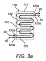
図3a及び図3bを簡単に参照すると、エネルギー貯蔵デバイス110の2つの代替的な実施例が図示及び説明され、同様の構成要素には同様の数詞が付与される。図3aに示される実施例は、図3aのエネルギー貯蔵デバイスの相変化材料140がカプセル封入されていない点で、図2に示される実施例と異なる。すなわち、相変化材料140は、相変化材料140のブロックとして筐体111内に設けられる。この実施例では、チャンバ112も、相変化カプセル141間の流体流路113も存在しない。代わりに、第1の流体は、第1のシステム10から第1の流体入口120aを介して受け取られ、迂曲経路で相変化材料140を通る第1の流体導管122を介して、第1の流体出口120bに送られる。同様に、第2の流体は、第2のシステム20から第2の流体入口130aを介して受け取られ、迂曲経路で相変化材料140を通る第2の流体導管132を介して、第2の流体出口130bに送られる。
3a and 3b, two alternative embodiments of the
図2の相変化カプセル141を参照して前述されたように、第1の流体導管122及び第2の流体導管132は、相変化材料と、第1の流体導管122及び第2の流体導管132を通って流動可能なそれぞれの第1の流体及び第2の流体との間に、任意の適切な熱交換界面を有することが、理解されよう。図3aに示される実施例では、相変化材料140は、「キャンドルライト効果」の影響を受け得ることにより、第1の流体が第1の流体導管を通るときに、第1の流体導管122に近い相変化材料140のみが融解される。同様に、第2の流体が第2の流体導管132を通るときに、第2の流体導管132に近い相変化材料140のみが凝固され得る。第1の流体入口120aと第1の流体出口120b、及び第2の流体入口130aと第2の流体出口130bのそれぞれの間に流体連結された付加的な第1の流体導管122及び第2の流体導管132を、例えばそれぞれのヘッダ(図示せず)により設けることで、第1の流体及び第2の流体と、相変化材料140との間の熱伝達特性の向上がもたらされ得る。代替的または付加的に、相変化材料140を通るより曲がりくねった経路の第1の流体導管122及び第2の流体導管132を設けることにより、より効率的な熱伝達特性が達成され得る。しかし、このような実施例では、エネルギー貯蔵デバイス110にわたり圧力降下の増加が生じ得、よって、第1の流体及び第2の流体を送るためのより大きなポンプが必要になり得る。
As discussed above with reference to the
図3bは、別の代替的なエネルギー貯蔵デバイス110を示す。ここでは、筐体111は、相変化材料140の柱状部により分離された複数の流体流路122、132、またはチャンバ122、132を含む。具体的には、エネルギー貯蔵デバイス110は、第1の流体を第1の流体入口120aから第1の流体出口120bへ送るように構成された複数の並列な第1の流体流路122と、第2の流体を第2の流体入口130aから第2の流体出口130bへ送るように構成された複数の並列な第2の流体流路132とを備える。各柱状部内の相変化材料140は、前述のように、熱交換界面142により、第1の流体通路122及び第2の流体通路132から分離される。
3b shows another alternative
図3a及び図3bに示される実施例のそれぞれでは、エネルギー貯蔵デバイス110内で、第1の流体及び第2の流体は、混合することが不可能である。いずれの事例でも、第1の流体及び第2の流体は、エネルギー貯蔵デバイス110を同時に通ることができ、これにより、相変化材料140を介した第1の流体から第2の流体へのより直接的な熱伝達が可能となり得る。本明細書で提示されたものに加えて、他の種類のエネルギー貯蔵デバイス110も、当業者には明らかであろう。
In each of the embodiments shown in FIG. 3a and FIG. 3b, the first and second fluids are not able to mix within the
ここで図4を参照すると、代替的なエネルギー貯蔵システム100が図示及び説明される。エネルギー貯蔵システム100は、図2~図3bのうちのいずれか1つを参照して上記に図示及び説明されたエネルギー貯蔵デバイス110のうちのいずれかであるエネルギー貯蔵デバイス110、または相変化材料140を有する任意の他の適切なエネルギー貯蔵デバイスを備える。ただし、図4では、エネルギー貯蔵デバイス110は、単一のエネルギー貯蔵デバイス入口114aと、単一のエネルギー貯蔵デバイス出口114bとを有し、これらは、筐体111への流体の流入、及び筐体111からの流体の流出を、それぞれ行う。
Now referring to FIG. 4, an alternative
図2のエネルギー貯蔵システム100とは対照的に、図4のエネルギー貯蔵システム100は、エネルギー貯蔵デバイス110内で、第1のシステム10及び第2のシステム20と、相変化材料140との間で熱エネルギーを、第3の流体を介して間接的に伝達するように構成される。具体的には、エネルギー貯蔵システム100は、第1の熱交換器180と、第2の熱交換器190と、流体導管115とを備える。第1の熱交換器180及び第2の熱交換器190は、任意の適切な流体間熱交換器である。エネルギー貯蔵システム100はまた、流体ループを備え、流体ループは、流体導管115と、エネルギー貯蔵デバイス110と、第1の熱交換器180及び第2の熱交換器190と、流体ループを周るように第3の流体を送る第3の流体ポンプ117とを含む。
In contrast to the
第1の熱交換器180は、エネルギー貯蔵システム100の第1の流体入口120a及び第1の流体出口120bを備え、これらは、第1のシステム10から第1の流体の受け取り、及び第1のシステム10へ第1の流体の供給を、それぞれ行う。第1の熱交換器180は、第1の流体を第1の流体入口120aから第1の流体出口120bへ第1の熱交換器180を通して送るための第1の熱交換器流路183を備える。第1の熱交換器180はまた、第3の流体ポンプ117から第1の熱交換器180内に第3の流体を受け入れるための第1の熱交換器入口181aと、第1の熱交換器180からエネルギー貯蔵デバイス110に第3の流体を供給するための第1の熱交換器出口181bと、流体ループにおいて第1の熱交換器入口181aから第1の熱交換器出口181bへ第3の流体を送るための第1の熱交換器ループ導管182と、を備える。このようにして、第1の熱交換器180は、第1の熱交換器流路183内の第1の流体と、第1の熱交換器ループ導管182内の第3の流体との間で、熱エネルギーを伝達するように構成される。
The
同様に、第2の熱交換器190は、エネルギー貯蔵システム100の第2の流体入口130a及び第2の流体出口130bを備え、これらは、第2のシステム20から第2の流体の受け取り、及び第2のシステム20へ第2の流体の供給を、それぞれ行う。第2の熱交換器190は、第2の流体を第2の流体入口130aから第2の流体出口130bへ第2の熱交換器190を通して送るための第2の熱交換器流路193を備える。第2の熱交換器190はまた、エネルギー貯蔵デバイス110から第2の熱交換器190内に第3の流体を受け入れるための第2の熱交換器入口191aと、第2の熱交換器190から第3の流体ポンプ117に第3の流体を供給するための第2の熱交換器出口191bと、流体ループにおいて第2の熱交換器入口191aから第2の熱交換器出口191bへ第3の流体を送るための第2の熱交換器ループ導管192と、を備える。このようにして、第2の熱交換器190は、第2の熱交換器ループ導管192内の第3の流体と、第2の熱交換器流路193内の第2の流体との間で、熱エネルギーを伝達するように構成される。
Similarly, the
このように、第3の流体は、第1の熱交換器180を介して受け取った第1の流体からの熱エネルギーを、エネルギー貯蔵デバイス110に伝達する。エネルギー貯蔵デバイス110は、第3の流体からエネルギーを受け取り、貯蔵する。次いで、第3の流体は、第2の熱交換器190を通り、そこで第3の流体は、第2の熱交換器190内の第2の流体に第3の流体の熱を伝達する。
In this manner, the third fluid transfers the thermal energy received from the first fluid through the
エネルギー貯蔵システム100は、第3の流体に第1の熱交換器180をバイパスさせるための流体ループバイパスバルブ116を備える。このようにして、エネルギー貯蔵システムは、流体ループバイパスバルブ116が閉鎖状態であり、エネルギー貯蔵デバイス110が、第1の熱交換器180を介して第1のシステム10から熱を受け取って貯蔵する、貯蔵構成に構成可能である。貯蔵構成では、第3の流体は、エネルギー貯蔵デバイス110を通った後に、第2のシステム20に流体の残留熱を供給して、例えば航行中に燃料貯蔵タンク内の燃料を加熱することもできる。エネルギー貯蔵システム100はまた、流体ループバイパスバルブ116が開放状態であり、第3の流体が、第1の熱交換器180を介して第1のシステム10から熱を受け取ることなく流体ループを通る、供給構成に構成可能である。すなわち、供給構成では、エネルギー貯蔵システムは、例えば港滞在中に、エネルギー貯蔵デバイス110に貯蔵された熱を第2のシステム20に供給するように構成される。
The
いくつかの実施例では、エネルギー貯蔵システム100は、第3の流体に第2の熱交換器190をバイパスさせるための第2の流体ループバイパスバルブ(図示せず)を備えることが、理解されよう。さらにいくつかの実施例では、第3の流体ポンプ117は、流体ループ内の他の場所に配置され得、及び/または第3の流体は、逆方向で流体ループを周るようにポンプ流送され得る。いくつかの実施例では、第3の流体は、3bar~5barの圧力に維持される。他の実施例では、第3の流体圧力は、この範囲外である。
It will be appreciated that in some embodiments, the
図5は、船舶1内のエネルギーを取り扱う例示的な方法500を示す。方法500は、船舶1の第1のシステム10から受け入れた第1の流体からの熱エネルギーを、相変化材料140に貯蔵すること510を含む。方法500はさらに、相変化材料140に貯蔵された熱エネルギーを、船舶1の第2のシステム20へ送り出す第2の流体に供給すること520を含む。
FIG. 5 illustrates an
示される実施例の方法500はまた、船舶の第1のシステムから第1の流体を受け取ること505と、相変化材料140に貯蔵された熱エネルギーにより加熱された第2の流体を、船舶の第2のシステムに供給すること515と、を含む。いくつかの実施例では、方法500は、本明細書で説明されるエネルギー貯蔵システム100のうちのいずれか1つにより実行される。よって、いくつかの実施例では、方法500は、本明細書で説明されるエネルギー貯蔵システム100及び/またはエネルギー貯蔵デバイス110のうちのいずれか1つにより実行されるアクションのうちのいずれかを含む。
The
本明細書で説明される実施例のうちのいずれかにおける相変化材料140は、任意の適切な相変化材料140であることが、理解されよう。いくつかの実施例では、相変化材料140は、例えばパラフィン系化合物または非パラフィン系化合物のいずれかを含む有機相変化材料140である。他の実施例では、相変化材料140は、例えば塩水和物または金属化合物を含む無機相変化材料140である。いくつかの実施例では、相変化材料140は、相変化材料140の構成部分のそれぞれの融点よりも低い融点を有する共晶相変化材料140である。いくつかの実施例では、共晶相変化材料は、2つ以上の有機相変化材料の組み合わせ、2つ以上の無機相変化材料の組み合わせ、または無機相変化材料と有機相変化材料の組み合わせである。
It will be appreciated that the
いくつかの実施例では、本明細書で説明される実施例のうちのいずれか1つのエネルギー貯蔵デバイス110は、相変化材料140を含む複合材料を備える。いくつかのこのような実施例では、複合材料は、相変化材料140を収容する支持構造を備える。いくつかの実施例では、支持構造は、相変化材料140と、第1の流体、第2の流体、及び/または第3の流体との間で熱を交換するための熱交換界面142を備える。他の実施例では、複合材料は、相変化材料140を含む、形状安定性のある複合材料である。いくつかのこのような実施例では、第1の流体、第2の流体、及び/または第3の流体は、形状安定複合材料と直接接触して、筐体111を通り得る。
In some embodiments, the
図2では、筐体111は略円筒形状であることが示されるが、他の実施例では、筐体111は任意の他の適切な形状であり得ることが、理解されよう。同様に、第1の熱交換器180及び第2の熱交換器190は、任意の適切な形状であり得、第1の熱交換器ループ導管182及び第2の熱交換器ループ導管192ならびに第1の熱交換器流路183及び第2の熱交換器流路193は、それぞれの第1の熱交換器180及び第2の熱交換器190を通る任意の適切な経路を有し得る。
2, the
本発明の実施形態は、図示された実施例を具体的に参照して論述された。しかしながら、説明された実施例に対して、添付の特許請求の範囲により定義される本発明の範囲内で、変形及び変更が行われてもよいことが、理解されよう。例えば、前述の実施例のうちの2つ以上が組み合わされてもよいこと、及びいくつかの実施例では、1つの実施例の特徴が、1つ以上の他の実施例の特徴と組み合わされてもよいことが、理解されよう。 Embodiments of the present invention have been discussed with particular reference to the illustrated examples. It will be understood, however, that variations and modifications may be made to the described examples within the scope of the invention as defined by the appended claims. For example, it will be understood that two or more of the above-described examples may be combined, and that in some examples, features of one example may be combined with features of one or more other examples.
Claims (15)
前記船舶の第1のシステムから第1の流体を受け入れるための第1の流体入口と、
前記船舶の第2のシステムに第2の流体を供給するための第2の流体出口と、
大気圧で0℃を上回る融解温度を有する相変化材料であって、前記第1のシステムから前記第1の流体入口を介して受け入れた前記第1の流体から、熱エネルギーを受け取って貯蔵し、前記第2の流体出口を介して前記第2のシステムに供給する前記第2の流体に、前記熱エネルギーを供給するための前記相変化材料と、
を備える、前記エネルギー貯蔵システム。 1. An energy storage system for a ship, comprising:
a first fluid inlet for receiving a first fluid from a first system of the vessel;
a second fluid outlet for supplying a second fluid to a second system of the vessel;
a phase change material having a melting temperature above 0° C. at atmospheric pressure, the phase change material for receiving and storing thermal energy from the first fluid received from the first system via the first fluid inlet and for providing the thermal energy to the second fluid provided to the second system via the second fluid outlet;
The energy storage system.
前記第1の流体入口が開放状態であり、前記第2の流体出口が閉鎖状態である第1の構成と、
前記第2の流体出口が開放状態であり、前記第1の流体入口が閉鎖状態である第2の構成と、
に構成可能である、請求項2に記載のエネルギー貯蔵システム。 The energy storage system includes:
a first configuration in which the first fluid inlet is open and the second fluid outlet is closed;
a second configuration in which the second fluid outlet is open and the first fluid inlet is closed; and
3. The energy storage system of claim 2 .
前記第2の流体入口を含む第2の熱交換器と、
前記第1の熱交換器、前記第2の熱交換器、及び前記導管を含む流体ループと、
を備える、請求項5に記載のエネルギー貯蔵システム。 a first heat exchanger including the first fluid inlet;
a second heat exchanger including the second fluid inlet; and
a fluid loop including the first heat exchanger, the second heat exchanger, and the conduit;
6. The energy storage system of claim 5, comprising:
筐体と、
前記船舶の第1のシステムから前記筐体内に第1の流体を受け入れるための第1の流体入口と、
前記筐体から前記船舶の第2のシステムに第2の流体を供給するための第2の流体出口と、
前記第1の流体入口を介して前記筐体内に受け入れた前記第1の流体から、熱エネルギーを受け取って貯蔵し、前記筐体から前記第2の流体出口を介して前記船舶の前記第2のシステムに供給される前記第2の流体に、前記熱エネルギーを供給するための、前記筐体内の相変化材料と、
を備える、前記エネルギー貯蔵デバイス。 1. An energy storage device for a marine vessel, comprising:
A housing and
a first fluid inlet for receiving a first fluid into the enclosure from a first system of the vessel;
a second fluid outlet for supplying a second fluid from the housing to a second system of the vessel;
a phase change material within the housing for receiving and storing thermal energy from the first fluid received within the housing via the first fluid inlet and for providing the thermal energy to the second fluid provided from the housing via the second fluid outlet to the second system of the vessel;
The energy storage device.
前記第1のシステム及び前記第2のシステムと、
を備える、船舶。 A vessel hull according to claim 12, an energy storage system according to any one of claims 1 to 8, or an energy storage device according to any one of claims 9 to 11;
the first system and the second system;
A vessel comprising:
大気圧で0℃を上回る融解温度を有する相変化材料に、前記船舶の第1のシステムから受け入れた第1の流体からの熱エネルギーを貯蔵することと、
前記相変化材料に貯蔵された前記熱エネルギーを、前記船舶の第2のシステムへ送り出す第2の流体に供給することと、
を含む、前記方法。 1. A method for handling energy on board a vessel, comprising:
storing thermal energy from a first fluid received from a first system of the vessel in a phase change material having a melting temperature above 0° C. at atmospheric pressure;
providing the thermal energy stored in the phase change material to a second fluid delivered to a second system of the marine vessel;
The method comprising:
前記第1の流体からの前記熱エネルギーを、前記相変化材料に貯蔵することと、
前記供給後に、前記筐体から前記船舶の前記第2のシステムに前記第2の流体を供給することと、
を含む、請求項14に記載の方法。 receiving the first fluid from the first system of the marine vessel into an enclosure in which the phase change material resides;
storing the thermal energy from the first fluid in the phase change material;
after the supplying, supplying the second fluid from the housing to the second system of the marine vessel;
15. The method of claim 14, comprising:
Applications Claiming Priority (3)
| Application Number | Priority Date | Filing Date | Title |
|---|---|---|---|
| DKPA202100448 | 2021-04-30 | ||
| DKPA202100448A DK202100448A1 (en) | 2021-04-30 | 2021-04-30 | Energy storage system and device |
| PCT/EP2022/061504 WO2022229397A1 (en) | 2021-04-30 | 2022-04-29 | Energy storage system and device |
Publications (1)
| Publication Number | Publication Date |
|---|---|
| JP2024518344A true JP2024518344A (en) | 2024-05-01 |
Family
ID=81854819
Family Applications (1)
| Application Number | Title | Priority Date | Filing Date |
|---|---|---|---|
| JP2023566621A Pending JP2024518344A (en) | 2021-04-30 | 2022-04-29 | ENERGY STORAGE SYSTEM AND ENERGY STORAGE DEVICE |
Country Status (6)
| Country | Link |
|---|---|
| EP (1) | EP4330617A1 (en) |
| JP (1) | JP2024518344A (en) |
| KR (1) | KR20240004394A (en) |
| CN (1) | CN117321372A (en) |
| DK (1) | DK202100448A1 (en) |
| WO (1) | WO2022229397A1 (en) |
Family Cites Families (4)
| Publication number | Priority date | Publication date | Assignee | Title |
|---|---|---|---|---|
| US20090173336A1 (en) * | 2006-10-19 | 2009-07-09 | Elcal Research, L.L.C. | Active thermal energy storage system and tank for use therein |
| JP6757191B2 (en) * | 2016-07-05 | 2020-09-16 | 川崎重工業株式会社 | Ship |
| US11002493B2 (en) * | 2016-08-24 | 2021-05-11 | Ford Global Technologies, Llc | Systems and methods for thermal battery control |
| FR3086741B1 (en) * | 2018-09-27 | 2020-09-25 | Commissariat Energie Atomique | THERMAL STORAGE (SST) SYSTEMS BY PHASE CHANGE MATERIALS (PCM), INCLUDING AN SST LOAD EVALUATION DEVICE |
-
2021
- 2021-04-30 DK DKPA202100448A patent/DK202100448A1/en not_active Application Discontinuation
-
2022
- 2022-04-29 EP EP22726637.6A patent/EP4330617A1/en active Pending
- 2022-04-29 CN CN202280031623.8A patent/CN117321372A/en active Pending
- 2022-04-29 JP JP2023566621A patent/JP2024518344A/en active Pending
- 2022-04-29 KR KR1020237037296A patent/KR20240004394A/en unknown
- 2022-04-29 WO PCT/EP2022/061504 patent/WO2022229397A1/en active Application Filing
Also Published As
| Publication number | Publication date |
|---|---|
| WO2022229397A1 (en) | 2022-11-03 |
| CN117321372A (en) | 2023-12-29 |
| DK202100448A1 (en) | 2022-11-16 |
| KR20240004394A (en) | 2024-01-11 |
| EP4330617A1 (en) | 2024-03-06 |
Similar Documents
| Publication | Publication Date | Title |
|---|---|---|
| KR101434431B1 (en) | System for Liquid Gas Fuel Supply and Ship Having The Same | |
| US7360368B2 (en) | System and method for vaporizing a cryogenically stored fuel | |
| US8794195B2 (en) | Heat storage system for an engine | |
| US8640678B2 (en) | Alternate fuel storage system and method | |
| US20130199751A1 (en) | Heat storage device for an engine | |
| KR102122023B1 (en) | Fuel Supply System of Liquefied Hydrogen Fuel Cell Propulsion Ship And Method for Operating the Same | |
| KR20080080157A (en) | Arrangement for and method of providing cooling energy to a cooling medium circuit of a marine vessel | |
| JP7288842B2 (en) | Cold heat recovery system, ship with cold heat recovery system, and cold heat recovery method | |
| JP2009209995A (en) | Liquefied natural gas vaporizer and liquefied natural gas vaporization system | |
| WO2021174115A1 (en) | Hull thermal management system | |
| EP2746148B1 (en) | Inland waterway tanker for transportation of liquid product | |
| JP2024518344A (en) | ENERGY STORAGE SYSTEM AND ENERGY STORAGE DEVICE | |
| KR100832851B1 (en) | Latent heat storage type heat storage system for fuel cell using phase change materials | |
| KR20130040320A (en) | Fresh water generating equipment for vessels by using waste heat | |
| JP2005307886A (en) | Cooling medium circulation device | |
| JP6897426B2 (en) | Fuel cell system | |
| US8084161B2 (en) | Combined accumulator and demineralizer functionality for a fuel cell | |
| CN108138626A (en) | Exhaust after treatment system with ammonia generator | |
| CN112673161B (en) | Arrangement for vaporizing liquefied gas for providing gas to an engine | |
| JP2647921B2 (en) | Heat exchange mechanism of hydrogen engine | |
| JP4831411B2 (en) | Storage heat source system | |
| JP2011012905A (en) | Heat supply facility | |
| JP2009127544A (en) | Thermoelectric power generation system | |
| WO2024099525A1 (en) | Fuel temperature control system and method | |
| CN113227565A (en) | Gas engine power plant and method for operating a gas engine power plant |