JP2024513997A - Implant delivery system - Google Patents
Implant delivery system Download PDFInfo
- Publication number
- JP2024513997A JP2024513997A JP2023563045A JP2023563045A JP2024513997A JP 2024513997 A JP2024513997 A JP 2024513997A JP 2023563045 A JP2023563045 A JP 2023563045A JP 2023563045 A JP2023563045 A JP 2023563045A JP 2024513997 A JP2024513997 A JP 2024513997A
- Authority
- JP
- Japan
- Prior art keywords
- docking
- tether
- coil
- docking coil
- flexible portion
- Prior art date
- Legal status (The legal status is an assumption and is not a legal conclusion. Google has not performed a legal analysis and makes no representation as to the accuracy of the status listed.)
- Pending
Links
- 239000007943 implant Substances 0.000 title claims description 73
- 238000003032 molecular docking Methods 0.000 claims abstract description 490
- 230000001154 acute effect Effects 0.000 claims description 5
- 238000004873 anchoring Methods 0.000 abstract description 63
- 210000002216 heart Anatomy 0.000 abstract description 44
- 210000004115 mitral valve Anatomy 0.000 description 119
- 238000000034 method Methods 0.000 description 97
- 210000003709 heart valve Anatomy 0.000 description 58
- 238000004804 winding Methods 0.000 description 47
- 210000005246 left atrium Anatomy 0.000 description 37
- 238000002513 implantation Methods 0.000 description 27
- 210000005240 left ventricle Anatomy 0.000 description 26
- 210000003698 chordae tendineae Anatomy 0.000 description 23
- 230000002861 ventricular Effects 0.000 description 22
- 210000000591 tricuspid valve Anatomy 0.000 description 15
- 230000007246 mechanism Effects 0.000 description 13
- 230000001746 atrial effect Effects 0.000 description 11
- 210000002837 heart atrium Anatomy 0.000 description 11
- 230000000087 stabilizing effect Effects 0.000 description 9
- 210000001765 aortic valve Anatomy 0.000 description 7
- 239000008280 blood Substances 0.000 description 7
- 210000004369 blood Anatomy 0.000 description 7
- 230000017531 blood circulation Effects 0.000 description 6
- 230000008859 change Effects 0.000 description 6
- 230000007704 transition Effects 0.000 description 5
- 238000013459 approach Methods 0.000 description 4
- 230000008901 benefit Effects 0.000 description 4
- 208000018578 heart valve disease Diseases 0.000 description 4
- 210000005245 right atrium Anatomy 0.000 description 4
- 206010027727 Mitral valve incompetence Diseases 0.000 description 3
- 230000006870 function Effects 0.000 description 3
- 210000003205 muscle Anatomy 0.000 description 3
- 238000013519 translation Methods 0.000 description 3
- 210000005166 vasculature Anatomy 0.000 description 3
- 230000009471 action Effects 0.000 description 2
- 210000003484 anatomy Anatomy 0.000 description 2
- 238000010586 diagram Methods 0.000 description 2
- 210000003191 femoral vein Anatomy 0.000 description 2
- 230000002262 irrigation Effects 0.000 description 2
- 238000003973 irrigation Methods 0.000 description 2
- 239000000463 material Substances 0.000 description 2
- 210000003540 papillary muscle Anatomy 0.000 description 2
- 210000005241 right ventricle Anatomy 0.000 description 2
- 230000006641 stabilisation Effects 0.000 description 2
- 238000011105 stabilization Methods 0.000 description 2
- 210000001519 tissue Anatomy 0.000 description 2
- 208000027896 Aortic valve disease Diseases 0.000 description 1
- 208000020128 Mitral stenosis Diseases 0.000 description 1
- 208000012287 Prolapse Diseases 0.000 description 1
- 206010067171 Regurgitation Diseases 0.000 description 1
- 201000001943 Tricuspid Valve Insufficiency Diseases 0.000 description 1
- 206010044640 Tricuspid valve incompetence Diseases 0.000 description 1
- 210000000709 aorta Anatomy 0.000 description 1
- 206010002906 aortic stenosis Diseases 0.000 description 1
- 201000002064 aortic valve insufficiency Diseases 0.000 description 1
- 210000003157 atrial septum Anatomy 0.000 description 1
- 230000036772 blood pressure Effects 0.000 description 1
- 210000004204 blood vessel Anatomy 0.000 description 1
- 230000000747 cardiac effect Effects 0.000 description 1
- 239000011248 coating agent Substances 0.000 description 1
- 238000000576 coating method Methods 0.000 description 1
- 230000008878 coupling Effects 0.000 description 1
- 238000010168 coupling process Methods 0.000 description 1
- 238000005859 coupling reaction Methods 0.000 description 1
- 238000002716 delivery method Methods 0.000 description 1
- 230000010339 dilation Effects 0.000 description 1
- 238000005553 drilling Methods 0.000 description 1
- 210000001105 femoral artery Anatomy 0.000 description 1
- 239000012530 fluid Substances 0.000 description 1
- 230000006872 improvement Effects 0.000 description 1
- 210000004731 jugular vein Anatomy 0.000 description 1
- 210000004975 mitral orifice Anatomy 0.000 description 1
- 208000006887 mitral valve stenosis Diseases 0.000 description 1
- 230000004048 modification Effects 0.000 description 1
- 238000012986 modification Methods 0.000 description 1
- 210000000056 organ Anatomy 0.000 description 1
- 230000000704 physical effect Effects 0.000 description 1
- 239000004810 polytetrafluoroethylene Substances 0.000 description 1
- 229920001343 polytetrafluoroethylene Polymers 0.000 description 1
- 230000008569 process Effects 0.000 description 1
- 210000003492 pulmonary vein Anatomy 0.000 description 1
- 230000009467 reduction Effects 0.000 description 1
- 230000008439 repair process Effects 0.000 description 1
- 230000000717 retained effect Effects 0.000 description 1
- 239000007787 solid Substances 0.000 description 1
- 210000001321 subclavian vein Anatomy 0.000 description 1
- 238000001356 surgical procedure Methods 0.000 description 1
- 238000002054 transplantation Methods 0.000 description 1
- 210000001631 vena cava inferior Anatomy 0.000 description 1
- 210000002620 vena cava superior Anatomy 0.000 description 1
Images


Classifications
-
- A—HUMAN NECESSITIES
- A61—MEDICAL OR VETERINARY SCIENCE; HYGIENE
- A61F—FILTERS IMPLANTABLE INTO BLOOD VESSELS; PROSTHESES; DEVICES PROVIDING PATENCY TO, OR PREVENTING COLLAPSING OF, TUBULAR STRUCTURES OF THE BODY, e.g. STENTS; ORTHOPAEDIC, NURSING OR CONTRACEPTIVE DEVICES; FOMENTATION; TREATMENT OR PROTECTION OF EYES OR EARS; BANDAGES, DRESSINGS OR ABSORBENT PADS; FIRST-AID KITS
- A61F2/00—Filters implantable into blood vessels; Prostheses, i.e. artificial substitutes or replacements for parts of the body; Appliances for connecting them with the body; Devices providing patency to, or preventing collapsing of, tubular structures of the body, e.g. stents
- A61F2/02—Prostheses implantable into the body
- A61F2/24—Heart valves ; Vascular valves, e.g. venous valves; Heart implants, e.g. passive devices for improving the function of the native valve or the heart muscle; Transmyocardial revascularisation [TMR] devices; Valves implantable in the body
- A61F2/2442—Annuloplasty rings or inserts for correcting the valve shape; Implants for improving the function of a native heart valve
- A61F2/2466—Delivery devices therefor
-
- A—HUMAN NECESSITIES
- A61—MEDICAL OR VETERINARY SCIENCE; HYGIENE
- A61F—FILTERS IMPLANTABLE INTO BLOOD VESSELS; PROSTHESES; DEVICES PROVIDING PATENCY TO, OR PREVENTING COLLAPSING OF, TUBULAR STRUCTURES OF THE BODY, e.g. STENTS; ORTHOPAEDIC, NURSING OR CONTRACEPTIVE DEVICES; FOMENTATION; TREATMENT OR PROTECTION OF EYES OR EARS; BANDAGES, DRESSINGS OR ABSORBENT PADS; FIRST-AID KITS
- A61F2/00—Filters implantable into blood vessels; Prostheses, i.e. artificial substitutes or replacements for parts of the body; Appliances for connecting them with the body; Devices providing patency to, or preventing collapsing of, tubular structures of the body, e.g. stents
- A61F2/95—Instruments specially adapted for placement or removal of stents or stent-grafts
- A61F2/962—Instruments specially adapted for placement or removal of stents or stent-grafts having an outer sleeve
- A61F2/966—Instruments specially adapted for placement or removal of stents or stent-grafts having an outer sleeve with relative longitudinal movement between outer sleeve and prosthesis, e.g. using a push rod
-
- A—HUMAN NECESSITIES
- A61—MEDICAL OR VETERINARY SCIENCE; HYGIENE
- A61F—FILTERS IMPLANTABLE INTO BLOOD VESSELS; PROSTHESES; DEVICES PROVIDING PATENCY TO, OR PREVENTING COLLAPSING OF, TUBULAR STRUCTURES OF THE BODY, e.g. STENTS; ORTHOPAEDIC, NURSING OR CONTRACEPTIVE DEVICES; FOMENTATION; TREATMENT OR PROTECTION OF EYES OR EARS; BANDAGES, DRESSINGS OR ABSORBENT PADS; FIRST-AID KITS
- A61F2/00—Filters implantable into blood vessels; Prostheses, i.e. artificial substitutes or replacements for parts of the body; Appliances for connecting them with the body; Devices providing patency to, or preventing collapsing of, tubular structures of the body, e.g. stents
- A61F2/02—Prostheses implantable into the body
- A61F2/24—Heart valves ; Vascular valves, e.g. venous valves; Heart implants, e.g. passive devices for improving the function of the native valve or the heart muscle; Transmyocardial revascularisation [TMR] devices; Valves implantable in the body
- A61F2/2427—Devices for manipulating or deploying heart valves during implantation
-
- A—HUMAN NECESSITIES
- A61—MEDICAL OR VETERINARY SCIENCE; HYGIENE
- A61F—FILTERS IMPLANTABLE INTO BLOOD VESSELS; PROSTHESES; DEVICES PROVIDING PATENCY TO, OR PREVENTING COLLAPSING OF, TUBULAR STRUCTURES OF THE BODY, e.g. STENTS; ORTHOPAEDIC, NURSING OR CONTRACEPTIVE DEVICES; FOMENTATION; TREATMENT OR PROTECTION OF EYES OR EARS; BANDAGES, DRESSINGS OR ABSORBENT PADS; FIRST-AID KITS
- A61F2/00—Filters implantable into blood vessels; Prostheses, i.e. artificial substitutes or replacements for parts of the body; Appliances for connecting them with the body; Devices providing patency to, or preventing collapsing of, tubular structures of the body, e.g. stents
- A61F2/02—Prostheses implantable into the body
- A61F2/24—Heart valves ; Vascular valves, e.g. venous valves; Heart implants, e.g. passive devices for improving the function of the native valve or the heart muscle; Transmyocardial revascularisation [TMR] devices; Valves implantable in the body
- A61F2/2409—Support rings therefor, e.g. for connecting valves to tissue
-
- A—HUMAN NECESSITIES
- A61—MEDICAL OR VETERINARY SCIENCE; HYGIENE
- A61F—FILTERS IMPLANTABLE INTO BLOOD VESSELS; PROSTHESES; DEVICES PROVIDING PATENCY TO, OR PREVENTING COLLAPSING OF, TUBULAR STRUCTURES OF THE BODY, e.g. STENTS; ORTHOPAEDIC, NURSING OR CONTRACEPTIVE DEVICES; FOMENTATION; TREATMENT OR PROTECTION OF EYES OR EARS; BANDAGES, DRESSINGS OR ABSORBENT PADS; FIRST-AID KITS
- A61F2/00—Filters implantable into blood vessels; Prostheses, i.e. artificial substitutes or replacements for parts of the body; Appliances for connecting them with the body; Devices providing patency to, or preventing collapsing of, tubular structures of the body, e.g. stents
- A61F2/02—Prostheses implantable into the body
- A61F2/24—Heart valves ; Vascular valves, e.g. venous valves; Heart implants, e.g. passive devices for improving the function of the native valve or the heart muscle; Transmyocardial revascularisation [TMR] devices; Valves implantable in the body
- A61F2/2427—Devices for manipulating or deploying heart valves during implantation
- A61F2/243—Deployment by mechanical expansion
-
- A—HUMAN NECESSITIES
- A61—MEDICAL OR VETERINARY SCIENCE; HYGIENE
- A61F—FILTERS IMPLANTABLE INTO BLOOD VESSELS; PROSTHESES; DEVICES PROVIDING PATENCY TO, OR PREVENTING COLLAPSING OF, TUBULAR STRUCTURES OF THE BODY, e.g. STENTS; ORTHOPAEDIC, NURSING OR CONTRACEPTIVE DEVICES; FOMENTATION; TREATMENT OR PROTECTION OF EYES OR EARS; BANDAGES, DRESSINGS OR ABSORBENT PADS; FIRST-AID KITS
- A61F2/00—Filters implantable into blood vessels; Prostheses, i.e. artificial substitutes or replacements for parts of the body; Appliances for connecting them with the body; Devices providing patency to, or preventing collapsing of, tubular structures of the body, e.g. stents
- A61F2/02—Prostheses implantable into the body
- A61F2/24—Heart valves ; Vascular valves, e.g. venous valves; Heart implants, e.g. passive devices for improving the function of the native valve or the heart muscle; Transmyocardial revascularisation [TMR] devices; Valves implantable in the body
- A61F2/2442—Annuloplasty rings or inserts for correcting the valve shape; Implants for improving the function of a native heart valve
- A61F2/2445—Annuloplasty rings in direct contact with the valve annulus
-
- A—HUMAN NECESSITIES
- A61—MEDICAL OR VETERINARY SCIENCE; HYGIENE
- A61M—DEVICES FOR INTRODUCING MEDIA INTO, OR ONTO, THE BODY; DEVICES FOR TRANSDUCING BODY MEDIA OR FOR TAKING MEDIA FROM THE BODY; DEVICES FOR PRODUCING OR ENDING SLEEP OR STUPOR
- A61M25/00—Catheters; Hollow probes
- A61M25/01—Introducing, guiding, advancing, emplacing or holding catheters
- A61M25/0105—Steering means as part of the catheter or advancing means; Markers for positioning
- A61M25/0133—Tip steering devices
- A61M25/0147—Tip steering devices with movable mechanical means, e.g. pull wires
-
- A—HUMAN NECESSITIES
- A61—MEDICAL OR VETERINARY SCIENCE; HYGIENE
- A61M—DEVICES FOR INTRODUCING MEDIA INTO, OR ONTO, THE BODY; DEVICES FOR TRANSDUCING BODY MEDIA OR FOR TAKING MEDIA FROM THE BODY; DEVICES FOR PRODUCING OR ENDING SLEEP OR STUPOR
- A61M25/00—Catheters; Hollow probes
- A61M25/01—Introducing, guiding, advancing, emplacing or holding catheters
- A61M25/0105—Steering means as part of the catheter or advancing means; Markers for positioning
- A61M25/0133—Tip steering devices
- A61M2025/0161—Tip steering devices wherein the distal tips have two or more deflection regions
Abstract
送達カテーテルは、様々な実施例で、患者の心臓の自己弁の弁輪にアンカー装置を送達するように構成され、アンカー装置は、自己弁輪に人工器官をより良好に固定することができる。実施例の送達カテーテルは、アンカー装置の展開中に心室方向に偏向するように構成されてもよい。ドッキングコイルスリーブ及びドッキングコイルの実施例が本明細書に開示される。The delivery catheter, in various embodiments, is configured to deliver an anchoring device to an annulus of a native valve in a patient's heart, where the anchoring device can better secure a prosthesis to the native valve annulus. Example delivery catheters may be configured to deflect toward the ventricle during deployment of the anchoring device. Examples of docking coil sleeves and docking coils are disclosed herein.
Description
(関連出願への相互参照)
本出願は、その内容全体が参照により本明細書に組み込まれる、2021年4月14日に出願された米国仮特許出願第63/174,712号の利益を主張する。
(Cross reference to related applications)
This application claims the benefit of U.S. Provisional Patent Application No. 63/174,712, filed April 14, 2021, the entire contents of which are incorporated herein by reference.
本開示は、概して、人工器官及びそれを使用する方法を支持する人工ドッキング装置などの、アンカー装置を送達するための展開ツールに関する。例えば、本開示は、送達カテーテルを利用して、埋め込み部位で人工心臓弁を支持するアンカー装置を展開する奇形及び/又は機能不全を有する心臓弁の交換、及び送達カテーテルを使用して、このようなアンカー装置及び/又は人工心臓弁を埋め込む方法に関する。 The present disclosure generally relates to deployment tools for delivering anchoring devices, such as prosthetic docking devices, that support prostheses and methods of using the same. For example, the present disclosure utilizes a delivery catheter to deploy an anchoring device to support a prosthetic heart valve at the site of implantation; The present invention relates to a method of implanting an anchoring device and/or a prosthetic heart valve.
図1A~1Bを全体的に参照すると、自己僧帽弁50は、ヒトの心臓の左心房51から左心室52への血流を制御し、同様に、三尖弁59は、右心房56と右心室61との間の血流を制御する。僧帽弁は、他の自己心臓弁とは異なる解剖学的構造を有する。僧帽弁は、僧帽弁口を取り囲む天然弁組織から成る弁輪と、弁輪から左心室内へと下向きに延在する尖点又は弁尖の対と、を含む。僧帽弁の弁輪は、「D」型、楕円形、又は別様で長軸及び短軸を有する円ではない断面形状を形成することができる。弁の前尖は、後尖よりも大きく、それらが一緒に閉鎖されるときに弁尖の当接する自由両側縁の間で略「C」型の境界を形成することができる。
Referring generally to FIGS. 1A-1B, the autologous
適切に動作しているとき、僧帽弁の前尖54及び後尖53は、一方向弁として一緒に機能して、血液が左心房51から左心室52に流れることを可能にする。左心房が肺静脈から酸素を含む血液を受け取った後、左心房の筋肉は収縮し、左心室は弛緩し(「心室拡張期」又は「拡張期」とも称される)、左心房に集められた酸素を含む血液は、左心室内へと流れる。次に、左心房の筋肉は弛緩し、左心室の筋肉は収縮し(「心室収縮期」又は「収縮期」とも称される)、酸素を含む血液を左心室52から、大動脈弁63及び大動脈58を通って体の残りの部分へ移動させる。心室収縮期に左心室の血圧が上昇すると、僧帽弁の二つの弁尖が一緒になり、それによって一方向の僧帽弁が閉じ、血液が左心房に逆流できない。心室収縮期に二つの弁尖が圧力下で脱出し、僧帽弁輪を通って左心房に向かって折り返されることを防止又は抑制するために、左心室内で腱索と呼ばれる複数の線維索62が弁尖を乳頭筋に連結する。腱索62は、図1Aの心臓断面及び図1Bの僧帽弁の上面図の両方に概略的に示されている。
When operating properly, the
僧帽弁の適切な機能に問題があるのは、弁膜性心疾患の一種である。弁膜性心疾患は、三尖弁を含む他の心臓弁にも影響し得る。弁膜性心疾患の一般的な形態は、弁漏出であり、逆流症としても知られ、これは、僧帽弁及び三尖弁の両方を含む、様々な心臓弁で起こり得る。心室収縮期に、自己僧帽弁は適切に閉鎖することができず、血液が左心室から左心房内に逆流するとき、僧帽弁逆流症が生じる。僧帽弁逆流症は、弁尖脱出、機能不全の乳頭筋、腱索に関する問題及び/又は左心室の拡張に起因する僧帽弁の弁輪の伸張などの異なる原因を有する。僧帽弁逆流症に加えて、僧帽弁狭小化又は僧帽弁狭窄が弁膜性心疾患の別の例である。三尖弁逆流症では、三尖弁が適切に閉鎖されず、血液は右心室から右心房に戻ってくる。 Problems with the proper functioning of the mitral valve is a type of valvular heart disease. Valvular heart disease can also affect other heart valves, including the tricuspid valve. A common form of valvular heart disease is valve leakage, also known as regurgitation, which can occur in various heart valves, including both the mitral and tricuspid valves. Mitral regurgitation occurs when the native mitral valve fails to close properly during ventricular systole and blood flows backward from the left ventricle into the left atrium. Mitral regurgitation has different causes, such as leaflet prolapse, dysfunctional papillary muscles, problems with the chordae tendineae and/or stretching of the mitral valve annulus due to left ventricular dilation. In addition to mitral regurgitation, mitral valve narrowing or mitral stenosis is another example of valvular heart disease. In tricuspid regurgitation, the tricuspid valve does not close properly and blood flows backward from the right ventricle into the right atrium.
僧帽弁及び三尖弁と同様に、大動脈弁は大動脈弁狭窄症又は大動脈弁不全症などの合併症の影響を受けやすい。大動脈心臓疾患を治療する一つの方法は、自己大動脈弁内に移植された人工弁の使用を含む。これらの人工弁は、様々な経カテーテル技術を含む、様々な技術を使用して移植することができる。経カテーテル心臓弁(THV)は、可撓性及び/又は操縦可能なカテーテルの端部に圧着状態で取り付けられ、心臓に接続された血管を介して心臓の埋め込み部位に前進され、その後、例えば、THVが取り付けられるバルーンを膨張させることによって、その機能的サイズまで拡張され得る。別の方法として、自己拡張性THVは、送達カテーテルの鞘内で半径方向に圧縮された状態で保持することができ、THVは鞘から展開することができ、それによってTHVがその機能状態まで拡張することができる。こうした送達カテーテル及び移植技術は、一般的に、大動脈弁での移植又は使用のためにより開発されているが、他の弁の固有の解剖学的構造及び課題については言及しない。 Like the mitral and tricuspid valves, the aortic valve is susceptible to complications such as aortic stenosis or insufficiency. One method of treating aortic heart disease involves the use of a prosthetic valve implanted within the autologous aortic valve. These prosthetic valves can be implanted using a variety of techniques, including various transcatheter techniques. Transcatheter heart valves (THVs) are crimped onto the end of a flexible and/or steerable catheter and advanced to an implantation site in the heart via a blood vessel connected to the heart, and then, for example, It can be expanded to its functional size by inflating the balloon to which the THV is attached. Alternatively, a self-expanding THV can be held radially compressed within a sheath of a delivery catheter, and the THV can be deployed from the sheath, thereby expanding the THV to its functional state. can do. These delivery catheters and implantation techniques are generally more developed for implantation or use with aortic valves, but do not address the unique anatomy and challenges of other valves.
本概要は、一部の実施例を提供することを意図しており、本開示の範囲を、いかようにも制限することを目的としていない。例えば、本概要のある実施例に含まれるいかなる特徴も、特許請求の範囲が、それらの特徴を明示的に列挙しない限り、特許請求の範囲によって要求されない。また、説明される特徴は、様々な方法で組み合わせることができる。本開示の他の箇所で説明するような様々な特徴及びステップは、ここで概説する例の中に含まれてもよい。 This summary is intended to provide some examples and is not intended to limit the scope of the disclosure in any way. For example, no feature included in an embodiment of this Summary is required by a claim unless the claim explicitly recite such feature. Also, the described features can be combined in various ways. Various features and steps as described elsewhere in this disclosure may be included in the examples outlined herein.
ツール及び方法が、僧帽弁位置及び三尖弁位置での使用のため、一つ又は複数の弁(例えば、大動脈弁の置換用に又は他の場所向けに設計されたもの)などの異なるタイプのインプラントを適合化することを含めて、僧帽弁及び三尖弁の置換向けに提供される。僧帽位置又は三尖位置でこれらの他の人工弁を適合化する一つの方法は、自己弁輪でより適切に形状設定された埋め込み部位を形成することとなるアンカー又は他のドッキングデバイス/ステーションなどのインプラントの内部で人工弁を展開することである。本明細書におけるアンカー又は他のドッキングデバイス/ステーションは、人工弁がより確実に移植されることを可能とするとともに、さらに、移植後における弁周囲での漏洩を低減又は解消する。 The tools and methods can be applied to different types of valves, such as one or more valves (e.g., those designed for aortic valve replacement or elsewhere), for use in the mitral valve position and the tricuspid valve position. for mitral and tricuspid valve replacement, including adapting implants for mitral and tricuspid valves. One way to adapt these other prosthetic valves in the mitral or tricuspid position is to use anchors or other docking devices/stations that will create a better shaped implantation site with the autologous annulus. This involves deploying a prosthetic valve inside an implant. The anchors or other docking devices/stations herein allow the prosthetic valve to be implanted more securely and further reduce or eliminate perivalvular leakage after implantation.
本明細書で使用され得るアンカー又はアンカー装置の形態をなす一つのタイプのインプラントは、円筒形状人工弁用の円形ドッキング部位若しくは円筒形ドッキング部位を提供するコイルアンカー又は螺旋形状アンカーを含めたドッキングコイルである。本明細書で使用され得る一つのタイプのアンカー又はアンカー装置は、円筒形状人工弁用の円形ドッキング部位若しくは円筒形ドッキング部位を提供するコイル状領域及び/又は螺旋形状領域を含む。このようにして、場合により、大動脈位置のために開発された既存の弁インプラントは、おそらく何らかの修正を伴って、このようなアンカー又はアンカー装置と共に、僧帽弁の位置などの別の弁の位置に移植され得る。こうしたアンカー又はアンカー装置は、三尖弁などの心臓のその他の天然弁で使用されて、それらの部位にもより確実に人工弁を固定することができる。 One type of implant in the form of an anchor or anchoring device that may be used herein is a docking coil, including a coil anchor or helical anchor that provides a circular or cylindrical docking site for a cylindrical prosthetic valve. It is. One type of anchor or anchoring device that may be used herein includes a coiled region and/or a helically shaped region that provides a circular or cylindrical docking site for a cylindrical shaped prosthetic valve. In this way, in some cases, existing valve implants developed for an aortic position can be used in another valve position, such as a mitral valve position, with such an anchor or anchoring device, perhaps with some modification. can be ported to. Such anchors or anchoring devices can be used with other natural valves of the heart, such as the tricuspid valve, to more securely secure the prosthetic valve in those locations as well.
本明細書で説明するものは、ヒトの心臓における、自己の僧帽弁領域、自己の大動脈弁領域、自己の三尖弁領域、又は自己の肺動脈弁領域、の一つへと、人工デバイスの形態をなすインプラントを送達することを支援するための展開ツールの実施例と、そのような展開ツールを使用するための方法と、である。開示する展開ツールは、人工心臓弁が移植され得る基礎支持構造を提供するために、埋め込み部位で、複数の巻線若しくはコイルを有した螺旋状アンカー装置又はアンカー装置などのアンカー装置(例えば、人工器官ドッキングデバイス、人工弁ドッキングデバイス、等)の形態をなすインプラントを展開するために使用することができる。送達カテーテルは、実施例によっては、操縦可能な送達カテーテルを含んでもよい。 What is described herein is a technique for introducing a prosthetic device into one of the native mitral valve region, the native aortic valve region, the native tricuspid valve region, or the native pulmonic valve region in a human heart. Examples of deployment tools to assist in delivering shaped implants and methods for using such deployment tools. The disclosed deployment tool provides an anchoring device, such as a helical anchoring device or an anchoring device having multiple windings or coils (e.g., a prosthetic It can be used to deploy implants in the form of organ docking devices, prosthetic valve docking devices, etc.). The delivery catheter may include a steerable delivery catheter in some embodiments.
実施例では、システムが開示される。システムは、患者の体内の一部にインプラントを送達するためのシステムを備えてもよい。システムは、インプラントが通過するための内部内腔を有する細長いシャフトと、第一の可撓性部分及び第一の可撓性部分の遠位に位置付けられた第二の可撓性部分を含む遠位端部分と、を含む送達カテーテルを備えてもよい。 In an embodiment, a system is disclosed. The system may include a system for delivering an implant to a portion within a patient's body. The system includes an elongate shaft having an internal lumen for passage of the implant, a first flexible portion and a second flexible portion positioned distal to the first flexible portion. A delivery catheter may include a distal portion.
第一の可撓性部分は、第一のテザーと、第一のテザーに対して円周方向に対向して位置付けられた第一の線形スパインと、を含んでもよく、第一の可撓性部分は、長手方向の力が第一のテザーに加えられると平面内で偏向するように構成される。 The first flexible portion may include a first tether and a first linear spine positioned circumferentially opposite to the first tether; The portion is configured to deflect in a plane when a longitudinal force is applied to the first tether.
第二の可撓性部分は、第一の線形スパインに対して非直交及び非平行に位置付けられた第二のテザー及び第二の線形スパインを含んでもよく、第二の可撓性部分は、長手方向の力が第二のテザーに加えられると、平面と非直交及び非平行な方向に偏向するように構成される。 The second flexible portion may include a second tether and a second linear spine positioned non-orthogonally and non-parallel to the first linear spine, and the second flexible portion may include: When a longitudinal force is applied to the second tether, it is configured to deflect in a direction non-orthogonal and non-parallel to the plane.
実施例では、システムが開示される。システムは、患者の体内の一部にインプラントを送達するためのシステムを備えてもよい。システムは、インプラントが通過するための内部内腔を有する細長いシャフトと、テザーを有する可撓性部分と、テザーから円周方向に鈍角に位置付けられた線形スパインとを含む遠位端部分と、を含む送達カテーテルを備えてもよい。可撓性部分は、長手方向の力がテザーに印加された時に、曲線を形成するために偏向するように構成されてもよい。 In an embodiment, a system is disclosed. The system may include a system for delivering an implant to a portion within a patient's body. The system includes an elongate shaft having an internal lumen for passage of the implant, a flexible portion having a tether, and a distal end portion including a linear spine positioned circumferentially at an obtuse angle from the tether. A delivery catheter may also be included. The flexible portion may be configured to deflect to form a curve when a longitudinal force is applied to the tether.
実施例では、システムが開示される。システムは、患者の体内の一部にインプラントを送達するためのシステムを備えてもよい。システムは、インプラントが通過するための内部内腔を有する細長いシャフトと、第一の可撓性部分及び第一の可撓性部分の遠位に位置付けられた第二の可撓性部分を含む遠位端部分と、を含む送達カテーテルを備えてもよい。 In an embodiment, a system is disclosed. The system may include a system for delivering an implant to a portion within a patient's body. The system includes an elongate shaft having an internal lumen for passage of the implant, a first flexible portion and a second flexible portion positioned distal to the first flexible portion. A delivery catheter may include a distal portion.
第一の可撓性部分は、第一のテザーと、第一のテザーに対して円周方向に対向して位置付けられた第一の線形スパインとを含んでもよく、第一の可撓性部分は、長手方向の力が第一のテザーに加えられると第一の平面内で偏向するように構成される。 The first flexible portion may include a first tether and a first linear spine positioned circumferentially opposite the first tether, the first flexible portion configured to deflect in a first plane when a longitudinal force is applied to the first tether.
第二の可撓性部分は、第一のテザーに対して直交して位置付けられた第二のテザーと、第二のテザーに対して円周方向に対向して位置付けられた第二の線形スパインと、第一のテザーに対して円周方向に対向して位置付けられた第三のテザーと、含んでもよく、第二の可撓性部分が、長手方向の力が前記第二のテザーに加えられると、第一の平面に直交する第二の平面内で偏向するように構成され、第二の可撓性部分が、長手方向の力が第三のテザーに加えられると、第一の平面内で偏向するように構成される。 The second flexible portion has a second tether positioned orthogonally to the first tether and a second linear spine positioned circumferentially opposite to the second tether. and a third tether positioned circumferentially opposite to the first tether, the second flexible portion being configured to allow a longitudinal force to be applied to the second tether. When a longitudinal force is applied to the third tether, the second flexible portion is configured to deflect in a second plane perpendicular to the first plane, and when a longitudinal force is applied to the third tether, the second flexible portion deflects in the first plane. configured to deflect within.
実施例では、システムが開示される。システムは、患者の体内の一部内のインプラントとドッキングするように構成されたドッキングコイルを含んでもよい。システムは、ドッキングコイルがその中を摺動するように構成された内部内腔と、ドッキングコイルスリーブの少なくとも一部分に沿って延び、ドッキングコイルスリーブを偏向するように構成されたテザーを含んでもよい。 In an embodiment, a system is disclosed. The system may include a docking coil configured to dock with an implant within a portion of a patient's body. The system may include an internal lumen configured for the docking coil to slide therethrough and a tether extending along at least a portion of the docking coil sleeve and configured to deflect the docking coil sleeve.
実施例では、システムが開示される。システムは、患者の体内の一部内のインプラントとドッキングするように構成され、かつ先導先端に延び、かつ配向を有する先導部分を含むドッキングコイルを含んでもよい。 In an embodiment, a system is disclosed. The system may include a docking coil configured to dock with an implant within a portion of a patient's body and including a leading portion extending and having an orientation to a leading tip.
システムは、ドッキングコイルがその中を摺動するように構成された内部内腔を有し、先導先端に延び、ドッキングコイルの先導部分の配向とは異なる配向を有する先導部分を含むドッキングコイルスリーブを含んでもよく、ドッキングコイルスリーブの先導先端は、ドッキングコイルの先導先端に対して摺動し、ドッキングコイルの先導先端又はドッキングコイルスリーブの先導先端を半径方向内向きに又は外向きに偏向させるように構成される。 The system includes a docking coil sleeve having an internal lumen configured for the docking coil to slide therein, extending to the leading tip and including a leading portion having an orientation different from the orientation of the leading portion of the docking coil. The leading tip of the docking coil sleeve may be slidable relative to the leading tip of the docking coil to deflect the leading tip of the docking coil or the leading tip of the docking coil sleeve radially inwardly or outwardly. configured.
実施例では、方法が開示される。方法は、送達カテーテルを患者の体内の位置に前進させることを含んでもよい。送達カテーテルは、インプラントが通過するための内部内腔を有する細長いシャフトと、第一の可撓性部分及び第一の可撓性部分の遠位に位置付けられた第二の可撓性部分を含む遠位端部分と、を含んでもよい。 In an embodiment, a method is disclosed. The method may include advancing a delivery catheter to a location within a patient. The delivery catheter may include an elongate shaft having an internal lumen for passage of the implant and a distal end portion including a first flexible portion and a second flexible portion positioned distal to the first flexible portion.
第一の可撓性部分は、第一のテザーと、第一のテザーに対して円周方向に対向して位置付けられた第一の線形スパインと、を含んでもよく、第一の可撓性部分は、長手方向の力が第一のテザーに加えられると平面内で偏向するように構成される。 The first flexible portion may include a first tether and a first linear spine positioned circumferentially opposite the first tether, the first flexible portion configured to deflect in a plane when a longitudinal force is applied to the first tether.
第二の可撓性部分は、第一の線形スパインに対して非直交及び非平行に位置付けられた第二のテザー及び第二の線形スパインを含み、第二の可撓性部分は、長手方向の力が第二のテザーに加えられると、平面と非直交及び非平行な方向に偏向するように構成される。 the second flexible portion includes a second tether and a second linear spine positioned non-orthogonally and non-parallel to the first linear spine; is configured to deflect in a non-orthogonal and non-parallel direction when a force is applied to the second tether.
方法は、インプラントを内部内腔から患者の体内の埋め込み部位に展開することを含んでもよい。 The method may include deploying the implant from the internal lumen to an implantation site within the patient's body.
実施例では、方法が開示される。方法は、送達カテーテルを患者の体内の位置に前進させることを含んでもよい。送達カテーテルは、インプラントが通過するための内部内腔を有する細長いシャフトと、第一の可撓性部分及び第一の可撓性部分の遠位に位置付けられた第二の可撓性部分を含む遠位端部分と、を含んでもよい。 In the examples, methods are disclosed. The method may include advancing a delivery catheter to a location within the patient's body. The delivery catheter includes an elongate shaft having an internal lumen for passage of the implant, a first flexible portion, and a second flexible portion positioned distal to the first flexible portion. and a distal end portion.
第一の可撓性部分は、第一のテザーと、第一のテザーに対して円周方向に対向して位置付けられた第一の線形スパインとを含んでもよく、第一の可撓性部分は、長手方向の力が第一のテザーに加えられると第一の平面内で偏向するように構成される。 The first flexible portion may include a first tether and a first linear spine positioned circumferentially opposed to the first tether; is configured to deflect in a first plane when a longitudinal force is applied to the first tether.
第二の可撓性部分は、第一のテザーに対して直交して位置付けられた第二のテザーと、第二のテザーに対して円周方向に対向して位置付けられた第二の線形スパインと、第一のテザーに対して円周方向に対向して位置付けられた第三のテザーと、含んでもよく、第二の可撓性部分が、長手方向の力が前記第二のテザーに加えられると、第一の平面に直交する第二の平面内で偏向するように構成され、第二の可撓性部分が、長手方向の力が第三のテザーに加えられると、第一の平面内で偏向するように構成される。 The second flexible portion may include a second tether positioned orthogonally to the first tether, a second linear spine positioned circumferentially opposite the second tether, and a third tether positioned circumferentially opposite the first tether, the second flexible portion configured to deflect in a second plane orthogonal to the first plane when a longitudinal force is applied to the second tether, and the second flexible portion configured to deflect in the first plane when a longitudinal force is applied to the third tether.
方法は、インプラントを内部内腔から患者の体内の埋め込み部位に展開することを含んでもよい。 The method may include deploying the implant from the internal lumen to an implantation site within the patient's body.
実施例では、方法が開示される。方法は、ドッキングコイルスリーブから患者の体内の埋め込み部位にドッキングコイルを展開することを含んでもよく、ドッキングコイルは、患者の体内のインプラントとドッキングするように構成され、ドッキングコイルスリーブは、その中を摺動するように構成された内部内腔を有し、ドッキングコイルスリーブの少なくとも一部分に沿って延び、ドッキングコイルスリーブを偏向するように構成されたテザーを含む。 In the examples, methods are disclosed. The method may include deploying a docking coil from a docking coil sleeve to an implantation site within the patient, the docking coil configured to dock with the implant within the patient, and the docking coil sleeve having a The tether has an interior lumen configured to slide and extends along at least a portion of the docking coil sleeve and includes a tether configured to deflect the docking coil sleeve.
実施例では、方法が開示される。方法は、ドッキングコイルスリーブから患者の体内の埋め込み部位にドッキングコイルを展開することを含んでもよく、ドッキングコイルは、患者の体内の一部内のインプラントとドッキングするように構成され、かつ先導先端に延び、かつ配向を有する先導部分を含む。 In the examples, methods are disclosed. The method may include deploying a docking coil from a docking coil sleeve to an implantation site within a patient's body, the docking coil configured to dock with an implant within a portion of the patient's body and extending to a leading tip. , and includes an oriented leading portion.
ドッキングコイルスリーブは、ドッキングコイルがその中を摺動するように構成された内部内腔を有し、先導先端に延び、ドッキングコイルの先導部分の配向とは異なる配向を有する先導部分を含み、ドッキングコイルスリーブの先導先端は、ドッキングコイルの先導先端に対して摺動し、ドッキングコイルの先導先端又はドッキングコイルスリーブの先導先端を半径方向内向きに又は外向きに偏向させるように構成される。 The docking coil sleeve has an internal lumen configured for the docking coil to slide therethrough, and includes a leading portion extending to the leading tip and having an orientation different from that of the leading portion of the docking coil. The leading tip of the coil sleeve is configured to slide relative to the leading tip of the docking coil to deflect the leading tip of the docking coil or the leading tip of the docking coil sleeve radially inwardly or outwardly.
本開示における上記の及び他の、目的、特徴、並びに利点は、添付図面を使用した以下の詳細な説明から、より明瞭となるであろう。図面では、以下の通りである。
特定の実施例を記述して示す以下の説明及び添付図は、本開示の様々な態様及び特徴に使用され得るシステム、装置、機器、構成要素、方法などのいくつかの可能な構成を非限定的な様式で実証するために作製される。一つの例として、様々なシステム、装置/機器、構成要素、方法などが、僧帽弁処置に関連し得る本明細書に記載される。しかしながら、提供される特定の例は、限定することを意図するものではなく、例えば、システム、装置/機器、構成要素、方法などは、(例えば、三尖弁における)僧帽弁の外にある他の弁で使用するために適合され得る。 The following description and accompanying figures that describe and illustrate specific examples are non-limiting examples of some possible configurations of systems, devices, equipment, components, methods, etc. that may be used with the various aspects and features of this disclosure. It is produced for demonstration in a formal manner. As one example, various systems, devices/equipment, components, methods, etc. are described herein that may be related to mitral valve treatment. However, the specific examples provided are not intended to be limiting, e.g., systems, devices/equipment, components, methods, etc. that are external to the mitral valve (e.g., in the tricuspid valve). Can be adapted for use with other valves.
本明細書で説明するものは、ヒトの心臓における、自己の僧帽弁領域、自己の大動脈弁領域、自己の三尖弁領域、又は自己の肺動脈弁領域、の一つで、人工デバイス(例えば、人工弁)の形態をなすインプラントを移植することを容易とすることを意図された展開ツールの実施例と、そのような展開ツールを使用するための方法の実施例と、である。人工デバイス又は人工弁は、拡張可能な経カテーテル心臓弁(「THV」)(例えば、バルーン拡張可能なTHV、自己拡張可能なTHV、及び/又は機械的に拡張可能なTHV)とすることができる。展開ツールは、自己弁領域に人工デバイス又は人工弁(例えば、THV)を固定するためにより安定的なドッキング部位を提供するアンカー装置(時として、ドッキングデバイス、ドッキングステーション、又は同様の用語、と称される)を展開するために使用することができる。アンカー装置は、実施例によっては、ドッキングコイルを含んでもよい。これらの展開ツールを使用して、こうしたアンカー装置(例えば、人工器官アンカー装置、人工弁アンカー装置など)をより正確に配置し、その結果、アンカー装置及びそれらに固定された任意の人工器官(例えば、人工装置又は人工心臓弁)が移植後に適切に機能することができる。 Described herein is one of the autologous mitral valve region, autologous aortic valve region, autologous tricuspid valve region, or autologous pulmonic valve region in a human heart, and a prosthetic device (e.g. , an example of a deployment tool intended to facilitate the implantation of an implant in the form of a prosthetic valve, and an example of a method for using such a deployment tool. The prosthetic device or valve can be an expandable transcatheter heart valve (“THV”) (e.g., a balloon expandable THV, a self-expandable THV, and/or a mechanically expandable THV). . The deployment tool includes an anchoring device (sometimes referred to as a docking device, docking station, or similar terminology) that provides a more stable docking site for securing a prosthetic device or valve (e.g., THV) to the native valve region. ) can be used to expand The anchor device may include a docking coil in some embodiments. These deployment tools are used to more accurately position such anchoring devices (e.g., prosthetic anchor devices, prosthetic valve anchor devices, etc.) and, as a result, to secure the anchor devices and any prostheses secured to them (e.g., , prosthetic device or artificial heart valve) can function properly after implantation.
図2は、経中隔技術を使用して、アンカー装置14の形態をなすインプラントを、自己僧帽弁輪50に設置するための、送達装置2を示している。同じ又は類似の送達装置2を使用して、右心房を離れて中隔を横断して左心房に入ることなく、三尖弁でアンカー装置14を送達することができる。送達装置2は、外側シース又はガイドシース20を含むシースカテーテルを含む。送達装置2は、送達カテーテル100を含む。ガイドシース20は、長尺中空チューブの形状とされたシャフトを有しており、このシャフトの内部を通して、送達カテーテル100と、様々な他の構成部材(例えば、アンカー装置、人工心臓弁、等のインプラント)と、が通過することができ、これにより、それら構成部材を、患者の心臓5内へと導入することができる。ガイドシース20は、ガイドシース20が心臓5を通過し、左心房51に入るのにガイドシース20が必要な様々な角度で曲げられるように、操縦可能である。シース20は、送達カテーテルが通過するための内腔を含んだ操縦可能なガイドシースを含んでもよい。操縦可能なガイドシースは、細長いシャフトが操縦可能なガイドシースの内腔内に配置された時に、送達カテーテル100の細長いシャフトの一部を偏向させるように構成されてもよい。ガイドシース20内に位置している時には、送達カテーテル100は、比較的直線的な形状又は直線的形状を有しており(以下でより詳細に説明する曲線形状と比較して)、例えば、送達カテーテル100は、ガイドシース20の構成又は形状に対応した構成又は形状で、ガイドシース20内に保持される。
FIG. 2 illustrates a
ガイドシース20と同様に、送達カテーテル100は、長尺中空チューブの形状を有した細長いシャフトを有している。しかしながら、送達カテーテル100は、シース20の内部で軸方向に摺動し得るよう、シース20よりも小さな直径を有している。他方で、送達カテーテル100は、ドッキングコイルなどのアンカー装置といったようなインプラントを収容して展開するために、充分な大きさとされている。
Like
送達カテーテル100の細長いシャフトは、遠位端部分102を有してもよい。遠位端部分102は、ドッキングコイルなどのアンカー装置のより正確な配置を可能にする構成へと屈曲してもよく、また遠位端部分102をこうした構成に保持することを可能にしてもよい。例えば、遠位端部分102は、僧帽弁50の心室側でアンカー装置からの押出又は押込を支援するように湾曲した曲線形状へと屈曲されてもよく、これにより、アンカー装置14の下側コイル(例えば、機能的コイル及び/又は包囲コイル)を、天然弁の弁輪の下方へと、適正に設置することができる。遠位端部分102は、また、アンカー装置の上側コイル(一つ若しくは複数)(例えば、安定化コイル/巻線、又は、上側コイル)が天然弁の弁輪の心房側で正確に展開され得るよう、曲線形状へと曲げられ得る。例えば、遠位端部分102は、上側コイルを取り付けるための湾曲した形状、及び下側コイルを取り付けるための湾曲した形状を有し得る。他の実施例では、遠位端部分102は、下側コイルを設置するための一つの構成と、上側コイルを設置するための別の構成と、を有することができる。
The elongated shaft of
図3は、例えば、僧帽弁の周りに位置付けられたドッキングコイルの形態のアンカー装置を示し、例えば、アンカー装置とドッキングされた経カテーテル心臓弁(THV)60などの人工弁を有する。アンカー装置14は、一つ若しくは複数の上側コイル/巻線(例えば、上側コイル10a、10b)が、天然弁(例えば、僧帽弁50又は三尖弁)の弁輪よりも上方に位置しているようにして、すなわち心房側に位置しているようにして、かつ、下側コイル12a、12bが、天然弁の弁輪よりも下方に位置しているようにして、すなわち心室側に位置しているようにして、移植することができる。この構成では、上側コイル10a、10bと下側コイル12a、12bとの間に、僧帽弁弁尖53、54を捕捉することができる。埋め込まれた時、本明細書の様々なアンカー装置は、人工弁を定位置に固定し、心臓の動作による移動を回避するための固体支持構造を提供することができる。
FIG. 3 shows an anchoring device, eg, in the form of a docking coil, positioned around the mitral valve, with a prosthetic valve, eg, a transcatheter heart valve (THV) 60, docked with the anchoring device.
図2を参照すると、展開の方法において、経中隔送達方法を使用して僧帽弁にアクセスする場合、ガイドシース20は、大腿静脈を通して、下大静脈57を通して、右心房56内に挿入され得る。あるいは、ガイドシース20は、頸静脈もしくは鎖骨下静脈、又は他の上部血管系部位を通して挿入され、上大静脈を通過し、右心房内に進むことができる。次いで、心房中隔55は、(例えば、卵円窩で)穴をあけられ、シース20は、図2に見ることができるように、左心房内51に進む。(三尖弁処置では、中隔55を穴あけ又は横切る必要はない。)
Referring to FIG. 2, in a method of deployment, when accessing the mitral valve using a transseptal delivery method, the
僧帽弁処置では、シース20が左心房51内の所定位置に位置した状態で、送達カテーテル100を、シース20の遠位端21から前進させ、これにより、送達カテーテル100の遠位端部分102も、また、左心房51内に位置させる。この位置で、僧帽弁50の弁輪でアンカー装置14を設置し得るよう、送達カテーテル100の遠位端部分102を、曲線形状へと駆動することができる。その後、アンカー装置14を、送達カテーテル100を通して前進させ得るとともに、僧帽弁50のところに設置することができる。アンカー装置14は、移植のために送達カテーテル100を通してアンカー装置14を前進させる又は押し出すプッシャーに対して、取り付けることができる。プッシャーは、送達カテーテル100を通してアンカー装置14を押し出すのに充分な強度及び物理的特性を有したワイヤ又はチューブとすることができる。一部の実施例では、プッシャーは、他の構造の中でも、とりわけ、スプリング若しくはコイル、チューブ押出器、編組チューブ、又はレーザー切断ハイポチューブ、から形成することができる、あるいは、それらを含むことができる。一部の実施例では、プッシャーは、その上に及び/又は内部にコーティングを有することができ、例えば、被覆されたルーメンを通して糸(例えば、縫合)が非外傷的に作動されることを可能にするために、PTFEによって被覆された内部内腔を有することができる。上述したように、一部の実施例では、プッシャーが、アンカー装置14の心室コイルを、左心室内で押し込んで適正に位置決めした後に、アンカー装置14の心室コイルを左心室内の所定位置に維持又は保持したまま、アンカー装置14の心房コイルを左心房内で解放し得るよう、遠位端部分102を駆動することができる。
In a mitral valve procedure, with the
アンカー装置14が設置された後には、遠位端部分102を直線化する又は湾曲を低減させることにより、ガイドシース20を通して送達カテーテル100が戻り得るようにすることで、送達カテーテル100を取り外すことができる。その後、送達カテーテル100が取り外された状態で、人工弁を、例えば人工経カテーテル心臓弁(THV)60を、例えば図3に示すように、例えば、ガイドシース20を通過させ得るとともに、アンカー装置14の内部に固定することができる。THV 60がアンカー装置14内に固定されると、THV 60用の任意の他の送達装置と共にガイドシース20を患者の体内から除去することができ、患者の中隔55及び右大腿静脈の開口部を閉鎖することができる。他の実施例では、アンカー装置14が移植された後、異なる鞘又は異なる送達装置をすべて別々に使用して、THV 60を送達することができる。例えば、ガイドワイヤは、ガイドシース20を通して導入されてもよく、又はガイドシース20は除去されてもよく、ガイドワイヤは、別個の送達カテーテルを使用して、同じアクセスポイントを介して、自己僧帽弁を通して、左心室内に前進されてもよい。一方、この実施例では、アンカー装置が経中隔的に埋め込まれているにもかかわらず、それは経中隔移植に限定されないし、THV 60の送達は経中隔送達(又はより一般的には、アンカー装置の送達と同じアクセスポイントを介した)に限定されない。さらに他の実施例では、アンカー装置14の経中隔送達の後、様々な他のアクセスポイントのいずれかを、その後、例えば経心尖的、経心房的、又は大腿動脈を介して、THV 60を移植するために使用することができる。
After
図4は、本明細書の実施例に従って利用され得る送達カテーテル100の実施例を示す。送達カテーテル100は、遠位先端106で終了する遠位端部分102を備えた細長いシャフト104を含んでもよい。遠位先端106は、インプラントが通過して送達カテーテル100から展開するための開口を含んでもよい。細長いシャフト104は、ハンドル110に対して結合し得る近位部分108を含んでもよい。
FIG. 4 depicts an example of a
ハンドル110は、ユーザーが把持するようにさらに細長いシャフト104を制御するようユーザーが操作するように、構成されてもよい。例えば、ハンドル110は、細長いシャフト104が患者の体内の血管系内へと遠位向きに前進駆動される際にユーザーが把持するように、構成されてもよい。ハンドル110は、さらに、患者の血管系内に配置された時に細長いシャフト104を回転駆動するようユーザーが把持するように、構成されてもよい。ハンドル110の回転は、細長いシャフト104の遠位先端106の位置を回転駆動してもよく、これにより、遠位先端106を、所望の構成で配置することができる。
Handle 110 may be configured to be manipulated by a user to further control
ハンドル110は、遠位端部分102の一つ以上の部分を含めて細長いシャフト104のすべて又は一部分を偏向するために利用され得る偏向機構112をさらに含んでもよい。偏向機構112は、例えば、細長いシャフト104の一部分を偏向するために、偏向機構112によってそれぞれのテザーに加えられる長手方向の力を有するように構成され得る、一つ以上のテザーの近位部分と係合してもよい。
Handle 110 may further include a
偏向機構112は、例えば、ユーザーがそれぞれのテザーを移動するために駆動するように構成され得る一つ以上のアクチュエータ114、116を含んでもよい。アクチュエータ114、116は、例えば、図4に示すような制御ノブを含んでもよい、あるいは、実施例によっては、他の形態を有してもよい。アクチュエータ114、116は、テザーチャネルの内部でそれぞれのテザーに対して長手方向の力を印加することでテザーチャネルの内部でテザーを駆動するように、構成されてもよい。長手方向の力は、細長いシャフト104の遠位端部分102のすべて又は一部の偏向をもたらし得る。他の実施例では、他の形態をなす偏向機構が利用されてもよい。
送達カテーテル100は、送達カテーテル100の一つ以上の内腔に洗浄流体を供給しうるさまざまな洗浄ポート120、122、124をさらに含んでもよい。送達カテーテル100は、縫合糸ロックアセンブリ121を含み得るハブアセンブリ118をさらに含んでもよい。ハブアセンブリ118はアンカー装置を展開するためのシステムの特徴を制御するように構成されてもよく、これは、プッシャーシャフト126及びドッキングコイルスリーブの制御を含んでもよい。ドッキングコイルスリーブのハンドル128は、プッシャーシャフト126に対するドッキングコイルスリーブの位置を制御するために利用されてもよい。ハブアセンブリ118は、コネクタ130を介してハンドル110に結合され得る。
本明細書の実施例で利用され得る送達カテーテル100及び送達システムの特徴は、2020年6月8日に出願され、「Systems, Devices, and Methods for treating Heart Valves」と題され、WO/2020/247907として公開された国際特許出願第PCT/US2020/036577号、及び米国特許公開第2018/0318079号、第2018/0263764号、及び第2018/0177594号で開示されてもよく、これらはすべて、参照によりその全体が本明細書に組み込まれる。
Features of the
図5Aは、細長いシャフト104の断面図を示す。細長いシャフト104は、図2に示す操縦可能なガイドシースのシース20などの別のカテーテルの内部で摺動するように構成され得る外面132を含んでもよい。細長いシャフト104は、例えば細長いシャフト104が貫通し得るシースカテーテルのシース20又は他の構造の形状に適合するためなどに、曲げられるように構成されてもよい。細長いシャフト104は、円筒形状を有してもよい、あるいは、実施例によっては、所望に応じて別の形状を有してもよい。
FIG. 5A shows a cross-sectional view of
細長いシャフト104は、インプラント送達システムの他の構成部材と一緒に、ドッキングコイルなどのアンカー装置などのインプラントが貫通するように構成され得るシースを含んでもよい。ドッキングコイルスリーブは、細長いシャフト104を通過するように構成されている。細長いシャフト104は、細長いシャフト104の遠位先端106から細長いシャフト104の近位端へと近位に延びる内部内腔134を含んでもよい。内部内腔134は、ドッキングコイルなどのアンカー装置などのインプラントが通過するように構成されてもよく、ドッキングコイルスリーブが通過することをさらに可能にしてもよい。実施例では、カテーテルなどの他の構成部材が、又は他のデバイスが、内部内腔134を貫通してもよい。細長いシャフト104は、内部内腔134に面し得る内表面136を含んでもよい。
細長いシャフト104は、内部内腔134に面し得る壁138を含んでもよい。壁138は、細長いシャフト104のすべて又は一部が所望の様式で偏向することを可能にし得る可撓性材料で作製され得る。
細長いシャフト104の遠位端部分102は、一つ以上の部分を含んでもよい。遠位端部分102は、例えば、第一の可撓性部分140と、第一の可撓性部分140の遠位に位置付けられた第二の可撓性部分142とを含み得る。
第一の可撓性部分140は、第一のテザー144の遠位端までテザー内腔146内に延在し得る第一のテザー144を含み得る。遠位端は、細長いシャフト104内の固定リング148又は他の固定点に結合されてもよい。第一の可撓性部分140は、細長いシャフト104に沿って延在する第一のスパイン150をさらに含み得る。実施例において、第一のスパイン150は、細長いシャフト104の長手方向軸に沿って延在する線形スパインを含み得る。
First
図5Bは、図5Aの線5B-5Bに沿った細長いシャフト104の断面図を示し、第一の可撓性部分140の断面図を示す。第一のスパイン150は、第一のテザー144及び第一のテザー内腔146に対して円周方向に対向して位置付けられてもよい。第一のスパイン150は、例えば、第一のテザー144から線152によって示される直線角度で位置付けられてもよい。このように、第一のテザー144に加えられる長手方向の力は、線152に沿った平面内で第一の可撓性部分140を偏向させる。第一のテザー144は、第一のスパイン150から内部内腔134を横切って位置付けられてもよい。
FIG. 5B shows a cross-sectional view of the
第一のスパイン150及び第一のテザー144はそれぞれ、細長いシャフト104の本体内に埋め込まれてもよい。第一のスパイン150は、壁138の隣接する部分よりも大きな剛性及び高いデュロメーターを有する材料を含んでもよい。壁138の隣接する部分は、第一のスパイン150に対して円周方向に隣接してもよい。
第一の可撓性部分140は、第一の可撓性部分140を通って延在する第二のテザー154及び第二のテザー内腔156を含み得る。第二のテザー154は、第一のテザー144及び第一のスパイン150と直交して位置付けられてもよい。第二のテザー154は、例えば、図5Bに示すように、細長いシャフト104の近位方向に面する時、時計回り方向に、第一のテザー144から直交してもよい。
First
図5Aを参照すると、第一の可撓性部分140は、第二の可撓性部分142と、第一の可撓性部分140に近接して位置付けられた細長いシャフト104の部分158との間に位置付けられてもよい。部分158は、第一の可撓性部分140よりも大きな剛性及び高いデュロメーターを有する壁160を含んでもよく、それ故に、長手方向の力が第一のテザー144に加えられた時に、第一の可撓性部分140が部分158に対して偏向することを可能にする。
Referring to FIG. 5A, the first
第二の可撓性部分142は、第一の可撓性部分140の遠位に、かつ、細長いシャフト104の遠位先端106に近位に配置されてもよい。実施例では、第二の可撓性部分142は、遠位先端106を含み得る。
A second
図5Cは、第二の可撓性部分142の断面図を示す。第二の可撓性部分は、図5Bに示す第一の可撓性部分140から遠位に延在してもよい第二のテザー154を含んでもよい。第二のテザー内腔156は、第一の可撓性部分140から遠位に延在してもよく、第二のテザー154は、第二のテザーの内腔156内に延在してもよい。第二のテザーの内腔156は、図5Aに示すように固定リング162などの固定装置に結合し得る遠位端を有してもよい。
FIG. 5C shows a cross-sectional view of the second
第二のテザー154は、第二の可撓性部分142内で軸方向に一列に位置付けられてもよく、その位置は第一の可撓性部分140内にある。したがって、図5B及び5Cに示すように、第二のテザー154は、同じ円周方向位置にあり得る。第二のテザー154は、第一のテザー144及び第一のスパイン150に対して直交して位置付けられてもよい。
The
しかしながら、第二の可撓性部分142は、図5Bに示す第一の線形スパイン150の円周位置からオフセットされて位置付けられる第二の線形スパインなどの第二のスパイン164を含んでもよい。第二の線形スパイン164は、図5B及び5Cの第一の線形スパイン150と第二の線形スパイン164との間の相対位置に示すように、第一の線形スパイン150に対して非直交及び非平行に位置付けられてもよい。第二の線形スパイン164は、例えば、図5B及び5Cの相対位置に示すように、第一の線形スパイン150に対して鈍角165で位置付けられてもよい。こうした鈍角165は、実施例では、91度~179度の範囲を含み得る。実施例では、第二の線形スパイン164は、第一の線形スパイン150に対して鋭角に位置付けられ得る。
However, the second
第二の線形スパイン164及び第二のテザー154はそれぞれ、細長いシャフト104の本体に埋め込まれてもよい。実施例での第二のテザー154は、第二の可撓性部分142を偏向させるために近位に格納されるように構成されたプルテザーを含み得る。実施例での第一のテザー144は、第一の可撓性部分140を偏向させるために近位に格納されるように構成されたプルテザーを含み得る。
Second
第二の線形スパイン164は、第一の線形スパイン150の遠位部分に結合する近位部分を有してもよく、第二の線形スパイン164は、第一の線形スパイン150の円周方向位置からオフセットされる。図6は、例えば、送達カテーテルのスパインを代表する断面図を示す。第一の線形スパイン150に対応し得る近位スパイン167は、固定リング148などの固定装置に結合する遠位部分を有してもよく、固定リング169などの固定装置に結合する近位部分を有し得る。近位スパインの遠位部分は、固定リング148又は別の結合様式を介して、遠位スパイン171の近位部分に結合され得る。遠位スパイン171は、第二の線形スパイン164に対応し得る。遠位スパイン171は、固定リング162に結合する遠位部分を有してもよい。したがって、スパインは、実施例において単一の本体を備えてもよく、スパインは一緒に結合されている。図6に示すスパインは、互いに平行に位置付けられている。しかしながら、図5B及び5Cに示すスパイン150、164は、は、互いに非平行かつ非直交して位置付けられる。
The second
図5Cを再び参照すると、第二の線形スパイン164は、第二のテザー154から非平行に位置付けられてもよい。さらに、第二の線形スパイン164は、第二のテザー154から直交しないで位置付けられてもよい。第二の線形スパイン164は、実施例では、第二のテザー154から円周方向に鈍角に位置付けられてもよく、これは91度~179度の範囲を含み得る。第二の線形スパイン164は、第二のテザー154から壁138の反対側に位置付けられてもよく、円周方向に対向する位置と、図5Bに示す第一のテザー144の円周位置の間である、第二のテザー154に関して円周配向で位置付けられてもよい。第二の線形スパイン164は、図5B及び5Cに示すように、第一のテザー144に対して鋭角で位置付けられてもよい。したがって、第二の線形スパイン164は、反時計回り方向よりも近位に面する時に、時計回り方向に第二のテザー154の近くに位置付けられ得る。
Referring again to FIG. 5C, second
図5Cに示す第二のテザー154と第二の線形スパイン164の相対的配向は、長手方向の力が第二のテザー154に加えられると、第二の可撓性部分142が、第一の可撓性部分140が偏向し得る平面(線152で表す)と非直交かつ非平行な方向に偏向することを可能にし得る。第二の線形スパイン164及び第二のテザー154の非平行位置は、例えば、第二の可撓性部分142が、図5Cで線166で画定された方向に偏向することを可能にし得る。線166は、例えば、第二の線形スパイン164と第二のテザー154との間に延在してもよく、図5Cに示すように、線152(第一の可撓性部分140の偏向平面を表し得る)に対して非平行かつ非直交である。
The relative orientation of the
第二の可撓性部分142が偏向するように構成される方向は、第一の可撓性部分140の偏向方向に対して鈍くてもよい。そのため、第一の可撓性部分140は、図5Bに示すように、平面内で上向きに偏向するように構成され、第二の可撓性部分142は、図5Cに示す第二の線形スパイン164及び第二のテザー154の配向に起因して、下向きかつ平面外へと偏向するように構成されてもよい。
The direction in which the second
図7A~8Eは、例えば、第一の可撓性部分140及び第二の可撓性部分142を含む、遠位端部分102の例示的な偏向を示す。第一のテザー144の位置は、参照のために破線で示されている。図7A~7Dは、第一の可撓性部分140の例示的な偏向を示す。
7A-8E illustrate example deflections of the
図7Aを参照すると、第一の可撓性部分140及び第二の可撓性部分142はガイドシース20から直線的に延在することが示されている。第一の可撓性部分140は、第一のテザー144及び第一のスパイン150が中に延在し、図5Bの線152によって表される平面内で偏向するように構成されてもよい。偏向方向は、第一のテザー144が近位長手方向に後退すると、第一のテザー144に向かってもよい。図7Bは、例えば、線152に沿った平面及び偏向方向を表す矢印163を示す。
Referring to FIG. 7A, first
図7Cは、例えば、図7Bの矢印163の方向に偏向された第一の可撓性部分140を示す。第一のテザー144は、第一の可撓性部分140を偏向させるために格納されてもよい。第一の可撓性部分140は、図7B及び7Dに示す線152に沿って平面で偏向されてもよい。したがって、第二の可撓性部分142は、細長いシャフト104の近位部分158に対してある角度で位置付けられるように偏向され得る。第一の可撓性部分140は、線152によって画定される平面において最大90度の角度まで、又は必要に応じて実施例では最大180度の角度まで偏向するように構成され得る。
FIG. 7C, for example, shows first
図8A~8Eは、細長いシャフト104の回転及び第二の可撓性部分142の例示的な偏向を示す。図8Aに示すように、細長いシャフト104は、ガイドシース20に対して回転されてもよく、こうした回転は、近位に面する時には反時計回り又は時計回りの方向であってもよいが、なおも図8Aでは、反時計回りの回転が示されている。回転は、第一のテザー144を図7Bに示す位置から直交して位置付けるために、90度であってもよい。実施例では、他の回転度が利用されてもよい。
8A-8E illustrate rotation of
したがって、第一のテザー144は、図8Aでは上向きに位置付けられてもよく、第一の可撓性部分140は、線152によって画定される平面内で上向き方向168に偏向するように構成されてもよい。図8Bは、図8Aに示す位置における、結果として生じる第一のテザー144の配向を示す。
Accordingly,
図8C及び8Dは、第一の可撓性部分140が図8Bに示す配向である場合の、第二の可撓性部分142の偏向の例示的方向を示す。第二の可撓性部分142は、第一の可撓性部分140が偏向するように構成される線152によって画定される平面と非直交及び非平行である方向に偏向してもよい。第二のテザー154は、第二の可撓性部分142を偏向させるために格納されてもよい。偏向方向の相対的配向を図8Dに示す。
8C and 8D illustrate exemplary directions of deflection of second
図8C及び8Dに示すように、第二の可撓性部分142は、長手方向の力が第二のテザー154に加えられると、近位に延在する曲線を形成するように偏向するように構成されてもよい。このように、第二の部分142の偏向の程度170は、実施例では90度より大きくてもよく、図8Cに示すように、実施例では180度より大きくてもよい。第二の可撓性部分142の曲線は、第二の可撓性部分142の遠位先端106を図8Bに示す角度とは違う角度で位置付けてもよく、図8Bに示す配向と直交してもよい。実施例では、他の角度は、第二の可撓性部分142の偏向によって形成され得る。
As shown in FIGS. 8C and 8D, the second
図8Eは、図8Dの視点から90度回転された視点での、細長いシャフト104の側面図を示す。第二の可撓性部分142の曲線は、第一の可撓性部分140が偏向するように構成された、図8Dに示す線152によって画定される平面と非直交及び非平行である平面175に延在することが示されている。
FIG. 8E shows a side view of
図8Eの側面図では、遠位先端106は、第一の可撓性部分140が延在する平面と平行であり、かつオフセットされる平面に延在することが示されている。平面間の距離は、図8D及び8Eに印付けられる高さ172によって画定されてもよい。遠位先端106は、細長いシャフト104の一部分の下に位置付けられてもよく、図8Bに示す遠位先端106の方向を横断するよう方向付けられる。したがって、遠位先端106は、異なる方向に配向されてもよく、図8Bに示す高さとは違う高さであってもよい。
In the side view of FIG. 8E,
第二の可撓性部分142の偏向は、第二の可撓性部分142の近位部分と、遠位先端106を含み得る第二の可撓性部分142の遠位部分との間に高さ172を形成し得る。高さ172は、図8Eに示すように、遠位先端106と第一の可撓性部分140、又は細長いシャフト104の近位部分158、又はガイドシース20との間にさらにあってもよい。高さ172は、インプラントを、第二の可撓性部分142の近位部分に対してより低い高さで遠位先端106から展開することを可能にし得る。このように、処置中、高さ172は、遠位先端106を第二の可撓性部分142の近位部分に対して心室方向に位置付けるために利用されてもよく、したがって、実施例では、遠位先端106を僧帽弁の交連部に近位してもよい心室内方向に位置付けてもよい。したがって、第一の可撓性部分140は、心房内に位置付けられてもよく、高さ172は、心室方向であってもよい。さらに、第二の可撓性部分142の曲線は、インプラントが僧帽弁平面内の遠位先端106から展開できるように、僧帽弁平面に対して平面であってもよい。
The deflection of the second
図8C~8Eに示すような第二の可撓性部分142の曲線は、第二の可撓性部分142を心房から心室に向かう方向で見た時に、僧帽弁輪に対して反時計回りであってもよい。こうした湾曲方向は、ドッキングコイルなどのアンカー装置が、第二の可撓性部分142を心房から心室に向かう方向で見た時に、僧帽弁輪に対して反時計回りの湾曲で展開することを可能にし得る。実施例では、別の湾曲方向(例えば、第二の可撓性部分142を心房から心室に向かう方向で見た時に時計回り)が利用され得る。
The curve of the second
図8C~8Eに示す細長いシャフト104の構成は、所望に応じて、アンカー装置を僧帽弁又は患者の体内の別の場所に展開するために利用され得る。図8C~8Eに示す細長いシャフト104の構成は、例えば、図12A及び12Bに示す細長いシャフト104の位置に対応してもよい。
The
図9A~9Cは、第二のスパイン164に対する第二のテザー154の配向が図5Cに示す配向とは異なる、細長いシャフト104の実施例を示す。図9Aから9Cの実施例では、第二のテザー154は、第二の線形スパイン164に対して円周方向に対向して位置付けられる。このように、第二の可撓性部分142は、線174によって画定される平面の周りを方向176に偏向するように構成される。第二のテザー154は、第二の線形スパイン164に対して直線角度で位置付けられてもよい。
9A-9C show an embodiment of the
第二の線形スパイン164は、図9Bに示す第一の線形スパイン150に対して非直交かつ非平行に位置付けられている。第二の可撓性部分142は、長手方向の力が第二のテザー154に加えられると、第一の可撓性部分140が偏向するように構成される線152によって画定される平面と非直交及び非平行である方向176に偏向するように構成される。方向176は、第一の可撓性部分140の偏向方向に対して鈍くてもよい。
The second
第二のテザー154は、図9B及び9Cに示すように、第一のテザー144の位置に対して鈍角で位置付けられてもよい。さらに、実施例では、第二の線形スパイン164は、第一の線形スパイン150の位置に対して鈍角に位置付けられてもよい。第二の線形スパイン164は、第一のテザー144に対して鋭角で位置付けられてもよい。
The
第二の可撓性部分142の偏向は、図8C~8Eに示されるものと同様の構成を生んでもよく、曲線は近位に延び、高さ172は遠位先端106と第二の可撓性部分142の近位部分及び第一の可撓性部分140との間に形成される。
Deflection of the second
図10A~10Cは、細長いシャフト104が第三のテザー178を含む実施例を示す。第三のテザー178は、細長いシャフト104に沿って延在してもよく、第二の可撓性部分142まで延在してもよい。例えば、図10Bの断面図に示すように、第一の可撓性部分140は、第一の線形スパイン150に対して円周方向に対向して位置付けられた第一のテザー144を含み得る。第一の可撓性部分140は、長手方向の力が第一のテザー144に加えられると、線152によって画定される平面内で偏向するように構成され得る。第二のテザー154は、第一の可撓性部分140に沿って延在してもよく、第一のテザー144及び第一の線形スパイン150に対して直交する位置で延在してもよい。
10A-10C illustrate an embodiment in which elongate
第三のテザー178は、第一のテザー144と円周方向に対向する位置で、かつ第二のテザー154の位置と直交し得る位置で、第一の可撓性部分140を通って延在してもよい。第一の可撓性部分140は、線152によって画定される平面内で偏向するように構成されてもよい。実施例では、第三のテザー178は、第一のスパイン150を通って延在してもよく、又は別の方法で、第三のテザー178が第一の可撓性部分140を通過することを可能にするように位置付けられてもよい。
The
図10Cは、第二のテザー154に対する第二の線形スパイン164の位置を示す、第二の可撓性部分142の実施例を示す。第二の線形スパイン164は、第二のテザー154に対して円周方向に対向して位置付けられてもよく、図10Bに示すように、第一の線形スパイン150及び第一のテザー144の位置に対して直交に位置付けられてもよい。第二のテザー154は、第一のテザー144に対して直交して位置付けられてもよい。そのため、第二の可撓性部分142は、長手方向の力が第二のテザー154に加えられると、線180によって画定される平面内で偏向するように構成され得る。平面は、第一の可撓性部分140が線152によって画定される平面内で偏向する平面に直交してもよい。
10C illustrates an example of the second
第三のテザー178は、第一の可撓性部分140の偏向方向から離れた方向に、第二の可撓性部分142を偏向するために利用されてもよい。このように、第三のテザー178は第二の可撓性部分142内に延在してもよく、図10Bに示す第一のテザー144に対して円周方向に対向して位置付けられてもよい。そのため、第三のテザー178は、第三のテザー178に長手方向の力が加えられると、第一の可撓性部分140の偏向方向から離れた方向に、第二の可撓性部分142を偏向してもよい。第三のテザー178は、第二の可撓性部分142が、線152によって画定される平面に沿って、さらに第一の可撓性部分140とは反対方向に偏向することを可能にするように構成され得る。実施例の第三のテザー178は、第二の可撓性部分142を偏向させるために近位に格納するように構成されたプルテザーを含み得る。
実施例では、第二の可撓性部分142は、第三のテザー178に対して円周方向に対向し、第二のテザー154から直交して位置付けられ得る、第三の線形スパイン182を含んでもよい。第三の線形スパイン182は、図10Bに示す第一のテザー144と一列に位置付けられてもよい。実施例では、第三の線形スパイン182は除外されてもよい。
In embodiments, the second
動作中、第一の可撓性部分140は、図7A~7Dに示すものと同様の様式で屈曲するように構成されてもよい。第二の可撓性部分142は、第二のテザー154が格納されると、第一の可撓性部分140の平面に直交する平面に曲線を形成するように構成され得る。曲線は近位に延びてもよい。第三のテザー178は、第二の可撓性部分142が高さを生むように格納されてもよく、図8C~8Eに示す構成と同様の構成をもたらしてもよい。第三のテザー178は、第三のテザー178上にかけられる張力の量に基づき、ユーザーが結果として生じる曲線の高さを制御することを可能にし得る。
In operation, first
したがって、第二の可撓性部分142は、第二のテザー154及び第三のテザー178の両方に加えられる長手方向の力に基づき、第一の可撓性部分140の偏向方向に対して鈍い方向に偏向するように構成されてもよい。第二の可撓性部分142は、長手方向の力が第二のテザー154及び第三のテザー178の両方に加えられると、線152によって画定される平面と非直交及び非平行である平面に延在してもよい。
Accordingly, the second
送達カテーテル、細長いシャフト、及び細長いシャフトの遠位端部分の実施例は、実施例においてドッキングコイルを備え得るアンカー装置を展開するために利用されてもよい。本明細書で開示される特徴は、患者の体内の一部に対してインプラントを送達するためのシステムを備えてもよい。埋め込み部位にアンカー装置を効果的に展開するために、様々なシース及び送達カテーテルの設計を使用することができる。例えば、送達カテーテルは、カテーテルから展開したコイルアンカーが、左心室内により容易に入り、前進中に腱索62を囲むことができるように、交連A3P3に向けるように成形及び/又は位置付けることができる。しかしながら、以下に説明される本開示の様々な例示的な実施例は、送達カテーテルの遠位開口部を、僧帽弁の交連A3P3に位置付けるように構成されるが、他の実施例では、送達カテーテルは、代わりに、交連A1P1に向けるように僧帽面に近づくことができ、交連A1P1を通してアンカー装置を前進させることができる。さらに、カテーテルは、時計回り又は反時計回りに屈曲して、僧帽弁の交連又は別の天然弁の所望の交連のいずれかに近づくことができ、アンカー装置は、埋め込まれるか、又は右回りもしくは反時計回りの方向に挿入することができる(例えば、アンカー装置のコイル/巻線は、どのようにアンカー装置が埋め込まれるされるかに応じて、時計回り又は反時計回りの方向に回転することができる)。
Embodiments of the delivery catheter, elongate shaft, and distal end portion of the elongate shaft may be utilized to deploy an anchor device, which in embodiments may include a docking coil. Features disclosed herein may include a system for delivering an implant to a portion within a patient's body. A variety of sheath and delivery catheter designs can be used to effectively deploy the anchor device at the implantation site. For example, the delivery catheter can be shaped and/or positioned to point toward commissure A3P3 so that a coil anchor deployed from the catheter can more easily enter the left ventricle and surround
図11A~12Bは、例えば、本明細書に開示される送達カテーテルの細長いシャフトの例を使用して位置付ける方法を図示する。位置付けには、送達カテーテル100の遠位先端106を僧帽弁の交連部で位置付けることを含んでもよく、僧帽弁輪を有する平面に遠位端部分102の曲線を位置付けることを含んでもよい。図11A~図12Bは、例えば、アンカー装置などのインプラントを天然弁に対して送達するために送達カテーテル100を位置付ける方法を図示している。アンカー装置は、本明細書に開示するような、ドッキングコイルなどのドッキングデバイスを含んでもよい。
11A-12B illustrate a method of positioning using, for example, an example elongated shaft of a delivery catheter disclosed herein. Positioning may include positioning the
送達カテーテル100を、患者の体内の位置に前進させてもよい。送達カテーテル100は、本明細書に開示される送達カテーテルの任意の実施例を含んでもよい。送達カテーテル100は、患者の自己弁で(例えば、経中隔技術を使用して、患者の自己僧帽弁50で)、アンカー装置(本明細書で説明する他のアンカー装置と比較して、同一のもの又は同様のものとし得る)の形態をなすインプラントを、送達して移植してもよい。
図11Aは、患者の心臓の左心房に関する切欠図であって、卵円窩(FO)で起こり得るように、心房中隔を貫通して左心房内へと進入したシースカテーテルのシース20(例えば、ガイドシース又は経中隔シース)と、シース20から延びた送達カテーテル100と、を図示している。
FIG. 11A is a cutaway view of the left atrium of a patient's heart, where the
図11Bは、左心房51から僧帽弁50を見下ろしている図の(すなわち、図11Aの線11B-11Bに沿った視点からの)図11Aに示す位置のガイドシース20及び送達カテーテル100を示す。図11Aを参照すると、シース20は、シースが、僧帽弁50の平面と実質的に平行になるように左心房に入ってもよい。ガイドシース20は、例えば本出願で説明する任意の形態などの、任意の適切な形態をとることができる。
FIG. 11B shows
一部の実施例では、シース20は、中隔に対して及び/又はFO壁に対してある角度(例えば、30度の角度、又は約30度の角度)を形成するまでシース20を配置したり曲げたりし得るよう、操縦可能なガイドシースとして、駆動又は操縦することができる。一部の実施例では、角度配向(例えば、30度の角度配向)は、シース20を回転させたりさらに駆動したりすることによって調整又は制御し得るとともに、送達カテーテル100が左心房内へと進入する配向をより良好に制御するように調整することができる。他の実施例では、中隔及び/又はFOに対する鞘20の偏角は、各状況に応じて、30度よりも多いか、又は30度未満のいずれかであってもよく、一部の用途では、中隔及び/又はFOに対して90度に配向されるか、又は90度になるように曲げられてもよい。特定の実施例では、鞘の偏角は、例えば、約5度~約80度、例えば約10度~約70度、例えば約15度~約60度、例えば約20度~約50度、例えば約25度~約40度、例えば約27度~約33度など、約0度~約90度で移動することができる。
In some embodiments, the
図12A~図12Bを参照すると、外側シース若しくはガイドシース20が、隔壁及び/又はFOを貫通して所望位置へと配置された後に、送達カテーテル100は、シース20から導出されて延出される。送達カテーテル100は、そのような構成とされた送達カテーテル100が直線的形状でガイドシース20から延びるようにして、シース20から遠位向きに駆動されてもよい。実施例では、送達カテーテル100の遠位端部分102は、偏向を開始し得るけれども、送達カテーテル100は、心房内のいくらかの距離にわたって、直線的形状で延びてもよい。送達カテーテル100は、ガイドシース20からの送達カテーテル100の伸長によって、さらに、所望量へのガイドシース20の撓みによって、所望位置に位置決めされてもよい。例えば、ガイドシース20は、送達カテーテル100をそのような方向へと配向させるために、心室方向を向くように偏向されてもよい。
12A-12B, after the outer or guide
送達カテーテル100が左心房51に延びる状態で、第一の可撓性部分140及び/又は第二の可撓性部分142は、細長いシャフトの遠位先端106を僧帽弁輪に対して所望の位置に位置付けるように偏向されてもよい。
With
実施例では、方法は、送達カテーテル100を左心房51に挿入することを含んでもよく、第一の可撓性部分140は、僧帽弁輪から離れた方向(例えば、心房方向)に上向きに偏向するように構成される。こうした配向は図8Aに示されてもよく、第一のテザー144が、第一の可撓性部分140を僧帽弁輪から離れた方向に偏向させるように構成される。しかしながら、第一の可撓性部分140は、こうした方向に偏向しなくてもよく、第二の可撓性部分142は、むしろ、図8C~8Eに示すように、第二の可撓性部分142が僧帽弁に向かって心室方向に下向きの曲線で延在する状態で、偏向されてもよい。図8D及び8Eは、例えば、心室方向に下向きに延在してもよく、図8D及び8Eに示す高さ172は、僧帽弁に向かって心室方向に延在してもよい。
In embodiments, the method may include inserting the
遠位端部分102の結果として生じる構成は、僧帽弁の交連部に延在してもよく、これは、例えば図12Bに示すようにA3P3交連を含んでもよい。細長いシャフト104は、心房内に位置付けられてもよく、第二の可撓性部分142は、患者の僧帽弁の交連部に偏向されてもよい。第二の可撓性部分142の曲線は、僧帽弁の交連部でアンカー装置の展開のために僧帽弁輪の平面に延在してもよい。
The resulting configuration of
遠位先端106は、交連部の下に位置付けられてもよく、所望する場合、実施例では心室内に延在してもよい。送達カテーテル100は、遠位端部分102の円形/湾曲した平面部分が、一般にFO壁の約30~40mm下方にある、僧帽弁50の平面に近づくまで、下向きに偏向してもよい。しかしながら、状況によっては、僧帽弁の平面は、FOより30mm未満下、又はFOより30mm超下にあってもよい。特定の実施例では、送達カテーテル100は、外側シースから、例えば、50mm以下、45mm以下、40mm以下、35mm以下、30mm以下、25mm以下、20mm以下、などといったように、60mm以下の分だけ延びるように、構成される。一部の実施例では、外側シースからの送達カテーテル100の最大の延出は、例えば、約25mm~約50mm、約30mm~約40mm、などといったように、約20mm~約60mmである。
The
遠位端部分102の形状の下側湾曲部分は、弁輪の高さ位置にまで又はその近傍にまで降下させてもよく、下側湾曲部分は、弁輪がなす平面に対して平行又はほぼ平行(例えば、平坦又はほぼ平坦)とすることができる、あるいは、下側湾曲部分は、弁輪がなす平面に対してわずかに上向きの角度のものとすることができる。
The lower curved portion of the shape of the
実施例では、カテーテル100の追加的な偏向が利用されてもよい。例えば、左心房51に入ると、第一の可撓性部分140は、図7Bに示すように、第一の可撓性部分が、僧帽弁輪の平面と平行かつオフセットされた平面内で偏向するように構成される。こうした構成では、第二の可撓性部分142は、部分的に又は完全に偏向されて、僧帽弁に向かって心室方向に延在してもよい。このように、遠位先端106は、左心室に向かって下向きの心室方向に延在し得る。
In embodiments, additional deflection of
第二の可撓性部分142が部分的又は完全に偏向された状態で、第一の可撓性部分140は、図7Cに示す偏向された構成と同様に、僧帽弁輪の平面と平行な平面内で偏向されてもよい。しかしながら、こうした構成での第二の可撓性部分142は、遠位先端106が僧帽弁の交連部に近接して位置付けられた状態で、心室方向に延在したままであり得る。第一の可撓性部分140及び/又は第二の可撓性部分142の偏向は、遠位先端106を僧帽弁の所望の交連部、例えば、A3P3交連部に位置付けるように、所望に応じて調整され得る。さらに、送達カテーテル100の回転を利用して、遠位先端106をA3P3交連部に対して所望の位置に位置付けてもよい。
With second
方法の工程では、ドッキングコイルなどのアンカー装置は、心室内及び僧帽弁弁尖の外部に位置付けられるように、遠位先端106の外へと部分的に延在してもよい。こうした処置により、アンカー装置に僧帽弁弁尖の一部分をフックで留めて、送達カテーテル100の遠位先端106の位置を維持させてもよい。実施例では、ドッキングコイルを部分的に延びる工程は除外されてもよい。
In a step of the method, an anchor device, such as a docking coil, may extend partially out of the
遠位先端106がA3P3交連部に対して所望の位置にある状態で、第一の可撓性部分140の偏向は、直線状の構成に向かって戻り、送達カテーテル100は、図8Aに示す方向に回転されて、第二の可撓性部分142が図8C~8Eに示す配向である結果をもたらしてもよい。このように、結果として生じる第二の可撓性部分142は、図12A及び12Bに示され、僧帽弁平面にアンカー装置を展開するように構成されてもよい。こうした構成では、心室方向に延在する第二の可撓性部分142の曲線は、送達カテーテル100が図8Aに示す方向に回転される時、遠位先端106がA3P3交連部でその位置から緩まないように支援してもよい。
With the
したがって、心室方向に延在するように構成されている第二の可撓性部分142の曲線は、第一の可撓性部分及び第二の可撓性部分が直交する平面で偏向する構成の改善を含む。第一の可撓性部分及び第二の可撓性部分が直交平面で偏向する構成では、送達カテーテルがが図8Aに示す方向に回転される時、第二の可撓性部分に対してトルクを行使してもよい。こうしたトルクは、望ましくないことに、A3P3交連部でのその位置から遠位先端が緩むことをもたらし得る。
Accordingly, the curve of the second
図12A及び12Bに示す結果として生じる構成は、図5A~10Cの様々な実施例に示される細長いシャフト104の構成を利用されるかどうかをもたらし得る。
The resulting configuration shown in Figures 12A and 12B may result in the
送達カテーテル100が図12A及び12Bに示す構成である状態で、アンカー装置は、埋め込み部位に展開されてもよい。アンカー装置は、様々な形態を有してもよく、その例は、2020年6月8日に出願され、「Systems, Devices, and Methods for treating Heart Valves」と題され、WO/2020/247907として公開された、国際特許出願第PCT/US2020/036577号に示され、その全体が参照により本明細書に組み込まれる。アンカー装置の形態でのインプラントは、送達カテーテル100の内部内腔から患者の体内の埋め込み部位に展開されてもよい。インプラントがドッキングコイルを備える実施例では、ドッキングコイルは、患者の僧帽弁の弁尖の周りに展開されてもよい。
With
図13A及び13Bは、本明細書の実施例に従って利用され得るアンカー装置の実施例を示す。例えば、アンカー装置は、患者の体内の一部内のインプラントとドッキングするように構成され得るドッキングコイル200を備えてもよい。
13A and 13B illustrate an example of an anchor device that may be utilized in accordance with example embodiments herein. For example, the anchor device may include a
ドッキングコイル200は、患者の体内の埋め込み及び/又は安定化のために利用され得る一つ以上の巻線を含んでもよい。ドッキングコイル200は、例えば、ドッキングコイル200の遠位先端又は先導先端204に延びてもよい、包囲巻線又は先導巻線202を含んでもよい。包囲巻線又は先導巻線202は、展開中に患者の心臓の天然構造、例えば、ドッキングコイル200の埋め込み中に囲まれる自己弁弁尖及び腱索を包囲するように構成されてもよい。
包囲巻線又は先導巻線202の近位部分は、一つ以上の機能的巻線206に結合してもよい。機能的巻線206は、ドッキングコイル200の中心軸に沿って互いの上に積み重ねられた巻線206を有するコイルへと形作られてもよい。機能的巻線206は、一つ以上の下側の巻線206aを含んでもよく、一つ以上の上側の巻線206bを含んでもよい。実施例における下側の巻線206aは、僧帽弁の心室側に位置付けられるように構成されてもよく、実施例における上側の巻線206bは、僧帽弁の心房側に位置付けられるように構成されてもよい。このように、実施例における僧帽弁は、ドッキングコイル200の機能的巻線206の間に位置付けられるように構成されてもよい。
A proximal portion of the surrounding or lead winding 202 may be coupled to one or more
実施例では、下側の巻線206a及び上側の巻線206bは両方とも、僧帽弁の心室側に位置付けられ、僧帽弁弁尖及び腱索などの他の天然構造を包囲するように構成されてもよい。 In an embodiment, both the lower winding 206a and the upper winding 206b may be positioned on the ventricular side of the mitral valve and configured to surround the mitral valve leaflets and other natural structures such as chordae tendineae.
実施例では、移行曲線208は、機能的巻線206の近位部分に結合してもよく、機能的巻線206よりも大きな直径を有してもよく、僧帽弁の心房側に位置付けられるように構成され得る安定化巻線210まで延在してもよい。移行曲線208は、軸方向寸法に延在してもよく、僧帽弁の交連部を通過して、機能的巻線206と安定化巻線210との間で移行するように構成されてもよい。
In embodiments,
図13Bは、図13Aに示すドッキングコイル200の上面図を示す。実施例では、ドッキングコイル200の構成は、所望に応じて変化してもよい。本明細書の実施例で利用され得るドッキングコイルの特徴は、2020年6月8日に出願され、「Systems, Devices, and Methods for Treating Heart Valves」と題され、WO/2020/247907として公開された、国際特許出願第PCT/US2020/036577号に開示され、その全体が参照により本明細書に組み込まれる。
FIG. 13B shows a top view of the
ドッキングコイル200は、ドッキングコイル200の上に延びる図14Aに示すように、ドッキングコイルスリーブ212により僧帽弁に展開されるように構成されてもよい。ドッキングコイル200は、ドッキングコイルスリーブ212の内腔内に位置付けられてもよい。ドッキングコイル200は、ドッキングコイルスリーブ212内で、僧帽弁の弁尖及び腱索を含む他の天然構造の周りに巻かれることによって展開されてもよい。僧帽弁の構造の周りに巻かれたドッキングコイル200の巻線は、例えば、図24A~24Cに示され、心房内に展開されている安定化巻線210は、例えば、図24D~24Hに示されている。
ドッキングコイル200は、僧帽弁の構造への摩擦による固定を生むように構成された外面を有するように構成されてもよい。そのため、僧帽弁の構造と接触すると外面は、ドッキングコイル200を定位置に固定するために摩擦を提供するように構成されている。
ドッキングコイルスリーブ212は、ドッキングコイル200と僧帽弁弁尖などの僧帽弁の構造との間に位置付けられることによって、ドッキングコイル200の上に延びて、展開中のドッキングコイル200と僧帽弁の構造との間の摩擦を低減するように構成されている。ドッキングコイル200及びドッキングコイルスリーブ212が定位置にある状態で、ドッキングコイルスリーブ212は、ドッキングコイル200に対して格納され、僧帽弁弁尖上の定位置にドッキングコイル200を残してもよい。
The
図14Aは、本明細書の実施例に従って利用され得るドッキングコイルスリーブ212の一実施例の側面図を示す。ドッキングコイルスリーブ212は、遠位先端214及び近位端216、並びに遠位先端214から近位端216に延びる長さを含んでもよい。ドッキングコイルスリーブ212は、スリーブが展開中に僧帽弁の構造の周りに延びる際に、ドッキングコイルスリーブ212と僧帽弁の構造との間の摩擦を低減するために潤滑性であるように構成されてもよい外面218を含んでもよい。
FIG. 14A shows a side view of one example of a
図14Bは、図14Aに示すドッキングコイルスリーブ212の部分断面図を示す。ドッキングコイルスリーブ212は、ドッキングコイル200が内部で摺動するように構成されてもよい内部内腔220を含んでもよい。内部内腔220は、潤滑な外面218の反対側に面してもよい。内部内腔220は、遠位先端214に対して遠位に延在してもよい。ドッキングコイルスリーブ212の壁222は、内部内腔220の周りに延びてもよい。
FIG. 14B shows a partial cross-sectional view of the
遠位先端214は、ドッキングコイルスリーブ212から展開するためにドッキングコイル200が通過するための開口を有してもよい。
ドッキングコイルスリーブ212は、実施例において、内部内腔220内に位置付けられたドッキングコイル200を有する自己の僧帽弁弁尖の周りを輪郭付けるように可撓性であるように構成されてもよい。したがって、ドッキングコイルスリーブ212は、自己の僧帽弁弁尖の周りに延びる時にコイルを形成して、内部内腔220内に位置付けられたドッキングコイル200のコイル形状を構成してもよい。
問題は、ドッキングコイルスリーブ212内のドッキングコイル200の先導巻線202が自己僧帽弁弁尖の周りに巻かれている時に生じる場合がある。潜在的な合併症は、図13Aに示す先導巻線202の直径が大きすぎる場合は、ドッキングコイル200の先導先端204又はドッキングコイルスリーブ212の遠位先端214が望ましくないことに患者の心臓内の表面に接触する場合があり、これは左心室又は腱索などの他の構造内に壁を備えてもよい。このように、僧帽弁弁尖の周りのドッキングコイルスリーブ212の誘導を可能にするために偏向可能であってもよいドッキングコイルスリーブ212を利用することが望ましい場合がある。
A problem may arise when the lead winding 202 of the
本明細書の実施例において、ドッキングコイルスリーブ212は、ドッキングコイルスリーブ212の少なくとも一部分に沿って延在し、かつドッキングコイルスリーブ212を偏向するように構成されてもよいテザー224を含んでもよい。テザー224は、ドッキングコイルスリーブ212の遠位先端214を偏向させるように構成されてもよい。
In embodiments herein, the
テザー224は、ドッキングコイルスリーブ212のすべて又は一部分に沿って延びてもよいテザー内腔226に沿って延びてもよい。テザー224は、ドッキングコイルスリーブ212の遠位部分228に位置付けられるように構成されてもよく、またドッキングコイルスリーブ212が僧帽弁の天然構造の周りに巻かれる際に、ドッキングコイルスリーブ212の遠位部分228の内側曲線に沿って位置付けられるように構成されてもよい。実施例では、テザー224は、所望に応じて他の場所に位置付けられてもよい。テザー224は、ドッキングコイルスリーブ212の遠位先端214に、又は所望に応じて別の位置に位置付けられ得る固定リング230などの固定装置に結合してもよい遠位端を有してもよい。
Tether 224 may extend along a
テザー224は、ドッキングコイルスリーブ212をテザー224に向かう方向に偏向させるために近位に格納されるように構成されてもよい。テザー224は、必要に応じて、実施例においてプルテザーを備えてもよい。
The
実施例では、テザー224は、使用中に係合及び格納のためにドッキングコイルスリーブ212の外部に延びてもよい近位部分229を含んでもよい。
In embodiments,
図14Cは、図14Bの線14C-14Cに沿った、ドッキングコイルスリーブ212の断面図を示す。
FIG. 14C shows a cross-sectional view of
ドッキングコイルスリーブ212の構成の変形が提供されてもよい。例えば、図15A及び15Bは、ドッキングコイルスリーブ240がドッキングコイルスリーブ240の少なくとも一部分に沿って延びるスパイン242を含む実施例を示す。スパイン242は、テザー246に対して円周方向に対向して位置付けられてもよい。スパイン242は、テザー246に向かう方向においてドッキングコイルスリーブ240の偏向に対向するように構成されてもよい。このように、スパイン242は、テザー246の解除に伴いドッキングコイルスリーブ240を反対方向に偏向させる弾性力を提供してもよい。
Variations in the configuration of
ドッキングコイルスリーブ240は、壁250内に位置付けられてもよい編組み248をさらに含んでもよい。したがって、編組み248は、編組み層を含み得る。編組み248は、内部内腔244の周りに延在し得る。実施例の編組み248は、ドッキングコイルスリーブ240の遠位端部分に位置付けられてもよい。
図15Aに示す通り、実施例の編組み248は、編組み248の近位部分に対して、編組み248の遠位部分では緩い編組み構成を有してもよい。このように、編組み248は、ドッキングコイルスリーブ240の近位部分よりもドッキングコイルスリーブ240の遠位端252の近くにより大きい偏向を有するように構成されてもよい。編組み248は、ドッキングコイルスリーブ240の遠位先端に向かう方向に増大する可撓性を有してもよい。したがって、ドッキングコイルスリーブ240は、偏向力がテザー246によって加えられると、ドッキングコイルスリーブ240の近位部分よりも遠位端252で、より大きい偏向を有してもよい。図15Bは、図15Aの線15B-15Bに沿った断面図を示す。
As shown in FIG. 15A,
図16A及び16Bは、互いから離間した関係で位置付けられた第一の保持リング262及び第二の保持リング264を含むドッキングコイルスリーブ260の例を示す。スパイン266は、第一の保持リング262と第二の保持リング264との間に延在してもよく、図15A及び15Bに示すスパイン242と同様の様式で動作してもよい。保持リング262、264の間の空間は、テザー268の格納に起因してドッキングコイルスリーブ260が偏向するための領域を画定してもよい。図16Bは、図16Aの線16B-16Bに沿った断面図を示す。
16A and 16B illustrate an example of a
図17A~17Cは、本明細書の実施例に開示される偏向のためのテザーを含むドッキングコイルスリーブの例示的な動作を示す。図17Aは、例えば、例えば図14に示すドッキングコイルスリーブ212の内部内腔220内のドッキングコイル200を示す。ドッキングコイル200の遠位先端又は先導先端204は、ドッキングコイルスリーブ212の遠位先端214から距離267に位置付けられてもよい。したがって、ドッキングコイルスリーブ212の遠位先端214は、ドッキングコイル200の遠位先端204に張り出す場合がある。ドッキングコイル200の遠位先端又は先導先端204とドッキングコイルスリーブ212の遠位先端214との間の内腔220内の空間は、長手方向の力がテザー224に加えられると、ドッキングコイルスリーブ212の遠位先端214の可撓性を強化してもよい。
17A-17C illustrate exemplary operation of a docking coil sleeve including a tether for deflection as disclosed in embodiments herein. FIG. 17A shows
テザー224に加えられる長手方向の力は、図17Aに示す矢印269の方向に遠位先端214を偏向してもよい。ドッキングコイルスリーブ212がコイルを形成する構成では、矢印269によって示される偏向の方向は半径方向内向きであってもよい。
A longitudinal force applied to tether 224 may deflect
図17Bは、ドッキングコイルスリーブ212の上側の巻線が見え、ドッキングコイルスリーブ212の遠位先端214がドッキングコイルスリーブ212の先導部分を含むように示され、僧帽弁の弁尖271、273の周りに延びるドッキングコイルスリーブ212の動作の上面概略図を示す。ドッキングコイルスリーブ212は、テザー224の動作を介して偏向可能であってもよく、図17Bに示す矢印269により表される半径方向内向きに偏向可能であってもよい。さらに、遠位先端214は、テザー224の解除を介して半径方向外向きに偏向可能であってもよい。矢印270は、テザー224の解除による偏向を表してもよい。実施例では、例えば、図15A~16Bに示すように、スパイン242、266は、テザー224の解除時に遠位先端214を半径方向外向きに偏向させてもよい。実施例では、例えば、図15A~15Bでは、編組み248を利用して、遠位先端214で偏向を位置付けてもよい。実施例では、例えば、図16A~16Bでは、保持リング262、264の間の偏向部分を利用して、遠位先端214での偏向を位置付けてもよい。特徴の様々な組み合わせを実施例で利用してもよい。
FIG. 17B shows the upper windings of the
図17Cは、僧帽弁弁尖271、273の周りに延びるドッキングコイルスリーブ212の側面図を示し、遠位先端214は、テザー224の動作に起因して偏向可能である。ドッキングコイルスリーブ212は、テザー224を利用して半径方向内向きに又は外向きに偏向可能であってもよい。ドッキングコイルスリーブ212は、テザー224で偏向されてもよい。テザー224は、ドッキングコイルスリーブ212を偏向するように格納されてもよい。
17C shows a side view of the
ドッキングコイルスリーブ212内のドッキングコイル200の巻線は、図17Cに示すように心室方向に延在してもよい。実施例では、別の形態の包囲が利用されてもよい。
The windings of
ドッキングコイルスリーブ212内のドッキングコイル200は、本明細書に開示され得るように、送達カテーテルから展開されると、僧帽弁弁尖を包囲してもよい。ドッキングコイルスリーブ212は、僧帽弁弁尖の包囲中にテザー224で偏向されてもよい。
The
ドッキングコイルスリーブ212及びドッキングコイル200が所望の位置にある状態で、ドッキングコイル200は、ドッキングコイルスリーブ212がドッキングコイル200に対して近位に格納されることによって、ドッキングコイルスリーブ212から埋め込み部位へと展開されてもよい。したがって、ドッキングコイル200は、僧帽弁弁尖の所定位置に留まり得る。
With docking
実施例では、図4に示す偏向機構112に類似した偏向機構は、テザー224の近位部分を係合して、テザー224が格納されてドッキングコイルスリーブ212を偏向することを可能にしてもよい。実施例では、所望に応じて、他の形態をなす偏向機構が利用されてもよい。
In embodiments, a deflection mechanism similar to
ドッキングコイルスリーブの偏向可能な遠位先端は、有利なことに、心室壁又は腱索との望ましくない接触を含み得る、自己心臓弁の構造との望ましくない接触の可能性の低減を可能にし得る。さらに、ドッキングコイルスリーブの偏向可能な遠位先端は、ドッキングコイルスリーブの強化された制御を可能にして、僧帽弁弁尖及び腱索などの望ましい天然構造を包囲してもよい。 The deflectable distal tip of the docking coil sleeve may advantageously allow for a reduction in the likelihood of undesired contact with autologous heart valve structures, which may include undesired contact with the ventricular wall or chordae tendineae. . Additionally, the deflectable distal tip of the docking coil sleeve may enable enhanced control of the docking coil sleeve to surround desirable natural structures such as the mitral valve leaflets and chordae tendineae.
図18A~22Cは、ドッキングコイルスリーブの先導部分がドッキングコイルの先導部分の配向とは異なる配向を有してもよい実施例を図示する。ドッキングコイルスリーブの先導先端は、ドッキングコイルの先導先端に対して摺動して、ドッキングコイルの先導先端又はドッキングコイルスリーブの先導先端を半径方向内向きに又は外向きに偏向させるように構成されてもよい。 18A-22C illustrate embodiments in which the leading portion of the docking coil sleeve may have a different orientation than the orientation of the leading portion of the docking coil. The leading tip of the docking coil sleeve is configured to slide relative to the leading tip of the docking coil to deflect the leading tip of the docking coil or the leading tip of the docking coil sleeve radially inwardly or outwardly. Good too.
図18Aは、本明細書の実施例に従って利用され得るドッキングコイル280の一実施例である。ドッキングコイル280は、図13Aに示す先導巻線202よりも小さい直径を有し得る先導巻線という形態での、先導部分282を含んでもよい。例えば、先導部分282は、機能的巻線284の直径と一致する直径を有してもよく、それ故に、図13Aに示す先導巻線202よりも小さな曲率半径を有してもよい。
FIG. 18A is one example of a
先導部分282は、配向(例えば、図18A)、及びドッキングコイル280の先導先端285へと延びてもよい。
Leading
安定化巻線286及び移行曲線288の構成は、図13Aに示す安定化巻線210及び移行曲線208のそれぞれの構成と同様であってもよい。
The configuration of stabilizing winding 286 and
図18Bは、図18Aに示すドッキングコイル280の上面図を示す。
FIG. 18B shows a top view of
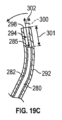
図19Aは、ドッキングコイルスリーブ292の先導部分290に対するドッキングコイル280の先導部分282の拡大図を示す。図19Aに示すように、ドッキングコイル280の先導部分282は、画定された曲率半径で湾曲した配向を有してもよい。
FIG. 19A shows an enlarged view of the leading
ドッキングコイルスリーブ292の先導部分290は、ドッキングコイルスリーブ292の先導先端298に延びてもよい。先導部分290は、ドッキングコイル280の先導部分282の配向とは異なる配向を有してもよい。図19Aに示すように、例えば、ドッキングコイルスリーブ292の先導部分290は、直線状の構成を有してもよい。他の実施例では、他の配向の中でも特に、ドッキングコイル280の異なる曲率半径を有する湾曲した配向を含む他の配向を利用してもよい。
A leading
図19Bを参照すると、ドッキングコイル280は、ドッキングコイルスリーブ292の内部内腔294内に位置付けられてもよい。ドッキングコイルスリーブ292の内部内腔294は、ドッキングコイル280が内部で摺動するように構成されてもよい。ドッキングコイル280の先導先端285は、ドッキングコイルスリーブ292の先導先端298から距離296に位置付けられてもよい。ドッキングコイルスリーブ292の先導先端298は、図19Bの線300により印付けられている方向に延在する。
Referring to FIG. 19B,
ドッキングコイル280は、ドッキングコイルスリーブ292の内部内腔294内で摺動可能であってもよく、ドッキングコイルスリーブ292内で遠位及び近位に摺動可能であってもよい。ドッキングコイルスリーブ292の内部内腔294内で摺動するドッキングコイル280は、ドッキングコイルスリーブ292の先導先端298からのドッキングコイル280の先導先端285の距離296を変化させてもよい。
ドッキングコイルスリーブ292の先導先端298からのドッキングコイル280の先導先端285の距離296の変化は、ドッキングコイルスリーブ292の先導先端298を偏向させてもよい。例えば、図19Cに示すように、ドッキングコイル280がドッキングコイルスリーブ292の先導先端298に対して遠位に前進されると、ドッキングコイル280の先導先端285とドッキングコイルスリーブ292の先導先端298との間の距離301は、図19Bに示す距離296から低減する。
A change in the
ドッキングコイル280の先導部分282の曲率半径に起因して、ドッキングコイルスリーブ292は、それに応じて先導部分282の湾曲に適合し、かつ先導部分282の湾曲に従って偏向してもよい。図19Cは、例えば、図19Bに示す線300によって表される方向からのドッキングコイルスリーブ292の先導先端298の偏向角度302の変化を示す。そのため、ドッキングコイルスリーブ292の先導先端298は、内部内腔294内のドッキングコイル280の摺動運動に起因して、図19Bに示す位置から偏向してもよい。
Due to the radius of curvature of the leading
ドッキングコイル280は、ドッキングコイルスリーブ292が図19Bに示す構成に戻ることを可能にするために格納されてもよい。例えば、ドッキングコイルスリーブ292は、ドッキングコイル280の格納に伴い、図19Bに示す構成に戻るように付勢されてもよい。
ドッキングコイルスリーブ292の先導先端298及びドッキングコイル280の先導先端285の相対位置は、ドッキングコイルスリーブ292の先導先端298がドッキングコイル280の展開中に偏向することを可能にするように変化してもよい。例えば、先端285、298間の距離は、僧帽弁弁尖の包囲中に偏向を引き起こすように変化してもよい。
The relative positions of leading
図22A及び22Bは、例えば、こうした動作を示す。ドッキングコイル280は、ドッキングコイルスリーブ292内に延在して示され、ドッキングコイル280の先導先端285は、図 22Aのドッキングコイルスリーブ292の先導先端298からの距離である。ドッキングコイルスリーブ292の先導部分290は、事前設定された曲率半径を有してもよく、これはドッキングコイル280の先導部分282の事前設定された曲率半径よりも大きくてもよい。さらに、ドッキングコイル280の先導部分282の配向は、図22Aに示すように、ドッキングコイルスリーブ292の先導部分290の直径よりも小さい直径を形成するように構成されてもよい。
Figures 22A and 22B, for example, illustrate such operation.
ドッキングコイルスリーブ292の先導先端298に対してドッキングコイル280の先導先端285を遠位に摺動させることは、例えば、図22Bに示すように、ドッキングコイルスリーブ292の先導先端298を半径方向内向きに偏向してもよい。さらに、ドッキングコイルスリーブ292の先導先端298に対してドッキングコイル280の先導先端285を近位に摺動させることは、ドッキングコイルスリーブ292の先導先端298を半径方向外向きに偏向してもよい。こうした動作は、ドッキングコイルスリーブ292を、例えば、図22Aに示す位置へと戻す。ドッキングコイル280が望ましい位置に来ると、ドッキングコイルスリーブ292は完全に格納されて、僧帽弁弁尖上の所定の位置にドッキングコイル280を残してもよい。
Sliding the leading
図19Aに示すように、ドッキングコイルスリーブ292は、直線状の構成を有してもよい。実施例では、ドッキングコイルスリーブ292は、ドッキングコイル280の異なる湾曲によって偏向され得る事前設定された湾曲を有してもよい。
As shown in FIG. 19A,
図20は、例えば、事前設定された湾曲を有する先導部分306を有するドッキングコイルスリーブ304の例を示す。先導部分306は、湾曲部分308と、湾曲部分308の遠位にある直線部分310とを含み得る。ドッキングコイルは、内部内腔312を通過して、先導先端を偏向させ、先導先端の偏向角度314を変化させてもよい。
FIG. 20, for example, shows an example of a
図21Aは、事前設定された湾曲を有する先導部分318を有するドッキングコイルスリーブ316の例を示す。ドッキングコイルスリーブ316の先導先端320は、先導部分318の湾曲を保持する。図21Bは、ドッキングコイルスリーブ316の内部内腔324を通過して、先導先端320を偏向させ、先導先端320の偏向角度326を変化させた、ドッキングコイル322を示す。
FIG. 21A shows an example of a
ドッキングコイルスリーブの偏向は、ドッキングコイルの展開中にドッキングコイルスリーブが偏向されることを可能にし得る。こうした偏向は、天然構造との望ましくない接触を回避して、僧帽弁弁尖及び腱索などの構造を包囲するのに役立ち得る。したがって、偏向は、図17Cの矢印269及び270で表される偏向と同様の結果を生んでもよい。
Deflection of the docking coil sleeve may allow the docking coil sleeve to be deflected during deployment of the docking coil. Such deflection may help to surround structures such as the mitral valve leaflets and chordae tendineae, avoiding undesirable contact with natural structures. Thus, the deflection may produce similar results to the deflections represented by
ドッキングコイルスリーブ292及びドッキングコイル280が所望の位置、例えば僧帽弁弁尖の周りに定置されると、ドッキングコイルスリーブ292はドッキングコイル280に対して格納されてもよい。ドッキングコイル280は、ドッキングコイルスリーブ292が患者の心室から取り外された状態で、僧帽弁弁尖に展開される位置に留まってもよい。
Once
ドッキングコイルスリーブ292及びドッキングコイル280の相対位置は、先導先端298、285の相対位置及び先導先端298、285間の距離の変化を制御し得る制御機構を用いて制御されてもよい。例えば、制御機構は、ドッキングコイルスリーブ292の近位部分及びドッキングコイル280に結合して、先導先端298、285間の距離を制御及び変化させてもよい。
The relative positions of
実施例では、ドッキングコイルスリーブ292は、図15A及び15Bに示すようなスパイン、又は図15A及び15Bに示すような編組み、又は図16A及び16Bに示すように保持リングの間に延在するスパインを含んでもよい。スパインは、例えばドッキングコイルスリーブの先導部分に沿って延びてもよい。編組みは、ドッキングコイルスリーブの先導部分に位置付けられてもよい。こうした特徴は、ドッキングコイル280が近位に格納されるのに伴い、ドッキングコイルスリーブ292をドッキングコイルスリーブ292の事前設定された配向に戻すように付勢してもよい。特徴の様々な組み合わせが、所望に応じて提供されてもよい。
In embodiments, the
実施例では、ドッキングコイルは、僧帽弁弁尖を包囲するドッキングコイルとドッキングコイルスリーブとの組み合わせの先導部分を備えてもよい。図23A~23Cは、例えば、このような例を示しており、ドッキングコイルスリーブ330が、例えば、図23Aに示すように事前設定された湾曲を有してもよい。ドッキングコイル332は、例えば、図23Bに示すように、ドッキングコイルスリーブ330の内部内腔334内に位置付けられてもよい。ドッキングコイル332は、ドッキングコイル332上に一つ以上の切り込み336を含んでもよく、これはドッキングコイル332の先導先端333がドッキングコイル332の上に延びるドッキングコイルスリーブ330上で偏向することを可能にし得る。一つ以上の切り込み336は、ドッキングコイル332の内側曲線上に位置付けられてもよい。
In embodiments, the docking coil may include a leading portion of a combination docking coil and docking coil sleeve that surrounds the mitral valve leaflets. 23A-23C, for example, illustrate such an example, where the
ドッキングコイル332の先導部分329の配向は、ドッキングコイルスリーブ330の先導部分331の直径よりも大きい直径を形成するように構成されてもよい。ドッキングコイルスリーブ330の先導部分331は、事前設定された曲率半径を有してもよく、これはドッキングコイル332の先導部分329の事前設定された曲率半径よりも小きくてもよい。そのため、ドッキングコイルスリーブ330の先導先端335に対してドッキングコイル332の先導先端333を遠位に摺動させることは、ドッキングコイル332の先導先端333を半径方向内向きに偏向してもよい。
The orientation of the leading
図23Cは、例えば、ドッキングコイル332を偏向させ、かつドッキングコイル332の偏角を変化させるために遠位に前進させたドッキングコイルスリーブ330を示す。
FIG. 23C, for example, shows the
図18A~23Cは、ドッキングコイルスリーブ及び/又はドッキングコイルが展開中に偏向することを可能にし、それ故に天然構造との望ましくない接触を回避し、又は僧帽弁弁尖又は腱索などの天然構造をより良好に包囲することを可能にし得る。 18A-23C allow the docking coil sleeve and/or the docking coil to deflect during deployment, thus avoiding undesirable contact with natural structures, such as the mitral valve leaflets or chordae tendineae. It may be possible to better enclose the structure.
図24A~24Mは、ドッキングコイルの形態でのアンカー装置のさらなる展開、及びアンカー装置への人工インプラントのさらなる埋め込みを伴う工程を示す。工程は、カテーテル装置が図12Bに示す位置にあることから継続してもよい。 Figures 24A-24M illustrate steps involving further deployment of the anchoring device in the form of a docking coil and further implantation of the artificial implant into the anchoring device. The process may continue with the catheter device in the position shown in Figure 12B.
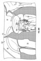
図24Aは、交連A3P3を通して、患者の心臓の左心室52における腱索62及び自己弁尖の周囲へと、ドッキングコイルスリーブ212を展開する送達カテーテル100を図示する。アンカー装置又は先導部分、又はアンカー装置の包囲コイル/巻線は、送達カテーテル100の遠位開口から導出されるとともに、送達カテーテル100の方向において、その形状セット又は形状記憶形態を取り始める。アンカー装置は、ドッキングコイルスリーブ212内に位置付けられてもよい。アンカー装置は、カテーテル100の内部内腔を通過するドッキングコイルを備えてもよい。
FIG. 24A illustrates
図24Bを参照すると、ドッキングコイルスリーブ212は、ドッキングコイルスリーブ212が僧帽弁50の平面に実質的に平行な位置で腱索62の周りを包むように、送達カテーテル100からさらに展開されてもよい。ドッキングコイルスリーブ212は、包囲処置中に本明細書の実施例に従って偏向されてもよい。
Referring to FIG. 24B,
図24Cを参照すると、ドッキングコイルスリーブ212は、心臓弁を保持するために、僧帽弁の心室側にアンカー装置を緩く位置付けるために、腱索62の周りに配置される。図示した実施形態では、ドッキングコイルスリーブ212は、アンカー装置の機能的コイル340及びドッキングコイルスリーブ212が腱索及び/又は自己弁尖の周りに密接に巻かれるように、左心室52内に配置される。実施例での下端部巻線/コイル、又は包囲巻線/コイルは、その曲率半径が大きいため、多少外側に延在してもよい。一部の実施例では、アンカー装置は、腱索及び/又は弁尖の周りに配置されている三つ未満のコイル又は四つ以上のコイルを含み得る。
Referring to FIG. 24C, a
アンカー装置が所望の位置にある時、ドッキングコイルスリーブは、僧帽弁弁尖上の所定位置にアンカー装置を残すように格納されてもよい。 When the anchor device is in the desired position, the docking coil sleeve may be retracted to leave the anchor device in place on the mitral leaflets.
図24Dは、アンカー装置のコイルが腱索62及び自己弁尖(図24Cに示すように)の周りに配置された後、一定の位置にある左心房51内の送達カテーテル100を示す。この位置では、送達カテーテル100の遠位先端106は、僧帽弁50がなす平面に対して実質的に平行であるとともに、僧帽弁50の交連部A3P3に又はその近傍に位置している(例えば、1mm~5mm以下などの分だけ、わずかに交連部A3P3の内部へと延びている又は交連部A3P3を貫通して延びている)。
FIG. 24D shows the
図24Eを参照すると、送達カテーテルは、方向Xにアンカー装置に沿って軸方向に、外側シース20内へと並進又は格納され得る。送達カテーテルの並進移動又は後退により、自己弁の心房側(例えば、心房内)に位置付けられたアンカー装置の部分が、送達カテーテルのシースから抜かれ、放出される。例えば、これは、自己弁(存在する場合)の心房側に位置する任意の機能的コイル及び/又は上側コイルの任意の上部をシースから抜き、放出することができる。一つの例示的な実施例では、例えば、プッシャーを使用して、送達カテーテルが後退する時に、アンカー装置を定位置に保持する、及び/又はアンカー装置の格納を阻止又は防止することができるなど、アンカー装置は、送達カテーテルが並進移動する際に移動しないか、又は実質的に移動しない。
Referring to FIG. 24E, the delivery catheter may be translated or retracted axially along the anchor device in direction X into
本明細書の実施例で利用され得るプッシャーの特徴は、2020年6月8日に出願され、「Systems, Devices, and Methods for Treating Heart Valves」と題され、WO/2020/247907として公開された、国際特許出願第PCT/US2020/036577号に開示され、その全体が参照により本明細書に組み込まれる。 Features of the pusher that may be utilized in the embodiments herein are disclosed in International Patent Application No. PCT/US2020/036577, filed June 8, 2020, entitled "Systems, Devices, and Methods for Treating Heart Valves," and published as WO/2020/247907, which is incorporated herein by reference in its entirety.
図24Fを参照すると、示された例では、送達カテーテルの並進又は後退はまた、送達カテーテルからアンカー装置又はドッキングコイル200の任意の上端部コイル/巻線(例えば、より大きな直径の安定化コイル/巻線)を抜く/放出することができる。抜き出し/解放の結果、アンカー装置又は上側コイル(例えば、より大きな直径を有した又はより大きな曲率半径を有した安定化コイル)の心房側は、送達カテーテル100から延びるとともに、その事前設定された又は緩和した形状設定/形状記憶形状を取り始める。実施例では、アンカー装置はまた、屈曲Zから上向きに延在する上向きの延在部分又は接続部分を含んでもよく、また、上端部安定化コイル/巻線と、アンカー装置(例えば、機能的コイル/巻線)の他のコイル/巻線との間を延在及び/又はブリッジすることができる。一部の実施例では、アンカー装置は、自己弁の心房側に一つの上側コイルのみを有することができる。一部の実施例では、アンカー装置は、自己弁の心房側に複数の上側コイルを含み得る。
Referring to FIG. 24F, in the example shown, translation or retraction of the delivery catheter also removes any upper end coils/windings (e.g., larger diameter stabilizing coils/windings) of the anchoring device or
図24Gを参照すると、送達カテーテル100は、外側シース又はガイドシース20へと戻り続け、これにより、アンカー装置の上部が送達カテーテルの内部から放出される。アンカー装置は、縫合糸/ライン901などの取付手段によって、プッシャー950に対して緊密に接続される(他の取付手段又は他の接続手段も、また、所望に応じて使用することができる)。上端部コイル/巻線又は安定化コイル/巻線は、僧帽弁50に対してのアンカー装置の位置又は高さを一時的に及び/又は緩く保持するために、心房壁に沿って配置されるものとして示されている。
24G, the
図24Hを参照すると、アンカー装置は、送達カテーテル100の内腔から完全に除去され、たるみは、アンカー装置に取り外し可能に取り付けられる縫合/糸901、例えば、縫合/糸901は、アンカー装置の端部で、穴を介して輪になることができる。アンカー装置を送達カテーテル100から除去するために、縫合901はアンカー装置から除去される。しかしながら、縫合901が除去される前に、アンカー装置の位置がチェックされ得る。アンカー装置又はドッキングコイル200の位置が不正確である場合、アンカー装置は、プッシャー950(例えば、プッシャーロッド、プッシャーワイヤ、プッシャーチューブなど)によって送達カテーテル内に引き戻され、再展開され得る。
Referring to FIG. 24H, the anchor device is completely removed from the lumen of the
図24Iを参照すると、送達カテーテル100及び外側シース20がアンカー装置から取り外された後、心臓弁送達装置/カテーテル902を使用して、心臓弁903を僧帽弁50に送達することができる。心臓弁送達装置902は、送達カテーテル100及び/又は外側シース若しくはガイドシース20の一つ以上の構成部材を利用してもよい、あるいは、送達装置902は、送達カテーテル100及び外側シース若しくはガイドシースから独立したものであってもよい。図示した実施例では、心臓弁送達装置902は、経中隔アプローチを使用して左心房51に入る。実施例では、心臓弁送達カテーテル902は、外側シース20を通過してもよい。心臓弁送達カテーテル902は、ドッキングコイルの形態でアンカー装置とドッキングするように、人工心臓弁を展開してもよい。
Referring to FIG. 24I, after
アンカー装置とのドッキングのために本明細書の実施例で利用され得るインプラントの特徴は、2020年6月8日に出願され、「Systems, Devices, and Methods for Treating Heart Valves」と題され、WO/2020/247907として公開された、国際特許出願第PCT/US2020/036577号に開示され、その全体が参照により本明細書に組み込まれる。 Implant features that may be utilized in the embodiments herein for docking with an anchoring device are described in the patent application filed June 8, 2020 and entitled "Systems, Devices, and Methods for Treating Heart Valves", WO Disclosed in International Patent Application No. PCT/US2020/036577, published as PCT/US2020/247907, herein incorporated by reference in its entirety.
図24Jを参照すると、心臓弁送達装置/カテーテル902は、心臓弁903が、僧帽弁の弁尖とアンカー装置との間に配置されるように、僧帽弁50を通って移動される。心臓弁903は、ガイドワイヤ904に沿って展開位置に誘導され得る。
Referring to FIG. 24J, heart valve delivery device/
図24Kを参照すると、心臓弁903が所望の位置に配置された後、任意選択のバルーンが拡張されて、心臓弁903をその拡張された展開されたサイズに拡張する。すなわち、心臓弁903は、僧帽弁50の弁尖と係合し、心室を増大されたサイズへ外向きに強制して心臓弁903とアンカー装置との間の弁尖を固定するように、随意のバルーンは膨張される。心臓弁903の外向き力及びコイルの内向き力は、自己組織をつまんで心臓弁903及びコイルを弁尖に保持することができる。一部の実施例では、自己拡張型心臓弁は、心臓弁送達装置902のシース内に半径方向に圧縮された状態で保持されてもよく、心臓弁はシースから展開されてもよく、これにより心臓弁がその拡張状態まで拡張される。一部の実施例では、機械的に拡張可能な心臓弁が使用されるか、又は部分的に機械的に拡張可能な心臓弁が使用される(例えば、自己拡張及び機械的拡張の組み合わせによって拡張し得る弁)。
Referring to FIG. 24K, after
図24Lを参照すると、心臓弁903がその拡張状態に移動された後、心臓弁送達装置902及びワイヤ904が患者の心臓から除去される。さらに、ガイドシース20も、同様に患者の心臓から取り外されてもよい。心臓弁903は、機能状態にあり、患者の心臓の僧帽弁50が行う機能を代替する。
Referring to FIG. 24L, after
図24Mは、左心室52における仰見図からの心臓弁903を示す。図24Mでは、心臓弁903は、拡張及び機能状態にある。図示した実施例では、心臓弁903は、開位置と閉位置との間で移動するように構成される、三つの弁部材905a~c(例えば、弁尖)を含む。代替的な実施例では、心臓弁903は、例えば、二つ以上の弁部材、三つ以上の弁部材、四つ以上の弁部材など、開位置と閉位置との間で移動するように構成される四つ以上の弁部材を有することができる。図示した実施例では、弁部材905a~905cは、閉位置で示されており、この閉位置は、収縮期に弁部材が取る位置であって、血液が左心室から左心房内へと流れることを防止する位置である。拡張期の間、弁部材905a~cは開位置に移動し、これにより血液は左心房から左心室に入ることができる。
FIG. 24M shows
本明細書に図示した実施例は、交連部A3P3を通してドッキングコイル200という形態でのアンカー装置を送達する送達カテーテル100を示しているが、アンカー装置が患者の心臓の左心室内で腱索の周囲に巻回され得るよう、送達カテーテル100が、交連部A1P1を通してアンカー装置を送達するような構成を取り得るとともに、そのように配置され得ることを、理解されたい。さらに、図示した実施例は、アンカー部材を、僧帽弁50に送達する送達カテーテル100、及び心臓弁903を僧帽弁50に送達する心臓弁送達装置902を示すが、アンカー装置及び心臓弁903は、三尖弁、大動脈弁、又は肺動脈弁を修復するために準用され得ることが理解されるべきである。
The embodiment illustrated herein shows a
本明細書に開示される実施例は、このような方法で利用され得る。例えば、本明細書に開示される送達カテーテル、ドッキングコイル、又はドッキングコイルスリーブの任意の実施例は、所望に応じて利用されてもよい。実施例では、構成要素は、所望に応じて別々に利用されてもよい。 The embodiments disclosed herein can be utilized in such a manner. For example, any embodiment of a delivery catheter, docking coil, or docking coil sleeve disclosed herein may be utilized as desired. In embodiments, the components may be utilized separately as desired.
本明細書に記載の送達カテーテルの構成は、アンカー装置の正確な位置決め及び展開を可能にする例示的実施例を提供する。しかしながら、一部の例では、例えば、アンカー装置を自己弁で再配置するため、又はアンカー装置を埋め込み部位から除去するために、アンカー装置の展開中又は展開後の任意の段階で、アンカー装置の回収又は部分的な回収が依然として必要であり得る。送達カテーテルからアンカー装置を押し出す展開プッシャーとの間で、アンカー装置又はドッキングデバイスを取り付け及び/又は取り外すために使用できる、様々なロック又はロック解除機構を使用することができる。例えば、参照により本明細書に組み入れられる、2017年9月20日出願の米国仮特許出願第62/560,962号に記載されるように、他のロック又はロック機構も可能である。アンカー装置は、その近位側で、アンカー装置を押したり引っ張ったり容易に取り外したりし得るプッシャー又は他の機構に対して、接続することができる。本明細書に開示したシステム、装置、及び方法に関して利用され得る更なる特徴は、2018年5月21日付けで出願された米国特許出願第15/984,661号(米国公開第2018/0318079号)に記載されており、その全体が参照により本明細書に組み込まれる。 The delivery catheter configurations described herein provide exemplary embodiments that allow for precise positioning and deployment of anchor devices. However, in some instances, the anchoring device may be removed at any stage during or after deployment of the anchoring device, for example, to reposition the anchoring device with an autologous valve or to remove the anchoring device from the implanted site. Retrieval or partial retrieval may still be necessary. Various locking or unlocking mechanisms can be used to attach and/or remove the anchoring device or docking device from the deployment pusher that pushes the anchoring device out of the delivery catheter. Other locks or locking mechanisms are also possible, such as those described in US Provisional Patent Application No. 62/560,962, filed September 20, 2017, which is incorporated herein by reference. The anchor device can be connected on its proximal side to a pusher or other mechanism that can push or pull the anchor device for easy removal. Additional features that may be utilized with respect to the systems, apparatus, and methods disclosed herein are disclosed in U.S. patent application Ser. ), which is incorporated herein by reference in its entirety.
実施例では、本明細書に記載されるシステム及び装置の様々な操作及び制御は、自動化及び/又は電動化され得る。例えば、上述の制御又はノブは、上述の制御/ノブに関して記載した動作を引き起こすボタン又は電気入力であってもよい。これは、ボタン又は電気入力によって起動されるモータ(例えば、電気モータ、空気圧モータ、油圧モータ、等)に対して、可動部材の一部又は全部を接続すること(直接的に又は間接的に)により、行うことができる。例えば、モータは、動作時には、制御ワイヤ若しくは引張りワイヤなどのテザーを緊張又は弛緩させることで、カテーテルの遠位領域を駆動するように、構成することができる。追加的に又は代替的に、モータは、動作時には、プッシャーなどのデバイスをカテーテルに対して並進方向に又は軸方向に駆動することで、アンカー若しくはドッキングデバイスを、カテーテル内において及び/又はカテーテルの内外にわたって駆動するように、構成することができる。自動停止又は予防対策は、例えば、特定の点を超えて構成要素が移動しないように、システム/装置及び/又は患者の損傷を防止するために組み込まれ得る。 In embodiments, various operations and controls of the systems and devices described herein may be automated and/or motorized. For example, the controls or knobs described above may be buttons or electrical inputs that cause the operations described with respect to the controls/knobs described above. This is the connection (directly or indirectly) of some or all of the movable members to a motor (e.g. electric motor, pneumatic motor, hydraulic motor, etc.) that is activated by a button or an electrical input. This can be done by For example, the motor can be configured to, in operation, tension or relax a tether, such as a control wire or puller wire, to drive the distal region of the catheter. Additionally or alternatively, the motor, in operation, drives a device, such as a pusher, translationally or axially relative to the catheter to move the anchor or docking device within and/or into and out of the catheter. It can be configured to drive across the entire range. Automatic shutdown or precautionary measures may be incorporated to prevent damage to the system/equipment and/or patient, such as to prevent movement of components beyond a certain point.
本明細書に記載される装置及び機器は、他の外科処置及びアクセスポイント(例えば、経心尖、開心など)と共に使用され得ることに留意されたい。また、本明細書に記載される装置(例えば、展開ツール)は、本明細書に記載される例とは異なる様々な他の種類のアンカー装置及び/又は人工弁と組み合わせて使用されてもよいことも留意されたい。 Note that the devices and instruments described herein can be used with other surgical procedures and access points (eg, transapical, open heart, etc.). Additionally, the devices described herein (e.g., deployment tools) may be used in combination with various other types of anchoring devices and/or prosthetic valves different from the examples described herein. Please also note that.
本明細書の目的のために、本開示の実施例のある特定の態様、利点、及び新規の特徴が、本明細書に記載される。開示される方法、装置、及びシステムは、決して制限するものと解釈されるべきではない。代わりに、本開示は、単独で、並びに互いとの様々な組み合わせ及び部分的な組み合わせで、様々な開示された実施例の全ての新規かつ非自明な特徴及び態様を対象とする。方法、装置、及びシステムが、任意の特定の態様若しくは特徴、又はそれらの組み合わせに限定されることもなく、開示される実施例が、任意の一つ以上の特定の利点が存在すること、又は問題が解決されることを必要とすることもない。一つの実施例の特徴、要素、又は構成要素を、本明細書の他の実施例に組み合わせることができる。 For purposes of this specification, certain aspects, advantages, and novel features of the embodiments of the present disclosure are described herein. The disclosed methods, apparatus, and systems should not be construed as limiting in any way. Instead, this disclosure is directed to all novel and non-obvious features and aspects of the various disclosed embodiments, both alone and in various combinations and subcombinations with each other. The methods, apparatus, and systems are not limited to any particular aspects or features, or combinations thereof, and the disclosed embodiments are not limited to any one or more particular advantages, or Nor does it require the problem to be solved. Features, elements, or components of one embodiment may be combined with other embodiments herein.
実施例1: 患者の体内の一部に対してインプラントを送達するためのシステム。システムは、インプラントが通過するための内部内腔を有する細長いシャフトと、第一の可撓性部分及び第一の可撓性部分の遠位に位置付けられた第二の可撓性部分を含む遠位端部分と、を含む送達カテーテルを含んでもよく、第一の可撓性部分は、第一のテザーと、第一のテザーに対して円周方向に対向して位置付けられた第一の線形スパインと、を含み、第一の可撓性部分は、長手方向の力が第一のテザーに加えられると、平面内で偏向するように構成されており、第二の可撓性部分は、第二のテザーと、第一の線形スパインに対して非直交かつ非平行に位置付けられた第二の線形スパインと、を含み、第二の可撓性部分は、長手方向の力が第二のテザーに加えられると、平面と非直交かつ非平行である方向に偏向するように構成されている。 Example 1: System for delivering an implant to a part of a patient's body. The system includes an elongate shaft having an internal lumen for passage of the implant, a first flexible portion and a second flexible portion positioned distal to the first flexible portion. a distal portion; the first flexible portion may include a first tether and a first linear portion positioned circumferentially opposed to the first tether; a spine, the first flexible portion is configured to deflect in a plane when a longitudinal force is applied to the first tether, and the second flexible portion is configured to deflect in a plane when a longitudinal force is applied to the first tether; a second tether and a second linear spine positioned non-orthogonally and non-parallel to the first linear spine, the second flexible portion being configured such that the longitudinal force When applied to the tether, it is configured to deflect in a direction that is non-orthogonal and non-parallel to the plane.
実施例2: 第二のテザーが、第二の線形スパインに対して円周方向に対向して位置付けられる、本明細書の任意の実施例、特に実施例1に記載のシステム。 Example 2: The system as described in any example herein, particularly Example 1, wherein the second tether is positioned circumferentially opposed to the second linear spine.
実施例3: 第二のテザーが、第一のテザーに対して鈍角に位置付けられる、本明細書の任意の実施例、特に実施例1又は実施例2に記載のシステム。 Example 3: A system as described in any example herein, particularly Example 1 or Example 2, wherein the second tether is positioned at an obtuse angle with respect to the first tether.
実施例4: 第二のテザーが、第一のテザーに対して直交に位置付けられる、本明細書の任意の実施例、特に実施例1に記載のシステム。 Example 4: The system as described in any example herein, particularly Example 1, wherein the second tether is positioned orthogonally to the first tether.
実施例5: 第二の線形スパインが、第一の線形スパインに対して鈍角に位置付けられている、本明細書の任意の実施例、特に実施例1~4に記載のシステム。 Example 5: A system as described in any of the examples herein, particularly Examples 1-4, wherein the second linear spine is positioned at an obtuse angle with respect to the first linear spine.
実施例6: 第二の線形スパインが、第一のテザーに対して鋭角に位置付けられている、本明細書の任意の実施例、特に実施例1~5に記載のシステム。 Example 6: A system as described in any of the examples herein, particularly Examples 1-5, wherein the second linear spine is positioned at an acute angle with respect to the first tether.
実施例7: 第二の可撓性部分が偏向するように構成される方向が、第一の可撓性部分の偏向方向に対して鈍い、本明細書の任意の実施例、特に実施例1~6に記載のシステム。 Example 7: Any example herein, especially Example 1, wherein the direction in which the second flexible portion is configured to deflect is obtuse with respect to the direction of deflection of the first flexible portion. The system described in ~6.
実施例8: 第二の可撓性部分が、近位に延在する曲線を形成するように偏向するように構成される、本明細書の任意の実施例、特に実施例1~7に記載のシステム。 Example 8: As described in any of the examples herein, particularly Examples 1-7, wherein the second flexible portion is configured to deflect to form a proximally extending curve. system.
実施例9: 平面が第一の平面であり、曲線が、第一の平面と非直交及び非平行である第二の平面に延在するように構成される、本明細書の任意の実施例、特に実施例8に記載のシステム。 Example 9: Any embodiment herein where the plane is a first plane and the curve is configured to extend in a second plane that is non-orthogonal and non-parallel to the first plane. , particularly the system described in Example 8.
実施例10: 第二の可撓性部分の遠位先端が、インプラントが通過して送達カテーテルから展開するための開口を含む、本明細書の任意の実施例、特に実施例9のシステム。 Example 10: The system of any example herein, particularly Example 9, wherein the distal tip of the second flexible portion includes an opening for the implant to pass through and be deployed from the delivery catheter.
実施例11: 曲線が、遠位先端を位置付け、第一の可撓性部分がその中に延在する平面と平行かつオフセットされた平面に延在するように構成される、本明細書の任意の実施例、特に実施例10に記載のシステム。 Example 11: Any herein wherein the curve locates the distal tip and is configured to extend in a plane parallel to and offset from the plane in which the first flexible portion extends. Examples, particularly the system described in Example 10.
実施例12: 第一の線形スパイン及び第二の線形スパインが、細長いシャフトの本体内に埋め込まれる、本明細書の任意の実施例、特に実施例1~11に記載のシステム。 Example 12: A system as described in any example herein, particularly Examples 1-11, wherein the first linear spine and the second linear spine are embedded within the body of the elongated shaft.
実施例13: 第一のテザーが、第一の可撓性部分を偏向させるために近位に格納されるように構成されたプルテザーを備え、第二のテザーが、第二の可撓性部分を偏向させるために近位に格納されるように構成されたプルテザーを備える、本明細書の任意の実施例、特に実施例1~12に記載のシステム。 Example 13: The first tether comprises a pull tether configured to be proximally retracted to deflect the first flexible portion, and the second tether comprises a pull tether configured to deflect the first flexible portion. A system as described in any embodiment herein, particularly Examples 1-12, comprising a pull tether configured to be proximally retracted to deflect the tether.
実施例14: インプラントをさらに含み、インプラントが、ドッキングコイルを含む、本明細書の任意の実施例、特に実施例1~13に記載のシステム。 Example 14: A system as described in any example herein, particularly Examples 1-13, further comprising an implant, the implant comprising a docking coil.
実施例15: 細長いシャフトを通過させるための内腔を含む操縦可能なガイドシースをさらに含み、操縦可能なガイドシースが、細長いシャフトが操縦可能なガイドシースの内腔内に位置付けられた細長いシャフトの一部分を偏向させるように構成される、本明細書の任意の実施例、特に実施例1~14に記載のシステム。 Example 15: further comprising a steerable guide sheath including a lumen for passing an elongated shaft therethrough, the steerable guide sheath comprising an elongate shaft positioned within the lumen of the steerable guide sheath. A system as described in any of the examples herein, particularly Examples 1-14, configured to deflect a portion.
実施例16: インプラントを患者の体内の一部に送達するためのシステムであって、システムが、インプラントが通過するための内部内腔を有する細長いシャフトと、テザー及びテザーから円周方向に鈍角に位置付けられた線形スパインとを有する可撓性部分を含む遠位端部分と、を含む送達カテーテルを備え、可撓性部分が、テザーに加えられる長手方向の力に基づき曲線を形成するように偏向するように構成される、システム。 Example 16: A system for delivering an implant to a portion of a patient's body, the system comprising: an elongate shaft having an internal lumen for the implant to pass through; a tether; and an obtuse circumferential angle from the tether. a distal end portion including a flexible portion having a linear spine positioned therein, the flexible portion deflecting to form a curve based on a longitudinal force applied to the tether; A system configured to:
実施例17: 曲線が、近位に延在するように構成される、本明細書の任意の実施例、特に実施例16に記載のシステム。 Example 17: A system as described in any Example herein, particularly Example 16, wherein the curve is configured to extend proximally.
実施例18: 可撓性部分の遠位先端が、インプラントが通過して送達カテーテルから展開するための開口を含む、本明細書の任意の実施例、特に実施例16又は17に記載のシステム。 Example 18: A system as described in any Example herein, particularly Example 16 or 17, wherein the distal tip of the flexible portion includes an opening for the implant to pass through and be deployed from the delivery catheter.
実施例19: 可撓性部分が第二の可撓性部分であり、テザーが第二のテザーであり、線形スパインが第二の線形スパインであり、細長いシャフトが、第二の可撓性部分の近位に位置付けられ、第一のテザーと、第一のテザーに対して円周方向に対向して位置付けられた第一の線形スパインとを含む、第一の可撓性部分をさらに含み、第一の可撓性部分が、長手方向の力が第一のテザーに加えられると、平面内で偏向するように構成されている、本明細書の任意の実施例、特に実施例16~18に記載のシステム。 Example 19: The flexible portion is a second flexible portion, the tether is a second tether, the linear spine is a second linear spine, and the elongated shaft is a second flexible portion further comprising a first flexible portion positioned proximal to the first flexible portion including a first tether and a first linear spine positioned circumferentially opposed to the first tether; Any embodiment herein, particularly Examples 16-18, wherein the first flexible portion is configured to deflect in a plane when a longitudinal force is applied to the first tether. system described in.
実施例20: 平面が第一の平面であり、曲線が、第一の平面と非直交及び非平行である第二の平面に延在するように構成される、本明細書の任意の実施例、特に実施例19に記載のシステム。 Example 20: Any embodiment herein where the plane is a first plane and the curve is configured to extend in a second plane that is non-orthogonal and non-parallel to the first plane. , particularly the system described in Example 19.
実施例21: 第二の可撓性部分が、第一の可撓性部分の偏向方向に対して鈍い方向に偏向するように構成される、本明細書の任意の実施例、特に実施例19又は20のシステム。 Example 21: Any example herein, especially Example 19, wherein the second flexible portion is configured to deflect in a direction obtuse with respect to the direction of deflection of the first flexible portion. Or 20 systems.
実施例22: 第一のテザーが、第一の可撓性部分を偏向させるために近位に格納されるように構成されたプルテザーを備え、第二のテザーが、第二の可撓性部分を偏向させるために近位に格納されるように構成されたプルテザーを備える、本明細書の任意の実施例、特に実施例19~21に記載のシステム。 Example 22: The first tether comprises a pull tether configured to be proximally retracted to deflect the first flexible portion, and the second tether comprises a pull tether configured to deflect the first flexible portion. A system as described in any of the examples herein, particularly Examples 19-21, comprising a pull tether configured to be proximally retracted to deflect the tether.
実施例23: 第一の線形スパイン及び第二の線形スパインが、細長いシャフトの本体内に埋め込まれる、本明細書の任意の実施例、特に実施例19~22に記載のシステム。 Example 23: A system as described in any of the examples herein, particularly Examples 19-22, wherein the first linear spine and the second linear spine are embedded within the body of the elongated shaft.
実施例24: インプラントをさらに含み、インプラントが、ドッキングコイルを含む、本明細書の任意の実施例、特に実施例16~23に記載のシステム。 Example 24: A system as described in any Example herein, particularly Examples 16-23, further comprising an implant, the implant comprising a docking coil.
実施例25: 細長いシャフトを通過させるための内腔を含む操縦可能なガイドシースをさらに含み、操縦可能なガイドシースが、細長いシャフトが操縦可能なガイドシースの内腔内に位置付けられた細長いシャフトの一部分を偏向させるように構成される、本明細書の任意の実施例、特に実施例16~24に記載のシステム。 Example 25: further comprising a steerable guide sheath including a lumen for passage of an elongate shaft, the steerable guide sheath comprising an elongate shaft positioned within the lumen of the steerable guide sheath. A system as described in any of the examples herein, particularly Examples 16-24, configured to deflect a portion.
実施例26: 患者の体内の一部に対してインプラントを送達するためのシステム。システムは、インプラントが通過するための内部内腔を有する細長いシャフトと、第一の可撓性部分及び第一の可撓性部分の遠位に位置付けられた第二の可撓性部分を含む遠位端部分と、を含む送達カテーテルを含んでもよく、第一の可撓性部分は、第一のテザーと、第一のテザーに対して円周方向に対向して位置付けられた第一の線形スパインと、を含み、第一の可撓性部分は、長手方向の力が第一のテザーに加えられると、第一の平面内で偏向するように構成され、第二の可撓性部分は、第一のテザーに対して直交に位置付けられた第二のテザーと、第二の線形スパインに対して円周方向に対向して位置付けられた第二の線形スパインと、第一のテザーに対して円周方向に対向して位置付けられた第三のテザーと、を含み、第二の可撓性部分は、長手方向の力が第二のテザーに加えられると、第一の平面に対して直交である第二の平面内で偏向するように構成され、第二の可撓性部分は、長手方向の力が第三のテザーに加えられると、第一の平面内で偏向するように構成される。 Example 26: A system for delivering an implant to a portion of a patient's body. The system may include a delivery catheter including an elongate shaft having an internal lumen for passage of the implant, and a distal end portion including a first flexible portion and a second flexible portion positioned distal to the first flexible portion, the first flexible portion including a first tether and a first linear spine positioned circumferentially opposite the first tether, the first flexible portion configured to deflect in a first plane when a longitudinal force is applied to the first tether, the second flexible portion including a second tether positioned orthogonally to the first tether, a second linear spine positioned circumferentially opposite the second linear spine, and a third tether positioned circumferentially opposite the first tether, the second flexible portion configured to deflect in a second plane that is orthogonal to the first plane when a longitudinal force is applied to the second tether, and the second flexible portion configured to deflect in the first plane when a longitudinal force is applied to the third tether.
実施例27: 第二の可撓性部分が、長手方向の力が第二のテザー及び第三のテザーの両方に加えられると、第一の可撓性部分の偏向方向に対して鈍い方向に偏向するように構成される、本明細書の任意の実施例、特に実施例26のシステム。 Example 27: The second flexible portion deflects in a direction obtuse relative to the direction of deflection of the first flexible portion when a longitudinal force is applied to both the second tether and the third tether. The system of any embodiment herein, particularly embodiment 26, configured to deflect.
実施例28: 第二の可撓性部分が、近位に延在する曲線を形成するように偏向するように構成される、本明細書の任意の実施例、特に実施例26又は27に記載のシステム。 Example 28: As described in any example herein, particularly Example 26 or 27, wherein the second flexible portion is configured to deflect to form a proximally extending curve. system.
実施例29: 曲線が、長手方向の力が第二のテザー及び第三のテザーの両方に加えられると、第一の平面と非直交及び非平行である第三の平面に延在するように構成される、本明細書の任意の実施例、特に実施例28に記載のシステム。 Example 29: The curve extends in a third plane that is non-orthogonal and non-parallel to the first plane when a longitudinal force is applied to both the second tether and the third tether. 29. A system as described in any embodiment herein, particularly embodiment 28, configured.
実施例30: 第二の可撓性部分の遠位先端が、インプラントが通過して送達カテーテルから展開するための開口を含む、本明細書の任意の実施例、特に実施例26~29に記載のシステム。 Example 30: As described in any of the examples herein, particularly Examples 26-29, wherein the distal tip of the second flexible portion includes an opening for the implant to pass through and be deployed from the delivery catheter. system.
実施例31: 第二の可撓性部分が、第三のテザーに対して円周方向に対向して位置付けられた第三の線形スパインを含む、本明細書の任意の実施例、特に実施例26~30に記載のシステム。 Example 31: Any example herein, particularly the example, wherein the second flexible portion includes a third linear spine positioned circumferentially opposite to the third tether. 26-30.
実施例32: 第一の線形スパイン及び第二の線形スパインが、細長いシャフトの本体内に埋め込まれる、本明細書の任意の実施例、特に実施例26~31に記載のシステム。 Example 32: A system as described in any of the examples herein, particularly Examples 26-31, wherein the first linear spine and the second linear spine are embedded within the body of the elongated shaft.
実施例33: 第一のテザーが、第一の可撓性部分を偏向させるために近位に格納されるように構成されたプルテザーを備え、第二のテザーが、第二の可撓性部分を偏向させるために近位に格納されるように構成されたプルテザーを備え、第三のテザーが、近位に格納されて第二の可撓性部分を偏向するように構成される、本明細書の任意の実施例、特に実施例26~32に記載のシステム。 Example 33: The first tether comprises a pull tether configured to be proximally retracted to deflect the first flexible portion, and the second tether comprises a pull tether configured to deflect the first flexible portion. a pull tether configured to be proximally retracted to deflect the second flexible portion; a third tether configured to be proximally retracted to deflect the second flexible portion; The system described in any of the embodiments of the present invention, particularly Examples 26-32.
実施例34: インプラントをさらに含み、インプラントが、ドッキングコイルを含む、本明細書の任意の実施例、特に実施例26~33に記載のシステム。 Example 34: A system as described in any Example herein, particularly Examples 26-33, further comprising an implant, the implant comprising a docking coil.
実施例35: 細長いシャフトを通過させるための内腔を含む操縦可能なガイドシースをさらに含み、操縦可能なガイドシースが、細長いシャフトが操縦可能なガイドシースの内腔内に位置付けられた細長いシャフトの一部分を偏向させるように構成される、本明細書の任意の実施例、特に実施例26~34に記載のシステム。 Example 35: further comprising a steerable guide sheath including a lumen for passing an elongated shaft therethrough, the steerable guide sheath comprising an elongate shaft positioned within the lumen of the steerable guide sheath. A system as described in any of the examples herein, particularly Examples 26-34, configured to deflect a portion.
実施例36: システム。システムは、患者の体内の一部内にインプラントをドッキングするように構成されたドッキングコイルと、ドッキングコイルがその中を摺動するように構成された内部内腔を有し、ドッキングコイルスリーブの少なくとも一部分に沿って延び、ドッキングコイルスリーブを偏向させるように構成されたテザーを含むドッキングコイルスリーブと、を含んでもよい。 Example 36: System. The system has a docking coil configured to dock the implant within a portion of the patient's body, an internal lumen configured to slide the docking coil therethrough, and the system includes at least a portion of the docking coil sleeve. a docking coil sleeve including a tether extending along the docking coil sleeve and configured to deflect the docking coil sleeve.
実施例37: ドッキングコイルスリーブが、内部内腔の反対側に面する潤滑性の外面を含む、本明細書の任意の実施例、特に実施例36に記載のシステム。 Example 37: A system as described in any Example herein, particularly Example 36, wherein the docking coil sleeve includes a lubricious outer surface facing opposite the inner lumen.
実施例38: ドッキングコイルスリーブが、ドッキングコイルが通過してドッキングコイルスリーブから展開するための開口を有する遠位先端を含む、本明細書の任意の実施例、特に実施例36又は実施例37に記載のシステム。 Example 38: Any example herein, particularly Example 36 or Example 37, wherein the docking coil sleeve includes a distal tip having an opening for the docking coil to pass through and deploy from the docking coil sleeve. System described.
実施例39: テザーが、遠位先端を偏向するように構成される、本明細書の任意の実施例、特に実施例38に記載のシステム。 Example 39: A system as described in any Example herein, particularly Example 38, wherein the tether is configured to deflect the distal tip.
実施例40: ドッキングコイルスリーブがコイルを形成するように構成され、またテザーが、ドッキングコイルスリーブがコイルを形成する時に遠位先端を半径方向内向きに偏向するように構成される、本明細書の任意の実施例、特に実施例39に記載のシステム。 Example 40: Herein, the docking coil sleeve is configured to form a coil and the tether is configured to deflect the distal tip radially inward as the docking coil sleeve forms a coil. The system according to any embodiment of the present invention, particularly embodiment 39.
実施例41: ドッキングコイルスリーブが、ドッキングコイルスリーブの遠位端部分に位置付けられた編組みを含む、本明細書の任意の実施例、特に実施例36~40に記載のシステム。 Example 41: A system as described in any example herein, particularly Examples 36-40, wherein the docking coil sleeve includes a braid located at a distal end portion of the docking coil sleeve.
実施例42: 編組みが、ドッキングコイルスリーブの遠位先端に向かう方向に増大する可撓性を有する、本明細書の任意の実施例、特に実施例41に記載のシステム。 Example 42: A system as described in any of the examples herein, particularly example 41, wherein the braid has increasing flexibility in a direction toward the distal tip of the docking coil sleeve.
実施例43: ドッキングコイルスリーブが、ドッキングコイルスリーブのドッキングコイルスリーブの少なくとも一部分に沿って延在するスパインを含む、本明細書の任意の実施例、特に実施例36~42に記載のシステム。 Example 43: The system as described in any example herein, particularly Examples 36-42, wherein the docking coil sleeve includes a spine extending along at least a portion of the docking coil sleeve.
実施例44: スパインが、テザーに対して円周方向に対向して位置付けられる、本明細書の任意の実施例、特に実施例43に記載のシステム。 Example 44: A system as described in any Example herein, particularly Example 43, wherein the spine is positioned circumferentially opposed to the tether.
実施例45: テザーが、ドッキングコイルスリーブを偏向するために近位に格納されるように構成されたプルテザーを備える、本明細書の任意の実施例、特に実施例36~44に記載のシステム。 Example 45: A system as described in any Example herein, particularly Examples 36-44, wherein the tether comprises a pull tether configured to be proximally retracted to deflect the docking coil sleeve.
実施例46: システム。システムは、患者の体内の一部内でインプラントとドッキングするように構成され、先導先端に延び、配向を有するドッキングコイルと、ドッキングコイルがその中を摺動するように構成された内部内腔を有し、先導先端に延び、ドッキングコイルの先導部分の配向とは異なる配向を有する先導部分を含むドッキングコイルスリーブを含んでもよく、ドッキングコイルスリーブの先導先端は、ドッキングコイルの先導先端に対して摺動し、ドッキングコイルの先導先端又はドッキングコイルスリーブの先導先端を半径方向内向きに又は外向きに偏向させるように構成される。 Example 46: System. The system may include a docking coil configured to dock with an implant within a portion of a patient's body, the docking coil having an orientation and extending to a leading tip, and a docking coil sleeve having an internal lumen through which the docking coil is configured to slide, the docking coil sleeve including a leading portion extending to the leading tip and having an orientation different from the orientation of the leading portion of the docking coil, the leading tip of the docking coil sleeve configured to slide relative to the leading tip of the docking coil and deflect the leading tip of the docking coil or the leading tip of the docking coil sleeve radially inwardly or outwardly.
実施例47: ドッキングコイルの先導部分の配向が、ドッキングコイルスリーブの先導部分の直径よりも小さい直径を形成するように構成され、ドッキングコイルスリーブの先導先端に対してドッキングコイルの先導先端を遠位に摺動させることが、ドッキングコイルスリーブの先導先端を半径方向内向きに偏向させる、本明細書の任意の実施例、特に実施例46に記載のシステム。 Example 47: The orientation of the leading portion of the docking coil is configured to form a diameter that is smaller than the diameter of the leading portion of the docking coil sleeve, distally positioning the leading tip of the docking coil relative to the leading tip of the docking coil sleeve. 47. The system as described in any embodiment herein, particularly embodiment 46, wherein sliding the leading tip of the docking coil sleeve radially inwardly.
実施例48: ドッキングコイルスリーブの先導先端に対してドッキングコイルの先導先端を近位に摺動させることが、ドッキングコイルスリーブの先導先端を半径方向外向きに偏向させる、本明細書の任意の実施例、特に実施例46又は実施例47に記載のシステム。 Example 48: Any implementation herein wherein sliding the leading tip of the docking coil proximally relative to the leading tip of the docking coil sleeve deflects the leading tip of the docking coil sleeve radially outward. Examples, particularly the system described in Example 46 or Example 47.
実施例49: ドッキングコイルの先導部分が事前設定された曲率半径を有する、本明細書の任意の実施例、特に実施例46~48のシステム。 Example 49: Any of the examples herein, particularly examples 46-48, wherein the leading portion of the docking coil has a preset radius of curvature.
実施例50: ドッキングコイルスリーブの先導部分が、ドッキングコイルの先導部分の事前設定された曲率半径よりも大きい事前設定された曲率半径を有する、本明細書の任意の実施例、特に実施例49に記載のシステム。 Example 50: Any embodiment herein, particularly Example 49, wherein the leading portion of the docking coil sleeve has a preset radius of curvature that is greater than the preset radius of curvature of the leading portion of the docking coil. System described.
実施例51: ドッキングコイルの先導部分の配向が、ドッキングコイルスリーブの先導部分の直径よりも大きい直径を形成するように構成され、ドッキングコイルの先導先端に対してドッキングコイルスリーブの先導先端を遠位に摺動させることが、ドッキングコイルの先導先端を半径方向内向きに偏向させる、本明細書の任意の実施例、特に実施例46に記載のシステム。 Example 51: The orientation of the leading portion of the docking coil is configured to form a diameter that is greater than the diameter of the leading portion of the docking coil sleeve, distally positioning the leading tip of the docking coil sleeve relative to the leading tip of the docking coil. 47. The system as described in any embodiment herein, particularly embodiment 46, wherein sliding the leading tip of the docking coil radially inwardly.
実施例52: ドッキングコイルが、ドッキングコイルの内側曲線部分上に一つ以上の切り込みを含み、一つ以上の切り込みが、ドッキングコイルの先導先端が偏向することを可能にするように構成されている、本明細書の任意の実施例、特に実施例51に記載のシステム。 Example 52: A docking coil includes one or more notches on an inner curved portion of the docking coil, the one or more notches configured to allow a leading tip of the docking coil to deflect. , the system described in any of the examples herein, particularly Example 51.
実施例53: ドッキングコイルスリーブの先導部分が、ドッキングコイルの先導部分の事前設定された曲率半径よりも小さい事前設定された曲率半径を有する、本明細書の任意の実施例、特に実施例51又は実施例52に記載のシステム。 Example 53: Any example herein, particularly Example 51 or 53, wherein the leading portion of the docking coil sleeve has a preset radius of curvature that is less than the preset radius of curvature of the leading portion of the docking coil. The system described in Example 52.
実施例54: ドッキングコイルスリーブの先導部分に位置付けられた編組みをさらに備える、本明細書の任意の実施例、特に実施例46~53に記載のシステム。 Example 54: A system as described in any of the examples herein, particularly Examples 46-53, further comprising a braid positioned in the leading portion of the docking coil sleeve.
実施例55: ドッキングコイルスリーブの先導部分に沿って延在するスパインをさらに備える、本明細書の任意の実施例、特に実施例46~54に記載のシステム。 Example 55: A system as described in any Example herein, particularly Examples 46-54, further comprising a spine extending along the leading portion of the docking coil sleeve.
実施例56: 送達カテーテルを患者の体内の位置に前進させることを含み、送達カテーテルが、インプラントが通過するための内部内腔を有する細長いシャフトと、第一の可撓性部分及び第一の可撓性部分の遠位に位置付けられた第二の可撓性部分を含む遠位端部分と、を含む送達カテーテルを含み、第一の可撓性部分が、第一のテザーと、第一のテザーに対して円周方向に対向して位置付けられた第一の線形スパインと、を含み、第一の可撓性部分が、長手方向の力が第一のテザーに加えられると、平面内で偏向するように構成され、第二の可撓性部分が、第二のテザーと、第一の線形スパインに対して非直交かつ非平行に位置付けられた第二の線形スパインと、を含み、第二の可撓性部分が、長手方向の力が第二のテザーに加えられると、平面と非直交かつ非平行である方向に偏向するように構成されている、方法。方法は、インプラントを内部内腔から患者の体内の埋め込み部位に展開することを含んでもよい。 Example 56: advancing a delivery catheter to a location within a patient's body, the delivery catheter having an elongate shaft having an internal lumen for passage of an implant, a first flexible portion and a first flexible portion. a distal end portion including a second flexible portion positioned distally of the flexible portion, the first flexible portion being connected to the first tether and the first flexible portion; a first linear spine positioned circumferentially opposite to the tether, wherein the first flexible portion is oriented in a plane when a longitudinal force is applied to the first tether. the second flexible portion is configured to deflect and includes a second tether and a second linear spine positioned non-orthogonally and non-parallel to the first linear spine; The second flexible portion is configured to deflect in a direction that is non-orthogonal and non-parallel to a plane when a longitudinal force is applied to the second tether. The method may include deploying the implant from the internal lumen to an implantation site within the patient's body.
実施例57: 近位に延在する曲線を形成するように第二の可撓性部分を偏向させることをさらに含む、本明細書の任意の実施例、特に実施例56に記載の方法。 Example 57: A method as described in any Example herein, particularly Example 56, further comprising deflecting the second flexible portion to form a proximally extending curve.
実施例58: 平面が第一の平面であり、曲線が、第一の平面と非直交及び非平行である第二の平面に延在する、本明細書の任意の実施例、特に実施例57に記載の方法。 Example 58: Any example herein, especially Example 57, wherein the plane is a first plane and the curve extends in a second plane that is non-orthogonal and non-parallel to the first plane. The method described in.
実施例59: 曲線が、第一の可撓性部分と第二の可撓性部分の遠位先端との間に高さを形成する、本明細書の任意の実施例、特に実施例57又は実施例58に記載の方法。 Example 59: Any example herein, especially Example 57 or 59, wherein the curve forms a height between the distal tip of the first flexible portion and the second flexible portion. The method described in Example 58.
実施例60: 第一の可撓性部分が患者の心臓の心房内に位置付けられ、高さが心室方向である、本明細書の任意の実施例、特に実施例59に記載の方法。 Example 60: A method as described in any Example herein, particularly Example 59, wherein the first flexible portion is positioned within an atrium of the patient's heart and the height is toward the ventricle.
実施例61: 曲線が、遠位先端を位置付け、第一の可撓性部分がその中に延在する平面と平行かつオフセットされた平面に延在する、本明細書の任意の実施例、特に実施例59又は60に記載の方法。 Example 61: Any embodiment herein, especially where the curve extends in a plane parallel to and offset from the plane in which the distal tip is positioned and the first flexible portion extends therein. The method described in Example 59 or 60.
実施例62: 第二の可撓性部分を偏向させるために第二のテザーを格納することをさらに含む、本明細書の任意の実施例、特に実施例56~61に記載の方法。 Example 62: A method as described in any Example herein, particularly Examples 56-61, further comprising retracting a second tether to deflect the second flexible portion.
実施例63: 第一の可撓性部分を偏向させるために第一のテザーを格納することをさらに含む、本明細書の任意の実施例、特に実施例56~62に記載の方法。 Example 63: A method as described in any Example herein, particularly Examples 56-62, further comprising retracting the first tether to deflect the first flexible portion.
実施例64: 細長いシャフトが、患者の心臓の心房内に位置付けられ、方法が、第二の可撓性部分を患者の僧帽弁の交連部に偏向させることをさらに含む、本明細書の任意の実施例、特に実施例56~63に記載の方法。 Example 64: Any herein, wherein the elongate shaft is positioned within an atrium of a patient's heart, and the method further comprises deflecting the second flexible portion to a commissure of a mitral valve of the patient. The methods described in the Examples, particularly Examples 56-63.
実施例65: インプラントがドッキングコイルを備え、方法が、ドッキングコイルを患者の僧帽弁の弁尖の周りに展開することをさらに含む、本明細書の任意の実施例、特に実施例56~64に記載の方法。 Example 65: Any example herein, especially Examples 56-64, wherein the implant comprises a docking coil, and the method further comprises deploying the docking coil about the leaflets of the patient's mitral valve. The method described in.
実施例66: 方法は、送達カテーテルを患者の体内の位置に前進させることを含んでもよい。送達カテーテルは、インプラントが通過するための内部内腔を有する細長いシャフトと、第一の可撓性部分及び第一の可撓性部分の遠位に位置付けられた第二の可撓性部分を含む遠位端部分と、を含んでもよく、第一の可撓性部分は、第一のテザーと、第一のテザーに対して円周方向に対向して位置付けられた第一の線形スパインと、を含み、第一の可撓性部分は、長手方向の力が第一のテザーに加えられると、平面内で偏向するように構成されており、第二の可撓性部分は、第二のテザーと、第一の線形スパインに対して非直交かつ非平行に位置付けられた第二の線形スパインと、を含み、第二の可撓性部分は、長手方向の力が第二のテザーに加えられると、平面と非直交かつ非平行である方向に偏向するように構成されている。方法は、インプラントを内部内腔から患者の体内の埋め込み部位に展開することを含んでもよい。 Example 66: A method may include advancing a delivery catheter to a location within a patient's body. The delivery catheter includes an elongate shaft having an internal lumen for passage of the implant, a first flexible portion, and a second flexible portion positioned distal to the first flexible portion. a distal end portion; the first flexible portion may include a first tether; a first linear spine positioned circumferentially opposed to the first tether; the first flexible portion is configured to deflect in a plane when a longitudinal force is applied to the first tether, and the second flexible portion is configured to deflect in a plane when a longitudinal force is applied to the first tether. a tether, and a second linear spine positioned non-orthogonally and non-parallel to the first linear spine, the second flexible portion being configured such that a longitudinal force is applied to the second tether. When the beam is deflected, it is configured to deflect in a direction that is non-orthogonal and non-parallel to the plane. The method may include deploying the implant from the internal lumen to an implantation site within the patient's body.
実施例67: 近位に延在する曲線を形成するように第二の可撓性部分を偏向させることをさらに含む、本明細書の任意の実施例、特に実施例66に記載の方法。 Example 67: A method as described in any Example herein, particularly Example 66, further comprising deflecting the second flexible portion to form a proximally extending curve.
実施例68: 曲線が、第一の平面と非直交及び非平行である第二の平面に延在する、本明細書の任意の実施例、特に実施例67に記載の方法。 Example 68: A method as described in any Example herein, particularly Example 67, wherein the curve extends in a second plane that is non-orthogonal and non-parallel to the first plane.
実施例69: 曲線が、第一の可撓性部分と第二の可撓性部分の遠位先端との間に高さを形成する、本明細書の任意の実施例、特に実施例67又は実施例68に記載の方法。 Example 69: The method of any of the examples herein, particularly example 67 or example 68, wherein the curve forms a height between the first flexible portion and the distal tip of the second flexible portion.
実施例70: 第一の可撓性部分が患者の心臓の心房内に位置付けられ、高さが心室方向である、本明細書の任意の実施例、特に実施例69に記載の方法。 Example 70: The method of any of the examples herein, particularly example 69, wherein the first flexible portion is positioned within an atrium of the patient's heart and the elevation is toward the ventricle.
実施例71: 曲線が、遠位先端を位置付け、第一の可撓性部分がその中に延在する平面と平行かつオフセットされた平面に延在する、本明細書の任意の実施例、特に実施例69又は70に記載の方法。 Example 71: Any embodiment herein, especially where the curve extends in a plane parallel to and offset from the plane in which the distal tip is positioned and the first flexible portion extends. The method described in Example 69 or 70.
実施例72: 第二の可撓性部分を偏向させるために第二のテザー及び第三のテザーの両方を格納することをさらに含む、本明細書の任意の実施例、特に実施例66~71に記載の方法。 Example 72: Any example herein, particularly Examples 66-71, further comprising retracting both the second tether and the third tether to deflect the second flexible portion. The method described in.
実施例73: 第一の可撓性部分を偏向させるために第一のテザーを格納することをさらに含む、本明細書の任意の実施例、特に実施例66~72に記載の方法。 Example 73: The method of any of the examples herein, particularly examples 66-72, further comprising retracting the first tether to deflect the first flexible portion.
実施例74: 細長いシャフトが、患者の心臓の心房内に位置付けられ、方法が、第二の可撓性部分を患者の僧帽弁の交連部に偏向させることをさらに含む、本明細書の任意の実施例、特に実施例66~73に記載の方法。 Example 74: Any herein, wherein the elongated shaft is positioned within an atrium of the patient's heart, and the method further comprises deflecting the second flexible portion to a commissure of the patient's mitral valve. The methods described in the Examples, particularly Examples 66-73.
実施例75: インプラントがドッキングコイルを備え、方法が、ドッキングコイルを患者の僧帽弁の弁尖の周りに展開することをさらに含む、本明細書の任意の実施例、特に実施例66~74に記載の方法。 Example 75: The method of any of the examples herein, particularly examples 66-74, wherein the implant comprises a docking coil, and the method further comprises deploying the docking coil around the leaflets of the patient's mitral valve.
実施例76: ドッキングコイルスリーブから患者の体内の埋め込み部位にドッキングコイルを展開することを含み、ドッキングコイルが、患者の体内のインプラントとドッキングするように構成され、ドッキングコイルスリーブが、ドッキングコイルがその中を摺動するように構成された内部内腔を有し、ドッキングコイルスリーブの少なくとも一部分に沿って延び、ドッキングコイルスリーブを偏向させるように構成されたテザーを含む、方法。 Example 76: A method comprising deploying a docking coil from a docking coil sleeve to an implantation site within a patient's body, the docking coil configured to dock with an implant within the patient's body, the docking coil sleeve having an internal lumen through which the docking coil is configured to slide, and including a tether extending along at least a portion of the docking coil sleeve and configured to deflect the docking coil sleeve.
実施例77: ドッキングコイルスリーブをテザーで偏向させることをさらに含む、本明細書の任意の実施例、特に実施例76に記載の方法。 Example 77: A method as described in any Example herein, particularly Example 76, further comprising deflecting the docking coil sleeve with a tether.
実施例78: ドッキングコイルスリーブを偏向させるためにテザーを格納することをさらに含む、本明細書の任意の実施例、特に実施例76又は77に記載の方法。 Example 78: A method as described in any Example herein, particularly Example 76 or 77, further comprising retracting a tether to deflect a docking coil sleeve.
実施例79: ドッキングコイルスリーブの遠位先端が、ドッキングコイルの遠位先端に張り出す、本明細書の任意の実施例、特に実施例76~78に記載の方法。 Example 79: A method as described in any of the examples herein, particularly Examples 76-78, wherein the distal tip of the docking coil sleeve overhangs the distal tip of the docking coil.
実施例80: ドッキングコイルスリーブが、ドッキングコイルスリーブの遠位端部分に位置付けられた編組みを含む、本明細書の任意の実施例、特に実施例76~79に記載の方法。 Example 80: A method as described in any of the examples herein, particularly Examples 76-79, wherein the docking coil sleeve includes a braid located at a distal end portion of the docking coil sleeve.
実施例81: 編組みが、ドッキングコイルスリーブの遠位先端に向かう方向に増大する可撓性を有する、本明細書の任意の実施例、特に実施例80に記載の方法。 Example 81: A method as described in any Example herein, particularly Example 80, wherein the braid has increasing flexibility in a direction toward the distal tip of the docking coil sleeve.
実施例82: ドッキングコイルスリーブが、ドッキングコイルスリーブのドッキングコイルスリーブの少なくとも一部分に沿って延在するスパインを含み、テザーに対して円周方向に対向して位置付けられる、本明細書の任意の実施例、特に実施例76~81に記載の方法。 Example 82: Any implementation herein, wherein the docking coil sleeve includes a spine extending along at least a portion of the docking coil sleeve and positioned in circumferential opposition to the tether. Examples, particularly the methods described in Examples 76-81.
実施例83: 埋め込み部位が患者の僧帽弁である、本明細書の任意の実施例、特に実施例76~82の方法。 Example 83: The method of any of the embodiments herein, particularly Examples 76-82, wherein the implantation site is the mitral valve of the patient.
実施例84: ドッキングコイルスリーブを患者の僧帽弁の弁尖の周りのコイルへと形成することと、テザーを利用してドッキングコイルスリーブを半径方向内向きに又は外向きに偏向させることと、をさらに含む、本明細書の任意の実施例、特に実施例83に記載の方法。 Example 84: Forming a docking coil sleeve into a coil around the leaflets of a patient's mitral valve; and utilizing a tether to deflect the docking coil sleeve radially inwardly or outwardly. The method described in any of the examples herein, particularly Example 83, further comprising:
実施例85: ドッキングコイルスリーブ及びドッキングコイルを患者の僧帽弁の弁尖の周りに延在させることと、ドッキングコイルをドッキングコイルスリーブに対して格納し、ドッキングコイルを患者の僧帽弁に展開することと、をさらに含む、本明細書の任意の実施例、特に実施例83又は実施例84に記載の方法。 Example 85: Extending a docking coil sleeve and a docking coil around the leaflets of a patient's mitral valve, retracting the docking coil relative to the docking coil sleeve, and deploying the docking coil onto the patient's mitral valve. The method of any example herein, particularly Example 83 or Example 84, further comprising:
実施例86: ドッキングコイルスリーブから患者の体内の埋め込み部位にドッキングコイルを展開することを含み、ドッキングコイルが、患者の体内の一部内のインプラントとドッキングするように構成され、先導先端に延び、配向を有する先導部分を含み、ドッキングコイルがその中を摺動するように構成された内部内腔を有し、先導先端に延び、ドッキングコイルの先導部分の配向とは異なる配向を有するドッキングコイルスリーブを含み、ドッキングコイルスリーブの先導先端が、ドッキングコイルの先導先端に対して摺動し、ドッキングコイルの先導先端又はドッキングコイルスリーブの先導先端を半径方向内向きに又は外向きに偏向させるように構成されている、方法。 Example 86: Deploying a docking coil from a docking coil sleeve to an implantation site within a patient's body, the docking coil configured to dock with an implant within a portion of the patient's body, extending to a leading tip and oriented a docking coil sleeve having an internal lumen configured for the docking coil to slide therein, extending to the leading tip and having an orientation different from the orientation of the leading portion of the docking coil; and a leading tip of the docking coil sleeve is configured to slide relative to the leading tip of the docking coil to deflect the leading tip of the docking coil or the leading tip of the docking coil sleeve radially inwardly or outwardly. That's the way it is.
実施例87: ドッキングコイルスリーブの先導先端に対してドッキングコイルの先導先端を遠位に摺動させて、ドッキングコイルスリーブの先導先端を半径方向内向きに偏向させることをさらに含む、本明細書の任意の実施例、特に実施例86に記載の方法。 Example 87: The method herein further comprising sliding the leading tip of the docking coil distally relative to the leading tip of the docking coil sleeve to deflect the leading tip of the docking coil sleeve radially inwardly. The method described in any of the Examples, particularly Example 86.
実施例88: ドッキングコイルスリーブに対してドッキングコイルの先導先端を近位に摺動させて、ドッキングコイルスリーブの先導先端を半径方向外向きに偏向させることをさらに含む、本明細書の任意の実施例、特に実施例86又は実施例87に記載の方法。 Example 88: Any implementation herein further comprising sliding the leading tip of the docking coil proximally relative to the docking coil sleeve to deflect the leading tip of the docking coil sleeve radially outward. Examples, particularly the method described in Example 86 or Example 87.
実施例89: ドッキングコイルの先導部分の配向が、ドッキングコイルスリーブの先導部分の直径よりも小さい直径を形成するように構成される、本明細書の任意の実施例、特に実施例86~88に記載の方法。 Example 89: Any example herein, particularly Examples 86-88, wherein the orientation of the leading portion of the docking coil is configured to form a diameter that is less than the diameter of the leading portion of the docking coil sleeve. Method described.
実施例90: ドッキングコイルの先導部分の配向が、ドッキングコイルスリーブの先導部分の直径よりも大きい直径を形成するように構成され、ドッキングコイルの先導先端に対してドッキングコイルスリーブの先導先端を遠位に摺動させることが、ドッキングコイルの先導先端を半径方向内向きに偏向させる、本明細書の任意の実施例、特に実施例86に記載の方法。 Example 90: The orientation of the leading portion of the docking coil is configured to form a diameter that is greater than the diameter of the leading portion of the docking coil sleeve, distal the leading tip of the docking coil sleeve relative to the leading tip of the docking coil. 87. A method as described in any embodiment herein, particularly embodiment 86, wherein sliding the leading tip of the docking coil radially inwardly.
実施例91: ドッキングコイルが、ドッキングコイルの内側曲線部分上に一つ以上の切り込みを含み、一つ以上の切り込みが、ドッキングコイルの先導先端が偏向することを可能にするように構成されている、本明細書の任意の実施例、特に実施例90に記載の方法。 Example 91: A docking coil includes one or more notches on an inner curved portion of the docking coil, the one or more notches configured to allow a leading tip of the docking coil to deflect. , any of the Examples herein, particularly Example 90.
実施例92: ドッキングコイルスリーブが、ドッキングコイルスリーブのドッキングコイルスリーブの先導部分に沿って延在するスパインを含む、本明細書の任意の実施例、特に実施例86~91に記載の方法。 Example 92: A method as described in any of the examples herein, particularly Examples 86-91, wherein the docking coil sleeve includes a spine extending along a leading portion of the docking coil sleeve.
実施例93: ドッキングコイルスリーブが、ドッキングコイルスリーブの先導部分に位置付けられた編組みを含む、本明細書の任意の実施例、特に実施例86~92に記載の方法。 Example 93: A method as described in any of the examples herein, particularly Examples 86-92, wherein the docking coil sleeve comprises a braid positioned in a leading portion of the docking coil sleeve.
実施例94: 埋め込み部位が患者の僧帽弁である、本明細書の任意の実施例、特に実施例86~93に記載の方法。 Example 94: A method as described in any Example herein, particularly Examples 86-93, wherein the implantation site is the patient's mitral valve.
実施例95: ドッキングコイルスリーブ及びドッキングコイルを患者の僧帽弁の弁尖の周りに延在させることと、ドッキングコイルスリーブをドッキングコイルに対して格納し、ドッキングコイルを患者の僧帽弁に展開することと、をさらに含む、本明細書の任意の実施例、特に実施例86から94に記載の方法。 Example 95: Extending a docking coil sleeve and docking coil around the leaflets of a patient's mitral valve, retracting the docking coil sleeve relative to the docking coil, and deploying the docking coil onto the patient's mitral valve. The method described in any of the examples herein, particularly Examples 86 to 94, further comprising:
上述の第一~九十五の実施例のいずれかを含むがこれに限定されない、実施例のいずれかの特徴のいずれかは、上記で言及された第一~九十五の実施例のいずれかの任意の実施形態を含むがこれに限定されない、本明細書で識別される他のすべての態様及び実施形態に適用可能である。さらに、上述の第一~九十五の態様の任意の実施形態を含むがこれに限定されない、様々な実施例の実施形態の任意の特徴は、本明細書に記述された他の実施例と本明細書に記載された他の実施例と部分的に又はすべて、独立して組み合わせ可能で、例えば、一つ、二つ、又は三つ以上の実施例は、すべて又は部分的に組み合わせることができ得る。さらに、上述の第一~九十五の実施例のいずれかの任意の実施形態を含むがこれに限定されない、様々な実施例の特徴のいずれも、他の実施例に対して任意選択であり得る。ある方法の任意の実施例は、別の実施例のシステム又は装置によって実施され得、システム又は装置の任意の態様又は実施形態は、上記で言及された第一~九十五の実施例のいずれかの任意の実施形態を含むがこれに限定されない、別の態様又は実施形態の方法を実施するように構成され得る。 Any feature of any of the embodiments, including but not limited to any of the first to ninety-fifth embodiments mentioned above, may be the same as any of the first to ninety-fifth embodiments mentioned above. It is applicable to all other aspects and embodiments identified herein, including but not limited to any embodiment. Furthermore, any feature of the embodiments of the various examples, including but not limited to any of the embodiments of aspects 1 through 95 above, may be different from other examples described herein. Can be independently combined in part or in whole with other embodiments described herein, e.g., one, two, or more embodiments can be combined in whole or in part with other embodiments described herein. It can be done. Furthermore, any of the features of the various embodiments, including but not limited to any of the embodiments of any of the first through ninety-fifth embodiments described above, are optional with respect to other embodiments. obtain. Any embodiment of a method may be practiced by a system or apparatus of another embodiment, and any aspect or embodiment of a system or apparatus may be implemented by any of the first through ninety-fifth embodiments mentioned above. The method may be configured to perform the method of any other aspect or embodiment, including, but not limited to, any embodiment of the present invention.
開示される実施例のうちのいくつかの操作が、提示の便宜上、特定の連続的な順序で記載されるが、特定の言葉によって特定の順序が要求されない限り、この記載方法が並べ替えを包含することは、理解されるべきである。例えば、連続的に記載される動作は、場合によっては、並べ替えされてもよいか、又は同時に実施されてもよい。さらに、簡略化のために、添付図面は、開示される方法が他の方法と併用され得る様々な方法を示さない場合がある。さらに、本明細書では時に、開示される方法を記載するために、「提供する」又は「達成する」のような用語が使用される。これらの用語は、実施される実際の操作の高レベルな抽象概念である。これらの用語に対応する実際の動作は、特定の実施態様に応じて異なり得、当業者によって容易に認識可能である。本明細書の様々な方法のステップを組み合わせることができる。 Although some of the operations of the disclosed embodiments are described in a particular sequential order for convenience of presentation, this method of description encompasses reordering unless a particular order is required by specific language. It should be understood that. For example, acts that are described sequentially may be reordered or performed simultaneously, as the case may be. Furthermore, for the sake of brevity, the accompanying drawings may not depict the various ways in which the disclosed methods may be used in conjunction with other methods. Additionally, terms such as "providing" or "achieving" are sometimes used herein to describe the disclosed methods. These terms are high-level abstractions of the actual operations performed. The actual operations corresponding to these terms may vary depending on the particular implementation and are readily discernable by those skilled in the art. The steps of the various methods herein can be combined.
本開示の原理が適用され得る多くの可能な実施例を考慮すると、例示される実施例が、本開示の好ましい実施例に過ぎず、本開示の範囲を限定するものとみなされるべきではないことが、認識されるべきである。むしろ、本開示の範囲は、以下の特許請求の範囲によって定義される。 Given the many possible embodiments to which the principles of the disclosure may be applied, the illustrated embodiments are only preferred embodiments of the disclosure and should not be considered as limiting the scope of the disclosure. should be recognized. Rather, the scope of the disclosure is defined by the following claims.
Claims (25)
送達カテーテルであって、
前記インプラントが通過するための内部内腔を有する細長いシャフトと、第一の可撓性部分と、前記第一の可撓性部分の遠位に位置付けられた第二の可撓性部分と、を含む遠位端部分と、を備え、
前記第一の可撓性部分が、第一のテザーと、前記第一のテザーに対して円周方向に対向して位置付けられた第一の線形スパインと、を含み、前記第一の可撓性部分が、長手方向の力が前記第一のテザーに加えられると、平面内で偏向するように構成され、
前記第二の可撓性部分が、第二のテザーと、前記第一の線形スパインに対して非直交及び非平行に位置付けられた第二の線形スパインと、を含み、前記第二の可撓性部分が、長手方向の力が前記第二のテザーに加えられると、前記平面と非直交及び非平行である方向に偏向するように構成される、システム。 A system for delivering an implant to a part of a patient's body, the system comprising:
A delivery catheter, the delivery catheter comprising:
an elongate shaft having an internal lumen for the implant to pass therethrough; a first flexible portion; and a second flexible portion positioned distally of the first flexible portion. a distal end portion including;
the first flexible portion includes a first tether and a first linear spine positioned circumferentially opposed to the first tether; a flexible portion configured to deflect in a plane when a longitudinal force is applied to the first tether;
the second flexible portion includes a second tether and a second linear spine positioned non-orthogonally and non-parallel to the first linear spine; the second tether is configured to deflect in a direction that is non-orthogonal and non-parallel to the plane when a longitudinal force is applied to the second tether.
患者の体内の一部内のインプラントとドッキングするように構成されたドッキングコイルと、
前記ドッキングコイルがその中を摺動するように構成された内部内腔を有し、前記ドッキングコイルスリーブの少なくとも一部分に沿って延在し、かつ前記ドッキングコイルスリーブを偏向させるように構成されたテザーを含む、ドッキングコイルスリーブと、を含む、システム。 A system,
a docking coil configured to dock with an implant within a portion of a patient's body;
a tether having an internal lumen configured for the docking coil to slide therethrough; a tether extending along at least a portion of the docking coil sleeve and configured to deflect the docking coil sleeve; a system including a docking coil sleeve;
患者の体内の一部内のインプラントとドッキングするように構成され、かつ先導先端に延び、かつ配向を有する先導部分を含むドッキングコイルと、
前記ドッキングコイルがその中を摺動するように構成された内部内腔を有し、先導先端に延在し、前記ドッキングコイルの前記先導部分の前記配向とは異なる配向を有する先導部分を含み、前記ドッキングコイルスリーブの前記先導先端が、前記ドッキングコイルの前記先導先端に対して摺動し、前記ドッキングコイルの前記先導先端又は前記ドッキングコイルスリーブの前記先導先端を半径方向内向きに又は外向きに偏向させるように構成されている、ドッキングコイルスリーブと、を含む、システム。 A system,
a docking coil configured to dock with an implant within a portion of a patient's body and including a leading portion extending to and having an orientation at a leading tip;
the docking coil has an internal lumen configured to slide therein, and includes a leading portion extending to a leading tip and having an orientation different from the orientation of the leading portion of the docking coil; The leading tip of the docking coil sleeve slides relative to the leading tip of the docking coil and radially inwardly or outwardly moves the leading tip of the docking coil or the leading tip of the docking coil sleeve. A system including a docking coil sleeve configured to deflect.
22. Sliding the leading tip of the docking coil proximally relative to the leading tip of the docking coil sleeve deflects the leading tip of the docking coil sleeve radially outwardly. system described in.
Applications Claiming Priority (3)
| Application Number | Priority Date | Filing Date | Title |
|---|---|---|---|
| US202163174712P | 2021-04-14 | 2021-04-14 | |
| US63/174,712 | 2021-04-14 | ||
| PCT/US2022/024563 WO2022221378A1 (en) | 2021-04-14 | 2022-04-13 | Delivery systems for implants |
Publications (1)
| Publication Number | Publication Date |
|---|---|
| JP2024513997A true JP2024513997A (en) | 2024-03-27 |
Family
ID=81448928
Family Applications (1)
| Application Number | Title | Priority Date | Filing Date |
|---|---|---|---|
| JP2023563045A Pending JP2024513997A (en) | 2021-04-14 | 2022-04-13 | Implant delivery system |
Country Status (10)
| Country | Link |
|---|---|
| US (1) | US20240024110A1 (en) |
| EP (1) | EP4322893A1 (en) |
| JP (1) | JP2024513997A (en) |
| KR (1) | KR20230171956A (en) |
| CN (3) | CN218391345U (en) |
| AU (1) | AU2022259589A1 (en) |
| BR (1) | BR112023020993A2 (en) |
| CA (1) | CA3216190A1 (en) |
| IL (1) | IL307333A (en) |
| WO (1) | WO2022221378A1 (en) |
Family Cites Families (7)
| Publication number | Priority date | Publication date | Assignee | Title |
|---|---|---|---|---|
| US10039637B2 (en) * | 2015-02-11 | 2018-08-07 | Edwards Lifesciences Corporation | Heart valve docking devices and implanting methods |
| US10722359B2 (en) | 2016-08-26 | 2020-07-28 | Edwards Lifesciences Corporation | Heart valve docking devices and systems |
| EP4218672A1 (en) * | 2016-12-16 | 2023-08-02 | Edwards Lifesciences Corporation | Deployment systems and tools for delivering an anchoring device for a prosthetic valve |
| CN114617677A (en) | 2016-12-20 | 2022-06-14 | 爱德华兹生命科学公司 | System and mechanism for deploying a docking device for replacing a heart valve |
| US11207499B2 (en) * | 2017-10-20 | 2021-12-28 | Edwards Lifesciences Corporation | Steerable catheter |
| US20210308423A1 (en) * | 2018-10-29 | 2021-10-07 | Canon U.S.A., Inc. | Support structure for medical apparatus and method of manufacturing same |
| BR112021023747A2 (en) | 2019-06-07 | 2022-01-04 | Edwards Lifesciences Corp | Systems, devices and methods for treating heart valves |
-
2022
- 2022-04-13 JP JP2023563045A patent/JP2024513997A/en active Pending
- 2022-04-13 CA CA3216190A patent/CA3216190A1/en active Pending
- 2022-04-13 AU AU2022259589A patent/AU2022259589A1/en active Pending
- 2022-04-13 WO PCT/US2022/024563 patent/WO2022221378A1/en active Application Filing
- 2022-04-13 KR KR1020237038548A patent/KR20230171956A/en unknown
- 2022-04-13 IL IL307333A patent/IL307333A/en unknown
- 2022-04-13 EP EP22720225.6A patent/EP4322893A1/en active Pending
- 2022-04-13 CN CN202220843896.XU patent/CN218391345U/en active Active
- 2022-04-13 CN CN202210382831.4A patent/CN115192255A/en active Pending
- 2022-04-13 CN CN202320031046.4U patent/CN219354279U/en active Active
- 2022-04-13 BR BR112023020993A patent/BR112023020993A2/en unknown
-
2023
- 2023-09-28 US US18/477,405 patent/US20240024110A1/en active Pending
Also Published As
| Publication number | Publication date |
|---|---|
| IL307333A (en) | 2023-11-01 |
| WO2022221378A1 (en) | 2022-10-20 |
| US20240024110A1 (en) | 2024-01-25 |
| EP4322893A1 (en) | 2024-02-21 |
| AU2022259589A1 (en) | 2023-10-12 |
| CA3216190A1 (en) | 2022-10-20 |
| CN219354279U (en) | 2023-07-18 |
| KR20230171956A (en) | 2023-12-21 |
| BR112023020993A2 (en) | 2024-02-06 |
| CN115192255A (en) | 2022-10-18 |
| CN218391345U (en) | 2023-01-31 |
Similar Documents
| Publication | Publication Date | Title |
|---|---|---|
| US20220331101A1 (en) | System for anchoring a prosthetic valve to a native heart valve | |
| US20230248511A1 (en) | Heart and peripheral vascular valve replacement in conjunction with a support ring | |
| US20210353413A1 (en) | Prosthetic heart valve delivery | |
| US9561102B2 (en) | Transcatheter delivery system and method with controlled expansion and contraction of prosthetic heart valve | |
| US9364637B2 (en) | Transcatheter balloon-assisted mitral valve navigation device and method | |
| JP2024513997A (en) | Implant delivery system | |
| US20230270551A1 (en) | Catheters for implants and medical procedures and methods of use thereof | |
| US20230270552A1 (en) | Systems, tools, and methods for delivering implants and catheters for a prosthetic valve | |
| JP2024057066A (en) | DEPLOYMENT SYSTEMS, TOOLS, AND METHODS FOR DELIVERING ANCHORING DEVICES FOR PROSTHETIC VALVES - Patent application |