JP2024507366A - Aircraft Range Extended Energy Pod (REEP) - Google Patents
Aircraft Range Extended Energy Pod (REEP) Download PDFInfo
- Publication number
- JP2024507366A JP2024507366A JP2023550177A JP2023550177A JP2024507366A JP 2024507366 A JP2024507366 A JP 2024507366A JP 2023550177 A JP2023550177 A JP 2023550177A JP 2023550177 A JP2023550177 A JP 2023550177A JP 2024507366 A JP2024507366 A JP 2024507366A
- Authority
- JP
- Japan
- Prior art keywords
- aircraft
- power
- energy source
- engine
- generator
- Prior art date
- Legal status (The legal status is an assumption and is not a legal conclusion. Google has not performed a legal analysis and makes no representation as to the accuracy of the status listed.)
- Pending
Links
- 239000000446 fuel Substances 0.000 claims abstract description 42
- 239000002828 fuel tank Substances 0.000 claims abstract description 30
- 238000001816 cooling Methods 0.000 claims description 146
- 230000009467 reduction Effects 0.000 claims description 76
- 238000000034 method Methods 0.000 claims description 48
- 238000002485 combustion reaction Methods 0.000 claims description 35
- 239000000463 material Substances 0.000 claims description 35
- 239000012530 fluid Substances 0.000 claims description 28
- 238000010248 power generation Methods 0.000 claims description 19
- 230000005611 electricity Effects 0.000 claims description 14
- 239000010705 motor oil Substances 0.000 claims description 7
- 230000001066 destructive effect Effects 0.000 claims 2
- 239000003570 air Substances 0.000 description 177
- 230000007246 mechanism Effects 0.000 description 48
- 239000003921 oil Substances 0.000 description 28
- 239000007788 liquid Substances 0.000 description 22
- 238000013461 design Methods 0.000 description 20
- 238000010586 diagram Methods 0.000 description 20
- 230000006870 function Effects 0.000 description 17
- 230000008901 benefit Effects 0.000 description 15
- 238000003860 storage Methods 0.000 description 14
- 238000013016 damping Methods 0.000 description 13
- 230000015654 memory Effects 0.000 description 13
- 238000011144 upstream manufacturing Methods 0.000 description 13
- 238000004891 communication Methods 0.000 description 12
- 239000006260 foam Substances 0.000 description 12
- 238000006243 chemical reaction Methods 0.000 description 11
- 230000002829 reductive effect Effects 0.000 description 10
- 238000012546 transfer Methods 0.000 description 10
- 230000005540 biological transmission Effects 0.000 description 9
- 238000005259 measurement Methods 0.000 description 7
- XLYOFNOQVPJJNP-UHFFFAOYSA-N water Substances O XLYOFNOQVPJJNP-UHFFFAOYSA-N 0.000 description 7
- LYCAIKOWRPUZTN-UHFFFAOYSA-N Ethylene glycol Chemical compound OCCO LYCAIKOWRPUZTN-UHFFFAOYSA-N 0.000 description 6
- 238000004146 energy storage Methods 0.000 description 6
- 230000008569 process Effects 0.000 description 6
- 230000033228 biological regulation Effects 0.000 description 5
- 230000001133 acceleration Effects 0.000 description 4
- 229910052782 aluminium Inorganic materials 0.000 description 4
- XAGFODPZIPBFFR-UHFFFAOYSA-N aluminium Chemical compound [Al] XAGFODPZIPBFFR-UHFFFAOYSA-N 0.000 description 4
- 239000004020 conductor Substances 0.000 description 4
- 230000008878 coupling Effects 0.000 description 4
- 238000010168 coupling process Methods 0.000 description 4
- 238000005859 coupling reaction Methods 0.000 description 4
- 238000004519 manufacturing process Methods 0.000 description 4
- 230000003287 optical effect Effects 0.000 description 4
- 238000012545 processing Methods 0.000 description 4
- RZVHIXYEVGDQDX-UHFFFAOYSA-N 9,10-anthraquinone Chemical compound C1=CC=C2C(=O)C3=CC=CC=C3C(=O)C2=C1 RZVHIXYEVGDQDX-UHFFFAOYSA-N 0.000 description 3
- RYGMFSIKBFXOCR-UHFFFAOYSA-N Copper Chemical compound [Cu] RYGMFSIKBFXOCR-UHFFFAOYSA-N 0.000 description 3
- 229920000877 Melamine resin Polymers 0.000 description 3
- 239000012080 ambient air Substances 0.000 description 3
- 239000002131 composite material Substances 0.000 description 3
- 230000001276 controlling effect Effects 0.000 description 3
- 229910052802 copper Inorganic materials 0.000 description 3
- 239000010949 copper Substances 0.000 description 3
- 238000011161 development Methods 0.000 description 3
- 238000009826 distribution Methods 0.000 description 3
- WGCNASOHLSPBMP-UHFFFAOYSA-N hydroxyacetaldehyde Natural products OCC=O WGCNASOHLSPBMP-UHFFFAOYSA-N 0.000 description 3
- 238000009434 installation Methods 0.000 description 3
- 230000033001 locomotion Effects 0.000 description 3
- 229910052751 metal Inorganic materials 0.000 description 3
- 239000002184 metal Substances 0.000 description 3
- 239000000203 mixture Substances 0.000 description 3
- 230000002093 peripheral effect Effects 0.000 description 3
- 239000000126 substance Substances 0.000 description 3
- 238000004804 winding Methods 0.000 description 3
- 229920000049 Carbon (fiber) Polymers 0.000 description 2
- 230000002411 adverse Effects 0.000 description 2
- 230000002238 attenuated effect Effects 0.000 description 2
- 239000002551 biofuel Substances 0.000 description 2
- 230000015572 biosynthetic process Effects 0.000 description 2
- 239000003990 capacitor Substances 0.000 description 2
- 239000004917 carbon fiber Substances 0.000 description 2
- 230000008859 change Effects 0.000 description 2
- 239000002826 coolant Substances 0.000 description 2
- 230000000875 corresponding effect Effects 0.000 description 2
- 230000007423 decrease Effects 0.000 description 2
- 230000010006 flight Effects 0.000 description 2
- 239000003502 gasoline Substances 0.000 description 2
- 238000010438 heat treatment Methods 0.000 description 2
- JDSHMPZPIAZGSV-UHFFFAOYSA-N melamine Chemical compound NC1=NC(N)=NC(N)=N1 JDSHMPZPIAZGSV-UHFFFAOYSA-N 0.000 description 2
- VNWKTOKETHGBQD-UHFFFAOYSA-N methane Chemical compound C VNWKTOKETHGBQD-UHFFFAOYSA-N 0.000 description 2
- 238000012986 modification Methods 0.000 description 2
- 230000004048 modification Effects 0.000 description 2
- 230000036961 partial effect Effects 0.000 description 2
- 239000000047 product Substances 0.000 description 2
- 230000004044 response Effects 0.000 description 2
- 239000007858 starting material Substances 0.000 description 2
- 230000000153 supplemental effect Effects 0.000 description 2
- 238000003466 welding Methods 0.000 description 2
- YXIWHUQXZSMYRE-UHFFFAOYSA-N 1,3-benzothiazole-2-thiol Chemical compound C1=CC=C2SC(S)=NC2=C1 YXIWHUQXZSMYRE-UHFFFAOYSA-N 0.000 description 1
- 229920000742 Cotton Polymers 0.000 description 1
- 239000004593 Epoxy Substances 0.000 description 1
- PXGOKWXKJXAPGV-UHFFFAOYSA-N Fluorine Chemical compound FF PXGOKWXKJXAPGV-UHFFFAOYSA-N 0.000 description 1
- 239000004640 Melamine resin Substances 0.000 description 1
- 239000004698 Polyethylene Substances 0.000 description 1
- 229910000831 Steel Inorganic materials 0.000 description 1
- 241000656145 Thyrsites atun Species 0.000 description 1
- 238000010521 absorption reaction Methods 0.000 description 1
- 230000003044 adaptive effect Effects 0.000 description 1
- 230000003416 augmentation Effects 0.000 description 1
- 230000003190 augmentative effect Effects 0.000 description 1
- 238000005452 bending Methods 0.000 description 1
- 230000009286 beneficial effect Effects 0.000 description 1
- 230000015556 catabolic process Effects 0.000 description 1
- 229920002678 cellulose Polymers 0.000 description 1
- 239000001913 cellulose Substances 0.000 description 1
- 230000008602 contraction Effects 0.000 description 1
- 230000002596 correlated effect Effects 0.000 description 1
- 230000007797 corrosion Effects 0.000 description 1
- 238000005260 corrosion Methods 0.000 description 1
- 238000006731 degradation reaction Methods 0.000 description 1
- 230000001419 dependent effect Effects 0.000 description 1
- 238000012938 design process Methods 0.000 description 1
- 239000002283 diesel fuel Substances 0.000 description 1
- 230000009977 dual effect Effects 0.000 description 1
- 230000000694 effects Effects 0.000 description 1
- 238000004880 explosion Methods 0.000 description 1
- 229910052731 fluorine Inorganic materials 0.000 description 1
- 239000011737 fluorine Substances 0.000 description 1
- 230000004927 fusion Effects 0.000 description 1
- 239000007789 gas Substances 0.000 description 1
- 230000036541 health Effects 0.000 description 1
- 238000009396 hybridization Methods 0.000 description 1
- 230000006698 induction Effects 0.000 description 1
- 239000012212 insulator Substances 0.000 description 1
- 230000010354 integration Effects 0.000 description 1
- 230000003993 interaction Effects 0.000 description 1
- 230000001788 irregular Effects 0.000 description 1
- 239000003350 kerosene Substances 0.000 description 1
- 230000005055 memory storage Effects 0.000 description 1
- 150000002739 metals Chemical class 0.000 description 1
- 230000000116 mitigating effect Effects 0.000 description 1
- 238000012544 monitoring process Methods 0.000 description 1
- 238000004806 packaging method and process Methods 0.000 description 1
- 238000009428 plumbing Methods 0.000 description 1
- -1 polyethylene Polymers 0.000 description 1
- 229920000573 polyethylene Polymers 0.000 description 1
- 230000001105 regulatory effect Effects 0.000 description 1
- 230000002441 reversible effect Effects 0.000 description 1
- 239000000779 smoke Substances 0.000 description 1
- 238000009987 spinning Methods 0.000 description 1
- 230000006641 stabilisation Effects 0.000 description 1
- 238000011105 stabilization Methods 0.000 description 1
- 230000000087 stabilizing effect Effects 0.000 description 1
- 239000010959 steel Substances 0.000 description 1
- 239000013589 supplement Substances 0.000 description 1
- 238000010396 two-hybrid screening Methods 0.000 description 1
- 238000009423 ventilation Methods 0.000 description 1
Images


Classifications
-
- B—PERFORMING OPERATIONS; TRANSPORTING
- B64—AIRCRAFT; AVIATION; COSMONAUTICS
- B64D—EQUIPMENT FOR FITTING IN OR TO AIRCRAFT; FLIGHT SUITS; PARACHUTES; ARRANGEMENT OR MOUNTING OF POWER PLANTS OR PROPULSION TRANSMISSIONS IN AIRCRAFT
- B64D27/00—Arrangement or mounting of power plants in aircraft; Aircraft characterised by the type or position of power plants
- B64D27/02—Aircraft characterised by the type or position of power plants
- B64D27/24—Aircraft characterised by the type or position of power plants using steam or spring force
-
- B—PERFORMING OPERATIONS; TRANSPORTING
- B64—AIRCRAFT; AVIATION; COSMONAUTICS
- B64D—EQUIPMENT FOR FITTING IN OR TO AIRCRAFT; FLIGHT SUITS; PARACHUTES; ARRANGEMENT OR MOUNTING OF POWER PLANTS OR PROPULSION TRANSMISSIONS IN AIRCRAFT
- B64D27/00—Arrangement or mounting of power plants in aircraft; Aircraft characterised by the type or position of power plants
- B64D27/02—Aircraft characterised by the type or position of power plants
- B64D27/026—Aircraft characterised by the type or position of power plants comprising different types of power plants, e.g. combination of a piston engine and a gas-turbine
-
- B—PERFORMING OPERATIONS; TRANSPORTING
- B64—AIRCRAFT; AVIATION; COSMONAUTICS
- B64D—EQUIPMENT FOR FITTING IN OR TO AIRCRAFT; FLIGHT SUITS; PARACHUTES; ARRANGEMENT OR MOUNTING OF POWER PLANTS OR PROPULSION TRANSMISSIONS IN AIRCRAFT
- B64D33/00—Arrangements in aircraft of power plant parts or auxiliaries not otherwise provided for
- B64D33/02—Arrangements in aircraft of power plant parts or auxiliaries not otherwise provided for of combustion air intakes
-
- B—PERFORMING OPERATIONS; TRANSPORTING
- B64—AIRCRAFT; AVIATION; COSMONAUTICS
- B64D—EQUIPMENT FOR FITTING IN OR TO AIRCRAFT; FLIGHT SUITS; PARACHUTES; ARRANGEMENT OR MOUNTING OF POWER PLANTS OR PROPULSION TRANSMISSIONS IN AIRCRAFT
- B64D33/00—Arrangements in aircraft of power plant parts or auxiliaries not otherwise provided for
- B64D33/04—Arrangements in aircraft of power plant parts or auxiliaries not otherwise provided for of exhaust outlets or jet pipes
- B64D33/06—Silencing exhaust or propulsion jets
-
- B—PERFORMING OPERATIONS; TRANSPORTING
- B64—AIRCRAFT; AVIATION; COSMONAUTICS
- B64D—EQUIPMENT FOR FITTING IN OR TO AIRCRAFT; FLIGHT SUITS; PARACHUTES; ARRANGEMENT OR MOUNTING OF POWER PLANTS OR PROPULSION TRANSMISSIONS IN AIRCRAFT
- B64D37/00—Arrangements in connection with fuel supply for power plant
- B64D37/02—Tanks
- B64D37/04—Arrangement thereof in or on aircraft
-
- B—PERFORMING OPERATIONS; TRANSPORTING
- B64—AIRCRAFT; AVIATION; COSMONAUTICS
- B64D—EQUIPMENT FOR FITTING IN OR TO AIRCRAFT; FLIGHT SUITS; PARACHUTES; ARRANGEMENT OR MOUNTING OF POWER PLANTS OR PROPULSION TRANSMISSIONS IN AIRCRAFT
- B64D33/00—Arrangements in aircraft of power plant parts or auxiliaries not otherwise provided for
- B64D33/02—Arrangements in aircraft of power plant parts or auxiliaries not otherwise provided for of combustion air intakes
- B64D2033/0266—Arrangements in aircraft of power plant parts or auxiliaries not otherwise provided for of combustion air intakes specially adapted for particular type of power plants
- B64D2033/028—Arrangements in aircraft of power plant parts or auxiliaries not otherwise provided for of combustion air intakes specially adapted for particular type of power plants for piston engines
-
- B—PERFORMING OPERATIONS; TRANSPORTING
- B64—AIRCRAFT; AVIATION; COSMONAUTICS
- B64D—EQUIPMENT FOR FITTING IN OR TO AIRCRAFT; FLIGHT SUITS; PARACHUTES; ARRANGEMENT OR MOUNTING OF POWER PLANTS OR PROPULSION TRANSMISSIONS IN AIRCRAFT
- B64D2221/00—Electric power distribution systems onboard aircraft
Landscapes
- Engineering & Computer Science (AREA)
- Aviation & Aerospace Engineering (AREA)
- Chemical & Material Sciences (AREA)
- Combustion & Propulsion (AREA)
- Mechanical Engineering (AREA)
- Installation Of Indoor Wiring (AREA)
- Connection Of Motors, Electrical Generators, Mechanical Devices, And The Like (AREA)
- Motor Or Generator Frames (AREA)
Abstract
航空機のエネルギ源は、エンクロージャと、エンジンと、発電機と、燃料をエンジンに供給するように構成された少なくとも1つの燃料タンクと、発電機によって生成された電力を航空機の少なくとも1つの電気部品又は電気バスに出力するための電気コネクタを含む。エンジン、発電機、及び少なくとも1つの燃料タンクはそれぞれエンクロージャ内に収容される。An energy source for the aircraft includes an enclosure, an engine, a generator, at least one fuel tank configured to supply fuel to the engine, and an electrical power source for supplying electrical power generated by the generator to at least one electrical component or component of the aircraft. Contains electrical connectors for output to electrical bus. The engine, generator, and at least one fuel tank are each housed within an enclosure.
Description
関連する特許出願の相互参照
本願は、2021年11月17日に出願した米国仮特許出願第63/280,615号、2021年3月19日に出願した米国仮特許出願第63/163,165号、及び2021年2月21日に出願した米国仮特許出願第63/151,760号の利益を主張するものであり、それぞれ出願の内容全体が参照により全体として本明細書に組み込まれる。
Cross-references to related patent applications This application is filed under U.S. Provisional Patent Application No. 63/280,615, filed on November 17, 2021, and U.S. Provisional Patent Application No. 63/163,165, filed on March 19, 2021. and U.S. Provisional Patent Application No. 63/151,760, filed February 21, 2021, each of which is incorporated herein by reference in its entirety.
本願は、航空機の航続距離延長エネルギポッド(Range Extending Energy Pod)(REEP)に関する。 This application relates to aircraft Range Extending Energy Pods (REEPs).
物品又は人を輸送したり、趣味として使用したりするために、様々な種類の航空機が使用され得る。様々な種類の航空機は、燃料容量、航空機の種類、エンジン又は他の推進システムの種類、気象条件等に基づいて、航続距離(range)を特定することができる。その航続距離は、その航空機が与えられた条件下でどのくらいの距離を安全に飛行できるかを示し得る。航空機を特定の航続距離を超えて飛行させようとすると、航空機は安全に動作しない可能性がある。 Various types of aircraft may be used to transport goods or people or for recreational use. Various types of aircraft may have specified ranges based on fuel capacity, aircraft type, engine or other propulsion system type, weather conditions, and the like. The range may indicate how far the aircraft can safely fly under given conditions. Attempting to fly an aircraft beyond a certain range may result in the aircraft not operating safely.
一実施形態では、航空機のエネルギ源は、エンクロージャと、エンジンと、発電機と、燃料をエンジンに供給するように構成された少なくとも1つの燃料タンクと、発電機によって生成された電力を航空機の少なくとも1つの電気部品又は電気バスに出力するための電気コネクタとを含む。エンジン、発電機、及び少なくとも1つの燃料タンクはそれぞれエンクロージャ内に収容される。 In one embodiment, an energy source for the aircraft includes an enclosure, an engine, a generator, at least one fuel tank configured to supply fuel to the engine, and at least one fuel tank configured to supply fuel to the engine, and at least one fuel tank configured to supply fuel to the engine. and an electrical connector for outputting to one electrical component or electrical bus. The engine, generator, and at least one fuel tank are each housed within an enclosure.
一実施形態では、航空機に取り外し可能なエネルギ源を使用するための方法は、取り外し可能なエネルギ源を航空機に取り付けるステップを含む。取り外し可能なエネルギ源はエンジン及び発電機を含み、エンジン及び発電機はそれぞれエンクロージャ内に収容される。この方法は、取り外し可能なエネルギ源の第1の電気コネクタを航空機の第2の電気コネクタに接続するステップをさらに含む。この方法は、取り外し可能なエネルギ源の発電機から航空機の少なくとも1つの電気部品又は電気バスに電力を出力するステップをさらに含む。 In one embodiment, a method for using a removable energy source in an aircraft includes attaching the removable energy source to the aircraft. The removable energy source includes an engine and a generator, each of which is housed within an enclosure. The method further includes connecting the first electrical connector of the removable energy source to a second electrical connector of the aircraft. The method further includes outputting power from the generator of the removable energy source to at least one electrical component or electrical bus of the aircraft.
一実施形態では、航空機のエネルギ源は、エンクロージャと、エンジンと、発電機と、エネルギ源を航空機に取り付けるための取付ハードウェアとを含む。航空機のエネルギ源は、発電機によって生成された電力を航空機の少なくとも1つの電気部品又は電気バスに出力するための電気コネクタをさらに含む。エンジン及び発電機はエンクロージャ内に収容される。 In one embodiment, an aircraft energy source includes an enclosure, an engine, a generator, and mounting hardware for attaching the energy source to the aircraft. The aircraft energy source further includes an electrical connector for outputting the electrical power generated by the generator to at least one electrical component or electrical bus of the aircraft. The engine and generator are housed within the enclosure.
今日の航空業界は、電動推進装置の広範な採用による革命を経験している。世界中で多くの乗り物(vehicles)が開発中であるが、推進、上昇、制御に使用されるファン/プロペラ/ロータへの電力供給は、機械シャフトではなく電線を介して行われる。電力をその発電及び蓄積装置から離れた場所に送るための電気の使用は、多くの新しい設計に関する設計因子である。 Today's aviation industry is experiencing a revolution with the widespread adoption of electric propulsion systems. In many vehicles being developed around the world, the power to the fans/propellers/rotors used for propulsion, lift, and control is delivered through electrical wires rather than mechanical shafts. The use of electricity to transport power away from its generation and storage devices is a design factor for many new designs.
電動推進は、システム電圧、エネルギ、及び電力という3つの重要な因子に依存する。エネルギは総蓄積容量(キロワット時又はkWhで測定される)であり、電力はエネルギの流れの尺度(kWで測定される)である。さらに、分散型電気推進を使用する多くの新世代航空機は、電力及びエネルギの蓄積及び伝送について直流(DC)に依存し得る。 Electric propulsion depends on three important factors: system voltage, energy, and power. Energy is the total storage capacity (measured in kilowatt hours or kWh) and power is a measure of energy flow (measured in kW). Additionally, many new generation aircraft using distributed electric propulsion may rely on direct current (DC) for power and energy storage and transmission.
電気エネルギを蓄積し電力を供給するための一般的な装置はバッテリパックである。バッテリの場合に、エネルギの変換には化学が関与する。エネルギ又は電力は、蓄積のためにバッテリパックに加えられ(その結果、化学変化が起こる)、その後、必要に応じて使用するために逆反応でバッテリパックから抽出される。エネルギ又は電力の蓄積に使用される別の装置は、スーパーキャパシタ又はウルトラキャパシタである。これらの装置は非常に高い電力レベルを送ることができるが、特定の製品重量に対して総エネルギ蓄積量が非常に少ないため、航空機の一次エネルギ蓄積装置として選択されることは殆どない。 A common device for storing electrical energy and providing power is a battery pack. In the case of batteries, chemistry is involved in converting energy. Energy or power is added to the battery pack for storage (resulting in a chemical change) and then extracted from the battery pack in a reverse reaction for use as needed. Another device used for energy or power storage is a supercapacitor or ultracapacitor. Although these devices can deliver very high power levels, their total energy storage is very low for a given product weight, so they are rarely selected as primary energy storage devices in aircraft.
バッテリパックは、モジュール内に配置された個々のセルから構成し、さらに複数のバッテリモジュール又はパックから構成されるバッテリパックに配置してもよい。安全規制及び性能要件により、バッテリ管理システム(複数回の充電/放電サイクルを通じてバランスのとれたセル電圧を維持するため)、冷却システム、火災又は他の化学製品/ガスの望ましくない放出の場合の通気、及び/又は安全回路の使用が必要になり得る。これら全てのサポートシステムがバッテリパックの総質量に寄与し得る。多くの場合に、有人航空機での安全な運用に適した完全なバッテリパックの比エネルギ(1キログラムあたりのワット時(Wh/kg)で測定される)は、航空機の設計及び航空機の与えられたミッションで必要とされ得るエネルギよりもはるかに低くなる。つまり、現在のバッテリは、今日の多くの航空機設計、及び/又は今日の航空機で実施されることが望まれる多くのミッション/飛行計画にとっては重過ぎる可能性がある。 The battery pack may be comprised of individual cells arranged in modules, and may further be arranged into battery packs comprised of multiple battery modules or packs. Safety regulations and performance requirements require the use of battery management systems (to maintain balanced cell voltages through multiple charge/discharge cycles), cooling systems, and ventilation in the event of fire or other unwanted releases of chemicals/gases. , and/or the use of safety circuits may be required. All these support systems can contribute to the total mass of the battery pack. In many cases, the specific energy (measured in watt hours per kilogram (Wh/kg)) of a complete battery pack suitable for safe operation in a manned aircraft is determined by the aircraft design and the aircraft's given much lower than the energy that could be required for a mission. That is, current batteries may be too heavy for many of today's aircraft designs and/or for many of the missions/flight programs that are desired to be performed on today's aircraft.
本明細書では、バッテリの低い比エネルギの問題に対処するのに役立つハイブリッド式発電機(hybrid-electric gensets)について説明する。特に、液体燃料の高いエネルギ密度をエンジンで使用してシャフト動力に変換し、発電機を使用してその動力を電気に変換することができる。このようにして、航空機に搭載される燃料の量によっては、システム全体の比エネルギがバッテリよりもはるかに大きくなる可能性がある。本明細書で説明するように、本願の様々な実施形態のハイブリッド式発電機は、バッテリの比エネルギ(単位質量当たりのエネルギ)の6倍(6X)を超えて、所望の電力レベルで供給することができる。 Hybrid-electric gensets are described herein that help address the problem of low battery specific energy. In particular, the high energy density of liquid fuels can be used in engines to convert into shaft power and generators to convert that power into electricity. In this way, depending on the amount of fuel on board the aircraft, the specific energy of the entire system can be much greater than that of the battery. As described herein, the hybrid generator of various embodiments of the present application provides a desired power level in excess of six times (6X) the specific energy (energy per unit mass) of the battery. be able to.
これらのハイブリッド式発電機は、航空機とハイブリッド式発電機との間の物理的マウント、配線、液体燃料貯蔵、及び空気流のインターフェイス及び相互作用のための構成要素を含むことができる。場合によっては、航空機は、内部発電機の追加に関する設計規定がなく、エネルギのバッテリ蓄積に関する計画のみが含まれて完成し得る。そのため、特定の状況では、航空機の主要な部分を再設計することなく、補助的なエネルギ又は電力を確保することが望ましい場合がある。そのため、航続距離延長エネルギポッド(REEP)が利用可能であれば、非常に役立つ。本明細書で説明するREEPは、物理的なアイテムの取り付けと電気的接続という、外部バッテリと全く同じ機能を行うことができる。 These hybrid generators can include components for physical mounting, wiring, liquid fuel storage, and airflow interface and interaction between the aircraft and the hybrid generator. In some cases, an aircraft may be completed with no design provisions for the addition of internal generators, and only plans for battery storage of energy. Therefore, in certain situations it may be desirable to have supplemental energy or power without redesigning major parts of the aircraft. Therefore, Range Extended Energy Pods (REEPs), if available, would be very helpful. The REEP described herein can perform exactly the same functions as an external battery: physical item attachment and electrical connection.
そのため、航空機の航続距離延長エネルギポッド(REEP)の様々な実施形態について本明細書で説明する。REEPは、単一のコンパクトなパッケージ又はエンクロージャ内にハイブリッド式発電装置及び/又は他の様々な所望の要素を含むことができる。エンクロージャ内には、エンジン、発電機、1つ又は複数の燃料タンク等、及び電動航空機に電力を供給するための他のあらゆるものが含まれ得る。そのため、REEPは、追加の電力が必要なときはいつでも、航空機に取り外し可能に接続できるという利点がある。例えば、一部の航空機は特定の制限された航続距離を有する場合がある。しかしながら、本明細書で説明するREEPは、そのような航空機に取り付けられ、追加の電力を供給し、それにより航空機の航続距離を延ばすことができる。このようにして、REEPは、高電圧バス等を介して航空機の既存の電気システムに差し込むだけで、バッテリとして機能し航空機に電力を供給できるという点で、航空機の観点からはバッテリと同様に機能することができる。 Accordingly, various embodiments of aircraft range extension energy pods (REEPs) are described herein. A REEP can include a hybrid power plant and/or various other desired elements within a single compact package or enclosure. Included within the enclosure may be an engine, a generator, one or more fuel tanks, etc., and anything else for powering the electric aircraft. REEP therefore has the advantage of being removably connected to the aircraft whenever additional power is required. For example, some aircraft may have a certain limited range. However, the REEP described herein can be installed on such aircraft to provide additional power and thereby extend the range of the aircraft. In this way, the REEP functions similarly to a battery from an aircraft perspective in that it simply plugs into the aircraft's existing electrical system, such as via a high-voltage bus, and can act as a battery and power the aircraft. can do.
REEPは、REEPを航空機に容易に機械的に固定し、所望に応じて航空機から取り外すことができるように、取付ハードウェアを含むこともできる。例えば、REEPは航空機にボルトで固定され得、2本の高電圧ワイヤ等の電気コネクタを差し込むことができる。その場合に、航空機には、恒久的に取り付けられた搭載システムが供給できる量を超える大量の電力又はエネルギが供給され得る。REEPからの電力又はエネルギは、推進システム(例えば、ロータ、プロペラ等を回転させるように構成された電気モータ)を駆動するために使用してもよく、及び/又は他の電子機器(例えば、付属品)への電力供給又は航空機のバッテリの充電等、航空機による他の目的に使用してもよい。従って、本明細書で説明する実施形態は、航空機によって使用される追加の電力及びエネルギを有利に提供する。 The REEP may also include mounting hardware so that the REEP can be easily mechanically secured to and removed from the aircraft as desired. For example, a REEP can be bolted to an aircraft and an electrical connector, such as two high voltage wires, can be plugged into it. In that case, the aircraft may be supplied with large amounts of power or energy in excess of what permanently attached onboard systems can supply. Power or energy from the REEP may be used to drive a propulsion system (e.g., an electric motor configured to rotate a rotor, propeller, etc.) and/or other electronic equipment (e.g., an attached It may also be used for other purposes by the aircraft, such as powering the aircraft or charging the aircraft's batteries. Accordingly, the embodiments described herein advantageously provide additional power and energy for use by the aircraft.
バッテリ駆動の電動航空機は、従来の発電装置の解決策を使用する従来の航空機が実行できない、又は実行が許可されないミッション又は飛行を実行できる可能性がある。例えば、電動航空機は、従来の動力を使用する航空機では離陸又は着陸できない狭いスペースでも離陸又は着陸できる可能性がある。また、電動航空機は、例えば、一部の従来型航空機によって発生する大量の騒音が原因で、従来の航空機では運航が許可されなかった地域でも運航が許可される場合がある Battery-powered electric aircraft may be able to perform missions or flights that conventional aircraft using conventional power generation solutions cannot or are not permitted to perform. For example, electric aircraft may be able to take off or land in confined spaces where conventionally powered aircraft cannot take off or land. Electric aircraft may also be permitted to operate in areas where conventional aircraft would not be permitted to operate, for example due to the high amount of noise produced by some conventional aircraft.
しかしながら、バッテリは非常に重い場合があり、多くの場合に、特定のミッション又は飛行経路を可能にするのに不十分なエネルギ又は電力を供給する場合がある(例えば、離陸又は着陸等の特定の電力が集中するタスクには十分なエネルギ又は電力を供給できない可能性がある、又は、必要に応じて十分な長さの飛行ルートに十分なエネルギを供給できない可能性がある)。そのため、本明細書では、液体燃料を、電動航空機(又は電気部品を備えた任意の航空機)によって利用され得る電気エネルギ及び電力に変換するハイブリッド式電気発電機の様々な実施形態について説明する。本明細書で説明する航続距離延長エネルギポッド(REEP)は、有利には、REEP(ハイブリッドバッテリとして機能し得る)を航空機の機体から完全に独立させ、設置を簡素にするために、任意の燃料、電力変換、熱処理、及び配線を含み得る。ほんの一例として、REEPは、支持用の4本のボルトと電気を送るための2本のワイヤを使用して航空機に取り付けることができる。そのため、本明細書で説明するREEPは、独自の推進機構及び発電装置を有する航空機に取り付けられ得、それらの航空機は、REEPを取り付けても取り付けなくても飛行することができる。代わりに、REEPは、例えば航空機の航続距離、航空機の飛行速度等を拡張するために、REEPなしで航空機が単独で有する電力を超える追加の電力を供給することができる。 However, batteries can be very heavy and often provide insufficient energy or power to enable a particular mission or flight path (e.g. It may not be possible to provide enough energy or power for a power-intensive task, or it may not be possible to provide enough energy for a flight path of sufficient length as required). As such, various embodiments of hybrid electric generators are described herein that convert liquid fuel into electrical energy and power that can be utilized by an electric aircraft (or any aircraft with electrical components). The Range Extended Energy Pods (REEPs) described herein are advantageously powered by any fuel, making the REEP (which may function as a hybrid battery) completely independent of the aircraft airframe and simplifying installation. , power conversion, heat treatment, and wiring. As just one example, a REEP can be attached to an aircraft using four bolts for support and two wires to carry electricity. As such, the REEPs described herein can be installed in aircraft that have their own propulsion mechanisms and power generation systems, and those aircraft can fly with or without the REEP installed. Alternatively, REEP can provide additional power beyond what the aircraft would have alone without REEP, for example to extend the range of the aircraft, the flight speed of the aircraft, etc.
ほんの一例として、一実施形態は、800ボルト直流(VDC)で185キロワット(kW)の電力を3時間ノンストップで供給するのに適した量の燃料の貯蔵を含み得る。これは約555キロワット時(kWh)のエネルギに相当する。このような実施形態は、約450kgの重量を有し、1キログラム当たり1200ワット時(Wh/kg)を超えるエネルギ密度を与えることができる。現在航空業界向けに入手可能な現在のバッテリパックは、安全な運航を維持するために冷却部品及び必要なバッテリ管理ハードウェアを含むパックレベルで考慮すると、最大エネルギ密度は約200Wh/kgしか供給できない。そのため、本明細書で説明する例示的な実施形態は、バッテリシステムと比較して、単位重量当たりのエネルギに基づいて少なくとも6倍の利益を提供することができる。また、本明細書の実施形態は、本明細書で説明するREEPが、例えばわずか4本のボルト及び簡素な電気接続を使用して、航空機に取り外し可能に取り付けることができるため、エネルギ密度の大幅な増加に対する使用の大幅な簡素化も提供する。 By way of example only, one embodiment may include storage of an amount of fuel suitable to provide 185 kilowatts (kW) of electrical power at 800 volts direct current (VDC) non-stop for three hours. This corresponds to approximately 555 kilowatt hours (kWh) of energy. Such embodiments can weigh approximately 450 kg and provide energy densities in excess of 1200 watt hours per kilogram (Wh/kg). Current battery packs currently available for the aviation industry can only deliver a maximum energy density of approximately 200 Wh/kg when considered at the pack level, including cooling components and necessary battery management hardware to maintain safe operations. . As such, the exemplary embodiments described herein may provide at least a six-fold benefit on an energy per unit weight basis compared to battery systems. Embodiments herein also provide a significant increase in energy density, as the REEPs described herein can be removably attached to an aircraft using, for example, as few as four bolts and simple electrical connections. It also provides a significant simplification of use for large numbers of users.
REEPの例示的な実施形態は、一体型ハイブリッド式発電機(例えば、以下の見出しの柔軟なアーキテクチャ要素の下等の、本明細書で説明する任意の柔軟なアーキテクチャ)を含むことができ、これは、液体燃料から直流電流(DC)電力への電力変換の規定を含み得る(例えば、以下の見出しの直流(DC)バス要素の下等の、電力部品に関連して本明細書で説明する構成要素のいずれかを含む)。ハイブリッド式発電機は、1つ又は複数の統合冷却システム(例えば、以下の見出しの空冷素子の下等の、本明細書で説明する冷却システム又は要素のいずれか)をさらに含むことができる。REEPの例示的な実施形態は、液体燃料用の1つ又は複数の貯蔵タンクと、この貯蔵燃料をハイブリッド式発電機に安全に接続するための構成要素とをさらに含むことができる。REEPの例示的な実施形態は、騒音低減要素(例えば、以下の騒音低減要素の見出しの下等の、本明細書で説明する騒音低減部品のいずれか)をさらに含むことができる。 An exemplary embodiment of a REEP may include an integrated hybrid generator (e.g., any flexible architecture described herein, such as under the heading Flexible Architecture Elements below), which may include provisions for power conversion from liquid fuel to direct current (DC) power (e.g., as described herein in connection with power components, such as under the heading Direct Current (DC) Bus Elements). (including any of the components). The hybrid generator may further include one or more integrated cooling systems (e.g., any of the cooling systems or elements described herein, such as under the heading Air Cooling Elements below). Exemplary embodiments of the REEP may further include one or more storage tanks for liquid fuel and components for safely connecting the stored fuel to the hybrid generator. The exemplary embodiments of the REEP may further include a noise reduction element (e.g., any of the noise reduction components described herein, such as under the heading Noise Reduction Elements below).
REEPの例示的な実施形態は、REEPの要素のためのエンクロージャ(例えば、カウリング)等の様々な物理的構造、REEPの要素のための物理フレーム等の取付ハードウェア、REEPを取り付けるために使用するボルト用の孔等をさらに含むことができる。例えば、REEPの構造フレームは、わずか4つの取付点で航空機に取り付けることができる。他の実施形態では、異なる数の取付点を使用してもよい。取付点は、REEPの底部に位置するかその下に延びる(例えば、既存の航空機の表面の上に取り付ける場合)、システム上に位置するかそのシステムの上に延びる(例えば、既存の航空機の表面の下に取り付ける場合)、又はREEPを航空機に取り付けるための取付点を提供するために必要な他の方法で構成することができる。取付ハードウェアには、航空機へのREEPの接続を容易にするように設計されたREEPのあらゆる態様も含まれ得る。例えば、航空機に取り付けられるように構成されたあらゆる種類の機械構造は、取付ハードウェアの一部であってもよい。例えば、REEPのカウリング、ハウジング、又はエンクロージャが航空機の表面又は一部と面一になり、溶接又はそうでなければ固定されるように設計される場合に、カウリング、ハウジング、又はエンクロージャは取付ハードウェアであってもよい。カウリング、ハウジング、又はエンクロージャ内のREEPの構成要素が取り付けられるフレームが、REEPを航空機に確実に取り付けるためにも使用される場合に(例えば、REEPのフレームの一部を航空機の一部にボルトで固定する)、REEPのフレーム又は構造部品も取付ハードウェアの一部であってもよい。 Exemplary embodiments of the REEP include various physical structures, such as enclosures (e.g., cowlings) for the elements of the REEP, mounting hardware, such as physical frames for the elements of the REEP, used to attach the REEP. Holes for bolts, etc. may further be included. For example, REEP's structural frame can be attached to an aircraft with only four attachment points. Other embodiments may use different numbers of attachment points. Attachment points may be located on or extend below the bottom of the REEP (e.g., when mounting over an existing aircraft surface), or may be located on or extend above the system (e.g., when mounting over an existing aircraft surface). or in any other manner necessary to provide an attachment point for attaching the REEP to the aircraft. Attachment hardware may also include any aspect of the REEP designed to facilitate connection of the REEP to an aircraft. For example, any type of mechanical structure configured to be attached to an aircraft may be part of the attachment hardware. For example, if a REEP cowling, housing, or enclosure is designed to be flush with, welded or otherwise secured to a surface or portion of an aircraft, the cowling, housing, or enclosure may be attached to the mounting hardware. It may be. If the frame to which the REEP components in the cowling, housing, or enclosure are attached is also used to securely attach the REEP to the aircraft (e.g., bolting a portion of the REEP frame to a portion of the aircraft). (securing), the frame or structural parts of the REEP may also be part of the mounting hardware.
REEPのエンクロージャは、冷却流を制御し、システムノイズの伝達を制限し、空気力学的抗力を低減し、及び/又はクリーンな統合パッケージを提供するための空気力学的ファイアウォールパッケージであってもよく、又はそれを含んでもよい。換言すれば、エンクロージャは、REEPの要素を収容して、それら要素をより空気力学的で、より視覚的に魅力的で、より安全で、騒音をより少なくすることができる。エンクロージャを含むREEP全体は、例えば4本のボルトを用いて航空機に取り付けることができる。取付点は、強度及び剛性の点でハイブリッド式発電機に適切な支持を与えるために、十分な横方向及び縦方向の広がり間隔をあけて配置され得る。一実施形態では、例示的なREEPの総重量は約1000ポンド(lbs)であり、そのため、このような実施形態では、取付ハードウェアは4×AN-4ボルト(1/4-28)を含むことができる。 The REEP enclosure may be an aerodynamic firewall package to control cooling flow, limit system noise transmission, reduce aerodynamic drag, and/or provide a clean integrated package; or may include it. In other words, the enclosure can house the REEP elements to make them more aerodynamic, more visually appealing, safer, and less noisy. The entire REEP, including the enclosure, can be attached to the aircraft using, for example, four bolts. The attachment points may be spaced with sufficient lateral and longitudinal extent to provide adequate support for the hybrid generator in terms of strength and rigidity. In one embodiment, the total weight of an exemplary REEP is approximately 1000 pounds (lbs), so in such an embodiment the mounting hardware includes 4 x AN-4 bolts (1/4-28) be able to.
電気コネクタは、高電圧電流(エネルギ及び電力)の伝達に使用され得る。電圧に応じて、これは単一対のワイヤ(正及び負)又は複数対のワイヤになり得る。例えば、REEPの一実施形態は、800VDCで最大185kWの電力を供給することができる。従って、そのような実施形態は、230アンペア(A)のDC電流を有することができ、3/0又は4/0のワイヤサイズを使用する単一対のワイヤを使用することができる。様々な実施形態では、他のサイズのワイヤ及びワイヤの数を使用してもよい。 Electrical connectors may be used to transmit high voltage current (energy and power). Depending on the voltage, this can be a single pair of wires (positive and negative) or multiple pairs of wires. For example, one embodiment of REEP can deliver up to 185 kW of power at 800 VDC. Accordingly, such an embodiment may have a DC current of 230 amperes (A) and may use a single pair of wires using 3/0 or 4/0 wire sizes. Other sizes and numbers of wires may be used in various embodiments.
様々な実施形態は、REEPと航空機の制御システムとの間に電気通信又は電子通信を有してもよく、これにより、航空機システムがREEPの起動又は停止、及び/又はREEPからのエネルギ及び電力の流れに影響を与え及び/又は制御できるようにする。この同じ通信インターフェイスは、航空機及びパイロットの使用のためにREEPのシステムの健全性及び安定性の情報を提供することができる。そのため、通信及び制御のために、REEPと航空機とを接続するために追加の配線を使用する場合がある。 Various embodiments may have electrical or electronic communications between the REEP and the aircraft's control systems, such that the aircraft systems can activate or deactivate the REEP and/or transfer energy and power from the REEP. Allowing flow to be influenced and/or controlled. This same communication interface can provide REEP system health and stability information for aircraft and pilot use. Therefore, additional wiring may be used to connect the REEP and the aircraft for communication and control purposes.
様々な実施形態はまた、良好な空気力学的性能を有するREEPも提供する。REEPが航空機の外面等の航空機に取り付けられるように構成されるため、REEPは、有利には、航空機の飛行に悪影響を及ぼさないような空気力学的プロファイルを有する。他の実施形態では、REEPは、エンクロージャを空気力学的に設計しなくてもよいように、航空機の胴体又は航空機の他の空力的に設計された部分内の航空機のバッテリエンクロージャに嵌合し得る。空気力学的形状の例としては、航空機に接続したときに抗力を低くするために、丸みを帯びた外部シェルを備えたエンクロージャが挙げられる。このような形状(例えば、図6~図8に示すような)は、隣接する航空機の表面から離れた表面を提供することができるため、REEPはそれ自体で空気力学的になるように設計される。他の実施形態(例えば、図1~図5に示されるような)は、隣接する航空機の表面と融合し調整するように設計された外部シェルを備えたエンクロージャを有してもよい。このような融合及び空力調整を容易にするために、REEPはシェルの最大80%を構成する主要な外部シェルを使用して設計され、シェルの残りの最大20%は特定の航空機の用途向けに設計され、各航空機に特有の空気力学的マージンを提供する。様々な実施形態において、設定されたシェル/エンクロージャの部分と、対象航空機に基づいてカスタマイズ可能なシェル/エンクロージャの部分とに対して、80/20以外の他の比率を使用してもよい。そのため、REEPは、様々な航空機で空気力学的になるように最適化することができる。 Various embodiments also provide REEPs with good aerodynamic performance. Because the REEP is configured to be attached to the aircraft, such as on the exterior of the aircraft, the REEP advantageously has an aerodynamic profile that does not adversely affect the flight of the aircraft. In other embodiments, the REEP may fit into the aircraft battery enclosure within the aircraft fuselage or other aerodynamically designed portion of the aircraft so that the enclosure does not have to be aerodynamically designed. . Examples of aerodynamic shapes include enclosures with rounded outer shells for low drag when connected to an aircraft. The REEP is designed to be aerodynamic in its own right, as such a shape (e.g., as shown in Figures 6-8) can provide a surface that is separated from adjacent aircraft surfaces. Ru. Other embodiments (eg, as shown in FIGS. 1-5) may have an enclosure with an outer shell designed to blend and coordinate with adjacent aircraft surfaces. To facilitate such fusion and aerodynamic adjustments, REEP is designed with a primary outer shell comprising up to 80% of the shell, with up to 20% of the remaining shell being tailored for specific aircraft applications. Designed to provide aerodynamic margins unique to each aircraft. In various embodiments, other ratios other than 80/20 may be used for configured shell/enclosure portions and shell/enclosure portions that are customizable based on the target aircraft. Therefore, REEP can be optimized to be aerodynamic on various aircraft.
様々な実施形態において、本明細書で説明するREEPは、ハイブリッド式発電装置を内部に保持するための内部空間又は他の構成/空間を有するように設計されていない可能性がある航空機を改造するために使用され得る。そのため、ハイブリッド式発電装置を備えていない航空機は、本明細書で説明するREEPの形態で追加した1つ又は複数のハイブリッド式発電装置を有することができる。換言すれば、本明細書で説明するREEPは、取り外し可能であってもよく(例えば、特定のミッション/用途のために航空機に着脱できる)、或いは航空機を改造するために使用してもよい(例えば、REEPを航空機により永続的に使用することが望ましい場合に、ハイブリッド化の規定を設けずに設計された航空機であっても、ハイブリッド式発電装置を搭載するように転換又は改造することができる)。 In various embodiments, the REEPs described herein modify aircraft that may not be designed to have interior spaces or other configurations/spaces to hold a hybrid power generator therein. can be used for As such, an aircraft not equipped with a hybrid power plant may have one or more hybrid power plants added in the form of a REEP as described herein. In other words, the REEPs described herein may be removable (e.g., can be attached to and removed from an aircraft for a specific mission/application) or may be used to modify an aircraft ( For example, if it is desired to permanently use REEP in an aircraft, even aircraft designed without provisions for hybridization can be converted or modified to be equipped with a hybrid power generator. ).
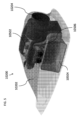
図1は、例示的な実施形態による、航続距離延長エネルギポッド(REEP)10115を有する航空機10100の斜視図を示す。REEP10115は、航空機10100の翼10110と胴体10105との中央に取り付けられる。これは、REEP10115が航空機10100のバランスを崩さないように、そのように取り付けられ得る。様々な実施形態において、2つ以上のREEPを使用してもよい。このような実施形態では、複数のREEPはそれぞれ航空機の中央軸に沿って配置してもよく、複数のREEPを使用する場合にでも航空機のバランスが維持されるように中央軸から等距離に配置してもよい。REEPが航空機の中央軸のいずれかの側に配置される実施形態では、航空機のバランスをとるために偶数のREEPを有することが望ましい場合がある。様々な実施形態において、REEPは、例えば胴体から離れた翼の下面又は上面に取り付けることができる。そのため、REEPは、1つ又は複数の翼の特定のハードポイントで(例えば、翼から吊り下げるために)航空機に取り付け可能なドロップタンクと同様に、航空機に接続することができる。様々な実施形態において、REEPは、必要に応じて航空機の他の部分に接続してもよい。本明細書で説明するように、REEP10115は、必要なとき(例えば、より長時間の飛行の場合)のみ使用されるように、航空機10100から取り外し可能であってもよい。REEPは、ボルト等の機械的締結具を介して航空機10100に接続してもよく、航空機10100のコネクタに取り外し可能に取り付けられ得る有線コネクタを介して航空機10100に電気的に接続してもよい。図1に示していないが、航空機10100は、REEPが少なくとも部分的に航空機10100に電力を供給するように、電気(例えば、REEP10115からのDC電力)によって電力を供給される推進システムを有してもよい。
FIG. 1 illustrates a perspective view of an
様々な実施形態において、REEPは、より恒久的な方法又は取り外し不可能な方法で航空機に接続してもよい。例えば、REEPのハウジングは、ハウジングを航空機の翼、胴体、又は他の構成要素に溶接、リベット留め、又は接合する等、より永続的な固定方法を使用して航空機の一部に接続することができる。このようにして、例えばボルトよりも恒久的な取付けにより、REEPは航空機により恒久的に取り付けられる。従って、説明するREEPは、自給式エンジン、発電機、燃料タンク、ファイアウォール、及び騒音軽減装置であり得、これら全ては、機械的コネクタを接続解除することによって航空機から取り外し可能であり得るか、又はより恒久的に航空機に取り付けられ得るハウジング又はエンクロージャ内に含まれる。いずれの場合でも、エンクロージャ/ハウジングは、胴体の外側の別個の位置で内部の構成要素を壁で仕切ることができ、それによって、これらの構成要素を胴体から有利に隔離し、リスク管理上の利点(例えば、胴体又は胴体付近での火災のリスクが少なくなる)を提供する。様々な実施形態において、REEPは、ハウジング又はエンクロージャ内に様々な構成要素を有することによってこれら及び他の目的を達成し、ハウジング又はエンクロージャを通過できる唯一の構成要素は、電力出力及び/又は制御信号用の配線である。エンクロージャ又はハウジングは、本明細書で説明し図示する空力学的エンクロージャであってもよく、それによって、REEPが胴体の外側に大きな抗力を生じさせず、本明細書で説明するように取り外し可能であるか、又はREEPに対応するために既存の航空機を再設計することなく、より恒久的な状態で航空機上に少なくとも配置することができる。例えば、REEPを航空機に接続するために使用し得るボルト、ナット等のハードウェアは、非破壊的に緩めることができるため(例えば、REEPを航空機に複数回取り付けるために使用される可能性がある)、取り外し可能であるとみなされ得る。様々な実施形態において、REEPの構成要素を航空機に溶接、リベット留め、接合等する場合に、それらの締結機構は破壊的に取り外すことしかできないため、航空機へのREEPのより恒久的な接続が望ましい場合に使用することができる。様々な実施形態において、非破壊的に取り外せる機構を単独で使用することができ、破壊的にのみ取り外すことができる機構を単独で使用することができ、又は破壊的及び非破壊的の両方で取り外すことができる機構を、REEPを航空機に締結又は他の方法で固定するために使用することができる。さらに、本明細書で説明するREEPのエンクロージャは、REEPによって出力されるノイズを伝達し、低減する機構としても機能する(例えば、本明細書で説明する騒音低減部品を含む)。そのため、REEPは、航空機を再設計する、又はREEP自体を取り付ける以外に騒音低減部品等の構成要素を追加する必要がなく、電力を航空機に取り外し可能又は恒久的に供給する構成要素のパッケージを有利に提供する。 In various embodiments, the REEP may be connected to the aircraft in a more permanent or non-removable manner. For example, the REEP housing may be connected to a portion of the aircraft using more permanent fastening methods, such as welding, riveting, or bonding the housing to the aircraft wing, fuselage, or other component. can. In this way, the REEP is more permanently attached to the aircraft, with a more permanent attachment than, for example, bolts. Thus, the described REEP may be a self-contained engine, generator, fuel tank, firewall, and noise abatement device, all of which may be removable from the aircraft by disconnecting mechanical connectors, or Contained within a housing or enclosure that can be more permanently attached to the aircraft. In either case, the enclosure/housing can wall off internal components at separate locations outside the fuselage, thereby advantageously isolating these components from the fuselage and providing risk management benefits. (e.g., reduced risk of fire in or near the fuselage). In various embodiments, the REEP achieves these and other objectives by having various components within the housing or enclosure, where the only components that can pass through the housing or enclosure are power output and/or control signals. This is the wiring for The enclosure or housing may be an aerodynamic enclosure as described and illustrated herein so that the REEP does not create significant drag on the outside of the fuselage and is removable as described herein. or can at least be placed on an aircraft in a more permanent manner without redesigning existing aircraft to accommodate REEP. For example, hardware such as bolts, nuts, etc. that may be used to connect the REEP to the aircraft may be loosened non-destructively (e.g., may be used to attach the REEP to the aircraft multiple times). ), may be considered removable. In various embodiments, when components of the REEP are welded, riveted, bonded, etc. to the aircraft, those fastening mechanisms can only be destructively removed, so a more permanent connection of the REEP to the aircraft is desirable. It can be used in case. In various embodiments, a non-destructively removable mechanism can be used alone, a destructively-only removable mechanism can be used alone, or both destructively and non-destructively removable. A mechanism that can be used to fasten or otherwise secure the REEP to the aircraft can be used to fasten or otherwise secure the REEP to the aircraft. Additionally, the enclosure of the REEP described herein also functions as a mechanism for transmitting and reducing noise output by the REEP (e.g., includes the noise reduction components described herein). REEP therefore favors a package of components that removably or permanently provide power to the aircraft without the need to redesign the aircraft or add components such as noise reduction parts other than installing the REEP itself. Provided to.
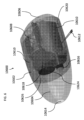
図2は、例示的な実施形態による航続距離延長エネルギポッド(REEP)10200の例の斜視図である。REEP10200は、エンクロージャ10202及び給気口10204を含む。給気口10204は、エンジンの空気を取り入れる、冷却等のために使用され得る。本明細書で説明するように、REEP10200は、図1の航空機10100等の、航空機に取り付けられるように空気力学的に設計され得る。
FIG. 2 is a perspective view of an example range extension energy pod (REEP) 10200 according to an example embodiment.
図3は、例示的な実施形態による、図2のREEP10200の側面図である。図4は、例示的な実施形態による、図2のREEP10200の正面図である。REEP10200は、REEP10200を本明細書で説明する航空機10100等の航空機に取り付けることができるように、取付ハードウェア10206及び配線10208をさらに含む。例えば、取付ハードウェア10206は、REEP10200の構成要素を支持する構造フレームに接続することができ、その構造フレームに、REEP10200の構成要素を取り付けることができる。取付ハードウェア10206はさらに、ボルト等、REEP10200を航空機に取り付けるための締結具を収容することができる。配線10208は、航空機又は他の電力消費又は分配装置に電力を出力することができる。配線10208は、電気機械(例えば、発電機)によって生成されるAC電力を出力してもよく、又は(例えば、REEP10200のインバータによってAC電力からDC電力に変換した後に)DC電力を出力してもよい。
FIG. 3 is a side view of the
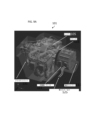
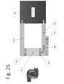
図5は、例示的な実施形態による、図2のREEP10200の斜視図であり、REEPのエンクロージャ10202が部分的に透明であることを示す。図5に示されるREEP10200は、本明細書で説明する(例えば、以下の柔軟なアーキテクチャ要素、空冷素子、直流(DC)バス要素、及び/又は騒音低減要素の段落)ハイブリッド式発電機をさらに含む。そのため、エンクロージャ10202内には、例えば、エンジン、発電機、冷却システム、騒音低減要素、DC電力及びエネルギを供給するためのパワーエレクトロニクス等を含めてもよい。さらに、ハイブリッド式発電機のエンジンで消費される燃料を貯蔵するために燃料タンク10504を含めてもよい。単一の燃料タンク10504のみが示されているが、REEP10200の重量のバランスをとるために、別の燃料タンクをエンクロージャ10202の反対側に配置してもよい。燃料タンク10504からの燃料は、例えば、チューブ10506を介してREEP10200のエンジンに移動され得る。また、図5には示していないが、1つ又は複数の燃料タンク(例えば、燃料タンク10504)は、燃料タンクへの充填を容易にする開口部又はポートを有してもよく、それらの開口部は、エンクロージャ10202内にあってもよく、エンクロージャ10202を貫通してもよい。そのような開口部には、また、燃料タンクが充填されていない間に、燃料タンクから燃料が漏れないように、キャップ又は他の同様のカバーを取り付けることができる。複数の燃料タンクが存在する様々な実施形態では、複数の燃料タンクの間で燃料のバランスをとり、一度に複数の燃料タンクを容易に充填できるように、複数の燃料タンク間に延びるバランスチューブを設けることもできる。
FIG. 5 is a perspective view of the
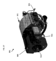
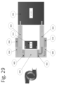
図6は、例示的な実施形態による、別の航続距離延長エネルギポッド(REEP)10600の斜視図であり、REEPのエンクロージャ10602が部分的に透明であることを示す。図7は、例示的な実施形態による、図6のREEP10600の正面図である。図8Aは、例示的な実施形態による、図6のREEP10600の側面図である。エンクロージャ10602は、上述の図5と同様に、ハイブリッド式発電機10608及び燃料タンク10610をさらに収容してもよい。REEP10600はまた、構造フレーム10620を含んでもよく、構造フレーム10620には、REEP10600の構成要素が恒久的に取り付けられ得、航空機への取り外し可能な取り付けを提供し得る(例えば、構造フレーム10620は、取付ハードウェアとしても機能し得る)。
FIG. 6 is a perspective view of another range extension energy pod (REEP) 10600, showing that the
空気は、入口10624で冷却システム10618に流入することができ、入口10624は、エンクロージャ10602の主区画をエンクロージャ10602の騒音低減チャンバ10604から分離する内壁10626に形成され得る。同様に、別の騒音低減チャンバ10606は、エンクロージャ10602の背面に取り付けてもよく、エンクロージャ10602の主区画をから騒音低減チャンバ10604から分離する壁をさらに有してもよい。騒音低減チャンバ10604及び/又は10606は、騒音低減要素(例えば、本明細書で説明する騒音減衰材料の壁によって形成されるチャネル)を内部に有してもよい。このようにして、REEP10600は、使用中にREEP10600によって出力される騒音を最小限に抑えるように設計することができる。
Air may enter the
REEP10600は、本明細書で説明するように、REEP10600を航空機に取り外し可能に電気的に接続するように構成された配線10612をさらに含む。航空機に供給される電力及びエネルギは、バッテリパックによって供給されるような、DC電力及びエネルギであってもよい。このようにして、バッテリ電源で動作するように設計された航空機は、航空機のバッテリ駆動部品の動作方法を変更することなく、REEP10600から電力供給を受けることができる。
REEP10600はさらに、燃焼及び電力生成のために濾過した空気をエンジン10608に導入する給気口フィルタ10616を含む。
図8Aはさらに、エンクロージャ10602の騒音低減チャンバ10606が排気口10602を有し得ることを示す。このようにして、冷却システム10618によって使用される空気は、出力する方法を有し得るが、空気が騒音低減チャンバを通過して、大気中に放出される騒音を低減する。
FIG. 8A further shows that the
図8Bは、REEPを使用する例示的な方法10900を示すフローチャートである。動作10902において、取り外し可能なエネルギ源又はREEPが航空機に取り付けられる。本明細書で説明するように、REEPはエンジン及び発電機を含むことができ、エンジン及び発電機はそれぞれエンクロージャ内に収容される。動作10904において、REEPの第1の電気コネクタが航空機の第2の電気コネクタに接続される。動作10906において、電力が、REEPの発電機から航空機の少なくとも1つの電気部品又は電気バスに出力される。様々な実施形態において、REEPは、REEPが、航空機ではない別の電力消費装置又は配電装置に電気的に接続できるように、第3セットの電気コネクタも有し得る。そのため、10908において、追加のコネクタ又は第3セットのコネクタは、航空機とは別個の別の装置に接続して、航空機からREEPを切り離すことなく別の装置に電力を供給することができる。様々な実施形態において、REEPは、REEPの発電機からAC電力を出力することができ、又はREEPは、発電機からのAC電力がDC電力に変換され、コネクタのいずれかを介してREEPによって出力されるようにインバータを含み得る。様々な実施形態において、REEPは、第1セットのコネクタを介してAC電力を出力し、第2セットのコネクタを介してDC電力を出力するように構成され得る。
FIG. 8B is a flowchart illustrating an
10910において、REEPは、制御配線用のコネクタを含み得る第1の電気コネクタ及び第2の電気コネクタを介して送信された、航空機からの制御信号に基づいて制御され得る。例えば、1つ又は複数の制御ワイヤ/コネクタを使用して、取り外し可能なエネルギ源のコントローラで航空機のコントローラから、コネクタを介してスロットル制御信号又は電力要求信号を受信することができる。このようにして、航空機は、生成される電力の量と航空機への出力とを制御でき得る。様々な実施形態では、他のタイプの制御信号及び/又は配線/コネクタをREEPと航空機との間で使用してもよい。例えば、REEP内の異なるセンサ読み取り値(例えば、温度、燃料レベル、現在出力している電力等)等、REEPからのステータス信号が航空機に送信され得る。AC電力又はDC電力を出力するか、それぞれどれ位の量を出力するかどうかにかかわらず、REEPの電源を入れる又は切るためのオン/オフ信号等の他の信号が、航空機からREEPに送信され、REEPを制御することができる。 At 10910, the REEP may be controlled based on control signals from the aircraft transmitted through a first electrical connector and a second electrical connector, which may include connectors for control wiring. For example, one or more control wires/connectors may be used to allow the removable energy source controller to receive throttle control signals or power request signals from the aircraft controller via the connector. In this way, the aircraft may be able to control the amount of power generated and output to the aircraft. In various embodiments, other types of control signals and/or wiring/connectors may be used between the REEP and the aircraft. For example, status signals from the REEP may be sent to the aircraft, such as different sensor readings within the REEP (eg, temperature, fuel level, power currently being output, etc.). Other signals, such as on/off signals to turn the REEP on or off, may be sent from the aircraft to the REEP, regardless of whether it outputs AC or DC power and how much of each. , REEP can be controlled.
10912において、電力がREEPから航空機に出力されなくなるように、REEPの電源が切られる。10914において、REEPの電気コネクタが航空機の電気コネクタから接続解除される。10916において、REEPが航空機から取り外される。このようにして、方法10900は、どのようにREEPを航空機に取り付けてその航空機に電力を供給することができるか、またどのようにそのREEPを航空機から取り外し可能にすることができるかを実証する。このようにして、REEPは、航空機の一時的で取り外し可能な電源となり得る。
At 10912, the REEP is powered down so that power is no longer output from the REEP to the aircraft. At 10914, the REEP electrical connector is disconnected from the aircraft electrical connector. At 10916, the REEP is removed from the aircraft. In this manner,
そのため、本明細書では、航空機上の他の場所の推進システム(例えば、REEPの一部ではない、又はREEPのハウジング/エンクロージャ内にない推進モータ、ロータ等)を駆動するために使用される電気エネルギを提供するために(非破壊的に取り外し可能な構成要素又は破壊的に取り外し可能な構成要素のいずれかを使用して)航空機に取り付けられ得るREEPの様々な実施形態について説明する。従って、そのような航空機は、REEPを取り外しても機能することができる(例えば、航空機は、それ自身の内蔵又は内部エネルギ源を有し得るが、REEPは、航空機に電力を供給するための外部の追加のエネルギ源を提供する)。REEPは、例えば、電気バス及び/又は航空機内の配線等の他の構成要素に接続することができ、その場合に、少なくとも1つの推進電気モータ及び/又は少なくとも1つの推進用バッテリ(例えば、推進モータに電力を供給するために使用されるバッテリ)が電気バス及び/又は他の構成要素に取り付けられる。このようにして、REEPは、航空機の他の部分に既に含まれている電気エネルギを増強するように構成することができる。そのため、REEPは、同じ推進モータにエネルギを供給することができ、この推進モータは、REEPを搭載又は取り付けた場所以外の航空機上のバッテリ又は他のエネルギ源によって供給を受けることもできる。従って、REEPは、航空機自体のエネルギ源又は内部エネルギ源から航空機が既に利用できる電力を補助又は増強する外部エネルギ源として機能することができる。従って、REEP又は外部エネルギ源は、構造的接続を介して航空機に取り付けられたREEP/外部エネルギ源の有無にかかわらず、航空機が飛行すること、又は飛行可能であることを可能にし得る。 As such, herein, electrical power used to drive propulsion systems elsewhere on the aircraft (e.g., propulsion motors, rotors, etc. that are not part of the REEP or not within the housing/enclosure of the REEP) Various embodiments of REEPs that can be attached to an aircraft (using either non-destructively removable components or destructively removable components) to provide energy are described. Thus, such an aircraft may function with the REEP removed (e.g., the aircraft may have its own built-in or internal energy source, but the REEP may have no external energy source to power the aircraft). (provide an additional source of energy). The REEP can be connected to other components, such as, for example, an electric bus and/or wiring within the aircraft, in which case at least one propulsion electric motor and/or at least one propulsion battery (e.g. propulsion A battery (used to power the motor) is attached to the electric bus and/or other components. In this way, the REEP can be configured to augment electrical energy already contained in other parts of the aircraft. As such, the REEP may supply energy to the same propulsion motor, which may also be powered by a battery or other energy source on the aircraft other than where the REEP is mounted or mounted. Thus, the REEP can function as an external energy source that supplements or augments the power already available to the aircraft from the aircraft's own energy sources or internal energy sources. Thus, a REEP or external energy source may enable an aircraft to fly or be capable of flight with or without a REEP/external energy source attached to the aircraft via a structural connection.
柔軟なアーキテクチャ要素
航空機は、典型的に、カスタム設計した推進機構と、それらの推進機構に動力を供給する方法とを有する。このようにして、推進機構とそれらの推進機構に供給される動力を最適化して、航空機内の構成要素の重量を最小限に抑えながら、特定のタイプ及びサイズの航空機に必要な推進量を供給することができる。換言すれば、推進機構とそれらの推進機構の動力とは、多くの場合、特定のタイプ及びサイズの航空機に合わせて最適化されているため、ある航空機の構成要素を、直接駆動航空機、並列駆動航空機、及び直列駆動航空機等の異なるタイプの航空機駆動アーキテクチャで容易に使用することはできない。
Flexible Architectural Elements Aircraft typically have custom designed propulsion mechanisms and methods for powering those propulsion mechanisms. In this way, the propulsion mechanisms and the power delivered to them can be optimized to provide the required amount of thrust for a particular type and size of aircraft while minimizing the weight of components within the aircraft. can do. In other words, propulsion mechanisms and the power of those propulsion mechanisms are often optimized for specific types and sizes of aircraft, so that certain aircraft components can be It cannot be easily used in different types of aircraft drive architectures, such as aircraft and series drive aircraft.
本明細書では、航空宇宙ハイブリッドシステムの柔軟なアーキテクチャ及びその最適化した構成要素の様々な実施形態について説明する。ハイブリッドシステムは、燃料がピストン、ロータリ、タービン、又は他のエンジン内で燃焼され、ピストンエンジンの出力を発電機に動作可能に接続して電力を出力するシステムであってもよく、又はこのシステムを含んでもよい。本明細書で説明する実施形態は、多くの異なるタイプの航空機及び推進機構に動力を供給できる柔軟なシステムを含むことができる。このようなシステムは、有利には、異なるタイプの航空機の設計の複雑さを軽減し、カスタマイズが少ないことでシステムの量産における規模の経済性が可能になるため、そのようなシステムの製造コストを削減し、最終的には、本明細書で説明するシステムを使用する航空機の複雑さを軽減することができる。 Various embodiments of a flexible architecture for an aerospace hybrid system and its optimized components are described herein. A hybrid system may be a system in which fuel is combusted within a piston, rotary, turbine, or other engine, and the output of the piston engine is operably connected to a generator to output electrical power; May include. Embodiments described herein can include flexible systems that can power many different types of aircraft and propulsion mechanisms. Such systems advantageously reduce the complexity of the design of different types of aircraft and reduce the cost of manufacturing such systems, as less customization allows for economies of scale in mass production of the system. and ultimately reduce the complexity of aircraft using the systems described herein.
本明細書で説明する柔軟なアーキテクチャは、同じ航空機内又は異なる航空機内で、異なる方法で推進機構に動力を供給するためにさらに使用され得る。例えば、推進機構に動力を供給するための柔軟なアーキテクチャは、複数の異なるモードで動作して、異なるタイプの推進機構に動力を供給することができ得る。第1の航空機は、柔軟なアーキテクチャが動作できる複数の異なるモードのうちの1つ、一部、又は全てを利用することができる。第2の航空機は、複数の異なるモードのうちの1つ、一部、又は全てを利用することができ、第2の航空機が利用するモードは、第1の航空機が利用するモードとは異なる場合がある。 The flexible architecture described herein may further be used to power propulsion mechanisms in different ways within the same aircraft or in different aircraft. For example, a flexible architecture for powering a propulsion mechanism may be capable of operating in multiple different modes to power different types of propulsion mechanisms. The first aircraft may utilize one, some, or all of a number of different modes in which the flexible architecture can operate. The second aircraft may utilize one, some, or all of a plurality of different modes, and the mode utilized by the second aircraft is different from the mode utilized by the first aircraft. There is.
従って、異なる航空機は、本明細書で説明する柔軟なアーキテクチャによって提供される推進機構に動力を供給する異なるモードを利用することができる。柔軟なアーキテクチャの使用はこのようにカスタマイズすることができるが、柔軟なアーキテクチャの物理的ハードウェアは、本明細書で説明する柔軟なアーキテクチャの物理的構成要素に最小限の変更を加えるか全く変更せずに、異なる航空機による使用に適合させることができる。代わりに、異なる航空機での異なるモードの使用は、主に、プロセッサ又はコントローラを使用して柔軟なアーキテクチャの構成要素をどの様に制御するかに基づいて達成され得る。従って、コンピュータ可読命令は、プロセッサ又はコントローラに動作可能に結合したメモリに格納してもよく、それによって、命令がプロセッサ又はコントローラによって実行されると、プロセッサ又はコントローラを含むコンピューティング装置が、本明細書で説明する柔軟なアーキテクチャの様々な構成要素を制御して、特定の実施態様、航空機、飛行段階等に望ましいあらゆる可能な使用モードを利用することができる。 Accordingly, different aircraft may utilize different modes of powering the propulsion mechanisms provided by the flexible architecture described herein. Although the use of the flexible architecture may be customized in this manner, the physical hardware of the flexible architecture may be modified with minimal or no changes to the physical components of the flexible architecture described herein. It can be adapted for use by different aircraft without having to do so. Instead, the use of different modes in different aircraft may be accomplished primarily based on how the components of the flexible architecture are controlled using a processor or controller. Accordingly, computer-readable instructions may be stored in a memory operably coupled to a processor or controller such that when executed by the processor or controller, a computing device including the processor or controller The various components of the flexible architecture described herein can be controlled to utilize any possible mode of use as desired for a particular implementation, aircraft, flight stage, etc.
航空機のための発電及び推進システムはまた、航空機の様々な構成要素が動作のために安全な温度に保たれることを保証するため、並びに構成要素がより効率的に動作できる温度範囲内に構成要素を維持することを保証するために、様々な冷却システムを利用することもできる。さらに、本明細書では、航空機の推進機構に動力を供給するための柔軟なアーキテクチャの構成要素を効率的に冷却するために、本明細書で説明するハイブリッド式アーキテクチャの様々な態様を利用する有利な冷却システムについて説明する。 Power generation and propulsion systems for aircraft are also designed to ensure that the various components of the aircraft are kept at safe temperatures for operation, as well as to ensure that the components are configured within a temperature range that allows them to operate more efficiently. Various cooling systems may also be utilized to ensure that the elements are maintained. Further, herein, we describe the advantages of utilizing various aspects of the hybrid architecture described herein to efficiently cool components of a flexible architecture for powering an aircraft propulsion mechanism. This section explains the cooling system.
異なるモードの動力を推進機構に供給するためのハードウェアを有する航空機は、冷却を与えることが望ましい様々な構成要素を有している可能性がある。こうして、異なる動力モードを可能にする様々な構成要素に空気を効率的に移動させる単一の冷却システムは、航空機の重量だけでなく、冷却システムの消費電力も削減することができる。図1~図8及びそれに付随する以下の説明は、特に、航空機の推進システムに動力を供給するための柔軟なアーキテクチャの例に関する。図9~図21及びそれに付随する以下の説明は、柔軟なアーキテクチャの例のための冷却システムの様々な実施形態に関する。 Aircraft having hardware for providing different modes of power to propulsion mechanisms may have various components for which it is desirable to provide cooling. Thus, a single cooling system that efficiently moves air to various components enabling different power modes can reduce not only the weight of the aircraft, but also the power consumption of the cooling system. 1-8 and the accompanying discussion below relate specifically to examples of flexible architectures for powering aircraft propulsion systems. 9-21 and the accompanying discussion below relate to various embodiments of cooling systems for example flexible architectures.
図9Aは、例示的な実施形態による航空宇宙ハイブリッドシステムの柔軟なアーキテクチャ101の例を示す。本明細書で議論するように、柔軟なアーキテクチャ101は、航空機の要件及び飛行段階に応じて複数の方法で適用できる(例えば、異なるモードで使用される)単一のハイブリッド式発電機システムを備えた幅広い用途で効率的に使用することができる。
FIG. 9A shows an example of an aerospace hybrid system
図9Aの柔軟なアーキテクチャ101は、エンジン105、クラッチ115、発電機/モータ(電動機)121、及び動力シャフト111を含むハイブリッド式発電機である。以下でさらに説明するように、柔軟なアーキテクチャ101は、必要に応じて、特定の航空機の設置要件又は特定の飛行段階に応じて、様々な異なるモードを実現するために使用することができる。エンジン105は、内燃機関等の燃焼機関であってもよい。エンジン105はさらに具体的には、ピストン内燃機関、ロータリエンジン、又はタービンエンジンのうちの1つであってもよい。このようなエンジンは、標準的なガソリン、ジェット燃料(例えば、Jet A、Jet A-1、Jet B燃料)、ディーゼル燃料、バイオ燃料代替品等を使用することができる。様々な実施形態では、ドローンの実施態様の小型エンジン(Rotaxガソリンエンジン等)他のタイプのエンジンも使用することができる。
The
上述したように、エンジン105はピストン燃焼機関であってもよい。ピストン燃焼機関は、他のエンジンよりも発電機及び/又は推進機構(例えば、プロペラ)に動力を供給するための直接出力にとってより望ましい毎分回転数(RPM)で出力ロータ又はシャフトを有利に回転させることができる。例えば、ピストン燃焼機関は、数千RPM程度の出力を有する場合もある。例えば、ピストン燃焼機関の出力は2200~2500RPMの範囲にあり得、これはプロペラにとって望ましいRPMとなり得る。特に、プロペラは、ピストン燃焼機関のRPM出力(例えば、2200~2500RPM)に基づいて、プロペラの所望の翼端速度をもたらすサイズを有するように設計され得る。タービンエンジン等の他のタイプのエンジンは、ピストン燃焼機関よりもはるかに高い、数万RPM程度の回転パワーを出力する場合がある。別の実施形態は、効率、動力出力(power output)、又は他の重要な因子に利益をもたらすために、タービンエンジンのより高いRPMでモータ/発電機を駆動することができる。いくつかの実施形態では、高RPMエンジンの出力と図9Aの他の構成要素との間にギアボックスを追加して、エンジン105の出力RPMを下げることができる。しかしながら、ギアボックスの追加は、いくつかの実施形態では望ましくないシステムの重量を増大させる可能性もある。ピストン燃焼機関は、タービンエンジンと比較して、騒音に関してさらに有利である可能性がある。典型的に、タービンエンジンはピストン燃焼機関よりも音が大きく、人間が知覚するタービンエンジンからの騒音は、典型的に、ピストン燃焼機関によって発生する騒音よりも聴取者にとって不快である。騒音の低減が望まれる都市部又は密集環境では、より静かなエンジンの価値がより高まる場合もある。 As mentioned above, engine 105 may be a piston combustion engine. Piston combustion engines advantageously rotate output rotors or shafts at revolutions per minute (RPM) that are more desirable for direct output to power generators and/or propulsion mechanisms (e.g., propellers) than other engines. can be done. For example, a piston combustion engine may have a power output on the order of several thousand RPM. For example, the power output of a piston combustion engine can range from 2200 to 2500 RPM, which can be a desirable RPM for a propeller. In particular, the propeller may be designed to have a size that provides a desired tip speed of the propeller based on the RPM power of the piston combustion engine (eg, 2200-2500 RPM). Other types of engines, such as turbine engines, may output rotational power on the order of tens of thousands of RPM, much higher than piston combustion engines. Another embodiment may drive the motor/generator at a higher RPM of the turbine engine to benefit efficiency, power output, or other important factors. In some embodiments, a gearbox can be added between the high RPM engine output and the other components of FIG. 9A to reduce the output RPM of the engine 105. However, the addition of a gearbox may also increase the weight of the system, which is undesirable in some embodiments. Piston combustion engines may have further advantages regarding noise compared to turbine engines. Turbine engines are typically louder than piston combustion engines, and human-perceived noise from turbine engines is typically more unpleasant to listeners than the noise produced by piston combustion engines. In urban or crowded environments where reduced noise is desired, a quieter engine may be more valuable.
エンジン105は、クラッチ115に回転動力を出力することができ、クラッチ115は、動力シャフト111を係合又は係合解除するように制御され得る。換言すれば、動力シャフト111は、クラッチ115によってエンジン105の回転出力と係合され得、それによって、回転力がエンジン105の出力と動力シャフト111との間で伝達され得る。クラッチ115をエンジン105の出力と動力シャフト111とから係合解除すると、動力シャフト111はエンジン105の出力とは独立して回転することができる。クラッチ115は、エンジン105と発電機/モータ121との間に物理的に配置することができ、柔軟なアーキテクチャの全体的な設置面積を減らすために、エンジン105及び発電機/モータ121の反対側に接触することさえできる。図1Aにおいて、クラッチ115が本明細書でさらに説明され、他の図に示される。しかしながら、様々な実施形態では、エンジン105と動力シャフト111とを解放可能に結合解除することができる任意の機構を、クラッチに加えて、又はクラッチに代えて使用することができる。例えば、この結合解除は、オーバーランニングクラッチ等における、エンジン105の出力と動力シャフト111との間の絶対回転数(RPM)又は相対RPMに基づくことができる。 Engine 105 can output rotational power to clutch 115, and clutch 115 can be controlled to engage or disengage power shaft 111. In other words, power shaft 111 may be engaged with the rotational output of engine 105 by clutch 115 such that rotational power may be transferred between the output of engine 105 and power shaft 111 . Disengaging the clutch 115 from the output of the engine 105 and the power shaft 111 allows the power shaft 111 to rotate independently of the output of the engine 105. Clutch 115 can be physically placed between engine 105 and generator/motor 121, on opposite sides of engine 105 and generator/motor 121, to reduce the overall footprint of the flexible architecture. You can even contact. In FIG. 1A, clutch 115 is further described herein and shown in other figures. However, in various embodiments, any mechanism that can releasably decouple engine 105 and power shaft 111 may be used in addition to or in place of a clutch. For example, the disengagement can be based on the absolute rotational speed (RPM) or relative RPM between the output of the engine 105 and the power shaft 111, such as at an overrunning clutch.
発電機/モータ121は、動力シャフト111と係合する、又は動力シャフト111との係合を解除することもできる。換言すれば、発電機/モータ121は、動力シャフト111の回転によって発電機/モータ121が電力を発生させないように、スイッチオフにするように制御してもよい。同様に、発電機/モータ121は、動力シャフトの回転によって発電機/モータ121が電力を発生させるように、スイッチオンにするように制御してもよい。発電機/モータ121は、発電機としてもモータとしても機能し得るため、発電機/モータと呼ばれる。様々な実施形態では、発電機/モータ121は電気機械と呼ばれ得、電気機械は、発電機、電気モータ、又はその両方であり得る。 Generator/motor 121 may also be engaged with or disengaged from power shaft 111. In other words, the generator/motor 121 may be controlled to be switched off so that the rotation of the power shaft 111 does not cause the generator/motor 121 to generate electrical power. Similarly, generator/motor 121 may be controlled to be switched on such that rotation of the power shaft causes generator/motor 121 to generate electrical power. Generator/motor 121 is called a generator/motor because it can function both as a generator and as a motor. In various embodiments, generator/motor 121 may be referred to as an electric machine, and an electric machine may be a generator, an electric motor, or both.
柔軟なアーキテクチャは、発電機/モータ121に接続された電力入出力(I/O)125をさらに含む。本明細書でさらに説明するように、発電機/モータ121は、電力I/O125を介して出力される動力シャフト111の回転に基づいて電力を生成してもよく、又は動力シャフト111を駆動するために使用され得る電力を電力I/O125を介して受け取ってもよい。電力I/O125の配線は複数のワイヤを含んでもよい。様々な実施形態では、発電機/モータ121に電力を入力するための配線は、発電機/モータ121から電力を出力するために使用される配線と同じであってもよい。他の様々な実施形態では、第1の配線は電力の入力のために使用してもよく、異なる第2の配線は電力の出力のために使用してもよい(入力用及び出力用に異なる配線を使用する)。様々な実施形態では、発電機/モータ121はまた、発電機/モータ121の制御に使用され、発電機/モータ121の動作に関するセンサ又は他のデータをコントローラ等に中継するために接続される配線を有してもよい。
The flexible architecture further includes power input/output (I/O) 125 connected to generator/motor 121. As further described herein, the generator/motor 121 may generate electrical power based on the rotation of the power shaft 111 output via the power I/
発電機/モータ121は、動力シャフト111のドライバとしても機能することができる。システム内の他の場所にあるバッテリ又は何らかの他の形態の電気エネルギ蓄積装置から電力I/O125を介して電力を受け取ると、発電機/モータ121は、動力シャフト111に回転力を与えて、動力シャフト111を駆動することができる。これは、発電機/モータ121が動力シャフト111と係合するようにスイッチオンにされるように制御されている限り起こり得る。発電機/モータ121が動力シャフト111と係合しないようにスイッチオフにされるように制御されると、動力シャフト111は、発電機/モータ121によって回転されなくなり得る。
Generator/motor 121 can also function as a driver for power shaft 111. Upon receiving power via power I/
電力I/O125からの電力出力は、電気推進機構(例えば、プロペラ)のための電気モータを駆動するために使用され得る。電力I/O125からの電力出力は、航空機又は航空宇宙機上の他の装置に電力を供給及び/又は充電するために使用することもできる。例えば、電力I/O125から出力される電力は、1つ又は複数のバッテリを充電するために使用され得る。電力I/O125からの電力出力は、航空機又は航空宇宙機上の他の装置又はアクセサリに電力を供給するために使用することもできる。電力I/O125も入力を有するため、動力シャフト111は、1つ又は複数のバッテリからの電力等、電力I/O125を介して受け取られる任意の電力によって駆動され得る。発電機/モータ121によって生成される電力は、交流(AC)電力であってもよい。そのAC電力は、パワーエレクトロニクス(例えば、整流器又はインバータ)によって直流(DC)電力に変換され、DCバスに出力され得る。このDCバスは、バッテリ及び/又は電気推進機構に接続され得る。このようにして、電気推進機構にDCバスを介して電力を供給することができる。様々な実施形態では、電気推進機構のモータはAC電力を使用することができ、従って、DCバスからのDC電力は、電気推進機構(例えば、インバータ)によって使用される前に、DC電力からAC電力に変換され得る。様々な実施形態において、発電機によって生成されたAC電力は、DC電力に変換されて再び戻されることなく、モータ又は他の装置に直接供給され得る。そのような実施形態では、そのようなAC電力は、AC電力バス又は同様の配線を介して伝送され得る。
Power output from power I/
動力シャフト111自体の任意の回転は、エンジン105によって駆動されるか又は発電機/モータ121によって駆動されるかにかかわらず、1つ又は複数の推進機構を駆動するために使用することもできる。例えば、動力シャフト111の回転は、プロペラを直接駆動するために使用してもよく、又は推進機構を駆動する電気モータに電力を供給するために使用してもよい。動力シャフト111の回転はまた、航空機の様々な用途のための1つ又は複数のプロペラ、1つ又は複数のロータ、又は他の回転装置等の別の構成要素に動作可能に接続されたギアボックスを駆動することもできる。 Any rotation of power shaft 111 itself, whether driven by engine 105 or generator/motor 121, may also be used to drive one or more propulsion mechanisms. For example, rotation of power shaft 111 may be used to directly drive a propeller or may be used to power an electric motor that drives a propulsion mechanism. Rotation of the power shaft 111 may also be caused by a gearbox operably connected to another component such as one or more propellers, one or more rotors, or other rotating devices for various applications in the aircraft. It can also be driven.
アクセサリパッド130は、エンジン105に結合することもでき、高電圧及び高電力I/Oのために構成され得る発電機/モータ121及び電力I/O125とは別個の電力用の低電圧直流(DC)発電機を含むことができる。いくつかの実施形態では、発電機/モータ121は2つの異なる巻線を有してもよく、電力I/O125は2つの異なる出力(例えば、高電圧及び低電圧)を有してもよい。アクセサリ電源は、アクセサリパッド130の出力に加えて、又はアクセサリパッド130の出力の代わりに、電力I/O125の出力のうちの1つに関連付けることができる。アクセサリパッド130は、電力I/O125において発電機/モータ121によって出力され得る高電圧又は電流出力を必要としない航空機又は航空宇宙機上の装置又はアクセサリに電力を供給するために使用され得る。航空機の電圧(HV)は、例えば400ボルト(V)又は800Vであり得るが、50V~1200Vの間のいずれかになることもあり得る。航空機の低電圧(LV)は、12V、14V、28V、又は50V未満の他の電圧であってもよい。
図9Bは、例示的な実施形態による航空宇宙ハイブリッドシステムのための柔軟なアーキテクチャ150の追加の例を示す。特に、図9Bの柔軟なアーキテクチャ150は、図9Aに関して上述した構成要素と同一又は類似であり得るいくつかの構成要素を含み、柔軟なアーキテクチャ150は、エンジン155、クラッチ175、動力シャフト180、及び/又は発電機/モータ185を含む。柔軟なアーキテクチャ150は、クランクシャフト160の形態でエンジン155の出力をさらに示し、クランクシャフト160は、出力フランジ165に堅固に接続される。出力フランジ165は、ボルト170を用いてクラッチ175の片側に堅固に接続される。
FIG. 9B illustrates an additional example of a
クラッチ175は、動力シャフト180と係合して、クランクシャフト160及び出力フランジ165から動力シャフト180に回転運動を変換するように構成され得る。クラッチ175はさらに、動力シャフト180から係合を解除するように構成され得、それによって、動力シャフト180は、クランクシャフト160及び出力フランジ165に対して独立して回転することができる。さらに、図9Bは、どの様にして柔軟なアーキテクチャ150の回転可能な構成要素全てを単一の軸線190に沿って整列させるかを示している。図9Aの回転可能な構成要素は、図9Bに示されるように、同様に単一の軸線に沿って整列され得る。さらに、動力シャフト180は、クラッチ175及び発電機/モータ185の内径開口部に嵌合するスプラインシャフトであってもよい。テーパ等、スプライン以外の他の特徴を使用してもよい。いずれの場合でも、発電機/モータ185及び/又はクラッチ175は、構成要素が互いに適切に係合できるように、動力シャフト180上のスプライン、テーパ、又は他の特徴に適合して接続するように構成され得る。
様々な実施形態では、クラッチ175は、エンジン155の出力から動力シャフト180を結合解除することができる、異なるタイプのクラッチ又は他の機構であってもよい。例えば、クラッチ175は、プレート式クラッチであってもよく、また、乾式又は湿式クラッチであってもよい。このようなプレート式クラッチは、機械的、油圧的、及び/又は電気的に(例えば、図10A及び図10Bのコントローラ205、220、及び/又は280によって)係合/係合解除され、又はそうでなければ制御され得る。プレート式クラッチには、3枚、5枚、又は10枚のプレート等、様々な数のプレートがある場合もある。様々な実施形態では、クラッチ175又は本明細書で説明する他のクラッチは、一方向クラッチ、オーバーランニング(overrunning)クラッチ、又はスプラグ(sprag)クラッチであってもよい。一方向クラッチ又はスプラグクラッチは、電気機械がエンジンの出力よりも速く動力シャフトを回転させている間に、エンジンの出力を動力シャフトから係合解除する(disengage:切り離す)ように構成され得る。換言すれば、エンジン155が発電機/モータ185よりも小さい動力を動力シャフト180に出力している場合に、クラッチ175は、例えばその係合解除を達成するために使用されるいかなる電気制御入力もなしに、エンジン155の出力を動力シャフト180から自動的に機械的に係合解除することができる。エンジン155がより高いRPMを有するか、又は発電機/モータ185よりも多くの動力を出力すると、一方向クラッチ又はスプラグクラッチが係合するため、動力がエンジン155の出力から動力シャフト180に加えられる。使用できる別のタイプのクラッチは遠心クラッチであり、RPMが増加するにつれて、クラッチのプレートの重みによって1つ又は複数のレバーが徐々に作動し、遠心クラッチのプレートが圧迫され、プレートが係合して、例えばエンジン155の出力及び動力シャフト180が接続される。
In various embodiments, clutch 175 may be a different type of clutch or other mechanism that can disconnect
有利には、図9Aの発電機/モータ121及び/又は図9Bの発電機/モータ185は、それぞれエンジン105又はエンジン155のスタータとして使用され得る。換言すれば、エンジン155を始動するためにクラッチ175が係合される間に、発電機/モータ185を使用してクランクシャフト160を回転させることができる。このようなシステムは、例えば発電機/モータ185にバッテリ又は他の電源によって電力を供給できる場合に有利となり得る。従って、エンジン155は、本明細書で説明するピストン燃焼機関であってもよく、別個のスタータ構成要素を必要とせず、本明細書で説明する柔軟なアーキテクチャの重量及び複雑さを軽減することができる。
Advantageously, generator/motor 121 of FIG. 9A and/or generator/
図10Aは、例示的な実施形態による、航空宇宙ハイブリッドシステムのための柔軟なアーキテクチャ201とともに使用される航空機制御システム200を表すブロック図を示す。航空機制御システム200は、例えば、本明細書で説明する柔軟なアーキテクチャを使用することができる、以下で議論する様々なモードのうちの1つ又は複数を実現するために使用され得る。柔軟なアーキテクチャ201は、図9A及び/又は図9Bの柔軟なアーキテクチャ101及び/又は150の構成要素と同じ、類似のもの、又はそれらの構成要素の一部又は全てを有することができる。航空機制御システム200は、1つ又は複数のプロセッサ又はコントローラ205(以下、コントローラ205と呼ぶ)、メモリ210、航空機メインコントローラ220、エンジン230、発電機/モータ235、クラッチ240、電力I/O245、アクセサリパッド250、及び1つ又は複数のセンサ260を含むことができる。図10Aの接続は、航空機制御システム200の構成要素同士の間の制御信号関連の接続を示している。図10Aに示されない他の接続は、航空機の高電圧(HV)又は低電圧(LV)電力等の電力を供給するために、航空機及び/又は航空機制御システム200の異なる態様の間に存在し得る。
FIG. 10A shows a block diagram representing an
メモリ210は、命令を記憶するように構成されたコンピュータ可読媒体であってもよい。このような命令は、本明細書の柔軟なアーキテクチャを使用する様々なモード及びこれらのモードの組合せを含む、本明細書で説明する様々な方法及びシステムを実現するためにコントローラ205によって実行されるコンピュータ実行可能コードであってもよい。コンピュータコードは、本明細書の柔軟なアーキテクチャの異なるモードを実現する様々な方法が、例えば、特定の飛行段階(例えば、着陸、離陸、巡航等)を示す様々な入力に基づいて自動的に実施されるように記述され得る。様々な実施形態では、コンピュータコードは、航空機又は航空宇宙機のユーザ又はパイロットからの入力に基づいて、本明細書の様々なモードを実現するように記述してもよく、又はユーザ入力と非人的入力(例えば、計画した飛行計画等に基づいて、航空機上又は航空機外のセンサから)に基づく自動実施との組合せに基づいて実現してもよい。コントローラ205は、アクセサリパッド130、1つ又は複数のバッテリ、電力I/O125の出力、任意の電源によって電力供給される航空機の電力バス、及び/又は利用可能な任意の他の電源等の、航空機又は航空宇宙機上の電源によって電力を供給され得る。
コントローラ205は、エンジン230、発電機/モータ235、クラッチ240、電力I/O245、アクセサリパッド250、及び/又はセンサ260のそれぞれと通信することもできる。このようにして、柔軟なアーキテクチャの構成要素を制御して、本明細書で説明する様々なモードを実現することができる。様々な実施形態では、エンジン230、発電機/モータ235、クラッチ240、電力I/O245、及びアクセサリパッド250は、図9Aに示し、図9Aに関して上述した同様の名前の構成要素と同様であってもよく、又は同様の名前が付いた構成要素であってもよい。電力I/O245はまた、例えば、本明細書で説明する直流(DC)バスを含む柔軟なアーキテクチャの電気部品を起動時の過剰な突入電流から保護するための、プリチャージ電子部品を含んでもよい。例えば、高電圧(HV)バスが400Vであり、新しい構成要素が0VのHVバスに接続される場合に、瞬間的な突入電流が非常に大きくなり、HVバス及び/又は構成要素に損傷を与える可能性がある。その結果、プリチャージ電子部品は、HVバス又は他の電源に完全に接続する前に、構成要素の電圧をゆっくりと上昇させることができる。
センサ260は、柔軟なアーキテクチャ201の異なる構成要素を監視するための様々なセンサを含むことができる。そのようなセンサには、例えば、クラッチ240の現在の状態、又は他のタイプのセンサを決定するために、温度センサ、タコメータ、流体圧力センサ、電圧センサ、電流センサ、状態センサ等が含まれ得る。例えば、電圧及び/又は電流センサは、モータ/発電機の機能及び設定、クラッチに選択された状態を知らせる、又はシステムの他の構成要素を調整するために使用され得る。状態センサは、柔軟なアーキテクチャが使用されている特定のモードを示すこともでき、システムは(例えば、パイロットから、自動飛行制御装置から)入力を受け取って、システムを今後の特定の飛行段階のための異なる状態又はモードに変更することができる。他のセンサには、航空機の対気速度を測定するためのピトー管、航空機の高度を測定するための高度計、及び/又は地上及び/又は既知の/マッピングされた構造物に対する位置を決定するための全地球測位システム(GPS)又は同様の地理的位置センサが含まれ得る。
Sensors 260 may include a variety of sensors for monitoring different components of
図10Aの柔軟なアーキテクチャ201の破線内の構成要素は、本明細書で説明する柔軟なアーキテクチャに関連付けられ得る一方、航空機メインコントローラ220は、より広範な航空機システムに関連付けられ得る。換言すれば、航空機メインコントローラ220は、柔軟なアーキテクチャ201以外の航空機の態様を制御することができる一方、コントローラ205は、柔軟なアーキテクチャ201に関連する航空機の態様を制御することができる。航空機メインコントローラ220及びコントローラ205は、互いに通信して、航空機の様々な推進機構に動力を供給するように調整することができる。例えば、航空機メインコントローラ220は、1つ又は複数の特定の推進機構に対する特定の動力出力レベルを要求する信号を制御装置205に送信することができる。コントローラ205は、そのような制御信号を受信し、航空機メインコントローラ220からの制御信号に基づいて所望の動力レベルを出力するために柔軟なアーキテクチャ201をどの様に調整するか(例えば、どのモードに入るか、柔軟なアーキテクチャ201の要素をどの様に制御するか)を決定することができる。様々な実施形態では、航空機メインコントローラ220は、柔軟なアーキテクチャ201の特定の態様の制御に関連する信号を送信することができる。換言すると、コントローラ205は、所望の動力出力信号をコントローラ205に送信することに加えて、又はその代わりに、航空機メインコントローラ220からの制御信号を柔軟なアーキテクチャ201の構成要素に再送信するための中継器として機能することができ、コントローラ205は、その制御信号から柔軟なアーキテクチャ201の個々の構成要素をどの様に制御するかを決定する。
While the components within the dashed lines of
様々な実施形態では、航空機メインコントローラ220は、将来の所望の動力出力、将来の飛行段階又は飛行計画情報等に関連する制御信号を送信することもできる。このようにして、コントローラ205は、航空機の予想される動力要求に関する情報を受信してこれを使用して、現時点と将来との両方で柔軟なアーキテクチャ201の態様をどの様に制御するかを決定するすることができる。例えば、飛行計画情報は、いつバッテリ電力を使用すべきか、いつバッテリを充電すべきか等を決定するために使用され得る。別の例では、大きな電力需要が予想される場合に、コントローラ205は、所望のレベルの電力の供給を開始する前に、エンジン230が動作していることを保証し得る。
In various embodiments, aircraft main controller 220 may also send control signals related to future desired power output, future flight stages, flight plan information, etc. In this manner,
様々な実施形態では、コントローラ205はまた、1つ又は複数のバッテリと通信して、それらの充電レベルを監視し、バッテリをいつ充電又は放電するかを制御し、バッテリをいつ使用して発電機/モータ235に電力を供給するかを制御し、バッテリをいつ使用して航空機の別の態様に直接電力を供給するかを制御することもできる。しかしながら、他の実施形態では、航空機メインコントローラ220は、航空機のバッテリと通信することができ、及び/又はバッテリ及びその制御に関する情報をコントローラ205に中継することができる。同様に、航空機のバッテリがコントローラ205ではなく航空機メインコントローラ220を用いて制御される場合に、コントローラ205は、バッテリが柔軟なアーキテクチャ201の機能に関して必要又は所望に応じて制御され得るように、バッテリに関連する制御信号を航空機メインコントローラに送信することができる。
In various embodiments, the
様々な実施形態では、電力I/O245は、発電機/モータ235の2つの異なる巻線に関連付けられた2つの異なる出力(例えば、高電圧(HV)出力及び低電圧(LV)出力)を含み得る。こうして、2つの異なる電圧(例えば、HV及びLV)が、出力され、コントローラ205及び/又は航空機メインコントローラ220によって制御され得る。電力I/O245は、追加的に又は代替的に、2つ以上の異なる電圧を出力できるように電圧変換部品(例えば、DC/DCコンバータ)を有することができる。このような実施形態では、2つの別個の巻線を使用することなく、2つの異なる出力を達成することができる。2つの異なる出力は、例えば、HVバス及びLVバス等、航空機の異なる電力バスに出力される場合がある。電力I/O245の2つの出力は、コントローラ205によって個別に制御することもできる。そのため、(例えば、モータ/発電機の界磁電流をオフにすることで、発電機の動力シャフト及びロータをモータ/発電機の残りの部分に対して回転又はフリーホイール(freewheel:自由回転)させることによって)出力をオフにすることができる。
In various embodiments, power I/
いくつかの実施形態では、アクセサリパッドは、コントローラ205及び/又は航空機メインコントローラ220によって制御しなくてもよい。アクセサリパッドは、単にエンジン230が動作しているときに常にオンであってもよく、又は航空機のアクセサリにいつどの様に電力を供給するかを制御するために個別に(例えば、ユーザが切り替える手動スイッチによって)制御してもよい。
In some embodiments, the accessory pad may not be controlled by
いくつかの実施形態では、コントローラ205は、航空機又は航空宇宙機に搭載され得る無線トランシーバと通信することができ、それによって、コントローラ205は、システム200に配線接続されていない他のコンピューティング装置と通信することができる。このようにして、本明細書で説明する柔軟なアーキテクチャの様々なモードを実現するための命令又は入力を、リモート装置コンピューティング装置から無線で受信することもできる。他の実施形態では、システム200は、航空機に搭載された構成要素とのみ通信することができる。
In some embodiments,
図10Bは、例示的な実施形態による、航空宇宙ハイブリッドシステムのための柔軟なアーキテクチャとともに使用される第2の航空機制御システム275を表すブロック図を示す。図10Bの例では、システム275は、図10Aのような別個の航空機メインコントローラを有していない。その代わりに、航空機全体は、柔軟なアーキテクチャ及び航空機(例えば、航空機の推進機構255を含む)の全ての態様を制御する単一のメインコントローラ280を有する。
FIG. 10B shows a block diagram representing a second
コントローラ285は、航空機上の1つ又は複数の推進機構255と通信して、それら推進機構255を制御することができる。コントローラ285は、航空機又は航空宇宙機上の1つ又は複数のセンサ270と通信することもでき、これらのセンサは、航空機のセンサ及び柔軟なアーキテクチャのセンサであってもよい。特に、センサ260は、上述した図9A及び/又は図9Bの構成要素のいずれかに埋め込むこともでき、従って、図9A及び/又は図9Bの装置がどの様に制御されるか、及び/又は本明細書で説明するモードがどの様に本明細書で説明するように実現されるかを知らせるために使用することができる。
Controller 285 may communicate with and control one or
図10A又は図10Bのいずれにおいても、コントローラ205、コントローラ285、及び/又は航空機メインコントローラ220は、柔軟なアーキテクチャの任意の構成要素、1つ又は複数のバッテリ、又は航空機の他の態様を冷却及び/又は加熱するように構成された冷却システムと通信することもできる。そのため、冷却システムは、本明細書で説明する他のシステム及び方法と連携して制御することもできる。
In either FIG. 10A or FIG. 10B,
本明細書で説明する柔軟なアーキテクチャ(例えば、図9A、図9B、図10A、及び図10Bに示され、それらに関して説明した柔軟なアーキテクチャを含む)の様々な実施形態を使用して実現され得る5つの特定のモードについて以下に説明する。 may be implemented using various embodiments of the flexible architectures described herein (including, for example, the flexible architectures shown in and described with respect to FIGS. 9A, 9B, 10A, and 10B). Five specific modes are described below.
本明細書ではハイブリッド式発電機モードと呼ばれ得る第1のモードにおいて、クラッチ(例えば、図9Aのクラッチ115及び/又は図9Bのクラッチ175)は、エンジン(例えば、図9Aのエンジン105及び/又は図9Bのエンジン155)を、クラッチから発電機/モータ(例えば、図9Aの発電機/モータ121及び/又は図9Bの発電機/モータ185)に延びる動力シャフト(例えば、図9Aの動力シャフト111及び/又はクラッチ出力/動力シャフト180)に係合するように制御され得、それによって、エンジンが発電機/モータ内の動力シャフトを回転させて、電力I/O(例えば、図9Aの電力I/O125)を介して、推進機構/システム等の航空機上の他のシステムに供給される電力を生成する。例えば、そのような推進機構/システムは、電気モータを使用して電力を供給され得、第1のモードにおいて発電機/モータによって出力された電力は、そのような推進機構/システムを駆動するために使用され得る。つまり、第1のモードでは、クラッチを用いてエンジンを動力シャフトに係合させて発電機/モータを駆動し、発電機/モータから電力を出力することができる。
In a first mode, which may be referred to herein as a hybrid generator mode, the clutch (e.g., clutch 115 of FIG. 9A and/or clutch 175 of FIG. 9B) is connected to the engine (e.g., engine 105 of FIG. 9A and/or clutch 175 of FIG. 9A). or
本明細書では直接駆動エンジンモードと呼ばれ得る第2のモードでは、クラッチ(例えば、図9Aのクラッチ115及び/又は図9Bのクラッチ175)は、エンジン(例えば、図9Aのエンジン105及び/又は図9Bのエンジン155)出力を、発電機/モータ(例えば、図9Aの発電機/モータ121及び/又は図9Bの発電機モータ185)を通って延びる動力シャフト(例えば、図9Aの動力シャフト111及び/又はクラッチ出力/動力シャフト180)に係合して、航空機のプロペラのような推進機構に機械的動力を供給することができる。このようなモードでは、発電機/モータの動力シャフト及びロータが回転又はフリーホイーリングし、従って、発電機/モータの電力I/O(例えば、図9Aの電力I/O125)が係合解除され、電力を出力しないように、発電機/モータから磁場を除去してもよい(例えば、発電機/モータがオフ又は係合解除されるように制御してもよい)。つまり、第2のモードでは、エンジンは動力シャフトを駆動して機械的又は他の方法で推進機構に動力を供給することができる一方、動力シャフトは電力I/Oで電力を受け取り又は出力することなく発電機/モータ内で回転する。
In a second mode, which may be referred to herein as a direct drive engine mode, the clutch (e.g., clutch 115 of FIG. 9A and/or clutch 175 of FIG. 9B) is connected to the engine (e.g., engine 105 of FIG. 9A and/or
本明細書では推力増強(augmented thrust)モードと呼ばれ得る第3のモードでは、クラッチ(例えば、図9Aのクラッチ115及び/又は図9Bのクラッチ175)が、エンジン(例えば、図9Aのエンジン105及び/又は図9Bのエンジン155)を、発電機/モータ(例えば、図9Aの発電機/モータ121及び/又は図9Bの発電機モータ185)を通って延びる動力シャフト(例えば、図9Aの動力シャフト111及び/又はクラッチ出力/動力シャフト180)に係合することができ、発電機/モータは、バッテリパック等の外部ソースからの電力I/O(例えば、図9Aの電力I/O125)を介して電力を引き込むモータとして使用される。これにより、エンジン又は発電機/モータが供給できるよりも高い機械的動力出力が動力シャフトに与えられる。つまり、第3のモードでは、エンジンと発電機/モータとの両方を使用して動力シャフトを同時に駆動し、推進機構に動力(電力)を送る。
In a third mode, which may be referred to herein as an augmented thrust mode, the clutch (e.g., clutch 115 of FIG. 9A and/or clutch 175 of FIG. 9B) is connected to the engine (e.g., engine 105 of FIG. 9A). and/or
本明細書では直接駆動発電機/モータモードと呼ばれ得る第4のモードでは、クラッチ(例えば、図9Aのクラッチ115及び/又は図9Bのクラッチ175)が、発電機/モータ(例えば、図9Aの発電機/モータ121及び/又は図9Bの発電機/モータ185)からエンジン(例えば、図9Aのエンジン105及び/又は図9Bのエンジン155)を係合解除することができ、それによって、電力が電力I/O(例えば、図9Aの電力I/O125)を介して発電機/モータに供給され、発電機/モータをモータとして駆動し、機械的動力を動力シャフト(例えば、図9Aの動力シャフト111及び/又はクラッチ出力/動力シャフト180)に供給することができる。つまり、第4のモードでは、発電機/モータのみが、電力I/Oで受け取った電力に基づいて動力(電力)を推進機構に供給することができる。
In a fourth mode, which may be referred to herein as a direct drive generator/motor mode, the clutch (e.g., clutch 115 of FIG. 9A and/or clutch 175 of FIG. 9B) is connected to the generator/motor (e.g., clutch 115 of FIG. 9A The engine (e.g., engine 105 of FIG. 9A and/or
本明細書ではエンジン出力分割モードと呼ばれ得る第5のモードでは、クラッチ(例えば、図9Aのクラッチ115及び/又は図9Bのクラッチ175)が、エンジン(例えば、図9Aのエンジン105及び/又は図9Bのエンジン155)を、発電機/モータ(例えば、図9Aの発電機/モータ121及び/又は図9Bの発電機/モータ185)に係合することができ、それによって、エンジンは、発電機/モータを発電機として回転させ、電力I/O(例えば、図9Aの電力I/O125)を介して航空機上の他のシステムに電力を供給するだけでなく、機械的動力を動力シャフト(例えば、図9Aの動力シャフト111及び/又はクラッチ出力/動力シャフト180)に与えて、プロペラのようなシステムを駆動することもできる。つまり、第5のモードでは、エンジンを使用して動力シャフト及び発電機/モータを駆動して、電力I/O及び動力シャフトを介して動力(電力)を出力することができる。
In a fifth mode, which may be referred to herein as an engine power split mode, the clutch (e.g., clutch 115 of FIG. 9A and/or clutch 175 of FIG. 9B) is connected to the engine (e.g., engine 105 of FIG. 9A and/or The
本明細書で説明するように、これらの5つのモード(又はその変形)のいずれも、本明細書で説明する単一の柔軟なアーキテクチャとともに使用することができる。さらに、特定のモード及び/又はモードの組合せは、特定の航空機又は航空宇宙機のタイプ、特定の推進機構タイプ、航空機又は航空宇宙機の特定の飛行段階等にとって有益であり得る。 Any of these five modes (or variations thereof) can be used with the single flexible architecture described herein. Additionally, particular modes and/or combinations of modes may be beneficial for particular aircraft or aerospace vehicle types, particular propulsion mechanism types, particular flight stages of the aircraft or aerospace vehicle, and the like.
例えば、電気モータ駆動プロペラを備えたハイブリッド式電気垂直離着陸(VTOL)航空機では、本明細書の柔軟なアーキテクチャは、電力源としてのみ使用され得る。そのため、柔軟なアーキテクチャは、航空機の電力バス又は航空機の1つ又は複数のモータに電力を供給しなければならない飛行段階の任意の部分中に、航空機を第1のモード(例えば、ハイブリッド式発電機モード)で駆動することができる。 For example, in a hybrid electric vertical takeoff and landing (VTOL) aircraft with an electric motor-driven propeller, the flexible architecture herein may be used only as a power source. As such, the flexible architecture allows the aircraft to be placed in a first mode (e.g., a hybrid generator mode).
別の例では、単一の大きなメイン推進(pusher)プロペラ(例えば、航空機の胴体後部)と電気モータ/プロペラ(例えば、航空機の翼上)のアレイとを備えた航空機では、柔軟なアーキテクチャは、離陸中に第5のモード(例えば、エンジン出力分割モード)で使用され、メイン推進プロペラに機械的に動力を供給し、翼に取り付けられたモータに電気的に電力を供給することができる。図11及び図12は、例示的な実施形態による航空宇宙ハイブリッドシステムのための柔軟なアーキテクチャを使用することができるそのような航空機300及び400の2つの例を示す。例えば、航空機300はメイン推進プロペラ305を有し、航空機400はダクト推進ファンの形態のメイン推進プロペラ405を有する。両方の例において、本明細書で説明する第5のモードは、動力シャフトからメイン推進プロペラ305及び405に機械的に動力を供給するために使用され得る。さらに、翼に取り付けられた電気モータ/プロペラ310及び410は、本明細書で説明するようにモータ/発電機からの電力で駆動され得る。
In another example, in an aircraft with a single large main pusher propeller (e.g., on the rear fuselage of the aircraft) and an array of electric motors/propellers (e.g., on the wings of the aircraft), the flexible architecture It can be used in a fifth mode (e.g., engine power split mode) during takeoff to mechanically power the main propulsion propeller and electrically power the wing-mounted motors. 11 and 12 illustrate two examples of
あるいはまた、本明細書で説明する柔軟なアーキテクチャを使用して、図11及び図12に示すような構成に、離陸時にバッテリパックが翼に取り付けられた両方のモータに電力を供給することによる第3のモード(例えば、推力増強モード)で電力を供給し、メイン推進プロペラを駆動する動力シャフトに対するエンジン出力を増強することもできる。巡航飛行中に、航空機は、メイン推進プロペラのみを駆動するために第2のモード(例えば、直接駆動エンジンモード)を使用することができる。別の例では、巡航飛行中に、航空機は動力シャフトと推進プロペラとの間にクラッチを備えてもよく、コントローラは、動力シャフトを推進プロペラから係合解除し、発電機/モータから翼に取り付けられたモータに電力を出力することによって、航空機を、翼に取り付けられたモータを駆動する第1のモード(例えば、ハイブリッド式発電機モード)で動作させてもよい。別の例(例えば、エンジン故障等の緊急事態)では、推進プロップは、1つ又は複数のバッテリ等の電力I/Oへの電力入力を使用して、第4のモード(例えば、直接駆動発電機/モータモード)で駆動され得る。 Alternatively, using the flexible architecture described herein, a configuration such as that shown in FIGS. Power can also be provided in three modes (eg, thrust enhancement mode) to enhance engine output to the power shaft driving the main propulsion propeller. During cruise flight, the aircraft may use a second mode (eg, direct drive engine mode) to drive only the main propulsion propeller. In another example, during cruise flight, the aircraft may include a clutch between the power shaft and the propulsion propeller, where the controller disengages the power shaft from the propulsion propeller and attaches the power shaft from the generator/motor to the wing. The aircraft may be operated in a first mode (e.g., a hybrid generator mode) that drives the wing-mounted motors by outputting power to the wing-mounted motors. In another example (e.g., an emergency situation such as an engine failure), the propulsion prop can be used in a fourth mode (e.g., direct drive generation) using power input to a power I/O, such as one or more batteries. machine/motor mode).
別の例では、航空機は、動力を与えられても動力を与えられずに動作することができ、翼に取り付けられた前方推進モータ及びプロペラを有し得る、ジャイロコプタ型のメインロータを備えたVTOL航空機であってもよい。一実施形態では、柔軟なアーキテクチャは、電力入力/出力(及び発電機/モータ)から供給される電力が、ジャイロコプタ型のメインロータに結合されたモータを駆動させ、電力を使用して翼に取り付けられたモータを駆動する、第1のモード(例えば、ハイブリッド式発電機モード)で完全に使用され得る。一実施形態では、航空機は、柔軟なアーキテクチャが第2のモード(例えば、直接駆動エンジンモード)又は第3のモード(例えば、推力増強モード)を使用して、ジャイロコプタ型のメインロータを回転させる(例えば、ジャイロコプタ型のロータを離陸速度に上げる)ことができるように、動力シャフトとジャイロコプタ型のメインロータとの間にクラッチを備えるように構成してもよい。このような例では、コントローラは、ジャイロコプタ型ロータが速度に達した後に、柔軟なアーキテクチャを第1のモード(例えば、ハイブリッド式発電機モード)に切り替えることができる(例えば、巡航飛行のために第1のモードに切り替える)。第4のモード(例えば、直接駆動発電機/モータモード)は、エンジン故障の場合に再び使用され、電力を使用して、1つ又は複数のバッテリ等の電源により動力シャフト(従ってジャイロコプタ型のロータ)を駆動することができる。 In another example, the aircraft includes a gyrocopter-type main rotor that can operate powered or unpowered and that can have forward propulsion motors and propellers attached to the wings. It may also be a VTOL aircraft. In one embodiment, the flexible architecture allows power provided from the power input/output (and generator/motor) to drive a motor coupled to a gyrocopter-type main rotor, which uses the power to drive the wings. It may be used entirely in a first mode (eg, hybrid generator mode), driving an attached motor. In one embodiment, the aircraft has a flexible architecture that rotates a gyrocopter-type main rotor using a second mode (e.g., direct drive engine mode) or a third mode (e.g., thrust augmentation mode). A clutch may be provided between the power shaft and the gyrocopter main rotor to allow the gyrocopter rotor to reach takeoff speed (eg, to bring the gyrocopter rotor up to takeoff speed). In such an example, the controller may switch the flexible architecture to a first mode (e.g., hybrid generator mode) after the gyrocopter-type rotor reaches speed (e.g., for cruise flight). switch to the first mode). A fourth mode (e.g., direct drive generator/motor mode) is used again in the event of an engine failure, using electrical power to drive the power shaft (and thus the gyrocopter type) from a power source such as one or more batteries. rotor).
図13は、例示的な実施形態による、航空宇宙ハイブリッドシステムのための柔軟なアーキテクチャを使用することができる別の例示的な航空機500を示す。例えば、航空機500は、Tilt翼上に複数(例えば、8個)の電気モータ/プロペラ505を含んでもよく、これらは、本明細書で説明する第1のモード(例えば、ハイブリッド式発電機モード)を使用して電力供給され得、エンジンは、クラッチを使用して動力シャフトと係合され、発電機/モータを駆動し、発電機/モータからTilt翼上の様々な電気モータ/プロペラ505に電力を出力することができる。
FIG. 13 illustrates another
従って、本明細書では、推進機構に動力を供給するための様々なモードを達成することができる航空機のための有利な柔軟なアーキテクチャについて説明する。特定の航空機及び推進機構の構成は、柔軟なアーキテクチャが可能な本明細書で説明する各モードを利用しない場合があるが、柔軟なアーキテクチャは、依然として異なるモードを達成するために異なる航空機に実装することができる。同様に、推進機構に動力を供給するための5つの異なるモードを有する柔軟なアーキテクチャの一例を本明細書で詳細に説明するが、推進機構に動力を供給するためのより少ない、より多い、又は異なるモードを有する他の柔軟なアーキテクチャも本明細書で企図される。 Accordingly, described herein is an advantageous flexible architecture for an aircraft that can achieve various modes for powering a propulsion mechanism. Although a particular aircraft and propulsion configuration may not utilize each mode described herein that the flexible architecture is capable of, the flexible architecture may still be implemented on different aircraft to achieve the different modes. be able to. Similarly, an example of a flexible architecture is detailed herein that has five different modes for powering a propulsion mechanism, including less, more, or Other flexible architectures with different modes are also contemplated herein.
例えば、柔軟なアーキテクチャは、本明細書で説明するようなクラッチを有さなくてもよく、エンジン出力をシステムのモータ/発電機及び/又は動力出力シャフトに結合することが望ましい場合に、依然として本明細書で説明する様々なモードを実現することができる。例えば、第1のモードにおいて、エンジンが動力シャフトを回転させて、発電機によって電気を発生させることができる。第2のモードでは、エンジンは、例えば機械的推進部品を直接駆動することができるが、モータ/発電機をオフにする、又はモータ/発電機の動力シャフト及びロータをモータ/発電機内でフリーホイールさせることができるため、エンジンをモータ/発電機又は動力シャフトから係合解除する必要はない。第3のモードでは、エンジン及びモータ/発電機が動力シャフトの駆動に使用されるため、クラッチを使用してエンジン及びモータ/発電機を係合解除することは望ましくない。第5のモードでは、エンジンは動力シャフトを回転させて、発電機によって電気を発生させ、動力シャフトが推進機構に機械的に動力を供給することができる。そのため、上述の第1、第2、第3、及び/又は第5のモードのいずれかを利用する航空機では、動力シャフトをエンジン出力から係合解除する必要はない。そのため、第1、第2、第3、及び/又は第5のモード(第4のモードではない)の任意の組合せを使用する実施態様では、システムがエンジンの出力をモータ/発電機の動力シャフトに常に接続している可能性があるため、クラッチを使用しない場合がある。クラッチは重い、及び/又は信頼性が低い可能性があるため、そのような実施形態は価値があり得る。 For example, a flexible architecture may not have a clutch as described herein and still be functional if it is desired to couple engine output to the system's motor/generator and/or power output shaft. Various modes described herein can be implemented. For example, in a first mode, the engine can rotate a power shaft to generate electricity by a generator. In the second mode, the engine can, for example, drive the mechanical propulsion components directly, but with the motor/generator turned off, or the motor/generator's power shaft and rotor freewheel within the motor/generator. There is no need to disengage the engine from the motor/generator or power shaft. In the third mode, the engine and motor/generator are used to drive the power shaft, so it is not desirable to use a clutch to disengage the engine and motor/generator. In a fifth mode, the engine rotates the power shaft to generate electricity by the generator, and the power shaft can mechanically power the propulsion mechanism. Therefore, in aircraft utilizing any of the first, second, third, and/or fifth modes described above, there is no need to disengage the power shaft from the engine output. Therefore, in embodiments using any combination of the first, second, third, and/or fifth modes (but not the fourth mode), the system transfers the engine's output to the motor/generator's power shaft. The clutch may not be used because it may be constantly connected. Such embodiments may be valuable because clutches may be heavy and/or unreliable.
図14は、例示的な実施形態による、メイン推進プロペラを備えた航空機の異なる飛行段階において航空宇宙ハイブリッドシステムの柔軟なアーキテクチャを使用するための第1の例示的な方法601を示すフローチャートである。特に、航空機は、単一のより大型の推進プロペラと、翼上の電気モータ及び対応するより小型なプロペラのアレイとを備えた航空機であってもよい。603での離陸飛行段階中に、本明細書で説明する第5のモードを使用して、メイン推進プロペラに機械的に動力を供給し、翼に取り付けられたモータに電力を供給することができる。605での巡航飛行段階中に、本明細書で説明する第2のモードを使用して、メイン推進プロペラのみに機械的に動力を供給し、より小型の電気モータ/プロペラには電力を供給しないようにすることができる。
FIG. 14 is a flowchart illustrating a
図15は、例示的な実施形態による、メイン推進プロペラを備えた航空機の異なる飛行段階において航空宇宙ハイブリッドシステムの柔軟なアーキテクチャを使用するための第2の例示的な方法700を示すフローチャートである。特に、航空機は、単一のより大型の推進プロペラと、翼上の電気モータ及び対応するより小型プロペラのアレイとを備えた航空機であってもよい。702での離陸飛行段階中に、本明細書で説明する推力増強と呼ばれる第3のモードを使用して、発電機/モータを介してメイン推進プロペラに電力を供給し(バッテリから電力を引き出す)、エンジンからメイン推進プロペラに機械的に直接動力を供給することができる。さらに、離陸中に電力(発電機/モータによって生成される、及び/又はバッテリから直接生成される)を翼上の電気モータに供給することもできる。704での巡航飛行段階中に、本明細書で説明する第2のモードを使用して、メイン推進プロペラのみに機械的に動力を供給し、より小型の電気モータ/プロペラには電力を供給しないようにすることができる。 FIG. 15 is a flowchart illustrating a second example method 700 for using a flexible architecture of an aerospace hybrid system in different flight stages of an aircraft with a main propulsion propeller, according to an example embodiment. In particular, the aircraft may be an aircraft with a single larger propulsion propeller and an electric motor on the wing and a corresponding array of smaller propellers. During the takeoff flight phase at 702, a third mode, referred to herein as thrust enhancement, is used to power the main propulsion propeller via the generator/motor (drawing power from the battery). , the main propulsion propeller can be mechanically powered directly from the engine. Furthermore, power (generated by a generator/motor and/or directly from a battery) can also be supplied to the electric motors on the wing during takeoff. During the cruise flight phase at 704, the second mode described herein is used to mechanically power only the main propulsion propeller and not the smaller electric motor/propeller. You can do it like this.
図9Aに戻って参照すると、エンジン105が動力シャフト111に動力を加え、発電機/モータ121が作動しない、又はオンにならないようにクラッチ115が係合されている場合に、動力シャフト111は発電機/モータ121内で(例えば、上述の第2のモードで)フリーホイールすることができる。同様に、図9Bの動力シャフト180は、様々な実施形態において、発電機/モータ185内でフリーホイールすることができる。しかしながら、エンジン105及び/又はエンジン155は、クラッチ115及び/又はクラッチ175がそれぞれの動力シャフト111及び/又は180と係合する場合に、発電機/モータ121及び/又は発電機/モータ185等の発電機にとって危険となり得るトルクパルスを動力シャフト111及び/又は動力シャフト180上に発生させる可能性がある。換言すれば、あるタイプのエンジン(例えば、ディーゼルピストン内燃機関)が点火するときに発生し得るものと同様の大きなトルクパルスがシャフトに発生することによって、動力シャフト111及び/又は180に結合された発電機/モータ121及び/又は発電機/モータ185の構成要素に疲労又は損傷を生じさせ得る高い角加速度を引き起こす可能性がある。そのため、このトルクを緩和するための構成要素は、フライホイール又は他の強力な減衰又はばね結合システム等を使用して、動力シャフト111及び/又は180上のトルクを平滑化することができる。
Referring back to FIG. 9A, when engine 105 applies power to power shaft 111 and clutch 115 is engaged so that generator/motor 121 does not operate or turn on, power shaft 111 generates power. can freewheel within the machine/motor 121 (eg, in the second mode described above). Similarly,
図16Aは、例示的な実施形態による、振動トルクを吸収するためのフライホイールを有する航空宇宙ハイブリッドシステムのための柔軟なアーキテクチャ800の例を示す。特に、柔軟なアーキテクチャ800は、図9Bに示し、図9Bに関して説明したものと同様又は同じ構成要素を含むが、ボルト170を用いて出力フランジ165に堅固に接続されたフライホイール195を含む。フライホイール195はさらに、ボルト198によってクラッチ175の片側に堅固に接続される。従って、回転運動は、エンジン155からクランクシャフト160、出力フランジ165、及びフライホイール195を介してクラッチ175に移され得る。クラッチ175は、フライホイール195から受け取った回転運動を動力シャフト180に選択的に変換するために、動力シャフト180と係合又は係合解除することができる。フライホイール195はさらに、例えば二重質量フライホイール又はばね連結器であってもよい。
FIG. 16A shows an example of a
他の様々な実施形態では、フライホイールを使用しなくてもよい。例えば、動力シャフト(例えば動力シャフト111)上のトルクを減衰させることができるが、フライホイールを含まない減衰システム及び減衰装置の更なる実施形態を本明細書で説明する。さらに、様々な実施形態では、フライホイール及び他の減衰システム又は構成要素を組み合わせて使用して、動力シャフトに加えられるトルクを減衰又は平滑化することができる。 In various other embodiments, a flywheel may not be used. For example, further embodiments of damping systems and apparatuses are described herein that can damp torque on a power shaft (eg, power shaft 111) but do not include a flywheel. Additionally, in various embodiments, flywheels and other damping systems or components may be used in combination to dampen or smooth the torque applied to the power shaft.
例えば、発電機/モータ自体内の動力シャフト又はロータは、発電機/モータのクランクシャフトに堅固に結合され得る。このようにして、クランクシャフト及びロータが一体となって動力シャフト又はロータ上のトルクパルスを減衰させることができ、エンジンからのトルクパルスによる接線方向の加速度を低減することができる。このような実施形態では、クラッチを省略してもよい。そのため、減衰システムは発電機/モータの内部にあり、減衰システムの設置面積及び重量は、発電機/モータの外部にあり得るフライホイール又は他の減衰システムよりも小さくすることができる。特に、動力シャフト又はロータとクランクシャフトとの堅固な結合は、動力シャフト又はロータの慣性を増大させる可能性があり、それによって、その追加の慣性は、動力シャフトが減速する、又はそうでなければエンジンのトルクパルスによる加速の影響を受けやすい方法で回転するのを防ぐのに役立つ。このような実施形態では、動力シャフト又はロータ及びクランクシャフトは、フライホイールと同様に機能することができる。 For example, a power shaft or rotor within the generator/motor itself may be rigidly coupled to the generator/motor's crankshaft. In this manner, the crankshaft and rotor can together dampen torque pulses on the power shaft or rotor, reducing tangential acceleration due to torque pulses from the engine. In such embodiments, the clutch may be omitted. As such, the damping system is internal to the generator/motor, and the footprint and weight of the damping system can be smaller than a flywheel or other damping system that may be external to the generator/motor. In particular, a rigid coupling between the power shaft or rotor and the crankshaft can increase the inertia of the power shaft or rotor, such that the additional inertia causes the power shaft to slow down or otherwise It helps prevent it from rotating in a way that is susceptible to acceleration from the engine's torque pulses. In such embodiments, the power shaft or rotor and crankshaft can function similarly to a flywheel.
様々な実施形態では、静止した内側部分と回転する外側部分とを有する発電機/モータが使用され得る。これにより、その回転部分の慣性が増大し、発電機/モータ内の磁石が回転して、トルクス(登録商標)パイクによって外れるのを回避できる可能性がある。換言すれば、磁石は外側部分で既に回転している可能性があるため、トルクスパイク加速による接線方向の慣性力に加えて、一定の安定化する半径方向の力が加えられる可能性がある。 In various embodiments, a generator/motor with a stationary inner portion and a rotating outer portion may be used. This increases the inertia of its rotating parts, potentially allowing the magnets within the generator/motor to rotate and avoid being dislodged by the Torx pike. In other words, the magnet may already be rotating in its outer part, so that in addition to the tangential inertial force due to the torque spike acceleration, a constant stabilizing radial force may be applied.
トルク減衰システムは、エンジンの出力を発電機/モータに接続する動力シャフト又はロータの一部として構成することもできる。例えば、発電機/モータの動力シャフト又はロータの間のハブには、ねじりばね特性及び/又は減衰特性を有する連結器が含まれ得る。ねじり減衰連結器には、潜在的に有害なトルクインパルスがエンジン出力から発電機の動力シャフト又はロータに伝わるのを低減する、エラストマ部品又はばね(例えば、鋼又は別の金属で作製された)が含まれ得る。ねじり減衰連結器は、共振減衰連結器と同様であるか、又は共振減衰連結器とも呼ばれ得る。例えば、そのようなねじり減衰連結器は、フライホイール又は他の大型減衰システムを使用するシステムとは対照的に、システム全体の重量及びサイズを削減することができる。1つ又は複数のねじり減衰連結器を、エンジン内、エンジンとクラッチとの間、クラッチ内、クラッチと発電機との間、及び/又は発電機内のいずれか1つ又は複数に設置して、動力シャフト又はロータが発電機自体の構成要素を損傷する前に減衰を達成することができる。 The torque damping system may also be configured as part of the power shaft or rotor that connects the engine's output to the generator/motor. For example, a hub between a power shaft or rotor of a generator/motor may include a coupler with torsion spring characteristics and/or damping characteristics. Torsional damping couplers include elastomeric components or springs (e.g., made of steel or another metal) that reduce the transmission of potentially harmful torque impulses from the engine output to the generator power shaft or rotor. may be included. A torsionally damped coupler is similar to or may also be referred to as a resonantly damped coupler. For example, such a torsionally damped coupler can reduce overall system weight and size as opposed to systems that use flywheels or other large damping systems. One or more torsion damping couplings are installed within the engine, between the engine and the clutch, within the clutch, between the clutch and the generator, and/or within the generator to provide power. Damping can be achieved before the shaft or rotor damages components of the generator itself.
発電機の動力シャフト又はロータ上のトルクを減衰する他の方法も使用することができる。例えば、発電機上の磁場は、発電機の動力シャフト又はロータに作用して、エンジンによって動力シャフト又はロータに与えられるトルクパルスの一部又は全てを打ち消すようにパルス状に制御され得る。発電機の磁場上のそのようなパルスは、エンジンによって加えられるトルクパルスの測定に基づいて制御することができ、その結果、発電機の構成要素がディーゼルエンジンによって損傷されないようにすることができる。例えば、エンジンと発電機/モータとの両方が動力シャフトに動力(電力)を供給する上記の第3のモードでは、発電機から動力シャフトにパルスが供給され、動力シャフトに電力が供給され、発電機の構成要素が損傷するのを防ぐことができる。本明細書で説明する他のモードでは、動力シャフトが全体的にエンジンによって部分的に駆動されているときはいつでも、発電機を使用して動力シャフトにパルスを印加することができる。こうして、このような方法で発電機の部品を適切に保護するために、発電機の磁場によって動力シャフト又はロータに印加されるパルスは、エンジンのトルクパルスと相関してそれらのトルクパルスに適切に対抗するように構成され得る。 Other methods of damping torque on the generator power shaft or rotor may also be used. For example, the magnetic field on the generator may be pulsed and controlled to act on the power shaft or rotor of the generator to cancel some or all of the torque pulses imparted to the power shaft or rotor by the engine. Such pulses on the generator's magnetic field can be controlled based on measurements of the torque pulses applied by the engine, so that generator components are not damaged by the diesel engine. For example, in the third mode described above where both the engine and the generator/motor provide power to the power shaft, the generator provides pulses to the power shaft, which powers the power shaft and generates electricity. Prevents damage to machine components. In other modes described herein, a generator may be used to pulse the power shaft whenever the power shaft is driven entirely and partially by the engine. Thus, in order to adequately protect the generator components in this manner, the pulses applied to the power shaft or rotor by the generator's magnetic field are correlated with the engine's torque pulses and are appropriately aligned with those torque pulses. may be configured to oppose.
図16Bは、例示的な実施形態による、振動トルクを吸収するためのフライホイール及びばね連結器を有する航空宇宙ハイブリッドシステムのための柔軟なアーキテクチャ801の例を示す。特に、柔軟なアーキテクチャ801は、図16Aに示し、図16Aに関して説明したものと類似又は同じ構成要素を含むが、フライホイール195及び動力シャフト180に堅固に接続されたばね連結器199を含む。フライホイール195のサイズ、重量等、並びにばね連結器199の特性は、エンジン155の出力及び互いの特性に従って調整することができため、振動トルクを所望の及び/又は可能な限り低減することができる。例えば、異なるエンジンは異なる量の振動トルクを生成する可能性があるため、本明細書の様々な実施形態は、クランクシャフト160から動力シャフト180に伝わる振動を低減するために、異なる特性を有するフライホイール及び/又はばね連結器を含む。様々な実施形態では、柔軟なアーキテクチャ801は、クランクシャフト160及び動力シャフト180が常に互いに結合されるように、クラッチを有さなくてもよい。様々な実施形態では、図16Bのアーキテクチャと同様の柔軟なアーキテクチャはまた、エンジン155の出力を最終的に動力シャフト180から解放可能に係合解除することができるように、クラッチを含んでもよい。様々な実施形態では、そのようなクラッチは、ばね連結器199と動力シャフト180との間に接続され得、又は動力シャフトは、複数のシャフトにクラッチを接続して複数のシャフトに分割してもよく、又はエンジン155の出力を発電機/モータ185を介して伝わる動力シャフト180の部分から選択的に係合解除することができるように、クラッチをエンジン155と発電機/モータ185との間のいずれかの場所に配置してもよい。様々な実施形態では、動力シャフト180を負荷(例えば、航空機の推進機構)から係合解除することができるように、追加的又は代替的に、発電機/モータ185の後にクラッチを位置付けしてもよい。
FIG. 16B shows an example of a
さらに、本明細書で説明する柔軟なアーキテクチャが実際の航空機にどの様にパッケージ化及び/又は使用され得るかの例を以下に説明する。例えば、特定の航空機は推進システムを駆動するために電気モータを使用する場合があるため、それらの推進システムを駆動するために十分な機内電気エネルギを有する、又はそのような機内電気エネルギを生成する方法を備えている必要がある。さらに、特定の管轄区域の規制では、航空機の運用規制に準拠するために十分な予備エネルギが必要な場合もある。本明細書で説明する柔軟なアーキテクチャは、本明細書で説明するシステムが様々な電動航空機で動作できるように、推進システムにそのような電気エネルギ及び/又は予備エネルギを供給することができる。例えば、本明細書の実施形態は、広く入手可能な燃料源を使用して電動航空機に電力を供給できるように、ジェット燃料(又は他の液体燃料又はガス燃料)の電気への効率的な変換を提供する。 Additionally, examples of how the flexible architecture described herein may be packaged and/or used in an actual aircraft are described below. For example, certain aircraft may use electric motors to drive their propulsion systems and thus have or generate sufficient onboard electrical energy to drive their propulsion systems. You need to have a method. Additionally, regulations in a particular jurisdiction may require sufficient reserve energy to comply with aircraft operating regulations. The flexible architecture described herein can provide such electrical energy and/or reserve energy to the propulsion system so that the systems described herein can operate on a variety of electrically powered aircraft. For example, embodiments herein provide efficient conversion of jet fuel (or other liquid or gaseous fuels) to electricity so that widely available fuel sources can be used to power electric aircraft. I will provide a.
図17は、例示的な実施形態による、航空宇宙ハイブリッドシステムの柔軟なアーキテクチャの例の斜視図901を示す。このハイブリッドユニットは、様々な種類の航空機及び実施態様のコア発電装置(powerplant)として使用することができる。図17のハイブリッドユニットは、図9A、図9B、図10A、図10B、及び/又は図16A/図16Bに示して説明したいくつかの要素、全ての要素、及び/又は追加の要素を含み得る、緊密に統合された発電装置である。
FIG. 17 illustrates a
さらに、ハイブリッドユニットは、ハイブリッドユニットの様々な態様、ハイブリッドユニットに関連する熱交換器、又はハイブリッドユニットの任意の態様に関するフィン付きアタッチメント等のヒートシンクを冷却する統合冷却システム905を含んでもよい。動力出力910は、回転動力がハイブリッドユニットから推進システム又は航空機の他の態様に出力されるように、動力シャフト(例えば、図9Aの動力シャフト110、図9B又は図16A/図16Bの動力シャフト180)であってもよく、又は動力シャフトに接続してもよい。電気コネクタ915は、本明細書で説明するように、電力を出力する(又は電力を入力する)ために使用してもよい。電気コネクタ915は、例えば、Amphenol Surlok Plus(商標)コネクタ又は同等品であってもよく、或いは他の任意のタイプの適切なコネクタであってもよい。このようにして、ハイブリッドユニットの直流(DC)バス等のメインバスは、電気コネクタ915(例えば、図9Aの電力入力/出力125、図10A又は図10Bの電力I/O245)を介して接続され得る。これら又は他のコネクタは、コントローラエリアネットワーク(CAN)バス、CAN2.0バス、及び/又はSAE J1939バスの使用等、ハイブリッドユニットの構成要素への接続及び制御を容易にすることもできる。このような通信バスは、250キロバイト/秒(kbps)、500kbps、1000kbps等の異なる速度で動作することができる。様々な実施形態では、電気コネクタ915及び/又は他のコネクタは、様々な種類の航空機と、それらの航空機が使用する通信及び電力システム等の特定の用途に合わせてカスタマイズすることができる。
Further, the hybrid unit may include an
電力出力910及び電気コネクタ915のおかげで、図17のハイブリッドユニットは、電力出力910を介して機械的動力を出力し、及び/又はハイブリッドユニット内の電気コネクタ915及びDCバス(例えば、図9Aの電力入力/出力125、図10A又は図10Bの電力I/O245)を介して電力を出力することができる。同様に、機械的動力を動力出力910を介して受け取って電気コネクタ915を介して出力するための電気を生成するのと同様に、電力を電気コネクタ915を介して受け取って動力出力910を駆動することができる。例えば、航空機が1つ又は複数のバッテリを有している場合に、バッテリからの追加電力を電気コネクタ915を介して受け取って、動力出力910に加えられる動力(電力)を高めることができ、これにより、本明細書で説明するように、電力出力910がエンジンと航空機のバッテリからの電力との両方によって駆動されるようになる。
By virtue of the
図17のハイブリッドユニットは、エンジンを燃料源に接続するためのコネクタ925をさらに含むことができる。コネクタ925は、AN6クイック燃料接続等のクイック燃料接続であってもよい。このようにして、エンジンには燃料が供給されて、動力出力910に動力を供給し、及び/又は電気コネクタ915を介して出力される電気を生成することができる。図17のハイブリッドユニットは、ハイブリッドユニットを航空機に取り付けるための取付ハードウェア921をさらに含むことができる。図17では、取付ハードウェア921がハイブリッドユニットの上部に示されているが、他の実施形態では、取付ハードウェアは、ハイブリッドユニットを航空機に所望通りに取り付けることができるように、ハイブリッドユニットの上部、底部、側面等のいずれかに追加的又は代替的に配置することができる。
The hybrid unit of FIG. 17 can further include a
図18は、例示的な実施形態による図9の柔軟なアーキテクチャの例の上面図1000を示す。図19は、例示的な実施形態による図17の柔軟なアーキテクチャの例の側面図1100を示す。
FIG. 18 illustrates a
従って、本明細書で説明するハイブリッドユニットは、電気航空機又はハイブリッド式電気航空機に電力を供給するために使用することができ、バッテリパック単独よりも優れた電力を提供することができる。例えば、図17~図19に示されるようなハイブリッドユニットはバッテリよりも優れたエネルギ密度(例えば、5~7倍優れたエネルギ密度)を提供することができる。例えば、本明細書で説明するハイブリッドユニットは、600~1200以上のワット時/キログラム(Wh/kg)以上の等価エネルギ密度を有し得る。また、本明細書で説明するハイブリッドユニットは、他のシステムよりも優れた燃費(例えば、タービンエンジンよりも40%優れた燃費)を有利に有し、Jet-A、ディーゼル、灯油、バイオ燃料代替品、或いは他の適切な又は所望の燃料等の容易に入手可能な燃料を使用することができる。換言すれば、本明細書のハイブリッドユニットは、コンパクトなパッケージ内に、エンジン、発電機、インバータ、及び空冷を使用する熱管理を含むことができ、それによって、柔軟なアーキテクチャが搭載された航空機は、これらの構成要素を発電装置として有利に利用することができる。様々な電圧(例えば、400ボルト(V)、800V、1000V、1200V等)の出力がハイブリッド式アーキテクチャから供給されるだけでなく、他のアクセサリ又はシステム電源(例えば、28V)用の接続も有している。本明細書で説明する柔軟なアーキテクチャは、他のシステムよりも静か(例えば、タービンエンジンシステムよりも静か)であり得る。例えば、現在のシステムから100フィート以下の距離では、騒音が70デシベル(dB)未満になり得る。 Accordingly, the hybrid units described herein can be used to power electric or hybrid electric aircraft and can provide superior power than battery packs alone. For example, hybrid units such as those shown in FIGS. 17-19 can provide superior energy density (eg, 5 to 7 times better energy density) than batteries. For example, the hybrid units described herein can have an equivalent energy density of 600 to 1200 watt hours per kilogram (Wh/kg) or more. Additionally, the hybrid units described herein advantageously have better fuel economy than other systems (e.g., 40% better fuel economy than turbine engines), and can be used for Jet-A, diesel, kerosene, and biofuel alternatives. Any readily available fuel can be used, such as fluorine, or other suitable or desired fuel. In other words, the hybrid unit herein can include an engine, a generator, an inverter, and thermal management using air cooling in a compact package, whereby an aircraft equipped with a flexible architecture can , these components can be advantageously utilized as a power generation device. Outputs of various voltages (e.g., 400 volts (V), 800V, 1000V, 1200V, etc.) are provided by the hybrid architecture, as well as connections for other accessories or system power (e.g., 28V). ing. The flexible architecture described herein may be quieter than other systems (eg, quieter than turbine engine systems). For example, at distances of 100 feet or less from current systems, noise can be less than 70 decibels (dB).
本明細書で説明する柔軟なアーキテクチャは、拡張可能でもあり得る。例えば、より大型の航空機では、本明細書で説明する柔軟なアーキテクチャのうちの2つ以上を使用してもよい。この柔軟なアーキテクチャは、様々な機能及び目的に合わせて設計された様々な航空機にも使用することができる。例えば、本明細書で説明する柔軟なアーキテクチャは、電動式垂直離着陸(eVTOL)航空機、電動式短距離離着陸(eSTOL)航空機、従来の電動式離着陸(eCTOL)航空機等のアーバンエアモビリティ(UAM)システムにおいて有用であり得る。図17~19に示されるもの等の柔軟なアーキテクチャの一例は、以下の表1に示す仕様を有することができる。

**乾燥質量は、エンジン、発電機、インバータ、及び熱システムを含む。
The flexible architecture described herein may also be extensible. For example, larger aircraft may use more than one of the flexible architectures described herein. This flexible architecture can also be used with different aircraft designed for different functions and purposes. For example, the flexible architecture described herein can be used in urban air mobility (UAM) systems such as electric vertical take-off and landing (eVTOL) aircraft, electric short take-off and landing (eSTOL) aircraft, and conventional electric take-off and landing (eCTOL) aircraft. can be useful in An example of a flexible architecture, such as those shown in FIGS. 17-19, may have the specifications shown in Table 1 below.
**Dry mass includes engine, generator, inverter, and thermal system.
上に示したように、185kWのハイブリッドユニットを設けることができる。従って、370kWの電力を供給するために、特定の航空機に2つのハイブリッドユニットを設けることができる。 As shown above, a 185 kW hybrid unit can be provided. Thus, a particular aircraft can be equipped with two hybrid units to provide 370 kW of power.
図20は、例示的な実施形態による航空宇宙ハイブリッドシステムのための柔軟なアーキテクチャの別の例の斜視図1200を示す。図20の柔軟なアーキテクチャは、エンジン1205及び発電機を含むが、これらはシステムの冷却ダクト等の他の構成要素により隠れているか見えない。しかしながら、図17~図19のハイブリッドユニットと同様に、機械的動力出力1210及び電気的出力1220(これらは両方ともオプションで同様に電力を受け取ることもできる)が提供される。
FIG. 20 illustrates a
このように、本明細書の様々な実施形態は、航空宇宙市場における様々な異なるタイプの航空機に組み込むことができるハイブリッド式発電装置を提供する。そうすることで、航空機メーカーは、航空機に電力を供給するためのエンジン、発電機、パワーエレクトロニクス、冷却システム、及び/又は制御システムで構成される独自のシステムを構築する必要がなくなる可能性がある。発電システムを形成し、それを航空宇宙規格に適合させるための開発プロセスには4年以上かかり、1,000万ドル以上の費用がかかる可能性があるため、これは有利となり得る。 Thus, various embodiments herein provide a hybrid power plant that can be incorporated into a variety of different types of aircraft in the aerospace market. In doing so, aircraft manufacturers may not need to build their own systems consisting of engines, generators, power electronics, cooling systems, and/or control systems to power the aircraft. . This can be advantageous because the development process to form a power generation system and make it meet aerospace standards can take more than four years and cost more than $10 million.
このように、本明細書で説明するハイブリッド式発電装置又は柔軟なアーキテクチャは、航空機の設計とは切り離して設計、製造等することができる。柔軟なアーキテクチャのいくつかの態様は、航空機メーカーの要望に応じてカスタマイズできるが、システム全体の再設計又は再構成を生じさない方法でカスタマイズすることができる。従って、本明細書の実施形態は、航空機に搭載される1つのパッケージ内にエンジン、発電機、パワーエレクトロニクス、冷却システム、及び/又は制御システムを含める統合ユニットを提供する。これらの要素を単一のスタンドアロンユニットに組み合わせると、そのユニットがシステムとして連邦航空局(FAA)の認証プロセスを通過できるようになり、さらに有利になる。そうすれば、複数の航空機メーカーが認証システムを使用できるようになり、航空機開発者の認証の負担及び開発の負担が軽減されるだけでなく、複数の航空機メーカーが自社の航空機用に特別に設計した多くの異なる発電システムの認証を取得する必要がなくなり、効率が向上する。 In this manner, the hybrid power plants or flexible architectures described herein can be designed, manufactured, etc. independently of the aircraft design. Certain aspects of the flexible architecture can be customized according to the wishes of the aircraft manufacturer, but in a manner that does not result in a redesign or reconfiguration of the entire system. Accordingly, embodiments herein provide an integrated unit that includes an engine, generator, power electronics, cooling system, and/or control system in one package on board an aircraft. Combining these elements into a single stand-alone unit provides an additional advantage by allowing the unit to pass the Federal Aviation Administration (FAA) certification process as a system. This would not only allow multiple aircraft manufacturers to use the certification system, reducing certification and development burdens for aircraft developers, but also allow multiple aircraft manufacturers to use the certification system specifically designed for their aircraft. This increases efficiency by eliminating the need to certify many different power generation systems.
エンジン、発電機、パワーエレクトロニクス、冷却システム、及び/又は制御システムを有する複合ユニットを提供することにより、本明細書で説明するハイブリッド式の柔軟なアーキテクチャは、個別の構成要素としてではなくシステム全体として最適化され得る。部分の最適化ではなく、システム全体を最適化する。さらに、このようなハイブリッドユニットは複数の航空機設計で使用され得るが、航空機設計プロセスの一部として設計されたシステムは、他の場所で再適用することが難しいように構成される。複数の市場セグメント及び共通の電力要件を有する航空機設計に適用できるハイブリッドユニットを搭載すると、航空機の主要部品(例えば、ハイブリッドユニット又は柔軟なアーキテクチャ等)が既に認証され、生産される航空機の開発が迅速化される。 By providing a composite unit with an engine, generator, power electronics, cooling system, and/or control system, the hybrid flexible architecture described herein can be used as an entire system rather than as individual components. can be optimized. Optimize the whole system, not just parts. Furthermore, although such hybrid units may be used in multiple aircraft designs, systems designed as part of the aircraft design process are configured in such a way that they are difficult to re-apply elsewhere. Equipped with a hybrid unit that can be applied to aircraft designs with multiple market segments and common power requirements, the key parts of the aircraft (e.g. hybrid unit or flexible architecture) are already certified and the development of production aircraft is accelerated. be converted into
航空用のハイブリッド電気システムは、歴史的に、各用途/航空機に対してゼロから設計されてきた。このようなプロセスは非効率的であり、本明細書の実施形態によって対処される。例えば、一部の航空機には、その航空機用に特別に設計された独自の発電装置が搭載されている。このような解決策には、カスタムエンジン、発電機、パワーエレクトロニクス、制御システム、冷却システム、バッテリパック、推進モータ、及び/又はプロペラが含まれ得る。本明細書の実施形態は、航空機の動力及び推進システム内の2つの別個の半分、すなわちパワートレイン(本明細書で説明するハイブリッド式パワートレイン等)の上流端及び下流端のうちの半分を構成することができる、航空機用のコンパクトなハイブリッドシステムを提供する。 Hybrid electrical systems for aviation have historically been designed from the ground up for each application/aircraft. Such processes are inefficient and are addressed by embodiments herein. For example, some aircraft have their own power generators designed specifically for that aircraft. Such solutions may include custom engines, generators, power electronics, control systems, cooling systems, battery packs, propulsion motors, and/or propellers. Embodiments herein constitute two separate halves within an aircraft power and propulsion system: an upstream end and a downstream end of a powertrain (such as a hybrid powertrain as described herein). To provide a compact hybrid system for aircraft that can
図21は、例示的な実施形態による、航空機1300を推進するための下流側部品1305、1310及び上流側部品1315、1320の例を示す。例えば、航空機システムの下流側部品1305、1310は、航空機の特定の設計により関連するモータ、ロータ/プロペラ、姿勢制御部品等を含み得る。異なる航空機内で反復可能であり得る航空機の上流側部品1315、1320は、エンジン、発電機、バッテリ、配電、燃料、発電機騒音軽減等のいずれかを含み得る。
FIG. 21 shows an example of
具体的には、パワートレインの上流端は、電力の生成を担うハイブリッド式パワートレイン要素を含むことができる。このような構成要素には、エンジン、発電機、パワーエレクトロニクス、制御システム(上流の発電構成要素用)、冷却システム(上流側部品用)、バッテリパック、及び/又は燃料が含まれ得る。パワートレインの下流端には、電力を推力、姿勢制御、及び/又は空力学のアクティブ制御に変換する役割を担うハイブリッド式パワートレイン要素が含まれ得る。これらの下流側部品には、電気モータ、プロペラ、モータコントローラ、及び/又は推進システムのための制御システムがさらに含まれ得る。 Specifically, the upstream end of the powertrain may include a hybrid powertrain element responsible for generating electrical power. Such components may include an engine, a generator, power electronics, a control system (for upstream power generation components), a cooling system (for upstream components), a battery pack, and/or fuel. The downstream end of the powertrain may include hybrid powertrain elements responsible for converting electrical power to thrust, attitude control, and/or active aerodynamic control. These downstream components may further include electric motors, propellers, motor controllers, and/or control systems for the propulsion system.
そのため、同様のサイズ及び総電力要件を有する非常に異なる電動航空機設計に亘って共通の上流側パワートレインのニーズが存在し得る。ただし、下流側パワートレインは航空機の間で一貫性が殆どないため、これらの構成要素は上流側構成要素のように多くの航空機設計で機能するように標準化されていない可能性がある。さらに、標準化に役立つ上流側要素には、総エネルギ要件ではなく電力要件に関連する構成要素が含まれ得る。エンジン、発電機、パワーエレクトロニクス、冷却システム、及び/又は制御システムの場合に、上流側パワートレインのこれらの要素は、航空機の特定の電力要件(kW又はhp)に適合するようにサイズ決めすることができる。ただし、燃料の量とバッテリパックのサイズとが総エネルギ要件(kWh又はhp hr)によって決まる場合があり、これらは航空機毎に異なる場合がある。このような実施形態では、航空機設計の要件に適合するように燃料タンクのサイズを変更することによって燃料の体積を調整することができ、kWh単位でのバッテリパックの容量は、バッテリパック内のセルの並列スタックの数を調整するか、又は追加のバッテリパックを追加することによって調整することができる。 As such, common upstream powertrain needs may exist across very different electric aircraft designs with similar size and total power requirements. However, because downstream powertrains have little consistency between aircraft, these components may not be standardized to work across many aircraft designs like upstream components. Additionally, upstream elements that lend themselves to standardization may include components that are related to power requirements rather than total energy requirements. In the case of engines, generators, power electronics, cooling systems, and/or control systems, these elements of the upstream powertrain should be sized to suit the specific power requirements (kW or hp) of the aircraft. I can do it. However, the amount of fuel and the size of the battery pack may be determined by the total energy requirements (kWh or hp hr), which may vary from aircraft to aircraft. In such embodiments, the volume of fuel can be adjusted by changing the size of the fuel tank to suit the requirements of the aircraft design, and the capacity of the battery pack in kWh can be adjusted by changing the size of the cells within the battery pack. can be adjusted by adjusting the number of parallel stacks or by adding additional battery packs.
従って、本明細書では、エンジン、発電機、パワーエレクトロニクス、制御システム(発電システム用)、及び/又は冷却システムを、重量効率及びスペース効率の高い方法で緊密に統合するハイブリッド式発電装置を供給するための実施形態を提供し、そのハイブリッド式発電装置は、航空機から分離可能な、推進力を提供するように設計されたスタンドアロンユニットとして認証され得る。 Accordingly, we provide herein a hybrid power plant that tightly integrates the engine, generator, power electronics, control system (for the power generation system), and/or cooling system in a weight- and space-efficient manner. provides an embodiment for the hybrid power generation system that can be certified as a standalone unit separable from the aircraft and designed to provide propulsion.
さらに、本明細書で説明するように、発電機内のロータは、ハイブリッド式発電装置の文脈において複数の目的を果たすように最適化することができる。従来の内燃機関は、動作の滑らかさを高めるために、回転シャフトにフライホイール質量が取り付けられている場合がある。ただし、航空宇宙システムの文脈では、余分な質量を追加することは好ましくない場合がある。本明細書で説明するように、エンジンがハイブリッド式発電装置の発電機に結合される場合に、発電機のロータは、エンジンからのトルクインパルスに耐えるように設計され得、エンジンが動作を滑らかにするために利用する回転質量となるように設計され得る。 Additionally, as described herein, the rotor within the generator can be optimized to serve multiple purposes in the context of a hybrid power plant. Conventional internal combustion engines may have a flywheel mass attached to the rotating shaft to enhance smoothness of operation. However, in the context of aerospace systems, adding extra mass may be undesirable. As described herein, when an engine is coupled to a generator of a hybrid power plant, the generator rotor can be designed to withstand torque impulses from the engine, allowing the engine to operate smoothly. It can be designed to be a rotating mass that can be used to
さらに、補助電力ユニットは従来技術で知られているが、これらのシステムは、航空機の主な推進力源としてとは異なる目的のために設計されている場合があり、従って、推進に使用するために必要である規格に認証することができる制御システムを有していない可能性がある。さらに、このようなシステムは冷却システムなしで設計することもでき、その点は機体設計者に委ねられる。そのため、これらのシステムはパート33(航空機発電装置に関するFAA規制)の認定を受けていない。また、これらの補助電力ユニットシステムは、飛行の全ての段階で使用される高効率の推進システムではなく、断続的に使用される軽量の補助システムとして設計される。さらに、補助電力ユニットは交流(AC)電力を生成するように設計され得るが、本明細書で説明するハイブリッド式発電装置は直流(DC)電力を生成することができるため、ハイブリッド式発電装置は、バッテリパックがDC電源を使用して電力供給及び充電されるので、大型の推進用バッテリパックに結合され得る。 Additionally, although auxiliary power units are known in the prior art, these systems may be designed for a purpose other than as the aircraft's primary propulsion source, and therefore may not be suitable for use in propulsion. may not have a control system that can be certified to the standards required. Additionally, such systems can be designed without a cooling system, leaving that to the airframe designer. As such, these systems are not Part 33 (FAA Regulations for Aircraft Power Plants) certified. Additionally, these auxiliary power unit systems are designed as lightweight auxiliary systems that are used intermittently, rather than highly efficient propulsion systems that are used during all phases of flight. Additionally, while the auxiliary power unit may be designed to generate alternating current (AC) power, the hybrid power generators described herein can generate direct current (DC) power; , can be coupled to a larger propulsion battery pack because the battery pack is powered and charged using a DC power source.
タービン発電機は、ハイブリッド電力用に提案されている適合型補助電力ユニットの一種である。このようなシステムには、ハイブリッド式発電装置の一部である冷却システムを機体開発者に提供する冷却システムの統合を欠いている。そのため、機体開発者は、タービン発電機の使用に伴う独自の冷却システムを設計する必要があり得る。本明細書の実施形態を使用すると、そのような冷却システムが本明細書で説明する柔軟なアーキテクチャに既に含まれているため、本明細書で説明するハイブリッド式発電装置を冷却するための別個の冷却システムを特定の機体用に設計又は開発する必要がなくなるという利点があり得る。 A turbine generator is a type of adaptive auxiliary power unit that has been proposed for hybrid power. Such systems lack cooling system integration that provides airframe developers with a cooling system that is part of a hybrid power plant. Therefore, airframe developers may need to design their own cooling systems with the use of turbine generators. Using embodiments herein, a separate There may be an advantage that cooling systems do not need to be designed or developed for specific airframes.
そのため、本明細書で説明する柔軟なアーキテクチャ及びハイブリッド式発電装置は、液体燃料(又は気体燃料)を回転機械動力に変換するエンジン、回転機械動力を電気に変換するように構成されたエンジンに結合された発電機、及び/又は発電機の直接AC出力を高電圧DC電力に変換するように構成された発電機に結合されたパワーエレクトロニクスを有利に提供する。本明細書で説明する柔軟なアーキテクチャ及びハイブリッド式発電装置は、航空機の電力需要を満たすために、航空機のメイン推進電気バスの電力需要に適合するようにエンジンの動力出力を変更するように構成された制御システムをさらに有利に提供する。 As such, the flexible architecture and hybrid power generation devices described herein are coupled to an engine that converts liquid fuel (or gaseous fuel) to rotary mechanical power, an engine that is configured to convert rotary mechanical power to electricity. The present invention advantageously provides a powered generator and/or power electronics coupled to the generator configured to convert the direct AC output of the generator into high voltage DC power. The flexible architecture and hybrid power generation system described herein is configured to vary the power output of the engine to match the power demands of the aircraft's main propulsion electric bus to meet the power demands of the aircraft. The present invention further advantageously provides a control system.
本明細書で説明するハイブリッド式発電装置制御システム、パワーエレクトロニクス、発電機、及び/又はエンジン設計は、航空宇宙推進システムの信頼性に関する規制要件にさらに準拠することができる(例えば、故障の確率は10-6未満又は10のマイナス6乗でなければならない)。柔軟なアーキテクチャ及びハイブリッド式発電装置は、柔軟なアーキテクチャ又はハイブリッド式発電装置が乗り物(vehicle)レベルの飛行制御システムと通信して、推進力コマンドを乗り物レベルの飛行制御システムからハイブリッド式発電装置制御システムに提供するのを可能にする制御インターフェイスをさらに含むことができ、ハイブリッド式発電装置制御システムがステータスメッセージを乗り物レベルの飛行制御システムに送り返す(例えば、柔軟なアーキテクチャ又はハイブリッド式発電装置の制御に使用するためのフィードバック)ことも有利に提供することができる。柔軟なアーキテクチャ及びハイブリッド式発電装置は、本明細書で説明する柔軟なアーキテクチャ及びハイブリッド式発電装置の動作出力の全範囲に亘って、発電機、パワーエレクトロニクス、及び/又はエンジンの温度範囲を維持する冷却システムをさらに含むことができる。 The hybrid generator control system, power electronics, generator, and/or engine designs described herein can further comply with regulatory requirements for reliability of aerospace propulsion systems (e.g., the probability of failure is (must be less than 10 -6 or 10 to the minus 6 power). The flexible architecture and hybrid power plant communicates with the vehicle-level flight control system to transmit propulsion commands from the vehicle-level flight control system to the hybrid power plant control system. The hybrid generator control system may further include a control interface that enables the hybrid generator control system to send status messages back to the vehicle-level flight control system (e.g., a control interface used for flexible architecture or hybrid generator control). Feedback (to provide feedback) can also be advantageously provided. The flexible architecture and hybrid power plant maintains a temperature range of the generator, power electronics, and/or engine over the full range of operating outputs of the flexible architecture and hybrid power plant described herein. A cooling system may further be included.
本明細書で説明する柔軟なアーキテクチャ又はハイブリッド式発電装置の様々な実施形態は、エンジントルクを変化させることによって動力出力を変化させる、及び/又は動力出力のかなりの範囲に亘って毎分回転数(RPM)を実質的に一定に維持する制御システムをさらに含むことができる。このような実施形態は、システムの回転慣性に関するスロットル遅れ及びより長い応答時間を排除することによって、柔軟なアーキテクチャ又はハイブリッド式発電装置のより速い応答を提供することができる。 Various embodiments of the flexible architecture or hybrid power plant described herein vary power output by varying engine torque and/or revolutions per minute over a significant range of power output. A control system may further include a control system that maintains (RPM) substantially constant. Such embodiments can provide flexible architectures or faster response of hybrid power plants by eliminating throttle lag and longer response times related to system rotational inertia.
本明細書で説明する柔軟なアーキテクチャ又はハイブリッド式発電装置の様々な実施形態は、エンジンの動力出力の一部を機械的なシャフト動力として提供し、一部をDC電力として提供するオプションをさらに含むことができる。本明細書で説明する柔軟なアーキテクチャ又はハイブリッド式発電装置の様々な実施形態は、エンジンがピストンエンジン、ディーゼルピストンエンジン、タービンエンジン、ロータリエンジン、又は他の形態の燃焼機関であり得る実施形態をさらに含み得る。本明細書で説明する柔軟なアーキテクチャ又はハイブリッド式発電装置の様々な実施形態は、発電機のロータがエンジンのフライホイールとなるように設計される例をさらに含み得る。本明細書で説明する柔軟なアーキテクチャ又はハイブリッド式発電装置の様々な実施形態は、本明細書で説明するいくつかのタイプの並列ハイブリッド設備においてエンジンが停止している間に発電機をモータとして動作させることができるように、エンジンと発電機との間にクラッチをさらに含んでもよい。 Various embodiments of the flexible architecture or hybrid power plant described herein further include the option of providing a portion of the engine's power output as mechanical shaft power and a portion as DC power. be able to. Various embodiments of the flexible architecture or hybrid power plant described herein further include embodiments in which the engine may be a piston engine, a diesel piston engine, a turbine engine, a rotary engine, or other form of combustion engine. may be included. Various embodiments of flexible architecture or hybrid power plants described herein may further include examples where the rotor of the generator is designed to be the flywheel of the engine. Various embodiments of the flexible architecture or hybrid power plant described herein operate the generator as a motor while the engine is stopped in some types of parallel hybrid installations described herein. A clutch may further be included between the engine and the generator to allow the engine to operate.
空冷素子
図22~図34に関して以下でさらに説明するように、本明細書で説明する様々な実施形態は、本明細書で説明するハイブリッド式の柔軟なアーキテクチャ等のハイブリッド式発電装置の複数の要素の同時空冷も提供する。例えば、エンジン(例えば、ピストンエンジン、ロータリエンジン、タービンエンジン等)、電気機械(例えば、本明細書で説明する発電機、モータ、又は発電機/モータ)、パワーエレクトロニクス、及び/又はハイブリッドシステムのエンジンの吸気は全て、本明細書で説明する冷却システムによって効率的且つ同時に冷却できるという利点があり得る。こうして、個別の冷却部品を備えたハイブリッド式発電装置の異種部品は、航空機の重量を軽減し、航空機の信頼性を高めることができる複合空冷システムとリンクすることができる。
Air Cooling Elements As further described below with respect to FIGS. 22-34, various embodiments described herein may be used to cool multiple elements of a hybrid power plant, such as the hybrid flexible architectures described herein. It also provides simultaneous air cooling. For example, engines (e.g., piston engines, rotary engines, turbine engines, etc.), electric machines (e.g., generators, motors, or generator/motors as described herein), power electronics, and/or engines of hybrid systems. It may be advantageous that all of the intake air can be efficiently and simultaneously cooled by the cooling system described herein. Thus, disparate parts of a hybrid power plant with individual cooling components can be linked with a combined air cooling system that can reduce aircraft weight and increase aircraft reliability.
本明細書で説明する冷却システムの様々な実施形態は、空気がハイブリッド式発電装置の異なる態様又は構成要素に供給されるように空冷を利用する。空気は、水等の冷却に使用される他の媒体よりも軽い。こうして、本明細書で説明する実施形態は、冷却のための主媒体として水等の液体を使用するシステム等の他のシステムに比べて重量面で有利となり得る。水冷システムは、空気ベースのシステムよりも重量が重いことに加えて、特に高高度で運用され得るため低温に曝される航空機では、着氷の問題に直面する可能性がある。 Various embodiments of the cooling system described herein utilize air cooling such that air is supplied to different aspects or components of the hybrid power plant. Air is lighter than other media used for cooling, such as water. Thus, embodiments described herein may have weight advantages over other systems, such as systems that use liquids such as water as the primary medium for cooling. In addition to being heavier than air-based systems, water cooling systems can face icing problems, especially on aircraft that may operate at high altitudes and are therefore exposed to low temperatures.
例示的な実施形態は、ファン、インペラ、及び/又はブロワを、本明細書で説明する柔軟なアーキテクチャの動力シャフト又はクランクシャフト(例えば、図9Aの動力シャフト111、図9Bのクランクシャフト160、図9Bの動力シャフト180)に有利に接続し、それによって、ファン、インペラ、及び/又はブロワは、本明細書で説明する柔軟なアーキテクチャのエンジン(例えば、図9Aのエンジン105、図9Bのエンジン155)、又は発電機/モータ(例えば、図9Aの発電機/モータ121、図9Bの発電機/モータ185)によって動力シャフト又はクランクシャフトに与えられる動力に基づいて機械的に駆動される。そのため、ファン、インペラ、及び/又はブロワは、回転する動力シャフト及び/又はクランクシャフトから受け取った機械的動力から直接空冷を提供するように構成されており、冷却のために複数のシステム要素に空気を提供することができ、これには、冷却のために空気を構成要素に直接提供する、又は他の構成要素(例えば、独自の液冷システムを備えた構成要素)を冷却するために使用される1つ又は複数の熱交換器又はフィン付きヒートシンクに空気を提供することが含まれる。特に明記しない限り、ファン、ブロワ、及び/又はインペラという用語は、ファン、ブロワ、インペラ、又は他の同様の構成要素のいずれか、及びそのような要素の任意の組合せを指すために個別に使用され得ることを理解されたい。
Exemplary embodiments connect the fan, impeller, and/or blower to a power shaft or crankshaft (e.g., power shaft 111 in FIG. 9A,
本明細書で説明する実施形態は、柔軟なアーキテクチャの個々の構成要素に別個の冷却を使用するシステムよりも軽量のシステムを提供する。さらに、動力シャフト又はクランクシャフトからの機械的動力が、ファンを駆動するために直接提供され得るため、本明細書の実施形態は、電動ファンを駆動するために機械的動力を電力に変換するシステムで発生し得る変換損失を低減することができる。そのため、柔軟なアーキテクチャからの機械的動力は空冷の流れに直接変換される。本明細書で説明する実施形態は、冷却ファン及び関連するダクト構造が柔軟なアーキテクチャの残りの部分に対して緊密に結合又は配置され得るため、軽量で効率的なシステムをさらに提供し、それにより航空機に動力を供給するための効率的で軽量且つコンパクトなシステムをもたらす。実施形態はまた、空冷システムの冷却入口と冷却される装置又は構成要素との間の距離を短縮することによって効率を高める。 Embodiments described herein provide a lighter weight system than systems that use separate cooling for individual components of a flexible architecture. Additionally, because mechanical power from a power shaft or crankshaft can be provided directly to drive a fan, embodiments herein provide a system for converting mechanical power into electrical power to drive an electric fan. It is possible to reduce the conversion loss that may occur. Therefore, mechanical power from the flexible architecture is directly converted into air cooling flow. Embodiments described herein further provide a lightweight and efficient system because the cooling fans and associated ductwork can be tightly coupled or arranged with respect to the rest of the flexible architecture, thereby Provides an efficient, lightweight and compact system for powering aircraft. Embodiments also increase efficiency by reducing the distance between the cooling inlet of the air cooling system and the equipment or component being cooled.
図22は、例示的な実施形態によるハイブリッド式発電装置の冷却システムの例の概略図を示す。ハイブリッド式発電装置は、例えば、図1~図8に示し、図1~図8に関して議論したような、本願で説明及び/又は図示する柔軟なアーキテクチャのいずれであってもよい。 FIG. 22 depicts a schematic diagram of an example cooling system for a hybrid power plant according to an example embodiment. The hybrid power plant may be of any of the flexible architectures described and/or illustrated herein, such as those shown in and discussed with respect to FIGS. 1-8, for example.
図22の冷却システムは、発電機/モータ914を通過するシャフトからの機械エネルギを介して直接動力を供給されるブロワ902を含む。シャフトは、エンジン904にも接続され得る。このようにして、シャフトは、発電機/モータ914及びエンジン904の一方又は両方によって駆動され得る。エンジン904は、ピストンエンジン、タービンエンジン、ロータリエンジン、又は他の種類の燃焼機関又は他のエンジンであってもよい。インバータ912が、発電機/モータ914にさらに取り付けられ得、それによって、シャフトの回転から電力が生成され得るか、又は(例えば、バッテリパック又は他の電源から)電力が発電機/モータ914に入力されてシャフトを回転させるために使用され得る。エンジン904は、シリンダ906、オイル冷却システム908用のオイル、及びターボチャージャ920をさらに含むことができる。ターボチャージャ920と協働するために給気冷却器918をシステムにさらに含めることができる。システムはさらに、オイルクーラ916及び種々のハードウェア911(例えば、制御又は他の電子機器)を含む。
The cooling system of FIG. 22 includes a
ブロワ902は、ブロワ902が接続されているシャフトを回転させるエンジン904及び/又は発電機/モータ914によって回転するように構成される。ブロワ902からの冷気は、様々なダクト構造を介して、モータ/発電機914、種々のハードウェア911、エンジン904のシリンダ906、オイルクーラ916(例えば、熱交換器)、給気冷却器918、又は冷却が必要な他の構成要素に導かれ得る。様々な実施形態において、空気が導かれる構成要素の一部は、熱交換器(例えば、空気-空気熱交換器、空気-流体熱交換器)であってもよく、又は熱交換器を含んでもよく、それによってブロワ902からの空気が熱交換器を介して構成要素を間接的に冷却するように使用され得る。様々な実施形態において、図22の構成要素のいずれか、又は柔軟なアーキテクチャの一部は、構成要素からの熱をブロワ902からの空気にシンクさせるように構成された一組のフィン等のヒートシンク要素を含んでもよい。そのため、構成要素は、ヒートシンク機構を介して間接的に冷却してもよく、ヒートシンク機構は、ブロワ902からの冷却空気に接している。様々な実施形態では、熱交換器とヒートシンク(例えば、フィン)との組合せを使用して構成要素を冷却することができる。例えば、ヒートシンク要素は、熱交換器の第1の側の空気又は流体に熱を放出することができ、ブロワ902からの空気を熱交換器の第2の側に向けて、熱交換器の第1の側の空気又は流体から熱を除去することができる。
従って、ブロワ902は、本明細書でさらに説明するように、柔軟なアーキテクチャの様々な構成要素を冷却するために使用することができる。例えば、ブロワ902からの空気は、ブロワ902からの空気とオイルクーラ916内のオイルとの間で熱を交換するように構成された空気-流体熱交換器であるオイルクーラ916に導くことができる。次に、オイルクーラ916からの冷却したオイルをエンジン904のオイル冷却システム908内に循環させて、エンジン904を冷却する(例えば、熱をオイルに伝達することによってエンジン904から熱を除去する)ことができる。次に、オイル冷却システム908からの高温オイルをオイルクーラ916に戻すように循環させて、ブロワ902からの空気を介して再び冷却することができる。
Accordingly,
また、給気冷却器918に冷気を供給することもできる。周囲空気がターボチャージャ920に入り、圧縮されてから給気冷却器918に出力することができる。次に、ターボチャージャ920の圧縮機入口側からの圧縮空気は、ブロワ902から給気冷却器918に導かれる空気を使用して、給気冷却器918で冷却され得る。換言すれば、給気冷却器918は、空気-空気熱交換器として機能することができる。次に、冷気は、給気冷却器918からエンジン904の吸気口に出力され、例えばエンジン904の燃焼サイクルで使用され得る。次に、エンジン904からの排気出力は、タービン又はターボチャージャ920の高温側に導かれ得、その後排気として空気を環境に排出する。このようにして、ターボチャージャ及び/又はエンジンによって使用される空気は、最終的には、ターボチャージャサイクルの一部として給気冷却器の空気-空気熱交換器を使用して間接的に冷却され得る。
Cold air can also be supplied to the
こうして、本明細書で説明するような柔軟なアーキテクチャの様々な構成要素を冷却することができる。ディーゼル航空機エンジン(例えば、ピストン燃焼機関)のシリンダ(又はロータ)は、空冷又は液冷することができる。図22の例では、シリンダ906は空冷される。しかしながら、シリンダは、シリンダ液冷システムの液体とブロワ902によって提供される冷気との間に熱交換器を追加することによって追加的又は代替的に液冷してもよい。液体冷却剤が使用される場合に、その液体は、例えば水とグリコールの混合物であってもよい。同様に、航空機ディーゼルエンジン(例えば、ピストン燃焼機関)のシリンダヘッドは、空冷、油冷、又は水-グリコールで冷却することができる。そのため、ブロワ902からの空気は、本明細書で説明するシリンダと同様に、直接的又は間接的に(熱交換器又はフィン付きヒートシンクを使用して)使用することができる。タービン又はロータリエンジン等、ピストンエンジン以外の他のエンジンでは、それらのエンジンの構成要素には液冷又は空冷システムも含まれる場合があり、従って、本明細書で説明する冷却システムからも同様に恩恵を受けることができる(例えば、ブロワ902からの空気、又はブロワ902からの空気とエンジンの又はエンジンに関連する別個の冷却システムの冷却液との間の熱交換器を介して直接冷却を通じて)。
In this way, various components of flexible architectures such as those described herein may be cooled. The cylinder (or rotor) of a diesel aircraft engine (eg, a piston combustion engine) can be air-cooled or liquid-cooled. In the example of FIG. 22,
エンジンのエンジンオイルも柔軟なアーキテクチャで冷却することができる。図22の例では、オイル冷却システム908のオイルはオイルクーラ916を通って循環され、オイル冷却システム908のオイルとブロワ902によって提供される冷気との間で熱交換が行われる。エンジン904内のオイル冷却システム908のオイルによって吸収される熱は、エンジン904内の軸受せん断から生じる可能性があり、オイルは、シリンダヘッド及び/又はピストン(又はロータ)等の他の冷却にも使用され得る。
Engine oil in the engine can also be cooled using the flexible architecture. In the example of FIG. 22, oil in oil cooling system 908 is circulated through
給気(吸入空気)は典型的に空冷され、これはターボ過給のために必要とされる。航空機では、ミッションに対処するパワーで使用可能な高度の範囲を拡大するためにターボ過給が非常に一般的であり、さらにターボ過給によりエンジンの全体的な熱効率が大幅に向上する。吸入空気を圧縮するとその温度が上昇し、ピストンの冷却及び爆発等に関連する問題を回避するには、シリンダに導入する前にこの温度を下げる必要がある。 Charge air (intake air) is typically air cooled, which is required for turbocharging. Turbocharging is very common in aircraft to extend the range of altitudes available with mission-capable power, and furthermore, turbocharging greatly increases the overall thermal efficiency of the engine. Compressing the intake air increases its temperature, which must be lowered before it is introduced into the cylinder to avoid problems associated with piston cooling, explosions, etc.
図22のモータ/発電機914等の電気モータ/発電機(本明細書では電気機械とも呼ばれる)は、モータ/発電機914内の電気部品及び電子部品における電気抵抗及び電流の存在により冷却されることもある。この冷却は、ブロワ902等からの空冷、又はブロワ902からの空冷が供給される熱交換器等を介して液冷によって達成され得る。液冷は、例えば、水とグリコールの混合物又は誘電性(非導電性)流体を介して行うことができる。
Electric motors/generators (also referred to herein as electric machines), such as motor/generator 914 of FIG. 22, are cooled by the presence of electrical resistance and current in the electrical and electronic components within motor/generator 914. Sometimes. This cooling can be achieved by air cooling from
図22のインバータ912等のインバータ(関連するパワーエレクトロニクスを備えた)は、高速スイッチ及び内部の他のハードウェア等の電気回路内で発生する熱により冷却され得る。このような冷却は、ブロワ902等からの空冷を介して、又はブロワ902からの冷気が供給される熱交換器等を介した液冷を介して達成することができる。液冷は、例えば、水とグリコールの混合物又は誘電性(非導電性)流体を介して行うことができる。
Inverters (with associated power electronics), such as inverter 912 of FIG. 22, may be cooled by heat generated within the electrical circuitry, such as high speed switches and other hardware therein. Such cooling can be achieved via air cooling, such as from
本明細書で説明するハイブリッド式発電装置の他の要素は、受動的な冷却を達成することができる。換言すれば、クラッチ(存在する場合)、カプラ、監視コントローラ又は他のコントローラ、ファンベアリング/シール等を含むがこれらに限定されないシステム要素の冷却要件は、提供する冷却を強化するためのアクティブな設計特徴(ファン、ポンプ、ラジエータ)のない通常の使用環境によって満たされる可能性がある。様々な実施形態では、必要に応じて、ブロワ902からのような空冷による能動的な冷却、又はブロワ902からの冷気を供給される熱交換器等による液冷による能動的な冷却が、本明細書で説明するように航空機の任意の構成要素に提供され得る。
Other elements of the hybrid power plant described herein can achieve passive cooling. In other words, the cooling requirements of system elements, including but not limited to clutches (if present), couplers, supervisory controllers or other controllers, fan bearings/seals, etc., are actively designed to enhance the cooling provided. May be satisfied by normal use environment without features (fans, pumps, radiators). In various embodiments, active cooling with air cooling, such as from
上で議論したように、空気又は流体システムを使用して、航空機の様々な態様を冷却することができる。しかしながら、本明細書の実施形態は、航空機の様々な態様を冷却するために航空機内で使用され得る流体冷却システムの数を減らすものを提供する。流体冷却システムは、流体を循環させるために1つ又は複数のポンプを使用してもよい。このようなポンプは機械式又は電気式でもよい。機械式ポンプの場合に、ポンプに関連する重量及び複雑さが伴う。ポンプ自体も航空機に設置する必要があるため、航空機の重量が増加し、複雑さが増す。ポンプには、漏れの可能性があるベアリング、シール、及び/又は配管継手がある場合もある。ポンプが電気によって駆動される場合に、そのようなポンプは熱伝達の定格があり、従って比較的高い電力(例えば、5000ワット(W)以上)を必要とする可能性がある。 As discussed above, air or fluid systems can be used to cool various aspects of an aircraft. However, embodiments herein provide for reducing the number of fluid cooling systems that may be used within an aircraft to cool various aspects of the aircraft. A fluid cooling system may use one or more pumps to circulate fluid. Such pumps may be mechanical or electrical. With mechanical pumps, there is weight and complexity associated with the pump. The pump itself also needs to be installed on the aircraft, adding weight and complexity to the aircraft. Pumps may also have bearings, seals, and/or plumbing fittings that can leak. If the pump is electrically powered, such a pump may be rated for heat transfer and therefore require relatively high power (eg, 5000 watts (W) or more).
流体システムは、使用中の流体の膨張及び収縮、システム充填中の空気の流出、使用中又は他の理由によるシステムの排出、及び/又は航空機の設計及び/又は動作における流体の流出に対応するように設計してもよい。これらの要因は全て、エンジニアリングの複雑さ及び認証の課題を表している可能性があり、それら複雑さ及び課題を回避し、本明細書で説明する空冷システムを使用することに利点がある可能性がある。 Fluid systems are designed to accommodate expansion and contraction of fluids during use, the loss of air during system filling, evacuation of the system during use or for other reasons, and/or the loss of fluid in the design and/or operation of the aircraft. may be designed. All of these factors can represent engineering complexities and certification challenges, and there may be advantages to avoiding these complexities and challenges and using the air cooling systems described herein. There is.
流体システムはまた、-35°F(-35℃)未満の温度等で氷の形成に関する問題を抱えている可能性がある。こうして、氷が形成されるとシステムが故障する又は効率が低下する可能性があり、或いは氷を避けるための追加の構成要素が加える場合があり、これにより冷却システムの重量及び複雑さがさらに増大する。 Fluid systems can also have problems with ice formation, such as at temperatures below -35°F (-35°C). Thus, ice formation may cause the system to fail or become less efficient, or additional components may be added to avoid ice, which further increases the weight and complexity of the cooling system. do.
流体システムは、ある種の熱交換器を使用することもできる。これは、より熱い流体の熱をより冷たい流体に伝達する流体-流体である場合もあれば、船外に排出される空気に熱を伝達する流体-空気である場合もある。いずれの場合にも、各熱交換器は、重量及び体積(柔軟なアーキテクチャ/発電装置システム及び/又は航空機全体の重量に寄与する)を表し、漏れが発生し得るいくつかの潜在的な不具合点(少なくとも2つ、さらに流出及びと排出)を表し、特定の金属疲労のリスクを伴う溶接を含むことがよくある。いくつかの熱交換器は、本明細書で説明する実施形態において依然として使用され得るが(例えば、エンジンオイルを冷却するために)、本明細書で説明するように、熱交換器及び/又は流体冷却システムの数を減らすことは有利であり得る。 The fluid system may also use some type of heat exchanger. This may be fluid-fluid, transferring heat from the hotter fluid to the cooler fluid, or fluid-air, transferring heat to the air discharged overboard. In either case, each heat exchanger represents a weight and volume (contributing to the flexible architecture/genset system and/or overall aircraft weight) and several potential failure points where leaks can occur. (at least two, plus spills and emissions) and often involves welding with certain metal fatigue risks. Although some heat exchangers may still be used in embodiments described herein (e.g., to cool engine oil), heat exchangers and/or fluid It may be advantageous to reduce the number of cooling systems.
流体冷却システムが流体-空気冷却器を使用するいくつかの例の航空機では、航空機及びシステム全体の設計に応じて、そのようなシステムは、専用のファンを使用して空気を動かし、所望の熱伝達を実行することができる。このようなファンは電気的に駆動される場合があるため、熱伝達の定格(例えば、5000W以上)の高出力モータが必要になる場合がある。上で議論したように、熱伝達用途での使用を考慮すると、高出力に定格された流体システム用のポンプも使用することができる。 In some example aircraft, where fluid cooling systems use fluid-air coolers, depending on the aircraft and overall system design, such systems use dedicated fans to move the air and provide the desired heat. transmission can be carried out. Such fans may be electrically driven and therefore may require a high power motor with a heat transfer rating (eg, 5000 W or more). As discussed above, pumps for fluid systems rated for high power may also be used when considering use in heat transfer applications.
高出力定格のポンプ及びファンの使用は、航空機冷却システムにとって特に不利になる可能性がある。多くのポンプ、クーラー、ファンは重く、複雑で、多くのスペースを占有し、複数の潜在的な不具合点を引き起こす可能性がある。電動ポンプ及び/又はファンをある程度使用するためには、冷却システムを稼働し続けるために適切な電力も供給する必要がある。例えば、航空機が時間延長したミッション(例えば、数分以上)を行っている場合に、蓄積したエネルギ(例えば、バッテリ)では、そのようなポンプ及びファンに電力を供給するのに十分ではない可能性があり、従って発電機又は他の電源が提供されることになる。場合によっては、そのような発電機はエンジンに直接取り付けられたオルタネータである場合もあり、別個の発電機を介する場合もあり、或いは1つ又は複数のDC-DCコンバータを介する場合もある。特に、1つ又は複数のリフトモータ又は推進モータ向けの高電圧電力による分散型電気推進を特徴とする航空機では、DC-DCを使用してこの高電圧電力の一部を、ポンプ及びファンが使用する低電圧に変換することが論理的である場合がある。しかしながら、そのような構成要素は、冷却システムにさらに複雑さ及び重量を加える。 The use of high power rated pumps and fans can be particularly disadvantageous for aircraft cooling systems. Many pumps, coolers, and fans are heavy, complex, take up a lot of space, and can introduce multiple potential points of failure. Some use of electric pumps and/or fans also requires adequate power to be provided to keep the cooling system running. For example, stored energy (e.g., batteries) may not be sufficient to power such pumps and fans when the aircraft is on an extended mission (e.g., more than a few minutes). Therefore, a generator or other power source will be provided. In some cases, such a generator may be an alternator attached directly to the engine, or via a separate generator, or via one or more DC-DC converters. Particularly in aircraft featuring distributed electric propulsion with high voltage power for one or more lift or propulsion motors, DC-DC is used to transfer a portion of this high voltage power to the pumps and fans. It may be logical to convert to a lower voltage. However, such components add further complexity and weight to the cooling system.
任意の追加の電気回路は、電力、接地、及び制御のための追加の接続を有することができる。これらの接続は重い場合があり、必ずサイズ及び剛性(例えば、最小曲げ半径)を必要とするため、安全な接続と装置への電力供給とのために、特定の電子装置の周りに追加の体積が必要になる。電力を供給される各装置には、装置を保護するが、安全上の理由からリセット可能であり得るヒューズ又はブレーカ等の短絡保護部品が備えられている場合もある。様々な電子装置には、サービス乗組員の安全な取り扱いを与える構成要素も含まれる場合があり、及び/又は場合によっては、ミッションの様々なパラメータに合わせて装置の機能を調整するための制御要素が含まれる場合もある。このような構成要素は、冷却システムの重量及び複雑さをさらに増大させる。 Any additional electrical circuitry may have additional connections for power, ground, and control. These connections can be heavy and necessarily require size and stiffness (e.g. minimum bending radius), so additional volume around certain electronic devices is required for secure connections and powering the device. is required. Each powered device may be equipped with a short circuit protection component, such as a fuse or breaker, which protects the device but may be resettable for safety reasons. The various electronic devices may also include components to provide safe handling of the service crew and/or, in some cases, control elements to adjust the functionality of the device to the various parameters of the mission. may also be included. Such components further increase the weight and complexity of the cooling system.
DC-DC変換が使用され、電圧の方向が高電圧から低電圧の方向である場合に、かなりの熱が生成され、その結果、効率が失われ、さらに別のシステム要素が能動的な冷却を必要とする可能性がある。 When DC-DC conversion is used and the voltage direction is from high voltage to low voltage, significant heat is generated resulting in loss of efficiency and requiring additional system elements to provide active cooling. may be required.
さらに、追加の電動装置が加えられる場合にはどこでも、銅製の導体を使用することができる。多くの場合に、航空機内で電流を流すには銅が好まれる。銅のゲージ(ワイヤの直径)は、使用中の電流と利用可能な局所的な熱伝達との組合せによって決定される。導体、絶縁体、各端のコネクタ、擦れを防ぐためのワイヤの物理的な支持体、及び/又は物理的な損傷を防ぐために配線に適用される追加の外装等、配線に関連する全てのものが重い場合がある。導体及びコネクタの能動的な熱伝達は実際的ではない可能性があるため、温度を低く保つために導体のサイズが大きくなり、その結果重量が増大する可能性がある。そのため、システムの重量及び複雑さを軽減するために、電動装置の数を減らすことがやはり望ましい。従って、同様に、航空機内で流体冷却を利用する構成要素又はシステムの数を減らすことも望ましい。 Additionally, copper conductors can be used wherever additional electrically powered equipment is added. Copper is often preferred for carrying electrical current in aircraft. The gauge of the copper (diameter of the wire) is determined by the combination of the current in use and the available local heat transfer. Everything associated with wiring, such as conductors, insulators, connectors at each end, physical supports for the wires to prevent chafing, and/or additional sheathing applied to the wiring to prevent physical damage. may be heavy. Active heat transfer of conductors and connectors may be impractical, so conductors may be increased in size to keep temperatures low, resulting in increased weight. Therefore, it is still desirable to reduce the number of electrically powered devices in order to reduce the weight and complexity of the system. Therefore, it is also desirable to reduce the number of components or systems that utilize fluid cooling within an aircraft.
図23は、例示的な実施形態による、冷却システムを備えたハイブリッド式発電装置の例を示す。図24は、例示的な実施形態による、図23の冷却システムを備えたハイブリッド式発電装置の例の断面図を示す。図25は、例示的な実施形態による、図23の冷却システムを備えたハイブリッド式発電装置の例の部分断面斜視図を示す。 FIG. 23 illustrates an example of a hybrid power plant with a cooling system, according to an example embodiment. FIG. 24 illustrates a cross-sectional view of an example hybrid power plant with the cooling system of FIG. 23, according to an example embodiment. FIG. 25 illustrates a partial cross-sectional perspective view of an example hybrid power plant with the cooling system of FIG. 23, according to an example embodiment.
特に、図23~図25は、ハイブリッド式発電装置で使用され得る冷却システムを共に示しており、その冷却は機械的動力によって直接駆動され、ハイブリッド式発電装置の様々なシステムに冷気を同時に供給し、それにより航空機内に存在する流体冷却システム及び電動システムを削減する様々な利点を達成する。発電機/モータのシャフトは、エンジン1010及び/又は発電機/モータ(ハウジング/シュラウド1014内にあるため図示せず)からファンブレード1020に動力を供給することができる。シャフト1002は、ファン又はプロペラ等の推進機構等の機械部品に動力を供給することができる。吸気口1004は周囲空気を受け取り、ファンブレード1020は空気をダクト構造1006、1012、1013、1016、1018及びシュラウド1014(例えば、環状)に移動させる。図10~図12の例では、ファンブレード1020は、遠心ブロワであり、ファンブレード1020の軸に対して略垂直又は直角に空気を導くようにする。様々な実施形態において、軸流ブロワ及び/又は組合せブロワは、図10~図12に示されるような遠心ブロワに加えて、又は遠心ブロワに代えて使用され得る。
In particular, Figures 23-25 together illustrate a cooling system that may be used in a hybrid power plant, where the cooling is directly driven by mechanical power and simultaneously supplies cold air to various systems of the hybrid power plant. , thereby achieving various benefits of reducing the fluid cooling and electrical systems present in the aircraft. A generator/motor shaft can power the
ファンブレード1020等のブロワはシャフト1002から機械的に駆動され得るため、変換損失は殆どなく、消費される電力は、システムの他の構成要素を冷却するために提供される冷却空気の圧力及び流量で測定可能であり得る。対照的に、電動ファンは、シャフト動力から電力への変換(発電)、電圧の変換(DC-DC)、電力の伝送(I2R損失)、及び場合によっては他の損失による損失を受ける可能性がある。
Because blowers such as
そのため、図10~図12に示される冷却システムは、空気流誘導要素が取り付けられた状態で、1つのシャフトから複数の装置及びシステムを同時に冷却し、ある設定した回転数(RPM)で回転する。様々な実施形態において、複数の空気流誘導要素(ファン又はブロワ)をシャフト1002等の単一のシャフトに取り付けてもよい。このようにして、異なる空気流誘導要素は、特定のシステム又は構成要素について説明するように、異なる圧力レベル等で異なる量の空気を異なる方向に導くことができる。
Therefore, the cooling system shown in Figures 10-12 cools multiple devices and systems simultaneously from one shaft and rotates at a set rotational speed (RPM) with airflow directing elements installed. . In various embodiments, multiple air flow directing elements (fans or blowers) may be attached to a single shaft, such as
様々な実施形態は、システム部品の様々な組合せの直列又は並列冷却(又は両方)を提供することができる。図23~図25に示されるシステムは、異なるダクトを介して様々な構成要素を並行して冷却する。空気は、ファンブレード1020からダクト構造1018(図25の点A)に導入され、ダクト構造1006を通って熱交換器1008に移動することができる。熱交換器1008は、例えば、給気冷却器918又はオイルクーラ916として使用され得る。図23~図25では、給気冷却器(又は他の空気誘導熱交換器)とオイルクーラとの両方が存在し得るが、図23~図25の図ではそれらの構成要素のうちの1つだけが見える一方、他の構成要素は図から見えない(ただし、図23では熱交換器1030として部分的に見える)。熱交換器1008及び1030は、2つの別個のダクトを備えたダクト構造1018に接続することができ、そのうちの1つ(例えば、ダクト構造1006)だけが図23及び24に示される。
Various embodiments may provide series or parallel cooling (or both) of various combinations of system components. The system shown in FIGS. 23-25 cools various components in parallel through different ducts. Air can be introduced from
空気は、ファンブレード1020からダクト構造1016(図25の点B)に導入され、ダクト構造1012及び1013を通過して、エンジン1010のシリンダ(図22のシリンダ906と同様)を冷却することができる。シュラウド1014は、電気機械(例えば、発電機モータ)の上又は周りに配置することができ、そのような電気機械を冷却するための冷気を供給するダクト構造として機能することができる。空気は、ファンブレード1020からシュラウド1014(図25の点C)に導入され、シュラウド1014を通過して(例えば、図22のモータ/発電機914及び/又はインバータ912を冷却するために)移動することができる。そのため、図23~図25では、単一の遠心ブロワが、エンジンのクランクシャフト又は動力シャフトからの動力を使用してシャフト駆動され、冷却空気を回転軸線に沿って平行にブロワに流入させることができる。次に、空気が、径方向外側に動き、ブロワホイールの周りに並んで配置された3つのボリュート(volute:渦巻き)A、B、Cによって収集される。
Air can be introduced from
さらに図25を参照すると、ブロワホイールのハイブリッド式発電装置への取付部から最も遠いボリュートのセクションAは、空気流を密閉ダクト1018内に集める。次に、このダクト1018は、高圧の冷却空気流をV字型構成内の2つのアルミニウム熱交換器に供給するように配置される。これらのクーラーの内の1つはエンジンオイル用であり得るが、もう1つはエンジンの吸気用であり得る。
Still referring to FIG. 25, section A of the volute furthest from the attachment of the blower wheel to the hybrid power plant collects the airflow into a sealed
セクションAとCの間にあるボリュートのセクションB(例えば、中央セクション)は、互いに180度離れて正反対に配置された2つのダクト内に空気流を集める。これら2つのダクトは、ピストンエンジンのシリンダに冷却空気流を供給するように配置される。ファンブレード1020がハイブリッド式発電装置に取り付けられる場所に最も近いボリュートのセクションCは、電気モータ及びインバータの冷却専用の薄いセクションである。この空気流はシュラウド1014内に封じ込められ、シュラウド1014を通って平行に強制的に流れることができる。シュラウド1014は、電気モータ及び/又はインバータハウジングから冷却流への冷却空気の流れと熱の移動とを可能にする目的で、電気モータ及び/又はインバータハウジングに接続された機械加工されたアルミニウムフィンをその中に含んでもよい。
Section B (eg, the center section) of the volute, located between sections A and C, collects the airflow into two ducts that are diametrically opposed and 180 degrees apart from each other. These two ducts are arranged to supply cooling airflow to the cylinders of the piston engine. Section C of the volute, closest to where the
様々な実施形態は、複数の遠心ブロワホイール又は放射状ブロワホイール及び/又は複数の軸流ファンブレードを含んでもよく、ギアボックスを使用する場合に、それらは異なるRPMで回転してもよい。これらのブロワ又はファンは、空気を複数の専用ラジエータ(例えば、流体-空気熱交換器又は空気-空気熱交換器)に供給する1つ又は複数のダクトに接続することができ、又は空気流によって冷却されるように設計された構成要素(当社のシリンダ及び当社のモータ/発電機)に直接接続することもできる。 Various embodiments may include multiple centrifugal or radial blower wheels and/or multiple axial fan blades, which may rotate at different RPMs if a gearbox is used. These blowers or fans can be connected to one or more ducts that supply air to multiple dedicated radiators (e.g., fluid-to-air heat exchangers or air-to-air heat exchangers), or by It can also be connected directly to components designed to be cooled (our cylinders and our motors/generators).
様々な実施形態において、単一の回転シャフトは、互いに背中合わせに接続した2つの遠心ブロワ要素とともに、本明細書で説明するように使用され、両方ともシャフトに取り付けられ得る。このような実施形態では、ハブの一方の側が、比較的高い圧力上昇及び高い質量流量を伴う複数の冷却要件を満たす、より大型のブロワを駆動することができる。ハブの反対側は、同じ又は異なる半径の比較的小型のブロワを駆動し、異なるレベルの圧力上昇及び質量流量を提供する。 In various embodiments, a single rotating shaft may be used as described herein with two centrifugal blower elements connected back to back to each other, both attached to the shaft. In such embodiments, one side of the hub can drive a larger blower that meets multiple cooling requirements with relatively high pressure rise and high mass flow. Opposite sides of the hub drive relatively small blowers of the same or different radii to provide different levels of pressure rise and mass flow.
様々な実施形態において、1つ又は複数の遠心ブロワ及び/又は1つ又は複数の軸流ファンブレードセットを含む装置は、ハイブリッド式発電装置のクランクシャフト及び/又は動力シャフトから機械的に駆動され得る。これは、システムの異なるパッケージング要件/設置面積を達成することができ、及び/又は、特定の航空機とそのそれぞれの推進システム及び冷却のニーズとに望ましい、異なる圧力上昇、質量流量、又は他の工学パラメータを有する異なる空気流を提供するために使用することができる。 In various embodiments, a device including one or more centrifugal blowers and/or one or more axial fan blade sets may be mechanically driven from the crankshaft and/or power shaft of the hybrid power generator. . This can achieve different packaging requirements/footprints for the system and/or provide different pressure rises, mass flow rates, or other Can be used to provide different airflows with engineering parameters.
様々な実施形態において、機械駆動システムは、単一のRPMでのみ回転するのではなく、クランクシャフト又は動力シャフトのRPMに対するファンシステムのRPMを変更するための歯車装置又は別の形式のトランスミッション(例えば、ベルト、無段変速機(CVT)、流体トルクコンバータ)を含んでもよい。このような特徴により、電気駆動の冷却システムを回避することで説明した全ての利点が達成され、歯車装置により空力ファン/ブロワの設計に柔軟性が加わる。 In various embodiments, the mechanical drive system does not rotate only at a single RPM, but rather includes a gearing or another type of transmission (e.g., , belts, continuously variable transmissions (CVTs), and fluid torque converters). Such a feature achieves all the advantages described by avoiding an electrically driven cooling system, and the gearing adds flexibility to the aerodynamic fan/blower design.
様々な実施形態において、そのようなシステムのダクト構造は、軽量システムを達成するために、アルミニウム、複合材料、3次元(3D)印刷材料等、又はそれらの任意の組合せ等の様々な構成要素から作製してもよい。ダクトの材料は、複雑な曲面に成形することもでき、空気力学的効率等を提供する。アルミニウム又は他の金属等の材料と比較して軽量化を実現するために、カーボンファイバ及びエポキシ等の複合材料を使用してもよい。ダクト自体(例えば、シャフトドライバのブロワ又はファンと冷却を必要とする装置との間)も、発電機上の複数の装置への圧力降下及び空気質量流量のバランスを保つのに役立つように慎重に設計される。これには、ダクトの形状及びサイズ、工学目的で直線又は簡素なダクトセクションに沿った狭窄が含まれる場合がある。 In various embodiments, the ductwork of such systems is made from various components, such as aluminum, composite materials, three-dimensional (3D) printed materials, etc., or any combination thereof, to achieve a lightweight system. You may also create one. The duct material can also be shaped into complex curves to provide aerodynamic efficiency, etc. Composite materials such as carbon fiber and epoxy may be used to achieve weight savings compared to materials such as aluminum or other metals. The ducting itself (e.g. between the shaft driver blower or fan and the equipment requiring cooling) should also be carefully designed to help balance the pressure drop and air mass flow to the multiple equipment on the generator. Designed. This may include duct shape and size, constrictions along straight or simple duct sections for engineering purposes.
様々な実施形態において、過冷却(例えば、周囲空気温度が低い場合)を防止するために、サーモスタット制御を追加することもできる。様々な実施形態はまた、各ダクト内を流れる(例えば、冷却される各構成要素への)空気の比率を変更するために、ダクト内にアクティブダンパを含んでもよい。冷却される構成要素の温度もコントローラによって監視され、構成要素が熱くなり過ぎる場合に、コントローラはその構成要素への空気の流れを調整して、より多くの量及び/又は圧力の冷却空気を供給することができる。 In various embodiments, thermostatic control may also be added to prevent overcooling (eg, when ambient air temperature is low). Various embodiments may also include active dampers within the ducts to change the ratio of air flowing within each duct (eg, to each component being cooled). The temperature of the component being cooled is also monitored by the controller, and if a component becomes too hot, the controller adjusts the air flow to that component to provide a greater volume and/or pressure of cooling air. can do.
図26は、例示的な実施形態によるハイブリッド式発電装置の冷却システムの第2の例の概略図を示す。ブロワ600は空気を取り込み、その空気を給気冷却器(例えば、エンジンインタークーラー)に供給し、そこで空気はダクト602を通ってエンジン606に送られ、エンジンのシリンダを冷却する。他の空気はダクト608を通ってエンジンオイルクーラ610を通過することができる。
FIG. 26 shows a schematic diagram of a second example cooling system for a hybrid power plant according to an example embodiment.
図27は、例示的な実施形態によるハイブリッド式発電装置の冷却システムの第3の例の概略図を示す。ブロワ600は、ダクト602を介して給気冷却器に空気を供給することができ、ダクト604に空気を個別に供給して、エンジン606のシリンダを冷却することができる。他の空気はダクト608を通ってエンジンオイルクーラ610を通過することができる。
FIG. 27 shows a schematic diagram of a third example of a cooling system for a hybrid power plant according to an example embodiment.
図28は、例示的な実施形態によるハイブリッド式発電装置の冷却システムの第4の例の概略図を示す。図28は図26と同様であり、例えば、空気はブロワ600からモータ612(例えば、本明細書で説明する電気機械又はモータ/発電機)にも供給される。
FIG. 28 shows a schematic diagram of a fourth example of a cooling system for a hybrid power plant according to an example embodiment. FIG. 28 is similar to FIG. 26, eg, air is also supplied from
図29は、例示的な実施形態によるハイブリッド式発電装置の冷却システムの第5の例の概略図を示す。図29は、ダクト614を介して追加の空気を液体空気冷却器616に供給してモータ/発電機及び/又は他のパワーエレクトロニクスを冷却することを除いて、図28と同様である。
FIG. 29 shows a schematic diagram of a fifth example of a cooling system for a hybrid power plant according to an example embodiment. FIG. 29 is similar to FIG. 28 except that additional air is provided via
図30は、例示的な実施形態による冷却システムを備えたハイブリッド式発電装置の例の上面図を示す。図31は、例示的な実施形態による図30のA-A線に沿った断面図を示し、図30のハイブリッド式発電装置の例を示す。図32は、例示的な実施形態による図31のB-B線に沿った断面図を示し、図30のハイブリッド式発電装置の例を示す。図33は、例示的な実施形態による図30のハイブリッド式発電装置の例の代替図を示し、エンジンの冷却フィンの詳細を示す。図34は、例示的な実施形態による冷却システムを備えた図30のハイブリッド式発電装置の例の側面図を示す。 FIG. 30 illustrates a top view of an example hybrid power plant with a cooling system according to an example embodiment. FIG. 31 shows a cross-sectional view along line AA of FIG. 30, illustrating the example hybrid power plant of FIG. 30, according to an exemplary embodiment. 32 shows a cross-sectional view along line BB of FIG. 31 according to an exemplary embodiment, illustrating the example hybrid power plant of FIG. 30. FIG. FIG. 33 depicts an alternative view of the example hybrid power plant of FIG. 30, showing details of the cooling fins of the engine, according to an example embodiment. FIG. 34 illustrates a side view of the example hybrid power plant of FIG. 30 with a cooling system according to an example embodiment.
特に、図30~図34はエンジン149を示しており、シャフト113がファンホイール302に動力を与え、ブロワ吸気口139を通して空気をもたらす。その空気は、上部ボリュート133、下部ボリュート177、右ダクト202、及び左ダクト204を通過する。ファンホイール302は、給気冷却器159によって取り囲まれてもよく、給気冷却器159は、ダクト119を介してターボチャージャ153入口から加熱した給気を受け取り、ダクト127を介して冷却した給気をエンジン149に出力し、ファンホイール302の回転によって供給された空気によって冷却される。図32は、エンジン吸気フィルタ304及びエンジン排気306をさらに示す。図32は、ファンホイール302のファンホイールフィン308も示している。
In particular, FIGS. 30-34 show an
モータ/発電機マウント143はまた、モータ発電機145をエンジン149に取り付ける。右ダクト202及び左ダクト204はまた、エンジンバッフリング(baffling)206に空気を供給して、エンジン149を冷却する。図33は、ダクト202及び204からの冷気でエンジンを冷却するために使用されるエンジンシリンダフィン402を示す。図34はさらに、ダクト202を介して空気を受け取ってエンジン用のオイルを冷却することができるエンジンオイルクーラ502を示しており、オイルは供給路504を介してエンジンに供給され、戻り路506を介して冷却器に戻される。一部の空気がエンジンシリンダに導かれる一方、他の空気がオイルクーラ502に導かれるように、ダクトセパレータ508を用いてダクト202の一部を分離することもできる。
Motor/
直流(DC)バス要素
本明細書では、ハイブリッド電動航空機を実装するための様々な実施形態について説明する。このような航空機は、航空機の推進機構用のモータ等、航空機の様々な構成要素に電力を分配するために高電圧電気バスを利用することができる。このようなハイブリッド電動航空機では、推進モータが適切に動作できるように、高電圧電気バスを特定の所定の電圧範囲内(例えば、公称電圧レベル付近)で安定させることが望ましい場合がある。本明細書で説明する様々な実施形態は、特に直流(DC)バスを使用することができるため、所望のDC電圧範囲を維持することが望ましい場合がある。有利には、本明細書の様々な実施形態は、少なくとも1つのバッテリ又はスーパーキャパシタをDCバスに直接接続することによって、DCバス上の所望のDC電圧範囲を効率的に維持し、さらに、少なくとも1つのバッテリ又はスーパーキャパシタに対して十分な充電を維持して、DCバス上の所望のDC電圧範囲を維持する。このような実施形態は、ハイブリッド電動航空機又は電動航空機の構成要素(例えば、推進用の電気モータ及びインバータ)に損傷を与える可能性のある電圧スパイクを防止し、航空機又は航空機のシステムの信頼性及び/又は性能及び安全性に悪影響を与える可能性のある電圧スパイク又は電圧降下を回避することができる。
Direct Current (DC) Bus Elements Various embodiments for implementing a hybrid electric aircraft are described herein. Such aircraft may utilize high voltage electrical buses to distribute power to various components of the aircraft, such as the motors for the aircraft's propulsion mechanisms. In such hybrid electric aircraft, it may be desirable to stabilize the high voltage electric bus within a certain predetermined voltage range (e.g., near a nominal voltage level) so that the propulsion motors can operate properly. Since the various embodiments described herein may particularly utilize a direct current (DC) bus, it may be desirable to maintain a desired DC voltage range. Advantageously, various embodiments herein efficiently maintain a desired DC voltage range on the DC bus by directly connecting at least one battery or supercapacitor to the DC bus, and further provide at least Sufficient charge is maintained on one battery or supercapacitor to maintain the desired DC voltage range on the DC bus. Such embodiments prevent voltage spikes that could damage the hybrid electric aircraft or components of the electric aircraft (e.g., propulsion electric motors and inverters) and improve the reliability and reliability of the aircraft or aircraft systems. Voltage spikes or drops that may adversely impact performance and safety may be avoided.
電動化した航空では、全体的なアーキテクチャの様々な実施形態は、低インピーダンス接続を介して高電圧DCバスに接続され、そのバスに電力及びエネルギを供給する1つ又は複数の電力発生装置(例えば、発電機)を含むことができる。同じ乗り物内に、同じDCバスに接続された1つ又は複数の電力消費装置(電気モータ等)が、そのDCバスから電力及びエネルギを受け取る場合がある。電動航空機の様々な実施形態は、バス電圧及びバッテリパック電圧に応じて、所望に応じて電力を受け取り又は送電することができる、バッテリパック又はキャパシタ(例えば、スーパーキャパシタ)等のエネルギ蓄積装置も含むことができる。 In electrified aviation, various embodiments of the overall architecture connect to a high voltage DC bus via a low impedance connection and include one or more power generators (e.g. , generator). Within the same vehicle, one or more power consuming devices (such as electric motors) connected to the same DC bus may receive power and energy from that DC bus. Various embodiments of electric aircraft also include energy storage devices, such as battery packs or capacitors (e.g., supercapacitors), that can receive or transmit power as desired depending on the bus voltage and the battery pack voltage. be able to.
高電圧発電機がDC電力を直接生成している場合、又は受動整流器を通じて動作している場合に、例えば、モータによって生成されるDC電圧は、主に発電機を回転させるシャフトの回転数(RPM)の関数である可能性がある。例えば、永久磁石電気モータは、回転速度(RPM)に基づいて電圧を生成することができる。多くの用途では、電圧とRPMの結合により、システム内のその電気モータの価値を制限するモータ制御の問題が発生する可能性がある。永久磁石を使用しないブラシレスモータをさらに活用するには、外部電圧参照を使用して所望の電圧レベルを維持することができる。航空業界特有の問題は、飛行の安全性を確保するには、広範囲の飛行条件に亘って電力消費機器(ファン、プロペラ、又は他の装置を駆動する電気モータ)を正確に制御する必要があり、その条件は電力消費機器(ブラシレス発電機等)の特性と一致しない可能性がある。使用されている高電圧発電機の回転が何らかの理由で予想よりも遅い場合に、バス電圧が所望の電圧よりも低い可能性があり、そのバス上のモータの動作が予想を下回る可能性があり、これは安全でない又は望ましくない状態につながる可能性がある。このような高電圧発電機が予想よりも速く回転している場合に、バス電圧が高くなり、モータの性能が予想又は望ましい値をさらに超える可能性がある。そのため、共通バスを共有する発電機及びモータの用途では、それに応じて使用される発電機及びモータを設計することが望ましい場合がある。電動化した航空では、航空機に揚力、推力、航空機の姿勢等を提供するために、モータを正確に制御することが望ましい。そのため、他の非航空関連の実施態様と比較して、モータに供給される電力を、モータを所望の性能レベルで動作させ続ける電圧に維持することによって(例えば、DCバスを介して)モータに供給される電力をより適切に制御できることが望ましい。さらに、モータに供給される電力は、航空機のパイロット又は制御システムが必要に応じて広範囲の使用に亘ってモータを制御できるように、迅速に調整可能であってもよい(例えば、柔軟で広い範囲に亘ってモータを制御できるパイロット又は制御システムを提供する)。様々な実施形態において、インバータは、高電圧バスに電力を供給するために使用され得る上流側発電機の出力電圧を調整するために使用され得る。インバータは、様々な負荷条件下で下流側のモータを正確に制御するために使用され得る。 When a high-voltage generator is generating DC power directly or is operating through a passive rectifier, for example, the DC voltage produced by a motor is primarily dependent on the rotational speed (RPM) of the shaft that rotates the generator. ) may be a function of For example, a permanent magnet electric motor can generate voltage based on rotational speed (RPM). In many applications, the combination of voltage and RPM can create motor control problems that limit the value of that electric motor in the system. To further utilize brushless motors that do not use permanent magnets, an external voltage reference can be used to maintain the desired voltage level. A problem unique to the aviation industry is that to ensure flight safety, power consuming equipment (electric motors that drive fans, propellers, or other equipment) must be precisely controlled over a wide range of flight conditions. , the conditions may not match the characteristics of the power consuming equipment (brushless generator, etc.). If the high voltage generator being used is spinning slower than expected for some reason, the bus voltage may be lower than the desired voltage and the motors on that bus may operate less than expected. , this can lead to unsafe or undesirable conditions. If such a high voltage generator is rotating faster than expected, the bus voltage may become high and the motor performance may further exceed expected or desired values. Therefore, in generator and motor applications that share a common bus, it may be desirable to design the generators and motors used accordingly. In electrified aviation, it is desirable to accurately control motors to provide lift, thrust, aircraft attitude, etc. to the aircraft. As such, compared to other non-aeronautical implementations, power is supplied to the motor by maintaining it at a voltage (e.g., via a DC bus) that keeps the motor operating at a desired performance level. It would be desirable to be able to better control the power supplied. Additionally, the power supplied to the motors may be rapidly adjustable (e.g., flexible, wide range (Providing a pilot or control system that can control the motor over In various embodiments, an inverter may be used to regulate the output voltage of an upstream generator that may be used to power the high voltage bus. Inverters can be used to accurately control downstream motors under various load conditions.
インバータにより、システム設計者は、電流を制御することによって任意のモータ及び/又は発電機の動作範囲を拡張できるようになり得る。これらのインバータが適切に機能するために、インバータに電力を供給するバス電圧は、モータ回転数以外の他の方法によって有利に設定及び維持され得る(モータ回転数のみが使用される場合に、バス上の電圧を正確に制御することが難しいため)。バス電圧の維持は、静電容量と、全てのシステム動作条件下で存在する予想される負荷の変動とに関係する。例えば、そのバスの負荷が急激に変化する、又は静電容量(類似の機械システムでは慣性のように機能する)が低過ぎる場合に、例えば、高電圧バス及びパワーエレクトロニクスシステムが不安定になる可能性がある。 Inverters may allow system designers to extend the operating range of any motor and/or generator by controlling the current. In order for these inverters to function properly, the bus voltage powering the inverters can advantageously be set and maintained by other means than motor speed (if only motor speed is used, the bus voltage (as it is difficult to accurately control the voltage above). Maintaining bus voltage is related to capacitance and the expected load variations that exist under all system operating conditions. For example, high voltage buses and power electronics systems can become unstable if the load on that bus changes rapidly or if the capacitance (which acts like inertia in similar mechanical systems) is too low. There is sex.
様々な実施形態において、バス電圧は、バッテリパック、キャパシタ、又はそれらの任意の組合せを使用して確立及び維持され得る。このような装置は、バスに静電容量及び/又は電気慣性を追加する可能性があり、受動的であるため、これは、意図した機能が完全に物理学によって支配され、制御及び介入(例えば、コントローラ又は制御システムによる)を必要としないことを意味する。スーパーキャパシタ(又はウルトラキャパシタ)には、典型的に、大きなエネルギ蓄積能力がないが、高静電容量という望ましい特徴もある。スーパーキャパシタは、非常に急速な変動に莫大な電力(例えば、時間の経過に伴うエネルギ)で応答することができる。つまり、それらスーパーキャパシタは、持続時間が比較的短い、振幅が低い、又はこれら2つの値の積が比較的低い変動に対してバスに安定性を提供することができる。バッテリは、バスの安定性のために大きな静電容量を有しており、高エネルギを蓄えることもできるため、望ましい場合もある。バッテリは、特に充電時(放電電力容量が充電容量の10倍以上であることがよくある)等、バッテリが電力の用途の速度がより制限されていることが多いため、スーパーキャパシタほど迅速に電圧の変化に応答できない場合がある。例えば、所望の電圧レベルを維持するためにバスから電流を引き出す必要がある場合に(例えば、バッテリの充電)、バッテリは、(選択したバッテリの特定の特性に応じて)特定の実施形態で望まれるほど早くその電流を吸収できない場合がある。しかしながら、いくつかの実施形態では、バス上で所望の電圧レベルを維持するには、1つ又は複数のバッテリパックだけで十分な場合がある。 In various embodiments, bus voltage may be established and maintained using a battery pack, a capacitor, or any combination thereof. Such devices can add capacitance and/or electrical inertia to the bus, and because they are passive, this means that their intended functionality is completely governed by physics and does not require control and intervention (e.g. , controller or control system). Supercapacitors (or ultracapacitors) typically do not have significant energy storage capabilities, but also have the desirable characteristic of high capacitance. Supercapacitors can respond to very rapid fluctuations with enormous amounts of power (eg, energy over time). That is, they can provide stability to the bus against fluctuations that are relatively short in duration, low in amplitude, or in the product of these two values. Batteries may be desirable because they have a large capacitance for bus stability and can also store high energy. Batteries are often more limited in the rate at which they can use their power, especially when charging (discharge power capacity is often more than 10 times the charge capacity), so supercapacitors do not charge voltage as quickly as they do. may not be able to respond to changes in For example, when current needs to be drawn from the bus to maintain a desired voltage level (e.g., battery charging), the battery may be It may not be possible to absorb that current as quickly as possible. However, in some embodiments, one or more battery packs may be sufficient to maintain the desired voltage level on the bus.
従って、DCバス上での所望の電圧を維持するために適切な設計を備えたバッテリパック及び/又はスーパーキャパシタバンクを追加することによって、1つ又は複数の上流側発電機及び下流側モータの独立制御を可能にする様々な実施形態について本明細書で説明する。これらの蓄電要素の電圧及び静電容量がバス上の主要なモータ制御要素に直接電気的に接続される(他のスイッチ、充電器、又は同様の装置によってシールドされない)アーキテクチャでは、バッテリパック及び/又はスーパーキャパシタバンクは、高電圧DCバス用の軽量で効果的なアンカー又はセットポイントを提供する。 Therefore, the independence of one or more upstream generators and downstream motors by adding a battery pack and/or supercapacitor bank with appropriate design to maintain the desired voltage on the DC bus Various embodiments are described herein that enable control. In architectures where the voltage and capacitance of these storage elements are directly electrically connected to the main motor control elements on the bus (not shielded by other switches, chargers, or similar devices), the battery pack and/or Alternatively, supercapacitor banks provide lightweight and effective anchors or set points for high voltage DC buses.
航空機内のバッテリパックは、飛行物品に適用されるシステム安全基準をサポートするために、ハイブリッド式発電システムとともに配備され得る。これらのバッテリパック及び/又はスーパーキャパシタが、必要な電力又はエネルギを供給するために選択されるだけでなく、正しい電圧又は所望の電圧に設定され、高電圧モータコントローラに接続される場合に、バッテリパック及び/又はスーパーキャパシタバンクは、バッテリパック及び/又はスーパーキャパシタバンクをDCバスに直接接続することにより、バスの安定化という第2の貴重な利点を提供し得る。バッテリパック及び/又はスーパーキャパシタバンクは、目標電圧を有するように特定の航空機に対して有利に選択してもよいが、バス上の実際の電圧は、充電状態(SOC)及び変動する電気負荷によって自然に多少変動する可能性がある。バッテリパック及び/又はスーパーキャパシタバンクは、実際の電圧が所望の範囲から外れる可能性が低いように有利に選択することもできる。実際の電圧が所望の範囲から外れる場合に、又は所望の範囲から外れることが予想される場合に、航空機のコントローラ又は航空機内のハイブリッド式発電機は、発電機に供給される動力(トルク等)を調整し、DCバスに供給される電力を増減して、プロペラ内の電圧を所望の範囲に維持することができる。さらに、RPMは、一定又は比較的一定のレベルに、或いは所定の範囲内に維持され得る。従って、発電機に供給される電力、又は動力シャフトに出力される動力は、エンジンの出力のRPMを調整することによってではなく、エンジンによって出力されるトルクを調整することによって調整することができる。さらに実際の電圧設定値を維持することが望ましい場合があり、実際の電圧設定値は、航空機の電気モータ又は他の構成要素を動作させるための所望の許容範囲内に留まる範囲で変動し得る。さらに、バッテリパックは、発電機又はハイブリッド式発電機の他の構成要素に不具合が発生した場合に、航空機のモータ又は他の構成要素を駆動するための補助電源として有利に機能し得る。従って、これにより、システムの安全性及び耐障害性のレベルが向上し得る。 Battery packs in aircraft may be deployed with hybrid power generation systems to support system safety standards applicable to flying articles. When these battery packs and/or supercapacitors are not only selected to provide the required power or energy, but are set to the correct or desired voltage and connected to a high voltage motor controller, the battery The pack and/or supercapacitor bank may provide a second valuable benefit of bus stabilization by directly connecting the battery pack and/or supercapacitor bank to the DC bus. Although the battery pack and/or supercapacitor bank may be advantageously selected for a particular aircraft to have a target voltage, the actual voltage on the bus will depend on the state of charge (SOC) and varying electrical loads. There may be some natural fluctuations. The battery pack and/or supercapacitor bank may also be advantageously selected such that the actual voltage is less likely to fall outside the desired range. The aircraft controller or the hybrid generator onboard the aircraft determines the power (torque, etc.) provided to the generator when the actual voltage is outside the desired range or expected to be outside the desired range. can be adjusted to increase or decrease the power supplied to the DC bus to maintain the voltage within the propeller within a desired range. Additionally, the RPM may be maintained at a constant or relatively constant level or within a predetermined range. Thus, the power supplied to the generator, or the power output to the power shaft, can be adjusted by adjusting the torque output by the engine, rather than by adjusting the RPM of the engine's output. Additionally, it may be desirable to maintain the actual voltage settings, which may vary within desired tolerances for operating the aircraft's electric motors or other components. Additionally, the battery pack may advantageously function as a supplemental power source for driving the aircraft's motors or other components in the event of a failure of the generator or other components of the hybrid generator. This may therefore increase the level of security and fault tolerance of the system.
図35は、例示的な実施形態による、直流(DC)バスに安定した電圧を供給するための例示的なシステム168の線図である。システム168はハイブリッド式発電機161を含み、ハイブリッド式発電機161は、コントローラ162、シャフト164によって発電機169に接続されたエンジン163、インバータ166、及び直流(DC)バス167を含む。エンジン163は、シャフト164を介して機械的(例えば、回転)動力を発電機169に供給することができ、それによって発電機169が電力(例えば、交流(AC)電力)を生成できるようにする。発電機169からのAC電力は、インバータ166によってDC電力に変換され、DCバス167に供給され得る。インバータ166はまた、DCバス167からのAC電力を、発電機169によって使用され得るAC電力に変換して、シャフトに電力出力を供給することもでき得る(例えば、発電機169が推進機構等の航空機の構成要素に電力を供給するモータとして機能する場合)。コントローラ162は、ハイブリッド式発電機161の構成要素のいずれかを制御することができる(例えば、発電機169に出力されるRPMを制御する)。コントローラ162はまた、DCバス上の電圧及び/又はDCバス167を流れる電流等のDCバス167の特性を測定することもできる。
FIG. 35 is a diagram of an
システム168は、DCバス167に接続されたインバータ172及び176、インバータ172及び176に接続された電気モータ174及び178、コントローラ181、並びにバッテリパック182及び184等の航空機部品をさらに含む。様々な実施形態において、航空機部品は、バッテリパック182及び184の代わりに、又はバッテリパック182及び184に加えて、スーパーキャパシタを有してもよい。様々な実施形態では、1つ又は複数のバッテリパック及び/又はスーパーキャパシタは、航空機部品が別個のバッテリ及び/又はスーパーキャパシタを有しているかどうかに関係なく、ハイブリッド式発電機161の一部として含まれ、ブリッド式発電機161内のDCバスに直接接続してもよい。一方、図35は、ハイブリッド式発電機161のDCバス167から航空機部品171まで延びる複数の接続を示しているが、ここでは、航空機部品171の別のバスへの単一接続、又はDCバス167自体が航空機部品171等の一部であるような他の構成も企図される。コントローラ181は、制御装置162と通信することができる。このようにして、コントローラ181は、インバータ172及び176、電気モータ174及び178を現在どのように制御/使用しているか、又はコントローラが将来これらの構成要素をどのように使用する予定であるかについての情報をコントローラ162に送信することができる。コントローラ181は、バッテリパック182及び184の状態を監視及び測定し、その状態に関連する情報(例えば、充電状態、電圧、バッテリに流入又はバッテリから流出する電流等に関連する任意の測定値等)をコントローラ182に送信することもできる。バッテリ又はスーパーキャパシタがハイブリッド式発電機161に含まれる実施形態では、コントローラ162は、同様の情報についてそのような構成要素を監視することができる。
様々な実施形態において、図35に示される要素に対して、より少ない要素、追加の要素、又は異なる要素が航空機に搭載され得る。 In various embodiments, fewer, additional, or different elements than those shown in FIG. 35 may be installed on the aircraft.
図36は、例示的な実施形態による、航空機レベルのコントローラからの通信に基づいて安定したDCバス電圧を維持するための例示的な方法203を示すフローチャートである。動作209において、コントローラ(例えば、図35のコントローラ162)は、航空機コントローラ(例えば、図35のコントローラ181)から電力消費又はバッテリ状態情報を含む通信を受信することができる。電力消費情報は、例えば航空機のインバータ又は電気モータによって電力を現在どのように使用しているかに関係し得る。電力消費情報(例えば、コントローラが将来の指定された時点でモータに供給される電力をどのように増加又は減少させるかに関する情報)は、航空機のインバータ又は電気モータによって電力をどのように使用するかにも関連し得る。バッテリ状態情報には、充電状態、システムのバッテリ又はスーパーキャパシタの実際の電圧、及び/又はバッテリ又はスーパーキャパシタに流入又は流出する電流が含まれ得る。
FIG. 36 is a flowchart illustrating an
従って、動作213において、コントローラは、DCバス上の所望の電圧範囲を維持するためにハイブリッド式発電機の電力出力をどのように調整すべきかを決定することができる。例えば、バッテリの充電レベルが低過ぎて、所望の電圧を維持できない危険がある場合に、動作217において、コントローラは、ハイブリッド式発電機の電力出力を増加させる命令を送信して、その電力出力はバッテリを充電するのに十分な電力である。別の例では、航空機のモータが現在使用している、又は現在使用しているよりも大幅に多くの電力を必要とすることが予想される場合に、動作217において、コントローラは、ハイブリッド式発電機の電力出力を増加させる命令を送信することができる。電力出力も同様に低下する可能性がある。いずれの場合でも、コントローラは、エンジンによって発電機に供給されるRPMを変更することによって、DCバスへのこの全体的な電力出力を調整することができる。そのため、バッテリパック及びスーパーキャパシタが、ハイブリッド式発電機の電力出力をリアルタイムに調整する必要性を軽減する一方で、バッテリパック及び/又はスーパーキャパシタはDCバスを所望の電圧レベルに維持できるため、RPMの何らかの制御又は調整、従ってDCバスへの出力電力の調整は、様々な実施形態において依然として望ましい場合がある。
Accordingly, in act 213, the controller may determine how to adjust the power output of the hybrid generator to maintain the desired voltage range on the DC bus. For example, if the battery charge level is at risk of being too low to maintain the desired voltage, in
図37は、例示的な実施形態による、ハイブリッド式発電機レベルのコントローラによる測定に基づいて安定したDCバス電圧を維持するための例示的な方法301を示すフローチャートである。方法301は、別のコントローラ(例えば、図35のコントローラ181等の航空機システム全体のコントローラ)からそのような測定値又は情報を受信するのではなく、ハイブリッド式発電機コントローラ自体(例えば、コントローラ162)によって実行され得る測定を考慮している点を除いて、方法203と同様である。
FIG. 37 is a flowchart illustrating an
動作303において、DCバスで利用可能な電力、又はDCバスを流れる電力の態様がコントローラによって測定される。DCバスがシステム全体の航空機コントローラによって測定可能である場合に、動作303はシステム全体の航空機コントローラによって同様に実行され得る。同様に、バッテリ及び/又はスーパーキャパシタが航空機システム全体の一部として位置付けされるのではなく、ハイブリッド式発電機の一部としてパッケージ化される場合に、動作303において、コントローラは、バッテリ/スーパーキャパシタの状態(例えば、充電状態、電流、電圧等)も測定することができる。動作307において、コントローラは、ハイブリッド式発電機の電力出力を測定値に基づいてどのように調整すべきかを決定する。例えば、DCバス電圧が所望の範囲外に近づきつつある場合に、動作309において、ハイブリッド式発電機の構成要素に命令を送信して、動作307における決定に基づいて、ハイブリッド式発電機の電力出力を調整して、DCバス電圧が所望の電圧範囲内に留まるようにする保証することが望ましい場合がある。
In operation 303, an aspect of the power available on or flowing through the DC bus is measured by the controller. If the DC bus is measurable by the system-wide aircraft controller, operation 303 may similarly be performed by the system-wide aircraft controller. Similarly, if the battery and/or supercapacitor is packaged as part of a hybrid generator rather than located as part of the overall aircraft system, in operation 303 the controller (eg, state of charge, current, voltage, etc.) can also be measured. In operation 307, the controller determines how to adjust the power output of the hybrid generator based on the measurements. For example, if the DC bus voltage is approaching outside the desired range, in
図38は、デスクトップコンピュータ、ラップトップ、スマートフォン、タブレット、又は命令を実行する能力を有する他の同様の装置等の汎用コンピューティングシステム環境100を含むコンピューティング環境の一例の線図であり、そのような命令は非一時的なコンピュータ可読媒体内に保存される。本明細書で開示する様々なコンピューティング装置(例えば、コントローラ162、コントローラ181、プロセッサ/コントローラ205、航空機メインコントローラ220、プロセッサ/コントローラ280、又はこれらのコントローラと通信する任意の他のコンピューティング装置、コントローラは、航空機の他の構成要素の一部であってもよい)は、コンピューティングシステム100と同様であってもよく、又はコンピューティングシステム100のいくつかの構成要素を含んでもよい。また、単一のコンピューティングシステム100の文脈で説明し図示しているが、当業者であれば、以下に説明する様々なタスクが、ローカル又はワイドエリアネットワークを介してリンクされた複数のコンピューティングシステム100を有する分散環境で実施できることも理解されよう。そして、実行可能命令は、複数のコンピューティングシステム100のうちの1つ又は複数に関連付けられ、及び/又はそれによって実行され得る。
FIG. 38 is a diagram of an example computing environment that includes a general purpose
その最も基本的な構成では、コンピューティングシステム環境100は、典型的に、バス106を介してリンクされ得る少なくとも1つの処理ユニット102及び少なくとも1つのメモリ104を含む。コンピューティングシステム環境の正確な構成及びタイプに応じて、メモリ104は、揮発性(RAM110等)、不揮発性(ROM108、フラッシュメモリ等)、又はこれら2つの組合せであってもよい。コンピューティングシステム環境100は、追加の特徴及び/又は機能を有することができる。例えば、コンピューティングシステム環境100は、磁気ディスク又は光ディスク、テープドライブ及び/又はフラッシュドライブを含むがこれらに限定されない追加の記憶装置(リムーバブル及び/又は非リムーバブル)を含むこともできる。このような追加のメモリ装置は、例えば、ハードディスク駆動インターフェイス112、磁気ディスク駆動インターフェイス114、及び/又は光ディスク駆動インターフェイス116によって、コンピューティングシステム環境100にアクセス可能にすることができる。理解されるように、これらの装置は、それぞれシステムバス306にリンクされ、ハードディスク118に対する読み書き、リムーバブル磁気ディスク120に対する読み書き、及び/又はCD/DVD ROM又は他の光媒体等のリムーバブル光ディスク122に対する読み書きを可能にする。駆動インターフェイス及びそれらに関連するコンピュータ可読媒体は、コンピュータシステム環境100のためのコンピュータ可読命令、データ構造、プログラムモジュール及び他のデータの不揮発性記憶を可能にする。さらに、当業者であれば、データを保存できる他のタイプのコンピュータ可読媒体がこの同じ目的に使用できることを理解するだろう。このような媒体装置の例には、磁気カセット、フラッシュメモリカード、デジタルビデオディスク、ベルヌーイカートリッジ、ランダムアクセスメモリ、ナノドライブ、メモリスティック、他の読み取り/書き込み及び/又は読み取り専用メモリ、及び/又はコンピュータ可読命令、データ構造、プログラムモジュール、又は他のデータ等の情報を保存するための他の方法又は技術含まれるが、これらに限定されない。このようなコンピュータ記憶媒体はいずれも、コンピューティングシステム環境100の一部であってもよい。
In its most basic configuration,
多くのプログラムモジュールが、1つ又は複数のメモリ/媒体装置に格納され得る。例えば、起動中等、コンピューティングシステム環境100内の要素同士の間で情報を転送するのに役立つ基本ルーチンを含む基本入出力システム(BIOS)124は、ROM108に記憶され得る。同様に、RAM110、ハードドライブ118、及び/又は周辺メモリ装置は、オペレーティングシステム126、1つ又は複数のアプリケーションプログラム128(例えば、本明細書に開示する機能を含み得る)、他のプログラムモジュール130、及び/又はプログラムデータ122を含むコンピュータ実行可能命令を記憶するために使用され得る。さらに、コンピュータ実行可能命令は、必要に応じて、例えばネットワーク接続を介してコンピューティング環境100にダウンロードしてもよい。
Many program modules may be stored in one or more memory/media devices. A basic input/output system (BIOS) 124, containing the basic routines that help to transfer information between elements within
エンドユーザは、キーボード134及び/又はポインティング装置136等の入力装置を介して、コンピューティングシステム環境100にコマンド及び情報を入力することができる。図示していないが、他の入力装置には、マイクロホン、ジョイスティック、ゲームパッド、スキャナ等が含まれ得る。これら及び他の入力装置は、典型的に、バス106に結合される周辺インターフェイス138によって処理ユニット102に接続される。入力装置は、直接的又は間接的に、例えば、パラレルポート、ゲームポート、ファイアワイヤ、又はユニバーサルシリアルバス(USB)等のインターフェイスを介してプロセッサ102に接続され得る。コンピューティングシステム環境100からの情報を見るために、ビデオアダプタ132等のインターフェイスを介して、モニタ140又は他のタイプの表示装置をバス106に接続してもよい。モニタ140に加えて、コンピューティングシステム環境100は、スピーカ及びプリンタ等、図示していない他の周辺出力装置も含み得る。
An end user may enter commands and information into the
コンピューティングシステム環境100は、1つ又は複数のコンピューティングシステム環境への論理接続を利用することもできる。コンピューティングシステム環境100とリモートコンピューティングシステム環境との間の通信は、ネットワークルーティングを担当するネットワークルータ152等の更なる処理装置を介して交換され得る。ネットワークルータ152との通信は、ネットワークインターフェイス構成要素154を介して実行され得る。こうして、そのようなネットワーク環境、例えば、インターネット、ワールドワイドウェブ、LAN、又は他の同様のタイプの有線又は無線ネットワーク内では、コンピューティングシステム環境100に関して示したプログラムモジュール、又はその一部が、コンピューティングシステム環境100のメモリ記憶装置に記憶され得ることが理解されよう。
コンピューティングシステム環境100は、コンピューティングシステム環境100の位置を決定するための位置特定ハードウェア186を含むこともできる。場合によっては、位置特定ハードウェア156は、例えば、GPSアンテナ、RFIDチップ又はリーダー、WiFiアンテナ、又はコンピューティングシステム環境100の位置を決定するために使用され得る信号を捕捉又は送信するために使用され得る他のコンピューティングハードウェアを含み得る。
本開示は特定の実施形態を説明してきたが、特許請求の範囲に明示的に記載している場合を除き、特許請求の範囲はこれらの実施形態に限定されることを意図していないことが理解されよう。逆に、本開示は、本開示の精神及び範囲内に含まれ得る代替物、修正物及び均等物を網羅することを意図している。さらに、本開示の詳細な説明では、開示した実施形態の完全な理解を与えるために、多くの特定の詳細を記載している。しかしながら、当業者には、本開示と一致するシステム及び方法が、これらの特定の詳細がなくても実施し得ることが明らかであろう。他の場合には、本開示の様々な態様を不必要に曖昧にしないように、周知の方法、手順、構成要素、及び回路については詳細に説明していない。 Although this disclosure has described particular embodiments, the claims are not intended to be limited to those embodiments, except as expressly stated in the claims. be understood. On the contrary, this disclosure is intended to cover alternatives, modifications, and equivalents as may be included within the spirit and scope of this disclosure. Additionally, the detailed description of the present disclosure sets forth numerous specific details to provide a thorough understanding of the disclosed embodiments. However, it will be apparent to one of ordinary skill in the art that systems and methods consistent with this disclosure may be practiced without these specific details. In other instances, well-known methods, procedures, components, and circuits have not been described in detail so as not to unnecessarily obscure various aspects of the present disclosure.
本開示の詳細な説明のいくつかの部分は、コンピュータ又はデジタルシステムメモリ内のデータビットに対する操作の手順、論理ブロック、処理、及び他の記号表現に関して提示されている。これらの説明及び表現は、データ処理技術の当業者がその仕事の内容を他の当業者に最も効果的に伝えるために使用する手段である。手順、論理ブロック、プロセス等は、本明細書では、そして一般に、所望の結果につながるステップ又は命令の自己一貫性のあるシーケンスであると考えられる。これらのステップは、物理量の物理的操作を必要とするステップである。必ずではないが、通常、これらの物理的操作は、コンピュータシステム又は同様の電子計算装置で保存、転送、結合、比較、他に操作が可能な電気又は磁気データの形式をとる。便宜上の理由から、一般的な使用法を参照して、このようなデータは、現在開示している様々な実施形態に関して、ビット、値、要素、記号、文字、用語、数字等と呼ばれる。 Some portions of the detailed descriptions of this disclosure are presented in terms of procedures, logic blocks, processes, and other symbolic representations of operations on data bits within a computer or digital system memory. These descriptions and representations are the means used by those skilled in the data processing arts to most effectively convey the substance of their work to others skilled in the art. A procedure, logical block, process, etc. is conceived herein, and generally, to be a self-consistent sequence of steps or instructions leading to a desired result. These steps are those requiring physical manipulations of physical quantities. Typically, but not necessarily, these physical operations take the form of electrical or magnetic data capable of being stored, transferred, combined, compared, and otherwise manipulated by a computer system or similar electronic computing device. For convenience, and with reference to common usage, such data may be referred to as bits, values, elements, symbols, characters, terms, numbers, etc. with respect to the various presently disclosed embodiments.
しかしながら、これらの用語は物理的な操作及び量を指すものとして解釈すべきであり、当技術分野で一般的に使用される用語を考慮してさらに解釈すべき単なる便宜的なラベルであることに留意すべきである。特に明記しない限り、本明細書の議論から明らかなように、本実施形態の議論を通じて、「決定する」、又は「出力する」、又は「送信する」、又は「記録する」、又は「位置特定する」、又は「記憶する」、又は「表示する」、又は「受信する」、又は「認識する」、又は「利用する」、又は「生成する」、又は「提供する」、又は「アクセスする」、又は「確認する」、又は「通知する」、又は「配信する」等の用語を利用した議論は、データを操作及び変換するコンピュータシステム又は同様の電子計算装置の動作及びプロセスを指す理解される。データは、コンピュータシステムのレジスタ及びメモリ内で物理的(電子)量として表され、コンピュータシステムのメモリ又はレジスタ、又は本明細書で説明する又はそうでなければ当業者には理解される他のそのような情報記憶装置、送信装置、又は表示装置内で同様に物理量として表される他のデータに変換される。 However, these terms should be construed as referring to physical operations and quantities, and are merely convenient labels that should be further interpreted with regard to terminology commonly used in the art. It should be kept in mind. Unless otherwise specified, the terms "determining," or "outputting," or "sending," or "recording," or "locating," or "locating," as is clear from the discussion herein, and throughout the discussion of this embodiment. or “remember” or “display” or “receive” or “recognize” or “utilize” or “generate” or “provide” or “access” , or “verifying,” or “notifying,” or “distributing,” etc., are understood to refer to the operations and processes of computer systems or similar electronic computing devices that manipulate and transform data. . Data may be represented as physical (electronic) quantities in the registers and memory of a computer system, or other such quantities as described herein or otherwise understood by those skilled in the art. in an information storage, transmission, or display device, such as in an information storage, transmission, or display device, into other data that is likewise represented as a physical quantity.
騒音低減要素
本明細書では、航空機の発電装置又はその構成要素等の航空機部品によって放出される騒音を低減するための様々な実施形態について説明する。本明細書で説明するいくつかの実施形態は、エンジンカウリング等の航空機の発電装置用のエンクロージャに関するが、本明細書で説明する様々な実施形態は、発電装置及びエンジン以外の航空機の構成要素に使用することができ、さらに、航空機(例えば、ヘリコプタ、飛行機、垂直離着陸(VTOL)航空機、短距離離着陸航空機(STOL)等)以外の構成要素から放出される騒音を低減するために使用することもできる。例えば、本明細書で説明する実施形態は、ボート、オートバイ、自動車、他の電動車両の部品等、空気が通過する又はその周りを通過し得る任意の騒音源に対して、或いは空気が通過する又はその周りで騒音を発生する固定部品に対しても実装することができる。
Noise Reduction Elements Various embodiments are described herein for reducing noise emitted by an aircraft component, such as an aircraft power plant or a component thereof. Although some embodiments described herein relate to enclosures for aircraft power generation equipment, such as engine cowlings, various embodiments described herein relate to enclosures for aircraft components other than the power generation equipment and engine. can be used to reduce noise emitted by components other than aircraft (e.g., helicopters, airplanes, vertical takeoff and landing (VTOL) aircraft, short takeoff and landing aircraft (STOL), etc.) can. For example, the embodiments described herein are useful for any noise source through which air passes or may pass, such as parts of boats, motorcycles, automobiles, other motorized vehicles, etc. Or it can be mounted on fixed parts that generate noise around them.
航空機の発電装置等の騒音発生部品の入口及び出口の空気流は、これらの部品に流入又は流出する空気流が騒音及び振動が伝播し得る媒体として機能し得るため、騒音源となる可能性がある。例えば、ハイブリッド式発電装置を有する航空機では、そのハイブリッド式発電装置は、騒音を発し、その騒音が伝わり得る空気流入口及び出口を有するピストン、ロータリ、又はタービンエンジンを含み得る。本明細書では、エンジンのカウリング等、騒音放出部品を内部に有するエンクロージャから最終的に放出される騒音の量を低減するために、空気流入口及び/又は出口の幾何学的形状を設計するための様々な実施形態について説明する。例えば、本明細書で説明する異なる給気口及び/又は排気口を有する様々な実施形態は、所望のアスペクト比(例えば、長さ/幅のアスペクト比)を有し、エンジン(例えば、騒音の多い燃焼エンジン)から騒音に敏感な航空機の外側のあらゆる方向の視線(line of sight:あらゆる方向への騒音の放出)を排除し、及び/又は内部の騒音反射面を騒音減衰材料で区切るように構成され得る。本明細書で説明するような実施形態は、航空機ハイブリッド式発電装置等の騒音発生部品からの動作騒音を低減する重量効率が高く効果的な手段を有利に提供する。 Airflow at the entrance and exit of noise-generating components, such as aircraft power generators, is a potential source of noise, as the airflow entering or exiting these components can act as a medium through which noise and vibrations can propagate. be. For example, in an aircraft with a hybrid power plant, the hybrid power plant may include a piston, rotary, or turbine engine that produces noise and has an air inlet and outlet through which the noise can be transmitted. In this specification, air inlet and/or outlet geometries are designed to reduce the amount of noise that is ultimately emitted from an enclosure having noise-emitting components inside, such as an engine cowling. Various embodiments will be described. For example, various embodiments with different air intake and/or exhaust ports described herein have a desired aspect ratio (e.g., length/width aspect ratio) and a to eliminate line of sight (noise emission in all directions) to the outside of the noise-sensitive aircraft from many combustion engines, and/or to delimit internal noise-reflecting surfaces with noise-attenuating materials. can be configured. Embodiments as described herein advantageously provide a weight efficient and effective means of reducing operational noise from noise producing components such as aircraft hybrid power generators.
本明細書で説明する騒音低減の実施形態は、特定の実施態様で使用するのに特に有利であり得る。例えば、一部の航空機は、内燃機関(例えば、タービン、ロータリ、ピストン)及び電気モータ/発電機等の電気機械を含むハイブリッド式発電装置を備えている場合がある。このようなハイブリッド式発電機からの騒音は、燃焼エンジンからの排気流内で発生し、排気流を介して伝わる可能性があり、さらに、燃焼エンジンの空気流入口を介して漏れることもある。排気流の騒音は消音器等の方法で最小限に抑えることができるが、ハイブリッド式発電装置及び/又は内燃機関の他の構成要素からも、エンジンコア、冷却ファン、ポンプ、他のアクセサリ装置全体等で騒音が発生する可能性がある。その騒音は一度に複数の場所で(例えば、複数の発生源/構成要素から)発生する可能性があるため、騒音を最小限に抑えるのは困難な場合がある。 The noise reduction embodiments described herein may be particularly advantageous for use in certain implementations. For example, some aircraft may be equipped with a hybrid power generation system that includes an internal combustion engine (eg, turbine, rotary, piston) and an electric machine such as an electric motor/generator. Noise from such hybrid generators can be generated in and transmitted through the exhaust stream from the combustion engine, and can also leak through the combustion engine's air inlet. Exhaust flow noise can be minimized with measures such as mufflers, but also from other components of the hybrid generator and/or internal combustion engine, such as throughout the engine core, cooling fans, pumps, and other accessory equipment. etc. may cause noise. Minimizing noise can be difficult because the noise can be generated in multiple places at once (eg, from multiple sources/components).
こうして、本明細書で説明する実施形態は、複数の発生源(例えば、騒音を同時に発する複数の発電装置又はエンジン部品)によって放出される騒音を低減するように構成される。騒音は、空気等の媒体を介して騒音源から人間の耳に伝わり得る。本明細書の実施形態は、騒音源(例えば、航空機の発電装置)を密閉し、そのようなエンクロージャ(及びその後の航空機の発電装置)に出入りする空気流を管理することを含む。本明細書で説明する実施形態は、エンクロージャの様々な部分に騒音減衰材料を追加することによって、及びエンクロージャから漏れる可能性のある騒音(エンクロージャの吸気口又は排気口を通って漏れる可能性のある騒音を含む)を低減するための様々な構成によって、更なる騒音低減をさらに提供する。その騒音減衰材料は、騒音減衰発泡体又は他の任意の種類の適切な材料であってもよい。 Thus, embodiments described herein are configured to reduce noise emitted by multiple sources (eg, multiple power generation units or engine parts that emit noise simultaneously). Noise can be transmitted from a noise source to the human ear through a medium such as air. Embodiments herein include enclosing a noise source (eg, an aircraft power generator) and managing airflow into and out of such an enclosure (and subsequent aircraft power generator). Embodiments described herein reduce noise that may leak from the enclosure by adding noise attenuating materials to various parts of the enclosure, and reduce noise that may leak through the enclosure's intake or exhaust ports. Further noise reduction is further provided by various configurations for reducing noise (including noise). The noise attenuating material may be a noise attenuating foam or any other type of suitable material.
このような騒音減衰材料は、さらに、システム全体の性能を妨げずに(例えば、空気の流れを妨げずに又は発電装置からの空気の流れを妨げずに)騒音を制限するために、特定の向き及び/又は幾何学的形状でエンクロージャ内(例えば、給気口及び/又は排気口内)に配置してもよい。従って、入口又は出口の冷却空気流に望ましくない圧力損失(例えば、出口の冷却空気流への背圧)を導入しないように有利にサイズ決めされた向き及び幾何学的形状についても本明細書で説明する。様々な実施形態において、使用する騒音減衰材料は、騒音減衰特性、液体、熱、及び/又は火に対する耐性、湿気に対する耐性、カビに対する耐性、腐食に対する耐性等に基づいて選択してもよく、それによって騒音減衰材料は、特定の用途に望ましい特性を有する。 Such noise attenuating materials may also be used to provide specific The orientation and/or geometry may be arranged within an enclosure (eg, within an air intake and/or exhaust port). Accordingly, orientation and geometry advantageously sized so as not to introduce undesirable pressure losses to the inlet or outlet cooling airflow (e.g., back pressure to the outlet cooling airflow) are also described herein. explain. In various embodiments, the noise attenuating materials used may be selected based on their noise attenuation properties, resistance to liquids, heat, and/or fire, resistance to moisture, resistance to mold, resistance to corrosion, etc. A noise attenuating material has properties that are desirable for a particular application.
従って、有利には、本明細書で説明する実施形態は、騒音放出部品がより低騒音特性で動作することを可能にし、これは、例えば航空用のハイブリッド電力において望ましい可能性がある。 Advantageously, therefore, embodiments described herein allow noise emitting components to operate with lower noise characteristics, which may be desirable in hybrid power for aviation, for example.
本明細書で説明するシステム及び方法を使用することが有利であり得るシステムの一例に過ぎないが、航空機用の電力及び機械的動力を生成するように構成されたハイブリッド式発電装置は、騒音を放出又は生成する可能性があるが、最小化することが望ましい。例えば、そのようなハイブリッド式発電装置は、燃焼を利用してシャフト仕事/動力を生成するエンジン等の原動機を含むことができる。その燃焼により騒音が発生する可能性があり、他の用途における燃焼エンジンからの騒音は、環境に直接放出されるか、或いは消音器又は同様の方法を使用して調整されることがよくある。 Just one example of a system that may benefit from using the systems and methods described herein is a hybrid power generator configured to generate electrical and mechanical power for an aircraft that generates noise. Although release or production is possible, it is desirable to minimize it. For example, such hybrid power plants can include a prime mover, such as an engine, that utilizes combustion to generate shaft work/power. The combustion can generate noise, and noise from combustion engines in other applications is often emitted directly to the environment or suppressed using mufflers or similar methods.
しかしながら、原動機(例えば、内燃機関)によって生成される騒音に加えて、ハイブリッド式発電装置は、(i)燃料噴射器の開閉、(ii)ピストンエンジン内部のシリンダ壁を叩くピストン、(iii)空気及び/又はスロットの隙間をはたき、騒音を発生させるファン、(iv)流体ポンプ(オイル、水、燃料等)、及び/又は(v)様々なパーツ及びピースを伝わる機械的振動を含むがこれらに限定されない、1つ又は複数の他の騒音源を含む場合がある。 However, in addition to the noise produced by the prime mover (e.g., an internal combustion engine), hybrid power generators also suffer from noise generated by (i) the opening and closing of fuel injectors, (ii) pistons hitting the cylinder walls inside the piston engine, and (iii) air (iv) fluid pumps (oil, water, fuel, etc.); and/or (v) mechanical vibrations transmitted through various parts and pieces. It may include, but is not limited to, one or more other noise sources.
ハイブリッド式発電装置の上記及び他の構成要素の集合的な騒音は、本明細書ではハイブリッド式発電装置の動作時の周囲騒音と呼ばれ得る。このような周囲騒音の放出及び周囲環境への伝播は、本明細書で説明する様々なシステム及び方法を使用して大幅に低減することができる。 The collective noise of these and other components of the hybrid power plant may be referred to herein as ambient noise during operation of the hybrid power plant. The emission and propagation of such ambient noise to the surrounding environment can be significantly reduced using the various systems and methods described herein.
ハイブリッド式発電装置は、発電装置から放出される騒音を環境に放出できるようにする別の特徴を有し得る。空気取入口又は冷気の入口は、エンジン内の燃焼及び/又は発電装置の他の冷却作業に使用され得る。暖気又は熱気の排気口又は出口も大気中に解放され得る。エンジンの吸気及び排気における気流速度が典型的に音速に比べて低いため(例えば、0.3マッハ(Ma)未満)、ハイブリッド式発電装置の構成要素によって発生する騒音は、エンジンの吸気及び/又は排気気流を通って伝わる可能性がある。換言すれば、ハイブリッド式発電装置に出入りする空気は音波を伝える可能性があり、本明細書で説明するシステム及び方法は、騒音を発する部品(例えば、ハイブリッド式発電装置、内燃機関、内燃機関の関連部品等の)エンクロージャ(カウリング)から放出される騒音を大幅に低減する吸気及び/又は排気の幾何学的形状及び材料を有利に説明している。 Hybrid power plants may have other features that allow the noise emitted by the power plant to be emitted into the environment. The air intake or cold air inlet may be used for combustion within the engine and/or other cooling operations of the power plant. A warm or hot air outlet or outlet may also be released to the atmosphere. Because airflow velocities at the engine intake and exhaust are typically low compared to the speed of sound (e.g., less than 0.3 Mach (Ma)), the noise generated by the components of a hybrid power plant is Can be transmitted through the exhaust airstream. In other words, air flowing into and out of a hybrid power plant can transmit sound waves, and the systems and methods described herein do not interfere with noise-producing components (e.g., hybrid power plants, internal combustion engines, Advantageously, intake and/or exhaust geometries and materials are described that significantly reduce noise emitted from the enclosure (cowling, etc.).
図39は、例示的な実施形態による騒音低減部品を有するエンクロージャ103の側断面図を示す。エンクロージャ103は、空気が給気口151から排気口157に流れることができるように、流体的に接続され得る給気口151(例えば、吸気)及び排気口157(例えば、排気)を含む。燃焼エンジン(例えば、ピストン、タービン、ロータリ)等の空気流を使用し得る構成要素のキャビティ117が、エンクロージャ103内にある。様々な実施形態において、キャビティ117内の構成要素は、この構成要素が動作していないときに、給気口151と排気口157との間の空気の流れを遮断することができる。しかしながら、構成要素が動作しているときに、それらの構成要素は空気を使用し、及び/又は空気を給気口151から排気口157に移動させることができる。そのため、たとえ構成要素がキャビティ117を満たし、給気口151と排気口157との間でエンクロージャの内部を完全に遮断及び/又は密閉している場合でも、キャビティ内の構成要素が動作している間(例えば、エンジンの運転中)に、給気口151及び排気口157は依然として流体的に接続されていると考えることができる。他の様々な実施形態において、キャビティ117内の構成要素は、給気口151と排気口157との間の流体経路を完全には遮断しないことがある。そのような実施形態において、キャビティ117内の構成要素が動作していないときでも、空気は依然としてエンクロージャを通って流れることができる。
FIG. 39 shows a side cross-sectional view of an
さらに図39に示されるように、エンクロージャ103は、様々な側壁147から構成され得る。様々な実施形態において、側壁147は、給気口及び排気口が望まれる場合に、用途、エンクロージャ内部に嵌め込まれる構成要素に基づいて、所望に応じて様々な構成又は形状であってよい。側壁147は、給気口151及び排気口157を通る空気の所望の流れを可能にし、その後、キャビティ117内の構成要素の吸気口に十分な空気を供給するとともに、キャビティ117内の構成要素から十分な排気を可能にするように構成することもできる。異なる形状のエンクロージャの例が図40~図51に示されており、図40~図51に関して以下でさらに説明する。側壁147のいずれか又は全ては、エンクロージャ103内の騒音を低減し、従ってエンクロージャ103から漏れ出る可能性のある騒音を低減するために、騒音減衰材料でコーティングされ、覆われ、又は騒音減衰材料から形成され、又は騒音減衰材料を組み込んでもよい。
As further shown in FIG. 39,
図39の側壁147は、給気口151を形成する開口部と、排気口157を形成する開口部とを有するように構成される。キャビティ117を形成することに加えて、側壁147は、騒音低減チャンバ173も形成する。図39では、騒音低減チャンバ173がキャビティ117と排気口157との間に示されているが、様々な実施形態は、追加的又は代替的に、給気口151とキャビティ117との間、又はエンクロージャ103内の空気流が存在する他の場所に騒音低減チャンバを含んでもよい。
The
騒音低減チャンバ173は、騒音低減チャンバ内の垂直方向に向き合わせた壁によって形成されるチャネル等の騒音減衰要素を含んでもよい。このようなチャネルの例は、図41、図42、図47~図51に示され、図41、図42、図47~図51に関してさらに説明する。様々な実施形態において、異なる方向に向き合わせたチャネルが使用され得る。例えば、垂直に向き合わせされた壁に加えて、壁は水平に、任意の角度等に向き合わしてもよい。様々な実施形態において、個々の壁又は複数の壁は、壁の異なるポイントで垂直に向き合わせされ、水平に向き合わせされ、角度が付けられ、又はそれらの任意の組合せとなるように成形され得る。このような実施形態では、壁同士の間のチャネルによって空気流の通過が可能になる限り、壁はいかなる形状であってもよい。
The
単なる例として、航空機のハイブリッド式発電装置の構成要素等の様々な構成要素123、129、135、及び179は、キャビティ117内の異なる位置に取り付けられるか、又はそうでなければ配置され得る。典型的には、より多い、又はより少ない構成要素をキャビティ117内に含めてもよく、様々な構成要素が、図39に示されるものとは異なるキャビティ117の位置にあってもよい。
By way of example only,
異なる構成要素123、129、135、及び179がキャビティ117内の異なる位置にあり得るため、それらの構成要素123、129、135、及び179は、キャビティ内の異なる位置から放出される騒音を生成又は放出し得る。従って、本明細書で説明するように、エンクロージャ103内のあらゆる潜在的な騒音源に対して騒音低減要素を具体的に調整することは困難であり得る。こうして、騒音低減チャンバ173は、排気空気が騒音低減チャンバ173から排気口157まで通過する際に排気内に伝播する騒音又は振動を減衰することができる(又は、騒音減衰要素(例えば、騒音低減チャンバ)が給気口の経路に沿って配置される存在する実施形態では、流入空気が吸気口からキャビティ117内の構成要素まで移動する際に流入空気内で伝播する騒音又は振動を減衰することができる)。例えば、騒音低減チャンバ内の複数のチャネルは、騒音又は振動がそれらのチャネルの壁によって吸収されるように、騒音減衰材料で形成され得、それにより、排気口157の空気出力に存在する騒音又は振動の量が低減される。
図39に示されるように、異なる構成要素123、129、135、及び179は、キャビティ117内のそれらの配置に基づいて、互いに対して排気口157に対してさらに遠く又は近くに配置され得る。従って、図39に示されるように、騒音低減チャンバは全長Aを有し得、構成要素123、129、135、及び179の一部には、少なくとも騒音低減チャンバ173の長さBを通って伝わる騒音及び/又は排気があり得る。構成要素123、129、135、及び179の他の構成要素には、騒音低減チャンバ173の長さBに加えて、騒音低減チャンバ173の長さCの一部又は全部をさらに通って伝わる騒音及び/又は排気があり得る。そのため、様々な実施形態において、キャビティ117を越えて騒音低減チャンバを延ばし(例えば、長さB)、キャビティ内の任意の発生源から放出される騒音が騒音低減チャンバ173内で少なくとも最小距離Bだけ伝わるのを保証するのが望ましい。そのため、騒音低減チャンバ173は、キャビティ117に直接隣接する長さCに関連する第1のセクションと、キャビティ117に直接隣接しない長さBに関連する第2のセクションとを含む。すなわち、キャビティ117からの空気は、第2のセクション(例えば、長さB)を通過して排気口157を通って出る前に、騒音低減チャンバ173の第1のセクション(例えば、長さC)を通過する。
As shown in FIG. 39,
騒音低減チャンバ173は、高さDを有してもよい。騒音低減チャンバ173内の複数の壁は、壁が(例えば、図42に示されるように)騒音低減チャンバ173の空間を実質的に満たすように、Dに略等しい高さとAに略等しい長さとを有するように構成され得る。キャビティ117と騒音低減チャンバ173との間には開口部があり、排気口157の側壁147にも開口部があるため、空気は、キャビティ117から騒音低減チャンバ173内の複数の壁の間を通り、排気口157を通って流れ出ることができる。騒音低減チャンバ173内の複数の壁が騒音減衰材料から形成され得るため、騒音低減チャンバ173を移動する空気中の騒音は、空気を排気口157で排出する前に除去又は低減され得る。排気口に関連する騒音低減チャンバについて図39に関して議論し示してきたが、同様の騒音低減チャンバが、キャビティ117と給気口151の間の側壁によって形成される任意の空間、又はキャビティ117自体内の任意の空間にさえ実装され得ることを理解すべきである。
図40Aは、例示的な実施形態による、騒音低減部品を内部に有する例示的なエンクロージャ207の給気口211を示す正面斜視図である。エンクロージャ207は、図39に示したものと同様であり、特に、エンクロージャ207の給気口211側と、内燃機関及び関連部品等の航空機用ハイブリッド式発電装置の構成要素を保持するように構成されたエンクロージャ207内にキャビティを部分的に形成する側壁219とを示す。図40Bは、例示的な実施形態による図40Aの例示的なエンクロージャを示す側面図である。図40Cは、例示的な実施形態による図40Aの例示的なエンクロージャを示す背面図である。図40Dは、例示的な実施形態による図40Aの例示的なエンクロージャを示す上面図である。
FIG. 40A is a front perspective view illustrating an
図41は、例示的な実施形態による図40Aのエンクロージャ207の排気口215を示す背面斜視図である。図41に示されるエンクロージャ207は、図39の排気口157と同様の排気口を示す。給気口211の縁部と、航空機のハイブリッド式発電装置用のキャビティを部分的に形成する別の側壁219とが、図41にも確認される。
FIG. 41 is a rear perspective view illustrating the
図41は、エンクロージャ207の騒音低減チャンバ208(図39の騒音低減チャンバ173と同様)内に形成され得る複数の壁223も示す。消音器222も示されており、これは消音チャンバ208内で複数の壁223のうちの2つの壁の間に配置され、大気中に放出される騒音をさらに低減することができる。複数の壁223は、騒音低減チャンバ208内に延びることができ、騒音低減チャンバ208の間の複数の壁223の間のチャネルの上部の開口部により、(さらに図42に示すように)エンクロージャ207のキャビティと騒音低減チャンバ208との間の空気の流れが可能になる。
FIG. 41 also shows a plurality of
図42は、例示的な実施形態による図40Aのエンクロージャ207の騒音低減チャンバ208内の騒音低減チャネル224の上面斜視図である。特に、側壁219はさらに騒音低減チャンバ208を形成し、複数の壁223は複数のチャネル224を形成する。1つの壁221は、例えば図41に示される消音器222を収容するために、他の複数の壁223とは異なる形状であってもよい。複数の壁223は、発泡体等の騒音減衰材料、又は任意の他の適切な材料から形成してもよい。複数のチャネル224は幅Eを有してもよい。しかしながら、様々な実施形態では、複数のチャネル224は全て同じ幅を有していなくてもよく、及び/又は可変の幅を有してもよい(例えば、エンクロージャキャビティに近づくほど幅が広くなり、排気口215の近くでは狭くなり得、エンクロージャキャビティに近づくほど幅が狭くなり、排気口215の近くでは広くなり得る)。騒音低減チャンバが不規則な形状、又は図39~図42に示される形状以外の任意の形状を有する実施形態では、複数の壁は、騒音低減チャンバに適合するように様々な形状を有し、所望のチャネルサイズ(例えば、幅E、長さA、B、C、高さD等)を形成するための所望の比率を有するように形成してもよい。複数の壁223はまた、所望に応じて変化する幅を有してもよく、又は特定の用途、選択した材料等に基づいて騒音低減のために最適化した所望の幅を有してもよい。さらに、複数のチャネルはそれぞれ、空気が流れる断面領域を有してもよい。その断面積は、個々のチャネルの長さに亘って、又は複数(又は全て)のチャネルの長さに亘って一定であってもよく、又は可変であってもよい。上で議論したように、複数の壁の寸法及びそれらの壁間の間隔は変えることができるので、壁によって形成されるチャネルの断面積も変えることができる。例えば、断面積は、エンクロージャ207のキャビティ付近よりも排気口215に近い方が大きくてもよく、又は、断面積は、エンクロージャ207のキャビティ付近よりも排気口215に近い方が小さくてもよい。
FIG. 42 is a top perspective view of the
このため、騒音低減チャンバ内の複数の壁、或いはエンクロージャ又はカウリングの他の部分は、騒音減衰を達成するために所望の任意の方法で配置してもよい。複数の壁及びそれらに関連するチャネルの様々な可能なサイズは、壁及びチャネルの幾何学的形状に適用される異なるアスペクト比に基づいて参照され得る。例えば、第2のセクションのみ(例えば、キャビティの後部に突き出ている騒音低減チャンバ208の部分)の長さ/幅の比は、図42の幅Eに亘って、図39の長さBであってもよい。ほんの一例として、所望の長さ幅比は少なくとも1.3であることが望ましく、例えば、アスペクト比が1.333の場合に、12インチの長さB及び9インチの幅Eを使用することができる。他のアスペクト比を使用して騒音低減チャンバの壁及びチャネルを構成することができ、これには、図39及び図42に示されるような寸法A、B、C、D、及び/又はEのいずれかを含めてよい。
Thus, the walls within the noise reduction chamber or other parts of the enclosure or cowling may be arranged in any manner desired to achieve noise attenuation. Various possible sizes of the walls and their associated channels may be referenced based on the different aspect ratios applied to the wall and channel geometries. For example, the length/width ratio of only the second section (e.g., the portion of the
これらのアスペクト比は、騒音低減チャンバを通る適切な空気流を可能にするという観点から、所望のアスペクト比を有するチャネルを形成するように有利に構成され得る。例えば、エンクロージャの入力又は出力のいずれかで、空気の低圧力降下通路が望ましい場合がある。一方で、平行な壁によって形成されるチャネルが広過ぎる場合に(例えば、チャネルの長さ及び高さに比べて発泡体の間隔が広過ぎる場合に)、騒音低減の質が低下する可能性がある。一方、チャネルが狭くて非常に長い場合に、騒音の圧力波が複数の壁に接触することによって減衰する可能性が十分にある。従って、特定の用途、壁材料の種類等について、チャネル幅(例えば、長さE又は2つの平行な面間の距離)、高さ(例えば、長さD)、及び長さ(例えば、長さA又は空気流の主方向の軸線に沿った距離)のバランスは、エンジン又はエンクロージャ内の他の構成要素の性能に大きな影響を与えることなく、チャネルの所望の騒音低減品質のバランスを有利に達成することが重要である。 These aspect ratios may be advantageously configured to form channels with a desired aspect ratio with a view to allowing adequate airflow through the noise reduction chamber. For example, a low pressure drop passage for air at either the input or output of the enclosure may be desirable. On the other hand, if the channels formed by parallel walls are too wide (e.g. if the spacing of the foam is too wide compared to the length and height of the channels), the quality of the noise reduction may be reduced. be. On the other hand, if the channel is narrow and very long, it is quite possible that the noise pressure waves will be attenuated by contacting multiple walls. Therefore, for a particular application, type of wall material, etc., the channel width (e.g., length E or distance between two parallel surfaces), height (e.g., length D), and length (e.g., length A or distance along the axis of the main direction of airflow) advantageously achieves the desired balance of noise reduction qualities of the channel without significantly affecting the performance of the engine or other components within the enclosure. It is important to.
本明細書で説明する実施形態で使用され得る騒音減衰材料の一例には、メラミン樹脂から作製されたメラミン連続気泡発泡体が含まれる。この発泡体は、高い難燃性と炎及び煙に対する耐性とを備えた優れた吸音性を特徴とし得る。例えば、連続気泡又は独立気泡発泡体を使用することができ、メラミン、セルロース、ポリエチレン、綿、他の適切な材料、又はそれらの任意の組合せ等の様々な材料から形成することができる。本明細書で説明する複数の壁は、任意の所望の厚さを有することができ、単に一例として、1インチ~2インチの厚さを使用することができる。騒音減衰材料として異なる材料が使用される場合に、厚さは、その材料の特性又は材料の組合せに基づいて変化し得る。本明細書で説明する騒音減衰材料及び/又は壁は、別の材料で裏打ち/コーティングしてもよく、又は他の材料で裏打ち/コーティングしなくてもよい。本明細書で説明する騒音を減衰するように構成された壁は、空気流に対する抵抗を低減し(例えば、より滑らかなパターン)、及び/又は騒音減衰を高めるために、様々な方法でパターン化することもできる。例えば、本明細書で説明する材料は、滑らかな表面、卵箱型の表面パターン、ピラミッド型の表面パターン、楔型の表面パターン、半球型の表面パターン、波型の表面パターン、他の任意のパターン、又はそれらの任意の組合せを有するように形成してもよい。 One example of a noise attenuating material that may be used in embodiments described herein includes melamine open cell foam made from melamine resin. The foam may feature excellent sound absorption properties with high flame retardancy and resistance to flame and smoke. For example, open cell or closed cell foam may be used and may be formed from a variety of materials such as melamine, cellulose, polyethylene, cotton, other suitable materials, or any combination thereof. The walls described herein can have any desired thickness, and by way of example only, a thickness of 1 inch to 2 inches can be used. When different materials are used as the noise attenuating material, the thickness may vary based on the properties of the material or the combination of materials. The noise attenuating materials and/or walls described herein may be lined/coated with another material or not lined/coated with another material. Walls configured to attenuate noise as described herein may be patterned in various ways to reduce resistance to airflow (e.g., smoother patterns) and/or to increase noise attenuation. You can also. For example, the materials described herein may have a smooth surface, an eggcrate surface pattern, a pyramidal surface pattern, a wedge-shaped surface pattern, a hemispherical surface pattern, a wavy surface pattern, or any other surface pattern. It may be formed to have a pattern or any combination thereof.
図42に示される実施形態では、発泡体壁は、別の種類の材料の発泡体内に内部支持システムを有さなくても壁が自立できるように十分に厚い。オプションとして、発泡体等の騒音減衰材料で両側をコーティングする薄い中央プレート(カーボンファイバー等)等の他の材料を発泡体内で使用して発泡体を支持することもできる。 In the embodiment shown in FIG. 42, the foam wall is thick enough so that the wall can stand on its own without having an internal support system within the foam of another type of material. Optionally, other materials can be used within the foam to support the foam, such as a thin central plate (such as carbon fiber) coated on both sides with a noise dampening material such as foam.
壁は、空気が発泡体の平行又は実質的に平行な面の間を通過できるように、本明細書で説明するチャネルを形成するようにさらに配置される。このようにして、騒音低減チャンバを通る空気の中心流がシステムに出入りする際の制限を最小限に抑えながら、音圧波を減衰させることができる。そのため、空気力学的抵抗(例えば、圧力損失)空気流(例えば、エンジン部品を冷却するために使用される空気流)が過大にならないように、壁と壁同士の間のチャネルを構成することが望ましく、(例えば、冷却システムの性能等を含む)エンジンの性能が低下する可能性がある。適切なサイズのチャネルを使用すると、このような性能低下の影響を最小限に抑えることができる。様々な実施形態において、本明細書で説明するように、非平行壁が追加的に又は代替的に使用され得る。 The walls are further arranged to form channels as described herein to allow air to pass between parallel or substantially parallel faces of the foam. In this way, sound pressure waves can be attenuated while minimizing restrictions on the central flow of air through the noise reduction chamber into and out of the system. Therefore, it is important to configure the channels between the walls so that the aerodynamic resistance (e.g. pressure loss) and airflow (e.g. airflow used to cool engine parts) are not excessive. Desirably, engine performance (including, for example, cooling system performance, etc.) may be reduced. Using appropriately sized channels can minimize the effects of such performance degradation. In various embodiments, non-parallel walls may additionally or alternatively be used as described herein.
図43は、例示的な実施形態による、騒音低減部品を内部に有する別の例示的なエンクロージャ500の上面斜視図である。図44は、例示的な実施形態による図43のエンクロージャ500の側面図である。図45は、例示的な実施形態による図43のエンクロージャ500の正面図である。図46は、例示的な実施形態による図43のエンクロージャ500の斜視図であり、部分的に透明なエンクロージャを示す。図43~図46のエンクロージャ500は、給気口507及び排気口(図43~図46には示されていないが、排気口1007を備えた同様のエンクロージャが図47~図51に示されている)を含む。エンクロージャ500は、具体的には、航空機のためのエンジン又はハイブリッド式発電装置のカウリングであってもよい。エンクロージャ500は、エンクロージャ500が空力的であり、給気口507が航空機の前方に向けられるように、航空機の外面となるように設計してもよい。図46に示されるように、エンクロージャ500が部分的に透明であるが、エンジン部品802はエンクロージャ500のキャビティ内にあり得る。図47~図51に示され、図47~図51に関して以下でさらに説明するように、エンクロージャ500と同様のエンクロージャは、本明細書で説明する騒音低減の利点を実現するために、その中に複数の騒音減衰壁を有することができる。
FIG. 43 is a top perspective view of another
図47は、例示的な実施形態による別の例示的なエンクロージャ900の斜視図であり、部分的に透明であり、騒音低減部品を内部に有するエンクロージャを示す。図48は、例示的な実施形態による図47のエンクロージャ900の上面図である。図49は、例示的な実施形態による図47のエンクロージャ900の側面図である。図50は、例示的な実施形態による図47のエンクロージャ900の背面図である。図51は、例示的な実施形態による図47のエンクロージャ900の背面図であり、エンクロージャを不透明として示すことを除いて、図47と同様である。
FIG. 47 is a perspective view of another
特に、図47~図51は、エンジン部品802によって放出される及び/又は生成される騒音を低減するための複数のチャネル1003を形成する、エンクロージャ900内の複数の壁903を示す。エンクロージャ900はさらに、給気口1004及び排気口1007を含み、空気は、エンジン部品802によって使用され、使用後に排気口1007から排出され得る。エンクロージャ900は、そのような航空機に電力を供給するために航空機に取り付けてもよい。一方、図47~図50は、エンクロージャ900内の構成要素が明らかになるように、エンクロージャを部分的に透明として示し、図51は、排気口1007をよりよく示すために、エンクロージャを不透明として示している。図47~図51に示されるように、複数の壁は、エンクロージャ自体の形状の結果として形状が変化し得る。こうして、この例に示すように、カウリング又はエンクロージャ内の任意の空間に適合するように複数の壁をカスタマイズして、その中の構成要素によって放出される騒音を低減することができる。
In particular, FIGS. 47-51 illustrate
例示的な実施形態では、本明細書で説明する動作のいずれも、コンピュータ可読媒体又はメモリに格納されたコンピュータ可読命令として少なくとも部分的に実装され得る。プロセッサによってコンピュータ可読命令が実行されると、コンピュータ可読命令はコンピューティング装置に動作を実行させることができる。 In example embodiments, any of the operations described herein may be implemented, at least in part, as computer-readable instructions stored on a computer-readable medium or memory. When executed by a processor, the computer readable instructions can cause a computing device to perform operations.
例示的な実施形態の前述の説明は、例示及び説明の目的で提示したものである。その説明は、開示した正確な形態に関して網羅的又は限定的なものではなく、上記の教示に照らして、又は開示した実施形態の実践から修正及び変更が可能である。本発明の範囲は、添付の特許請求の範囲及びその均等物によって規定されることを意図している。
The foregoing description of example embodiments has been presented for purposes of illustration and description. The description is not exhaustive or restrictive with respect to the precise form disclosed, and modifications and variations are possible in light of the above teachings or from practice of the disclosed embodiments. It is intended that the scope of the invention be defined by the claims appended hereto and their equivalents.
Claims (30)
エンクロージャと、
エンジンと、
発電機と、
燃料を前記エンジンに供給するように構成された少なくとも1つの燃料タンクと、
前記航空機の推進システムに電力を出力するための電気コネクタと、を含み、
前記電力は、前記発電機によって生成され、前記航空機の少なくとも1つの電気部品又は電気バスに出力され、
前記エンジン、前記発電機、及び前記少なくとも1つの燃料タンクはそれぞれ前記エンクロージャ内に収容され、
前記航空機の前記推進システムは、当該エネルギ源の前記エンクロージャ内にない、
エネルギ源。 An energy source for an aircraft, the energy source comprising:
an enclosure;
engine and
generator and
at least one fuel tank configured to supply fuel to the engine;
an electrical connector for outputting power to a propulsion system of the aircraft;
the electrical power is generated by the generator and output to at least one electrical component or electrical bus of the aircraft;
the engine, the generator, and the at least one fuel tank are each housed within the enclosure;
the propulsion system of the aircraft is not within the enclosure of the energy source;
energy source.
前記航空機の前記推進システムは推進モータを含み、
前記航空機は、前記第1のエネルギ源とは別の第2のエネルギ源を含み、
前記航空機の発電装置は、飛行可能であり、前記第1のエネルギ源の使用の有無にかかわらず、前記第2のエネルギ源を使用して前記推進モータに電力を供給するように構成される、請求項1に記載のエネルギ源。 The energy source is a first energy source,
the propulsion system of the aircraft includes a propulsion motor;
the aircraft includes a second energy source separate from the first energy source;
the aircraft power generation unit is flightable and configured to use the second energy source to power the propulsion motor with or without use of the first energy source; Energy source according to claim 1.
前記エンジン又は前記発電機の少なくとも1つの構成要素、又は
前記エンジン又は前記発電機のうちの少なくとも1つの構成要素を冷却するように構成された熱交換器又はフィン付きヒートシンクのうちの少なくとも1つを含む冷却素子
に向けて空気を導くように構成される、請求項16に記載のエネルギ源。 The fan or blower is
at least one component of the engine or the generator; or at least one of a heat exchanger or a finned heat sink configured to cool at least one component of the engine or the generator. 17. The energy source of claim 16, configured to direct air towards a cooling element.
前記エンジンのシリンダ冷却部品、
エンジンオイルの熱交換器、
前記発電機、又は
ターボチャージャの給気冷却器
のうちの少なくとも2つに空気を導くように構成される、請求項18に記載のエネルギ源。 the at least two different air ducts are
a cylinder cooling part of the engine;
engine oil heat exchanger,
20. The energy source of claim 18, configured to direct air to at least two of the generator or a turbocharger charge air cooler.
前記第1のエネルギ源を前記航空機に取り付けるステップであって、
前記第1のエネルギ源はエンジン及び発電機を含み、
前記エンジン及び前記発電機はそれぞれエンクロージャ内に収容されており、
前記航空機は、該航空機の推進モータに電力を供給するように構成された第2のエネルギ源を含み、
該第2のエネルギ源は、前記第1のエネルギ源の前記エンクロージャ内に配置されていない、ステップと、
前記第1のエネルギ源の第1の電気コネクタを前記航空機の第2の電気コネクタに接続するステップと、
前記第1のエネルギ源の前記発電機から、前記第1及び第2の電気コネクタを介して前記航空機の少なくとも1つの電気部品又は電気バスに電力を出力するステップと、を含み、
前記少なくとも1つの電気部品又は前記電気バスは前記航空機の推進モータに接続され、さらに、前記航空機の前記推進モータは、前記第1のエネルギ源を使用せずに前記第2のエネルギ源によって電力を供給されるように構成される、
方法。 A method for using a first energy source in an aircraft, the method comprising:
attaching the first energy source to the aircraft, the step of:
the first energy source includes an engine and a generator;
The engine and the generator are each housed in an enclosure,
the aircraft includes a second energy source configured to power a propulsion motor of the aircraft;
the second energy source is not located within the enclosure of the first energy source;
connecting a first electrical connector of the first energy source to a second electrical connector of the aircraft;
outputting power from the generator of the first energy source to at least one electrical component or bus of the aircraft through the first and second electrical connectors;
The at least one electrical component or the electric bus is connected to a propulsion motor of the aircraft, and further the propulsion motor of the aircraft is powered by the second energy source without using the first energy source. configured to be supplied;
Method.
前記第1のエネルギ源の前記第1の電気コネクタを前記航空機の前記第2の電気コネクタから接続解除するステップと、
前記航空機から第1のエネルギ源を取り外すステップと、をさらに含む、請求項26に記載の方法。 powering down the first energy source such that power is no longer output from the first energy source to the at least one electrical component of the aircraft or the electrical bus;
disconnecting the first electrical connector of the first energy source from the second electrical connector of the aircraft;
27. The method of claim 26, further comprising removing a first energy source from the aircraft.
Applications Claiming Priority (7)
| Application Number | Priority Date | Filing Date | Title |
|---|---|---|---|
| US202163151760P | 2021-02-21 | 2021-02-21 | |
| US63/151,760 | 2021-02-21 | ||
| US202163163165P | 2021-03-19 | 2021-03-19 | |
| US63/163,165 | 2021-03-19 | ||
| US202163280615P | 2021-11-17 | 2021-11-17 | |
| US63/280,615 | 2021-11-17 | ||
| PCT/US2022/017379 WO2022178452A1 (en) | 2021-02-21 | 2022-02-22 | Range extending energy pod (reep) for an aircraft |
Publications (1)
| Publication Number | Publication Date |
|---|---|
| JP2024507366A true JP2024507366A (en) | 2024-02-19 |
Family
ID=82931818
Family Applications (1)
| Application Number | Title | Priority Date | Filing Date |
|---|---|---|---|
| JP2023550177A Pending JP2024507366A (en) | 2021-02-21 | 2022-02-22 | Aircraft Range Extended Energy Pod (REEP) |
Country Status (5)
| Country | Link |
|---|---|
| US (1) | US20230399115A1 (en) |
| EP (1) | EP4294726A1 (en) |
| JP (1) | JP2024507366A (en) |
| BR (1) | BR112023016759A2 (en) |
| WO (1) | WO2022178452A1 (en) |
Families Citing this family (1)
| Publication number | Priority date | Publication date | Assignee | Title |
|---|---|---|---|---|
| WO2024089670A1 (en) * | 2022-10-28 | 2024-05-02 | H3 Dynamics Holdings Pte. Ltd. | Frame device for a propulsion unit of a flight device |
Family Cites Families (5)
| Publication number | Priority date | Publication date | Assignee | Title |
|---|---|---|---|---|
| US20080184906A1 (en) * | 2007-02-07 | 2008-08-07 | Kejha Joseph B | Long range hybrid electric airplane |
| US9650138B2 (en) * | 2012-03-30 | 2017-05-16 | W.Morrison Consulting Group, Inc. | Long range electric aircraft and method of operating same |
| US11105340B2 (en) * | 2016-08-19 | 2021-08-31 | General Electric Company | Thermal management system for an electric propulsion engine |
| US11292593B2 (en) * | 2017-11-03 | 2022-04-05 | Joby Aero, Inc. | Boom control effectors |
| US20200140079A1 (en) * | 2018-11-02 | 2020-05-07 | Textron Innovations Inc. | Vertical takeoff and landing dual-wing aerial vehicle |
-
2022
- 2022-02-22 EP EP22757136.1A patent/EP4294726A1/en active Pending
- 2022-02-22 WO PCT/US2022/017379 patent/WO2022178452A1/en active Application Filing
- 2022-02-22 BR BR112023016759A patent/BR112023016759A2/en unknown
- 2022-02-22 JP JP2023550177A patent/JP2024507366A/en active Pending
-
2023
- 2023-08-21 US US18/236,363 patent/US20230399115A1/en active Pending
Also Published As
| Publication number | Publication date |
|---|---|
| BR112023016759A2 (en) | 2023-10-31 |
| US20230399115A1 (en) | 2023-12-14 |
| EP4294726A1 (en) | 2023-12-27 |
| WO2022178452A1 (en) | 2022-08-25 |
Similar Documents
| Publication | Publication Date | Title |
|---|---|---|
| CN108016623B (en) | System and method for enhancing a primary power device | |
| US10364037B2 (en) | Optionally hybrid power system | |
| EP2636601B1 (en) | Rotary wing aircraft propulsion system with electric power generaton | |
| US10717539B2 (en) | Hybrid gas-electric turbine engine | |
| CA2736795A1 (en) | Accessory gearbox with a starter/generator | |
| US20230399115A1 (en) | Range extending energy pod (reep) for an aircraft | |
| CA2826127C (en) | Systems and methods for driving an oil cooling fan of a gas turbine engine | |
| US20240002066A1 (en) | Simultaneous air cooling of multiple elements of a hybrid powerplant | |
| CA2901822C (en) | Propulsion, electrical, and thermal management device for a small unmanned aerial vehicle | |
| Hofmann et al. | A comprehensive approach to the assessment of a hybrid electric powertrain for commuter aircraft | |
| EP3750793B1 (en) | Aircraft having hybrid-electric propulsion system with electric storage located in fuselage | |
| CN117177911A (en) | Range extended energy pod for aircraft (REEP) | |
| US20230391463A1 (en) | Flexible architecture for an aerospace hybrid system and optimized components thereof | |
| CN117042995A (en) | Simultaneous air cooling of multiple elements of a hybrid device | |
| CN117203128A (en) | Flexible architecture of an aerospace hybrid system and optimized components thereof | |
| WO2023091579A1 (en) | Split turbocharger having independent electric turbine and electric compressor components | |
| WO2023091559A1 (en) | Hybrid control system spanning multiple operation modes | |
| Bermperis et al. | Synergies and Trade-Offs in Hybrid Propulsion Systems Through Physics-Based Electrical Component Modeling | |
| Johnsen et al. | Integration of a 7-KW Turboelectric Power System in a Vertical Take-Off and Landing Unmanned Aircraft | |
| JP7231791B2 (en) | flying object | |
| US20230037350A1 (en) | Multicopter | |
| EP3995678B1 (en) | Gas generator speed limit and power recovery | |
| US20240010346A1 (en) | Hybrid-electric aircraft propulsion system and method | |
| Collins et al. | Design and Performance of a 100+ kW Hybrid-Electric Power Generation Testbed | |
| Lay et al. | Layout and testing of a serial hybrid electric powertrain for a light twin demonstrator platform |