JP2024507122A - Bottom-up and scalable synthesis of oxide-based subnano and nanofilaments, nanofilament-based two-dimensional flakes and mesoporous powders - Google Patents
Bottom-up and scalable synthesis of oxide-based subnano and nanofilaments, nanofilament-based two-dimensional flakes and mesoporous powders Download PDFInfo
- Publication number
- JP2024507122A JP2024507122A JP2023548178A JP2023548178A JP2024507122A JP 2024507122 A JP2024507122 A JP 2024507122A JP 2023548178 A JP2023548178 A JP 2023548178A JP 2023548178 A JP2023548178 A JP 2023548178A JP 2024507122 A JP2024507122 A JP 2024507122A
- Authority
- JP
- Japan
- Prior art keywords
- nanofilaments
- composition
- metal
- quaternary ammonium
- phosphide
- Prior art date
- Legal status (The legal status is an assumption and is not a legal conclusion. Google has not performed a legal analysis and makes no representation as to the accuracy of the status listed.)
- Pending
Links
- 239000000843 powder Substances 0.000 title description 22
- 230000015572 biosynthetic process Effects 0.000 title description 8
- 238000003786 synthesis reaction Methods 0.000 title description 5
- 239000010936 titanium Substances 0.000 claims abstract description 146
- 238000000034 method Methods 0.000 claims abstract description 117
- GWEVSGVZZGPLCZ-UHFFFAOYSA-N Titan oxide Chemical compound O=[Ti]=O GWEVSGVZZGPLCZ-UHFFFAOYSA-N 0.000 claims abstract description 99
- 229910052719 titanium Inorganic materials 0.000 claims abstract description 55
- 229910021332 silicide Inorganic materials 0.000 claims abstract description 41
- 150000004767 nitrides Chemical class 0.000 claims abstract description 40
- 229910000951 Aluminide Inorganic materials 0.000 claims abstract description 39
- 125000001453 quaternary ammonium group Chemical group 0.000 claims abstract description 19
- -1 titanium carbides Chemical class 0.000 claims abstract description 19
- 206010028980 Neoplasm Diseases 0.000 claims abstract description 8
- 201000011510 cancer Diseases 0.000 claims abstract description 8
- 239000000203 mixture Substances 0.000 claims description 90
- WGTYBPLFGIVFAS-UHFFFAOYSA-M tetramethylammonium hydroxide Chemical group [OH-].C[N+](C)(C)C WGTYBPLFGIVFAS-UHFFFAOYSA-M 0.000 claims description 66
- KWGKDLIKAYFUFQ-UHFFFAOYSA-M lithium chloride Chemical compound [Li+].[Cl-] KWGKDLIKAYFUFQ-UHFFFAOYSA-M 0.000 claims description 56
- RTAQQCXQSZGOHL-UHFFFAOYSA-N Titanium Chemical compound [Ti] RTAQQCXQSZGOHL-UHFFFAOYSA-N 0.000 claims description 55
- 238000002441 X-ray diffraction Methods 0.000 claims description 54
- 229910052751 metal Inorganic materials 0.000 claims description 52
- 239000002184 metal Substances 0.000 claims description 52
- 239000002245 particle Substances 0.000 claims description 43
- FVBUAEGBCNSCDD-UHFFFAOYSA-N silicide(4-) Chemical compound [Si-4] FVBUAEGBCNSCDD-UHFFFAOYSA-N 0.000 claims description 31
- 150000003242 quaternary ammonium salts Chemical class 0.000 claims description 28
- 229910052723 transition metal Inorganic materials 0.000 claims description 25
- 150000003624 transition metals Chemical class 0.000 claims description 25
- 239000002105 nanoparticle Substances 0.000 claims description 21
- 150000003839 salts Chemical class 0.000 claims description 19
- 239000003814 drug Substances 0.000 claims description 16
- VDZOOKBUILJEDG-UHFFFAOYSA-M tetrabutylammonium hydroxide Chemical compound [OH-].CCCC[N+](CCCC)(CCCC)CCCC VDZOOKBUILJEDG-UHFFFAOYSA-M 0.000 claims description 16
- 229940124597 therapeutic agent Drugs 0.000 claims description 16
- 238000005406 washing Methods 0.000 claims description 16
- 235000011114 ammonium hydroxide Nutrition 0.000 claims description 14
- 229910052799 carbon Inorganic materials 0.000 claims description 13
- VHUUQVKOLVNVRT-UHFFFAOYSA-N Ammonium hydroxide Chemical compound [NH4+].[OH-] VHUUQVKOLVNVRT-UHFFFAOYSA-N 0.000 claims description 12
- 230000002829 reductive effect Effects 0.000 claims description 11
- 239000000908 ammonium hydroxide Substances 0.000 claims description 10
- KWYUFKZDYYNOTN-UHFFFAOYSA-M Potassium hydroxide Chemical compound [OH-].[K+] KWYUFKZDYYNOTN-UHFFFAOYSA-M 0.000 claims description 9
- HEMHJVSKTPXQMS-UHFFFAOYSA-M Sodium hydroxide Chemical compound [OH-].[Na+] HEMHJVSKTPXQMS-UHFFFAOYSA-M 0.000 claims description 9
- OKTJSMMVPCPJKN-UHFFFAOYSA-N Carbon Chemical compound [C] OKTJSMMVPCPJKN-UHFFFAOYSA-N 0.000 claims description 8
- 239000011230 binding agent Substances 0.000 claims description 8
- 239000000126 substance Substances 0.000 claims description 8
- 229940073455 tetraethylammonium hydroxide Drugs 0.000 claims description 8
- LRGJRHZIDJQFCL-UHFFFAOYSA-M tetraethylazanium;hydroxide Chemical compound [OH-].CC[N+](CC)(CC)CC LRGJRHZIDJQFCL-UHFFFAOYSA-M 0.000 claims description 8
- LPSKDVINWQNWFE-UHFFFAOYSA-M tetrapropylazanium;hydroxide Chemical compound [OH-].CCC[N+](CCC)(CCC)CCC LPSKDVINWQNWFE-UHFFFAOYSA-M 0.000 claims description 8
- 230000001747 exhibiting effect Effects 0.000 claims description 7
- 238000001914 filtration Methods 0.000 claims description 7
- WMFOQBRAJBCJND-UHFFFAOYSA-M Lithium hydroxide Chemical compound [Li+].[OH-] WMFOQBRAJBCJND-UHFFFAOYSA-M 0.000 claims description 6
- WCUXLLCKKVVCTQ-UHFFFAOYSA-M Potassium chloride Chemical compound [Cl-].[K+] WCUXLLCKKVVCTQ-UHFFFAOYSA-M 0.000 claims description 6
- FAPWRFPIFSIZLT-UHFFFAOYSA-M Sodium chloride Chemical compound [Na+].[Cl-] FAPWRFPIFSIZLT-UHFFFAOYSA-M 0.000 claims description 6
- 229910052744 lithium Inorganic materials 0.000 claims description 6
- PQXKHYXIUOZZFA-UHFFFAOYSA-M lithium fluoride Chemical compound [Li+].[F-] PQXKHYXIUOZZFA-UHFFFAOYSA-M 0.000 claims description 6
- PUZPDOWCWNUUKD-UHFFFAOYSA-M sodium fluoride Chemical compound [F-].[Na+] PUZPDOWCWNUUKD-UHFFFAOYSA-M 0.000 claims description 6
- 229910052791 calcium Inorganic materials 0.000 claims description 5
- 238000004146 energy storage Methods 0.000 claims description 5
- NLXLAEXVIDQMFP-UHFFFAOYSA-N Ammonia chloride Chemical compound [NH4+].[Cl-] NLXLAEXVIDQMFP-UHFFFAOYSA-N 0.000 claims description 4
- 150000001412 amines Chemical class 0.000 claims description 4
- 229940107816 ammonium iodide Drugs 0.000 claims description 4
- AIYUHDOJVYHVIT-UHFFFAOYSA-M caesium chloride Chemical compound [Cl-].[Cs+] AIYUHDOJVYHVIT-UHFFFAOYSA-M 0.000 claims description 4
- 150000002736 metal compounds Chemical class 0.000 claims description 4
- 229910044991 metal oxide Inorganic materials 0.000 claims description 4
- 150000004706 metal oxides Chemical class 0.000 claims description 4
- 229910052742 iron Inorganic materials 0.000 claims description 3
- 229910052749 magnesium Inorganic materials 0.000 claims description 3
- 229910052758 niobium Inorganic materials 0.000 claims description 3
- 229910052708 sodium Inorganic materials 0.000 claims description 3
- 239000011780 sodium chloride Substances 0.000 claims description 3
- 229910052725 zinc Inorganic materials 0.000 claims description 3
- 229910019931 (NH4)2Fe(SO4)2 Inorganic materials 0.000 claims description 2
- QTBSBXVTEAMEQO-UHFFFAOYSA-M Acetate Chemical compound CC([O-])=O QTBSBXVTEAMEQO-UHFFFAOYSA-M 0.000 claims description 2
- BVKZGUZCCUSVTD-UHFFFAOYSA-L Carbonate Chemical compound [O-]C([O-])=O BVKZGUZCCUSVTD-UHFFFAOYSA-L 0.000 claims description 2
- 229910021591 Copper(I) chloride Inorganic materials 0.000 claims description 2
- 229910021592 Copper(II) chloride Inorganic materials 0.000 claims description 2
- QAOWNCQODCNURD-UHFFFAOYSA-L Sulfate Chemical compound [O-]S([O-])(=O)=O QAOWNCQODCNURD-UHFFFAOYSA-L 0.000 claims description 2
- 229910052792 caesium Inorganic materials 0.000 claims description 2
- ZCDOYSPFYFSLEW-UHFFFAOYSA-N chromate(2-) Chemical compound [O-][Cr]([O-])(=O)=O ZCDOYSPFYFSLEW-UHFFFAOYSA-N 0.000 claims description 2
- 229910052804 chromium Inorganic materials 0.000 claims description 2
- 229910052802 copper Inorganic materials 0.000 claims description 2
- OXBLHERUFWYNTN-UHFFFAOYSA-M copper(I) chloride Chemical compound [Cu]Cl OXBLHERUFWYNTN-UHFFFAOYSA-M 0.000 claims description 2
- ORTQZVOHEJQUHG-UHFFFAOYSA-L copper(II) chloride Chemical compound Cl[Cu]Cl ORTQZVOHEJQUHG-UHFFFAOYSA-L 0.000 claims description 2
- 239000003937 drug carrier Substances 0.000 claims description 2
- 231100000518 lethal Toxicity 0.000 claims description 2
- 230000001665 lethal effect Effects 0.000 claims description 2
- 229910052748 manganese Inorganic materials 0.000 claims description 2
- 229910000000 metal hydroxide Inorganic materials 0.000 claims description 2
- 150000004692 metal hydroxides Chemical class 0.000 claims description 2
- 229910052759 nickel Inorganic materials 0.000 claims description 2
- 229920000642 polymer Polymers 0.000 claims description 2
- 229910052700 potassium Inorganic materials 0.000 claims description 2
- 229910052715 tantalum Inorganic materials 0.000 claims description 2
- 239000011592 zinc chloride Substances 0.000 claims description 2
- 235000005074 zinc chloride Nutrition 0.000 claims description 2
- JIAARYAFYJHUJI-UHFFFAOYSA-L zinc dichloride Chemical compound [Cl-].[Cl-].[Zn+2] JIAARYAFYJHUJI-UHFFFAOYSA-L 0.000 claims description 2
- 229910021556 Chromium(III) chloride Inorganic materials 0.000 claims 1
- 229910021580 Cobalt(II) chloride Inorganic materials 0.000 claims 1
- 229910021577 Iron(II) chloride Inorganic materials 0.000 claims 1
- 229910021578 Iron(III) chloride Inorganic materials 0.000 claims 1
- 229910021380 Manganese Chloride Inorganic materials 0.000 claims 1
- GLFNIEUTAYBVOC-UHFFFAOYSA-L Manganese chloride Chemical compound Cl[Mn]Cl GLFNIEUTAYBVOC-UHFFFAOYSA-L 0.000 claims 1
- 229910015221 MoCl5 Inorganic materials 0.000 claims 1
- 229910021586 Nickel(II) chloride Inorganic materials 0.000 claims 1
- QSWDMMVNRMROPK-UHFFFAOYSA-K chromium(3+) trichloride Chemical group [Cl-].[Cl-].[Cl-].[Cr+3] QSWDMMVNRMROPK-UHFFFAOYSA-K 0.000 claims 1
- 239000011636 chromium(III) chloride Substances 0.000 claims 1
- 235000007831 chromium(III) chloride Nutrition 0.000 claims 1
- NMCUIPGRVMDVDB-UHFFFAOYSA-L iron dichloride Chemical compound Cl[Fe]Cl NMCUIPGRVMDVDB-UHFFFAOYSA-L 0.000 claims 1
- RBTARNINKXHZNM-UHFFFAOYSA-K iron trichloride Chemical compound Cl[Fe](Cl)Cl RBTARNINKXHZNM-UHFFFAOYSA-K 0.000 claims 1
- BAUYGSIQEAFULO-UHFFFAOYSA-L iron(2+) sulfate (anhydrous) Chemical compound [Fe+2].[O-]S([O-])(=O)=O BAUYGSIQEAFULO-UHFFFAOYSA-L 0.000 claims 1
- 229910000359 iron(II) sulfate Inorganic materials 0.000 claims 1
- 239000011565 manganese chloride Substances 0.000 claims 1
- 235000002867 manganese chloride Nutrition 0.000 claims 1
- 229910001960 metal nitrate Inorganic materials 0.000 claims 1
- GICWIDZXWJGTCI-UHFFFAOYSA-I molybdenum pentachloride Chemical compound Cl[Mo](Cl)(Cl)(Cl)Cl GICWIDZXWJGTCI-UHFFFAOYSA-I 0.000 claims 1
- QMMRZOWCJAIUJA-UHFFFAOYSA-L nickel dichloride Chemical compound Cl[Ni]Cl QMMRZOWCJAIUJA-UHFFFAOYSA-L 0.000 claims 1
- 239000000463 material Substances 0.000 abstract description 30
- 238000013459 approach Methods 0.000 abstract description 8
- 238000010586 diagram Methods 0.000 abstract description 2
- 230000035899 viability Effects 0.000 abstract description 2
- 239000013335 mesoporous material Substances 0.000 abstract 1
- LFQSCWFLJHTTHZ-UHFFFAOYSA-N Ethanol Chemical compound CCO LFQSCWFLJHTTHZ-UHFFFAOYSA-N 0.000 description 50
- 239000010410 layer Substances 0.000 description 27
- 239000002243 precursor Substances 0.000 description 27
- XLYOFNOQVPJJNP-UHFFFAOYSA-N water Substances O XLYOFNOQVPJJNP-UHFFFAOYSA-N 0.000 description 23
- 239000000047 product Substances 0.000 description 21
- 238000001228 spectrum Methods 0.000 description 21
- 229910010413 TiO 2 Inorganic materials 0.000 description 19
- 239000000725 suspension Substances 0.000 description 19
- 239000000523 sample Substances 0.000 description 17
- 238000002411 thermogravimetry Methods 0.000 description 16
- 238000004630 atomic force microscopy Methods 0.000 description 14
- 238000004627 transmission electron microscopy Methods 0.000 description 13
- 238000004833 X-ray photoelectron spectroscopy Methods 0.000 description 12
- 238000005259 measurement Methods 0.000 description 12
- 238000004140 cleaning Methods 0.000 description 11
- 150000004820 halides Chemical class 0.000 description 11
- 238000010438 heat treatment Methods 0.000 description 11
- 230000008569 process Effects 0.000 description 11
- 239000000243 solution Substances 0.000 description 11
- 238000004998 X ray absorption near edge structure spectroscopy Methods 0.000 description 10
- 239000007787 solid Substances 0.000 description 10
- 238000003775 Density Functional Theory Methods 0.000 description 9
- 229910001416 lithium ion Inorganic materials 0.000 description 9
- 230000003647 oxidation Effects 0.000 description 9
- 238000007254 oxidation reaction Methods 0.000 description 9
- 239000002002 slurry Substances 0.000 description 9
- 238000002484 cyclic voltammetry Methods 0.000 description 8
- 150000001247 metal acetylides Chemical class 0.000 description 8
- HBBGRARXTFLTSG-UHFFFAOYSA-N Lithium ion Chemical compound [Li+] HBBGRARXTFLTSG-UHFFFAOYSA-N 0.000 description 7
- 238000000026 X-ray photoelectron spectrum Methods 0.000 description 7
- 125000004429 atom Chemical group 0.000 description 7
- 230000005540 biological transmission Effects 0.000 description 7
- 229910052760 oxygen Inorganic materials 0.000 description 7
- 239000002244 precipitate Substances 0.000 description 7
- 238000003991 Rietveld refinement Methods 0.000 description 6
- JDZCKJOXGCMJGS-UHFFFAOYSA-N [Li].[S] Chemical compound [Li].[S] JDZCKJOXGCMJGS-UHFFFAOYSA-N 0.000 description 6
- 238000010521 absorption reaction Methods 0.000 description 6
- 238000006243 chemical reaction Methods 0.000 description 6
- 238000001000 micrograph Methods 0.000 description 6
- 238000002253 near-edge X-ray absorption fine structure spectrum Methods 0.000 description 6
- 229920003223 poly(pyromellitimide-1,4-diphenyl ether) Polymers 0.000 description 6
- 238000001350 scanning transmission electron microscopy Methods 0.000 description 6
- 230000004580 weight loss Effects 0.000 description 6
- 229910005540 GaP Inorganic materials 0.000 description 5
- SECXISVLQFMRJM-UHFFFAOYSA-N N-Methylpyrrolidone Chemical compound CN1CCCC1=O SECXISVLQFMRJM-UHFFFAOYSA-N 0.000 description 5
- 238000001237 Raman spectrum Methods 0.000 description 5
- 238000003917 TEM image Methods 0.000 description 5
- ATJFFYVFTNAWJD-UHFFFAOYSA-N Tin Chemical compound [Sn] ATJFFYVFTNAWJD-UHFFFAOYSA-N 0.000 description 5
- 239000011575 calcium Substances 0.000 description 5
- 150000001768 cations Chemical class 0.000 description 5
- 230000008859 change Effects 0.000 description 5
- 238000002474 experimental method Methods 0.000 description 5
- 239000011521 glass Substances 0.000 description 5
- 239000000976 ink Substances 0.000 description 5
- 239000011229 interlayer Substances 0.000 description 5
- 238000001878 scanning electron micrograph Methods 0.000 description 5
- 238000004626 scanning electron microscopy Methods 0.000 description 5
- 239000002904 solvent Substances 0.000 description 5
- 239000006228 supernatant Substances 0.000 description 5
- 230000007704 transition Effects 0.000 description 5
- QYEXBYZXHDUPRC-UHFFFAOYSA-N B#[Ti]#B Chemical compound B#[Ti]#B QYEXBYZXHDUPRC-UHFFFAOYSA-N 0.000 description 4
- XEEYBQQBJWHFJM-UHFFFAOYSA-N Iron Chemical compound [Fe] XEEYBQQBJWHFJM-UHFFFAOYSA-N 0.000 description 4
- WHXSMMKQMYFTQS-UHFFFAOYSA-N Lithium Chemical compound [Li] WHXSMMKQMYFTQS-UHFFFAOYSA-N 0.000 description 4
- OAICVXFJPJFONN-UHFFFAOYSA-N Phosphorus Chemical compound [P] OAICVXFJPJFONN-UHFFFAOYSA-N 0.000 description 4
- 238000001069 Raman spectroscopy Methods 0.000 description 4
- 229910009818 Ti3AlC2 Inorganic materials 0.000 description 4
- 229910033181 TiB2 Inorganic materials 0.000 description 4
- 229910052782 aluminium Inorganic materials 0.000 description 4
- XAGFODPZIPBFFR-UHFFFAOYSA-N aluminium Chemical compound [Al] XAGFODPZIPBFFR-UHFFFAOYSA-N 0.000 description 4
- 238000004364 calculation method Methods 0.000 description 4
- 239000008367 deionised water Substances 0.000 description 4
- 229910021641 deionized water Inorganic materials 0.000 description 4
- 239000007789 gas Substances 0.000 description 4
- 238000006138 lithiation reaction Methods 0.000 description 4
- 238000004519 manufacturing process Methods 0.000 description 4
- 230000007246 mechanism Effects 0.000 description 4
- 229910052698 phosphorus Inorganic materials 0.000 description 4
- 239000011574 phosphorus Substances 0.000 description 4
- 238000012545 processing Methods 0.000 description 4
- 229910052712 strontium Inorganic materials 0.000 description 4
- 101100317222 Borrelia hermsii vsp3 gene Proteins 0.000 description 3
- 229910003074 TiCl4 Inorganic materials 0.000 description 3
- 238000005266 casting Methods 0.000 description 3
- 238000005119 centrifugation Methods 0.000 description 3
- 239000010949 copper Substances 0.000 description 3
- 230000001351 cycling effect Effects 0.000 description 3
- 230000007547 defect Effects 0.000 description 3
- 230000000694 effects Effects 0.000 description 3
- 239000007772 electrode material Substances 0.000 description 3
- 238000005430 electron energy loss spectroscopy Methods 0.000 description 3
- 239000000835 fiber Substances 0.000 description 3
- HZXMRANICFIONG-UHFFFAOYSA-N gallium phosphide Chemical compound [Ga]#P HZXMRANICFIONG-UHFFFAOYSA-N 0.000 description 3
- 238000003384 imaging method Methods 0.000 description 3
- 239000004615 ingredient Substances 0.000 description 3
- 238000011068 loading method Methods 0.000 description 3
- 230000007774 longterm Effects 0.000 description 3
- 239000011777 magnesium Substances 0.000 description 3
- 239000012528 membrane Substances 0.000 description 3
- 239000010955 niobium Substances 0.000 description 3
- 239000000049 pigment Substances 0.000 description 3
- 230000035484 reaction time Effects 0.000 description 3
- 230000009467 reduction Effects 0.000 description 3
- 238000011160 research Methods 0.000 description 3
- 239000011734 sodium Substances 0.000 description 3
- 229910052717 sulfur Inorganic materials 0.000 description 3
- 238000012360 testing method Methods 0.000 description 3
- XJDNKRIXUMDJCW-UHFFFAOYSA-J titanium tetrachloride Chemical compound Cl[Ti](Cl)(Cl)Cl XJDNKRIXUMDJCW-UHFFFAOYSA-J 0.000 description 3
- 239000011701 zinc Substances 0.000 description 3
- AZKSAVLVSZKNRD-UHFFFAOYSA-M 3-(4,5-dimethylthiazol-2-yl)-2,5-diphenyltetrazolium bromide Chemical compound [Br-].S1C(C)=C(C)N=C1[N+]1=NC(C=2C=CC=CC=2)=NN1C1=CC=CC=C1 AZKSAVLVSZKNRD-UHFFFAOYSA-M 0.000 description 2
- IJGRMHOSHXDMSA-UHFFFAOYSA-N Atomic nitrogen Chemical compound N#N IJGRMHOSHXDMSA-UHFFFAOYSA-N 0.000 description 2
- 206010006187 Breast cancer Diseases 0.000 description 2
- 208000026310 Breast neoplasm Diseases 0.000 description 2
- OYPRJOBELJOOCE-UHFFFAOYSA-N Calcium Chemical compound [Ca] OYPRJOBELJOOCE-UHFFFAOYSA-N 0.000 description 2
- XTHFKEDIFFGKHM-UHFFFAOYSA-N Dimethoxyethane Chemical compound COCCOC XTHFKEDIFFGKHM-UHFFFAOYSA-N 0.000 description 2
- KMTRUDSVKNLOMY-UHFFFAOYSA-N Ethylene carbonate Chemical compound O=C1OCCO1 KMTRUDSVKNLOMY-UHFFFAOYSA-N 0.000 description 2
- 229910000530 Gallium indium arsenide Inorganic materials 0.000 description 2
- 239000002033 PVDF binder Substances 0.000 description 2
- 229910052778 Plutonium Inorganic materials 0.000 description 2
- 239000004698 Polyethylene Substances 0.000 description 2
- 229910052581 Si3N4 Inorganic materials 0.000 description 2
- 229910009817 Ti3SiC2 Inorganic materials 0.000 description 2
- 229910010062 TiCl3 Inorganic materials 0.000 description 2
- 238000002835 absorbance Methods 0.000 description 2
- 238000000862 absorption spectrum Methods 0.000 description 2
- 239000011149 active material Substances 0.000 description 2
- 239000000853 adhesive Substances 0.000 description 2
- 230000001070 adhesive effect Effects 0.000 description 2
- RNQKDQAVIXDKAG-UHFFFAOYSA-N aluminum gallium Chemical compound [Al].[Ga] RNQKDQAVIXDKAG-UHFFFAOYSA-N 0.000 description 2
- 230000008901 benefit Effects 0.000 description 2
- 125000004432 carbon atom Chemical group C* 0.000 description 2
- 238000012512 characterization method Methods 0.000 description 2
- 239000007795 chemical reaction product Substances 0.000 description 2
- 239000003795 chemical substances by application Substances 0.000 description 2
- 239000002131 composite material Substances 0.000 description 2
- 150000001875 compounds Chemical class 0.000 description 2
- 239000013078 crystal Substances 0.000 description 2
- 238000002050 diffraction method Methods 0.000 description 2
- 238000000157 electrochemical-induced impedance spectroscopy Methods 0.000 description 2
- 239000003792 electrolyte Substances 0.000 description 2
- 238000000619 electron energy-loss spectrum Methods 0.000 description 2
- 238000005516 engineering process Methods 0.000 description 2
- JBTWLSYIZRCDFO-UHFFFAOYSA-N ethyl methyl carbonate Chemical compound CCOC(=O)OC JBTWLSYIZRCDFO-UHFFFAOYSA-N 0.000 description 2
- 238000005562 fading Methods 0.000 description 2
- 239000011888 foil Substances 0.000 description 2
- 238000009472 formulation Methods 0.000 description 2
- 229910052746 lanthanum Inorganic materials 0.000 description 2
- FZLIPJUXYLNCLC-UHFFFAOYSA-N lanthanum atom Chemical compound [La] FZLIPJUXYLNCLC-UHFFFAOYSA-N 0.000 description 2
- 230000000670 limiting effect Effects 0.000 description 2
- 239000007788 liquid Substances 0.000 description 2
- 201000001441 melanoma Diseases 0.000 description 2
- 239000004570 mortar (masonry) Substances 0.000 description 2
- PXHVJJICTQNCMI-UHFFFAOYSA-N nickel Substances [Ni] PXHVJJICTQNCMI-UHFFFAOYSA-N 0.000 description 2
- 229910052757 nitrogen Inorganic materials 0.000 description 2
- 230000000737 periodic effect Effects 0.000 description 2
- MPCFEQUPROVEQK-UHFFFAOYSA-N phosphanylidyneholmium Chemical compound [Ho]#P MPCFEQUPROVEQK-UHFFFAOYSA-N 0.000 description 2
- OYEHPCDNVJXUIW-UHFFFAOYSA-N plutonium atom Chemical compound [Pu] OYEHPCDNVJXUIW-UHFFFAOYSA-N 0.000 description 2
- 238000006068 polycondensation reaction Methods 0.000 description 2
- 229920000573 polyethylene Polymers 0.000 description 2
- 229920002981 polyvinylidene fluoride Polymers 0.000 description 2
- 230000002441 reversible effect Effects 0.000 description 2
- 238000005070 sampling Methods 0.000 description 2
- 229910052706 scandium Inorganic materials 0.000 description 2
- SIXSYDAISGFNSX-UHFFFAOYSA-N scandium atom Chemical compound [Sc] SIXSYDAISGFNSX-UHFFFAOYSA-N 0.000 description 2
- HQVNEWCFYHHQES-UHFFFAOYSA-N silicon nitride Chemical compound N12[Si]34N5[Si]62N3[Si]51N64 HQVNEWCFYHHQES-UHFFFAOYSA-N 0.000 description 2
- 238000000527 sonication Methods 0.000 description 2
- RJAVVKVGAZUUIE-UHFFFAOYSA-N stibanylidynephosphane Chemical compound [Sb]#P RJAVVKVGAZUUIE-UHFFFAOYSA-N 0.000 description 2
- UCSJYZPVAKXKNQ-HZYVHMACSA-N streptomycin Chemical compound CN[C@H]1[C@H](O)[C@@H](O)[C@H](CO)O[C@H]1O[C@@H]1[C@](C=O)(O)[C@H](C)O[C@H]1O[C@@H]1[C@@H](NC(N)=N)[C@H](O)[C@@H](NC(N)=N)[C@H](O)[C@H]1O UCSJYZPVAKXKNQ-HZYVHMACSA-N 0.000 description 2
- CIOAGBVUUVVLOB-UHFFFAOYSA-N strontium atom Chemical compound [Sr] CIOAGBVUUVVLOB-UHFFFAOYSA-N 0.000 description 2
- 239000000758 substrate Substances 0.000 description 2
- 230000004083 survival effect Effects 0.000 description 2
- 230000002194 synthesizing effect Effects 0.000 description 2
- OGIDPMRJRNCKJF-UHFFFAOYSA-N titanium oxide Inorganic materials [Ti]=O OGIDPMRJRNCKJF-UHFFFAOYSA-N 0.000 description 2
- YONPGGFAJWQGJC-UHFFFAOYSA-K titanium(iii) chloride Chemical compound Cl[Ti](Cl)Cl YONPGGFAJWQGJC-UHFFFAOYSA-K 0.000 description 2
- MTPVUVINMAGMJL-UHFFFAOYSA-N trimethyl(1,1,2,2,2-pentafluoroethyl)silane Chemical compound C[Si](C)(C)C(F)(F)C(F)(F)F MTPVUVINMAGMJL-UHFFFAOYSA-N 0.000 description 2
- ZXEYZECDXFPJRJ-UHFFFAOYSA-N $l^{3}-silane;platinum Chemical compound [SiH3].[Pt] ZXEYZECDXFPJRJ-UHFFFAOYSA-N 0.000 description 1
- WNXJIVFYUVYPPR-UHFFFAOYSA-N 1,3-dioxolane Chemical compound C1COCO1 WNXJIVFYUVYPPR-UHFFFAOYSA-N 0.000 description 1
- IHGSAQHSAGRWNI-UHFFFAOYSA-N 1-(4-bromophenyl)-2,2,2-trifluoroethanone Chemical compound FC(F)(F)C(=O)C1=CC=C(Br)C=C1 IHGSAQHSAGRWNI-UHFFFAOYSA-N 0.000 description 1
- INZDTEICWPZYJM-UHFFFAOYSA-N 1-(chloromethyl)-4-[4-(chloromethyl)phenyl]benzene Chemical compound C1=CC(CCl)=CC=C1C1=CC=C(CCl)C=C1 INZDTEICWPZYJM-UHFFFAOYSA-N 0.000 description 1
- QIJNJJZPYXGIQM-UHFFFAOYSA-N 1lambda4,2lambda4-dimolybdacyclopropa-1,2,3-triene Chemical compound [Mo]=C=[Mo] QIJNJJZPYXGIQM-UHFFFAOYSA-N 0.000 description 1
- IGPFOKFDBICQMC-UHFFFAOYSA-N 3-phenylmethoxyaniline Chemical compound NC1=CC=CC(OCC=2C=CC=CC=2)=C1 IGPFOKFDBICQMC-UHFFFAOYSA-N 0.000 description 1
- PGYDGBCATBINCB-UHFFFAOYSA-N 4-diethoxyphosphoryl-n,n-dimethylaniline Chemical compound CCOP(=O)(OCC)C1=CC=C(N(C)C)C=C1 PGYDGBCATBINCB-UHFFFAOYSA-N 0.000 description 1
- JBRZTFJDHDCESZ-UHFFFAOYSA-N AsGa Chemical compound [As]#[Ga] JBRZTFJDHDCESZ-UHFFFAOYSA-N 0.000 description 1
- 238000012935 Averaging Methods 0.000 description 1
- 229910052582 BN Inorganic materials 0.000 description 1
- ZOXJGFHDIHLPTG-UHFFFAOYSA-N Boron Chemical compound [B] ZOXJGFHDIHLPTG-UHFFFAOYSA-N 0.000 description 1
- PZNSFCLAULLKQX-UHFFFAOYSA-N Boron nitride Chemical compound N#B PZNSFCLAULLKQX-UHFFFAOYSA-N 0.000 description 1
- 108091003079 Bovine Serum Albumin Proteins 0.000 description 1
- 229910014033 C-OH Inorganic materials 0.000 description 1
- 239000006009 Calcium phosphide Substances 0.000 description 1
- 229910052684 Cerium Inorganic materials 0.000 description 1
- RYGMFSIKBFXOCR-UHFFFAOYSA-N Copper Chemical compound [Cu] RYGMFSIKBFXOCR-UHFFFAOYSA-N 0.000 description 1
- VMQMZMRVKUZKQL-UHFFFAOYSA-N Cu+ Chemical compound [Cu+] VMQMZMRVKUZKQL-UHFFFAOYSA-N 0.000 description 1
- 229910014570 C—OH Inorganic materials 0.000 description 1
- 229910052691 Erbium Inorganic materials 0.000 description 1
- 229910002601 GaN Inorganic materials 0.000 description 1
- 229910052688 Gadolinium Inorganic materials 0.000 description 1
- 229910001218 Gallium arsenide Inorganic materials 0.000 description 1
- JMASRVWKEDWRBT-UHFFFAOYSA-N Gallium nitride Chemical compound [Ga]#N JMASRVWKEDWRBT-UHFFFAOYSA-N 0.000 description 1
- DGAQECJNVWCQMB-PUAWFVPOSA-M Ilexoside XXIX Chemical compound C[C@@H]1CC[C@@]2(CC[C@@]3(C(=CC[C@H]4[C@]3(CC[C@@H]5[C@@]4(CC[C@@H](C5(C)C)OS(=O)(=O)[O-])C)C)[C@@H]2[C@]1(C)O)C)C(=O)O[C@H]6[C@@H]([C@H]([C@@H]([C@H](O6)CO)O)O)O.[Na+] DGAQECJNVWCQMB-PUAWFVPOSA-M 0.000 description 1
- 229910000673 Indium arsenide Inorganic materials 0.000 description 1
- GPXJNWSHGFTCBW-UHFFFAOYSA-N Indium phosphide Chemical compound [In]#P GPXJNWSHGFTCBW-UHFFFAOYSA-N 0.000 description 1
- 229910018091 Li 2 S Inorganic materials 0.000 description 1
- 229910009105 Li1.33Ti1.66O4 Inorganic materials 0.000 description 1
- 229910009109 Li1.33Ti1.67O4 Inorganic materials 0.000 description 1
- 229910013553 LiNO Inorganic materials 0.000 description 1
- 229910013870 LiPF 6 Inorganic materials 0.000 description 1
- 238000000134 MTT assay Methods 0.000 description 1
- 231100000002 MTT assay Toxicity 0.000 description 1
- 229910001345 Magnesium aluminide Inorganic materials 0.000 description 1
- 229910039444 MoC Inorganic materials 0.000 description 1
- 229910002651 NO3 Inorganic materials 0.000 description 1
- 229910052779 Neodymium Inorganic materials 0.000 description 1
- NHNBFGGVMKEFGY-UHFFFAOYSA-N Nitrate Chemical compound [O-][N+]([O-])=O NHNBFGGVMKEFGY-UHFFFAOYSA-N 0.000 description 1
- 229930182555 Penicillin Natural products 0.000 description 1
- JGSARLDLIJGVTE-MBNYWOFBSA-N Penicillin G Chemical compound N([C@H]1[C@H]2SC([C@@H](N2C1=O)C(O)=O)(C)C)C(=O)CC1=CC=CC=C1 JGSARLDLIJGVTE-MBNYWOFBSA-N 0.000 description 1
- 229910052777 Praseodymium Inorganic materials 0.000 description 1
- 239000012980 RPMI-1640 medium Substances 0.000 description 1
- NPXOKRUENSOPAO-UHFFFAOYSA-N Raney nickel Chemical compound [Al].[Ni] NPXOKRUENSOPAO-UHFFFAOYSA-N 0.000 description 1
- KJTLSVCANCCWHF-UHFFFAOYSA-N Ruthenium Chemical compound [Ru] KJTLSVCANCCWHF-UHFFFAOYSA-N 0.000 description 1
- 229910052772 Samarium Inorganic materials 0.000 description 1
- XUIMIQQOPSSXEZ-UHFFFAOYSA-N Silicon Chemical compound [Si] XUIMIQQOPSSXEZ-UHFFFAOYSA-N 0.000 description 1
- NINIDFKCEFEMDL-UHFFFAOYSA-N Sulfur Chemical compound [S] NINIDFKCEFEMDL-UHFFFAOYSA-N 0.000 description 1
- NRTOMJZYCJJWKI-UHFFFAOYSA-N Titanium nitride Chemical compound [Ti]#N NRTOMJZYCJJWKI-UHFFFAOYSA-N 0.000 description 1
- 238000010162 Tukey test Methods 0.000 description 1
- 229910052769 Ytterbium Inorganic materials 0.000 description 1
- HCHKCACWOHOZIP-UHFFFAOYSA-N Zinc Chemical compound [Zn] HCHKCACWOHOZIP-UHFFFAOYSA-N 0.000 description 1
- 239000006011 Zinc phosphide Substances 0.000 description 1
- 229910007948 ZrB2 Inorganic materials 0.000 description 1
- 229910026551 ZrC Inorganic materials 0.000 description 1
- UJXVAJQDLVNWPS-UHFFFAOYSA-N [Al].[Al].[Al].[Fe] Chemical compound [Al].[Al].[Al].[Fe] UJXVAJQDLVNWPS-UHFFFAOYSA-N 0.000 description 1
- OQPDWFJSZHWILH-UHFFFAOYSA-N [Al].[Al].[Al].[Ti] Chemical compound [Al].[Al].[Al].[Ti] OQPDWFJSZHWILH-UHFFFAOYSA-N 0.000 description 1
- DBNPLCUZNLSUCT-UHFFFAOYSA-N [B].[B].[B].[B].[B].[B].[Ba] Chemical compound [B].[B].[B].[B].[B].[B].[Ba] DBNPLCUZNLSUCT-UHFFFAOYSA-N 0.000 description 1
- PZKRHHZKOQZHIO-UHFFFAOYSA-N [B].[B].[Mg] Chemical compound [B].[B].[Mg] PZKRHHZKOQZHIO-UHFFFAOYSA-N 0.000 description 1
- WRSVIZQEENMKOC-UHFFFAOYSA-N [B].[Co].[Co].[Co] Chemical compound [B].[Co].[Co].[Co] WRSVIZQEENMKOC-UHFFFAOYSA-N 0.000 description 1
- QHFBXOYEDDRLIZ-UHFFFAOYSA-N [B].[Ni].[Ni].[Ni] Chemical compound [B].[Ni].[Ni].[Ni] QHFBXOYEDDRLIZ-UHFFFAOYSA-N 0.000 description 1
- OTCHGXYCWNXDOA-UHFFFAOYSA-N [C].[Zr] Chemical compound [C].[Zr] OTCHGXYCWNXDOA-UHFFFAOYSA-N 0.000 description 1
- KXNLCSXBJCPWGL-UHFFFAOYSA-N [Ga].[As].[In] Chemical compound [Ga].[As].[In] KXNLCSXBJCPWGL-UHFFFAOYSA-N 0.000 description 1
- BCQHDASQPXKQPK-UHFFFAOYSA-N [Zn].[As].[Cd] Chemical compound [Zn].[As].[Cd] BCQHDASQPXKQPK-UHFFFAOYSA-N 0.000 description 1
- 239000000654 additive Substances 0.000 description 1
- 230000000996 additive effect Effects 0.000 description 1
- SNAAJJQQZSMGQD-UHFFFAOYSA-N aluminum magnesium Chemical compound [Mg].[Al] SNAAJJQQZSMGQD-UHFFFAOYSA-N 0.000 description 1
- 238000004458 analytical method Methods 0.000 description 1
- 239000007864 aqueous solution Substances 0.000 description 1
- 238000003556 assay Methods 0.000 description 1
- QVGXLLKOCUKJST-UHFFFAOYSA-N atomic oxygen Chemical compound [O] QVGXLLKOCUKJST-UHFFFAOYSA-N 0.000 description 1
- BCZWPKDRLPGFFZ-UHFFFAOYSA-N azanylidynecerium Chemical compound [Ce]#N BCZWPKDRLPGFFZ-UHFFFAOYSA-N 0.000 description 1
- PSBUJOCDKOWAGJ-UHFFFAOYSA-N azanylidyneeuropium Chemical compound [Eu]#N PSBUJOCDKOWAGJ-UHFFFAOYSA-N 0.000 description 1
- NWAIGJYBQQYSPW-UHFFFAOYSA-N azanylidyneindigane Chemical compound [In]#N NWAIGJYBQQYSPW-UHFFFAOYSA-N 0.000 description 1
- QCLQZCOGUCNIOC-UHFFFAOYSA-N azanylidynelanthanum Chemical compound [La]#N QCLQZCOGUCNIOC-UHFFFAOYSA-N 0.000 description 1
- CFJRGWXELQQLSA-UHFFFAOYSA-N azanylidyneniobium Chemical compound [Nb]#N CFJRGWXELQQLSA-UHFFFAOYSA-N 0.000 description 1
- SKKMWRVAJNPLFY-UHFFFAOYSA-N azanylidynevanadium Chemical compound [V]#N SKKMWRVAJNPLFY-UHFFFAOYSA-N 0.000 description 1
- 229910052788 barium Inorganic materials 0.000 description 1
- YXTPWUNVHCYOSP-UHFFFAOYSA-N bis($l^{2}-silanylidene)molybdenum Chemical compound [Si]=[Mo]=[Si] YXTPWUNVHCYOSP-UHFFFAOYSA-N 0.000 description 1
- QPXOIGGWJBMJIH-UHFFFAOYSA-N bis(boranylidyne)uranium Chemical compound B#[U]#B QPXOIGGWJBMJIH-UHFFFAOYSA-N 0.000 description 1
- 229910052797 bismuth Inorganic materials 0.000 description 1
- JCXGWMGPZLAOME-UHFFFAOYSA-N bismuth atom Chemical compound [Bi] JCXGWMGPZLAOME-UHFFFAOYSA-N 0.000 description 1
- 239000008280 blood Substances 0.000 description 1
- 210000004369 blood Anatomy 0.000 description 1
- XTDYFZCKGPKVED-UHFFFAOYSA-N boranylidyneerbium Chemical compound B#[Er] XTDYFZCKGPKVED-UHFFFAOYSA-N 0.000 description 1
- QDWJUBJKEHXSMT-UHFFFAOYSA-N boranylidynenickel Chemical compound [Ni]#B QDWJUBJKEHXSMT-UHFFFAOYSA-N 0.000 description 1
- FFBGYFUYJVKRNV-UHFFFAOYSA-N boranylidynephosphane Chemical compound P#B FFBGYFUYJVKRNV-UHFFFAOYSA-N 0.000 description 1
- XTDAIYZKROTZLD-UHFFFAOYSA-N boranylidynetantalum Chemical compound [Ta]#B XTDAIYZKROTZLD-UHFFFAOYSA-N 0.000 description 1
- 229910052796 boron Inorganic materials 0.000 description 1
- ZDVYABSQRRRIOJ-UHFFFAOYSA-N boron;iron Chemical compound [Fe]#B ZDVYABSQRRRIOJ-UHFFFAOYSA-N 0.000 description 1
- VWZIXVXBCBBRGP-UHFFFAOYSA-N boron;zirconium Chemical compound B#[Zr]#B VWZIXVXBCBBRGP-UHFFFAOYSA-N 0.000 description 1
- 229910052793 cadmium Inorganic materials 0.000 description 1
- 238000004422 calculation algorithm Methods 0.000 description 1
- 230000004611 cancer cell death Effects 0.000 description 1
- 239000006229 carbon black Substances 0.000 description 1
- 229910002091 carbon monoxide Inorganic materials 0.000 description 1
- 125000003178 carboxy group Chemical group [H]OC(*)=O 0.000 description 1
- 239000012159 carrier gas Substances 0.000 description 1
- 238000005341 cation exchange Methods 0.000 description 1
- 230000003833 cell viability Effects 0.000 description 1
- 229910001567 cementite Inorganic materials 0.000 description 1
- GWXLDORMOJMVQZ-UHFFFAOYSA-N cerium Chemical compound [Ce] GWXLDORMOJMVQZ-UHFFFAOYSA-N 0.000 description 1
- PBAYDYUZOSNJGU-UHFFFAOYSA-N chelidonic acid Natural products OC(=O)C1=CC(=O)C=C(C(O)=O)O1 PBAYDYUZOSNJGU-UHFFFAOYSA-N 0.000 description 1
- 239000003153 chemical reaction reagent Substances 0.000 description 1
- 239000011651 chromium Substances 0.000 description 1
- GVEHJMMRQRRJPM-UHFFFAOYSA-N chromium(2+);methanidylidynechromium Chemical compound [Cr+2].[Cr]#[C-].[Cr]#[C-] GVEHJMMRQRRJPM-UHFFFAOYSA-N 0.000 description 1
- NUEWEVRJMWXXFB-UHFFFAOYSA-N chromium(iii) boride Chemical compound [Cr]=[B] NUEWEVRJMWXXFB-UHFFFAOYSA-N 0.000 description 1
- XLJKHNWPARRRJB-UHFFFAOYSA-N cobalt(2+) Chemical compound [Co+2] XLJKHNWPARRRJB-UHFFFAOYSA-N 0.000 description 1
- 239000000084 colloidal system Substances 0.000 description 1
- 230000001143 conditioned effect Effects 0.000 description 1
- 230000003750 conditioning effect Effects 0.000 description 1
- 239000011889 copper foil Substances 0.000 description 1
- PMHQVHHXPFUNSP-UHFFFAOYSA-M copper(1+);methylsulfanylmethane;bromide Chemical compound Br[Cu].CSC PMHQVHHXPFUNSP-UHFFFAOYSA-M 0.000 description 1
- 230000034994 death Effects 0.000 description 1
- 230000007423 decrease Effects 0.000 description 1
- 230000003247 decreasing effect Effects 0.000 description 1
- 238000007865 diluting Methods 0.000 description 1
- 238000010790 dilution Methods 0.000 description 1
- 239000012895 dilution Substances 0.000 description 1
- 208000037265 diseases, disorders, signs and symptoms Diseases 0.000 description 1
- 208000035475 disorder Diseases 0.000 description 1
- 239000006185 dispersion Substances 0.000 description 1
- 238000012377 drug delivery Methods 0.000 description 1
- 238000001035 drying Methods 0.000 description 1
- 230000009977 dual effect Effects 0.000 description 1
- 238000002848 electrochemical method Methods 0.000 description 1
- 239000008151 electrolyte solution Substances 0.000 description 1
- 238000010894 electron beam technology Methods 0.000 description 1
- 238000002524 electron diffraction data Methods 0.000 description 1
- UYAHIZSMUZPPFV-UHFFFAOYSA-N erbium Chemical compound [Er] UYAHIZSMUZPPFV-UHFFFAOYSA-N 0.000 description 1
- LNBHUCHAFZUEGJ-UHFFFAOYSA-N europium(3+) Chemical compound [Eu+3] LNBHUCHAFZUEGJ-UHFFFAOYSA-N 0.000 description 1
- 239000012091 fetal bovine serum Substances 0.000 description 1
- 239000003517 fume Substances 0.000 description 1
- UIWYJDYFSGRHKR-UHFFFAOYSA-N gadolinium atom Chemical compound [Gd] UIWYJDYFSGRHKR-UHFFFAOYSA-N 0.000 description 1
- 239000003365 glass fiber Substances 0.000 description 1
- MELCCCHYSRGEEL-UHFFFAOYSA-N hafnium diboride Chemical compound [Hf]1B=B1 MELCCCHYSRGEEL-UHFFFAOYSA-N 0.000 description 1
- WHJFNYXPKGDKBB-UHFFFAOYSA-N hafnium;methane Chemical compound C.[Hf] WHJFNYXPKGDKBB-UHFFFAOYSA-N 0.000 description 1
- 230000036571 hydration Effects 0.000 description 1
- 238000006703 hydration reaction Methods 0.000 description 1
- XLYOFNOQVPJJNP-UHFFFAOYSA-M hydroxide Chemical compound [OH-] XLYOFNOQVPJJNP-UHFFFAOYSA-M 0.000 description 1
- 150000004679 hydroxides Chemical class 0.000 description 1
- 238000005286 illumination Methods 0.000 description 1
- 238000007654 immersion Methods 0.000 description 1
- 238000001566 impedance spectroscopy Methods 0.000 description 1
- 230000006872 improvement Effects 0.000 description 1
- 239000012535 impurity Substances 0.000 description 1
- 229910052738 indium Inorganic materials 0.000 description 1
- RPQDHPTXJYYUPQ-UHFFFAOYSA-N indium arsenide Chemical compound [In]#[As] RPQDHPTXJYYUPQ-UHFFFAOYSA-N 0.000 description 1
- APFVFJFRJDLVQX-UHFFFAOYSA-N indium atom Chemical compound [In] APFVFJFRJDLVQX-UHFFFAOYSA-N 0.000 description 1
- 231100000405 induce cancer Toxicity 0.000 description 1
- 230000010354 integration Effects 0.000 description 1
- 230000003993 interaction Effects 0.000 description 1
- 238000009830 intercalation Methods 0.000 description 1
- 230000002687 intercalation Effects 0.000 description 1
- 230000016507 interphase Effects 0.000 description 1
- 238000011835 investigation Methods 0.000 description 1
- 238000005342 ion exchange Methods 0.000 description 1
- 150000002500 ions Chemical class 0.000 description 1
- 229910021326 iron aluminide Inorganic materials 0.000 description 1
- VAKIVKMUBMZANL-UHFFFAOYSA-N iron phosphide Chemical compound P.[Fe].[Fe].[Fe] VAKIVKMUBMZANL-UHFFFAOYSA-N 0.000 description 1
- 230000002427 irreversible effect Effects 0.000 description 1
- 238000003475 lamination Methods 0.000 description 1
- 210000003041 ligament Anatomy 0.000 description 1
- 230000031700 light absorption Effects 0.000 description 1
- IDBFBDSKYCUNPW-UHFFFAOYSA-N lithium nitride Chemical compound [Li]N([Li])[Li] IDBFBDSKYCUNPW-UHFFFAOYSA-N 0.000 description 1
- YTHCQFKNFVSQBC-UHFFFAOYSA-N magnesium silicide Chemical compound [Mg]=[Si]=[Mg] YTHCQFKNFVSQBC-UHFFFAOYSA-N 0.000 description 1
- 229910021338 magnesium silicide Inorganic materials 0.000 description 1
- 230000014759 maintenance of location Effects 0.000 description 1
- 239000011572 manganese Substances 0.000 description 1
- 238000004949 mass spectrometry Methods 0.000 description 1
- 239000011159 matrix material Substances 0.000 description 1
- 238000000691 measurement method Methods 0.000 description 1
- UNASZPQZIFZUSI-UHFFFAOYSA-N methylidyneniobium Chemical compound [Nb]#C UNASZPQZIFZUSI-UHFFFAOYSA-N 0.000 description 1
- NFFIWVVINABMKP-UHFFFAOYSA-N methylidynetantalum Chemical compound [Ta]#C NFFIWVVINABMKP-UHFFFAOYSA-N 0.000 description 1
- 238000010295 mobile communication Methods 0.000 description 1
- 239000003607 modifier Substances 0.000 description 1
- 239000002808 molecular sieve Substances 0.000 description 1
- 229910052750 molybdenum Inorganic materials 0.000 description 1
- 229910021344 molybdenum silicide Inorganic materials 0.000 description 1
- 239000002086 nanomaterial Substances 0.000 description 1
- 239000002074 nanoribbon Substances 0.000 description 1
- QEFYFXOXNSNQGX-UHFFFAOYSA-N neodymium atom Chemical compound [Nd] QEFYFXOXNSNQGX-UHFFFAOYSA-N 0.000 description 1
- 229910000907 nickel aluminide Inorganic materials 0.000 description 1
- RUFLMLWJRZAWLJ-UHFFFAOYSA-N nickel silicide Chemical compound [Ni]=[Si]=[Ni] RUFLMLWJRZAWLJ-UHFFFAOYSA-N 0.000 description 1
- 229910021334 nickel silicide Inorganic materials 0.000 description 1
- GUCVJGMIXFAOAE-UHFFFAOYSA-N niobium atom Chemical compound [Nb] GUCVJGMIXFAOAE-UHFFFAOYSA-N 0.000 description 1
- QGLKJKCYBOYXKC-UHFFFAOYSA-N nonaoxidotritungsten Chemical compound O=[W]1(=O)O[W](=O)(=O)O[W](=O)(=O)O1 QGLKJKCYBOYXKC-UHFFFAOYSA-N 0.000 description 1
- 230000006911 nucleation Effects 0.000 description 1
- 238000010899 nucleation Methods 0.000 description 1
- 238000005580 one pot reaction Methods 0.000 description 1
- 238000005457 optimization Methods 0.000 description 1
- 150000002892 organic cations Chemical class 0.000 description 1
- 229910052762 osmium Inorganic materials 0.000 description 1
- SYQBFIAQOQZEGI-UHFFFAOYSA-N osmium atom Chemical compound [Os] SYQBFIAQOQZEGI-UHFFFAOYSA-N 0.000 description 1
- 239000001301 oxygen Substances 0.000 description 1
- 125000004430 oxygen atom Chemical group O* 0.000 description 1
- 239000008188 pellet Substances 0.000 description 1
- 229940049954 penicillin Drugs 0.000 description 1
- HOKBIQDJCNTWST-UHFFFAOYSA-N phosphanylidenezinc;zinc Chemical compound [Zn].[Zn]=P.[Zn]=P HOKBIQDJCNTWST-UHFFFAOYSA-N 0.000 description 1
- NAUXLTDHJZDBHT-UHFFFAOYSA-N phosphanylidynedysprosium Chemical compound [Dy]#P NAUXLTDHJZDBHT-UHFFFAOYSA-N 0.000 description 1
- AGXKTYMXNZEEHT-UHFFFAOYSA-N phosphanylidyneerbium Chemical compound [Er]#P AGXKTYMXNZEEHT-UHFFFAOYSA-N 0.000 description 1
- PQFNNANPDJBCCR-UHFFFAOYSA-N phosphanylidynelutetium Chemical compound [Lu]#P PQFNNANPDJBCCR-UHFFFAOYSA-N 0.000 description 1
- OATFOCVSPXTLNR-UHFFFAOYSA-N phosphanylidyneniobium Chemical compound [Nb]#P OATFOCVSPXTLNR-UHFFFAOYSA-N 0.000 description 1
- QRVXKVFNBYFEOG-UHFFFAOYSA-N phosphanylidynesamarium Chemical compound [Sm]#P QRVXKVFNBYFEOG-UHFFFAOYSA-N 0.000 description 1
- YSYUNNARJACYRQ-UHFFFAOYSA-N phosphanylidyneterbium Chemical compound [Tb]#P YSYUNNARJACYRQ-UHFFFAOYSA-N 0.000 description 1
- XSKLKLHDOPCDAC-UHFFFAOYSA-N phosphanylidynethulium Chemical compound [Tm]#P XSKLKLHDOPCDAC-UHFFFAOYSA-N 0.000 description 1
- UTHMXILCQVBCDM-UHFFFAOYSA-N phosphanylidyneuranium Chemical compound [U]#P UTHMXILCQVBCDM-UHFFFAOYSA-N 0.000 description 1
- DWDQAMUKGDBIGM-UHFFFAOYSA-N phosphanylidyneyttrium Chemical compound [Y]#P DWDQAMUKGDBIGM-UHFFFAOYSA-N 0.000 description 1
- FAIAAWCVCHQXDN-UHFFFAOYSA-N phosphorus trichloride Chemical compound ClP(Cl)Cl FAIAAWCVCHQXDN-UHFFFAOYSA-N 0.000 description 1
- 229910021339 platinum silicide Inorganic materials 0.000 description 1
- 239000005077 polysulfide Substances 0.000 description 1
- 229920001021 polysulfide Polymers 0.000 description 1
- 150000008117 polysulfides Polymers 0.000 description 1
- PUDIUYLPXJFUGB-UHFFFAOYSA-N praseodymium atom Chemical compound [Pr] PUDIUYLPXJFUGB-UHFFFAOYSA-N 0.000 description 1
- 238000010926 purge Methods 0.000 description 1
- 238000011002 quantification Methods 0.000 description 1
- 239000010453 quartz Substances 0.000 description 1
- 230000005855 radiation Effects 0.000 description 1
- 230000008521 reorganization Effects 0.000 description 1
- 229910052702 rhenium Inorganic materials 0.000 description 1
- WUAPFZMCVAUBPE-UHFFFAOYSA-N rhenium atom Chemical compound [Re] WUAPFZMCVAUBPE-UHFFFAOYSA-N 0.000 description 1
- 229910052707 ruthenium Inorganic materials 0.000 description 1
- KZUNJOHGWZRPMI-UHFFFAOYSA-N samarium atom Chemical compound [Sm] KZUNJOHGWZRPMI-UHFFFAOYSA-N 0.000 description 1
- 229910052594 sapphire Inorganic materials 0.000 description 1
- 239000010980 sapphire Substances 0.000 description 1
- 229910052710 silicon Inorganic materials 0.000 description 1
- 239000010703 silicon Substances 0.000 description 1
- VYPSYNLAJGMNEJ-UHFFFAOYSA-N silicon dioxide Inorganic materials O=[Si]=O VYPSYNLAJGMNEJ-UHFFFAOYSA-N 0.000 description 1
- 238000004088 simulation Methods 0.000 description 1
- 238000002791 soaking Methods 0.000 description 1
- URGAHOPLAPQHLN-UHFFFAOYSA-N sodium aluminosilicate Chemical compound [Na+].[Al+3].[O-][Si]([O-])=O.[O-][Si]([O-])=O URGAHOPLAPQHLN-UHFFFAOYSA-N 0.000 description 1
- 229910021336 sodium silicide Inorganic materials 0.000 description 1
- 239000007784 solid electrolyte Substances 0.000 description 1
- 238000001179 sorption measurement Methods 0.000 description 1
- 241000894007 species Species 0.000 description 1
- 238000013112 stability test Methods 0.000 description 1
- 229910001220 stainless steel Inorganic materials 0.000 description 1
- 239000010935 stainless steel Substances 0.000 description 1
- 229960005322 streptomycin Drugs 0.000 description 1
- 239000011593 sulfur Substances 0.000 description 1
- 230000000153 supplemental effect Effects 0.000 description 1
- 230000005469 synchrotron radiation Effects 0.000 description 1
- 229910003468 tantalcarbide Inorganic materials 0.000 description 1
- MZLGASXMSKOWSE-UHFFFAOYSA-N tantalum nitride Chemical compound [Ta]#N MZLGASXMSKOWSE-UHFFFAOYSA-N 0.000 description 1
- 238000004670 tapping atomic force microscopy Methods 0.000 description 1
- XSOKHXFFCGXDJZ-UHFFFAOYSA-N telluride(2-) Chemical compound [Te-2] XSOKHXFFCGXDJZ-UHFFFAOYSA-N 0.000 description 1
- 229910021324 titanium aluminide Inorganic materials 0.000 description 1
- 229910021341 titanium silicide Inorganic materials 0.000 description 1
- ADDWXBZCQABCGO-UHFFFAOYSA-N titanium(iii) phosphide Chemical compound [Ti]#P ADDWXBZCQABCGO-UHFFFAOYSA-N 0.000 description 1
- 229910003470 tongbaite Inorganic materials 0.000 description 1
- 238000012876 topography Methods 0.000 description 1
- 238000012546 transfer Methods 0.000 description 1
- 238000000991 transmission electron microscopy selected area electron diffraction Methods 0.000 description 1
- UONOETXJSWQNOL-UHFFFAOYSA-N tungsten carbide Chemical compound [W+]#[C-] UONOETXJSWQNOL-UHFFFAOYSA-N 0.000 description 1
- WQJQOUPTWCFRMM-UHFFFAOYSA-N tungsten disilicide Chemical compound [Si]#[W]#[Si] WQJQOUPTWCFRMM-UHFFFAOYSA-N 0.000 description 1
- 229910001930 tungsten oxide Inorganic materials 0.000 description 1
- 229910021342 tungsten silicide Inorganic materials 0.000 description 1
- 238000007492 two-way ANOVA Methods 0.000 description 1
- 238000002371 ultraviolet--visible spectrum Methods 0.000 description 1
- NAWDYIZEMPQZHO-UHFFFAOYSA-N ytterbium Chemical compound [Yb] NAWDYIZEMPQZHO-UHFFFAOYSA-N 0.000 description 1
- 229910052727 yttrium Inorganic materials 0.000 description 1
- VWQVUPCCIRVNHF-UHFFFAOYSA-N yttrium atom Chemical compound [Y] VWQVUPCCIRVNHF-UHFFFAOYSA-N 0.000 description 1
- AKJVMGQSGCSQBU-UHFFFAOYSA-N zinc azanidylidenezinc Chemical compound [Zn++].[N-]=[Zn].[N-]=[Zn] AKJVMGQSGCSQBU-UHFFFAOYSA-N 0.000 description 1
- 229940048462 zinc phosphide Drugs 0.000 description 1
- ZVWKZXLXHLZXLS-UHFFFAOYSA-N zirconium nitride Chemical compound [Zr]#N ZVWKZXLXHLZXLS-UHFFFAOYSA-N 0.000 description 1
Images


Classifications
-
- A—HUMAN NECESSITIES
- A61—MEDICAL OR VETERINARY SCIENCE; HYGIENE
- A61K—PREPARATIONS FOR MEDICAL, DENTAL OR TOILETRY PURPOSES
- A61K45/00—Medicinal preparations containing active ingredients not provided for in groups A61K31/00 - A61K41/00
- A61K45/06—Mixtures of active ingredients without chemical characterisation, e.g. antiphlogistics and cardiaca
-
- H—ELECTRICITY
- H01—ELECTRIC ELEMENTS
- H01M—PROCESSES OR MEANS, e.g. BATTERIES, FOR THE DIRECT CONVERSION OF CHEMICAL ENERGY INTO ELECTRICAL ENERGY
- H01M4/00—Electrodes
- H01M4/02—Electrodes composed of, or comprising, active material
- H01M4/36—Selection of substances as active materials, active masses, active liquids
- H01M4/48—Selection of substances as active materials, active masses, active liquids of inorganic oxides or hydroxides
- H01M4/485—Selection of substances as active materials, active masses, active liquids of inorganic oxides or hydroxides of mixed oxides or hydroxides for inserting or intercalating light metals, e.g. LiTi2O4 or LiTi2OxFy
-
- Y—GENERAL TAGGING OF NEW TECHNOLOGICAL DEVELOPMENTS; GENERAL TAGGING OF CROSS-SECTIONAL TECHNOLOGIES SPANNING OVER SEVERAL SECTIONS OF THE IPC; TECHNICAL SUBJECTS COVERED BY FORMER USPC CROSS-REFERENCE ART COLLECTIONS [XRACs] AND DIGESTS
- Y02—TECHNOLOGIES OR APPLICATIONS FOR MITIGATION OR ADAPTATION AGAINST CLIMATE CHANGE
- Y02E—REDUCTION OF GREENHOUSE GAS [GHG] EMISSIONS, RELATED TO ENERGY GENERATION, TRANSMISSION OR DISTRIBUTION
- Y02E60/00—Enabling technologies; Technologies with a potential or indirect contribution to GHG emissions mitigation
- Y02E60/10—Energy storage using batteries
Landscapes
- Health & Medical Sciences (AREA)
- Chemical & Material Sciences (AREA)
- Medicinal Chemistry (AREA)
- Pharmacology & Pharmacy (AREA)
- Epidemiology (AREA)
- Life Sciences & Earth Sciences (AREA)
- Animal Behavior & Ethology (AREA)
- General Health & Medical Sciences (AREA)
- Public Health (AREA)
- Veterinary Medicine (AREA)
- Inorganic Chemistry (AREA)
- Chemical Kinetics & Catalysis (AREA)
- Electrochemistry (AREA)
- General Chemical & Material Sciences (AREA)
- Inorganic Compounds Of Heavy Metals (AREA)
- Oxygen, Ozone, And Oxides In General (AREA)
- Carbon And Carbon Compounds (AREA)
Abstract
提供されるのは、ボトムアップ・アプローチによって、二元および三元チタン炭化物、窒化物、ホウ化物、リン化物、アルミナイド、シリサイドを、第四級アンモニウム溶液に適度な温度で浸漬することによって、場合によっては2D薄片に自己集合するナノフィラメントに変換する方法である。得られた薄片は、断面がナノフィラメントで構成されるC含有アナターゼベースの層となり、そのナノフィラメントの中には、場合によっては数ミクロンの長さのものもある。これらの材料から作られた電極は、エネルギー・システムで良好な性能を発揮した。この材料はまた、一部のがん細胞の生存能力を低下させる。また、メソポーラス材料、装置、関連方法も提供される。【選択図】なしA bottom-up approach provides a case in which binary and ternary titanium carbides, nitrides, borides, phosphides, aluminides, and silicides are immersed in quaternary ammonium solutions at moderate temperatures. In some cases, nanofilaments can be converted into nanofilaments that self-assemble into 2D flakes. The resulting flakes result in a C-containing anatase-based layer whose cross section is composed of nanofilaments, some of which are several microns long. Electrodes made from these materials have shown good performance in energy systems. This material also reduces the viability of some cancer cells. Also provided are mesoporous materials, devices, and related methods. [Selection diagram] None
Description
関連出願
本出願は、米国特許出願第63/148,348号(2021年2月11日出願)、米国特許出願第63/167,197号(2021年3月29日出願)、米国特許出願第63/171,293号(2021年4月6日出願)、および米国特許出願第63/275,631号(2021年11月4日出願)の優先権および利益を主張する。前述の出願は、あらゆる目的のためにその全体が本明細書に組み込まれる。
Related Applications This application is filed in U.S. Patent Application No. 63/148,348 (filed on February 11, 2021), U.S. Patent Application No. 63/167,197 (filed on March 29, 2021), and U.S. Patent Application No. No. 63/171,293, filed April 6, 2021, and U.S. Patent Application No. 63/275,631, filed November 4, 2021. The aforementioned applications are incorporated herein in their entirety for all purposes.
技術分野
本開示は、1Dおよび2D材料の分野、および金属酸化物ベースのナノ材料の分野に関する。
TECHNICAL FIELD The present disclosure relates to the field of 1D and 2D materials, and the field of metal oxide-based nanomaterials.
一次元(1D)および二次元(2D)材料には、3D対応物にはない利点がある。歴史的に、バルクでの2D材料の合成の出発点は、粘土、グラファイト、あるいは最近ではMAX相のような層状固体がほとんどであった。非層状固体からバルクで2D固体を合成するという考えは、困難/不可能と考えられてきた。従って、2D固体、特に非層状固体からバルクで合成されるそのような固体に対するニーズがある。ほとんどの1Dナノフィラメントは水中で安定ではない。したがって、1D固体、特に水中で安定な固体が必要とされている。 One-dimensional (1D) and two-dimensional (2D) materials have advantages over their 3D counterparts. Historically, the starting point for the synthesis of 2D materials in bulk has been mostly layered solids such as clays, graphites, or more recently MAX phases. The idea of synthesizing 2D solids in bulk from non-layered solids has been considered difficult/impossible. Therefore, there is a need for 2D solids, especially such solids synthesized in bulk from non-layered solids. Most 1D nanofilaments are not stable in water. Therefore, there is a need for 1D solids, especially solids that are stable in water.
開示された技術の一例として、我々はボトムアップ・アプローチにより、10種類の二元および三元チタン炭化物、窒化物、ホウ化物、リン化物、およびシリサイドを、例えば25~85℃の範囲の温度で水酸化テトラメチルアンモニウム(TMAH)溶液に浸漬することにより、2D薄片に変換した。X線回折、密度汎関数理論、X線光電子、電子エネルギー損失、ラマン、X線吸収端近傍構造分光、透過型および走査型電子顕微鏡画像、選択領域回折に基づき、得られた薄片はC含有アナターゼベース層であり、その断面は(いくつかの実施形態では)≒6x10Å2ナノフィラメントで構成され、その一部は数ミクロンの長さであると結論付けた。これらのフィルムの一部から作られた電極は、リチウムイオンおよびリチウム硫黄システムで良好な性能を示した。これらの材料はまた、がん細胞の生存率を低下させるので、生物医学的応用の可能性を示している。非層状の安価な前駆体(例えばTiC、TiB2、TiNなど)を用いて、1D体からなる2次元(2D)材料を常温に近い条件で合成することは、パラダイムシフトであり、研究および応用の新しくエキサイティングな道を開くことは間違いない。 As an example of the disclosed technology, we used a bottom-up approach to synthesize 10 binary and ternary titanium carbides, nitrides, borides, phosphides, and silicides at temperatures ranging from 25 to 85 °C, for example. It was converted into 2D flakes by immersion in tetramethylammonium hydroxide (TMAH) solution. Based on X-ray diffraction, density functional theory, X-ray photoelectron, electron energy loss, Raman, X-ray absorption near-edge structure spectroscopy, transmission and scanning electron microscopy images, and selected area diffraction, the obtained thin sections were found to be C-containing anatase. We conclude that the base layer, the cross-section of which (in some embodiments) consists of ≈6x10 Å 2 nanofilaments, some of which are several microns long. Electrodes made from some of these films showed good performance in lithium-ion and lithium-sulfur systems. These materials also show potential for biomedical applications as they reduce the viability of cancer cells. Synthesizing two-dimensional (2D) materials consisting of 1D bodies at near-room temperature conditions using non-layered and inexpensive precursors (e.g. TiC, TiB 2 , TiN, etc.) is a paradigm shift and is an exciting topic for research and application. There is no doubt that it will open up new and exciting avenues.
記載された長年のニーズを満たすために、本開示は、複数の金属酸化物(例えば、金属酸化物ベース)ナノフィラメントおよび/またはサブナノフィラメント、ならびに任意に炭素の量を含む、組成物を提供する。(本明細書に記載されているように、ナノフィラメントはチタンを含むことができる。)そのような組成物の例は、"Bottom-up, scalable synthesis of anatase nanofilament-based two-dimensional titanium carbo-oxide flakes", Badr et al., Materials Today (2021)に見出され、その全体は、あらゆる目的のために参照により本明細書に組み込まれる。 To meet the long-standing needs described, the present disclosure provides compositions that include a plurality of metal oxide (e.g., metal oxide-based) nanofilaments and/or sub-nanofilaments and optionally an amount of carbon. . (As described herein, nanofilaments can include titanium.) Examples of such compositions include "Bottom-up, scalable synthesis of anatase nanofilament-based two-dimensional titanium carbo- oxide flakes", Badr et al., Materials Today (2021), incorporated herein by reference in its entirety for all purposes.
また、装置が提供され、この装置は、本開示による組成物、例えば、態様1~16のいずれか1つによる組成物を含む。 Also provided is a device comprising a composition according to the present disclosure, eg, a composition according to any one of embodiments 1-16.
本開示による装置、例えば態様16による装置を操作する工程を含む、方法がさらに開示される。
A method is further disclosed comprising operating a device according to the present disclosure, such as a device according to
また、一元、二元、三元、またはそれ以上の炭化物、窒化物、ホウ化物、リン化物、アルミナイド、またはシリサイド、またはチタン金属を、第四級アンモニウム塩および/または塩基と接触させる工程であって、前記一元、二元、三元、またはそれ以上の炭化物、窒化物、ホウ化物、リン化物、アルミナイド、またはシリサイド、またはチタン金属は、任意に非水溶性であり、前記非水溶性の二元、または三元、またはそれ以上の炭化物、窒化物、ホウ化物、リン化物、アルミナイド、またはシリサイドは、任意に遷移金属を含み、前記遷移金属は、任意にチタンを含み、前記接触させる工程は、ナノフィラメント状生成物を生じさせるのに十分な条件下で行われる、接触させる工程を含む方法が開示される。 It also includes contacting mono, binary, ternary or more carbides, nitrides, borides, phosphides, aluminides, or silicides, or titanium metal with quaternary ammonium salts and/or bases. and said mono, binary, ternary, or more carbide, nitride, boride, phosphide, aluminide, or silicide, or titanium metal is optionally water-insoluble, and said water-insoluble binary The elementary, ternary, or higher carbide, nitride, boride, phosphide, aluminide, or silicide optionally comprises a transition metal, said transition metal optionally comprising titanium, and said contacting step , a method comprising a contacting step carried out under conditions sufficient to produce a nanofilamentary product is disclosed.
また、粒子状TiO2を第四級アンモニウム塩と接触させる工程を含み、前記接触させる工程は、アナターゼナノ粒子生成物を生じさせるのに十分な条件下で行われ、前記ナノ粒子生成物は、任意に、少なくともいくつかのナノ粒子が、約2nm~約1000nm、任意に約10nm~約100nmの直径を有する、方法も開示される。 It also includes contacting the particulate TiO 2 with a quaternary ammonium salt, said contacting being conducted under conditions sufficient to produce an anatase nanoparticle product, said nanoparticle product comprising: Optionally, methods are also disclosed in which at least some of the nanoparticles have a diameter of about 2 nm to about 1000 nm, optionally about 10 nm to about 100 nm.
さらに、本開示に従って、例えば態様38~42の1つに従って製造されたアナターゼナノ粒子の集団を含む、組成物が提供される。 Further, in accordance with the present disclosure there is provided a composition comprising a population of anatase nanoparticles produced, for example, according to one of embodiments 38-42.
また、TiO2を、本開示に従って、例えば態様38~42のいずれか1つに従って製造されたアナターゼナノ粒子の集団で置換する工程を含む方法も開示される。 Also disclosed is a method comprising replacing TiO 2 with a population of anatase nanoparticles made according to the present disclosure, eg, according to any one of embodiments 38-42.
また、一元、二元、三元、またはそれ以上の炭化物、窒化物、ホウ化物、リン化物、アルミナイド、もしくはシリサイド、またはチタン金属を、第四級アンモニウム塩および/または塩基と接触させる工程であって、前記一元、二元、三元、またはそれ以上の炭化物、窒化物、ホウ化物、リン化物、アルミナイド、もしくはシリサイド、またはチタン金属は、任意に非水溶性であり、前記非水溶性の二元、または三元、またはそれ以上の炭化物、窒化物、ホウ化物、リン化物、アルミナイド、またはシリサイドは、任意に遷移金属を含み、前記遷移金属は、任意にチタンを含み、前記接触させる工程は、任意に振盪しながら行われ、および、前記接触させる工程は、メソポーラス粒子を生じさせるのに十分な条件下で行われる、接触させる工程を含む方法が開示される。 Also, the step of contacting mono, binary, ternary, or more carbides, nitrides, borides, phosphides, aluminides, or silicides, or titanium metal with quaternary ammonium salts and/or bases. and said mono, binary, ternary, or more carbide, nitride, boride, phosphide, aluminide, or silicide, or titanium metal is optionally water-insoluble, and said water-insoluble binary The elementary, ternary, or higher carbide, nitride, boride, phosphide, aluminide, or silicide optionally comprises a transition metal, said transition metal optionally comprising titanium, and said contacting step A method is disclosed comprising the step of contacting, optionally with shaking, and wherein the contacting step is performed under conditions sufficient to produce mesoporous particles.
また、一元、二元、三元、またはそれ以上の炭化物、窒化物、ホウ化物、リン化物、アルミナイド、もしくはシリサイド、またはチタン金属を、第四級アンモニウム塩および/または塩基と接触させる工程であって、前記一元、二元、三元、またはそれ以上の炭化物、窒化物、ホウ化物、リン化物、アルミナイド、もしくはシリサイド、またはチタン金属は、任意に非水溶性であり、前記非水溶性の二元、または三元、またはそれ以上の炭化物、窒化物、ホウ化物、リン化物、アルミナイド、もしくはシリサイドは、任意に遷移金属を含み、前記遷移金属は、任意にチタンを含み、前記接触させる工程は任意に振盪しながら行われ、および、前記接触させる工程は、その後に少なくとも1つの塩で洗浄され、メソポーラス粒子を生じさせるのに十分な条件下で行われる、接触させる工程を含む方法が開示される。 Also, the step of contacting mono, binary, ternary, or more carbides, nitrides, borides, phosphides, aluminides, or silicides, or titanium metal with quaternary ammonium salts and/or bases. and said mono, binary, ternary, or more carbide, nitride, boride, phosphide, aluminide, or silicide, or titanium metal is optionally water-insoluble, and said water-insoluble binary The elementary, ternary, or higher carbide, nitride, boride, phosphide, aluminide, or silicide optionally comprises a transition metal, said transition metal optionally comprising titanium, and said contacting step A method is disclosed comprising the step of contacting, optionally with shaking, and wherein said contacting step is subsequently washed with at least one salt and conducted under conditions sufficient to produce mesoporous particles. Ru.
一元、二元、三元、またはそれ以上の炭化物、窒化物、ホウ化物、リン化物、アルミナイド、またはシリサイド、またはチタン金属を、第四級アンモニウム塩および/または塩基と接触させる工程であって、前記一元、二元、三元、またはそれ以上の炭化物、窒化物、ホウ化物、リン化物、アルミナイド、またはシリサイド、またはチタン金属は、任意に非水溶性であり、前記非水溶性の二元、または三元、またはそれ以上の炭化物、窒化物、ホウ化物、リン化物、アルミナイド、またはシリサイドは、任意に遷移金属を含み、前記遷移金属は、任意にチタンを含み、前記接触させる工程は任意に振盪しながら、約50~約95℃の温度で行われ、次いでLiClで洗浄され、メソポーラス粒子が生じる、接触させる工程を含む方法がさらに開示される。 contacting a mono, binary, ternary, or more carbide, nitride, boride, phosphide, aluminide, or silicide, or titanium metal with a quaternary ammonium salt and/or a base, comprising: The mono, binary, ternary, or more carbide, nitride, boride, phosphide, aluminide, or silicide, or titanium metal is optionally water-insoluble, and the water-insoluble binary, or the ternary or higher carbide, nitride, boride, phosphide, aluminide, or silicide optionally comprises a transition metal, said transition metal optionally comprising titanium, and said contacting step optionally comprising titanium. Further disclosed is a method comprising the step of contacting with shaking, carried out at a temperature of about 50 to about 95° C., followed by washing with LiCl, resulting in mesoporous particles.
また、本開示に従って、例えば、態様45~47のいずれか1つに従って製造されたメソポーラス粒子も提供される。 Also provided in accordance with the present disclosure are mesoporous particles made, for example, according to any one of embodiments 45-47.
さらに、メソポーラス粒子を含む組成物であって、前記メソポーラス粒子がチタンを含み、前記メソポーラス粒子が、ナノまたはバルクアナターゼのXRDパターンと比較して、約38°および約55°2シータ(2θ)に減少した(104)および(105)ピークを示すXRDパターンを示す、組成物が提供される。 Further, a composition comprising mesoporous particles, wherein the mesoporous particles include titanium, and wherein the mesoporous particles have an XRD pattern of about 38° and about 55° two theta (2θ) as compared to an XRD pattern of nano or bulk anatase. Compositions are provided that exhibit XRD patterns that exhibit reduced (104) and (105) peaks.
また、対象への治療薬の送達を行うことを含む方法であって、前記治療薬は、本開示による、例えば、態様48~49のいずれか1つによる組成物中に含まれるものである、方法が提供される。 Also, a method comprising delivering a therapeutic agent to a subject, said therapeutic agent being comprised in a composition according to the present disclosure, e.g., according to any one of aspects 48-49. A method is provided.
また、対象への治療薬の送達を行うことを含む方法であって、前記治療薬は、本開示による、例えば、態様48~49のいずれか1つによる組成物中に含まれるものである、方法が開示される。 Also, a method comprising delivering a therapeutic agent to a subject, said therapeutic agent being comprised in a composition according to the present disclosure, e.g., according to any one of aspects 48-49. A method is disclosed.
さらに、電極が提供され、前記電極は、本開示による、例えば、態様48~49のいずれか1つによる組成物を含む。 Furthermore, an electrode is provided, said electrode comprising a composition according to the present disclosure, eg, according to any one of aspects 48-49.
また、装置であって、前記装置は、本開示による、例えば、態様48~49のいずれか1つによる組成物を含む、装置が開示される。 Also disclosed is a device, said device comprising a composition according to the present disclosure, eg, according to any one of aspects 48-49.
また、方法であって、前記方法は、本開示による、例えば、態様52~53のいずれか1つによる装置を操作する工程を含む、方法が提供される。 Also provided is a method, said method comprising operating an apparatus according to the present disclosure, eg, according to any one of aspects 52-53.
この特許又は出願のファイルには、少なくとも1つのカラー図面/写真が含まれている。本特許又は特許出願公開のカラー図面/写真付き写しは、請求及び必要な手数料の支払に基づき、国内官庁から提供される。 This patent or application file contains at least one color drawing/photograph. Color drawings/photocopies of this patent or patent application publication will be provided by the Office upon request and payment of the necessary fee.
必ずしも縮尺通りに描かれていない図面において、同様の数字は、異なる図において同様の構成要素を表すことができる。異なる文字の接尾辞を有する同様の数字は、同様の構成要素の異なる例を表すことができる。図面は、本明細書で議論される様々な態様を、限定ではなく例として一般的に示す。図面において: In the drawings, which are not necessarily drawn to scale, like numerals may represent similar components in different figures. Similar numbers with different letter suffixes can represent different instances of similar components. The drawings generally illustrate, by way of example, and not by way of limitation, various aspects discussed herein. In the drawing:
本開示は、所望の実施形態の以下の詳細な説明およびそこに含まれる例を参照することにより、より容易に理解され得る。 The present disclosure may be more readily understood by reference to the following detailed description of desired embodiments and the examples contained therein.
別段の定義がない限り、本明細書で使用されるすべての技術用語および科学用語は、当業者によって一般的に理解されるのと同じ意味を有する。矛盾する場合には、定義を含む本明細書が優先する。好ましい方法および材料は以下に記載されているが、本明細書に記載されているものと類似または同等の方法および材料を、実施または試験において使用することができる。本明細書に記載された全ての刊行物、特許出願、特許およびその他の文献は、参照によりその全体が組み込まれる。本明細書に開示された材料、方法、および実施例は、例示に過ぎず、限定を意図するものではない。 Unless otherwise defined, all technical and scientific terms used herein have the same meaning as commonly understood by one of ordinary skill in the art. In case of conflict, the present specification, including definitions, will control. Preferred methods and materials are described below, although methods and materials similar or equivalent to those described herein can be used in the practice or testing. All publications, patent applications, patents, and other documents mentioned herein are incorporated by reference in their entirety. The materials, methods, and examples disclosed herein are illustrative only and not intended to be limiting.
単数形の「a」、「an」、「the」は、文脈上明らかにそうでない場合を除き、複数形の参照を含む。 The singular forms "a," "an," and "the" include plural references unless the context clearly dictates otherwise.
本明細書および特許請求の範囲で使用される場合、用語「含む(comprising)」は、実施形態「からなる(consisting of)」および「本質的にからなる(consisting essentially of)」を含み得る。本明細書で使用される用語「含む(comprise(s))」、「含む(include(s))」、「有する(having)」、「有する(has)」、「できる(can)」、「含む(contain(s))」、およびそれらの変形は、命名された成分/工程の存在を必要とし、他の成分/工程の存在を許容する、オープンエンドの経過的な句、用語、または単語であることが意図される。しかしながら、このような記載は、組成物又はプロセスを、列挙された成分/工程「からなる」及び「本質的にからなる」とも記載しているものと解釈されるべきであり、これは、列挙された成分/工程を、そこから生じる可能性のある不純物とともに許容し、他の成分/工程を除外するものである。 As used herein and in the claims, the term "comprising" can include "consisting of" and "consisting essentially of" embodiments. As used herein, the terms "comprise(s)", "include(s)", "having", "has", "can", " "contain(s)," and variations thereof, are open-ended transitional phrases, terms, or words that require the presence of a named ingredient/step and permit the presence of other ingredients/steps. It is intended that However, such statements should also be construed as describing the composition or process "consisting of" and "consisting essentially of" the listed ingredients/steps; It allows the components/steps identified, along with any impurities that may arise therefrom, and excludes other components/steps.
本明細書で使用する場合、「約(about)」及び「または約(at or about)」という用語は、問題の量又は値が、ほぼ又はほぼ同じ他の値を指定した値であり得ることを意味する。本明細書で使用される場合、別段の指示または推論がない限り、それは±10%の変動で示される公称値であることが一般的に理解される。この用語は、類似の値が特許請求の範囲に記載された同等の結果または効果を促進することを伝えることを意図している。すなわち、量、サイズ、配合物、パラメータ、および他の量および特性は、正確ではなく、正確である必要はないが、公差、換算係数、四捨五入、測定誤差など、および当業者に公知の他の要因を反映して、所望に応じて近似値および/またはより大きくまたはより小さくすることができると理解される。一般に、量、サイズ、処方、パラメータ、または他の量もしくは特性は、そのように明示されているか否かにかかわらず、「約」または「概算」である。定量的な値の前に「約」が使用される場合、特に別段の記載がない限り、パラメータには特定の定量的な値自体も含まれると理解される。 As used herein, the terms "about" and "at or about" mean that the quantity or value in question can be about or about the same value as another value. means. As used herein, unless otherwise indicated or inferred, it is generally understood that it is a nominal value given with a variation of ±10%. This terminology is intended to convey that similar values promote equivalent results or advantages as recited in the claims. That is, amounts, sizes, formulations, parameters, and other quantities and characteristics are not, and need not be, exact, but are subject to tolerances, conversion factors, rounding, measurement errors, etc., and other values known to those skilled in the art. It is understood that the approximations and/or can be made larger or smaller as desired to reflect factors. Generally, an amount, size, formulation, parameter, or other quantity or characteristic is "about" or "approximate" whether or not explicitly stated as such. When "about" is used before a quantitative value, it is understood that the parameter also includes the particular quantitative value itself, unless specifically stated otherwise.
反対の指示がない限り、数値は、同じ有効数字に減じたときに同じである数値、および数値を決定するために本願明細書に記載されているタイプの従来の測定技術の実験誤差未満だけ記載値と異なる数値を含むと理解されるべきである。 Unless indicated to the contrary, numerical values represent numerical values that are the same when reduced to the same significant figures, and are less than the experimental error of conventional measurement techniques of the type described herein for determining the numerical values. It should be understood that it includes numerical values different from values.
本明細書に開示されるすべての範囲は、言及される終点を包含し、終点とは独立している(例えば、「2グラムと10グラムの間、およびすべての中間値は、2グラム、10グラム、およびすべての中間値を含む」)。本明細書に開示される範囲の終点および任意の値は、正確な範囲または値に限定されず、これらの範囲および/または値に近似する値を含むように十分に不正確である。すべての範囲は、組み合わせ可能である。 All ranges disclosed herein are inclusive of and independent of the stated endpoints (e.g., "between 2 grams and 10 grams, and all intermediate values are inclusive of 2 grams, 10 grams, gram, and all intermediate values). The endpoints of ranges and any values disclosed herein are not limited to exact ranges or values, but are sufficiently imprecise to include values approximating those ranges and/or values. All ranges are combinable.
本明細書で使用されるように、近似的な表現は、それが関連する基本的な機能に変化をもたらすことなく変化し得る任意の定量的表現を修正するために適用することができる。したがって、「約」や「実質的に」などの用語によって修正される値は、場合によっては、指定された正確な値に限定されないことがある。少なくとも場合によっては、近似的な表現は、値を測定する機器の精度に対応することができる。また、修飾語「約」は、2つの端点の絶対値によって定義される範囲を開示するものと考えるべきである。例えば、「約2から約4まで」という表現は、「2から4まで」という範囲も開示する。用語「約」は、示された数値のプラスマイナス10%を指すことができる。例えば、「約10%」は9%から11%の範囲を示すことができ、「約1」は0.9から1.1を意味することができる。「約」の他の意味は、四捨五入など文脈から明らかであるため、例えば「約1」は0.5~1.4を意味することもできる。さらに、用語「含む(comprising)」は、用語「含む(including)」のオープンエンドな意味を有すると理解されるべきであるが、用語「からなる(consisting)」のクローズドな意味も含む。例えば、成分AおよびBを含む組成物は、A、Bおよび他の成分を含む組成物であり得るが、AおよびBのみからなる組成物であり得る。本明細書で引用されるあらゆる文書は、あらゆる目的のためにその全体が参照により組み込まれる。 As used herein, approximate expression can be applied to modify any quantitative expression that can be changed without resulting in a change in the fundamental functionality with which it is associated. Thus, values modified by terms such as "about" and "substantially" may, in some cases, not be limited to the exact values specified. At least in some cases, the approximate representation may correspond to the precision of the instrument measuring the value. Also, the modifier "about" should be considered to disclose a range defined by the absolute values of the two endpoints. For example, the phrase "from about 2 to about 4" also discloses the range "from 2 to 4." The term "about" can refer to plus or minus 10% of the stated value. For example, "about 10%" can refer to a range of 9% to 11%, and "about 1" can mean 0.9 to 1.1. Other meanings of "about" are clear from the context, such as rounding, so for example "about 1" can also mean 0.5 to 1.4. Furthermore, the term "comprising" should be understood to have the open-ended meaning of the term "including", but also includes the closed meaning of the term "consisting". For example, a composition containing components A and B may be a composition containing A, B and other components, or may be a composition consisting only of A and B. All documents cited herein are incorporated by reference in their entirety for all purposes.
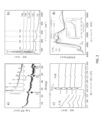
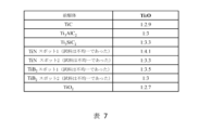
TiO2を前駆体とした場合を除き、すべてのケースで2D薄片が得られた。TiC由来のフィルムの典型的な断面走査型電子顕微鏡(SEM)画像(図1b)は、FFの2次元的性質を明確に示している。この顕微鏡写真は、未消化のTiC粒子(右下)と薄片の両方を示している点で特に明瞭である。濃度が10g/Lのコロイド懸濁液を図1bの挿入図に示す。他のフィルムのSEM画像を図5に示す。FFの色は薄い灰色から濃い灰色まで様々であった。これらの薄片が非層状前駆体から合成でき、構造的にも化学的にも類似したFFが得られるという事実は、ボトムアップ・アプローチの強力な証拠である。我々の解釈では、TMAHは前駆体を溶解し、TMAH/水におけるCおよびOと自発的に反応して自己組織化ナノフィラメントからなる2D薄片を形成するTi原子を放出する、ほぼ普遍的な溶媒として働く(下記参照)。このように、TMAHの役割は、溶媒と鋳型形成剤の2つである。 2D flakes were obtained in all cases except when TiO 2 was used as the precursor. A typical cross-sectional scanning electron microscopy (SEM) image of a TiC-derived film (Fig. 1b) clearly shows the two-dimensional nature of the FF. This photomicrograph is particularly clear in that it shows both undigested TiC particles (bottom right) and flakes. A colloidal suspension with a concentration of 10 g/L is shown in the inset of Figure 1b. SEM images of other films are shown in FIG. The color of FF varied from light gray to dark gray. The fact that these flakes can be synthesized from non-layered precursors, yielding structurally and chemically similar FFs, is strong evidence for a bottom-up approach. Our interpretation is that TMAH is a nearly universal solvent that dissolves the precursor and releases Ti atoms that spontaneously react with C and O in TMAH/water to form 2D flakes consisting of self-assembled nanofilaments. (see below). Thus, the role of TMAH is twofold: solvent and template forming agent.
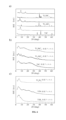
エタノール洗浄後のTi3AlC2由来フィルムのX線回折(XRD)パターン(図2aの挿入図)は、2D材料の典型的なものである。[7,9]他の前駆体から得られた乾燥FFのXRDパターンを図6に示す。ほとんどの場合、前駆体に関連するピークがないことは注目に値する。基礎構造を知るために、垂直配向FFのXRDパターン(図2a)を得た。[14](図7a参照)。これは、Ti3AlC2を50℃で3日間加熱した後、エタノールと水で洗浄した後に得られたものである。赤い縦線は次のようにして得られた:まず、水平配向フィルムからc格子定数LPを計算した(図2aの挿入図)。次に、図1cに示した構造を用いて、すべてのピークの位置を計算した。l指数がゼロでない面はすべて消去し、赤線が残った。密度汎関数理論(DFT)で生成されたLPと実験的なLP(図1dの挿入図)がよく一致していることから、4 Ti層アナターゼベースの2D材料を扱っていることが裏付けられた(後述)。他の前駆体から得られた他の垂直配向フィルムのパターンを図7bに示す。すべてのケースで、同じ角度のピークが得られた。これは、前駆体の化学的性質が、LPを含む形成された構造を変化させないことを示しているため、極めて重要であり、いくら強調しても強調しすぎることはない。 The X-ray diffraction (XRD) pattern of the Ti3AlC2 - derived film after ethanol washing (inset of Fig. 2a) is typical of a 2D material. [7,9] XRD patterns of dried FF obtained from other precursors are shown in FIG. It is noteworthy that in most cases there are no peaks related to precursors. To know the basic structure, an XRD pattern (Fig. 2a) of the vertically aligned FF was obtained. [14] (see Figure 7a). This was obtained after heating Ti 3 AlC 2 at 50° C. for 3 days, followed by washing with ethanol and water. The red vertical line was obtained as follows: first, the c lattice constant LP was calculated from the horizontally oriented film (inset of Fig. 2a). The positions of all peaks were then calculated using the structure shown in Figure 1c. All surfaces with non-zero l index were erased, leaving a red line. The good agreement between the density functional theory (DFT) generated LP and the experimental LP (inset of Fig. 1d) confirms that we are dealing with a 4 Ti-layer anatase-based 2D material. (described later). Other vertically oriented film patterns obtained from other precursors are shown in Figure 7b. In all cases, peaks with the same angle were obtained. This is extremely important and cannot be overemphasized as it indicates that the precursor chemistry does not change the formed structure containing the LP.
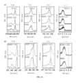
TiC、TiSiC2、およびTi3AlC2由来の薄片の透過型電子顕微鏡(TEM)画像から、横方向のサイズ>1μmである2D薄片の存在が明らかになった(図3a、図8)。一部の領域で後者の選択領域回折(SAD)を行った結果、3つの主要なリングが得られた(図8bとcの挿入図を参照)。リングのd-間隔を2θ値に変換すると(図2aの青い四角)、XRDピークとよく一致することがわかり、SADパターンが代表的であることが確認された(より詳しい結果は表3を参照)。さらに興味深いことに、他の領域では2組の円弧(図3aおよび図8aの挿入図)が観察された。円弧の1つはナノフィラメントの長軸が[110]方向にあることを示し、もう1つは[200]方向にあることを示している。これらの間の角度は、挿入図とメイン顕微鏡写真の両方に示されている。これらは、左上のシートの端に見られるほつれた繊維と同じ方向である。円弧が観察された場所は限られている。3つのリングが観察された領域は、より偏在しており、これは、あらゆる方向を向いている小さいnfsの存在を示唆している。同様に、現段階では、真にアモルファスな領域の存在を否定することはできない。 Transmission electron microscopy (TEM) images of TiC, TiSiC 2 and Ti 3 AlC 2 derived flakes revealed the presence of 2D flakes with lateral size >1 μm (Fig. 3a, Fig. 8). Selected area diffraction (SAD) of the latter in some areas resulted in three major rings (see insets in Fig. 8b and c). Converting the d-spacing of the rings to 2θ values (blue squares in Figure 2a) showed good agreement with the XRD peaks, confirming that the SAD pattern is representative (see Table 3 for more detailed results). ). More interestingly, in other regions two sets of circular arcs (Fig. 3a and inset of Fig. 8a) were observed. One of the circular arcs indicates that the long axis of the nanofilament is in the [110] direction, and the other indicates that it is in the [200] direction. The angle between these is shown in both the inset and the main micrograph. These are in the same direction as the frayed fibers seen at the edge of the top left sheet. The locations where arcs have been observed are limited. The region where three rings were observed was more ubiquitous, suggesting the presence of small nfs pointing in all directions. Similarly, at this stage, we cannot deny the existence of truly amorphous regions.
走査型透過電子顕微鏡(STEM)顕微鏡写真(図3b)は、試料の繊維状の性質をはっきりと示している。個々のナノフィラメントの幅は≒1nmと推定される。その厚さは≒5.9Åであるため、断面がおよそ6x10Å2で、長さがマイクロメートルになるナノフィラメントを扱っていることになる(図3bの挿入図と図8cを参照)。その他のTEM顕微鏡写真を図8に示す。これらのナノフィラメントの理論表面積は、≒1500m2/gであることに着目する。 The scanning transmission electron microscopy (STEM) micrograph (Fig. 3b) clearly shows the fibrous nature of the sample. The width of individual nanofilaments is estimated to be ≈1 nm. Its thickness is ≈5.9 Å, so we are dealing with nanofilaments with a cross-section of approximately 6 x 10 Å and a length of micrometers (see inset of Fig. 3b and Fig. 8c). Other TEM micrographs are shown in FIG. It is noted that the theoretical surface area of these nanofilaments is ≈1500 m 2 /g.
図3cと図9は、ガラス上にスピンコートしたTiC由来の試料(80℃で5日間、水で洗浄)のTEMと原子間力顕微鏡(AFM)マップである。生成物の繊維状の性質と自己整列の傾向は明らかである。同じ懸濁液を500倍に希釈してドロップキャストすると、個々のナノフィラメントが分離した(図3d)。図3dの青線に沿ったAFMトレースは、最小のリボンの厚さまたは高さは≒1.5nmであることを示している(図3dの挿入図)。 Figures 3c and 9 are TEM and atomic force microscopy (AFM) maps of TiC-derived samples spin-coated on glass (washed with water at 80°C for 5 days). The fibrous nature and self-alignment tendency of the product is evident. When the same suspension was diluted 500 times and drop cast, individual nanofilaments were separated (Fig. 3d). The AFM trace along the blue line in Figure 3d shows that the minimum ribbon thickness or height is ≈1.5 nm (inset in Figure 3d).
フィラメントあたりのTi層数を決定するために、第一原理計算を用いてLPを予測した。このために、エネルギーが最も低いアナターゼ(101)表面[16]が上部と下部の境界となる、2-(図示せず)、4-(図1c)、および6-Ti層(図10a)からなる3つのスーパーセル構造について緩和計算を行った。(我々の座標系はアナターゼの座標系と異なることに注意;ここではc軸が積層方向である。SMの結晶学のセクションを参照)。次に、TiO2-2xCx(xは0.25またはTi4O6C)の全体的な化学組成を得るために、スラブ中心で2個のO原子を1個のC原子で置き換えた。これは構造上のCを考慮し、構造を動的に安定させるためである(図10b)。他のすべての構成では動的不安定性が生じた。図1dの挿入図に示すように、3つの構造のb軸のLPは、特にDFT計算が0Kで行われたことを考えると、実験値とよく一致している。しかし、Ti層の数が4または6に増えると、a-LPの大きな増加が観察され、実験値に近づく(図1dの挿入図の青い曲線)。4層と6層のアナターゼの厚さは、それぞれ≒5.9Åと≒8Åである。TMAカチオンの直径は4.5~6Åの範囲である[17,18]。下限を用いると、4層と6層構造のフィラメント間のd間隔は、それぞれ10.4Åと12.5Åとなる。上限を用いると、4層構造のd間隔(11.9Å)が得られ、XRDから得られた11.5のd間隔とよく一致する(図2aと図6aの挿入図)。つまり、実験値は4層構造と一致しており、6層構造は厚すぎる。 To determine the number of Ti layers per filament, first-principles calculations were used to predict the LP. To this end, the lowest energy anatase (101) surface [16] serves as the upper and lower boundary from the 2- (not shown), 4- (Fig. 1c), and 6-Ti layers (Fig. 10a). We performed relaxation calculations for three supercell structures. (Note that our coordinate system is different from that of anatase; here the c-axis is the stacking direction; see the Crystallography section of SM). Then, two O atoms were replaced by one C atom at the slab center to obtain the overall chemical composition of TiO 2-2x C x (x is 0.25 or Ti 4 O 6 C). . This is to take structural C into consideration and to dynamically stabilize the structure (FIG. 10b). All other configurations resulted in dynamic instability. As shown in the inset of Fig. 1d, the b-axis LP of the three structures is in good agreement with the experimental values, especially considering that the DFT calculations were performed at 0 K. However, when the number of Ti layers increases to 4 or 6, a large increase in a-LP is observed, approaching the experimental value (blue curve in the inset of Fig. 1d). The thicknesses of the 4-layer and 6-layer anatase are ≈5.9 Å and ≈8 Å, respectively. The diameter of TMA cations ranges from 4.5 to 6 Å [17,18]. Using the lower limit, the d-spacing between filaments in the 4-layer and 6-layer structures is 10.4 Å and 12.5 Å, respectively. Using the upper limit, we obtain a d-spacing of the four-layer structure (11.9 Å), which is in good agreement with the d-spacing of 11.5 obtained from XRD (Fig. 2a and inset of Fig. 6a). That is, the experimental values are consistent with a 4-layer structure, and a 6-layer structure is too thick.
多くのFFのラマン分光法(図2b)は、前駆体の化学的性質に関係なく、すべてのピークがアナターゼに属することを示している。[15,19] Raman spectroscopy of many FFs (Fig. 2b) shows that all peaks belong to anatase, regardless of the precursor chemistry. [15,19]
薄片の化学的性質を解明するために、X線光電子分光(XPS)法による包括的な研究が行われた(図11~13および表4)。TiとOの結合エネルギーは、前駆体の化学的性質(図11)、洗浄プロトコル、あるいはAr中で800℃に加熱した場合(図12a)には弱い関数であることがわかった。このことは、すべてのフィルムの化学的類似性を改めて裏付けている。ボトムアップ・アプローチのさらなる証拠は、小さなSiピークを示すTi3SiC2由来フィルムを除き、他のすべてのXPSスペクトルが、出発前駆体に関係なく、Ti、C、Oの3元素のみで構成されていることである(図13)。 A comprehensive study by X-ray photoelectron spectroscopy (XPS) was performed to elucidate the chemical properties of the flakes (Figures 11-13 and Table 4). The binding energy of Ti and O was found to be a weak function of precursor chemistry (Fig. 11), cleaning protocol, or heating to 800 °C in Ar (Fig. 12a). This again confirms the chemical similarity of all films. Further evidence of the bottom-up approach is that except for the Ti3SiC2 - derived film, which shows a small Si peak, all other XPS spectra are composed of only three elements, Ti, C, and O, regardless of the starting precursor. (Figure 13).
議論したように、薄片中のC含有量を定量化することはできなかった。いくつかのTiCベースの薄片のEELSは、Ti:C:Oの原子比が≒1:1:1であることを示した(図2cと表5)。これらの薄片には少量の窒素が含まれていたが、簡易化のためここでは無視する。SEMとTEMの両方のEDSで、Ti:O比が≒1.0であることが確認されたことに注意することが重要である(表6)。この比に基づいて、もしCが構造中に存在しなければ、Tiの酸化状態は≒+2でなければならないが、これは、TiC由来のフィルムのTi KエッジにおけるX線吸収端近傍構造(XANES)測定(図2d)が、平均酸化状態(AOS)が+3から+4の間であることを示していることからも裏付けられる。すべての場合において、XPSにおけるO:Ti比は1よりも3に近かった(表7)。 As discussed, it was not possible to quantify the C content in the thin sections. EELS of several TiC-based flakes showed that the atomic ratio of Ti:C:O was ≈1:1:1 (Fig. 2c and Table 5). These flakes contained small amounts of nitrogen, which will be ignored here for simplicity. It is important to note that both SEM and TEM EDS confirmed that the Ti:O ratio was ≈1.0 (Table 6). Based on this ratio, if C is not present in the structure, the oxidation state of Ti must be ≈+2, which is similar to the X-ray absorption near-edge structure (XANES) at the Ti K edge of TiC-derived films. ) measurements (Fig. 2d) show that the average oxidation state (AOS) is between +3 and +4. In all cases, the O:Ti ratio in XPS was closer to 3 than 1 (Table 7).
化学的性質と薄片の形態をよりよく理解するために、選択したフィルムについてAr中で800℃までの熱重量分析(TGA)を行った。結果を図14aに示す。TiO2由来のフィルムを特筆すべき例外として、他のすべての場合において、LiClで洗浄したフィルムを加熱すると、2つの主要な重量減少現象が見られた。ひとつは≒200℃の前、もうひとつは≒300℃またはそれ以上の温度である。TiB2、TiCおよびTi3SiC2由来フィルムでは、後者が非常に急激である。ほとんどの場合、≒300℃での重量損失は約4%であった。Ti3AlC2およびTiN由来フィルムの300℃以上での重量損失はより拡散しているが、それでも合計は≒4%であった。300℃での重量減少の鋭さは、空気中で800℃に加熱したTiCフィルムの図14bでよくわかる。この実験では、TGAに質量分析計が装備され、その結果が図14cに示されている。400℃まで放出されたガスは水だけであった。1つ目はおそらく弱く結合した層間水であり、2つ目はLiイオンと結合した水和水である可能性がある。原子番号の高い化学種がないことは、LiCl洗浄工程がTMAカチオンやその他の反応生成物の層間空間を除去したことを間接的に証明している。当然のことながら、エタノールのみで洗浄したフィルムの重量損失はより大きかった(図14aの赤い曲線)。 Thermogravimetric analysis (TGA) in Ar up to 800 °C was performed on selected films to better understand the chemistry and flake morphology. The results are shown in Figure 14a. With the notable exception of the TiO 2 derived films, in all other cases two major weight loss phenomena were observed upon heating the LiCl cleaned films. One is before ≒200°C, and the other is at a temperature of ≒300°C or higher. The latter is very steep for TiB 2 , TiC and Ti 3 SiC 2 derived films. In most cases, the weight loss at ≈300°C was approximately 4%. The weight loss above 300° C. for Ti 3 AlC 2 and TiN derived films was more diffuse, but still totaled ≈4%. The sharpness of the weight loss at 300°C is best seen in Figure 14b for the TiC film heated to 800°C in air. In this experiment, the TGA was equipped with a mass spectrometer and the results are shown in Figure 14c. The only gas released up to 400°C was water. The first is probably weakly bound interlayer water, and the second is likely hydration water bound with Li ions. The absence of high atomic number species indirectly proves that the LiCl cleaning step removed the interlayer spaces of TMA cations and other reaction products. Not surprisingly, the weight loss of the film washed with ethanol only was greater (red curve in Figure 14a).
TGA実行後、得られた粉末のXRDパターンを得た(図15)。XRDパターンのリートベルト解析の結果、表8に示す値が得られた。すべてのケースで、2つの主要な相が同定された:チタン酸リチウム、LT、相-Li1.33Ti1.67O4とルチルまたはアナターゼ。Ti3AlC2、Ti3SiC2、TiCの場合、TiO2/LTAのモル比は≒7:3;TiB2の場合、その比は1:1に近く;TiO2の場合、LTはほとんどない。Liの含有量が高いほど、フィルム中のTi3+の割合が高くなることに注意されたい。したがって、我々のアプローチは、多くの用途で考慮されるTi3+/Ti4+比を調整するために使用することができる。 After performing TGA, an XRD pattern of the resulting powder was obtained (Figure 15). As a result of Rietveld analysis of the XRD pattern, the values shown in Table 8 were obtained. In all cases, two main phases were identified: lithium titanate, LT, phase - Li 1.33 Ti 1.67 O 4 and rutile or anatase. For Ti 3 AlC 2 , Ti 3 SiC 2 , TiC, the molar ratio of TiO 2 /LTA is ≈7:3; for TiB 2 , the ratio is close to 1:1; for TiO 2 , there is almost no LT . Note that the higher the Li content, the higher the proportion of Ti 3+ in the film. Therefore, our approach can be used to tune the Ti 3+ /Ti 4+ ratio considered in many applications.
エタノールのみで洗浄し、Ar中でフィルムを800℃まで加熱しても、Li含有相は得られなかった。したがって、LT相の存在は、層間のカチオン(TMA+、および/またはプロトン)が、MXeneの研究を非常に彷彿とさせる方法で、LiCl洗浄工程中にLiと交換されたことを示唆している。[20,21]TiO2由来の試料は、LiClで洗浄した後でも、わずかにリチウム化されただけであった(表8)。この試料のTGA(図14aの黒い曲線)も同じ理由で外れ値である。カチオン交換は、層状複水酸化物を扱っている可能性を排除する。XPSにClシグナルが存在しない(図13b参照)ことも、この結論を裏付けている。 Even after washing with ethanol only and heating the film to 800° C. in Ar, no Li-containing phase was obtained. Therefore, the presence of the LT phase suggests that interlayer cations (TMA + and/or protons) were exchanged with Li during the LiCl cleaning step in a manner very reminiscent of the MXene studies. . [20,21] TiO2 -derived samples were only slightly lithiated even after cleaning with LiCl (Table 8). The TGA of this sample (black curve in Figure 14a) is also an outlier for the same reason. Cation exchange eliminates the possibility that we are dealing with layered double hydroxides. The absence of Cl signal in XPS (see Figure 13b) also supports this conclusion.
EELS、XANES、DFTおよびTGAの結果に基づけば、薄片の化学的性質はZδ(Ti4+)1-δ(Ti3+)δO2-2xCxで与えられ、x<1.0であると仮定するのが妥当である。Zは、Tiの酸化状態が<4+であることを説明するカチオンである。そうでなければ、酸化状態の減少はカチオンによってバランスがとれなければならない。この結論は、ナノフィラメントに欠陥がないことを前提としており、非常にあり得ないシナリオであることに注意する。多くのフィルムが濃い灰色から黒色であるという事実は、バンドギャップにおける欠陥状態の存在を強く示唆している。 Based on the EELS, XANES, DFT and TGA results, the chemical properties of the flakes are given by Z δ (Ti 4+ ) 1−δ (Ti 3+ ) δ O 2−2x C x , where x<1.0 It is reasonable to assume that. Z is a cation explaining that the oxidation state of Ti is <4+. Otherwise, the reduction in oxidation state must be balanced by cations. Note that this conclusion assumes that the nanofilaments are defect-free, a highly unlikely scenario. The fact that many films are dark gray to black strongly suggests the presence of defect states in the bandgap.
全体的な状況はさらに複雑である。たとえば、領域によっては、Ti:X比(X=O+C+N)が1に近づくところもある(表5のスポット1および5参照)。我々が扱っているのは、必ずしも均質ではなく、解読に多くの作業を必要とする、非常に複雑なシステムであることをここに認める。これらのコメントにもかかわらず、薄片の構造と構造中のCの存在に関する我々の結論は依然として有効である。
The overall situation is even more complex. For example, in some regions the Ti:X ratio (X=O+C+N) approaches 1 (see
特性について論じる前に、ナノフィラメントと2D層の形成に関わるメカニズムについて論じることが有益である。Chenらは、チタン酸テトラ-n-ブチルとTMAHから出発して、TMAHの存在が有機カチオンを提供し、Ti-オクタヘドラ重縮合プロセスを補助し、指示することで、観察された矩形ナノ結晶アナターゼ粒子の規則的な配列が得られたと結論づけた。[15]Tanらは、TiCl4を125℃で水熱処理した。[19]反応時間が1時間と4時間の場合、彼らのXRDパターンは、60°2θ付近の(240)の位置以外は、図2aと同じであった。反応時間を12時間、24時間と長くすると、2D材料はバルクアナターゼに変換された。彼らは、TMAHがTi八面体を2D層に組み立てるのを助けると同時に、得られたシートを挿入するというモデルを提案した。TMA分子がより安定するのに十分低い温度で作業しているため[22]、我々の材料がバルクアナターゼに変化しないことを除けば、このメカニズムがここでも当てはまらないと考える理由はない。最後に、これまでの全ての研究とは異なり、TMAHは低エネルギー(00l)面をキャップするだけではなく[19]、成長方向に垂直な第二の面もキャップしなければならない。これにより、成長が一つの次元に限定される状況が生まれる。図3bと図8fの挿入図は、フィラメントが前駆体から化学的に「引き出され」、重縮合プロセスが(特定の理論に縛られることなく)その界面で起こる可能性を示唆している。一旦ナノフィラメントが形成されると、それらは自己集合して2D薄片になる必要がある。図8dは、特定の領域において、ナノフィラメントがどのように自己整列して「結晶」領域を形成するかを示すスナップショットである。 Before discussing the properties, it is useful to discuss the mechanisms involved in the formation of nanofilaments and 2D layers. Starting from tetra-n-butyl titanate and TMAH, Chen et al. observed that the presence of TMAH provides organic cations to assist and direct the Ti-octahedra polycondensation process, resulting in the observed rectangular nanocrystalline anatase. It was concluded that a regular arrangement of particles was obtained. [15] Tan et al. hydrothermally treated TiCl4 at 125 °C. [19] When the reaction time was 1 h and 4 h, their XRD patterns were the same as in Figure 2a except for the (240) position around 60°2θ. Increasing the reaction time to 12 and 24 hours converted the 2D material to bulk anatase. They proposed a model in which TMAH helps assemble Ti octahedra into 2D layers while simultaneously inserting the resulting sheets. There is no reason to think that this mechanism does not apply here as well, except that our material does not convert to bulk anatase because we are working at temperatures low enough for TMA molecules to be more stable [22]. Finally, unlike all previous studies, TMAH not only caps the low energy (00l) plane [19] but also has to cap the second plane perpendicular to the growth direction. This creates a situation where growth is limited to one dimension. The insets of Fig. 3b and Fig. 8f suggest that the filament is chemically “pulled” from the precursor and the polycondensation process occurs at the interface (without being bound to a particular theory). Once the nanofilaments are formed, they need to self-assemble into 2D flakes. Figure 8d is a snapshot showing how nanofilaments self-align to form "crystalline" regions in certain regions.
TiCとMAX相から得られたフィルムは導電性で、導電率は0.01~0.05S/cmの範囲であったが、TiO2、TiB2から得られたものはそうではない。これらの導電率は、2,000~25,000S/cmの範囲にあるMXeneよりもおよそ5~6桁低いが、典型的な酸化物、特に層状チタン酸塩の一般的なバージョン、すなわちレピドクロサイトよりも明らかに高い桁である[23-25]。導電率は常に存在するわけではなく、現在調査中の未知の変数が作用していることを示唆している。 Films obtained from TiC and MAX phases were electrically conductive, with conductivities ranging from 0.01 to 0.05 S/cm, whereas those obtained from TiO 2 , TiB 2 were not. Their conductivity is approximately 5-6 orders of magnitude lower than that of MXene, which is in the range of 2,000-25,000 S/cm, but that of typical oxides, especially the common version of layered titanates, i.e. lepidochrome. This is clearly an order of magnitude higher than that of the site [23-25]. Conductivity is not always present, suggesting that unknown variables currently under investigation are at play.
電子構造を明らかにするため、200nmから800nmの紫外可視光吸収スペクトルを測定した。すべてのフィルムのTaucプロット(図4a)は、間接バンドギャップEgの明確なサインを示すとともに、サブギャップ状態間の遷移に起因する顕著なアーバッハテールを示した。修正されたTauc法を使用して、無秩序に関連するアーバッハテール状態の寄与からバンド間遷移をデコンボリューションした場合[26]、間接バンドギャップは4eVの範囲に収まると結論づけられた。この値は、アナターゼで報告された中で最高値であるが、寸法が小さくなるにつれてEgが増加することと一致する。[27]Liao et al.[28]は、2-Ti層状2Dアナターゼ薄片についてEg≒3.6eVを予測および確認した。我々の薄片は、≒6x10Å2ナノフィラメントで構成されているため、Egはさらに高い。この記録的なTiO2のEg値は、間接的に我々のナノフィラメントの極端な寸法を裏付けるものであるため、いくら強調してもしすぎることはない。3.3eVにおいて、我々のTiO2ベースのナノ粒子のEgは、予想通りバルクアナターゼのEgに近いことに注意されたい(図4a)。 In order to clarify the electronic structure, ultraviolet-visible light absorption spectra from 200 nm to 800 nm were measured. The Tauc plots (Fig. 4a) of all films showed clear signatures of indirect bandgap E , as well as a pronounced Urbach tail due to transitions between subgap states. When using a modified Tauc method to deconvolute the interband transitions from the contribution of disorder-related Urbach tail states [26], it was concluded that the indirect band gap is in the range of 4 eV. This value is the highest reported for anatase, but is consistent with an increase in E g with decreasing size. [27] Liao et al. [28] predicted and confirmed E g ≈3.6 eV for 2-Ti layered 2D anatase flakes. Our flakes are composed of ≈6 x 10 Å 2 nanofilaments, so the E g is even higher. This record TiO 2 E g value cannot be overstated as it indirectly confirms the extreme dimensions of our nanofilaments. Note that at 3.3 eV , the E g of our TiO2 - based nanoparticles is close to that of bulk anatase, as expected (Fig. 4a).
興味深いことに(そして、特定の理論や実施形態に縛られることなく)、ここでは、Li濃度から推測されるTi3+の含有量とアーバッハテールとの間には、一部の人が示唆したような相関関係はない[29]。従って、このテールと導電性は点欠陥に起因すると暫定的に結論づけた。EELS測定の一部では、Tiの割合が0.5に近づいており(表5)、O/C空孔が形成されていることを示唆している。このコメントはともかく、これらのフィルムの一部が導電性を示すことがある理由を理解するには、さらなる研究が必要である。 Interestingly (and without being bound by any particular theory or embodiment), here we note that the relationship between the Ti 3+ content inferred from the Li concentration and the Urbach tail is similar to that suggested by some. There is no such correlation [29]. Therefore, we tentatively concluded that this tail and conductivity are caused by point defects. In some of the EELS measurements, the Ti fraction approaches 0.5 (Table 5), suggesting the formation of O/C vacancies. Regardless of this comment, further research is needed to understand why some of these films may exhibit electrical conductivity.
応用の可能性を検討するため、リチウムイオン電池(LIB)とリチウム硫黄電池(Li-S)において、われわれの2D薄片の性能を探った。結果はそれぞれ図4bとcに示すとおりで、いずれの場合も有望な結果が得られた。詳細な考察はSMにある(図17と18参照)。LIBの場合、1.64Vと2.1Vにリチウム化ピークと脱リチウム化ピークがないことから(図4bの挿入図)、この電極がTiO2でも層状チタン酸塩でもないことが確認された[30,31]。さらに、この電極のクーロン効率は、200サイクル後で≒99.3%であり(図17d)、非常に効率的な電気化学サイクルを反映していた。 To explore potential applications, we explored the performance of our 2D flakes in lithium-ion batteries (LIBs) and lithium-sulfur batteries (Li-S). The results are shown in Figures 4b and c, respectively, and promising results were obtained in both cases. A detailed discussion can be found in the SM (see Figures 17 and 18). In the case of LIB, the absence of lithiation and delithiation peaks at 1.64 V and 2.1 V (inset of Fig. 4b) confirms that this electrode is neither TiO2 nor layered titanate [ 30, 31]. Furthermore, the Coulombic efficiency of this electrode was ≈99.3% after 200 cycles (Fig. 17d), reflecting a highly efficient electrochemical cycle.
LiアノードとTiC由来のTCOカソードを持つリチウム硫黄(Li-S)コインセルを組み立て、サイクルを行った。結果を図4cに示し、SMで詳述する。 A lithium-sulfur (Li-S) coin cell with a Li anode and a TiC-derived TCO cathode was assembled and cycled. The results are shown in Figure 4c and detailed in SM.
これらの結果は、得られた材料の2D性質とその可能性を確認するために含まれている。しかしながら、これらの結果は、得られたものをよりよく理解することで大きく向上させることができる。これらのコメントはともかく、そのメカニズムや関与などを理解するためには、本稿の範囲を明らかに超えた、より多くの研究が必要であることをここに認める。しかしながら、これらの材料は、特にLi-Sカソードとして大きな可能性を示していることは言うまでもない。例えば、図18bに示すように、容量は、フェードするまで≒1000mAh/gで約300サイクルにわたって一定であった。 These results are included to confirm the 2D nature of the obtained materials and their potential. However, these results can be greatly improved with a better understanding of what is being obtained. Regardless of these comments, we acknowledge that more research is clearly needed beyond the scope of this paper to understand its mechanisms and involvement. However, it goes without saying that these materials show great potential, especially as Li-S cathodes. For example, as shown in Figure 18b, the capacity remained constant for approximately 300 cycles at ≈1000 mAh/g before fading.
最後に、TCOの多用途性をさらに実証するために、生物医学的応用の可能性を探ったところ、実際にがん治療に利用できることがわかった(図4d)。ここでは、マウス4T1乳がん細胞とB16-F10メラノーマ細胞を、異なる濃度のTiC由来TCOで24時間処理した後、MTTアッセイを用いて生存率を測定した。200μg/mlの濃度で、TCO粒子はがん細胞の死を誘導することができ、B16-F10メラノーマ細胞よりも4T1乳がん細胞により効果的であった。従って、本開示による組成物をがん含有試料に投与することができ、この投与によりがん細胞の死滅を誘導することができる。 Finally, to further demonstrate the versatility of TCO, we explored its potential biomedical applications and found that it can indeed be used in cancer treatment (Fig. 4d). Here, mouse 4T1 breast cancer cells and B16-F10 melanoma cells were treated with different concentrations of TiC-derived TCO for 24 hours, and then the survival rate was measured using an MTT assay. At a concentration of 200 μg/ml, TCO particles were able to induce cancer cell death and were more effective in 4T1 breast cancer cells than in B16-F10 melanoma cells. Accordingly, a composition according to the present disclosure can be administered to a cancer-containing sample, and this administration can induce death of cancer cells.
結論 conclusion
我々は、ナノフィラメントから構成される2Dチタンカーボ-オキシドフィルムを作製するための、シンプルで安価、比較的高収率、常温近傍、完全に拡張可能、ワンポット、ボトムアップ・アプローチを発見した。11の異なる層状および非層状のチタンベースの前駆体粉末をTMAH中で異なる温度(25℃~85℃)で様々な時間加熱することにより、そのうちの10種類をアナターゼベースの2D薄片に変換し、実質的なC含有量を持つ≒6x10Å2ナノフィラメントに構成した。いくつかのフィルムは色が濃く、導電性のものもあり、導電率は0.01~0.05S/cmの範囲であった。しかし、アーバッハテールと、全体のLi含有量から推測されるTi3+の割合との間には相関関係が見られなかったため、導電性の原因は還元された酸化状態ではなく、おそらく点欠陥であると結論付けた。TCOはLIBおよびLi-S電池の電極として良好な性能を示した。また、バイオメディカルへの応用も期待できる。 We have discovered a simple, inexpensive, relatively high-yield, near-room temperature, fully scalable, one-pot, bottom-up approach to fabricate 2D titanium carboxide films composed of nanofilaments. By heating 11 different layered and non-layered titanium-based precursor powders in TMAH at different temperatures (25 °C to 85 °C) for various times, 10 of them were converted into anatase-based 2D flakes; It was constructed into ≈6×10 Å 2 nanofilaments with substantial C content. Some of the films were dark in color and conductive, with conductivities ranging from 0.01 to 0.05 S/cm. However, since there was no correlation between the Urbach tail and the proportion of Ti 3+ inferred from the total Li content, the conductivity was probably caused by point defects rather than the reduced oxidation state. I concluded that there is. TCO showed good performance as an electrode for LIB and Li-S batteries. It is also expected to have biomedical applications.
材料と方法 Materials and methods
フィルムの加工 Film processing
この合成プロセスでは、室温(RT)から85℃の範囲の温度で、24時間から1週間の期間、ホットプレート上で加熱されるポリエチレンジャー内の25wt%TMAHに前駆体粉末を浸漬することを伴う。TMAHとの反応後、(Ti2SbP、TiB2およびTiO2を除く)暗黒色の沈殿物が得られ、これを回収し、エタノールで洗浄した後、振盪し、透明な上清が得られるまで3500rpmで何サイクルも遠心分離した。上清が透明になったら、脱イオン水30mLを洗浄した生成物に加え、5分間振盪した。超音波処理を行わず、3500rpmで0.5時間遠心分離した後、安定したコロイド懸濁液が得られた。未反応の粉末は沈殿した。次いで、このコロイドを真空濾過し、FFを生成し、その一部を特徴付けた。 This synthesis process involves soaking the precursor powder in 25 wt% TMAH in a polyethylene jar heated on a hot plate for a period of 24 hours to 1 week at temperatures ranging from room temperature (RT) to 85 °C. . After reaction with TMAH, a dark black precipitate (except for Ti2SbP , TiB2 and TiO2 ) was obtained, which was collected and washed with ethanol, then shaken and incubated until a clear supernatant was obtained. Centrifugation was performed at 3500 rpm for multiple cycles. Once the supernatant was clear, 30 mL of deionized water was added to the washed product and shaken for 5 minutes. A stable colloidal suspension was obtained after centrifugation at 3500 rpm for 0.5 h without sonication. Unreacted powder precipitated. This colloid was then vacuum filtered to produce FF, a portion of which was characterized.
場合によっては、LiCl溶液で洗浄する追加の工程を実施し、生成した薄片を特性評価した。上記で得られた黒色コロイド懸濁液に5M LiCl溶液を加えた。その結果、脱凝集が起こった。沈殿物を振盪し、5000rpmの遠心分離を3サイクル行い、脱イオン水で洗浄した。LiCl/脱イオン水洗浄をpH≒7になるまで繰り返した。次に、洗浄した沈殿物を、Arを流しながら冷浴中で1時間超音波処理し、5分間振盪した後、3500rpmで10分間遠心分離した。コロイド懸濁液を濾過し、FFを得た。次に、FFを真空チャンバー内で一晩乾燥させた後、さらに特性評価を行った。
In some cases, an additional step of washing with LiCl solution was performed and the resulting flakes were characterized. A 5M LiCl solution was added to the black colloidal suspension obtained above. As a result, disaggregation occurred. The precipitate was shaken, centrifuged at 5000 rpm for three cycles, and washed with deionized water. The LiCl/deionized water wash was repeated until
少数の場合において、TMAHとTiCの反応から生成した黒色スラリーを、溶媒を加えずにそのまま遠心分離(5000rpm、5分間)し、上清をデカントし、沈殿物を20mLの脱イオン水に懸濁し、5分間振盪した後、3500rpmで30分間遠心分離した。生成した黒色コロイド懸濁液をXRD(図示せず)とTEM検査に使用した。 In a few cases, the black slurry produced from the reaction of TMAH and TiC was directly centrifuged (5000 rpm, 5 min) without the addition of solvent, the supernatant was decanted, and the precipitate was suspended in 20 mL of deionized water. After shaking for 5 minutes, centrifugation was performed at 3500 rpm for 30 minutes. The resulting black colloidal suspension was used for XRD (not shown) and TEM examination.
収率は、前駆体から供給されたモル数に対する、生成したアナターゼ様構造中のTiのモル数(簡易化のためTiO2のモル質量を使用)の割合として計算した。例えば、TiCとTi3AlC2の収率は、それぞれ19%と28%である。一般的に、収率は出発前駆体によって≒20%のオーダーである。コロイド懸濁液の固形負荷は10g/Lのオーダーである。 The yield was calculated as the ratio of moles of Ti in the anatase-like structure produced (using the molar mass of TiO 2 for simplicity) to the moles supplied from the precursor. For example, the yields of TiC and Ti 3 AlC 2 are 19% and 28%, respectively. Generally, yields are on the order of ≈20% depending on the starting precursor. The solids loading of the colloidal suspension is of the order of 10 g/L.
X線回折、XRD X-ray diffraction, XRD
空気乾燥した試料のXRDパターンは、粉末回折装置(Rigaku SmartLab)を用いて、2~65°2θ範囲のCu Kα線を用い、0.02°のステップサイズと1秒/ステップのドエルタイムで、Bragg-Brentano幾何学で取得した。また、透過モードで垂直配向フィルムのXRDパターンも得た。 XRD patterns of air-dried samples were obtained using a powder diffractometer (Rigaku SmartLab) using Cu Kα radiation in the 2-65° 2θ range, with a step size of 0.02° and a dwell time of 1 s/step. Obtained with Bragg-Brentano geometry. An XRD pattern of the vertically oriented film was also obtained in transmission mode.
ラマン分光法、RS Raman spectroscopy, RS
ラマン散乱スペクトルは、多数の前駆体のFFから、大気中300Kで収集した(図2b)。試料に3.75mWのパワーを照射し、スポット径~0.5μmに集光した532-nmレーザーを用いてプローブした。散乱光は幾何学的後方散乱で集められ、電荷結合検出器アレイ(Horiba XploRA,Edison NJ)を備えた単軸モノクロメーターを用いて分散および検出された。 Raman scattering spectra were collected at 300 K in air from a number of precursor FFs (Fig. 2b). The sample was irradiated with a power of 3.75 mW and probed with a 532-nm laser focused to a spot diameter of ~0.5 μm. Scattered light was collected with geometric backscatter, dispersed and detected using a single-axis monochromator equipped with a charge-coupled detector array (Horiba XploRA, Edison NJ).
X線光電子分光法、XPS X-ray photoelectron spectroscopy, XPS
XPSは分光器(VersaProbe 5000, Physical Electronics,チャナッセン,ミネソタ州)を用いて行った。スポットサイズ200μmの単色Al-Kα X線を用いた。通過エネルギー23.5eV、エネルギーステップ0.05eV、ステップタイム0.5秒で高分解能スペクトルを収集した。1回のスキャンの繰り返し回数は10回であった。XPSスペクトルは、主要なC-Cピークを、285.0eVに設定して校正した。非対称のガウス/ローレンツ線形状を用いてピークをフィットさせた。バックグラウンドはShirleyアルゴリズムを用いて決定した。すべての試料はカーボンテープでXPSステージにマウントした。
XPS was performed using a spectrometer (
走査型電子顕微鏡、SEM scanning electron microscope, SEM
顕微鏡写真と元素組成は、エネルギー分散型X線分光器(EDS、Oxford EDS,Oxfordshire,英国)を装備したSEM(Zeiss Supra 50 VP,Carl Zeiss SMT AG、Oberkochen,ドイツ)を用いて得た。報告されているEDS値は、加速電圧15 kV、滞留時間60秒で、ランダムに選択した領域を低倍率で少なくとも2回測定した平均値である。
Micrographs and elemental compositions were obtained using a SEM (
原子間力顕微鏡、AFM Atomic force microscope, AFM
フィラメントと薄片の厚さは、AFM(Bruker Nano SurfacesによるMultimode 8 AFM)を用いて測定した。ピークフォースタッピングAFMイメージングモードを適用し、表面形態と高さプロファイルを取得した。スキャンはScanAsyst-Air窒化ケイ素プローブを用い、走査速度0.6Hzで行った。トポグラフィ画像は256*256ピクセルの解像度で記録され、Nano Scope Analysisソフトウェアで解析された。
Filament and flake thicknesses were measured using AFM (
透過型電子顕微鏡、TEM Transmission electron microscope, TEM
TEMイメージングと電子回折パターンは、JEOL JEM2100F電界放射型TEMを用いて収集した。TEMは200keVで作動し、画像解像度は0.2nmであった。画像と回折パターンはGatan USC1000 CCDカメラで収集した。走査型透過電子顕微鏡(STEM)は、300kVで動作する単色化および二重Cs補正されたFEI Titan3 60-300で実行された。 TEM imaging and electron diffraction patterns were collected using a JEOL JEM2100F field emission TEM. The TEM was operated at 200 keV and the image resolution was 0.2 nm. Images and diffraction patterns were collected with a Gatan USC1000 CCD camera. Scanning transmission electron microscopy (STEM) was performed on a monochromatic and dual Cs-corrected FEI Titan3 60-300 operating at 300 kV.
電子エネルギー損失分光法、EELS electron energy loss spectroscopy, EELS
STEM-EELSスペクトルは、Gatan GIF Quantum ERSポストカラムイメージングフィルターを使用し、0.25 eV/チャンネルエネルギー分散、収集半角55mradで1秒ずつ取得した100スペクトルを平均することにより取得した。存在するエッジの元素定量は、Digital Micrographの内蔵機能を用いて行った。 STEM-EELS spectra were acquired by averaging 100 spectra acquired for 1 second each using a Gatan GIF Quantum ERS post-column imaging filter with a 0.25 eV/channel energy dispersion and a collection half-angle of 55 mrad. Elemental quantification of existing edges was performed using the built-in function of Digital Micrograph.
X線吸収端近傍構造、XANES X-ray absorption edge structure, XANES
Ti Kエッジ等方性XANESスペクトルは、HELIOS-II型ヘリカルアンジュレータ(HU-52)の第一高調波によって供給される円偏光X線を用いて、フィルムの法線から54°の位置で記録された。X線ビームは、一対のSi(111)結晶を備えた固定出口二重結晶モノクロメーターを用いて単色化した。総蛍光収量信号は、後方散乱ジオメトリーに取り付けられたSiフォトダイオードによって収集された。スペクトルは自己吸収の影響を補正した。試料は、厚さ≒1mmの圧縮粉末ペレットであった。等方性XANESスペクトルは、吸収エッジの遥か上方でエッジジャンプが単一になるように正規化した。光子エネルギースケールは、4965.6eVに設定されたTiフィルムの吸収スペクトルにおけるピーク前の最大値を用いて較正された。スポットサイズは0.4x0.3mm2であった。実験はグルノーブルの欧州放射光施設(ESRF)ID12ビームラインで行った。 Ti K-edge isotropic XANES spectra were recorded at a position of 54° from the film normal using circularly polarized X-rays provided by the first harmonic of a HELIOS-II type helical undulator (HU-52). Ta. The X-ray beam was monochromated using a fixed exit double crystal monochromator equipped with a pair of Si(111) crystals. The total fluorescence yield signal was collected by a Si photodiode mounted in a backscatter geometry. The spectra were corrected for the effects of self-absorption. The samples were compressed powder pellets with a thickness of ≈1 mm. Isotropic XANES spectra were normalized to have a single edge jump far above the absorption edge. The photon energy scale was calibrated using the pre-peak maximum in the absorption spectrum of the Ti film, which was set at 4965.6 eV. The spot size was 0.4x0.3mm2 . The experiments were conducted at the European Synchrotron Radiation Facility (ESRF) ID12 beamline in Grenoble.
電気抵抗率 electrical resistivity
電気抵抗率測定は、4点プローブ装置(Loresta-AX MCP-T370、日東精工、日本)を用いて室温で行い、電気伝導率値に変換した。 Electrical resistivity measurements were performed at room temperature using a four-point probe device (Loresta-AX MCP-T370, Nitto Seiko, Japan) and converted into electrical conductivity values.
熱重量分析、TGA Thermogravimetric analysis, TGA
TGA分析には熱天秤(TA Instruments Q50,デラウェア州ニューキャッスル)を使用した。FFの小片(≒20mg)をサファイアるつぼに入れ、Arを10mL/分でパージしながら、10℃/分で800℃まで加熱した。ある実験では、質量分析計に取り付けた熱天秤を使用した。これらの測定では、40Vのイオン化ポテンシャルで動作する質量分析計(TA instruments Discovery Series)と組み合わせた熱分析計(TA instruments,SDT 650,Discovery Series)を使用した。試料は、0.5時間室温に保持した後、50mL/分の乾燥圧縮空気流下、10℃/分の速度で800℃まで加熱した。試料からのキャリアガスと発生ガスを、1~100原子質量単位の範囲でスキャンして測定した。各m/z(質量/電荷比)のイオン電流は、初期試料重量で正規化された。 A thermobalance (TA Instruments Q50, New Castle, Del.) was used for TGA analysis. A small piece of FF (≈20 mg) was placed in a sapphire crucible and heated to 800 °C at 10 °C/min while purging with Ar at 10 mL/min. One experiment used a thermobalance attached to a mass spectrometer. These measurements used a thermal analyzer (TA instruments, SDT 650, Discovery Series) combined with a mass spectrometer (TA instruments Discovery Series) operating at an ionization potential of 40V. The samples were kept at room temperature for 0.5 h and then heated to 800° C. at a rate of 10° C./min under a flow of dry compressed air of 50 mL/min. Carrier gas and evolved gas from the sample were scanned and measured in the range of 1 to 100 atomic mass units. The ion current for each m/z (mass/charge ratio) was normalized to the initial sample weight.
UV-vis. UV-vis.
UV-VISスペクトルは分光光度計(Evolution 300 UV-Visible,Thermo Scientific)を用いて記録した。測定は、石英スライド上にコーティングされた厚さ1~10μmのフィルムに対して透過モードで実行された。
UV-VIS spectra were recorded using a spectrophotometer (
DFT計算 DFT calculation
第一原理計算は、Vienna ab initio simulation package(VASP)を用いて行った。[32]プロジェクター増強波動法(PAW)を、600eVの運動エネルギーカットオフまで拡張した平面波基底とともに用いた。交換相関効果は、Perdew,Burke,and Ernzerhof(PBE)関数を用いた一般化勾配近似で記述した[33]。ブリュアンゾーンの積分は、0.05eVのスミア幅でガウス・スミア法を用いて行った。使用した擬ポテンシャルの電子配置は、C:[He]2S22P2、O:[He]2s22p4、Ti_sv:[Ne]3s23p63d24s2である。計算スーパーセルは、スラブモデルを用いて様々なアナターゼ(101)原子層から構成され、スーパーセルのa軸とb軸に沿って周期性を持つように構築された。スーパーセルの形状と原子位置は、各原子にかかる力が<5meV/Åになるまで緩和した。スラブに垂直な周期像間の相互作用を排除するために、スーパーセルのc軸(新しい座標系)に沿って15Åの真空領域を追加した。構造最適化のために、第一ブリュアンゾーンは16x6x1のk点サンプリングで、フォノン計算には8x3x1のスーパーセルと2x2x1のk点サンプリングを用いた。
First-principles calculations were performed using the Vienna ab initio simulation package (VASP). [32] Projector-enhanced wave method (PAW) was used with a plane wave basis extended to a kinetic energy cutoff of 600 eV. The exchange-correlation effect was described by a generalized gradient approximation using the Perdew, Burke, and Ernzerhof (PBE) function [33]. Brillouin zone integration was performed using the Gaussian smear method with a smear width of 0.05 eV. The electronic configurations of the pseudopotentials used are C:[He]2S 2 2P 2 , O: [He]
電気化学測定 electrochemical measurement
リチウムイオン電池、LIB Lithium ion battery, LIB
LIB材料としての電極材料としてのTCOの電気化学的性能を評価するため、Li金属に対するハーフセル構成でTCOを試験した。TCA作用電極は、結合剤および炭素添加剤を含む活物質のスラリーを、炭素被覆銅箔上にドロップキャストすることで作製した。スラリーは、40.0mgの活物質、5.0mgのポリ(フッ化ビニリデン)(PVDF、Sigma Aldrich、米国)結合剤N-メチル-2-ピロリジノン(NMP、99.5%、Acros Organics、Extra Dry over Molecular Sieve、ドイツ)溶媒、および5.0mgのカーボンブラックを混合して調製した。調製した電極を60℃で一晩乾燥させた。電極の質量負荷は~1.2~1.5 mg/cm2であった。2電極CR2032型コインセルを、O2およびH2O<0.1ppmのAr充填グローブボックス内で組み立てた。対極にはLi金属箔を用いた。エチレンカーボネート(EC)/エチルメチルカーボネート(EMC)3:7(重量比)の1M LiPF6とガラス繊維をそれぞれ電解液とセパレーターとして使用した。電気化学ワークステーション(BioLogic VMP3)とサイクラー(Landt CT2001A,)を用いて、Li/Li+に対して0.001~3.0Vのカットオフ電気化学電圧ウィンドウでCVとガルバノスタティック充放電試験を行った。電気化学ワークステーション(BioLogic VMP3)を用いて、周波数100kHz~10mHzの電気化学インピーダンス分光測定を行った。 To evaluate the electrochemical performance of TCO as an electrode material as a LIB material, TCO was tested in a half-cell configuration on Li metal. The TCA working electrode was prepared by drop-casting a slurry of active material containing a binder and carbon additive onto a carbon-coated copper foil. The slurry contained 40.0 mg active material, 5.0 mg poly(vinylidene fluoride) (PVDF, Sigma Aldrich, USA), binder N-methyl-2-pyrrolidinone (NMP, 99.5%, Acros Organics, Extra Dry). over Molecular Sieve, Germany) solvent, and 5.0 mg of carbon black. The prepared electrodes were dried at 60°C overnight. The mass loading of the electrode was ~1.2-1.5 mg/ cm2 . A two-electrode CR2032 type coin cell was assembled in an Ar-filled glovebox with O 2 and H 2 O <0.1 ppm. Li metal foil was used for the counter electrode. 1M LiPF 6 with ethylene carbonate (EC)/ethyl methyl carbonate (EMC) 3:7 (weight ratio) and glass fiber were used as the electrolyte and separator, respectively. CV and galvanostatic charge-discharge tests were performed using an electrochemical workstation (BioLogic VMP3) and a cycler (Landt CT2001A,) with a cut-off electrochemical voltage window of 0.001 to 3.0 V for Li/Li + . Ta. Electrochemical impedance spectrometry was performed at a frequency of 100 kHz to 10 mHz using an electrochemical workstation (BioLogic VMP3).
硫黄リチウム電池 sulfur lithium battery
Li-S電池における硫黄ホストとしてのTCOの性能を評価するため、スラリーを用いた方法でTCO/S正極を作製した。簡単に説明すると、35wt%の真空乾燥TCO、35wt%の硫黄、S、20wt%の導電性カーボン(Alfa Aesar,Super P)、および10wt%のバッテリーグレードPVDF結合剤(MTI Corp.)を混合してスラリーを調製した。混合物が均一になるまで材料を乳鉢と乳棒で手動により粉砕した。その後、N-メチル-2-ピロリドン(TCI、米国)を、スラリーに必要な目に見える粘度と均一性が達成されるまでゆっくりと添加した(~25分)。その後、スラリーを、ドクターブレード(MTI Corp.,米国)を用いてアルミニウム箔上に20μmの厚さでキャストした。キャスト後、スラリーを密閉ヒュームフードに2時間保持した後、真空オーブンに移し、50℃で12時間乾燥させた。 In order to evaluate the performance of TCO as a sulfur host in a Li-S battery, a TCO/S positive electrode was fabricated by a method using a slurry. Briefly, 35 wt% vacuum-dried TCO, 35 wt% S, S, 20 wt% conductive carbon (Alfa Aesar, Super P), and 10 wt% battery grade PVDF binder (MTI Corp.) were mixed. A slurry was prepared. The material was manually ground in a mortar and pestle until the mixture was homogeneous. Then, N-methyl-2-pyrrolidone (TCI, USA) was slowly added until the required visible viscosity and homogeneity of the slurry was achieved (~25 minutes). The slurry was then cast onto aluminum foil at a thickness of 20 μm using a doctor blade (MTI Corp., USA). After casting, the slurry was kept in a closed fume hood for 2 hours, then transferred to a vacuum oven and dried at 50°C for 12 hours.
乾燥したTCO/Sカソードを穴あけパンチ(直径11mm)で切断し、円盤状にした。その後、電極の重量を測定し、Arを充填したグローブボックス(MBraun Lab star,O2<1ppm,およびH2O<1ppm)に移した。TCO/Sカソード、直径15.6mm、厚さ450μmのLiディスクアノード(Xiamen TMAX Battery Equipment)、3層セパレーター(Celgard 2325)、ステンレス鋼バネと2つのスペーサー、電解液を用いて、CR2032(MTI CorporationおよびXiamen TMAX Battery Equipment)コイン型Li-Sセルを組み立てた。1,2-ジメトキシエタンと1,3-ジオキソランを体積比1:1で混合した1M LiTFSiと1wt%のLiNO3を含む電解液を購入し(TMAX Battery Equipment,中国)、メーカーによると微量の酸素と水分を含んでいた(H2O<6ppmおよびO2<1ppm)。電気化学実験を行う前に、組み立てたコインセルを開回路電位で10時間静止させた。サイクリックボルタンメトリーは、ポテンショスタット(Biologic VMP3)を用いて、Li/Li+に対して、電圧1.8~2.6V間を0.1mV.s-1のスキャン速度で実行された。長期サイクル安定性試験は、バッテリーサイクラー(Neware BTS 4000)を用いて、電圧1.8~2.6Vの間の様々なCレート(ここで、1C=1675mAh.g-1)で行った。Li-Sセルは2分間コンディショニングされた。0.1Cと0.2Cでサイクルを行った後、0.5Cで長時間サイクルを行った。
The dried TCO/S cathode was cut into a disk shape using a hole punch (
生物学的試験 biological test
処理の1日前、4T1およびB16-F10細胞を96ウェルプレートに10000個/ウェルの密度で添加した。この細胞を、10%ウシ胎児血清と100IU/mLペニシリン/ストレプトマイシンを添加したRPMI-1640培地中、37℃/5% CO2で24時間培養した。その後、10μg/mL、50μg/mL、200μg/mLの濃度のTiC系TCOで処理した。24時間の処理後、チアゾリルブルーテトラゾリウムブロマイド(MTT)アッセイをメーカーのプロトコルに従って行った。570nmと630nmの吸光度を測定した。相対細胞生存率は、未処理細胞の吸光度と比較することで求めた。すべての測定は三重で行った。データは二元配置分散分析(two-way ANOVA)とTukeyの事後検定を用いて解析した。 One day before treatment, 4T1 and B16-F10 cells were added to 96-well plates at a density of 10,000 cells/well. The cells were cultured for 24 hours at 37° C./5% CO 2 in RPMI-1640 medium supplemented with 10% fetal bovine serum and 100 IU/mL penicillin/streptomycin. Thereafter, it was treated with TiC-based TCO at concentrations of 10 μg/mL, 50 μg/mL, and 200 μg/mL. After 24 hours of treatment, thiazolyl blue tetrazolium bromide (MTT) assay was performed according to the manufacturer's protocol. Absorbance was measured at 570 nm and 630 nm. Relative cell viability was determined by comparison with the absorbance of untreated cells. All measurements were performed in triplicate. Data were analyzed using two-way ANOVA and Tukey's post hoc test.
[1] K.S. Novoselov, et al., Science 353 (2016) 461. [1] K.S. Novoselov, et al., Science 353 (2016) 461.
[2] D. Deng, K.S. Novoselov, Q. Fu, N. Zheng, Z. Tian, X. Bao, Nat. Nanotechnol. 11 (2016) 218-230. [2] D. Deng, K.S. Novoselov, Q. Fu, N. Zheng, Z. Tian, X. Bao, Nat. Nanotechnol. 11 (2016) 218-230.
[3] K.S. Novoselov, Science 306 (2004) 666-669. [3] K.S. Novoselov, Science 306 (2004) 666-669.
[4] K.S. Novoselov, D. Jiang, F. Schedin, T.J. Booth, V.V. Khotkevich, S.V. Morozov, A.K. Geim, PNAS 102 (2005) 10451-10453. [4] K.S. Novoselov, D. Jiang, F. Schedin, T.J. Booth, V.V. Khotkevich, S.V. Morozov, A.K. Geim, PNAS 102 (2005) 10451-10453.
[5] F. Xia, H. Wang, Y. Jia, Nat. Commun. 5 (2014) 4458-4458. [5] F. Xia, H. Wang, Y. Jia, Nat. Commun. 5 (2014) 4458-4458.
[6] M. Naguib, M. Kurtoglu, V. Presser, J. Lu, J. Niu, M. Heon, L. Hultman, Y. Gogotsi, M.W. Barsoum, Adv. Mater. 23 (2011) 4248-4253. [6] M. Naguib, M. Kurtoglu, V. Presser, J. Lu, J. Niu, M. Heon, L. Hultman, Y. Gogotsi, M.W. Barsoum, Adv. Mater. 23 (2011) 4248-4253.
[7] L. Verger, C. Xu, V. Natu, H.-M. Cheng, W. Ren, M.W. Barsoum, Curr. Opin. Solid State Mater. Sci. 23 (2019) 149-163. [7] L. Verger, C. Xu, V. Natu, H.-M. Cheng, W. Ren, M.W. Barsoum, Curr. Opin. Solid State Mater. Sci. 23 (2019) 149-163.
[8] S.L. Swartzen-Allen, E. Matijevic, Chem. Rev. 74 (1974) 385-400. [8] S.L. Swartzen-Allen, E. Matijevic, Chem. Rev. 74 (1974) 385-400.
[9] L. Verger, V. Natu, M. Carey, M.W. Barsoum, Trends Chem. 1 (2019) 656-669. [9] L. Verger, V. Natu, M. Carey, M.W. Barsoum, Trends Chem. 1 (2019) 656-669.
[10] T. Yang, T.T. Song, M. Callsen, J. Zhou, J.W. Chai, Y.P. Feng, S.J. Wang, M. Yang, Adv. Mater. Interfaces 6 (2019) 1801160. [10] T. Yang, T.T. Song, M. Callsen, J. Zhou, J.W. Chai, Y.P. Feng, S.J. Wang, M. Yang, Adv. Mater. Interfaces 6 (2019) 1801160.
[11] Z. Sun, T. Liao, Y. Dou, S.M. Hwang, M.-S. Park, L. Jiang, J.H. Kim, S.X. Dou, Nat. Commun. 5 (2014) 3813. [11] Z. Sun, T. Liao, Y. Dou, S.M. Hwang, M.-S. Park, L. Jiang, J.H. Kim, S.X. Dou, Nat. Commun. 5 (2014) 3813.
[12] J. Xuan, Z. Wang, Y. Chen, D. Liang, L. Cheng, X. Yang, Z. Liu, R. Ma, T. Sasaki, F. Geng, Angew. Chem. (2016). [12] J. Xuan, Z. Wang, Y. Chen, D. Liang, L. Cheng, X. Yang, Z. Liu, R. Ma, T. Sasaki, F. Geng, Angew. Chem. (2016) .
[13] D.N. Miller, A.K. Azad, H. Delpouve, L. Quazuguel, J. Zhou, A. Sinha, P. Wormald, J.T.S. Irvine, J. Mater. Chem. A 4 (2016) 5730-5736. [13] D.N. Miller, A.K. Azad, H. Delpouve, L. Quazuguel, J. Zhou, A. Sinha, P. Wormald, J.T.S. Irvine, J. Mater. Chem. A 4 (2016) 5730-5736.
[14] M. Ghidiu, M.W. Barsoum, J. Amer. Ceram. Soc. 100 (2017) 5395-5399. [14] M. Ghidiu, M.W. Barsoum, J. Amer. Ceram. Soc. 100 (2017) 5395-5399.
[15] Yunxia Chen, Xin He, Xiujian Zhao, Qihua Yuan, X. Gu, J. Colloid Interface Sci. 310 (2007) 171-177. [15] Yunxia Chen, Xin He, Xiujian Zhao, Qihua Yuan, X. Gu, J. Colloid Interface Sci. 310 (2007) 171-177.
[16] Frederic Labat, Philippe Baranek, C. Adamo, J. Chem. Theory Comput. 4 (2008) 341-352. [16] Frederic Labat, Philippe Baranek, C. Adamo, J. Chem. Theory Comput. 4 (2008) 341-352.
[17] Z. Liu, K. Ooi, H. Kanoh, W. Tang, T. Tomida, Langmuir 16 (2000) 4154-4164. [17] Z. Liu, K. Ooi, H. Kanoh, W. Tang, T. Tomida, Langmuir 16 (2000) 4154-4164.
[18] S.L. Brock, et al. , J. Phys. Chem. B 103 (1999) 7416-7428. [18] S.L. Brock, et al., J. Phys. Chem. B 103 (1999) 7416-7428.
[19] Z. Tan, K. Sato, S. Ohara, Adv Powder Technol 26 (2015) 296-302. [19] Z. Tan, K. Sato, S. Ohara, Adv Powder Technol 26 (2015) 296-302.
[20] M. Ghidiu, J. Halim, S. Kota, D. Bish, Y. Gogotsi, M.W. Barsoum, Chem. Mater. 28 (2016) 3507-3514. [20] M. Ghidiu, J. Halim, S. Kota, D. Bish, Y. Gogotsi, M.W. Barsoum, Chem. Mater. 28 (2016) 3507-3514.
[21] L. Verger, V. Natu, M. Ghidiu, M.W. Barsoum, J. Phys. Chem. C 20044-20050 (2019) 19725-19733. [21] L. Verger, V. Natu, M. Ghidiu, M.W. Barsoum, J. Phys. Chem. C 20044-20050 (2019) 19725-19733.
[22] X. Dong, J. Tao, Y. Li, H. Zhu, Appl. Surf 256 (2010) 2532-2538. [22] X. Dong, J. Tao, Y. Li, H. Zhu, Appl. Surf 256 (2010) 2532-2538.
[23] A.D. Dillon, M.J. Ghidiu, A.L. Krick, J. Griggs, S.J. May, Y. Gogotsi, M.W. Barsoum, A.T. Fafarman, Adv. Funct. Mater. 26 (2016) 4162-4168. [23] A.D. Dillon, M.J. Ghidiu, A.L. Krick, J. Griggs, S.J. May, Y. Gogotsi, M.W. Barsoum, A.T. Fafarman, Adv. Funct. Mater. 26 (2016) 4162-4168.
[24] M. Ghidiu, M.R. Lukatskaya, M.-Q. Zhao, Y. Gogotsi, M.W. Barsoum, Nature (2014). [24] M. Ghidiu, M.R. Lukatskaya, M.-Q. Zhao, Y. Gogotsi, M.W. Barsoum, Nature (2014).
[25] C.J. Zhang, B. Anasori, A. Seral-Ascaso, S.-H. Park, N. McEvoy, A. Shmeliov, G.S. Duesberg, J.N. Coleman, Y. Gogotsi, V. Nicolosi, Adv. Mater. 29 (2017) 1702678. [25] C.J. Zhang, B. Anasori, A. Seral-Ascaso, S.-H. Park, N. McEvoy, A. Shmeliov, G.S. Duesberg, J.N. Coleman, Y. Gogotsi, V. Nicolosi, Adv. Mater. 29 (2017) 1702678.
[26] P. Makula, M. Pacia, W. Macyk, J. Phys. Chem. 9 (2018) 6814-6817. [26] P. Makula, M. Pacia, W. Macyk, J. Phys. Chem. 9 (2018) 6814-6817.
[27] A.S.D. Wang, T. Sasaki, Chem. Rev. 114 (2014) 9455-9486. [27] A.S.D. Wang, T. Sasaki, Chem. Rev. 114 (2014) 9455-9486.
[28] T. Liao, Z. Sun, S.X. Dou, ACS Appl. Mater. Interfaces 9 (2017) 8255-8262. [28] T. Liao, Z. Sun, S.X. Dou, ACS Appl. Mater. Interfaces 9 (2017) 8255-8262.
[29] D.-e. Gu, Y. Lu, B.-c. Yang, Y.-d. Hu, Chem. Commun. (2008) 2453-2455. [29] D.-e. Gu, Y. Lu, B.-c. Yang, Y.-d. Hu, Chem. Commun. (2008) 2453-2455.
[30] Y. Dong, M. Yu, Z. Wang, Y. Liu, X. Wang, Z. Zhao, J. Qiu, Adv. Funct. Mater. 26 (2016) 7590-7598. [30] Y. Dong, M. Yu, Z. Wang, Y. Liu, X. Wang, Z. Zhao, J. Qiu, Adv. Funct. Mater. 26 (2016) 7590-7598.
[31] J. Xu, C. Jia, B. Cao, W. Zhang, Electrochim. Acta 52 (2007) 8044-8047. [31] J. Xu, C. Jia, B. Cao, W. Zhang, Electrochim. Acta 52 (2007) 8044-8047.
[32] G. Kresse, J. Furthmuller, Phys. Rev. B 54 (1996) 11169-11186. [32] G. Kresse, J. Furthmuller, Phys. Rev. B 54 (1996) 11169-11186.
[33] J.P. Perdew, K. Burke, M. Ernzerhof, Phys. Rev. Lett. 77 (1996) 3865-3868. [33] J.P. Perdew, K. Burke, M. Ernzerhof, Phys. Rev. Lett. 77 (1996) 3865-3868.
補足開示 Supplemental disclosure
LiCl洗浄の理由 Reason for LiCl cleaning
2D材料のイオン交換とコロイド安定性に関する先行研究に基づいて[1-9]、以下の理由でLiCl洗浄工程を実施した。 Based on previous studies on ion exchange and colloidal stability of 2D materials [1-9], a LiCl cleaning step was performed for the following reasons.
TMAカチオンを層間から取り除くため。TMAカチオンによって非導電性フィルムが形成されるケースもあったため、これは有用であった。 To remove TMA cations from the interlayers. This was useful because in some cases non-conductive films were formed by TMA cations.
層間に交換可能な陽イオンが存在することを証明するため。もし交換可能な陽イオンが存在しない場合、Li+イオンが層間に挿入されることはなかっただろう。 To prove the existence of exchangeable cations between the layers. If there were no exchangeable cations, Li + ions would not be intercalated between the layers.
濾過されたフィルムFFをAr中で800℃に加熱した後、得られた結晶相の割合を知ることで、Ti3+の含有量を推定することができた。 After heating the filtered film FF to 800 °C in Ar, knowing the proportion of the crystalline phase obtained allowed the content of Ti 3+ to be estimated.
X線回折 X-ray diffraction
驚くことではないが、水平配向のフィルムのX線回折、XRDでは、その根本的な構造を明らかにすることはできなかった。代わりに、Ghidiuら[10]と同様のセットアップを用いて、垂直配向フィルムのパターンを得た。フィルムを得るために、1~3mlのコロイド懸濁液を、ピペットを使って、スライドガラスに取り付けたカプトンテープ上にドロップキャストした(図7aの挿入図)。3層のコロイド懸濁液をドロップキャストし、塗布の間に乾燥を行った。乾燥は、ペトリ皿内の室温、RTでファンを使って行った。ドロップキャストした試料は、両面テープを使って垂直な試料ホルダーに固定された(図7a)。次に、試料ホルダーは、試料を通る信号が最大になるようにアライメントされた。 Not surprisingly, X-ray diffraction, or XRD, of the horizontally oriented film failed to reveal its underlying structure. Instead, a similar setup to Ghidiu et al. [10] was used to obtain a pattern of vertically oriented films. To obtain films, 1-3 ml of the colloidal suspension was drop-cast using a pipette onto Kapton tape attached to a glass slide (inset of Figure 7a). Three layers of colloidal suspension were drop cast and allowed to dry between applications. Drying was performed in a Petri dish at room temperature, RT using a fan. The drop-cast samples were fixed in a vertical sample holder using double-sided tape (Fig. 7a). The sample holder was then aligned to maximize the signal through the sample.
結晶学 crystallography
ここで用いている座標系は、バルクアナターゼの座標系ではなく、図1cの左下に示した座標系であることに注意されたい。我々のレシピに従うと、成長したnfsベースの2D薄片は、バルクアナターゼ(すなわち、アナターゼ座標系)の最低エネルギー面である(110)に沿って優先的に配向する。2Dの文献と整合させるため、我々の系では、薄片の積層方向はc軸に沿っている。つまり、我々の座標系では、これは(00l)平面である。 Note that the coordinate system used here is not that of bulk anatase, but the coordinate system shown at the bottom left of Figure 1c. Following our recipe, the grown NFS-based 2D flakes are preferentially oriented along (110), which is the lowest energy plane of bulk anatase (i.e., anatase coordinate system). To be consistent with the 2D literature, in our system the stacking direction of the flakes is along the c-axis. That is, in our coordinate system, this is the (00l) plane.
透過型電子顕微鏡、TEM Transmission electron microscope, TEM
TEM像は、整列した領域が全体のごく一部であることを示している。かなりの割合で、ナノフィラメントは整列しておらず、薄片の平面内でランダムに配向している。このことは、選択領域回折パターン(SAD)でも確認され、ほとんどの薄片で回折リングが見られた。 The TEM image shows that the aligned area is only a small part of the whole. In a significant proportion, the nanofilaments are not aligned but randomly oriented within the plane of the flake. This was also confirmed by selected area diffraction patterns (SAD), where diffraction rings were visible in most of the flakes.
電子エネルギー損失分光法、EELS electron energy loss spectroscopy, EELS
TMAOH中で50℃、3日間加熱後、エタノール洗浄したTiC系薄片について、5種類の粒子のEELSスペクトルを測定した。図2cは、~280eVのエネルギー損失における炭素-Kエッジ、~450eVのエネルギー損失におけるチタン-L3,2ピーク、および~530eVのエネルギー損失における酸素-Kエッジを含む。すべてのスペクトルはチタンエッジのピーク強度で規格化されている。厚い粒子は急峻なバックグラウンドを示し、それはスペクトルの低エネルギーでより容易に見られる。一番上と一番下のスペクトルは、真ん中の3つの粒子に比べて強度が明らかに低い。5つの粒子のうち、上部と下部のスペクトルはほぼ同量のCを含むが、中央の3つ(2、3および4)の化学組成はTi:C:O原子比≒1:1:1で一貫している。すべてのスペクトルは、~400eVのエネルギー損失でN-Kのわずかな量(図示していない)も示している。本稿では、この少量のNは無視する。これらのスペクトルの結果を表5にまとめた。C-損失ピークの強度が電子ビーム照射下で時間と共に変化しなかったことから、Cは構造のバックボーンにあると推定される。 EELS spectra of five types of particles were measured for TiC-based flakes that had been heated in TMAOH at 50° C. for 3 days and then washed with ethanol. Figure 2c includes a carbon-K edge at an energy loss of ˜280 eV, a titanium-L3,2 peak at an energy loss of ˜450 eV, and an oxygen-K edge at an energy loss of ˜530 eV. All spectra are normalized to the titanium edge peak intensity. Thick particles exhibit a steep background, which is more easily seen at lower energies of the spectrum. The top and bottom spectra are clearly lower in intensity than the middle three particles. Among the five particles, the upper and lower spectra contain almost the same amount of C, but the chemical composition of the middle three (2, 3, and 4) is Ti:C:O atomic ratio ≒ 1:1:1. Consistent. All spectra also show a small amount of NK (not shown) with an energy loss of ~400 eV. In this paper, we ignore this small amount of N. The results of these spectra are summarized in Table 5. Since the intensity of the C-loss peak did not change with time under electron beam irradiation, it is presumed that C is in the backbone of the structure.
重要なことは、2つの粒子が著しく高い比率のTiを含んでいたことである。1つのケースでは、Tiの原子割合は0.5に近い。これは、プロセス中にTi原子が平均酸化状態+2まで化学的に還元されることを示唆している。 Importantly, both particles contained significantly higher proportions of Ti. In one case, the atomic fraction of Ti is close to 0.5. This suggests that Ti atoms are chemically reduced to an average oxidation state of +2 during the process.
ここで、様々なピークの強度は、ビーム下での長時間の照明によっても変化しなかったため、Cは構造内から発生すると推定されることに留意されたい。さもなければ汚染された試料に由来する可能性がある。TEMチャンバー内で500℃に加熱しても、Ti/C比は変化しなかった。 It should be noted here that the intensity of the various peaks did not change even with long-term illumination under the beam, so it is assumed that C originates from within the structure. It may originate from an otherwise contaminated sample. Even when heated to 500° C. in a TEM chamber, the Ti/C ratio did not change.
X線吸収端近傍構造、XANES、 X-ray absorption edge structure, XANES,
XANES実験は、ESRFビームラインID12において、Ti由来フィルムのTi Kエッジで行った。遷移金属のK吸収端におけるXANESスペクトルは、非占有4p状態への双極子遷移が支配的であり、通常、4p-3d混成状態への遷移に関連する構造化プレエッジピークを伴う。[11]吸収端のエネルギー位置、特にプレエッジピークは、一般的に吸収原子の酸化状態と配位と関連している。我々のTCO膜のXANESスペクトル(図2d)を、Ti4+(アナターゼ)、TiC、Ti3AlC2およびTi3+(TiCl3)の参照化合物のスペクトルと比較すると、TCOフィルムの平均的なTi酸化状態は3+と4+の間であることがわかる。これらの結果は、我々の材料が純粋なアナターゼ、すなわちCを含まないアナターゼではないことを明確に示している。 XANES experiments were performed on the Ti K edge of Ti-derived films at ESRF beamline ID12. XANES spectra at the K-edge of transition metals are dominated by dipole transitions to unoccupied 4p states, usually accompanied by structured pre-edge peaks associated with transitions to 4p-3d hybrid states. [11] The energy position of the absorption edge, especially the pre-edge peak, is generally related to the oxidation state and coordination of the absorbing atom. Comparing the XANES spectrum of our TCO film (Fig. 2d) with the spectra of reference compounds of Ti4 + (anatase), TiC, Ti3AlC2 and Ti3 + ( TiCl3 ), the average Ti oxidation state of the TCO film It can be seen that is between 3+ and 4+. These results clearly indicate that our material is not pure anatase, i.e., C-free anatase.
共有結合と3dカウントの両方が、TiのKエッジXANESスペクトルのエネルギーシフトにつながる可能性がある。前者のメカニズムは主にメインエッジで現れる。しかし、メインエッジ以下の弱い特徴(4極子遷移1s->3dから生じる)のエネルギー位置は、3d占有の効果によって支配される。4964eVから4968eVのエネルギー範囲におけるXANESスペクトルの一次微分(図2dの挿入図)を比較すると、TiC中のTiの酸化状態は参照化合物であるTiCl3と同様に3+に近いことが明らかである。それとは逆に、TiCOはTi3+とTi4+の両方の状態を含んでおり、その微分スペクトルには2つのピークがあり、これらのピークのエネルギー位置はTiCl3のピークとTiO2の最初のピークと一致している。
Both covalent bonds and 3d counts can lead to energy shifts in the K-edge XANES spectra of Ti. The former mechanism mainly appears at the main edge. However, the energy position of the weak features below the main edge (resulting from the
X線光電子分光法、XPS X-ray photoelectron spectroscopy, XPS
全フィルムの典型的なXPSスペクトルを図11に比較する。ピークをフィッティングし、結果を表4にまとめた。フィルムのTi:O比を表7にまとめた。後者は、≒459eVピークのTiピークと≒530eVピークのOピークの面積から求めた。この比はおよそ1:3である。 Typical XPS spectra of all films are compared in FIG. The peaks were fitted and the results are summarized in Table 4. The Ti:O ratio of the films is summarized in Table 7. The latter was determined from the area of the Ti peak at ≈459 eV peak and the O peak at ≈530 eV peak. This ratio is approximately 1:3.
C 1sスペクトル(図11の第2列)には3つのピークがあり、最大のピークは結合エネルギー(BE)≒285eVを中心とし、2つの小さなピークは≒286.5eVと288.5eVを中心とする。これらはそれぞれ、文献で一般的に報告されているC-C、C-OH、-COOH BEと一致する。[12]我々は最近、MXenesにおいて、C原子が6個のTi 原子で囲まれている場合のBEが282eVであることを示した。[13]ここでは、282eVにピークは見られず、Cが6個のTi原子で囲まれていないことと一致する。我々の構造では、Cは4つのTi原子と結合しているため、それらのBEが282eVよりも高いのは驚くべきことではない。慎重に検討した結果、我々のTCOのCピークは偶発的なC-Cピークと重なると結論した。
The
図11に示すように、Ti 2p3/2のBEは処理の弱い関数である。例えば、エタノール洗浄後、LiCl処理後、さらには800℃までのTGA処理後のBEは、いずれも同程度であり、したがって、これらのフィルムで得られた値は、すべての処理条件におけるすべてのBEを代表しているとみなすことができる。フィルムを空気中で加熱すると、XPSスペクトルはシフトした(図示していない)。
As shown in FIG. 11, the BE of
図13は、Siシグナルが観測されたTi3SiC2の場合を除き(図13c)、他のフィルムはすべてTi、O、Cの3元素のみで構成されていることを示している。また、層間にはClが存在せず、二層水酸化物を扱っていないことが確認された(図13b)。 Figure 13 shows that except for the case of Ti3SiC2 where a Si signal was observed (Figure 13c), all other films are composed of only three elements, Ti, O, and C. Furthermore, it was confirmed that Cl was not present between the layers, and that a two-layer hydroxide was not being treated (FIG. 13b).
熱重量分析、TGA Thermogravimetric analysis, TGA
エタノールとLiClで洗浄した試料をTGAに入れ、Ar中で800℃に加熱した。結果を図14に示す。TiO2由来フィルムとエタノール洗浄フィルム(図14aの2つの外れ値)を特筆すべき例外として、全体の重量減少は約15%であった。TiC由来のLiCl洗浄フィルムをAr中で1回行ったところ、Ar中で加熱した場合と同じ結果が得られた。ただしこの場合、TGAは質量分析計に接続されており、400℃までに発生した唯一のガスは水であることが示された(図14bおよびc)。その温度を超えると、若干のCO2が発生した。 The sample washed with ethanol and LiCl was placed in a TGA and heated to 800° C. in Ar. The results are shown in FIG. With the notable exceptions of the TiO 2 -derived film and the ethanol-washed film (two outliers in Figure 14a), the overall weight loss was about 15%. A single LiCl cleaning film from TiC in Ar gave the same results as heating in Ar. However, in this case the TGA was connected to a mass spectrometer and the only gas evolved up to 400 °C was shown to be water (Fig. 14b and c). Above that temperature, some CO2 was evolved.
TiO2が外れ値である理由は、XRDとTEM(図16)によって、この場合に形成されるのは2D構造ではなく、ナノアナターゼ粒子であることを示したからである。この時点で、アナターゼと我々の2D薄片のXRD回折パターンを比較することは有益である。後者では(104)と(105)のピークは存在せず、アナターゼの63°2θのピークは60°2θにかなり近くシフトしている(図16a)。 TiO2 is an outlier because XRD and TEM (Fig. 16) showed that it is nanoanatase particles rather than 2D structures that are formed in this case. At this point, it is instructive to compare the XRD diffraction patterns of anatase and our 2D thin sections. In the latter, the (104) and (105) peaks are absent and the 63° 2θ peak of anatase is shifted much closer to 60° 2θ (Fig. 16a).
TGAで800℃に加熱した試料のリートベルト分析 Rietveld analysis of samples heated to 800°C with TGA
TGAでAr中800℃に加熱したFFのXRDパターンのリートベルト分析(RA)の結果(図15)を切り出し、様々な相の分率を定量化した。結果を表8に示す。ほとんどの場合、得られた相はチタン酸リチウム、LTA、Li1.33Ti1.66O4およびアナターゼまたはルチル、TiO2であった。ほとんどのχ2の値は<2であり、適合度は非常に良好であった。TiO2から得られたフィルムは層状でないため、LTA体積分率が最も低いことに留意されたい。 Rietveld analysis (RA) results (Figure 15) of the XRD pattern of FF heated to 800° C. in Ar in TGA were cut out and the fractions of various phases were quantified. The results are shown in Table 8. In most cases, the resulting phases were lithium titanate, LTA, Li 1.33 Ti 1.66 O 4 and anatase or rutile, TiO 2 . Most χ 2 values were <2, indicating very good fit. Note that the film obtained from TiO2 is not layered and therefore has the lowest LTA volume fraction.
原子間力顕微鏡、AFM Atomic force microscope, AFM
2D薄片の寸法と構成をよりよく理解するために、2D薄片とナノリボンのAFM研究を行った。図3cとdに示す結果から、得られた2D薄片が自己整列したナノフィラメントで構成されていることが確認された。 To better understand the dimensions and composition of the 2D flakes, we performed AFM studies of 2D flakes and nanoribbons. The results shown in Figure 3c and d confirmed that the obtained 2D flakes were composed of self-aligned nanofilaments.
ナノフィラメントを得るために、TiC粉末をTMAH中で80℃、5日間加熱した。このコロイド懸濁液をスライドガラス上に1000rpmで10秒間スピンコートしたところ、AFMによって、フィラメントがほぼ同じ方向に整列した、紛れもない繊維構造が観察された(図3c)。このコロイド懸濁液を500倍に希釈し、基板上にドロップキャストした。その結果、フィラメントが分離した(図3d)。図3dに示す青い線を横切ってAFMをトレースすると、得られたプロファイルは、最も細い繊維の厚さは≒1.5nmであることを示した(図3dの挿入図)。 To obtain nanofilaments, TiC powder was heated in TMAH at 80° C. for 5 days. When this colloidal suspension was spin-coated onto a glass slide at 1000 rpm for 10 seconds, an unmistakable fibrous structure with filaments aligned in approximately the same direction was observed by AFM (Figure 3c). This colloidal suspension was diluted 500 times and drop cast onto a substrate. As a result, the filaments separated (Fig. 3d). Tracing the AFM across the blue line shown in Fig. 3d, the obtained profile showed that the thickness of the thinnest fiber was ≈1.5 nm (inset of Fig. 3d).
リチウムイオン電池、LIB Lithium ion battery, LIB
リチウムイオン二次電池では、CR2032型コインセルを作製し、Ti3AlC2由来の電極の電気化学的性能を調べた。0.001~3.0V対Li/Li+の電圧領域において、0.1mVs-1の走査速度で得られたサイクリックボルタンメトリー(CV)曲線(図4bの挿入図)は、MXeneの文献にある曲線と非常によく似ている。[14,15] For a lithium ion secondary battery, a CR2032 type coin cell was fabricated, and the electrochemical performance of the Ti 3 AlC 2 -derived electrode was investigated. Cyclic voltammetry (CV) curves (inset of Fig. 4b) obtained at a scan rate of 0.1 mVs −1 in the voltage range of 0.001–3.0 V vs. Li/Li + can be found in the MXene literature. very similar to a curve. [14,15]
本稿の図4bは、比電流20mAg-1におけるガルバノスタティック充放電電圧プロフィールを示しており、初期リチウム化比容量は714mAhg、初期脱リチウム化比容量は265mAhg-1である。最初のリチウム化過程での比容量損失は、0.85V以下の固体電解質間相(SEI)層形成と他の不可逆反応に起因すると考えられる。[16]比容量は2サイクル後に安定する。安定したリチウム化比容量210mAhgと脱リチウム化比容量209mAhg-1は、5サイクル後も維持される。図17aは、電極の電気化学インピーダンス分光法をプロットしたもので、低いシステム抵抗(4Ω)と小さな電荷移動抵抗(18Ω)を示し、観察された電気化学的性能を裏付けている。速度処理能力の結果を図17bに示す。500mAg-1では、~110mAhg-1の可逆容量を維持できる。1000mAg-1でも、~80mAhg-1の可逆容量が達成でき、20mAg-1に戻すと、容量は~180mAhg-1まで回復した。図17cおよびdに示すように、調製したままのTCO電極は、100mAg-1の比電流で優れたサイクル安定性能を示した。この電極は、200サイクルで155mAhg-1の比容量を示した。さらに、この電極のクーロン効率は30サイクル後で≒98.9%であり、非常に効率的な電気化学サイクルを反映している。 Figure 4b of this paper shows the galvanostatic charge-discharge voltage profile at a specific current of 20 mAg −1 , with an initial lithiation specific capacity of 714 mAhg and an initial delithiation specific capacity of 265 mAhg −1 . The specific capacity loss during the initial lithiation process is believed to be due to solid electrolyte interphase (SEI) layer formation below 0.85 V and other irreversible reactions. [16] The specific capacity stabilizes after two cycles. Stable lithiation specific capacity of 210 mAhg and delithiation specific capacity of 209 mAhg −1 are maintained after 5 cycles. Figure 17a plots the electrochemical impedance spectroscopy of the electrode, showing low system resistance (4 Ω) and small charge transfer resistance (18 Ω), corroborating the observed electrochemical performance. The speed throughput results are shown in Figure 17b. At 500 mAg −1 , a reversible capacity of ~110 mAhg −1 can be maintained. Even at 1000 mAg −1 , a reversible capacity of ~80 mAhg −1 was achieved, and upon returning to 20 mAg −1 , the capacity recovered to ~180 mAhg −1 . As shown in Figure 17c and d, the as-prepared TCO electrode exhibited excellent cycling stability performance at a specific current of 100 mAg −1 . This electrode exhibited a specific capacity of 155 mAhg −1 at 200 cycles. Furthermore, the Coulombic efficiency of this electrode was ≈98.9% after 30 cycles, reflecting a highly efficient electrochemical cycle.
硫黄リチウム、Li-S電極 Lithium sulfur, Li-S electrode
図18aは、0.1mV-s-1の走査速度で、1.8~2.6V(対Li/Li+)範囲の典型的なCV曲線をプロットしたものである。CV曲線は、2つの鋭く明確なカソードピークと1つのアノードピークを示している。2.3Vの最初のカソードピークは、長鎖多硫化リチウム(LiPs)へのS還元(12)に起因し、2番目のピークは、その後のLiPのLi26/Li2Sへの還元に関連している。[17]最初のアノードピークの後のピークシフトは、LiPが12に再堆積する間の核生成/再組織化によるものであると考えられる。図4cは、CV結果と一致する典型的な放電プラトーを示している。TCO/S複合電極は、0.1、0.2、0.5Cレートでそれぞれ1300、1200、1050mAhg-1の容量を示した。このような高容量は、LiPと結合する可能性のある表面活性部位と組み合わせて、TiCOの導電性と関連している可能性がある。カソードの長期安定性を評価するため、0.83mgcm-2のS負荷で0.5Cサイクルを行った。図14bによると、セルの初期容量は~1300mAhg-1で、最初の5サイクル後には~1000mAhg-1に安定する。この初期容量の低下は、0.1℃と0.2℃の低レートでの2つのコンディショニング・サイクルに関連している。複合材料は、≒300サイクル後に~1000mAhg-1の容量を示し、約100%の保持率を示した。容量は300サイクル後に低下する。これらの値は、カソードがTCO薄片と市販のS粉末を乳鉢と乳棒を使ってスラリー状に混合した物であることを考えると、素晴らしいものである。
FIG. 18a plots a typical CV curve in the 1.8-2.6 V (vs. Li/Li + ) range at a scan rate of 0.1 mV-s −1 . The CV curve shows two sharp and distinct cathodic peaks and one anodic peak. The first cathodic peak at 2.3 V is due to S reduction to long-chain lithium polysulfides (LiPs) (12), and the second peak is due to the subsequent reduction of LiP to
メゾスコピック材料 mesoscopic material
50gのTiB2粉末を500mLの25%TMAH溶液に入れ、80℃で3日間ポリエチレン瓶中にて加熱し、機械式ラボシェーカーで振盪した。シェーカーで3日後、得られた懸濁液を沈降させ、液体をデカントした。次に500mLのエタノールを加え、懸濁液を沈降させ、液体をデカントした。エタノール洗浄を合計3回繰り返した。 50 g of TiB 2 powder was placed in 500 mL of 25% TMAH solution and heated in a polyethylene bottle at 80 °C for 3 days and shaken on a mechanical lab shaker. After 3 days on a shaker, the resulting suspension was allowed to settle and the liquid was decanted. Then 500 mL of ethanol was added to settle the suspension and the liquid was decanted. Ethanol washing was repeated a total of three times.
上澄み液をデカンテーションした後、得られた沈殿物を500mLの5M LiCl水溶液で4時間、室温で洗浄した。2回目の水洗浄の後、上清をデカンテーションし、灰色の沈殿物を得た。この沈殿物を40℃で一晩乾燥させた後、手動で粉砕して微粉末にした。 After decanting the supernatant, the resulting precipitate was washed with 500 mL of 5M LiCl aqueous solution for 4 hours at room temperature. After the second water wash, the supernatant was decanted to obtain a gray precipitate. The precipitate was dried at 40° C. overnight and then manually ground into a fine powder.
粉末のXRDパターンは、d間隔9.4Aの低角度のピーク、25°と48°に2Dアナターゼに対応する非基底ピークを示した。(104)と(105)のピークは消失していた。未反応のTiB2前駆体に属する低強度のピークがいくつか残っていた。得られた粉末のSEM顕微鏡写真(図19)を見ると、およそ10μmの大きさのよく分離したメソポーラス粒子が均一に分布していた。メソポーラス粒子は、長さ数ミクロン、直径100nm以下のリガメントで構成され得る。メソポーラス粒子は、例えば薬物送達、エネルギー貯蔵、装置などに使用することができる。一例として、治療薬をメソポーラス粒子に結合させることができ(例えば、吸着、インターカレーションなど)、治療薬を結合させた粒子を対象に導入し、治療薬を対象に送達することができる。 The XRD pattern of the powder showed low angle peaks with a d-spacing of 9.4 A, and non-basal peaks at 25° and 48° corresponding to 2D anatase. The peaks of (104) and (105) had disappeared. Some low intensity peaks belonging to unreacted TiB2 precursor remained. An SEM micrograph (FIG. 19) of the obtained powder shows that well-separated mesoporous particles of approximately 10 μm in size were uniformly distributed. Mesoporous particles may be composed of ligaments several microns long and 100 nm or less in diameter. Mesoporous particles can be used, for example, in drug delivery, energy storage, devices, etc. As an example, a therapeutic agent can be attached to a mesoporous particle (eg, adsorption, intercalation, etc.), the particles with attached therapeutic agent can be introduced into a subject, and the therapeutic agent can be delivered to the subject.
参考文献と注釈 References and notes
[1] A.P. Ferris, W.B. Jepson, J. Colloid Interface Sci. 51 (1975) 245-259. [1] A.P. Ferris, W.B. Jepson, J. Colloid Interface Sci. 51 (1975) 245-259.
[2] M. Ghidiu, J. Halim, S. Kota, D. Bish, Y. Gogotsi, M.W. Barsoum, Chem.Mater.28 (2016) 3507-3514. [2] M. Ghidiu, J. Halim, S. Kota, D. Bish, Y. Gogotsi, M.W. Barsoum, Chem.Mater.28 (2016) 3507-3514.
[3] M. Ghidiu, S. Kota, J. Halim, A.W. Sherwood, N. Nedfors, J. Rosen, V.N. Mochalin, M.W. Barsoum, Chem.Mater.29 (2017) 1099-1106. [3] M. Ghidiu, S. Kota, J. Halim, A.W. Sherwood, N. Nedfors, J. Rosen, V.N. Mochalin, M.W. Barsoum, Chem.Mater.29 (2017) 1099-1106.
[4] W.G. Lawrence, J. Am.Ceram 41 (1958) 136-140. [4] W.G. Lawrence, J. Am.Ceram 41 (1958) 136-140.
[5] L. Verger, V. Natu, M. Ghidiu, M.W. Barsoum, J. Phys. Chem.C 20044-20050 (2019) 19725-19733. [5] L. Verger, V. Natu, M. Ghidiu, M.W. Barsoum, J. Phys. Chem.C 20044-20050 (2019) 19725-19733.
[6] M.M. Gudarzi, Langmuir 32 (2016) 5058-5068. [6] M.M. Gudarzi, Langmuir 32 (2016) 5058-5068.
[7] G. Lagaly, S. Ziesmer, J. Colloid Interface Sci. 100-102 (2003) 105-128. [7] G. Lagaly, S. Ziesmer, J. Colloid Interface Sci. 100-102 (2003) 105-128.
[8] T. Missana, A. Adell, J. Colloid Interface Sci. 230 (2000) 150-156. [8] T. Missana, A. Adell, J. Colloid Interface Sci. 230 (2000) 150-156.
[9] V. Natu, M. Sokol, L. Verger, M.W. Barsoum, J. Phys. Chem.C 122 (2018) 27745-27753. [9] V. Natu, M. Sokol, L. Verger, M.W. Barsoum, J. Phys. Chem.C 122 (2018) 27745-27753.
[10] M. Ghidiu, M.W. Barsoum, J. Amer.Ceram.Soc. 100 (2017) 5395-5399. [10] M. Ghidiu, M.W. Barsoum, J. Amer.Ceram.Soc. 100 (2017) 5395-5399.
[11] A. Rogalev, F. Wilhelm, Phys. Met.Metallogr. 116 (2015) 1285-1336. [11] A. Rogalev, F. Wilhelm, Phys. Met.Metallogr. 116 (2015) 1285-1336.
[12] T.L. Barr, S. Seal, J. Vac.Sci. Technol 13 (1995) 1239-1246. [12] T.L. Barr, S. Seal, J. Vac.Sci. Technol 13 (1995) 1239-1246.
[13] V. Natu, M. Benchakar, C. Canaff, A. Habrioux, S. Celerier, M.W. Barsoum, Matter 4 (2021) 1224-1251. [13] V. Natu, M. Benchakar, C. Canaff, A. Habrioux, S. Celerier, M.W. Barsoum, Matter 4 (2021) 1224-1251.
[14] J. Luo, X. Tao, J. Zhang, Y. Xia, H. Huang, L. Zhang, Y. Gan, C. Liang, W. Zhang, ACS Nano 10 (2016) 2491-2499. [14] J. Luo, X. Tao, J. Zhang, Y. Xia, H. Huang, L. Zhang, Y. Gan, C. Liang, W. Zhang, ACS Nano 10 (2016) 2491-2499.
[15] B. Ahmed, D.H. Anjum, M.N. Hedhili, Y. Gogotsi, H.N. Alshareef, Nanoscale 8 (2016) 7580-7587. [15] B. Ahmed, D.H. Anjum, M.N. Hedhili, Y. Gogotsi, H.N. Alshareef, Nanoscale 8 (2016) 7580-7587.
[16] M. Naguib, J. Come, B. Dyatkin, V. Presser, P.-L. Taberna, P. Simon, M.W. Barsoum, Y. Gogotsi, Electrochem. commun.16 (2012) 61-64. [16] M. Naguib, J. Come, B. Dyatkin, V. Presser, P.-L. Taberna, P. Simon, M.W. Barsoum, Y. Gogotsi, Electrochem. commun.16 (2012) 61-64.
[17] A. Manthiram, Y. Fu, S.-H.Chung, C. Zu, Y.-S.Su, Chem.Rev. 114 (2014) 11751-11787. [17] A. Manthiram, Y. Fu, S.-H.Chung, C. Zu, Y.-S.Su, Chem.Rev. 114 (2014) 11751-11787.
態様 aspect
以下の態様は例示であり、本開示の範囲または添付の特許請求の範囲を限定するものではない。 The following aspects are illustrative and do not limit the scope of the disclosure or the appended claims.
態様1.組成物であって、複数の酸化物ベースのナノフィラメントおよび/またはサブナノフィラメントと、任意に炭素の量とを含む、組成物。(本明細書に記載されるように、前記ナノフィラメントはチタンを含むことができる)。前記組成物は、粉末微粒子が酸化物ベースのナノフィラメントおよび/またはサブナノフィラメントを含むメソポーラス粉末として存在することができる。
態様2.態様1の組成物において、前記ナノフィラメントおよび/またはサブナノフィラメントの少なくとも一部が、約3~約50Åの範囲の幅を有する、組成物。前記幅は、例えば、約3~約50Å、約5~約45Å、約7~約40Å、約9~約35Å、約12~約30Å、約15~約20Å、およびすべての中間値および組み合わせであり得る。
前記組成物は、懸濁液中、例えば溶液中またはインク中で構成されることができ、このインクは印刷可能である。インクに関しては、インクは、基材に噴霧、印刷、または他の方法で塗布することができる。インクは、溶媒、結合剤などを含むことができる。 The composition can be constituted in a suspension, for example in a solution, or in an ink, which ink is printable. Regarding inks, the inks can be sprayed, printed, or otherwise applied to the substrate. Inks can include solvents, binders, and the like.
態様3.態様2記載の組成物において、前記ナノフィラメントおよび/またはサブナノフィラメントの少なくとも一部が、約7~約20Åの範囲の平均幅を有する、組成物。
態様4.態様1~3のいずれか1つに記載の組成物において、前記ナノフィラメントおよび/またはサブナノフィラメントは非円形断面を規定する、組成物。
態様5.態様4記載の組成物において、前記ナノフィラメントおよび/またはサブナノフィラメントが、1より大きく約10までの断面アスペクト比を規定する、組成物。例えば、断面アスペクト比は、1.1~10、1.5~9、1.8~8、2.2~7、2.5~6、2.8~5、またはさらには3.2~4であり得る。
態様6.態様5記載の組成物において、前記ナノフィラメントおよび/またはサブナノフィラメントが、約2~約5の断面アスペクト比を規定する、組成物。
態様7.態様1~6のいずれか1つに記載の組成物において、前記ナノフィラメントおよび/またはサブナノフィラメントは、約10~約100Å2の範囲の平均断面積を有する、組成物。例えば、平均断面積は、約10~約100Å2、約15~約90Å2、約20~約80Å2、約30~約70Å2、約40~約60Å2、または約50Å2の範囲とすることができる。
態様8.態様1~7のいずれか1つに記載の組成物において、前記ナノフィラメントおよび/またはサブナノフィラメントの少なくとも一部が、1nm~約25μmの範囲の長さを有する、組成物。長さは、例えば、約1nm~約25μm、約10nm~約20μm、約50nm~約10μm、約100nm~約5μm、または約250nm~約2μmであり得る。
態様9.態様8記載の組成物において、前記ナノフィラメントおよび/またはサブナノフィラメントの少なくとも一部が、1nm~約1μmの範囲の長さを有する、組成物。
態様10.態様1~9のいずれか1つに記載の組成物において、前記ナノフィラメントおよび/またはサブナノフィラメントが複数の薄片で構成され;前記ナノフィラメントおよび/またはサブナノフィラメントが薄片に自己集合し得る、組成物。特定の理論または実施形態に束縛されることなく、前記ナノフィラメントおよび/またはサブナノフィラメントは、平面内で整列することができ;薄片は、整列したナノフィラメントおよび/またはサブナノフィラメントの2つ以上の層を含むことができ、これにより、ナノフィラメントおよび/またはサブナノフィラメント層の整然とした積層である薄片を提供することができる。ナノフィラメントは、自己整列することができる。
態様11.態様7記載の組成物において、前記複数の薄片の少なくとも一部が共通の平面にある、組成物。薄片は、積層方向に沿って良好に積層され得る。ナノフィラメントおよび/またはサブナノフィラメントは、2D材料の典型的なXRDパターン、すなわち、1つのファミリーの平面のみが回折するXRDパターンをもたらし得る。特定の理論または実施形態に束縛されることなく、ナノフィラメントおよび/またはサブナノフィラメントは、2D薄片に自己集合することができる。
態様12.態様1~11のいずれか1つに記載の組成物であって、薬学的に許容される担体をさらに含む、組成物。
態様13.態様1~12のいずれか1つに記載の組成物であって、がん細胞に対して致死的である1つ以上の材料をさらに含む、組成物。
態様14.態様1~13のいずれか1つに記載の組成物であって、結合剤をさらに含む、組成物。このような結合剤は、例えば、接着剤、粘着剤、または他のマトリックス材料であり得る。
態様15.態様14記載の組成物において、前記結合剤がポリマーを含む、組成物。
態様16.態様1~15のいずれか1つに記載の組成物において、前記ナノフィラメントおよび/またはサブナノフィラメントが、ナノまたはバルクアナターゼのXRDパターンと比較して、約38°および約55°2シータ(2θ)に減少した(104)および(105)ピークを示すXRDパターンを示す、組成物。開示されたナノフィラメントおよび/またはサブナノフィラメントは、いくつかの実施形態において、バルクアナターゼのラマンスペクトルに非常に類似したラマンスペクトルを示すことができるが、本明細書に記載されるように、XRDスペクトルに関してはバルクアナターゼとは異なることができる。
態様17.装置であって、前記装置が態様1~16のいずれか1つに記載の組成物を含む、装置。
態様18.態様17記載の装置であって、前記装置が電極を含む、装置。
態様19.態様17記載の装置であって、前記装置がエネルギー貯蔵装置として特徴付けられる、装置。このような装置は、例えば、電池、スーパーキャパシタなどであることができる。装置は、再充電可能であり得るが、使い捨て可能であり得る。このような装置は、モバイルコンピューティング装置、モバイル通信装置、コンピューティング装置、照明装置、信号送信装置、信号受信装置で構成することができる。
態様20.態様18記載の装置において、前記電極が、態様1~16のいずれか1つに記載の組成物を含む、装置。
態様21.態様17記載の装置であって、前記装置がディスペンサーを含み、前記ディスペンサーは、態様1~16のいずれか1つに記載の組成物をその中に配置する、装置。ディスペンサーは、例えば、注射器、ノズルなどであり得る。このようなディスペンサーは、(例えば、態様1~16のいずれか1つによる)組成物を、対象(例えば、ヒト患者)および/または患者から得られた試料に送達するために使用され得る。このような試料は、例えば、血液試料であり得る。
態様22.方法であって、態様17記載の装置を操作する工程を含む、方法。
態様23.方法であって、前記方法は、一元、二元、三元、またはそれ以上の炭化物、窒化物、ホウ化物、リン化物、アルミナイド、もしくはシリサイド、またはチタン金属を、第四級アンモニウム塩および/または塩基と接触させる工程であって、前記一元、二元、三元、またはそれ以上の炭化物、窒化物、ホウ化物、リン化物、アルミナイド、もしくはシリサイド、またはチタン金属は、任意に非水溶性であり、前記非水溶性の二元、または三元、またはそれ以上の炭化物、窒化物、ホウ化物、リン化物、アルミナイド、またはシリサイドは、任意に遷移金属を含み、前記遷移金属は、任意にチタンを含み、前記接触させる工程は、ナノフィラメント状(および/またはサブナノフィラメント状)生成物を生じさせるのに十分な条件下で行われる、接触させる工程を含む方法。前記生成物は、2D薄片に自己組織化することができる。
例示的な炭化物としては、例えば、炭化チタン、炭化ジルコニウム、炭化ハフニウム、炭化バナジウム、炭化ニオブ、炭化タンタル、炭化クロム、炭化モリブデン、炭化タングステン、炭化鉄を含む。窒化物の例としては、例えば、窒化アルミニウム、窒化ホウ素、窒化カルシウム、窒化セリウム、窒化ユウロピウム、窒化ガリウム、窒化インジウム、窒化ランタン、窒化リチウム、窒化マグネシウム、窒化ニオブ、窒化ケイ素、窒化ストロンチウム、窒化タンタル、窒化チタン、窒化バナジウム、窒化亜鉛、窒化ジルコニウムを含む。 Exemplary carbides include, for example, titanium carbide, zirconium carbide, hafnium carbide, vanadium carbide, niobium carbide, tantalum carbide, chromium carbide, molybdenum carbide, tungsten carbide, iron carbide. Examples of nitrides include aluminum nitride, boron nitride, calcium nitride, cerium nitride, europium nitride, gallium nitride, indium nitride, lanthanum nitride, lithium nitride, magnesium nitride, niobium nitride, silicon nitride, strontium nitride, and tantalum nitride. , titanium nitride, vanadium nitride, zinc nitride, zirconium nitride.
ホウ化物の例としては、例えば、二ホウ化アルミニウム、十二ホウ化アルミニウム、ホウ化アルミニウムマグネシウム、ホウ化バリウム、六ホウ化カルシウム、六ホウ化セリウム、ホウ化クロム(III)、ホウ化コバルト、ホウ化二ニッケル、六ホウ化エルビウム、四ホウ化エルビウム、二ホウ化ハフニウム、ホウ化鉄、四ホウ化鉄、六ホウ化ランタン、二ホウ化マグネシウム、ホウ化ニッケル、二ホウ化ニオブ、ホウ化オスミウム、ホウ化プルトニウム、二ホウ化レニウム、ホウ化ルテニウム、六ホウ化サマリウム、十二ホウ化スカンジウム、ホウ化ケイ素、六ホウ化ストロンチウム、ホウ化タンタル、二ホウ化チタン、ホウ化三ニッケル、ホウ化タングステン、二ホウ化ウラン、ホウ化イットリウム、二ホウ化ジルコニウムなどを含む。 Examples of borides include aluminum diboride, aluminum dodecoboride, magnesium aluminum boride, barium boride, calcium hexaboride, cerium hexaboride, chromium(III) boride, cobalt boride, Dinickel boride, erbium hexaboride, erbium tetraboride, hafnium diboride, iron boride, iron tetraboride, lanthanum hexaboride, magnesium diboride, nickel boride, niobium diboride, boride Osmium, plutonium boride, rhenium diboride, ruthenium boride, samarium hexaboride, scandium dodecoboride, silicon boride, strontium hexaboride, tantalum boride, titanium diboride, trinickel boride, boron Contains tungsten oxide, uranium diboride, yttrium boride, zirconium diboride, etc.
リン化物の例としては、例えば、リン化アルミニウムガリウム、リン化アルミニウムガリウム、リン化アルミニウム、リン化ビスマス、リン化ホウ素、リン化カドミウム、一リン化カルシウム、リン化カルシウム、一リン化炭素、リン化コバルト(II)、リン化銅(I)、リン化ジスプロシウム、リン化エルビウム、リン化ユウロピウム(III)、フェロホスホル、リン化ガドリニウム、リン化ガリウムヒ素、リン化ガリウムインジウムヒ素アンチモン、リン化ガリウム、リン化ホルミウム、リン化インジウムヒ素アンチモン、リン化ガリウム、リン化ホルミウム、インジウムガリウムヒ素リン、インジウムガリウムリン、リン化インジウム、リン化鉄、リン化ランタン、リン化リチウム、リン化ルテチウム、リン化ネオジム、リン化ニオブ、炭化リン、塩化リン、リン化ケイ化物、リン化プルトニウム、リン化プラセオジム、リン化サマリウム、リン化スカンジウム、リン化ナトリウム、リン化ストロンチウム、リン化テルル化物、リン化テルビウム、リン化ツリウム、リン化チタン(III)、一リン化ウラン、リン化イッテルビウム、リン化イットリウム、二リン化亜鉛、亜鉛カドミウムリン化ヒ素、リン化亜鉛を含む。 Examples of phosphides include aluminum gallium phosphide, aluminum gallium phosphide, aluminum phosphide, bismuth phosphide, boron phosphide, cadmium phosphide, calcium monophosphide, calcium phosphide, carbon monophosphide, and phosphorus. Cobalt (II) phosphide, copper (I) phosphide, dysprosium phosphide, erbium phosphide, europium (III) phosphide, ferrophosphor, gadolinium phosphide, gallium arsenide phosphide, gallium indium arsenide antimony phosphide, gallium phosphide, Holmium phosphide, indium arsenide antimony phosphide, gallium phosphide, holmium phosphide, indium gallium arsenide phosphide, indium gallium phosphide, indium phosphide, iron phosphide, lanthanum phosphide, lithium phosphide, lutetium phosphide, neodymium phosphide , niobium phosphide, phosphorus carbide, phosphorus chloride, phosphorus silicide, plutonium phosphide, praseodymium phosphide, samarium phosphide, scandium phosphide, sodium phosphide, strontium phosphide, telluride phosphide, terbium phosphide, phosphorus Contains thulium phosphide, titanium (III) phosphide, uranium monophosphide, ytterbium phosphide, yttrium phosphide, zinc diphosphide, zinc cadmium arsenic phosphide, and zinc phosphide.
アルミナイドの例としては、例えば、マグネシウムアルミナイド、チタンアルミナイド、鉄アルミナイド、ニッケルアルミナイドを含む。 Examples of aluminides include, for example, magnesium aluminide, titanium aluminide, iron aluminide, and nickel aluminide.
シリサイドの例としては、例えば、ニッケルシリサイド、ナトリウムシリサイド、マグネシウムシリサイド、プラチナシリサイド、チタンシリサイド、タングステンシリサイド、およびモリブデンシリサイドが含まれる。 Examples of silicides include, for example, nickel silicide, sodium silicide, magnesium silicide, platinum silicide, titanium silicide, tungsten silicide, and molybdenum silicide.
特定の理論または実施形態に束縛されることなく、チタンを含む、一元、二元、または三元、またはそれ以上の炭化物、窒化物、ホウ化物、リン化物、アルミナイド、またはシリサイドが特に好適である。同様に、チタンスポンジは、開示された技術で使用するためのチタン金属の特に好適な形態であると考えられる。例えば、本明細書に記載されるように、ナノフィラメント状(またはサブナノフィラメント状)生成物を生じさせるように、本明細書に記載されるように、チタンスポンジを第四級アンモニウム塩と接触させることができる。 Without being bound to any particular theory or embodiment, mono, binary, or ternary or higher carbides, nitrides, borides, phosphides, aluminides, or silicides containing titanium are particularly suitable. . Similarly, titanium sponge is believed to be a particularly suitable form of titanium metal for use in the disclosed technology. For example, contacting a titanium sponge with a quaternary ammonium salt, as described herein, to yield a nanofilamentary (or subnanofilamentary) product, as described herein. be able to.
態様24.態様23記載の方法において、前記条件は、約0.5時間から約1、2、3、4、または5週間において、0~100℃、200℃、または300℃の温度を含む、方法。温度は、曝露時間中一定とすることもできるが、例えば、上昇および/または下降させるなど、変化させることもできる。温度は、例えば、約0~約300℃、約5~約95℃、約10~約90℃、約15~約85℃、約20~約80℃、約25~約75℃、約30~約70℃、約35~約65℃、約40~約60℃、約45~約55℃、または約50℃とすることができる。100~200℃の温度も適している。温度は曝露中に変化させることができるが(例えば、第一の温度に曝露した後に第二の温度に曝露する)、これは必須要件ではない。曝露は、例えば、温度および/または曝露時間を設定する予めプログラムされたスケジュールに従って行うことができる。曝露温度は、例えば、約25℃、約30℃、約35℃、約40℃、約45℃、約50℃、約55℃、約60℃、約65℃、約70℃、約75℃、約80℃、約90℃、約95℃、あるいは約100℃とすることができる。
前記条件は、いくつかの実施形態では、約20~約300℃の温度と、約0.5時間から約2、3、4、あるいは5週間の曝露を含む。前記条件は、約100~約200℃の温度と、約1時間~約1週間の曝露を含み得る。温度は、曝露時間中一定であり得るが、変化させることもでき、例えば、上昇および/または低下させることもできる。温度は、例えば、約100~約200℃、約105~約195℃、約100~約190℃、約115~約185℃、約120~約180℃、約25~約175℃、約130~約170℃、約135~約165℃、約140~約160℃、約145~約155℃、または約150℃とすることができる。温度は曝露中に変化させることができるが(例えば、第一の温度に曝露した後に第二の温度に曝露する)、これは必須要件ではない。曝露は、例えば、温度および/または曝露時間を設定する予めプログラムされたスケジュールに従って行うことができる。曝露温度は、例えば、約125、約130、約135、約140、約145、約150、約155、約160、約165、約170、約175、約180、約190、約195であり得る。本方法は、閉鎖系、例えば圧力容器内で実施することができる。圧力は大気圧とすることができるが、大気圧未満とすることもでき、あるいは大気圧以上とすることもでき、例えば、1気圧(101.325kPa)を超える圧力から約10気圧(1013.250kPa)の圧力とすることができる。 The conditions, in some embodiments, include temperatures from about 20 to about 300° C. and exposure for about 0.5 hours to about 2, 3, 4, or 5 weeks. The conditions may include temperatures of about 100 to about 200°C and exposure for about 1 hour to about 1 week. The temperature can be constant during the exposure time, but it can also be varied, eg, raised and/or lowered. The temperature is, for example, about 100 to about 200°C, about 105 to about 195°C, about 100 to about 190°C, about 115 to about 185°C, about 120 to about 180°C, about 25 to about 175°C, about 130 to about The temperature can be about 170°C, about 135 to about 165°C, about 140 to about 160°C, about 145 to about 155°C, or about 150°C. Although the temperature can be varied during exposure (eg, exposure to a first temperature followed by exposure to a second temperature), this is not a necessary requirement. Exposure can be performed according to a preprogrammed schedule that sets the temperature and/or exposure time, for example. The exposure temperature can be, for example, about 125, about 130, about 135, about 140, about 145, about 150, about 155, about 160, about 165, about 170, about 175, about 180, about 190, about 195 . The method can be carried out in a closed system, such as a pressure vessel. The pressure can be atmospheric, but it can also be less than atmospheric, or it can be greater than atmospheric, for example from more than 1 atm (101.325 kPa) to about 10 atm (1013.250 kPa). ) pressure can be used.
曝露期間(これは「反応時間」と呼ぶことができる)は、例えば、約1時間~約7日間、約5時間~約6日間、約15時間~約5日間、約20時間~約4日間、約24時間~約3日間、または約2日間であることができる。しかし、いくつかの例として、曝露は、12時間~約72時間、約15時間~約70時間、約18時間~約64時間、約24時間~約60時間、約30時間~約55時間、約33時間~約52時間、約37時間~約48時間、約40時間~約45時間、およびすべての中間値および範囲の亜組み合わせであり得る。 The exposure period (which can be referred to as "reaction time") can be, for example, about 1 hour to about 7 days, about 5 hours to about 6 days, about 15 hours to about 5 days, about 20 hours to about 4 days. , about 24 hours to about 3 days, or about 2 days. However, in some examples, the exposure may be from 12 hours to about 72 hours, from about 15 hours to about 70 hours, from about 18 hours to about 64 hours, from about 24 hours to about 60 hours, from about 30 hours to about 55 hours, It can be from about 33 hours to about 52 hours, from about 37 hours to about 48 hours, from about 40 hours to about 45 hours, and all intermediate values and subcombinations of ranges.
態様25.態様23記載の方法において、一元、二元、三元、またはそれ以上のホウ化物(Tiを含み得る)を、生成物を生じさせるように第四級アンモニウム塩および/または塩基と接触させる工程を含み、この生成物はナノフィラメント性および/またはサブナノフィラメント性であり得る、方法。
態様26.態様25記載の方法において、前記二元ホウ化物が1つ以上のチタンホウ化物を含む、方法。
態様27.態様23~26のいずれか1つに記載の方法において、前記第四級アンモニウム塩および/または塩基が、水酸化アンモニウム、ハロゲン化アンモニウム、またはそれらの任意の組み合わせを含む、方法。
態様28.態様27記載の方法において、前記水酸化第四級アンモニウムが、水酸化テトラメチルアンモニウム(TMAOH)、水酸化テトラエチルアンモニウム(TEAOH)、水酸化テトラプロピルアンモニウム(TPAOH)、水酸化テトラブチルアンモニウム(TBAOH)、アンモニウムヒドロキシド(NH4OH)、それらのアミン誘導体、またはそれらの任意の組み合わせを含む、方法。
態様29.態様27記載の方法において、前記第四級アンモニウム塩が、第四級アンモニウム塩化物、第四級アンモニウム臭化物、第四級アンモニウムヨウ化物、第四級アンモニウムフッ化物、またはそれらの任意の組み合わせを含む、方法。第四級アンモニウム塩と第四級アンモニウム塩基のいずれか一方または両方を使用できることは理解されるべきである。
態様30.態様23~29のいずれか1つに記載の方法であって、前記生成物を濾過する工程をさらに含む、方法。
態様31.態様23~30のいずれか1つに記載の方法であって、金属塩および/または他の水溶性金属化合物で前記生成物を洗浄する工程をさらに含む、方法。
前記金属塩は、ハロゲン化金属塩、例えば、ハロゲン化Li、ハロゲン化Na、ハロゲン化K、ハロゲン化Rb、ハロゲン化Cs、ハロゲン化Fr、ハロゲン化Be、ハロゲン化Mg、ハロゲン化Ca、ハロゲン化Sr、ハロゲン化Ba、ハロゲン化Ra、ハロゲン化Mn、ハロゲン化Fe、ハロゲン化Ni、ハロゲン化Co、ハロゲン化Cu、ハロゲン化Zn、ハロゲン化Mo、ハロゲン化Nb、ハロゲン化W、またはそれらの任意の組み合わせであり得る。 The metal salt is a halogenated metal salt, for example, a halogenated Li, a halogenated Na, a halogenated K, a halogenated Rb, a halogenated Cs, a halogenated Fr, a halogenated Be, a halogenated Mg, a halogenated Ca, a halogenated Sr, Ba halide, Ra halide, Mn halide, Fe halide, Ni halide, Co halide, Cu halide, Zn halide, Mo halide, Nb halide, W halide, or any thereof It can be a combination of
態様32.態様23~31のいずれか1つに記載の方法において、前記金属塩および/または水溶性金属化合物で前記生成物を洗浄する工程をさらに含む、方法。前記金属塩は、任意に、金属硫酸塩、硝酸塩、クロム酸塩、酢酸塩、炭酸塩、過マンガン酸塩、または金属水酸化物、またはそれらの任意の組み合わせを含むことができる。
Aspect 32. A method according to any one of
態様33.態様32記載の方法において、前記塩中の前記金属が周期表から本質的に任意の金属であり得る、方法。しかしいくつかの非限定的な例として、前記金属塩中の前記金属は、Li、Na、K、Cs、Mg、Ca、Cr、Mn、Fe、Co、Ni、Cu、Zn、Nb、Mo、Cd、Ta、またはW、またはそれらの任意の組み合わせであり得る。金属塩は、例えば、LiCl、KCl、NaCl、LiF、KF、NaF、LiOH、KOH、NaOH、またはそれらの任意の組み合わせであり得る。
態様34.態様32~33のいずれか1つに記載の方法において、前記金属塩が、LiCl、KCl、NaCl、LiF、CsCl、KF、NaF、LiOH、KOH、NaOH、またはそれらの任意の組み合わせである、方法。
態様35.態様32~33のいずれか1つに記載の方法において、前記金属塩が、CrCl3、MnCl2、FeCl2、FeCl3、CoCl2、NiCl2、MoCl5、FeSO4、(NH4)2Fe(SO4)2、CuCl2、CuCl、ZnCl2またはそれらの任意の組み合わせを含む、方法。
Aspect 35. The method according to any one of aspects 32-33, wherein the metal salt is CrCl 3 , MnCl 2 , FeCl 2 ,
態様36.態様23~35のいずれか1つに記載の方法において、前記生成物が、態様1~16のいずれか1つに記載の組成物である、方法。
Aspect 36. A method according to any one of
態様37.態様23~36のいずれか1つに記載の方法において、前記ナノフィラメント状(および/またはサブナノフィラメント状)生成物が、ナノまたはバルクアナターゼのXRDパターンと比較して、約38°および約55°2シータ(2θ)に減少した(104)および(105)ピークを示すXRDパターンを示す、方法。本明細書の他の箇所に記載されているように、開示されたナノフィラメントおよび/またはサブナノフィラメントは、いくつかの実施形態において、バルクアナターゼのラマンスペクトルに類似したラマンスペクトルを示し得るが、本明細書に記載されているように、XRDスペクトルに関してはバルクアナターゼとは異なり得る。 Aspect 37. 37. The method of any one of aspects 23-36, wherein the nanofilamentary (and/or subnanofilamentary) product has an XRD pattern of about 38° and about 55° compared to the nano- or bulk anatase XRD pattern. A method showing an XRD pattern exhibiting (104) and (105) peaks reduced to 2-theta (2θ). As described elsewhere herein, the disclosed nanofilaments and/or sub-nanofilaments may, in some embodiments, exhibit Raman spectra similar to that of bulk anatase; As described in the specification, it may differ from bulk anatase with respect to the XRD spectrum.
態様38.方法であって、前記方法は、 Aspect 38. A method, the method comprising:
粒子状TiO2を第四級アンモニウム塩および/または塩基と接触させる工程であって、 A step of contacting particulate TiO2 with a quaternary ammonium salt and/or a base, the step comprising:
前記接触させる工程は、アナターゼナノ粒子生成物の生成に十分な条件下で行われるものである、接触させる工程を含み、 The contacting step is carried out under conditions sufficient to produce an anatase nanoparticle product;
前記ナノ粒子生成物は、任意に、少なくともいくつかのナノ粒子が約2nm~約1000nm、任意に約10nm~約100nmの直径を有する、方法。 The nanoparticle product optionally has a diameter of at least some of the nanoparticles from about 2 nm to about 1000 nm, optionally from about 10 nm to about 100 nm.
ナノ粒子生成物は、例えば、加熱、さらなる反応などによって、さらに処理することができる。さらなる処理は、生成物を粗くするために、例えば、より大きなサイズの粒子、例えば、約0.1~約0.7μm、または約0.2~約0.5μmを生じさせるために行うことができる。 The nanoparticle product can be further processed, eg, by heating, further reactions, and the like. Further processing can be performed to coarsen the product, for example to produce larger sized particles, such as from about 0.1 to about 0.7 μm, or from about 0.2 to about 0.5 μm. can.
本開示のアナターゼ生成物を製造するための開示された方法は、TiO2(顔料グレードのTiO2を含む)の代替物を提供し、また、そのようなTiO2、特に顔料グレードのTiO2を製造するための既存のプロセスに対する改善を提供する。 The disclosed method for producing anatase products of the present disclosure provides an alternative to TiO2 (including pigment grade TiO2 ) and also provides an alternative to TiO2 , particularly pigment grade TiO2 . Provide improvements to existing processes for manufacturing.
より具体的には、現在、顔料グレードのTiO2を製造するには、低品位のTiO2から始め、その低品位のTiO2を高温で塩素化してTiO2をTiCl4に変換し、後者を酸化する。開示された方法は、この面倒な既存のプロセスを改善するものである。 More specifically, currently, producing pigment-grade TiO2 starts with low-grade TiO2 , chlorinates the low-grade TiO2 at high temperature to convert the TiO2 to TiCl4, and converts the latter into TiCl4 . Oxidize. The disclosed method improves on this cumbersome existing process.
前記接触させる工程は、約20℃~約80℃、または約25℃~約75℃、または約30℃~約70℃、または約35℃~約65℃、または約40℃~約60℃、または約45℃~約55℃、さらには約50℃で行うことができる。前記接触させる工程は、例えば、約5分~約5時間、約10分~約4.5時間、約15分~約4時間、約20分~約3.5時間、約30分~約3時間、約45分~約2時間、またはそれらの任意の組み合わせもしくは部分範囲内とすることができる。 The contacting step includes about 20°C to about 80°C, or about 25°C to about 75°C, or about 30°C to about 70°C, or about 35°C to about 65°C, or about 40°C to about 60°C, Alternatively, it can be carried out at about 45°C to about 55°C, or even at about 50°C. The contacting step may be performed for about 5 minutes to about 5 hours, about 10 minutes to about 4.5 hours, about 15 minutes to about 4 hours, about 20 minutes to about 3.5 hours, about 30 minutes to about 3 hours, for example. time, about 45 minutes to about 2 hours, or any combination or subrange thereof.
態様39.態様38記載の方法において、前記第四級アンモニウム塩および/または塩基は、水酸化アンモニウム、ハロゲン化アンモニウム、またはそれらの任意の組み合わせを含む、方法。 Aspect 39. 39. The method of embodiment 38, wherein the quaternary ammonium salt and/or base comprises ammonium hydroxide, ammonium halide, or any combination thereof.
態様40.態様38記載の方法において、前記第四級アンモニウム塩基は、水酸化テトラメチルアンモニウム(TMAOH)、水酸化テトラエチルアンモニウム(TEAOH)、水酸化テトラプロピルアンモニウム(TPAOH)、水酸化テトラブチルアンモニウム(TBAOH)、水酸化アンモニウム(NH4OH)、それらのアミン誘導体、またはそれらの任意の組み合わせを含む、方法。
態様41.態様38記載の方法において、前記第四級アンモニウム塩は、第四級アンモニウム塩化物、第四級アンモニウム臭化物、第四級アンモニウムヨウ化物、第四級アンモニウムフッ化物、またはそれらの任意の組み合わせを含む、方法。本明細書の他の箇所に記載されているように、第四級アンモニウム塩および第四級アンモニウム塩基のいずれか一方または両方を使用することができる。 Aspect 41. 39. The method of embodiment 38, wherein the quaternary ammonium salt comprises quaternary ammonium chloride, quaternary ammonium bromide, quaternary ammonium iodide, quaternary ammonium fluoride, or any combination thereof. ,Method. As described elsewhere herein, either or both quaternary ammonium salts and quaternary ammonium bases can be used.
態様42.態様38~41のいずれか1つに記載の方法において、前記生成物を濾過する工程をさらに含む、方法。 Aspect 42. 42. The method according to any one of aspects 38-41, further comprising the step of filtering the product.
態様43.態様38~42のいずれか1つに従って製造されたアナターゼナノ粒子の集団を含む、組成物。このようなナノ粒子は、約200nm~約600nm、例えば、約200nm~約600nm、約225nm~約575nm、約250nm~約550nm、約275nm~約525nm、約300nm~約500nm、約325nm~約475nm、約350nm~約450nm、約375nm~約425nm、またはさらには約400nmのサイズ範囲とすることができる。 Aspect 43. A composition comprising a population of anatase nanoparticles produced according to any one of aspects 38-42. Such nanoparticles may be about 200 nm to about 600 nm, such as about 200 nm to about 600 nm, about 225 nm to about 575 nm, about 250 nm to about 550 nm, about 275 nm to about 525 nm, about 300 nm to about 500 nm, about 325 nm to about 475 nm. , about 350 nm to about 450 nm, about 375 nm to about 425 nm, or even about 400 nm.
態様44.態様38~42のいずれか1つに従って製造されたアナターゼナノ粒子の集団でTiO2を置換する工程を含む、方法。例として、従来のTiO2を本開示に従って、例えば、態様38~42のいずれか1つに従って、アナターゼナノ粒子で置換することによって、従来のTiO2で通常製造される顔料を配合することができる。 Aspect 44. A method comprising replacing TiO 2 with a population of anatase nanoparticles produced according to any one of aspects 38-42. By way of example, pigments typically made with conventional TiO 2 can be formulated by replacing conventional TiO 2 with anatase nanoparticles according to the present disclosure, e.g., according to any one of embodiments 38-42. .
態様45.方法であって、前記方法は、一元、二元、三元、またはそれ以上の炭化物、窒化物、ホウ化物、リン化物、アルミナイド、もしくはシリサイド、またはチタン金属を、第四級アンモニウム塩および/または塩基と接触させる工程であって、前記一元、二元、三元、またはそれ以上の炭化物、窒化物、ホウ化物、リン化物、アルミナイド、もしくはシリサイド、またはチタン金属は、任意に非水溶性であり、前記非水溶性の二元、または三元、またはそれ以上の炭化物、窒化物、ホウ化物、リン化物、アルミナイド、またはシリサイドは、任意に遷移金属を含み、前記遷移金属は、任意にチタンを含み、前記接触させる工程は、任意に振盪しながら行われ、および、前記接触させる工程は、メソポーラス粒子を生じさせるのに十分な条件下で行われる、接触させる工程を含む、方法。
態様46.方法であって、前記方法は、一元、二元、三元、またはそれ以上の炭化物、窒化物、ホウ化物、リン化物、アルミナイド、もしくはシリサイド、またはチタン金属を、第四級アンモニウム塩および/または塩基と接触させる工程であって、前記一元、二元、三元、またはそれ以上の炭化物、窒化物、ホウ化物、リン化物、アルミナイド、もしくはシリサイド、またはチタン金属は、任意に非水溶性であり、前記非水溶性の二元、または三元、またはそれ以上の炭化物、窒化物、ホウ化物、リン化物、アルミナイド、もしくはシリサイドは、任意に遷移金属を含み、前記遷移金属は、任意にチタンを含み、前記接触させる工程は任意に振盪しながら行われ、および、前記接触させる工程は、その後に少なくとも1つの塩で洗浄され、メソポーラス粒子を生じさせるのに十分な条件下で行われる、接触させる工程を含む、方法。 Aspect 46. A method, wherein the method comprises adding mono, binary, ternary or more carbides, nitrides, borides, phosphides, aluminides, or silicides, or titanium metal to a quaternary ammonium salt and/or contacting with a base, wherein the mono, binary, ternary, or more carbide, nitride, boride, phosphide, aluminide, or silicide, or titanium metal is optionally water-insoluble. , said water-insoluble binary, ternary, or higher carbide, nitride, boride, phosphide, aluminide, or silicide optionally includes a transition metal, and said transition metal optionally includes titanium. wherein the contacting step is optionally performed with shaking, and the contacting step is followed by washing with at least one salt, and the contacting step is performed under conditions sufficient to produce mesoporous particles. A method, including a process.
態様47.方法であって、前記方法は、一元、二元、三元、またはそれ以上の炭化物、窒化物、ホウ化物、リン化物、アルミナイド、またはシリサイド、またはチタン金属を、第四級アンモニウム塩および/または塩基と接触させる工程であって、前記一元、二元、三元、またはそれ以上の炭化物、窒化物、ホウ化物、リン化物、アルミナイド、またはシリサイド、またはチタン金属は、任意に非水溶性であり、前記非水溶性の二元、または三元、またはそれ以上の炭化物、窒化物、ホウ化物、リン化物、アルミナイド、またはシリサイドは、任意に遷移金属を含み、前記遷移金属は、任意にチタンを含み、前記接触させる工程は任意に振盪しながら、約50~約95℃の温度で行われ、次いでLiClで洗浄され、メソポーラス粒子が生じる、接触させる工程を含む、方法。 Aspect 47. A method, wherein the method comprises adding a mono, binary, ternary or more carbide, nitride, boride, phosphide, aluminide, or silicide, or titanium metal to a quaternary ammonium salt and/or contacting with a base, said mono, binary, ternary or more carbide, nitride, boride, phosphide, aluminide, or silicide, or titanium metal, optionally being insoluble in water; , said water-insoluble binary, ternary, or higher carbide, nitride, boride, phosphide, aluminide, or silicide optionally includes a transition metal, and said transition metal optionally includes titanium. and wherein the contacting step is performed at a temperature of about 50 to about 95° C., optionally with shaking, and then washed with LiCl to yield mesoporous particles.
態様48.請求項45~47のいずれか1つに従って製造されたメソポーラス粒子を含む組成物。
Aspect 48. A composition comprising mesoporous particles produced according to any one of
メソポーラス粒子は、ナノまたはバルクアナターゼのXRDパターンと比較すると、約38°および約55°2シータ(2θ)に減少した(104)および(105)ピークを示すXRDパターンを示すことができる。開示されたメソポーラス粒子は、いくつかの実施形態において、バルクアナターゼのラマンスペクトルに非常に類似したラマンスペクトルを示すことができるが、本明細書に記載されるように、XRDスペクトルの点でバルクアナターゼとは異なることもできる。 Mesoporous particles can exhibit an XRD pattern exhibiting reduced (104) and (105) peaks to about 38° and about 55° 2 theta (2θ) when compared to the XRD pattern of nano or bulk anatase. The disclosed mesoporous particles, in some embodiments, can exhibit a Raman spectrum that is very similar to that of bulk anatase, but as described herein, It can also be different.
態様49.メソポーラス粒子を含む組成物であって、前記メソポーラス粒子はチタンを含み、前記メソポーラス粒子は、ナノアナターゼまたはバルクアナターゼのXRDパターンと比較して、約38°および約55°2シータ(2θ)に減少した(104)および(105)ピークを示すXRDパターンを示す、組成物。開示されたメソポーラス粒子は、いくつかの実施形態において、バルクアナターゼのラマンスペクトルに非常に類似したラマンスペクトルを示すことができるが、本明細書に記載されるように、XRDスペクトルの点でバルクアナターゼとは異なることもできる。
態様50.請求項48~49のいずれか1つに記載の組成物であって、治療薬をさらに含む、組成物。
態様51.方法であって、対象への治療薬の送達を行うことを含む方法であって、前記治療薬は、請求項48~49のいずれか1つに記載の組成物中に含まれる、方法。
態様52.電極であって、前記電極は、請求項48~49のいずれか1つに記載の組成物を含む、電極。 Aspect 52. An electrode, said electrode comprising a composition according to any one of claims 48 to 49.
態様53.装置であって、前記装置が請求項48~49のいずれか1つに記載の組成物を含む、装置。 Aspect 53. A device, said device comprising a composition according to any one of claims 48-49.
態様54.請求項52記載の装置であって、前記装置がエネルギー貯蔵装置である、装置。 Aspect 54. 53. The device of claim 52, wherein the device is an energy storage device.
態様55.方法であって、請求項52~53のいずれか1つに記載の装置を操作する工程を含む方法。 Aspect 55. A method comprising the step of operating an apparatus according to any one of claims 52-53.
Claims (60)
一元、二元、三元、またはそれ以上の炭化物、窒化物、ホウ化物、リン化物、アルミナイド、もしくはシリサイド、またはチタン金属を、第四級アンモニウム塩および/または塩基と接触させる工程を含み、
前記一元、二元、三元、またはそれ以上の炭化物、窒化物、ホウ化物、リン化物、アルミナイド、もしくはシリサイド、またはチタン金属は、任意に非水溶性であり、
前記非水溶性の二元、または三元、またはそれ以上の炭化物、窒化物、ホウ化物、リン化物、アルミナイド、またはシリサイドは、任意に遷移金属を含み、前記遷移金属は、任意にチタンを含み、
前記接触させる工程は、ナノフィラメント状生成物を生じさせるのに十分な条件下で行われる、
方法。 A method, the method comprising:
contacting a mono, binary, ternary, or more carbide, nitride, boride, phosphide, aluminide, or silicide, or titanium metal with a quaternary ammonium salt and/or a base;
The mono, binary, ternary, or more carbide, nitride, boride, phosphide, aluminide, or silicide, or titanium metal is optionally water-insoluble;
The water-insoluble binary, ternary, or higher carbide, nitride, boride, phosphide, aluminide, or silicide optionally includes a transition metal, and the transition metal optionally includes titanium. ,
the contacting step is carried out under conditions sufficient to produce a nanofilamentary product;
Method.
粒子状TiO2を第四級アンモニウム塩および/または塩基と接触させる工程を含み、
前記接触させる工程は、アナターゼナノ粒子生成物の生成に十分な条件下で行われるものであり、
前記ナノ粒子生成物は、任意に約2nm~約1000nm、任意に約10~約100nmの直径を有する少なくともいくつかのナノ粒子を有する、
方法。 A method, the method comprising:
contacting the particulate TiO2 with a quaternary ammonium salt and/or a base;
the contacting step is carried out under conditions sufficient to produce anatase nanoparticle products;
The nanoparticle product optionally has at least some nanoparticles having a diameter of about 2 nm to about 1000 nm, optionally about 10 to about 100 nm.
Method.
一元、二元、三元、またはそれ以上の炭化物、窒化物、ホウ化物、リン化物、アルミナイド、もしくはシリサイド、またはチタン金属を、第四級アンモニウム塩および/または塩基と接触させる工程を含み、
前記一元、二元、三元、またはそれ以上の炭化物、窒化物、ホウ化物、リン化物、アルミナイド、もしくはシリサイド、またはチタン金属は、任意に非水溶性であり、
前記非水溶性の二元、または三元、またはそれ以上の炭化物、窒化物、ホウ化物、リン化物、アルミナイド、またはシリサイドは、任意に遷移金属を含み、前記遷移金属は、任意にチタンを含み、
前記接触させる工程は、任意に振盪しながら行われ、および、
前記接触させる工程は、メソポーラス粒子を生じさせるのに十分な条件下で行われる、
方法。 A method, the method comprising:
contacting a mono, binary, ternary, or more carbide, nitride, boride, phosphide, aluminide, or silicide, or titanium metal with a quaternary ammonium salt and/or a base;
The mono, binary, ternary, or more carbide, nitride, boride, phosphide, aluminide, or silicide, or titanium metal is optionally water-insoluble;
The water-insoluble binary, ternary, or higher carbide, nitride, boride, phosphide, aluminide, or silicide optionally includes a transition metal, and the transition metal optionally includes titanium. ,
The contacting step is optionally performed with shaking, and
The contacting step is carried out under conditions sufficient to produce mesoporous particles.
Method.
一元、二元、三元、またはそれ以上の炭化物、窒化物、ホウ化物、リン化物、アルミナイド、もしくはシリサイド、またはチタン金属を、第四級アンモニウム塩および/または塩基と接触させる工程を含み、
前記一元、二元、三元、またはそれ以上の炭化物、窒化物、ホウ化物、リン化物、アルミナイド、もしくはシリサイド、またはチタン金属は、任意に非水溶性であり、
前記非水溶性の二元、または三元、またはそれ以上の炭化物、窒化物、ホウ化物、リン化物、アルミナイド、もしくはシリサイドは、任意に遷移金属を含み、前記遷移金属は、任意にチタンを含み、
前記接触させる工程は任意に振盪しながら行われ、および、前記接触させる工程は、その後に少なくとも1つの塩で洗浄され、メソポーラス粒子を生じさせるのに十分な条件下で行われる、
方法。 A method, the method comprising:
contacting a mono, binary, ternary, or more carbide, nitride, boride, phosphide, aluminide, or silicide, or titanium metal with a quaternary ammonium salt and/or a base;
The mono, binary, ternary, or more carbide, nitride, boride, phosphide, aluminide, or silicide, or titanium metal is optionally water-insoluble;
The water-insoluble binary, ternary, or higher carbide, nitride, boride, phosphide, aluminide, or silicide optionally includes a transition metal, and the transition metal optionally includes titanium. ,
The contacting step is performed with optional shaking, and the contacting step is followed by washing with at least one salt and performed under conditions sufficient to produce mesoporous particles.
Method.
一元、二元、三元、またはそれ以上の炭化物、窒化物、ホウ化物、リン化物、アルミナイド、またはシリサイド、またはチタン金属を、第四級アンモニウム塩および/または塩基と接触させる工程を含み、
前記一元、二元、三元、またはそれ以上の炭化物、窒化物、ホウ化物、リン化物、アルミナイド、またはシリサイド、またはチタン金属は、任意に非水溶性であり、
前記非水溶性の二元、または三元、またはそれ以上の炭化物、窒化物、ホウ化物、リン化物、アルミナイド、またはシリサイドは、任意に遷移金属を含み、前記遷移金属は、任意にチタンを含み、
前記接触させる工程は振盪しながら、約50~約95℃の温度で行われ、次いでLiClで洗浄され、メソポーラス粒子が生じる、
方法。 A method, the method comprising:
contacting a mono, binary, ternary, or more carbide, nitride, boride, phosphide, aluminide, or silicide, or titanium metal with a quaternary ammonium salt and/or a base;
The mono, binary, ternary, or more carbide, nitride, boride, phosphide, aluminide, or silicide, or titanium metal is optionally water-insoluble;
The water-insoluble binary, ternary, or higher carbide, nitride, boride, phosphide, aluminide, or silicide optionally includes a transition metal, and the transition metal optionally includes titanium. ,
The contacting step is carried out at a temperature of about 50 to about 95° C. with shaking, followed by washing with LiCl, resulting in mesoporous particles.
Method.
Applications Claiming Priority (9)
| Application Number | Priority Date | Filing Date | Title |
|---|---|---|---|
| US202163148348P | 2021-02-11 | 2021-02-11 | |
| US63/148,348 | 2021-02-11 | ||
| US202163167197P | 2021-03-29 | 2021-03-29 | |
| US63/167,197 | 2021-03-29 | ||
| US202163171293P | 2021-04-06 | 2021-04-06 | |
| US63/171,293 | 2021-04-06 | ||
| US202163275631P | 2021-11-04 | 2021-11-04 | |
| US63/275,631 | 2021-11-04 | ||
| PCT/US2022/070644 WO2022174264A1 (en) | 2021-02-11 | 2022-02-11 | Bottom-up, scalable synthesis of oxide-based sub-nano and nanofilaments and nanofilament-based two-dimensional flakes and mesoporous powders |
Publications (1)
| Publication Number | Publication Date |
|---|---|
| JP2024507122A true JP2024507122A (en) | 2024-02-16 |
Family
ID=82838001
Family Applications (1)
| Application Number | Title | Priority Date | Filing Date |
|---|---|---|---|
| JP2023548178A Pending JP2024507122A (en) | 2021-02-11 | 2022-02-11 | Bottom-up and scalable synthesis of oxide-based subnano and nanofilaments, nanofilament-based two-dimensional flakes and mesoporous powders |
Country Status (3)
| Country | Link |
|---|---|
| EP (1) | EP4291240A1 (en) |
| JP (1) | JP2024507122A (en) |
| WO (1) | WO2022174264A1 (en) |
Family Cites Families (4)
| Publication number | Priority date | Publication date | Assignee | Title |
|---|---|---|---|---|
| KR101973050B1 (en) * | 2012-12-12 | 2019-04-26 | 삼성에스디아이 주식회사 | Super capacitor electrode material with titanate of porous structure and carbon materials and method of preparation of the same |
| TWI651269B (en) * | 2013-09-23 | 2019-02-21 | 歐洲泰奧色得有限公司 | Titanium dioxide particles and preparation method thereof |
| US11554961B2 (en) * | 2017-12-22 | 2023-01-17 | Drexel University | Crumpled mesoporous MXene powders synthesized by acid-, base-, or salt-induced crumpling |
| CN108245682B (en) * | 2018-02-11 | 2021-03-12 | 中国人民解放军第二军医大学 | Acidity and photo-thermal response type mesoporous MXene nanosheet drug carrier and preparation method thereof |
-
2022
- 2022-02-11 JP JP2023548178A patent/JP2024507122A/en active Pending
- 2022-02-11 WO PCT/US2022/070644 patent/WO2022174264A1/en active Application Filing
- 2022-02-11 EP EP22753568.9A patent/EP4291240A1/en active Pending
Also Published As
| Publication number | Publication date |
|---|---|
| WO2022174264A1 (en) | 2022-08-18 |
| EP4291240A1 (en) | 2023-12-20 |
Similar Documents
| Publication | Publication Date | Title |
|---|---|---|
| Hemanth et al. | Transition metal dichalcogenide-decorated MXenes: promising hybrid electrodes for energy storage and conversion applications | |
| Chen et al. | Electrochemical mechanism investigation of Cu2MoS4 hollow nanospheres for fast and stable sodium ion storage | |
| Luo et al. | A three-dimensional self-assembled SnS 2-nano-dots@ graphene hybrid aerogel as an efficient polysulfide reservoir for high-performance lithium–sulfur batteries | |
| Eom et al. | Graphene‐mimicking 2D porous Co3O4 nanofoils for lithium battery applications | |
| Zhao et al. | An Ion‐Exchange Promoted Phase Transition in a Li‐Excess Layered Cathode Material for High‐Performance Lithium Ion Batteries | |
| Chen et al. | Fabrication of core–shell porous nanocubic Mn 2 O 3@ TiO 2 as a high-performance anode for lithium ion batteries | |
| Chen et al. | Facile synthesis of 3D few-layered MoS 2 coated TiO 2 nanosheet core–shell nanostructures for stable and high-performance lithium-ion batteries | |
| Wu et al. | Zn–Fe–ZIF-derived porous ZnFe2O4/C@ NCNT nanocomposites as anodes for lithium-ion batteries | |
| Jin et al. | Titanium Containing γ‐MnO2 (TM) Hollow Spheres: One‐Step Synthesis and Catalytic Activities in Li/Air Batteries and Oxidative Chemical Reactions | |
| He et al. | MXene derivatives for energy storage applications | |
| Zhang et al. | Fe 2 O 3 nanocluster-decorated graphene as O 2 electrode for high energy Li–O 2 batteries | |
| Devina et al. | Synthesis of MoO2/Mo2C/RGO composite in supercritical fluid and its enhanced cycling stability in Li-ion batteries | |
| Soares et al. | SiOC functionalization of MoS2 as a means to improve stability as sodium-ion battery anode | |
| Permana et al. | Template-free synthesis of hierarchical porous anatase TiO2 microspheres with carbon coating and their electrochemical properties | |
| Badr et al. | Bottom-up, scalable synthesis of anatase nanofilament-based two-dimensional titanium carbo-oxide flakes | |
| KR20120045411A (en) | Spinel type li4ti5o12/reduced graphite oxide(graphene) composite and method for preparing the composite | |
| Zhou et al. | Colloidal WSe 2 nanocrystals as anodes for lithium-ion batteries | |
| Yoon et al. | One-pot route for uniform anchoring of TiO2 nanoparticles on reduced graphene oxides and their anode performance for lithium-ion batteries | |
| CN114039060B (en) | N-TiO 2 /Ti 3 C 2 T x Heterogeneous MXene structural material, preparation and application thereof | |
| Qiao et al. | Surface modification of MoO x S y on porous TiO 2 nanospheres as an anode material with highly reversible and ultra-fast lithium storage properties | |
| Phulpoto et al. | Tuning the morphologies of fluorine-doped tin oxides in the three-dimensional architecture of graphene for high-performance lithium-ion batteries | |
| Tian et al. | Design and facile synthesis of defect-rich C-MoS2/rGO nanosheets for enhanced lithium–sulfur battery performance | |
| WO2023079315A1 (en) | Carbon anode materials | |
| Lim et al. | Enhancing nanostructured nickel-rich lithium-ion battery cathodes via surface stabilization | |
| Yun et al. | A morphology, porosity and surface conductive layer optimized MnCo 2 O 4 microsphere for compatible superior Li+ ion/air rechargeable battery electrode materials |