JP2024503103A - Multi-optical sensor pointing device system - Google Patents
Multi-optical sensor pointing device system Download PDFInfo
- Publication number
- JP2024503103A JP2024503103A JP2023543088A JP2023543088A JP2024503103A JP 2024503103 A JP2024503103 A JP 2024503103A JP 2023543088 A JP2023543088 A JP 2023543088A JP 2023543088 A JP2023543088 A JP 2023543088A JP 2024503103 A JP2024503103 A JP 2024503103A
- Authority
- JP
- Japan
- Prior art keywords
- sleeve
- optical sensors
- pointing device
- base member
- device system
- Prior art date
- Legal status (The legal status is an assumption and is not a legal conclusion. Google has not performed a legal analysis and makes no representation as to the accuracy of the status listed.)
- Pending
Links
- 230000003287 optical effect Effects 0.000 claims abstract description 157
- 230000033001 locomotion Effects 0.000 claims abstract description 83
- 238000000034 method Methods 0.000 claims description 21
- 238000004891 communication Methods 0.000 claims description 13
- 230000008859 change Effects 0.000 claims description 6
- 230000000694 effects Effects 0.000 claims description 4
- 238000010586 diagram Methods 0.000 abstract 1
- 241000699666 Mus <mouse, genus> Species 0.000 description 32
- 230000008901 benefit Effects 0.000 description 13
- 230000000875 corresponding effect Effects 0.000 description 13
- 238000005259 measurement Methods 0.000 description 9
- 230000006870 function Effects 0.000 description 8
- 230000005355 Hall effect Effects 0.000 description 7
- 238000001514 detection method Methods 0.000 description 7
- 238000003708 edge detection Methods 0.000 description 7
- 238000005516 engineering process Methods 0.000 description 7
- 230000008569 process Effects 0.000 description 5
- 210000000707 wrist Anatomy 0.000 description 5
- 230000009471 action Effects 0.000 description 4
- 238000013500 data storage Methods 0.000 description 4
- 239000000463 material Substances 0.000 description 4
- 230000004044 response Effects 0.000 description 4
- 238000012986 modification Methods 0.000 description 3
- 230000004048 modification Effects 0.000 description 3
- HBBGRARXTFLTSG-UHFFFAOYSA-N Lithium ion Chemical compound [Li+] HBBGRARXTFLTSG-UHFFFAOYSA-N 0.000 description 2
- 230000004913 activation Effects 0.000 description 2
- 238000001994 activation Methods 0.000 description 2
- 230000004075 alteration Effects 0.000 description 2
- 238000013459 approach Methods 0.000 description 2
- 238000013461 design Methods 0.000 description 2
- 239000000428 dust Substances 0.000 description 2
- 239000012530 fluid Substances 0.000 description 2
- 210000004247 hand Anatomy 0.000 description 2
- 230000006872 improvement Effects 0.000 description 2
- 229910001416 lithium ion Inorganic materials 0.000 description 2
- 210000003739 neck Anatomy 0.000 description 2
- 238000005070 sampling Methods 0.000 description 2
- 210000002832 shoulder Anatomy 0.000 description 2
- 230000003068 static effect Effects 0.000 description 2
- 241000699670 Mus sp. Species 0.000 description 1
- 208000027418 Wounds and injury Diseases 0.000 description 1
- XAGFODPZIPBFFR-UHFFFAOYSA-N aluminium Chemical compound [Al] XAGFODPZIPBFFR-UHFFFAOYSA-N 0.000 description 1
- 229910052782 aluminium Inorganic materials 0.000 description 1
- 230000000712 assembly Effects 0.000 description 1
- 238000000429 assembly Methods 0.000 description 1
- 230000005540 biological transmission Effects 0.000 description 1
- 239000003086 colorant Substances 0.000 description 1
- 238000010276 construction Methods 0.000 description 1
- 230000006378 damage Effects 0.000 description 1
- 230000007812 deficiency Effects 0.000 description 1
- 230000001419 dependent effect Effects 0.000 description 1
- 239000004744 fabric Substances 0.000 description 1
- 230000014509 gene expression Effects 0.000 description 1
- 230000000266 injurious effect Effects 0.000 description 1
- 208000014674 injury Diseases 0.000 description 1
- 230000001788 irregular Effects 0.000 description 1
- 230000007774 longterm Effects 0.000 description 1
- 230000002093 peripheral effect Effects 0.000 description 1
- 230000002085 persistent effect Effects 0.000 description 1
- 238000013519 translation Methods 0.000 description 1
Images


Classifications
-
- G—PHYSICS
- G06—COMPUTING; CALCULATING OR COUNTING
- G06F—ELECTRIC DIGITAL DATA PROCESSING
- G06F3/00—Input arrangements for transferring data to be processed into a form capable of being handled by the computer; Output arrangements for transferring data from processing unit to output unit, e.g. interface arrangements
- G06F3/01—Input arrangements or combined input and output arrangements for interaction between user and computer
- G06F3/03—Arrangements for converting the position or the displacement of a member into a coded form
- G06F3/033—Pointing devices displaced or positioned by the user, e.g. mice, trackballs, pens or joysticks; Accessories therefor
- G06F3/0362—Pointing devices displaced or positioned by the user, e.g. mice, trackballs, pens or joysticks; Accessories therefor with detection of 1D translations or rotations of an operating part of the device, e.g. scroll wheels, sliders, knobs, rollers or belts
Abstract
本明細書で説明される態様は、人間工学的ポインティングデバイスシステムを対象とする。一例では、ポインティングデバイスシステムは、細長ベース部材、細長ベース部材の少なくとも一部の上に適合するように配置されたスリーブであって、スリーブは細長ベース部材の周りを第1の方向に回転し、かつ細長ベース部材の周りを第1の方向に実質的に直交する第2の方向にスライドするように構成されていること、ならびに複数の光学センサーであって、細長ベース部材内に配置されていて、スリーブの複数の光学センサーに対する回転運動およびスリーブの複数の光学センサーに対する軸方向運動の少なくとも1つを検出するために位置付けられること、を含む。【選択図】図1Aspects described herein are directed to ergonomic pointing device systems. In one example, the pointing device system includes an elongate base member, a sleeve fitably disposed over at least a portion of the elongate base member, the sleeve rotating about the elongate base member in a first direction; and configured to slide around the elongate base member in a second direction substantially perpendicular to the first direction, and a plurality of optical sensors disposed within the elongate base member. , positioned to detect at least one of rotational movement of the sleeve relative to the plurality of optical sensors and axial movement of the sleeve relative to the plurality of optical sensors. [Selection diagram] Figure 1
Description
本開示の背景
コンピュータシステムでは、ポインティングデバイスは一般に、その支持面に対する2次元の動きを検出することによって機能する。ポインティングデバイスは、そのデバイスのユーザーがシステム依存操作を実行するのを可能にする、「ホイール」またはボタンなどの、様々な特徴を含み得る。ポインティングデバイスの動きは典型的には、グラフィカルユーザーインタフェース(GUI)の細かい制御を可能にする、ディスプレイ上のポインタの動きに変換される。典型的なポインティングデバイスは、カーソルが、一旦、所望の位置に移動されると、ユーザーのボタン押下に応答してクリック操作を実行する「ポイント&クリック」の連続操作を利用する。コンピュータマウスは、かかるポインティングデバイスの一例である。他の既知の例は、トラックボール、ジョイスティック、またはタッチパッドを含み得る。
BACKGROUND OF THE DISCLOSURE In computer systems, pointing devices generally function by detecting two-dimensional movement relative to their support surface. Pointing devices may include various features, such as "wheels" or buttons, that enable a user of the device to perform system-dependent operations. Movement of the pointing device is typically translated into movement of a pointer on a display, allowing fine control of a graphical user interface (GUI). Typical pointing devices utilize a "point and click" sequence in which the cursor, once moved to the desired location, performs a click operation in response to a user's button press. A computer mouse is an example of such a pointing device. Other known examples may include a trackball, joystick, or touchpad.
本明細書で説明される態様および実施形態は、不必要な動作および動きを要求することなく、ユーザーによって制御可能なポインティングデバイスシステムを対象とする。具体的には、様々な実施形態は、ユーザーに対して傷害または負担を引き起こし得る有害な動きの回避を容易にする。ユーザーの腕、背中、肩、首、手、および手首への負担を最小限にすることに加えて、本明細書で説明されるポインティングデバイスシステムの態様および実施形態は、ポインティングデバイスの安定性、構造的完全性、ならびに位置合わせおよび精度を改善する。本明細書で説明される態様および実施形態は、長さが短くされ、位置精度が改善されて、機能性が向上している、改善された人間工学的ローラーマウスポインティングデバイスシステムを対象とする。加えて、態様および実施形態は、細長ベース部材(ホルダー)の任意の表面(内部または外部)に沿って配置できる複数の光学センサーを含むマルチセンサー測定システムを対象とする。具体的には、本明細書で説明される態様および実施形態は、光学センサーに沿ってその上を移動している外側スリーブの動きを検出するために使用される、ハウジング(中央ホルダー)の表面に沿って配置された複数の(少なくとも2つの)光学センサーを有する人間工学的ローラーマウスポインティングデバイスシステムを対象とする。具体的には、本明細書で提供される態様および実施形態は、長さを短くできるホルダーおよび外側スリーブをもたらす複数の光学センサーを備えた人間工学的ローラーマウスを提供し、そのためにローラーマウスデバイスはもっと小さくでき、同時に、測定精度および機能性が改善されているローラーマウスも提供する。本明細書で説明される態様および実施形態の様々な他の利益および利点が、図面を参照してさらに説明される。 Aspects and embodiments described herein are directed to a pointing device system that is controllable by a user without requiring unnecessary motion and movement. Specifically, various embodiments facilitate avoiding harmful movements that may cause injury or strain to the user. In addition to minimizing strain on the user's arms, back, shoulders, neck, hands, and wrists, aspects and embodiments of the pointing device systems described herein improve pointing device stability, Improve structural integrity, as well as alignment and accuracy. Aspects and embodiments described herein are directed to an improved ergonomic roller mouse pointing device system that has reduced length, improved positional accuracy, and increased functionality. Additionally, aspects and embodiments are directed to a multi-sensor measurement system that includes a plurality of optical sensors that can be placed along any surface (internal or external) of an elongated base member (holder). Specifically, the aspects and embodiments described herein are directed to a surface of a housing (central holder) that is used to detect movement of an outer sleeve moving thereover along an optical sensor. An ergonomic roller mouse pointing device system having a plurality (at least two) of optical sensors arranged along a. Specifically, aspects and embodiments provided herein provide an ergonomic roller mouse with multiple optical sensors resulting in a holder and outer sleeve that can be shortened in length, thereby providing a roller mouse device. also offers a roller mouse that can be made smaller, while at the same time having improved measurement accuracy and functionality. Various other benefits and advantages of the aspects and embodiments described herein are further explained with reference to the drawings.
一態様によれば、改善された位置決めシステムが提供される。一例では、ポインティングデバイスシステムは、細長ベース部材、細長ベース部材の一部の上に適合するように配置されたスリーブであって、スリーブは、細長ベース部材の周りを第1の方向に回転し、かつ細長ベース部材の周りを、第1の方向に実質的に直交する第2の方向にスライドするように構成されて、スリーブは、その内側表面上にパターンを含むこと、ならびに細長ベース部材の表面に沿って、または細長ベース部材内に配置された複数の光学センサーであって、複数の光学センサーの視野内のパターンの変化に少なくとも一部基づいて、センサーに対するスリーブの回転運動およびセンサーに対するスリーブの軸方向運動のうちの少なくとも1つを検出するように位置付けられていること、を含む。 According to one aspect, an improved positioning system is provided. In one example, the pointing device system includes an elongate base member, a sleeve fitably positioned over a portion of the elongate base member, the sleeve rotating about the elongate base member in a first direction; and configured to slide around the elongate base member in a second direction substantially orthogonal to the first direction, the sleeve comprising a pattern on an inner surface thereof and a surface of the elongate base member. a plurality of optical sensors disposed along or within the elongated base member, the rotational movement of the sleeve relative to the sensor and the rotational movement of the sleeve relative to the sensor based at least in part on a change in the pattern within the field of view of the plurality of optical sensors; and being positioned to detect at least one of the axial motions.
一例では、ポインティングデバイスシステムは、細長ベース部材、細長ベース部材の一部の上に適合するように配置されたスリーブ、および少なくとも2つの光学センサーを含む。スリーブは、細長ベース部材の周りを第1の(Y)方向に回転し、かつ、細長ベース部材の周りを、第1の方向に実質的に直交する第2の(X)方向にスライドするように構成される。少なくとも2つの光学センサーは、細長ベース部材の表面に沿って配置されて、少なくとも2つの光学センサーのうちの少なくとも1つのセンサーの視野内のスリーブの内側表面から少なくとも2つの光学センサー信号の少なくとも1つによって受信された少なくとも1つの信号の変化に少なくとも一部基づいて、複数の光学センサーに対するスリーブの回転運動および少なくとも2つの光学センサーに対するスリーブの軸方向運動のうちの少なくとも1つからスリーブの位置読取りを検出するために位置付けられる。 In one example, a pointing device system includes an elongate base member, a sleeve fitably disposed over a portion of the elongate base member, and at least two optical sensors. The sleeve is configured to rotate about the elongate base member in a first (Y) direction and slide about the elongate base member in a second (X) direction substantially orthogonal to the first direction. It is composed of At least two optical sensors are disposed along the surface of the elongate base member to generate at least one of the at least two optical sensor signals from the inner surface of the sleeve within a field of view of at least one of the at least two optical sensors. obtaining a position reading of the sleeve from at least one of rotational movement of the sleeve relative to the plurality of optical sensors and axial movement of the sleeve relative to the at least two optical sensors based at least in part on a change in the at least one signal received by the optical sensor; positioned for detection.
一例では、位置読取りは、光学センサーのうちの1つだけによって受信された信号に基づく。 In one example, the position reading is based on a signal received by only one of the optical sensors.
一例では、位置読取りは、スリーブによってカバーされた光学センサーから受信された信号に基づき、スリーブによってカバーされていない光学センサーからの読取りは無視される。 In one example, position readings are based on signals received from optical sensors covered by the sleeve, and readings from optical sensors not covered by the sleeve are ignored.
一例では、少なくとも2つの光学センサーは、2つの光学センサーを含み、位置読取りは、2つの光学センサーから受信された信号に基づく。一例では、位置読取りは、2つの光学センサーからの信号の平均に基づく。 In one example, the at least two optical sensors include two optical sensors and the position reading is based on signals received from the two optical sensors. In one example, the position reading is based on an average of signals from two optical sensors.
一例では、位置読取りは、2つの光学センサーからの信号のうちのより高い品質から選択される。 In one example, the position reading is selected from the higher quality of the signals from the two optical sensors.
一例では、位置読取りは、2つの光学センサーからの信号に基づくスリーブの判断された移動方向に基づいてカバーされている可能性がより高いセンサーから選択される。 In one example, the position reading is selected from the sensor that is more likely to be covered based on the determined direction of movement of the sleeve based on signals from the two optical sensors.
一例では、位置読取りは、スリーブが、2つの光学センサーからの信号に基づき左に移動しているという判断に基づいて左のセンサーから選択される。 In one example, the position reading is selected from the left sensor based on a determination that the sleeve is moving to the left based on signals from the two optical sensors.
一例では、位置読取りは、スリーブが、2つの光学センサーからの信号に基づき右に移動しているという判断に基づいて右のセンサーから選択される。 In one example, the position reading is selected from the right sensor based on a determination that the sleeve is moving to the right based on signals from the two optical sensors.
一例では、細長ベース部材の表面は、内側表面であり、2つの光学センサーは、内側表面に沿って配置されて、各センサーは、細長ベース部材内のそれぞれの開口部を通してスリーブの内側表面から信号を受信する。 In one example, the surface of the elongate base member is an inner surface, and two optical sensors are disposed along the inner surface, each sensor receiving a signal from the inner surface of the sleeve through a respective opening in the elongate base member. receive.
一例では、スリーブの長さは、2つの光学センサー間の端から端までの間隔の距離よりも少なくとも2mm大きい。 In one example, the length of the sleeve is at least 2 mm greater than the distance of the edge-to-edge spacing between the two optical sensors.
一例では、スリーブの長さは10cmであり、センサー間の距離は7cmである。 In one example, the length of the sleeve is 10 cm and the distance between the sensors is 7 cm.
一例では、位置決めデバイスは、改善されたローラーマウスポインティングデバイスである。 In one example, the positioning device is an improved roller mouse pointing device.
一例では、改善されたポインティングデバイスは、シングル光学センサーローラーマウスポインティングデバイスの少なくとも2倍のX範囲を有する。 In one example, the improved pointing device has at least twice the X range of a single optical sensor roller mouse pointing device.
一例では、改善されたポインティングデバイスは、シングル光学センサーローラーマウスポインティングデバイスに対して改善された位置決め精度を有する。 In one example, the improved pointing device has improved positioning accuracy relative to a single optical sensor roller mouse pointing device.
一例では、改善されたポインティングデバイスは、シングル光学センサーローラーマウスポインティングデバイスよりも小さい。 In one example, the improved pointing device is smaller than a single optical sensor roller mouse pointing device.
一例では、改善された位置決めデバイスは、スリーブの回転運動および軸方向運動の少なくとも1つに基づいて検出された位置読取りをホストコンピュータに送信するように構成される、複数の光学センサーと通信する回路をさらに含む。 In one example, the improved positioning device includes a circuit in communication with a plurality of optical sensors configured to transmit a detected position reading based on at least one of rotational movement and axial movement of the sleeve to a host computer. further including.
一例では、複数の光学センサーと通信する回路は、スリーブの回転運動および軸方向運動の少なくとも1つの検出された位置読取りに対する表示装置内のポインタの動きを達成するように構成されるプロセッサと通信する。 In one example, the circuit in communication with the plurality of optical sensors communicates with a processor configured to effect movement of a pointer within the display in response to a detected position reading of at least one of the rotational movement and the axial movement of the sleeve. .
一態様によれば、改善された位置決め方法が提供される。一例では、本方法は、細長ベース部材の一部の上に配置されたスリーブを移動させることであって、スリーブは、細長ベース部材の周りを第1の(Y)方向に回転し、かつ、細長ベース部材の周りを、第1の方向に実質的に直交する第2の(X)方向にスライドするように構成されていること、ならびに位置読取りを提供するために、少なくとも2つの光学センサーのうちの少なくとも1つの光学センサーの視野内のスリーブの内側表面から少なくとも2つの光学センサー信号の少なくとも1つによって受信された光信号の変化に少なくとも一部基づいて、少なくとも2つの光学センサーに対するスリーブの回転運動および少なくとも2つの光学センサーに対するスリーブの軸方向運動のうちの少なくとも1つから、細長ベース部材の表面に沿って配置された少なくとも2つの光学センサーのうちの少なくとも1つの光学センサーから光信号を受信することを含む。 According to one aspect, an improved positioning method is provided. In one example, the method includes moving a sleeve disposed over a portion of the elongate base member, the sleeve rotating about the elongate base member in a first (Y) direction; at least two optical sensors configured to slide about the elongate base member in a second (X) direction substantially orthogonal to the first direction; rotation of the sleeve relative to the at least two optical sensors based at least in part on a change in an optical signal received by at least one of the at least two optical sensor signals from an inner surface of the sleeve within the field of view of at least one optical sensor therein; receiving an optical signal from at least one of the motion and axial motion of the sleeve relative to the at least two optical sensors from at least one optical sensor of the at least two optical sensors disposed along a surface of the elongate base member; including doing.
一例では、位置読取りは、少なくとも2つの光学センサーの1つだけによって受信された信号に基づく。 In one example, the position reading is based on a signal received by only one of the at least two optical sensors.
一例では、位置読取りは、スリーブによってカバーされた光学センサーから受信された信号に基づき、スリーブによってカバーされていない光学センサーからの読取りは無視される。 In one example, position readings are based on signals received from optical sensors covered by the sleeve, and readings from optical sensors not covered by the sleeve are ignored.
一例では、位置読取りは、少なくとも2つの光学センサーのうちの2つから受信された信号に基づく。一例では、位置読取りは、2つの光学センサーから受信された信号の平均に基づく。一例では、位置読取りは、2つの光学センサーからの信号のうちのより高い品質から選択される。一例では、位置読取りは、2つの光学センサーからの信号に基づくスリーブの判断された移動方向に基づいてカバーされている可能性がより高いセンサーから選択される。 In one example, the position reading is based on signals received from two of the at least two optical sensors. In one example, the position reading is based on an average of signals received from two optical sensors. In one example, the position reading is selected from the higher quality of the signals from the two optical sensors. In one example, the position reading is selected from the sensor that is more likely to be covered based on the determined direction of movement of the sleeve based on signals from the two optical sensors.
一例では、位置読取りは、スリーブが、2つの光学センサーからの信号に基づき左に移動しているという判断に基づいて左のセンサーから選択される。 In one example, the position reading is selected from the left sensor based on a determination that the sleeve is moving to the left based on signals from the two optical sensors.
一例では、位置読取りは、スリーブが、2つの光学センサーからの信号に基づき右に移動しているという判断に基づいて右のセンサーから選択される。 In one example, the position reading is selected from the right sensor based on a determination that the sleeve is moving to the right based on signals from the two optical sensors.
一例では、位置読取りは、改善されたローラーマウスポインティングデバイスを提供するために処理される。 In one example, position readings are processed to provide an improved roller mouse pointing device.
一例では、本方法は、スリーブの回転運動および軸方向運動の少なくとも1つの位置読取りに対する表示装置内のポインタの動きを達成するために、位置読取りをホストコンピュータに送信することをさらに含む。 In one example, the method further includes transmitting the position reading to the host computer to effect movement of a pointer within the display relative to the position reading of at least one of the rotational and axial movement of the sleeve.
これらの例示的な態様および実施形態のさらに他の態様、実施形態、および利点が以下で詳細に説明される。本明細書で開示される実施形態は、本明細書で開示される原理の少なくとも1つと一致する任意の方法で他の実施形態と組み合わされ得、「一実施形態」、「いくつかの実施形態」、「代替実施形態」、「様々な実施形態」、「1つの実施形態」または同様のものへの言及は必ずしも相互に排他的ではなく、説明される特定の特徴、構造、または特性が少なくとも1つの実施形態に含まれ得ることを示すことを意図する。本明細書でのかかる用語の出現は、必ずしも全て同じ実施形態を参照していない。本明細書で説明される様々な態様および実施形態は、説明される方法または機能のいずれかを実行するための手段を含み得る。 Further aspects, embodiments, and advantages of these exemplary aspects and embodiments are described in detail below. Embodiments disclosed herein may be combined with other embodiments in any manner consistent with at least one of the principles disclosed herein, and may be referred to as "one embodiment" or "some embodiments". ”, “alternative embodiments”, “various embodiments”, “one embodiment” or the like are not necessarily mutually exclusive, and the particular features, structures, or characteristics described are It is intended to indicate that it may be included in one embodiment. The appearances of such terms herein are not necessarily all referring to the same embodiment. Various aspects and embodiments described herein may include means for performing any of the described methods or functions.
少なくとも1つの実施形態の様々な態様が添付の図面を参照して以下で説明され、図面は原寸に比例して描かれることを意図していない。図面は、様々な態様および実施形態の説明およびさらなる理解を提供するために含まれており、本明細書に組み込まれて、その一部を構成するが、本発明の制限の定義は意図していない。図面では、様々な図面内で例示されている各同一またはほぼ同一の構成要素は同様の番号によって表される。明瞭さを目的として、全ての構成要素が全ての図面内でラベル付けされているわけではない。 Various aspects of at least one embodiment are described below with reference to the accompanying drawings, which are not intended to be drawn to scale. The drawings are included to provide an explanation and further understanding of various aspects and embodiments, and are incorporated into and constitute a part of this specification, but are not intended to define the limitations of the invention. do not have. In the drawings, each identical or nearly identical component that is illustrated in various figures is represented by a like numeral. For purposes of clarity, not all components are labeled in all drawings.
従来型のポインティングデバイスは、人間工学的な問題などの、様々な欠陥に悩まされている。しばしば、従来型のポインティングデバイスは、無駄に広いスペースを必要とする。その上、ある従来型のポインティングデバイスの長期使用は、ユーザーに対する傷害または負担となることが知られている。それに応じて、本明細書で説明される態様および実施形態は、ポインティングデバイスの操作に必要なスペースの量を減らし、同時に、ユーザーの腕、背中、肩、首、手、または手首への負担も最小限にする。本明細書で説明される改善された人間工学的ローラーマウスポインティングデバイスの様々な態様および実施形態はそれ故に、従来型のコンピュータマウスに対する代替品として開発されている。 Traditional pointing devices suffer from various deficiencies, such as ergonomic issues. Often, conventional pointing devices require an unnecessarily large amount of space. Moreover, long-term use of certain conventional pointing devices is known to be injurious or burdensome to the user. Accordingly, aspects and embodiments described herein reduce the amount of space required to operate a pointing device while also reducing strain on a user's arms, back, shoulders, neck, hands, or wrists. Minimize. Various aspects and embodiments of the improved ergonomic roller mouse pointing device described herein are therefore being developed as an alternative to conventional computer mice.
本明細書で説明される態様および実施形態は、改善されたポインティングデバイスシステムおよび設計を対象とする。一例では、ポインティングデバイスシステムは、細長ベース部材(「中央ハウジングまたはホルダー」とも呼ばれる)に沿って回転可能およびスライド可能であるスリーブを含み得る。ポインティングデバイスシステムは、スリーブの回転および/または軸方向運動を検出するために配置されて、表示装置内のポインタの動きを達成するためにプロセッサと通信するように構成される、複数の光学センサーを含む。具体的には、スリーブを細長ベース部材の周りを回転させ、かつ、それを細長ベース部材に沿ってスライドさせることにより、ポインティングデバイスシステムのユーザーは、そのポインティングデバイスシステムが接続されるコンピュータシステムのグラフィカルユーザーインタフェース(GUI)におけるポインタ位置のxおよびy座標を制御し得る。いくつかの例によれば、必ずしも必要ではないが、細長ベース部材は、ユーザーによって押下可能であり得、ユーザーが従来型のマウスクリックに対応する動作を実行するのを可能にする。様々な例では、必ずしも必要ではないが、ポインティングデバイスシステムは、個々に、または任意の組合せのいずれかで、支持組立体、パターンのある内側スリーブ、圧電素子、および/またはクリック圧調整器も含み得、それらの各々は、有用性だけでなく、ポインティングデバイスシステムの機能性も改善する。 Aspects and embodiments described herein are directed to improved pointing device systems and designs. In one example, a pointing device system may include a sleeve that is rotatable and slidable along an elongate base member (also referred to as a "central housing or holder"). The pointing device system includes a plurality of optical sensors arranged to detect rotational and/or axial movement of the sleeve and configured to communicate with the processor to effectuate movement of the pointer within the display device. include. Specifically, by rotating the sleeve about the elongate base member and sliding it along the elongate base member, the user of the pointing device system can The x and y coordinates of a pointer position in a user interface (GUI) may be controlled. According to some examples, although not necessarily, the elongated base member may be depressable by a user to enable the user to perform an action corresponding to a conventional mouse click. In various examples, although not necessarily, the pointing device system also includes a support assembly, a patterned inner sleeve, a piezoelectric element, and/or a click pressure regulator, either individually or in any combination. and each of them improves not only the usability but also the functionality of the pointing device system.
本明細書で説明される態様および実施形態は、他の人間工学的ポインティングデバイスシステムと比べて、より小さくて、改善された位置精度、および改善された機能性を有している、改善された人間工学的ローラーマウスポインティングデバイスシステムを対象とする。さらに、態様および実施形態は、細長ベース部材(ホルダー)の任意の表面(内側または外側)に沿って配置できる複数の光学センサーを含むマルチセンサー測定システムを対象とする。具体的には、本明細書で説明される態様および実施形態は、光学センサーに沿ってその上をX-Y方向に移動している外側スリーブの動きを検出するために使用されるハウジング(中央ホルダー)の表面に沿って配置された複数の(少なくとも2つの)光学センサーを有する人間工学的ローラーマウスポインティングデバイスシステムを対象とする。マルチセンサー測定システムから生じる利点の一部は、ホルダーの周囲に配置された外側スリーブの長さを短くでき、中央ハウジング(ホルダー)の長さを短くでき、ローラーマウスデバイス全体をより小さくできることであり、同時に、ローラーマウスデバイスは改善されたX-Y位置精度および、例えば、X方向への、より広い移動範囲などの、改善された機能性も有するという追加の利点も有する。マルチセンサー測定システムの別の利点は、小さい中央ホルダーおよび小さい外側スリーブをもつローラーマウスデバイスの小型版を可能にするものである。 Aspects and embodiments described herein provide improved ergonomic pointing device systems that are smaller, have improved positional accuracy, and improved functionality compared to other ergonomic pointing device systems. Targeted ergonomic roller mouse pointing device system. Additionally, aspects and embodiments are directed to a multi-sensor measurement system that includes a plurality of optical sensors that can be placed along any surface (inside or outside) of an elongated base member (holder). In particular, aspects and embodiments described herein are directed to a housing (center An ergonomic roller mouse pointing device system having a plurality (at least two) of optical sensors disposed along the surface of a mouse holder. Some of the benefits arising from a multi-sensor measurement system are that the length of the outer sleeve placed around the holder can be shortened, the length of the central housing (holder) can be shortened, and the overall roller mouse device can be made smaller. , at the same time, the roller mouse device also has the additional advantage of having improved XY positional accuracy and improved functionality, such as a wider range of movement, for example in the X direction. Another advantage of the multi-sensor measurement system is that it allows for a smaller version of the roller mouse device with a smaller central holder and smaller outer sleeve.
マルチセンサー技術システムの別の態様は、複数の光学センサー間の任意のハンドオーバーを扱うソフトウェアおよび/またはファームウェア機能である。マルチセンサー技術システムの別の態様は、制限された範囲の摺動面を有する任意の装置または用途に対して使用できるものであり、それはポインティングデバイスだけに制限されない。マルチセンサー技術システムの別の態様は、内部光学センサー(ホルダーの内側)または外部光学センサー(ホルダーの外側)を有する任意のローラーマウスシステムと共に使用できるものである。マルチセンサー技術システムの別の態様は、ディスプレイ内のポインタに変換できる、そのX-Y範囲に沿った外側スリーブの絶対位置のより正確な再構成を提供するものである。マルチセンサー技術システムの別の態様は、もっと多くの光学センサーが使用されて、位置決め測定がもっと正確にできるものである。マルチセンサー技術システムおよび改善された人間工学的ローラーマウスポインティングデバイスの別の態様は、もっと短いスリーブを備えて、ポインティングデバイスのX方向への移動範囲をシングル光学センサーシステムと比べて2倍にできるものであり、それは、例えば、ホルダーに沿ったX方向でのスリーブの端検出によって制限されることなく、複数のモニター(すなわち、デュアルモニター用途)間での左から右への移動を可能にし;単一モニター環境において、ユーザーがポインティングデバイスのX移動範囲の端に滅多に、または決して達しないようにポインティングデバイスのXからYへの移動を2倍にするのを可能し、それは、必要な端検出の必要性を最小限にし、かつ/または単純化する。本明細書で説明される態様および実施形態の様々な他の利益および利点は、図面を参照してさらに説明される。 Another aspect of the multi-sensor technology system is the software and/or firmware functionality that handles any handover between multiple optical sensors. Another aspect of the multi-sensor technology system is that it can be used for any device or application that has a limited range of sliding surfaces, and it is not limited to just pointing devices. Another aspect of the multi-sensor technology system is that it can be used with any roller mouse system that has an internal optical sensor (on the inside of the holder) or an external optical sensor (on the outside of the holder). Another aspect of the multi-sensor technology system is to provide a more accurate reconstruction of the absolute position of the outer sleeve along its XY range, which can be translated into a pointer in a display. Another aspect of a multi-sensor technology system is where more optical sensors are used to make positioning measurements more accurate. Another aspect of the multi-sensor technology system and improved ergonomic roller mouse pointing device is one that includes a shorter sleeve to double the range of movement of the pointing device in the X direction compared to a single optical sensor system. , which allows left-to-right movement between multiple monitors (i.e. dual-monitor applications) without being limited by, for example, sleeve edge detection in the X direction along the holder; In a single monitor environment, it allows the user to double the X to Y movement of the pointing device such that the end of the pointing device's X movement range is rarely or never reached, which requires edge detection. minimize and/or simplify the need for Various other benefits and advantages of the aspects and embodiments described herein are further explained with reference to the drawings.
本明細書で説明されるシステムおよび装置の実施形態は、以下の記述で説明されているか、または添付の図面で例示されている構成の詳細および構成要素の配置に対する適用に制限されないことが理解される。本システムおよび装置は、他の実施形態での実装および様々な方法での実施または実行が可能である。特定の実施態様および組合せの例がここで、例示のみを目的として提供され、制限することは意図していない。また、本明細書で使用される表現および用語は、説明のためであり、制限として考えられるべきでない。「~を含む(including)」、「~を含む(comprising)」、「~を有する(having)」、「~を包含する(containing)」、「~を伴う(involving)」およびその変形の本明細書での使用は、以後リストされる項目およびその均等物ならびに追加の項目を包含することを意図する。「または(or)」への言及は、「または」を使用して説明される任意の項目が、説明される項目の1つ、2つ以上、および全部のいずれかを示し得るように、包括的と解釈され得る。前および後、左および右、上部および下部、上方および下方、ならびに垂直および水平への任意の言及は、説明の便宜のためであり、本システムおよび方法またはそれらの構成要素を任意の1つの位置または空間的配向に制限しない。 It is understood that the system and apparatus embodiments described herein are not limited in application to the details of construction and arrangement of components described in the following description or illustrated in the accompanying drawings. Ru. The systems and apparatus are capable of other embodiments and of being practiced or carried out in various ways. Examples of particular implementations and combinations are provided herein for illustrative purposes only and are not intended to be limiting. Also, the expressions and terminology used herein are for illustration only and should not be considered as limiting. Books on "including," "comprising," "having," "containing," "involving," and their variations. As used in the specification, it is intended to encompass the items listed hereafter and their equivalents as well as additional items. References to "or" are inclusive, such that any item described using "or" may indicate one, more than one, and all of the items being described. can be interpreted as a target. Any references to front and rear, left and right, top and bottom, above and below, and vertical and horizontal are for convenience of explanation and do not refer to the present systems and methods or their components in any one position. or not limited to spatial orientation.
図1を参照すると、ポインティングデバイスシステム100の第1の例が示されている。一実施態様では、ポインティングデバイスシステム100は、デバイスケース102を含むことができる。デバイスケース102は、ポインティングデバイスシステム100の追加の部品および構成要素を保護して守る。図1は、ポインティングデバイスシステム100を、取外し可能なリストレスト104を含むデバイスケース102を有するとして例示する。リストレスト104は、ポインティングデバイス100のユーザーの手首の位置決めを改善するために1つ以上のクッション106を有し得る。ポインティングデバイスシステムは、細長ベース部材108およびスリーブ110も含む。
Referring to FIG. 1, a first example of a
図1~図2を参照すると、様々な例では、ポインティングデバイスシステム100は、細長ベース部材108(「ベース部材」または「中央ハウジング」または「ホルダー」)およびスリーブ110を含む。スリーブは、ベース部材108の一部の上に適合するように配置され、ベース部材108は、ある事例では、中空管を含み得る。図1の例に示されるとおり、ある事例では、ベース部材108は、スリーブ110がベース部材108の周りを第1の(Y)方向(方向Aとして示されている)に回転し、かつベース部材108に沿って実質的に直交する第2の(X)方向(方向Bとして示されている)に平行移動(例えば、スライド)し得るように、スリーブ110の中心を通って同軸に延在し得る。例示を目的として、矢印インジケータAは、スリーブ110がその周りを回転するように構成される第1の(Y)方向を表し、矢印インジケータBは、スリーブ110がその周りをスライドするように構成される第2の(X)方向を表す。図のように、この例では、デバイスケース102は、スリーブ110および細長ベース部材108を、ポインティングデバイスシステム100のユーザーに対してアクセス可能にするために、それらを部分的にむき出しにする。様々な実施形態では、スリーブ110は、グリップ204などの、スリーブ110の外表面上に配置された触覚材料を含むことができる。スリーブ110は、可撓性でもあり、プラスチック、布、紙、ゴム、または他の材料の1つから成り得る。ある実施形態では、スリーブ110は、剛性材料から成り得、具体的には、細長ベース部材108の形(例えば、実質的に円筒形として示されている)を取り得る。しかし、ある他の例では、スリーブ110は、細長ベース部材108の形状とは実質的に異なる形を取り得る。ある実施形態では、スリーブは、可撓性であって、中央ハウジングの上にゆったりと適合し得、そのため細長ベース部材の形を取る必要がない。
Referring to FIGS. 1-2, in various examples, pointing
システム100は、ホルダーの内部またはホルダーの外部のいずれかに配置できる複数の光学センサーを含む光学センサーシステムを含む。ある実施形態では、スリーブ110の回転運動および軸方向運動の少なくとも1つを検出するために、複数の光学センサーが細長ベース部材108内に配置される。図示例では、1つ以上のスイッチが、ポインティングデバイスシステム100のケース102内に含まれていて、スリーブ110(および/または細長ベース部材108)の押下を検出して、本明細書で「クリック操作」または「マウスクリック」と呼ばれる動作を開始するために位置付けられる。例えば、システム100は、スリーブ110への下押し圧力の印加に応答して作動させるために位置付けられたクリックトリガースイッチを含み得る。様々な実施形態では、デバイスケース102は、クリックトリガースイッチなどの、デバイスケース102の内側構成要素の一部を取り囲むカバーも含んで、構成要素をちり、ほこり、湿気などから保護する。
ある例では、スリーブ110は、その外表面上に印刷された証印も含み得、ユーザーによって第2のスリーブと交換可能であり得る。図に示すように、様々な実施形態では、スリーブ110は、ベース部材108の周りの流体回転およびスライドを可能にする1つ以上のブッシング(bushing)202a、202bによって細長ベース部材108上で支持される。ベース部材108およびスリーブ110は、概ね管形状を含むとして示されているが、様々な追加の実施形態では、ベース部材108およびスリーブ110は、概ね非円形断面、少なくとも1つの平面および少なくとも1つの曲面を有する断面、または少なくとも3つの丸みのある角を有する断面を有する形状を含み得る。ベース部材108は、アルミニウムなどの、任意の耐久性のある材料から成り得る。様々な実施形態では、ベース部材108は、スリーブ110のベース部材108の周りの流体運動を提供するためにベース部材108とスリーブ110との間で低い静摩擦係数を有するように選択される。
In some examples,
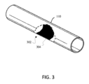
図3を参照すると、スリーブ110の一例が示されている。具体的には、図3は、スリーブ110の内側(すなわち、内部)面がその中に見える、スリーブ110の切り欠き302を示している。図のように、様々な例では、スリーブ110はその内側面上にパターン304を含む。パターン304は、スリーブ110の内側面上に印刷されるか、付着されるか、または別の方法で形成され得る。パターン304は、内側面上のカラーパターン、テクスチャパターン、および/または任意の規則的もしくは不規則なデザインを含み得る。特定の例では、パターン304は、複数の光学センサーが、視野内のパターン304における変化に基づき、各光学センサー(および細長ベース部材108)に対する、スリーブ110の回転運動および軸方向運動の少なくとも1つを検出し得るように、ポインティングデバイスシステム100の複数の光学センサーの視野内に配置され得る。本明細書で説明されるように、ある例では、パターン304における変化は、パターン304の光学センサーに対する移動を含み得る。
Referring to FIG. 3, an example of
ここで図4を参照すると、図1に示されているスリーブ110の内側面に適用され得るパターン402の一例が示されている。具体的には、図4は、交互の色パターンの一例を示す。そのパターンは、スリーブ110の長さに沿って(例えば、第2の方向Bに)延在して、複数の交互の黒い円筒セクションを含む。図4の例では、パターン402は交互の黒い円筒セクションを含むとして示されているが、他の色および形状が様々な他の実施態様で使用され得る。一例では、パターン402は、複数のゾーンに分割され得、各ゾーンは、複数の光学センサーと通信するプロセッサによって実行される機能に対応する。例えば、ゾーンは、ポインタの移動速度の増大または減少、スリーブの端とホルダーの端との近接(スリーブの端検出)のいずれか、もしくは全部に対応し、それらに対して使用され得る。例えば、本システムは、スリーブ110が細長ベース部材108の端に近づくと開始する、端検出を提供できる。一旦、検出されると、システム100は、スリーブ110が細長ベース部材108の端から取り除かれるまで、プロセッサに表示装置内のポインタの位置を対応する方向に継続して自動的に移動させるように促す。ある他の例では、光学センサーによるあるゾーンの検出は、代替としてプロセッサに、「スクロール」モードの動作に入るように促し得る。「スクロール」モードの間、ユーザーは、スリーブ110をベース部材108の周りを回転させて、表示装置内に提示されている情報に関してスクロール動作を実行し得る。ポインティングデバイスシステム100は、カーソル端回避(cursor end avoidance)、またはカーソル自動センタリングのいずれかもしくは全部に対する機能も提供し得る。
Referring now to FIG. 4, an example of a
しかし、ある他の例では、ポインティングデバイスシステム100は、スリーブ110の動きを検出するために1つ以上の追加のセンサーを含み得る。例えば、システム100は、スリーブ110の細長ベース部材108の端に対する瞬間的な位置を監視するために配置される1つ以上のリニアホール効果センサーを含み得る。例えば、システム100は、細長ベース部材108の第1の端に配置された第1のリニアホール効果センサーおよび細長ベース部材の遠位の第2の端に配置された第2のリニアホール効果センサーを含み得る。各リニアホール効果センサーは、スリーブと、スリーブの対応する端との近接を判断するために対応する磁石と相互作用し得る。一旦、リニアホール効果センサーと対応する磁石との間の所定の閾値に達する(すなわち、磁石とリニアホール効果センサーが所定の近さに達する)と、プロセッサは、本明細書でさらに説明されるように、「スクロール」モードに入り、かつ/または1つ以上の端検出動作を実行するように促され得る。
However, in certain other examples, pointing
記述のとおり、本開示の態様によれば、細長ベース部材は、その細長ベース部材の表面上に配置された複数の光学センサーを含む。ここで図5A~図5Cを参照すると、ある例では、複数の光学センサー512、514が、細長ベース部材508内に配置されている(すなわち、内部光学センサー)。光学センサー512、514は、細長ベース部材508内のそれぞれの開口部を通してスリーブ510の回転運動および/または軸方向運動を検出するために配置され得る。スリーブ510の動きを検出するために、動きを検出している光学センサーは、それが光を検出しているスリーブ510の内側面によって常にカバーされている必要がある。それに応じて、改善されたローラーマウスデバイスのスリーブ510は、少なくとも1つの光学センサー512、514のそれぞれの開口部を少なくとも常に覆っている必要がある。シングルセンサーローラーマウスデバイスでは、当技術分野で知られているように、単一の光学センサーの最適な位置は、細長いホルダーの中央であり、スリーブは典型的には、細長いホルダーの長さの少なくとも半分の長さ(典型的にはもう少し)を有する。しかし、かかる配置構成に関連する問題は、スリーブの、および従って、ポインティングデバイスの動きの範囲がローラーマウスデバイスの細長いホルダーのサイズの半分に制限されることである。それに対して、本開示の態様に従ったマルチ光学センサーシステム500では、光学センサー512、514およびそれらそれぞれの開口部は、細長いホルダー508の長さに沿って間隔が空けられていて、スリーブは、図5Cに示されるように、センサー512、514の両方をカバーするために十分に長い長さを有しているが、図5A、図5Bに示されるように、センサー512、514の両方を常にカバーする必要はない。例として、図5A~図5Cに示されるように、光学センサー512、514およびそれぞれの開口部は、細長いホルダーの長さの略1/3および2/3において均等に間隔が空けられ得る。態様および実施形態によれば、スリーブ510は、ローラーマウスシステムが対応するように設計される物理的な動きの最大速度およびシステムの最大サンプリングレートによっても決定される下限値を有するセンサー512、514と最小限のオーバーラップを有する長さを有する。ほんの一例として、決して唯一のサイズでなく、一実施形態では、センサー512、514およびそれぞれの開口部は、ホルダーの長さに沿って7cm離して配置されて、スリーブ長は10cmである。この配置構成は、わずか1msのサンプリングレートに対して設計されている。かかる配置構成では、結果として生じるスリーブの最小限のオーバーラップは、少なくとも最低数ミリメートルである。スリーブを、少なくとも数ミリメートルから3cmまでの範囲のオーバーラップを有するための長さにすることにより、スリーブの追跡の損失および他の潜在的な問題を吸収するために合理的な余裕を可能にする改善されたローラーマウスシステムが提供される。本開示の態様に従ったかかる配置構成の1つの利点は、少なくともスリーブ510のサイズおよび細長いホルダー508のサイズを縮小できることである。
As described, in accordance with aspects of the present disclosure, an elongate base member includes a plurality of optical sensors disposed on a surface of the elongate base member. 5A-5C, in some examples, a plurality of
複数のセンサー512、514は、2つの光学センサーに制限される必要はなく、3つ以上の光学センサーにできること、ならびにそれぞれの開口部は細長いホルダーの長さの1/3および2/3のところに配置する必要はないことが理解される。スリーブ510の長さならびに、複数の光学センサー512、514およびそれぞれの開口部の位置は、いずれの時点においても、光学センサー512、514およびそれぞれの開口部の少なくとも1つがスリーブ510によってカバーされるように中央ホルダーに沿って配置できる。その結果、本明細書で開示される態様および実施形態によれば、スリーブは、2つの光学センサー間のシームレスなハンドオーバーを可能にするために、複数の光学センサーのうちの2つの隣接する光学センサー間の最大距離よりもわずかに長い必要があるだけである。態様および実施形態によれば、内部光学センサーは、スリーブ510と、細長ベース部材108の1つ以上の端との近接をさらに検出し得ることも理解される。それに応じて、ある例では、ポインティングデバイスシステム500は、スリーブ510の全ての動き(例えば、回転、軸方向、および端検出)を検出する複数の光学センサーを含み得る。細長いホルダーの端に配置されて、例えば、端検出を検出するために使用される光学センサーを含む実施形態に対して、スリーブは、ホルダーの長さに沿った複数の光学センサーのうちの2つの隣接する光学センサー間の最大距離、およびホルダーの長さに沿った光学センサーと動き検出の範囲の端に対して使用されるホルダーの端の光学センサーとの間の距離の2つのうちの大きい方よりも長い必要があるだけである。これらの配置構成の各々は、他のポインティングデバイスと比較して改善された効率、改善された位置精度、ならびに削減されたサイズおよび複雑さを有するローラーマウスデバイスの利益をもたらす。
The plurality of
改善されたローラーマウスポインティングデバイスおよびマルチセンサー技術システムの別の態様は、複数の光学センサーからの読取り間の任意のハンドオーバーを扱うセンサー検出およびハンドオーバー機能である。図6を参照すると、本開示の態様および実施形態に従ったマルチセンサーハンドオーバー機能のフローチャートが示されている。その機能は、例えば、ソフトウェアおよび/またはファームウェアで実装できる。一般に、本システムは、複数のセンサーによって検出されたスリーブの動きおよび複数のセンサーのカバー状態を定期的に監視し、その情報を使用してスリーブのX-Y運動を正確に判断してそれをカーソルの動きに変換する。一般に、各光学センサーは、「カバーされている」または「カバーされていない」のいずれかと考えられる論理状態を有するために時間内にスナップショットで判断される。論理状態がカバーされている場合、センサーはアクティブと考えられて情報がそれから収集される。センサーが「カバーされていない」と考えられる場合、そのセンサーはからの情報は無視される。2つ以上のセンサーがカバーされている場合、センサー読取りによって生じる検出されたX運動は、複数の方式に従った全ての読取りの組合せである。態様および実施形態によれば、複数のセンサーからの情報は、次の複数の考えられる方式に従って使用できる:
1.各センサーからの読取りの品質を監視して、最も高い品質を備えた読取りだけを使用する、
2.各センサーからの読取りを使用して、読取りの平均を決定する、または
3.センサー読取りによって決定されたスリーブの動きの方向に基づき、カバーされている可能性が最も高い(カバーされていない可能性が低い)センサーからの読取りを選択する。具体的には、左のセンサーからの情報は、左のセンサーに向かう方向で、動きがある速度を上回っている場合に使用される。両方のセンサーがスリーブによってカバーされていると考えられるスリーブの領域では、スリーブの動きが右に向かっていると判断される場合、右のセンサーからの情報が使用される。スリーブがどちらの方向に移動しているか、およびどちらのセンサー情報を選ぶべきかを判断するために、2つのセンサー運動の平均が決定される。例えば、図5Cを見ると、スリーブが右に向かって移動している場合、スリーブの移動中、センサー514が最もアクティブであるので、読取りは、センサー514から取得される。同様に、スリーブが左に向かって移動している場合、X方向読取りは、左のセンサー512から取得される。
Another aspect of the improved roller mouse pointing device and multi-sensor technology system is a sensor detection and handover feature that handles any handover between readings from multiple optical sensors. Referring to FIG. 6, a flowchart of a multi-sensor handover function in accordance with aspects and embodiments of the present disclosure is shown. The functionality can be implemented in software and/or firmware, for example. Generally, the system periodically monitors the movement of the sleeve detected by multiple sensors and the coverage status of multiple sensors and uses that information to accurately determine the X-Y motion of the sleeve and Convert to cursor movement. Generally, each optical sensor is determined at a snapshot in time to have a logical state that is considered either "covered" or "uncovered." If the logical state is covered, the sensor is considered active and information is collected from it. If a sensor is considered "uncovered", information from that sensor is ignored. If more than one sensor is covered, the detected X motion resulting from the sensor readings is a combination of all readings according to multiple schemes. According to aspects and embodiments, information from multiple sensors can be used according to multiple possible schemes:
1. monitor the quality of readings from each sensor and use only the highest quality readings;
2. Using the readings from each sensor, determine the average of the readings, or 3. Based on the direction of sleeve movement determined by the sensor readings, select the reading from the sensor that is most likely to be covered (least likely to be uncovered). Specifically, information from the left sensor is used when movement is above a certain speed in the direction toward the left sensor. In areas of the sleeve where both sensors are considered covered by the sleeve, the information from the right sensor is used if it is determined that the movement of the sleeve is towards the right. An average of the two sensor movements is determined to determine in which direction the sleeve is moving and which sensor information to select. For example, looking at FIG. 5C, if the sleeve is moving toward the right, a reading will be taken from
複数の光学センサーからの読取り間の任意のハンドオーバーを決定するためのプロセスが、図6に関してここで説明される。プロセスは602から始まる。読取りが複数のセンサーで取得される前に、604で予め選択された時間間隔が経過するのを可能にする。その時間間隔の後、測定が両方のセンサーにおいて取得されて(606)これらの測定から各センサーがカバーされているか、またはカバーされていないと考えられるかどうかが判断される。右のセンサーがカバーされていないと判断される場合(608)、X-Y位置を決定するために左のセンサーからの読取りが使用される(610)。左のセンサーがカバーされていないと判断される場合(612)、X-Y位置を決定するために右のセンサーからの読取りが使用される(614)。両方のセンサーがカバーされていると考えられる場合(616)、本明細書で開示される複数の方式のいずれかに従って(620)、両方のセンサーからの読取りが使用される(618)。最終的な読取りが次いでホストコンピュータに送信されて(622)X-Yポインタ移動に変換される。プロセスは次いで繰り返される(624)。センサー間でのシームレスなハンドオーバーに対する別の態様は、読取りの同時性を相関させる能力である。センサー間で共有される時間ベースがないので、時分割アプローチが使用される。具体的には、同じ時間スロット内での読取りは、スリーブの移動時における同じサンプルスナップショットを指すと考えられる。 A process for determining any handover between readings from multiple optical sensors will now be described with respect to FIG. The process begins at 602. A preselected time interval is allowed to elapse at 604 before readings are taken at the plurality of sensors. After that time interval, measurements are taken at both sensors (606) and from these measurements it is determined whether each sensor is considered covered or uncovered. If the right sensor is determined to be uncovered (608), the readings from the left sensor are used to determine the XY position (610). If the left sensor is determined to be uncovered (612), the readings from the right sensor are used to determine the XY position (614). If both sensors are considered covered (616), readings from both sensors are used (618) according to any of the schemes disclosed herein (620). The final read is then sent (622) to the host computer and converted into an XY pointer movement. The process then repeats (624). Another aspect to seamless handover between sensors is the ability to correlate read concurrency. Since there is no shared time base between sensors, a time-sharing approach is used. Specifically, readings within the same time slot are considered to refer to the same sample snapshot during movement of the sleeve.
ここで説明される機能および方法は、任意の数のセンサーに適用できることが理解される。それに応じて、2つのセンサーだけを有するマルチセンサーサブシステムの一例が示されているが、他のデバイスでは、ここで説明される機能および方法は、3つの以上の光学センサーを有するローラーマウスポインティングデバイスと共に使用できることが理解される。かかる配置構成の利点は、本明細書で記述される追加の利点の全ても提供しながら、スリーブおよび細長いホルダーの長さが、2つのセンサーを使用するデバイスさえよりも、削減できることである。 It is understood that the functions and methods described herein are applicable to any number of sensors. Accordingly, although one example of a multi-sensor subsystem is shown having only two sensors, in other devices, the features and methods described herein may be used in roller mouse pointing devices having three or more optical sensors. It is understood that it can be used with An advantage of such an arrangement is that the length of the sleeve and elongate holder can be reduced over devices using even two sensors, while also providing all of the additional benefits described herein.
ある例では、各光学センサー512、514は、細長いホルダー508内のそれぞれの開口部を通して光を放出および検出するレーザーセンサーである。各光学センサーは、スリーブ510の移動中、スリーブ510の内側面上のパターンにおける変化に少なくとも一部基づいて、スリーブ510の細長いホルダー508に対する移動を検出する。図7は、複数の光学センサー512、514(図5を参照)に対して使用できて、細長ベース部材708内に配置できる、内部光学センサー702の一例の拡張断面図を示す。内部光学センサー702は、センサーハウジング704に取り付けられ得、センサーハウジング704は、細長ベース部材710内のセンサー回路基板706に、または細長ベース部材710の表面上に取り付けられる。一例では、内部光学センサー702はレーザーセンサーを含むが、他の例では、任意の他の適切な光学センサーなどの、任意の適切なタイプのセンサーが使用され得る。一例では、内部光学センサー702は、スリーブ(例えば、図5のスリーブ510)の内側面に、光を供給して、それからの反射光を検出する。スリーブの移動は、内部光学センサー702の視野内のパターン、およびスリーブの内側面からの反射光の特性を変化させる。センサー支持710は、センサー回路基板706、および内部光学センサー702を細長ベース部材708内で固定する。様々な例では、細長ベース部材708は、光学センサー702がスリーブの内側面とそれを通して光学的に接触する、それぞれの開口部を有する。光学センサー512、514(図5を参照)によって検出された動きは、少なくともセンサー回路基板706を通して他のシステム構成要素(例えば、ポインティングデバイスシステムと通信するプロセッサ)に伝達される。一例では、スリーブの内側面上のパターンは、端近接検出を容易にし得るが、ある他の例では、対応するポインティングデバイスシステム600は、本明細書で開始されているように、追加の光学センサー、ホール効果センサー、および接触スイッチなどの、1つ以上の端検出センサーも(または代替として)含み得る。加えて、精密X-Y測定を提供する複数のセンサーでは、端検出も必要ない可能性があることが分かった。具体的には、バーの長さおよびセンサーの間隔情報と結合された、「カバーの損失」のセンサー情報を持つ、位置情報を提供する複数のセンサーでは、その配列構成は、スリーブのその範囲に沿った絶対位置のより正確な再構成を可能にする。より多くのセンサーが使用されれば、それだけ正確である。従って、必ずしも端検出を提供する必要さえない可能性があり、それによりポインティングデバイスをさらに単純化する。そのため本配置構成の別の態様および利点は、利用可能な動きセンサーに完全に基づいて、外側スリーブの絶対位置再構成を提供することである。これは、端検出にとって適切であるだけでなく、スリーブの絶対X位置をホスト上の何らかの制御された要素にマッピングすることが望まれる用途におけるデバイスの使用にとっても適切である。
In one example, each
図5を再度参照すると、他の構成要素の中でとりわけ、図5は、対応するスイッチ(図示せず)を有する1つ以上のボタン516、およびスクロールホイール518も含むシステム500を示す。1つ以上のボタン516、およびスクロールホイール518の任意の1つのアクティブ化は、ユーザーが、従来型のマウスによって一般に実行される機能を実行するのを可能にする。例えば、各ボタン516は対応するスイッチを有し得、それは、押下された場合に、コピー、貼り付け、右クリック、左クリック、またはダブルクリックなどの、動作を表し得る。対応するボタンの押下は、対応するスイッチを作動させて、所与の動作を実行するために信号を生成し得る。各ボタン516は追加として、対応する動作が生じていることをユーザーに示すために音声フィードバック(例えば、クリック音)を提供し得る。例示されたボタンの各々は、独立してプログラム可能であり得、ユーザー選好に基づいて動作を割り当てられ得る。各ボタンは、コピー、貼り付け、右クリック、左クリック、またはダブルクリック機能を実行するように個別に構成され得ると説明されるが、様々なさらなる実施形態では、複数のボタン516は、ユーザー定義機能を実行するためにユーザーによっても構成可能であり得ることも理解される。
Referring again to FIG. 5, among other components, FIG. 5 shows a
前述のとおり、ポインティングデバイスシステム500の様々な実施形態は、コンピュータシステム、または類似のデバイスと通信して、スリーブ510の細長ベース部材508に対する動きをコンピュータシステムの表示装置上のポインタの動きに変換するように構成され得る。例えば、通信は、例えば、ケーブルを含み得る、有線接続(図示せず)を通した通信を含み得る。しかし、様々な追加の実施態様では、ポインティングデバイスシステム500は、対応するコンピュータシステムに対する有線接続の欠如によって特徴付けられる。すなわち、有線接続は、無線接続で置換され得る。一般に、ポインティングデバイスシステム500およびコンピュータシステムを無線送信機/受信機と接続しているワイヤーを置換すると、ポインティングデバイスシステム500の人間工学をさらに改善して、ユーザーの作業空間から障害物を取り除く。
As previously discussed, various embodiments of pointing
ある実施形態では、回路基板(図示せず)もセンサーハウジング内に配置できる。例えば、回路基板は、複数の光学センサー(例えば、センサー回路基板を介して)、1つ以上のスイッチ、クリックトリガー、およびポインティングデバイスシステムの1つ以上の他の構成要素と結合されて、それらと通信し得る。具体的には、回路基板は、スリーブの細長ベース部材の周りの検出された運動に応答してコンピュータシステムのプロセッサとデータの送受信を行うように構成され得る。本明細書で説明されるポインティングデバイスシステムの様々な構成要素は、単一の共通プリント回路基板に、または2つ以上のプリント回路基板の間で分散してのいずれかで、取り付けられる。回路基板は、1つ以上の締め具(例えば、ねじ)を用いてデバイスケースに固定され得る。回路基板は、コンピュータシステムにおける無線送信機/受信機との無線通信のための無線送信機/受信機を含む送信機回路を含み得る。例えば、送信機は、無線周波数(RF)送信機を含み得、それは、例えば、USBポートに接続できるUSBタイプのデバイスの形にできる。コントローラは、送信機に電気的に接続されるか、またはそうでなければ、送信機と関連付けられて、スリーブ510の検出された回転および平行移動に関するデータの送信を引き起こす。スリーブ510の送信された動きは、コンピュータインタフェース回路により、表示装置に対するカーソル制御信号に変換される。送信機は、スリーブ510のベース部材508の周りの移動、クリック操作、スクロールホイールおよびボタンアクティブ化を含む、情報をコード化して送信する。受信機は、送信および応答可能に復号された情報を受信するように構成される。様々な実施形態では、受信機は、コンピュータシステムの周辺マウス入力にプラグインするように構成される。インタフェースを最小限にするために、一実施形態の送信機および受信機は、2.4GHzの周波数で動作するように構成され得る。様々な実施形態は、ポインティングデバイスシステム500とコンピュータシステムとの間で通信するために、ブルートゥース(登録商標)送信機/受信機、または当技術分野で使用される任意の他の無線信号送信機/受信機を使用し得ることも理解される。本明細書では、ブルートゥース(登録商標)は、別名ピコネットとして知られている、近距離アドホックネットワークを指す。
In some embodiments, a circuit board (not shown) can also be disposed within the sensor housing. For example, the circuit board may be coupled to and communicate with a plurality of optical sensors (e.g., via the sensor circuit board), one or more switches, click triggers, and one or more other components of the pointing device system. Can communicate. Specifically, the circuit board may be configured to send and receive data to and from a processor of the computer system in response to detected movement about the elongated base member of the sleeve. The various components of the pointing device systems described herein are mounted either on a single common printed circuit board or distributed among two or more printed circuit boards. The circuit board may be secured to the device case using one or more fasteners (eg, screws). The circuit board may include transmitter circuitry that includes a wireless transmitter/receiver for wireless communication with a wireless transmitter/receiver in a computer system. For example, the transmitter may include a radio frequency (RF) transmitter, which may be in the form of a USB type device that can be connected to a USB port, for example. A controller is electrically connected to or otherwise associated with the transmitter to cause transmission of data regarding the detected rotation and translation of
様々な実施形態では、回路基板は、USBケーブルによって供給された電力を電源に供給するように構成されたユニバーサルシリアルバス(USB)回路をさらに含む。ある実施形態では、ポインティングデバイスシステム500は、USBケーブルを介してコンピュータシステムと通信するようにも構成され得る。例えば、ポインティングデバイスシステム500は、検出されたスリーブ510の移動およびクリック操作などの、情報をケーブルを介してコンピュータシステムに送信するように構成され得る。それに応じて、USB回路は、センサー回路基板などの、回路基板および様々な他のシステム500構成要素と選択的に通信し得る。様々な実施形態では、USBケーブルは取外し可能であり、ポインティングデバイスシステム500は、コンピュータシステムに対する全ての有線接続が無しで構成される。
In various embodiments, the circuit board further includes a universal serial bus (USB) circuit configured to supply power supplied by the USB cable to the power supply. In some embodiments, pointing
図5には明示的に示されていないが、ポインティングデバイス500は、再充電可能電源も含み得る。様々な実施形態では、再充電可能電源は、充電式バッテリーを含む。電源は、回路基板およびセンサー回路基板上に配置された構成要素と電気通信しているか、またはそれに対して電力を供給するように構成される。例えば、一例の再充電可能電源は、充電式リチウムイオン(LiOn)バッテリーを含み得る。様々な例では、ポインティングデバイスシステム100、500は、デスクトップコンピュータなどの、コンピュータシステムのプロセッサと通信し得る。改善されたポインティングデバイスシステムが一緒に使用できるコンピュータシステムの多くの例がある。例としてであるが、それらに制限されず、これらの例は、とりわけ、ネットワークアプライアンス、パーソナルコンピュータ、ワークステーション、メインフレーム、ネットワーク化されたクライアント、サーバー、メディアサーバー、アプリケーションサーバー、データベースサーバー、およびウェブサーバーを含む。コンピュータシステムの他の例は、モバイルコンピュータシステム(例えば、スマートフォン、タブレットコンピュータ、ラップトップコンピュータ、および携帯情報端末)およびネットワーク機器(例えば、負荷分散装置、ルーター、およびスイッチ)を含み得る。モバイルコンピュータシステムの特定のモデルの例は、Appleから入手可能なiOSオペレーティングシステムを実行するiPhone、iPad、および、iPodタッチ、Samsung Galaxyシリーズ、LG Nexus、およびMotorola Droid XのようなAndroidデバイス、Blackberry Limitedから入手可能なBlackberryデバイス、ならびにエリア電話装置を含む。
Although not explicitly shown in FIG. 5,
様々な実施形態のコンピュータシステムは、プロセッサ、メモリ、相互接続要素、インタフェース、およびデータ記憶要素を含み得る。本明細書で開示される態様、機能、およびプロセスの少なくとも一部を実装するために、プロセッサは、操作されたデータをもたらす一連の命令を実行する。プロセッサは、任意のタイプのプロセッサ、マルチプロセッサまたはコントローラであり得る。プロセッサ例は、市販のプロセッサ、例えば、Intel Xeon、Itanium、Core、Celeron、もしくはPentiumプロセッサ、AMD Opteronプロセッサ、Apple A4もしくはA5プロセッサ、Sun UltraSPARCプロセッサ、IBM Power5+プロセッサ、IBMメインフレームチップ、または量子コンピュータなどを含み得る。プロセッサは、相互接続要素によって、1つ以上のメモリ装置を含む、他のシステム構成要素に接続される。 A computer system of various embodiments may include a processor, memory, interconnect elements, interfaces, and data storage elements. To implement at least some of the aspects, features, and processes disclosed herein, a processor executes a series of instructions that result in manipulated data. A processor may be any type of processor, multiprocessor or controller. Examples of processors include commercially available processors, such as Intel Xeon, Itanium, Core, Celeron, or Pentium processors, AMD Opteron processors, Apple A4 or A5 processors, Sun UltraSPARC processors, IBM Power5+ processors, IBM mainframe chips, or quantum computers. may include. The processor is connected to other system components, including one or more memory devices, by interconnect elements.
メモリは、コンピュータシステムの動作中に、プログラム(例えば、プロセッサによって実行可能になるようにコード化された一連の命令)およびデータを格納する。従って、本メモリは、ダイナミックランダムアクセスメモリ(「DRAM」)またはスタティックメモリ(「SRAM」)などの、比較的高性能の、揮発性、ランダムアクセスメモリであり得る。しかし、本メモリは、ディスクドライブまたは他の不揮発性記憶装置などの、データを格納するための任意の装置を含み得る。 Memory stores programs (eg, sequences of instructions coded for execution by a processor) and data during operation of a computer system. Accordingly, the memory may be a relatively high performance, volatile, random access memory, such as dynamic random access memory ("DRAM") or static memory ("SRAM"). However, the memory may include any device for storing data, such as a disk drive or other non-volatile storage device.
コンピュータシステムの構成要素は、相互接続要素によって結合される。相互接続要素は、命令およびデータを含む、通信が、コンピュータシステムのシステム構成要素間でやり取りされるのを可能にする。コンピュータシステムは、入力装置、出力装置および入力/出力装置の組合せなどの、1つ以上のインタフェース装置も含む。インタフェース装置は、入力を受信するか、または出力を提供し得る。より詳細には、出力装置は情報を外部に提示するためにレンダリングし得る。入力装置は、本明細書で説明される人間工学的ポインティングデバイスの様々な実施形態などの、外部情報源から情報を受け入れ得る。入力装置は無線であり得、人間工学的ポインティングデバイスシステムは、ブルートゥース(登録商標)などの、無線信号を介してコンピュータシステムに伝達し得る。 Components of a computer system are coupled by interconnecting elements. Interconnecting elements enable communications, including instructions and data, to be exchanged between system components of a computer system. The computer system also includes one or more interface devices, such as input devices, output devices, and combinations of input/output devices. An interface device may receive input or provide output. More particularly, an output device may render information for external presentation. The input device may accept information from external sources, such as the various embodiments of ergonomic pointing devices described herein. The input device may be wireless and the ergonomic pointing device system may communicate to the computer system via wireless signals, such as Bluetooth.
データ記憶要素は、プロセッサによって実行されるプログラムまたは他のオブジェクトを定義する命令がその中に格納される、コンピュータ可読および書込み可能な不揮発性、または持続性データ記憶媒体を含む。データ記憶要素は、媒体上もしくは媒体内に記録されて、プログラムの実行中にプロセッサによって処理される、情報も含み得る。 Data storage elements include computer readable and writable, non-volatile, or persistent data storage media in which are stored instructions that define programs or other objects to be executed by a processor. Data storage elements may also include information recorded on or in the medium and processed by the processor during execution of the program.
図1~図7は、マルチ光学センサーサブシステムを有する改善されたポインティングデバイスシステムのいくつかの例、およびそれらの他の構成要素を示しているが、本開示の態様は、図1~図7を参照して説明されるそれらの特定の例に制限されるべきではない。様々な修正および変形が前述の教示に照らして明らかになり得る。例えば、図8~図12の各々は、本開示のマルチ光学センサーサブシステムがその中に組み込まれ得る、異なるポインティングデバイスシステム配置構成を示す。その上、図8~図12に示されるポインティングデバイスシステム配置構成の様々な態様は、図1~図7を参照して説明されるような例に組み込まれ得る。 While FIGS. 1-7 illustrate several examples of improved pointing device systems having multi-optical sensor subsystems and other components thereof, aspects of the present disclosure are shown in FIGS. 1-7. should not be limited to those specific examples described with reference to. Various modifications and variations may be apparent in light of the above teachings. For example, each of FIGS. 8-12 illustrates a different pointing device system arrangement into which the multi-optical sensor subsystem of the present disclosure may be incorporated. Moreover, various aspects of the pointing device system arrangements shown in FIGS. 8-12 may be incorporated into examples such as those described with reference to FIGS. 1-7.
例えば、図8および図9を参照すると、マルチ光学センサーサブシステムをその中に含むことができる内部センサーポインティングデバイスシステムの他の例が示されている。図8では、ポインティングデバイスシステム1500は、細長ベース部材1502およびデバイスケース1504を含むとして示されている。デバイスケース1504は、他の構成要素の中でとりわけ、回路基板、クリックトリガー、1つ以上のスイッチ、および圧電素子などの、追加の部品を含み得る。図のように、ポインティングデバイス1500は、細長ベース部材1502の一部の上に適合するスリーブ1506も含む。スリーブ1506は、細長ベース部材1502の一部の周りを回転可能であり、細長ベース部材1502の長さに沿ってスライド可能でもある。少なくとも図1および図2を参照して例示および説明されるスリーブ110と同様に、スリーブ1506は、ブッシング1508aおよび1508bによって支持されて、外面上にグリップ1510を含み得る。リストサポート1512も示されている。
For example, referring to FIGS. 8 and 9, another example of an internal sensor pointing device system that can include multiple optical sensor subsystems therein is shown. In FIG. 8,
図9は、図8に示されているポインティングデバイスシステム1500のそれと類似した配置構成を有するポインティングデバイスシステム1600を示す。具体的には、図9は、細長ベース部材1602、スリーブ1604、およびデバイスケース1606を示す。デバイスケース1606は、他のハードウェアの中でとりわけ、回路基板、1つ以上のスイッチ、および圧電素子などの、ポインティングデバイスシステム1600の追加の構成要素の部分を取り囲んで、それらの構成要素をちり、ほこり、湿気および同様のものから保護する。異なるカバーおよび異なるレイアウトが実装され得、ポインティングデバイスシステム1600の意図する位置(例えば、デスクトップ、リモートコンピュータ端末など)に基づいて調整され得る。
FIG. 9 shows a
ここで図10を参照すると、本明細書で開示される任意の実施態様で公表できるポインティングデバイスシステム支持組立体の一例が示されている。ある例(図示せず)では、一対のブラケットおよび支柱が細長ベース部材1702およびスリーブ1704を支えて浮かせ(suspend)得るが、ある他の実施形態では、他の支持組立体が使用され得る。例えば、図10では、一対の板ばね1706aおよび1706bが示されている。細長ベース部材1702およびスリーブ1704は、細長ベース部材1702の端に近接して配置されている、板ばね1706aおよび1706bによって支持される。一対の板ばねが説明を目的として示されているが、ある例では、細長ベース部材1702は、細長ベース部材1702の一方の端に位置付けられた単一の板ばねによって支持され得る。ユーザーによって力がスリーブ1704上に概ね下向きに印加されると、板ばね1706a、1706bは偏向してスリーブ1704および細長ベース部材1702の沈下を可能にする。ここで説明されるとおり、様々な例では、下向きの動きは、クリックトリガーを作動させ得、それは、例えば、ポインティングデバイスでドラッグアンドドロップ操作を実行するために、使用され得る。ある例では、各板ばね1706a、1706bの応力は、クリックトリガーを作動させる下押し圧力を調整するために調整され得る。
Referring now to FIG. 10, illustrated is an example of a pointing device system support assembly that may be disclosed in any of the embodiments disclosed herein. In some examples (not shown), a pair of brackets and struts may support and suspend
ここで図11を参照すると、マルチ光学センサーサブシステムを含み、一対のソレノイド1802a、1802bを有する支持組立体も組み込んでいるポインティングデバイスシステム1800の一例が示されている。各ソレノイド1802a、1802bは、それぞれのプランジャ、コイル、およびプランジャ戻しばねを含む。細長ベース部材1804およびスリーブ1806は、ソレノイド1802a、1802bによって支持され、それらは細長ベース部材1804の端に近接して配置されて、板ばね1808a、1808bと機械的に通信している。ユーザーによって力がスリーブ1806上に概ね下向きに印加されると、ソレノイドプランジャ(複数可)は、板ばね1808a、1808bと同様に、偏向して、スリーブ1806の沈下を可能にする。
Referring now to FIG. 11, an example
ここで図12を参照すると、マルチ光学センサーサブシステムを含むように修正できるポインティングデバイスシステム1900の別の例の透視図が示されている。図のように、ポインティングデバイスシステム1900は、本明細書で説明される他のポインティングデバイスシステム例と同じ構成要素の多くを含み得る。例えば、ポインティングデバイスシステム1900は、他の構成要素の中でとりわけ、デバイスケース1902、細長ベース部材1904、回路基板1906、スリーブ1908、複数の光学センサー、およびクリックトリガーを含み得る。
Referring now to FIG. 12, a perspective view of another example
図12は、細長ベース部材1904およびスリーブ1906を支えて浮かせるために使用できる支持組立体の別の例をさらに示す。具体的には、図12は、細長ベース部材1904の遠位端に配置された第1の支持1908aおよび第2の支持1908bを示す。各支持1908a、支持1908bは、細長ベース部材1904を受け入れるように構成されて、細長ベース部材1904および取り囲んでいるスリーブ1908を浮かせ、その沈下を可能にする。支持システムは、第1および第2の支持1908a、1908bの間に置かれた複数の支持レール1910も含み得る。様々な例では、支持レール1910は、スリーブ1908の外表面に実質的に隣接して配置される。さらなる例では、支持レール1910は、1つ以上の可撓性中空ロッドを含むことができる。
FIG. 12 further illustrates another example of a support assembly that can be used to support and float
様々な実施形態では、デバイスケースは、デバイスケースの基部1902に連結された第1の旋回軸1912a、およびデバイスケースの基部1902に連結された第2の旋回軸1912bを含む。第1の旋回軸1912aは、第1の支持1908aからの第1の角度拡張1914aを受け入れるように構成され得、第2の旋回軸1912bは、第2の支持1914bからの第2の角度拡張1914bを受け入れるように構成され得る。それに応じて、第1の角度拡張1914aおよび第2の角度拡張1914bは、それぞれ、デバイスの基部1902に対して細長ベース部材1904またはスリーブ1906に印加されている下押し圧力に応答して、第1の旋回軸1912aおよび第2の旋回軸1912bの周りを旋回するように構成される。様々な実施形態では、第1および第2の旋回軸1912a、1912bは、第1の角度拡張1914aおよび第2の角度拡張1912bの回転軸に沿った回転を実質的に位置合わせするために、実質的に位置合わせされる。本明細書でさらに詳細に説明されるように、かかる下押し圧力は、クリック操作を開始するために使用できる。
In various embodiments, the device case includes a
少なくとも1つの実施形態のいくつかの態様をこのように説明しているが、様々な変更、修正、および改善が当業者には容易に思い付くことが理解される。かかる変更、修正、および改善は、本開示の一部であることが意図されて、本開示の範囲内であることが意図される。それに応じて、前述の説明および図面はほんの一例である。 Having thus described certain aspects of at least one embodiment, it is understood that various alterations, modifications, and improvements will readily occur to those skilled in the art. Such alterations, modifications, and improvements are intended to be part of this disclosure, and are intended to be within the scope of this disclosure. Accordingly, the foregoing description and drawings are illustrative only.
Claims (30)
前記細長ベース部材の一部の上に適合するように配置されたスリーブであって、前記細長ベース部材の周りを第1の(Y)方向に回転し、かつ前記細長ベース部材の周りを、前記第1の方向に実質的に直交する第2の(X)方向にスライドするように構成されたスリーブと、
細長ベース部材の表面に沿って配置された少なくとも2つの光学センサーであって、前記少なくとも2つの光学センサーのうちの少なくとも1つのセンサーの視野内の前記スリーブの内側表面から前記少なくとも2つの光学センサー信号のうちの前記少なくとも1つによって受信された少なくとも1つの信号の変化に少なくとも一部基づいて、前記スリーブの前記複数の光学センサーに対する回転運動および前記スリーブの前記少なくとも2つの光学センサーに対する軸方向運動の少なくとも1つから前記スリーブの位置読取りを検出するように位置付けられた、少なくとも2つの光学センサーと
を備える、位置決めデバイス。 an elongated base member;
a sleeve adapted to fit over a portion of the elongate base member, the sleeve being configured to rotate about the elongate base member in a first (Y) direction and to rotate the sleeve about the elongate base member in a first (Y) direction; a sleeve configured to slide in a second (X) direction substantially perpendicular to the first direction;
at least two optical sensors disposed along a surface of an elongate base member, the at least two optical sensor signals from an inner surface of the sleeve within a field of view of at least one of the at least two optical sensors; rotational movement of the sleeve with respect to the plurality of optical sensors and axial movement of the sleeve with respect to the at least two optical sensors based at least in part on a change in at least one signal received by the at least one of the at least two optical sensors positioned to detect position readings of the sleeve from at least one.
位置読取りを提供するために、少なくとも2つの光学センサーのうちの少なくとも1つの光学センサーの視野内の前記スリーブの内側表面から前記少なくとも2つの光学センサー信号の前記少なくとも1つによって受信された光信号の変化に少なくとも一部基づいて、前記少なくとも2つの光学センサーに対する前記スリーブの回転運動および前記少なくとも2つの光学センサーに対する前記スリーブの軸方向運動のうちの少なくとも1つから、前記細長ベース部材の表面に沿って配置された前記少なくとも2つの光学センサーのうちの少なくとも1つの光学センサーから前記光信号を受信することと
を含む、位置を決定する方法。 moving a sleeve disposed over a portion of the elongate base member, the sleeve rotating about the elongate base member in a first (Y) direction; configured to slide in a second (X) direction substantially perpendicular to the first direction;
of an optical signal received by the at least one of the at least two optical sensor signals from an inner surface of the sleeve within the field of view of at least one of the at least two optical sensors to provide a position reading; from at least one of rotational movement of the sleeve relative to the at least two optical sensors and axial movement of the sleeve relative to the at least two optical sensors based at least in part on a change along a surface of the elongated base member. receiving the optical signal from at least one optical sensor of the at least two optical sensors located at a location.
Applications Claiming Priority (3)
| Application Number | Priority Date | Filing Date | Title |
|---|---|---|---|
| US202163139105P | 2021-01-19 | 2021-01-19 | |
| US63/139,105 | 2021-01-19 | ||
| PCT/US2022/012890 WO2022159434A1 (en) | 2021-01-19 | 2022-01-19 | Multiple optical-sensor pointing device systems |
Publications (1)
| Publication Number | Publication Date |
|---|---|
| JP2024503103A true JP2024503103A (en) | 2024-01-24 |
Family
ID=80786898
Family Applications (1)
| Application Number | Title | Priority Date | Filing Date |
|---|---|---|---|
| JP2023543088A Pending JP2024503103A (en) | 2021-01-19 | 2022-01-19 | Multi-optical sensor pointing device system |
Country Status (6)
| Country | Link |
|---|---|
| EP (1) | EP4281845A1 (en) |
| JP (1) | JP2024503103A (en) |
| CN (1) | CN116897329A (en) |
| AU (1) | AU2022211364A1 (en) |
| TW (1) | TW202238356A (en) |
| WO (1) | WO2022159434A1 (en) |
Family Cites Families (3)
| Publication number | Priority date | Publication date | Assignee | Title |
|---|---|---|---|---|
| EP0382354A3 (en) * | 1989-02-10 | 1991-08-14 | Hewlett-Packard Company | Cursor control mechanism |
| US5635926A (en) * | 1994-08-02 | 1997-06-03 | Li; Kenneth K. | Pointing and/or directional control device for controlling the movement and positioning of an object |
| US11023053B2 (en) * | 2016-11-11 | 2021-06-01 | Contour Innovations Llc | Inner-sensor pointing device system |
-
2022
- 2022-01-18 TW TW111101995A patent/TW202238356A/en unknown
- 2022-01-19 AU AU2022211364A patent/AU2022211364A1/en active Pending
- 2022-01-19 JP JP2023543088A patent/JP2024503103A/en active Pending
- 2022-01-19 CN CN202280009699.0A patent/CN116897329A/en active Pending
- 2022-01-19 WO PCT/US2022/012890 patent/WO2022159434A1/en active Application Filing
- 2022-01-19 EP EP22704053.2A patent/EP4281845A1/en active Pending
Also Published As
| Publication number | Publication date |
|---|---|
| AU2022211364A1 (en) | 2023-07-27 |
| WO2022159434A1 (en) | 2022-07-28 |
| EP4281845A1 (en) | 2023-11-29 |
| TW202238356A (en) | 2022-10-01 |
| CN116897329A (en) | 2023-10-17 |
Similar Documents
| Publication | Publication Date | Title |
|---|---|---|
| US10782802B2 (en) | Touch sensing of user input device | |
| CN108345396B (en) | Touch control pen with magnetic induction roller and operation method thereof | |
| US20210365130A1 (en) | Dual-mode optical input device | |
| US8810514B2 (en) | Sensor-based pointing device for natural input and interaction | |
| JP2008511907A (en) | Pack-based input device with rotation detection | |
| WO2001009708A1 (en) | Computer input device for multiple-dimensional control | |
| DK181047B1 (en) | INDOOR SENSOR DEVICE SYSTEMS | |
| CN111587414B (en) | Multifunctional touch control pen | |
| US10031591B2 (en) | Pointing device bracket assembly and system | |
| US5379053A (en) | Electromagnetic cursor control device for a computer display | |
| JP2024503103A (en) | Multi-optical sensor pointing device system | |
| CN110196647B (en) | Active stylus | |
| CN110764633A (en) | Gesture control pen-shaped mouse | |
| JP2002217009A (en) | Multi-axis potentiometer | |
| US20200409478A1 (en) | Enhanced 2D/3D Mouse For Computer Display Interactions | |
| KR100357333B1 (en) | Encoder having chageable capacitance and wireless mouse applying the same | |
| KR20000063255A (en) | 2D wired / wireless location information input device using gyroscope in 3D space | |
| CN105311840A (en) | Position and track detection device | |
| JP2013225182A (en) | Pen type input device and information input system using the same | |
| JP2001109573A (en) | Pointing device capable of being operated in all directions or in low-gravity environment |