JP2024171663A - Reactor, converter, and power converter - Google Patents
Reactor, converter, and power converter Download PDFInfo
- Publication number
- JP2024171663A JP2024171663A JP2023088799A JP2023088799A JP2024171663A JP 2024171663 A JP2024171663 A JP 2024171663A JP 2023088799 A JP2023088799 A JP 2023088799A JP 2023088799 A JP2023088799 A JP 2023088799A JP 2024171663 A JP2024171663 A JP 2024171663A
- Authority
- JP
- Japan
- Prior art keywords
- core portion
- core
- gap plate
- coil
- magnetic
- Prior art date
- Legal status (The legal status is an assumption and is not a legal conclusion. Google has not performed a legal analysis and makes no representation as to the accuracy of the status listed.)
- Pending
Links
Images


Classifications
-
- H—ELECTRICITY
- H01—ELECTRIC ELEMENTS
- H01F—MAGNETS; INDUCTANCES; TRANSFORMERS; SELECTION OF MATERIALS FOR THEIR MAGNETIC PROPERTIES
- H01F27/00—Details of transformers or inductances, in general
- H01F27/24—Magnetic cores
-
- H—ELECTRICITY
- H01—ELECTRIC ELEMENTS
- H01F—MAGNETS; INDUCTANCES; TRANSFORMERS; SELECTION OF MATERIALS FOR THEIR MAGNETIC PROPERTIES
- H01F37/00—Fixed inductances not covered by group H01F17/00
-
- H—ELECTRICITY
- H02—GENERATION; CONVERSION OR DISTRIBUTION OF ELECTRIC POWER
- H02M—APPARATUS FOR CONVERSION BETWEEN AC AND AC, BETWEEN AC AND DC, OR BETWEEN DC AND DC, AND FOR USE WITH MAINS OR SIMILAR POWER SUPPLY SYSTEMS; CONVERSION OF DC OR AC INPUT POWER INTO SURGE OUTPUT POWER; CONTROL OR REGULATION THEREOF
- H02M3/00—Conversion of DC power input into DC power output
- H02M3/02—Conversion of DC power input into DC power output without intermediate conversion into AC
- H02M3/04—Conversion of DC power input into DC power output without intermediate conversion into AC by static converters
- H02M3/10—Conversion of DC power input into DC power output without intermediate conversion into AC by static converters using discharge tubes with control electrode or semiconductor devices with control electrode
- H02M3/145—Conversion of DC power input into DC power output without intermediate conversion into AC by static converters using discharge tubes with control electrode or semiconductor devices with control electrode using devices of a triode or transistor type requiring continuous application of a control signal
- H02M3/155—Conversion of DC power input into DC power output without intermediate conversion into AC by static converters using discharge tubes with control electrode or semiconductor devices with control electrode using devices of a triode or transistor type requiring continuous application of a control signal using semiconductor devices only
Landscapes
- Engineering & Computer Science (AREA)
- Power Engineering (AREA)
- Coils Or Transformers For Communication (AREA)
- Dc-Dc Converters (AREA)
Abstract
Description
本開示は、リアクトル、コンバータ、および電力変換装置に関する。 This disclosure relates to a reactor, a converter, and a power conversion device.
特許文献1および特許文献2は、コイルと磁性コアとを備えるリアクトルを開示する。特許文献1のリアクトルにおいて、磁性コアは、複数の磁性体と、磁性体間に挿入されるギャップ材とを備える。ギャップ材は板状である。磁性体とギャップ材とは接着されている。特許文献2のリアクトルにおいて、磁性コアは、コイル内に配置された内コア片と、コイル外に配置された外コア片とを含み、磁性コアを覆う樹脂モールド部によって一体化されている。この磁性コアは、複数の内コア片を備え、隣り合う内コア片間にギャップ部を有する。特許文献2の一例では、隣り合う内コア片間に配置された内側分割片の内側壁部がギャップ部として機能する。
特許文献1および特許文献2の技術のように、ギャップ部を備える磁性コアは、複数のコア片とギャップ板とが組み合わされることで構成されている。ギャップ板はコア片の間に配置される。ギャップ板を挟んで隣り合う2つのコア片は、ギャップ板によって分断されている。つまり、隣り合うコア片は、互いにつながった一体物ではなく、独立した部材である。
As in the technologies of
従来の磁性コアでは、コア片とギャップ板との接合箇所の機械的強度を確保しにくい。磁性コアが振動、衝撃または繰り返し応力を受けると、コア片がギャップ板から分離するおそれがある。コア片がギャップ板から分離すると、磁性コアが分解されてしまう。例えば、コイル内に配置された内側コア部にギャップ板が設けられている場合、コア片がギャップ板から分離すると、コイルから内側コア部が抜け落ちる可能性がある。したがって、ギャップ板が配置された磁性コアの機械的強度を向上することが望まれる。 In conventional magnetic cores, it is difficult to ensure the mechanical strength of the joints between the core pieces and the gap plate. If the magnetic core is subjected to vibration, impact, or repeated stress, the core pieces may separate from the gap plate. If the core pieces separate from the gap plate, the magnetic core will disassemble. For example, if a gap plate is provided on the inner core part arranged in the coil, if the core pieces separate from the gap plate, the inner core part may fall out of the coil. Therefore, it is desirable to improve the mechanical strength of magnetic cores in which gap plates are arranged.
本開示は、磁性コアにギャップ板が設けられていても、磁性コアの機械的強度を確保することができるリアクトルを提供することを目的の一つとする。 One of the objectives of this disclosure is to provide a reactor that can ensure the mechanical strength of the magnetic core even if a gap plate is provided in the magnetic core.
本開示のリアクトルは、
コイルと、
前記コイルの内側に配置された内側コア部と前記コイルの外側に配置された外側コア部とを有する磁性コアと、を備え、
前記内側コア部は、
前記コイルの軸に沿うX方向に並んで配置された第一コア部と第二コア部と、
前記第一コア部と前記第二コア部との間に配置されたギャップ板と、
前記第一コア部と前記第二コア部とをつなぐ連結コア部と、を有し、
前記第一コア部と前記第二コア部と前記連結コア部とは、樹脂中に軟磁性粉末が分散された複合材料によって一体成形されている。
The reactor of the present disclosure includes:
A coil and
a magnetic core having an inner core portion disposed inside the coil and an outer core portion disposed outside the coil,
The inner core portion is
A first core portion and a second core portion arranged side by side in an X direction along an axis of the coil;
a gap plate disposed between the first core portion and the second core portion;
a coupling core portion connecting the first core portion and the second core portion,
The first core portion, the second core portion and the coupling core portion are integrally molded from a composite material in which soft magnetic powder is dispersed in resin.
本開示のリアクトルは、磁性コアにギャップ板が設けられていても、磁性コアの機械的強度を確保することができる。 The reactor of the present disclosure can ensure the mechanical strength of the magnetic core even if a gap plate is provided in the magnetic core.
[本開示の実施形態の説明]
最初に本開示の実施態様を列記して説明する。
[Description of the embodiments of the present disclosure]
First, the embodiments of the present disclosure will be listed and described.
(1)本開示のリアクトルは、
コイルと、
前記コイルの内側に配置された内側コア部と前記コイルの外側に配置された外側コア部とを有する磁性コアと、を備え、
前記内側コア部は、
前記コイルの軸に沿うX方向に並んで配置された第一コア部と第二コア部と、
前記第一コア部と前記第二コア部との間に配置されたギャップ板と、
前記第一コア部と前記第二コア部とをつなぐ連結コア部と、を有し、
前記第一コア部と前記第二コア部と前記連結コア部とは、樹脂中に軟磁性粉末が分散された複合材料によって一体成形されている。
(1) The reactor of the present disclosure has
A coil and
a magnetic core having an inner core portion disposed inside the coil and an outer core portion disposed outside the coil,
The inner core portion is
A first core portion and a second core portion arranged side by side in an X direction along an axis of the coil;
a gap plate disposed between the first core portion and the second core portion;
a coupling core portion connecting the first core portion and the second core portion,
The first core portion, the second core portion and the coupling core portion are integrally molded from a composite material in which soft magnetic powder is dispersed in resin.
本開示のリアクトルは、内側コア部にギャップ板が設けられている。内側コア部は、ギャップ板を挟んで隣り合う第一コア部と第二コア部とが連結コア部によってつながった一体物である。よって、第一コア部と第二コア部とは、ギャップ板を挟んで分断されていない。第一コア部と第二コア部とが連結コア部によってつながっていることで、第一コア部と第二コア部とが分離しにくい。ギャップ板に対する第一コア部および第二コア部の接合強度が高いことから、内側コア部の機械的強度が向上する。したがって、内側コア部にギャップ板が設けられていても、磁性コアの機械的強度を確保することができる。 The reactor of the present disclosure has a gap plate provided in the inner core portion. The inner core portion is an integral body in which adjacent first and second core portions sandwiching the gap plate are connected by a coupling core portion. Thus, the first and second core portions are not separated by the gap plate. Because the first and second core portions are connected by the coupling core portion, the first and second core portions are less likely to separate. The high bonding strength of the first and second core portions to the gap plate improves the mechanical strength of the inner core portion. Therefore, even if a gap plate is provided in the inner core portion, the mechanical strength of the magnetic core can be ensured.
また、本開示のリアクトルによれば、第一コア部と第二コア部とをギャップ板に接着したり、樹脂モールド部によって一体化したりする必要がない。したがって、リアクトルの生産性が高い。 In addition, with the reactor of the present disclosure, there is no need to bond the first core portion and the second core portion to a gap plate or to integrate them with a resin molded portion. This makes the reactor highly productive.
(2)上記(1)に記載のリアクトルにおいて、
前記ギャップ板は、前記第一コア部と接する第一面と前記第二コア部と接する第二面との間を貫通する貫通孔を有し、
前記連結コア部は、前記貫通孔に設けられた第一連結コア部を含んでもよい。
(2) In the reactor described in (1) above,
the gap plate has a through hole passing between a first surface in contact with the first core portion and a second surface in contact with the second core portion,
The couple core portion may include a first couple core portion provided in the through hole.
上記(2)の構成では、ギャップ板の貫通孔に設けられた第一連結コア部によって、第一コア部と第二コア部とがつながっている。内側コア部に磁束が流れたとき、連結コア部を通る磁束が第一連結コア部に集中して流れることで、ギャップ板から外側へ漏れる磁束を抑制しやすい。 In the above configuration (2), the first core portion and the second core portion are connected by a first connecting core portion provided in the through hole of the gap plate. When magnetic flux flows through the inner core portion, the magnetic flux passing through the connecting core portion flows concentratedly in the first connecting core portion, which makes it easier to suppress magnetic flux leaking outward from the gap plate.
(3)上記(1)または(2)に記載のリアクトルにおいて、
前記内側コア部を前記X方向から見たとき、前記ギャップ板の輪郭面積が前記第一コア部および前記第二コア部の各々の輪郭面積よりも小さく、
前記連結コア部は、前記ギャップ板の外周面よりも外側に設けられた第二連結コア部を含んでもよい。
(3) In the reactor according to (1) or (2),
When the inner core portion is viewed from the X direction, a contour area of the gap plate is smaller than a contour area of each of the first core portion and the second core portion,
The couple core portion may include a second couple core portion provided outside an outer circumferential surface of the gap plate.
上記(3)の構成では、ギャップ板の外側に設けられた第二連結コア部によって、第一コア部と第二コア部とがつながっている。内側コア部に磁束が流れたとき、連結コア部を通る磁束が第二連結コア部に集中して流れることで、ギャップ板から外側へ漏れる磁束を抑制しやすい。 In the above configuration (3), the first core portion and the second core portion are connected by a second connected core portion provided on the outside of the gap plate. When magnetic flux flows through the inner core portion, the magnetic flux passing through the connected core portion flows concentratedly in the second connected core portion, which makes it easier to suppress magnetic flux leaking to the outside from the gap plate.
(4)上記(1)から(3)のいずれかに記載のリアクトルにおいて、
さらに、前記コイルの少なくとも一方の端部に配置されたスペーサを備え、
前記スペーサは、前記ギャップ板を支持する支持部を有してもよい。
(4) In the reactor according to any one of (1) to (3),
Further, a spacer is disposed on at least one end of the coil,
The spacer may have a support portion that supports the gap plate.
上記(4)の構成によれば、ギャップ板を内側コア部の所定の位置に配置しやすい。 The configuration (4) above makes it easy to position the gap plate in a predetermined position in the inner core section.
(5)上記(1)から(4)のいずれかに記載のリアクトルにおいて、
前記ギャップ板は、
前記第一コア部と接する第一面と、
前記第二コア部と接する第二面と、
前記第一面と前記第二面の少なくとも一方の面に設けられたフック部と、を有し、
前記フック部は、
前記ギャップ板の少なくとも一方の面から前記X方向に突出する軸部と、
前記軸部の先端から前記X方向と交差する方向に張り出す頭部と、を有してもよい。
(5) In the reactor according to any one of (1) to (4),
The gap plate is
A first surface in contact with the first core portion;
A second surface in contact with the second core portion;
A hook portion is provided on at least one of the first surface and the second surface,
The hook portion is
a shaft portion protruding in the X direction from at least one surface of the gap plate;
The shaft portion may have a head portion that projects from a tip end of the shaft portion in a direction intersecting the X direction.
上記(5)の構成によれば、フック部が第一コア部および第二コア部の少なくとも一方に引っかかることで、少なくとも一方のコア部がギャップ板から分離しにくい。第一コア部および第二コア部の少なくとも一方とギャップ板との接合強度が高くなる。 According to the above configuration (5), the hook portion is caught on at least one of the first core portion and the second core portion, so that at least one of the core portions is less likely to separate from the gap plate. The bonding strength between at least one of the first core portion and the second core portion and the gap plate is increased.
(6)上記(2)に記載のリアクトルにおいて、
前記ギャップ板は、前記第一面と前記第二面の少なくとも一方の面に設けられたフック部を有し、
前記フック部は、
前記ギャップ板の少なくとも一方の面から前記X方向に突出する軸部と、
前記軸部の先端から前記X方向と交差する方向に張り出す頭部と、を有し、
前記ギャップ板を前記X方向から見たとき、前記頭部が前記貫通孔と重なる位置に設けられていてもよい。
(6) In the reactor described in (2) above,
the gap plate has a hook portion provided on at least one of the first surface and the second surface,
The hook portion is
a shaft portion protruding in the X direction from at least one surface of the gap plate;
a head portion extending from a tip of the shaft portion in a direction intersecting the X direction,
The head may be provided at a position overlapping the through hole when the gap plate is viewed from the X direction.
上記(6)の構成によれば、フック部の頭部が貫通孔と重なる位置に設けられていることで、第一コア部と第二コア部との間の磁気抵抗を調整しやすい。 According to the configuration (6) above, the head of the hook portion is positioned so as to overlap the through hole, making it easier to adjust the magnetic resistance between the first core portion and the second core portion.
(7)上記(1)から(6)のいずれかに記載のリアクトルにおいて、
前記連結コア部の断面積が1mm2以上20mm2以下であってもよい。
(7) In the reactor according to any one of (1) to (6),
The cross-sectional area of the connection core portion may be 1 mm 2 or more and 20 mm 2 or less.
連結コア部の断面積が1mm2以上であることで、ギャップ板に対する第一コア部および第二コア部の接合強度を高めることができる。連結コア部の断面積が20mm2以下であることで、連結コア部を通る磁束が少なくなるため、磁性コアの磁気特性を調整しやすい。 When the cross-sectional area of the couple core part is 1 mm2 or more, the joining strength of the first core part and the second core part to the gap plate can be increased. When the cross-sectional area of the couple core part is 20 mm2 or less, the magnetic flux passing through the couple core part is reduced, making it easier to adjust the magnetic properties of the magnetic core.
(8)上記(1)から(7)のいずれかに記載のリアクトルにおいて、
前記ギャップ板の厚さが0.5mm以上3mm以下であってもよい。
(8) In the reactor according to any one of (1) to (7),
The gap plate may have a thickness of 0.5 mm or more and 3 mm or less.
上記(8)の構成によれば、磁性コアの磁気特性を調整しやすい。 The configuration (8) above makes it easy to adjust the magnetic properties of the magnetic core.
(9)上記(1)から(8)のいずれかに記載のリアクトルにおいて、
前記外側コア部は、前記第一コア部と前記第二コア部と前記連結コア部と一体成形されていてもよい。
(9) In the reactor according to any one of (1) to (8),
The outer core portion may be integrally formed with the first core portion, the second core portion and the couple core portion.
上記(9)の構成によれば、内側コア部と外側コア部とを接着したり、樹脂モールド部によって一体化したりする必要がない。したがって、リアクトルの生産性が高い。 According to the above configuration (9), there is no need to bond the inner core portion and the outer core portion together or to integrate them with a resin molded portion. This makes it possible to manufacture the reactor more productively.
(10)上記(1)から(9)のいずれかに記載のリアクトルにおいて、
前記磁性コアを前記X方向から見たとき、前記磁性コアの縦方向の寸法が横方向の寸法の1/3以下であってもよい。
(10) In the reactor according to any one of (1) to (9),
When the magnetic core is viewed from the X direction, a vertical dimension of the magnetic core may be ⅓ or less of a horizontal dimension thereof.
上記(10)の構成によれば、リアクトルが薄型である。 According to the configuration (10) above, the reactor is thin.
(11)上記(1)から(10)のいずれかに記載のリアクトルにおいて、
前記磁性コアの縦方向の寸法が20mm以下であってもよい。
(11) In the reactor according to any one of (1) to (10),
The magnetic core may have a vertical dimension of 20 mm or less.
上記(11)の構成によれば、リアクトルが薄型である。 According to the configuration (11) above, the reactor is thin.
(12)本開示のコンバータは、
上記(1)から(11)のいずれか1つに記載のリアクトルを備える。
(12) The converter of the present disclosure comprises:
The reactor according to any one of (1) to (11) above is included.
本開示のリアクトルは、磁性コアの機械的強度が高い。したがって、本開示のコンバータは安定して動作する。 The reactor disclosed herein has a magnetic core with high mechanical strength. Therefore, the converter disclosed herein operates stably.
(13)本開示の電力変換装置は、
上記(12)に記載のコンバータを備える。
(13) The power conversion device according to the present disclosure includes:
The converter includes the converter described in (12) above.
本開示の電力変換装置は、本開示のコンバータを備えることから、安定して動作する。 The power conversion device of the present disclosure operates stably because it is equipped with the converter of the present disclosure.
[本開示の実施形態の詳細]
本開示の実施形態の具体例を、図面を参照して説明する。図中の同一符号は同一又は相当部分を示す。
[Details of the embodiment of the present disclosure]
Specific examples of the embodiments of the present disclosure will be described with reference to the drawings. In the drawings, the same reference numerals indicate the same or corresponding parts.
<リアクトル>
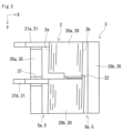
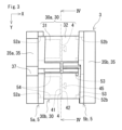
図1から図10を参照して、実施形態に係るリアクトル1を説明する。リアクトル1は、図1および図2に示すように、コイル2と磁性コア3とを備える。磁性コア3は、内側コア部30と外側コア部35とを有する。内側コア部30は、図3に示すように、第一コア部31および第二コア部32と、ギャップ板4とを含む。ギャップ板4は、第一コア部31と第二コア部32との間に配置されている。
<Reactor>
A
実施形態のリアクトル1の特徴の一つは、図3および図4に示すように、内側コア部30が連結コア部33を有する点にある。ギャップ板4を挟んで隣り合う第一コア部31と第二コア部32とは、連結コア部33によって一連につながっている。第一コア部31と第二コア部32と連結コア部33とは、後述する複合材料によって一体成形されている。以下、リアクトル1の各構成要素について詳しく説明する。
One of the features of the
以下の説明では、リアクトル1において、X方向、Y方向およびZ方向を次のように定義する。X方向は、コイル2の軸に沿う方向である。具体的には、コイル2の軸線をX軸とし、コイル2の第一端部2aから第二端部2bに向かう方向がX方向である。コイル2の側面と直交する線をY軸とし、コイル2の第一の側面から第二の側面に向かう方向がY方向である。X軸とY軸とは直交する。Y方向はX方向と直交する。Y方向は横方向である。X軸およびY軸と直交する線をZ軸とし、コイル2の下面から上面に向かう方向をZ方向とする。Z方向は、X方向およびY方向の双方と直交する。Z方向は縦方向である。
In the following description, the X-direction, Y-direction, and Z-direction in the
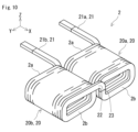
(コイル)
図1、図2および図10を主に参照して、コイル2の構成を説明する。コイル2は、図1および図2に示すように、巻回部20を有する。コイル2は、巻線によって形成されている。巻回部20は、巻線が螺旋状に巻回されて構成されている。巻回部20の軸に沿う方向はX方向と一致する。巻線は、例えば、導体線と、導体線を覆う絶縁被覆とを有する被覆平角線である。導体線は、例えば、銅製の平角線からなる。絶縁被覆は、例えばエナメルからなる。本例のコイル2は、被覆平角線が螺旋状に巻回されたエッジワイズコイルである。
(coil)
The configuration of the
本例では、巻回部20の数が2つである。本例のコイル2は、第一巻回部20aと第二巻回部20bとを有する。第一巻回部20aと第二巻回部20bとは、Y方向に間隔をあけて並列に配置されている。第一巻回部20aの軸に沿う方向と第二巻回部20bの軸に沿う方向は実質的に平行である。第一巻回部20aおよび第二巻回部20bの各々のX方向の寸法は実質的に同じである。
In this example, the number of winding
巻回部20は、図10に示すように、筒状の形状を有する。本例の巻回部20の形状は角筒状である。具体的には、巻回部20の形状が矩形筒状である。矩形筒状とは、巻回部20の端面の輪郭形状が矩形状であることをいう。ここでいう端面とは、巻回部20をX方向から見た端部の面である。巻回部20の角部は丸められていてもよい。本例の巻回部20の端面は、一対の直線状の長辺と、一対の円弧状の短辺とを有する矩形状である。上記長辺はY軸に沿って延びる。上記短辺はZ軸に沿って延びる。第一巻回部20aの形状と第二巻回部20bの形状は実質的に同じである。
As shown in FIG. 10, the winding
コイル2は、端末部21を有する。本例では、コイル2の第一端部2aから端末部21が引き出されている。端末部21は、コイル2の上側に位置する。本例のコイル2は、第一端末部21aと第二端末部21bとを有する。第一端末部21aは、第一巻回部20aからX軸に沿って引き出されている。第二端末部21bは、第二巻回部20bからX軸に沿って引き出されている。端末部21が引き出される方向はX方向とは反対方向である。端末部21は、図示しないバスバーに接続される。バスバーは、コイル2と図示しない電源とをつなぐ。
The
本例のコイル2は、図10に示すように、第二端部2bにおいて、第一巻回部20aと第二巻回部20bとをつなぐ連結部22を有する。連結部22は、第一巻回部20aおよび第二巻回部20bのそれぞれの第二端部2bにおけるターン同士をつなぐZ字状に折り曲げられた部位である。連結部22は、第一巻回部20aおよび第二巻回部20bを構成する巻線の一部によって形成されている。本例では、第一巻回部20aおよび第二巻回部20bは、それぞれ別々の巻線を巻回して構成されている。第一巻回部20aおよび第二巻回部20bを構成するそれぞれの巻線同士は、連結部22の途中に設けられた接合部23によって一連に接続されている。接合部23は、第一巻回部20aを構成する巻線と第二巻回部20bを構成する巻線とを接合した箇所である。本例の接合部23は、第一巻回部20aを構成する巻線と第二巻回部20bを構成する巻線との端面同士を突き合わせて冷間圧接することにより構成されている。コイル2は、第一巻回部20aおよび第二巻回部20bの大半をそれぞれ形成しておき、巻線同士を冷間圧接した後、第一巻回部20aおよび第二巻回部20bの残りを形成することで得ることができる。本例とは異なり、コイル2は1つの巻線によって形成されていてもよい。この場合、第一巻回部20a、連結部22および第二巻回部20bが一連の巻線によって構成されており、連結部22に接合部23は存在しない。
As shown in FIG. 10, the
(磁性コア)
図2および図3を主に参照して、磁性コア3の構成を説明する。磁性コア3には、コイル2が配置される。磁性コア3は、内側コア部30と外側コア部35とを有する。磁性コア3は、内側コア部30と外側コア部35とで閉磁路を形成する。本例の磁性コア3は、図3に示すように、平面視においてO字状の形状を有する。コイル2が通電されると、磁性コア3の内部に磁束が流れ、磁性コア3に閉磁路が形成される。
(Magnetic core)
The configuration of the
(内側コア部)
内側コア部30は、図3に示すように、図2に示すコイル2内に配置された部分である。内側コア部30はX軸に沿って延びる。内側コア部30の端部はコイル2の端部から突出していてもよい。この突出する部分も内側コア部30の一部である。つまり、内側コア部30のX方向の寸法は、コイル2のX方向の寸法よりも長くてもよい。
(Inner core part)
As shown in Fig. 3, the
内側コア部30の数は、巻回部20の数と同じである。本例では、内側コア部30の数が2つである。本例の磁性コア3は、第一内側コア部30aと第二内側コア部30bとを有する。第一内側コア部30aは第一巻回部20aの内側に配置される。第二内側コア部30bは第二巻回部20bの内側に配置される。第一内側コア部30aと第二内側コア部30bとは、X軸に概ね平行に並んでおり、かつ、Y方向に間隔をあけて並列に配置されている。第一内側コア部30aおよび第二内側コア部30bの各々のX方向の寸法は実質的に同じである。
The number of
内側コア部30の形状は、コイル2、即ち巻回部20の内側形状に概ね対応した形状である。本例の内側コア部30は角柱状であり、X方向と直交する内側コア部30の断面は矩形状である。第一内側コア部30aの形状と第二内側コア部30bの形状は実質的に同じである。内側コア部30の外周面は、コイル2、即ち巻回部20の内周面と接している。これにより、内側コア部30の磁路断面積を確保しやすい。
The shape of the
〈第一コア部・第二コア部〉
本例の内側コア部30は、図3に示すように、第一コア部31と第二コア部32とを有する。第一コア部31と第二コア部32とは、X方向に並んで配置されている。第一コア部31および第二コア部32の各々の断面の形状および断面積は実質的に同じである。ここでいう断面とは、X方向と直交する断面である。本例では、第一コア部31および第二コア部32の各々の断面は矩形状である。
<First Core Department/Second Core Department>
As shown in Fig. 3, the
本例では、内側コア部30の第一端部は、後述する第一エンドコア部35aと接続されている。内側コア部30の第二端部は、後述する第二エンドコア部35bと接続されている。内側コア部30の第一端部は、第一コア部31が位置する端部である。内側コア部30の第二端部は、第二コア部32が位置する端部である。
In this example, the first end of the
第一コア部31と第二コア部32との間には、後述するギャップ板4が配置されている。つまり、第一コア部31と第二コア部32とは、ギャップ板4を挟んで互いに向かい合う。
第一コア部31および第二コア部32は、ギャップ板4の第一面41および第二面42とそれぞれ接している。さらに、第一コア部31と第二コア部32とは、図4に示す連結コア部33によって一連につながっている。
A
The
〈ギャップ板〉
ギャップ板4は、磁性コア3の磁気特性を調整する部材である。ギャップ板4は、第一コア部31と第二コア部32との間の磁気抵抗を大きくして、内側コア部30の内部に流れる磁束量を調整する。内側コア部30にギャップ板4が設けられていることで、例えば、内側コア部30の磁気飽和を抑制したり、磁性コア3のインダクタンスを高めたりすることができる。ギャップ板4は、第一コア部31と接する第一面41と、第二コア部32と接する第二面42とを有する。本例のギャップ板4は、内側コア部30の中間部に設けられている。
<Gap plate>
The
図4から図7を主に参照して、ギャップ板4の構成を説明する。本例のギャップ板4は、図4に示すように、図3に示す第一面41と第二面42との間を貫通する貫通孔43を有する。貫通孔43はギャップ板4をX方向に貫通している。ギャップ板4が貫通孔43を有する場合、図4に示すように、連結コア部33は、後述する第一連結コア部331を有する。貫通孔43の断面積は、連結コア部33の断面積が所定の値となるように適宜選択することができる。貫通孔43の断面積は、例えば1mm2以上20mm2以下である。ここでいう断面積とは、X方向と直交する断面の面積である。貫通孔43の数が複数である場合、貫通孔43の断面積は、全ての貫通孔43の断面積の合計である。貫通孔43が2つである場合、2つの貫通孔43の断面積の合計が例えば1mm2以上20mm2以下である。貫通孔43の断面積は、さらに2mm2以上15mm2以下、3mm2以上10mm2以下であってもよい。
The configuration of the
貫通孔43の断面の形状は多角形状でもよいし、円形状でもよい。多角形状は、例えば、三角形または四角形である。本例の貫通孔43の断面は矩形状である。貫通孔43の数は1つでもよいし、複数でもよい。本例の貫通孔43の数は2つである。本例では、2つの貫通孔43がY方向に間隔をあけて並んでいる。貫通孔43の位置は適宜選択することができる。
The cross-sectional shape of the through
ギャップ板4の輪郭形状は、図3に示す第一コア部31および第二コア部32の各々の輪郭形状と同じであってもよいし、異なってもよい。内側コア部30をX方向から見たとき、ギャップ板4の輪郭形状は、第一コア部31および第二コア部32からはみ出さない形状である。本例のギャップ板4の輪郭形状は、図4に示すように矩形状であり、第一コア部31および第二コア部32の各々の輪郭形状と実質的に同じである。また、図4に示す本例のギャップ板4の輪郭面積は、第一コア部31および第二コア部32の各々の輪郭面積と実質的に同じである。輪郭形状とは、内側コア部30をX方向から見たときの各部材の外周の輪郭形状のことであり、輪郭面積とは、輪郭形状の面積のことである。
The contour shape of the
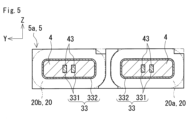
本実施形態とは異なり、ギャップ板4の輪郭面積は、第一コア部31および第二コア部32の各々の輪郭面積よりも小さくてもよい。ギャップ板4の輪郭面積が第一コア部31および第二コア部32の各々の輪郭面積よりも小さい場合、図5に例示するように、連結コア部33は後述する第二連結コア部332を有する。図5は、図3の切断線IV-IVと共通の線で切断した断面を示す。図5では、分かりやすくするため、第二連結コア部332を誇張して示している。図5に示すギャップ板4は、輪郭形状が矩形状であり、かつ、輪郭面積が第一コア部31および第二コア部32の各々の輪郭面積よりも若干小さい。ギャップ板4の輪郭面積は、連結コア部33の断面積が所定の値となるように適宜選択することができる。第一コア部31または第二コア部32の輪郭面積とギャップ板4の輪郭面積との差は、例えば1mm2以上20mm2以下である。上記輪郭面積の差は、さらに2mm2以上15mm2以下、3mm2以上10mm2以下であってもよい。図5では、上記輪郭面積の差を誇張して示しているため、上記輪郭面積の差が貫通孔43の断面積よりも大きく図示されている。図4に示す本例のギャップ板4の場合、ギャップ板4の輪郭形状が第一コア部31および第二コア部32の各々の輪郭形状と同じであり、上記輪郭面積の差は実質的にゼロである。
Unlike the present embodiment, the contour area of the
ギャップ板4の外周面に、第一面41から第二面42まで延びる溝が形成されていてもよい。ギャップ板4の外周面に上記溝を有する場合、ギャップ板4の輪郭面積が小さくなる。
A groove may be formed on the outer peripheral surface of the
図5に示すギャップ板4は、貫通孔43を有すると共に、ギャップ板4の輪郭面積が第一コア部31および第二コア部32の各々の輪郭面積よりも小さい。ギャップ板4が貫通孔43を有する場合、ギャップ板4の輪郭形状および輪郭面積は第一コア部31および第二コア部32の各々の輪郭形状および輪郭面積と同じであってもよい。この場合、連結コア部33は、後述する第二連結コア部332を含まない。ギャップ板4の輪郭面積が第一コア部31および第二コア部32の各々の輪郭面積よりも小さい場合、ギャップ板4は貫通孔43を有していなくてもよい。この場合、連結コア部33は、後述する第一連結コア部331を含まない。
The
ギャップ板4の厚さは、例えば0.5mm以上3mm以下である。ギャップ板4の厚さは、ギャップ板4のX方向の寸法である。つまり、ギャップ板4の厚さは、第一面41との第二面42との間の距離である。ギャップ板4の厚さが0.5mm以上3mm以下であることで、磁性コア3の磁気特性を調整しやすい。ギャップ板4の厚さが0.5mm以上であれば、ギャップ板4の機械的強度を確保しやすい。ギャップ板4の厚さが3mm以下であれば、ギャップ板4からの漏れ磁束を低減しやすい。ギャップ板4の厚さは、さらに1mm以上2.5mm以下、1mm以上2mm以下であってもよい。
The thickness of the
ギャップ板4は、例えば樹脂またはセラミックスなどの非磁性材料によって形成されている。ギャップ板4を構成する樹脂は熱可塑性樹脂でもよいし、熱硬化性樹脂でもよい。熱可塑性樹脂は、例えば、ポリフェニレンスルフィド(PPS)樹脂、ポリテトラフルオロエチレン(PTFE)樹脂、液晶ポリマー(LCP)、ポリアミド(PA)樹脂、ポリブチレンテレフタレート(PBT)樹脂、またはアクリロニトリル・ブタジエン・スチレン(ABS)樹脂である。ポリアミド樹脂は、例えば、ナイロン6、ナイロン66またはナイロン9Tである。熱硬化性樹脂は、例えば、不飽和ポリエステル樹脂、エポキシ樹脂、ウレタン樹脂、またはシリコーン樹脂である。本例のギャップ板4は樹脂によって形成されている。
The
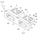
〈フック部〉
ギャップ板4は、図6に示すように、フック部45を有してもよい。フック部45は、第一面41と第二面42の少なくとも一方の面に設けられている。本例では、1つのフック部45が第二面42に設けられている。本例のフック部45は、ギャップ板4に一体成形されている。つまり、ギャップ板4とフック部45とは一体物である。フック部45は、軸部451と頭部452とを有する。本例のフック部45は、平面視においてT字状の形状を有する。
<Hook section>
As shown in Fig. 6, the
軸部451は、ギャップ板4の少なくとも一方の面からX軸に沿って突出する。本例では、軸部451は、第二面42からX方向に突出している。軸部451の形状は角柱状でもよいし、円柱状でもよい。本例の軸部451は角柱状であり、軸部451の断面は矩形状である。本例では、軸部451が2つの貫通孔43の間に位置する。軸部451の位置は適宜選択することができる。
The
頭部452は、軸部451の先端からX方向と交差する方向に張り出す。本例では、頭部452は、軸部451からX方向と直交する方向に張り出している。具体的には、頭部452は、軸部451からY軸に沿って突出している。本例の頭部452の形状は角柱状である。頭部452は、軸部451からZ軸に沿って突出していてもよいし、軸部451の全周から突出していてもよい。頭部452が軸部451よりも張り出していれば、頭部452の形状はいずれの形状でもよい。頭部452の形状は、例えば、角錐状、円錐状、円柱状または半球状でもよい。
The
本例では、ギャップ板4をX方向から見たとき、図7に示すように、頭部452が貫通孔43と重なる位置に設けられている。頭部452が貫通孔43と重なる位置に設けられていることで、後述する第一連結コア部331をX軸に沿って通過する磁束の流れが頭部452によって妨げられる。第一連結コア部331を通る磁束の流れが頭部452によって妨げられるため、第一コア部31と第二コア部32との間の磁気抵抗を調整しやすい。
In this example, when the
フック部45が第二面42に設けられている場合、図3に示すように、フック部45は第二コア部32に埋め込まれる。フック部45が第二コア部32に引っかかることによって、第二コア部32がギャップ板4から分離しにくい。ギャップ板4に対する第二コア部32の接合強度が高くなる。本実施形態とは異なり、フック部45は第一面41に設けられていてもよい。フック部45が第一面41に設けられている場合、フック部45は第一コア部31に埋め込まれる。この場合、フック部45が第一コア部31に引っかかることによって、第一コア部31がギャップ板4から分離しにくくなるため、ギャップ板4に対する第一コア部31の接合強度が高くなる。フック部45は第一面41と第二面42の両方に設けられていてもよい。フック部45が第一面41および第二面42にそれぞれ設けられている場合、第一コア部31と第二コア部32とがギャップ板4から分離しにくくなるため、ギャップ板4に対する第一コア部31および第二コア部32の接合強度が高くなる。
When the
フック部45の数は1つでもよいし、複数でもよい。フック部45は、第二面42に2つ以上設けられていてもよいし、第一面41に2つ以上設けられていてもよいし、第一面41および第二面42にそれぞれ1つ以上設けられていてもよい。フック部45の位置はいずれの位置でもよい。
The number of
〈連結コア部〉
連結コア部33は、第一コア部31と第二コア部32とをつなぐ部分である。ギャップ板4を挟んで隣り合う第一コア部31と第二コア部32とは、連結コア部33によってつながった一体物である。つまり、第一コア部31と第二コア部32とは、ギャップ板4を挟んで分断されていない。第一コア部31と第二コア部32とが連結コア部33によってつながっていることで、第一コア部31と第二コア部32とが分離しにくい。ギャップ板4に対する第一コア部31および第二コア部32の接合強度が高いことから、内側コア部30の機械的強度が向上する。したがって、内側コア部30が高い機械的強度を有することで、磁性コア3の機械的強度を確保することができる。
<Connected core section>
The coupled
主に図4および図5を参照して、連結コア部33の構成を説明する。連結コア部33は、第一連結コア部331および第二連結コア部332の少なくとも一方を含む。連結コア部33は、第一連結コア部331および第二連結コア部332のいずれか一方を含んでいればよい。本例の連結コア部33は、図4に示すように、第一連結コア部331のみを有し、第二連結コア部332を含まない。連結コア部33は、図5に示すように、第一連結コア部331および第二連結コア部332の両方を有してもよい。図4および図5に示す第一連結コア部331は、ギャップ板4の貫通孔43に設けられている。図5に示す第二連結コア部332は、ギャップ板4の外周面よりも外側に設けられている。第二連結コア部332は、コイル2、即ち巻回部20の内周面とギャップ板4の外周面との間に配置される。
The configuration of the linked
連結コア部33の断面積は、例えば1mm2以上20mm2以下である。ここでいう連結コア部33の断面積は、1つの内側コア部30における連結コア部33の断面積である。連結コア部33の断面積が1mm2以上であることで、上記接合強度を高めることができ、内側コア部30の機械的強度を確保しやすい。連結コア部33の断面積が20mm2以下であることで、連結コア部33を通る磁束を少なくすることができ、磁性コア3の磁気特性を調整しやすい。連結コア部33の断面積が小さいほど、ギャップ板4の断面積が増加することになるため、ギャップ板4による磁気特性を調整する効果が得られやすい。連結コア部33の断面積が20mm2以下であれば、例えば、内側コア部30の磁気飽和を抑制したり、磁性コア3のインダクタンスを高めたりすることができる。連結コア部33の断面積は、さらに2mm2以上15mm2以下、3mm2以上10mm2以下であってもよい。
The cross-sectional area of the
連結コア部33の断面積は、第一連結コア部331の断面積と第二連結コア部332の断面積との合計である。連結コア部33が第一連結コア部331または第二連結コア部332のいずれかを有する場合、第一連結コア部331の断面積、または第二連結コア部332の断面積のいずれかが、上記した連結コア部33の断面積の範囲を満たす。連結コア部33が第一連結コア部331および第二連結コア部332の両方を有する場合、第一連結コア部331の断面積と第二連結コア部332の断面積との合計が、上記した連結コア部33の断面積の範囲を満たす。第一連結コア部331の断面積は、貫通孔43の断面積に実質的に等しい。第二連結コア部332の断面積は、第一コア部31または第二コア部32の輪郭面積とギャップ板4の輪郭面積との差に実質的に等しい。図4に示す本例のギャップ板4の場合、連結コア部33の断面積が第一連結コア部331の断面積と同じである。図4に示すギャップ板4の場合、上記輪郭面積の差は実質的にゼロである。つまり、本例では、第二連結コア部332の断面積は実質的にゼロである。
The cross-sectional area of the
連結コア部33が第一連結コア部331を有する場合、連結コア部33を通る磁束は、ギャップ板4の貫通孔43に設けられた第一連結コア部331に集中して流れる。そのため、ギャップ板4から外側へ漏れる磁束を抑制しやすい。第一連結コア部331の断面積が1mm2以上であれば、ギャップ板4からの漏れ磁束を低減しやすい。
When the
連結コア部33が第二連結コア部332を有する場合、連結コア部33を通る磁束は、ギャップ板4の外側に設けられた第二連結コア部332に集中して流れる。そのため、ギャップ板4から外側へ漏れる磁束を抑制しやすい。第二連結コア部332の断面積が1mm2以上であれば、ギャップ板4からの漏れ磁束を低減しやすい。ギャップ板4の外周面に上記溝を有する場合、この溝内に第二連結コア部332が入り込むことで、第二連結コア部332の断面積が増える。
When the
〈複合材料〉
第一コア部31と第二コア部32と連結コア部33とは、複合材料によって一体成形されている。つまり、第一コア部31と第二コア部32と連結コア部33とは、同一の複合材料によって形成された一体物である。複合材料の成形体は、樹脂中に軟磁性粉末が分散された構造を有する。複合材料の成形体は、未固化の樹脂と軟磁性粉末とが混合された複合材料の原料を金型に注入し、樹脂を固化させたものである。複合材料における軟磁性粉末の含有量は、複合材料全体を100体積%としたとき、例えば30体積%以上80体積%以下である。複合材料における軟磁性粉末の含有量は、さらに50体積%以上、60体積%以上、または70体積%以上でもよい。
<Composite Materials>
The
軟磁性粉末を構成する粒子は、軟磁性金属の粒子、軟磁性金属の粒子の外周に絶縁被覆を備える被覆粒子、および軟磁性非金属の粒子からなる群より選択される少なくとも一種である。軟磁性金属は、例えば、純鉄または鉄合金である。鉄合金は、例えば、Fe(鉄)-Si(シリコン)合金またはFe-Ni(ニッケル)合金である。絶縁被覆は、例えばリン酸塩である。軟磁性非金属は、例えばフェライトである。 The particles constituting the soft magnetic powder are at least one type selected from the group consisting of soft magnetic metal particles, coated particles with an insulating coating on the outer periphery of soft magnetic metal particles, and soft magnetic nonmetal particles. The soft magnetic metal is, for example, pure iron or an iron alloy. The iron alloy is, for example, an Fe (iron)-Si (silicon) alloy or an Fe-Ni (nickel) alloy. The insulating coating is, for example, a phosphate. The soft magnetic nonmetal is, for example, a ferrite.
複合材料を構成する樹脂は熱可塑性樹脂でもよいし、熱硬化性樹脂でもよい。熱可塑性樹脂は、例えば、PPS樹脂、PTFE樹脂、LCP、PA樹脂、PBT樹脂、またはABS樹脂である。熱硬化性樹脂は、例えば、不飽和ポリエステル樹脂、エポキシ樹脂、ウレタン樹脂、またはシリコーン樹脂である。その他、複合材料を構成する樹脂は、例えば、BMC(Bulk molding compound)、ミラブル型シリコーンゴム、またはミラブル型ウレタンゴムでもよい。BMCは、例えば、不飽和ポリエステルと、炭酸カルシウムまたはガラス繊維とが混合されたものである。 The resin constituting the composite material may be a thermoplastic resin or a thermosetting resin. The thermoplastic resin is, for example, PPS resin, PTFE resin, LCP, PA resin, PBT resin, or ABS resin. The thermosetting resin is, for example, unsaturated polyester resin, epoxy resin, urethane resin, or silicone resin. In addition, the resin constituting the composite material may be, for example, BMC (bulk molding compound), millable silicone rubber, or millable urethane rubber. BMC is, for example, a mixture of unsaturated polyester and calcium carbonate or glass fiber.
(外側コア部)
外側コア部35は、図2に示すように、コイル2の外に配置された部分である。外側コア部35は、図3に示す内側コア部30と接続されることで閉磁路を形成する。本例の外側コア部35は、第一エンドコア部35aと第二エンドコア部35bである。第一エンドコア部35aは、内側コア部30の第一端部、即ち第一コア部31と接続される。第二エンドコア部35bは、内側コア部30の第二端部、即ち第二コア部32と接続される。
(Outer core part)
The
第一エンドコア部35aおよび第二エンドコア部35bは、コイル2の両端部にそれぞれ向かい合うように配置されている。第一エンドコア部35aは、コイル2の第一端部2aと向かい合う。第二エンドコア部35bは、コイル2の第二端部2bと向かい合う。第一エンドコア部35aおよび第二エンドコア部35bはそれぞれ、Y軸に沿って延びる。図3に示すように、第一エンドコア部35aは、第一内側コア部30aおよび第二内側コア部30bの各々の第一端部と接続されている。第一エンドコア部35aは、第一内側コア部30aおよび第二内側コア部30bの第一端部同士をつなぐ。第二エンドコア部35bは、第一内側コア部30aおよび第二内側コア部30bの各々の第二端部と接続されている。第二エンドコア部35bは、第一内側コア部30aおよび第二内側コア部30bの第二端部同士をつなぐ。第一エンドコア部35aと第二エンドコア部35bとは、Y軸に概ね平行に並んでおり、かつ、X方向に間隔をあけて並列に配置されている。
The first
第一エンドコア部35aおよび第二エンドコア部35bのそれぞれの形状は、第一内側コア部30aおよび第二内側コア部30bの端部同士をつなぐ形状であれば、いずれの形状でもよい。本例の第一エンドコア部35aおよび第二エンドコア部35bは角柱状であり、Y方向と直交する第一エンドコア部35aおよび第二エンドコア部35bの各々の断面は矩形状である。第一エンドコア部35aの形状と第二エンドコア部35bの形状は実質的に同じである。
The first
本例の第一エンドコア部35aは、図1に示すように、コイル2の端末部21が配置される凹部37を有する。端末部21が凹部37内に配置されることで、端末部21が第一エンドコア部35aと干渉しない。本例では、2つの凹部37が第一エンドコア部35aの上面に設けられている。2つの凹部37の位置は、第一端末部21aおよび第二端末部21bの位置にそれぞれ対応している。
As shown in FIG. 1, the first
外側コア部35、即ち第一エンドコア部35aおよび第二エンドコア部35bは、磁性材料によって形成されている。外側コア部35は、例えば、上述した複合材料の成形体である。外側コア部35は、圧粉成形体の少なくとも一部を複合材料で覆った被覆成形体でもよい。第一エンドコア部35aが被覆成形体であれば、凹部37を容易に成形することができる。
The
圧粉成形体は、軟磁性粉末を含む原料粉末を圧縮成形したものである。圧粉成形体は、複合材料の成形体に比較して軟磁性粉末の含有量が多い。そのため、圧粉成形体は、複合材料の成形体に比較して、例えば、比透磁率および飽和磁束密度が高い。圧粉成形体は、例えば、バインダ樹脂および成形助剤の少なくとも一つを含有してもよい。圧粉成形体における軟磁性粉末の含有量は、圧粉成形体全体を100体積%とするとき、例えば80体積%超99.99体積%以下である。圧粉成形体における軟磁性粉末の含有量は、さらに85体積%以上99体積%以下でもよい。 The powder compact is formed by compressing raw powder containing soft magnetic powder. The powder compact contains a larger amount of soft magnetic powder than the composite material compact. Therefore, the powder compact has a higher relative permeability and saturation magnetic flux density than the composite material compact. The powder compact may contain at least one of a binder resin and a molding aid. The content of the soft magnetic powder in the powder compact is, for example, more than 80% by volume and 99.99% by volume or less, when the entire powder compact is taken as 100% by volume. The content of the soft magnetic powder in the powder compact may further be 85% by volume or more and 99% by volume or less.
本例の外側コア部35、即ち第一エンドコア部35aおよび第二エンドコア部35bは複合材料の成形体である。本例では、外側コア部35が第一コア部31と第二コア部32と連結コア部33と一体成形されている。つまり、第一エンドコア部35aおよび第二エンドコア部35bと、第一コア部31、第二コア部32および連結コア部33とは、同一の複合材料によって形成された一体物である。内側コア部30と外側コア部35とが一体物であることから、従来のように、内側コア部30と外側コア部35とを接着したり、樹脂モールド部によって一体化したりする必要がない。
In this example, the
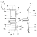
(スペーサ)
本例のリアクトル1は、図1から図3に示すように、スペーサ5を備えてもよい。スペーサ5は、コイル2の少なくとも一方の端部に配置される。スペーサ5は、磁性コア3に対してコイル2を位置決めする部材である。スペーサ5は樹脂によって形成されている。スペーサ5を構成する樹脂は、ギャップ板4を構成する樹脂として説明した上述の樹脂を用いることができる。スペーサ5を構成する樹脂は、ギャップ板4を構成する樹脂と同じでもよいし、異なってもよい。
(Spacer)
The
本例では、コイル2の両端部にスペーサ5がそれぞれ配置されている。本例のリアクトル1は、第一スペーサ5aと第二スペーサ5bとを備える。第一スペーサ5aは、コイル2の第一端部2aに配置される。第二スペーサ5bは、コイル2の第二端部2bに配置される。図6、図8および図9を参照して、スペーサ5の構成を説明する。以下の説明では、コイル2および磁性コア3の各構成については図1から図3を適宜参照するものとする。ギャップ板4の構成については、図6および図7を適宜参照するものとする。
In this example,
〈第一スペーサ〉
図6および図8を主に参照して、第一スペーサ5aの構成を説明する。第一スペーサ5aは、コイル2の第一端部2aの面と接する枠状の形状を有する。本例の第一スペーサ5aは、概ね矩形枠状である。コイル2の第一端部2aと向かい合う第一スペーサ5aの面は、第一巻回部20aおよび第二巻回部20bのそれぞれの端面と接する。第一スペーサ5aの上面および下面は、コイル2の上面および下面とそれぞれ実質的に面一である。
<First Spacer>
The configuration of the
第一スペーサ5aは、内側コア部30の第一端部が配置される開口部52aを有する。本例では、開口部52aの数が2つである。2つの開口部52a内に、第一内側コア部30aおよび第二内側コア部30bの各々の第一端部が配置される。開口部52aの形状は矩形状である。
The
本例の第一スペーサ5aは、図8に示すように、凹部57を有する。凹部57には、コイル2の端末部21が配置される。端末部21が凹部57内に配置されることで、端末部21が第一スペーサ5aと干渉しない。本例では、2つの凹部57が第一スペーサ5aの上面に設けられている。2つの凹部57の位置は、第一端末部21aおよび第二端末部21bの位置にそれぞれ対応している。
As shown in FIG. 8, the
第一スペーサ5aは、第一巻回部20aと第二巻回部20bとの間に配置される仕切り部55aを有してもよい。仕切り部55aは、コイル2の第一端部2aと向かい合う第一スペーサ5aの面から突出する。仕切り部55aが突出する方向はX方向である。仕切り部55aは、第一巻回部20aおよび第二巻回部20bの互いに向かい合う側面の間に挟まれる。仕切り部55aは、コイル2の第一端部2aに近い領域に設けられている。仕切り部55aのX方向の寸法は、巻回部20のX方向の寸法の半分未満である。
The
〈支持部〉
さらに、本例の第一スペーサ5aは、ギャップ板4を支持する支持部54を有する。支持部54は、コイル2の第一端部2aと向かい合う第一スペーサ5aの面からギャップ板4までX方向に延びる。支持部54の先端はギャップ板4の第一面41に接続されている。本例では、2つの支持部54によってギャップ板4が第一スペーサ5aに支持されている。各支持部54は、巻回部20の側面の内面に接する。X方向と直交する支持部54の断面は、図7に示すように、巻回部20の側面の内面に対応したC字状である。支持部54は、巻回部20の内周面と内側コア部30の外周面との間に配置される。内側コア部30の外周面のうち、支持部54が配置された部分は、巻回部20の内周面と接していない。第一スペーサ5aが支持部54を有することで、巻回部20内にギャップ板4を位置決めすることができる。また、支持部54は、第一スペーサ5aに巻回部20を位置決めする機能を有する。
<Support section>
Furthermore, the
本例では、支持部54および仕切り部55aが第一スペーサ5aに一体成形されている。さらに、ギャップ板4が支持部54に一体成形されている。つまり、ギャップ板4と第一スペーサ5aとは、同一の樹脂によって形成された一体物である。
In this example, the
〈第二スペーサ〉
図6および図9を主に参照して、第二スペーサ5bの構成を説明する。第二スペーサ5bは、コイル2の第二端部2bの面と接する枠状の形状を有する。本例の第二スペーサ5bは、概ね矩形枠状である。コイル2の第二端部2bと向かい合う第二スペーサ5bの面は、第一巻回部20aおよび第二巻回部20bのそれぞれの端面と接する。第二スペーサ5bの上面および下面は、コイル2の上面および下面とそれぞれ実質的に面一である。
<Second Spacer>
The configuration of the
第二スペーサ5bは、内側コア部30の第二端部が配置される開口部52bを有する。本例では、開口部52bの数が2つである。2つの開口部52b内に、第一内側コア部30aおよび第二内側コア部30bの各々の第二端部が配置される。開口部52bの形状は矩形状である。
The
第二スペーサ5bは、第一巻回部20aと第二巻回部20bとの間に配置される仕切り部55bを有してもよい。仕切り部55bは、コイル2の第二端部2bと向かい合う第二スペーサ5bの面から突出する。仕切り部55bが突出する方向はX方向とは反対方向である。仕切り部55bは、第一巻回部20aおよび第二巻回部20bの互いに向かい合う側面の間に挟まれる。仕切り部55bは、コイル2の第二端部2bに近い領域に設けられている。仕切り部55bのX方向の寸法は、巻回部20のX方向の寸法の半分未満である。仕切り部55bの上端は、図10に示すコイル2の連結部22を通すために、コイル2の上面よりも低くなっている。
The
〈突起部〉
さらに、第二スペーサ5bは、コイル2の第二端部2bと向かい合う面から突出する突起部53を有してもよい。突起部53が突出する方向はX方向とは反対方向である。突起部53は、巻回部20の側面の内面に接する。1つの巻回部20に対する突起部53の数は2つである。突起部53は、巻回部20の内周面と内側コア部30の外周面との間に配置される。内側コア部30の外周面のうち、突起部53が配置された部分は、巻回部20の内周面と接していない。突起部53は、第二スペーサ5bに巻回部20を位置決めする機能を有する。本例では、X方向と直交する突起部53の断面は、巻回部20の側面の内面に対応したC字状である。突起部53のX方向の寸法は、支持部54のX方向の寸法よりも短い。
<Protrusion>
Furthermore, the
本例では、突起部53および仕切り部55bが第二スペーサ5bに一体成形されている。
In this example, the
本実施形態とは異なり、支持部54は第二スペーサ5bに設けられていてもよい。この場合、第一スペーサ5aは、支持部54に代えて突起部53を有してもよい。
Unlike this embodiment, the
図1に示す実施形態のリアクトル1は薄型である。薄型とは、縦方向の寸法が横方向の寸法よりも小さいことをいう。本例では、磁性コア3をX方向から見たとき、磁性コア3の縦方向の寸法Hが横方向の寸法Wの1/3以下である。以下、縦方向の寸法Hと横方向の寸法Wとの比を縦横比H/Wという。縦方向はZ方向である。縦方向の寸法Hとは、X方向から見たときの磁性コア3の外周の輪郭形状を包絡する最小の長方形における短辺の長さのことである。縦方向の寸法Hは厚さを意味する。横方向はY方向である。横方向の寸法Wとは、X方向から見たときの磁性コア3の外周の輪郭形状を包絡する最小の長方形における長辺の長さのことである。横方向の寸法Wは幅を意味する。縦横比H/Wは、さらに1/4以下、1/5以下、1/6以下でもよい。
The
磁性コア3の縦方向の寸法Hは、例えば20mm以下である。本例では、コイル2の縦方向の寸法が、磁性コア3の縦方向の寸法Hと実質的に同じである。磁性コア3の縦方向の寸法Hは、さらに10mm以下であってもよい。
The vertical dimension H of the
〈リアクトルの製造方法〉
実施形態のリアクトル1は、以下に示すリアクトルの製造方法によって製造することができる。リアクトルの製造方法は、下記の工程Aと工程Bとを備える。
A.コイル2にスペーサ5を組み付ける工程。
B.コイル2にスペーサ5が組み付けられた状態で、内側コア部30および外側コア部35を複合材料によって成形する工程。
<Reactor Manufacturing Method>
The
A. A process of assembling the
B. A process of molding the
(工程A)
コイル2にスペーサ5を組み付けることで、スペーサ5がコイル2に組み付けられたコイルアセンブリが得られる。コイル2に対するスペーサ5の組み付けは、次のように行う。コイル2の第一端部2aから巻回部20内に第一スペーサ5aの支持部54とギャップ板4を挿入して、第一端部2aに第一スペーサ5aを取り付ける。第一端部2aに第一スペーサ5aが取り付けられることで、巻回部20内にギャップ板4が配置されると共に、支持部54によってギャップ板4が位置決めされる。また、支持部54が巻回部20の内周面に接することで、第一端部2aに対して第一スペーサ5aが位置決めされる。コイル2の第二端部2bから巻回部20内に第二スペーサ5bの突起部53を挿入して、第二端部2bに第二スペーサ5bを取り付ける。突起部53が巻回部20の内周面に接することで、第二端部2bに対して第二スペーサ5bが位置決めされる。
(Step A)
By assembling the
(工程B)
コイル2にスペーサ5を組み付けた後、内側コア部30および外側コア部35をコイルアセンブリに対して成形することで磁性コア3を形成する。内側コア部30および外側コア部35の成形は、次のように行う。コイルアセンブリを金型に入れ、金型内に複合材料の原料を注入する。金型は、外側コア部35を成形するキャビティを有する。金型内には、コイルアセンブリを位置決めするピンが設けられている。複合材料の原料は、コイル2内と上記キャビティに導入される。複合材料の原料は、コイル2の第一端部2aから第二端部2bに向けて原料が流れるように導入してもよいし、第一端部2aから第二端部2bに向けて原料が流れるように導入してもよい。上記キャビティは、巻回部20内と連通しており、上記キャビティから巻回部20内に原料が導入される。巻回部20内に導入された原料は、ギャップ板4の貫通孔43を通って、巻回部20内に充填される。ギャップ板4の外周面と巻回部20の内周面との間の隙間がある場合は、その隙間を通って、原料が巻回部20内に充填される。巻回部20内と上記キャビティに複合材料の原料を充填した後、複合材料を構成する樹脂を固化させることで、内側コア部30と外側コア部35とを一体成形する。
(Process B)
After the
<コンバータ・電力変換装置>
実施形態のリアクトル1は、以下の通電条件を満たす用途に利用できる。通電条件は、例えば、最大直流電流が100A以上1000A以下程度であり、平均電圧が100V以上1000V以下程度であり、使用周波数が5kHz以上100kHz以下程度である。実施形態のリアクトル1は、代表的には電気自動車およびハイブリッド自動車などの車両に搭載されるコンバータの構成部品、およびこのコンバータを備える電力変換装置の構成部品に利用できる。
<Converter/power conversion device>
The
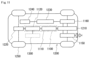
ハイブリッド自動車および電気自動車などの車両1200は、図11に示すようにメインバッテリ1210と、メインバッテリ1210に接続される電力変換装置1100と、メインバッテリ1210からの供給電力により駆動して走行に利用されるモータ1220とを備える。モータ1220は、代表的には、3相交流モータである。モータ1220は、走行時、車輪1250を駆動し、回生時、発電機として機能する。ハイブリッド自動車の場合、車両1200は、モータ1220に加えてエンジン1300を備える。図11では、車両1200の充電箇所としてインレットを示すが、プラグを備える形態とすることができる。
As shown in FIG. 11, a
電力変換装置1100は、メインバッテリ1210に接続されるコンバータ1110と、コンバータ1110に接続されて、直流と交流との相互変換を行うインバータ1120とを有する。この例に示すコンバータ1110は、車両1200の走行時、200V以上300V以下程度のメインバッテリ1210の入力電圧を400V以上700V以下程度にまで昇圧して、インバータ1120に給電する。コンバータ1110は、回生時、モータ1220からインバータ1120を介して出力される入力電圧をメインバッテリ1210に適合した直流電圧に降圧して、メインバッテリ1210に充電させている。入力電圧は、直流電圧である。インバータ1120は、車両1200の走行時、コンバータ1110で昇圧された直流を所定の交流に変換してモータ1220に給電し、回生時、モータ1220からの交流出力を直流に変換してコンバータ1110に出力している。
The
コンバータ1110は、図12に示すように複数のスイッチング素子1111と、スイッチング素子1111の動作を制御する駆動回路1112と、リアクトル1115とを備え、ON/OFFの繰り返しにより入力電圧の変換を行う。入力電圧の変換とは、ここでは昇降圧を行う。スイッチング素子1111には、電界効果トランジスタ、絶縁ゲートバイポーラトランジスタなどのパワーデバイスが利用される。リアクトル1115は、回路に流れようとする電流の変化を妨げようとするコイルの性質を利用し、スイッチング動作によって電流が増減しようとしたとき、その変化を滑らかにする機能を有する。リアクトル1115として、実施形態のリアクトル1を備える。
As shown in FIG. 12, the
車両1200は、コンバータ1110の他、メインバッテリ1210に接続された給電装置用コンバータ1150や、補機類1240の電力源となるサブバッテリ1230とメインバッテリ1210とに接続され、メインバッテリ1210の高圧を低圧に変換する補機電源用コンバータ1160を備える。コンバータ1110は、代表的には、DC-DC変換を行うが、給電装置用コンバータ1150や補機電源用コンバータ1160は、AC-DC変換を行う。給電装置用コンバータ1150のなかには、DC-DC変換を行うものもある。給電装置用コンバータ1150および補機電源用コンバータ1160のリアクトルに、実施形態のリアクトル1と同様の構成を備え、適宜、大きさまたは形状などを変更したリアクトルを利用できる。また、入力電力の変換を行うコンバータであって、昇圧のみを行うコンバータまたは降圧のみを行うコンバータに、実施形態のリアクトル1を利用することもできる。
In addition to the
本発明はこれらの例示に限定されるものではなく、特許請求の範囲によって示され、特許請求の範囲と均等の意味および範囲内でのすべての変更が含まれることが意図される。 The present invention is not limited to these examples, but is indicated by the claims, and is intended to include all modifications within the meaning and scope of the claims.
巻回部20の数は1つでもよい。磁性コア3の形状は、O字状ではなく、θ字状であってもよい。θ字状の磁性コアは、1つのミドルコア部、2つのサイドコア部、および2つのエンドコア部を備える。ミドルコア部は、コイルの内側に配置される。サイドコア部の各々は、コイルの外側でミドルコア部と並列される。つまり、ミドルコア部は2つのサイドコア部の間に挟まれるように配置される。2つのエンドコア部の1つは、並列されたミドルコア部およびサイドコア部の第一端部同士をつなぐ。残る1つのエンドコア部は、並列されたミドルコア部およびサイドコア部の第二端部同士をつなぐ。換言すれば、θ字状の磁性コアは、2つのE型のコア片を一体に組み合わせたような形状である。これらミドルコア部、サイドコア部およびエンドコア部は、いずれも複合材料の成形体で一体に成形されている。θ字状の磁性コアは、ミドルコア部が内側コア部、サイドコア部およびエンドコア部が外側コア部に相当する。
The number of winding
1 リアクトル
2 コイル
2a 第一端部、2b 第二端部
20 巻回部
20a 第一巻回部、20b 第二巻回部
21 端末部
21a 第一端末部、21b 第二端末部
22 連結部
23 接合部
3 磁性コア
30 内側コア部
30a 第一内側コア部、30b 第二内側コア部
31 第一コア部、32 第二コア部
33 連結コア部
331 第一連結コア部、332 第二連結コア部
35 外側コア部
35a 第一エンドコア部、35b 第二エンドコア部
37 凹部
4 ギャップ板
41 第一面、42 第二面
43 貫通孔
45 フック部
451 軸部、452 頭部
5 スペーサ
5a 第一スペーサ、5b 第二スペーサ
52a、52b 開口部
53 突起部
54 支持部
55a、55b 仕切り部
57 凹部
H 縦方向の寸法
W 横方向の寸法
1100 電力変換装置、1110 コンバータ
1111 スイッチング素子、1112 駆動回路
1115 リアクトル、1120 インバータ
1150 給電装置用コンバータ、1160 補機電源用コンバータ
1200 車両
1210 メインバッテリ、1220 モータ
1230 サブバッテリ、1240 補機類、1250 車輪、1300 エンジン
LIST OF
Claims (13)
前記コイルの内側に配置された内側コア部と前記コイルの外側に配置された外側コア部とを有する磁性コアと、を備え、
前記内側コア部は、
前記コイルの軸に沿うX方向に並んで配置された第一コア部と第二コア部と、
前記第一コア部と前記第二コア部との間に配置されたギャップ板と、
前記第一コア部と前記第二コア部とをつなぐ連結コア部と、を有し、
前記第一コア部と前記第二コア部と前記連結コア部とは、樹脂中に軟磁性粉末が分散された複合材料によって一体成形されている、
リアクトル。 A coil and
a magnetic core having an inner core portion disposed inside the coil and an outer core portion disposed outside the coil,
The inner core portion is
A first core portion and a second core portion arranged side by side in an X direction along an axis of the coil;
a gap plate disposed between the first core portion and the second core portion;
a coupling core portion connecting the first core portion and the second core portion,
The first core portion, the second core portion, and the connecting core portion are integrally molded from a composite material in which soft magnetic powder is dispersed in a resin.
Reactor.
前記連結コア部は、前記貫通孔に設けられた第一連結コア部を含む、請求項1に記載のリアクトル。 the gap plate has a through hole passing between a first surface in contact with the first core portion and a second surface in contact with the second core portion,
The reactor according to claim 1 , wherein the couple core portion includes a first couple core portion provided in the through hole.
前記連結コア部は、前記ギャップ板の外周面よりも外側に設けられた第二連結コア部を含む、請求項1または請求項2に記載のリアクトル。 When the inner core portion is viewed from the X direction, a contour area of the gap plate is smaller than a contour area of each of the first core portion and the second core portion,
The reactor according to claim 1 or 2, wherein the couple core portion includes a second couple core portion provided outside an outer circumferential surface of the gap plate.
前記スペーサは、前記ギャップ板を支持する支持部を有する、請求項1または請求項2に記載のリアクトル。 Further, a spacer is disposed on at least one end of the coil,
The reactor according to claim 1 or 2, wherein the spacer has a support portion that supports the gap plate.
前記第一コア部と接する第一面と、
前記第二コア部と接する第二面と、
前記第一面と前記第二面の少なくとも一方の面に設けられたフック部と、を有し、
前記フック部は、
前記ギャップ板の少なくとも一方の面から前記X方向に突出する軸部と、
前記軸部の先端から前記X方向と交差する方向に張り出す頭部と、を有する、請求項1または請求項2に記載のリアクトル。 The gap plate is
A first surface in contact with the first core portion;
A second surface in contact with the second core portion;
A hook portion is provided on at least one of the first surface and the second surface,
The hook portion is
a shaft portion protruding in the X direction from at least one surface of the gap plate;
The reactor according to claim 1 or 2, further comprising: a head portion extending from a tip of the shaft portion in a direction intersecting with the X-direction.
前記フック部は、
前記ギャップ板の少なくとも一方の面から前記X方向に突出する軸部と、
前記軸部の先端から前記X方向と交差する方向に張り出す頭部と、を有し、
前記ギャップ板を前記X方向から見たとき、前記頭部が前記貫通孔と重なる位置に設けられている、請求項2に記載のリアクトル。 the gap plate has a hook portion provided on at least one of the first surface and the second surface,
The hook portion is
a shaft portion protruding in the X direction from at least one surface of the gap plate;
a head portion extending from a tip of the shaft portion in a direction intersecting the X direction,
The reactor according to claim 2 , wherein the head portion is provided at a position overlapping with the through hole when the gap plate is viewed from the X direction.
コンバータ。 A reactor comprising the reactor according to claim 1 or 2.
converter.
電力変換装置。 A converter comprising:
Power conversion equipment.
Priority Applications (3)
| Application Number | Priority Date | Filing Date | Title |
|---|---|---|---|
| JP2023088799A JP2024171663A (en) | 2023-05-30 | 2023-05-30 | Reactor, converter, and power converter |
| CN202480031941.3A CN121153092A (en) | 2023-05-30 | 2024-05-10 | Reactor, converter, and power conversion device |
| PCT/JP2024/017513 WO2024247669A1 (en) | 2023-05-30 | 2024-05-10 | Reactor, converter, and power conversion device |
Applications Claiming Priority (1)
| Application Number | Priority Date | Filing Date | Title |
|---|---|---|---|
| JP2023088799A JP2024171663A (en) | 2023-05-30 | 2023-05-30 | Reactor, converter, and power converter |
Publications (1)
| Publication Number | Publication Date |
|---|---|
| JP2024171663A true JP2024171663A (en) | 2024-12-12 |
Family
ID=93657555
Family Applications (1)
| Application Number | Title | Priority Date | Filing Date |
|---|---|---|---|
| JP2023088799A Pending JP2024171663A (en) | 2023-05-30 | 2023-05-30 | Reactor, converter, and power converter |
Country Status (3)
| Country | Link |
|---|---|
| JP (1) | JP2024171663A (en) |
| CN (1) | CN121153092A (en) |
| WO (1) | WO2024247669A1 (en) |
Family Cites Families (3)
| Publication number | Priority date | Publication date | Assignee | Title |
|---|---|---|---|---|
| JP2014027025A (en) * | 2012-07-24 | 2014-02-06 | Sumitomo Electric Ind Ltd | Reactor, converter and electrical power conversion apparatus |
| JP7117905B2 (en) * | 2018-06-14 | 2022-08-15 | 株式会社タムラ製作所 | Reactor |
| JP7022342B2 (en) * | 2018-10-18 | 2022-02-18 | 株式会社オートネットワーク技術研究所 | Reactor |
-
2023
- 2023-05-30 JP JP2023088799A patent/JP2024171663A/en active Pending
-
2024
- 2024-05-10 WO PCT/JP2024/017513 patent/WO2024247669A1/en active Pending
- 2024-05-10 CN CN202480031941.3A patent/CN121153092A/en active Pending
Also Published As
| Publication number | Publication date |
|---|---|
| WO2024247669A1 (en) | 2024-12-05 |
| CN121153092A (en) | 2025-12-16 |
Similar Documents
| Publication | Publication Date | Title |
|---|---|---|
| JP6065609B2 (en) | Reactor, converter, and power converter | |
| KR20130033370A (en) | Reactor | |
| JP6747383B2 (en) | Reactor | |
| JP7367583B2 (en) | Reactors, converters, and power conversion equipment | |
| US10600557B2 (en) | Reactor having air discharge paths | |
| CN110494940B (en) | Reactor | |
| JP2024171663A (en) | Reactor, converter, and power converter | |
| WO2024247671A1 (en) | Reactor, converter, and power conversion device | |
| JP2019021779A (en) | Reactor | |
| JP7630767B2 (en) | Reactor, converter, and power conversion device | |
| US20240258025A1 (en) | Reactor, converter, and power converter device | |
| JP2015188019A (en) | Gap member, magnetic core and reactor | |
| WO2025110060A1 (en) | Reactor, converter, and power conversion device | |
| CN115244635B (en) | Reactor, converter and power conversion device | |
| JP7469057B2 (en) | Reactor and method for manufacturing the same | |
| WO2024257672A1 (en) | Core piece, reactor, converter, power conversion device, and method for manufacturing core piece | |
| JP7367584B2 (en) | Reactors, converters, and power conversion equipment | |
| JP2024143648A (en) | Reactor, converter, and power conversion device | |
| WO2025047578A1 (en) | Reactor, converter, and power conversion device | |
| CN121079747A (en) | Magnetic chip, reactor, converter, and power conversion device | |
| WO2023063178A1 (en) | Reactor, converter, and power conversion device | |
| WO2025182594A1 (en) | Reactor, converter, and power conversion device | |
| JP2013093469A (en) | Reactor, fixing structure of reactor, converter, power converting device |
Legal Events
| Date | Code | Title | Description |
|---|---|---|---|
| A621 | Written request for application examination |
Free format text: JAPANESE INTERMEDIATE CODE: A621 Effective date: 20250916 |