JP2024166375A - Keyboard device - Google Patents
Keyboard device Download PDFInfo
- Publication number
- JP2024166375A JP2024166375A JP2024161379A JP2024161379A JP2024166375A JP 2024166375 A JP2024166375 A JP 2024166375A JP 2024161379 A JP2024161379 A JP 2024161379A JP 2024161379 A JP2024161379 A JP 2024161379A JP 2024166375 A JP2024166375 A JP 2024166375A
- Authority
- JP
- Japan
- Prior art keywords
- weight
- weight member
- key
- hammer assembly
- hammer
- Prior art date
- Legal status (The legal status is an assumption and is not a legal conclusion. Google has not performed a legal analysis and makes no representation as to the accuracy of the status listed.)
- Granted
Links
Images


Classifications
-
- G—PHYSICS
- G10—MUSICAL INSTRUMENTS; ACOUSTICS
- G10H—ELECTROPHONIC MUSICAL INSTRUMENTS; INSTRUMENTS IN WHICH THE TONES ARE GENERATED BY ELECTROMECHANICAL MEANS OR ELECTRONIC GENERATORS, OR IN WHICH THE TONES ARE SYNTHESISED FROM A DATA STORE
- G10H1/00—Details of electrophonic musical instruments
- G10H1/32—Constructional details
- G10H1/34—Switch arrangements, e.g. keyboards or mechanical switches specially adapted for electrophonic musical instruments
- G10H1/344—Structural association with individual keys
- G10H1/346—Keys with an arrangement for simulating the feeling of a piano key, e.g. using counterweights, springs, cams
-
- G—PHYSICS
- G10—MUSICAL INSTRUMENTS; ACOUSTICS
- G10C—PIANOS, HARPSICHORDS, SPINETS OR SIMILAR STRINGED MUSICAL INSTRUMENTS WITH ONE OR MORE KEYBOARDS
- G10C3/00—Details or accessories
- G10C3/12—Keyboards; Keys
-
- G—PHYSICS
- G10—MUSICAL INSTRUMENTS; ACOUSTICS
- G10H—ELECTROPHONIC MUSICAL INSTRUMENTS; INSTRUMENTS IN WHICH THE TONES ARE GENERATED BY ELECTROMECHANICAL MEANS OR ELECTRONIC GENERATORS, OR IN WHICH THE TONES ARE SYNTHESISED FROM A DATA STORE
- G10H2220/00—Input/output interfacing specifically adapted for electrophonic musical tools or instruments
- G10H2220/155—User input interfaces for electrophonic musical instruments
- G10H2220/265—Key design details; Special characteristics of individual keys of a keyboard; Key-like musical input devices, e.g. finger sensors, pedals, potentiometers, selectors
- G10H2220/275—Switching mechanism or sensor details of individual keys, e.g. details of key contacts, hall effect or piezoelectric sensors used for key position or movement sensing purposes; Mounting thereof
Landscapes
- Physics & Mathematics (AREA)
- Engineering & Computer Science (AREA)
- Acoustics & Sound (AREA)
- Multimedia (AREA)
- Electrophonic Musical Instruments (AREA)
Abstract
Description
本発明の一実施形態は鍵盤装置に関する。特に、本発明の一実施形態は鍵によって異なる慣性モーメントを有するハンマアセンブリを備えた鍵盤装置に関する。 One embodiment of the present invention relates to a keyboard device. In particular, one embodiment of the present invention relates to a keyboard device equipped with a hammer assembly having different moments of inertia depending on the key.
従来のグランドピアノやアップライトピアノなどのアコースティックピアノは、多くの部品によって構成されている。従来のピアノでは、鍵を通して演奏者の指に感覚(以下、タッチ感という)が与えられるために、鍵の下方に錘(以下、ウェイト部材という)を有するハンマアセンブリが備えられている(例えば、特許文献1)。近年、電子鍵盤装置では、従来のピアノと同様のタッチ感を実現するために、異なる音階に属する鍵に対して異なる慣性モーメントを有するハンマアセンブリが用いられた構成が採用されている。 Conventional acoustic pianos, such as grand pianos and upright pianos, are made up of many parts. Conventional pianos are equipped with hammer assemblies with weights (hereinafter referred to as weight members) below the keys to provide sensations (hereinafter referred to as touch) to the player's fingers through the keys (for example, Patent Document 1). In recent years, electronic keyboard devices have adopted a configuration in which hammer assemblies with different moments of inertia are used for keys belonging to different scales in order to achieve a touch similar to that of conventional pianos.
特許文献1に示すような鍵盤装置の場合、長細い棒状のウェイト部材が用いられていたため、ハンマアセンブリの奥行き方向における鍵盤装置の縮小化に限界があった。鍵盤装置を当該奥行き方向に縮小化すると、ウェイト部材の質量を確保するため、ウェイト部材を太くする必要がある。さらに、鍵盤装置を奥行き方向に縮小化すると、フレームに設けられたリブやボスなどの部材の配置位置が制限される。その影響により、リブやボスを隣接するハンマアセンブリの間に配置する必要がある。そのような条件下において、ウェイト部材が太くなるとハンマアセンブリとリブやボスとが干渉してしまうという問題があった。
In the case of the keyboard device shown in
本発明の一実施形態の目的の一つは、奥行き方向のサイズが縮小化された鍵盤装置を提供することである。 One of the objectives of one embodiment of the present invention is to provide a keyboard device with a reduced size in the depth direction.
本発明の一実施形態による鍵盤装置は、フレームと、第1部材と、鍵と、前記鍵の動きに応じて回動するハンマアセンブリと、を有する。前記ハンマアセンブリは、前記フレームに対して回動軸を中心に回動可能に接続された回動部材と、前記回動部材に取り付けられ、第1部分及び第2部分を備えたウェイト部材と、を有する。前記回動軸が延びる第1方向において、前記第2部分は前記第1部材と対面し、前記第1方向において、前記第2部分の厚みは前記第1部分の厚みより小さく、前記ウェイト部材の回動方向において、前記第2部分の長さは前記第1部分の長さより大きい。 A keyboard device according to one embodiment of the present invention has a frame, a first member, a key, and a hammer assembly that rotates in response to the movement of the key. The hammer assembly has a rotating member that is connected to the frame so as to be rotatable about a rotation axis, and a weight member that is attached to the rotating member and has a first part and a second part. In a first direction in which the rotation axis extends, the second part faces the first member, the thickness of the second part is smaller than the thickness of the first part in the first direction, and the length of the second part is greater than the length of the first part in the rotation direction of the weight member.
本発明の一実施形態による鍵盤装置は、フレームと、第1部材と、鍵と、前記鍵の動きに応じて回動するハンマアセンブリと、を有する。前記ハンマアセンブリは、前記フレームに対して回動軸を中心に回動可能に接続された回動部材と、前記回動部材に取り付けられ、第1部分及び第2部分を備えたウェイト部材と、を有する。前記回動軸が延びる第1方向において、前記第2部分は前記第1部材と対面し、前記第2部分は、前記第1部分が前記第1方向に潰れた形状である。 A keyboard device according to one embodiment of the present invention has a frame, a first member, a key, and a hammer assembly that rotates in response to the movement of the key. The hammer assembly has a rotating member that is connected to the frame so as to be rotatable about a rotation axis, and a weight member that is attached to the rotating member and has a first portion and a second portion. In a first direction in which the rotation axis extends, the second portion faces the first member, and the second portion has a shape in which the first portion is crushed in the first direction.
前記ハンマアセンブリは複数設けられ、前記第1部材は、前記フレームの一部又は前記フレームに固定された部材であり、隣接する前記ハンマアセンブリの間に設けられていてもよい。 The hammer assemblies may be provided in plurality, and the first member may be a part of the frame or a member fixed to the frame, and may be provided between adjacent hammer assemblies.
前記第1部材はボスであってもよい。 The first member may be a boss.
前記第1部材はリブであってもよい。 The first member may be a rib.
前記第1部材は前記ハンマアセンブリの前記第1方向の移動を規制するガイドであってもよい。 The first member may be a guide that restricts movement of the hammer assembly in the first direction.
前記ウェイト部材は棒状であり、前記第2部分は棒状の端部であってもよい。 The weight member may be rod-shaped, and the second portion may be the end of the rod.
前記ウェイト部材は棒状であり、前記第2部分は前記回動部材に覆われていてもよい。 The weight member may be rod-shaped, and the second portion may be covered by the rotating member.
本発明によれば、製造コスト及び作業負担の小さい鍵盤装置を提供することができる。 The present invention provides a keyboard device with low manufacturing costs and low labor burden.
以下、本発明の一実施形態における鍵盤装置について、図面を参照しながら詳細に説明する。以下に示す実施形態は本発明の実施する形態の一例であって、本発明はこれらの実施形態に限定して解釈されない。本実施形態で参照する図面において、同一部分又は同様の機能を有する部分には同一の符号又は類似の符号(数字の後にA、B等を付しただけの符号)が付されており、それらの繰り返しの説明は省略する場合がある。図面の寸法比率(各構成間の比率、縦横高さ方向の比率等)は説明の都合上実際の比率とは異なる場合、及び、構成の一部が図面から省略される場合がある。以下の説明において、各図面における上下方向に基づいて、「上」、「上方」、「上端」、「下」、「下方」、「下端」と表現する場合があるが、これらの上下方向は相対的な方向の関係を説明しているに過ぎず、上下方向が逆転してもよい。なお、鍵によってハンマアセンブリの慣性モーメントが異なる構成を、ハンマアセンブリのグレードが異なる、という場合がある。 The following describes in detail a keyboard device according to an embodiment of the present invention with reference to the drawings. The following embodiment is an example of the implementation of the present invention, and the present invention is not limited to these embodiments. In the drawings referred to in this embodiment, the same parts or parts having similar functions are given the same or similar symbols (symbols with A, B, etc. added after the numbers), and repeated explanations of them may be omitted. The dimensional ratios of the drawings (ratios between each component, ratios of length, width, height, etc.) may differ from the actual ratios for convenience of explanation, and some components may be omitted from the drawings. In the following explanation, the vertical directions in each drawing may be expressed as "top", "upper", "upper end", "bottom", "lower", and "lower end", but these vertical directions merely describe the relative directional relationships, and the vertical directions may be reversed. Note that a configuration in which the moment of inertia of the hammer assembly differs depending on the key may be said to have a different grade of hammer assembly.
1.第1実施形態
[1-1.鍵盤装置の構成]
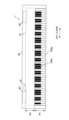
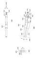
図1は、第1実施形態における鍵盤装置の構成を示す図である。鍵盤装置1は、ユーザ(演奏者)の押鍵に応じて発音する、例えば電子ピアノなどの電子鍵盤楽器である。鍵盤装置1は、外部の音源装置を制御するための制御データ(例えば、MIDI)を、押鍵に応じて出力する鍵盤型のコントローラであってもよい。この場合には、鍵盤装置1は、音源装置を有していなくてもよい。
1. First embodiment [1-1. Configuration of keyboard device]
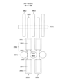
1 is a diagram showing the configuration of a keyboard device in the first embodiment. The
鍵盤装置1は、鍵盤アセンブリ10を備える。鍵盤アセンブリ10は、白鍵100w及び黒鍵100bを含む。白鍵100w及び黒鍵100bを区別する必要がない場合は、単に鍵100という。複数の白鍵100w及び黒鍵100bは並んで配列されている。鍵100の数は、N個であり、この例では88個である。これらの鍵100が配列された方向をスケール方向という。以下の説明において、符号(数字)の後に「w」が付された構成は、白鍵に対応する構成であることを意味している。符号(数字)の後に「b」が付された構成は、黒鍵に対応する構成であることを意味している。
The
鍵盤アセンブリ10の一部は、筐体90の内部に存在している。鍵盤装置1を上方から見た場合において、鍵盤アセンブリ10のうち筐体90に覆われている部分を非外観部NVといい、筐体90から露出してユーザから視認できる部分を外観部PVという。すなわち、外観部PVは、鍵100の一部であって、ユーザによって演奏操作が可能な領域を示す。以下、鍵100のうち外観部PVによって露出されている部分を鍵本体部という場合がある。
A part of the
筐体90内部には、音源装置70及びスピーカ80が配置されている。音源装置70は、鍵100の押下に伴って音波形信号を生成する。スピーカ80は、音源装置70において生成された音波形信号を外部の空間に出力する。鍵盤装置1は、音量をコントロールするためのスライダ、音色を切り替えるためのスイッチ、様々な情報を表示するディスプレイなどを備えていてもよい。
A
本明細書における説明において、上、下、左、右、手前及び奥などの方向は、演奏するときの演奏者から鍵盤装置1を見た場合の方向を示している。例えば、非外観部NVは、外観部PVよりも奥側に位置している、と表現することができる。鍵前端側(鍵前方側)、鍵後端側(鍵後方側)のように、鍵100を基準として方向を示す場合もある。この場合、鍵前端側は鍵100に対して演奏者から見た手前側を示す。鍵後端側は鍵100に対して演奏者から見た奥側を示す。この定義によれば、黒鍵100bのうち、黒鍵100bの鍵本体部の前端から後端までが、白鍵100wよりも上方に突出した部分である、と表現することができる。
In the description in this specification, directions such as up, down, left, right, front, and back refer to the directions when the player sees the
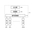
図2は、第1実施形態における音源装置の構成を示すブロック図である。音源装置70は、信号変換部710、音源部730及び出力部750を備える。センサ300は、各鍵100に対応して設けられ、鍵の操作を検出し、検出した内容に応じた信号を出力する。この例では、センサ300は、3段階の押鍵量に応じて信号を出力する。この信号の間隔に応じて押鍵速度が検出可能である。
Figure 2 is a block diagram showing the configuration of the sound source device in the first embodiment. The
信号変換部710は、センサ300(88個の鍵100に対応したセンサ300-1、300-2、・・・、300-88)の出力信号を取得し、各鍵100における操作状態に応じた操作信号を生成して出力する。この例では、操作信号はMIDI形式の信号である。押鍵操作に応じて、信号変換部710はノートオンを出力する。このとき、88個の鍵100のいずれが操作されたかを示すキーナンバ及び押鍵速度に対応するベロシティが、ノートオンに対応付けて出力される。一方、離鍵操作に応じて、信号変換部710はキーナンバとノートオフとを対応付けて出力する。信号変換部710には、ペダル等の他の操作に応じた信号が入力され、操作信号に反映されてもよい。
The
音源部730は、信号変換部710から出力された操作信号に基づいて、音波形信号を生成する。出力部750は、音源部730によって生成された音波形信号を出力する。この音波形信号は、例えば、スピーカ80又は音波形信号出力端子などに出力される。
The
[1-2.鍵盤アセンブリの構成]
図3は、第1実施形態における筐体内部の構成を側面から見た場合の説明図である。以下の説明では、白鍵100wを例示して説明するが、本実施形態に係るハンマアセンブリ200は黒鍵100bに用いることもでき、白鍵100wに用いられるハンマアセンブリ200に限定されない。図3に示すように、筐体90の内部において、鍵盤アセンブリ10及びスピーカ80が配置されている。スピーカ80は、鍵盤アセンブリ10の奥側に配置されている。このスピーカ80は、押鍵に応じた音を筐体90の上方及び下方に向けて出力するように配置されている。下方に出力される音は、筐体90の下面側から外部に進む。一方、上方に出力される音は筐体90の内部から鍵盤アセンブリ10の内部の空間を通過して、外観部PVにおける白鍵100wの隣接間の隙間又は白鍵100wと筐体90との隙間から外部に進む。
[1-2. Configuration of the keyboard assembly]
FIG. 3 is an explanatory diagram of the configuration inside the housing in the first embodiment when viewed from the side. In the following description, the white key 100w will be described as an example, but the
鍵盤アセンブリ10の構成について、図3を用いて説明する。鍵盤アセンブリ10は、上述した白鍵100w及びセンサ300の他にも、ハンマアセンブリ200、フレーム500、接続部800、及び取付部900を含む。鍵盤アセンブリ10は、ほとんどの構成が射出成形などによって製造された樹脂製の構造体である。フレーム500は筐体90に固定されている。取付部900はフレーム500に固定されている。接続部800は、取付部900に取り付けられ、白鍵100wをフレーム500に対して回動可能に接続する。白鍵100wは鍵本体部110w及び鍵支持部120wを含む。鍵本体部110wは鍵支持部120wを介して接続部800に接続されている。鍵支持部120wは板状の部材である。鍵支持部120wの一部は、他の部分に比べて板厚方向に薄く、可撓性を有している。当該可撓性によって鍵支持部120wの一部が曲がることで、白鍵100wがフレーム500に対して回動する。
The configuration of the
白鍵100wは、前端鍵ガイド150wを備える。前端鍵ガイド150wは、フレーム500の前端フレームガイド510を覆った状態で摺動可能に接触している。前端鍵ガイド150wは、その上部と下部のスケール方向の両側において、前端フレームガイド510と接触している。一方、黒鍵100bには、前端鍵ガイド150wに相当する部材は設けられていない。
The white key 100w is equipped with a front-end
ハンマアセンブリ200は、フレーム500に設けられた軸部に対して回動可能に取り付けられている。詳細は後述するが、ハンマアセンブリ200に備えられた軸受け部材220が軸部に回動可能に取り付けられている。軸部をフレーム500に固定された固定部材という場合がある。軸受け部材220を固定部材に対して回動可能に接続された回動部材という場合がある。ハンマアセンブリ200の前端部材210は、白鍵100wにおけるハンマ支持部130wの内部空間において、概ね前後方向に摺動可能にハンマ支持部130wと接触する。この摺動部分、すなわち前端部材210とハンマ支持部130wとが接触する部分は、外観部PV(鍵本体部110wの後端よりも前方)における白鍵100wの下方に位置する。
The
ハンマアセンブリ200は、ハンマアセンブリ200の回動軸よりも奥側に金属製のウェイト部材230を備えている。通常時(押鍵していないとき)には、ウェイト部材230が下側ストッパ410に載置された状態であり、ハンマアセンブリ200の前端部材210が、白鍵100wを上方に押し挙げている。押鍵されると、ウェイト部材230が上方に移動し、上側ストッパ430に衝突する。つまり、ハンマアセンブリ200は白鍵100wの動きに応じて回動する。このウェイト部材230によって、ハンマアセンブリ200は押鍵に対する加重を与える。下側ストッパ410及び上側ストッパ430は、緩衝材等(不織布、弾性体等)で形成されている。
The
鍵本体部110wの下方には、フレーム500にセンサ300が取り付けられている。押鍵により鍵本体部110wの下面側でセンサ300が押しつぶされると、センサ300は検出信号を出力する。センサ300は、上述したように、各鍵100に対応して設けられている。
A
なお、上記の様に、本実施形態では、ハンマアセンブリ200に備えられた軸受け部材220がフレーム500に備えられた軸部に回動可能に取り付けられた構成を例示するが、ハンマアセンブリ200に軸部に相当する部材が備えられ、フレーム500に軸受け部材220に相当する部材が備えられてもよい。
As described above, in this embodiment, the bearing member 220 of the
[1-3.ハンマアセンブリ200の構成]
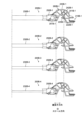
図4は、本発明の一実施形態における、グレードの異なるハンマアセンブリの一例を示す側面図である。図4に示すように、ハンマアセンブリ200は、前端部材210、軸受け部材220、ウェイト部材230、本体部材240、ウェイト支持部材250、及びマーカ部材260を備える。図4では、4種類のハンマアセンブリ200が示されている。ハンマアセンブリ200の種類によってハンマアセンブリ200-1、200-2、200-3、200-4が示されている。以下の説明において、各々のハンマアセンブリ200を区別して説明をする場合、ハンマアセンブリ200及びハンマアセンブリ200を構成する各部材の符号の後に「-1」等の枝番号を付して説明する。一方、各々のハンマアセンブリ200を区別する必要がない場合、当該枝番号を付さずに、単にハンマアセンブリ200と表現する。
[1-3. Configuration of hammer assembly 200]
FIG. 4 is a side view showing an example of a hammer assembly of different grades in an embodiment of the present invention. As shown in FIG. 4, the
本体部材240は、ハンマアセンブリ200のうちウェイト部材230を除く主要部分を構成し、ハンマアセンブリ200のフレームとして機能する部材である。本体部材240は、リブ241及び凹部242を備えている。リブ241によって本体部材240の剛性が確保されつつ、凹部242によって本体部材240の軽量化が実現されている。なお、凹部242の存在によって、本体部材240の樹脂成形のしやすさが向上する。リブ241は、ウェイト部材230が延びる方向に対して傾斜した方向に延びている。ただし、リブ241が延びる方向はウェイト部材230が延びる方向に対して傾斜していなくてもよい。
The main body member 240 constitutes the main part of the
前端部材210は、上記のように、ハンマ支持部130wに対して摺動可能に取り付けられる。前端部材210は、軸受け部材220から離れる方向に本体部材240から突出している。前端部材210は上下に二股状の突出部を有しており、2つの突出部の間の溝の部分において、ハンマ支持部130wが摺動する。
As described above, the
軸受け部材220は、軸部に取付け可能な形状を有している。具体的には、軸受け部材220は、円弧状の内壁によって構成されており、軸部に取り付けるための開口243が設けられている。ハンマアセンブリ200を軸部に取り付ける場合、軸部が開口243を通って軸受け部材220に到達するようにハンマアセンブリ200が移動する。なお、軸受け部材220は、軸部に対してスナップフィット方式で取り付けられている。つまり、軸受け部材220の開口端部の幅は軸部の径よりも小さい。
The bearing member 220 has a shape that allows it to be attached to the shaft. Specifically, the bearing member 220 is configured with an arc-shaped inner wall, and has an opening 243 for attachment to the shaft. When attaching the
ウェイト支持部材250は、軸受け部材220に対して前端部材210とは反対側に設けられている。本実施形態では、ウェイト支持部材250は前端部材210とは反対方向に本体部材240から突出している。ウェイト支持部材250は、ウェイト部材230の一部を覆った状態でウェイト部材230を固定している。ウェイト支持部材250は、ウェイト部材230がウェイト支持部材250の内側に配置された状態で樹脂成形される。ハンマアセンブリ200-1~200-4において、それぞれのウェイト支持部材250に対するウェイト部材230の位置が異なるため、ウェイト支持部材250-1~250-4は形状が異なる。ウェイト支持部材250には凹部251が設けられている。凹部251はウェイト部材230を挟むように2箇所に設けられている。当該樹脂成形の際に凹部251を介してウェイト部材230を挟んだ状態で樹脂成形が行われる。
The weight support member 250 is provided on the opposite side of the bearing member 220 to the
ウェイト部材230は、ウェイト支持部材250において固定されており、本体部材240から離れる方向に延びている。つまり、ウェイト部材230は棒状である。図4の4つのハンマアセンブリ200-1~200-4の下にウェイト支持部材250から取り外された状態のウェイト部材230が示されている。ウェイト部材230は、第1部分231及び第2部分232を備えている。本実施形態では、第2部分232の全てと第1部分231の一部とがウェイト支持部材250によって覆われている。ウェイト部材230の詳細な構成は後述するが、第1部分231は鍵100の長手方向に長手を有している。第1部分231の当該長手方向に直交する断面形状は円形である。つまり、第1部分231は円柱状である。第2部分232は、第1部分231が潰れた形状である。
The
本実施形態では第1部分231の断面形状が円形である構成を例示したが、この構成に限定されない。例えば、当該断面形状は矩形であってもよく、その他の多角形であってもよく、楕円形であってもよい。なお、第1部分231の断面形状が棒状であるとは、第1部分231が長手を有し、かつ、第1部分231の断面形状が円形、正方形、[短辺/長辺]が3/4以上1未満の長方形、又は当該断面形状に外接する矩形において互いに直交する第1辺及び第2辺の比[第1辺/第2辺]が3/4以上4/3以下である場合を意味する。一方、上記以外の場合を板状という。つまり、第2部分232の断面形状が板状であるとは、第2部分232の断面形状が[短辺/長辺]が3/4未満の長方形、又は当該断面形状に外接する矩形における上記第1辺及び第2辺の比[第1辺/第2辺]が3/4未満又は4/3より大きい場合を意味する。
In this embodiment, the cross-sectional shape of the
詳細は後述するが、第2部分232を除き、長手方向の任意の複数の点におけるウェイト部材230の断面形状(長手方向に直交する断面の形状)は同じである。換言すると、ウェイト部材230の長手方向における全長に対する半分以上の長さの領域において、長手方向の任意の複数の点におけるウェイト部材230の断面形状は同じである。また、換言すると、ウェイト部材230の長手方向において、ウェイト部材230の両端部からウェイト部材230の全長に対する10%の長さの領域を除いた領域において、当該長手方向の任意の複数の点におけるウェイト部材230の断面形状は同じである。さらに換言すると、ウェイト支持部材250-1から露出されたウェイト部材230-1の断面形状は、ウェイト部材230-1の長手方向に略均一である。また、詳細は後述するが、第2部分232の形状は、第1部分231が潰れた形状なので、長手方向の任意の複数の点におけるウェイト部材230(第1部分231及び第2部分232を含む)の断面積(長手方向の任意の複数の点に直交する断面積)は同じである。換言すると、第1部分231及び第2部分232の当該断面積は同じである。
Although details will be described later, except for the
上記のウェイト部材230の長手方向に直交する断面における最大の長さ(例えば、断面形状が矩形の場合は対角線の長さ)と、ウェイト部材230の長手方向の全長とを対比した場合、断面における最大長さに対する長手方向の全長の比(つまり、全長/断面における最大長さ)が2.5以上である場合、仮に当該断面形状における[第1辺/第2辺]が3/4未満又は4/3より大きい場合であっても棒状という場合がある。
When comparing the maximum length of the cross section perpendicular to the longitudinal direction of the weight member 230 (for example, the length of the diagonal if the cross section is rectangular) with the total length in the longitudinal direction of the
ハンマアセンブリ200-1~200-4では、ウェイト部材230の形状に差はない。つまり、ウェイト部材230-1~230-4の各々の形状は同一である。同様に、ウェイト部材230-1~230-4の各々の材質は同一である。形状及び材質が同様である結果、ウェイト部材230-1~230-4の各々の質量は同一である。したがって、例えば、ウェイト部材230-1を他のハンマアセンブリ200-2~200-4に用いることができる。
There is no difference in the shape of the
一方、それぞれウェイト部材230-1~230-4がウェイト支持部材250-1~250-4に取り付けられている位置が異なる。図4に示すように、第2部分232の端部に相当する位置(ウェイト支持部材250の右の端部の位置)は、ハンマアセンブリ200-1、200-2、200-3、200-4の順に、軸受け部材220に近づいている。つまり、ウェイト部材230-2の右側端部は、ウェイト部材230-1の右側端部よりも軸受け部材220に近い。ウェイト部材230-3の右側端部は、ウェイト部材230-2の右側端部よりも軸受け部材220に近い。ウェイト部材230-4の右側端部は、ウェイト部材230-3の右側端部よりも軸受け部材220に近い。つまり、ウェイト支持部材250-1~250-4はそれぞれ形状が異なっている。 On the other hand, the positions at which the weight members 230-1 to 230-4 are attached to the weight support members 250-1 to 250-4 are different. As shown in FIG. 4, the position corresponding to the end of the second portion 232 (the position of the right end of the weight support member 250) is closer to the bearing member 220 in the order of the hammer assemblies 200-1, 200-2, 200-3, and 200-4. In other words, the right end of the weight member 230-2 is closer to the bearing member 220 than the right end of the weight member 230-1. The right end of the weight member 230-3 is closer to the bearing member 220 than the right end of the weight member 230-2. The right end of the weight member 230-4 is closer to the bearing member 220 than the right end of the weight member 230-3. In other words, the weight support members 250-1 to 250-4 have different shapes.
上記の構成によって、ウェイト部材230の先端(左側端部)の位置は、ハンマアセンブリ200-1、200-2、200-3、200-4の順に、回動中心222に近づいている。つまり、ウェイト部材230の重心の位置は、ハンマアセンブリ200-1、200-2、200-3、200-4の順に、軸受け部材220に近づいている。具体的には、ウェイト部材230-1の重心と回動中心222-1との距離は、ウェイト部材230-2の重心と回動中心222-2との距離と異なる。その結果、ハンマアセンブリ200-1~200-4の各々の慣性モーメントが異なる。上記のように、ウェイト部材230-1~230-4の各々の形状及び質量は同一なので、ウェイト部材230-1~230-4自体の重心は同じであるが、ウェイト部材230-1~230-4を取り付ける位置によってハンマアセンブリ200-1~200-4の各々の慣性モーメントが異なる。
With the above configuration, the position of the tip (left end) of the
第1部分231は、長手を軸とする円柱状の形状である。第2部分232は、スケール方向に対向する主面を有する平板状の形状である。第2部分232の上下方向の幅は第1部分231の上下方向の幅よりも大きい。第2部分232は第1部分231が潰れた形状である。第2部分232はウェイト支持部材250に覆われている。また、ウェイト支持部材250は第2部分232と第1部分231との境界部分233を覆っている。
The
ウェイト部材230が平板状の第2部分232を有していることで、ウェイト部材230の長手方向を軸としたウェイト部材230の回転が規制される。つまり、第2部分232及びそれを覆うウェイト支持部材250は、ウェイト部材230の上記回転を規制するストッパとして機能する。また、ウェイト支持部材250が境界部分233を覆っていることで、ウェイト部材230が軸受け部材220から離れる方向へ移動することが規制される。つまり、境界部分233及びそれを覆うウェイト支持部材250は、ウェイト部材230の上記移動を規制するストッパとして機能する。
Since the
ハンマアセンブリ200は、回動中心222を中心として回動する。白鍵100wの音階に応じてハンマアセンブリ200-1~200-4が用いられる。又は、黒鍵100bの音階に応じてハンマアセンブリ200-1~200-4が用いられる。つまり、白鍵100wと黒鍵100bとの間で異なるハンマアセンブリ200-1~200-4が用いられるのではなく、複数の白鍵100w又は複数の黒鍵100bの中で異なるハンマアセンブリ200-1~200-4が用いられる。
The
マーカ部材260は、本体部材240の上部に設けられている。ハンマアセンブリ200-1~200-4の各々に設けられたマーカ部材260-1~260-4は、それぞれ異なる形状を有している。具体的には、マーカ部材260-1は1個の突起部を有しており、マーカ部材260-2は2個の突起部を有しており、マーカ部材260-3は3個の突起部を有しており、マーカ部材260-4は4個の突起部を有している。慣性モーメントが同一のハンマアセンブリ200には同一のマーカ部材260が設けられており、慣性モーメントが異なるハンマアセンブリ200には異なるマーカ部材260が設けられている。つまり、作業者はマーカ部材260に設けられた突起部の数に基づいて、ハンマアセンブリ200の種類を認識することができる。
The marker member 260 is provided on the upper part of the main body member 240. The marker members 260-1 to 260-4 provided on the hammer assemblies 200-1 to 200-4 each have a different shape. Specifically, the marker member 260-1 has one protrusion, the marker member 260-2 has two protrusions, the marker member 260-3 has three protrusions, and the marker member 260-4 has four protrusions. The same marker member 260 is provided on the
本実施形態では、ウェイト部材230-1~230-4が同一形状である構成を例示したが、ウェイト部材230-1~230-4の一部又は全部の形状が異なっていてもよい。本実施形態では、ウェイト部材230-1~230-4が同一材料である構成を例示したが、ウェイト部材230-1~230-4の一部又は全部が異なる材料であってもよい。本実施形態では、ウェイト部材230-1~230-4が棒状である構成を例示したが、一例を後述するように、ウェイト部材230-1~230-4は棒状以外の形状であってもよい。本実施形態では、ウェイト支持部材250-1~250-4の形状が異なる構成を例示したが、ウェイト支持部材250-1~250-4の一部又は全部が同一の構成であってもよい。 In this embodiment, the weight members 230-1 to 230-4 have the same shape, but some or all of the weight members 230-1 to 230-4 may have different shapes. In this embodiment, the weight members 230-1 to 230-4 have the same material, but some or all of the weight members 230-1 to 230-4 may have different materials. In this embodiment, the weight members 230-1 to 230-4 have a rod shape, but as an example will be described later, the weight members 230-1 to 230-4 may have a shape other than a rod shape. In this embodiment, the weight support members 250-1 to 250-4 have different shapes, but some or all of the weight support members 250-1 to 250-4 may have the same shape.
以上のように、本実施形態に係るハンマアセンブリ200によると、同一のウェイト部材230を用いて、慣性モーメントが異なる複数のハンマアセンブリ200を実現することができる。その結果、ハンマアセンブリ200ごとに異なるウェイト部材230を準備する必要がないため、製造コスト及び作業負担の小さい鍵盤装置を実現することができる。
As described above, according to the
[1-4.変形例]
図5を用いて、第1実施形態の変形例について説明する。図5は、本発明の一実施形態における、グレードの異なるハンマアセンブリの一例を示す側面図である。図5(A)に示すハンマアセンブリ200Aは、図4に示すハンマアセンブリ200と類似しているが、ウェイト部材230Aの形状がウェイト部材230の形状と異なる点において、ハンマアセンブリ200と相違する。以下の説明において、図4のハンマアセンブリ200と同様の特徴については説明を省略し、主にハンマアセンブリ200と相違する点について説明する。なお、以下の説明において、第1実施形態と同様の構成について説明をする場合、図1~図4を参照し、これらの図に示された符号の後にアルファベット“A”を付して説明する。
[1-4. Modifications]
A modified example of the first embodiment will be described with reference to FIG. 5. FIG. 5 is a side view showing an example of a hammer assembly of a different grade in one embodiment of the present invention. The
図5(B)に示すように、ウェイト部材230Aは板状である。ウェイト部材230Aは板金加工等によって形成することができる。図5の例では、ウェイト部材230Aの形状は、スケール方向に見て、長方形の第1-1部分270Aの先端に台形の第1-2部分280Aが設けられた形状である。第1-1部分270Aに対して第1-2部分280Aとは反対側に、第2部分232Aが設けられている。第2部分232Aの形状は、第1-1部分270Aの一部が潰れた形状である。なお、図5の例は一実施例に過ぎず、ウェイト部材230Aとして図5に示す形状以外の板状部材を用いることができる。
As shown in FIG. 5(B), the
ハンマアセンブリ200A-1~200A-4において、ウェイト部材230A-1~230A-4の形状に差はない。つまり、ウェイト部材230A-1~230A-4の各々の形状は同一である。同様に、ウェイト部材230A-1~230A-4の各々の材質は同一である。形状及び材質が同様である結果、ウェイト部材230A-1~230A-4の各々の質量は同一である。したがって、例えば、ウェイト部材230A-1を他のハンマアセンブリ200A-2~200A-4に用いることができる。一方で、図4と同様に、それぞれウェイト部材230A-1~230A-4がウェイト支持部材250A-1~250A-4に取り付けられている位置が異なる。その結果、ハンマアセンブリ200A-1~200A-4の各々の慣性モーメントが異なる。
There is no difference in the shape of the
以上のように、第1実施形態の変形例によると、同一のウェイト部材230Aを用いて、慣性モーメントが異なる複数のハンマアセンブリ200Aを実現することができる。その結果、ハンマアセンブリ200Aごとに異なるウェイト部材230Aを準備する必要がないため、製造コスト及び作業負担の小さい鍵盤装置を実現することができる。
As described above, according to the modified example of the first embodiment, it is possible to realize
2.第2実施形態
[2-1.ハンマアセンブリ200Bの構成]
図6を用いて、第2実施形態について説明する。図6は、本発明の一実施形態における、グレードの異なるハンマアセンブリの一例を示す側面図である。図6に示すハンマアセンブリ200Bは、図4に示すハンマアセンブリ200と類似しているが、ハンマアセンブリ200Bのウェイト部材230B-1~230B-4の形状がハンマアセンブリ200のウェイト部材230-1~230-4の形状と相違する。以下の説明において、図4のハンマアセンブリ200と同様の特徴については説明を省略し、主にハンマアセンブリ200と相違する点について説明する。なお、以下の説明において、他の実施形態と同様の構成について説明をする場合、図1~図5を参照し、これらの図に示された符号の後にアルファベット“B”を付して説明する。
2. Second embodiment [2-1. Configuration of
The second embodiment will be described with reference to FIG. 6. FIG. 6 is a side view showing an example of a hammer assembly of a different grade in one embodiment of the present invention. The
ハンマアセンブリ200Bは、回動中心222Bを中心として回動する。白鍵100wBの音階に応じてハンマアセンブリ200B-1~200B-4が用いられる。又は、黒鍵100bBの音階に応じてハンマアセンブリ200B-1~200B-4が用いられる。つまり、白鍵100wBと黒鍵100bBとの間で異なるハンマアセンブリ200B-1~200B-4が用いられるのではなく、複数の白鍵100wB又は複数の黒鍵100bBの中で異なるハンマアセンブリ200B-1~200B-4が用いられる。
The
図6に示すように、鍵100Bの長手方向において、ウェイト部材230B-1~230B-4がウェイト支持部材250B-1~250B-4にそれぞれ取り付けられている位置は同一である。つまり、鍵100Bの長手方向におけるウェイト支持部材250B-1~250B-4の端部の位置は同一である。また、鍵100Bの長手方向において、ウェイト部材230B-1~230B-4の先端の位置は同一である。一方、ウェイト部材230B-1~230B-4の径(太さ)が相違する。換言すると、ウェイト部材230B-1~230B-4の延伸方向に直交する断面における断面積は異なる。具体的には、ウェイト部材230B-1の延伸方向に直交するウェイト部材230B-1の断面積は、当該延伸方向において略均一である。同様に、ウェイト部材230B-4の延伸方向に直交するウェイト部材230B-4の断面積は、当該延伸方向において略均一である。なお、延伸方向とは、後述するように、ウェイト部材230Bの任意の位置において断面積が最小になる方向の断面に対して直交する方向を意味する。
As shown in FIG. 6, the
上記の構成を換言すると、ウェイト支持部材250B-1から露出されたウェイト部材230B-1の延伸方向に直交するウェイト部材230B-1の断面積は、ウェイト部材230B-1の延伸方向に略均一である。同様に、ウェイト支持部材250B-4から露出されたウェイト部材230B-4の延伸方向に直交するウェイト部材230B-4の断面積は、ウェイト部材230B-4の延伸方向に略均一である。
In other words, the cross-sectional area of
ウェイト部材230B-1~230B-4は同一材料で構成されているため、上記の径(太さ)及び断面積によって、ウェイト部材230B-1~230B-4の質量は異なる。なお、径(太さ)は、ウェイト部材230Bの断面形状が円形である場合はその直径を意味し、ウェイト部材230Bが円形ではない場合は、その断面形状における最大幅を意味する。
Since the
本実施形態におけるウェイト部材230Bは、ウェイト部材230B-1~230B-4の各々において長手方向の任意の複数の点における断面積が均一である構成(つまり、長手方向の任意の複数の点における径が一定である構成)を有する。ウェイト部材230B-1~230B-4の各々を形成する場合、1本の棒状の母体から所定の長さを切り出すことで、各ウェイト部材230Bを得ることができる。
In this embodiment, the
なお、上記のウェイト部材230Bの延伸方向に直交する断面を換言すると、ウェイト部材の長手方向における端部以外の位置において断面積が最小になる方向の断面ということができる。例えば、ウェイト部材230Bが湾曲している場合、上記の断面積を評価するための断面の方向は、常に一定の方向ではなく、当該位置において断面積が最小になる方向の断面である。つまり、ウェイト部材230Bが湾曲している場合において当該断面積を評価するための断面の方向は、ウェイト部材230Bの延伸方向の位置によって異なる。換言すると、延伸方向とは、ウェイト部材230Bの任意の位置において断面積が最小になる方向の断面に対して直交する方向を意味する。
In addition, the cross section perpendicular to the extension direction of the
ウェイト部材230B-1~230B-4は異なる断面積を有しているが、ウェイト部材230B-1~230B-4の各々は、長手方向の任意の複数の点における断面積がほぼ均一である。したがって、鍵100Bの長手方向において、ウェイト部材230B-1~230B-4の各々の重心の位置はほぼ同じである。例えば、ウェイト部材230B-1の重心と回動中心222B-1との距離は、ウェイト部材230B-2の重心と回動中心222B-2との距離と同じである。
The
上記のように、ウェイト部材230B-1~230B-4の質量が異なるため、ハンマアセンブリ200B-1~200B-4の各々の慣性モーメントが異なる。ウェイト部材230B-1~230B-4の形状は、図4に示すウェイト部材230の形状と同一又は類似である。つまり、ウェイト部材230B-1~230B-4の各々は、図4に示すウェイト部材230と同様に、第1部分231B及び第2部分232を有している。
As described above, the masses of the
本実施形態では、鍵100Bの長手方向において、ウェイト部材230B-1~230B-4の各々の重心の位置はほぼ同じである構成を例示したが、ウェイト部材230B-1~230B-4の各々の重心の位置が異なっていてもよい。ウェイト部材230B-1~230B-4のうち重心の位置が異なる組み合わせについては、質量が同じであってもよい。ウェイト部材230B-1~230B-4の材料は一部又は全部が異なっていてもよい。
In this embodiment, the
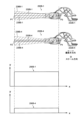
図7は、本実施形態において、質量が異なるウェイト部材230B-1、230B-4について、ハンマアセンブリ200Bの回動範囲内における各ウェイト部材の中心線の回転面(又は回転軌跡)を示した図である。ウェイト部材230B-1、230B-4の各々の中心線239B-1、239B-4が点線で示されている。ハンマアセンブリ200Bが回動した場合に、これらの中心線が描く回転面238B-1、238B-4が斜線のハッチングで示されている。スケール方向にハンマアセンブリ200Bを見た場合、回転面238B-1、238B-4は重なっており、回転面238B-1、238B-4の各々の外縁はほぼ一致している。換言すると、回転面238B-1と回転面238B-4とはほぼ同一の形状である。
Figure 7 shows the rotation planes (or rotation trajectories) of the center lines of the
スケール方向にハンマアセンブリ200Bを見た場合、中心線239B-1の先端P1と中心線239B-4の先端P2とはほぼ重なっている(一致している)。先端P1、P2は、回動中心222B-1、222B-4から遠い側のウェイト部材230B-1、230B-4の先端である。上記と同様に、スケール方向にハンマアセンブリ200Bを見た場合、中心線239B-1の先端P3と中心線239B-4の先端P4とはほぼ重なっている(一致している)。先端P3、P4は、回動中心222B-1に近い側のウェイト部材230B-1、230B-4の先端である。
When the
図7には、鍵100Bの長手方向をx軸とし、ウェイト部材230B-1、230B-4の線密度をy軸としたグラフが示されている。グラフ290B-1はウェイト部材230B-1の線密度を示し、グラフ290B-4はウェイト部材230B-4の線密度を示す。グラフ290B-1を描く関数は、グラフ290B-4を描く関数を定数倍した関数である。
Figure 7 shows a graph with the longitudinal direction of key 100B as the x-axis and the linear density of
なお、図7に示す例では、ウェイト部材230B-1、230B-4に対応する領域のグラフ290B-1、290B-4が直線である構成を示したが、この構成に限定されない。例えば、これらのグラフが曲線であってもよい。
In the example shown in FIG. 7, the
以上のように、本実施形態に係るハンマアセンブリ200Bによると、断面積の異なるウェイト部材230Bを準備することで、慣性モーメントが異なる複数のハンマアセンブリ200Bを実現することができる。
As described above, with the
また、ウェイト部材の長さを調整することで慣性モーメントの異なる複数のハンマアセンブリを形成する場合、ウェイト部材の先端又は根本を切断して短くする必要がある。ウェイト部材の先端側を短くする場合、フレームに設けられるストッパ(下側ストッパ410及び上側ストッパ430に相当するストッパ)は、最も短いウェイト部材に合わせて配置する必要がある。ストッパは、複数のハンマアセンブリに対して共通して設けられている。したがって、上記のようにストッパが配置された場合、最も長いウェイト部材では、ウェイト部材の先端がストッパを越えた位置に存在する。その結果、ウェイト部材がストッパに衝突したときに、ウェイト部材のうちストッパと衝突した箇所から先端までの部分が振動することにより、ウェイト部材全体の振動が発生してしまう。一方、ウェイト部材の根本側を短くする場合、ウェイト部材を支持するウェイト支持部材の形状をウェイト部材に合わせて設計する必要があり、そのようなウェイト支持部材を形成するために別々の樹脂成形用の金型が必要になる。
In addition, when forming multiple hammer assemblies with different moments of inertia by adjusting the length of the weight member, it is necessary to cut or shorten the tip or base of the weight member. When shortening the tip side of the weight member, the stopper (the stopper corresponding to the
本実施形態に係るウェイト部材230Bを用いることで、上記のような問題点を解消することができる。
By using the
また、本実施形態に係る構成によって、演奏者が鍵100Bを弱打した場合と強打した場合との間のタッチ感のバランスを、異なる鍵100Bの間で同じにすることができる。つまり、ハンマアセンブリ200B-1、200B-4において同じ力で弱打した場合のタッチ感の比は、ハンマアセンブリ200B-1、200B-4において同じ力で強打した場合のタッチ感の比と略同一である。例えば、同じ力で弱出した場合において、ハンマアセンブリ200B-1によって演奏者が受ける重みとハンマアセンブリ200B-4によって演奏者が受ける重みとの比が3倍であるとき、同じ力で強打した場合において、上記の重みの比は3倍である。より詳細に説明すると、上記の構成によって静的な慣性モーメントのつり合い(静的なタッチ感)と、慣性モーメントに起因するハンマアセンブリ200Bの回動が加速する際に生じる反力(動的なタッチ感)と、の相対比をハンマアセンブリ200B-1、200B-4の各々に属する鍵100B間で同程度にすることができる。
Furthermore, the configuration according to this embodiment allows the balance of the touch sensation between when the player hits the key 100B lightly and when the player hits it hard to be the same for different keys 100B. In other words, the ratio of the touch sensation when the
3.第3実施形態
[3-1.ハンマアセンブリ200Dの構成]
図8を用いて、第3実施形態について説明する。図8は、本発明の一実施形態におけるハンマアセンブリの一例を示す図である。図8に示すハンマアセンブリ200Dは、図4に示すハンマアセンブリ200と類似しているが、1つのハンマアセンブリ200Dに複数のウェイト部材230Dが設けられている点において、ハンマアセンブリ200と相違する。以下の説明において、図4のハンマアセンブリ200と同様の特徴については説明を省略し、主にハンマアセンブリ200と相違する点について説明する。なお、以下の説明において、他の実施形態と同様の構成について説明をする場合、図1~図7を参照し、これらの図に示された符号の後にアルファベット“D”を付して説明する。
3. Third embodiment [3-1. Configuration of
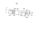
The third embodiment will be described with reference to FIG. 8. FIG. 8 is a diagram showing an example of a hammer assembly in one embodiment of the present invention. The
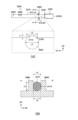
図8(B)、(C)に示すように、ハンマアセンブリ200Dのウェイト部材230Dは、第1ウェイト部材236D及び第2ウェイト部材237Dを有する。ハンマアセンブリ200Dは、軸受け部材220Dによってフレーム500Dの軸部に対して回動可能に取り付けられる。第1ウェイト部材236D及び第2ウェイト部材237Dは、ハンマアセンブリ200Dの回動中心222Dに対して、鍵100Dがハンマアセンブリ200Dに作用する部分(前端部材210D)とは逆側に設けられている。ハンマアセンブリ200Dの回動によって、ウェイト部材230Dは、ウェイト部材230Dの回動方向(R方向)に回動する。この回動によって形成される第1ウェイト部材236Dの回転面は、第2ウェイト部材237Dの回転面と重なる。つまり、第1ウェイト部材236Dは、第2ウェイト部材237Dの回転面238D内に設けられている。換言すると、第1ウェイト部材236Dと第2ウェイト部材237Dとは、鍵盤装置1Dが演奏される状態において、鉛直方向に重なっている。ただし、第1ウェイト部材236Dと第2ウェイト部材237Dとは、当該状態において鉛直方向に重なっていなくてもよい。
8(B) and (C), the
本実施形態において、第1ウェイト部材236D及び第2ウェイト部材237Dは、いずれも棒状(円柱状)であり、各々の形状は同じである。第1ウェイト部材236D及び第2ウェイト部材237Dはウェイト支持部材250Dにおいて固定されている。打鍵時において、第1ウェイト部材236Dが上側ストッパ430D(図3参照)に接触した状態で、第1ウェイト部材236Dが上側ストッパ430を押す方向が、第1ウェイト部材236Dの長手方向に対して直交する方向である。同様に、離鍵時において、第2ウェイト部材237Dが下側ストッパ410D(図3参照)に接触した状態で、第2ウェイト部材237Dが下側ストッパ410Dを押す方向が、第2ウェイト部材237Dの長手方向に対して直交する方向である。
In this embodiment, the
また、第1ウェイト部材236D及び第2ウェイト部材237Dは、ウェイト支持部材250Dからこれらのウェイト部の先端に向かって両者間の距離が小さくなるように配置されている。このような配置によって、第1ウェイト部材236D及び第2ウェイト部材237Dはウェイト支持部材250Dにおいて強固に保持されつつ、これらのウェイト部材の先端付近では専有領域を小さくすることができる。なお、本実施形態において、上記のような思想で構成された第1ウェイト部材236Dの長手方向と第2ウェイト部材237Dの長手方向とは非平行である。
The
上記のように、第1ウェイト部材236Dが第2ウェイト部材237Dの回転面238D内に設けられる構成が実現されるため、ウェイト支持部材250Dは本体部材240Dの側方に設けられており、その一部は下方に突出している。ウェイト支持部材250Dと本体部材240Dとを接続するために、リブ244Dが設けられている。
As described above, in order to realize a configuration in which the
前端部材210Dは、図4に示す前端部材210とは異なり、接続部材211D及び係止部材212Dを有する。接続部材211Dは、本体部材240Dと係止部材212Dとの間においてこれらを接続する。接続部材211Dは板状である。係止部材212Dは、接続部材211Dの端部に設けられている。係止部材212Dは板状の接続部材211Dからスケール方向に突出している。上記の前端部材210Dの係止部材212Dが、ハンマ支持部130w(図3参照)の内壁部分に対して摺動することで、ハンマアセンブリ200Dが鍵100Dの動きに応じて回動する。なお、図8に示すようなハンマアセンブリ200Dが用いられる場合、上記の前端部材210Dの形状に合わせてハンマ支持部130wの内壁の形状が設計される。
The
本実施形態では、第1ウェイト部材236D及び第2ウェイト部材237Dがいずれも円柱形状である構成が例示されているが、この構成に限定されない。例えば、図4に示すウェイト部材230のように、第1ウェイト部材236D及び第2ウェイト部材237Dの各々について、ウェイト支持部材250Dによって覆われた領域の一部が潰れた形状であってもよい。又は、図4のように、異なるハンマアセンブリ200Dにおいて、第1ウェイト部材236D及び第2ウェイト部材237Dの一方又は両方がウェイト支持部材250Dに取り付けられる位置が異なり、ハンマアセンブリ200Dによって慣性モーメントが異なるように構成されてもよい。又は、図5のように、異なるハンマアセンブリ200において第1ウェイト部材236D及び第2ウェイト部材237Dの一方又は両方の最大断面積が異なり、ハンマアセンブリ200Dによって慣性モーメントが異なるように構成されてもよい。
In this embodiment, the
また、本実施形態では、第1ウェイト部材236D及び第2ウェイト部材237Dが、それぞれ棒状である構成を例示したが、この構成に限定されない。後述するように、第1ウェイト部材236D及び第2ウェイト部材237Dが棒状でなくてもよい。第1ウェイト部材236Dと第2ウェイト部材237Dとが棒状であるばあい、これらが平行であってもよい。また、上記のように、第1ウェイト部材236Dの形状が第2ウェイト部材の形状と異なってもよい。
In addition, in this embodiment, the
以上のように、本実施形態に係るハンマアセンブリ200Dによると、鍵100Dの長手方向におけるハンマアセンブリ200Dの長さを短くすることができるため、鍵盤装置1Dの奥行き方向の省スペース化を実現することができる。また、第1ウェイト部材236D及び第2ウェイト部材237Dに同一のウェイト部材を用いることができれば、製造コスト及び作業負担の小さい鍵盤装置を実現することができる。
As described above, with the
[3-2.変形例]
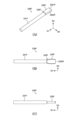
図9を用いて、第3実施形態の変形例について説明する。図9は、本発明の一実施形態におけるハンマアセンブリの一例を示す図である。図9に示すハンマアセンブリ200Eは、図8に示すハンマアセンブリ200Dと類似しているが、第1ウェイト部材236D及び第2ウェイト部材237Dの形状が棒状ではない点において、ハンマアセンブリ200Dと相違する。以下の説明において、図8のハンマアセンブリ200Dと同様の特徴については説明を省略し、主にハンマアセンブリ200Dと相違する点について説明する。なお、以下の説明において、他の実施形態と同様の構成について説明をする場合、図1~図8を参照し、これらの図に示された符号の後にアルファベット“E”を付して説明する。
[3-2. Modifications]
A modified example of the third embodiment will be described with reference to FIG. 9. FIG. 9 is a diagram showing an example of a hammer assembly in one embodiment of the present invention. The
図9に示すように、ハンマアセンブリ200Eのウェイト部材230Eは、平板状の第1ウェイト部材236E及び第2ウェイト部材237Eを有する。図8と同様に、第1ウェイト部材236Eは、第2ウェイト部材237Eの回転面238E内に設けられている。第1ウェイト部材236E及び第2ウェイト部材237Eは、例えば、リブ241Eによって囲まれた凹部242Eに設けることができる。又は、凹部242Eの代わりに開口部が設けられており、当該開口部にウェイト部材が設けられてもよい。
As shown in FIG. 9, the
以上のように、第3実施形態の変形例によると、鍵100Eの長手方向におけるハンマアセンブリ200Eの長さを短くすることができるため、鍵盤装置1Eの奥行き方向の省スペース化を実現することができる。
As described above, according to the modified example of the third embodiment, the length of the
なお、図8及び図9では、第1ウェイト部材236D、236E及び第2ウェイト部材237D、237Eが、ハンマアセンブリ200D、200Eの回動中心222D、222Eに対して、鍵100D、100Eがハンマアセンブリ200D、200Eに作用する部分(前端部材210D、210E)とは逆側に設けられた構成を例示したが、この構成に限定されない。例えば、第1ウェイト部材236D、第2ウェイト部材237D、及び鍵100Dがハンマアセンブリ200Dに作用する部分は、回動中心222Dに対して同じ側に設けられていてもよい。つまり、当該2つのウェイト部材236D、237Dと回動中心222Dとの間において、鍵100Dがハンマアセンブリ200Dに作用してもよい。
8 and 9, the
4.第4実施形態
[4-1.ハンマアセンブリ200Fの構成]
図10を用いて、第4実施形態について説明する。図10は、本発明の一実施形態において、ハンマアセンブリがフレームに取り付けられた状態における構成を上方から見た図である。図10に示すハンマアセンブリ200Fは、図4に示すハンマアセンブリ200-1がフレーム500に取り付けられた状態の上方から見た断面図である。以下の説明において、図4のハンマアセンブリ200と同様の特徴については説明を省略し、第1実施形態では説明していない点について説明する。なお、以下の説明において、他の実施形態と同様の構成について説明をする場合、図1~図9を参照し、これらの図に示された符号の後にアルファベット“F”を付して説明する。
4. Fourth embodiment [4-1. Configuration of
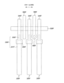
The fourth embodiment will be described with reference to FIG. 10. FIG. 10 is a diagram showing a configuration in a state where a hammer assembly is attached to a frame in one embodiment of the present invention, as viewed from above. The
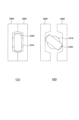
図10に示すように、ハンマアセンブリ200Fは軸部520Fに取り付けられている。軸部520Fはスケール方向(「第1方向」という場合がある)に延びている。複数のハンマアセンブリ200F(ウェイト部分230F)同士はスケール方向に隣接している。複数のリブ590F同士はスケール方向に隣接している。隣接するハンマアセンブリ200Fの間にリブ590F及びボス580Fが設けられている。ハンマアセンブリ200Fに備えられたウェイト部分230Fは第1部分231F及び第2部分232Fを含む。以下の説明において、隣接するリブ590F及びボス580Fの少なくともいずれかを、「第1部材」という場合がある。
As shown in FIG. 10, the
スケール方向において、第2部分232Fの幅は第1部分231Fの幅より小さい。詳細は後述するが、第2部分232Fは、スケール方向に第1部分231Fが潰れた形状である。第1部分231Fは上記の第1部材(リブ590F及びボス580F)と対面せず、第2部分232Fは当該第1部材と対面する。換言すると、第1部材は、スケール方向に隣接する第2部分232Fによって挟まれた領域に設けられている。一方、スケール方向に隣接する第1部分231Fによって挟まれた領域には、第1部材は設けられていない。換言すると、スケール方向に見て、第2部分232Fと第1部材とは重なるが、第1部分231Fと第1部材とは重ならない。なお、全てのハンマアセンブリ200Fと第1部材との間に上記の関係が満たされている必要はなく、少なくとも一部のハンマアセンブリ200Fと第1部材との間で上記の関係が成り立っていればよい。
In the scale direction, the width of the
リブ590F及びボス580F(第1部材)は、フレーム500Fの一部、つまりフレーム500Fと一体形成されていてもよく、接着等によってフレーム500Fに固定された部材であってもよい。図10の例では、2つのリブ590Fの一方の先端にボス580Fが設けられている。ただし、ボス580Fは2つのリブ590Fの両方の先端に設けられていてもよい。スケール方向において、ボス580Fの幅はリブ590Fの幅より大きい。ウェイト支持部材250Fは第2部分232Fの全てと第1部分231Fの一部とを覆っている。
The
上記の構成を換言すると、隣接するリブ590F(第1部材)の間のウェイト部材230Fの一部は、スケール方向(第1方向)に潰れた形状である、ということができる。さらに換言すると、ウェイト部材230Fのうち隣接するリブ590Fの間の部分に相当する第2部分232Fは、第1部分231Fに比べてスケール方向の厚みが小さい。この構成によって、スケール方向において、第2部分232Fに対応する領域のウェイト支持部材250Fの厚みは、第1部分231Fに対応する領域のウェイト支持部材250Fの厚みよりも小さい。
In other words, the part of the
鍵盤装置1Fでは、鍵100Fに隣接する位置に、フレーム500Fの強度を向上させるためのリブ590Fが設けられる場合や、他の部材との接続に用いられるボス580Fが設けられる場合がある。鍵盤装置1Fの縮小化に伴い、リブ590F及びボス580Fを配置するスペースが制限されると、リブ590Fやボス580Fを鍵100Fに隣接する位置に配置する必要性が生じる場合がある。そのような場合であっても、上記の構成によって、ウェイト部材230Fの重量を確保しつつ鍵100Fとの干渉を避けることができる。
In the keyboard device 1F, a
なお、本実施形態では、ウェイト部材230Fに対してスケール方向に隣接するリブ590F及びボス580Fが第1部材に相当する場合について説明したが、この構成に限定されない。例えば、第1部材は、上下方向においてウェイト部材230Fを挟む部材であってもよい。つまり、上下方向において第1部材と第2部材との間にウェイト部材230Fが設けられていてもよい。
In this embodiment, the
[4-2.ウェイト部材230Fの構成]
図11は、本発明の一実施形態におけるウェイト部材の一例を示す図である。図11(A)~(C)に示すように、ウェイト部材230Fは第1部分231F及び第2部分232Fを有する。第1部分231Fは棒状、具体的には円柱状である。第2部分232Fは平板状である。第2部分232Fは第1部分231Fの一部が両側から潰されることで形成されている。したがって、D3方向において、第2部分232Fの幅は第1部分231Fの幅より小さい。D2方向において、第2部分232Fの長さは第1部分231Fの長さより大きい。また、ウェイト部材230Fの長手方向(D1方向)に対して直交する断面において、第1部分231Fの断面積は第2部分232Fの断面積とほぼ等しい。また、第2部分232Fは、D2方向に上端から下端まで連続している。つまり、第2部分232Fは、刻印や締結孔のようにD2方向に一部の領域だけに凹部又は開口がある形状とは異なる。
[4-2. Configuration of
FIG. 11 is a diagram showing an example of a weight member in one embodiment of the present invention. As shown in FIG. 11(A) to (C), the
同様に、D1方向において、第1部分231Fの単位長さあたりの質量と、第2部分232Fの単位長さあたりの質量とは、ほぼ等しい。また、上記のように、第1部分231Fの一部が潰されることで第2部分232Fが形成されるため、第2部分232Fの主面2321Fには、圧縮に用いられたプレス機によって押し潰された跡が残されている場合がある。一方、第2部分232Fの側面2322Fは、圧縮の際に主面2321Fが潰された結果伸びた部分である。したがって、主面2321Fの表面状態は側面2322Fの表面状態と異なる。上記のように、第1部分231が潰れた形状であり、かつ、相対的に厚みが小さい第2部分232Fは、棒状のウェイト部材230Fの端部に設けられている。図10に示すように、第2部分232Fは、ウェイト支持部材250Fに覆われている。
Similarly, in the D1 direction, the mass per unit length of the
上記のように、第2部分232Fの主面2321Fに対して直交する方向(D3方向)から見た場合に、D1方向及びD3方向に直交するD2方向において、第2部分232Fの幅は第1部分231Fの幅より大きい。D3方向から見た場合において、境界部分233FにおけるD2方向の幅は、第1部分231Fから第2部分232Fに向かって曲線を描くように広がっている。D3方向から見た場合において、第2部分232Fの先端部2323Fは湾曲している。先端部2323Fの湾曲形状は、D1方向に直交する面の断面形状が円形である第1部分231Fが潰されることによって第2部分232Fが形成されることに起因している。なお、上記のD3方向は図10のスケール方向に相当する。
As described above, when viewed from a direction perpendicular to the
図11では、第1部分231Fの上記断面形状が円形である構成を例示したが、この構成に限定されない。例えば、第1部分231Fの断面形状が平板状であってもよい。また、図11では、第2部分232Fは、第1部分231Fの一部がスケール方向に潰された形状である構成が例示されているが、この構成に限定されない。例えば、第1部分231Fの端部がウェイト部材230Fの長手方向に潰された形状(釘の頭部のような形状)であってもよい。
In FIG. 11, a configuration in which the cross-sectional shape of the
[4-3.変形例]
図12~図14を用いて、第4実施形態の変形例について説明する。図12~図14は、それぞれ本発明の一実施形態において、ハンマアセンブリがフレームに取り付けられた状態における構成を上方から見た図である。図12~図14に示すハンマアセンブリ200G(変形例1)、200H(変形例2)、200J(変形例3)は、図10に示すハンマアセンブリ200Fと類似している。以下の変形例の説明において、図10のハンマアセンブリ200Fと同様の特徴については説明を省略し、主にハンマアセンブリ200Fと相違する点について説明する。なお、以下の説明において、第4実施形態と同様の構成について説明をする場合、図10又はその他の図面を参照し、これらの図に示された符号の後にそれぞれアルファベット“G”(変形例1)、“H”(変形例2)、“J”(変形例3)を付して説明する。
[4-3. Modifications]
A modification of the fourth embodiment will be described with reference to Figs. 12 to 14. Figs. 12 to 14 are views of the configuration in a state in which the hammer assembly is attached to the frame in one embodiment of the present invention, as viewed from above.
[4-3-1.変形例1]
図12に示す変形例は、リブ590Gにハンマアセンブリ200Gの動作を規制するガイド591Gが設けられている点において、ハンマアセンブリ200Fと相違する。図12に示すように、リブ590Gには、リブ590Gからハンマアセンブリ200Gに向かって突出するガイド591Gが設けられている。ガイド591Gは隣接するリブ590Gの各々に設けられている。ガイド591Gはウェイト支持部材250Gに接しており、ハンマアセンブリ200Gの回動動作に伴い、ウェイト支持部材250Gに対して摺動する。つまり、ガイド591Gは、ハンマアセンブリ200Gのスケール方向の移動を規制する。スケール方向に見て、ガイド591Gは第2部分232Gと重なっている。スケール方向において、第2部分232Gに対応する領域のウェイト支持部材250Gの幅は、第1部分231Gに対応する領域のウェイト支持部材250Gの幅よりも小さい。ガイド591Gは、ウェイト支持部材250Gのうち、スケール方向の幅が相対的に小さい領域のウェイト支持部材250Gに接している。なお、ガイド591Gはウェイト支持部材250Gに対して摺動可能であればよく、常に接していなくてもよい。
[4-3-1. Modification 1]
The modified example shown in FIG. 12 differs from the
[4-3-2.変形例2]
図13に示す変形例2では、第2部分232Hがウェイト部材230Hの中央付近に設けられており、第1部分231Hがウェイト部材230Hの両端付近を含む領域に設けられている。つまり、ウェイト部材230Hでは、第2部分232Hは第1部分231Hに挟まれている。また、鍵100Hの長手方向において、ボス580Hがリブ590Hから離れた位置に設けられている。スケール方向に見て、第2部分232Hはボス580Hと重なる位置に設けられている。ウェイト支持部材250Hは第1部分231Hを覆うように設けられており、第2部分232Hの一部はウェイト支持部材250Hから露出されている。ウェイト支持部材250Hは第1部分231Hと第2部分232Hとの境界部分233Hを覆うように設けられている。
[4-3-2. Modification 2]
In the second modification shown in FIG. 13, the
変形例2では、第2部分232Hに対応する位置にボス580Hが設けられた構成を例示したが、この構成に限定されない。例えば、第2部分232Hは、ボス580H以外の部材であっても、ハンマアセンブリ200Hと干渉する可能性がある部材とスケール方向に見て重なる位置に設けられる。また、後述する図14のように、ウェイト支持部材250Hは境界部分233Hを覆っていなくてもよい。つまり、第1部分231Hの一部がウェイト支持部材250Hから露出されていてもよい。
In the second modification, a configuration in which the
[4-3-3.変形例3]
図14に示す変形例3は、図13に示す変形例2と類似しているが、図13のボス580Hの代わりにガイド591Jが設けられている点において、図13に示す変形例2と相違する。ガイド591Jはフレーム500Jに対して固定されている。スケール方向に見て、第2部分232Jはガイド591Jと重なる位置に設けられている。スケール方向において、第2部分232Jは2つのガイド591Jの間に設けられている。ガイド591Jは第2部分232Jに接しており、ハンマアセンブリ200Jの回動動作に伴い、第2部分232Jに対して摺動する。つまり、ガイド591Jは、ハンマアセンブリ200Jのスケール方向の移動を規制する。なお、ガイド591Jは第2部分232Jに対して摺動可能であればよく、常に接していなくてもよい。
[4-3-3. Modification 3]
The third modification shown in FIG. 14 is similar to the second modification shown in FIG. 13, but differs from the second modification shown in FIG. 13 in that a
変形例3では、第1部分231Jの一部はウェイト支持部材250Jから露出されている。つまり、境界部分233Jはウェイト支持部材250Jから露出されている。ただし、変形例2と同様に、境界部分233Jがウェイト支持部材250Jによって覆われていてもよい。
In the third modification, a portion of the
上記の変形例1~3に係る鍵盤装置1G、1H、1Jによって、第4実施形態に係る鍵盤装置1Fと同様の効果を得ることができる。 The keyboard devices 1G, 1H, and 1J according to the above-mentioned modified examples 1 to 3 can achieve the same effects as the keyboard device 1F according to the fourth embodiment.
5.第5実施形態
[5-1.ウェイト部材230Kの構成]
図15及び図16を用いて、第5実施形態について説明する。図15は、本発明の一実施形態におけるウェイト部材の一例を示す図である。図15(A)は、ウェイト部材230Kの上面図である。図15(B)は、図15(A)のA-A’線の断面図である。
5. Fifth embodiment [5-1. Configuration of
The fifth embodiment will be described with reference to Fig. 15 and Fig. 16. Fig. 15 is a diagram showing an example of a weight member in one embodiment of the present invention. Fig. 15(A) is a top view of a
図15(A)に示すように、ウェイト部材230Kの第1部分231Kには溝910K及びマーカ部920Kが設けられている。溝910Kは、上面視で、D2方向における第1部分231Kの両端から第1部分231Kの内部に向かって凹んでいる。換言すると、溝910Kは、第1溝910-1K及び第2溝910-2Kを含む。第1溝910-1Kは、ウェイト部材230Kを基準として、第2溝910-2Kの反対側に設けられている。溝910Kは第1部分231Kの一部に設けられているが、第1部分231Kのほとんどの領域、具体的には75%以上の領域は、溝910K及びマーカ部920Kが設けられていない領域である。当該領域では、第1部分231Kが延びる方向に対して直交する断面形状が同一である。
As shown in FIG. 15(A), the
図15(A)の点線で囲まれた領域は、第1部分231Kのうち溝910Kが設けられた領域の部分拡大図である。溝910KのD2方向の深さはL1である。溝910KのD1方向の幅はL2である。溝910Kの底部911Kは平面状である。ただし、底部911Kの形状は、後述するアライメント部材990Kの形状に応じて適宜調整することができる。例えば、アライメント部材990Kの形状が円柱状である場合、底部911Kの形状が当該円柱の外周に沿った円弧形状であってもよい。本実施形態では、溝910Kが第1部分231Kの両端に設けられた構成を例示したが、第1部分231Kの一端だけに設けられていてもよい。
The area surrounded by the dotted line in FIG. 15(A) is a partially enlarged view of the area of the
溝910Kは、ウェイト支持部材を樹脂成形する際に、ウェイト部材230Kのアライメントとして用いられる。具体的には、樹脂成形をするための金型の位置とアライメント部材990Kの位置とが固定されており、当該金型に対してウェイト部材230Kを設置する際に、溝910Kがアライメント部材990Kの位置に配置されるようにウェイト部材230Kが設置される。図15(A)は、ウェイト部材230Kがアライメント部材990Kによって位置決めされた状態を示す。本実施形態では、アライメント部材990Kの形状は円柱状であり、当該円柱状の円の径はL3である。L3は、3mm以上、5mm以上、又は7mm以上である。アライメント部材990Kの強度を考慮すると、L3は3mm以上であることが好ましい。ただし、アライメント部材990Kの形状は円柱状に限定されず、その他の多様な形状を適用することができる。
The
L1は0.2mm以上、0.3mm以上、又は0.5mm以上である。溝910Kの深さL1のばらつき、アライメント部材990Kの位置のばらつき、第1部分231Kの直径のばらつき、及び第1部分231Kの反り等を考慮すると、L1は0.2mm以上であることが好ましい。L2は、2mm以上、3mm以上、又は5mm以上である。アライメント部材990Kの径L3が3mm以上であること、溝910Kの深さL1が0.2mm以上であることを考慮すると、L2は2mm以上であることが好ましい。
L1 is 0.2 mm or more, 0.3 mm or more, or 0.5 mm or more. Considering the variation in depth L1 of
マーカ部920Kは、D2方向の端部に設けられている。マーカ部920Kは、第1部分231Kの表面に沿って形成されている。例えば、第1部分231Kの表面が粗化されることで、マーカ部920Kが形成されてもよい。上記のように、溝910Kは平面状の底部911Kを提供するのに対して、マーカ部920Kはそのような平面を提供しない点において、両者は明確に異なる。
The
図15(B)に示すように、対向するアライメント部材990Kの距離L4は、第1部分231Kにおいて断面形状が円形である部分の直径L5より小さく、D2方向における第1部分231Kの両端に設けられた2つの底部911Kの距離L6より大きい。ウェイト部材230Kがアライメント部材990Kによって位置決めされた状態で、底部911Kはアライメント部材990Kの側壁と接している又は対向している。図15(A)に示すように、溝910Kが2つのアライメント部材990Kの間に位置するようにウェイト部材230Kが配置されることで、第2部分232Kの向きを一定の方向に位置決めすることができる。
As shown in FIG. 15(B), the distance L4 between the opposing
図16は、本発明の一実施形態におけるウェイト部材にウェイト支持部材を樹脂成形する工程を示す図である。図16(A)は、第2部分232Kが適正な向きで、ウェイト支持部材250Kを樹脂成形するための金型290Kによってウェイト部材230Kの第2部分232Kが挟まれた状態を示す図である。図16(B)は、第2部分232Kが不適切な向きでウェイト部材230Kが金型290Kによって挟まれた状態を示す図である。図16(B)に示すように、第2部分232Kが正常な状態(図16(A)に示す状態)から大きく傾いた状態でウェイト部材230Kが金型290Kによって挟まれると、金型290Kが第2部分232Kに当たってしまい、金型290K又は第2部分232Kが破損してしまう可能性がある。しかし、図15(A)に示すように、アライメント部材990Kによってウェイト部材230Kが位置決めされることで、図16(B)に示すような状態を避けることができる。
16 is a diagram showing a process of resin-molding a weight support member on a weight member in one embodiment of the present invention. FIG. 16(A) is a diagram showing a state in which the
上述した実施形態では、ハンマアセンブリが適用された鍵盤装置の例として電子ピアノを示した。また、当該ハンマアセンブリが鍵に対して設けられている構成を例示した。しかし、上述した実施形態のハンマアセンブリは、電子ピアノ以外の装置又は電子ピアノの鍵以外の部材に適用されてもよい。 In the above-described embodiment, an electronic piano is shown as an example of a keyboard device to which a hammer assembly is applied. Also, a configuration in which the hammer assembly is provided on a key is shown as an example. However, the hammer assembly of the above-described embodiment may be applied to devices other than an electronic piano or to components other than the keys of an electronic piano.
なお、本発明は上記の実施形態に限られたものではなく、趣旨を逸脱しない範囲で適宜変更することが可能である。例えば、本発明に係る実施形態は以下の構成であってもよい。 The present invention is not limited to the above-described embodiment, and can be modified as appropriate without departing from the spirit of the invention. For example, the embodiment of the present invention may have the following configuration.
本発明の一実施形態による鍵盤装置は、フレームと、第1鍵と、第2鍵と、前記第1鍵の動きに応じて回動する第1ハンマアセンブリと、前記第2鍵の動きに応じて回動する第2ハンマアセンブリと、を有する。前記第1ハンマアセンブリは、前記フレームに固定された第1固定部材と、前記第1固定部材に対して第1回動中心を中心に回動可能に接続された第1回動部材と、前記第1回動部材に固定された第1ウェイト部材と、を有する。前記第2ハンマアセンブリは、前記フレームに固定された第2固定部材と、前記第2固定部材に対して第2回動中心を中心に回動可能に接続された第2回動部材と、前記第2回動部材に固定された、前記第1ウェイト部材と同じ質量の第2ウェイト部材と、を有する。前記第1ウェイト部材の重心と前記第1回動中心との距離は、前記第2ウェイト部材の重心と前記第2回動中心との距離と異なる。 A keyboard device according to one embodiment of the present invention includes a frame, a first key, a second key, a first hammer assembly that rotates in response to the movement of the first key, and a second hammer assembly that rotates in response to the movement of the second key. The first hammer assembly includes a first fixed member fixed to the frame, a first rotating member connected to the first fixed member so as to be rotatable about a first rotation center, and a first weight member fixed to the first rotating member. The second hammer assembly includes a second fixed member fixed to the frame, a second rotating member connected to the second fixed member so as to be rotatable about a second rotation center, and a second weight member of the same mass as the first weight member that is fixed to the second rotating member. The distance between the center of gravity of the first weight member and the first rotation center is different from the distance between the center of gravity of the second weight member and the second rotation center.
前記第1ウェイト部材と前記第2ウェイト部材とは、同一形状であってもよい。 The first weight member and the second weight member may have the same shape.
前記第1ウェイト部材と前記第2ウェイト部材とは、同一材料であってもよい。 The first weight member and the second weight member may be made of the same material.
前記第1ウェイト部材と前記第2ウェイト部材とは、棒状であってもよい。 The first weight member and the second weight member may be rod-shaped.
前記第1鍵及び前記第2鍵の両方は、白鍵又は黒鍵であってもよい。 Both the first key and the second key may be white keys or black keys.
前記第1固定部材が第1軸部であり、前記第2固定部材が第2軸部であり、前記第1回動部材が第1軸受け部材であり、前記第2回動部材が第2軸受け部材であってもよい。 The first fixed member may be a first shaft portion, the second fixed member may be a second shaft portion, the first rotating member may be a first bearing member, and the second rotating member may be a second bearing member.
前記第1軸受け部材は、前記第2軸受け部材と異なる形状であってもよい。 The first bearing member may have a different shape than the second bearing member.
本発明の一実施形態による鍵盤装置は、フレームと、第1鍵と、第2鍵と、前記第1鍵の動きに応じて回動する第1ハンマアセンブリと、前記第2鍵の動きに応じて回動する第2ハンマアセンブリと、を有する。前記第1ハンマアセンブリは、前記フレームに固定された第1固定部材と、前記第1固定部材に対して第1回動中心を中心に回動可能に接続された第1回動部材と、前記第1回動部材に固定された棒状の第1ウェイト部材と、を有する。前記第2ハンマアセンブリは、前記フレームに固定された第2固定部材と、前記第2固定部材に対して第2回動中心を中心に回動可能に接続された第2回動部材と、前記第2回動部材に固定された棒状の第2ウェイト部材と、を有する。前記第1ウェイト部材の延伸方向に直交する前記第1ウェイト部材の断面積は前記第1ウェイト部材の延伸方向に略均一であり、前記第2ウェイト部材の延伸方向に直交する前記第2ウェイト部材の断面積は前記第2ウェイト部材の延伸方向に略均一であり、前記第1ウェイト部材の断面積は前記第2ウェイト部材の断面積と異なる。 A keyboard device according to one embodiment of the present invention includes a frame, a first key, a second key, a first hammer assembly that rotates in response to the movement of the first key, and a second hammer assembly that rotates in response to the movement of the second key. The first hammer assembly includes a first fixed member fixed to the frame, a first rotating member connected to the first fixed member so as to be rotatable about a first rotation center, and a rod-shaped first weight member fixed to the first rotating member. The second hammer assembly includes a second fixed member fixed to the frame, a second rotating member connected to the second fixed member so as to be rotatable about a second rotation center, and a rod-shaped second weight member fixed to the second rotating member. The cross-sectional area of the first weight member perpendicular to the extension direction of the first weight member is approximately uniform in the extension direction of the first weight member, the cross-sectional area of the second weight member perpendicular to the extension direction of the second weight member is approximately uniform in the extension direction of the second weight member, and the cross-sectional area of the first weight member is different from the cross-sectional area of the second weight member.
前記第1ウェイト部材の一方の端部を覆って支持する第1ウェイト支持部材と、前記第2ウェイト部材の一方の端部を覆って支持する第2ウェイト支持部材と、をさらに有し、前記第1ウェイト支持部材から露出された前記第1ウェイト部材の延伸方向に直交する前記第1ウェイト部材の断面積は、前記第1ウェイト部材の延伸方向に略均一であり、前記第2ウェイト支持部材から露出された前記第2ウェイト部材の延伸方向に直交する前記第2ウェイト部材の断面積は、前記第2ウェイト部材の延伸方向に略均一であってもよい。 The device may further include a first weight support member that covers and supports one end of the first weight member, and a second weight support member that covers and supports one end of the second weight member, and the cross-sectional area of the first weight member exposed from the first weight support member perpendicular to the extension direction of the first weight member may be substantially uniform in the extension direction of the first weight member, and the cross-sectional area of the second weight member exposed from the second weight support member perpendicular to the extension direction of the second weight member may be substantially uniform in the extension direction of the second weight member.
前記第1ウェイト部材と前記第2ウェイト部材とが並ぶスケール方向に前記第1ウェイト部材と前記第2ウェイト部材とを見た場合、前記第1回動中心から遠い側の前記第1ウェイト部材の第1中心線の第1先端と前記第2回動中心から遠い側の前記第2ウェイト部材の第2中心線の第2先端とは重なっており、前記第1回動中心に近い側の前記第1中心線の第3先端と前記第2回動中心に近い側の前記第2中心線の第4先端とは重なってもよい。 When the first weight member and the second weight member are viewed in the scale direction in which the first weight member and the second weight member are aligned, a first tip of a first center line of the first weight member farther from the first rotation center and a second tip of a second center line of the second weight member farther from the second rotation center may overlap, and a third tip of the first center line closer to the first rotation center and a fourth tip of the second center line closer to the second rotation center may overlap.
前記第1ウェイト部材と前記第2ウェイト部材とが並ぶスケール方向に前記第1ウェイト部材と前記第2ウェイト部材とを見た場合、前記第1ハンマアセンブリの回動によって前記第1中心線が描く第1回転面と、前記第2ハンマアセンブリの回動によって前記第2中心線が描く第2回転面とは一致してもよい。 When the first weight member and the second weight member are viewed in the scale direction in which the first weight member and the second weight member are aligned, a first plane of rotation described by the first center line due to the rotation of the first hammer assembly may coincide with a second plane of rotation described by the second center line due to the rotation of the second hammer assembly.
前記第1鍵及び前記第2鍵の長手方向をx軸、前記第1ウェイト部材及び前記第2ウェイト部材の線密度をy軸としたグラフにおいて、前記第1ウェイト部材に対応する領域の前記線密度を示す第1グラフと、前記第2ウェイト部材に対応する領域の前記線密度を示す第2グラフとは、一方を定数倍した関係にあってもよい。 In a graph in which the longitudinal direction of the first key and the second key is the x-axis and the line density of the first weight member and the second weight member is the y-axis, a first graph showing the line density of the area corresponding to the first weight member and a second graph showing the line density of the area corresponding to the second weight member may be in a relationship in which one is multiplied by a constant.
前記第1ウェイト部材の重心と前記第1回動中心との距離は、前記第2ウェイト部材の重心と前記第2回動中心との距離と同じであってもよい。 The distance between the center of gravity of the first weight member and the first pivot center may be the same as the distance between the center of gravity of the second weight member and the second pivot center.
前記第1ウェイト部材の断面積は、前記第1ウェイト部材の長手方向における端部以外の位置において断面積が最小になる方向の断面における断面積であり、前記第2ウェイト部材の断面積は、前記第2ウェイト部材の長手方向における端部以外の位置において断面積が最小になる方向の断面における断面積であってもよい。 The cross-sectional area of the first weight member may be the cross-sectional area in a cross section in a direction in which the cross-sectional area is smallest at a position other than the end in the longitudinal direction of the first weight member, and the cross-sectional area of the second weight member may be the cross-sectional area in a cross section in a direction in which the cross-sectional area is smallest at a position other than the end in the longitudinal direction of the second weight member.
前記第1ウェイト部材と前記第2ウェイト部材とは、質量が異なっていてもよい。 The first weight member and the second weight member may have different masses.
前記第1ウェイト部材と前記第2ウェイト部材とは、同一材料であってもよい。 The first weight member and the second weight member may be made of the same material.
前記第1鍵及び前記第2鍵の両方は、白鍵又は黒鍵であってもよい。 Both the first key and the second key may be white keys or black keys.
前記第1固定部材が軸部であり、前記第1回動部材が軸受け部材であってもよい。 The first fixed member may be a shaft portion, and the first rotating member may be a bearing member.
本発明の一実施形態による鍵盤装置は、フレームと、鍵と、前記鍵の動きに応じて回動するハンマアセンブリと、を有する。前記ハンマアセンブリは、前記フレームに固定された固定部材と、前記固定部材に対して回動軸を中心に回動可能に接続された回動部材と、前記回動部材に取り付けられた第1ウェイト部材と、前記回動部材に取り付けられた第2ウェイト部材と、を有する。前記第1ウェイト部材は、前記第2ウェイト部材の回動面内に設けられており、前記第1ウェイト部材及び前記第2ウェイト部材は共に、前記回動軸に対して前記鍵が前記ハンマアセンブリに作用する部分と同じ側又は逆側に設けられている。 A keyboard device according to one embodiment of the present invention has a frame, a key, and a hammer assembly that rotates in response to the movement of the key. The hammer assembly has a fixed member fixed to the frame, a rotating member connected to the fixed member so as to be rotatable about a rotation axis, a first weight member attached to the rotating member, and a second weight member attached to the rotating member. The first weight member is provided within the rotation plane of the second weight member, and both the first weight member and the second weight member are provided on the same side or the opposite side of the rotation axis as the part where the key acts on the hammer assembly.
前記第1ウェイト部材及び前記第2ウェイト部材は、それぞれ棒状であってもよい。 The first weight member and the second weight member may each be rod-shaped.
前記第1ウェイト部材と前記第2ウェイト部材とは非平行に配置されていてもよい。 The first weight member and the second weight member may be arranged non-parallel.
前記第1ウェイト部材の形状は、前記第2ウェイト部材の形状と同じであってもよい。 The shape of the first weight member may be the same as the shape of the second weight member.
前記固定部材が軸部であり、前記回動部材が軸受け部材であってもよい。 The fixed member may be a shaft portion, and the rotating member may be a bearing member.
1:鍵盤装置、 10:鍵盤アセンブリ、 70:音源装置、 80:スピーカ、 90:筐体、 100:鍵、 100b:黒鍵、 100w:白鍵、 110w:鍵本体部、 120w:鍵支持部、 130w:ハンマ支持部、 150w:前端鍵ガイド、 200:ハンマアセンブリ、 210:前端部材、 211D:接続部材、 212D:係止部材、 220:軸受け部材、 222:回動中心、 230:ウェイト部材、 231:第1部分、 232:第2部分、 233:境界部分、 234C:第3部分、 235C:第4部分、 236D:第1ウェイト部材、 237D:第2ウェイト部材、 238D:回転面、 240:本体部材、 241:リブ、 242:凹部、 243:開口、 244D:リブ、 250:ウェイト支持部材、 251:凹部、 260:マーカ部材、 270A:第1-1部分、 280A:第1-2部分、 300:センサ、 410:下側ストッパ、 430:上側ストッパ、 500:フレーム、 510:前端フレームガイド、 520F:軸部、 580F:ボス、 590F:リブ、 591G:ガイド、 710:信号変換部、 730:音源部、 750:出力部、 800:接続部、 900:取付部、 2321F:主面、 2322F:側面、 2323F:先端部、 NV:非外観部、 PV:外観部 1: keyboard device, 10: keyboard assembly, 70: sound source device, 80: speaker, 90: housing, 100: key, 100b: black key, 100w: white key, 110w: key body, 120w: key support, 130w: hammer support, 150w: front end key guide, 200: hammer assembly, 210: front end member, 211D: connecting member, 212D: locking member, 220: bearing member, 222: rotation center, 230: weight member, 231: first portion, 232: second portion, 233: boundary portion, 234C: third portion, 235C: fourth portion, 236D: first weight member, 237D: second weight member, 238D: rotation surface, 240: main body member, 241: rib, 242: recess, 243: opening, 244D: rib, 250: weight support member, 251: recess, 260: marker member, 270A: 1-1 part, 280A: 1-2 part, 300: sensor, 410: lower stopper, 430: upper stopper, 500: frame, 510: front end frame guide, 520F: shaft portion, 580F: boss, 590F: rib, 591G: guide, 710: signal conversion portion, 730: sound source portion, 750: output portion, 800: connection portion, 900: attachment portion, 2321F: main surface, 2322F: side surface, 2323F: tip portion, NV: non-exterior portion, PV: Exterior
Claims (7)
第1鍵と、
第2鍵と、
前記第1鍵の動きに応じて回動する第1ハンマアセンブリと、
前記第2鍵の動きに応じて回動する第2ハンマアセンブリと、を有し、
前記第1ハンマアセンブリは、
前記フレームに固定された第1固定部材と、
前記第1固定部材に対して第1回動中心を中心に回動可能に接続された第1回動部材と、
前記第1回動部材に固定された第1ウェイト部材と、を有し、
前記第2ハンマアセンブリは、
前記フレームに固定された第2固定部材と、
前記第2固定部材に対して第2回動中心を中心に回動可能に接続された第2回動部材と、
前記第2回動部材に固定された、前記第1ウェイト部材と同じ質量の第2ウェイト部材と、を有し、
前記第1ウェイト部材の重心と前記第1回動中心との距離は、前記第2ウェイト部材の重心と前記第2回動中心との距離と異なる鍵盤装置。 A frame,
A first key;
A second key;
a first hammer assembly that rotates in response to movement of the first key;
a second hammer assembly that rotates in response to movement of the second key,
The first hammer assembly includes:
A first fixing member fixed to the frame;
a first rotating member connected to the first fixed member so as to be rotatable about a first rotation center;
a first weight member fixed to the first rotating member,
The second hammer assembly includes:
A second fixing member fixed to the frame;
a second rotating member connected to the second fixed member so as to be rotatable about a second rotation center;
a second weight member fixed to the second rotating member and having the same mass as the first weight member;
A keyboard device in which the distance between the center of gravity of the first weight member and the first rotation center is different from the distance between the center of gravity of the second weight member and the second rotation center.
Applications Claiming Priority (10)
| Application Number | Priority Date | Filing Date | Title |
|---|---|---|---|
| JP2021047713 | 2021-03-22 | ||
| JP2021047714 | 2021-03-22 | ||
| JP2021047713 | 2021-03-22 | ||
| JP2021047712 | 2021-03-22 | ||
| JP2021047712 | 2021-03-22 | ||
| JP2021047714 | 2021-03-22 | ||
| JP2021047717 | 2021-03-22 | ||
| JP2021047717 | 2021-03-22 | ||
| JP2023508654A JP7559928B2 (en) | 2021-03-22 | 2022-01-12 | Keyboard device |
| PCT/JP2022/000723 WO2022201751A1 (en) | 2021-03-22 | 2022-01-12 | Keyboard device |
Related Parent Applications (1)
| Application Number | Title | Priority Date | Filing Date |
|---|---|---|---|
| JP2023508654A Division JP7559928B2 (en) | 2021-03-22 | 2022-01-12 | Keyboard device |
Publications (2)
| Publication Number | Publication Date |
|---|---|
| JP2024166375A true JP2024166375A (en) | 2024-11-28 |
| JP7758121B2 JP7758121B2 (en) | 2025-10-22 |
Family
ID=83396827
Family Applications (2)
| Application Number | Title | Priority Date | Filing Date |
|---|---|---|---|
| JP2023508654A Active JP7559928B2 (en) | 2021-03-22 | 2022-01-12 | Keyboard device |
| JP2024161379A Active JP7758121B2 (en) | 2021-03-22 | 2024-09-18 | keyboard device |
Family Applications Before (1)
| Application Number | Title | Priority Date | Filing Date |
|---|---|---|---|
| JP2023508654A Active JP7559928B2 (en) | 2021-03-22 | 2022-01-12 | Keyboard device |
Country Status (4)
| Country | Link |
|---|---|
| US (1) | US20240046905A1 (en) |
| JP (2) | JP7559928B2 (en) |
| DE (1) | DE112022001750T5 (en) |
| WO (1) | WO2022201751A1 (en) |
Citations (3)
| Publication number | Priority date | Publication date | Assignee | Title |
|---|---|---|---|---|
| JP2002099280A (en) * | 2000-09-22 | 2002-04-05 | Yamaha Corp | Keyboard instrument and method of regulating keyboard instrument |
| JP2013076815A (en) * | 2011-09-30 | 2013-04-25 | Kawai Musical Instr Mfg Co Ltd | Hammer device of electronic keyboard musical instrument |
| JP2021012310A (en) * | 2019-07-08 | 2021-02-04 | ヤマハ株式会社 | Keyboard, and components for keyboard |
Family Cites Families (5)
| Publication number | Priority date | Publication date | Assignee | Title |
|---|---|---|---|---|
| JPH11265177A (en) * | 1998-03-16 | 1999-09-28 | Casio Comput Co Ltd | Keyboard device |
| JP2018081137A (en) | 2016-11-14 | 2018-05-24 | ヤマハ株式会社 | Keyboard device |
| JP6911436B2 (en) | 2017-03-24 | 2021-07-28 | ヤマハ株式会社 | Hammer assembly, keyboard instruments and hammers |
| JP6780768B2 (en) | 2017-03-24 | 2020-11-04 | ヤマハ株式会社 | Keyboard device |
| JP6795022B2 (en) | 2018-10-18 | 2020-12-02 | カシオ計算機株式会社 | Keyboard instrument |
-
2022
- 2022-01-12 DE DE112022001750.3T patent/DE112022001750T5/en active Pending
- 2022-01-12 JP JP2023508654A patent/JP7559928B2/en active Active
- 2022-01-12 WO PCT/JP2022/000723 patent/WO2022201751A1/en not_active Ceased
-
2023
- 2023-09-12 US US18/465,453 patent/US20240046905A1/en active Pending
-
2024
- 2024-09-18 JP JP2024161379A patent/JP7758121B2/en active Active
Patent Citations (3)
| Publication number | Priority date | Publication date | Assignee | Title |
|---|---|---|---|---|
| JP2002099280A (en) * | 2000-09-22 | 2002-04-05 | Yamaha Corp | Keyboard instrument and method of regulating keyboard instrument |
| JP2013076815A (en) * | 2011-09-30 | 2013-04-25 | Kawai Musical Instr Mfg Co Ltd | Hammer device of electronic keyboard musical instrument |
| JP2021012310A (en) * | 2019-07-08 | 2021-02-04 | ヤマハ株式会社 | Keyboard, and components for keyboard |
Also Published As
| Publication number | Publication date |
|---|---|
| DE112022001750T5 (en) | 2024-01-11 |
| US20240046905A1 (en) | 2024-02-08 |
| JP7559928B2 (en) | 2024-10-02 |
| JPWO2022201751A1 (en) | 2022-09-29 |
| WO2022201751A1 (en) | 2022-09-29 |
| JP7758121B2 (en) | 2025-10-22 |
Similar Documents
| Publication | Publication Date | Title |
|---|---|---|
| EP1746572B1 (en) | Keyboard apparatus | |
| US11183162B2 (en) | Keyboard apparatus | |
| US20190043459A1 (en) | Pivot mechanism and keyboard apparatus | |
| CN103456288A (en) | Key press switch for electronic piano | |
| US10553190B2 (en) | Keyboard apparatus | |
| US10885884B2 (en) | Pivot member and keyboard apparatus | |
| JP2023090912A (en) | keyboard instrument | |
| JP6747240B2 (en) | Keyboard device | |
| JP2018180527A (en) | Keyboard device | |
| JP7559928B2 (en) | Keyboard device | |
| US10304422B2 (en) | Support assembly and keyboard apparatus | |
| US10607577B2 (en) | Support assembly and keyboard apparatus | |
| US10636394B2 (en) | Hammer assembly, keyboard instrument, and hammer | |
| CN117099153A (en) | keyboard device | |
| JP2020060604A (en) | Electronic keyboard instrument and electronic keyboard device | |
| JP6673454B2 (en) | Method of manufacturing keyboard instruments | |
| JP6834660B2 (en) | Hammer assembly and keyboard instruments | |
| WO2018174261A1 (en) | Hammer assembly and keyboard device | |
| JP2014149356A (en) | Keyboard device and electronic keyboard instrument | |
| KR20200089067A (en) | Keyboard Frame and Keyboard Structure of Electronic Keyboard Instruments | |
| JP6707942B2 (en) | Rotating mechanism and keyboard device | |
| JP6464868B2 (en) | Support assembly and keyboard device | |
| JP6707832B2 (en) | Support assembly | |
| JP2004198721A (en) | Keyboard instrument | |
| WO2017163961A1 (en) | Keyboard device |
Legal Events
| Date | Code | Title | Description |
|---|---|---|---|
| A621 | Written request for application examination |
Free format text: JAPANESE INTERMEDIATE CODE: A621 Effective date: 20240918 |
|
| A977 | Report on retrieval |
Free format text: JAPANESE INTERMEDIATE CODE: A971007 Effective date: 20250415 |
|
| A131 | Notification of reasons for refusal |
Free format text: JAPANESE INTERMEDIATE CODE: A131 Effective date: 20250430 |
|
| A521 | Request for written amendment filed |
Free format text: JAPANESE INTERMEDIATE CODE: A523 Effective date: 20250626 |
|
| TRDD | Decision of grant or rejection written | ||
| A01 | Written decision to grant a patent or to grant a registration (utility model) |
Free format text: JAPANESE INTERMEDIATE CODE: A01 Effective date: 20250909 |
|
| A61 | First payment of annual fees (during grant procedure) |
Free format text: JAPANESE INTERMEDIATE CODE: A61 Effective date: 20250922 |
|
| R150 | Certificate of patent or registration of utility model |
Ref document number: 7758121 Country of ref document: JP Free format text: JAPANESE INTERMEDIATE CODE: R150 |