JP2024166350A - Lighting fixtures - Google Patents
Lighting fixtures Download PDFInfo
- Publication number
- JP2024166350A JP2024166350A JP2024160782A JP2024160782A JP2024166350A JP 2024166350 A JP2024166350 A JP 2024166350A JP 2024160782 A JP2024160782 A JP 2024160782A JP 2024160782 A JP2024160782 A JP 2024160782A JP 2024166350 A JP2024166350 A JP 2024166350A
- Authority
- JP
- Japan
- Prior art keywords
- mounting
- light source
- contact portion
- fixture
- source unit
- Prior art date
- Legal status (The legal status is an assumption and is not a legal conclusion. Google has not performed a legal analysis and makes no representation as to the accuracy of the status listed.)
- Pending
Links
Images


Landscapes
- Arrangement Of Elements, Cooling, Sealing, Or The Like Of Lighting Devices (AREA)
Abstract
Description
本開示は、照明器具に関し、より詳細には、シール部材を備えた照明器具に関する。 The present disclosure relates to a lighting fixture, and more specifically, to a lighting fixture having a sealing member.
従来例として、特許文献1記載の照明器具を例示する。特許文献1記載の照明器具(以下、従来例という。)は、いわゆるダウンライトである。従来例は、LEDモジュールを保持する灯具本体と、灯具本体の上部に配設されてLEDモジュールを点灯させる電源ユニットとを備えている。従来例は、電源ユニット及び灯具本体の大部分を、天井板などの造営材に設けられた埋込穴に埋め込むようにして造営材に取り付けられる。
As an example of a conventional lighting fixture, the lighting fixture described in
灯具本体は、LEDモジュール以外に、一対の取付バネと、LEDホルダーと、第1リフレクタと、セードと、Oリングと、第2リフレクタとを有する。Oリングは、例えば合成ゴム製のシート材により形成され、第2リフレクタの内側周縁部とセードの周縁部との間に介在するように配置される。Oリングは、第2リフレクタとセードとの間の空気流通を抑制することによって、室内空間の気密性を確保している。 In addition to the LED module, the lamp body has a pair of mounting springs, an LED holder, a first reflector, a shade, an O-ring, and a second reflector. The O-ring is formed, for example, from a synthetic rubber sheet material, and is positioned so as to be interposed between the inner periphery of the second reflector and the periphery of the shade. The O-ring ensures airtightness of the indoor space by suppressing air flow between the second reflector and the shade.
ところで、上記従来例におけるOリング(シール部材)は、円環状に形成され、第2リフレクタに設けられた円環状の溝に挿入され、第1リフレクタを介して第2リフレクタにセードが取り付けられることで灯具本体に取り付けられる。 The O-ring (sealing member) in the above conventional example is formed in a circular ring shape and is inserted into a circular groove provided in the second reflector, and is attached to the lamp body by attaching the shade to the second reflector via the first reflector.
一方、上記従来例の構造では、Oリング(シール部材)の取付作業の作業性の向上を図ることが困難であった。 On the other hand, with the above conventional structure, it was difficult to improve the workability of installing the O-ring (sealing member).
本開示の目的は、シール部材の取付作業の作業性の向上を図ることができる照明器具を提供することである。 The objective of this disclosure is to provide a lighting fixture that can improve the workability of installing a sealing member.
本開示の一態様に係る照明器具は、光源を有する光源ユニットと、筒状に形成されて前記光源ユニットを収容する器具本体と、前記器具本体及び前記光源ユニットの隙間をシールするシール部材とを備える。前記シール部材は、前記器具本体に接触する第1接触部と、前記光源ユニットに接触する第2接触部と、前記第1接触部から前記器具本体に向かって突出する1つ以上の突部と、前記器具本体を造営材に取り付けるための1つ以上の取付具とを有する。前記器具本体は、前記突部が挿通される1つ以上の挿通穴を有する。前記突部は、前記器具本体における前記挿通穴の縁に引っ掛かる引掛爪を有する。前記取付具は、前記器具本体に設けられた取付部に取り付けられる。前記突部は、前記取付部に取り付けられた前記取付具によって、前記挿通穴に対して抜け止めされる。 A lighting fixture according to one aspect of the present disclosure includes a light source unit having a light source, a fixture body formed in a cylindrical shape to house the light source unit, and a seal member that seals a gap between the fixture body and the light source unit. The seal member has a first contact portion that contacts the fixture body, a second contact portion that contacts the light source unit, one or more protrusions that protrude from the first contact portion toward the fixture body, and one or more mounting fixtures for attaching the fixture body to a construction material. The fixture body has one or more insertion holes through which the protrusions are inserted. The protrusions have hooks that hook onto the edges of the insertion holes in the fixture body. The mounting fixture is attached to an attachment portion provided on the fixture body. The protrusions are prevented from falling out of the insertion holes by the attachment fixture attached to the attachment portion.
本開示の照明器具は、シール部材の取付作業の作業性の向上を図ることができるという効果がある。 The lighting fixture disclosed herein has the advantage of improving the workability of installing the sealing member.
以下、本開示の実施形態に係る照明器具について、図面を参照して詳細に説明する。ただし、下記の実施形態において説明する各図は模式的な図であり、各構成要素の大きさ及び厚さのそれぞれの比が必ずしも実際の寸法比を反映しているとは限らない。なお、以下の実施形態で説明する構成は本開示の一例にすぎない。本開示は、以下の実施形態に限定されず、本開示の効果を奏することができれば、設計等に応じて種々の変更が可能である。 The lighting device according to the embodiment of the present disclosure will be described in detail below with reference to the drawings. However, each figure described in the following embodiment is a schematic diagram, and the ratio of the size and thickness of each component does not necessarily reflect the actual dimensional ratio. Note that the configuration described in the following embodiment is merely one example of the present disclosure. The present disclosure is not limited to the following embodiment, and various modifications are possible depending on the design, etc., as long as the effects of the present disclosure can be achieved.
(1)実施形態に係る照明器具の概要
実施形態に係る照明器具A1は、光源(LED30)を有する光源ユニット3と、筒状に形成されて光源ユニット3を収容する器具本体1と、器具本体1及び光源ユニット3の隙間をシールするシール部材6とを備える。
(1) Overview of the Lighting Device According to the Embodiment The lighting device A1 according to the embodiment includes a
シール部材6は、器具本体1に接触する第1接触部61と、光源ユニット3に接触する第2接触部62と、第1接触部61から器具本体1に向かって突出する1つ以上の突部63とを有する。
The sealing
器具本体1は、突部63が挿通される1つ以上の挿通穴13を有する。突部63は、器具本体1における挿通穴13の縁に引っ掛かる引掛爪64を有する。
The
しかして、実施形態に係る照明器具A1では、器具本体1に設けられた挿通穴13に突部63を挿通し、突部63が有する引掛爪64を器具本体1における挿通穴13の縁に引っ掛けることでシール部材6が器具本体1に取り付けられる。つまり、実施形態に係る照明器具A1は、別の部材を使わずにシール部材6単独で器具本体1に取付可能であるので、シール部材6の取付作業の作業性の向上を図ることができる。
In the lighting fixture A1 according to the embodiment, the
(2)実施形態に係る照明器具の詳細
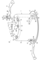
実施形態に係る照明器具A1(以下、照明器具A1と略す。)は、例えば、商業施設、病院、介護施設、宿泊施設などの屋内の天井に埋め込むように配設されるダウンライトである。照明器具A1は、図1-図4に示すように、器具本体1、灯体2、シール部材6、保持部材7及び3つの取付具8などを備える。
(2) Details of the Lighting Fixture According to the Embodiment The lighting fixture A1 according to the embodiment (hereinafter, abbreviated as lighting fixture A1) is a downlight that is disposed so as to be embedded in an indoor ceiling of, for example, a commercial facility, a hospital, a care facility, an accommodation facility, etc. As shown in Figs. 1 to 4, the lighting fixture A1 includes a
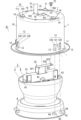
(2-1)器具本体
器具本体1は、有底円筒形状の円筒部10と、円筒部10の下端の全周に渡って円筒部10の下端から外向きに突出する円環状の枠部11とを有している。円筒部10と枠部11は、例えば、金属製の板材が絞り加工されることで一体に形成されている。ただし、円筒部10と枠部11は、別体に形成された後、溶接などの適宜の方法で一体に結合されても構わない。
(2-1) Instrument Body The
円筒部10の底には円形の開口部14が設けられている(図4参照)。また、円筒部10の底の上面における周縁に、3つの突台部15が設けられている(図2参照)。各突台部15は、弧状に形成されている。また、3つの突台部15は、円筒部10の底の周方向に沿って等間隔に配置されている。
A
円筒部10の周面(側面)には、3つの取付部12が設けられている(図2参照)。各取付部12は、一対の差込片120とロック溝121を有する。一対の差込片120は、円筒部10の軸方向(上下方向)から見て鉤形(L字形)に形成されている。また、一対の差込片120は、円筒部10の周方向に沿って間隔を空けて向かい合っている。なお、一対の差込片120は、円筒部10の一部を切り起こして形成されている(図2参照)。
Three
各取付部12のロック溝121は、円筒部10の周面における、一対の差込片120の間に設けられている(図2参照)。ロック溝121は、円筒部10の一部が円筒部10の内部に向かって切り起こされることで長方形状に形成されている(図2参照)。
The
(2-2)灯体
灯体2は、光源ユニット3と支持ブロック4を有する。灯体2は、器具本体1内に収容される(図3及び図4参照)。
(2-2) Light Body The
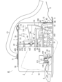
(2-2-1)光源ユニット
光源ユニット3は、LED30、レンズ31、ホルダ32、レンズカバー33、ユニット本体34を備える(図3-図5参照)。LED30は、COB(Chip on Board)型の
照明用白色LEDである。なお、LED30の発光面(照明光が放射される面)は、円形に形成されている。
(2-2-1) Light Source Unit The
レンズ31は、円板状のベース310と、ベース310の一方の表面(上面)に形成された複数のシリンドリカルレンズ311と、ベース310の他方の表面(下面)に形成されたフレネルレンズ312とを有する。なお、複数のシリンドリカルレンズ311は、それぞれの軸を平行させるように並べて配置されている(図4参照)。
The
ホルダ32は、LED30とレンズ31を保持する。ホルダ32は、円筒形状の周壁320と、周壁320の内周面から上向きに突出する円錐台状の底壁321と、底壁321の中央から円錐台状に突出する取付台322と、配線部323とを有する(図4及び図5参照)。なお、周壁320、底壁321、取付台322及び配線部323は、例えば、ポリブチレンテレフタレートなどの合成樹脂材料の成形体として一体に形成されている。LED30は、取付台322の上面に開口する窓3220を塞ぐようにホルダ32に支持される。レンズ31は、周壁320の下端の開口を塞ぐようにホルダ32に支持される。配線部323は、電源ケーブルC1の3本の電線(プラス極の電線、マイナス極の電線及び接地線)を保持している。なお、これら3本の電線は、ホルダ32内においてLED30と電気的に接続される。
The
ユニット本体34は、金属材料によって有底円筒形状に形成されている。ユニット本体34の内部に、ホルダ32の一部(底壁321及び取付台322)とLED30が収容される。ユニット本体34の底面(上面)の中央に、ユニット本体34の内部に向かって突出する台部340が設けられている。台部340は、ホルダ32に保持されたLED30の背面と接触する。つまり、LED30が発する熱は、台部340からユニット本体34全体に伝導されて放熱される。また、ユニット本体34の底面の端部に、ホルダ32の配線部323の一部が挿通される挿通穴341が設けられている(図5参照)。なお、ユニット本体34とホルダ32は、ねじ止めによって結合される。
The
レンズカバー33は、光源ユニット3の外郭を構成している。レンズカバー33は、主部330、縁部331、リブ332、反射部333及び一対のボス334を有している。なお、主部330、縁部331、リブ332、反射部333及び一対のボス334は、合成樹脂材料の成形体として一体に形成されている。
The lens cover 33 forms the outer shell of the
主部330は、球殻から、球殻の中心を含む第1の平面と第1の平面に平行な第2の平面に挟まれた部分を切り取った形状に形成されている。つまり、主部330の外周面は球面となる。縁部331は、円環の一部と円錐台を組み合わせた形状に形成されて主部330の下端とつながっている。反射部333は、円錐台状に形成され、縁部331の下端から上向きかつ縁部331の内側に向かって突出している。リブ332は、軸に対して傾斜した平面で円筒を切り取った形状に形成され、主部330の上端から上向きに突出している。一対のボス334は、それぞれ円筒状に形成され、縁部331の内周面に沿って上向きに伸びるように主部330と一体に形成されている。なお、一対のボス334は、反射部333を挟んで対向する位置に配置されている。
The
(2-2-2)支持ブロック
支持ブロック4は、固定部材40、第1可動部材41、第2可動部材42及び4つの軸部43を有している(図5参照)。
(2-2-2) Support Block The
固定部材40は、長方形状の固定片400と、固定片400の長手方向の両端から固定片400の厚み方向(上方向)に立ち上がる一対の支持片401とを有している。一対の支持片401には、めねじ402が1つずつ設けられている。固定片400と一対の支持片401は、長方形状の1枚の金属板が曲げ加工されることによって、U字状に一体に形成されている。
The fixing
固定部材40は、2本の取付ねじ404によって固定片400がユニット本体34の上面にねじ止めされることでユニット本体34に固定される。また、固定片400の長手方向の両端にそれぞれねじ挿通穴403が設けられている。そして、これら2つのねじ挿通穴403に、タッピングねじからなる固定ねじ44が1本ずつ挿通される。これら2本の固定ねじ44は、ユニット本体34の底面に設けられた穴(図示せず)を通して、レンズカバー33の2つのボス334に1本ずつねじ込まれる。つまり、固定部材40は、レンズカバー33にも固定される。
The fixing
第1可動部材41は、第1主片410と、一対の第1脚片411と、一対の第2脚片412とを有している。第1主片410は、長方形の平板状に形成されている。一対の第1脚片411はそれぞれ長方形の平板状に形成され、第1主片410の長手方向の両端から第1主片410の厚み方向(下方向)に立ち下がっている。一対の第2脚片412は、長方形の平板状に形成され、第1主片410の短手方向の両端から第1主片410の厚み方向(下方向)に立ち下がっている。第1主片410と一対の第1脚片411と一対の第2脚片412は、長方形状の1枚の金属板が曲げ加工されることによって一体に形成されている。
The first
第1主片410の長手方向の中央において、第1主片410の短手方向の両端に、長方形状の挿通溝414が1つずつ設けられている。各第1脚片411には、円形の第1軸穴413が設けられている。各第2脚片412には、円形の第2軸穴415が設けられている。
A
第1可動部材41は、2つの軸部43によって、固定部材40に対して揺動可能に取り付けられる。各軸部43は、段付ねじ430と、平座金431と、波形座金432で構成されている。第1可動部材41の一対の第1脚片411は、それぞれ固定部材40の一対の支持片401の外側に配置される。そして、軸部43の段付ねじ430は、波形座金432と平座金431を介して第1脚片411の第1軸穴413に挿通され、支持片401のめねじ402にねじ込まれる。ここで、段付ねじ430の円筒部4300が第1軸穴413と嵌合することにより、段付ねじ430の円筒部4300を軸として第1可動部材41が固定部材40に対して揺動可能に取り付けられる。
The first
第2可動部材42は、長方形の平板状に形成された第2主片420と、長方形の平板状に形成され、第2主片420の短手方向の両端から第2主片420の厚み方向(下方向)に立ち下がる一対の第3脚片421を有している。第2主片420と一対の第3脚片421は、長方形状の1枚の金属板が曲げ加工されることによって一体に形成されている。第2主片420の長手方向の一端に円形のねじ挿通穴423が設けられている。各第3脚片421の下端にめねじ422が1つずつ設けられている。
The second
第2可動部材42は、2つの軸部43によって、第1可動部材41に対して揺動可能に取り付けられる。第2可動部材42の一対の第3脚片421は、それぞれ第1可動部材41の第1主片410に設けられた一対の挿通溝414に1つずつ挿通され、第1可動部材41の一対の第2脚片412の内側に配置される。そして、軸部43の段付ねじ430は、波形座金432と平座金431を介して第2脚片412の第2軸穴415に挿通され、第3脚片421のめねじ422にねじ込まれる。ここで、段付ねじ430の円筒部4300が第2軸穴415と嵌合することにより、段付ねじ430の円筒部4300を軸として第2可動部材42が第1可動部材41に対して揺動に取り付けられる。
The second
(2-3)保持部材
保持部材7は、器具本体1に対して支持ブロック4(灯体2)を回転可能に保持する。保持部材7は、図3及び図4に示すように、保持板70と、3つの押さえ部71と、固定ねじ72とを有する。
(2-3) Holding Member The holding
保持板70は、金属製の板材によって円板状に形成されている。保持板70の中心には、長方形状の挿通穴701が設けられている。また、保持板70の周縁部であって、挿通穴701の長手方向に沿って挿通穴701と隣り合う位置にめねじ700が設けられている。さらに、保持板70の挿通穴701の短手方向に沿って挿通穴701と隣り合う位置に、円形のケーブル挿通穴702が設けられている。
The retaining
保持板70の挿通穴701には、保持板70の下から第2可動部材42の第2主片420が挿通される。そして、保持板70の上に配置された第2主片420のねじ挿通穴423に固定ねじ72が挿通され、固定ねじ72が保持板70のめねじ402にねじ込まれる。その結果、保持板70と支持ブロック4がねじ止めによって結合される(図2及び図4参照)。
The second
また、保持板70は、3つの押さえ部71に押さえられて、器具本体1の円筒部10の上面に取り付けられる。3つの押さえ部71はそれぞれ、段付ねじ710と平座金711で構成されている。段付ねじ710は、平座金711を介して、円筒部10の上面における突台部15の近傍に設けられているねじ穴にねじ込まれる。ただし、円筒部10の上面と平座金711の下面の間には、突台部15の高さ分の隙間が生じる。そして、円筒部10の上面と平座金711の下面の間の隙間に、保持板70の周縁部分が挟み込まれることによって、保持板70が器具本体1の円筒部10の上面に回転可能に取り付けられる(図2-図4参照)。
The retaining
ここで、円筒部10の上面において、段付ねじ710のための3つのねじ穴と同心円上に、半球状の3つの位置決め突起16が等間隔に設けられている。これら3つの位置決め突起16により、保持板70の中心と円筒部10の上面の中心との位置ずれを抑制することができる(図2-図4参照)。なお、保持板70のケーブル挿通穴702には、電源ケ
ーブルC1が挿通される。電源ケーブルC1の一端は、光源ユニット3の配線部323と電気的に接続される。また、電源ケーブルC1の他端は、図示しない電源ユニットと電気的に接続される。
Here, three
(2-4)取付具
照明器具A1は、3つの取付具8を備えている。ただし、3つの取付具8は、すべて同一の構成を有している。
(2-4) Fixtures The lighting fixture A1 includes three
取付具8は、図2に示すように、ばね片80、取付片81、抜け止め片82、ロック爪83及び一対の補強部84を有している。ばね片80、取付片81、抜け止め片82、ロック爪83及び一対の補強部84は、例えば、ステンレス鋼のようにばねの材料に適した金属によって一体に形成されている。
As shown in FIG. 2, the mounting
ばね片80は、長尺の帯状に形成されている。取付片81は、長方形状に形成されている。抜け止め片82は、取付片81よりも幅の狭い長方形状に形成され、取付片81及びばね片80とそれぞれつながっている。ただし、ばね片80とつながった抜け止め片82の下端はU字状に湾曲している。ロック爪83は、取付片81の一部が切り抜かれることによって鉤形に形成されている。一対の補強部84はそれぞれ、取付片81及び抜け止め片82の一部が絞り加工されることによって長尺のバスタブ状に形成されている。これら一対の補強部84により、取付片81と抜け止め片82の厚み方向に沿った変形が抑制される。
The
(2-5)シール部材
シール部材6は、第1接触部61、第2接触部62、6つの突部63、6つの引掛爪64、非接触部65及びつば部66を有している(図6参照)。第1接触部61、第2接触部62、6つの突部63、6つの引掛爪64、非接触部65及びつば部66は、例えば、シリコーン樹脂などの柔軟性を有する合成樹脂材料によって一体に形成されている。
(2-5) Sealing Member The sealing
第1接触部61は、円筒形状に形成されている。つば部66は、円環形状に形成されて第1接触部61の下端から外向きに突出している。非接触部65は、円錐台形状に形成されて第1接触部61の上端とつながって第1接触部61の上端から上向きに突出している。第2接触部62は、円環状に形成され、非接触部65の上端から内向きに突出している。なお、非接触部65の厚みは、第1接触部61及び第2接触部62のそれぞれの厚みよりも大きい(図6D参照)。
The
6つの突部63はそれぞれ、4角柱状に形成されている。各突部63は、3角柱状の引掛爪64を1つずつ有している。6つの突部63はそれぞれ、第1接触部61の外周面から第1接触部61の厚み方向に沿って外向きに突出している。ただし、6つの突部63は、2つを1組として第1接触部61の周方向に沿って等間隔に配置されている。
Each of the six
1組の突部63は、取付具8の取付片81の幅寸法よりも狭く、かつ、抜け止め片82の幅寸法よりも広い間隔を空けて、第1接触部61の周方向に沿って隣り合うように配置されている。また、1組の突部63において、それぞれの突部63が有する引掛爪64は、それぞれの突部63が第1接触部61の周方向に沿って対向する面(以下、対向面と呼ぶ場合がある。)と反対の面から外向きに突出している。さらに、1組の突部63のそれぞれの対向面は、上方に向かって互いに離れる向きに傾斜している(図6C参照)。ここで、1組の突部63の対向面の開き角αは、約26度である。
The pair of
(3)実施形態に係る照明器具の組立手順
次に、照明器具A1の組立手順を説明する。ただし、以下の説明においては、灯体2及び保持部材7が取り付けられた器具本体1に対して、シール部材6と取付具8を取り付ける手順について説明する。
(3) Assembly Procedure of the Lighting Fixture According to the Embodiment Next, an assembly procedure of the lighting fixture A1 will be described. However, in the following description, a procedure for attaching the
まず、作業者は、器具本体1の円筒部10にシール部材6を挿入する。そして、作業者は、第1接触部61の内周面の方から1組の突部63を指で摘まみ、1組の突部63を互いに近付く向きに変位させる。作業者は、指で摘まんで変位させた1組の突部63を、円筒部10の1組の挿通穴13のそれぞれに1つずつ挿入する。そして、作業者が1組の突部63から指を離すと、1組の突部63のそれぞれの引掛爪64が、1組の挿通穴13のそれぞれの外側の縁に引っ掛かる(図7参照)。作業者は、残り2組の突部63の引掛爪64も同じ手順で挿通穴13の外側の縁に引っ掛ける。その結果、シール部材6は、6つの引掛爪64が器具本体1の円筒部10における6つの挿通穴13の縁に引っ掛けられることにより、器具本体1(の円筒部10)に取り付けられる。なお、シール部材6が器具本体1に取り付けられた状態においては、シール部材6の第2接触部62の開口に灯体2の一部(レンズカバー33)が挿通される(図4参照)。
First, the worker inserts the
続いて、作業者は、3つの取付具8を器具本体1の3つの取付部12に1つずつ取り付ける。作業者は、取付具8の抜け止め片82を、円筒部10の外周面に沿って上から下に向かって取付部12の一対の差込片120の間を通して1組の突部63の間に差し込む。このとき、1組の突部63のそれぞれの対向面が上方に向かって互いに離れる向きに傾斜しているため、作業者が1組の突部63の間に抜け止め片82を差し込みやすい。
The worker then attaches the three mounting
作業者が1組の突部63の間に抜け止め片82を差し込むと、取付具8の取付片81が取付部12の一対の差込片120と円筒部10の外周面の間の空間に挿入され、一対の差込片120によって取付片81が支持される。さらに、取付具8のロック爪83が取付部12のロック溝121に挿入されると、取付片81の上方向への移動が禁止され、器具本体1の取付部12に対する取付具8の取付が完了する。
When an operator inserts the retaining
(4)実施形態に係る照明器具の特徴
上述のように、照明器具A1は、シール部材6が器具本体1に取り付けられる作業において、シール部材6以外の別の部材を使わずにシール部材6が器具本体1に取り付けられることができる。そのため、照明器具A1は、シール部材6の取付作業の作業性の向上を図ることができる。
(4) Features of the Lighting Fixture According to the Embodiment As described above, in the lighting fixture A1, in the process of attaching the
また、取付具8が器具本体1の取付部12に取り付けられた状態では、取付具8の抜け止め片82が一対の突部63の間に配置され、円筒部10の1組の挿通穴13の一部が抜け止め片82によって塞がれる(図7参照)。「挿通穴13の一部」とは、挿通穴13のうちで引掛爪64が挿通穴13の縁に引っ掛かっている場合に突部63が存在しない部分である(図2参照)。
When the mounting
しかして、器具本体1の取付部12に取付具8が取り付けられた状態では、挿通穴13の一部が抜け止め片82に塞がれるため、挿通穴13の縁から引掛爪64を離す方向に突部63が移動することができない。つまり、照明器具A1は、取付具8以外の別の部材を使わずに、引掛爪64が挿通穴13の縁から外れることを防ぐことができる。その結果、照明器具A1は、シール部材6の取付作業の作業性の更なる向上を図ることができる。
When the mounting
ところで、器具本体1にシール部材6が取り付けられると、円筒部10の下面の開口と灯体2の間がシール部材6によってシールされる。具体的には、シール部材6の第1接触部61が円筒部10の内周面に接触し、シール部材6の第2接触部62が灯体2のレンズカバー33に接触する。
When the
ここで、灯体2は、器具本体1に対して回転可能及び揺動可能に構成されている。つまり、灯体2が器具本体1に対して回転したり、揺動した場合、シール部材6の第2接触部62に対してレンズカバー33が摺動するが、レンズカバー33と第2接触部62の間にはたらく摩擦力はほぼ一定に保たれる。
The
すなわち、灯体2の回転の軸は、回転の軸方向(上下方向)から見た形状が円形であるレンズカバー33の主部330の中心と重なっているので(図4参照)、灯体2が回転しても回転の軸から主部330の外周面までの距離がほぼ一定に保たれる。そのため、灯体2が回転したときにレンズカバー33と第2接触部62の間にはたらく摩擦力がほぼ一定に保たれる。ゆえに、照明器具A1は、灯体2が回転させられた場合でも第2接触部62とレンズカバー33の外周面を接触させてシール性能の低下を抑制することができる。
In other words, the axis of rotation of the
また、灯体2の揺動の軸は、第1可動部材41の一対の第1軸穴413の中心線と一対の第2軸穴415の中心線に一致する。しかも、支持ブロック4においては、一対の第1軸穴413の中心線と一対の第2軸穴415の中心線が、灯体2の回転の軸と一点で交わり、かつ、一対の第1軸穴413の中心線と一対の第2軸穴415の中心線を含む仮想の平面が保持板70と平行である。そのため、灯体2が一対の第1軸穴413の中心線と一対の第2軸穴415の中心線を軸として揺動した場合、それぞれの軸とレンズカバー33の主部330の外周面との距離がほぼ一定に保たれる(図4における2点鎖線参照)。ゆえに、灯体2が揺動したときにレンズカバー33と第2接触部62の間にはたらく摩擦力がほぼ一定に保たれる。その結果、照明器具A1は、灯体2が揺動させられた場合でも第2接触部62とレンズカバー33の外周面を接触させてシール性能の低下を抑制することができる。
The axis of the oscillation of the
さらに、シール部材6の非接触部65の厚みが第1接触部61及び第2接触部62のそれぞれの厚みよりも大きいため、第2接触部62がレンズカバー33から摩擦力を受けたときに非接触部65の変形を抑制してシール性能の低下を抑制することができる。
Furthermore, since the thickness of the
(5)実施形態に係る照明器具の変形例
次に、実施形態に係る照明器具の変形例を説明する。ただし、以下に説明する変形例は、シール部材6に特徴がある。変形例におけるシール部材6は、図8に示すように、複数の突部63のそれぞれが2つの引掛爪64を有している。つまり、1組の突部63のそれぞれの対向面にも引掛爪64が形成されている。
(5) Modifications of the Lighting Fixture According to the Embodiment Next, a modification of the lighting fixture according to the embodiment will be described. However, the modification described below is characterized by the
すなわち、変形例におけるシール部材6は、器具本体の円筒部に設けられた挿通穴の縁に2つの引掛爪64がそれぞれ引っ掛けられて器具本体に取り付けられる。つまり、変形例の照明器具では、取付具の抜け止め片で挿通穴を塞がなくても、器具本体に対してシール部材6が外れにくくなっている。
In other words, the sealing
しかして、変形例の照明器具においても、シール部材6が器具本体に取り付けられる作業において、シール部材6以外の別の部材を使わずにシール部材6が器具本体に取り付けられる。そのため、変形例の照明器具は、シール部材6の取付作業の作業性の向上を図ることができる。
In the lighting fixture of the modified example, the sealing
また、変形例におけるシール部材6は、図9に示すように、非接触部65の厚みを第1接触部61の厚みよりも小さくしている。変形例の照明器具は、非接触部65の厚みを第1接触部61の厚みより小さくしたことにより、第2接触部62を変形しやすくしてシール性能の低下を抑制することができる。
In addition, as shown in FIG. 9, the sealing
(6)まとめ
本開示の第1の態様に係る照明器具(A1)は、光源(LED30)を有する光源ユニット(3)と、筒状に形成されて光源ユニット(3)を収容する器具本体(1)と、器具本体(1)及び光源ユニット(3)の隙間をシールするシール部材(6)とを備える。シール部材(6)は、器具本体(1)に接触する第1接触部(61)と、光源ユニット(3)に接触する第2接触部(62)と、第1接触部(61)から器具本体(1)に向かって突出する1つ以上の突部(63)とを有する。器具本体(1)は、突部(63)が挿通される1つ以上の挿通穴(13)を有する。突部(63)は、器具本体(1)における挿通穴(13)の縁に引っ掛かる引掛爪(64)を有する。
(6) Summary The lighting fixture (A1) according to the first aspect of the present disclosure includes a light source unit (3) having a light source (LED 30), a fixture body (1) formed in a cylindrical shape to house the light source unit (3), and a seal member (6) that seals a gap between the fixture body (1) and the light source unit (3). The seal member (6) has a first contact portion (61) that contacts the fixture body (1), a second contact portion (62) that contacts the light source unit (3), and one or more protrusions (63) that protrude from the first contact portion (61) toward the fixture body (1). The fixture body (1) has one or more insertion holes (13) through which the protrusions (63) are inserted. The protrusions (63) have hook claws (64) that hook onto the edges of the insertion holes (13) in the fixture body (1).
第1の態様に係る照明器具(A1)は、器具本体(1)の挿通穴(13)に突部(63)を挿通し、突部(63)が有する引掛爪(64)を器具本体(1)における挿通穴(13)の縁に引っ掛けることでシール部材(6)が器具本体(1)に取り付けられる。ゆえに、第1の態様に係る照明器具(A1)は、別の部材を使わずにシール部材(6)単独で器具本体(1)に取付可能であるので、シール部材(6)の取付作業の作業性の向上を図ることができる。 In the lighting fixture (A1) according to the first aspect, the sealing member (6) is attached to the fixture body (1) by inserting the protrusion (63) into the insertion hole (13) of the fixture body (1) and hooking the hook (64) of the protrusion (63) onto the edge of the insertion hole (13) in the fixture body (1). Therefore, in the lighting fixture (A1) according to the first aspect, the sealing member (6) alone can be attached to the fixture body (1) without using a separate member, which improves the workability of attaching the sealing member (6).
本開示の第2の態様に係る照明器具(A1)は、第1の態様との組合せにより実現され得る。第2の態様に係る照明器具(A1)は、器具本体(1)を造営材に取り付けるための1つ以上の取付具(8)を更に備えることが好ましい。取付具(8)は、器具本体(1)に設けられた取付部(12)に着脱可能に取り付けられることが好ましい。挿通穴(13)は、器具本体(1)における取付部(12)の近傍に設けられることが好ましい。突部(63)は、取付部(12)に取り付けられた取付具(8)によって、挿通穴(13)に対して抜け止めされることが好ましい。 The lighting fixture (A1) according to the second aspect of the present disclosure can be realized by combining it with the first aspect. The lighting fixture (A1) according to the second aspect preferably further comprises one or more mounting fixtures (8) for mounting the fixture body (1) to a construction material. The mounting fixtures (8) are preferably detachably attached to a mounting portion (12) provided on the fixture body (1). The insertion hole (13) is preferably provided near the mounting portion (12) on the fixture body (1). The protrusion (63) is preferably prevented from coming out of the insertion hole (13) by the mounting fixture (8) attached to the mounting portion (12).
第2の態様に係る照明器具(A1)は、取付具(8)以外の別の部材を使わずに、引掛爪(64)が挿通穴(13)の縁から外れることを防ぐことができる。その結果、第2の態様に係る照明器具(A1)は、シール部材(6)の取付作業の作業性の更なる向上を図ることができる。 The lighting fixture (A1) according to the second aspect can prevent the hook claw (64) from coming off the edge of the insertion hole (13) without using any other member other than the mounting fixture (8). As a result, the lighting fixture (A1) according to the second aspect can further improve the workability of the installation work of the sealing member (6).
本開示の第3の態様に係る照明器具(A1)は、第2の態様との組合せにより実現され得る。第3の態様に係る照明器具(A1)において、取付具(8)は、取付部(12)に取り付けられた状態において、挿通穴(13)の一部を塞ぐことによって突部(63)を抜け止めすることが好ましい。 The lighting fixture (A1) according to the third aspect of the present disclosure can be realized by combining it with the second aspect. In the lighting fixture (A1) according to the third aspect, it is preferable that the mounting fixture (8) prevents the protrusion (63) from coming off by partially blocking the insertion hole (13) when attached to the mounting portion (12).
第3の態様に係る照明器具(A1)は、取付具(8)に特別な構造を追加せずに突部(63)の抜け止めを図ることができる。 The lighting fixture (A1) according to the third aspect can prevent the protrusion (63) from coming loose without adding any special structure to the mounting fixture (8).
本開示の第4の態様に係る照明器具(A1)は、第3の態様との組合せにより実現され得る。第4の態様に係る照明器具(A1)において、引掛爪(64)は、取付具(8)によって塞がされる挿通穴(13)の一部と異なる挿通穴(13)の縁に引っ掛かるように形成されていることが好ましい。 The lighting fixture (A1) according to the fourth aspect of the present disclosure can be realized by combining it with the third aspect. In the lighting fixture (A1) according to the fourth aspect, it is preferable that the hook claw (64) is formed so as to hook onto an edge of the insertion hole (13) other than the part of the insertion hole (13) that is blocked by the mounting fixture (8).
第4の態様に係る照明器具(A1)は、引掛爪(64)と取付具(8)の干渉を防ぐことができる。 The lighting fixture (A1) according to the fourth aspect can prevent interference between the hook (64) and the mounting fixture (8).
本開示の第5の態様に係る照明器具(A1)は、第2-第4のいずれかの態様との組合せにより実現され得る。第5の態様に係る照明器具(A1)において、取付具(8)は、器具本体(1)の表面に沿って移動することで取付部(12)に取り付けられることが好ましい。突部(63)の取付部(12)と対向する面は、取付具(8)が移動する方向に沿って傾斜していることが好ましい。 The lighting fixture (A1) according to the fifth aspect of the present disclosure can be realized by combining it with any of the second to fourth aspects. In the lighting fixture (A1) according to the fifth aspect, it is preferable that the mounting fixture (8) is attached to the mounting portion (12) by moving along the surface of the fixture body (1). It is preferable that the surface of the protrusion (63) facing the mounting portion (12) is inclined along the direction in which the mounting fixture (8) moves.
第5の態様に係る照明器具(A1)は、取付具(8)を器具本体(1)に取り付ける際の作業性の向上を図ることができる。 The lighting fixture (A1) according to the fifth aspect can improve the workability when attaching the mounting fixture (8) to the fixture body (1).
本開示の第6の態様に係る照明器具(A1)は、第2-第5の態様との組合せにより実現され得る。第6の態様に係る照明器具(A1)において、器具本体(1)は、1つの取付部(12)の近傍に2つの挿通穴(13)が設けられていることが好ましい。シール部材(6)は、2つの挿通穴(13)のそれぞれに1つずつ挿通される2つの突部(63)を有することが好ましい。取付部(12)に取り付けられた取付具(8)の一部(抜け止め片82)が、2つの突部(63)の間に配置されることが好ましい。取付具(8)の一部(抜け止め片82)の幅は、取付具(8)の一部を除く部位(取付片81)の幅よりも狭いことが好ましい。 The lighting fixture (A1) according to the sixth aspect of the present disclosure can be realized by combining it with the second to fifth aspects. In the lighting fixture (A1) according to the sixth aspect, the fixture body (1) preferably has two insertion holes (13) near one mounting portion (12). The sealing member (6) preferably has two protrusions (63) that are inserted into each of the two insertion holes (13). It is preferable that a part (anti-slip piece 82) of the mounting fixture (8) attached to the mounting portion (12) is disposed between the two protrusions (63). It is preferable that the width of the part (anti-slip piece 82) of the mounting fixture (8) is narrower than the width of the portion (mounting piece 81) excluding the part of the mounting fixture (8).
第6の態様に係る照明器具(A1)は、2つの突部(63)の間に配置される、取付具(8)の一部の幅を狭くしたので、2つの突部(63)の間隔を狭めることができる。 The lighting fixture (A1) according to the sixth aspect has a narrower width of a portion of the mounting fixture (8) that is disposed between the two protrusions (63), so that the distance between the two protrusions (63) can be narrowed.
本開示の第7の態様に係る照明器具(A1)は、第1-第6のいずれかの態様との組合せにより実現され得る。第7の態様に係る照明器具(A1)において、器具本体(1)に対して光源ユニット(3)を揺動可能に支持する支持ブロック(4)を備えることが好ましい。 The lighting fixture (A1) according to the seventh aspect of the present disclosure can be realized by combining it with any of the first to sixth aspects. In the lighting fixture (A1) according to the seventh aspect, it is preferable that the lighting fixture (A1) includes a support block (4) that supports the light source unit (3) so that it can swing relative to the fixture body (1).
第7の態様に係る照明器具(A1)は、支持ブロック(4)で光源ユニット(3)を揺動させることにより、光源ユニット(3)から照射される照明光の配光を調整することができる。 The seventh aspect of the lighting fixture (A1) can adjust the light distribution of the illumination light emitted from the light source unit (3) by swinging the light source unit (3) on the support block (4).
本開示の第8の態様に係る照明器具(A1)は、第7の態様との組合せにより実現され得る。第8の態様に係る照明器具(A1)において、光源ユニット(3)は、光源を囲む外郭(レンズカバー33)を有することが好ましい。第2接触部(62)と接触する外郭の表面は、光源ユニット(3)が揺動する方向に沿って円弧状に形成されていることが好ましい。 The lighting device (A1) according to the eighth aspect of the present disclosure can be realized by combining it with the seventh aspect. In the lighting device (A1) according to the eighth aspect, it is preferable that the light source unit (3) has an outer shell (lens cover 33) that surrounds the light source. It is preferable that the surface of the outer shell that contacts the second contact portion (62) is formed in an arc shape along the direction in which the light source unit (3) swings.
第8の態様に係る照明器具(A1)は、光源ユニット(3)が揺動しても第2接触部(62)と外郭の表面との接触状態を保つことかできる。 The lighting fixture (A1) according to the eighth aspect can maintain contact between the second contact portion (62) and the surface of the outer casing even when the light source unit (3) swings.
本開示の第9の態様に係る照明器具(A1)は、第7又は第8の態様との組合せにより実現され得る。第9の態様に係る照明器具(A1)は、器具本体(1)に対して支持ブロック(4)を回転可能に保持する保持部材(7)を備えることが好ましい。 The lighting device (A1) according to the ninth aspect of the present disclosure can be realized in combination with the seventh or eighth aspect. The lighting device (A1) according to the ninth aspect preferably includes a holding member (7) that rotatably holds the support block (4) relative to the device body (1).
第9の態様に係る照明器具(A1)は、保持部材(7)で支持ブロック(4)を回転させることにより、光源ユニット(3)から照射される照明光の配光を調整することができる。 The lighting fixture (A1) according to the ninth aspect can adjust the light distribution of the illumination light emitted from the light source unit (3) by rotating the support block (4) with the holding member (7).
本開示の第10の態様に係る照明器具(A1)は、第9の態様との組合せにより実現され得る。第10の態様に係る照明器具(A1)において、光源ユニット(3)は、光源を囲む外郭を有することが好ましい。第2接触部(62)と接触する外郭の表面は、保持部材(7)が回転する方向に沿って円弧状に形成されていることが好ましい。 The lighting device (A1) according to the tenth aspect of the present disclosure can be realized by combining it with the ninth aspect. In the lighting device (A1) according to the tenth aspect, it is preferable that the light source unit (3) has an outer shell surrounding the light source. It is preferable that the surface of the outer shell that contacts the second contact portion (62) is formed in an arc shape along the direction in which the holding member (7) rotates.
第10の態様に係る照明器具(A1)は、光源ユニット(3)が回転しても第2接触部(62)と外郭の表面との接触状態を保つことかできる。 The lighting fixture (A1) according to the tenth aspect can maintain contact between the second contact portion (62) and the surface of the outer casing even when the light source unit (3) rotates.
本開示の第11の態様に係る照明器具(A1)は、第7-第10のいずれかの態様との組合せにより実現され得る。第11の態様に係る照明器具(A1)において、器具本体(1)は、有底円筒形状に形成されることが好ましい。光源ユニット(3)は、光源を囲む外郭を有することが好ましい。第2接触部(62)と接触する外郭の表面は、球面状に形成されていることが好ましい。 The lighting device (A1) according to the eleventh aspect of the present disclosure can be realized by combining it with any of the seventh to tenth aspects. In the lighting device (A1) according to the eleventh aspect, the device body (1) is preferably formed in a cylindrical shape with a bottom. The light source unit (3) preferably has an outer shell surrounding the light source. The surface of the outer shell that contacts the second contact portion (62) is preferably formed in a spherical shape.
第11の態様に係る照明器具(A1)は、光源ユニット(3)が揺動又は回転しても第2接触部(62)と外郭の表面との接触状態を保つことかできる。 The lighting fixture (A1) according to the eleventh aspect can maintain contact between the second contact portion (62) and the surface of the outer casing even when the light source unit (3) swings or rotates.
本開示の第12の態様に係る照明器具(A1)は、第1-第11のいずれかの態様との組合せにより実現され得る。第12の態様に係る照明器具(A1)において、シール部材(6)は、第1接触部(61)と第2接触部(62)の間に位置して器具本体(1)及び光源ユニット(3)に接触しない非接触部(65)を有することが好ましい。非接触部(65)の厚みは、第1接触部(61)及び第2接触部(62)のそれぞれの厚みよりも大きいことが好ましい。 The lighting device (A1) according to the twelfth aspect of the present disclosure can be realized by combining it with any of the first to eleventh aspects. In the lighting device (A1) according to the twelfth aspect, it is preferable that the sealing member (6) has a non-contact portion (65) that is located between the first contact portion (61) and the second contact portion (62) and does not contact the device body (1) and the light source unit (3). It is preferable that the thickness of the non-contact portion (65) is greater than the thickness of each of the first contact portion (61) and the second contact portion (62).
第12の態様に係る照明器具(A1)は、第2接触部(62)が外郭から摩擦力を受けたときに非接触部(65)の変形を抑制してシール性能の低下を抑制することができる。 The lighting fixture (A1) according to the twelfth aspect can suppress the deformation of the non-contact portion (65) when the second contact portion (62) receives a frictional force from the outer shell, thereby suppressing the deterioration of the sealing performance.
A1 照明器具
1 器具本体
3 光源ユニット
4 支持ブロック
6 シール部材
7 保持部材
8 取付具
12 取付部
13 挿通穴
30 LED(光源)
33 レンズカバー(外郭)
61 第1接触部
62 第2接触部
63 突部
64 引掛爪
65 非接触部
81 取付片
82 抜け止め片
33 Lens cover (outer shell)
61
Claims (12)
筒状に形成されて前記光源ユニットを収容する器具本体と、
前記器具本体及び前記光源ユニットの隙間をシールするシール部材と、
を備え、
前記シール部材は、
前記器具本体に接触する第1接触部と、
前記光源ユニットに接触する第2接触部と、
前記第1接触部から前記器具本体に向かって突出する1つ以上の突部と、
前記器具本体を造営材に取り付けるための1つ以上の取付具と、
を有し、
前記器具本体は、
前記突部が挿通される1つ以上の挿通穴を有し、
前記突部は、前記器具本体における前記挿通穴の縁に引っ掛かる引掛爪を有し、
前記取付具は、前記器具本体に設けられた取付部に取り付けられ、
前記突部は、前記取付部に取り付けられた前記取付具によって、前記挿通穴に対して抜け止めされる、
照明器具。 a light source unit having a light source;
A device main body formed in a cylindrical shape and housing the light source unit;
A seal member that seals a gap between the fixture body and the light source unit;
Equipped with
The sealing member is
A first contact portion that contacts the tool body;
A second contact portion that contacts the light source unit;
One or more protrusions protruding from the first contact portion toward the tool body;
One or more mounting tools for mounting the device body to a construction material;
having
The instrument body includes:
The protrusion has one or more insertion holes through which the protrusion is inserted,
The protrusion has a hook that hooks onto an edge of the insertion hole in the tool body,
The mounting fixture is attached to a mounting portion provided on the device body,
The protrusion is prevented from coming out of the insertion hole by the mounting fixture attached to the mounting portion.
Lighting fixtures.
前記挿通穴は、前記器具本体における前記取付部の近傍に設けられる、
請求項1記載の照明器具。 The mounting fixture is detachably attached to the mounting portion,
The insertion hole is provided in the vicinity of the mounting portion in the instrument body.
2. The lighting device of claim 1.
請求項2記載の照明器具。 The mounting tool, when attached to the mounting portion, blocks a part of the insertion hole to prevent the protrusion from coming off.
3. A lighting device according to claim 2.
請求項3記載の照明器具。 The hook claw is formed to hook onto an edge of the insertion hole different from a part of the insertion hole that is blocked by the mounting tool.
4. A lighting device according to claim 3.
前記突部の前記取付部と対向する面は、前記取付具が移動する方向に沿って傾斜している、
請求項2-4のいずれか1項に記載の照明器具。 The attachment tool is attached to the attachment portion by moving along a surface of the appliance body,
A surface of the protrusion facing the mounting portion is inclined along a direction in which the mounting tool moves.
A lighting device according to any one of claims 2 to 4.
前記シール部材は、2つの前記挿通穴のそれぞれに1つずつ挿通される2つの前記突部を有し、
前記取付部に取り付けられた前記取付具の一部が、2つの前記突部の間に配置され、
前記取付具の前記一部の幅は、前記取付具の前記一部を除く部位の幅よりも狭い、
請求項2-5のいずれか1項に記載の照明器具。 The tool body is provided with two of the insertion holes near one of the mounting portions,
the seal member has two protrusions each inserted into one of the two insertion holes,
A portion of the mounting tool attached to the mounting portion is disposed between the two protrusions,
The width of the part of the mounting tool is narrower than the width of the part of the mounting tool excluding the part.
A lighting device according to any one of claims 2 to 5.
請求項1-6のいずれか1項に記載の照明器具。 A support block is provided to support the light source unit so as to be swingable relative to the fixture body.
A lighting device according to any one of claims 1 to 6.
前記第2接触部と接触する前記外郭の表面は、前記光源ユニットが揺動する方向に沿って円弧状に形成されている、
請求項7記載の照明器具。 The light source unit has an outer casing that surrounds the light source,
The surface of the outer shell that comes into contact with the second contact portion is formed in an arc shape along a direction in which the light source unit swings.
8. A lighting device according to claim 7.
請求項7又は8記載の照明器具。 A holding member is provided to rotatably hold the support block relative to the instrument body.
9. A lighting fixture according to claim 7 or 8.
前記第2接触部と接触する前記外郭の表面は、前記保持部材が回転する方向に沿って円弧状に形成されている、
請求項9記載の照明器具。 The light source unit has an outer casing that surrounds the light source,
The surface of the outer shell that comes into contact with the second contact portion is formed in an arc shape along a direction in which the holding member rotates.
10. A lighting device according to claim 9.
前記光源ユニットは、前記光源を囲む外郭を有し、
前記第2接触部と接触する前記外郭の表面は、球面状に形成されている、
請求項7-10のいずれか1項に記載の照明器具。 The device body is formed in a cylindrical shape with a bottom,
The light source unit has an outer casing that surrounds the light source,
The surface of the outer shell that comes into contact with the second contact portion is formed into a spherical shape.
A lighting device according to any one of claims 7 to 10.
前記非接触部の厚みは、前記第1接触部及び前記第2接触部のそれぞれの厚みよりも大きい、
請求項1-11のいずれか1項に記載の照明器具。 The seal member has a non-contact portion located between the first contact portion and the second contact portion and not in contact with the fixture body and the light source unit,
The thickness of the non-contact portion is greater than the thickness of each of the first contact portion and the second contact portion.
A luminaire according to any one of claims 1 to 11.
Priority Applications (1)
| Application Number | Priority Date | Filing Date | Title |
|---|---|---|---|
| JP2024160782A JP2024166350A (en) | 2020-10-29 | 2024-09-18 | Lighting fixtures |
Applications Claiming Priority (2)
| Application Number | Priority Date | Filing Date | Title |
|---|---|---|---|
| JP2020181802A JP7742570B2 (en) | 2020-10-29 | 2020-10-29 | lighting fixtures |
| JP2024160782A JP2024166350A (en) | 2020-10-29 | 2024-09-18 | Lighting fixtures |
Related Parent Applications (1)
| Application Number | Title | Priority Date | Filing Date |
|---|---|---|---|
| JP2020181802A Division JP7742570B2 (en) | 2020-10-29 | 2020-10-29 | lighting fixtures |
Publications (1)
| Publication Number | Publication Date |
|---|---|
| JP2024166350A true JP2024166350A (en) | 2024-11-28 |
Family
ID=81604722
Family Applications (2)
| Application Number | Title | Priority Date | Filing Date |
|---|---|---|---|
| JP2020181802A Active JP7742570B2 (en) | 2020-10-29 | 2020-10-29 | lighting fixtures |
| JP2024160782A Pending JP2024166350A (en) | 2020-10-29 | 2024-09-18 | Lighting fixtures |
Family Applications Before (1)
| Application Number | Title | Priority Date | Filing Date |
|---|---|---|---|
| JP2020181802A Active JP7742570B2 (en) | 2020-10-29 | 2020-10-29 | lighting fixtures |
Country Status (1)
| Country | Link |
|---|---|
| JP (2) | JP7742570B2 (en) |
Family Cites Families (5)
| Publication number | Priority date | Publication date | Assignee | Title |
|---|---|---|---|---|
| JP2004006112A (en) * | 2002-05-31 | 2004-01-08 | Sumitomo Wiring Syst Ltd | Water proof connector |
| JP4343654B2 (en) * | 2003-11-11 | 2009-10-14 | 株式会社畑屋製作所 | Lighting |
| JP4785069B2 (en) * | 2005-05-23 | 2011-10-05 | アイティーエル株式会社 | Lighting device for display case |
| JP2017174785A (en) * | 2016-03-25 | 2017-09-28 | 東芝ライテック株式会社 | Luminaire |
| US10697599B1 (en) * | 2019-01-17 | 2020-06-30 | Signify Holding B.V. | Adjustable light fixtures |
-
2020
- 2020-10-29 JP JP2020181802A patent/JP7742570B2/en active Active
-
2024
- 2024-09-18 JP JP2024160782A patent/JP2024166350A/en active Pending
Also Published As
| Publication number | Publication date |
|---|---|
| JP2022072399A (en) | 2022-05-17 |
| JP7742570B2 (en) | 2025-09-22 |
Similar Documents
| Publication | Publication Date | Title |
|---|---|---|
| JP2005158363A (en) | Recessed ceiling lighting fixture and lighting system | |
| JP4281517B2 (en) | lighting equipment | |
| JP5570465B2 (en) | Lighting device | |
| JP2011044412A (en) | Lighting fixture | |
| JP2010287581A (en) | Lighting system | |
| JP7742570B2 (en) | lighting fixtures | |
| JP6044758B2 (en) | Light source unit and lighting fixture | |
| JP6443697B2 (en) | lighting equipment | |
| JP3159960U (en) | Lighting equipment | |
| JP4345571B2 (en) | lighting equipment | |
| JP7557834B2 (en) | Lighting fixtures | |
| TWI548837B (en) | Lighting apparatus | |
| JP5419800B2 (en) | lighting equipment | |
| JP6493675B2 (en) | lighting equipment | |
| JP6558689B2 (en) | lighting equipment | |
| JP7535753B2 (en) | Optical Components and Lighting Equipment | |
| JP6770725B2 (en) | Bathroom lighting device | |
| JP6548167B2 (en) | Lighting fixture and lighting unit | |
| JP6990149B2 (en) | lighting equipment | |
| JP5300437B2 (en) | Recessed lighting fixture | |
| JP2023115536A (en) | LED lighting device | |
| JP2009283198A (en) | Embedded lighting device | |
| JP4280916B2 (en) | Recessed ceiling lighting fixture | |
| CN206330002U (en) | Lighting fixtures and lighting units | |
| CN207179406U (en) | Ligthing paraphernalia |
Legal Events
| Date | Code | Title | Description |
|---|---|---|---|
| A621 | Written request for application examination |
Free format text: JAPANESE INTERMEDIATE CODE: A621 Effective date: 20240918 |