JP2024158181A - Magnetic field generating device and magnetic refrigeration device - Google Patents
Magnetic field generating device and magnetic refrigeration device Download PDFInfo
- Publication number
- JP2024158181A JP2024158181A JP2023073161A JP2023073161A JP2024158181A JP 2024158181 A JP2024158181 A JP 2024158181A JP 2023073161 A JP2023073161 A JP 2023073161A JP 2023073161 A JP2023073161 A JP 2023073161A JP 2024158181 A JP2024158181 A JP 2024158181A
- Authority
- JP
- Japan
- Prior art keywords
- magnetic field
- generating device
- field generating
- coil
- coils
- Prior art date
- Legal status (The legal status is an assumption and is not a legal conclusion. Google has not performed a legal analysis and makes no representation as to the accuracy of the status listed.)
- Pending
Links
Images




Classifications
-
- H—ELECTRICITY
- H01—ELECTRIC ELEMENTS
- H01F—MAGNETS; INDUCTANCES; TRANSFORMERS; SELECTION OF MATERIALS FOR THEIR MAGNETIC PROPERTIES
- H01F6/00—Superconducting magnets; Superconducting coils
- H01F6/04—Cooling
-
- F—MECHANICAL ENGINEERING; LIGHTING; HEATING; WEAPONS; BLASTING
- F25—REFRIGERATION OR COOLING; COMBINED HEATING AND REFRIGERATION SYSTEMS; HEAT PUMP SYSTEMS; MANUFACTURE OR STORAGE OF ICE; LIQUEFACTION SOLIDIFICATION OF GASES
- F25B—REFRIGERATION MACHINES, PLANTS OR SYSTEMS; COMBINED HEATING AND REFRIGERATION SYSTEMS; HEAT PUMP SYSTEMS
- F25B21/00—Machines, plants or systems, using electric or magnetic effects
-
- H—ELECTRICITY
- H01—ELECTRIC ELEMENTS
- H01F—MAGNETS; INDUCTANCES; TRANSFORMERS; SELECTION OF MATERIALS FOR THEIR MAGNETIC PROPERTIES
- H01F6/00—Superconducting magnets; Superconducting coils
-
- H—ELECTRICITY
- H01—ELECTRIC ELEMENTS
- H01F—MAGNETS; INDUCTANCES; TRANSFORMERS; SELECTION OF MATERIALS FOR THEIR MAGNETIC PROPERTIES
- H01F6/00—Superconducting magnets; Superconducting coils
- H01F6/02—Quenching; Protection arrangements during quenching
-
- H—ELECTRICITY
- H01—ELECTRIC ELEMENTS
- H01F—MAGNETS; INDUCTANCES; TRANSFORMERS; SELECTION OF MATERIALS FOR THEIR MAGNETIC PROPERTIES
- H01F6/00—Superconducting magnets; Superconducting coils
- H01F6/06—Coils, e.g. winding, insulating, terminating or casing arrangements therefor
-
- F—MECHANICAL ENGINEERING; LIGHTING; HEATING; WEAPONS; BLASTING
- F25—REFRIGERATION OR COOLING; COMBINED HEATING AND REFRIGERATION SYSTEMS; HEAT PUMP SYSTEMS; MANUFACTURE OR STORAGE OF ICE; LIQUEFACTION SOLIDIFICATION OF GASES
- F25B—REFRIGERATION MACHINES, PLANTS OR SYSTEMS; COMBINED HEATING AND REFRIGERATION SYSTEMS; HEAT PUMP SYSTEMS
- F25B2321/00—Details of machines, plants or systems, using electric or magnetic effects
- F25B2321/002—Details of machines, plants or systems, using electric or magnetic effects by using magneto-caloric effects
- F25B2321/0023—Details of machines, plants or systems, using electric or magnetic effects by using magneto-caloric effects with modulation, influencing or enhancing an existing magnetic field
-
- Y—GENERAL TAGGING OF NEW TECHNOLOGICAL DEVELOPMENTS; GENERAL TAGGING OF CROSS-SECTIONAL TECHNOLOGIES SPANNING OVER SEVERAL SECTIONS OF THE IPC; TECHNICAL SUBJECTS COVERED BY FORMER USPC CROSS-REFERENCE ART COLLECTIONS [XRACs] AND DIGESTS
- Y02—TECHNOLOGIES OR APPLICATIONS FOR MITIGATION OR ADAPTATION AGAINST CLIMATE CHANGE
- Y02B—CLIMATE CHANGE MITIGATION TECHNOLOGIES RELATED TO BUILDINGS, e.g. HOUSING, HOUSE APPLIANCES OR RELATED END-USER APPLICATIONS
- Y02B30/00—Energy efficient heating, ventilation or air conditioning [HVAC]
Landscapes
- Engineering & Computer Science (AREA)
- Power Engineering (AREA)
- Physics & Mathematics (AREA)
- Mechanical Engineering (AREA)
- Thermal Sciences (AREA)
- General Engineering & Computer Science (AREA)
- Containers, Films, And Cooling For Superconductive Devices (AREA)
- Dynamo-Electric Clutches, Dynamo-Electric Brakes (AREA)
Abstract
Description
本発明は、磁場発生装置および磁気冷凍装置に関する。 The present invention relates to a magnetic field generating device and a magnetic refrigeration device.
昨今、脱炭素社会に向けた重要なエネルギー源として水素の利用が考えられている。水素は、酸素と化学結合させて発電したり、燃焼させて熱エネルギーとして利用したりすることができる。
水素をエネルギー源とする水素社会実現のためには、水素を社会に供給するために、水素の製造、貯蔵、輸送の水素サプライチェーンが構築される必要がある。水素エネルギーの貯蔵、輸送を考えるとき、水素ガスはエネルギー密度が低いことから、体積が1/800に小さくなる液体水素(液化水素)の形態を利用することが有用である。
In recent years, the use of hydrogen has been considered as an important energy source toward a carbon-free society. Hydrogen can be chemically combined with oxygen to generate electricity, or combusted to produce thermal energy.
To realize a hydrogen society using hydrogen as an energy source, it is necessary to build a hydrogen supply chain for the production, storage, and transportation of hydrogen in order to supply hydrogen to society.When considering the storage and transportation of hydrogen energy, it is useful to use liquid hydrogen (liquefied hydrogen), which has a volume reduced to 1/800 of that of conventional hydrogen gas, because hydrogen gas has a low energy density.
しかし、液体水素の液化温度は、マイナス253度であることから水素のエネルギーのおよそ1/3が液化および冷温保持のために使われてしまうことになる。したがって、液体水素の生成効率が十分に高くなければ、水素をエネルギー源とするメリットを活かすことができない。現在、既存の水素液化プラントの効率は30%程度とされており、さらなる効率の改善が望まれている。 However, because the liquefaction temperature of liquid hydrogen is minus 253 degrees, roughly one-third of the energy of the hydrogen is used to liquefy it and keep it cold. Therefore, unless the efficiency of liquid hydrogen production is sufficiently high, the benefits of using hydrogen as an energy source cannot be realized. Currently, the efficiency of existing hydrogen liquefaction plants is said to be around 30%, and further efficiency improvements are desirable.
近年、磁気熱量効果を利用した高効率の水素液化が脚光を浴びている。磁気熱量効果とは、磁性体のエントロピーと温度の依存性から生じる性質である。一定温度で磁性体に磁場を印加すると、磁性体の磁気モーメントが磁場によって整列しエントロピーが減少する。一方、断熱状態にして磁場を取り除くと外部から熱を吸収して(外部を冷却して)磁気モーメントはランダムになる。これをカルノーサイクル的に運転すれば断熱消磁による冷却となる。 In recent years, high-efficiency hydrogen liquefaction using the magnetocaloric effect has been attracting attention. The magnetocaloric effect is a property that arises from the dependence of a magnetic material's entropy and temperature. When a magnetic field is applied to a magnetic material at a constant temperature, the magnetic moments of the magnetic material are aligned by the magnetic field, and the entropy decreases. On the other hand, when the magnetic field is removed in an adiabatic state, heat is absorbed from the outside (the outside is cooled) and the magnetic moments become random. If this is operated in a Carnot cycle manner, cooling occurs through adiabatic demagnetization.
磁気熱量効果を利用した磁気冷凍装置では、磁気作業物質(磁性体)に対して磁場を印加する、取り去るということを繰り返すことと、磁気作業物質(磁性体)と熱交換して冷熱を回収する作業流体の制御とが必要である。非特許文献1には、能動的蓄冷式磁気冷凍(AMR:Active Magnetic Regenerative)について解説がされている。 A magnetic refrigeration device that uses the magnetocaloric effect requires repeatedly applying and removing a magnetic field to a magnetic working material (magnetic body), and controlling a working fluid that exchanges heat with the magnetic working material (magnetic body) to recover cold. Non-Patent Document 1 provides an explanation of active magnetic regenerative refrigeration (AMR).
AMRの動作は、下記の4つのステップからなる。1)磁場を磁気作業物質に印加する。2)作業流体を一方向から流入して熱交換する。3)磁場を取り除く。4)作業流体を逆方向に流して冷熱を回収する。非特許文献1では、固定された永久磁石に対して、磁気作業物質を詰め込んだユニットが、永久磁石がつくる磁場空間を往復運動することによって、磁気作業物質に対し磁場の印加と除去を繰り返している。 The operation of AMR consists of the following four steps: 1) Apply a magnetic field to the magnetic working material. 2) Allow working fluid to flow in one direction to exchange heat. 3) Remove the magnetic field. 4) Allow the working fluid to flow in the opposite direction to recover cold. In Non-Patent Document 1, a unit filled with magnetic working material moves back and forth in the magnetic field space created by a fixed permanent magnet, repeatedly applying and removing a magnetic field to the magnetic working material.
特許文献1および特許文献2では、固定された磁気作業物質に対して磁界発生装置が回転することによって磁場の印加と除去を繰り返している。また、磁気冷凍機を用いた水素液化機については同じく非特許文献1に多段のAMRと水素凝縮用のカルノーサイクル磁気冷凍機(CMR:Carnot Magnetic Refrigerator)を組み合わせた液化装置が開示されている。
一方、水素液化用磁気冷凍装置の大容量化のために、回転型の超電導磁石を用いて磁場の印加、除去を行なう方法が特許文献3に開示されている。この方法によると、ギャップを空けて対向させた超電導コイル群を回転軸に対して回転方向に並べて配置し、これを軸を中心に回転させることによって磁気作業物質に磁場の印加および除去を繰り返し行なうこととし、この回転超電導コイル群を多数積層することによって作業領域を増やして大容量化を実現している。
In Patent Document 1 and Patent Document 2, a magnetic field generator rotates relative to a fixed magnetic working material to repeatedly apply and remove a magnetic field. As for a hydrogen liquefaction device using a magnetic refrigerator, Non-Patent Document 1 also discloses a liquefaction device that combines a multi-stage AMR and a Carnot cycle magnetic refrigerator (CMR) for condensing hydrogen.
Meanwhile, in order to increase the capacity of a magnetic refrigeration device for liquefying hydrogen, a method of applying and removing a magnetic field using a rotating superconducting magnet is disclosed in Patent Document 3. According to this method, a group of superconducting coils facing each other with a gap therebetween are arranged in the direction of rotation about a rotation axis, and a magnetic field is repeatedly applied and removed from the magnetic working material by rotating this about the axis, and a large capacity is realized by stacking many groups of these rotating superconducting coils to increase the working area.
特許文献3に開示されている磁石のように、ギャップを有して対向する磁石(電磁石、永久磁石)では、互いにひきつけ合うような電磁力が磁石間に働く。磁気冷凍装置ではギャップの磁場強度を上げることが重要であるため、ギャップの磁場強度が高い磁石では強大な電磁力が働き、これを支持するための構造が必要である。特許文献3では電磁力支持するためのコイル支持円板を備えられており、かつ、ギャップを有して積層された磁石の端部には磁性体円板を設置し、磁性体に働く吸引力を利用して磁石間に働く電磁力を低減している。 As with the magnets disclosed in Patent Document 3, when magnets (electromagnets, permanent magnets) face each other with a gap between them, an electromagnetic force that attracts them to each other acts between the magnets. In magnetic refrigeration devices, it is important to increase the magnetic field strength of the gap, so a strong electromagnetic force acts on magnets with a high magnetic field strength in the gap, and a structure to support this is required. Patent Document 3 is provided with a coil support disk to support the electromagnetic force, and magnetic disks are placed at the ends of the magnets stacked with a gap, reducing the electromagnetic force acting between the magnets by utilizing the attractive force acting on the magnetic material.
この電磁力の低減は、積層磁石を構成するそれぞれの起磁力(電磁石、永久磁石など)の電磁力バランスを取ることによって実現されている。起磁力のバランスが崩れた場合にはそのずれによってアンバランス電磁力が発生することから、それを支持するための強度が高い支持構造が必要となる。
なお、MRI(磁気共鳴装置)は、磁石間にギャップを有して対向するが、磁石が強度の高い構造体に固定されている。また、磁石間のギャップには、移動する構成要素がない。そのため、本願発明の課題は存在しない。
This reduction in electromagnetic force is achieved by balancing the electromagnetic forces of the individual magnetomotive forces (electromagnets, permanent magnets, etc.) that make up the laminated magnet. If the balance of magnetomotive forces is lost, this deviation will generate unbalanced electromagnetic forces, requiring a support structure with high strength to support them.
In addition, in an MRI (magnetic resonance imaging), magnets face each other with a gap between them, but the magnets are fixed to a strong structure, and there are no moving components in the gap between the magnets. Therefore, the problem of the present invention does not exist.
本発明は上記実状に鑑み創案されたものであり、電磁力支持構造を簡素化しつつ、アンバランス電磁力の発生を抑制できる磁場発生装置および磁気冷凍装置の提供を目的とする。 The present invention was devised in consideration of the above-mentioned circumstances, and aims to provide a magnetic field generating device and a magnetic refrigeration device that can suppress the generation of unbalanced electromagnetic forces while simplifying the electromagnetic force support structure.
前記課題を解決するため、本発明の磁場発生装置は、周状に複数の電磁石が配置された円板と、前記複数の電磁石がそれぞれ対向するように間隔を空けて前記円板を積層することによって形成される磁場作用空間を有する磁場発生装置であって、前記円板によって積層された前記電磁石間に働く電磁力が支持されており、積層された前記円板の両端部には前記電磁石間に働く電磁力を低減する磁性体ヨークが設置されており、前記円板内の前記電磁石は、前記電磁石の軸方向に磁束が連続するように前記円板内の同一位相位置に配置され、前記同一位相位置の前記電磁石は、同一電流で運転されるように結線されている。 To solve the above problem, the magnetic field generating device of the present invention is a magnetic field generating device having a disk on which multiple electromagnets are arranged circumferentially, and a magnetic field action space formed by stacking the disks at intervals so that the multiple electromagnets face each other, the electromagnetic force acting between the stacked electromagnets is supported by the disks, magnetic yokes that reduce the electromagnetic force acting between the electromagnets are installed at both ends of the stacked disks, the electromagnets in the disk are arranged at the same phase position within the disk so that the magnetic flux is continuous in the axial direction of the electromagnets, and the electromagnets at the same phase position are wired so that they are operated with the same current.
本発明によれば、電磁力支持構造を簡素化しつつ、アンバランス電磁力の発生を抑制できる磁場発生装置および磁気冷凍装置を提供することができる。 The present invention provides a magnetic field generating device and a magnetic refrigeration device that can suppress the generation of unbalanced electromagnetic forces while simplifying the electromagnetic force support structure.
以下、本発明の実施形態について、適宜図面を参照しながら詳細に説明する。
図1は、本発明の実施形態に係る回転磁場発生装置8の構成を示す斜視図である。図2は、回転磁場発生装置8の磁石円板3の構成を示す平面図である。各図において、参照番号が同一のものは同一の構成要件あるいは類似の機能を備えた構成要件を示している。
図1に示すように、回転磁場発生装置8(磁場発生装置)は、磁場を発生させる磁石円板3を備え、磁石円板3は、支持円板2(図2)上に鉄芯4a1、4b1、4c1、4d1を磁極として、それぞれ平板状に巻き回された超電導コイル1a、1b、1c、1d(総称する場合は、超電導コイル1と呼ぶ)が、90度ピッチで配置されている。
Hereinafter, an embodiment of the present invention will be described in detail with reference to the drawings as appropriate.
Fig. 1 is a perspective view showing the configuration of a rotating magnetic field generator 8 according to an embodiment of the present invention. Fig. 2 is a plan view showing the configuration of a magnet disk 3 of the rotating magnetic field generator 8. In each figure, the same reference numbers indicate the same components or components with similar functions.
As shown in FIG. 1, a rotating magnetic field generator 8 (magnetic field generator) includes a magnet disk 3 that generates a magnetic field. The magnet disk 3 includes
図2に示すように、超電導コイル1a、1b、1c、1dは、それぞれ、鉄芯4a1、4b1、4c1、4d1とともに、電磁石4a、4b、4c、4d(総称する場合は、電磁石4と呼ぶ)を形成している。
複数の超電導コイル1(1a、1b、1c、1d)と複数の鉄芯4a1、4b1、4c1、4d1とは、支持円板2の両面に形成されている。
As shown in FIG. 2,
A plurality of superconducting coils 1 (1a, 1b, 1c, 1d) and a plurality of iron cores 4a1, 4b1, 4c1, 4d1 are formed on both sides of a support disk 2.
<ギャップgを有する多層積層磁石>
図3は、本実施形態の回転磁場発生装置8のシャフト6(伝熱シャフト)とこれに固定される磁石円板3(3a、……)を示す斜視図である。
回転磁場発生装置8は、空隙のギャップgを介して、磁石円板3(3a、……)が積層され構成されている。換言すれば、磁石円板3(3a、……)における対向する電磁石4a、4b、4c、4d(超電導コイル1(1a、1b、1c、1d)、鉄心4a1、4b1、4c1、4d1)の間には、軸方向に、空隙のギャップgが形成されている。ギャップgの空間が磁場作用空間として利用される。磁場作用空間とは、電磁石4a、4b、4c、4dが取り付けられた磁石円板3(3a、……)間の空間である。
<Multilayered magnet with gap g>
FIG. 3 is a perspective view showing the shaft 6 (heat transfer shaft) of the rotating magnetic field generating device 8 of this embodiment and the magnet disk 3 (3a, ...) fixed thereto.
The rotating magnetic field generator 8 is configured by stacking magnet disks 3 (3a, ...) with gaps g between them. In other words, gaps g are formed in the axial direction between the opposing electromagnets 4a, 4b, 4c, 4d (superconducting coils 1 (1a, 1b, 1c, 1d), iron cores 4a1, 4b1, 4c1, 4d1) in the magnet disks 3 (3a, ...). The space of the gaps g is used as a magnetic field action space. The magnetic field action space is the space between the magnet disks 3 (3a, ...) to which the electromagnets 4a, 4b, 4c, 4d are attached.
回転磁場発生装置8の磁場発生手段は、図3に示す超電導磁石もしくは常電導電磁石の電磁石4a、4b、4c、4dである。本実施形態では、磁場発生手段として上述の超電導電磁石を用いた例を説明する。
電磁石4として超電導磁石を用いることで、エネルギー消費を削減できる。
The magnetic field generating means of the rotating magnetic field generating device 8 is electromagnets 4a, 4b, 4c, and 4d, which are superconducting magnets or normal conducting magnets, as shown in Fig. 3. In this embodiment, an example will be described in which the above-mentioned superconducting electromagnets are used as the magnetic field generating means.
By using a superconducting magnet as the electromagnet 4, energy consumption can be reduced.
磁石円板3は、シャフト6等もしくはその他の構造を介して中心軸が一致するように一体化され、回転磁場発生装置8の場合はこの軸を中心としてモータ等により駆動され回転する。回転磁場発生装置8は、磁石円板3の回転に伴い、磁場作用空間は回転して移動する。 The magnet disk 3 is integrated with the shaft 6 or other structure so that their central axes coincide, and in the case of the rotating magnetic field generator 8, it is driven by a motor or the like to rotate around this axis. With the rotating magnetic field generator 8, the magnetic field action space rotates and moves as the magnet disk 3 rotates.
<回転磁場発生装置8の磁束の流れ>
図4は、実施形態の回転磁場発生装置8における磁束の流れを側方から見た概念図である。
回転磁場発生装置8のシャフト6方向の端部jc1,jc2(図4参照)に鉄製の円板のエンドヨーク7(磁性体ヨーク)が設置されている。
超電導コイル1a、1b、1c、1dは、それぞれ電流を流した際に隣接する超電導コイルに発生する磁場が、互いに逆向きになるように配置されている(図4の白抜き矢印参照)。磁石円板3(3a、……)を上下方向に積層する際、電流が流れる超電導コイル1a、1b、1c、1dの作る磁束が、電磁石4の軸方向に連続するように、磁石円板3(3a、……)の位相が配置される。
<Flow of magnetic flux in rotating magnetic field generating device 8>
FIG. 4 is a conceptual diagram showing the flow of magnetic flux in the rotating magnetic field generating device 8 of the embodiment as viewed from the side.
An iron disk end yoke 7 (magnetic yoke) is attached to ends jc1, jc2 (see FIG. 4) of the rotating magnetic field generating device 8 on the shaft 6 side.
The
磁束の向きは、エンドヨーク7で磁束が軸(シャフト6)に直角方向に形成され、磁束が上向き下向きが交互になるように並べられている。回転磁場発生装置8のある位相に着目すると、磁束は、シャフト6が延在する軸方向に連続しており一つの棒磁石のように見える。回転磁場発生装置8を全体として見ると、棒磁石がN極とS極の極性を変えて並んでいるように見える。 The magnetic flux is oriented at right angles to the axis (shaft 6) at the end yoke 7, and is arranged so that the magnetic flux alternates between upward and downward. When focusing on a certain phase of the rotating magnetic field generator 8, the magnetic flux is continuous in the axial direction along which the shaft 6 extends, and looks like a single bar magnet. When looking at the rotating magnetic field generator 8 as a whole, it looks like bar magnets lined up with alternating north and south poles.
図4に示すように、棒磁石の向きを交互に変えて、磁石全体として磁気モーメントがゼロとなるように構成すると、磁気ロスが無いので回転磁場発生装置8が全体としての漏洩磁場を小さく抑えることができる。
また、回転磁場発生装置8のシャフト6方向の端部jc1,jc2に鉄製の円板のエンドヨーク7が設置されているので、磁界が磁性体のエンドヨーク7内を密度が高くなるように通り、回転磁場発生装置8の端部jc1,jc2からの磁場の漏洩を抑制できる。
As shown in FIG. 4, by alternating the orientation of the bar magnets so that the magnetic moment of the magnets as a whole is zero, there is no magnetic loss, and the rotating magnetic field generator 8 can keep the overall leakage magnetic field small.
In addition, since an iron circular end yoke 7 is installed at the ends jc1, jc2 of the rotating magnetic field generator 8 facing the shaft 6, the magnetic field passes through the magnetic end yoke 7 at high density, thereby suppressing leakage of the magnetic field from the ends jc1, jc2 of the rotating magnetic field generator 8.
エンドヨーク7によって、磁束密度が高められ、回転磁場発生装置8の端部jc1,jc2に近い磁場作用空間の磁場強度をエンハンス(強化)するので有利である。
また、銅酸化物超電導材料のテープ線材で超電導コイル1(1a、……)を構成する場合には、超電導コイル1a、1b、1c、1dはテープ面に対して垂直方向の磁場によって超電導電流輸送特性が低下する。エンドヨーク7によって磁界がエンドヨーク7の延在方向に沿って集中して通り、端部jc1,jc2の超電導コイル1a、1b、1c、1dに加わる垂直成分の磁場強度を低減できる。
そのため、より多くの電流を超電導コイル1a、1b、1c、1dに流すことができるので、磁場を発生させる上で有利となる。
The end yoke 7 advantageously increases the magnetic flux density and enhances the magnetic field strength in the magnetic field action space close to the ends jc1, jc2 of the rotating magnetic field generating device 8.
In addition, when the superconducting coil 1 (1a, ...) is made of a tape wire of a copper oxide superconducting material, the superconducting current transport characteristics of the
Therefore, a larger amount of current can be passed through the
磁石円板3(3a、……)は、前記のとおり、ギャップg(図4参照)を空けて積層されており、中心軸がシャフト6に一致するように一体化される。
この時、磁石円板3(3a、……)を一体化シャフトのシャフト6を使って一体化する。もしくは磁石円板3同士の接触部にインロー構造を構成しておいて互いに嵌合させる。あるいは、インロー構造の伝達部品を介して、磁石円板3を一体化する。磁石円板3の一体化は磁石円板3の位置ずれ(軸ずれ)を防止するためである。回転磁場発生装置8においては、さらに軸ずれの他、シャフト6の回転力を、磁石円板3に伝達するための摩擦構造、キー構造などを備えることで、シャフト6の回転駆動力を磁石円板3に伝達できる。
As described above, the magnet disks 3 (3a, ...) are stacked with a gap g (see FIG. 4) therebetween, and are integrated so that their central axes coincide with the shaft 6.
At this time, the magnet discs 3 (3a, ...) are integrated using the shaft 6 of the integrated shaft. Alternatively, a spigot structure is formed at the contact points between the magnet discs 3, and they are fitted together. Alternatively, the magnet discs 3 are integrated via a transmission part with a spigot structure. The magnet discs 3 are integrated to prevent misalignment (axial misalignment) of the magnet discs 3. In addition to axial misalignment, the rotating magnetic field generator 8 is also provided with a friction structure, a key structure, etc. for transmitting the rotational force of the shaft 6 to the magnet discs 3, so that the rotational driving force of the shaft 6 can be transmitted to the magnet discs 3.
磁石円板3を構成する支持円板2は、磁石円板3(3a、……)間の吸引力を支持するために、強度のある鉄またはステンレス製としたが、電磁力が問題にならない場合には円板は熱伝導率の大きな銅やアルミニウム合金などを使ってもよい。支持円板2が銅やアルミニウム合金の場合には、熱伝導率が高い支持円板2を利用して超電導コイル1a、1b、1c、1dを冷却できるので望ましい。
The support disk 2 that constitutes the magnet disk 3 is made of strong iron or stainless steel to support the attractive force between the magnet disks 3 (3a, ...), but if electromagnetic force is not an issue, the disk may be made of copper or aluminum alloy, which has a high thermal conductivity. If the support disk 2 is made of copper or aluminum alloy, this is preferable because the support disk 2, which has a high thermal conductivity, can be used to cool the
図1に示すように、磁石円板3はシャフト6もしくはその他の構造を介して中心軸が一致するように一体化されている。回転磁場発生装置8の場合は、シャフト6の軸を中心としてモータ等(図示せず)により駆動され回転する。回転磁場発生装置8の場合は磁石円板3(3a、……)の回転に伴い、磁場作用空間は回転して移動する。 As shown in FIG. 1, the magnet disk 3 is integrated with the shaft 6 or other structure so that their central axes coincide. In the case of the rotating magnetic field generator 8, it is driven by a motor or the like (not shown) to rotate around the axis of the shaft 6. In the case of the rotating magnetic field generator 8, the magnetic field action space rotates and moves as the magnet disk 3 (3a, ...) rotates.
このように、回転磁場発生装置8(図1)は、周状に複数の電磁石4が配置され磁石円板3(図3)と、複数の電磁石4がそれぞれ対向するように間隔を空けて磁石円板3を積層することによって形成される磁場作用空間(ギャップgの空間)を有する。回転磁場発生装置8は、支持円板2(図2)によって積層された電磁石4間に働く電磁力が支持されており、積層された磁石円板3の両端部(端部jc1,jc2)には電磁石4間に働く電磁力を低減するエンドヨーク7(図4)が設置されている。磁石円板3内の電磁石4は、電磁石4の軸方向に磁束が連続するように磁石円板3内の同一位相位置に配置され、同一位相位置の電磁石4は、同一電流で運転(後記「ドライブ運転モード」「永久電流モード運転」)されるように結線されている。 In this way, the rotating magnetic field generator 8 (Fig. 1) has a magnet disk 3 (Fig. 3) on which multiple electromagnets 4 are arranged circumferentially, and a magnetic field action space (space of gap g) formed by stacking the magnet disks 3 at intervals so that the multiple electromagnets 4 face each other. In the rotating magnetic field generator 8, the electromagnetic force acting between the stacked electromagnets 4 is supported by the support disk 2 (Fig. 2), and end yokes 7 (Fig. 4) that reduce the electromagnetic force acting between the electromagnets 4 are installed at both ends (ends jc1, jc2) of the stacked magnet disks 3. The electromagnets 4 in the magnet disk 3 are arranged at the same phase position in the magnet disk 3 so that the magnetic flux is continuous in the axial direction of the electromagnets 4, and the electromagnets 4 at the same phase position are wired so that they are operated with the same current ("drive operation mode" and "persistent current mode operation" described below).
以下上述のように構成された回転磁場発生装置8の動作について説明する。
<電磁力を低減するための原理>
まず、電磁力を低減するための原理について説明する。
端部のない無限長ソレノイドコイルに働く電磁力はゼロである。これはコイルのどの位置から周囲の磁場環境を見ても対称であって区別が付かず、また、ソレノイドコイル軸方向に直交する磁場成分が存在しない。そのため、ソレノイドコイルの各部分には軸方向の電磁力が発生しないためである。
ギャップgを有する積層磁石においても同様にこのような状況を作り出せば各超電導磁石4a、4b、4c、4dに働く軸方向の吸引力を低減(またはゼロ)とすることができる。実際の場合には、端部のない無限長の積層磁石を実現することは不可能である。そこで、それに準ずるようにコイルが感じる磁場分布があたかも無限長ソレノイドがつくるような、磁石軸のシャフト6に直交する磁場成分をつくらないように構成する。
The operation of the rotating magnetic field generating device 8 configured as above will now be described.
<Principles for reducing electromagnetic force>
First, the principle of reducing electromagnetic force will be described.
The electromagnetic force acting on an infinitely long solenoid coil with no ends is zero. This is because the surrounding magnetic field environment is symmetrical and indistinguishable no matter where you look at it from on the coil, and there is no magnetic field component perpendicular to the axial direction of the solenoid coil. Therefore, no axial electromagnetic force is generated in any part of the solenoid coil.
If such a situation can be created in a laminated magnet having gap g, the axial attractive force acting on each of the superconducting magnets 4a, 4b, 4c, and 4d can be reduced (or eliminated). In practice, it is impossible to realize an infinitely long laminated magnet with no ends. Therefore, in a similar manner, the magnetic field distribution felt by the coil is configured to not create a magnetic field component perpendicular to the shaft 6 of the magnet axis, as if an infinitely long solenoid were to create it.
そのために、積層磁石の端部から漏れる磁束を端部jc1、jc2に設置した磁性体円板のエンドヨーク7に引き込んで、リターンする磁束を積層磁石が感じないようにする。そのためには磁性体円板のエンドヨーク7の厚さを十分に厚くする。また、隣接する積層磁石J(Ja、Jb、Jc、Jd)のつくる磁束の向きを互いに反対の向きとして、磁束の流れを連続とする、ことが有効である。この構成により、積層されたそれぞれの積層磁石Jが感じるシャフト6に直交方向の磁場が小さくなる。その結果、積層磁石Jを構成する磁石の軸方向の吸引力を小さくすることができる。 To achieve this, the magnetic flux leaking from the ends of the laminated magnet is drawn into the end yoke 7 of the magnetic disk installed at the ends jc1 and jc2 so that the laminated magnet does not feel the returning magnetic flux. To achieve this, the thickness of the end yoke 7 of the magnetic disk is made sufficiently thick. It is also effective to make the magnetic flux generated by adjacent laminated magnets J (Ja, Jb, Jc, Jd) in opposite directions to each other, making the flow of magnetic flux continuous. With this configuration, the magnetic field felt by each of the laminated magnets J in the direction perpendicular to the shaft 6 is reduced. As a result, the axial attractive force of the magnets that make up the laminated magnet J can be reduced.
これは見方を変えれば、積層磁石Ja、Jb、Jc、Jdを構成する個々の磁石間には互いに軸方向の吸引力が働いているが、両端部に磁性体円板のエンドヨーク7を配置することによって、端部jc1、jc2に配置された磁石に対して磁性体円板のエンドヨーク7方向への吸引力を働かせて互いの電磁力をキャンセルしているとも言える。もちろん、エンドヨーク7には本来超電導コイル1a、1b、1c、1dに働く吸引電磁力をキャンセルするための力が発生していることから、エンドヨーク7同士の間に機械的支持構造を配置してこの力を支える必要がある。
Looking at this from another perspective, an attractive force acts in the axial direction between the individual magnets that make up the stacked magnets Ja, Jb, Jc, and Jd, but by arranging the end yoke 7 made of a magnetic disk at both ends, an attractive force acts in the direction of the end yoke 7 made of a magnetic disk on the magnets placed at ends jc1 and jc2, canceling out each other's electromagnetic forces. Of course, since the end yoke 7 generates a force that essentially cancels the attractive electromagnetic forces acting on the
積層磁石Jの個々の磁石にとって軸方向の電磁力がバランスしている状態とは、個々のどの磁石から見てもその磁石周辺の磁場分布が同じように見えているということである。電磁力は磁気モーメントの大きさと磁界の勾配(ひずみ)によって生じるが、それぞれの磁石の強度が同じであって、その磁石の周辺の磁場のひずみ具合が対称であり磁石間で同じであれば、電磁力はバランスした結果、磁石間に働く吸引力はゼロとなる。したがって、磁石間に働く吸引力をゼロとする(小さくする)には、磁石の強度と磁石がつくる磁場の形が等しいことが必要条件となる。 When the electromagnetic forces in the axial direction of each magnet in the stacked magnet J are balanced, this means that the magnetic field distribution around the magnet appears the same when viewed from any of the individual magnets. Electromagnetic force is generated by the magnitude of the magnetic moment and the gradient (distortion) of the magnetic field, but if the strength of each magnet is the same and the distortion of the magnetic field around the magnet is symmetrical and the same between the magnets, then the electromagnetic forces will be balanced and the attractive force acting between the magnets will be zero. Therefore, in order to make the attractive force acting between magnets zero (to reduce it), a necessary condition is that the strength of the magnets and the shape of the magnetic field they create are equal.
<アンバランス電磁力の発生>
次に、アンバランス電磁力の発生について説明する。
前記の通り、積層磁石Ja、Jb、Jc、Jdを構成する個々の磁石間に働く軸方向吸引力をキャンセルしている本質は、磁石が周囲につくる磁場環境がどの磁石から見ても同じであることである。したがって、この条件が崩れると電磁力がバランスしなくなりマクロな吸引力が発生することになる。
アンバランスの発生要因は、個々の磁石位置が設計位置からずれることや起磁力の大きさが変化することである。位置ずれの要因については構成方法によって様々な要因があるためここでは考えない。電磁石についてのみ考えることにする。電磁石の積層磁石Ja、Jb、Jc、Jdの起磁力が変化する要因としては、超電導コイル1a、1b、1c、1dに流れる電流の大きさや電流の経路が変化することなどが考えられる。
<Generation of unbalanced electromagnetic force>
Next, the generation of an unbalanced electromagnetic force will be described.
As mentioned above, the essence of canceling the axial attractive forces acting between the individual magnets that make up the magnet stack Ja, Jb, Jc, and Jd is that the magnetic field environment created by the magnets around them is the same as seen from any magnet. Therefore, if this condition is violated, the electromagnetic forces will not be balanced and a macroscopic attractive force will be generated.
The causes of imbalance are deviations of the individual magnet positions from their designed positions and changes in the magnitude of the magnetomotive force. As there are various factors that cause position deviations depending on the construction method, we will not consider them here. We will only consider electromagnets. Possible factors that cause changes in the magnetomotive force of the laminated magnets Ja, Jb, Jc, and Jd of an electromagnet include changes in the magnitude of the current flowing through the
例えば、REBCO(銅酸化物超伝導体)、BSCCO(ビスマス系超伝導体)などの高温超電導材料を使ったテープ導体を用いたコイルでは、コイル巻線層間の電気絶縁を省略してコイルを巻き回す無絶縁巻線(NI)という巻き方がされる場合がある。これは、万一、コイルの一部に劣化が生じた(生じている)場合においても、その劣化箇所(超電導電流輸送特性が劣る部分)を迂回して隣接した層の超電導テープに電流が渡ることによって、その劣化箇所での局所発熱による焼損を防止する方法である。 For example, in coils using tape conductors made of high-temperature superconducting materials such as REBCO (copper oxide superconductor) and BSCCO (bismuth-based superconductor), a method of winding called non-insulated winding (NI) is sometimes used, in which the coil is wound without electrical insulation between the coil winding layers. This is a method of preventing burnout due to localized heat generation at the deteriorated part (part with poor superconducting current transport properties) by bypassing the deteriorated part (part with poor superconducting current transport properties) and passing it to the adjacent layer of superconducting tape, even if deterioration occurs (is occurring) in part of the coil.
このようなコイルでは、不測の事態によりコイルの電流経路が変化し起磁力(アンペアターン)が変化する可能性がある。このような状況になると磁界がバランスしなくなり、アンバランス電磁力が発生する。また、永久電流モード運転をしているコイルの一部がクエンチして超電導が常電導になると磁場喪失することになり、アンバランス電磁力が発生することになる。 In such coils, unforeseen circumstances can cause the current path in the coil to change, resulting in a change in magnetomotive force (ampere turns). If this happens, the magnetic field will no longer be balanced, generating an unbalanced electromagnetic force. Furthermore, if part of a coil operating in persistent current mode quenches and the superconductivity becomes normal conductivity, the magnetic field will be lost and an unbalanced electromagnetic force will be generated.
したがって、アンバランス電磁力を発生させないためには、積層磁石Ja、Jb、Jc、Jdの個々のコイルの運転電流比を一定に保ち、かつ、各積層磁石Ja、Jb、Jc、Jdのそれぞれの電流経路を変化させないことが必要となる。また、電流経路を変化させないことが、常時それが完全に実現できないまでもアンバランス電磁力を増大させないように速やかに、個々のコイルの運転電流比を一定に保つこと、および、電流経路を変化させないことの条件に復帰させることが必要となる。 Therefore, in order to prevent the generation of unbalanced electromagnetic forces, it is necessary to keep the operating current ratio of each coil of the laminated magnets Ja, Jb, Jc, and Jd constant and not change the current path of each of the laminated magnets Ja, Jb, Jc, and Jd. Even if it is not possible to completely keep the current path unchanged all the time, it is necessary to keep the operating current ratio of each coil constant and to quickly return to the condition of not changing the current path so as not to increase the unbalanced electromagnetic forces.
<アンバランス電磁力の抑制の実現方法>
次に、アンバランス電磁力の抑制の実現方法について述べる。
アンバランス電磁力抑制の対象として、同一位相に磁石軸方向にギャップgを介して並べられたコイル群(積層磁石Ja、Jb、Jc、Jdの各コイル)を想定する。このコイル群をコイルカラム(磁石カラム)9a、9b、9c、9d(図6参照)、個々の各コイルの超電導コイル(1a、1e、1j)、(1b、1f、1k)、(1c、1g、1m)、(1d、1h、1n)を要素コイルと呼ぶことにする。
<Method of suppressing unbalanced electromagnetic force>
Next, a method for suppressing the unbalanced electromagnetic force will be described.
Assuming that the target for suppressing unbalanced electromagnetic force is a group of coils (the coils of laminated magnets Ja, Jb, Jc, and Jd) arranged in the same phase with a gap g in the magnet axial direction, this group of coils is called a coil column (magnet column) 9a, 9b, 9c, and 9d (see FIG. 6), and each of the superconducting coils (1a, 1e, 1j), (1b, 1f, 1k), (1c, 1g, 1m), and (1d, 1h, 1n) is called an element coil.
一つの積層磁石Jaの要素コイルである超電導コイル1a、1e、1jを眺めたときに、要素コイルである超電導コイル(1a、1e、1j)の入口と出口の間の電流経路において電流の流れる大きさが変化する電流パスを持たないように構成する。
また、一つの積層磁石Jbの要素コイルである超電導コイル(1b、1f、1k)を眺めたときに、要素コイルの超電導コイル(1b、1f、1k)の入口と出口の間の電流経路において電流の流れる大きさが変化する電流パスを持たないように構成し、かつ、コイルカラム9a、9b、9c、9dを構成する個々の要素コイルである超電導コイル(1a、1e、1j)、(1b、1f、1k)、(1c、1g、1m)、(1d、1h、1n)にそれぞれ流れる電流の比を一定に保つ。積層磁石Jc、Jdの各要素コイルについても、積層磁石Ja、Jbと同様である。これにより、各積層磁石Ja、Jb、Jc、Jdの電磁力アンバランスの発生を抑制することができる。
When looking at the
In addition, when looking at the superconducting coils (1b, 1f, 1k) which are element coils of one laminated magnet Jb, the current path between the inlet and outlet of the superconducting coils (1b, 1f, 1k) of the element coils is configured so as not to have a current path in which the magnitude of the current changes, and the ratio of the currents flowing through the superconducting coils (1a, 1e, 1j), (1b, 1f, 1k), (1c, 1g, 1m), (1d, 1h, 1n) which are the individual element coils constituting the
積層磁石Ja、Jb、Jc、Jdの各要素コイルの入口と出口の間で電流経路を変化させないようにするためには、コイル巻線の素線絶縁なされており分流経路を持たないように構成すれば実現される。なお、テープ2枚持ちで電流容量を増やした複合導体の場合については、コイルにした時にその2つの経路の電流がつくる磁場は同一と見做せるので、その2導体間での電流の分流については経路が変わらないものと見做す。 In order to prevent the current path from changing between the inlet and outlet of each element coil of the laminated magnets Ja, Jb, Jc, and Jd, the coil winding wires are insulated so that there are no shunt paths. In the case of a composite conductor with two tapes to increase the current capacity, the magnetic field created by the current in the two paths can be considered to be the same when made into a coil, so the path for the shunting of the current between the two conductors can be considered to not change.
各コイルカラム9a、9b、9c、9dを構成する要素コイル(超電導コイル(1a、、1e、1j)、(1b、1f、1k)、(1c、1g、1m)、(1d、1h、1n)のそれぞれに流れる電流比を一定に保つためには、個々の要素コイルに流れる電流が連続となるように結線することによって実現することができる。なお、各要素コイルに流れる電流値が連続であればよく、要素コイルが空間的に隣接するような順番で結線されている必要はない。また、要素コイルは、物理的に接続された結線ではなく磁気的な結合を介して(トランス等を介して)で電流が供給されていてもよく、電流値が連続であればよい。
In order to keep the current ratio constant for each of the element coils (superconducting coils (1a, 1e, 1j), (1b, 1f, 1k), (1c, 1g, 1m), (1d, 1h, 1n) that make up each
回転磁場発生装置8(磁場発生装置)は、ドライブ運転モード(励磁電源に超電導磁石が接続されて常時電源から電流が供給される運転方法)と、永久電流モード運転とがあり、順に説明する。 The rotating magnetic field generator 8 (magnetic field generator) operates in a drive mode (an operating method in which a superconducting magnet is connected to an excitation power supply and current is constantly supplied from the power supply) and a persistent current mode, which will be explained in order.
<ドライブ運転モード>
図5は、ドライブ運転モード(励磁電源に超電導磁石が接続されて常時電源から電流が供給される運転方法)の場合の結線方法を示す回路図である。
<Drive operation mode>
FIG. 5 is a circuit diagram showing a connection method in the drive operation mode (an operation method in which a superconducting magnet is connected to an excitation power supply and current is constantly supplied from the power supply).
図5は、90°ピッチで4つのコイルカラム9a、9b、9c、9dが3段の要素コイル(1a、1e、1j)、(1b、1f、1k)、(1c、1g、1m)、(1d、1h、1n)で結線された例を表している。
図5の結線方法の例では、並列接続された4つのコイルカラム9a、9b、9c、9dへの電流供給が1つの電流経路(図5の符号A参照)で供給されている。
それぞれのコイルカラム9a、9b、9c、9dにおいて、電流パスは1つしかないので、常にコイルカラム9a、9b、9c、9d内の各要素コイル(1a、1e、1j)、(1b、1f、1k)、(1c、1g、1m)、(1d、1h、1m)に流れる電流は等しく比は一定状態が保たれる。
図5の結線方法の例では、並列接続された4つのコイルカラム9a、9b、9c、9dへの電流供給が1つの電流経路(図5の符号A参照)で供給されており、その4つのコイルカラム9a、9b、9c、9dそれぞれで電磁力がバランスするように設計がされることになる。
FIG. 5 shows an example in which four
In the example of the connection method in FIG. 5, current is supplied to four
Since there is only one current path in each of the
In the example of the wiring method in Figure 5, current is supplied to four
ここで、前記の図3に示すように、要素コイルの超電導コイル1a、1b、1c、1dを支持円板2の上に設置し、支持円板2を積層することで積層磁石Ja、Jb、Jc、Jdを構成した。しかし、この方法に限らず、例えば、予め積層磁石の軸方向に要素コイルを、ギャップを介して巻き回せる巻枠構造を作製しておく。そして、その巻枠に超電導線を巻き回してコイルカラムを形成し、コイルカラムを回転軸に対して回転対称となるように製作しても、回転磁場発生装置8を構成することができる。
なお、磁石の製作方法は、上記に限定されず、コイルカラム単位で同一電流が流れるような電流経路を形成するものであればどのような構成でもよい。
Here, as shown in Fig. 3, the
The method of manufacturing the magnet is not limited to the above, and any configuration may be used as long as it forms a current path through which the same current flows in each coil column.
図6は、ドライブ運転モードの場合の他の結線方法を示す回路図である。図6中の矢印は、電流の流れを表わす。
図6は、90°ピッチで4つのコイルカラム9a、9b、9c、9dが3段の要素コイル(1a、1e、1j)、(1b、1f、1k)、(1c、1g、1m)、(1d、1h、1n)において、すべての要素コイルをひとつづきに結線される。すなわち、入力口のコイルカラム9aの要素コイル1aが、コイルカラム9bの要素コイル1bに接続され、コイルカラム9bの要素コイル1bが、コイルカラム9cの要素コイル1cに接続され、コイルカラム9cの要素コイル1cが、コイルカラム9dの要素コイル1dに接続され、コイルカラム9dの要素コイル1dが、同じコイルカラム9dの次段の要素コイル1hに接続される。以下同様に接続され、コイルカラム9dの最終段の要素コイル1nが出力口となる。
Fig. 6 is a circuit diagram showing another connection method in the drive operation mode. The arrows in Fig. 6 indicate the flow of current.
In Fig. 6, four
図6の結線方法の例では、4つのコイルカラム9a、9b、9c、9dが3段の要素コイル(1a、1e、1j)、(1b、1f、1k)、(1c、1g、1m)、(1d、1h、1n)において、ひとつづきに結線されるので、超電導コイル(1a、1e、1j)の入口と出口の間の電流経路において電流の流れる大きさが変化する電流パスを持たず、コイルカラム9a、9b、9c、9d内の各要素コイル(1a、1e、1j)、(1b、1f、1k)、(1c、1g、1m)、(1d、1h、1m)に流れる電流は等しく比は一定状態が保たれる。
In the example of the wiring method in Figure 6, the four
<無絶縁巻線の場合>
テープ状超電導線材を巻き回したコイルにおいて、高電流密度設計をする場合について述べる。
REBCO(銅酸化物超伝導体)やBSCCO(ビスマス系超伝導体)といったテープ状超電導線材を巻き回したコイルにおいて、高電流密度設計をする場合には、素線の絶縁をせずにコイルを巻き回す無絶縁巻線が行われる場合がある。要素コイルの入口、出口での電流値が連続で、かつ、コイルの内部で磁場分布に影響が出るような電流経路の変化が生じないことがアンバランス電磁力を発生させない要件である。そのため、コイル内部での電流経路が変化し、かつ、その経路変化は外部から制御できない無絶縁巻線ではアンバランス電磁力発生を抑制することが困難であり、ギャップgを有する積層超電導磁石(J)への適用は望ましくない。
<In the case of non-insulated windings>
This paper describes a coil made of wound tape-shaped superconducting wire, and how to design it for high current density.
In coils wound with tape-shaped superconducting wire such as REBCO (copper oxide superconductor) or BSCCO (bismuth-based superconductor), non-insulated windings are sometimes used in high current density designs, where the wire is wound without insulation. The current value at the inlet and outlet of the element coil must be continuous, and there must be no change in the current path inside the coil that affects the magnetic field distribution. For this reason, it is difficult to suppress the generation of unbalanced electromagnetic forces with non-insulated windings, where the current path inside the coil changes and the change in path cannot be controlled from the outside, and it is therefore undesirable to apply this to laminated superconducting magnets (J) with gap g.
<永久電流モード運転の場合>
永久電流モード運転の場合、前述のドライブ運転モードと同様に、図5に示す結線方法のように、コイルカラム単位で超電導的に結線し、そのコイルカラム単位で永久電流ループを構成する。永久電流ループを構成するとは一続きのコイルカラムの電流の入り口と出口を永久電流スイッチで接続して、超電導閉回路を構成することである。この場合、4つのコイルカラムに対して4つの永久電流ループが構成される。
また、図6に示す結線方法のようにすべてのコイルを一続きとなるように超電導的に接続し、その電流の入り口と出口を永久電流スイッチで接続して永久電流ループを構成してもよい。この場合は4つのコイルカラムに対して1つの永久電流ループが形成される。
どちらの場合においても、永久電流ループ内の超電導コイルがクエンチして抵抗状態になった場合、その一続きの電流のループ内部で電流減衰が起きることとなり、すべてのコイルに流れる電流は等しく保たれていることからアンバランス電磁力は発生しない。
<In case of persistent current mode operation>
In the persistent current mode operation, as in the drive operation mode described above, each coil column is superconductively connected as shown in Fig. 5, and a persistent current loop is formed for each coil column. Forming a persistent current loop means connecting the current inlet and outlet of a series of coil columns with a persistent current switch to form a superconducting closed circuit. In this case, four persistent current loops are formed for the four coil columns.
Alternatively, all the coils may be connected superconductively as a continuous coil as shown in Fig. 6, and the inlet and outlet of the current may be connected by a persistent current switch to form a persistent current loop. In this case, one persistent current loop is formed for four coil columns.
In either case, when a superconducting coil in a persistent current loop is quenched and becomes resistive, current decay occurs within the continuous current loop, and since the current flowing through all coils is kept equal, no unbalanced electromagnetic force is generated.
<ギャップgを有する積層超電導磁石(J)への適用>
ギャップgを有する積層超電導磁石(J)への適用について述べる。
本発明の適用対象のギャップを有する積層超電導磁石では、構成コイルの数が多くまた構造が複雑であるから個々のコイルをすべて超電導接続して永久電流回路を構成することは製作難易度が高く、また、製作コストもかかる。
<Application to stacked superconducting magnets (J) with gap g>
We will discuss its application to a laminated superconducting magnet (J) having a gap g.
In the laminated superconducting magnet with a gap to which the present invention is applicable, the number of constituent coils is large and the structure is complex, so that forming a persistent current circuit by superconductively connecting all the individual coils is difficult and costly to manufacture.
図7は、超電導コイルと永久電流スイッチ(PCS:persistent current switch)で構成された単位永久電流運転コイル(モジュールコイル10と呼ぶ)の回路図である。
モジュールコイル10は、簡便な永久電流磁石の利用方法を実現する。
図7に示すように、モジュールコイル10は、超電導コイル1と、永久電流スイッチ(PCS)11と、を備える。
永久電流スイッチ(PCS)11は、熱的に超電導コイル1のオンオフを行なうものでヒーターを備えている(図7ではヒーターは抵抗で表現)。ヒーターへの通電によって、超電導コイル1のオンオフを行なう。
FIG. 7 is a circuit diagram of a unit persistent current operation coil (referred to as a module coil 10) that is composed of a superconducting coil and a persistent current switch (PCS).
The
As shown in FIG. 7, the
The persistent current switch (PCS) 11 is provided with a heater and thermally switches the superconducting coil 1 on and off (the heater is represented by a resistor in FIG. 7). The superconducting coil 1 is turned on and off by passing a current through the heater.
ギャップgを有する積層超電導磁石(J)は、モジュールコイル10を積層し、モジュールコイル10間を常電導の配線ではんだ接続することによって、積層超電導磁石を製作する。モジュールコイル10を積層し、モジュールコイル10間を常電導の配線ではんだ接続する構成は、製作が簡便であり、また、実質的に磁場安定な永久電流モード磁石を実現することが可能である。 A laminated superconducting magnet (J) having a gap g is produced by stacking module coils 10 and soldering the module coils 10 together with normal conductive wiring. The configuration of stacking module coils 10 and soldering the module coils 10 together with normal conductive wiring is easy to produce, and also makes it possible to realize a persistent current mode magnet with a substantially stable magnetic field.
<アンバランス電磁力の発生>
アンバランス電磁力の発生について述べる。
モジュールコイル10で積層磁石を構成した場合、定常運転時にはそれぞれのモジュールコイルで永久電流モード運転がされることから、無視できる程度の電流減衰によって起磁力は変化するものの一定の起磁力が保たれ、したがってアンバランス電磁力が発生することはない。しかしながら、いずれかひとつのモジュールコイル10がクエンチしてコイルが常電導状態に転移すると、モジュールコイル10の永久電流ループにおいて電流減衰が起る。その結果、該当モジュールコイル10の磁場が失われて、アンバランス電磁力が発生する。
<Generation of unbalanced electromagnetic force>
This section describes the generation of unbalanced electromagnetic forces.
When a laminated magnet is formed using module coils 10, each module coil operates in a persistent current mode during steady-state operation, so although the magnetomotive force changes due to negligible current decay, a constant magnetomotive force is maintained, and therefore no unbalanced electromagnetic force is generated. However, when one of the module coils 10 is quenched and the coil transitions to a normal conducting state, current decay occurs in the persistent current loop of the
個々の要素コイルが永久電流モード運転されたモジュールコイルで構成される場合には、それぞれのコイル(要素コイル;モジュールコイル)は永久電流モード運転されていることから、クエンチしたコイルに隣接したコイルには磁気結合によってコイルの磁束を保存するように電流が流れ(増加し)、単にひとつのコイルがクエンチした時よりも大きなアンバランス電磁力が発生することになる。 When each element coil is configured as a module coil operated in persistent current mode, each coil (element coil; module coil) is operated in persistent current mode, so that current flows (increases) in the coils adjacent to the quenched coil to preserve the magnetic flux of the coil due to magnetic coupling, and a larger unbalanced electromagnetic force is generated than when a single coil is simply quenched.
図8は、モジュールコイル10が積層された積層磁石のエネルギー回収回路図である。
図8に示すように、エネルギー回収回路50は、積層磁石を構成するモジュールコイル10(10a,10e,10j)と、モジュールコイル10をループするダイオード12と、を備える。なお、エネルギー回収回路50は、必要に応じて蓄積エネルギーを減衰させる外部抵抗を備えるものでもよい。
図8に示すエネルギー回収回路50は、コイルカラム9(例えば、9a)(図5、図6)を構成するモジュールコイル10(10a,10e,10j)(図8)が数珠つなぎとなるように構成されている。
エネルギー回収回路50は、適切な公知のクエンチ検出手段がクエンチ発生を検出すると、速やかにそれぞれのモジュールコイル10(10a,10e,10j)の永久電流スイッチ11(11a,11e,11j)をオフにすることによって、アンバランス電磁力の発生を最小限に抑えることができる。
FIG. 8 is a circuit diagram of an energy recovery circuit for a laminated magnet in which module coils 10 are laminated.
8, the
The
When an appropriate known quench detection means detects the occurrence of a quench, the
本実施形態で用いられるモジュールコイル10は、MgB2コイルであり、コイル巻線層間に銅シートが挿入されている。エネルギー回収回路50は、モジュールコイル10にクエンチが発生しても、自分自身の巻線のエンタルピーとエネルギー回収回路50(以下、大ループという)のダイオード12によってコイルの蓄積エネルギーが回収されて焼損に至らないように設計されている。
適切な公知のクエンチ検出手段を用いてコイルクエンチを検出したのち、エネルギー回収回路50は、コイルカラム9aを構成するすべてのモジュールコイル10a,10e,10jの永久電流スイッチ11であるPCS11a,11e,11jを同時にオフにする。PCS11a,11e,11jが次第に抵抗状態になると、その抵抗の大きさに応じた電流減衰がそれぞれのモジュールコイル10a,10e,10jの小ループで始まる。
The
After detecting a coil quench using an appropriate known quench detection means, the
PCS11a,11e,11jに発生した電圧が、外部エネルギー回収回路のダイオード12のフォワード電圧に到達すると、大ループを回ってコイルカラム9aのエネルギーが回収され始める。PCS11a,11e,11jの抵抗増加とともに全ての要素コイル1a,1e,1j(超電導コイル1)がダイオード12で支配される大ループで同一電流となってエネルギー回収が行われる。エネルギー回収することで、モジュールコイル10a,10e,10jの焼損が抑制される。
When the voltage generated in
ところで、コイルクエンチが発生したモジュールコイル10における小ループ(モジュールコイル10a,10e,10j)での初期電流減衰と、PCS11のオフ時間のばらつきによって生じる小ループでの電流減衰によって、個々のモジュールコイル10の電流には差が生じる。しかし、コイルクエンチが発生した際にコイルカラム9が大ループへ接続されことによって、モジュールコイル10a,10e,10jの個々の電流のばらつき低減される。これにより、モジュールコイル10a,10e,10jでは、同一電流で流れるようになる。
However, differences occur in the current of each
以上により、速やかなクエンチ検出とPCS11a,11e,11jの遮断と、ダイオード12が接続される大ループによる電流のばらつきの回復によって電磁力のアンバランスは抑制することができる。その結果、コイルクエンチによって磁場喪失する場合によって発生するモジュールコイル10a,10e,10j間の電磁アンバランスを劇的に改善することができる。電磁アンバランスの低減により、積層超電導磁石(J)の電磁力支持構造の物量を低減することが可能となる。
As a result, the electromagnetic force imbalance can be suppressed by quickly detecting a quench, shutting off the
なお、ダイオード12でエネルギー回収が足りない場合は、外部抵抗がダイオード12に直列に接続される。また、永久電流モード運転に支障がなく、エネルギー回収できる構成であれば、ダイオード12に代えて抵抗で構成してもよい。
If the energy recovery by the
また、PCS11a,11e,11jのオンオフにするヒーター回路(ヒーター11ta、11te,11tjが接続される回路)については直列接続で同一電流が同時に流れることが保証されるように構成しているが、これは実施の一例であって、PCSヒーター回路は別々に構成されていてもよく、ヒーター11ta、11te,11tjの電流の大きさに差があってもよい。
The heater circuits (circuits to which heaters 11ta, 11te, and 11tj are connected) that turn
<永久電流モード運転の場合2>
図8に示すエネルギー回収回路50では、コイルカラム9、すなわち、磁石軸(シャフト6)方向に積層された超電導コイルをひとまとまりにした励磁回路であるが、積層磁石を構成するモジュールコイルを任意の順番で接続した場合でもコイルカラム単位でPCSをオフとすることによってクエンチ発生時のアンバランス電磁力発生を抑制できる。
<Persistent current mode operation 2>
The
図9は、90°ピッチで配置された4つのコイルカラム9(9a,9b,9c,9d)から構成される磁石であって、それぞれのコイルカラム9は3段コイルから構成されている回路図である。
モジュールコイル10a~10nは、入力点i1と出力点o1との間に直列に接続されている。
FIG. 9 is a circuit diagram of a magnet composed of four coil columns 9 (9a, 9b, 9c, 9d) arranged at a 90° pitch, each of which is composed of three coil stages.
The module coils 10a to 10n are connected in series between an input point i1 and an output point o1.
コイルカラム9aは、超電導コイル1a、1e、1jにて形成されている。コイルカラム9bは、超電導コイル1b、1f、1kにて形成されている。コイルカラム9cは、超電導コイル1c、1g、1mにて形成されている。コイルカラム9dは、超電導コイル1d、1h、1nにて形成されている。モジュールコイル10a~10nとは並列にダイオード12が、出力点o1から入力点i1に向けて電流が流れるように接続されている。
それぞれのコイルカラム9に対して同時にPCS11をオフにできるようにヒーター11tを有するヒーター回路が構成されている。例えば、コイルカラム9aに対して同時にPCS11a、11e、11jをオフにできるようにヒーター11ta、11te、11tjを有するヒーター回路が構成されている。
The
A heater circuit having a
こうして、エネルギー回収用のダイオード12は、数珠つなぎとなったモジュールコイル(10a~10n)に対しその両端を短絡するように接続されて大ループを構成している。
In this way, the
以上の構成において、4つのコイルカラム9(9a,9b,9c,9d)を構成するモジュールコイル10a~10nのどれかひとつがクエンチした場合、クエンチ検出と同時にクエンチしたコイルカラム9のPCS11をすべて同時にオフにする。例えば、モジュールコイル10aがクエンチした場合、クエンチ検出と同時にクエンチしたコイルカラム9aのPCS11a、11e、11jをすべて同時にオフにする等である。
PCS11a、11e、11jがオフになって十分な抵抗が発生すると、PCS11a、11e、11jがオフされたモジュールコイル10a、10e、10jを構成する要素コイルの超電導コイル1a、1e、1jは大ループのダイオード12と結合されることになり、一続きの電流ループが構成されアンバランス電磁力の発生が抑制される。
In the above configuration, if any one of the module coils 10a to 10n constituting the four coil columns 9 (9a, 9b, 9c, 9d) is quenched, the
When the
一方、PCSオフしないその他のコイルカラム9b、9c、9dはこの動作に関わらず、永久電流モードのまま磁場が維持される。PCSオフしたコイルカラム9aに流れていた電流は、PCSオフしていないコイルカラムのPCS9b、9c、9d(超電導状態で抵抗ゼロ)を通過してダイオード12に流れることになり、モジュールコイル10a~10nの結線順番に関わらずクエンチしたコイルカラム9aの要素コイル(超電導コイル1a、1e、1j)は、ダイオード12が接続される大ループに直列接続されることになる。
Meanwhile, the magnetic field of the
このように任意の順番に接続されたモジュールコイル10a~10nであっても、コイルカラム9単位でPCS11オフ操作ができるように構成しておく。そして、コイルクエンチと同時に、コイルクエンチしたコイルカラム9内のPCS11をオフとすることよってアンバランス電磁力の発生を抑制できる。
Even if the module coils 10a to 10n are connected in any order in this way, the configuration is such that the
<結線方法>
このようにドライブモード運転でも永久電流モード運転でも、一続きの電流経路を実現することによってアンバランス電磁力発生を抑制できる。そのため、ギャップgを有する積層磁石Jを構成する場合には簡便な方法で要素コイル(超電導コイル1)の結線を行えばよい。
<Wiring method>
In this way, in both drive mode operation and persistent current mode operation, the generation of unbalanced electromagnetic force can be suppressed by realizing a continuous current path. Therefore, when constructing a laminated magnet J having a gap g, it is sufficient to connect the element coils (superconducting coils 1) in a simple manner.
最も合理的な磁石構成方法は、予め磁石円板3(図1)を積層した磁石円板モジュール(図示省略)を構成し、それを積層する方法である。具体的には、予め磁石円板モジュール内部で要素コイル(超電導コイル1)(図1)間の電流接続を行っておき、磁石円板3を積層した後に上下の磁石円板3間で電流接続することである。永久電流モード磁石、すなわちモジュールコイル10を用いて積層磁石Jを構成する場合には、モジュールコイル10間の接続はハンドリング容易な銅線をはんだ接続することになる。しかし、定常運転状態ではモジュールコイル10内でループ状に電流が流れる。そのため、モジュールコイル10間の接続銅線には電流が流れないため発熱のことをあまり考慮することはなく、容易に結線することができる。
The most rational magnet construction method is to construct a magnet disk module (not shown) by stacking magnet disks 3 (Fig. 1) in advance, and then stack them. Specifically, current connections are made between element coils (superconducting coils 1) (Fig. 1) inside the magnet disk module in advance, and after stacking the magnet disks 3, current connections are made between the upper and lower magnet disks 3. When constructing a laminated magnet J using a persistent current mode magnet, i.e., module coils 10, the connections between the module coils 10 are made by soldering copper wire, which is easy to handle. However, in a steady-state operating state, current flows in a loop inside the
一方、ドライブモード運転磁石の場合には、常時電流をコイル間の渡り線に流すことになる。そのため、渡り線およびはんだ接続部のジュール発熱を低減することが必須となる。その場合には支持円板2(図1)にマウントされた隣接する要素コイル同士のコイル口出し線を密着させるとともに、十分な接続面積を有する長さをもって接続されなければならない。
高温超電導線材は一般に曲げなどに対して耐力が小さく、曲げ半径が大きいと電流輸送特性が劣化する。そのため、最小限の曲げで線材を引き回したうえで接続する必要がある。曲げやねじりが最小で隣接するコイル間の接続を行なうためには、隣接するコイルの口出し位置を揃えてなるべく線材が直線上に並ぶようにして接続することとなる。
On the other hand, in the case of drive mode operation magnets, current is always passed through the jumper wires between the coils. Therefore, it is essential to reduce Joule heating in the jumper wires and soldered connections. In that case, the coil lead wires of adjacent element coils mounted on the support disk 2 (Figure 1) must be in close contact with each other and must be connected with a length that provides a sufficient connection area.
High-temperature superconducting wires generally have low resistance to bending, and a large bending radius leads to a deterioration of current transport properties. Therefore, it is necessary to route the wire with minimal bending before connecting it. To connect adjacent coils with minimal bending and twisting, the wires should be connected by aligning the lead positions of the adjacent coils and lining up the wires as straight as possible.
図10Aおよび図10Bは、テープ導体が巻き回されたダブルパンケーキ巻きコイルの場合の接続を示す図である。図10Aは、ダブルパンケーキ巻きコイル21、22の結線方法の一例の平面図を示す。図10Bは、図10Aのダブルパンケーキ巻きコイル21、22のI方向矢視の一部断面を含む概念的側面図を示す。
パンケーキ巻きとは、主にテープ導体や幅広の矩形導体を用いてコイルを巻き回す方法の一つで、導体を一層巻いて、その層に次の導体が重なるように半径方向に導体を巻き重ねていく巻き方であり、平たいパンケーキ状の仕上がりになることからパンケーキ巻きと呼ばれる。ダブルパンケーキ巻きとはパンケーキ巻きコイルが2つ組み合わさった形状のもので、内側から巻き始めた2つのパンケーキコイルの終端部(口出しと呼ばれる)が外側となる。互いに逆向きに巻いたパンケーキ巻きコイルを2つ重ねて中心部で電気的接続を取ったパンケーキ巻きコイルは接続のあるダブルパンケーキ巻きコイルと呼ばれる。いずれの場合もダブルパンケーキ巻きコイルでは電流を流し込むための口出し部がコイルの外周側に位置することになる。ダブルパンケーキ巻きコイルを用いることにより、電流導入のためのリードと結線が容易となる効果がある。
10A and 10B are diagrams showing connections in the case of a double pancake wound coil in which a tape conductor is wound. Fig. 10A shows a plan view of an example of a method for connecting double pancake wound coils 21 and 22. Fig. 10B shows a conceptual side view including a partial cross section of the double pancake wound coils 21 and 22 in Fig. 10A as viewed in the direction of the arrow I.
Pancake winding is a method of winding coils, mainly using tape conductors or wide rectangular conductors. The conductor is wound in a single layer, and then the next layer is wound radially on top of the previous layer. It is called pancake winding because it results in a flat pancake-like finish. Double pancake winding is a combination of two pancake coils, with the ends (called the ends) of the two pancake coils that start winding from the inside being on the outside. A pancake coil that is made by stacking two pancake coils wound in opposite directions and electrically connecting them at the center is called a double pancake coil with connection. In either case, the ends for feeding current are located on the outer periphery of the coil in a double pancake coil. Using a double pancake coil has the effect of making it easier to connect the leads for current introduction.
図10Aに示すように、複数のダブルパンケーキ巻コイル21、22を接続するためには、隣接するダブルパンケーキ巻きコイル21の口出し線21a、21b、ダブルパンケーキ巻きコイル22の口出し線22a、22b等が直線となるように設置する。 As shown in FIG. 10A, in order to connect multiple double pancake coils 21 and 22, the outlet wires 21a and 21b of adjacent double pancake coils 21 and the outlet wires 22a and 22b of adjacent double pancake coils 22 are arranged in a straight line.
図10Bに示すように、ダブルパンケーキ巻きコイル22の口出し線22aと、ダブルパンケーキ巻きコイル21の口出し線21bとは、接続テープ導体t1を介して接続することとなる。口出し線22aと口出し線21bとの直接的な接続は、接続テープ導体t1をねじりながら接続することとなり、口出し線22aと口出し線21bとのコイル間距離が短い場合には実装困難となる。このように同一幅の接続テープ導体t1、t2、t3を介して接続する場合には接続テープ導体t1、t2、t3が斜めになってしまうため接続面積を稼ぐことが難しくなる。 As shown in FIG. 10B, the lead wire 22a of the double pancake coil 22 and the lead wire 21b of the double pancake coil 21 are connected via the connection tape conductor t1. Direct connection between the lead wire 22a and the lead wire 21b requires twisting the connection tape conductor t1, which is difficult to implement when the coil-to-coil distance between the lead wire 22a and the lead wire 21b is short. When connecting via the connection tape conductors t1, t2, and t3 of the same width in this way, the connection tape conductors t1, t2, and t3 are slanted, making it difficult to secure a sufficient connection area.
図11は、幅広テープ線T1、T2、T3を用いたパンケーキ巻きコイル結線方法の一例の図10AのI方向矢視の一部断面を含む概念的側面図である。
図11に示すように、口出し線22a、21bの位置が異なる場合には、幅広のテープ導体T1、T2、T3を利用する。
これにより、口出し線22aと口出し線21bとの接続等に、テープ導体T1に十分な接続面積を確保して接続することが可能となる。なお、幅広のテープ導体T1、T2、T3を用いた場合も、例えば、幅広のテープ導体T1の両端部をそれぞれ口出し線22a、21bに半田で2箇所接続することになる。つまり、接続部が2箇所となる。
接続部は2箇所となるものの幅の広いテープを使うことによって、テープを平行に揃えて接続長を長くとって接続することが可能となり、接続部でのジュール発熱を低減することができる。
FIG. 11 is a conceptual side view including a partial cross section seen in the direction of the arrow I in FIG. 10A, showing an example of a method for connecting a pancake wound coil using wide tape wires T1, T2, and T3.
As shown in FIG. 11, when the positions of the lead wires 22a, 21b are different, wide tape conductors T1, T2, T3 are used.
This makes it possible to secure a sufficient connection area for the tape conductor T1 when connecting the lead wires 22a and 21b, etc. When the wide tape conductors T1, T2, and T3 are used, for example, both ends of the wide tape conductor T1 are connected to the lead wires 22a and 21b at two points by soldering, i.e., there are two connection points.
Although there are two connections, by using a wide tape, it is possible to align the tape in parallel and make the connection longer, thereby reducing Joule heat generation at the connection.
図12Aは、口出し位置を揃えたダブルパンケーキ巻きコイル31、32の結線方法の一例を示す図である。図12Bは、図12Aのダブルパンケーキ巻きコイル31、32のII方向矢視の一部断面を含む概念的側面図である。
接続テープ導体を介して接続することを回避するためには、図12A、図12Bに示すように、ダブルパンケーキ巻きコイル31の口出し線31aと、ダブルパンケーキ巻きコイル32の口出し線32aの位置が揃うように2種類のダブルパンケーキ巻きコイル31とダブルパンケーキ巻きコイル32とを準備する。この場合、口出し線31aと口出し線32aは、軸に垂直な面内で直線上になるように配置できる。また、ダブルパンケーキ巻きコイル31、32の上下方向(軸方向)にも揃っているため接続テープ導体を介することなく直線的に接続ができる。半田で接続する接続箇所を、口出し線31aと口出し線32aとの接続部の1か所の半分に減らせることから、接続部でのジュール発熱を半分に低減することができる。
Fig. 12A is a diagram showing an example of a method for connecting double pancake coils 31 and 32 with the lead positions aligned. Fig. 12B is a conceptual side view including a partial cross section of the double pancake coils 31 and 32 shown in Fig. 12A as viewed in the direction of the arrow II.
In order to avoid connecting via a connecting tape conductor, as shown in Figures 12A and 12B, two types of double pancake coils 31 and 32 are prepared so that the positions of the lead wires 31a of the double pancake coil 31 and the lead wires 32a of the double pancake coil 32 are aligned. In this case, the lead wires 31a and 32a can be arranged so as to be on a straight line in a plane perpendicular to the axis. In addition, since the double pancake coils 31 and 32 are aligned in the up and down directions (axial direction), they can be connected linearly without using a connecting tape conductor. Since the number of connection points to be connected by solder can be reduced to half of the one connection point between the lead wires 31a and 32a, the Joule heat at the connection point can be reduced by half.
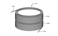
図13Aは、口出部41a、41bが外側にくるレイヤー巻きコイル41の斜視図である。
レイヤー巻きとは、テープ状の導体だけではなく、矩形や丸断面の線材で巻き回す一般的な巻線方法である。具体的には、一周巻き回した線に並ぶように隣の列に(コイルの巻き軸方向)巻き回し軸方向に1層のコイルを形成した後、折り返すようにして1層巻きコイルに乗り上げて、次の層を軸方向に巻き進める方法である。この巻線の仕方では、コイルの口出し部はコイル巻線の内側と外側に位置することになる。
FIG. 13A is a perspective view of a layer-
Layer winding is a common winding method that uses not only tape-shaped conductors, but also wires with rectangular or round cross sections. Specifically, it is a method in which one layer of coil is formed in the axial direction by winding the wire in the adjacent row (in the direction of the coil winding axis) in line with a single turn of the wire, and then the wire is folded back to land on the one-layer coil, and the next layer is wound in the axial direction. With this winding method, the coil ends are located on the inside and outside of the coil winding.
そのため、本実施形態の磁石円板3(図1)のようにコイルを横にならべて結線をするためには、コイルの内側の口出しから接続線を引き回す必要があり隣接するコイル間の結線が難しくなる。
ダブルパンケーキ巻きコイルの結線方法について述べたが、図13Aに示すレイヤー巻きと呼ばれるコイルの巻き方においても同様に口出し部を外側に位置するように構成することによってコイル間の接続を容易にすることができる。
Therefore, in order to connect the coils side by side as in the magnet disk 3 of this embodiment (Figure 1), it is necessary to run the connection wires from the inner outlet of the coil, making it difficult to connect adjacent coils.
A method for connecting a double pancake wound coil has been described above. However, in a coil winding method called layer winding shown in FIG. 13A, the connection between the coils can also be facilitated by positioning the lead portions on the outside in a similar manner.
そこで、ダブルパンケーキ巻きと同様のやりかたで、2つ重ねた巻線41A、41B(図13A参照)の中央からそれぞれレイヤー巻を行なうとレイヤー巻きながら口出部41a、41bが外側にくるレイヤー巻きコイル41を形成することができる。なお、2つ重ねた巻線41A、41Bは、中心部で電気的接続がなされている。
こうして、口出し部41a、41bが外側にあるレイヤー巻きコイル41を並べれば、隣接間コイルの接続が容易になる。
Therefore, by layer winding each of the two overlapping
In this way, by arranging the layer wound coils 41 with the
図13Bは、口出部41a、42aが高さ方向で揃う口出部41a、41b、42a、42bが外側にくるレイヤー巻きコイル41、42の斜視図である。
図13Bに示すように、ダブルパンケーキ巻きコイルの時と同様に口出し位置が高さ方向で揃うように2種類の口出し部41a、41bが外側に位置するレイヤー巻きコイル41と、口出し部42a、42bが外側に位置するレイヤー巻きコイル42とを並べることによって、さらに接続を容易にすることができる。
FIG. 13B is a perspective view of the layer wound coils 41 and 42 in which the
As shown in FIG. 13B, similarly to the case of a double pancake wound coil, by arranging a
<磁気冷凍装置R>
次に、本実施形態のギャップgを有する積層超電導磁石Jを用いた磁気冷凍装置Rについて説明する。
<Magnetic Refrigeration Device R>
Next, a magnetic refrigeration device R using the laminated superconducting magnet J having the gap g of this embodiment will be described.
図14は、本実施形態のギャップgを有する積層超電導磁石Jを用いた磁気冷凍装置Rの概念図である。
磁気冷凍装置Rは、真空容器102内に2段回転冷却装置101が固定されている。2段回転冷却装置101の最下部のコールドヘッド101hに積層超電導磁石(J)で構成された回転超電導磁石ユニット100が吊り下げられている。
2段回転冷却装置101は回転可能なように構成されている。磁石駆動ユニット105は、駆動力伝達機構106を介して、2段回転冷却装置101の回転コールドヘッド101hおよび超電導磁石ユニット100を回転させる。
FIG. 14 is a conceptual diagram of a magnetic refrigeration device R using a laminated superconducting magnet J having a gap g according to this embodiment.
The magnetic refrigeration device R has a two-stage
The two-stage
回転超電導磁石ユニット100は、磁気冷凍磁性体ユニット103の一部を挿入可能なようにギャップgを空けて積層構成されている。磁気冷凍磁性体ユニット103は、その一部が積層超電導磁石(J)のギャップgにおさまるように設置されている。
また、磁気冷凍装置Rとして働かせるために磁気冷凍磁性体ユニット103には磁気冷凍装置配管バブおよび排熱ユニット104が設置されている。そして、これら磁気冷凍構成に対して輻射入熱を低減するための輻射シールド107が設置されている。
The rotating
Further, a magnetic refrigeration device piping valve and a
上記構成によれば、複数のギャップgを有する積層磁石Jにおいて磁石間に働く吸引力をキャンセルし電磁力アンバランスの発生を抑制できる。
したがって、アンバランス電磁力の発生を抑制し電磁力支持構造を簡素化したギャップgを有する回転磁場発生装置8および磁気冷凍装置Rを提供できる。
According to the above configuration, the attractive forces acting between the magnets in the magnet stack J having a plurality of gaps g can be cancelled, thereby suppressing the occurrence of electromagnetic force imbalance.
Therefore, it is possible to provide a rotating magnetic field generating device 8 and a magnetic refrigeration device R having a gap g that suppresses the generation of an unbalanced electromagnetic force and simplifies the electromagnetic force support structure.
[効果]
以上説明したように、本実施形態に係る回転磁場発生装置8(図1)は、周状に複数の電磁石4が配置された円板(支持円板2,磁石円板3)(図3)と、複数の電磁石4がそれぞれ対向するように間隔を空けて円板(磁石円板3)を積層することによって形成される磁場作用空間(ギャップgの空間)を有する磁場発生装置であって、回転磁場発生装置8は、円板(支持円板2)(図3)によって積層された電磁石4間に働く電磁力が支持されており、積層された円板(磁石円板3)の両端部(端部jc1,jc2)には電磁石4間に働く電磁力を低減する磁性体ヨーク(エンドヨーク7)(図4)が設置されており、円板(磁石円板3)内の電磁石4は、電磁石4の軸方向に磁束が連続するように円板(磁石円板3)内の同一位相位置に配置され、同一位相位置の電磁石4は、同一電流で運転(「ドライブ運転モード」「永久電流モード運転」)されるように結線されている(図5、図6)。
[effect]
As described above, the rotating magnetic field generator 8 (FIG. 1) according to this embodiment is a magnetic field generator having a disk (support disk 2, magnet disk 3) (FIG. 3) on which a plurality of electromagnets 4 are arranged circumferentially, and a magnetic field action space (space of gap g) formed by stacking the disks (magnet disks 3) at intervals so that the plurality of electromagnets 4 face each other, and in the rotating magnetic field generator 8, the electromagnetic force acting between the stacked electromagnets 4 is supported by the disk (support disk 2) (FIG. 3), and magnetic yokes (end yokes 7) (FIG. 4) that reduce the electromagnetic force acting between the electromagnets 4 are installed at both ends (ends jc1, jc2) of the stacked disks (magnet disks 3), and the electromagnets 4 in the disk (magnet disk 3) are arranged at the same phase position in the disk (magnet disk 3) so that the magnetic flux is continuous in the axial direction of the electromagnets 4, and the electromagnets 4 at the same phase position are wired so as to be operated with the same current ("drive operation mode", "persistent current mode operation") (FIGS. 5 and 6).
このように構成することにより、回転磁場発生装置8は、磁石円板3の両端部(端部jc1,jc2)にエンドヨーク7を配置することによって、端部jc1,jc2の超電導コイル1a、1b、1c、1dに加わる垂直成分の磁場強度を低減し、より多くの電流を超電導コイル1a、1b、1c、1dに流して有利な磁場を発生させるとともに、支持円板2(図3)が積層された電磁石4間に働く電磁力を機械的支持構造により支持する(<個々の磁石にとっての電磁力バランス達成>)。そして、回転磁場発生装置8は、同一位相位置の電磁石4が、同一電流で運転されるように結線することで(図5、図6)、電磁石に流れる電流の大きさや電流の経路を変化しないようにして電磁石の起磁力の変化を防ぎ、アンバランス電磁力の発生を抑制する(<アンバランス電磁力の発生抑制>)。これにより、電磁力支持構造を簡素化しつつ、アンバランス電磁力の発生を抑制する回転磁場発生装置8を実現することができる。
By configuring in this way, the rotating magnetic field generator 8 reduces the magnetic field strength of the vertical component applied to the
回転磁場発生装置8(図1)において、電磁石4は、磁極(鉄心4a1、4b1、4c1、4d1)を平板状に巻き回された超電導コイル1(1a、1b、1c、1d)を要素コイル1(1a、1b、1c、1d)として有し、要素コイル1は、当該要素コイルが作る磁束が電磁石4の軸方向に連続するように積層された各磁石円板3内に配置される(図4)。 In the rotating magnetic field generator 8 (Figure 1), the electromagnet 4 has superconducting coils 1 (1a, 1b, 1c, 1d) wound around magnetic poles (iron cores 4a1, 4b1, 4c1, 4d1) in a flat shape as element coils 1 (1a, 1b, 1c, 1d), and the element coils 1 are arranged within each stacked magnet disk 3 so that the magnetic flux generated by the element coils is continuous in the axial direction of the electromagnet 4 (Figure 4).
このようにすることにより、磁石円板4を上下方向に積層する際、超電導コイル1(1a、1b、1c、1d)の作る磁束が、電磁石4の軸方向に連続するように、磁石円板4の位相を配置するので、磁束は軸方向に連続しており一つの棒磁石のように見做せ、超電導コイル群を多数積層することによって作業領域を増やして大容量化を実現することができる。 By doing this, when stacking the magnet disks 4 in the vertical direction, the phase of the magnet disks 4 is arranged so that the magnetic flux created by the superconducting coils 1 (1a, 1b, 1c, 1d) is continuous in the axial direction of the electromagnet 4. Therefore, the magnetic flux is continuous in the axial direction and can be regarded as a single bar magnet. By stacking a large number of superconducting coils, the working area can be increased and a large capacity can be achieved.
回転磁場発生装置8(図1)において、要素コイル(1a、1e、1j)、(1b、1f、1k)、(1c、1g、1m)、(1d、1h、1n)は、それぞれ電流を流した際に隣接する要素コイルに発生する磁場が、互いに逆向きになるように配置される(図4の白抜き矢印)。 In the rotating magnetic field generator 8 (Figure 1), the element coils (1a, 1e, 1j), (1b, 1f, 1k), (1c, 1g, 1m), and (1d, 1h, 1n) are arranged so that when a current is passed through each of them, the magnetic fields generated in the adjacent element coils are in the opposite directions (white arrows in Figure 4).
このようにすることにより、超電導コイル1(1a、1b、1c、1d)の作る磁束は軸方向に連続しており一つの棒磁石のように見做せ、かつ、この棒磁石の向きを交互に変えているので、磁石全体として磁気モーメントがゼロとなるように構成することができる。磁気ロスが無いので回転磁場発生装置8全体としての漏洩磁場を小さく抑えることができる。 By doing this, the magnetic flux created by the superconducting coils 1 (1a, 1b, 1c, 1d) is continuous in the axial direction and can be regarded as one bar magnet, and because the orientation of this bar magnet is alternated, the magnet as a whole can be configured to have a magnetic moment of zero. Since there is no magnetic loss, the leakage magnetic field of the rotating magnetic field generator 8 as a whole can be kept small.
回転磁場発生装置8(図1)において、要素コイル(1a、1e、1j)、(1b、1f、1k)、(1c、1g、1m)、(1d、1h、1n) (図5、図6)は、各要素コイル(1a、1e、1j)、(1b、1f、1k)、(1c、1g、1m)、(1d、1h、1n)に流れる電流が連続となるように電気的に接続されている。 In the rotating magnetic field generating device 8 (Fig. 1), the element coils (1a, 1e, 1j), (1b, 1f, 1k), (1c, 1g, 1m), (1d, 1h, 1n) (Figs. 5 and 6) are electrically connected so that the current flowing through each of the element coils (1a, 1e, 1j), (1b, 1f, 1k), (1c, 1g, 1m), (1d, 1h, 1n) is continuous.
このようにすることにより、要素コイル(1a、1e、1j)、(1b、1f、1k)、(1c、1g、1m)、(1d、1h、1n)に流れる電流または電流比を一定に保つことが可能になり、各要素コイルが作る起磁力の変化を防止し、アンバランス電磁力の発生を抑制することができる。 By doing this, it becomes possible to keep the current or current ratio flowing through the element coils (1a, 1e, 1j), (1b, 1f, 1k), (1c, 1g, 1m), (1d, 1h, 1n) constant, preventing changes in the magnetomotive force generated by each element coil and suppressing the generation of unbalanced electromagnetic forces.
回転磁場発生装置8(図1)において、要素コイル(1a、1e、1j)、(1b、1f、1k)、(1c、1g、1m)、(1d、1h、1n)は、各磁石円板3内の同一位相位置に配置されてコイルカラム(磁石カラム)9a、9b、9c、9d(図5、図6)を構成し、当該コイルカラム9a、9b、9c、9dを構成する各要素コイル(1a、1e、1j)、(1b、1f、1k)、(1c、1g、1m)、(1d、1h、1n) (図5、図6)が、一続きの電流で励磁される。
In the rotating magnetic field generator 8 (Fig. 1), the element coils (1a, 1e, 1j), (1b, 1f, 1k), (1c, 1g, 1m), (1d, 1h, 1n) are arranged at the same phase position in each magnet disk 3 to form coil columns (magnet columns) 9a, 9b, 9c, 9d (Figs. 5, 6), and each of the element coils (1a, 1e, 1j), (1b, 1f, 1k), (1c, 1g, 1m), (1d, 1h, 1n) (Figs. 5, 6) that make up the
このようにすることにより、縦方向(電磁石4の軸方向)に構成されたコイルカラム9a、9b、9c、9dが同一電流であることを保証することができ、アンバランス電磁力の発生を抑制することができる。
By doing this, it is possible to ensure that the
回転磁場発生装置8(磁場発生装置)(図1)において、コイルカラム9a、9b、9c、9d(図5、図6)を構成する各要素コイル(1a、1e、1j)、(1b、1f、1k)、(1c、1g、1m)、(1d、1h、1n)に流れる電流または電流の比を所定値に保つ。
In the rotating magnetic field generator 8 (magnetic field generator) (Fig. 1), the current or current ratio flowing through each of the element coils (1a, 1e, 1j), (1b, 1f, 1k), (1c, 1g, 1m), (1d, 1h, 1n) constituting the
このようにすることにより、個々の要素コイルの運転電流比を一定に保つことで、個々の要素コイルに流れる電流の大きさの変化を防ぎ、アンバランス電磁力の発生を抑制することができる。 By doing this, the operating current ratio of each element coil is kept constant, preventing changes in the magnitude of the current flowing through each element coil and suppressing the generation of unbalanced electromagnetic forces.
回転磁場発生装置8(磁場発生装置)(図1)において、並列接続されたコイルカラム9a、9b、9c、9d(図5)への電流供給は、1つの電流経路(図5の符号A参照)から電流を流す。
In the rotating magnetic field generator 8 (magnetic field generator) (Figure 1), current is supplied to the parallel-connected
例えば、図5に示すように、並列接続された4つのコイルカラム9a、9b、9c、9dへの電流供給が1つの電流経路で供給される。それぞれのコイルカラム9a、9b、9c、9dで電流パスは1つしかないので常にそのコイルカラム9a、9b、9c、9d内の要素コイルに流れる電流は等しく比は一定状態が保たれる。また、縦方向(電磁石4の軸方向)に構成されたコイルカラム9a、9b、9c、9dが同一電流である。これにより、コイルカラム9a、9b、9c、9d内の要素コイル(1a、1e、1j)、(1b、1f、1k)、(1c、1g、1m)、(1d、1h、1n)に流れる電流は等しく比は一定状態が保たれ、アンバランス電磁力の発生を抑制することができる。
For example, as shown in FIG. 5, current is supplied to four
また、回転磁場発生装置8は、永久電流モード運転の場合、図5のようにコイルカラム9a、9b、9c、9d単位で結線し、そのコイルカラム9a、9b、9c、9d単位で永久電流ループを構成することで、コイルカラム9a、9b、9c、9dに発生するアンバランス電磁力の発生の抑制を行うことができる。
In addition, when the rotating magnetic field generating device 8 is operated in the persistent current mode, the
回転磁場発生装置8(図1)において、コイルカラム9a、9b、9c、9d(図6)を構成する各要素コイル(1a、1e、1j)、(1b、1f、1k)、(1c、1g、1m)、(1d、1h、1n)を一続きに結線して電流を流す。
In the rotating magnetic field generator 8 (Fig. 1), the
このようにすることにより、個々の要素コイルに流れる電流が連続となるように結線され、電流が供給されるので、個々の要素コイルに流れる電流の大きさの変化を防ぐことができる。また、縦方向(電磁石4の軸方向)に構成されたコイルカラム9a、9b、9c、9dが一続きの電流で励磁される。これにより、アンバランス電磁力の発生を抑制することができる。
By doing this, the current flowing through each element coil is connected and supplied so that it is continuous, which prevents changes in the magnitude of the current flowing through each element coil. In addition, the
また、回転磁場発生装置8は、永久電流モード運転の場合、図6のようにすべての要素コイルを一続きに結線して磁石全体で永久電流モード回路を構成することで、コイルカラムに発生するアンバランス電磁力の発生の抑制を行うことができる。 In addition, when the rotating magnetic field generator 8 is operated in persistent current mode, all element coils are connected in series as shown in Figure 6 to form a persistent current mode circuit for the entire magnet, thereby suppressing the generation of unbalanced electromagnetic forces in the coil column.
回転磁場発生装置8(図1)において、電磁石4は、超電導磁石である。 In the rotating magnetic field generating device 8 (Figure 1), the electromagnet 4 is a superconducting magnet.
このようにすることにより、電磁石4として超電導磁石を用いることで、エネルギー消費を削減できる。また、超電導磁石を用いる回転磁場発生装置8において、電磁力バランスを維持することができる。 In this way, energy consumption can be reduced by using a superconducting magnet as the electromagnet 4. In addition, the electromagnetic force balance can be maintained in the rotating magnetic field generating device 8 that uses a superconducting magnet.
回転磁場発生装置8(磁場発生装置)(図1)において、電磁石4は、超電導磁石であり、電磁石4は、永久電流モードで運転される。 In the rotating magnetic field generator 8 (magnetic field generator) (Figure 1), the electromagnet 4 is a superconducting magnet, and the electromagnet 4 is operated in a persistent current mode.
このようにすることにより、超電導磁石を用いる回転磁場発生装置8において、電磁力バランスを維持することができる。 By doing this, it is possible to maintain electromagnetic force balance in the rotating magnetic field generating device 8 that uses a superconducting magnet.
回転磁場発生装置8(磁場発生装置)(図1)において、電磁石4は、要素コイル1と要素コイル1が接続される永久電流スイッチ11とを有する要素永久電流モード磁石10(図7)を構成する。
In the rotating magnetic field generator 8 (magnetic field generator) (Figure 1), the electromagnet 4 constitutes an element persistent current mode magnet 10 (Figure 7) having an element coil 1 and a persistent
このようにすることにより、要素永久電流モード磁石10を用いる回転磁場発生装置8において、永久電流モード運転の場合、電磁力バランスを維持することができる。
また、超電導コイルと永久電流スイッチ11で構成された要素永久電流モード磁石10は、モジュールコイル間を常電導の配線ではんだ接続するこが可能であり、積層超電導磁石を製作するのが簡便であり、また、実質的に磁場安定な永久電流モード磁石を実現することができる。
By doing so, in the rotating magnetic field generating device 8 using the element persistent
Furthermore, the elemental persistent
回転磁場発生装置8(図8)において、電磁石4の軸方向に磁束が連続するように配置される円板内の同一位相位置の電磁石4に対して、クエンチが発生した場合に、当該同一位相位置の要素永久電流モード磁石の永久電流スイッチ11が全て遮断される。
In a rotating magnetic field generator 8 (Figure 8), when a quench occurs in electromagnets 4 at the same phase position in a disk arranged so that the magnetic flux is continuous in the axial direction of the electromagnets 4, all of the persistent
すなわち、モジュールコイルで積層磁石を構成した場合、どれかひとつのモジュールコイルがクエンチしてコイルが常電導状態に転移すると、モジュールコイルの永久電流ループにおいて電流減衰がおこり、その結果そのモジュールコイルの磁場が失われアンバランス電磁力が発生する不具合がある。
回転磁場発生装置8は、クエンチ発生を検出すると同時に速やかにそれぞれのモジュールコイルの永久電流スイッチ11をオフにすることによって、アンバランス電磁力の発生を最小限に抑えることができる。
In other words, when a laminated magnet is constructed using module coils, if one of the module coils quenches and the coil transitions to a normal conducting state, current attenuation occurs in the persistent current loop of the module coil, resulting in a loss of magnetic field in that module coil and the generation of an unbalanced electromagnetic force.
The rotating magnetic field generating device 8 can minimize the generation of unbalanced electromagnetic forces by quickly turning off the persistent
回転磁場発生装置8(磁場発生装置)(図8、図9)において、クエンチが発生したときの電磁石の蓄積エネルギーを回収するダイオード12または抵抗が、電磁石4に電流を流す回路に並列に接続されている。
In the rotating magnetic field generator 8 (magnetic field generator) (Figures 8 and 9), a
このようにすることにより、クエンチが発生しても自分自身の巻線のエンタルピーとエネルギー回収回路50(大ループ)のダイオード12によってコイルの蓄積エネルギーが回収されて焼損に至らないようにすることができる。
By doing this, even if a quench occurs, the coil's stored energy is recovered by the enthalpy of its own winding and the
回転磁場発生装置8(磁場発生装置)(図10A)において、要素コイル1の電流導入部である口出し部41a等が当該要素コイルの外周側に位置する。
In the rotating magnetic field generator 8 (magnetic field generator) (FIG. 10A), the
このようにすることにより、要素コイル1の口出し部41a位置を揃えることができ、例えばテープ導体が巻き回されたダブルパンケーキ巻きコイル21(図10A、図12A)を用いることが容易となる。
By doing this, the positions of the lead-out
回転磁場発生装置8(図1)において、要素コイル1がパンケーキ巻きコイル21(図10A、図12A)で構成されている。 In the rotating magnetic field generating device 8 (Fig. 1), the element coil 1 is composed of a pancake wound coil 21 (Figs. 10A and 12A).
このようにすることにより、例えばテープ導体が巻き回されたダブルパンケーキ巻きコイル21(図10A)を用いることが可能となる。 By doing this, it is possible to use, for example, a double pancake wound coil 21 (Figure 10A) with a tape conductor wound around it.
回転磁場発生装置8(図1)において、要素コイル1がパンケーキ巻きコイルで21(図10A、図12A)構成されており、パンケーキ巻きコイル21間の電流接続がパンケーキ巻きコイル21の巻線の導体サイズよりも大きな導体で接続されている。 In the rotating magnetic field generator 8 (Fig. 1), the element coil 1 is composed of pancake coils 21 (Fig. 10A, Fig. 12A), and the current connections between the pancake coils 21 are made with conductors larger than the conductor size of the windings of the pancake coils 21.
このようにすることにより、幅の広いテープを使うことによって、テープを平行に揃えて接続長を長くとって接続することが可能となり、接続部でのジュール発熱を低減することができる。例えばテープ導体が巻き回されたダブルパンケーキ巻きコイル21(図10A)を用いる場合であっても、幅広のテープ導体を利用することにより十分な接続面積を確保して接続することが可能となる。
なお、隣接する要素コイルの接続において、要素コイルの口出し線引出し位置を揃えることと、要素間接続を幅広の導電テープを介して接続することとは、それぞれ単独で適用してもよいし、併用してもよい。
In this way, by using a wide tape, it is possible to align the tape in parallel and connect with a long connection length, thereby reducing Joule heat at the connection. For example, even when using a double pancake wound coil 21 (FIG. 10A) with a wound tape conductor, it is possible to secure a sufficient connection area by using a wide tape conductor.
In addition, when connecting adjacent element coils, aligning the lead wire draw-out positions of the element coils and connecting the elements via a wide conductive tape may be applied alone or in combination.
回転磁場発生装置8(図1)において、要素コイル1の巻線口出し位置が、要素コイル同士で、要素コイル1の軸方向の位置が揃えられている(図11)。 In the rotating magnetic field generator 8 (Figure 1), the winding end positions of the element coils 1 are aligned in the axial direction between the element coils (Figure 11).
このようにすることにより、口出し線21a(図10A)は面内で直線上になるように配置でき、かつ、上下方向にも揃っているため接続テープ導体を介することなく直線的に接続ができる。例えば、口出し部41a、41b(図13A、図14A)が外側にあるレイヤー巻きコイル41を並べれば、隣接間コイルの接続が容易になる。これにより、接続箇所を半分に減らせることから接続部でのジュール発熱を半分に低減することができる。
By doing this, the lead wires 21a (Fig. 10A) can be arranged so that they are linear within the plane, and because they are aligned vertically, they can be connected linearly without going through a connecting tape conductor. For example, arranging layer-wound coils 41 with
上記回転磁場発生装置8(図1)が用いられることを特徴とする磁気冷凍装置R(図3)。 A magnetic refrigeration device R (Fig. 3) characterized by using the above-mentioned rotating magnetic field generating device 8 (Fig. 1).
磁気冷凍装置R(図3)は、アンバランス電磁力の発生を抑制できる回転磁場発生装置8(図1)を用いることで、磁気冷凍用の磁石装置の構造の簡素化、および装置の大容量化を実現することができる。 The magnetic refrigeration device R (Figure 3) uses a rotating magnetic field generator 8 (Figure 1) that can suppress the generation of unbalanced electromagnetic forces, making it possible to simplify the structure of the magnet device for magnetic refrigeration and increase the capacity of the device.
<その他の実施形態>
本発明は上記各実施形態に限定されるものではなく、特許請求の範囲に記載した本発明の要旨を逸脱しない限りにおいて、他の変形例、応用例を含む。
<Other embodiments>
The present invention is not limited to the above-described embodiments, and includes other modifications and applications without departing from the gist of the present invention described in the claims.
上記各実施形態は本発明をわかりやすく説明するために詳細に説明したものであり、必ずしも説明した全ての構成を備えるものに限定されるものではない。また、ある実施形態の構成の一部を他の実施形態の構成に置き換えることが可能であり、また、ある実施形態の構成に他の実施形態の構成を加えることも可能である。また、各実施形態の構成の一部について、他の構成の追加・削除・置換をすることが可能である。 The above embodiments have been described in detail to clearly explain the present invention, and are not necessarily limited to those having all of the configurations described. In addition, it is possible to replace part of the configuration of one embodiment with the configuration of another embodiment, and it is also possible to add the configuration of another embodiment to the configuration of one embodiment. In addition, it is possible to add, delete, or replace part of the configuration of each embodiment with other configurations.
本発明の磁場発生装置は、磁気熱量効果を利用した磁気冷凍用の磁石装置であり液体水素の液化などに利用できる。 The magnetic field generating device of the present invention is a magnet device for magnetic refrigeration that utilizes the magnetocaloric effect and can be used for liquefying liquid hydrogen, etc.
1、1a、1b、1c、1d、1e、1f、1g、1h、1j、1k、1m、1n 超電導コイル(電磁石、超電導磁石、要素コイル、コイル)
2 円板
3 磁石円板(円板)
4a、4b、4c、4d 電磁石(超電導磁石)
4a1、4b1、4c1、4d1 鉄心(磁極)
6 シャフト
7 エンドヨーク(磁性体ヨーク)
8 回転磁場発生装置(磁場発生ユニット、磁場発生装置)
9、9a、9b、9c、9d コイルカラム(磁石カラム)
10、10a、10b、10c、10d、10e、10f、10g、10h、10j、10k、10m、10n モジュールコイル(要素永久電流モード磁石)
11、11a、11b、11c、11d、11e、11f、11g、11h、11j、11k、11m、11n 永久電流スイッチ
11t、11ta~11tn ヒーター(永久電流スイッチ)
12 ダイオード
21、22、31、32パンケーキ巻きコイル
21a、21b、22a、22b、31a、32a 口出し線(口出し部)
口出し部 41a、41b、42a、42b
50 エネルギー回収回路
100 回転超電導磁石ユニット(磁場発生装置)
101 2段回転冷却装置(磁気冷凍装置)
101h コールドヘッド(磁気冷凍装置)
102 真空容器(磁気冷凍装置)
103 磁気冷凍磁性体ユニット(磁気冷凍装置)
104 排熱ユニット(磁気冷凍装置)
107 輻射シールド(磁気冷凍装置)
g ギャップ(磁場作用空間)
J、Ja、Jb、Jc、Jd 電磁石(同一位相位置の電磁石)
jc1、jc2 端部
R 磁気冷凍装置
1, 1a, 1b, 1c, 1d, 1e, 1f, 1g, 1h, 1j, 1k, 1m, 1n Superconducting coil (electromagnet, superconducting magnet, element coil, coil)
2 Disk 3 Magnet disk (disk)
4a, 4b, 4c, 4d Electromagnet (superconducting magnet)
4a1, 4b1, 4c1, 4d1 Iron core (magnetic pole)
6 Shaft 7 End yoke (magnetic yoke)
8 Rotating magnetic field generator (magnetic field generating unit, magnetic field generator)
9, 9a, 9b, 9c, 9d Coil column (magnetic column)
10, 10a, 10b, 10c, 10d, 10e, 10f, 10g, 10h, 10j, 10k, 10m, 10n Module coil (element persistent current mode magnet)
11, 11a, 11b, 11c, 11d, 11e, 11f, 11g, 11h, 11j, 11k, 11m, 11n: persistent
12 Diode 21, 22, 31, 32 Pancake coil 21a, 21b, 22a, 22b, 31a, 32a Lead wire (lead portion)
50
101 Two-stage rotating cooling device (magnetic refrigeration device)
101h Cold head (magnetic refrigeration device)
102 Vacuum vessel (magnetic refrigeration device)
103 Magnetic refrigeration magnetic unit (magnetic refrigeration device)
104 Heat dissipation unit (magnetic refrigeration device)
107 Radiation shield (magnetic refrigeration device)
g Gap (magnetic field action space)
J, Ja, Jb, Jc, Jd electromagnets (electromagnets in the same phase position)
jc1, jc2 End R Magnetic refrigeration device
Claims (18)
前記複数の電磁石がそれぞれ対向するように間隔を空けて前記円板を積層することによって形成される磁場作用空間を有する磁場発生装置であって、
前記円板によって積層された前記電磁石間に働く電磁力が支持されており、
積層された前記円板の両端部には前記電磁石間に働く電磁力を低減する磁性体ヨークが設置されており、
前記円板内の前記電磁石は、前記電磁石の軸方向に磁束が連続するように前記円板内の同一位相位置に配置され、
前記同一位相位置の前記電磁石は、同一電流で運転されるように結線されている
ことを特徴とする磁場発生装置。 A disk having a plurality of electromagnets arranged around its circumference;
A magnetic field generating device having a magnetic field action space formed by stacking the disks at intervals so that the plurality of electromagnets face each other,
The electromagnetic force acting between the stacked electromagnets is supported by the disk,
A magnetic yoke is provided at each end of the stacked disks to reduce the electromagnetic force acting between the electromagnets.
The electromagnets in the disk are arranged at the same phase position in the disk so that magnetic flux is continuous in the axial direction of the electromagnets,
The magnetic field generating device, wherein the electromagnets in the same phase position are connected so as to be operated with the same current.
前記電磁石は、
磁極を平板状に巻き回された超電導コイルを要素コイルとして有し、
前記要素コイルは、当該要素コイルが作る磁束が前記電磁石の軸方向に連続するように積層された各前記円板内に配置される
ことを特徴とする磁場発生装置。 2. The magnetic field generating device according to claim 1,
The electromagnet is
The element coil is a superconducting coil wound around a magnetic pole in a flat shape,
A magnetic field generating device, characterized in that the element coils are arranged in each of the stacked disks so that magnetic flux generated by the element coils is continuous in the axial direction of the electromagnet.
前記要素コイルは、それぞれ電流を流した際に隣接する前記要素コイルに発生する磁場が、互いに逆向きになるように配置される
ことを特徴とする磁場発生装置。 3. The magnetic field generating device according to claim 2,
The magnetic field generating device, characterized in that the element coils are arranged such that magnetic fields generated in adjacent element coils when a current is passed therethrough are in opposite directions to each other.
前記要素コイルは、各前記要素コイルに流れる電流が連続となるように電気的に接続されている
ことを特徴とする磁場発生装置。 3. The magnetic field generating device according to claim 2,
The magnetic field generating device, characterized in that the element coils are electrically connected so that currents flowing through the element coils are continuous.
前記要素コイルは、各前記円板内の同一位相位置に配置されてコイルカラムを構成し、当該コイルカラムを構成する各前記要素コイルが、一続きの電流で励磁される
ことを特徴とする磁場発生装置。 3. The magnetic field generating device according to claim 2,
The element coils are arranged at the same phase position within each of the disks to form a coil column, and each of the element coils constituting the coil column is excited by a continuous current.
前記コイルカラムを構成する各前記要素コイルに流れる電流または電流の比を所定値に保つ
ことを特徴とする磁場発生装置。 6. The magnetic field generating device according to claim 5,
A magnetic field generating device characterized in that the current flowing through each of the element coils constituting the coil column or the ratio of currents is maintained at a predetermined value.
並列接続された前記コイルカラムへの電流供給は、1つの電流経路から電流を流す
ことを特徴とする磁場発生装置。 6. The magnetic field generating device according to claim 5,
A magnetic field generating device, characterized in that current is supplied to the coil columns connected in parallel by flowing current through one current path.
前記コイルカラムを構成する各前記要素コイルを一続きに結線して電流を流す
ことを特徴とする磁場発生装置。 6. The magnetic field generating device according to claim 5,
A magnetic field generating device, characterized in that each of the element coils constituting the coil column is connected in series to pass a current through it.
前記電磁石は、超電導磁石である
ことを特徴とする磁場発生装置。 2. The magnetic field generating device according to claim 1,
The magnetic field generating device, wherein the electromagnet is a superconducting magnet.
前記電磁石は、超電導磁石であり、
前記電磁石は、永久電流モードで運転される
ことを特徴とする磁場発生装置。 2. The magnetic field generating device according to claim 1,
the electromagnet is a superconducting magnet,
The magnetic field generating device, wherein the electromagnet is operated in a persistent current mode.
前記電磁石は、前記要素コイルと前記要素コイルが接続される永久電流スイッチとを有する要素永久電流モード磁石を構成する
ことを特徴とする磁場発生装置。 3. The magnetic field generating device according to claim 2,
The magnetic field generating device, wherein the electromagnet constitutes an element persistent current mode magnet having the element coil and a persistent current switch to which the element coil is connected.
前記電磁石の軸方向に磁束が連続するように配置される前記円板内の前記同一位相位置の電磁石に対して、クエンチが発生した場合に、当該同一位相位置の前記要素永久電流モード磁石の前記永久電流スイッチが全て遮断されることを特徴とする磁場発生装置。 The magnetic field generating device according to claim 11,
A magnetic field generating device characterized in that, when a quench occurs in the electromagnets at the same phase position in the disk arranged so that magnetic flux is continuous in the axial direction of the electromagnets, all of the persistent current switches of the element persistent current mode magnets at the same phase position are turned off.
クエンチが発生したときの前記電磁石の蓄積エネルギーを回収するダイオードまたは抵抗が、前記電磁石に電流を流す回路に並列に接続されていることを特徴とする磁場発生装置。 2. The magnetic field generating device according to claim 1,
A magnetic field generating device, characterized in that a diode or resistor for recovering the stored energy of the electromagnet when a quench occurs is connected in parallel to a circuit for passing a current through the electromagnet.
前記要素コイルの電流導入部である口出し部が当該要素コイルの外周側に位置する
ことを特徴とする磁場発生装置。 3. The magnetic field generating device according to claim 2,
A magnetic field generating device, characterized in that an outlet portion which is a current introduction portion of the element coil is located on an outer periphery side of the element coil.
前記要素コイルがパンケーキ巻きコイルで構成されている
ことを特徴とする磁場発生装置。 3. The magnetic field generating device according to claim 2,
A magnetic field generating device, characterized in that the element coils are composed of pancake wound coils.
前記要素コイルがパンケーキ巻きコイルで構成されており、当該パンケーキ巻きコイル間の電流接続が当該パンケーキ巻きコイルの巻線の導体サイズよりも大きな導体で接続されていることを特徴とする磁場発生装置。 3. The magnetic field generating device according to claim 2,
A magnetic field generating device characterized in that the element coils are composed of pancake wound coils, and current connections between the pancake wound coils are made with conductors larger than the conductor size of the windings of the pancake wound coils.
前記要素コイルの巻線口出し位置が、前記要素コイル同士で、前記要素コイルの軸方向の位置が揃えられている
ことを特徴とする磁場発生装置。 3. The magnetic field generating device according to claim 2,
a winding lead position of each of the element coils being aligned in an axial direction of the element coils;
ことを特徴とする磁気冷凍装置。 A magnetic refrigeration device comprising the magnetic field generating device according to any one of claims 1 to 16.
Priority Applications (3)
| Application Number | Priority Date | Filing Date | Title |
|---|---|---|---|
| JP2023073161A JP2024158181A (en) | 2023-04-27 | 2023-04-27 | Magnetic field generating device and magnetic refrigeration device |
| EP24796854.8A EP4704122A1 (en) | 2023-04-27 | 2024-04-15 | Magnetic field generation device and magnetic refrigeration device |
| PCT/JP2024/015026 WO2024225100A1 (en) | 2023-04-27 | 2024-04-15 | Magnetic field generation device and magnetic refrigeration device |
Applications Claiming Priority (1)
| Application Number | Priority Date | Filing Date | Title |
|---|---|---|---|
| JP2023073161A JP2024158181A (en) | 2023-04-27 | 2023-04-27 | Magnetic field generating device and magnetic refrigeration device |
Publications (1)
| Publication Number | Publication Date |
|---|---|
| JP2024158181A true JP2024158181A (en) | 2024-11-08 |
Family
ID=93256385
Family Applications (1)
| Application Number | Title | Priority Date | Filing Date |
|---|---|---|---|
| JP2023073161A Pending JP2024158181A (en) | 2023-04-27 | 2023-04-27 | Magnetic field generating device and magnetic refrigeration device |
Country Status (3)
| Country | Link |
|---|---|
| EP (1) | EP4704122A1 (en) |
| JP (1) | JP2024158181A (en) |
| WO (1) | WO2024225100A1 (en) |
Family Cites Families (2)
| Publication number | Priority date | Publication date | Assignee | Title |
|---|---|---|---|---|
| JP6232284B2 (en) | 2013-12-27 | 2017-11-15 | パナソニック アプライアンシズ リフリジレーション デヴァイシズ シンガポール | Compressor |
| JP7478694B2 (en) * | 2021-03-08 | 2024-05-07 | 株式会社日立製作所 | Rotating magnetic field generator, magnetic refrigeration device, and hydrogen liquefaction device |
-
2023
- 2023-04-27 JP JP2023073161A patent/JP2024158181A/en active Pending
-
2024
- 2024-04-15 EP EP24796854.8A patent/EP4704122A1/en active Pending
- 2024-04-15 WO PCT/JP2024/015026 patent/WO2024225100A1/en not_active Ceased
Also Published As
| Publication number | Publication date |
|---|---|
| EP4704122A1 (en) | 2026-03-04 |
| WO2024225100A1 (en) | 2024-10-31 |
Similar Documents
| Publication | Publication Date | Title |
|---|---|---|
| US7489060B2 (en) | Superconducting rotating machines with stationary field coils | |
| US6066906A (en) | Rotating machine having superconducting windings | |
| JP4001365B2 (en) | Cryogenic cooling system for rotor with high temperature superconducting field winding | |
| US7119644B2 (en) | Mounting structure for superconducting windings | |
| US8204562B2 (en) | Superconducting synchronous machine | |
| US7492073B2 (en) | Superconducting rotating machines with stationary field coils | |
| US6597082B1 (en) | HTS superconducting rotating machine | |
| WO2001041283A2 (en) | Synchronous machine with superconductors | |
| US12590739B2 (en) | Rotating magnetic field generation device, magnetic refrigeration device, and hydrogen liquefaction device | |
| JP5448296B2 (en) | Tubular electrical machine | |
| JP3892299B2 (en) | HTS superconducting rotating machine | |
| GB2462532A (en) | Brushless motor/generator with trapped-flux superconductors | |
| JP2010016026A (en) | Superconductive device | |
| JP6462490B2 (en) | Superconducting motor and superconducting generator | |
| WO2019004847A1 (en) | Flywheel energy storage system | |
| KR100888030B1 (en) | Superconducting Synchronous Motor | |
| JP2004039591A (en) | Non-inductive winding and permanent current switch | |
| WO2024225100A1 (en) | Magnetic field generation device and magnetic refrigeration device | |
| CN113169658A (en) | Rotor with superconducting windings for operation in continuous current mode | |
| JP2019096849A (en) | Permanent current switch | |
| JP4923301B2 (en) | Superconducting coil device, inductor-type synchronous machine, and transformer device | |
| Dondapati | Superconducting Generators/Motors | |
| Goddard et al. | Alternative designs of a superconducting synchronous generator: the Southampton approach | |
| CA2709819C (en) | Electric motor comprising an inductor with a superconducting element incorporated between coils | |
| KR200473549Y1 (en) | Super conducting electric power generation system |
Legal Events
| Date | Code | Title | Description |
|---|---|---|---|
| A621 | Written request for application examination |
Free format text: JAPANESE INTERMEDIATE CODE: A621 Effective date: 20260209 |