JP2024128564A - Vehicle lighting fixtures - Google Patents
Vehicle lighting fixtures Download PDFInfo
- Publication number
- JP2024128564A JP2024128564A JP2023037590A JP2023037590A JP2024128564A JP 2024128564 A JP2024128564 A JP 2024128564A JP 2023037590 A JP2023037590 A JP 2023037590A JP 2023037590 A JP2023037590 A JP 2023037590A JP 2024128564 A JP2024128564 A JP 2024128564A
- Authority
- JP
- Japan
- Prior art keywords
- screw
- hole
- shade
- protrusions
- positioning holes
- Prior art date
- Legal status (The legal status is an assumption and is not a legal conclusion. Google has not performed a legal analysis and makes no representation as to the accuracy of the status listed.)
- Pending
Links
Images


Classifications
-
- F—MECHANICAL ENGINEERING; LIGHTING; HEATING; WEAPONS; BLASTING
- F21—LIGHTING
- F21S—NON-PORTABLE LIGHTING DEVICES; SYSTEMS THEREOF; VEHICLE LIGHTING DEVICES SPECIALLY ADAPTED FOR VEHICLE EXTERIORS
- F21S41/00—Illuminating devices specially adapted for vehicle exteriors, e.g. headlamps
- F21S41/40—Illuminating devices specially adapted for vehicle exteriors, e.g. headlamps characterised by screens, non-reflecting members, light-shielding members or fixed shades
- F21S41/43—Illuminating devices specially adapted for vehicle exteriors, e.g. headlamps characterised by screens, non-reflecting members, light-shielding members or fixed shades characterised by the shape thereof
-
- F—MECHANICAL ENGINEERING; LIGHTING; HEATING; WEAPONS; BLASTING
- F21—LIGHTING
- F21S—NON-PORTABLE LIGHTING DEVICES; SYSTEMS THEREOF; VEHICLE LIGHTING DEVICES SPECIALLY ADAPTED FOR VEHICLE EXTERIORS
- F21S41/00—Illuminating devices specially adapted for vehicle exteriors, e.g. headlamps
- F21S41/10—Illuminating devices specially adapted for vehicle exteriors, e.g. headlamps characterised by the light source
- F21S41/14—Illuminating devices specially adapted for vehicle exteriors, e.g. headlamps characterised by the light source characterised by the type of light source
- F21S41/141—Light emitting diodes [LED]
- F21S41/147—Light emitting diodes [LED] the main emission direction of the LED being angled to the optical axis of the illuminating device
- F21S41/148—Light emitting diodes [LED] the main emission direction of the LED being angled to the optical axis of the illuminating device the main emission direction of the LED being perpendicular to the optical axis
-
- F—MECHANICAL ENGINEERING; LIGHTING; HEATING; WEAPONS; BLASTING
- F21—LIGHTING
- F21S—NON-PORTABLE LIGHTING DEVICES; SYSTEMS THEREOF; VEHICLE LIGHTING DEVICES SPECIALLY ADAPTED FOR VEHICLE EXTERIORS
- F21S41/00—Illuminating devices specially adapted for vehicle exteriors, e.g. headlamps
- F21S41/20—Illuminating devices specially adapted for vehicle exteriors, e.g. headlamps characterised by refractors, transparent cover plates, light guides or filters
- F21S41/25—Projection lenses
- F21S41/255—Lenses with a front view of circular or truncated circular outline
-
- F—MECHANICAL ENGINEERING; LIGHTING; HEATING; WEAPONS; BLASTING
- F21—LIGHTING
- F21S—NON-PORTABLE LIGHTING DEVICES; SYSTEMS THEREOF; VEHICLE LIGHTING DEVICES SPECIALLY ADAPTED FOR VEHICLE EXTERIORS
- F21S41/00—Illuminating devices specially adapted for vehicle exteriors, e.g. headlamps
- F21S41/30—Illuminating devices specially adapted for vehicle exteriors, e.g. headlamps characterised by reflectors
- F21S41/32—Optical layout thereof
- F21S41/321—Optical layout thereof the reflector being a surface of revolution or a planar surface, e.g. truncated
-
- F—MECHANICAL ENGINEERING; LIGHTING; HEATING; WEAPONS; BLASTING
- F21—LIGHTING
- F21S—NON-PORTABLE LIGHTING DEVICES; SYSTEMS THEREOF; VEHICLE LIGHTING DEVICES SPECIALLY ADAPTED FOR VEHICLE EXTERIORS
- F21S41/00—Illuminating devices specially adapted for vehicle exteriors, e.g. headlamps
- F21S41/40—Illuminating devices specially adapted for vehicle exteriors, e.g. headlamps characterised by screens, non-reflecting members, light-shielding members or fixed shades
- F21S41/47—Attachment thereof
-
- F—MECHANICAL ENGINEERING; LIGHTING; HEATING; WEAPONS; BLASTING
- F21—LIGHTING
- F21S—NON-PORTABLE LIGHTING DEVICES; SYSTEMS THEREOF; VEHICLE LIGHTING DEVICES SPECIALLY ADAPTED FOR VEHICLE EXTERIORS
- F21S45/00—Arrangements within vehicle lighting devices specially adapted for vehicle exteriors, for purposes other than emission or distribution of light
- F21S45/40—Cooling of lighting devices
- F21S45/47—Passive cooling, e.g. using fins, thermal conductive elements or openings
-
- F—MECHANICAL ENGINEERING; LIGHTING; HEATING; WEAPONS; BLASTING
- F21—LIGHTING
- F21W—INDEXING SCHEME ASSOCIATED WITH SUBCLASSES F21K, F21L, F21S and F21V, RELATING TO USES OR APPLICATIONS OF LIGHTING DEVICES OR SYSTEMS
- F21W2102/00—Exterior vehicle lighting devices for illuminating purposes
- F21W2102/10—Arrangement or contour of the emitted light
- F21W2102/13—Arrangement or contour of the emitted light for high-beam region or low-beam region
- F21W2102/135—Arrangement or contour of the emitted light for high-beam region or low-beam region the light having cut-off lines, i.e. clear borderlines between emitted regions and dark regions
- F21W2102/155—Arrangement or contour of the emitted light for high-beam region or low-beam region the light having cut-off lines, i.e. clear borderlines between emitted regions and dark regions having inclined and horizontal cutoff lines
Landscapes
- Engineering & Computer Science (AREA)
- General Engineering & Computer Science (AREA)
- Physics & Mathematics (AREA)
- Microelectronics & Electronic Packaging (AREA)
- Optics & Photonics (AREA)
- Non-Portable Lighting Devices Or Systems Thereof (AREA)
Abstract
Description
本発明は、車両用灯具に関する。 The present invention relates to a vehicle lamp.
車両用灯具において、光学部品を固定部材に固定する場合、固定部材側の位置決めピンを光学部品の位置決め穴に差し込んで位置決めし、この状態でネジ部材により光学部品を固定部材に締結する方法が知られている(例えば、特許文献1参照)。 In vehicle lighting, when fixing an optical component to a fixed member, a method is known in which a positioning pin on the fixed member is inserted into a positioning hole in the optical component to position it, and in this state, the optical component is fastened to the fixed member by a screw member (see, for example, Patent Document 1).
特許文献1のように位置決め穴に位置決めピンを差し込んで位置決めする構成では、各部の寸法のバラつきによる干渉防止等のため、位置決め穴の径が位置決めピンの径よりも大きくなるように設計される。このため、光学部品が位置決めされた状態からネジ部材で締結する際、ネジ部材を回転させる際のトルクが光学部品に伝達され、光学部品の位置ズレが生じる可能性がある。
In a configuration in which positioning is performed by inserting a positioning pin into a positioning hole as in
本発明は、上記に鑑みてなされたものであり、ネジ部材で光学部品を固定する際の位置ズレを抑制できる車両用灯具を提供することを目的とする。 The present invention has been made in consideration of the above, and aims to provide a vehicle lamp that can suppress misalignment when fixing optical components with screw members.
本発明に係る車両用灯具は、光源部と、前記光源部からの光を車両前方に照射する光学系と、前記光学系で導かれる光の一部を遮光するシェードと、前記光源部、前記光学系及び前記シェードを支持する支持部材とを備え、前記光源部、前記シェード及び前記光学系のうち少なくとも1つの光学部品は、1本のネジ部材により前記支持部材に固定され、前記支持部材は、前記ネジ部材が挿入されるネジ穴と、前記ネジ穴を挟む位置に配置され前記光学部品を位置決めする2つの突起部と、を有し、前記光学部品は、前記ネジ部材を貫通させるネジ貫通穴と、前記ネジ貫通穴を挟む位置に配置され2つの前記突起部を挿入する位置決め穴とを有し、前記ネジ穴と、2つの前記突起部とは、直線に沿った第1方向に並んで配置され、2つの前記位置決め穴は、それぞれ前記突起部よりも径が大きく、前記ネジ貫通穴を基準とした前記第1方向上の位置に対して、前記ネジ部材を固定する際の回転方向に沿って所定のオフセット値だけずれた位置に配置される。 The vehicle lamp according to the present invention includes a light source unit, an optical system that irradiates light from the light source unit toward the front of the vehicle, a shade that blocks a portion of the light guided by the optical system, and a support member that supports the light source unit, the optical system, and the shade. At least one optical component among the light source unit, the shade, and the optical system is fixed to the support member by a single screw member. The support member has a screw hole into which the screw member is inserted and two protrusions that are arranged at positions that sandwich the screw hole and position the optical component. The optical component has a screw through hole through which the screw member passes and a positioning hole that is arranged at positions that sandwich the screw through hole and into which the two protrusions are inserted. The screw hole and the two protrusions are arranged side by side in a first direction along a straight line, and the two positioning holes each have a diameter larger than that of the protrusion, and are arranged at a position that is shifted by a predetermined offset value along the rotation direction when the screw member is fixed with respect to a position in the first direction based on the screw through hole.
本発明によれば、ネジ部材で光学部品を固定する際の位置ズレを抑制することが可能な車両用灯具を提供することができる。 The present invention provides a vehicle lamp that can suppress misalignment when fixing optical components with screw members.
以下、本発明に係る車両用灯具の実施形態を図面に基づいて説明する。なお、この実施形態によりこの発明が限定されるものではない。また、下記実施形態における構成要素には、当業者が置換可能かつ容易なもの、あるいは実質的に同一のものが含まれる。 Below, an embodiment of a vehicle lamp according to the present invention will be described with reference to the drawings. Note that the present invention is not limited to this embodiment. Furthermore, the components in the following embodiments include those that are easily replaceable by a person skilled in the art, or those that are substantially the same.
以下の説明において、前後方向、上下方向、及び左右方向のそれぞれは、車両に取り付けられた状態における車両用前照灯の方向を示す。前方とは、車両が直進状態で前進するときの前方向をいう。後方とは、水平面内において前方の逆方向をいう。上方とは、水平面と直交する方向において車両の走行面から離れる方向をいう。下方とは、水平面と直交する方向において上方の逆方向をいう。左方とは、車両が直進状態で前進するときの左方向をいう。右方とは、水平面内において左方の逆方向をいう。なお、前方が正面側、後方が背面側である。 In the following description, the terms front-to-rear, up-down, and left-to-right refer to the directions of the vehicle headlights when they are attached to the vehicle. Forward refers to the forward direction when the vehicle is moving forward in a straight line. Rear refers to the opposite direction of forward in a horizontal plane. Upward refers to the direction away from the vehicle's running surface in a direction perpendicular to the horizontal plane. Downward refers to the opposite direction of upward in a direction perpendicular to the horizontal plane. Left refers to the left direction when the vehicle is moving forward in a straight line. Right refers to the opposite direction of left in a horizontal plane. Note that forward is the front side and rear is the rear side.
[第1実施形態]
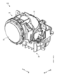
図1は、第1実施形態に係る車両用灯具100の一例を示す斜視図である。図2は、第1実施形態に係る車両用灯具100の一例を示す分解斜視図である。図1及び図2を示すように、車両用灯具100は、光源部10と、光学系20と、シェード30と、支持部材40とを備える。車両用灯具100は、例えば車両前方にロービームパターンを形成する。
[First embodiment]
Fig. 1 is a perspective view showing an example of a
光源部10は、光源11及び基板12を有する。光源11は、例えばLED等の半導体型光源である。基板12には、光源11が実装される。基板12は、例えばネジ部材により支持部材40に固定される。
The
光学系20は、リフレクタ21と、投影レンズ22とを有する。リフレクタ21は、光源11からの光を投影レンズ22に向けて反射する。リフレクタ21は、光源11の上方に配置され、例えば樹脂部材など、耐熱性が高くかつ光不透過性の材料を用いて形成されている。リフレクタ21は、例えばネジ部材により支持部材40に固定される。リフレクタ21は、前側部分および下側部分が開口し、かつ、後側部分および上側部分および左右両側部分が閉塞した中空形状となっており、内面に反射面が形成されている。
The
投影レンズ22は、リフレクタ21に対して前方に配置される。投影レンズ22は、例えばレーザー溶着により支持部材40に取り付けられる。なお、投影レンズ22は、例えばレンズホルダ等を介してに支持部材40に支持された構成であってもよい。投影レンズ22の光軸は、リフレクタ21の光軸と一致もしくはほぼ一致する。投影レンズ22は、リフレクタ21からの反射光を車両の前方に照射する。
The
シェード30は、例えば金属板など、光源部10からの光を遮光可能な部材で板状に形成される。シェード30は、例えばロービームパターンの水平カットオフラインを形成するための水平部分31aと、斜めカットオフラインを形成するための傾斜部分31bとを有する。シェード30は、例えばネジ部材により支持部材40に固定される。シェード30は、例えばリフレクタ21と投影レンズ22との間に配置される。シェード30は、光源11から出射され、リフレクタ21で反射された反射光の一部を遮光する。
The
支持部材40は、光源部10、光学系20及びシェード30を支持する。支持部材40は、光源11で生じる熱を外部に放熱するヒートシンクとしての機能を有する。支持部材40は、例えば金型成形等を用いて製造可能である。支持部材40には、光源部10、光学系20及びシェード30のうち、少なくとも1つの光学部品60が1本のネジ部材50により固定される。以下、本実施形態では、1本のネジ部材50により固定される光学部品60がシェード30である場合を例に挙げて説明する。
The
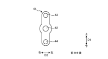
支持部材40は、シェード固定部41を有する。シェード固定部41は、上記したシェード30を固定する。図3は、正面視におけるシェード固定部41の一例を示す図である。図3に示すように、シェード固定部41は、ネジ穴42と、突起部43、44とを有する。ネジ穴42は、シェード30を固定するためのネジ部材50が挿入される。ネジ穴42は、内部にネジ部材50に対応するネジ山が形成される。ネジ穴42は、後方に向けて延びている。
The
突起部43、44は、ネジ穴42を挟む位置に配置される。突起部43、44は、前方に向けて延びている。ネジ穴42と、2つの突起部43、44とは、直線に沿った第1方向D1に並んだ状態で配置される。本実施形態において、第1方向D1は、上下方向に平行な方向である。この場合、ネジ穴42の上方に突起部43が配置され、ネジ穴42の下方に突起部44が配置される。ネジ穴42と突起部43との距離、ネジ穴42と突起部44との距離は、それぞれ等しくなっている。
The
突起部43、44は、それぞれ正面視で円形の形状を有し、例えば円筒状又は円錐台状である。
The
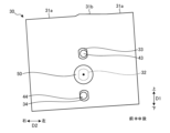
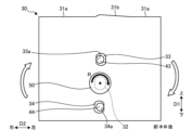
図4は、正面視におけるシェード30の一例を示す図である。図4に示すように、シェード30は、ネジ貫通穴32と、2つの位置決め穴33、34とを有する。
Figure 4 is a diagram showing an example of a
ネジ貫通穴32は、シェード30を支持部材40に固定する際にネジ部材50を貫通させる。
The screw through
2つの位置決め穴33、34は、ネジ貫通穴32を挟む位置に配置される。本実施形態において、ネジ貫通穴32と、2つの位置決め穴33、34とは、正面視において水平部分31aと直交する直線に沿って配置される。位置決め穴33は、例えば正面視において長円状であり、上記した突起部43が挿入される。位置決め穴34は、例えば正面視において長円状であり、上記した突起部44が挿入される。位置決め穴33、34の正面視における形状は、異なってもよい。位置決め穴33、34に突起部43、44が挿入されることにより、シェード30と支持部材40のシェード固定部41との間で位置決めが行われる。また、位置決め穴33、34に突起部43、44が挿入されることにより、ネジ貫通穴32がネジ穴42に対応する位置に配置される。この状態において、ネジ貫通穴32を貫通させてネジ部材50をネジ穴42に挿入することが可能となる。
The two
ネジ部材50をネジ穴42に挿入する場合、後述する図6等に示すように、正面視においてネジ穴42を基準とした時計回り方向にネジ部材50を回転させる。以下、ネジ部材50を回転させる時計回り方向を回転方向Rと表記する。
When inserting the
正面視で第1方向D1に直交する第2方向(左右方向)D2について、位置決め穴33、34は、突起部43、44よりも寸法が大きい。したがって、突起部43、44を挿入する際に、位置決め穴33、34の内周部との間の干渉を避けることができる。第2方向D2について、位置決め穴33の寸法W2と突起部43の寸法W1との差分S1は、突起部43が位置決め穴33に挿入される際のマージンとなる。また、第2方向D2について、位置決め穴34の寸法W4と突起部44の寸法W3との差分S2は、突起部44が位置決め穴34に挿入される際のマージンとなる。
In the second direction (left-right direction) D2 perpendicular to the first direction D1 in a front view, the positioning holes 33, 34 have larger dimensions than the
位置決め穴33は、ネジ貫通穴32を基準とした第1方向D1の上方の位置に対して、突起部43の寸法W1と位置決め穴33の寸法W2との差分S1を2で割ったオフセット値T1(S1/2)だけ、ネジ部材50で固定する際の回転方向Rに沿って、第2方向D2にずれた位置に配置される。すなわち、位置決め穴33は、ネジ貫通穴32を基準とした第1方向D1の上方の位置に対して、オフセット値T1だけ、左方にずれた位置に配置される。また、位置決め穴34は、ネジ貫通穴32を基準とした第1方向D1の下方の位置に対して、突起部44の寸法W3と位置決め穴34の寸法W4との差分S2を2で割ったオフセット値T2(S2/2)だけ、ネジ部材50で固定する際の回転方向Rに沿って、第2方向D2にずれた位置に配置される。すなわち、位置決め穴34は、ネジ貫通穴32を基準とした第1方向D1の下方の位置に対して、オフセット値T2だけ、右方にずれた位置に配置される。
The
このように、それぞれの位置決め穴33、34は、ネジ貫通穴32を基準とした第1方向D1上の位置に対して、回転方向Rに沿って、突起部43、44の寸法W1、W3と位置決め穴33、34の寸法W2、W4との差分S1、S2を2で割ったオフセット値T1、T2(S1/2、S2/2)だけずれた位置に配置される。本実施形態では、位置決め穴33、34は、回転方向Rに沿って第2方向D2にずれた位置に配置される。
In this way, each of the positioning holes 33, 34 is positioned at a position shifted in the rotation direction R from a position in the first direction D1 based on the screw through
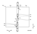
次に、上記のように構成された車両用灯具100を製造する際に、シェード30を支持部材40のシェード固定部41に固定する固定方法の一例を説明する。図5及び図6は、シェード30をシェード固定部41に固定する様子を示す図である。図5に示すように、位置決め穴33に突起部43を挿入し、位置決め穴34に突起部44を挿入する。位置決め穴33、34に突起部43、44が挿入されることにより、シェード30と支持部材40のシェード固定部41との間で位置決めが行われる。また、位置決め穴33、34に突起部43、44が挿入されることにより、ネジ貫通穴32がネジ穴42に対応する位置に配置される。このため、ネジ貫通穴32を貫通させてネジ部材50をネジ穴42に挿入することが可能となる。
Next, an example of a fixing method for fixing the
シェード30が位置決めされた後、図6に示すように、ネジ部材50をネジ穴42に挿入してシェード30をシェード固定部41に固定する。ネジ部材50を挿入する場合、図6に示すように、正面視においてネジ穴42を基準とした時計回り方向である回転方向Rにネジ部材50を回転させる。
After the
ネジ部材50を回転させながらシェード30をシェード固定部41に固定すると、ネジ部材50のトルクがシェード30に伝達され、シェード30が回転方向Rに回転する。シェード30が回転すると、位置決めが行われた状態から回転方向Rに傾いた状態となる。シェード30は、位置決め穴33、34の内周面がそれぞれ突起部43、44に当接されることで、回転が規制される。具体的には、位置決め穴33の右内周部33aが突起部43に当接され、位置決め穴34の左内周部34aが突起部44に当接される。したがって、シェード30は、位置決め穴33、34の内周面が突起部43、44に当接した状態で、シェード固定部41に固定される。
When the
本実施形態では、それぞれの位置決め穴33、34は、ネジ貫通穴32を基準とした第1方向D1上の位置に対して、回転方向Rに沿って、突起部43、44の寸法W1、W3と位置決め穴33、34の寸法W2、W4との差分S1、S2を2で割ったオフセット値T1、T2(S1/2、S2/2)だけずれた位置に配置される。このため、位置決め穴33、34の内周面が突起部43、44に当接した状態において、シェード30が適切な位置、すなわち水平部分31aが水平方向に平行となる位置で固定される。このように、シェード30が適切な位置に固定されるように位置決め穴33、34の回転方向Rへのずれ量を設定することで、ネジ部材50の回転による意図しないシェード30の位置ズレを抑制できる。
In this embodiment, the positioning holes 33, 34 are positioned in a position shifted by an offset value T1, T2 (S1/2, S2/2) obtained by dividing the difference S1, S2 between the dimensions W1, W3 of the
以上のように、本実施形態に係る車両用灯具は、光源部10と、光源部10からの光を車両前方に照射する光学系20と、光学系20で導かれる光の一部を遮光するシェード30と、光源部10、光学系20及びシェード30を支持する支持部材40とを備え、光源部10、シェード30及び光学系20のうち少なくとも1つの光学部品60は、1本のネジ部材50により支持部材40に固定され、支持部材40は、ネジ部材50が挿入されるネジ穴42と、ネジ穴42を挟む位置に配置され光学部品60を位置決めする2つの突起部43、44と、を有し、光学部品60は、ネジ部材50を貫通させるネジ貫通穴32と、ネジ貫通穴32を挟む位置に配置され2つの突起部43、44を挿入する位置決め穴33、34とを有し、ネジ穴42と、2つの突起部43、44とは、直線に沿った第1方向D1に並んで配置され、2つの位置決め穴33、34は、それぞれ突起部43、44よりも径が大きく、ネジ貫通穴32を基準とした第1方向D1上の位置に対して、ネジ部材50を固定する際の回転方向に沿って所定のオフセット値だけずれた位置に配置される。
As described above, the vehicle lamp according to this embodiment includes a
この構成によれば、それぞれの位置決め穴33、34は、ネジ貫通穴32を基準とした第1方向D1上の位置に対して、回転方向Rに沿って、突起部43、44の寸法W1、W3と位置決め穴33、34の寸法W2、W4との差分S1、S2を2で割ったオフセット値T1、T2(S1/2、S2/2)だけずれた位置に配置される。このため、1本のネジ部材50を回転方向Rに回転させつつ光学部品60を支持部材40に固定する場合、位置決め穴33、34の内周面が突起部43、44に当接して回転が規制された状態において、光学部品60が適切な位置で固定される。これにより、ネジ部材50で光学部品60を固定する際の位置ズレを抑制できる。
According to this configuration, each of the positioning holes 33, 34 is positioned at a position shifted by an offset value T1, T2 (S1/2, S2/2) obtained by dividing the difference S1, S2 between the dimensions W1, W3 of the
本実施形態に係る車両用灯具100において、オフセット値は、第1方向D1に直交する第2方向D2についての突起部43、44の寸法と位置決め穴33、34の寸法との差分を2で割った値である。この構成によれば、ネジ部材50で固定した状態の光学部品60の位置精度を高めることができる。
In the
本実施形態に係る車両用灯具100において、それぞれの位置決め穴33、34は、ネジ貫通穴32を基準とした第1方向D1上の位置に対して、第2方向D2にずれた位置に配置される。この構成によれば、ネジ部材50で固定した状態の光学部品60の位置精度を高めることができる。
In the
本実施形態に係る車両用灯具100において、ネジ穴42と、2つの突起部43、44とは、車両搭載状態における上下方向に並んでいる。これにより、ネジ穴42と、2つの突起部43、44とは、車両搭載状態における上下方向に並んだ構成の車両用灯具100において、1本のネジ部材50を回転させることでシェード30を精度よく支持部材40に固定することができる。
In the
本実施形態に係る車両用灯具100において、2つの位置決め穴33、34は、上下方向に延びた長穴状である。シェード30は、上端縁の水平部分31a及び傾斜部分31bによりロービームパターンのカットオフラインを形成するため、当該上端縁の上下方向の位置が重要になる。すなわち、シェード30が適正位置から上下方向にズレて配置されると、例えば不要な光を通過させたり、必要な光を遮光したりすることになる。本実施形態では、シェード30の2つの位置決め穴33、34が上下方向に延びた長穴状であるため、シェード30をシェード固定部41に配置した後に、位置決め穴33、34に沿って上下方向に位置を調整することができる。シェード30を上下方向に位置合わせしてからネジ部材50により固定することで、シェード30の水平部分31a及び傾斜部分31bの上下方向の位置及び姿勢を適切な状態にすることができる。
In the
本実施形態に係る車両用灯具100において、光学部品60は、シェード30である。この構成によれば、シェード30が本来の位置、すなわち水平部分31aが水平方向に平行となる位置で固定される。したがって、1本のネジ部材50を回転させることでシェード30を精度よく支持部材40に固定することができる。これにより、ネジ部材50で光学部品であるシェード30を固定する際の位置ズレを抑制できる。
In the
[第2実施形態]
図7は、第2実施形態に係る車両用灯具200の一例を示す分解斜視図である。図2に示す車両用灯具200は、光源部110と、光学系120と、シェード130と、支持部材140とを備える。車両用灯具200は、車両用灯具100と同様、例えば車両前方にロービームパターンを形成する。光源部110及び光学系120の構成については、車両用灯具100と同様である。
[Second embodiment]
Fig. 7 is an exploded perspective view showing an example of a vehicle lamp 200 according to the second embodiment. The vehicle lamp 200 shown in Fig. 2 includes a
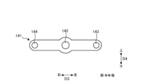
支持部材140は、シェード固定部141を有する。シェード固定部141は、支持部材140の前部に設けられ、シェード130を固定する。図8は、正面視におけるシェード固定部141の一例を示す図である。図8に示すように、シェード固定部141は、ネジ穴142と、突起部143、144とを有する。ネジ穴142は、後方に向けて延びている。突起部143、144は、前方に向けて延びている。
The
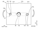
本実施形態において、ネジ穴142と、2つの突起部143、144とは、直線に沿った第1方向D3に並んだ状態で配置される。本実施形態において、第1方向D3は、左右方向に平行な方向である。つまり、ネジ穴142の左方に突起部143が配置され、ネジ穴142の右方に突起部144が配置される。ネジ穴142と突起部143との距離、ネジ穴142と突起部144との距離は、それぞれ等しくなっている。
In this embodiment, the
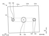
図9は、正面視におけるシェード130の一例を示す図である。図9に示すように、シェード130は、第1実施形態と同様、例えばロービームパターンの水平カットオフラインを形成するための水平部分131aと、斜めカットオフラインを形成するための傾斜部分131bとを有する。また、シェード130は、ネジ貫通穴132と、2つの位置決め穴133、134とを有する。
Figure 9 is a diagram showing an example of the
ネジ貫通穴132は、シェード130を支持部材140に固定する際にネジ部材50を貫通させる。
The screw through
2つの位置決め穴133、134は、ネジ貫通穴132を挟む位置に配置される。本実施形態では、正面視において、ネジ貫通穴132と、2つの位置決め穴133、134とは、水平部分131aと平行な直線に沿って配置される。位置決め穴133は、例えば正面視において円形状であり、上記した突起部143が挿入される。位置決め穴134は、例えば正面視において長円状であり、上記した突起部144が挿入される。位置決め穴133、134の正面視における形状は、同一であってもよい。
The two
第1実施形態と同様、位置決め穴133、134に突起部143、144が挿入されることにより、シェード130と支持部材140のシェード固定部141との間で位置決めが行われる。また、位置決め穴133、134に突起部143、144が挿入されることにより、ネジ貫通穴132がネジ穴142に対応する位置に配置される。この状態において、ネジ貫通穴132を貫通させてネジ部材50をネジ穴142に挿入することが可能となる。ネジ部材50をネジ穴142に挿入する場合、回転方向Rにネジ部材50を回転させる。
As in the first embodiment, the
正面視で第1方向D3に直交する第2方向(上下方向)D4について、位置決め穴133の寸法W6は、突起部143の寸法W5よりも大きい。位置決め穴133の寸法W6と突起部143の寸法W5との差分S3は、突起部143が位置決め穴133に挿入される際のマージンとなる。位置決め穴134の寸法W8は、突起部144の寸法W7よりも大きい。位置決め穴134の寸法W8と突起部144の寸法W7との差分S4は、突起部144が位置決め穴134に挿入される際のマージンとなる。
In the second direction (vertical direction) D4 perpendicular to the first direction D3 in a front view, the dimension W6 of the
位置決め穴133は、ネジ貫通穴132を基準とした第1方向D3の左方の位置に対して、突起部143の寸法W5と位置決め穴133の寸法W6との差分S3を2で割ったオフセット値T3(S3/2)だけ、ネジ部材50で固定する際の回転方向Rに沿って、第2方向D4にずれた位置に配置される。すなわち、位置決め穴133は、ネジ貫通穴132を基準とした第1方向D3の左方の位置に対して、オフセット値T3だけ、下方にずれた位置に配置される。また、位置決め穴134は、ネジ貫通穴132を基準とした第1方向D3の右方の位置に対して、突起部144の寸法W7と位置決め穴134の寸法W8との差分S4を2で割ったオフセット値T4(S4/2)だけ、ネジ部材50で固定する際の回転方向Rに沿って、第2方向D4にずれた位置に配置される。すなわち、位置決め穴134は、ネジ貫通穴132を基準とした第1方向D3の右方の位置に対して、オフセット値T4だけ、上方にずれた位置に配置される。
The
このように、それぞれの位置決め穴133、134は、ネジ貫通穴132を基準とした第1方向D3上の位置に対して、回転方向Rに沿って、突起部143、144の寸法W5、W7と位置決め穴133、134の寸法W6、W8との差分S3、S4を2で割ったオフセット値T3、T4(S3/2、S4/2)だけずれた位置に配置される。本実施形態では、位置決め穴133、134は、回転方向Rに沿って第2方向D2にずれた位置に配置される。
In this way, each of the positioning holes 133, 134 is positioned at a position shifted in the rotation direction R from a position in the first direction D3 based on the screw through
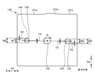
図10及び図11は、第2実施形態に係るシェード130をシェード固定部141に固定する様子を示す図である。図10に示すように、位置決め穴133に突起部143を挿入し、位置決め穴134に突起部144を挿入する。位置決め穴133、134に突起部143、144が挿入されることにより、シェード130と支持部材140のシェード固定部141との間で位置決めが行われる。また、位置決め穴133、134に突起部143、144が挿入されることにより、ネジ貫通穴132がネジ穴142に対応する位置に配置される。このため、ネジ貫通穴132を貫通させてネジ部材50をネジ穴142に挿入することが可能となる。
Figures 10 and 11 are diagrams showing how the
シェード130が位置決めされた後、図11に示すように、ネジ部材50をネジ穴142に挿入してシェード130をシェード固定部141に固定する。ネジ部材50を挿入する場合、図11に示すように、回転方向Rにネジ部材50を回転させる。
After the
ネジ部材50を回転させながらシェード130をシェード固定部141に固定すると、ネジ部材50のトルクがシェード130に伝達され、シェード130が回転方向Rに回転する。シェード130が回転すると、位置決めが行われた状態から回転方向Rに傾いた状態となる。シェード30は、位置決め穴133、134の内周面がそれぞれ突起部143、144に当接されることで、回転が規制される。具体的には、位置決め穴133の上内周部133aが突起部143に当接され、位置決め穴134の下内周部134aが突起部144に当接される。したがって、シェード130は、位置決め穴133、134の内周面が突起部143、144に当接した状態で、シェード固定部141に固定される。
When the
本実施形態では、それぞれの位置決め穴133、134は、ネジ貫通穴132を基準とした第1方向D3上の位置に対して、回転方向Rに沿って、突起部143、144の寸法W5、W7と位置決め穴133、134の寸法W6、W8との差分S3、S4を2で割ったオフセット値T3、T4(S3/2、S4/2)だけずれた位置に配置される。このため、位置決め穴133、134の内周面が突起部143、144に当接した状態において、シェード130が適切な位置、すなわち水平部分131aが水平方向に平行となる位置で固定される。
In this embodiment, the positioning holes 133, 134 are positioned at positions shifted along the rotational direction R from the position in the first direction D3 based on the screw through
このように、ネジ貫通穴132及び位置決め穴133、134と、ネジ穴142及び突起部143、144とをそれぞれ左右方向に直線状に配置した場合においても、シェード130が適切な位置に固定されるように位置決め穴133、134の回転方向Rへのずれ量を設定することで、ネジ部材50の回転による意図しないシェード130の位置ズレを抑制できる。
In this way, even if the screw through
本実施形態に係る車両用灯具200は、ネジ穴142と、2つの突起部143、144とは、車両搭載状態における左右方向に並んでいる。これにより、ネジ穴142と、2つの突起部143、144とは、車両搭載状態における左右方向に並んだ構成の車両用灯具200において、1本のネジ部材50を回転させることでシェード130を精度よく支持部材140に固定することができる。
In the vehicle lamp 200 according to this embodiment, the
本実施形態に係る車両用灯具200において、2つの位置決め穴133、134の一方は、左右方向に延びた長穴状である。この構成によれば、2つの位置決め穴133、134と2つの突起部143、144との間にマージンがより大きく確保されるため、シェード130と支持部材140との間を左右方向に微調整することができる。
In the vehicle lamp 200 according to this embodiment, one of the two
本発明の技術範囲は上記実施形態に限定されるものではなく、本発明の趣旨を逸脱しない範囲で適宜変更を加えることができる。例えば、上記実施形態においては、光学部品60としてシェード30を例に挙げて説明したが、この構成に限定されない。光学部品60として、シェード30に加えて、又はシェード30に代えて、光源部10、光学系20の一部または全部を1本のネジ部材で固定する場合にも適用することができる。
The technical scope of the present invention is not limited to the above embodiment, and appropriate modifications can be made without departing from the spirit of the present invention. For example, in the above embodiment, the
R…回転方向、10,110…光源部、11…光源、12…基板、20,120…光学系、21…リフレクタ、22…投影レンズ、30,130…シェード、31a,131a…水平部分、31b…傾斜部分、32,132…ネジ貫通穴、33,34,133,134…位置決め穴、40,140…支持部材、41,141…シェード固定部、42,142…ネジ穴、43,44,143,144…突起部、50…ネジ部材、60…光学部品、100,200…車両用灯具 R...Rotation direction, 10, 110...Light source unit, 11...Light source, 12...Substrate, 20, 120...Optical system, 21...Reflector, 22...Projection lens, 30, 130...Shade, 31a, 131a...Horizontal part, 31b...Inclined part, 32, 132...Screw through hole, 33, 34, 133, 134...Positioning hole, 40, 140...Support member, 41, 141...Shade fixing part, 42, 142...Screw hole, 43, 44, 143, 144...Protrusion, 50...Screw member, 60...Optical part, 100, 200...Vehicle lamp
Claims (8)
前記光源部からの光を車両前方に照射する光学系と、
前記光学系で導かれる光の一部を遮光するシェードと、
前記光源部、前記光学系及び前記シェードを支持する支持部材と
を備え、
前記光源部、前記シェード及び前記光学系のうち少なくとも1つの光学部品は、1本のネジ部材により前記支持部材に固定され、
前記支持部材は、前記ネジ部材が挿入されるネジ穴と、前記ネジ穴を挟む位置に配置され前記光学部品を位置決めする2つの突起部と、を有し、
前記光学部品は、前記ネジ部材を貫通させるネジ貫通穴と、前記ネジ貫通穴を挟む位置に配置され2つの前記突起部を挿入する位置決め穴とを有し、
前記ネジ穴と、2つの前記突起部とは、直線に沿った第1方向に並んで配置され、
2つの前記位置決め穴は、それぞれ前記突起部よりも径が大きく、前記ネジ貫通穴を基準とした前記第1方向上の位置に対して、前記ネジ部材を固定する際の回転方向に沿って所定のオフセット値だけずれた位置に配置される
車両用灯具。 A light source unit;
an optical system that irradiates light from the light source unit toward a front of the vehicle;
A shade that blocks a portion of the light guided by the optical system;
a support member that supports the light source unit, the optical system, and the shade,
At least one of the optical components among the light source unit, the shade, and the optical system is fixed to the support member by a single screw member;
the support member has a screw hole into which the screw member is inserted, and two protrusions that are disposed at positions sandwiching the screw hole and that position the optical component,
the optical component has a screw through hole through which the screw member passes, and positioning holes disposed at positions sandwiching the screw through hole and into which the two protrusions are inserted,
The screw hole and the two protrusions are arranged side by side in a first direction along a straight line,
The two positioning holes each have a diameter larger than that of the protrusion, and are positioned at a position shifted by a predetermined offset value along the rotation direction when fixing the screw member, relative to a position in the first direction based on the screw through hole.
請求項1に記載の車両用灯具。 The vehicular lamp according to claim 1 , wherein the offset value is a value obtained by dividing a difference between a dimension of the protrusion and a dimension of the positioning hole in a second direction perpendicular to the first direction by two.
請求項2に記載の車両用灯具。 The vehicular lamp according to claim 2 , wherein each of the positioning holes is disposed at a position shifted in the second direction from a position in the first direction based on the screw through hole.
請求項1に記載の車両用灯具。 The vehicular lamp according to claim 1 , wherein the screw hole and the two protrusions are aligned in a vertical direction when the lamp is mounted on a vehicle.
請求項4に記載の車両用灯具。 The vehicular lamp according to claim 4 , wherein the two positioning holes are elongated holes extending in the vertical direction.
請求項1に記載の車両用灯具。 The vehicular lamp according to claim 1 , wherein the screw hole and the two protrusions are aligned in the left-right direction when the lamp is mounted on the vehicle.
請求項6に記載の車両用灯具。 The vehicular lamp according to claim 6 , wherein one of the two positioning holes is an elongated hole extending in the left-right direction.
請求項1に記載の車両用灯具。 The vehicular lamp according to claim 1 , wherein the optical component is the shade.
Priority Applications (4)
| Application Number | Priority Date | Filing Date | Title |
|---|---|---|---|
| JP2023037590A JP2024128564A (en) | 2023-03-10 | 2023-03-10 | Vehicle lighting fixtures |
| EP24770805.0A EP4678972A1 (en) | 2023-03-10 | 2024-03-08 | Vehicle lamp |
| CN202480017127.6A CN120752474A (en) | 2023-03-10 | 2024-03-08 | Vehicle lighting |
| PCT/JP2024/009172 WO2024190699A1 (en) | 2023-03-10 | 2024-03-08 | Vehicle lamp |
Applications Claiming Priority (1)
| Application Number | Priority Date | Filing Date | Title |
|---|---|---|---|
| JP2023037590A JP2024128564A (en) | 2023-03-10 | 2023-03-10 | Vehicle lighting fixtures |
Publications (1)
| Publication Number | Publication Date |
|---|---|
| JP2024128564A true JP2024128564A (en) | 2024-09-24 |
Family
ID=92755818
Family Applications (1)
| Application Number | Title | Priority Date | Filing Date |
|---|---|---|---|
| JP2023037590A Pending JP2024128564A (en) | 2023-03-10 | 2023-03-10 | Vehicle lighting fixtures |
Country Status (4)
| Country | Link |
|---|---|
| EP (1) | EP4678972A1 (en) |
| JP (1) | JP2024128564A (en) |
| CN (1) | CN120752474A (en) |
| WO (1) | WO2024190699A1 (en) |
Family Cites Families (2)
| Publication number | Priority date | Publication date | Assignee | Title |
|---|---|---|---|---|
| JP2016100231A (en) | 2014-11-25 | 2016-05-30 | スタンレー電気株式会社 | Multiple lamp type vehicular lighting fixture |
| JP6968015B2 (en) * | 2018-03-22 | 2021-11-17 | 三菱電機株式会社 | Manufacturing method of in-vehicle lamps and in-vehicle lamps |
-
2023
- 2023-03-10 JP JP2023037590A patent/JP2024128564A/en active Pending
-
2024
- 2024-03-08 CN CN202480017127.6A patent/CN120752474A/en active Pending
- 2024-03-08 EP EP24770805.0A patent/EP4678972A1/en active Pending
- 2024-03-08 WO PCT/JP2024/009172 patent/WO2024190699A1/en not_active Ceased
Also Published As
| Publication number | Publication date |
|---|---|
| EP4678972A1 (en) | 2026-01-14 |
| WO2024190699A1 (en) | 2024-09-19 |
| CN120752474A (en) | 2025-10-03 |
Similar Documents
| Publication | Publication Date | Title |
|---|---|---|
| US7568824B2 (en) | Vehicle lighting device | |
| JP6441823B2 (en) | Vehicle lighting | |
| US10434928B2 (en) | Lamp device for vehicle and lighting device for vehicle | |
| US20050122737A1 (en) | Headlight | |
| JP7197399B2 (en) | lighting unit | |
| US20190041020A1 (en) | Light-emitting unit and vehicle lamp | |
| WO2020080410A1 (en) | Rotating reflector manufacturing method and rotating reflector | |
| JP4661804B2 (en) | Projector type lamp | |
| WO2023026865A1 (en) | Lighting fixture for vehicle | |
| JP2024128564A (en) | Vehicle lighting fixtures | |
| JP7515006B2 (en) | Automotive floodlights | |
| JP2008108613A (en) | Vehicle lighting | |
| JP6711950B2 (en) | Vehicle lighting | |
| JP6832718B2 (en) | Vehicle lighting | |
| JP2014175097A (en) | Lamp unit for vehicle head lamp | |
| CN210860958U (en) | Vehicle lamp | |
| JP4803166B2 (en) | Vehicle lighting | |
| US7314299B2 (en) | Vehicle lamp and method of manufacturing the vehicle lamp | |
| CN116642148B (en) | Lock catch fixed optical structure | |
| WO2024101368A1 (en) | Jig and vehicle headlight manufacturing method | |
| JP2020191263A (en) | Vehicular lighting fixture | |
| JP2026055532A (en) | Vehicle lighting | |
| JP2025124259A (en) | Vehicle lighting fixtures | |
| BR112019016072B1 (en) | LIGHTING DEVICE FOR VEHICLES |
Legal Events
| Date | Code | Title | Description |
|---|---|---|---|
| A621 | Written request for application examination |
Free format text: JAPANESE INTERMEDIATE CODE: A621 Effective date: 20251208 |