JP2024053625A - Gaming Machines - Google Patents
Gaming Machines Download PDFInfo
- Publication number
- JP2024053625A JP2024053625A JP2022159956A JP2022159956A JP2024053625A JP 2024053625 A JP2024053625 A JP 2024053625A JP 2022159956 A JP2022159956 A JP 2022159956A JP 2022159956 A JP2022159956 A JP 2022159956A JP 2024053625 A JP2024053625 A JP 2024053625A
- Authority
- JP
- Japan
- Prior art keywords
- display
- period
- game
- state
- emitting means
- Prior art date
- Legal status (The legal status is an assumption and is not a legal conclusion. Google has not performed a legal analysis and makes no representation as to the accuracy of the status listed.)
- Pending
Links
- 230000008859 change Effects 0.000 claims description 654
- 230000015654 memory Effects 0.000 claims description 440
- 238000003860 storage Methods 0.000 claims description 43
- 230000000694 effects Effects 0.000 description 2355
- 239000012634 fragment Substances 0.000 description 1391
- 239000011521 glass Substances 0.000 description 660
- 238000000034 method Methods 0.000 description 508
- 230000008569 process Effects 0.000 description 495
- 238000011161 development Methods 0.000 description 362
- 238000010586 diagram Methods 0.000 description 337
- 238000005336 cracking Methods 0.000 description 318
- 239000002243 precursor Substances 0.000 description 293
- 239000000872 buffer Substances 0.000 description 216
- 230000009471 action Effects 0.000 description 189
- 230000033001 locomotion Effects 0.000 description 169
- 238000005286 illumination Methods 0.000 description 158
- 238000002834 transmittance Methods 0.000 description 123
- 238000012545 processing Methods 0.000 description 115
- 230000004044 response Effects 0.000 description 103
- 230000001965 increasing effect Effects 0.000 description 90
- 239000003086 colorant Substances 0.000 description 87
- 238000001514 detection method Methods 0.000 description 71
- 230000009467 reduction Effects 0.000 description 60
- 230000002708 enhancing effect Effects 0.000 description 34
- 230000004397 blinking Effects 0.000 description 32
- 230000005484 gravity Effects 0.000 description 31
- 230000007704 transition Effects 0.000 description 29
- 230000005540 biological transmission Effects 0.000 description 27
- 238000011084 recovery Methods 0.000 description 27
- 230000006870 function Effects 0.000 description 25
- 230000007423 decrease Effects 0.000 description 24
- 238000005034 decoration Methods 0.000 description 23
- 230000002265 prevention Effects 0.000 description 21
- 206010027336 Menstruation delayed Diseases 0.000 description 19
- 206010012335 Dependence Diseases 0.000 description 16
- 238000013461 design Methods 0.000 description 14
- 238000006073 displacement reaction Methods 0.000 description 13
- 230000001788 irregular Effects 0.000 description 11
- 238000007726 management method Methods 0.000 description 10
- OMFRMAHOUUJSGP-IRHGGOMRSA-N bifenthrin Chemical compound C1=CC=C(C=2C=CC=CC=2)C(C)=C1COC(=O)[C@@H]1[C@H](\C=C(/Cl)C(F)(F)F)C1(C)C OMFRMAHOUUJSGP-IRHGGOMRSA-N 0.000 description 9
- 230000003247 decreasing effect Effects 0.000 description 9
- 238000002360 preparation method Methods 0.000 description 9
- 238000004904 shortening Methods 0.000 description 8
- 238000004458 analytical method Methods 0.000 description 6
- 238000012790 confirmation Methods 0.000 description 6
- 230000007257 malfunction Effects 0.000 description 6
- 230000000630 rising effect Effects 0.000 description 6
- 241000404030 Anacyclus clavatus Species 0.000 description 5
- 206010037660 Pyrexia Diseases 0.000 description 5
- 239000000284 extract Substances 0.000 description 5
- 238000005562 fading Methods 0.000 description 5
- 238000004519 manufacturing process Methods 0.000 description 5
- 238000013459 approach Methods 0.000 description 4
- 230000006399 behavior Effects 0.000 description 4
- 238000004590 computer program Methods 0.000 description 4
- 230000003111 delayed effect Effects 0.000 description 4
- 238000005401 electroluminescence Methods 0.000 description 4
- 238000013467 fragmentation Methods 0.000 description 4
- 238000006062 fragmentation reaction Methods 0.000 description 4
- 238000005259 measurement Methods 0.000 description 4
- 230000004048 modification Effects 0.000 description 4
- 238000012986 modification Methods 0.000 description 4
- 238000004080 punching Methods 0.000 description 4
- 230000008685 targeting Effects 0.000 description 4
- 241000032989 Ipomoea lacunosa Species 0.000 description 3
- 230000014759 maintenance of location Effects 0.000 description 3
- 230000007246 mechanism Effects 0.000 description 3
- 230000002250 progressing effect Effects 0.000 description 3
- 235000009754 Vitis X bourquina Nutrition 0.000 description 2
- 235000012333 Vitis X labruscana Nutrition 0.000 description 2
- 240000006365 Vitis vinifera Species 0.000 description 2
- 235000014787 Vitis vinifera Nutrition 0.000 description 2
- 230000005856 abnormality Effects 0.000 description 2
- 238000007792 addition Methods 0.000 description 2
- 230000003466 anti-cipated effect Effects 0.000 description 2
- 239000003990 capacitor Substances 0.000 description 2
- 239000003795 chemical substances by application Substances 0.000 description 2
- 239000004020 conductor Substances 0.000 description 2
- 238000009795 derivation Methods 0.000 description 2
- 238000003745 diagnosis Methods 0.000 description 2
- 238000010304 firing Methods 0.000 description 2
- 230000009191 jumping Effects 0.000 description 2
- 239000004973 liquid crystal related substance Substances 0.000 description 2
- 238000012544 monitoring process Methods 0.000 description 2
- 230000001151 other effect Effects 0.000 description 2
- 238000003825 pressing Methods 0.000 description 2
- 230000007480 spreading Effects 0.000 description 2
- 238000003892 spreading Methods 0.000 description 2
- 230000001360 synchronised effect Effects 0.000 description 2
- 230000001131 transforming effect Effects 0.000 description 2
- 230000001133 acceleration Effects 0.000 description 1
- 239000002131 composite material Substances 0.000 description 1
- 238000005520 cutting process Methods 0.000 description 1
- 230000002349 favourable effect Effects 0.000 description 1
- 230000007935 neutral effect Effects 0.000 description 1
- NJPPVKZQTLUDBO-UHFFFAOYSA-N novaluron Chemical compound C1=C(Cl)C(OC(F)(F)C(OC(F)(F)F)F)=CC=C1NC(=O)NC(=O)C1=C(F)C=CC=C1F NJPPVKZQTLUDBO-UHFFFAOYSA-N 0.000 description 1
- 238000005293 physical law Methods 0.000 description 1
- 238000007781 pre-processing Methods 0.000 description 1
- 230000003068 static effect Effects 0.000 description 1
- 239000000126 substance Substances 0.000 description 1
- 235000013616 tea Nutrition 0.000 description 1
Images


Landscapes
- Display Devices Of Pinball Game Machines (AREA)
Abstract
【課題】好適な客待ち制御を行うことができる遊技機を提供すること。【解決手段】演出制御用CPU120は、低ベース状態における遊技が終了(可変表示が停止表示)した後の第1客待ち期間(第1期間)において第1背景表示004SG081を表示し、第1客待ち期間が終了した後の第2客待ち期間(第2期間)においてデモムービーを表示する。【選択図】図31[Problem] To provide a gaming machine capable of performing suitable customer waiting control. [Solution] A performance control CPU 120 displays a first background display 004SG081 during a first customer waiting period (first period) after a game in a low base state ends (variable display stops), and displays a demo movie during a second customer waiting period (second period) after the first customer waiting period ends. [Selected figure] Fig. 31
Description
本発明は、遊技可能な遊技機に関する。 The present invention relates to a gaming machine that can be played.
遊技機に代表されるパチンコ遊技機として、図柄の可変表示が終了した後の第1客待ち期間において通常背景表示を表示し、該第1客待ち期間が終了した後の第2客待ち期間において、デモンストレーション表示を表示する制御を実行するものがあった(例えば、特許文献1参照)。また、従来の遊技機には、可変表示を実行可能であるとともに遊技者にとって有利な大当り遊技状態(有利状態)に制御可能であって、新たな始動入賞の発生によって可変表示に関する情報を含む保留記憶が発生すると、該保留記憶にもとづく保留表示を段階的に表示していく出現アニメーションの表示を実行可能なものがある(例えば、特許文献2参照)。 Among gaming machines, there are pachinko gaming machines that execute control to display a normal background display during a first customer waiting period after the variable display of the symbols has ended, and to display a demonstration display during a second customer waiting period after the first customer waiting period has ended (see, for example, Patent Document 1). In addition, among conventional gaming machines, there are some that are capable of executing variable display and are controllable to a jackpot gaming state (advantageous state) that is advantageous to the player, and that, when a reserved memory containing information regarding a variable display is generated due to the occurrence of a new start winning, are capable of executing display of an appearance animation that gradually displays a reserved display based on the reserved memory (see, for example, Patent Document 2).
特許文献1および特許文献2の機能や構成を有する遊技機において、商品性を高める余地があった。
There was room for improving the marketability of gaming machines having the functions and configurations of
この発明は、上記の実状に鑑みてなされたものであり、商品性を高めた遊技機を提供することを目的とする。 This invention was made in consideration of the above situation, and aims to provide a gaming machine with improved marketability.
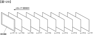
本発明の請求項1に記載の遊技機は、
可変表示を行い、遊技者にとって有利な有利状態に制御可能な遊技機であって、
遊技制御手段と、
演出実行手段と、
表示手段と、
保留記憶手段と、を備え、
前記表示手段は、
遊技が終了した後の第1期間において、背景表示を表示し、
前記第1期間が終了した後の第2期間において、デモンストレーション表示を表示し、
前記デモンストレーション表示は、企業名表示シーンと、タイトル名表示シーンと、注意喚起表示シーンと、を含んで構成され、
前記企業名表示シーンは、該遊技機に係る企業名の文字表示をアニメーション表示させるシーンであり、
前記タイトル名表示シーンは、該遊技機のタイトル名の文字表示をアニメーション表示させるシーンであり、
前記注意喚起表示シーンは、該遊技機を遊技する際の注意喚起の文字表示をアニメーション表示させるシーンであり、
該遊技機に係る企業名の文字表示のアニメーション表示は、該遊技機を遊技する際の注意喚起の文字表示のアニメーション表示よりも強調される態様であり、
該遊技機のタイトル名の文字表示のアニメーション表示は、該遊技機を遊技する際の注意喚起の文字表示のアニメーション表示よりも強調される態様であり、
前記保留記憶手段は、所定数を上限として可変表示に関する情報を保留記憶として記憶することが可能であり、
前記遊技制御手段は、可変表示が終了したときに、次の可変表示に対応する保留記憶がある場合に次の可変表示を実行可能であり、
前記演出実行手段は、
保留記憶が記憶されたときに、開始態様と、完了態様と、該完了態様の1つ前の態様である完了前態様を含む複数の途中態様と、を段階的に変化させて保留表示を表示可能であり、
保留記憶が記憶されたときに、入賞時演出を実行可能であり、
可変表示中に既に記憶されている保留記憶に対応する保留表示を次の可変表示が開始されるタイミングに基づく保留シフト開始タイミングから特定期間かけて表示されていた位置から次の可変表示に対応する位置に移動させることが可能であり、
前記所定数未満のN数の保留記憶が記憶されている状況における可変表示である保留記憶数N時可変表示の実行中において、
次の可変表示が開始されるまでの期間が所定期間よりも長いときに、新たな保留記憶が記憶された場合は、N+1数目に対応する保留表示位置に前記保留表示を前記開始態様で開始し該開始態様から前記複数の途中態様に段階的に変化させた後に前記完了態様に変化させる変化、を該所定期間かけて実行して該保留表示を表示し、
次の可変表示が開始されるまでの期間が前記所定期間よりも短いときに、新たな保留記憶が記憶された場合は、N+1数目に対応する保留表示位置に前記保留表示を前記開始態様で開始し、該開始態様から前記完了前態様とは異なる途中態様まで変化させ、該完了前態様とは異なる途中態様となっている状況で次の可変表示が開始されるタイミングとなることで、該タイミングに基づいて前記完了態様に変化させて該保留表示を表示し、
前記保留記憶数N時可変表示が終了し、前記保留シフト開始タイミングから前記特定期間が経過するまでに新たな保留記憶が記憶された場合は、N数目に対応する保留表示位置に前記保留表示を前記開始態様で開始し該開始態様から前記複数の途中態様に段階的に変化させた後に前記完了態様に変化させる変化、を前記所定期間かけて実行して該保留表示を表示し、
前記保留記憶数N時可変表示の実行中において、次の可変表示が開始されるまでの期間が前記所定期間よりも長いときに、新たな保留記憶が記憶された場合と、前記保留記憶数N時可変表示の実行中において、次の可変表示が開始されるまでの期間が該所定期間よりも短いときに、新たな保留記憶が記憶された場合と、前記保留記憶数N時可変表示が終了し、前記保留シフト開始タイミングから前記特定期間が経過するまでに新たな保留記憶が記憶された場合と、のいずれの場合であっても、前記入賞時演出を実行可能である。
この特徴によれば、上記実情を鑑み、商品性を高めた遊技機を提供することができる。
The gaming machine according to
A gaming machine that performs variable display and can be controlled to an advantageous state that is advantageous to a player,
A game control means;
A performance execution means;
A display means;
A reservation storage means,
The display means includes:
In a first period after the game ends, a background display is displayed;
displaying a demonstration display during a second period after the first period has ended;
the demonstration display includes a company name display scene, a title name display scene, and a warning display scene;
the company name display scene is a scene in which the character display of the company name related to the gaming machine is displayed in animation,
the title name display scene is a scene in which the title name of the gaming machine is displayed in characters as an animation,
The warning display scene is a scene in which text display of a warning when playing the gaming machine is displayed in an animated form,
the animated display of the text display of the company name related to the gaming machine is emphasized more than the animated display of the text display of the caution when playing the gaming machine,
the animation display of the character display of the title name of the gaming machine is emphasized more than the animation display of the character display of the attention calling for playing the gaming machine,
The reserved storage means is capable of storing information regarding variable display as reserved storage up to a predetermined number,
The game control means is capable of executing the next variable display when the variable display is completed and there is a reserved memory corresponding to the next variable display,
The performance execution means includes:
When the reserved memory is stored, the reserved display can be displayed by gradually changing a start state, a completion state, and a plurality of intermediate states including a pre-completion state which is one state before the completion state,
When the reserved memory is stored, a winning performance can be executed,
It is possible to move a reserved display corresponding to a reserved memory already stored during the variable display from a position where it has been displayed for a specific period from a reserved shift start timing based on the timing at which the next variable display is started to a position corresponding to the next variable display,
During execution of the N-time variable display of the reserved memory number, which is a variable display in a situation where N-number of reserved memories less than the predetermined number are stored,
When the period until the next variable display is started is longer than a predetermined period, if a new reserved memory is stored, the reserved display is started in the start state at the reserved display position corresponding to the N+1th number, and then the start state is changed stepwise to the plurality of intermediate states, and then the change is changed to the completion state, over the predetermined period, to display the reserved display;
When the period until the next variable display is started is shorter than the predetermined period and a new reserved memory is stored, the reserved display is started in the start state at the reserved display position corresponding to the N+1th number, and is changed from the start state to an intermediate state different from the pre-completion state, and when the next variable display is started in a situation in which the intermediate state different from the pre-completion state is reached, the reserved display is changed to the completion state based on the timing and displayed;
When the N-hour variable display of the number of reserved memories is ended and a new reserved memory is stored between the reserved shift start timing and the specific period has elapsed, the reserved display is started in the start state at the reserved display position corresponding to the Nth number, and the start state is gradually changed to the plurality of intermediate states, and then the change is changed to the completion state over the specified period, and the reserved display is displayed;
The winning performance can be executed in any of the following cases: when a new reserved memory is stored during execution of the N-hour variable display of the reserved memory number when the period until the start of the next variable display is longer than the specified period; when a new reserved memory is stored during execution of the N-hour variable display of the reserved memory number when the period until the start of the next variable display is shorter than the specified period; and when the N-hour variable display of the reserved memory number ends and a new reserved memory is stored before the specific period has elapsed from the reservation shift start timing.
According to this feature, in consideration of the above-mentioned circumstances, a gaming machine with improved marketability can be provided.
尚、本発明は、本発明の請求項に記載された発明特定事項のみを有するものであって良いし、本発明の請求項に記載された発明特定事項とともに該発明特定事項以外の構成を有するものであっても良い。 The present invention may have only the invention-specific matters described in the claims of the present invention, or may have the invention-specific matters described in the claims of the present invention as well as configurations other than the invention-specific matters.
本発明に係る遊技機を実施するための形態を実施の形態に基づいて以下に説明する。 The following describes how to implement the gaming machine according to the present invention.
[形態1]
形態1-1の遊技機は、
遊技可能な遊技機であって、
表示手段と、
発光手段と、
発光制御手段と、を備え、
前記表示手段は、
遊技が終了した後の第1期間において、背景表示を表示し、
前記第1期間が終了した後の第2期間において、デモンストレーション表示を表示し、
前記発光制御手段は、
前記第1期間において、前記背景表示に対応する背景表示用輝度データテーブルを用いて前記発光手段を制御し、
前記第2期間において、前記デモンストレーション表示に対応するデモンストレーション表示用輝度データテーブルを用いて前記発光手段を制御し、
前記表示手段が前記背景表示から前記デモンストレーション表示に表示を切り替えるよりも前に、前記背景表示用輝度データテーブルから前記デモンストレーション表示用輝度データテーブルに切り替えて前記発光手段を制御する(図18、図19、図38、図39、図40等)
ことを特徴としている。
この特徴によれば、発光手段の制御から先に切り替え、その後、デモンストレーション表示が開始される段階的な設計をしていることで、すべてを一斉に始めるよりも変化することに注目させることができ、デモンストレーション表示の開始に気付かせることができ、結果として好適な客待ち制御を行うことができる。
[Form 1]
The gaming machine of form 1-1 is
A gaming machine capable of playing games,
A display means;
A light emitting means;
A light emission control means,
The display means includes:
In a first period after the game ends, a background display is displayed;
displaying a demonstration display during a second period after the first period has ended;
The light emission control means
during the first period, controlling the light emitting means using a background display luminance data table corresponding to the background display;
during the second period, controlling the light emitting means using a luminance data table for demonstration display corresponding to the demonstration display;
Before the display means switches from the background display to the demonstration display, the luminance data table for the background display is switched to the luminance data table for the demonstration display to control the light emitting means (FIGS. 18, 19, 38, 39, 40, etc.).
It is characterized by the following.
According to this feature, a step-by-step design in which the control of the light-emitting means is switched on first and then the demonstration display starts makes it possible to draw attention to the change rather than starting everything at once, and to make people aware of the start of the demonstration display, resulting in optimal customer waiting control.
[形態2]
形態2-1の遊技機は、
遊技可能な遊技機であって、
表示手段と、
発光手段と、
発光制御手段と、を備え、
通常状態と該通常状態よりも遊技者にとって有利な特別状態とがあり、
前記表示手段は、
前記通常状態における遊技が終了した後の第1期間において、通常状態背景表示を表示し、
前記特別状態における遊技が終了した後の第1期間において、特別状態背景表示を表示し、
前記通常状態における遊技が終了した後の第1期間が終了した後の第2期間において、デモンストレーション表示を表示し、
前記特別状態における遊技が終了した後の第1期間が終了した後の第2期間において、前記デモンストレーション表示を表示し、
前記発光制御手段は、
前記通常状態における遊技が終了した後の第1期間において、前記通常状態背景表示に対応する通常状態背景表示用輝度データテーブルを用いて前記発光手段を制御し、
前記特別状態における遊技が終了した後の第1期間において、前記特別状態背景表示に対応する特別状態背景表示用輝度データテーブルを用いて前記発光手段を制御し、
前記通常状態における遊技が終了した後の第1期間が終了した後の第2期間において、前記デモンストレーション表示に対応するデモンストレーション表示用輝度データテーブルを用いて前記発光手段を制御し、
前記特別状態における遊技が終了した後の第1期間が終了した後の第2期間において、前記デモンストレーション表示用輝度データテーブルを用いて前記発光手段を制御し、
前記表示手段が前記通常状態背景表示から前記デモンストレーション表示に表示を切り替えるよりも前に、前記通常状態背景表示用輝度データテーブルから前記デモンストレーション表示用輝度データテーブルに切り替えて前記発光手段を制御し、
前記表示手段が前記特別状態背景表示から前記デモンストレーション表示に表示を切り替えるよりも前に、前記特別状態背景表示用輝度データテーブルから前記デモンストレーション表示用輝度データテーブルに切り替えて前記発光手段を制御する(図18、図19、図38、図39、図40、図42、図43等)
ことを特徴としている。
この特徴によれば、発光手段の制御から先に切り替え、その後、デモンストレーション表示の表示が開始される段階的な設計をしていることで、すべてを一斉に始めるよりも変化することに注目させることができ、デモンストレーション表示の開始に気付かせることができ、結果として好適な客待ち制御を行うことができる。
[Form 2]
The gaming machine of form 2-1 is,
A gaming machine capable of playing games,
A display means;
A light emitting means;
A light emission control means,
There is a normal state and a special state that is more advantageous to the player than the normal state,
The display means includes:
displaying a normal state background display during a first period after the game in the normal state is ended;
displaying a special state background display during a first period after the game in the special state is ended;
displaying a demonstration display during a second period after the first period after the end of the game in the normal state;
displaying the demonstration display during a second period after a first period after a game in the special state ends;
The light emission control means
during a first period after the end of a game in the normal state, controlling the light emitting means using a normal state background display luminance data table corresponding to the normal state background display;
during a first period after the game in the special state is ended, controlling the light emitting means using a special state background display luminance data table corresponding to the special state background display;
In a second period after the first period after the end of the game in the normal state, the light emitting means is controlled using a luminance data table for demonstration display corresponding to the demonstration display;
In a second period after a first period after a game in the special state ends, the light emitting means is controlled using the demonstration display brightness data table;
before the display means switches the display from the normal state background display to the demonstration display, the luminance data table is switched from the normal state background display luminance data table to the demonstration display luminance data table to control the light emitting means;
Before the display means switches the display from the special status background display to the demonstration display, the luminance data table for the special status background display is switched to the luminance data table for the demonstration display to control the light emitting means (FIGS. 18, 19, 38, 39, 40, 42, 43, etc.).
It is characterized by the following.
According to this feature, a step-by-step design in which the control of the light-emitting means is switched on first and then the display of the demonstration display is started makes it possible to draw attention to the change rather than starting everything at once, and to make people aware of the start of the demonstration display, resulting in optimal customer waiting control.
形態2-2の遊技機は、形態2-1に記載の遊技機であって、
前記デモンストレーション表示用輝度データテーブルにおいて最初に用いられる輝度データは、通常状態背景表示用輝度データテーブルにおいて用いられる最終の輝度データおよび特別状態背景表示用輝度データテーブルにおいて用いられる最終の輝度データと異なる色で発光させるデータである(図80、図84、図88、図92等)
ことを特徴としている。
この特徴によれば、通常状態背景表示中の最後の輝度データの色とデモンストレーション表示中の最初の輝度データの色とが異なり、特別状態背景表示中の最後の輝度データの色とデモンストレーション表示中の最初の輝度データの色とが異なるため、各々の状態でデモンストレーション表示が開始される際に発光手段の色の切り替わりが際立つため、デモンストレーション表示が開始されることがわかりやすく、結果として好適な客待ち制御を行うことができる。
The gaming machine of aspect 2-2 is the gaming machine according to aspect 2-1,
The luminance data used initially in the luminance data table for demonstration display is data that emits light in a color different from the final luminance data used in the luminance data table for normal state background display and the final luminance data used in the luminance data table for special state background display (Figures 80, 84, 88, 92, etc.).
It is characterized by the following.
According to this feature, the color of the last luminance data during the normal state background display is different from the color of the first luminance data during the demonstration display, and the color of the last luminance data during the special state background display is different from the color of the first luminance data during the demonstration display. Therefore, when the demonstration display starts in each state, the change in color of the light-emitting means stands out, making it easy to understand that the demonstration display is starting, and as a result, suitable customer waiting control can be performed.
[形態3]
形態3-1の遊技機は、
遊技可能な遊技機であって、
表示手段と、
発光手段と、
発光制御手段と、を備え、
前記発光手段は、第1発光手段と、第2発光手段と、第3発光手段と、を含み、
前記第3発光手段は、演出用操作手段に対応して設けられる発光手段であり、
前記表示手段は、
遊技が終了した後の第1期間において、背景表示を表示し、
前記第1期間が終了した後の第2期間において、デモンストレーション表示を表示し、
前記発光制御手段は、
前記第1期間において、前記背景表示に対応する背景表示用輝度データテーブルを用いて前記第1発光手段および前記第2発光手段を制御し、
前記第2期間において、前記デモンストレーション表示に対応するデモンストレーション表示用輝度データテーブルを用いて前記第1発光手段および前記第2発光手段を制御し、
前記第1期間および前記第2期間において、前記背景表示用輝度データテーブルおよび前記デモンストレーション表示用輝度データテーブルとは異なる一の輝度データテーブルを用いて前記第3発光手段を制御する(図29、図38、図39、図42等)
ことを特徴としている。
この特徴によれば、演出用操作手段に対応する発光手段の態様を切り替えてしまうことで、演出用操作手段の操作が促されていると遊技者に勘違いさせてしまう可能性があるため、一定の態様としておくことで、勘違いさせてしまうことを防止でき、結果として好適な客待ち制御を行うことができる。
[Form 3]
The gaming machine of form 3-1 is,
A gaming machine capable of playing games,
A display means;
A light emitting means;
A light emission control means,
the light emitting means includes a first light emitting means, a second light emitting means, and a third light emitting means;
the third light-emitting means is a light-emitting means provided in correspondence with the performance operation means,
The display means includes:
In a first period after the game ends, a background display is displayed;
displaying a demonstration display during a second period after the first period has ended;
The light emission control means
during the first period, controlling the first light-emitting means and the second light-emitting means using a background display luminance data table corresponding to the background display;
during the second period, controlling the first light-emitting means and the second light-emitting means using a luminance data table for demonstration display corresponding to the demonstration display;
In the first period and the second period, the third light-emitting means is controlled using a luminance data table different from the background display luminance data table and the demonstration display luminance data table (FIGS. 29, 38, 39, 42, etc.).
It is characterized by the following.
According to this feature, by switching the state of the light-emitting means corresponding to the operation means for presentation, there is a possibility that the player may mistakenly believe that he or she is being prompted to operate the operation means for presentation. Therefore, by keeping the state constant, this mistake can be prevented, and as a result, ideal customer waiting control can be achieved.
[形態4]
形態4-1の遊技機は、
遊技可能な遊技機であって、
表示手段と、
発光手段と、
発光制御手段と、を備え、
前記発光手段は、第1発光手段と、第2発光手段と、第3発光手段と、を含み、
前記第3発光手段は、演出用操作手段に対応して設けられる発光手段であり、
通常状態と該通常状態よりも遊技者にとって有利な特別状態とがあり、
前記表示手段は、
前記通常状態における遊技が終了した後の第1期間において、通常状態背景表示を表示し、
前記特別状態における遊技が終了した後の第1期間において、特別状態背景表示を表示し、
前記通常状態における遊技が終了した後の第1期間が終了した後の第2期間において、デモンストレーション表示を表示し、
前記特別状態における遊技が終了した後の第1期間が終了した後の第2期間において、前記デモンストレーション表示を表示し、
前記発光制御手段は、
前記通常状態における遊技が終了した後の第1期間において、前記通常状態背景表示に対応する通常状態背景表示用輝度データテーブルを用いて前記第1発光手段および前記第2発光手段を制御し、
前記特別状態における遊技が終了した後の第1期間において、前記特別状態背景表示に対応する特別状態背景表示用輝度データテーブルを用いて前記第1発光手段および前記第2発光手段を制御し、
前記通常状態における遊技が終了した後の第1期間が終了した後の第2期間において、前記デモンストレーション表示に対応するデモンストレーション表示用輝度データテーブルを用いて前記第1発光手段および前記第2発光手段を制御し、
前記特別状態における遊技が終了した後の第1期間が終了した後の第2期間において、前記デモンストレーション表示用輝度データテーブルを用いて前記第1発光手段および前記第2発光手段を制御し、
前記通常状態における遊技が終了した後の第1期間において、前記通常状態背景表示用輝度データテーブルおよび前記特別状態背景表示用輝度データテーブル、前記デモンストレーション表示用輝度データテーブルとは異なる一の輝度データテーブルを用いて前記第3発光手段を制御し、
前記特別状態における遊技が終了した後の第1期間において、前記一の輝度データテーブルを用いて前記第3発光手段を制御し、
前記通常状態における遊技が終了した後の第1期間が終了した後の第2期間において、前記一の輝度データテーブルを用いて前記第3発光手段を制御し、
前記特別状態における遊技が終了した後の第1期間が終了した後の第2期間において、前記一の輝度データテーブルを用いて前記第3発光手段を制御する(図29、図38、図39、図42等)
ことを特徴としている。
この特徴によれば、演出用操作手段に対応する発光手段の態様を切り替えてしまうことで、演出用操作手段の操作が促されていると遊技者に勘違いさせてしまう可能性があるため、通常状態および特別状態において一定の態様としておくことで、通常状態および特別状態のいずれの状態においても勘違いさせてしまうことを防止でき、結果として好適な客待ち制御を行うことができる。
[Form 4]
The gaming machine of form 4-1 is
A gaming machine capable of playing games,
A display means;
A light emitting means;
A light emission control means,
the light emitting means includes a first light emitting means, a second light emitting means, and a third light emitting means;
the third light-emitting means is a light-emitting means provided corresponding to the performance operation means,
There is a normal state and a special state that is more advantageous to the player than the normal state,
The display means includes:
displaying a normal state background display during a first period after the game in the normal state is ended;
displaying a special state background display during a first period after the game in the special state is ended;
displaying a demonstration display during a second period after the first period after the end of the game in the normal state;
displaying the demonstration display during a second period after a first period after a game in the special state ends;
The light emission control means
during a first period after the end of a game in the normal state, controlling the first light-emitting means and the second light-emitting means using a normal state background display luminance data table corresponding to the normal state background display;
during a first period after the game in the special state is ended, controlling the first light-emitting means and the second light-emitting means using a special state background display luminance data table corresponding to the special state background display;
In a second period after a first period after a game in the normal state ends, the first light-emitting means and the second light-emitting means are controlled using a luminance data table for demonstration display corresponding to the demonstration display;
In a second period after a first period after a game in the special state ends, the first light-emitting means and the second light-emitting means are controlled using the luminance data table for demonstration display;
during a first period after the end of a game in the normal state, controlling the third light-emitting means using one luminance data table different from the luminance data table for displaying the background in the normal state, the luminance data table for displaying the background in the special state, and the luminance data table for displaying the demonstration;
during a first period after a game in the special state is ended, the third light-emitting means is controlled using the one brightness data table;
In a second period after a first period after a game in the normal state ends, the third light-emitting means is controlled using the one brightness data table;
In a second period after the first period after the game in the special state ends, the third light-emitting means is controlled using the one brightness data table (FIGS. 29, 38, 39, 42, etc.).
It is characterized by the following.
According to this feature, by switching the state of the light-emitting means corresponding to the operation means for presentation, there is a possibility that the player may mistakenly believe that he or she is being prompted to operate the operation means for presentation. Therefore, by keeping the state constant in both the normal and special states, it is possible to prevent the player from being confused in either the normal or special state, and as a result, it is possible to carry out ideal customer waiting control.
[形態5]
形態5-1の遊技機は、
遊技可能な遊技機であって、
表示手段と、
発光手段と、
発光制御手段と、を備え、
前記発光手段は、第1発光手段と、第2発光手段と、第3発光手段と、を含み、
前記第3発光手段は、演出用操作手段に対応して設けられる発光手段であり、
前記表示手段は、
遊技が終了した後の第1期間において、背景表示を表示し、
前記第1期間が終了した後の第2期間において、デモンストレーション表示を表示し、
前記デモンストレーション表示は、第1シーンと、第2シーンと、を含んで構成され、
前記発光制御手段は、
前記第1期間において、前記背景表示に対応する背景表示用輝度データテーブルを用いて前記第1発光手段および前記第2発光手段を制御し、
前記第2期間における前記第1シーンにおいて、前記第1シーンに対応する第1シーン用輝度データテーブルを用いて前記第1発光手段および前記第2発光手段を制御し、
前記第2期間における前記第2シーンにおいて、前記第2シーンに対応する第2シーン用輝度データテーブルを用いて前記第1発光手段および前記第2発光手段を制御し、
前記第2期間における前記第1シーンにおいて、前記第1シーン用輝度データテーブルおよび前記第2シーン用輝度データテーブルとは異なる一の輝度データテーブルを用いて前記第3発光手段を制御し、
前記第2期間における前記第2シーンにおいて、前記一の輝度データテーブルを用いて前記第3発光手段を制御する(図29、図38、図39、図42等)
ことを特徴としている。
この特徴によれば、演出用操作手段に対応する発光手段の態様を切り替えてしまうことで、演出用操作手段の操作が促されていると遊技者に勘違いさせてしまう可能性があるため、一定の態様としておくことで、勘違いさせてしまうことを防止でき、結果として好適な客待ち制御を行うことができる。
[Form 5]
The gaming machine of form 5-1 is
A gaming machine capable of playing games,
A display means;
A light emitting means;
A light emission control means,
the light emitting means includes a first light emitting means, a second light emitting means, and a third light emitting means;
the third light-emitting means is a light-emitting means provided in correspondence with the performance operation means,
The display means includes:
In a first period after the game ends, a background display is displayed;
displaying a demonstration display during a second period after the first period has ended;
the demonstration display includes a first scene and a second scene;
The light emission control means
during the first period, controlling the first light-emitting means and the second light-emitting means using a background display luminance data table corresponding to the background display;
controlling the first light-emitting means and the second light-emitting means in the first scene in the second period by using a first scene luminance data table corresponding to the first scene;
controlling the first light-emitting means and the second light-emitting means in the second scene in the second period by using a second scene luminance data table corresponding to the second scene;
controlling the third light-emitting means by using a luminance data table different from the luminance data table for the first scene and the luminance data table for the second scene in the second period;
In the second scene in the second period, the third light-emitting means is controlled using the one luminance data table (FIGS. 29, 38, 39, 42, etc.).
It is characterized by the following.
According to this feature, by switching the state of the light-emitting means corresponding to the operation means for presentation, there is a possibility that the player may mistakenly believe that he or she is being prompted to operate the operation means for presentation. Therefore, by keeping the state constant, this mistake can be prevented, and as a result, ideal customer waiting control can be achieved.
形態5-2の遊技機は、形態3-1、形態4-1、形態5-1に記載の遊技機であって、
一の輝度データテーブルは、演出用操作手段の操作を促す促進演出が実行されるときに用いられる促進演出用輝度データテーブルと異なる輝度データテーブルであり、一の輝度データテーブルを構成する輝度データの方が促進演出用輝度データテーブルを構成する輝度データよりも輝度の変化が少ない(図97~図105等)
ことを特徴としている。
この特徴によれば、一の輝度データテーブルは、演出用操作手段の操作が促されている時よりも強調しない態様とするための輝度データで構成されるため、演出用操作手段の操作が促されていると遊技者に勘違いさせてしまうことを防止でき、結果として好適な客待ち制御を行うことができる。
The gaming machine of aspect 5-2 is the gaming machine according to aspect 3-1, aspect 4-1, or aspect 5-1,
The first luminance data table is a luminance data table different from the promotion performance luminance data table used when a promotion performance for encouraging the operation of the performance operation means is executed, and the luminance data constituting the first luminance data table has less change in luminance than the luminance data constituting the promotion performance luminance data table (Figures 97 to 105, etc.).
It is characterized by the following.
According to this feature, one brightness data table is composed of brightness data for making the operation of the performance operation means less emphasized than when the operation of the performance operation means is being urged, thereby preventing the player from mistakenly thinking that he or she is being urged to operate the performance operation means, and as a result, optimal customer waiting control can be achieved.
形態5-3の遊技機は、形態3-1、形態4-1、形態5-1に記載の遊技機であって、
一の輝度データテーブルは、消灯させるための輝度データにより構成されている
ことを特徴としている。
この特徴によれば、一の輝度データテーブルは、消灯させるための輝度データで構成されるため、演出用操作手段の操作が促されていると遊技者に勘違いさせてしまうことを防止でき、結果として好適な客待ち制御を行うことができる。
The gaming machine of aspect 5-3 is the gaming machine according to aspect 3-1, aspect 4-1, or aspect 5-1,
The first brightness data table is characterized in that it is composed of brightness data for turning off the light.
According to this feature, one brightness data table is composed of brightness data for turning off the light, which prevents the player from misunderstanding that he is being prompted to operate the performance operation means, thereby enabling optimal customer waiting control.
形態5-4の遊技機は、形態3-1、形態4-1、形態5-1に記載の遊技機であって、
第1発光手段は、遊技盤に設けられ、
第2発光手段および第3発光手段は、遊技枠に設けられる(図36等)
ことを特徴としている。
この特徴によれば、演出用操作手段に対応する発光手段は遊技枠に設けられるが、遊技枠に設けられる他の発光手段と同じ輝度データテーブルで管理せずに、別の管理とすることで、演出用操作手段の操作が促されていると遊技者に勘違いさせてしまうことを防止するための設計を好適に行うことができ、結果として好適な客待ち制御を行うことができる。
The gaming machine of aspect 5-4 is the gaming machine according to aspect 3-1, aspect 4-1, or aspect 5-1,
The first light emitting means is provided on the game board,
The second light emitting means and the third light emitting means are provided on the game frame (FIG. 36, etc.).
It is characterized by the following.
According to this feature, the light-emitting means corresponding to the operation means for presentation is provided in the game slot, but by managing it separately rather than using the same brightness data table as the other light-emitting means provided in the game slot, it is possible to appropriately design the device to prevent the player from mistakingly believing that he or she is being prompted to operate the operation means for presentation, and as a result, it is possible to carry out appropriate customer waiting control.
形態5-5の遊技機は、形態3-1、形態4-1、形態5-1に記載の遊技機であって、
表示手段は、電源投入がされた後、起動中である旨を示す表示を表示し、
発光制御手段は、
表示手段が起動中である旨を示す表示を表示することに関連するタイミングで、背景表示用輝度データテーブルを用いて前記第1発光手段および前記第2発光手段を制御し、
表示手段が起動中である旨を示す表示を表示することに関連するタイミングで、一の輝度データテーブルを用いて前記第3発光手段を制御する(図47、図49等)
ことを特徴としている。
この特徴によれば、背景表示がされるよりも前から輝度データテーブルを用いて発光させることで、立ち上げ時の段階で発光手段が正常であるかの確認をすることができ、その後、シームレスに客待ち中の発光態様にすることができ、結果として好適な客待ち制御を行うことができる。
The gaming machine of aspect 5-5 is the gaming machine according to aspect 3-1, aspect 4-1, or aspect 5-1,
The display means displays a message indicating that the device is starting up after the device is powered on,
The light emission control means includes:
controlling the first light-emitting means and the second light-emitting means using a background display luminance data table at a timing related to displaying a display indicating that the display means is running;
The third light-emitting means is controlled using one luminance data table at a timing related to displaying a display indicating that the display means is activated (FIGS. 47, 49, etc.).
It is characterized by the following.
According to this feature, by using the brightness data table to emit light before the background is displayed, it is possible to check whether the light emitting means is normal at the start-up stage, and then the light emitting mode can be seamlessly changed to the one for waiting customers, resulting in optimal control of waiting for customers.
[形態6]
形態6-1の遊技機は、
遊技可能な遊技機であって、
表示手段と、
発光手段と、
発光制御手段と、を備え、
前記表示手段は、
遊技が終了した後の第1期間において、背景表示を表示し、
前記第1期間が終了した後の第2期間において、デモンストレーション表示を表示し、
前記デモンストレーション表示は、企業名表示シーンと、タイトル名表示シーンと、注意喚起表示シーンと、第1機種紹介シーンと、第2機種紹介シーンと、を含んで構成され、
前記企業名表示シーンは、該遊技機に係る企業名の文字表示を行うシーンであり、
前記タイトル名表示シーンは、該遊技機のタイトル名の文字表示を行うシーンであり、
前記注意喚起表示シーンは、該遊技機を遊技する際の注意喚起の文字表示を行うシーンであり、
前記第1機種紹介シーンは、該遊技機の紹介の文字表示を行うシーンであり、
前記第2機種紹介シーンは、前記第1機種紹介シーンとは異なるシーンであって、該遊技機の紹介の文字表示を行うシーンであり、
前記発光制御手段は、
前記第1期間において、前記背景表示に対応する背景表示用輝度データテーブルを用いて前記発光手段を制御し、
前記第2期間における前記企業名表示シーンにおいて、前記企業名表示シーンに対応する企業名表示シーン用輝度データテーブルを用いて前記発光手段を制御し、
前記第2期間における前記タイトル名表示シーンにおいて、前記タイトル名表示シーンに対応するタイトル名表示シーン用輝度データテーブルを用いて前記発光手段を制御し、
前記第2期間における前記注意喚起表示シーンにおいて、前記注意喚起表示シーンに対応する注意喚起表示シーン用輝度データテーブルを用いて前記発光手段を制御し、
前記第2期間における前記第1機種紹介シーンにおいて、前記企業名表示シーン用輝度データテーブルおよび前記タイトル名表示用輝度データテーブル、前記注意喚起表示シーン用輝度データテーブルとは異なる一の輝度データテーブルを用いて前記発光手段を制御し、
前記第2期間における前記第2機種紹介シーンにおいて、前記一の輝度データテーブルを用いて前記発光手段を制御する(図29等)
ことを特徴としている。
[Form 6]
The gaming machine of form 6-1 is
A gaming machine capable of playing games,
A display means;
A light emitting means;
A light emission control means,
The display means includes:
In a first period after the game ends, a background display is displayed;
displaying a demonstration display during a second period after the first period has ended;
the demonstration display includes a company name display scene, a title name display scene, a warning display scene, a first model introduction scene, and a second model introduction scene;
the company name display scene is a scene in which the name of a company related to the gaming machine is displayed in text,
the title name display scene is a scene in which the title name of the gaming machine is displayed in characters,
The attention-calling display scene is a scene in which textual display of a warning is displayed when playing the gaming machine,
The first model introduction scene is a scene in which text introducing the gaming machine is displayed,
The second model introduction scene is a scene different from the first model introduction scene, and is a scene in which text introduction of the gaming machine is displayed,
The light emission control means
during the first period, controlling the light emitting means using a background display luminance data table corresponding to the background display;
In the company name display scene in the second period, the light emitting means is controlled using a company name display scene luminance data table corresponding to the company name display scene;
In the title name display scene in the second period, the light emitting means is controlled using a title name display scene luminance data table corresponding to the title name display scene;
In the attention-calling display scene in the second period, the light-emitting means is controlled by using a luminance data table for the attention-calling display scene corresponding to the attention-calling display scene;
In the first model introduction scene in the second period, the light emitting means is controlled using one luminance data table different from the luminance data table for the company name display scene, the luminance data table for the title name display scene, and the luminance data table for the warning display scene;
In the second model introduction scene in the second period, the light emitting means is controlled using the one brightness data table (FIG. 29, etc.).
It is characterized by the following.
なお、企業名とは、当該遊技機の開発、製造、販売に携わった企業の名称を含む。
この特徴によれば、文字表示により情報を伝えるシーンが複数あるが、企業名の情報、機種タイトル、注意喚起といった情報はそれぞれ強調したいため、それぞれ専用の発光をさせることで他の文字表示との比較で、強調させることができ、結果として好適な客待ち制御を行うことができる。
The company name includes the name of the company involved in the development, manufacturing, and sales of the gaming machine.
According to this feature, there are multiple scenes in which information is conveyed by text displays, and since it is desired to emphasize each piece of information, such as company name information, model title, and warnings, by emitting dedicated light for each piece, it is possible to highlight them in comparison with other text displays, thereby enabling optimal customer waiting control.
形態6-2の遊技機は、形態6-1に記載の遊技機であって、
第1機種紹介シーンと、第2機種紹介シーンと、の間に、他のシーンがあり、
他のシーンでは一の輝度データテーブルとは異なる輝度データテーブルが用いられる(図29等)
ことを特徴としている。
この特徴によれば、第1機種紹介シーンと、第2機種紹介シーンと、で共通の輝度データテーブルが用いられるため、容量を増やすことなく、好適な発光をさせることができ、結果として好適な客待ち制御を行うことができる。
The gaming machine of aspect 6-2 is the gaming machine according to aspect 6-1,
There is another scene between the first model introduction scene and the second model introduction scene.
In other scenes, a luminance data table different from the first luminance data table is used (e.g., FIG. 29).
It is characterized by the following.
According to this feature, a common brightness data table is used in the first model introduction scene and the second model introduction scene, so that suitable light emission can be achieved without increasing capacity, resulting in suitable customer waiting control.
形態6-3の遊技機は、形態6-1に記載の遊技機であって、
第1機種紹介シーンおよび第2機種紹介シーンを含む機種紹介シーンの実行期間(30sec)>企業名表示シーンの実行期間(10sec)、第1機種紹介シーンおよび第2機種紹介シーンを含む機種紹介シーンの実行期間(30sec)>注意喚起表示シーンの実行期間(5sec)となる実行期間の関係であり、
企業名の文字表示および注意喚起の文字表示については、デモンストレーション表示中以外の表示タイミングで表示されることがある
ことを特徴としている。
この特徴によれば、デモンストレーション表示中にのみ表示される機種紹介シーンやタイトル名表示シーンは長めに強調できるようにすることで、好適な客待ち制御とすることができる。
The gaming machine of aspect 6-3 is the gaming machine according to aspect 6-1,
the execution period of the model introduction scene including the first model introduction scene and the second model introduction scene (30 sec)>the execution period of the company name display scene (10 sec), and the execution period of the model introduction scene including the first model introduction scene and the second model introduction scene (30 sec)>the execution period of the warning display scene (5 sec),
A distinctive feature of this system is that the company name and warning text may be displayed at times other than during the demonstration display.
According to this feature, the model introduction scene and the title name display scene that are displayed only during the demonstration display can be highlighted for a longer period of time, thereby achieving suitable customer waiting control.
[形態7]
形態7-1の遊技機は、
遊技可能な遊技機であって、
表示手段と、
発光手段と、
発光制御手段と、を備え、
前記表示手段は、
遊技が終了した後の第1期間において、背景表示を表示し、
前記第1期間が終了した後の第2期間において、デモンストレーション表示を表示し、
前記デモンストレーション表示は、企業名表示シーンと、第1機種紹介シーンと、第2機種紹介シーンと、を含んで構成され、
前記企業名表示シーンは、該遊技機に係る企業名の文字表示をアニメーション表示させるシーンであり、
前記第1機種紹介シーンは、該遊技機の紹介の文字表示をアニメーション表示させるシーンであり、
前記第2機種紹介シーンは、前記第1機種紹介シーンとは異なるシーンであって、該遊技機の紹介の文字表示をアニメーション表示させるシーンであり、
前記発光制御手段は、
前記第1期間において、前記背景表示に対応する背景表示用輝度データテーブルを用いて前記発光手段を制御し、
前記第2期間における前記企業名表示シーンにおいて、前記企業名表示シーンに対応する企業名表示シーン用輝度データテーブルを用いて前記発光手段を制御し、
前記第2期間における前記第1機種紹介シーンにおいて、前記企業名表示シーン用輝度データテーブルとは異なる一の輝度データテーブルを用いて前記発光手段を制御し、
前記第2期間における前記第2機種紹介シーンにおいて、前記一の輝度データテーブルを用いて前記発光手段を制御し、
前記企業名表示シーン用輝度データテーブルは、該遊技機に係る企業名の文字表示のアニメーションに連動する輝度データを含み、
前記一の輝度データテーブルは、前記第1機種紹介シーンにおける該遊技機の紹介の文字表示のアニメーションに連動する輝度データおよび前記第2機種紹介シーンにおける該遊技機の紹介の文字表示のアニメーションに連動する輝度データを含まない(図29、図31、図32、図91~図98、図119)
ことを特徴としている。
この特徴によれば、文字表示により情報を伝えるシーンが複数あるが、特に企業名の情報を伝えたいため、表示アニメーションに連動した輝度データとすることで、他の文字表示との比較で、強調させることができ、結果として好適な客待ち制御を行うことができる。
[Form 7]
The gaming machine of form 7-1 is
A gaming machine capable of playing games,
A display means;
A light emitting means;
A light emission control means,
The display means includes:
In a first period after the game ends, a background display is displayed;
displaying a demonstration display during a second period after the first period has ended;
the demonstration display includes a company name display scene, a first model introduction scene, and a second model introduction scene,
the company name display scene is a scene in which the character display of the company name related to the gaming machine is displayed in animation,
The first model introduction scene is a scene in which text display introducing the gaming machine is displayed in animation,
The second model introduction scene is a scene different from the first model introduction scene, and is a scene in which a character display introducing the gaming machine is animated.
The light emission control means
during the first period, controlling the light emitting means using a background display luminance data table corresponding to the background display;
In the company name display scene in the second period, the light emitting means is controlled using a company name display scene luminance data table corresponding to the company name display scene;
In the first model introduction scene in the second period, the light-emitting means is controlled using a luminance data table different from the luminance data table for the company name display scene;
In the second model introduction scene in the second period, the light-emitting means is controlled using the one luminance data table;
the company name display scene luminance data table includes luminance data linked to an animation of the character display of the company name related to the gaming machine,
The one brightness data table does not include brightness data linked to the animation of the character display of the introduction of the gaming machine in the first model introduction scene and brightness data linked to the animation of the character display of the introduction of the gaming machine in the second model introduction scene (FIGS. 29, 31, 32, 91 to 98, 119).
It is characterized by the following.
According to this feature, there are several scenes in which information is conveyed by displaying text, but since it is particularly desired to convey information about a company name, by using brightness data linked to the display animation, it is possible to emphasize the name in comparison with other text displays, resulting in optimal customer waiting control.
[形態8]
形態8-1の遊技機は、
遊技可能な遊技機であって、
表示手段と、
発光手段と、
発光制御手段と、を備え、
前記表示手段は、
遊技が終了した後の第1期間において、背景表示を表示し、
前記第1期間が終了した後の第2期間において、デモンストレーション表示を表示し、
前記デモンストレーション表示は、タイトル名表示シーンと、第1機種紹介シーンと、第2機種紹介シーンと、を含んで構成され、
前記タイトル名表示シーンは、該遊技機のタイトル名の文字表示をアニメーション表示させるシーンであり、
前記第1機種紹介シーンは、該遊技機の紹介の文字表示をアニメーション表示させるシーンであり、
前記第2機種紹介シーンは、前記第1機種紹介シーンとは異なるシーンであって、該遊技機の紹介の文字表示をアニメーション表示させるシーンであり、
前記発光制御手段は、
前記第1期間において、前記背景表示に対応する背景表示用輝度データテーブルを用いて前記発光手段を制御し、
前記第2期間における前記タイトル名表示シーンにおいて、前記タイトル名表示シーンに対応するタイトル名表示シーン用輝度データテーブルを用いて前記発光手段を制御し、
前記第2期間における前記第1機種紹介シーンおよび前記第2期間における前記第2機種紹介シーンにおいて、前記タイトル名表示用輝度データテーブルとは異なる一の輝度データテーブルを用いて前記発光手段を制御し、
前記タイトル名表示シーン用輝度データテーブルは、該遊技機のタイトル名の文字表示のアニメーションに連動する輝度データを含み、
前記一の輝度データテーブルは、前記第1機種紹介シーンにおける該遊技機の紹介の文字表示のアニメーションに連動する輝度データおよび前記第2機種紹介シーンにおける該遊技機の紹介の文字表示のアニメーションに連動する輝度データを含まない(図29、図31、図32、図91~図98、図119)
ことを特徴としている。
この特徴によれば、文字表示により情報を伝えるシーンが複数あるが、特に機種名の情報を伝えたいため、表示アニメーションに連動した輝度データとすることで、他の文字表示との比較で、強調させることができ、結果として好適な客待ち制御を行うことができる。
[Form 8]
The gaming machine of form 8-1 is
A gaming machine capable of playing games,
A display means;
A light emitting means;
A light emission control means,
The display means includes:
In a first period after the game ends, a background display is displayed;
displaying a demonstration display during a second period after the first period has ended;
the demonstration display includes a title name display scene, a first model introduction scene, and a second model introduction scene;
the title name display scene is a scene in which the title name of the gaming machine is displayed in characters as an animation,
The first model introduction scene is a scene in which text display introducing the gaming machine is displayed in animation,
The second model introduction scene is a scene different from the first model introduction scene, and is a scene in which a character display introducing the gaming machine is animated.
The light emission control means
during the first period, controlling the light emitting means using a background display luminance data table corresponding to the background display;
In the title name display scene in the second period, the light emitting means is controlled using a title name display scene luminance data table corresponding to the title name display scene;
controlling the light emitting means using a luminance data table different from the title name display luminance data table in the first model introduction scene in the second period and the second model introduction scene in the second period;
The title name display scene brightness data table includes brightness data linked to an animation of the character display of the title name of the gaming machine,
The one brightness data table does not include brightness data linked to the animation of the character display of the introduction of the gaming machine in the first model introduction scene and brightness data linked to the animation of the character display of the introduction of the gaming machine in the second model introduction scene (FIGS. 29, 31, 32, 91 to 98, 119).
It is characterized by the following.
According to this feature, there are several scenes in which information is conveyed by text display, but since it is particularly desired to convey information about the model name, by using brightness data linked to the display animation, it is possible to emphasize it in comparison with other text displays, resulting in optimal customer waiting control.
[形態9]
形態9-1の遊技機は、
遊技可能な遊技機であって、
表示手段と、
発光手段と、
発光制御手段と、を備え、
前記表示手段は、
遊技が終了した後の第1期間において、背景表示を表示し、
前記第1期間が終了した後の第2期間において、デモンストレーション表示を表示し、
前記デモンストレーション表示は、企業名表示シーンと、タイトル名表示シーンと、注意喚起表示シーンと、を含んで構成され、
前記企業名表示シーンは、該遊技機に係る企業名の文字表示を行うシーンであり、
前記タイトル名表示シーンは、該遊技機のタイトル名の文字表示を行うシーンであり、
前記注意喚起表示シーンは、該遊技機を遊技する際の注意喚起の文字表示を行うシーンであり、
前記発光制御手段は、
前記第1期間において、前記背景表示に対応する背景表示用輝度データテーブルを用いて前記発光手段を制御し、
前記第2期間における前記企業名表示シーンにおいて、前記企業名表示シーンに対応する企業名表示シーン用輝度データテーブルを用いて前記発光手段を制御し、
前記第2期間における前記タイトル名表示シーンにおいて、前記タイトル名表示シーンに対応するタイトル名表示シーン用輝度データテーブルを用いて前記発光手段を制御し、
前記第2期間における前記注意喚起表示シーンにおいて、前記注意喚起表示シーンに対応する注意喚起表示シーン用輝度データテーブルを用いて前記発光手段を制御し、
前記企業名表示シーン用輝度データテーブルが用いられて制御される前記発光手段の態様は、前記注意喚起表示シーン用輝度データテーブルが用いられて制御される前記発光手段の態様よりも強調される態様であり、
前記タイトル名表示シーン用輝度データテーブルが用いられて制御される前記発光手段の態様は、前記注意喚起表示シーン用輝度データテーブルが用いられて制御される前記発光手段の態様よりも強調される態様である(図28等)
ことを特徴としている。
この特徴によれば、文字表示により情報を伝えるシーンが複数あるが、企業名の情報、機種タイトル、注意喚起といった情報それぞれを強調したいため、それぞれ専用の発光をさせることで、強調させることができ、その中でも注意喚起のシーンに比べ、企業名、および機種タイトルの表示シーンの発光態様を強調させることで、企業名および機種タイトルを強調させることができ、結果として好適な客待ち制御を行うことができる。
[Mode 9]
The gaming machine of form 9-1 is
A gaming machine capable of playing games,
A display means;
A light emitting means;
A light emission control means,
The display means includes:
In a first period after the game ends, a background display is displayed;
displaying a demonstration display during a second period after the first period has ended;
the demonstration display includes a company name display scene, a title name display scene, and a warning display scene;
the company name display scene is a scene in which the name of a company related to the gaming machine is displayed in text,
the title name display scene is a scene in which the title name of the gaming machine is displayed in characters,
The attention-calling display scene is a scene in which textual display of a warning is displayed when playing the gaming machine,
The light emission control means
during the first period, controlling the light emitting means using a background display luminance data table corresponding to the background display;
In the company name display scene in the second period, the light emitting means is controlled using a company name display scene luminance data table corresponding to the company name display scene;
In the title name display scene in the second period, the light emitting means is controlled using a title name display scene luminance data table corresponding to the title name display scene;
In the attention-calling display scene in the second period, the light-emitting means is controlled by using a luminance data table for the attention-calling display scene corresponding to the attention-calling display scene;
the state of the light-emitting means controlled by using the luminance data table for the company name display scene is emphasized more than the state of the light-emitting means controlled by using the luminance data table for the attention-calling display scene,
The state of the light-emitting means controlled by using the luminance data table for the title name display scene is emphasized more than the state of the light-emitting means controlled by using the luminance data table for the attention-calling display scene (FIG. 28, etc.).
It is characterized by the following.
According to this feature, there are multiple scenes in which information is conveyed by text display, and since it is desired to emphasize each piece of information, such as company name information, model title, and warnings, this can be emphasized by emitting dedicated light for each piece. In particular, by emphasizing the lighting state of the company name and model title display scenes compared to warning scenes, the company name and model title can be emphasized, resulting in optimal customer waiting control.
形態9-2の遊技機は、形態9-1に記載の遊技機であって、
前記企業名表示シーン用輝度データテーブルが用いられて制御される前記発光手段の態様が、前記注意喚起表示シーン用輝度データテーブルが用いられて制御される前記発光手段の態様よりも強調される態様、および前記タイトル名表示シーン用輝度データテーブルが用いられて制御される前記発光手段の態様が、前記注意喚起表示シーン用輝度データテーブルが用いられて制御される前記発光手段の態様よりも強調される態様は、以下のいずれかである
(1)点滅が多い態様
(2)点灯する色が多い態様
(3)用いる発光手段の数が多い(図28等)
ことを特徴としている。
この特徴によれば、企業名および機種タイトルを強調させることができ、結果として好適な客待ち制御を行うことができる。
The gaming machine of aspect 9-2 is the gaming machine according to aspect 9-1,
The manner in which the state of the light-emitting means controlled using the luminance data table for the company name display scene is emphasized more than the state of the light-emitting means controlled using the luminance data table for the attention-calling display scene, and the manner in which the state of the light-emitting means controlled using the luminance data table for the title name display scene is emphasized more than the state of the light-emitting means controlled using the luminance data table for the attention-calling display scene are any of the following: (1) A manner in which there is a lot of blinking; (2) A manner in which there are a lot of colors that are lit up; and (3) A large number of light-emitting means are used (Figure 28, etc.).
It is characterized by the following.
According to this feature, the company name and the model title can be emphasized, resulting in an optimal customer waiting control.
形態9-3の遊技機は、形態9-1に記載の遊技機であって、
前記企業名表示シーン用輝度データテーブルが用いられて制御される前記発光手段の態様は、前記タイトル名表示シーン用輝度データテーブルが用いられて制御される前記発光手段の態様よりも強調される
ことを特徴としている。
この特徴によれば、企業名をより強調させることができ、遊技者にいずれの企業が関連した遊技機であるかわかりやすくアピールすることができ、結果として好適な客待ち制御を行うことができる。
The gaming machine of aspect 9-3 is the gaming machine according to aspect 9-1,
The aspect of the light-emitting means controlled using the brightness data table for the company name display scene is characterized in that it is more emphasized than the aspect of the light-emitting means controlled using the brightness data table for the title name display scene.
According to this feature, the company name can be more emphasized, and it is possible to clearly appeal to players which company the gaming machine is related to, resulting in optimal customer waiting control.
[形態10]
形態10-1の遊技機は、
遊技可能な遊技機であって、
表示手段と、
発光手段と、
発光制御手段と、を備え、
前記発光手段は、第1発光手段と、第2発光手段と、を含み、
前記表示手段は、
遊技が終了した後の第1期間において、背景表示を表示し、
前記第1期間が終了した後の第2期間において、デモンストレーション表示を表示し、
前記デモンストレーション表示は、企業名表示シーンと、機種紹介シーンと、を含んで構成され、
前記発光制御手段は、
前記第1期間において、前記背景表示に対応する背景表示用輝度データテーブルを用いて前記第1発光手段および前記第2発光手段を制御し、
前記第2期間における前記企業名表示シーンにおいて、前記企業名表示シーンに対応する企業名表示シーン用輝度データテーブルを用いて前記第1発光手段および前記第2発光手段を制御し、
前記第2期間における前記機種紹介シーンにおいて、前記機種紹介表示シーンに対応する機種紹介表示シーン用輝度データテーブルを用いて前記第1発光手段および前記第2発光手段を制御し、
前記企業名表示シーン用輝度データテーブルを構成する複数の輝度データは、前記第1発光手段および前記第2発光手段が発光するように構成された輝度データであり、
前記機種紹介シーン用輝度データテーブルを構成する複数の輝度データは、前記第1発光手段が発光し、前記第2発光手段が発光しないように構成された輝度データである(図29、図90~図98)
ことを特徴としている。
この特徴によれば、文字表示により情報を伝えるシーンが複数あるが、企業名表示シーンにおいては、第1発光手段と第2発光手段の双方が発光するようにし、機種紹介シーンにおいては、第1発光手段が発光するが、第2発光手段は発光しないようにすることで、相対的に企業名表示シーンを強調することができ、結果として好適な客待ち制御を行うことができる。
形態10-2の遊技機は、
遊技可能な遊技機であって、
表示手段と、
発光手段と、
発光制御手段と、を備え、
前記発光手段は、第1発光手段と、第2発光手段と、を含み、
前記表示手段は、
遊技が終了した後の第1期間において、背景表示を表示し、
前記第1期間が終了した後の第2期間において、デモンストレーション表示を表示し、
前記デモンストレーション表示は、企業名表示シーンと、第1機種紹介シーンと、第2機種紹介シーンと、を含んで構成され、
前記発光制御手段は、
前記第1期間において、前記背景表示に対応する背景表示用輝度データテーブルを用いて前記第1発光手段および前記第2発光手段を制御し、
前記第2期間における前記企業名表示シーンにおいて、前記企業名表示シーンに対応する企業名表示シーン用輝度データテーブルを用いて前記第1発光手段および前記第2発光手段を制御し、
前記第2期間における前記第1機種紹介シーンにおいて、前記第1機種紹介表示シーンに対応する第1機種紹介表示シーン用輝度データテーブルを用いて前記第1発光手段を制御し、
前記第2期間における前記第2機種紹介シーンにおいて、前記第2機種紹介表示シーンに対応する第2機種紹介表示シーン用輝度データテーブルを用いて前記第1発光手段を制御し、
前記第2期間における前記第1機種紹介シーンおよび前記第2期間における前記第2機種紹介シーンにおいて、一の輝度データテーブルを用いて前記第2発光手段を制御する
ことを特徴としている。
この特徴によれば、文字表示により情報を伝えるシーンが複数あるが、企業名表示シーンにおいては、第1発光手段と第2発光手段の双方専用の発光態様で発光するようにし、第1機種紹介シーンおよび第2機種紹介シーンにおいては、第1発光手段は専用の発光態様で発光するようにするが、第2発光手段は共通の発光態様で発光するようにすることで、相対的に企業名表示シーンを強調することができ、結果として好適な客待ち制御を行うことができる。
[Form 10]
The gaming machine of form 10-1 is
A gaming machine capable of playing games,
A display means;
A light emitting means;
A light emission control means,
The light emitting means includes a first light emitting means and a second light emitting means,
The display means includes:
In a first period after the game ends, a background display is displayed;
displaying a demonstration display during a second period after the first period has ended;
The demonstration display includes a company name display scene and a model introduction scene,
The light emission control means
during the first period, controlling the first light-emitting means and the second light-emitting means using a background display luminance data table corresponding to the background display;
In the company name display scene in the second period, the first light-emitting means and the second light-emitting means are controlled using a company name display scene luminance data table corresponding to the company name display scene;
In the model introduction scene in the second period, the first light-emitting means and the second light-emitting means are controlled using a model introduction display scene luminance data table corresponding to the model introduction display scene;
the plurality of luminance data constituting the luminance data table for the company name display scene are luminance data configured to be emitted by the first light-emitting means and the second light-emitting means,
The plurality of luminance data constituting the luminance data table for the model introduction scene are luminance data configured so that the first light-emitting means emits light and the second light-emitting means does not emit light (FIG. 29, FIG. 90 to FIG. 98).
It is characterized by the following.
According to this feature, there are a number of scenes in which information is conveyed by text display; in the company name display scene, both the first light-emitting means and the second light-emitting means are made to emit light, and in the model introduction scene, the first light-emitting means emits light but the second light-emitting means does not emit light, thereby making it possible to relatively emphasize the company name display scene, and as a result, optimal customer waiting control can be achieved.
The gaming machine of form 10-2 is
A gaming machine capable of playing games,
A display means;
A light emitting means;
A light emission control means,
The light emitting means includes a first light emitting means and a second light emitting means,
The display means includes:
In a first period after the game ends, a background display is displayed;
displaying a demonstration display during a second period after the first period has ended;
the demonstration display includes a company name display scene, a first model introduction scene, and a second model introduction scene,
The light emission control means
during the first period, controlling the first light-emitting means and the second light-emitting means using a background display luminance data table corresponding to the background display;
In the company name display scene in the second period, the first light-emitting means and the second light-emitting means are controlled using a company name display scene luminance data table corresponding to the company name display scene;
In the first model introduction scene in the second period, the first light-emitting means is controlled using a brightness data table for a first model introduction display scene corresponding to the first model introduction display scene;
In the second model introduction scene in the second period, the first light-emitting means is controlled using a brightness data table for a second model introduction display scene corresponding to the second model introduction display scene;
The second light-emitting means is controlled using one luminance data table in the first model introduction scene in the second period and in the second model introduction scene in the second period.
According to this feature, there are a number of scenes in which information is conveyed by text display, and in the company name display scene, both the first light-emitting means and the second light-emitting means are made to emit light in a dedicated light-emitting mode, and in the first model introduction scene and the second model introduction scene, the first light-emitting means is made to emit light in a dedicated light-emitting mode, but the second light-emitting means is made to emit light in a common light-emitting mode, thereby making it possible to relatively emphasize the company name display scene, and as a result, optimal customer waiting control can be achieved.
[形態11]
形態11-1の遊技機は、
遊技可能な遊技機であって、
表示手段と、
発光手段と、
発光制御手段と、を備え、
前記表示手段は、
遊技が終了した後の第1期間において、背景表示を表示し、
前記第1期間が終了した後の第2期間において、デモンストレーション表示を表示し、
前記発光制御手段は、
前記第2期間において、レインボー輝度データテーブルを用いて前記発光手段を制御し、
特定演出が実行される場合に、レインボー輝度データテーブルを用いて前記発光手段を制御し、
前記第2期間に用いられるレインボー輝度データテーブルと、前記特定演出が実行される場合に用いられるレインボー輝度データテーブルと、は共通の輝度データテーブルである(図28、図31、図32等)
ことを特徴としている。
この特徴によれば、デモンストレーション表示中に、発光態様をレインボーとすることで、デモンストレーション表示を華やかにすることができ、その上で、発光態様をレインボーとするための輝度データテーブルは遊技中に実行される特定演出に対応して用いられる輝度データテーブルと共通とすることで、容量を増やすことがなく、結果として好適な客待ち制御を行うことができる。
[Form 11]
The gaming machine of form 11-1 is
A gaming machine capable of playing games,
A display means;
A light emitting means;
A light emission control means,
The display means includes:
In a first period after the game ends, a background display is displayed;
displaying a demonstration display during a second period after the first period has ended;
The light emission control means
during the second period, controlling the light emitting means using a rainbow luminance data table;
When a specific performance is executed, the light emitting means is controlled using a rainbow luminance data table;
The rainbow luminance data table used in the second period and the rainbow luminance data table used when the specific performance is executed are a common luminance data table (FIGS. 28, 31, 32, etc.).
It is characterized by the following.
According to this feature, by changing the light emission pattern to rainbow during the demonstration display, the demonstration display can be made more vibrant, and further, by making the brightness data table for changing the light emission pattern to rainbow common to the brightness data table used in response to specific effects executed during play, there is no need to increase capacity, resulting in optimal customer waiting control.
[形態12]
形態12-1の遊技機は、
遊技可能な遊技機であって、
表示手段と、
発光手段と、
発光制御手段と、を備え、
通常状態と該通常状態よりも遊技者にとって有利な特別状態とがあり、
前記表示手段は、
前記通常状態における遊技が終了した後の第1期間において、通常状態背景表示を表示し、
前記特別状態における遊技が終了した後の第1期間において、特別状態背景表示を表示し、
前記通常状態における遊技が終了した後の第1期間が終了した後の第2期間において、デモンストレーション表示を表示し、
前記特別状態における遊技が終了した後の第1期間が終了した後の第2期間において、前記デモンストレーション表示を表示し、
前記発光制御手段は、
前記通常状態における遊技が終了した後の第1期間が終了した後の第2期間において、レインボー輝度データテーブルを用いて前記発光手段を制御し、
前記特別状態における遊技が終了した後の第1期間が終了した後の第2期間において、レインボー輝度データテーブルを用いて前記発光手段を制御し、
前記通常状態において実行可能な特定演出および前記特別状態において実行可能な特別演出が実行される場合に、レインボー輝度データテーブルを用いて前記発光手段を制御し、
前記通常状態における遊技終了した後の第1期間が終了した後の第2期間に用いられるレインボー輝度データテーブルと、前記特別状態における遊技終了した後の第1期間が終了した後の第2期間に用いられるレインボー輝度データテーブルと、前記通常状態において実行可能な特定演出および前記特別状態において実行可能な特別演出が実行される場合に用いられるレインボー輝度データテーブルと、は共通の輝度データテーブルである(図28、図31、図32等)
ことを特徴としている。
この特徴によれば、デモンストレーション表示中に、発光態様をレインボーとすることで、デモンストレーション表示を華やかにすることができ、その上で、発光態様をレインボーとするための輝度データテーブルは通常状態において実行可能な特定演出および特別状態において実行可能な特別演出に対応して用いられる輝度データテーブルと共通とすることで、容量を増やすことがなく、結果として好適な客待ち制御を行うことができる。
[Form 12]
The gaming machine of form 12-1 is
A gaming machine capable of playing games,
A display means;
A light emitting means;
A light emission control means,
There is a normal state and a special state that is more advantageous to the player than the normal state,
The display means includes:
displaying a normal state background display during a first period after the game in the normal state is ended;
displaying a special state background display during a first period after the game in the special state is ended;
displaying a demonstration display during a second period after the first period after the end of the game in the normal state;
displaying the demonstration display during a second period after a first period after a game in the special state ends;
The light emission control means
In a second period after the first period after the end of the game in the normal state, the light emitting means is controlled using a rainbow luminance data table;
In a second period after a first period after a game in the special state ends, the light emitting means is controlled using a rainbow luminance data table;
When a specific effect executable in the normal state and a special effect executable in the special state are executed, the light emitting means is controlled using a rainbow luminance data table;
The rainbow luminance data table used in the second period after the first period after the end of the game in the normal state, the rainbow luminance data table used in the second period after the first period after the end of the game in the special state, and the rainbow luminance data table used when a specific effect executable in the normal state and a special effect executable in the special state are executed are common luminance data tables (FIGS. 28, 31, 32, etc.).
It is characterized by the following.
According to this feature, by changing the light emission pattern to rainbow during the demonstration display, the demonstration display can be made more gorgeous, and further, by making the brightness data table for changing the light emission pattern to rainbow common to the brightness data table used in response to specific effects that can be executed in the normal state and special effects that can be executed in the special state, there is no increase in capacity, and as a result, suitable customer waiting control can be achieved.
形態12-2の遊技機は、形態12-1に記載の遊技機であって、
前記特定演出および前記特別演出は、有利状態に制御されることを確定的に報知する演出である
ことを特徴としている。
この特徴によれば、有利状態に制御されることが確定する演出に対して用いられる輝度データテーブルがデモンストレーション表示にも用いられるため、結果として好適な客待ち制御を行うことができる。
The gaming machine of aspect 12-2 is the gaming machine according to aspect 12-1,
The specific effects and the special effects are characterized in that they are effects that definitively notify the player that they are being controlled to an advantageous state.
According to this feature, the brightness data table used for the performance that is determined to be controlled to an advantageous state is also used for the demonstration display, resulting in optimal customer waiting control.
[形態13]
形態13-1の遊技機は、
遊技可能な遊技機であって、
表示手段と、
発光手段と、
発光制御手段と、を備え、
前記表示手段は、
遊技が終了した後の第1期間において、背景表示を表示し、
前記第1期間が終了した後の第2期間において、デモンストレーション表示を表示し、
前記デモンストレーション表示は、タイトル名表示シーンを含んで構成され、
前記タイトル名表示シーンは、該遊技機のメインタイトル名の文字表示を表示するメインタイトル名表示パートと、その後該遊技機のサブタイトル名の文字表示を表示するサブタイトル名表示パートで構成され、
前記発光制御手段は、前記メインタイトル名表示パートから前記サブタイトル名表示パートに切り替わるタイミングで、前記サブタイトル名表示パートに対応するサブタイトル名表示パート用輝度データテーブルを用いて前記発光手段を制御し、
前記サブタイトル名表示パート用輝度データテーブルは、複数の輝度データにより、前記サブタイトル名の文字表示のアニメーションに連動する発光態様で前記発光手段を発光させるための輝度データテーブルである(図29等)
ことを特徴としている。
この特徴によれば、メインタイトル名、サブタイトル名の順に表示され、サブタイトル名が表示されることで、該遊技機のタイトル名が完成するため、サブタイトル名の表示アニメーションに連動するように発光手段を発光させることで、該遊技機のタイトル名を強調することができ、結果として好適な客待ち制御を行うことができる。
[Form 13]
The gaming machine of form 13-1 is
A gaming machine capable of playing games,
A display means;
A light emitting means;
A light emission control means,
The display means includes:
In a first period after the game ends, a background display is displayed;
displaying a demonstration display during a second period after the first period has ended;
the demonstration display includes a title name display scene,
The title name display scene is composed of a main title name display part which displays a character display of a main title name of the gaming machine, and a subtitle name display part which displays a character display of a subtitle name of the gaming machine thereafter,
the light emission control means controls the light emission means using a subtitle name display part luminance data table corresponding to the subtitle name display part at a timing when the main title name display part is switched to the subtitle name display part;
The brightness data table for the subtitle name display part is a brightness data table for making the light-emitting means emit light in a lighting mode linked to the animation of the character display of the subtitle name based on a plurality of brightness data (see FIG. 29, etc.).
It is characterized by the following.
According to this feature, the main title name and the subtitle name are displayed in that order, and the title name of the gaming machine is completed when the subtitle name is displayed. Therefore, by illuminating the light-emitting means in conjunction with the display animation of the subtitle name, the title name of the gaming machine can be emphasized, resulting in optimal customer waiting control.
[形態14]
形態14-1の遊技機は、
遊技可能な遊技機であって、
表示手段を備え、
前記表示手段は、
遊技が終了した後の第1期間において、背景表示を表示し、
前記第1期間が終了した後の第2期間において、デモンストレーション表示を表示し、
前記デモンストレーション表示は、企業名表示シーンと、タイトル名表示シーンと、注意喚起表示シーンと、を含んで構成され、
前記企業名表示シーンは、該遊技機に係る企業名の文字表示をアニメーション表示させるシーンであり、
前記タイトル名表示シーンは、該遊技機のタイトル名の文字表示をアニメーション表示させるシーンであり、
前記注意喚起表示シーンは、該遊技機を遊技する際の注意喚起の文字表示をアニメーション表示させるシーンであり、
該遊技機に係る企業名の文字表示のアニメーション表示は、該遊技機を遊技する際の注意喚起の文字表示のアニメーション表示よりも強調される態様であり、
該遊技機のタイトル名の文字表示のアニメーション表示は、該遊技機を遊技する際の注意喚起の文字表示のアニメーション表示よりも強調される態様である(図120、図121等)
ことを特徴としている。
この特徴によれば、文字表示により情報を伝えるシーンが複数あるが、企業名の情報、機種タイトル、注意喚起といった情報それぞれを強調したいため、それぞれ専用の表示アニメーションで表示させることで、強調させることができ、その中でも注意喚起のシーンに比べ、企業名、および機種タイトルの表示シーンの表示アニメーションを強調させることで、企業名および機種タイトルを強調させることができ、結果として好適な客待ち制御を行うことができる。
[Form 14]
The gaming machine of form 14-1 is
A gaming machine capable of playing games,
A display means is provided,
The display means includes:
In a first period after the game ends, a background display is displayed;
displaying a demonstration display during a second period after the first period has ended;
the demonstration display includes a company name display scene, a title name display scene, and a warning display scene;
the company name display scene is a scene in which the character display of the company name related to the gaming machine is animated;
the title name display scene is a scene in which the title name of the gaming machine is displayed in characters as an animation,
The warning display scene is a scene in which a character display of a warning to a player when playing the gaming machine is displayed in the form of an animation,
the animated display of the text display of the company name related to the gaming machine is emphasized more than the animated display of the text display of the caution when playing the gaming machine,
The animation display of the title name of the gaming machine is more emphasized than the animation display of the text display of the caution when playing the gaming machine (FIGS. 120, 121, etc.).
It is characterized by the following.
According to this feature, there are multiple scenes in which information is conveyed by displaying text, and since it is desired to emphasize each piece of information, such as company name information, model title, and warnings, this can be emphasized by displaying each piece with a dedicated display animation. In particular, by emphasizing the display animation of the company name and model title display scenes compared to warning scenes, the company name and model title can be emphasized, resulting in optimal customer waiting control.
[形態15]
形態15-1の遊技機は、
遊技可能な遊技機であって、
表示手段を備え、
前記表示手段は、
遊技が終了した後の第1期間において、背景表示を表示し、
前記第1期間が終了した後の第2期間において、デモンストレーション表示を表示し、
前記デモンストレーション表示は、タイトル名表示シーンと、注意喚起表示シーンと、を含んで構成され、
前記タイトル名表示シーンは、該遊技機のタイトル名の文字表示を行うシーンであり、
前記注意喚起表示シーンは、該遊技機を遊技する際の注意喚起の文字表示を行うシーンであり、
前記表示手段は、
前記タイトル名表示シーンにおいて、該遊技機のタイトル名の文字表示を規定表示位置にアニメーション表示し、
その後、該遊技機のタイトル名の文字表示をアニメーション表示し、
前記注意喚起表示シーンにおいて、該遊技機を遊技する際の注意喚起の文字表示を規定表示位置にアニメーション表示し、
その後、該遊技機を遊技する際の注意喚起の文字表示をアニメーション表示せずに表示する(図120、図121等)
ことを特徴としている。
この特徴によれば、遊技のタイトル名の表示には余韻的な動きをつけることで、タイトルへの注目感を与え、注意喚起は、余韻的な動きをさせないようにすることで、文字をしっかりと読ませることができ、結果として好適な客待ち制御を行うことができる。
[Form 15]
The gaming machine of form 15-1 is
A gaming machine capable of playing games,
A display means is provided,
The display means includes:
In a first period after the game ends, a background display is displayed;
displaying a demonstration display during a second period after the first period has ended;
the demonstration display includes a title name display scene and a warning display scene,
the title name display scene is a scene in which the title name of the gaming machine is displayed in characters,
The attention-calling display scene is a scene in which textual display of a warning is displayed when playing the gaming machine,
The display means includes:
In the title name display scene, the character display of the title name of the gaming machine is animated at a specified display position;
Then, the title name of the game machine is animated.
In the attention-calling display scene, a character display of a warning to a player when playing the gaming machine is displayed in an animation at a specified display position;
After that, the text display of the caution when playing the gaming machine is displayed without animation (FIG. 120, FIG. 121, etc.).
It is characterized by the following.
According to this feature, the display of the game title name is given a lingering movement to draw attention to the title, and the attention is drawn to the title without any lingering movement, so that the characters can be read clearly, resulting in ideal customer waiting control.
[形態16]
形態16-1の遊技機は、
遊技可能な遊技機であって、
表示手段を備え、
前記表示手段は、
遊技が終了した後の第1期間において、背景表示を表示し、
前記第1期間が終了した後の第2期間において、デモンストレーション表示を表示し、
前記デモンストレーション表示は、注意喚起表示シーンを含んで構成され、
前記注意喚起表示シーンは、該遊技機を遊技する際の注意喚起の文字表示を行うシーンであり、
前記注意喚起表示シーンは、第1事象に対する注意喚起の文字表示を表示する第1注意喚起表示パートと、第2事象に対する注意喚起の文字表示を表示する第2注意喚起表示パートと、で構成され、
前記第1注意喚起表示パートにおける文字表示の背景色と、前記第2注意喚起表示パートにおける文字表示の背景色と、が異なる(図33、図34等)
ことを特徴としている。
この特徴によれば、異なる事象への注意喚起について、背景色を異ならせることで切り替わった際の注目感を増すことができ、結果として好適な客待ち制御を行うことができる。
[Form 16]
The gaming machine of form 16-1 is
A gaming machine capable of playing games,
A display means is provided,
The display means includes:
In a first period after the game ends, a background display is displayed;
displaying a demonstration display during a second period after the first period has ended;
The demonstration display includes a warning display scene,
The attention-calling display scene is a scene in which textual display of a caution when playing the gaming machine is performed,
the attention-calling display scene is composed of a first attention-calling display part that displays a text display of an attention-call for a first event, and a second attention-calling display part that displays a text display of an attention-call for a second event,
The background color of the text display in the first attention-calling display part is different from the background color of the text display in the second attention-calling display part (FIGS. 33, 34, etc.).
It is characterized by the following.
According to this feature, by using different background colors to draw attention to different events, it is possible to increase the sense of attention when the event changes, thereby enabling optimal control of customer waiting.
[形態17]
形態17-1の遊技機は、
遊技可能な遊技機であって、
表示手段を備え、
前記表示手段は、
遊技が終了した後の第1期間において、背景表示を表示し、
前記第1期間が終了した後の第2期間において、デモンストレーション表示を表示し、
前記デモンストレーション表示は、企業名表示シーンと、注意喚起表示シーンと、を含んで構成され、
前記企業名表示シーンは、該遊技機に係る企業名の文字表示を行うシーンであり、
前記注意喚起表示シーンは、該遊技機を遊技する際の注意喚起の文字表示を行うシーンであり、
前記企業名表示シーンにおける文字表示の背景色と、前記注意喚起表示シーンにおける文字表示の背景色と、が異なる(図33、図34等)
ことを特徴としている。
この特徴によれば、企業名の表示と注意喚起について、背景色を異ならせることで切り替わった際の注目感を増すことができ、結果として好適な客待ち制御を行うことができる。
[Form 17]
The gaming machine of form 17-1 is
A gaming machine capable of playing games,
A display means is provided,
The display means includes:
In a first period after the game ends, a background display is displayed;
displaying a demonstration display during a second period after the first period has ended;
The demonstration display includes a company name display scene and a warning display scene,
the company name display scene is a scene in which the name of a company related to the gaming machine is displayed in text,
The attention-calling display scene is a scene in which textual display of a caution when playing the gaming machine is performed,
The background color of the character display in the company name display scene is different from the background color of the character display in the warning display scene (FIGS. 33, 34, etc.).
It is characterized by the following.
According to this feature, by using different background colors for the company name display and the warning notice, it is possible to increase the sense of attention when they switch, resulting in ideal customer waiting control.
[形態18]
形態18-1の遊技機は、
遊技可能な遊技機であって、
表示手段と、
発光手段と、
発光制御手段と、を備え、
前記表示手段は、
遊技が終了した後の第1期間において、背景表示を表示し、
前記第1期間が終了した後の第2期間において、デモンストレーション表示を表示し、
前記第2期間が終了した後、再度前記背景表示を表示し、
前記発光制御手段は、
前記第1期間において、前記背景表示に対応する背景表示用輝度データテーブルを用いて前記発光手段を制御し、
前記第2期間において、前記デモンストレーション表示に対応するデモンストレーション表示用輝度データテーブルを用いて前記発光手段を制御し、
前記表示手段が前記デモンストレーション表示から前記背景表示に表示を切り替えるよりも前に、前記デモンストレーション表示用輝度データテーブルから前記背景表示用輝度データテーブルに切り替えて前記発光手段を制御する(図50、図51等)
ことを特徴としている。
この特徴によれば、発光手段の制御から先に切り替え、その後、背景表示が開始される段階的な設計をしていることで、デモンストレーション表示の終了の後味が悪くなってしまうことを防止でき、結果として好適な客待ち制御を行うことができる。
[Form 18]
The gaming machine of form 18-1 is
A gaming machine capable of playing games,
A display means;
A light emitting means;
A light emission control means,
The display means includes:
In a first period after the game ends, a background display is displayed;
displaying a demonstration display during a second period after the first period has ended;
After the second period ends, the background display is displayed again;
The light emission control means
during the first period, controlling the light emitting means using a background display luminance data table corresponding to the background display;
during the second period, controlling the light emitting means using a luminance data table for demonstration display corresponding to the demonstration display;
Before the display means switches from the demonstration display to the background display, the luminance data table for the demonstration display is switched to the luminance data table for the background display to control the light emitting means (FIGS. 50, 51, etc.).
It is characterized by the following.
According to this feature, a step-by-step design is adopted in which the control of the light-emitting means is switched on first, and then the background display starts, thereby preventing a bad feeling when the demonstration display ends, and as a result, optimal customer waiting control can be performed.
[形態19]
形態19-1の遊技機は、
遊技可能な遊技機であって、
表示手段と、
発光手段と、
発光制御手段と、を備え、
通常状態と該通常状態よりも遊技者にとって有利な特別状態とがあり、
前記表示手段は、
前記通常状態における遊技が終了した後の第1期間において、通常状態背景表示を表示し、
前記特別状態における遊技が終了した後の第1期間において、特別状態背景表示を表示し、
前記通常状態における遊技が終了した後の第1期間が終了した後の第2期間において、デモンストレーション表示を表示し、
前記特別状態における遊技が終了した後の第1期間が終了した後の第2期間において、前記デモンストレーション表示を表示し、
前記通常状態における第2期間が終了した後、再度、前記通常状態背景表示を表示し、
前記特別状態における第2期間が終了した後、再度、前記特別状態背景表示を表示し、
前記発光制御手段は、
前記通常状態における遊技が終了した後の第1期間において、前記通常状態背景表示に対応する通常状態背景表示用輝度データテーブルを用いて前記発光手段を制御し、
前記特別状態における遊技が終了した後の第1期間において、前記特別状態背景表示に対応する特別状態背景表示用輝度データテーブルを用いて前記発光手段を制御し、
前記通常状態における遊技が終了した後の第1期間が終了した後の第2期間において、前記デモンストレーション表示に対応するデモンストレーション表示用輝度データテーブルを用いて前記発光手段を制御し、
前記特別状態における遊技が終了した後の第1期間が終了した後の第2期間において、前記デモンストレーション表示用輝度データテーブルを用いて前記発光手段を制御し、
前記表示手段が前記デモンストレーション表示から前記通常状態背景表示に表示を切り替えるよりも前に、前記デモンストレーション表示用輝度データテーブルから前記通常状態背景表示用輝度データテーブルに切り替えて前記発光手段を制御し、
前記表示手段が前記デモンストレーション表示から前記特別状態背景表示に表示を切り替えるよりも前に、前記デモンストレーション表示用輝度データテーブルから前記特別状態背景表示用輝度データテーブルに切り替えて前記発光手段を制御する(図50~図52等)
ことを特徴としている。
この特徴によれば、発光手段の制御から先に切り替え、その後、背景表示が開始される段階的な設計をしていることで、デモンストレーション表示の終了の後味が悪くなってしまうことを防止でき、さらに、ランプの発光態様によりいずれの状態であるかがいち早く遊技者に知らせることができ、結果として好適な客待ち制御を行うことができる。
[Form 19]
The gaming machine of form 19-1 is
A gaming machine capable of playing games,
A display means;
A light emitting means;
A light emission control means,
There is a normal state and a special state that is more advantageous to the player than the normal state,
The display means includes:
displaying a normal state background display during a first period after the game in the normal state is ended;
displaying a special state background display during a first period after the game in the special state is ended;
displaying a demonstration display during a second period after the first period after the end of the game in the normal state;
displaying the demonstration display during a second period after a first period after a game in the special state ends;
After the second period in the normal state ends, the normal state background display is displayed again;
After a second period in the special state has ended, displaying the special state background display again;
The light emission control means
during a first period after the end of a game in the normal state, controlling the light emitting means using a normal state background display luminance data table corresponding to the normal state background display;
during a first period after the game in the special state is ended, controlling the light emitting means using a special state background display luminance data table corresponding to the special state background display;
In a second period after the first period after the end of the game in the normal state, the light emitting means is controlled using a luminance data table for demonstration display corresponding to the demonstration display;
In a second period after a first period after a game in the special state ends, the light emitting means is controlled using the demonstration display brightness data table;
before the display means switches the display from the demonstration display to the normal state background display, the luminance data table is switched from the demonstration display luminance data table to the normal state background display luminance data table to control the light emitting means;
Before the display means switches the display from the demonstration display to the special status background display, the luminance data table for the demonstration display is switched to the luminance data table for the special status background display to control the light emitting means (FIGS. 50 to 52, etc.).
It is characterized by the following.
According to this feature, by adopting a step-by-step design in which the control of the light-emitting means is switched on first and then the background display starts, it is possible to prevent a bad feeling from being felt when the demonstration display ends, and furthermore, the state of the lamp can be quickly notified to the player, resulting in optimal customer waiting control.
[形態20]
形態20-1の遊技機は、
始動条件が成立したことにより、特別識別情報の可変表示を行うことが可能な遊技機であって、
表示手段と、
発光手段と、
発光制御手段と、を備え、
前記表示手段は、
可変表示が終了した後の第1期間において、背景表示を表示し、
前記第1期間が終了した後の第2期間において、デモンストレーション表示を表示し、
前記特別識別情報の可変表示に対応する演出識別情報の可変表示を表示可能であり、
前記発光制御手段は、
前記第1期間において、前記背景表示に対応する背景表示用輝度データテーブルを用いて前記発光手段を制御し、
前記第2期間において、前記デモンストレーション表示に対応するデモンストレーション表示用輝度データテーブルを用いて前記発光手段を制御し、
前記表示手段により前記デモンストレーション表示が表示されているときに前記始動条件が成立した場合、前記表示手段が該デモンストレーション表示から前記演出識別情報の可変表示に対応する表示に表示を切り替えるよりも前に、前記デモンストレーション表示用輝度データテーブルから該演出識別情報の可変表示に対応する輝度データテーブルに切り替えて前記発光手段を制御する(図53~図58等)
ことを特徴としている。
この特徴によれば、発光手段の制御から先に切り替えることで、発光手段の切り替わりにより、いち早く、始動条件が成立しデモンストレーション表示が終了したことを知らせることができ、結果として好適な客待ち制御を行うことができる。
[Form 20]
The gaming machine of form 20-1 is
A gaming machine capable of variably displaying special identification information when a start condition is satisfied,
A display means;
A light emitting means;
A light emission control means,
The display means includes:
In a first period after the variable display is ended, a background display is displayed;
displaying a demonstration display during a second period after the first period has ended;
A variable display of a performance identification information corresponding to the variable display of the special identification information can be displayed,
The light emission control means
during the first period, controlling the light emitting means using a background display luminance data table corresponding to the background display;
during the second period, controlling the light emitting means using a luminance data table for demonstration display corresponding to the demonstration display;
When the start condition is satisfied while the demonstration display is being displayed by the display means, before the display means switches the display from the demonstration display to a display corresponding to the variable display of the performance identification information, the luminance data table for the demonstration display is switched to a luminance data table corresponding to the variable display of the performance identification information, and the light emitting means is controlled (FIGS. 53 to 58, etc.).
It is characterized by the following.
According to this feature, by switching the control of the light-emitting means first, the switching of the light-emitting means can quickly notify that the starting conditions have been met and the demonstration display has ended, resulting in optimal customer waiting control.
[形態21]
形態21-1の遊技機は、
始動条件が成立したことにより、特別識別情報の可変表示を行うことが可能な遊技機であって、
表示手段と、
発光手段と、
発光制御手段と、を備え、
通常状態と該通常状態よりも遊技者にとって有利な特別状態とがあり、
前記表示手段は、
前記通常状態における可変表示が終了した後の第1期間において、通常状態背景表示を表示し、
前記特別状態における可変表示が終了した後の第1期間において、特別状態背景表示を表示し、
前記通常状態における可変表示が終了した後の第1期間が終了した後の第2期間において、デモンストレーション表示を表示し、
前記特別状態における可変表示が終了した後の第1期間が終了した後の第2期間において、前記デモンストレーション表示を表示し、
前記特別識別情報の可変表示に対応する演出識別情報の可変表示を表示可能であり、
前記発光制御手段は、
前記通常状態における可変表示が終了した後の第1期間において、前記通常状態背景表示に対応する通常状態背景表示用輝度データテーブルを用いて前記発光手段を制御し、
前記特別状態における可変表示が終了した後の第1期間において、前記特別状態背景表示に対応する特別状態背景表示用輝度データテーブルを用いて前記発光手段を制御し、
前記通常状態における可変表示が終了した後の第1期間終了した後の第2期間において、前記デモンストレーション表示に対応するデモンストレーション表示用輝度データテーブルを用いて前記発光手段を制御し、
前記特別状態における可変表示が終了した後の第1期間終了した後の第2期間において、前記デモンストレーション表示に対応するデモンストレーション表示用輝度データテーブルを用いて前記発光手段を制御し、
前記通常状態において前記表示手段により前記デモンストレーション表示が表示されているときに前記始動条件が成立した場合、前記表示手段が前記デモンストレーション表示から該通常状態における演出識別情報の可変表示に表示を切り替えるよりも前に、前記デモンストレーション表示用輝度データテーブルから該通常状態における演出識別情報の可変表示に対応する輝度データテーブルに切り替えて前記発光手段を制御し、
前記特別状態において前記表示手段により前記デモンストレーション表示が表示されているときに前記始動条件が成立した場合、前記表示手段が前記デモンストレーション表示から該特別状態における演出識別情報の可変表示に表示を切り替えるよりも前に、前記デモンストレーション表示用輝度データテーブルから該特別状態における演出識別情報の可変表示に対応する輝度データテーブルに切り替えて前記発光手段を制御する(図53~図58等)
ことを特徴としている。
この特徴によれば、通常状態および特別状態において、発光手段の制御から先に切り替えることで、発光手段の切り替わりにより、いち早く、始動条件が成立しデモンストレーション表示が終了したことを知らせることができ、結果として好適な客待ち制御を行うことができる。
[Mode 21]
The gaming machine of form 21-1 is
A gaming machine capable of variably displaying special identification information when a start condition is satisfied,
A display means;
A light emitting means;
A light emission control means,
There is a normal state and a special state that is more advantageous to the player than the normal state,
The display means includes:
displaying a normal state background display during a first period after the variable display in the normal state is terminated;
displaying a special status background display during a first period after the variable display in the special status is terminated;
displaying a demonstration display during a second period after a first period after the variable display in the normal state has ended;
displaying the demonstration display during a second period after a first period after the variable display in the special state has ended;
A variable display of a performance identification information corresponding to the variable display of the special identification information can be displayed,
The light emission control means
during a first period after the variable display in the normal state is ended, controlling the light emitting means using a normal state background display luminance data table corresponding to the normal state background display;
during a first period after the variable display in the special state is ended, controlling the light emitting means using a luminance data table for special state background display corresponding to the special state background display;
during a second period following the end of a first period following the end of the variable display in the normal state, controlling the light emitting means using a luminance data table for demonstration display corresponding to the demonstration display;
during a second period following the end of a first period following the end of the variable display in the special state, controlling the light emitting means using a luminance data table for demonstration display corresponding to the demonstration display;
when the start condition is satisfied while the demonstration display is being displayed by the display means in the normal state, before the display means switches the display from the demonstration display to a variable display of the performance identification information in the normal state, the display means switches from the luminance data table for the demonstration display to a luminance data table corresponding to the variable display of the performance identification information in the normal state, thereby controlling the light emitting means;
When the start condition is satisfied while the demonstration display is being displayed by the display means in the special state, before the display means switches the display from the demonstration display to the variable display of the performance identification information in the special state, the luminance data table for the demonstration display is switched to a luminance data table corresponding to the variable display of the performance identification information in the special state, and the light emitting means is controlled (FIGS. 53 to 58, etc.).
It is characterized by the following.
According to this feature, in the normal state and the special state, by switching the control of the light-emitting means first, the switching of the light-emitting means can quickly notify that the starting conditions have been met and the demonstration display has ended, resulting in optimal customer waiting control.
[形態22]
形態22-1の遊技機は、
第1始動条件が成立したことにより第1特別識別情報の可変表示を行い、第2始動条件が成立したことにより、第2特別識別情報の可変表示を行うことが可能な遊技機であって、
表示手段と、
発光手段と、
発光制御手段と、を備え、
前記表示手段は、
前記第1特別識別情報の可変表示が終了した後の第1期間において、背景表示を表示し、
前記第2特別識別情報の可変表示が終了した後の第1期間において、前記背景表示を表示し、
前記第1特別識別情報の可変表示が終了した後の第1期間が終了した後の第2期間において、デモンストレーション表示を表示し、
前記第2特別識別情報の可変表示が終了した後の第1期間が終了した後の前記第2期間において、前記デモンストレーション表示を表示し、
前記第1特別識別情報の可変表示に対応する演出識別情報の可変表示を表示可能であり、
前記第2特別識別情報の可変表示に対応する演出識別情報の可変表示を表示可能であり、
前記発光制御手段は、
前記第1特別識別情報の可変表示が終了した後の第1期間において、前記背景表示に対応する背景表示用輝度データテーブルを用いて前記発光手段を制御し、
前記第2特別識別情報の可変表示が終了した後の第1期間において、前記背景表示用輝度データテーブルを用いて前記発光手段を制御し、
前記第1特別識別情報が終了した後の第1期間が終了した後の第2期間において、前記デモンストレーション表示に対応するデモンストレーション表示用輝度データテーブルを用いて前記発光手段を制御し、
前記第2特別識別情報が終了した後の第1期間が終了した後の第2期間において、前記デモンストレーション表示用輝度データテーブルを用いて前記発光手段を制御し、
前記表示手段により前記デモンストレーション表示が表示されているときに前記第1始動条件が成立した場合、前記表示手段が前記デモンストレーション表示から前記第1特別識別情報に対応する演出識別情報の可変表示に表示を切り替えるよりも前に、前記デモンストレーション表示用輝度データテーブルから該第1特別識別情報に対応する演出識別情報の可変表示に対応する輝度データテーブルに切り替えて前記発光手段を制御し、
前記表示手段により前記デモンストレーション表示が表示されているときに前記第2始動条件が成立した場合、前記表示手段が前記デモンストレーション表示から前記第2特別識別情報に対応する演出識別情報の可変表示に表示を切り替えるよりも前に、前記デモンストレーション表示用輝度データテーブルから該第2特別識別情報に対応する演出識別情報の可変表示に対応する輝度データテーブルに切り替えて前記発光手段を制御する(図53~図58等)
ことを特徴としている。
この特徴によれば、いずれの始動条件が成立した場合であっても、発光手段の制御から先に切り替えることで、発光手段の切り替わりにより、いち早く、始動条件が成立しデモンストレーション表示が終了したことを知らせることができ、結果として好適な客待ち制御を行うことができる。
[Mode 22]
The gaming machine of form 22-1 is
A gaming machine capable of variably displaying a first special identification information when a first start condition is satisfied, and variably displaying a second special identification information when a second start condition is satisfied,
A display means;
A light emitting means;
A light emission control means,
The display means includes:
displaying a background display during a first period after the variable display of the first special identification information is completed;
displaying the background display during a first period after the variable display of the second special identification information is completed;
displaying a demonstration display during a second period after a first period after the variable display of the first special identification information has ended;
displaying the demonstration display during the second period after the first period after the variable display of the second special identification information has ended;
A variable display of a performance identification information corresponding to the variable display of the first special identification information can be displayed,
A variable display of a performance identification information corresponding to the variable display of the second special identification information can be displayed,
The light emission control means
during a first period after the variable display of the first special identification information is completed, the light emitting means is controlled using a background display luminance data table corresponding to the background display;
during a first period after the variable display of the second special identification information is completed, the light emitting means is controlled using the background display brightness data table;
In a second period after the first period after the first special identification information ends, the light emitting means is controlled using a luminance data table for demonstration display corresponding to the demonstration display;
In a second period after the first period after the second special identification information ends, the light emitting means is controlled using the luminance data table for demonstration display;
when the first start condition is satisfied while the demonstration display is being displayed by the display means, before the display means switches the display from the demonstration display to a variable display of the performance identification information corresponding to the first special identification information, the display means switches from the luminance data table for the demonstration display to a luminance data table corresponding to the variable display of the performance identification information corresponding to the first special identification information, thereby controlling the light emitting means;
When the second start condition is satisfied while the demonstration display is being displayed by the display means, before the display means switches the display from the demonstration display to the variable display of the performance identification information corresponding to the second special identification information, the luminance data table for the demonstration display is switched to a luminance data table corresponding to the variable display of the performance identification information corresponding to the second special identification information, and the light emitting means is controlled (Figures 53 to 58, etc.).
It is characterized by the following.
According to this feature, regardless of which of the starting conditions is satisfied, by switching the control of the light-emitting means first, the switching of the light-emitting means can quickly notify that the starting conditions have been satisfied and the demonstration display has ended, thereby enabling optimal customer waiting control.
[形態23]
形態23-1の遊技機は、
始動条件が成立したことにより、特別識別情報の可変表示を行うことが可能な遊技機であって、
表示手段を備え、
前記表示手段は、
可変表示が終了した後の第1期間において、背景表示を表示し、
前記第1期間が終了した後の第2期間において、デモンストレーション表示を表示し、
前記特別識別情報の可変表示に対応する演出識別情報の可変表示を表示可能であり、
前記始動条件が成立した場合、前記演出識別情報の透過率が第1値から第1値よりも高い第2値となるように、該演出識別情報の可変表示を表示し、
前記デモンストレーション表示が表示されているときに前記始動条件が成立した場合、前記演出識別情報の透過率が前記第2値となる前に、該デモンストレーション表示から該演出識別情報の可変表示に表示を切り替えて表示する(図25、図54等)
ことを特徴としている。
この特徴によれば、演出識別情報の透過率が高くなる前に、デモンストレーション表示からの切り替えを完了させることで、始動条件が成立しデモンストレーション表示が終了したことを知らせることができ、結果として好適な客待ち制御を行うことができる。
[Mode 23]
The gaming machine of form 23-1 is
A gaming machine capable of variably displaying special identification information when a start condition is satisfied,
A display means is provided,
The display means includes:
In a first period after the variable display is ended, a background display is displayed;
displaying a demonstration display during a second period after the first period has ended;
A variable display of a performance identification information corresponding to the variable display of the special identification information can be displayed,
When the start condition is satisfied, a variable display of the effect identification information is displayed so that a transparency of the effect identification information changes from a first value to a second value higher than the first value;
When the start condition is satisfied while the demonstration display is being displayed, the display is switched from the demonstration display to a variable display of the performance identification information before the transparency of the performance identification information becomes the second value (FIGS. 25, 54, etc.).
It is characterized by the following.
According to this feature, by completing the switch from the demonstration display before the transparency of the performance identification information becomes high, it is possible to inform the customer that the starting conditions have been met and the demonstration display has ended, thereby enabling optimal customer waiting control.
[形態24]
形態24-1の遊技機は、
始動条件が成立したことにより、特別識別情報の可変表示を行うことが可能な遊技機であって、
表示手段を備え、
通常状態と該通常状態よりも遊技者にとって有利な特別状態とがあり、
前記表示手段は、
前記通常状態における可変表示が終了した後の第1期間において、通常状態背景表示を表示し、
前記特別状態における可変表示が終了した後の第1期間において、特別状態背景表示を表示し、
前記通常状態における可変表示が終了した後の第1期間が終了した後の第2期間において、デモンストレーション表示を表示し、
前記特別状態における可変表示が終了した後の第1期間が終了した後の第2期間において、デモンストレーション表示を表示し、
前記特別識別情報の可変表示に対応する演出識別情報の可変表示を表示可能であり、
前記始動条件が成立した場合、前記演出識別情報の透過率が第1値から該第1値よりも高い第2値となるように、該演出識別情報の可変表示を表示し、
前記通常状態において、前記デモンストレーション表示が表示されているときに前記始動条件が成立した場合、前記演出識別情報の透過率が前記第2値となる前に、該デモンストレーション表示から該通常状態における演出識別情報の可変表示に表示を切り替えて表示し、
前記特別状態において、前記デモンストレーション表示が表示されているときに前記始動条件が成立した場合、前記演出識別情報の透過率が前記第2値となる前に、該デモンストレーション表示から該特別状態における演出識別情報の可変表示に表示を切り替えて表示する(図25、図54、図124等)
ことを特徴としている。
この特徴によれば、通常状態および特別状態のいずれにおいても、演出識別情報の透過率が高くなる前に、デモンストレーション表示からの切り替えを完了させることで、始動条件が成立しデモンストレーション表示が終了したことを知らせることができ、結果として好適な客待ち制御を行うことができる。
[Form 24]
The gaming machine of form 24-1 is
A gaming machine capable of variably displaying special identification information when a start condition is satisfied,
A display means is provided,
There is a normal state and a special state that is more advantageous to the player than the normal state,
The display means includes:
displaying a normal state background display during a first period after the variable display in the normal state is terminated;
displaying a special status background display during a first period after the variable display in the special status is terminated;
displaying a demonstration display during a second period after a first period after the variable display in the normal state has ended;
displaying a demonstration display during a second period after a first period after the variable display in the special state has ended;
A variable display of a performance identification information corresponding to the variable display of the special identification information can be displayed,
When the start condition is satisfied, a variable display of the effect identification information is displayed so that a transparency of the effect identification information changes from a first value to a second value higher than the first value;
When the start condition is satisfied while the demonstration display is being displayed in the normal state, before the transparency of the performance identification information becomes the second value, the display is switched from the demonstration display to a variable display of the performance identification information in the normal state,
In the special state, when the start condition is satisfied while the demonstration display is being displayed, before the transparency of the performance identification information becomes the second value, the display is switched from the demonstration display to a variable display of the performance identification information in the special state (FIGS. 25, 54, 124, etc.).
It is characterized by the following.
According to this feature, in either the normal state or the special state, by completing the switch from the demonstration display before the transparency of the performance identification information becomes high, it is possible to inform the customer that the starting conditions have been met and the demonstration display has ended, thereby enabling optimal customer waiting control.
[形態25]
形態25-1の遊技機は、
第1始動条件が成立したことにより第1特別識別情報の可変表示を行い、第2始動条件が成立したことにより、第2特別識別情報の可変表示を行うことが可能な遊技機であって、
表示手段を備え、
前記表示手段は、
前記第1特別識別情報の可変表示が終了した後の第1期間において、背景表示を表示し、
前記第2特別識別情報の可変表示が終了した後の第1期間において、前記背景表示を表示し、
前記第1特別識別情報の可変表示が終了した後の第1期間が終了した後の第2期間において、デモンストレーション表示を表示し、
前記第2特別識別情報の可変表示が終了した後の第1期間が終了した後の前記第2期間において、前記デモンストレーション表示を表示し、
前記第1特別識別情報の可変表示に対応する演出識別情報の可変表示を表示可能であり、
前記第2特別識別情報の可変表示に対応する演出識別情報の可変表示を表示可能であり、
前記始動条件が成立した場合、前記演出識別情報の透過率が第1値から該第1値よりも高い第2値となるように、該演出識別情報の可変表示を表示し、
前記デモンストレーション表示が表示されているときに前記第1始動条件が成立した場合、前記演出識別情報の透過率が前記第2値となる前に、該デモンストレーション表示から第1特別識別情報に対応する演出識別情報の可変表示に表示を切り替えて表示し、
前記デモンストレーション表示が表示されているときに前記第2始動条件が成立した場合、前記演出識別情報の透過率が前記第2値となる前に、該デモンストレーション表示から第2特別識別情報に対応する演出識別情報の可変表示に表示を切り替えて表示する(図25、図54、図124等)
ことを特徴としている。
この特徴によれば、いずれの始動条件が成立した場合であっても、演出識別情報の透過率が高くなる前に、デモンストレーション表示からの切り替えを完了させることで、始動条件が成立しデモンストレーション表示が終了したことを知らせることができ、結果として好適な客待ち制御を行うことができる。
[Form 25]
The gaming machine of form 25-1 is
A gaming machine capable of variably displaying a first special identification information when a first start condition is satisfied, and variably displaying a second special identification information when a second start condition is satisfied,
A display means is provided,
The display means includes:
displaying a background display during a first period after the variable display of the first special identification information is completed;
displaying the background display during a first period after the variable display of the second special identification information is completed;
displaying a demonstration display during a second period after a first period after the variable display of the first special identification information has ended;
displaying the demonstration display during the second period after the first period after the variable display of the second special identification information has ended;
A variable display of a performance identification information corresponding to the variable display of the first special identification information can be displayed,
A variable display of a performance identification information corresponding to the variable display of the second special identification information can be displayed,
When the start condition is satisfied, a variable display of the effect identification information is displayed so that a transparency of the effect identification information changes from a first value to a second value higher than the first value;
When the first start condition is satisfied while the demonstration display is being displayed, before the transparency of the performance identification information becomes the second value, the demonstration display is switched to a variable display of the performance identification information corresponding to the first special identification information,
When the second start condition is satisfied while the demonstration display is being displayed, before the transparency of the performance identification information becomes the second value, the display is switched from the demonstration display to a variable display of the performance identification information corresponding to the second special identification information (FIGS. 25, 54, 124, etc.).
It is characterized by the following.
According to this feature, regardless of which start condition is met, by completing the switch from the demonstration display before the transparency of the performance identification information becomes high, it is possible to inform the customer that the start condition has been met and the demonstration display has ended, thereby enabling optimal customer waiting control.
[形態26]
形態26-1の遊技機は、
始動条件が成立したことにより、特別識別情報の可変表示を行うことが可能な遊技機であって、
発射操作手段と、
表示手段と、
発光手段と、
発光制御手段と、を備え、
前記表示手段は、
可変表示が終了した後の第1期間において、背景表示を表示し、
前記第1期間が終了した後の第2期間において、デモンストレーション表示を表示し、
前記デモンストレーション表示を表示しているときに前記発射操作手段が操作された場合、該デモンストレーション表示から前記背景表示に切り替えて表示し、
前記発光制御手段は、
前記第1期間において、前記背景表示に対応する背景表示用輝度データテーブルを用いて前記発光手段を制御し、
前記第2期間において、前記デモンストレーション表示に対応するデモンストレーション表示用輝度データテーブルを用いて前記発光手段を制御し、
前記表示手段により前記デモンストレーション表示が表示されているときに前記発射操作手段が操作された場合、前記表示手段が該デモンストレーション表示から前記背景表示に表示を切り替えるよりも前に、前記デモンストレーション表示用輝度データテーブルから前記背景表示用輝度データテーブルに切り替えて前記発光手段を制御する(図59、図60等)
ことを特徴としている。
この特徴によれば、発光手段の制御から先に切り替えることで、発光手段の切り替わりにより、いち早く、発射操作手段が操作されたことでデモンストレーション表示が終了したことを知らせることができ、結果として好適な客待ち制御を行うことができる。
[Mode 26]
The gaming machine of form 26-1 is
A gaming machine capable of variably displaying special identification information when a start condition is satisfied,
A launch operation means;
A display means;
A light emitting means;
A light emission control means,
The display means includes:
In a first period after the variable display is ended, a background display is displayed;
displaying a demonstration display during a second period after the first period has ended;
when the firing operation means is operated while the demonstration display is being displayed, the demonstration display is switched to the background display and displayed;
The light emission control means
during the first period, controlling the light emitting means using a background display luminance data table corresponding to the background display;
during the second period, controlling the light emitting means using a luminance data table for demonstration display corresponding to the demonstration display;
When the firing operation means is operated while the demonstration display is being displayed by the display means, the display means switches from the luminance data table for the demonstration display to the luminance data table for the background display and controls the light emitting means before the display means switches from the demonstration display to the background display (FIGS. 59, 60, etc.).
It is characterized by the following.
According to this feature, by switching the control of the light-emitting means first, the switching of the light-emitting means can quickly notify the user that the demonstration display has ended due to the operation of the launch operating means, thereby enabling optimal customer waiting control.
[形態27]
形態27-1の遊技機は、
遊技を行うことが可能な遊技機であって、
メニュー操作手段と、
表示手段と、
発光手段と、
発光制御手段と、を備え、
前記表示手段は、
遊技が終了した後の第1期間において、背景表示を表示し、
前記第1期間が終了した後の第2期間において、デモンストレーション表示を表示し、
前記デモンストレーション表示を表示しているときに前記メニュー操作手段が操作された場合、該デモンストレーション表示からメニュー表示に切り替えて表示し、
前記発光制御手段は、
前記第1期間において、背景表示用輝度データテーブルを用いて前記発光手段を制御し、
前記第2期間において、前記デモンストレーション表示に対応するデモンストレーション表示用輝度データテーブルを用いて前記発光手段を制御し、
前記メニュー表示がされる場合、該メニュー表示に対応するメニュー表示用輝度データテーブルを用いて前記発光手段を制御し、
前記表示手段により前記デモンストレーション表示が表示されているときに前記メニュー操作手段が操作された場合、前記表示手段が該デモンストレーション表示から前記メニュー表示に表示を切り替えるよりも前に、前記デモンストレーション表示用輝度データテーブルから前記メニュー表示用輝度データテーブルに切り替えて前記発光手段を制御する(図61~図63等)
ことを特徴としている。
この特徴によれば、発光手段の制御から先に切り替えることで、発光手段の切り替わりにより、いち早く、メニュー操作手段が操作されたことでデモンストレーション表示が終了したことを知らせることができ、結果として好適な客待ち制御を行うことができる。
[Mode 27]
The gaming machine of form 27-1 is
A gaming machine capable of playing a game,
A menu operation means;
A display means;
A light emitting means;
A light emission control means,
The display means includes:
In a first period after the game ends, a background display is displayed;
displaying a demonstration display during a second period after the first period has ended;
when the menu operation means is operated while the demonstration display is being displayed, the demonstration display is switched to a menu display and displayed;
The light emission control means
during the first period, controlling the light emitting means using a background display luminance data table;
during the second period, controlling the light emitting means using a luminance data table for demonstration display corresponding to the demonstration display;
When the menu is displayed, the light emitting means is controlled using a menu display luminance data table corresponding to the menu display;
When the menu operation means is operated while the demonstration display is being displayed by the display means, before the display means switches from the demonstration display to the menu display, the luminance data table for the demonstration display is switched to the luminance data table for the menu display to control the light emitting means (FIGS. 61 to 63, etc.).
It is characterized by the following.
According to this feature, by switching the control of the light-emitting means first, the switching of the light-emitting means can quickly notify that the demonstration display has ended due to the operation of the menu operation means, resulting in optimal customer waiting control.
[形態28]
形態28-1の遊技機は、
遊技を行うことが可能な遊技機であって、
メニュー操作手段と、
表示手段と、
発光手段と、
発光制御手段と、を備え、
通常状態と該通常状態よりも遊技者にとって有利な特別状態とがあり、
前記表示手段は、
前記通常状態における遊技が終了した後の第1期間において、通常状態背景表示を表示し、
前記特別状態における遊技が終了した後の第1期間において、特別状態背景表示を表示し、
前記通常状態における遊技が終了した後の第1期間が終了した後の第2期間において、デモンストレーション表示を表示し、
前記特別状態における遊技が終了した後の第1期間が終了した後の第2期間において、デモンストレーション表示を表示し、
前記デモンストレーション表示を表示しているときに前記メニュー操作手段が操作された場合、該デモンストレーション表示からメニュー表示に切り替えて表示し、
前記発光制御手段は、
前記通常状態における遊技が終了した後の第1期間において、前記通常状態背景表示に対応する通常状態背景表示用輝度データテーブルを用いて前記発光手段を制御し、
前記特別状態における遊技が終了した後の第1期間において、前記特別状態背景表示に対応する特別状態背景表示用輝度データテーブルを用いて前記発光手段を制御し、
前記通常状態における遊技が終了した後の第1期間が終了した後の第2期間において、前記デモンストレーション表示に対応するデモンストレーション表示用輝度データテーブルを用いて前記発光手段を制御し、
前記特別状態における遊技が終了した後の第1期間が終了した後の第2期間において、前記デモンストレーション表示用輝度データテーブルを用いて前記発光手段を制御し、
前記メニュー表示がされる場合、該メニュー表示に対応するメニュー表示用輝度データテーブルを用いて前記発光手段を制御し、
前記通常状態において前記表示手段により前記デモンストレーション表示が表示されているときに前記メニュー操作手段が操作された場合、前記表示手段が前記デモンストレーション表示から前記メニュー表示に表示を切り替えるよりも前に、前記デモンストレーション表示用輝度データテーブルから前記メニュー表示用輝度データテーブルに切り替えて前記発光手段を制御し、
前記特別状態において前記表示手段により前記デモンストレーション表示が表示されているときに前記メニュー操作手段が操作された場合、前記表示手段が前記デモンストレーション表示から前記メニュー表示に表示を切り替えるよりも前に、前記デモンストレーション表示用輝度データテーブルから前記メニュー表示用輝度データテーブルに切り替えて前記発光手段を制御する(図61~図63等)
ことを特徴としている。
この特徴によれば、通常状態および特別状態において、発光手段の制御から先に切り替えることで、発光手段の切り替わりにより、いち早く、メニュー操作手段が操作されたことでデモンストレーション表示が終了したことを知らせることができ、結果として好適な客待ち制御を行うことができる。
ことを特徴としている。
この特徴によれば、結果として好適な客待ち制御を行うことができる。
[Mode 28]
The gaming machine of form 28-1 is
A gaming machine capable of playing a game,
A menu operation means;
A display means;
A light emitting means;
A light emission control means,
There is a normal state and a special state that is more advantageous to the player than the normal state,
The display means includes:
displaying a normal state background display during a first period after the game in the normal state is ended;
displaying a special state background display during a first period after the game in the special state is ended;
displaying a demonstration display during a second period after the first period after the end of the game in the normal state;
displaying a demonstration display during a second period after a first period after a game in the special state ends;
when the menu operation means is operated while the demonstration display is being displayed, the demonstration display is switched to a menu display and displayed;
The light emission control means
during a first period after the end of a game in the normal state, controlling the light emitting means using a normal state background display luminance data table corresponding to the normal state background display;
during a first period after the game in the special state is ended, controlling the light emitting means using a special state background display luminance data table corresponding to the special state background display;
In a second period after the first period after the end of the game in the normal state, the light emitting means is controlled using a luminance data table for demonstration display corresponding to the demonstration display;
In a second period after a first period after a game in the special state ends, the light emitting means is controlled using the luminance data table for demonstration display;
When the menu is displayed, the light emitting means is controlled using a menu display luminance data table corresponding to the menu display;
when the menu operation means is operated while the demonstration display is being displayed by the display means in the normal state, before the display means switches from the demonstration display to the menu display, the luminance data table for the demonstration display is switched to the luminance data table for the menu display to control the light emitting means;
When the menu operation means is operated while the demonstration display is being displayed by the display means in the special state, the luminance data table for the demonstration display is switched to the luminance data table for the menu display and the light emitting means is controlled before the display means switches the display from the demonstration display to the menu display (FIGS. 61 to 63, etc.).
It is characterized by the following.
According to this feature, in the normal state and the special state, by switching the control of the light-emitting means first, the switching of the light-emitting means can quickly notify that the menu operation means has been operated and the demonstration display has ended, resulting in optimal customer waiting control.
It is characterized by the following.
This feature results in optimal customer waiting control.
[形態29]
形態29-1の遊技機は、
遊技可能な遊技機であって、
表示手段を備え、
前記表示手段は、
遊技が終了した後の第1期間において、背景表示を表示し、
前記第1期間が終了した後の第2期間において、デモンストレーション表示を表示し、
前記第2期間が終了した後、切替表示を表示し、その後、前記背景表示を表示し、
前記デモンストレーション表示を表示しているときに、割込条件が成立した場合、前記切替表示を表示することなく、該デモンストレーション表示から前記背景表示に切り替えて表示する(図50~図63等)
ことを特徴としている。
この特徴によれば、時間経過によるデモンストレーション表示の終了は、切替表示を挟むことで、急に切り替わったように見せることを防止し、割込条件によるデモンストレーション表示の終了は、切替表示を挟むことなく急に切り替わったことを見せることで、それらの事象の対比により、特に、割り込んで終了したことを際立たせることができ、結果として好適な客待ち制御を行うことができる。
[Mode 29]
The gaming machine of form 29-1 is
A gaming machine capable of playing games,
A display means is provided,
The display means includes:
In a first period after the game ends, a background display is displayed;
displaying a demonstration display during a second period after the first period has ended;
After the second period ends, displaying a switching display, and then displaying the background display;
When the demonstration display is being displayed, if an interruption condition is met, the demonstration display is switched to the background display without displaying the switching display (FIGS. 50 to 63, etc.).
It is characterized by the following.
According to this feature, the end of the demonstration display due to the passage of time is prevented from appearing as an abrupt change by inserting a switching display, and the end of the demonstration display due to an interruption condition is made to appear as an abrupt change without an interrupting switching display, so that by contrasting these events, it is possible to highlight in particular the fact that the demonstration display ended due to an interruption, resulting in ideal customer waiting control.
[形態30]
形態30-1の遊技機は、
遊技可能な遊技機であって、
表示手段を備え、
通常状態と該通常状態よりも遊技者にとって有利な特別状態とがあり、
前記表示手段は、
前記通常状態における遊技が終了した後の第1期間において、通常状態背景表示を表示し、
前記特別状態における遊技が終了した後の第1期間において、特別状態背景表示を表示し、
前記通常状態における遊技が終了した後の第1期間が終了した後の第2期間において、デモンストレーション表示を表示し、
前記特別状態における遊技が終了した後の第1期間が終了した後の第2期間において、前記デモンストレーション表示を表示し、
前記通常状態における第2期間が終了した後、切替表示を表示し、その後、前記通常状態背景表示を表示し、
前記特別状態における第2期間が終了した後、前記切替表示を表示し、その後、前記特別状態背景表示を表示し、
前記通常状態において前記デモンストレーション表示を表示しているときに、割込条件が成立した場合、前記切替表示を表示することなく、該デモンストレーション表示から前記通常状態背景表示に切り替えて表示する
[Form 30]
The gaming machine of form 30-1 is
A gaming machine capable of playing games,
A display means is provided,
There is a normal state and a special state that is more advantageous to the player than the normal state,
The display means includes:
displaying a normal state background display during a first period after the game in the normal state is ended;
displaying a special state background display during a first period after the game in the special state is ended;
displaying a demonstration display during a second period after the first period after the end of the game in the normal state;
displaying the demonstration display during a second period after a first period after a game in the special state ends;
After the second period in the normal state ends, displaying a switching display, and then displaying the normal state background display;
After the second period in the special state has ended, display the switching indication, and then display the special state background indication;
When the demonstration display is displayed in the normal state, if an interruption condition is met, the demonstration display is switched to the normal state background display without displaying the switching display.
前記特別状態において前記デモンストレーション表示を表示しているときに、前記割込条件が成立した場合、前記切替表示を表示することなく、該デモンストレーション表示から前記特別状態背景表示に切り替えて表示する(図50~図63等)
ことを特徴としている。
この特徴によれば、通常状態および特別状態において、時間経過によるデモンストレーション表示の終了は、切替表示を挟むことで、急に切り替わったように見せることを防止し、割込条件によるデモンストレーション表示の終了は、切替表示を挟むことなく急に切り替わったことを見せることで、それらの事象の対比により、特に、割り込んで終了したことを際立たせることができ、結果として好適な客待ち制御を行うことができる。
When the demonstration display is displayed in the special state, if the interrupt condition is met, the demonstration display is switched to the special state background display without displaying the switching display (FIGS. 50 to 63, etc.).
It is characterized by the following.
According to this feature, in the normal state and the special state, the end of the demonstration display due to the passage of time is prevented from appearing as a sudden change by inserting a switching display in between, and the end of the demonstration display due to an interruption condition is made to appear as a sudden change without an interruption display, so that by contrasting these events, it is possible to particularly highlight the fact that the display ended due to an interruption, resulting in ideal customer waiting control.
[形態31]
形態31-1の遊技機は、
遊技可能な遊技機であって、
表示手段を備え、
前記表示手段は、
電源断が発生し、電源投入がされた場合、
電源投入がされた後、演出調整に関する案内表示を背景表示の表示開始タイミングにおいて表示せずに該背景表示を表示し、
その後、デモンストレーション表示を表示し、
その後、前記案内表示を前記背景表示の表示開始タイミングにおいて表示しつつ、該背景表示を表示し、
電源断が発生し、初期化を伴う電源投入がされた場合、
電源投入がされた後、演出調整に関する案内表示を前記背景表示の表示開始タイミングにおいて表示せずに該背景表示を表示し、
その後、前記デモンストレーション表示を表示し、
その後、前記案内表示を前記背景表示の表示開始タイミングにおいて表示しつつ、該背景表示を表示する(図44、図45)
ことを特徴としている。
この特徴によれば、遊技店が開店する前の立ち上げの状況として、ホットスタート(初期化を伴わない電源投入)、コールドスタート(初期化を伴う電源投入)のいずれかが考えられ、いずれの立ち上げでも、遊技店員が電源投入後の背景表示の確認、デモンストレーション表示の確認、案内表示の確認といった流れで表示の確認を行うことができ、確認の効率化が上がる、さらには、遊技店が開店し、遊技者を迎え入れる状況において背景表示が表示される場合は、案内表示が表示された背景表示となるため、遊技開始のタイミングから演出調整に対してしっかりと案内ができ、遊技者に対して好適な遊技環境を提供することができ、結果として好適な客待ち制御を行うことができる。
[Mode 31]
The gaming machine of form 31-1 is
A gaming machine capable of playing games,
A display means is provided,
The display means includes:
When a power outage occurs and the power is turned on,
After the power is turned on, the background display is displayed without displaying a guide display related to the performance adjustment at the display start timing of the background display;
Then, display the demonstration display,
Thereafter, the background display is displayed while the guidance display is displayed at a timing when the background display starts;
When a power outage occurs and the power is turned on with initialization,
After the power is turned on, the background display is displayed without displaying a guide display related to performance adjustment at a display start timing of the background display;
Thereafter, displaying said demonstration display;
Thereafter, the background display is displayed while the guidance display is displayed at the display start timing of the background display (FIGS. 44 and 45).
It is characterized by the following.
According to this feature, the start-up situation before an amusement store opens can be either a hot start (power on without initialization) or a cold start (power on with initialization). In either case of start-up, an amusement store staff member can check the displays by checking the background display after powering on, checking the demonstration display, and checking the guide display, thereby improving the efficiency of the check. Furthermore, when the background display is displayed when the amusement store opens and players are welcomed, the guide display will be the background display, so that proper guidance can be given to adjustments to the presentation from the timing of the start of play, and a suitable gaming environment can be provided to players, resulting in suitable customer waiting control.
[形態32]
形態32-1の遊技機は、
遊技可能な遊技機であって、
表示手段を備え、
通常状態と該通常状態よりも遊技者にとって有利な特別状態とがあり、
前記表示手段は、
前記通常状態において、通常状態背景表示を表示し、
前記特別状態において、特別状態背景表示を表示し、
前記通常状態において、電源断が発生し、電源投入がされた場合、
電源投入がされた後、演出調整に関する案内表示を前記通常状態背景表示の表示開始タイミングにおいて表示せずに該通常状態背景表示を表示し、
その後、デモンストレーション表示を表示し、
その後、前記案内表示を前記通常状態背景表示の表示開始タイミングにおいて表示しつつ、該通常状態背景表示を表示し、
前記特別状態において、電源断が発生し、電源投入がされた場合、
電源投入がされた後、演出調整に関する案内表示を前記特別状態背景表示の表示開始タイミングにおいて表示せずに該特別状態背景表示を表示し、
その後、前記デモンストレーション表示を表示し、
その後、前記案内表示を前記特別状態背景表示の表示開始タイミングにおいて表示しつつ、該特別状態背景表示を表示する(図46~図49等)
ことを特徴としている。
この特徴によれば、遊技店が開店する前の立ち上げの状況として、通常状態である場合と特別状態である場合とが考えられ、いずれの状態で立ち上がったかが背景で確認できるように、案内表示を表示することなく、邪魔をしないようにし、その後再度背景が表示される場合は、もう既に状態を確認できている可能性が高いため、案内表示を背景表示の表示開始タイミングから表示することで、遊技店が開店し、遊技者を迎え入れる状況において背景表示が表示される場合は、案内表示が表示された背景表示となるため、遊技開始のタイミングから演出調整に対してしっかりと案内ができ、遊技者に対して好適な遊技環境を提供することができ、結果として好適な客待ち制御を行うことができる。
[Mode 32]
The gaming machine of form 32-1 is
A gaming machine capable of playing games,
A display means is provided,
There is a normal state and a special state that is more advantageous to the player than the normal state,
The display means includes:
In the normal state, a normal state background display is displayed;
displaying a special status background display in the special status;
In the normal state, if a power outage occurs and the power is turned on,
After the power is turned on, the normal state background display is displayed without displaying a guide display related to the performance adjustment at the display start timing of the normal state background display;
Then, display the demonstration display,
Thereafter, the normal state background display is displayed while displaying the guidance display at a display start timing of the normal state background display;
In the special state, if a power outage occurs and the power is turned on,
After the power is turned on, the special state background display is displayed without displaying a guide display regarding performance adjustment at a display start timing of the special state background display;
Thereafter, displaying said demonstration display;
Thereafter, the special status background display is displayed while displaying the guidance display at the timing when the special status background display starts (FIGS. 46 to 49, etc.).
It is characterized by the following.
According to this feature, the start-up state before the gaming establishment opens can be either a normal state or a special state, and in order to make it possible to check in the background which state the establishment has started up in, no information display is displayed to avoid any intrusion, and if the background is subsequently displayed again, it is highly likely that the state has already been confirmed, so by displaying the information display from the timing at which the background display starts to be displayed, if the background display is displayed when the gaming establishment opens and players are welcomed, it will be the background display that displays the information display, so that proper guidance can be given to adjustments to the presentation from the timing at which play begins, and a suitable gaming environment can be provided to players, resulting in suitable customer waiting control.
[形態33]
形態33-1の遊技機は、
遊技可能な遊技機であって、
表示手段を備え、
通常状態と該通常状態よりも遊技者にとって有利な特別状態とがあり、
前記表示手段は、
前記通常状態において、可変表示が終了した後、
演出調整に関する案内表示を表示せずに通常状態背景表示を表示し、所定期間が経過した後、該案内表示を表示しつつ該通常状態背景表示を表示し、
その後、デモンストレーション表示を表示し、該デモンストレーション表示の表示期間が経過した後、前記案内表示をしつつ前記通常状態背景表示を表示し、
前記特別状態において、可変表示が終了した後、
演出調整に関する案内表示を表示せずに特別状態背景表示を表示し、所定期間が経過した後、該案内表示を表示しつつ該特別状態背景表示を表示し、
その後、前記デモンストレーション表示を表示し、該デモンストレーション表示の表示期間が経過した後、前記案内表示をしつつ前記特別状態背景表示を表示する(図39~図44等)
ことを特徴としている。
この特徴によれば、通常状態および特別状態のいずれの状態においても、変動の終了後には、すぐに案内表示を出さないことで、必要以上に演出調整を促すことを防止し、一度デモンストレーション表示が終了してからは、遊技者が離席をしている状況である可能性があるため、デモンストレーション表示から背景表示に切り替わってからすぐに演出調整を促すことで、好適な遊技環境で遊技させることを促すことができ、結果として好適な客待ち制御を行うことができる。
[Mode 33]
The gaming machine of form 33-1 is
A gaming machine capable of playing games,
A display means is provided,
There is a normal state and a special state that is more advantageous to the player than the normal state,
The display means includes:
In the normal state, after the variable display is finished,
displaying a normal state background display without displaying a guide display related to the performance adjustment, and after a predetermined period of time has elapsed, displaying the normal state background display while displaying the guide display;
Then, a demonstration display is displayed, and after a display period of the demonstration display has elapsed, the normal state background display is displayed while displaying the guidance display;
In the special state, after the variable display is completed,
A special status background display is displayed without displaying a guide display related to the performance adjustment, and after a predetermined period of time has elapsed, the special status background display is displayed while displaying the guide display;
Then, the demonstration display is displayed, and after the display period of the demonstration display has elapsed, the special status background display is displayed while displaying the guidance display (FIGS. 39 to 44, etc.).
It is characterized by the following.
According to this feature, in either the normal state or the special state, by not displaying a guide immediately after the end of the fluctuation, it is possible to prevent the player from being prompted to make unnecessary adjustments to the presentation, and since there is a possibility that the player will have left their seat once the demonstration display has ended, by prompting the player to make adjustments to the presentation immediately after switching from the demonstration display to the background display, it is possible to encourage the player to play in a suitable gaming environment, resulting in suitable customer waiting control.
[形態34]
形態34-1の遊技機は、
第1始動条件が成立したことにより第1特別識別情報の可変表示を行い、第2始動条件が成立したことにより、第2特別識別情報の可変表示を行うことが可能な遊技機であって、
表示手段を備え、
通常状態と該通常状態よりも遊技者にとって有利な特別状態とがあり、
前記表示手段は、
前記通常状態において、前記第1特別識別情報の可変表示が終了した後、
演出調整に関する案内表示を表示せずに通常状態背景表示を表示し、所定期間が経過した後、該案内表示を表示しつつ該通常状態背景表示を表示し、
その後、デモンストレーション表示を表示し、該デモンストレーション表示の表示期間が経過した後、前記案内表示をしつつ前記通常状態背景表示を表示し、
前記通常状態において、前記第2特別識別情報の可変表示が終了した後、
前記案内表示を表示せずに前記通常状態背景表示を表示し、前記所定期間が経過した後、該案内表示を表示しつつ該通常状態背景表示を表示し、
その後、前記デモンストレーション表示を表示し、該デモンストレーション表示の表示期間が経過した後、前記案内表示をしつつ前記通常状態背景表示を表示し、
前記特別状態において、前記第1特別識別情報の可変表示が終了した後、
前記案内表示を表示せずに特別状態背景表示を表示し、前記所定期間が経過した後、該案内表示を表示しつつ該特別状態背景表示を表示し、
その後、前記デモンストレーション表示を表示し、該デモンストレーション表示の表示期間が経過した後、前記案内表示をしつつ前記特別状態背景表示を表示し、
前記特別状態において、前記第2特別識別情報の可変表示が終了した後、
前記案内表示を表示せずに前記特別状態背景表示を表示し、前記所定期間が経過した後、該案内表示を表示しつつ該特別状態背景表示を表示し、
その後、前記デモンストレーション表示を表示し、該デモンストレーション表示の表示期間が経過した後、前記案内表示をしつつ前記特別状態背景表示を表示する(図39~図44等)
ことを特徴としている。
この特徴によれば、通常状態および特別状態のいずれの状態の第1特別識別情報の変動終了後、第2特別識別情報の変動終了後であっても、変動の終了後には、すぐに案内表示を出さないことで、必要以上に演出調整を促すことを防止し、一度デモンストレーション表示が終了してからは、遊技者が離席をしている状況である可能性があるため、デモンストレーション表示から背景表示に切り替わってからすぐに演出調整を促すことで、好適な遊技環境で遊技させることを促すことができ、結果として好適な客待ち制御を行うことができる。
[Form 34]
The gaming machine of form 34-1 is
A gaming machine capable of variably displaying a first special identification information when a first start condition is satisfied, and variably displaying a second special identification information when a second start condition is satisfied,
A display means is provided,
There is a normal state and a special state that is more advantageous to the player than the normal state,
The display means includes:
In the normal state, after the variable display of the first special identification information is completed,
displaying a normal state background display without displaying a guide display related to the performance adjustment, and after a predetermined period of time has elapsed, displaying the normal state background display while displaying the guide display;
Then, a demonstration display is displayed, and after a display period of the demonstration display has elapsed, the normal state background display is displayed while displaying the guidance display;
In the normal state, after the variable display of the second special identification information is completed,
displaying the normal state background display without displaying the guidance display, and after the predetermined period has elapsed, displaying the normal state background display while displaying the guidance display;
Then, the demonstration display is displayed, and after a display period of the demonstration display has elapsed, the normal state background display is displayed while displaying the guidance display;
In the special state, after the variable display of the first special identification information is completed,
displaying a special status background display without displaying the guidance display, and after the predetermined period has elapsed, displaying the special status background display while displaying the guidance display;
Then, displaying the demonstration display, and after a display period of the demonstration display has elapsed, displaying the special status background display while displaying the guidance display;
In the special state, after the variable display of the second special identification information is completed,
displaying the special status background display without displaying the guidance display, and after the predetermined period has elapsed, displaying the special status background display while displaying the guidance display;
Then, the demonstration display is displayed, and after the display period of the demonstration display has elapsed, the special status background display is displayed while displaying the guidance display (FIGS. 39 to 44, etc.).
It is characterized by the following.
According to this feature, after the change of the first special identification information has finished in either the normal state or the special state, or even after the change of the second special identification information has finished, a guidance display is not displayed immediately after the change has finished, thereby preventing unnecessary prompting for adjustment of the presentation, and since there is a possibility that the player has left his/her seat once the demonstration display has finished, by prompting the player to adjust the presentation as soon as the demonstration display is switched to the background display, it is possible to encourage the player to play in a suitable gaming environment, resulting in suitable customer waiting control.
[形態35]
形態35-1の遊技機は、
遊技可能な遊技機であって、
表示手段を備え、
前記表示手段は、
可変表示が終了した後、
演出調整に関する案内表示を表示せずに背景表示を表示し、所定期間が経過した後、該案内表示を特定アニメーション表示することにより該背景表示に重畳するように表示し、
その後、デモンストレーション表示を表示し、該デモンストレーション表示の表示期間が経過した後、前記案内表示を前記特定アニメーション表示することにより前記背景表示に重畳するように表示する(図39~図44等)
ことを特徴としている。
この特徴によれば、変動の終了後には、すぐに案内表示を出さないことで、必要以上に演出調整を促すことを防止し、一度デモンストレーション表示が終了してからは、デモンストレーション表示から背景表示に切り替わってからすぐに演出調整を促すことで、好適な遊技環境で遊技させることを促すことができ、さらにデモンストレーション表示から背景表示に切り替わってからすぐに案内表示を表示する際にも変動終了後に案内表示をする場合と共通のアニメーションにより案内表示をすることで、コストをかけずに案内表示が表示されたことをアピールすることができ、結果として好適な客待ち制御を行うことができる。
[Form 35]
The gaming machine of form 35-1 is
A gaming machine capable of playing games,
A display means is provided,
The display means includes:
After the variable display is completed,
displaying a background display without displaying a guide display relating to the performance adjustment, and after a predetermined period of time has elapsed, displaying the guide display in a specific animation so as to be superimposed on the background display;
Then, a demonstration display is displayed, and after the display period of the demonstration display has elapsed, the guidance display is displayed in the specific animation so as to be superimposed on the background display (FIGS. 39 to 44, etc.).
It is characterized by the following.
According to this feature, by not displaying the information immediately after the change has ended, it is possible to prevent the player from being prompted to make more adjustments to the presentation than necessary, and once the demonstration display has ended, by prompting the player to make adjustments to the presentation immediately after the display switches from the demonstration display to the background display, it is possible to encourage the player to play in a suitable gaming environment, and further, by displaying the information immediately after the display switches from the demonstration display to the background display using the same animation as when the information display is displayed after the change has ended, it is possible to appeal to the player that the information display has been displayed without incurring any costs, and as a result, it is possible to perform suitable customer waiting control.
[形態36]
形態36-1の遊技機は、
遊技可能な遊技機であって、
表示手段を備え、
通常状態と該通常状態よりも遊技者にとって有利な特別状態とがあり、
前記表示手段は、
前記通常状態において、可変表示が終了した後、第1特定期間が経過したことにより、デモンストレーション表示を表示し、
前記特別状態において、可変表示が終了した後、前記第1特定期間が経過したことにより、前記デモンストレーション表示を表示し、
前記通常状態において、電源断が発生し、電源投入がされた後、第2特定期間が経過したことにより、前記デモンストレーション表示を表示し、
前記特別状態において、電源断が発生し、電源投入がされた後、前記第2特定期間が経過したことにより、前記デモンストレーション表示を表示し、
前記第1特定期間は前記第2特定期間よりも長い期間である(図39、図42、図47、図49、図123等)
ことを特徴としている。
この特徴によれば、変動終了後は、すぐにデモンストレーション表示を表示してしまうと、遊技者が入れ替わっていない可能性もあり、煩わしくなってしまうため、長めの時間を設定し、電源投入後は、遊技者ではなく、遊技店員が居合わせるため、短めに設定することで、遊技店員がデモンストレーション表示の確認をすぐにでき、結果として好適な客待ち制御を行うことができる。
[Form 36]
The gaming machine of form 36-1 is
A gaming machine capable of playing games,
A display means is provided,
There is a normal state and a special state that is more advantageous to the player than the normal state,
The display means includes:
In the normal state, after the variable display is ended, a demonstration display is displayed when a first specific period has elapsed;
In the special state, after the variable display is ended, the demonstration display is displayed when the first specific period has elapsed;
In the normal state, a power outage occurs, and then the power is turned on. Then, a second specific period of time elapses, and the demonstration display is displayed.
In the special state, a power outage occurs, and after the power is turned on, the second specific period has elapsed, and the demonstration display is displayed;
The first specific period is longer than the second specific period (FIGS. 39, 42, 47, 49, 123, etc.).
It is characterized by the following.
According to this feature, if the demonstration display is displayed immediately after the fluctuation has ended, there is a possibility that the player has not yet been replaced, which would be annoying, so a longer time is set, and since an arcade attendant, not a player, is present after the power is turned on, a shorter time is set so that the arcade attendant can immediately check the demonstration display, resulting in optimal customer waiting control.
[形態37]
形態37-1の遊技機は、
遊技可能な遊技機であって、
表示手段を備え、
通常状態と該通常状態よりも遊技者にとって有利な特別状態とがあり、
前記表示手段は、
前記通常状態において、可変表示が終了した後、第1特定期間が経過したことにより、デモンストレーション表示を表示し、
前記特別状態において、可変表示が終了した後、前記第1特定期間が経過したことにより、前記デモンストレーション表示を表示し、
前記通常状態において、電源断が発生し、初期化を伴う電源投入がされた後、第2特定期間が経過したことにより、前記デモンストレーション表示を表示し、
前記特別状態において、電源断が発生し、初期化を伴う電源投入がされた後、前記第2特定期間が経過したことにより、前記デモンストレーション表示を表示し、
前記第1特定期間は前記第2特定期間よりも長い期間である(図39、図42、図45、図123等)
ことを特徴としている。
この特徴によれば、変動終了後は、すぐにデモンストレーション表示を表示してしまうと、遊技者が入れ替わっていない可能性もあり、煩わしくなってしまうため、長めの時間を設定し、コールドスタート(初期化を伴う電源投入)は、遊技店に遊技機が導入された場合に、はじめに行うことを要するスタート方法であるため、デモンストレーション表示がすぐに表示されるようにすることで、遊技店員がデモンストレーション表示の確認をすぐにでき、導入された機械についてより詳しくなってもらうことができるため、結果として好適な客待ち制御を行うことができる。
[Mode 37]
The gaming machine of form 37-1 is
A gaming machine capable of playing games,
A display means is provided,
There is a normal state and a special state that is more advantageous to the player than the normal state,
The display means includes:
In the normal state, after the variable display is ended, a demonstration display is displayed when a first specific period has elapsed;
In the special state, after the variable display is ended, the demonstration display is displayed when the first specific period has elapsed;
In the normal state, a power outage occurs, and then power is turned on with initialization, and then a second specific period has elapsed, whereby the demonstration display is displayed;
In the special state, a power outage occurs, and then power-on with initialization is performed. Then, the second specific period elapses, and the demonstration display is displayed.
The first specific period is longer than the second specific period (FIGS. 39, 42, 45, 123, etc.).
It is characterized by the following.
According to this feature, if the demonstration display is displayed immediately after the end of the fluctuation, there is a possibility that the player has not yet been replaced, which would be annoying, so a longer time is set, and since a cold start (power-on with initialization) is the starting method that must be performed first when a gaming machine is introduced to an amusement store, by making the demonstration display appear immediately, gaming store staff can immediately check the demonstration display and become more familiar with the introduced machine, which results in optimal customer waiting control.
[形態38]
形態38-1の遊技機は、
遊技可能な遊技機であって、
表示手段を備え、
通常状態と該通常状態よりも遊技者にとって有利な特別状態とがあり、
前記表示手段は、
前記通常状態において、電源断が発生し、電源投入がされた後、第1特定期間が経過したことにより、デモンストレーション表示を表示し、
前記特別状態において、電源断が発生し、電源投入がされた後、前記第1特定期間が経過したことにより、前記デモンストレーション表示を表示し、
前記通常状態において、電源断が発生し、初期化を伴う電源投入がされた後、第2特定期間が経過したことにより、前記デモンストレーション表示を表示し、
前記特別状態において、電源断が発生し、初期化を伴う電源投入がされた後、前記第2特定期間が経過したことにより、前記デモンストレーション表示を表示し、
前記第1特定期間は前記第2特定期間よりも長い期間である(図45、図47、図49、図123等)
ことを特徴としている。
この特徴によれば、コールドスタート(初期化を伴う電源投入)は、遊技店に遊技機が導入された場合に、はじめに行うことを要するスタート方法であるため、デモンストレーション表示がすぐに表示されるようにすることで、遊技店員がデモンストレーション表示の確認をすぐにでき、導入された機械についてより詳しくなってもらうことができるため、結果として好適な客待ち制御を行うことができる。
[Mode 38]
The gaming machine of form 38-1 is
A gaming machine capable of playing games,
A display means is provided,
There is a normal state and a special state that is more advantageous to the player than the normal state,
The display means includes:
In the normal state, a power outage occurs, and then the power is turned on. Then, a first specific period of time elapses, and a demonstration display is displayed.
In the special state, a power outage occurs, and after the power is turned on, the first specific period has elapsed, and the demonstration display is displayed;
In the normal state, a power outage occurs, and then power is turned on with initialization, and then a second specific period has elapsed, whereby the demonstration display is displayed;
In the special state, a power outage occurs, and then power-on with initialization is performed. Then, the second specific period elapses, and the demonstration display is displayed.
The first specific period is a period longer than the second specific period (FIGS. 45, 47, 49, 123, etc.).
It is characterized by the following.
According to this feature, since a cold start (power-on with initialization) is the first starting method that must be performed when a gaming machine is introduced to an amusement establishment, by making the demonstration display appear immediately, gaming establishment staff can immediately check the demonstration display and become more familiar with the introduced machine, which results in optimal customer waiting control.
[形態39]
形態39-1の遊技機は、
遊技可能な遊技機であって、
表示手段を備え、
通常状態と該通常状態よりも遊技者にとって有利な特別状態とがあり、
前記表示手段は、
前記通常状態において、可変表示が終了した後、第1特定期間が経過したことにより、デモンストレーション表示を表示し、該デモンストレーション表示が終了した後、所定期間が経過したことにより、再度該デモンストレーション表示を表示し、
前記特別状態において、可変表示が終了した後、前記第1特定期間が経過したことにより、前記デモンストレーション表示を表示し、該デモンストレーション表示が終了した後、前記所定期間が経過したことにより、再度該デモンストレーション表示を表示し、
前記通常状態において、電源断が発生し、初期化を伴う電源投入がされた後、第2特定期間が経過したことにより、前記デモンストレーション表示を表示し、該デモンストレーション表示が終了した後、前記所定期間が経過したことにより、再度該デモンストレーション表示を表示し、
前記特別状態において、電源断が発生し、初期化を伴う電源投入がされた後、前記第2特定期間が経過したことにより、前記デモンストレーション表示を表示し、該デモンストレーション表示が終了した後、前記所定期間が経過したことにより、再度該デモンストレーション表示を表示し、
前記第1特定期間は前記第2特定期間よりも長い期間である(図39、図42、図45、図123等)
ことを特徴としている。
この特徴によれば、変動終了後は、すぐにデモンストレーション表示を表示してしまうと、遊技者が入れ替わっていない可能性もあり、煩わしくなってしまうため、長めの時間を設定し、コールドスタート(初期化を伴う電源投入)は、遊技店に遊技機が導入された場合に、はじめに行うことを要するスタート方法であるため、デモンストレーション表示がすぐに表示されるようにすることで、遊技店員がデモンストレーション表示の確認をすぐにでき、導入された機械についてより詳しくなってもらうことができ、さらに、通常状態における変動終了後、特別状態における変動終了後、コールドスタート後、のいずれの状況においても一度デモンストレーション表示が表示され、その後再度デモンストレーション表示が表示されるまでの期間は共通とすることで、安定的にデモムービーを見せることができ、結果として好適な客待ち制御を行うことができる。
[Mode 39]
The gaming machine of embodiment 39-1 is
A gaming machine capable of playing games,
A display means is provided,
There is a normal state and a special state that is more advantageous to the player than the normal state,
The display means includes:
In the normal state, after the variable display is ended, a demonstration display is displayed when a first specific period has elapsed, and after the demonstration display is ended, a predetermined period has elapsed, and the demonstration display is displayed again;
In the special state, after the variable display is ended, the demonstration display is displayed when the first specific period has elapsed, and after the demonstration display is ended, the demonstration display is displayed again when the predetermined period has elapsed;
In the normal state, after a power outage occurs and power is turned on with initialization, the demonstration display is displayed when a second specific period has elapsed, and after the demonstration display ends, the demonstration display is displayed again when the predetermined period has elapsed;
In the special state, after a power outage occurs and power is turned on with initialization, the demonstration display is displayed when the second specific period has elapsed, and after the demonstration display ends, the demonstration display is displayed again when the predetermined period has elapsed;
The first specific period is longer than the second specific period (FIGS. 39, 42, 45, 123, etc.).
It is characterized by the following.
According to this feature, if the demonstration display is displayed immediately after the end of the fluctuation, there is a possibility that the player has not been replaced and it would be annoying, so a longer time is set, and since a cold start (power-on with initialization) is the first starting method that must be performed when a gaming machine is introduced to an amusement store, by making the demonstration display displayed immediately, gaming store staff can immediately check the demonstration display and become more familiar with the introduced machine, and further, by making the period of time until the demonstration display is displayed again after the demonstration display is displayed once the same in any of the situations, that is, after the end of the fluctuation in the normal state, after the end of the fluctuation in the special state, and after a cold start, a demo movie can be shown stably, and as a result, suitable customer waiting control can be performed.
[形態40]
形態40-1の遊技機は、
遊技可能な遊技機であって、
表示手段と、
発光手段と、
発光制御手段と、を備え、
前記表示手段は、
遊技が終了した後の第1期間において、背景表示を表示し、
前記第1期間が終了した後の第2期間において、デモンストレーション表示を表示し、
前記発光制御手段は、
前記第1期間において、特定エラーが発生していない場合、前記背景表示に対応する背景表示用輝度データテーブルを用いて前記発光手段を制御し、
前記第2期間において、前記特定エラーが発生していない場合、前記デモンストレーション表示に対応するデモンストレーション表示用輝度データテーブルを用いて前記発光手段を制御し、
遊技中に、前記特定エラーが発生した場合、該特定エラーに対応する特定エラー用輝度データテーブルを用いて前記発光手段を制御し、
その後、前記第1期間中において、前記特定エラーが解消されていない場合、前記特定エラー用輝度データテーブルを用いた前記発光手段の制御を継続し、
その後、前記第2期間中において、前記特定エラーが解消されていない場合、前記特定エラー用輝度データテーブルを用いた前記発光手段の制御を継続する(図65~図67等)
ことを特徴としている。
この特徴によれば、遊技中に発生した特定エラーのランプによる報知を、背景表示中、デモンストレーション表示中のいずれにおいても引き継いで実行されるようにすることで、安定的な特定エラーの報知を行うことができ、結果として好適な客待ち制御を行うことができる。
[Form 40]
The gaming machine of form 40-1 is
A gaming machine capable of playing games,
A display means;
A light emitting means;
A light emission control means,
The display means includes:
In a first period after the game ends, a background display is displayed;
displaying a demonstration display during a second period after the first period has ended;
The light emission control means
When a specific error does not occur during the first period, the light emitting means is controlled using a background display luminance data table corresponding to the background display;
If the specific error does not occur during the second period, controlling the light emitting means using a luminance data table for demonstration display corresponding to the demonstration display;
When the specific error occurs during a game, the light emitting means is controlled using a specific error brightness data table corresponding to the specific error;
Thereafter, if the specific error is not eliminated during the first period, the control of the light emitting means using the specific error luminance data table is continued;
Thereafter, if the specific error is not eliminated during the second period, the control of the light emitting means using the specific error brightness data table is continued (FIGS. 65 to 67, etc.).
It is characterized by the following.
According to this feature, by continuing to use the lamp to notify of specific errors that occur during play whether the background is being displayed or the demonstration is being displayed, it is possible to provide stable notification of specific errors, thereby enabling optimal customer waiting control.
[形態41]
形態41-1の遊技機は、
遊技可能な遊技機であって、
表示手段と、
発光手段と、
発光制御手段と、を備え、
通常状態と該通常状態よりも遊技者にとって有利な特別状態とがあり、
前記表示手段は、
前記通常状態における遊技が終了した後の第1期間において、通常状態背景表示を表示し、
前記特別状態における遊技が終了した後の第1期間において、特別状態背景表示を表示し、
前記通常状態における遊技が終了した後の第1期間が終了した後の第2期間において、デモンストレーション表示を表示し、
前記特別状態における遊技が終了した後の第1期間が終了した後の第2期間において、前記デモンストレーション表示を表示し、
前記発光制御手段は、
前記通常状態における遊技が終了した後の第1期間において、特定エラーが発生していない場合、前記通常状態背景表示に対応する通常状態背景表示用輝度データテーブルを用いて前記発光手段を制御し、
前記特別状態における遊技が終了した後の第1期間において、前記特定エラーが発生していない場合、前記特別状態背景表示に対応する特別状態背景表示用輝度データテーブルを用いて前記発光手段を制御し、
前記通常状態における遊技が終了した後の第1期間が終了した後の第2期間において、前記特定エラーが発生していない場合、前記デモンストレーション表示に対応するデモンストレーション表示用輝度データテーブルを用いて前記発光手段を制御し、
前記特別状態における遊技が終了した後の第1期間が終了した後の第2期間において、前記特定エラーが発生していない場合、前記デモンストレーション表示用輝度データテーブルを用いて前記発光手段を制御し、
前記通常状態における遊技中に、前記特定エラーが発生した場合、該特定エラーに対応する特定エラー用輝度データテーブルを用いて前記発光手段を制御し、
その後、前記通常状態における遊技が終了した後の第1期間において、前記特定エラーが解消されていない場合、前記特定エラー用輝度データテーブルを用いた前記発光手段の制御を継続し、
その後、前記通常状態における遊技が終了した後の第1期間が終了した後の第2期間において、前記特定エラーが解消されていない場合、前記特定エラー用輝度データテーブルを用いた前記発光手段の制御を継続し、
前記特別状態における遊技中に、前記特定エラーが発生した場合、前記特定エラー用輝度データテーブルを用いて前記発光手段を制御し、
その後、前記特別状態における遊技が終了した後の第1期間において、前記特定エラーが解消されていない場合、前記特定エラー用輝度データテーブルを用いた前記発光手段の制御を継続し、
その後、前記特別状態における遊技が終了した後の第1期間が終了した後の第2期間において、前記特定エラーが解消されていない場合、前記特定エラー用輝度データテーブルを用いた前記発光手段の制御を継続する(図65~図68等)
ことを特徴としている。
この特徴によれば、通常状態および特別状態のいずれの状態においても遊技中に発生した特定エラーのランプによる報知を、背景表示中、デモンストレーション表示中のいずれにおいても引き継いで実行されるようにすることで、安定的な特定エラーの報知を行うことができ、結果として好適な客待ち制御を行うことができる。
[Form 41]
The gaming machine of form 41-1 is
A gaming machine capable of playing games,
A display means;
A light emitting means;
A light emission control means,
There is a normal state and a special state that is more advantageous to the player than the normal state,
The display means includes:
displaying a normal state background display during a first period after the game in the normal state is ended;
displaying a special state background display during a first period after the game in the special state is ended;
displaying a demonstration display during a second period after the first period after the end of the game in the normal state;
displaying the demonstration display during a second period after a first period after a game in the special state ends;
The light emission control means
If no specific error occurs during a first period after the game in the normal state is ended, the light emitting means is controlled using a normal state background display luminance data table corresponding to the normal state background display;
If the specific error does not occur during a first period after the game in the special state is ended, the light emitting means is controlled using a special state background display luminance data table corresponding to the special state background display;
If the specific error does not occur during a second period after the first period after the end of the game in the normal state, the light emitting means is controlled using a luminance data table for demonstration display corresponding to the demonstration display;
If the specific error does not occur during a second period after the first period after the game in the special state ends, the light emitting means is controlled using the demonstration display brightness data table;
When the specific error occurs during the game in the normal state, the light emitting means is controlled using a specific error brightness data table corresponding to the specific error.
Thereafter, in a first period after the end of the game in the normal state, if the specific error is not resolved, the control of the light emitting means using the specific error brightness data table is continued;
Thereafter, in a second period after the first period after the end of the game in the normal state, if the specific error is not resolved, the control of the light emitting means using the specific error brightness data table is continued;
When the specific error occurs during a game in the special state, the light emitting means is controlled using the specific error brightness data table;
Thereafter, in a first period after the game in the special state is ended, if the specific error is not resolved, the control of the light emitting means using the specific error brightness data table is continued;
Thereafter, in a second period after the first period after the game in the special state ends, if the specific error is not resolved, the control of the light emitting means using the specific error brightness data table is continued (FIGS. 65 to 68, etc.).
It is characterized by the following.
According to this feature, by allowing the lamp to continue to notify of specific errors that occur during play in both the normal and special states, whether the background is being displayed or the demonstration is being displayed, it is possible to provide stable notification of specific errors, thereby enabling optimal customer waiting control.
[形態42]
形態42-1の遊技機は、
第1始動条件が成立したことにより第1特別識別情報の可変表示を行い、第2始動条件が成立したことにより、第2特別識別情報の可変表示を行うことが可能な遊技機であって、
表示手段と、
発光手段と、
発光制御手段と、を備え、
前記表示手段は、
前記第1特別識別情報の可変表示が終了した後の第1期間において、背景表示を表示し、
前記第2特別識別情報の可変表示が終了した後の第1期間において、前記背景表示を表示し、
前記第1特別識別情報の可変表示が終了した後の第1期間が終了した後の第2期間において、デモンストレーション表示を表示し、
前記第2特別識別情報の可変表示が終了した後の第1期間が終了した後の前記第2期間において、前記デモンストレーション表示を表示し、
前記発光制御手段は、
前記第1特別識別情報の可変表示が終了した後の第1期間において、特定エラーが発生していない場合、前記背景表示に対応する背景表示用輝度データテーブルを用いて前記発光手段を制御し、
前記第2特別識別情報の可変表示が終了した後の第1期間において、前記特定エラーが発生していない場合、前記背景表示用輝度データテーブルを用いて前記発光手段を制御し、
前記第1特別識別情報の可変表示が終了した後の第1期間が終了した後の第2期間において、前記特定エラーが発生していない場合、前記デモンストレーション表示に対応するデモンストレーション表示用輝度データテーブルを用いて前記発光手段を制御し、
前記第2特別識別情報の可変表示が終了した後の第1期間が終了した後の第2期間において、前記特定エラーが発生していない場合、前記デモンストレーション表示用輝度データテーブルを用いて前記発光手段を制御し、
前記第1特別識別情報の可変表示中に、前記特定エラーが発生した場合、該特定エラーに対応する特定エラー用輝度データテーブルを用いて前記発光手段を制御し、
その後、前記第1特別識別情報の可変表示が終了した後の第1期間において、前記特定エラーが解消されていない場合、前記特定エラー用輝度データテーブルを用いた前記発光手段の制御を継続し、
その後、前記第1特別識別情報の可変表示が終了した後の第1期間が終了した後の第2期間において、前記特定エラーが解消されていない場合、前記特定エラー用輝度データテーブルを用いた前記発光手段の制御を継続し、
前記第2特別識別情報の可変表示中に、前記特定エラーが発生した場合、前記特定エラー用輝度データテーブルを用いて前記発光手段を制御し、
その後、前記第2特別識別情報の可変表示が終了した後の第1期間において、前記特定エラーが解消されていない場合、前記特定エラー用輝度データテーブルを用いた前記発光手段の制御を継続し、
その後、前記第2特別識別情報の可変表示が終了した後の第1期間が終了した後の第2期間において、前記特定エラーが解消されていない場合、前記特定エラー用輝度データテーブルを用いた前記発光手段の制御を継続する(図65~図68等)
ことを特徴としている。
この特徴によれば、第1特別識別情報の可変表示中および第2特別識別情報の可変表示中に発生した特定エラーのランプによる報知を、背景表示中、デモンストレーション表示中のいずれにおいても引き継いで実行されるようにすることで、安定的な特定エラーの報知を行うことができ、結果として好適な客待ち制御を行うことができる。
[Form 42]
The gaming machine of form 42-1 is
A gaming machine capable of variably displaying a first special identification information when a first start condition is satisfied, and variably displaying a second special identification information when a second start condition is satisfied,
A display means;
A light emitting means;
A light emission control means,
The display means includes:
displaying a background display during a first period after the variable display of the first special identification information is completed;
displaying the background display during a first period after the variable display of the second special identification information is completed;
displaying a demonstration display during a second period after a first period after the variable display of the first special identification information has ended;
displaying the demonstration display during the second period after the first period after the variable display of the second special identification information has ended;
The light emission control means
If no specific error occurs during a first period after the variable display of the first special identification information is completed, the light emitting means is controlled using a background display luminance data table corresponding to the background display;
If the specific error does not occur during a first period after the variable display of the second special identification information is completed, the light emitting means is controlled using the background display luminance data table;
If the specific error does not occur during a second period after the first period after the variable display of the first special identification information has ended, the light emitting means is controlled using a luminance data table for demonstration display corresponding to the demonstration display;
In a second period after the first period after the variable display of the second special identification information is ended, if the specific error does not occur, the light emitting means is controlled using the brightness data table for demonstration display;
When the specific error occurs during the variable display of the first special identification information, the light emitting means is controlled using a specific error luminance data table corresponding to the specific error.
Then, in a first period after the variable display of the first special identification information is completed, if the specific error is not resolved, the control of the light-emitting means using the specific error brightness data table is continued;
Then, in a second period after the first period after the variable display of the first special identification information is ended, if the specific error is not resolved, the control of the light-emitting means using the specific error brightness data table is continued;
When the specific error occurs during the variable display of the second special identification information, the light emitting means is controlled using the specific error brightness data table;
Then, in a first period after the variable display of the second special identification information is completed, if the specific error is not resolved, the control of the light-emitting means using the specific error brightness data table is continued;
Thereafter, in a second period after the first period after the variable display of the second special identification information ends, if the specific error is not resolved, the control of the light-emitting means using the specific error brightness data table is continued (FIGS. 65 to 68, etc.).
It is characterized by the following.
According to this feature, by allowing the lamp notification of a specific error that occurs during the variable display of the first special identification information and the variable display of the second special identification information to be continued and executed both during background display and during demonstration display, it is possible to provide stable notification of specific errors, and as a result, it is possible to carry out optimal customer waiting control.
[形態43]
形態43-1の遊技機は、
遊技可能な遊技機であって、
表示手段と、
発光手段と、
発光制御手段と、を備え、
前記表示手段は、
遊技が終了した後の第1期間において、背景表示を表示し、
前記第1期間が終了した後の第2期間において、デモンストレーション表示を表示し、
前記発光制御手段は、
前記第1期間において、特定エラーが発生していない場合、前記背景表示に対応する背景表示用輝度データテーブルを用いて前記発光手段を制御し、
前記第2期間において、前記特定エラーが発生していない場合、前記デモンストレーション表示に対応するデモンストレーション表示用輝度データテーブルを用いて前記発光手段を制御し、
遊技中に、前記特定エラーが発生した場合、該特定エラーに対応する特定エラー用輝度データテーブルを用いて前記発光手段を制御し、
その後、前記第1期間中において、前記特定エラーが解消されていない場合、前記特定エラー用輝度データテーブルを用いた前記発光手段の制御を継続し、
その後、前記第2期間中において、前記特定エラーが解消されていない場合、前記特定エラー用輝度データテーブルを用いた前記発光手段の制御を継続し、
前記デモンストレーション表示用輝度データテーブルを構成する輝度データと、前記特定エラー用輝度データテーブルを構成する輝度データと、で割合を多く占める色が異なる(図35、図78~図89、図110~図112等)
ことを特徴としている。
この特徴によれば、特定エラー用の輝度データテーブルと、デモンストレーション表示用の輝度データテーブルとで、輝度データにおける主の色を異ならせるように構成することで、デモンストレーション表示中の発光態様により特定エラーが発生していることを示唆することができ、結果として好適な客待ち制御を行うことができる。
[Form 43]
The gaming machine of form 43-1 is
A gaming machine capable of playing games,
A display means;
A light emitting means;
A light emission control means,
The display means includes:
In a first period after the game ends, a background display is displayed;
displaying a demonstration display during a second period after the first period has ended;
The light emission control means
When a specific error does not occur during the first period, the light emitting means is controlled using a background display luminance data table corresponding to the background display;
If the specific error does not occur during the second period, controlling the light emitting means using a luminance data table for demonstration display corresponding to the demonstration display;
When the specific error occurs during a game, the light emitting means is controlled using a specific error brightness data table corresponding to the specific error;
Thereafter, if the specific error is not eliminated during the first period, the control of the light emitting means using the specific error luminance data table is continued;
Thereafter, if the specific error is not eliminated during the second period, the control of the light emitting means using the specific error luminance data table is continued;
The brightness data constituting the brightness data table for demonstration display and the brightness data constituting the brightness data table for specific errors have different colors that account for a large proportion of the brightness data (FIG. 35, FIGS. 78 to 89, FIGS. 110 to 112, etc.).
It is characterized by the following.
According to this feature, by configuring the brightness data table for a specific error and the brightness data table for a demonstration display to have different main colors in the brightness data, it is possible to indicate that a specific error has occurred based on the light emission mode during the demonstration display, thereby enabling optimal customer waiting control.
[形態44]
形態44-1の遊技機は、
遊技可能な遊技機であって、
表示手段と、
発光手段と、
発光制御手段と、を備え、
前記表示手段は、
遊技が終了した後の第1期間において、背景表示を表示し、
前記第1期間が終了した後の第2期間において、デモンストレーション表示を表示し、
前記発光制御手段は、
前記第1期間において、特定エラーが発生していない場合、前記背景表示に対応する背景表示用輝度データテーブルを用いて前記発光手段を制御し、
前記第2期間において、前記特定エラーが発生していない場合、前記デモンストレーション表示に対応するデモンストレーション表示用輝度データテーブルを用いて前記発光手段を制御し、
遊技中に、前記特定エラーが発生した場合、該特定エラーに対応する特定エラー用輝度データテーブルを用いて前記発光手段を制御し、
その後、前記第1期間中において、前記特定エラーが解消されていない場合、前記特定エラー用輝度データテーブルを用いた前記発光手段の制御を継続し、
その後、前記第2期間中において、前記特定エラーが解消されていない場合、前記特定エラー用輝度データテーブルを用いた前記発光手段の制御を継続し、
前記背景表示用輝度データテーブルを構成する輝度データと、前記特定エラー用輝度データテーブルを構成する輝度データと、で割合を多く占める色が異なる(図35、図78~図89、図110~図112等)
ことを特徴としている。
この特徴によれば、特定エラー用の輝度データテーブルと、背景表示用の輝度データテーブルとで、輝度データにおける主の色を異ならせるように構成することで、背景表示中の発光態様により特定エラーが発生していることを示唆することができ、結果として好適な客待ち制御を行うことができる。
[Form 44]
The gaming machine of form 44-1 is
A gaming machine capable of playing games,
A display means;
A light emitting means;
A light emission control means,
The display means includes:
In a first period after the game ends, a background display is displayed;
displaying a demonstration display during a second period after the first period has ended;
The light emission control means
When a specific error does not occur during the first period, the light emitting means is controlled using a background display luminance data table corresponding to the background display;
If the specific error does not occur during the second period, controlling the light emitting means using a luminance data table for demonstration display corresponding to the demonstration display;
When the specific error occurs during a game, the light emitting means is controlled using a specific error brightness data table corresponding to the specific error;
Thereafter, if the specific error is not eliminated during the first period, the control of the light emitting means using the specific error luminance data table is continued;
Thereafter, if the specific error is not eliminated during the second period, the control of the light emitting means using the specific error luminance data table is continued;
The luminance data constituting the background display luminance data table and the luminance data constituting the specific error luminance data table have different colors that account for a large proportion of the luminance data (FIG. 35, FIGS. 78 to 89, FIGS. 110 to 112, etc.).
It is characterized by the following.
According to this feature, by configuring the brightness data table for specific errors and the brightness data table for background display to have different main colors in the brightness data, it is possible to indicate that a specific error has occurred based on the light emission mode during background display, resulting in optimal customer waiting control.
[形態45]
形態45-1の遊技機は、
遊技可能な遊技機であって、
表示手段と、
発光手段と、
発光制御手段と、を備え、
通常状態と該通常状態よりも遊技者にとって有利な特別状態とがあり、
前記表示手段は、
前記通常状態における遊技が終了した後の第1期間において、通常状態背景表示を表示し、
前記特別状態における遊技が終了した後の第1期間において、特別状態背景表示を表示し、
前記通常状態における遊技が終了した後の第1期間が終了した後の第2期間において、デモンストレーション表示を表示し、
前記特別状態における遊技が終了した後の第1期間が終了した後の第2期間において、前記デモンストレーション表示を表示し、
前記発光制御手段は、
前記通常状態における遊技が終了した後の第1期間において、特定エラーが発生していない場合、前記通常状態背景表示に対応する通常状態背景表示用輝度データテーブルを用いて前記発光手段を制御し、
前記特別状態における遊技が終了した後の第1期間において、前記特定エラーが発生していない場合、前記特別状態背景表示に対応する特別状態背景表示用輝度データテーブルを用いて前記発光手段を制御し、
前記通常状態における遊技が終了した後の第1期間が終了した後の第2期間において、前記特定エラーが発生していない場合、前記デモンストレーション表示に対応するデモンストレーション表示用輝度データテーブルを用いて前記発光手段を制御し、
前記特別状態における遊技が終了した後の第1期間が終了した後の第2期間において、前記特定エラーが発生していない場合、前記デモンストレーション表示用輝度データテーブルを用いて前記発光手段を制御し、
前記通常状態における遊技中に、前記特定エラーが発生した場合、該特定エラーに対応する特定エラー用輝度データテーブルを用いて前記発光手段を制御し、
その後、前記通常状態における遊技が終了した後の第1期間において、前記特定エラーが解消されていない場合、前記特定エラー用輝度データテーブルを用いた前記発光手段の制御を継続し、
その後、前記通常状態における遊技が終了した後の第1期間が終了した後の第2期間において、前記特定エラーが解消されていない場合、前記特定エラー用輝度データテーブルを用いた前記発光手段の制御を継続し、
前記特別状態における遊技中に、前記特定エラーが発生した場合、前記特定エラー用輝度データテーブルを用いて前記発光手段を制御し、
その後、前記特別状態における遊技が終了した後の第1期間において、前記特定エラーが解消されていない場合、前記特定エラー用輝度データテーブルを用いた前記発光手段の制御を継続し、
その後、前記特別状態における遊技が終了した後の第1期間が終了した後の第2期間において、前記特定エラーが解消されていない場合、前記特定エラー用輝度データテーブルを用いた前記発光手段の制御を継続し、
前記通常状態背景表示用輝度データテーブルを構成する輝度データと、前記特定エラー用輝度データテーブルを構成する輝度データと、で割合を多く占める色が異なり、
前記特別状態背景表示用輝度データテーブルを構成する輝度データと、前記特定エラー用輝度データテーブルを構成する輝度データと、で割合を多く占める色が異なる(図35、図78~図89、図110~図112等)
ことを特徴としている。
この特徴によれば、特定エラー用の輝度データテーブルと、通常状態背景表示用の輝度データテーブルとで、輝度データにおける主の色を異ならせるように構成し、特定エラー用の輝度データテーブルと、特別状態背景表示用の輝度データテーブルとで、輝度データにおける主の色を異ならせるように構成することで、いずれの背景表示中であっても背景表示中の発光態様により特定エラーが発生していることを示唆することができ、結果として好適な客待ち制御を行うことができる。
[Form 45]
The gaming machine of form 45-1 is
A gaming machine capable of playing games,
A display means;
A light emitting means;
A light emission control means,
There is a normal state and a special state that is more advantageous to the player than the normal state,
The display means includes:
displaying a normal state background display during a first period after the game in the normal state is ended;
displaying a special state background display during a first period after the game in the special state is ended;
displaying a demonstration display during a second period after the first period after the end of the game in the normal state;
displaying the demonstration display during a second period after a first period after a game in the special state ends;
The light emission control means
If no specific error occurs during a first period after the game in the normal state is ended, the light emitting means is controlled using a normal state background display luminance data table corresponding to the normal state background display;
If the specific error does not occur during a first period after the game in the special state is ended, the light emitting means is controlled using a special state background display luminance data table corresponding to the special state background display;
If the specific error does not occur during a second period after the first period after the end of the game in the normal state, the light emitting means is controlled using a luminance data table for demonstration display corresponding to the demonstration display;
If the specific error does not occur during a second period after the first period after the game in the special state ends, the light emitting means is controlled using the demonstration display brightness data table;
When the specific error occurs during the game in the normal state, the light emitting means is controlled using a specific error brightness data table corresponding to the specific error.
Thereafter, in a first period after the end of the game in the normal state, if the specific error is not resolved, the control of the light emitting means using the specific error brightness data table is continued;
Thereafter, in a second period after the first period after the end of the game in the normal state, if the specific error is not resolved, the control of the light emitting means using the specific error brightness data table is continued;
When the specific error occurs during a game in the special state, the light emitting means is controlled using the specific error brightness data table;
Thereafter, in a first period after the game in the special state is ended, if the specific error is not resolved, the control of the light emitting means using the specific error brightness data table is continued;
Then, in a second period after the first period after the game in the special state ends, if the specific error is not resolved, the control of the light emitting means using the specific error brightness data table is continued;
the luminance data constituting the normal state background display luminance data table and the luminance data constituting the specific error luminance data table have different colors that account for a large proportion of the luminance data,
The luminance data constituting the special status background display luminance data table and the luminance data constituting the specific error luminance data table have different colors that account for a large proportion of the data (FIG. 35, FIGS. 78 to 89, FIGS. 110 to 112, etc.).
It is characterized by the following.
According to this feature, the luminance data table for a specific error and the luminance data table for normal status background display are configured to have different main colors in the luminance data, and the luminance data table for a specific error and the luminance data table for special status background display are configured to have different main colors in the luminance data, so that regardless of which background is being displayed, it is possible to suggest that a specific error has occurred based on the light emission mode during the background display, and as a result, optimal customer waiting control can be performed.
[形態46]
形態46-1の遊技機は、
遊技可能な遊技機であって、
表示手段と、
発光手段と、
発光制御手段と、を備え、
前記発光手段は、第1発光手段と、第2発光手段と、を含み、
前記表示手段は、
遊技が終了した後の第1期間において、背景表示を表示し、
前記第1期間が終了した後の第2期間において、デモンストレーション表示を表示し、
前記発光制御手段は、
前記第2期間において、特定エラーが発生していない場合、前記デモンストレーション表示に対応するデモンストレーション表示用輝度データを用いて前記第1発光手段および前記第2発光手段を制御し、
前記第2期間において、前記特定エラーが発生している場合、
前記特定エラーに対応する特定エラー用輝度データを用いて前記第1発光手段を制御し、
前記デモンストレーション表示用輝度データを用いて前記第2発光手段を制御し、
前記デモンストレーション表示用輝度データと、前記特定エラー用輝度データと、で割合を多く占める色が異なる(図35、図78~図89、図110~図112等)
ことを特徴としている。
この特徴によれば、特定エラー用の輝度データと、デモンストレーション表示用の輝度データとで、輝度データにおける主の色を異ならせるように構成することで、デモンストレーション表示中の発光態様により特定エラーが発生していることを示唆することができ、結果として好適な客待ち制御を行うことができる。
[Form 46]
The gaming machine of form 46-1 is
A gaming machine capable of playing games,
A display means;
A light emitting means;
A light emission control means,
The light emitting means includes a first light emitting means and a second light emitting means,
The display means includes:
In a first period after the game ends, a background display is displayed;
displaying a demonstration display during a second period after the first period has ended;
The light emission control means
When a specific error does not occur during the second period, the first light-emitting means and the second light-emitting means are controlled using luminance data for demonstration display corresponding to the demonstration display;
If the specific error occurs during the second period,
controlling the first light-emitting means using specific error luminance data corresponding to the specific error;
controlling the second light emitting means using the luminance data for the demonstration display;
The colors that make up the majority of the luminance data for the demonstration display and the luminance data for the specific error are different (FIG. 35, FIGS. 78 to 89, FIGS. 110 to 112, etc.)
It is characterized by the following.
According to this feature, by configuring the brightness data for a specific error and the brightness data for a demonstration display to have different main colors in the brightness data, it is possible to indicate that a specific error has occurred based on the light emission mode during the demonstration display, thereby enabling optimal customer waiting control to be performed.
[形態47]
形態47-1の遊技機は、
遊技可能な遊技機であって、
表示手段と、
発光手段と、
発光制御手段と、を備え、
前記発光手段は、第1発光手段と、第2発光手段と、を含み、
前記表示手段は、
遊技が終了した後の第1期間において、背景表示を表示し、
前記第1期間が終了した後の第2期間において、デモンストレーション表示を表示し、
前記発光制御手段は、
前記第1期間において、特定エラーが発生していない場合、前記背景表示に対応する背景表示用輝度データを用いて前記第1発光手段および前記第2発光手段を制御し、
前記第1期間において、前記特定エラーが発生している場合、
前記特定エラーに対応する特定エラー用輝度データを用いて前記第1発光手段を制御し、
前記背景表示用輝度データを用いて前記第2発光手段を制御し、
前記背景表示用輝度データと、前記特定エラー用輝度データと、で割合を多く占める色が異なる(図35、図78~図89、図110~図112等)
ことを特徴としている。
この特徴によれば、特定エラー用の輝度データと、背景表示用の輝度データとで、輝度データにおける主の色を異ならせるように構成することで、背景表示中の発光態様により特定エラーが発生していることを示唆することができ、結果として好適な客待ち制御を行うことができる。
[Form 47]
The gaming machine of form 47-1 is
A gaming machine capable of playing games,
A display means;
A light emitting means;
A light emission control means,
The light emitting means includes a first light emitting means and a second light emitting means,
The display means includes:
In a first period after the game ends, a background display is displayed;
displaying a demonstration display during a second period after the first period has ended;
The light emission control means
When a specific error has not occurred during the first period, the first light-emitting means and the second light-emitting means are controlled using background display luminance data corresponding to the background display;
If the specific error occurs during the first period,
controlling the first light-emitting means using specific error luminance data corresponding to the specific error;
controlling the second light-emitting means using the background display luminance data;
The colors that make up the majority of the luminance data for background display and the luminance data for specific errors are different (FIG. 35, FIGS. 78 to 89, FIGS. 110 to 112, etc.)
It is characterized by the following.
According to this feature, by configuring the luminance data for a specific error and the luminance data for background display to have different main colors, it is possible to indicate that a specific error has occurred based on the light emission mode during background display, thereby enabling optimal customer waiting control.
[形態48]
形態48-1の遊技機は、
遊技可能な遊技機であって、
表示手段と、
発光手段と、
発光制御手段と、を備え、
通常状態と該通常状態よりも遊技者にとって有利な特別状態とがあり、
前記表示手段は、
前記通常状態における遊技が終了した後の第1期間において、通常状態背景表示を表示し、
前記特別状態における遊技が終了した後の第1期間において、特別状態背景表示を表示し、
前記通常状態における遊技が終了した後の第1期間が終了した後の第2期間において、デモンストレーション表示を表示し、
前記特別状態における遊技が終了した後の第1期間が終了した後の第2期間において、前記デモンストレーション表示を表示し、
前記発光制御手段は、
前記通常状態における遊技が終了した後の第1期間において、特定エラーが発生していない場合、前記通常状態背景表示に対応する通常状態背景表示用輝度データを用いて前記第1発光手段および前記第2発光手段を制御し、
前記特別状態における遊技が終了した後の第1期間において、前記特定エラーが発生していない場合、前記特別状態背景表示に対応する特別状態背景表示用輝度データを用いて前記第1発光手段および前記第2発光手段を制御し、
前記通常状態における遊技が終了した後の第1期間において、前記特定エラーが発生している場合、
前記特定エラーに対応する特定エラー用輝度データを用いて前記第1発光手段を制御し、
前記通常状態背景表示用輝度データを用いて前記第2発光手段を制御し、
前記特別状態における遊技が終了した後の第1期間において、前記特定エラーが発生している場合、
前記特定エラーに対応する特定エラー用輝度データを用いて前記第1発光手段を制御し、
前記特別状態背景表示用輝度データを用いて前記第2発光手段を制御し、
前記通常状態背景表示用輝度データと、前記特定エラー用輝度データと、で割合を多く占める色が異なり、
前記特別状態背景表示用輝度データと、前記特定エラー用輝度データと、で割合を多く占める色が異なる(図35、図78~図89、図110~図112等)
ことを特徴としている。
この特徴によれば、特定エラー用の輝度データと、通常状態背景表示用の輝度データとで、輝度データにおける主の色を異ならせるようにし、特定エラー用の輝度データと、特別状態背景表示用の輝度データとで、輝度データにおける主の色を異ならせるように構成することで、通常状態および特別状態のいずれの状態であっても、背景表示中の発光態様により特定エラーが発生していることを示唆することができ、結果として好適な客待ち制御を行うことができる。
[Form 48]
The gaming machine of form 48-1 is
A gaming machine capable of playing games,
A display means;
A light emitting means;
A light emission control means,
There is a normal state and a special state that is more advantageous to the player than the normal state,
The display means includes:
displaying a normal state background display during a first period after the game in the normal state is ended;
displaying a special state background display during a first period after the game in the special state is ended;
displaying a demonstration display during a second period after the first period after the end of the game in the normal state;
displaying the demonstration display during a second period after a first period after a game in the special state ends;
The light emission control means
When a specific error does not occur during a first period after the game in the normal state is ended, the first light-emitting means and the second light-emitting means are controlled using normal state background display luminance data corresponding to the normal state background display;
In a first period after the game in the special state is ended, if the specific error does not occur, the first light-emitting means and the second light-emitting means are controlled using special state background display luminance data corresponding to the special state background display;
If the specific error occurs during a first period after the game in the normal state is ended,
controlling the first light-emitting means using specific error luminance data corresponding to the specific error;
controlling the second light-emitting means using the normal state background display luminance data;
If the specific error occurs during the first period after the game in the special state ends,
controlling the first light-emitting means using specific error luminance data corresponding to the specific error;
Controlling the second light emitting means using the luminance data for the special status background display;
The normal state background display luminance data and the specific error luminance data have different colors that occupy a large proportion of the data,
The colors that make up the majority of the luminance data for the special status background display and the luminance data for the specific error are different (FIG. 35, FIG. 78 to FIG. 89, FIG. 110 to FIG. 112, etc.)
It is characterized by the following.
According to this feature, by configuring the luminance data for a specific error and the luminance data for normal status background display to have different main colors in the luminance data, and by configuring the luminance data for a specific error and the luminance data for special status background display to have different main colors in the luminance data, it is possible to indicate that a specific error has occurred based on the light emission mode during background display in either the normal status or the special status, and as a result, optimal customer waiting control can be performed.
[形態49]
形態49-1の遊技機は、
遊技可能な遊技機であって、
表示手段と、
発光手段と、
発光制御手段と、を備え、
前記表示手段は、
遊技が終了した後の第1期間において、背景表示を表示し、
前記第1期間が終了した後の第2期間において、デモンストレーション表示を表示し、
前記発光制御手段は、
前記第1期間において、特定エラーが発生していない場合、前記背景表示に対応する背景表示用輝度データテーブルを用いて前記発光手段を制御し、
前記第2期間において、前記特定エラーが発生していない場合、前記デモンストレーション表示に対応するデモンストレーション表示用輝度データテーブルを用いて前記発光手段を制御し、
遊技中に、前記特定エラーが発生した場合、該特定エラーに対応する特定エラー用輝度データテーブルを用いて前記発光手段を制御し、
その後、前記第1期間中において、前記特定エラーが解消されていない場合、前記特定エラー用輝度データテーブルを用いた前記発光手段の制御を継続し、
その後、前記第2期間中において、前記特定エラーが解消されていない場合、前記特定エラー用輝度データテーブルを用いた前記発光手段の制御を継続し、
前記デモンストレーション表示用輝度データテーブルを構成する輝度データと、前記特定エラー用輝度データテーブルを構成する輝度データと、で遊技者が視認する前記発光手段の発光動作態様が異なるように構成される(図35、図78~図89、図110~図112等)
ことを特徴としている。
この特徴によれば、特定エラー用の輝度データテーブルと、デモンストレーション表示用の輝度データテーブルとで、遊技者に見せる発光手段の動きを異ならせるように構成することで、デモンストレーション表示中の発光態様により特定エラーが発生していることを示唆することができ、結果として好適な客待ち制御を行うことができる。
[Form 49]
The gaming machine of form 49-1 is
A gaming machine capable of playing games,
A display means;
A light emitting means;
A light emission control means,
The display means includes:
In a first period after the game ends, a background display is displayed;
displaying a demonstration display during a second period after the first period has ended;
The light emission control means
When a specific error does not occur during the first period, the light emitting means is controlled using a background display luminance data table corresponding to the background display;
If the specific error does not occur during the second period, controlling the light emitting means using a luminance data table for demonstration display corresponding to the demonstration display;
When the specific error occurs during a game, the light emitting means is controlled using a specific error brightness data table corresponding to the specific error;
Thereafter, if the specific error is not eliminated during the first period, the control of the light emitting means using the specific error luminance data table is continued;
Thereafter, if the specific error is not eliminated during the second period, the control of the light emitting means using the specific error luminance data table is continued,
The luminance data constituting the luminance data table for demonstration display and the luminance data constituting the luminance data table for specific errors are configured so that the light emitting operation mode of the light emitting means visually recognized by the player is different (FIG. 35, FIG. 78 to FIG. 89, FIG. 110 to FIG. 112, etc.).
It is characterized by the following.
According to this feature, by configuring the movement of the light-emitting means shown to the player to be different between the brightness data table for a specific error and the brightness data table for a demonstration display, it is possible to suggest that a specific error has occurred based on the light-emitting mode during the demonstration display, and as a result, it is possible to carry out optimal customer waiting control.
[形態50]
形態50-1の遊技機は、
遊技可能な遊技機であって、
表示手段と、
発光手段と、
発光制御手段と、を備え、
前記表示手段は、
遊技が終了した後の第1期間において、背景表示を表示し、
前記第1期間が終了した後の第2期間において、デモンストレーション表示を表示し、
前記発光制御手段は、
前記第1期間において、特定エラーが発生していない場合、前記背景表示に対応する背景表示用輝度データテーブルを用いて前記発光手段を制御し、
前記第2期間において、前記特定エラーが発生していない場合、前記デモンストレーション表示に対応するデモンストレーション表示用輝度データテーブルを用いて前記発光手段を制御し、
遊技中に、前記特定エラーが発生した場合、該特定エラーに対応する特定エラー用輝度データテーブルを用いて前記発光手段を制御し、
その後、前記第1期間中において、前記特定エラーが解消されていない場合、前記特定エラー用輝度データテーブルを用いた前記発光手段の制御を継続し、
その後、前記第2期間中において、前記特定エラーが解消されていない場合、前記特定エラー用輝度データテーブルを用いた前記発光手段の制御を継続し、
前記背景表示用輝度データテーブルを構成する輝度データと、前記特定エラー用輝度データテーブルを構成する輝度データと、で遊技者が視認する前記発光手段の発光動作態様が異なるように構成される(図35、図78~図89、図110~図112等)
ことを特徴としている。
この特徴によれば、特定エラー用の輝度データテーブルと、背景表示用の輝度データテーブルとで、遊技者に見せる発光手段の動きを異ならせるように構成することで、背景表示中の発光態様により特定エラーが発生していることを示唆することができ、結果として好適な客待ち制御を行うことができる。
[Form 50]
The gaming machine of form 50-1 is
A gaming machine capable of playing games,
A display means;
A light emitting means;
A light emission control means,
The display means includes:
In a first period after the game ends, a background display is displayed;
displaying a demonstration display during a second period after the first period has ended;
The light emission control means
When a specific error does not occur during the first period, the light emitting means is controlled using a background display luminance data table corresponding to the background display;
If the specific error does not occur during the second period, controlling the light emitting means using a luminance data table for demonstration display corresponding to the demonstration display;
When the specific error occurs during a game, the light emitting means is controlled using a specific error brightness data table corresponding to the specific error;
Thereafter, if the specific error is not eliminated during the first period, the control of the light emitting means using the specific error luminance data table is continued;
Thereafter, if the specific error is not eliminated during the second period, the control of the light emitting means using the specific error luminance data table is continued,
The luminance data constituting the background display luminance data table and the luminance data constituting the specific error luminance data table are configured so that the light emitting operation mode of the light emitting means visually recognized by the player differs (FIG. 35, FIG. 78 to FIG. 89, FIG. 110 to FIG. 112, etc.).
It is characterized by the following.
According to this feature, by configuring the movement of the light-emitting means shown to the player to be different between the brightness data table for a specific error and the brightness data table for background display, it is possible to indicate that a specific error has occurred based on the light-emitting state during background display, resulting in optimal customer waiting control.
[形態51]
形態51-1の遊技機は、
遊技可能な遊技機であって、
表示手段と、
発光手段と、
発光制御手段と、を備え、
通常状態と該通常状態よりも遊技者にとって有利な特別状態とがあり、
前記表示手段は、
前記通常状態における遊技が終了した後の第1期間において、通常状態背景表示を表示し、
前記特別状態における遊技が終了した後の第1期間において、特別状態背景表示を表示し、
前記通常状態における遊技が終了した後の第1期間が終了した後の第2期間において、デモンストレーション表示を表示し、
前記特別状態における遊技が終了した後の第1期間が終了した後の第2期間において、前記デモンストレーション表示を表示し、
前記発光制御手段は、
前記通常状態における遊技が終了した後の第1期間において、特定エラーが発生していない場合、前記通常状態背景表示に対応する通常状態背景表示用輝度データテーブルを用いて前記発光手段を制御し、
前記特別状態における遊技が終了した後の第1期間において、前記特定エラーが発生していない場合、前記特別状態背景表示に対応する特別状態背景表示用輝度データテーブルを用いて前記発光手段を制御し、
前記通常状態における遊技が終了した後の第1期間が終了した後の第2期間において、前記特定エラーが発生していない場合、前記デモンストレーション表示に対応するデモンストレーション表示用輝度データテーブルを用いて前記発光手段を制御し、
前記特別状態における遊技が終了した後の第1期間が終了した後の第2期間において、前記特定エラーが発生していない場合、前記デモンストレーション表示用輝度データテーブルを用いて前記発光手段を制御し、
前記通常状態における遊技中に、前記特定エラーが発生した場合、該特定エラーに対応する特定エラー用輝度データテーブルを用いて前記発光手段を制御し、
その後、前記通常状態における遊技が終了した後の第1期間において、前記特定エラーが解消されていない場合、前記特定エラー用輝度データテーブルを用いた前記発光手段の制御を継続し、
その後、前記通常状態における遊技が終了した後の第1期間が終了した後の第2期間において、前記特定エラーが解消されていない場合、前記特定エラー用輝度データテーブルを用いた前記発光手段の制御を継続し、
前記特別状態における遊技中に、前記特定エラーが発生した場合、前記特定エラー用輝度データテーブルを用いて前記発光手段を制御し、
その後、前記特別状態における遊技が終了した後の第1期間において、前記特定エラーが解消されていない場合、前記特定エラー用輝度データテーブルを用いた前記発光手段の制御を継続し、
その後、前記特別状態における遊技が終了した後の第1期間が終了した後の第2期間において、前記特定エラーが解消されていない場合、前記特定エラー用輝度データテーブルを用いた前記発光手段の制御を継続し、
前記通常状態背景表示用輝度データテーブルを構成する輝度データと、前記特定エラー用輝度データテーブルを構成する輝度データと、で遊技者が視認する発光手段の発光動作態様が異なるように構成され、
前記特別状態背景表示用輝度データテーブルを構成する輝度データと、前記特定エラー用輝度データテーブルを構成する輝度データと、で遊技者が視認する前記発光手段の発光動作態様が異なるように構成される(図35、図78~図89、図110~図112等)
ことを特徴としている。
この特徴によれば、特定エラー用の輝度データテーブルと、通常状態背景表示用の輝度データテーブルとで、遊技者に見せる発光手段の動きを異ならせるように構成し、特定エラー用の輝度データテーブルと、特別状態背景表示用の輝度データテーブルとで、遊技者に見せる発光手段の動きを異ならせるように構成することで、いずれの背景表示中であっても背景表示中の発光態様により特定エラーが発生していることを示唆することができ、結果として好適な客待ち制御を行うことができる。
[Mode 51]
The gaming machine of form 51-1 is
A gaming machine capable of playing games,
A display means;
A light emitting means;
A light emission control means,
There is a normal state and a special state that is more advantageous to the player than the normal state,
The display means includes:
displaying a normal state background display during a first period after the game in the normal state is ended;
displaying a special state background display during a first period after the game in the special state is ended;
displaying a demonstration display during a second period after the first period after the end of the game in the normal state;
displaying the demonstration display during a second period after a first period after a game in the special state ends;
The light emission control means
If no specific error occurs during a first period after the game in the normal state is ended, the light emitting means is controlled using a normal state background display luminance data table corresponding to the normal state background display;
If the specific error does not occur during a first period after the game in the special state is ended, the light emitting means is controlled using a special state background display luminance data table corresponding to the special state background display;
If the specific error does not occur during a second period after the first period after the end of the game in the normal state, the light emitting means is controlled using a luminance data table for demonstration display corresponding to the demonstration display;
If the specific error does not occur during a second period after the first period after the game in the special state ends, the light emitting means is controlled using the demonstration display brightness data table;
When the specific error occurs during the game in the normal state, the light emitting means is controlled using a specific error brightness data table corresponding to the specific error.
Thereafter, in a first period after the end of the game in the normal state, if the specific error is not resolved, the control of the light emitting means using the specific error brightness data table is continued;
Thereafter, in a second period after the first period after the end of the game in the normal state, if the specific error is not resolved, the control of the light emitting means using the specific error brightness data table is continued;
When the specific error occurs during a game in the special state, the light emitting means is controlled using the specific error brightness data table;
Thereafter, in a first period after the game in the special state is ended, if the specific error is not resolved, the control of the light emitting means using the specific error brightness data table is continued;
Then, in a second period after the first period after the game in the special state ends, if the specific error is not resolved, the control of the light emitting means using the specific error brightness data table is continued;
The luminance data constituting the normal state background display luminance data table and the luminance data constituting the specific error luminance data table are configured so that the light emitting operation state of the light emitting means visually recognized by the player is different,
The luminance data constituting the luminance data table for displaying the special state background and the luminance data constituting the luminance data table for specific errors are configured so that the light emitting operation mode of the light emitting means visually recognized by the player is different (FIG. 35, FIG. 78 to FIG. 89, FIG. 110 to FIG. 112, etc.).
It is characterized by the following.
According to this feature, the movement of the light emitting means shown to the player is configured to differ between the brightness data table for a specific error and the brightness data table for normal state background display, and by configuring the movement of the light emitting means shown to the player to differ between the brightness data table for a specific error and the brightness data table for special state background display, it is possible to suggest that a specific error has occurred based on the light emitting state during the background display regardless of which background is being displayed, and as a result, optimal customer waiting control can be performed.
[形態52]
形態52-1の遊技機は、
遊技可能な遊技機であって、
表示手段と、
発光手段と、
発光制御手段と、を備え、
前記発光手段は、第1発光手段と、第2発光手段と、を含み、
前記表示手段は、
遊技が終了した後の第1期間において、背景表示を表示し、
前記第1期間が終了した後の第2期間において、デモンストレーション表示を表示し、
前記発光制御手段は、
前記第2期間において、特定エラーが発生していない場合、前記デモンストレーション表示に対応するデモンストレーション表示用輝度データを用いて前記第1発光手段および前記第2発光手段を制御し、
前記第2期間において、前記特定エラーが発生している場合、
前記特定エラーに対応する特定エラー用輝度データを用いて前記第1発光手段を制御し、
前記デモンストレーション表示用輝度データを用いて前記第2発光手段を制御し、
前記デモンストレーション表示用輝度データと、前記特定エラー用輝度データと、で遊技者が視認する前記第1発光手段の発光動作態様と前記第2発光手段の発光動作態様とが異なるように構成される(図35、図78~図89、図110~図112等)
ことを特徴としている。
この特徴によれば、特定エラー用の輝度データと、デモンストレーション表示用の輝度データとで、遊技者に見せる発光手段の動きを異ならせるように構成することで、デモンストレーション表示中の発光態様により特定エラーが発生していることを示唆することができ、結果として好適な客待ち制御を行うことができる。
[Form 52]
The gaming machine of form 52-1 is
A gaming machine capable of playing games,
A display means;
A light emitting means;
A light emission control means,
The light emitting means includes a first light emitting means and a second light emitting means,
The display means includes:
In a first period after the game ends, a background display is displayed;
displaying a demonstration display during a second period after the first period has ended;
The light emission control means
When a specific error does not occur during the second period, the first light-emitting means and the second light-emitting means are controlled using luminance data for demonstration display corresponding to the demonstration display;
If the specific error occurs during the second period,
controlling the first light-emitting means using specific error luminance data corresponding to the specific error;
controlling the second light emitting means using the luminance data for the demonstration display;
The luminance data for the demonstration display and the luminance data for the specific error are configured so that the light emitting operation mode of the first light emitting means and the light emitting operation mode of the second light emitting means visually recognized by the player are different (FIG. 35, FIG. 78 to FIG. 89, FIG. 110 to FIG. 112, etc.).
It is characterized by the following.
According to this feature, by configuring the movement of the light-emitting means shown to the player to be different between the brightness data for a specific error and the brightness data for a demonstration display, it is possible to suggest that a specific error has occurred based on the light-emitting state during the demonstration display, thereby enabling optimal customer waiting control to be performed.
[形態53]
形態53-1の遊技機は、
遊技可能な遊技機であって、
表示手段と、
発光手段と、
発光制御手段と、を備え、
前記発光手段は、第1発光手段と、第2発光手段と、を含み、
前記表示手段は、
遊技が終了した後の第1期間において、背景表示を表示し、
前記第1期間が終了した後の第2期間において、デモンストレーション表示を表示し、
前記発光制御手段は、
前記第1期間において、特定エラーが発生していない場合、前記背景表示に対応する背景表示用輝度データを用いて前記第1発光手段および前記第2発光手段を制御し、
前記第1期間において、前記特定エラーが発生している場合、
前記特定エラーに対応する特定エラー用輝度データを用いて前記第1発光手段を制御し、
前記背景表示用輝度データを用いて前記第2発光手段を制御し、
前記背景表示用輝度データと、前記特定エラー用輝度データと、で遊技者が視認する前記第1発光手段の発光動作態様と前記第2発光手段の発光動作態様とが異なるように構成される(図35、図78~図89、図110~図112等)
ことを特徴としている。
この特徴によれば、特定エラー用の輝度データと、背景表示用の輝度データとで、遊技者に見せる発光手段の動きを異ならせるように構成することで、背景表示中の発光態様により特定エラーが発生していることを示唆することができ、結果として好適な客待ち制御を行うことができる。
[Mode 53]
The gaming machine of form 53-1 is
A gaming machine capable of playing games,
A display means;
A light emitting means;
A light emission control means,
The light emitting means includes a first light emitting means and a second light emitting means,
The display means is
In a first period after the game ends, a background display is displayed;
displaying a demonstration display during a second period after the first period has ended;
The light emission control means
When a specific error has not occurred during the first period, the first light-emitting means and the second light-emitting means are controlled using background display luminance data corresponding to the background display;
If the specific error occurs during the first period,
controlling the first light-emitting means using specific error luminance data corresponding to the specific error;
controlling the second light-emitting means using the background display luminance data;
The light emitting operation mode of the first light emitting means and the light emitting operation mode of the second light emitting means visually recognized by the player are configured to be different from each other based on the background display luminance data and the specific error luminance data (FIG. 35, FIG. 78 to FIG. 89, FIG. 110 to FIG. 112, etc.).
It is characterized by the following.
According to this feature, by configuring the movement of the light-emitting means shown to the player to be different between the brightness data for a specific error and the brightness data for the background display, it is possible to indicate that a specific error has occurred based on the light-emitting state during the background display, resulting in optimal customer waiting control.
[形態54]
形態54-1の遊技機は、
遊技可能な遊技機であって、
表示手段と、
発光手段と、
発光制御手段と、を備え、
通常状態と該通常状態よりも遊技者にとって有利な特別状態とがあり、
前記表示手段は、
前記通常状態における遊技が終了した後の第1期間において、通常状態背景表示を表示し、
前記特別状態における遊技が終了した後の第1期間において、特別状態背景表示を表示し、
前記通常状態における遊技が終了した後の第1期間が終了した後の第2期間において、デモンストレーション表示を表示し、
前記特別状態における遊技が終了した後の第1期間が終了した後の第2期間において、前記デモンストレーション表示を表示し、
前記発光制御手段は、
前記通常状態における遊技が終了した後の第1期間において、特定エラーが発生していない場合、前記通常状態背景表示に対応する通常状態背景表示用輝度データを用いて前記第1発光手段および前記第2発光手段を制御し、
前記特別状態における遊技が終了した後の第1期間において、前記特定エラーが発生していない場合、前記特別状態背景表示に対応する特別状態背景表示用輝度データを用いて前記第1発光手段および前記第2発光手段を制御し、
前記通常状態における遊技が終了した後の第1期間において、前記特定エラーが発生している場合、
前記特定エラーに対応する特定エラー用輝度データを用いて前記第1発光手段を制御し、
前記通常状態背景表示用輝度データを用いて前記第2発光手段を制御し、
前記特別状態における遊技が終了した後の第1期間において、前記特定エラーが発生している場合、
前記特定エラーに対応する特定エラー用輝度データを用いて前記第1発光手段を制御し、
前記特別状態背景表示用輝度データを用いて前記第2発光手段を制御し、
前記通常状態背景表示用輝度データと、前記特定エラー用輝度データと、で遊技者が視認する前記第1発光手段の発光動作態様と前記第2発光手段の発光動作態様とが異なるように構成され、
前記特別状態背景表示用輝度データと、前記特定エラー用輝度データと、で遊技者が視認する前記第1発光手段の発光動作態様と前記第2発光手段の発光動作態様とが異なるように構成される(図35、図78~図89、図110~図112等)
ことを特徴としている。
この特徴によれば、特定エラー用の輝度データと、通常状態背景表示用の輝度データとで、遊技者に見せる発光手段の動きを異ならせるように構成し、特定エラー用の輝度データと、特別状態背景表示用の輝度データとで、遊技者に見せる発光手段の動きを異ならせるように構成することで、通常状態および特別状態のいずれの状態であっても、背景表示中の発光態様により特定エラーが発生していることを示唆することができ、結果として好適な客待ち制御を行うことができる。
[Form 54]
The gaming machine of form 54-1 is
A gaming machine capable of playing games,
A display means;
A light emitting means;
A light emission control means,
There is a normal state and a special state that is more advantageous to the player than the normal state,
The display means includes:
displaying a normal state background display during a first period after the game in the normal state is ended;
displaying a special state background display during a first period after the game in the special state is ended;
displaying a demonstration display during a second period after the first period after the end of the game in the normal state;
displaying the demonstration display during a second period after a first period after a game in the special state ends;
The light emission control means
When a specific error does not occur during a first period after the game in the normal state is ended, the first light-emitting means and the second light-emitting means are controlled using normal state background display luminance data corresponding to the normal state background display;
In a first period after the game in the special state is ended, if the specific error does not occur, the first light-emitting means and the second light-emitting means are controlled using special state background display luminance data corresponding to the special state background display;
If the specific error occurs during a first period after the game in the normal state is ended,
controlling the first light-emitting means using specific error luminance data corresponding to the specific error;
controlling the second light-emitting means using the normal state background display luminance data;
If the specific error occurs during the first period after the game in the special state ends,
controlling the first light-emitting means using specific error luminance data corresponding to the specific error;
Controlling the second light emitting means using the luminance data for the special status background display;
The normal state background display luminance data and the specific error luminance data are configured so that the light emitting operation mode of the first light emitting means and the light emitting operation mode of the second light emitting means visually recognized by a player are different from each other;
The light emitting operation mode of the first light emitting means and the light emitting operation mode of the second light emitting means visually recognized by the player are configured to be different from each other by the luminance data for displaying the special state background and the luminance data for the specific error (FIG. 35, FIG. 78 to FIG. 89, FIG. 110 to FIG. 112, etc.).
It is characterized by the following.
According to this feature, the movement of the light-emitting means shown to the player is configured to differ between the brightness data for a specific error and the brightness data for normal state background display, and by configuring the movement of the light-emitting means shown to the player to differ between the brightness data for a specific error and the brightness data for special state background display, it is possible to suggest that a specific error has occurred based on the light-emitting mode during background display, regardless of whether the state is normal or special, and as a result, optimal customer waiting control can be performed.
[形態55]
形態55-1の遊技機は、
遊技可能な遊技機であって、
遊技媒体を払い出す払出部と、
前記払出部に設けられ、遊技媒体を検出する検出手段と、
表示手段と、
発光手段と、
発光制御手段と、を備え、
遊技媒体の払出条件が成立し、前記検出手段が遊技媒体を検出せず、未払出の遊技媒体が発生した場合、特定エラーとなり、
前記表示手段は、
遊技が終了した後の第1期間において、背景表示を表示し、
前記第1期間が終了した後の第2期間において、デモンストレーション表示を表示し、
前記発光制御手段は、
前記第1期間において、前記特定エラーが発生していない場合、前記背景表示に対応する背景表示用輝度データテーブルを用いて前記発光手段を制御し、
前記第2期間において、前記特定エラーが発生していない場合、前記デモンストレーション表示に対応するデモンストレーション表示用輝度データテーブルを用いて前記発光手段を制御し、
遊技中に、前記特定エラーが発生した場合、該特定エラーに対応する特定エラー用輝度データテーブルを用いて前記発光手段を制御し、
その後、前記第1期間中において、前記特定エラーが解消されていない場合、前記特定エラー用輝度データテーブルを用いた前記発光手段の制御を継続し、
その後、前記第2期間中において、前記特定エラーが解消されていない場合、前記特定エラー用輝度データテーブルを用いた前記発光手段の制御を継続し、
前記第2期間中に前記特定エラーが発生しているときに、未払出数を超える遊技媒体が前記払出部に配給された場合および未払出数を超えない遊技媒体が該払出部に配給された場合のいずれの場合であっても、前記検出手段が配給された最初の遊技媒体を検出したことに関連するタイミングで、前記特定エラー用輝度データテーブルから前記デモンストレーション表示用輝度データテーブルに切り替えて、前記発光手段を制御する(図35、図64、図65、図78~図89、図110~図112等)
ことを特徴としている。
この特徴によれば、払出部に配給された遊技球がいずれの球数であろうと、検出センサが1球目の遊技球を検出したタイミングで、発光手段の発光態様をデモンストレーション表示に対応する発光態様に切り替えることで、デモンストレーション表示を違和感なく見せることができ、かつ処理を共通化することができ、結果として好適な客待ち制御を行うことができる。
[Form 55]
The gaming machine of form 55-1 is
A gaming machine capable of playing games,
A payout unit that pays out game media;
A detection means provided in the payout unit for detecting game media;
A display means;
A light emitting means;
A light emission control means,
When the payout condition of the game media is satisfied, and the detection means does not detect the game media, and unpaid game media occurs, a specific error occurs.
The display means includes:
In a first period after the game ends, a background display is displayed;
displaying a demonstration display during a second period after the first period has ended;
The light emission control means
When the specific error does not occur during the first period, the light emitting means is controlled using a background display luminance data table corresponding to the background display;
If the specific error does not occur during the second period, controlling the light emitting means using a luminance data table for demonstration display corresponding to the demonstration display;
When the specific error occurs during a game, the light emitting means is controlled using a specific error brightness data table corresponding to the specific error;
Thereafter, if the specific error is not eliminated during the first period, the control of the light emitting means using the specific error luminance data table is continued;
Thereafter, if the specific error is not eliminated during the second period, the control of the light emitting means using the specific error luminance data table is continued,
When the specific error occurs during the second period, in either case where game media exceeding the unpaid number are distributed to the dispensing section or game media not exceeding the unpaid number are distributed to the dispensing section, the light emitting section switches from the specific error brightness data table to the demonstration display brightness data table at a timing related to the detection of the first game medium distributed by the detection means (FIGS. 35, 64, 65, 78 to 89, 110 to 112, etc.).
It is characterized by the following.
According to this feature, regardless of the number of gaming balls dispensed to the payout section, the light emission mode of the light emitting means is switched to a light emission mode corresponding to the demonstration display at the timing when the detection sensor detects the first gaming ball, so that the demonstration display can be made to look natural and the processing can be standardized, resulting in optimal customer waiting control.
[形態56]
形態56-1の遊技機は、
遊技可能な遊技機であって、
遊技媒体を払い出す払出部と、
前記払出部に設けられ、遊技媒体を検出する検出手段と、
表示手段と、
発光手段と、
発光制御手段と、を備え、
遊技媒体の払出条件が成立し、前記検出手段が遊技媒体を検出せず、未払出の遊技媒体が発生した場合、特定エラーとなり、
前記表示手段は、
遊技が終了した後の第1期間において、背景表示を表示し、
前記第1期間が終了した後の第2期間において、デモンストレーション表示を表示し、
前記発光制御手段は、
前記第1期間において、前記特定エラーが発生していない場合、前記背景表示に対応する背景表示用輝度データテーブルを用いて前記発光手段を制御し、
前記第2期間において、前記特定エラーが発生していない場合、前記デモンストレーション表示に対応するデモンストレーション表示用輝度データテーブルを用いて前記発光手段を制御し、
遊技中に、前記特定エラーが発生した場合、該特定エラーに対応する特定エラー用輝度データテーブルを用いて前記発光手段を制御し、
その後、前記第1期間中において、前記特定エラーが解消されていない場合、前記特定エラー用輝度データテーブルを用いた前記発光手段の制御を継続し、
その後、前記第2期間中において、前記特定エラーが解消されていない場合、前記特定エラー用輝度データテーブルを用いた前記発光手段の制御を継続し、
前記第1期間中に前記特定エラーが発生しているときに、未払出数を超える遊技媒体が前記払出部に配給された場合および未払出数を超えない遊技媒体が該払出部に配給された場合のいずれの場合であっても、前記検出手段が配給された最初の遊技媒体を検出したことに関連するタイミングで、前記特定エラー用輝度データテーブルから前記背景表示用輝度データテーブルに切り替えて、前記発光手段を制御する(図35、図64、図65、図78~図89、図110~図112等)
ことを特徴としている。
この特徴によれば、払出部に配給された遊技球がいずれの球数であろうと、検出センサが1球目の遊技球を検出したタイミングで、発光手段の発光態様を背景表示に対応する発光態様に切り替えることで、いち早く背景表示を違和感なく見せることができ、かつ処理を共通化することができ、結果として好適な客待ち制御を行うことができる。
[Form 56]
The gaming machine of form 56-1 is
A gaming machine capable of playing games,
A payout unit that pays out game media;
A detection means provided in the payout unit for detecting game media;
A display means;
A light emitting means;
A light emission control means,
When the payout condition of the game media is satisfied, and the detection means does not detect the game media, and unpaid game media occurs, a specific error occurs.
The display means includes:
In a first period after the game ends, a background display is displayed;
displaying a demonstration display during a second period after the first period has ended;
The light emission control means
When the specific error does not occur during the first period, the light emitting means is controlled using a background display luminance data table corresponding to the background display;
If the specific error does not occur during the second period, controlling the light emitting means using a luminance data table for demonstration display corresponding to the demonstration display;
When the specific error occurs during a game, the light emitting means is controlled using a specific error brightness data table corresponding to the specific error;
Thereafter, if the specific error is not eliminated during the first period, the control of the light emitting means using the specific error luminance data table is continued;
Thereafter, if the specific error is not eliminated during the second period, the control of the light emitting means using the specific error luminance data table is continued,
When the specific error occurs during the first period, in either case where game media exceeding the unpaid number are distributed to the dispensing section or game media not exceeding the unpaid number are distributed to the dispensing section, the light emitting section switches from the specific error luminance data table to the background display luminance data table at a timing related to the detection of the first game medium distributed by the detection section (FIGS. 35, 64, 65, 78 to 89, 110 to 112, etc.).
It is characterized by the following.
According to this feature, regardless of the number of gaming balls dispensed to the payout section, the light emission mode of the light emitting means is switched to a light emission mode corresponding to the background display at the timing when the detection sensor detects the first gaming ball, so that the background display can be quickly made to look natural and the processing can be standardized, resulting in optimal customer waiting control.
[形態57]
形態57-1の遊技機は、
遊技可能な遊技機であって、
遊技媒体を払い出す払出部と、
前記払出部に設けられ、遊技媒体を検出する検出手段と、
表示手段と、
発光手段と、
発光制御手段と、を備え、
遊技媒体の払出条件が成立し、前記検出手段が遊技媒体を検出せず、未払出の遊技媒体が発生した場合、特定エラーとなり、
前記表示手段は、
遊技が終了した後の第1期間において、背景表示を表示し、
前記第1期間が終了した後の第2期間において、デモンストレーション表示を表示し、
前記発光制御手段は、
前記第1期間において、前記特定エラーが発生していない場合、前記背景表示に対応する背景表示用輝度データテーブルを用いて前記発光手段を制御し、
前記第2期間において、前記特定エラーが発生していない場合、前記デモンストレーション表示に対応するデモンストレーション表示用輝度データテーブルを用いて前記発光手段を制御し、
前記第2期間中において、遊技媒体の払出条件が成立し、前記検出手段が遊技媒体を検出していない期間が所定期間継続した場合、前記デモンストレーション表示用輝度データテーブルから前記特定エラーに対応する特定エラー用輝度データテーブルに切り替えて前記発光手段を制御し、
前記第2期間中に前記特定エラーが発生しているときに、前記検出手段が遊技媒体を検出してから前記所定期間より短い特定期間が経過したときに、前記特定エラー用輝度データテーブルから前記デモンストレーション表示用輝度データテーブルに切り替えて前記発光手段を制御する(図35、図64、図65、図78~図89、図110~図112等)
ことを特徴としている。
この特徴によれば、検出手段が検出していない状態は、特定エラーの可能性があるが、球遅れ等の可能性もあるため、発光手段の発光態様をすぐには切り替えず、遊技球を検出した場合は、発光手段の発光態様をデモンストレーション表示に対応する発光態様にすぐに切り替えることで、デモンストレーション表示を違和感なく見せることができ、結果として好適な客待ち制御を行うことができる。
[Form 57]
The gaming machine of form 57-1 is
A gaming machine capable of playing games,
A payout unit that pays out game media;
A detection means provided in the payout unit for detecting game media;
A display means;
A light emitting means;
A light emission control means,
When the payout condition of the game media is satisfied, and the detection means does not detect the game media, and unpaid game media occurs, a specific error occurs.
The display means includes:
In a first period after the game ends, a background display is displayed;
displaying a demonstration display during a second period after the first period has ended;
The light emission control means
When the specific error does not occur during the first period, the light emitting means is controlled using a background display luminance data table corresponding to the background display;
If the specific error does not occur during the second period, controlling the light emitting means using a luminance data table for demonstration display corresponding to the demonstration display;
during the second period, if a condition for paying out game media is established and a period during which the detection means does not detect game media continues for a predetermined period, switching from the demonstration display brightness data table to a specific error brightness data table corresponding to the specific error to control the light emitting means;
When the specific error occurs during the second period, when a specific period shorter than the predetermined period has elapsed since the detection means detected the game medium, the luminance data table for the specific error is switched to the luminance data table for the demonstration display to control the light emitting means (FIGS. 35, 64, 65, 78 to 89, 110 to 112, etc.).
It is characterized by the following.
According to this feature, when the detection means does not detect a ball, this may be due to a specific error, but it may also be due to a delayed ball, etc., so the light emission mode of the light emitting means is not immediately switched. When a game ball is detected, the light emission mode of the light emitting means is immediately switched to a light emission mode corresponding to the demonstration display, so that the demonstration display can be displayed without any sense of incongruity, and as a result, ideal customer waiting control can be performed.
[形態58]
形態58-1の遊技機は、
遊技可能な遊技機であって、
遊技媒体を払い出す払出部と、
前記払出部に設けられ、遊技媒体を検出する検出手段と、
表示手段と、
発光手段と、
発光制御手段と、を備え、
遊技媒体の払出条件が成立し、前記検出手段が遊技媒体を検出せず、未払出の遊技媒体が発生した場合、特定エラーとなり、
前記表示手段は、
遊技が終了した後の第1期間において、背景表示を表示し、
前記第1期間が終了した後の第2期間において、デモンストレーション表示を表示し、
前記発光制御手段は、
前記第1期間において、前記特定エラーが発生していない場合、前記背景表示に対応する背景表示用輝度データテーブルを用いて前記発光手段を制御し、
前記第2期間において、前記特定エラーが発生していない場合、前記デモンストレーション表示に対応するデモンストレーション表示用輝度データテーブルを用いて前記発光手段を制御し、
前記第1期間中において、遊技媒体の払出条件が成立し、前記検出手段が遊技媒体を検出していない期間が所定期間継続した場合、前記背景表示用輝度データテーブルから前記特定エラーに対応する特定エラー用輝度データテーブルに切り替えて前記発光手段を制御し、
前記第1期間中に前記特定エラーが発生しているときに、前記検出手段が遊技媒体を検出してから前記所定期間より短い特定期間が経過したときに、前記特定エラー用輝度データテーブルから前記背景表示用輝度データテーブルに切り替えて前記発光手段を制御する(図35、図64、図65、図78~図89、図110~図112等)
ことを特徴としている。
この特徴によれば、検出手段が検出していない状態は、特定エラーの可能性があるが、球遅れ等の可能性もあるため、発光手段の発光態様をすぐには切り替えず、遊技球を検出した場合は、発光手段の発光態様を背景表示に対応する発光態様にすぐに切り替えることで、背景表示を違和感なく見せることができ、結果として好適な客待ち制御を行うことができる。
[Form 58]
The gaming machine of form 58-1 is
A gaming machine capable of playing games,
A payout unit that pays out game media;
A detection means provided in the payout unit for detecting game media;
A display means;
A light emitting means;
A light emission control means,
When the payout condition of the game media is satisfied, and the detection means does not detect the game media, and unpaid game media occurs, a specific error occurs.
The display means includes:
In a first period after the game ends, a background display is displayed;
displaying a demonstration display during a second period after the first period has ended;
The light emission control means
When the specific error does not occur during the first period, the light emitting means is controlled using a background display luminance data table corresponding to the background display;
If the specific error does not occur during the second period, controlling the light emitting means using a luminance data table for demonstration display corresponding to the demonstration display;
during the first period, when a condition for paying out game media is established and a period during which the detection means does not detect game media continues for a predetermined period, switching from the background display brightness data table to a specific error brightness data table corresponding to the specific error, and controlling the light emitting means;
When the specific error occurs during the first period, when a specific period shorter than the predetermined period has elapsed since the detection means detected the game medium, the luminance data table for specific errors is switched to the luminance data table for background display to control the light emitting means (FIGS. 35, 64, 65, 78 to 89, 110 to 112, etc.).
It is characterized by the following.
According to this feature, when the detection means does not detect a ball, this may be due to a specific error, but it may also be due to a delayed ball, etc., so the light emission mode of the light emitting means is not immediately switched. When a game ball is detected, the light emission mode of the light emitting means is immediately switched to a light emission mode corresponding to the background display, so that the background display can be made to look natural, and as a result, ideal customer waiting control can be performed.
(基本説明)
まず、パチンコ遊技機1の基本的な構成及び制御(一般的なパチンコ遊技機の構成及び制御でもある。)について説明する。
(Basic explanation)
First, the basic configuration and control of the pachinko gaming machine 1 (which is also the configuration and control of a general pachinko gaming machine) will be described.
次に、本発明に係る遊技機を実施するための形態を図面に基づいて以下に説明する。以下において、図1の手前側をパチンコ遊技機1の前方(前面、正面)側、奥側を後方(後面、背面)側とし、パチンコ遊技機1を前面側から見たときの上下左右方向を基準として説明する。尚、本実施の形態におけるパチンコ遊技機1の前面とは、該パチンコ遊技機1にて遊技を行う遊技者と対向する対向面である。また、フローチャートの各ステップの説明において、例えば「ステップS1」と記載する箇所を「S1」や「004SGS1」と略記したり、「ノーマルリーチ」を「Nリーチ」、「スーパーリーチ」を「SPリーチ」と略記したりする場合がある。
Next, an embodiment of the gaming machine according to the present invention will be described below with reference to the drawings. In the following, the near side of FIG. 1 is the front (front face, front) side of the
(パチンコ遊技機1の構成等)
図1は、パチンコ遊技機1の正面図であり、主要部材の配置レイアウトを示す。パチンコ遊技機(遊技機)1は、大別して、遊技盤面を構成する遊技盤(ゲージ盤)2と、遊技盤2を支持固定する遊技機用枠(台枠)3とから構成されている。遊技盤2には、遊技領域が形成され、この遊技領域には、遊技媒体としての遊技球が、所定の打球発射装置から発射されて打ち込まれる。
(Configuration of
1 is a front view of a
尚、特別図柄の「可変表示」とは、例えば、複数種類の特別図柄を変動可能に表示することである(後述の他の図柄についても同じ)。変動としては、複数の図柄の更新表示、複数の図柄のスクロール表示、1以上の図柄の変形、1以上の図柄の拡大/縮小などがある。特別図柄や後述の普通図柄の変動では、複数種類の特別図柄又は普通図柄が更新表示される。後述の飾り図柄の変動では、複数種類の飾り図柄がスクロール表示又は更新表示されたり、1以上の飾り図柄が変形や拡大/縮小されたりする。尚、変動には、ある図柄を点滅表示する態様も含まれる。可変表示の最後には、表示結果として所定の特別図柄が停止表示(導出または導出表示などともいう)される(後述の他の図柄の可変表示についても同じ)。尚、可変表示を変動表示、変動と表現する場合がある。 Note that the "variable display" of special symbols means, for example, a variable display of multiple types of special symbols (the same applies to other symbols described below). Variations include updating the display of multiple symbols, scrolling the display of multiple symbols, transforming one or more symbols, and enlarging/reducing one or more symbols. In the variation of special symbols and normal symbols described below, multiple types of special symbols or normal symbols are updated and displayed. In the variation of decorative symbols described below, multiple types of decorative symbols are scrolled or updated, or one or more decorative symbols are transformed or enlarged/reduced. Note that variations also include a mode in which a certain symbol is displayed flashing. At the end of the variable display, a specified special symbol is displayed stationary (also called derived or derived display) as the display result (the same applies to the variable display of other symbols described below). Note that the variable display may be expressed as a variable display or variation.
尚、第1特別図柄表示装置4Aにおいて可変表示される特別図柄を「第1特図」ともいい、第2特別図柄表示装置4Bにおいて可変表示される特別図柄を「第2特図」ともいう。また、第1特図を用いた特図ゲームを「第1特図ゲーム」といい、第2特図を用いた特図ゲームを「第2特図ゲーム」ともいう。尚、特別図柄の可変表示を行う特別図柄表示装置は1種類であってもよい。
The special pattern variably displayed on the first special
遊技盤2における遊技領域の中央付近には画像表示装置5が設けられている。画像表示装置5は、例えばLCD(液晶表示装置)や有機EL(Electro Luminescence)等から構成され、各種の演出画像を表示する。画像表示装置5は、プロジェクタおよびスクリーンから構成されていてもよい。画像表示装置5には、各種の演出画像が表示される。
An
例えば、画像表示装置5の画面上では、第1特図ゲームや第2特図ゲームと同期して、特別図柄とは異なる複数種類の装飾識別情報としての飾り図柄(数字などを示す図柄など)の可変表示が行われる。ここでは、第1特図ゲームまたは第2特図ゲームに同期して、「左」、「中」、「右」の各飾り図柄表示エリア5L、5C、5Rにおいて飾り図柄が可変表示(例えば上下方向のスクロール表示や更新表示)される。尚、同期して実行される特図ゲームおよび飾り図柄の可変表示を総称して単に可変表示ともいう。
For example, on the screen of the
また、画像表示装置5の表示画面(表示領域)左上には、第1保留記憶数(例えば、数字の「0」など)、第2保留記憶数(例えば、数字の「4」など)及び飾り図柄に対応する小図柄を表示するための表示エリア5Sが設けられ、飾り図柄の可変表示に対応して小図柄が可変表示される。
In addition, a
尚、第1保留記憶数、第2保留記憶数、保留表示、小図柄、パチンコ遊技機1に生じたエラー状態を示すエラー表示(図示略)や、遊技者に対し右打ち操作を促す右打ち報知画像004SG201(図21参照)や、時短残回数を示す時短残表示004SG202(図21参照)などについては、キャラクタなどの演出画像よりも手前側(上位レイヤ)に表示されることで、演出画像が重複して第1保留記憶数、第2保留記憶数、小図柄やエラー表示の視認性が低下することが防止される一方で、飾り図柄については、演出画像よりも奥側(下位レイヤ)に表示されることで、飾り図柄が重複して演出画像の視認性が低下することが防止されるようにしてもよい。
The first reserved memory number, the second reserved memory number, the reserved display, the small symbol, the error display (not shown) indicating an error state that has occurred in the
尚、上記小図柄は、第4図柄とも言う。第4図柄は、特別図柄(第1特別図柄、第2特別図柄)が可変表示していることを示す図柄として、例えば、画像表示装置5のような表示装置において常に視認可能な態様で一定の動作により可変表示される。第4図柄が可変表示されることにより、飾り図柄の可変表示を含む演出内容が画面上から一瞬消えるような演出が行われたり、可動体32が画像表示装置5の画面上の全部または一部を遮蔽するような演出が行われたりする等、飾り図柄が認識しにくくても、現在可変表示中の状態であるのか否かを認識することが可能となる。演出制御用CPU120は、第1可変表示開始コマンドを受信したことに基づいて、画像表示装置5を動作させることにより第1特別図柄に対応する第4図柄の可変表示を行う。また、演出制御用CPU120は、第2可変表示開始コマンドを受信したことに基づいて、画像表示装置5を動作させることにより第2特別図柄に対応する第4図柄の可変表示を行う。
The small pattern is also called the fourth pattern. The fourth pattern is displayed variably by a certain operation in a manner that is always visible on a display device such as the
また、第1特図用LEDや第2特図用LEDなど、画像表示装置5以外の個所(例えば、遊技盤2の所定個所である特別可変入賞球装置7など)に設けた第4図柄表示装置にて表示される図柄を第4図柄とも言う。
The pattern displayed on the fourth pattern display device provided at a location other than the image display device 5 (such as the special variable winning
画像表示装置5の画面下部には、実行が保留されている可変表示に対応する保留表示や、実行中の可変表示に対応するアクティブ表示を表示するための表示エリア(特図保留記憶表示エリア5U、アクティブ表示エリア5F)が設けられている。保留表示およびアクティブ表示を総称して可変表示に対応する可変表示対応表示ともいう。尚、本実施の形態では、第1特別図柄と第2特別図柄とに共通の特図保留記憶表示エリア5Uが設けられているが、第1特別図柄の実行が保留されている可変表示を表す第1保留表示が表示される第1特図保留記憶表示エリアと、第2特別図柄の実行が保留されている可変表示を表す第2保留表示が表示される第2特図保留記憶表示エリアと、が別々に設けられていてもよい。
At the bottom of the screen of the
遊技盤2の所定位置には、複数のLEDを含んで構成された第1保留表示器25Aと第2保留表示器25Bとが設けられている。第1保留表示器25Aは、LEDの点灯個数によって、第1保留記憶数を表示する。第2保留表示器25Bは、LEDの点灯個数によって、第2保留記憶数を表示する。
A
画像表示装置5の下方には入賞球装置6Aが設けられており、該入賞球装置6Aの右側方には、可変入賞球装置6Bが設けられている。
A winning
入賞球装置6Aは、例えば所定の玉受部材によって常に遊技球が進入可能な一定の開放状態に保たれる第1始動入賞口を形成する。第1始動入賞口に遊技球が進入したときには、所定個(例えば3個)の賞球が払い出されるとともに、第1特図ゲームが開始され得る。
The winning
可変入賞球装置6B(普通電動役物)は、ソレノイド81(図2参照)によって閉鎖状態と開放状態とに変化する第2始動入賞口を形成する。可変入賞球装置6Bは、例えば、開閉可能な可動片を有する電動役物を備え、ソレノイド81がオフ状態であるときに可動片が起立位置となることにより、第2始動入賞口に遊技球が進入しない閉鎖状態になる(第2始動入賞口が閉鎖状態になるともいう。)。その一方で、可変入賞球装置6Bは、ソレノイド81がオン状態であるときに可動片が傾倒位置となることにより、第2始動入賞口に遊技球が進入できる開放状態になる(第2始動入賞口が開放状態になるともいう。)。第2始動入賞口に遊技球が進入したときには、所定個(例えば3個)の賞球が払い出されるとともに、第2特図ゲームが開始され得る。尚、可変入賞球装置6Bは、閉鎖状態と開放状態とに変化するものであれば上記のものに限定されない。
The variable winning
遊技盤2の所定位置(図1に示す例では、遊技領域の左下方3箇所と可変入賞球装置6Bの上方1箇所)には、所定の玉受部材によって常に一定の開放状態に保たれる一般入賞口10が設けられる。この場合には、一般入賞口10のいずれかに進入したときには、所定個数(例えば10個)の遊技球が賞球として払い出される。
At predetermined positions on the game board 2 (in the example shown in FIG. 1, three locations are provided at the lower left of the game area and one location is provided above the variable winning
入賞球装置6Aと可変入賞球装置6Bとの間には、大入賞口を有する特別可変入賞球装置7が設けられている。特別可変入賞球装置7は、ソレノイド82(図2参照)によって開閉駆動される大入賞口扉を備え、その大入賞口扉によって開放状態と閉鎖状態とに変化する特定領域としての大入賞口を形成する。
Between the winning
一例として、特別可変入賞球装置7では、大入賞口扉用(特別電動役物用)のソレノイド82がオフ状態であるときに大入賞口扉が大入賞口を閉鎖状態として、遊技球が大入賞口に進入(通過)できなくなる。その一方で、特別可変入賞球装置7では、大入賞口扉用のソレノイド82がオン状態であるときに大入賞口扉が大入賞口を開放状態として、遊技球が大入賞口に進入しやすくなる。
As an example, in the special variable winning
大入賞口に遊技球が進入したときには、所定個数(例えば14個)の遊技球が賞球として払い出される。大入賞口に遊技球が進入したときには、例えば第1始動入賞口や第2始動入賞口および一般入賞口10に遊技球が進入したときよりも多くの賞球が払い出される。
When a game ball enters the large prize opening, a predetermined number of game balls (for example, 14 balls) are paid out as prize balls. When a game ball enters the large prize opening, more prize balls are paid out than when a game ball enters the first start prize opening, the second start prize opening, or the
一般入賞口10を含む各入賞口に遊技球が進入することを「入賞」ともいう。特に、始動口(第1始動入賞口、第2始動入賞口)への入賞を始動入賞ともいう。
The entry of a game ball into each winning port, including the general winning
遊技盤2の所定位置(図1に示す例では、遊技領域の左下方)には、普通図柄表示器20が設けられている。一例として、普通図柄表示器20は、7セグメントのLEDなどからなり、特別図柄とは異なる複数種類の普通識別情報としての普通図柄の可変表示を行う。普通図柄は、「0」~「9」を示す数字や「-」などの点灯パターンなどにより表される。普通図柄には、LEDを全て消灯したパターンが含まれてもよい。このような普通図柄の可変表示は、普図ゲームともいう。
A
画像表示装置5の右方には、遊技球が通過可能な通過ゲート41が設けられている。遊技球が通過ゲート41を通過したことに基づき、普図ゲームが実行される。
A
普通図柄表示器20の下方には、普図保留表示器25Cが設けられている。普図保留表示器25Cは、例えば4個のLEDを含んで構成され、実行が保留されている普図ゲームの数である普図保留記憶数をLEDの点灯個数により表示する。
A regular
遊技盤2の表面には、上記の構成以外にも、遊技球の流下方向や速度を変化させる風車および多数の障害釘が設けられている。遊技領域の最下方には、いずれの入賞口にも進入しなかった遊技球が取り込まれるアウト口が設けられている。
In addition to the above features, the surface of the
遊技機用枠3の左右上部位置には、効果音等を再生出力するためのスピーカ8L、8Rが設けられている。遊技機用枠3における画像表示装置5の上方位置にはメインランプ9aが設けられており、該メインランプ9aの左右には、遊技領域を包囲するようにサイドランプ9bが設けられており、遊技盤2の下方には、ボタンランプ9eが設けられている。これら遊技機用枠3に設けられるメインランプ9a、サイドランプ9b及びボタンランプ9eは「枠ランプ」とも称される。
遊技盤2の所定位置(図1では画像表示装置5の上方位置及び下方位置)には、演出に応じて動作する可動体32が設けられ、可動体32には、可動体ランプ9dが設けられている。また、遊技盤2における特別可変入賞球装置7の近傍位置にはアタッカランプ9cが設けられ、遊技盤2の左側には装飾ランプ9fが設けられている。これら遊技盤2に設けられるアタッカランプ9c、可動体ランプ9d、装飾ランプ9fは「盤ランプ」とも称される。また、これらメインランプ9a、サイドランプ9b、アタッカランプ9c、可動体ランプ9d、ボタンランプ9e、装飾ランプ9fとは纏めて遊技効果ランプ9と呼称する場合がある。尚、これらメインランプ9a、サイドランプ9b、アタッカランプ9c、可動体ランプ9d、ボタンランプ9e、装飾ランプ9fは、LEDを含んで構成されている(図36参照)。また、各種ランプについては後述する。
At a predetermined position on the game board 2 (above and below the
遊技機用枠3の右下部位置には、遊技球を打球発射装置により遊技領域に向けて発射するために遊技者等によって操作される打球操作ハンドル(操作ノブ)30が設けられている。
At the lower right position of the
遊技領域の下方における遊技機用枠3の所定位置には、賞球として払い出された遊技球や所定の球貸機により貸し出された遊技球を、打球発射装置へと供給可能に保持(貯留)する打球供給皿(上皿)が設けられている。尚、遊技機用枠3には、上皿とは別に、上皿満タン時に賞球が払い出される払出部(打球供給皿)を設けてもよい。
At a predetermined position of the
遊技領域の下方における遊技機用枠3の所定位置には、遊技者が把持して傾倒操作が可能なスティックコントローラ31Aが取り付けられている。スティックコントローラ31Aには、遊技者が押下操作可能なトリガボタンが設けられている。スティックコントローラ31Aに対する操作は、コントローラセンサユニット35A(図2参照)により検出される。
A
遊技領域の下方における遊技機用枠3の所定位置には、遊技者が押下操作などにより所定の指示操作を可能なプッシュボタン31Bが設けられている。プッシュボタン31Bに対する操作は、プッシュセンサ35B(図2参照)により検出される。
At a predetermined position on the
パチンコ遊技機1では、遊技者の動作(操作等)を検出する検出手段として、スティックコントローラ31Aやプッシュボタン31Bが設けられるが、これら以外の検出手段が設けられていてもよい。
In the
(遊技の進行の概略)
パチンコ遊技機1が備える打球操作ハンドル30への遊技者による回転操作により、遊技球が遊技領域に向けて発射される。遊技球が通過ゲート41を通過すると、普通図柄表示器20による普図ゲームが開始される。尚、前回の普図ゲームの実行中の期間等に遊技球が通過ゲート41を通過した場合(遊技球が通過ゲート41を通過したが当該通過に基づく普図ゲームを直ちに実行できない場合)には、当該通過に基づく普図ゲームは所定の上限数(例えば4)まで保留される。
(Outline of game progress)
The game ball is launched toward the game area by the player rotating the ball hitting operation handle 30 provided on the
この普図ゲームでは、特定の普通図柄(普図当り図柄)が停止表示されれば、普通図柄の表示結果が「普図当り」となる。その一方、確定普通図柄として、普図当り図柄以外の普通図柄(普図はずれ図柄)が停止表示されれば、普通図柄の表示結果が「普図はずれ」となる。「普図当り」となると、可変入賞球装置6Bを所定期間開放状態とする開放制御が行われる(第2始動入賞口が開放状態になる)。
In this normal game, if a specific normal symbol (a normal winning symbol) is displayed as a fixed normal symbol, the display result of the normal symbol will be "normal winning". On the other hand, if a normal symbol other than a normal winning symbol (a normal losing symbol) is displayed as a fixed normal symbol, the display result of the normal symbol will be "normal losing". When a "normal winning" occurs, an opening control is performed to keep the variable winning
入賞球装置6Aに形成された第1始動入賞口に遊技球が進入すると、第1特別図柄表示装置4Aによる第1特図ゲームが開始される。
When a game ball enters the first start winning hole formed in the winning
可変入賞球装置6Bに形成された第2始動入賞口に遊技球が進入すると、第2特別図柄表示装置4Bによる第2特図ゲームが開始される。
When a game ball enters the second start winning hole formed in the variable winning
尚、特図ゲームの実行中の期間や、後述する大当り遊技状態に制御されている期間に、遊技球が始動入賞口へ進入(入賞)した場合(始動入賞が発生したが当該始動入賞に基づく特図ゲームを直ちに実行できない場合)には、当該進入に基づく特図ゲームは所定の上限数(例えば4)までその実行が保留される。 In addition, if the game ball enters (wins) the start winning hole during the period when the special game is being played or during the period when the game is controlled to the jackpot game state described below (when a start winning occurs but the special game based on the start winning cannot be played immediately), the special game based on that entry will be put on hold until a specified upper limit number (for example, 4) is reached.
特図ゲームにおいて、確定特別図柄として特定の特別図柄(大当り図柄、例えば「7」、後述の大当り種別に応じて実際の図柄は異なる。)が停止表示されれば、「大当り」となり、大当り図柄とは異なる特別図柄(はずれ図柄、例えば「-」)が停止表示されれば「はずれ」となる。 In special game, if a specific special symbol (a jackpot symbol, for example, "7"; the actual symbol varies depending on the type of jackpot, as described below) is displayed as a confirmed special symbol, it is a "jackpot", and if a special symbol other than the jackpot symbol (a losing symbol, for example, "-") is displayed as a confirmed special symbol, it is a "loss".
特図ゲームでの表示結果が「大当り」になった後には、遊技者にとって有利な有利状態として大当り遊技状態に制御される。 After the display result in the special game becomes "jackpot," the game is controlled to a jackpot game state, which is an advantageous state for the player.
大当り遊技状態では、特別可変入賞球装置7により形成される大入賞口が所定の態様で開放状態となる。当該開放状態は、所定期間(例えば29秒間や1.8秒間)の経過タイミングと、大入賞口に進入した遊技球の数が所定個数(例えば9個)に達するまでのタイミングと、のうちのいずれか早いタイミングまで継続される。前記所定期間は、1ラウンドにおいて大入賞口を開放することができる上限期間であり、以下、開放上限期間ともいう。このように大入賞口が開放状態となる1のサイクルをラウンド(ラウンド遊技)という。大当り遊技状態では、当該ラウンドが所定の上限回数(15回や2回)に達するまで繰り返し実行可能となっている。
In the jackpot game state, the large prize opening formed by the special variable
大当り遊技状態においては、遊技者は、遊技球を大入賞口に進入させることで、賞球を得ることができる。従って、大当り遊技状態は、遊技者にとって有利な状態である。大当り遊技状態におけるラウンド数が多い程、また、開放上限期間が長い程遊技者にとって有利となる。 In the jackpot gaming state, the player can get prize balls by making the gaming ball enter the big prize opening. Therefore, the jackpot gaming state is an advantageous state for the player. The more rounds there are in the jackpot gaming state, and the longer the upper limit opening period, the more advantageous it is for the player.
尚、「大当り」には、大当り種別が設定されている。例えば、大入賞口の開放態様(ラウンド数や開放上限期間)や、大当り遊技状態後の遊技状態(通常状態、時短状態、確変状態など)を複数種類用意し、これらに応じて大当り種別が設定されている。大当り種別として、多くの賞球を得ることができる大当り種別や、賞球の少ない大当り種別、または、ほとんど賞球を得ることができない大当り種別が設けられていてもよい。 The "jackpot" has a jackpot type set. For example, there are multiple types of opening modes of the jackpot opening (number of rounds or maximum opening period) and game states after the jackpot game state (normal state, time-saving state, special state, etc.), and the jackpot type is set according to these. There may be jackpot types that offer many prize balls, jackpot types that offer few prize balls, or jackpot types that offer almost no prize balls.
大当り遊技状態が終了した後は、上記大当り種別に応じて、時短状態や確変状態に制御されることがある。 After the jackpot game state ends, the game may be controlled to a time-saving state or a special state depending on the type of jackpot mentioned above.
時短状態では、平均的な特図変動時間(特図を変動させる期間)を通常状態よりも短縮させる制御(時短制御)が実行される。時短状態では、平均的な普図変動時間(普図を変動させる期間)を通常状態よりも短縮させたり、普図ゲームで「普図当り」となる確率を通常状態よりも向上させる等により、第2始動入賞口に遊技球が進入しやすくなる制御(高開放制御、高ベース制御)も実行される。時短状態は、特別図柄(特に第2特別図柄)の変動効率が向上する状態であるので、遊技者にとって有利な状態である。 In the time-saving state, control (time-saving control) is executed to shorten the average special symbol fluctuation time (period during which the special symbol fluctuates) more than in the normal state. In the time-saving state, control (high opening control, high base control) is also executed to make it easier for the game ball to enter the second start winning hole by shortening the average regular symbol fluctuation time (period during which the regular symbol fluctuates) more than in the normal state and by improving the probability of a "regular symbol hit" in the regular symbol game more than in the normal state. The time-saving state is an advantageous state for the player because it is a state in which the fluctuation efficiency of special symbols (especially the second special symbol) is improved.
確変状態(確率変動状態)では、時短制御に加えて、表示結果が「大当り」となる確率が通常状態よりも高くなる確変制御が実行される。確変状態は、特別図柄の変動効率が向上することに加えて「大当り」となりやすい状態であるので、遊技者にとってさらに有利な状態である。 In the probability variable state (probability fluctuating state), in addition to time-saving control, probability variable control is executed, which increases the probability that the display result will be a "jackpot" compared to the normal state. The probability variable state is an even more advantageous state for the player, as it not only improves the efficiency of special symbol fluctuation, but also makes it easier to get a "jackpot."
時短状態や確変状態は、所定回数の特図ゲームが実行されたことと、次回の大当り遊技状態が開始されたこと等といった、いずれか1つの終了条件が先に成立するまで継続する。所定回数の特図ゲームが実行されたことが終了条件となるものを、回数切り(回数切り時短、回数切り確変等)ともいう。 The time-saving state or the probability of a special bonus state will continue until one of the end conditions is met first, such as the specified number of special games being played or the start of the next big win game state. The end condition of the state in which the specified number of special games have been played is also called a count-cut (count-cut time-saving state, count-cut probability of a special bonus state, etc.).
通常状態とは、遊技者にとって有利な大当り遊技状態等の有利状態、時短状態、確変状態等の特別状態以外の遊技状態のことであり、普図ゲームにおける表示結果が「普図当り」となる確率および特図ゲームにおける表示結果が「大当り」となる確率などのパチンコ遊技機1が、パチンコ遊技機1の初期設定状態(例えばシステムリセットが行われた場合のように、電源投入後に所定の復帰処理を実行しなかったとき)と同一に制御される状態である。
The normal state refers to a game state other than advantageous states such as a jackpot game state that is advantageous to the player, and special states such as time-saving states and probability-varying states, and is a state in which the
確変制御が実行されている状態を高確状態、確変制御が実行されていない状態を低確状態ともいう。時短制御が実行されている状態を高ベース状態、時短制御が実行されていない状態を低ベース状態ともいう。これらを組み合わせて、時短状態は低確高ベース状態、確変状態は高確高ベース状態、通常状態は低確低ベース状態などともいわれる。高確状態かつ低ベース状態は高確低ベース状態ともいう。 The state in which probability variable control is being executed is also called a high probability state, and the state in which probability variable control is not being executed is also called a low probability state. The state in which time-saving control is being executed is also called a high base state, and the state in which time-saving control is not being executed is also called a low base state. Combining these, the time-saving state is also called a low probability high base state, the probability variable state is a high probability high base state, and the normal state is a low probability low base state. The high probability state and low base state are also called a high probability low base state.
尚、遊技状態は、大当り遊技状態中に遊技球が特定領域(例えば、大入賞口内の特定領域)を通過したことに基づいて、変化してもよい。例えば、遊技球が特定領域を通過したとき、その大当り遊技状態後に確変状態に制御してもよい。 The game state may change based on the game ball passing through a specific area (e.g., a specific area in a big prize opening) during a big win game state. For example, when the game ball passes through a specific area, the game state may be controlled to a high probability state after the big win game state.
(演出の進行など)
パチンコ遊技機1では、遊技の進行に応じて種々の演出(遊技の進行状況を報知したり、遊技を盛り上げたりする演出)が実行される。当該演出について以下説明する。尚、当該演出は、画像表示装置5に各種の演出画像を表示することによって行われるが、当該表示に加えて、または当該表示に代えて、スピーカ8L、8Rからの音声出力、遊技効果ランプ9の点灯や消灯、可動体32の動作、あるいは、これらの一部または全部を含む任意の演出装置を用いた演出として行われてもよい。
(Progression of the performance, etc.)
In the
遊技の進行に応じて実行される演出として、画像表示装置5に設けられた「左」、「中」、「右」の飾り図柄表示エリア5L、5C、5Rでは、第1特図ゲームまたは第2特図ゲームが開始されることに対応して、飾り図柄の可変表示が開始される。第1特図ゲームや第2特図ゲームにおいて表示結果(確定特別図柄ともいう。)が停止表示されるタイミングでは、飾り図柄の可変表示の表示結果となる確定飾り図柄(3つの飾り図柄の組合せ)も停止表示(導出)される。
As an effect that is executed according to the progress of the game, in the "left", "middle" and "right" decorative
飾り図柄の可変表示が開始されてから終了するまでの期間では、飾り図柄の可変表示の態様が所定のリーチ態様となる(リーチが成立する)ことがある。ここで、リーチ態様とは、画像表示装置5の画面上にて停止表示された飾り図柄が後述の大当り組合せの一部を構成しているときに未だ停止表示されていない飾り図柄については可変表示が継続している態様などのことである。
During the period from when the variable display of the decorative symbols starts to when it ends, the state of the variable display of the decorative symbols may become a predetermined reach state (a reach is achieved). Here, a reach state refers to a state in which the decorative symbols that have not yet been stopped and displayed on the screen of the
また、飾り図柄の可変表示中に上記リーチ態様となったことに対応してリーチ演出が実行される。パチンコ遊技機1では、演出態様に応じて表示結果(特図ゲームの表示結果や飾り図柄の可変表示の表示結果)が「大当り」となる割合(大当り信頼度、大当り期待度とも呼ばれる。)が異なる複数種類のリーチ演出が実行される。リーチ演出には、例えば、ノーマルリーチと、ノーマルリーチよりも大当り信頼度の高いスーパーリーチと、がある。
In addition, when the above-mentioned reach state occurs during the variable display of the decorative symbols, a reach effect is executed. In the
特図ゲームの表示結果が「大当り」となるときには、画像表示装置5の画面上において、飾り図柄の可変表示の表示結果として、予め定められた大当り組合せとなる確定飾り図柄が導出される(飾り図柄の可変表示の表示結果が「大当り」となる)。一例として、「左」、「中」、「右」の飾り図柄表示エリア5L、5C、5Rにおける所定の有効ライン上に同一の飾り図柄(例えば、「7」等)が揃って停止表示される。
When the display result of the special game is a "jackpot", a fixed decorative pattern that is a predetermined jackpot combination is derived as the display result of the variable display of decorative patterns on the screen of the image display device 5 (the display result of the variable display of decorative patterns is a "jackpot"). As an example, the same decorative patterns (for example, "7") are displayed stopped in line on a predetermined effective line in the "left", "center", and "right" decorative
大当り遊技状態の終了後に確変状態に制御される「確変大当り」である場合には、奇数の飾り図柄(例えば、「7」等)が揃って停止表示され、大当り遊技状態の終了後に確変状態に制御されない「非確変大当り(通常大当り)」である場合には、偶数の飾り図柄(例えば、「6」等)が揃って停止表示されるようにしてもよい。この場合、奇数の飾り図柄を確変図柄、偶数の飾り図柄を非確変図柄(通常図柄)ともいう。非確変図柄でリーチ態様となった後に、最終的に「確変大当り」となる昇格演出を実行するようにしてもよい。 In the case of a "probability jackpot" that is controlled to a probability jackpot state after the end of the jackpot game state, odd decorative symbols (e.g., "7") are displayed in a line, and in the case of a "non-probability jackpot (normal jackpot)" that is not controlled to a probability jackpot state after the end of the jackpot game state, even decorative symbols (e.g., "6") may be displayed in a line. In this case, odd decorative symbols are also called probability jackpot symbols, and even decorative symbols are also called non-probability jackpot symbols (normal symbols). After a reach state is reached with non-probability jackpot symbols, a promotion effect may be executed that ultimately results in a "probability jackpot".
特図ゲームの表示結果が「はずれ」となる場合には、飾り図柄の可変表示の態様がリーチ態様とならずに、飾り図柄の可変表示の表示結果として、非リーチ組合せの確定飾り図柄(「非リーチはずれ」ともいう。)が停止表示される(飾り図柄の可変表示の表示結果が「非リーチはずれ」となる)ことがある。また、表示結果が「はずれ」となる場合には、飾り図柄の可変表示の態様がリーチ態様となった後に、飾り図柄の可変表示の表示結果として、大当り組合せでない所定のリーチ組合せ(「リーチはずれ」ともいう。)の確定飾り図柄が停止表示される(飾り図柄の可変表示の表示結果が「リーチはずれ」となる)こともある。 When the display result of the special game is a "miss," the state of the variable display of the decorative pattern does not become a reach state, and the display result of the variable display of the decorative pattern may display a fixed decorative pattern of a non-reach combination (also called a "non-reach miss") as a "non-reach miss" (the display result of the variable display of the decorative pattern may be a "non-reach miss"). Also, when the display result is a "miss," after the state of the variable display of the decorative pattern becomes a reach state, the display result of the variable display of the decorative pattern may display a fixed decorative pattern of a predetermined reach combination (also called a "reach miss") that is not a jackpot combination as a "reach miss" (the display result of the variable display of the decorative pattern may be a "reach miss").
パチンコ遊技機1が実行可能な演出には、上記の可変表示対応表示(保留表示やアクティブ表示)を表示することも含まれる。また、他の演出として、例えば、大当り信頼度を予告する予告演出等が飾り図柄の可変表示中に実行される。予告演出には、実行中の可変表示における大当り信頼度を予告する予告演出や、実行前の可変表示(実行が保留されている可変表示)における大当り信頼度を予告する先読予告演出がある。先読予告演出として、可変表示対応表示(保留表示やアクティブ表示)の表示態様を通常とは異なる態様に変化させる演出が実行されるようにしてもよい。
The effects that the
また、画像表示装置5において、飾り図柄の可変表示中に飾り図柄を一旦仮停止させた後に可変表示を再開させることで、1回の可変表示を擬似的に複数回の可変表示のように見せる擬似連演出を実行するようにしてもよい。
In addition, in the
大当り遊技状態中にも、大当り遊技状態を報知する大当り中演出が実行される。大当り中演出としては、ラウンド数を報知する演出や、大当り遊技状態の価値が向上することを示す昇格演出が実行されてもよい。 Even during a jackpot game state, a jackpot performance is executed to notify the player of the jackpot game state. The jackpot performance may include a performance to notify the player of the number of rounds, or an upgrade performance to show that the value of the jackpot game state is increasing.
また、例えば特図ゲーム等が実行されていないときには、画像表示装置5にデモ(デモンストレーション)画像が表示される(客待ちデモ演出が実行される)。 In addition, for example, when a special game or the like is not being executed, a demo (demonstration) image is displayed on the image display device 5 (a customer waiting demo performance is executed).
(基板構成)
パチンコ遊技機1には、例えば図2に示すような主基板11、演出制御基板12、音声制御基板13、ランプ制御基板14、中継基板15などが搭載されている。その他にも、パチンコ遊技機1の背面には、例えば払出制御基板004SG030、情報端子基板、発射制御基板などといった、各種の基板が配置されている。さらには、電源基板17も搭載されている。各種制御基板は、導体パターンが形成されて電気部品を実装可能なプリント配線板などの電子回路基板だけでなく、電子回路基板に電気部品が実装されて特定の電気的機能を実現するように構成された電子回路実装基板を含む概念である。
(Board configuration)
The
電源基板17には、電源スイッチ91が接続されており、該電源スイッチ91を操作する(ON状態にする)ことによって、商用電源などの外部電源におけるAC100Vといった交流電源からの電力を、電源基板17から主基板11や演出制御基板12などの各種制御基板を含めた電気部品に供給可能である。電源基板17は、例えば交流(AC)を直流(DC)に変換するための整流回路、所定の直流電圧を特定の直流電圧(例えば直流12Vや直流5Vなど)に変換するための電源回路などを備えている。
A
主基板11は、メイン側の制御基板であり、パチンコ遊技機1における上記遊技の進行(特図ゲームの実行(保留の管理を含む)、普図ゲームの実行(保留の管理を含む)、大当り遊技状態、遊技状態など)を制御する機能を有する。主基板11は、遊技制御用マイクロコンピュータ100、スイッチ回路110、出力回路111などを有する。
The
主基板11に搭載された遊技制御用マイクロコンピュータ100は、例えば1チップのマイクロコンピュータであり、ROM(Read Only Memory)101と、RAM(Random Access Memory)102と、CPU(Central Processing Unit)103と、乱数回路104と、I/O(Input/Output port)105と、リアルタイムクロック106と、を備える。
The
CPU103は、ROM101に記憶されたプログラムを実行することにより、遊技の進行を制御する処理(主基板11の機能を実現する処理)を行う。このとき、ROM101が記憶する各種データ(後述の変動パターン、後述の演出制御コマンド、後述の各種決定を行う際に参照される各種テーブルなどのデータ)が用いられ、RAM102がメインメモリとして使用される。RAM102は、その一部または全部がパチンコ遊技機1に対する電力供給が停止しても、所定期間記憶内容が保存されるバックアップRAMとなっている。尚、ROM101に記憶されたプログラムの全部または一部をRAM102に展開して、RAM102上で実行するようにしてもよい。
The
乱数回路104は、遊技の進行を制御するときに使用される各種の乱数値(遊技用乱数)を示す数値データを更新可能にカウントする。遊技用乱数は、CPU103が所定のコンピュータプログラムを実行することで更新されるもの(ソフトウェアで更新されるもの)であってもよい。
The
I/O105は、例えば各種信号(後述の検出信号)が入力される入力ポートと、各種信号(第1特別図柄表示装置4A、第2特別図柄表示装置4B、普通図柄表示器20、第1保留表示器25A、第2保留表示器25B、普図保留表示器25Cなどを制御(駆動)する信号、ソレノイド駆動信号)を伝送するための出力ポートとを含んで構成される。
The I/
スイッチ回路110は、遊技球検出用の各種スイッチ(ゲートスイッチ21、始動口スイッチ(第1始動口スイッチ22Aおよび第2始動口スイッチ22B)、カウントスイッチ23)からの検出信号(遊技球が通過または進入してスイッチがオンになったことを示す検出信号など)を取り込んで遊技制御用マイクロコンピュータ100に伝送する。検出信号の伝送により、遊技球の通過または進入が検出されたことになる。
The
スイッチ回路110には、電源基板17からのリセット信号、電源断信号、クリア信号が取り込まれて遊技制御用マイクロコンピュータ100に伝送される。リセット信号は、遊技制御用マイクロコンピュータ100などの制御回路を動作停止状態とするための動作停止信号であり、電源監視回路、ウォッチドッグタイマ内蔵IC、システムリセットICのいずれかを用いて出力可能であればよい。電源断信号は、パチンコ遊技機1において用いられる所定電源電圧が所定値を超えるとオフ状態となり、所定電源電圧が所定値以下になった期間が電断基準時間以上まで継続したときにオン状態となる。クリア信号は、例えば電源基板17に設けられたクリアスイッチ92に対する押下操作などに応じてオン状態となる。
The
出力回路111は、遊技制御用マイクロコンピュータ100からのソレノイド駆動信号(例えば、ソレノイド81やソレノイド82をオンする信号など)を、普通電動役物用のソレノイド81や大入賞口扉用のソレノイド82に伝送する。
The
払出制御基板004SG030には、払出信号を受信したことにもとづいて所定球数(例えば、3球、5球、10球、15球など)の遊技球を遊技者に払い出すために駆動される払出装置004SG031と、払出装置004SG031にて払出された遊技球が通過する払出通路(図示略)内に設けられた遊技球検出センサ004SG032と、が接続されており、該遊技球検出センサ004SG032から受信する遊技球検出信号の態様に応じて払出装置004SG031の駆動を停止することが可能となっている。 The payout control board 004SG030 is connected to a payout device 004SG031 that is driven to pay out a predetermined number of game balls (e.g., 3, 5, 10, 15, etc.) to a player based on receiving a payout signal, and a game ball detection sensor 004SG032 that is provided in a payout passage (not shown) through which the game balls paid out by the payout device 004SG031 pass, and it is possible to stop driving the payout device 004SG031 depending on the state of the game ball detection signal received from the game ball detection sensor 004SG032.
また、払出制御基板004SG030には、遊技者による操作量を検知するためのハンドルセンサ004SG034と、遊技者が打球操作ハンドル30を把持していることを検出するタッチリング004SG035(タッチセンサ)と、が接続されており、これらのセンサ類から入力された信号に基づいて、払出制御基板004SG030は、遊技球を遊技盤2に発射することが可能な発射装置004SG033を制御する。また、タッチリング004SG35が検出されているか否かを示す信号、発射装置004SG033により遊技球が発射されたことを示す信号が払出制御基板004SG030から主基板11の遊技制御用マイクロコンピュータ100に入力される。
The payout control board 004SG030 is also connected to a handle sensor 004SG034 for detecting the amount of operation by the player, and a touch ring 004SG035 (touch sensor) for detecting that the player is gripping the ball-hitting
主基板11(遊技制御用マイクロコンピュータ100)は、遊技の進行の制御の一部として、遊技の進行に応じて演出制御コマンド(遊技の進行状況等を指定(通知)するコマンド)を演出制御基板12に供給する。主基板11から出力された演出制御コマンドは、中継基板15により中継され、演出制御基板12に供給される。当該演出制御コマンドには、例えば主基板11における各種の決定結果(例えば、特図ゲームの表示結果(大当り種別を含む。)、特図ゲームを実行する際に使用される変動パターン(詳しくは後述))、遊技の状況(例えば、可変表示の開始や終了、大入賞口の開放状況、入賞の発生、保留記憶数、遊技状態)、エラーの発生等を指定するコマンド等が含まれる。
As part of controlling the progress of the game, the main board 11 (game control microcomputer 100) supplies presentation control commands (commands that specify (notify) the progress of the game, etc.) to the
演出制御基板12は、主基板11とは独立したサブ側の制御基板であり、演出制御コマンドを受信し、受信した演出制御コマンドに基づいて演出(遊技の進行に応じた種々の演出であり、可動体32の駆動、エラー報知、電断復旧の報知等の各種報知を含む)を実行する機能を有する。
The
演出制御基板12には、演出制御用CPU120と、ROM121と、RAM122と、表示制御部123と、乱数回路124と、I/O125とが搭載されている。
The
演出制御用CPU120は、ROM121に記憶されたプログラムを実行することにより、表示制御部123とともに演出を実行するための処理(演出制御基板12の上記機能を実現するための処理であり、実行する演出の決定等を含む)を行う。このとき、ROM121が記憶する各種データ(各種テーブルなどのデータ)が用いられ、RAM122がメインメモリとして使用される。
The
演出制御用CPU120は、コントローラセンサユニット35Aやプッシュセンサ35Bからの検出信号(遊技者による操作を検出したときに出力される信号であり、操作内容を適宜示す信号)に基づいて演出の実行を表示制御部123に指示することもある。
The
表示制御部123は、VDP(Video Display Processor)、CGROM(Character Generator ROM)、VRAM(Video RAM)などを備え、演出制御用CPU120からの演出の実行指示に基づき、演出を実行する。
The
表示制御部123は、演出制御用CPU120からの演出の実行指示に基づき、実行する演出に応じた映像信号を画像表示装置5に供給することで、演出画像を画像表示装置5に表示させる。また、表示レジスタにて指定されているVRAM領域の表示画像作成領域の画像データをビデオ信号として出力する表示処理を行う。本実施の形態では、Vブランク毎に表示画像作成領域及び描画領域が切り替わる。このため、あるVブランクにおいて描画領域として割り当てられた領域の描画が行われるとともに、次のVブランクにおいては、表示画像作成領域に切り替わるので、前のVブランクにおいて描画された画像データが表示出力されることとなり、その間も他方の領域で描画が行われることとなる。
The
また、表示制御部123では、複数のレイヤを重畳(合成)することによって画像表示装置5に表示するための画像の生成を行っているため、VRAM領域には、これら各レイヤの画像を描画・配置するためのレイヤ画像描画領域と、各レイヤ画像描画領域にて描画・配置された画像を更に重畳(合成)して画像表示装置5に表示するための画像を生成する表示画像作成領域と、が配置されている。尚、各レイヤには上位・中位・下位の概念があり、上位レイヤの画像ほど画像表示装置5において表示優先度が高く設定されており、下位レイヤの画像ほど画像表示装置5において表示優先度が低く設定されている。
In addition, since the
VRAM領域にはレイヤ1の画像を描画・配置するためのレイヤ1画像描画領域、レイヤ2の画像を描画・配置するためのレイヤ2画像描画領域、レイヤ3の画像を描画・配置するためのレイヤ3画像描画領域が配置されている。また、VRAM領域には変位画像を作成するための変位画像作成領域と、表示画像作成領域も配置されている。
The VRAM area contains a
変位画像作成領域は、レイヤ2画像描画領域にて描画・配置された画像とレイヤ3画像描画領域にて描画・配置された画像とを重畳(合成)した画像を変位対象画像として作成するとともに、該変位対象画像に変位用画像を適用することで変位画像を作成する領域である。
The displacement image creation area is an area where an image drawn and placed in the
表示画像作成領域は、レイヤ1画像描画領域にて描画・配置された画像、レイヤ2画像描画領域にて描画・配置された画像、レイヤ3画像描画領域にて描画・配置された画像を重畳(合成)した画像、または、レイヤ1画像描画領域にて描画・配置された画像と変位画像作成領域にて作成された変位画像を重畳(合成)した画像を画像表示装置5において表示するための表示用画像として作成する領域である。
The display image creation area is an area in which an image obtained by superimposing (compositing) an image drawn and placed in the
尚、レイヤ1画像描画領域に描画・配置される画像は画像表示装置5において最も表示優先度の高い画像(表示優先度:高)、レイヤ2画像描画領域に描画・配置される画像は画像表示装置5においてレイヤ1画像描画領域に描画・配置される画像よりも表示優先度の低い画像(表示優先度:中)、レイヤ3画像描画領域に描画・配置される画像は画像表示装置5において最も表示優先度の低い画像(表示優先度:低)にそれぞれ設定されている。つまり、レイヤ1は画像の表示優先度が最も高い上位レイヤであり、レイヤ2はレイヤ1よりも画像の表示優先度が低い中位レイヤであり、レイヤ3は画像の表示優先度が最も低い下位レイヤである。
The image drawn and placed in the
レイヤ1画像描画領域は、画像表示装置5の表示画面の下部において、第1特図保留記憶数及び第2特図保留記憶数を特定可能に表示する特図保留記憶表示エリア5Uを含む第1インターフェイス画像と、画像表示装置5の表示画面の左上部において、飾り図柄よりも表示画面の小さい小図柄及び保留記憶数表示を含む第2インターフェイス画像を表示するためにこれら画像を描画する描画領域である。
The
レイヤ2画像描画領域は、画像表示装置5の表示画面の中央部において、飾り図柄の可変表示を実行するためにこれら左、中、右の飾り図柄を描画する描画領域である。
The
そして、レイヤ3画像描画領域は、画像表示装置5の表示画面の全域において、背景表示を表示するために該背景表示を描画する描画領域である。
The
本実施の形態では、これらレイヤ1画像描画領域で描画・配置された画像(レイヤ1の画像)、レイヤ2画像描画領域で描画・配置された画像(レイヤ2の画像)、レイヤ3画像描画領域で描画・配置された画像(レイヤ3の画像)のそれぞれを重畳することによって画像表示装置5の表示画面にて表示する画像を生成可能となっている。特に、前述したようにレイヤ1画像描画領域に描画された画像(第1インターフェイス画像と、第2インターフェイス画像)は、最も表示優先度が高く設定されているため、画像表示装置5において最も上層の画像として表示され、レイヤ2画像描画領域に描画された画像(飾り図柄)は、レイヤ1画像描画領域に描画された画像よりも表示優先度が低く設定されているため、画像表示装置5において中層の画像として表示され、レイヤ3画像描画領域に描画された画像(背景表示)は、最も表示優先度が低く設定されているため、画像表示装置5において低層の画像として表示される。
In this embodiment, an image to be displayed on the display screen of the
尚、本実施の形態において各画像描画領域で描画・配置される画像は、重畳された際に上層の画像が下層の画像の重複箇所を遊技者から視認不能とするために透過率(透明度)が0%に設定されているが、本発明はこれに限定されるものではなく、状況に応じて各画像描画領域で描画・配置される画像の透過率(透明度)を0%よりも高く設定し、画像表示装置5の表示画面にて透過して表示される画像や一時的に非表示となる画像を設けてもよい。
In this embodiment, the transmittance (transparency) of the images drawn and placed in each image drawing area is set to 0% so that when superimposed, the upper image makes the overlapping area of the lower image invisible to the player; however, the present invention is not limited to this, and depending on the situation, the transmittance (transparency) of the images drawn and placed in each image drawing area may be set to a value higher than 0%, and images may be displayed transparently on the display screen of the
表示制御部123は、さらに、演出画像の表示に同期した音声出力や、遊技効果ランプ9の点灯/消灯を行うため、音指定信号(出力する音声を指定する信号)を音声制御基板13に供給したり、ランプ信号(ランプの点灯/消灯態様を指定する信号)をランプ制御基板14に供給したりする。また、表示制御部123は、可動体32を動作させる信号を当該可動体32または当該可動体32を駆動する駆動回路に供給する。
The
音声制御基板13は、スピーカ8L、8Rを駆動する各種回路を搭載しており、当該音指定信号に基づきスピーカ8L、8Rを駆動し、当該音指定信号が指定する音声をスピーカ8L、8Rから出力させる。
The
ランプ制御基板14は、遊技効果ランプ9を駆動する各種回路を搭載しており、当該ランプ信号に基づき遊技効果ランプ9を駆動し、当該ランプ信号が指定する態様で遊技効果ランプ9を点灯/消灯する。このようにして、表示制御部123は、音声出力、ランプの点灯/消灯を制御する。
The
尚、音声出力、ランプの点灯/消灯の制御(音指定信号やランプ信号の供給等)、可動体32の制御(可動体32を動作させる信号の供給等)は、演出制御用CPU120が実行するようにしてもよい。
In addition, the control of sound output, turning on/off of the lamp (such as supplying a sound designation signal or a lamp signal), and control of the movable body 32 (such as supplying a signal to operate the movable body 32) may be performed by the
乱数回路124は、各種演出を実行するために使用される各種の乱数値(演出用乱数)を示す数値データを更新可能にカウントする。演出用乱数は、演出制御用CPU120が所定のコンピュータプログラムを実行することで更新されるもの(ソフトウェアで更新されるもの)であってもよい。
The
演出制御基板12に搭載されたI/O125は、例えば主基板11などから伝送された演出制御コマンドを取り込むための入力ポートと、各種信号(映像信号、音指定信号、ランプ信号)を伝送するための出力ポートとを含んで構成される。
The I/
演出制御基板12、音声制御基板13、ランプ制御基板14といった、主基板11以外の基板をサブ基板ともいう。パチンコ遊技機1のようにサブ基板が機能別に複数設けられていてもよいし、1のサブ基板が複数の機能を有するように構成してもよい。
The boards other than the
図3(A)は、本実施の形態で用いられる演出制御コマンドの内容の一例を示す説明図である。演出制御コマンドは、例えば2バイト構成であり、1バイト目はMODE(コマンドの分類)を示し、2バイト目はEXT(コマンドの種類)を表す。MODEデータの先頭ビット(ビット7)は必ず「0」とされ、EXTデータの先頭ビットは「0」とされる。尚、図3(A)に示されたコマンド形態は一例であって、他のコマンド形態を用いてもよい。また、この例では、制御コマンドが2つの制御信号で構成されることになるが、制御コマンドを構成する制御信号数は、1であってもよいし、3以上の複数であってもよい。 Figure 3(A) is an explanatory diagram showing an example of the contents of a performance control command used in this embodiment. The performance control command is, for example, two bytes in length, with the first byte indicating MODE (command classification) and the second byte indicating EXT (type of command). The first bit of the MODE data (bit 7) is always set to "0", and the first bit of the EXT data is set to "0". Note that the command format shown in Figure 3(A) is only an example, and other command formats may be used. Also, in this example, the control command is composed of two control signals, but the number of control signals that make up the control command may be one, or may be three or more.
図3(A)に示す例において、コマンド8001Hは、第1特別図柄表示装置4Aにおける第1特図を用いた特図ゲームにおける可変表示の開始を指定する第1可変表示開始コマンドである。コマンド8002Hは、第2特別図柄表示装置4Bにおける第2特図を用いた特図ゲームにおける可変表示の開始を指定する第2可変表示開始コマンドである。コマンド81XXHは、特図ゲームにおける特別図柄の可変表示に対応して画像表示装置5における「左」、「中」、「右」の各飾り図柄表示エリア5L,5C,5Rで可変表示される飾り図柄(演出図柄ともいう)などの変動パターン(変動時間(可変表示時間))を指定する変動パターン指定コマンドである。ここで、XXHは不特定の16進数であることを示し、演出制御コマンドによる指示内容に応じて任意に設定される値であればよい。尚、変動パターン指定コマンドでは、指定する変動パターンなどに応じて、異なるEXTデータが設定される。
In the example shown in FIG. 3(A), command 8001H is a first variable display start command that specifies the start of variable display in a special symbol game using the first special symbol in the first special
コマンド8CXXHは、可変表示結果指定コマンドであり、特別図柄や飾り図柄などの可変表示結果を指定する演出制御コマンドである。可変表示結果指定コマンドでは、例えば図3(B)に示すように、可変表示結果(変動表示結果ともいう)が「はずれ」であるか「大当り」であるかの決定結果(事前決定結果)や、可変表示結果が「大当り」となる場合の大当り種別を複数種類のいずれとするかの決定結果(大当り種別決定結果)に応じて、異なるEXTデータが設定される。 Command 8CXXH is a variable display result specification command, which is a presentation control command that specifies a variable display result such as a special pattern or a decorative pattern. In the variable display result specification command, as shown in FIG. 3(B), for example, different EXT data is set depending on the determination result (predetermined result) of whether the variable display result (also called the variable display result) is a "miss" or a "jackpot", and the determination result (jackpot type determination result) of which of several types of jackpot type should be selected when the variable display result is a "jackpot".
可変表示結果指定コマンドでは、例えば、図3(B)に示すように、コマンド8C00Hは、可変表示結果が「はずれ」となる旨の事前決定結果を示す第1可変表示結果指定コマンドである。コマンド8C01Hは、可変表示結果が「大当り」で大当り種別が「確変大当りA」となる旨の事前決定結果及び大当り種別決定結果を通知する第2可変表示結果指定コマンドである。コマンド8C02Hは、可変表示結果が「大当り」で大当り種別が「確変大当りB」となる旨の事前決定結果及び大当り種別決定結果を通知する第3可変表示結果指定コマンドである。コマンド8C03Hは、可変表示結果が「大当り」で大当り種別が「確変大当りC」となる旨の事前決定結果及び大当り種別決定結果を通知する第4可変表示結果指定コマンドである。コマンド8C04Hは、可変表示結果が「大当り」で大当り種別が「非確変大当り」となる旨の事前決定結果及び大当り種別決定結果を通知する第5可変表示結果指定コマンドである。 For example, as shown in FIG. 3B, in the variable display result designation command, command 8C00H is a first variable display result designation command indicating a pre-determined result that the variable display result will be "miss". Command 8C01H is a second variable display result designation command notifying the pre-determined result and the jackpot type determination result that the variable display result will be "jackpot" and the jackpot type will be "variable jackpot A". Command 8C02H is a third variable display result designation command notifying the pre-determined result and the jackpot type determination result that the variable display result will be "jackpot" and the jackpot type will be "variable jackpot B". Command 8C03H is a fourth variable display result designation command notifying the pre-determined result and the jackpot type determination result that the variable display result will be "jackpot" and the jackpot type will be "variable jackpot C". Command 8C04H is a fifth variable display result specification command that notifies the pre-determined result that the variable display result is "jackpot" and the jackpot type is "non-variable jackpot" and the jackpot type determined result.
コマンド8F00Hは、画像表示装置5における「左」、「中」、「右」の各飾り図柄表示エリア5L,5C,5Rで飾り図柄の変動停止(確定)を指定する図柄確定コマンドである。コマンド9000Hは、パチンコ遊技機1がコールドスタートしたこと(クリアスイッチ92が押下操作されている状態で電源投入されたこと(初期化を伴う電源投入))を指定する電源投入指定コマンドである。尚、コールドスタートとは、電源投入がされたときに、電源投入前のデータを復帰させることなく、データを初期化した上で、遊技機の種々の処理を実行可能な状態とすることを指す。コマンド9200Hは、パチンコ遊技機がホットスタートしたこと(クリアスイッチ92が押下操作されていない状態で電源投入されたこと(初期化を伴わない電源投入))を指定する停電復旧指定コマンドである。尚、ホットスタートとは、電源投入がされたときに、バックアップされたデータに基づき、遊技機の種々の処理を実行可能な状態とすることを指す。ホットスタートする際には、初期化を伴わないことから初期化を伴わない電源投入とも称する。コマンド95XXHは、パチンコ遊技機1における現在の遊技状態を指定する遊技状態指定コマンドである。遊技状態指定コマンドでは、例えばパチンコ遊技機1における現在の遊技状態に応じて、異なるEXTデータが設定される。具体的な一例として、コマンド9500Hを時短制御と確変制御がいずれも行われない遊技状態(低確低ベース状態、通常状態)に対応した第1遊技状態指定コマンドとし、コマンド9501Hを時短制御が行われる一方で確変制御は行われない遊技状態(低確高ベース状態、時短状態)に対応した第2遊技状態指定コマンドとする。また、コマンド9502Hを時短制御と確変制御がともに行われる遊技状態(高確高ベース状態、時短付確変状態)に対応した第3遊技状態指定コマンドとする。尚、時短付確変状態は、単に「確変状態」と呼称する場合がある。コマンド96XXHは、パチンコ遊技機1にエラーが発生したこと及びエラーが解除されたことを指定するエラー指定コマンドである。
Command 8F00H is a pattern determination command that specifies the stopping (determination) of the change in the decorative patterns in each of the "left", "middle", and "right" decorative
コマンドA0XXHは、大当り遊技の開始を示す演出画像の表示を指定する当り開始指定コマンド(「ファンファーレコマンド」ともいう)である。コマンドA1XXHは、大当り遊技状態において、大入賞口が開放状態となっている期間であることを通知する大入賞口開放中通知コマンドである。コマンドA2XXHは、大当り遊技状態において、大入賞口が開放状態から閉鎖状態に変化した期間であることを通知する大入賞口開放後通知コマンドである。コマンドA3XXHは、大当り遊技の終了時における演出画像の表示を指定する当り終了指定コマンドである。 Command A0XXH is a start of jackpot command (also called a "fanfare command") that specifies the display of an effect image indicating the start of a jackpot game. Command A1XXH is a large prize opening open notification command that notifies the player that the large prize opening is in an open state during a jackpot game state. Command A2XXH is a large prize opening post-open notification command that notifies the player that the large prize opening has changed from an open state to a closed state during a jackpot game state. Command A3XXH is a end of jackpot command that specifies the display of an effect image at the end of a jackpot game.
当り開始指定コマンドや当り終了指定コマンドでは、例えば可変表示結果指定コマンドと同様のEXTデータが設定されることなどにより、事前決定結果や大当り種別決定結果に応じて異なるEXTデータが設定されてもよい。あるいは、当り開始指定コマンドや当り終了指定コマンドでは、事前決定結果及び大当り種別決定結果と設定されるEXTデータとの対応関係を、可変表示結果指定コマンドにおける対応関係とは異ならせるようにしてもよい。大入賞口開放中通知コマンドや大入賞口開放後通知コマンドでは、例えば、後述する大当り状態におけるラウンドの実行回数(例えば「0」~「10」)に対応して、異なるEXTデータが設定される。 In the hit start specification command and hit end specification command, for example, EXT data similar to that of the variable display result specification command may be set, so that different EXT data is set according to the pre-determined result and the result of the big win type determination. Alternatively, in the hit start specification command and hit end specification command, the correspondence between the pre-determined result and the big win type determination result and the EXT data set may be made different from the correspondence in the variable display result specification command. In the big win opening notification command and the big win opening after notification command, for example, different EXT data is set according to the number of rounds executed in the big win state (for example, "0" to "10") described later.
コマンドB100Hは、入賞球装置6Aが形成する第1始動入賞口を通過(進入)した遊技球が第1始動口スイッチ22Aにより検出されて始動入賞(第1始動入賞)が発生したことに基づき、第1特別図柄表示装置4Aにおける第1特図を用いた特図ゲームを実行するための第1始動条件が成立したことを通知する第1始動口入賞指定コマンドである。コマンドB200Hは、可変入賞球装置6Bが形成する第2始動入賞口を通過(進入)した遊技球が第2始動口スイッチ22Bにより検出されて始動入賞(第2始動入賞)が発生したことに基づき、第2特別図柄表示装置4Bにおける第2特図を用いた特図ゲームを実行するための第2始動条件が成立したことを通知する第2始動口入賞指定コマンドである。
Command B100H is a first start port entry designation command that notifies the first start condition for executing a special symbol game using a first special symbol in the first special
コマンドC1XXHは、特図保留記憶数を特定可能とするために、第1特図保留記憶数を通知する第1保留記憶数通知コマンドである。コマンドC2XXHは、特図保留記憶数を特定可能とするために、第2特図保留記憶数を通知する第2保留記憶数通知コマンドである。第1保留記憶数通知コマンドは、例えば第1始動入賞口を遊技球が通過(進入)して第1始動条件が成立したことにもとづいて、第1始動口入賞指定コマンドが送信されるときに、主基板11から演出制御基板12に対して送信される。第2保留記憶数通知コマンドは、例えば第2始動入賞口を遊技球が通過(進入)して第2始動条件が成立したことにもとづいて、第2始動口入賞指定コマンドが送信されるときに、主基板11から演出制御基板12に対して送信される。また、第1保留記憶数通知コマンドや第2保留記憶数通知コマンドは、第1開始条件と第2開始条件のいずれかが成立したとき(保留記憶数が減少したとき)に、特図ゲームの実行が開始されることなどに対応して送信されるようにしてもよい。コマンドE100Hは、客待ちデモ(デモ演出)の実行を指定する客待ちデモ指定コマンドである。コマンドF100Hは、各入力ポート(タッチリング004SG35のオン/オフを含む)の状態を指定する枠状態表示指定コマンドである。
Command C1XXH is a first reserved memory number notification command that notifies the first reserved memory number so that the reserved memory number of special charts can be specified. Command C2XXH is a second reserved memory number notification command that notifies the second reserved memory number so that the reserved memory number of special charts can be specified. The first reserved memory number notification command is transmitted from the
第1保留記憶数通知コマンドや第2保留記憶数通知コマンドに代えて、合計保留記憶数を通知する合計保留記憶数通知コマンドを送信するようにしてもよい。即ち、合計保留記憶数の増加(または減少)を通知するための合計保留記憶数通知コマンドが用いられてもよい。 Instead of the first pending memory number notification command and the second pending memory number notification command, a total pending memory number notification command that notifies the total pending memory number may be sent. In other words, the total pending memory number notification command may be used to notify an increase (or decrease) in the total pending memory number.
尚、図3(A)に示すコマンドは一例であり、これらのコマンドの一部を有しないものであってもよいし、これらのコマンドに代えて異なるコマンドを用いてもよいし、これらのコマンドと異なるコマンドを追加してもよい。例えば、各入賞口に遊技球が入賞したことにもとづいて払い出される賞球数を特定可能とするための賞球数通知コマンドや、遊技球が通過ゲート41を通過したことを通知するためのゲート通過通知コマンドや、確変制御や時短制御が実行される残りの可変表示回数を通知する通知コマンド等を設けるようにしてもよい。
The commands shown in FIG. 3(A) are merely examples, and some of these commands may not be included, or different commands may be used instead of these commands, or different commands may be added to these commands. For example, a prize ball number notification command may be provided to enable the number of prize balls to be paid out based on the game ball having entered each winning port to be specified, a gate passage notification command to notify that the game ball has passed through the
図4は、主基板11の側においてカウントされる乱数値を例示する説明図である。図4に示すように、主基板11の側において、特図表示結果判定用の乱数値MR1、大当り種別判定用の乱数値MR2、変動パターン判定用の乱数値MR3、普図表示結果判定用の乱数値MR4のそれぞれを示す数値データが、カウント可能に制御される。尚、遊技効果を高めるために、これら以外の乱数値が用いられてもよい。こうした遊技の進行を制御するために用いられる乱数は、遊技用乱数ともいう。
Figure 4 is an explanatory diagram illustrating an example of random numbers counted on the
乱数回路104は、これらの乱数値MR1~MR4の一部または全部を示す数値データをカウントするものであればよい。CPU103は、例えば、図示しない遊技制御カウンタ設定部に設けられたランダムカウンタといった、乱数回路104とは異なるランダムカウンタを用いて、ソフトウェアによって各種の数値データを更新することで、乱数値MR1~MR4の一部を示す数値データをカウントするようにしてもよい。
The
特図表示結果判定用の乱数値MR1は、特図ゲームにおける特別図柄などの可変表示結果を「大当り」として大当り遊技状態に制御するか否かを決定するために用いられる乱数値であり、例えば「0」~「65536」の範囲の値をとる。大当り種別判定用の乱数値MR2は、可変表示結果を「大当り」とする場合における大当り種別を「確変大当りA」、「確変大当りB」、「確変大当りC」、「非確変大当り」のいずれかに決定するために用いられる乱数値であり、例えば「0」~「100」の範囲の値をとる。 The random number value MR1 for determining the special symbol display result is a random number value used to determine whether or not to control the variable display result of a special symbol or other such in a special symbol game to a jackpot game state as a "jackpot", and takes a value in the range of "0" to "65536", for example. The random number value MR2 for determining the jackpot type is a random number value used to determine the jackpot type as either "Probable jackpot A", "Probable jackpot B", "Probable jackpot C", or "Non-probable jackpot" when the variable display result is a "jackpot", and takes a value in the range of "0" to "100", for example.
変動パターン判定用の乱数値MR3は、特別図柄や飾り図柄の可変表示における変動パターンを、予め用意された複数種類のいずれかに決定するために用いられる乱数値であり、例えば「0」~「997」の範囲の値をとる。 The random number value MR3 for determining the change pattern is a random number value used to determine the change pattern in the variable display of special patterns and decorative patterns to one of several types prepared in advance, and can take a value in the range of "0" to "997", for example.
普図表示結果判定用の乱数値MR4は、普通図柄表示器20による普図ゲームにおける可変表示結果を「普図当り」とするか「普図はずれ」とするかなどの決定を行うために用いられる乱数値であり、例えば「3」~「13」の範囲の値をとる。
The random number value MR4 for determining the normal symbol display result is a random number value used to determine whether the variable display result in the normal symbol game by the normal
図5は、ROM101に記憶される表示結果判定テーブルの構成例を示している。本実施の形態では、表示結果判定テーブルとして、第1特図と第2特図とで共通の表示結果判定テーブルを用いているが、本発明はこれに限定されるものではなく、第1特図と第2特図とで個別の表示結果判定テーブルを用いるようにしてもよい。
Figure 5 shows an example of the configuration of a display result determination table stored in
表示結果判定テーブルは、第1特別図柄表示装置4Aによる第1特図を用いた特図ゲームや第2特別図柄表示装置4Bによる第2特図を用いた特図ゲームにおいて可変表示結果となる確定特別図柄が導出表示される以前に、その可変表示結果を「大当り」として大当り遊技状態に制御するか否かを、特図表示結果判定用の乱数値MR1にもとづいて決定するために参照されるテーブルである。
The display result determination table is a table that is referenced to determine whether or not to control the variable display result to a jackpot game state as a "jackpot" before a determined special pattern that is a variable display result is derived and displayed in a special pattern game using a first special pattern by the first special
表示結果判定テーブルでは、パチンコ遊技機1における遊技状態が通常状態または時短状態(低確状態)であるか、確変状態(高確状態)であるかに応じて、特図表示結果判定用の乱数値MR1と比較される数値(判定値)が、「大当り」や「はずれ」の特図表示結果に割り当てられている。
In the display result determination table, a numerical value (determination value) that is compared with the random number value MR1 for determining the special chart display result is assigned to the special chart display result of "jackpot" or "miss" depending on whether the game state of the
表示結果判定テーブルにおいて、特図表示結果判定用の乱数値MR1と比較される判定値を示すテーブルデータは、特図表示結果を「大当り」として大当り遊技状態に制御するか否かの決定結果に割り当てられる判定用データとなっている。表示結果判定テーブルでは、遊技状態が確変状態(高確状態)であるときに、通常状態または時短状態(低確状態)であるときよりも多くの判定値が、「大当り」の特図表示結果に割り当てられている。これにより、パチンコ遊技機1において確変制御が行われる確変状態(高確状態)では、通常状態または時短状態(低確状態)であるときに特図表示結果を「大当り」として大当り遊技状態に制御すると決定される確率(本実施の形態では約1/300)に比べて、特図表示結果を「大当り」として大当り遊技状態に制御すると決定される確率が高くなる(本実施の形態では約1/30)。即ち、表示結果判定テーブルでは、パチンコ遊技機1における遊技状態が確変状態(高確状態)であるときに、通常状態や時短状態であるときに比べて大当り遊技状態に制御すると決定される確率が高くなるように、判定用データが大当り遊技状態に制御するか否かの決定結果に割り当てられている。
In the display result judgment table, the table data indicating the judgment value to be compared with the random number value MR1 for judging the special chart display result is judgment data assigned to the decision result of whether or not to control the special chart display result to a jackpot game state as a "jackpot". In the display result judgment table, when the game state is a probability variable state (high probability state), more judgment values are assigned to the special chart display result of a "jackpot" than when the game state is a normal state or a time-saving state (low probability state). As a result, in the probability variable state (high probability state) in which probability variable control is performed in the
図6(A)は、ROM101に記憶される大当り種別判定テーブルの構成例を示している。本実施の形態における大当り種別判定テーブルは、特図表示結果を「大当り」として大当り遊技状態に制御すると決定されたときに、大当り種別判定用の乱数値MR2に基づき、大当り種別を複数種類のいずれかに決定するために参照されるテーブルである。大当り種別判定テーブルでは、特図ゲームにおいて可変表示(変動表示)が行われた特別図柄が第1特図(第1特別図柄表示装置お4Aによる特図ゲーム)であるか第2特図(第2特別図柄表示装置4Bによる特図ゲーム)であるかに応じて、大当り種別判定用の乱数値MR2と比較される数値(判定値)が、「非確変大当り」や「確変大当りA」、「確変大当りB」、「確変大当りC」といった複数種類の大当り種別に割り当てられている。
Figure 6 (A) shows an example of the configuration of the jackpot type determination table stored in
ここで、本実施の形態における大当り種別について、図6(B)を用いて説明すると、本実施の形態では、大当り種別として、大当り遊技状態の終了後において確変制御と時短制御とが実行されて高確高ベース状態に移行する「確変大当りA」、「確変大当りB」、「確変大当りC」と、大当り遊技状態の終了後において時短制御のみが実行されて低確高ベース状態に移行する「非確変大当り」とが設定されている。 Now, the types of jackpots in this embodiment will be explained with reference to FIG. 6(B). In this embodiment, the jackpot types are set to "Probable variable jackpot A", "Probable variable jackpot B", and "Probable variable jackpot C", in which after the jackpot game state ends, probable variable control and time-saving control are executed to transition to a high-probability, high-base state, and "non-probable variable jackpot", in which after the jackpot game state ends, only time-saving control is executed to transition to a low-probability, high-base state.
「確変大当りA」による大当り遊技状態は、特別可変入賞球装置7を遊技者にとって有利な第1状態に変化させるラウンドが10回(いわゆる10ラウンド)、繰り返し実行される通常開放大当りである。一方、「確変大当りB」による大当り遊技状態は、特別可変入賞球装置7を遊技者にとって有利な第1状態に変化させるラウンドが5回(いわゆる5ラウンド)、繰り返し実行される通常開放大当りである。「確変大当りC」による大当り遊技状態は、特別可変入賞球装置7を遊技者にとって有利な第1状態に変化させるラウンドが2回(いわゆる2ラウンド)、繰り返し実行される通常開放大当りである。また、「非確変大当り」による大当り遊技状態は、特別可変入賞球装置7を遊技者にとって有利な第1状態に変化させるラウンドが5回(いわゆる5ラウンド)、繰り返し実行される通常開放大当りである。よって、「確変大当りA」を10ラウンド(10R)確変大当りと呼称し、「確変大当りB」を5ラウンド(5R)確変大当りと呼称し、「確変大当りC」を2ラウンド(2R)確変大当りと呼称する場合がある。
The jackpot game state by "probable jackpot A" is a normal opening jackpot in which the rounds that change the special variable winning
確変大当りA~確変大当りCの大当り遊技状態の終了後において開始される確変制御と時短制御とは、大当り遊技状態に制御されることを条件に終了される。また、非確変大当りの大当り遊技状態の終了後において開始される時短制御は、100回の可変表示が終了すること、または、該100回の可変表示が終了する迄に大当り遊技状態に制御されることを条件に終了される。よって、再度発生した大当りが確変大当りA~確変大当りCのいずれかである場合には、大当り遊技状態の終了後に再度、確変制御と時短制御が実行されるので、大当り遊技状態が通常状態を介することなく連続的に発生する、いわゆる連荘状態となる。つまり、本実施の形態における確変状態は、可変表示回数にかかわらず可変表示結果が大当りとなるまで継続する遊技状態である一方で、本実施の形態における時短状態は、可変表示結果が大当りとならなければ、100回の可変表示が実行されることによって通常状態に制御される遊技状態である。このため、時短状態は、連荘状態が終了し得る際に制御される遊技状態でもある。 The variable probability control and time-saving control that are started after the end of the jackpot game state of the variable probability jackpot A to the variable probability jackpot C are ended on the condition that the state is controlled to the jackpot game state. In addition, the time-saving control that is started after the end of the non-variable probability jackpot game state is ended on the condition that 100 variable displays are ended, or that the state is controlled to the jackpot game state before the 100 variable displays are ended. Therefore, if the jackpot that occurs again is any of the variable probability jackpot A to the variable probability jackpot C, the variable probability control and time-saving control are executed again after the jackpot game state ends, so that the jackpot game state occurs continuously without going through the normal state, which is called a consecutive state. In other words, the variable probability state in this embodiment is a game state that continues until the variable display result becomes a jackpot regardless of the number of variable displays, while the time-saving state in this embodiment is a game state that is controlled to the normal state by executing 100 variable displays unless the variable display result becomes a jackpot. For this reason, the time-saving state is also the game state that is controlled when a winning streak may end.
図6(A)に示す大当り種別判定テーブルの設定例では、可変表示される特図が第1特図であるか第2特図であるかに応じて、「確変大当りA」、「確変大当りB」、「確変大当りC」、「非確変大当り」の大当り種別に対する判定値の割当てが異なっている。即ち、可変表示される特図が第1特図である場合には、所定範囲の判定値(「81」~「100」の範囲の値)がラウンド数の少ない「確変大当りB」や「確変大当りC」の大当り種別に割り当てられる一方で、可変表示される特図が第2特図である場合には、「確変大当りB」や「確変大当りC」の大当り種別に対して判定値が割り当てられていない。このような設定により、第1特別図柄表示装置4Aによる第1特図を用いた特図ゲームを開始するための第1開始条件が成立したことにもとづいて大当り種別を複数種類のいずれかに決定する場合と、第2特別図柄表示装置4Bによる第2特図を用いた特図ゲームを開始するための第2開始条件が成立したことにもとづいて大当り種別を複数種類のいずれかに決定する場合とで、大当り種別をラウンド数の少ない「確変大当りB」や「確変大当りC」に決定する割合を、異ならせることができる。特に、第2特図を用いた特図ゲームでは大当り種別を「確変大当りB」や「確変大当りC」としてラウンド数の少ない大当り状態に制御すると決定されることがないので、例えば時短制御に伴う高開放制御により、可変入賞球装置6Bが形成する第2始動入賞口に遊技球が進入しやすい遊技状態において、得られる賞球が少ない大当り状態の頻発を回避して遊技興趣が低下してしまうことを防止できるようになっている。
In the example of the jackpot type determination table shown in FIG. 6(A), the allocation of determination values to the jackpot types "Probable variable jackpot A", "Probable variable jackpot B", "Probable variable jackpot C", and "Non-probable variable jackpot" differs depending on whether the variably displayed special chart is the first special chart or the second special chart. In other words, when the variably displayed special chart is the first special chart, a predetermined range of determination values (values in the range of "81" to "100") are assigned to the jackpot types "Probable variable jackpot B" and "Probable variable jackpot C" with fewer rounds, while when the variably displayed special chart is the second special chart, no determination value is assigned to the jackpot types "Probable variable jackpot B" and "Probable variable jackpot C". With this setting, the ratio of determining the jackpot type to "probable jackpot B" or "probable jackpot C" with fewer rounds can be made different between the case where the jackpot type is determined to be one of a plurality of types based on the establishment of the first start condition for starting a special game using the first special symbol by the first special
尚、図6(A)に示す大当り種別判定テーブルの設定例では、「非確変」の大当り種別に対する判定値の割当ては、第1特図の特図ゲームであるか第2特図であるかに係わらず同一とされているので、非確変の大当りとなる確率と確変の大当りとなる確率は、第1特図の特図ゲームであるか第2特図であるかにかかわらず同一とされている。 In the example of the jackpot type determination table shown in FIG. 6(A), the allocation of the determination value for the "non-probability variable" jackpot type is the same regardless of whether it is the first special chart game or the second special chart game, so the probability of a non-probability variable jackpot and the probability of a probability variable jackpot are the same regardless of whether it is the first special chart game or the second special chart game.
よって、前述したように、「確変大当りB」や「確変大当りC」に対する判定値の割当てが、第1特図の特図ゲームであるか第2特図であるかに応じて異なることに応じて、「確変大当りA」に対する判定値の割当ても第1特図の特図ゲームであるか第2特図であるかに応じて異なり、ラウンド数の多い「確変大当りA」については、第2特図の特図ゲームである場合の方が第1特図の特図ゲームである場合よりも決定され易くなるように設定されている。 As described above, the allocation of judgment values for "Probable Variable Jackpot B" and "Probable Variable Jackpot C" differs depending on whether it is the first special chart game or the second special chart, and accordingly, the allocation of judgment values for "Probable Variable Jackpot A" also differs depending on whether it is the first special chart game or the second special chart, and for "Probable Variable Jackpot A" which has a larger number of rounds, it is set up so that it is easier to determine in the second special chart game than in the first special chart game.
尚、第2特図の特図ゲームである場合にも、第1特図の特図ゲームである場合とは異なる所定範囲の判定値が、「確変大当りB」や「確変大当りC」の大当り種別に割り当てられるようにしてもよい。例えば、第2特図の特図ゲームである場合には、第1特図の特図ゲームである場合に比べて少ない判定値が、「確変大当りB」や「確変大当りC」の大当り種別に割り当てられてもよい。あるいは、第1特図の特図ゲームであるか第2特図であるかにかかわらず、共通のテーブルデータを参照して、大当り種別の決定を行うようにしてもよい。 In addition, in the case of the special chart game of the second special chart, a predetermined range of judgment values different from that in the case of the special chart game of the first special chart may be assigned to the jackpot type of "Probable jackpot B" or "Probable jackpot C". For example, in the case of the special chart game of the second special chart, a smaller judgment value than that in the case of the special chart game of the first special chart may be assigned to the jackpot type of "Probable jackpot B" or "Probable jackpot C" compared to the case of the special chart game of the first special chart. Alternatively, regardless of whether it is the special chart game of the first special chart or the second special chart, the jackpot type may be determined by referring to common table data.
図7は、本実施の形態における変動パターンを示している。本実施の形態では、可変表示結果が「はずれ」となる場合のうち、飾り図柄の可変表示態様が「非リーチ」である場合と「リーチ」である場合のそれぞれに対応して、また、可変表示結果が「大当り」となる場合に対応して、複数の変動パターンが予め用意されている。尚、可変表示結果が「はずれ」で飾り図柄の変動表示態様が「非リーチ」である場合に対応した変動パターンは、非リーチ変動パターン(「非リーチはずれ変動パターン」ともいう)と称され、可変表示結果が「はずれ」で飾り図柄の変動表示態様が「リーチ」である場合に対応した変動パターンは、リーチ変動パターン(「リーチはずれ変動パターン」ともいう)と称される。また、非リーチ変動パターンとリーチ変動パターンは、可変表示結果が「はずれ」となる場合に対応したはずれ変動パターンに含まれる。可変表示結果が「大当り」である場合に対応した変動パターンは、大当り変動パターンと称される。 Figure 7 shows the variation pattern in this embodiment. In this embodiment, a plurality of variation patterns are prepared in advance for the cases where the variable display result is a "miss" and the variable display mode of the decorative pattern is a "non-reach" and a "reach", respectively, and for the case where the variable display result is a "jackpot". The variation pattern corresponding to the case where the variable display result is a "miss" and the variable display mode of the decorative pattern is a "non-reach" is called a non-reach variation pattern (also called a "non-reach miss variation pattern"), and the variation pattern corresponding to the case where the variable display result is a "miss" and the variable display mode of the decorative pattern is a "reach" is called a reach variation pattern (also called a "reach miss variation pattern"). The non-reach variation pattern and the reach variation pattern are included in the miss variation pattern corresponding to the case where the variable display result is a "miss". The variation pattern corresponding to the case where the variable display result is a "jackpot" is called a jackpot variation pattern.
大当り変動パターンやリーチ変動パターンには、ノーマルリーチのリーチ演出が実行されるノーマルリーチ変動パターンと、スーパーリーチのリーチ演出が実行されるスーパーリーチ変動パターンとがある。尚、本実施の形態では、ノーマルリーチ変動パターンを1種類設けているが、本発明はこれに限定されるものではなく、2種類以上のノーマルリーチ変動パターンを設けてもよい。また、本実施の形態では、スーパーリーチ変動パターンとしてスーパーリーチ(擬似連無し)、スーパーリーチ(擬似連1回)、スーパーリーチ(擬似連2回)の3種類の変動パターンを設けているが、本発明はこれに限定されるものではなく、スーパーリーチ変動パターンを4種類以上或いは2種類以下設けてもよい。 The jackpot fluctuation pattern and reach fluctuation pattern include a normal reach fluctuation pattern in which a normal reach reach performance is executed, and a super reach fluctuation pattern in which a super reach reach performance is executed. In this embodiment, one normal reach fluctuation pattern is provided, but the present invention is not limited to this, and two or more normal reach fluctuation patterns may be provided. Also, in this embodiment, three types of fluctuation patterns are provided as super reach fluctuation patterns: super reach (no pseudo consecutive hits), super reach (one pseudo consecutive hit), and super reach (two pseudo consecutive hits), but the present invention is not limited to this, and four or more types or two or less types of super reach fluctuation patterns may be provided.
尚、本実施の形態におけるスーパーリーチ変動パターンは、スーパーリーチ(擬似連無し)の変動パターンとして可変表示結果が大当りとなる変動パターン(PB1-2)とはずれとなる変動パターン(PA2-2)、スーパーリーチ(擬似連1回)の変動パターンとして可変表示結果が大当りとなる変動パターン(PB1-3)とはずれとなる変動パターン(PA2-3)、スーパーリーチ(擬似連2回)の変動パターンとして可変表示結果が大当りとなる変動パターン(PB1-4)とはずれとなる変動パターン(PA2-4)が設けられている。 In the present embodiment, the super reach variation patterns are as follows: a variation pattern for super reach (no pseudo consecutive hits) in which the variable display result is a jackpot (PB1-2) and a variation pattern for miss (PA2-2); a variation pattern for super reach (one pseudo consecutive hit) in which the variable display result is a jackpot (PB1-3) and a variation pattern for miss (PA2-3); and a variation pattern for super reach (two pseudo consecutive hits) in which the variable display result is a jackpot (PB1-4) and a variation pattern for miss (PA2-4).
図7に示すように、本実施の形態におけるノーマルリーチのリーチ演出が実行されるノーマルリーチ変動パターンの特図変動時間については、スーパーリーチ変動パターンよりも短く設定されている。 As shown in FIG. 7, the special chart change time of the normal reach change pattern in which the reach performance of the normal reach in this embodiment is executed is set shorter than that of the super reach change pattern.
尚、本実施の形態では、スーパーリーチ、ノーマルリーチ、非リーチの順に可変表示結果が「大当り」となる大当り期待度が高くなるように設定されているため、ノーマルリーチ変動パターン及びスーパーリーチ変動パターンにおいては特図変動時間が長いほど大当り期待度が高くなっている。 In this embodiment, the variable display result is set to have a higher chance of becoming a "jackpot" in the order of super reach, normal reach, and non-reach, so in the normal reach variation pattern and super reach variation pattern, the longer the special chart variation time, the higher the chance of a jackpot.
また、本実施の形態においては、後述するように、これら変動パターンを、変動パターン判定用の乱数値MR3のみを用いて決定するようにしているが、本発明はこれに限定されるものではなく、たとえば、変動パターン判定用の乱数値MR3に加えて、変動パターン種別判定用の乱数値を設けて、これら変動パターン種別判定用の乱数値から変動パターンの種別を先に決定してから、該決定した種別に属する変動パターンを決定するようにしてもよい。 In addition, in this embodiment, as described below, these fluctuation patterns are determined using only the random number value MR3 for determining the fluctuation pattern, but the present invention is not limited to this. For example, in addition to the random number value MR3 for determining the fluctuation pattern, a random number value for determining the type of fluctuation pattern may be provided, and the type of fluctuation pattern may first be determined from these random number values for determining the type of fluctuation pattern, and then the fluctuation pattern belonging to the determined type may be determined.
図8は、本実施の形態における変動パターンの決定方法の説明図である。本実施の形態では、実行する可変表示の表示結果や保留記憶数、遊技状態等に応じて、選択する変動パターン判定テーブルを異ならせている。 Figure 8 is an explanatory diagram of the method for determining the variation pattern in this embodiment. In this embodiment, the variation pattern determination table to be selected varies depending on the display result of the variable display to be executed, the number of reserved memories, the game status, etc.
具体的には、図8に示すように、可変表示結果が非確変大当りである場合は、大当り用変動パターン判定テーブルAを選択し、該大当り用変動パターン判定テーブルAを用いて変動パターンをPB1-1(ノーマルリーチ大当りの変動パターン)、PB1-2(スーパーリーチ(擬似連演出無し)大当りの変動パターン)、PB1-3(スーパーリーチ(擬似連演出1回)大当りの変動パターン)、PB1-4(スーパーリーチ(擬似連演出2回)大当りの変動パターン)とから決定する。より具体的には、大当り用変動パターン判定テーブルAでは、PB1-1を5%の割合で決定し、PB1-2を20%の割合で決定し、PB1-3を35%の割合で決定し、PB1-4を40%の割合で決定する。 Specifically, as shown in FIG. 8, when the variable display result is a non-variable jackpot, the jackpot fluctuation pattern determination table A is selected, and the fluctuation pattern is determined using the jackpot fluctuation pattern determination table A from PB1-1 (fluctuation pattern of normal reach jackpot), PB1-2 (fluctuation pattern of super reach (no pseudo consecutive performance) jackpot), PB1-3 (fluctuation pattern of super reach (one pseudo consecutive performance) jackpot), and PB1-4 (fluctuation pattern of super reach (two pseudo consecutive performances) jackpot). More specifically, in the jackpot fluctuation pattern determination table A, PB1-1 is determined at a rate of 5%, PB1-2 at a rate of 20%, PB1-3 at a rate of 35%, and PB1-4 at a rate of 40%.
また、可変表示結果が確変大当りA~Cである場合は、大当り用変動パターン判定テーブルBを選択し、該大当り用変動パターン判定テーブルBを用いて変動パターンをPB1-1(ノーマルリーチ大当りの変動パターン)、PB1-2(スーパーリーチ(擬似連演出無し)大当りの変動パターン)、PB1-3(スーパーリーチ(擬似連演出1回)大当りの変動パターン)、PB1-4(スーパーリーチ(擬似連演出2回)大当りの変動パターン)とから決定する。より具体的には、大当り用変動パターン判定テーブルBでは、PB1-2を10%の割合で決定し、PB1-3を20%の割合で決定し、PB1-4を70%の割合で決定する。 In addition, if the variable display result is a sure-win A to C, the jackpot fluctuation pattern determination table B is selected, and the fluctuation pattern is determined using the jackpot fluctuation pattern determination table B from PB1-1 (normal reach jackpot fluctuation pattern), PB1-2 (super reach (no pseudo consecutive performance) jackpot fluctuation pattern), PB1-3 (super reach (one pseudo consecutive performance) jackpot fluctuation pattern), and PB1-4 (super reach (two pseudo consecutive performance) jackpot fluctuation pattern). More specifically, in the jackpot fluctuation pattern determination table B, PB1-2 is determined at a rate of 10%, PB1-3 is determined at a rate of 20%, and PB1-4 is determined at a rate of 70%.
また、遊技状態が低ベース状態(通常状態)、可変表示結果がはずれであり且つ変動特図の保留記憶数が1個以下である場合は、はずれ用変動パターン判定テーブルAを選択し、該はずれ用変動パターン判定テーブルAを用いて変動パターンをPA1-1(短縮無し非リーチはずれの変動パターン)、PA2-1(ノーマルリーチはずれ)、PA2-2(スーパーリーチ(擬似連演出なし)はずれの変動パターン)、PA2-3(スーパーリーチ(擬似連演出1回)はずれの変動パターン)、PA2-4(スーパーリーチ(擬似連演出2回)はずれの変動パターン)とから決定する。より具体的には、はずれ用変動パターン判定テーブルAでは、PA1-1を50%の割合で決定し、PA2-1を40%の割合で決定し、PA2-2を5%の割合で決定し、PA2-3を3%の割合で決定し、PA2-4を2%の割合で決定する。 Also, when the game state is a low base state (normal state), the variable display result is a miss, and the number of reserved memories of the variable special chart is one or less, the miss fluctuation pattern determination table A is selected, and the miss fluctuation pattern is determined using the miss fluctuation pattern determination table A from PA1-1 (non-reach miss fluctuation pattern without shortening), PA2-1 (normal reach miss), PA2-2 (super reach (no pseudo consecutive performance) miss fluctuation pattern), PA2-3 (super reach (one pseudo consecutive performance) miss fluctuation pattern), and PA2-4 (super reach (two pseudo consecutive performance) miss fluctuation pattern). More specifically, in the miss fluctuation pattern determination table A, PA1-1 is determined at a rate of 50%, PA2-1 is determined at a rate of 40%, PA2-2 is determined at a rate of 5%, PA2-3 is determined at a rate of 3%, and PA2-4 is determined at a rate of 2%.
また、遊技状態が低ベース状態(通常状態)、可変表示結果がはずれであり且つ変動特図の保留記憶数が2個である場合は、はずれ用変動パターン判定テーブルBを選択し、該はずれ用変動パターン判定テーブルBを用いて変動パターンをPA1-2(短縮非リーチはずれの変動パターン)、PA2-1(ノーマルリーチはずれ)、PA2-2(スーパーリーチ(擬似連演出なし)はずれの変動パターン)、PA2-3(スーパーリーチ(擬似連演出1回)はずれの変動パターン)、PA2-4(スーパーリーチ(擬似連演出2回)はずれの変動パターン)とから決定する。より具体的には、はずれ用変動パターン判定テーブルBでは、PA1-2を60%の割合で決定し、PA2-1を30%の割合で決定し、PA2-2を5%の割合で決定し、PA2-3を3%の割合で決定し、PA2-4を2%の割合で決定する。 Also, when the game state is a low base state (normal state), the variable display result is a miss, and the number of reserved memories of the variable special chart is two, the miss fluctuation pattern determination table B is selected, and the miss fluctuation pattern is determined from PA1-2 (shortened non-reach miss fluctuation pattern), PA2-1 (normal reach miss), PA2-2 (super reach (no pseudo consecutive performance) miss fluctuation pattern), PA2-3 (super reach (one pseudo consecutive performance) miss fluctuation pattern), and PA2-4 (super reach (two pseudo consecutive performance) miss fluctuation pattern) using the miss fluctuation pattern determination table B. More specifically, in the miss fluctuation pattern determination table B, PA1-2 is determined at a rate of 60%, PA2-1 is determined at a rate of 30%, PA2-2 is determined at a rate of 5%, PA2-3 is determined at a rate of 3%, and PA2-4 is determined at a rate of 2%.
また、遊技状態が低ベース状態(通常状態)、可変表示結果がはずれであり且つ変動特図の保留記憶数が3個である場合は、はずれ用変動パターン判定テーブルCを選択し、該はずれ用変動パターン判定テーブルCを用いて変動パターンをPA1-3(短縮非リーチはずれの変動パターン)、PA2-1(ノーマルリーチはずれ)、PA2-2(スーパーリーチ(擬似連演出なし)はずれの変動パターン)、PA2-3(スーパーリーチ(擬似連演出1回)はずれの変動パターン)、PA2-4(スーパーリーチ(擬似連演出2回)はずれの変動パターン)とから決定する。より具体的には、はずれ用変動パターン判定テーブルCでは、PA1-3を70%の割合で決定し、PA2-1を20%の割合で決定し、PA2-2を5%の割合で決定し、PA2-3を3%の割合で決定し、PA2-4を2%の割合で決定する。 Also, when the game state is a low base state (normal state), the variable display result is a miss, and the number of reserved memories of the variable special chart is three, the miss fluctuation pattern determination table C is selected, and the miss fluctuation pattern is determined from PA1-3 (shortened non-reach miss fluctuation pattern), PA2-1 (normal reach miss), PA2-2 (super reach (no pseudo consecutive performance) miss fluctuation pattern), PA2-3 (super reach (one pseudo consecutive performance) miss fluctuation pattern), and PA2-4 (super reach (two pseudo consecutive performance) miss fluctuation pattern) using the miss fluctuation pattern determination table C. More specifically, in the miss fluctuation pattern determination table C, PA1-3 is determined at a rate of 70%, PA2-1 is determined at a rate of 20%, PA2-2 is determined at a rate of 5%, PA2-3 is determined at a rate of 3%, and PA2-4 is determined at a rate of 2%.
また、遊技状態が高ベース状態(時短状態または確変状態)である場合は、はずれ用変動パターン判定テーブルDを選択し、該はずれ用変動パターン判定テーブルDを用いて変動パターンをPA1-3(短縮非リーチはずれの変動パターン)、PA2-1(ノーマルリーチはずれ)、PA2-2(スーパーリーチ(擬似連演出なし)はずれの変動パターン)、PA2-3(スーパーリーチ(擬似連演出1回)はずれの変動パターン)、PA2-4(スーパーリーチ(擬似連演出2回)はずれの変動パターン)とから決定する。より具体的には、はずれ用変動パターン判定テーブルCでは、PA1-3を80%の割合で決定し、PA2-1を10%の割合で決定し、PA2-2を5%の割合で決定し、PA2-3を3%の割合で決定し、PA2-4を2%の割合で決定する。 Also, when the game state is a high base state (time-saving state or probability-changing state), the miss fluctuation pattern determination table D is selected, and the fluctuation pattern is determined using the miss fluctuation pattern determination table D from PA1-3 (shortened non-reach miss fluctuation pattern), PA2-1 (normal reach miss), PA2-2 (super reach (no pseudo consecutive performance) miss fluctuation pattern), PA2-3 (super reach (one pseudo consecutive performance) miss fluctuation pattern), and PA2-4 (super reach (two pseudo consecutive performance) miss fluctuation pattern). More specifically, in the miss fluctuation pattern determination table C, PA1-3 is determined 80% of the time, PA2-1 is determined 10% of the time, PA2-2 is determined 5% of the time, PA2-3 is determined 3% of the time, and PA2-4 is determined 2% of the time.
尚、本実施の形態では、可変表示結果が大当りである場合に、大当り種別に応じて変動パターンを決定する形態を例示しているが、本発明はこれに限定されるものではなく、複数の大当り用の変動パターン(PB1-1~PB1-4)のうちいずれかの変動パターンの選択割合を大当り種別にかかわらず、例えば、遊技状態に応じて異ならせてもよい。このようにすることで、遊技状態に適した変動パターンで可変表示が行われるので、遊技興趣を向上できる。 In this embodiment, when the variable display result is a jackpot, the variable pattern is determined according to the type of jackpot. However, the present invention is not limited to this. The selection ratio of one of the multiple jackpot variable patterns (PB1-1 to PB1-4) may be varied according to the game state, for example, regardless of the jackpot type. In this way, the variable display is performed with a variable pattern suitable for the game state, which can increase the interest in the game.
図2に示す遊技制御用マイクロコンピュータ100が備えるRAM102は、その一部または全部が所定の電源基板において作成されるバックアップ電源によってバックアップされているバックアップRAMであればよい。すなわち、パチンコ遊技機1に対する電力供給が停止しても、所定期間(バックアップ電源としてのコンデンサが放電してバックアップ電源が電力供給不能になるまで)は、RAM102の一部または全部の内容は保存される。特に、少なくとも、遊技状態すなわち遊技制御手段の制御状態に応じたデータ(特図プロセスフラグなど)と未払出賞球数を示すデータとは、バックアップRAMに保存されるようにすればよい。遊技制御手段の制御状態に応じたデータとは、停電等が生じた後に復旧した場合に、そのデータにもとづいて、制御状態を停電等の発生前に復旧させるために必要なデータである。また、制御状態に応じたデータと未払出賞球数を示すデータとを遊技の進行状態を示すデータと定義する。
The
このようなRAM102には、パチンコ遊技機1における遊技の進行などを制御するために用いられる各種のデータを保持する領域として、例えば図9に示すような遊技制御用データ保持エリア004SG150が設けられている。図9に示す遊技制御用データ保持エリア004SG150は、第1特図保留記憶部004SG151Aと、第2特図保留記憶部004SG151Bと、普図保留記憶部004SG151Cと、遊技制御フラグ設定部004SG152と、遊技制御タイマ設定部004SG153と、遊技制御カウンタ設定部004SG154と、遊技制御バッファ設定部004SG155とを備えている。
In this
第1特図保留記憶部004SG151Aは、入賞球装置6Aが形成する第1始動入賞口を遊技球が通過(進入)して始動入賞(第1始動入賞)が発生したものの未だ開始されていない特図ゲーム(第1特別図柄表示装置4Aにおける第1特図を用いた特図ゲーム)の保留データを入賞順に記憶する。
The first special symbol reserve memory unit 004SG151A stores the reserved data of special symbol games (special symbol games using the first special symbol in the first special
第2特図保留記憶部004SG151Bは、可変入賞球装置6Bが形成する第2始動入賞口を遊技球が通過(進入)して始動入賞(第2始動入賞)が発生したものの未だ開始されていない特図ゲーム(第2特別図柄表示装置4Bにおける第2特図を用いた特図ゲーム)の保留データを入賞順に記憶する。
The second special symbol reserve memory unit 004SG151B stores the reserved data of special symbol games (special symbol games using the second special symbol in the second special
一例として、第1特図保留記憶部004SG151Aは、第1始動入賞口への入賞順(遊技球の検出順)に保留番号と関連付けて、その遊技球の通過(進入)における第1始動条件の成立に基づいてCPU103により乱数回路104等から抽出された可変表示結果判定用の乱数値MR1や当り種別判定用の乱数値MR2、変動パターン判定用の乱数値MR3を示す数値データを保留データとして、その記憶数が所定の上限値(例えば「4」)に達するまで記憶する。また、第2特図保留記憶部004SG151Bは、第2始動入賞口への入賞順(遊技球の検出順)に保留番号と関連付けて、その遊技球の通過(進入)における第1始動条件の成立に基づいてCPU103により乱数回路104等から抽出された可変表示結果判定用の乱数値MR1や当り種別判定用の乱数値MR2、変動パターン判定用の乱数値MR3を示す数値データを保留データとして、その記憶数が所定の上限値(例えば「4」)に達するまで記憶する。
As an example, the first special chart reserve memory unit 004SG151A associates the reserved number with the order of winning (the order of detection of the game balls) at the first start winning port, and stores numerical data indicating the random number value MR1 for determining the variable display result, the random number value MR2 for determining the type of win, and the random number value MR3 for determining the fluctuation pattern, which are extracted by the
こうして第1特図保留記憶部004SG151Aや第2特図保留記憶部004SG151Bに記憶された保留データは、第1特図を用いた特図ゲームや第2特図を用いた特図ゲームの実行が保留されていることを示し、これら特図ゲームにおける可変表示結果(特図表示結果)に基づき大当りとなるか否かなどを判定可能にする保留情報となる。 The reserved data stored in the first special chart reserved memory unit 004SG151A and the second special chart reserved memory unit 004SG151B in this way indicates that the execution of a special chart game using the first special chart or a special chart game using the second special chart is reserved, and serves as reserved information that makes it possible to determine whether or not a jackpot will be reached based on the variable display results (special chart display results) in these special chart games.
尚、本実施の形態では、このように第1始動入賞口を遊技球が通過(進入)したことによる第1始動条件の成立に基づく保留情報(第1保留情報)と、第2始動入賞口を遊技球が通過(進入)したことによる第2始動入賞の成立に基づく保留情報(第2保留情報)とを、個別の保留記憶部にて保留番号と対応付けて記憶する場合については、第2保留記憶情報に基づく可変表示を、第1保留情報に基づく可変表示よりも優先して実行するようになっている。 In this embodiment, when the reserved information (first reserved information) based on the establishment of the first start condition by the game ball passing (entering) the first start winning port and the reserved information (second reserved information) based on the establishment of the second start winning condition by the game ball passing (entering) the second start winning port are stored in separate reserved memory units in association with the reserved number, the variable display based on the second reserved memory information is executed in priority over the variable display based on the first reserved information.
普図保留記憶部004SG151Cは、遊技球がゲートスイッチ21によって検出されたにもかかわらず、未だ普通図柄表示器20により開始されていない普図ゲームの保留情報を記憶する。例えば、普図保留記憶部004SG151Cは、遊技球がゲートスイッチ21によって検出された順に保留番号と対応付けて、その遊技球の通過に基づいてCPU103により乱数回路104等から抽出された普図表示結果判定用の乱数値MR4を示す数値データなどを保留データとして、その数が所定の上限値(例えば「4」)に達するまで記憶する。
The regular symbol reserve memory unit 004SG151C stores reserve information for regular symbol games that have not yet been started by the regular
遊技制御フラグ設定部004SG152には、パチンコ遊技機1における遊技の進行状況などに応じて状態を更新可能な複数種類のフラグが設けられている。例えば、遊技制御フラグ設定部004SG152には、複数種類のフラグそれぞれについて、フラグの値を示すデータや、オン状態あるいはオフ状態を示すデータが記憶される。
The game control flag setting unit 004SG152 is provided with multiple types of flags whose states can be updated depending on the progress of the game on the
遊技制御タイマ設定部004SG153には、パチンコ遊技機1における遊技の進行を制御するために用いられる各種のタイマが設けられている。例えば、遊技制御タイマ設定部004SG153には、複数種類のタイマそれぞれにおけるタイマ値を示すデータが記憶される。
The game control timer setting unit 004SG153 is provided with various timers used to control the progress of the game in the
遊技制御カウンタ設定部004SG154には、パチンコ遊技機1における遊技の進行を制御するために用いられるカウント値を計数するための複数種類のカウンタが設けられている。例えば、遊技制御カウンタ設定部004SG154には、複数種類のカウンタそれぞれにおけるカウント値を示すデータが記憶される。ここで、遊技制御カウンタ設定部004SG154には、遊技用乱数の一部または全部をCPU103がソフトウェアにより更新可能にカウントするためのランダムカウンタが設けられてもよい。
The game control counter setting unit 004SG154 is provided with multiple types of counters for counting count values used to control the progress of the game in the
遊技制御カウンタ設定部004SG154のランダムカウンタには、乱数回路104で生成されない乱数値、例えば、乱数値MR1~MR4を示す数値データが、ランダムカウント値として記憶され、CPU103によるソフトウェアの実行に応じて、定期的あるいは不定期に、各乱数値を示す数値データが更新される。CPU103がランダムカウント値を更新するために実行するソフトウェアは、ランダムカウント値を乱数回路104における数値データの更新動作とは別個に更新するためのものであってもよいし、乱数回路104から抽出された数値データの全部又は一部にスクランブル処理や演算処理といった所定の処理を施すことによりランダムカウント値を更新するためのものであってもよい。
In the random counter of the game control counter setting unit 004SG154, random numbers not generated by the
遊技制御バッファ設定部004SG155には、パチンコ遊技機1における遊技の進行を制御するために用いられるデータを一時的に記憶する各種のバッファが設けられている。例えば、遊技制御バッファ設定部004SG155には、複数種類のバッファそれぞれにおけるバッファ値を示すデータが記憶される。
The game control buffer setting unit 004SG155 is provided with various buffers that temporarily store data used to control the progress of the game in the
図2に示す演出制御基板12に搭載されたROM121には、演出制御用のプログラムの他にも、演出動作を制御するために用いられる各種のデータテーブルなどが格納されている。例えば、ROM121には、演出制御用CPU120が各種の判定や決定、設定を行うために用意された複数の判定テーブルを構成するテーブルデータ、各種の演出制御パターンを構成するパターンデータなどが記憶されている。
The
一例として、ROM121には、演出制御用CPU120が各種の演出装置(例えば画像表示装置5やスピーカ8L,8R、遊技効果ランプ9及び装飾用LED、演出用模型など)による演出動作を制御するために使用する演出制御パターンを複数種類格納した演出制御パターンテーブルが記憶されている。演出制御パターンは、パチンコ遊技機1における遊技の進行状況に応じて実行される各種の演出動作に対応して、その制御内容を示すデータなどから構成されている。演出制御パターンテーブルには、例えば特図可変表示時演出制御パターンと、予告演出制御パターンと、各種演出制御パターン等が、格納されていればよい。
As an example, the
図2に示す演出制御基板12に搭載されたRAM122には、演出動作を制御するために用いられる各種データを保持する領域として、例えば図10(A)に示すような演出制御用データ保持エリア004SG190が設けられている。図10(A)に示す演出制御用データ保持エリア004SG190は、演出制御フラグ設定部004SG191と、演出制御タイマ設定部004SG192と、演出制御カウンタ設定部004SG193と、演出制御バッファ設定部004SG194とを備えている。
The
演出制御フラグ設定部004SG191には、例えば画像表示装置5の画面上における演出画像の表示状態などといった演出動作状態や主基板11から送信された演出制御コマンド等に応じて状態を更新可能な複数種類のフラグが設けられている。例えば、演出制御フラグ設定部004SG191には、複数種類のフラグそれぞれについて、フラグの値を示すデータや、オン状態あるいはオフ状態を示すデータが記憶される。
The performance control flag setting unit 004SG191 is provided with multiple types of flags whose states can be updated according to the performance operation state, such as the display state of the performance image on the screen of the
演出制御タイマ設定部004SG192には、例えば画像表示装置5の画面上における演出画像の表示動作などといった各種演出動作の進行を制御するために用いられる複数種類のタイマが設けられている。例えば、演出制御タイマ設定部004SG192には、複数種類のタイマそれぞれにおけるタイマ値を示すデータが記憶される。
The performance control timer setting unit 004SG192 is provided with multiple types of timers that are used to control the progress of various performance operations, such as the display operation of a performance image on the screen of the
演出制御カウンタ設定部004SG193には、各種演出動作の進行を制御するために用いられる複数種類のカウンタが設けられている。例えば、演出制御カウンタ設定部004SG193には、複数種類のカウンタそれぞれにおけるカウント値を示すデータが記憶される。 The performance control counter setting unit 004SG193 is provided with multiple types of counters used to control the progress of various performance operations. For example, the performance control counter setting unit 004SG193 stores data indicating the count values of each of the multiple types of counters.
演出制御バッファ設定部004SG194には、各種演出動作の進行を制御するために用いられるデータを一時的に記憶する各種のバッファが設けられている。例えば、演出制御バッファ設定部004SG194には、複数種類のバッファそれぞれにおけるバッファ値を示すデータが記憶される。 The performance control buffer setting unit 004SG194 is provided with various buffers that temporarily store data used to control the progress of various performance operations. For example, the performance control buffer setting unit 004SG194 stores data indicating the buffer values for each of multiple types of buffers.
本実施の形態では、図10(B)に示すような始動入賞時受信コマンドバッファ004SG194Aを構成するデータが、演出制御バッファ設定部004SG194の所定領域に記憶されている。始動入賞時受信コマンドバッファ004SG194Aには、第1特図保留記憶の合計保留記憶数の最大値(例えば「4」)に対応した格納領域(バッファ番号「1-1」~「1-4」に対応した領域)と、可変表示中の第1特図に対応した格納領域(バッファ番号「1-0」に対応した領域)とが設けられている。また、始動入賞時受信コマンドバッファ004SG194Aには、第2特図保留記憶の合計保留記憶数の最大値(例えば「4」)に対応した格納領域(バッファ番号「2-1」~「2-4」に対応した領域)と、可変表示中の第2特図に対応した格納領域(バッファ番号「2-0」に対応した領域)とが設けられている。第1始動入賞口や第2始動入賞口への始動入賞があったときには、始動口入賞指定コマンド(第1始動口入賞指定コマンドまたは第2始動口入賞指定コマンド)及び保留記憶数通知コマンド(第1保留記憶数通知コマンドまたは第2保留記憶数通知コマンド)という2つのコマンドが1セットとして、主基板11から演出制御基板12へと送信される。始動入賞時受信コマンドバッファ004SG194Aにおける第1特図保留記憶に対応した格納領域と第2特図保留記憶に対応した格納領域は、これらの始動口入賞指定コマンド、保留記憶数通知コマンドを対応付けて、第1特図保留記憶と第2特図保留記憶とに分けて格納するための格納領域(エントリ)が確保されている。
In this embodiment, data constituting the start winning time receiving command buffer 004SG194A as shown in FIG. 10 (B) is stored in a predetermined area of the performance control buffer setting unit 004SG194. The start winning time receiving command buffer 004SG194A has a storage area (area corresponding to buffer numbers "1-1" to "1-4") corresponding to the maximum value of the total reserved memory number of the first special chart reserved memory (for example, "4") and a storage area (area corresponding to buffer number "1-0") corresponding to the first special chart being variably displayed. In addition, the start winning time receiving command buffer 004SG194A has a storage area (area corresponding to buffer numbers "2-1" to "2-4") corresponding to the maximum value of the total reserved memory number of the second special chart reserved memory (for example, "4") and a storage area (area corresponding to buffer number "2-0") corresponding to the second special chart being variably displayed. When a start win occurs at the first start win port or the second start win port, two commands, a start win designation command (first start win designation command or second start win designation command) and a reserved memory number notification command (first reserved memory number notification command or second reserved memory number notification command), are sent as a set from the
これら格納領域(エントリ)の記憶内容は、開始条件が成立して最上位の保留記憶(バッファ番号「1-1」またはバッファ番号「2-1」)の可変表示が開始されるときに、後述するように1つずつ上位にシフトされていくとともに、該開始条件が成立した保留記憶の内容を格納するバッファ番号「1-0」またはバッファ番号「2-0」の記憶内容は、当該可変表示を終了するときに実行される特図当り待ち処理においてクリアされるようになっている。 The contents of these storage areas (entries) are shifted up one at a time when the start condition is met and the variable display of the top reserved memory (buffer number "1-1" or buffer number "2-1") begins, as described below, and the contents of buffer number "1-0" or buffer number "2-0", which stores the contents of the reserved memory for which the start condition is met, are cleared in the special chart hit waiting process that is executed when the variable display ends.
演出制御用CPU120は、第1始動入賞口への始動入賞時には、コマンドを始動入賞時受信コマンドバッファ004SG194Aの第1特図保留記憶に対応する空きエントリにおける先頭(バッファ番号の最も若いエントリ)から格納していき、第2始動入賞口への始動入賞時には、コマンドを始動入賞時受信コマンドバッファ004SG194Aの第2特図保留記憶に対応する空きエントリにおける先頭(バッファ番号の最も若いエントリ)から格納していく。始動入賞時には、始動口入賞指定コマンドから保留記憶数通知コマンドまでが順次送信される。従って、コマンド受信が行われれば、第1特図保留記憶または第2特図保留記憶に対応するバッファ番号の末尾「0」~「4」のそれぞれに対応する格納領域に、始動口入賞指定コマンド、保留記憶数通知コマンドの順に格納されていくことになる。
When a start win is made to the first start win port, the
図10(B)に示す始動入賞時受信コマンドバッファ004SG194Aに格納されているコマンドは、飾り図柄の可変表示を開始するごとに、直前に終了した可変表示の保留記憶に対応したエントリ(バッファ番号「1-0」または「2-0」のエントリ)に格納されているものが削除されるとともに、該開始する可変表示の保留記憶に対応したエントリ(バッファ番号「1-1」または「2-1」に対応したエントリ)に格納されているものと、該開始する可変表示の保留記憶以降のエントリの記憶内容がシフトされる。例えば図10(B)に示す格納状態において第1特図保留記憶の飾り図柄の可変表示が終了した場合には、バッファ番号「0」に格納されている各コマンドが削除され、バッファ番号「0」に格納されている各コマンドがバッファ番号「0」にシフトされるとともに、バッファ番号「2」に対応した領域にて格納されている各コマンドがバッファ番号「0」に対応した領域にシフトされ、バッファ番号「3」、「4」のそれぞれに対応した領域にて格納されている各コマンドが、バッファ番号「2」、「3」に対応した領域にシフトされる。よって、バッファ番号「0」は、その時点において可変表示されている保留記憶に関する各コマンドを格納するための領域(エントリ)となる。 Whenever the variable display of the decorative pattern is started, the commands stored in the start winning time reception command buffer 004SG194A shown in FIG. 10(B) are deleted from the entry corresponding to the reserved memory of the variable display that was just ended (the entry with buffer number "1-0" or "2-0"), and the contents stored in the entry corresponding to the reserved memory of the variable display that is about to start (the entry corresponding to buffer number "1-1" or "2-1") and the contents stored in the entries after the reserved memory of the variable display that is about to start are shifted. For example, when the variable display of the decorative pattern of the first special pattern reserved memory is ended in the storage state shown in FIG. 10(B), each command stored in buffer number "0" is deleted, each command stored in buffer number "0" is shifted to buffer number "0", each command stored in the area corresponding to buffer number "2" is shifted to the area corresponding to buffer number "0", and each command stored in the area corresponding to buffer number "3" and "4" is shifted to the area corresponding to buffer number "2" and "3". Therefore, buffer number "0" becomes the area (entry) for storing each command related to the pending memory that is variably displayed at that time.
(動作)
次に、パチンコ遊技機1の動作(作用)を説明する。
(motion)
Next, the operation (function) of the
(主基板11の主要な動作)
まず、主基板11における主要な動作を説明する。パチンコ遊技機1に対して電力供給が開始されると、遊技制御用マイクロコンピュータ100が起動し、CPU103によって遊技制御メイン処理が実行される。図11は、主基板11におけるCPU103が実行する遊技制御メイン処理を示すフローチャートである。
(Main Operations of Main Board 11)
First, a description will be given of the main operations of the
図11に示す遊技制御メイン処理において、CPU103は、まず、割込禁止に設定する(ステップS1)。続いて、必要な初期設定を行う(ステップS2)。初期設定には、スタックポインタの設定、内蔵デバイス(CTC(カウンタ/タイマ回路)、パラレル入出力ポート等)のレジスタ設定、RAM102をアクセス可能状態にする設定等が含まれる。
In the game control main process shown in FIG. 11, the
次いで、復旧条件が成立したか否かを判定する(ステップS3)。復旧条件は、クリア信号がオフ状態であり、バックアップデータがあり、バックアップRAMが正常である場合に、成立可能である。パチンコ遊技機1の電力供給が開始されたときに、例えば電源基板17に設けられたクリアスイッチが押下操作されていれば、オン状態のクリア信号が遊技制御用マイクロコンピュータ100に入力される。このようなオン状態のクリア信号が入力されている場合には、ステップS3にて復旧条件が成立していないと判定すればよい。バックアップデータは、遊技制御用のバックアップRAMとなるRAM102に保存可能であればよい。ステップS3では、バックアップデータの有無やデータ誤りの有無などを確認あるいは検査して、復旧条件が成立し得るか否かを判定すればよい。
Next, it is determined whether the recovery condition is met (step S3). The recovery condition can be met when the clear signal is in the OFF state, backup data is present, and the backup RAM is normal. When power supply to the
復旧条件が成立した場合には(ステップS3;Yes)、復旧処理(ステップS4)を実行した後に、乱数回路設定処理(ステップS8)を実行する。ステップS4の復旧処理により、RAM102の記憶内容に基づいて作業領域の設定が行われる。RAM102に記憶されたバックアップデータを用いて作業領域を設定することで、電力供給が停止したときの遊技状態に復旧し、例えば特別図柄の変動中であった場合には、停止前の状態から特別図柄の変動を再開可能であればよい。
If the recovery condition is met (Step S3; Yes), recovery processing (Step S4) is executed, followed by random number circuit setting processing (Step S8). The recovery processing in Step S4 sets a working area based on the contents stored in
また、復旧条件が成立しなかった場合には(ステップS3;No)、初期化処理(ステップS6)を実行した後に、乱数回路設定処理(ステップS8)を実行する。ステップS6の初期化処理は、RAM102に記憶されるフラグ、カウンタ、バッファをクリアするクリア処理を含み、クリア処理の実行により作業領域に初期値が設定される。
If the recovery condition is not met (step S3; No), an initialization process (step S6) is executed, followed by a random number circuit setting process (step S8). The initialization process in step S6 includes a clearing process that clears flags, counters, and buffers stored in
乱数回路設定処理(ステップS8)の実行後、CPU103は、所定時間(例えば2ms)毎に定期的にタイマ割込がかかるように遊技制御用マイクロコンピュータ100に内蔵されているCTCのレジスタの設定を行い(ステップS9)、割込みを許可する(ステップS10)。その後、ループ処理に入る。以後、所定時間(例えば2ms)ごとにCTCから割込み要求信号がCPU103へ送出され、CPU103は定期的にタイマ割込み処理を実行することができる。
After executing the random number circuit setting process (step S8), the
こうした遊技制御メイン処理を実行したCPU103は、CTCからの割込み要求信号を受信して割込み要求を受け付けると、図12のフローチャートに示す遊技制御用タイマ割込み処理を実行する。図12に示す遊技制御用タイマ割込み処理を開始すると、CPU103は、まず、所定のスイッチ処理を実行することにより、スイッチ回路110を介してゲートスイッチ21、第1始動口スイッチ22A、第2始動口スイッチ22B、カウントスイッチ23といった各種スイッチからの検出信号の受信の有無を判定する(ステップS21)。続いて、所定のメイン側エラー処理を実行することにより、パチンコ遊技機1の異常診断を行い、その診断結果に応じて必要ならば警告を発生可能とする(ステップS22)。この後、所定の情報出力処理を実行することにより、例えばパチンコ遊技機1の外部に設置されたホール管理用コンピュータに供給される大当り情報(大当りの発生回数等を示す情報)、始動情報(始動入賞の回数等を示す情報)、確率変動情報(確変状態となった回数等を示す情報)などのデータを出力する(ステップS23)。
When the
情報出力処理に続いて、主基板11の側で用いられる遊技用乱数の少なくとも一部をソフトウェアにより更新するための遊技用乱数更新処理を実行する(ステップS24)。この後、CPU103は、特別図柄プロセス処理を実行する(ステップS25)。CPU103がタイマ割込み毎に特別図柄プロセス処理を実行することにより、特図ゲームの実行および保留の管理や、大当り遊技状態の制御、遊技状態の制御などが実現される。
Following the information output process, a game random number update process is executed to update at least a portion of the game random numbers used on the
特別図柄プロセス処理に続いて、普通図柄プロセス処理が実行される(ステップS26)。CPU103がタイマ割込み毎に普通図柄プロセス処理を実行することにより、ゲートスイッチ21からの検出信号に基づく(通過ゲート41に遊技球が通過したことに基づく)普図ゲームの実行および保留の管理や、「普図当り」に基づく可変入賞球装置6Bの開放制御などを可能にする。普図ゲームの実行は、普通図柄表示器20を駆動することにより行われ、普図保留表示器25Cを点灯させることにより普図保留数を表示する。
Following the special symbol process, the normal symbol process is executed (step S26). The
普通図柄プロセス処理を実行した後、遊技制御用タイマ割込み処理の一部として、電断が発生したときの処理、賞球を払い出すための処理等などが行われてもよい。その後、CPU103は、コマンド制御処理を実行する(ステップS27)。CPU103は、上記各処理にて演出制御コマンドを送信設定することがある。ステップS27のコマンド制御処理では、送信設定された演出制御コマンドを演出制御基板12などのサブ側の制御基板に対して伝送させる処理が行われる。コマンド制御処理を実行した後には、割込みを許可してから、遊技制御用タイマ割込み処理を終了する。
After executing the normal symbol process processing, as part of the game control timer interrupt processing, processing when a power outage occurs, processing for paying out prize balls, etc. may be performed. After that, the
(特別図柄プロセス処理)
図13は、特別図柄プロセス処理として、図12に示すステップS25にて実行される処理の一例を示すフローチャートである。この特別図柄プロセス処理において、CPU103は、まず、始動入賞判定処理を実行する(ステップS101)。
(Special pattern processing)
Fig. 13 is a flow chart showing an example of the special symbol process executed in step S25 shown in Fig. 12. In this special symbol process, the
始動入賞判定処理では、始動入賞の発生を検出し、RAM102の所定領域に保留情報を格納し保留記憶数を更新する処理が実行される。始動入賞が発生すると、表示結果(大当り種別を含む)や変動パターンを決定するための乱数値が抽出され、保留情報として記憶される。また、抽出した乱数値に基づいて、表示結果や変動パターンを先読判定する処理が実行されてもよい。保留情報や保留記憶数を記憶した後には、演出制御基板12に始動入賞の発生、保留記憶数、先読判定等の判定結果を指定するための演出制御コマンドを送信するための送信設定が行われる。こうして送信設定された始動入賞時の演出制御コマンドは、例えば特別図柄プロセス処理が終了した後、図12に示すステップS27のコマンド制御処理が実行されることなどにより、主基板11から演出制御基板12に対して伝送される。
In the start winning judgment process, a process is executed to detect the occurrence of a start winning, store the reserved information in a specified area of the
ステップS101にて始動入賞判定処理を実行した後、CPU103は、RAM102に設けられた特図プロセスフラグの値に応じて、ステップS110~S117の処理のいずれかを選択して実行する。尚、特別図柄プロセス処理の各処理(ステップS110~S117)では、各処理に対応した演出制御コマンドを演出制御基板12に送信するための送信設定が行われる。
After executing the start winning determination process in step S101, the
ステップS110の特別図柄通常処理は、特図プロセスフラグの値が"0"(初期値)のときに実行される。この特別図柄通常処理では、保留情報の有無などに基づいて、第1特図ゲームまたは第2特図ゲームを開始するか否かの判定が行われる。また、特別図柄通常処理では、表示結果決定用の乱数値に基づき、特別図柄や飾り図柄の表示結果を「大当り」とするか否かや「大当り」とする場合の大当り種別を、その表示結果が導出表示される以前に決定(事前決定)する。さらに、特別図柄通常処理では、決定された表示結果に対応して、特図ゲームにおいて停止表示させる確定特別図柄(大当り図柄、はずれ図柄のいずれか)が設定される。その後、特図プロセスフラグの値が"1"に更新され、特別図柄通常処理は終了する。尚、本実施の形態では、第2特図を用いた特図ゲームが第1特図を用いた特図ゲームよりも優先して実行されるようになっている(特図2優先消化ともいう)。また、第1始動入賞口および第2始動入賞口への遊技球の入賞順序を記憶し、入賞順に特図ゲームの開始条件を成立させるようにしてもよい(入賞順消化ともいう)。
The normal special pattern processing in step S110 is executed when the value of the special pattern process flag is "0" (initial value). In this normal special pattern processing, a determination is made as to whether or not to start the first special pattern game or the second special pattern game based on the presence or absence of reserved information. In addition, in the normal special pattern processing, based on the random number value for determining the display result, whether or not the display result of the special pattern or the decorative pattern is to be a "jackpot" and, if it is a "jackpot", the type of jackpot is determined (pre-determined) before the display result is derived and displayed. Furthermore, in the normal special pattern processing, a determined special pattern (either a jackpot pattern or a losing pattern) to be stopped and displayed in the special pattern game is set in response to the determined display result. After that, the value of the special pattern process flag is updated to "1", and the normal special pattern processing is terminated. In this embodiment, the special pattern game using the second special pattern is executed in priority to the special pattern game using the first special pattern (also called
乱数値に基づき各種の決定を行う場合には、ROM101に格納されている各種のテーブル(乱数値と比較される決定値が決定結果に割り当てられているテーブル)が参照される。主基板11における他の決定、演出制御基板12における各種の決定についても同じである。演出制御基板12においては、各種のテーブルがROM121に格納されている。
When making various decisions based on random number values, various tables stored in ROM 101 (tables in which decision values compared with random number values are assigned to decision results) are referenced. The same applies to other decisions on the
ステップS111の変動パターン設定処理は、特図プロセスフラグの値が"1"のときに実行される。この変動パターン設定処理には、表示結果を「大当り」とするか否かの事前決定結果等に基づき、変動パターン決定用の乱数値を用いて変動パターンを複数種類のいずれかに決定する処理などが含まれている。変動パターン設定処理では、変動パターンを決定したときに、特図プロセスフラグの値が"2"に更新され、変動パターン設定処理は終了する。 The fluctuation pattern setting process of step S111 is executed when the value of the special chart process flag is "1". This fluctuation pattern setting process includes a process of determining one of multiple types of fluctuation patterns using a random number value for determining the fluctuation pattern based on a pre-determined result of whether or not the display result is a "jackpot". In the fluctuation pattern setting process, when a fluctuation pattern is determined, the value of the special chart process flag is updated to "2" and the fluctuation pattern setting process ends.
変動パターンは、特図ゲームの実行時間(特図変動時間)(飾り図柄の可変表示の実行時間でもある)や、飾り図柄の可変表示の態様(リーチの有無等)、飾り図柄の可変表示中の演出内容(リーチ演出の種類等)を指定するものであり、可変表示パターンとも呼ばれる。 The variation pattern specifies the execution time of the special game (special game variation time) (which is also the execution time of the variable display of the decorative symbols), the manner of the variable display of the decorative symbols (whether or not there is a reach, etc.), and the content of the presentation during the variable display of the decorative symbols (type of reach presentation, etc.), and is also called the variable display pattern.
ステップS112の特別図柄変動処理は、特図プロセスフラグの値が"2"のときに実行される。この特別図柄変動処理には、第1特別図柄表示装置4Aや第2特別図柄表示装置4Bにおいて特別図柄を変動させるための設定を行う処理や、その特別図柄が変動を開始してからの経過時間を計測する処理などが含まれている。また、計測された経過時間が変動パターンに対応する特図変動時間に達したか否かの判定も行われる。そして、特別図柄の変動を開始してからの経過時間が特図変動時間に達したときには、特図プロセスフラグの値が"3"に更新され、特別図柄変動処理は終了する。
The special pattern change process of step S112 is executed when the value of the special pattern process flag is "2". This special pattern change process includes a process for making settings to change the special pattern in the first special
ステップS113の特別図柄停止処理は、特図プロセスフラグの値が"3"のときに実行される。この特別図柄停止処理には、第1特別図柄表示装置4Aや第2特別図柄表示装置4Bにて特別図柄の変動を停止させ、特別図柄の表示結果となる確定特別図柄を停止表示(導出)させるための設定を行う処理が含まれている。そして、表示結果が「大当り」である場合には特図プロセスフラグの値が"4"に更新される。表示結果が「はずれ」である場合、時短状態や確変状態に制御されているときであって、回数切りの終了成立する場合には、遊技状態も更新される。特図プロセスフラグの値が更新されると、特別図柄停止処理は終了する。
The special pattern stop process in step S113 is executed when the value of the special pattern process flag is "3". This special pattern stop process includes a process for setting the first special
ステップS114の大当り開放前処理は、特図プロセスフラグの値が"4"のときに実行される。この大当り開放前処理には、表示結果が「大当り」となったことなどに基づき、大当り遊技状態においてラウンドの実行を開始して大入賞口を開放状態とするための設定を行う処理などが含まれている。大入賞口を開放状態とするときには、大入賞口扉用のソレノイド82に対してソレノイド駆動信号を供給する処理が実行される。このときには、例えば大当り種別がいずれであるかに対応して、大入賞口を開放状態とする開放上限期間や、ラウンドの上限実行回数を設定する。これらの設定が終了すると、特図プロセスフラグの値が"5"に更新され、大当り開放前処理は終了する。
The pre-opening process for the jackpot in step S114 is executed when the value of the special chart process flag is "4". This pre-opening process for the jackpot includes a process for setting the jackpot opening port to open by starting the execution of a round in the jackpot game state based on the display result being "jackpot". When the jackpot opening port is opened, a process for supplying a solenoid drive signal to the
ステップS115の大当り開放中処理は、特図プロセスフラグの値が"5"のときに実行される。この大当り開放中処理には、大入賞口を開放状態としてからの経過時間を計測する処理や、その計測した経過時間やカウントスイッチ23によって検出された遊技球の個数などに基づいて、大入賞口を開放状態から閉鎖状態に戻すタイミングとなったか否かを判定する処理などが含まれている。そして、大入賞口を閉鎖状態に戻すときには、大入賞口扉用のソレノイド82に対するソレノイド駆動信号の供給を停止させる処理などを実行した後、特図プロセスフラグの値が"6"に更新し、大当り開放中処理を終了する。
The jackpot opening process of step S115 is executed when the value of the special chart process flag is "5". This jackpot opening process includes a process for measuring the time that has elapsed since the jackpot opening was opened, and a process for determining whether it is time to return the jackpot opening from an open state to a closed state based on the measured elapsed time and the number of game balls detected by the
ステップS116の大当り開放後処理は、特図プロセスフラグの値が"6"のときに実行される。この大当り開放後処理には、大入賞口を開放状態とするラウンドの実行回数が設定された上限実行回数に達したか否かを判定する処理や、上限実行回数に達した場合に大当り遊技状態を終了させるための設定を行う処理などが含まれている。そして、ラウンドの実行回数が上限実行回数に達していないときには、特図プロセスフラグの値が"5"に更新される一方、ラウンドの実行回数が上限実行回数に達したときには、特図プロセスフラグの値が"7"に更新される。特図プロセスフラグの値が更新されると、大当り開放後処理は終了する。 The post-jackpot opening process of step S116 is executed when the value of the special chart process flag is "6". This post-jackpot opening process includes a process for determining whether the number of times the round that opens the big prize opening has been executed has reached a set upper limit, and a process for making settings to end the jackpot game state when the upper limit has been reached. When the number of times the round has been executed has not reached the upper limit, the value of the special chart process flag is updated to "5", whereas when the number of times the round has been executed has reached the upper limit, the value of the special chart process flag is updated to "7". When the value of the special chart process flag is updated, the post-jackpot opening process ends.
ステップS117の大当り終了処理は、特図プロセスフラグの値が"7"のときに実行される。この大当り終了処理には、大当り遊技状態の終了を報知する演出動作としてのエンディング演出が実行される期間に対応した待ち時間が経過するまで待機する処理や、大当り遊技状態の終了に対応して確変制御や時短制御を開始するための各種の設定を行う処理などが含まれている。こうした設定が行われたときには、特図プロセスフラグの値が"0"に更新され、大当り終了処理は終了する。 The jackpot end process of step S117 is executed when the value of the special chart process flag is "7". This jackpot end process includes a process of waiting until a waiting time corresponding to the period during which an ending presentation is executed as a presentation operation that notifies the end of the jackpot game state has elapsed, and a process of making various settings for starting special rate control or time-saving control in response to the end of the jackpot game state. When such settings are made, the value of the special chart process flag is updated to "0", and the jackpot end process ends.
(始動入賞判定処理)
図14は、図13に示す始動入賞判定処理(S101)を示すフローチャートである。始動入賞判定処理においてCPU103は、先ず、入賞球装置6Aが形成する第1始動入賞口に対応して設けられた第1始動口スイッチ22Aからの検出信号に基づき、第1始動口スイッチ22Aがオンであるか否かを判定する(004SGS101)。このとき、第1始動口スイッチ22Aがオンであれば(004SGS101;Y)、第1特図を用いた特図ゲームの保留記憶数である第1特図保留記憶数が、所定の上限値(例えば上限記憶数としての「4」)となっているか否かを判定する(004SGS102)。CPU103は、例えば遊技制御カウンタ設定部004SG154に設けられた第1保留記憶数カウンタの格納値である第1保留記憶数カウント値を読み取ることにより、第1特図保留記憶数を特定できればよい。004SGS102にて第1特図保留記憶数が上限値ではないときには(004SGS102;N)、例えば遊技制御バッファ設定部004SG155に設けられた始動口バッファの格納値を、「0」に設定する(004SGS103)。
(Start winning judgment process)
14 is a flow chart showing the start winning judgment process (S101) shown in FIG. 13. In the start winning judgment process, the
004SGS101にて第1始動口スイッチ22Aがオフであるときや(004SGS101;N)、004SGS102にて第1特図保留記憶数が上限値に達しているときには(004SGS102;Y)、可変入賞球装置6Bが形成する第2始動入賞口に対応して設けられた第2始動口スイッチ22Bからの検出信号に基づき、第2始動口スイッチ22Bがオンであるか否かを判定する(004SGS104)。このとき、第2始動口スイッチ22Bがオンであれば(004SGS104;Y)、第2特図を用いた特図ゲームの保留記憶数である第2特図保留記憶数が、所定の上限値(例えば上限記憶数としての「4」)となっているか否かを判定する(004SGS105)。CPU103は、例えば遊技制御カウンタ設定部004SG154に設けられた第2保留記憶数カウンタの格納値である第2保留記憶数カウント値を読み取ることにより、第2特図保留記憶数を特定できればよい。004SGS105にて第2特図保留記憶数が上限値ではないときには(004SGS105;N)、例えば遊技制御バッファ設定部004SG155に設けられた始動口バッファの格納値を、「2」に設定する(004SGS106)。
When the first
004SGS103,004SGS106の処理のいずれかを実行した後には、始動口バッファの格納値である始動口バッファ値に応じた特図保留記憶数を1加算するように更新する(004SGS107)。例えば、始動口バッファ値が「0」であるときには第1保留記憶数カウント値を1加算する一方で、始動口バッファ値が「2」であるときには第2保留記憶数カウント値を1加算する。こうして、第1保留記憶数カウント値は、第1始動入賞口を遊技球が通過(進入)して第1特図を用いた特図ゲームに対応した第1始動条件が成立したときに、1増加するように更新される。また、第2保留記憶数カウント値は、第2始動入賞口を遊技球が通過(進入)して第2特図を用いた特図ゲームに対応した第2始動条件が成立したときに、1増加するように更新される。このときには、合計保留記憶数も1加算するように更新する(004SGS108)。例えば、遊技制御カウンタ設定部004SG154に設けられた合計保留記憶数カウンタの格納値である合計保留記憶数カウント値を、1加算するように更新すればよい。 After executing any of the processes of 004SGS103 and 004SGS106, the number of reserved memories corresponding to the start port buffer value, which is the stored value of the start port buffer, is updated to add 1 (004SGS107). For example, when the start port buffer value is "0", the first reserved memory count value is added by 1, while when the start port buffer value is "2", the second reserved memory count value is added by 1. Thus, the first reserved memory count value is updated to increase by 1 when the game ball passes (enters) the first start winning port and the first start condition corresponding to the special game using the first special game is established. In addition, the second reserved memory count value is updated to increase by 1 when the game ball passes (enters) the second start winning port and the second start condition corresponding to the special game using the second special game is established. At this time, the total reserved memory number is also updated to add 1 (004SGS108). For example, the total reserved memory count value, which is the stored value of the total reserved memory count counter provided in the game control counter setting unit 004SG154, can be updated to add 1.
004SGS108の処理を実行した後に、CPU103は、乱数回路104や遊技制御カウンタ設定部004SG154のランダムカウンタによって更新されている数値データのうちから、特図表示結果判定用の乱数値MR1や大当り種別判定用の乱数値MR2、変動パターン判定用の乱数値MR3を示す数値データを抽出する(004SGS109)。こうして抽出した各乱数値を示す数値データ及び始動口バッファ値は、特図保留記憶部における空きエントリの先頭に、保留情報としてセットされることで記憶される(004SGS110)。
After executing the process of 004SGS108, the
特図表示結果判定用の乱数値MR1や大当り種別判定用の乱数値MR2を示す数値データは、特別図柄や飾り図柄の可変表示結果を「大当り」とするか否か、更には可変表示結果を「大当り」とする場合の大当り種別を判定するために用いられる。変動パターン判定用の乱数値MR3は、特別図柄や飾り図柄の可変表示時間を含む変動パターンを判定するために用いられる。CPU103は、004SGS109の処理を実行することにより、特別図柄や飾り図柄の可変表示結果や可変表示時間を含む可変表示態様の判定に用いられる乱数値のうち全部を示す数値データを抽出する。
The numerical data indicating the random number value MR1 for determining the special symbol display result and the random number value MR2 for determining the type of jackpot are used to determine whether the variable display result of the special symbol or decorative symbol is a "jackpot" or not, and further to determine the type of jackpot if the variable display result is a "jackpot". The random number value MR3 for determining the variation pattern is used to determine the variation pattern including the variable display time of the special symbol or decorative symbol. By executing the processing of 004SGS109, the
004SGS110の処理に続いて、始動口バッファ値に応じた始動口入賞指定コマンドの送信設定が行われる(004SGS111)。例えば、始動口バッファ値が「0」であるときにはROM101における第1始動口入賞指定コマンドテーブルの記憶アドレスを送信コマンドバッファにおいて送信コマンドポインタにより指定されたバッファ領域に格納することなどにより、演出制御基板12に対して第1始動口入賞指定コマンドを送信するための設定を行う。これに対して、始動口バッファ値が「2」であるときにはROM101における第2始動口入賞指定コマンドテーブルの記憶アドレスを送信コマンドバッファのバッファ領域に格納することなどにより、演出制御基板12に対して第2始動口入賞指定コマンドを送信するための設定を行う。こうして設定された始動口入賞指定コマンドは、例えば特別図柄プロセス処理が終了した後、図12に示すS27のコマンド制御処理が実行されることなどにより、主基板11から演出制御基板12に対して伝送される。
Following the processing of 004SGS110, the sending setting of the start port winning designation command according to the start port buffer value is performed (004SGS111). For example, when the start port buffer value is "0", the storage address of the first start port winning designation command table in
CPU103は、004SGS111の処理に続いて、例えばROM101における保留記憶数通知コマンドテーブルの記憶アドレスを送信コマンドバッファにおいて送信コマンドポインタによって指定されたバッファ領域に格納することなどにより、演出制御基板12に対して保留記憶数通知コマンドを送信するための設定を行う(004SGS113)。こうして設定された保留記憶数通知コマンドは、例えば特別図柄プロセス処理が終了した後、図12に示すS27のコマンド制御処理が実行されることなどにより、主基板11から演出制御基板12に対して伝送される。
Following the processing of 004SGS111, the
004SGS113の処理を実行した後には、始動口バッファ値が「0」であるか否かを判定する(004SGS114)。このとき、始動口バッファ値が「0」であれば(004SGS114でY)始動口バッファをクリアして、その格納値を「0」に初期化してから(004SGS115)、2390SGS104の処理に進む。これに対して、始動口バッファ値が「2」であるときには(004SGS114でN)、始動口バッファをクリアして、その格納値を「0」に初期化してから(004SGS116)、始動入賞処理を終了する。これにより、第1始動口スイッチ22Aと第2始動口スイッチ22Bの双方が同時に有効な遊技球の始動入賞を検出した場合でも、確実に双方の有効な始動入賞の検出に基づく処理を完了できる。
After executing the process of 004SGS113, it is determined whether the start port buffer value is "0" (004SGS114). At this time, if the start port buffer value is "0" (Y in 004SGS114), the start port buffer is cleared and its stored value is initialized to "0" (004SGS115), and then the process of 2390SGS104 is advanced to. In contrast, if the start port buffer value is "2" (N in 004SGS114), the start port buffer is cleared and its stored value is initialized to "0" (004SGS116), and then the start winning process is terminated. This ensures that even if both the first
(特別図柄通常処理)
図15は、特別図柄通常処理として、図13のS110にて実行される処理の一例を示すフローチャートである。図15に示す特別図柄通常処理において、CPU103は、まず、第2特図保留記憶数が「0」であるか否かを判定する(ステップ004SGS141)。第2特図保留記憶数は、第2特別図柄表示装置4Bによる第2特図を用いた特図ゲームの保留記憶数である。例えば、ステップ004SGS141の処理では、遊技制御カウンタ設定部に記憶されている第2保留記憶数カウント値を読み出し、その読出値が「0」であるか否かを判定すればよい。
(Special pattern normal processing)
Fig. 15 is a flow chart showing an example of the process executed in S110 of Fig. 13 as the normal special symbol process. In the normal special symbol process shown in Fig. 15, the
ステップ004SGS141にて第2特図保留記憶数が「0」以外であるときには(ステップ004SGS141;N)、第2特図保留記憶部にて保留番号「0」に対応して記憶されている保留データとして、特図表示結果判定用の乱数値MR1、大当り種別判定用の乱数値MR2、変動パターン判定用の乱数値MR3をそれぞれ読み出す(ステップ004SGS142)。このとき読み出された数値データは、例えば変動用乱数バッファなどに格納されて、一時記憶されればよい。 When the second special chart reserved memory number is other than "0" in step 004SGS141 (step 004SGS141; N), the random number value MR1 for determining the special chart display result, the random number value MR2 for determining the jackpot type, and the random number value MR3 for determining the fluctuation pattern are read out as reserved data stored in the second special chart reserved memory section corresponding to the reserved number "0" (step 004SGS142). The numerical data read out at this time may be temporarily stored, for example, in a fluctuation random number buffer.
ステップ004SGS142の処理に続いて、第2特図保留記憶数カウント値や合計保留記憶数カウント値を1減算して更新することなどにより、第2特図保留記憶数と合計保留記憶数を1減算させるように更新するとともに、第2特図保留記憶部のデータを更新する。具体的には、第2特図保留記憶部にて保留番号「0」より下位のエントリ(例えば保留番号「2」~「4」に対応するエントリ)に記憶された乱数値MR1~MR3を示す保留データを、1エントリずつ上位にシフトする(ステップ004SGS143)。 Following the processing of step 004SGS142, the second special chart reserved memory count value and the total reserved memory count value are updated by subtracting 1 from each other, and the second special chart reserved memory count and the total reserved memory count are updated, and the data in the second special chart reserved memory section is updated. Specifically, the reserved data indicating the random number values MR1 to MR3 stored in entries lower than reserved number "0" in the second special chart reserved memory section (for example, entries corresponding to reserved numbers "2" to "4") are shifted to higher entries by one entry at a time (step 004SGS143).
その後、変動特図指定バッファの格納値である変動特図指定バッファ値を「2」に更新した後(ステップ004SGS144)、ステップ004SGS149に移行する。 Then, the variable special chart designation buffer value, which is the value stored in the variable special chart designation buffer, is updated to "2" (step 004SGS144), and the process proceeds to step 004SGS149.
一方、ステップ004SGS141にて第2特図保留記憶数が「0」であるときには(ステップ004SGS141;Y)、第1特図保留記憶数が「0」であるか否かを判定する(ステップ004SGS145)。第1特図保留記憶数は、第1特別図柄表示装置4Aによる第1特図を用いた特図ゲームの保留記憶数である。例えば、ステップ004SGS145の処理では、遊技制御カウンタ設定部にて第1保留記憶数カウンタが記憶する第1保留記憶数カウント値を読み出し、その読出値が「0」であるか否かを判定すればよい。このように、ステップ004SGS145の処理は、ステップ004SGS141にて第2特図保留記憶数が「0」であると判定されたときに実行されて、第1特図保留記憶数が「0」であるか否かを判定する。これにより、第2特図を用いた特図ゲームは、第1特図を用いた特図ゲームよりも優先して実行が開始されることになる。
On the other hand, when the second special pattern reserved memory number is "0" in step 004SGS141 (step 004SGS141; Y), it is determined whether the first special pattern reserved memory number is "0" (step 004SGS145). The first special pattern reserved memory number is the reserved memory number of the special pattern game using the first special pattern by the first special
尚、第2特図を用いた特図ゲームが第1特図を用いた特図ゲームよりも優先して実行されるものに限定されず、例えば第1始動入賞口や第2始動入賞口を遊技球が進入(通過)して始動入賞が発生した順に、特図ゲームの実行が開始されるようにしてもよい。この場合には、始動入賞が発生した順番を特定可能なデータを記憶するテーブルを設けて、その記憶データから第1特図と第2特図のいずれを用いた特図ゲームの実行を開始するかを決定できればよい。 The special chart game using the second special chart is not limited to being executed with priority over the special chart game using the first special chart, and may be started in the order in which the game ball enters (passes) the first start winning port or the second start winning port and the start winning occurs. In this case, a table may be provided that stores data that can identify the order in which the start winning occurs, and it may be possible to determine whether to start the special chart game using the first special chart or the second special chart from the stored data.
ステップ004SGS145にて第1特図保留記憶数が「0」以外であるときには(ステップ004SGS145;N)、第1特図保留記憶部にて保留番号「0」に対応して記憶されている保留データとして、特図表示結果判定用の乱数値MR1、大当り種別判定用の乱数値MR2、変動パターン判定用の乱数値MR3を示す数値データをそれぞれ読み出す(ステップ004SGS146)。このとき読み出された数値データは、例えば変動用乱数バッファなどに格納されて、一時記憶されればよい。 When the first special chart reserved memory number is other than "0" in step 004SGS145 (step 004SGS145; N), the reserved data stored in the first special chart reserved memory section corresponding to the reserved number "0" is read out as numerical data indicating a random number value MR1 for determining the special chart display result, a random number value MR2 for determining the type of big win, and a random number value MR3 for determining the fluctuation pattern (step 004SGS146). The numerical data read out at this time may be temporarily stored, for example, in a fluctuation random number buffer.
ステップ004SGS146の処理に続いて、第1特図保留記憶数カウント値や合計保留記憶数カウント値を1減算して更新することなどにより、第1特図保留記憶数と合計保留記憶数を1減算させるように更新するとともに、第1特図保留記憶部のデータを更新する。具体的には、第1特図保留記憶部にて保留番号「0」より下位のエントリ(例えば保留番号「2」~「4」に対応するエントリ)に記憶された乱数値MR1~MR3を示す保留データを、1エントリずつ上位にシフトする(ステップ004SGS147)。 Following the processing of step 004SGS146, the first special chart reserved memory count value and the total reserved memory count value are updated by subtracting 1 from each other, and the first special chart reserved memory count and the total reserved memory count are updated, and the data in the first special chart reserved memory section is updated. Specifically, the reserved data indicating the random number values MR1 to MR3 stored in entries lower than reserved number "0" in the first special chart reserved memory section (for example, entries corresponding to reserved numbers "2" to "4") are shifted to higher entries by one entry at a time (step 004SGS147).
その後、変動特図指定バッファの格納値である変動特図指定バッファ値を「0」に更新した後(ステップ004SGS148)、ステップ004SGS149に移行する。 After that, the variable special chart designation buffer value, which is the stored value in the variable special chart designation buffer, is updated to "0" (step 004SGS148), and then the process proceeds to step 004SGS149.
ステップ004SGS149においては、特別図柄の可変表示結果である特図表示結果を「大当り」と「はずれ」のいずれとするかを決定するための使用テーブルとして、図5に示す表示結果判定テーブルを選択してセットする。続いて、変動用乱数バッファに格納された特図表示結果判定用の乱数値MR1を示す数値データを、「大当り」や「はずれ」の各特図表示結果に割り当てられた判定値と比較して、特図表示結果を「大当り」と「はずれ」のいずれとするかを決定する(ステップ004SGS150)。尚、このステップ004SGS150においては、その時点の遊技状態が、確変フラグがオン状態である高確状態(確変状態)であれば、特図表示結果判定用の乱数値MR1が高確状態(確変状態)に対応する10000~12180の範囲に該当すれば「大当り」と判定し、該当しなければ「はずれ」と判定する。また、確変フラグがオフである低確状態(本特徴部であれば低確低ベース状態)であれば、特図表示結果判定用の乱数値MR1が1~219の範囲に該当すれば「大当り」と判定し、該当しなければ「はずれ」と判定する。 In step 004SGS149, the display result judgment table shown in FIG. 5 is selected and set as a table to be used to determine whether the special pattern display result, which is the variable display result of the special pattern, is a "jackpot" or a "miss". Next, the numerical data indicating the random number value MR1 for special pattern display result judgment stored in the variable random number buffer is compared with the judgment value assigned to each special pattern display result of "jackpot" or "miss" to determine whether the special pattern display result is a "jackpot" or a "miss" (step 004SGS150). In addition, in this step 004SGS150, if the game state at that time is a high probability state (high probability state) in which the high probability flag is on, if the random number value MR1 for special pattern display result judgment falls within the range of 10000 to 12180 corresponding to the high probability state (high probability state), it is judged as a "jackpot", and if it does not fall within the range, it is judged as a "miss". Also, if the probability of a jackpot is off and the game is in a low probability state (this feature is in a low probability, low base state), if the random number value MR1 used to determine the special chart display result falls within the range of 1 to 219, it is judged to be a "jackpot," and if it does not fall within the range, it is judged to be a "miss."
このように、ステップ004SGS149で選択される表示結果判定テーブルにおいては、その時点の遊技状態(高確、低確)に対応して異なる判定値が「大当り」に割り当てられていることから、ステップ004SGS150の処理では、特図ゲームなどの可変表示が開始されるときの遊技状態が高確状態であるか否かに応じて、異なる判定用データ(判定値)を用いて特図表示結果を「大当り」とするか否かが決定されることで、遊技状態が高確状態である場合には、低確状態である場合よりも高確率で「大当り」と判定(決定)される。 In this way, in the display result judgment table selected in step 004SGS149, different judgment values are assigned to a "jackpot" depending on the game state (high probability, low probability) at that time, so in the processing of step 004SGS150, depending on whether the game state when the variable display of the special game or the like is started is a high probability state, different judgment data (judgment values) are used to determine whether the special game display result is a "jackpot", so that when the game state is a high probability state, a "jackpot" is judged (determined) with a higher probability than when the game state is a low probability state.
ステップ004SGS150にて「大当り」であると判定された場合には(ステップ004SGS150;Y)、大当りフラグをオン状態とする(ステップ004SGS152)。このときには、大当り種別を複数種類のいずれかに決定するための使用テーブルとして、図6(A)に示す大当り種別判定テーブルを選択してセットする(ステップ004SGS153)。こうしてセットされた大当り種別判定テーブルを参照することにより、変動用乱数バッファに格納された大当り種別判定用の乱数値MR2を示す数値データと、大当り種別判定テーブルにおいて「非確変大当り」、「確変大当りA」、「確変大当りB」、「確変大当りC」の各大当り種別に割り当てられた判定値のいずれと合致するかに応じて、大当り種別を複数種別のいずれとするかを決定する(ステップ004SGS154)。 When it is determined in step 004SGS150 that it is a "jackpot" (step 004SGS150; Y), the jackpot flag is set to ON (step 004SGS152). At this time, the jackpot type determination table shown in FIG. 6(A) is selected and set as the table to be used for determining the jackpot type as one of the multiple types (step 004SGS153). By referring to the jackpot type determination table thus set, it is determined which of the multiple types of jackpot type the jackpot type should be, depending on whether the numerical data indicating the random number value MR2 for jackpot type determination stored in the variable random number buffer matches with the determination value assigned to each jackpot type of "non-variable jackpot", "variable jackpot A", "variable jackpot B", or "variable jackpot C" in the jackpot type determination table (step 004SGS154).
ステップ004SGS154の処理にて大当り種別を決定することにより、大当り遊技状態の終了後における遊技状態を、時短状態(低確高ベース状態)と、時短状態よりも遊技者にとって有利度が高い確変状態(高確高ベース状態)とのうち、いずれの遊技状態に制御するかが、可変表示結果としての確定特別図柄が導出される以前に決定されることになる。こうして決定された大当り種別に対応して、例えば遊技制御バッファ設定部に設けられた大当り種別バッファの格納値である大当り種別バッファ値を設定することなどにより(ステップ004SGS155)、決定された大当り種別を記憶する。一例として、大当り種別が非確変大当りに対応する「非確変大当り」であれば大当り種別バッファ値を「0」とし、確変大当りAに対応する「確変A」であれば「0」とし、確変大当りBに対応する「確変B」であれば「2」とし、確変大当りCに対応する「確変C」であれば「3」とすればよい。尚、ステップ004SGS155の処理後はステップ004SGS156に進む。 By determining the jackpot type in the processing of step 004SGS154, it is determined before the derivation of the fixed special pattern as a variable display result whether the game state after the end of the jackpot game state is to be controlled to a time-saving state (low probability high base state) or a probability variable state (high probability high base state) which is more advantageous to the player than the time-saving state. In response to the jackpot type thus determined, for example, the jackpot type buffer value, which is the stored value of the jackpot type buffer provided in the game control buffer setting unit, is set (step 004SGS155), and the determined jackpot type is stored. As an example, if the jackpot type is a "non-probability variable jackpot" corresponding to a non-probability variable jackpot, the jackpot type buffer value is set to "0", if it is a "probability variable A" corresponding to a probability variable jackpot A, it is set to "0", if it is a "probability variable B" corresponding to a probability variable jackpot B, it is set to "2", and if it is a "probability variable C" corresponding to a probability variable jackpot C, it is set to "3". After processing step 004SGS155, proceed to step 004SGS156.
また、ステップ004SGS150にて「はずれ」であると判定された場合には(ステップ004SGS150;N)、ステップ004SGS152~004SGS155の処理を実行することなくステップ004SGS156の処理を実行する。 Also, if step 004SGS150 determines that the result is a miss (step 004SGS150; N), step 004SGS156 is executed without executing steps 004SGS152 to 004SGS155.
ステップ004SGS156では、CPU103は、大当り遊技状態に制御するか否か(大当りフラグがオン状態にされているか否か)の事前決定結果、大当り遊技状態とする場合における大当り種別の決定結果に対応して、確定特別図柄を設定する。一例として、特図表示結果を「はずれ」とする旨の事前決定結果に対応して、はずれ図柄となる「-」の記号を示す特別図柄を、確定特別図柄に設定する。また、ステップ004SGS150aにて特図表示結果が「大当り」であると判定された場合には、ステップ004SGS154における大当り種別が「確変大当りA」である場合には「7」の数字を示す特別図柄を確定特別図柄に設定する。また、大当り種別が「確変大当りB」である場合には、「5」の数字を示す特別図柄を、確定特別図柄に設定する。また、大当り種別が「非確変大当り」である場合には、「3」の数字を示す特別図柄を、確定特別図柄に設定する。また、大当り種別が「確変大当りC」である場合には、「0」の数字を示す特別図柄を、確定特別図柄に設定する。尚、これら確定特別図柄は一例であり、これら以外の確定特別図柄を設定してもよいし、確定特別図柄として複数種類の図柄を設定するようにしてもよい。
In step 004SGS156, the
ステップ004SGS156にて確定特別図柄を設定した後には、特図プロセスフラグの値を変動パターン設定処理に対応した値である"1"に更新してから(ステップ004SGS157)、特別図柄通常処理を終了する。 After the confirmed special symbol is set in step 004SGS156, the value of the special symbol process flag is updated to "1", which corresponds to the variable pattern setting process (step 004SGS157), and then the normal special symbol processing is terminated.
尚、ステップ004SGS145にて第1特図を用いた特図ゲームの保留記憶数が「0」である場合には(ステップ004SGS145;Y)、所定のデモ表示設定を行ってから(ステップ004SGS158)、特別図柄通常処理を終了する。このデモ表示設定では、例えば画像表示装置5において所定の演出画像を表示することなどによるデモンストレーション表示(デモ画面表示)を指定する演出制御コマンド(客待ちデモ指定コマンド)が、主基板11から演出制御基板12に対して送信済みであるか否かを判定する。このとき、既に、客待ちデモ指定コマンドを送信済みであれば、そのままデモ表示設定を終了する。これに対して、未送信であれば、客待ちデモ指定コマンドを送信するための設定を行ってから、デモ表示設定を終了する。
If the number of reserved memories for the special symbol game using the first special symbol is "0" in step 004SGS145 (step 004SGS145; Y), a predetermined demo display setting is performed (step 004SGS158), and then the normal special symbol processing is terminated. In this demo display setting, it is determined whether or not a performance control command (customer waiting demo designation command) that designates a demonstration display (demo screen display) by, for example, displaying a predetermined performance image on the
(演出制御基板12の主要な動作)
次に、演出制御基板12における主要な動作を説明する。演出制御基板12では、電源基板等から電源電圧の供給を受けると、演出制御用CPU120が起動して、図16のフローチャートに示すような演出制御メイン処理を実行する。図16に示す演出制御メイン処理を開始すると、演出制御用CPU120は、まず、所定の初期化処理を実行して(ステップS71)、RAM122のクリアや各種初期値の設定、また演出制御基板12に搭載されたCTC(カウンタ/タイマ回路)のレジスタ設定等を行う。
(Main operations of the performance control board 12)
Next, the main operations of the
その後、タイマ割込みフラグがオンとなっているか否かの判定を行う(ステップS73)。タイマ割込みフラグは、例えばCTCのレジスタ設定に基づき、所定時間(例えば2ミリ秒)が経過するごとにオン状態にセットされる。このとき、タイマ割込みフラグがオフであれば(ステップS73;No)、ステップS73の処理を繰り返し実行して待機する。 Then, it is determined whether the timer interrupt flag is on or not (step S73). The timer interrupt flag is set to the on state every time a predetermined time (e.g., 2 milliseconds) elapses, for example based on the register setting of the CTC. At this time, if the timer interrupt flag is off (step S73; No), the process of step S73 is repeatedly executed and the system waits.
また、演出制御基板12の側では、所定時間が経過するごとに発生するタイマ割込みとは別に、主基板11からの演出制御コマンドを受信するための割込みが発生する。この割込みは、例えば主基板11からの演出制御INT信号がオン状態となることにより発生する割込みである。演出制御INT信号がオン状態となることによる割込みが発生すると、演出制御用CPU120は、自動的に割込み禁止に設定するが、自動的に割込み禁止状態にならないCPUを用いている場合には、割込み禁止命令(DI命令)を発行することが望ましい。演出制御用CPU120は、演出制御INT信号がオン状態となることによる割込みに対応して、例えば所定のコマンド受信割込み処理を実行する。このコマンド受信割込み処理では、I/O125に含まれる入力ポートのうちで、中継基板15を介して主基板11から送信された制御信号を受信する所定の入力ポートより、演出制御コマンドを取り込む。このとき取り込まれた演出制御コマンドは、例えばRAM122に設けられた演出制御コマンド受信用バッファに格納する。その後、演出制御用CPU120は、割込み許可に設定してから、コマンド受信割込み処理を終了する。
In addition, on the
ステップS73にてタイマ割込みフラグがオンである場合には(ステップS73;Yes)、タイマ割込みフラグをクリアしてオフ状態にするとともに(ステップS74)、コマンド解析処理を実行する(ステップS75)。コマンド解析処理では、例えば主基板11の遊技制御用マイクロコンピュータ100から送信されて演出制御コマンド受信用バッファに格納されている各種の演出制御コマンドを読み出した後に、その読み出された演出制御コマンドに対応した設定や制御などが行われる。例えば、どの演出制御コマンドを受信したかや演出制御コマンドが特定する内容等を演出制御プロセス処理等で確認できるように、読み出された演出制御コマンドをRAM122の所定領域に格納したり、RAM122に設けられた受信フラグをオンしたりする。また、演出制御コマンドが遊技状態を特定する場合、遊技状態に応じた背景の表示を表示制御部123に指示してもよい。
If the timer interrupt flag is on in step S73 (step S73; Yes), the timer interrupt flag is cleared to an off state (step S74), and a command analysis process is executed (step S75). In the command analysis process, for example, various presentation control commands transmitted from the
ステップS75にてコマンド解析処理を実行した後には、演出制御プロセス処理を実行する(ステップS76)。演出制御プロセス処理では、例えば画像表示装置5の表示画面における演出画像の表示動作、スピーカ8L、8Rからの音声出力動作、遊技効果ランプ9および装飾用LEDといった装飾発光体における点灯動作、可動体32の駆動動作といった、各種の演出装置を動作させる制御が行われる。また、各種の演出装置を用いた演出動作の制御内容について、主基板11から送信された演出制御コマンド等に応じた判定や決定、設定などが行われる。
After executing the command analysis process in step S75, the performance control process is executed (step S76). In the performance control process, for example, control is performed to operate various performance devices, such as the display operation of the performance image on the display screen of the
ステップS76の演出制御プロセス処理に続いて、演出用乱数更新処理が実行され(ステップS77)、演出制御基板12の側で用いられる演出用乱数の少なくとも一部がソフトウェアにより更新される。更に、演出用乱数値更新処理(ステップS77)の後には、パチンコ遊技機1においてデモ演出を実行するためのデモ演出制御処理(ステップS78)と、画像表示装置5において表示されている背景表示を他の背景表示に更新する背景表示更新処理(ステップS79)と、遊技待機状態において画像表示装置5においてメニュー画面を表示するメニュー表示処理(ステップS80)と、が実行される。その後、ステップS73の処理に戻る。ステップS73の処理に戻る前に、他の処理が実行されてもよい。
Following the performance control process processing of step S76, a performance random number update processing is executed (step S77), and at least a part of the performance random numbers used on the
尚、本実施の形態の背景表示更新処理では、第1演出モードに対応する第1背景表示004SG081と、第2演出モードに対応する第2背景表示004SG082と、第3演出モードに対応する第3背景表示004SG083と、のうちからいずれかが選択表示されるようになっている。第1背景表示004SG081は遊技状態が通常状態であるときに表示可能とされ、第2背景表示004SG082は遊技状態が低確高ベース状態であるときに表示可能とされ、第3背景表示004SG083は遊技状態が高確高ベース状態であるときに表示可能とされている。 In the background display update process of this embodiment, one of the first background display 004SG081 corresponding to the first presentation mode, the second background display 004SG082 corresponding to the second presentation mode, and the third background display 004SG083 corresponding to the third presentation mode is selected and displayed. The first background display 004SG081 can be displayed when the game state is in the normal state, the second background display 004SG082 can be displayed when the game state is in the low probability high base state, and the third background display 004SG083 can be displayed when the game state is in the high probability high base state.
メニュー表示処理は、遊技待機状態において画像表示装置5にメニュー画面を表示する処理に加えて、該メニュー画面が表示されている状態において、更に遊技者のプッシュボタン31Bの操作等に応じて、スピーカ8L、8Rから出力される音量を調整する処理、遊技効果ランプ9の光量(輝度)を調整する処理を含んでいる。
The menu display process not only displays a menu screen on the
尚、デモ演出制御処理において演出制御用CPU120は、例えば、客待ちデモ指定コマンドを受信したことにもとづいて客待ちデモ演出開始待ちタイマ等の客待ちデモ演出を開始するまでのタイマをセットし、可変表示が開始されることなく該タイマがタイマアウトしたことにもとづいて客待ちデモ演出を開始すればよい。尚、客待ちデモ演出開始待ちタイマの動作中や客待ちデモ演出の実行中に可変表示が開始された場合には、客待ちデモ演出開始待ちタイマのクリアや、客待ちデモ演出を中断し、画像表示装置5の表示を飾り図柄の可変表示に切り替えればよい。
In the demo performance control process, the
(演出制御プロセス処理)
図17は、演出制御プロセス処理として、図16のステップS76にて実行される処理の一例を示すフローチャートである。図17に示す演出制御プロセス処理において、演出制御用CPU120は、まず、画像表示装置5の特図保留記憶表示エリア5Uにおける保留記憶表示(第1保留表示004SG101や第2保留表示004SG102)を、始動入賞時受信コマンドバッファ004SG194Aの記憶内容に応じた表示に更新する後述するシフト表示などを行う保留表示更新処理を実行する(ステップS161)。保留表示更新処理の実行後は、例えばRAM122に設けられた演出プロセスフラグの値に応じて、以下のようなステップS170~S175の処理のいずれかを選択して実行する。
(Performance control process)
17 is a flowchart showing an example of the process executed in step S76 of FIG. 16 as the performance control process. In the performance control process shown in FIG. 17, the
尚、ステップS161において、主基板11から送信された始動入賞時の演出制御コマンドに基づいて、先読予告演出(例えば、保留表示の表示色などを変化させる演出など)を実行するための判定や決定、設定などが行われる先読予告設定処理を上記保留表示更新処理とともに実行するようにしてもよい。
In addition, in step S161, a pre-reading preview setting process may be executed together with the above-mentioned hold display update process, in which judgments, decisions, and settings are made to execute a pre-reading preview performance (such as a performance that changes the display color of the hold display) based on the performance control command sent from the
ステップS170の可変表示開始待ち処理は、演出プロセスフラグの値が"0"(初期値)のときに実行される処理である。この可変表示開始待ち処理は、主基板11から可変表示の開始を指定するコマンドなどを受信したか否かに基づき、画像表示装置5における飾り図柄の可変表示を開始するか否かを判定する処理などを含んでいる。画像表示装置5における飾り図柄の可変表示を開始すると判定された場合、演出プロセスフラグの値を"1"に更新し、可変表示開始待ち処理を終了する。
The variable display start waiting process of step S170 is executed when the value of the presentation process flag is "0" (initial value). This variable display start waiting process includes a process of determining whether or not to start the variable display of the decorative pattern on the
ステップS171の可変表示開始設定処理は、演出プロセスフラグの値が"1"のときに実行される処理である。この可変表示開始設定処理では、演出制御コマンドにより特定される表示結果や変動パターンに基づいて、飾り図柄の可変表示の表示結果(確定飾り図柄)、飾り図柄の可変表示の態様、リーチ演出や各種予告演出などの各種演出の実行の有無やその態様や実行開始タイミングなどを決定する。そして、その決定結果等を反映した演出制御パターン(表示制御部123に演出の実行を指示するための制御データの集まり)を設定する。その後、設定した演出制御パターンに基づいて、飾り図柄の可変表示の実行開始を表示制御部123に指示し、演出プロセスフラグの値を"2"に更新し、可変表示開始設定処理を終了する。表示制御部123は、飾り図柄の可変表示の実行開始の指示により、画像表示装置5において、飾り図柄の可変表示を開始させる。
The variable display start setting process of step S171 is a process executed when the value of the performance process flag is "1". In this variable display start setting process, the display result of the variable display of the decorative pattern (determined decorative pattern), the mode of the variable display of the decorative pattern, whether or not various performances such as reach performances and various advance notice performances are executed, and the mode and execution start timing are determined based on the display result and the change pattern specified by the performance control command. Then, a performance control pattern (a collection of control data for instructing the
ステップS172の可変表示中演出処理は、演出プロセスフラグの値が"2"のときに実行される処理である。この可変表示中演出処理において、演出制御用CPU120は、表示制御部123を指示することで、ステップS171にて設定された演出制御パターンに基づく演出画像を画像表示装置5の表示画面に表示させることや、可動体32を駆動させること、音声制御基板13に対する指令(効果音信号)の出力によりスピーカ8L、8Rから音声や効果音を出力させること、ランプ制御基板14に対する指令(電飾信号)の出力により遊技効果ランプ9や装飾用LEDを点灯/消灯/点滅させることといった、飾り図柄の可変表示中における各種の演出制御を実行する。こうした演出制御を行った後、例えば演出制御パターンから飾り図柄の可変表示終了を示す終了コードが読み出されたこと、あるいは、主基板11から確定飾り図柄を停止表示させることを指定するコマンドを受信したことなどに対応して、飾り図柄の表示結果となる確定飾り図柄を停止表示させる。確定飾り図柄を停止表示したときには、演出プロセスフラグの値が"3"に更新され、可変表示中演出処理は終了する。
The variable display performance process of step S172 is a process executed when the performance process flag value is "2". In this variable display performance process, the
ステップS173の特図当り待ち処理は、演出プロセスフラグの値が"3"のときに実行される処理である。この特図当り待ち処理において、演出制御用CPU120は、主基板11から大当り遊技状態を開始することを指定する演出制御コマンドの受信があったか否かを判定する。そして、大当り遊技状態を開始することを指定する演出制御コマンドを受信したきに、演出プロセスフラグの値を"4"に更新する。また、大当り遊技状態を開始することを指定するコマンドを受信せずに、当該コマンドの受信待ち時間が経過したときには、特図ゲームにおける表示結果が「はずれ」であったと判定して、演出プロセスフラグの値を初期値である"0"に更新する。演出プロセスフラグの値を更新すると、特図当り待ち処理を終了する。
The special winning wait process of step S173 is executed when the value of the presentation process flag is "3". In this special winning wait process, the
ステップS174の大当り中演出処理は、演出プロセスフラグの値が"4"のときに実行される処理である。この大当り中演出処理において、演出制御用CPU120は、例えば大当り遊技状態における演出内容に対応した演出制御パターン等を設定し、その設定内容に基づく大当り遊技状態における各種の演出制御を実行する。また、大当り中演出処理では、例えば主基板11から大当り遊技状態を終了することを指定するコマンドを受信したことに対応して、演出プロセスフラグの値をエンディング演出処理に対応した値である"5"に更新し、大当り中演出処理を終了する。
The jackpot performance process of step S174 is executed when the performance process flag value is "4". In this jackpot performance process, the
ステップS175のエンディング演出処理は、演出プロセスフラグの値が"5"のときに実行される処理である。このエンディング演出処理において、演出制御用CPU120は、例えば大当り遊技状態の終了などに対応した演出制御パターン等を設定し、その設定内容に基づく大当り遊技状態の終了時におけるエンディング演出の各種の演出制御を実行する。その後、演出プロセスフラグの値を初期値である"0"に更新し、エンディング演出処理を終了する。
The ending presentation process of step S175 is executed when the value of the presentation process flag is "5". In this ending presentation process, the
(デモ演出制御処理)
次に、演出制御用CPU120の動作について説明する。図18~図20は、図16のステップS78にて実行される処理の一例を示すフローチャートである。デモ演出制御処理において、演出制御用CPU120は、まず、デモムービー表示の実行中か否かを判定する(ステップ004SGS501)。デモムービー表示の実行中か否かは、デモムービー表示の実行中を示すデモムービー実行中フラグがセットされているか否かにより判定される。
(Demo performance control process)
Next, the operation of the
ステップ004SGS501においてデモムービー表示の実行中でないと判定した場合には、メニュー表示中か否かを判定する(ステップ004SGS502)。メニュー表示中か否かは、メニュー表示中を示すメニュー表示中フラグがセットされているか否かにより判定される。 If it is determined in step 004SGS501 that the demo movie display is not in progress, it is determined whether or not the menu is being displayed (step 004SGS502). Whether or not the menu is being displayed is determined by whether or not the menu display flag, which indicates that the menu is being displayed, is set.
ステップ004SGS502においてメニュー表示中でないと判定した場合には、タッチリング004SG035がオンであるか否かを判定する(ステップ004SGS503)。タッチリング004SG035がオンである否かは、タッチリング004SG035がオンである旨を示すタッチリングオンフラグがセットされているか否かにより判定される。 If it is determined in step 004SGS502 that the menu is not being displayed, it is determined whether or not the touch ring 004SG035 is on (step 004SGS503). Whether or not the touch ring 004SG035 is on is determined by whether or not a touch ring on flag, which indicates that the touch ring 004SG035 is on, is set.
ステップ004SGS503においてタッチリング004SG035がオンでないと判定した場合には、デモムービー開始待ちであるか否かを判定する(ステップ004SGS504)。デモムービー開始待ちであるか否かは、デモムービー開始待ちを示すデモムービー開始待ちフラグがセットされているか否かにより判定される。 If it is determined in step 004SGS503 that the touch ring 004SG035 is not on, it is determined whether or not the device is waiting to start a demo movie (step 004SGS504). Whether or not the device is waiting to start a demo movie is determined by whether or not a demo movie start waiting flag, which indicates that the device is waiting to start a demo movie, is set.
ステップ004SGS504においてデモムービー開始待ちでないと判定した場合には、客待ちデモ指定コマンドを受信したか否かを判定する(ステップ004SGS505)。客待ちデモ指定コマンドを受信したか否かは、客待ちデモ指定コマンドの受信を示す客待ちデモ指定コマンド受信フラグがセットされているか否かにより判定される。 If it is determined in step 004SGS504 that the demo movie is not waiting to start, it is determined whether or not a customer waiting demo designation command has been received (step 004SGS505). Whether or not a customer waiting demo designation command has been received is determined based on whether or not a customer waiting demo designation command reception flag, which indicates that a customer waiting demo designation command has been received, has been set.
ステップ004SGS505において客待ちデモ指定コマンドを受信していると判定した場合には、デモムービー表示が開始するまでの時間を計時するためのデモムービー開始待ちタイマの値として約120秒に相当するタイマ値(60000)を設定し(ステップ004SGS506)、デモムービー開始待ちフラグをセットし(ステップ004SGS511)、案内表示が開始するまでの時間を計時するための案内表示開始待ちタイマの値として約30秒に相当するタイマ値(15000)を設定し(ステップ004SGS512)、案内表示開始待ちを示す案内表示開始待ちフラグをセットし(ステップ004SGS513)、デモ演出制御処理を終了して演出制御メイン処理に復帰する。 If it is determined in step 004SGS505 that a customer waiting demo designation command has been received, the demo movie start waiting timer for timing the time until the demo movie display starts is set to a timer value (60,000) equivalent to approximately 120 seconds (step 004SGS506), a demo movie start waiting flag is set (step 004SGS511), a guide display start waiting timer for timing the time until the guide display starts is set to a timer value (15,000) equivalent to approximately 30 seconds (step 004SGS512), a guide display start waiting flag indicating a wait for guide display start is set (step 004SGS513), the demo performance control process is terminated, and the process returns to the performance control main process.
ステップ004SGS505において客待ちデモ指定コマンドを受信していないと判定した場合には、電源投入指定コマンドを受信したか否かを判定する(ステップ004SGS507)。電源投入指定コマンドを受信したか否かは、電源投入指定コマンドの受信を示す電源投入指定コマンド受信フラグがセットされているか否かにより判定される。 If it is determined in step 004SGS505 that the customer waiting demo designation command has not been received, it is determined whether or not a power-on designation command has been received (step 004SGS507). Whether or not a power-on designation command has been received is determined by whether or not a power-on designation command reception flag, which indicates that a power-on designation command has been received, is set.
ステップ004SGS507において電源投入指定コマンドを受信していると判定した場合には、デモムービー開始待ちタイマの値として約60秒に相当するタイマ値(30000)を設定し(ステップ004SGS508)、デモムービー開始待ちフラグをセットし(ステップ004SGS511)、案内表示開始待ちタイマの値として約30秒に相当するタイマ値(15000)を設定し(ステップ004SGS512)、案内表示開始待ちフラグをセットし(ステップ004SGS513)、デモ演出制御処理を終了して演出制御メイン処理に復帰する。 If it is determined in step 004SGS507 that a power-on command has been received, the demo movie start waiting timer is set to a timer value (30,000) equivalent to approximately 60 seconds (step 004SGS508), a demo movie start waiting flag is set (step 004SGS511), the guide display start waiting timer is set to a timer value (15,000) equivalent to approximately 30 seconds (step 004SGS512), a guide display start waiting flag is set (step 004SGS513), the demo performance control process is terminated, and the process returns to the performance control main process.
ステップ004SGS507において電源投入指定コマンドを受信していないと判定した場合には、停電復旧指定コマンドを受信したか否かを判定する(ステップ004SGS509)。停電復旧指定コマンドを受信したか否かは、停電復旧指定コマンドの受信を示す停電復旧指定コマンド受信フラグがセットされているか否かにより判定される。 If it is determined in step 004SGS507 that the power-on command has not been received, it is determined whether or not a power outage recovery command has been received (step 004SGS509). Whether or not a power outage recovery command has been received is determined by whether or not a power outage recovery command reception flag, which indicates that a power outage recovery command has been received, is set.
ステップ004SGS509において停電復旧指定コマンドを受信していないと判定した場合には、デモ演出制御処理を終了して演出制御メイン処理に復帰する。一方、ステップ004SGS509において停電復旧指定コマンドを受信していると判定した場合には、デモムービー開始待ちタイマの値として約90秒に相当するタイマ値(45000)を設定し(ステップ004SGS510)、デモムービー開始待ちフラグをセットし(ステップ004SGS511)、案内表示開始待ちタイマの値として約30秒に相当するタイマ値(15000)を設定し(ステップ004SGS512)、案内表示開始待ちフラグをセットし(ステップ004SGS513)、デモ演出制御処理を終了して演出制御メイン処理に復帰する。 If it is determined in step 004SGS509 that the power outage recovery command has not been received, the demo performance control process is terminated and the main performance control process is returned to. On the other hand, if it is determined in step 004SGS509 that the power outage recovery command has been received, the demo movie start waiting timer is set to a timer value (45000) equivalent to approximately 90 seconds (step 004SGS510), the demo movie start waiting flag is set (step 004SGS511), the information display start waiting timer is set to a timer value (15000) equivalent to approximately 30 seconds (step 004SGS512), the information display start waiting flag is set (step 004SGS513), the demo performance control process is terminated and the main performance control process is returned to.
ステップ004SGS504においてデモムービー開始待ちであると判定した場合には、終了条件E2が成立したか否か、すなわち始動入賞が発生したか否かを判定する(ステップ004SGS514)。終了条件E2が成立したか否かは、始動口入賞指定コマンドの受信を示す始動口入賞指定コマンド受信フラグがセットされているか否かにより判定される。 If it is determined in step 004SGS504 that the demo movie is waiting to start, it is determined whether or not the end condition E2 is satisfied, i.e., whether or not a start winning has occurred (step 004SGS514). Whether or not the end condition E2 is satisfied is determined by whether or not the start winning designation command reception flag, which indicates the reception of the start winning designation command, is set.
ステップ004SGS514において終了条件E2が成立していると判定した場合には、デモムービー開始待ちフラグをクリアし(ステップ004SGS519)、デモムービー開始待ちタイマのタイマ値をクリアして0とし(ステップ004SGS520)、案内表示開始待ちフラグをクリアし(ステップ004SGS521)、案内表示開始待ちタイマのタイマ値をクリアして0とし(ステップ004SGS522)、デモ演出制御処理を終了して演出制御メイン処理に復帰する。 If it is determined in step 004SGS514 that termination condition E2 is satisfied, the demo movie start waiting flag is cleared (step 004SGS519), the timer value of the demo movie start waiting timer is cleared to 0 (step 004SGS520), the guidance display start waiting flag is cleared (step 004SGS521), the timer value of the guidance display start waiting timer is cleared to 0 (step 004SGS522), the demo performance control process is terminated, and the process returns to the performance control main process.
ステップ004SGS514において終了条件E2が成立していないと判定した場合には、終了条件E3が成立したか否か、すなわちタッチリング004SG035がオンであるか否かを判定する(ステップ004SGS515)。終了条件E3が成立したか否かは、枠状態表示指定コマンドにより特定されるタッチリング004SG035の検出状態がオフからオンに変化したか否かにより判定される。 If it is determined in step 004SGS514 that the termination condition E2 is not satisfied, it is determined whether or not the termination condition E3 is satisfied, i.e., whether or not the touch ring 004SG035 is on (step 004SGS515). Whether or not the termination condition E3 is satisfied is determined by whether or not the detection state of the touch ring 004SG035 specified by the frame state display specification command has changed from off to on.
ステップ004SGS515において終了条件E3が成立していると判定した場合には、タッチリングオンフラグをセットし(ステップ004SGS516)、デモムービー開始待ちフラグをクリアし(ステップ004SGS519)、デモムービー開始待ちタイマのタイマ値をクリアして0とし(ステップ004SGS520)、案内表示開始待ちフラグをクリアし(ステップ004SGS521)、案内表示開始待ちタイマのタイマ値をクリアして0とし(ステップ004SGS522)、デモ演出制御処理を終了して演出制御メイン処理に復帰する。 If it is determined in step 004SGS515 that the termination condition E3 is satisfied, the touch ring on flag is set (step 004SGS516), the demo movie start waiting flag is cleared (step 004SGS519), the timer value of the demo movie start waiting timer is cleared to 0 (step 004SGS520), the guide display start waiting flag is cleared (step 004SGS521), the timer value of the guide display start waiting timer is cleared to 0 (step 004SGS522), the demo performance control process is terminated, and the process returns to the performance control main process.
ステップ004SGS515において終了条件E3が成立していないと判定した場合には、終了条件E4が成立したか否か、すなわちメニュー表示が開始したか否かを判定する(ステップ004SGS517)。終了条件E4が成立したか否かは、前回のステップ80のメニュー表示処理においてメニュー表示の制御が開始したか否かにより判定される。
If it is determined in step 004SGS515 that the termination condition E3 is not satisfied, it is determined whether or not the termination condition E4 is satisfied, i.e., whether or not the menu display has started (step 004SGS517). Whether or not the termination condition E4 is satisfied is determined based on whether or not the control of the menu display has started in the previous menu display process in
ステップ004SGS517において終了条件E4が成立していると判定した場合には、メニュー表示中フラグをセットし(ステップ004SGS518)、デモムービー開始待ちフラグをクリアし(ステップ004SGS519)、デモムービー開始待ちタイマのタイマ値をクリアして0とし(ステップ004SGS520)、案内表示開始待ちフラグをクリアし(ステップ004SGS521)、案内表示開始待ちタイマのタイマ値をクリアして0とし(ステップ004SGS522)、デモ演出制御処理を終了して演出制御メイン処理に復帰する。 If it is determined in step 004SGS517 that termination condition E4 is met, the menu display flag is set (step 004SGS518), the demo movie start waiting flag is cleared (step 004SGS519), the timer value of the demo movie start waiting timer is cleared to 0 (step 004SGS520), the guide display start waiting flag is cleared (step 004SGS521), the timer value of the guide display start waiting timer is cleared to 0 (step 004SGS522), the demo performance control process is terminated, and the process returns to the performance control main process.
ステップ004SGS517において終了条件E4が成立していないと判定した場合には、デモムービー開始待ちタイマのタイマ値を1減算し(ステップ004SGS523)、案内表示開始待ちであるか否かを判定する(ステップ004SGS524)。案内表示開始待ちであるか否かは、案内表示開始待ちフラグがセットされているか否かにより判定される。 If it is determined in step 004SGS517 that the termination condition E4 is not satisfied, the timer value of the demo movie start waiting timer is decremented by 1 (step 004SGS523), and it is determined whether or not the device is waiting for the start of the guidance display (step 004SGS524). Whether or not the device is waiting for the start of the guidance display is determined by whether or not the guidance display start waiting flag is set.
ステップ004SGS524において案内表示開始待ちであると判定した場合には、案内表示開始待ちタイマのタイマ値を1減算し(ステップ004SGS525)、案内表示開始待ちタイマのタイマ値が0か否か、すなわち案内表示開始待ちタイマによる計時を開始してから30秒が経過したか否かを判定する(ステップ004SGS526)。 If it is determined in step 004SGS524 that the guidance display start waiting timer is waiting for the display to start, the timer value of the guidance display start waiting timer is decremented by 1 (step 004SGS525), and it is determined whether the timer value of the guidance display start waiting timer is 0, i.e., whether 30 seconds have elapsed since the guidance display start waiting timer started timing (step 004SGS526).
ステップ004SGS526において案内表示開始待ちタイマのタイマ値が0であると判定した場合には、案内表示開始待ちフラグをクリアし(ステップ004SGS527)、案内表示を開始させ(ステップ004SGS528)、デモ演出制御処理を終了して演出制御メイン処理に復帰する。 If it is determined in step 004SGS526 that the timer value of the guidance display start waiting timer is 0, the guidance display start waiting flag is cleared (step 004SGS527), the guidance display is started (step 004SGS528), the demo performance control process is terminated, and the process returns to the performance control main process.
ステップ004SGS524において案内表示開始待ちでないと判定した場合、またはステップ004SGS526において案内表示開始待ちタイマのタイマ値が0でないと判定した場合には、デモムービー開始待ちタイマのタイマ値が0か否か、すなわちデモムービー開始待ちタイマによる計時を開始してから規定時間(60秒、90秒、120秒のいずれか)が経過したか否かを判定する(ステップ004SGS529)。 If it is determined in step 004SGS524 that the device is not waiting for the guidance display to start, or if it is determined in step 004SGS526 that the timer value of the guidance display start waiting timer is not 0, it is determined whether the timer value of the demo movie start waiting timer is 0, i.e., whether a specified time (60 seconds, 90 seconds, or 120 seconds) has elapsed since the demo movie start waiting timer started timing (step 004SGS529).
ステップ004SGS529においてデモムービー開始待ちタイマのタイマ値が0でないと判定した場合には、デモ演出制御処理を終了して演出制御メイン処理に復帰する。一方、ステップ004SGS529においてデモムービー開始待ちタイマのタイマ値が0であると判定した場合には、デモムービー開始待ちフラグをクリアし(ステップ004SGS530)、デモムービー実行中フラグをセットし(ステップ004SGS531)、デモムービー表示が終了するまでの時間を計時するためのデモムービータイマの値として約55秒に相当するタイマ値(27500)を設定し(ステップ004SGS532)、デモムービー表示を開始し(ステップ004SGS533)、デモ演出制御処理を終了して演出制御メイン処理に復帰する。 If it is determined in step 004SGS529 that the timer value of the demo movie start waiting timer is not 0, the demo performance control process is terminated and the process returns to the performance control main process. On the other hand, if it is determined in step 004SGS529 that the timer value of the demo movie start waiting timer is 0, the demo movie start waiting flag is cleared (step 004SGS530), the demo movie running flag is set (step 004SGS531), a timer value (27500) equivalent to approximately 55 seconds is set as the demo movie timer value for timing the time until the demo movie display ends (step 004SGS532), the demo movie display is started (step 004SGS533), the demo performance control process is terminated and the process returns to the performance control main process.
ステップ004SGS501においてデモムービー表示の実行中と判定した場合には、終了条件E2~E4のいずれかが成立したか否か、すなわち始動入賞の発生、タッチリング004SG035のオン、メニュー表示の開始のいずれかが特定されたか否かを判定する(ステップ004SGS534)。 If it is determined in step 004SGS501 that the demo movie display is in progress, it is determined whether any of the end conditions E2 to E4 has been met, i.e., whether a start winning has occurred, the touch ring 004SG035 has been turned on, or the menu display has started (step 004SGS534).
ステップ004SGS534において終了条件E2~E4のいずれも成立してないと判定した場合には、デモムービータイマのタイマ値を1減算し(ステップ004SGS535)、デモムービータイマのタイマ値が0か否か、すなわちデモムービータイマによる計時を開始してから55秒が経過したか否かを判定する(ステップ004SGS536)。 If it is determined in step 004SGS534 that none of the termination conditions E2 to E4 are met, the timer value of the demo movie timer is decremented by 1 (step 004SGS535), and it is determined whether the timer value of the demo movie timer is 0, i.e., whether 55 seconds have elapsed since the demo movie timer started timing (step 004SGS536).
ステップ004SGS536においてデモムービータイマのタイマ値が0でないと判定した場合には、デモ演出制御処理を終了して演出制御メイン処理に復帰する。一方、ステップ004SGS536においてデモムービータイマのタイマ値が0であると判定した場合には、デモムービー実行中フラグをクリアし(ステップ004SGS537)、デモムービー開始待ちフラグをセットし(ステップ004SGS538)、デモムービー開始待ちタイマのタイマ値として約30秒に相当するタイマ値(15000)を設定し(ステップ004SGS539)、案内表示を開始し(ステップ004SGS540)、デモ演出制御処理を終了して演出制御メイン処理に復帰する。 If it is determined in step 004SGS536 that the timer value of the demo movie timer is not 0, the demo performance control process is terminated and the process returns to the main performance control process. On the other hand, if it is determined in step 004SGS536 that the timer value of the demo movie timer is 0, the demo movie running flag is cleared (step 004SGS537), the demo movie start waiting flag is set (step 004SGS538), the timer value of the demo movie start waiting timer is set to a timer value (15000) equivalent to approximately 30 seconds (step 004SGS539), a guide display is started (step 004SGS540), the demo performance control process is terminated and the process returns to the main performance control process.
ステップ004SGS534において終了条件E2~E4のいずれかが成立したと判定した場合には、デモムービー実行中フラグをクリアし(ステップ004SGS541)、デモムービータイマのタイマ値をクリアして0とし(ステップ004SGS542)、デモムービー表示を終了し(ステップ004SGS543)、終了条件E3が成立したか否か、すなわちタッチリング004SG035がオンであるか否かを判定する(ステップ004SGS544)。 If it is determined in step 004SGS534 that any of the termination conditions E2 to E4 has been met, the demo movie running flag is cleared (step 004SGS541), the timer value of the demo movie timer is cleared to 0 (step 004SGS542), the demo movie display is terminated (step 004SGS543), and it is determined whether or not the termination condition E3 has been met, i.e., whether or not the touch ring 004SG035 is on (step 004SGS544).
ステップ004SGS544において終了条件E3が成立していないと判定した場合には、終了条件E4が成立したか否か、すなわちメニュー表示が開始したか否かを判定する(ステップ004SGS545)。 If it is determined in step 004SGS544 that the termination condition E3 is not satisfied, it is determined whether the termination condition E4 is satisfied, i.e., whether the menu display has started (step 004SGS545).
ステップ004SGS545において終了条件E4が成立していないと判定した場合、すなわち終了条件E2が成立した場合には、デモ演出制御処理を終了して演出制御メイン処理に復帰する。 If it is determined in step 004SGS545 that termination condition E4 is not satisfied, i.e., if termination condition E2 is satisfied, the demo performance control process is terminated and the process returns to the performance control main process.
ステップ004SGS544において終了条件E3が成立したと判定した場合には、タッチリングオンフラグをセットし(ステップ004SGS516)、デモムービー開始待ちフラグをクリアし(ステップ004SGS519)、デモムービー開始待ちタイマのタイマ値をクリアして0とし(ステップ004SGS520)、案内表示開始待ちフラグをクリアし(ステップ004SGS521)、案内表示開始待ちタイマのタイマ値をクリアして0とし(ステップ004SGS522)、デモ演出制御処理を終了して演出制御メイン処理に復帰する。 If it is determined in step 004SGS544 that the termination condition E3 is satisfied, the touch ring on flag is set (step 004SGS516), the demo movie start waiting flag is cleared (step 004SGS519), the timer value of the demo movie start waiting timer is cleared to 0 (step 004SGS520), the guide display start waiting flag is cleared (step 004SGS521), the timer value of the guide display start waiting timer is cleared to 0 (step 004SGS522), the demo performance control process is terminated, and the process returns to the performance control main process.
ステップ004SGS545において終了条件E4が成立したと判定した場合には、メニュー表示中フラグをセットし(ステップ004SGS518)、デモムービー開始待ちフラグをクリアし(ステップ004SGS519)、デモムービー開始待ちタイマのタイマ値をクリアして0とし(ステップ004SGS520)、案内表示開始待ちフラグをクリアし(ステップ004SGS521)、案内表示開始待ちタイマのタイマ値をクリアして0とし(ステップ004SGS522)、デモ演出制御処理を終了して演出制御メイン処理に復帰する。 If it is determined in step 004SGS545 that termination condition E4 is met, the menu display flag is set (step 004SGS518), the demo movie start waiting flag is cleared (step 004SGS519), the timer value of the demo movie start waiting timer is cleared to 0 (step 004SGS520), the guide display start waiting flag is cleared (step 004SGS521), the timer value of the guide display start waiting timer is cleared to 0 (step 004SGS522), the demo performance control process is terminated, and the process returns to the performance control main process.
ステップ004SGS502においてメニュー表示中と判定された場合には、終了条件2が成立したか否か、すなわち始動入賞が発生したか否かを判定する(ステップ004SGS546)。
If it is determined in step 004SGS502 that the menu is being displayed, it is determined whether or not end
ステップ004SGS546において終了条件が2が成立したと判定した場合、すなわち始動入賞によりメニュー表示が終了した場合には、メニュー表示中フラグをクリアし(ステップ004SGS547)、デモ演出制御処理を終了して演出制御メイン処理に復帰する。
If it is determined in step 004SGS546 that the
ステップ004SGS546において終了条件が2が成立していないと判定した場合には、メニュー表示が終了したか否かを判定する(ステップ004SGS548)。メニュー表示が終了したか否かは、前回のステップS80のメニュー表示処理においてメニュー表示の制御が終了したか否かにより判定される。
If it is determined in step 004SGS546 that the
ステップ004SGS548においてメニュー表示が終了していないと判定した場合には、デモ演出制御処理を終了して演出制御メイン処理に復帰する。一方、ステップ004SGS548においてメニュー表示が終了したと判定した場合には、メニュー表示中フラグをクリアし(ステップ004SGS549)、デモムービー開始待ちタイマの値として約120秒に相当するタイマ値(60000)を設定し(ステップ004SGS506)、デモムービー開始待ちフラグをセットし(ステップ004SGS511)、案内表示開始待ちタイマの値として約30秒に相当するタイマ値(15000)を設定し(ステップ004SGS512)、案内表示開始待ちフラグをセットし(ステップ004SGS513)、デモ演出制御処理を終了して演出制御メイン処理に復帰する。 If it is determined in step 004SGS548 that the menu display has not ended, the demo performance control process is terminated and the process returns to the main performance control process. On the other hand, if it is determined in step 004SGS548 that the menu display has ended, the menu display flag is cleared (step 004SGS549), the demo movie start waiting timer is set to a timer value (60,000) equivalent to approximately 120 seconds (step 004SGS506), the demo movie start waiting flag is set (step 004SGS511), the guide display start waiting timer is set to a timer value (15,000) equivalent to approximately 30 seconds (step 004SGS512), the guide display start waiting flag is set (step 004SGS513), the demo performance control process is terminated and the process returns to the main performance control process.
ステップ004SGS503においてタッチリング004SG035がオンであると判定された場合には、終了条件2が成立したか否か、すなわち始動入賞が発生したか否かを判定する(ステップ004SGS550)。
If it is determined in step 004SGS503 that touch ring 004SG035 is on, it is determined whether or not end
ステップ004SGS550において終了条件が2が成立したと判定した場合には、デモ演出制御処理を終了して演出制御メイン処理に復帰する。一方、ステップ004SGS550において終了条件が2が成立していないと判定した場合には、終了条件4が成立したか否か、すなわちメニュー表示が開始したか否かを判定する(ステップ004SGS551)。
If it is determined in step 004SGS550 that end
ステップ004SGS551において終了条件4が成立していないと判定した場合には、タッチリング004SG035がオフであるか否かを判定する(ステップ004SGS552)。タッチリング004SG035がオフであるか否かは、枠状態表示指定コマンドによりタッチリング004SG035の検出状態がオンからオフに変化したか否かにより判定される。
If it is determined in step 004SGS551 that
ステップ004SGS552にいてタッチリング004SG035がオフであると判定した場合には、タッチリングオンフラグをクリアし(ステップ004SGS553)、デモムービー開始待ちタイマの値として約120秒に相当するタイマ値(60000)を設定し(ステップ004SGS506)、デモムービー開始待ちフラグをセットし(ステップ004SGS511)、案内表示開始待ちタイマの値として約30秒に相当するタイマ値(15000)を設定し(ステップ004SGS512)、案内表示開始待ちフラグをセットし(ステップ004SGS513)、デモ演出制御処理を終了して演出制御メイン処理に復帰する。 If it is determined in step 004SGS552 that the touch ring 004SG035 is off, the touch ring on flag is cleared (step 004SGS553), the demo movie start waiting timer is set to a timer value (60,000) equivalent to approximately 120 seconds (step 004SGS506), the demo movie start waiting flag is set (step 004SGS511), the guide display start waiting timer is set to a timer value (15,000) equivalent to approximately 30 seconds (step 004SGS512), the guide display start waiting flag is set (step 004SGS513), the demo performance control process ends, and the process returns to the performance control main process.
ステップ004SGS551において終了条件4が成立したと判定した場合には、メニュー表示中フラグをセットし(ステップ004SGS518)、デモムービー開始待ちフラグをクリアし(ステップ004SGS519)、デモムービー開始待ちタイマのタイマ値をクリアして0とし(ステップ004SGS520)、案内表示開始待ちフラグをクリアし(ステップ004SGS521)、案内表示開始待ちタイマのタイマ値をクリアして0とし(ステップ004SGS522)、デモ演出制御処理を終了して演出制御メイン処理に復帰する。
If it is determined in step 004SGS551 that
(演出モードの種別)
次に、演出モードの種別について、図21に基づいて説明する。図21は、(A1)(A2)は第1演出モード、(B1)(B2)は第2演出モード、(C1)(C2)は第3演出モードの態様を示す図である。
(Type of performance mode)
Next, the types of presentation modes will be described with reference to Fig. 21. Fig. 21 shows (A1) and (A2) the first presentation mode, (B1) and (B2) the second presentation mode, and (C1) and (C2) the third presentation mode.
図21(A1)に示すように、遊技状態が低ベース状態であるときに各飾り図柄表示エリア5L、5C、5Rに表示される飾り図柄(低ベース状態用)は、正面視円形の数字用台座部及び該数字用台座部の前面に表示された「0」~「9」の数字からなる数字表示部004SG051と、数字表示部004SG051の各数字「0」~「9」に対応する10種類のキャラクタ(全てのキャラクタの図示は省略)が表示されるキャラクタ表示部004SG052と、正面視長方形状の情報用台座部及び該情報用台座部の前面に表示されるキャラクタに関する情報(例えば、本実施の形態では、キャラクタの名前)からなる情報表示部004SG053と、これら数字表示部004SG051、キャラクタ表示部004SG052及び情報表示部004SG053の周囲を囲むように表示される略四角形状の台座表示部004SG054と、から構成される。
As shown in FIG. 21 (A1), the decorative patterns (for low base state) displayed in each decorative
尚、本実施の形態では、情報表示部004SG053に、キャラクタ表示部004SG052に表示されているキャラクタの名前が表示される形態を例示したが、本発明はこれに限定されるものではなく、キャラクタ表示部004SG052に表示されているキャラクタに関する情報であれば、名前以外の種々の情報(例えば、キャラクタのニックネーム、性格、対戦レベル、キャラクタが所有するアイテムなどの情報)が表示されてもよい。 In this embodiment, the information display unit 004SG053 shows the name of the character displayed in the character display unit 004SG052, but the present invention is not limited to this. Various information other than the name (such as the character's nickname, personality, battle level, items owned by the character, etc.) may be displayed as long as it is information about the character displayed in the character display unit 004SG052.
また、図21(B1)、(C1)に示すように、遊技状態が高ベース状態であるときに各飾り図柄表示エリア5L、5C、5Rに表示される飾り図柄(高ベース状態用)は、「0」~「9」の数字からなる数字表示部004SG061と、数字表示部004SG061の周囲を囲むように表示される略四角形状の台座表示部004SG064と、から構成されている。高ベース状態用の飾り図柄は、低ベース状態用の飾り図柄のようなキャラクタ表示部及び情報表示部は設けられていない。
Also, as shown in Figures 21 (B1) and (C1), the decorative patterns (for high base state) displayed in each decorative
また、画像表示装置5の左上部に設けられた表示エリア5Sには、第1保留記憶数及び第2保留記憶数と飾り図柄に対応する小図柄(第4図柄)とが表示されている。小図柄は、小図柄表示エリア5SL、5SC、5SR各々に表示される「0」~「9」の数字からなり、各数字は、飾り図柄に対応している。尚、本実施の形態では、飾り図柄の数字と小図柄の数字とは対応しているが、必ずしも両図柄の数字が全て対応していなくてもよく、例えば、小図柄の数字は、飾り図柄の「0」~「9」の数字よりも少ない「1」~「5」までの数字とされていてもよいし、飾り図柄の数字とは異なる記号や図形などであってもよい。
In addition, the
図21に示すように、演出制御用CPU120は、演出モードとして、第1演出モード(図21(A1)(A2)参照)、第2演出モード(図21(B1)(B2)参照)及び第3演出モード(図21(C1)(C2)参照)のいずれかを実行可能とされている。第1演出モードは、遊技状態が低確低ベース状態に制御される場合に実行可能な演出モードである。また、第2演出モードは、遊技状態が低確高ベース状態に制御されるときに実行可能な演出モードであり、第3演出モードは、遊技状態が高確高ベース状態に制御されるときに実行可能な演出モードである。
As shown in FIG. 21, the
図21(A1)に示すように、第1演出モードでは、低ベース状態用の飾り図柄が飾り図柄表示エリア5L、5C、5Rに表示され、飾り図柄の背景表示として、昼の街の風景をあらわした第1背景表示004SG081が表示される。また、図21(A2)に示すように、飾り図柄の可変表示は、飾り図柄表示エリア5L、5C、5Rを上方から下方に向けて直線状に移動するスクロール表示(第1スクロール表示)にて実行される。
As shown in FIG. 21 (A1), in the first presentation mode, decorative symbols for a low base state are displayed in the decorative
例えば、各飾り図柄は、飾り図柄表示エリア5L、5C、5Rの上辺部から下方に向けてフレームイン表示され、その後、下方に向けて直線状に移動し、飾り図柄表示エリア5L、5C、5Rの下辺部から下方に向けてフレームアウト表示される。また、フレームイン表示された先行の飾り図柄(例えば、「3」の飾り図柄)が、飾り図柄表示エリア5L、5C、5Rの上下方向の中央に設定された飾り図柄の停止位置を通過したときに、後続の飾り図柄(例えば、「4」の飾り図柄)がフレームイン表示され下方に向けて移動していく。つまり、先行の「3」の飾り図柄が停止位置を通過しているときは先行の「2」の飾り図柄と後続の「4」の飾り図柄は視認できないが、先行の「3」の飾り図柄が停止位置を通過した後は、先行の「3」の飾り図柄と後続の「4」の飾り図柄とが視認可能となる。このように飾り図柄は、数字が「0」、「1」、「2」、「3」・・の順に増加していき、「9」の後に「0」に戻って「0」~「9」の更新表示が繰り返し行われる。つまり、各飾り図柄表示エリア5L、5C、5Rにおいて「0」~「9」の飾り図柄がループ表示されることにより、飾り図柄のスクロール表示が実行される。
For example, each decorative pattern is framed in from the top of the decorative
また、画像表示装置5の画面左上に設けられた表示エリア5Sには、第1保留記憶数、第2保留記憶数及び小図柄が表示され、画像表示装置5の画面下部に設けられた特図保留記憶表示エリア5U、アクティブ表示エリア5Fには、実行が保留されている可変表示に対応する第1保留表示004SG101及び第2保留表示004SG102や、実行中の可変表示に対応するアクティブ表示004SG103が表示される。尚、これら第1保留記憶数、第2保留記憶数、小図柄、特図保留記憶表示エリア5U、アクティブ表示エリア5Fは、全ての演出モードに共通に表示されるため、以下においては説明を省略する。
The
図21(B1)に示すように、第2演出モードでは、高ベース状態用の飾り図柄が飾り図柄表示エリア5L、5C、5Rに表示され、飾り図柄の背景表示として、夕方の街の風景をあらわした第2背景表示004SG082が表示される。また、図21(B2)に示すように、飾り図柄の可変表示は、飾り図柄表示エリア5L、5C、5Rにおいて、上下方向を向く回転軸を中心として回転する回転表示にて可変表示が実行される。
As shown in FIG. 21 (B1), in the second presentation mode, decorative symbols for the high base state are displayed in the decorative
例えば、第2演出モードにおける飾り図柄は、第1面と該第1面の反対面である第2面とを有しており、第1面には先行の飾り図柄(例えば、「3」の飾り図柄)が表示される。一方、第1面が正面を向いているときには、第2面に後続の飾り図柄(例えば、「4」の飾り図柄)が表示されているかを特定することはできない。つまり、台座表示部004SG064は透過率が低い(不透明)であるため、第2面に表示された飾り図柄を正面側から透視する(飾り図柄を通して正面側から視認する)ことはできない。 For example, the decorative pattern in the second presentation mode has a first surface and a second surface that is the opposite surface of the first surface, and the preceding decorative pattern (e.g., a decorative pattern of "3") is displayed on the first surface. On the other hand, when the first surface faces forward, it is not possible to determine whether the succeeding decorative pattern (e.g., a decorative pattern of "4") is displayed on the second surface. In other words, because the base display unit 004SG064 has low transmittance (is opaque), the decorative pattern displayed on the second surface cannot be seen through from the front side (visible from the front side through the decorative pattern).
また、飾り図柄は一方向(例えば、平面視時計回りまたは反時計回り)に回転可能とされており、第1面、第2面、第1面、第2面・・の順に回転することで、数字が「0」、「1」、「2」、「3」・・の順に増加していき、「9」の後に「0」に戻って「0」~「9」までの更新表示が繰り返し行われる。つまり、各飾り図柄表示エリア5L、5C、5Rにおいて「0」~「9」の飾り図柄がループ表示されることにより、飾り図柄の回転表示が実行される。
The decorative patterns can also be rotated in one direction (for example, clockwise or counterclockwise when viewed from above), and as they rotate from the first side, to the second side, to the first side, to the second side, etc., the numbers increase in the order of "0", "1", "2", "3", etc., returning to "0" after "9", and then repeatedly updating and displaying "0" to "9". In other words, the decorative patterns are displayed in a loop of "0" to "9" in each of the decorative
また、画像表示装置5の画面右上部には、遊技者に右打ち操作の促進を報知する右矢印及び「右打ち」の文字からなる右打ち報知画像004SG201が表示され、画像表示装置5の画面左下部には、時短制御が実行される残回数を示す時短残表示004SG202(本例では、「残りXX回」の文字、XX=0~100)が表示される。
In addition, a right-hit notification image 004SG201 consisting of a right arrow and the words "right hit" to encourage the player to perform a right-hit operation is displayed in the upper right corner of the screen of the
図21(C1)に示すように、第3演出モードでは、高ベース状態用の飾り図柄が飾り図柄表示エリア5L、5C、5Rに表示され、飾り図柄の背景表示として、夜の街の風景をあらわした第3背景表示004SG083が表示される。また、図21(C2)に示すように、飾り図柄の可変表示は、飾り図柄表示エリア5L、5C、5Rを上方から下方に向けて直線状に移動するスクロール表示(第3スクロール表示)にて可変表示が実行される。
As shown in FIG. 21 (C1), in the third presentation mode, decorative symbols for the high base state are displayed in the decorative
例えば、各飾り図柄は、飾り図柄表示エリア5L、5C、5Rの上辺部から下方に向けてフレームイン表示され、その後、下方に向けて直線状に移動し、飾り図柄表示エリア5L、5C、5Rの下辺部から下方に向けてフレームアウト表示される。また、フレームイン表示された先行の飾り図柄(例えば、「3」の飾り図柄)が、飾り図柄表示エリア5L、5C、5Rの上下方向の中央に設定された飾り図柄の停止位置を通過するときに、後続の飾り図柄(例えば、「4」の飾り図柄)がフレームイン表示され下方に向けて移動していく。つまり、先行の「3」の飾り図柄が停止位置を通過しているときは先行の「2」の飾り図柄と後続の「4」の飾り図柄は視認できないが、先行の「3」の飾り図柄が停止位置を通過した後は、先行の「3」の飾り図柄と後続の「4」の飾り図柄とが視認可能となる。このように飾り図柄は、数字が「0」、「1」、「2」、「3」・・の順に増加していき、「9」の後に「0」に戻って「0」~「9」までの増加が繰り返し行われる。つまり、各飾り図柄表示エリア5L、5C、5Rにおいて「0」~「9」の飾り図柄がループ表示されることにより、飾り図柄のスクロール表示が実行される。
For example, each decorative pattern is framed in from the top of the decorative
また、画像表示装置5の画面右上部には、遊技者に右打ち操作の促進を報知する右矢印及び「右打ち」の文字からなる右打ち報知画像004SG201が表示される。
In addition, a right-hit notification image 004SG201 consisting of a right arrow and the words "right hit" is displayed in the upper right corner of the screen of the
また、飾り図柄と小図柄は、可変表示の態様が異なる。例えば、飾り図柄が高速でスクロール表示されている期間において、一の飾り図柄が、飾り図柄表示エリア5L、5C、5Rの上辺部からフレームイン表示され、下辺部からフレームアウト表示されるまでに所定期間を要する。つまり、一の飾り図柄が表示され、該飾り図柄表示が表示を終えるまでに所定期間を要する。一方、小図柄は、上記所定期間において、はずれ組合せの小図柄が複数回(例えば、5回など)切り替えて(更新されて)表示される。
The decorative patterns and small patterns also have different variable display modes. For example, during a period in which the decorative patterns are scrolled at high speed, one decorative pattern is framed-in from the top edge of the decorative
また、飾り図柄は、第1演出モード及び第3演出モードにおけるスクロール表示や、第2演出モードにおける回転表示において、可変表示の開始時に可変表示速度が低速から高速に変化し、可変表示の停止時に高速から低速に変化する、つまり、可変表示速度が変化可能である一方で、小図柄は、可変表示が開始してから停止するまで一定速度にて可変表示されるようになっている。 In addition, in the scroll display of the decorative patterns in the first and third presentation modes, and in the rotating display in the second presentation mode, the variable display speed changes from low to high when the variable display starts, and changes from high to low when the variable display stops; in other words, the variable display speed is variable, whereas the small patterns are variably displayed at a constant speed from when the variable display starts until it stops.
尚、本実施の形態では、演出制御用CPU120が演出モードとして第1演出モード、第2演出モード、第3演出モードを実行可能な形態を例示したが、本発明はこれに限定されるものではなく、4種類以上の演出モードを実行可能としてもよい。特に、一の遊技状態(例えば、低確低ベース状態)に対応して複数種類の演出モードを実行可能としてもよい。
In this embodiment, the
(可変表示開始時の各部の動作例)
次に、可変表示開始時の各部の動作例について、図22~図25に基づいて説明する。図22は、第1演出モードにおける飾り図柄の可変表示の流れを示す図である。図23は、図22に続く飾り図柄の可変表示の流れを示す図である。図24は、第3演出モードにおける飾り図柄の可変表示の流れを示す図である。図25は、(A)は第1演出モード、(B)は第2・第3演出モードにおける可変表示開始時の各部の態様を示すタイミングチャートである。
(Example of operation of each part when variable display starts)
Next, an example of the operation of each part at the start of variable display will be described with reference to Figs. 22 to 25. Fig. 22 is a diagram showing the flow of variable display of decorative symbols in the first presentation mode. Fig. 23 is a diagram showing the flow of variable display of decorative symbols following Fig. 22. Fig. 24 is a diagram showing the flow of variable display of decorative symbols in the third presentation mode. Fig. 25 is a timing chart showing the state of each part at the start of variable display in (A) the first presentation mode and (B) the second and third presentation modes.
尚、以下の画像表示装置5の表示画面を表す図において、実線以外の線(例えば、1点鎖線や点線など)で表した図や、符号を付していない矢印については、表示画面に表示された画像を示すものではなく、画像の動きなどを説明するために表したものである。
In the following diagrams showing the display screen of the
(第1演出モードの可変表示の動作例)
まず、第1演出モードにおいて飾り図柄の可変表示が開始されるときの各部の動作例について、図22及び図23に基づいて説明する。
(Example of variable display operation in first presentation mode)
First, an example of the operation of each section when variable display of decorative symbols is started in the first presentation mode will be described with reference to Figs. 22 and 23.
図22(A)には、第1演出モードにおいて、各飾り図柄表示エリア5L、5C、5Rにてスクロール表示されていた飾り図柄が停止位置に仮停止表示された状態が示されている。ここでは未だ特別図柄の可変表示は終了されておらず、飾り図柄は仮停止表示状態であるため、表示エリア5Sに表示されている小図柄は可変表示中である。また、アクティブ表示エリア5Fには、当該可変表示に対応するアクティブ表示004SG103が表示され、特図保留記憶表示エリア5Uには、2つの第1保留表示004SG101が表示されている(第1保留記憶数「2」)。
Figure 22 (A) shows a state in which the decorative symbols that were scrolling in each of the decorative
次いで、図22(B)に示すように、第1特別図柄の可変表示が終了し、小図柄がはずれの組合せで停止表示されると、当該終了した可変表示に対応するアクティブ表示004SG103がアクティブ表示エリア5Fから消去されるとともに、該アクティブ表示004SG103が消去されたことを強調する消去エフェクト004SG110が表示される。
Next, as shown in FIG. 22(B), when the variable display of the first special symbol ends and the small symbols are displayed in a non-winning combination, the active display 004SG103 corresponding to the variable display that has ended is erased from the
図22(C)に示すように、左から1番目の表示エリアに表示されていた第1保留表示004SG101に対応する可変表示が開始されると、小図柄の可変表示が開始される一方で、飾り図柄の変動開始アクションが、左飾り図柄表示エリア5L、右飾り図柄表示エリア5R、中飾り図柄表示エリアの順に開始される。また、2つの第1保留表示004SG101がアクティブ表示エリア5Fに向けて移動するシフト表示が開始される。
As shown in FIG. 22(C), when the variable display corresponding to the first pending display 004SG101 displayed in the first display area from the left starts, the variable display of the small symbols starts, while the decorative symbol change start action starts in the order of the left decorative
具体的には、第1保留表示004SG101は、左斜め上に向けて移動を開始し、その後、放物線を描くように左斜め下に向けて移動し、左から1番目の表示エリアからアクティブ表示エリア5Fまで移動することで、アクティブ表示004SG103として表示される(図22(D)参照)。また、左から2番目の表示エリアに表示されていた第1保留表示004SG101は、左から1番目の表示エリアに表示されていた第1保留表示004SG101に連動して、左側に向けて水平移動(シフト表示)を開始し(図22(C)参照)、左から2番目の表示エリアから1番目の表示エリアまで移動(シフト表示)する(図22(D)参照)。
Specifically, the first hold display 004SG101 starts moving diagonally upward to the left, then moves diagonally downward to the left in a parabolic arc, and moves from the first display area from the left to the
尚、図22(B)において表示された消去エフェクト004SG110は、左から1番目の表示エリアに表示されていた第1保留表示004SG101に対応する次の可変表示が開始された後もしばらくの間継続して表示される。 The erase effect 004SG110 displayed in FIG. 22(B) will continue to be displayed for a while even after the next variable display corresponding to the first pending display 004SG101 displayed in the first display area from the left has started.
図22(E)に示すように、左から1番目の表示エリアに表示されていた第1保留表示004SG101がアクティブ表示エリア5Fまで移動するシフト表示が終了すると、左飾り図柄表示エリア5Lに表示されている飾り図柄のアクション(キャラクタの反転動作)が終了して上昇のアクションが開始され、上昇移動が終了すると、図22(F)に示すように、下方への移動が開始されてスクロール表示が開始される。
As shown in FIG. 22(E), when the shift display of the first pending display 004SG101 displayed in the first display area from the left moving to the
次いで、図22(F)に示すように、右飾り図柄表示エリア5Rに表示されている飾り図柄の(キャラクタの反転動作)が終了して上昇のアクションが開始され、上昇移動が終了すると、図22(G)に示すように、下方への移動が開始されてスクロール表示が開始される。
Next, as shown in FIG. 22(F), the decorative pattern displayed in the right decorative
次いで、図22(G)に示すように、中飾り図柄表示エリア5Cに表示されている飾り図柄のアクション(キャラクタの反転動作)が終了して上昇のアクションが開始され、上昇移動が終了すると、図22(H)に示すように、下方への移動が開始されてスクロール表示が開始される。
Next, as shown in FIG. 22(G), the action of the decorative pattern displayed in the center decorative
このように、左から1番目の表示エリアに表示されていた第1保留表示004SG101に対応する可変表示が開始されて小図柄の可変表示が開始されたことに伴い、左飾り図柄表示エリア5L、右飾り図柄表示エリア5R、中飾り図柄表示エリアの順に停止表示されている飾り図柄の可変表示が開始されるが、左から1番目の表示エリアに表示されている第1保留表示004SG101がアクティブ表示エリア5Fに移動するシフト表示が終了するまでは、飾り図柄表示エリア5L、5C、5Rに表示されている飾り図柄のスクロール表示は開始されないようになっている。
In this way, as the variable display corresponding to the first reserved display 004SG101 displayed in the first display area from the left starts and the variable display of the small pattern starts, the variable display of the decorative patterns displayed in a stopped state in the left decorative
つまり、第1保留表示004SG101のアクティブ表示エリア5Fへの移動が完了し(シフト表示が終了し)、アクティブ表示004SG103として表示されてからスクロール表示が開始されるため、該保留表示に基づく可変表示が開始されことを遊技者に違和感なく認識させることができる。また、可変表示の開始とともにシフト表示が開始されてから該シフト表示が終了するまで、飾り図柄は、スクロール表示はしないものの、キャラクタが反転動作する変動開始アクションが行われるため、可変表示が開始されていることを遊技者に認識させることができる。尚、変動開始アクションの動作態様は種々に変更可能である。
In other words, scrolling display begins after the first pending display 004SG101 has completed moving to the
また、飾り図柄表示エリア5L、5C、5Rの飾り図柄は、スクロール表示が開始されると、スクロール表示速度(移動速度)が低速、中速、高速の順に漸次増加するとともに、表示速度の増加に比例して画像の透過率(透明度)が漸次増加していき、高速になると透過率がほぼ90%となるフェードアウト表示が実行される。例えば、左飾り図柄表示エリア5Lの飾り図柄は、図22(F)(G)に示すように、可変表示の開始直後は低速とされ、図22(H)に示す中速を経て、図23(I)(J)(K)に示す高速になる。速度の増加につれて透過率も高まっていくので、高速になると、各飾り図柄を目視により視認することは極めて困難となる。また、図22(G)~図23(K)に示すように、右飾り図柄表示エリア5Rの飾り図柄及び中飾り図柄表示エリア5Rの飾り図柄も、可変表示の開始直後は低速とされ、中速を経て高速になるとともに、加速に伴って透過率も高まるフェードアウト表示が実行される。
In addition, when the scroll display of the decorative patterns in the decorative
(第3演出モードの可変表示の動作例)
次に、第3演出モードにおいて飾り図柄の可変表示が開始されるときの各部の動作例について、図24に基づいて説明する。
(Example of variable display operation in the third presentation mode)
Next, an example of the operation of each part when variable display of decorative symbols is started in the third presentation mode will be described with reference to FIG.
図24(A)には、第3演出モードにおいて、各飾り図柄表示エリア5L、5C、5Rにてスクロール表示されていた飾り図柄が停止位置に仮停止表示された状態が示されている。ここでは未だ特別図柄の可変表示は終了されておらず、飾り図柄は仮停止表示状態であるため、表示エリア5Sに表示されている小図柄は可変表示中である。また、アクティブ表示エリア5Fには、当該可変表示に対応するアクティブ表示004SG103が表示され、特図保留記憶表示エリア5Uには、2つの第1保留表示004SG101が表示されている(第1保留記憶数「2」)。また、小図柄及び右打ち報知画像004SG201は飾り図柄よりも手前側(上位レイヤ)に重畳するように表示されている。(図24(A)参照)
Figure 24 (A) shows the state in which the decorative symbols that were scrolled in each of the decorative
次いで、図24(B)に示すように、第1特別図柄の可変表示が終了し、小図柄がはずれの組合せで停止表示されると、当該終了した可変表示に対応するアクティブ表示004SG103がアクティブ表示エリア5Fから消去されるとともに、該アクティブ表示004SG103が消去されたことを強調する消去エフェクト004SG110が表示される。
Next, as shown in FIG. 24(B), when the variable display of the first special symbol ends and the small symbols are displayed in a non-winning combination, the active display 004SG103 corresponding to the variable display that has ended is erased from the
図24(C)に示すように、左から1番目の表示エリアに表示されていた第1保留表示004SG101に対応する可変表示が開始されると、小図柄の可変表示が開始されるが、高ベース状態であるため、飾り図柄の変動開始アクション(図24(A)参照)は行われない。また、2つの第1保留表示004SG101がアクティブ表示エリア5Fに向けて移動するシフト表示が開始される。
As shown in FIG. 24(C), when the variable display corresponding to the first pending display 004SG101 displayed in the first display area from the left starts, the variable display of the small symbols starts, but since it is in a high base state, the decorative symbol change start action (see FIG. 24(A)) is not performed. Also, a shift display starts in which the two first pending displays 004SG101 move toward the
具体的には、第1保留表示004SG101は、左斜め上に向けて移動を開始し、その後、放物線を描くように左斜め下に向けて移動し、左から1番目の表示エリアからアクティブ表示エリア5Fまで移動することで、アクティブ表示004SG103として表示される(図24(C)参照)。また、左から2番目の表示エリアに表示されていた第1保留表示004SG101は、左から1番目の表示エリアに表示されていた第1保留表示004SG101に連動して、左側に向けて水平移動(シフト表示)を開始し(図24(C)参照)、左から2番目の表示エリアから1番目の表示エリアまで移動(シフト表示)する(図24(D)参照)。
Specifically, the first hold display 004SG101 starts moving diagonally upward to the left, then moves diagonally downward to the left in a parabolic arc, and moves from the first display area from the left to the
尚、図24(B)において表示された消去エフェクト004SG110は、左から1番目の表示エリアに表示されていた第1保留表示004SG101に対応する可変表示が開始された後もしばらくの間継続して表示される。 The erase effect 004SG110 displayed in FIG. 24(B) continues to be displayed for a while even after the variable display corresponding to the first pending display 004SG101 displayed in the first display area from the left has started.
図24(C)に示すように、左から1番目の表示エリアに表示されていた第1保留表示004SG101がアクティブ表示エリア5Fまで移動するシフト表示が終了すると、各飾り図柄表示エリア5L、5C、5Rに表示されている飾り図柄のスクロール表示が開始される(図24(D)参照)。高ベース状態では、各飾り図柄表示エリア5L、5C、5Rに表示されている飾り図柄のスクロール表示が一斉に開始される。
As shown in FIG. 24(C), when the shift display in which the first pending display 004SG101 displayed in the first display area from the left moves to the
このように、左から1番目の表示エリアに表示されていた第1保留表示004SG101に対応する可変表示が開始されると、各飾り図柄表示エリア5L、5C、5Rに停止表示されている飾り図柄のスクロール表示が一斉に開始されるが、左から1番目の表示エリアに表示されている第1保留表示004SG101がアクティブ表示エリア5Fに移動するシフト表示が終了するまでは、飾り図柄表示エリア5L、5C、5Rに表示されている飾り図柄のスクロール表示が開始されない。
In this way, when the variable display corresponding to the first pending display 004SG101 displayed in the first display area from the left starts, the scrolling display of the decorative patterns displayed in a stopped state in each decorative
つまり、第1保留表示004SG101のアクティブ表示エリア5Fへの移動が完了し(シフト表示が終了し)、アクティブ表示004SG103として表示されてからスクロール表示が開始されるため、該保留表示に基づく可変表示が開始されことを遊技者に違和感なく認識させることができる。
In other words, the scroll display begins after the first pending display 004SG101 has completed moving to the
また、飾り図柄表示エリア5L、5C、5Rの飾り図柄は、スクロール表示が開始されると、スクロール表示速度(移動速度)が低速、中速、高速の順に漸次増加するとともに、表示速度の増加に比例し、画像の透過率(透明度)が漸次増加していき、高速になると透過率がほぼ90%となるフェードアウト表示が実行される。例えば、飾り図柄表示エリア5L、5C、5Rの飾り図柄は、図24(E)(F)に示すように、可変表示の開始直後は低速とされ、図24(G)に示す中速を経て、図24(H)に示す高速になる。速度の増加につれて透過率も高まっていくので、高速になると、各飾り図柄を目視により視認することは極めて困難となる。
In addition, when the scrolling display of the decorative patterns in the decorative
尚、本実施の形態では、飾り図柄の透過率は、飾り図柄が停止表示されているときに第1値(0%)とされ、可変表示が開始されると漸次透過率が上昇し、最終的に高速スクロール表示において第2値(90%)となる形態を例示したが、本発明はこれに限定されるものではない。詳しくは、上記第1値は、透過率の最小値であって、飾り図柄がはっきりと視認可能な状態となる値であればよく、例えば、設定上、透過率が5%のとき飾り図柄が最もはっきりと表示される状態となる場合は、第1値が0%でなく5%に設定されていてもよい。また、上記第2値は、透過率の最大値であって、飾り図柄がほぼ視認困難な状態となる値であればよく、例えば、設定上、透過率が100%のとき飾り図柄がほぼ見えない状態となる場合は、第2値が90%でなく100%に設定されていてもよい。つまり、上記第1値と第2値とは種々に変更可能である。 In the present embodiment, the transparency of the decorative pattern is set to a first value (0%) when the decorative pattern is displayed stationary, and when the variable display starts, the transparency gradually increases, and finally becomes a second value (90%) in the high-speed scroll display. However, the present invention is not limited to this. In detail, the first value is the minimum value of the transparency, and may be a value at which the decorative pattern is clearly visible. For example, if the decorative pattern is most clearly displayed when the transparency is 5% in the settings, the first value may be set to 5% instead of 0%. The second value is the maximum value of the transparency, and may be a value at which the decorative pattern is almost difficult to see. For example, if the decorative pattern is almost invisible when the transparency is 100% in the settings, the second value may be set to 100% instead of 90%. In other words, the first value and the second value can be changed in various ways.
以上説明したように、低ベース状態において、演出制御用CPU120は、可変表示の開始に伴い保留シフト表示を行っているときに、飾り図柄の変動開始アクションを行うとともに、特図保留記憶表示エリア5Uにおける左から1番目の表示エリアに表示されていた第1保留表示004SG101をアクティブ表示エリア5Fにアクティブ表示004SG103として切り替えるシフト表示が終了するまで、飾り図柄のスクロール表示を開始させないようにしている。
As explained above, in the low base state, when the
このようにすることで、特別図柄の可変表示開始に伴って、該可変表示に対応する保留表示をアクティブ表示に切り替えるシフト表示を行うとともに、シフト表示を行っているときに、飾り図柄を移動表示とは異なる態様で動作させる変動開始アクションを行うことで、シフト表示を行うのに要する期間を有効に活用することができる。また、低ベース状態よりも有利な高ベース状態においてシフト表示を行っているときに変動開始アクションが行われるため、高ベース状態における飾り図柄の可変表示の開始を盛り上げることができる。 In this way, when the variable display of the special symbol starts, a shift display is performed to switch the reserved display corresponding to the variable display to an active display, and a variable start action is performed to operate the decorative symbol in a manner different from the moving display while the shift display is being performed, making it possible to effectively utilize the period required to perform the shift display. Also, since the variable start action is performed when the shift display is being performed in a high base state, which is more advantageous than a low base state, it is possible to liven up the start of the variable display of the decorative symbol in the high base state.
また、演出制御用CPU120は、ステップS76の演出制御プロセス処理において主基板11から送信される変動パターン指定コマンドに基づいて飾り図柄の可変表示を実行可能であり、第1種類の変動パターン指定コマンド(例えば、非リーチ変動パターン指定コマンド)に基づいて可変表示が実行されるときと第2種類の変動パターン指定コマンド(例えば、リーチ変動パターン指定コマンド)に基づいて可変表示が実行されるときとで、共通のシフト表示を行うことが可能であることで、異なる種類の可変表示パターンに基づく可変表示が実行されるときでも共通のシフト表示を行うので、シフト表示のパターンを削減することができる。
The
また、本実施の形態では、低ベース状態において、演出制御用CPU120は、可変表示の開始に伴い保留シフト表示を行っているときに、飾り図柄の変動開始アクションを行うとともに、特図保留記憶表示エリア5Uにおける左から1番目の表示エリアに表示されていた第1保留表示004SG101をアクティブ表示エリア5Fにアクティブ表示004SG103として切り替え表示するまで、飾り図柄のスクロール表示を開始させない一方で、高ベース状態において、演出制御用CPU120は、可変表示の開始に伴い保留シフト表示を行っているときに、飾り図柄の変動開始アクションを行わない形態を例示したが、本発明はこれに限定されるものではなく、高ベース状態において、演出制御用CPU120は、可変表示の開始に伴い保留シフト表示を行っているときに、飾り図柄の変動開始アクションを行うとともに、特図保留記憶表示エリア5Uにおける左から1番目の表示エリアに表示されていた第1保留表示004SG101をアクティブ表示エリア5Fにアクティブ表示004SG103として切り替え表示するまで、飾り図柄のスクロール表示を開始させないようにしてもよい。
In addition, in this embodiment, in the low base state, when the
このようにすることで、特別図柄の可変表示開始に伴って、該可変表示に対応する保留表示をアクティブ表示に切り替えるシフト表示を行うとともに、シフト表示を行っているときに、飾り図柄を移動表示とは異なる態様で動作させる変動開始アクションを行うことで、シフト表示を行うのに要する期間を有効に活用することができる。また、低ベース状態よりも有利な高ベース状態においてシフト表示を行っているときに変動開始アクションが行われるため、高ベース状態における飾り図柄の可変表示の開始を盛り上げることができる。 In this way, when the variable display of the special symbol starts, a shift display is performed to switch the reserved display corresponding to the variable display to an active display, and a variable start action is performed to operate the decorative symbol in a manner different from the moving display while the shift display is being performed, making it possible to effectively utilize the period required to perform the shift display. Also, since the variable start action is performed when the shift display is being performed in a high base state, which is more advantageous than a low base state, it is possible to liven up the start of the variable display of the decorative symbol in the high base state.
また、高ベース状態においても、演出制御用CPU120は、ステップS76の演出制御プロセス処理において主基板11から送信される変動パターン指定コマンドに基づいて飾り図柄の可変表示を実行可能であり、第1種類の変動パターン指定コマンド(例えば、非リーチ変動パターン指定コマンド)に基づいて可変表示が実行されるときと第2種類の変動パターン指定コマンド(例えば、リーチ変動パターン指定コマンド)に基づいて可変表示が実行されるときとで、共通のシフト表示を行うことが可能であることで、異なる種類の可変表示パターンに基づく可変表示が実行されるときでも共通のシフト表示を行うので、シフト表示のパターンを削減することができる。
Even in the high base state, the
また、本実施の形態では、特別図柄の可変表示開始に伴って、該可変表示に対応する保留表示をアクティブ表示に切り替えるシフト表示が終了してから、左、右、中の順に飾り図柄表示エリア5L、5C、5Rに表示されている飾り図柄のスクロール表示が開始される形態を例示したが、本発明はこれに限定されるものではなく、特別図柄の可変表示開始に伴って、該可変表示に対応する保留表示をアクティブ表示に切り替えるシフト表示が終了してから、左、右、中のうちいずれか1つの飾り図柄表示エリア5L、5C、5Rに表示されている飾り図柄のスクロール表示が開始されるようになっていれば、シフト表示が行われているときに飾り図柄表示エリア5L、5C、5Rのうちいずれかの飾り図柄のスクロール表示が開始されてもよい。
In addition, in this embodiment, the scroll display of the decorative patterns displayed in the decorative
(可変表示開始時の各部の動作態様)
図25(A)に示すように、第1演出モードにおいて、保留記憶数が「2」以下で非リーチはずれの変動パターンPA1-1に基づく可変表示が実行された場合、特別図柄の可変表示の開始に伴い、小図柄が高速で可変表示されるとともに、左飾り図柄表示エリア5Lの飾り図柄、右飾り図柄表示エリア5Rの飾り図柄、中飾り図柄表示エリア5Cの飾り図柄の順に変動開始アクションが行われた後、スクロール表示が開始される。また、保留表示のシフト表示が行われ、該シフト表示が終了してから各飾り図柄表示エリア5L、5C、5Rの飾り図柄のスクロール表示が開始される。
(Operation of each part when variable display starts)
As shown in Fig. 25 (A), in the first performance mode, when the reserved memory number is "2" or less and the variable display based on the non-reach miss variable pattern PA1-1 is executed, the small symbols are variably displayed at high speed with the start of the variable display of the special symbols, and the scroll display is started after the variable start action is performed in the order of the decorative symbols in the left decorative
また、飾り図柄表示エリア5L、5C、5Rの飾り図柄は、スクロール表示が開始されてから漸次加速して高速表示になるとともに、速度の増加に比例して透過率(透明度)も高まってフェードアウト表示されていく。このフェードアウト表示期間A21は各飾り図柄表示エリア5L、5C、5Rで共通とされている。
The decorative patterns in the decorative
飾り図柄表示エリア5L、5C、5Rの停止タイミングが近づくと、左飾り図柄表示エリア5Lの飾り図柄、右飾り図柄表示エリア5Rの飾り図柄、中飾り図柄表示エリア5Cの飾り図柄の順に漸次減速して低速表示になるとともに、速度の低下に比例して透過率(透明度)も低くなりフェードイン表示されていく。このフェードイン表示期間は各飾り図柄表示エリア5L、5C、5Rで共通とされている。
As the stopping timing of the decorative
その後、左飾り図柄表示エリア5Lの飾り図柄、右飾り図柄表示エリア5Rの飾り図柄、中飾り図柄表示エリア5Cの飾り図柄の順に仮停止表示されていく。また、仮停止表示の際には変動停止アクションが行われ、ループアクションが繰り返し実行される。その後、可変表示が終了して小図柄が停止表示されると、飾り図柄のループアクションが終了して停止表示される。その後、図柄確定期間(例えば、500ms)を経て次の可変表示が開始可能となる。
Then, the decorative patterns in the left decorative
次に、図25(B)に示すように、第2演出モード及び第3演出モードにおいて、短縮非リーチはずれの変動パターンPA1-3に基づく可変表示が実行された場合、特別図柄の可変表示の開始に伴い、小図柄が高速で可変表示されるとともに、飾り図柄表示エリア5L、5C、5Rの飾り図柄は、変動開始アクションが行われることなく回転表示またはスクロール表示が一斉に開始される。また、保留表示のシフト表示が行われ、該シフト表示が終了してから各飾り図柄表示エリア5L、5C、5Rの飾り図柄のスクロール表示が開始される。
Next, as shown in FIG. 25(B), in the second and third presentation modes, when a variable display based on the shortened non-reach miss variable pattern PA1-3 is executed, as the variable display of the special pattern starts, the small patterns are displayed variably at high speed, and the decorative patterns in the decorative
また、飾り図柄表示エリア5L、5C、5Rの飾り図柄は、スクロール表示が開始されてから漸次加速して高速表示になるとともに、速度の増加に比例して透過率(透明度)も高まってフェードアウト表示されていく。このフェードアウト表示期間A23は各飾り図柄表示エリア5L、5C、5Rで共通とされている。
The decorative patterns in the decorative
飾り図柄表示エリア5L、5C、5Rの停止タイミングが近づくと、飾り図柄表示エリア5L、5C、5Rの飾り図柄は一斉に漸次減速して低速表示になるとともに、速度の低下に比例して透過率(透明度)も低くなりフェードイン表示されていく。このフェードイン表示期間B23は各飾り図柄表示エリア5L、5C、5Rで共通とされている。
As the stopping timing of the decorative
その後、飾り図柄表示エリア5L、5C、5Rの飾り図柄が一斉に停止表示される。つまり、第1演出モードや第2演出モードのような変動停止アクションとループアクションは実行されず、そのまま可変表示が終了して小図柄とともに飾り図柄が停止表示される。その後、図柄確定期間(例えば、500ms)を経て次の可変表示が開始可能となる。
Then, the decorative symbols in the decorative
また、第2演出モードにおいて回転表示または第3演出モードにおいてスクロール表示が実行されるときのフェードアウト表示期間A23よりも、第1演出モードにおいてスクロール表示が実行されるときのフェードアウト表示期間A21の方が長くなっている(フェードアウト表示期間A23<フェードアウト表示期間A21。図25(A)(B)参照)。 Furthermore, the fade-out display period A21 when a scroll display is performed in the first presentation mode is longer than the fade-out display period A23 when a rotating display is performed in the second presentation mode or a scroll display is performed in the third presentation mode (fade-out display period A23 < fade-out display period A21. See Figures 25 (A) and (B)).
尚、第1演出モードにおいては、第1特別図柄と第2特別図柄とのいずれの可変表示が開始された場合でも図25(A)に示す態様となる。また、第2演出モード、第3演出モードにおいては、第1特別図柄と第2特別図柄とのいずれの可変表示が開始された場合でも図25(B)に示す態様となる。 In the first presentation mode, the appearance shown in FIG. 25(A) will be obtained regardless of whether the variable display of the first special symbol or the second special symbol is started. In the second and third presentation modes, the appearance shown in FIG. 25(B) will be obtained regardless of whether the variable display of the first special symbol or the second special symbol is started.
(SPリーチ演出の動作例)
次に、SPリーチ演出の動作例について、図26及び図27に基づいて説明する。図26は、低ベース状態におけるSPリーチ演出の流れを示す図である。図27は、高ベース状態におけるSPリーチ演出の流れを示す図である。尚、図27においては、第3演出モードにおけるリーチ演出の動作例を説明するが、第2演出モードにおいても同様のリーチ演出を実行可能としてのもよいし、異なるリーチ演出を実行可能としてもよい。
(Example of SP reach performance)
Next, an example of the operation of the SP reach performance will be described based on Fig. 26 and Fig. 27. Fig. 26 is a diagram showing the flow of the SP reach performance in a low base state. Fig. 27 is a diagram showing the flow of the SP reach performance in a high base state. Note that Fig. 27 describes an example of the operation of the reach performance in the third performance mode, but the same reach performance may be executed in the second performance mode, or a different reach performance may be executed.
図26(A)に示すように、低ベース状態においてスーパーリーチ変動パターンに基づく可変表示が開始される場合、演出制御用CPU120は、可変表示結果に基づいて、複数のキャラクタが段階的に出現するステップアップ演出を実行するか否か、及び該ステップアップ演出における所定のステップにて背景表示が大当り確定の報知となるレインボー態様となる特定ステップアップ演出表示パターン(図26(B)参照)を表示するか否かを判定する。そして、ステップアップ演出の実行及び特定ステップアップ演出表示パターンの表示を決定した場合、可変表示が開始されてから所定時間が経過したときにステップアップ演出を開始するとともに、所定ステップにおいて特定ステップアップ演出表示パターンを表示する(図26(B)参照)。尚、ステップアップ演出の非実行が決定された場合や、ステップアップ演出の実行が決定されたが特定ステップアップ演出表示パターンの表示が決定されなかった場合は、背景がレインボーの表示を含まないステップアップ演出表示パターンが表示される。
As shown in FIG. 26(A), when a variable display based on a super reach variation pattern is started in a low base state, the
次いで、左飾り図柄表示エリア5Lに飾り図柄が仮停止表示された後、左飾り図柄表示エリア5Lに仮停止表示された飾り図柄と同じ数字の飾り図柄が右飾り図柄表示エリア5Rに仮停止表示されて、飾り図柄の可変表示の態様が所定のリーチ態様となってリーチ演出が開始される(図26(C)参照)。このとき、中飾り図柄表示エリア5Cでは飾り図柄が高速表示されている。
Next, after a decorative pattern is temporarily displayed in the left decorative
次いで、可変表示態様がリーチ態様となった後、SPリーチ演出の種別を示すリーチタイトル表示004SG070が表示されることでリーチタイトルが報知され、大当り遊技状態に制御されるか否かを報知する報知演出としてのSPリーチ演出(例えば、味方キャラクタと敵キャラクタとのバトルなど)が開始される(図26(D)参照)。SPリーチ演出では、通常背景表示である第1背景表示004SG081とは異なる画像であって、SPリーチ演出に対応した宇宙をあらわした第4背景表示004SG084が表示される(図26(E)(F)参照)。尚、第4背景表示004SG084は、SPリーチ演出の種別に応じて態様が異なる画像とされていてもよい。 Next, after the variable display mode becomes the reach mode, the reach title display 004SG070 indicating the type of SP reach performance is displayed to notify the reach title, and the SP reach performance (for example, a battle between an ally character and an enemy character) is started as a notification performance to notify whether or not the game will be controlled to a jackpot game state (see FIG. 26(D)). In the SP reach performance, a fourth background display 004SG084 is displayed, which is an image different from the first background display 004SG081, which is the normal background display, and which shows space corresponding to the SP reach performance (see FIG. 26(E)(F)). Note that the fourth background display 004SG084 may be an image with a different mode depending on the type of SP reach performance.
次いで、バトルが決着するタイミングから所定の操作有効期間が経過するまでの間、プッシュボタン31Bの操作を促す「押せ!!」の文字からなる操作促進表示004SG071と、プッシュボタン31Bを模したボタン表示004SG072とが表示されることで開始される(図26(G)参照)。
Next, the game starts by displaying an operation prompt display 004SG071, consisting of the text "PRESS!!" that prompts the player to operate the
そして、操作有効期間内にプッシュボタン31Bの操作が検出されたとき、または操作が検出されず操作有効期間が経過したときに、操作促進表示004SG071とボタン表示004SG072とが非表示となって終了する。そして、可変表示結果が大当りの場合は、可動体ランプ9dが所定の発光色で点灯しながら可動体32が原点位置から演出位置に下降し、可動体32を強調するエフェクト表示004SG073が表示されるとともに所定の演出効果音が出力され、大当り遊技状態に制御されることが報知される(図26(H)参照)。
When operation of the
次いで、味方キャラクタが敵キャラクタとのバトルに勝利したことを示す結果表示(図示略)が表示された後、背景表示として、SPリーチ演出に対応した第4背景表示004SG084が表示されているときに、大当り確定図柄の組合せ(例えば、「222」)が仮停止表示された後(図26(I)参照)、SPリーチ演出の終了に伴い、第4背景表示004SG084が非表示となって第1背景表示004SG081が表示され、第1背景表示004SG081が表示されているときに大当り確定図柄の組合せ(例えば、「222」)が仮停止表示された後、小図柄及び各飾り図柄が停止表示され、大当り表示結果が導出表示される(図26(J)参照)。 Next, a result display (not shown) is displayed indicating that the friendly character has won the battle against the enemy character, and then, when the fourth background display 004SG084 corresponding to the SP reach performance is displayed as the background display, the combination of symbols that confirm a jackpot (e.g., "222") is temporarily displayed (see FIG. 26(I)). With the end of the SP reach performance, the fourth background display 004SG084 is hidden and the first background display 004SG081 is displayed, and when the first background display 004SG081 is displayed, the combination of symbols that confirm a jackpot (e.g., "222") is temporarily displayed, and then the small symbols and each decorative symbol are displayed and the jackpot display result is derived and displayed (see FIG. 26(J)).
一方、可変表示結果がはずれとなる場合は、可動体32が原点位置から演出位置に下降せずに、味方キャラクタが敵キャラクタとのバトルに敗北したことを示す結果報知表示004SG078が表示された後(図26(K)参照)、報知演出において、背景表示として、SPリーチ演出に対応した第4背景表示004SG084が表示されているときに、大当り組合せでないはずれの確定図柄の組合せ(例えば、「232」)が仮停止表示される(図26(L)参照)。
On the other hand, if the variable display result is a miss, the
そして、図26(M)に示されるように、報知演出(SPリーチ演出)の終了に伴い、第4背景表示004SG084が非表示となって第1背景表示004SG081が表示され、第1背景表示004SG081が表示されているときにはずれの確定図柄の組合せ(例えば、「232」)が仮停止表示された後、小図柄及び各飾り図柄が停止表示され、はずれ表示結果が導出表示される(図26(M)参照)。 Then, as shown in FIG. 26(M), when the notification effect (SP reach effect) ends, the fourth background display 004SG084 is hidden and the first background display 004SG081 is displayed, and while the first background display 004SG081 is displayed, the combination of symbols that confirm the loss (for example, "232") is temporarily displayed, after which the small symbols and each decorative symbol are displayed temporarily, and the loss display result is derived and displayed (see FIG. 26(M)).
次に、図27(A)に示すように、高ベース状態においてスーパーリーチ変動パターンに基づく可変表示が開始される場合、演出制御用CPU120は、可変表示結果に基づいて、特定キャラクタが出現するとともに背景表示が大当り確定の報知となるレインボー態様となる特定カットイン演出表示パターン(図27(D)参照)を表示するか否かを判定し、判定結果を記憶しておく。
Next, as shown in FIG. 27(A), when a variable display based on a super reach fluctuation pattern is started in a high base state, the
そして、左飾り図柄表示エリア5Lに飾り図柄が仮停止表示された後、左飾り図柄表示エリア5Lに仮停止表示された飾り図柄と同じ数字の飾り図柄が右飾り図柄表示エリア5Rに仮停止表示されて、飾り図柄の可変表示の態様が所定のリーチ態様となってリーチ演出が開始される(図27(B)参照)。このとき、中飾り図柄表示エリア5Cでは飾り図柄が高速表示されている。
After the decorative pattern is temporarily displayed in the left decorative
次いで、可変表示態様がリーチ態様となった後、SPリーチ演出の種別を示すリーチタイトル表示004SG070が表示されることでリーチタイトルが報知され、大当り遊技状態に制御されるか否かを報知する報知演出としてのSPリーチ演出(例えば、味方キャラクタと敵キャラクタとのバトルなど)が開始される(図27(C)参照)。 Next, after the variable display mode becomes the reach mode, the reach title display 004SG070 indicating the type of SP reach effect is displayed to notify the reach title, and the SP reach effect (for example, a battle between an ally character and an enemy character) is started as an indication effect to notify whether or not the game state is controlled to a jackpot (see FIG. 27(C)).
ここで、可変表示の開始時に、特定カットイン演出表示パターンの表示が決定された場合、リーチタイトル表示004SG070が表示された後、特定カットイン演出表示パターンでカットイン演出が開始される(図27(D)参照)。尚、カットイン演出の非実行が決定された場合や、カットイン演出の実行が決定されたが特定カットイン演出表示パターンの表示が決定されなかった場合は、背景がレインボー以外の表示色のカットイン表示が表示される。 Here, if it is decided to display a specific cut-in performance display pattern at the start of the variable display, the reach title display 004SG070 is displayed, and then the cut-in performance starts with the specific cut-in performance display pattern (see FIG. 27 (D)). Note that if it is decided not to execute the cut-in performance, or if it is decided to execute the cut-in performance but not to display the specific cut-in performance display pattern, a cut-in display with a background color other than rainbow is displayed.
そして、SPリーチ演出では、通常背景表示である第1背景表示004SG081とは異なる画像であって、SPリーチ演出に対応した宇宙をあらわした第4背景表示004SG084が表示される(図27(E)(F)参照)。尚、第4背景表示004SG084は、SPリーチ演出の種別に応じて態様が異なる画像とされていてもよい。 In the SP reach performance, a fourth background display 004SG084 is displayed, which is an image different from the first background display 004SG081, which is the normal background display, and which depicts space corresponding to the SP reach performance (see FIG. 27 (E) (F)). Note that the fourth background display 004SG084 may be an image with a different appearance depending on the type of SP reach performance.
尚、図27(G)~(M)の流れについては、図27(J)(M)において高ベース用の第3背景表示004SG083となる点が異なるだけで他は図26(G)~(M)とほぼ同様のためここでの詳細な説明は省略する。 The flow of Figures 27(G)-(M) is almost the same as Figures 26(G)-(M), except that in Figures 27(J)-(M) the third background display 004SG083 for high base is used, so a detailed explanation will be omitted here.
本実施の形態において演出制御用CPU120は、大当り確定を報知する特定演出として、低ベース状態においては、背景がレインボー態様の特定ステップアップ演出を実行可能であり(図26(B)参照)、高ベース状態においては、背景がレインボー態様のカットインを含む特定カットイン演出を実行可能である(図27(D)参照)。そして、特定ステップアップ演出と特定カットイン演出とは、背景が同じレインボー態様であるものの表示態様は異なっているが、このときの盤ランプやサイドランプの発光態様は共通とされている。つまり、演出制御用CPU120は、盤ランプやサイドランプを共通の輝度データテーブル(共通テーブル)に基づいて発光制御を行うため、発光用のデータ容量を削減できる。
In this embodiment, the
(客待ちデモ演出[デモムービー表示])
次に、客待ちデモ演出について、図28~図34に基づいて説明する。図28は、(A)はデモムービー表示の開始・終了条件、(B)はデモムービー表示の構成を示す図である。図29は、デモムービー表示中における各部の動作例を示す図である。図30は、客待ちデモ演出の遷移図である。図31は、デモムービー表示の動作例を示す図である。図32は、デモムービー表示の動作例を示す図である。図33は、(A)は第1シーン(企業名)、(B)は第4シーン(注意喚起1)、(C)は第4シーン(注意喚起2)の表示例を示す図である。図34は、第1シーン(企業名)、第4シーン(注意喚起1、2)、保留記憶数及び小図柄の表示態様を比較する図である。
(Customer waiting demo performance [demo movie display])
Next, the customer waiting demo performance will be explained based on Fig. 28 to Fig. 34. Fig. 28 shows (A) the start and end conditions for the demo movie display, and (B) the configuration of the demo movie display. Fig. 29 shows an example of the operation of each part during the demo movie display. Fig. 30 is a transition diagram of the customer waiting demo performance. Fig. 31 shows an example of the operation of the demo movie display. Fig. 32 shows an example of the operation of the demo movie display. Fig. 33 shows (A) the first scene (company name), (B) the fourth scene (attention 1), and (C) the fourth scene (attention 2) display examples. Fig. 34 is a diagram comparing the display mode of the first scene (company name), the fourth scene (
「客待ちデモ演出」は、演出制御用CPU120が、遊技(例えば、可変表示、大当り遊技や小当り遊技など)が行われていない遊技待機状態、つまり、客待ち状態であることを報知するための演出であり、主に画像表示装置5にデモムービー表示(図31及び図32参照)を表示することにより行われる。
The "customer waiting demo effect" is an effect that the
デモムービー表示は、遊技中の背景表示とは異なるデモムービー表示が表示されることで、遊技客による遊技が行われていない空き台であることを遊技客に知らせるための表示であり、いずれの企業が関連している遊技機であるのかを知らせる企業名シーンや、当該パチンコ遊技機1がどのようなストーリーなのか、どのようなキャラクタが登場するのか、どのような演出やどのような仕様であるかを伝える機種紹介シーンや、パチンコ遊技機1のタイトルやサブタイトルを伝える機種紹介シーンや、遊技前に遊技中の注意事項を伝える注意喚起シーンなどから構成されている。尚、デモムービー表示においては、上記内容以外にも、例えば、機種紹介シーンなどにおいて、演出の紹介や機種スペックの説明等を行ったりしてもよく、内容は種々に変更可能である。
The demo movie display is a display that is different from the background display during play, and is intended to inform the player that the machine is vacant and not being used by the player. It is made up of a company name scene that informs the player of which company the gaming machine is related to, a machine introduction scene that explains the story of the
図28(A)~図30に示すように、「客待ちデモ演出」(以下、デモムービー表示、デモンストレーション表示とも称する)は、演出制御用CPU120が以下に示す開始条件S1~S6のいずれかが成立したと判定したことに基づいて開始される。詳しくは、開始条件S1は、可変表示の終了に伴い主基板11から出力される客待ちデモ指定コマンドを受信してから第1時間(例えば、120秒)が経過したことで成立し、開始条件S2は、初期化を伴う電源投入がされたことにより主基板11から出力される電源投入指定コマンドを受信してから第2時間(例えば、60秒)が経過したことで成立し、開始条件S3は、初期化を伴わない電源投入がされたことにより主基板11から出力される停電復旧指定コマンドを受信してから第3時間(例えば、90秒)が経過したことで成立し、開始条件S4は、タッチセンサ(タッチリング004SG035)がオフ状態となってから第4時間(例えば、120秒)が経過したことで成立し、開始条件S5は、メニュー画面表示が終了したときから第5時間(例えば、120秒)が経過したことで成立し、開始条件S6は、S1~S5の条件を経由したデモムービー表示が終了してから第6時間(例えば、30秒)が経過したこと(2週目以降はこのS6の条件同様、客待ちデモ演出終了後に30秒経過でデモムービー表示が開始される)で成立する。
As shown in Figures 28(A) to 30, the "customer waiting demo performance" (hereinafter also referred to as demo movie display or demonstration display) is started based on the
また、「デモムービー表示」は、演出制御用CPU120が以下に示す終了条件E1~E4のいずれかが成立したと判定したことに基づいて終了する。詳しくは、終了条件E1は、デモムービー表示が開始されてから終了時間(例えば、55秒)が経過したことで成立し、終了条件E2は、始動入賞が発生したことで成立し、終了条件E3は、タッチリング004SG035のオンが検出されたことで成立し、終了条件E4は、メニュー画面表示の開始操作がされたことで成立する。
The "demo movie display" ends when the
また、デモムービー表示の実行中ではないが、上記開始条件の成立の待機状態(デモムービー開始待ち期間)において第1時間~第6時間の計時を行っているときに上記終了条件E2~E4が成立したときには計時を中止し、その後、上記開始条件S1、S4、S5が成立したときには計時をリセット(再設定)する。 In addition, when the demo movie display is not being executed but the first to sixth hours are being timed in the waiting state for the above start conditions to be met (demo movie start waiting period), if the above end conditions E2 to E4 are met, the timekeeping is stopped, and thereafter, if the above start conditions S1, S4, and S5 are met, the timekeeping is reset (reset).
また、上記デモムービー開始待ち期間では、デモムービー表示は表示されないが、各種背景表示上に、演出調整に関する案内表示として、メニュー案内表示004SG401及び音量・光量案内表示004SG402が表示されるようになっている(図37(A4)、図123参照)。 In addition, during the waiting period for the demo movie to start, the demo movie display is not displayed, but the menu guide display 004SG401 and the volume/light intensity guide display 004SG402 are displayed on various background displays as guide displays regarding performance adjustments (see Figure 37 (A4) and Figure 123).
尚、演出調整に関する案内表示とは、例えば、プッシュボタン31Bに備えられた振動機能、Vフラッシュ機能、オートボタン機能、演出モードといった各種演出機能のカスタマイズ及びカスタマイズリセットなどの演出機能調整が可能なメニュー画面を表示するためのプッシュボタン31B操作を案内表示するメニュー案内表示004SG401や、音量・光量を調整するためのボタン操作を案内する音量・光量案内表示004SG402だけでなく、上記以外の演出機能調整の案内表示を含んでいてもよい。
In addition, the guidance display regarding the adjustment of the effect may include, for example, a menu guidance display 004SG401 that displays guidance on the operation of the
また、終了条件E3が成立している場合、終了条件E2が成立することはほとんどない。つまり、始動入賞が発生するためには打球操作ハンドル30を操作しなければならないので、基本的には、終了条件E2よりも先に終了条件E3が成立するが、以下のイレギュラーケースの場合、終了条件E3が成立せずに終了条件E2が成立する可能性がある。
In addition, if end condition E3 is met, end condition E2 is almost never met. In other words, because the ball-hitting
イレギュラーケース1:ブドウ(所謂、釘間での球詰まり)が発生したことに基づいて、遊技者は店員を呼ぶが、店員が来るまでにデモムービー表示が開始され、その後、ブドウが解除されることにより始動入賞が発生した場合、打球操作ハンドル30を操作せずにデモムービー表示が終了するため、終了条件E3が成立せずに終了条件E2が成立する。 Irregular case 1: The player calls a store attendant based on the occurrence of a grape (so-called a ball stuck between the nails), but the demo movie display starts before the store attendant arrives. If the grape is then released and an initial winning occurs, the demo movie display ends without the ball-hitting operation handle 30 being operated, so that the end condition E3 is not met and the end condition E2 is met.
イレギュラーケース2:CPU103に何かしらの不具合または演出制御用CPU120に不具合が生じたことにより、タッチセンサのオン状態を演出制御用CPU120で確認できない場合、タッチセンサのオン状態を確認できない状態で始動入賞が発生することがあるため、終了条件E3が成立せずに終了条件E2が成立する。
Irregular case 2: If the on state of the touch sensor cannot be confirmed by the
尚、タッチセンサのオン状態で成立する終了条件E3が終了条件として設定しなくてもよく、このような場合、ハンドル操作だけではデモムービー表示が終了することはなく、始動入賞の発生で終了条件E2が成立してデモムービー表示が終了することになる。 Note that the end condition E3, which is satisfied when the touch sensor is in the on state, does not have to be set as the end condition. In such a case, the demo movie display will not end due to the handle operation alone, and the end condition E2 will be satisfied when the start winning occurs, and the demo movie display will end.
図28(B)に示すように、デモムービー表示は、第1シーン~第4シーンの4つのシーンから構成されている。詳しくは、第1シーンは、当該企業の開発、製造、販売等に携わった企業の名称及びスローガンが表示される「企業名」パート(企業名パート)とされている(図31(A)(B)参照)。
As shown in FIG. 28(B), the demo movie display is made up of four scenes,
第2シーンは、当該パチンコ遊技機にて行われる演出のストーリー紹介が行われる「機種紹介1」~「機種紹介3」パート(機種紹介1~3パート)から構成されている。「機種紹介1」パート(機種紹介1パート)では、演出に登場する味方キャラクタ及び名前が表示される(図31(C)~(F)参照)。「機種紹介2-1」パート(機種紹介2-1パート)では、味方キャラクタと敵キャラクタとの対決シーン及びナレーション文字が表示され(図31(G)、(H)参照)、「機種紹介2-2」パート(機種紹介2-2パート)では、味方キャラクタと敵キャラクタとの対決シーン及びナレーション文字が表示され(図31(J)、(K)参照)、「機種紹介2-3」パート(機種紹介2-3パート)では、味方キャラクタと敵キャラクタとの対決シーン及びナレーション文字が表示される(図32(M)~(O)参照)。「機種紹介3-1」パート(機種紹介3-1パート)では、「機種紹介2-1」パート(機種紹介2-1パート)と「機種紹介2-2」パート(機種紹介2-2パート)との間で、味方キャラクタのカットイン表示が文字無しで表示され(図32(I)参照)、「機種紹介3-2」パート(機種紹介3-2パート)では、「機種紹介2-2」(機種紹介2-2パート)パートと「機種紹介2-3」パート(機種紹介2-3パート)との間で、味方キャラクタのカットイン表示が文字無しで表示される(図32(L)参照)。
The second scene is made up of the "
第3シーンは、当該パチンコ遊技機のメインタイトル名が表示される「機種名メインタイトル名」パート(メインタイトルパート)及び「機種サブタイトル名」パート(サブタイトルパート1、2)から構成されている(図32(P)~(V)参照)。尚、「機種メインタイトル名」パート(メインタイトルパート)では、メインタイトル名である「FEVER POWERFUL」が表示され、「機種サブタイトル名」パートでは、サブタイトル名である「II/全員集合Ver.」が表示される。
The third scene is composed of a "Machine Name Main Title Name" part (main title part) in which the main title name of the pachinko machine is displayed, and a "Machine Subtitle Name" part (
尚、「機種メインタイトル名」とは、当該パチンコ遊技機1の主題であり、当該機種のテーマを一言で表したものであり、「機種サブタイトル名」とは、当該パチンコ遊技機1の副題であり、機種メインタイトル名に付け足される補足的な情報(例えば、本タイトルの2作品目であることを示す「II」や見出し「全員集合Ver.」など)であればよく、内容は種々に変更可能である。
The "machine main title name" is the main theme of the
第4シーンは、遊技者に対する注意喚起が行われる「注意喚起1」パート(注意喚起1パート)及び「注意喚起2」パート(注意喚起2パート)から構成されている(図32(W)~(X)参照)。尚、「注意喚起1」パート(注意喚起1パート)では、遊技にのめり込むことを防止するための注意表示が表示され、「注意喚起2」パート(注意喚起2パート)では、当該パチンコ遊技機による物理的な事故を防止するための注意表示が表示される。 The fourth scene is made up of a "warning 1" part (warning 1 part) and a "warning 2" part (warning 2 part), in which the player is warned (see Figure 32 (W) to (X)). In the "warning 1" part (warning 1 part), a warning message is displayed to prevent the player from becoming addicted to playing the game, and in the "warning 2" part (warning 2 part), a warning message is displayed to prevent physical accidents caused by the pachinko gaming machine.
図29に示すように、デモムービー表示は、開始条件が成立してから、第1シーン、第2シーン、第3シーン、第4シーンの順に各種デモ画像が表示されていく。第1シーンの表示期間tb2aは約10秒(tb2a=10秒)、第2シーンの表示期間tb2bは約30秒(tb2b=30秒)、第3シーンの表示期間tb2cは約10秒(tb2c=10秒)、第4シーンの表示期間tb2dは約10秒(tb2d=5秒)とされ、1回のデモムービー表示の表示期間tbは約55秒(tb2=55秒)とされている。そして、図30に示すように、デモムービー表示の表示中に終了条件E2~E4が成立せずに1回目のデモムービー表示が終了した場合、つまり、開始条件S1~S5のいずれかの成立で開始された1回目のデモムービー表示が終了条件E1で終了した場合は、第1客待ち期間(デモムービー開始待ち期間)に移行する。その後、第1客待ち期間(デモムービー開始待ち期間)に移行してから第6時間である30秒が経過した場合、開始条件S6が成立したとして、再びデモムービー表示が開始される。以降は、デモムービー表示の終了条件E2~E4が終了するまで、第1客待ち期間(デモムービー開始待ち期間)と第2客待ち期間(デモムービー期間)とが繰り返し実行される。 As shown in FIG. 29, after the start condition is satisfied, various demo images are displayed in the order of the first scene, the second scene, the third scene, and the fourth scene. The display period tb2a of the first scene is about 10 seconds (tb2a=10 seconds), the display period tb2b of the second scene is about 30 seconds (tb2b=30 seconds), the display period tb2c of the third scene is about 10 seconds (tb2c=10 seconds), and the display period tb2d of the fourth scene is about 10 seconds (tb2d=5 seconds), and the display period tb of one demo movie display is about 55 seconds (tb2=55 seconds). Then, as shown in FIG. 30, if the first demo movie display ends without the end conditions E2 to E4 being satisfied during the display of the demo movie display, that is, if the first demo movie display started by the satisfaction of any of the start conditions S1 to S5 ends by the end condition E1, the first customer waiting period (demo movie start waiting period) will be entered. After that, when 30 seconds, which is the sixth time, have elapsed since the transition to the first customer waiting period (demo movie start waiting period), the start condition S6 is deemed to be met and the demo movie display starts again. After that, the first customer waiting period (demo movie start waiting period) and the second customer waiting period (demo movie period) are repeatedly executed until the demo movie display end conditions E2 to E4 end.
画像表示装置5にてデモムービー表示を表示している期間中は、メニュー案内表示004SG401及び音量・光量案内表示004SG402は非表示となり、保留記憶数及び小図柄の表示が維持される(図31、図32参照)。尚、本実施の形態では、デモムービー表示の表示中に保留記憶数及び小図柄が表示される形態を例示したが、本発明はこれに限定されるものではなく、デモムービー表示中に保留記憶数及び小図柄が非表示となるようにしてもよい。
While the demo movie display is being displayed on the
また、演出制御用CPU120は、画像表示装置5にてデモムービー表示を表示している期間中において、盤ランプ(アタッカランプ9c、可動体ランプ9d、装飾ランプ9f)と、枠ランプ(メインランプ9a及びサイドランプ9b)については、客待ちデモ用輝度データテーブル(後述するランプデータテーブル:客待ちデモ)に基づいて発光制御を行う一方で、ボタンランプ9eについては、デモムービー表示に対応しない白点灯用(デフォルト用)輝度データテーブル(後述するランプデータテーブル:ボタン白点灯)に基づいて発光制御を行う。また、スピーカ8L、8RからBGMは出力しないが、デモムービー表示用の楽曲を出力するようにしてもよい。
In addition, while the demo movie display is being displayed on the
客待ちデモ用輝度データテーブル(後述するランプデータテーブル:客待ちデモ)は、複数の輝度データテーブル(後述する孫テーブル)から構成される。 The brightness data table for the customer waiting demo (the lamp data table: customer waiting demo described later) is made up of multiple brightness data tables (grandchild tables described later).
詳しくは、客待ちデモ用輝度データテーブル(後述するランプデータテーブル:客待ちデモ)を構成するメインランプ9aの輝度データテーブル(後述する孫テーブル)として、企業名パートの期間に対応する輝度データテーブル、機種紹介1パート~機種紹介2-3パートの期間に対応する輝度データテーブル、メインタイトルパートの期間に対応する輝度データテーブル、サブタイトルパート1の期間に対応する輝度データテーブル、サブタイトルパート2の期間に対応する輝度データテーブル、注意喚起1パート~注意喚起2パートの期間に対応する輝度データテーブルを備えており、それぞれの期間において対応する輝度データテーブルに基づいて発光制御が行われる。
In more detail, the brightness data table for the
また、客待ちデモ用輝度データテーブル(後述するランプデータテーブル:客待ちデモ)を構成するサイドランプ9b、アタッカランプ9c、可動体ランプ9d、装飾ランプ9fの輝度データテーブル(後述する孫テーブル)として、企業名パートの期間に対応する輝度データテーブル、機種紹介1パートの期間に対応する輝度データテーブル、機種紹介2-1パートの期間に対応する輝度データテーブル、機種紹介3-1パートの期間に対応する輝度データテーブル、機種紹介2-2パートの期間に対応する輝度データテーブル、機種紹介3-2パートの期間に対応する輝度データテーブル、機種紹介2-3パートの期間に対応する輝度データテーブル、メインタイトルパートの期間に対応する輝度データテーブル、サブタイトルパート1の期間に対応する輝度データテーブル、サブタイトルパート2の期間に対応する輝度データテーブル、注意喚起1パート~注意喚起2パートの期間に対応する輝度データテーブルを備えており、それぞれの期間において対応する輝度データテーブルに基づいて発光制御が行われる。
The brightness data table for the customer waiting demo (lamp data table: customer waiting demo) for the
尚、デモムービー表示を表示している期間中の輝度データテーブルを用いた制御については、後に詳述する。 The control using the brightness data table during the period when the demo movie is displayed will be described in detail later.
(デモムービー表示の動作例)
次に、デモムービー表示の動作例について、図31、図32、図119~図121に基づいて説明する。尚、図119は、(A1)~(A4)は各シーンにおける文字表示と発光態様との動作例を示す図である。図120は、(A)は第1シーン、(B)は第3シーン、(C)は第4シーンの動作例を示す図である。図121は、文字アニメーション表示を示す比較表である。
(Example of demo movie display)
Next, an example of the operation of the demo movie display will be described with reference to Figs. 31, 32, 119 to 121. In Fig. 119, (A1) to (A4) are diagrams showing an example of the character display and light emission mode in each scene. Fig. 120 shows an example of the operation of the first scene (A), the third scene (B), and the fourth scene (C). Fig. 121 is a comparison table showing the character animation display.
尚、以下の説明で用いる表示態様を示す表現の一例を説明する。
「フェードアウト表示」は、時間の経過に応じて表示画像の透過率(透明度)を高めていく表示であるのに対し、「フェードイン表示」は、時間の経過に応じて表示画像の透過率(透明度)を低下させていく表示である。
An example of an expression showing a display mode used in the following description will be described.
A "fade-out display" is a display in which the transmittance (transparency) of the displayed image increases over time, whereas a "fade-in display" is a display in which the transmittance (transparency) of the displayed image decreases over time.
「アニメーション表示」は、例えば、1コマ(1フレーム)前の画像と比較して当該画像の少なくとも一部の視認性を変化させることにより動きを持たせる動的な表示(動画表示)であって、表示画像の位置、サイズ、色、透過率のうち少なくともいずれか1つを1コマ前の画像と異ならせることで視認性が変化するものであればよい。つまり、「アニメーション表示」は、「移動表示」や「回転表示」、「拡大表示」や「縮小表示」、「フレームイン表示」や「フレームアウト表示」といった画像の変位を伴う表示はもちろん、「フェードアウト表示」や「フェードイン表示」といった画像の変位を伴わないが色調などの表示態様が変化する表示なども含む。尚、本実施の形態では、1秒間の動画で表示する静止画像の枚数(コマ数)は30枚、つまり、フレームレートは30FPSとされている。 An "animation display" is, for example, a dynamic display (moving image display) that gives movement by changing the visibility of at least a part of the image compared to the image one frame before, and visibility can be changed by making at least one of the position, size, color, and transparency of the displayed image different from that of the image one frame before. In other words, an "animation display" includes not only displays that involve image displacement, such as "moving display", "rotating display", "enlarged display", "reduced display", "frame-in display", and "frame-out display", but also displays that do not involve image displacement, such as "fade-out display" and "fade-in display", in which the display mode, such as color tone, changes. In this embodiment, the number of still images (number of frames) displayed in a one-second moving image is 30, that is, the frame rate is 30 FPS.
「静止表示」は、アニメーション表示と逆の言葉であって、1コマ前の画像と比較して当該画像の視認性を変化させないことで表示態様の変化が一切ない非動的な表示(静止画表示)である。 "Still display" is the opposite of animation display, and refers to a non-dynamic display (still image display) in which the visibility of the image does not change compared to the previous image, and the display mode does not change at all.
また、以下の説明で用いる発光態様を示す表現の一例を説明する。
「ウェーブ点灯」は、輝度データの輝度を順次変化させる発光パターンであり、以下のフラッシュよりは、各データ間での輝度の変化が少なく、例えば、ランプの輝度が所定の周期で高くなったり、所定の周期で色が変化したり、所定の色が発光領域内を移動するように発光したりするパターンである。また、ランプを単に点灯させ続けるだけでは演出要素として寂しいときや、以下のフラッシュのようにランプよりも画像表示装置5等を強調したいときに、ランプが目立ちすぎないようにするときに用いる。
In addition, an example of an expression used in the following description to indicate a light emission mode will be described.
"Wave lighting" is a lighting pattern that sequentially changes the brightness of the brightness data, and has less change in brightness between each data than the following flash, for example, the brightness of the lamp increases at a predetermined cycle, the color changes at a predetermined cycle, or a predetermined color is emitted to move within the lighting area. It is also used when the effect element is not sufficient to simply keep the lamp lit, or when it is desired to emphasize the
「フラッシュ(点滅)」は、輝度の高い輝度データ、輝度の低い(消灯を含む)輝度データを交互に用いる発光のパターンである。光の強弱により、遊技者の視認している明るさに大きな変化を与えることができ、強調するときに用いる発光パターンである。 "Flash" is a lighting pattern that alternates between high brightness data and low brightness data (including off). By varying the intensity of the light, it is possible to greatly change the brightness perceived by the player, and this lighting pattern is used for emphasis.
「レインボー」は、低ベース状態において図26(B)の表示が実行されたときや、高ベース状態において図27(D)の演出が実行されたときに共通に用いられるパターンである。本実施例では、7色の輝度データを順次変化させることによりウェーブ点灯するレインボーウェーブパターンとされているが、7色の輝度データを順次変化させながら輝度データ間に輝度の低い(消灯を含む)輝度データを交互に用いることでレインボーフラッシュパターンを用いてもよい。 "Rainbow" is a pattern commonly used when the display in FIG. 26(B) is executed in a low base state, and when the effect in FIG. 27(D) is executed in a high base state. In this embodiment, a rainbow wave pattern is used in which the seven colors are lit in waves by sequentially changing the brightness data, but a rainbow flash pattern may also be used by sequentially changing the brightness data of the seven colors and alternating between the brightness data with low brightness data (including off).
図31(A)、(B)に示すように、デモムービー表示の開始条件が成立すると、第1シーンの表示が開始される。尚、後述するように、開始条件によっては、第1シーンの表示が開始される前に切替表示が表示される場合がある。第1シーンでは、白色の文字からなる企業名用背景表示004SG301が表示されるとともに、主に青色の企業スローガン表示004SG302A及び企業ロゴ表示004SG302Bからなる企業名表示004SG302が、画面中央位置に「小」サイズで表示された後、漸次拡大しつつ透過率(透明度)を低下させながらフェードイン表示されることで、企業名表示004SG302が表示画面の奥側から手前側に向けて移動表示しているように見せることができる。尚、表示画面の左上部の表示エリア5Sには、保留記憶数及び小図柄が表示されたまま維持される。このように、飾り図柄が非表示でも小図柄が表示されていることで、可変表示が停止状態であることを遊技者に認識させることができる。
As shown in Fig. 31 (A) and (B), when the start conditions for the demo movie display are met, the display of the first scene starts. Note that, as described later, depending on the start conditions, a switching display may be displayed before the display of the first scene starts. In the first scene, a company name background display 004SG301 consisting of white characters is displayed, and a company name display 004SG302 consisting mainly of a blue company slogan display 004SG302A and a company logo display 004SG302B is displayed in a "small" size at the center of the screen, and then faded in while gradually expanding and decreasing the transmittance (transparency), so that the company name display 004SG302 appears to be moving from the back side of the display screen to the front side. Note that the number of reserved memories and small patterns are displayed and maintained in the
また、第1シーンにおいて、盤ランプや枠ランプ(ボタンランプ9eを除く)は、例えば、企業名表示004SG302のフェードイン表示(アニメーション表示)に連動して発光態様(例えば、点灯、点滅、消灯、色、輝度など)が変化する。例えば、企業名表示004SG302の透過率が低下するにつれて盤ランプや枠ランプ(ボタンランプ9eを除く)の輝度が高くなったり色が変化したりすればよい。
In addition, in the first scene, the panel lamps and frame lamps (excluding
図120(A)を用いて詳しく説明すると、まず、企業名表示004SG302が画面中央位置に「小」サイズで表示された後、約3秒間にわたり、漸次拡大しつつ透過率(透明度)を低下させながらフェードイン表示され(図120(A1)参照)、規定位置に表示されたときに、企業名表示004SG302が壁に衝突して跳ね返された後に規定位置に表示される態様のバウンド表示が表示される(図120(A2)参照)。そして、画面中央の規定位置に約4秒にわたり静止表示された後(図120(A3)参照)、1秒にわたりフェードアウト表示される(図120(A4)参照)。 To explain in more detail using Figure 120(A), first, the company name display 004SG302 is displayed in "small" size at the center of the screen, and then fades in over a period of about three seconds while gradually expanding and decreasing in transmittance (transparency) (see Figure 120(A1)). When it is displayed at the specified position, a bound display is displayed in which the company name display 004SG302 collides with a wall, bounces off, and is then displayed at the specified position (see Figure 120(A2)). Then, after being statically displayed at the specified position in the center of the screen for about four seconds (see Figure 120(A3)), it is faded out over one second (see Figure 120(A4)).
また、図119(A1)に示すように、盤ランプや枠ランプ(ボタンランプ9eを除く)は、企業名表示004SG302が表示されるときに白フラッシュした後、白色に点灯する。このように、デモムービー表示の開始時に白フラッシュすることで、企業名表示004SG302の表示が開始されることが強調される。そして、企業名表示004SG302が拡大しながらフェードイン表示するのに連動して輝度が高くなっていき(白フェードイン点灯)、企業名表示004SG302のバウンド表示に連動して白フラッシュした後に白点灯になり、フェードアウト表示に連動して輝度が低くなっていく(白フェードアウト点灯)。
Also, as shown in FIG. 119 (A1), the panel lamps and frame lamps (excluding
次に、第2シーンの「機種紹介1」パートの表示が開始されると、各種演出に登場する味方キャラクタ004SG500A~004SG500D及び各キャラクタの名前を示す文字表示004SG501A~004SG501Dが順番にフェードイン表示(アニメーション表示)されていくとともに、背景にはエフェクト表示004SG502が表示される(図31(C)~(F)参照)。尚、図119(A2)に示すように、盤ランプや枠ランプ(ボタンランプ9eを除く)は、各キャラクタの登場及び名前のフェードイン表示に合わせてキャラクタに対応する色で点灯した後に白点灯する。
Next, when the "
次に、第2シーンの「機種紹介2-1」パートの表示が開始されると、各種演出に登場する敵キャラクタ004SG510Aがアニメーション表示されるとともに、「敵が街で暴れている!」なる文字表示004SG511Aがフェードイン表示(アニメーション表示)される(図31(G)、(H)参照)。次いで、「機種紹介3-1」パートの表示が開始されると、街中を示す背景表示004SG503と味方キャラクタ004SG500Aとが表示され、味方キャラクタが街中を飛んで駆けつけている状況を示すカットイン表示が表示される(図31(I)参照)。 Next, when the "Model Introduction 2-1" part of the second scene begins to be displayed, an animation of the enemy character 004SG510A that appears in various effects is displayed, and a fade-in (animated) text display 004SG511A reads "The enemy is rampaging in the city!" (see Figures 31 (G) and (H)). Next, when the "Model Introduction 3-1" part begins to be displayed, a background display 004SG503 showing the city and an ally character 004SG500A are displayed, and a cut-in display is displayed showing the ally character flying through the city to rush to the scene (see Figure 31 (I)).
次いで、再び第2シーンの「機種紹介2-2」パートの表示が開始されると、味方キャラクタ004SG500Aと敵キャラクタ004SG510A及び「敵から街を守れ!」なる文字表示004SG511Bがフェードイン表示(アニメーション表示)される(図31(J)、(K)参照)。その後「機種紹介3-2」の表示が開始されると、味方キャラクタ004SG500Aが拡大表示されるとともに、背景にエフェクト表示004SG504が表示されるカットイン表示が表示される(図31(L)参照)。 Next, when the "Model Introduction 2-2" part of the second scene starts to be displayed again, the ally character 004SG500A, enemy character 004SG510A, and text display 004SG511B saying "Protect the town from the enemy!" are faded in (animated) (see Figures 31 (J) and (K)). After that, when the "Model Introduction 3-2" display starts, the ally character 004SG500A is enlarged and a cut-in display is displayed with the effect display 004SG504 in the background (see Figure 31 (L)).
次いで、再び第2シーンの「機種紹介2-3」パートの表示が開始されると、味方キャラクタ004SG500Aと敵キャラクタ004SG510Aとが戦っている画像及び「負けるな!」なる文字表示004SG511Cがフェードイン表示(アニメーション表示)される(図32(M)~(N)参照)。その後、味方キャラクタ004SG500A~004SG500D全員及び「全員集結!」なる文字表示004SG511Dがフェードイン表示(アニメーション表示)される(図32(O)参照)。 Next, when the "Model Introduction 2-3" part of the second scene starts to be displayed again, an image of friendly character 004SG500A and enemy character 004SG510A fighting and text display 004SG511C saying "Don't lose!" are faded in (animated) (see Figures 32 (M) to (N)). After that, all friendly characters 004SG500A to 004SG500D and text display 004SG511D saying "Everyone unite!" are faded in (animated) (see Figure 32 (O)).
尚、第2シーンにおける味方キャラクタ004SG500A~004SG500Dや敵キャラクタ004SG510Aのアニメーション表示は、味方キャラクタが拡大、縮小したり、戦うなどの動作を伴うアニメーション表示であるのに対し、各種の文字表示004SG501A~004SG501D、004SG511A~004SG511Dについては、例えば、表示の開始時にフェードイン表示されるなど、味方キャラクタ004SG500A~004SG500Dのような動きを伴うアニメーション表示よりも視認性の変化の度合いが低いアニメーション表示とされている。 Note that the animation display of the friendly characters 004SG500A-004SG500D and enemy character 004SG510A in the second scene involves the friendly characters expanding and contracting and fighting, while the various text displays 004SG501A-004SG501D and 004SG511A-004SG511D are animated with less change in visibility than the animation displays involving movement such as the friendly characters 004SG500A-004SG500D, for example by fading in at the start of the display.
また、図119(A2)に示すように、第2シーンにおいて、盤ランプや枠ランプ(ボタンランプ9eを除く)は、「機種紹介3-1」や「機種紹介3-2」が表示されるときに緑フラシュするが、基本的には白ウェーブ点灯しており、各種の文字表示004SG501A~004SG501D、004SG511A~004SG511Dのアニメーション表示(フェードイン表示)に連動して発光態様(例えば、点灯、点滅、消灯、色、輝度など)が変化することは少なく(または無い)、基本的には、味方キャラクタ004SG500A~004SG500Dや敵キャラクタ004SG510Aが走る、飛び跳ねる、パンチするといった動的なアニメーション表示に連動して発光態様(例えば、点灯、点滅、消灯、色、輝度など)が変化することが多い。
Also, as shown in FIG. 119 (A2), in the second scene, the board lamps and frame lamps (excluding
具体的には、例えば、味方キャラクタ004SG500A~004SG500Dや敵キャラクタ004SG510Aが走る、飛び跳ねる、パンチするといった動きに合わせて盤ランプや枠ランプ(ボタンランプ9eを除く)が点灯、点滅(フラッシュ)したり、色が変化したりしてもよい。
Specifically, for example, the board lamps and frame lamps (excluding
なお、第2シーンにおいて、メインランプ9aは消灯状態に制御されるが、メインランプ9aについても他の盤ランプや枠ランプ(ボタンランプ9eを除く)と同様に発光態様を変化させるようにしても良い。
In the second scene, the
次に、第3シーンの表示が開始されると、背景にエフェクト表示004SG505が表示されるとともに、「FEVER POWERFUL」なる文字と雲形の背景からなる機種メインタイトル名表示004SG520Aが、表示画面の中央位置(規定表示位置)に「小」サイズにて表示された後、漸次拡大しつつ透過率(透明度)を低下させながらフェードイン表示(アニメーション表示)されることで、機種メインタイトル名表示004SG520Aが表示画面の奥側から手前側に向けて移動表示しているように見せることができる(図32(P)~(R)参照)。 Next, when the display of the third scene begins, an effect display 004SG505 is displayed in the background, and a model main title name display 004SG520A consisting of the words "FEVER POWER" and a cloud-shaped background is displayed in "small" size in the center of the display screen (prescribed display position), and then fades in (animated) while gradually enlarging and decreasing its transmittance (transparency), giving the appearance that the model main title name display 004SG520A is moving from the back of the display screen to the front (see Figures 32 (P) to (R)).
次いで、「II」なる文字からなる機種サブタイトル名表示004SG520Bが、機種メインタイトル名表示004SG520Aの右側(規定表示位置)に「特大」サイズで表示された後、やや縮小しつつ透過率(透明度)を低下させながらフェードイン表示され、「FEVER POWERFUL」の右側(規定表示位置)に「大」サイズでバウンド表示される(図32(S)~(T)参照)。 Next, the model subtitle name display 004SG520B, consisting of the letters "II," is displayed in "extra large" size to the right of the model main title name display 004SG520A (standard display position), then fades in while shrinking slightly and decreasing its transmittance (transparency), and finally bounds in "large" size to the right of "FEVER POWER" (standard display position) (see Figures 32 (S) to (T)).
さらに、「全員集結Ver.」なる文字からなる機種サブタイトル名表示004SG520Cが、機種メインタイトル名表示004SG520Aの手前中央(規定表示位置)に「特大」サイズで表示された後、やや縮小しつつ「FEVER POWERFUL」の下側(規定表示位置)まで移動して「大」サイズでバウンド表示される(図32(U)~(V)参照)。 In addition, the model subtitle name display 004SG520C, which consists of the characters "Everyone Assemble Ver.", is displayed in "extra large" size in the center (default display position) in front of the model main title name display 004SG520A, and then it shrinks slightly and moves to the bottom of "FEVER POWER" (default display position) where it is displayed in "large" size (see Figures 32 (U) to (V)).
また、第3シーンにおいて、盤ランプや枠ランプ(ボタンランプ9eを除く)は、基本的には、レインボー(虹色)でウェーブ点灯しており、機種サブタイトル名表示004SG520C、004SG520Cのアニメーション表示に連動して発光態様が変化する。特に、「機種サブタイトル名」パートでは、機種サブタイトル名表示004SG520C、004SG520Cが移動表示され規定表示位置にバウンド表示されたときに、盤ランプや枠ランプ(ボタンランプ9eを除く)がフラッシュ(点滅)する。
In addition, in the third scene, the board lamps and frame lamps (excluding
図120(B)を用いて、「全員集結Ver.」なる文字からなる機種サブタイトル名表示004SG520Cの表示について、詳しく説明すると、機種メインタイトル名表示004SG520Aの手前中央(規定表示位置)に「特大」サイズで表示された後(図120(B1)参照)、約0.5秒にわたり、やや縮小しつつ「FEVER POWERFUL」の下側(規定表示位置)まで移動して「大」サイズでバウンド表示され(図120(B2)参照)、規定表示位置に0.5秒間静止表示される(図120(B3)参照)。その後、機種メインタイトル名表示004SG520A及び機種サブタイトル名表示004SG520B、004SG520Cからなる機種タイトル名表示004SG520全体が、約1.5秒かけて徐々にゆっくりと拡大表示(アニメーション表示)される(図120(B4)参照)。 Using Fig. 120(B), the display of the model subtitle name display 004SG520C consisting of the characters "Everyone Gathers Ver." will be explained in detail. After being displayed in "extra large" size in the center (prescribed display position) in front of the model main title name display 004SG520A (see Fig. 120(B1)), it moves slightly shrinking over about 0.5 seconds to the lower side of "FEVER POWER" (prescribed display position) and bounds in "large" size (see Fig. 120(B2)), and is statically displayed at the prescribed display position for 0.5 seconds (see Fig. 120(B3)). After that, the entire model title name display 004SG520 consisting of the model main title name display 004SG520A and the model subtitle name displays 004SG520B and 004SG520C is gradually enlarged (animated) over about 1.5 seconds (see Fig. 120(B4)).
また、図119(A3)に示すように、盤ランプや枠ランプ(ボタンランプ9eを除く)は、機種メインタイトル名表示004SG520Aが表示されるときはレインボー点灯(レインボーウェーブ点灯)し、機種サブタイトル名表示004SG520Bと機種サブタイトル名表示004SG520Cが表示されるときは、拡大・縮小(アニメーション)表示に連動して白フラッシュした後、レインボー点灯(レインボーウェーブ点灯)する。
Also, as shown in FIG. 119 (A3), the board lamps and frame lamps (excluding
次に、第4シーンの「注意喚起1」パートの表示が開始されると、濃緑色の注意用背景表示004SG311が表示されるとともに、画面中央位置にのめり込み防止表示004SG312がフェードイン表示(アニメーション表示)される(図32(W)参照)。次いで、「注意喚起2」パートの表示が開始されると、黒色の注意用背景表示004SG321に切り替え表示されるとともに、事故防止表示004SG322が表示される(図32(X)参照)。
Next, when the "
図120(C)を用いて、「注意喚起1」パートの表示について詳しく説明すると、第4シーンの「注意喚起1」パートの表示が開始されると、濃緑色の注意用背景表示004SG311が表示されるとともに、画面中央位置にのめり込み防止表示004SG312が規定表示位置に表示され、0.5秒にわたりフェードイン表示(アニメーション表示)される(図120(C1)、(C2)参照)。次いで、のめり込み防止表示004SG312は、透過率が0%になった後(図120(C3)参照)、2秒にわたり静止表示される(図120(C4)参照)。
Using Figure 120 (C), the display of the "
また、図119(A4)に示すように、盤ランプや枠ランプ(ボタンランプ9eを除く)は、「注意喚起1」及び「注意喚起2」のパートにおいてのめり込み防止表示004SG312のフェードイン表示に連動して白フラッシュすることなく、第4シーンにおいては白色ウェーブ点灯が継続して行われる。
Also, as shown in FIG. 119 (A4), the board lamps and frame lamps (excluding
また、第4シーンにおいて、盤ランプや枠ランプ(ボタンランプ9eを除く)は、例えば、のめり込み防止表示004SG312のフェードイン表示(アニメーション表示)に連動して発光態様(例えば、点灯、点滅、消灯、色、輝度など)が変化することはないので、のめり込み防止表示004SG312が企業名表示004SG302や機種メインタイトル名表示004SG520A及び機種サブタイトル名表示004SG520C、004SG520Cよりも強調して表示されることが防止される。
In addition, in the fourth scene, the panel lamps and frame lamps (excluding
(各シーンの表示態様の比較)
次に、図28(B)に基づいて、図31及び図32を参照しながら、デモムービー表示中の各シーンの画像表示装置5の表示態様を比較する。
(Comparison of display modes for each scene)
Next, based on FIG. 28B, the display modes of the
<文字表示開始時の表示態様>第1シーン(企業名)、第2シーン(機種紹介1、2)、第3シーン(機種メインタイトル名、機種サブタイトル名)、第4シーン(注意喚起1)では、各種文字がフェードイン表示(アニメーション表示)される一方で、第2シーン(機種紹介3)及び第4シーン(注意喚起2)では、各種文字がフェードイン表示(アニメーション表示)されない。
<Display mode when text display begins> In the first scene (company name), second scene (
<文字のアニメーション表示(視認性の変化度合い)>第1シーン(企業名)及び第3シーン(機種メインタイトル名、機種サブタイトル名)では、視認性の変化度合いが「大」でアニメーション表示が行われ、第2シーン(機種紹介1、2)では、視認性の変化度合いが「中」のアニメーション表示が行われ、第2シーン(機種紹介3)及び第4シーン(注意喚起1)では、視認性の変化度合いが「小」のアニメーション表示が行われる一方で、第2シーン(機種紹介3)及び第4シーン(注意喚起2)では、文字表示がアニメーション表示されない。
<Text animation (degree of change in visibility)> In the first scene (company name) and third scene (model main title name, model subtitle name), an animation is displayed with a "large" degree of change in visibility, in the second scene (
<文字のサイズ>第1シーン(企業名)、第3シーン(機種メインタイトル名)では、文字を「小」サイズで表示した後に「大」サイズに拡大して表示する一方で、第4シーン(注意喚起1、2)では、文字を最初から「小」サイズまたは「中」サイズで一定の大きさで表示する。また、第2シーン(機種紹介1、2)では文字を「中」サイズで表示し、第3シーン(機種サブタイトル名)では、サブタイトル文字を「特大」サイズで表示した後に「大」サイズに縮小して表示する。
<Text size> In the first scene (company name) and third scene (main title name of the model), the text is displayed in "small" size and then enlarged to "large", while in the fourth scene (
<背景色>第1シーン(企業名)では、背景色は白色、第2シーン(機種紹介1~3)ではストーリーに応じた色、第3シーン(機種メインタイトル名、機種サブタイトル名)ではタイトルに応じた色、第4シーン(注意喚起1)では、注意喚起1パートは濃青色、注意喚起2パートは黒色とされる。
<Background color> In the first scene (company name), the background color is white, in the second scene (model introductions 1-3) the color corresponds to the story, in the third scene (model main title name, model subtitle name) the color corresponds to the title, and in the fourth scene (warning 1), the
尚、文字表示については、例えば、アニメーション表示する場合の方が、アニメーション表示しない場合よりも強調度合いが高くなり(強調される態様となり)、アニメーション表示における視認性の変化が大きい場合の方が、視認性の変化が小さい場合よりも強調度合いが高くなり(強調される態様となり)、文字の表示色が多い場合の方が、文字色が少ない場合よりも強調度合いが高くなる(強調される態様となる)。 For example, when displaying text, the text will be emphasized more when it is animated than when it is not animated, the text will be emphasized more when there is a large change in visibility in the animation than when there is a small change in visibility, and the text will be emphasized more when there are many text colors than when there are few text colors.
図28(B)に示すように、第1シーン(企業名)において表示される企業スローガン表示004SG302A及び企業ロゴ表示004SG302Bからなる企業名表示004SG302のアニメーション表示は、文字表示がフェードイン表示された後、バウンド表示されるとともに、サイズが拡大する態様であるのに対し、第4シーン(注意喚起1)において表示されるのめり込み防止表示004SG312のアニメーション表示は、フェードイン表示されるが、サイズは「中」で変化しないため、企業名表示004SG302のアニメーション表示は、のめり込み防止表示004SG312のアニメーション表示よりも強調される態様、つまり、文字表示の視認性の変化度合いが高い態様とされている。 As shown in FIG. 28(B), the animation display of the company name display 004SG302, which is made up of the company slogan display 004SG302A and the company logo display 004SG302B displayed in the first scene (company name), is displayed in such a way that the text fades in and then bounds and expands in size, whereas the animation display of the anti-addiction display 004SG312 displayed in the fourth scene (warning 1) fades in, but the size remains "medium", so that the animation display of the company name display 004SG302 is more emphasized than the animation display of the anti-addiction display 004SG312, i.e., the degree of change in the visibility of the text display is greater.
また、第3シーン(機種メインタイトル名、機種サブタイトル名)において表示される機種メインタイトル名表示004SG520Aや機種サブタイトル名表示004SG520B、004SG520Cのアニメーション表示は、文字表示が規定表示位置にフェードイン表示された後、サイズが拡大、縮小したり移動したりする態様であるのに対し、第4シーン(注意喚起1)において表示されるのめり込み防止表示004SG312のアニメーション表示は、文字表示が規定表示位置にフェードイン表示されるだけで、その後はサイズが拡大、縮小したり移動したりせずに変化しない態様であるため、企業名表示004SG302のアニメーション表示は、のめり込み防止表示004SG312のアニメーション表示よりも強調される態様、つまり、文字表示の視認性の変化度合いが高い態様とされている。 In addition, the animated display of the model main title name display 004SG520A and the model subtitle name display 004SG520B, 004SG520C displayed in the third scene (model main title name, model subtitle name) is a display in which the text display fades in to a specified display position and then expands, contracts or moves, whereas the animated display of the anti-addiction display 004SG312 displayed in the fourth scene (warning 1) is a display in which the text display simply fades in to a specified display position and does not change thereafter by expanding, contracting or moving, so that the animated display of the company name display 004SG302 is more emphasized than the animated display of the anti-addiction display 004SG312, i.e., the degree of change in the visibility of the text display is greater.
ここで、図120及び図121に基づいて、第1シーン(企業名)、第3シーン(機種メインタイトル名、機種サブタイトル名)、第4シーン(注意喚起1)の文字アニメーション表示を比較する。 Here, based on Figures 120 and 121, we will compare the animated text displays in the first scene (company name), the third scene (model main title name, model subtitle name), and the fourth scene (warning 1).
図121に示すように、第1シーン(企業名)では、表示開始時に企業名表示004SG302が拡大しながらフェードイン表示され(図120(A1)参照)、規定位置表示時にはバウンド表示され(図120(A2)参照)、規定位置表示後は静止表示される(図120(A3)参照)。第3シーン(機種メインタイトル名)では、表示開始時に機種メインタイトル名表示004SG520Aが拡大しながらフェードイン表示された後、規定位置表示時は静止表示され(図32(P)~(R)参照)、規定位置表示後は拡大表示される(図120(B4)参照)。第3シーン(機種サブタイトル名)では、表示開始時に機種サブタイトル名表示004SG520B、004SG520Cが拡大した後に縮小表示され(図120(B1)、(B2)参照)、規定位置表示時は静止表示され(図120(B3)参照)、規定位置表示後は拡大表示される(図120(B4)参照)。第4シーン(注意喚起1)では、表示開始時にのめり込み防止表示004SG312がフェードイン表示された(図120(C1)、(C2)参照)、規定位置表示時及び規定位置表示後は静止表示される(図120(C3)、(C4)参照)。 As shown in Fig. 121, in the first scene (company name), the company name display 004SG302 is displayed with a fade-in while expanding at the start of display (see Fig. 120 (A1)), is displayed with a bounding display when the specified position is displayed (see Fig. 120 (A2)), and is displayed as still after the specified position is displayed (see Fig. 120 (A3)). In the third scene (model main title name), the model main title name display 004SG520A is displayed with a fade-in while expanding at the start of display, is displayed as still when the specified position is displayed (see Figs. 32 (P) to (R)), and is displayed as expanded after the specified position is displayed (see Fig. 120 (B4)). In the third scene (model subtitle name), the model subtitle name display 004SG520B, 004SG520C is enlarged at the start of display and then reduced (see Figs. 120(B1) and (B2)), is still displayed when the specified position is displayed (see Fig. 120(B3)), and is enlarged after the specified position is displayed (see Fig. 120(B4)). In the fourth scene (warning 1), the addiction prevention display 004SG312 is faded in at the start of display (see Figs. 120(C1) and (C2)), and is still displayed when and after the specified position is displayed (see Figs. 120(C3) and (C4)).
つまり、表示における強調度合いは、企業名≧機種タイトル(メイン、サブ)>注意喚起の関係となる。注意喚起は、表示開始時のフェードイン表示のみであり、規定位置表示時、規定位置表示後にはアニメーション表示がないため、強調度合いが低い。一方、企業名は、表示開始時、規定位置表示時といった2箇所でアニメーション表示を用いるため強調度合いが注意喚起よりも高く、機種タイトル名(メイン、サブ)は、表示開始時、規定位置表示後といった2箇所でアニメーション表示を用いるため強調度合いが注意喚起よりも高い。 In other words, the degree of emphasis in the display is as follows: company name >= model title (main, sub) > warning. The warning is only a fade-in display when the display starts, and there is no animation when the specified position is displayed or after the specified position is displayed, so the degree of emphasis is low. On the other hand, the company name is emphasized more than the warning because it uses animation display in two places, when the display starts and when the specified position is displayed, and the model title name (main, sub) is emphasized more than the warning because it uses animation display in two places, when the display starts and after the specified position is displayed.
このように、デモムービー表示では文字表示により情報を伝えるシーンが複数あるが、企業名の情報、機種タイトル、注意喚起といった情報それぞれを強調したいため、それぞれ専用の表示アニメーションで表示させることで強調させることができるが、その中でも注意喚起1のシーンに比べ、企業名、および機種タイトルの表示シーンのアニメーション表示を強調させることで、企業名および機種タイトルを強調させることができ、結果として好適な客待ち制御を行うことができる。
In this way, the demo movie display has multiple scenes that convey information through text display, but since it is desired to emphasize information such as company name information, model title, and warnings, each can be emphasized by displaying them with a dedicated display animation. Among these, by emphasizing the animation display of the company name and model title display scene compared to the
また、第3シーン(機種メインタイトル名、機種サブタイトル名)において、機種メインタイトル名表示004SG520Aや機種サブタイトル名表示004SG520B、004SG520Cの文字表示を規定表示位置にフェードイン表示した後、サイズを拡大、縮小させたり移動させるアニメーション表示を行うのに対し、第4シーン(注意喚起1)において、のめり込み防止表示004SG312を規定表示位置にフェードイン表示した後、サイズを拡大、縮小させたり移動させるアニメーション表示をせずに表示する。 In addition, in the third scene (model main title name, model subtitle name), the text display of the model main title name display 004SG520A and the model subtitle name display 004SG520B, 004SG520C is faded in to the specified display position, and then an animation display is performed in which the size is enlarged, reduced, or moved, whereas in the fourth scene (warning 1), the addictive prevention display 004SG312 is faded in to the specified display position, and then it is displayed without an animation display in which the size is enlarged, reduced, or moved.
このように、機種タイトル名の表示には余韻的な動きをつけることで、タイトルへの注目感を与え、注意喚起は、余韻的な動きをさせないようにすることで、文字をしっかりと読ませることができ、結果として好適な客待ち制御を行うことができる。 In this way, by adding a lingering movement to the display of the machine title name, customers are drawn to the title, and by not adding a lingering movement to the display of the attention, the characters can be read clearly, resulting in optimal customer waiting control.
(企業名と注意喚起の表示態様の比較)
ここで、図33及び図34に基づいて、第1シーン(企業名)と第4シーン(注意喚起1、2)と保留記憶数及び小図柄との表示態様を比較する。
(Comparison of company names and warning notices)
Here, based on Figures 33 and 34, the display modes of the number of reserved memories and small patterns in the first scene (company name) and the fourth scene (
図33(A)に示すように、第1シーン(企業名)においては、企業名用背景表示004SG301が表示されるとともに、画面中央に、企業スローガン表示004SG302A及び企業ロゴ表示004SG302Bからなる企業名表示004SG302が表示される。尚、表示画面の左上に設けられた表示エリア5Sには、保留記憶数及び小図柄が表示されている。
As shown in FIG. 33(A), in the first scene (company name), a company name background display 004SG301 is displayed, and a company name display 004SG302 consisting of a company slogan display 004SG302A and a company logo display 004SG302B is displayed in the center of the screen. The number of reserved memories and small patterns are displayed in the
図33(B)に示すように、第4シーン(注意喚起1)においては、注意用背景表示004SG311が表示されるとともに、画面中央位置にのめり込み防止表示004SG312がアニメーション表示される。のめり込み防止表示004SG312は、「パチンコ・パチスロは適度に楽しむ遊びです。」なる文字からなる見出し表示004SG313と、見出し表示004SG313の背景となる横長長方形状の見出し枠表示004SG314と、から構成される。 As shown in FIG. 33(B), in the fourth scene (warning 1), a warning background display 004SG311 is displayed, and an animation of an addiction prevention display 004SG312 is displayed in the center of the screen. The addiction prevention display 004SG312 is composed of a heading display 004SG313 consisting of the text "Pachinko and pachislot are games that should be enjoyed in moderation," and a horizontally long rectangular heading frame display 004SG314 that forms the background of the heading display 004SG313.
図33(C)に示すように、第4シーン(注意喚起2)においては、注意用背景表示004SG321に切り替え表示されるとともに、事故防止表示004SG322が表示される。事故防止表示004SG322は、第1事故防止表示004SG322Aと第2事故防止表示004SG322Bとから構成される。 As shown in FIG. 33(C), in the fourth scene (warning 2), the warning background display 004SG321 is displayed and the accident prevention display 004SG322 is displayed. The accident prevention display 004SG322 is composed of a first accident prevention display 004SG322A and a second accident prevention display 004SG322B.
第1事故防止表示004SG322Aは、遊技機用枠3の上部の突出部に遊技者が頭をぶつける状況を示すイラスト表示004SG323Aと、「頭上注意」の文字からなる見出し表示004SG324Aと、「上部がせり出しています。頭をぶつけないようにご注意ください。」の文字からなる注意詳細表示004SG325Aと、三角形状のマーク内に「!」が表示されてなる注意マーク004SG326Aと、「×」のマークからなる注目マーク表示004SG327Aと、から構成されている。
The first accident prevention display 004SG322A is composed of an illustration display 004SG323A showing a situation where a player hits his head on the protruding part at the top of the
第2事故防止表示004SG322Bは、スティックコントローラ31Aと筐体との隙間に遊技者の手指が挟まれる状況を示すイラスト表示004SG323Bと、「指挟み注意」の文字からなる見出し表示004SG324Bと、「スティックが動きます。手、指の挟み込みにご注意ください。」の文字からなる注意詳細表示004SG325Bと、三角形状のマーク内に「!」が表示されてなる注意マーク004SG326Bと、「↓」のマークからなる注目マーク表示004SG327Bと、から構成されている。
The second accident prevention display 004SG322B is composed of an illustration display 004SG323B showing a situation in which the player's fingers are caught in the gap between the
図34に示すように、第1シーン(企業名)において、企業スローガン表示004SG302Aの文字は、サイズは「中」、色は有彩色(青色)とされ、企業ロゴ表示004SG302Bの文字は、サイズは「大」、色は有彩色(青色)とされ、企業名用背景表示004SG301は、色は無彩色(白色)とされている。 As shown in FIG. 34, in the first scene (company name), the characters in the company slogan display 004SG302A are medium size and chromatic (blue) in color, the characters in the company logo display 004SG302B are large size and chromatic (blue) in color, and the company name background display 004SG301 is achromatic (white) in color.
第4シーン(注意喚起1)において、見出し表示004SG313の文字は、サイズは「中」、色は無彩色(白色)とされ、見出し枠表示004SG314は、色は有彩色(濃青色)とされ、注意用背景表示004SG311は、色は有彩色(薄青色)とされている。また、見出し枠表示004SG314の枠線は無彩色(黒色)とされている。 In the fourth scene (warning 1), the text of the heading display 004SG313 is medium size and achromatic (white), the heading frame display 004SG314 is chromatic (dark blue), and the warning background display 004SG311 is chromatic (light blue). In addition, the border of the heading frame display 004SG314 is achromatic (black).
尚、見出し表示004SG313の文字表示の背景として、表示画面の全域となる注意用背景表示004SG311だけでなく、表示画面の一部に設けられる見出し枠表示004SG314も含む。 The background of the text displayed in the heading display 004SG313 includes not only the warning background display 004SG311, which covers the entire display screen, but also the heading frame display 004SG314, which is provided in part of the display screen.
第4シーン(注意喚起2)において、イラスト表示004SG323Aは、サイズは「大」、色は無彩色(白色)とされ、見出し表示004SG324Aの文字は、サイズは「中」、色は無彩色(白色)とされ、注意詳細表示004SG325Aの文字は、サイズは「小」、色は無彩色(白色)とされ、注意マーク004SG326Aは、サイズは「中」、色は有彩色(黄色)とされ、注目マーク表示004SG327Aは、サイズは「小」、色は有彩色(赤色)とされ、注意用背景表示004SG321は、色は無彩色(黒色)とされている。 In the fourth scene (warning 2), the illustration display 004SG323A is "large" in size and achromatic (white) in color, the text of the heading display 004SG324A is "medium" in size and achromatic (white) in color, the text of the warning detail display 004SG325A is "small" in size and achromatic (white) in color, the warning mark 004SG326A is "medium" in size and chromatic (yellow) in color, the attention mark display 004SG327A is "small" in size and chromatic (red) in color, and the warning background display 004SG321 is achromatic (black) in color.
尚、「注意マーク004SG326A、004SG326B」は、遊技者に注意を喚起する見出し文字が目立つように補助するマークであり、「注目マーク表示004SG327A、004SG327B」は、遊技者に注視して欲しい個所を示すイラストを補助するマークであり、これらは文字と異なり、一のマークで表示されるので、無彩色の見出しの文字表示よりも目立つように有彩色であることが好ましい。 The "Caution Marks 004SG326A, 004SG326B" are marks that help make the heading text that draws the player's attention more noticeable, and the "Attention Mark Display 004SG327A, 004SG327B" are marks that help the illustration that shows the area the player should pay attention to. Unlike text, these are displayed as a single mark, so it is preferable that they are a chromatic color so that they stand out more than the achromatic heading text display.
保留記憶数及び小図柄については、サイズは「小」、色は無彩色(黒色)とされている。 The reserved memory number and small pattern are "small" in size and achromatic (black) in color.
図33(A)及び図34に示すように、第1シーン(企業名)における企業名表示004SG302と保留記憶数及び小図柄との表示態様を比較すると、企業スローガン表示004SG302Aや企業ロゴ表示004SG302Bは、保留記憶数及び小図柄よりも、文字サイズは大きく、使用している表示色数は多く、色調(トーン)を構成する彩度・明度も高いため、企業スローガン表示004SG302Aや企業ロゴ表示004SG302Bを保留記憶数及び小図柄よりも強調して表示することができる。 As shown in Figures 33(A) and 34, when comparing the display mode of the company name display 004SG302 in the first scene (company name) with the number of reserved memories and small patterns, the company slogan display 004SG302A and the company logo display 004SG302B have a larger character size, use a greater number of display colors, and have higher saturation and brightness that make up the color tone than the number of reserved memories and small patterns, so the company slogan display 004SG302A and the company logo display 004SG302B can be displayed more emphasized than the number of reserved memories and small patterns.
尚、本実施の形態では、保留記憶数及び小図柄を無彩色(黒色)とした形態を例示したが、有彩色であってもよく、このような場合でも、企業スローガン表示004SG302Aや企業ロゴ表示004SG302Bは、保留記憶数及び小図柄よりも、文字サイズが大きい、使用している表示色数が多い、彩度・明度が高い、のうち少なくともいずれか1つを満たしていれば、企業スローガン表示004SG302Aや企業ロゴ表示004SG302Bを保留記憶数及び小図柄よりも強調して表示することができる。 In this embodiment, the number of reserved memories and the small pattern are shown in an achromatic color (black), but they may be in a chromatic color. Even in this case, the company slogan display 004SG302A and the company logo display 004SG302B can be displayed more emphasized than the number of reserved memories and the small pattern as long as they satisfy at least one of the following: a larger character size, a greater number of display colors, and higher saturation/brightness than the number of reserved memories and the small pattern.
次に、図33(B)、(C)及び図34に示すように、第4シーン(注意喚起1)におけるのめり込み防止表示004SG312と、第4シーン(注意喚起2)における事故防止表示004SG322とを比較すると、注意用背景表示004SG311は有彩色(薄青色)、見出し表示004SG313の背景となる見出し枠表示004SG314は有彩色(濃青色)とされる一方で、注意用背景表示004SG321は無彩色(黒色)とされている。 Next, as shown in Figures 33 (B), (C) and 34, comparing the addiction prevention display 004SG312 in the fourth scene (warning 1) with the accident prevention display 004SG322 in the fourth scene (warning 2), the warning background display 004SG311 is a chromatic color (light blue), the heading frame display 004SG314 that forms the background of the heading display 004SG313 is a chromatic color (dark blue), while the warning background display 004SG321 is an achromatic color (black).
このように、注意喚起1パートと異なる注意喚起2パートとで、注意喚起の文字表示の背景表示色が異なっていることで、のめり込み防止と物理的事故防止といった異なる事象への注意喚起について、注意喚起1パートから注意喚起2パートに切り替わった際の注目感を増すことができるため、結果として好適な客待ち制御を行うことができる。
In this way, by using different background display colors for the text display of the warnings in
次に、第1シーン(企業名)における企業名表示004SG302と、第4シーン(注意喚起1)におけるのめり込み防止表示004SG312及び第4シーン(注意喚起2)における事故防止表示004SG322とを比較すると、企業名表示004SG302の企業名用背景表示004SG301は無彩色(白色)とされる一方で、のめり込み防止表示004SG312の注意用背景表示004SG311は有彩色(薄青色)、見出し枠表示004SG314は有彩色(濃青色)、事故防止表示004SG322の注意用背景表示004SG321は無彩色(黒色)とされている。 Next, comparing the company name display 004SG302 in the first scene (company name) with the addiction prevention display 004SG312 in the fourth scene (warning 1) and the accident prevention display 004SG322 in the fourth scene (warning 2), the company name background display 004SG301 in the company name display 004SG302 is achromatic (white), while the caution background display 004SG311 in the addiction prevention display 004SG312 is chromatic (light blue), the heading frame display 004SG314 is chromatic (dark blue), and the caution background display 004SG321 in the accident prevention display 004SG322 is achromatic (black).
このように、第1シーン(企業名)と異なる第4シーン(注意喚起1、注意喚起2)とで、文字表示の背景表示色が異なっていることで、企業名の表示と注意喚起について、背景色を異ならせることで切り替わった際の注目感を増すことができ、結果として好適な客待ち制御を行うことができる。
In this way, the background display color of the text display is different between the first scene (company name) and the fourth scene (
また、本実施の形態では、企業名用背景表示004SG301と注意用背景表示004SG311と見出し枠表示004SG314と注意用背景表示004SG321の文字表示の背景表示色が全て異なっている形態を例示したが、本発明はこれに限定されるものではなく、注意用背景表示004SG311と見出し枠表示004SG314と注意用背景表示004SG321のうち少なくとも1つの文字表示の背景表示色が、企業名用背景表示004SG301の文字表示の背景表示色と異なっていればよい。 In addition, in this embodiment, the background display color of the text display of the company name background display 004SG301, the warning background display 004SG311, the heading frame display 004SG314, and the warning background display 004SG321 are all different, but the present invention is not limited to this, and it is sufficient that the background display color of the text display of at least one of the warning background display 004SG311, the heading frame display 004SG314, and the warning background display 004SG321 is different from the background display color of the text display of the company name background display 004SG301.
(各シーンの発光態様の比較)
次に、図28(B)に基づいて、図31及び図32を参照しながら、デモムービー表示中の各シーンのランプの発光態様を比較する。
(Comparison of lighting patterns in each scene)
Next, based on FIG. 28B, the light emission state of the lamp in each scene during the demo movie display will be compared with reference to FIG. 31 and FIG.
<文字アニメーション表示との連動>第1シーン(企業名)、第3シーン(機種メインタイトル名、機種サブタイトル名)、第4シーン(注意喚起1)では、文字のアニメーション表示(フェードイン表示)に連動して盤ランプや枠ランプ(ボタンランプ9eを除く)を発光させる一方で、第2シーン(機種紹介1、2)では、文字のアニメーション表示(フェードイン表示)に連動させず(非連動)、キャラクタのアニメーション表示に連動して盤ランプや枠ランプ(ボタンランプ9eを除く)を発光させる。
<Linkage with animated text display> In the first scene (company name), third scene (main title name of model, subtitle name of model), and fourth scene (warning 1), the board lamps and frame lamps (excluding
<強調度合い>第1シーン(企業名)、第3シーン(機種メインタイトル名、機種サブタイトル名)では、盤ランプや枠ランプ(ボタンランプ9eを除く)を、強調度合いが「高」の態様で発光させ、第2シーン(機種紹介1~3)では、盤ランプや枠ランプ(ボタンランプ9eを除く)を、強調度合いが「中」の態様で発光させ、第4シーン(注意喚起1、2)では、盤ランプや枠ランプ(ボタンランプ9eを除く)を、強調度合いが「低」の態様で発光させる。
<Degree of emphasis> In the first scene (company name) and third scene (main model title name, subtitle model name), the board lamps and frame lamps (excluding
「強調度合い」は、盤ランプや枠ランプ(ボタンランプ9eを除く)による発光態様における強調の度合いである。例えば、フラッシュ(点滅)、つまり、輝度データの色の移り変わりの間隔が短い場合の方が、ウェーブ点灯など輝度データの色の移り変わりの間隔が長い場合よりも強調度合いが高くなり(強調される態様となり)、点灯するランプ数が多い場合の方が、点灯するランプ数が少ない場合よりも強調度合いが高くなり(強調される態様となり)、点灯色が多い場合の方が、点灯色が少ない場合よりも強調度合いが高くなり(強調される態様となり)、有彩色の割合が多い場合の方が、有彩色の割合が少ない場合よりも強調度合いが高くなり(強調される態様となり)、レインボーで点灯する場合の方が、レインボーで点灯しない場合よりも強調度合いが高くなり(強調される態様となり)、輝度が高い場合の方が、輝度が低い場合よりも強調度合いが高くなる(強調される態様となる)。
"Degree of emphasis" refers to the degree of emphasis in the light emission mode of the panel lamps and frame lamps (excluding
具体的には、図28(B)に基づいて図119を参照しながら説明すると、第1シーン(企業名)は、文字アニメーション表示に連動して白フラッシュが用いられるシーンがあるので強調度合いは「高」であり、第2シーン(機種紹介1~3)は、緑フラッシュはあるが文字アニメーション表示に連動していないので強調度合いは「中」であり、第3シーン(機種メインタイトル名、機種サブタイトル名)は、文字アニメーション表示に連動して白フラッシュが用いられるシーンがあるので強調度合いは「高」であり、第4シーン(注意喚起1、2)は、文字アニメーション表示には連動していないので強調度合いは「小」である。
Specifically, referring to FIG. 119 and based on FIG. 28(B), the first scene (company name) has a scene in which a white flash is used in conjunction with the text animation display, so the degree of emphasis is "high," the second scene (model introductions 1-3) has a green flash but is not linked to the text animation display, so the degree of emphasis is "medium," the third scene (model main title name, model subtitle name) has a scene in which a white flash is used in conjunction with the text animation display, so the degree of emphasis is "high," and the fourth scene (
つまり、ランプの強調度合いは、企業名のときの発光態様の方が注意喚起のときの発光態様よりも強調度合いは高く、また、タイトル名のときの発光態様の方が注意喚起のときの発光態様よりも強調度合いは高い。そして、企業名の方が機種タイトルよりもアニメーション表示に連動したランプの切り替わりが多いため、企業名のときの発光態様の方が機種タイトルのときの発光態様よりも強調度合いは高い。よって、ランプの強調度合いは、企業名>機種タイトル(メイン、サブ)>注意喚起の関係となる。 In other words, the degree of emphasis of the lamp is higher when the lighting mode is on for the company name than when it is warning, and also higher when the lighting mode is on for the title name than when it is warning. And because there are more lamp changes linked to animation displays for company names than for model titles, the lighting mode for company names is higher in emphasis than the lighting mode for model titles. Therefore, the relationship of lamp emphasis is company name > model title (main, sub) > warning.
尚、盤ランプと枠ランプはそれぞれ複数個所に複数設けられているため、複数のランプからなる第1ランプの発光と、複数のランプからなる第2ランプの発光との強調度合いを比較する場合、1個の第1ランプと1個の第2ランプの強調度合いを比較するのではなく、第1ランプ全体を平均化したときの発光態様と第2ランプ全体を平均化したときの発光態様とを比較すればよい。 In addition, since multiple panel lamps and frame lamps are provided at multiple locations, when comparing the degree of emphasis between the light emitted by a first lamp consisting of multiple lamps and the light emitted by a second lamp consisting of multiple lamps, it is sufficient to compare the light emission mode when the entire first lamp is averaged with the light emission mode when the entire second lamp is averaged, rather than comparing the degree of emphasis between one first lamp and one second lamp.
<レインボー>第3シーン(機種メインタイトル名、機種サブタイトル名)のうち、「機種サブタイトル名」パート(例えば、図32(P)~(V))において、盤ランプや枠ランプをレインボー態様で発光させる。このときに用いる輝度データテーブル(後述する孫テーブル)は、前述したステップアップ演出(図26(B)参照)やカットイン演出(図27(D)参照)にて用いるレインボー用輝度データテーブルと共通のレインボー用輝度データテーブル(後述する共通テーブル(XD___L~_RAINBOW_01))とされている。 <Rainbow> In the "Model Subtitle Name" part (e.g., FIG. 32 (P)-(V)) of the third scene (model main title name, model subtitle name), the board lamp and frame lamp are illuminated in rainbow mode. The brightness data table (grandchild table described later) used at this time is the same as the rainbow brightness data table used in the step-up effect (see FIG. 26 (B)) and cut-in effect (see FIG. 27 (D)) described above (common table (XD___L-_RAINBOW_01) described later).
<特定発光>第3シーン(タイトル名)における機種サブタイトル名の所定のコマ(例えば、図32(S)、(U))においてのみ、盤ランプや枠ランプを白フラッシュ(特定態様)で発光させる。このときに用いる輝度データテーブル(後述する孫テーブル)は、機種メインタイトル名にて用いるメインタイトル用輝度データテーブルとは異なるサブタイトル1用輝度データテーブル及びサブタイトル2用輝度データテーブルとされ、文字表示の文字アニメーション表示に連動して発光する白フラッシュ(特定態様)とされる。
<Specific lighting> Only in certain frames (e.g., Fig. 32 (S) and (U)) of the model subtitle name in the third scene (title name), the board lamp and frame lamp are illuminated with a white flash (specific mode). The brightness data table (grandchild table described later) used at this time is a brightness data table for
図28(B)に示すように、第2シーン(機種紹介2-1)において、企業用輝度データテーブル(企業名パートに対応する孫テーブル)とは異なる紹介2用輝度データテーブル(機種紹介2-1、2-2、2-3パートに対応する孫テーブル)(図29参照)が用いられ、第2シーン(機種紹介2-2)において、第2シーン(機種紹介2-1)と共通の紹介2用輝度データテーブル(機種紹介2-1、2-2、2-3パートに対応する孫テーブル)(図29参照)が用いられ、企業用輝度データテーブル(企業名パートに対応する孫テーブル)は、第1シーン(企業名)において表示される企業名表示004SG302のフェードイン表示(アニメーション表示)に連動する輝度データを含み、紹介2用輝度データテーブル(機種紹介2-1、2-2、2-3パートに対応する孫テーブル)は、第2シーン(機種紹介2-1)における「敵が街で暴れている!」を示す文字表示004SG511Aのフェードイン表示(アニメーション表示)に連動する輝度データ、および第2シーン(機種紹介2-2)における「敵から街を守れ!」なる文字表示004SG511Bのフェードイン表示(アニメーション表示)に連動する輝度データを含まない。 As shown in FIG. 28B, in the second scene (model introduction 2-1), a brightness data table for introduction 2 (grandchild table corresponding to model introductions 2-1, 2-2, and 2-3 parts) (see FIG. 29) different from the company brightness data table (grandchild table corresponding to the company name part) is used, and in the second scene (model introduction 2-2), a brightness data table for introduction 2 (grandchild table corresponding to model introductions 2-1, 2-2, and 2-3 parts) (see FIG. 29) common to the second scene (model introduction 2-1) is used, and the company brightness data table (grandchild table corresponding to the company name part) is used in the first scene (company name). The brightness data table for introduction 2 (the grandchild table corresponding to the model introductions 2-1, 2-2, and 2-3 parts) includes brightness data linked to the fade-in display (animation display) of the text display 004SG511A indicating "The enemy is rampaging in the city!" in the second scene (model introduction 2-1), and does not include brightness data linked to the fade-in display (animation display) of the text display 004SG511B indicating "Protect the city from the enemy!" in the second scene (model introduction 2-2).
このように、デモムービー表示においては文字表示により情報を伝えるシーンが複数あるが、特に企業名の情報を伝えたいため、表示アニメーションに連動した輝度データとすることで、他の文字表示との比較で、強調させることができ、結果として好適な客待ち制御を行うことができる。 In this way, the demo movie display has several scenes where information is conveyed by displaying text, but since we want to convey the company name in particular, by using brightness data linked to the display animation, we can emphasize it in comparison with other text displays, resulting in optimal customer waiting control.
図28(B)に示すように、第2シーン(機種紹介2-1)において、メインタイトル用輝度データテーブル(メインタイトルパートに対応する孫テーブル)、サブタイトル1用輝度データテーブル、サブタイトル2用輝度データテーブル(サブタイトル1、2パートに対応する孫テーブル)とは異なる紹介2用輝度データテーブル(機種紹介2-1、2-2、2-3パートに対応する孫テーブル)(図29参照)が用いられ、第2シーン(機種紹介2-2)において、第2シーン(機種紹介2-1)と共通の紹介2用輝度データテーブル(機種紹介2-1、2-2、2-3パートに対応する孫テーブル)(図29参照)が用いられ、メインタイトル用輝度データテーブル(メインタイトルパートに対応する孫テーブル)、サブタイトル1用輝度データテーブル、サブタイトル2用輝度データテーブル(サブタイトル1、2パートに対応する孫テーブル)は、第3シーン(機種メインタイトル名、機種サブタイトル名)において表示される機種メインタイトル名表示004SG520Aや機種サブタイトル名表示004SG520B、004SG520Cのフェードイン表示(アニメーション表示)に連動する輝度データを含み、紹介2用輝度データテーブル(機種紹介2-1、2-2、2-3パートに対応する孫テーブル)は、第2シーン(機種紹介2-1)における「敵が街で暴れている!」を示す文字表示004SG511Aのフェードイン表示(アニメーション表示)に連動する輝度データ、および第2シーン(機種紹介2-2)における「敵から街を守れ!」なる文字表示004SG511Bのフェードイン表示(アニメーション表示)に連動する輝度データを含まない。
As shown in FIG. 28B, in the second scene (model introduction 2-1), a brightness data table for introduction 2 (grandchild table corresponding to model introduction 2-1, 2-2, and 2-3 parts) (see FIG. 29) is used, which is different from the brightness data table for main title (grandchild table corresponding to main title part), the brightness data table for
このように、デモムービー表示においては文字表示により情報を伝えるシーンが複数あるが、特に機種名の情報を伝えたいため、表示アニメーションに連動した輝度データとすることで、他の文字表示との比較で、強調させることができ、結果として好適な客待ち制御を行うことができる。 In this way, the demo movie display has several scenes where information is conveyed by text display, but since we want to convey the model name in particular, by using brightness data linked to the display animation, we can emphasize it in comparison with other text displays, resulting in optimal customer waiting control.
また、企業用輝度データテーブル(企業名パートに対応する孫テーブル)(図29参照)が用いられて制御される盤ランプ及び枠ランプ(ボタンランプ9eを除く)の態様は、注意用輝度データテーブル(注意喚起1、注意喚起2パートに対応する孫テーブル)(図29参照)が用いられて制御される盤ランプ及び枠ランプ(ボタンランプ9eを除く)の態様よりも強調度合いが高い(強調される)態様であり、メインタイトル用輝度データテーブル(メインタイトルパートに対応する孫テーブル)、サブタイトル1用輝度データテーブル、サブタイトル2用輝度データテーブル(サブタイトル1、2パートに対応する孫テーブル)(図29参照)が用いられて制御される盤ランプ及び枠ランプ(ボタンランプ9eを除く)の態様は、注意用輝度データテーブル(注意喚起1、注意喚起2パートに対応する孫テーブル)が用いられて制御される盤ランプ及び枠ランプ(ボタンランプ9eを除く)の態様よりも強調度合いが高い(強調される)態様である。
The state of the board lamps and frame lamps (excluding
具体的には、第1シーン(企業名)は、文字アニメーション表示に連動して白フラッシュが用いられるシーンがあるので強調度合いは「高」であり、第3シーン(機種メインタイトル名、機種サブタイトル名)は、文字アニメーション表示に連動して白フラッシュが用いられるシーンがあるので強調度合いは「高」であるのに対し、第4シーン(注意喚起1、2)は、文字アニメーション表示には連動していないので強調度合いは「低」である。
Specifically, the first scene (company name) has a scene where a white flash is used in conjunction with the animated text display, so the emphasis level is "high," the third scene (main title name of the model, subtitle name of the model) has a scene where a white flash is used in conjunction with the animated text display, so the emphasis level is "high," whereas the fourth scene (
このように、デモムービー表示では文字表示により情報を伝えるシーンが複数あるが、企業名の情報、機種タイトル、注意喚起といった情報それぞれを強調したいため、それぞれ専用の発光をさせることで、強調させることができ、その中でも注意喚起のシーンに比べ、企業名、および機種タイトルの表示シーンの発光態様を強調させることで、企業名および機種タイトルを強調させることができ、結果として好適な客待ち制御を行うことができる。 In this way, the demo movie display has multiple scenes that convey information through text display, but since it is desired to emphasize information such as company name information, model title, and warnings, each can be emphasized by emitting a dedicated light. In particular, by emphasizing the lighting conditions of the company name and model title display scenes compared to warning scenes, the company name and model title can be emphasized, resulting in optimal customer waiting control.
また、企業用輝度データテーブル(企業名パートに対応する孫テーブル)が用いられて制御される盤ランプ及び枠ランプ(ボタンランプ9eを除く)の態様が、注意用輝度データテーブル(注意喚起1、注意喚起2パートに対応する孫テーブル)が用いられて制御される盤ランプ及び枠ランプ(ボタンランプ9eを除く)の態様、およびメインタイトル用輝度データテーブル(メインタイトルパートに対応する孫テーブル)、サブタイトル1用輝度データテーブル、サブタイトル2用輝度データテーブル(サブタイトル1、2パートに対応する孫テーブル)が用いられて制御される盤ランプ及び枠ランプ(ボタンランプ9eを除く)の態様が、注意用輝度データテーブル(注意喚起1、注意喚起2パートに対応する孫テーブル)が用いられて制御される盤ランプ及び枠ランプ(ボタンランプ9eを除く)の態様よりも強調される態様は、(1)点滅が多い態様、(2)点灯する色が多い態様、(3)用いる発光手段の数が多い、(4)輝度が高い態様のうちいずれかであることで、企業名および機種タイトルを強調させることができ、結果として好適な客待ち制御を行うことができる。
In addition, the modes of the panel lamps and frame lamps (excluding
また、企業用輝度データテーブル(企業名パートに対応する孫テーブル)が用いられて制御される盤ランプ及び枠ランプ(ボタンランプ9eを除く)の態様は、メインタイトル用輝度データテーブル(メインタイトルパートに対応する孫テーブル)、サブタイトル1用輝度データテーブル、サブタイトル2用輝度データテーブル(サブタイトル1、2パートに対応する孫テーブル)が用いられて制御される盤ランプ及び枠ランプ(ボタンランプ9eを除く)の態様よりも強調されることで、企業名をより強調させることができ、遊技者にいずれの企業が関連した遊技機であるかわかりやすくアピールすることができ、結果として好適な客待ち制御を行うことができる。
In addition, the appearance of the board lamps and frame lamps (excluding
また、演出制御用CPU120は、デモムービー表示の実行中において、レインボー用輝度データテーブル(タイトルパート、サブタイトル1、2パートに対応する孫テーブル)を用いて盤ランプ及び枠ランプ(ボタンランプ9eを除く)を制御し、ステップアップ演出(図26(B)参照)やカットイン演出(図27(D)参照)が実行される場合に、レインボー用輝度データテーブル(ステップアップ演出やカットイン演出に対応する孫テーブル)を用いて盤ランプ及び枠ランプ(ボタンランプ9eを除く)を制御し、デモムービー表示の実行中において用いられるレインボー用輝度データテーブル(タイトルパート、サブタイトル1、2パートに対応する孫テーブル)と、ステップアップ演出(図26(B)参照)やカットイン演出(図27(D)参照)が実行される場合に用いられるレインボー用輝度データテーブル(ステップアップ演出やカットイン演出に対応する孫テーブル)と、は共通の輝度データテーブル(共通テーブル(XD___L~_RAINBOW_01))である。
The
このように、デモンストレーション表示中に、発光態様をレインボーとすることで、デモンストレーション表示を華やかにすることができ、その上で、発光態様をレインボーとするための輝度データテーブルは遊技中に実行される特定演出(例えば、ステップアップ演出やカットイン演出)に対応して用いられる輝度データテーブルと共通とすることで、容量を増やすことがなく、結果として好適な客待ち制御を行うことができる。 In this way, by changing the light emission pattern to rainbow during the demonstration display, the demonstration display can be made more vibrant, and the brightness data table for changing the light emission pattern to rainbow is shared with the brightness data table used in response to specific effects executed during play (e.g., step-up effects and cut-in effects), which does not increase capacity and results in optimal customer waiting control.
また、低ベース状態(通常状態)における遊技終了した後のデモムービー開始待ち期間(第1期間)が終了した後のデモムービー実行期間(第2期間)に用いられるレインボー用輝度データテーブル(タイトルパート、サブタイトル1、2パートに対応する孫テーブル)と、高ベース状態(特別状態)における遊技終了した後のデモムービー開始待ち期間(第1期間)が終了した後のデモムービー実行期間(第2期間)に用いられるレインボー用輝度データテーブル(タイトルパート、サブタイトル1、2パートに対応する孫テーブル)と、低ベース状態(通常状態)において実行可能なステップアップ演出(図26(B)参照)(特定演出)および高ベース状態(特別状態)において実行可能なカットイン演出(図27(D)参照)が実行される場合に用いられるレインボー用輝度データテーブル(ステップアップ演出やカットイン演出に対応する孫テーブル)と、は共通の輝度データテーブル(共通テーブル(XD___L~_RAINBOW_01))である。
The rainbow brightness data table (grandchild table corresponding to the title part,
このように、デモンストレーション表示中に、発光態様をレインボーとすることで、デモンストレーション表示を華やかにすることができ、その上で、発光態様をレインボーとするための輝度データテーブルは通常状態において実行可能な特定演出および特別状態において実行可能な特別演出に対応して用いられる輝度データテーブルと共通とすることで、容量を増やすことがなく、結果として好適な客待ち制御を行うことができる。 In this way, by changing the light emission pattern to rainbow during the demonstration display, the demonstration display can be made more vibrant, and by sharing the brightness data table for changing the light emission pattern to rainbow with the brightness data table used for the specific effects that can be executed in the normal state and the special effects that can be executed in the special state, there is no need to increase capacity, and as a result, it is possible to perform optimal customer waiting control.
また、低ベース状態(通常状態)において実行可能なステップアップ演出(図26(B)参照)(特定演出)および高ベース状態(特別状態)において実行可能なカットイン演出(図27(D)参照)は、大当り遊技状態に制御されることを確定的に報知する演出であることで、大当り遊技状態に制御されることが確定する演出に対して用いられる輝度データテーブル(共通テーブル(XD___L~_RAINBOW_01))がデモンストレーション表示にも用いられるため、結果として好適な客待ち制御を行うことができる。 In addition, the step-up effect (see FIG. 26(B)) (specific effect) that can be executed in the low base state (normal state) and the cut-in effect (see FIG. 27(D)) that can be executed in the high base state (special state) are effects that definitively notify that control will be entered into a jackpot gaming state, and the brightness data table (common table (XD___L to _RAINBOW_01)) used for effects that definitively indicate that control will be entered into a jackpot gaming state is also used for the demonstration display, resulting in optimal customer waiting control.
また、サブタイトル1用輝度データテーブル及びサブタイトル2用輝度データテーブル(サブタイトル1、2パートに対応する孫テーブル)は、複数の輝度データにより、機種サブタイトル名表示004SG520B、004SG520Cのアニメーション表示に連動する発光態様で盤ランプ及び枠ランプ(ボタンランプ9eを除く)を発光させるための輝度データテーブルである。
The brightness data table for
このように、メインタイトル名、サブタイトル名の順に表示され、サブタイトル名が表示されることで、該遊技機のタイトル名が完成するため、サブタイトル名の表示アニメーションに連動するように盤ランプ及び枠ランプ(ボタンランプ9eを除く)を発光させることで、該遊技機のタイトル名を強調することができ、結果として好適な客待ち制御を行うことができる。
In this way, the main title name is displayed first, followed by the subtitle name, and the title name of the gaming machine is completed when the subtitle name is displayed. Therefore, by illuminating the board lamp and frame lamp (excluding
また、図29に示すように、企業名用輝度データテーブル(企業名パートに対応する孫テーブル)を構成する複数の輝度データは、メインランプ9a(第2発光手段)と盤ランプ及びサイドランプ9b(第1発光手段)が発光するように構成された輝度データであり、紹介用輝度データテーブル(機種紹介1、機種紹介2-1、2-2、2-3、機種紹介3-1、3-2パートに対応する孫テーブル)を構成する複数の輝度データは、サイドランプ9b及び盤ランプが発光し、メインランプ9aが発光しないように構成された輝度データである。
Also, as shown in FIG. 29, the multiple luminance data constituting the company name luminance data table (grandchild table corresponding to the company name part) are luminance data configured so that the
このように、文字表示により情報を伝えるシーンが複数あるが、企業名表示シーンにおいては、メインランプ9a(第2発光手段)と盤ランプ及びサイドランプ9b(第1発光手段)の双方が発光するようにし、機種紹介シーンにおいては、盤ランプ及びサイドランプ9b(第1発光手段)が発光するが、メインランプ9a(第2発光手段)は発光しないようにすることで、相対的に企業名が表示される第1シーンを強調することができ、結果として好適な客待ち制御を行うことができる。
In this way, there are multiple scenes in which information is conveyed by displaying text. In the company name display scene, both the
尚、本実施の形態では、第1発光手段を盤ランプ及びサイドランプ9b、第2発光手段をメインランプ9aとした形態を例示したが、本発明はこれに限定されるものではなく、第2シーンで発光しない第2発光手段として枠ランプのうち少なくとも1つを適用し、第1発光手段として盤ランプのうち少なくとも1つを適用するようにしてもよい。
In the present embodiment, the first light-emitting means is a panel lamp and a
また、変形例として、演出制御用CPU120は、第2シーンの機種紹介パートにおいて、機種紹介1パートに対応する紹介1用輝度データテーブル(機種紹介1パートに対応する孫テーブル)を用いて第1発光手段(例えば、盤ランプ)を制御し、機種紹介2パートにおいて、紹介2用輝度データテーブル(機種紹介2-1、2-2、2-3パートに対応する孫テーブル)を用いて第1発光手段(例えば、盤ランプ)を制御し、機種紹介1パートおよび機種紹介2パートにおいて、一の輝度データテーブル(一の孫テーブル)を用いて第2発光手段(例えば、枠ランプ)を制御するようにしてもよい。
Also, as a variant, the
このように、デモムービー表示中は文字表示により情報を伝えるシーンが複数あるが、企業名表示シーンにおいては、第1発光手段と第2発光手段の双方専用の発光態様で発光するようにし、機種紹介1パートおよび機種紹介2パートにおいては、第1発光手段は専用の発光態様で発光するようにするが、第2発光手段は共通の発光態様で発光するようにすることで、相対的に企業名表示シーンを強調することができ、結果として好適な客待ち制御を行うことができる。
In this way, while the demo movie is being displayed, there are multiple scenes in which information is conveyed by displaying text, and in the company name display scene, both the first light-emitting means and the second light-emitting means emit light in a dedicated light-emitting mode, and in the
また、演出制御用CPU120は、第2シーンの機種紹介1パートにおいて、企業用輝度データテーブル(企業名パートに対応する孫テーブル)および機種メインタイトル用輝度データテーブル(メインタイトルパートに対応する孫テーブル)、機種サブタイトル用輝度データテーブル(サブタイトル1、2パートに対応する孫テーブル)、注意喚起1用輝度データテーブル、注意喚起2用輝度データテーブル(注意喚起1、2パートに対応する孫テーブル)とは異なる一の機種紹介1用輝度データテーブル(機種紹介1パートに対応する孫テーブル)を用いて盤ランプ及び枠ランプ(ボタンランプ9eを除く)を制御し、第2シーンの機種紹介2パートにおいて、前記一の輝度データテーブル(機種紹介1パートに対応する孫テーブル)を用いて盤ランプ及び枠ランプ(ボタンランプ9eを除く)を制御するようにしてもよい。
In addition, the
このように、文字表示により情報を伝えるシーンが複数あるが、企業名の情報、機種タイトル、注意喚起といった情報はそれぞれ強調したいため、それぞれ専用の発光をさせることで他の文字表示との比較で、強調させることができ、結果として好適な客待ち制御を行うことができる。 As mentioned above, there are multiple situations where information is conveyed by text displays, but since it is desirable to emphasize information such as company names, model titles, and warnings, each can be highlighted by emitting a dedicated light to highlight them in comparison with other text displays, resulting in optimal customer waiting control.
また、機種紹介1パートおよび機種紹介2パートを含む機種紹介シーンの実行期間(30sec)>企業名表示シーンの実行期間(10sec)、第1機種紹介パートおよび第2機種紹介パートを含む機種紹介シーンの実行期間(30sec)>注意喚起表示シーンの実行期間(5sec)となる実行期間の関係であり、企業名の文字表示および注意喚起の文字表示については、デモムービー表示中以外の表示タイミングで表示されることがある。このように、デモムービー表示中にのみ表示される機種紹介シーンやタイトル名表示シーンは長めに強調できるようにすることで、好適な客待ち制御とすることができる。
In addition, the execution period of the model introduction scene including
尚、デモムービー表示中以外においても、企業名の文字表示や注意喚起の文字表示を表示することが可能である。例えば、企業名の文字表示および注意喚起の文字表示は、大当りラウンドが終了した後のエンディング期間において表示されてもよいし、デモムービー表示中に表示される表示と同じ表示が表示されるようにしてもよい。この場合、大当りと高ベース状態のテンポを崩さないようにするために、表示時間はデモムービー表示中よりも短く設定されていてもよい。 It is also possible to display the company name text and warning text even when the demo movie is not being displayed. For example, the company name text and warning text may be displayed during the ending period after the big win round has ended, or the same display as that displayed during the demo movie may be displayed. In this case, the display time may be set shorter than during the demo movie in order to maintain the tempo of the big win and high base state.
(遊技状態に対応したランプの発光態様)
次に、遊技状態に対応したランプの発光態様について、図35及び図36に基づいて説明する。図35は、遊技状態に対応したランプの発光態様を示す図である。図36は、(A)はパチンコ遊技機におけるランプの配置位置を示す図、(B)は(A)の概略図である。
(Light emission pattern of lamps corresponding to game status)
Next, the light emission modes of the lamps corresponding to the game states will be described with reference to Fig. 35 and Fig. 36. Fig. 35 is a diagram showing the light emission modes of the lamps corresponding to the game states. Fig. 36 (A) is a diagram showing the arrangement positions of the lamps in a pachinko game machine, and (B) is a schematic diagram of (A).
図35に示すように、パチンコ遊技機1に配置された盤ランプや枠ランプは、パチンコ遊技機1の状態、例えば、コールドスタートに伴い初期化報知が行われるときと、低ベース状態に制御されているときと、高ベース状態に制御されているときと、デモムービー表示が表示されているときと後述するエラー報知が行われているときと、で異なる態様で発光するようになっている。
As shown in FIG. 35, the panel lamp and frame lamp arranged on the
具体的には、初期化報知の実行期間では、初期化報知用輝度データテーブル(ランプデータテーブル:初期化報知)が用いられ、盤ランプ、メインランプ9a、サイドランプ9b、ボタンランプ9eは「赤色」点滅する。
Specifically, during the execution period of the initialization notification, the initialization notification brightness data table (lamp data table: initialization notification) is used, and the board lamp,
低ベース状態では、通常背景用輝度データテーブル(ランプデータテーブル:背景通常)が用いられ、盤ランプ、メインランプ9a、サイドランプ9bは「青色」を主要色としてウェーブ点灯し、ボタンランプ9eは「白色」点灯する。
In the low base state, the normal background brightness data table (lamp data table: normal background) is used, the panel lamp,
低確高ベース状態(時短状態)では、時短背景用輝度データテーブル(ランプデータテーブル:背景時短)が用いられ、盤ランプ、メインランプ9a、サイドランプ9bは「緑色」を主要色としてウェーブ点灯し、ボタンランプ9eは「白色」点灯する。また、高確高ベース状態(確変状態)では、確変背景用輝度データテーブル(ランプデータテーブル:背景確変)が用いられ、盤ランプ、メインランプ9a、サイドランプ9bは「紫色」を主要色としてウェーブ点灯し、ボタンランプ9eは「白色」点灯する。尚、以下においては、これら時短背景用輝度データテーブルと確変背景用輝度データテーブルとをまとめて、高ベース背景用輝度データテーブル(または高B背景用輝度データテーブル)と称することもある。
In the low probability high base state (time-saving state), the time-saving background brightness data table (lamp data table: background time-saving) is used, and the board lamp,
デモ演出(デモムービー表示)の実行期間では、客待ちデモ用輝度データテーブル(ランプデータテーブル:客待ちデモ)が用いられ、盤ランプ、メインランプ9a、サイドランプ9bは「白色」を主要色として発光態様が変化し、ボタンランプ9eは「白色」点灯する。
When the demo performance (demo movie display) is in progress, the customer waiting demo brightness data table (lamp data table: customer waiting demo) is used, the panel lamp,
エラー報知の実行期間では、エラー用輝度データテーブル(ランプデータテーブル:エラー)が用いられ、盤ランプ及びサイドランプ9bは「状態(低ベース状態、高ベース状態、デモ演出)に応じた色」にて点灯する一方で、メインランプ9aは「赤色」にて点滅し、ボタンランプ9eは「白色」点灯する。
When the error notification is in progress, the error brightness data table (lamp data table: error) is used, and the board lamp and
尚、「主要色」とは、各期間における全体の色彩の基調をなす色であって、例えば、各期間において発光時間及び発光領域(ランプ数)の占有率が最も高い色であればよく、上記した色以外の色で発光することがあってもよい。また、所定の色相において輝度、明度、彩度などが異なっている複数の色を含んでいてもよく、主要色が「青色」の場合は「青色」の同系色であればよい。 The "primary color" refers to the color that forms the basis of the overall color scheme in each period, and may be, for example, the color that has the highest light emission time and occupies the highest light emission area (number of lamps) in each period, and may be a color other than the colors listed above. Also, a given hue may include multiple colors that differ in brightness, lightness, saturation, etc., and if the primary color is "blue," it may be a color similar to "blue."
例えば、図122に基づいて、同系色について説明する。色には、色相(色味)、明度(輝度、明るさ)、彩度(鮮やかさ)の3つの属性があり、「同系色」とは、1.トーン(輝度、明度(明るさ)と彩度(鮮やかさ)が同じ色相グループ)は同じで色相上隣り合う色(隣接色)の組合せ、2.トーンは異なるが同じ色相の組合せ、3.明度もしくは彩度だけが異なる色の組合せ、が含まれる。 For example, similar colors will be explained based on Figure 122. Colors have three attributes: hue (color tone), value (brightness, brightness), and saturation (vividness). "Similar colors" include: 1. combinations of colors that are adjacent in terms of hue (adjacent colors) and have the same tone (hue group with the same brightness, value (brightness) and saturation (vividness)), 2. combinations of the same hue but different tones, and 3. combinations of colors that differ only in value or saturation.
上記「1.トーン(明度(輝度、明るさ)と彩度(鮮やかさ)が同じ色相グループ)は同じで色相上隣り合う色(隣接色)の組合せ」の例を、図122(A)、(B)に基づいて説明すると、所定数(ここでは24色)の色相環において、光の三原色である赤(R)[F00]、緑(G)[0F0]、青(B)[00F]を120度の角度間隔で配置した場合、各3色は互いに非同系色となる。この色相環の角度で30~60度の範囲において色相差がある色は「同系色」となり、色相環上で隣り合う隣接色同士の組合せに限定されるものではない。 To explain an example of "1. Combinations of adjacent colors (adjacent colors) with the same tone (hue group with the same lightness (luminance, brightness) and saturation (vividness))" above with reference to Figures 122 (A) and (B), if the three primary colors of light, red (R) [F00], green (G) [0F0], and blue (B) [00F], are arranged at angular intervals of 120 degrees on a hue wheel of a given number (24 colors in this case), each of the three colors will be dissimilar to one another. Colors with a hue difference within an angle range of 30 to 60 degrees on this hue wheel are "similar colors," and combinations are not limited to adjacent colors that are adjacent to each other on the hue wheel.
例えば、赤(R)を基準色とした場合、黄(Y)側に30度、水色(C)側に30度(計60度)の範囲に属する色が赤(R)と同系色となり、緑(G)を基準色とした場合、赤紫(M)側に30度、黄(Y)側に30度(計60度)の範囲に属する色が緑(G)の同系色となり、青(B)を基準色とした場合、水色(C)側に30度、赤紫(M)側に30度(計60度)の範囲に属する色が青(B)の同系色となる。よって、色相環の色数が24色未満あるいは24色以上であった場合でも、色相環の角度で30~60度の範囲において色相差がある色の組合せを「同系色」とすればよい。 For example, if red (R) is the base color, colors that fall within a range of 30 degrees to the yellow (Y) side and 30 degrees to the light blue (C) side (total 60 degrees) are similar to red (R), if green (G) is the base color, colors that fall within a range of 30 degrees to the reddish purple (M) side and 30 degrees to the yellow (Y) side (total 60 degrees) are similar to green (G), and if blue (B) is the base color, colors that fall within a range of 30 degrees to the light blue (C) side and 30 degrees to the reddish purple (M) side (total 60 degrees) are similar to blue (B). Therefore, even if the number of colors on the hue wheel is less than 24 or more than 24, combinations of colors that have a hue difference within the range of 30 to 60 degrees on the hue wheel can be considered "similar colors".
また、同系色は、赤色や黄色などの暖みを感じさせる有彩色である暖色や、青色や紫色など、冷たさを感じさせる有彩色である寒色に含まれる色の組合せや、緑色や紫色など暖色と寒色の中間に位置する有彩色である中性色に含まれる色の組合せを含むことが好ましい。 Furthermore, it is preferable that similar colors include combinations of colors that are included in warm colors, such as red and yellow, which are chromatic colors that give a warm feeling, and cool colors, such as blue and purple, which are chromatic colors that give a cold feeling, as well as combinations of colors that are included in neutral colors, which are chromatic colors that are intermediate between warm and cool colors, such as green and purple.
図36(A)に示すように、盤ランプは、遊技盤2の右下部に設けられた特別可変入賞球装置7に内蔵されたアタッカランプ9c、画像表示装置5の上部に設けられた可動体32に内蔵された可動体ランプ9d、画像表示装置5の左側に設けられた装飾体に内蔵された装飾ランプ9fが含まれる。尚、遊技盤2に設けられたランプであれば上記以外のランプ(例えば、入賞装置に内蔵されたランプなど)を含んでいてもよい。
As shown in FIG. 36(A), the board lamps include an
また、枠ランプは、遊技機用枠3の上部に設けられたメインランプ9a、左右に設けられたサイドランプ9b、プッシュボタン31Bに設けられたボタンランプ9eが含まれる。尚、遊技機用枠3に設けられたランプであれば上記以外のランプ(例えば、打球操作ハンドル30やスピーカ8L、8Rに内蔵されたランプなど)を含んでいてもよい。
The frame lamps include a
また、盤ランプのアタッカランプ9cは複数のLEDから構成され、可動体ランプ9dは複数のLEDから構成され、装飾ランプ9fは複数のLEDから構成され、メインランプ9aは複数のLEDから構成され、サイドランプ9bは複数のLEDから構成され、ボタンランプ9eは複数のLEDから構成されている。
The panel lamp, the
また、図36(B)は、図36(A)に示す各種ランプの配置態様を示す概略図であり、以後の説明においては、説明の便宜上、図36(B)に示す概略図を用いて表すことがある。 Figure 36(B) is a schematic diagram showing the arrangement of the various lamps shown in Figure 36(A), and in the following explanation, for convenience of explanation, the schematic diagram shown in Figure 36(B) may be used.
(客待ちデモ演出の開始 変動停止Ver.)
次に、可変表示が停止されてから客待ちデモ演出が開始されるまでの流れについて、図37~図42、図123に基づいて説明する。図37は、(A1)~(A8)は低ベース状態における第1特別図柄の可変表示が終了してから客待ちデモ演出が介される場合の動作例を示す図である。図38は、(A4)~(A5)は図37の要部を示す図である。図39は、低ベース状態における客待ちデモ演出の流れを示すタイミングチャートである。図40は、低ベース状態における客待ちデモ演出の流れを示すタイミングチャートである。図41は、(B1)~(B8)は高ベース状態における客待ちデモ演出の動作例を示す図である。図42は、高ベース状態における客待ちデモ演出の流れを示すタイミングチャートである。図43は、高ベース状態における客待ちデモ演出の流れを示すタイミングチャートである。図44は、パチンコ遊技機がコールドスタート(初期化を伴う電源投入)で起動した後に客待ちデモ演出が開始される場合の動作例を示す図である。図45は、パチンコ遊技機がコールドスタートで起動した後に客待ちデモ演出が開始される流れを示すタイミングチャートである。図46は、低ベース状態においてパチンコ遊技機がホットスタート(初期化を伴わない電源投入)で起動した後に客待ちデモ演出が開始される場合の動作例を示す図である。図47は、低ベース状態においてパチンコ遊技機がホットスタートで起動した後に客待ちデモ演出が開始される流れを示すタイミングチャートである。図48は、高ベース状態においてパチンコ遊技機がホットスタートで起動した後に客待ちデモ演出が開始される場合の動作例を示す図である。図49は、高ベース状態においてパチンコ遊技機がホットスタートで起動した後に客待ちデモ演出が開始される流れを示すタイミングチャートである。
(Start of customer waiting demo performance. Stop fluctuation version.)
Next, the flow from when the variable display is stopped to when the customer waiting demo performance starts will be described based on Figs. 37 to 42 and 123. Fig. 37, (A1) to (A8), is a diagram showing an example of operation when the customer waiting demo performance is interposed after the variable display of the first special symbol in the low base state ends. Fig. 38, (A4) to (A5), is a diagram showing the main part of Fig. 37. Fig. 39 is a timing chart showing the flow of the customer waiting demo performance in the low base state. Fig. 40 is a timing chart showing the flow of the customer waiting demo performance in the low base state. Fig. 41, (B1) to (B8), is a diagram showing an example of operation of the customer waiting demo performance in the high base state. Fig. 42 is a timing chart showing the flow of the customer waiting demo performance in the high base state. Fig. 43 is a timing chart showing the flow of the customer waiting demo performance in the high base state. Fig. 44 is a diagram showing an example of operation when the customer waiting demo performance starts after the pachinko game machine is started by cold start (power-on with initialization). FIG. 45 is a timing chart showing the flow of starting a customer waiting demo performance after a pachinko game machine is started by a cold start. FIG. 46 is a diagram showing an example of operation when a pachinko game machine is started by a hot start (power-on without initialization) in a low base state and then a customer waiting demo performance is started. FIG. 47 is a timing chart showing the flow of starting a customer waiting demo performance after a pachinko game machine is started by a hot start in a low base state. FIG. 48 is a diagram showing an example of operation when a pachinko game machine is started by a hot start in a high base state and then a customer waiting demo performance is started. FIG. 49 is a timing chart showing the flow of starting a customer waiting demo performance after a pachinko game machine is started by a hot start in a high base state.
<低ベース状態>
まず、遊技状態が低ベース状態である場合に客待ちデモ演出が開始されるときの動作例について、図37~図40に基づいて説明する。
<Low base state>
First, an example of the operation when the customer waiting demo presentation is started when the gaming state is in a low base state will be described with reference to Figures 37 to 40.
図37及び図39に示すように、低ベース状態において、第1特別図柄の可変表示が開始されると、特に図示はしないが、予告演出やリーチ演出などの実行が決定されていればこれら演出が実行される(図37(A1)参照)。可変表示中は、背景には第1背景表示004SG081が表示され、メニュー案内表示004SG401及び音量・光量案内表示004SG402は非表示とされている。 As shown in Figures 37 and 39, when the variable display of the first special symbol starts in a low base state, if a preview effect or reach effect has been determined to be executed, these effects are executed (see Figure 37 (A1)), although not shown in particular. During the variable display, the first background display 004SG081 is displayed in the background, and the menu guide display 004SG401 and the volume/light amount guide display 004SG402 are not displayed.
また、盤ランプ及び枠ランプは通常背景用輝度データテーブル(ランプデータテーブル:背景通常)に基づいて青色のウェーブ点灯が開始され、ボタンランプ9eはデフォルト用輝度データテーブルに基づいて白色点灯が継続する。また、スピーカ8L、8Rからは通常背景用のBGMが出力される。尚、予告演出やリーチ演出が実行される場合は、予告演出やリーチ演出用の輝度データテーブル(予告演出やリーチ演出に対応するランプデータテーブル)が設定され、演出に応じた態様の発光制御とBGMの出力が行われる。
The board lamp and frame lamp start to light up in blue waves based on the normal background brightness data table (lamp data table: normal background), and the
次いで、可変表示が終了して、はずれの確定図柄の組合せ(例えば、「326」)が停止表示されると(図37(A2)参照)、CPU103から客待ちデモ指定コマンドが送信されたことに基づき、演出制御用CPU120によりデモムービー開始待ちタイマの計時(120秒)が開始され、第1客待ち期間(デモムービー開始待ち期間)となる。尚、BGMの出力が停止されるが、可変表示の終了から所定時間が経過したときにフェードアウトされるようにしてもよい。
Next, when the variable display ends and the losing combination of confirmed symbols (for example, "326") is displayed statically (see FIG. 37 (A2)), the
デモムービー開始待ちタイマの計時が開始されてからデモ終了条件が成立せずに30秒が経過すると、メニュー案内表示004SG401が、表示画面の左辺下部からフレームイン表示され(図37(A3)参照)、規定位置まで右側に向けて移動してアニメーション表示されると、音量・光量案内表示004SG402が表示画面左下角部に表示される(図37(A4)参照)。 When 30 seconds have passed since the demo movie start waiting timer started timing and the demo end conditions have not been met, the menu guide display 004SG401 is framed in from the bottom left side of the display screen (see FIG. 37(A3)), and when it moves to the right to a specified position and is animated, the volume/light intensity guide display 004SG402 is displayed in the bottom left corner of the display screen (see FIG. 37(A4)).
そこからさらに90秒が経過し、デモムービー開始待ちタイマの計時が開始されてからデモ終了条件が成立せずに120秒が経過すると、デモ演出の開始条件S1が成立したと判定されたことに基づき客待ちデモ演出が開始され、表示画面において、メニュー案内表示004SG401及び音量・光量案内表示004SG402は非表示とされ、デモムービー表示が表示され、第2客待ち期間(デモ演出期間)が開始される(図37(A5)~(A8)参照)。また、盤ランプ及び枠ランプは、通常背景用輝度データテーブル(ランプデータテーブル:背景通常)から客待ちデモ用輝度データテーブルに切り替わり、客待ちデモ用輝度データテーブル(ランプデータテーブル:客待ちデモ)に基づいて白色を基調とする発光態様の制御が開始され、ボタンランプ9eはデフォルト用輝度データテーブル(ランプデータテーブル:ボタン白点灯)に基づいて白色点灯が継続する。
After another 90 seconds have passed, and 120 seconds have passed since the demo movie start waiting timer started without the demo end condition being met, it is determined that the demo performance start condition S1 has been met, and the customer waiting demo performance starts, and the menu guide display 004SG401 and the volume/light amount guide display 004SG402 are hidden on the display screen, the demo movie display is displayed, and the second customer waiting period (demo performance period) starts (see Figures 37 (A5) to (A8)). In addition, the board lamp and frame lamp switch from the normal background brightness data table (lamp data table: background normal) to the customer waiting demo brightness data table, and control of the light emission mode based on white is started based on the customer waiting demo brightness data table (lamp data table: customer waiting demo), and the
このようにデモムービー表示を開始するにあたり、演出制御用CPU120は、表示画面に表示されている第1背景表示004SG081及びはずれの確定図柄の組合せ(飾り図柄)をデモ演出用のデモムービー表示に切り替える前に、通常背景用輝度データテーブル(ランプデータテーブル:背景通常)から客待ちデモ用輝度データテーブル(ランプデータテーブル:客待ちデモ)に切り替えて盤ランプ及び枠ランプ(ボタンランプ9eを除く)の発光制御を行うようになっている。
When starting the demo movie display in this way, the
詳しくは、図38(A4)に示すように、第1客待ち期間(デモムービー開始待ち期間)では、表示画面に、第1背景表示004SG081の背景にはずれの確定図柄の組合せ(飾り図柄)が停止表示されている。また、盤ランプ及び枠ランプ(ボタンランプ9eを除く)は、通常背景用輝度データテーブル(ランプデータテーブル:背景通常)に基づいて青色でウェーブ点灯している。
In more detail, as shown in FIG. 38 (A4), during the first customer waiting period (demo movie start waiting period), the display screen displays a combination of winning confirmed symbols (decorative symbols) frozen against the background of the first background display 004SG081. Also, the board lamp and frame lamp (excluding
次いで、デモ演出の開始条件S1が成立したとき、第1背景表示004SG081からデモムービー表示に切り替わる前に、第1背景表示004SG081及びはずれの確定図柄の組合せ(飾り図柄)のフェードアウト表示が開始されて、第1背景表示004SG081及びはずれの確定図柄の組合せ(飾り図柄)の透過率が漸次高まるとともに、通常背景用輝度データテーブル(ランプデータテーブル:背景通常)から客待ちデモ用輝度データテーブル(ランプデータテーブル:客待ちデモ)に切り替わり、盤ランプ及び枠ランプ(ボタンランプ9eを除く)が青色のウェーブ点灯から白色を基調とする発光態様に切り替わる(図38(A41)、(A42)参照)。そして、第1背景表示004SG081及びはずれの確定図柄の組合せ(飾り図柄)の透過率が100%に近づいて表示画面がホワイトアウトした後(図38(A42)参照)、デモムービー表示が開始される(図38(A5)参照)。
Next, when the demo performance start condition S1 is met, before switching from the first background display 004SG081 to the demo movie display, a fade-out display of the first background display 004SG081 and the combination of the determined losing symbols (decorative symbols) begins, the transmittance of the first background display 004SG081 and the combination of the determined losing symbols (decorative symbols) gradually increases, the brightness data table for the normal background (lamp data table: normal background) is switched to the brightness data table for the customer waiting demo (lamp data table: customer waiting demo), and the board lamps and frame lamps (excluding
このように演出制御用CPU120は、低ベース状態における遊技が終了(可変表示が停止表示)した後の第1客待ち期間(第1期間)において第1背景表示004SG081を表示し、第1客待ち期間が終了した後の第2客待ち期間(第2期間)においてデモムービー表示を表示する。そして、表示画面に表示されている第1背景表示004SG081及び飾り図柄を、デモ演出用のデモムービー表示に切り替える前に、通常背景用輝度データテーブル(ランプデータテーブル:背景通常)から客待ちデモ用輝度データテーブル(ランプデータテーブル:客待ちデモ)に切り替えて盤ランプ及び枠ランプ(ボタンランプ9eを除く)の発光制御を開始する。
In this way, the
よって、盤ランプ及び枠ランプ(ボタンランプ9eを除く)の制御から先に切り替え、その後、デモムービー表示が開始される段階的な設計をしていることで、すべてを一斉に始めるよりも変化することに注目させることができ、デモムービー表示の開始に気付かせることができ、結果として好適な客待ち制御を行うことができる。
Therefore, by using a gradual design in which the control of the panel lamps and frame lamps (excluding
より詳しくは、演出制御用CPU120は、デモ演出の開始条件S1が成立したときに、まず表示制御部123に対してデモムービー表示を指定するコマンドを出力する。これに伴い表示制御部123は、デモムービー表示に対応する拡張コマンド:BF01を演出用制御用CPU120に対し送信し、拡張コマンド:BF01を受信した演出制御用CPU120は、デモムービー表示に対応する客待ちデモ用輝度データテーブル(ランプデータテーブル:客待ちデモ)に基づく盤ランプ及び枠ランプ(ボタンランプ9eを除く)の発光制御を開始する。一方、表示制御部123は、デモムービー表示に対応する拡張コマンド:BF01を送信した後、所定期間tf(tf1=0.3秒)が経過してから、表示画面に表示されている第1背景表示004SG081及び飾り図柄をデモ演出用のデモムービー表示に切り替える。このため、図39に示すように、デモ演出の開始条件S1が成立してから所定期間tf(tf1=0.3秒)が経過したときに、第1背景表示004SG081及び飾り図柄のフェードアウト表示(切替表示)を開始し、表示画面がホワイトアウトしてから企業名表示004SG302の表示を開始する。つまり、演出制御用CPU120は、デモ演出の開始条件S1が成立したときに、通常背景用輝度データテーブル(ランプデータテーブル:背景通常)から客待ちデモ用輝度データテーブル(ランプデータテーブル:客待ちデモ)に切り替えて盤ランプ及び枠ランプ(ボタンランプ9eを除く)の発光制御を開始する一方で、表示内容について、通常背景表示から該通常背景表示のフェードアウト表示(切替表示)を含むデモムービー表示へ切り替える切替制御を開始するが、デモムービー表示としてのフェードアウト表示(切替表示)の表示は、デモ開始条件S1の成立から所定期間tf(tf1=0.3秒)が経過してから開始する。
More specifically, when the start condition S1 of the demo performance is satisfied, the
よって、デモムービー表示が開始されるのは、盤ランプ及び枠ランプ(ボタンランプ9eを除く)の発光態様が切り替わってから所定期間tfが経過した後になり、特に、デモムービー表示の企業名表示004SG302(図37(A5)参照)が開始されるのは、所定期間tf及び切替表示期間が経過した後になるため、見た目上は第1背景表示004SG081及び飾り図柄がデモムービー表示に切り替わる前に、盤ランプ及び枠ランプ(ボタンランプ9eを除く)の客待ちデモ用の発光制御が開始されることになる。
Therefore, the demo movie display starts after a predetermined period tf has elapsed since the light emission mode of the board lamps and frame lamps (excluding
このように、上記のようなフェードアウト表示による切替表示が行われずに、盤ランプ及び枠ランプ(ボタンランプ9eを除く)の発光制御が先に切り替わることで、遊技者に違和感を与えてしまうことを防止できる(図38(A31)、(A32)、図39参照)。
In this way, the lighting control of the board lamp and frame lamp (excluding
尚、本実施の形態では、デモムービー表示の開始を遅延させるための所定期間tfは約0.3秒とされているが、0.3秒以上であってもよいし、種々に変更可能である。また、切替表示としてフェード表示が行われていたが、フェード表示以外のシーン変更表示を行ってもよいし、フェード表示などを行わずに第1背景表示004SG081及び飾り図柄の表示が維持されてもよい。 In this embodiment, the predetermined period tf for delaying the start of the demo movie display is set to about 0.3 seconds, but it may be longer than 0.3 seconds and can be changed in various ways. Also, although a fade display is performed as the switching display, a scene change display other than a fade display may be performed, or the display of the first background display 004SG081 and the decorative pattern may be maintained without performing a fade display or the like.
また、図39に示すように、デモムービー表示が開始されてからデモ終了条件が成立せずに55秒が経過すると、デモ演出の終了条件E1が成立したと判定されたことに基づき、1回目のデモムービー表示が終了する。そして、表示画面には、第1背景表示004SG081及びはずれの確定図柄の組合せ(飾り図柄)が表示されるとともに、メニュー案内表示004SG401及び音量・光量案内表示004SG402も表示され、2回目の第1客待ち期間(デモムービー開始待ち期間)が開始される(図37(A4)参照)。また、盤ランプ及び枠ランプは、客待ちデモ用輝度データテーブル(ランプデータテーブル:客待ちデモ)から通常背景用輝度データテーブルに切り替わり、通常背景用輝度データテーブル(ランプデータテーブル:背景通常)に基づいて発光制御が行われ、ボタンランプ9eはデフォルト用輝度データテーブル(ランプデータテーブル:ボタン白点灯)に基づいて発光制御が行われる。
Also, as shown in FIG. 39, if 55 seconds have passed since the start of the demo movie display without the demo end condition being satisfied, the first demo movie display ends based on the determination that the demo performance end condition E1 has been satisfied. Then, the display screen displays the first background display 004SG081 and the combination of the determined symbols that have not been selected (decorative symbols), as well as the menu guide display 004SG401 and the volume/light quantity guide display 004SG402, and the second first customer waiting period (demo movie start waiting period) begins (see FIG. 37 (A4)). Also, the board lamp and frame lamp switch from the customer waiting demo brightness data table (lamp data table: customer waiting demo) to the normal background brightness data table, and light emission control is performed based on the normal background brightness data table (lamp data table: background normal), and the
このように、デモ演出の終了条件E1の成立によりデモムービー表示が終了した後は、デモ演出の終了条件E2~E4のいずれかが成立するまで、第1客待ち期間(デモムービー開始待ち期間)及び第2客待ち期間(デモムービー期間)が、2回目以降も繰り返し行われる。尚、2回目以降においては、第1客待ち期間(デモムービー開始待ち期間)が開始されたことに基づいて第1背景表示004SG081及び飾り図柄が表示されるとともに、第1背景表示004SG081及び飾り図柄の表示とともに、メニュー案内表示004SG401及び音量・光量案内表示004SG402のアニメーション表示(フレームイン表示)が開始され、第1客待ち期間(デモムービー開始待ち期間)が開始されてから30秒が経過した時点でデモムービー表示が開始される(図123参照)。 In this way, after the demo movie display ends due to the satisfaction of the demo performance end condition E1, the first customer waiting period (demo movie start waiting period) and the second customer waiting period (demo movie period) are repeated from the second time onwards until any of the demo performance end conditions E2 to E4 is satisfied. Note that from the second time onwards, the first background display 004SG081 and the decorative pattern are displayed based on the start of the first customer waiting period (demo movie start waiting period), and together with the display of the first background display 004SG081 and the decorative pattern, animation display (frame-in display) of the menu guide display 004SG401 and the volume/light amount guide display 004SG402 is started, and the demo movie display starts 30 seconds after the start of the first customer waiting period (demo movie start waiting period) (see FIG. 123).
尚、2回目以降のメニュー案内表示004SG401及び音量・光量案内表示004SG402のアニメーション表示(フレームイン表示)は、1回目のメニュー案内表示004SG401及び音量・光量案内表示004SG402のアニメーション表示(フレームイン表示)と共通のアニメーション表示とされている(図37(A3)参照)。 The animation display (frame-in display) of the menu guide display 004SG401 and the volume/light level guide display 004SG402 from the second time onwards is the same animation display as the animation display (frame-in display) of the menu guide display 004SG401 and the volume/light level guide display 004SG402 for the first time (see FIG. 37 (A3)).
また、第1客待ち期間(デモムービー開始待ち期間)から第2客待ち期間(デモムービー期間)に変化するときは、図38にて説明したように、演出制御用CPU120は、表示画面に表示されている第1背景表示004SG081及び飾り図柄をデモ演出用のデモムービー表示に切り替える前に、客待ちデモ用輝度データテーブル(ランプデータテーブル:客待ちデモ)から通常背景用輝度データテーブル(ランプデータテーブル:背景通常)に切り替えて盤ランプ及び枠ランプ(ボタンランプ9eを除く)の発光制御を開始する。
In addition, when changing from the first customer waiting period (demo movie start waiting period) to the second customer waiting period (demo movie period), as explained in FIG. 38, the
また、演出制御用CPU120は、低ベース状態における遊技が終了(可変表示が停止表示)した後の第1客待ち期間(第1期間)において第1背景表示004SG081を表示し、第1客待ち期間が終了した後の第2客待ち期間(第2期間)において、デモムービー表示を表示し、第1客待ち期間において通常背景用輝度データテーブル(ランプデータテーブル:背景通常)を用いて盤ランプ及び枠ランプ(ボタンランプ9eを除く)の発光制御を行い、第2客待ち期間において客待ちデモ用輝度データテーブル(ランプデータテーブル:客待ちデモ)を用いて盤ランプ及び枠ランプ(ボタンランプ9eを除く)の発光制御を行う一方で、第1客待ち期間および第2客待ち期間において、通常背景用輝度データテーブル(ランプデータテーブル:背景通常)および客待ちデモ用輝度データテーブル(ランプデータテーブル:客待ちデモ)とは異なる一のデフォルト用輝度データテーブル(ランプデータテーブル:ボタン白点灯)を用いてボタンランプ9eの発光制御を行う。
The
このように、デモムービー表示の開始に応じてプッシュボタン31Bに対応するボタンランプ9eの態様を切り替えてしまうことで、プッシュボタン31Bの操作が促されていると遊技者に勘違いさせてしまう可能性があるため、ボタンランプ9eについては一定の態様としておくことで、勘違いさせてしまうことを防止でき、結果として好適な客待ち制御を行うことができる。
In this way, by switching the state of the
詳しくは、上記したように、盤ランプ及び枠ランプ(ボタンランプ9eを除く)に対応する客待ちデモ用輝度データテーブル(ランプデータテーブル:客待ちデモ)を用いる場合、デモムービー表示の表示態様に連動して盤ランプ及び枠ランプ(ボタンランプ9eを除く)を点灯、点滅させたりするため、例えば、演出紹介シーンでプッシュボタン31Bの操作促進を促すような操作促進表示が表示されたときにボタンランプ9eが点灯すると、遊技者が勘違いして無駄な操作を行ってしまう可能性があるため、ボタンランプ9eについては一定の態様としている。
In more detail, as described above, when using the customer waiting demo brightness data table (lamp data table: customer waiting demo) corresponding to the board lamps and frame lamps (excluding
また、図40に示すように、低ベース状態において、イレギュラー入賞などにより第2特別図柄の可変表示が開始された場合、可変表示が終了してからデモムービー表示が開始される流れについては、図39に示すように、低ベース状態において第1特別図柄の可変表示が開始された場合と同様であるため、ここでの詳細な説明は省略する。 Also, as shown in Figure 40, when the variable display of the second special pattern is started due to an irregular win or the like in a low base state, the flow from the variable display ending to the demo movie display starting is the same as when the variable display of the first special pattern is started in a low base state as shown in Figure 39, so a detailed explanation will be omitted here.
<高ベース状態>
次に、遊技状態が高ベース状態である場合の客待ちデモ演出の動作例について、図41~図42に基づいて説明する。
<High base state>
Next, an example of the operation of the customer waiting demo presentation when the gaming state is in a high base state will be described with reference to Figs.
図41及び図42に示すように、高ベース状態において、第2特別図柄の可変表示が開始されると、特に図示はしないが、予告演出やリーチ演出などの実行が決定されていればこれら演出が実行される(図41(B1)参照)。可変表示中は、背景には第3背景表示004SG083(または第2背景表示004SG082)が表示され、メニュー案内表示004SG401及び音量・光量案内表示004SG402は非表示とされている。 As shown in Figures 41 and 42, when the variable display of the second special symbol starts in the high base state, if a preview effect or reach effect has been decided to be executed, these effects are executed (see Figure 41 (B1)), although not shown in particular. During the variable display, the third background display 004SG083 (or the second background display 004SG082) is displayed in the background, and the menu guide display 004SG401 and the volume/light amount guide display 004SG402 are not displayed.
また、盤ランプ及び枠ランプは確変用(または時短用)の高B背景用輝度データテーブル(ランプデータテーブル:背景確変(またはランプデータテーブル:背景時短))に基づいて紫色(または緑色)のウェーブ点灯が開始され、ボタンランプ9eはデフォルト用輝度データテーブル(ランプデータテーブル:ボタン白点灯)に基づいて白色点灯が継続する。また、スピーカ8L、8Rからは高B背景用のBGMが出力される。尚、予告演出やリーチ演出が実行される場合は、予告演出やリーチ演出用の輝度データテーブル(予告演出やリーチ演出に対応するランプデータテーブル)が設定され、演出に応じた態様の発光制御とBGMの出力が行われる。
The board lamp and frame lamp start to light up in purple (or green) waves based on the brightness data table for the high B background for the probability change (or time saving) (lamp data table: background probability change (or lamp data table: background time saving)), and the
次いで、可変表示が終了して、はずれの確定図柄の組合せ(例えば、「326」)が停止表示されると(図41(B2)参照)、CPU103から客待ちデモ指定コマンドが送信されたことに基づき、演出制御用CPU120によりデモムービー開始待ちタイマの計時(120秒)が開始され、第1客待ち期間(デモムービー開始待ち期間)となる。尚、BGMの出力が停止されるが、可変表示の終了から所定時間が経過したときにフェードアウトされるようにしてもよい。
Next, when the variable display ends and the losing combination of confirmed symbols (for example, "326") is displayed statically (see FIG. 41 (B2)), the
デモムービー開始待ちタイマの計時が開始されてからデモ終了条件が成立せずに30秒が経過すると、メニュー案内表示004SG401が、表示画面の左辺下部からフレームイン表示され(図41(B3)参照)、規定位置まで右側に向けて移動してアニメーション表示されると、音量・光量案内表示004SG402が表示画面左下角部に表示される(図41(B4)参照)。 If 30 seconds have passed since the demo movie start waiting timer started timing and the demo end conditions have not been met, the menu guide display 004SG401 will be framed in from the bottom left side of the display screen (see FIG. 41 (B3)), and when it moves to the right to a specified position and is animated, the volume/light intensity guide display 004SG402 will be displayed in the bottom left corner of the display screen (see FIG. 41 (B4)).
そこからさらに90秒が経過し、デモムービー開始待ちタイマの計時が開始されてからデモ終了条件が成立せずに120秒が経過すると、デモ演出の開始条件S1が成立したと判定されたことに基づき客待ちデモ演出が開始され、表示画面において、メニュー案内表示004SG401及び音量・光量案内表示004SG402は非表示とされ、デモムービー表示が表示され、第2客待ち期間(デモ演出期間)が開始される(図41(B5)~(B8)参照)。また、盤ランプ及び枠ランプは、高B背景用輝度データテーブル(ランプデータテーブル:背景確変(またはランプデータテーブル:背景時短))から客待ちデモ用輝度データテーブルに切り替わり、客待ちデモ用輝度データテーブル(ランプデータテーブル:客待ちデモ)に基づいて白色を基調とする発光態様の制御が開始され、ボタンランプ9eはデフォルト用輝度データテーブルル(ランプデータテーブル:ボタン白点灯)に基づいて白色点灯が継続する。
After another 90 seconds have passed, and 120 seconds have passed since the demo movie start waiting timer started without the demo end condition being met, the demo performance start condition S1 is determined to have been met, and the customer waiting demo performance starts, the menu guide display 004SG401 and the volume/light quantity guide display 004SG402 are hidden on the display screen, the demo movie display is displayed, and the second customer waiting period (demo performance period) starts (see Figure 41 (B5) to (B8)). In addition, the board lamp and frame lamp switch from the high B background brightness data table (lamp data table: background probability change (or lamp data table: background time reduction)) to the customer waiting demo brightness data table, and control of the light emission mode based on white is started based on the customer waiting demo brightness data table (lamp data table: customer waiting demo), and the
このようにデモムービー表示を開始するにあたり、演出制御用CPU120は、表示画面に表示されている第3背景表示004SG083(または第2背景表示004SG082)及びはずれの確定図柄の組合せ(飾り図柄)をデモ演出用のデモムービー表示に切り替える前に、高B背景用輝度データテーブル(ランプデータテーブル:背景確変(またはランプデータテーブル:背景時短))から客待ちデモ用輝度データテーブル(ランプデータテーブル:客待ちデモ)に切り替えて盤ランプ及び枠ランプ(ボタンランプ9eを除く)の発光制御を行うようになっている。
When starting the demo movie display in this way, the
詳しくは、第1客待ち期間(デモムービー開始待ち期間)では、表示画面に、第3背景表示004SG083の背景にはずれの確定図柄の組合せ(飾り図柄)が停止表示されている。また、盤ランプ及び枠ランプ(ボタンランプ9eを除く)は、確変用(または時短用)の高B背景用輝度データテーブル(ランプデータテーブル:背景時短、またはランプデータテーブル:背景確変)に基づいて紫色(または緑色)でウェーブ点灯している。
In more detail, during the first customer waiting period (demo movie start waiting period), the display screen displays a combination of winning symbols (decorative symbols) frozen on the background of the third background display 004SG083. Also, the board lamps and frame lamps (excluding
次いで、デモ演出の開始条件S1が成立したとき、第3背景表示004SG083(または第2背景表示004SG082)からデモムービー表示に切り替わる前に、第3背景表示004SG083(または第2背景表示004SG082)及びはずれの確定図柄の組合せ(飾り図柄)のフェードアウト表示が開始されて、第3背景表示004SG083(または第2背景表示004SG084)及びはずれの確定図柄の組合せ(飾り図柄)の透過率が漸次高まるとともに、高B背景用輝度データテーブル(ランプデータテーブル:背景確変(またはランプデータテーブル:背景時短))から客待ちデモ用輝度データテーブル(ランプデータテーブル:客待ちデモ)に切り替わり、盤ランプ及び枠ランプ(ボタンランプ9eを除く)が紫色または緑色のウェーブ点灯から白色を基調とする発光態様に切り替わる(図38(A41)、(A42)参照)。そして、第3背景表示004SG083(または第2背景表示004SG082)及びはずれの確定図柄の組合せ(飾り図柄)の透過率が100%に近づいて表示画面がホワイトアウトした後、デモムービー表示が開始される(図41(B5)参照)。
Next, when the demo performance start condition S1 is satisfied, before switching from the third background display 004SG083 (or the second background display 004SG082) to the demo movie display, a fade-out display of the third background display 004SG083 (or the second background display 004SG082) and the combination of the determined symbols that have lost (decorative symbols) begins, the transmittance of the third background display 004SG083 (or the second background display 004SG084) and the combination of the determined symbols that have lost (decorative symbols) gradually increases, the brightness data table for the high B background (lamp data table: background probability change (or lamp data table: background time reduction)) is switched to the brightness data table for the customer waiting demo (lamp data table: customer waiting demo), and the board lamp and frame lamp (excluding the
このように演出制御用CPU120は、高ベース状態における遊技が終了(可変表示が停止表示)した後の第1客待ち期間(第1期間)において第3背景表示004SG0833(または第2背景表示004SG082)を表示し、第1客待ち期間が終了した後の第2客待ち期間(第2期間)においてデモムービー表示を表示する。そして、表示画面に表示されている第3背景表示004SG0833(または第2背景表示004SG082)及び飾り図柄を、デモ演出用のデモムービー表示に切り替える前に、高B背景用輝度データテーブル(ランプデータテーブル:背景確変(またはランプデータテーブル:背景時短))から客待ちデモ用輝度データテーブル(ランプデータテーブル:客待ちデモ)に切り替えて盤ランプ及び枠ランプ(ボタンランプ9eを除く)の発光制御を開始する。
In this way, the
よって、盤ランプ及び枠ランプ(ボタンランプ9eを除く)の制御から先に切り替え、その後、デモムービー表示が開始される段階的な設計をしていることで、すべてを一斉に始めるよりも変化することに注目させることができ、デモムービー表示の開始に気付かせることができ、結果として好適な客待ち制御を行うことができる。
Therefore, by using a gradual design in which the control of the panel lamps and frame lamps (excluding
より詳しくは、演出制御用CPU120は、デモ演出の開始条件S1が成立したときに、まず表示制御部123に対してデモムービー表示を指定するコマンドを出力する。これに伴い表示制御部123は、デモムービー表示に対応する拡張コマンド:BF01を演出用制御用CPU120に対し送信し、拡張コマンド:BF01を受信した演出制御用CPU120は、デモムービー表示に対応する客待ちデモ用輝度データテーブル(ランプデータテーブル:客待ちデモ)に基づく盤ランプ及び枠ランプ(ボタンランプ9eを除く)の発光制御を開始する。一方、表示制御部123は、デモムービー表示に対応する拡張コマンド:BF01を送信した後、所定期間tf(tf1=0.3秒)が経過してから、表示画面に表示されている第3背景表示004SG083(または第2背景表示004SG082)及び飾り図柄をデモ演出用のデモムービー表示に切り替える。このため、図41に示すように、演出制御用CPU120は、デモ演出の開始条件S1が成立してから所定期間tf(tf1=0.3秒)が経過したときに、第3背景表示004SG083(または第2背景表示004SG082)及び飾り図柄のフェードアウト表示(切替表示)を開始し、表示画面がホワイトアウトしてから企業名表示004SG302の表示を開始する。つまり、演出制御用CPU120は、デモ演出の開始条件S1が成立したときに、高B背景用輝度データテーブル(ランプデータテーブル:背景確変(またはランプデータテーブル:背景時短))から客待ちデモ用輝度データテーブル(ランプデータテーブル:客待ちデモ)に切り替えて盤ランプ及び枠ランプ(ボタンランプ9eを除く)の発光制御を開始する一方で、表示内容を高ベース背景表示から該高ベース背景表示のフェードアウト表示(切替表示)を含むデモムービー表示へ切り替える切替制御を開始するが、デモムービーとしてのフェードアウト表示(切替表示)の表示は、デモ開始条件S1の成立から所定期間tf(tf1=0.3秒)が経過してから開始する。
More specifically, when the start condition S1 of the demo performance is satisfied, the
よって、デモムービー表示が開始されるのは、盤ランプ及び枠ランプ(ボタンランプ9eを除く)の発光態様が切り替わってから所定期間tfが経過した後になり、特に、デモムービー表示の企業名表示004SG302(図41(B5)参照)が開始されるのは、所定期間tf及び切替表示期間が経過した後になるため、見た目上は第3背景表示004SG083(または第2背景表示004SG082)及び飾り図柄がデモムービー表示に切り替わる前に、盤ランプ及び枠ランプ(ボタンランプ9eを除く)の客待ちデモ用の発光制御が開始されることになる。
Therefore, the demo movie display starts after a predetermined period tf has elapsed since the light emission mode of the board lamps and frame lamps (excluding
このように、上記のようなフェードアウト表示による切替表示が行われずに、盤ランプ及び枠ランプ(ボタンランプ9eを除く)の発光制御が先に切り替わることで、遊技者に違和感を与えてしまうことを防止できる(図38(A31)、(A32)、図42参照)。
In this way, the lighting control of the board lamps and frame lamps (excluding
尚、本実施の形態では、所定期間tfは約0.3秒とされているが、0.3秒以上であってもよいし、種々に変更可能である。また、切替表示としてフェード表示が行われていたが、フェード表示以外のシーン変更表示を行ってもよいし、フェード表示などを行わずに第3背景表示004SG083(または第2背景表示004SG082)及び飾り図柄の表示が維持されてもよい。 In this embodiment, the predetermined period tf is set to about 0.3 seconds, but it may be longer than 0.3 seconds and can be changed in various ways. Also, although a fade display is performed as the switching display, a scene change display other than a fade display may be performed, or the display of the third background display 004SG083 (or the second background display 004SG082) and the decorative pattern may be maintained without performing a fade display or the like.
また、図42に示すように、デモムービー表示が開始されてからデモ終了条件が成立せずに55秒が経過すると、デモ演出の終了条件E1が成立したと判定されたことに基づき、1回目のデモムービー表示が終了する。そして、表示画面には、第3背景表示004SG083(または第2背景表示004SG082)及びはずれの確定図柄の組合せ(飾り図柄)が表示されるとともに、メニュー案内表示004SG401及び音量・光量案内表示004SG402も表示され、2回目の第1客待ち期間(デモムービー開始待ち期間)が開始される(図37(A4)参照)。また、盤ランプ及び枠ランプは、客待ちデモ用輝度データテーブル(ランプデータテーブル:客待ちデモ)から高B背景用輝度データテーブル(ランプデータテーブル:背景確変(またはランプデータテーブル:背景時短))に切り替わり、高B背景用輝度データテーブル(ランプデータテーブル:背景確変(またはランプデータテーブル:背景時短))に基づいて発光制御が行われ、ボタンランプ9eはデフォルト用輝度データテーブル(ランプデータテーブル:ボタン白点灯)に基づいて発光制御が行われる。
Also, as shown in Figure 42, if 55 seconds have passed since the start of the demo movie display without the demo end condition being met, it is determined that the demo performance end condition E1 has been met, and the first demo movie display ends. Then, the display screen displays the third background display 004SG083 (or the second background display 004SG082) and the combination of the winning confirmed symbols (decorative symbols), as well as the menu guide display 004SG401 and the volume/light intensity guide display 004SG402, and the second first customer waiting period (demo movie start waiting period) begins (see Figure 37 (A4)). In addition, the board lamp and frame lamp switch from the customer waiting demo brightness data table (lamp data table: customer waiting demo) to the high B background brightness data table (lamp data table: background probability change (or lamp data table: background time reduction)), and light emission control is performed based on the high B background brightness data table (lamp data table: background probability change (or lamp data table: background time reduction)), and the
このように、デモ演出の終了条件E1の成立によりデモムービー表示が終了した後は、デモ演出の終了条件E2~E4のいずれかが成立するまで、第1客待ち期間(デモムービー開始待ち期間)及び第2客待ち期間(デモムービー期間)が、2回目以降も繰り返し行われる。尚、2回目以降においては、第1客待ち期間(デモムービー開始待ち期間)が開始されたことに基づいて第3背景表示004SG083(または第2背景表示004SG082)及び飾り図柄が表示されるとともに、第3背景表示004SG083(または第2背景表示004SG082)及び飾り図柄の表示とともに、メニュー案内表示004SG401及び音量・光量案内表示004SG402のアニメーション表示(フレームイン表示)が開始され、第1客待ち期間(デモムービー開始待ち期間)が開始されてから30秒が経過した時点でデモムービー表示が開始される(図123参照)。 In this way, after the demo movie display ends due to the completion of the demo performance end condition E1, the first customer waiting period (demo movie start waiting period) and the second customer waiting period (demo movie period) are repeated from the second time onwards until any of the demo performance end conditions E2 to E4 is completed. Note that from the second time onwards, the third background display 004SG083 (or the second background display 004SG082) and the decorative pattern are displayed based on the start of the first customer waiting period (demo movie start waiting period), and the animation display (frame-in display) of the menu guide display 004SG401 and the volume/light amount guide display 004SG402 is started along with the display of the third background display 004SG083 (or the second background display 004SG082) and the decorative pattern, and the demo movie display starts 30 seconds after the start of the first customer waiting period (demo movie start waiting period) (see FIG. 123).
尚、2回目以降のメニュー案内表示004SG401及び音量・光量案内表示004SG402のアニメーション表示(フレームイン表示)は、1回目のメニュー案内表示004SG401及び音量・光量案内表示004SG402のアニメーション表示(フレームイン表示)と共通のアニメーション表示とされている(図41(B3)参照)。 The animation display (frame-in display) of the menu guide display 004SG401 and the volume/light level guide display 004SG402 from the second time onwards is the same animation display as the animation display (frame-in display) of the menu guide display 004SG401 and the volume/light level guide display 004SG402 for the first time (see FIG. 41 (B3)).
また、第1客待ち期間(デモムービー開始待ち期間)から第2客待ち期間(デモムービー期間)に変化するときは、演出制御用CPU120は、表示画面に表示されている第3背景表示004SG083(または第2背景表示004SG082)及び飾り図柄をデモ演出用のデモムービー表示に切り替える前に、高B背景用輝度データテーブル(ランプデータテーブル:背景確変(またはランプデータテーブル:背景時短))から客待ちデモ用輝度データテーブル(ランプデータテーブル:客待ちデモ)に切り替えて盤ランプ及び枠ランプ(ボタンランプ9eを除く)の発光制御を開始する。
In addition, when changing from the first customer waiting period (demo movie start waiting period) to the second customer waiting period (demo movie period), the
また、演出制御用CPU120は、高ベース状態における遊技が終了(可変表示が停止表示)した後の第1客待ち期間(第1期間)において第3背景表示004SG083(または第2背景表示004SG082)を表示し、第1客待ち期間が終了した後の第2客待ち期間(第2期間)において、デモムービー表示を表示し、第1客待ち期間において高B背景用輝度データテーブル(ランプデータテーブル:背景確変(またはランプデータテーブル:背景時短))を用いて盤ランプ及び枠ランプ(ボタンランプ9eを除く)の発光制御を行い、第2客待ち期間において客待ちデモ用輝度データテーブル(ランプデータテーブル:客待ちデモ)を用いて盤ランプ及び枠ランプ(ボタンランプ9eを除く)の発光制御を行う一方で、第1客待ち期間及び第2客待ち期間において、高B背景用輝度データテーブル(ランプデータテーブル:背景確変(またはランプデータテーブル:背景時短))および客待ちデモ用輝度データテーブル(ランプデータテーブル:客待ちデモ)とは異なる一のデフォルト用輝度データテーブル(ランプデータテーブル:ボタン白点灯)を用いてボタンランプ9eの発光制御を行う。
In addition, the
このように、デモムービー表示の開始に応じてプッシュボタン31Bに対応するボタンランプ9eの態様を切り替えてしまうことで、プッシュボタン31Bの操作が促されていると遊技者に勘違いさせてしまう可能性があるため、ボタンランプ9eについては一定の態様としておくことで、勘違いさせてしまうことを防止でき、結果として好適な客待ち制御を行うことができる。
In this way, by switching the state of the
また、低ベース状態および高ベース状態のいずれの状態においてもボタンランプ9eについては一定の態様としておくことで、低ベース状態および高ベース状態のいずれの状態においても勘違いさせてしまうことを防止でき、結果として好適な客待ち制御を行うことができる。
In addition, by keeping the
また、演出制御用CPU120は、第1客待ち期間において、通高B背景用輝度データテーブル(ランプデータテーブル:背景確変(またはランプデータテーブル:背景時短))を用いて盤ランプ及び枠ランプ(ボタンランプ9eを除く)を制御し、第2客待ち期間における第1シーン(例えば、第1シーン(企業名)など)において、第1シーンに対応する企業用輝度データテーブル(企業名パートに対応する孫テーブル)を用いて盤ランプ及び枠ランプ(ボタンランプ9eを除く)を制御し、第2客待ち期間における第2シーン(例えば、第2シーン(機種紹介1~3)など)において、第2シーンに対応する紹介1~3用輝度データテーブル(機種紹介1、2-1、2-2、2-3、3-1、3-2パートに対応する孫テーブル)を用いて盤ランプ及び枠ランプ(ボタンランプ9eを除く)を制御し、第2客待ち期間における第1シーンにおいて、企業用輝度データテーブル(企業名パートに対応する孫テーブル)および紹介1~3用輝度データテーブル(機種紹介1、2-1、2-2、2-3、3-1、3-2パートに対応する孫テーブル)とは異なる一のデフォルト用輝度データテーブル(ランプデータテーブル:ボタン白点灯)を用いてボタンランプ9eを制御し、第2客待ち期間における第2シーンにおいて、デフォルト用輝度データテーブル(ランプデータテーブル:ボタン白点灯)を用いてボタンランプ9eを制御する。 In addition, the performance control CPU 120 controls the board lamps and frame lamps (excluding button lamp 9e) during the first customer waiting period using a luminance data table for the high-speed B background (lamp data table: background probability change (or lamp data table: background time reduction)), and controls the board lamps and frame lamps (excluding button lamp 9e) during the first scene (e.g., first scene (company name) etc.) during the second customer waiting period using a company luminance data table corresponding to the first scene (grandchild table corresponding to the company name part), and controls the board lamps and frame lamps (excluding button lamp 9e) during the second scene (e.g., second scene (machine introductions 1 to 3) etc.) using a luminance data table for introductions 1 to 3 corresponding to the second scene (machine introductions 1, 2-1, The panel lamp and frame lamp (excluding button lamp 9e) are controlled using a grandchild table corresponding to parts 2-2, 2-3, 3-1, and 3-2, and in the first scene during the second customer waiting period, button lamp 9e is controlled using a default brightness data table (lamp data table: button white lit) different from the company brightness data table (grandchild table corresponding to the company name part) and the brightness data table for introductions 1 to 3 (grandchild tables corresponding to model introductions 1, 2-1, 2-2, 2-3, 3-1, and 3-2), and in the second scene during the second customer waiting period, button lamp 9e is controlled using the default brightness data table (lamp data table: button white lit).
このように、プッシュボタン31Bに対応するボタンランプ9eの態様を切り替えてしまうことで、プッシュボタン31Bの操作が促されていると遊技者に勘違いさせてしまう可能性があるため、一定の態様としておくことで、勘違いさせてしまうことを防止でき、結果として好適な客待ち制御を行うことができる。
In this way, by switching the state of the
また、一のデフォルト用輝度データテーブル(ランプデータテーブル:ボタン白点灯)は、プッシュボタン31Bの操作を促す促進演出(図26(G)参照)が実行されるときに用いられる促進演出用輝度データテーブル(ランプデータテーブル:ボタン白点滅、ランプデータテーブル:ボタン赤点滅)と異なる輝度データテーブルであり、デフォルト用輝度データテーブル(ランプデータテーブル:ボタン白点灯)を構成する輝度データの方が促進演出用輝度データテーブルを構成する輝度データ(ランプデータテーブル:ボタン白点滅、ランプデータテーブル:ボタン赤点滅)よりも輝度の変化が少ない。
The default brightness data table (lamp data table: button lit white) is a different brightness data table from the promotion effect brightness data table (lamp data table: button flashing white, lamp data table: button flashing red) used when a promotion effect (see FIG. 26(G)) that encourages the operation of the
このようにすることで、デフォルト用輝度データテーブル(ランプデータテーブル:ボタン白点灯)は、プッシュボタン31Bの操作が促されているときよりも強調しない態様とするための輝度データで構成されるため、プッシュボタン31Bの操作が促されていると遊技者に勘違いさせてしまうことを防止でき、結果として好適な客待ち制御を行うことができる
By doing this, the default brightness data table (lamp data table: button white lighting) is composed of brightness data that makes the
また、デフォルト用輝度データテーブルを、ボタンランプ9eを消灯させるための輝度データで構成されるようにしてもよく、このようにすることで、プッシュボタン31Bの操作が促されていると遊技者に勘違いさせてしまうことを防止でき、結果として好適な客待ち制御を行うことができる。
The default brightness data table may also be configured with brightness data for turning off the
また、プッシュボタン31Bに対応するボタンランプ9eは遊技機用枠3に設けられるが、遊技機用枠3に設けられる他のメインランプ9aやサイドランプ9bと同じ輝度データテーブルで管理せずに、別の管理とすることで、プッシュボタン31Bの操作が促されていると遊技者に勘違いさせてしまうことを防止するための設計を好適に行うことができ、結果として好適な客待ち制御を行うことができる。
The
また、図39に示すように、低ベース状態において、第1特別図柄の可変表示が終了した後、演出制御用CPU120は、演出調整に関するメニュー案内表示004SG401及び音量・光量案内表示004SG402(案内表示)を、第1背景表示004SG081の表示開始タイミングにおいて表示せずに第1背景表示004SG081を表示し(図37(A2)参照)、その後、デモムービー表示を表示する。デモムービー表示が終了した後、メニュー案内表示004SG401及び音量・光量案内表示004SG402を、第1背景表示004SG081の表示開始タイミングにおいて表示しつつ、該第1背景表示004SG081を表示する。
Also, as shown in FIG. 39, in the low base state, after the variable display of the first special symbol ends, the
また、図42に示すように、高ベース状態において、第2特別図柄の可変表示が終了した後、演出制御用CPU120は、演出調整に関するメニュー案内表示004SG401及び音量・光量案内表示004SG402(案内表示)を、第3背景表示004SG083(または第2背景表示004SG082)の表示開始タイミングにおいて表示せずに第3背景表示004SG083(または第2背景表示004SG082)を表示し(図41(B2)参照)、その後、デモムービー表示を表示する。デモムービー表示が終了した後、メニュー案内表示004SG401及び音量・光量案内表示004SG402を、第3背景表示004SG083(または第2背景表示004SG082)の表示開始タイミングにおいて表示しつつ、該第3背景表示004SG083(または第2背景表示004SG082)を表示する。
Also, as shown in FIG. 42, in the high base state, after the variable display of the second special symbol ends, the
このように、低ベース状態および高ベース状態のいずれの状態においても、可変表示の終了後には、すぐに案内表示を出さないことで、必要以上に演出調整を促すことを防止し、一度デモムービー表示が終了してからは、遊技者が離席をしている状況である可能性があるため、デモムービー表示から背景表示に切り替わってからすぐに演出調整を促すことで、好適な遊技環境で遊技させることを促すことができ、結果として好適な客待ち制御を行うことができる。 In this way, in both the low base state and the high base state, by not displaying a guide immediately after the variable display ends, it is possible to prevent the player from being prompted to make unnecessary adjustments to the presentation, and since there is a possibility that the player may have left their seat once the demo movie display has ended, by prompting the player to make adjustments to the presentation immediately after switching from the demo movie display to the background display, it is possible to encourage the player to play in a suitable gaming environment, resulting in suitable customer waiting control.
また、図43に示すように、高ベース状態において、イレギュラー入賞などにより第1特別図柄の可変表示が開始された場合、可変表示が終了してからデモムービー表示が開始される流れについては、図42に示すように、高ベース状態において第2特別図柄の可変表示が開始された場合と同様であるため、ここでの詳細な説明は省略する。 Also, as shown in FIG. 43, when the variable display of the first special symbol is started due to an irregular win or the like in a high base state, the flow from the variable display ending to the start of the demo movie display is the same as when the variable display of the second special symbol is started in a high base state as shown in FIG. 42, so a detailed explanation will be omitted here.
このように本実施の形態では、図40に示すように、低ベース状態において、イレギュラー入賞などにより第2特別図柄の可変表示が終了した後、演出制御用CPU120は、演出調整に関するメニュー案内表示004SG401及び音量・光量案内表示004SG402(案内表示)を、第1背景表示004SG081の表示開始タイミングにおいて表示せずに第1背景表示004SG081を表示し(図37(A2)参照)、その後、デモムービー表示を表示する。デモムービー表示が終了した後、メニュー案内表示004SG401及び音量・光量案内表示004SG402を、第1背景表示004SG081の表示開始タイミングにおいて表示しつつ、該第1背景表示004SG081を表示する。
As described above, in this embodiment, as shown in FIG. 40, in a low base state, after the variable display of the second special symbol ends due to an irregular win or the like, the
また、図43に示すように、高ベース状態において、イレギュラー入賞などにより第1特別図柄の可変表示が終了した後、演出制御用CPU120は、演出調整に関するメニュー案内表示004SG401及び音量・光量案内表示004SG402(案内表示)を、第3背景表示004SG083(または第2背景表示004SG082)の表示開始タイミングにおいて表示せずに第3背景表示004SG083(または第2背景表示004SG082)を表示し(図41(B2)参照)、その後、デモムービー表示を表示する。デモムービー表示が終了した後、メニュー案内表示004SG401及び音量・光量案内表示004SG402を、第3背景表示004SG083(または第2背景表示004SG082)の表示開始タイミングにおいて表示しつつ、該第3背景表示004SG083(または第2背景表示004SG082)を表示する。
Also, as shown in Figure 43, in the high base state, after the variable display of the first special pattern has ended due to an irregular winning or the like, the
このように、低ベース状態および高ベース状態のいずれの状態の第1特別図柄の可変表示の終了後、第2特別図柄の可変表示の終了後であっても、可変表示の終了後には、すぐに案内表示を出さないことで、必要以上に演出調整を促すことを防止し、一度デモムービー表示が終了してからは、遊技者が離席をしている状況である可能性があるため、デモムービー表示から背景表示に切り替わってからすぐに演出調整を促すことで、好適な遊技環境で遊技させることを促すことができ、結果として好適な客待ち制御を行うことができる。 In this way, after the variable display of the first special pattern has ended in either the low base state or the high base state, or even after the variable display of the second special pattern has ended, by not displaying the guide display immediately after the variable display has ended, it is possible to prevent the player from being prompted to make unnecessary adjustments to the presentation, and since there is a possibility that the player has left their seat once the demo movie display has ended, by prompting the player to make adjustments to the presentation immediately after switching from the demo movie display to the background display, it is possible to encourage the player to play in a suitable gaming environment, resulting in suitable customer waiting control.
<コールドスタート>
次に、パチンコ遊技機1がコールドスタート(初期化を伴う電源投入)で起動した後に客待ちデモ演出が開始される場合の動作例について、図44~図45に基づいて説明する。
<Cold start>
Next, an example of operation when the
図44(C1)及び図45に示すように、パチンコ遊技機1がコールドスタートにて起動すると、該起動タイミングから画像表示装置5において起動準備表示004SG600の表示が開始される。起動タイミングからから3秒が経過すると、第1特別図柄表示装置4Aや第2特別図柄表示装置4Bを構成する特図ランプの点灯が開始されるとともに、演出制御用CPU120がCPU103から電源投入指定コマンド、第1遊技状態背景指定コマンドを受信したタイミングで、画像表示装置5における起動準備表示004SG600の表示が終了し、起動準備表示004SG600に替えて初期化中表示004SG610の表示が開始される(図44(C2)参照)とともに、イニシャル動作制御として可動体32の確認動作などが開始される(図示略)。また、盤ランプ及び枠ランプは、初期化報知用輝度データテーブル(ランプデータテーブル:初期化報知)に基づいて赤色の点滅が開始され、スピーカ8L、8Rから初期化報知音の出力が開始される。また、デモムービー開始待ちタイマの計時(60秒)が開始され、第1客待ち期間(デモムービー開始待ち期間)となる。
As shown in FIG. 44 (C1) and FIG. 45, when the
次いで、電源投入指定コマンド、第1遊技状態背景指定コマンドを受信してから10秒が経過すると、初期化処理の終了に伴い、初期化中表示004SG610の表示が終了し、第1背景表示004SG081の表示が開始される(図44(C3)参照)。このときはメニュー案内表示004SG401及び音量・光量案内表示004SG402は非表示とされている。また、盤ランプ及び枠ランプ(ボタンランプ9eを除く)は通常背景用輝度データテーブル(ランプデータテーブル:背景通常)に基づいて青色のウェーブ点灯が開始され、ボタンランプ9eはデフォルト用輝度データテーブル(ランプデータテーブル:ボタン白点灯)に基づいて白色点灯が開始される。また、スピーカ8L、8RからのBGMの出力が停止される。
Next, when 10 seconds have passed since the power-on command and the first game state background command were received, the initialization process ends, the display of the initialization display 004SG610 ends, and the display of the first background display 004SG081 begins (see FIG. 44 (C3)). At this time, the menu guide display 004SG401 and the volume/light quantity guide display 004SG402 are not displayed. In addition, the board lamps and frame lamps (excluding
次いで、デモムービー開始待ちタイマの計時が開始されてからデモ終了条件が成立せずに30秒が経過すると、メニュー案内表示004SG401が、表示画面の左辺下部からフレームイン表示され(図44(C4)参照)、規定位置まで右側に向けて移動してアニメーション表示されると、音量・光量案内表示004SG402が表示画面左下角部に表示される(図44(C5)参照)。 Next, if 30 seconds have passed since the demo movie start waiting timer started timing without the demo end conditions being met, the menu guide display 004SG401 is framed in from the bottom left side of the display screen (see FIG. 44 (C4)), and when it moves to the right to a specified position and is animated, the volume/light intensity guide display 004SG402 is displayed in the bottom left corner of the display screen (see FIG. 44 (C5)).
そこからさらに30秒が経過し、デモムービー開始待ちタイマの計時が開始されてからデモ終了条件が成立せずに60秒が経過すると、デモ演出の開始条件S2が成立したと判定されたことに基づき客待ちデモ演出が開始され、表示画面において、メニュー案内表示004SG401及び音量・光量案内表示004SG402は非表示とされ、デモムービー表示が表示され、第2客待ち期間(デモ演出期間)が開始される(図44(C6)~(C9)参照)。また、盤ランプ及び枠ランプ(ボタンランプ9eを除く)は通常背景用輝度データテーブル(ランプデータテーブル:背景通常)から客待ちデモ用輝度データテーブル(ランプデータテーブル:客待ちデモ)に切り替わり、客待ちデモ用輝度データテーブル(ランプデータテーブル:客待ちデモ)に基づいて白色を基調とする発光態様の制御が開始され、ボタンランプ9eはデフォルト用輝度データテーブルに基づいて白色点灯が継続する。
After another 30 seconds have passed, and 60 seconds have passed since the demo movie start waiting timer started without the demo end condition being satisfied, it is determined that the demo performance start condition S2 has been satisfied, and the customer waiting demo performance starts, and the menu guide display 004SG401 and the volume/light quantity guide display 004SG402 are hidden on the display screen, the demo movie display is displayed, and the second customer waiting period (demo performance period) starts (see FIG. 44 (C6) to (C9)). In addition, the board lamp and frame lamp (excluding the
尚、以降の流れについては、図37~図39の低ベース状態の流れと同様であるため、個々での詳細な説明は省略する。 The subsequent flow is similar to that in the low base state shown in Figures 37 to 39, so a detailed explanation of each will be omitted.
<ホットスタート(低ベース状態)>
次に、低ベース状態においてパチンコ遊技機1がホットスタート(初期化を伴わない電源投入)で起動した後に客待ちデモ演出が開始される場合の動作例について、図46~図47に基づいて説明する。
<Hot start (low base state)>
Next, an example of operation when the
図46(D1)及び図47に示すように、低ベース状態においてパチンコ遊技機1がホットスタートにて起動すると、該起動タイミングから画像表示装置5において起動準備表示004SG600の表示が開始される。起動タイミングからから3秒が経過すると、第1特別図柄表示装置4Aや第2特別図柄表示装置4Bを構成する特図ランプの点灯が開始されるとともに、演出制御用CPU120がCPU103から停電復旧指定コマンド、第1遊技状態背景指定コマンドを受信したタイミングで、盤ランプ及び枠ランプ(ボタンランプ9eを除く)は、通常背景用輝度データテーブル(ランプデータテーブル:背景通常)に基づいて青色のウェーブ点灯が開始され、ボタンランプ9eはデフォルト用輝度データテーブル(ランプデータテーブル:ボタン白点灯)に基づいて白色点灯が開始され、スピーカ8L、8RからのBGMの出力が停止される。また、デモムービー開始待ちタイマの計時(90秒)が開始され、第1客待ち期間(デモムービー開始待ち期間)となる。
As shown in FIG. 46 (D1) and FIG. 47, when the
次いで、演出制御用CPU120がCPU103から停電復旧指定コマンド、第1遊技状態背景指定コマンドを受信してから2秒後、画像表示装置5における起動準備表示004SG600の表示が終了し、第1背景表示004SG081の表示が開始される(図46(D2)参照)とともに、イニシャル動作制御として可動体32の確認動作などが開始される(図示略)。次いで、デモムービー開始待ちタイマの計時が開始されてからデモ終了条件が成立せずに30秒が経過すると、メニュー案内表示004SG401が、表示画面の左辺下部からフレームイン表示され(図46(D3)参照)、規定位置まで右側に向けて移動してアニメーション表示されると、音量・光量案内表示004SG402が表示画面左下角部に表示される(図46(D4)参照)。
Then, 2 seconds after the
そこからさらに60秒が経過し、デモムービー開始待ちタイマの計時が開始されてからデモ終了条件が成立せずに90秒が経過すると、デモ演出の開始条件S3が成立したと判定されたことに基づき客待ちデモ演出が開始され、表示画面において、メニュー案内表示004SG401及び音量・光量案内表示004SG402は非表示とされ、デモムービー表示が表示され、第2客待ち期間(デモ演出期間)が開始される(図46(D5)~(D8)参照)。また、盤ランプ及び枠ランプ(ボタンランプ9eを除く)は、通常背景用輝度データテーブル(ランプデータテーブル:背景通常)から客待ちデモ用輝度データテーブルに切り替わり、客待ちデモ用輝度データテーブル(ランプデータテーブル:客待ちデモ)に基づいて白色を基調とする発光態様の制御が開始され、ボタンランプ9eはデフォルト用輝度データテーブル(ランプデータテーブル:ボタン白点灯)に基づいて白色点灯が継続する。
If another 60 seconds pass, and 90 seconds pass without the demo end condition being satisfied after the demo movie start waiting timer starts, the demo performance start condition S3 is determined to be satisfied, and the customer waiting demo performance starts, the menu guide display 004SG401 and the volume/light quantity guide display 004SG402 are hidden on the display screen, the demo movie display is displayed, and the second customer waiting period (demo performance period) starts (see FIG. 46 (D5) to (D8)). In addition, the board lamp and frame lamp (excluding the
尚、以降の流れについては、図37~図39の低ベース状態の流れと同様であるため、個々での詳細な説明は省略する。 The subsequent flow is similar to that in the low base state shown in Figures 37 to 39, so a detailed explanation of each will be omitted.
<ホットスタート(高ベース状態)>
次に、低ベース状態においてパチンコ遊技機1がホットスタート(初期化を伴わない電源投入)で起動した後に客待ちデモ演出が開始される場合の動作例について、図48~図49に基づいて説明する。
<Hot start (high base state)>
Next, an example of operation when the
図48(E1)及び図49に示すように、高ベース状態においてパチンコ遊技機1がホットスタートにて起動すると、該起動タイミングから画像表示装置5において起動準備表示004SG600の表示が開始される。起動タイミングからから3秒が経過すると、第1特別図柄表示装置4Aや第2特別図柄表示装置4Bを構成する特図ランプの点灯が開始されるとともに、演出制御用CPU120がCPU103から停電復旧指定コマンド、第2、3遊技状態背景指定コマンドを受信したタイミングで、盤ランプ及び枠ランプ(ボタンランプ9eを除く)は、高B背景用輝度データテーブル(ランプデータテーブル:背景確変(またはランプデータテーブル:背景時短))に基づいて紫色(または緑色)のウェーブ点灯が開始され、ボタンランプ9eはデフォルト用輝度データテーブル(ランプデータテーブル:ボタン白点灯に基づいて白色点灯が開始され、スピーカ8L、8RからのBGMの出力が停止される。また、デモムービー開始待ちタイマの計時(90秒)が開始され、第1客待ち期間(デモムービー開始待ち期間)となる。
As shown in Figures 48 (E1) and 49, when the
次いで、演出制御用CPU120がCPU103から停電復旧指定コマンド、第2、3遊技状態背景指定コマンドを受信してから2秒後、画像表示装置5における起動準備表示004SG600の表示が終了し、第3背景表示004SG083(または第2背景表示004SG082)の表示が開始される(図48(E2)参照)とともに、イニシャル動作制御として可動体32の確認動作などが開始される(図示略)。次いで、デモムービー開始待ちタイマの計時が開始されてからデモ終了条件が成立せずに30秒が経過すると、メニュー案内表示004SG401が、表示画面の左辺下部からフレームイン表示され(図48(E3)参照)、規定位置まで右側に向けて移動してアニメーション表示されると、音量・光量案内表示004SG402が表示画面左下角部に表示される(図48(E4)参照)。
Then, two seconds after the
そこからさらに60秒が経過し、デモムービー開始待ちタイマの計時が開始されてからデモ終了条件が成立せずに90秒が経過すると、デモ演出の開始条件S3が成立したと判定されたことに基づき客待ちデモ演出が開始され、表示画面において、メニュー案内表示004SG401及び音量・光量案内表示004SG402は非表示とされ、デモムービー表示が表示され、第2客待ち期間(デモ演出期間)が開始される(図48(E5)~(E8)参照)。また、盤ランプ及び枠ランプ(ボタンランプ9eを除く)は、高B背景用輝度データテーブル(ランプデータテーブル:背景確変(またはランプデータテーブル:背景時短))から客待ちデモ用輝度データテーブル(ランプデータテーブル:客待ちデモ)に切り替わり、客待ちデモ用輝度データテーブル(ランプデータテーブル:客待ちデモ)に基づいて白色を基調とする発光態様の制御が開始され、ボタンランプ9eはデフォルト用輝度データテーブル(ランプデータテーブル:ボタン白点灯)に基づいて白色点灯が継続する。
If another 60 seconds pass, and 90 seconds pass without the demo end condition being satisfied after the demo movie start waiting timer starts, the demo performance start condition S3 is determined to be satisfied, and the customer waiting demo performance starts, and the menu guide display 004SG401 and the volume/light quantity guide display 004SG402 are hidden on the display screen, the demo movie display is displayed, and the second customer waiting period (demo performance period) starts (see FIG. 48 (E5) to (E8)). In addition, the board lamp and frame lamp (excluding the
尚、以降の流れについては、図41~図43の高ベース状態の流れと同様であるため、個々での詳細な説明は省略する。 The subsequent flow is similar to that in the high base state shown in Figures 41 to 43, so detailed explanations of each will be omitted.
図47、図49に示すように、パチンコ遊技機1において電源断が発生し、その後、ホットスタートした場合、演出制御用CPU120は、演出調整に関するメニュー案内表示004SG401及び音量・光量案内表示004SG402(案内表示)を、第1背景表示004SG081や第3背景表示004SG083(または第2背景表示004SG082)の表示開始タイミングにおいて表示せずに第1背景表示004SG081や第3背景表示004SG083(または第2背景表示004SG082)を表示し(図46(D2)、図48(E2)参照)、その後、デモムービー表示を表示する。デモムービー表示が終了した後、メニュー案内表示004SG401及び音量・光量案内表示004SG402を、第1背景表示004SG081や第3背景表示004SG083(または第2背景表示004SG082)の表示開始タイミングにおいて表示しつつ、該第1背景表示004SG081や第3背景表示004SG083(または第2背景表示004SG082)を表示する。
As shown in Figures 47 and 49, when a power outage occurs in the
また、図45に示すように、パチンコ遊技機1において電源断が発生し、その後、コールドスタートした場合、演出制御用CPU120は、演出調整に関するメニュー案内表示004SG401及び音量・光量案内表示004SG402(案内表示)を、第1背景表示004SG081の表示開始タイミングにおいて表示せずに第1背景表示004SG081を表示し(図44(C3)参照)、その後、デモムービー表示を表示する。デモムービー表示が終了した後、メニュー案内表示004SG401及び音量・光量案内表示004SG402を、第1背景表示004SG081の表示開始タイミングにおいて表示しつつ、該第1背景表示004SG081を表示する。
Also, as shown in FIG. 45, when a power outage occurs in the
このように、遊技店が開店する前の立ち上げの状況として、ホットスタート(初期化を伴わない電源投入)、コールドスタート(初期化を伴う電源投入)のいずれかが考えられ、いずれの立ち上げでも、遊技店員が電源投入後の背景表示の確認、デモムービー表示の確認、案内表示の確認といった流れで表示の確認を行うことができ、確認の効率化が上がる。さらには、遊技店が開店し、遊技者を迎え入れる状況において背景表示が表示される場合は、案内表示が表示された背景表示となるため、遊技開始のタイミングから演出調整に対してしっかりと案内ができ、遊技者に対して好適な遊技環境を提供することができ、結果として好適な客待ち制御を行うことができる。 In this way, the start-up situation before an amusement store opens can be either a hot start (power on without initialization) or a cold start (power on with initialization), and in either case, the amusement store staff can check the displays by checking the background display after powering on, checking the demo movie display, and checking the information display, improving the efficiency of the checks. Furthermore, when the background display is displayed when the amusement store opens and players are welcomed, the information display will be the background display, so that proper guidance can be given to adjustments to the presentation from the timing of the start of play, and a suitable gaming environment can be provided to players, resulting in suitable customer waiting control.
尚、本実施の形態では、ホットスタートやコールドスタート後において、第1背景表示004SG081や第3背景表示004SG083(または第2背景表示004SG082)が表示された後にメニュー案内表示004SG401及び音量・光量案内表示004SG402が表示されてからデモムービー表示が開始される形態を例示したが、本発明はこれに限定されるものではなく、第1背景表示004SG081や第3背景表示004SG083(または第2背景表示004SG082)が表示された後に、メニュー案内表示004SG401及び音量・光量案内表示004SG402が表示されずにデモムービー表示が開始されるようにしてもよい。 In the present embodiment, after a hot start or cold start, the first background display 004SG081 or the third background display 004SG083 (or the second background display 004SG082) is displayed, followed by the menu guide display 004SG401 and the volume and light guide display 004SG402, and then the demo movie display starts. However, the present invention is not limited to this, and the demo movie display may start after the first background display 004SG081 or the third background display 004SG083 (or the second background display 004SG082) is displayed, without the menu guide display 004SG401 and the volume and light guide display 004SG402 being displayed.
また、図45、図47に示すように、低ベース状態においてパチンコ遊技機1において電源断が発生し、その後、電源投入された場合、演出制御用CPU120は、演出調整に関するメニュー案内表示004SG401及び音量・光量案内表示004SG402(案内表示)を、第1背景表示004SG081の表示開始タイミングにおいて表示せずに第1背景表示004SG081を表示し(図44(C3)、図46(D2)参照)、その後、デモムービー表示を表示する。デモムービー表示が終了した後、メニュー案内表示004SG401及び音量・光量案内表示004SG402を、第1背景表示004SG081の表示開始タイミングにおいて表示しつつ、該第1背景表示004SG081を表示する。
Also, as shown in Figures 45 and 47, when a power outage occurs in the
また、図48に示すように、高ベース状態においてパチンコ遊技機1において電源断が発生し、その後、電源投入された場合、演出制御用CPU120は、演出調整に関するメニュー案内表示004SG401及び音量・光量案内表示004SG402(案内表示)を、第3背景表示004SG083(または第2背景表示004SG082)の表示開始タイミングにおいて表示せずに第3背景表示004SG083(または第2背景表示004SG082)を表示し(図48(D2)参照)、その後、デモムービー表示を表示する。デモムービー表示が終了した後、メニュー案内表示004SG401及び音量・光量案内表示004SG402を、第3背景表示004SG083(または第2背景表示004SG082)の表示開始タイミングにおいて表示しつつ、該第3背景表示004SG083(または第2背景表示004SG082)を表示する。
Also, as shown in FIG. 48, if a power outage occurs in the
このように、遊技店が開店する前の立ち上げの状況として、低ベース状態である場合と高ベース状態である場合とが考えられ、いずれの状態で立ち上がったかが背景で確認できるように、案内表示を表示することなく、邪魔をしないようにし、その後再度背景が表示される場合は、もう既に状態を確認できている可能性が高いため、案内表示を背景表示の表示開始タイミングから表示することで、遊技店が開店し、遊技者を迎え入れる状況において背景表示が表示される場合は、案内表示が表示された背景表示となるため、遊技開始のタイミングから演出調整に対してしっかりと案内ができ、遊技者に対して好適な遊技環境を提供することができ、結果として好適な客待ち制御を行うことができる。 In this way, the start-up state before the gaming establishment opens can be either a low base state or a high base state, and in order to make it possible to check in the background which state the establishment was in, no information display is displayed to avoid getting in the way, and since it is highly likely that the state has already been confirmed if the background is subsequently displayed again, by displaying the information display from the timing at which the background display starts to be displayed, if the background display is displayed when the gaming establishment opens and players are welcomed, it will be the background display that displays the information display, so that proper guidance can be given to adjustments to the presentation from the timing of the start of play, and a suitable gaming environment can be provided to players, resulting in suitable customer waiting control.
また、可変表示が終了した後、メニュー案内表示004SG401及び音量・光量案内表示004SG402を表示せずに第1背景表示004SG081や第3背景表示004SG083(または第2背景表示004SG082)を表示し、所定期間(例えば、30秒)が経過した後、メニュー案内表示004SG401及び音量・光量案内表示004SG402を特定アニメーション表示(フェードイン表示)することにより第1背景表示004SG081や第3背景表示004SG083(または第2背景表示004SG082)に重畳するように表示し、その後、デモムービー表示を表示し、該デモムービー表示の表示期間が経過した後、メニュー案内表示004SG401及び音量・光量案内表示004SG402を、1回目のメニュー案内表示004SG401及び音量・光量案内表示004SG402のアニメーション表示(フレームイン表示)と共通のアニメーション表示(フレームイン表示)することにより、第1背景表示004SG081や第3背景表示004SG083(または第2背景表示004SG082)に重畳するように表示する。 In addition, after the variable display is finished, the menu guide display 004SG401 and the volume/light level guide display 004SG402 are not displayed, and the first background display 004SG081 and the third background display 004SG083 (or the second background display 004SG082) are displayed, and after a predetermined period (e.g., 30 seconds) has elapsed, the menu guide display 004SG401 and the volume/light level guide display 004SG402 are displayed in a specific animation (fade-in display), thereby changing the first background display 004SG081 and the third background display 004SG083 (or the second background display 004SG082). ), then a demo movie display is displayed, and after the display period of the demo movie display has elapsed, the menu guide display 004SG401 and the volume and light level guide display 004SG402 are displayed in a common animation display (frame-in display) with the animation display (frame-in display) of the first menu guide display 004SG401 and the volume and light level guide display 004SG402, so as to be superimposed on the first background display 004SG081 or the third background display 004SG083 (or the second background display 004SG082).
このように、可変表示の終了後には、すぐに案内表示を出さないことで、必要以上に演出調整を促すことを防止し、一度デモムービー表示が終了してからは、デモムービー表示から背景表示に切り替わってからすぐに演出調整を促すことで、好適な遊技環境で遊技させることを促すことができ、さらにデモムービー表示から背景表示に切り替わってからすぐに案内表示を表示する際にも変動終了後に案内表示をする場合と共通のアニメーション表示により案内表示をすることで、コストをかけずに案内表示が表示されたことをアピールすることができ、結果として好適な客待ち制御を行うことができる。 In this way, by not displaying the information immediately after the variable display has ended, it is possible to prevent unnecessary promptings for adjustments to the presentation, and once the demo movie display has ended, by prompting the user to adjust the presentation immediately after switching from the demo movie display to the background display, it is possible to encourage the user to play in a suitable gaming environment, and further, by displaying the information immediately after switching from the demo movie display to the background display using the same animation display as when the information display is displayed after the variable display has ended, it is possible to appeal to the user that the information display has been displayed without incurring any costs, resulting in suitable customer waiting control.
尚、本実施の形態では、メニュー案内表示004SG401及び音量・光量案内表示004SG402のアニメーション表示としてフレームイン表示が適用された形態を例示したが、本発明はこれに限定されるものではなく、移動方向、移動速度、表示位置等は上記のものに限定されるものではない。また、アニメーション表示として、フェードイン表示や移動表示や拡大表示など他の態様のアニメーション表示としてもよい。 In the present embodiment, a frame-in display is applied as an animation display of the menu guide display 004SG401 and the volume/light level guide display 004SG402, but the present invention is not limited to this, and the movement direction, movement speed, display position, etc. are not limited to those described above. In addition, the animation display may be other types of animation display such as a fade-in display, a moving display, or an enlarged display.
また、図39、図42、図47、図49及び図123に示すように、演出制御用CPU120は、低ベース状態において可変表示が終了した後、120秒(第1特定期間tc1)が経過したことによりデモムービー表示を表示し、高ベース状態において可変表示が終了した後、120秒(第1特定期間tc2)が経過したことによりデモムービー表示を表示し、低ベース状態においてパチンコ遊技機1がホットスタートにて起動したことに基づいて停電復旧指定コマンドを受信してから90秒(第3特定期間tc4)が経過したことによりデモムービー表示を表示し、高ベース状態においてパチンコ遊技機1がホットスタートにて起動したことに基づいて停電復旧指定コマンドを受信してから90秒(第3特定期間tc5)が経過したことによりデモムービー表示を表示する。この場合、120秒(第1特定期間tc1、tc2)は90秒(第3特定期間tc4、tc5)よりも長い期間である。
Also, as shown in FIG. 39, FIG. 42, FIG. 47, FIG. 49 and FIG. 123, the
このように、可変表示の終了後は、すぐにデモムービー表示を表示してしまうと遊技者が入れ替わっていない可能性もあり煩わしくなってしまうため、長めの時間であるtc1、tc2=120秒を設定しているのに対し、ホットスタート後は、遊技者ではなく、遊技店員が居合わせるため、短めの時間であるtc4、tc5=90秒に設定することで、遊技店員がデモムービー表示の確認をすぐにでき、結果として好適な客待ち制御を行うことができる。 In this way, if the demo movie display were to be displayed immediately after the variable display ends, it is possible that the player has not yet changed, which would be annoying, so a longer time of tc1 and tc2 (120 seconds) is set. However, after a hot start, since it is the game store staff, not the players, who are present, a shorter time of tc4 and tc5 (90 seconds) is set, so that the game store staff can immediately check the demo movie display, resulting in optimal customer waiting control.
また、図39、図42、図45及び図123に示すように、演出制御用CPU120は、低ベース状態において可変表示が終了した後、120秒(第1特定期間tc1)が経過したことによりデモムービー表示を表示し、高ベース状態において可変表示が終了した後、120秒(第1特定期間tc2)が経過したことによりデモムービー表示を表示し、低ベース状態においてパチンコ遊技機1がコールドスタートにて起動したことに基づいて電源投入指定コマンドを受信してから60秒(第2特定期間tc3)が経過したことによりデモムービー表示を表示し、高ベース状態においてパチンコ遊技機1がコールドスタートにて起動したことに基づいて電源投入指定コマンドを受信してから60秒(第2特定期間tc3)が経過したことによりデモムービー表示を表示する。この場合、120秒(第1特定期間tc1、tc2)は60秒(第3特定期間tc3)よりも長い期間である。
Also, as shown in FIG. 39, FIG. 42, FIG. 45 and FIG. 123, the
このように、可変表示の終了後は、すぐにデモムービー表示を表示してしまうと、遊技者が入れ替わっていない可能性もあり、煩わしくなってしまうため、長めの時間であるtc1、tc2=120秒を設定し、コールドスタート(初期化を伴う電源投入)後は、遊技店に遊技機が導入された場合に、はじめに行うことを要するスタート方法であるため、デモムービー表示がすぐに表示されるように、短めの時間であるtc3=60秒に設定することで、遊技店員がデモムービー表示の確認をすぐにでき、導入された機械についてより詳しくなってもらうことができるため、結果として好適な客待ち制御を行うことができる。 In this way, if the demo movie display is displayed immediately after the variable display ends, there is a possibility that the player has not yet changed, which would be annoying, so a longer time, tc1 and tc2, = 120 seconds, is set, and since a cold start (power-on with initialization) is the first start method that must be performed when a gaming machine is introduced to an amusement arcade, a shorter time, tc3, = 60 seconds, is set so that the demo movie display is displayed immediately, allowing the gaming arcade staff to immediately check the demo movie display and become more familiar with the introduced machine, resulting in optimal customer waiting control.
また、図45、図47、図49及び図123に示すように、演出制御用CPU120は、低ベース状態においてパチンコ遊技機1がホットスタートにて起動したことに基づいて停電復旧指定コマンドを受信してから90秒(第3特定期間tc4)が経過したことによりデモムービー表示を表示し、高ベース状態においてパチンコ遊技機1がホットスタートにて起動したことに基づいて停電復旧指定コマンドを受信してから90秒(第3特定期間tc5)が経過したことによりデモムービー表示を表示し、低ベース状態においてパチンコ遊技機1がコールドスタートにて起動したことに基づいて電源投入指定コマンドを受信してから60秒(第2特定期間tc3)が経過したことによりデモムービー表示を表示し、高ベース状態においてパチンコ遊技機1がコールドスタートにて起動したことに基づいて電源投入指定コマンドを受信してから60秒(第2特定期間tc3)が経過したことによりデモムービー表示を表示する。この場合、90秒(第3特定期間tc4、tc5)は60秒(第2特定期間tc3)よりも長い期間である。
Also, as shown in Figures 45, 47, 49 and 123, the
このように、コールドスタート(初期化を伴う電源投入)は、遊技店に遊技機が導入された場合に、はじめに行うことを要するスタート方法であるため、デモムービー表示がすぐに表示されるようにすることで、遊技店員がデモムービー表示の確認をすぐにでき、導入された機械についてより詳しくなってもらうことができるため、結果として好適な客待ち制御を行うことができる。 As such, since a cold start (power-on with initialization) is the first starting method that must be performed when a gaming machine is introduced to an amusement establishment, by having the demo movie display appear immediately, gaming establishment staff can immediately check the demo movie display and become more familiar with the introduced machine, resulting in optimal customer waiting control.
また、図39、図42及び図45に示すように、演出制御用CPU120は、低ベース状態において可変表示が終了した後、120秒(第1特定期間tc1)が経過したことによりデモムービー表示を表示し、該デモムービー表示が終了した後、30秒(所定期間)が経過したことにより、再度該デモムービー表示を表示し、高ベース状態において可変表示が終了した後、120秒(第1特定期間tc2)が経過したことによりデモムービー表示を表示し、該デモムービー表示が終了した後、30秒(所定期間)が経過したことにより、再度該デモムービー表示を表示し、低ベース状態においてパチンコ遊技機1がコールドスタートにて起動したことに基づいて電源投入指定コマンドを受信してから60秒(第2特定期間tc3)が経過したことによりデモムービー表示を表示し、該デモムービー表示が終了した後、30秒(所定期間)が経過したことにより、再度該デモムービー表示を表示し、高ベース状態においてパチンコ遊技機1がコールドスタートにて起動したことに基づいて電源投入指定コマンドを受信してから60秒(第2特定期間tc3)が経過したことによりデモムービー表示を表示し、該デモムービー表示が終了した後、30秒(所定期間)が経過したことにより、再度該デモムービー表示を表示する。この場合、120秒(第1特定期間tc1、tc2)は60秒(第3特定期間tc3)よりも長い期間である。 39, 42 and 45, the performance control CPU 120 displays a demo movie display when 120 seconds (first specific period tc1) have elapsed after the variable display has ended in the low base state, and displays the demo movie display again when 30 seconds (predetermined period) have elapsed after the demo movie display has ended; in the high base state, the performance control CPU 120 displays a demo movie display when 120 seconds (first specific period tc2) have elapsed after the variable display has ended, and displays the demo movie display again when 30 seconds (predetermined period) have elapsed after the demo movie display has ended; in the low base state, the performance control CPU 120 displays a demo movie display when 120 seconds (first specific period tc2) have elapsed after the variable display has ended, and displays the demo movie display again when 30 seconds (predetermined period) have elapsed after the demo movie display has ended; A demo movie display is displayed when 60 seconds (second specific period tc3) have passed since the power-on command was received based on the fact that the pachinko game machine 1 was started up by a cold start, and when 30 seconds (predetermined period) have passed since the demo movie display ended, the demo movie display is displayed again, and when 60 seconds (second specific period tc3) have passed since the power-on command was received based on the fact that the pachinko game machine 1 was started up by a cold start in a high base state, the demo movie display is displayed again when 30 seconds (predetermined period) have passed since the demo movie display ended. In this case, 120 seconds (first specific period tc1, tc2) is a period longer than 60 seconds (third specific period tc3).
このように、可変表示の終了後は、すぐにデモムービー表示を表示してしまうと、遊技者が入れ替わっていない可能性もあり、煩わしくなってしまうため、長めの時間である120秒(第1特定期間tc1、tc2)を設定し、コールドスタート(初期化を伴う電源投入)は、遊技店に遊技機が導入された場合に、はじめに行うことを要するスタート方法であるため、デモムービー表示がすぐに表示されるように、短めの時間であるtc3=60秒に設定することで、遊技店員がデモムービー表示の確認をすぐにでき、導入された機械についてより詳しくなってもらうことができ、さらに、低ベース状態における可変表示の終了後、高ベース状態における変動終了後、コールドスタート後、のいずれの状況においても一度デモムービー表示が表示され、その後再度デモムービー表示が表示されるまでの期間は共通とすることで、安定的にデモムービー表示を見せることができ、結果として好適な客待ち制御を行うことができる。 In this way, if the demo movie display is displayed immediately after the variable display ends, there is a possibility that the player has not changed and it would be annoying, so a longer time of 120 seconds (first specific period tc1, tc2) is set, and since a cold start (power-on with initialization) is the first start method that must be performed when a gaming machine is introduced to an amusement store, a shorter time of tc3 = 60 seconds is set so that the demo movie display is displayed immediately, allowing gaming store staff to immediately check the demo movie display and become more familiar with the introduced machine. Furthermore, in any of the situations where the variable display ends in a low base state, after the fluctuation in a high base state ends, and after a cold start, the demo movie display is displayed once, and the period until the demo movie display is displayed again is the same, so that the demo movie display can be displayed stably, resulting in ideal customer waiting control.
また、図47及び図49に示すように、ホットスタートにて起動された後、起動中である旨を示す起動準備表示004SG600を表示し(図46(D1)、図48(E1)参照)、起動中である旨を示す表示を表示することに関連するタイミングで、通常背景用輝度データテーブル(ランプデータテーブル:背景通常)を用いて盤ランプ及び枠ランプ(ボタンランプ9eを除く)を制御し、起動準備表示004SG600を表示することに関連するタイミングで、一のデフォルト用輝度データテーブル(ランプデータテーブル:ボタン白点灯)にを用いてボタンランプ9eを制御する。
Also, as shown in Figures 47 and 49, after being started by a hot start, a start-up preparation display 004SG600 is displayed to indicate that the device is starting up (see Figures 46 (D1) and 48 (E1)), and at the timing associated with displaying the display indicating that the device is starting up, the panel lamp and frame lamp (excluding
このように、背景表示が表示されるよりも前から通常背景用輝度データテーブル(ランプデータテーブル:背景通常)を用いて発光させることで、立ち上げ時の段階で盤ランプ及び枠ランプが正常であるかの確認をすることができ、その後、シームレスに客待ち中の発光態様にすることができ、結果として好適な客待ち制御を行うことができる。 In this way, by illuminating the panel lamp and frame lamp using the normal background brightness data table (lamp data table: normal background) before the background display is displayed, it is possible to check whether the panel lamp and frame lamp are normal at the start-up stage, and then seamlessly switch to the illumination mode for when customers are waiting, resulting in optimal customer waiting control.
(客待ちデモ演出の終了 時間経過Ver.)
次に、客待ちデモ演出が時間経過で終了するときの流れについて、図50~図52に基づいて説明する。図50は、(A)~(E)は低ベース状態においてデモムービー表示が時間経過で終了する場合の動作例を示す図である。図51は、低ベース状態においてデモムービー表示が時間経過で終了する流れを示すタイミングチャートである。図52は、高ベース状態においてデモムービー表示が時間経過で終了する流れを示すタイミングチャートである。
(End of waiting demo performance. Time lapse version.)
Next, the flow when the customer waiting demo performance ends over time will be described with reference to Fig. 50 to Fig. 52. Fig. 50 (A) to (E) are diagrams showing an example of operation when the demo movie display ends over time in a low base state. Fig. 51 is a timing chart showing the flow when the demo movie display ends over time in a low base state. Fig. 52 is a timing chart showing the flow when the demo movie display ends over time in a high base state.
<低ベース状態>
まず、遊技状態が低ベース状態である場合に客待ちデモ演出が時間経過で終了するときの動作例について、図50及び図51に基づいて説明する。
<Low base state>
First, an example of the operation when the customer waiting demo presentation ends over time when the gaming state is in a low base state will be described with reference to Figures 50 and 51.
図50及び図51に示すように、低ベース状態において、開始条件S1~S5のいずれかの成立で開始された1回目のデモムービー表示が終了条件E1の成立、つまり、デモムービー表示が開始されてから55秒が経過したことに基づいて終了した場合は、第1客待ち期間(デモムービー開始待ち期間)に移行する。その後、第1客待ち期間(デモムービー開始待ち期間)に移行してから第6時間である30秒が経過した場合、開始条件S6が成立したとして、再びデモムービー表示が開始される。以降は、デモムービー表示の終了条件E2~E4が終了するまで、第1客待ち期間(デモムービー開始待ち期間)と第2客待ち期間(デモムービー期間)とが繰り返し実行される。 As shown in Figures 50 and 51, in the low base state, if the first demo movie display, which was started when any of the start conditions S1 to S5 was satisfied, ends when the end condition E1 is satisfied, that is, 55 seconds have passed since the demo movie display started, the first customer waiting period (demo movie start waiting period) will begin. After that, if 30 seconds, which is the sixth time, have passed since the transition to the first customer waiting period (demo movie start waiting period), the start condition S6 is deemed to have been satisfied and the demo movie display will begin again. Thereafter, the first customer waiting period (demo movie start waiting period) and the second customer waiting period (demo movie period) will be repeatedly executed until the end conditions E2 to E4 of the demo movie display end.
詳しくは、図50(A)に示すように、デモムービー表示の最後の第4シーンの注意喚起2パートが表示されている場合は、盤ランプ及び枠ランプ(ボタンランプ9eを除く)は、客待ちデモ用輝度データテーブル(ランプデータテーブル:客待ちデモ)に基づいて白色を基調とする発光態様で点灯し、ボタンランプ9eはデフォルト用輝度データテーブル(ランプデータテーブル:ボタン白点灯)に基づいて白色点灯が行われる。
In more detail, as shown in FIG. 50 (A), when the second part of the warning message for the fourth and final scene of the demo movie is displayed, the board lamp and frame lamp (excluding
そして、1回目のデモムービー表示の終了条件E1が成立すると、客待ちデモ用輝度データテーブル(ランプデータテーブル:客待ちデモ)から通常背景用輝度データテーブル(ランプデータテーブル:背景通常)に切り替わり、盤ランプ及び枠ランプ(ボタンランプ9eを除く)の青色のウェーブ点灯が開始される(図50(B)参照)。
When the end condition E1 for the first demo movie display is met, the brightness data table for the customer waiting demo (lamp data table: customer waiting demo) is switched to the brightness data table for the normal background (lamp data table: normal background), and the board lamps and frame lamps (excluding
次いで、終了条件E1が成立してから所定期間tg(tg1=0.3秒)が経過したときに、第4シーンの注意喚起2パートの事故防止表示004SG322が漸次黒色に変化して黒色の注意用背景表示004SG321と同化していくフェードアウト表示(切替表示)が開始される(図50(C)参照)。そして、表示画面が黒画面になってブラックアウトしてから第1背景表示004SG081及び飾り図柄の表示が開始されるとともに、メニュー案内表示004SG401を表示画面の左辺下部からフレームイン表示され(図50(D)参照)、規定位置まで右側に向けて移動してアニメーション表示されると、音量・光量案内表示004SG402が表示画面左下角部に表示される(図50(E)参照)。 Next, when a predetermined period tg (tg1 = 0.3 seconds) has elapsed since the end condition E1 was met, the 2nd part of the 4th scene's accident prevention display 004SG322 gradually changes to black and merges with the black background display 004SG321 for caution, starting a fade-out display (switching display) (see FIG. 50(C)). Then, the display screen goes black and blacks out, and the first background display 004SG081 and decorative pattern start to be displayed, and the menu guide display 004SG401 is framed in from the bottom left side of the display screen (see FIG. 50(D)), and when it moves to the right side to the specified position and is animated, the volume/light quantity guide display 004SG402 is displayed in the bottom left corner of the display screen (see FIG. 50(E)).
つまり、演出制御用CPU120は、終了条件E1が成立したときに、客待ちデモ用輝度データテーブル(ランプデータテーブル:客待ちデモ)から通常背景用輝度データテーブル(ランプデータテーブル:背景通常)に切り替えて盤ランプ及び枠ランプ(ボタンランプ9eを除く)の発光制御を開始する一方で、表示内容について、デモムービー表示から、フェードアウト表示(切替表示)を含む通常背景表示へ切り替える切替制御を開始するが、通常背景としてのフェードアウト表示(切替表示)の表示は、終了条件E1の成立から所定期間tg(tg1=0.3秒)が経過してから開始する(図50(C)、図51参照)。
In other words, when the end condition E1 is met, the
詳しくは、演出制御用CPU120は、終了条件E1が成立したときに、まず表示制御部123に対して通常背景表示を指定するコマンドを出力する。これに伴い表示制御部123は、通常背景表示に対応する拡張コマンド:B10Eを演出用制御用CPU120に対し送信し、拡張コマンド:B10Eを受信した演出制御用CPU120は、通常背景表示に対応する通常背景用輝度データテーブル(ランプデータテーブル:背景通常)に基づく盤ランプ及び枠ランプ(ボタンランプ9eを除く)の発光制御を開始する。一方、表示制御部123は、通常背景表示に対応する拡張コマンド:B10Eを送信した後、所定期間tg(tg1=0.3秒)が経過してから、デモムービー表示を通常背景表示に切り替える。
In more detail, when the termination condition E1 is met, the
よって、背景表示が開始されるのは、盤ランプ及び枠ランプ(ボタンランプ9eを除く)の発光態様が切り替わってから所定期間tgが経過した後になり、特に、第1背景表示004SG081及び飾り図柄の表示が開始されるのは、所定期間tg及び切替表示期間が経過した後になるため、見た目上はデモムービー表示が終了して第1背景表示004SG081及び飾り図柄の表示に切り替わる前に、盤ランプ及び枠ランプ(ボタンランプ9eを除く)の通常背景用の発光制御が開始されることになる。
Therefore, the background display starts after a predetermined period tg has elapsed since the light emission mode of the board lamp and frame lamp (excluding
つまり、演出制御用CPU120は、デモ表示から通常背景表示に表示を切り替えるよりも前に、客待ちデモ用輝度データテーブル(ランプデータテーブル:客待ちデモ)から通常背景用輝度データテーブル(ランプデータテーブル:背景通常)に切り替えて盤ランプ及び枠ランプ(ボタンランプ9eを除く)を制御する。
In other words, before switching the display from the demo display to the normal background display, the
このように、盤ランプ及び枠ランプ(ボタンランプ9eを除く)の制御から先に切り替え、その後、通常背景表示が開始される段階的な設計をしていることで、デモ表示の終了の後味が悪くなってしまうことを防止でき、結果として好適な客待ち制御を行うことができる。
In this way, the control of the panel lamps and frame lamps (excluding
また、演出制御用CPU120は、盤ランプ及び枠ランプ(ボタンランプ9eを除く)を、低ベース状態における可変表示が終了した後の第1客待ち期間が終了した後の第2客待ち期間において客待ちデモ用輝度データテーブル(ランプデータテーブル:客待ちデモ)を用いて制御し、高ベース状態における第2客待ち期間が終了した後の第1客待ち期間において、通常背景用輝度データテーブル(ランプデータテーブル:背景通常)を用いて制御し、デモムービー表示から第3背景表示004SG081に表示を切り替えるよりも前に、客待ちデモ用輝度データテーブル(ランプデータテーブル:客待ちデモ)から通常背景用輝度データテーブルに切り替えて制御し、デモムービー表示から第1背景表示004SG081に表示を切り替えるよりも前に、客待ちデモ用輝度データテーブル(ランプデータテーブル:客待ちデモ)から通常背景用輝度データテーブル(ランプデータテーブル:背景通常)に切り替えて制御する。
The
このように、盤ランプ及び枠ランプ(ボタンランプ9eを除く)の制御から先に切り替え、その後、背景表示が開始される段階的な設計をしていることで、デモムービー表示の終了の後味が悪くなってしまうことを防止でき、さらに、ランプの発光態様によりいずれの状態であるかがいち早く遊技者に知らせることができ、結果として好適な客待ち制御を行うことができる。
In this way, the control of the board lamps and frame lamps (excluding
また、開始条件S1~S5のいずれかの成立に基づきデモムービー表示が開始される場合、背景表示からデモムービー表示に切り替わってから所定時間が経過した後に、メニュー案内表示004SG401及び音量・光量案内表示004SG402の表示が開始される一方で、終了条件E1の成立に基づきデモムービー表示が終了する場合、デモムービー表示から背景表示に切り替わったときにメニュー案内表示004SG401及び音量・光量案内表示004SG402の表示が開始される。 In addition, when the demo movie display is started based on the satisfaction of any one of the start conditions S1 to S5, the menu guide display 004SG401 and the volume and light level guide display 004SG402 start to be displayed a predetermined time after the background display is switched to the demo movie display, whereas when the demo movie display is ended based on the satisfaction of the end condition E1, the menu guide display 004SG401 and the volume and light level guide display 004SG402 start to be displayed when the demo movie display is switched to the background display.
<高ベース状態>
まず、遊技状態が高ベース状態である場合に客待ちデモ演出が時間経過で終了するときの動作例について、図50及び図52に基づいて説明する。
<High base state>
First, an example of the operation when the customer waiting demo presentation ends over time when the gaming state is in a high base state will be described with reference to Figures 50 and 52.
図50及び図52に示すように、高ベース状態において、開始条件S1~S5のいずれかの成立で開始された1回目のデモムービー表示が終了条件E1の成立、つまり、デモムービー表示が開始されてから55秒が経過したことに基づいて終了した場合は、第1客待ち期間(デモムービー開始待ち期間)に移行する。その後、第1客待ち期間(デモムービー開始待ち期間)に移行してから第6時間である30秒が経過した場合、開始条件S6が成立したとして、再びデモムービー表示が開始される。以降は、デモムービー表示の終了条件E2~E4が終了するまで、第1客待ち期間(デモムービー開始待ち期間)と第2客待ち期間(デモムービー期間)とが繰り返し実行される。 As shown in Figures 50 and 52, in the high base state, if the first demo movie display, which was started when any of the start conditions S1 to S5 was satisfied, ends when the end condition E1 is satisfied, that is, 55 seconds have passed since the demo movie display started, the first customer waiting period (demo movie start waiting period) will begin. After that, if 30 seconds, which is the sixth time, have passed since the transition to the first customer waiting period (demo movie start waiting period), the start condition S6 is deemed to have been satisfied and the demo movie display will begin again. Thereafter, the first customer waiting period (demo movie start waiting period) and the second customer waiting period (demo movie period) will be repeatedly executed until the end conditions E2 to E4 of the demo movie display end.
詳しくは、図50(A)に示すように、デモムービー表示の最後の第4シーンの注意喚起2パートが表示されている場合は、盤ランプ及び枠ランプ(ボタンランプ9eを除く)は、客待ちデモ用輝度データテーブル(ランプデータテーブル:客待ちデモ)に基づいて白色を基調とする発光態様で点灯し、ボタンランプ9eはデフォルト用輝度データテーブル(ランプデータテーブル:ボタン白点灯)に基づいて白色点灯が行われる。
In more detail, as shown in FIG. 50 (A), when the second part of the warning message for the fourth and final scene of the demo movie is displayed, the board lamp and frame lamp (excluding
そして、1回目のデモムービー表示の終了条件E1が成立すると、客待ちデモ用輝度データテーブル(ランプデータテーブル:客待ちデモ)から高B背景用輝度データテーブル(ランプデータテーブル:背景確変(またはランプデータテーブル:背景時短))に切り替わり、盤ランプ及び枠ランプ(ボタンランプ9eを除く)の紫色(または緑色)のウェーブ点灯が開始される(図50(B)参照)。
When the end condition E1 of the first demo movie display is met, the brightness data table for the customer waiting demo (lamp data table: customer waiting demo) is switched to the brightness data table for the high B background (lamp data table: background guaranteed change (or lamp data table: background time reduction)), and the board lamps and frame lamps (excluding
次いで、終了条件E1が成立してから所定期間tg(tg1=0.3秒)が経過したときに、終了条件E1が成立してから所定期間tg(tg1=0.3秒)が経過したときに、第4シーンの注意喚起2パートの事故防止表示004SG322が漸次黒色に変化して黒色の注意用背景表示004SG321と同化していくフェードアウト表示(切替表示)が開始される(図50(C)参照)。そして、表示画面が黒画面になってブラックアウトしてから第3背景表示004SG083(または第2背景表示004SG082)及び飾り図柄の表示が開始されるとともに、メニュー案内表示004SG401を表示画面の左辺下部からフレームイン表示され(図50(D)参照)、規定位置まで右側に向けて移動してアニメーション表示されると、音量・光量案内表示004SG402が表示画面左下角部に表示される(図50(E)参照)。 Next, when a predetermined period tg (tg1 = 0.3 seconds) has elapsed since the end condition E1 was met, the 4th scene's 2nd part accident prevention display 004SG322 gradually changes to black and merges with the black caution background display 004SG321, starting a fade-out display (switching display) (see FIG. 50(C)). Then, the display screen turns black and blacks out, and the 3rd background display 004SG083 (or 2nd background display 004SG082) and decorative pattern start to be displayed, and the menu guide display 004SG401 is framed in from the bottom left side of the display screen (see FIG. 50(D)), and when it moves to the right side to the specified position and is animated, the volume/light quantity guide display 004SG402 is displayed in the bottom left corner of the display screen (see FIG. 50(E)).
つまり、演出制御用CPU120は、終了条件E1が成立したときに、客待ちデモ用輝度データテーブル(ランプデータテーブル:客待ちデモ)から高B背景用輝度データテーブル(ランプデータテーブル:背景確変(またはランプデータテーブル:背景時短))に切り替えて盤ランプ及び枠ランプ(ボタンランプ9eを除く)の発光制御を開始する一方で、表示内容について、デモムービー表示から、フェードアウト表示(切替表示)を含む第3背景表示004SG083(または第2背景表示004SG082)及び飾り図柄の背景表示へ切り替える切替制御を開始するが、高B楽曲背景としてのフェードアウト表示(切替表示)の表示は、終了条件E1の成立から所定期間tg(tg1=0.3秒)が経過してから開始する(図50(C)、図52参照)。
In other words, when the end condition E1 is satisfied, the
詳しくは、演出制御用CPU120は、終了条件E1が成立したときに、まず表示制御部123に対して第3背景表示004SG083(または第2背景表示004SG082)及び飾り図柄の背景表示を指定するコマンドを出力する。これに伴い表示制御部123は、第3背景表示004SG083(または第2背景表示004SG082)及び飾り図柄の背景表示に対応する拡張コマンド:B11D(またはB121)を演出用制御用CPU120に対し送信し、拡張コマンド:B11D(またはB121)を受信した演出制御用CPU120は、第3背景表示004SG083(または第2背景表示004SG082)及び飾り図柄の背景表示に対応する高B背景用輝度データテーブル(ランプデータテーブル:背景確変(またはランプデータテーブル:背景時短))に基づく盤ランプ及び枠ランプ(ボタンランプ9eを除く)の発光制御を開始する。一方、表示制御部123は、第3背景表示004SG083(または第2背景表示004SG082)及び飾り図柄の背景表示に対応する拡張コマンド:B11D(またはB121)を送信した後、所定期間tg(tg1=0.3秒)が経過してから、デモムービー表示を第3背景表示004SG083(または第2背景表示004SG082)及び飾り図柄の背景表示に切り替える。
In detail, when the end condition E1 is satisfied, the
よって、背景表示が開始されるのは、盤ランプ及び枠ランプ(ボタンランプ9eを除く)の発光態様が切り替わってから所定期間tgが経過した後になり、特に、第3背景表示004SG083(または第2背景表示004SG082)及び飾り図柄の表示が開始されるのは、所定期間tg及び切替表示期間が経過した後になるため、見た目上はデモムービー表示が終了して第3背景表示004SG083(または第2背景表示004SG082)及び飾り図柄の表示に切り替わる前に、盤ランプ及び枠ランプ(ボタンランプ9eを除く)の高B楽曲背景の発光制御が開始されることになる。
Therefore, the background display starts after a predetermined period tg has elapsed since the light emission mode of the board lamp and frame lamp (excluding
つまり、演出制御用CPU120は、デモ表示から第3背景表示004SG083(または第2背景表示004SG082)及び飾り図柄に表示を切り替えるよりも前に、客待ちデモ用輝度データテーブル(ランプデータテーブル:客待ちデモ)から高B背景用輝度データテーブル(ランプデータテーブル:背景確変(またはランプデータテーブル:背景時短))に切り替えて盤ランプ及び枠ランプ(ボタンランプ9eを除く)を制御する。
In other words, before switching the display from the demo display to the third background display 004SG083 (or the second background display 004SG082) and the decorative pattern, the
このように、盤ランプ及び枠ランプ(ボタンランプ9eを除く)の制御から先に切り替え、その後、高B背景表示が開始される段階的な設計をしていることで、デモ表示の終了の後味が悪くなってしまうことを防止でき、結果として好適な客待ち制御を行うことができる。
In this way, the control of the panel lamps and frame lamps (excluding
また、演出制御用CPU120は、盤ランプ及び枠ランプ(ボタンランプ9eを除く)を、高ベース状態における可変表示が終了した後の第1客待ち期間が終了した後の第2客待ち期間において客待ちデモ用輝度データテーブル(ランプデータテーブル:客待ちデモ)を用いて制御し、高ベース状態における第2客待ち期間が終了した後の第1客待ち期間において、高B背景用輝度データテーブル(ランプデータテーブル:背景確変(またはランプデータテーブル:背景時短))を用いて制御し、デモムービー表示から第3背景表示004SG083(または第2背景表示004SG082)に表示を切り替えるよりも前に、客待ちデモ用輝度データテーブル(ランプデータテーブル:客待ちデモ)から高B背景用輝度データテーブル(ランプデータテーブル:背景確変(またはランプデータテーブル:背景時短))に切り替えて制御し、デモムービー表示から第3背景表示004SG083(または第2背景表示004SG082)に表示を切り替えるよりも前に、客待ちデモ用輝度データテーブル(ランプデータテーブル:客待ちデモ)から高B背景用輝度データテーブル(ランプデータテーブル:背景確変(またはランプデータテーブル:背景時短))に切り替えて制御する。
In addition, the
このように、盤ランプ及び枠ランプ(ボタンランプ9eを除く)の制御から先に切り替え、その後、背景表示が開始される段階的な設計をしていることで、デモムービー表示の終了の後味が悪くなってしまうことを防止でき、さらに、ランプの発光態様によりいずれの状態であるかがいち早く遊技者に知らせることができ、結果として好適な客待ち制御を行うことができる。
In this way, the control of the board lamps and frame lamps (excluding
また、開始条件S1~S5のいずれかの成立に基づきデモムービー表示が開始される場合、背景表示からデモムービー表示に切り替わってから所定時間が経過した後に、メニュー案内表示004SG401及び音量・光量案内表示004SG402の表示が開始される一方で、終了条件E1の成立に基づきデモムービー表示が終了する場合、デモムービー表示から背景表示に切り替わったときにメニュー案内表示004SG401及び音量・光量案内表示004SG402の表示が開始される。 In addition, when the demo movie display is started based on the satisfaction of any one of the start conditions S1 to S5, the menu guide display 004SG401 and the volume and light level guide display 004SG402 start to be displayed a predetermined time after the background display is switched to the demo movie display, whereas when the demo movie display is ended based on the satisfaction of the end condition E1, the menu guide display 004SG401 and the volume and light level guide display 004SG402 start to be displayed when the demo movie display is switched to the background display.
(客待ちデモ演出の終了 始動入賞Ver.)
次に、客待ちデモ演出が始動入賞で終了するときの流れについて、図53~図58に基づいて説明する。図53は、(A)~(E)は低ベース状態においてデモムービー表示が始動入賞で終了する場合の動作例を示す図である。図54は、(A)~(G)は図53の表示態様の詳細を示す図である。図55は、低ベース状態においてデモムービー表示が第1始動入賞で終了する流れを示すタイミングチャートである。図56は、低ベース状態においてデモムービー表示が第2始動入賞で終了する流れを示すタイミングチャートである。図57は、高ベース状態においてデモムービー表示が第2始動入賞で終了する流れを示すタイミングチャートである。図58は、高ベース状態においてデモムービー表示が第1始動入賞で終了する流れを示すタイミングチャートである。
(End of waiting demo performance. Start winning version.)
Next, the flow when the customer waiting demo performance ends with a start winning will be described based on FIG. 53 to FIG. 58. FIG. 53 is a diagram showing an example of operation when the demo movie display ends with a start winning in a low base state, with (A) to (E). FIG. 54 is a diagram showing details of the display mode of FIG. 53, with (A) to (G). FIG. 55 is a timing chart showing the flow when the demo movie display ends with the first start winning in a low base state. FIG. 56 is a timing chart showing the flow when the demo movie display ends with the second start winning in a low base state. FIG. 57 is a timing chart showing the flow when the demo movie display ends with the second start winning in a high base state. FIG. 58 is a timing chart showing the flow when the demo movie display ends with the first start winning in a high base state.
<低ベース状態>
まず、遊技状態が低ベース状態である場合に客待ちデモ演出が第1始動入賞で終了するときの動作例について、図53~図55に基づいて説明する。
<Low base state>
First, an example of the operation when the customer waiting demo presentation ends with the first start winning when the gaming state is in a low base state will be described with reference to Figures 53 to 55.
図53~図55に示すように、低ベース状態において、開始条件S1~S6のいずれかの成立で開始されたデモムービー表示が、終了条件E2の成立、つまり、デモムービー中に発生した第1始動入賞(第1特別図柄の可変表示の開始)の発生に基づいて終了した場合は、デモムービー表示が終了して飾り図柄の可変表示が開始される。 As shown in Figures 53 to 55, in the low base state, if the demo movie display that is started by the satisfaction of any of the start conditions S1 to S6 ends based on the satisfaction of the end condition E2, that is, the occurrence of the first start winning (the start of the variable display of the first special symbol) that occurs during the demo movie, the demo movie display ends and the variable display of the decorative symbol begins.
詳しくは、図53(A)に示すように、デモムービー中は、盤ランプ及び枠ランプ(ボタンランプ9eを除く)は、客待ちデモ用輝度データテーブル(ランプデータテーブル:客待ちデモ)に基づいて白色を基調とする発光態様で点灯し、ボタンランプ9eはデフォルト用輝度データテーブル(ランプデータテーブル:ボタン白点灯)に基づいて白色点灯している。
In more detail, as shown in FIG. 53 (A), during the demo movie, the board lamp and frame lamp (excluding
そして、例えば、デモムービー表示における第2シーンの紹介1パートが表示されているときに第1始動入賞が発生して終了条件E2が成立すると、客待ちデモ用輝度データテーブル(ランプデータテーブル:客待ちデモ)から通常背景用輝度データテーブル(ランプデータテーブル:背景通常)に切り替わり、盤ランプ及び枠ランプ(ボタンランプ9eを除く)の青色のウェーブ点灯が開始される(図53(B)参照)。次いで、終了条件E2が成立してから所定期間th(th1=0.3秒)が経過したときに、第1背景表示004SG081及び飾り図柄の表示が開始されるとともに、飾り図柄の可変表示が開始される(図53(C)~(E)参照)。
For example, when the first start winning occurs and the end condition E2 is satisfied while the
つまり、演出制御用CPU120は、終了条件E2が成立したときに、客待ちデモ用輝度データテーブル(ランプデータテーブル:客待ちデモ)から通常背景用輝度データテーブル(ランプデータテーブル:背景通常)に切り替えて盤ランプ及び枠ランプ(ボタンランプ9eを除く)の発光制御を開始する一方で、表示内容について、デモムービー表示から通常背景(可変表示)表示及び飾り図柄の可変表示へ切り替える切替制御を開始するが、通常背景表示及び飾り図柄の可変表示は、少なくとも終了条件E2の成立から所定期間th(th1=0.3秒)が経過してから開始する(図53(C)、図55参照)。
In other words, when the end condition E2 is met, the
より詳しくは、演出制御用CPU120は、終了条件E2が成立したときに、まず表示制御部123に対して通常背景表示及び飾り図柄の可変表示を指定するコマンドを出力する。これに伴い表示制御部123は、通常背景表示及び飾り図柄の可変表示に対応する拡張コマンド:B10Eを演出用制御用CPU120に対し送信し、拡張コマンド:B10Eを受信した演出制御用CPU120は、通常背景表示及び飾り図柄の可変表示に対応する通常背景用輝度データテーブル(ランプデータテーブル:背景通常)に基づく盤ランプ及び枠ランプ(ボタンランプ9eを除く)の発光制御を開始する。一方、表示制御部123は、通常背景表示及び飾り図柄の可変表示に対応する拡張コマンド:B10Eを送信した後、所定期間th(th1=0.3秒)が経過してから、デモムービー表示を通常背景表示及び飾り図柄の可変表示に切り替える。このため、図54(A)に示すように、デモムービー表示における第2シーンの紹介1パートが表示されているときに第1始動入賞が発生して終了条件E2が成立すると、客待ちデモ用輝度データテーブル(ランプデータテーブル:客待ちデモ)から通常背景用輝度データテーブル(ランプデータテーブル:背景通常)に切り替わり、盤ランプ及び枠ランプ(ボタンランプ9eを除く)の青色のウェーブ点灯が開始される一方で、終了条件E2が成立してから所定期間th(th1=0.3秒)が経過するまで、デモムービー表示が維持され、小図柄の可変表示が開始される(図54(B)参照)。
More specifically, when the termination condition E2 is satisfied, the
次いで、終了条件E2が成立してから所定期間th(th1=0.3秒)が経過すると、第1背景表示004SG081及び飾り図柄の表示が開始されるとともに、特図保留記憶表示エリア5Uに第1保留表示004SG101が表示された後、該第1保留表示004SG101がアクティブ表示エリア5Fに移動するシフト表示が開始される(図54(C)、(D)参照)。
Next, when a predetermined period th (th1 = 0.3 seconds) has elapsed since the end condition E2 was met, the display of the first background display 004SG081 and decorative pattern begins, and the first reserved display 004SG101 is displayed in the special reserved
また、飾り図柄表示エリア5L、5R、5Cに仮停止表示されている飾り図柄は、図54(C)~図54(E)に示すように、特図保留記憶表示エリア5Uに表示された第1保留表示004SG101がアクティブ表示エリア5Fへの移動、つまり、保留表示のシフト表示が完了するまで、飾り図柄表示エリア5L、5R、5Cに仮停止表示されたままスクロール表示を開始せず、各キャラクタが変動開始アクションを実行する。変動開始アクションとは、例えば、キャラクタ表示部004SG052に表示されたキャラクタが、台座表示部004SG054上で顔や身体を動したり表情を変えるなど、スクロール表示とは異なる態様で動作するものを含む。
As shown in Figures 54(C) to 54(E), the decorative patterns temporarily displayed in the decorative
そして、保留表示のシフト表示が完了すると、飾り図柄表示エリア5L、5R、5Cの飾り図柄は、左、右、中の順でスクロール表示が開始される(図52(F)参照)。スクロール表示が開始されると、スクロール表示速度(移動速度)が低速、中速、高速の順に漸次増加するとともにフェードアウト表示が開始され、表示速度の増加に比例して画像の透過率(透明度)が漸次増加していき、高速になると透過率がほぼ90%となる(図52(G)及び図55参照)。尚、低ベース状態(第1演出モード)においては、第1特別図柄と第2特別図柄とのいずれの可変表示が開始された場合でも図54に示す態様となる。
When the shift display of the pending display is completed, the decorative patterns in the decorative
よって、第1背景表示004SG081の表示や飾り図柄のスクロール表示が開始されるのは、盤ランプ及び枠ランプ(ボタンランプ9eを除く)の発光態様が切り替わってから所定期間thが経過した後になるため、見た目上はデモムービー表示が終了して第1背景表示004SG081及び飾り図柄のスクロール表示に切り替わる前に、盤ランプ及び枠ランプ(ボタンランプ9eを除く)の通常背景用の発光制御が開始されることになる。
As a result, the display of the first background display 004SG081 and the scrolling display of the decorative patterns begin a predetermined period of time th after the lighting mode of the board lamp and frame lamp (excluding
つまり、演出制御用CPU120は、デモ表示から通常背景表示に表示を切り替えるよりも前に、客待ちデモ用輝度データテーブル(ランプデータテーブル:客待ちデモ)から通常背景用輝度データテーブル(ランプデータテーブル:背景通常)に切り替えて盤ランプ及び枠ランプ(ボタンランプ9eを除く)を制御する。
In other words, before switching the display from the demo display to the normal background display, the
このように、盤ランプ及び枠ランプ(ボタンランプ9eを除く)の制御から先に切り替えることで、盤ランプ及び枠ランプ(ボタンランプ9eを除く)の切り替わりにより、いち早く、第1始動条件が成立しデモムービー表示が終了したことを知らせることができ、結果として好適な客待ち制御を行うことができる。
In this way, by switching the control of the panel lamp and frame lamp (excluding
特に、盤ランプ及び枠ランプ(ボタンランプ9eを除く)は、デモムービー表示が表示される画像表示装置5の表示画面の周囲に該表示画面より広範囲にわたり配置されていることで、発光態様の変化が遊技者の目に入りやすいため、第1始動条件が成立してデモムービー表示が終了したことをいち早く知らせることができる。
In particular, the board lamps and frame lamps (excluding
また、図56に示すように、低ベース状態において、イレギュラー入賞などにより第2特別図柄の可変表示が開始されたことによりデモムービー表示が終了する流れについては、図55に示すように、低ベース状態において第1特別図柄の可変表示が開始されたことによりデモムービー表示が終了する流れと同様であるため、ここでの詳細な説明は省略する。 As shown in FIG. 56, the flow in which the demo movie display ends when the variable display of the second special symbol begins due to an irregular win or the like in a low base state is the same as the flow in which the demo movie display ends when the variable display of the first special symbol begins in a low base state as shown in FIG. 55, so a detailed explanation will be omitted here.
<高ベース状態>
まず、遊技状態が高ベース状態である場合に客待ちデモ演出が第2始動入賞で終了するときの動作例について、図57に基づき、図53及び図124を参照しながら説明する。
<High base state>
First, an example of the operation when the customer waiting demo performance ends with the second start winning when the gaming state is in a high base state will be explained based on Figure 57, with reference to Figures 53 and 124.
図57に示すように、高ベース状態において、開始条件S1~S6のいずれかの成立で開始されたデモムービー表示が、終了条件E2の成立、つまり、デモムービー中に発生した第2始動入賞(第2特別図柄の可変表示の開始)の発生に基づいて終了した場合は、デモムービー表示が終了して飾り図柄の可変表示が開始される。 As shown in FIG. 57, in the high base state, if the demo movie display that is started by the satisfaction of any one of the start conditions S1 to S6 ends based on the satisfaction of the end condition E2, that is, the occurrence of a second start winning (the start of the variable display of the second special pattern) that occurs during the demo movie, the demo movie display ends and the variable display of the decorative pattern begins.
詳しくは、図53(A)に示すように、デモムービー中は、盤ランプ及び枠ランプ(ボタンランプ9eを除く)は、客待ちデモ用輝度データテーブル(ランプデータテーブル:客待ちデモ)に基づいて白色を基調とする発光態様で点灯し、ボタンランプ9eはデフォルト用輝度データテーブル(ランプデータテーブル:ボタン白点灯)に基づいて白色点灯が行われる。
In more detail, as shown in FIG. 53 (A), during the demo movie, the board lamp and frame lamp (excluding
そして、例えば、デモムービー表示における第2シーンの紹介1パートが表示されているときに第2始動入賞が発生して終了条件E2が成立すると、客待ちデモ用輝度データテーブル(ランプデータテーブル:客待ちデモ)から高B背景用輝度データテーブル(ランプデータテーブル:背景確変(またはランプデータテーブル:背景時短))に切り替わり、盤ランプ及び枠ランプ(ボタンランプ9eを除く)の紫色(または緑色)のウェーブ点灯が開始される(図53(B)参照。図53(B)では青色のウェーブ点灯)。次いで、終了条件E2が成立してから所定期間th(th1=0.3秒)が経過したときに、第3背景表示004SG083(または第2背景表示004SG082)及び飾り図柄の表示が開始されるとともに、飾り図柄の可変表示が開始される(図53(C)~(E)参照)。
For example, when the
つまり、演出制御用CPU120は、終了条件E2が成立したときに、客待ちデモ用輝度データテーブル(ランプデータテーブル:客待ちデモ)から高B背景用輝度データテーブル(ランプデータテーブル:背景確変(またはランプデータテーブル:背景時短))に切り替えて盤ランプ及び枠ランプ(ボタンランプ9eを除く)の発光制御を開始する一方で、表示内容について、デモムービー表示から第3背景表示004SG083(または第2背景表示004SG082)及び飾り図柄の可変表示へ切り替える切替制御を開始するが、第3背景表示004SG083(または第2背景表示004SG082)及び飾り図柄の可変表示は、少なくとも終了条件E2の成立から所定期間th(th1=0.3秒)が経過してから開始する(図53(C)参照)。
In other words, when the end condition E2 is satisfied, the
より詳しくは、演出制御用CPU120は、終了条件E2が成立したときに、まず表示制御部123に対して第3背景表示004SG083(または第2背景表示004SG082)及び飾り図柄の可変表示を指定するコマンドを出力する。これに伴い表示制御部123は、第3背景表示004SG083(または第2背景表示004SG082)及び飾り図柄の可変表示に対応する拡張コマンド:B11D(またはB121)を演出用制御用CPU120に対し送信し、拡張コマンド:B11D(またはB121)を受信した演出制御用CPU120は、第3背景表示004SG083(または第2背景表示004SG082)及び飾り図柄の可変表示に対応する高B背景用輝度データテーブルに基づく盤ランプ及び枠ランプ(ボタンランプ9eを除く)の発光制御を開始する。一方、表示制御部123は、第3背景表示004SG083(または第2背景表示004SG082)及び飾り図柄の可変表示に対応する拡張コマンド:B11D(またはB121)を送信した後、所定期間th(th1=0.3秒)が経過してから、デモムービー表示を第3背景表示004SG083(または第2背景表示004SG082)及び飾り図柄の可変表示に切り替える。このため、図124(A)に示すように、デモムービー表示における第2シーンの紹介1パートが表示されているときに第2始動入賞が発生して終了条件E2が成立すると、客待ちデモ用輝度データテーブル(ランプデータテーブル:客待ちデモ)から高B背景用輝度データテーブル(ランプデータテーブル:背景確変(またはランプデータテーブル:背景時短))に切り替わり、盤ランプ及び枠ランプ(ボタンランプ9eを除く)の紫色(または緑色)のウェーブ点灯が開始される一方で、終了条件E2が成立してから所定期間th(th1=0.3秒)が経過するまで、デモムービー表示が維持され、小図柄の可変表示が開始される(図124(B)参照)。
More specifically, when the termination condition E2 is satisfied, the
次いで、終了条件E2が成立してから所定期間th(th1=0.3秒)が経過すると、第3背景表示004SG083(または第2背景表示004SG082)及び飾り図柄の表示が開始されるとともに、特図保留記憶表示エリア5Uに第2保留表示004SG102が表示された後、該第2保留表示004SG102がアクティブ表示エリア5Fに移動するシフト表示が開始される(図124(C)参照)。
Next, when a predetermined period th (th1 = 0.3 seconds) has elapsed since the end condition E2 was met, the display of the third background display 004SG083 (or the second background display 004SG082) and the decorative pattern begins, and the second reserved display 004SG102 is displayed in the special reserved
また、飾り図柄表示エリア5L、5R、5Cに仮停止表示されている飾り図柄は、図124(C)~図124(D)に示すように、特図保留記憶表示エリア5Uに表示された第2保留表示004SG102がアクティブ表示エリア5Fへの移動、つまり、保留表示のシフト表示が完了するまで、飾り図柄表示エリア5L、5R、5Cに仮停止表示されたままスクロール表示を開始しないが、高ベース状態においては、各キャラクタの変動開始アクションは実行されない(図25(B)参照)。
In addition, as shown in Figures 124 (C) to 124 (D), the decorative patterns temporarily displayed in the decorative
そして、保留表示のシフト表示が完了すると、飾り図柄表示エリア5L、5R、5Cの飾り図柄は、左、右、中全てで一斉にスクロール表示が開始される(図124(E)参照)。スクロール表示が開始されると、スクロール表示速度(移動速度)が低速、中速、高速の順に漸次増加するとともにフェードアウト表示が開始され、表示速度の増加に比例して画像の透過率(透明度)が漸次増加していき、高速になると透過率がほぼ90%となる(図124(F)、(G)参照)。
When the shift display of the pending display is completed, the decorative patterns in the decorative
尚、高ベース状態(第2演出モード、第3演出モード)においては、第1特別図柄と第2特別図柄とのいずれの可変表示が開始された場合でも図124に示す態様となる。 In addition, in the high base state (second presentation mode, third presentation mode), the appearance shown in FIG. 124 will be obtained regardless of whether the variable display of the first special pattern or the second special pattern is started.
よって、第3背景表示004SG083(または第2背景表示004SG082)や飾り図柄のスクロール表示が開始されるのは、盤ランプ及び枠ランプ(ボタンランプ9eを除く)の発光態様が切り替わってから所定期間thが経過した後になるため、見た目上はデモムービー表示が終了して第3背景表示004SG083(または第2背景表示004SG082)及び飾り図柄のスクロール表示に切り替わる前に、盤ランプ及び枠ランプ(ボタンランプ9eを除く)の高B背景用の発光制御が開始されることになる。
As a result, the third background display 004SG083 (or second background display 004SG082) and the scrolling display of the decorative patterns begin a predetermined period of time th after the lighting mode of the board lamp and frame lamp (excluding
つまり、演出制御用CPU120は、盤ランプ及び枠ランプ(ボタンランプ9eを除く)を、低ベース状態においてデモムービー表示が表示されているときに第1始動条件が成立した場合、デモムービー表示から低ベース状態における第1特別図柄の可変表示に表示を切り替えるよりも前に、客待ちデモ用輝度データテーブル(ランプデータテーブル:客待ちデモ)から通常背景用輝度データテーブル(ランプデータテーブル:背景通常)に切り替え制御し、高ベース状態においてデモムービー表示が表示されているときに第2始動条件が成立した場合、デモムービー表示から高ベース状態における第2特別図柄の可変表示に表示を切り替えるよりも前に、客待ちデモ用輝度データテーブ(ランプデータテーブル:客待ちデモ)ルから高B背景用輝度データテーブル(ランプデータテーブル:背景確変(またはランプデータテーブル:背景時短))に切り替え制御する。
In other words, when the first start condition is met while the demo movie display is being displayed in the low base state, the
このように、高ベース状態において、盤ランプ及び枠ランプ(ボタンランプ9eを除く)の制御から先に切り替えることで、盤ランプ及び枠ランプ(ボタンランプ9eを除く)の切り替わりにより、いち早く、第2始動条件が成立しデモムービー表示が終了したことを知らせることができ、結果として好適な客待ち制御を行うことができる。
In this way, in the high base state, by switching control of the panel lamp and frame lamp (excluding
また、低ベース状態及び高ベース状態において、盤ランプ及び枠ランプ(ボタンランプ9eを除く)の制御から先に切り替えることで、盤ランプ及び枠ランプ(ボタンランプ9eを除く)の切り替わりにより、いち早く、第1始動条件または第2始動条件が成立しデモムービー表示が終了したことを知らせることができ、結果として好適な客待ち制御を行うことができる。
In addition, in the low base state and high base state, by switching control of the panel lamp and frame lamp (excluding
特に、盤ランプ及び枠ランプ(ボタンランプ9eを除く)は、デモムービー表示が表示される画像表示装置5の表示画面の周囲に該表示画面より広範囲にわたり配置されていることで、発光態様の変化が遊技者の目に入りやすいため、第2始動条件が成立してデモムービー表示が終了したことをいち早く知らせることができる。
In particular, the board lamps and frame lamps (excluding
また、図58に示すように、高ベース状態において、イレギュラー入賞などにより第1特別図柄の可変表示が開始されたことによりデモムービー表示が終了する流れについては、図57に示すように、高ベース状態において第2特別図柄の可変表示が開始されたことによりデモムービー表示が終了する流れと同様であるため、ここでの詳細な説明は省略する。 As shown in FIG. 58, the flow in which the demo movie display ends when the variable display of the first special symbol begins due to an irregular win or the like in a high base state is the same as the flow in which the demo movie display ends when the variable display of the second special symbol begins in a high base state as shown in FIG. 57, so a detailed explanation will be omitted here.
また、演出制御用CPU120は、盤ランプ及び枠ランプ(ボタンランプ9eを除く)を、デモムービー表示が表示されているときに第1始動入賞が発生した場合、デモムービー表示から第1特別図柄の可変表示に表示を切り替えるよりも前に、客待ちデモ用輝度データテーブル(ランプデータテーブル:客待ちデモ)から通常背景輝度データテーブル(ランプデータテーブル:背景通常)に切り替えて制御し、デモムービー表示が表示されているときに第2始動入賞が発生した場合、デモムービー表示から第2特別図柄の可変表示に表示を切り替えるよりも前に、客待ちデモ用輝度データテーブル(ランプデータテーブル:客待ちデモ)から高B背景用輝度データテーブル(ランプデータテーブル:背景確変(またはランプデータテーブル:背景時短))に切り替えて制御する。
In addition, the
このように、いずれの始動入賞が発生した場合であっても、盤ランプ及び枠ランプ(ボタンランプ9eを除く)の制御から先に切り替えることで、盤ランプ及び枠ランプ(ボタンランプ9eを除く)の切り替わりにより、いち早く、始動入賞が発生しデモムービー表示が終了したことを知らせることができ、結果として好適な客待ち制御を行うことができる。
In this way, regardless of which start winning event occurs, by switching the control of the board lamp and frame lamp (excluding
また、演出制御用CPU120は、デモムービー表示が表示されているときに第1始動入賞や第2始動入賞が発生した場合、飾り図柄の透過率が第1値(例えば、0%)から第1値よりも高い第2値(例えば、90%)となるように飾り図柄のスクロール表示を表示し、デモムービー表示が表示されているときに第1始動入賞や第2始動入賞が発生した場合、飾り図柄の透過率が90%となる前に、デモムービー表示から飾り図柄の可変表示に表示を切り替えて表示する。
In addition, if a first or second start winning occurs while the demo movie display is being displayed, the
このように、飾り図柄の透過率が高くなる前に、デモムービー表示からの切り替えを完了させることで、始動入賞が発生しデモムービー表示が終了したことを知らせることができ、結果として好適な客待ち制御を行うことができる。 In this way, by completing the switch from the demo movie display before the transparency of the decorative pattern becomes high, it is possible to inform customers that a starting win has occurred and the demo movie display has ended, resulting in optimal customer waiting control.
また、演出制御用CPU120は、デモムービー表示が表示されているときに第1始動入賞や第2始動入賞が発生した場合、飾り図柄の透過率が第1値(例えば、0%)から第1値よりも高い第2値(例えば、90%)となるように飾り図柄のスクロール表示を表示し、低ベース状態においてデモムービー表示が表示されているときに第1始動入賞や第2始動入賞が発生した場合、飾り図柄の透過率が90%となる前に、デモムービー表示から飾り図柄の可変表示に表示を切り替えて表示し、高ベース状態においてデモムービー表示が表示されているときに第1始動入賞や第2始動入賞が発生した場合、飾り図柄の透過率が90%となる前に、デモムービー表示から飾り図柄の可変表示に表示を切り替えて表示する。
In addition, when the first or second start winning occurs while the demo movie display is being displayed, the
このように、低ベース状態および高ベース状態のいずれにおいても、飾り図柄の透過率が高くなる前に、デモムービー表示からの切り替えを完了させることで、第1始動入賞や第2始動入賞が発生しデモムービー表示が終了したことを知らせることができ、結果として好適な客待ち制御を行うことができる。 In this way, in both the low base state and the high base state, by completing the switch from the demo movie display before the transparency of the decorative pattern becomes high, it is possible to inform the customer that the first or second start winning has occurred and the demo movie display has ended, resulting in optimal customer waiting control.
また、第1始動入賞や第2始動入賞の発生に伴い小図柄の可変表示が開始されても、飾り図柄が変動開始アクションを実施しているときは透過率を変化させないため、飾り図柄の透過率が第1値から変化する前にデモムービー表示から飾り図柄の可変表示用の背景表示に切り替わることになる。 In addition, even if the variable display of the small symbols begins with the occurrence of a first start winning or a second start winning, the transparency does not change while the decorative symbols are performing a variable start action, so the display will switch from the demo movie display to a background display for the variable display of the decorative symbols before the transparency of the decorative symbols changes from the first value.
また、演出制御用CPU120は、デモムービー表示が表示されているときに第1始動入賞が発生した場合、飾り図柄の透過率が90%となる前に、デモムービー表示から第1特別図柄に対応する飾り図柄の可変表示に表示を切り替えて表示し、デモムービー表示が表示されているときに第2始動入賞が発生した場合、飾り図柄の透過率が90%となる前に、デモムービー表示から第2特別図柄に対応する飾り図柄の可変表示に表示を切り替えて表示する。
In addition, if a first start winning occurs while the demo movie display is being displayed, the
このように、第1始動入賞と第2始動入賞のいずれが発生した場合であっても、飾り図柄の透過率が高くなる前に、デモムービー表示からの切り替えを完了させることで、始動入賞が発生しデモムービー表示が終了したことを知らせることができ、結果として好適な客待ち制御を行うことができる。 In this way, regardless of whether the first or second start winning occurs, by completing the switch from the demo movie display before the transparency of the decorative pattern becomes high, it is possible to inform the customer that the start winning has occurred and the demo movie display has ended, resulting in optimal customer waiting control.
(客待ちデモ演出の終了 ハンドル操作Ver.)
次に、客待ちデモ演出がハンドル操作で終了するときの流れについて、図59~図60に基づいて説明する。図59は、(A)~(C)は低ベース状態においてデモムービー表示がハンドル操作で終了する場合の動作例を示す図である。図60は、低ベース状態においてデモムービー表示がハンドル操作で終了する流れを示すタイミングチャートである。
(End of customer waiting demo. Steering wheel operation version.)
Next, the flow when the customer waiting demo performance ends by steering operation will be described with reference to Fig. 59 to Fig. 60. Fig. 59 (A) to (C) are diagrams showing an example of operation when the demo movie display ends by steering operation in a low base state. Fig. 60 is a timing chart showing the flow when the demo movie display ends by steering operation in a low base state.
<低ベース状態>
遊技状態が低ベース状態である場合に客待ちデモ演出がハンドル操作で終了するときの動作例について、図59~図60に基づいて説明する。尚、以下においては、低ベース状態である場合に客待ちデモ演出がハンドル操作で終了する動作例を説明するが、高ベース状態である場合に客待ちデモ演出がハンドル操作で終了する動作例についても、背景表示やランプデータが高ベース用に替わるだけで動作例はほぼ同様であるため、ここでの説明は省略する。
<Low base state>
An example of operation when the customer waiting demo performance ends by steering operation when the game state is in a low base state will be described with reference to Figures 59 to 60. Note that, in the following, an example of operation when the customer waiting demo performance ends by steering operation when the game state is in a low base state will be described, but an example of operation when the customer waiting demo performance ends by steering operation when the game state is in a high base state will be omitted here because the example of operation is almost the same except that the background display and lamp data are changed to those for the high base.
図59~図60に示すように、低ベース状態において、開始条件S1~S6のいずれかの成立で開始されたデモムービー表示が、終了条件E3の成立、つまり、ハンドル操作に基づいて終了した場合は、デモムービー表示が終了して第1背景表示004SG081及び飾り図柄の表示が開始される。 As shown in Figures 59 to 60, in the low base state, if the demo movie display that is started when any of the start conditions S1 to S6 is satisfied is ended when the end condition E3 is satisfied, that is, based on steering wheel operation, the demo movie display ends and the display of the first background display 004SG081 and the decorative pattern begins.
詳しくは、図59(A)に示すように、デモムービー中は、盤ランプ及び枠ランプ(ボタンランプ9eを除く)は、客待ちデモ用輝度データテーブル(ランプデータテーブル:客待ちデモ)に基づいて白色を基調とする発光態様で点灯し、ボタンランプ9eはデフォルト用輝度データテーブル(ランプデータテーブル:ボタン白点灯)に基づいて白色点灯が行われる。
In more detail, as shown in FIG. 59 (A), during the demo movie, the board lamp and frame lamp (excluding
そして、例えば、デモムービー表示における第2シーンの紹介1パートが表示されているときにハンドル操作が検出されて終了条件E3が成立すると、客待ちデモ用輝度データテーブル(ランプデータテーブル:客待ちデモ)から通常背景用輝度データテーブル(ランプデータテーブル:背景通常)に切り替わり、盤ランプ及び枠ランプ(ボタンランプ9eを除く)の青色のウェーブ点灯が開始される(図59(B)参照)。次いで、終了条件E3が成立してから所定期間th(th1=0.3秒)が経過したときに、第1背景表示004SG081及び飾り図柄の表示が開始されるとともに、メニュー案内表示004SG401を表示画面の左辺下部からフレームイン表示され、規定位置まで右側に向けて移動してアニメーション表示されると、音量・光量案内表示004SG402が表示画面左下角部に表示される(図59(C)参照)。
For example, when the first part of the introduction to the second scene in the demo movie display is displayed, if a handle operation is detected and the end condition E3 is satisfied, the brightness data table for the customer waiting demo (lamp data table: customer waiting demo) is switched to the brightness data table for the normal background (lamp data table: normal background), and the blue wave lighting of the board lamp and frame lamp (excluding the
つまり、演出制御用CPU120は、終了条件E3が成立したときに、客待ちデモ用輝度データテーブル(ランプデータテーブル:客待ちデモ)から通常背景用輝度データテーブル(ランプデータテーブル:背景通常)に切り替えて盤ランプ及び枠ランプ(ボタンランプ9eを除く)の発光制御を開始する一方で、表示内容について、デモムービー表示から通常背景(図柄停止)表示へ切り替える切替制御を開始するが、通常背景表示及び飾り図柄は、少なくとも終了条件E3の成立から所定期間th(th1=0.3秒)が経過してから開始する(図59(C)、図60参照)。
In other words, when the end condition E3 is met, the
詳しくは、演出制御用CPU120は、終了条件E3が成立したときに、まず表示制御部123に対して通常背景表示を指定するコマンドを出力する。これに伴い表示制御部123は、通常背景表示に対応する拡張コマンド:B10Eを演出用制御用CPU120に対し送信し、拡張コマンド:B10Eを受信した演出制御用CPU120は、通常背景表示に対応する通常背景用輝度データテーブル(ランプデータテーブル:背景通常)に基づく盤ランプ及び枠ランプ(ボタンランプ9eを除く)の発光制御を開始する。一方、表示制御部123は、通常背景表示に対応する拡張コマンド:B10Eを送信した後、所定期間th(th1=0.3秒)が経過してから、デモムービー表示を通常背景表示に切り替える。
In more detail, when termination condition E3 is met, the
よって、第1背景表示004SG081の表示や飾り図柄の表示が開始されるのは、盤ランプ及び枠ランプ(ボタンランプ9eを除く)の発光態様が切り替わってから所定期間thが経過した後になるため、見た目上はデモムービー表示が終了して第1背景表示004SG081、飾り図柄及び案内表示の表示に切り替わる前に、盤ランプ及び枠ランプ(ボタンランプ9eを除く)の通常背景用の発光制御が開始されることになる。
As a result, the display of the first background display 004SG081 and the decorative pattern begins a predetermined period of time th after the light emission mode of the board lamp and frame lamp (excluding
つまり、演出制御用CPU120は、デモムービー表示が表示されているときに打球操作ハンドル30の操作が検出された場合、デモ表示から通常背景表示に表示を切り替えるよりも前に、客待ちデモ用輝度データテーブル(ランプデータテーブル:客待ちデモ)から通常背景用輝度データテーブル(ランプデータテーブル:背景通常)に切り替えて盤ランプ及び枠ランプ(ボタンランプ9eを除く)を制御する。
In other words, if the operation of the
このように、盤ランプ及び枠ランプ(ボタンランプ9eを除く)の制御から先に切り替えることで、盤ランプ及び枠ランプ(ボタンランプ9eを除く)の切り替わりにより、いち早く、打球操作ハンドル30が操作されたとしてデモムービー表示が終了したことを知らせることができ、結果として好適な客待ち制御を行うことができる。
In this way, by switching the control of the board lamp and frame lamp (excluding
特に、盤ランプ及び枠ランプ(ボタンランプ9eを除く)は、デモムービー表示が表示される画像表示装置5の表示画面の周囲に該表示画面より広範囲にわたり配置されていることで、発光態様の変化が遊技者の目に入りやすいため、終了条件E3が成立してデモムービー表示が終了したことをいち早く知らせることができる。
In particular, the board lamps and frame lamps (excluding
(客待ちデモ演出の終了 メニュー操作Ver.)
次に、客待ちデモ演出がメニュー操作で終了するときの流れについて、図61~図62に基づいて説明する。図61は、(A)~(C)は低ベース状態においてデモムービー表示がメニュー操作で終了する場合の動作例を示す図である。図62は、低ベース状態においてデモムービー表示がメニュー操作で終了する流れを示すタイミングチャートである。図63は、高ベース状態においてデモムービー表示がメニュー操作で終了する流れを示すタイミングチャートである。
(End of waiting demo performance Menu operation version)
Next, the flow when the customer waiting demo performance is ended by menu operation will be described with reference to Fig. 61 to Fig. 62. Fig. 61 (A) to (C) are diagrams showing an example of operation when the demo movie display is ended by menu operation in a low base state. Fig. 62 is a timing chart showing the flow when the demo movie display is ended by menu operation in a low base state. Fig. 63 is a timing chart showing the flow when the demo movie display is ended by menu operation in a high base state.
<低ベース状態>
遊技状態が低ベース状態である場合に客待ちデモ演出がメニュー表示を開く操作で終了するときの動作例について、図61~図63に基づいて説明する。
<Low base state>
An example of the operation when the customer waiting demo performance ends with an operation to open the menu display when the gaming state is in a low base state will be described with reference to Figures 61 to 63.
図61~図62に示すように、低ベース状態において、開始条件S1~S6のいずれかの成立で開始されたデモムービー表示が、終了条件E4の成立、つまり、メニュー表示004SG410を開く操作(以下、メニュー操作とも言う)に基づいて終了した場合は、デモムービー表示が終了して第1背景表示004SG081及び飾り図柄の表示が開始されるとともに、その手前側にメニュー表示004SG410が表示される。尚、メニュー表示004SG410を開く操作は、メニュー案内表示004SG401が表示されている状態でのプッシュボタン31Bの操作とされているが、スティックコントローラ31Aなど他の操作であってもよい。
As shown in Figures 61 and 62, in the low base state, when the demo movie display that was started by the satisfaction of any one of the start conditions S1 to S6 is ended by the satisfaction of the end condition E4, that is, based on the operation of opening the menu display 004SG410 (hereinafter also referred to as the menu operation), the demo movie display ends and the display of the first background display 004SG081 and the decorative pattern begins, and the menu display 004SG410 is displayed in front of them. Note that the operation of opening the menu display 004SG410 is assumed to be the operation of the
詳しくは、図61(A)に示すように、デモムービー中は、盤ランプ及び枠ランプ(ボタンランプ9eを除く)は、客待ちデモ用輝度データテーブル(ランプデータテーブル:客待ちデモ)に基づいて白色を基調とする発光態様で点灯し、ボタンランプ9eはデフォルト用輝度データテーブル(ランプデータテーブル:ボタン白点灯)に基づいて白色点灯している。
In more detail, as shown in FIG. 61 (A), during the demo movie, the board lamp and frame lamp (excluding
そして、例えば、デモムービー表示における第2シーンの紹介1パートが表示されているときにメニュー操作が検出されて終了条件E4が成立すると、客待ちデモ用輝度データテーブル(ランプデータテーブル:客待ちデモ)から通常背景用輝度データテーブル(ランプデータテーブル:背景通常)に切り替わり、盤ランプ及び枠ランプ(ボタンランプ9eを除く)の青色のウェーブ点灯が開始される(図61(B)参照)。次いで、終了条件E4が成立してから所定期間th(th1=0.3秒)が経過したときに、第1背景表示004SG081及び飾り図柄の表示が開始されるとともに、音量・光量案内表示004SG402が表示画面左下角部に表示され、さらに第1背景表示004SG081の手前側に、メニュー表示004SG410が表示される(図61(C)参照)。
For example, when a menu operation is detected while the first part of the introduction to the second scene is being displayed in the demo movie display, and the end condition E4 is satisfied, the brightness data table for the customer waiting demo (lamp data table: customer waiting demo) is switched to the brightness data table for the normal background (lamp data table: normal background), and the blue wave lighting of the board lamp and frame lamp (excluding the
つまり、演出制御用CPU120は、終了条件E4が成立したときに、客待ちデモ用輝度データテーブル(ランプデータテーブル:客待ちデモ)から通常背景用輝度データテーブル(ランプデータテーブル:背景通常)に切り替えて盤ランプ及び枠ランプ(ボタンランプ9eを除く)の発光制御を開始する一方で、表示内容について、デモムービー表示から通常背景及びメニュー表示004SG410の表示へ切り替える切替制御を開始するが、通常背景表示及びメニュー表示004SG410は、少なくとも終了条件E4の成立から所定期間th(th1=0.3秒)が経過してから開始する(図61(C)、図62参照)。
In other words, when the end condition E4 is met, the
詳しくは、演出制御用CPU120は、終了条件E4が成立したときに、まず表示制御部123に対して通常背景及びメニュー表示004SG410を指定するコマンドを出力する。これに伴い表示制御部123は、通常背景及びメニュー表示004SG410に対応する拡張コマンド:B10Eを演出用制御用CPU120に対し送信し、拡張コマンド:B10Eを受信した演出制御用CPU120は、通常背景及びメニュー表示004SG410に対応する通常背景用輝度データテーブル(ランプデータテーブル:背景通常)に基づく盤ランプ及び枠ランプ(ボタンランプ9eを除く)の発光制御を開始する。一方、表示制御部123は、通常背景及びメニュー表示004SG410に対応する拡張コマンド:B10Eを送信した後、所定期間th(th1=0.3秒)が経過してから、デモムービー表示を通常背景及びメニュー表示004SG410に切り替える。
In more detail, when the termination condition E4 is satisfied, the
よって、第1背景表示004SG081やメニュー表示004SG410の表示が開始されるのは、盤ランプ及び枠ランプ(ボタンランプ9eを除く)の発光態様が切り替わってから所定期間thが経過した後になるため、見た目上はデモムービー表示が終了して第1背景表示004SG081、飾り図柄及びメニュー表示004SG410の表示に切り替わる前に、盤ランプ及び枠ランプ(ボタンランプ9eを除く)の通常背景用の発光制御が開始されることになる。
As a result, the display of the first background display 004SG081 and the menu display 004SG410 begins a predetermined period of time th after the lighting state of the board lamp and frame lamp (excluding
つまり、演出制御用CPU120は、デモムービー表示が表示されているときにプッシュボタン31Bによりメニュー表示004SG410を表示する操作が検出された場合、デモ表示から通常背景表示及びメニュー案内表示004SG401に表示を切り替えるよりも前に、客待ちデモ用輝度データテーブル(ランプデータテーブル:客待ちデモ)から通常背景用輝度データテーブル(ランプデータテーブル:背景通常)に切り替えて盤ランプ及び枠ランプ(ボタンランプ9eを除く)を制御する。
In other words, when the
このように、盤ランプ及び枠ランプ(ボタンランプ9eを除く)の制御から先に切り替えることで、盤ランプ及び枠ランプ(ボタンランプ9eを除く)の切り替わりにより、いち早く、メニュー案内表示004SG401を表示するためにプッシュボタン31Bが操作されたことでデモムービー表示が終了したことを知らせることができ、結果として好適な客待ち制御を行うことができる。
In this way, by switching the control of the board lamps and frame lamps (excluding
特に、盤ランプ及び枠ランプ(ボタンランプ9eを除く)は、デモムービー表示が表示される画像表示装置5の表示画面の周囲に該表示画面より広範囲にわたり配置されていることで、発光態様の変化が遊技者の目に入りやすいため、終了条件E4が成立してデモムービー表示が終了したことをいち早く知らせることができる。
In particular, the board lamps and frame lamps (excluding
<高ベース状態>
遊技状態が高ベース状態である場合に客待ちデモ演出がメニュー表示を開く操作で終了するときの動作例について、図61及び図63に基づいて説明する。
<High base state>
An example of the operation when the customer waiting demo performance ends with an operation to open the menu display when the gaming state is in a high base state will be described with reference to Figures 61 and 63.
図61及び図63に示すように、高ベース状態において、開始条件S1~S6のいずれかの成立で開始されたデモムービー表示が、終了条件E4の成立、つまり、メニュー表示004SG410を開く操作(以下、メニュー操作とも言う)に基づいて終了した場合は、デモムービー表示が終了して第3背景表示004SG083(図61では第1背景表示004SG081となっている)及び飾り図柄の表示が開始されるとともに、その手前側にメニュー表示004SG410が表示される。尚、メニュー表示004SG410を開く操作は、メニュー案内表示004SG401が表示されている状態でのプッシュボタン31Bの操作とされているが、スティックコントローラ31Aなど他の操作であってもよい。
As shown in Figures 61 and 63, in the high base state, when the demo movie display that was started by the satisfaction of any one of the start conditions S1 to S6 ends based on the satisfaction of the end condition E4, that is, the operation of opening the menu display 004SG410 (hereinafter also referred to as the menu operation), the demo movie display ends and the display of the third background display 004SG083 (first background display 004SG081 in Figure 61) and the decorative pattern begins, and the menu display 004SG410 is displayed in front of them. Note that the operation of opening the menu display 004SG410 is the operation of the
詳しくは、図61(A)に示すように、デモムービー中は、盤ランプ及び枠ランプ(ボタンランプ9eを除く)は、客待ちデモ用輝度データテーブル(ランプデータテーブル:客待ちデモ)に基づいて白色を基調とする発光態様で点灯し、ボタンランプ9eはデフォルト用輝度データテーブル(ランプデータテーブル:ボタン白点灯)に基づいて白色点灯が行われる。
In more detail, as shown in FIG. 61 (A), during the demo movie, the board lamp and frame lamp (excluding
そして、例えば、デモムービー表示における第2シーンの紹介1パートが表示されているときにメニュー操作が検出されて終了条件E4が成立すると、客待ちデモ用輝度データテーブル(ランプデータテーブル:客待ちデモ)から高B背景用輝度データテーブル(ランプデータテーブル:背景確変(またはランプデータテーブル:背景時短))に切り替わり、盤ランプ及び枠ランプ(ボタンランプ9eを除く)の紫色(または緑色)のウェーブ点灯が開始される(図61(B)では青色になっている)。次いで、終了条件E4が成立してから所定期間th(th1=0.3秒)が経過したときに、第3背景表示004SG083(または第2背景表示004SG082)及び飾り図柄の表示が開始されるとともに、音量・光量案内表示004SG402が表示画面左下角部に表示され、さらに第3背景表示004SG083(または第2背景表示004SG082)の手前側に、メニュー表示004SG410が表示される(図61(C)参照)。
For example, when the first introductory part of the second scene in the demo movie display is being displayed, if a menu operation is detected and termination condition E4 is satisfied, the brightness data table for the customer waiting demo (lamp data table: customer waiting demo) is switched to the brightness data table for the high B background (lamp data table: background guaranteed change (or lamp data table: background time reduction)), and the board lamps and frame lamps (excluding
つまり、演出制御用CPU120は、終了条件E4が成立したときに、客待ちデモ用輝度データテーブルから高B背景用輝度データテーブル客待ちデモ用輝度データテーブル(ランプデータテーブル:客待ちデモ)から高B背景用輝度データテーブル(ランプデータテーブル:背景確変(またはランプデータテーブル:背景時短))に切り替えて盤ランプ及び枠ランプ(ボタンランプ9eを除く)の発光制御を開始する一方で、表示内容について、デモムービー表示から第3背景表示004SG083(または第2背景表示004SG082)の表示へ切り替える切替制御を開始するが、第3背景表示004SG083(または第2背景表示004SG082)及びメニュー表示004SG410は、少なくとも終了条件E4の成立から所定期間th(th1=0.3秒)が経過してから開始する(図61(C)、図63参照)。
In other words, when the end condition E4 is met, the
詳しくは、演出制御用CPU120は、終了条件E4が成立したときに、まず表示制御部123に対して第3背景表示004SG083(または第2背景表示004SG082)及びメニュー表示004SG410を指定するコマンドを出力する。これに伴い表示制御部123は、第3背景表示004SG083(または第2背景表示004SG082)及びメニュー表示004SG410に対応する拡張コマンド:B11D(またはB121)を演出用制御用CPU120に対し送信し、拡張コマンド:B11D(またはB121)を受信した演出制御用CPU120は、第3背景表示004SG083(または第2背景表示004SG082)及びメニュー表示004SG410に対応する高B背景用輝度データテーブル(ランプデータテーブル:背景確変(またはランプデータテーブル:背景時短))に基づく盤ランプ及び枠ランプ(ボタンランプ9eを除く)の発光制御を開始する。一方、表示制御部123は、第3背景表示004SG083(または第2背景表示004SG082)及びメニュー表示004SG410に対応する拡張コマンド:B11D(またはB121)を送信した後、所定期間th(th1=0.3秒)が経過してから、デモムービー表示を第3背景表示004SG083(または第2背景表示004SG082)及びメニュー表示004SG410に切り替える。
In detail, when the termination condition E4 is satisfied, the
よって、第3背景表示004SG083(または第2背景表示004SG082)やメニュー表示004SG410の表示が開始されるのは、盤ランプ及び枠ランプ(ボタンランプ9eを除く)の発光態様が切り替わってから所定期間thが経過した後になるため、見た目上はデモムービー表示が終了して第3背景表示004SG083(または第2背景表示004SG082)及びメニュー表示004SG410の表示に切り替わる前に、盤ランプ及び枠ランプ(ボタンランプ9eを除く)の高B背景用の発光制御が開始されることになる。
Therefore, the display of the third background display 004SG083 (or the second background display 004SG082) and the menu display 004SG410 begins after a predetermined period of time th has elapsed since the lighting state of the board lamp and frame lamp (excluding
つまり、演出制御用CPU120は、デモムービー表示が表示されているときにプッシュボタン31Bによりメニュー表示004SG410を表示する操作が検出された場合、デモ表示から第3背景表示004SG083(または第2背景表示004SG082)及びメニュー表示004SG410に表示を切り替えるよりも前に、客待ちデモ用輝度データテーブル(ランプデータテーブル:客待ちデモ)から高B背景用輝度データテーブル(ランプデータテーブル:背景確変(またはランプデータテーブル:背景時短))に切り替えて盤ランプ及び枠ランプ(ボタンランプ9eを除く)を制御する。
In other words, when the
このように、盤ランプ及び枠ランプ(ボタンランプ9eを除く)の制御から先に切り替えることで、盤ランプ及び枠ランプ(ボタンランプ9eを除く)の切り替わりにより、いち早く、メニュー案内表示004SG401を表示するためにプッシュボタン31Bが操作されたことでデモムービー表示が終了したことを知らせることができ、結果として好適な客待ち制御を行うことができる。
In this way, by switching the control of the board lamps and frame lamps (excluding
特に、盤ランプ及び枠ランプ(ボタンランプ9eを除く)は、デモムービー表示が表示される画像表示装置5の表示画面の周囲に該表示画面より広範囲にわたり配置されていることで、発光態様の変化が遊技者の目に入りやすいため、終了条件E4が成立してデモムービー表示が終了したことをいち早く知らせることができる。
In particular, the board lamps and frame lamps (excluding
また、本実施の形態では、盤ランプ及び枠ランプ(ボタンランプ9eを除く)のメニュー用輝度データテーブルとして、高B背景用輝度データテーブル(ランプデータテーブル:背景確変(またはランプデータテーブル:背景時短))を適用した形態を例示したが、本発明はこれに限定されるものではなく、メニュー用輝度データテーブルとして、高B背景用輝度データテーブル(ランプデータテーブル:背景確変(またはランプデータテーブル:背景時短))とは発光態様が異なる輝度データテーブルを設定してもよい。
In addition, in this embodiment, an example is given of a form in which a high B background luminance data table (lamp data table: background variable (or lamp data table: background time reduction)) is applied as the menu luminance data table for the board lamp and frame lamp (excluding
(割込条件が成立した場合の客待ちデモ演出の終了)
本実施の形態では、演出制御用CPU120は、デモムービー表示を表示しているときに、割込条件が成立した場合、つまり、終了条件2(始動入賞)、終了条件3(ハンドル操作)、終了条件E4(メニュー操作)のいずれかが成立した場合、終了条件E1(時間経過)が成立した場合に切替表示として表示するフェードアウト表示などを表示せずに、該デモムービー表示から通常背景表示や第3背景表示004SG083(または第2背景表示004SG082)に切り替えて表示する。
(End of customer waiting demo performance when the interruption conditions are met)
In this embodiment, when an interrupt condition is satisfied while displaying a demo movie display, that is, when any of end condition E2 (start-up winning), end condition E3 (handle operation), and end condition E4 (menu operation) is satisfied, or when end condition E1 (time passage) is satisfied, the
このように、時間経過によるデモムービー表示の終了は、切替表示を挟むことで、急に切り替わったように見せることを防止し、割込条件によるデモムービー表示の終了は、切替表示を挟むことなく急に切り替わったことを見せることで、それらの事象の対比により、特に、割り込んで終了したことを際立たせることができ、結果として好適な客待ち制御を行うことができる。 In this way, the end of the demo movie display due to the passage of time is prevented from appearing as a sudden change by inserting a switching display, and the end of the demo movie display due to an interruption condition is made to appear as a sudden change without an interrupting display. By contrasting these events, it is possible to highlight the fact that the display ended due to an interruption, resulting in ideal customer waiting control.
より詳しくは、演出制御用CPU120は、低ベース状態においてデモムービー表示を表示しているときに、割込条件が成立した場合、つまり、終了条件2(始動入賞)、終了条件3(ハンドル操作)、終了条件E4(メニュー操作)のいずれかが成立した場合、終了条件E1(時間経過)が成立した場合に切替表示として表示するフェードアウト表示などを表示せずに、該デモムービー表示から通常背景表示に切り替えて表示し、高ベース状態においてデモムービー表示を表示しているときに、割込条件が成立した場合、つまり、終了条件2(始動入賞)、終了条件3(ハンドル操作)、終了条件E4(メニュー操作)のいずれかが成立した場合、終了条件E1(時間経過)が成立した場合に切替表示として表示するフェードアウト表示などを表示せずに、該デモムービー表示からや第3背景表示004SG083(または第2背景表示004SG082)に切り替えて表示する。
More specifically, when the demo movie display is displayed in the low base state, if an interruption condition is met, that is, if any of the end conditions E2 (start-up winning), E3 (handle operation), and E4 (menu operation) is met, the
このように、時間経過によるデモムービー表示の終了は、切替表示を挟むことで、急に切り替わったように見せることを防止し、割込条件によるデモムービー表示の終了は、切替表示を挟むことなく急に切り替わったことを見せることで、それらの事象の対比により、特に、割り込んで終了したことを際立たせることができ、結果として好適な客待ち制御を行うことができる。 In this way, the end of the demo movie display due to the passage of time is prevented from appearing as a sudden change by inserting a switching display, and the end of the demo movie display due to an interruption condition is made to appear as a sudden change without an interrupting display. By contrasting these events, it is possible to highlight the fact that the display ended due to an interruption, resulting in ideal customer waiting control.
また、本実施の形態では、デモムービー表示を表示しているときに、割込条件が成立した場合、つまり、終了条件2(始動入賞)、終了条件3(ハンドル操作)、終了条件E4(メニュー操作)のいずれかが成立した場合、終了条件E1(時間経過)が成立した場合に切替表示として表示するフェードアウト表示などを表示せずに、該デモムービー表示から第1背景表示004SG081や第3背景表示004SG083(または第2背景表示004SG082)の手前側にメニュー表示004SG410が表示される形態を例示したが、本発明はこれに限定されるものではなく、デモムービー表示を表示しているときに終了条件E2~E4のいずれかが成立した場合、切替表示を表示せずに、メニュー表示004SG410を背景表示として表示するようにしてもよい。 In addition, in this embodiment, when an interruption condition is met while the demo movie display is being displayed, that is, when any of the end conditions E2 (start winning), E3 (handle operation), E4 (menu operation) is met, or when the end condition E1 (time lapse) is met, the menu display 004SG410 is displayed in front of the first background display 004SG081 or the third background display 004SG083 (or the second background display 004SG082) from the demo movie display without displaying a fade-out display or the like that is displayed as a switching display when the end condition E1 (time lapse) is met. However, the present invention is not limited to this, and when any of the end conditions E2 to E4 are met while the demo movie display is being displayed, the menu display 004SG410 may be displayed as a background display without displaying a switching display.
(客待ちデモ演出の終了 エラー発生Ver.)
次に、客待ちデモ演出においてエラーが発生している場合について、図64~図67に基づいて説明する。図64は、(A)は入賞に伴う払出装置の正常な動作例を示すタイミングチャート、(B)は入賞に伴う払出装置のエラー動作例を示すタイミングチャートである。図65は、客待ちデモ演出において球切れエラーが発生している場合の動作例を示す図である。図66は、優先レイヤについて説明するための図である。図67は、低ベース状態において開始された客待ちデモ演出においてエラーが発生している場合の流れを示す図である。図68は、高ベース状態において開始された客待ちデモ演出においてエラーが発生している場合の流れを示す図である。
(End of waiting demo performance. Error occurred.)
Next, a case where an error occurs in the customer waiting demo performance will be described based on Fig. 64 to Fig. 67. Fig. 64 is a timing chart showing a normal operation example of the payout device when a prize is won, and Fig. 64 is a timing chart showing an error operation example of the payout device when a prize is won. Fig. 65 is a diagram showing an operation example when a ball out error occurs in the customer waiting demo performance. Fig. 66 is a diagram for explaining the priority layer. Fig. 67 is a diagram showing a flow when an error occurs in the customer waiting demo performance started in a low base state. Fig. 68 is a diagram showing a flow when an error occurs in the customer waiting demo performance started in a high base state.
まず、エラーの1つである球切れエラーについて説明する。球切れエラーは、払出制御部により払出装置004SG031が動作したにもかかわらず遊技球検出センサ004SG032により遊技球が検出されなかった場合に生じるエラーとされている。 First, we will explain the ball out error, which is one type of error. The ball out error occurs when the payout device 004SG031 is operated by the payout control unit, but the game ball detection sensor 004SG032 does not detect a game ball.
詳しくは、図64(A)に示すように、入賞の発生などに伴い賞球の払出条件が成立したことに基づいて、払出装置004SG031により所定個数(例えば、5個)の遊技球を払出す払出動作(例えば、スプロケット(図示略)の回転動作)が行われた場合、払出通路に遊技球が払出される。払出動作が開始されてから5個の遊技球が全て遊技球検出センサ004SG032により検出された場合、CPU103は払出しが正常に行われたとして払出処理を終了する。よって、画像表示装置5の表示画面に、マークと「球切れエラー」なる文字表示からなるエラー表示004SG700(図65(B)参照)が表示されることはなく、また、メインランプ9aも後述するエラー点滅はしない。
In more detail, as shown in FIG. 64(A), when the conditions for paying out prize balls are met due to the occurrence of a winning prize or the like, the payout device 004SG031 performs a payout operation (for example, the rotation of a sprocket (not shown)) to pay out a predetermined number of game balls (for example, five balls), and the game balls are paid out into the payout passage. When all five game balls are detected by the game ball detection sensor 004SG032 after the payout operation has started, the
次に、図64(B)に示すように、入賞の発生などに伴い、払出装置004SG031により所定個数(例えば、5個)の遊技球を払出す払出動作(例えば、スプロケット(図示略)の回転動作)が行われた場合において、CPU103は、未払出球が存在している状態(例えば、5個のうち残り3個の遊技球が検出されていない状態)で遊技球検出センサ004SG032により遊技球を検出していない期間が第1判定期間tl(例えば、tl=5秒)継続したか否かを判定する。そして、この第1判定期間tl内に遊技球が検出されなかった、つまり、未払出球が存在している状態で遊技球を検出していない期間が第1判定期間tl継続したと判定した場合、払出しが正常に行われなかったとして、未払出球数(例えば、5個)の遊技球が検出されるまで、5個の遊技球を払出す払出動作及び第1判定期間tl内の遊技球の検出判定を繰返し実行するリトライ動作を継続して実行する。
Next, as shown in FIG. 64(B), when a payout operation (e.g., rotation of a sprocket (not shown)) is performed by the payout device 004SG031 to pay out a predetermined number of game balls (e.g., 5 balls) in response to a winning prize, the
そして、このリトライ動作期間において3回目のリトライ動作が終了しても5個の遊技球が検出されなかった場合、つまり、未払出球が存在している状態で遊技球を検出していない期間が第2判定期間tm(例えば、15秒。第1判定期間tlを含む)にわたり継続した場合、CPU103は、払出装置004SG031への遊技球の補給不足、払出装置004SG031の故障、払出通路における球詰まりなどのいずれかの不具合が発生している可能性があるとして、球切れエラーの発生を示すエラー指定コマンドを送信し、リトライ動作を継続する。
If five game balls have not been detected even after the third retry operation has ended during this retry operation period, that is, if the period during which no game balls have been detected while there are unpaid balls continues for the second judgment period tm (e.g., 15 seconds, including the first judgment period tl), the
一方、演出制御用CPU120は、エラー指定コマンドを受信したことに基づいて、メインランプ9aについてはエラー報知用の赤色点滅に切り替える一方、盤ランプやサイドランプ9bはそれまでの発光態様の制御を維持する。また、エラー指定コマンドを受信してから所定期間tk(例えば、tk=3秒)が経過したときに表示画面にエラー表示004SG700(図65(B)参照)を表示させてエラー報知を行う。
Meanwhile, the
また、CPU103は、球切れエラーを示すエラー指定コマンドを送信した後、リトライ動作により1個目の遊技球を検出したとき、球切れエラーが解除されたことを指定するエラー指定コマンドを演出制御用CPU120に送信する。つまり、未払出球数が2個以上ある場合でも、リトライ動作により1個目の遊技球が検出されたときから、第1判定期間tlや第2判定期間tmよりも短い特定期間(例えば、1秒)が経過したときに、球切れエラーの解除を指定するエラー指定コマンドを送信するため、全ての未払出球が検出されるまで待つことなく、エラー報知を早急に終了させることができる。また、エラー解除指定コマンドを受信してから所定期間tk(例えば、tk=3秒)が経過したときに表示画面からエラー表示004SG700を消去させてエラー報知を終了する。
In addition, after the
尚、エラーの解除を指定するエラー指定コマンドを送信した後、未払出球が未だ残存している場合、再度リトライ動作が開始され、再開してから3回目のリトライ動作が終了しても未払出球数の遊技球が検出されない場合、改めて球切れエラーを指定するエラー指定コマンドが送信され、演出制御用CPU120により前述したエラー報知が再開される。
If there are still unpaid balls remaining after sending an error designation command to clear the error, the retry operation will be started again, and if the number of unpaid game balls is not detected even after the third retry operation is restarted, an error designation command specifying a ball out error will be sent again, and the
<低ベース状態>
次に、低ベース状態において開始された第1特別図柄の可変表示中に発生した球切れエラーが、デモムービー表示が開始された後も継続するときの動作例について、図65~図67に基づいて説明する。
<Low base state>
Next, an example of operation when a bulb-out error that occurs during the variable display of the first special pattern that is started in a low base state continues even after the demo movie display has started will be described with reference to Figures 65 to 67.
図65~図67に示すように、低ベース状態において、第1特別図柄の可変表示が開始されると、背景には第1背景表示004SG081が表示される(図65(A)参照)。また、盤ランプ及び枠ランプは通常背景用輝度データテーブル(ランプデータテーブル:背景通常)に基づいて青色のウェーブ点灯が開始され、ボタンランプ9eはデフォルト用輝度データテーブルに基づいて白色点灯を維持する。
As shown in Figures 65 to 67, when the variable display of the first special symbol starts in the low base state, the first background display 004SG081 is displayed in the background (see Figure 65 (A)). In addition, the board lamp and frame lamp start to light up in blue waves based on the normal background brightness data table (lamp data table: normal background), and the
次いで、演出制御用CPU120は、可変表示中に球切れエラーを示すエラー指定コマンドを受信した場合、通常背景用輝度データテーブル(ランプデータテーブル:背景通常)に基づいて盤ランプ及び枠ランプ(ボタンランプ9eを除く)の発光制御を継続する一方で、メインランプ9aについては、図66に示すように、優先レイヤのメインランプ9aに対応する輝度データとしてエラー用輝度データ(ランプデータテーブル:エラー)を設定するため、赤色点滅の発光制御に切り替える(図65(B)参照)。
Next, if the
ここで、図66に示すように、基本的には、通常レイヤに、盤ランプ及び枠ランプに対応する通常背景用輝度データテーブル(ランプデータテーブル:背景通常)等が状態に応じて設定される一方で、通常レイヤよりも優先される優先レイヤには、上記のようにエラーが発生した場合においてはエラー用の輝度データテーブル(ランプデータテーブル:エラー)が設定される。そして、エラー用輝度データテーブル(ランプデータテーブル:エラー)を、通常レイヤに設定された輝度データテーブル(ランプデータテーブル:背景通常等)よりも優先的に用いてLEDドライバに輝度データを出力することで、メインランプ9aは赤色点滅することになる。この間、演出制御用CPU120は、通常レイヤに設定された輝度データテーブル(ランプデータテーブル:背景通常等)を用いた発光制御の時間の計時を止めることなく、タイマの値を更新させ続ける。
As shown in FIG. 66, the normal layer is basically set with a normal background brightness data table (lamp data table: normal background) corresponding to the board lamp and frame lamp according to the state, while the priority layer, which has priority over the normal layer, is set with an error brightness data table (lamp data table: error) when an error occurs as described above. The error brightness data table (lamp data table: error) is used in preference to the brightness data table (lamp data table: normal background, etc.) set in the normal layer to output brightness data to the LED driver, causing the
次いで、図65(C)に示すように、球切れエラーが発生してメインランプ9aが赤色点滅に切り替わってから所定期間tk(tk1=3秒)が経過すると、表示画面の飾り図柄表示エリア5L、5C、5Rの手前の優先表示レイヤに、エラー表示004SG700が表示される。
Next, as shown in FIG. 65(C), when a predetermined period tk (tk1 = 3 seconds) has elapsed since the bulb failure error occurred and the
その後、可変表示が終了して飾り図柄が飾り図柄表示エリア5L、5C、5Rに停止表示されると、メニュー案内表示004SG401が、表示画面の左辺下部からフレームイン表示され、規定位置まで右側に向けて移動してアニメーション表示されると、音量・光量案内表示004SG402が表示画面左下角部に表示される(図65(D)参照)。この間も、エラー表示004SG700とメインランプ9aの赤色点滅は継続して実行される。
After that, when the variable display ends and the decorative patterns are displayed statically in the decorative
また、デモムービー表示の開始条件S1が成立すると、盤ランプ及びサイドランプ9bに対応する通常背景用輝度データテーブル(ランプデータテーブル:背景通常)が客待ちデモ用輝度データテーブル(ランプデータテーブル:客待ちデモ)に切り替わり、白色を基調とする発光態様の制御が開始される。尚、デモムービー表示が開始されても、エラー表示004SG700とメインランプ9aの赤色点滅は継続して実行される(図65(E)参照)。その後、デモムービー表示の開始条件S1が成立してから所定期間tf(tf1=0.3秒)が経過したときにデモムービー表示が開始される(図65(F)参照)。
In addition, when the start condition S1 for displaying the demo movie is met, the normal background brightness data table (lamp data table: normal background) corresponding to the board lamp and
その後、デモムービー表示中の所定タイミングで球切れエラーが解除されると、メインランプ9aについて通常レイヤの客待ちデモ用輝度データテーブル(ランプデータテーブル:客待ちデモ)に基づく発光制御に切り替わることで、メインランプ9aもデモムービー表示に対応する客待ちデモ用輝度データテーブル(ランプデータテーブル:客待ちデモ)に基づく発光制御が開始される(図65(G)参照)。このとき、客待ちデモ用輝度データテーブル客待ちデモ用輝度データテーブル(ランプデータテーブル:客待ちデモ)に基づく発光制御も通常レイヤで行われていたため、デモムービー表示の所定時点から客待ちデモ用輝度データテーブル客待ちデモ用輝度データテーブル(ランプデータテーブル:客待ちデモ)に基づく発光制御を途中から開始することができる。また、球切れエラーが解除されてから所定期間tk(tk1=3秒)が経過したときに、エラー表示004SG700が消去される(図65(G)参照)。
After that, when the bulb failure error is released at a predetermined timing during the demo movie display, the
また、特に詳細な図示しないが、低ベース状態において、イレギュラー入賞などにより開始された第2特別図柄の可変表示中に発生した球切れエラーが、デモムービー表示が開始された後も継続するときの流れについては、図65に示すように、低ベース状態において開始された第1特別図柄の可変表示中に発生した球切れエラーが、デモムービー表示が開始された後も継続するときの流れと同様であるため、ここでの詳細な説明は省略する。 Although not shown in detail, the flow when a bulb-out error occurs during the variable display of the second special symbol initiated by an irregular win or the like in a low base state and continues after the demo movie display has started is similar to the flow when a bulb-out error occurs during the variable display of the first special symbol initiated in a low base state and continues after the demo movie display has started, as shown in FIG. 65, so a detailed explanation will be omitted here.
また、演出制御用CPU120は、可変表示中に球切れエラー(特定エラー)が発生した場合、該球切れエラーに対応するエラー用輝度データテーブル(ランプデータテーブル:エラー)を用いてメインランプ9aを制御し、その後、第1客待ち期間中において球切れエラーが解消されていない場合、エラー用輝度データテーブル(ランプデータテーブル:エラー)を用いたメインランプ9aの制御を継続し、その後、第2期間中において、球切れエラーが解消されていない場合、エラー用輝度データテーブル(ランプデータテーブル:エラー)を用いたメインランプ9aの制御を継続する。
In addition, if a bulb-out error (specific error) occurs during variable display, the
このように、遊技中に発生した特定エラー(例えば、球切れエラー)のランプによる報知を、背景表示中、デモムービー表示中のいずれにおいても引き継いで実行されるようにすることで、安定的な球切れエラーの報知を行うことができ、結果として好適な客待ち制御を行うことができる。 In this way, by having the lamp continue to notify of specific errors that occur during play (for example, a bulb-out error) whether the background is being displayed or the demo movie is being displayed, it is possible to provide stable notification of bulb-out errors, resulting in optimal customer waiting control.
また、演出制御用CPU120は、第1特別図柄の可変表示中に球切れエラー(特定エラー)が発生した場合、該球切れエラーに対応するエラー用輝度データテーブル(ランプデータテーブル:エラー)を用いてメインランプ9aを制御し、その後、第1客待ち期間中において球切れエラーが解消されていない場合、エラー用輝度データテーブル(ランプデータテーブル:エラー)を用いたメインランプ9aの制御を継続し、その後、第2期間中において、球切れエラーが解消されていない場合、エラー用輝度データテーブル(ランプデータテーブル:エラー)を用いたメインランプ9aの制御を継続し、第2特別図柄の可変表示中に球切れエラー(特定エラー)が発生した場合、該球切れエラーに対応するエラー用輝度データテーブル(ランプデータテーブル:エラー)を用いてメインランプ9aを制御し、その後、第1客待ち期間中において球切れエラーが解消されていない場合、エラー用輝度データテーブル(ランプデータテーブル:エラー)を用いたメインランプ9aの制御を継続し、その後、第2期間中において、球切れエラーが解消されていない場合、エラー用輝度データテーブル(ランプデータテーブル:エラー)を用いたメインランプ9aの制御を継続する。 In addition, if a bulb-out error (specific error) occurs during the variable display of the first special symbol, the performance control CPU 120 controls the main lamp 9a using the error brightness data table (lamp data table: error) corresponding to the bulb-out error, and then, if the bulb-out error is not resolved during the first customer waiting period, continues to control the main lamp 9a using the error brightness data table (lamp data table: error), and then, if the bulb-out error is not resolved during the second period, continues to control the main lamp 9a using the error brightness data table (lamp data table: error), and if a bulb-out error (specific error) occurs during the variable display of the second special symbol, controls the main lamp 9a using the error brightness data table (lamp data table: error) corresponding to the bulb-out error, and then, if the bulb-out error is not resolved during the first customer waiting period, continues to control the main lamp 9a using the error brightness data table (lamp data table: error), and then, if the bulb-out error is not resolved during the second period, continues to control the main lamp 9a using the error brightness data table (lamp data table: error).
このように、第1特別図柄の可変表示中および第2特別図柄の可変表示中に発生した特定エラーのランプによる報知を、背景表示中、デモムービー表示中のいずれにおいても引き継いで実行されるようにすることで、安定的な球切れエラーの報知を行うことができ、結果として好適な客待ち制御を行うことができる。 In this way, by continuing to use the lamp to notify of specific errors that occur during the variable display of the first special symbol and the variable display of the second special symbol, whether the background is being displayed or the demo movie is being displayed, it is possible to provide stable notification of bulb-out errors, resulting in optimal customer waiting control.
<高ベース状態>
次に、高ベース状態において開始された第2特別図柄の可変表示中に発生した球切れエラーが、デモムービー表示が開始された後も継続するときの動作例について、図68に基づいて、図65を参照しながら説明する。
<High base state>
Next, an example of operation when a bulb-out error that occurs during the variable display of the second special pattern that is started in a high base state continues even after the demo movie display has started will be explained based on Figure 68 and with reference to Figure 65.
図68に示すように、高ベース状態において、第2特別図柄の可変表示が開始されると、背景には第3背景表示004SG083(または第2背景表示004SG082)が表示される(図65(A)参照)。また、盤ランプ及び枠ランプは高B背景用輝度データテーブル(ランプデータテーブル:背景確変(またはランプデータテーブル:背景時短))に基づいて紫色(または緑色)のウェーブ点灯が開始され、ボタンランプ9eはデフォルト用輝度データテーブルに基づいて白色点灯を維持する。
As shown in Figure 68, when the variable display of the second special symbol starts in the high base state, the third background display 004SG083 (or the second background display 004SG082) is displayed in the background (see Figure 65 (A)). In addition, the board lamp and frame lamp start to light up in purple (or green) waves based on the high B background brightness data table (lamp data table: background probability change (or lamp data table: background time reduction)), and the
次いで、演出制御用CPU120は、可変表示中に球切れエラーを示すエラー指定コマンドを受信した場合、高B背景用輝度データテーブル(ランプデータテーブル:背景確変(またはランプデータテーブル:背景時短))に基づいて盤ランプ及び枠ランプ(ボタンランプ9eを除く)の発光制御を継続する一方で、メインランプ9aについては、図66に示すように、優先レイヤのメインランプ9aに対応する輝度データとしてエラー用輝度データ(ランプデータテーブル:エラー)を設定するため、赤色点滅の発光制御に切り替える(図65(B)参照)。
Next, when the
ここで、図66に示すように、基本的には、通常レイヤに、盤ランプ及び枠ランプに対応する高B背景用輝度データテーブル(ランプデータテーブル:背景確変(またはランプデータテーブル:背景時短))等が状態に応じて設定される一方で、通常レイヤよりも優先される優先レイヤには、上記のようにエラーが発生した場合においてはエラー用の輝度データテーブル(ランプデータテーブル:エラー)が設定される。そして、エラー用輝度データテーブル(ランプデータテーブル:エラー)を、通常レイヤに設定された輝度データテーブル(ランプデータテーブル:背景確変(またはランプデータテーブル:背景時短)等)よりも優先的に用いてLEDドライバに輝度データを出力することで、メインランプ9aは赤色点滅することになる。この間、演出制御用CPU120は、通常レイヤに設定された輝度データテーブル(ランプデータテーブル:背景確変(またはランプデータテーブル:背景時短)等)を用いた発光制御の時間の計時を止めることなく、タイマの値を更新させ続ける。
Here, as shown in FIG. 66, basically, the high B background brightness data table (lamp data table: background probability change (or lamp data table: background time reduction)) corresponding to the board lamp and frame lamp is set in the normal layer according to the state, while the priority layer, which has priority over the normal layer, is set with a brightness data table for errors (lamp data table: error) when an error occurs as described above. Then, the
次いで、球切れエラーが発生してメインランプ9aが赤色点滅に切り替わってから所定期間tk(tk1=3秒)が経過すると、表示画面の飾り図柄表示エリア5L、5C、5Rの手前の優先表示レイヤに、エラー表示004SG700が表示される(図65(C)参照)。
Next, when a predetermined period tk (tk1 = 3 seconds) has elapsed since the bulb failure error occurred and the
その後、可変表示が終了して飾り図柄が飾り図柄表示エリア5L、5C、5Rに停止表示されると、メニュー案内表示004SG401が、表示画面の左辺下部からフレームイン表示され、規定位置まで右側に向けて移動してアニメーション表示されると、音量・光量案内表示004SG402が表示画面左下角部に表示される(図65(D)参照)。この間も、エラー表示004SG700とメインランプ9aの赤色点滅は継続して実行される。
After that, when the variable display ends and the decorative patterns are displayed statically in the decorative
また、デモムービー表示の開始条件S1が成立すると、盤ランプ及びサイドランプ9bに対応する高B背景用輝度データテーブル(ランプデータテーブル:背景確変(またはランプデータテーブル:背景時短))が客待ちデモ用輝度データテーブル(ランプデータテーブル:客待ちデモ)に切り替わり、白色を基調とする発光態様の制御が開始される。尚、デモムービー表示が開始されても、エラー表示004SG700とメインランプ9aの赤色点滅は継続して実行される(図65(E)参照)。その後、デモムービー表示の開始条件S1が成立してから所定期間tf(tf1=0.3秒)が経過したときにデモムービー表示が開始される(図65(F)参照)。
When the demo movie display start condition S1 is met, the high B background brightness data table (lamp data table: background probability change (or lamp data table: background time reduction)) corresponding to the board lamp and
その後、デモムービー表示中の所定タイミングで球切れエラーが解除されると、メインランプ9aについて通常レイヤの客待ちデモ用輝度データテーブル(ランプデータテーブル:客待ちデモ)に基づく発光制御に切り替わることで、メインランプ9aもデモムービー表示に対応する客待ちデモ用輝度データテーブル(ランプデータテーブル:客待ちデモ)に基づく発光制御が開始される(図65(G)参照)。このとき、客待ちデモ用輝度データテーブル客待ちデモ用輝度データテーブル(ランプデータテーブル:客待ちデモ)に基づく発光制御も通常レイヤで行われていたため、デモムービー表示の所定時点から客待ちデモ用輝度データテーブル客待ちデモ用輝度データテーブル(ランプデータテーブル:客待ちデモ)に基づく発光制御を途中から開始することができる。また、球切れエラーが解除されてから所定期間tk(tk1=3秒)が経過したときに、エラー表示004SG700が消去される(図65(G)参照)。
After that, when the bulb failure error is released at a predetermined timing during the demo movie display, the
また、特に詳細な図示しないが、高ベース状態において、イレギュラー入賞などにより開始された第1特別図柄の可変表示中に発生した球切れエラーが、デモムービー表示が開始された後も継続するときの流れについては、図68に示すように、高ベース状態において開始された第2特別図柄の可変表示中に発生した球切れエラーが、デモムービー表示が開始された後も継続するときの流れと同様であるため、ここでの詳細な説明は省略する。 Although not shown in detail, the flow when a bulb-out error occurs during the variable display of the first special symbol initiated by an irregular win or the like in a high base state and continues after the demo movie display has started is similar to the flow when a bulb-out error occurs during the variable display of the second special symbol initiated in a high base state and continues after the demo movie display has started, as shown in FIG. 68, so a detailed explanation will be omitted here.
また、演出制御用CPU120は、低ベース状態における第1特別図柄の可変表示中に球切れエラー(特定エラー)が発生した場合、該球切れエラーに対応するエラー用輝度データテーブル(ランプデータテーブル:エラー)を用いてメインランプ9aを制御し、その後、第1客待ち期間中において球切れエラーが解消されていない場合、エラー用輝度データテーブル(ランプデータテーブル:エラー)を用いたメインランプ9aの制御を継続し、その後、第2期間中において、球切れエラーが解消されていない場合、エラー用輝度データテーブル(ランプデータテーブル:エラー)を用いたメインランプ9aの制御を継続し、高ベース状態における第2特別図柄の可変表示中に球切れエラー(特定エラー)が発生した場合、該球切れエラーに対応するエラー用輝度データテーブル(ランプデータテーブル:エラー)を用いてメインランプ9aを制御し、その後、第1客待ち期間中において球切れエラーが解消されていない場合、エラー用輝度データテーブル(ランプデータテーブル:エラー)を用いたメインランプ9aの制御を継続し、その後、第2期間中において、球切れエラーが解消されていない場合、エラー用輝度データテーブル(ランプデータテーブル:エラー)を用いたメインランプ9aの制御を継続する。 In addition, if a bulb failure error (specific error) occurs during the variable display of the first special symbol in the low base state, the performance control CPU 120 controls the main lamp 9a using the error brightness data table (lamp data table: error) corresponding to the bulb failure error, and then, if the bulb failure error is not resolved during the first customer waiting period, continues to control the main lamp 9a using the error brightness data table (lamp data table: error), and then, if the bulb failure error is not resolved during the second period, continues to control the main lamp 9a using the error brightness data table (lamp data table: error), and if a bulb failure error (specific error) occurs during the variable display of the second special symbol in the high base state, controls the main lamp 9a using the error brightness data table (lamp data table: error) corresponding to the bulb failure error, and then, if the bulb failure error is not resolved during the first customer waiting period, continues to control the main lamp 9a using the error brightness data table (lamp data table: error), and then, if the bulb failure error is not resolved during the second period, continues to control the main lamp 9a using the error brightness data table (lamp data table: error).
このように、低ベース状態および高ベース状態のいずれの状態においても可変表示中に発生した球切れエラーのランプによる報知を、背景表示中、デモムービー表示中のいずれにおいても引き継いで実行されるようにすることで、安定的な球切れエラーの報知を行うことができ、結果として好適な客待ち制御を行うことができる。 In this way, by having the lamp continue to notify of a bulb failure error that occurs during variable display in both the low base state and the high base state, even when the background is being displayed or the demo movie is being displayed, it is possible to provide stable bulb failure error notifications, resulting in optimal customer waiting control.
また、演出制御用CPU120は、第1特別図柄の可変表示中に球切れエラー(特定エラー)が発生した場合、該球切れエラーに対応するエラー用輝度データテーブル(ランプデータテーブル:エラー)を用いてメインランプ9aを制御し、その後、第1客待ち期間中において球切れエラーが解消されていない場合、エラー用輝度データテーブル(ランプデータテーブル:エラー)を用いたメインランプ9aの制御を継続し、その後、第2期間中において、球切れエラーが解消されていない場合、エラー用輝度データテーブル(ランプデータテーブル:エラー)を用いたメインランプ9aの制御を継続し、第2特別図柄の可変表示中に球切れエラー(特定エラー)が発生した場合、該球切れエラーに対応するエラー用輝度データテーブル(ランプデータテーブル:エラー)を用いてメインランプ9aを制御し、その後、第1客待ち期間中において球切れエラーが解消されていない場合、エラー用輝度データテーブル(ランプデータテーブル:エラー)を用いたメインランプ9aの制御を継続し、その後、第2期間中において、球切れエラーが解消されていない場合、エラー用輝度データテーブル(ランプデータテーブル:エラー)を用いたメインランプ9aの制御を継続する。 In addition, if a bulb-out error (specific error) occurs during the variable display of the first special symbol, the performance control CPU 120 controls the main lamp 9a using the error brightness data table (lamp data table: error) corresponding to the bulb-out error, and then, if the bulb-out error is not resolved during the first customer waiting period, continues to control the main lamp 9a using the error brightness data table (lamp data table: error), and then, if the bulb-out error is not resolved during the second period, continues to control the main lamp 9a using the error brightness data table (lamp data table: error), and if a bulb-out error (specific error) occurs during the variable display of the second special symbol, controls the main lamp 9a using the error brightness data table (lamp data table: error) corresponding to the bulb-out error, and then, if the bulb-out error is not resolved during the first customer waiting period, continues to control the main lamp 9a using the error brightness data table (lamp data table: error), and then, if the bulb-out error is not resolved during the second period, continues to control the main lamp 9a using the error brightness data table (lamp data table: error).
このように、第1特別図柄の可変表示中および第2特別図柄の可変表示中に発生した特定エラーのランプによる報知を、背景表示中、デモムービー表示中のいずれにおいても引き継いで実行されるようにすることで、安定的な球切れエラーの報知を行うことができ、結果として好適な客待ち制御を行うことができる。 In this way, by continuing to use the lamp to notify of specific errors that occur during the variable display of the first special symbol and the variable display of the second special symbol, whether the background is being displayed or the demo movie is being displayed, it is possible to provide stable notification of bulb-out errors, resulting in optimal customer waiting control.
また、客待ちデモ用輝度データテーブル(ランプデータテーブル:客待ちデモ)を構成する輝度データと、エラー用輝度データテーブル(ランプデータテーブル:エラー)を構成する輝度データと、で割合を多く占める色が異なる。具体的には、客待ちデモ用輝度データテーブル(ランプデータテーブル:客待ちデモ)を構成する輝度データで割合を多く占める色は白色である一方で、エラー用輝度データテーブル(ランプデータテーブル:エラー)を構成する輝度データで割合を多く占める色は赤色である(図35参照)。 In addition, the color that accounts for the majority of the luminance data that makes up the customer waiting demo luminance data table (lamp data table: customer waiting demo) is different from the color that accounts for the majority of the luminance data that makes up the error luminance data table (lamp data table: error). Specifically, the color that accounts for the majority of the luminance data that makes up the customer waiting demo luminance data table (lamp data table: customer waiting demo) is white, while the color that accounts for the majority of the luminance data that makes up the error luminance data table (lamp data table: error) is red (see FIG. 35).
このように、エラー用の輝度データテーブル(ランプデータテーブル:エラー)と客待ちデモ用の輝度データテーブル(ランプデータテーブル:客待ちデモ)とで、輝度データにおける主の色を異ならせるように構成することで、デモムービー表示中の発光態様により球切れエラーが発生していることを示唆することができ、結果として好適な客待ち制御を行うことができる。 In this way, by configuring the brightness data table for errors (lamp data table: error) and the brightness data table for the customer waiting demo (lamp data table: customer waiting demo) to have different main colors in the brightness data, it is possible to indicate that a bulb blown error has occurred based on the lighting conditions during the demo movie display, resulting in optimal customer waiting control.
また、通常背景用輝度データテーブル(ランプデータテーブル:背景通常)を構成する輝度データと、エラー用輝度データテーブル(ランプデータテーブル:エラー)を構成する輝度データと、で割合を多く占める色が異なる。具体的には、通常背景用輝度データテーブル(ランプデータテーブル:背景通常)を構成する輝度データで割合を多く占める色は青色である一方で、エラー用輝度データテーブル(ランプデータテーブル:エラー)を構成する輝度データで割合を多く占める色は赤色である(図35参照)。 In addition, the color that accounts for the majority of the luminance data that makes up the normal background luminance data table (lamp data table: normal background) is different from the color that accounts for the majority of the luminance data that makes up the error luminance data table (lamp data table: error). Specifically, the color that accounts for the majority of the luminance data that makes up the normal background luminance data table (lamp data table: normal background) is blue, while the color that accounts for the majority of the luminance data that makes up the error luminance data table (lamp data table: error) is red (see Figure 35).
このように、エラー用輝度データテーブル(ランプデータテーブル:エラー)と、通常背景用輝度データテーブル(ランプデータテーブル:背景通常)とで、輝度データにおける主の色を異ならせるように構成することで、背景表示中の発光態様により球切れエラーが発生していることを示唆することができ、結果として好適な客待ち制御を行うことができる。 In this way, by configuring the brightness data table for errors (lamp data table: error) and the brightness data table for normal backgrounds (lamp data table: normal background) to have different main colors in the brightness data, it is possible to indicate that a bulb-out error has occurred based on the lighting conditions during background display, resulting in optimal customer waiting control.
また、通常背景用輝度データテーブル(ランプデータテーブル:背景通常)を構成する輝度データと、エラー用輝度データテーブル(ランプデータテーブル:エラー)を構成する輝度データと、で割合を多く占める色が異なり、高B背景用輝度データテーブル(ランプデータテーブル:背景確変(またはランプデータテーブル:背景時短))を構成する輝度データと、エラー用輝度データテーブル(ランプデータテーブル:エラー)を構成する輝度データと、で割合を多く占める色が異なる。具体的には、通常背景用輝度データテーブル(ランプデータテーブル:背景通常)を構成する輝度データで割合を多く占める色は青色である一方で、エラー用輝度データテーブル(ランプデータテーブル:エラー)を構成する輝度データで割合を多く占める色は赤色である(図35参照)。また、高B背景用輝度データテーブル(ランプデータテーブル:背景確変(またはランプデータテーブル:背景時短))を構成する輝度データで割合を多く占める色は、緑色(時短用)または紫色(確変用)である一方で、エラー用輝度データテーブル(ランプデータテーブル:エラー)を構成する輝度データで割合を多く占める色は赤色である(図35参照)。 In addition, the brightness data constituting the normal background brightness data table (lamp data table: normal background) and the brightness data constituting the error brightness data table (lamp data table: error) have different predominant colors, and the brightness data constituting the high B background brightness data table (lamp data table: background variable (or lamp data table: background time-saving)) and the brightness data constituting the error brightness data table (lamp data table: error) have different predominant colors. Specifically, the predominant color in the brightness data constituting the normal background brightness data table (lamp data table: normal background) is blue, while the predominant color in the brightness data constituting the error brightness data table (lamp data table: error) is red (see Figure 35). In addition, the color that accounts for a large proportion of the brightness data that makes up the high B background brightness data table (lamp data table: background probability change (or lamp data table: background time reduction)) is green (for time reduction) or purple (for probability change), while the color that accounts for a large proportion of the brightness data that makes up the error brightness data table (lamp data table: error) is red (see Figure 35).
このように、エラー用輝度データテーブル(ランプデータテーブル:エラー)と通常背景用輝度データテーブル(ランプデータテーブル:背景通常)とで、輝度データにおける主の色を異ならせるように構成し、エラー用輝度データテーブル(ランプデータテーブル:エラー)と高B背景用の輝度データテーブル(ランプデータテーブル:背景確変(またはランプデータテーブル:背景時短))とで、輝度データにおける主の色を異ならせるように構成することで、いずれの背景表示中であっても背景表示中の発光態様により球切れエラーが発生していることを示唆することができ、結果として好適な客待ち制御を行うことができる。 In this way, by configuring the main color of the brightness data to be different between the error brightness data table (lamp data table: error) and the normal background brightness data table (lamp data table: normal background), and by configuring the main color of the brightness data to be different between the error brightness data table (lamp data table: error) and the high B background brightness data table (lamp data table: background variable (or lamp data table: background time-saving)), it is possible to indicate that a bulb burnout error has occurred based on the light emission mode during background display regardless of which background is being displayed, resulting in optimal customer waiting control.
また、背景表示中において、球切れエラーが発生していない場合、背景用輝度データテーブル(ランプデータテーブル:背景通常、ランプデータテーブル:背景時短、ランプデータテーブル:背景確変)を用いてメインランプ9aおよびサイドランプ9bや盤ランプを制御し、デモムービー表示期間において球切れエラーが発生している場合、エラー用輝度データテーブル(ランプデータテーブル:エラー)を用いてメインランプ9aを制御し、デモムービー表示期間において球切れエラーが発生していない場合、が客待ちデモ用輝度データテーブル(ランプデータテーブル:客待ちデモ)を用いてメインランプ9aおよびサイドランプ9bや盤ランプを制御し、デモムービー表示期間において球切れエラーが発生している場合、エラー用輝度データテーブル(ランプデータテーブル:エラー)を用いてメインランプ9aを制御し、客待ちデモ用輝度データテーブル(ランプデータテーブル:客待ちデモ)とエラー用輝度データテーブル(ランプデータテーブル:エラー)と、で割合を多く占める色が異なる(図35参照)。
In addition, if a bulb failure error does not occur during background display, the
このように、エラー用輝度データ(ランプデータテーブル:エラー)と客待ちデモ用輝度データテーブル(ランプデータテーブル:客待ちデモ)とで、輝度データにおける主の色を異ならせるように構成することで、デモムービー表示中の発光態様により球切れエラーが発生していることを示唆することができ、結果として好適な客待ち制御を行うことができる。 In this way, by configuring the brightness data for errors (lamp data table: error) and the brightness data table for customer waiting demo (lamp data table: customer waiting demo) to have different main colors in the brightness data, it is possible to indicate that a bulb blown error has occurred based on the lighting conditions during the demo movie display, resulting in optimal customer waiting control.
また、背景表示中において、球切れエラーが発生していない場合、背景用輝度データテーブル(ランプデータテーブル:背景通常、ランプデータテーブル:背景時短、ランプデータテーブル:背景確変)を用いてメインランプ9aおよびサイドランプ9bや盤ランプを制御し、背景表示中において、球切れエラーが発生している場合、エラー用輝度データテーブル(ランプデータテーブル:エラー)を用いてメインランプ9aを制御し、デモムービー表示期間において球切れエラーが発生していない場合、が客待ちデモ用輝度データテーブル(ランプデータテーブル:客待ちデモ)を用いてメインランプ9aおよびサイドランプ9bや盤ランプを制御し、デモムービー表示期間において球切れエラーが発生している場合、エラー用輝度データテーブル(ランプデータテーブル:エラー)を用いてメインランプ9aを制御し、背景用輝度データテーブル(ランプデータテーブル:背景通常、ランプデータテーブル:背景時短、ランプデータテーブル:背景確変)とエラー用輝度データテーブル(ランプデータテーブル:エラー)と、で割合を多く占める色が異なる(図35参照)。
In addition, if a bulb failure error does not occur during background display, the
このように、エラー用輝度データテーブル(ランプデータテーブル:エラー)と背景用輝度データテーブル(ランプデータテーブル:背景通常、ランプデータテーブル:背景時短、ランプデータテーブル:背景確変)とで、輝度データにおける主の色を異ならせるように構成することで、背景表示中の発光態様により球切れエラーが発生していることを示唆することができ、結果として好適な客待ち制御を行うことができる。 In this way, by configuring the error brightness data table (lamp data table: error) and the background brightness data table (lamp data table: normal background, lamp data table: time-saving background, lamp data table: variable background) to have different main colors in the brightness data, it is possible to indicate that a bulb-out error has occurred based on the lighting conditions during background display, resulting in optimal customer waiting control.
尚、本実施の形態では、エラー報知を行うときに、優先レイヤに設定されるエラー用輝度データテーブルに基づいて赤色点滅の発光制御を行う形態を例示したが、本発明はこれに限定されるものではなく、エラー報知を行うときに、エラー報知専用のランプを赤色点滅させる専用のエラー輝度データ(孫データ)に基づいて発光制御を行うようにしてもよい。 In the present embodiment, an example is given of a form in which red flashing light emission control is performed based on an error brightness data table set in the priority layer when an error is notified, but the present invention is not limited to this, and light emission control may be performed based on dedicated error brightness data (grandchild data) that causes a lamp dedicated to error notification to flash red when an error is notified.
また、本実施の形態では、エラー報知を行うときに、枠ランプのうちのメインランプ9aを用いてエラー報知用の発光制御を行うが、エラーランプは遊技店員に気付いてもらうための役割で発光させているため、枠ランプにおいて遊技者により隠蔽されない一番高いところに配置され遊技店員が最も気づきやすいメインランプ9aとしているが、サイドランプ9bや他のランプ等を用いてもよい。
In addition, in this embodiment, when an error is notified, the
また、低ベース状態における背景表示中において球切れエラーが発生していない場合、通常背景用輝度データテーブル(ランプデータテーブル:背景通常)を用いてメインランプ9aおよびサイドランプ9bや盤ランプを制御し、低ベース状態における背景表示中において球切れエラーが発生している場合、エラー用輝度データテーブル(ランプデータテーブル:エラー)を用いてメインランプ9aを制御し、低ベース状態における可変表示が終了した後のデモムービー表示期間において球切れエラーが発生していない場合、客待ちデモ用輝度データテーブル(ランプデータテーブル:客待ちデモ)を用いてメインランプ9aおよびサイドランプ9bや盤ランプを制御し、低ベース状態における可変表示が終了した後のデモムービー表示期間において球切れエラーが発生している場合、エラー用輝度データテーブル(ランプデータテーブル:エラー)を用いてメインランプ9aを制御し、高ベース状態における背景表示中において球切れエラーが発生していない場合、高B背景用輝度データテーブル(ランプデータテーブル:背景確変(またはランプデータテーブル:背景時短))を用いてメインランプ9aおよびサイドランプ9bや盤ランプを制御し、高ベース状態における背景表示中において球切れエラーが発生している場合、エラー用輝度データテーブル(ランプデータテーブル:エラー)を用いてメインランプ9aを制御し、高ベース状態における可変表示が終了した後のデモムービー表示期間において球切れエラーが発生していない場合、客待ちデモ用輝度データテーブル(ランプデータテーブル:客待ちデモ)を用いてメインランプ9aおよびサイドランプ9bや盤ランプを制御し、高ベース状態における可変表示が終了した後のデモムービー表示期間において球切れエラーが発生している場合、エラー用輝度データテーブル(ランプデータテーブル:エラー)を用いてメインランプ9aを制御し、通常背景用輝度データテーブル(ランプデータテーブル:背景通常)とエラー用輝度データテーブル(ランプデータテーブル:エラー)とで割合を多く占める色が異なり、高B背景用輝度データテーブル(ランプデータテーブル:背景確変(またはランプデータテーブル:背景時短))とエラー用輝度データテーブル(ランプデータテーブル:エラー)とで割合を多く占める色が異なる(図35参照)。
In addition, if a bulb failure error occurs during background display in the low base state, the
このように、通常背景用輝度データテーブル(ランプデータテーブル:背景通常)とエラー用輝度データテーブル(ランプデータテーブル:エラー)とで、輝度データにおける主の色を異ならせるようにし、高B背景用輝度データテーブル(ランプデータテーブル:背景確変(またはランプデータテーブル:背景時短))とエラー用輝度データテーブル(ランプデータテーブル:エラー)とで、輝度データにおける主な色を異ならせるように構成することで、背景表示中の発光態様により球切れエラーが発生していることを示唆することができ、結果として好適な客待ち制御を行うことができる。 In this way, by configuring the main color of the brightness data to be different between the normal background brightness data table (lamp data table: normal background) and the error brightness data table (lamp data table: error), and by configuring the main color of the brightness data to be different between the high B background brightness data table (lamp data table: background variable (or lamp data table: background time-saving)) and the error brightness data table (lamp data table: error), it is possible to indicate that a bulb-out error has occurred based on the light emission mode during background display, resulting in optimal customer waiting control.
また、客待ちデモ用輝度データテーブル(ランプデータテーブル:客待ちデモ)を構成する輝度データとエラー用輝度データテーブル(ランプデータテーブル:エラー)を構成する輝度データと、で遊技者が視認する盤ランプ及び枠ランプ(ボタンランプ9eを除く)の発光動作態様が異なるように構成される。具体的には、客待ちデモ用輝度データテーブル(ランプデータテーブル:客待ちデモ)では白色を基調とする発光態様であるに対し、エラー用輝度データテーブル(ランプデータテーブル:エラー)では赤色点滅する(図35参照)。
The brightness data constituting the customer waiting demo brightness data table (lamp data table: customer waiting demo) and the brightness data constituting the error brightness data table (lamp data table: error) are configured so that the light emission behavior of the board lamps and frame lamps (excluding
このように、エラー用輝度データテーブル(ランプデータテーブル:エラー)と、客待ちデモ用輝度データテーブル(ランプデータテーブル:客待ちデモ)とで、遊技者に見せる盤ランプ及び枠ランプ(ボタンランプ9eを除く)の動きを異ならせるように構成することで、デモムービー表示中の発光態様により球切れエラーが発生していることを示唆することができ、結果として好適な客待ち制御を行うことができる。
In this way, by configuring the behavior of the board lamps and frame lamps (excluding
また、背景表示中において、球切れエラーが発生していない場合、背景用輝度データテーブル(ランプデータテーブル:背景通常、ランプデータテーブル:背景時短、ランプデータテーブル:背景確変)を用いてメインランプ9aおよびサイドランプ9bや盤ランプを制御し、背景表示中において、球切れエラーが発生している場合、エラー用輝度データテーブル(ランプデータテーブル:エラー)を用いてメインランプ9aを制御し、デモムービー表示期間において球切れエラーが発生していない場合、が客待ちデモ用輝度データテーブル(ランプデータテーブル:客待ちデモ)を用いてメインランプ9aおよびサイドランプ9bや盤ランプを制御し、デモムービー表示期間において球切れエラーが発生している場合、エラー用輝度データテーブル(ランプデータテーブル:エラー)を用いてメインランプ9aを制御し、背景用輝度データテーブル(ランプデータテーブル:背景通常、ランプデータテーブル:背景時短、ランプデータテーブル:背景確変)を構成する輝度データとエラー用輝度データテーブル(ランプデータテーブル:エラー)を構成する輝度データと、で遊技者が視認する盤ランプ及び枠ランプ(ボタンランプ9eを除く)の発光動作態様が異なるように構成される。具体的には、通常背景用輝度データテーブル(ランプデータテーブル:背景通常)では青色のウェーブ点灯、高B背景用輝度データテーブル(ランプデータテーブル:背景確変(またはランプデータテーブル:背景時短))では紫色(または緑色)のウェーブ点灯に対し、エラー用輝度データテーブル(ランプデータテーブル:エラー)では赤色点滅する(図35参照)。 In addition, if a bulb-out error does not occur while the background is being displayed, the main lamp 9a, side lamp 9b and board lamp are controlled using the background brightness data table (lamp data table: background normal, lamp data table: background time-saving, lamp data table: background probability variable), and if a bulb-out error occurs while the background is being displayed, the main lamp 9a is controlled using the error brightness data table (lamp data table: error), and if a bulb-out error does not occur during the demo movie display period, the main lamp 9a, side lamp 9b and board lamp are controlled using the customer waiting demo brightness data table (lamp data table: customer waiting demo), and if a bulb-out error occurs during the demo movie display period, the main lamp 9a is controlled using the error brightness data table (lamp data table: error), and the light-emitting operation patterns of the board lamp and frame lamp (excluding button lamp 9e) visually recognized by the player are different between the brightness data constituting the background brightness data table (lamp data table: background normal, lamp data table: background time-saving, lamp data table: background probability variable) and the brightness data constituting the error brightness data table (lamp data table: error). Specifically, the normal background brightness data table (lamp data table: normal background) lights up in blue waves, the high B background brightness data table (lamp data table: background probability change (or lamp data table: background time reduction)) lights up in purple (or green) waves, while the error brightness data table (lamp data table: error) flashes red (see Figure 35).
このように、エラー用輝度データテーブル(ランプデータテーブル:エラー)と、背景用輝度データテーブル(ランプデータテーブル:背景通常、ランプデータテーブル:背景時短、ランプデータテーブル:背景確変)とで、遊技者に見せる盤ランプ及び枠ランプ(ボタンランプ9eを除く)の動きを異ならせるように構成することで、デモムービー表示中の発光態様により球切れエラーが発生していることを示唆することができ、結果として好適な客待ち制御を行うことができる。
In this way, by configuring the movement of the board lamps and frame lamps (excluding
また、通常背景用輝度データテーブル(ランプデータテーブル:背景通常)を構成する輝度データとエラー用輝度データテーブル(ランプデータテーブル:エラー)を構成する輝度データと、で遊技者が視認する盤ランプ及び枠ランプ(ボタンランプ9eを除く)の発光動作態様が異なるように構成され、高B背景用輝度データテーブル(ランプデータテーブル:背景確変(またはランプデータテーブル:背景時短))を構成する輝度データとエラー用輝度データテーブル(ランプデータテーブル:エラー)を構成する輝度データと、で遊技者が視認する盤ランプ及び枠ランプ(ボタンランプ9eを除く)の発光動作態様が異なるように構成される。具体的には、通常背景用輝度データテーブル(ランプデータテーブル:背景通常)では青色のウェーブ点灯に対し、高B背景用輝度データテーブル(ランプデータテーブル:背景確変(またはランプデータテーブル:背景時短))では紫色(または緑色)のウェーブ点灯に対し、エラー用輝度データテーブル(ランプデータテーブル:エラー)では赤色点滅する(図35参照)。
The brightness data constituting the normal background brightness data table (lamp data table: normal background) and the brightness data constituting the error brightness data table (lamp data table: error) are configured so that the light emission operation modes of the board lamps and frame lamps (excluding
このように、エラー用輝度データテーブル(ランプデータテーブル:エラー)と、通常背景用輝度データテーブル(ランプデータテーブル:背景通常)とで、遊技者に見せる盤ランプ及び枠ランプ(ボタンランプ9eを除く)の動きを異ならせるように構成し、エラー用輝度データテーブル(ランプデータテーブル:エラー)と、高B背景用輝度データテーブル(ランプデータテーブル:背景確変(またはランプデータテーブル:背景時短))とで、遊技者に見せる盤ランプ及び枠ランプ(ボタンランプ9eを除く)の動きを異ならせるように構成することで、デモムービー表示中の発光態様により球切れエラーが発生していることを示唆することができ、結果として好適な客待ち制御を行うことができる。
In this way, the movement of the board lamps and frame lamps (excluding
また、低ベース状態における背景表示中において球切れエラーが発生していない場合、通常背景用輝度データテーブル(ランプデータテーブル:背景通常)を用いてメインランプ9aおよびサイドランプ9bや盤ランプを制御し、低ベース状態における背景表示中において球切れエラーが発生している場合、エラー用輝度データテーブル(ランプデータテーブル:エラー)を用いてメインランプ9aを制御し、低ベース状態における可変表示が終了した後のデモムービー表示期間において球切れエラーが発生していない場合、客待ちデモ用輝度データテーブル(ランプデータテーブル:客待ちデモ)を用いてメインランプ9aおよびサイドランプ9bや盤ランプを制御し、低ベース状態における可変表示が終了した後のデモムービー表示期間において球切れエラーが発生している場合、エラー用輝度データテーブル(ランプデータテーブル:エラー)を用いてメインランプ9aを制御し、高ベース状態における背景表示中において球切れエラーが発生していない場合、高B背景用輝度データテーブル(ランプデータテーブル:背景確変(またはランプデータテーブル:背景時短))を用いてメインランプ9aおよびサイドランプ9bや盤ランプを制御し、高ベース状態における背景表示中において球切れエラーが発生している場合、エラー用輝度データテーブル(ランプデータテーブル:エラー)を用いてメインランプ9aを制御し、高ベース状態における可変表示が終了した後のデモムービー表示期間において球切れエラーが発生していない場合、客待ちデモ用輝度データテーブル(ランプデータテーブル:客待ちデモ)を用いてメインランプ9aおよびサイドランプ9bや盤ランプを制御し、高ベース状態における可変表示が終了した後のデモムービー表示期間において球切れエラーが発生している場合、エラー用輝度データテーブル(ランプデータテーブル:エラー)を用いてメインランプ9aを制御し、通常背景用輝度データテーブル(ランプデータテーブル:背景通常)を構成する輝度データとエラー用輝度データテーブル(ランプデータテーブル:エラー)を構成する輝度データと、で遊技者が視認する盤ランプ及び枠ランプ(ボタンランプ9eを除く)の発光動作態様が異なるように構成され、高B背景用輝度データテーブル(ランプデータテーブル:背景確変(またはランプデータテーブル:背景時短))を構成する輝度データとエラー用輝度データテーブル(ランプデータテーブル:エラー)を構成する輝度データと、で遊技者が視認する盤ランプ及び枠ランプ(ボタンランプ9eを除く)の発光動作態様が異なるように構成される。具体的には、通常背景用輝度データテーブル(ランプデータテーブル:背景通常)では青色のウェーブ点灯に対し、高B背景用輝度データテーブル(ランプデータテーブル:背景確変(またはランプデータテーブル:背景時短))では紫色(または緑色)のウェーブ点灯に対し、エラー用輝度データテーブル(ランプデータテーブル:エラー)では赤色点滅する(図35参照)。 In addition, if a bulb failure error occurs during background display in the low base state, the main lamp 9a, side lamp 9b, and panel lamp are controlled using the normal background brightness data table (lamp data table: background normal), and if a bulb failure error occurs during background display in the low base state, the main lamp 9a is controlled using the error brightness data table (lamp data table: error), and if a bulb failure error occurs during the demo movie display period after the variable display in the low base state ends, the main lamp 9a, side lamp 9b, and panel lamp are controlled using the customer waiting demo brightness data table (lamp data table: customer waiting demo), and if a bulb failure error occurs during the demo movie display period after the variable display in the low base state ends, the main lamp 9a is controlled using the error brightness data table (lamp data table: error), and if a bulb failure error occurs during background display in the high base state, the main lamp 9a, side lamp 9b, and panel lamp are controlled using the high B background brightness data table (lamp data table: background variable (or lamp data table: background time reduction)), and if a bulb failure error occurs during background display in the high base state In this case, the main lamp 9a is controlled using the error brightness data table (lamp data table: error), and if a bulb-out error does not occur during the demo movie display period after the variable display in the high base state has ended, the main lamp 9a, side lamp 9b and board lamp are controlled using the customer waiting demo brightness data table (lamp data table: customer waiting demo), and if a bulb-out error occurs during the demo movie display period after the variable display in the high base state has ended, the main lamp 9a is controlled using the error brightness data table (lamp data table: error), and the brightness data constituting the normal background brightness data table (lamp data table: background normal) and the brightness data constituting the error brightness data table (lamp data table: error) are configured so that the light-emitting operation modes of the board lamp and frame lamp (excluding the button lamp 9e) visually recognized by the player are different, and the brightness data constituting the high B background brightness data table (lamp data table: background probability change (or lamp data table: background time reduction)) and the brightness data constituting the error brightness data table (lamp data table: error) are configured so that the light-emitting operation modes of the board lamp and frame lamp (excluding the button lamp 9e) visually recognized by the player are different. Specifically, the normal background brightness data table (lamp data table: normal background) lights up in a blue wave, the high B background brightness data table (lamp data table: background probability change (or lamp data table: background time reduction)) lights up in a purple (or green) wave, and the error brightness data table (lamp data table: error) flashes red (see Figure 35).
このように、エラー用輝度データテーブル(ランプデータテーブル:エラー)と、通常背景用輝度データテーブル(ランプデータテーブル:背景通常)とで、遊技者に見せる盤ランプ及び枠ランプ(ボタンランプ9eを除く)の動きを異ならせるように構成し、エラー用輝度データテーブル(ランプデータテーブル:エラー)と、高B背景用輝度データテーブル(ランプデータテーブル:背景確変(またはランプデータテーブル:背景時短))とで、遊技者に見せる盤ランプ及び枠ランプ(ボタンランプ9eを除く)の動きを異ならせるように構成することで、デモムービー表示中の発光態様により球切れエラーが発生していることを示唆することができ、結果として好適な客待ち制御を行うことができる。
In this way, the movement of the board lamps and frame lamps (excluding
また、客待ちデモ用輝度データテーブル(ランプデータテーブル:客待ちデモ)とエラー用輝度データテーブル(ランプデータテーブル:エラー)と、で遊技者が視認するメインランプ9aの発光動作態様と盤ランプ及びサイドランプ9bの発光動作態様とが異なるように構成される。具体的には、客待ちデモ用輝度データテーブル(ランプデータテーブル:客待ちデモ)では、盤ランプ及び枠ランプ(ボタンランプ9eを除く)は白色を基調とする発光態様で点灯し、エラー用輝度データテーブル(ランプデータテーブル:エラー)では、メインランプ9aは赤色点滅し、盤ランプ及びサイドランプ9bは状態に応じた態様で点灯する(図35参照)。
The brightness data table for the customer waiting demo (lamp data table: customer waiting demo) and the brightness data table for the error (lamp data table: error) are configured so that the light emission operation modes of the
このように、エラー用輝度データテーブル(ランプデータテーブル:エラー)と客待ちデモ用輝度データテーブル(ランプデータテーブル:客待ちデモ)とで、遊技者に見せる盤ランプ及び枠ランプ(ボタンランプ9eを除く)の動きを異ならせるように構成することで、デモムービー表示中の発光態様によりエラーが発生していることを示唆することができ、結果として好適な客待ち制御を行うことができる。
In this way, by configuring the behavior of the board lamps and frame lamps (excluding
また、背景用輝度データテーブル(ランプデータテーブル:背景通常、ランプデータテーブル:背景時短、ランプデータテーブル:背景確変)とエラー用輝度データテーブル(ランプデータテーブル:エラー)と、で遊技者が視認するメインランプ9aの発光動作態様と盤ランプ及びサイドランプ9bの発光動作態様とが異なるように構成される。具体的には、背景用輝度データテーブル(ランプデータテーブル:背景通常、ランプデータテーブル:背景時短、ランプデータテーブル:背景確変)では、盤ランプ及び枠ランプ(ボタンランプ9eを除く)は青色ウェーブ点灯、緑色ウェーブ点灯または紫色ウェーブ点灯し、エラー用輝度データテーブル(ランプデータテーブル:エラー)では、メインランプ9aは赤色点滅し、盤ランプ及びサイドランプ9bは状態に応じた態様で点灯する(図35参照)。
The background brightness data table (lamp data table: normal background, lamp data table: time-saving background, lamp data table: guaranteed change background) and the error brightness data table (lamp data table: error) are configured so that the light emission operation modes of the
このように、エラー用輝度データテーブル(ランプデータテーブル:エラー)と背景用輝度データテーブル(ランプデータテーブル:背景通常、ランプデータテーブル:背景時短、ランプデータテーブル:背景確変)とで、遊技者に見せる盤ランプ及び枠ランプ(ボタンランプ9eを除く)の動きを異ならせるように構成することで、背景表示中の発光態様により球切れエラーが発生していることを示唆することができ、結果として好適な客待ち制御を行うことができる。
In this way, by configuring the movement of the board lamps and frame lamps (excluding
また、低ベース状態における背景表示中において球切れエラーが発生していない場合、通常背景用輝度データテーブル(ランプデータテーブル:背景通常)を用いてメインランプ9aおよびサイドランプ9bや盤ランプを制御し、低ベース状態における背景表示中において球切れエラーが発生している場合、エラー用輝度データテーブル(ランプデータテーブル:エラー)を用いてメインランプ9aを制御し、低ベース状態における可変表示が終了した後のデモムービー表示期間において球切れエラーが発生していない場合、客待ちデモ用輝度データテーブル(ランプデータテーブル:客待ちデモ)を用いてメインランプ9aおよびサイドランプ9bや盤ランプを制御し、低ベース状態における可変表示が終了した後のデモムービー表示期間において球切れエラーが発生している場合、エラー用輝度データテーブル(ランプデータテーブル:エラー)を用いてメインランプ9aを制御し、高ベース状態における背景表示中において球切れエラーが発生していない場合、高B背景用輝度データテーブル(ランプデータテーブル:背景確変(またはランプデータテーブル:背景時短))を用いてメインランプ9aおよびサイドランプ9bや盤ランプを制御し、高ベース状態における背景表示中において球切れエラーが発生している場合、エラー用輝度データテーブル(ランプデータテーブル:エラー)を用いてメインランプ9aを制御し、高ベース状態における可変表示が終了した後のデモムービー表示期間において球切れエラーが発生していない場合、客待ちデモ用輝度データテーブル(ランプデータテーブル:客待ちデモ)を用いてメインランプ9aおよびサイドランプ9bや盤ランプを制御し、高ベース状態における可変表示が終了した後のデモムービー表示期間において球切れエラーが発生している場合、エラー用輝度データテーブル(ランプデータテーブル:エラー)を用いてメインランプ9aを制御し、通常背景用輝度データテーブル(ランプデータテーブル:背景通常)とエラー用輝度データテーブル(ランプデータテーブル:エラー)と、で遊技者が視認するメインランプ9aの発光動作態様と盤ランプ及びサイドランプ9bの発光動作態様とが異なり、高B背景用輝度データテーブル(ランプデータテーブル:背景確変(またはランプデータテーブル:背景時短))とエラー用輝度データテーブル(ランプデータテーブル:エラー)と、で遊技者が視認するメインランプ9aの発光動作態様と盤ランプ及びサイドランプ9bの発光動作態様とが異なるように構成される。具体的には、通常背景用輝度データテーブル(ランプデータテーブル:背景通常)では、盤ランプ及び枠ランプ(ボタンランプ9eを除く)は青色のウェーブ点灯し、高B背景用輝度データテーブル(ランプデータテーブル:背景確変(またはランプデータテーブル:背景時短))では、紫色(または緑色)のウェーブ点灯し、エラー用輝度データテーブル(ランプデータテーブル:エラー)では、メインランプ9aは赤色点滅し、盤ランプ及びサイドランプ9bは状態に応じた態様で点灯する(図35参照)。
In addition, if a bulb failure error occurs during background display in the low base state, the main lamp 9a, side lamp 9b, and panel lamp are controlled using the normal background brightness data table (lamp data table: background normal), and if a bulb failure error occurs during background display in the low base state, the main lamp 9a is controlled using the error brightness data table (lamp data table: error), and if a bulb failure error occurs during the demo movie display period after the variable display in the low base state has ended, the main lamp 9a, side lamp 9b, and panel lamp are controlled using the customer waiting demo brightness data table (lamp data table: customer waiting demo), and if a bulb failure error occurs during the demo movie display period after the variable display in the low base state has ended, the main lamp 9a is controlled using the error brightness data table (lamp data table: error), and if a bulb failure error occurs during background display in the high base state, the main lamp 9a, side lamp 9b, and panel lamp are controlled using the high B background brightness data table (lamp data table: background guaranteed change (or lamp data table: background time reduction)), and if a bulb failure error occurs during background display in the high base state, When a bulb-out error occurs during the demo movie display period after the variable display in the high base state is completed, the main lamp 9a is controlled using the error brightness data table (lamp data table: error), and when a bulb-out error does not occur during the demo movie display period after the variable display in the high base state is completed, the main lamp 9a and the side lamp 9b and the board lamp are controlled using the customer waiting demo brightness data table (lamp data table: customer waiting demo), and when a bulb-out error occurs during the demo movie display period after the variable display in the high base state is completed, the main lamp 9a is controlled using the error brightness data table (lamp data table: error), and the light-emitting operation mode of the main lamp 9a and the board lamp and side lamp 9b that are visually recognized by the player differ between the normal background brightness data table (lamp data table: background normal) and the error brightness data table (lamp data table: error), and the light-emitting operation mode of the main lamp 9a and the board lamp and side lamp 9b that are visually recognized by the player differ between the high B background brightness data table (lamp data table: background probability variable (or lamp data table: background time-saving)) and the error brightness data table (lamp data table: error). Specifically, in the normal background brightness data table (lamp data table: normal background), the board lamp and frame lamp (excluding
このように、エラー用輝度データテーブル(ランプデータテーブル:エラー)と通常背景用輝度データテーブル(ランプデータテーブル:背景通常)とで、遊技者に見せる盤ランプ及び枠ランプ(ボタンランプ9eを除く)の動きを異ならせるように構成し、エラー用輝度データテーブル(ランプデータテーブル:エラー)と高B背景用輝度データテーブル(ランプデータテーブル:背景確変(またはランプデータテーブル:背景時短))とで、遊技者に見せる盤ランプ及び枠ランプ(ボタンランプ9eを除く)の動きを異ならせるように構成することで、背景表示中の発光態様により球切れエラーが発生していることを示唆することができ、結果として好適な客待ち制御を行うことができる。
In this way, the movement of the board lamps and frame lamps (excluding
尚、上記した発光動作態様とは、遊技者に何かしらの動きが見えるようにする発光態様であり、例えば、点滅:点灯と消灯を交互に繰り返す態様や、揺れ(モヤ):輝度の変化がある態様(RGB:700からRGB:400に変化するなど)を含み、輝度の変化がない点灯や消灯は発光動作態様に含まれない。例えば、揺れ(モヤ)の場合、第1輝度データ xms間 特定の発光手段を、第1輝度(RGBが100)とする(または第1色、第2色、第3色のそれぞれの輝度の組合せが第1組合せとなるようにする)、第2輝度データ yms間 特定の発光手段を、第2輝度とする(RGBがA00)(または第1色、第2色、第3色のそれぞれの輝度の組合せが第2組合せとなるようにする)・・・といったように、第1輝度データの次に第2輝度データが用いられていく前提で、前回の輝度データとは特定の発光手段の輝度が異なっていくようにすることが好ましい。 The above-mentioned light-emitting operation modes are light-emitting modes that allow the player to see some kind of movement, and include, for example, blinking: a mode in which the light is turned on and off alternately, and swaying (hazy): a mode in which the brightness changes (e.g., changing from RGB: 700 to RGB: 400), but turning on and off without a change in brightness is not included in the light-emitting operation modes. For example, in the case of swaying (hazy), it is preferable to make the brightness of the specific light-emitting means different from the previous brightness data on the assumption that the second brightness data is used after the first brightness data, such as setting the specific light-emitting means to the first brightness (RGB is 100) during the first brightness data x ms (or making the combination of the brightness of the first, second, and third colors the first combination), setting the specific light-emitting means to the second brightness (RGB is A00) during the second brightness data y ms (or making the combination of the brightness of the first, second, and third colors the second combination), etc.
また、遊技球の払出条件が成立し、遊技球検出センサ004SG032が遊技球を検出せず、未払出の遊技球が発生した場合に球切れエラーとなり、演出制御用CPU120は、第2客待ち期間中に球切れエラーが発生しているときに、未払出数を超える遊技球が払出装置004SG031(払出部)に配給された場合および未払出数を超えない遊技球が該払出装置004SG031に配給された場合のいずれの場合であっても、遊技球検出センサ004SG032が配給された最初(1個目)の遊技球を検出したことに関連するタイミングで、エラー用輝度データテーブル(ランプデータテーブル:エラー)から客待ちデモ用輝度データテーブル(ランプデータテーブル:客待ちデモ)に切り替えて盤ランプ及び枠ランプを制御する。
In addition, when the conditions for dispensing game balls are met, the game ball detection sensor 004SG032 does not detect any game balls, and an unpaid game ball occurs, a ball out error occurs, and the
このように、払出装置004SG031に配給された遊技球がいずれの球数であろうと、遊技球検出センサ004SG032が1個目の遊技球を検出したタイミングで、盤ランプ及び枠ランプの発光態様をデモムービー表示に対応する発光態様に切り替えることで、デモムービー表示を違和感なく見せることができ、かつ処理を共通化することができ、結果として好適な客待ち制御を行うことができる。 In this way, regardless of the number of game balls dispensed to the payout device 004SG031, the light emission mode of the board lamp and frame lamp is switched to a light emission mode corresponding to the demo movie display at the timing when the game ball detection sensor 004SG032 detects the first game ball, so that the demo movie display can be made to look natural and the processing can be standardized, resulting in optimal customer waiting control.
また、遊技球の払出条件が成立し、遊技球検出センサ004SG032が遊技球を検出せず、未払出の遊技球が発生した場合に球切れエラーとなり、演出制御用CPU120は、第1客待ち期間中に球切れエラーが発生しているときに、未払出数を超える遊技球が払出装置004SG031(払出部)に配給された場合および未払出数を超えない遊技球が該払出装置004SG031に配給された場合のいずれの場合であっても、遊技球検出センサ004SG032が配給された最初(1個目)の遊技球を検出したことに関連するタイミングで、エラー用輝度データテーブル(ランプデータテーブル:エラー)から背景用輝度データテーブル(ランプデータテーブル:背景通常、ランプデータテーブル:背景時短、ランプデータテーブル:背景確変)に切り替えて盤ランプ及び枠ランプを制御する。
In addition, when the conditions for dispensing game balls are met, the game ball detection sensor 004SG032 does not detect any game balls, and an unpaid game ball occurs, a ball out error occurs, and the
このように、払出装置004SG031に配給された遊技球がいずれの球数であろうと、遊技球検出センサ004SG032が1個目の遊技球を検出したタイミングで、盤ランプ及び枠ランプの発光態様を背景表示に対応する発光態様に切り替えることで、背景表示を違和感なく見せることができ、かつ処理を共通化することができ、結果として好適な客待ち制御を行うことができる。 In this way, regardless of the number of game balls dispensed to the payout device 004SG031, the light emission mode of the board lamp and frame lamp is switched to the light emission mode corresponding to the background display at the timing when the game ball detection sensor 004SG032 detects the first game ball, so that the background display can be made to look natural and the processing can be standardized, resulting in optimal customer waiting control.
また、第2客待ち期間中において、遊技球の払出条件が成立し、遊技球検出センサ004SG032が遊技球を検出していない期間が第2判定期間tm(または第1判定期間tl)継続した場合、客待ちデモ用輝度データテーブル(ランプデータテーブル:客待ちデモ)からエラー用輝度データテーブル(ランプデータテーブル:エラー)に切り替えて盤ランプ及び枠ランプを制御し、第2客待ち期間中に球切れエラーが発生しているときに、遊技球検出センサ004SG032が遊技球を検出してから第2判定期間tm(または第1判定期間tl)より短い特定期間(例えば、1秒)が経過したときに、エラー用輝度データテーブル(ランプデータテーブル:エラー)から客待ちデモ用輝度データテーブル(ランプデータテーブル:客待ちデモ)に切り替えて盤ランプ及び枠ランプを制御する。 In addition, during the second waiting period, if the condition for paying out the game ball is met and the period during which the game ball detection sensor 004SG032 does not detect a game ball continues for the second judgment period tm (or the first judgment period tl), the brightness data table for waiting for customers (lamp data table: waiting for customers demo) is switched to the brightness data table for error (lamp data table: error) to control the board lamp and frame lamp, and when a bulb-out error occurs during the second waiting period, when a specific period (e.g., 1 second) shorter than the second judgment period tm (or the first judgment period tl) has elapsed since the game ball detection sensor 004SG032 detected the game ball, the brightness data table for error (lamp data table: error) is switched to the brightness data table for waiting for customers (lamp data table: waiting for customers demo) to control the board lamp and frame lamp.
このように、遊技球検出センサ004SG032が検出していない状態は、球切れエラーの可能性があるが、球遅れ等の可能性もあるため、盤ランプ及び枠ランプの発光態様をすぐには切り替えず、遊技球を検出した場合は、盤ランプ及び枠ランプの発光態様をデモムービー表示に対応する発光態様にすぐに切り替えることで、デモムービー表示を違和感なく見せることができ、結果として好適な客待ち制御を行うことができる。 In this way, when the gaming ball detection sensor 004SG032 is not detecting a ball, this may be due to a bulb blown error, but since there is also the possibility of a delayed ball, the lighting mode of the board lamp and frame lamp is not immediately switched. Instead, when a gaming ball is detected, the lighting mode of the board lamp and frame lamp is immediately switched to a lighting mode that corresponds to the demo movie display, allowing the demo movie display to be displayed without any sense of incongruity, resulting in optimal customer waiting control.
また、第1客待ち期間中において、遊技球の払出条件が成立し、遊技球検出センサ004SG032が遊技球を検出していない期間が第2判定期間tm(または第1判定期間tl)継続した場合、背景用輝度データテーブル(ランプデータテーブル:背景通常、ランプデータテーブル:背景時短、ランプデータテーブル:背景確変)からエラー用輝度データテーブル(ランプデータテーブル:エラー)に切り替えて盤ランプ及び枠ランプを制御し、第1客待ち期間中に球切れエラーが発生しているときに、遊技球検出センサ004SG032が遊技球を検出してから第2判定期間tm(または第1判定期間tl)より短い特定期間(例えば、1秒)が経過したときに、エラー用輝度データテーブル(ランプデータテーブル:エラー)から背景用輝度データテーブル(ランプデータテーブル:背景通常、ランプデータテーブル:背景時短、ランプデータテーブル:背景確変)に切り替えて盤ランプ及び枠ランプを制御する。 In addition, during the first customer waiting period, if the condition for paying out the game ball is met and the period during which the game ball detection sensor 004SG032 does not detect a game ball continues for the second judgment period tm (or the first judgment period tl), the board lamp and frame lamp are controlled by switching from the background brightness data table (lamp data table: background normal, lamp data table: background time-saving, lamp data table: background probability variable) to the error brightness data table (lamp data table: error), and when a bulb-out error occurs during the first customer waiting period, the board lamp and frame lamp are controlled by switching from the error brightness data table (lamp data table: error) to the background brightness data table (lamp data table: background normal, lamp data table: background time-saving, lamp data table: background probability variable) when a specific period (e.g., 1 second) shorter than the second judgment period tm (or the first judgment period tl) has elapsed since the game ball detection sensor 004SG032 detected the game ball.
このように、遊技球検出センサ004SG032が検出していない状態は、球切れエラーの可能性があるが、球遅れ等の可能性もあるため、盤ランプ及び枠ランプの発光態様をすぐには切り替えず、遊技球を検出した場合は、盤ランプ及び枠ランプの発光態様を背景表示に対応する発光態様にすぐに切り替えることで、背景表示を違和感なく見せることができ、結果として好適な客待ち制御を行うことができる。 In this way, when the gaming ball detection sensor 004SG032 is not detecting a ball, this may be due to a bulb failure error, but since there is also the possibility of a delayed ball, the lighting mode of the board lamp and frame lamp is not immediately switched. Instead, when a gaming ball is detected, the lighting mode of the board lamp and frame lamp is immediately switched to the lighting mode that corresponds to the background display, allowing the background display to look natural and resulting in optimal customer waiting control.
[LEDドライバ(ランプドライバ)への出力の仕組み]
図69は、LEDドライバへの出力の仕組みを説明するための図である。本実施例において、演出制御基板12に搭載された演出制御用CPU120は、遊技効果ランプ9に含まれる複数のLEDのうちの1または複数のLEDを点灯/点滅/消灯させるための輝度データを、LEDドライバ(ランプドライバとも称する)に出力する。尚、以下では、演出制御用CPU120によってLEDなどのランプに対して行われる点灯/点滅/消灯の制御を、ランプ制御とも称する。LEDドライバは、演出制御用CPU120から受信した輝度データに基づき、ランプ制御対象となる遊技効果ランプ9に含まれる各ランプを点灯/点滅/消灯させるため、当該各ランプに流れる電流を調整する。各遊技効果ランプ9は、LEDドライバにより調整された電流に基づき、点灯/点滅/消灯する。
[Output mechanism to LED driver (lamp driver)]
FIG. 69 is a diagram for explaining the mechanism of output to the LED driver. In this embodiment, the
より具体的に説明すると、演出制御基板12のROM121には、各遊技効果ランプ9をランプ制御するための輝度データが格納されたランプデータテーブルが記憶されている。ランプデータテーブルは、エラーの発生時に用いられるエラー用ランプデータテーブルと、スーパーリーチ中において用いられるSPリーチ用ランプデータテーブルと、背景用ランプデータテーブルとを含む。
To explain more specifically, the
さらに、背景用ランプデータテーブルは、通常状態において用いられる通常背景用ランプデータテーブル(図77に示す背景通常)と、ファンファーレ演出が実行されるファンファーレ状態において用いられるファンファーレ背景用ランプデータテーブルと、大当り遊技状態のラウンド中において用いられる大当り背景用ランプデータテーブルと、大当り遊技状態の終了を報知するエンディング演出が実行されるエンディング状態において用いられるエンディンング背景用ランプデータテーブルと、確変状態において用いられる確変背景用ランプデータテーブル(図77に示す背景確変)と、時短状態において用いられる時短背景用ランプデータテーブル(図77に示す背景時短)と、客待ち状態において用いられる客待ち用ランプデータテーブル(図77に示す客待ちデモ)と、を含む。 Furthermore, the background lamp data table includes a normal background lamp data table used in the normal state (normal background shown in FIG. 77), a fanfare background lamp data table used in the fanfare state in which a fanfare effect is executed, a jackpot background lamp data table used during a round in the jackpot game state, an ending background lamp data table used in the ending state in which an ending effect that notifies the end of the jackpot game state is executed, a probability variable background lamp data table used in the probability variable state (probability variable background shown in FIG. 77), a time-saving background lamp data table used in the time-saving state (time-saving background shown in FIG. 77), and a customer waiting lamp data table used in the customer waiting state (customer waiting demo shown in FIG. 77).
上述した背景用ランプデータテーブルの各々は重なることなく用いられ、通常状態、ファンファーレ状態、大当り遊技状態、エンディング状態、確変状態、時短状態、および客待ち状態など、複数種類の遊技状態のうちのいずれの遊技状態に制御されているかに応じて、いずれかの背景用ランプデータテーブルが用いられる。すなわち、演出制御用CPU120は、制御中の遊技状態ごとにいずれかの背景用ランプデータテーブルを用いて、当該背景用ランプデータテーブルに基づく輝度データをLEDドライバに出力する。これにより、制御中の遊技状態に応じて、各遊技効果ランプ9がランプ制御される。
The above-mentioned background lamp data tables are used without overlapping, and one of the background lamp data tables is used depending on which of the multiple game states the game is controlled to, such as normal state, fanfare state, jackpot game state, ending state, probability change state, time-saving state, and waiting state. In other words, the
さらに、エラー用ランプデータテーブル、SPリーチ用ランプデータテーブル、および背景用ランプデータテーブルの各々に対しては、用いられる際の優先度が定められている。具体的には、図69に示すように、エラー用ランプデータテーブル、SPリーチ用ランプデータテーブル、および背景用ランプデータテーブルの順に用いられる際の優先度が高くなっている。 Furthermore, a priority is set for each of the error lamp data table, the SP reach lamp data table, and the background lamp data table. Specifically, as shown in FIG. 69, the priority is highest for the error lamp data table, followed by the SP reach lamp data table, and then the background lamp data table.
例えば、演出制御用CPU120は、通常状態において通常背景用ランプデータテーブルに基づき輝度データを出力しているときにスーパーリーチ演出に発展した場合、当該スーパーリーチ演出に対応するSPリーチ用ランプデータテーブルを通常背景用ランプデータテーブルよりも優先的に用いて、当該SPリーチ用ランプデータテーブルに基づき輝度データをLEDドライバに出力する。これにより、通常背景用ランプデータテーブルに基づき通常状態に対応する態様で遊技効果ランプ9がランプ制御されているときにスーパーリーチ演出に発展すると、遊技効果ランプ9のうちSPリーチ用ランプデータテーブルに基づく輝度データが設定されていないランプについては、背景用ランプデータテーブルに基づく態様でランプ制御されるが、遊技効果ランプ9のうちSPリーチ用ランプデータテーブルに基づく輝度データが設定されているランプについては、SPリーチ用ランプデータテーブルに基づきスーパーリーチ演出に対応する態様でランプ制御される。尚、SPリーチ用ランプデータテーブルに基づく輝度データがLEDドライバに出力されている期間において、SPリーチ用ランプデータテーブルに基づく輝度データが設定されているランプについては、背景用ランプデータテーブルに基づく輝度データはLEDドライバに出力されず、スーパーリーチ演出が終了した後、通常状態に戻った場合には通常背景用ランプデータテーブルに基づく輝度データがLEDドライバに出力される。また、スーパーリーチ演出が終了した後、大当りとなってファンファーレ状態となった場合にはファンファーレ背景用ランプデータテーブルに基づく輝度データがLEDドライバに出力され、いずれのランプについてもファンファーレ背景用ランプデータテーブルに基づく態様でランプ制御される。
For example, when the
より具体的には、演出制御用CPU120は、制御中の遊技状態に対応するランプ制御の時間をタイマによって計時しながら、当該制御中の遊技状態に対応する背景用ランプデータテーブルを用いてLEDドライバに輝度データを出力するが、スーパーリーチ演出などに発展すると、当該スーパーリーチ演出に対応するSPリーチ用ランプデータテーブルを、背景用ランプデータテーブルよりも優先的に用いてLEDドライバに輝度データを出力する。この間、演出制御用CPU120は、背景用ランプデータテーブルを用いたランプ制御の時間の計時を止めることなく、タイマの値を更新させ続ける。つまり、演出制御用CPU120は、SPリーチ用ランプデータテーブルに基づき遊技効果ランプ9をランプ制御している間においても、背景用ランプデータテーブルに含まれる輝度データを更新し続けるが、当該背景用ランプデータテーブルに含まれる輝度データは、SPリーチ用ランプデータテーブルに含まれる輝度データよりも優先度が低いために、当該背景用ランプデータテーブルに含まれる輝度データについてはLEDドライバに出力しないようになっている。そして、演出制御用CPU120は、スーパーリーチ演出が終了した後、更新し続けていた輝度データの続きから、背景用ランプデータテーブルに含まれる輝度データを再びLEDドライバに出力し始める。なお、遊技効果ランプ9のうちSPリーチ用ランプデータテーブルに基づく輝度データが設定されていないランプについては、背景用ランプデータテーブルに含まれる輝度データをLEDドライバに出力し続ける。
More specifically, the
また、例えば、演出制御用CPU120は、通常状態において通常背景用ランプデータテーブルに基づき輝度データを出力しているときやスーパーリーチ演出中においてSPリーチ用ランプデータテーブルに基づき輝度データを出力しているときにエラーが発生した場合、遊技効果ランプ9のうちエラー用ランプデータテーブルに基づく輝度データが設定されていないランプについては、背景用ランプデータテーブルまたはSPリーチ用ランプデータテーブルに基づく態様でランプ制御されるが、遊技効果ランプ9のうちエラー用ランプデータテーブルに基づく輝度データが設定されているランプについては、当該エラーに対応するエラー用ランプデータテーブルを背景用ランプデータテーブル及びSPリーチ用ランプデータテーブルよりも優先的に用いて、当該エラー用ランプデータテーブルに基づき輝度データをLEDドライバに出力する。これにより、遊技効果ランプ9のうちエラー用ランプデータテーブルに基づく輝度データが設定されていないランプについては、背景用ランプデータテーブルまたはSPリーチ用ランプデータテーブルに基づく態様でランプ制御されるが、遊技効果ランプ9のうちエラー用ランプデータテーブルに基づく輝度データが設定されているランプについては、エラー用ランプデータテーブルに基づきエラーに対応する態様で遊技効果ランプ9がランプ制御される。尚、エラー用ランプデータテーブルに基づく輝度データがLEDドライバに出力されている期間において、エラー用ランプデータテーブルに基づく輝度データが設定されているランプについては、背景用ランプデータテーブルまたはSPリーチ用ランプデータテーブルに基づく輝度データはLEDドライバに出力されず、エラーが解除されて再び通常状態やスーパーリーチ演出中の遊技状態に戻った場合には、背景用ランプデータテーブルまたはSPリーチ用ランプデータテーブルに基づく輝度データがLEDドライバに出力される。
Also, for example, when an error occurs while outputting brightness data based on the normal background lamp data table in the normal state or while outputting brightness data based on the SP reach lamp data table during a super reach performance, the
より具体的には、演出制御用CPU120は、通常状態に対応するランプ制御や制御中のスーパーリーチ演出に対応するランプ制御の時間をタイマによって計時しながら、当該通常状態に対応する通常背景用ランプデータテーブルやスーパーリーチ演出に対応するSPリーチ用ランプデータテーブルを用いてLEDドライバに輝度データを出力するが、エラーが発生すると、当該エラーに対応するエラー用ランプデータテーブルを、背景用ランプデータテーブルやSPリーチ用ランプデータテーブルよりも優先的に用いてLEDドライバに輝度データを出力する。この間、演出制御用CPU120は、背景用ランプデータテーブルやSPリーチ用ランプデータテーブルを用いたランプ制御の時間の計時を止めることなく、タイマの値を更新させ続ける。つまり、演出制御用CPU120は、エラー用ランプデータテーブルに基づき遊技効果ランプ9をランプ制御している間においても、背景用ランプデータテーブルやSPリーチ用ランプデータテーブルに含まれる輝度データを更新し続けるが、当該背景用ランプデータテーブルやSPリーチ用ランプデータテーブルに含まれる輝度データは、エラー用ランプデータテーブルに含まれる輝度データよりも優先度が低いために、当該背景用ランプデータテーブルやSPリーチ用ランプデータテーブルに含まれる輝度データについてはLEDドライバに出力しないようになっている。そして、演出制御用CPU120は、エラーが解除された後、更新し続けていた輝度データの続きから、背景用ランプデータテーブルやSPリーチ用ランプデータテーブルに含まれる輝度データを再びLEDドライバに出力し始める。なお、遊技効果ランプ9のうちエラー用ランプデータテーブルに基づく輝度データが設定されていないランプについては、背景用ランプデータテーブルやSPリーチ用ランプデータテーブルに含まれる輝度データをLEDドライバに出力し続ける。
More specifically, the
[遊技効果ランプの点灯態様]
本実施例においては、上述したような演出制御用CPU120によるLEDドライバへの輝度データの出力によって、各遊技効果ランプ9がランプ制御される。本実施例においては、各遊技効果ランプ9の点灯に関する用語として、「消灯」、「略消灯」、「点灯」、および「点滅」などを用いる。また、前述したように、「点灯」および「点滅」による各遊技効果ランプ9の態様を「点灯態様」とも称する。
[Lighting state of the game effect lamp]
In this embodiment, the lamps of each
「消灯」という用語は、遊技効果ランプ9が点灯しておらず輝度が0となる状態を含む。「略消灯」という用語は、遊技効果ランプ9が点灯しているがその輝度が極低輝度(例えば、後述する輝度「1」)となる状態を含む。
The term "off" includes a state in which the
例えば、輝度データとして規定されるRGB(Red、Green、Blue)のデータが「000」である場合、該当するLEDは「消灯」する。また、輝度データ(RGBのデータ)が「111」である場合、該当するLEDは極低輝度で白色に点灯する。本実施例においては、このようなRGBのデータが「111」となるLEDの状態を、便宜上「略消灯」と称する場合がある。 For example, when the RGB (Red, Green, Blue) data defined as the brightness data is "000", the corresponding LED is "off". Also, when the brightness data (RGB data) is "111", the corresponding LED is lit in white with extremely low brightness. In this embodiment, the state of an LED when the RGB data is "111" is sometimes referred to as "almost off" for convenience.
「点灯」という用語は、遊技効果ランプ9が常に点灯している常時点灯と、遊技効果ランプ9に含まれる複数の並んだランプが順番に消灯から点灯に切り替わるウェーブ点灯と、遊技効果ランプ9が輝度を変化させながらぼんやり点灯しているモヤ点灯とを含む。具体的には、「点灯」は、輝度データが「2」~「F」のうちのいずれかである場合における遊技効果ランプ9の点灯を含む。尚、輝度データは、16進数のデータであって「0」から「F」まで指定することができ、「0」が輝度がなく、「1」が最も輝度が低く、「F」が最も輝度が高くなる。
The term "lighting" includes a constant lighting state in which the
「点滅」という用語は、遊技効果ランプ9が上述した「消灯」や「点灯」以外の態様であって、各ランプの点灯における輝度が第1輝度と当該第1輝度よりも高い第2輝度との間で交互に切り替わるような態様を含む。例えば、「点滅」は、点灯と消灯または略消灯とを繰り返すことを含み、具体的には、「点滅」は、輝度データが「2」~「F」のうちのいずれかである場合と、輝度データが「0」や「1」である場合とを時間の経過とともに切り替わることを含む。上述したように、本実施例においては、ランプの点灯態様として、モヤ点灯があるが、当該モヤ点灯は遊技効果ランプ9が輝度を変化させながらぼんやり点灯している状態であるのに対して、点滅は、遊技効果ランプ9に含まれる各ランプの全体が点灯と消灯または略消灯とを繰り返す点で、両者が異なる。
The term "blinking" includes a state in which the
[遊技効果ランプに関する説明]
次に、遊技効果ランプ9のランプ制御について、図70~図76を参照しながら説明する。
[Explanation of the game effect lamp]
Next, the lamp control of the
[ランプデータテーブルを用いた遊技効果ランプのランプ制御について]
演出制御用CPU120は、ROM121に格納されたランプデータテーブルを用いて、遊技効果ランプ9に含まれる複数のランプのうちの1または複数のランプをランプ制御によって点灯/点滅/消灯させる。
[Regarding lamp control of game effect lamps using lamp data tables]
The
具体的には、表示制御部123は、主基板11に搭載されたCPU103から送信される変動パターンコマンドに応じて、サブ変動時間を設定する。サブ変動時間は、表示される画像の1フレーム(33ms)で1減算されるカウンタである。表示制御部123は、サブ変動時間が各パートに対応する表示を開始するタイミングとなったときに、ROM121に格納された画像データ(動画データ、アニメーションデータ)に基づき、画像表示装置5の表示制御を行う。表示制御部123は、自身が行っている表示制御に応じて、画像表示装置5に表示させる演出表示(演出シーン)に対応して拡張コマンド(例えば、拡張コマンドBXXXなど(「X」は任意の値(0~F))を設定し、当該拡張コマンドを演出制御用CPU120に送信する。演出制御用CPU120は、表示制御部123から受信した拡張コマンドに基づき、表示制御部123によって表示制御が行われる演出表示(演出シーン)に対応する親テーブルのアドレスを特定する。
Specifically, the
図70は、ランプデータテーブルを用いたランプ制御の一例を説明するための図である。図70に示すように、例えば、表示制御部123が所定の表示制御を行う場合、当該表示制御を指定するための拡張コマンド(BXXX)を演出制御用CPU120に送信する。演出制御用CPU120は、表示制御部123から受信した拡張コマンドに基づき、所定の表示制御に対応する親テーブル(XXX(親))のアドレスを特定する。
Figure 70 is a diagram illustrating an example of lamp control using a lamp data table. As shown in Figure 70, for example, when the
親テーブルでは、遊技効果ランプ9に含まれる各種ランプのうちのランプ制御の対象となるランプ(点灯箇所または消灯箇所)を指定する情報と、ランプ制御の対象となるランプに対応して、ランプ制御時に参照される子テーブルを指定する情報と、ランプ制御が行われる最大時間を指定する情報とが格納されている。尚、親テーブルにおいては、ランプ制御の対象となるランプについての情報のみが格納されており、ランプ制御の対象とならないランプについての情報は格納されない。
The parent table stores information specifying which lamps (lighted or unlit) among the various lamps included in the
例えば、図72に示す親テーブルにおいては、ランプ制御の対象としてサイドランプ9bが指定されている。また、サイドランプ9に対応して子テーブル:XD_J_LWU_1_BXXXが指定され、この子テーブルによるランプ制御が行われる最大時間として600000ms(600000/10)が指定されており、この子テーブルによるランプ制御が行われる最大時間として600000ms(600000/10)が指定されている。尚、親テーブルにおいて、遊技効果ランプ9のうち対応する情報が格納されていないランプ(図72では、メインランプ9a、可動体ランプ9d、装飾ランプ9f、アタッカランプ9c、ボタンランプ9e)については、それ以前に最後に設定された親テーブルの情報に基づくランプ制御が継続して行われる。
For example, in the parent table shown in FIG. 72,
図70に示すように、演出制御用CPU120は、親テーブルにおいて指定されたランプを指定された子テーブルによりランプ制御を行う場合に、例えば、最大時間として600000ms(10分間)が指定されている場合には、この600000ms(10分間)を計時するために10msごとにカウンタを1減算する。すなわち、演出制御用CPU120は、カウンタの減算処理を60000回実行することで、600000ms(10分間)を計時したことになる。演出制御用CPU120は、最大600000ms(10分間)を計時するまで、親テーブルによって指定された子テーブルを用いて対象となるランプのランプ制御を行うようになっている。また、演出制御用CPU120は、拡張コマンドを受信した後、最大600000ms(10分間)を計時する前に、新たに別の拡張コマンドを受信した場合には、実行中のランプ制御を中止し、新たに受信した拡張コマンドが指定する親テーブルによって指定された子テーブルを用いて対象となるランプのランプ制御を行うようになっている。尚、演出表示(演出シーン)に600000ms要するものは想定されていないが、子テーブルによりランプ制御を行う最大時間としては、演出表示(演出シーン)に要する時間よりも大幅に長い600000msを設定しており、演出制御用CPU120が、何らかの原因で次の拡張コマンドを受信しなかった場合でも、最大600000ms(10分間)にわたり実行中のランプ制御を継続させることができる。
As shown in FIG. 70, when the
子テーブルには、遊技効果ランプ9に含まれる各種ランプのうちのランプ制御の対象となるランプ(点灯箇所)毎に、ランプ制御時に参照される孫テーブルを指定する情報と、ランプ制御が行われる実行時間を指定する情報とが、各ランプ制御が実行される順番に格納されている。尚、子テーブルにおいては、ランプ制御の対象となるランプについての情報のみが格納されており、ランプ制御の対象とならないランプについての情報は格納されない。
In the child table, for each lamp (illuminated location) that is the subject of lamp control among the various lamps included in the
例えば、図73に示す子テーブルにおいては、サイドランプ9b(XD_J_LWU_1_BXXX)に対応して、孫テーブル:XD___LWU_1_BXXX_1とこの孫テーブルによるランプ制御が行われる実行時間:500ms、孫テーブル:XD___LWU_1_BXXX_2とこの孫テーブルによるランプ制御が行われる実行時間:500ms、孫テーブル:XD___LWU_1_BXXX_3とこの孫テーブルによるランプ制御が行われる実行時間:230ms、孫テーブル:XD___LWU_1_BXXX_2とこの孫テーブルによるランプ制御が行われる実行時間:600000msが、これらの孫テーブルによるランプ制御が実行される順番に指定されている。尚、子テーブルにおいて、遊技効果ランプ9のうち対応する情報が格納されていないランプ(図73では、メインランプ9a、可動体ランプ9d、装飾ランプ9f、アタッカランプ9c、ボタンランプ9e)については、それ以前に最後に設定された子テーブルの情報に基づくランプ制御が継続して行われる。
For example, in the child table shown in Figure 73, corresponding to
図70に示すように、演出制御用CPU120は、対象となるランプを子テーブルにより指定された孫テーブルによりランプ制御を行う場合に、例えば、最初に指定された孫テーブルを用いて対象となるランプのランプ制御を行い、この孫テーブルに対応する実行時間を計時した後、次に指定された孫テーブルを用いて対象となるランプのランプ制御を行う行程を、指定された全ての孫テーブルについて、指定された順番で行うようになっている。例えば、図73に示す子テーブルであれば、サイドランプ9bについて、最初に500msを計時するまで孫テーブル:XD___LWU_1_XXX_1によるランプ制御を行い、次に500msを計時するまで孫テーブル:XD___LWU_1_XXX_2によるランプ制御を行い、次に230msを計時するまで孫テーブル:XD___LWU_1_XXX_3によるランプ制御を行い、次に600000msを計時するまで孫テーブル:XD___LWU_1_XXX_2によるランプ制御を行う。尚、演出表示(演出シーン)に600000ms要するものは想定されていないが、最後に指定される孫テーブルによりランプ制御を行う最大時間として、演出表示(演出シーン)に要する時間よりも大幅に長い600000msを設定することで、演出制御用CPU120が、何らかの原因で次の拡張コマンドを受信しなかった場合でも、最大600000ms(10分間)にわたり実行中のランプ制御を継続させることができる。
As shown in FIG. 70, when the
また、子テーブルでは、サイドランプ9bをランプ制御の対象とする場合に、左側のサイドランプ9b及び右側のサイドランプ9bに対応する孫テーブルとして、例えば、図74に示すように、1つの孫テーブル:XD___LWU_1_XXX_1が指定される場合と、図示しないが、2つの孫テーブル:XD___LWU_1_XXX_1及びXD___LWU_2_XXX_1が指定される場合がある。そして、演出制御用CPU120は、左側のサイドランプ9b及び右側のサイドランプ9bに対応する孫テーブルとして1つの孫テーブルが指定されている場合には、この1つの孫テーブルを用いて左側のサイドランプ9b及び右側のサイドランプ9bの双方について同一のランプ制御を行う。一方、演出制御用CPU120は、左側のサイドランプ9b及び右側のサイドランプ9bに対応する孫テーブルとして2つの孫テーブルが指定されている場合には、2つの孫テーブルのうち一方の孫テーブルを用いて左側のサイドランプ9bのランプ制御を行い、他方の孫テーブルを用いて右側のサイドランプ9bのランプ制御を行う。このため、左側のサイドランプ9b及び右側のサイドランプ9bに対応する孫テーブルとして1つの孫テーブルが指定されている場合には、左側のサイドランプ9bと、右側のサイドランプ9bと、で共通のランプ制御が行われる一方、2つの孫テーブルが指定されている場合には、左側のサイドランプ9bと、右側のサイドランプ9bと、で個別のランプ制御が行われるようになっている。
In addition, in the child table, when the
孫テーブルには、遊技効果ランプ9に含まれる各種ランプのうちのランプ制御の対象となるランプ(点灯箇所)毎に、ランプ制御時に参照される輝度データと、ランプ制御が行われる実行時間を指定する情報とが、各ランプ制御が実行される順番に格納されている。尚、孫テーブルにおいては、ランプ制御の対象となるランプについての情報のみが格納されており、ランプ制御の対象とならないランプについての情報は格納されない。
The grandchild table stores, for each lamp (illuminated location) that is the subject of lamp control among the various lamps included in the
例えば、図74に示す孫テーブルにおいては、サイドランプ9b(XD___LWU_1_XXX_1)に対応して、輝度データ:0x000000, 0x000000, 0x000000, 0x000000, 0x000000, 0x000、この輝度データによるランプ制御が行われる実行時間:100ms、輝度データ:0x000000, 0x000000, 0x000000, 0x000000, 0x000000, 0x000、この輝度データによるランプ制御が行われる実行時間:120ms、輝度データ:0x000000, 0x000000, 0x000000, 0x000000, 0x000000, 0x000、この輝度データによるランプ制御が行われる実行時間:120ms、輝度データ:0x5AA5AA, 0x5AA5AA, 0x5AA5AA, 0x5AA5AA, 0x5AA5AA, 0x5AA、この輝度データによるランプ制御が行われる実行時間:120ms、輝度データ:0x5AA5AA, 0x5AA5AA, 0x5AA5AA, 0x5AA5AA, 0x5AA5AA, 0x5AA、この輝度データによるランプ制御が行われる実行時間:40msが、これらの輝度データによるランプ制御が実行される順番に指定されている。尚、孫テーブルにおいて、遊技効果ランプ9のうち対応する情報が格納されていないランプ(図74では、メインランプ9a、可動体ランプ9d、装飾ランプ9f、アタッカランプ9c、ボタンランプ9e)については、それ以前に最後に設定された孫テーブルの情報に基づくランプ制御が継続して行われる。
For example, in the grandchild table shown in FIG. 74, the following data are stored for
図72~図74に示す孫テーブルの左側のサイドランプ9b及び右側のサイドランプ9b(XD___LWU_1_XXX_1)の輝度データにおいては、1番、2番に対応するデータの下位4桁目~6桁目の値が双方のサイドランプ9bの上から1番目のランプのRGBの値を示し、1番、2番に対応するデータの下位1桁目~3桁目の値が双方のサイドランプ9bの上から2番目のランプのRGBの値を示すものであり、3番、4番に対応するデータの下位4桁目~6桁目の値が双方のサイドランプ9bの上から3番目のランプの値を示し、3番、4番に対応するデータの下位1桁目~3桁目の値が双方のサイドランプ9bの上から4番目のランプのRGBの値を示すものであり、5番、6番に対応するデータの下位4桁目~6桁目の値が双方のサイドランプ9bの上から5番目のランプのRGBの値を示し、5番、6番に対応するデータの下位1桁目~3桁目の値が双方のサイドランプ9bの上から6番目のランプのRGBの値を示すものであり、7番、8番に対応するデータの下位4桁目~6桁目の値が双方のサイドランプ9bの上から7番目のランプのRGBの値を示し、7番、8番に対応するデータの下位1桁目~3桁目の値が双方のサイドランプ9bの上から8番目のランプのRGBの値を示し、9番、10番に対応するデータの下位4桁目~6桁目の値が双方のサイドランプ9bの上から9番目のランプのRGBの値を示し、9番、10番に対応するデータの下位1桁目~3桁目の値が双方のサイドランプ9bの上から10番目のランプのRGBの値を示し、9番、11番に対応するデータの下位1桁目~3桁目の値が双方のサイドランプ9bの上から11番目のランプのRGBの値を示すものである。
In the brightness data of the
また、特に図示しないが、左側のサイドランプ9bと、右側のサイドランプ9bと、で別の孫テーブルが指定される場合に、左側のサイドランプ9b(XD___LWU_1_~)の輝度データにおいては、1番、2番に対応するデータの下位4桁目~6桁目の値が左側のサイドランプ9bの上から1番目のランプのRGBの値を示し、1番、2番に対応するデータの下位1桁目~3桁目の値が左側のサイドランプ9bの上から2番目のランプのRGBの値を示すものであり、3番、4番に対応するデータの下位4桁目~6桁目の値が左側のサイドランプ9bの上から3番目のランプの値を示し、3番、4番に対応するデータの下位1桁目~3桁目の値が左側のサイドランプ9bの上から4番目のランプのRGBの値を示すものであり、5番、6番に対応するデータの下位4桁目~6桁目の値が左側のサイドランプ9bの上から5番目のランプのRGBの値を示し、5番、6番に対応するデータの下位1桁目~3桁目の値が左側のサイドランプ9bの上から6番目のランプのRGBの値を示すものであり、7番、8番に対応するデータの下位4桁目~6桁目の値が左側のサイドランプ9bの上から7番目のランプのRGBの値を示し、7番、8番に対応するデータの下位1桁目~3桁目の値が左側のサイドランプ9bの上から8番目のランプのRGBの値を示し、9番、10番に対応するデータの下位4桁目~6桁目の値が左側のサイドランプ9bの上から9番目のランプのRGBの値を示し、9番、10番に対応するデータの下位1桁目~3桁目の値が左側のサイドランプ9bの上から10番目のランプのRGBの値を示し、11番に対応するデータの下位1桁目~3桁目の値が左側のサイドランプ9bの上から11番目のランプのRGBの値を示すものであり、右側のサイドランプ9b(XD___LWU_2_~)の輝度データにおいては、1番、2番に対応するデータの下位4桁目~6桁目の値が右側のサイドランプ9bの上から1番目のランプのRGBの値を示し、1番、2番に対応するデータの下位1桁目~3桁目の値が右側のサイドランプ9bの上から2番目のランプのRGBの値を示すものであり、3番、4番に対応するデータの下位4桁目~6桁目の値が右側のサイドランプ9bの上から3番目のランプの値を示し、3番、4番に対応するデータの下位1桁目~3桁目の値が右側のサイドランプ9bの上から4番目のランプのRGBの値を示すものであり、5番、6番に対応するデータの下位4桁目~6桁目の値が右側のサイドランプ9bの上から5番目のランプのRGBの値を示し、5番、6番に対応するデータの下位1桁目~3桁目の値が右側のサイドランプ9bの上から6番目のランプのRGBの値を示すものであり、7番、8番に対応するデータの下位4桁目~6桁目の値が右側のサイドランプ9bの上から7番目のランプのRGBの値を示し、7番、8番に対応するデータの下位1桁目~3桁目の値が右側のサイドランプ9bの上から8番目のランプのRGBの値を示し、9番、10番に対応するデータの下位4桁目~6桁目の値が右側のサイドランプ9bの上から9番目のランプのRGBの値を示し、9番、10番に対応するデータの下位1桁目~3桁目の値が右側のサイドランプ9bの上から10番目のランプのRGBの値を示し、11番に対応するデータの下位1桁目~3桁目の値が右側のサイドランプ9bの上から11番目のランプのRGBの値を示すものである。
In addition, although not shown in the figure, when separate grandchild tables are specified for the left side lamp 9b and the right side lamp 9b, in the brightness data for the left side lamp 9b (XD___LWU_1_~), the values of the lowest 4th to 6th digits of the data corresponding to numbers 1 and 2 indicate the RGB values of the first lamp from the top of the left side lamp 9b, the values of the lowest 1st to 3rd digits of the data corresponding to numbers 1 and 2 indicate the RGB values of the second lamp from the top of the left side lamp 9b, the values of the lowest 4th to 6th digits of the data corresponding to numbers 3 and 4 indicate the RGB values of the third lamp from the top of the left side lamp 9b, the values of the lowest 1st to 3rd digits of the data corresponding to numbers 3 and 4 indicate the RGB values of the fourth lamp from the top of the left side lamp 9b, and the values of the lowest 4th to 6th digits of the data corresponding to numbers 5 and 6 indicate the RGB values of the left The data corresponding to numbers 5 and 6 indicate the RGB values of the fifth lamp from the top of the left side lamp 9b, the values of the lowest digits to the third digits of the data corresponding to numbers 5 and 6 indicate the RGB values of the sixth lamp from the top of the left side lamp 9b, the values of the lowest digits to the third digits of the data corresponding to numbers 7 and 8 indicate the RGB values of the seventh lamp from the top of the left side lamp 9b, the values of the lowest digits to the third digits of the data corresponding to numbers 7 and 8 indicate the RGB values of the eighth lamp from the top of the left side lamp 9b, the values of the lowest digits to the sixth digits of the data corresponding to numbers 9 and 10 indicate the RGB values of the ninth lamp from the top of the left side lamp 9b, the values of the lowest digits to the third digits of the data corresponding to numbers 9 and 10 indicate the RGB values of the tenth lamp from the top of the left side lamp 9b, and the values of the lowest digits to the third digits of the data corresponding to number 11 indicate the RGB values of the left side lamp 9 and in the brightness data for the right side lamp 9b (XD___LWU_2_~), the values of the lowest 4th to 6th digits of the data corresponding to numbers 1 and 2 indicate the RGB values of the first lamp from the top of the right side lamp 9b, the values of the lowest 1st to 3rd digits of the data corresponding to numbers 1 and 2 indicate the RGB values of the second lamp from the top of the right side lamp 9b, the values of the lowest 4th to 6th digits of the data corresponding to numbers 3 and 4 indicate the RGB values of the third lamp from the top of the right side lamp 9b, the values of the lowest 1st to 3rd digits of the data corresponding to numbers 3 and 4 indicate the RGB values of the fourth lamp from the top of the right side lamp 9b, and the values of the lowest 4th to 6th digits of the data corresponding to numbers 5 and 6 indicate the RGB values of the fifth lamp from the top of the right side lamp 9b. The lowest digits of the data corresponding to
また、特に図示しないが、メインランプ9aを指定する孫テーブル(XD___LMAIN_~)の輝度データにおいては、下位1桁目~3桁目の値がメインランプ9aRGBの値を示すものである。また、可動体ランプ9dを指定する孫テーブル(XD___LLOGO_~)の輝度データにおいては、1番、2番に対応するデータの下位4桁目~6桁目の値が可動体ランプ9dの左から1番目のランプのRGBの値を示し、1番、2番に対応するデータの下位1桁目~3桁目の値が可動体ランプ9dの左から2番目のランプのRGBの値を示すものであり、3番、4番に対応するデータの下位4桁目~6桁目の値が可動体ランプ9dの左から2番目のランプの値を示し、3番、4番に対応するデータの下位1桁目~3桁目の値が可動体ランプ9dの左から4番目のランプのRGBの値を示すものである。また、装飾ランプ9fを指定する孫テーブル(XD___LSLMP_~)の輝度データにおいては、1番、2番に対応するデータの下位4桁目~6桁目の値が装飾ランプ9fの上から1番目のランプのRGBの値を示し、1番、2番に対応するデータの下位1桁目~3桁目の値が装飾ランプ9fの上から2番目のランプのRGBの値を示すものであり、3番、4番に対応するデータの下位4桁目~6桁目の値が装飾ランプ9fの上から3番目のランプの値を示し、3番、4番に対応するデータの下位1桁目~3桁目の値が装飾ランプ9fの上から4番目のランプのRGBの値を示し、5番に対応するデータの下位1桁目~3桁目の値が装飾ランプ9fの上から5番目のランプのRGBの値を示すものである。また、アタッカランプ9cを指定する孫テーブル(XD___LATAK_~)の輝度データにおいては、1番、2番に対応するデータの下位4桁目~6桁目の値がアタッカランプ9cの左から1番目のランプのRGBの値を示し、1番、2番に対応するデータの下位1桁目~3桁目の値がアタッカランプ9cの左から2番目のランプのRGBの値を示すものであり、3番、4番に対応するデータの下位4桁目~6桁目の値がアタッカランプ9cの左から3番目のランプの値を示し、3番、4番に対応するデータの下位1桁目~3桁目の値がアタッカランプ9cの左から4番目のランプのRGBの値を示すものである。また、ボタンランプ9eを指定する孫テーブル(XD___LPUSH_~)の輝度データにおいては、下位1桁目~3桁目の値がボタンランプ9eRGBの値を示すものである。
Although not shown, in the brightness data of the grandchild table (XD___LMAIN_~) that specifies the
輝度データの値はランプ制御の対象となるランプに出力される電流値に対応している。メインランプ9a、サイドランプ9b、可動体ランプ9d、装飾ランプ9f、アタッカランプ9c、ボタンランプ9eは、「R」、「G」、「B」といった3つの素子からなるLEDによって構成されるが、各素子に対する輝度データは、各素子に対して出力される電流値に対応する。具体的には、輝度データは、0~Fまでの16段階に電流値が分かれており、輝度データが0の場合は電流値が最低値(例えば、0)となり、輝度データがFの場合は電流値が最大値となる。例えば、「R」の素子に「A」の輝度データが出力されると、当該「A」の輝度データに対応する電流が「R」の素子に流れ、「G」の素子に「1」の輝度データが出力されると、当該「1」の輝度データに対応する電流が「G」の素子に流れ、「G」の素子に「F」の輝度データが出力されると、当該「F」の輝度データに対応する電流が「G」の素子に流れる。
The brightness data value corresponds to the current value output to the lamp that is the subject of the lamp control. The
メインランプ9a、サイドランプ9b、可動体ランプ9d、装飾ランプ9f、アタッカランプ9c、ボタンランプ9eは、RGBの各素子に輝度データに対応する電流が流れることで、様々な色で発光可能である。また、メインランプ9a、サイドランプ9b、可動体ランプ9d、装飾ランプ9f、アタッカランプ9c、ボタンランプ9eは、輝度データに基づく発光によって、各演出やキャラクタに応じた色などで点灯することができる。一例としては、輝度データとして「F00」のデータがLEDランプからLEDに出力され、当該データに対応する電流が流れることで、LEDが赤色に点灯する。また、輝度データとして「F0F」のデータがLEDランプからLEDに出力され、当該データに対応する電流が流れることで、LEDが赤紫色に点灯する。また、輝度データとして「FF0」のデータがLEDランプからLEDに出力され、当該データに対応する電流が流れることで、LEDが黄色に点灯する。
The
図70に示すように、演出制御用CPU120は、対象となるランプを孫テーブルの輝度データを参照してランプ制御を行う場合に、例えば、最初に指定された輝度データをLEDドライバに出力し、この輝度データに対応する実行時間を計時した後、次に指定された輝度データをLEDドライバに出力する行程を、指定された全ての輝度データについて、指定された順番で行うようになっている。例えば、図73に示す子テーブルであれば、左側のサイドランプ9b及び右側のサイドランプ9bについて、最初に100msを計時するまで輝度データ:0x000000, 0x000000, 0x000000, 0x000000, 0x000000, 0x000をLEDドライバに出力し、次に120msを計時するまで輝度データ:0x000000, 0x000000, 0x000000, 0x000000, 0x000000, 0x000をLEDドライバに出力し、次に120msを計時するまで輝度データ:0x000000, 0x000000, 0x000000, 0x000000, 0x000000, 0x000をLEDドライバに出力し、次に120msを計時するまで輝度データ:0x5AA5AA, 0x5AA5AA, 0x5AA5AA, 0x5AA5AA, 0x5AA5AA, 0x5AAをLEDドライバに出力し、次に40msを計時するまで0x5AA5AA, 0x5AA5AA, 0x5AA5AA, 0x5AA5AA, 0x5AA5AA, 0x5AAをLEDドライバに出力する。そして、LEDドライバは、受信した輝度データに基づき、指定されたLEDに対して、当該輝度データに対応する電流を流す。これにより、演出制御用CPU120は、LEDドライバを介して、遊技効果ランプ9に含まれる各ランプをランプ制御することができる。
As shown in FIG. 70, when the
上述したように、演出制御用CPU120は、親テーブル、子テーブル、および孫テーブルの各々に対応するタイマを有しており、当該タイマを一定の周期(例えば、10ms周期)で減算しながら、親テーブル、子テーブル、および孫テーブルに基づきランプ制御を行う。
As described above, the
具体的には、演出制御用CPU120は、孫テーブルの最初の指定箇所から輝度データの出力を開始し、当該孫テーブルの最後の指定箇所まで輝度データの出力を完了した場合において、当該孫テーブルを指定している子テーブルに対応するタイマの値が未だ残っていれば、再び当該孫テーブルの最初の指定箇所から輝度データの出力を開始する。一方、演出制御用CPU120は、孫テーブルに基づき輝度データを出力している間において、当該孫テーブルを指定している子テーブルに対応するタイマの値が0になれば、今度は、当該子テーブルを指定している親テーブルによって指定されている別の子テーブルに対応するタイマをセットして、当該子テーブルで指定する孫テーブルの最初の指定箇所から輝度データの出力を開始する。これにより、孫テーブルが切り替わり、切り替わった後の孫テーブルに基づきランプ制御が行われる。
Specifically, the
演出制御用CPU120による子テーブルのタイマ管理について、図を参照しながら説明する。図71は、子テーブルのタイマ管理による孫テーブルを用いたランプ制御の一例を説明するための図である。図71に示すように、子テーブル:XD_J_LWU_1_XXXにおいては、サイドランプ9bに対して最初にランプ制御が行われる時間として500msが指定され、かつ孫テーブル:XD___LWU_1_XXX_1が指定されており、2番目にランプ制御が行われる時間として500msが指定され、かつ孫テーブル:XD___LWU_1_XXX_2が指定されており、3番目にランプ制御が行われる時間として230msが指定され、かつ孫テーブル:XD___LWU_1_XXX_3が指定されており、4番目にランプ制御が行われる時間として600000msが指定され、かつ孫テーブル:XD___LWU_1_XXX_2が指定されている。2番目及び4番目の孫テーブル:XD___LWU_1_XXX_2においては、サイドランプ9bについて、輝度データ(RGBのデータ)として「0x5AA499, 0x388499, 0x5AA499, 0x388499, 0x5AA499, 0x388」、「0x4995AA, 0x499388, 0x4995AA, 0x499388, 0x4995AA, 0x499」、「0x388499, 0x5AA499, 0x388499, 0x5AA499, 0x388499, 0x5AA」、「0x499388, 0x4995AA, 0x499388, 0x4995AA, 0x499388, 0x499」の順番で100ms間隔で実行されるように指定されている。尚、説明の便宜上、最初の100msにおける輝度データをデータ1、2番目の100msにおける輝度データをデータ2、3番目の100msにおける輝度データをデータ3、4番目の100msにおける輝度データをデータ4と称する。
The timer management of the child table by the
演出制御用CPU120は、子テーブル:XD_J_LWU_1_XXXの2番目に指定された孫テーブル:XD___LWU_1_XXX_2についてのランプ制御を行う場合に、10msごとにカウンタを1減算することで指定された500msを計時し、当該計時が500msに到達するまで、:XD___LWU_1_XXX_2に基づき100ms間隔でデータ1、データ2、データ3、データ4の輝度データをLEDドライバに出力するが、データ1からデータ4まで出力した後、未だ計時が500msに到達していなければ、再度、最初のデータ1から順に輝度データをLEDドライバに出力する。演出制御用CPU120は、やがて、計時が500msに到達すると、その時点で孫テーブル:XD___LWU_1_XXX_2に基づく輝度データの出力を停止し、子テーブルによって指定された次の孫テーブル:XD___LWU_1_XXX_3に基づく輝度データの出力を開始する。
When controlling lamps for the second grandchild table: XD___LWU_1_XXX_2 of the child table: XD_J_LWU_1_XXX, the
また、演出制御用CPU120は、子テーブル:XD_J_LWU_1_XXXの4番目に指定された孫テーブル:XD___LWU_1_XXX_2についてのランプ制御を行う場合に、10msごとにカウンタを1減算することで指定された600000msを計時し、当該計時が600000msに到達するまで、:XD___LWU_1_XXX_2に基づき100ms間隔でデータ1、データ2、データ3、データ4の輝度データをLEDドライバに出力するが、データ1からデータ4まで出力した後、未だ計時が600000msに到達していなければ、再度、最初のデータ1から順に輝度データをLEDドライバに出力する。演出制御用CPU120は、計時が600000msに到達すると、その時点で孫テーブル:XD___LWU_1_XXX_2に基づく輝度データの出力を停止する。この際、子テーブルには次の孫テーブルが指定されていないことから、子テーブルで最初に指定された孫テーブル:XD___LWU_1_XXX_1に基づく輝度データの出力を開始することとなるが、何らかの異常が生じなければ計時が600000msに到達することがなく、計時が600000msに到達する前に、表示制御部123から次の拡張コマンドを受信することで、新たに受信した拡張コマンドが指定する親テーブル・子テーブル・孫テーブルに基づく輝度データの出力を開始することとなる。
When controlling lamps for the fourth specified grandchild table: XD___LWU_1_XXX_2 of the child table: XD_J_LWU_1_XXX, the
尚、図72に示す親テーブルのように、子テーブルによるランプ制御の最大時間としては600000ms(10分)が指定されており、このような親テーブルにおける10分データは、不具合対策の役割を担う。すなわち、演出制御用CPU120は、主基板11からの演出制御コマンドに基づき親テーブルを切り替えてランプ制御を行うが、ある親テーブルに基づきランプ制御が行われている間に何らかの不具合が生じて、演出制御用CPU120が主基板11からからの演出制御コマンドを受信しなかった場合でも、10分間は同じ親テーブルに基づきランプ制御が行われるため、不具合が生じたところから次々と違うランプ制御が行われてしまうことを防止することができる。
As shown in the parent table in FIG. 72, the maximum time for lamp control by a child table is set to 600,000 ms (10 minutes), and the 10-minute data in this parent table serves as a measure against malfunctions. That is, the
また、図73に示す子テーブルのように、最後に指定される孫テーブルによるランプ制御の実行時間としては600000ms(10分)が指定されており、このような子テーブルにおける10分データは、子テーブルに対応するタイマの値が0となったときに、未だ親テーブルのタイマが残っていることにより、再び子テーブルの最初に指定される孫テーブルによるランプ制御が行われてしまうことを防止する役割を担う。 Also, as in the child table shown in Figure 73, the execution time for lamp control by the last-specified grandchild table is specified as 600,000 ms (10 minutes). The 10-minute data in such a child table serves to prevent lamp control from being performed again by the first-specified grandchild table of the child table when the value of the timer corresponding to the child table becomes 0, because the parent table's timer is still remaining.
また、孫テーブルにおいて、最後に指定される輝度データを参照するランプ制御の実行時間として600000ms(10分)が指定されるようにしても良く、このような構成とすることで、輝度データにおける10分データが、孫テーブルに対応するタイマの値が0となったときに、未だ子テーブルのタイマが残っていることにより、再び孫テーブルの最初に指定される輝度データによるランプ制御が行われてしまうことを防止する役割を担うこととなる。このように、孫テーブルの最後に指定される輝度データを10分データとすることで、決められた一の発光でランプが維持されるため、ランプの点灯の変化が起こり続ける不具合を防止することができる。さらに、子テーブルの最後に指定された孫テーブルの最後に600000ms(10分)に亘る輝度データを指定するようにすれば、より効果的にランプの点灯の変化が起こり続ける不具合を防止することができる。 In addition, in the grandchild table, 600,000 ms (10 minutes) may be specified as the execution time of the lamp control that references the last specified brightness data. With this configuration, the 10-minute data in the brightness data serves to prevent lamp control from being performed again using the brightness data specified at the beginning of the grandchild table when the timer corresponding to the grandchild table has reached 0, due to the timer of the child table still remaining. In this way, by setting the brightness data specified at the end of the grandchild table to 10-minute data, the lamp is maintained at a fixed light emission, preventing the problem of continuous changes in the lamp lighting. Furthermore, by specifying brightness data spanning 600,000 ms (10 minutes) at the end of the grandchild table specified at the end of the child table, the problem of continuous changes in the lamp lighting can be more effectively prevented.
[非遊技中に用いるランプデータテーブルについて1]
図77は、非遊技中に用いられるランプデータテーブル(ボタン白点滅、ボタン赤点滅のみ遊技中に用いられる。)を示す図である。
[Lamp data table used during non-play 1]
FIG. 77 shows a lamp data table used when not playing (only the white button flashing and the red button flashing are used during playing).
図77に示す背景通常は、通常用背景画像に対応するボタンランプ9e以外の遊技効果ランプのランプデータテーブルであり、演出制御用CPU120は、電断復帰後(通常状態に制御される場合)、遊技状態の初期化に伴う初期化報知の終了後、通常状態における変動終了後、時短状態における最後の遊技の変動終了後、大当り遊技状態の終了後(通常状態に制御される場合)、通常状態におけるデモムービー終了後、通常状態におけるメニュー表示終了後に、表示制御部123が通常用背景画像を表示させる制御を行うことに伴い送信される拡張コマンド:B10Eを受信したときに、背景通常を用いて遊技効果ランプ9のランプ制御を行う。
The background normal shown in FIG. 77 is a lamp data table of the game effect lamps other than the
図77に示す背景時短は、時短用背景画像に対応するボタンランプ9e以外の遊技効果ランプのランプデータテーブルであり、演出制御用CPU120は、電断復帰後(時短状態に制御される場合)、時短状態における変動終了後、大当り遊技状態の終了後(時短状態に制御される場合)、時短状態におけるデモムービー終了後、時短状態におけるメニュー表示終了後に、表示制御部123が時短用背景画像を表示させる制御を行うことに伴い送信される拡張コマンド:B11Dを受信したときに、背景通常を用いて遊技効果ランプ9のランプ制御を行う。
The background time-saving shown in FIG. 77 is a lamp data table of the game effect lamps other than the
図77に示す背景確変は、確変用背景画像に対応するボタンランプ9e以外の遊技効果ランプのランプデータテーブルであり、演出制御用CPU120は、電断復帰後(確変状態に制御される場合)、確変状態における変動終了後、大当り遊技状態の終了後(確変状態に制御される場合)、確変状態におけるデモムービー終了後、確変状態におけるメニュー表示終了後に、表示制御部123が確変用背景画像を表示させる制御を行うことに伴い送信される拡張コマンド:B121を受信したときに、背景通常を用いて遊技効果ランプ9のランプ制御を行う。
The background probability change shown in FIG. 77 is a lamp data table of the game effect lamps other than the
図77に示す客待ちデモは、客待ちデモ演出に対応するボタンランプ9e以外の遊技効果ランプのランプデータテーブルであり、演出制御用CPU120は、客待ちデモ演出の開始条件が成立し、表示制御部123が客待ちデモ演出に対応する画像を表示させる制御を行うことに伴い送信される拡張コマンド:BF01を受信したときに、客待ちデモを用いて遊技効果ランプ9のランプ制御を行う。
The customer waiting demo shown in FIG. 77 is a lamp data table of the game effect lamps other than the
図77に示すボタン白点灯は、初期化報知中を除く非遊技中に対応するボタンランプ9eのランプデータテーブルであり、演出制御用CPU120は、電断復帰後、遊技状態の初期化に伴う初期化報知の終了後、操作促進演出終了後に表示制御部123から送信される拡張コマンド:B001を受信したときに、ボタン白点灯を用いて遊技効果ランプ9のランプ制御を行う。
The button white light shown in FIG. 77 is the lamp data table for the
図77に示すボタン白点滅は、操作促進演出に対応するボタンランプ9eのランプデータテーブルであり、演出制御用CPU120は、遊技中において表示制御部123ボタンランプ9eを白点滅させる操作促進演出に対応する画像を表示させる制御を行うことに伴い送信される拡張コマンド:B002を受信したときに、ボタン白点滅を用いて遊技効果ランプ9のランプ制御を行う。
The button flashing white shown in FIG. 77 is a lamp data table for the
図77に示すボタン赤点滅は、操作促進演出に対応するボタンランプ9eのランプデータテーブルであり、演出制御用CPU120は、遊技中において表示制御部123がボタンランプ9eを赤点滅させる操作促進演出に対応する画像を表示させる制御を行うことに伴い送信される拡張コマンド:B003を受信したときに、ボタン白点滅を用いて遊技効果ランプ9のランプ制御を行う。
The button flashing red shown in FIG. 77 is a lamp data table for the
尚、ボタンランプ9eは、初期化報知中、エラー報知中及び操作促進演出中以外に用いるランプデータテーブルにおいては指定されることがなく、初期化報知中、エラー報知中及び操作促進演出中以外は、ボタン白点灯を用いて遊技効果ランプ9のランプ制御が行われる。また、ボタン白点灯、ボタン白点滅、ボタン赤点滅は、ボタンランプ9e以外の遊技効果ランプ9が指定されないため、演出制御用CPU120は、ボタン白点灯、ボタン白点滅、ボタン赤点滅を指定する拡張コマンドを受信した場合でも、ボタンランプ9e以外の遊技効果ランプ9については、それ以前のランプデータテーブルに基づくランプ制御を継続して行う。
The
図77に示す初期化報知は、初期化報知に対応するランプデータテーブルであり、演出制御用CPU120は、表示制御部123が初期化報知に対応する画像を表示させる制御を行うことに伴い送信される拡張コマンド:BFFFを受信したときに、初期化を用いて遊技効果ランプ9のランプ制御を行う。
The initialization notification shown in FIG. 77 is a lamp data table corresponding to the initialization notification, and when the
図77に示すエラーは、エラー報知に対応するメインランプ9aのランプデータテーブルであり、演出制御用CPU120は、エラーの発生に伴い表示制御部123から送信される拡張コマンド:BFF1を受信したときに、エラーを用いて遊技効果ランプ9のランプ制御を行う。
The error shown in Figure 77 is the lamp data table of the
尚、エラーは、メインランプ9a以外の遊技効果ランプ9が指定されないため、演出制御用CPU120は、エラーを指定する拡張コマンドを受信した場合でも、メインランプ9a以外の遊技効果ランプ9については、それ以前のランプデータテーブルに基づくランプ制御を継続して行う。
In addition, since an error does not specify any
[ランプデータテーブル:背景通常]
図78は、拡張コマンド:B10Eを受信した場合に用いられるランプデータテーブル:背景通常の親テーブルの設定内容を示す図であり、図79は、ランプデータテーブル:背景通常の子テーブルの設定内容を示す図であり、図80~図81は、ランプデータテーブル:背景通常の孫テーブルの設定内容を示す図である。
[Lamp Data Table: Background Normal]
Figure 78 is a diagram showing the setting contents of the parent table of the lamp data table: background normal used when the extension command: B10E is received, Figure 79 is a diagram showing the setting contents of the child table of the lamp data table: background normal, and Figures 80 and 81 are diagrams showing the setting contents of the grandchild table of the lamp data table: background normal.
演出制御用CPU120は、表示制御部123が通常用背景画像を表示させる制御を行うことに伴い送信される拡張コマンド:B10Eを受信した場合に、拡張コマンド:B10Eに基づいて背景通常の親テーブルを指定する。背景通常の親テーブルには、図78に示すように、メインランプ9aについて最大600000msにわたり子テーブル:XD_J_LMAIN_TSUJOHENDO_TSUJO_LOOPを参照するランプ制御を繰り返し行うことが設定されており、演出制御用CPU120は、拡張コマンド:B10Eを受信した場合に、背景通常の親テーブルにより指定された子テーブル:XD_J_LMAIN_TSUJOHENDO_TSUJO_LOOPを参照してメインランプ9aのランプ制御を行う。
When the
子テーブル:XD_J_LMAIN_TSUJOHENDO_TSUJO_LOOPには、図79に示すように、参照するメインランプ9aの孫テーブルと実行時間とが設定されている。
Child table: XD_J_LMAIN_TSUJOHENDO_TSUJO_LOOP contains the grandchild table of the
演出制御用CPU120は、最大600000msにわたり子テーブル:XD_J_LMAIN_TSUJOHENDO_TSUJO_LOOPに設定されている孫テーブル:XD___LMAIN_TSUJOHENDO_TSUJO(図80)を参照してランプ制御を行う。
The
孫テーブル:XD___LMAIN_TSUJOHENDO_TSUJOには、図80に示すように、参照するメインランプ9aの輝度データと実行時間とが設定されている。そして、演出制御用CPU120は、孫テーブル:XD___LMAIN_TSUJOHENDO_TSUJOに設定された輝度データに基づく制御を当該輝度データの実行時間毎に切り替える。孫テーブル:XD___LMAIN_TSUJOHENDO_TSUJOに設定された輝度データは、青色を基調とする輝度が設定されており、メインランプ9aは、青色を基調として輝度が変化する点灯態様となる。
The grandchild table: XD___LMAIN_TSUJOHENDO_TSUJO is set with the brightness data and execution time of the
演出制御用CPU120は、子テーブル:XD_J_LMAIN_TSUJOHENDO_TSUJO_LOOPが指定された後、600000ms経過するまで、孫テーブル:XD___LMAIN_TSUJOHENDO_TSUJOによるランプ制御を繰り返し行い、600000ms経過した場合には、再度子テーブル:XD_J_LMAIN_TSUJOHENDO_TSUJO_LOOPを設定し、同様の制御を繰り返す。また、演出制御用CPU120は、子テーブル:XD_J_LMAIN_TSUJOHENDO_TSUJO_LOOPが指定された後、600000ms経過する前に、拡張コマンドを受信した場合には、新たに受信した拡張コマンドに基づくランプデータテーブルに基づくランプ制御を行う。
After the child table: XD_J_LMAIN_TSUJOHENDO_TSUJO_LOOP is specified, the
図78~図81に示すように、背景通常の親テーブルには、サイドランプ9b、可動体ランプ9d、装飾ランプ9f、アタッカランプ9cについても参照する子テーブルが設定されており、また、これらの子テーブルには、参照する孫テーブル等が設定されており、また、これらの孫テーブルには、参照する輝度データ等が実行順に設定されており、演出制御用CPU120は、親テーブルで指定された子テーブル、子テーブルで指定された孫テーブル、孫テーブルで指定された輝度データを参照して上記と同様の手順にてサイドランプ9b、可動体ランプ9d、装飾ランプ9f、アタッカランプ9cのランプ制御を行う。
As shown in Figures 78 to 81, the normal background parent table has child tables set that also refer to the
背景通常の子テーブルがサイドランプ9b、可動体ランプ9d、装飾ランプ9f、アタッカランプ9cについて参照する孫テーブルに設定された輝度データについても、青色を基調とする輝度が設定されており、サイドランプ9b、可動体ランプ9d、装飾ランプ9f、アタッカランプ9cについても、青色を基調として輝度が変化する点灯態様となる。
The brightness data set in the grandchild table that the background normal child table references for the
尚、背景通常の親テーブルには、ボタンランプ9eについての子テーブル、孫テーブルは設定されていないため、それ以前に設定されているランプデータテーブル(ボタン白点灯)に基づくランプ制御が継続して行われる。
In addition, since the normal background parent table does not have a child table or grandchild table set for
[ランプデータテーブル:背景時短]
図82は、拡張コマンド:B11Dを受信した場合に用いられるランプデータテーブル:背景時短の親テーブルの設定内容を示す図であり、図83は、ランプデータテーブル:背景時短の子テーブルの設定内容を示す図であり、図84~図85は、ランプデータテーブル:背景時短の孫テーブルの設定内容を示す図である。
[Lamp Data Table: Background Time Reduction]
Figure 82 is a diagram showing the setting contents of the parent table of the lamp data table: background time reduction used when the extended command: B11D is received, Figure 83 is a diagram showing the setting contents of the child table of the lamp data table: background time reduction, and Figures 84 to 85 are diagrams showing the setting contents of the grandchild table of the lamp data table: background time reduction.
演出制御用CPU120は、表示制御部123が時短用背景画像を表示させる制御を行うことに伴い送信される拡張コマンド:B11Dを受信した場合に、拡張コマンド:B11Dに基づいて背景時短の親テーブルを指定する。図82~図85に示すように、背景時短の親テーブルには、メインランプ9a、サイドランプ9b、可動体ランプ9d、装飾ランプ9f、アタッカランプ9cについて参照する子テーブルが設定されており、また、これらの子テーブルには、参照する孫テーブル等が設定されており、また、これらの孫テーブルには、参照する輝度データ等が実行順に設定されており、演出制御用CPU120は、親テーブルで指定された子テーブル、子テーブルで指定された孫テーブル、孫テーブルで指定された輝度データを参照して背景通常と同様の手順にてメインランプ9a、サイドランプ9b、可動体ランプ9d、装飾ランプ9f、アタッカランプ9cのランプ制御を行う。
When the
背景時短の子テーブルがメインランプ9a、サイドランプ9b、可動体ランプ9d、装飾ランプ9f、アタッカランプ9cについて参照する孫テーブルに設定された輝度データについては、緑色を基調とする輝度が設定されており、メインランプ9a、サイドランプ9b、可動体ランプ9d、装飾ランプ9f、アタッカランプ9cについても、緑色を基調として輝度が変化する点灯態様となる。
The brightness data set in the grandchild table that the background time reduction child table references for the
尚、背景時短の親テーブルには、ボタンランプ9eについての子テーブル、孫テーブルは設定されていないため、それ以前に設定されているランプデータテーブル(ボタン白点灯)に基づくランプ制御が継続して行われる。
In addition, since no child or grandchild tables for
[ランプデータテーブル:背景確変]
図86は、拡張コマンド:B121を受信した場合に用いられるランプデータテーブル:背景確変の親テーブルの設定内容を示す図であり、図87は、ランプデータテーブル:背景確変の子テーブルの設定内容を示す図であり、図88~図89は、ランプデータテーブル:背景確変の孫テーブルの設定内容を示す図である。
[Lamp Data Table: Background Chance Variation]
Figure 86 is a diagram showing the setting contents of the parent table of the lamp data table: background probability change used when the extended command: B121 is received, Figure 87 is a diagram showing the setting contents of the child table of the lamp data table: background probability change, and Figures 88 to 89 are diagrams showing the setting contents of the grandchild table of the lamp data table: background probability change.
演出制御用CPU120は、表示制御部123が確変用背景画像を表示させる制御を行うことに伴い送信される拡張コマンド:B121を受信した場合に、拡張コマンド:B121に基づいて背景確変の親テーブルを指定する。図86~図89に示すように、背景確変の親テーブルには、メインランプ9a、サイドランプ9b、可動体ランプ9d、装飾ランプ9f、アタッカランプ9cについて参照する子テーブルが設定されており、また、これらの子テーブルには、参照する孫テーブル等が設定されており、また、これらの孫テーブルには、参照する輝度データ等が実行順に設定されており、演出制御用CPU120は、親テーブルで指定された子テーブル、子テーブルで指定された孫テーブル、孫テーブルで指定された輝度データを参照して背景通常と同様の手順にてメインランプ9a、サイドランプ9b、可動体ランプ9d、装飾ランプ9f、アタッカランプ9cのランプ制御を行う。
When the
背景確変の子テーブルがメインランプ9a、サイドランプ9b、可動体ランプ9d、装飾ランプ9f、アタッカランプ9cについて参照する孫テーブルに設定された輝度データについては、紫色を基調とする輝度が設定されており、メインランプ9a、サイドランプ9b、可動体ランプ9d、装飾ランプ9f、アタッカランプ9cについても、紫色を基調として輝度が変化する点灯態様となる。
The brightness data set in the grandchild table that the background probability change child table references for the
尚、背景確変の親テーブルには、ボタンランプ9eについての子テーブル、孫テーブルは設定されていないため、それ以前に設定されているランプデータテーブル(ボタン白点灯)に基づくランプ制御が継続して行われる。
In addition, since the parent table of the background probability change does not have a child table or grandchild table set for the
[ランプデータテーブル:客待ちデモ]
図90は、拡張コマンド:BF01を受信した場合に用いられるランプデータテーブル:客待ちデモの親テーブルの設定内容を示す図であり、図91は、ランプデータテーブル:客待ちデモの子テーブルの設定内容を示す図であり、図92~図98は、ランプデータテーブル:客待ちデモの孫テーブルの設定内容を示す図である。
[Lamp Data Table: Customer Waiting Demo]
Figure 90 is a diagram showing the setting contents of the parent table of the lamp data table: customer waiting demo used when the extended command: BF01 is received, Figure 91 is a diagram showing the setting contents of the child table of the lamp data table: customer waiting demo, and Figures 92 to 98 are diagrams showing the setting contents of the grandchild table of the lamp data table: customer waiting demo.
演出制御用CPU120は、表示制御部が客待ちデモ表示演出の表示制御を行う場合に送信される拡張コマンド:BF01を受信した場合に、拡張コマンド:BF01に基づいて客待ちデモの親テーブルを指定する。客待ちデモの親テーブルには、図90に示すように、メインランプ9aについて最大600000msにわたり子テーブル:XD_J_LMAIN_KYAKUMACHIDEMOを参照してランプ制御を行うことが設定されており、演出制御用CPU120は、拡張コマンド:BF01を受信した場合に、客待ちデモの親テーブルにより指定された子テーブル:XD_J_LMAIN_KYAKUMACHIDEMOを参照してメインランプ9aのランプ制御を行う。
When the
子テーブル:XD_J_LMAIN_KYAKUMACHIDEMOには、図91に示すように、参照する順にメインランプ9aの孫テーブルと実行時間とが設定されている。
Child table: XD_J_LMAIN_KYAKUMACHIDEMO contains the grandchild tables and execution times of
演出制御用CPU120は、まず、子テーブル:XD_J_LMAIN_KYAKUMACHIDEMOにおいて最初に設定されている孫テーブル:XD___LMAIN_KYAKUMACHIDEMO_01(図92)を参照してランプ制御を行う。これにより、客待ちデモ演出を構成する企業名パートの開始時に、メインランプ9aは白色に点滅する。
The
演出制御用CPU120は、その後、孫テーブル:XD___LMAIN_KYAKUMACHIDEMO_01の実行時間である500ms計時すると、子テーブル:XD_J_LMAIN_KYAKUMACHIDEMOにおいて2番目に設定されている孫テーブル:XD___LMAIN_KYAKUMACHIDEMO_02(図93、図94)を参照してランプ制御を行う。これにより、客待ちデモ演出を構成する企業名パートの期間にわたり、メインランプ9aは白色に点灯し、かつ企業名の文字の動きに合わせて発光態様が変化する。
Then, when the
演出制御用CPU120は、その後、孫テーブル:XD___LMAIN_KYAKUMACHIDEMO_02の実行時間である9500ms計時すると、子テーブル:XD_J_LMAIN_KYAKUMACHIDEMOにおいて3番目に設定されている共通テーブル(孫テーブル):XD___LMAIN_OFF(図114)を参照してランプ制御を行う。共通テーブルは、親テーブルが異なる場合でも共通して参照される孫テーブルである。これにより、客待ちデモ演出を構成する機種紹介1、機種紹介2-1、機種紹介3-1、機種紹介2-2、機種紹介3-1、機種紹介2-3のパートの期間にわたり、メインランプ9aは消灯状態となる。
Then, when the
演出制御用CPU120は、その後、共通テーブル(孫テーブル):XD___LMAIN_OFFの実行時間である30500ms計時すると、子テーブル:XD_J_LMAIN_KYAKUMACHIDEMOにおいて4番目に設定されている共通テーブル(孫テーブル):XD___LMAIN_RAINBOW_01(図115)を参照してランプ制御を行う。共通テーブル(孫テーブル):XD___LMAIN_RAINBOW_01は、大当り状態のタイトル表示を行う際に用いられるものと共通の孫テーブルである。これにより、客待ちデモ演出を構成するメインタイトルパートの期間にわたり、メインランプ9aは虹色に発光色が変化する。
Then, when the
演出制御用CPU120は、その後、共通テーブル(孫テーブル):XD___LMAIN_RAINBOW_01の実行時間である4500ms計時すると、子テーブル:XD_J_LMAIN_KYAKUMACHIDEMOにおいて5番目に設定されている孫テーブル:XD___LMAIN_KYAKUMACHIDEMO_01(図92)を参照してランプ制御を行う。これにより、客待ちデモ演出を構成するサブタイトル1パートの開始時に、メインランプ9aは白色に点滅する。
Then, when the
演出制御用CPU120は、その後、孫テーブル:XD___LMAIN_KYAKUMACHIDEMO_01の実行時間である500ms計時すると、子テーブル:XD_J_LMAIN_KYAKUMACHIDEMOにおいて6番目に設定されている共通テーブル(孫テーブル):XD___LMAIN_RAINBOW_01(図115)を参照してランプ制御を行う。これにより、客待ちデモ演出を構成するサブタイトル1パートの期間にわたり、メインランプ9aは虹色に発光色が変化する。
Then, when the
演出制御用CPU120は、その後、共通テーブル(孫テーブル):XD___LMAIN_RAINBOW_01の実行時間である4500ms計時すると、子テーブル:XD_J_LMAIN_KYAKUMACHIDEMOにおいて7番目に設定されている孫テーブル:XD___LMAIN_KYAKUMACHIDEMO_01(図92)を参照してランプ制御を行う。これにより、客待ちデモ演出を構成するサブタイトル2パートの開始時に、メインランプ9aは白色に点滅する。
Then, when the
演出制御用CPU120は、その後、孫テーブル:XD___LMAIN_KYAKUMACHIDEMO_01の実行時間である500ms計時すると、子テーブル:XD_J_LMAIN_KYAKUMACHIDEMOにおいて8番目に設定されている共通テーブル(孫テーブル):XD___LMAIN_RAINBOW_01(図115)を参照してランプ制御を行う。これにより、客待ちデモ演出を構成するサブタイトル2パートの期間にわたり、メインランプ9aは虹色に発光色が変化する。
Then, when the
演出制御用CPU120は、その後、共通テーブル(孫テーブル):XD___LMAIN_RAINBOW_01の実行時間である4500ms計時すると、子テーブル:XD_J_LMAIN_KYAKUMACHIDEMOにおいて9番目に設定されている共通テーブル(孫テーブル):XD___LMAIN_OFF(図114)を参照してランプ制御を行う。これにより、500msにわたりメインランプ9aは消灯状態となる。
Then, when the
演出制御用CPU120は、その後、共通テーブル(孫テーブル):XD___LMAIN_OFFの実行時間である500ms計時すると、子テーブル:XD_J_LMAIN_KYAKUMACHIDEMOにおいて10番目に設定されている孫テーブル:XD___LMAIN_KYAKUMACHIDEMO_06(図98)を参照してランプ制御を行う。これにより、客待ちデモ演出を構成する注意喚起1、注意喚起2パートの期間にそれぞれ、メインランプ9aは白色に点灯する。
Then, when the
演出制御用CPU120は、その後、孫テーブル:XD___LMAIN_KYAKUMACHIDEMO_06の実行時間である4000ms計時すると、子テーブル:XD_J_LMAIN_KYAKUMACHIDEMOにおいて11番目に設定されている共通テーブル(孫テーブル):XD___LMAIN_OFF(図114)を参照してランプ制御を行う。これにより、500msにわたりメインランプ9aは消灯状態となる。
Then, when the
演出制御用CPU120は、その後、表示制御部123が背景通常等の表示制御を行う場合に送信される拡張コマンド(B10E、B11DまたはB121)を受信することで、新たに受信した拡張コマンドに基づくランプデータテーブルによるランプ制御に切り替える。これにより、メインランプ9aは、新たな拡張コマンドを受信するまで消灯状態が継続するとともに、新たな拡張コマンドを受信することで、受信した拡張コマンドに基づく発光態様に切り替わる。
The
客待ちデモの親テーブルには、図90に示すように、サイドランプ9bについて最大600000msにわたり子テーブル:XD_J_LWU_1_KYAKUMACHIDEMOを参照してランプ制御を行うことが設定されており、演出制御用CPU120は、拡張コマンド:BF01を受信した場合に、客待ちデモの親テーブルにより指定された子テーブル:XD_J_LWU_1_KYAKUMACHIDEMOを参照してサイドランプ9bのランプ制御を行う。
As shown in FIG. 90, the parent table of the customer waiting demo is set to perform lamp control for the
子テーブル:XD_J_LWU_1_KYAKUMACHIDEMOには、図91に示すように、参照する順にサイドランプ9bの孫テーブルと実行時間とが設定されている。
In child table: XD_J_LWU_1_KYAKUMACHIDEMO, the grandchild tables of
演出制御用CPU120は、まず、子テーブル:XD_J_LWU_1_KYAKUMACHIDEMOにおいて最初に設定されている孫テーブル:XD___LWU_1_KYAKUMACHIDEMO_01(図92)を参照してランプ制御を行う。これにより、客待ちデモ演出を構成する企業名パートの開始時に、サイドランプ9bは白色に点滅する。
The
演出制御用CPU120は、その後、孫テーブル:XD___LWU_1_KYAKUMACHIDEMO_01の実行時間である500ms計時すると、子テーブル:XD_J_LWU_1_KYAKUMACHIDEMOにおいて2番目に設定されている孫テーブル:XD___LWU_1_KYAKUMACHIDEMO_02(図93、図94)を参照してランプ制御を行う。これにより、客待ちデモ演出を構成する企業名パートの期間にわたり、サイドランプ9bは白色に点灯し、かつ企業名の文字の動きに合わせて発光態様が変化する。
Then, when the
演出制御用CPU120は、その後、孫テーブル:XD___LWU_1_KYAKUMACHIDEMO_02の実行時間である9500ms計時すると、子テーブル:XD_J_LWU_1_KYAKUMACHIDEMOにおいて3番目に設定されている共通テーブル(孫テーブル):XD___LWU_1_OFF(図114)を参照してランプ制御を行う。これにより、500msにわたりサイドランプ9bは消灯状態となる。
Then, when the
演出制御用CPU120は、その後、共通テーブル(孫テーブル):XD___LWU_1_OFFの実行時間である500ms計時すると、子テーブル:XD_J_LWU_1_KYAKUMACHIDEMOにおいて4番目に設定されている孫テーブル:XD___LWU_1_KYAKUMACHIDEMO_03(図95)を参照してランプ制御を行う。これにより、客待ちデモ演出を構成する機種紹介1の期間にわたり、サイドランプ9bは登場するキャラクタの種類に合わせて緑色、白色、紫色、白色、桃色、白色、青色、白色の順に点灯色が変化する。
Then, when the
演出制御用CPU120は、その後、孫テーブル:XD___LWU_1_KYAKUMACHIDEMO_03の実行時間である12500ms計時すると、子テーブル:XD_J_LWU_1_KYAKUMACHIDEMOにおいて5番目に設定されている孫テーブル:XD___LWU_1_KYAKUMACHIDEMO_04(図96)を参照してランプ制御を行う。これにより、客待ちデモ演出を構成する機種紹介2-1の期間にわたり、サイドランプ9bは白色に点灯し、かつ所定のパターンで発光態様が変化する。
Then, when the
演出制御用CPU120は、その後、孫テーブル:XD___LWU_1_KYAKUMACHIDEMO_04の実行時間である5000ms計時すると、子テーブル:XD_J_LWU_1_KYAKUMACHIDEMOにおいて6番目に設定されている孫テーブル:XD___LWU_1_KYAKUMACHIDEMO_05(図97)を参照してランプ制御を行う。これにより、客待ちデモ演出を構成する機種紹介3-1の期間にわたり、サイドランプ9bは緑色に点滅する。
Then, when the
演出制御用CPU120は、その後、孫テーブル:XD___LWU_1_KYAKUMACHIDEMO_05の実行時間である1000ms計時すると、子テーブル:XD_J_LWU_1_KYAKUMACHIDEMOにおいて7番目に設定されている孫テーブル:XD___LWU_1_KYAKUMACHIDEMO_04(図96)を参照してランプ制御を行う。これにより、客待ちデモ演出を構成する機種紹介2-2の期間にわたり、サイドランプ9bは白色に点灯し、かつ所定のパターンで発光態様が変化する。
Then, when the
演出制御用CPU120は、その後、孫テーブル:XD___LWU_1_KYAKUMACHIDEMO_04の実行時間である5000ms計時すると、子テーブル:XD_J_LWU_1_KYAKUMACHIDEMOにおいて8番目に設定されている孫テーブル:XD___LWU_1_KYAKUMACHIDEMO_05(図97)を参照してランプ制御を行う。これにより、客待ちデモ演出を構成する機種紹介3-2の期間にわたり、サイドランプ9bは緑色に点滅する。
Then, when the
演出制御用CPU120は、その後、孫テーブル:XD___LWU_1_KYAKUMACHIDEMO_05の実行時間である1000ms計時すると、子テーブル:XD_J_LWU_1_KYAKUMACHIDEMOにおいて9番目に設定されている孫テーブル:XD___LWU_1_KYAKUMACHIDEMO_04(図96)を参照してランプ制御を行う。これにより、客待ちデモ演出を構成する機種紹介2-3の期間にわたり、サイドランプ9bは白色に点灯し、かつ所定のパターンで発光態様が変化する。
Then, when the
演出制御用CPU120は、その後、孫テーブル:XD___LWU_1_KYAKUMACHIDEMO_04の実行時間である5000ms計時すると、子テーブル:XD_J_LWU_1_KYAKUMACHIDEMOにおいて10番目に設定されている共通テーブル(孫テーブル):XD___LWU_1_OFF(図114)を参照してランプ制御を行う。これにより、500msにわたりサイドランプ9bは消灯状態となる。
Then, when the
演出制御用CPU120は、その後、共通テーブル(孫テーブル):XD___LWU_1_OFFの実行時間である500ms計時すると、子テーブル:XD_J_LWU_1_KYAKUMACHIDEMOにおいて11番目に設定されている共通テーブル(孫テーブル):XD___LWU_1_RAINBOW_01(図115)を参照してランプ制御を行う。共通テーブル(孫テーブル):XD___LWU_1_RAINBOW_01は、大当り状態のタイトル表示を行う際に用いられるものと共通の孫テーブルである。これにより、客待ちデモ演出を構成するメインタイトルパートの期間にわたり、サイドランプ9bは虹色に発光色が変化する。
Then, when the
演出制御用CPU120は、その後、共通テーブル(孫テーブル):XD___LWU_1_RAINBOW_01の実行時間である4500ms計時すると、子テーブル:XD_J_LWU_1_KYAKUMACHIDEMOにおいて12番目に設定されている孫テーブル:XD___LWU_1_KYAKUMACHIDEMO_01(図92)を参照してランプ制御を行う。これにより、客待ちデモ演出を構成するサブタイトル1パートの開始時に、サイドランプ9bは白色に点滅する。
Then, when the
演出制御用CPU120は、その後、孫テーブル:XD___LWU_1_KYAKUMACHIDEMO_01の実行時間である500ms計時すると、子テーブル:XD_J_LWU_1_KYAKUMACHIDEMOにおいて13番目に設定されている共通テーブル(孫テーブル):XD___LWU_1_RAINBOW_01(図115)を参照してランプ制御を行う。これにより、客待ちデモ演出を構成するサブタイトル1パートの期間にわたり、サイドランプ9bは虹色に発光色が変化する。
Then, when the
演出制御用CPU120は、その後、共通テーブル(孫テーブル):XD___LWU_1_RAINBOW_01の実行時間である4500ms計時すると、子テーブル:XD_J_LWU_1_KYAKUMACHIDEMOにおいて14番目に設定されている孫テーブル:XD___LWU_1_KYAKUMACHIDEMO_01(図92)を参照してランプ制御を行う。これにより、客待ちデモ演出を構成するサブタイトル2パートの開始時に、サイドランプ9bは白色に点滅する。
Then, when the
演出制御用CPU120は、その後、孫テーブル:XD___LWU_1_KYAKUMACHIDEMO_01の実行時間である500ms計時すると、子テーブル:XD_J_LWU_1_KYAKUMACHIDEMOにおいて15番目に設定されている共通テーブル(孫テーブル):XD___LWU_1_RAINBOW_01(図115)を参照してランプ制御を行う。これにより、客待ちデモ演出を構成するサブタイトル2パートの期間にわたり、サイドランプ9bは虹色に発光色が変化する。
Then, when the
演出制御用CPU120は、その後、共通テーブル(孫テーブル):XD___LWU_1_RAINBOW_01の実行時間である4500ms計時すると、子テーブル:XD_J_LWU_1_KYAKUMACHIDEMOにおいて16番目に設定されている共通テーブル(孫テーブル):XD___LWU_1_OFF(図114)を参照してランプ制御を行う。これにより、500msにわたりサイドランプ9bは消灯状態となる。
Then, when the
演出制御用CPU120は、その後、共通テーブル(孫テーブル):XD___LWU_1_OFFの実行時間である500ms計時すると、子テーブル:XD_J_LWU_1_KYAKUMACHIDEMOにおいて17番目に設定されている孫テーブル:XD___LWU_1_KYAKUMACHIDEMO_06(図98)を参照してランプ制御を行う。これにより、客待ちデモ演出を構成する注意喚起1、注意喚起2パートの期間にそれぞれ、サイドランプ9bは白色に点灯する。
Then, when the
演出制御用CPU120は、その後、孫テーブル:XD___LWU_1_KYAKUMACHIDEMO_06の実行時間である4000ms計時すると、子テーブル:XD_J_LWU_1_KYAKUMACHIDEMOにおいて18番目に設定されている共通テーブル(孫テーブル):XD___LWU_1_OFF(図114)を参照してランプ制御を行う。これにより、500msにわたりサイドランプ9bは消灯状態となる。
Then, when the
演出制御用CPU120は、その後、表示制御部123が背景通常等の表示制御を行う場合に送信される拡張コマンド(B10E、B11DまたはB121)を受信することで、新たに受信した拡張コマンドに基づくランプデータテーブルによるランプ制御に切り替える。これにより、サイドランプ9bは、新たな拡張コマンドを受信するまで消灯状態が継続するとともに、新たな拡張コマンドを受信することで、受信した拡張コマンドに基づく発光態様に切り替わる。
The
図90~図98に示すように、客待ちデモの親テーブルには、可動体ランプ9d、装飾ランプ9f、アタッカランプ9cについても参照する子テーブルが設定されており、また、これらの子テーブルには、参照する孫テーブル等が実行順に設定されており、また、これらの孫テーブルには、参照する輝度データ等が実行順に設定されており、演出制御用CPU120は、親テーブルで指定された子テーブル、子テーブルで指定された孫テーブル、孫テーブルで指定された輝度データを参照して上記と同様の手順にて可動体ランプ9d、装飾ランプ9f、アタッカランプ9cのランプ制御を行う。
As shown in Figures 90 to 98, the parent table for the customer waiting demo has child tables set that also refer to the
これにより可動体ランプ9d、装飾ランプ9f、アタッカランプ9cは、客待ちデモ演出の開始後、客待ちデモ演出を構成する企業名パートの開始時に500msにわたり白色に点滅し、客待ちデモ演出を構成する企業名パートの期間にわたり白色に点灯し、かつ企業名の文字の動きに合わせて発光態様が変化し、その後、500msにわたり消灯状態となり、客待ちデモ演出を構成する機種紹介1の期間にわたり登場するキャラクタの種類に合わせて緑色、白色、紫色、白色、桃色、白色、青色、白色の順に点灯色が変化し、客待ちデモ演出を構成する機種紹介2-1の期間にわたり白色に点灯し、かつ所定のパターンで発光態様が変化し、客待ちデモ演出を構成する機種紹介3-1の期間にわたり緑色に点滅し、客待ちデモ演出を構成する機種紹介2-2の期間にわたり白色に点灯し、かつ所定のパターンで発光態様が変化し、客待ちデモ演出を構成する機種紹介3-2の期間にわたり緑色に点滅し、客待ちデモ演出を構成する機種紹介2-3の期間にわたり白色に点灯し、かつ所定のパターンで発光態様が変化し、その後、500msにわたり消灯状態となり、客待ちデモ演出を構成するメインタイトルパートの期間にわたり虹色に発光色が変化し、客待ちデモ演出を構成するサブタイトル1パートの開始時に白色に点滅し、客待ちデモ演出を構成するサブタイトル1パートの期間にわたり虹色に発光色が変化し、客待ちデモ演出を構成するサブタイトル2パートの開始時に白色に点滅し、客待ちデモ演出を構成するサブタイトル2パートの期間にわたり虹色に発光色が変化し、その後、500msにわたり消灯状態となり、客待ちデモ演出を構成する注意喚起1、注意喚起2パートの期間にそれぞれ白色に点灯し、その後、500msにわたり消灯状態となり、新たな拡張コマンドを受信するまで消灯状態が継続するとともに、新たな拡張コマンドを受信することで、受信した拡張コマンドに基づく発光態様に切り替わる。 As a result, after the start of the customer waiting demo performance, the movable body lamp 9d, decorative lamp 9f, and attacca lamp 9c flash white for 500 ms at the start of the company name part that constitutes the customer waiting demo performance, light up in white for the period of the company name part that constitutes the customer waiting demo performance, and the light emission mode changes in accordance with the movement of the letters of the company name, then turn off for 500 ms, and the light color changes in the order of green, white, purple, white, pink, white, blue, and white in accordance with the type of character that appears during the period of model introduction 1 that constitutes the customer waiting demo performance, light up in white for the period of model introduction 2-1 that constitutes the customer waiting demo performance, and the light emission mode changes in a predetermined pattern, flashing green for the period of model introduction 3-1 that constitutes the customer waiting demo performance, light up in white for the period of model introduction 2-2 that constitutes the customer waiting demo performance, and the light emission mode changes in a predetermined pattern, flashing green for the period of model introduction 3-2 that constitutes the customer waiting demo performance, and It lights up in white for the period of model introduction 2-3 that constitutes the performance, and the light emission state changes in a predetermined pattern, then it is turned off for 500 ms, the light emission color changes to rainbow colors for the period of the main title part that constitutes the customer waiting demo performance, it flashes white at the start of the subtitle 1 part that constitutes the customer waiting demo performance, the light emission color changes to rainbow colors for the period of the subtitle 1 part that constitutes the customer waiting demo performance, it flashes white at the start of the subtitle 2 part that constitutes the customer waiting demo performance, the light emission color changes to rainbow colors for the period of the subtitle 2 part that constitutes the customer waiting demo performance, then it is turned off for 500 ms, it lights up in white for the periods of the attention call 1 and attention call 2 that constitute the customer waiting demo performance, then it is turned off for 500 ms, and it remains turned off until a new extended command is received, and when a new extended command is received, it switches to the light emission state based on the received extended command.
このように演出制御用CPU120は、拡張コマンド:BF01を受信した場合に、拡張コマンド:BF01に基づいてランプデータテーブル:客待ちデモに基づいてランプ制御を行うことにより、メインランプ9a、可動体ランプ9d、装飾ランプ9f、アタッカランプ9cは、客待ちデモ演出の各パートに応じた発光色及び発光態様にて変化する。
In this way, when the
尚、客待ちデモの親テーブルには、ボタンランプ9eについての子テーブル、孫テーブルは設定されていないため、それ以前に設定されているランプデータテーブル(ボタン白点灯)に基づくランプ制御が継続して行われる。
In addition, since no child or grandchild tables for
また、ランプデータテーブル:客待ちデモは、可動体ランプ9d、装飾ランプ9f、アタッカランプ9cについて、企業名パート、機種紹介1パート、機種紹介2-1、機種紹介3-1、機種紹介2-2、機種紹介3-2、機種紹介2-3、メインタイトルパート、サブタイトル1パート、サブタイトル2パート、注意喚起パート毎に、孫テーブルが指定されるため、可動体ランプ9d、装飾ランプ9f、アタッカランプ9cが各パートに応じた発光態様となるようにランプ制御を行うことができる。
In addition, in the Lamp Data Table: Customer Waiting Demo, grandchild tables are specified for the Company Name Part,
また、ランプデータテーブル:客待ちデモは、メインランプ9aについて、企業名パート、機種紹介パート、メインタイトルパート、サブタイトル1パート、サブタイトル2パート、注意喚起パート毎に、孫テーブルが指定される一方、機種紹介パートを構成する機種紹介2-1、機種紹介3-1、機種紹介2-2、機種紹介3-2、機種紹介2-3については、一の孫テーブルが指定されるので、全体のデータ量を少なくできる。
In addition, for the Lamp Data Table: Customer Waiting Demo, for the
また、ランプデータテーブル:客待ちデモは、ボタンランプ9eの孫テーブルを備えず、ボタンランプ9eについては、客待ちデモ前からの一の孫テーブルに基づくランプ制御が行われるため、全体のデータ量を少なくできる。
In addition, the Lamp Data Table: Customer Waiting Demo does not have a grandchild table for
また、消灯状態に制御する孫テーブルや、虹色に発光させる孫テーブルについては、他の親テーブルにおいても共通でも用いる共通テーブルを用いてランプ制御を行うため、全体のデータ量を少なくできる。一時的に白く発光させる孫テーブルについても、共通テーブルを用いて制御するようにしても良い。 In addition, for grandchild tables that control the lights to be turned off or illuminate in rainbow colors, the lamps are controlled using a common table that is also used by other parent tables, so the overall amount of data can be reduced. Grandchild tables that temporarily illuminate in white can also be controlled using a common table.
[ランプデータテーブル:ボタン白点灯]
図99は、拡張コマンド:B001を受信した場合に用いられるランプデータテーブル:ボタン白点灯の親テーブルの設定内容を示す図であり、図100は、ランプデータテーブル:ボタン白点灯の子テーブルの設定内容を示す図であり、図101は、ランプデータテーブル:ボタン白点灯の孫テーブルの設定内容を示す図である。
[Lamp Data Table: Button White Light]
FIG. 99 is a diagram showing the setting contents of the parent table of the Lamp Data Table: Button White Light used when the extension command: B001 is received, FIG. 100 is a diagram showing the setting contents of the child table of the Lamp Data Table: Button White Light, and FIG. 101 is a diagram showing the setting contents of the grandchild table of the Lamp Data Table: Button White Light.
演出制御用CPU120は、電断復帰後、遊技状態の初期化に伴う初期化報知の終了後、操作促進演出終了後に表示制御部123から送信される拡張コマンド:B001を受信した場合に、拡張コマンド:B001に基づいてボタン白点灯の親テーブルを指定する。ボタン白点灯の親テーブルには、図99に示すように、ボタンランプ9eについて最大600000msにわたり子テーブル:XD_J_LPUSH_SHIRO_TENTOU_LOOPを参照するランプ制御を繰り返し行うことが設定されており、演出制御用CPU120は、拡張コマンド:B001を受信した場合に、ボタン白点灯の親テーブルにより指定された子テーブル:XD_J_LPUSH_SHIRO_TENTOU_LOOPを参照してボタンランプ9eのランプ制御を行う。
When the
子テーブル:XD_J_LPUSH_SHIRO_TENTOU_LOOPには、図100に示すように、参照するボタンランプ9eの孫テーブルと実行時間とが設定されている。
Child table: XD_J_LPUSH_SHIRO_TENTOU_LOOP contains the grandchild table and execution time of the referenced
演出制御用CPU120は、最大600000msにわたり子テーブル:XD_J_LPUSH_SHIRO_TENTOU_LOOPに設定されている孫テーブル:XD___LPUSH_SHIRO_TENTOU(図101)を参照してランプ制御を行う。
The
孫テーブル:XD___LPUSH_SHIRO_TENTOUには、図101に示すように、参照するボタンランプ9eの輝度データと実行時間とが設定されている。そして、演出制御用CPU120は、孫テーブル:XD___LPUSH_SHIRO_TENTOUに設定された輝度データに基づく制御を当該輝度データの実行時間毎に切り替える。孫テーブル:XD___LPUSH_SHIRO_TENTOUに設定された輝度データは、白色に発光する輝度が設定されており、ボタンランプ9eは白色に点灯する。
As shown in FIG. 101, the grandchild table: XD___LPUSH_SHIRO_TENTOU is set with the brightness data and execution time of the referenced
演出制御用CPU120は、子テーブル:XD_J_LPUSH_SHIRO_TENTOU_LOOPが指定された後、600000ms経過するまで、孫テーブル:XD___LPUSH_SHIRO_TENTOUによるランプ制御を繰り返し行い、600000ms経過した場合には、再度子テーブル:XD_J_LPUSH_SHIRO_TENTOU_LOOPを設定し、同様の制御を繰り返す。また、演出制御用CPU120は、子テーブル:XD_J_LPUSH_SHIRO_TENTOU_LOOPが指定された後、600000ms経過する前に、ボタンランプ9eの点灯態様を変化させる拡張コマンド(B002またはB003)を受信した場合には、新たに受信した拡張コマンドに基づくランプデータテーブルに基づくランプ制御を行う。
After the child table: XD_J_LPUSH_SHIRO_TENTOU_LOOP is specified, the
尚、ボタン白点灯の親テーブルには、メインランプ9a、サイドランプ9b、可動体ランプ9d、装飾ランプ9f、アタッカランプ9cについての子テーブル、孫テーブルは設定されていないため、それ以前に設定されているランプデータテーブルに基づくランプ制御が継続して行われる。
In addition, since the parent table for the white button light does not have child or grandchild tables set for the
[ランプデータテーブル:ボタン白点滅]
図102は、拡張コマンド:B002を受信した場合に用いられるランプデータテーブル:ボタン白点滅の親テーブルの設定内容を示す図であり、図103は、ランプデータテーブル:ボタン白点滅の子テーブルの設定内容を示す図であり、図104は、ランプデータテーブル:ボタン白点滅の孫テーブルの設定内容を示す図である。
[Lamp Data Table: Button flashing white]
Figure 102 is a diagram showing the setting contents of the parent table of the lamp data table: button blinking white used when extended command: B002 is received, Figure 103 is a diagram showing the setting contents of the child table of the lamp data table: button blinking white, and Figure 104 is a diagram showing the setting contents of the grandchild table of the lamp data table: button blinking white.
演出制御用CPU120は、遊技中において表示制御部123ボタンランプ9eを白点滅させる操作促進演出に対応する画像を表示させる制御を行うことに伴い送信される拡張コマンド:B002を受信した場合に、拡張コマンド:B002に基づいてボタン白点滅の親テーブルを指定する。ボタン白点滅の親テーブルには、図102に示すように、ボタンランプ9eについて最大600000msにわたり子テーブル:XD_J_LPUSH_SHIRO_TENMETSU_LOOPを参照するランプ制御を繰り返し行うことが設定されており、演出制御用CPU120は、拡張コマンド:B002を受信した場合に、ボタン白点滅の親テーブルにより指定された子テーブル:XD_J_LPUSH_SHIRO_TENMETSU_LOOPを参照してボタンランプ9eのランプ制御を行う。
When the
子テーブル:XD_J_LPUSH_SHIRO_TENMETSU_LOOPには、図103に示すように、参照するボタンランプ9eの孫テーブルと実行時間とが設定されている。
Child table: XD_J_LPUSH_SHIRO_TENMETSU_LOOP contains the grandchild table and execution time of the referenced
演出制御用CPU120は、最大600000msにわたり子テーブル:XD_J_LPUSH_SHIRO_TENMETSU_LOOPに設定されている孫テーブル:XD___LPUSH_SHIRO_TENMETSU(図104)を参照してランプ制御を行う。
The
孫テーブル:XD__LPUSH_SHIRO_TENMETSUには、図104に示すように、参照するボタンランプ9eの輝度データと実行時間とが設定されている。そして、演出制御用CPU120は、孫テーブル:XD__LPUSH_SHIRO_TENMETSUに設定された輝度データに基づく制御を当該輝度データの実行時間毎に切り替える。孫テーブル:XD__LPUSH_SHIRO_TENMETSUに設定された輝度データは、白色に発光する輝度と消灯状態とが設定されており、ボタンランプ9eは白色に点滅する。
As shown in FIG. 104, the grandchild table: XD__LPUSH_SHIRO_TENMETSU is set with the brightness data and execution time of the referenced
演出制御用CPU120は、子テーブル:XD_J_LPUSH_SHIRO_TENMETSU_LOOPが指定された後、600000ms経過するまで、孫テーブル:XD__LPUSH_SHIRO_TENMETSUによるランプ制御を繰り返し行い、600000ms経過した場合には、再度子テーブル:XD_J_LPUSH_SHIRO_TENMETSU_LOOPを設定し、同様の制御を繰り返す。また、演出制御用CPU120は、子テーブル:XD_J_LPUSH_SHIRO_TENMETSU_LOOPが指定された後、600000ms経過する前に、ボタンランプ9eの点灯態様を変化させる拡張コマンド(B001)を受信した場合には、新たに受信した拡張コマンドに基づくランプデータテーブルに基づくランプ制御を行う。
After the child table: XD_J_LPUSH_SHIRO_TENMETSU_LOOP is specified, the
尚、ボタン白点滅の親テーブルには、メインランプ9a、サイドランプ9b、可動体ランプ9d、装飾ランプ9f、アタッカランプ9cについての子テーブル、孫テーブルは設定されていないため、それ以前に設定されているランプデータテーブルに基づくランプ制御が継続して行われる。
In addition, since the parent table for the white blinking button does not have child or grandchild tables set for the
[ランプデータテーブル:ボタン赤点滅]
図105は、拡張コマンド:B003を受信した場合に用いられるランプデータテーブル:ボタン赤点滅の親テーブルの設定内容を示す図であり、図106は、ランプデータテーブル:ボタン赤点滅の子テーブルの設定内容を示す図であり、図107は、ランプデータテーブル:ボタン赤点滅の孫テーブルの設定内容を示す図である。
[Lamp Data Table: Button flashing red]
Figure 105 is a diagram showing the setting contents of the parent table of the Lamp Data Table: Red Flashing Button used when the extended command: B003 is received, Figure 106 is a diagram showing the setting contents of the child table of the Lamp Data Table: Red Flashing Button, and Figure 107 is a diagram showing the setting contents of the grandchild table of the Lamp Data Table: Red Flashing Button.
演出制御用CPU120は、遊技中において表示制御部123ボタンランプ9eを赤点滅させる操作促進演出に対応する画像を表示させる制御を行うことに伴い送信される拡張コマンド:B003を受信した場合に、拡張コマンド:B003に基づいてボタン赤点滅の親テーブルを指定する。ボタン赤点滅の親テーブルには、図105に示すように、ボタンランプ9eについて最大600000msにわたり子テーブル:XD_J_LPUSH_AKA_TENMETSU_LOOPを参照するランプ制御を繰り返し行うことが設定されており、演出制御用CPU120は、拡張コマンド:B003を受信した場合に、ボタン赤点滅の親テーブルにより指定された子テーブル:XD_J_LPUSH_AKA_TENMETSU_LOOPを参照してボタンランプ9eのランプ制御を行う。
When the
子テーブル:XD_J_LPUSH_AKA_TENMETSU_LOOPには、図106に示すように、参照するボタンランプ9eの孫テーブルと実行時間とが設定されている。
Child table: XD_J_LPUSH_AKA_TENMETSU_LOOP contains the grandchild table and execution time of the referenced
演出制御用CPU120は、最大600000msにわたり子テーブル:XD_J_LPUSH_AKA_TENMETSU_LOOPに設定されている孫テーブル:XD___LPUSH_AKA_TENMETSU(図107)を参照してランプ制御を行う。
The
孫テーブル::XD___LPUSH_AKA_TENMETSUには、図107に示すように、参照するボタンランプ9eの輝度データと実行時間とが設定されている。そして、演出制御用CPU120は、孫テーブル::XD___LPUSH_AKA_TENMETSUに設定された輝度データに基づく制御を当該輝度データの実行時間毎に切り替える。孫テーブル::XD___LPUSH_AKA_TENMETSUに設定された輝度データは、赤色に発光する輝度と消灯状態とが設定されており、ボタンランプ9eは赤色に点滅する。
As shown in FIG. 107, the grandchild table::XD___LPUSH_AKA_TENMETSU is set with the brightness data and execution time of the referenced
演出制御用CPU120は、子テーブル:XD_J_LPUSH_AKA_TENMETSU_LOOPが指定された後、600000ms経過するまで、孫テーブル:XD___LPUSH_AKA_TENMETSUによるランプ制御を繰り返し行い、600000ms経過した場合には、再度子テーブル:XD_J_LPUSH_AKA_TENMETSU_LOOPを設定し、同様の制御を繰り返す。また、演出制御用CPU120は、子テーブル:XD_J_LPUSH_AKA_TENMETSU_LOOPが指定された後、600000ms経過する前に、ボタンランプ9eの点灯態様を変化させる拡張コマンド(B001)を受信した場合には、新たに受信した拡張コマンドに基づくランプデータテーブルに基づくランプ制御を行う。
After the child table: XD_J_LPUSH_AKA_TENMETSU_LOOP is specified, the
尚、ボタン赤点滅の親テーブルには、メインランプ9a、サイドランプ9b、可動体ランプ9d、装飾ランプ9f、アタッカランプ9cについての子テーブル、孫テーブルは設定されていないため、それ以前に設定されているランプデータテーブルに基づくランプ制御が継続して行われる。
In addition, since the parent table for the red flashing button does not have child or grandchild tables set for the
[ランプデータテーブル:初期化報知]
図108は、拡張コマンド:BFFFを受信した場合に用いられるランプデータテーブル:初期化報知の親テーブルの設定内容を示す図であり、図109は、ランプデータテーブル:初期化報知の子テーブルの設定内容を示す図であり、図110は、ランプデータテーブル:初期化報知の孫テーブルの設定内容を示す図である。
[Lamp Data Table: Initialization Notification]
Figure 108 is a diagram showing the setting contents of the parent table of the lamp data table: initialization notification used when the extended command: BFFF is received, Figure 109 is a diagram showing the setting contents of the child table of the lamp data table: initialization notification, and Figure 110 is a diagram showing the setting contents of the grandchild table of the lamp data table: initialization notification.
演出制御用CPU120は、表示制御部123が初期化報知に対応する画像を表示させる制御を行うことに伴い送信される拡張コマンド:BFFFを受信した場合に、拡張コマンド:BFFFに基づいて初期化報知の親テーブルを指定する。初期化報知の親テーブルには、図108に示すように、メインランプ9aについて最大600000msにわたり子テーブル:XD_J_LMAIN_SHOKIKA_LOOPを参照するランプ制御を繰り返し行うことが設定されており、演出制御用CPU120は、拡張コマンド:BFFFを受信した場合に、初期化報知の親テーブルにより指定された子テーブル:XD_J_LMAIN_SHOKIKA_LOOPを参照してメインランプ9aのランプ制御を行う。
When the
子テーブル:XD_J_LMAIN_SHOKIKA_LOOPには、図109に示すように、参照するメインランプ9aの孫テーブルと実行時間とが設定されている。
Child table: XD_J_LMAIN_SHOKIKA_LOOP contains the grandchild table of the
演出制御用CPU120は、最大600000msにわたり子テーブル:XD_J_LMAIN_SHOKIKA_LOOPに設定されている孫テーブル:XD___LMAIN_SHOKIKA(図110)を参照してランプ制御を行う。
The
孫テーブル:XD___LMAIN_SHOKIKAには、図110に示すように、参照するメインランプ9aの輝度データと実行時間とが設定されている。そして、演出制御用CPU120は、孫テーブル:XD___LMAIN_SHOKIKAに設定された輝度データに基づく制御を当該輝度データの実行時間毎に切り替える。孫テーブル:XD___LMAIN_SHOKIKAに設定された輝度データは、赤色に発光させる輝度が設定されており、メインランプ9aは、赤色に点灯する。
As shown in FIG. 110, the grandchild table: XD___LMAIN_SHOKIKA is set with the brightness data and execution time of the
演出制御用CPU120は、子テーブル:XD_J_LMAIN_SHOKIKA_LOOPが指定された後、600000ms経過するまで、孫テーブル:XD___LMAIN_SHOKIKAによるランプ制御を繰り返し行い、600000ms経過した場合には、再度子テーブル:XD_J_LMAIN_SHOKIKA_LOOPを設定し、同様の制御を繰り返す。また、演出制御用CPU120は、子テーブル:XD_J_LMAIN_SHOKIKA_LOOPが指定された後、600000ms経過する前に、拡張コマンドを受信した場合には、新たに受信した拡張コマンドに基づくランプデータテーブルに基づくランプ制御を行う。
After the child table: XD_J_LMAIN_SHOKIKA_LOOP is specified, the
図108~図110に示すように、初期化報知の親テーブルには、サイドランプ9b、可動体ランプ9d、装飾ランプ9f、アタッカランプ9c、ボタンランプ9eについても参照する子テーブルが設定されており、また、これらの子テーブルには、参照する孫テーブル等が設定されており、また、これらの孫テーブルには、参照する輝度データ等が実行順に設定されており、演出制御用CPU120は、親テーブルで指定された子テーブル、子テーブルで指定された孫テーブル、孫テーブルで指定された輝度データを参照して上記と同様の手順にてサイドランプ9b、可動体ランプ9d、装飾ランプ9f、アタッカランプ9c、ボタンランプ9eのランプ制御を行う。
As shown in Figures 108 to 110, the parent table for the initialization notification has child tables set up that also refer to the
初期化報知の子テーブルがサイドランプ9b、可動体ランプ9d、装飾ランプ9f、アタッカランプ9c、ボタンランプ9eについて参照する孫テーブルに設定された輝度データについても、赤色に発光させる輝度が設定されており、サイドランプ9b、可動体ランプ9d、装飾ランプ9f、アタッカランプ9c、ボタンランプ9eについても、赤色に点灯する。
The brightness data set in the grandchild table that the initialization notification child table references for the
[ランプデータテーブル:エラー]
図111は、拡張コマンド:BFF1を受信した場合に用いられるランプデータテーブル:エラーの親テーブルの設定内容を示す図であり、図112は、ランプデータテーブル:エラーの子テーブルの設定内容を示す図であり、図113は、ランプデータテーブル:エラーの孫テーブルの設定内容を示す図である。
[Lamp Data Table: Error]
Figure 111 is a diagram showing the setting contents of the lamp data table: error parent table used when the extension command: BFF1 is received, Figure 112 is a diagram showing the setting contents of the lamp data table: error child table, and Figure 113 is a diagram showing the setting contents of the lamp data table: error grandchild table.
演出制御用CPU120は、エラーの発生に伴い表示制御部123から送信される拡張コマンド:BFF1を受信した場合に、拡張コマンド:BFF1に基づいてエラーの親テーブルを指定する。エラーの親テーブルには、図111に示すように、メインランプ9aについて最大600000msにわたり子テーブル:XD_J_LMAIN_ERROR_LOOPを参照するランプ制御を繰り返し行うことが設定されており、演出制御用CPU120は、拡張コマンド:BFF1を受信した場合に、エラーの親テーブルにより指定された子テーブル:XD_J_LMAIN_ERROR_LOOPを参照してメインランプ9aのランプ制御を行う。
When the
子テーブル:XD_J_LMAIN_ERROR_LOOPには、図112に示すように、参照するメインランプ9aの孫テーブルと実行時間とが設定されている。
Child table: XD_J_LMAIN_ERROR_LOOP contains the grandchild table of the
演出制御用CPU120は、最大600000msにわたり子テーブル:XD_J_LMAIN_ERROR_LOOPに設定されている孫テーブル:XD___LMAIN_ERROR(図113)を参照してランプ制御を行う。
The
孫テーブル:XD___LMAIN_ERRORには、図113に示すように、参照するメインランプ9aの輝度データと実行時間とが設定されている。そして、演出制御用CPU120は、孫テーブル:XD___LMAIN_ERRORに設定された輝度データに基づく制御を当該輝度データの実行時間毎に切り替える。孫テーブル:XD___LMAIN_ERRORに設定された輝度データは、赤色に発光する輝度と消灯状態とが設定されており、メインランプ9aは赤色に点滅する。
As shown in FIG. 113, the grandchild table: XD___LMAIN_ERROR is set with the brightness data and execution time of the
演出制御用CPU120は、子テーブル:XD_J_LMAIN_ERROR_LOOPが指定された後、600000ms経過するまで、孫テーブル:XD___LMAIN_ERRORによるランプ制御を繰り返し行い、600000ms経過した場合には、再度子テーブル:XD_J_LMAIN_ERROR_LOOPを設定し、同様の制御を繰り返す。また、演出制御用CPU120は、子テーブル:XD_J_LMAIN_ERROR_LOOPが指定された後、600000ms経過する前に、拡張コマンドを受信した場合には、新たに受信した拡張コマンドに基づくランプデータテーブルに基づくランプ制御を行う。
After the child table: XD_J_LMAIN_ERROR_LOOP is specified, the
尚、エラーの親テーブルには、サイドランプ9b、可動体ランプ9d、装飾ランプ9f、アタッカランプ9c、ボタンランプ9eについての子テーブル、孫テーブルは設定されていないため、それ以前に設定されているランプデータテーブルに基づくランプ制御が継続して行われる。
In addition, since the error parent table does not have child or grandchild tables set for the
[共通テーブル]
共通テーブルは、異なる親テーブルに設定された子テーブルからも参照される孫テーブルであり、図114~図118に示すように、メインランプ9a、サイドランプ9b、可動体ランプ9d、装飾ランプ9f、アタッカランプ9c、ボタンランプ9eを消灯させる共通テーブル(XD___L~_OFF)、メインランプ9a、サイドランプ9b、可動体ランプ9d、装飾ランプ9f、アタッカランプ9c、ボタンランプ9eをゆっくりと虹色に変化させる共通テーブル(XD___L~_RAINBOW_01)、メインランプ9a、サイドランプ9b、可動体ランプ9d、装飾ランプ9f、アタッカランプ9c、ボタンランプ9eを高速で虹色に変化させる共通テーブル(XD___L~_RAINBOW_02)等を備える。
[Common Table]
The common table is a grandchild table that is also referenced by child tables set in different parent tables, and as shown in Figures 114 to 118, it includes a common table (XD___L to _OFF) that turns off the
これらの共通テーブルは、インランプ9a、サイドランプ9b、可動体ランプ9d、装飾ランプ9f、アタッカランプ9c、ボタンランプ9e毎に設けられており、遊技効果ランプ9のうち一部のランプについて、共通テーブルを用いてランプ制御を行うことが可能である。
These common tables are provided for each of the in-
このように異なる親テーブルに設定された子テーブルからも参照してランプ制御を行うことが可能な共通テーブルを備えることで、データ容量を削減できる。 By providing a common table that can be referenced from child tables set in different parent tables to control lamps in this way, data volume can be reduced.
以上、本発明の実施の形態を図面により説明してきたが、具体的な構成はこれら実施の形態に限られるものではなく、本発明の要旨を逸脱しない範囲における変更や追加があっても本発明に含まれる。 Although the embodiments of the present invention have been described above with reference to the drawings, the specific configuration is not limited to these embodiments, and the present invention also includes modifications and additions that do not deviate from the gist of the present invention.
例えば、前記実施の形態では、低ベース状態において第1演出モードを実行可能とされ、低確高ベース状態において第2演出モード、高確高ベース状態において第3演出モードを実行可能な形態を例示したが、本発明はこれに限定されるものではなく、低ベース状態において2種類以上の演出モードを実行可能としてもよいし、高ベース状態において3種類以上の演出モードを実行可能としてもよし、1種類の演出モードのみ実行可能であってもよい。 For example, in the above embodiment, a form was exemplified in which a first presentation mode can be executed in a low base state, a second presentation mode can be executed in a low-probability high base state, and a third presentation mode can be executed in a high-probability high base state, but the present invention is not limited to this, and two or more types of presentation modes may be executable in a low base state, three or more types of presentation modes may be executable in a high base state, or only one type of presentation mode may be executable.
また、前記実施の形態では、第1演出モードでは上下方向のスクロール表示、第2演出モードでは回転表示、第3演出モードでは上下方向のスクロール表示が実行される形態を例示したが、本発明はこれに限定されるものではなく、各演出モードにおける飾り図柄の可変表示の態様は種々に変更可能である。 In addition, in the above embodiment, an example is given of a form in which a vertical scrolling display is performed in the first presentation mode, a rotating display is performed in the second presentation mode, and a vertical scrolling display is performed in the third presentation mode, but the present invention is not limited to this, and the manner in which the decorative patterns are variable displayed in each presentation mode can be changed in various ways.
また、前記実施の形態では、遊技者にとって有利な有利状態の一例として大当り遊技状態を適用した形態を例示したが、本発明はこれに限定されるものではなく、有利状態として時短状態や確変状態、小当り遊技状態などを適用してもよい。 In addition, in the above embodiment, a form in which a big win game state is applied as an example of an advantageous state that is advantageous to the player is exemplified, but the present invention is not limited to this, and a time-saving state, a probability-varying state, a small win game state, etc. may also be applied as an advantageous state.
また、本実施の形態では、通常状態を低確低ベース状態とし、該通常状態よりも可変表示が実行されやすいとともに平均可変表示期間が短い特別状態を低確高ベース状態及び高確低ベース状態とした形態を例示したが、本発明はこれに限定されるものではなく、通常状態を低確率状態、特別状態を高確率状態としてもよい。 In addition, in this embodiment, an example is given in which the normal state is a low-probability, low-base state, and the special state, which is more likely to execute a variable display than the normal state and has a shorter average variable display period, is a low-probability, high-base state and a high-probability, low-base state, but the present invention is not limited to this, and the normal state may be a low-probability state and the special state a high-probability state.
また、前記実施の形態では、遊技状態として通常状態(低ベース状態)、時短状態(低確高ベース状態)、確変状態(高確高ベース状態)とを設け、大当り遊技終了時に時短状態または確変状態に制御可能なパチンコ遊技機1に本発明を適用する形態を例示したが、本発明はこれに限定されるものではなく、低確率状態において可変表示結果がはずれなった場合の一部であって、可変表示結果が特定の結果で表示されたことにもとづいて時短状態に制御可能であったり、有利状態の終了後またはRAMクリア(パチンコ遊技機1のコールドスタート)後の低確率状態において有利状態に制御されることなく所定回数の可変表示が実行されたことにもとづいて時短状態に制御可能なパチンコ遊技機に本発明を適用してもよい。この場合、例えば、大当り遊技後に制御される時短状態を時短状態A、有利状態の終了後またはRAMクリア(パチンコ遊技機1のコールドスタート)後の低確率状態において有利状態に制御されることなく所定回数の可変表示が実行されたことにもとづいて制御される時短状態を時短状態B、低確率状態において可変表示結果がはずれなった場合の一部であって、可変表示結果が特定の結果で表示されたことにもとづいて制御される時短状態を時短状態Cとすればよい。
In addition, in the above embodiment, the game states are a normal state (low base state), a time-saving state (low probability high base state), and a high probability state (high probability high base state), and an example of applying the present invention to a
また、上記した時短状態Cに制御可能なパチンコ遊技機にあっては、時短状態Cに当選する可変表示結果の種類を複数設け、時短状態Cに当選した際の可変表示結果の種類に応じて時短制御が行われる可変表示回数を異ならせてもよい。 In addition, in a pachinko gaming machine that can be controlled to the time-saving state C described above, multiple types of variable display results that can be won in the time-saving state C can be provided, and the number of variable displays for which time-saving control is performed can be varied depending on the type of variable display result when the time-saving state C is won.
また、前記実施の形態では、遊技媒体の一例として、球状の遊技球(パチンコ球)が適用されていたが、球状の遊技媒体に限定されるものではなく、例えば、メダル等の非球状の遊技媒体であってもよい。 In addition, in the above embodiment, spherical gaming balls (pachinko balls) were used as an example of gaming media, but the gaming media is not limited to spherical gaming media and may be non-spherical gaming media such as medals.
また、前記実施の形態では、遊技機の一例としてパチンコ遊技機が適用されていたが、例えば遊技用価値を用いて1ゲームに対して所定数の賭数を設定することによりゲームが開始可能となるとともに、各々が識別可能な複数種類の図柄を変動表示可能な変動表示装置に変動表示結果が導出されることにより1ゲームが終了し、該変動表示装置に導出された変動表示結果に応じて入賞が発生可能とされたスロットマシンにも適用可能である。尚、スロットマシンの場合、通常状態は非AT状態、有利状態はビッグボーナス、レギュラーボーナス、アシストタイム(AT)、特別状態はアシストタイム(AT)等が該当する。 In the above embodiment, a pachinko game machine was used as an example of a game machine, but the present invention can also be applied to a slot machine in which a game can be started by setting a predetermined number of bets for one game using game value, one game ends when a variable display result is derived from a variable display device that can variably display multiple types of identifiable patterns, and a prize can be won depending on the variable display result derived from the variable display device. In the case of a slot machine, the normal state corresponds to the non-AT state, the advantageous state corresponds to the big bonus, regular bonus, and assist time (AT), and the special state corresponds to assist time (AT), etc.
本発明の遊技機は、遊技媒体を封入し入賞の発生に基づいて得点を付与する封入式遊技機やスロットマシンなどにも適用することができる。また、遊技が可能な遊技機とは、少なくとも遊技を行うものであれば良く、パチンコ遊技機やスロットマシンに限らず、一般ゲーム機であっても良い。 The gaming machine of the present invention can also be applied to slot machines and other enclosed gaming machines that enclose gaming media and award points based on winning. In addition, a gaming machine capable of playing games is one that at least allows playing games, and is not limited to pachinko gaming machines or slot machines, and may be a general game machine.
本発明に係る遊技機を実施するための形態を実施例に基づいて以下にさらに説明する。 The following describes further the form for implementing the gaming machine according to the present invention based on the examples.
[形態A1-1]
形態A1-1の遊技機は、
可変表示を行い、遊技者にとって有利な有利状態に制御可能な遊技機であって、
表示手段と、
演出実行手段と、を備え、
演出実行手段は、
有利状態に制御されることを示唆する所定演出を実行可能であり、
所定演出とは異なる演出であって有利状態に制御されることを示唆する特定演出を実行可能であり、
表示手段は、
所定表示レイヤにおいて割れ前兆画像を表示可能であり、
所定表示レイヤよりも優先度が高い特定表示レイヤにおいて破片画像を表示可能であり、
特定表示レイヤよりも優先度が高い特別表示レイヤにおいて可変表示に関する特別情報を表示可能であり、
所定演出は、割れ前兆画像を表示する第1所定パートと、該割れ前兆画像に対応した破片画像を複数表示する第2所定パートと、を含む演出であり、
特定演出は、所定演出において割れ前兆画像が表示されてから該割れ前兆画像に対応した破片画像が表示されるまでの期間よりも短い期間で複数の破片画像の表示を開始する演出であり、
所定演出と特定演出とで、実行タイミングが異なり、
第1所定パートが実行される前と、第2所定パートにおける破片画像が表示された後とで、所定表示レイヤよりも優先度が下位の表示レイヤにおいて表示される背景画像の種類が異なり、
特定演出が実行される前と、特定演出における破片画像が表示された後とで、特定表示レイヤよりも優先度が下位の表示レイヤにおいて表示される背景画像の種類が異なる(図157~図160、図169、図170、図176、図187、図192参照)、
ことを特徴としている。
この特徴によれば、割れ前兆画像および破片画像を表示する所定演出と割れ前兆画像を表示せずに破片画像を表示する特定演出とをそれぞれ異なるタイミングにて実行可能であることにより、様々なタイミングで遊技者に驚きを与えることができ、さらに、所定演出と特定演出とにおいて共通に破片画像が表示される前とされた後とで背景画像の種類が異なるため、同様に破片画像が表示される演出であっても好適に異なった印象を与え、遊技興趣を高めることができる。
[Form A1-1]
The gaming machine of form A1-1 is
A gaming machine that performs variable display and can be controlled to an advantageous state that is advantageous to a player,
A display means;
A performance execution means,
The means of performance execution are:
It is possible to execute a predetermined effect that suggests that the game will be controlled to an advantageous state,
It is possible to execute a specific effect that is different from the predetermined effect and suggests that the effect will be controlled to an advantageous state,
The display means is
A crack precursor image can be displayed in a predetermined display layer;
The fragment image can be displayed in a specific display layer having a higher priority than the predetermined display layer,
Special information regarding the variable display can be displayed in a special display layer having a higher priority than the specific display layer;
The predetermined effect includes a first predetermined part that displays a cracking precursor image, and a second predetermined part that displays a plurality of fragment images corresponding to the cracking precursor image,
The specific effect is an effect in which a plurality of fragment images are displayed in a period shorter than the period from when a crack precursor image is displayed in a predetermined effect to when a fragment image corresponding to the crack precursor image is displayed,
The execution timing is different between the specified performance and the specific performance.
before the first predetermined part is executed and after the fragment image in the second predetermined part is displayed, the type of background image displayed in the display layer having a lower priority than the predetermined display layer is different;
The type of background image displayed in a display layer having a lower priority than the specific display layer is different before the specific performance is executed and after the fragment image in the specific performance is displayed (see FIGS. 157 to 160, 169, 170, 176, 187, and 192).
It is characterized by the following.
According to this feature, since the predetermined effect in which a crack precursor image and a fragment image are displayed and the specific effect in which a fragment image is displayed without displaying a crack precursor image can be executed at different times, it is possible to surprise the player at various times; furthermore, since the types of background images are different before and after the fragment image is displayed in both the predetermined effect and the specific effect, even in effects in which fragment images are similarly displayed, different impressions can be suitably given, thereby increasing interest in the game.
[形態A1-2]
形態A1-2の遊技機は、
一の可変表示において所定演出と特定演出との両方を実行可能であり、
所定演出が実行されずに特定演出が実行されるときの方が、特定演出が実行されずに所定演出が実行されるときよりも有利状態に制御される期待度が高い(図157~図160参照)、
ことを特徴としている。
この特徴によれば、所定演出と特定演出との実行状況に注目させ、興趣を高めることができる。
[Form A1-2]
The gaming machine of form A1-2 is
Both a predetermined performance and a specific performance can be executed in one variable display,
When a specific performance is executed without a predetermined performance, the expectation of being controlled to an advantageous state is higher than when a specific performance is executed without a predetermined performance (see Figures 157 to 160).
It is characterized by the following.
According to this feature, it is possible to draw attention to the execution status of the predetermined performance and the specific performance, thereby increasing interest.
[形態A1-3]
形態A1-3の遊技機は、
背景画像は、第1背景画像と、該第1背景画像よりも有利な第2背景画像と、を含み、
第1背景画像を表示しているときに第1所定パートを実行可能であり、
第2所定パートの実行中に第2背景画像が表示され、
第2背景画像は、所定演出とは異なる第2背景煽り演出を実行したときにおいても表示可能であり、
所定演出により第2背景画像が表示されたときの方が、第2背景煽り演出により第2背景画像が表示されたときよりも有利状態に制御される期待度が高い(図154参照)、
ことを特徴としている。
この特徴によれば、所定演出と第2背景煽り演出とのいずれにより第2背景画像が表示されるかに注目させ、興趣を高めることができる。
[Form A1-3]
The gaming machine of form A1-3 is
The background image includes a first background image and a second background image that is more advantageous than the first background image;
The first predetermined part can be executed while the first background image is displayed,
A second background image is displayed during the execution of the second predetermined part;
The second background image can be displayed even when a second background teasing effect different from the predetermined effect is executed,
When the second background image is displayed by the predetermined effect, the expectation of being controlled to an advantageous state is higher than when the second background image is displayed by the second background teasing effect (see FIG. 154).
It is characterized by the following.
According to this feature, interest can be heightened by drawing attention to whether the second background image is displayed through the predetermined effect or the second background preview effect.
[形態A1-4-1]
形態A1-4-1の遊技機は、
一の可変表示において、所定演出と特定演出との両方を実行可能であり、
所定演出は、装飾識別情報がリーチ状態となる前に実行可能な演出であり、
特定演出は、装飾識別情報がリーチ状態となった後に実行可能な演出であり、
特定演出の実行前に、所定演出が実行されたときの方が、されなかったときよりも有利状態に制御される期待度が高い(図157~図160参照)、
ことを特徴としている。
この特徴によれば、所定演出と特定演出との両方が実行されることに期待させることで、興趣を高めることができる。
[Form A1-4-1]
The gaming machine of the form A1-4-1 is,
In one variable display, both a predetermined performance and a specific performance can be executed,
The predetermined effect is an effect that can be executed before the decoration identification information becomes a reach state,
The specific performance is a performance that can be executed after the decoration identification information becomes a reach state,
When a specific performance is performed before the specific performance is performed, the expectation of being controlled to an advantageous state is higher than when the specific performance is not performed (see Figures 157 to 160).
It is characterized by the following.
According to this feature, interest can be increased by making the player expect that both the predetermined effect and the specific effect will be executed.
[形態A1-4-2]
形態A1-4-2の遊技機は、
所定演出は、装飾識別情報がリーチ状態となる前に実行可能な演出であり、
特定演出は、装飾識別情報がリーチ状態となった後に実行可能な演出であり、
背景画像は、装飾識別情報がリーチ状態となる前の第1背景画像と、装飾識別情報がリーチ状態となる前であって該第1背景画像よりも有利な第2背景画像と、装飾識別情報がリーチ状態となった後の第3背景画像と、装飾識別情報がリーチ状態となった後であって該第3背景画像よりも有利な第4背景画像と、を含み、
第2所定パートにおける破片画像は、第2背景画像とともに表示され、
特定演出における破片画像は、第4背景画像とともに表示される(図169、図170、図176、図187、図192参照)、
ことを特徴としている。
この特徴によれば、所定演出と特定演出と背景画像との関係性に注目させ、興趣を高めることができる。
[Form A1-4-2]
The gaming machine of the form A1-4-2 is,
The predetermined effect is an effect that can be executed before the decoration identification information becomes a reach state,
The specific performance is a performance that can be executed after the decoration identification information becomes a reach state,
the background image includes a first background image before the decoration identification information reaches a reach state, a second background image before the decoration identification information reaches a reach state and which is more advantageous than the first background image, a third background image after the decoration identification information reaches a reach state, and a fourth background image after the decoration identification information reaches a reach state and which is more advantageous than the third background image,
The fragment image in the second predetermined part is displayed together with a second background image;
The fragment image in the specific performance is displayed together with the fourth background image (see Figures 169, 170, 176, 187, and 192).
It is characterized by the following.
According to this feature, it is possible to draw attention to the relationship between the predetermined effect, the specific effect, and the background image, thereby increasing interest.
[形態A1-4-3]
形態A1-4-3の遊技機は、
第2所定パートにおける破片画像は、重畳関係にある第2背景画像の少なくとも一部を認識することが可能な透過態様の画像であり、
特定演出における破片画像は、重畳関係にある第4背景画像の少なくとも一部を認識することが可能な透過態様の画像である(図183、図184、図197参照)、
ことを特徴としている。
この特徴によれば、第2所定パートおよび特定演出の演出効果を高めることができる。
[Form A1-4-3]
The gaming machine of the form A1-4-3 is,
the fragment image in the second predetermined part is an image in a transparent mode through which at least a part of the second background image in a superimposed relationship can be recognized;
The fragment image in the specific performance is a transparent image that allows recognition of at least a part of the fourth background image in a superimposed relationship (see FIG. 183, FIG. 184, FIG. 197).
It is characterized by the following.
According to this feature, the effect of the second specified part and the specific performance can be improved.
[形態A1-4-4]
形態A1-4-4の遊技機は、
破片画像は、回転動作を行うことが可能であり、
回転動作により破片画像が第1の角度となった場合、該破片画像と重畳関係にある第2背景画像の少なくとも一部を認識することが可能となり、
回転動作により破片画像が第2の角度となった場合、該破片画像と重畳関係にある第2背景画像の少なくとも一部を認識することが困難となる(図207、図213参照)、
ことを特徴としている。
この特徴によれば、破片画像を表示したときの演出効果を高めることができる。
[Form A1-4-4]
The gaming machine of the form A1-4-4 is,
The fragment image is capable of performing a rotational movement;
When the image fragment is rotated to a first angle, it becomes possible to recognize at least a part of the second background image superimposed on the image fragment;
When the rotation operation causes the image fragment to be at the second angle, it becomes difficult to recognize at least a part of the second background image that is superimposed on the image fragment (see FIGS. 207 and 213).
It is characterized by the following.
This feature can enhance the dramatic effect when the fragment images are displayed.
[形態A1-4-5]
形態A1-4-5の遊技機は、
複数の破片画像のうち第1の破片画像が第1の角度のときに、複数の破片画像のうち第2の破片画像は第2の角度となる(図207、図213参照)、
ことを特徴としている。
この特徴によれば、破片画像を表示したときの演出効果を高めることができる。
[Form A1-4-5]
The gaming machine of form A1-4-5 is,
When a first fragment image among the plurality of fragment images is at a first angle, a second fragment image among the plurality of fragment images is at a second angle (see FIGS. 207 and 213 );
It is characterized by the following.
This feature can enhance the dramatic effect when the fragment images are displayed.
[形態A1-5]
形態A1-5の遊技機は、
第2所定パートにおける破片画像と特定演出における破片画像とは、共通に、少なくとも所定方向と特定方向とを含む複数方向に向かって移動する態様で表示され、
特定方向に向かって移動する態様で表示される破片画像の方が、所定方向に向かって移動する態様で表示される破片画像よりも表示手段の表示領域において非表示となるまでに要する期間が長い(図208参照)、
ことを特徴としている。
この特徴によれば、破片画像を表示したときの演出効果を高めることができる。
[Form A1-5]
The gaming machine of form A1-5 is
The fragment image in the second predetermined part and the fragment image in the specific performance are displayed in a manner that moves in a plurality of directions including at least the predetermined direction and the specific direction in common;
A fragment image displayed in a manner moving in a specific direction takes a longer time to disappear from the display area of the display means than a fragment image displayed in a manner moving in a predetermined direction (see FIG. 208 ).
It is characterized by the following.
This feature can enhance the dramatic effect when the fragment images are displayed.
[形態A1-6]
形態A1-6の遊技機は、
第2所定パートにおける破片画像は、該破片画像の表示期間に亘って速度の変化を伴わずに移動する態様で表示され、
特定演出における破片画像は、該破片画像の表示期間に亘って速度の変化を伴わずに移動する態様で表示される(図196参照)、
ことを特徴としている。
この特徴によれば、破片画像を自然に表示することができる。
[Form A1-6]
The gaming machine of form A1-6 is
the fragment image in the second predetermined part is displayed in a manner of moving without a change in speed throughout a display period of the fragment image,
The fragment images in the specific performance are displayed in a manner that moves without any change in speed throughout the display period of the fragment images (see FIG. 196).
It is characterized by the following.
According to this feature, the fragment images can be displayed naturally.
[形態A1-7-1]
形態A1-7-1の遊技機は、
第2所定パートにおける破片画像と特定演出における破片画像とは、共通に、少なくとも所定方向と特定方向とを含む複数方向に向かって移動する態様で表示され、
第2所定パートにおける破片画像と特定演出における破片画像とで、表示手段の表示領域において非表示となるまでに要する期間が共通である(図199、図204参照)、
ことを特徴としている。
この特徴によれば、所定演出と特定演出との関連性が高まり、双方の演出効果を高めることができる。
[Form A1-7-1]
The gaming machine of the form A1-7-1 is,
The fragment image in the second predetermined part and the fragment image in the specific performance are displayed in a manner that moves in a plurality of directions including at least the predetermined direction and the specific direction in common;
The period required for the fragment image in the second predetermined part and the fragment image in the specific performance to be hidden in the display area of the display means is the same (see FIG. 199 and FIG. 204 ).
It is characterized by the following.
According to this feature, the correlation between the predetermined effect and the specific effect is increased, thereby enhancing the effects of both effects.
[形態A1-7-2]
形態A1-7-2の遊技機は、
特定方向に向かって移動表示する破片画像は、表示が開始されたときと、表示手段の表示領域において非表示となる前のタイミングとで、視認性が異なる(図199、図204参照)、
ことを特徴としている。
この特徴によれば、破片画像を表示したときの演出効果を高めることができる。
[Form A1-7-2]
The gaming machine of form A1-7-2 is
The visibility of the fragment images that are displayed moving in a specific direction differs between when the display starts and the timing before the fragment images are hidden in the display area of the display means (see FIGS. 199 and 204).
It is characterized by the following.
This feature can enhance the dramatic effect when the fragment images are displayed.
[形態A1-7-3]
形態A1-7-3の遊技機は、
特定演出において特定方向に向かって移動表示する破片画像の方が、所定演出において特定方向に移動表示する破片画像よりも表示手段の表示領域において非表示となるまでに要する期間が長い(図208参照)、
ことを特徴としている。
この特徴によれば、破片画像を自然に表示することができる。
[Form A1-7-3]
The gaming machine of the form A1-7-3 is,
A fragment image that moves in a specific direction in a specific performance takes a longer time to disappear from the display area of the display means than a fragment image that moves in a specific direction in a predetermined performance (see FIG. 208).
It is characterized by the following.
According to this feature, the fragment images can be displayed naturally.
[形態A1-8]
形態A1-8の遊技機は、
第2所定パートにおける破片画像および特定演出における破片画像は、回転動作を行うことが可能であり、
第2所定パートにおける複数の破片画像のうち第1の破片画像が表示されてから表示手段の表示領域において非表示となるまでに行う回転動作の回数と、特定演出における複数の破片画像のうち第2の破片画像が表示されてから表示手段の表示領域において非表示となるまでに行う回転動作の回数とが共通である(図207、図213参照)、
ことを特徴としている。
この特徴によれば、所定演出と特定演出との関連性が高まり、双方の演出効果を高めることができる。
[Form A1-8]
The gaming machine of form A1-8 is
The fragment image in the second predetermined part and the fragment image in the specific performance can perform a rotational motion,
The number of rotational operations performed from when a first fragment image among the plurality of fragment images in the second predetermined part is displayed until it is not displayed in the display area of the display means is the same as the number of rotational operations performed from when a second fragment image among the plurality of fragment images in the specific performance is displayed until it is not displayed in the display area of the display means (see Figs. 207 and 213 ).
It is characterized by the following.
According to this feature, the correlation between the predetermined effect and the specific effect is increased, thereby enhancing the effects of both effects.
[形態A2-1]
形態A2-1の遊技機は、
可変表示を行い、遊技者にとって有利な有利状態に制御可能な遊技機であって、
表示手段と、
演出実行手段と、を備え、
演出実行手段は、
有利状態に制御されることを示唆する所定演出を実行可能であり、
所定演出とは異なる演出であって有利状態に制御されることを示唆する特定演出を実行可能であり、
表示手段は、
所定表示レイヤにおいて割れ前兆画像を表示可能であり、
所定表示レイヤよりも優先度が高い特定表示レイヤにおいて破片画像を表示可能であり、
特定表示レイヤよりも優先度が高い特別表示レイヤにおいて可変表示に関する特別情報を表示可能であり、
所定演出は、割れ前兆画像を表示する第1所定パートと、該割れ前兆画像に対応した破片画像を複数表示する第2所定パートと、を含む演出であり、
特定演出は、所定演出において割れ前兆画像が表示されてから該割れ前兆画像に対応した破片画像が表示されるまでの期間よりも短い期間で複数の破片画像の表示を開始する演出であり、
表示手段は、第1所定パートから第2所定パートに移行するときの第1タイミングと、特定演出における破片画像が表示されるときの第2タイミングと、においてエフェクト画像を表示可能であり、
エフェクト画像の表示期間のうち、第1期間に亘って破片画像を視認することが困難であり、該第1期間経過後の第2期間に亘って破片画像を視認することが可能である(図169、図170、図176、図187、図192参照)、
ことを特徴としている。
この特徴によれば、割れ前兆画像および破片画像を表示する所定演出と割れ前兆画像を表示せずに破片画像を表示する特定演出とをそれぞれ異なるタイミングにて実行可能であることにより、様々なタイミングで遊技者に驚きを与えることができ、さらに、エフェクト画像により破片画像が表示されるときの違和感を軽減して好適に所定演出および特定演出を実行することができる。
[Form A2-1]
The gaming machine of form A2-1 is
A gaming machine that performs variable display and can be controlled to an advantageous state that is advantageous to a player,
A display means;
A performance execution means,
The means of performance execution are:
It is possible to execute a predetermined effect that suggests that the game will be controlled to an advantageous state,
It is possible to execute a specific effect that is different from the predetermined effect and suggests that the effect will be controlled to an advantageous state,
The display means is
A crack precursor image can be displayed in a predetermined display layer;
The fragment image can be displayed in a specific display layer having a higher priority than the predetermined display layer,
Special information regarding the variable display can be displayed in a special display layer having a higher priority than the specific display layer;
The predetermined effect includes a first predetermined part that displays a cracking precursor image, and a second predetermined part that displays a plurality of fragment images corresponding to the cracking precursor image,
The specific effect is an effect in which a plurality of fragment images are displayed in a period shorter than the period from when a crack precursor image is displayed in a predetermined effect to when a fragment image corresponding to the crack precursor image is displayed,
the display means is capable of displaying an effect image at a first timing when a transition is made from a first predetermined part to a second predetermined part and at a second timing when a fragment image in a specific performance is displayed;
During a display period of the effect image, it is difficult to visually recognize the image fragments over a first period, and it is possible to visually recognize the image fragments over a second period after the first period has elapsed (see FIGS. 169, 170, 176, 187, and 192).
It is characterized by the following.
According to this feature, since the predetermined effect of displaying a crack precursor image and a fragment image, and the specific effect of displaying a fragment image without displaying a crack precursor image, can be executed at different times, it is possible to surprise the player at various times, and furthermore, the sense of incongruity felt when a fragment image is displayed by an effect image is reduced, allowing the predetermined effect and the specific effect to be executed preferably.
[形態A2-2]
形態A2-2の遊技機は、
第1タイミングで表示されるエフェクト画像と第2タイミングで表示されるエフェクト画像とで、表示期間の長さが共通である(図187、図192参照)、
ことを特徴としている。
この特徴によれば、所定演出と特定演出との関連性が高まり、双方の演出効果を高めることができる。
[Form A2-2]
The gaming machine of form A2-2 is
The length of the display period of the effect image displayed at the first timing and the effect image displayed at the second timing are the same (see FIGS. 187 and 192 ).
It is characterized by the following.
According to this feature, the correlation between the predetermined effect and the specific effect is increased, thereby enhancing the effects of both effects.
[形態A2-3]
形態A2-3の遊技機は、
第1所定パートの実行期間は、第2所定パートの実行期間よりも長く、
エフェクト画像の表示期間は、第1所定パートの実行期間および第2所定パートの実行期間よりも短い(図187参照)、
ことを特徴としている。
この特徴によれば、破片画像の表示をエフェクト画像により違和感無く開始することができる。
[Form A2-3]
The gaming machine of form A2-3 is
The execution period of the first predetermined part is longer than the execution period of the second predetermined part,
The display period of the effect image is shorter than the execution period of the first predetermined part and the execution period of the second predetermined part (see FIG. 187 ).
It is characterized by the following.
According to this feature, the display of the fragment images can be started without creating an awkward feeling by using the effect image.
[形態A2-4]
形態A2-4の遊技機は、
第1タイミングと第2タイミングとで、エフェクト画像の表示パターンが共通である(図169、図170、図176参照)、
ことを特徴としている。
この特徴によれば、所定演出と特定演出との関連性が高まり、双方の演出効果を高めることができる。
[Form A2-4]
The gaming machine of form A2-4 is
The display pattern of the effect image is common between the first timing and the second timing (see FIGS. 169, 170, and 176).
It is characterized by the following.
According to this feature, the correlation between the predetermined effect and the specific effect is increased, thereby enhancing the effects of both effects.
[形態A3-1]
形態A3-1の遊技機は、
可変表示を行い、遊技者にとって有利な有利状態に制御可能な遊技機であって、
表示手段と、
演出実行手段と、を備え、
演出実行手段は、
有利状態に制御されることを示唆する所定演出を実行可能であり、
所定演出とは異なる演出であって有利状態に制御されることを示唆する特定演出を実行可能であり、
表示手段は、
所定表示レイヤにおいて割れ前兆画像を表示可能であり、
所定表示レイヤよりも優先度が高い特定表示レイヤにおいて破片画像を表示可能であり、
特定表示レイヤよりも優先度が高い特別表示レイヤにおいて可変表示に関する特別情報を表示可能であり、
所定演出は、割れ前兆画像を表示する第1所定パートと、該割れ前兆画像に対応した破片画像を複数表示する第2所定パートと、を含む演出であり、
特定演出は、所定演出において割れ前兆画像が表示されてから該割れ前兆画像に対応した破片画像が表示されるまでの期間よりも短い期間で複数の破片画像の表示を開始する演出であり、
所定演出と特定演出とで、実行タイミングが異なり、
第2所定パートにおける破片画像は、該破片画像の表示期間に亘って速度の変化を伴わずに移動する態様で表示され、
特定演出における破片画像は、該破片画像の表示期間に亘って第1速度から第2速度に変化して移動する態様で表示される(図172、図179、図189、図194、図196参照)、
ことを特徴としている。
この特徴によれば、割れ前兆画像および破片画像を表示する所定演出と割れ前兆画像を表示せずに破片画像を表示する特定演出とをそれぞれ異なるタイミングにて実行可能であることにより、様々なタイミングで遊技者に驚きを与えることができ、さらに、所定演出と特定演出とで破片画像の移動表示の際の速度が異なるため、同様に破片画像が表示される演出であっても好適に異なった印象を与え、遊技興趣を高めることができる。
[Form A3-1]
The gaming machine of form A3-1 is
A gaming machine that performs variable display and can be controlled to an advantageous state that is advantageous to a player,
A display means;
A performance execution means,
The means of performance execution are:
It is possible to execute a predetermined effect that suggests that the game will be controlled to an advantageous state,
It is possible to execute a specific effect that is different from the predetermined effect and suggests that the effect will be controlled to an advantageous state,
The display means is
A crack precursor image can be displayed in a predetermined display layer;
The fragment image can be displayed in a specific display layer having a higher priority than the predetermined display layer,
Special information regarding the variable display can be displayed in a special display layer having a higher priority than the specific display layer;
The predetermined effect includes a first predetermined part that displays a cracking precursor image, and a second predetermined part that displays a plurality of fragment images corresponding to the cracking precursor image,
The specific effect is an effect in which a plurality of fragment images are displayed in a period shorter than the period from when a crack precursor image is displayed in a predetermined effect to when a fragment image corresponding to the crack precursor image is displayed,
The execution timing is different between the specified performance and the specific performance.
the fragment image in the second predetermined part is displayed in a manner of moving without a change in speed throughout a display period of the fragment image,
The fragment images in the specific performance are displayed in a manner in which they change and move from a first speed to a second speed over the display period of the fragment images (see FIGS. 172, 179, 189, 194, and 196).
It is characterized by the following.
According to this feature, since the predetermined effect in which a crack precursor image and a fragment image are displayed and the specific effect in which a fragment image is displayed without displaying a crack precursor image can be executed at different times, it is possible to surprise the player at various times; furthermore, since the speed at which the fragment images are moved is different between the predetermined effect and the specific effect, even effects in which fragment images are similarly displayed can give different impressions in a suitable manner, thereby increasing interest in the game.
[形態A3-2]
形態A3-2の遊技機は、
一の可変表示において、所定演出は複数回実行可能である一方、特定演出は一回実行可能であり、
所定演出が複数回実行されたときの方が、所定演出が一回実行されたときよりも有利状態に制御される期待度が高く、
特定演出が一回実行されたときの方が、所定演出が複数回実行されたときよりも有利状態に制御される期待度が高い(図157~図160参照)、
ことを特徴する遊技機。
この特徴によれば、所定演出と特定演出との実行状況に注目させ、興趣を高めることができる。
[Form A3-2]
The gaming machine of form A3-2 is
In one variable display, a predetermined performance can be performed multiple times, while a specific performance can be performed once;
When the predetermined performance is executed multiple times, the expectation of being controlled to an advantageous state is higher than when the predetermined performance is executed once,
When a specific performance is executed once, there is a higher expectation of being controlled to an advantageous state than when a predetermined performance is executed multiple times (see Figures 157 to 160).
The gaming machine is characterized by the above.
According to this feature, it is possible to draw attention to the execution status of the predetermined performance and the specific performance, thereby increasing interest.
[形態A3-3]
形態A3-3の遊技機は、
第1所定パートから第2所定パートに移行するときの第1タイミングと、特定演出における破片画像が表示されるときの第2タイミングと、において、共通に、特定色のエフェクト画像を表示可能であり、
第1タイミングと第2タイミングとで、エフェクト画像の表示パターンが異なる(図172(C)、図179(C)参照)、
ことを特徴する遊技機。
この特徴によれば、所定演出と特定演出とでエフェクト画像の表示パターンに差異を持たせ、興趣を高めることができる。
[Form A3-3]
The gaming machine of form A3-3 is
A specific color effect image can be displayed in common at a first timing when the first predetermined part transitions to a second predetermined part and at a second timing when a fragment image in a specific performance is displayed;
The display pattern of the effect image is different between the first timing and the second timing (see FIG. 172(C) and FIG. 179(C)).
The gaming machine is characterized by the above.
According to this feature, the display pattern of the effect image can be made different between the predetermined effect and the specific effect, thereby increasing interest.
[形態A3-4-1]
形態A3-4-1の遊技機は、
特定演出における破片画像は、表示期間のうち、表示が開始されてから特定タイミングまでの第1期間に亘って第1の速度より移動する態様で表示され、特定タイミングから表示手段の表示領域において非表示となるまでの第2期間に亘って第2の速度により移動する態様で表示され、
第2期間の方が、第1期間よりも長い(図196参照)、
ことを特徴としている。
この特徴によれば、破片画像を表示したときの演出効果を高めることができる。
[Form A3-4-1]
The gaming machine of the form A3-4-1 is
The fragment images in the specific performance are displayed in a manner moving at a first speed over a first period from the start of display to a specific timing during the display period, and are displayed in a manner moving at a second speed over a second period from the specific timing to being hidden in the display area of the display means;
The second period is longer than the first period (see FIG. 196 ).
It is characterized by the following.
This feature can enhance the dramatic effect when the fragment images are displayed.
[形態A3-4-2]
形態A3-4-2の遊技機は、
特定演出における破片画像が表示されるときのタイミングにおいて、エフェクト画像を表示可能であり、
エフェクト画像の表示期間は、第1期間と重複する一方、第2期間とは重複しない(図194、図196、図205参照)、
ことを特徴としている。
この特徴によれば、特定演出の演出効果が低下してしまうことを防ぐことができる。
[Form A3-4-2]
The gaming machine of the form A3-4-2 is
An effect image can be displayed at the timing when the fragment image in the specific performance is displayed,
The display period of the effect image overlaps with the first period but does not overlap with the second period (see FIGS. 194, 196, and 205).
It is characterized by the following.
This feature can prevent the effect of a particular presentation from being reduced.
[形態A3-5]
形態A3-5の遊技機は、
第2所定パートにおける破片画像および特定演出における破片画像は、回転動作を行うことが可能であり、
第2所定パートにおける複数の破片画像のうち第1の破片画像が表示されてから表示手段の表示領域において非表示となるまでに行う回転動作の回数の方が、特定演出における複数の破片画像のうち第2の破片画像が表示されてから表示手段の表示領域において非表示となるまでに行う回転動作の回数よりも多い(図213参照)、
ことを特徴としている。
この特徴によれば、破片画像を表示したときの演出効果を高めることができる。
[Form A3-5]
The gaming machine of form A3-5 is
The fragment image in the second predetermined part and the fragment image in the specific performance can perform a rotational motion,
the number of rotational actions performed from when a first fragment image among the plurality of fragment images in the second predetermined part is displayed until it is not displayed in the display area of the display means is greater than the number of rotational actions performed from when a second fragment image among the plurality of fragment images in the specific performance is displayed until it is not displayed in the display area of the display means (see FIG. 213 );
It is characterized by the following.
This feature can enhance the dramatic effect when the fragment images are displayed.
[形態A4-1]
形態A4-1の遊技機は、
可変表示を行い、遊技者にとって有利な有利状態に制御可能な遊技機であって、
表示手段と、
演出実行手段と、を備え、
演出実行手段は、
有利状態に制御されることを示唆する所定演出を実行可能であり、
所定演出とは異なる演出であって有利状態に制御されることを示唆する特定演出を実行可能であり、
表示手段は、
所定表示レイヤにおいて割れ前兆画像を表示可能であり、
所定表示レイヤよりも優先度が高い特定表示レイヤにおいて破片画像を表示可能であり、
特定表示レイヤよりも優先度が高い特別表示レイヤにおいて可変表示に関する特別情報を表示可能であり、
所定演出は、割れ前兆画像を表示する第1所定パートと、該割れ前兆画像に対応した破片画像を複数表示する第2所定パートと、を含む演出であり、
特定演出は、所定演出において割れ前兆画像が表示されてから該割れ前兆画像に対応した破片画像が表示されるまでの期間よりも短い期間で複数の破片画像の表示を開始する演出であり、
所定演出と特定演出とで、実行タイミングが異なり、
第2所定パートにおける破片画像は、重畳関係にある背景画像の少なくとも一部を認識することが困難な非透過態様の画像であり、
特定演出における破片画像は、重畳関係にある背景画像の少なくとも一部を認識することが可能な透過態様の画像である(図172、図179、図183、図184、図189、図194、図206参照)、
ことを特徴としている。
この特徴によれば、割れ前兆画像および破片画像を表示する所定演出と割れ前兆画像を表示せずに破片画像を表示する特定演出とをそれぞれ異なるタイミングにて実行可能であることにより、様々なタイミングで遊技者に驚きを与えることができ、さらに、所定演出と特定演出とで破片画像の表示態様が異なるため、同様に破片画像が表示される演出であっても好適に異なった印象を与え、遊技興趣を高めることができる。
[Form A4-1]
The gaming machine of form A4-1 is
A gaming machine that performs variable display and can be controlled to an advantageous state that is advantageous to a player,
A display means;
A performance execution means,
The means of performance execution are:
It is possible to execute a predetermined effect that suggests that the game will be controlled to an advantageous state,
It is possible to execute a specific effect that is different from the predetermined effect and suggests that the effect will be controlled to an advantageous state,
The display means is
A crack precursor image can be displayed in a predetermined display layer;
The fragment image can be displayed in a specific display layer having a higher priority than the predetermined display layer,
Special information regarding the variable display can be displayed in a special display layer having a higher priority than the specific display layer;
The predetermined effect includes a first predetermined part that displays a cracking precursor image, and a second predetermined part that displays a plurality of fragment images corresponding to the cracking precursor image,
The specific effect is an effect in which a plurality of fragment images are displayed in a period shorter than the period from when a crack precursor image is displayed in a predetermined effect to when a fragment image corresponding to the crack precursor image is displayed,
The execution timing is different between the specified performance and the specific performance.
The fragment image in the second predetermined part is an image in a non-transparent manner that makes it difficult to recognize at least a part of the background image in an overlapping relationship,
The fragment image in a specific performance is a transparent image that allows recognition of at least a part of the background image in a superimposed relationship (see FIGS. 172, 179, 183, 184, 189, 194, and 206).
It is characterized by the following.
According to this feature, since the predetermined effect in which a crack precursor image and a fragment image are displayed and the specific effect in which a fragment image is displayed without displaying a crack precursor image can be executed at different times, it is possible to surprise the player at various times; furthermore, since the display manner of the fragment image differs between the predetermined effect and the specific effect, even effects in which fragment images are similarly displayed can give a suitably different impression, thereby increasing interest in the game.
[形態A4-2]
形態A4-2の遊技機は、
特定演出は、破片画像の表示とともに特殊画像を表示することを含む演出であり、
特定演出における破片画像と特殊画像とは重畳関係にあり、
特定演出における複数の破片画像のうち第1の破片画像は、背景画像の少なくとも一部を認識することが可能な透過態様の画像であり、
特定演出における複数の破片画像のうち第2の破片画像は、特殊画像の少なくとも一部を認識することが可能な透過態様の画像であり、
特定演出における複数の破片画像のうち第3の破片画像は、背景画像の少なくとも一部と特殊画像の少なくとも一部との両方を認識することが可能な透過態様の画像である(図206参照)、
ことを特徴としている。
この特徴によれば、演出ごとに破片画像の表示態様を異ならせることで、各演出の演出効果を高めることができる。
[Form A4-2]
The gaming machine of form A4-2 is
The specific effect is an effect including displaying a special image together with the fragment image,
In a specific performance, the fragment image and the special image are in a superimposed relationship,
A first fragment image among the plurality of fragment images in the specific performance is an image in a transparent form through which at least a part of the background image can be recognized;
The second fragment image among the plurality of fragment images in the specific effect is an image in a transparent form through which at least a part of the special image can be recognized,
The third fragment image among the multiple fragment images in the specific performance is a transparent image that allows recognition of both at least a part of the background image and at least a part of the special image (see FIG. 206 ).
It is characterized by the following.
According to this feature, by varying the display mode of the fragment images for each performance, the performance effect of each performance can be enhanced.
[形態A4-3-1]
形態A4-3-1の遊技機は、
特定演出における破片画像は、回転動作を行うことが可能であり、
回転動作により第1の破片画像が第1の角度となった場合、該破片画像と重畳関係にある背景画像の少なくとも一部を認識することが可能となり、
回転動作により第1の破片画像が第2の角度となった場合、該破片画像と重畳関係にある背景画像の少なくとも一部を認識することが困難となる(図207、図213参照)、
ことを特徴としている。
この特徴によれば、破片画像を表示したときの演出効果を高めることができる。
[Form A4-3-1]
The gaming machine of form A4-3-1 is
The fragment images in certain effects can rotate.
When the first image fragment is rotated to a first angle, it becomes possible to recognize at least a part of a background image that is superimposed on the first image fragment;
When the rotation operation causes the first image fragment to be at the second angle, it becomes difficult to recognize at least a portion of the background image that is superimposed on the first image fragment (see FIGS. 207 and 213).
It is characterized by the following.
This feature can enhance the dramatic effect when the fragment images are displayed.
[形態A4-3-2]
形態A4-3-2の遊技機は、
特定演出において、複数の破片画像のうち第1の破片画像が第1の角度のときに、複数の破片画像のうち第2の破片画像は第2の角度となる(図207、図213参照)、
ことを特徴としている。
この特徴によれば、破片画像を表示したときの演出効果を高めることができる。
[Form A4-3-2]
The gaming machine of form A4-3-2 is
In a specific performance, when a first fragment image among the plurality of fragment images is at a first angle, a second fragment image among the plurality of fragment images is at a second angle (see FIG. 207 and FIG. 213 ).
It is characterized by the following.
This feature can enhance the dramatic effect when the fragment images are displayed.
[形態A5-1]
形態A5-1の遊技機は、
可変表示を行い、遊技者にとって有利な有利状態に制御可能な遊技機であって、
表示手段と、
演出実行手段と、を備え、
演出実行手段は、
有利状態に制御されることを示唆する所定演出を実行可能であり、
所定演出とは異なる演出であって有利状態に制御されることを示唆する特定演出を実行可能であり、
表示手段は、
所定表示レイヤにおいて割れ前兆画像を表示可能であり、
所定表示レイヤよりも優先度が高い特定表示レイヤにおいて破片画像を表示可能であり、
特定表示レイヤよりも優先度が高い特別表示レイヤにおいて可変表示に関する特別情報を表示可能であり、
所定演出は、割れ前兆画像を表示する第1所定パートと、該割れ前兆画像に対応した破片画像を複数表示する第2所定パートと、を含む演出であり、
特定演出は、所定演出において割れ前兆画像が表示されてから該割れ前兆画像に対応した破片画像が表示されるまでの期間よりも短い期間で複数の破片画像の表示を開始する演出であり、
所定演出と特定演出とで、実行タイミングが異なり、
第2所定パートにおける破片画像と特定演出における破片画像とは、共通に、少なくとも所定方向と特定方向とを含む複数方向に向かって移動する態様で表示され、
特定方向に向かって移動する態様で表示される破片画像の方が、所定方向に向かって移動する態様で表示される破片画像よりも表示手段の表示領域において非表示となるまでに要する期間が長い(図172、図179、図189、図194参照)、
ことを特徴としている。
この特徴によれば、割れ前兆画像および破片画像を表示する所定演出と割れ前兆画像を表示せずに破片画像を表示する特定演出とをそれぞれ異なるタイミングにて実行可能であることにより、様々なタイミングで遊技者に驚きを与えることができ、さらに、所定演出と特定演出とで破片画像が移動する方向が共通である一方で非表示となるまでに要する期間が異なるため、同様に破片画像が表示される演出であっても好適に異なった印象を与え、遊技興趣を高めることができる。
[Form A5-1]
The gaming machine of form A5-1 is
A gaming machine that performs variable display and can be controlled to an advantageous state that is advantageous to a player,
A display means;
A performance execution means,
The means of performance execution are:
It is possible to execute a predetermined effect that suggests that the game will be controlled to an advantageous state,
It is possible to execute a specific effect that is different from the predetermined effect and suggests that the effect will be controlled to an advantageous state,
The display means is
A crack precursor image can be displayed in a predetermined display layer;
The fragment image can be displayed in a specific display layer having a higher priority than the predetermined display layer,
Special information regarding the variable display can be displayed in a special display layer having a higher priority than the specific display layer;
The predetermined effect includes a first predetermined part that displays a cracking precursor image, and a second predetermined part that displays a plurality of fragment images corresponding to the cracking precursor image,
The specific effect is an effect in which a plurality of fragment images are displayed in a period shorter than the period from when a crack precursor image is displayed in a predetermined effect to when a fragment image corresponding to the crack precursor image is displayed,
The execution timing is different between the specified performance and the specific performance.
The fragment image in the second predetermined part and the fragment image in the specific performance are displayed in a manner that moves in a plurality of directions including at least the predetermined direction and the specific direction in common;
A fragment image displayed in a manner moving in a specific direction takes a longer time to disappear from the display area of the display means than a fragment image displayed in a manner moving in a predetermined direction (see FIGS. 172, 179, 189, and 194).
It is characterized by the following.
According to this feature, the predetermined effect in which a crack precursor image and a fragment image are displayed, and the specific effect in which a fragment image is displayed without displaying a crack precursor image can be executed at different times, thereby allowing the player to be surprised at various times; furthermore, while the direction in which the fragment images move is the same in the predetermined effect and the specific effect, the period of time required for them to disappear differs, so that even effects in which fragment images are similarly displayed can give suitably different impressions, thereby increasing interest in the game.
[形態A5-2]
形態A5-2の遊技機は、
特定方向に向かって移動表示する破片画像は、表示が開始されたときと、表示手段の表示領域において非表示となる前のタイミングとで、視認性が異なる(図201、図205参照)、
ことを特徴としている。
この特徴によれば、破片画像を表示したときの演出効果を高めることができる。
[Form A5-2]
The gaming machine of form A5-2 is
The visibility of the fragment image that moves in a specific direction differs between when the display starts and the timing before it is hidden in the display area of the display means (see Figs. 201 and 205).
It is characterized by the following.
This feature can enhance the dramatic effect when the fragment images are displayed.
[形態A5-3]
形態A5-3の遊技機は、
特定演出において特定方向に向かって移動表示する破片画像の方が、所定演出において特定方向に移動表示する破片画像よりも表示手段の表示領域において非表示となるまでに要する期間が長い(図208参照)、
ことを特徴としている。
この特徴によれば、所定演出と特定演出とで差異を持たせ、多様な見せ方により興趣を高めることができる。
[Form A5-3]
The gaming machine of form A5-3 is
A fragment image that moves in a specific direction in a specific performance takes a longer time to disappear from the display area of the display means than a fragment image that moves in a specific direction in a predetermined performance (see FIG. 208).
It is characterized by the following.
According to this feature, a difference can be created between the predetermined presentation and the specific presentation, and interest can be increased by providing a variety of presentation methods.
[形態A5-4]
形態A5-4の遊技機は、
第2所定パートにおける破片画像のうち全ての破片画像は、表示手段の表示領域において該表示領域外に向かって移動する態様で非表示となり(例えば、図207(A)参照)、
特定演出における破片画像のうち第1の破片画像は、表示手段の表示領域において該表示領域外に向かって移動する態様で非表示となり、
特定演出における破片画像のうち第1の破片画像とは異なる第2の破片画像は、表示手段の表示領域において該表示領域外に向かって移動する前に非表示となる(例えば、図207(B)参照)、
ことを特徴としている。
この特徴によれば、所定演出と特定演出とで破片画像の見せ方に差異を持たせ、興趣を高めることができる。
[Form A5-4]
The gaming machine of form A5-4 is
All of the fragment images in the second predetermined part are hidden in a manner that they move toward the outside of the display area of the display means (for example, see FIG. 207(A) ),
A first fragment image among the fragment images in the specific performance is hidden in a manner of moving toward the outside of the display area of the display means,
A second fragment image, which is different from the first fragment image among the fragment images in the specific performance, is hidden before moving outside the display area of the display means (for example, see FIG. 207(B)).
It is characterized by the following.
According to this feature, the way in which the fragment images are displayed can be differentiated between the predetermined presentation and the specific presentation, thereby increasing interest.
[形態A6-1]
形態A6-1の遊技機は、
可変表示を行い、遊技者にとって有利な有利状態に制御可能な遊技機であって、
表示手段と、
演出実行手段と、を備え、
演出実行手段は、
有利状態に制御されることを示唆する所定演出を実行可能であり、
所定演出とは異なる演出であって有利状態に制御されることを示唆する特定演出を実行可能であり、
表示手段は、
特殊表示レイヤにおいてオブジェクト画像を表示可能であり、
特殊表示レイヤよりも優先度が高い所定表示レイヤにおいて割れ前兆画像を表示可能であり、
所定表示レイヤよりも優先度が高い特定表示レイヤにおいて破片画像を表示可能であり、
特定表示レイヤよりも優先度が高い特別表示レイヤにおいて可変表示に関する特別情報を表示可能であり、
所定演出は、オブジェクト画像を表示し、該オブジェクト画像の動作に応じて第1ヒビ態様の割れ前兆画像を表示する第1所定パートと、該オブジェクト画像の動作に応じて割れ前兆画像を第1ヒビ態様から第2ヒビ態様に変化させる第2所定パートと、該割れ前兆画像に対応した破片画像を複数表示する第3所定パートと、を含む演出であり、
特定演出は、オブジェクト画像を表示し、該オブジェクト画像の動作に応じて、所定演出において第1ヒビ態様の割れ前兆画像が表示されてから該割れ前兆画像に対応した破片画像が表示されるまでの期間よりも短い期間で複数の破片画像の表示を開始する演出であり、
所定演出と特定演出とで、実行タイミングが異なり、
第2所定パートが実行された後に、第3所定パートが実行されるときと、実行されないときと、があり、
所定演出において第2ヒビ態様の割れ前兆画像が表示されてから破片画像が表示されるまでの期間の方が、特定演出においてオブジェクト画像が表示されてから破片画像が表示されるまでの期間よりも長く、
第3所定パートにおいて、破片画像は、表示されてから表示手段の表示領域において非表示となるまでに第1期間を要し、
特定演出において、破片画像は、表示されてから表示手段の表示領域において非表示となるまでに第1期間とは異なる第2期間を要する(図173~図175、図183、図184、図190、図191参照)、
ことを特徴としている。
この特徴によれば、割れ前兆画像および破片画像を表示する所定演出と割れ前兆画像を表示せずに破片画像を表示する特定演出とをそれぞれ異なるタイミングにて実行可能であることにより、様々なタイミングで遊技者に驚きを与えることができ、さらに、所定演出と特定演出とでオブジェクト画像が表示されてから破片画像が表示されるまでの期間、また破片画像の表示期間が異なるため、同様に破片画像が表示される演出であっても好適に異なった印象を与え、遊技興趣を高めることができる。
[Form A6-1]
The gaming machine of form A6-1 is
A gaming machine that performs variable display and can be controlled to an advantageous state that is advantageous to a player,
A display means;
A performance execution means,
The means of performance execution are:
It is possible to execute a predetermined effect that suggests that the game will be controlled to an advantageous state,
It is possible to execute a specific effect that is different from the predetermined effect and suggests that the effect will be controlled to an advantageous state,
The display means is
The object image can be displayed in the special display layer;
A crack precursor image can be displayed in a predetermined display layer having a higher priority than the special display layer,
The fragment image can be displayed in a specific display layer having a higher priority than the predetermined display layer,
Special information regarding the variable display can be displayed in a special display layer having a higher priority than the specific display layer;
The predetermined effect includes a first predetermined part that displays an object image and displays a crack precursor image of a first crack form in response to a movement of the object image, a second predetermined part that changes the crack precursor image from the first crack form to a second crack form in response to a movement of the object image, and a third predetermined part that displays a plurality of fragment images corresponding to the crack precursor image,
The specific effect is an effect in which an object image is displayed, and in response to a movement of the object image, a plurality of fragment images are started to be displayed in a period shorter than a period from when a crack precursor image of a first crack form is displayed in a predetermined effect until a fragment image corresponding to the crack precursor image is displayed;
The execution timing is different between the specified performance and the specific performance.
After the second predetermined part is executed, the third predetermined part is executed or not executed,
The period from when the crack precursor image of the second crack type is displayed to when the fragment image is displayed in the predetermined effect is longer than the period from when the object image is displayed to when the fragment image is displayed in the specific effect,
In the third predetermined part, the fragment image requires a first period from when it is displayed until when it is no longer displayed in the display area of the display means;
In a specific performance, the fragment image requires a second period different from the first period from when it is displayed until it is hidden in the display area of the display means (see FIGS. 173 to 175, 183, 184, 190, and 191).
It is characterized by the following.
According to this feature, since the predetermined effect in which a crack precursor image and a fragment image are displayed and the specific effect in which a fragment image is displayed without displaying a crack precursor image can be executed at different times, it is possible to surprise the player at various times; furthermore, since the period from when the object image is displayed to when the fragment image is displayed, as well as the display period of the fragment image, differs between the predetermined effect and the specific effect, even effects in which fragment images are displayed similarly can give different impressions in a suitable manner, thereby increasing interest in the game.
[形態A6-2]
形態A6-2の遊技機は、
第2所定パートの方が、第1所定パートよりも実行期間が長い(図183、図184、図189、図194参照)、
ことを特徴としている。
この特徴によれば、単調な演出構成により所定演出の興趣が低下してしまうことを防ぐことができる。
[Form A6-2]
The gaming machine of form A6-2 is
The second predetermined part has a longer execution period than the first predetermined part (see Figures 183, 184, 189, and 194).
It is characterized by the following.
According to this feature, it is possible to prevent the interest of a given presentation from decreasing due to a monotonous presentation structure.
[形態A6-3]
形態A6-3の遊技機は、
第2所定パートが実行され、その後、第3所定パートが実行されなかったときに、第3所定パートにおける破片画像の表示期間よりも長い期間に亘って第2ヒビ態様の割れ前兆画像を継続して表示する第4所定パートを実行可能である(図190参照)、
ことを特徴としている。
この特徴によれば、第3所定パートが実行されないことを好適に示すことができる。
[Form A6-3]
The gaming machine of form A6-3 is
When the second predetermined part is executed and then the third predetermined part is not executed, a fourth predetermined part can be executed in which a crack precursor image of the second crack form is continuously displayed for a period longer than the display period of the fragment image in the third predetermined part (see FIG. 190).
It is characterized by the following.
According to this feature, it is possible to preferably indicate that the third predetermined part will not be executed.
[形態A6-4-1]
形態A6-4-1の遊技機は、
所定演出は、装飾識別情報をリーチ状態とする演出であり、
所定演出が実行されて装飾識別情報がリーチ状態となる第1パターンと、所定演出が実行されずに装飾識別情報がリーチ状態となる第2パターンと、があり、
第1パターンにより可変表示が行われるときの方が、第2パターンにより可変表示が行われるときよりも有利状態に制御される期待度が高い(図190参照)、
ことを特徴としている。
この特徴によれば、所定演出が実行されることに注目させ、興趣を高めることができる。
[Form A6-4-1]
The gaming machine of the form A6-4-1 is
The predetermined effect is an effect in which the decoration identification information is in a reach state,
a first pattern in which a predetermined effect is executed and the decoration identification information is in a reach state, and a second pattern in which the predetermined effect is not executed and the decoration identification information is in a reach state,
When the variable display is performed according to the first pattern, there is a higher expectation of control to an advantageous state than when the variable display is performed according to the second pattern (see FIG. 190).
It is characterized by the following.
According to this feature, it is possible to draw attention to the execution of a predetermined performance, thereby enhancing interest.
[形態A6-4-2]
形態A6-4-2の遊技機は、
一の可変表示において、所定演出と特定演出との両方を実行可能であり、
特定演出は、第3所定パートが実行された後に実行可能であり、
特定演出の実行前に、第3所定パートが実行されたときの方が、されなかったときよりも有利状態に制御される期待度が高い(図157~図160参照)、
ことを特徴としている。
この特徴によれば、所定演出における第3所定パートが実行されることに注目させ、興趣を高めることができる。
[Form A6-4-2]
The gaming machine of form A6-4-2 is
In one variable display, both a predetermined performance and a specific performance can be executed,
The specific performance can be executed after the third predetermined part is executed,
When the third predetermined part is executed before the execution of the specific performance, the expectation of being controlled to an advantageous state is higher than when it is not executed (see Figures 157 to 160).
It is characterized by the following.
According to this feature, it is possible to draw attention to the execution of the third specified part in the specified performance, thereby increasing interest.
[形態A6-5]
形態A6-5の遊技機は、
第2所定パートから第3所定パートに移行するときの第1タイミングと、特定演出における破片画像が表示されるときの第2タイミングと、において、共通に、特定色のエフェクト画像を表示可能であり、
第1タイミングと第2タイミングとで、エフェクト画像の表示パターンが異なる(図173(G)、図175(D)参照)、
ことを特徴としている。
この特徴によれば、所定演出と特定演出とでエフェクト画像の表示パターンに差異を持たせ、興趣を高めることができる。
[Form A6-5]
The gaming machine of form A6-5 is
An effect image of a specific color can be displayed in common at a first timing when the second predetermined part transitions to a third predetermined part and at a second timing when a fragment image in a specific performance is displayed;
The display pattern of the effect image is different between the first timing and the second timing (see FIG. 173(G) and FIG. 175(D)).
It is characterized by the following.
According to this feature, the display pattern of the effect image can be made different between the predetermined effect and the specific effect, thereby increasing interest.
[形態A6-6]
形態A6-6の遊技機は、
所定演出は、装飾識別情報をリーチ状態とする演出であり、
第3所定パートにおいてリーチ状態の装飾識別情報を強調表示することが可能であり、
第3所定パートにおいて、リーチ状態の装飾識別情報が強調表示される期間の方が、破片画像の表示期間よりも長い(図174(I)~図174(K)参照)、
ことを特徴としている。
この特徴によれば、リーチ状態となったことを好適に示すことができる。
[Form A6-6]
The gaming machine of form A6-6 is
The predetermined effect is an effect in which the decoration identification information is in a reach state,
The decoration identification information in the reach state can be highlighted in the third predetermined part,
In the third predetermined part, the period during which the decoration identifying information in the reach state is highlighted is longer than the period during which the fragment images are displayed (see FIG. 174(I) to FIG. 174(K)).
It is characterized by the following.
According to this feature, it is possible to appropriately indicate that a reach state has been reached.
[形態A6-7-1]
形態A6-7-1の遊技機は、
第1所定パートにおいてオブジェクト画像の動作に対応して動作強調画像を表示可能であり、
特定表示レイヤよりも優先度が高い表示レイヤにおいて表示可能であり、
ヒビ態様の割れ前兆画像の表示を開始するタイミングで動作強調画像を表示する(図173(D)参照)、
ことを特徴としている。
この特徴によれば、割れ前兆画像を違和感無くヒビ態様に変化させることができる。
[Form A6-7-1]
The gaming machine of form A6-7-1 is
A motion emphasis image can be displayed in the first predetermined part in accordance with a motion of the object image,
It is possible to display it in a display layer having a higher priority than the specific display layer,
A motion-emphasized image is displayed at the same time as the display of the crack precursor image of the crack pattern starts (see FIG. 173(D)).
It is characterized by the following.
According to this feature, the crack precursor image can be changed to a cracked state without creating an unnatural feeling.
[形態A6-7-2]
形態A6-7-2の遊技機は、
動作強調画像の表示とともに小破片画像を表示可能であり、
小破片画像の表示期間は、動作強調画像の表示期間よりも長い(図173(D)参照)、
ことを特徴としている。
この特徴によれば、割れ前兆画像がヒビ態様に変化したことを好適に示すことができる。
[Form A6-7-2]
The gaming machine of form A6-7-2 is
A small fragment image can be displayed along with the motion-enhanced image;
The display period of the small fragment image is longer than the display period of the motion emphasis image (see FIG. 173(D) ).
It is characterized by the following.
According to this feature, it is possible to appropriately indicate that the crack precursor image has changed to a cracked state.
[形態A6-7-3]
形態A6-7-3の遊技機は、
第2所定パートにおいてオブジェクト画像の動作に対応してエフェクト画像を表示可能であり、
エフェクト画像を表示するときに動作強調画像を表示しない(図173(H)、図190参照)、
ことを特徴としている。
この特徴によれば、第1所定パート第2所定パートとで差異を持たせ、所定演出が単調な演出となってしまうことを防ぐことができる。
[Form A6-7-3]
The gaming machine of form A6-7-3 is
An effect image can be displayed in the second predetermined part in response to the action of the object image,
When displaying an effect image, the action emphasis image is not displayed (see FIG. 173(H) and FIG. 190).
It is characterized by the following.
According to this feature, a difference is provided between the first and second predetermined parts, and the predetermined presentation can be prevented from becoming monotonous.
[形態A6-7-4]
形態A6-7-4の遊技機は、
第1所定パートにおける小破片画像と、第3所定パートにおける破片画像とで、表示手段の表示領域において非表示となるまでに要する期間が異なる(図190)、
ことを特徴としている。
この特徴によれば、第1所定パートと第3所定パートとで破片画像の見せ方に差異を持たせ、興趣を高めることができる。
[Form A6-7-4]
The gaming machine of the form A6-7-4 is
The period required for the small fragment image in the first predetermined part to be hidden in the display area of the display means is different from the period required for the small fragment image in the third predetermined part to be hidden in the display area of the display means (FIG. 190).
It is characterized by the following.
According to this feature, the fragment images are displayed differently in the first and third specified parts, which can enhance interest.
[形態A6-8]
形態A6-8の遊技機は、
第3所定パートにおける破片画像は、重畳関係にある背景画像の少なくとも一部を認識することが可能な透過態様の画像であり、
特定演出における破片画像は、重畳関係にある背景画像の少なくとも一部を認識することが困難な非透過態様の画像である(図183、図184、図197参照)、
ことを特徴としている。
この特徴によれば、所定演出と特定演出とで破片画像の表示態様に差異を持たせ、興趣を高めることができる。
[Form A6-8]
The gaming machine of form A6-8 is
The fragment image in the third predetermined part is an image in a transparent form through which at least a part of the background image in a superimposed relationship can be recognized,
The fragment image in a specific performance is a non-transparent image that makes it difficult to recognize at least a part of the background image in a superimposed relationship (see Figures 183, 184, and 197).
It is characterized by the following.
According to this feature, the display mode of the fragment images can be made different between the predetermined effect and the specific effect, thereby increasing interest.
[形態A6-9]
形態A6-9の遊技機は、
第3所定パートにおける破片画像は、該破片画像の表示期間に亘って速度の変化を伴わずに移動する態様で表示され、
特定演出における破片画像は、該破片画像の表示期間に亘って速度の変化を伴わずに移動する態様で表示される(図196参照)、
ことを特徴としている。
この特徴によれば、破片画像を自然に表示することができる。
[Form A6-9]
The gaming machine of form A6-9 is
the fragment image in the third predetermined part is displayed in a manner of moving without a change in speed throughout the display period of the fragment image,
The fragment images in the specific performance are displayed in a manner that moves without any change in speed throughout the display period of the fragment images (see FIG. 196).
It is characterized by the following.
According to this feature, the fragment images can be displayed naturally.
[形態A6-10]
形態A6-10の遊技機は、
特定演出における破片画像が表示されてから表示手段の表示領域において非表示となるまでに要する期間の方が、第3所定パートにおける破片画像が表示されてから表示手段の表示領域において非表示となるまでに要する期間よりも長い(図190、図191参照)、
ことを特徴としている。
この特徴によれば、所定演出と特定演出とで差異を持たせ、多様な見せ方により興趣を高めることができる。
[Form A6-10]
The gaming machine of form A6-10 is
The period required from when the fragment image in the specific performance is displayed until when it is hidden in the display area of the display means is longer than the period required from when the fragment image in the third predetermined part is displayed until when it is hidden in the display area of the display means (see Figures 190 and 191).
It is characterized by the following.
According to this feature, a difference can be created between the predetermined presentation and the specific presentation, and interest can be increased by providing a variety of presentation methods.
[形態A7-1]
形態A7-1の遊技機は、
可変表示を行い、遊技者にとって有利な有利状態に制御可能な遊技機であって、
遊技者の動作を検出可能な動作検出手段と、
表示手段と、
演出実行手段と、を備え、
演出実行手段は、
遊技者に動作検出手段に対する動作を促す動作促進演出を実行可能であり、
有利状態に制御されることを示唆する所定演出を実行可能であり、
所定演出とは異なる演出であって有利状態に制御されることを示唆する特定演出を実行可能であり、
表示手段は、
所定表示レイヤにおいて割れ前兆画像を表示可能であり、
所定表示レイヤよりも優先度が高い特定表示レイヤにおいて破片画像を表示可能であり、
特定表示レイヤよりも優先度が高い特殊表示レイヤにおいて動作促進画像を表示可能であり、
特殊表示レイヤよりも優先度が高い特別表示レイヤにおいて可変表示に関する特別情報を表示可能であり、
所定演出は、割れ前兆画像を表示する第1所定パートと、該割れ前兆画像に対応した破片画像を複数表示する第2所定パートと、を含む演出であり、
特定演出は、所定演出において割れ前兆画像が表示されてから該割れ前兆画像に対応した破片画像が表示されるまでの期間よりも短い期間で複数の破片画像の表示を開始する演出であり、
所定演出と特定演出とで、実行タイミングが異なり、
動作促進演出は、動作有効期間に亘って動作促進画像を表示し、遊技者の動作が検出されたときに該動作促進画像の表示態様を動作促進態様から動作完了態様に変化させる演出であり、
動作促進演出により動作促進画像が動作促進態様から動作完了態様に変化したときに、特定演出を実行可能であり、
特定演出の実行期間のうちの少なくとも一部の期間において、動作完了態様の動作促進画像と該特定演出における破片画像との両方を視認することが可能であり、
特定演出おける破片画像の表示期間は、動作促進態様の動作促進画像の表示期間よりも短く、動作完了態様の動作促進画像の表示期間よりも長い(図169、図170、図179、図187、図194参照)、
ことを特徴としている。
この特徴によれば、割れ前兆画像および破片画像を表示する所定演出と割れ前兆画像を表示せずに破片画像を表示する特定演出とをそれぞれ異なるタイミングにて実行可能であることにより、様々なタイミングで遊技者に驚きを与えることができ、さらに、単調な演出構成により特定演出の興趣が低下してしまうことを防ぐことができる。
[Form A7-1]
The gaming machine of form A7-1 is
A gaming machine that performs variable display and can be controlled to an advantageous state that is advantageous to a player,
A motion detection means capable of detecting a motion of a player;
A display means;
A performance execution means,
The means of performance execution are:
A motion promotion effect can be executed to encourage the player to perform a motion on the motion detection means,
It is possible to execute a predetermined effect that suggests that the game will be controlled to an advantageous state,
It is possible to execute a specific effect that is different from the predetermined effect and suggests that the effect will be controlled to an advantageous state,
The display means is
A crack precursor image can be displayed in a predetermined display layer;
The fragment image can be displayed in a specific display layer having a higher priority than the predetermined display layer,
The action prompting image can be displayed in a special display layer having a higher priority than the specific display layer,
Special information regarding the variable display can be displayed in a special display layer having a higher priority than the special display layer;
The predetermined effect includes a first predetermined part that displays a cracking precursor image, and a second predetermined part that displays a plurality of fragment images corresponding to the cracking precursor image,
The specific effect is an effect in which a plurality of fragment images are displayed in a period shorter than the period from when a crack precursor image is displayed in a predetermined effect to when a fragment image corresponding to the crack precursor image is displayed,
The execution timing is different between the specified performance and the specific performance.
The action promotion effect is an effect in which an action promotion image is displayed over a valid action period, and when a player's action is detected, the display mode of the action promotion image is changed from the action promotion mode to the action completion mode,
When the action promotion image is changed from the action promotion state to the action completion state by the action promotion effect, a specific effect can be executed;
During at least a portion of the execution period of the specific performance, it is possible to visually recognize both the action prompting image of the action completion mode and the fragment image in the specific performance;
The display period of the fragment image in the specific performance is shorter than the display period of the action promotion image in the action promotion mode and longer than the display period of the action promotion image in the action completion mode (see FIGS. 169, 170, 179, 187, and 194).
It is characterized by the following.
According to this feature, since the predetermined effect displaying a crack precursor image and a fragment image and the specific effect displaying a fragment image without displaying a crack precursor image can be executed at different times, it is possible to surprise the player at various times and further to prevent the interest of the specific effect from decreasing due to a monotonous presentation structure.
[形態A8-1]
形態A8-1の遊技機は、
可変表示を行い、遊技者にとって有利な有利状態に制御可能な遊技機であって、
表示手段と、
演出実行手段と、を備え、
演出実行手段は、有利状態に制御されることを示唆する所定演出を実行可能であり、
所定演出は、第1所定演出と、第2所定演出と、を含み、
表示手段は、
所定表示レイヤにおいて割れ前兆画像を表示可能であり、
所定表示レイヤよりも優先度が高い特定表示レイヤにおいて破片画像を表示可能であり、
特定表示レイヤよりも優先度が高い特別表示レイヤにおいて可変表示に関する特別情報を表示可能であり、
第1所定演出は、第1ヒビ態様の割れ前兆画像を表示する第1所定パートと、該割れ前兆画像に対応した破片画像を複数表示する第2所定パートと、を含む演出であり、
第2所定演出は、第2ヒビ態様の割れ前兆画像を表示する第3所定パートと、該割れ前兆画像に対応した破片画像を複数表示する第4所定パートと、を含む演出であり、
第1所定演出と第2所定演出とで、実行タイミングが異なり、
第1所定パートと第3所定パートとで、実行期間の長さが異なり、
第1所定パートが実行される前と、第2所定パートにおける破片画像が表示されたときとで、所定表示レイヤよりも優先度が下位の表示レイヤにおいて表示される背景画像の種類が異なり、
第3所定パートが実行される前と、第4所定パートにおける破片画像が表示されたときとで、所定表示レイヤよりも優先度が下位の表示レイヤにおいて表示される背景画像の種類が異なる(図169、図170、図172、図187、図189参照)、
ことを特徴としている。
この特徴によれば、割れ前兆画像および破片画像を表示する第1所定演出と第2所定演出をそれぞれ異なるタイミングにて実行可能であることにより、様々なタイミングで遊技者に驚きを与えることができ、さらに、第1所定演出と第2所定演出とにおいて共通に破片画像が表示される前とされた後とで背景画像の種類が異なるため、同様に破片画像が表示される演出であっても好適に異なった印象を与え、遊技興趣を高めることができる。
[Form A8-1]
The gaming machine of form A8-1 is
A gaming machine that performs variable display and can be controlled to an advantageous state that is advantageous to a player,
A display means;
A performance execution means,
The performance execution means is capable of executing a predetermined performance suggesting that the game is controlled to be in an advantageous state,
The predetermined performance includes a first predetermined performance and a second predetermined performance,
The display means is
A crack precursor image can be displayed in a predetermined display layer;
The fragment image can be displayed in a specific display layer having a higher priority than the predetermined display layer,
Special information regarding the variable display can be displayed in a special display layer having a higher priority than the specific display layer;
The first predetermined effect includes a first predetermined part that displays a crack precursor image of a first crack type, and a second predetermined part that displays a plurality of fragment images corresponding to the crack precursor image,
The second predetermined effect includes a third predetermined part that displays a crack precursor image of the second crack type, and a fourth predetermined part that displays a plurality of fragment images corresponding to the crack precursor image,
The first and second predetermined effects have different execution timings,
The first and third predetermined parts have different execution periods,
the type of background image displayed in the display layer having a lower priority than the predetermined display layer is different before the first predetermined part is executed and when the fragment image in the second predetermined part is displayed;
The type of background image displayed in a display layer having a lower priority than the predetermined display layer is different before the third predetermined part is executed and when the fragment image in the fourth predetermined part is displayed (see Figs. 169, 170, 172, 187, and 189).
It is characterized by the following.
According to this feature, the first and second predetermined effects, which display the crack precursor image and the fragment images, can be executed at different times, making it possible to surprise the player at various times; furthermore, since the types of background images before and after the fragment images are displayed are different in common between the first and second predetermined effects, even effects which similarly display fragment images can give suitably different impressions, thereby increasing interest in the game.
[形態A8-2]
形態A8-2の遊技機は、
第1所定パートにおいて割れ前兆画像を第1ヒビ前段態様から第1ヒビ態様に変化させて表示可能であり、
第3所定パートにおいて割れ前兆画像を第2ヒビ前段態様から第2ヒビ態様に変化させて表示可能であり、
第1所定パートにおいて割れ前兆画像が第1ヒビ前段態様から第1ヒビ態様に変化するまでの期間と、第3所定パートにおいて割れ前兆画像が第2ヒビ前段態様から第2ヒビ態様に変化するまでの期間とで、長さが異なる(図169、図170、図172、図187、図189参照)、
ことを特徴としている。
この特徴によれば、割れ前兆画像をヒビ態様にて表示するときの演出効果を高めることができる。
[Form A8-2]
The gaming machine of form A8-2 is
The crack precursor image can be changed from a first pre-crack state to a first crack state in the first predetermined part,
In the third predetermined part, the crack precursor image can be changed from the second pre-crack state to the second crack state and displayed,
The period until the crack precursor image changes from the first crack pre-stage state to the first crack state in the first predetermined part and the period until the crack precursor image changes from the second crack pre-stage state to the second crack state in the third predetermined part are different in length (see Figures 169, 170, 172, 187, and 189).
It is characterized by the following.
According to this feature, it is possible to enhance the presentation effect when the crack precursor image is displayed in a cracked form.
[形態A9-1]
形態A9-1の遊技機は、
可変表示を行い、遊技者にとって有利な有利状態に制御可能な遊技機であって、
表示手段と、
演出実行手段と、を備え、
演出実行手段は、有利状態に制御されることを示唆する所定演出を実行可能であり、
所定演出は、第1所定演出と、第2所定演出と、を含み、
表示手段は、
所定表示レイヤにおいて割れ前兆画像を表示可能であり、
所定表示レイヤよりも優先度が高い特定表示レイヤにおいて破片画像を表示可能であり、
特定表示レイヤよりも優先度が高い特別表示レイヤにおいて可変表示に関する特別情報を表示可能であり、
第1所定演出は、第1ヒビ態様の割れ前兆画像を表示する第1所定パートと、該割れ前兆画像に対応した破片画像を複数表示する第2所定パートと、を含む演出であり、
第2所定演出は、第2ヒビ態様の割れ前兆画像を表示する第3所定パートと、該割れ前兆画像に対応した破片画像を複数表示する第4所定パートと、を含む演出であり、
第1所定演出と第2所定演出とで、実行タイミングが異なり、
第1所定パートと第3所定パートとで、実行期間の長さが異なり、
表示手段は、第1所定パートから第2所定パートに移行するときの第1タイミングと、第3所定パートから第4所定パートに移行するときの第2タイミングと、においてエフェクト画像を表示可能であり、
エフェクト画像の表示期間のうち、第1期間に亘って破片画像を視認することが困難であり、該第1期間経過後の第2期間に亘って破片画像を視認することが可能である(図169、図170、図172、図187、図189参照)、
ことを特徴としている。
この特徴によれば、割れ前兆画像および破片画像を表示する第1所定演出と第2所定演出とをそれぞれ異なるタイミングにて実行可能であることにより、様々なタイミングで遊技者に驚きを与えることができ、さらに、エフェクト画像により破片画像が表示されるときの違和感を軽減して好適に第1所定演出および第2所定演出を実行することができる。
[Form A9-1]
The gaming machine of form A9-1 is
A gaming machine that performs variable display and can be controlled to an advantageous state that is advantageous to a player,
A display means;
A performance execution means,
The performance execution means is capable of executing a predetermined performance suggesting that the game is controlled to be in an advantageous state,
The predetermined performance includes a first predetermined performance and a second predetermined performance,
The display means is
A crack precursor image can be displayed in a predetermined display layer;
The fragment image can be displayed in a specific display layer having a higher priority than the predetermined display layer,
Special information regarding the variable display can be displayed in a special display layer having a higher priority than the specific display layer;
The first predetermined effect includes a first predetermined part that displays a crack precursor image of a first crack type, and a second predetermined part that displays a plurality of fragment images corresponding to the crack precursor image,
The second predetermined effect includes a third predetermined part that displays a crack precursor image of the second crack type, and a fourth predetermined part that displays a plurality of fragment images corresponding to the crack precursor image,
The first and second predetermined effects have different execution timings,
The first and third predetermined parts have different execution periods,
the display means is capable of displaying an effect image at a first timing when a transition is made from the first predetermined part to the second predetermined part and at a second timing when a transition is made from the third predetermined part to the fourth predetermined part;
During a display period of the effect image, it is difficult to visually recognize the image fragments over a first period, and it is possible to visually recognize the image fragments over a second period after the first period has elapsed (see FIGS. 169, 170, 172, 187, and 189).
It is characterized by the following.
According to this feature, the first and second predetermined effects which display the crack precursor image and the fragment image can be executed at different times, so that the player can be surprised at various times, and further, the strange feeling when the fragment image is displayed by the effect image can be reduced, so that the first and second predetermined effects can be executed preferably.
[形態A9-2]
形態A9-2の遊技機は、
第1所定パートにおいて割れ前兆画像を第1ヒビ前段態様から第1ヒビ態様に変化させて表示可能であり、
第3所定パートにおいて割れ前兆画像を第2ヒビ前段態様から第2ヒビ態様に変化させて表示可能であり、
第1所定パートにおいて割れ前兆画像が第1ヒビ前段態様から第1ヒビ態様に変化するまでの期間と、第3所定パートにおいて割れ前兆画像が第2ヒビ前段態様から第2ヒビ態様に変化するまでの期間とで、長さが異なる(図169、図170、図172参照)、
ことを特徴としている。
この特徴によれば、割れ前兆画像をヒビ態様にて表示するときの演出効果を高めることができる。
[Form A9-2]
The gaming machine of form A9-2 is
The crack precursor image can be changed from a first pre-crack state to a first crack state in the first predetermined part,
In the third predetermined part, the crack precursor image can be changed from the second pre-crack state to the second crack state and displayed,
The period until the crack precursor image changes from the first crack pre-stage state to the first crack stage in the first predetermined part and the period until the crack precursor image changes from the second crack pre-stage state to the second crack stage in the third predetermined part are different in length (see Figures 169, 170, and 172).
It is characterized by the following.
According to this feature, it is possible to enhance the presentation effect when the crack precursor image is displayed in a cracked form.
[形態A10-1]
形態A10-1の遊技機は、
可変表示を行い、遊技者にとって有利な有利状態に制御可能な遊技機であって、
表示手段と、
演出実行手段と、を備え、
演出実行手段は、有利状態に制御されることを示唆する所定演出を実行可能であり、
所定演出は、第1所定演出と、第2所定演出と、を含み、
表示手段は、
所定表示レイヤにおいて割れ前兆画像を表示可能であり、
所定表示レイヤよりも優先度が高い特定表示レイヤにおいて破片画像を表示可能であり、
特定表示レイヤよりも優先度が高い特別表示レイヤにおいて可変表示に関する特別情報を表示可能であり、
第1所定演出は、第1ヒビ態様の割れ前兆画像を表示する第1所定パートと、該割れ前兆画像に対応した破片画像を複数表示する第2所定パートと、を含む演出であり、
第2所定演出は、第2ヒビ態様の割れ前兆画像を表示する第3所定パートと、該割れ前兆画像に対応した破片画像を複数表示する第4所定パートと、を含む演出であり、
第1所定演出と第2所定演出とで、実行タイミングが異なり、
第1所定パートと第3所定パートとで、実行期間の長さが異なり、
第2所定パートにおける破片画像は、該破片画像の表示期間に亘って速度の変化を伴わずに移動する態様で表示され、
第4所定パートにおける破片画像は、該破片画像の表示期間に亘って第1速度から第2速度に変化して移動する態様で表示される(図169、図170、図177、図178、図187、図193、図196参照)、
ことを特徴としている。
この特徴によれば、割れ前兆画像および破片画像を表示する第1所定演出と第2所定演出とをそれぞれ異なるタイミングにて実行可能であることにより、様々なタイミングで遊技者に驚きを与えることができ、さらに、第1所定演出と第2所定演出とで破片画像の 移動表示の際の速度が異なるため、同様に破片画像が表示される演出であっても好適に異なった印象を与え、遊技興趣を高めることができる。
[Form A10-1]
The gaming machine of form A10-1 is
A gaming machine that performs variable display and can be controlled to an advantageous state that is advantageous to a player,
A display means;
A performance execution means,
The performance execution means is capable of executing a predetermined performance suggesting that the game is controlled to be in an advantageous state,
The predetermined performance includes a first predetermined performance and a second predetermined performance,
The display means is
A crack precursor image can be displayed in a predetermined display layer;
The fragment image can be displayed in a specific display layer having a higher priority than the predetermined display layer,
Special information regarding the variable display can be displayed in a special display layer having a higher priority than the specific display layer;
The first predetermined effect includes a first predetermined part that displays a crack precursor image of a first crack type, and a second predetermined part that displays a plurality of fragment images corresponding to the crack precursor image,
The second predetermined effect includes a third predetermined part that displays a crack precursor image of the second crack type, and a fourth predetermined part that displays a plurality of fragment images corresponding to the crack precursor image,
The first and second predetermined effects have different execution timings,
The first and third predetermined parts have different execution periods,
the fragment image in the second predetermined part is displayed in a manner of moving without a change in speed throughout a display period of the fragment image,
The image fragments in the fourth predetermined part are displayed in a manner that the image fragments move at a speed that changes from a first speed to a second speed over the display period of the image fragments (see FIGS. 169, 170, 177, 178, 187, 193, and 196).
It is characterized by the following.
According to this feature, the first and second predetermined effects, which display the crack precursor image and the fragment images, can be executed at different times, making it possible to surprise the player at various times; furthermore, because the speed at which the fragment images are moved is different in the first and second predetermined effects, even effects which similarly display fragment images can give different impressions, thereby increasing interest in the game.
[形態A10-2]
形態A10-2の遊技機は、
第1所定パートから第2所定パートに移行するときの第1タイミングと、第3所定パートから第4所定パート移行するときの第2タイミングと、において、共通に、特定色のエフェクト画像を表示可能であり、
第1タイミングと第2タイミングとで、エフェクト画像の表示パターンが異なる(図169(G)、図177(H)参照)、
ことを特徴としている。
この特徴によれば、第1所定演出と第2所定演出とでエフェクト画像の表示パターンに差異を持たせ、興趣を高めることができる。
[Form A10-2]
The gaming machine of form A10-2 is
A specific color effect image can be displayed in common at a first timing when the first predetermined part transitions to a second predetermined part and at a second timing when the third predetermined part transitions to a fourth predetermined part;
The display pattern of the effect image is different between the first timing and the second timing (see FIG. 169(G) and FIG. 177(H)).
It is characterized by the following.
According to this feature, the display pattern of the effect image can be made different between the first predetermined performance and the second predetermined performance, thereby increasing interest.
[形態A10-3-1]
形態A10-3-1の遊技機は、
第4所定パートにおける破片画像は、表示が開始されてから特定タイミングまでの第1期間に亘って第1の速度より移動する態様で表示され、特定タイミングから非表示となるまでの第2期間に亘って第2の速度により移動する態様で表示され、
第2期間の方が、第1期間よりも長い(図196参照)、
ことを特徴としている。
この特徴によれば、第1所定演出と第2所定演出とで破片画像の見せ方に差異を持たせ、興趣を高めることができる。
[Form A10-3-1]
The gaming machine of the form A10-3-1 is
the fragment images in the fourth predetermined part are displayed in a manner moving at a first speed over a first period from the start of display to a specific timing, and are displayed in a manner moving at a second speed over a second period from the specific timing to being hidden;
The second period is longer than the first period (see FIG. 196 ).
It is characterized by the following.
According to this feature, the way in which the fragment images are displayed can be made different between the first and second predetermined presentations, thereby increasing interest.
[形態A10-3-2]
形態A10-3-2の遊技機は、
第4所定パートにおける破片画像が表示されるときに、エフェクト画像を表示可能であり、
第4所定パートにおいて、エフェクト画像の表示期間は、第1期間と重複する一方、第2期間とは重複しない(図177、図196参照)、
ことを特徴としている。
この特徴によれば、特定演出の演出効果が低下してしまうことを防ぐことができる。
[Form A10-3-2]
The gaming machine of form A10-3-2 is
When the fragment image in the fourth predetermined part is displayed, an effect image can be displayed;
In the fourth predetermined part, the display period of the effect image overlaps with the first period but does not overlap with the second period (see FIGS. 177 and 196 ).
It is characterized by the following.
This feature can prevent the effect of a particular presentation from being reduced.
[形態A10-4]
形態A10-4の遊技機は、
第2所定パートにおける破片画像のうち全ての破片画像は、表示手段の表示領域において該表示領域外に向かって移動する態様で非表示となり(図207(A)参照)、
第4所定パートにおける破片画像のうち第1の破片画像は、表示手段の表示領域において該表示領域外に向かって移動する態様で非表示となり、
第4所定パートにおける破片画像のうち第1の破片画像とは異なる第2の破片画像は、表示手段の表示領域において該表示領域外に向かって移動する前に非表示となる(図207(B)参照)、
ことを特徴としている。
この特徴によれば、第1所定演出と第2特定演出とで破片画像の見せ方に差異を持たせ、興趣を高めることができる。
[Form A10-4]
The gaming machine of form A10-4 is
All of the fragment images in the second predetermined part are hidden from view by moving out of the display area of the display means (see FIG. 207(A) ),
a first fragment image among the fragment images in the fourth predetermined part is hidden in a manner of moving toward the outside of the display area of the display means;
A second fragment image, which is different from the first fragment image, among the fragment images in the fourth predetermined part is made invisible before moving out of the display area of the display means (see FIG. 207(B) ).
It is characterized by the following.
According to this feature, the fragment images are displayed differently in the first predetermined presentation and the second specific presentation, thereby increasing interest.
[形態A10-5]
形態A10-5の遊技機は、
第2所定パートにおける破片画像は、重畳関係にある背景画像の少なくとも一部を認識することが可能な透過態様の画像であり、
第2所定パートにおける破片画像は、重畳関係にある背景画像の少なくとも一部を認識することが可能な透過態様の画像である(図183、図184、図197参照)、
ことを特徴としている。
この特徴によれば、破片画像を表示したときの演出効果を高めることができる。
[Form A10-5]
The gaming machine of form A10-5 is
the fragment image in the second predetermined part is an image in a transparent mode through which at least a part of the background image in a superimposed relationship can be recognized;
The fragment image in the second predetermined part is a transparent image through which at least a part of the background image in a superimposed relationship can be recognized (see FIGS. 183, 184, and 197).
It is characterized by the following.
This feature can enhance the dramatic effect when the fragment images are displayed.
[形態A10-6-1]
形態A10-6-1の遊技機は、
第2所定パートにおける破片画像と第4所定パートにおける破片画像とは、共通に、少なくとも所定方向と特定方向とを含む複数方向に向かって移動する態様で表示され、
第4所定パートにおいて特定方向に向かって移動表示する破片画像の方が、第2所定パートにおいて特定方向に移動表示する破片画像よりも表示手段の表示領域において非表示となるまでに要する期間が長い(図199、図200参照)、
ことを特徴としている。
この特徴によれば、破片画像を表示したときの演出効果を高めることができる。
[Form A10-6-1]
The gaming machine of the form A10-6-1 is,
the fragment image in the second predetermined part and the fragment image in the fourth predetermined part are commonly displayed in a manner of moving in a plurality of directions including at least a predetermined direction and a specific direction;
The fragment image displayed moving in a specific direction in the fourth predetermined part takes a longer time to disappear from the display area of the display means than the fragment image displayed moving in a specific direction in the second predetermined part (see Figs. 199 and 200).
It is characterized by the following.
This feature can enhance the dramatic effect when the fragment images are displayed.
[形態A10-6-2]
形態A10-6-2の遊技機は、
特定方向に向かって移動表示する破片画像は、表示が開始されたときと非表示となる前のタイミングとで視認性が異なる(図199、図200参照)、
ことを特徴としている。
この特徴によれば、破片画像を表示したときの演出効果を高めることができる。
[Form A10-6-2]
The gaming machine of the form A10-6-2 is
The visibility of the fragment images moving in a specific direction differs between when the display starts and before it is hidden (see FIGS. 199 and 200).
It is characterized by the following.
This feature can enhance the dramatic effect when the fragment images are displayed.
[形態A10-7-1]
形態A10-7-1の遊技機は、
第2所定パートにおける破片画像および第4所定パートにおける破片画像は、回転動作を行うことが可能であり、
第2所定パートにおける複数の破片画像のうち第1の破片画像が表示されてから表示手段の表示領域において非表示となるまでに行う回転動作の回数の方が、第4所定パートにおける複数の破片画像のうち第2の破片画像が表示されてから表示手段の表示領域において非表示となるまでに行う回転動作の回数よりも多い(図213参照)、
ことを特徴としている。
この特徴によれば、破片画像を表示したときの演出効果を高めることができる。
[Form A10-7-1]
The gaming machine of the form A10-7-1 is
The fragment image in the second predetermined part and the fragment image in the fourth predetermined part are capable of rotating;
the number of rotational operations performed from when a first fragment image among the plurality of fragment images in the second predetermined part is displayed until it is not displayed in the display area of the display means is greater than the number of rotational operations performed from when a second fragment image among the plurality of fragment images in the fourth predetermined part is displayed until it is not displayed in the display area of the display means (see FIG. 213 );
It is characterized by the following.
This feature can enhance the dramatic effect when the fragment images are displayed.
[形態A10-7-2]
形態A10-7-2の遊技機は、
回転動作により破片画像が第1の角度となった場合、該破片画像と重畳関係にある背景画像の少なくとも一部を認識することが可能となり、
回転動作により破片画像が第2の角度となった場合、該破片画像と重畳関係にある背景画像の少なくとも一部を認識することが困難となる(図207、図213参照)、
ことを特徴としている。
この特徴によれば、破片画像を表示したときの演出効果を高めることができる。
[Form A10-7-2]
The gaming machine of the form A10-7-2 is
When the image fragment is rotated to a first angle, it becomes possible to recognize at least a part of the background image superimposed on the image fragment;
When the rotation operation causes the image fragment to be at the second angle, it becomes difficult to recognize at least a portion of the background image that is superimposed on the image fragment (see FIGS. 207 and 213).
It is characterized by the following.
This feature can enhance the dramatic effect when the fragment images are displayed.
[形態A10-7-3]
形態A10-7-3の遊技機は、
第1の破片画像が第1の角度のときに、複数の破片画像のうち第2の破片画像は第2の角度となる(図207、図213参照)、
ことを特徴としている。
この特徴によれば、破片画像を表示したときの演出効果を高めることができる。
[Form A10-7-3]
The gaming machine of the form A10-7-3 is,
When the first fragment image is at a first angle, the second fragment image among the plurality of fragment images is at a second angle (see FIGS. 207 and 213 );
It is characterized by the following.
This feature can enhance the dramatic effect when the fragment images are displayed.
[形態A10-8]
形態A10-8の遊技機は、
一の可変表示において、第1所定演出と第2所定演出との両方を実行可能であり、
第1所定演出は、装飾識別情報がリーチ状態となる前に実行可能な演出であり、
第2所定演出は、装飾識別情報がリーチ状態となった後に実行可能な演出であり、
第2所定演出の実行前に、第1所定演出が実行されたときの方が、されなかったときよりも有利状態に制御される期待度が高い(図157~図160参照)、
ことを特徴としている。
この特徴によれば、第1所定演出が実行されることに注目させ、興趣を高めることができる。
[Form A10-8]
The gaming machine of form A10-8 is
In one variable display, both the first predetermined performance and the second predetermined performance can be executed,
The first predetermined effect is an effect that can be executed before the decoration identification information becomes a reach state,
The second predetermined effect is an effect that can be executed after the decoration identification information becomes a reach state,
When the first predetermined performance is executed before the execution of the second predetermined performance, the expectation of being controlled to an advantageous state is higher than when the first predetermined performance is not executed (see Figures 157 to 160).
It is characterized by the following.
According to this feature, it is possible to draw attention to the execution of the first predetermined performance, thereby increasing interest.
[形態A10-9]
形態A10-9の遊技機は、
第1所定パートにおいて割れ前兆画像を第1ヒビ前段態様から第1ヒビ態様に変化させて表示可能であり、
第3所定パートにおいて割れ前兆画像を第2ヒビ前段態様から第2ヒビ態様に変化させて表示可能であり、
第1所定パートにおいて割れ前兆画像が第1ヒビ前段態様から第1ヒビ態様に変化するまでの期間と、第3所定パートにおいて割れ前兆画像が第2ヒビ前段態様から第2ヒビ態様に変化するまでの期間とで、長さが異なる(図187、図193参照)、
ことを特徴としている。
この特徴によれば、割れ前兆画像をヒビ態様にて表示するときの演出効果を高めることができる。
[Form A10-9]
The gaming machine of form A10-9 is
The crack precursor image can be changed from a first pre-crack state to a first crack state in the first predetermined part,
In the third predetermined part, the crack precursor image can be changed from the second pre-crack state to the second crack state and displayed,
The period until the crack precursor image changes from the first crack pre-stage state to the first crack state in the first predetermined part and the period until the crack precursor image changes from the second crack pre-stage state to the second crack state in the third predetermined part are different in length (see Figures 187 and 193).
It is characterized by the following.
According to this feature, it is possible to enhance the presentation effect when the crack precursor image is displayed in a cracked form.
[形態A11-1]
形態A11-1の遊技機は、
可変表示を行い、遊技者にとって有利な有利状態に制御可能な遊技機であって、
表示手段と、
演出実行手段と、を備え、
演出実行手段は、有利状態に制御されることを示唆する所定演出を実行可能であり、
所定演出は、第1所定演出と、第2所定演出と、を含み、
表示手段は、
所定表示レイヤにおいて割れ前兆画像を表示可能であり、
所定表示レイヤよりも優先度が高い特定表示レイヤにおいて破片画像を表示可能であり、
特定表示レイヤよりも優先度が高い特別表示レイヤにおいて可変表示に関する特別情報を表示可能であり、
第1所定演出は、第1ヒビ態様の割れ前兆画像を表示する第1所定パートと、該割れ前兆画像に対応した破片画像を複数表示する第2所定パートと、を含む演出であり、
第2所定演出は、第2ヒビ態様の割れ前兆画像を表示する第3所定パートと、該割れ前兆画像に対応した破片画像を複数表示する第4所定パートと、を含む演出であり、
第1所定演出と第2所定演出とで、実行タイミングが異なり、
第1所定パートと第3所定パートとで、実行期間の長さが異なり、
第2所定パートにおける破片画像は、重畳関係にある背景画像の少なくとも一部を認識することが困難な非透過態様の画像であり、
第4所定パートにおける破片画像は、重畳関係にある背景画像の少なくとも一部を認識することが可能な透過態様の画像である(図172、図169、図170、図189、図187参照)、
ことを特徴としている。
この特徴によれば、割れ前兆画像および破片画像を表示する第1所定演出と第2所定演出とをそれぞれ異なるタイミングにて実行可能であることにより、様々なタイミングで遊技者に驚きを与えることができ、さらに、第1所定演出と第2所定演出とで破片画像の表示態様が異なるため、同様に破片画像が表示される演出であっても好適に異なった印象を与え、遊技興趣を高めることができる。
[Form A11-1]
The gaming machine of form A11-1 is
A gaming machine that performs variable display and can be controlled to an advantageous state that is advantageous to a player,
A display means;
A performance execution means,
The performance execution means is capable of executing a predetermined performance suggesting that the game is controlled to be in an advantageous state,
The predetermined performance includes a first predetermined performance and a second predetermined performance,
The display means is
A crack precursor image can be displayed in a predetermined display layer;
The fragment image can be displayed in a specific display layer having a higher priority than the predetermined display layer,
Special information regarding the variable display can be displayed in a special display layer having a higher priority than the specific display layer;
The first predetermined effect includes a first predetermined part that displays a crack precursor image of a first crack type, and a second predetermined part that displays a plurality of fragment images corresponding to the crack precursor image,
The second predetermined effect includes a third predetermined part that displays a crack precursor image of the second crack type, and a fourth predetermined part that displays a plurality of fragment images corresponding to the crack precursor image,
The first and second predetermined effects have different execution timings,
The first and third predetermined parts have different execution periods,
The fragment image in the second predetermined part is an image in a non-transparent manner that makes it difficult to recognize at least a part of the background image in an overlapping relationship,
The fragment image in the fourth predetermined part is a transparent image through which at least a part of the background image in a superimposed relationship can be recognized (see FIGS. 172, 169, 170, 189, and 187).
It is characterized by the following.
According to this feature, the first and second predetermined effects, which display the crack precursor image and the fragment images, can be executed at different times, making it possible to surprise the player at various times; furthermore, because the display manner of the fragment images differs between the first and second predetermined effects, even effects which similarly display fragment images can give different impressions, thereby increasing interest in the game.
[形態A12-1]
形態A12-1の遊技機は、
可変表示を行い、遊技者にとって有利な有利状態に制御可能な遊技機であって、
表示手段と、
演出実行手段と、を備え、
演出実行手段は、有利状態に制御されることを示唆する所定演出を実行可能であり、
所定演出は、第1所定演出と、第2所定演出と、を含み、
表示手段は、
所定表示レイヤにおいて割れ前兆画像を表示可能であり、
所定表示レイヤよりも優先度が高い特定表示レイヤにおいて破片画像を表示可能であり、
特定表示レイヤよりも優先度が高い特別表示レイヤにおいて可変表示に関する特別情報を表示可能であり、
第1所定演出は、第1ヒビ態様の割れ前兆画像を表示する第1所定パートと、該割れ前兆画像に対応した破片画像を複数表示する第2所定パートと、を含む演出であり、
第2所定演出は、第2ヒビ態様の割れ前兆画像を表示する第3所定パートと、該割れ前兆画像に対応した破片画像を複数表示する第4所定パートと、を含む演出であり、
第1所定演出と第2所定演出とで、実行タイミングが異なり、
第1所定パートと第3所定パートとで、実行期間の長さが異なり、
第2所定パートにおける破片画像と第4所定パートにおける破片画像とは、共通に、少なくとも所定方向と特定方向との複数方向に向かって移動する態様で表示され、
特定方向に向かって移動表示する破片画像の方が、所定方向に向かって移動表示する破片画像よりも表示手段の表示領域において非表示となるまでに要する期間が長く、
第4所定パートにおいて特定方向に向かって移動表示する破片画像の方が、第2所定パートにおいて特定方向に移動表示する破片画像よりも表示手段の表示領域において非表示となるまでに要する期間が長い(図169、図170、図177、図178、図187、図193参照)、
ことを特徴としている。
この特徴によれば、割れ前兆画像および破片画像を表示する第1所定演出と第2所定演出とをそれぞれ異なるタイミングにて実行可能であることにより、様々なタイミングで遊技者に驚きを与えることができ、さらに、所定演出と特定演出とで破片画像が移動する方向が共通である一方で非表示となるまでに要する期間が異なるため、同様に破片画像が表示される演出であっても好適に異なった印象を与え、遊技興趣を高めることができる。
[Form A12-1]
The gaming machine of form A12-1 is
A gaming machine that performs variable display and can be controlled to an advantageous state that is advantageous to a player,
A display means;
A performance execution means,
The performance execution means is capable of executing a predetermined performance suggesting that the game is controlled to be in an advantageous state,
The predetermined performance includes a first predetermined performance and a second predetermined performance,
The display means is
A crack precursor image can be displayed in a predetermined display layer;
The fragment image can be displayed in a specific display layer having a higher priority than the predetermined display layer,
Special information regarding the variable display can be displayed in a special display layer having a higher priority than the specific display layer;
The first predetermined effect includes a first predetermined part that displays a crack precursor image of a first crack type, and a second predetermined part that displays a plurality of fragment images corresponding to the crack precursor image,
The second predetermined effect includes a third predetermined part that displays a crack precursor image of the second crack type, and a fourth predetermined part that displays a plurality of fragment images corresponding to the crack precursor image,
The first and second predetermined effects have different execution timings,
The first and third predetermined parts have different execution periods,
the fragment image in the second predetermined part and the fragment image in the fourth predetermined part are commonly displayed in a manner moving in a plurality of directions, at least the predetermined direction and the specific direction;
the fragment image displayed moving in a specific direction takes a longer time to disappear from the display area of the display means than the fragment image displayed moving in a predetermined direction;
A fragment image displayed moving in a specific direction in the fourth predetermined part takes a longer time to become invisible in the display area of the display means than a fragment image displayed moving in a specific direction in the second predetermined part (see Figs. 169, 170, 177, 178, 187, and 193).
It is characterized by the following.
According to this feature, the first and second predetermined effects, which display the crack precursor image and the fragment images, can be executed at different times, making it possible to surprise the player at various times; furthermore, while the direction in which the fragment images move is the same in the predetermined effect and the specific effect, the period of time required for them to disappear is different, so that even effects that similarly display fragment images can give different impressions and increase interest in the game.
[形態A13-1]
形態A13-1の遊技機は、
可変表示を行い、遊技者にとって有利な有利状態に制御可能な遊技機であって、
表示手段と、
演出実行手段と、を備え、
演出実行手段は、有利状態に制御されることを示唆する所定演出を実行可能であり、
所定演出は、第1所定演出と、第2所定演出と、を含み、
表示手段は、
特殊表示レイヤにおいてオブジェクト画像を表示可能であり、
特殊表示レイヤよりも優先度が高い所定表示レイヤにおいて割れ前兆画像を表示可能であり、
所定表示レイヤよりも優先度が高い特定表示レイヤにおいて破片画像を表示可能であり、
特定表示レイヤよりも優先度が高い特別表示レイヤにおいて可変表示に関する特別情報を表示可能であり、
第1所定演出は、オブジェクト画像を表示し、該オブジェクト画像の動作に応じて第1ヒビ態様の割れ前兆画像を表示する第1所定パートと、該オブジェクト画像の動作に応じて該割れ前兆画像を第1ヒビ態様から第2ヒビ態様に変化させる第2所定パートと、該割れ前兆画像に対応した破片画像を複数表示する第3所定パートと、を含む演出であり、
第2所定演出は、オブジェクト画像を表示し、該オブジェクト画像の動作に応じて第3ヒビ態様の割れ前兆画像を表示する第4所定パートと、該オブジェクト画像の動作に応じて該割れ前兆画像に対応した破片画像を複数表示する第5所定パートと、を含む演出であり、
第1所定演出と第2所定演出とで、実行タイミングが異なり、
第1所定パートと第4所定パートとで、実行期間の長さが異なり、
第2所定パートが実行された後に、第3所定パートが実行されるときと、実行されないときと、があり、
第2所定パートを開始してから第3所定パートに移行するまでの期間の方が、第4所定パートを開始してから第5所定パートに移行するまでの期間よりも長く、
第3所定パートにおいて、破片画像は、表示されてから表示手段の表示領域において非表示となるまでに第1期間を要し、
第5所定パートにおいて、破片画像は、表示されてから表示手段の表示領域において非表示となるまでに第1期間とは異なる第2期間を要する(図169、図170、図173、図174、図190、図187参照)、
ことを特徴としている。
この特徴によれば、割れ前兆画像および破片画像を表示する第1所定演出と第2所定演出とをそれぞれ異なるタイミングにて実行可能であることにより、様々なタイミングで遊技者に驚きを与えることができ、さらに、第1所定演出と第2所定演出とでオブジェクト画像が表示されてから破片画像が表示されるまでの期間、また破片画像の表示期間が異なるため、同様に破片画像が表示される演出であっても好適に異なった印象を与え、遊技興趣を高めることができる。
[Form A13-1]
The gaming machine of form A13-1 is
A gaming machine that performs variable display and can be controlled to an advantageous state that is advantageous to a player,
A display means;
A performance execution means,
The performance execution means is capable of executing a predetermined performance suggesting that the game is controlled to be in an advantageous state,
The predetermined performance includes a first predetermined performance and a second predetermined performance,
The display means is
The object image can be displayed in the special display layer;
A crack precursor image can be displayed in a predetermined display layer having a higher priority than the special display layer,
The fragment image can be displayed in a specific display layer having a higher priority than the predetermined display layer,
Special information regarding the variable display can be displayed in a special display layer having a higher priority than the specific display layer;
The first predetermined effect includes a first predetermined part that displays an object image and displays a crack precursor image of a first crack form in response to a movement of the object image, a second predetermined part that changes the crack precursor image from the first crack form to a second crack form in response to a movement of the object image, and a third predetermined part that displays a plurality of fragment images corresponding to the crack precursor image.
The second predetermined effect includes a fourth predetermined part that displays an object image and displays a crack precursor image of a third crack type in response to a movement of the object image, and a fifth predetermined part that displays a plurality of fragment images corresponding to the crack precursor image in response to a movement of the object image.
The first and second predetermined effects have different execution timings,
The first and fourth predetermined parts have different execution periods,
After the second predetermined part is executed, the third predetermined part is executed or not executed,
The period from the start of the second predetermined part to the transition to the third predetermined part is longer than the period from the start of the fourth predetermined part to the transition to the fifth predetermined part,
In the third predetermined part, the fragment image requires a first period from when it is displayed until when it is no longer displayed in the display area of the display means;
In the fifth predetermined part, the fragment image requires a second period different from the first period from when it is displayed until it is hidden in the display area of the display means (see FIGS. 169, 170, 173, 174, 190, and 187).
It is characterized by the following.
According to this feature, the first and second predetermined effects, which display the crack precursor image and the fragment images, can be executed at different times, making it possible to surprise the player at various times; furthermore, since the period from when the object image is displayed to when the fragment images are displayed, and the display period of the fragment images, are different between the first and second predetermined effects, even effects which similarly display fragment images can give different impressions, thereby increasing interest in the game.
[形態A13-2]
形態A13-2の遊技機は、
第1所定パートにおいて割れ前兆画像をオブジェクト画像の動作に応じて第1ヒビ態様にて表示可能であり、
第4所定パートにおいて割れ前兆画像を第3ヒビ前段態様から第3ヒビ態様に変化させて表示可能である(図173、図169参照)、
ことを特徴としている。
この特徴によれば、割れ前兆画像をヒビ態様にて表示するときの演出効果を高めることができる。
[Form A13-2]
The gaming machine of form A13-2 is
In the first predetermined part, the crack precursor image can be displayed in a first crack form according to the movement of the object image,
In the fourth predetermined part, the crack precursor image can be changed from the third crack pre-stage state to the third crack state and displayed (see FIG. 173 and FIG. 169 ).
It is characterized by the following.
According to this feature, it is possible to enhance the presentation effect when the crack precursor image is displayed in a cracked form.
[形態A14-1]
形態A14-1の遊技機は、
可変表示を行い、遊技者にとって有利な有利状態に制御可能な遊技機であって、
表示手段と、
演出実行手段と、を備え、
演出実行手段は、有利状態に制御されることを示唆する所定演出を実行可能であり、
所定演出は、第1所定演出と、第2所定演出と、を含み、
表示手段は、
所定表示レイヤにおいて割れ前兆画像を表示可能であり、
所定表示レイヤよりも優先度が高い特定表示レイヤにおいて破片画像を表示可能であり、
特定表示レイヤよりも優先度が高い特別表示レイヤにおいて可変表示に関する特別情報を表示可能であり、
第1所定演出は、割れ前兆画像を表示する第1所定パートと、該割れ前兆画像に対応した破片画像を複数表示する第2所定パートと、を含む演出であり、
第2所定演出は、割れ前兆画像を表示する第3所定パートと、該割れ前兆画像に対応した破片画像を複数表示する第4所定パートと、を含む演出であり、
第2所定演出は、第1所定演出を実行した後の特定タイミングで実行可能であり、
第1所定パートと第3所定パートとで、実行期間の長さが共通であり、
第2所定パートと第4所定パートとで、実行期間の長さが共通であり、
第1所定演出の後に第2所定演出を実行する場合に、第2所定パートにおいて表示した破片画像を表示手段の表示領域において非表示とした後に、第3所定パートを開始する(図166、図167、図185参照)、
ことを特徴としている。
この特徴によれば、割れ前兆画像および破片画像を表示する第1所定演出と第2所定演出とを連続して実行可能であることにより、連続的に遊技者に驚きを与えることができ、さらに、第3所定パートは第2所定パートにおける破片画像が非表示となった後に開始されるため、すでに破片画像が表示されているにもかかわらず、新たな割れ前兆画像が表示されてしまうことによる演出効果の低下を防ぐことができる。
[Form A14-1]
The gaming machine of form A14-1 is
A gaming machine that performs variable display and can be controlled to an advantageous state that is advantageous to a player,
A display means;
A performance execution means,
The performance execution means is capable of executing a predetermined performance suggesting that the game is controlled to be in an advantageous state,
The predetermined performance includes a first predetermined performance and a second predetermined performance,
The display means is
A crack precursor image can be displayed in a predetermined display layer;
The fragment image can be displayed in a specific display layer having a higher priority than the predetermined display layer,
Special information regarding the variable display can be displayed in a special display layer having a higher priority than the specific display layer;
The first predetermined effect includes a first predetermined part that displays a cracking precursor image, and a second predetermined part that displays a plurality of fragment images corresponding to the cracking precursor image.
The second predetermined effect includes a third predetermined part that displays a cracking precursor image, and a fourth predetermined part that displays a plurality of fragment images corresponding to the cracking precursor image.
The second predetermined performance can be executed at a specific timing after the first predetermined performance is executed,
The first and third predetermined parts have the same execution period,
The second predetermined part and the fourth predetermined part have the same length of the execution period,
When executing the second predetermined performance after the first predetermined performance, the fragment image displayed in the second predetermined part is made non-displayed in the display area of the display means, and then the third predetermined part is started (see Figs. 166, 167, and 185).
It is characterized by the following.
According to this feature, the first and second predetermined effects, which display a crack precursor image and a fragment image, can be executed consecutively, thereby continuously giving the player surprises, and further, since the third predetermined part starts after the fragment image in the second predetermined part has gone invisible, it is possible to prevent a decrease in the presentation effect caused by a new crack precursor image being displayed even when a fragment image is already being displayed.
[形態A14-2]
形態A14-2の遊技機は、
第2所定パートにおける破片画像と第4所定パートにおける破片画像とは、共通に、少なくとも所定方向と特定方向とを含む複数方向に向かって移動する態様で表示され、
第2所定パートと第4所定パートとで、破片画像の表示が開始される位置が異なる(図166、図167、図208参照)、
ことを特徴としている。
この特徴によれば、第1所定演出第2所定演出とで破片画像の見せ方に差異を持たせ、興趣を高めることができる。
[Form A14-2]
The gaming machine of form A14-2 is
the fragment image in the second predetermined part and the fragment image in the fourth predetermined part are commonly displayed in a manner of moving in a plurality of directions including at least a predetermined direction and a specific direction;
The position where the display of the image fragment starts is different between the second predetermined part and the fourth predetermined part (see FIGS. 166, 167, and 208).
It is characterized by the following.
According to this feature, the fragment images are displayed differently between the first and second predetermined presentations, thereby enhancing interest.
[形態A14-3]
形態A14-3の遊技機は、
第2所定パートと第4所定パートとで、共通に、破片画像とともに特殊画像を表示可能であり、
第2所定パートにおける特殊画像は、第1態様にて表示され、
第4所定パートにおける特殊画像は、第1態様とは異なる第2態様にて表示される(図166(F)、図167(F)参照)、
ことを特徴としている。
この特徴によれば、第1所定演出と第2所定演出とで特殊画像の見せ方に差異を持たせ、興趣を高めることができる。
[Form A14-3]
The gaming machine of form A14-3 is
The second and fourth predetermined parts are capable of displaying a special image together with the fragment image,
The special image in the second predetermined part is displayed in a first manner,
The special image in the fourth predetermined part is displayed in a second manner different from the first manner (see FIG. 166(F) and FIG. 167(F)).
It is characterized by the following.
According to this feature, the special image is displayed differently in the first and second predetermined effects, thereby enhancing interest.
[形態A14-4]
形態A14-4の遊技機は、
第2所定パートと第4所定パートとで、破片画像の表示期間の長さが異なる一方、特殊画像の表示期間の長さが共通である(図185参照)、
ことを特徴としている。
この特徴によれば、第1所定演出第2所定演出とで破片画像の見せ方に差異を持たせ、興趣を高めることができる。
[Form A14-4]
The gaming machine of form A14-4 is
The second and fourth predetermined parts have different lengths of the display period of the fragment images, but have the same length of the display period of the special image (see FIG. 185 ).
It is characterized by the following.
According to this feature, the fragment images are displayed differently between the first and second predetermined presentations, thereby enhancing interest.
[形態A14-5]
形態A14-5の遊技機は、
第1所定演出の実行後に第2所定演出を実行する第1パターンと、第1所定演出の実行後に第2所定演出を実行しない第2パターンと、があり、
第1パターンにより遊技が進行する方が、第2パターンにより遊技が進行するよりも有利状態に制御される割合が高い(図151参照)、
ことを特徴としている。
この特徴によれば、第2所定演出が実行されることに注目させ、興趣を高めることができる。
[Form A14-5]
The gaming machine of form A14-5 is
There is a first pattern in which the second predetermined performance is executed after the first predetermined performance is executed, and a second pattern in which the second predetermined performance is not executed after the first predetermined performance is executed,
The rate at which the game proceeds according to the first pattern is more advantageous than the rate at which the game proceeds according to the second pattern (see FIG. 151 ).
It is characterized by the following.
According to this feature, it is possible to draw attention to the execution of the second predetermined performance, thereby increasing interest.
[形態A14-6]
形態A14-2の遊技機は、
第2所定パートにおける破片画像は、該破片画像の表示期間に亘って速度の変化を伴わずに移動する態様で表示され、
第4所定パートにおける破片画像は、該破片画像の表示期間に亘って速度の変化を伴わずに移動する態様で表示される(図196参照)、
ことを特徴としている。
この特徴によれば、第1所定演出と第2所定演出とに関連性を高め、興趣を高めることができる。
[Form A14-6]
The gaming machine of form A14-2 is
the fragment image in the second predetermined part is displayed in a manner of moving without a change in speed throughout a display period of the fragment image,
The image fragments in the fourth predetermined part are displayed in a manner that does not involve a change in speed throughout the display period of the image fragments (see FIG. 196 ).
It is characterized by the following.
According to this feature, the relevance between the first and second predetermined effects can be increased, thereby increasing interest.
[形態A14-7-1]
形態A14-7-1の遊技機は、
第1所定パートから第2所定パートに移行するときの第1タイミングと、第3所定パートから第4所定パート移行するときの第2タイミングと、において、共通に、特定色のエフェクト画像を表示可能であり、
第1タイミングと第2タイミングとで、エフェクト画像の表示パターンが共通である(図166(C)、図167(C)、図185参照)、
ことを特徴としている。
この特徴によれば、第1所定演出と第2所定演出との関連性が高まり、双方の演出効果を高めることができる。
[Form A14-7-1]
The gaming machine of the form A14-7-1 is,
A specific color effect image can be displayed in common at a first timing when the first predetermined part transitions to a second predetermined part and at a second timing when the third predetermined part transitions to a fourth predetermined part;
The display pattern of the effect image is common between the first timing and the second timing (see Fig. 166(C), Fig. 167(C), Fig. 185).
It is characterized by the following.
According to this feature, the correlation between the first predetermined performance and the second predetermined performance is increased, and the effects of both performances can be improved.
[形態A14-7-2]
形態A14-7-2の遊技機は、
第1タイミングで表示されるエフェクト画像と第2タイミングで表示されるエフェクト画像とで、表示期間の長さが共通である(図185参照)、
ことを特徴としている。
この特徴によれば、第1所定演出と第2所定演出との関連性が高まり、双方の演出効果を高めることができる。
[Form A14-7-2]
The gaming machine of the form A14-7-2 is
The effect image displayed at the first timing and the effect image displayed at the second timing have the same display period (see FIG. 185 ).
It is characterized by the following.
According to this feature, the correlation between the first predetermined performance and the second predetermined performance is increased, and the effects of both performances can be improved.
[形態A15-1]
形態A15-1の遊技機は、
可変表示を行い、遊技者にとって有利な有利状態に制御可能な遊技機であって、
表示手段と、
演出実行手段と、を備え、
演出実行手段は、
有利状態に制御されることを示唆する所定演出を実行可能であり、
有利状態に制御されるか否かを報知する報知演出を実行可能であり、
表示手段は、
所定表示レイヤにおいて割れ前兆画像を表示可能であり、
所定表示レイヤよりも優先度が高い特定表示レイヤにおいて破片画像を表示可能であり、
特定表示レイヤよりも優先度が高い特別表示レイヤにおいて可変表示に関する特別情報を表示可能であり、
所定演出は、第1ヒビ態様の割れ前兆画像を表示する第1所定パートと、該割れ前兆画像に対応した破片画像を複数表示する第2所定パートと、を含む演出であり、
報知演出により有利状態に制御されないことが報知されたときに、第2ヒビ態様の割れ前兆画像を表示するとともに、該割れ前兆画像に対応した破片画像を複数表示し、
第2所定パートにおける破片画像は、表示手段の表示領域において非表示となるまでに第1期間を要し、
報知演出により有利状態に制御されないことが報知されたときにおける破片画像は、表示手段の表示領域において非表示となるまでに第1期間とは異なる第2期間を要する(図169、図170、図182、図187、図195(B)参照)、
ことを特徴としている。
この特徴によれば、割れ前兆画像および破片画像を表示する所定演出を実行可能であることにより、遊技者に驚きを与えることができ、さらに、所定演出における破片画像とは 非表示となるまでに要する期間が異なる破片画像とともに割れ前兆画像を表示することにより、遊技者に対し、適切に有利状態に制御されないことを報知することができる。
[Form A15-1]
The gaming machine of form A15-1 is
A gaming machine that performs variable display and can be controlled to an advantageous state that is advantageous to a player,
A display means;
A performance execution means,
The means of performance execution are:
It is possible to execute a predetermined effect that suggests that the game will be controlled to an advantageous state,
It is possible to execute a notification effect that notifies whether or not the game is controlled to be in an advantageous state,
The display means is
A crack precursor image can be displayed in a predetermined display layer;
The fragment image can be displayed in a specific display layer having a higher priority than the predetermined display layer,
Special information regarding the variable display can be displayed in a special display layer having a higher priority than the specific display layer;
The predetermined effect includes a first predetermined part that displays a crack precursor image of a first crack type, and a second predetermined part that displays a plurality of fragment images corresponding to the crack precursor image,
When it is notified by the notification performance that the game is not controlled to the advantageous state, a crack precursor image of a second crack form is displayed, and a plurality of fragment images corresponding to the crack precursor image are displayed;
the fragment image in the second predetermined part requires a first period of time until it is no longer displayed in the display area of the display means;
When the notification effect notifies the player that the game is not controlled to be in an advantageous state, the fragment image requires a second period different from the first period until it is hidden in the display area of the display means (see FIGS. 169, 170, 182, 187, and 195(B)).
It is characterized by the following.
According to this feature, it is possible to execute a predetermined effect in which a crack precursor image and a fragment image are displayed, thereby giving the player a sense of surprise; furthermore, by displaying the crack precursor image together with a fragment image that takes a different amount of time to disappear than the fragment image in the predetermined effect, it is possible to notify the player that the game is not being properly controlled to an advantageous state.
[形態A15-2]
形態A15-2の遊技機は、
有利状態に制御されないことが報知されたときにおける割れ前兆画像の方が、第1所定パートにおける割れ前兆画像よりも表示期間が長い(図187参照)、
ことを特徴としている。
この特徴によれば、有利状態に制御されないことを好適に示すことができる。
[Form A15-2]
The gaming machine of form A15-2 is
The display period of the breakage precursor image when it is notified that the win state is not controlled is longer than the display period of the breakage precursor image in the first predetermined part (see FIG. 187 ).
It is characterized by the following.
This feature makes it possible to effectively indicate that control is not being exercised in an advantageous state.
[形態A15-3]
形態A15-3の遊技機は、
第2所定パートにおける複数の破片画像のうち最も表示サイズが大きい第1の破片画像があり、
有利状態に制御されないことが報知されたときにおける複数の破片画像のうち最も表示サイズが大きい第2の破片画像があり、
第1の破片画像の方が、第2の破片画像よりも表示サイズが大きい(例えば、図170(J)、図182(D)参照)、
ことを特徴としている。
この特徴によれば、破片画像の見せ方に差異を持たせ、興趣を高めることができる。
[Form A15-3]
The gaming machine of form A15-3 is
a first fragment image having the largest display size among the plurality of fragment image in the second predetermined part;
a second fragment image having the largest display size among the plurality of fragment images when it is notified that the game is not controlled to the advantageous state;
The display size of the first fragment image is larger than that of the second fragment image (see, for example, FIG. 170(J) and FIG. 182(D)).
It is characterized by the following.
According to this feature, the fragment images can be displayed differently, which can enhance interest.
[形態A15-4]
形態A15-4の遊技機は、
第2所定パートにおける破片画像は、重畳関係にある背景画像の少なくとも一部を認識することが可能な透過態様の画像であり、
有利状態に制御されないことが報知されたときにおける破片画像は、重畳関係にある背景画像の少なくとも一部を認識することが可能な透過態様の画像である(図197参照)、
ことを特徴としている。
この特徴によれば、破片画像の見せ方に差異を持たせ、興趣を高めることができる。
[Form A15-4]
The gaming machine of form A15-4 is
The fragment image in the second predetermined part is an image in a transparent mode through which at least a part of the background image in a superimposed relationship can be recognized,
When it is notified that the game is not controlled to the advantageous state, the fragment image is a transparent image that allows recognition of at least a part of the background image that is superimposed thereon (see FIG. 197).
It is characterized by the following.
According to this feature, the fragment images can be displayed differently, which can enhance interest.
[形態A15-5]
形態A15-5の遊技機は、
第2所定パートにおける破片画像と有利状態に制御されないことが報知されたときにおける破片画像とは、共通に、少なくとも所定方向と特定方向とを含む複数方向に向かって移動する態様で表示される(例えば、図199、図201参照)、
ことを特徴としている。
この特徴によれば、破片画像の見せ方に関連性を持たせ、興趣を高めることができる。
[Form A15-5]
The gaming machine of form A15-5 is
The fragment image in the second predetermined part and the fragment image when it is notified that the game is not controlled to the advantageous state are commonly displayed in a manner of moving in a plurality of directions including at least a predetermined direction and a specific direction (for example, see FIG. 199 and FIG. 201).
It is characterized by the following.
According to this feature, the way the fragment images are displayed can be made relevant, enhancing interest.
[形態A15-6]
形態A15-6の遊技機は、
第1所定パートから第2所定パートに移行するときの第1タイミングと、有利状態に制御されないことが報知されたときにおける破片画像が表示されるときの第2タイミングと、において、共通に、特定色のエフェクト画像を表示可能であり、
第1タイミングと第2タイミングとで、エフェクト画像の表示パターンが異なる(図169(G)、図182(C)参照)、
ことを特徴としている。
この特徴によれば、エフェクト画像の表示パターンに差異を持たせ、興趣を高めることができる。
[Form A15-6]
The gaming machine of form A15-6 is
An effect image of a specific color can be displayed in common at a first timing when the first predetermined part is shifted to a second predetermined part and at a second timing when a fragment image is displayed when it is notified that the game is not controlled in an advantageous state;
The display pattern of the effect image is different between the first timing and the second timing (see FIG. 169(G) and FIG. 182(C)).
It is characterized by the following.
According to this feature, the display pattern of the effect image can be differentiated, which can enhance interest.
[形態A16-1]
形態A16-1の遊技機は、
可変表示を行い、遊技者にとって有利な有利状態に制御可能な遊技機であって、
表示手段と、
発光手段と、
演出実行手段と、を備え、
演出実行手段は、
有利状態に制御されることを示唆する所定演出を実行可能であり、
有利状態に制御されるか否かを報知する報知演出を実行可能であり、
表示手段は、
所定表示レイヤにおいて割れ前兆画像を表示可能であり、
所定表示レイヤよりも優先度が高い特定表示レイヤにおいて破片画像を表示可能であり、
特定表示レイヤよりも優先度が高い特別表示レイヤにおいて可変表示に関する特別情報を表示可能であり、
所定演出は、第1ヒビ態様の割れ前兆画像を表示する第1所定パートと、該割れ前兆画像に対応した破片画像を複数表示する第2所定パートと、を含む演出であり、
報知演出により有利状態に制御されないことが報知されたときに、第2ヒビ態様の割れ前兆画像を表示可能であり、
第1ヒビ態様の割れ前兆画像が表示されたときに、第1発光パターンにより発光手段が発光し、
第2ヒビ態様の割れ前兆画像が表示されたときに、第2発光パターンにより発光手段が発光し、
第1発光パターンによる発光手段の発光は、第2所定パートが実行されるまで継続し、
第2発光パターンによる発光手段の発光は、有利状態に制御されないことが報知された報知演出が終了した後において所定条件が成立するまで継続する(図169、図170、図182、図187、図195(B)参照)、
ことを特徴としている。
この特徴によれば、割れ前兆画像を表示する所定演出を実行可能であることにより、遊技者に驚きを与えることができ、さらに、割れ前兆画像と報知演出終了後の所定条件が成立するまで継続する第2発光パターンとを用いることにより、遊技者に対し、適切に有利状態に制御されないことを報知することができる。
[Form A16-1]
The gaming machine of form A16-1 is
A gaming machine that performs variable display and can be controlled to an advantageous state that is advantageous to a player,
A display means;
A light emitting means;
A performance execution means,
The means of performance execution are:
It is possible to execute a predetermined effect that suggests that the game will be controlled to an advantageous state,
It is possible to execute a notification effect that notifies whether or not the game is controlled to be in an advantageous state,
The display means is
A crack precursor image can be displayed in a predetermined display layer;
The fragment image can be displayed in a specific display layer having a higher priority than the predetermined display layer,
Special information regarding the variable display can be displayed in a special display layer having a higher priority than the specific display layer;
The predetermined effect includes a first predetermined part that displays a crack precursor image of a first crack type, and a second predetermined part that displays a plurality of fragment images corresponding to the crack precursor image,
When the notification effect notifies the player that the game is not controlled to the advantageous state, a crack precursor image of a second crack mode can be displayed.
When the crack precursor image of the first crack type is displayed, the light emitting means emits light in a first light emitting pattern;
When the crack precursor image of the second crack form is displayed, the light emitting means emits light in a second light emitting pattern;
The light emission of the light emitting means in the first light emitting pattern continues until a second predetermined part is executed;
The light emission of the light emitting means according to the second light emission pattern continues until a predetermined condition is satisfied after the notification performance in which it is not controlled to the advantageous state ends (see FIG. 169, FIG. 170, FIG. 182, FIG. 187, FIG. 195(B)).
It is characterized by the following.
According to this feature, it is possible to execute a predetermined effect that displays a crack precursor image, thereby giving the player a surprise, and further, by using the crack precursor image and a second light-emitting pattern that continues until a predetermined condition is met after the notification effect ends, it is possible to notify the player that the reel is not being properly controlled to an advantageous state.
[形態A17-1]
形態A17-1の遊技機は、
可変表示を行い、遊技者にとって有利な有利状態に制御可能な遊技機であって、
表示手段と、
演出実行手段と、を備え、
演出実行手段は、
有利状態に制御されることを示唆する所定演出を実行可能であり、
有利状態に制御されるか否かを報知する報知演出を実行可能であり、
表示手段は、
所定表示レイヤにおいて割れ前兆画像を表示可能であり、
所定表示レイヤよりも優先度が高い特定表示レイヤにおいて破片画像を表示可能であり、
特定表示レイヤよりも優先度が高い特別表示レイヤにおいて可変表示に関する特別情報を表示可能であり、
所定演出は、第1ヒビ態様の割れ前兆画像を表示する第1所定パートと、該割れ前兆画像に対応した破片画像を複数表示する第2所定パートと、を含む演出であり、
報知演出により有利状態に制御されないことが報知されたときに、第2ヒビ態様の割れ前兆画像を表示可能であり、
第1所定パートが実行される前と、第2所定パートにおける破片画像が表示されたときとで、背景画像の種類が異なり(図169(A)~図169(F)、図170(I)~図170(K)参照)、
報知演出により有利状態に制御されるか否かが報知される前と、有利状態に制御されないことが報知されたときにおける破片画像が表示されたときとで、背景画像の表示態様が異なる(図182(A)、図182(B)、図182(D)、図187、図195(B)参照)、
ことを特徴としている。
この特徴によれば、割れ前兆画像を表示する所定演出を実行可能であることにより、遊技者に驚きを与えることができ、さらに、割れ前兆画像を用いるとともに有利状態に制御されるか否かが報知される前の背景画像の表示態様を変化させることにより、遊技者に対し、適切に有利状態に制御されないことを報知することができる。
[Form A17-1]
The gaming machine of form A17-1 is
A gaming machine that performs variable display and can be controlled to an advantageous state that is advantageous to a player,
A display means;
A performance execution means,
The means of performance execution are:
It is possible to execute a predetermined effect that suggests that the game will be controlled to an advantageous state,
It is possible to execute a notification effect that notifies whether or not the game is controlled to be in an advantageous state,
The display means is
A crack precursor image can be displayed in a predetermined display layer;
The fragment image can be displayed in a specific display layer having a higher priority than the predetermined display layer,
Special information regarding the variable display can be displayed in a special display layer having a higher priority than the specific display layer;
The predetermined effect includes a first predetermined part that displays a crack precursor image of a first crack type, and a second predetermined part that displays a plurality of fragment images corresponding to the crack precursor image,
When the notification effect notifies the player that the game is not controlled to the advantageous state, a crack precursor image of a second crack mode can be displayed.
The type of background image is different before the first predetermined part is executed and when the fragment image is displayed in the second predetermined part (see FIGS. 169(A) to 169(F) and 170(I) to 170(K)).
The display mode of the background image is different before it is notified whether or not the game will be controlled to an advantageous state by the notification effect, and when the fragment image is displayed when it is notified that the game will not be controlled to an advantageous state (see FIGS. 182(A), 182(B), 182(D), 187, and 195(B)).
It is characterized by the following.
According to this feature, it is possible to execute a predetermined effect that displays a crack precursor image, thereby giving the player a surprise, and further, by using the crack precursor image and changing the display mode of the background image before it is notified whether or not the reel will be controlled to an advantageous state, it is possible to notify the player that the reel will not be appropriately controlled to an advantageous state.
[形態A18-1]
形態A18-1の遊技機は、
可変表示を行い、遊技者にとって有利な有利状態に制御可能な遊技機であって、
可動体と、
表示手段と、
演出実行手段と、を備え、
演出実行手段は、有利状態に制御されることを示唆する所定演出を実行可能であり、
所定演出は、第1所定演出と、第2所定演出と、を含み、
表示手段は、
特殊表示レイヤにおいてオブジェクト画像を表示可能であり、
特殊表示レイヤよりも優先度が高い所定表示レイヤにおいて割れ前兆画像を表示可能であり、
所定表示レイヤよりも優先度が高い特定表示レイヤにおいて破片画像を表示可能であり、
特定表示レイヤよりも優先度が高い特別表示レイヤにおいて可変表示に関する特別情報を表示可能であり、
第1所定演出は、オブジェクト画像を表示する第1所定パートと、該オブジェクト画像の動作に応じて第1ヒビ態様の割れ前兆画像を表示する第2所定パートと、該割れ前兆画像に対応した破片画像を複数表示する第3所定パートと、を含む演出であり、
第2所定演出は、第2ヒビ態様の割れ前兆画像を表示する第4所定パートと、可動体の第1動作を開始する第5所定パートと、該割れ前兆画像に対応した破片画像を複数表示する第6所定パートと、を含む演出であり、
第1所定演出と第2所定演出とで、実行タイミングが異なり、
第6所定パートにおいて、可動体は、第1動作とは異なる第2動作を開始し、破片画像が表示手段の表示領域において非表示となった後に該可動体の該第2動作が終了する(図169、図170、図172、図187、図189参照)、
ことを特徴としている。
この特徴によれば、割れ前兆画像および破片画像を表示する第1所定演出と第2所定演出とをそれぞれ異なるタイミングにて実行可能であることにより、様々なタイミングで遊技者に驚きを与えることができ、さらに、割れ前兆画像を表示した後に可動体を動作させて破片画像を表示することにより、迫力がある演出を提供することができる。
[Form A18-1]
The gaming machine of form A18-1 is
A gaming machine that performs variable display and can be controlled to an advantageous state that is advantageous to a player,
A movable body,
A display means;
A performance execution means,
The performance execution means is capable of executing a predetermined performance suggesting that the game is controlled to be in an advantageous state,
The predetermined performance includes a first predetermined performance and a second predetermined performance,
The display means is
The object image can be displayed in the special display layer;
A crack precursor image can be displayed in a predetermined display layer having a higher priority than the special display layer,
The fragment image can be displayed in a specific display layer having a higher priority than the predetermined display layer,
Special information regarding the variable display can be displayed in a special display layer having a higher priority than the specific display layer;
The first predetermined effect includes a first predetermined part that displays an object image, a second predetermined part that displays a crack precursor image of a first crack type in response to a movement of the object image, and a third predetermined part that displays a plurality of fragment images corresponding to the crack precursor image,
The second predetermined performance includes a fourth predetermined part that displays a crack precursor image of the second crack type, a fifth predetermined part that starts a first operation of the movable body, and a sixth predetermined part that displays a plurality of fragment images corresponding to the crack precursor image,
The first and second predetermined effects have different execution timings,
In the sixth predetermined part, the movable body starts a second action different from the first action, and the second action of the movable body ends after the fragment image becomes invisible in the display area of the display means (see Figs. 169, 170, 172, 187, and 189).
It is characterized by the following.
According to this feature, the first and second predetermined effects which display the crack precursor image and the fragment image can be executed at different times, making it possible to surprise the player at various times, and furthermore, by displaying the crack precursor image and then operating the movable body to display the fragment image, it is possible to provide a powerful presentation.
[形態A18-2]
形態A18-2の遊技機は、
第1所定パートにおいて割れ前兆画像を第1ヒビ前段態様から第1ヒビ態様に変化させて表示可能であり、
第4所定パートにおいて割れ前兆画像を第2ヒビ前段態様から第2ヒビ態様に変化させて表示可能であり、
第1所定パートにおいて割れ前兆画像が第1ヒビ前段態様から第1ヒビ態様に変化するまでの期間と、第4所定パートにおいて割れ前兆画像が第2ヒビ前段態様から第2ヒビ態様に変化するまでの期間とで、長さが異なる(図187、図189参照)、
ことを特徴としている。
この特徴によれば、割れ前兆画像をヒビ態様にて表示するときの演出効果を高めることができる。
[Form A18-2]
The gaming machine of form A18-2 is
The crack precursor image can be changed from a first pre-crack state to a first crack state in the first predetermined part,
In the fourth predetermined part, the crack precursor image can be changed from the second pre-crack state to the second crack state and displayed,
The period until the crack precursor image changes from the first crack pre-stage state to the first crack state in the first predetermined part and the period until the crack precursor image changes from the second crack pre-stage state to the second crack state in the fourth predetermined part are different in length (see Figures 187 and 189).
It is characterized by the following.
According to this feature, the presentation effect can be improved when the crack precursor image is displayed in a cracked form.
[形態A18-3-1]
形態A18-3-1の遊技機は、
第2所定パートから第3所定パートに移行するときの第1タイミングと、第5所定パートから第6所定パートに移行するときの第2タイミングと、において、共通に、特定色のエフェクト画像を表示可能であり、
第1タイミングと第2タイミングとで、エフェクト画像の表示パターンが異なる(図169(G)、図172(C)参照)、
ことを特徴としている。
この特徴によれば、エフェクト画像の表示パターンに差異を持たせ、興趣を高めることができる。
[Form A18-3-1]
The gaming machine of the form A18-3-1 is
A specific color effect image can be displayed in common at a first timing when the second predetermined part transitions to a third predetermined part and at a second timing when the fifth predetermined part transitions to a sixth predetermined part;
The display pattern of the effect image is different between the first timing and the second timing (see FIG. 169(G) and FIG. 172(C)).
It is characterized by the following.
According to this feature, the display pattern of the effect image can be differentiated, which can enhance interest.
[形態A18-3-2]
形態A18-3-2の遊技機は、
第1動作は、可動体が原点位置から進出位置に向かって移動する動作であり、
可動体が進出位置に配置されるときにエフェクト画像の表示が開始される(図172(C)参照)、
ことを特徴としている。
この特徴によれば、可動体の動作とエフェクト画像の表示とを連動させることで、一体感が生まれ、第2所定演出の演出効果を高めることができる。
[Form A18-3-2]
The gaming machine of the form A18-3-2 is
The first action is an action in which the movable body moves from the origin position toward the advanced position,
When the movable body is placed in the advanced position, the display of the effect image is started (see FIG. 172(C) ).
It is characterized by the following.
According to this feature, by linking the movement of the movable body with the display of the effect image, a sense of unity is created, thereby enhancing the presentation effect of the second predetermined presentation.
[形態A18-3-3]
形態A18-3-3の遊技機は、
可動体の第1動作の期間の方が、エフェクト画像の表示期間よりも長く、
第6所定パートにおける破片画像の表示期間の方が、可動体の第1動作の期間よりも長い(図189参照)、
ことを特徴としている。
この特徴によれば、第2所定演出の演出効果を高めることができる。
[Form A18-3-3]
The gaming machine of the form A18-3-3 is
The period of the first movement of the movable body is longer than the display period of the effect image,
The display period of the fragment image in the sixth predetermined part is longer than the period of the first movement of the movable body (see FIG. 189 ).
It is characterized by the following.
According to this feature, the effect of the second predetermined effect can be enhanced.
[形態A18-4]
形態A18-4の遊技機は、
第2所定演出とは異なる演出であって可動体を動作させることにより有利状態に制御されることを示唆する示唆演出を実行可能であり、
可動体の動作に伴い該可動体と重畳する表示領域において可動体強調画像を表示可能であり、
示唆演出における可動体の動作に伴って可動体強調画像が表示される一方、第5所定パートにおける可動体の第1動作に伴って可動体強調画像が表示されない(図189参照)、
ことを特徴としている。
この特徴によれば、可動体強調画像により第2所定演出の演出効果が低下してしまうことを防ぐことができる。
[Form A18-4]
The gaming machine of form A18-4 is
A suggestion effect that suggests that the movable body will be controlled to an advantageous state by operating the movable body, which is different from the second predetermined effect, can be executed;
A movable body emphasizing image can be displayed in a display area superimposed on the movable body in accordance with the movement of the movable body,
While a movable body emphasis image is displayed in association with the movement of the movable body in the suggestion performance, a movable body emphasis image is not displayed in association with the first movement of the movable body in the fifth predetermined part (see FIG. 189 ).
It is characterized by the following.
According to this feature, it is possible to prevent the effect of the second predetermined effect from being reduced by the movable body emphasis image.
[形態A19-1]
形態A19-1の遊技機は、
可変表示を行い、遊技者にとって有利な有利状態に制御可能な遊技機であって、
可動体と、
表示手段と、
演出実行手段と、を備え、
演出実行手段は、有利状態に制御されることを示唆する所定演出を実行可能であり、
所定演出は、第1所定演出と、第2所定演出と、を含み、
表示手段は、
特殊表示レイヤにおいてオブジェクト画像を表示可能であり、
特殊表示レイヤよりも優先度が高い所定表示レイヤにおいて割れ前兆画像を表示可能であり、
所定表示レイヤよりも優先度が高い特定表示レイヤにおいて破片画像を表示可能であり、
特定表示レイヤよりも優先度が高い特別表示レイヤにおいて可変表示に関する特別情報を表示可能であり、
第1所定演出は、オブジェクト画像を表示する第1所定パートと、該オブジェクト画像の動作に応じて第1ヒビ態様の割れ前兆画像を表示する第2所定パートと、該割れ前兆画像に対応した破片画像を複数表示する第3所定パートと、を含む演出であり、
第2所定演出は、可動体の第1動作とともに第2ヒビ態様の割れ前兆画像を表示する第4所定パートと、該割れ前兆画像に対応した破片画像を複数表示する第5所定パートと、を含む演出であり、
第1所定演出と第2所定演出とで、実行タイミングが異なり、
第5所定パートにおいて、可動体は、第1動作とは異なる第2動作を開始し、破片画像が表示手段の表示領域において非表示となるよりも前に該可動体の該第2動作が終了する(図169、図170、図180、図181、図187、図195(A)参照)、
ことを特徴としている。
この特徴によれば、割れ前兆画像および破片画像を表示する第1所定演出と第2所定演出とをそれぞれ異なるタイミングにて実行可能であることにより、様々なタイミングで遊技者に驚きを与えることができ、さらに、可動体を動作させて割れ前兆画像を表示することにより、迫力がある演出を提供することができる。
[Form A19-1]
The gaming machine of form A19-1 is
A gaming machine that performs variable display and can be controlled to an advantageous state that is advantageous to a player,
A movable body,
A display means;
A performance execution means,
The performance execution means is capable of executing a predetermined performance suggesting that the game is controlled to be in an advantageous state,
The predetermined performance includes a first predetermined performance and a second predetermined performance,
The display means is
The object image can be displayed in the special display layer;
A crack precursor image can be displayed in a predetermined display layer having a higher priority than the special display layer,
The fragment image can be displayed in a specific display layer having a higher priority than the predetermined display layer,
Special information regarding the variable display can be displayed in a special display layer having a higher priority than the specific display layer;
The first predetermined effect includes a first predetermined part that displays an object image, a second predetermined part that displays a crack precursor image of a first crack type in response to a movement of the object image, and a third predetermined part that displays a plurality of fragment images corresponding to the crack precursor image,
The second predetermined performance includes a fourth predetermined part that displays a crack precursor image of the second crack type together with the first movement of the movable body, and a fifth predetermined part that displays a plurality of fragment images corresponding to the crack precursor image,
The first and second predetermined effects have different execution timings,
In the fifth predetermined part, the movable body starts a second action different from the first action, and the second action of the movable body ends before the fragment image becomes invisible in the display area of the display means (see Figs. 169, 170, 180, 181, 187, and 195(A)).
It is characterized by the following.
According to this feature, the first and second predetermined effects, which display the crack precursor image and the fragment image, can be executed at different times, so that the player can be surprised at various times, and further, by operating the movable body to display the crack precursor image, a powerful effect can be provided.
[形態A19-2]
形態A19-2の遊技機は、
第1所定パートにおいて割れ前兆画像を第1ヒビ前段態様から第1ヒビ態様に変化させて表示可能であり、
第4所定パートにおいて割れ前兆画像を第2ヒビ前段態様から第2ヒビ態様に変化させて表示可能であり、
第1所定パートにおいて割れ前兆画像が第1ヒビ前段態様から第1ヒビ態様に変化するまでの期間と、第4所定パートにおいて割れ前兆画像が第2ヒビ前段態様から第2ヒビ態様に変化するまでの期間とで、長さが異なる(図187、図195参照)、
ことを特徴としている。
この特徴によれば、割れ前兆画像をヒビ態様にて表示するときの演出効果を高めることができる。
[Form A19-2]
The gaming machine of form A19-2 is
The crack precursor image can be changed from a first pre-crack state to a first crack state in the first predetermined part,
In the fourth predetermined part, the crack precursor image can be changed from the second pre-crack state to the second crack state and displayed,
The period until the crack precursor image changes from the first crack pre-stage state to the first crack state in the first predetermined part and the period until the crack precursor image changes from the second crack pre-stage state to the second crack state in the fourth predetermined part are different in length (see Figures 187 and 195).
It is characterized by the following.
According to this feature, it is possible to enhance the presentation effect when the crack precursor image is displayed in a cracked form.
[形態A19-3-1]
形態A19-3-1の遊技機は、
第2所定パートから第3所定パートに移行するときの第1タイミングと、第4所定パートから第5所定パートに移行するときの第2タイミングと、において、共通に、特定色のエフェクト画像を表示可能であり、
第1タイミングと第2タイミングとで、エフェクト画像の表示パターンが異なる(図169(G)、図180(E)参照)、
ことを特徴としている。
この特徴によれば、第1所定演出第2所定演出とでエフェクト画像の表示パターンに差異を持たせ、興趣を高めることができる。
[Form A19-3-1]
The gaming machine of the form A19-3-1 is
A specific color effect image can be displayed in common at a first timing when the second predetermined part transitions to a third predetermined part and at a second timing when the fourth predetermined part transitions to a fifth predetermined part;
The display pattern of the effect image is different between the first timing and the second timing (see FIG. 169(G) and FIG. 180(E)).
It is characterized by the following.
According to this feature, the display pattern of the effect image can be made different between the first predetermined performance and the second predetermined performance, thereby increasing interest.
[形態A19-3-2]
形態A19-3-2の遊技機は、
第2動作は、可動体が進出位置から原点位置に向かって移動する動作であり、
第2動作が開始されるときにエフェクト画像の表示が開始される(図180(F)参照)、
ことを特徴としている。
この特徴によれば、可動体の動作とエフェクト画像の表示とを連動させることで、一体感が生まれ、第2所定演出の演出効果を高めることができる。
[Form A19-3-2]
The gaming machine of the form A19-3-2 is
The second action is an action in which the movable body moves from the advanced position toward the origin position,
When the second action is started, the display of the effect image is started (see FIG. 180(F) );
It is characterized by the following.
According to this feature, by linking the movement of the movable body with the display of the effect image, a sense of unity is created, thereby enhancing the presentation effect of the second predetermined presentation.
[形態A19-3-3]
形態A19-3-3の遊技機は、
可動体の第2動作の期間の方が、エフェクト画像の表示期間よりも長く、
第5所定パートにおける破片画像の表示期間の方が、可動体の第2動作の期間よりも長い(図195参照)、
ことを特徴としている。
この特徴によれば、第2所定演出の演出効果を高めることができる。
[Form A19-3-3]
The gaming machine of the form A19-3-3 is
The period of the second movement of the movable body is longer than the display period of the effect image,
The display period of the fragment image in the fifth predetermined part is longer than the period of the second movement of the movable body (see FIG. 195 ).
It is characterized by the following.
According to this feature, the effect of the second predetermined effect can be enhanced.
[形態A19-4]
形態A19-4の遊技機は、
第2所定演出とは異なる演出であって可動体を動作させることにより有利状態に制御されることを示唆する示唆演出を実行可能であり、
可動体の動作に伴い該可動体と重畳する表示領域において可動体強調画像を表示可能であり、
示唆演出における可動体の動作に伴って可動体強調画像が表示される一方、第4所定パートにおける可動体の第1動作に伴って可動体強調画像が表示されない(図195参照)、
ことを特徴としている。
この特徴によれば、可動体強調画像により第2所定演出の演出効果が低下してしまうことを防ぐことができる。
[Form A19-4]
The gaming machine of form A19-4 is
A suggestion effect that suggests that the movable body will be controlled to an advantageous state by operating the movable body, which is different from the second predetermined effect, can be executed;
A movable body emphasizing image can be displayed in a display area superimposed on the movable body in accordance with the movement of the movable body,
While a movable body emphasis image is displayed in association with the movement of the movable body in the suggestion performance, a movable body emphasis image is not displayed in association with the first movement of the movable body in the fourth predetermined part (see FIG. 195 ).
It is characterized by the following.
According to this feature, it is possible to prevent the effect of the second predetermined effect from being reduced by the movable body emphasis image.
[形態A20-1]
形態A20-1の遊技機は、
可変表示を行い、遊技者にとって有利な有利状態に制御可能な遊技機であって、
可動体と、
表示手段と、
演出実行手段と、を備え、
演出実行手段は、
有利状態に制御されることを示唆する所定演出を実行可能であり、
所定演出とは異なる演出であって有利状態に制御されることを示唆する特定演出を実行可能であり、
表示手段は、
特殊表示レイヤにおいてオブジェクト画像を表示可能であり、
特殊表示レイヤよりも優先度が高い所定表示レイヤにおいて割れ前兆画像を表示可能であり、
所定表示レイヤよりも優先度が高い特定表示レイヤにおいて破片画像を表示可能であり、
特定表示レイヤよりも優先度が高い特別表示レイヤにおいて可変表示に関する特別情報を表示可能であり、
第1所定演出は、オブジェクト画像を表示する第1所定パートと、該オブジェクト画像の動作に応じて割れ前兆画像を表示する第2所定パートと、該割れ前兆画像に対応した破片画像を複数表示する第3所定パートと、を含む演出であり、
特定演出は、可動体の第1動作に応じて、所定演出において割れ前兆画像が表示されてから該割れ前兆画像に対応した破片画像が表示されるまでの期間よりも短い期間で複数の破片画像の表示を開始する演出であり、
所定演出と特定演出とで、実行タイミングが異なり、
特定演出において、可動体は、第1動作とは異なる第2動作を実行可能であり、破片画像が表示手段の表示領域において非表示となった後に該可動体の該第2動作を開始する(図169、図170、図176、図187、図192参照)、
ことを特徴としている。
この特徴によれば、割れ前兆画像および破片画像を表示する所定演出と特定演出 とをそれぞれ異なるタイミングにて実行可能であることにより、様々なタイミングで遊技者に驚きを与えることができ、さらに、可動体を動作させて割れ前兆画像を表示することなく破片画像を表示することにより、迫力がある演出を提供することができる。
[Form A20-1]
The gaming machine of form A20-1 is
A gaming machine that performs variable display and can be controlled to an advantageous state that is advantageous to a player,
A movable body,
A display means;
A performance execution means,
The means of performance execution are:
It is possible to execute a predetermined effect that suggests that the game will be controlled to an advantageous state,
It is possible to execute a specific effect that is different from the predetermined effect and suggests that the effect will be controlled to an advantageous state,
The display means is
The object image can be displayed in the special display layer;
A crack precursor image can be displayed in a predetermined display layer having a higher priority than the special display layer,
The fragment image can be displayed in a specific display layer having a higher priority than the predetermined display layer,
Special information regarding the variable display can be displayed in a special display layer having a higher priority than the specific display layer;
The first predetermined effect includes a first predetermined part that displays an object image, a second predetermined part that displays a cracking precursor image according to the movement of the object image, and a third predetermined part that displays a plurality of fragment images corresponding to the cracking precursor image.
The specific performance is a performance in which, in response to a first action of the movable body, a display of a plurality of fragment images is started in a period shorter than a period from when a crack precursor image is displayed in a predetermined performance to when a fragment image corresponding to the crack precursor image is displayed;
The execution timing is different between the specified performance and the specific performance.
In a specific performance, the movable body can execute a second action different from the first action, and the second action of the movable body is started after the fragment image is hidden in the display area of the display means (see FIGS. 169, 170, 176, 187, and 192).
It is characterized by the following.
According to this feature, the predetermined effect and the specific effect that display the crack precursor image and the fragment image can be executed at different times, so that the player can be surprised at various times. Furthermore, by operating the movable body to display the fragment image without displaying the crack precursor image, a powerful effect can be provided.
[形態A20-2-1]
形態A20-2-1の遊技機は、
第1動作は、可動体が原点位置から進出位置に向かって移動する動作であり、
第1動作が開始されるときにエフェクト画像の表示が開始される(図176(B)参照)、
ことを特徴としている。
この特徴によれば、可動体の動作とエフェクト画像の表示とを連動させることで、一体感が生まれ、特定演出の演出効果を高めることができる。
[Form A20-2-1]
The gaming machine of the form A20-2-1 is
The first action is an action in which the movable body moves from the origin position toward the advanced position,
When the first action is started, the display of the effect image is started (see FIG. 176(B) );
It is characterized by the following.
According to this feature, by linking the movement of the movable body with the display of the effect image, a sense of unity is created, thereby enhancing the presentation effect of a particular presentation.
[形態A20-2-2]
形態A20-2-2の遊技機は、
エフェクト画像は、第1表示期間と第2表示期間とを含む表示期間に亘って表示可能であり、
可動体の第1動作期間の長さとエフェクト画像の第1表示期間との長さとが略共通であり、
特定演出における破片画像の表示期間の方が、可動体の第1動作の期間よりも長い(図192参照)、
ことを特徴としている。
この特徴によれば、特定演出の演出効果を高めることができる。
[Form A20-2-2]
The gaming machine of the form A20-2-2 is
the effect image can be displayed over a display period including the first display period and the second display period;
The length of the first operation period of the movable body and the length of the first display period of the effect image are substantially the same,
The display period of the fragment image in the specific performance is longer than the period of the first movement of the movable body (see FIG. 192 ).
It is characterized by the following.
This feature can enhance the effect of the specific presentation.
[形態A20-3]
形態A20-3の遊技機は、
特定演出とは異なる演出であって可動体を動作させることにより有利状態に制御されることを示唆する示唆演出を実行可能であり、
可動体の動作に伴い該可動体と重畳する表示領域において可動体強調画像を表示可能であり、
示唆演出における可動体の動作に伴って可動体強調画像が表示される一方、特定演出における可動体の第1動作に伴って可動体強調画像が表示されない(図192参照)、
ことを特徴としている。
この特徴によれば、可動体強調画像により特定演出の演出効果が低下してしまうことを防ぐことができる。
[Form A20-3]
The gaming machine of form A20-3 is
It is possible to execute a suggestion effect that is different from the specific effect and suggests that the movable body will be controlled to an advantageous state by operating the movable body,
A movable body emphasizing image can be displayed in a display area superimposed on the movable body in accordance with the movement of the movable body,
While a moving body emphasis image is displayed in association with the movement of the moving body in the suggestion performance, a moving body emphasis image is not displayed in association with the first movement of the moving body in the specific performance (see FIG. 192 ).
It is characterized by the following.
According to this feature, it is possible to prevent the effect of a particular presentation from being reduced by the moving body emphasis image.
[形態A21-1]
形態A21-1の遊技機は、
可変表示を行い、遊技者にとって有利な有利状態に制御可能な遊技機であって、
表示手段と、
演出実行手段と、を備え、
演出実行手段は、有利状態に制御されることを示唆する所定演出を実行可能であり、
所定演出は、第1所定演出と、第2所定演出と、を含み、
表示手段は、
所定表示レイヤにおいて割れ前兆画像を表示可能であり、
所定表示レイヤよりも優先度が高い特別表示レイヤにおいて可変表示に関する特別情報を表示可能であり、
第1所定演出は、第1ヒビ態様の割れ前兆画像を表示する演出であり、
第2所定演出は、第2ヒビ態様の割れ前兆画像を表示する演出であり、
第1所定演出と第2所定演出とで、実行タイミングが異なり、
第1ヒビ態様または第2ヒビ態様の割れ前兆画像が表示されても、該割れ前兆画像とともに背景画像を視認可能であり、
第1ヒビ態様または第2ヒビ態様の割れ前兆画像が表示されていないときの所定表示レイヤよりも優先度が下位の表示レイヤにおいて表示される画像は、第1の視認性により表示され、
第1ヒビ態様の割れ前兆画像が表示されているときの背景画像は、第1の視認性よりも視認性が低い第2の視認性により表示され、
第2ヒビ態様の割れ前兆画像が表示されているときの所定表示レイヤよりも優先度が下位の表示レイヤにおいて表示される画像は、所定範囲にわたって第2の視認性により表示され、該所定範囲とは異なる特定範囲にわたって第1の視認性により表示される(図169(E)、(F)、図171(C)、図187、図188参照)、
ことを特徴としている。
この特徴によれば、それぞれ異なるヒビ態様の割れ前兆画像を表示する第1所定演出と第2所定演出とをそれぞれ異なるタイミングにて実行可能であることにより、様々なタイミングで遊技者に驚きを与えることができ、さらに、ヒビ態様の種類によって割れ前兆画像とともに視認可能な背景画像の視認性が異なるため、同様に割れ前兆画像が表示される演出であっても好適に異なった印象を与え、遊技興趣を高めることができる。
[Form A21-1]
The gaming machine of form A21-1 is
A gaming machine that performs variable display and can be controlled to an advantageous state that is advantageous to a player,
A display means;
A performance execution means,
The performance execution means is capable of executing a predetermined performance suggesting that the game is controlled to be in an advantageous state,
The predetermined performance includes a first predetermined performance and a second predetermined performance,
The display means is
A crack precursor image can be displayed in a predetermined display layer;
Special information regarding variable display can be displayed in a special display layer having a higher priority than the predetermined display layer;
The first predetermined effect is an effect of displaying a crack precursor image of a first crack type,
The second predetermined effect is an effect of displaying a crack precursor image of a second crack type,
The first and second predetermined effects have different execution timings,
Even if a crack precursor image of the first crack form or the second crack form is displayed, the background image can be visually recognized together with the crack precursor image,
When the crack precursor image of the first crack aspect or the second crack aspect is not displayed, an image displayed in a display layer having a lower priority than a predetermined display layer is displayed with a first visibility,
The background image when the crack precursor image of the first crack aspect is displayed is displayed with a second visibility lower than the first visibility,
An image displayed in a display layer having a lower priority than a predetermined display layer when a crack precursor image of the second crack mode is displayed is displayed with the second visibility over a predetermined range, and is displayed with the first visibility over a specific range different from the predetermined range (see FIGS. 169(E), (F), 171(C), 187, and 188).
It is characterized by the following.
According to this feature, the first and second predetermined effects, which display crack precursor images with different crack patterns, can be executed at different times, making it possible to surprise the player at a variety of times; furthermore, since the visibility of the background image that can be viewed together with the crack precursor image varies depending on the type of crack pattern, even effects that display similar crack precursor images can give different impressions in an appropriate manner, thereby increasing interest in the game.
[形態A21-2]
形態A21-2の遊技機は、
所定範囲と特定範囲との境界を第1の視認性および第2の視認性よりも視認性が高い第3の視認性により表示可能である(図171(C)拡大図参照)、
ことを特徴としている。
この特徴によれば、第2所定演出の演出効果を高めることができる。
[Form A21-2]
The gaming machine of form A21-2 is
The boundary between the predetermined range and the specific range can be displayed with a third visibility higher than the first visibility and the second visibility (see the enlarged view of FIG. 171(C) ).
It is characterized by the following.
According to this feature, the effect of the second predetermined effect can be enhanced.
[形態A21-3]
形態A21-3の遊技機は、
所定表示レイヤよりも優先度が高い特殊表示レイヤにおいて可変表示に対応した対応画像を表示可能であり、
第2ヒビ態様にて割れ前兆画像が表示されているときの対応画像は、所定範囲に重畳して表示され、特定範囲に重畳して表示されない(図171(C)参照)、
ことを特徴としている。
この特徴によれば、第2所定演出の実行中においても好適に対応画像を表示することができる。
[Form A21-3]
The gaming machine of form A21-3 is
A corresponding image corresponding to the variable display can be displayed in a special display layer having a higher priority than the predetermined display layer,
When the crack precursor image is displayed in the second crack mode, the corresponding image is displayed superimposed on a predetermined range and is not displayed superimposed on a specific range (see FIG. 171(C)).
It is characterized by the following.
According to this feature, the corresponding image can be suitably displayed even during execution of the second predetermined performance.
[形態A21-4]
形態A21-4の遊技機は、
第2ヒビ態様の割れ前兆画像の表示期間の方が、第1ヒビ態様の割れ前兆画像の表示期間よりも長い(図188参照)、
ことを特徴としている。
この特徴によれば、第1所定演出と第2所定演出とで割れ前兆画像の見せ方に差異を持たせ、興趣を高めることができる。
[Form A21-4]
The gaming machine of form A21-4 is
The display period of the crack precursor image of the second crack form is longer than the display period of the crack precursor image of the first crack form (see FIG. 188 ).
It is characterized by the following.
According to this feature, the way in which the crack precursor image is displayed can be made different between the first and second predetermined effects, thereby increasing interest.
[形態A22-1]
形態A22-1の遊技機は、
可変表示を行い、遊技者にとって有利な有利状態に制御可能な遊技機であって、
表示手段と、
演出実行手段と、を備え、
演出実行手段は、有利状態に制御されることを示唆する所定演出を実行可能であり、
所定演出は、第1所定演出と、第2所定演出と、を含み、
表示手段は、
所定表示レイヤにおいて割れ前兆画像を表示可能であり、
所定表示レイヤよりも優先度が高い特別表示レイヤにおいて可変表示に関する特別情報を表示可能であり、
第1所定演出は、第1ヒビ態様の割れ前兆画像を表示する演出であり、
第2所定演出は、第2ヒビ態様の割れ前兆画像を表示する演出であり、
第1所定演出と第2所定演出とで、実行タイミングが異なり、
第1ヒビ態様の割れ前兆画像が表示されたときと、第2ヒビ態様の割れ前兆画像が表示されたときとで、背景画像の視認性が異なり、
第2ヒビ態様の割れ前兆画像の方が、第1ヒビ態様の割れ前兆画像よりも表示期間が長く、
第2ヒビ態様の割れ前兆画像は複数種類あり、
第1種類の第2ヒビ態様の割れ前兆画像が表示されたときよりも、第2種類の第2ヒビ態様の割れ前兆画像が表示されたときの方が、有利状態に制御される期待度が高い(図168~図170、図186、図187参照)、
ことを特徴としている。
この特徴によれば、それぞれ異なるヒビ態様の割れ前兆画像を表示する第1所定演出と第2所定演出とをそれぞれ異なるタイミングにて実行可能であることにより、様々なタイミングで遊技者に驚きを与えることができ、さらに、遊技者は第2ヒビ態様の割れ前兆画像の種類に注目するようになり、同様に割れ前兆画像が表示される演出であっても好適に異なった印象を与え、遊技興趣を高めることができる。
[Form A22-1]
The gaming machine of form A22-1 is
A gaming machine that performs variable display and can be controlled to an advantageous state that is advantageous to a player,
A display means;
A performance execution means,
The performance execution means is capable of executing a predetermined performance suggesting that the game is controlled to be in an advantageous state,
The predetermined performance includes a first predetermined performance and a second predetermined performance,
The display means is
A crack precursor image can be displayed in a predetermined display layer;
Special information regarding variable display can be displayed in a special display layer having a higher priority than the predetermined display layer;
The first predetermined effect is an effect of displaying a crack precursor image of a first crack type,
The second predetermined effect is an effect of displaying a crack precursor image of a second crack type,
The first and second predetermined effects have different execution timings,
The visibility of the background image is different when the crack precursor image of the first crack aspect is displayed and when the crack precursor image of the second crack aspect is displayed,
The crack precursor image of the second crack form has a longer display period than the crack precursor image of the first crack form,
There are multiple types of crack precursor images for the second crack type.
When a crack precursor image of the second type of the second crack mode is displayed, the expectation of being controlled in an advantageous state is higher than when a crack precursor image of the first type of the second crack mode is displayed (see Figures 168 to 170, 186, and 187).
It is characterized by the following.
According to this feature, the first and second predetermined effects, which display crack precursor images with different crack patterns, can be executed at different times, making it possible to surprise the player at various times, and furthermore, the player will be drawn to the type of crack precursor image with the second crack pattern, so that even effects that display similar crack precursor images can give a suitably different impression, thereby increasing interest in the game.
[形態A22-2]
形態A22-2の遊技機は、
第1種類の第2ヒビ態様の割れ前兆画像が表示されたときと、第2種類の第2ヒビ態様の割れ前兆画像が表示されたときとで、所定表示レイヤよりも下位に表示される背景画像の視認性が異なる(図169、図168参照)、
ことを特徴としている。
この特徴によれば、割れ前兆画像の見せ方に差異を持たせ、興趣を高めることができる。
[Form A22-2]
The gaming machine of form A22-2 is
When a crack precursor image of the first type of the second crack aspect is displayed, the visibility of the background image displayed below the predetermined display layer is different from that when a crack precursor image of the second type of the second crack aspect is displayed (see Figures 169 and 168).
It is characterized by the following.
According to this feature, the crack precursor image can be displayed differently, which can increase interest.
[形態A22-3]
形態A22-3の遊技機は、
第1所定演出と第2所定演出とで、共通に、特定色のエフェクト画像を表示可能であり、
第1所定演出と第2タイミング所定演出とで、エフェクト画像の表示パターンが異なる(図169、図168参照)、
ことを特徴としている。
この特徴によれば、エフェクト画像の表示パターンに差異を持たせ、興趣を高めることができる。
[Form A22-3]
The gaming machine of form A22-3 is
The first predetermined effect and the second predetermined effect can display an effect image of a specific color in common,
The display pattern of the effect image is different between the first predetermined performance and the second timing predetermined performance (see FIG. 169 and FIG. 168).
It is characterized by the following.
According to this feature, the display pattern of the effect image can be differentiated, which can enhance interest.
[形態A23-1]
形態A23-1の遊技機は、
可変表示を行い、遊技者にとって有利な有利状態に制御可能な遊技機であって、
表示手段と、
演出実行手段と、を備え、
演出実行手段は、
有利状態に制御されることを示唆する所定演出を実行可能であり、
可変表示に対応した対応画像の表示態様を変化させる変化演出を実行可能であり、
所定演出は、第1所定演出と、第2所定演出と、を含み、
表示手段は、
特殊表示レイヤにおいて可変表示に対応した対応画像を表示可能であり、
特殊表示レイヤよりも優先度が高い第1所定表示レイヤにおいて第1割れ前兆画像を表示可能であり、
特殊表示レイヤよりも優先度が低い第2所定表示レイヤにおいて第2割れ前兆画像を表示可能であり、
第1所定表示レイヤよりも優先度が高い特別表示レイヤにおいて可変表示に関する特別情報を表示可能であり、
第1所定演出は、第1割れ前兆画像を表示する演出であり、
第2所定演出は、第2割れ前兆画像を表示する演出であり、
第1所定演出と第2所定演出とで、実行タイミングが異なり、
第1割れ前兆画像が表示されたときに、対応画像の視認性が低下し、
第2割れ前兆画像が表示されたときに、対応画像の視認性が低下せず、
第1所定演出が実行される場合に変化演出を実行せず、
第2所定演出が実行される場合に変化演出を実行可能である(図169~図171、図187、図188、図215参照)、
ことを特徴としている。
この特徴によれば、第1割れ前兆画像を表示する第1所定演出と第2割れ前兆画像を表示する第2所定演出とをそれぞれ異なるタイミングにて実行可能であることにより、様々なタイミングで遊技者に驚きを与えることができ、さらに、同様に割れ前兆画像が表示される演出であっても表示レイヤや変化演出の実行の有無が異なるため、好適に異なった印象を与え、遊技興趣を高めることができる。
[Form A23-1]
The gaming machine of form A23-1 is
A gaming machine that performs variable display and can be controlled to an advantageous state that is advantageous to a player,
A display means;
A performance execution means,
The means of performance execution are:
It is possible to execute a predetermined effect that suggests that the game will be controlled to an advantageous state,
A change effect can be executed to change the display mode of the corresponding image corresponding to the variable display,
The predetermined performance includes a first predetermined performance and a second predetermined performance,
The display means is
A corresponding image corresponding to a variable display can be displayed in the special display layer;
The first crack precursor image can be displayed in a first predetermined display layer having a higher priority than the special display layer,
The second crack precursor image can be displayed on a second predetermined display layer having a lower priority than the special display layer,
Special information regarding variable display can be displayed in a special display layer having a higher priority than the first predetermined display layer;
The first predetermined effect is an effect of displaying a first crack precursor image,
The second predetermined effect is an effect of displaying a second crack precursor image,
The first and second predetermined effects have different execution timings,
When the first crack precursor image is displayed, the visibility of the corresponding image decreases,
When the second crack precursor image is displayed, the visibility of the corresponding image does not decrease,
When the first predetermined performance is executed, the change performance is not executed,
When the second predetermined performance is executed, a change performance can be executed (see FIGS. 169 to 171, 187, 188, and 215).
It is characterized by the following.
According to this feature, the first predetermined effect displaying the first cracking precursor image and the second predetermined effect displaying the second cracking precursor image can be executed at different timings, thereby allowing the player to be surprised at a variety of times; furthermore, even in effects that similarly display a cracking precursor image, the presence or absence of a display layer or a change effect differs, thereby giving a suitably different impression and increasing interest in the game.
[形態A23-2-1]
形態A23-2-1の遊技機は、
変化演出は、所定オブジェクト画像を表示し、該所定オブジェクト画像が対応表示に作用する動作を行うことで対応表示の表示態様を変化させる演出であり、
所定オブジェクト画像は、所定表示レイヤよりも優先度が下位の表示レイヤにおいて表示可能である(図215参照)、
ことを特徴としている。
この特徴によれば、第2所定演出の演出効果を最低限低下させずに、変化演出を実行することができる。
[Form A23-2-1]
The gaming machine of the form A23-2-1 is
The change effect is an effect in which a predetermined object image is displayed and the predetermined object image performs an action that affects a corresponding display, thereby changing the display mode of the corresponding display;
The predetermined object image can be displayed on a display layer having a lower priority than the predetermined display layer (see FIG. 215 ).
It is characterized by the following.
According to this feature, the change presentation can be executed without reducing the presentation effect of the second predetermined presentation to a minimum.
[形態A23-2-2]
形態A23-2-2の遊技機は、
所定オブジェクト画像の動作に対応して、特殊表示レイヤよりも上位の表示レイヤにおいて対応画像に重畳するように変化強調画像を表示可能である(図215参照)、
ことを特徴としている。
この特徴によれば、第2所定演出の実行中においても変化演出を好適に実行することができる。
[Form A23-2-2]
The gaming machine of the form A23-2-2 is
In response to the action of a predetermined object image, a change emphasis image can be displayed so as to be superimposed on the corresponding image in a display layer higher than the special display layer (see FIG. 215 ).
It is characterized by the following.
According to this feature, the change presentation can be preferably executed even during execution of the second predetermined presentation.
[形態A24-1]
形態A24-1の遊技機は、
可変表示を行い、遊技者にとって有利な有利状態に制御可能な遊技機であって、
表示手段と、
演出実行手段と、を備え、
演出実行手段は、
有利状態に制御されることを示唆する第1所定演出を実行可能であり、
有利状態に制御されることを示唆する第2所定演出を実行可能であり、
第2所定演出の実行後に、特別演出を実行可能であり、
表示手段は、
所定表示レイヤにおいて割れ前兆画像を表示可能であり、
所定表示レイヤよりも優先度が高い特定表示レイヤにおいて破片画像を表示可能であり、
特定表示レイヤよりも優先度が高い特別表示レイヤにおいて可変表示に関する特別情報を表示可能であり、
第1所定演出は、第1ヒビ態様の割れ前兆画像を表示し、該割れ前兆画像に対応した破片画像を複数表示する演出であり、
第2所定演出は、第2ヒビ態様の割れ前兆画像を表示し、該割れ前兆画像に対応した破片画像を複数表示する演出であり、
第1所定演出と第2所定演出とで、実行タイミングが異なり、
第1所定演出における破片画像と第2所定演出における破片画像とで、表示態様が異なり、
第2所定演出における破片画像は、特別演出が実行されることを示唆する示唆態様の画像を含み、
第2所定演出における破片画像の表示期間の方が、第1所定演出における破片画像の表示期間よりも長い(図169、図187、図192、図216、図217参照)、
ことを特徴としている。
この特徴によれば、割れ前兆画像および破片画像を表示する第1所定演出と第2所定演出とをそれぞれ異なるタイミングにて実行可能であることにより、様々なタイミングで遊技者に驚きを与えることができ、さらに、第1所定演出と第2所定演出とで破片画像の表示態様が異なるとともに、第2所定演出における破片画像とその後に実行される演出とで関連性が高めることができるため、同様に破片画像が表示される演出であっても好適に異なった印象を与え、遊技興趣を高めることができる。
[Form A24-1]
The gaming machine of form A24-1 is
A gaming machine that performs variable display and can be controlled to an advantageous state that is advantageous to a player,
A display means;
A performance execution means,
The means of performance execution are:
A first predetermined effect that suggests that the game is controlled to be in an advantageous state can be executed,
A second predetermined effect that suggests that the game is controlled to be in an advantageous state can be executed.
After the second predetermined performance is performed, a special performance can be performed.
The display means is
A crack precursor image can be displayed in a predetermined display layer;
The fragment image can be displayed in a specific display layer having a higher priority than the predetermined display layer,
Special information regarding the variable display can be displayed in a special display layer having a higher priority than the specific display layer;
The first predetermined effect is an effect of displaying a crack precursor image of a first crack type and displaying a plurality of fragment images corresponding to the crack precursor image,
The second predetermined effect is an effect of displaying a crack precursor image of a second crack type and displaying a plurality of fragment images corresponding to the crack precursor image,
The first and second predetermined effects have different execution timings,
The display mode of the fragment image in the first predetermined performance and the display mode of the fragment image in the second predetermined performance are different,
The fragment image in the second predetermined performance includes an image in a suggestive state suggesting that a special performance will be executed,
The display period of the fragment image in the second predetermined performance is longer than the display period of the fragment image in the first predetermined performance (see FIG. 169, FIG. 187, FIG. 192, FIG. 216, FIG. 217).
It is characterized by the following.
According to this feature, the first and second predetermined effects, which display the crack precursor image and the fragment images, can be executed at different times, making it possible to surprise the player at various times; furthermore, the display manner of the fragment images differs between the first and second predetermined effects, and it is possible to increase the correlation between the fragment images in the second predetermined effect and the effect executed thereafter, so that even effects which similarly display fragment images can give different impressions in a suitable manner, thereby increasing interest in the game.
[形態A24-2]
形態A24-2の遊技機は、
特別演出は、第1特別演出と、第2特別演出と、があり、
第2特別演出が実行されたときの方が、第1特別演出が実行されたときよりも有利状態に制御される期待度が高く、
示唆態様は、第1特別演出が実行されることを示唆する第1示唆態様と、第2特別演出が実行されることを示唆する第2示唆態様と、を含む(図216、図217、図218参照)、
ことを特徴としている。
この特徴によれば、第2所定演出における破片画像に対する注目度合いを高めることができる。
[Form A24-2]
The gaming machine of form A24-2 is
There are two special effects: the first special effect and the second special effect.
When the second special effect is executed, the expectation of being controlled to an advantageous state is higher than when the first special effect is executed,
The suggestion mode includes a first suggestion mode suggesting that a first special performance will be executed and a second suggestion mode suggesting that a second special performance will be executed (see FIG. 216, FIG. 217, FIG. 218).
It is characterized by the following.
According to this feature, it is possible to increase the level of attention to the fragment image in the second predetermined presentation.
[形態A24-3-1]
形態A24-3-1の遊技機は、
第2所定演出における破片画像は、示唆態様と、特定表示レイヤよりも下位のレイヤにおいて表示される背景画像の少なくとも一部を視認可能な透過態様と、を含み、
透過態様の破片画像の方が、示唆態様の破片画像よりも多く表示される(図218参照)、
ことを特徴としている。
この特徴によれば、第2所定演出における破片画像に対する注目度合いを高めることができる。
[Form A24-3-1]
The gaming machine of the form A24-3-1 is
The fragment image in the second predetermined performance includes a suggestive mode and a transparent mode in which at least a part of a background image displayed in a layer lower than the specific display layer can be seen,
The transparent fragment images are displayed more frequently than the suggestive fragment images (see FIG. 218 ).
It is characterized by the following.
According to this feature, it is possible to increase the level of attention to the fragment image in the second predetermined presentation.
[形態A24-3-2]
形態A24-3-2の遊技機は、
破片画像は、回転動作を行うことが可能であり、
第2所定演出において、透過態様の破片画像の方が、示唆態様の破片画像よりも回転動作量が多い(図218参照)、
ことを特徴としている。
この特徴によれば、第2所定演出における破片画像に対する注目度合いを高めることができる。
[Form A24-3-2]
The gaming machine of the form A24-3-2 is
The fragment image is capable of performing a rotational movement;
In the second predetermined performance, the transparent fragment image has a larger rotation amount than the suggestive fragment image (see FIG. 218 ).
It is characterized by the following.
According to this feature, it is possible to increase the level of attention to the fragment image in the second predetermined presentation.
[形態A24-4]
形態A24-4の遊技機は、
第2所定演出は、第1所定パートと第2所定パートとを含み、
第1所定パートにおいて、示唆態様の破片画像が複数表示され、透過態様の破片画像が複数表示され、
第2所定パートにおいて、示唆態様の破片画像が単数表示され、透過態様の破片画像が複数表示される(図217参照)、
ことを特徴としている。
この特徴によれば、第2所定演出における破片画像に対する注目度合いを高めることができる。
[Form A24-4]
The gaming machine of form A24-4 is
The second predetermined performance includes a first predetermined part and a second predetermined part,
In the first predetermined part, a plurality of fragment images in a suggestive mode are displayed, and a plurality of fragment images in a transparent mode are displayed;
In the second predetermined part, a single fragment image in a suggestive mode is displayed, and a plurality of fragment images in a transparent mode are displayed (see FIG. 217 ).
It is characterized by the following.
According to this feature, it is possible to increase the level of attention to the fragment image in the second predetermined presentation.
[形態A25]
形態A25の遊技機は、
可変表示を行い、遊技者にとって有利な有利状態に制御可能な遊技機であって、
表示手段と、
演出実行手段と、を備え、
演出実行手段は、
有利状態に制御されることを示唆する所定演出を実行可能であり、
所定演出が実行される前に、前段演出(図176(C))を実行可能であり、
表示手段は、
特定表示レイヤにおいて割れ画像を表示可能であり、
特定表示レイヤよりも優先度が高い特別表示レイヤにおいて可変表示に関する特別情報を表示可能であり、
所定演出は、第1態様の割れ画像を表示した後に(図204(B1))、該割れ画像を該第1態様から第2態様に変化させる(図204(B2)~(B5))ことを含む演出であり、
前段演出の実行期間の方が、第1態様の割れ画像の表示期間よりも長い(図192、図204参照)、
ことを特徴としている。
この特徴によれば、前段演出により、割れへの溜めを作り、第1態様の割れ画像はスピード感を出すことで、好適な割れパターンを実現できる。
[Form A25]
The gaming machine of form A25 is
A gaming machine that performs variable display and can be controlled to an advantageous state that is advantageous to a player,
A display means;
A performance execution means,
The means of performance execution are:
It is possible to execute a predetermined effect that suggests that the game will be controlled to an advantageous state,
Before the predetermined performance is executed, the pre-stage performance (FIG. 176(C)) can be executed.
The display means is
A crack image can be displayed in a specific display layer;
Special information regarding the variable display can be displayed in a special display layer having a higher priority than the specific display layer;
The predetermined effect is an effect including displaying a cracked image of a first mode (FIG. 204(B1)), and then changing the cracked image from the first mode to a second mode (FIG. 204(B2) to (B5)),
The execution period of the first stage performance is longer than the display period of the cracked image of the first mode (see FIG. 192 and FIG. 204 ).
It is characterized by the following.
According to this feature, the preliminary effects create a build-up to the crack, and the crack image of the first mode gives a sense of speed, thereby achieving a suitable crack pattern.
[形態A26]
形態A26の遊技機は、
可変表示を行い、遊技者にとって有利な有利状態に制御可能な遊技機であって、
表示手段と、
演出実行手段と、を備え、
演出実行手段は、
有利状態に制御されることを示唆する所定演出を実行可能であり、
所定演出が実行される前に、前段演出(図176(C))を実行可能であり、
表示手段は、
特定表示レイヤにおいて割れ画像を表示可能であり、
特定表示レイヤよりも優先度が高い特別表示レイヤにおいて可変表示に関する特別情報を表示可能であり、
所定演出は、第1態様の割れ画像を表示した後に(図204(B1))、該割れ画像を該第1態様から第2態様に変化させる(図204(B2)~(B5))ことを含む演出であり、
割れ画像を第1態様にて表示する期間と第2態様にて表示する期間とを合算した期間の方が、前段演出の実行期間よりも長い(図192、図204参照)、
ことを特徴としている。
この特徴によれば、割れ画像が第1態様および第2態様である期間を前段演出の実行期間よりも長くすることで、割れパターンを印象付ける。
[Form A26]
The gaming machine of form A26 is
A gaming machine that performs variable display and can be controlled to an advantageous state that is advantageous to a player,
A display means;
A performance execution means,
The means of performance execution are:
It is possible to execute a predetermined effect that suggests that the game will be controlled to an advantageous state,
Before the predetermined performance is executed, the pre-stage performance (FIG. 176(C)) can be executed.
The display means is
A crack image can be displayed in a specific display layer;
Special information regarding the variable display can be displayed in a special display layer having a higher priority than the specific display layer;
The predetermined effect is an effect including displaying a cracked image of a first mode (FIG. 204(B1)), and then changing the cracked image from the first mode to a second mode (FIG. 204(B2) to (B5)),
The combined period during which the cracked image is displayed in the first mode and the period during which it is displayed in the second mode is longer than the execution period of the first stage performance (see FIG. 192 and FIG. 204).
It is characterized by the following.
According to this feature, the period during which the cracked image is in the first and second modes is made longer than the execution period of the first stage performance, thereby making the cracked pattern more memorable.
[形態A27]
形態A27の遊技機は、
可変表示を行い、遊技者にとって有利な有利状態に制御可能な遊技機であって、
表示手段を備え、
表示手段は、
第1表示レイヤにおいてエフェクト画像を表示可能であり、
第1表示レイヤよりも優先度が低い第2表示レイヤにおいて割れ画像を表示可能であり、
第1表示レイヤよりも優先度が高い第3表示レイヤにおいて可変表示に関する特別情報を表示可能であり、
エフェクト画像の表示期間と割れ画像の表示期間との少なくとも一部が重複し、
エフェクト画像の表示期間は、割れ画像の表示期間よりも短く、
エフェクト画像の表示期間のうち、第1期間に亘って割れ画像を視認することが困難であり、該第1期間経過後の第2期間に亘って該割れ画像を視認することが可能であり、
第2期間の方が、第1期間よりも長い(図185~図195、図199~図205参照)、
ことを特徴としている。
この特徴によれば、エフェクト画像は割れ画像の最初の表示部分を隠す役割があり、役割を果たしつつも、割れ画像よりもエフェクト画像の方が強調されてしまうことを防止する。
[Form A27]
The gaming machine of form A27 is
A gaming machine that performs variable display and can be controlled to an advantageous state that is advantageous to a player,
A display means is provided,
The display means is
An effect image can be displayed in the first display layer;
A cracked image can be displayed on a second display layer having a lower priority than the first display layer,
Special information regarding the variable display can be displayed in a third display layer having a higher priority than the first display layer;
The display period of the effect image and the display period of the cracked image at least partially overlap each other,
The display period of the effect image is shorter than that of the cracked image,
During a display period of the effect image, it is difficult to visually recognize the cracked image over a first period, and the cracked image is visually recognized over a second period after the first period has elapsed;
The second period is longer than the first period (see Figures 185 to 195 and Figures 199 to 205).
It is characterized by the following.
According to this feature, the effect image has a role of hiding the initial display portion of the cracked image, and while fulfilling this role, it prevents the effect image from being emphasized more than the cracked image.
[形態A28]
形態A28の遊技機は、
可変表示を行い、遊技者にとって有利な有利状態に制御可能な遊技機であって、
表示手段と、
演出実行手段と、を備え、
演出実行手段は、有利状態に制御されることを示唆する所定演出を実行可能であり、
表示手段は、
第1表示レイヤにおいてエフェクト画像を表示可能であり、
第1表示レイヤよりも優先度が低い第2表示レイヤにおいて割れ画像を表示可能であり、
第1表示レイヤよりも優先度が高い第3表示レイヤにおいて可変表示に関する特別情報を表示可能であり、
所定演出は、第1態様の割れ画像を表示した後に、該割れ画像を該第1態様から第2態様に変化させることを含む演出であり、
表示手段は、第1態様の割れ画像を表示するときにエフェクト画像を表示し、第2態様の該割れ画像を表示する前のタイミングで該エフェクト画像を非表示とする(図185~図195、図199~図205参照)、
ことを特徴としている。
この特徴によれば、エフェクト画像が割れ画像の最初の表示部分を隠すことで、割れ画像において違和感を与えてしまうことを防止する。
[Form A28]
The gaming machine of form A28 is
A gaming machine that performs variable display and can be controlled to an advantageous state that is advantageous to a player,
A display means;
A performance execution means,
The performance execution means is capable of executing a predetermined performance suggesting that the game is controlled to be in an advantageous state,
The display means is
An effect image can be displayed in the first display layer;
A cracked image can be displayed on a second display layer having a lower priority than the first display layer,
Special information regarding the variable display can be displayed in a third display layer having a higher priority than the first display layer;
The predetermined effect is an effect including displaying a cracked image of a first aspect and then changing the cracked image from the first aspect to a second aspect,
The display means displays an effect image when displaying the cracked image of the first mode, and makes the effect image invisible at a timing before displaying the cracked image of the second mode (see FIGS. 185 to 195 and 199 to 205 ).
It is characterized by the following.
According to this feature, the effect image hides the initial display portion of the cracked image, thereby preventing the cracked image from giving an unnatural feeling.
[形態A29]
形態A29の遊技機は、
可変表示を行い、遊技者にとって有利な有利状態に制御可能な遊技機であって、
表示手段と、
演出実行手段と、を備え、
演出実行手段は、有利状態に制御されることを示唆する所定演出を実行可能であり、
表示手段は、
特定表示レイヤにおいて割れ画像を表示可能であり、
特定表示レイヤよりも優先度が高い特別表示レイヤにおいて可変表示に関する特別情報を表示可能であり、
所定演出は、第1態様の割れ画像を表示した後に(図203(B1))、該割れ画像を該第1態様から第2態様に変化させる(図203(B2)~(B5))ことを含む演出であり、
第2態様の割れ画像の表示期間における第1タイミングと第2タイミングとで、該第2態様の該割れ画像の透過率が異なる(図191、図203参照)、
ことを特徴としている。
この特徴によれば、第2態様の割れ画像が表示されたときの演出効果を高めることができる。
[Form A29]
The gaming machine of form A29 is
A gaming machine that performs variable display and can be controlled to an advantageous state that is advantageous to a player,
A display means;
A performance execution means,
The performance execution means is capable of executing a predetermined performance suggesting that the game is controlled to be in an advantageous state,
The display means is
A crack image can be displayed in a specific display layer;
Special information regarding the variable display can be displayed in a special display layer having a higher priority than the specific display layer;
The predetermined effect is an effect including displaying a cracked image of a first mode (FIG. 203(B1)), and then changing the cracked image from the first mode to a second mode (FIG. 203(B2) to (B5)),
The transmittance of the cracked image of the second aspect is different between the first timing and the second timing in the display period of the cracked image of the second aspect (see FIG. 191 and FIG. 203 ).
It is characterized by the following.
According to this feature, the dramatic effect when the cracked image of the second aspect is displayed can be enhanced.
[形態A30]
形態A30の遊技機は、
可変表示を行い、遊技者にとって有利な有利状態に制御可能な遊技機であって、
表示手段と、
演出実行手段と、を備え、
演出実行手段は、
有利状態に制御されることを示唆する所定演出を実行可能であり、
有利状態に制御されることを示唆する特定演出を実行可能であり、
表示手段は、
特定表示レイヤにおいて割れ画像を表示可能であり、
特定表示レイヤよりも優先度が高い特別表示レイヤにおいて可変表示に関する特別情報を表示可能であり、
所定演出は、第1態様の割れ画像を表示した後に(図199(B1))、該割れ画像を該第1態様から第2態様に変化させる(図199(B2)~(B5))ことを含む演出であり、
特定演出は、第3態様の割れ画像を表示した後に(図203(B1))、該割れ画像を該第3態様から第4態様に変化させる(図203(B2)~(B5))ことを含む演出であり、
第2態様の割れ画像の表示が開始されてからの所定タイミングにおける該割れ画像と、第4態様の割れ画像の表示が開始されてからの特定タイミングにおける該割れ画像とで、透過率が異なる(図187、図191、図199、図203、図207(A)参照)、
ことを特徴としている。
この特徴によれば、第2態様の割れ画像が表示されたときと第4態様の割れ画像が表示されたときとの演出効果を高めることができる。
[Form A30]
The gaming machine of form A30 is
A gaming machine that performs variable display and can be controlled to an advantageous state that is advantageous to a player,
A display means;
A performance execution means,
The means of performance execution are:
It is possible to execute a predetermined effect that suggests that the game will be controlled to an advantageous state,
It is possible to execute a specific effect that suggests that the game will be controlled in an advantageous state,
The display means is
A crack image can be displayed in a specific display layer;
Special information regarding the variable display can be displayed in a special display layer having a higher priority than the specific display layer;
The predetermined effect is an effect including displaying a cracked image of a first mode (FIG. 199(B1)), and then changing the cracked image from the first mode to a second mode (FIG. 199(B2) to (B5)),
The specific performance is a performance including displaying a cracked image of the third mode (FIG. 203(B1)), and then changing the cracked image from the third mode to a fourth mode (FIG. 203(B2) to (B5)),
The transmittance of the cracked image at a predetermined timing after the display of the cracked image of the second aspect starts is different from that of the cracked image at a specific timing after the display of the cracked image of the fourth aspect starts (see FIGS. 187, 191, 199, 203, and 207(A)).
It is characterized by the following.
According to this feature, the presentation effect can be enhanced when the cracked image of the second aspect is displayed and when the cracked image of the fourth aspect is displayed.
[形態A31]
形態A31の遊技機は、
可変表示を行い、遊技者にとって有利な有利状態に制御可能な遊技機であって、
表示手段と、
演出実行手段と、を備え、
演出実行手段は、
有利状態に制御されることを示唆する所定演出を実行可能であり、
有利状態に制御されることを示唆する特定演出を実行可能であり、
表示手段は、
特定表示レイヤにおいて割れ画像を表示可能であり、
特定表示レイヤよりも優先度が高い特別表示レイヤにおいて可変表示に関する特別情報を表示可能であり、
所定演出は、通常状態において実行可能な演出であって、第1態様の割れ画像を表示した後に(図199(B1))、該割れ画像を該第1態様から第2態様に変化させる(図199(B2)~(B5))ことを含む演出であり、
特定演出は、通常状態よりも有利な特別状態において実行可能な演出であって、第3態様の割れ画像を表示した後に(図203(B1))、該割れ画像を該第3態様から第4態様に変化させる(図203(B2)~(B5))ことを含む演出であり、
第2態様の割れ画像の表示が開始されてからの所定タイミングにおける該割れ画像と、第4態様の割れ画像の表示が開始されてからの特定タイミングにおける該割れ画像とで、透過率が異なる(図154~図156、図187、図191、図199、図203、図207(A)参照)、
ことを特徴としている。
この特徴によれば、第2態様の割れ画像が表示されたときと第4態様の割れ画像が表示されたときとの演出効果を高めることができる。
[Form A31]
The gaming machine of form A31 is
A gaming machine that performs variable display and can be controlled to an advantageous state that is advantageous to a player,
A display means;
A performance execution means,
The means of performance execution are:
It is possible to execute a predetermined effect that suggests that the game will be controlled to an advantageous state,
It is possible to execute a specific effect that suggests that the game will be controlled in an advantageous state,
The display means is
A crack image can be displayed in a specific display layer;
Special information regarding the variable display can be displayed in a special display layer having a higher priority than the specific display layer;
The predetermined effect is an effect that can be executed in a normal state, and includes displaying a cracked image of a first mode (FIG. 199(B1)), and then changing the cracked image from the first mode to a second mode (FIGS. 199(B2) to (B5)),
The specific effect is an effect that can be executed in a special state that is more advantageous than a normal state, and includes displaying a cracked image of a third mode (FIG. 203(B1)), and then changing the cracked image from the third mode to a fourth mode (FIG. 203(B2) to (B5)).
The transmittance of the cracked image at a predetermined timing after the display of the cracked image of the second aspect starts is different from that of the cracked image at a specific timing after the display of the cracked image of the fourth aspect starts (see FIGS. 154 to 156, 187, 191, 199, 203, and 207(A)).
It is characterized by the following.
According to this feature, the presentation effect can be enhanced when the cracked image of the second aspect is displayed and when the cracked image of the fourth aspect is displayed.
[形態A32]
形態A32の遊技機は、
可変表示を行い、遊技者にとって有利な有利状態に制御可能な遊技機であって、
表示手段と、
発光手段と、
発光制御手段と、を備え、
表示手段は、
特定表示レイヤにおいて割れ画像を表示可能であり、
特定表示レイヤよりも優先度が低い表示レイヤにおいて背景画像を表示可能であり、
特定表示レイヤよりも優先度が高い表示レイヤにおいて可変表示に関する特別情報を表示可能であり、
発光制御手段は、
割れ画像が表示されるときに、特定輝度データテーブルを用いて発光手段の発光制御を行い、
割れ画像の表示期間における特定タイミングまで特定輝度データテーブルを用いて発光手段の発光制御を行い、該特定タイミング以降は、背景画像に対応した輝度データテーブルを用いて発光手段の発光制御を行う(図185~図187、図190参照)、
ことを特徴としている。
この特徴によれば、割れ画像が表示されるときの発光手段の発光制御を好適に行うことができる。
[Form A32]
The gaming machine of form A32 is
A gaming machine that performs variable display and can be controlled to an advantageous state that is advantageous to a player,
A display means;
A light emitting means;
A light emission control means,
The display means is
A crack image can be displayed in a specific display layer;
A background image can be displayed on a display layer having a lower priority than the specific display layer;
Special information regarding the variable display can be displayed in a display layer having a higher priority than the specific display layer;
The light emission control means includes:
When the cracked image is displayed, the light emission of the light emitting means is controlled using the specific brightness data table;
A specific brightness data table is used to control the light emission of the light-emitting means until a specific timing during the display period of the cracked image, and after the specific timing, a brightness data table corresponding to the background image is used to control the light emission of the light-emitting means (see FIGS. 185 to 187 and 190).
It is characterized by the following.
According to this feature, it is possible to suitably control the light emission of the light emitting means when a broken image is displayed.
[形態A33]
形態A33の遊技機は、
可変表示を行い、遊技者にとって有利な有利状態に制御可能な遊技機であって、
表示手段と、
音出力手段と、を備え、
表示手段は、
第1表示レイヤにおいてエフェクト画像を表示可能であり、
第1表示レイヤよりも優先度が低い第2表示レイヤにおいて割れ画像を表示可能であり、
第1表示レイヤよりも優先度が高い第3表示レイヤにおいて可変表示に関する特別情報を表示可能であり、
エフェクト画像の表示期間と割れ画像の表示期間との少なくとも一部が重複し、
音出力手段は、エフェクト画像が表示されるタイミングにおいて割れ画像に対応する音を出力する(図185~図191参照)、
ことを特徴としている。
この特徴によれば、割れ画像が表示されたときの演出効果を高めることができる。
[Form A33]
The gaming machine of form A33 is
A gaming machine that performs variable display and can be controlled to an advantageous state that is advantageous to a player,
A display means;
A sound output means,
The display means is
An effect image can be displayed in the first display layer;
A cracked image can be displayed on a second display layer having a lower priority than the first display layer,
Special information regarding the variable display can be displayed in a third display layer having a higher priority than the first display layer;
The display period of the effect image and the display period of the cracked image at least partially overlap each other,
The sound output means outputs a sound corresponding to the cracked image at the timing when the effect image is displayed (see FIGS. 185 to 191 ).
It is characterized by the following.
This feature can enhance the dramatic effect when the cracked image is displayed.
[形態A34]
形態A34の遊技機は、
可変表示を行い、遊技者にとって有利な有利状態に制御可能な遊技機であって、
表示手段と、
音出力手段と、を備え、
表示手段は、
特定表示レイヤにおいて割れ画像を表示可能であり、
特定表示レイヤよりも優先度が高い特別表示レイヤにおいて可変表示に関する特別情報を表示可能であり、
割れ画像の表示パターンとして、第1パターンと、第2パターンと、があり、
音出力手段は、第1パターンにより割れ画像が表示されたときに、該割れ画像に対応する音を出力する一方(図185参照)、第2パターンにより割れ画像が表示されたときに、該割れ画像に対応する音を出力しない(図192参照)、
ことを特徴としている。
この特徴によれば、異なる印象を与える複数の表示パターンにより割れ画像を表示することができる。
[Form A34]
The gaming machine of form A34 is
A gaming machine that performs variable display and can be controlled to an advantageous state that is advantageous to a player,
A display means;
A sound output means,
The display means is
A crack image can be displayed in a specific display layer;
Special information regarding the variable display can be displayed in a special display layer having a higher priority than the specific display layer;
The display pattern of the cracked image includes a first pattern and a second pattern,
the sound output means, when a cracked image is displayed in the first pattern, outputs a sound corresponding to the cracked image (see FIG. 185), while, when a cracked image is displayed in the second pattern, does not output a sound corresponding to the cracked image (see FIG. 192);
It is characterized by the following.
According to this feature, the cracked image can be displayed in a plurality of display patterns that give different impressions.
[形態A35]
形態A35の遊技機は、
可変表示を行い、遊技者にとって有利な有利状態に制御可能な遊技機であって、
表示手段と、
音出力手段と、を備え、
表示手段は、
特定表示レイヤにおいて割れ画像を表示可能であり、
特定表示レイヤよりも優先度が高い特別表示レイヤにおいて可変表示に関する特別情報を表示可能であり、
割れ画像の表示パターンとして、第1パターンと、第2パターンと、があり、
音出力手段は、第1パターンにより割れ画像が表示されたときに、該割れ画像に対応する音を出力する一方(図185参照)、第2パターンにより割れ画像が表示されたときに、有利状態に制御されることを報知する音を出力する(図195参照)、
ことを特徴としている。
この特徴によれば、遊技状態に応じた異なる印象を与える複数の表示パターンにより割れ画像を表示することができる。
[Form A35]
The gaming machine of form A35 is
A gaming machine that performs variable display and can be controlled to an advantageous state that is advantageous to a player,
A display means;
A sound output means,
The display means is
A crack image can be displayed in a specific display layer;
Special information regarding the variable display can be displayed in a special display layer having a higher priority than the specific display layer;
The display pattern of the cracked image includes a first pattern and a second pattern,
The sound output means outputs a sound corresponding to the cracked image when the cracked image is displayed in the first pattern (see FIG. 185), and outputs a sound notifying the player that the game is controlled to be in an advantageous state when the cracked image is displayed in the second pattern (see FIG. 195).
It is characterized by the following.
According to this feature, the cracked image can be displayed in a plurality of display patterns that give different impressions according to the gaming status.
[形態A36]
形態A36の遊技機は、
可変表示を行い、遊技者にとって有利な有利状態に制御可能な遊技機であって、
表示手段と、
音出力手段と、を備え、
表示手段は、
所定表示レイヤにおいて割れ前兆画像を表示可能であり、
所定表示レイヤよりも優先度が高い特定表示レイヤにおいて割れ画像を表示可能であり、
特定表示レイヤよりも優先度が高い特別表示レイヤにおいて可変表示に関する特別情報を表示可能であり、
割れ画像の表示パターンとして、第1パターンと、第2パターンと、があり、
割れ前兆画像は、割れ画像が第1パターンにより表示される場合に、該割れ画像が表示されるよりも前のタイミングで表示可能な画像であり、
音出力手段は、第1パターンにより割れ画像が表示されたときに、該割れ画像に対応する音を出力する一方(図185参照)、第2パターンにより割れ画像が表示されたときに、該割れ画像に対応する音を出力しない(図192参照)、
ことを特徴としている。
この特徴によれば、異なる印象を与える複数の表示パターンにより割れ画像を表示することができる。
[Form A36]
The gaming machine of form A36 is
A gaming machine that performs variable display and can be controlled to an advantageous state that is advantageous to a player,
A display means;
A sound output means,
The display means is
A crack precursor image can be displayed in a predetermined display layer;
A cracked image can be displayed in a specific display layer having a higher priority than the predetermined display layer,
Special information regarding the variable display can be displayed in a special display layer having a higher priority than the specific display layer;
The display pattern of the cracked image includes a first pattern and a second pattern,
the crack precursor image is an image that can be displayed at a timing before the crack image is displayed when the crack image is displayed in the first pattern;
the sound output means, when a cracked image is displayed in the first pattern, outputs a sound corresponding to the cracked image (see FIG. 185), while, when a cracked image is displayed in the second pattern, does not output a sound corresponding to the cracked image (see FIG. 192);
It is characterized by the following.
According to this feature, the cracked image can be displayed in a plurality of display patterns that give different impressions.
[形態A37]
形態A37の遊技機は、
可変表示を行い、遊技者にとって有利な有利状態に制御可能な遊技機であって、
表示手段と、
音出力手段と、を備え、
表示手段は、
所定表示レイヤにおいて割れ前兆画像を表示可能であり、
所定表示レイヤよりも優先度が高い特定表示レイヤにおいて割れ画像を表示可能であり、
特定表示レイヤよりも優先度が高い特別表示レイヤにおいて可変表示に関する特別情報を表示可能であり、
音出力手段は、
割れ前兆画像が表示されるときに所定音を出力可能であり、
割れ画像が表示されるときに特定音を出力可能であり、
音出力手段が出力する特定音は、所定音よりも大きい音である(図212参照)、
ことを特徴としている。
この特徴によれば、割れ前兆画像が表示されたときと割れ画像が表示されたときとのメリハリを付け、割れ画像を表示したときの印象付けを好適に行うことができる。
[Form A37]
The gaming machine of form A37 is
A gaming machine that performs variable display and can be controlled to an advantageous state that is advantageous to a player,
A display means;
A sound output means,
The display means is
A crack precursor image can be displayed in a predetermined display layer;
A cracked image can be displayed in a specific display layer having a higher priority than the predetermined display layer,
Special information regarding the variable display can be displayed in a special display layer having a higher priority than the specific display layer;
The sound output means is
A predetermined sound can be output when the crack precursor image is displayed,
A specific sound can be output when a cracked image is displayed.
The specific sound output by the sound output means is a sound louder than the predetermined sound (see FIG. 212 ).
It is characterized by the following.
According to this feature, it is possible to provide a contrast between when the crack precursor image is displayed and when the cracked image is displayed, and to favorably create an impression when the cracked image is displayed.
[形態A38]
形態A38の遊技機は、
可変表示を行い、遊技者にとって有利な有利状態に制御可能な遊技機であって、
表示手段と、
音出力手段と、を備え、
表示手段は、
特殊表示レイヤにおいてオブジェクト画像を表示可能であり、
特殊表示レイヤよりも優先度が高い所定表示レイヤにおいて割れ前兆画像を表示可能であり、
所定表示レイヤよりも優先度が高い特定表示レイヤにおいて割れ画像を表示可能であり、
特定表示レイヤよりも優先度が高い特別表示レイヤにおいて可変表示に関する特別情報を表示可能であり、
オブジェクト画像の動作表示に連動させて割れ前兆画像を表示可能であり、
音出力手段は、
割れ前兆画像が表示されるときに、オブジェクト画像に対応する音を出力可能であり、
割れ画像が表示されるときに、該割れ画像に対応する音を出力可能である(図212参照)、
ことを特徴としている。
この特徴によれば、割れ前兆画像が表示されたときと割れ画像が表示されたときとのメリハリを付け、割れ画像を表示したときの印象付けを好適に行うことができる。
[Form A38]
The gaming machine of form A38 is
A gaming machine that performs variable display and can be controlled to an advantageous state that is advantageous to a player,
A display means;
A sound output means,
The display means is
The object image can be displayed in the special display layer;
A crack precursor image can be displayed in a predetermined display layer having a higher priority than the special display layer,
A cracked image can be displayed in a specific display layer having a higher priority than the predetermined display layer,
Special information regarding the variable display can be displayed in a special display layer having a higher priority than the specific display layer;
It is possible to display a cracking warning image in conjunction with the motion display of the object image,
The sound output means is
When the cracking precursor image is displayed, a sound corresponding to the object image can be output;
When a cracked image is displayed, a sound corresponding to the cracked image can be output (see FIG. 212).
It is characterized by the following.
According to this feature, it is possible to provide a contrast between when the crack precursor image is displayed and when the cracked image is displayed, and to favorably create an impression when the cracked image is displayed.
[形態A39]
形態A39の遊技機は、
可変表示を行い、遊技者にとって有利な有利状態に制御可能な遊技機であって、
表示手段を備え、
表示手段は、
特定表示レイヤにおいて破片画像を複数表示可能であり、
特定表示レイヤよりも優先度が高い特別表示レイヤにおいて可変表示に関する特別情報を表示可能であり、
破片画像の表示パターンとして、第1パターンと、第2パターンと、があり、
第1パターンは、変動量が特定値となっていることで、該第1パターンにおける第1サイズの破片画像と該第1サイズよりも小さい第2サイズの破片画像との動作速度が異なり、
第2パターンは、変動量が0となっていることで、該第2パターンにおける第3サイズの破片画像と該第3サイズよりも小さい第4サイズの破片画像との動作速度が共通である(図197、図198参照)、
ことを特徴としている。
この特徴によれば、第1パターンは、大きさによりアニメーション影響の受け方が異なり、小さい破片画像は早く飛び、大きい破片画像はやや遅く、すぐに落下するような割れパターンとなり、リアルな動きを見せたいときに用いることができ、第2パターンは、大きさに関わらずアニメーション影響の受け方がすべて同じような飛び方で同じような落下の仕方となり、シーンに応じて適した割れパターンを選択することができる。
[Form A39]
The gaming machine of form A39 is
A gaming machine that performs variable display and can be controlled to an advantageous state that is advantageous to a player,
A display means is provided,
The display means is
A plurality of fragment images can be displayed in a specific display layer;
Special information regarding the variable display can be displayed in a special display layer having a higher priority than the specific display layer;
The display pattern of the fragment image includes a first pattern and a second pattern,
In the first pattern, the amount of variation is a specific value, so that the motion speed of the fragment image of a first size in the first pattern is different from that of the fragment image of a second size smaller than the first size,
In the second pattern, the amount of variation is 0, so that the motion speed of the fragment image of the third size in the second pattern is the same as that of the fragment image of a fourth size smaller than the third size (see FIGS. 197 and 198 ).
It is characterized by the following.
According to this feature, the first pattern is a cracking pattern in which the animation effect varies depending on the size, with small fragment images flying quickly and large fragment images being somewhat slower and falling quickly, and can be used when it is desired to show realistic movement, while the second pattern is a cracking pattern in which all fragments are affected by the animation in the same way regardless of size, flying and falling in the same way, allowing the appropriate cracking pattern to be selected depending on the scene.
[形態A40]
形態A40の遊技機は、
可変表示を行い、遊技者にとって有利な有利状態に制御可能な遊技機であって、
表示手段を備え、
表示手段は、
特定表示レイヤにおいて破片画像を表示可能であり、
特定表示レイヤよりも優先度が高い特別表示レイヤにおいて可変表示に関する特別情報を表示可能であり、
破片画像は、表示が開始されてから落下していく態様で表示され、
破片画像の表示パターンとして、第1パターンと、第2パターンと、があり、
第1パターンと第2パターンとで、重力値の設定が異なることで、破片画像が落下する速さが異なる(図197、図198参照)、
ことを特徴としている。
この特徴によれば、パラメータの値を異ならせ、破片画像が落下する速度を異ならせることで、多彩なパターンを構築することができ、演出効果を高めることができる。
[Form A40]
The gaming machine of form A40 is
A gaming machine that performs variable display and can be controlled to an advantageous state that is advantageous to a player,
A display means is provided,
The display means is
A fragment image can be displayed in a specific display layer;
Special information regarding the variable display can be displayed in a special display layer having a higher priority than the specific display layer;
The image of the debris is displayed in a falling manner after the display starts,
The display pattern of the fragment image includes a first pattern and a second pattern,
The speed at which the image fragments fall differs between the first and second patterns due to different gravity value settings (see FIGS. 197 and 198).
It is characterized by the following.
According to this feature, by varying the parameter value and varying the speed at which the fragment images fall, a variety of patterns can be created, enhancing the dramatic effect.
[形態A41]
形態A41の遊技機は、
可変表示を行い、遊技者にとって有利な有利状態に制御可能な遊技機であって、
表示手段を備え、
表示手段は、
特定表示レイヤにおいて破片画像を表示可能であり、
特定表示レイヤよりも優先度が高い特別表示レイヤにおいて可変表示に関する特別情報を表示可能であり、
破片画像の表示パターンとして、第1パターンと、第2パターンと、があり、
第1パターンと第2パターンとで、重力方向の設定が異なることで、破片画像が移動表示されるときの進行方向が異なる(図197、図198参照)、
ことを特徴としている。
この特徴によれば、パラメータの値を異ならせ、破片画像が進行する方向を異ならせることで、多彩なパターンを構築することができ、演出効果を高めることができる。
[Form A41]
The gaming machine of form A41 is
A gaming machine that performs variable display and can be controlled to an advantageous state that is advantageous to a player,
A display means is provided,
The display means is
A fragment image can be displayed in a specific display layer;
Special information regarding the variable display can be displayed in a special display layer having a higher priority than the specific display layer;
The display pattern of the fragment image includes a first pattern and a second pattern,
Since the gravity direction is set differently between the first pattern and the second pattern, the moving direction of the fragment images when they are displayed is different (see FIGS. 197 and 198 ).
It is characterized by the following.
According to this feature, by varying the parameter values and changing the direction in which the fragment images move, a variety of patterns can be created, enhancing the dramatic effect.
[形態A42]
形態A42の遊技機は、
可変表示を行い、遊技者にとって有利な有利状態に制御可能な遊技機であって、
表示手段を備え、
表示手段は、
特定表示レイヤにおいて破片画像を複数表示可能であり、
特定表示レイヤよりも優先度が高い特別表示レイヤにおいて可変表示に関する特別情報を表示可能であり、
破片画像の表示パターンとして、第1パターンと、第2パターンと、第3パターンと、があり、
第1パターンは、破片画像の表示に関する第1パラメータと、破片画像の表示に関する第2パラメータと、を含んで構成され、
第2パターンは、第1パラメータと、第2パラメータと、を含んで構成され、
第3パターンは、第1パラメータと、第2パラメータと、を含んで構成され、
第1パターンと第2パターンと第3パターンとで、第1パラメータの値が共通であり、第2パラメータの値が異なる(図197、図198参照)、
ことを特徴としている。
この特徴によれば、第1パラメータの値は固定し、破片画像に対して共通の部分を作りつつ、第2パラメータの値が異なることにより、多彩なパターンを構築することで、安定的で多彩な破片画像の表示パターンを構築することができる。
[Form A42]
The gaming machine of form A42 is
A gaming machine that performs variable display and can be controlled to an advantageous state that is advantageous to a player,
A display means is provided,
The display means is
A plurality of fragment images can be displayed in a specific display layer;
Special information regarding the variable display can be displayed in a special display layer having a higher priority than the specific display layer;
The display patterns of the fragment images include a first pattern, a second pattern, and a third pattern,
the first pattern includes a first parameter related to displaying the fragment image and a second parameter related to displaying the fragment image;
The second pattern includes a first parameter and a second parameter,
The third pattern includes a first parameter and a second parameter,
The first pattern, the second pattern, and the third pattern have a common value of the first parameter and different values of the second parameter (see FIGS. 197 and 198 ).
It is characterized by the following.
According to this feature, the value of the first parameter is fixed, creating common parts for the fragment images, while the value of the second parameter is varied to create a variety of patterns, thereby making it possible to create a stable and diverse display pattern for the fragment images.
[形態A43]
形態A43の遊技機は、
可変表示を行い、遊技者にとって有利な有利状態に制御可能な遊技機であって、
表示手段を備え、
表示手段は、
特定表示レイヤにおいて破片画像を複数表示可能であり、
特定表示レイヤよりも優先度が高い特別表示レイヤにおいて可変表示に関する特別情報を表示可能であり、
破片画像の表示パターンとして、第1パターンと、第2パターンと、第3パターンと、があり、
第1パターンは、破片画像の表示に関する第1パラメータと、破片画像の表示に関する第2パラメータと、を含んで構成され、
第2パターンは、第1パラメータと、第2パラメータと、を含んで構成され、
第3パターンは、第1パラメータと、第2パラメータと、を含んで構成され、
第1パターンと第2パターンとで、第1パラメータの値が共通であり、第2パラメータの値が異なり、
第2パターンと第3パターンとで、第1パラメータの値が異なり、第2パラメータの値が共通である(図197、図198参照)、
ことを特徴としている。
この特徴によれば、それぞれのパターンで、破片画像に対して共通の部分を作りつつ、異なるパラメータの値により構成されることで、安定的で多彩な破片画像の表示パターンを構築することができる。
[Form A43]
The gaming machine of form A43 is
A gaming machine that performs variable display and can be controlled to an advantageous state that is advantageous to a player,
A display means is provided,
The display means is
A plurality of fragment images can be displayed in a specific display layer;
Special information regarding the variable display can be displayed in a special display layer having a higher priority than the specific display layer;
The display patterns of the fragment images include a first pattern, a second pattern, and a third pattern,
the first pattern includes a first parameter related to displaying the fragment image and a second parameter related to displaying the fragment image;
The second pattern includes a first parameter and a second parameter,
The third pattern includes a first parameter and a second parameter,
The first pattern and the second pattern have a common value of a first parameter and different values of a second parameter,
The second and third patterns have different values of the first parameter and have a common value of the second parameter (see FIGS. 197 and 198 ).
It is characterized by the following.
According to this feature, by creating common parts for the image fragments in each pattern while using different parameter values, it is possible to construct stable and diverse display patterns for the image fragments.
[形態A44]
形態A44の遊技機は、
可変表示を行い、遊技者にとって有利な有利状態に制御可能な遊技機であって、
表示手段を備え、
表示手段は、
特定表示レイヤにおいて割れ画像を表示可能であり、
特定表示レイヤよりも優先度が高い特別表示レイヤにおいて可変表示に関する特別情報を表示可能であり、
割れ画像の表示パターンとして、第1パターンと、第2パターンと、があり、
第1パターンによる割れ画像は、通常状態において表示可能であり、
第2パターンによる割れ画像は、通常状態よりも有利な特別状態において表示可能であり、
第1パターンにより割れ画像が表示される前と、第1パターンにより割れ画像が表示された後とで、特定表示レイヤよりも優先度が下位の表示レイヤにおいて表示される背景画像の種類が異なり、
第2パターンにより割れ画像が表示される前と、第2パターンにより割れ画像が表示された後とで、特定表示レイヤよりも優先度が下位の表示レイヤにおいて表示される背景画像の種類が異なる(図154、図156、図169~図171参照)、
ことを特徴としている。
この特徴によれば、通常状態において割れ画像を表示するときと特別状態において割れ画像を表示するときとで、異なる印象を与え、興趣を高めることができる。
[Form A44]
The gaming machine of form A44 is
A gaming machine that performs variable display and can be controlled to an advantageous state that is advantageous to a player,
A display means is provided,
The display means is
A crack image can be displayed in a specific display layer;
Special information regarding the variable display can be displayed in a special display layer having a higher priority than the specific display layer;
The display pattern of the cracked image includes a first pattern and a second pattern,
The cracked image according to the first pattern can be displayed in a normal state,
The cracked image according to the second pattern can be displayed in a special state that is more advantageous than the normal state,
before the cracked image is displayed by the first pattern and after the cracked image is displayed by the first pattern, the type of background image displayed in the display layer having a lower priority than the specific display layer is different;
The type of background image displayed in the display layer having a lower priority than the specific display layer is different before the cracked image is displayed by the second pattern and after the cracked image is displayed by the second pattern (see FIGS. 154, 156, 169 to 171).
It is characterized by the following.
According to this feature, when the cracked image is displayed in the normal state and when the cracked image is displayed in the special state, different impressions are given, which can increase interest.
[形態A45]
形態A45の遊技機は、
可変表示を行い、遊技者にとって有利な有利状態に制御可能な遊技機であって、
表示手段と、
演出実行手段と、を備え、
演出実行手段は、有利状態に制御されることを示唆する所定演出を実行可能であり、
表示手段は、
第1表示レイヤにおいてエフェクト画像を表示可能であり、
第1表示レイヤよりも優先度が低い第2表示レイヤにおいて割れ画像を表示可能であり、
第1表示レイヤよりも優先度が高い第3表示レイヤにおいて可変表示に関する特別情報を表示可能であり、
所定演出は、第1態様の割れ画像を表示した後に、該割れ画像を該第1態様から第2態様に変化させることを含む演出であり、
表示手段は、
通常状態と該通常状態よりも有利な特別状態と、において、割れ画像を表示可能であり、
第1態様の割れ画像を表示するときにエフェクト画像を表示し、第2態様の該割れ画像を表示する前のタイミングで該エフェクト画像を非表示とする(図154、図156、図169、図170参照)、
ことを特徴としている。
この特徴によれば、エフェクト画像が割れ画像の最初の表示部分を隠すことで、割れ画像において違和感を与えてしまうことを防止する。
[Form A45]
The gaming machine of form A45 is
A gaming machine that performs variable display and can be controlled to an advantageous state that is advantageous to a player,
A display means;
A performance execution means,
The performance execution means is capable of executing a predetermined performance suggesting that the game is controlled to be in an advantageous state,
The display means is
An effect image can be displayed in the first display layer;
A cracked image can be displayed on a second display layer having a lower priority than the first display layer,
Special information regarding the variable display can be displayed in a third display layer having a higher priority than the first display layer;
The predetermined effect is an effect including displaying a cracked image of a first aspect and then changing the cracked image from the first aspect to a second aspect,
The display means is
A cracked image can be displayed in a normal state and a special state that is more advantageous than the normal state;
An effect image is displayed when the cracked image of the first mode is displayed, and the effect image is made non-displayed at a timing before the cracked image of the second mode is displayed (see FIGS. 154, 156, 169, and 170).
It is characterized by the following.
According to this feature, the effect image hides the initial display portion of the cracked image, thereby preventing the cracked image from giving an unnatural feeling.
[形態A46]
形態A46の遊技機は、
可変表示を行い、遊技者にとって有利な有利状態に制御可能な遊技機であって、
表示手段を備え、
表示手段は、
特定表示レイヤにおいて割れ画像を表示可能であり、
特定表示レイヤよりも優先度が高い特別表示レイヤにおいて可変表示に関する特別情報を表示可能であり、
割れ画像の表示パターンとして、第1パターンと、第2パターンと、があり、
第1パターンによる割れ画像は、通常状態において表示可能であり、
第2パターンによる割れ画像は、通常状態よりも有利な特別状態において表示可能であり、
第1パターンにより表示された割れ画像と、第2パターンにより表示された割れ画像とは、共通に、少なくとも所定方向と特定方向とを含む複数方向に向かって移動する態様で表示され、
第1パターンにより表示された割れ画像と、第2パターンにより表示された割れ画像とで、移動する速さが異なる(図154、図156、図169~図171参照)、
ことを特徴としている。
この特徴によれば、特別状態のテンポを崩さない割れ画像の表示パターンにより、特別状態中の演出効果を高めることができる。
[Form A46]
The gaming machine of form A46 is
A gaming machine that performs variable display and can be controlled to an advantageous state that is advantageous to a player,
A display means is provided,
The display means is
A crack image can be displayed in a specific display layer;
Special information regarding the variable display can be displayed in a special display layer having a higher priority than the specific display layer;
The display pattern of the cracked image includes a first pattern and a second pattern,
The cracked image according to the first pattern can be displayed in a normal state,
The cracked image according to the second pattern can be displayed in a special state that is more advantageous than the normal state,
The crack image displayed by the first pattern and the crack image displayed by the second pattern are commonly displayed in a manner of moving in a plurality of directions including at least a predetermined direction and a specific direction,
The moving speed of the cracked image displayed by the first pattern is different from that of the cracked image displayed by the second pattern (see FIGS. 154, 156, 169 to 171).
It is characterized by the following.
According to this feature, the presentation effect during the special state can be enhanced by using a display pattern of the cracked images that does not disrupt the tempo of the special state.
[形態A47]
形態A47の遊技機は、
可変表示を行い、遊技者にとって有利な有利状態に制御可能な遊技機であって、
表示手段を備え、
表示手段は、
特定表示レイヤにおいて割れ画像を表示可能であり、
特定表示レイヤよりも優先度が高い特別表示レイヤにおいて可変表示に関する特別情報を表示可能であり、
割れ画像の表示パターンとして、第1パターンと、第2パターンと、があり、
第1パターンによる割れ画像は、通常状態において表示可能であり、
第2パターンによる割れ画像は、通常状態よりも有利な特別状態において表示可能であり、
第1パターンにより割れ画像が表示されたときに有利状態に制御される期待度と、第2パターンにより割れ画像が表示されたときに有利状態に制御される期待度と、が異なる(図151、図153(C)、図154、図156参照)、
ことを特徴としている。
この特徴によれば、割れ画像の表示パターンに応じて有利状態に制御される期待度が異なるため割れ画像の表示パターンにより注目させることができる。
[Form A47]
The gaming machine of form A47 is
A gaming machine that performs variable display and can be controlled to an advantageous state that is advantageous to a player,
A display means is provided,
The display means is
A crack image can be displayed in a specific display layer;
Special information regarding the variable display can be displayed in a special display layer having a higher priority than the specific display layer;
The display pattern of the cracked image includes a first pattern and a second pattern,
The cracked image according to the first pattern can be displayed in a normal state,
The cracked image according to the second pattern can be displayed in a special state that is more advantageous than the normal state,
The expectation level at which the player is controlled to be in an advantageous state when a cracked image is displayed by the first pattern is different from the expectation level at which the player is controlled to be in an advantageous state when a cracked image is displayed by the second pattern (see FIGS. 151, 153(C), 154, and 156).
It is characterized by the following.
According to this feature, the degree of expectation of being controlled to an advantageous state differs depending on the display pattern of the cracked image, so that the display pattern of the cracked image can draw attention.
[形態A48]
形態A48の遊技機は、
可変表示を行い、遊技者にとって有利な有利状態に制御可能な遊技機であって、
表示手段を備え、
表示手段は、
所定表示レイヤにおいて第1種類の破片画像を複数表示可能であり、
所定表示レイヤよりも優先度が低い特定表示レイヤにおいて第2種類の破片画像を複数表示可能であり、
所定表示レイヤよりも優先度が高い特別表示レイヤにおいて可変表示に関する特別情報を表示可能であり、
第1種類の破片画像の表示期間と第2種類の破片画像の表示期間とは、少なくとも一部が重複し、
第1種類の破片画像は、キャラクタが描かれた態様であり、
第2種類の破片画像は、特定表示レイヤよりも下位の表示レイヤにおいて表示される背景画像の少なくとも一部を認識することが可能な透過態様である(図204、図218参照)、
ことを特徴としている。
この特徴によれば、表示態様が異なる2種類の破片画像の表示期間を重複させて表示することで、印象に残る演出を提供することができる。
[Form A48]
The gaming machine of form A48 is
A gaming machine that performs variable display and can be controlled to an advantageous state that is advantageous to a player,
A display means is provided,
The display means is
A plurality of first type fragment images can be displayed on a predetermined display layer;
A second type of fragment image can be displayed in a specific display layer having a lower priority than the predetermined display layer,
Special information regarding variable display can be displayed in a special display layer having a higher priority than the predetermined display layer;
a display period of the first type of fragment image and a display period of the second type of fragment image at least partially overlap each other;
The first type of fragment image is in a form in which a character is drawn,
The second type of fragment image is in a transparent state that allows recognition of at least a part of a background image displayed on a display layer lower than the specific display layer (see FIGS. 204 and 218 ).
It is characterized by the following.
According to this feature, by overlapping the display periods of two types of fragment images having different display modes, it is possible to provide a memorable presentation.
[形態A49]
形態A49の遊技機は、
可変表示を行い、遊技者にとって有利な有利状態に制御可能な遊技機であって、
表示手段を備え、
表示手段は、
所定表示レイヤにおいて第1種類の破片画像を複数表示可能であり、
所定表示レイヤよりも優先度が低い特定表示レイヤにおいて第2種類の破片画像を複数表示可能であり、
所定表示レイヤよりも優先度が高い特別表示レイヤにおいて可変表示に関する特別情報を表示可能であり、
第1種類の破片画像の表示期間と第2種類の破片画像の表示期間とは、少なくとも一部が重複し、
第1種類の破片画像と第2種類の破片画像とで、表示態様が異なり、
第1種類の破片画像の表示期間は、第2種類の破片画像の表示期間よりも長い(図204、図218参照)、
ことを特徴としている。
この特徴によれば、表示態様が異なる2種類の破片画像の表示期間を重複させて表示することで、印象に残る演出を提供することができる。
[Form A49]
The gaming machine of form A49 is
A gaming machine that performs variable display and can be controlled to an advantageous state that is advantageous to a player,
A display means is provided,
The display means is
A plurality of first type fragment images can be displayed on a predetermined display layer;
A second type of fragment image can be displayed in a specific display layer having a lower priority than the predetermined display layer,
Special information regarding variable display can be displayed in a special display layer having a higher priority than the predetermined display layer;
a display period of the first type of fragment image and a display period of the second type of fragment image at least partially overlap each other;
The first type of fragment image and the second type of fragment image have different display modes,
The display period of the first type of image fragment is longer than the display period of the second type of image fragment (see FIGS. 204 and 218 ).
It is characterized by the following.
According to this feature, by overlapping the display periods of two types of fragment images having different display modes, it is possible to provide a memorable presentation.
[形態A50]
形態A50の遊技機は、
可変表示を行い、遊技者にとって有利な有利状態に制御可能な遊技機であって、
可動体と、
表示手段と、を備え、
表示手段は、
特定表示レイヤにおいて破片画像を複数表示可能であり、
特定表示レイヤよりも優先度が高い特別表示レイヤにおいて可変表示に関する特別情報を表示可能であり、
可動体は、表示手段の表示領域に重畳する動作を行うことが可能であり、
破片画像の表示期間と可動体の動作期間とは、少なくとも一部が重複し、
可動体が重畳しない表示領域である第1領域に表示される破片画像の方が、可動体が重畳する表示領域である第2領域に表示される破片画像よりも表示量が多い(図204、図218参照)、
ことを特徴としている。
この特徴によれば、可動体が表示手段の表示領域と重畳している中で、好適に破片の表示を行うことができる。
[Form A50]
The gaming machine of form A50 is
A gaming machine that performs variable display and can be controlled to an advantageous state that is advantageous to a player,
A movable body,
A display means,
The display means is
A plurality of fragment images can be displayed in a specific display layer;
Special information regarding the variable display can be displayed in a special display layer having a higher priority than the specific display layer;
the movable body is capable of performing an operation of superimposing the display area of the display means;
The display period of the fragment image and the operation period of the movable body at least partially overlap each other,
The fragment images displayed in the first area, which is a display area where the movable body is not overlapped, are displayed in a larger amount than the fragment images displayed in the second area, which is a display area where the movable body is overlapped (see Figures 204 and 218).
It is characterized by the following.
According to this feature, the fragments can be displayed appropriately while the movable body overlaps with the display area of the display means.
[形態A51]
形態A51の遊技機は、
可変表示を行い、遊技者にとって有利な有利状態に制御可能な遊技機であって、
可動体と、
表示手段と、を備え、
表示手段は、
特定表示レイヤにおいて破片画像を複数表示可能であり、
特定表示レイヤよりも優先度が高い特別表示レイヤにおいて可変表示に関する特別情報を表示可能であり、
可動体は、表示手段の表示領域に重畳する動作を行うことが可能であり、
破片画像の表示期間と可動体の動作期間とは、少なくとも一部が重複し、
複数の破片画像のうちの第1破片画像は、可動体が重畳しない表示領域である第1領域から該可動体が重畳する表示領域である第2領域に進入するように移動する態様で表示され、
複数の破片画像のうちの第2破片画像は、第2領域に進入しないように第1領域を移動する態様で表示される(図204、図218参照)、
ことを特徴としている。
この特徴によれば、可動体が重畳している領域に入り込まない破片画像により、割れたということを認識させつつ、可動体が重畳している領域を通過する破片画像を用意することで、躍動感ある演出を提供することができる。
[Form A51]
The gaming machine of form A51 is
A gaming machine that performs variable display and can be controlled to an advantageous state that is advantageous to a player,
A movable body,
A display means,
The display means is
A plurality of fragment images can be displayed in a specific display layer;
Special information regarding the variable display can be displayed in a special display layer having a higher priority than the specific display layer;
the movable body is capable of performing an operation of superimposing the display area of the display means;
The display period of the fragment image and the operation period of the movable body at least partially overlap each other,
a first fragment image of the plurality of fragment images is displayed in a manner of moving from a first region, which is a display region in which the movable body is not overlapped, to a second region, which is a display region in which the movable body is overlapped;
A second image fragment of the plurality of image fragments is displayed in a manner that moves within the first area so as not to enter the second area (see FIGS. 204 and 218 ).
It is characterized by the following.
According to this feature, a fragment image that does not enter the area where the movable body overlaps allows the viewer to recognize that the object has broken, while a fragment image that passes through the area where the movable body overlaps provides a dynamic presentation.
[形態A52]
形態A52の遊技機は、
可変表示を行い、遊技者にとって有利な有利状態に制御可能な遊技機であって、
可動体と、
表示手段と、を備え、
表示手段は、
特定表示レイヤにおいて破片画像を複数表示可能であり、
特定表示レイヤよりも優先度が高い特別表示レイヤにおいて可変表示に関する特別情報を表示可能であり、
可動体は、表示手段の表示領域に重畳する動作を行うことが可能であり、
破片画像の表示期間と可動体の動作期間とは、少なくとも一部が重複し、
表示手段の表示領域に重畳している可動体が該表示領域に重畳しない位置に動作した後も、破片画像が継続して表示される(図204、図218参照)、
ことを特徴としている。
この特徴によれば、可動体が表示手段の表示領域と重畳する中で、破片画像を見逃さないように好適に破片画像の表示を行うことができる。
[Form A52]
The gaming machine of form A52 is
A gaming machine that performs variable display and can be controlled to an advantageous state that is advantageous to a player,
A movable body,
A display means,
The display means is
A plurality of fragment images can be displayed in a specific display layer;
Special information regarding the variable display can be displayed in a special display layer having a higher priority than the specific display layer;
the movable body is capable of performing an operation of superimposing the display area of the display means;
The display period of the fragment image and the operation period of the movable body at least partially overlap each other,
Even after the movable body overlapping the display area of the display means is moved to a position where it is not overlapped with the display area, the fragment image continues to be displayed (see Figs. 204 and 218).
It is characterized by the following.
According to this feature, while the movable body overlaps with the display area of the display means, the image of the fragment can be displayed in an appropriate manner so that the image of the fragment is not overlooked.
[形態A53]
形態A53の遊技機は、
可変表示を行い、遊技者にとって有利な有利状態に制御可能な遊技機であって、
表示手段と、
演出実行手段と、を備え、
演出実行手段は、有利状態に制御されることを示唆する所定演出を実行可能であり、
表示手段は、
所定表示レイヤにおいて割れ前兆画像を表示可能であり、
所定表示レイヤよりも優先度が高い特定表示レイヤにおいて破片画像を表示可能であり、
特定表示レイヤよりも優先度が高い特別表示レイヤにおいて可変表示に関する特別情報を表示可能であり、
所定演出は、割れ前兆画像を表示する第1所定パートと、該割れ前兆画像に対応した第1種類の破片画像を複数表示する第2所定パートと、を含む演出であり、
表示手段は、割れ前兆画像が表示されるときに、第2種類の破片画像を複数表示可能であり、
第2種類の破片画像は、第1種類の破片画像よりも表示手段の表示領域において非表示となるまでに要する期間が短い(図173、図174参照)、
ことを特徴としている。
この特徴によれば、破片画像を表示する演出の演出効果を高めることができる。
[Form A53]
The gaming machine of form A53 is
A gaming machine that performs variable display and can be controlled to an advantageous state that is advantageous to a player,
A display means;
A performance execution means,
The performance execution means is capable of executing a predetermined performance suggesting that the game will be controlled to be in an advantageous state,
The display means is
A crack precursor image can be displayed in a predetermined display layer;
The fragment image can be displayed in a specific display layer having a higher priority than the predetermined display layer,
Special information regarding the variable display can be displayed in a special display layer having a higher priority than the specific display layer;
The predetermined effect includes a first predetermined part that displays a cracking precursor image, and a second predetermined part that displays a first type of fragment image corresponding to the cracking precursor image,
the display means is capable of displaying a plurality of second type fragment images when the crack precursor image is displayed;
The second type of fragment image takes a shorter period of time to become invisible in the display area of the display means than the first type of fragment image (see FIGS. 173 and 174 ).
It is characterized by the following.
According to this feature, the presentation effect of displaying the fragment images can be improved.
[形態A54]
形態A54の遊技機は、
可変表示を行い、遊技者にとって有利な有利状態に制御可能な遊技機であって、
表示手段を備え、
表示手段は、
特殊表示レイヤにおいて特定キャラクタを表示可能であり、
特殊表示レイヤよりも優先度が高い特定表示レイヤにおいて割れ画像を表示可能であり、
特定表示レイヤよりも優先度が高い特別表示レイヤにおいて可変表示に関する特別情報を表示可能であり、
割れ画像の表示パターンとして、第1パターンと、第2パターンと、があり、
第1パターンは、特定キャラクタの動作に連動させて第1種類の割れ画像を表示するパターンであり、
第2パターンは、特定キャラクタの動作に連動させて第2種類の割れ画像を表示するパターンであり、
第1パターンにより第1種類の割れ画像が表示される前と、第1パターンにより第1種類の割れ画像が表示された後とで、特定表示レイヤよりも優先度が下位の表示レイヤにおいて表示される背景画像の種類が異なり、
第2パターンにより第2種類の割れ画像が表示される前と、第2パターンにより第2種類の割れ画像が表示された後とで、特定表示レイヤよりも優先度が下位の表示レイヤにおいて表示される背景画像の種類が異なる(図169、図170、図175参照)、
ことを特徴としている。
この特徴によれば、複数の割れ画像の表示パターンに共通して特定キャラクタが登場するため、特定キャラクタに対する注目度合いが高まる。
[Form A54]
The gaming machine of form A54 is
A gaming machine that performs variable display and can be controlled to an advantageous state that is advantageous to a player,
A display means is provided,
The display means is
A specific character can be displayed in the special display layer;
A cracked image can be displayed in a specific display layer having a higher priority than the special display layer;
Special information regarding the variable display can be displayed in a special display layer having a higher priority than the specific display layer;
The display pattern of the cracked image includes a first pattern and a second pattern,
The first pattern is a pattern in which a first type of cracked image is displayed in conjunction with an action of a specific character,
The second pattern is a pattern in which a second type of cracked image is displayed in conjunction with an action of a specific character,
before the first type of cracked image is displayed by the first pattern and after the first type of cracked image is displayed by the first pattern, the type of background image displayed in the display layer having a lower priority than the specific display layer is different;
The type of background image displayed in the display layer having a lower priority than the specific display layer is different before the second type of cracked image is displayed by the second pattern and after the second type of cracked image is displayed by the second pattern (see FIGS. 169, 170, and 175).
It is characterized by the following.
According to this feature, since the specific character appears in common in the display patterns of the multiple cracked images, the specific character attracts more attention.
[形態A55]
形態A55の遊技機は、
可変表示を行い、遊技者にとって有利な有利状態に制御可能な遊技機であって、
表示手段を備え、
表示手段は、
第1表示レイヤにおいてエフェクト画像を表示可能であり、
第1表示レイヤよりも優先度が低い第2表示レイヤにおいて割れ画像を表示可能であり、
第2表示レイヤよりも優先度が低い第3表示レイヤにおいて特定キャラクタを表示可能であり、
第1表示レイヤよりも優先度が高い第4表示レイヤにおいて可変表示に関する特別情報を表示可能であり、
割れ画像の表示パターンとして、第1パターンと、第2パターンと、があり、
第1パターンは、特定キャラクタが動作したときに第1種類の割れ画像を表示するパターンであり、
第2パターンは、特定キャラクタが動作したときに第2種類の割れ画像を表示するパターンであり、
表示手段は、
第1パターンにより第1種類の割れ画像を表示する場合に、特定キャラクタの動作に連動させてエフェクト画像を表示し、第1種類の割れ画像を表示してからの所定タイミングで該エフェクト画像を非表示とし、
第2パターンにより第2種類の割れ画像を表示する場合に、特定キャラクタの動作に連動させてエフェクト画像を表示し、第2種類の割れ画像を表示してからの特定タイミングで該エフェクト画像を非表示とする(図169、図170、図175参照)、
ことを特徴としている。
この特徴によれば、エフェクト画像が割れ画像の最初の表示部分を隠すことで、割れ画像において違和感を与えてしまうことを防止する。
[Form A55]
The gaming machine of form A55 is
A gaming machine that performs variable display and can be controlled to an advantageous state that is advantageous to a player,
A display means is provided,
The display means is
An effect image can be displayed in the first display layer;
A cracked image can be displayed on a second display layer having a lower priority than the first display layer,
A specific character can be displayed on a third display layer having a lower priority than the second display layer,
Special information regarding variable display can be displayed in a fourth display layer having a higher priority than the first display layer;
The display pattern of the cracked image includes a first pattern and a second pattern,
The first pattern is a pattern in which a first type of cracked image is displayed when the specific character makes an action;
The second pattern is a pattern in which a second type of cracked image is displayed when the specific character makes an action,
The display means is
When the first type of cracked image is displayed according to the first pattern, an effect image is displayed in conjunction with an action of a specific character, and the effect image is made non-displayable at a predetermined timing after the first type of cracked image is displayed;
When the second type of cracked image is displayed according to the second pattern, an effect image is displayed in conjunction with the action of a specific character, and the effect image is made non-displayable at a specific timing after the second type of cracked image is displayed (see Figs. 169, 170, and 175).
It is characterized by the following.
According to this feature, the effect image hides the initial display portion of the cracked image, thereby preventing the cracked image from giving an unnatural feeling.
[形態A56]
形態A56の遊技機は、
可変表示を行い、遊技者にとって有利な有利状態に制御可能な遊技機であって、
表示手段を備え、
表示手段は、
特殊表示レイヤにおいて特定キャラクタを表示可能であり、
特殊表示レイヤよりも優先度が高い特定表示レイヤにおいて破片画像を表示可能であり、
特定表示レイヤよりも優先度が高い特別表示レイヤにおいて可変表示に関する特別情報を表示可能であり、
破片画像の表示パターンとして、第1パターンと、第2パターンと、があり、
第1パターンは、特定キャラクタの動作に連動させて第1種類の破片画像を複数表示するパターンであり、
第2パターンは、特定キャラクタの動作に連動させて第2種類の破片画像を複数表示するパターンであり、
第1種類の破片画像は、該第1種類の破片画像の表示期間に亘って第1速度から第2速度に変化して移動する態様で表示され、
第2種類の破片画像は、該第2種類の破片画像の表示期間に亘って速度の変化を伴わずに移動する態様で表示される(図169、図170、図175参照)、
ことを特徴としている。
この特徴によれば、破片画像の表示パターンの種類に応じて破片画像が移動する速度を変えて演出効果を高めることができる。
[Form A56]
The gaming machine of form A56 is
A gaming machine that performs variable display and can be controlled to an advantageous state that is advantageous to a player,
A display means is provided,
The display means is
A specific character can be displayed in the special display layer;
The fragment image can be displayed in a specific display layer having a higher priority than the special display layer;
Special information regarding the variable display can be displayed in a special display layer having a higher priority than the specific display layer;
The display pattern of the fragment image includes a first pattern and a second pattern,
The first pattern is a pattern in which a first type of fragment image is displayed in multiple images in response to an action of a specific character;
The second pattern is a pattern in which a second type of fragment image is displayed in multiples in response to an action of a specific character,
the first type of fragment image is displayed in a manner that changes and moves from a first speed to a second speed over a display period of the first type of fragment image,
The second type of image fragments are displayed in a manner that moves without any change in speed throughout the display period of the second type of image fragments (see FIGS. 169, 170, and 175).
It is characterized by the following.
According to this feature, the speed at which the fragment images move can be changed depending on the type of display pattern of the fragment images, thereby improving the dramatic effect.
[形態A57]
形態A57の遊技機は、
可変表示を行い、遊技者にとって有利な有利状態に制御可能な遊技機であって、
表示手段を備え、
表示手段は、
特殊表示レイヤにおいて特定キャラクタを表示可能であり、
特殊表示レイヤよりも優先度が高い特定表示レイヤにおいて割れ画像を表示可能であり、
特定表示レイヤよりも優先度が高い特別表示レイヤにおいて可変表示に関する特別情報を表示可能であり、
割れ画像の表示パターンとして、第1パターンと、第2パターンと、があり、
第1パターンは、特定キャラクタの動作に連動させて第1種類の割れ画像を表示するパターンであり、
第2パターンは、特定キャラクタの動作に連動させて第2種類の割れ画像を表示するパターンであり、
第1パターンにより割れ画像が表示されたときと、第2パターンにより割れ画像が表示されたときとで、有利状態に制御される期待度が異なる(図169、図170、図173、図174参照)、
ことを特徴としている。
この特徴によれば、特定キャラクタへの期待感を高めるとともに、特定キャラクタが表示された後の割れ画像の表示パターンに注目させて興趣を向上する。
[Form A57]
The gaming machine of form A57 is
A gaming machine that performs variable display and can be controlled to an advantageous state that is advantageous to a player,
A display means is provided,
The display means is
A specific character can be displayed in the special display layer;
A cracked image can be displayed in a specific display layer having a higher priority than the special display layer;
Special information regarding the variable display can be displayed in a special display layer having a higher priority than the specific display layer;
The display pattern of the cracked image includes a first pattern and a second pattern,
The first pattern is a pattern in which a first type of cracked image is displayed in conjunction with an action of a specific character,
The second pattern is a pattern in which a second type of cracked image is displayed in conjunction with an action of a specific character,
The degree of expectation controlled to the advantageous state is different when a cracked image is displayed by the first pattern and when a cracked image is displayed by the second pattern (see Figures 169, 170, 173, and 174).
It is characterized by the following.
According to this feature, the expectation for the specific character is heightened, and interest is enhanced by drawing attention to the display pattern of the cracked image after the specific character is displayed.
(パチンコ遊技機1の構成等)
図125は、パチンコ遊技機1の正面図であり、主要部材の配置レイアウトを示す。パチンコ遊技機(遊技機)1は、大別して、遊技盤面を構成する遊技盤(ゲージ盤)2と、遊技盤2を支持固定する遊技機用枠(台枠)3とから構成されている。遊技盤2には、遊技領域が形成され、この遊技領域には、遊技媒体としての遊技球が、所定の打球発射装置から発射されて打ち込まれる。
(Configuration of
Fig. 125 is a front view of a
尚、特別図柄の「可変表示」とは、例えば、複数種類の特別図柄を変動可能に表示することである(後述の他の図柄についても同じ)。変動としては、複数の図柄の更新表示、複数の図柄のスクロール表示、1以上の図柄の変形、1以上の図柄の拡大/縮小などがある。特別図柄や後述の普通図柄の変動では、複数種類の特別図柄又は普通図柄が更新表示される。後述の飾り図柄の変動では、複数種類の飾り図柄がスクロール表示又は更新表示されたり、1以上の飾り図柄が変形や拡大/縮小されたりする。尚、変動には、ある図柄を点滅表示する態様も含まれる。可変表示の最後には、表示結果として所定の特別図柄が停止表示(導出または導出表示などともいう)される(後述の他の図柄の可変表示についても同じ)。尚、可変表示を変動表示、変動と表現する場合がある。 Note that the "variable display" of special symbols means, for example, a variable display of multiple types of special symbols (the same applies to other symbols described below). Variations include updating the display of multiple symbols, scrolling the display of multiple symbols, transforming one or more symbols, and enlarging/reducing one or more symbols. In the variation of special symbols and normal symbols described below, multiple types of special symbols or normal symbols are updated and displayed. In the variation of decorative symbols described below, multiple types of decorative symbols are scrolled or updated, or one or more decorative symbols are transformed or enlarged/reduced. Note that variations also include a mode in which a certain symbol is displayed flashing. At the end of the variable display, a specified special symbol is displayed stationary (also called derived or derived display) as the display result (the same applies to the variable display of other symbols described below). Note that the variable display may be expressed as a variable display or variation.
尚、第1特別図柄表示装置4Aにおいて可変表示される特別図柄を「第1特図」ともいい、第2特別図柄表示装置4Bにおいて可変表示される特別図柄を「第2特図」ともいう。また、第1特図を用いた特図ゲームを「第1特図ゲーム」といい、第2特図を用いた特図ゲームを「第2特図ゲーム」ともいう。尚、特別図柄の可変表示を行う特別図柄表示装置は1種類であってもよい。
The special pattern variably displayed on the first special
遊技盤2における遊技領域の中央付近には画像表示装置5が設けられている。画像表示装置5は、例えばLCD(液晶表示装置)や有機EL(Electro Luminescence)等から構成され、各種の演出画像を表示する。画像表示装置5は、プロジェクタおよびスクリーンから構成されていてもよい。画像表示装置5には、各種の演出画像が表示される。
An
例えば、画像表示装置5の画面上では、第1特図ゲームや第2特図ゲームと同期して、特別図柄とは異なる複数種類の装飾識別情報としての飾り図柄(数字などを示す図柄など)の可変表示が行われる。ここでは、第1特図ゲームまたは第2特図ゲームに同期して、「左」、「中」、「右」の各飾り図柄表示エリア5L、5C、5Rにおいて飾り図柄が可変表示(例えば上下方向のスクロール表示や更新表示)される。尚、同期して実行される特図ゲームおよび飾り図柄の可変表示を総称して単に可変表示ともいう。
For example, on the screen of the
また、画像表示装置5の表示画面(表示領域)左上には、第1保留記憶数(例えば、数字の「0」など)、第2保留記憶数(例えば、数字の「4」など)及び飾り図柄に対応する小図柄を表示するための表示エリア5Sが設けられ、飾り図柄の可変表示に対応して小図柄が可変表示される。
In addition, a
尚、第1保留記憶数、第2保留記憶数、保留表示、小図柄、パチンコ遊技機1に生じたエラー状態を示すエラー表示(図示略)や、遊技者に対し右打ち操作を促す右打ち報知画像や、時短残回数を示す時短残表示などについては、キャラクタなどの演出画像(オブジェクト画像)よりも手前側(上位レイヤ)に表示されることで、演出画像が重複して第1保留記憶数、第2保留記憶数、小図柄やエラー表示の視認性が低下することが防止される一方で、飾り図柄については、演出画像よりも奥側(下位レイヤ)に表示されることで、飾り図柄が重複して演出画像の視認性が低下することが防止されるようにしてもよい。
The first reserved memory number, the second reserved memory number, the reserved display, the small symbol, the error display (not shown) indicating an error state that has occurred in the
尚、上記小図柄は、第4図柄とも言う。第4図柄は、特別図柄(第1特別図柄、第2特別図柄)が可変表示していることを示す図柄として、例えば、画像表示装置5のような表示装置において常に視認可能な態様で一定の動作により可変表示される。第4図柄が可変表示されることにより、飾り図柄の可変表示を含む演出内容が画面上から一瞬消えるような演出が行われたり、可動体32が画像表示装置5の画面上の全部または一部を遮蔽するような演出が行われたりする等、飾り図柄が認識しにくくても、現在可変表示中の状態であるのか否かを認識することが可能となる。演出制御用CPU120は、第1可変表示開始コマンドを受信したことに基づいて、画像表示装置5を動作させることにより第1特別図柄に対応する第4図柄の可変表示を行う。また、演出制御用CPU120は、第2可変表示開始コマンドを受信したことに基づいて、画像表示装置5を動作させることにより第2特別図柄に対応する第4図柄の可変表示を行う。
The small pattern is also called the fourth pattern. The fourth pattern is displayed variably by a certain operation in a manner that is always visible on a display device such as the
画像表示装置5の画面下部には、実行が保留されている可変表示に対応する保留表示や、実行中の可変表示に対応するアクティブ表示を表示するための表示エリア(特図保留記憶表示エリア5U、アクティブ表示エリア5F)が設けられている。保留表示およびアクティブ表示を総称して可変表示に対応する可変表示対応表示ともいう。尚、本実施の形態では、第1特別図柄と第2特別図柄とに共通の特図保留記憶表示エリア5Uが設けられているが、第1特別図柄の実行が保留されている可変表示を表す第1保留表示が表示される第1特図保留記憶表示エリアと、第2特別図柄の実行が保留されている可変表示を表す第2保留表示が表示される第2特図保留記憶表示エリアと、が別々に設けられていてもよい。尚、本実施の形態において、特図保留記憶表示エリア5Uは、遊技状態が通常状態である場合は第1特別図柄に応じた保留表示を表示する表示エリアであり、遊技状態が時短状態や確変状態である場合は第2特別図柄に応じた保留表示を表示する表示エリアである。更にアクティブ表示エリア5F遊技状態が通常状態である場合は第1特別図柄に応じたアクティブ表示を表示する表示エリアであり、遊技状態が時短状態や確変状態である場合は第2特別図柄に応じたアクティブ表示を表示する表示エリアである。
At the bottom of the screen of the
遊技盤2の所定位置には、複数のLEDを含んで構成された第1保留表示器25Aと第2保留表示器25Bとが設けられている。第1保留表示器25Aは、LEDの点灯個数によって、第1保留記憶数を表示する。第2保留表示器25Bは、LEDの点灯個数によって、第2保留記憶数を表示する。
A
画像表示装置5の下方には入賞球装置6Aが設けられており、該入賞球装置6Aの右側方には、可変入賞球装置6Bが設けられている。
A winning
入賞球装置6Aは、例えば所定の玉受部材によって常に遊技球が進入可能な一定の開放状態に保たれる第1始動入賞口を形成する。第1始動入賞口に遊技球が進入したときには、所定個(例えば3個)の賞球が払い出されるとともに、第1特図ゲームが開始され得る。
The winning
可変入賞球装置6B(普通電動役物)は、ソレノイド81(図126参照)によって閉鎖状態と開放状態とに変化する第2始動入賞口を形成する。可変入賞球装置6Bは、例えば、開閉可能な可動片を有する電動役物を備え、ソレノイド81がオフ状態であるときに可動片が起立位置となることにより、第2始動入賞口に遊技球が進入しない閉鎖状態になる(第2始動入賞口が閉鎖状態になるともいう。)。その一方で、可変入賞球装置6Bは、ソレノイド81がオン状態であるときに可動片が傾倒位置となることにより、第2始動入賞口に遊技球が進入できる開放状態になる(第2始動入賞口が開放状態になるともいう。)。第2始動入賞口に遊技球が進入したときには、所定個(例えば3個)の賞球が払い出されるとともに、第2特図ゲームが開始され得る。尚、可変入賞球装置6Bは、閉鎖状態と開放状態とに変化するものであれば上記のものに限定されない。
The variable winning
遊技盤2の所定位置(図125に示す例では、遊技領域の左下方3箇所と可変入賞球装置6Bの上方1箇所)には、所定の玉受部材によって常に一定の開放状態に保たれる一般入賞口10が設けられる。この場合には、一般入賞口10のいずれかに進入したときには、所定個数(例えば10個)の遊技球が賞球として払い出される。
At predetermined positions on the game board 2 (in the example shown in FIG. 125, three locations at the lower left of the game area and one location above the variable winning
入賞球装置6Aと可変入賞球装置6Bとの間には、大入賞口を有する特別可変入賞球装置7が設けられている。特別可変入賞球装置7は、ソレノイド82(図126参照)によって開閉駆動される大入賞口扉を備え、その大入賞口扉によって開放状態と閉鎖状態とに変化する特定領域としての大入賞口を形成する。
Between the winning
一例として、特別可変入賞球装置7では、大入賞口扉用(特別電動役物用)のソレノイド82がオフ状態であるときに大入賞口扉が大入賞口を閉鎖状態として、遊技球が大入賞口に進入(通過)できなくなる。その一方で、特別可変入賞球装置7では、大入賞口扉用のソレノイド82がオン状態であるときに大入賞口扉が大入賞口を開放状態として、遊技球が大入賞口に進入しやすくなる。
As an example, in the special variable winning
大入賞口に遊技球が進入したときには、所定個数(例えば14個)の遊技球が賞球として払い出される。大入賞口に遊技球が進入したときには、例えば第1始動入賞口や第2始動入賞口および一般入賞口10に遊技球が進入したときよりも多くの賞球が払い出される。
When a game ball enters the large prize opening, a predetermined number of game balls (for example, 14 balls) are paid out as prize balls. When a game ball enters the large prize opening, more prize balls are paid out than when a game ball enters the first start prize opening, the second start prize opening, or the
一般入賞口10を含む各入賞口に遊技球が進入することを「入賞」ともいう。特に、始動口(第1始動入賞口、第2始動入賞口)への入賞を始動入賞ともいう。
The entry of a game ball into each winning port, including the general winning
遊技盤2の所定位置(図125に示す例では、遊技領域の左下方)には、普通図柄表示器20が設けられている。一例として、普通図柄表示器20は、7セグメントのLEDなどからなり、特別図柄とは異なる複数種類の普通識別情報としての普通図柄の可変表示を行う。普通図柄は、「0」~「9」を示す数字や「-」などの点灯パターンなどにより表される。普通図柄には、LEDを全て消灯したパターンが含まれてもよい。このような普通図柄の可変表示は、普図ゲームともいう。
A
画像表示装置5の右方には、遊技球が通過可能な通過ゲート41が設けられている。遊技球が通過ゲート41を通過したことに基づき、普図ゲームが実行される。
A
普通図柄表示器20の下方には、普図保留表示器25Cが設けられている。普図保留表示器25Cは、例えば4個のLEDを含んで構成され、実行が保留されている普図ゲームの数である普図保留記憶数をLEDの点灯個数により表示する。
A regular
遊技盤2の表面には、上記の構成以外にも、遊技球の流下方向や速度を変化させる風車および多数の障害釘が設けられている。遊技領域の最下方には、いずれの入賞口にも進入しなかった遊技球が取り込まれるアウト口が設けられている。
In addition to the above features, the surface of the
遊技機用枠3の左右上部位置には、効果音等を再生出力するためのスピーカ8L、8Rが設けられている。遊技機用枠3における画像表示装置5の上方位置にはメインランプ9aが設けられており、該メインランプ9aの左右には、遊技領域を包囲するようにサイドランプ9bが設けられており、遊技盤2の下方には、ボタンランプ9eが設けられている。これら遊技機用枠3に設けられるメインランプ9a、サイドランプ9b及びボタンランプ9eは「枠ランプ」とも称される。
遊技盤2の所定位置(図125では画像表示装置5の上方位置)には、演出に応じて動作する可動体32が設けられ、可動体32には、可動体ランプ9dが設けられている。また、遊技盤2における特別可変入賞球装置7の近傍位置にはアタッカランプ9cが設けられ、遊技盤2の左側には装飾ランプ9fが設けられている。これら遊技盤2に設けられるアタッカランプ9c、可動体ランプ9d、装飾ランプ9fは「盤ランプ」とも称される。また、これらメインランプ9a、サイドランプ9b、アタッカランプ9c、可動体ランプ9d、ボタンランプ9e、装飾ランプ9fとは纏めて遊技効果ランプ9と呼称する場合がある。尚、これらメインランプ9a、サイドランプ9b、アタッカランプ9c、可動体ランプ9d、ボタンランプ9e、装飾ランプ9fは、LEDを含んで構成されている(図160参照)。また、各種ランプについては後述する。
At a predetermined position on the game board 2 (above the
遊技機用枠3の右下部位置には、遊技球を打球発射装置により遊技領域に向けて発射するために遊技者等によって操作される打球操作ハンドル(操作ノブ)30が設けられている。
At the lower right position of the
遊技領域の下方における遊技機用枠3の所定位置には、賞球として払い出された遊技球や所定の球貸機により貸し出された遊技球を、打球発射装置へと供給可能に保持(貯留)する打球供給皿(上皿)が設けられている。尚、遊技機用枠3には、上皿とは別に、上皿満タン時に賞球が払い出される払出部(打球供給皿)を設けてもよい。
At a predetermined position of the
遊技領域の下方における遊技機用枠3の所定位置には、遊技者が把持して傾倒操作が可能なスティックコントローラ31Aが取り付けられている。スティックコントローラ31Aには、遊技者が押下操作可能なトリガボタンが設けられている。スティックコントローラ31Aに対する操作は、コントローラセンサユニット35A(図126参照)により検出される。
A
遊技領域の下方における遊技機用枠3の所定位置には、遊技者が押下操作などにより所定の指示操作を可能なプッシュボタン31Bが設けられている。プッシュボタン31Bに対する操作は、プッシュセンサ35B(図126参照)により検出される。
At a predetermined position on the
パチンコ遊技機1では、遊技者の動作(操作等)を検出する検出手段として、スティックコントローラ31Aやプッシュボタン31Bが設けられるが、これら以外の検出手段が設けられていてもよい。
In the
(遊技の進行の概略)
パチンコ遊技機1が備える打球操作ハンドル30への遊技者による回転操作により、遊技球が遊技領域に向けて発射される。遊技球が通過ゲート41を通過すると、普通図柄表示器20による普図ゲームが開始される。尚、前回の普図ゲームの実行中の期間等に遊技球が通過ゲート41を通過した場合(遊技球が通過ゲート41を通過したが当該通過に基づく普図ゲームを直ちに実行できない場合)には、当該通過に基づく普図ゲームは所定の上限数(例えば4)まで保留される。
(Outline of game progress)
The game ball is launched toward the game area by the player rotating the ball hitting operation handle 30 provided on the
この普図ゲームでは、特定の普通図柄(普図当り図柄)が停止表示されれば、普通図柄の表示結果が「普図当り」となる。その一方、確定普通図柄として、普図当り図柄以外の普通図柄(普図はずれ図柄)が停止表示されれば、普通図柄の表示結果が「普図はずれ」となる。「普図当り」となると、可変入賞球装置6Bを所定期間開放状態とする開放制御が行われる(第2始動入賞口が開放状態になる)。
In this normal game, if a specific normal symbol (a normal winning symbol) is displayed as a fixed normal symbol, the display result of the normal symbol will be "normal winning". On the other hand, if a normal symbol other than a normal winning symbol (a normal losing symbol) is displayed as a fixed normal symbol, the display result of the normal symbol will be "normal losing". When a "normal winning" occurs, an opening control is performed to keep the variable winning
入賞球装置6Aに形成された第1始動入賞口に遊技球が進入すると、第1特別図柄表示装置4Aによる第1特図ゲームが開始される。
When a game ball enters the first start winning hole formed in the winning
可変入賞球装置6Bに形成された第2始動入賞口に遊技球が進入すると、第2特別図柄表示装置4Bによる第2特図ゲームが開始される。
When a game ball enters the second start winning hole formed in the variable winning
尚、特図ゲームの実行中の期間や、後述する大当り遊技状態に制御されている期間に、遊技球が始動入賞口へ進入(入賞)した場合(始動入賞が発生したが当該始動入賞に基づく特図ゲームを直ちに実行できない場合)には、当該進入に基づく特図ゲームは所定の上限数(例えば4)までその実行が保留される。 In addition, if the game ball enters (wins) the start winning hole during the period when the special game is being played or during the period when the game is controlled to the jackpot game state described below (when a start winning occurs but the special game based on the start winning cannot be played immediately), the special game based on that entry will be put on hold until a specified upper limit number (for example, 4) is reached.
特図ゲームにおいて、確定特別図柄として特定の特別図柄(大当り図柄、例えば「7」、後述の大当り種別に応じて実際の図柄は異なる。)が停止表示されれば、「大当り」となり、大当り図柄とは異なる特別図柄(はずれ図柄、例えば「-」)が停止表示されれば「はずれ」となる。 In special game, if a specific special symbol (a jackpot symbol, for example, "7"; the actual symbol varies depending on the type of jackpot, as described below) is displayed as a confirmed special symbol, it is a "jackpot", and if a special symbol other than the jackpot symbol (a losing symbol, for example, "-") is displayed as a confirmed special symbol, it is a "loss".
特図ゲームでの表示結果が「大当り」になった後には、遊技者にとって有利な有利状態として大当り遊技状態に制御される。 After the display result in the special game becomes "jackpot," the game is controlled to a jackpot game state, which is an advantageous state for the player.
大当り遊技状態では、特別可変入賞球装置7により形成される大入賞口が所定の態様で開放状態となる。当該開放状態は、所定期間(例えば29秒間や1.8秒間)の経過タイミングと、大入賞口に進入した遊技球の数が所定個数(例えば9個)に達するまでのタイミングと、のうちのいずれか早いタイミングまで継続される。前記所定期間は、1ラウンドにおいて大入賞口を開放することができる上限期間であり、以下、開放上限期間ともいう。このように大入賞口が開放状態となる1のサイクルをラウンド(ラウンド遊技)という。大当り遊技状態では、当該ラウンドが所定の上限回数(15回や2回等)に達するまで繰り返し実行可能となっている。
In the jackpot game state, the large prize opening formed by the special variable
大当り遊技状態においては、遊技者は、遊技球を大入賞口に進入させることで、賞球を得ることができる。従って、大当り遊技状態は、遊技者にとって有利な状態である。大当り遊技状態におけるラウンド数が多い程、また、開放上限期間が長い程遊技者にとって有利となる。 In the jackpot gaming state, the player can get prize balls by making the gaming ball enter the big prize opening. Therefore, the jackpot gaming state is an advantageous state for the player. The more rounds there are in the jackpot gaming state, and the longer the upper limit opening period, the more advantageous it is for the player.
尚、「大当り」には、大当り種別が設定されている。例えば、大入賞口の開放態様(ラウンド数や開放上限期間)や、大当り遊技状態後の遊技状態(通常状態、時短状態、確変状態など)を複数種類用意し、これらに応じて大当り種別が設定されている。大当り種別として、多くの賞球を得ることができる大当り種別や、賞球の少ない大当り種別、または、ほとんど賞球を得ることができない大当り種別が設けられていてもよい。 The "jackpot" has a jackpot type set. For example, there are multiple types of opening modes of the jackpot opening (number of rounds or maximum opening period) and game states after the jackpot game state (normal state, time-saving state, special state, etc.), and the jackpot type is set according to these. There may be jackpot types that offer many prize balls, jackpot types that offer few prize balls, or jackpot types that offer almost no prize balls.
大当り遊技状態が終了した後は、上記大当り種別に応じて、時短状態や確変状態に制御されることがある。 After the jackpot game state ends, the game may be controlled to a time-saving state or a special state depending on the type of jackpot mentioned above.
時短状態では、平均的な特図変動時間(特図を変動させる期間)を通常状態よりも短縮させる制御(時短制御)が実行される。時短状態では、平均的な普図変動時間(普図を変動させる期間)を通常状態よりも短縮させたり、普図ゲームで「普図当り」となる確率を通常状態よりも向上させる等により、第2始動入賞口に遊技球が進入しやすくなる制御(高開放制御、高ベース制御)も実行される。時短状態は、特別図柄(特に第2特別図柄)の変動効率が向上する状態であるので、遊技者にとって有利な状態である。 In the time-saving state, control (time-saving control) is executed to shorten the average special symbol fluctuation time (period during which the special symbol fluctuates) more than in the normal state. In the time-saving state, control (high opening control, high base control) is also executed to make it easier for the game ball to enter the second start winning hole by shortening the average regular symbol fluctuation time (period during which the regular symbol fluctuates) more than in the normal state and by improving the probability of a "regular symbol hit" in the regular symbol game more than in the normal state. The time-saving state is an advantageous state for the player because it is a state in which the fluctuation efficiency of special symbols (especially the second special symbol) is improved.
確変状態(確率変動状態)では、時短制御に加えて、表示結果が「大当り」となる確率が通常状態よりも高くなる確変制御が実行される。確変状態は、特別図柄の変動効率が向上することに加えて「大当り」となりやすい状態であるので、遊技者にとってさらに有利な状態である。 In the probability variable state (probability fluctuating state), in addition to time-saving control, probability variable control is executed, which increases the probability that the display result will be a "jackpot" compared to the normal state. The probability variable state is an even more advantageous state for the player, as it not only improves the efficiency of special symbol fluctuation, but also makes it easier to get a "jackpot."
時短状態や確変状態は、所定回数の特図ゲームが実行されたことと、次回の大当り遊技状態が開始されたこと等といった、いずれか1つの終了条件が先に成立するまで継続する。所定回数の特図ゲームが実行されたことが終了条件となるものを、回数切り(回数切り時短、回数切り確変等)ともいう。 The time-saving state or the probability of a special bonus state will continue until one of the end conditions is met first, such as the specified number of special games being played or the start of the next big win game state. The end condition of the state in which the specified number of special games have been played is also called a count-cut (count-cut time-saving state, count-cut probability of a special bonus state, etc.).
通常状態とは、遊技者にとって有利な大当り遊技状態等の有利状態、時短状態、確変状態等の特別状態以外の遊技状態のことであり、普図ゲームにおける表示結果が「普図当り」となる確率および特図ゲームにおける表示結果が「大当り」となる確率などのパチンコ遊技機1が、パチンコ遊技機1の初期設定状態(例えばシステムリセットが行われた場合のように、電源投入後に所定の復帰処理を実行しなかったとき)と同一に制御される状態である。
The normal state refers to a game state other than advantageous states such as a jackpot game state that is advantageous to the player, and special states such as a time-saving state and a probability-varying state, and is a state in which the
確変制御が実行されている状態を高確状態、確変制御が実行されていない状態を低確状態ともいう。時短制御が実行されている状態を高ベース状態、時短制御が実行されていない状態を低ベース状態ともいう。これらを組み合わせて、時短状態は低確高ベース状態、確変状態は高確高ベース状態、通常状態は低確低ベース状態などともいわれる。高確状態かつ低ベース状態は高確低ベース状態ともいう。 The state in which probability variable control is being executed is also called a high probability state, and the state in which probability variable control is not being executed is also called a low probability state. The state in which time-saving control is being executed is also called a high base state, and the state in which time-saving control is not being executed is also called a low base state. Combining these, the time-saving state is also called a low probability high base state, the probability variable state is a high probability high base state, and the normal state is a low probability low base state. The high probability state and low base state are also called a high probability low base state.
尚、遊技状態は、大当り遊技状態中に遊技球が特定領域(例えば、大入賞口内の特定領域)を通過したことに基づいて、変化してもよい。例えば、遊技球が特定領域を通過したとき、その大当り遊技状態後に確変状態に制御してもよい。 The game state may change based on the game ball passing through a specific area (e.g., a specific area in a big prize opening) during a big win game state. For example, when the game ball passes through a specific area, the game state may be controlled to a high probability state after the big win game state.
(演出の進行など)
パチンコ遊技機1では、遊技の進行に応じて種々の演出(遊技の進行状況を報知したり、遊技を盛り上げたりする演出)が実行される。当該演出について以下説明する。尚、当該演出は、画像表示装置5に各種の演出画像を表示することによって行われるが、当該表示に加えて、または当該表示に代えて、スピーカ8L、8Rからの音声出力、遊技効果ランプ9の点灯や消灯、可動体32の動作、あるいは、これらの一部または全部を含む任意の演出装置を用いた演出として行われてもよい。
(Progression of the performance, etc.)
In the
遊技の進行に応じて実行される演出として、画像表示装置5に設けられた「左」、「中」、「右」の飾り図柄表示エリア5L、5C、5Rでは、第1特図ゲームまたは第2特図ゲームが開始されることに対応して、飾り図柄の可変表示が開始される。第1特図ゲームや第2特図ゲームにおいて表示結果(確定特別図柄ともいう。)が停止表示されるタイミングでは、飾り図柄の可変表示の表示結果となる確定飾り図柄(3つの飾り図柄の組合せ)も停止表示(導出)される。
As an effect that is executed according to the progress of the game, in the "left", "middle" and "right" decorative
飾り図柄の可変表示が開始されてから終了するまでの期間では、飾り図柄の可変表示の態様が所定のリーチ態様となる(リーチが成立する)ことがある。ここで、リーチ態様とは、画像表示装置5の画面上にて停止表示された飾り図柄が後述の大当り組合せの一部を構成しているときに未だ停止表示されていない飾り図柄については可変表示が継続している態様などのことである。
During the period from when the variable display of the decorative symbols starts to when it ends, the state of the variable display of the decorative symbols may become a predetermined reach state (a reach is achieved). Here, a reach state refers to a state in which the decorative symbols that have not yet been stopped and displayed on the screen of the
また、飾り図柄の可変表示中に上記リーチ態様となったことに対応してリーチ演出が実行される。パチンコ遊技機1では、演出態様に応じて表示結果(特図ゲームの表示結果や飾り図柄の可変表示の表示結果)が「大当り」となる割合(大当り信頼度、大当り期待度とも呼ばれる。)が異なる複数種類のリーチ演出が実行される。リーチ演出には、例えば、ノーマルリーチと、ノーマルリーチよりも大当り信頼度の高いスーパーリーチと、がある。
In addition, when the above-mentioned reach state occurs during the variable display of the decorative symbols, a reach effect is executed. In the
特図ゲームの表示結果が「大当り」となるときには、画像表示装置5の画面上において、飾り図柄の可変表示の表示結果として、予め定められた大当り組合せとなる確定飾り図柄が導出される(飾り図柄の可変表示の表示結果が「大当り」となる)。一例として、「左」、「中」、「右」の飾り図柄表示エリア5L、5C、5Rにおける所定の有効ライン上に同一の飾り図柄(例えば、「7」等)が揃って停止表示される。
When the display result of the special game is a "jackpot", a fixed decorative pattern that is a predetermined jackpot combination is derived as the display result of the variable display of decorative patterns on the screen of the image display device 5 (the display result of the variable display of decorative patterns is a "jackpot"). As an example, the same decorative patterns (for example, "7") are displayed stopped in line on a predetermined effective line in the "left", "center", and "right" decorative
大当り遊技状態の終了後に確変状態に制御される「確変大当り」である場合には、奇数の飾り図柄(例えば、「7」等)が揃って停止表示され、大当り遊技状態の終了後に確変状態に制御されない「非確変大当り(通常大当り)」である場合には、偶数の飾り図柄(例えば、「6」等)が揃って停止表示されるようにしてもよい。この場合、奇数の飾り図柄を確変図柄、偶数の飾り図柄を非確変図柄(通常図柄)ともいう。非確変図柄でリーチ態様となった後に、最終的に「確変大当り」となる昇格演出を実行するようにしてもよい。 In the case of a "probability jackpot" that is controlled to a probability jackpot state after the end of the jackpot game state, odd decorative symbols (e.g., "7") are displayed in a line, and in the case of a "non-probability jackpot (normal jackpot)" that is not controlled to a probability jackpot state after the end of the jackpot game state, even decorative symbols (e.g., "6") may be displayed in a line. In this case, odd decorative symbols are also called probability jackpot symbols, and even decorative symbols are also called non-probability jackpot symbols (normal symbols). After a reach state is reached with non-probability jackpot symbols, a promotion effect may be executed that ultimately results in a "probability jackpot".
特図ゲームの表示結果が「はずれ」となる場合には、飾り図柄の可変表示の態様がリーチ態様とならずに、飾り図柄の可変表示の表示結果として、非リーチ組合せの確定飾り図柄(「非リーチはずれ」ともいう。)が停止表示される(飾り図柄の可変表示の表示結果が「非リーチはずれ」となる)ことがある。また、表示結果が「はずれ」となる場合には、飾り図柄の可変表示の態様がリーチ態様となった後に、飾り図柄の可変表示の表示結果として、大当り組合せでない所定のリーチ組合せ(「リーチはずれ」ともいう。)の確定飾り図柄が停止表示される(飾り図柄の可変表示の表示結果が「リーチはずれ」となる)こともある。 When the display result of the special game is a "miss," the state of the variable display of the decorative pattern does not become a reach state, and the display result of the variable display of the decorative pattern may display a fixed decorative pattern of a non-reach combination (also called a "non-reach miss") as a "non-reach miss" (the display result of the variable display of the decorative pattern may be a "non-reach miss"). Also, when the display result is a "miss," after the state of the variable display of the decorative pattern becomes a reach state, the display result of the variable display of the decorative pattern may display a fixed decorative pattern of a predetermined reach combination (also called a "reach miss") that is not a jackpot combination as a "reach miss" (the display result of the variable display of the decorative pattern may be a "reach miss").
パチンコ遊技機1が実行可能な演出には、上記の可変表示対応表示(保留表示やアクティブ表示)を表示することも含まれる。また、他の演出として、例えば、大当り信頼度を予告する予告演出等が飾り図柄の可変表示中に実行される。予告演出には、実行中の可変表示における大当り信頼度を予告する予告演出や、実行前の可変表示(実行が保留されている可変表示)における大当り信頼度を予告する先読予告演出がある。先読予告演出として、可変表示対応表示(保留表示やアクティブ表示)の表示態様を通常とは異なる態様に変化させる演出が実行されるようにしてもよい。
The effects that the
また、画像表示装置5において、飾り図柄の可変表示中に飾り図柄を一旦仮停止させた後に可変表示を再開させることで、1回の可変表示を擬似的に複数回の可変表示のように見せる擬似連演出を実行するようにしてもよい。
In addition, in the
大当り遊技状態中にも、大当り遊技状態を報知する大当り中演出が実行される。大当り中演出としては、ラウンド数を報知する演出や、大当り遊技状態の価値が向上することを示す昇格演出が実行されてもよい。 Even during a jackpot game state, a jackpot performance is executed to notify the player of the jackpot game state. The jackpot performance may include a performance to notify the player of the number of rounds, or an upgrade performance to show that the value of the jackpot game state is increasing.
また、例えば特図ゲーム等が実行されていないときには、画像表示装置5にデモ(デモンストレーション)画像が表示される(客待ちデモ演出が実行される)。 In addition, for example, when a special game or the like is not being executed, a demo (demonstration) image is displayed on the image display device 5 (a customer waiting demo performance is executed).
(基板構成)
パチンコ遊技機1には、例えば図126に示すような主基板11、演出制御基板12、音声制御基板13、ランプ制御基板14、中継基板15などが搭載されている。その他にも、パチンコ遊技機1の背面には、例えば払出制御基板、情報端子基板、発射制御基板などといった、各種の基板が配置されている。さらには、電源基板17も搭載されている。各種制御基板は、導体パターンが形成されて電気部品を実装可能なプリント配線板などの電子回路基板だけでなく、電子回路基板に電気部品が実装されて特定の電気的機能を実現するように構成された電子回路実装基板を含む概念である。
(Board configuration)
The
電源基板17には、電源スイッチ91が接続されており、該電源スイッチ91を操作する(ON状態にする)ことによって、商用電源などの外部電源におけるAC100Vといった交流電源からの電力を、電源基板17から主基板11や演出制御基板12などの各種制御基板を含めた電気部品に供給可能である。電源基板17は、例えば交流(AC)を直流(DC)に変換するための整流回路、所定の直流電圧を特定の直流電圧(例えば直流12Vや直流5Vなど)に変換するための電源回路などを備えている。
A
主基板11は、メイン側の制御基板であり、パチンコ遊技機1における上記遊技の進行(特図ゲームの実行(保留の管理を含む)、普図ゲームの実行(保留の管理を含む)、大当り遊技状態、遊技状態など)を制御する機能を有する。主基板11は、遊技制御用マイクロコンピュータ100、スイッチ回路110、出力回路111などを有する。
The
主基板11に搭載された遊技制御用マイクロコンピュータ100は、例えば1チップのマイクロコンピュータであり、ROM(Read Only Memory)101と、RAM(Random Access Memory)102と、CPU(Central Processing Unit)103と、乱数回路104と、I/O(Input/Output port)105と、リアルタイムクロック106と、を備える。
The
CPU103は、ROM101に記憶されたプログラムを実行することにより、遊技の進行を制御する処理(主基板11の機能を実現する処理)を行う。このとき、ROM101が記憶する各種データ(後述の変動パターン、後述の演出制御コマンド、後述の各種決定を行う際に参照される各種テーブルなどのデータ)が用いられ、RAM102がメインメモリとして使用される。RAM102は、その一部または全部がパチンコ遊技機1に対する電力供給が停止しても、所定期間記憶内容が保存されるバックアップRAMとなっている。尚、ROM101に記憶されたプログラムの全部または一部をRAM102に展開して、RAM102上で実行するようにしてもよい。
The
乱数回路104は、遊技の進行を制御するときに使用される各種の乱数値(遊技用乱数)を示す数値データを更新可能にカウントする。遊技用乱数は、CPU103が所定のコンピュータプログラムを実行することで更新されるもの(ソフトウェアで更新されるもの)であってもよい。
The
I/O105は、例えば各種信号(後述の検出信号)が入力される入力ポートと、各種信号(第1特別図柄表示装置4A、第2特別図柄表示装置4B、普通図柄表示器20、第1保留表示器25A、第2保留表示器25B、普図保留表示器25Cなどを制御(駆動)する信号、ソレノイド駆動信号)を伝送するための出力ポートとを含んで構成される。
The I/
スイッチ回路110は、遊技球検出用の各種スイッチ(ゲートスイッチ21、始動口スイッチ(第1始動口スイッチ22Aおよび第2始動口スイッチ22B)、カウントスイッチ23)からの検出信号(遊技球が通過または進入してスイッチがオンになったことを示す検出信号など)を取り込んで遊技制御用マイクロコンピュータ100に伝送する。検出信号の伝送により、遊技球の通過または進入が検出されたことになる。
The
スイッチ回路110には、電源基板17からのリセット信号、電源断信号、クリア信号が取り込まれて遊技制御用マイクロコンピュータ100に伝送される。リセット信号は、遊技制御用マイクロコンピュータ100などの制御回路を動作停止状態とするための動作停止信号であり、電源監視回路、ウォッチドッグタイマ内蔵IC、システムリセットICのいずれかを用いて出力可能であればよい。電源断信号は、パチンコ遊技機1において用いられる所定電源電圧が所定値を超えるとオフ状態となり、所定電源電圧が所定値以下になった期間が電断基準時間以上まで継続したときにオン状態となる。クリア信号は、例えば電源基板17に設けられたクリアスイッチ92に対する押下操作などに応じてオン状態となる。
The
出力回路111は、遊技制御用マイクロコンピュータ100からのソレノイド駆動信号(例えば、ソレノイド81やソレノイド82をオンする信号など)を、普通電動役物用のソレノイド81や大入賞口扉用のソレノイド82に伝送する。
The
払出制御基板006SG030には、払出信号を受信したことにもとづいて所定球数(例えば、3球、5球、10球、15球など)の遊技球を遊技者に払い出すために駆動される払出装置006SG031と、払出装置006SG031にて払出された遊技球が通過する払出通路(図示略)内に設けられた遊技球検出センサ006SG032と、が接続されており、該遊技球検出センサ006SG032から受信する遊技球検出信号の態様に応じて払出装置006SG031の駆動を停止することが可能となっている。 The payout control board 006SG030 is connected to a payout device 006SG031 that is driven to pay out a predetermined number of game balls (e.g., 3, 5, 10, 15, etc.) to a player based on receiving a payout signal, and a game ball detection sensor 006SG032 that is provided in a payout passage (not shown) through which the game balls paid out by the payout device 006SG031 pass, and it is possible to stop driving the payout device 006SG031 depending on the state of the game ball detection signal received from the game ball detection sensor 006SG032.
また、払出制御基板006SG030には、遊技者による操作量を検知するためのハンドルセンサ006SG034と、遊技者が打球操作ハンドル30を把持していることを検出するタッチリング006SG035(タッチセンサ)と、が接続されており、これらのセンサ類から入力された信号に基づいて、払出制御基板006SG030は、遊技球を遊技盤2に発射することが可能な発射装置006SG033を制御する。また、タッチリング006SG35が検出されているか否かを示す信号、発射装置006SG033により遊技球が発射されたことを示す信号が払出制御基板006SG030から主基板11の遊技制御用マイクロコンピュータ100に入力される。
The payout control board 006SG030 is also connected to a handle sensor 006SG034 for detecting the amount of operation by the player, and a touch ring 006SG035 (touch sensor) for detecting that the player is gripping the ball-hitting
主基板11(遊技制御用マイクロコンピュータ100)は、遊技の進行の制御の一部として、遊技の進行に応じて演出制御コマンド(遊技の進行状況等を指定(通知)するコマンド)を演出制御基板12に供給する。主基板11から出力された演出制御コマンドは、中継基板15により中継され、演出制御基板12に供給される。当該演出制御コマンドには、例えば主基板11における各種の決定結果(例えば、特図ゲームの表示結果(大当り種別を含む。)、特図ゲームを実行する際に使用される変動パターン(詳しくは後述))、遊技の状況(例えば、可変表示の開始や終了、大入賞口の開放状況、入賞の発生、保留記憶数、遊技状態)、エラーの発生等を指定するコマンド等が含まれる。
As part of controlling the progress of the game, the main board 11 (game control microcomputer 100) supplies presentation control commands (commands that specify (notify) the progress of the game, etc.) to the
演出制御基板12は、主基板11とは独立したサブ側の制御基板であり、演出制御コマンドを受信し、受信した演出制御コマンドに基づいて演出(遊技の進行に応じた種々の演出であり、可動体32の駆動、エラー報知、電断復旧の報知等の各種報知を含む)を実行する機能を有する。
The
演出制御基板12には、演出制御用CPU120と、ROM121と、RAM122と、表示制御部123と、乱数回路124と、I/O125とが搭載されている。
The
演出制御用CPU120は、ROM121に記憶されたプログラムを実行することにより、表示制御部123とともに演出を実行するための処理(演出制御基板12の上記機能を実現するための処理であり、実行する演出の決定等を含む)を行う。このとき、ROM121が記憶する各種データ(各種テーブルなどのデータ)が用いられ、RAM122がメインメモリとして使用される。
The
演出制御用CPU120は、コントローラセンサユニット35Aやプッシュセンサ35Bからの検出信号(遊技者による操作を検出したときに出力される信号であり、操作内容を適宜示す信号)に基づいて演出の実行を表示制御部123に指示することもある。
The
表示制御部123は、VDP(Video Display Processor)、CGROM(Character Generator ROM)、VRAM(Video RAM)などを備え、演出制御用CPU120からの演出の実行指示に基づき、演出を実行する。
The
表示制御部123は、演出制御用CPU120からの演出の実行指示に基づき、実行する演出に応じた映像信号を画像表示装置5に供給することで、演出画像を画像表示装置5に表示させる。また、表示レジスタにて指定されているVRAM領域の表示画像作成領域の画像データをビデオ信号として出力する表示処理を行う。本実施の形態では、Vブランク毎に表示画像作成領域及び描画領域が切り替わる。このため、あるVブランクにおいて描画領域として割り当てられた領域の描画が行われるとともに、次のVブランクにおいては、表示画像作成領域に切り替わるので、前のVブランクにおいて描画された画像データが表示出力されることとなり、その間も他方の領域で描画が行われることとなる。
The
また、図127に示すように、表示制御部123では、複数のレイヤを重畳(合成)することによって画像表示装置5に表示するための画像の生成を行っているため、VRAM領域には、これら各レイヤの画像を描画・配置するためのレイヤ画像描画領域と、各レイヤ画像描画領域にて描画・配置された画像を更に重畳(合成)して画像表示装置5に表示するための画像を生成する表示画像作成領域と、が配置されている。尚、に各レイヤ画像描画領域には上位・中位・下位の概念があり、上位レイヤ画像描画領域の画像ほど画像表示装置5において表示優先度が高く設定されており、下位レイヤ描画領域の画像ほど画像表示装置5において表示優先度が低く設定されている。
As shown in FIG. 127, the
図128に示すように、VRAM領域にはレイヤ1の画像として背景画像を描画・配置するためのレイヤ1画像描画領域、レイヤ2の画像として飾り図柄を描画・配置するためのレイヤ2画像描画領域、レイヤ3の画像としてキャラクタ等のオブジェクト画像を描画・配置するためのレイヤ3画像描画領域、レイヤ4の画像として後述する割れ前兆画像(ガラス板画像006SG301等)を描画・配置するためのレイヤ4画像描画領域、レイヤ5の画像として、ガラス板画像006SG301に替えて表示される割れ対象画像としてのガラス板画像006SG301A及び該ガラス板画像006SG301Aが割れたことにより生じる破片画像006SG302を描画・配置するためのレイヤ5画像描画領域、レイヤ6の画像として後述する動作エフェクト画像を描画・配置するためのレイヤ6画像描画領域、レイヤ7の画像として後述するホワイトアウト画像006SG303を描画・配置するためのレイヤ7画像描画領域、レイヤ8の画像として後述する操作促進画像を描画・配置するためのレイヤ8画像描画領域、レイヤ9の画像として可変表示対応表示(保留表示やアクティブ表示)を描画・配置するためのレイヤ9画像描画領域、レイヤ10の画像として小図柄(第4図柄)や第1保留記憶数、第2保留記憶数、右打ち報知画像を描画・配置するためのレイヤ10画像描画領域が配置されている。また、エラー表示を描画・配置するためのレイヤ11画像描画領域が更に配置されてもよい。
As shown in FIG. 128, the VRAM area includes a
レイヤ4画像描画領域にて描画・配置されるガラス板画像006SG301は、キャラクタや可動体32の作用によって画像表示装置5の表示領域にヒビが入ったように遊技者に認識させるための画像であり、レイヤ5画像描画領域にて描画・配置されるガラス板画像006SG301Aは、画像表示装置5の表示領域が割れたように遊技者に認識させるための画像である。また、破片画像006SG302は、キャラクタや可動体32の作用によって画像表示装置5の表示領域が割れたことを遊技者に強調するためにガラス板画像006SG301Aの一部が変化して表示される画像である。
The glass plate image 006SG301 drawn and placed in the
ガラス板画像006SG301は、後述する第1連続割れ演出、第2連続割れ演出、セリフ予告演出、背景変化演出A、背景変化演出B、擬似連演出、リーチ示唆演出、弱発展演出、強発展演出A、強発展演出B、カットイン演出、結果報知演出における割れ演出の開始タイミング(ガラス板画像006SG301Aの割れタイミング)において非表示となる画像である。また、ガラス板画像006SG301Aは、後述する第1連続割れ演出、第2連続割れ演出、セリフ予告演出、背景変化演出A、背景変化演出B、擬似連演出、リーチ示唆演出、弱発展演出、強発展演出A、強発展演出B、カットイン演出、結果報知演出における割れ演出の開始タイミング(ガラス板画像006SG301Aの割れタイミング)においてガラス板画像006SG301に替えて表示される画像(割れ対象画像)でもある。 The glass plate image 006SG301 is an image that is not displayed at the start timing (the timing of the glass plate image 006SG301A) of the cracking effects in the first consecutive cracking effect, the second consecutive cracking effect, the dialogue preview effect, the background change effect A, the background change effect B, the pseudo consecutive effect, the reach suggestion effect, the weak development effect, the strong development effect A, the strong development effect B, the cut-in effect, and the result notification effect, which will be described later. The glass plate image 006SG301A is also an image (the image to be cracked) that is displayed in place of the glass plate image 006SG301 at the start timing (the timing of the glass plate image 006SG301A) of the cracking effects in the first consecutive cracking effect, the second consecutive cracking effect, the dialogue preview effect, the background change effect A, the background change effect B, the pseudo consecutive effect, the reach suggestion effect, the weak development effect, the strong development effect A, the strong development effect B, the cut-in effect, and the result notification effect, which will be described later.
更に、後述するように、第1連続割れ演出、第2連続割れ演出、セリフ予告演出、背景変化演出A、背景変化演出B、擬似連演出、リーチ示唆演出、弱発展演出、強発展演出A、強発展演出B、カットイン演出、結果報知演出における割れ演出の開始タイミングは、ホワイトアウト画像006SG303の表示によってガラス板画像006SG301とガラス板画像006SG301Aの表示の切り替えが遊技者から視認不能となっている。このため、本実施の形態では、ヒビが表示されたガラス板画像006SG301を遊技者に気付かれることなくガラス板画像006SG301Aに切り替えることができるので、ガラス板画像006SG301に表示されたヒビからは想定できない割れ(破片画像006SG302の移動表示)を実現することができ、割れ演出を遊技者に対して強く印象付けることが可能となっている。 Furthermore, as described below, the start timing of the cracking effects in the first consecutive cracking effect, the second consecutive cracking effect, the dialogue preview effect, the background change effect A, the background change effect B, the pseudo consecutive effect, the reach suggestion effect, the weak development effect, the strong development effect A, the strong development effect B, the cut-in effect, and the result notification effect is such that the switching between the display of the glass plate image 006SG301 and the glass plate image 006SG301A is not visible to the player due to the display of the whiteout image 006SG303. Therefore, in this embodiment, the glass plate image 006SG301 with the crack displayed can be switched to the glass plate image 006SG301A without the player noticing, so it is possible to realize a crack (moving display of the fragment image 006SG302) that would not be expected from the crack displayed in the glass plate image 006SG301, and it is possible to make a strong impression of the cracking effect on the player.
本実施の形態では、これらレイヤ1画像描画領域~レイヤ10画像描画領域において描画・配置された各画像を重畳することによって画像表示装置5の表示画面にて表示する画像を生成可能となっている。また、図128及び図129に示すように、レイヤ1画像描画領域に描画される画像は表示優先度が最も低く設定されており、レイヤ2画像描画領域に描画される画像はレイヤ1画像描画領域に描画される画像よりも表示優先度が高く設定されており、レイヤ3画像描画領域に描画される画像はレイヤ2画像描画領域に描画される画像よりも表示優先度が高く設定されており、レイヤ4画像描画領域に描画される画像はレイヤ3画像描画領域に描画される画像よりも表示優先度が高く設定されており、レイヤ5画像描画領域に描画される画像はレイヤ4画像描画領域に描画される画像よりも表示優先度が高く設定されており、レイヤ6画像描画領域に描画される画像はレイヤ5画像描画領域に描画される画像よりも表示優先度が高く設定されており、レイヤ7画像描画領域に描画される画像はレイヤ6画像描画領域に描画される画像よりも表示優先度が高く設定されており、レイヤ8画像描画領域に描画される画像はレイヤ7画像描画領域に描画される画像よりも表示優先度が高く設定されており、レイヤ9画像描画領域に描画される画像はレイヤ8画像描画領域に描画される画像よりも表示優先度が高く設定されており、レイヤ10画像描画領域に描画される画像はレイヤ9画像描画領域に描画される画像よりも表示優先度が高く設定されている。また、VRAM領域にレイヤ11画像描画領域が更に配置される場合、該レイヤ11画像描画領域に描画される画像はレイヤ10画像描画領域描画される画像よりも表示優先度が高く設定される。
In this embodiment, an image to be displayed on the display screen of the
つまり、レイヤ1画像描画領域に描画される画像は画像表示装置5において最も下層に表示される画像であり、レイヤ2画像描画領域に描画される画像は画像表示装置5においてレイヤ1画像描画領域に描画される画像よりも上層に表示される(優先表示される)画像であり、レイヤ3画像描画領域に描画される画像は画像表示装置5においてレイヤ2画像描画領域に描画される画像よりも上層に表示される(優先表示される)画像であり、レイヤ4画像描画領域に描画される画像は画像表示装置5においてレイヤ3画像描画領域に描画される画像よりも上層に表示される(優先表示される)画像であり、レイヤ5画像描画領域に描画される画像は画像表示装置5においてレイヤ4画像描画領域に描画される画像よりも上層に表示される(優先表示される)画像であり、レイヤ6画像描画領域に描画される画像は画像表示装置5においてレイヤ5画像描画領域に描画される画像よりも上層に表示される(優先表示される)画像であり、レイヤ7画像描画領域に描画される画像は画像表示装置5においてレイヤ6画像描画領域に描画される画像よりも上層に表示される(優先表示される)画像であり、レイヤ8画像描画領域に描画される画像は画像表示装置5においてレイヤ7画像描画領域に描画される画像よりも上層に表示される(優先表示される)画像であり、レイヤ9画像描画領域に描画される画像は画像表示装置5においてレイヤ8画像描画領域に描画される画像よりも上層に表示される(優先表示される)画像であり、レイヤ10画像描画領域に描画される画像は画像表示装置5においてレイヤ9画像描画領域に描画される画像よりも上層に表示される(優先表示される)画像である。また、VRAM領域にレイヤ11画像描画領域が更に配置される場合、該レイヤ11画像描画領域に描画される画像は画像表示装置5においてレイヤ10画像描画領域描画される画像よりも上層に表示される(優先表示される)画像である。また、背景画像を描画・配置するためのレイヤ1画像描画領域を有する旨を説明したが、当該レイヤ1画像描画領域の代わりとして、レイヤ1-1画像描画領域、レイヤ1-2画像描画領域、レイヤ1-3画像描画領域を有するようにしてもよい。この場合、レイヤ1-1画像描画領域には、後述する通常背景画像(第1背景画像006SG081、第6背景画像)を描画可能であり、レイヤ1-2画像描画領域には、後述するチャンス背景画像(第2背景画像006SG082、第7背景画像)、ノーマルリーチ背景画像、スーパーリーチα背景画像(弱Sリーチ演出用画像006SG088)、スーパーリーチβ背景画像(第4背景画像006SG084)を描画可能であり、レイヤ1-3画像描画領域には、後述する背景エフェクト画像(背景エフェクト画像006SG322)、大当り報知背景画像(第5背景画像006SG085)を描画可能であり、レイヤ1-3画像描画領域にて描画された画像はレイヤ2画像描画領域にて描画された画像よりも画像表示装置5における表示優先度が低い画像であり、レイヤ1-2画像描画領域にて描画された画像はレイヤ1-3画像描画領域にて描画された画像よりも画像表示装置5における表示優先度が低い画像であり、レイヤ1-1画像描画領域にて描画された画像はレイヤ1-2画像描画領域にて描画された画像よりも画像表示装置5における表示優先度が低い画像である。
That is, the image drawn in the
尚、本実施の形態において各画像描画領域で描画・配置される画像は、重畳された際に上層の画像が下層の画像の重複箇所を遊技者から視認不能とするために透過率(透明度)が0%に設定されているが、本発明はこれに限定されるものではなく、状況に応じて各画像描画領域で描画・配置される画像の透過率(透明度)を0%よりも高く設定し、画像表示装置5の表示画面にて透過して表示される画像や一時的に非表示となる画像を設けてもよい。
In this embodiment, the transmittance (transparency) of the images drawn and placed in each image drawing area is set to 0% so that when superimposed, the upper image makes the overlapping area of the lower image invisible to the player; however, the present invention is not limited to this, and depending on the situation, the transmittance (transparency) of the images drawn and placed in each image drawing area may be set to a value higher than 0%, and images may be displayed transparently on the display screen of the
表示制御部123は、さらに、演出画像の表示に同期した音声出力や、遊技効果ランプ9の点灯/消灯を行うため、音指定信号(出力する音声を指定する信号)を音声制御基板13に供給したり、ランプ信号(ランプの点灯/消灯態様を指定する信号)をランプ制御基板14に供給したりする。また、表示制御部123は、可動体32を動作させる信号を当該可動体32または当該可動体32を駆動する駆動回路に供給する。
The
音声制御基板13は、スピーカ8L、8Rを駆動する各種回路を搭載しており、当該音指定信号に基づきスピーカ8L、8Rを駆動し、当該音指定信号が指定する音声をスピーカ8L、8Rから出力させる。
The
ランプ制御基板14は、遊技効果ランプ9を駆動する各種回路を搭載しており、当該ランプ信号に基づき遊技効果ランプ9を駆動し、当該ランプ信号が指定する態様で遊技効果ランプ9を点灯/消灯する。このようにして、表示制御部123は、音声出力、ランプの点灯/消灯を制御する。
The
尚、音声出力、ランプの点灯/消灯の制御(音指定信号やランプ信号の供給等)、可動体32の制御(可動体32を動作させる信号の供給等)は、演出制御用CPU120が実行するようにしてもよい。
In addition, the control of sound output, turning on/off of the lamp (such as supplying a sound designation signal or a lamp signal), and control of the movable body 32 (such as supplying a signal to operate the movable body 32) may be performed by the
乱数回路124は、各種演出を実行するために使用される各種の乱数値(演出用乱数)を示す数値データを更新可能にカウントする。演出用乱数は、演出制御用CPU120が所定のコンピュータプログラムを実行することで更新されるもの(ソフトウェアで更新されるもの)であってもよい。
The
演出制御基板12に搭載されたI/O125は、例えば主基板11などから伝送された演出制御コマンドを取り込むための入力ポートと、各種信号(映像信号、音指定信号、ランプ信号)を伝送するための出力ポートとを含んで構成される。
The I/
演出制御基板12、音声制御基板13、ランプ制御基板14といった、主基板11以外の基板をサブ基板ともいう。パチンコ遊技機1のようにサブ基板が機能別に複数設けられていてもよいし、1のサブ基板が複数の機能を有するように構成してもよい。
The boards other than the
図127(A)は、本実施の形態で用いられる演出制御コマンドの内容の一例を示す説明図である。演出制御コマンドは、例えば2バイト構成であり、1バイト目はMODE(コマンドの分類)を示し、2バイト目はEXT(コマンドの種類)を表す。MODEデータの先頭ビット(ビット7)は必ず「0」とされ、EXTデータの先頭ビットは「0」とされる。尚、図127(A)に示されたコマンド形態は一例であって、他のコマンド形態を用いてもよい。また、この例では、制御コマンドが2つの制御信号で構成されることになるが、制御コマンドを構成する制御信号数は、1であってもよいし、3以上の複数であってもよい。 Figure 127 (A) is an explanatory diagram showing an example of the contents of a performance control command used in this embodiment. The performance control command is, for example, two bytes in length, with the first byte indicating MODE (command classification) and the second byte indicating EXT (type of command). The first bit of the MODE data (bit 7) is always set to "0", and the first bit of the EXT data is set to "0". Note that the command format shown in Figure 127 (A) is only an example, and other command formats may be used. Also, in this example, the control command is composed of two control signals, but the number of control signals constituting the control command may be one, or may be three or more.
図130(A)に示す例において、コマンド8001Hは、第1特別図柄表示装置4Aにおける第1特図を用いた特図ゲームにおける可変表示の開始を指定する第1可変表示開始コマンドである。コマンド8002Hは、第2特別図柄表示装置4Bにおける第2特図を用いた特図ゲームにおける可変表示の開始を指定する第2可変表示開始コマンドである。コマンド81XXHは、特図ゲームにおける特別図柄の可変表示に対応して画像表示装置5における「左」、「中」、「右」の各飾り図柄表示エリア5L,5C,5Rで可変表示される飾り図柄(演出図柄ともいう)などの変動パターン(変動時間(可変表示時間))を指定する変動パターン指定コマンドである。ここで、XXHは不特定の16進数であることを示し、演出制御コマンドによる指示内容に応じて任意に設定される値であればよい。尚、変動パターン指定コマンドでは、指定する変動パターンなどに応じて、異なるEXTデータが設定される。
In the example shown in FIG. 130(A), command 8001H is a first variable display start command that specifies the start of variable display in a special symbol game using the first special symbol in the first special
コマンド8CXXHは、可変表示結果指定コマンドであり、特別図柄や飾り図柄などの可変表示結果を指定する演出制御コマンドである。可変表示結果指定コマンドでは、例えば図130(B)に示すように、可変表示結果(変動表示結果ともいう)が「はずれ」であるか「大当り」であるかの決定結果(事前決定結果)や、可変表示結果が「大当り」となる場合の大当り種別を複数種類のいずれとするかの決定結果(大当り種別決定結果)に応じて、異なるEXTデータが設定される。 Command 8CXXH is a variable display result specification command, which is a presentation control command that specifies a variable display result such as a special pattern or a decorative pattern. In the variable display result specification command, as shown in FIG. 130(B), for example, different EXT data is set depending on the determination result (predetermined result) of whether the variable display result (also called the variable display result) is a "miss" or a "jackpot", and the determination result (jackpot type determination result) of which of several types of jackpot type should be used if the variable display result is a "jackpot".
可変表示結果指定コマンドでは、例えば、図130(B)に示すように、コマンド8C00Hは、可変表示結果が「はずれ」となる旨の事前決定結果を示す第1可変表示結果指定コマンドである。コマンド8C01Hは、可変表示結果が「大当り」で大当り種別が「確変大当りA」となる旨の事前決定結果及び大当り種別決定結果を通知する第2可変表示結果指定コマンドである。コマンド8C02Hは、可変表示結果が「大当り」で大当り種別が「確変大当りB」となる旨の事前決定結果及び大当り種別決定結果を通知する第3可変表示結果指定コマンドである。コマンド8C03Hは、可変表示結果が「大当り」で大当り種別が「確変大当りC」となる旨の事前決定結果及び大当り種別決定結果を通知する第4可変表示結果指定コマンドである。コマンド8C04Hは、可変表示結果が「大当り」で大当り種別が「非確変大当り」となる旨の事前決定結果及び大当り種別決定結果を通知する第5可変表示結果指定コマンドである。 For example, as shown in FIG. 130(B), in the variable display result designation command, command 8C00H is a first variable display result designation command indicating the pre-determined result that the variable display result will be "miss". Command 8C01H is a second variable display result designation command notifying the pre-determined result and the jackpot type determination result that the variable display result will be "jackpot" and the jackpot type will be "variable jackpot A". Command 8C02H is a third variable display result designation command notifying the pre-determined result and the jackpot type determination result that the variable display result will be "jackpot" and the jackpot type will be "variable jackpot B". Command 8C03H is a fourth variable display result designation command notifying the pre-determined result and the jackpot type determination result that the variable display result will be "jackpot" and the jackpot type will be "variable jackpot C". Command 8C04H is a fifth variable display result specification command that notifies the pre-determined result that the variable display result is "jackpot" and the jackpot type is "non-variable jackpot" and the jackpot type determined result.
コマンド8F00Hは、画像表示装置5における「左」、「中」、「右」の各飾り図柄表示エリア5L,5C,5Rで飾り図柄の変動停止(確定)を指定する図柄確定コマンドである。コマンド9000Hは、パチンコ遊技機1がコールドスタートしたこと(クリアスイッチ92が押下操作されている状態で電源投入されたこと(初期化を伴う電源投入))を指定する電源投入指定コマンドである。尚、コールドスタートとは、電源投入がされたときに、電源投入前のデータを復帰させることなく、データを初期化した上で、遊技機の種々の処理を実行可能な状態とすることを指す。コマンド9200Hは、パチンコ遊技機がホットスタートしたこと(クリアスイッチ92が押下操作されていない状態で電源投入されたこと(初期化を伴わない電源投入))を指定する停電復旧指定コマンドである。尚、ホットスタートとは、電源投入がされたときに、バックアップされたデータに基づき、遊技機の種々の処理を実行可能な状態とすることを指す。ホットスタートする際には、初期化を伴わないことから初期化を伴わない電源投入とも称する。コマンド95XXHは、パチンコ遊技機1における現在の遊技状態を指定する遊技状態指定コマンドである。遊技状態指定コマンドでは、例えばパチンコ遊技機1における現在の遊技状態に応じて、異なるEXTデータが設定される。具体的な一例として、コマンド9500Hを時短制御と確変制御がいずれも行われない遊技状態(低確低ベース状態、通常状態)に対応した第1遊技状態指定コマンドとし、コマンド9501Hを時短制御が行われる一方で確変制御は行われない遊技状態(低確高ベース状態、時短状態)に対応した第2遊技状態指定コマンドとし、コマンド9502Hを時短制御と確変制御とが行われる遊技状態(高確高ベース状態、確変状態)に対応した第3遊技状態指定コマンドとする。尚、高確高ベース状態は、単に「確変状態」と呼称する場合がある。
Command 8F00H is a pattern determination command that specifies the stopping (determination) of the change in the decorative patterns in each of the "left", "middle", and "right" decorative
コマンドA0XXHは、大当り遊技の開始を示す演出画像の表示を指定する当り開始指定コマンド(「ファンファーレコマンド」ともいう)である。コマンドA1XXHは、大当り遊技状態において、大入賞口が開放状態となっている期間であることを通知する大入賞口開放中通知コマンドである。コマンドA2XXHは、大当り遊技状態において、大入賞口が開放状態から閉鎖状態に変化した期間であることを通知する大入賞口開放後通知コマンドである。コマンドA3XXHは、大当り遊技の終了時における演出画像の表示を指定する当り終了指定コマンドである。 Command A0XXH is a start of jackpot command (also called a "fanfare command") that specifies the display of an effect image indicating the start of a jackpot game. Command A1XXH is a large prize opening open notification command that notifies the player that the large prize opening is in an open state during a jackpot game state. Command A2XXH is a large prize opening post-open notification command that notifies the player that the large prize opening has changed from an open state to a closed state during a jackpot game state. Command A3XXH is a end of jackpot command that specifies the display of an effect image at the end of a jackpot game.
当り開始指定コマンドや当り終了指定コマンドでは、例えば可変表示結果指定コマンドと同様のEXTデータが設定されることなどにより、事前決定結果や大当り種別決定結果に応じて異なるEXTデータが設定されてもよい。あるいは、当り開始指定コマンドや当り終了指定コマンドでは、事前決定結果及び大当り種別決定結果と設定されるEXTデータとの対応関係を、可変表示結果指定コマンドにおける対応関係とは異ならせるようにしてもよい。大入賞口開放中通知コマンドや大入賞口開放後通知コマンドでは、例えば、後述する大当り状態におけるラウンドの実行回数(例えば「0」~「10」)に対応して、異なるEXTデータが設定される。 In the hit start specification command and hit end specification command, for example, EXT data similar to that of the variable display result specification command may be set, so that different EXT data is set according to the pre-determined result and the result of the big win type determination. Alternatively, in the hit start specification command and hit end specification command, the correspondence between the pre-determined result and the big win type determination result and the EXT data set may be made different from the correspondence in the variable display result specification command. In the big win opening notification command and the big win opening after notification command, for example, different EXT data is set according to the number of rounds executed in the big win state (for example, "0" to "10") described later.
コマンドB100Hは、入賞球装置6Aが形成する第1始動入賞口を通過(進入)した遊技球が第1始動口スイッチ22Aにより検出されて始動入賞(第1始動入賞)が発生したことに基づき、第1特別図柄表示装置4Aにおける第1特図を用いた特図ゲームを実行するための第1始動条件が成立したことを通知する第1始動口入賞指定コマンドである。コマンドB200Hは、可変入賞球装置6Bが形成する第2始動入賞口を通過(進入)した遊技球が第2始動口スイッチ22Bにより検出されて始動入賞(第2始動入賞)が発生したことに基づき、第2特別図柄表示装置4Bにおける第2特図を用いた特図ゲームを実行するための第2始動条件が成立したことを通知する第2始動口入賞指定コマンドである。
Command B100H is a first start port entry designation command that notifies the first start condition for executing a special symbol game using a first special symbol in the first special
コマンドC1XXHは、特図保留記憶数を特定可能とするために、第1特図保留記憶数を通知する第1保留記憶数通知コマンドである。コマンドC2XXHは、特図保留記憶数を特定可能とするために、第2特図保留記憶数を通知する第2保留記憶数通知コマンドである。第1保留記憶数通知コマンドは、例えば第1始動入賞口を遊技球が通過(進入)して第1始動条件が成立したことにもとづいて、第1始動口入賞指定コマンドが送信されるときに、主基板11から演出制御基板12に対して送信される。第2保留記憶数通知コマンドは、例えば第2始動入賞口を遊技球が通過(進入)して第2始動条件が成立したことにもとづいて、第2始動口入賞指定コマンドが送信されるときに、主基板11から演出制御基板12に対して送信される。また、第1保留記憶数通知コマンドや第2保留記憶数通知コマンドは、第1開始条件と第2開始条件のいずれかが成立したとき(保留記憶数が減少したとき)に、特図ゲームの実行が開始されることなどに対応して送信されるようにしてもよい。
Command C1XXH is a first reserved memory number notification command that notifies the first reserved memory number so that the reserved memory number of special charts can be specified. Command C2XXH is a second reserved memory number notification command that notifies the second reserved memory number so that the reserved memory number of special charts can be specified. The first reserved memory number notification command is transmitted from the
コマンドC4XXHおよびコマンドC6XXHは、入賞時判定結果の内容を示す演出制御コマンド(入賞時判定結果指定コマンド)である。このうち、コマンドC4XXHは、入賞時判定結果として、可変表示結果が「大当り」となるか否か及び大当り種別(確変や非確変や突確)の判定結果を示す図柄指定コマンドである。また、コマンドC6XXHは、入賞時判定結果として、変動パターン判定用の乱数値が、「非リーチ」、「スーパーリーチ」、「その他(ノーマルリーチ)」のいずれの変動パターンとなるかの判定結果を示す変動カテゴリコマンドである。 Commands C4XXH and C6XXH are presentation control commands (commands specifying the judgment result at the time of winning) that indicate the content of the judgment result at the time of winning. Of these, command C4XXH is a design specification command that indicates the judgment result at the time of winning, whether the variable display result will be a "jackpot" or not, and the type of jackpot (probable win, non-probable win, or sudden jackpot). Command C6XXH is a variation category command that indicates the judgment result at the time of winning, whether the random number value for judging the variation pattern will be a "non-reach", "super reach", or "other (normal reach)".
第1保留記憶数通知コマンドや第2保留記憶数通知コマンドに代えて、合計保留記憶数を通知する合計保留記憶数通知コマンドを送信するようにしてもよい。即ち、合計保留記憶数の増加(または減少)を通知するための合計保留記憶数通知コマンドが用いられてもよい。 Instead of the first pending memory number notification command and the second pending memory number notification command, a total pending memory number notification command that notifies the total pending memory number may be sent. In other words, the total pending memory number notification command may be used to notify an increase (or decrease) in the total pending memory number.
尚、図130(A)に示すコマンドは一例であり、これらのコマンドの一部を有しないものであってもよいし、これらのコマンドに代えて異なるコマンドを用いてもよいし、これらのコマンドと異なるコマンドを追加してもよい。例えば、各入賞口に遊技球が入賞したことにもとづいて払い出される賞球数を特定可能とするための賞球数通知コマンドや、遊技球が通過ゲート41を通過したことを通知するためのゲート通過通知コマンドや、確変制御や時短制御が実行される残りの可変表示回数を通知する通知コマンド等を設けるようにしてもよい。
The commands shown in FIG. 130(A) are just an example, and some of these commands may not be included, or different commands may be used instead of these commands, or different commands may be added to these commands. For example, a prize ball number notification command may be provided to enable the number of prize balls to be paid out based on the game balls entering each winning port to be specified, a gate passage notification command to notify that the game ball has passed through the
図131は、主基板11の側においてカウントされる乱数値を例示する説明図である。内容は図4と同様であるため、説明は省略する。
Figure 131 is an explanatory diagram illustrating an example of random numbers counted on the
図132は、ROM101に記憶される表示結果判定テーブルの構成例を示している。本実施の形態では、表示結果判定テーブルとして、第1特図と第2特図とで共通の表示結果判定テーブルを用いているが、本発明はこれに限定されるものではなく、第1特図と第2特図とで個別の表示結果判定テーブルを用いるようにしてもよい。
Figure 132 shows an example of the configuration of a display result determination table stored in
表示結果判定テーブルは、第1特別図柄表示装置4Aによる第1特図を用いた特図ゲームや第2特別図柄表示装置4Bによる第2特図を用いた特図ゲームにおいて可変表示結果となる確定特別図柄が導出表示される以前に、その可変表示結果を「大当り」として大当り遊技状態に制御するか否かを、特図表示結果判定用の乱数値MR1にもとづいて決定するために参照されるテーブルである。
The display result determination table is a table that is referenced to determine whether or not to control the variable display result to a jackpot game state as a "jackpot" before a determined special pattern that is a variable display result is derived and displayed in a special pattern game using a first special pattern by the first special
表示結果判定テーブルでは、パチンコ遊技機1における遊技状態が通常状態または時短状態(低確状態)であるか、確変状態(高確状態)であるかに応じて、特図表示結果判定用の乱数値MR1と比較される数値(判定値)が、「大当り」や「はずれ」の特図表示結果に割り当てられている。
In the display result determination table, a numerical value (determination value) that is compared with the random number value MR1 for determining the special chart display result is assigned to the special chart display result of "jackpot" or "miss" depending on whether the game state of the
表示結果判定テーブルにおいて、特図表示結果判定用の乱数値MR1と比較される判定値を示すテーブルデータは、特図表示結果を「大当り」として大当り遊技状態に制御するか否かの決定結果に割り当てられる判定用データとなっている。表示結果判定テーブルで22は、遊技状態が確変状態(高確状態)であるときに、通常状態または時短状態(低確状態)であるときよりも多くの判定値が、「大当り」の特図表示結果に割り当てられている。これにより、パチンコ遊rrは時短状態(低確状態)であるときに特図表示結果を「大当り」として大当り遊技状態に制御すると決定される確率(本実施の形態では約1/300)に比べて、特図表示結果を「大当り」として大当り遊技状態に制御すると決定される確率が高くなる(本実施の形態では約1/30)。即ち、表示結果判定テーブルでは、パチンコ遊技機1における遊技状態が確変状態(高確状態)であるときに、通常状態や時短状態であるときに比べて大当り遊技状態に制御すると決定される確率が高くなるように、判定用データが大当り遊技状態に制御するか否かの決定結果に割り当てられている。
In the display result judgment table, the table data indicating the judgment value to be compared with the random number value MR1 for judging the special chart display result is judgment data assigned to the decision result of whether or not to control the special chart display result to a jackpot game state as a "jackpot". In the display result judgment table 22, when the game state is a probability change state (high probability state), more judgment values are assigned to the special chart display result of "jackpot" than when it is in a normal state or a time-saving state (low probability state). As a result, the probability that the special chart display result is determined to be controlled to a jackpot game state as a "jackpot" is higher (about 1/30 in this embodiment) than the probability that the special chart display result is determined to be controlled to a jackpot game state as a "jackpot" when the pachinko game rr is in a time-saving state (low probability state) (about 1/300 in this embodiment). That is, in the display result judgment table, judgment data is assigned to the decision result of whether or not to control to a jackpot game state so that when the game state of the
図133(A)は、ROM101に記憶される大当り種別判定テーブルの構成例を示している。また、図133(B)は、大当り種別の説明図である。内容は図6(A)および図6(B)と同様であるため、説明は省略する。
Figure 133 (A) shows an example of the configuration of a jackpot type determination table stored in
図134(A)及び図134(B)は、本実施の形態における変動パターンを示している。本実施の形態では、遊技状態が通常状態(低確低ベース状態)である場合と時短状態または確変状態(低確高ベース状態または高確高ベース状態)である場合とで、それぞれ可変表示結果が「はずれ」となる場合のうち、飾り図柄の可変表示態様が「非リーチ」である場合と「リーチ」である場合のそれぞれに対応して、また、可変表示結果が「大当り」となる場合に対応して、複数の変動パターンが予め用意されている。尚、可変表示結果が「はずれ」で飾り図柄の変動表示態様が「非リーチ」である場合に対応した変動パターンは、非リーチ変動パターン(「非リーチはずれ変動パターン」ともいう)と称され、可変表示結果が「はずれ」で飾り図柄の変動表示態様が「リーチ」である場合に対応した変動パターンは、リーチ変動パターン(「リーチはずれ変動パターン」ともいう)と称される。また、非リーチ変動パターンとリーチ変動パターンは、可変表示結果が「はずれ」となる場合に対応したはずれ変動パターンに含まれる。可変表示結果が「大当り」である場合に対応した変動パターンは、大当り変動パターンと称される。 134(A) and 134(B) show the variation patterns in this embodiment. In this embodiment, when the game state is the normal state (low probability low base state) and when the time-saving state or the probability change state (low probability high base state or high probability high base state), a plurality of variation patterns are prepared in advance for the cases where the variable display result is "miss" when the variable display state of the decorative pattern is "non-reach" and "reach", and for the case where the variable display result is "jackpot". The variation pattern corresponding to the case where the variable display result is "miss" and the variable display state of the decorative pattern is "non-reach" is called the non-reach variation pattern (also called the "non-reach miss variation pattern"), and the variation pattern corresponding to the case where the variable display result is "miss" and the variable display state of the decorative pattern is "reach" is called the reach variation pattern (also called the "reach miss variation pattern"). In addition, the non-reach fluctuation pattern and the reach fluctuation pattern are included in the miss fluctuation pattern corresponding to the case where the variable display result is a "miss." The fluctuation pattern corresponding to the case where the variable display result is a "jackpot" is called the jackpot fluctuation pattern.
大当り変動パターンやリーチ変動パターンには、ノーマルリーチのリーチ演出が実行されるノーマルリーチ変動パターンと、スーパーリーチのリーチ演出が実行されるスーパーリーチ変動パターンとがある。 There are two types of jackpot fluctuation patterns and reach fluctuation patterns: normal reach fluctuation patterns, in which the reach performance of a normal reach is executed, and super reach fluctuation patterns, in which the reach performance of a super reach is executed.
本実施の形態において遊技状態が通常状態(低確低ベース状態)である場合については、スーパーリーチ変動パターンとして、可変表示中に飾り図柄仮停止及び再可変表示を含む擬似連演出が1回実行された後にノーマルリーチを経由してスーパーリーチαのリーチ演出が実行されて可変表示結果がはずれまたは大当りとなる変動パターン(PA2-2、PB1-2)、擬似連演出が実行されずにノーマルリーチを経由してスーパーリーチβのリーチ演出が実行されて可変表示結果がはずれまたは大当りとなる変動パターン(PA2-3、PB1-3)、擬似連演出が2回実行された後にノーマルリーチ及びスーパーリーチαのリーチ演出を経由してスーパーリーチβのリーチ演出が実行され、可変表示結果がはずれまたは大当りとなる変動パターン(PA2-4、PB1-4)が設けられている。尚、本実施の形態におけるスーパーリーチαのリーチ演出は、後述する弱Sリーチ演出が該当し、スーパーリーチβのリーチ演出は、後述する強Sリーチ演出Aと強Sリーチ演出Bとが該当する。 In this embodiment, when the game state is in the normal state (low probability low base state), the following patterns are provided as super reach variation patterns: a pseudo consecutive performance including a temporary stop of the decorative symbol and a re-variable display is executed once during the variable display, and then the reach performance of the super reach α is executed via the normal reach, resulting in a miss or a jackpot (PA2-2, PB1-2); a variation pattern in which the reach performance of the super reach β is executed via the normal reach without executing the pseudo consecutive performance, resulting in a miss or a jackpot (PA2-3, PB1-3); and a variation pattern in which the reach performance of the super reach β is executed via the reach performance of the normal reach and the super reach α after the pseudo consecutive performance is executed twice, resulting in a miss or a jackpot (PA2-4, PB1-4). The reach performance of the super reach α in this embodiment corresponds to the weak S reach performance described later, and the reach performance of the super reach β corresponds to the strong S reach performance A and the strong S reach performance B described later.
尚、遊技状態が時短状態または確変状態(低確高ベース状態または高確高ベース状態)である場合については、スーパーリーチ変動パターンとして、ノーマルリーチを経由してスーパーリーチγのリーチ演出が実行されて可変表示結果がはずれまたは大当りとなる変動パターン(PA2-6、PB1-6)、ノーマルリーチを経由してスーパーリーチδのリーチ演出が実行されて可変表示結果がはずれまたは大当りとなる変動パターン(PA2-7、PB1-7)が設けられている。尚、本実施の形態におけるスーパーリーチγのリーチ演出は、後述する弱Sリーチ演出が該当し、スーパーリーチδのリーチ演出は、後述する強Sリーチ演出Aと強Sリーチ演出Bとが該当する。 When the game state is in the time-saving state or the probability change state (low probability high base state or high probability high base state), the super reach variation pattern includes a variation pattern (PA2-6, PB1-6) in which the reach effect of the super reach γ is executed via the normal reach, and the variable display result is a miss or a jackpot, and a variation pattern (PA2-7, PB1-7) in which the reach effect of the super reach δ is executed via the normal reach, and the variable display result is a miss or a jackpot. In addition, the reach effect of the super reach γ in this embodiment corresponds to the weak S reach effect described later, and the reach effect of the super reach δ corresponds to the strong S reach effect A and the strong S reach effect B described later.
図134に示すように、本実施の形態におけるノーマルリーチのリーチ演出が実行されるノーマルリーチ変動パターンの特図変動時間については、スーパーリーチ変動パターンよりも短く設定されている。 As shown in FIG. 134, the special chart change time of the normal reach change pattern in which the reach performance of the normal reach in this embodiment is executed is set shorter than that of the super reach change pattern.
尚、本実施の形態では、スーパーリーチ、ノーマルリーチ、非リーチの順に可変表示結果が「大当り」となる大当り期待度が高くなるように設定されているため、ノーマルリーチ変動パターン及びスーパーリーチ変動パターンにおいては特図変動時間が長いほど大当り期待度が高くなっている。 In this embodiment, the variable display result is set to have a higher chance of becoming a "jackpot" in the order of super reach, normal reach, and non-reach, so in the normal reach variation pattern and super reach variation pattern, the longer the special chart variation time, the higher the chance of a jackpot.
また、本実施の形態においては、後述するように、これら変動パターンを、変動パターン判定用の乱数値MR3のみを用いて決定するようにしているが、本発明はこれに限定されるものではなく、たとえば、変動パターン判定用の乱数値MR3に加えて、変動パターン種別判定用の乱数値を設けて、これら変動パターン種別判定用の乱数値から変動パターンの種別を先に決定してから、該決定した種別に属する変動パターンを決定するようにしてもよい。 In addition, in this embodiment, as described below, these fluctuation patterns are determined using only the random number value MR3 for determining the fluctuation pattern, but the present invention is not limited to this. For example, in addition to the random number value MR3 for determining the fluctuation pattern, a random number value for determining the type of fluctuation pattern may be provided, and the type of fluctuation pattern may first be determined from these random number values for determining the type of fluctuation pattern, and then the fluctuation pattern belonging to the determined type may be determined.
図135は、本実施の形態における変動パターンの決定方法の説明図である。本実施の形態では、実行する可変表示の表示結果や保留記憶数、遊技状態等に応じて、選択する変動パターン判定テーブルを異ならせている。 Figure 135 is an explanatory diagram of a method for determining a variation pattern in this embodiment. In this embodiment, the variation pattern determination table to be selected varies depending on the display result of the variable display to be executed, the number of reserved memories, the game status, etc.
具体的には、図135(A)~図135(D)に示すように、遊技状態が通常状態(低ベース状態)且つ可変表示結果がはずれであるとき、可変表示を実行する特別図柄の保留記憶数(同種保留記憶数)が1個以下である場合ははずれ用変動パターン判定テーブルAと乱数値MR3の値にもとづいて変動パターンを決定し、可変表示を実行する特別図柄の保留記憶数が2個である場合ははずれ用変動パターン判定テーブルBと乱数値MR3の値にもとづいて変動パターンを決定し、可変表示を実行する特別図柄の保留記憶数が3個である場合ははずれ用変動パターン判定テーブルCと乱数値MR3の値にもとづいて変動パターンを決定する。また、遊技状態が時短状態または確変状態(高ベース状態)且つ可変表示結果がはずれであるときは、はずれ用変動パターン判定テーブルDと乱数値MR3の値にもとづいて変動パターンを決定する。そして、図135(E)及び図135(F)に示すように、遊技状態が通常状態(低ベース状態)且つ可変表示結果が大当りであるときは大当り用変動パターン判定テーブルAと乱数値MR3の値にもとづいて変動パターンを決定し、遊技状態が時短状態または確変状態(高ベース状態)且つ可変表示結果が大当りであるときは大当り用変動パターン判定テーブルBと乱数値MR3の値にもとづいて変動パターンを決定する。 Specifically, as shown in Figures 135(A) to 135(D), when the game state is normal (low base state) and the variable display result is a miss, if the reserved memory number (same type reserved memory number) of the special symbol that executes the variable display is one or less, the variation pattern is determined based on the miss variation pattern determination table A and the value of the random number MR3, if the reserved memory number of the special symbol that executes the variable display is two, the variation pattern is determined based on the miss variation pattern determination table B and the value of the random number MR3, and if the reserved memory number of the special symbol that executes the variable display is three, the variation pattern is determined based on the miss variation pattern determination table C and the value of the random number MR3. Also, when the game state is time-saving state or high probability state (high base state) and the variable display result is a miss, the variation pattern is determined based on the miss variation pattern determination table D and the value of the random number MR3. Then, as shown in FIG. 135(E) and FIG. 135(F), when the game state is normal (low base state) and the variable display result is a jackpot, the fluctuation pattern is determined based on the jackpot fluctuation pattern determination table A and the value of the random number value MR3, and when the game state is time-saving state or high probability state (high base state) and the variable display result is a jackpot, the fluctuation pattern is determined based on the jackpot fluctuation pattern determination table B and the value of the random number value MR3.
例えば、図135(A)に示すように、はずれ用変動パターン判定テーブルAを選択した場合は、乱数値MR3の値が1~660の範囲内であれば変動パターンを短縮無しの非リーチはずれの変動パターン(PA1-1)に決定し、乱数値MR3の値が661~900の範囲内であれば変動パターンをノーマルリーチはずれの変動パターン(PA2-1)に決定し、乱数値MR3の値が901~970の範囲内であれば変動パターンを、擬似連演出を1回実行した後にノーマルリーチを経由してスーパーリーチαはずれとなる変動パターン(PA2-2)に決定し、乱数値MR3の値が971~990の範囲内であれば変動パターンを、ノーマルリーチを経由してスーパーリーチβはずれとなる変動パターン(PA2-3)に決定し、乱数値MR3の値が991~997の範囲内であれば変動パターンを、擬似連演出を2回実行した後にノーマルリーチ及びスーパーリーチαを経由してスーパーリーチβはずれとなる変動パターン(PA2-4)に決定する。 For example, as shown in FIG. 135(A), when the miss fluctuation pattern determination table A is selected, if the value of the random number MR3 is within the range of 1 to 660, the fluctuation pattern is determined to be a non-reach miss fluctuation pattern (PA1-1) without shortening, if the value of the random number MR3 is within the range of 661 to 900, the fluctuation pattern is determined to be a normal reach miss fluctuation pattern (PA2-1), if the value of the random number MR3 is within the range of 901 to 970, the fluctuation pattern is determined to be a fluctuation pattern (PA2-2) in which a pseudo consecutive performance is executed once and then a normal reach results in a super reach α miss, if the value of the random number MR3 is within the range of 971 to 990, the fluctuation pattern is determined to be a fluctuation pattern (PA2-3) in which a normal reach results in a super reach β miss, if the value of the random number MR3 is within the range of 991 to 997, the fluctuation pattern is determined to be a fluctuation pattern (PA2-4) in which a pseudo consecutive performance is executed twice and then a normal reach and a super reach α results in a super reach β miss.
また、図135(B)に示すように、はずれ用変動パターン判定テーブルBを選択した場合は、乱数値MR3の値が1~700の範囲内であれば変動パターンを短縮非リーチはずれの変動パターン(PA1-2)に決定し、乱数値MR3の値が701~900の範囲内であれば変動パターンをノーマルリーチはずれの変動パターン(PA2-1)に決定し、乱数値MR3の値が901~970の範囲内であれば変動パターンを、擬似連演出を1回実行した後にノーマルリーチを経由してスーパーリーチαはずれとなる変動パターン(PA2-2)に決定し、乱数値MR3の値が971~990の範囲内であれば変動パターンを、ノーマルリーチを経由してスーパーリーチβはずれとなる変動パターン(PA2-3)に決定し、乱数値MR3の値が991~997の範囲内であれば変動パターンを、擬似連演出を2回実行した後にノーマルリーチ及びスーパーリーチαを経由してスーパーリーチβはずれとなる変動パターン(PA2-4)に決定する。 Also, as shown in FIG. 135(B), when the miss fluctuation pattern determination table B is selected, if the value of the random number MR3 is within the range of 1 to 700, the fluctuation pattern is determined to be the shortened non-reach miss fluctuation pattern (PA1-2), if the value of the random number MR3 is within the range of 701 to 900, the fluctuation pattern is determined to be the normal reach miss fluctuation pattern (PA2-1), if the value of the random number MR3 is within the range of 901 to 970, the fluctuation pattern is determined to be the fluctuation pattern (PA2-2) in which the pseudo consecutive performance is executed once and then the normal reach becomes a super reach α miss, if the value of the random number MR3 is within the range of 971 to 990, the fluctuation pattern is determined to be the fluctuation pattern (PA2-3) in which the normal reach becomes a super reach β miss, if the value of the random number MR3 is within the range of 991 to 997, the fluctuation pattern is determined to be the fluctuation pattern (PA2-4) in which the pseudo consecutive performance is executed twice and then the normal reach and the super reach α become a super reach β miss.
また、図135(C)に示すように、はずれ用変動パターン判定テーブルCを選択した場合は、乱数値MR3の値が1~750の範囲内であれば変動パターンを短縮非リーチはずれの変動パターン(PA1-3)に決定し、乱数値MR3の値が751~900の範囲内であれば変動パターンをノーマルリーチはずれの変動パターン(PA2-1)に決定し、乱数値MR3の値が901~970の範囲内であれば変動パターンを、擬似連演出を1回実行した後にノーマルリーチを経由してスーパーリーチαはずれとなる変動パターン(PA2-2)に決定し、乱数値MR3の値が971~990の範囲内であれば変動パターンを、ノーマルリーチを経由してスーパーリーチβはずれとなる変動パターン(PA2-3)に決定し、乱数値MR3の値が991~997の範囲内であれば変動パターンを、擬似連演出を2回実行した後にノーマルリーチ及びスーパーリーチαを経由してスーパーリーチβはずれとなる変動パターン(PA2-4)に決定する。 Also, as shown in FIG. 135(C), when the miss fluctuation pattern determination table C is selected, if the value of the random number value MR3 is within the range of 1 to 750, the fluctuation pattern is determined to be the shortened non-reach miss fluctuation pattern (PA1-3), if the value of the random number value MR3 is within the range of 751 to 900, the fluctuation pattern is determined to be the normal reach miss fluctuation pattern (PA2-1), if the value of the random number value MR3 is within the range of 901 to 970, the fluctuation pattern is determined to be the fluctuation pattern (PA2-2) in which the pseudo consecutive performance is executed once and then the normal reach becomes a super reach α miss, if the value of the random number value MR3 is within the range of 971 to 990, the fluctuation pattern is determined to be the fluctuation pattern (PA2-3) in which the normal reach becomes a super reach β miss, if the value of the random number value MR3 is within the range of 991 to 997, the fluctuation pattern is determined to be the fluctuation pattern (PA2-4) in which the pseudo consecutive performance is executed twice and then the normal reach and the super reach α become a super reach β miss.
また、図135(D)に示すように、はずれ用変動パターン判定テーブルDを選択した場合は、乱数値MR3の値が1~300の範囲内であれば変動パターンを短非リーチはずれの変動パターン(PA1-4)に決定し、乱数値MR3の値が301~550の範囲内であれば変動パターンを非リーチはずれの変動パターン(PA2-5)に決定し、乱数値MR3の値が551~750の範囲内であれば変動パターンを、非リーチはずれの変動パターン(PA1-6)に決定し、乱数値MR3の値が751~900の範囲内であれば変動パターンを、ノーマルリーチはずれの変動パターン(PA2-5)に決定し、乱数値MR3の値が901~970の範囲内であれば変動パターンを、ノーマルリーチを経由してスーパーリーチγはずれとなる変動パターン(PA2-6)に決定し、乱数値MR3の値が971~997の範囲内であれば変動パターンを、ノーマルリーチを経由してスーパーリーチδはずれとなる変動パターン(PA2-7)に決定する。 Also, as shown in FIG. 135 (D), when miss fluctuation pattern determination table D is selected, if the value of random number value MR3 is within the range of 1 to 300, the fluctuation pattern is determined to be a short non-reach miss fluctuation pattern (PA1-4), if the value of random number value MR3 is within the range of 301 to 550, the fluctuation pattern is determined to be a non-reach miss fluctuation pattern (PA2-5), and if the value of random number value MR3 is within the range of 551 to 750, the fluctuation pattern is determined to be a non-reach miss fluctuation pattern (PA1-6), If the value of the random number MR3 is within the range of 751 to 900, the fluctuation pattern is determined to be a normal reach miss fluctuation pattern (PA2-5); if the value of the random number MR3 is within the range of 901 to 970, the fluctuation pattern is determined to be a normal reach followed by a super reach gamma miss fluctuation pattern (PA2-6); if the value of the random number MR3 is within the range of 971 to 997, the fluctuation pattern is determined to be a normal reach followed by a super reach delta miss fluctuation pattern (PA2-7).
また、図135(E)に示すように、大当り用変動パターン判定テーブルAを選択した場合は、乱数値MR3の値が1~30の範囲内であれば変動パターンをノーマルリーチ大当りの変動パターン(PB1-1)に決定し、乱数値MR3の値が31~200の範囲内であれば変動パターンを、擬似連演出を1回実行した後にノーマルリーチを経由してスーパーリーチα大当りとなる変動パターン(PB1-2)に決定し、乱数値MR3の値が201~500の範囲内であれば変動パターンを、ノーマルリーチを経由してスーパーリーチβ大当りとなる変動パターン(PB1-3)に決定し、乱数値MR3の値が501~997の範囲内であれば変動パターンを、擬似連演出を2回実行した後にノーマルリーチ及びスーパーリーチαを経由してスーパーリーチβ大当りとなる変動パターン(PB1-4)に決定する。 Also, as shown in FIG. 135(E), when the jackpot fluctuation pattern determination table A is selected, if the value of the random number value MR3 is within the range of 1 to 30, the fluctuation pattern is determined to be the normal reach jackpot fluctuation pattern (PB1-1), if the value of the random number value MR3 is within the range of 31 to 200, the fluctuation pattern is determined to be the fluctuation pattern (PB1-2) that results in a super reach α jackpot after one pseudo consecutive performance via a normal reach, if the value of the random number value MR3 is within the range of 201 to 500, the fluctuation pattern is determined to be the fluctuation pattern (PB1-3) that results in a super reach β jackpot after a normal reach, and if the value of the random number value MR3 is within the range of 501 to 997, the fluctuation pattern is determined to be the fluctuation pattern (PB1-4) that results in a super reach β jackpot after two pseudo consecutive performances via a normal reach and a super reach α.
また、図135(F)に示すように、大当り用変動パターン判定テーブルBを選択した場合は、乱数値MR3の値が1~100の範囲内であれば変動パターンを非リーチ大当りの変動パターン(PB1-5)に決定し、乱数値MR3の値が101~400の範囲内であれば変動パターンを、ノーマルリーチを経由してスーパーリーチγ大当りとなる変動パターン(PB1-6)に決定し、乱数値MR3の値が401~997の範囲内であれば変動パターンを、ノーマルリーチを経由してスーパーリーチδ大当りとなる変動パターン(PB1-7)に決定する。 Also, as shown in FIG. 135(F), when jackpot fluctuation pattern determination table B is selected, if the value of random number value MR3 is within the range of 1 to 100, the fluctuation pattern is determined to be a non-reach jackpot fluctuation pattern (PB1-5), if the value of random number value MR3 is within the range of 101 to 400, the fluctuation pattern is determined to be a fluctuation pattern (PB1-6) that results in a super reach γ jackpot via a normal reach, and if the value of random number value MR3 is within the range of 401 to 997, the fluctuation pattern is determined to be a fluctuation pattern (PB1-7) that results in a super reach δ jackpot via a normal reach.
尚、本実施の形態では、可変表示結果が大当りである場合は、大当り種別にかかわらない1の割合で変動パターンを決定する形態を例示しているが、本発明はこれに限定されるものではなく、大当り種別に応じて、複数の大当り用の変動パターンの決定割合を異ならせてもよい。このようにすることで、いずれの変動パターンの可変表示で大当りとなったかに遊技者を注目させることができ遊技興趣を向上させることができる。 In this embodiment, when the variable display result is a jackpot, the variable pattern is determined at a rate of 1 regardless of the type of jackpot, but the present invention is not limited to this, and the determination rate of multiple variable patterns for jackpots may be different depending on the type of jackpot. In this way, the player can pay attention to which variable display of the variable pattern resulted in a jackpot, which can increase the interest in the game.
図126に示す遊技制御用マイクロコンピュータ100が備えるRAM102は、その一部または全部が所定の電源基板において作成されるバックアップ電源によってバックアップされているバックアップRAMであればよい。すなわち、パチンコ遊技機1に対する電力供給が停止しても、所定期間(バックアップ電源としてのコンデンサが放電してバックアップ電源が電力供給不能になるまで)は、RAM102の一部または全部の内容は保存される。特に、少なくとも、遊技状態すなわち遊技制御手段の制御状態に応じたデータ(特図プロセスフラグなど)と未払出賞球数を示すデータとは、バックアップRAMに保存されるようにすればよい。遊技制御手段の制御状態に応じたデータとは、停電等が生じた後に復旧した場合に、そのデータにもとづいて、制御状態を停電等の発生前に復旧させるために必要なデータである。また、制御状態に応じたデータと未払出賞球数を示すデータとを遊技の進行状態を示すデータと定義する。
The
このようなRAM102には、パチンコ遊技機1における遊技の進行などを制御するために用いられる各種のデータを保持する領域として、例えば図136に示すような遊技制御用データ保持エリア006SG150が設けられている。図136に示す遊技制御用データ保持エリア006SG150は、第1特図保留記憶部006SG151Aと、第2特図保留記憶部006SG151Bと、普図保留記憶部006SG151Cと、遊技制御フラグ設定部006SG152と、遊技制御タイマ設定部006SG153と、遊技制御カウンタ設定部006SG154と、遊技制御バッファ設定部006SG155とを備えている。
In this
第1特図保留記憶部006SG151Aは、入賞球装置6Aが形成する第1始動入賞口を遊技球が通過(進入)して始動入賞(第1始動入賞)が発生したものの未だ開始されていない特図ゲーム(第1特別図柄表示装置4Aにおける第1特図を用いた特図ゲーム)の保留データを入賞順に記憶する。
The first special symbol reserve memory unit 006SG151A stores the reserved data of special symbol games (special symbol games using the first special symbol in the first special
第2特図保留記憶部006SG151Bは、可変入賞球装置6Bが形成する第2始動入賞口を遊技球が通過(進入)して始動入賞(第2始動入賞)が発生したものの未だ開始されていない特図ゲーム(第2特別図柄表示装置4Bにおける第2特図を用いた特図ゲーム)の保留データを入賞順に記憶する。
The second special symbol reserve memory unit 006SG151B stores the reserved data of special symbol games (special symbol games using the second special symbol in the second special
一例として、第1特図保留記憶部006SG151Aは、第1始動入賞口への入賞順(遊技球の検出順)に保留番号と関連付けて、その遊技球の通過(進入)における第1始動条件の成立に基づいてCPU103により乱数回路104等から抽出された可変表示結果判定用の乱数値MR1や当り種別判定用の乱数値MR2、変動パターン判定用の乱数値MR3を示す数値データを保留データとして、その記憶数が所定の上限値(例えば「4」)に達するまで記憶する。また、第2特図保留記憶部006SG151Bは、第2始動入賞口への入賞順(遊技球の検出順)に保留番号と関連付けて、その遊技球の通過(進入)における第1始動条件の成立に基づいてCPU103により乱数回路104等から抽出された可変表示結果判定用の乱数値MR1や当り種別判定用の乱数値MR2、変動パターン判定用の乱数値MR3を示す数値データを保留データとして、その記憶数が所定の上限値(例えば「4」)に達するまで記憶する。
As an example, the first special chart reserve memory unit 006SG151A associates the reserved number with the order of winning (the order of detection of the game balls) at the first start winning port, and stores numerical data indicating the random number value MR1 for determining the variable display result, the random number value MR2 for determining the type of win, and the random number value MR3 for determining the fluctuation pattern, which are extracted by the
こうして第1特図保留記憶部006SG151Aや第2特図保留記憶部006SG151Bに記憶された保留データは、第1特図を用いた特図ゲームや第2特図を用いた特図ゲームの実行が保留されていることを示し、これら特図ゲームにおける可変表示結果(特図表示結果)に基づき大当りとなるか否かなどを判定可能にする保留情報となる。 The reserved data stored in the first special chart reserved memory unit 006SG151A and the second special chart reserved memory unit 006SG151B in this way indicates that the execution of a special chart game using the first special chart or a special chart game using the second special chart is reserved, and serves as reserved information that makes it possible to determine whether or not a jackpot will be reached based on the variable display results (special chart display results) in these special chart games.
尚、本実施の形態では、このように第1始動入賞口を遊技球が通過(進入)したことによる第1始動条件の成立に基づく保留情報(第1保留情報)と、第2始動入賞口を遊技球が通過(進入)したことによる第2始動入賞の成立に基づく保留情報(第2保留情報)とを、個別の保留記憶部にて保留番号と対応付けて記憶する場合については、第2保留記憶情報に基づく可変表示を、第1保留情報に基づく可変表示よりも優先して実行するようになっている。 In this embodiment, when the reserved information (first reserved information) based on the establishment of the first start condition by the game ball passing (entering) the first start winning port and the reserved information (second reserved information) based on the establishment of the second start winning condition by the game ball passing (entering) the second start winning port are stored in separate reserved memory units in association with the reserved number, the variable display based on the second reserved memory information is executed in priority over the variable display based on the first reserved information.
普図保留記憶部006SG151Cは、遊技球がゲートスイッチ21によって検出されたにもかかわらず、未だ普通図柄表示器20により開始されていない普図ゲームの保留情報を記憶する。例えば、普図保留記憶部006SG151Cは、遊技球がゲートスイッチ21によって検出された順に保留番号と対応付けて、その遊技球の通過に基づいてCPU103により乱数回路104等から抽出された普図表示結果判定用の乱数値MR4を示す数値データなどを保留データとして、その数が所定の上限値(例えば「4」)に達するまで記憶する。
The regular symbol reserve memory unit 006SG151C stores reserve information for regular symbol games that have not yet been started by the regular
遊技制御フラグ設定部006SG152には、パチンコ遊技機1における遊技の進行状況などに応じて状態を更新可能な複数種類のフラグが設けられている。例えば、遊技制御フラグ設定部006SG152には、複数種類のフラグそれぞれについて、フラグの値を示すデータや、オン状態あるいはオフ状態を示すデータが記憶される。
The game control flag setting unit 006SG152 is provided with multiple types of flags whose states can be updated depending on the progress of the game on the
遊技制御タイマ設定部006SG153には、パチンコ遊技機1における遊技の進行を制御するために用いられる各種のタイマが設けられている。例えば、遊技制御タイマ設定部006SG153には、複数種類のタイマそれぞれにおけるタイマ値を示すデータが記憶される。
The game control timer setting unit 006SG153 is provided with various timers used to control the progress of the game in the
遊技制御カウンタ設定部006SG154には、パチンコ遊技機1における遊技の進行を制御するために用いられるカウント値を計数するための複数種類のカウンタが設けられている。例えば、遊技制御カウンタ設定部006SG154には、複数種類のカウンタそれぞれにおけるカウント値を示すデータが記憶される。ここで、遊技制御カウンタ設定部006SG154には、遊技用乱数の一部または全部をCPU103がソフトウェアにより更新可能にカウントするためのランダムカウンタが設けられてもよい。
The game control counter setting unit 006SG154 is provided with multiple types of counters for counting count values used to control the progress of the game in the
遊技制御カウンタ設定部006SG154のランダムカウンタには、乱数回路104で生成されない乱数値、例えば、乱数値MR1~MR4を示す数値データが、ランダムカウント値として記憶され、CPU103によるソフトウェアの実行に応じて、定期的あるいは不定期に、各乱数値を示す数値データが更新される。CPU103がランダムカウント値を更新するために実行するソフトウェアは、ランダムカウント値を乱数回路104における数値データの更新動作とは別個に更新するためのものであってもよいし、乱数回路104から抽出された数値データの全部又は一部にスクランブル処理や演算処理といった所定の処理を施すことによりランダムカウント値を更新するためのものであってもよい。
In the random counter of the game control counter setting unit 006SG154, random numbers not generated by the
遊技制御バッファ設定部006SG155には、パチンコ遊技機1における遊技の進行を制御するために用いられるデータを一時的に記憶する各種のバッファが設けられている。例えば、遊技制御バッファ設定部006SG155には、複数種類のバッファそれぞれにおけるバッファ値を示すデータが記憶される。
The game control buffer setting unit 006SG155 is provided with various buffers that temporarily store data used to control the progress of the game in the
図126に示す演出制御基板12に搭載されたROM121には、演出制御用のプログラムの他にも、演出動作を制御するために用いられる各種のデータテーブルなどが格納されている。例えば、ROM121には、演出制御用CPU120が各種の判定や決定、設定を行うために用意された複数の判定テーブルを構成するテーブルデータ、各種の演出制御パターンを構成するパターンデータなどが記憶されている。
The
一例として、ROM121には、演出制御用CPU120が各種の演出装置(例えば画像表示装置5やスピーカ8L,8R、遊技効果ランプ9及び装飾用LED、演出用模型など)による演出動作を制御するために使用する演出制御パターンを複数種類格納した演出制御パターンテーブルが記憶されている。演出制御パターンは、パチンコ遊技機1における遊技の進行状況に応じて実行される各種の演出動作に対応して、その制御内容を示すデータなどから構成されている。演出制御パターンテーブルには、例えば特図可変表示時演出制御パターンと、予告演出制御パターンと、各種演出制御パターン等が、格納されていればよい。
As an example, the
図126に示す演出制御基板12に搭載されたRAM122には、演出動作を制御するために用いられる各種データを保持する領域として、例えば図137(A)に示すような演出制御用データ保持エリア006SG190が設けられている。図137(A)に示す演出制御用データ保持エリア006SG190は、演出制御フラグ設定部006SG191と、演出制御タイマ設定部006SG192と、演出制御カウンタ設定部006SG193と、演出制御バッファ設定部006SG194とを備えている。
The
演出制御フラグ設定部006SG191には、例えば画像表示装置5の画面上における演出画像の表示状態などといった演出動作状態や主基板11から送信された演出制御コマンド等に応じて状態を更新可能な複数種類のフラグが設けられている。例えば、演出制御フラグ設定部006SG191には、複数種類のフラグそれぞれについて、フラグの値を示すデータや、オン状態あるいはオフ状態を示すデータが記憶される。
The performance control flag setting unit 006SG191 is provided with multiple types of flags whose states can be updated according to the performance operation state, such as the display state of the performance image on the screen of the
演出制御タイマ設定部006SG192には、例えば画像表示装置5の画面上における演出画像の表示動作などといった各種演出動作の進行を制御するために用いられる複数種類のタイマが設けられている。例えば、演出制御タイマ設定部006SG192には、複数種類のタイマそれぞれにおけるタイマ値を示すデータが記憶される。
The performance control timer setting unit 006SG192 is provided with multiple types of timers that are used to control the progress of various performance operations, such as the display operation of a performance image on the screen of the
演出制御カウンタ設定部006SG193には、各種演出動作の進行を制御するために用いられる複数種類のカウンタが設けられている。例えば、演出制御カウンタ設定部006SG193には、複数種類のカウンタそれぞれにおけるカウント値を示すデータが記憶される。 The performance control counter setting unit 006SG193 is provided with multiple types of counters used to control the progress of various performance operations. For example, the performance control counter setting unit 006SG193 stores data indicating the count values of each of the multiple types of counters.
演出制御バッファ設定部006SG194には、各種演出動作の進行を制御するために用いられるデータを一時的に記憶する各種のバッファが設けられている。例えば、演出制御バッファ設定部006SG194には、複数種類のバッファそれぞれにおけるバッファ値を示すデータが記憶される。 The performance control buffer setting unit 006SG194 is provided with various buffers that temporarily store data used to control the progress of various performance operations. For example, the performance control buffer setting unit 006SG194 stores data indicating the buffer values for each of multiple types of buffers.
本実施の形態では、図137(B)に示すような始動入賞時受信コマンドバッファ006SG194Aを構成するデータが、演出制御バッファ設定部006SG194の所定領域に記憶されている。始動入賞時受信コマンドバッファ006SG194Aには、第1特図保留記憶の合計保留記憶数の最大値(例えば「4」)に対応した格納領域(バッファ番号「1-1」~「1-4」に対応した領域)と、可変表示中の第1特図に対応した格納領域(バッファ番号「1-0」に対応した領域)とが設けられている。また、始動入賞時受信コマンドバッファ006SG194Aには、第2特図保留記憶の合計保留記憶数の最大値(例えば「4」)に対応した格納領域(バッファ番号「2-1」~「2-4」に対応した領域)と、可変表示中の第2特図に対応した格納領域(バッファ番号「2-0」に対応した領域)とが設けられている。第1始動入賞口や第2始動入賞口への始動入賞があったときには、始動口入賞指定コマンド(第1始動口入賞指定コマンドまたは第2始動口入賞指定コマンド)、保留記憶数通知コマンド(第1保留記憶数通知コマンドまたは第2保留記憶数通知コマンド)、図柄指定コマンド、変動カテゴリコマンドという4つのコマンドが1セットとして、主基板11から演出制御基板12へと送信される。始動入賞時受信コマンドバッファ006SG194Aにおける第1特図保留記憶に対応した格納領域と第2特図保留記憶に対応した格納領域は、これらの始動口入賞指定コマンド、保留記憶数通知コマンド、図柄指定コマンド、変動カテゴリコマンドを対応付けて、第1特図保留記憶と第2特図保留記憶とに分けて格納するための格納領域(エントリ)が確保されている。
In this embodiment, the data constituting the start winning time receiving command buffer 006SG194A as shown in FIG. 137 (B) is stored in a predetermined area of the performance control buffer setting unit 006SG194. The start winning time receiving command buffer 006SG194A has a storage area (area corresponding to buffer numbers "1-1" to "1-4") corresponding to the maximum value of the total reserved memory number of the first special symbol reserved memory (for example, "4") and a storage area (area corresponding to buffer number "1-0") corresponding to the first special symbol being displayed variably. The start winning time receiving command buffer 006SG194A also has a storage area (area corresponding to buffer numbers "2-1" to "2-4") corresponding to the maximum value of the total reserved memory number of the second special symbol reserved memory (for example, "4") and a storage area (area corresponding to buffer number "2-0") corresponding to the second special symbol being displayed variably. When a start win occurs at the first start win port or the second start win port, a set of four commands, namely, a start win designation command (first start win designation command or second start win designation command), a reserved memory number notification command (first reserved memory number notification command or second reserved memory number notification command), a pattern designation command, and a variable category command, are sent from the
これら格納領域(エントリ)の記憶内容は、開始条件が成立して最上位の保留記憶(バッファ番号「1-1」またはバッファ番号「2-1」)の可変表示が開始されるときに、後述するように1つずつ上位にシフトされていくとともに、該開始条件が成立した保留記憶の内容を格納するバッファ番号「1-0」またはバッファ番号「2-0」の記憶内容は、当該可変表示を終了するときに実行される特図当り待ち処理においてクリアされるようになっている。 The contents of these storage areas (entries) are shifted up one at a time when the start condition is met and the variable display of the top reserved memory (buffer number "1-1" or buffer number "2-1") begins, as described below, and the contents of buffer number "1-0" or buffer number "2-0", which stores the contents of the reserved memory for which the start condition is met, are cleared in the special chart hit waiting process that is executed when the variable display ends.
更に、本実施の形態における始動入賞時受信コマンドバッファ006SG194Aには、保留記憶表示の表示パターン(表示態様)に応じたフラグ値がセットされる保留表示フラグと、後述する連続割れ演出の対象であるか否かを特定可能な連続割れ演出フラグと、を第1特図保留記憶及び第2特図保留記憶に対応する各バッファ番号に対応付けて格納できるように記憶領域が、各格納領域(エントリ)毎に確保されている。 Furthermore, in the start winning reception command buffer 006SG194A in this embodiment, a memory area is reserved for each storage area (entry) so that a hold display flag in which a flag value corresponding to the display pattern (display mode) of the hold memory display is set, and a continuous break effect flag that can identify whether or not the player is the target of the continuous break effect described below can be stored in association with each buffer number corresponding to the first special chart hold memory and the second special chart hold memory.
尚、保留表示フラグには、後述する保留表示演出決定処理において、保留表示演出の実行が決定されなかった場合には、通常の保留表示の表示パターンに対応する「0」が格納され、保留表示演出の実行が決定された場合には、通常の表示態様とは異なる特別態様(例えば、四角形(◇)や星(☆))の保留記憶表示の表示パターンに対応する「1」(四角形(◇))または「2」(星(☆))がセットされるようになっている。そして、保留表示演出決定処理の実行後は、更に後述する保留表示更新処理が実行されることで、アクティブ表示や保留表示が各保留表示フラグに応じた表示態様(例えば、保留表示フラグの値が「0」であれば白抜きの丸形(○)、保留表示フラグの値が「1」であれば四角形(◇)、保留表示フラグの値が「2」であれば星(☆)が表示されるようになっている。また、連続割れ演出フラグの値は、後述する連続割れ演出設定処理(図150参照)においてセットされるようになっている。 In addition, in the hold display effect determination process described later, if the execution of the hold display effect is not determined, the hold display flag is set to "0", which corresponds to the display pattern of the normal hold display, and if the execution of the hold display effect is determined, "1" (square (◇)) or "2" (star (☆)) corresponding to the display pattern of the hold memory display in a special form (e.g., square (◇) or star (☆)) different from the normal display form is set. After the hold display effect determination process is executed, the hold display update process described later is executed, so that the active display and the hold display are displayed in a display form according to each hold display flag (e.g., if the hold display flag value is "0", a white circle (○), if the hold display flag value is "1", a square (◇), and if the hold display flag value is "2", a star (☆). In addition, the value of the continuous break effect flag is set in the continuous break effect setting process (see FIG. 150) described later.
演出制御用CPU120は、第1始動入賞口への始動入賞時には、コマンドを始動入賞時受信コマンドバッファ006SG194Aの第1特図保留記憶に対応する空きエントリにおける先頭(バッファ番号の最も若いエントリ)から格納していき、第2始動入賞口への始動入賞時には、コマンドを始動入賞時受信コマンドバッファ006SG194Aの第2特図保留記憶に対応する空きエントリにおける先頭(バッファ番号の最も若いエントリ)から格納していく。始動入賞時には、始動口入賞指定コマンド、保留記憶数通知コマンド、図柄指定コマンド、変動カテゴリコマンドが順次送信される。従って、コマンド受信が行われれば、第1特図保留記憶または第2特図保留記憶に対応するバッファ番号の末尾「0」~「4」のそれぞれに対応する格納領域に、始動口入賞指定コマンド、保留記憶数通知コマンド、図柄指定コマンド、変動カテゴリコマンドが順に格納されていくことになる。
When a start win is made to the first start win port, the
図137(B)に示す始動入賞時受信コマンドバッファ006SG194Aに格納されているコマンドは、飾り図柄の可変表示を開始するごとに、直前に終了した可変表示の保留記憶に対応したエントリ(バッファ番号「1-0」または「2-0」のエントリ)に格納されているものが削除されるとともに、該開始する可変表示の保留記憶に対応したエントリ(バッファ番号「1-1」または「2-1」に対応したエントリ)に格納されているものと、該開始する可変表示の保留記憶以降のエントリの記憶内容がシフトされる。例えば図137(B)に示す格納状態において第1特図保留記憶の飾り図柄の可変表示が終了した場合には、バッファ番号「0」に格納されている各コマンドが削除され、バッファ番号「0」に格納されている各コマンドがバッファ番号「0」にシフトされるとともに、バッファ番号「2」に対応した領域にて格納されている各コマンドがバッファ番号「0」に対応した領域にシフトされ、バッファ番号「3」、「4」のそれぞれに対応した領域にて格納されている各コマンドが、バッファ番号「2」、「3」に対応した領域にシフトされる。よって、バッファ番号「0」は、その時点において可変表示されている保留記憶に関する各コマンドを格納するための領域(エントリ)となる。 Whenever the variable display of the decorative pattern is started, the commands stored in the start winning time reception command buffer 006SG194A shown in FIG. 137(B) are deleted from the entry corresponding to the reserved memory of the variable display that was just ended (the entry with buffer number "1-0" or "2-0"), and the contents stored in the entry corresponding to the reserved memory of the variable display that is to start (the entry corresponding to buffer number "1-1" or "2-1") and the contents stored in the entry after the reserved memory of the variable display that is to start are shifted. For example, when the variable display of the decorative pattern of the first special pattern reserved memory is ended in the storage state shown in FIG. 137(B), each command stored in buffer number "0" is deleted, each command stored in buffer number "0" is shifted to buffer number "0", each command stored in the area corresponding to buffer number "2" is shifted to the area corresponding to buffer number "0", and each command stored in the area corresponding to buffer number "3" and "4" is shifted to the area corresponding to buffer number "2" and "3". Therefore, buffer number "0" becomes the area (entry) for storing each command related to the pending memory that is variably displayed at that time.
(動作)
次に、パチンコ遊技機1の動作(作用)を説明する。
(motion)
Next, the operation (function) of the
(主基板11の主要な動作)
まず、主基板11における主要な動作を説明する。パチンコ遊技機1に対して電力供給が開始されると、遊技制御用マイクロコンピュータ100が起動し、CPU103によって遊技制御メイン処理が実行される。図138は、主基板11におけるCPU103が実行する遊技制御メイン処理を示すフローチャートである。
(Main Operations of Main Board 11)
First, a description will be given of the main operations in the
図138に示す遊技制御メイン処理は、図11で示した遊技制御メイン処理と同様であるため、説明は省略する。 The game control main process shown in FIG. 138 is similar to the game control main process shown in FIG. 11, so a detailed explanation is omitted.
こうした遊技制御メイン処理を実行したCPU103は、CTCからの割込み要求信号を受信して割込み要求を受け付けると、図139のフローチャートに示す遊技制御用タイマ割込み処理を実行する。図139に示す遊技制御用タイマ割込み処理は、図12で示した遊技制御用タイマ割込み処理と同様であるため、説明は省略する。
When the
(特別図柄プロセス処理)
図140は、特別図柄プロセス処理として、図139に示すステップS25にて実行される処理の一例を示すフローチャートである。図140に示す特別図柄プロセス処理は、図13で示した特別図柄プロセス処理と同様であるため、説明は省略する。
(Special pattern processing)
Fig. 140 is a flowchart showing an example of the special symbol process executed in step S25 shown in Fig. 139 as the special symbol process. The special symbol process shown in Fig. 140 is similar to the special symbol process shown in Fig. 13, so the description will be omitted.
(始動入賞判定処理)
図141は、図140に示す始動入賞判定処理(S101)を示すフローチャートである。始動入賞判定処理においてCPU103は、先ず、入賞球装置6Aが形成する第1始動入賞口に対応して設けられた第1始動口スイッチ22Aからの検出信号に基づき、第1始動口スイッチ22Aがオンであるか否かを判定する(006SGS101)。このとき、第1始動口スイッチ22Aがオンであれば(006SGS101;Y)、第1特図を用いた特図ゲームの保留記憶数である第1特図保留記憶数が、所定の上限値(例えば上限記憶数としての「4」)となっているか否かを判定する(006SGS102)。CPU103は、例えば遊技制御カウンタ設定部006SG154に設けられた第1保留記憶数カウンタの格納値である第1保留記憶数カウント値を読み取ることにより、第1特図保留記憶数を特定できればよい。006SGS102にて第1特図保留記憶数が上限値ではないときには(006SGS102;N)、例えば遊技制御バッファ設定部006SG155に設けられた始動口バッファの格納値を、「0」に設定する(006SGS103)。
(Start winning judgment process)
FIG. 141 is a flow chart showing the start winning judgment process (S101) shown in FIG. 140. In the start winning judgment process, the
006SGS101にて第1始動口スイッチ22Aがオフであるときや(006SGS101;N)、006SGS102にて第1特図保留記憶数が上限値に達しているときには(006SGS102;Y)、可変入賞球装置6Bが形成する第2始動入賞口に対応して設けられた第2始動口スイッチ22Bからの検出信号に基づき、第2始動口スイッチ22Bがオンであるか否かを判定する(006SGS104)。このとき、第2始動口スイッチ22Bがオンであれば(006SGS104;Y)、第2特図を用いた特図ゲームの保留記憶数である第2特図保留記憶数が、所定の上限値(例えば上限記憶数としての「4」)となっているか否かを判定する(006SGS105)。CPU103は、例えば遊技制御カウンタ設定部006SG154に設けられた第2保留記憶数カウンタの格納値である第2保留記憶数カウント値を読み取ることにより、第2特図保留記憶数を特定できればよい。006SGS105にて第2特図保留記憶数が上限値ではないときには(006SGS105;N)、例えば遊技制御バッファ設定部006SG155に設けられた始動口バッファの格納値を、「2」に設定する(006SGS106)。
When the first
006SGS103,006SGS106の処理のいずれかを実行した後には、始動口バッファの格納値である始動口バッファ値に応じた特図保留記憶数を1加算するように更新する(006SGS107)。例えば、始動口バッファ値が「0」であるときには第1保留記憶数カウント値を1加算する一方で、始動口バッファ値が「2」であるときには第2保留記憶数カウント値を1加算する。こうして、第1保留記憶数カウント値は、第1始動入賞口を遊技球が通過(進入)して第1特図を用いた特図ゲームに対応した第1始動条件が成立したときに、1増加するように更新される。また、第2保留記憶数カウント値は、第2始動入賞口を遊技球が通過(進入)して第2特図を用いた特図ゲームに対応した第2始動条件が成立したときに、1増加するように更新される。このときには、合計保留記憶数も1加算するように更新する(006SGS108)。例えば、遊技制御カウンタ設定部006SG154に設けられた合計保留記憶数カウンタの格納値である合計保留記憶数カウント値を、1加算するように更新すればよい。 After executing any of the processes of 006SGS103 and 006SGS106, the number of reserved memories corresponding to the start port buffer value, which is the stored value of the start port buffer, is updated to add 1 (006SGS107). For example, when the start port buffer value is "0", the first reserved memory count value is added by 1, while when the start port buffer value is "2", the second reserved memory count value is added by 1. Thus, the first reserved memory count value is updated to increase by 1 when the game ball passes (enters) the first start winning port and the first start condition corresponding to the special game using the first special game is established. In addition, the second reserved memory count value is updated to increase by 1 when the game ball passes (enters) the second start winning port and the second start condition corresponding to the special game using the second special game is established. At this time, the total reserved memory number is also updated to add 1 (006SGS108). For example, the total reserved memory count value, which is the stored value of the total reserved memory count counter provided in the game control counter setting unit 006SG154, can be updated to add 1.
006SGS108の処理を実行した後に、CPU103は、乱数回路104や遊技制御カウンタ設定部006SG154のランダムカウンタによって更新されている数値データのうちから、特図表示結果判定用の乱数値MR1や大当り種別判定用の乱数値MR2、変動パターン判定用の乱数値MR3を示す数値データを抽出する(006SGS109)。こうして抽出した各乱数値を示す数値データ及び始動口バッファ値は、特図保留記憶部における空きエントリの先頭に、保留情報としてセットされることで記憶される(006SGS110)。
After executing the process of 006SGS108, the
特図表示結果判定用の乱数値MR1や大当り種別判定用の乱数値MR2を示す数値データは、特別図柄や飾り図柄の可変表示結果を「大当り」とするか否か、更には可変表示結果を「大当り」とする場合の大当り種別を判定するために用いられる。変動パターン判定用の乱数値MR3は、特別図柄や飾り図柄の可変表示時間を含む変動パターンを判定するために用いられる。CPU103は、006SGS109の処理を実行することにより、特別図柄や飾り図柄の可変表示結果や可変表示時間を含む可変表示態様の判定に用いられる乱数値のうち全部を示す数値データを抽出する。
The numerical data indicating the random number value MR1 for determining the special symbol display result and the random number value MR2 for determining the type of jackpot are used to determine whether the variable display result of the special symbol or decorative symbol is a "jackpot" or not, and further to determine the type of jackpot if the variable display result is a "jackpot". The random number value MR3 for determining the variation pattern is used to determine the variation pattern including the variable display time of the special symbol or decorative symbol. By executing the processing of 006SGS109, the
006SGS110の処理に続いて、始動口バッファ値に応じた始動口入賞指定コマンドの送信設定が行われる(006SGS111)。例えば、始動口バッファ値が「0」であるときにはROM101における第1始動口入賞指定コマンドテーブルの記憶アドレスを送信コマンドバッファにおいて送信コマンドポインタにより指定されたバッファ領域に格納することなどにより、演出制御基板12に対して第1始動口入賞指定コマンドを送信するための設定を行う。これに対して、始動口バッファ値が「2」であるときにはROM101における第2始動口入賞指定コマンドテーブルの記憶アドレスを送信コマンドバッファのバッファ領域に格納することなどにより、演出制御基板12に対して第2始動口入賞指定コマンドを送信するための設定を行う。こうして設定された始動口入賞指定コマンドは、例えば特別図柄プロセス処理が終了した後、図139に示すS27のコマンド制御処理が実行されることなどにより、主基板11から演出制御基板12に対して伝送される。
Following the processing of 006SGS110, the sending setting of the start port winning designation command according to the start port buffer value is performed (006SGS111). For example, when the start port buffer value is "0", the storage address of the first start port winning designation command table in
CPU103は、006SGS111の処理に続いて、入賞時乱数値判定処理を実行した後(ステップ006SGS112)、例えばROM101における保留記憶数通知コマンドテーブルの記憶アドレスを送信コマンドバッファにおいて送信コマンドポインタによって指定されたバッファ領域に格納することなどにより、演出制御基板12に対して保留記憶数通知コマンドを送信するための設定を行う(006SGS113)。こうして設定された保留記憶数通知コマンドは、例えば特別図柄プロセス処理が終了した後、図139に示すS27のコマンド制御処理が実行されることなどにより、主基板11から演出制御基板12に対して伝送される。
Following the processing of 006SGS111, the
006SGS113の処理を実行した後には、始動口バッファ値が「0」であるか否かを判定する(006SGS114)。このとき、始動口バッファ値が「0」であれば(006SGS114でY)始動口バッファをクリアして、その格納値を「0」に初期化してから(006SGS115)、2390SGS104の処理に進む。これに対して、始動口バッファ値が「2」であるときには(006SGS114でN)、始動口バッファをクリアして、その格納値を「0」に初期化してから(006SGS116)、始動入賞処理を終了する。これにより、第1始動口スイッチ22Aと第2始動口スイッチ22Bの双方が同時に有効な遊技球の始動入賞を検出した場合でも、確実に双方の有効な始動入賞の検出に基づく処理を完了できる。
After executing the process of 006SGS113, it is determined whether the start port buffer value is "0" (006SGS114). At this time, if the start port buffer value is "0" (Y in 006SGS114), the start port buffer is cleared and its stored value is initialized to "0" (006SGS115), and then the process of 2390SGS104 is started. In contrast, if the start port buffer value is "2" (N in 006SGS114), the start port buffer is cleared and its stored value is initialized to "0" (006SGS116), and then the start winning process is terminated. This ensures that the process based on the detection of both valid start winnings can be completed reliably, even if both the first
(入賞時乱数値判定処理)
図142(A)は、入賞時乱数値判定処理として、図141のステップ006SGS112にて実行される処理の一例を示すフローチャートである。本特徴部006SGにおいて、特別図柄や飾り図柄の可変表示が開始されるときには、後述する特別図柄通常処理により、特図表示結果(特別図柄の可変表示結果)を「大当り」として大当り遊技状態に制御するか否かの判定が行われる。また、後述する変動パターン設定処理において、飾り図柄の可変表示態様を具体的に規定する変動パターンの判定などが行われる。他方、これらの判定とは別に、遊技球が始動入賞口(第1始動入賞口または第2始動入賞口)にて検出されたタイミングで、CPU103がステップ006SGS112の入賞時乱数値判定処理を実行することにより、特図表示結果として大当り図柄を停止表示すると判定されるか否かの判定や、飾り図柄の可変表示態様がスーパーリーチを伴う所定表示態様となるか否かの判定などを行う。これにより、始動入賞口に進入した遊技球の検出に基づく特別図柄や飾り図柄の可変表示が開始されるより前、つまり、該可変表示の開始時に大当りとするか否かが決定されるよりも前に、特図表示結果が「大当り」となることや、飾り図柄の可変表示態様がいずれのカテゴリの可変表示態様となるかを判定し、この判定結果に基づいて、演出制御用CPU120などにより、後述するように、先読予告演出等の予告演出が実行されるようになる。
(Random value judgment process when winning)
FIG. 142(A) is a flow chart showing an example of a process executed in step 006SGS112 of FIG. 141 as a winning random number value determination process. In this feature section 006SG, when the variable display of the special symbol or the decorative symbol is started, a determination is made by a special symbol normal process described later as to whether or not the special symbol display result (the variable display result of the special symbol) is controlled to a jackpot game state as a "jackpot". In addition, in a variable pattern setting process described later, a determination is made of a variable pattern that specifically specifies the variable display mode of the decorative symbol. On the other hand, apart from these determinations, at the timing when the game ball is detected at the start winning hole (the first start winning hole or the second start winning hole), the
図142(A)に示す入賞時乱数値判定処理において、CPU103は、まず、例えば遊技制御フラグ設定部006SG152などに設けられた時短フラグや確変フラグの状態を確認することなどにより、パチンコ遊技機1における現在の遊技状態を特定する(ステップ006SGS121)。CPU103は、確変フラグがオン状態であるときには確変状態(高確高ベース状態)であることを特定し、確変フラグがオフであり時短フラグがオン状態であるときには時短状態(低確高ベース状態)であることを特定し、確変フラグと時短フラグがともにオフであるときには通常状態(低確定ベース状態)であることを特定すればよい。
In the winning random number determination process shown in FIG. 142(A), the
ステップ006SGS121の処理に続いて、図132に示す特図表示結果判定テーブル1を選択してセットする(ステップ006SGS122)。その後、図141のステップ006SGS109にて抽出された特図表示結果判定用の乱数値MR1を示す数値データが所定の大当り判定範囲内であるか否かを判定する(ステップ006SGS123)。大当り判定範囲には、ステップ006SGS122の処理により選択された特図表示結果判定テーブルにおいて「大当り」の特図表示結果に割り当てられた個々の判定値が設定され、CPU103が乱数値MR1と各判定値とを逐一比較することにより、乱数値MR1と合致する判定値の有無を判定できればよい。あるいは、大当り判定範囲に含まれる判定値の最小値(下限値)と最大値(上限値)とを示す数値を設定して、CPU103が乱数値MR1と大当り判定範囲の最小値や最大値とを比較することにより、乱数値MR1が大当り判定範囲の範囲内であるか否かを判定できればよい。このとき、乱数値MR1が大当り判定範囲の範囲内であると判定されることにより、その乱数値MR1を含む保留データに基づく可変表示結果が「大当り」に決定されると判定できる。
Following the processing of step 006SGS121, the special chart display result judgment table 1 shown in FIG. 132 is selected and set (step 006SGS122). After that, it is judged whether the numerical data indicating the random number value MR1 for the special chart display result judgment extracted in step 006SGS109 of FIG. 141 is within a predetermined jackpot judgment range (step 006SGS123). In the jackpot judgment range, individual judgment values assigned to the special chart display result of "jackpot" in the special chart display result judgment table selected by the processing of step 006SGS122 are set, and the
ステップ006SGS123にて大当り判定範囲内ではないと判定された場合、つまり、可変表示において大当りとならないと判定された場合には(ステップ006SGS123;N)、可変表示結果が「はずれ」となることに応じた図柄指定コマンドである第1図柄指定コマンドの送信設定を実行し(ステップ006SGS128)、時短フラグがオン状態であるか否か、つまり、現在の遊技状態が時短状態と確変状態とのどちらかであるか否かを判定する(ステップ006SGS129)。時短フラグがオフである場合は(ステップ006SGS129;N)、はずれ用変動パターン判定テーブルAを選択してセットし、時短フラグがオン状態である場合は(ステップ006SGS129;Y)、はずれ用変動パターン判定テーブルDを選択してセットする(ステップ006SGS131)。 If it is determined in step 006SGS123 that the result is not within the jackpot determination range, i.e., if it is determined that the variable display will not result in a jackpot (step 006SGS123; N), the transmission setting of the first pattern designation command, which is a pattern designation command corresponding to the variable display result being "miss" (step 006SGS128), is executed, and it is determined whether the time-saving flag is on or not, i.e., whether the current game state is either the time-saving state or the guaranteed bonus state (step 006SGS129). If the time-saving flag is off (step 006SGS129; N), the miss fluctuation pattern determination table A is selected and set, and if the time-saving flag is on (step 006SGS129; Y), the miss fluctuation pattern determination table D is selected and set (step 006SGS131).
尚、本実施の形態では、これらのはずれ用変動パターン判定テーブルAやはずれ用変動パターン判定テーブルDに加えて、保留記憶数に応じたはずれ用変動パターン判定テーブルBとはずれ用変動パターン判定テーブルCが予め用意されているが、図135に示すように、これらはずれ用変動パターン判定テーブルA~Cのうち、はずれ用変動パターン判定テーブルAでは、非リーチの変動パターンに対して変動パターン判定用の乱数値MR3がとりうる範囲のうち1~660までの判定値が割り当てられており、はずれ用変動パターン判定テーブルB、Cでは、非リーチの変動パターンに対して変動パターン判定用の乱数値MR3がとりうる範囲のうちそれぞれ1~700、1~750までの判定値が割り当てられている。一方、はずれ用変動パターン判定テーブルA~Cでは、スーパーリーチの変動パターンに対して変動パターン判定用の乱数値MR3がとりうる範囲のうち901~997までの判定値が割り当てられている。 In this embodiment, in addition to these miss fluctuation pattern determination tables A and D, miss fluctuation pattern determination tables B and C are prepared in advance according to the number of reserved memories. As shown in FIG. 135, among these miss fluctuation pattern determination tables A to C, in miss fluctuation pattern determination table A, a determination value of 1 to 660 is assigned to the non-reach fluctuation pattern from the range of the random number value MR3 for fluctuation pattern determination, and in miss fluctuation pattern determination tables B and C, a determination value of 1 to 700 and 1 to 750 is assigned to the non-reach fluctuation pattern from the range of the random number value MR3 for fluctuation pattern determination. On the other hand, in miss fluctuation pattern determination tables A to C, a determination value of 901 to 997 is assigned to the super reach fluctuation pattern from the range of the random number value MR3 for fluctuation pattern determination.
このため、ステップ006SGS126においてはずれ用変動パターン判定テーブルAを用いて変動パターンを判定することで、非リーチとスーパーリーチの判定は、該判定後に保留記憶数が変化しても必ず非リーチまたはスーパーリーチの変動パターンとなるので、始動入賞時の判定においては、はずれ用変動パターン判定テーブルAを用いて判定するようになっている。 For this reason, in step 006SGS126, the fluctuation pattern is determined using the miss fluctuation pattern determination table A, and the determination of non-reach and super reach will always result in a non-reach or super reach fluctuation pattern even if the number of reserved memories changes after the determination, so the determination at the time of the initial winning is made using the miss fluctuation pattern determination table A.
また、ステップ006SGS123にて大当り判定範囲内であると判定された場合、つまり、可変表示時に大当りとなると判定された場合には(ステップ006SGS123;Y)、図142(A)に示すように、大当り種別判定用の乱数値MR2に基づいて、大当り種別を判定する(ステップ006SGS132)。このとき、CPU103は、始動口バッファ値に対応して特定される変動特図(「1」に対応する「第1特図」または「2」に対応する「第2特図」)に応じて、大当り種別判定テーブルを構成するテーブルデータから大当り種別判定用テーブルデータを選択する。そして、選択した大当り種別判定用テーブルデータを参照することにより、大当り種別が複数種別のいずれに判定されるかを判定する。
Also, if it is determined in step 006SGS123 that the value is within the jackpot determination range, that is, if it is determined that a jackpot will occur during variable display (step 006SGS123; Y), as shown in FIG. 142(A), the jackpot type is determined based on the random number value MR2 for jackpot type determination (step 006SGS132). At this time, the
また、判定した大当り種別に応じた図柄指定コマンド、つまり、確変大当りAである場合には第2図柄指定コマンド、確変大当りBである場合には第3図柄指定コマンド、確変大当りCである場合には第4図柄指定コマンド、非変大当りである場合には第5図柄指定コマンドの送信設定を実行し(ステップ006SGS133)、大当り変動パターンを判定するためのテーブルとして、遊技状態に応じて大当り用変動パターン判定テーブルを選択してセットして(ステップ006SGS135)、ステップ006SGS138に進む。尚、ステップ006SGS135の処理では、遊技状態が通常状態(低確低ベース状態)であれば大当り用変動パターン判定テーブルAを選択し、遊技状態が時短状態や確変状態(低確高ベース状態や高確高ベース状態)であれば大当り用変動パターン判定テーブルBをセットすればよい。 In addition, the transmission setting of the symbol designation command according to the determined jackpot type is executed (step 006SGS133), i.e., the second symbol designation command in the case of a sure jackpot A, the third symbol designation command in the case of a sure jackpot B, the fourth symbol designation command in the case of a sure jackpot C, and the fifth symbol designation command in the case of a non-variable jackpot, and the jackpot variation pattern determination table is selected and set according to the game state as a table for determining the jackpot variation pattern (step 006SGS135), and the process proceeds to step 006SGS138. In addition, in the processing of step 006SGS135, if the game state is a normal state (low probability low base state), the jackpot variation pattern determination table A is selected, and if the game state is a time-saving state or a sure jackpot state (low probability high base state or high probability high base state), the jackpot variation pattern determination table B is set.
ステップ006SGS138の処理では、各ステップにおいてセットされた各変動パターン判定テーブルと変動パターン判定用の乱数値MR3を示す数値データとを用いて、乱数値MR3が含まれる判定値の範囲に応じた変動カテゴリを判定する(ステップ006SGS138)。本実施の形態では、図142(B)に示すように、少なくとも可変表示結果が「はずれ」となる場合に、合計保留記憶数にかかわらず共通して「非リーチ」の可変表示態様となる変動カテゴリと、「スーパーリーチ」の可変表示態様となる変動カテゴリと、「非リーチ」と「スーパーリーチ」以外の可変表示態様(例えばノーマルリーチ)となる「その他」の変動カテゴリと、を設け、乱数値MR3に基づいて、このような変動カテゴリに決定されるか否かを判定できればよい。 In the processing of step 006SGS138, the variable category is determined according to the range of determination values that includes the random number value MR3, using each variable pattern determination table set in each step and numerical data indicating the random number value MR3 for determining the variable pattern (step 006SGS138). In this embodiment, as shown in FIG. 142(B), at least when the variable display result is "miss", a variable category that has a variable display mode of "non-reach" regardless of the total number of reserved memories, a variable category that has a variable display mode of "super reach", and an "other" variable category that has a variable display mode other than "non-reach" and "super reach" (for example, normal reach), are provided, and it is sufficient to be able to determine whether such a variable category is determined based on the random number value MR3.
その後、ステップ006SGS138の処理による判定結果に応じた変動カテゴリ指定コマンドを、演出制御基板12に対して送信するための設定を行ってから(ステップ006SGS132)、入賞時乱数値判定処理を終了する。 After that, a variable category designation command according to the result of the processing in step 006SGS138 is set up to be sent to the performance control board 12 (step 006SGS132), and the winning random number value determination process is terminated.
(特別図柄通常処理)
図143は、特別図柄通常処理として、図140のS110にて実行される処理の一例を示すフローチャートである。図143に示す特別図柄通常処理において、CPU103は、まず、第2特図保留記憶数が「0」であるか否かを判定する(ステップ006SGS141)。第2特図保留記憶数は、第2特別図柄表示装置4Bによる第2特図を用いた特図ゲームの保留記憶数である。例えば、ステップ006SGS141の処理では、遊技制御カウンタ設定部に記憶されている第2保留記憶数カウント値を読み出し、その読出値が「0」であるか否かを判定すればよい。
(Special pattern normal processing)
Fig. 143 is a flow chart showing an example of the process executed in S110 of Fig. 140 as the normal special symbol process. In the normal special symbol process shown in Fig. 143, the
ステップ006SGS141にて第2特図保留記憶数が「0」以外であるときには(ステップ006SGS141;N)、第2特図保留記憶部にて保留番号「0」に対応して記憶されている保留データとして、特図表示結果判定用の乱数値MR1、大当り種別判定用の乱数値MR2、変動パターン判定用の乱数値MR3をそれぞれ読み出す(ステップ006SGS142)。このとき読み出された数値データは、例えば変動用乱数バッファなどに格納されて、一時記憶されればよい。 When the second special chart reserved memory number is other than "0" in step 006SGS141 (step 006SGS141; N), the random number value MR1 for determining the special chart display result, the random number value MR2 for determining the jackpot type, and the random number value MR3 for determining the fluctuation pattern are read out as reserved data stored in the second special chart reserved memory section corresponding to the reserved number "0" (step 006SGS142). The numerical data read out at this time may be temporarily stored, for example, in a fluctuation random number buffer.
ステップ006SGS142の処理に続いて、第2特図保留記憶数カウント値や合計保留記憶数カウント値を1減算して更新することなどにより、第2特図保留記憶数と合計保留記憶数を1減算させるように更新するとともに、第2特図保留記憶部のデータを更新する。具体的には、第2特図保留記憶部にて保留番号「0」より下位のエントリ(例えば保留番号「2」~「4」に対応するエントリ)に記憶された乱数値MR1~MR3を示す保留データを、1エントリずつ上位にシフトする(ステップ006SGS143)。 Following the processing of step 006SGS142, the second special chart reserved memory count value and the total reserved memory count value are updated by subtracting 1 from each other, and the second special chart reserved memory count and the total reserved memory count are updated. Specifically, the reserved data indicating the random number values MR1 to MR3 stored in entries lower than reserved number "0" in the second special chart reserved memory unit (for example, entries corresponding to reserved numbers "2" to "4") are shifted to higher entries by one entry at a time (step 006SGS143).
その後、変動特図指定バッファの格納値である変動特図指定バッファ値を「2」に更新した後(ステップ006SGS144)、ステップ006SGS149に移行する。 Then, the variable special chart designation buffer value, which is the stored value in the variable special chart designation buffer, is updated to "2" (step 006SGS144), and the process proceeds to step 006SGS149.
一方、ステップ006SGS141にて第2特図保留記憶数が「0」であるときには(ステップ006SGS141;Y)、第1特図保留記憶数が「0」であるか否かを判定する(ステップ006SGS145)。第1特図保留記憶数は、第1特別図柄表示装置4Aによる第1特図を用いた特図ゲームの保留記憶数である。例えば、ステップ006SGS145の処理では、遊技制御カウンタ設定部にて第1保留記憶数カウンタが記憶する第1保留記憶数カウント値を読み出し、その読出値が「0」であるか否かを判定すればよい。このように、ステップ006SGS145の処理は、ステップ006SGS141にて第2特図保留記憶数が「0」であると判定されたときに実行されて、第1特図保留記憶数が「0」であるか否かを判定する。これにより、第2特図を用いた特図ゲームは、第1特図を用いた特図ゲームよりも優先して実行が開始されることになる。
On the other hand, when the second special pattern reserved memory number is "0" in step 006SGS141 (step 006SGS141; Y), it is determined whether the first special pattern reserved memory number is "0" (step 006SGS145). The first special pattern reserved memory number is the reserved memory number of the special pattern game using the first special pattern by the first special
尚、第2特図を用いた特図ゲームが第1特図を用いた特図ゲームよりも優先して実行されるものに限定されず、例えば第1始動入賞口や第2始動入賞口を遊技球が進入(通過)して始動入賞が発生した順に、特図ゲームの実行が開始されるようにしてもよい。この場合には、始動入賞が発生した順番を特定可能なデータを記憶するテーブルを設けて、その記憶データから第1特図と第2特図のいずれを用いた特図ゲームの実行を開始するかを決定できればよい。 In addition, the special chart game using the second special chart is not limited to being executed with priority over the special chart game using the first special chart, and for example, the special chart game may be started in the order in which the game ball enters (passes) the first start winning port or the second start winning port and the start winning occurs. In this case, a table may be provided that stores data that can identify the order in which the start winning occurs, and it may be possible to determine whether to start the special chart game using the first special chart or the second special chart from the stored data.
ステップ006SGS145にて第1特図保留記憶数が「0」以外であるときには(ステップ006SGS145;N)、第1特図保留記憶部にて保留番号「0」に対応して記憶されている保留データとして、特図表示結果判定用の乱数値MR1、大当り種別判定用の乱数値MR2、変動パターン判定用の乱数値MR3を示す数値データをそれぞれ読み出す(ステップ006SGS146)。このとき読み出された数値データは、例えば変動用乱数バッファなどに格納されて、一時記憶されればよい。 When the first special chart reserved memory number is other than "0" in step 006SGS145 (step 006SGS145; N), the reserved data stored in the first special chart reserved memory section corresponding to the reserved number "0" is read out as numerical data indicating a random number value MR1 for determining the special chart display result, a random number value MR2 for determining the type of big win, and a random number value MR3 for determining the fluctuation pattern (step 006SGS146). The numerical data read out at this time may be temporarily stored, for example, in a fluctuation random number buffer.
ステップ006SGS146の処理に続いて、第1特図保留記憶数カウント値や合計保留記憶数カウント値を1減算して更新することなどにより、第1特図保留記憶数と合計保留記憶数を1減算させるように更新するとともに、第1特図保留記憶部のデータを更新する。具体的には、第1特図保留記憶部にて保留番号「0」より下位のエントリ(例えば保留番号「2」~「4」に対応するエントリ)に記憶された乱数値MR1~MR3を示す保留データを、1エントリずつ上位にシフトする(ステップ006SGS147)。 Following the processing of step 006SGS146, the first special chart reserved memory count value and the total reserved memory count value are updated by subtracting 1 from each other, and the first special chart reserved memory count and the total reserved memory count are updated, and the data in the first special chart reserved memory section is updated. Specifically, the reserved data indicating the random number values MR1 to MR3 stored in entries lower than reserved number "0" in the first special chart reserved memory section (for example, entries corresponding to reserved numbers "2" to "4") are shifted to higher entries by one entry (step 006SGS147).
その後、変動特図指定バッファの格納値である変動特図指定バッファ値を「0」に更新した後(ステップ006SGS148)、ステップ006SGS149に移行する。 Then, the variable special chart designation buffer value, which is the stored value in the variable special chart designation buffer, is updated to "0" (step 006SGS148), and the process proceeds to step 006SGS149.
ステップ006SGS149においては、特別図柄の可変表示結果である特図表示結果を「大当り」と「はずれ」のいずれとするかを決定するための使用テーブルとして、図132に示す表示結果判定テーブルを選択してセットする。続いて、変動用乱数バッファに格納された特図表示結果判定用の乱数値MR1を示す数値データを、「大当り」や「はずれ」の各特図表示結果に割り当てられた判定値と比較して、特図表示結果を「大当り」と「はずれ」のいずれとするかを決定する(ステップ006SGS150)。尚、このステップ006SGS150においては、その時点の遊技状態が、確変フラグがオン状態である高確状態(確変状態)であれば、特図表示結果判定用の乱数値MR1が高確状態(確変状態)に対応する10000~12180の範囲に該当すれば「大当り」と判定し、該当しなければ「はずれ」と判定する。また、確変フラグがオフである低確状態(本実施の形態であれば低確低ベース状態と低確高ベース状態)であれば、特図表示結果判定用の乱数値MR1が1~219の範囲に該当すれば「大当り」と判定し、該当しなければ「はずれ」と判定する。 In step 006SGS149, the display result judgment table shown in FIG. 132 is selected and set as a table to be used to determine whether the special pattern display result, which is the variable display result of the special pattern, is a "jackpot" or a "miss". Next, the numerical data indicating the random number value MR1 for special pattern display result judgment stored in the variable random number buffer is compared with the judgment value assigned to each special pattern display result of "jackpot" or "miss" to determine whether the special pattern display result is a "jackpot" or a "miss" (step 006SGS150). In addition, in this step 006SGS150, if the game state at that time is a high probability state (high probability state) in which the high probability flag is on, if the random number value MR1 for special pattern display result judgment falls within the range of 10000 to 12180 corresponding to the high probability state (high probability state), it is judged as a "jackpot", and if it does not fall within the range, it is judged as a "miss". Also, if the probability of winning is low and the probability flag is off (in this embodiment, the probability is low and the probability is high), if the random number value MR1 used to determine the result of the special chart display falls within the range of 1 to 219, it is determined to be a "jackpot," and if it does not fall within the range, it is determined to be a "miss."
このように、ステップ006SGS149で選択される表示結果判定テーブルにおいては、その時点の遊技状態(高確、低確)に対応して異なる判定値が「大当り」に割り当てられていることから、ステップ006SGS150の処理では、特図ゲームなどの可変表示が開始されるときの遊技状態が高確状態であるか否かに応じて、異なる判定用データ(判定値)を用いて特図表示結果を「大当り」とするか否かが決定されることで、遊技状態が高確状態である場合には、低確状態である場合よりも高確率で「大当り」と判定(決定)される。 In this way, in the display result judgment table selected in step 006SGS149, different judgment values are assigned to a "jackpot" depending on the game state at that time (high probability, low probability), so in the processing of step 006SGS150, depending on whether the game state when the variable display of the special game or the like is started is a high probability state, different judgment data (judgment values) are used to determine whether the special game display result is a "jackpot", so that when the game state is a high probability state, a "jackpot" is judged (determined) with a higher probability than when the game state is a low probability state.
ステップ006SGS150にて「大当り」であると判定された場合には(ステップ006SGS150;Y)、大当りフラグをオン状態とする(ステップ006SGS152)。このときには、大当り種別を複数種類のいずれかに決定するための使用テーブルとして、図133(A)に示す大当り種別判定テーブルを選択してセットする(ステップ006SGS153)。こうしてセットされた大当り種別判定テーブルを参照することにより、変動用乱数バッファに格納された大当り種別判定用の乱数値MR2を示す数値データと、大当り種別判定テーブルにおいて「非確変大当り」、「確変大当りA」、「確変大当りB」、「確変大当りC」の各大当り種別に割り当てられた判定値のいずれと合致するかに応じて、大当り種別を複数種別のいずれとするかを決定する(ステップ006SGS154)。 When it is determined in step 006SGS150 that it is a "jackpot" (step 006SGS150; Y), the jackpot flag is set to ON (step 006SGS152). At this time, the jackpot type determination table shown in FIG. 133(A) is selected and set as the table to be used for determining the jackpot type as one of the multiple types (step 006SGS153). By referring to the jackpot type determination table thus set, it is determined which of the multiple types of jackpot types the jackpot type should be, depending on whether the numerical data indicating the random number value MR2 for jackpot type determination stored in the variable random number buffer matches with the determination value assigned to each jackpot type of "non-variable jackpot", "variable jackpot A", "variable jackpot B", or "variable jackpot C" in the jackpot type determination table (step 006SGS154).
ステップ006SGS154の処理にて大当り種別を決定することにより、大当り遊技状態の終了後における遊技状態を、時短状態(低確高ベース状態)と、時短状態よりも遊技者にとって有利度が高い確変状態(高確高ベース状態)とのうち、いずれの遊技状態に制御するかが、可変表示結果としての確定特別図柄が導出される以前に決定されることになる。こうして決定された大当り種別に対応して、例えば遊技制御バッファ設定部に設けられた大当り種別バッファの格納値である大当り種別バッファ値を設定することなどにより(ステップ006SGS155)、決定された大当り種別を記憶する。一例として、大当り種別が非確変大当りに対応する「非確変大当り」であれば大当り種別バッファ値を「0」とし、確変大当りAに対応する「確変A」であれば「0」とし、確変大当りBに対応する「確変B」であれば「2」とし、確変大当りCに対応する「確変C」であれば「3」とすればよい。尚、ステップ006SGS155の処理後はステップ006SGS156に進む。 By determining the jackpot type in the process of step 006SGS154, it is determined before the derivation of the fixed special pattern as a variable display result whether the game state after the end of the jackpot game state is to be controlled to a time-saving state (low probability high base state) or a probability variable state (high probability high base state) which is more advantageous to the player than the time-saving state. In response to the jackpot type thus determined, the determined jackpot type is stored by setting, for example, a jackpot type buffer value, which is a stored value of the jackpot type buffer provided in the game control buffer setting unit (step 006SGS155). As an example, if the jackpot type is a "non-probability variable jackpot" corresponding to a non-probability variable jackpot, the jackpot type buffer value is set to "0", if it is a "probability variable A" corresponding to a probability variable jackpot A, it is set to "0", if it is a "probability variable B" corresponding to a probability variable jackpot B, it is set to "2", and if it is a "probability variable C" corresponding to a probability variable jackpot C, it is set to "3". After processing step 006SGS155, proceed to step 006SGS156.
また、ステップ006SGS150にて「はずれ」であると判定された場合には(ステップ006SGS150;N)、ステップ006SGS152~006SGS155の処理を実行することなくステップ006SGS156の処理を実行する。 Also, if step 006SGS150 determines that the result is a miss (step 006SGS150; N), step 006SGS156 is executed without executing steps 006SGS152 to 006SGS155.
ステップ006SGS156では、CPU103は、大当り遊技状態に制御するか否か(大当りフラグがオン状態にされているか否か)の事前決定結果、大当り遊技状態とする場合における大当り種別の決定結果に対応して、確定特別図柄を設定する。一例として、特図表示結果を「はずれ」とする旨の事前決定結果に対応して、はずれ図柄となる「-」の記号を示す特別図柄を、確定特別図柄に設定する。また、ステップ006SGS150aにて特図表示結果が「大当り」であると判定された場合には、ステップ006SGS154における大当り種別が「確変大当りA」である場合には「7」の数字を示す特別図柄を確定特別図柄に設定する。また、大当り種別が「確変大当りB」である場合には、「5」の数字を示す特別図柄を、確定特別図柄に設定する。また、大当り種別が「非確変大当り」である場合には、「3」の数字を示す特別図柄を、確定特別図柄に設定する。また、大当り種別が「確変大当りC」である場合には、「0」の数字を示す特別図柄を、確定特別図柄に設定する。尚、これら確定特別図柄は一例であり、これら以外の確定特別図柄を設定してもよいし、確定特別図柄として複数種類の図柄を設定するようにしてもよい。
In step 006SGS156, the
ステップ006SGS156にて確定特別図柄を設定した後には、特図プロセスフラグの値を変動パターン設定処理に対応した値である"1"に更新してから(ステップ006SGS157)、特別図柄通常処理を終了する。 After the confirmed special symbol is set in step 006SGS156, the value of the special symbol process flag is updated to "1", which corresponds to the variable pattern setting process (step 006SGS157), and then the normal special symbol processing is terminated.
尚、ステップ006SGS145にて第1特図を用いた特図ゲームの保留記憶数が「0」である場合には(ステップ006SGS145;Y)、所定のデモ表示設定を行ってから(ステップ006SGS158)、特別図柄通常処理を終了する。このデモ表示設定では、例えば画像表示装置5において所定の演出画像を表示することなどによるデモンストレーション表示(デモ画面表示)を指定する演出制御コマンド(客待ちデモ指定コマンド)が、主基板11から演出制御基板12に対して送信済みであるか否かを判定する。このとき、既に、客待ちデモ指定コマンドを送信済みであれば、そのままデモ表示設定を終了する。これに対して、未送信であれば、客待ちデモ指定コマンドを送信するための設定を行ってから、デモ表示設定を終了する。
If the number of reserved memories for the special symbol game using the first special symbol is "0" in step 006SGS145 (step 006SGS145; Y), a predetermined demo display setting is performed (step 006SGS158), and then the normal special symbol processing is terminated. In this demo display setting, it is determined whether or not a performance control command (customer waiting demo designation command) that designates a demonstration display (demo screen display) by, for example, displaying a predetermined performance image on the
(変動パターン設定処理)
図144は、変動パターン設定処理として、図140のステップS111にて実行される処理の一例を示すフローチャートである。図144に示す変動パターン設定処理において、CPU103は、状態に応じた変動パターン判定テーブルを選択する(ステップ006SGS161)。例えば、可変表示結果がはずれであるとき、遊技状態が通常状態且つ可変表示を実行する特別図柄の保留記憶数が1個であれば、はずれ用変動パターン判定テーブルAを選択し、遊技状態が通常状態且つ可変表示を実行する特別図柄の保留記憶数が2個であれば、はずれ用変動パターン判定テーブルBを選択し、遊技状態が通常状態且つ可変表示を実行する特別図柄の保留記憶数が3個であれば、はずれ用変動パターン判定テーブルCを選択し、遊技状態が時短状態や確変状態であれば、はずれ用変動パターン判定テーブルDを選択する。また、可変表示結果が大当りであるとき、遊技状態が通常状態であれば大当り用変動パターン判定テーブルAを選択し、遊技状態が時短状態や確変状態であれば大当り用変動パターン判定テーブルBを選択する。
(Variation pattern setting process)
FIG. 144 is a flow chart showing an example of the process executed in step S111 of FIG. 140 as the variable pattern setting process. In the variable pattern setting process shown in FIG. 144, the
そして、例えば変動用乱数バッファなどに格納されている変動パターン判定用の乱数値MR3を示す数値データなどに基づき、選択(セット)された変動パターン判定テーブルを参照することにより、変動パターンを複数種類のいずれかに決定する(ステップ006SGS162)。 Then, based on, for example, numerical data indicating the random number value MR3 for determining the fluctuation pattern stored in a fluctuation random number buffer, the selected (set) fluctuation pattern determination table is referenced to determine the fluctuation pattern as one of multiple types (step 006SGS162).
ステップ006SGS162にて変動パターンを決定した後には、変動特図指定バッファ値に応じて、第1特別図柄表示装置4Aにおける第1特図を用いた特図ゲームと、第2特別図柄表示装置4Bにおける第2特図を用いた特図ゲームのいずれかを開始させるように、特別図柄の変動を開始させるための設定を行う(ステップ006SGS163)。一例として、変動特図指定バッファ値が「1」であれば、第1特別図柄表示装置4Aにおける第1特図の表示を更新させる駆動信号を送信するための設定を行う。一方、変動特図指定バッファ値が「2」であれば、第2特別図柄表示装置4Bにおける第2特図の表示を更新させる駆動信号を送信するための設定を行う。
After the variation pattern is determined in step 006SGS162, settings are made to start the variation of the special patterns so that either a special pattern game using the first special pattern on the first special
ステップ006SGS163の処理に続いて、特別図柄の変動開始時用となる各種コマンドを送信するための設定を行う(ステップ006SGS164)。例えば、変動特図指定バッファ値が「1」である場合に、CPU103は、主基板11から演出制御基板12に対して遊技状態指定コマンド、第1変動開始コマンド、変動パターン指定コマンド、可変表示結果指定コマンド、第1保留記憶数通知コマンドを順次に送信するために、予め用意された第1変動開始用コマンドテーブルのROM101における記憶アドレス(先頭アドレス)を示す設定データを、遊技制御バッファ設定部006SG155に設けられた送信コマンドバッファにおいて送信コマンドポインタによって指定されたバッファ領域に格納する。他方、変動特図指定バッファ値が「2」である場合に、CPU103は、主基板11から演出制御基板12に対して遊技状態指定コマンド、第2変動開始コマンド、変動パターン指定コマンド、可変表示結果指定コマンド、第2保留記憶数通知コマンドを順次に送信するために、予め用意された第2変動開始用コマンドテーブルのROM101における記憶アドレスを示す設定データを、遊技制御バッファ設定部006SG155に設けられた送信コマンドバッファにおいて送信コマンドポインタによって指定されたバッファ領域に格納する。
Following the processing of step 006SGS163, settings are made to send various commands for when the special pattern starts to change (step 006SGS164). For example, when the special pattern change designation buffer value is "1", the
ステップ006SGS164の処理を実行した後、その変動パターンの決定結果に応じた特別図柄の可変表示時間である特図可変表示時間を設定する(ステップ006SGS165)。特別図柄の可変表示時間となる特図可変表示時間は、特図ゲームにおいて特別図柄の可変表示を開始してから可変表示結果(特図表示結果)となる確定特別図柄が停止表示されるまでの所要時間である。その後、特図プロセスフラグの値を特別図柄変動処理に対応した値である"2"に更新してから(ステップ006SGS166)、変動パターン設定処理を終了する。 After executing the process of step 006SGS164, the special pattern variable display time, which is the variable display time of the special pattern according to the result of the determination of the variation pattern, is set (step 006SGS165). The special pattern variable display time, which is the variable display time of the special pattern, is the time required from the start of the variable display of the special pattern in the special pattern game to the fixed special pattern, which is the variable display result (special pattern display result), being displayed stationary. Thereafter, the value of the special pattern process flag is updated to "2", which is the value corresponding to the special pattern variation process (step 006SGS166), and the variation pattern setting process is terminated.
ステップ006SGS166でのコマンド送信設定に基づいて、変動パターン設定処理が終了してから図139に示すステップS27のコマンド制御処理が実行されるごとに、主基板11から演出制御基板12に対して遊技状態指定コマンド、第1変動開始コマンドまたは第2変動開始コマンド、変動パターン指定コマンド、可変表示結果指定コマンド、第1保留記憶数通知コマンドまたは第2保留記憶数通知コマンドが、順次に送信されることになる。尚、これらの演出制御コマンドが送信される順番は任意に変更可能であり、例えば可変表示結果指定コマンドを最初に送信してから、第1変動開始コマンドまたは第2変動開始コマンド、変動パターン指定コマンド、遊技状態指定コマンド、第1保留記憶数通知コマンドまたは第2保留記憶数通知コマンドの順などで送信されるようにしてもよい。
Based on the command transmission setting in step 006SGS166, each time the command control process of step S27 shown in FIG. 139 is executed after the variation pattern setting process is completed, the
(特別図柄停止処理)
図145は、特別図柄停止処理として、図140のステップS113にて実行される処理の一例を示すフローチャートである。特別図柄停止処理において、CPU103は、ステップS113の特別図柄変動処理で参照される終了フラグをオン状態として特別図柄の変動を終了させ、第1特別図柄表示装置4Aや第2特別図柄表示装置4Bに停止図柄を停止表示する制御を行う(ステップ006SGS180)。尚、変動特図指定バッファ値が第1特図を示す「1」である場合には、第1特別図柄表示装置4Aでの第1特別図柄の変動を終了させ、変動特図指定バッファ値が第2特図を示す「2」である場合には、第2特別図柄表示装置4Bでの第2特別図柄の変動を終了させる。また、演出制御基板12に図柄確定コマンドを送信する制御を行う(ステップ006SGS181)。そして、大当りフラグがオン状態にされているか否かを判定する(ステップ006SGS182)。
(Special symbol stop processing)
FIG. 145 is a flow chart showing an example of the process executed in step S113 of FIG. 140 as the special symbol stop process. In the special symbol stop process, the
大当りフラグがオン状態にされている場合(ステップ006SGS182;Y)にCPU103は、確変フラグや時短フラグがオン状態にされていれば、確変フラグ及び時短フラグをクリアしてオフ状態とし(ステップ006SGS184)、演出制御基板12に、記憶されている大当りの種別に応じて当り開始1指定コマンド(確変大当りA)、当り開始2指定コマンド(確変大当りB)、当り開始3指定コマンド(確変大当りC)、当り開始4指定コマンド(非確変)を送信するための設定を行う(ステップ006SGS185)。
When the jackpot flag is in the ON state (step 006SGS182; Y), if the special probability flag or time-saving flag is in the ON state, the
更にCPU103は、演出制御基板12に通常状態を示す遊技状態指定コマンドを送信するための設定を行う(ステップ006SGS186)。
The
そして、大当り表示時間タイマに大当り表示時間(大当りが発生したことを、例えば、画像表示装置5において報知する時間)に相当する値を設定する(ステップ006SGS187)。また、大入賞口開放回数カウンタに開放回数(例えば、非確変大当りや確変大当りAの場合には10回、確変大当りBの場合には5回、確変大当りCの場合には2回)をセットする(ステップ006SGS188)。そして、特別図柄プロセスフラグの値を大当り開放前処理(ステップS114)に対応した値である"4"に更新する(ステップ006SGS189)。 Then, the jackpot display timer is set to a value corresponding to the jackpot display time (the time for announcing the occurrence of a jackpot, for example, on the image display device 5) (step 006SGS187). The large prize opening count counter is also set to the number of times it has been opened (for example, 10 times for a non-variable jackpot or variable jackpot A, 5 times for variable jackpot B, and 2 times for variable jackpot C) (step 006SGS188). The value of the special symbol process flag is then updated to "4", which is the value corresponding to the jackpot opening pre-processing (step S114) (step 006SGS189).
一方、大当りフラグがオフである場合には(ステップ006SGS182;N)、ステップ006SGS191において時短フラグがオンであるか否かを判定する(ステップ006SGS191)。時短フラグがオフである場合(ステップ006SGS191;N)は、ステップ006SGS196に進み、時短フラグがオンである場合(ステップ006SGS191;Y)は、時短回数カウンタの値が「0」であるか否かを判定する。時短回数カウンタの値が「0」である場合(ステップ006SGS192;Y)には、ステップ006SGS196に進む。 On the other hand, if the jackpot flag is off (step 006SGS182; N), it is determined in step 006SGS191 whether the time-saving flag is on or not (step 006SGS191). If the time-saving flag is off (step 006SGS191; N), the process proceeds to step 006SGS196. If the time-saving flag is on (step 006SGS191; Y), it is determined whether the value of the time-saving counter is "0". If the value of the time-saving counter is "0" (step 006SGS192; Y), the process proceeds to step 006SGS196.
一方、時短回数カウンタの値が「0」でない場合(ステップ006SGS192;N)、つまり、時短回数が残存している高ベース状態である場合には、該時短回数カウンタの値を-1する(ステップ006SGS193)。そして、減算後の時短回数カウンタの値が「0」であるか否かを判定し(ステップ006SGS194)、「0」でない場合(ステップ006SGS194;N)にはステップ006SGS196に進み、時短回数カウンタの値が「0」である場合(ステップ006SGS194;Y)には、時短制御を終了させるために、時短フラグをクリアしてオフ状態とした後(ステップ006SGS195)、確変フラグまたは時短フラグの状態に対応した遊技状態(具体的には低確低ベース)に対応した遊技状態指定コマンドの送信設定を行った後(ステップ006SGS195)、ステップ006SGS196に進む。 On the other hand, if the value of the time-saving counter is not "0" (step 006SGS192; N), that is, if the time-saving counter is in a high base state with remaining time-saving times, the value of the time-saving counter is decremented by 1 (step 006SGS193). Then, it is determined whether the value of the time-saving counter after subtraction is "0" or not (step 006SGS194). If it is not "0" (step 006SGS194; N), the process proceeds to step 006SGS196. If the value of the time-saving counter is "0" (step 006SGS194; Y), the process clears the time-saving flag to turn it off (step 006SGS195) to end the time-saving control, and then sets the transmission of a game state designation command corresponding to the game state (specifically, low probability low base) corresponding to the state of the probability flag or the time-saving flag (step 006SGS195), and then proceeds to step 006SGS196.
ステップ006SGS196では、確変フラグや時短フラグの状態に応じた遊技状態指定コマンドの送信設定を行う。そして、特図プロセスフラグの値を特別図柄通常処理に対応した値である"0"に更新してから、当該特別図柄停止処理を終了する(ステップ006SGS197)。 In step 006SGS196, the sending of a game state designation command is set according to the state of the probability bonus flag and time-saving flag. Then, the value of the special symbol process flag is updated to "0", which corresponds to the normal processing of the special symbol, and the special symbol stop processing is terminated (step 006SGS197).
(大当り終了処理)
図146は、大当り終了処理として、図140のS117にて実行される処理の一例を示すフローチャートである。
(Jackpot end processing)
FIG. 146 is a flowchart showing an example of processing executed in S117 of FIG. 140 as a jackpot end processing.
大当り終了処理において、CPU103は、大当り終了表示タイマが動作中、つまりタイマカウント中であるか否かを判定する(ステップ006SGS201)。大当り終了表示タイマが動作中でない場合(ステップ006SGS201;N)には、大当り終了表示タイマに、画像表示装置5において大当り終了表示を行う時間(大当り終了表示時間)に対応する表示時間に相当する値を設定し(ステップ006SGS202)、処理を終了する。
In the jackpot end processing, the
一方、大当り終了表示タイマが動作中である場合(ステップ006SGS201;Y)には、大当り終了表示タイマの値を1減算する(ステップ006SGS203)。そして、CPU103は、大当り終了表示タイマの値が0になっているか否か、即ち、大当り終了表示時間が経過したか否か確認する(ステップ006SGS204)。経過していなければ処理を終了する。
On the other hand, if the jackpot end display timer is running (step 006SGS201; Y), the value of the jackpot end display timer is decremented by 1 (step 006SGS203). The
大当り終了表示時間を経過していれば(ステップ006SGS204;Y)、CPU103は、記憶されている大当り種別が非確変大当りであるかを判定する(ステップ006SGS205)。
If the jackpot end display time has elapsed (step 006SGS204; Y), the
記憶されている大当り種別が非確変大当りでない場合(ステップ006SGS205;N)には、確変フラグと時短フラグとをオンにする(ステップ006SGS207、ステップ006SGS208)。また、時短回数カウンタに「0」をセットし(ステップ006SGS209)、ステップ006SGS213に進む。 If the stored jackpot type is not a non-variable jackpot (step 006SGS205; N), the variable jackpot flag and time-saving flag are turned on (step 006SGS207, step 006SGS208). In addition, the time-saving counter is set to "0" (step 006SGS209), and the process proceeds to step 006SGS213.
一方、大当り種別が非確変大当りである場合には(ステップ006SGS205;Y)には、ステップ006SGS211とステップ006SGS212を実行することで、時短フラグをオン状態にするとともに時短回数カウンタに「100」をセットした後、ステップ006SGS213に進む。 On the other hand, if the jackpot type is a non-variable jackpot (step 006SGS205; Y), steps 006SGS211 and 006SGS212 are executed to turn on the time-saving flag and set the time-saving counter to "100", and then the process proceeds to step 006SGS213.
ステップ006SGS213では、大当りフラグをオフ状態とし、大当り種別に応じた大当り終了指定コマンドの送信設定を行う(ステップ006SGS214)。そして、オン状態にされた確変フラグや時短フラグに基づく遊技状態を演出制御基板12に通知するための遊技状態指定コマンドの送信設定を行った後(ステップ006SGS215)、特図プロセスフラグの値を特別図柄通常処理に対応した値である"0"に更新して大当り終了処理を終了する(ステップ006SGS216)。
In step 006SGS213, the jackpot flag is turned off, and a jackpot end command is set to be sent according to the type of jackpot (step 006SGS214). Then, after setting up the sending of a game state designation command to notify the
(演出制御基板12の主要な動作)
次に、演出制御基板12における主要な動作を説明する。演出制御基板12では、電源基板等から電源電圧の供給を受けると、演出制御用CPU120が起動して、図147のフローチャートに示すような演出制御メイン処理を実行する。図147に示す演出制御メイン処理を開始すると、演出制御用CPU120は、まず、所定の初期化処理を実行して(ステップS71)、RAM122のクリアや各種初期値の設定、また演出制御基板12に搭載されたCTC(カウンタ/タイマ回路)のレジスタ設定等を行う。
(Main operations of the performance control board 12)
Next, the main operations of the
その後、タイマ割込みフラグがオンとなっているか否かの判定を行う(ステップS73)。タイマ割込みフラグは、例えばCTCのレジスタ設定に基づき、所定時間(例えば2ミリ秒)が経過するごとにオン状態にセットされる。このとき、タイマ割込みフラグがオフであれば(ステップS73;No)、ステップS73の処理を繰り返し実行して待機する。 Then, it is determined whether the timer interrupt flag is on or not (step S73). The timer interrupt flag is set to the on state every time a predetermined time (e.g., 2 milliseconds) elapses, for example based on the register setting of the CTC. At this time, if the timer interrupt flag is off (step S73; No), the process of step S73 is repeatedly executed and the system waits.
また、演出制御基板12の側では、所定時間が経過するごとに発生するタイマ割込みとは別に、主基板11からの演出制御コマンドを受信するための割込みが発生する。この割込みは、例えば主基板11からの演出制御INT信号がオン状態となることにより発生する割込みである。演出制御INT信号がオン状態となることによる割込みが発生すると、演出制御用CPU120は、自動的に割込み禁止に設定するが、自動的に割込み禁止状態にならないCPUを用いている場合には、割込み禁止命令(DI命令)を発行することが望ましい。演出制御用CPU120は、演出制御INT信号がオン状態となることによる割込みに対応して、例えば所定のコマンド受信割込み処理を実行する。このコマンド受信割込み処理では、I/O125に含まれる入力ポートのうちで、中継基板15を介して主基板11から送信された制御信号を受信する所定の入力ポートより、演出制御コマンドを取り込む。このとき取り込まれた演出制御コマンドは、例えばRAM122に設けられた演出制御コマンド受信用バッファに格納する。その後、演出制御用CPU120は、割込み許可に設定してから、コマンド受信割込み処理を終了する。
In addition, on the
ステップS73にてタイマ割込みフラグがオンである場合には(ステップS73;Yes)、タイマ割込みフラグをクリアしてオフ状態にするとともに(ステップS74)、コマンド解析処理を実行する(ステップS75)。コマンド解析処理では、例えば主基板11の遊技制御用マイクロコンピュータ100から送信されて演出制御コマンド受信用バッファに格納されている各種の演出制御コマンドを読み出した後に、その読み出された演出制御コマンドに対応した設定や制御などが行われる。例えば、どの演出制御コマンドを受信したかや演出制御コマンドが特定する内容等を演出制御プロセス処理等で確認できるように、読み出された演出制御コマンドをRAM122の所定領域に格納したり、RAM122に設けられた受信フラグをオンしたりする。また、演出制御コマンドが遊技状態を特定する場合、遊技状態に応じた背景の表示を表示制御部123に指示してもよい。
If the timer interrupt flag is on in step S73 (step S73; Yes), the timer interrupt flag is cleared to an off state (step S74), and a command analysis process is executed (step S75). In the command analysis process, for example, various presentation control commands transmitted from the
ステップS75にてコマンド解析処理を実行した後には、演出制御プロセス処理を実行する(ステップS76)。演出制御プロセス処理では、例えば画像表示装置5の表示画面における演出画像の表示動作、スピーカ8L、8Rからの音声出力動作、遊技効果ランプ9および装飾用LEDといった装飾発光体における点灯動作、可動体32の駆動動作といった、各種の演出装置を動作させる制御が行われる。また、各種の演出装置を用いた演出動作の制御内容について、主基板11から送信された演出制御コマンド等に応じた判定や決定、設定などが行われる。
After executing the command analysis process in step S75, the performance control process is executed (step S76). In the performance control process, for example, control is performed to operate various performance devices, such as the display operation of the performance image on the display screen of the
ステップS76の演出制御プロセス処理に続いて、演出用乱数更新処理が実行され(ステップS77)、演出制御基板12の側で用いられる演出用乱数の少なくとも一部がソフトウェアにより更新される。更に、演出用乱数値更新処理(ステップS77)の後には、パチンコ遊技機1においてデモ演出を実行するためのデモ演出制御処理(ステップS78)と、画像表示装置5において表示されている背景表示を他の背景表示に更新する背景表示更新処理(ステップS79)と、が実行される。その後、ステップS73の処理に戻る。ステップS73の処理に戻る前に、他の処理が実行されてもよい。
Following the performance control process processing of step S76, a performance random number update processing is executed (step S77), and at least a portion of the performance random numbers used on the
尚、本実施の形態の背景表示更新処理では、可変表示中において特定の演出(例えば、後述する背景変化演出やリーチ演出)の実行や遊技状態が変化することに応じて、画像表示装置5において表示される背景画像を更新する制御を実行可能となっている。
In addition, in the background display update process of this embodiment, control can be executed to update the background image displayed on the
メニュー表示処理は、遊技待機状態において画像表示装置5にメニュー画面を表示する処理に加えて、該メニュー画面が表示されている状態において、更に遊技者のプッシュボタン31Bの操作等に応じて、スピーカ8L、8Rから出力される音量を調整する処理、遊技効果ランプ9の光量(輝度)を調整する処理を含んでいる。
The menu display process not only displays a menu screen on the
尚、デモ演出制御処理において演出制御用CPU120は、例えば、客待ちデモ指定コマンドを受信したことにもとづいて客待ちデモ演出開始待ちタイマ等の客待ちデモ演出を開始するまでのタイマをセットし、可変表示が開始されることなく該タイマがタイマアウトしたことにもとづいて客待ちデモ演出を開始すればよい。尚、客待ちデモ演出開始待ちタイマの動作中や客待ちデモ演出の実行中に可変表示が開始された場合には、客待ちデモ演出開始待ちタイマのクリアや、客待ちデモ演出を中断し、画像表示装置5の表示を飾り図柄の可変表示に切り替えればよい。
In the demo performance control process, the
(演出制御プロセス処理)
図148は、演出制御プロセス処理として、図147のステップS76にて実行される処理の一例を示すフローチャートである。図148に示す演出制御プロセス処理において、演出制御用CPU120は、まず、特図保留記憶表示エリア5Uに表示される保留表示やアクティブ表示エリア5Fにて表示されるアクティブ表示の表示態様を決定する保留表示演出決定処理を実行する(ステップS160)。また、特図保留記憶表示エリア5Uにおける保留表示の表示態様やアクティブ表示エリア5Fにおけるアクティブ表示の表示態様を更新する保留表示更新処理(ステップS161)を実行する。尚、保留表示更新処理は、保留表示演出決定処理において新たに表示態様が決定された保留表示やアクティブ表示の表示を新たに開始するための処理でもある。保留表示更新処理の実行後は、例えばRAM122に設けられた演出プロセスフラグの値に応じて、以下のようなステップS170~S175の処理のいずれかを選択して実行する。
(Performance control process)
FIG. 148 is a flowchart showing an example of the process executed in step S76 of FIG. 147 as the performance control process. In the performance control process shown in FIG. 148, the
ステップS170の可変表示開始待ち処理は、演出プロセスフラグの値が"0"(初期値)のときに実行される処理である。この可変表示開始待ち処理は、主基板11から可変表示の開始を指定するコマンドなどを受信したか否かに基づき、画像表示装置5における飾り図柄の可変表示を開始するか否かを判定する処理などを含んでいる。画像表示装置5における飾り図柄の可変表示を開始すると判定された場合、演出プロセスフラグの値を"1"に更新し、可変表示開始待ち処理を終了する。
The variable display start waiting process of step S170 is executed when the value of the presentation process flag is "0" (initial value). This variable display start waiting process includes a process of determining whether or not to start the variable display of the decorative pattern on the
ステップS171の可変表示開始設定処理は、演出プロセスフラグの値が"1"のときに実行される処理である。この可変表示開始設定処理では、演出制御コマンドにより特定される表示結果や変動パターンに基づいて、飾り図柄の可変表示の表示結果(確定飾り図柄)、飾り図柄の可変表示の態様、リーチ演出や各種予告演出などの各種演出の実行の有無やその態様や実行開始タイミングなどを決定する。そして、その決定結果等を反映した演出制御パターン(表示制御部123に演出の実行を指示するための制御データの集まり)を設定する。その後、設定した演出制御パターンに基づいて、飾り図柄の可変表示の実行開始を表示制御部123に指示し、演出プロセスフラグの値を"2"に更新し、可変表示開始設定処理を終了する。表示制御部123は、飾り図柄の可変表示の実行開始の指示により、画像表示装置5において、飾り図柄の可変表示を開始させる。
The variable display start setting process of step S171 is a process executed when the value of the performance process flag is "1". In this variable display start setting process, the display result of the variable display of the decorative pattern (determined decorative pattern), the mode of the variable display of the decorative pattern, whether or not various performances such as reach performances and various advance notice performances are executed, and the mode and execution start timing are determined based on the display result and the change pattern specified by the performance control command. Then, a performance control pattern (a collection of control data for instructing the
ステップS172の可変表示中演出処理は、演出プロセスフラグの値が"2"のときに実行される処理である。この可変表示中演出処理において、演出制御用CPU120は、表示制御部123を指示することで、ステップS171にて設定された演出制御パターンに基づく演出画像を画像表示装置5の表示画面に表示させることや、可動体32を駆動させること、音声制御基板13に対する指令(効果音信号)の出力によりスピーカ8L、8Rから音声や効果音を出力させること、ランプ制御基板14に対する指令(電飾信号)の出力により遊技効果ランプ9や装飾用LEDを点灯/消灯/点滅させることといった、飾り図柄の可変表示中における各種の演出制御を実行する。こうした演出制御を行った後、例えば演出制御パターンから飾り図柄の可変表示終了を示す終了コードが読み出されたこと、あるいは、主基板11から確定飾り図柄を停止表示させることを指定するコマンドを受信したことなどに対応して、飾り図柄の表示結果となる確定飾り図柄を停止表示させる。確定飾り図柄を停止表示したときには、演出プロセスフラグの値が"3"に更新され、可変表示中演出処理は終了する。
The variable display performance process of step S172 is a process executed when the performance process flag value is "2". In this variable display performance process, the
ステップS173の特図当り待ち処理は、演出プロセスフラグの値が"3"のときに実行される処理である。この特図当り待ち処理において、演出制御用CPU120は、主基板11から大当り遊技状態を開始することを指定する演出制御コマンドの受信があったか否かを判定する。そして、大当り遊技状態を開始することを指定する演出制御コマンドを受信したきに、演出プロセスフラグの値を"4"に更新する。また、大当り遊技状態を開始することを指定するコマンドを受信せずに、当該コマンドの受信待ち時間が経過したときには、特図ゲームにおける表示結果が「はずれ」であったと判定して、演出プロセスフラグの値を初期値である"0"に更新する。演出プロセスフラグの値を更新すると、特図当り待ち処理を終了する。
The special winning wait process of step S173 is executed when the value of the presentation process flag is "3". In this special winning wait process, the
ステップS174の大当り中演出処理は、演出プロセスフラグの値が"4"のときに実行される処理である。この大当り中演出処理において、演出制御用CPU120は、例えば大当り遊技状態における演出内容に対応した演出制御パターン等を設定し、その設定内容に基づく大当り遊技状態における各種の演出制御を実行する。また、大当り中演出処理では、例えば主基板11から大当り遊技状態を終了することを指定するコマンドを受信したことに対応して、演出プロセスフラグの値をエンディング演出処理に対応した値である"5"に更新し、大当り中演出処理を終了する。
The jackpot performance process of step S174 is executed when the performance process flag value is "4". In this jackpot performance process, the
ステップS175のエンディング演出処理は、演出プロセスフラグの値が"5"のときに実行される処理である。このエンディング演出処理において、演出制御用CPU120は、例えば大当り遊技状態の終了などに対応した演出制御パターン等を設定し、その設定内容に基づく大当り遊技状態の終了時におけるエンディング演出の各種の演出制御を実行する。その後、演出プロセスフラグの値を初期値である"0"に更新し、エンディング演出処理を終了する。
The ending presentation process of step S175 is executed when the value of the presentation process flag is "5". In this ending presentation process, the
(保留表示演出決定処理)
図149は、図148に示す保留表示演出における保留表示やアクティブ表示の表示態様の決定割合である。保留表示演出決定処理において演出制御用CPU120は、先ず、図137(B)に示す始動入賞時受信コマンドバッファ006SGS194Aを参照し、保留表示フラグがセットされていないエントリの有無を特定する。保留表示フラグがセットされていないエントリが有る場合は、該エントリにおける図柄指定コマンドから可変表示結果を、該エントリにおける変動カテゴリコマンドから変動カテゴリをそれぞれ特定し、これら特定した可変表示結果と変動カテゴリとにもとづいて保留表示演出の実行の有無及び演出パターン、すなわち、保留表示やアクティブ表示の表示態様を決定する。
(Hold display performance determination process)
Fig. 149 is a determination ratio of the display mode of the reserved display and active display in the reserved display performance shown in Fig. 148. In the reserved display performance determination process, the
例えば、図149に示すように、可変表示結果が大当りの場合は、5%の割合で保留表示演出の非実行を決定し、25%の割合で保留表示演出の演出パターンαでの実行を決定し、70%の割合で保留表示演出の演出パターンβでの実行を決定する。また、可変表示結果がはずれ且つ変動カテゴリが非リーチである場合は、95%の割合で保留表示演出の非実行を決定し、5%の割合で保留表示演出の演出パターンαでの実行を決定し、0%の割合で保留表示演出の演出パターンβでの実行を決定する。また、可変表示結果がはずれ且つ変動カテゴリがその他(ノーマルリーチ)である場合は、75%の割合で保留表示演出の非実行を決定し、20%の割合で保留表示演出の演出パターンαでの実行を決定し、5%の割合で保留表示演出の演出パターンβでの実行を決定する。また、可変表示結果がはずれ且つ変動カテゴリがスーパーリーチである場合は、65%の割合で保留表示演出の非実行を決定し、25%の割合で保留表示演出の演出パターンαでの実行を決定し、10%の割合で保留表示演出の演出パターンβでの実行を決定する。 For example, as shown in FIG. 149, when the variable display result is a jackpot, there is a 5% chance that the reserved display effect will not be executed, a 25% chance that the reserved display effect will be executed in presentation pattern α, and a 70% chance that the reserved display effect will be executed in presentation pattern β. Also, when the variable display result is a miss and the variable category is a non-reach, there is a 95% chance that the reserved display effect will not be executed, a 5% chance that the reserved display effect will be executed in presentation pattern α, and a 0% chance that the reserved display effect will be executed in presentation pattern β. Also, when the variable display result is a miss and the variable category is other (normal reach), there is a 75% chance that the reserved display effect will not be executed, a 20% chance that the reserved display effect will be executed in presentation pattern α, and a 5% chance that the reserved display effect will be executed in presentation pattern β. In addition, if the variable display result is a miss and the variable category is a super reach, there is a 65% chance that the hold display effect will not be executed, there is a 25% chance that the hold display effect will be executed in effect pattern α, and there is a 10% chance that the hold display effect will be executed in effect pattern β.
上記したように保留表示演出の実行の有無及び演出パターンを決定した後、演出制御用CPU120は、保留表示予告演出の非実行が決定されていた場合は、該エントリの保留表示フラグの値として「0」をセットし、保留表示予告演出の演出パターンαでの実行が決定されていた場合は、該エントリの保留表示フラグの値として「1」をセットし、保留表示予告演出の演出パターンβでの実行が決定されていた場合は、該エントリの保留表示フラグの値として「2」をセットする。
After determining whether or not to execute the hold display effect and the effect pattern as described above, the
そして、本実施の形態では、上記したように始動入賞時受信コマンドバッファ006SG194Aにおいて各エントリに対応する保留表示フラグに0~2の値をセットした後に演出制御用CPU120が保留表示更新処理(ステップS61)を実行することで、保留表示フラグの値として「0」がセットされた場合は、該保留表示フラグに応じた保留表示やアクティブ表示が白抜きの丸形(○)で表示され、保留表示フラグの値として「1」がセットされた場合は、該保留表示フラグに応じた保留表示やアクティブ表示が白色の四角形(◇)で表示され、保留表示フラグの値として「2」がセットされた場合は、該保留表示フラグに応じた保留表示やアクティブ表示が白色の星形(☆)で表示される。
In this embodiment, as described above, after setting the pending display flag corresponding to each entry in the start winning reception command buffer 006SG194A to a value between 0 and 2, the
このような設定により、保留表示やアクティブ表示が表示パターンAの白色の四角形や表示パターンB白色の星形にて表示される場合は、保留表示やアクティブ表示が白色の丸形で表示される場合よりも大当り遊技状態に制御される割合(大当り期待度)が高くなるとともに、保留表示やアクティブ表示が表示パターンB白色の星形にて表示される場合は、保留表示やアクティブ表示が表示パターンAの白色の四角形で表示される場合よりも大当り遊技状態に制御される割合(大当り期待度)が高くなるので、これら保留表示やアクティブ表示の表示態様、即ち、保留表示演出が実行されるか否か及び演出パターンに対して遊技者を注目させることができる。 With these settings, when the pending display or active display is displayed as a white square in display pattern A or a white star in display pattern B, the probability of being controlled to a jackpot game state (expected jackpot probability) is higher than when the pending display or active display is displayed as a white circle, and when the pending display or active display is displayed as a white star in display pattern B, the probability of being controlled to a jackpot game state (expected jackpot probability) is higher than when the pending display or active display is displayed as a white square in display pattern A, so that the display mode of these pending displays and active displays, i.e., whether or not a pending display effect is executed and the effect pattern, can be used to draw the player's attention.
(可変表示開始設定処理)
図150は、図148に示された演出制御プロセス処理における可変表示開始設定処理(ステップS171)を示すフローチャートである。可変表示開始設定処理において、演出制御用CPU120は、まず、第1可変表示開始コマンド受信フラグオン状態であるか否かを判定する(ステップ006SGS271)。第1可変表示開始コマンド受信フラグがオン状態である場合は(ステップ006SGS271;Y)、始動入賞時受信コマンドバッファ006SG194Aにおける第1特図保留記憶のバッファ番号「1-0」~「1-4」に対応付けて格納されている各種コマンドデータと各種フラグを、バッファ番号1個分ずつ上位にシフトする(ステップ006SGS272)。尚、バッファ番号「1-0」の内容については、シフトする先が存在しないためにシフトすることはできないので消去される。
(Variable display start setting process)
Fig. 150 is a flow chart showing the variable display start setting process (step S171) in the performance control process shown in Fig. 148. In the variable display start setting process, the
具体的には、第1特図保留記憶のバッファ番号「1-1」に対応付けて格納されている各種コマンドデータと各種フラグをバッファ番号「1-0」に対応付けて格納するようにシフトし、第1特図保留記憶のバッファ番号「1-2」に対応付けて格納されている各種コマンドデータと各種フラグをバッファ番号「1-1」に対応付けて格納するようにシフトし、第1特図保留記憶のバッファ番号「1-3」に対応付けて格納されている各種コマンドデータと各種フラグをバッファ番号「1-2」に対応付けて格納するようにシフトし、第1特図保留記憶のバッファ番号「1-4」に対応付けて格納されている各種コマンドデータと各種フラグをバッファ番号「1-3」に対応付けて格納するようにシフトする。 Specifically, the various command data and flags stored in association with buffer number "1-1" of the first special chart reserved memory are shifted to be stored in association with buffer number "1-0", the various command data and flags stored in association with buffer number "1-2" of the first special chart reserved memory are shifted to be stored in association with buffer number "1-1", the various command data and flags stored in association with buffer number "1-3" of the first special chart reserved memory are shifted to be stored in association with buffer number "1-2", and the various command data and flags stored in association with buffer number "1-4" of the first special chart reserved memory are shifted to be stored in association with buffer number "1-3".
また、ステップ006SGS271において第1可変表示開始コマンド受信フラグがオフである場合は(ステップ006SGS271;N)、第2可変表示開始コマンド受信フラグがオン状態であるか否かを判定する(ステップ006SGS273)。第2可変表示開始コマンド受信フラグがオフである場合は(ステップ006SGS273;N)、可変表示開始設定処理を終了し、第2可変表示開始コマンド受信フラグがオン状態である場合は(ステップ006SGS273;Y)、始動入賞時受信コマンドバッファ006SG194Aにおける第2特図保留記憶のバッファ番号「2-0」~「2-4」に対応付けて格納されている各種コマンドデータと各種フラグを、バッファ番号1個分ずつ上位にシフトする(ステップ006SGS274)。尚、バッファ番号「2-0」の内容については、シフトする先が存在しないためにシフトすることはできないので消去される。 In addition, if the first variable display start command reception flag is off in step 006SGS271 (step 006SGS271; N), it is determined whether the second variable display start command reception flag is on (step 006SGS273). If the second variable display start command reception flag is off (step 006SGS273; N), the variable display start setting process is terminated, and if the second variable display start command reception flag is on (step 006SGS273; Y), the various command data and various flags stored in association with the buffer numbers "2-0" to "2-4" of the second special chart reservation memory in the start winning time reception command buffer 006SG194A are shifted up by one buffer number (step 006SGS274). Note that the contents of buffer number "2-0" cannot be shifted because there is no destination to shift to, so it is erased.
具体的には、第2特図保留記憶のバッファ番号「2-1」に対応付けて格納されている各種コマンドデータと各種フラグをバッファ番号「2-0」に対応付けて格納するようにシフトし、第2特図保留記憶のバッファ番号「2-2」に対応付けて格納されている各種コマンドデータと各種フラグをバッファ番号「2-1」に対応付けて格納するようにシフトし、第2特図保留記憶のバッファ番号「2-3」に対応付けて格納されている各種コマンドデータと各種フラグをバッファ番号「2-2」に対応付けて格納するようにシフトし、第2特図保留記憶のバッファ番号「2-4」に対応付けて格納されている各種コマンドデータと各種フラグをバッファ番号「2-3」に対応付けて格納するようにシフトする。 Specifically, the various command data and flags stored in association with buffer number "2-1" of the second special chart reserved memory are shifted to be stored in association with buffer number "2-0", the various command data and flags stored in association with buffer number "2-2" of the second special chart reserved memory are shifted to be stored in association with buffer number "2-1", the various command data and flags stored in association with buffer number "2-3" of the second special chart reserved memory are shifted to be stored in association with buffer number "2-2", and the various command data and flags stored in association with buffer number "2-4" of the second special chart reserved memory are shifted to be stored in association with buffer number "2-3".
ステップ006SGS272またはステップ006SGS274の実行後、演出制御用CPU120は、変動パターン指定コマンド格納領域から変動パターン指定コマンドを読み出す(ステップ006SGS275)。
After executing step 006SGS272 or step 006SGS274, the
次いで、表示結果指定コマンド格納領域に格納されているデータ(即ち、受信した表示結果指定コマンド)に応じて飾り図柄の表示結果(停止図柄)を決定する(ステップ006SGS276)。この場合、演出制御用CPU120は、表示結果指定コマンドで指定される表示結果に応じた飾り図柄の停止図柄を決定し、決定した飾り図柄の停止図柄を示すデータを飾り図柄表示結果格納領域に格納する。
Next, the display result (stopping pattern) of the decorative pattern is determined according to the data stored in the display result designation command storage area (i.e., the received display result designation command) (step 006SGS276). In this case, the
尚、本特徴部006SGでは、受信した可変表示結果指定コマンドが確変大当りAに該当する第2可変表示結果指定コマンドである場合において、演出制御用CPU120は、例えば、停止図柄として3図柄が「7」で揃った飾り図柄の組合せ(大当り図柄)を決定する。また、受信した可変表示結果指定コマンドが確変大当りBに該当する第3可変表示結果指定コマンドや確変大当りCに該当する第4可変表示結果指定コマンドである場合においては、停止図柄として、「7」以外の奇数図柄の複数の組合せ(例えば「111」、「333」、「555」、「999」などの飾り図柄の組合せ)の中から決定する。また、受信した可変表示結果指定コマンドが非確変大当りに該当する第5可変表示結果指定コマンドである場合において、演出制御用CPU120は、例えば、停止図柄として3図柄が偶数図柄で揃った飾り図柄の組合せ(大当り図柄)を決定する。また、受信した可変表示結果指定コマンドが、はずれに該当する第1可変表示結果指定コマンドである場合には、変動パターンに応じて、停止図柄として3図柄が不揃いとなる組み合わせや、「767」等のリーチはずれとなる組み合わせ(はずれ図柄)を決定する。
In addition, in this feature section 006SG, when the received variable display result designation command is the second variable display result designation command corresponding to the probability variable jackpot A, the
これら停止図柄の決定においては、演出制御用CPU120は、例えば、停止図柄を決定するための乱数を抽出し、飾り図柄の組合せを示すデータと数値とが対応付けられている停止図柄判定テーブルを用いて、飾り図柄の停止図柄を決定すればよい。即ち、抽出した乱数に一致する数値に対応する飾り図柄の組合せを示すデータを選択することによって停止図柄を決定すればよい。
When determining these stopping patterns, the
ステップ006SGS276の実行後、演出制御用CPU120は、可変表示中において連続割れ演出を実行するための連続割れ演出設定処理(ステップ006SGS277)、可変表示中においてセリフ予告演出を実行するためのセリフ予告演出設定処理(ステップ006SGS278)、可変表示中において背景変化演出を実行するための背景変化演出設定処理(ステップ006SGS279)、可変表示中においてリーチ示唆演出を実行するためのリーチ示唆演出設定処理(ステップ006SGS280)、可変表示中においてカットイン演出を実行するためのカットイン演出設定処理(ステップ006SGS281)を実行する。
After executing step 006SGS276, the
そして、演出制御用CPU120は、変動パターン指定コマンドに応じた演出制御パターン(プロセステーブル)を選択し(ステップ006SGS282)、該選択したプロセステーブルのプロセスデータ1におけるプロセスタイマをスタートさせる(ステップ006SGS283)。
Then, the
尚、プロセステーブルには、画像表示装置5の表示を制御するための表示制御実行データ、各LEDの点灯を制御するためのランプ制御実行データ、スピーカ8L,8Rから出力する音の制御するための音制御実行データや、プッシュボタン31Bやスティックコントローラ31Aの操作を制御するための操作部制御実行データ等が、各プロセスデータn(1~N番まで)に対応付けて時系列に順番配列されている。
In addition, in the process table, display control execution data for controlling the display of the
次いで、演出制御用CPU120は、プロセスデータ1の内容(表示制御実行データ1、ランプ制御実行データ1、音制御実行データ1、操作部制御実行データ1)に従って演出装置(演出用部品としての画像表示装置5、演出用部品としての各種ランプ及び演出用部品としてのスピーカ8L,8R、操作部(プッシュボタン31B、スティックコントローラ31A等))の制御を実行する(ステップ006SGS284)。例えば、画像表示装置5において変動パターンに応じた画像を表示させるために、表示制御部123に指令を出力する。また、各種ランプを点灯/消灯制御を行わせるために、ランプ制御基板14に対して制御信号(ランプ制御実行データ)を出力する。また、スピーカ8L,8Rからの音声出力を行わせるために、音声制御基板13に対して制御信号(音番号データ)を出力する。
Then, the
尚、本実施の形態では、演出制御用CPU120は、変動パターン指定コマンドに1対1に対応する変動パターンによる飾り図柄の可変表示が行われるように制御するが、演出制御用CPU120は、変動パターン指定コマンドに対応する複数種類の変動パターンから、使用する変動パターンを選択するようにしてもよい。
In this embodiment, the
そして、可変表示時間タイマに、変動パターン指定コマンドで特定される可変表示時間に相当する値を設定する(ステップ006SGS285)。また、可変表示制御タイマに所定時間を設定する(ステップ006SGS286)。尚、所定時間は例えば30msであり、演出制御用CPU120は、所定時間が経過する毎に左中右の飾り図柄の表示状態を示す画像データをVRAMに書き込み、表示制御部123がVRAMに書き込まれた画像データに応じた信号を画像表示装置5に出力し、画像表示装置5が信号に応じた画像を表示することによって飾り図柄の可変表示(変動)が実現される。次いで、演出制御プロセスフラグの値を可変表示中演出処理(ステップS172)に対応した値にする(ステップ006SGS287)。
Then, the variable display time timer is set to a value corresponding to the variable display time specified by the variation pattern designation command (step 006SGS285). A predetermined time is also set to the variable display control timer (step 006SGS286). The predetermined time is, for example, 30 ms, and the
(連続割れ演出設定処理)
図151(A)は、図150に示された可変表示開始設定処理における連続割れ演出設定処理(ステップ006SGS277)を示すフローチャートである。連続割れ演出設定処理において演出制御用CPU120は、先ず、遊技状態が通常状態であるか否かを判定する(ステップ006SGS311)。遊技状態が通常状態である場合(ステップ006SGS311;Y)は、始動入賞時受信コマンドバッファ006SG194Aを参照し、連続割れ演出フラグの値(「0」または「1」)がセットされていないエントリの有無を特定し(ステップ006SGS312)、連続割れ演出フラグの値のセットされているエントリが有るか否かを判定する(ステップ006SGS313)。
(Continuous Breaking Effects Setting Processing)
151(A) is a flow chart showing the continuous break effect setting process (step 006SGS277) in the variable display start setting process shown in FIG. 150. In the continuous break effect setting process, the
連続割れ演出フラグの値のセットされているエントリが無い場合(ステップ006SGS313;N)はステップ006SGS318に進み、連続割れ演出フラグの値のセットされているエントリが有る場合(ステップ006SGS313;Y)は、当該エントリに記憶されている図柄指定コマンド及び変動カテゴリコマンドに基づいて連続割れ演出の実行の有無を決定する(ステップ006SGS314)。尚、本実施の形態における通常状態で連続割れ演出は、未だ実行されていない可変表示を対象として複数回の可変表示に亘って実行することによって該対象となる可変表示の可変表示結果が大当りとなることを示唆する演出である(図154参照)。 If there is no entry with the value of the continuous break effect flag set (step 006SGS313; N), proceed to step 006SGS318. If there is an entry with the value of the continuous break effect flag set (step 006SGS313; Y), determine whether or not to execute the continuous break effect based on the designation command and variable category command stored in the entry (step 006SGS314). Note that in the normal state in this embodiment, the continuous break effect is an effect that suggests that the variable display result of the target variable display will be a jackpot by executing it over multiple variable displays on a variable display that has not yet been executed (see FIG. 154).
遊技状態が通常状態であるときに、ステップ006SGS314において演出制御用CPU120は、図151(B)に示すように、可変表示結果が大当りである場合、20%の割合で連続割れ演出の非実行を決定し、80%の割合で連続割れ演出の実行を決定する。また、可変表示結果がはずれであり変動カテゴリが非リーチである場合、80%の割合で連続割れ演出の非実行を決定し、20%の割合で連続割れ演出の実行を決定する。また、可変表示結果がはずれであり変動カテゴリがその他(ノーマルリーチ)である場合、60%の割合で連続割れ演出の非実行を決定し、40%の割合で連続割れ演出の実行を決定する。また、可変表示結果がはずれであり変動カテゴリがスーパーリーチである場合、50%の割合で連続割れ演出の非実行を決定し、50%の割合で連続割れ演出の実行を決定する。
When the game state is normal, in step 006SGS314, as shown in FIG. 151(B), if the variable display result is a jackpot, the
また、遊技状態が時短状態/確変状態であるときに、ステップ006SGS314において演出制御用CPU120は、可変表示結果が大当りである場合、30%の割合で連続割れ演出の非実行を決定し、70%の割合で連続割れ演出の実行を決定する。可変表示結果がはずれであり変動カテゴリが非リーチである場合、70%の割合で連続割れ演出の非実行を決定し、30%の割合で連続割れ演出の実行を決定する。また、可変表示結果がはずれであり変動カテゴリがノーマルリーチである場合、50%の割合で連続割れ演出の非実行を決定し、50%の割合で連続割れ演出の実行を決定する。また、可変表示結果がはずれであり変動カテゴリがスーパーリーチである場合、40%の割合で連続割れ演出の非実行を決定し、60%の割合で連続割れ演出の実行を決定する。このように、本実施の形態において、通常状態と時短状態/確変状態とで、連続割れ演出が実行されたときに大当り遊技状態に制御される割合、すなわち大当り期待度が異なっている。
When the game state is the time-saving state/probability change state, in step 006SGS314, if the variable display result is a jackpot, the
そして、演出制御用CPU120は、ステップ006SGS314の処理において連続割れ演出の実行を決定したか否かを判定する(ステップ006SGS315)。連続割れ演出の実行を決定した場合(ステップ006SGS315;Y)、演出制御用CPU120は、当該エントリの連続割れ演出フラグの値として「1」をセットしてステップ006SGS318に進み、連続割れ演出の非実行を決定した場合(ステップ006SGS315;N)、演出制御用CPU120は、当該エントリの連続割れ演出フラグの値として「0」をセットしてステップ006SGS318に進む。
Then, the
次いで、ステップ006SGS318において演出制御用CPU120は、連続割れ演出フラグの値として「1」がセットされているエントリが有るか否か、つまり、連続割れ演出の実行が決定されているか否かを判定する(ステップ006SGS318)。連続割れ演出フラグの値として「1」がセットされているエントリが無い場合(ステップ006SGS318;N)は連続割れ演出設定処理を終了し、連続割れ演出フラグの値として「1」がセットされているエントリが有る場合(ステップ006SGS318;Y)は、更に連続割れ演出フラグの値として「1」がセットされているエントリは当該可変表示に応じたエントリであるか否か、つまり、始動入賞時受信コマンドバッファ006SG194Aのバッファ番号「1-0」または「2-0」の格納領域に格納されているエントリであるか否かを判定する(ステップ006SGS319)。
Next, in step 006SGS318, the
連続割れ演出フラグの値として「1」がセットされているエントリが当該可変表示に応じたエントリではない場合(ステップ006SGS319;N)は、当該可変表示が連続割れ演出の対象可変表示ではないことに応じた第1連続割れ演出の実行設定を行って連続割れ演出設定処理を終了し(ステップ006SGS320)、連続割れ演出フラグの値として「1」がセットされているエントリが当該可変表示に応じたエントリである場合(ステップ006SGS319;Y)は、更に、当該可変表示が非リーチまたはノーマルリーチの変動パターンによる可変表示であるか否かを判定する(ステップ006SGS321)。当該可変表示が非リーチまたはノーマルリーチの変動パターンによる可変表示である場合(ステップ006SGS321;Y)は連続割れ演出設定処理を終了し、当該可変表示がスーパーリーチの変動パターンによる可変表示である場合(ステップ006SGS321;N)は、当該可変表示が連続割れ演出の対象可変表示であることに応じた第2連続割れ演出の実行設定を行って連続割れ演出設定処理を終了する(ステップ006SGS322)。 If the entry in which the value of the continuous break effect flag is set to "1" is not an entry corresponding to the variable display (step 006SGS319; N), the execution setting of the first continuous break effect is performed in response to the fact that the variable display is not a target variable display for the continuous break effect, and the continuous break effect setting process is terminated (step 006SGS320). If the entry in which the value of the continuous break effect flag is set to "1" is an entry corresponding to the variable display (step 006SGS319; Y), it is further determined whether or not the variable display is a variable display due to a non-reach or normal reach fluctuation pattern (step 006SGS321). If the variable display is a variable display due to a non-reach or normal reach fluctuation pattern (step 006SGS321; Y), the continuous break effect setting process is terminated, and if the variable display is a variable display due to a super reach fluctuation pattern (step 006SGS321; N), the execution setting of a second continuous break effect is performed in accordance with the variable display being a target variable display for the continuous break effect, and the continuous break effect setting process is terminated (step 006SGS322).
つまり、本実施の形態において遊技状態が通常状態であるときに連続割れ演出の実行を決定した場合は、該連続割れ演出の対象である可変表示以前の可変表示においては第1連続割れ演出を実行する。そして、該連続割れ演出の対象である可変表示において、該可変表示が非リーチやノーマルリーチの変動パターンでの可変表示であれば第2連続割れ演出が実行されない一方で、該可変表示がスーパーリーチの変動パターンでの可変表示であれば第2連続割れ演出が実行されるようになっている。 In other words, in this embodiment, if it is decided to execute a continuous break effect when the game state is normal, the first continuous break effect is executed in the variable display prior to the variable display that is the target of the continuous break effect. Then, in the variable display that is the target of the continuous break effect, if the variable display is a variable display with a non-reach or normal reach variable pattern, the second continuous break effect is not executed, whereas if the variable display is a variable display with a super reach variable pattern, the second continuous break effect is executed.
尚、遊技状態が時短状態や確変状態である場合(ステップ006SGS311;N)、演出制御用CPU120は、当該可変表示の変動パターンに応じた連続割れ演出の実行設定を行って連続割れ演出の設定処理を終了する(ステップ006SGS323)。例えば、ステップ006SGS323において演出制御用CPU120は、先ず、当該可変表示の変動パターンに応じて連続割れ演出の実行の有無を決定する。このとき、当該可変表示の変動パターンが非リーチの変動パターンである場合は連続割れ演出を最も低い割合で決定し、当該可変表示の変動パターンがスーパーリーチの変動パターンである場合は連続割れ演出を最も高い割合で決定すればよい(変動パターン毎の連続割れ演出の実行割合:スーパーリーチ>ノーマルリーチ>非リーチ)。そして、連続割れ演出の実行が決定された場合は、当該可変表示の変動パターンが非リーチであれば、当該可変表示において連続割れ演出(第1連続割れ演出)の1回または2回の実行設定を行い、当該可変表示の変動パターンがノーマルリーチやスーパーリーチであれば、当該可変表示において第1連続割れ演出の2回の実行及び該2回の第1連続割れ演出後の1回の第2連続割れ演出の実行設定を行えばよい。
If the game state is in the time-saving state or the probability change state (step 006SGS311; N), the
つまり、本実施例の時短状態や確変状態における連続割れ演出は、1の可変表示に中において複数回実行可能な演出であって、該実行回数に応じてリーチとなることを示唆する演出となっている。 In other words, the continuous breaking effect during the time-saving state or the probability bonus state in this embodiment is an effect that can be executed multiple times within one variable display, and it is an effect that suggests a reach depending on the number of times it is executed.
(セリフ予告演出設定処理)
図152(A)は、図150に示された可変表示開始設定処理におけるセリフ予告演出設定処理(ステップ006SGS278)を示すフローチャートである。可変表示開始設定処理において、演出制御用CPU120は、まず、当該可変表示の変動パターンが短縮非リーチであるか否かを判定する(ステップ006SGS331)。当該可変表示の変動パターンが短縮非リーチである場合(ステップ006SGS331;Y)はセリフ予告演出設定処理を終了し、当該可変表示の変動パターンが短縮無しの非リーチ、ノーマルリーチ、スーパーリーチのいずれかである場合(ステップ006SGS331;N)は、変動パターン及び可変表示結果に応じてセリフ予告演出の実行の有無及び演出パターンを決定する(ステップ006SGS332)。
(Dialogue preview performance setting process)
Fig. 152 (A) is a flow chart showing the dialogue preview performance setting process (step 006SGS278) in the variable display start setting process shown in Fig. 150. In the variable display start setting process, the
例えば、図152(B)に示すように、変動パターンが非リーチ且つ可変表示結果がはずれである場合は、セリフ予告演出の非実行を70%の割合で決定し、セリフ予告演出の演出パターンAでの実行を30%の割合で決定する。また、変動パターンがノーマルリーチ且つ可変表示結果がはずれである場合は、セリフ予告演出の非実行を60%の割合で決定し、セリフ予告演出の演出パターンAでの実行を35%の割合で決定し、セリフ予告演出の演出パターンBでの実行を5%の割合で決定する。また、変動パターンがスーパーリーチ且つ可変表示結果がはずれである場合は、セリフ予告演出の非実行を40%の割合で決定し、セリフ予告演出の演出パターンAでの実行を10%の割合で決定し、セリフ予告演出の演出パターンBでの実行を20%の割合で決定し、セリフ予告演出の演出パターンCでの実行を30%の割合で決定する。そして、可変表示結果が大当りの場合は、セリフ予告演出の非実行を10%の割合で決定し、セリフ予告演出の演出パターンAでの実行を5%の割合で決定し、セリフ予告演出の演出パターンBでの実行を10%の割合で決定し、セリフ予告演出の演出パターンCでの実行を75%の割合で決定する。 For example, as shown in FIG. 152(B), when the fluctuation pattern is a non-reach and the variable display result is a miss, the dialogue preview performance is determined not to be executed at a rate of 70%, and the dialogue preview performance is determined to be executed in performance pattern A at a rate of 30%. Also, when the fluctuation pattern is a normal reach and the variable display result is a miss, the dialogue preview performance is determined not to be executed at a rate of 60%, the dialogue preview performance is determined to be executed in performance pattern A at a rate of 35%, and the dialogue preview performance is determined to be executed in performance pattern B at a rate of 5%. Also, when the fluctuation pattern is a super reach and the variable display result is a miss, the dialogue preview performance is determined not to be executed at a rate of 40%, the dialogue preview performance is determined to be executed in performance pattern A at a rate of 10%, the dialogue preview performance is determined to be executed in performance pattern B at a rate of 20%, and the dialogue preview performance is determined to be executed in performance pattern C at a rate of 30%. Then, if the variable display result is a jackpot, the dialogue preview performance is determined not to be performed at a rate of 10%, the dialogue preview performance is determined to be performed in performance pattern A at a rate of 5%, the dialogue preview performance is determined to be performed in performance pattern B at a rate of 10%, and the dialogue preview performance is determined to be performed in performance pattern C at a rate of 75%.
図152(C)に示すように、演出パターンAは、セリフ予告演出の一部として実行した割れ演出において画像表示装置5の表示領域に生成された領域において「チャンス!?」のセリフを表示する演出パターンであり、演出パターンBは、セリフ予告演出の一部として実行した割れ演出において画像表示装置5の表示領域に生成された領域において「チ熱い!」のセリフを表示する演出パターンであり、演出パターンCは、セリフ予告演出の一部として実行した割れ演出において画像表示装置5の表示領域に生成された領域において「激アツ!」のセリフを表示する演出パターンである。
As shown in FIG. 152 (C), presentation pattern A is a presentation pattern in which the line "Chance?!" is displayed in an area generated in the display area of the
尚、本実施の形態については、図152(B)に示すように、可変表示中においてセリフ予告演出が実行される場合はセリフ予告演出が実行されない(非実行)場合よりも大当り遊技状態に制御される割合が高く設定されている。更に、セリフ予告演出が実行されるときについては、セリフ予告演出が演出パターンCにて実行される場合が最も大当り遊技状態に制御される割合が高く設定されており、セリフ予告演出が演出パターンAにて実行される場合が最も大当り遊技状態に制御される割合が低く設定されている(セリフ予告演出の実行の有無及び演出パターンに応じた大当り期待度:演出パターンC>演出パターンB>演出パターンA>非実行)。 In this embodiment, as shown in FIG. 152(B), when the dialogue preview performance is executed during variable display, the probability of being controlled to the jackpot game state is set higher than when the dialogue preview performance is not executed (not executed). Furthermore, when the dialogue preview performance is executed, the probability of being controlled to the jackpot game state is set highest when the dialogue preview performance is executed in performance pattern C, and the probability of being controlled to the jackpot game state is set lowest when the dialogue preview performance is executed in performance pattern A (jackpot expectation depending on whether the dialogue preview performance is executed and the performance pattern: performance pattern C > performance pattern B > performance pattern A > not executed).
(背景変化演出設定処理)
次に、図150に示す背景変化演出設定処理(ステップ006SGS279)について説明する。背景変化演出設定処理において演出制御用CPU120は、先ず、当該可変表示の変動パターンがPA1-1、PA1-6、PA1-7、PA2-1、PA2-2、PA2-3、PA2-4、PA2-7、PB1-1、PB1-2、PB1-3、PB1-4、PB1-7のいずれであるか否かを判定する。当該可変表示の変動パターンがPA1-1、PA1-6、PA1-7、PA2-1、PA2-2、PA2-3、PA2-4、PA2-7、PB1-1、PB1-2、PB1-3、PB1-4、PB1-7のいずれである場合は、始動入賞時受信コマンドバッファ006SG194Aを参照する。
(Background change effect setting process)
Next, the background change effect setting process (step 006SGS279) shown in FIG. 150 will be described. In the background change effect setting process, the
遊技状態が通常状態であるときに、始動入賞時受信コマンドバッファ006SG194Aに大当りを示す図柄指定コマンドが記憶されていない、つまり、大当りとなる保留記憶が無い場合は、図153(A)に示すように、背景画像の変化を実行しない且つ背景変化演出の非実行を60%の割合で決定し、背景画像の変化を実行しない且つ背景変化演出の失敗パターンでの実行(当該可変表示の変動パターンがPA1-1、PA2-1、PA2-3、PB1-1、PB1-3のいずれかであれば背景変化演出Aの失敗パターンでの実行、当該可変表示の変動パターンがPA2-2、PA2-4、PB1-2、PB1-4のいずれかであれば背景変化演出Bの失敗パターンでの実行)を30%の割合で決定し、背景画像の変化の実行且つ背景変化演出の成功パターンでの実行(当該可変表示の変動パターンがPA1-1、PA2-1、PA2-3、PB1-1、PB1-3のいずれかであれば背景変化演出Aの成功パターンでの実行、当該可変表示の変動パターンがPA2-2、PA2-4、PB1-2、PB1-4のいずれかであれば背景変化演出Bの成功パターンでの実行)を10%の割合で決定する。また、遊技状態が時短状態/確変状態であるときに、始動入賞時受信コマンドバッファ006SG194Aに大当りを示す図柄指定コマンドが記憶されていない、つまり、大当りとなる保留記憶が無い場合は、背景画像の変化を実行しない且つ背景変化演出の非実行を50%の割合で決定し、背景画像の変化を実行しない且つ背景変化演出の失敗パターンでの実行(当該可変表示の変動パターンがPB1-7、PA1-5、PA1-6、PA2-7のいずれかであれば背景変化演出Aの失敗パターンでの実行)を45%の割合で決定し、背景画像の変化の実行且つ背景変化演出の成功パターンでの実行(当該可変表示の変動パターンがPB1-7、PA1-5、PA1-6、PA2-7のいずれかであれば背景変化演出Aの成功パターンでの実行)を5%の割合で決定する。
When the game is in the normal state, if the start winning time reception command buffer 006SG194A does not store a symbol designation command indicating a jackpot, that is, if there is no reserved memory for a jackpot, as shown in FIG. 153 (A), the background image will not be changed and the background change effect will not be executed with a probability of 60%, and the background image will not be changed and the background change effect will be executed with a failure pattern (if the change pattern of the variable display is PA1-1, PA2-1, PA2-3, PB1-1, or PB1-3, the background change effect A will be executed with a failure pattern, and the variable display A failure pattern of background change performance B is executed if the change pattern is any of PA2-2, PA2-4, PB1-2, and PB1-4) is determined at a rate of 30%, and a change in the background image and an execution of a successful pattern of the background change performance (a successful pattern of background change performance A is executed if the change pattern of the variable display is any of PA1-1, PA2-1, PA2-3, PB1-1, and PB1-3, and an execution of a successful pattern of background change performance B is executed if the change pattern of the variable display is any of PA2-2, PA2-4, PB1-2, and PB1-4) is determined at a rate of 10%. Also, when the game state is in the time-saving state/probable bonus state, if the start winning time reception command buffer 006SG194A does not store a symbol designation command indicating a jackpot, in other words, if there is no reserved memory for a jackpot, it will decide not to change the background image and not to perform the
また、遊技状態が通常状態であるときに、始動入賞時受信コマンドバッファ006SG194Aに大当りを示す図柄指定コマンドが記憶されている、つまり、大当りとなる保留記憶が有る場合は、図153(A)に示すように、背景画像の変化を実行しない且つ背景変化演出の非実行を30%の割合で決定し、背景画像の変化を実行しない且つ背景変化演出の失敗パターンでの実行(当該可変表示の変動パターンがPA1-1、PA2-1、PA2-3、PB1-1、PB1-3のいずれかであれば背景変化演出Aの失敗パターンでの実行、当該可変表示の変動パターンがPA2-2、PA2-4、PB1-2、PB1-4のいずれかであれば背景変化演出Bの失敗パターンでの実行)を0%の割合で決定し、背景画像の変化の実行且つ背景変化演出の成功パターンでの実行(当該可変表示の変動パターンがPA1-1、PA2-1、PA2-3、PB1-1、PB1-3のいずれかであれば背景変化演出Aの成功パターンでの実行、当該可変表示の変動パターンがPA2-2、PA2-4、PB1-2、PB1-4のいずれかであれば背景変化演出Bの成功パターンでの実行)を70%の割合で決定する。また、遊技状態が時短状態/確変状態であるときに、始動入賞時受信コマンドバッファ006SG194Aに大当りを示す図柄指定コマンドが記憶されている、つまり、大当りとなる保留記憶が有る場合は、背景画像の変化を実行しない且つ背景変化演出の非実行を20%の割合で決定し、背景画像の変化を実行しない且つ背景変化演出の失敗パターンでの実行(当該可変表示の変動パターンがPB1-7、PA1-5、PA1-6、PA2-7のいずれかであれば背景変化演出Aの失敗パターンでの実行)を0%の割合で決定し、背景画像の変化の実行且つ背景変化演出の成功パターンでの実行(当該可変表示の変動パターンがPB1-7、PA1-5、PA1-6、PA2-7のいずれかであれば背景変化演出Aの成功パターンでの実行)80%の割合で決定する。このように、本実施の形態において、通常状態と時短状態/確変状態とで、背景変化演出が実行されたときに大当り遊技状態に制御される割合、すなわち大当り期待度が異なっている。 In addition, when the game is in the normal state, if a symbol designation command indicating a jackpot is stored in the start winning reception command buffer 006SG194A, that is, if there is a reserved memory for a jackpot, as shown in FIG. 153 (A), the background image will not be changed and the background change effect will not be executed with a probability of 30%, and the background image will not be changed and the background change effect will be executed with a failure pattern (if the change pattern of the variable display is PA1-1, PA2-1, PA2-3, PB1-1, or PB1-3, the background change effect A will be executed with a failure pattern, and the variable display The execution of a change in the background image and a successful pattern of the background change performance (if the variable display fluctuation pattern is any of PA1-1, PA2-1, PA2-3, PB1-1, PB1-3, execution of the successful pattern of background change performance A; if the variable display fluctuation pattern is any of PA2-2, PA2-4, PB1-2, PB1-4, execution of the successful pattern of background change performance B) is determined at a rate of 0%. The execution of a change in the background image and a successful pattern of the background change performance (if the variable display fluctuation pattern is any of PA1-1, PA2-1, PA2-3, PB1-1, PB1-3, execution of the successful pattern of background change performance A; if the variable display fluctuation pattern is any of PA2-2, PA2-4, PB1-2, PB1-4, execution of the successful pattern of background change performance B) is determined at a rate of 70%. Also, when the game state is the time-saving state/probability-changing state, if the start winning time reception command buffer 006SG194A stores a symbol designation command indicating a jackpot, that is, if there is a reserved memory for a jackpot, the game determines not to change the background image and not to execute the background change effect at a rate of 20%, not to change the background image and to execute the background change effect in a failure pattern (if the variable display change pattern is PB1-7, PA1-5, PA1-6, or PA2-7, execute the background change effect in a failure pattern A) at a rate of 0%, and execute the background image change and execute the background change effect in a success pattern (if the variable display change pattern is PB1-7, PA1-5, PA1-6, or PA2-7, execute the background change effect in a success pattern A) at a rate of 80%. In this way, in this embodiment, the rate at which the game state is controlled to a jackpot when the background change effect is executed is different between the normal state and the time-saving state/probability-changing state, i.e., the probability of winning.
尚、背景変化演出のいずれか演出パターンでの実行を決定した場合は、該背景変化演出の演出パターンに応じた実行設定を行い、該実行設定に応じて可変表示中演出処理において背景変化演出を実行すればよい。また、背景画像の変化を決定した場合(背景変化演出の成功パターンでの実行を決定した場合)は、背景画像の変化設定を行う。尚、背景画像の変化は、図147に示す背景表示更新処理(ステップS79)にて実行すればよい。 When it is decided to execute a background change effect using one of the effect patterns, an execution setting according to the effect pattern of the background change effect is made, and the background change effect is executed in the variable display effect processing according to the execution setting. When it is decided to change the background image (when it is decided to execute a background change effect using a successful pattern), a setting for changing the background image is made. The background image change can be executed in the background display update processing (step S79) shown in FIG. 147.
(リーチ示唆演出設定処理)
次に、図150に示すリーチ示唆演出設定処理(ステップ006SGS280)について説明する。リーチ示唆演出設定処理において演出制御用CPU120は、先ず、当該可変表示の変動パターンがPA2-1、PA2-3、PB1-1、PB1-3のいずれかである否かを判定する。当該可変表示の変動パターンがPA2-1、PA2-3、PB1-1、PB1-3のいずれかである場合は、当該可変表示の変動パターンに応じてリーチ示唆演出の実行の有無及びリーチ示唆演出の演出パターンを決定する。
(Reach suggestion performance setting process)
Next, the reach suggestion effect setting process (step 006SGS280) shown in Fig. 150 will be described. In the reach suggestion effect setting process, the
例えば、図153(B)に示すように、当該可変表示の変動パターンが非リーチの変動パターンである場合は、リーチ示唆演出の非実行を80%の割合で決定し、リーチ示唆演出の失敗パターンでの実行を20%の割合で決定する。また、当該可変表示の変動パターンがリーチの変動パターンである場合は、リーチ示唆演出の非実行を30%の割合で決定し、リーチ示唆演出の成功パターンでの実行を70%の割合で決定する。つまり、本実施の形態において、リーチ示唆演出が実行される場合は、リーチ示唆演出が実行されない場合よりも高い割合でリーチ(ノーマルリーチまたはスーパーリーチのリーチ演出)が実行される用に設定されている。さらには、リーチ示唆演出が実行される場合については、該リーチ示唆演出が失敗パターンにて実行されることによってリーチとならないことが遊技者に報知される一方で、該リーチ示唆演出が成功パターンにて実行されることによってリーチとなることが遊技者に報知されるようになっている。
For example, as shown in FIG. 153(B), when the variable display fluctuation pattern is a non-reach fluctuation pattern, the reach suggestion effect is determined not to be executed 80% of the time, and the reach suggestion effect is determined to be executed in a
尚、リーチ示唆演出のいずれか演出パターンでの実行を決定した場合は、該リーチ示唆演出の演出パターンに応じた実行設定を行い、該実行設定に応じて可変表示中演出処理においてリーチ示唆演出を実行すればよい。 When it is decided to execute one of the reach suggestion effect patterns, an execution setting is made according to the effect pattern of the reach suggestion effect, and the reach suggestion effect is executed in the variable display effect processing according to the execution setting.
(カットイン演出設定処理)
次に、図150に示すカットイン演出設定処理(ステップ006SGS281)について説明する。カットイン演出設定処理において演出制御用CPU120は、先ず、当該可変表示の変動パターンがPA2-3、PA2-4、PB1-3、PB1-4、PA2-7、PB1-7のいずれかであるか否かを判定する。当該可変表示の変動パターンがPA2-3、PA2-4、PB1-3、PB1-4、PA2-7、PB1-7のいずれかである場合は、当該可変表示の可変表示結果に応じてカットイン演出の実行の有無及びカットイン演出の演出パターンを決定する。
(Cut-in effect setting process)
Next, the cut-in effect setting process (step 006SGS281) shown in Fig. 150 will be described. In the cut-in effect setting process, the
例えば、遊技状態が通常状態であるときは、図153(C)に示すように、可変表示結果がはずれの場合、カットイン演出の非実行を65%の割合で決定し、カットイン演出の演出パターンXでの実行を30%の割合で決定し、カットイン演出の演出パターンYでの実行を5%の割合で決定する。また、可変表示結果が大当りの場合、カットイン演出の非実行を10%の割合で決定し、カットイン演出の演出パターンXでの実行を20%の割合で決定し、カットイン演出の演出パターンYでの実行を70%の割合で決定する。
For example, when the game state is normal, as shown in FIG. 153(C), if the variable display result is a miss, the cut-in effect is determined not to be executed 65% of the time, the cut-in effect is determined to be executed with presentation pattern X 30% of the time, and the cut-in effect is determined to be executed with
つまり、本実施の形態では、カットイン演出が実行される場合はカットイン演出が実行されない場合よりも高い割合で大当り遊技状態に制御されるように設定されている。更に、カットイン演出が実行される場合については、カットイン演出が演出パターンYで実行される場合はカットイン演出が演出パターンXで実行される場合よりも高い割合で大当り遊技状態に制御されるように設定されている(カットイン演出の実行の有無及び演出パターンの大当り期待度:演出パターンY>演出パターンX>カットイン演出非実行)。また、遊技状態が時短状態/確変状態であるときは、可変表示結果がはずれの場合、カットイン演出の非実行を70%の割合で決定し、カットイン演出の演出パターンXでの実行を30%の割合で決定し、カットイン演出の演出パターンYでの実行を0%の割合で決定する。また、可変表示結果が大当りの場合、カットイン演出の非実行を10%の割合で決定し、カットイン演出の演出パターンXでの実行を15%の割合で決定し、カットイン演出の演出パターンYでの実行を75%の割合で決定する。このように、本実施の形態において、通常状態と時短状態/確変状態とで、カットイン演出が実行されたときに大当り遊技状態に制御される割合、すなわち大当り期待度が異なっている。 That is, in this embodiment, when the cut-in effect is executed, it is set to be controlled to a jackpot game state at a higher rate than when the cut-in effect is not executed. Furthermore, when the cut-in effect is executed, it is set to be controlled to a jackpot game state at a higher rate than when the cut-in effect is executed in effect pattern Y (whether or not the cut-in effect is executed and the jackpot expectation of the effect pattern: effect pattern Y> effect pattern X> no cut-in effect). Also, when the game state is in the time-saving state/probability change state, if the variable display result is a miss, the cut-in effect is not executed at a rate of 70%, the cut-in effect is executed in effect pattern X at a rate of 30%, and the cut-in effect is executed in effect pattern Y at a rate of 0%. Also, when the variable display result is a jackpot, the cut-in effect is not executed at a rate of 10%, the cut-in effect is executed in effect pattern X at a rate of 15%, and the cut-in effect is executed in effect pattern Y at a rate of 75%. In this embodiment, the rate at which the game is controlled to a jackpot game state when a cut-in effect is executed, i.e., the jackpot expectation rate, differs between the normal state and the time-saving/high probability state.
尚、本実施の形態におけるカットイン演出は、演出パターンに応じて異なる画像(例えば、「熱!!」の文字の画像や「チャンス!」の文字の画像等)を表示する演出であって、いずれの画像が表示されるか(いずれの演出パターンにて実行されるか)に応じて大当り遊技状態に制御される割合が異なる演出である(本実施の形態であれば、演出パターンXが「チャンス!」の文字の画像を表示する演出パターンであり、演出パターンYが「熱!!」の文字の画像を表示する演出パターン)。 The cut-in effect in this embodiment is an effect that displays different images (for example, an image of the letters "Hot!!" or an image of the letters "Chance!") depending on the effect pattern, and the proportion of the effect that is controlled to the jackpot game state differs depending on which image is displayed (which effect pattern is executed) (in this embodiment, effect pattern X is an effect pattern that displays an image of the letters "Chance!", and effect pattern Y is an effect pattern that displays an image of the letters "Hot!!").
尚、カットイン演出のいずれか演出パターンでの実行を決定した場合は、該カットイン演出の演出パターンに応じた実行設定を行い、該実行設定に応じて可変表示中演出処理においてカットイン演出を実行すればよい。 When it is decided to execute a cut-in effect using one of the effect patterns, an execution setting corresponding to the effect pattern of the cut-in effect is made, and the cut-in effect is executed in the variable display effect processing according to the execution setting.
尚、本実施の形態では、カットイン演出を、割れ演出を伴う演出とする形態を例示しているが(図155、図179参照)、本発明はこれに限定されるものではなく、カットイン演出の演出パターンとして、割れ演出を伴う演出パターンと割れ演出を伴わない演出パターンとを設けてもよい。例えば、大当り期待度の高い演出パターンYを割れ演出を伴う演出パターンとし、大当り期待度の低い演出パターンXを割れ演出を伴わない演出パターンとしてもよい。更に、このように演出パターンXを割れ演出を伴わない演出パターンとする場合は、カットイン演出の演出パターンを演出パターンXに決定したとき、画像表示装置5に表示する帯状の画像の表示態様を可変表示結果に応じた複数の態様から決定(例えば、画像の表示色を可変表示結果が大当りの場合とはずれの場合とで、青、緑、赤から異なる割合で決定)してもよい。このようにすることで、カットイン演出として割れ演出が伴うか否かに対して遊技者を注目させることが可能となるとともに、カットイン演出として割れ演出が伴わない場合は、更に表示される画像の表示態様に遊技者を注目させることが可能となる。
In the present embodiment, the cut-in effect is exemplified as an effect accompanied by a cracking effect (see Fig. 155 and Fig. 179), but the present invention is not limited to this, and the cut-in effect may have an effect pattern accompanied by a cracking effect and an effect pattern not accompanied by a cracking effect. For example, the effect pattern Y with a high expectation of a jackpot may be an effect pattern accompanied by a cracking effect, and the effect pattern X with a low expectation of a jackpot may be an effect pattern not accompanied by a cracking effect. Furthermore, when the effect pattern X is set as an effect pattern not accompanied by a cracking effect in this way, when the effect pattern X of the cut-in effect is set as an effect pattern not accompanied by a cracking effect, the display mode of the strip-shaped image displayed on the
(演出説明)
以上のように本実施の形態では、可変表示の開始時において連続割れ演出、セリフ予告演出、背景変化演出、リーチ示唆演出、カットイン演出の実行の有無を決定可能となっている。更に、本実施の形態では、上記した連続割れ演出、セリフ予告演出、背景変化演出、リーチ示唆演出、カットイン演出に加えて可変表示中において複数の演出を実行可能となっている。
(Description of the production)
As described above, in this embodiment, at the start of the variable display, it is possible to determine whether or not to execute the continuous breaking effect, the dialogue preview effect, the background change effect, the reach suggestion effect, and the cut-in effect. Furthermore, in this embodiment, in addition to the continuous breaking effect, the dialogue preview effect, the background change effect, the reach suggestion effect, and the cut-in effect, multiple effects can be executed during the variable display.
具体的には、図154及び図155に示すように、遊技状態が通常状態である場合は、第1連続割れ演出、第2連続割れ演出、セリフ予告演出、背景変化演出A、背景変化演出B、擬似連演出、リーチ示唆演出、弱発展演出、強発展演出A、強発展演出B、カットイン演出、結果報知演出を実行可能となっている。一方で、図156に示すように、遊技状態が時短状態または確変状態である場合は、第1連続割れ演出、第2連続割れ演出、背景変化演出A、弱発展演出、強発展演出A、カットイン演出、結果報知演出を実行可能となっている。尚、第1連続割れ演出、第2連続割れ演出、カットイン演出については、通常状態において実行不能とし、時短状態または確変状態でのみ実行可能な演出として設けられてもよい。この場合の第1連続割れ演出、第2連続割れ演出、カットイン演出は、図151(B)、図153(C)の決定割合にしたがって実行される。このようにすれば、通常状態と時短状態や確変状態とで、異なる種類の割れ演出を実行可能とすることができる。 Specifically, as shown in FIG. 154 and FIG. 155, when the game state is normal, the first consecutive break effect, the second consecutive break effect, the dialogue notice effect, the background change effect A, the background change effect B, the pseudo consecutive effect, the reach suggestion effect, the weak development effect, the strong development effect A, the strong development effect B, the cut-in effect, and the result notification effect can be executed. On the other hand, as shown in FIG. 156, when the game state is in the time-saving state or the probability change state, the first consecutive break effect, the second consecutive break effect, the background change effect A, the weak development effect, the strong development effect A, the cut-in effect, and the result notification effect can be executed. Note that the first consecutive break effect, the second consecutive break effect, and the cut-in effect may be set as effects that cannot be executed in the normal state and can be executed only in the time-saving state or the probability change state. In this case, the first consecutive break effect, the second consecutive break effect, and the cut-in effect are executed according to the determination ratios of FIG. 151 (B) and FIG. 153 (C). In this way, different types of crack effects can be performed in the normal state, the time-saving state, and the special state.
図154~図156に示すように、これら演出のうち第1連続割れ演出は、画像表示装置5の表示領域に透過率が100%未満のガラス板画像006SG301が表示され、該ガラス板画像006SG301に替えて割れ対象画像として表示されるガラス板画像006SG301Aが割れる割れ演出が可変表示の開始タイミングから実行される演出であって、可動体32の動作やキャラクタの作用等に依らずガラス板画像006SG301にヒビが発生し、該ヒビの発生した部分のみが割れる(割れる範囲がガラス板画像006SG301に替えて表示されるガラス板画像006SG301Aの一部のみ)演出である。また、第1連続割れ演出は、該割れ演出の対象領域(画像表示装置5の表示領域の一部であって該割れ演出によって割れた領域)とその他の表示領域とで背景画像の視認性が異なる演出でもある。更に、第1連続割れ演出は、先読み対象の可変表示以前の可変表示において実行されることがある演出である一方で、時短状態や確変状態においては、1の可変表示の実行中において複数回実行されることが有り得る演出であり、実行回数に応じて可変表示結果が大当りとなることを示唆する演出でもある。
As shown in Figures 154 to 156, the first continuous cracking effect is an effect in which a glass plate image 006SG301 with a transmittance of less than 100% is displayed in the display area of the
第2連続割れ演出は、画像表示装置5の表示領域に透過率が100%未満のガラス板画像006SG301が表示されるとともに該ガラス板画像006SG301に替えて表示されるガラス板画像006SG301Aが割れる割れ演出が可変表示の開始タイミングから実行される演出であって、可動体の動作やキャラクタの作用等に依らずガラス板画像006SG301にヒビが発生し、該ヒビの発生した部分のみが割れる(割れる範囲がガラス板画像006SG301に替えて表示されるガラス板画像006SG301Aの一部のみ)演出である。また、第2連続割れ演出は、該割れ演出の対象領域(画像表示装置5の表示領域の一部であって該割れ演出によって割れた領域)とその他の表示領域とで背景画像の視認性が異なる演出でもある。更に、第2連続割れ演出は、先読み対象の可変表示において実行されることがある演出である。
The second continuous cracking effect is an effect in which a glass plate image 006SG301 with a transmittance of less than 100% is displayed in the display area of the
セリフ予告演出は、操作促進演出として画像表示装置5の表示領域の所定位置(例えば、表示領域の中央部)において遊技者に対してプッシュボタン31Bを操作するように促す操作促進画像が表示された後、プッシュボタン31Bの操作に応じて画像表示装置5の表示領域に透過率が100%未満のガラス板画像006SG301が表示されるとともに該ガラス板画像006SG301に替えて表示されるガラス板画像006SG301Aが割れる割れ演出が実行される演出であって、可動体の動作やキャラクタの作用等に依らずガラス板画像006SG301にヒビが発生し、該ヒビの発生した部分のみが割れる(割れる範囲がガラス板画像006SG301に替えて表示されるガラス板画像006SG301Aの一部のみ)演出である。また、セリフ予告演出は、割れ演出の対象領域(画像表示装置5の表示領域の一部であって該割れ演出によって割れた領域)とその他の表示領域とで背景画像の視認性が異なる演出であるとともに、割れた領域(割れ演出の対象領域)において「チャンス!」、「熱い!」、「激アツ!」のいずれかのセリフが表示され、表示されたセリフに応じて大当り遊技状態に制御される割合が異なる(表示されるセリフによって大当り遊技状態に制御される割合(大当り期待度)を示唆する)演出である。
The dialogue preview performance is a performance in which an operation promotion image urging the player to operate
背景変化演出Aは、画像表示装置5の表示領域に透過率が100%未満のガラス板画像006SG301が表示されるとともに該ガラス板画像006SG301に替えて表示されるガラス板画像006SG301Aが割れる割れ演出が実行されることによって背景画像を変化させることがある演出である。尚、背景変化演出Aは、キャラクタの作用によってガラス板画像006SG301にヒビが発生し、ガラス板画像006SG301に替えて表示されるガラス板画像006SG301A全体が割れることによって背景画像が変化する成功パターンにて実行される場合と、キャラクタが登場せずガラス板画像006SG301Aが表示されない(ガラス板画像006SG301Aが割れない)ことから背景画像が変化しない失敗パターンにて実行される場合と、がある。
The background change performance A is a performance that may change the background image by displaying a glass plate image 006SG301 with a transmittance of less than 100% in the display area of the
背景変化演出Bは、画像表示装置5の表示領域に透過率が100%未満のガラス板画像006SG301が表示されるとともに該ガラス板画像006SG301に替えて表示されるガラス板画像006SG301Aが割れる割れ演出が実行されることによって背景画像を変化させることがある演出である。尚、背景変化演出Bは、ガラス板画像006SG301に2段階に亘ってヒビが発生し、ガラス板画像006SG301に替えて表示されるガラス板画像006SG301A全体が割れることによって背景画像が変化する成功パターンにて実行される場合と、ガラス板画像006SG301に1段階目のヒビが発生するものの2段階目のヒビが発生せずガラス板画像006SG301Aが割れない、或いは、ガラス板画像006SG301に1段階目と2段階目のヒビが発生するもののガラス板画像006SG301Aが割れないことから背景画像が変化しない失敗パターン(失敗パターン1と失敗パターン2)にて実行される場合と、がある。
The background change effect B is an effect in which a glass plate image 006SG301 with a transmittance of less than 100% is displayed in the display area of the
擬似連演出は、可変表示の実行中において飾り図柄が特定の組み合わせで仮停止した際に、画像表示装置5の表示領域に透過率が100%未満のガラス板画像006SG301が表示されるとともに該ガラス板画像006SG301に替えて表示されるガラス板画像006SG301Aが割れる割れ演出が実行されることによって飾り図柄の再可変表示が開始される演出であって、可動体32が動作することによってガラス板画像006SG301にヒビが発生し、ガラス板画像006SG301に替えて表示されるガラス板画像006SG301A全体が割れる演出である。また、本実施の形態では、1の可変表示中において最大で2回まで擬似連演出が実行されるようになっており、1回目の擬似連演出として割れたガラス板画像006SG301Aの破片の色と2回目の擬似連演出として割れたガラス板画像006SG301Aの破片の色とが異なっている。更に、本実施の形態では、図134及び図135に示すように、可変表示中に実行される擬似連演出の回数が多いほど当該可変表示結果が大当りとなる割合(大当り遊技状態に制御される割合)が高くなるように設定さえている。つまり、本実施の形態における擬似連演出では、該擬似連演出の一部として実行される割れ演出におけるガラス板画像006SG301Aの破片の色によって大当り遊技状態に制御される割合(大当り期待度)を遊技者に対して示唆することが可能となっている。
The pseudo consecutive performance is a performance in which, when the decorative symbols temporarily stop in a specific combination during execution of the variable display, a glass plate image 006SG301 with a transmittance of less than 100% is displayed in the display area of the
リーチ示唆演出は、可変表示中においてリーチの成立を示唆する演出であって、画像表示装置5の表示領域に透過率が100%未満のガラス板画像006SG301が表示されるとともに該ガラス板画像006SG301に替えて表示されるガラス板画像006SG301Aが割れる割れ演出が実行されることよってリーチが成立することがある演出である。尚、リーチ示唆演出は、キャラクタの作用によってガラス板画像006SG301にヒビが発生し、ガラス板画像006SG301に替えて表示されるガラス板画像006SG301A全体が割れることによってリーチが成立する成功パターンにて実行される場合と、キャラクタが作用してヒビが発生したにもかかわらずガラス板画像006SG301Aが表示されない(ガラス板画像006SG301Aが割れない)ことでリーチも成立しない失敗パターンにて実行される場合と、がある。
The reach suggestion effect is an effect that suggests the achievement of a reach during variable display, and may result in the achievement of a reach when a glass plate image 006SG301 with a transmittance of less than 100% is displayed in the display area of the
弱発展演出は、ノーマルリーチのリーチ演出後において、画像表示装置5の表示領域に透過率が100%未満のガラス板画像006SG301が表示されるとともに該ガラス板画像006SG301に替えて表示されるガラス板画像006SG301Aが割れる割れ演出が実行されることによって、遊技状態が通常状態であれば遊技者に対してスーパーリーチαのリーチ演出への移行を報知する演出であって、遊技状態が時短状態や確変状態であれば遊技者に対してスーパーリーチγのリーチ演出への移行を報知する演出である。また、弱発展演出は、キャラクタの作用によってヒビが発生することなくガラス板画像006SG301に替えて表示されるガラス板画像006SG301A全体が割れる演出でもある。
The weak development effect is an effect in which, after a normal reach reach effect, a glass plate image 006SG301 with a transmittance of less than 100% is displayed in the display area of the
強発展演出Aは、遊技状態が通常状態である場合は、スーパーリーチαのリーチ演出後において、画像表示装置5の表示領域に透過率が100%未満のガラス板画像006SG301が表示されるとともに該ガラス板画像006SG301に替えて表示されるガラス板画像006SG301Aが可動体32の動作に応じて割れる割れ演出が実行されることによって、スーパーリーチβのリーチ演出への移行を報知する演出であり、遊技状態が時短状態や確変状態である場合は、ノーマルリーチのリーチ演出後において、画像表示装置5の表示領域に透過率が100%未満のガラス板画像006SG301が表示されるとともに該ガラス板画像006SG301に替えて表示されるガラス板画像006SG301Aが可動体32の動作に応じて割れる割れ演出が実行されることによって、スーパーリーチδのリーチ演出への移行を報知する演出である。
When the game state is in the normal state, the strong development effect A is an effect that notifies the transition to the reach effect of the super reach β by displaying a glass plate image 006SG301 with a transmittance of less than 100% in the display area of the
強発展演出Bは、キャラクタが作用することなくヒビが発生し、ガラス板画像006SG301に替えて表示されるガラス板画像006SG301A全体が割れる演出でもある。スーパーリーチαのリーチ演出中において、画像表示装置5の表示領域に透過率が100%未満のガラス板画像006SG301が表示されるとともに該ガラス板画像006SG301に替えて表示されるガラス板画像006SG301Aが割れる割れ演出が実行されることによって、スーパーリーチβのリーチ演出への移行を報知する演出であり、可動体32の動作やキャラクタの作用に依らずヒビが発生することなくガラス板画像006SG301に替えて表示されるガラス板画像006SG301A全体が割れる演出である。
The strong development performance B is also a performance in which cracks occur without the action of a character, and the entire glass plate image 006SG301A displayed in place of the glass plate image 006SG301 breaks. During the reach performance of Super Reach α, a glass plate image 006SG301 with a transmittance of less than 100% is displayed in the display area of the
カットイン演出は、操作促進演出として画像表示装置5の表示領域の所定位置(例えば、表示領域の中央部)において遊技者に対してプッシュボタン31Bを操作するように促す操作促進画像が表示された後、プッシュボタン31Bの操作に応じて画像表示装置5の表示領域に透過率が100%未満のガラス板画像006SG301が表示されるとともに該ガラス板画像006SG301に替えて表示されるガラス板画像006SG301Aが割れる割れ演出が実行される演出であって、可動体の動作やキャラクタの作用等に依らずヒビが発生することなくガラス板画像006SG301に替えて表示されるガラス板画像006SG301A全体が割れる演出である。また、カットイン演出は、ガラス板画像006SG301Aが割れたときから演出パターンに応じて異なるカットイン画像が表示され、表示されたカットイン画像に応じて大当り遊技状態に制御される割合が異なる(表示されるカットイン画像によって大当り遊技状態に制御される割合(大当り期待度)を示唆する)演出である。
The cut-in effect is an effect in which, after an operation prompting image is displayed in a predetermined position (for example, the center of the display area) of the display area of the
結果報知演出は、操作促進演出として画像表示装置5の表示領域の所定位置(例えば、表示領域の中央部)において遊技者に対してプッシュボタン31Bを操作するように促す操作促進画像が表示された後、プッシュボタン31Bの操作に応じて画像表示装置5の表示領域に透過率が100%未満のガラス板画像006SG301が表示されるとともに該ガラス板画像006SG301に替えて表示されるガラス板画像006SG301Aが割れる割れ演出が実行されることによって大当り遊技状態に制御されることを報知することがある演出である。尚、結果報知演出は、可動体の動作によってヒビが発生した後にガラス板画像006SG301に替えて表示されるガラス板画像006SG301A全体が割れることによって大当り遊技状態に制御されることを報知する成功パターンにて実行される場合と、可動体が動作せずにガラス板画像006SG301にヒビが発生せず、ガラス板画像006SG301Aが表示されない(ガラス板画像006SG301Aが割れない)ことにより大当り遊技状態に制御されない、すなわち可変表示結果がはずれであることを報知する失敗パターンにて実行される場合と、がある。尚、本実施の形態の結果報知演出は、遊技状態が時短状態または確変状態である場合において、例外的に非リーチ大当りまたは非リーチはずれの変動パターンであるPA1-6、PB1-5の可変表示にて実行される場合がある(図160参照)。
The result notification effect is an effect in which an operation prompting image is displayed in a predetermined position (e.g., the center of the display area) of the display area of the
(各変動パターンにおける演出タイミング)
次に、本実施の形態における各演出の変動パターン毎の大まかな実行タイミング及び実行期間について説明する。先ず、遊技状態が通常状態である場合の可変表示について説明すると、図157(A)に示すように、短縮なし非リーチはずれの変動パターンであるPA1-1にて可変表示が実行される場合については、可変表示の開始タイミングから第1連続割れ演出、セリフ予告演出、背景変化演出A、リーチ示唆演出の順にそれぞれ演出期間が重複することなく個別に実行可能となっている。
(Performance timing for each variation pattern)
Next, the rough execution timing and execution period of each variation pattern of the effects in this embodiment will be explained. First, the variable display when the game state is normal will be explained. As shown in Fig. 157 (A), when the variable display is executed in PA1-1, which is a variation pattern of no shortening and no reach loss, the first continuous break effect, the dialogue advance notice effect, the background change effect A, and the reach suggestion effect can be executed individually without overlapping in the performance period from the start timing of the variable display.
図157(B)に示すように、短縮非リーチはずれの変動パターンであるPA1-2、PA1-3にて可変表示が実行される場合については、可変表示の開始タイミングから第1連続割れ演出を実行可能となっている。 As shown in FIG. 157(B), when variable display is executed in PA1-2 and PA1-3, which are shortened non-reach missed variable patterns, the first consecutive break effect can be executed from the start timing of the variable display.
図157(C)に示すように、ノーマルリーチ大当りやノーマルリーチはずれの変動パターンであるPA2-1、PB1-1にて可変表示が実行される場合については、可変表示の開始から暫くしてからセリフ予告演出、背景変化演出A、リーチ示唆演出、ノーマルリーチのリーチ演出の順にそれぞれ演出期間が重複することなく個別に実行可能となっている。 As shown in Figure 157 (C), when the variable display is executed in PA2-1 or PB1-1, which are the variable patterns for a normal reach jackpot or a normal reach miss, a short time after the start of the variable display, the dialogue preview effect, background change effect A, reach suggestion effect, and normal reach reach effect can be executed individually without overlapping in the performance period.
図157(D)に示すように、スーパーリーチα大当りやスーパーリーチαはずれの変動パターンであるPA2-2、PB1-2にて可変表示が実行される場合については、可変表示の開始タイミングから第2連続割れ演出、背景変化演出B、1回目の擬似連演出、ノーマルリーチのリーチ演出、弱発展演出、スーパーリーチαのリーチ演出の順にそれぞれ演出期間が重複することなく個別に実行可能となっている。尚、スーパーリーチαのリーチ演出の実行期間中においては、該スーパーリーチαのリーチ演出と重複して結果報知演出が実行されるようになっている。 As shown in FIG. 157(D), when the variable display is executed in PA2-2 and PB1-2, which are the variable patterns of the Super Reach α jackpot and the Super Reach α miss, the second consecutive break effect, background change effect B, the first pseudo consecutive effect, the normal reach reach effect, the weak development effect, and the Super Reach α reach effect can be executed individually from the start timing of the variable display without overlapping in the performance period. Furthermore, during the execution period of the Super Reach α reach effect, the result notification effect is executed overlapping with the Super Reach α reach effect.
図158(A)に示すように、スーパーリーチβ大当りやスーパーリーチβはずれの変動パターンであるPA2-3、PB1-3にて可変表示が実行される場合については、可変表示の開始タイミングから第2連続割れ演出、セリフ予告演出、背景変化演出A、リーチ示唆演出、ノーマルリーチのリーチ演出、弱発展演出、スーパーリーチαのリーチ演出、強発展演出A、スーパーリーチβのリーチ演出の順にそれぞれ演出期間が重複することなく個別に実行可能となっている。尚、スーパーリーチβのリーチ演出の実行期間中においては、該スーパーリーチβのリーチ演出と重複してカットイン演出と結果報知演出とが個別に実行されるようになっている。 As shown in FIG. 158(A), when the variable display is executed in PA2-3 and PB1-3, which are the variable patterns of the Super Reach β jackpot and the Super Reach β miss, the following can be executed individually from the start timing of the variable display in the order of the second consecutive break effect, the dialogue preview effect, the background change effect A, the reach suggestion effect, the normal reach reach effect, the weak development effect, the Super Reach α reach effect, the strong development effect A, and the Super Reach β reach effect, without overlapping in the performance period. During the execution period of the Super Reach β reach effect, the cut-in effect and the result notification effect are executed individually, overlapping with the Super Reach β reach effect.
特に、背景変化演出Aにおいて表示されるキャラクタは、セリフ予告演出におけるセリフの表示(画像表示装置5の表示領域のうち割れた領域の表示)が非表示となった後に表示が開始されるので、すでに割れ演出が発生していることろに新たな割れ演出が発生することがないため、遊技者の注目が複数の割れ演出に分散してしまうことによる各割れ演出の演出効果の低下を防ぐことができる。 In particular, the characters displayed in the background change effect A begin to be displayed after the dialogue in the dialogue preview effect (the display of the cracked area of the display area of the image display device 5) has gone invisible, so a new crack effect will not occur when a new crack effect has already occurred, preventing the player's attention from being scattered across multiple crack effects, thereby preventing a decrease in the effectiveness of each crack effect.
図158(B)に示すように、スーパーリーチβ大当りやスーパーリーチβはずれの変動パターンであるPA2-4、PB1-4にて可変表示が実行される場合については、可変表示の開始タイミングから第2連続割れ演出、背景変化演出B、1回目の擬似連演出、2回目の擬似連演出、ノーマルリーチのリーチ演出、弱発展演出、スーパーリーチαのリーチ演出、強発展演出B、スーパーリーチβのリーチ演出の順にそれぞれ演出期間が重複することなく個別に実行可能となっている。尚、スーパーリーチβのリーチ演出の実行期間中においては、該スーパーリーチβのリーチ演出と重複してカットイン演出と結果報知演出とが個別に実行されるようになっている。 As shown in FIG. 158(B), when the variable display is executed in PA2-4 and PB1-4, which are the variable patterns of the Super Reach β jackpot and the Super Reach β miss, the second consecutive break effect, background change effect B, first pseudo consecutive effect, second pseudo consecutive effect, normal reach reach effect, weak development effect, Super Reach α reach effect, strong development effect B, and Super Reach β reach effect can be executed individually from the start timing of the variable display without overlapping in the performance period. Furthermore, during the execution period of the Super Reach β reach effect, the cut-in effect and the result notification effect are executed individually, overlapping with the Super Reach β reach effect.
尚、本実施の形態では、図157~図159に示すように、背景変化演出Bが実行される可変表示とセリフ予告演出が実行される可変表示とが異なっている形態を例示しているが、本発明はこれに限定されるものではなく、これら背景変化演出Bとセリフ予告演出とは同一の可変表示中において実行可能な演出としてもよい。更に、このように、背景変化演出Bとセリフ予告演出とを同一の可変表示中において実行可能な演出とする場合については、背景変化演出Bの実行が決定された場合は、背景変化演出Bとセリフ予告演出の実行期間が重複しないようにしてもよい。このようにすることで、例えば、背景変化演出Bとしてのヒビの発生中にセリフ予告演出としての割れ演出が実行されることによって、背景変化演出Bとしての割れ演出の実行が実行された遊技者に誤認されてしまうこと、すなわち、背景画像が変化すると遊技者に誤認されてしまうことを防止することができる。 In this embodiment, as shown in Figures 157 to 159, the variable display in which the background change effect B is executed and the variable display in which the dialogue preview effect is executed are different, but the present invention is not limited to this, and the background change effect B and the dialogue preview effect may be executable effects during the same variable display. Furthermore, in this case where the background change effect B and the dialogue preview effect are executable effects during the same variable display, when the execution of the background change effect B is decided, the execution period of the background change effect B and the dialogue preview effect may not overlap. In this way, for example, it is possible to prevent the player who has executed the crack effect as the background change effect B from mistaking it for the crack effect to be executed as the dialogue preview effect while a crack is occurring as the background change effect B, that is, the player from mistaking it for the background image to be changed.
次に、遊技状態が時短状態や確変状態である場合の可変表示について説明する。図159(A)及び図159(B)に示すように、非リーチはずれの変動パターンであるPA1-5にて可変表示が実行される場合について、非リーチはずれや非リーチ大当りの変動パターンであるPA1-6、PB1-5を対象とした連続割れ演出の実行が決定されているときは、可変表示の開始タイミングから第1連続割れ演出を実行可能となっており、スーパーリーチδ大当りの変動パターンであるPB1-7を対象とした先読みとして背景変化演出の実行が決定されているときは、可変表示の開始タイミングから背景変化演出Aを実行可能となっている。 Next, we will explain the variable display when the game state is in the time-saving state or the probability change state. As shown in Figures 159 (A) and 159 (B), when the variable display is executed in PA1-5, which is a non-reach miss fluctuation pattern, if it is decided to execute the continuous crack effect targeting PA1-6 and PB1-5, which are non-reach miss and non-reach jackpot fluctuation patterns, the first continuous crack effect can be executed from the start timing of the variable display, and if it is decided to execute the background change effect as a pre-reading targeting PB1-7, which is a super reach δ jackpot fluctuation pattern, the background change effect A can be executed from the start timing of the variable display.
尚、非リーチ大当りの変動パターンであるPB1-5の可変表示を対象とし、先読み予告演出として該可変表示以前の可変表示から徐々に画像表示装置5の表示領域においてヒビが広がっていく演出を実行し、PB1-5の可変表示の開始時に割れ演出が実行されて大当り図柄が表示されるような演出(所謂即当り演出、特別連続割れ演出)を実行可能としてもよい。尚、該演出は即当り演出であるため、割れ演出として表示される破片の移動速度を他の割れ演出として表示される破片よりも速くしてもよい。
In addition, for the variable display of PB1-5, which is a variable pattern for a non-reach jackpot, a performance in which cracks gradually expand in the display area of the
図159(C)及び図159(D)に示すように、非リーチはずれの変動パターンであるPA1-6にて可変表示が実行される場合について、非リーチはずれや非リーチ大当りの変動パターンであるPA1-6、PB1-5を対象とした連続割れ演出の実行が決定されているときは、可変表示の開始タイミングから第1連続割れ演出を個別に2回実行可能となっており、スーパーリーチδ大当りの変動パターンであるPB1-7を対象とした先読みとして背景変化演出の実行が決定されているときは、可変表示の開始タイミングから背景変化演出Aを実行可能となっている。 As shown in Figures 159 (C) and 159 (D), when variable display is executed in PA1-6, which is a non-reach miss fluctuation pattern, if it has been decided to execute a consecutive break effect targeting PA1-6 and PB1-5, which are non-reach miss and non-reach jackpot fluctuation patterns, the first consecutive break effect can be executed twice individually from the start timing of the variable display, and when it has been decided to execute a background change effect as a pre-reading targeting PB1-7, which is a super reach δ jackpot fluctuation pattern, background change effect A can be executed from the start timing of the variable display.
また、図160(A)に示すように、非リーチはずれの変動パターンであるPA1-6にて可変表示が実行される場合について、連続割れ演出の対象であるとき及びスーパーリーチδ大当りの変動パターンであるPB1-7を対象とした先読みとして背景変化演出の実行が決定されていないときと、非リーチ大当りの変動パターンであるPB1-5にて可変表示が実行される場合については、可変表示の開始タイミングから第1連続割れ演出が個別に3回実行された後、更に結果報知演出が実行されるようになっている。 As shown in FIG. 160(A), when the variable display is executed in PA1-6, which is a non-reach miss variable pattern, if it is subject to the consecutive break effect, when the execution of the background change effect has not been determined as a pre-read for PB1-7, which is a super reach δ jackpot variable pattern, and when the variable display is executed in PB1-5, which is a non-reach jackpot variable pattern, the first consecutive break effect is executed three times individually from the start timing of the variable display, and then the result notification effect is executed.
図160(B)に示すように、ノーマルリーチはずれの変動パターンであるPA2-5にて可変表示が実行される場合については、可変表示の開始タイミングからリーチタイミングまで飾り図柄の可変表示を除く演出は実行されず、リーチタイミングからノーマルリーチのリーチ演出のみが実行される。 As shown in FIG. 160(B), when the variable display is executed in PA2-5, which is a variable pattern for a normal reach miss, no effects are executed except for the variable display of the decorative pattern from the start timing of the variable display to the reach timing, and only the reach effect of the normal reach is executed from the reach timing.
図160(C)に示すように、スーパーリーチγ大当りまたはスーパーリーチγはずれの変動パターンであるPA2-6、PB1-6にて可変表示が実行される場合については、可変表示の開始タイミングからリーチタイミングまで飾り図柄の可変表示を除く演出は実行されず、リーチタイミングからノーマルリーチのリーチ演出、弱発展演出、スーパーリーチγのリーチ演出の順にそれぞれ演出期間が重複することなく個別に実行可能となっている。尚、スーパーリーチγのリーチ演出の実行期間中においては、該スーパーリーチγのリーチ演出と重複して結果報知演出が実行されるようになっている。 As shown in FIG. 160(C), when the variable display is executed in PA2-6, PB1-6, which are the variable patterns of the Super Reach γ jackpot or the Super Reach γ miss, no effects are executed except for the variable display of the decorative pattern from the start timing of the variable display to the reach timing, and from the reach timing, the normal reach reach effect, the weak development effect, and the Super Reach γ reach effect can be executed individually without overlapping in the performance period. Furthermore, during the execution period of the Super Reach γ reach effect, the result notification effect is executed overlapping with the Super Reach γ reach effect.
図160(D)に示すように、スーパーリーチδ大当りまたはスーパーリーチδはずれの変動パターンであるPA2-7、PB1-7にて可変表示が実行される場合については、可変表示の開始タイミングからリーチタイミングまでの期間中において背景変化演出Aを実行可能となっている。また、リーチタイミングからは、ノーマルリーチのリーチ演出、強発展演出A、スーパーリーチδのリーチ演出の順にそれぞれ演出期間が重複することなく個別に実行可能となっている。尚、スーパーリーチδのリーチ演出の実行期間中においては、該スーパーリーチδのリーチ演出と重複してカットイン演出と結果報知演出とが個別に実行されるようになっている。 As shown in FIG. 160(D), when the variable display is executed in PA2-7, PB1-7, which are the variable patterns of the Super Reach δ jackpot or the Super Reach δ miss, the background change performance A can be executed during the period from the start timing of the variable display to the reach timing. In addition, from the reach timing, the normal reach reach performance, the strong development performance A, and the Super Reach δ reach performance can be executed individually without overlapping in the performance period. Furthermore, during the execution period of the Super Reach δ reach performance, the cut-in performance and the result notification performance are executed individually, overlapping with the Super Reach δ reach performance.
(スーパーリーチαにおける演出の流れ)
次に、スーパーリーチαにおける演出の流れについて、図161~図163に基づいて説明する。図161は、スーパーリーチαにおける演出の流れを示す図である。図162は、スーパーリーチαにおける演出の流れを示す図である。図163は、スーパーリーチαにおける演出の流れを示す図である。
(Super Reach Alpha presentation flow)
Next, the flow of presentation in Super Reach α will be described with reference to Figures 161 to 163. Figure 161 is a diagram showing the flow of presentation in Super Reach α. Figure 162 is a diagram showing the flow of presentation in Super Reach α. Figure 163 is a diagram showing the flow of presentation in Super Reach α.
図161(A1)に示すように、通常状態(低確低ベース状態)において、スーパーリーチαの変動パターンに基づく図柄の可変表示が開始されると、背景画像として、第1背景画像(例えば、昼の街の風景を表した画像)が表示されるとともに、各飾り図柄表示エリア5L、5C、5Rにおいて飾り図柄の可変表示が実行される。可変表示が開始されてから所定時間が経過すると、第2連続割れ演出が開始される。具体的には、第2連続割れ演出が開始されると、割れ前兆画像(ガラス板等)が表示され、該割れ前兆画像の一部にヒビが表示されることにより割れ前兆画像がヒビ態様にて表示された後(図161(A2)参照)、割れ前兆画像に替わる割れ対象画像の一部が割れて、複数の破片画像が飛び散る態様の割れ演出が実行される。尚、割れ演出が開始されてから所定期間にわたり表示画面全域にホワイトアウト画像(エフェクト画像)が表示される。その後、割れ前兆画像に替わる割れ対象画像において部分的に割れた領域(特定範囲)にキャラクタ画像(オブジェクト画像)が表示され、表示されたキャラクタ画像の種別によって可変表示結果が大当りになる可能性が示唆される(図161(A3)参照)。第2連続割れ演出が終了した後は、再び可変表示が実行される。
As shown in FIG. 161 (A1), in the normal state (low probability low base state), when the variable display of the pattern based on the fluctuation pattern of the Super Reach α starts, the first background image (for example, an image showing a daytime cityscape) is displayed as the background image, and the variable display of the decorative pattern is executed in each decorative
第2連続割れ演出が終了してから所定期間が経過すると、セリフ予告演出が開始される。具体的には、セリフ予告演出が開始されてから所定のタイミングでプッシュボタン31Bの操作を促進する操作促進画像が表示される(図161(A4)参照)。尚、操作促進画像は、プッシュボタン31Bを模したボタン画像と、「押せ!!」なる文字画像と、操作有効期間を示すインジケータ画像と、エフェクト画像とから構成される。
When a predetermined period of time has elapsed since the end of the second consecutive crack performance, the dialogue preview performance begins. Specifically, at a predetermined timing after the dialogue preview performance begins, an operation prompting image that prompts the user to operate the
次いで、プッシュボタン31Bが操作されたとき、または、プッシュボタン31Bが操作されずに操作有効期間が終了したとき、割れ前兆画像(ガラス板等)が表示され、該割れ前兆画像の一部にヒビが表示されることにより割れ前兆画像がヒビ態様にて表示された後(図161(A5)参照)、割れ前兆画像に替わる割れ対象画像の一部が割れて、複数の破片画像が飛び散る態様の割れ演出が実行される。尚、割れ演出が開始されてから所定期間にわたり表示画面全域にホワイトアウト画像(エフェクト画像)が表示される。その後、割れ前兆画像に替わる割れ対象画像において部分的に割れた領域(特定範囲)に「チャンス!?」なる文字画像が表示され、表示された文字画像の内容により可変表示結果が大当りになる可能性が示唆される(図161(A6)参照)。セリフ予告演出が終了した後は、再び可変表示が実行される。
Next, when the
セリフ予告演出が終了してから所定期間が経過すると、背景変化演出Aが開始される。具体的には、表示画面中央にエフェクト画像が表示された後(図161(A7)参照)、キャラクタの出現が決定されている場合にはキャラクタ画像(オブジェクト画像)が表示される(図161(A8)参照)。次いで、キャラクタ画像の動作(例えば、キャラクタがキックする動作)に応じて割れ前兆画像(ガラス板等)が表示され、該割れ前兆画像の一部にヒビが表示されることにより割れ前兆画像がヒビ態様にて表示された後(図161(A9)参照)、割れ前兆画像に替わる割れ対象画像の全域が割れて、複数の破片画像が飛び散る態様の割れ演出が実行される(図161(A10)参照)。尚、割れ演出が開始されてから所定期間にわたり表示画面全域にホワイトアウト画像(エフェクト画像)が表示される。ホワイトアウト画像の透過率が増加していくと、背景画像として、第1背景画像とは異なる第2背景画像(例えば、荒野の風景を表わした特別ゾーン画像)が表示される(図161(A11)参照)。背景変化演出Aが終了した後は、再び可変表示が実行される。 When a predetermined period of time has elapsed since the dialogue preview performance ended, the background change performance A starts. Specifically, after an effect image is displayed in the center of the display screen (see FIG. 161 (A7)), if the appearance of a character has been determined, a character image (object image) is displayed (see FIG. 161 (A8)). Next, a crack precursor image (glass plate, etc.) is displayed according to the action of the character image (for example, the action of the character kicking), and after a crack is displayed in a cracked form by displaying a crack in a part of the crack precursor image (see FIG. 161 (A9)), the entire area of the crack target image that replaces the crack precursor image is cracked, and a crack performance in which a plurality of fragment images scatter is executed (see FIG. 161 (A10)). Note that a whiteout image (effect image) is displayed over the entire display screen for a predetermined period of time after the crack performance starts. As the transmittance of the whiteout image increases, a second background image (for example, a special zone image showing a wilderness landscape) different from the first background image is displayed as the background image (see FIG. 161 (A11)). After background change performance A ends, the variable display will be performed again.
背景変化演出Aが終了してから所定期間が経過すると、リーチ示唆演出が開始される。具体的には、左飾り図柄表示エリア5Lに飾り図柄が仮停止表示されるとともに、表示画面中央にキャラクタ画像(オブジェクト画像)が表示される(図161(A12)参照)。次いで、キャラクタ画像の動作(例えば、キャラクタが小槌で左飾り図柄表示エリア5Lに対応する領域を叩く動作)に応じて割れ前兆画像(ガラス板等)が表示され、該割れ前兆画像の左側にヒビが表示されることにより割れ前兆画像が第1ヒビ態様にて表示された後(図161(A13)参照)、キャラクタ画像の動作(例えば、キャラクタが小槌で右飾り図柄表示エリア5Rに対応する領域を叩く動作)に応じて割れ前兆画像の右側にヒビが表示されることにより割れ前兆画像が第1ヒビ態様から第2ヒビ態様にて変化し(図161(A14)参照)、さらに、キャラクタ画像の動作(例えば、キャラクタが小槌で中飾り図柄表示エリア5Cに対応する領域を叩く動作)に応じて(図161(A15)、割れが決定されている場合には、割れ前兆画像に替わる割れ対象画像の全域が割れて、複数の破片画像が飛び散る態様の割れ演出が実行される(図161(A16)参照)。
When a predetermined period of time has elapsed since the end of the background change effect A, the reach suggestion effect begins. Specifically, a decorative pattern is temporarily displayed in the left decorative
尚、割れ演出が開始されてから所定期間にわたり表示画面全域にホワイトアウト画像(エフェクト画像)が表示される。ホワイトアウト画像の透過率が増加していくと、左右の飾り図柄表示エリア5L、5Rに同じ数字の飾り図柄が仮停止表示され、Nリーチ演出が開始される。
In addition, after the cracking effect starts, a whiteout image (effect image) is displayed across the entire display screen for a specified period of time. As the transparency of the whiteout image increases, decorative symbols of the same number are temporarily displayed in the left and right decorative
Nリーチ演出が開始されてから所定期間が経過すると、弱発展演出が開始される。具体的には、表示画面中央にキャラクタ画像(オブジェクト画像)が表示された後(図161(A17)参照)、キャラクタ画像の動作(例えば、キャラクタが表示画面手前側に向けて移動してガラス板をパンチする動作)に応じて割れ前兆画像(ガラス板等)が表示され(図162(A18)参照)、該割れ前兆画像の一部にヒビが表示されることなく、割れ前兆画像に替わる割れ対象画像の全域が割れて、複数の破片画像が飛び散る態様の割れ演出が実行される(図162(A19)参照)。尚、割れ演出が開始されてから所定期間にわたり表示画面全域にホワイトアウト画像(エフェクト画像)が表示される。ホワイトアウト画像の透過率が増加していくと、弱Sリーチ演出A(例えば、味方キャラクタと敵キャラクタとのボーリング対決など)が開始される(図162(A20)~(A22)参照)。 When a predetermined period of time has elapsed since the start of the N reach effect, the weak development effect starts. Specifically, after a character image (object image) is displayed in the center of the display screen (see FIG. 161 (A17)), a breakage precursor image (glass plate, etc.) is displayed in response to the character image's action (for example, the character moves toward the front side of the display screen to punch the glass plate) (see FIG. 162 (A18)), and the entire area of the break target image that replaces the breakage precursor image is broken without any cracks being displayed in a part of the breakage precursor image, and a breakage effect is executed in which multiple fragment images are scattered (see FIG. 162 (A19)). Note that a whiteout image (effect image) is displayed over the entire display screen for a predetermined period of time after the breakage effect starts. As the transmittance of the whiteout image increases, a weak S reach effect A (for example, a bowling match between a friendly character and an enemy character) starts (see FIG. 162 (A20) to (A22)).
弱Sリーチ演出が開始されてから所定期間が経過すると、強発展演出Aが開始される。具体的には、中飾り図柄表示エリア5Cに「発展」の文字が表示された発展図柄が仮停止表示された後(図162(A23)参照)、可動体32の動作(例えば、可動体32が表示画面上方の原点位置から表示画面の略中央位置に重複する演出位置まで落下する動作)に応じて割れ前兆画像(ガラス板等)が表示され、該割れ前兆画像の一部にヒビが表示されることなく、割れ前兆画像に替わる割れ対象画像の全域が割れて、複数の破片画像が飛び散る態様の割れ演出が実行される(図162(A24)参照)。尚、割れ演出が開始されてから所定期間にわたり表示画面全域にホワイトアウト画像(エフェクト画像)が表示される。ホワイトアウト画像の透過率が増加していくと、リーチタイトル画像が表示され、強Sリーチ演出(例えば、味方キャラクタと敵キャラクタとのバトルなど)が開始される(図162(A25)~(A27)参照)。
When a predetermined period of time has elapsed since the start of the weak S reach performance, the strong development performance A starts. Specifically, after the development pattern with the word "development" displayed in the middle decoration
強Sリーチ演出が開始されてから所定期間が経過すると、カットイン演出が開始される。具体的には、強Sリーチ演出が開始されてから所定のタイミングでプッシュボタン31Bの操作を促進する操作促進画像が表示される(図162(A28)参照)。次いで、プッシュボタン31Bが操作されたとき、または、プッシュボタン31Bが操作されずに操作有効期間が終了したとき、割れ前兆画像(ガラス板等)が表示され、該割れ前兆画像の一部にヒビが表示されることなく、割れ前兆画像に替わる割れ対象画像の全域が割れて、複数の破片画像が飛び散る態様の割れ演出が実行される。尚、割れ演出が開始されてから所定期間にわたり表示画面全域にホワイトアウト画像(エフェクト画像)が表示される。その後、割れた領域(特定範囲)に「熱!!」なる文字画像が表示され、表示された文字画像の内容により可変表示結果が大当りになる可能性が示唆される(図162(A29)参照)。カットイン演出が終了した後は、再び強Sリーチ演出が実行される。
When a predetermined period of time has elapsed since the start of the strong S reach performance, the cut-in performance begins. Specifically, an operation prompting image that prompts the operation of the
カットイン演出が終了してから所定期間が経過すると、結果報知演出が開始される。具体的には、まず、味方キャラクタが最後の一撃を繰り出す画像が表示された後(図163(A30)参照)、味方キャラクタ動作がスローモーション表示になるとともに画像がフェードアウト表示されていく(図163(A31)参照)。 When a predetermined period of time has elapsed since the cut-in effect ended, the result notification effect begins. Specifically, first, an image of an ally character delivering a final blow is displayed (see FIG. 163 (A30)), and then the ally character's movement is displayed in slow motion and the image is faded out (see FIG. 163 (A31)).
可変表示結果が大当り表示結果の場合は、味方キャラクタの攻撃が敵キャラクタにヒットする画像が表示された後(図163(A32)参照)、可動体32の動作(例えば、可動体32が表示画面上方の原点位置から該原点位置と演出位置との間の所定演出位置まで落下する動作)に応じて割れ前兆画像(ガラス板等)が表示され、該割れ前兆画像の一部にヒビが表示されることにより割れ前兆画像がヒビ態様(例えば、可動体32から下方に向けてヒビが入る態様)にて表示されるとともに、表示画面全域にホワイトアウト画像(エフェクト画像)が表示される(図163(A33)参照)。
If the variable display result is a jackpot display result, an image of an ally character's attack hitting an enemy character is displayed (see FIG. 163 (A32)), and then a crack precursor image (such as a glass plate) is displayed in response to the movement of the movable body 32 (for example, the movement of the
次いで、可動体の動作(例えば、可動体32が表示画面上方の所定演出位置から原点位置まで上昇する原点復帰動作)に応じて割れ前兆画像に替わる割れ対象画像の全域が割れて、複数の破片画像が飛び散る態様の割れ演出が実行される(図163(A34)参照)。尚、割れ演出が開始されてから所定期間にわたり表示画面全域にホワイトアウト画像(エフェクト画像)が表示される。ホワイトアウト画像の透過率が増加していくと、各飾り図柄表示エリア5L、5C、5Rに大当り組合せの確定飾り図柄が仮停止表示され、味方キャラクタが敵キャラクタのバトルに勝利したことが報知される。また、背景画像が大当り用の第5背景画像006SG085(例えば、レインボー態様の画像)にて表示されるとともに、可動体ランプ9dが所定の発光色(例えば、レインボー)で点灯されて所定の演出効果音が出力され、大当り遊技状態に制御されることが報知された後(図163(A35)参照)、背景画像が第1背景画像に復帰して大当り組合せの確定飾り図柄が停止表示される(図163(A36)参照)。
Next, in response to the movement of the movable body (for example, a return-to-origin movement in which the
一方、可変表示結果がはずれ表示結果の場合は、敵キャラクタのパンチが味方キャラクタにヒットする画像が表示された後(図163(A37)参照)、可動体32が動作することなく割れ前兆画像(ガラス板等)が表示され、該割れ前兆画像の一部にヒビが表示されることにより割れ前兆画像がヒビ態様(例えば、表示画面中央にヒビが入る態様)にて表示されるとともに、表示画面全域にグレー画像(エフェクト画像)が表示される(図163(A38)参照)。
On the other hand, if the variable display result is a miss display result, an image of an enemy character's punch hitting an ally character is displayed (see FIG. 163 (A37)), and then a crack precursor image (such as a glass plate) is displayed without the
次いで、ホワイトアウト画像(エフェクト画像)が表示された後(図163(A39)参照)、ホワイトアウト画像の透過率が増加していくと、大当りでない組合せの確定飾り図柄が仮停止表示され、味方キャラクタが敵キャラクタのバトルに敗北したことが報知される(図163(A40)。また、大当り遊技状態に制御されないことが報知された後、背景画像が第1背景画像に復帰して大当りでない組合せの確定飾り図柄が停止表示される(図163(A41)参照)。 Next, after a white-out image (effect image) is displayed (see FIG. 163 (A39)), the transparency of the white-out image increases, and the fixed decorative pattern of the non-jackpot combination is temporarily stopped, and it is announced that the friendly character has been defeated in a battle with the enemy character (FIG. 163 (A40)). In addition, after it is announced that the game state will not be controlled to a jackpot, the background image returns to the first background image, and the fixed decorative pattern of the non-jackpot combination is temporarily stopped (see FIG. 163 (A41)).
(スーパーリーチβにおける演出の流れ)
次に、スーパーリーチβにおける演出の流れについて、図164及び図165に基づいて説明する。図164は、スーパーリーチβにおける演出の流れを示す図である。図165は、スーパーリーチβにおける演出の流れを示す図である。
(Super Reach β performance flow)
Next, the flow of the presentation in the super reach β will be described with reference to Figures 164 and 165. Figure 164 is a diagram showing the flow of the presentation in the super reach β. Figure 165 is a diagram showing the flow of the presentation in the super reach β.
図164(B1)に示すように、通常状態(低確低ベース状態)において、スーパーリーチβの変動パターンに基づく図柄の可変表示が開始されると、背景画像として第1背景画像が表示されるとともに、各飾り図柄表示エリア5L、5C、5Rにおいて飾り図柄の可変表示が実行される。可変表示が開始されてから所定時間が経過すると、背景変化演出Bが開始される。具体的には、背景変化演出Bが開始されると割れ前兆画像(ガラス板等)が表示され、該割れ前兆画像の左下に、小さな割れ領域を含むヒビからなるヒビ割れ表示領域が表示されることにより割れ前兆画像がヒビ態様にて表示された後(図164(B2)参照)、割れ前兆画像の右側にヒビ割れ表示領域が2箇所に表示されることにより割れ前兆画像のヒビ態様が段階的に変化し(図164(B3)参照)、割れが決定されている場合には、割れ前兆画像に替わる割れ対象画像の全域が割れて、複数の破片画像が飛び散る態様の割れ演出が実行される(図164(B4)参照)。尚、割れ演出が開始されてから所定期間にわたり表示画面全域にホワイトアウト画像(エフェクト画像)が表示される。ホワイトアウト画像の透過率が増加していくと、背景画像として、第1背景画像とは異なる第2背景画像が表示される(図164(B5)参照)。
As shown in FIG. 164 (B1), in the normal state (low probability low base state), when the variable display of the pattern based on the fluctuation pattern of the Super Reach β starts, the first background image is displayed as the background image, and the variable display of the decorative pattern is executed in each decorative
背景変化演出Aが終了した後は、再び可変表示が実行され、左飾り図柄表示エリア5Lに飾り図柄が仮停止表示された後(図164(B6)参照)、右飾り図柄表示エリア5Rに、左飾り図柄表示エリア5Lに仮停止表示された飾り図柄と数字が同じ飾り図柄が仮停止表示されることにより、可変表示態様がリーチ態様となる(図164(B7)参照)。
After the background change performance A ends, the variable display is executed again, and after a decorative pattern is temporarily displayed in the left decorative
背景変化演出Bが終了してから所定期間が経過すると、擬似連演出が開始される。具体的には、中飾り図柄表示エリア5Cにおいて、再可変表示が開始されることを示す「NEXT」の文字が表示された擬似連図柄が停止表示位置の手前で減速表示される(図164(B8)参照)。
When a predetermined period of time has elapsed since the end of the background change effect B, the pseudo consecutive effect begins. Specifically, in the center decoration
次いで、中飾り図柄表示エリア5Cにおける停止表示位置に擬似連図柄が仮停止表示された後(図164(B9)参照)、割れ前兆画像(ガラス板等)が表示され、該割れ前兆画像の一部にヒビが表示されることにより割れ前兆画像がヒビ態様にて表示された後(図164(B10)参照)、可動体32の動作(例えば、可動体32が表示画面上方の原点位置から表示画面の略中央位置に重複する演出位置まで落下する動作)に応じて、割れ前兆画像に替わる割れ対象画像の全域が割れて、複数の破片画像が飛び散る態様の割れ演出が実行される(図164(B11)参照)。尚、割れ演出が開始されてから所定期間にわたり表示画面全域にホワイトアウト画像(エフェクト画像)が表示される。ホワイトアウト画像の透過率が増加していくと、再可変表示回数を示す「×2」などの文字画像が表示された後、可変表示が再開する(図164(B12)~(B13)参照)。
Next, after the pseudo consecutive pattern is temporarily stopped and displayed at the stop display position in the middle decoration
また、擬似連予告が実行されない可変表示の場合、中飾り図柄表示エリア5Cにおける停止表示位置を擬似連図柄が通過して、左右の飾り図柄表示エリア5L、5Rに仮停止表示されている飾り図柄より1つ大きい数字の飾り図柄が停止表示され、はずれの可変表示結果が表示される(図164(B9A)参照)。
In addition, in the case of a variable display in which a pseudo consecutive prediction is not executed, the pseudo consecutive pattern passes through the stop display position in the center decorative
飾り図柄の可変表示が再開された後、3連パターンの擬似連演出の場合は、中飾り図柄表示エリア5Cにおいて、擬似連演出の開始を示す「NEXT」の文字が表示された擬似連図柄が停止表示位置の手前で減速表示される(図164(B14)参照)。中飾り図柄表示エリア5Cにおける停止表示位置に擬似連図柄が仮停止表示された後(図164(B15)参照)、割れ前兆画像(ガラス板等)が表示され、該割れ前兆画像の一部にヒビが表示されることにより割れ前兆画像がヒビ態様にて表示された後(図164(B16)参照)、可動体32の動作(例えば、可動体32が表示画面上方の原点位置から表示画面の略中央位置に重複する演出位置まで落下する動作)に応じて、割れ前兆画像に替わる割れ対象画像の全域が割れて、複数の破片画像が飛び散る態様の割れ演出が実行される(図164(B17)参照)。尚、割れ演出が開始されてから所定期間にわたり表示画面全域にホワイトアウト画像(エフェクト画像)が表示される。ホワイトアウト画像の透過率が増加していくと、再可変表示回数を示す「×3」などの文字画像が表示された後、可変表示が再開する(図165(B18)~(B19)参照)。
After the variable display of the decorative symbols is resumed, in the case of a pseudo-consecutive performance of a triple pattern, the pseudo-consecutive performance with the word "NEXT" indicating the start of the pseudo-consecutive performance is decelerated and displayed in front of the stop display position in the middle decorative
2連パターンの擬似連演出の場合は2回目、3連パターンの擬似連演出の場合は3回目の可変表示が再開された後、左飾り図柄表示エリア5Lにて可変表示されていた飾り図柄が仮停止表示され(図165(B20)参照)、左飾り図柄表示エリア5Lに仮停止表示された飾り図柄と同じ数字の飾り図柄が右飾り図柄表示エリア5Rに仮停止表示されてNリーチとなり(図165(B21)参照)、Nリーチ演出が開始される。
After the variable display is resumed for the second time in the case of a pseudo consecutive performance of a two-row pattern, or for the third time in the case of a pseudo consecutive performance of a three-row pattern, the decorative pattern that was variably displayed in the left decorative
Nリーチ演出が開始されてから所定期間が経過すると、弱発展演出が開始される。具体的には、表示画面中央にキャラクタ画像(オブジェクト画像)が表示された後(図165(B22)参照)、キャラクタ画像の動作(例えば、キャラクタが表示画面手前側に向けて移動してガラス板をパンチする動作)に応じて割れ前兆画像(ガラス板等)が表示され(図165(B23)参照)、該割れ前兆画像の一部にヒビが表示されることなく、割れ前兆画像に替わる割れ対象画像の全域が割れて、複数の破片画像が飛び散る態様の割れ演出が実行される(図165(B24)参照)。尚、割れ演出が開始されてから所定期間にわたり表示画面全域にホワイトアウト画像(エフェクト画像)が表示される。ホワイトアウト画像の透過率が増加していくと、弱Sリーチ演出(例えば、味方キャラクタと敵キャラクタとのボーリング対決など)が開始される(図165(B25)~(B26)参照)。 When a predetermined period of time has elapsed since the start of the N reach effect, the weak development effect starts. Specifically, after a character image (object image) is displayed in the center of the display screen (see FIG. 165 (B22)), a breakage precursor image (glass plate, etc.) is displayed (see FIG. 165 (B23)) in response to the character image's action (for example, the character moves toward the front side of the display screen to punch the glass plate), and a breakage effect is executed in which the entire area of the break target image that replaces the breakage precursor image breaks without displaying any cracks in a part of the breakage precursor image, and multiple fragment images scatter (see FIG. 165 (B24)). Note that a whiteout image (effect image) is displayed over the entire display screen for a predetermined period of time after the breakage effect starts. As the transmittance of the whiteout image increases, a weak S reach effect (for example, a bowling match between a friendly character and an enemy character) starts (see FIG. 165 (B25) to (B26)).
弱Sリーチ演出が開始されてから所定期間が経過すると、強発展演出Bが開始される。具体的には、強発展演出Bが開始されると、割れ前兆画像(ガラス板等)が表示され、該割れ前兆画像の一部にヒビが表示されることにより割れ前兆画像がヒビ態様にて表示された後(図165(B27)参照)、割れ前兆画像に替わる割れ対象画像の全域が割れて、複数の破片画像が飛び散る態様の割れ演出が実行される(図165(B28)参照)。尚、割れ演出が開始されてから所定期間にわたり表示画面全域にホワイトアウト画像(エフェクト画像)が表示される。ホワイトアウト画像の透過率が増加していくと、中飾り図柄表示エリア5Cに「発展」の文字が表示された発展図柄が仮停止表示された後(図165(B29)参照)、リーチタイトル画像が表示され、強Sリーチ演出B(例えば、味方キャラクタと敵キャラクタとのバトルなど)が開始される(図165(B30)参照)。尚、強Sリーチ演出Bは、強Sリーチ演出Aよりも期待度が高いSリーチ演出とされている。また、強Sリーチ演出Bは、強Sリーチ演出Aよりも期待度が高いSリーチ演出となっていることから、後述するカットイン演出が演出パターンYにて実行されやすくなっている。つまり、強Sリーチ演出Bは、強Sリーチ演出Aよりも後述する破片画像006SG302が表示されやすい演出となっている。
When a predetermined period of time has elapsed since the start of the weak S reach performance, the strong development performance B starts. Specifically, when the strong development performance B starts, a cracking premonition image (such as a glass plate) is displayed, and after a crack is displayed in part of the cracking premonition image, the cracking premonition image is displayed in a cracked form (see FIG. 165 (B27)), the entire area of the crack target image that replaces the cracking premonition image is cracked, and a cracking performance in which multiple fragment images scatter is executed (see FIG. 165 (B28)). In addition, a whiteout image (effect image) is displayed over the entire display screen for a predetermined period of time after the cracking performance starts. As the transmittance of the whiteout image increases, a development pattern with the word "development" displayed in the middle decoration
強Sリーチ演出Bは、敵キャラクタ等の種類が異なるだけでスーパーリーチαの強Sリーチ演出Aとほぼ同様であるため、以降、可変表示が終了するまでの流れの詳細な説明については省略する。 Strong S Reach Performance B is almost the same as Strong S Reach Performance A of Super Reach α, except for the types of enemy characters, etc., so we will not go into detail about the flow up until the end of the variable display.
(各種演出の動作例)
次に、演出制御用CPU120が実行可能な各種演出における割れ演出の動作例について、図166~図182に基づいて説明する。
(Examples of various effects)
Next, examples of the operation of the cracking effects in various effects that can be executed by the
尚、以下の説明で用いる表示態様を示す表現の一例を説明する。 In addition, the following explanation will explain an example of the expression used to indicate the display mode.
「フェードアウト表示」は、時間の経過に応じて表示画像の透過率(透明度)を高めていく表示であるのに対し、「フェードイン表示」は、時間の経過に応じて表示画像の透過率(透明度)を低下させていく表示である。 A "fade-out display" is a display in which the transmittance (transparency) of the displayed image increases over time, whereas a "fade-in display" is a display in which the transmittance (transparency) of the displayed image decreases over time.
「アニメーション表示」は、例えば、1コマ(1フレーム)前の画像と比較して当該画像の少なくとも一部の視認性を変化させることにより動きを持たせる動的な表示(動画表示)であって、表示画像の位置、サイズ、色、透過率のうち少なくともいずれか1つを1コマ前の画像と異ならせることで視認性が変化するものであればよい。つまり、「アニメーション表示」は、「移動表示」や「回転表示」、「拡大表示」や「縮小表示」、「フレームイン表示」や「フレームアウト表示」といった画像の変位を伴う表示はもちろん、「フェードアウト表示」や「フェードイン表示」といった画像の変位を伴わないが色調などの表示態様が変化する表示なども含む。尚、本実施の形態では、1秒間の動画で表示する静止画像の枚数(コマ数)は30枚、つまり、フレームレートは30FPSとされている。 An "animation display" is, for example, a dynamic display (moving image display) that gives movement by changing the visibility of at least a part of the image compared to the image one frame before, and visibility can be changed by making at least one of the position, size, color, and transparency of the displayed image different from that of the image one frame before. In other words, an "animation display" includes not only displays that involve image displacement, such as "moving display", "rotating display", "enlarged display", "reduced display", "frame-in display", and "frame-out display", but also displays that do not involve image displacement, such as "fade-out display" and "fade-in display", in which the display mode, such as color tone, changes. In this embodiment, the number of still images (number of frames) displayed in a one-second moving image is 30, that is, the frame rate is 30 FPS.
「静止表示」は、アニメーション表示と逆の言葉であって、1コマ前の画像と比較して当該画像の視認性を変化させないことで表示態様の変化が一切ない非動的な表示(静止画表示)である。 "Still display" is the opposite of animation display, and refers to a non-dynamic display (still image display) in which the visibility of the image does not change compared to the previous image, and the display mode does not change at all.
図166~図182に示すように、遊技状態が低ベース状態であるときに各飾り図柄表示エリア5L、5C、5Rに表示される飾り図柄(低ベース状態用)は、正面視円形の数字用台座部及び該数字用台座部の前面に表示された「0」~「9」の数字からなる数字表示部と、数字表示部の各数字「0」~「9」に対応する10種類のキャラクタ(全てのキャラクタの図示は省略)が表示されるキャラクタ表示部と、正面視長方形状の情報用台座部及び該情報用台座部の前面に表示されるキャラクタに関する情報(例えば、キャラクタの名前)からなる情報表示部と、これら数字表示部、キャラクタ表示部及び情報表示部の周囲を囲むように表示される略四角形状の台座表示部と、から構成される(図125など参照)。
As shown in Figures 166 to 182, the decorative patterns (for low base state) displayed in each decorative
尚、特に詳細な説明はしないが、遊技状態が高ベース状態であるときや他の演出モードにおいては、上記した低ベース状態用の飾り図柄とは表示態様が異なる飾り図柄が各飾り図柄表示エリア5L、5C、5Rに可変表示可能とされていてもよい。また、低ベース状態用の飾り図柄の可変表示態様として、表示画面の上方から下方に向けて縦方向にスクロール表示される形態を例示したが、他の可変表示態様としてもよいし、遊技状態や演出モードによって可変表示態様が異なるようにしてもよい。
Although no detailed explanation will be given, when the game state is a high base state or in other presentation modes, decorative patterns with a display mode different from the decorative patterns for the low base state described above may be variably displayed in each decorative
画像表示装置5の左上部に設けられた表示エリア5Sには、第1保留記憶数及び第2保留記憶数と飾り図柄に対応する小図柄(第4図柄)とが表示されている。小図柄は、小図柄表示エリア5SL、5SC、5SR各々に表示される「0」~「9」の数字からなり、各数字は、飾り図柄に対応している。尚、本実施の形態では、飾り図柄の数字と小図柄の数字とは対応しているが、必ずしも両図柄の数字が全て対応していなくてもよく、例えば、小図柄の数字は、飾り図柄の「0」~「9」の数字よりも少ない「1」~「5」までの数字とされていてもよいし、飾り図柄の数字とは異なる記号や図形などであってもよい。
The
画像表示装置5の画面下部に設けられた特図保留記憶表示エリア5Uには、実行が保留されている可変表示に対応する第1保留表示006SG101(図215参照)や第2保留表示(図示略)が表示され、画面下部に設けられたアクティブ表示エリア5Fには、実行中の可変表示に対応するアクティブ表示006SG103が表示される。尚、これら第1保留記憶数、第2保留記憶数、小図柄、特図保留記憶表示エリア5U、アクティブ表示エリア5Fは、全ての演出モードに共通に表示される。
The special pattern pending
<第1連続割れ演出及び第2連続割れ演出>
第1連続割れ演出及び第2連続割れ演出の動作例の詳細について、図166及び図167に基づいて説明する。図166は、第1連続割れ演出の動作例の詳細を示す図である。図167は、第2連続割れ演出の動作例の詳細を示す図である。
<First consecutive break effect and second consecutive break effect>
Details of the operation example of the first and second consecutive break effects will be described with reference to Fig. 166 and Fig. 167. Fig. 166 is a diagram showing details of the operation example of the first consecutive break effect. Fig. 167 is a diagram showing details of the operation example of the second consecutive break effect.
図166(A)に示すように、遊技状態が通常状態である場合には、各飾り図柄表示エリア5L、5C、5Rにおいて飾り図柄の可変表示が実行されてから所定時間が経過して第2連続割れ演出が開始されると、第1背景画像006SG081よりも上位のレイヤ4画像描画領域に、割れ前兆画像としてのガラス板画像006SG301が表示され、該ガラス板画像006SG301の略中央よりやや右側位置から放射状に拡がるようにヒビが表示されることによりガラス板画像006SG301がヒビ態様にて表示される。また、ガラス板画像006SG301よりも下位のレイヤ2画像描画領域に表示される飾り図柄や、レイヤ1画像描画領域に表示される第1背景画像006SG081は、ガラス板画像006SG301が表示されていないときは第1視認性にて表示される一方で、ガラス板画像006SG301が表示されたときは第1視認性よりも視認性が低い第2視認性にて表示されることで、ヒビ態様が目立つように表示される(図166(B)参照)。また、遊技状態が時短状態/確変状態である場合には、各飾り図柄表示エリア5L、5C、5Rにおいて飾り図柄の可変表示が実行されてから所定時間が経過して第2連続割れ演出が開始されると、時短状態/確変状態用の通常背景画像である第6背景画像よりも上位のレイヤ4画像描画領域に、割れ前兆画像としてのガラス板画像006SG301が表示され、該ガラス板画像006SG301の略中央よりやや右側位置から放射状に拡がるようにヒビが表示されることによりガラス板画像006SG301がヒビ態様にて表示される。また、ガラス板画像006SG301よりも下位のレイヤ2画像描画領域に表示される飾り図柄や、レイヤ1画像描画領域に表示される第6背景画像は、ガラス板画像006SG301が表示されていないときは第1視認性にて表示される一方で、ガラス板画像006SG301が表示されたときは第1視認性よりも視認性が低い第2視認性にて表示されることで、ヒビ態様が目立つように表示される。
As shown in FIG. 166 (A), when the game state is normal, when a predetermined time has elapsed since the variable display of the decorative patterns is executed in each decorative
また、ガラス板画像006SG301がヒビ態様にて表示されたときに、ヒビが表示された部分から、小破片画像006SG302Aが下方に落下するように表示される。尚、小破片画像006SG302Aは、レイヤ5画像描画領域に表示されてもよいし、レイヤ4画像描画領域に表示されてもよい。
When the glass plate image 006SG301 is displayed in a cracked form, the small fragment image 006SG302A is displayed as if it is falling downward from the part where the crack is displayed. The small fragment image 006SG302A may be displayed in the
次いで、ガラス板画像006SG301が非表示となるとともに、該ガラス板画像006SG301に替えて該ガラス板画像006SG301よりも上位のレイヤ5画像描画領域に表示されたガラス板画像006SG301Aの一部が割れて(ガラス板画像006SG301Aが割れ態様にて表示されて)、小破片画像006SG302Aよりも大きい複数の破片画像006SG302が飛び散る態様の割れ演出が実行される。尚、割れ演出が開始されてから所定期間にわたり表示画面全域にホワイトアウト画像006SG303が表示される(図166(C)参照)。ホワイトアウト画像006SG303は、レイヤ7画像描画領域に透過率が0%(不透明)で表示される白色の画像であり、表示開始時においては、レイヤ7画像描画領域よりも下位のレイヤに表示されるガラス板画像006SG301Aや破片画像006SG302を視認することが困難となる。そして、時間の経過とともに透過率が漸次増加していくことでガラス板画像006SG301A、破片画像006SG302の視認が可能となり(図166(D)参照)、透過率が100%となることでホワイトアウト画像006SG303の表示が終了する(図166(E)参照)。
Next, the glass plate image 006SG301 is hidden, and a part of the glass plate image 006SG301A displayed in the
その後、ガラス板画像006SG301Aにおける割れ表示領域006SG304には、破片画像006SG302の表示が終了するまで、ガラス板画像006SG301Aよりも下位のレイヤ3画像描画領域に表示されるキャラクタ画像006SG305や背景エフェクト画像006SG314が表示された後(図166(F)参照)、ガラス板画像006SG301A及びキャラクタ画像006SG305や背景エフェクト画像006SG314が非表示となる(図166(G)参照)。ここで、ガラス板画像006SG301Aが表示されているときの背景エフェクト画像006SG314は、ガラス板画像006SG301Aにおける割れ表示領域006SG304以外の所定範囲では第2視認性で表示され、割れ表示領域006SG304(特定範囲)では、第2視認性よりも視認性が高い第1視認性で表示される。つまり、割れていない領域と、割れた領域を通して見える部分とで視認性が異なるため、ガラス板画像006SG301の一部が割れたことを認識しやすくなる。
After that, in the crack display area 006SG304 in the glass plate image 006SG301A, the character image 006SG305 and the background effect image 006SG314 displayed in the
次に、図167に示すように、第2連続割れ演出については、出現するキャラクタの種別が異なるだけその他の態様はほぼ第1連続割れ演出と同様であるため、ここでの詳細な説明は省略する。尚、本実施の形態では、第1連続割れ演出と第2連続割れ演出の動作例はほぼ同様とされている形態を例示したが、第1連続割れ演出と第2連続割れ演出の動作例は異なっていてもよい。 Next, as shown in FIG. 167, the second continuous breaking effect is almost the same as the first continuous breaking effect except for the type of character that appears, so a detailed explanation will be omitted here. Note that in this embodiment, the first continuous breaking effect and the second continuous breaking effect are illustrated as being almost the same in terms of their operation examples, but the first continuous breaking effect and the second continuous breaking effect may be different in terms of their operation examples.
例えば、第1連続割れ演出と第2連続割れ演出とで、割れパターンは共通の割れパターンDとし、破片画像006SG302がX軸方向、Y軸方向、Z軸方向に移動する態様は同様にする一方で、図166(B)においてはヒビが右側に表示される一方で、図167(B)でヒビが左側に表示されるようにするなどして、割れが開始されたときに破片画像006SG302の表示が開始される位置が異なるようにしてもよい。このようにすることで、第1連続割れ演出と第2連続割れ演出とで破片画像006SG302の見せ方に差違を持たせることができる。 For example, the first and second consecutive cracking performances may use the same cracking pattern D, and the manner in which the fragment image 006SG302 moves in the X-axis, Y-axis, and Z-axis directions may be the same, but the position at which the fragment image 006SG302 begins to display when cracking begins may be different, for example, by displaying the crack on the right side in FIG. 166(B) and the crack on the left side in FIG. 167(B). In this way, it is possible to create a difference in how the fragment image 006SG302 is displayed in the first and second consecutive cracking performances.
また、例えば、ガラス板画像006SG301に表示されたヒビに対応する部分(例えば、ガラス板画像006SG301よりも上位のレイヤ画像描画領域)に、該ヒビを強調させるエフェクト画像を表示可能とし、該エフェクト画像の表示態様により、第1連続割れ演出と第2連続割れ演出とのいずれが実行されるかを示唆してもよい。また、第1連続割れ演出と第2連続割れ演出とで、割れパターンを異ならせてもよい。特に、第2連続割れ演出については、破片画像006SG302の表示量を多くしたり、破片画像006SG302をスローモーションで表示して、当該可変表示への注目度を高めるようにしてもよい。 In addition, for example, an effect image that emphasizes the crack may be displayed in a portion corresponding to the crack displayed in the glass plate image 006SG301 (for example, a layer image drawing area higher than the glass plate image 006SG301), and the display mode of the effect image may indicate whether the first or second continuous breaking effect will be executed. Also, the crack pattern may be different between the first and second continuous breaking effects. In particular, for the second continuous breaking effect, the amount of fragment image 006SG302 displayed may be increased, or the fragment image 006SG302 may be displayed in slow motion to increase attention to the variable display.
さらに、第1連続割れ演出におけるキャラクタ画像006SG305に対応するキャラクタボイスと、第2連続割れ演出におけるキャラクタ画像006SG305に対応するキャラクタボイスと、を出力可能とし、いずれもホワイトアウト画像006SG303の表示タイミングで割れ音とともに出力されるようにしてもよいし、ホワイトアウト画像006SG303の表示タイミングで割れ音を出力し終えた後にキャラクタボイスが出力されるようにしてもよいし、割れ音の出力を制限してもよい。 In addition, it is possible to output a character voice corresponding to the character image 006SG305 in the first continuous cracking effect, and a character voice corresponding to the character image 006SG305 in the second continuous cracking effect, and either may be output together with the cracking sound when the whiteout image 006SG303 is displayed, or the character voice may be output after the cracking sound has been output when the whiteout image 006SG303 is displayed, or the output of the cracking sound may be limited.
<セリフ予告演出>
セリフ予告演出の動作例の詳細について、図168に基づいて説明する。図168は、セリフ予告演出の動作例の詳細を示す図である。
<Dialogue preview performance>
Details of an operation example of the dialogue preview performance will be described with reference to Fig. 168. Fig. 168 is a diagram showing details of an operation example of the dialogue preview performance.
図168(A)に示すように、各飾り図柄表示エリア5L、5C、5Rにおいて飾り図柄の可変表示が実行されているときにセリフ予告演出が開始されると、第1背景画像006SG081よりも上位のレイヤ8画像描画領域に、操作促進画像006SG310が表示される(図168(B)参照)。
As shown in FIG. 168(A), when the dialogue preview performance starts while the decorative pattern is being displayed variably in each decorative
次いで、プッシュボタン31Bが操作されたとき、または、プッシュボタン31Bが操作されずに操作有効期間が終了したとき、操作促進画像006SG310が非表示になるとともに、第1背景画像006SG081よりも上位のレイヤ4画像描画領域に、割れ前兆画像としてのガラス板画像006SG301が表示され、該ガラス板画像006SG301の略中央よりやや右側位置から放射状に拡がるようにヒビが表示されることによりガラス板画像006SG301がヒビ態様にて表示される。また、ガラス板画像006SG301よりも下位のレイヤ2画像描画領域に表示される飾り図柄や、レイヤ1画像描画領域に表示される第1背景画像006SG081は、ガラス板画像006SG301が表示されていないときは第1視認性にて表示される一方で、ガラス板画像006SG301が表示されたときは第1視認性よりも視認性が低い第2視認性にて表示されることで、ヒビ態様が目立つように表示される(図168(C)参照)。
Next, when the
また、ガラス板画像006SG301がヒビ態様にて表示されたときに、ヒビが表示された部分から、小破片画像006SG302Aが下方に落下するように表示される。尚、小破片画像006SG302Aは、レイヤ5画像描画領域に表示されてもよいし、レイヤ4画像描画領域に表示されてもよい。
When the glass plate image 006SG301 is displayed in a cracked form, the small fragment image 006SG302A is displayed as if it is falling downward from the part where the crack is displayed. The small fragment image 006SG302A may be displayed in the
次いで、ガラス板画像006SG301が非表示となるとともに、該ガラス板画像006SG301に替えて該ガラス板画像006SG301よりも上位のレイヤ5画像描画領域に表示されたガラス板画像006SG301Aの一部が割れて、レイヤ5画像描画領域に小破片画像006SG302Aよりも大きい複数の破片画像006SG302が飛び散る態様の割れ演出が実行される。尚、割れ演出が開始されてから所定期間にわたり表示画面全域にホワイトアウト画像006SG303が表示される(図168(D)参照)。ホワイトアウト画像006SG303は、レイヤ7画像描画領域に透過率が0%(不透明)で表示される白色の画像であり、表示開始時においては、レイヤ7画像描画領域よりも下位のレイヤに表示されるガラス板画像006SG301Aや破片画像006SG302を視認することが困難となる。そして、時間の経過とともに透過率が漸次増加していくことでガラス板画像006SG301A、破片画像006SG302及びキャラクタ画像006SG305の視認が可能となり(図168(E)参照)、透過率が100%となることでホワイトアウト画像006SG303の表示が終了する(図168(F)参照)。
Next, the glass plate image 006SG301 is hidden, and a part of the glass plate image 006SG301A displayed in the
その後、ガラス板画像006SG301Aにおける割れ表示領域006SG304には、破片画像006SG302の表示が終了するまで、ガラス板画像006SG301Aよりも下位のレイヤ3画像描画領域には、大当りの期待度を示唆する「チャンス!?」なる文字画像006SG306と、その背景となるセリフ背景画像006SG087と、が表示される(図168(F)参照)。ここで、ガラス板画像006SG301Aにおける割れ表示領域006SG304に表示されるセリフ背景画像006SG087及び文字画像006SG306は第1視認性により表示され、ガラス板画像006SG301における割れ表示領域006SG304以外の領域に表示される第1背景画像006SG081は、第1視認性よりも視認性が低い第2視認性により表示される。つまり、割れていない領域と、割れた領域を通して見える部分とで視認性が異なるため、ガラス板画像006SG301Aの一部が割れたことを認識しやすくなる。次いで、ガラス板画像006SG301A及びセリフ背景画像006SG087及び文字画像006SG306が非表示となる(図168(H)参照)。
Thereafter, in the crack display area 006SG304 in the glass plate image 006SG301A, until the display of the fragment image 006SG302 is finished, a text image 006SG306 indicating the likelihood of a jackpot, and a dialogue background image 006SG087 that serves as the background for the text image 006SG306 are displayed in the
尚、図168(C)において、例えば、ガラス板画像006SG301に表示されたヒビに対応する部分(例えば、ガラス板画像006SG301よりも上位のレイヤ画像描画領域)に、該ヒビを強調させるエフェクト画像を表示可能とし、該エフェクト画像の表示態様により、「チャンス!?」「熱い!」「激アツ!」のいずれのセリフ文字画像006SG306が表示されるかを示唆してもよい。また、セリフ文字の種類に応じて、割れパターンを異ならせてもよい(破片画像006SG302の表示量など。特に「激アツ!」の表示時には破片画像006SG302をスローモーションで表示して注目度合いを高めてもよい)し、共通の割れパターンを用いつつ、割れの位置(例えば、期待度が高いほど中央に寄るなど)や割れの範囲(例えば、期待度が高いほど割れの範囲が広いなど)を変えてもよい。また、キャラクタ画像006SG305の種別に対応するキャラクタボイスを出力可能とし、いずれもホワイトアウト画像006SG303の表示タイミングで割れ音とともに出力されるようにしてもよいし、ホワイトアウト画像006SG303の表示タイミングで割れ音を出力し終えた後にキャラクタボイスが出力されるようにしてもよいし、割れ音の出力を制限してもよい。 168(C), for example, an effect image that emphasizes the cracks displayed in the glass plate image 006SG301 can be displayed in a portion corresponding to the cracks (e.g., a layer image drawing area higher than the glass plate image 006SG301), and the display mode of the effect image can indicate which of the dialogue text images 006SG306, "Chance!?", "Hot!", or "Super Hot!", will be displayed. Also, the crack pattern can be made different depending on the type of dialogue text (such as the amount of display of the fragment image 006SG302. In particular, when "Super Hot!" is displayed, the fragment image 006SG302 can be displayed in slow motion to increase the level of attention), and the position of the crack (e.g., the closer to the center the higher the expectation) or the range of the crack (e.g., the wider the range of the crack the higher the expectation) can be changed while using a common crack pattern. Additionally, it is possible to output a character voice corresponding to the type of character image 006SG305, and either may be output together with a crackling sound when the whiteout image 006SG303 is displayed, or the character voice may be output after the crackling sound has been output when the whiteout image 006SG303 is displayed, or the output of the crackling sound may be limited.
<背景変化演出A>
背景変化演出Aの動作例の詳細について、図169及び図170に基づいて説明する。図169は、背景変化演出Aの動作例の詳細を示す図である。図170は、背景変化演出Aの動作例の詳細を示す図である。
<Background change effect A>
Details of an operation example of background change presentation A will be described with reference to Fig. 169 and Fig. 170. Fig. 169 is a diagram showing details of an operation example of background change presentation A. Fig. 170 is a diagram showing details of an operation example of background change presentation A.
図169(A)に示すように、遊技状態が通常状態である場合には、各飾り図柄表示エリア5L、5C、5Rにおいて飾り図柄の可変表示が実行されているときに背景変化演出Aが開始されると、第1背景画像006SG081よりも上位のレイヤ6画像描画領域にエフェクト画像006SG320が表示され、漸次拡大表示された後(図169(B)、(C)参照)、エフェクト画像006SG320がフェードアウト表示されてキャラクタ画像006SG305が表示される(図169(D)参照)。また、遊技状態が時短状態/確変状態である場合には、各飾り図柄表示エリア5L、5C、5Rにおいて飾り図柄の可変表示が実行されているときに背景変化演出Aが開始されると、時短状態/確変状態用の通常背景画像である第6背景画像よりも上位のレイヤ6画像描画領域にエフェクト画像006SG320が表示され、漸次拡大表示された後、エフェクト画像006SG320がフェードアウト表示されてキャラクタ画像006SG305が表示される。
As shown in Figure 169 (A), when the game state is normal, when background change performance A is initiated while variable display of decorative patterns is being executed in each decorative
尚、図169(B)にて表示されるエフェクト画像006SG320は、図169(D)においてキャラクタ画像006SG305が表示されるか否かを煽る演出であり、成功パターンの場合は図169(C)に移行し、失敗パターンの場合は図169(C)に移行せず、エフェクト画像006SG320が縮小表示された後に非表示となり、キャラクタ画像006SG305が表示されないことが示唆される。 The effect image 006SG320 displayed in FIG. 169(B) is a presentation that teases whether or not the character image 006SG305 will be displayed in FIG. 169(D). In the case of a successful pattern, the display moves to FIG. 169(C). In the case of an unsuccessful pattern, the display does not move to FIG. 169(C), and the effect image 006SG320 is displayed in a reduced size and then becomes hidden, suggesting that the character image 006SG305 will not be displayed.
次いで、遊技状態が通常状態である場合には、第1背景画像006SG081よりも上位のレイヤ4画像描画領域に、割れ前兆画像としてのガラス板画像006SG301が表示された後、キャラクタ画像006SG305が手前側に向けてキックする動作に応じて、該ガラス板画像006SG301の略中央よりやや右側位置から放射状に拡がるようにヒビが表示されることにより、ガラス板画像006SG301がヒビ前段態様にて表示された後(図169(E)参照)、ヒビが次第に放射状に拡がってヒビ態様に変化する(図169(F)参照)。また、ガラス板画像006SG301よりも下位のレイヤ3画像描画領域に表示されるキャラクタ画像006SG305、レイヤ2画像描画領域に表示される飾り図柄及びレイヤ1画像描画領域に表示される第1背景画像006SG081は、ガラス板画像006SG301が表示されていないときは第1視認性にて表示される一方で、ガラス板画像006SG301が表示されたときは第1視認性よりも視認性が低い第2視認性にて表示されることで、ヒビ態様が目立つように表示される。また、遊技状態が時短状態/確変状態である場合には、第6背景画像よりも上位のレイヤ4画像描画領域に、割れ前兆画像としてのガラス板画像006SG301が表示された後、キャラクタ画像006SG305が手前側に向けてキックする動作に応じて、該ガラス板画像006SG301の略中央よりやや右側位置から放射状に拡がるようにヒビが表示されることにより、ガラス板画像006SG301がヒビ前段態様にて表示された後、ヒビが次第に放射状に拡がってヒビ態様に変化する。また、ガラス板画像006SG301よりも下位のレイヤ3画像描画領域に表示されるキャラクタ画像006SG305、レイヤ2画像描画領域に表示される飾り図柄及びレイヤ1画像描画領域に表示される第6背景画像は、ガラス板画像006SG301が表示されていないときは第1視認性にて表示される一方で、ガラス板画像006SG301が表示されたときは第1視認性よりも視認性が低い第2視認性にて表示されることで、ヒビ態様が目立つように表示される。
Next, when the game is in the normal state, a glass plate image 006SG301 is displayed as a crack precursor image in the
また、ガラス板画像006SG301がヒビ態様にて表示されたときに、ヒビが表示された部分から、小破片画像006SG302Aが下方に落下するように表示される。尚、小破片画像006SG302Aは、レイヤ5画像描画領域に表示されてもよいし、レイヤ4画像描画領域に表示されてもよい。
When the glass plate image 006SG301 is displayed in a cracked form, the small fragment image 006SG302A is displayed as if it is falling downward from the part where the crack is displayed. The small fragment image 006SG302A may be displayed in the
次いで、遊技状態が通常状態である場合には、ガラス板画像006SG301が非表示となるとともに、該ガラス板画像006SG301に替えて該ガラス板画像006SG301よりも上位のレイヤ5画像描画領域に表示されたガラス板画像006SG301Aの全域が割れて、レイヤ5画像描画領域に小破片画像006SG302Aよりも大きい複数の破片画像006SG302が飛び散る態様の割れ演出が実行される。尚、割れ演出が開始されてから所定期間にわたり表示画面全域にホワイトアウト画像006SG303が表示される(図169(G)参照)。ホワイトアウト画像006SG303は、レイヤ7画像描画領域に透過率が0%(不透明)で表示される白色の画像であり、表示開始時においては、レイヤ7画像描画領域よりも下位のレイヤに表示されるガラス板画像006SG301Aや破片画像006SG302を視認することが困難となる。そして、時間の経過とともに透過率が漸次増加していくことで、破片画像006SG302及び第2背景画像006SG082の視認性が高くなっていく(図169(H)、図170(I)参照)。そして、透過率が100%となることでホワイトアウト画像006SG303の表示が終了した後(図170(J)参照)、破片画像006SG302の表示が終了する(図170(K)参照)。このように、背景画像が第1背景画像006SG081から第2背景画像006SG082に変化するときに割れ演出が実行されることで、第1背景画像006SG081が第2背景画像006SG082に変化したことを自然に見せることができるため、背景変化を違和感なく見せることができる。また、遊技状態が時短状態/確変状態である場合には、ガラス板画像006SG301が非表示となるとともに、該ガラス板画像006SG301に替えて該ガラス板画像006SG301よりも上位のレイヤ5画像描画領域に表示されたガラス板画像006SG301Aの全域が割れて、レイヤ5画像描画領域に小破片画像006SG302Aよりも大きい複数の破片画像006SG302が飛び散る態様の割れ演出が実行される。尚、割れ演出が開始されてから所定期間にわたり表示画面全域にホワイトアウト画像006SG303が表示される。ホワイトアウト画像006SG303は、レイヤ7画像描画領域に透過率が0%(不透明)で表示される白色の画像であり、表示開始時においては、レイヤ7画像描画領域よりも下位のレイヤに表示されるガラス板画像006SG301Aや破片画像006SG302を視認することが困難となる。そして、時間の経過とともに透過率が漸次増加していくことで、破片画像006SG302及び時短状態/確変状態用のチャンス背景画像である第7背景画像の視認性が高くなっていく。そして、透過率が100%となることでホワイトアウト画像006SG303の表示が終了した後、破片画像006SG302の表示が終了する。このように、背景画像が第6背景画像から第7背景画像に変化するときに割れ演出が実行されることで、第6背景画像が第7背景画像に変化したことを自然に見せることができるため、背景変化を違和感なく見せることができる。
Next, when the game state is in the normal state, the glass plate image 006SG301 is not displayed, and the entire glass plate image 006SG301A displayed in the
また、例えば、背景画像として第2背景画像006SG082よりも表示されたときに有利な第3背景画像(図示略)を表示可能であり、キャラクタ画像006SG305の動作態様(パンチ、キック等のアクション)によって第2背景画像006SG082が表示されるか第3背景画像が表示されるかを示唆可能としてもよい。また、キャラクタ画像006SG305以外のキャラクタを表示可能とすることで、第2背景画像006SG082が表示されるか第3背景画像が表示されるかを示唆可能としてもよい。 In addition, for example, a third background image (not shown) that is more advantageous when displayed as a background image than the second background image 006SG082 may be displayed, and it may be possible to suggest whether the second background image 006SG082 or the third background image will be displayed depending on the action mode of the character image 006SG305 (action such as punching or kicking). Also, it may be possible to suggest whether the second background image 006SG082 or the third background image will be displayed by making it possible to display a character other than the character image 006SG305.
<背景変化演出B>
背景変化演出Bの動作例の詳細について、図171に基づいて説明する。図171は、背景変化演出Bの動作例の詳細を示す図である。
<Background change effect B>
Details of an operation example of the background change presentation B will be described with reference to Fig. 171. Fig. 171 is a diagram showing details of an operation example of the background change presentation B.
図171(A)に示すように、各飾り図柄表示エリア5L、5C、5Rにおいて飾り図柄の可変表示が実行されているときに背景変化演出Bが開始されると、第1背景画像006SG081よりも上位のレイヤ4画像描画領域に、割れ前兆画像としてのガラス板画像006SG301が表示され、該ガラス板画像006SG301の左下方位置に、小さな割れ領域を含むヒビからなるヒビ割れ表示領域006SG324が表示されることにより、ガラス板画像006SG301がヒビ態様にて表示される(図171(B)参照)。その後、ヒビ割れ表示領域006SG324の右上方位置に、新たなヒビ割れ表示領域006SG324が2箇所に表示されることにより、ガラス板画像006SG301のヒビ態様が段階的に変化する(図171(C)参照)。
As shown in FIG. 171(A), when background change performance B is started while the decorative pattern is being displayed in each decorative
このように、ガラス板画像006SG301よりも下位のレイヤ2画像描画領域に表示される飾り図柄や、レイヤ1画像描画領域に表示される第1背景画像006SG081は、ガラス板画像006SG301がヒビ態様にて表示されてないときは第1視認性で表示される一方で、ガラス板画像006SG301がヒビ態様にて表示されたときは第1視認性よりも視認性が低い第2視認性にて表示されることで、ヒビ態様が目立つように表示される。
In this way, the decorative pattern displayed in the
また、ガラス板画像006SG301がヒビ態様にて表示されたときに、ヒビが表示された部分から、小破片画像006SG302Aが下方に落下するように表示される。尚、小破片画像006SG302Aは、レイヤ5画像描画領域に表示されてもよいし、レイヤ4画像描画領域に表示されてもよい。
When the glass plate image 006SG301 is displayed in a cracked form, the small fragment image 006SG302A is displayed as if it is falling downward from the part where the crack is displayed. The small fragment image 006SG302A may be displayed in the
また、図171(C)における拡大図に示すように、ガラス板画像006SG301よりも下位のレイヤ1画像描画領域に表示される第1背景画像006SG081は、各ヒビ割れ表示領域006SG324以外の領域においては第2視認性により表示される一方で、各ヒビ割れ表示領域006SG324においては第2視認性よりも視認性が高い第1視認性により表示される。つまり、割れていない領域と、割れた領域を通して見える部分とで視認性が異なるため、ガラス板画像006SG301の一部がヒビ割れていることを認識しやすくなる。
Also, as shown in the enlarged view in FIG. 171(C), the first background image 006SG081 displayed in the
次いで、ガラス板画像006SG301が非表示となるとともに、該ガラス板画像006SG301に替えて該ガラス板画像006SG301よりも上位のレイヤ5画像描画領域に表示されたガラス板画像006SG301Aの全域が割れて、レイヤ5画像描画領域に小破片画像006SG302Aよりも大きい複数の破片画像006SG302が飛び散る態様の割れ演出が実行される。尚、割れ演出が開始されてから所定期間にわたり表示画面全域にホワイトアウト画像006SG303が表示される(図171(D)参照)。ホワイトアウト画像006SG303は、レイヤ7画像描画領域に透過率が0%(不透明)で表示される白色の画像であり、表示開始時においては、レイヤ7画像描画領域よりも下位のレイヤに表示されるガラス板画像006SG301Aや破片画像006SG302を視認することが困難となる。そして、時間の経過とともに透過率が漸次増加していくことで、破片画像006SG302及び第2背景画像006SG082の視認性が高くなっていく(図171(E)参照)。そして、透過率が100%となることでホワイトアウト画像006SG303の表示が終了した後(図171(F)参照)、破片画像006SG302の表示が終了する(図171(G)参照)。このように、背景画像が第1背景画像006SG081から第2背景画像006SG082に変化するときに割れ演出が実行されることで、第1背景画像006SG081が第2背景画像006SG082に変化したことを自然に見せることができるため、背景変化を違和感なく見せることができる。
Next, the glass plate image 006SG301 is hidden, and the entire glass plate image 006SG301A displayed in the
また、例えば、ガラス板画像006SG301に表示されたヒビに対応する部分(例えば、ガラス板画像006SG301よりも上位のレイヤ画像描画領域)に、該ヒビを強調させるエフェクト画像を表示可能とし、該エフェクト画像の表示態様により、演出の発展期待度を示唆してもよい。具体的には、エフェクト画像の表示色が青の場合、1段階目(図171(B)参照)で終了しやすく、エフェクト画像の表示色が緑の場合、2段階目(図171(C)参照)で終了しやすく、赤の場合、青や緑と比較して最も割れ演出に発展しやすくなっていることが好ましい。また、図188(B)に示すように、失敗パターン1において1段階目で終了する場合、背景変化演出Bの開始から1500ms経過時に透過率が徐々に高くなって非表示となり(フェードアウト表示)、図188(C)に示すように、失敗パターン2において2段階目で終了する場合、背景変化演出Bの開始から3000ms経過時に透過率が徐々に高くなって非表示となるようにしてもよい。
Also, for example, an effect image that emphasizes the cracks may be displayed in a portion corresponding to the cracks displayed in the glass plate image 006SG301 (for example, a layer image drawing area higher than the glass plate image 006SG301), and the display mode of the effect image may suggest the expected degree of development of the performance. Specifically, when the display color of the effect image is blue, it is likely to end at the first stage (see FIG. 171(B)), and when the display color of the effect image is green, it is likely to end at the second stage (see FIG. 171(C)), and it is preferable that red is most likely to develop into a cracked performance compared to blue and green. Also, as shown in FIG. 188(B), when the effect image ends at the first stage in
また、背景変化演出Bが実行されている間、ガラス板画像006SG301よりも上位のレイヤ画像描画領域に表示される画像であるアクティブ表示・保留表示に対する変化演出を制限する一方で、ガラス板画像006SG301よりも下位のレイヤ画像描画領域に表示される画像(例えば、ミニキャラクタ画像など)を用いた演出の制限を行わないようにしてもよい。このようにすることで、割れ演出の演出効果が低下することを抑制できる。 In addition, while background change performance B is being executed, it is possible to restrict the change performance for the active display and pending display, which are images displayed in the layer image drawing area higher than the glass plate image 006SG301, while not restricting the performance using images (such as mini character images) displayed in the layer image drawing area lower than the glass plate image 006SG301. By doing this, it is possible to prevent a decrease in the performance effect of the cracking performance.
<擬似連演出>
擬似連演出の動作例の詳細について、図172に基づいて説明する。図172は、擬似連演出の一部の動作例の詳細を示す図である。
<Pseudo consecutive performance>
Details of an operation example of the pseudo consecutive performance will be described with reference to Fig. 172. Fig. 172 is a diagram showing details of a part of an operation example of the pseudo consecutive performance.
図172(A)に示すように、擬似連演出が開始された後、中飾り図柄表示エリア5Cにおいて、再可変表示が開始されることを示す「NEXT」の文字が表示された擬似連図柄が停止表示位置に仮停止表示された場合、第2背景画像006SG082よりも上位のレイヤ4画像描画領域に、割れ前兆画像としてのガラス板画像006SG301が表示され、該ガラス板画像006SG301の略中央位置から放射状に拡がるようにヒビが表示されることにより、ガラス板画像006SG301がヒビ態様にて表示される。また、ガラス板画像006SG301よりも下位のレイヤ2画像描画領域に表示される飾り図柄や、レイヤ1画像描画領域に表示される第2背景画像006SG082は、ガラス板画像006SG301が表示されていないときは第1視認性にて表示される一方で、ガラス板画像006SG301が表示されたときは第1視認性よりも視認性が低い第2視認性にて表示されることで、ヒビ態様が目立つように表示される(図172(B)参照)。
As shown in FIG. 172 (A), after the pseudo consecutive performance has started, when the pseudo consecutive pattern with the word "NEXT" displayed in the middle decorative
また、ガラス板画像006SG301がヒビ態様にて表示されたときに、ヒビが表示された部分から、小破片画像006SG302Aが下方に落下するように表示された後、フレームアウトして非表示となる。尚、小破片画像006SG302Aは、レイヤ5画像描画領域に表示されてもよいし、レイヤ4画像描画領域に表示されてもよい。
In addition, when the glass plate image 006SG301 is displayed in a cracked form, the small fragment image 006SG302A is displayed as if it is falling downward from the part where the crack is displayed, and then it goes out of the frame and becomes hidden. Note that the small fragment image 006SG302A may be displayed in the
ガラス板画像006SG301がヒビ態様にて表示された後、可動体32が原点位置から演出位置まで落下する動作が開始され、この動作に応じて、レイヤ7画像描画領域における略中央位置にホワイトアウト画像006SG303が表示された後(図172(C)参照)、ホワイトアウト画像006SG303が周囲に拡がり、割れ演出が開始されてから所定期間にわたり表示画面全域にホワイトアウト画像006SG303が表示される(図172(D)参照)。また、ホワイトアウト画像006SG303の表示とともに、ガラス板画像006SG301が非表示となるとともに、該ガラス板画像006SG301に替えて該ガラス板画像006SG301よりも上位のレイヤ5画像描画領域に表示されたガラス板画像006SG301Aの全域が割れて、レイヤ5画像描画領域に小破片画像006SG302Aよりも大きい複数の破片画像006SG302が飛び散る態様の割れ演出が実行される。
After the glass plate image 006SG301 is displayed in a cracked state, the
尚、ホワイトアウト画像006SG303は、レイヤ7画像描画領域に透過率が0%(不透明)で表示される白色の画像であり、表示開始時においては、レイヤ7画像描画領域よりも下位のレイヤに表示されるガラス板画像006SG301Aや破片画像006SG302を視認することが困難となる。そして、時間の経過とともに透過率が漸次増加していくことで、破片画像006SG302及び第2背景画像006SG082の視認性が高くなっていく(図172(E)参照)。そして、透過率が100%となることでホワイトアウト画像006SG303の表示が終了すると、レイヤ7画像描画領域よりも下位のレイヤ6画像描画領域に、可動体32が演出位置まで移動したことを強調するための動作エフェクト画像006SG321が可動体32から周囲に拡がるように表示されるとともに、レイヤ1画像描画領域にも背景エフェクト画像006SG322が可動体32から周囲に拡がるように表示される(図172(F)、(G)参照)。
The whiteout image 006SG303 is a white image displayed in the
次いで、可動体32は、ホワイトアウト画像006SG303の表示が終了した後、破片画像006SG302が表示されているときに演出位置から原点位置へ向けて移動を開始した後(図172(G)参照)、全ての破片画像006SG302が非表示となった後に演出位置に停止され、原点位置への復帰動作が終了する(図172(H)参照)。
Next, after the display of the whiteout image 006SG303 has ended, the
尚、可動体32の演出位置から原点位置に向けての原点位置への復帰動作を、破片画像006SG302の表示が終了し、その後、背景エフェクト画像006SG322の表示が終了した後に開始するようにしてもよい。
The return operation of the
また、本実施の形態では、擬似連演出において擬似連図柄が仮停止表示されて再可変表示が開始されるときにガラス板画像006SG301が表示されるが、1回目の可変表示において表示されるガラス板画像006SG301の表示色を青色とし、2回目の可変表示において表示されるガラス板画像006SG301の表示色を緑色とし、3回目の可変表示において表示されるガラス板画像006SG301の表示色を赤色とするなど、ガラス板画像006SG301の表示態様を異ならせるようにしてもよい。また、例えば、再可変表示が行われるごとにガラス板画像006SG301のヒビ態様が漸次大きくなるなど、ヒビ態様が異なるようにしてもよい。 In addition, in this embodiment, the glass plate image 006SG301 is displayed when the pseudo consecutive patterns are temporarily stopped and the re-variable display begins in the pseudo consecutive performance, but the display color of the glass plate image 006SG301 displayed in the first variable display may be blue, the display color of the glass plate image 006SG301 displayed in the second variable display may be green, and the display color of the glass plate image 006SG301 displayed in the third variable display may be red, for example. Also, the crack pattern of the glass plate image 006SG301 may be different, for example, the crack pattern of the glass plate image 006SG301 may become gradually larger each time the re-variable display is performed.
また、この場合、ガラス板画像006SG301の表示色は再可変表示の回数によって異なるが、割れパターンは共通であることが好ましい。このように、割れ演出を多様に行う遊技機において割れパターンを共通化することにより、擬似連演出が実行されたことを的確に示すことができる。また、1回目の再可変表示と2回目の再可変表示と3回目の再可変表示とで、可動体32の動作パターンを共通とする一方、例えば、1回目の再可変表示と2回目の再可変表示と3回目の再可変表示とで、破片画像006SG302のサイズが異なる、破片画像006SG302の表示数が異なる、破片画像006SG302の移動速度が異なるなど、割れパターンの表示態様を異ならせてもよい。
In this case, the display color of the glass plate image 006SG301 differs depending on the number of times the re-variable display is performed, but it is preferable that the crack pattern is common. In this way, by making the crack pattern common in gaming machines that perform a variety of crack effects, it is possible to accurately indicate that a pseudo consecutive performance has been performed. In addition, while the operation pattern of the
<リーチ示唆演出>
リーチ示唆演出の動作例の詳細について、図173及び図174に基づいて説明する。図173は、リーチ示唆演出の動作例の詳細を示す図である。図174は、リーチ示唆演出の動作例の詳細を示す図である。
<Reach suggestion effect>
Details of an operation example of the reach suggestion effect will be described with reference to Fig. 173 and Fig. 174. Fig. 173 is a diagram showing details of an operation example of the reach suggestion effect. Fig. 174 is a diagram showing details of an operation example of the reach suggestion effect.
図173(A)に示すように、各飾り図柄表示エリア5L、5C、5Rにおいて飾り図柄の可変表示が実行されているときにリーチ示唆演出が開始されると、左飾り図柄表示エリア5Lに飾り図柄が仮停止表示された後(図173(B)参照)、表示画面中央にキャラクタ画像006SG305が表示される(図173(C)参照)。次いで、第2背景画像006SG082よりも上位のレイヤ4画像描画領域に、割れ前兆画像としてのガラス板画像006SG301が表示され、キャラクタ画像006SG305が小槌で左飾り図柄表示エリア5Lに対応する領域を叩く動作に応じて、該ガラス板画像006SG301の左側にヒビが表示されることによりガラス板画像006SG301が第1ヒビ態様にて表示されるとともに、ガラス板画像006SG301よりも上位のレイヤ6画像描画領域に動作エフェクト画像006SG323が表示される(図173(D)参照)。
As shown in FIG. 173(A), when the variable display of the decorative symbols is being executed in each of the decorative
次いで、キャラクタ画像006SG305が小槌で右飾り図柄表示エリア5Rに対応する領域を叩く動作に応じて、該ガラス板画像006SG301の右側にヒビが表示されることによりガラス板画像006SG301が第2ヒビ態様に変化するように表示されるとともに、ガラス板画像006SG301よりも上位のレイヤ6画像描画領域に動作エフェクト画像006SG323が表示される(図173(E)参照)。
Next, in response to the action of the character image 006SG305 hitting the area corresponding to the right decorative
さらに、キャラクタ画像006SG305が小槌で中飾り図柄表示エリア5Cに対応する領域を叩く動作に応じて(図173(F)参照)、レイヤ7画像描画領域における略中央位置にホワイトアウト画像006SG303が表示された後(図173(G)参照)、ホワイトアウト画像006SG303が周囲に拡がり、所定期間にわたり表示画面全域にホワイトアウト画像006SG303が表示される(図173(H)参照)。
Furthermore, in response to the action of the character image 006SG305 hitting the area corresponding to the middle decoration
また、図173(D)、(E)に示すように、ガラス板画像006SG301がヒビ態様にて表示されたときに、ヒビが表示された部分から、小破片画像006SG302Aが下方に落下するように表示された後、フレームアウトして非表示となる。尚、小破片画像006SG302Aは、レイヤ5画像描画領域に表示されてもよいし、レイヤ4画像描画領域に表示されてもよい。
Also, as shown in Figures 173 (D) and (E), when the glass plate image 006SG301 is displayed in a cracked form, the small fragment image 006SG302A is displayed as if it is falling downward from the part where the crack is displayed, and then it goes out of the frame and becomes hidden. Note that the small fragment image 006SG302A may be displayed in the
また、図173(H)に示すように、ホワイトアウト画像006SG303が表示画面全域に表示されるタイミングで、ガラス板画像006SG301が非表示となるとともに、該ガラス板画像006SG301に替えて該ガラス板画像006SG301よりも上位のレイヤ5画像描画領域に表示されたガラス板画像006SG301Aの全域が割れて、レイヤ5画像描画領域に小破片画像006SG302Aよりも大きい複数の破片画像006SG302が飛び散る態様の割れ演出が実行される。尚、割れ演出が開始されてから所定期間にわたり表示画面全域にホワイトアウト画像006SG303が表示される。ホワイトアウト画像006SG303は、レイヤ7画像描画領域に透過率が0%(不透明)で表示される白色の画像であり、表示開始時においては、レイヤ7画像描画領域よりも下位のレイヤに表示されるガラス板画像006SG301Aや破片画像006SG302を視認することが困難となる。次いで、時間の経過とともに透過率が漸次増加していくことで、飾り図柄、破片画像006SG302及び第2背景画像006SG082の視認性が高くなっていく(図174(I)参照)。そして、透過率が100%となることでホワイトアウト画像006SG303の表示が終了し、左右の飾り図柄表示エリア5L、5Rに仮停止表示されている飾り図柄が拡大強調表示された後(図174(J)参照)、飾り図柄が縮小表示され、破片画像006SG302の表示が終了する(図174(K)参照)。
Also, as shown in FIG. 173(H), at the timing when the whiteout image 006SG303 is displayed across the entire display screen, the glass plate image 006SG301 is hidden, and the entire glass plate image 006SG301A, which is displayed in the
尚、本実施の形態において割れ演出を伴う各種演出では、例えば、図174(J)~図174(K)の流れのように、割れ演出において破片画像006SG302が画像表示装置5の表示領域から完全に捌けて非表示となった後に演出が進行する(例えば、割れ演出を伴うリーチ示唆演出から割れ演出を伴わないリーチ演出に進行する)ようになっている。
In the various effects that accompany the cracking effect in this embodiment, for example, as shown in the flow of Figures 174 (J) to 174 (K), the effect progresses after the fragment image 006SG302 is completely removed from the display area of the
また、例えば、ガラス板画像006SG301に表示されたヒビに対応する部分(例えば、ガラス板画像006SG301よりも上位のレイヤ画像描画領域)に、該ヒビを強調させるエフェクト画像を表示可能とし、該エフェクト画像の表示態様により、リーチ発展の期待度を示唆してもよい。具体的には、エフェクト画像の表示態様として青色と赤色とがある場合において、赤色で表示されたときの方が青色で表示されたときよりもリーチとなりやすくなればよい。 In addition, for example, an effect image that emphasizes the crack may be displayed in a portion corresponding to the crack displayed in the glass plate image 006SG301 (for example, a layer image drawing area higher than the glass plate image 006SG301), and the display mode of the effect image may indicate the likelihood of a reach developing. Specifically, if the effect image has display modes of blue and red, it is sufficient if the effect image is displayed in red, making it more likely to result in a reach than when it is displayed in blue.
また、失敗パターンの場合、キャラクタ画像006SG305が小槌で中飾り図柄表示エリア5Cに対応する領域を叩く動作に応じてホワイトアウト画像006SG303が表示された後(図173(G)、(H)参照)、中飾り図柄表示エリア5Cに対応する領域に、ガッカリしている態様のキャラクタ画像006SG305が表示され、その後、キャラクタ画像006SG305とヒビ割れたガラス板画像006SG301とが非表示となり、はずれ図柄が停止して可変表示が終了する。
In the case of a failure pattern, after a white-out image 006SG303 is displayed in response to the action of the character image 006SG305 hitting the area corresponding to the middle decoration
<弱発展演出>
弱発展演出の動作例の詳細について、図175に基づいて説明する。図175は、弱発展演出の動作例の詳細を示す図である。
<Weak development performance>
Details of an operation example of the weak development performance will be described with reference to Fig. 175. Fig. 175 is a diagram showing details of an operation example of the weak development performance.
図175(A)に示すように、遊技状態が通常状態と時短状態/確変状態とのいずれの状態であっても、各飾り図柄表示エリア5L、5C、5Rにおいて飾り図柄の可変表示がリーチ態様となったときに弱発展演出が開始されると、レイヤ1画像描画領域に背景エフェクト画像006SG322が表示されるとともに、その上位のレイヤ6画像描画領域の略中央位置にキャラクタ画像006SG305が表示された後(図175(B)参照)、パンチするキャラクタ画像006SG305が表示された後、表示画面手前側に向けて移動しているように拡大しながらスローモーション表示される(図175(C)参照)。尚、飾り図柄表示エリア5L、5C、5Rは表示画面の右上方位置に移動して縮小表示される。
As shown in FIG. 175(A), regardless of whether the game state is normal or time-saving/probable bonus, when the variable display of the decorative symbols in each decorative
次いで、遊技状態が通常状態である場合には、ノーマルリーチ背景画像よりも上位のレイヤ5画像描画領域に、ガラス板画像006SG301Aが表示された後、該ガラス板画像006SG301Aがヒビ態様にて表示されることなく、ガラス板画像006SG301Aの全域が割れて、レイヤ5画像描画領域に小破片画像006SG302Aよりも大きい複数の破片画像006SG302が飛び散る態様の割れ演出が実行される。尚、割れ演出が開始されてから所定期間にわたり表示画面全域にホワイトアウト画像006SG303が表示される(図175(D)参照)。ホワイトアウト画像006SG303は、レイヤ7画像描画領域に透過率が0%(不透明)で表示される白色の画像であり、表示開始時においては、レイヤ7画像描画領域よりも下位のレイヤに表示されるガラス板画像006SG301Aや破片画像006SG302を視認することが困難となる。そして、時間の経過とともに透過率が漸次増加していくことで、破片画像006SG302及びキャラクタ画像006SG305の視認性が高くなっていく(図175(E)参照)。そして、透過率が100%となることでホワイトアウト画像006SG303の表示が終了した後(図175(F)参照)、破片画像006SG302の表示が終了すると、再びホワイトアウト画像006SG303が表示される(図175(G)参照)。そして、ホワイトアウト画像006SG303が表示されてから所定期間が経過したときに、弱Sリーチ演出用画像006SG088が表示されて、弱Sリーチ演出に移行する(図175(H)参照)。また、遊技状態が時短状態/確変状態である場合には、ノーマルリーチ背景画像よりも上位のレイヤ5画像描画領域に、ガラス板画像006SG301Aが表示された後、該ガラス板画像006SG301Aがヒビ態様にて表示されることなく、ガラス板画像006SG301Aの全域が割れて、レイヤ5画像描画領域に小破片画像006SG302Aよりも大きい複数の破片画像006SG302が飛び散る態様の割れ演出が実行される。尚、割れ演出が開始されてから所定期間にわたり表示画面全域にホワイトアウト画像006SG303が表示される。ホワイトアウト画像006SG303は、レイヤ7画像描画領域に透過率が0%(不透明)で表示される白色の画像であり、表示開始時においては、レイヤ7画像描画領域よりも下位のレイヤに表示されるガラス板画像006SG301Aや破片画像006SG302を視認することが困難となる。そして、時間の経過とともに透過率が漸次増加していくことで、破片画像006SG302及びキャラクタ画像006SG305の視認性が高くなっていく。そして、透過率が100%となることでホワイトアウト画像006SG303の表示が終了した後、破片画像006SG302の表示が終了すると、再びホワイトアウト画像006SG303が表示される。そして、ホワイトアウト画像006SG303が表示されてから所定期間が経過したときに、弱Sリーチ演出用画像006SG088が表示されて、弱Sリーチ演出に移行する。尚、後述の図184、図197では、弱発展演出における破片画像006SG302の表示態様について非透過としているが、これは破片画像006SG302の最終的な表示態様であって、弱発展演出における破片画像006SG302は、後述の図203(B1)~(B3)において透過性を有する(例えば、透過率70%以上)透過態様で表示され、その後、図203(B4)、(B5)においては透過性を有さない(例えば、透過率10%未満)非透過態様で表示される。すなわち、図203(B3)に相当する第1タイミングにおいて破片画像006SG302は透過態様にて視認することができ、図203(B4)に相当する第2タイミングにおいて破片画像006SG302は非透過態様にて視認することができる。
Next, when the game state is normal, after the glass plate image 006SG301A is displayed in the
このように、Nリーチ演出から弱Sリーチ演出に発展するときに割れ演出が実行されることで、Nリーチ演出用画像が弱Sリーチ演出用画像006SG088に変化したことを自然に見せることができるため、演出の変化を違和感なく見せることができる。 In this way, by executing the crack effect when the N reach effect progresses to the weak S reach effect, the change from the N reach effect image to the weak S reach effect image 006SG088 can be made to look natural, so the change in effect can be made to look natural.
<強発展演出A>
強発展演出Aの動作例の詳細について、図176に基づいて説明する。図176は、強発展演出Aの一部の動作例の詳細を示す図である。
<Strong Development Performance A>
Details of an operation example of the strong development effect A will be described with reference to Fig. 176. Fig. 176 is a diagram showing details of a part of an operation example of the strong development effect A.
図176(A)に示すように、弱Sリーチ演出において、「発展」の文字が表示された発展図柄が仮停止表示され、強発展演出Aが開始されると、可動体32が原点位置から演出位置まで落下する動作が開始されるとともに、この落下動作が開始されるときに、レイヤ7画像描画領域における略中央位置にホワイトアウト画像006SG303が表示され、可動体32が落下していく(図176(B)参照)。ホワイトアウト画像006SG303は、割れ演出が開始されてから所定期間にわたり表示画面全域に表示される。
As shown in FIG. 176(A), in the weak S reach performance, a development symbol with the word "Development" displayed is temporarily stopped and when the strong development performance A starts, the
また、割れ演出前の前段演出として可動体32が原点位置から演出位置へ移動し、可動体32が演出位置に移動したときに、弱Sリーチ演出用画像006SG088よりも上位のレイヤ5画像描画領域に、ガラス板画像006SG301Aが表示され、ガラス板画像006SG301Aがヒビ態様にて表示されることなく、該ガラス板画像006SG301Aの全域が割れて、レイヤ5画像描画領域に小破片画像006SG302Aよりも大きい複数の破片画像006SG302が飛び散る態様の割れ演出が実行される(図176(C)参照)。
In addition, as a preliminary effect before the cracking effect, the
尚、ホワイトアウト画像006SG303は、レイヤ7画像描画領域に透過率が0%(不透明)で表示される白色の画像であり、ここでは、可動体32が原点位置から演出位置へ移動するまでは透過率は0%のままであるため、レイヤ7画像描画領域よりも下位のレイヤに表示されるガラス板画像006SG301Aや破片画像006SG302を視認することが困難となる(図176(C)参照)。そして、時間の経過とともに透過率が漸次増加していくことで、破片画像006SG302の視認性が高くなっていく(図176(D)参照)。次いで、透過率が100%となることでホワイトアウト画像006SG303の表示が終了すると、レイヤ7画像描画領域よりも下位のレイヤ6画像描画領域に、可動体32が演出位置まで移動したことを強調するための動作エフェクト画像006SG325が可動体32から周囲に拡がるように表示されるとともに、レイヤ1画像描画領域にも背景エフェクト画像006SG322が可動体32から周囲に拡がるように表示される(図176(E)参照)。
The whiteout image 006SG303 is a white image displayed in the
次いで、可動体32は、ホワイトアウト画像006SG303の表示が終了し、さらに破片画像006SG302が非表示となった後、演出位置から原点位置まで移動する動作を開始する(図176(F)参照)。そして、原点位置への復帰動作が終了し、リーチタイトル画像006SG326が表示されて強Sリーチ演出に発展する(図176(G)参照)。
Next, the display of the whiteout image 006SG303 ends, and the fragment image 006SG302 goes invisible, after which the
<強発展演出B>
強発展演出Bの動作例の詳細について、図177及び図178に基づいて説明する。図177は、強発展演出Bの動作例の詳細を示す図である。図178は、強発展演出Bの動作例の詳細を示す図である。
<Strong Development Performance B>
Details of an operation example of the strong development performance B will be described with reference to Fig. 177 and Fig. 178. Fig. 177 is a diagram showing details of an operation example of the strong development performance B. Fig. 178 is a diagram showing details of an operation example of the strong development performance B.
図177(A)に示すように、弱Sリーチ演出が開始されてから所定期間が経過したときに強発展演出Bが開始されると、弱Sリーチ演出用画像006SG088よりも上位のレイヤ4画像描画領域に、割れ前兆画像としてのガラス板画像006SG301が表示され、該ガラス板画像006SG301の略中央位置から放射状に拡がるようにヒビが表示されることによりガラス板画像006SG301がヒビ態様にて表示される(図177(B)参照)。また、ガラス板画像006SG301よりも下位のレイヤ2画像描画領域に表示される飾り図柄や、レイヤ1画像描画領域に表示される弱Sリーチ演出用画像006SG088は、ガラス板画像006SG301が表示されていないときは第1視認性にて表示される一方で、ガラス板画像006SG301が表示されたときは第1視認性よりも視認性が低い第2視認性にて表示されることで、ヒビ態様が目立つように表示される。
As shown in FIG. 177(A), when a certain period of time has elapsed since the start of the weak S reach performance and the strong development performance B starts, a glass plate image 006SG301 is displayed as a crack precursor image in the
また、ガラス板画像006SG301がヒビ態様にて表示されたときに、ヒビが表示された部分から、小破片画像006SG302Aが下方に落下するように表示された後、フレームアウトして非表示となる。尚、小破片画像006SG302Aは、レイヤ5画像描画領域に表示されてもよいし、レイヤ4画像描画領域に表示されてもよい。
When the glass plate image 006SG301 is displayed in a cracked form, the small fragment image 006SG302A is displayed as if it is falling downward from the part where the crack is displayed, and then it goes out of the frame and becomes hidden. The small fragment image 006SG302A may be displayed in the
次いで、レイヤ7画像描画領域における略中央位置にホワイトアウト画像006SG303が表示された後(図177(C)参照)、ホワイトアウト画像006SG303が周囲に拡がり、所定期間にわたり表示画面全域にホワイトアウト画像006SG303が表示される(図177(D)参照)。
Next, a whiteout image 006SG303 is displayed approximately in the center of the
また、図177(D)に示すように、ホワイトアウト画像006SG303が表示画面全域に表示されるタイミングで、ガラス板画像006SG301が非表示となるとともに、該ガラス板画像006SG301に替えて該ガラス板画像006SG301よりも上位のレイヤ5画像描画領域に表示されたガラス板画像006SG301Aの全域が割れて、レイヤ5画像描画領域に小破片画像006SG302Aよりも大きい複数の破片画像006SG302が飛び散る態様の割れ演出が実行される。尚、割れ演出が開始されてから所定期間にわたり表示画面全域にホワイトアウト画像006SG303が表示される。ホワイトアウト画像006SG303は、レイヤ7画像描画領域に透過率が0%(不透明)で表示される白色の画像であり、表示開始時においては、レイヤ7画像描画領域よりも下位のレイヤに表示されるガラス板画像006SG301Aや破片画像006SG302を視認することが困難となる。そして、時間の経過とともに透過率が漸次増加していくことで、飾り図柄、破片画像006SG302の視認性が高くなっていく(図177(E)参照)。次いで、透過率が100%となることでホワイトアウト画像006SG303の表示が終了し、中飾り図柄表示エリア5Cに「発展」の文字が表示された発展図柄が仮停止表示されている飾り図柄が表示された後(図177(F)参照)、破片画像006SG302の表示が終了する(図177(G)参照)。
Also, as shown in FIG. 177(D), at the timing when the whiteout image 006SG303 is displayed across the entire display screen, the glass plate image 006SG301 is hidden, and the entire glass plate image 006SG301A, which is displayed in the
次いで、レイヤ7画像描画領域における略中央位置にホワイトアウト画像006SG303が表示された後(図177(H)参照)、ホワイトアウト画像006SG303が周囲に拡がり、所定期間にわたり表示画面全域にホワイトアウト画像006SG303が表示され、発展図柄が非表示となる(図178(I)参照)。そして、時間の経過とともに透過率が漸次増加していくことで、強Sリーチ演出に対応するリーチタイトル画像006SG326の視認性が高くなっていく(図178(J)、(K)参照)。
Next, a whiteout image 006SG303 is displayed approximately in the center of the
このように、弱Sリーチ演出から強Sリーチ演出に発展するときに割れ演出が実行されることで、弱Sリーチ演出用画像006SG088が割れてリーチタイトル画像006SG326に変化したように見せることができるため、リーチ演出の変化を違和感なく見せることができる。 In this way, by executing a cracking effect when progressing from a weak S reach effect to a strong S reach effect, it is possible to make it appear as if the weak S reach effect image 006SG088 has cracked and changed into the reach title image 006SG326, making the change in reach effect look natural.
<カットイン演出>
カットイン演出の動作例の詳細について、図179に基づいて説明する。図179は、カットイン演出の動作例の詳細を示す図である。
<Cut-in effects>
Details of an operation example of a cut-in effect will be described with reference to Fig. 179. Fig. 179 is a diagram showing details of an operation example of a cut-in effect.
図179(A)に示すように、強Sリーチ演出が開始されてから所定期間が経過したときにカットイン演出が開始されると、強Sリーチ演出用の第4背景画像006SG084よりも上位のレイヤ8画像描画領域に、操作促進画像006SG310が表示される(図179(B)参照)。
As shown in FIG. 179(A), when a cut-in effect starts a predetermined period of time after the start of the strong S reach effect, an operation prompting image 006SG310 is displayed in the
次いで、プッシュボタン31Bが操作されたとき(または、プッシュボタン31Bが操作されずに操作有効期間が終了したとき)、第4背景画像006SG084よりも上位のレイヤ4画像描画領域にガラス板画像006SG301Aが表示され、ガラス板画像006SG301Aがヒビ態様にて表示されることなく、ガラス板画像006SG301Aの全域が割れて、レイヤ5画像描画領域に小破片画像006SG302Aよりも大きい複数の破片画像006SG302が飛び散る態様の割れ演出が実行される。また、操作促進画像006SG310が、操作によりボタンが押圧された態様にて表示されるとともに、その周囲に操作エフェクト画像006SG327が表示され、時間の経過により拡大表示されていく(図179(C)、(D)参照)。
Next, when the
また、割れ演出が開始されてから所定期間にわたり表示画面全域にホワイトアウト画像006SG303が表示される。ホワイトアウト画像006SG303は、レイヤ7画像描画領域に透過率が0%(不透明)で表示される白色の画像であり、表示開始時においては、レイヤ7画像描画領域よりも下位のレイヤに表示されるガラス板画像006SG301Aや破片画像006SG302を視認することが困難となる(図179(C)参照)。尚、操作促進画像006SG310及び操作エフェクト画像006SG327は、ホワイトアウト画像006SG303よりも上位のレイヤ8画像描画領域に表示されているため、ホワイトアウト画像006SG303が表示されていないときの第1視認性と同じ第1視認性を維持したまま表示される。
In addition, a whiteout image 006SG303 is displayed across the entire display screen for a predetermined period of time after the cracking effect starts. The whiteout image 006SG303 is a white image displayed in the
そして、時間の経過とともに透過率が漸次増加していくことで破片画像006SG302の視認が可能となり(図179(D)参照)、さらに操作促進画像006SG310及び操作エフェクト画像006SG327が非表示となる一方で、「熱!!」なる文字画像006SG307の視認が可能となり(図179(E)参照)、透過率が100%となることでホワイトアウト画像006SG303の表示が終了した後(図179(F)参照)、破片画像006SG302が非表示となる(図179(G)参照)。 As time passes, the transmittance gradually increases, making it possible to see the fragment image 006SG302 (see FIG. 179(D)). Furthermore, the operation prompting image 006SG310 and the operation effect image 006SG327 are hidden, while the text image 006SG307 saying "Heat!!" is visible (see FIG. 179(E)). After the display of the whiteout image 006SG303 ends as the transmittance reaches 100% (see FIG. 179(F)), the fragment image 006SG302 is no longer visible (see FIG. 179(G)).
尚、本実施の形態では、カットイン演出の演出パターンX、Yはともに割れ演出を伴う演出パターンとして記載されているが、カットイン演出の演出パターンとして、大当り期待度の高い演出パターンYを割れ演出を伴うチャンス演出パターンとし、大当り期待度の低い演出パターンXを割れ演出を伴わない演出パターンとしてもよく、このような場合、割れ演出を伴わない演出パターンでは、第4背景画像006SG084上に帯状のカットイン画像(図示略)が表示される態様で演出が行われるようにすればよい。 In this embodiment, both cut-in effect patterns X and Y are described as effect patterns that include a cracking effect, but as a cut-in effect effect pattern, the effect pattern Y with a high probability of winning may be a chance effect pattern that includes a cracking effect, and the effect pattern X with a low probability of winning may be an effect pattern that does not include a cracking effect. In such a case, in the effect pattern that does not include a cracking effect, a band-shaped cut-in image (not shown) may be displayed on the fourth background image 006SG084.
<結果報知演出(大当り)>
結果報知演出(大当り)の動作例の詳細について、図180及び図181に基づいて説明する。図180は、可変表示結果が大当りの場合の結果報知演出の動作例の詳細を示す図である。図181は、可変表示結果が大当りの場合の結果報知演出の動作例の詳細を示す図である。
<Result notification (jackpot)>
Details of the operation example of the result notification effect (jackpot) will be described with reference to Fig. 180 and Fig. 181. Fig. 180 is a diagram showing details of the operation example of the result notification effect when the variable display result is a jackpot. Fig. 181 is a diagram showing details of the operation example of the result notification effect when the variable display result is a jackpot.
図180(A)に示すように、カットイン演出が終了してから所定期間が経過すると、敵キャラクタに攻撃する態様の味方キャラクタを示すキャラクタ画像006SG305が表示されて結果報知演出が開始される。そして、キャラクタ画像006SG305の動作速度が漸次低下してスローモーション表示されながらフェードアウト表示された後、表示画面全域に透過率0%(不透明)のホワイトアウト画像が表示される(図180(B)参照)。 As shown in FIG. 180(A), when a predetermined period of time has elapsed since the cut-in effect ended, a character image 006SG305 showing an ally character attacking an enemy character is displayed, and the result notification effect begins. Then, the movement speed of the character image 006SG305 gradually decreases and the image fades out in slow motion, after which a whiteout image with a transmittance of 0% (opaque) is displayed across the entire display screen (see FIG. 180(B)).
次いで、可変表示結果が大当り表示結果となる場合、味方キャラクタの攻撃が敵キャラクタにヒットするオブジェクト画像006SG308が表示された後(図180(C)参照)、可動体32が原点位置から所定演出位置まで落下する動作が開始されるとともに、この落下動作に応じて、オブジェクト画像006SG308よりも上位のレイヤ4画像描画領域に、割れ前兆画像としてのガラス板画像006SG301が表示され、該ガラス板画像006SG301における可動体32から下方に向けて拡がるようにヒビが表示されることによりガラス板画像006SG301がヒビ態様にて表示される。また、ガラス板画像006SG301よりも下位のレイヤ3画像描画領域に表示されるオブジェクト画像006SG308は、ガラス板画像006SG301が表示されていないときは第1視認性にて表示される一方で、ガラス板画像006SG301が表示されたときは第1視認性よりも視認性が低い第2視認性にて表示されることで、ヒビ態様が目立つように表示される(図180(D)参照)。
Next, if the variable display result is a jackpot display result, an object image 006SG308 is displayed in which an attack from an ally character hits an enemy character (see FIG. 180 (C)), and then the
また、ガラス板画像006SG301がヒビ態様にて表示されたときに、ヒビが表示された部分から、小破片画像006SG302Aが下方に落下するように表示された後に非表示となる。尚、小破片画像006SG302Aは、レイヤ5画像描画領域に表示されてもよいし、レイヤ4画像描画領域に表示されてもよい。
When the glass plate image 006SG301 is displayed in a cracked form, the small fragment image 006SG302A is displayed as if it is falling downward from the part where the crack is displayed, and then is hidden. The small fragment image 006SG302A may be displayed in the
次いで、レイヤ7画像描画領域における可動体32の下方近傍位置にホワイトアウト画像006SG303の表示が開始され(図180(E)参照)、可動体32が所定演出位置から原点位置まで上昇する原点復帰動作が開始されたことに応じて、ホワイトアウト画像006SG303が下方に向けて拡がり、所定期間にわたり表示画面全域にホワイトアウト画像006SG303が表示される(図180(F)参照)。
Next, a whiteout image 006SG303 begins to be displayed in a position adjacent to the bottom of the
また、図180(F)に示すように、可動体32の原点復帰動作が開始されてホワイトアウト画像006SG303が表示画面全域に表示されるタイミングで、ガラス板画像006SG301が非表示となるとともに、該ガラス板画像006SG301に替えて該ガラス板画像006SG301よりも上位のレイヤ5画像描画領域に表示されたガラス板画像006SG301Aの全域が割れて、レイヤ5画像描画領域に小破片画像006SG302Aよりも大きい複数の破片画像006SG302が飛び散る態様の割れ演出が実行される。尚、割れ演出が開始されてから所定期間にわたり表示画面全域にホワイトアウト画像006SG303が表示される。ホワイトアウト画像006SG303は、レイヤ7画像描画領域に透過率が0%(不透明)で表示される白色の画像であり、表示開始時においては、レイヤ7画像描画領域よりも下位のレイヤに表示されるガラス板画像006SG301Aや破片画像006SG302を視認することが困難となる。そして、時間の経過とともに透過率が漸次増加していくことで、飾り図柄、破片画像006SG302の視認性が高くなっていく(図180(G)参照)。
Also, as shown in FIG. 180(F), when the return-to-origin operation of the
次いで、透過率が100%となることでホワイトアウト画像006SG303の表示が終了し、第5背景画像006SG085及び大当り組合せの確定飾り図柄が表示された後(図180(H)参照)、破片画像006SG302の表示が終了し、大当り遊技状態に制御されることが報知され(図181(I)参照)、背景画像が第1背景画像006SG081に復帰して大当り組合せの確定飾り図柄が停止表示される(図181(J)参照)。 Next, the transparency becomes 100%, and the display of the whiteout image 006SG303 ends, and the fifth background image 006SG085 and the fixed decorative pattern of the jackpot combination are displayed (see FIG. 180(H)), after which the display of the fragment image 006SG302 ends, and it is announced that the game will be controlled to a jackpot game state (see FIG. 181(I)), and the background image returns to the first background image 006SG081, and the fixed decorative pattern of the jackpot combination is displayed in a static state (see FIG. 181(J)).
尚、可動体32が原点復帰するための上昇動作が開始されたことに応じて割れ演出が開始された後、ホワイトアウト画像006SG303の透過率が高くなり視認可能となった破片画像006SG302の表示が終了する(非表示となる)前に、可動体32の所定演出位置から原点位置まで復帰する上昇動作が終了するようになっていることで、大当りとなったことを早く報知することができる。
In addition, after the cracking effect starts in response to the start of the upward movement of the
<結果報知演出(はずれ)>
結果報知演出(はずれ)の動作例の詳細について、図182に基づいて説明する。図182は、可変表示結果がはずれの場合の結果報知演出の動作例の詳細を示す図である。
<Result announcement (loss)>
Details of an operation example of the result notification effect (loss) will be described with reference to Fig. 182. Fig. 182 is a diagram showing details of an operation example of the result notification effect when the variable display result is a loss.
図182(A)に示すように、カットイン演出が終了してから所定期間が経過すると、敵キャラクタに攻撃する態様の味方キャラクタを示すキャラクタ画像006SG305が表示されて結果報知演出が開始される。そして、キャラクタ画像006SG305の動作速度が漸次低下してスローモーション表示されながらフェードアウト表示された後、表示画面全域に透過率0%(不透明)のホワイトアウト画像が表示される(図182(B)参照)。 As shown in FIG. 182(A), when a predetermined period of time has elapsed since the cut-in effect ended, a character image 006SG305 showing an ally character attacking an enemy character is displayed, and the result notification effect begins. Then, the movement speed of the character image 006SG305 gradually decreases and the image fades out in slow motion, after which a whiteout image with a transmittance of 0% (opaque) is displayed across the entire display screen (see FIG. 182(B)).
次いで、可変表示結果がはずれ表示結果となる場合、可動体32が動作することなく、レイヤ7画像描画領域に、所定期間にわたり表示画面全域にホワイトアウト画像006SG303が表示される(図182(C)参照)。ホワイトアウト画像006SG303は、レイヤ7画像描画領域に透過率が0%(不透明)で表示される白色の画像であり、表示開始時においては、レイヤ7画像描画領域よりも下位のレイヤに表示されるガラス板画像006SG301やキャラクタ画像006SG305を視認することが困難となる。
Next, if the variable display result is a miss-display result, the
その後、キャラクタ画像006SG305よりも上位のレイヤ4画像描画領域に、割れ前兆画像としてのガラス板画像006SG301が表示され、該ガラス板画像006SG301における略中央位置から放射状に拡がるようにヒビが表示されることによりガラス板画像006SG301がヒビ態様にて表示される。ガラス板画像006SG301よりも下位のレイヤ3画像描画領域に表示されるキャラクタ画像006SG305や、レイヤ1画像描画領域に表示されるグレーの背景画像006SG313は、ガラス板画像006SG301が表示されていないときは第1視認性にて表示される一方で、ガラス板画像006SG301が表示されたときは第1視認性よりも視認性が低い第2視認性にて表示されることで、ヒビ態様が目立つように表示される(図182(D)参照)。
Then, in the
また、ガラス板画像006SG301がヒビ態様にて表示されたときに、ヒビが表示された部分から、小破片画像006SG302Aが下方に落下するように表示された後、フレームアウトして非表示となる。尚、小破片画像006SG302Aは、レイヤ5画像描画領域に表示されてもよいし、レイヤ4画像描画領域に表示されてもよい。
When the glass plate image 006SG301 is displayed in a cracked form, the small fragment image 006SG302A is displayed as if it is falling downward from the part where the crack is displayed, and then it goes out of the frame and becomes hidden. The small fragment image 006SG302A may be displayed in the
このように、ガラス板画像006SG301がヒビ態様にて表示されたものの、ヒビ態様が維持されたまま、ガラス板画像006SG301が割れる割れ演出が行われなかったことで、大当り遊技状態に制御されないことが報知される。 Thus, although the glass plate image 006SG301 is displayed in a cracked state, the cracked state is maintained and no cracking effect is performed in which the glass plate image 006SG301 breaks, which indicates that the game is not controlled to a jackpot game state.
ガラス板画像006SG301がヒビ態様にて表示されてから所定期間が経過すると、レイヤ7画像描画領域全体に再びホワイトアウト画像006SG303が表示され(図182(E)参照)、次いで、アイキャッチ画像006SG309が表示された後(図182(F)参照)、背景画像が第1背景画像006SG081に復帰して大当りでない組合せの確定飾り図柄が停止表示される(図182(G)参照)。
When a predetermined period of time has elapsed since the glass plate image 006SG301 was displayed in a cracked form, the whiteout image 006SG303 is displayed again over the
(演出詳細)
次に、本実施の形態において実行可能な各演出について詳細な説明を行う。図183、図185、図166、図167に示すように、第1連続割れ演出と第2連続割れ演出としては、先ず、画像表示装置5の表示領域において500msに亘って1段階目のヒビが表示される(1段階目ヒビ表示期間)。次に、ガラス板画像006SG301Aの割れタイミングとなると、ガラス板画像006SG301に替えて表示されたガラス板画像006SG301Aが割れることによって1000msに亘り破片画像006SG302の表示が行われる(破片画像表示期間)。また、ガラス板画像006SG301Aの割れタイミングからは、400msに亘って上記した破片画像006SG302を遊技者から隠蔽するためのホワイトアウト画像006SG303が表示された後(ホワイトアウト表示前期期間)、該ホワイトアウト表示前期期間よりも透過率の高いホワイトアウト画像006SG303が400msに亘って表示される(ホワイトアウト表示後期期間)。このため、本実施の形態の第1連続割れ演出及び第2連続割れ演出では、ガラス板画像006SG301Aの割れタイミングから400msのホワイトアウト表示前期期間では遊技者はホワイトアウト画像006SG303に阻まれて破片画像006SG302を視認することが不可能となっている。一方で、ホワイトアウト表示前期期間後のホワイトアウト表示後期期間を含む600msにおいては、破片画像006SG302視認可能期間として遊技者が破片画像006SG302を視認可能となっている。
(Details of the performance)
Next, detailed explanations will be given for each of the effects that can be executed in this embodiment. As shown in Fig. 183, Fig. 185, Fig. 166, and Fig. 167, in the first and second continuous crack effects, first, a first stage crack is displayed for 500 ms in the display area of the image display device 5 (first stage crack display period). Next, when the timing for the glass plate image 006SG301A to crack comes, the glass plate image 006SG301A displayed in place of the glass plate image 006SG301 is cracked, and the fragment image 006SG302 is displayed for 1000 ms (fragment image display period). Also, after the glass plate image 006SG301A is broken, a whiteout image 006SG303 for hiding the above-mentioned fragment image 006SG302 from the player is displayed for 400 ms (whiteout display early period), and then a whiteout image 006SG303 having a higher transmittance than the whiteout display early period is displayed for 400 ms (whiteout display late period). Therefore, in the first and second continuous broken effects of this embodiment, during the whiteout display early period of 400 ms from the glass plate image 006SG301A is broken, the player is blocked by the whiteout image 006SG303 and is unable to view the fragment image 006SG302. On the other hand, during the 600 ms including the whiteout display late period after the whiteout display early period, the player can view the fragment image 006SG302 as the fragment image 006SG302 viewable period.
更に、ガラス板画像006SG301Aの割れタイミングからは、該ガラス板画像006SG301Aの割れた領域(割れ演出の対象領域)の周囲において3000msに亘って2段階目のヒビが表示される(2段階目ヒビ表示期間)。尚、第1連続割れ演出及び第2連続割れ演出において表示される破片画像006SG302は透過性を有しており、これら破片画像006SG302を通して画像表示装置5の表示領域に表示されている他の画像(例えば、背景画像等)を遊技者が視認可能となっている。
Furthermore, from the timing when the glass plate image 006SG301A breaks, second-stage cracks are displayed around the broken area of the glass plate image 006SG301A (target area for the broken effect) for 3000 ms (second-stage crack display period). Note that the fragment images 006SG302 displayed in the first and second continuous broken effects are transparent, and the player can see other images (e.g., background images, etc.) displayed in the display area of the
また、第1連続割れ演出及び第2連続割れ演出においては、上記したヒビ表示期間である500msに亘ってスピーカ8L、8Rから該ヒビの表示に応じたヒビ割れ音の出力が行われ、ガラス板画像006SG301Aの割れタイミングから1000msに亘っては、スピーカ8L、8Rから割れ演出に対応した割れ演出音の出力が行われる(ヒビ割れ音出力期間)。尚、第1連続割れ演出と第2連続割れ演出とで、出力されるヒビ割れ音及び割れ演出音の種類は共通しているが、第1連続割れ演出においては割れ演出音とともに図166(E)のキャラクタに対応する第1キャラクタボイスが出力され、第2連続割れ演出においては割れ演出音とともに図167(E)のキャラクタに対応する第2キャラクタボイスが出力される。これにより、第1連続割れ演出と第2連続割れ演出との識別が容易となっている。更に、割れ演出音は、ヒビ割れ音よりも音量が大きく、遊技者に認識されやすい音であるが、第1キャラクタボイス及び第2キャラクタボイスは、割れ演出音よりも更に大きい音量で出力され、且つ割れ演出音よりも出力期間が長いため、割れ演出音よりも遊技者に認識されやすい音となっている。
In addition, in the first and second continuous cracking effects, the cracking sound corresponding to the display of the crack is output from the
更に、遊技効果ランプ9の発光については、ガラス板画像006SG301Aの割れタイミングまでは通常背景画像用発光データテーブルを用いることによって、通常背景画像(第1背景画像006SG081)の表示に応じた態様での白色発光を主としない発光が行われ、ガラス板画像006SG301Aの割れタイミングからホワイトアウト表示後期期間の終了タイミングまでの800msに亘っては割れ演出(ホワイトアウト800ms)用発光データテーブルを用いることによって、割れ演出に応じた態様での白色発光を主とした発光が行われる。尚、割れ演出に応じた態様での発光の終了後は、再度通常背景画像用発光データテーブルを用いることによって、通常背景画像(第1背景画像006SG081)の表示に応じた態様での発光が行われる。尚、割れ演出(ホワイトアウト800ms)用発光データテーブルは、ホワイトアウト表示前期期間に対応する400msに亘って遊技効果ランプ9を高輝度で白色発光させ、ホワイトアウト表示後期期間に対応する400msに亘って遊技効果ランプ9を高輝度と低輝度とで交互に白色発光させるためのデータテーブルである。
Furthermore, for the illumination of the
図183、図186、図168に示すように、セリフ予告演出としては、先ず、操作促進演出として、画像表示装置5の表示領域において遊技者に対してプッシュボタン31Bを操作するように促す操作促進画像が3000msに亘って表示される(操作促進演出実行期間)。操作促進演出の実行中に遊技者がプッシュボタン31Bを操作する、或いは、操作促進演出の実行期間が終了すると、該タイミングから500msに亘って1段階目のヒビが表示される(1段階目ヒビ表示期間)。次に、ガラス板画像006SG301Aの割れタイミングとなると、ガラス板画像006SG301に替えて表示されたガラス板画像006SG301Aの一部が割れることによって1000msに亘り破片画像006SG302の表示が行われる(破片画像表示期間)。また、ガラス板画像006SG301Aの割れタイミングからは、400msに亘って上記した破片画像006SG302を遊技者から隠蔽するためのホワイトアウト画像006SG303が表示された後(ホワイトアウト表示前期期間)、該ホワイトアウト表示前期期間よりも透過率の高いホワイトアウト画像006SG303が400msに亘って表示される(ホワイトアウト表示後期期間)。このため、本実施の形態のセリフ予告演出では、ガラス板画像006SG301Aの割れタイミングから400msのホワイトアウト表示前期期間では遊技者はホワイトアウト画像006SG303に阻まれて破片画像006SG302を視認することが不可能となっている。一方で、ホワイトアウト表示前期期間後のホワイトアウト表示後期期間を含む600msにおいては、破片画像006SG302視認可能期間として遊技者が破片画像006SG302を視認可能となっている。
As shown in Figures 183, 186 and 168, the dialogue preview performance begins with an operation promotion image being displayed in the display area of the
更に、ガラス板画像006SG301Aの割れタイミングからは、該ガラス板画像006SG301Aの割れた領域(割れ演出の対象領域)の周囲において5000msに亘って2段階目のヒビが表示される。尚、セリフ予告演出において表示される破片画像006SG302は透過性を有しており、これら破片画像006SG302を通して画像表示装置5の表示領域に表示されている他の画像(例えば、背景画像等)を遊技者が視認可能となっている。
Furthermore, from the timing when the glass plate image 006SG301A breaks, second-stage cracks are displayed for 5000 ms around the broken area of the glass plate image 006SG301A (the area targeted by the broken effect). The fragment images 006SG302 displayed in the dialogue preview effect are transparent, and the player can see other images (e.g., background images, etc.) displayed in the display area of the
また、セリフ予告演出においては、上記した1段階目のヒビ表示期間である500msに亘ってスピーカ8L、8Rから該ヒビの表示に応じたヒビ割れ音の出力が行われ(ヒビ割れ音出力期間)、ガラス板画像006SG301Aの割れタイミングから1000msに亘っては、スピーカ8L、8Rから割れ演出に対応した割れ演出音の出力が行われる(割れ演出音出力期間)。尚、セリフ予告演出と第1連続割れ演出及び第2連続割れ演出とで、出力されるヒビ割れ音及び割れ演出音の種類は共通しており、セリフ予告演出においては割れ演出音が出力された後(割れ演出音出力期間の経過時)に文字画像006SG306の種類に対応するセリフボイス音が出力される。これにより、割れ演出音によってセリフボイス音が聞き取りにくくなってしまうことを防ぐことができる。
In addition, in the dialogue preview performance, cracking sounds corresponding to the display of the cracks are output from
更に、遊技効果ランプ9の発光については、ガラス板画像006SG301の割れタイミングまでは通常背景画像用発光データテーブルを用いることによって、通常背景画像(第1背景画像006SG081)の表示に応じた態様での白色発光を主としない発光が行われ、ガラス板画像006SG301Aの割れタイミングからホワイトアウト表示後期期間の終了タイミングまでの800msに亘っては割れ演出(ホワイトアウト800ms)用発光データテーブルを用いることによって、割れ演出に応じた態様での白色発光を主とした発光が行われる。尚、割れ演出に応じた態様での発光の終了後は、再度通常背景画像用発光データテーブルを用いることによって、通常背景画像(第1背景画像006SG081)の表示に応じた態様での発光が行われる。
Furthermore, for the illumination of the
図183、図187(A)、図187(B)、図169、図170に示すように、成功パターンの背景変化演出Aとしては、先ず、前段動作として、画像表示装置5の表示領域においてキャラクタが表示されるとともに該キャラクタがガラス板画像006SG301に対して作用する画像が2000msに亘って表示される(前段動作期間)。該前段動作(キャラクタの作用)の終了タイミングからは、2000msに亘ってヒビが表示される(ヒビ表示期間)。
As shown in Figures 183, 187(A), 187(B), 169, and 170, the background change presentation A of the successful pattern begins with a pre-stage action in which a character is displayed in the display area of the
尚、該2000msに亘るヒビ表示期間は、図187(B)に示すにように、1000msに亘るヒビ前段表示期間と該ヒビ前段表示期間後の1000msに亘るヒビ後段表示期間とから構成されている。このうちヒビ前段表示期間では、該ヒビ前段表示期間の開始タイミングから、キャラクタの作用に対応した動作エフェクトが100msに亘って表示されるとともに、ガラス板画像006SG301Aの割れタイミングから表示される破片画像006SG302よりもサイズの小さい小破片画像006SG302Aが200msに亘って表示される。 As shown in FIG. 187(B), the 2000 ms crack display period is made up of a 1000 ms early crack display period and a 1000 ms late crack display period following the early crack display period. During the early crack display period, an action effect corresponding to the character's action is displayed for 100 ms from the start of the early crack display period, and a small fragment image 006SG302A, which is smaller than the fragment image 006SG302 displayed from the time the glass plate image 006SG301A breaks, is displayed for 200 ms.
次に、ガラス板画像006SG301Aの割れタイミングとなると、該タイミングにおいてそれまで表示されていた通常背景画像(第1背景画像006SG081)がチャンス背景画像(第2背景画像006SG082)に更新される(図170参照)。更に、該ガラス板画像006SG301Aの割れタイミングからは、2500msに亘り破片画像006SG302の表示が行われる(破片画像表示期間)。また、ガラス板画像006SG301Aの割れタイミングからは、500msに亘って上記した破片画像006SG302を遊技者から隠蔽するためのホワイトアウト画像006SG303が表示された後(ホワイトアウト表示前期期間)、該ホワイトアウト表示前期期間よりも透過率の高いホワイトアウト画像006SG303が500msに亘って表示される(ホワイトアウト表示後期期間)。このため、本実施の形態の背景変化演出Aでは、ガラス板画像006SG301Aの割れタイミングから500msのホワイトアウト表示前期期間では遊技者はホワイトアウト画像006SG303に阻まれて破片画像006SG302を視認することが不可能となっている。一方で、ホワイトアウト表示前期期間後のホワイトアウト表示後期期間を含む2000msにおいては、破片画像006SG302視認可能期間として遊技者が破片画像006SG302を視認可能となっている。 Next, when the glass plate image 006SG301A is broken, the normal background image (first background image 006SG081) that was displayed at that time is updated to the chance background image (second background image 006SG082) (see FIG. 170). Furthermore, from the time when the glass plate image 006SG301A is broken, the fragment image 006SG302 is displayed for 2500 ms (fragment image display period). Also, from the time when the glass plate image 006SG301A is broken, a whiteout image 006SG303 for concealing the above-mentioned fragment image 006SG302 from the player is displayed for 500 ms (whiteout display early period), and then a whiteout image 006SG303 with a higher transmittance than the whiteout display early period is displayed for 500 ms (whiteout display late period). For this reason, in the background change presentation A of this embodiment, during the early whiteout display period of 500 ms from the timing when the glass plate image 006SG301A breaks, the player is unable to see the fragment image 006SG302 because it is blocked by the whiteout image 006SG303. On the other hand, during the 2000 ms that includes the late whiteout display period following the early whiteout display period, the player can see the fragment image 006SG302 as this is the fragment image 006SG302 visible period.
尚、成功パターンでの背景変化演出Aにおいて表示される破片画像006SG302は透過性を有しており、これら破片画像006SG302を通して画像表示装置5の表示領域に表示されている他の画像(例えば、背景画像等)を遊技者が視認可能となっている。
The fragment images 006SG302 displayed during background change presentation A in a successful pattern are transparent, allowing the player to see other images (e.g., background images) displayed in the display area of the
また、成功パターンでの背景変化演出Aにおいては、上記したヒビ前段表示期間の開始タイミングから500msに亘ってスピーカ8L、8Rから該ヒビの表示に応じたヒビ割れ音の出力が行われる(ヒビ割れ音出力期間)とともにキャラクタの作用アクションに対応するキャラクタボイスが出力され、ガラス板画像006SG301Aの割れタイミングから2500msに亘っては、スピーカ8L、8Rから割れ演出に対応した割れ演出音の出力が行われる(割れ演出音出力期間)。尚、背景変化演出Aにおける割れ演出音は、背景変化演出A専用の音となっており、ガラス板画像006SG301Aが割れた効果音と、背景画像がチャンス背景画像に切り替わったことを報知する効果音とを含んで構成された音であり、2500msの出力期間のうち、1000ms間に亘ってガラス板画像006SG301Aが割れた効果音とともに背景画像がチャンス背景画像に切り替わったことを報知する効果音が出力され、その後、1500ms間に亘って背景画像がチャンス背景画像に切り替わったことを報知する効果音が継続して出力される。また、ヒビ割れ音の出力期間を500msとしているが、ヒビ表示期間に対応する2000msとしてもよく、2000msに亘ってヒビ割れの進行に応じた音を出力するようにしてもよい。また、ヒビ割れ音に重複して、動作エフェクト表示期間に対応する100ms間に亘って、動作エフェクト音が出力される。動作エフェクト音は、ヒビ割れ音よりも大きい音量により出力される音であり、動作エフェクト音の出力時にヒビ割れ音が聞き取り困難となるが、ヒビ割れ音よりも出力期間が短いため、動作エフェクト音の出力後にはヒビ割れ音を聞き取ることが可能となる。
In addition, in the background change performance A in the successful pattern, a cracking sound corresponding to the display of the crack is output from
更に、遊技効果ランプ9の発光については、ヒビ表示期間の開始タイミングまでは通常背景画像用発光データテーブルを用いることによって、通常背景画像(第1背景画像006SG081)の表示に応じた態様での白色発光を主としない発光が行われ、ヒビ表示期間の開始タイミングからガラス板画像006SG301Aの割れタイミングまでの2000msに亘っては遊技効果ランプ9を白色発光させることを主としたヒビ表示期間用発光データテーブルを用いることによって、ヒビが表示されていることに応じた態様での発光が行われる。更に、ガラス板画像006SG301Aの割れタイミングからホワイトアウト表示後期期間の終了タイミングまでの1000msに亘っては割れ演出(ホワイトアウト1000ms)用発光データテーブルを用いることによって、割れ演出に応じた態様での白色発光を主とした発光が行われる。尚、割れ演出に応じた態様での発光の終了後は、チャンス背景画像用発光データテーブルを用いることによって、チャンス背景画像(第2背景画像006SG082)の表示に応じた態様での白色発光を主としない発光が行われる。尚、割れ演出(ホワイトアウト1000ms)用発光データテーブルは、ホワイトアウト表示前期期間に対応する500msに亘って遊技効果ランプ9を高輝度で白色発光させ、ホワイトアウト表示後期期間に対応する500msに亘って遊技効果ランプ9を高輝度と低輝度とで交互に白色発光させるためのデータテーブルである。尚、前段動作期間において通常背景画像用発光データテーブルを用いる例を説明したが、これに限らず、前段動作期間に亘って図169(D)のキャラクタに対応する緑色発光を主とした前段動作用発光データテーブルを用いて遊技効果ランプ9を発光させてもよい。この場合、ガラス板画像006SG301が表示されるまでは図169(D)のキャラクタに対応する緑色発光を主として遊技効果ランプ9が発光するが、ガラス板画像006SG301及びガラス板画像006SG301Aが表示された後は、ガラス板画像006SG301及びガラス板画像006SG301Aに対応する白色発光を主として遊技効果ランプ9が発光することとなる。このようにすれば、ガラス板画像006SG301及びガラス板画像006SG301Aが表示される前と、ガラス板画像006SG301及びガラス板画像006SG301Aが表示されたときとで、メリハリが生じるため、背景変化演出Aの演出効果をより高めることができる。尚、ヒビ表示期間用発光データテーブルと割れ演出(ホワイトアウト1000ms)用発光データテーブルとは、いずれも白色発光を主とした発光を実行する発光データテーブルとなっているが、割れ演出(ホワイトアウト1000ms)用発光データテーブルに基づく白色発光は、高輝度の白色発光と低輝度の白色発光とを交互に行う点滅パターンを含んで実行されるのに対して、ヒビ表示期間用発光データテーブルに基づく白色発光は、点滅パターンを含まずに実行されるものとなっている。
Furthermore, for the illumination of the
尚、図187(C)に示すように、失敗パターンでの背景変化演出Aは、前段動作としての画像表示装置5の表示領域におけるキャラクタの表示は行われない。つまり、該失敗パターンでの背景変化演出Aにおいては、キャラクタが表示されないことから割れ演出が実行されないので、通常背景画像(第1背景画像006SG081)の表示が継続して実行される。この場合、図169(B)、(C)の通り、キャラクタが表示されるか否かの煽り演出が行われるものの、キャラクタもガラス板画像006SG301も表示されないため、発光データテーブルとしては、通常背景画像用発光データテーブルが用いられる。
As shown in FIG. 187(C), in the background change performance A in the failure pattern, the character is not displayed in the display area of the
図183、図188(A)、図171に示すように、成功パターンの背景変化演出Bとしては、先ず、画像表示装置5の表示領域において、3000msに亘って1段階目のヒビが表示される(1段階目ヒビ表示期間)。1段階目ヒビ表示期間においては、該1段階目ヒビ表示期間の開始タイミングから、ガラス板画像006SG301Aの割れタイミングから表示される破片画像006SG302よりもサイズの小さい小破片画像006SG302Aが200msに亘って表示される。 As shown in Figures 183, 188(A), and 171, the background change presentation B of the successful pattern first displays a first-stage crack for 3000 ms in the display area of the image display device 5 (first-stage crack display period). During the first-stage crack display period, a small fragment image 006SG302A, which is smaller in size than the fragment image 006SG302 displayed from the timing when the glass plate image 006SG301A breaks, is displayed for 200 ms from the start timing of the first-stage crack display period.
また、1段階目ヒビ表示期間において1500msが経過したタイミングからは、1500msに亘って該1段階目ヒビ表示期間よりも画像表示装置5の表示領域における広範囲の領域で2段階目のヒビが表示される(2段階目ヒビ表示期間)。尚、2段階目ヒビ表示期間においても、該2段階目ヒビ表示期間の開始タイミングから、ガラス板画像006SG301Aの割れタイミングから表示される破片画像006SG302よりもサイズの小さい小破片画像006SG302Aが200msに亘って表示される。尚、1段階目ヒビ表示期間における小破片画像006SG302Aと、2段階目ヒビ表示期間における小破片画像006SG302Aとでは、図197に示す「強度」や「繰り返し」のパラメータの値が異なるため、飛び散る速さや小破片画像一つ一つの大きさ、数が異なるように設計されている一方で、「重力」のパラメータの値は同じとなっているため、共通に下方向へフレームアウト表示されるようになっている。
In addition, from the timing when 1500 ms have elapsed in the first-stage crack display period, second-stage cracks are displayed in a wider area of the display area of the
次に、ガラス板画像006SG301Aの割れタイミングとなると、該タイミングにおいてそれまで表示されていた通常背景画像(第1背景画像006SG081)がチャンス背景画像(第2背景画像006SG082)に更新される(図171参照)。更に、該ガラス板画像006SG301Aの割れタイミングからは、1250msに亘り破片画像006SG302の表示が行われる(破片画像表示期間)。また、ガラス板画像006SG301Aの割れタイミングからは、500msに亘って上記した破片画像006SG302を遊技者から隠蔽するためのホワイトアウト画像006SG303が表示された後(ホワイトアウト表示前期期間)、該ホワイトアウト表示前期期間よりも透過率の高いホワイトアウト画像006SG303が500msに亘って表示される(ホワイトアウト表示後期期間)。このため、本実施の形態の背景変化演出Aでは、ガラス板画像006SG301Aの割れタイミングから500msのホワイトアウト表示前期期間では遊技者はホワイトアウト画像006SG303に阻まれて破片画像006SG302を視認することが不可能となっている。一方で、ホワイトアウト表示前期期間後のホワイトアウト表示後期期間を含む750msにおいては、破片画像006SG302視認可能期間として遊技者が破片画像006SG302を視認可能となっている。 Next, when the glass plate image 006SG301A is broken, the normal background image (first background image 006SG081) that was displayed at that time is updated to the chance background image (second background image 006SG082) (see FIG. 171). Furthermore, from the time when the glass plate image 006SG301A is broken, the fragment image 006SG302 is displayed for 1250 ms (fragment image display period). Also, from the time when the glass plate image 006SG301A is broken, a whiteout image 006SG303 for concealing the above-mentioned fragment image 006SG302 from the player is displayed for 500 ms (whiteout display early period), and then a whiteout image 006SG303 with a higher transmittance than the whiteout display early period is displayed for 500 ms (whiteout display late period). For this reason, in the background change presentation A of this embodiment, during the early whiteout display period of 500 ms from the timing when the glass plate image 006SG301A breaks, the player is unable to see the fragment image 006SG302 because it is blocked by the whiteout image 006SG303. On the other hand, during the 750 ms including the late whiteout display period following the early whiteout display period, the player can see the fragment image 006SG302 as this is the fragment image 006SG302 visible period.
尚、成功パターンでの背景変化演出Bにおいて表示される破片画像006SG302は透過性を有しており、これら破片画像006SG302を通して画像表示装置5の表示領域に表示されている他の画像(例えば、背景画像等)を遊技者が視認可能となっている。
The fragment images 006SG302 displayed in the background change presentation B in the successful pattern are transparent, and the player can see other images (e.g., background images) displayed in the display area of the
また、成功パターンでの背景変化演出Bにおいては、1段階目ヒビ表示期間の開始タイミングから500msに亘ってスピーカ8L、8Rから該ヒビの表示に応じた1段階目ヒビ割れ音の出力が行われ(1段階目ヒビ割れ音出力期間)、2階目ヒビ表示期間の開始タイミングから500msに亘ってスピーカ8L、8Rから該ヒビの表示に応じた2階目ヒビ割れ音の出力が行われ(2段階目ヒビ割れ音出力期間)、ガラス板画像006SG301Aの割れタイミングから150msに亘っては、スピーカ8L、8Rから割れ演出に対応した割れ演出音の出力が行われる(割れ演出音出力期間)。尚、背景変化演出Bにおける割れ演出音は、背景変化演出B専用の音となっており、ガラス板画像006SG301Aが割れた効果音と、背景画像がチャンス背景画像に切り替わったことを報知する効果音とを含んで構成された音であり、1250msの出力期間のうち、1000ms間に亘ってガラス板画像006SG301Aが割れた効果音とともに背景画像がチャンス背景画像に切り替わったことを報知する効果音が出力され、その後、250ms間に亘って背景画像がチャンス背景画像に切り替わったことを報知する効果音が継続して出力される。尚、背景変化演出Bにおける割れに関する音量は、割れ演出音が最も大きく、1段階目ヒビ割れ音と2段階目ヒビ割れ音とで、音量を共通としてもよいし、2段階目ヒビ割れ音の方を1段階目ヒビ割れ音よりも大きくしてもよい。
In addition, in the background change performance B in the successful pattern, a first stage crack sound corresponding to the display of the crack is output from
更に、遊技効果ランプ9の発光については、ガラス板画像006SG301Aの割れタイミングまでは通常背景画像用発光データテーブルを用いることによって、通常背景画像(第1背景画像006SG081)の表示に応じた態様での白色発光を主としない発光が行われ、ガラス板画像006SG301Aの割れタイミングからホワイトアウト表示後期期間の終了タイミングまでの1000msに亘っては割れ演出(ホワイトアウト1000ms)用発光データテーブルを用いることによって、割れ演出に応じた態様での白色発光を主とした発光が行われる。尚、割れ演出に応じた態様での発光の終了後は、チャンス背景画像用発光データテーブルを用いることによって、チャンス背景画像(第2背景画像006SG082)の表示に応じた態様での発光が行われる。
Furthermore, for the illumination of the
尚、図188(B)、図188(C)に示すように、失敗パターン1での背景変化演出Bは、1500msに亘って1段階目のヒビ及び200msに亘って外第1段階目のヒビに応じた小破片画像が表示されるものの、2段階目のヒビが表示されず、ガラス板画像006SG301Aが割れない演出パターンであり、失敗パターン2での背景変化演出Bは、3000msに亘って1段階目のヒビ及び200msに亘って少破片画像が表示されるとともに、該1段階目ヒビ表示期間において1500msが経過したタイミングから1500msに亘って2段階目のヒビ及び200msに亘って該2段階目のヒビに応じた小破片画像が表示されるものの、ガラス板画像006SG301Aが割れない演出パターンである。これら失敗パターンでの背景変化演出Bおいては、ガラス板画像006SG301Aが割れないので、通常背景画像(第1背景画像006SG081)の表示が継続して実行される。
As shown in Figures 188 (B) and 188 (C), the background change presentation B in
図183、図189、図172に示すように、擬似連演出としては、先ず、画像表示装置5の表示領域において、「左」の飾り図柄、「右」の飾り図柄、「中」の飾り図柄の順に仮停止する。そして、「中」の飾り図柄である擬似連図柄の停止タイミングからは、1500msに亘ってヒビが表示される(ヒビ表示期間)。該ヒビ表示期間中においては、前段動作として、1500msに亘って可動体32の落下動作が行われる(可動体落下期間)。可動体32の落下動作が完了する(1500msが経過する)ことによって、ガラス板画像006SG301Aの割れタイミングとなる。尚、擬似連演出のヒビ表示期間におけるヒビ割れと背景変化演出Aのヒビ表示期間におけるヒビ割れとでは、ヒビ割れの仕方が異なるように設計されている。例えば、背景変化演出Aのヒビ割れは、ヒビ前段表示期間とヒビ後段表示期間とに亘って段階的にガラス板画像006SG301のヒビ割れが進行していく態様で表示されるが、擬似連演出のヒビ割れは、ガラス板画像006SG301が一気にヒビ割れする態様で表示される。
As shown in Figures 183, 189, and 172, the pseudo consecutive performance first temporarily stops the "left" decorative pattern, the "right" decorative pattern, and the "middle" decorative pattern in that order in the display area of the
次に、ガラス板画像006SG301Aの割れタイミングとなると、該ガラス板画像006SG301Aの割れタイミングからは、1000msに亘り破片画像006SG302の表示が行われる(破片画像表示期間)。また、ガラス板画像006SG301Aの割れタイミングからは、500msに亘って上記した破片画像006SG302を遊技者から隠蔽するためのホワイトアウト画像006SG303が表示された後(ホワイトアウト表示前期期間)、該ホワイトアウト表示前期期間よりも透過率の高いホワイトアウト画像006SG303が500msに亘って表示される(ホワイトアウト表示後期期間)。このため、本実施の形態の擬似連演出では、ガラス板画像006SG301Aの割れタイミングから500msのホワイトアウト表示前期期間では遊技者はホワイトアウト画像006SG303に阻まれて破片画像006SG302を視認することが不可能となっている。一方で、ホワイトアウト表示後期期間の500msにおいては、破片画像006SG302視認可能期間として遊技者が破片画像006SG302を視認可能となっている。また、ガラス板画像006SG301Aの割れタイミングから3000msに亘り破片画像006SG302とともに背景エフェクト画像006SG322の表示も行われる Next, when the time comes for the glass plate image 006SG301A to break, the fragment image 006SG302 is displayed for 1000 ms from the time when the glass plate image 006SG301A breaks (fragment image display period). Also, from the time when the glass plate image 006SG301A breaks, a whiteout image 006SG303 for concealing the fragment image 006SG302 from the player is displayed for 500 ms (early whiteout display period), after which a whiteout image 006SG303 with a higher transmittance than the early whiteout display period is displayed for 500 ms (late whiteout display period). For this reason, in the pseudo consecutive performance of this embodiment, during the early whiteout display period of 500 ms from the timing of the glass plate image 006SG301A breaking, the player is blocked by the whiteout image 006SG303 and is unable to see the fragment image 006SG302. On the other hand, during the later whiteout display period of 500 ms, the player can see the fragment image 006SG302 as the fragment image 006SG302 visibility period. In addition, the background effect image 006SG322 is also displayed together with the fragment image 006SG302 for 3000 ms from the timing of the glass plate image 006SG301A breaking.
尚、擬似連演出において表示される破片画像006SG302は透過性を有しておらず、これら破片画像006SG302を通して画像表示装置5の表示領域に表示されている他の画像(例えば、背景画像等)を遊技者が視認不能となっている。
The fragment images 006SG302 displayed during the pseudo consecutive performance are not transparent, and the player cannot see other images (e.g., background images) displayed in the display area of the
尚、ガラス板画像006SG301Aの割れタイミングから3000msに亘っては、スピーカ8L、8Rから割れ演出に対応した割れ演出音の出力が行われる(割れ演出音出力期間)。尚、擬似連演出における割れ演出音は、擬似連演出専用の音となっており、ガラス板画像006SG301Aが割れた効果音と、可動体32の落下に対応した動作エフェクトの効果音とを含んで構成された音であり、3000msの出力期間のうち、1000ms間に亘ってガラス板画像006SG301Aが割れた効果音とともに可動体32の落下に対応した動作エフェクトの効果音が出力され、その後、2000ms間に亘って可動体32の落下に対応した動作エフェクトの効果音が継続して出力される。その後、割れ演出音の出力期間が終了した後は、通常背景画像またはチャンス背景画像に対応するBGMが出力されるため、可動体32の上昇期間において多様な音が出力されることとなる。更に、ホワイトアウト表示後期期間の終了体タイミング、すなわち、破片画像006G302の表示終了タイミングからは、該3000msの期間に亘って可動体32の初期位置までの上昇が行われる(可動体上昇期間)。
In addition, for 3000 ms from the timing of the glass plate image 006SG301A breaking, the
更に、遊技効果ランプ9の発光については、ヒビ表示の開始タイミングまで通常背景画像用発光データテーブルまたはチャンス背景画像用発光データテーブルを用いることによって、通常背景画像(第1背景画像006SG081)またはチャンス背景画像(第2背景画像006SG082)の表示に応じた態様での白色発光を主としない発光が行われ、ヒビ表示の開始タイミングからガラス板画像006SG301Aの割れタイミングまでの2000msに亘ってはヒビ表示用発光データテーブルを用いることによって、ヒビ表示に応じた態様での白色発光を主とした発光が行われる。そして、ガラス板画像006SG301Aの割れタイミングからホワイトアウト表示後期期間の終了タイミングまでの1000msに亘っては割れ演出(ホワイトアウト1000ms)用発光データテーブルを用いることによって、割れ演出に応じた態様での白色発光を主とした発光が行われる。割れ演出に応じた態様での発光の終了後は、2000msに亘って、擬似連演出の実行回数に応じた擬似連演出用発光データテーブルを用いることによって、擬似連演出の実行回数に応じた態様での発光が行われる。例えば、1回目の擬似連出の実行時は、1回目の擬似連演出の実行に応じて遊技効果ランプ9を緑色で発光させ、2回目の擬似連出の実行時は、2回目の擬似連演出の実行に応じて遊技効果ランプ9を赤色で発光させる等すればよい。そして、擬似連演出の実行回数に応じた態様での発光の終了後は、再度通常背景画像用発光データテーブルまたはチャンス背景画像用発光データテーブルを用いることによって、通常背景画像(第1背景画像006SG081)またはチャンス背景画像(第2背景画像006SG082)の表示に応じた態様での発光が行われる。尚、ヒビ表示期間用発光データテーブルと割れ演出(ホワイトアウト1000ms)用発光データテーブルとは、いずれも白色発光を主とした発光を実行する発光データテーブルとなっているが、割れ演出(ホワイトアウト1000ms)用発光データテーブルに基づく白色発光は、高輝度の白色発光と低輝度の白色発光とを交互に行う点滅パターンを含んで実行されるのに対して、ヒビ表示期間用発光データテーブルに基づく白色発光は、点滅パターンを含まずに実行されるものとなっている。
Furthermore, for the illumination of the
尚、図187及び図189に示すように、本実施の形態における背景変化演出Aと擬似連演出とでは、ヒビ表示期間が異なっている形態を例示しているが、本発明はこれに限定されるものではなく、背景変化演出Aと擬似連演出とでは、ヒビ表示期間の長さが同一であってもよい。 As shown in Figures 187 and 189, the present embodiment illustrates an example in which the crack display period is different between background change performance A and pseudo consecutive performance, but the present invention is not limited to this, and the length of the crack display period may be the same between background change performance A and pseudo consecutive performance.
図183、図190(A)、図173、図174に示すように、成功パターンのリーチ示唆演出としては、先ず、前段動作として、画像表示装置5の表示領域においてキャラクタが表示されるとともに該キャラクタがガラス板画像006SG301における「左」の飾り図柄表示エリア5Lに作用する画像、ガラス板画像006SG301における「右」の飾り図柄表示エリア5Rに作用する画像、ガラス板画像006SG301における「中」の飾り図柄表示エリア5Cに作用する画像が10000msに亘って順に表示される(前段動作期間)。前段動作期間中においては、キャラクタがガラス板画像006SG301における「左」の飾り図柄表示エリア5Lに作用したタイミングからは、該「左」の飾り図柄表示エリア5Lにおいて8000msに亘ってヒビが表示され(左ヒビ表示期間)、更に、キャラクタがガラス板画像006SG301における「右」の飾り図柄表示エリア5Rに作用したタイミングからは、該「右」の飾り図柄表示エリア5Rにおいて4000msに亘ってヒビが表示される(右ヒビ表示期間)。
As shown in Figures 183, 190(A), 173 and 174, the reach indication performance for a successful pattern is as follows: first, as a pre-stage operation, a character is displayed in the display area of the
このうち左ヒビ表示期間では、該左ヒビ表示期間の開始タイミングから、キャラクタの作用に対応した動作エフェクトが100msに亘って「左」の飾り図柄表示エリア5Lの周囲に表示されるとともに、ガラス板画像006SG301Aの割れタイミングから表示される破片画像006SG302よりもサイズの小さい小破片画像006SG302Aが200msに亘って「左」の飾り図柄表示エリア5Lの周囲に表示され、右ヒビ表示期間の開始タイミングから、キャラクタの作用に対応した動作エフェクトが100msに亘って「右」の飾り図柄表示エリア5Rの周囲に表示されるとともに、ガラス板画像006SG301Aの割れタイミングから表示される破片画像006SG302よりもサイズの小さい小破片画像006SG302Aが200msに亘って「右」の飾り図柄表示エリア5Rの周囲に表示される。尚、「左」の飾り図柄表示エリア5Lの周囲に表示される小破片画像006SG302Aと、「右」の飾り図柄表示エリア5Rの周囲に表示される小破片画像006SG302Aとでは、図197に示す「強度」や「繰り返し」のパラメータの値が異なるため、飛び散る速さや小破片画像一つ一つの大きさ、数が異なるように設計されている一方で、「重力」のパラメータの値は同じとなっているため、共通に下方向へフレームアウト表示されるようになっている。
During the left crack display period, from the start of the left crack display period, action effects corresponding to the character's actions are displayed around the "left" decorative
前段動作期間においてキャラクタがガラス板画像006SG301における「中」の飾り図柄表示エリア5Cに作用したことによって該前段動作期間が終了すると、ガラス板画像006SG301Aの割れタイミングとなる。ガラス板画像006SG301Aの割れタイミングとなると、該タイミングにおいてそれまで表示されていた通常背景画像(第1背景画像006SG081)またはチャンス背景画像(第2背景画像006SG082)がノーマルリーチのリーチ演出に対応したノーマルリーチ背景画像に更新される。更に、該ガラス板画像006SG301Aの割れタイミングからは、2000msに亘り破片画像006SG302の表示が行われる(破片画像表示期間)。また、ガラス板画像006SG301Aの割れタイミングからは、500msに亘って上記した破片画像006SG302を遊技者から隠蔽するためのホワイトアウト画像006SG303が表示された後(ホワイトアウト表示前期期間)、該ホワイトアウト表示前期期間よりも透過率の高いホワイトアウト画像006SG303が500msに亘って表示される(ホワイトアウト表示後期期間)。このため、本実施の形態の成功パターンのリーチ示唆演出では、ガラス板画像006SG301Aの割れタイミングから500msのホワイトアウト表示前期期間では遊技者はホワイトアウト画像006SG303に阻まれて破片画像006SG302を視認することが不可能となっている。一方で、ホワイトアウト表示前期期間後のホワイトアウト表示後期期間を含む1500msにおいては、破片画像006SG302視認可能期間として遊技者が破片画像006SG302を視認可能となっている。
When the previous operation period ends due to the character acting on the "medium" decorative
更に、ホワイトアウト表示後期期間の終了タイミングからは、例えば、飾り図柄を一時的に拡大表示する等してリーチとなったことを遊技者に対して報知するための飾り図柄の強調表示が3000msに亘って行われる(飾り図柄強調表示期間)。 Furthermore, from the end of the later whiteout display period, the decorative symbols are highlighted for 3000 ms to inform the player that a win has been reached, for example by temporarily enlarging the decorative symbols (decorative symbol highlighting period).
尚、成功パターンでのリーチ示唆演出において表示される破片画像006SG302は透過性を有しており、これら破片画像006SG302を通して画像表示装置5の表示領域に表示されている他の画像(例えば、背景画像等)を遊技者が視認可能となっている。
The fragment images 006SG302 displayed during the reach suggestion performance in a successful pattern are transparent, and the player can see other images (e.g., background images) displayed in the display area of the
また、成功パターンでのリーチ示唆演出においては、上記した左ヒビ表示期間の開始タイミングから500msに亘ってスピーカ8L、8Rから該ヒビの表示に応じた左ヒビ割れ音の出力が行われる(左ヒビ割れ音出力期間)とともにキャラクタの第1作用アクションに対応する第1キャラクタボイスが出力され、上記した右ヒビ表示期間の開始タイミングから500msに亘ってスピーカ8L、8Rから該ヒビの表示に応じた右ヒビ割れ音の出力が行われる(右ヒビ割れ音出力期間)とともにキャラクタの第2作用アクションに対応する第2キャラクタボイスが出力され、ガラス板画像006SG301Aの割れタイミングから2000msに亘っては、スピーカ8L、8Rから割れ演出に対応した割れ演出音の出力が行われる(割れ演出音出力期間)。尚、リーチ示唆演出(成功パターン)における割れ演出音は、リーチ示唆演出専用の音となっており、ガラス板画像006SG301Aが割れた効果音と、飾り図柄を一時的に拡大表示する等してリーチとなったことを遊技者に対して報知するための飾り図柄の強調表示の効果音とを含んで構成された音であり、3000msの出力期間のうち、1000ms間に亘ってガラス板画像006SG301Aが割れた効果音とともに強調表示の効果音が出力され、その後、2000ms間に亘って強調表示の効果音が継続して出力される。その後、割れ演出音の出力期間が終了した後は、ノーマルリーチ背景画像に対応するBGMが出力されることとなる。また、キャラクタの作用に対応した動作エフェクト表示されるときには、動作エフェクトに対応する効果音が出力されるようになっており、この効果音は、動作エフェクトが「左」の飾り図柄表示エリア5Lの周囲に表示されるときと「右」の飾り図柄表示エリア5Rの周囲に表示されるときとのいずれにおいても用いるようになっている。
In addition, in the reach suggestion performance in the successful pattern, a left crack sound corresponding to the display of the crack is output from
更に、遊技効果ランプ9の発光については、ガラス板画像006SG301Aの割れタイミングまでは通常背景画像用発光データテーブルまたはチャンス背景画像用発光データテーブルを用いることによって、通常背景画像(第1背景画像006SG081)またはチャンス背景画像(第2背景画像006SG082)の表示に応じた態様での白色発光を主としない発光が行われ、ガラス板画像006SG301Aの割れタイミングからホワイトアウト表示後期期間の終了タイミングまでの1000msに亘っては割れ演出(ホワイトアウト1000ms)用発光データテーブルを用いることによって、割れ演出に応じた態様での白色発光を主とした発光が行われる。尚、割れ演出に応じた態様での発光の終了後は、ノーマルリーチ背景画像用発光データテーブルを用いることによって、ノーマルリーチ背景画像の表示に応じた態様での白色発光を主としない発光が行われる。
Furthermore, for the illumination of the
尚、図190(B)に示すように、失敗パターンでのリーチ示唆演出は、前段動作として、画像表示装置5の表示領域においてキャラクタが表示されるとともに該キャラクタが「左」の飾り図柄表示エリア5Lに作用する画像、「右」の飾り図柄表示エリア5Rに作用する画像、「中」の飾り図柄表示エリア5Cに作用する画像が14000msに亘って順に表示される(前段動作期間)。前段動作期間中においては、キャラクタが「左」の飾り図柄表示エリア5Lに作用したタイミングからは、該「左」の飾り図柄表示エリア5Lにおいて12000msに亘ってヒビが表示され(左ヒビ表示期間)、更に、キャラクタが「右」の飾り図柄表示エリア5Rに作用したタイミングからは、該「右」の飾り図柄表示エリア5Rにおいて8000msに亘ってヒビが表示される(右ヒビ表示期間)。
As shown in FIG. 190(B), the reach suggestion effect in the failure pattern is a preliminary operation in which a character is displayed in the display area of the
このうち左ヒビ表示期間では、該左ヒビ表示期間の開始タイミングから、キャラクタの作用に対応した動作エフェクトが100msに亘って「左」の飾り図柄表示エリア5Lの周囲に表示されるとともに、ガラス板画像006SG301Aの割れタイミングから表示される破片画像006SG302よりもサイズの小さい小破片画像006SG302Aが200msに亘って「左」の飾り図柄表示エリア5Lの周囲に表示され、右ヒビ表示期間の開始タイミングから、キャラクタの作用に対応した動作エフェクトが100msに亘って「右」の飾り図柄表示エリア5Rの周囲に表示されるとともに、ガラス板画像006SG301Aの割れタイミングから表示される破片画像006SG302よりもサイズの小さい小破片画像006SG302Aが200msに亘って「右」の飾り図柄表示エリア5Rの周囲に表示される。尚、失敗パターンにおける小破片画像006SG302は、成功パターンにおける小破片画像006SG302と同じパラメータの値に基づいて表示されるため、小破片画像006SG302の飛び散る速さや小破片画像一つ一つの大きさ、数を見て、遊技者は成功パターンと失敗パターンとのいずれであるかを判別することができないため、好適にノーマルリーチが実行されるか否かを煽ることができるようになっている。
During the left crack display period, from the start of the left crack display period, action effects corresponding to the character's actions are displayed around the "left" decorative
また、失敗パターンのリーチ示唆演出においては、上記した左ヒビ表示期間の開始タイミングから500msに亘ってスピーカ8L、8Rから該ヒビの表示に応じた左ヒビ割れ音の出力が行われ(左ヒビ割れ音出力期間)、上記した右ヒビ表示期間の開始タイミングから500msに亘ってスピーカ8L、8Rから該ヒビの表示に応じた右ヒビ割れ音の出力が行われる(右ヒビ割れ音出力期間)。更に、成功パターンのリーチ示唆演出におけるガラス板画像006SG301Aの割れタイミングと同一タイミング(失敗パターンのリーチ示唆演出の開始から10000が経過したタイミング)からは、1000msに亘って、ホワイトアウト画像006SG303が表示される(ホワイトアウト表示期間)。ホワイトアウト表示期間は、ホワイトアウト画像006SG303の表示によって画像表示装置5の表示領域に表示されている他の画像を遊技者から視認不能とする期間である。尚、キャラクタの作用に対応した動作エフェクト表示されるときには、動作エフェクトに対応する効果音が出力されるようになっており、この効果音は、動作エフェクトが「左」の飾り図柄表示エリア5Lの周囲に表示されるときと「右」の飾り図柄表示エリア5Rの周囲に表示されるときとのいずれにおいても用いるようになっている。
In addition, in the reach suggestion performance of the failure pattern, a left cracking sound corresponding to the display of the crack is output from the
尚、該失敗パターンのリーチ示唆演出においては、ホワイトアウト表示期間の開始タイミングまでは、通常背景画像またはチャンス背景画像用発光データテーブルを用いた通常背景画像(第1背景画像006SG081)またはチャンス背景画像(第2背景画像006SG082)の表示に応じた態様での発光が実行された後、ホワイトアウト表示期間では、ホワイトアウト用発光データテーブルを用いてホワイトアウト画像006SG303の表示に応じた態様での白色発光を主とした発光が実行される。そして、ホワイトアウト表示期間の終了タイミングからは、失敗報知用発光データテーブルを用いて、リーチとならないこと(当該リーチ示唆演出が失敗パターンであること)を報知することに応じた態様での白色発光を主とした発光が実行される。尚、リーチとならないこと(当該リーチ示唆演出が失敗パターンであること)を報知することに応じた態様での発光は、可変表示の停止によって終了する。尚、割れ演出(ホワイトアウト1000ms)用発光データテーブルとホワイトアウト用発光データテーブルと失敗報知用発光データテーブルとは、いずれも白色発光を主とした発光を実行する発光データテーブルとなっているが、割れ演出(ホワイトアウト1000ms)用発光データテーブルに基づく白色発光は、高輝度の白色発光と低輝度の白色発光とを交互に行う点滅パターンを含んで実行されるのに対して、ホワイトアウト用発光データテーブルと失敗報知用発光データテーブルとに基づく白色発光は、点滅パターンを含まずに実行されるものとなっている。また、失敗報知用発光データテーブルに基づいて遊技効果ランプ9が発光を行っている間(可変表示の停止によって当該可変表示が終了するまで)、スピーカ8L、8Rからは演出音が出力されない。
In the reach suggestion performance of the failure pattern, until the start timing of the whiteout display period, light is emitted in a manner corresponding to the display of the normal background image (first background image 006SG081) or the chance background image (second background image 006SG082) using the light emission data table for the normal background image or the chance background image, and then during the whiteout display period, light is emitted mainly in white in a manner corresponding to the display of the whiteout image 006SG303 using the light emission data table for whiteout. Then, from the end timing of the whiteout display period, light is emitted mainly in white in a manner corresponding to the notification that the reach will not be reached (the reach suggestion performance is a failure pattern) using the light emission data table for failure notification. In addition, light emission in a manner corresponding to the notification that the reach will not be reached (the reach suggestion performance is a failure pattern) ends when the variable display stops. The light emission data table for the crack effect (whiteout 1000 ms), the light emission data table for the whiteout, and the light emission data table for the failure notification are all light emission data tables that mainly emit white light, but the white light emission based on the light emission data table for the crack effect (whiteout 1000 ms) is executed with a blinking pattern that alternates between high-luminance white light emission and low-luminance white light emission, whereas the white light emission based on the light emission data table for the whiteout and the light emission data table for the failure notification is executed without a blinking pattern. Also, while the
図184、図191、図175に示すように、弱発展演出としては、先ず、前段動作として、画像表示装置5の表示領域においてキャラクタが表示されるとともに該キャラクタが画像表示装置5の表示領域の中央部に作用する画像が4000msに亘って表示される(前段動作期間)。尚、前段動作期間について4000msとしているが、別途、前段動作期間(2000ms)のパターンを設け、遊技者に対して大当り期待度が高いことを示唆するときには、前段動作期間(4000ms)のパターンよりも前段動作期間(2000ms)のパターンを用いて弱発展演出を実行することを高い割合で決定してもよい。
As shown in Figures 184, 191, and 175, the weak development presentation is first performed by displaying a character in the display area of the
次に、ガラス板画像006SG301Aの割れタイミングとなると、該タイミングにおいてそれまで表示されていたノーマルリーチのリーチ演出に対応したノーマルリーチ背景画像が弱発展演出に対応した弱発展演出背景画像(背景エフェクト画像006SG322)に更新されるとともに、ガラス板画像006SG301に替えて表示されたガラス板画像006SG301Aが割れることによって3500msに亘り破片画像006SG302の表示が行われる(破片画像表示期間)。また、ガラス板画像006SG301Aの割れタイミングからは、500msに亘って上記した破片画像006SG302を遊技者から隠蔽するためのホワイトアウト画像006SG303が表示された後(ホワイトアウト表示前期期間)、該ホワイトアウト表示前期期間よりも透過率の高いホワイトアウト画像006SG303が500msに亘って表示される(ホワイトアウト表示後期期間)。このため、本実施の形態の弱発展演出では、ガラス板画像006SG301Aの割れタイミングから500msのホワイトアウト表示前期期間では遊技者はホワイトアウト画像006SG303に阻まれて破片画像006SG302を視認することが不可能となっている。一方で、ホワイトアウト表示前期期間後のホワイトアウト表示後期期間を含む3000msにおいては、破片画像006SG302視認可能期間として遊技者が破片画像006SG302を視認可能となっている。そして、破片画像006SG302の表示終了タイミングとなると、該タイミングにおいてそれまで表示されていた弱発展演出に対応した弱発展演出背景画像がスーパーリーチαのリーチ演出に対応したスーパーリーチα背景画像に更新される。 Next, when the glass plate image 006SG301A is broken, the normal reach background image corresponding to the reach effect of the normal reach that had been displayed at that time is updated to a weak development effect background image (background effect image 006SG322) corresponding to the weak development effect, and the glass plate image 006SG301A displayed in place of the glass plate image 006SG301 is broken, causing the display of the fragment image 006SG302 for 3500 ms (fragment image display period). Also, from the time when the glass plate image 006SG301A is broken, a whiteout image 006SG303 for hiding the above-mentioned fragment image 006SG302 from the player is displayed for 500 ms (whiteout display early period), and then a whiteout image 006SG303 with a higher transmittance than the whiteout display early period is displayed for 500 ms (whiteout display late period). For this reason, in the weak development effect of this embodiment, during the early whiteout display period of 500 ms from the timing when the glass plate image 006SG301A breaks, the player is unable to see the fragment image 006SG302 because it is blocked by the whiteout image 006SG303. On the other hand, during the 3000 ms including the late whiteout display period after the early whiteout display period, the player can see the fragment image 006SG302 as the fragment image 006SG302 visible period. Then, when the display of the fragment image 006SG302 ends, the weak development effect background image corresponding to the weak development effect that was displayed up until that time is updated to the Super Reach α background image corresponding to the reach effect of the Super Reach α.
尚、弱発展演出において表示される破片画像006SG302は透過性を有しておらず、これら破片画像006SG302を通して画像表示装置5の表示領域に表示されている他の画像(例えば、背景画像等)を遊技者が視認不能となっている。尚、弱発展演出における破片画像006SG302は、透過性を有さないとしているが、これは破片画像006SG302の最終的な表示態様であって、弱発展演出における破片画像006SG302は、破片画像表示期間である3500msのうち、表示が開始されてから1500msに亘って透過性を有する(例えば、透過率70%以上)透過態様で表示され、その後、1000msに亘って徐々に透過性を有さない非透過態様(例えば、透過率70%~10%)に変化していき、その後、1000msに亘って透過性を有さない非透過態様(例えば、透過率10%未満)で表示される。
The fragment images 006SG302 displayed in the weak development effect are not transparent, and the player cannot see other images (e.g., background images, etc.) displayed in the display area of the
また、弱発展演出においては、ガラス板画像006SG301Aの割れタイミングから1000msに亘って、スピーカ8L、8Rから割れ演出に対応した割れ演出音の出力が行われる(割れ演出音出力期間)。また、割れ演出音とともに、割れタイミングから3500msに亘って弱発展演出音の出力も行われる。尚、割れ演出音は、弱発展演出音よりも音量が大きいため、遊技者から認識されやすい音となっている。
In addition, in the weak development effect, a cracking effect sound corresponding to the cracking effect is output from
更に、遊技効果ランプ9の発光については、前段動作の開始タイミングまではーマルリーチ背景画像用発光データテーブルを用いることによって、ノーマルリーチ背景画像の表示に応じた態様での白色発光を主としない発光が行われ、前段動作の開始タイミングからガラス板画像006SG301Aの割れタイミングまでの4000msに亘っては弱発展演出用発光データテーブルを用いることによって、弱発展演出に応じた態様での白色発光を主としない発光が行われ、ガラス板画像006SG301Aの割れタイミングからホワイトアウト表示後期期間の終了タイミングまでの1000msに亘っては割れ演出(ホワイトアウト1000ms)用発光データテーブルを用いることによって、割れ演出に応じた態様での白色発光を主とした発光が行われ、ホワイトアウト表示後期期間の終了タイミングから破片画像表示期間の終了タイミングまでの2500msに亘っては再度弱発展演出用発光テーブルを用いることによって、弱発展演出に応じた態様での発光が行われる。尚、割れ演出に応じた態様での発光の終了後は、スーパーリーチα背景画像用発光データテーブルを用いることによって、スーパーリーチα背景画像(弱Sリーチ演出用画像006SG088)の表示に応じた態様での白色発光を主としない発光が行われる。
Furthermore, with regard to the illumination of the
尚、本実施の形態の弱発展演出では、破片画像006SG302の表示終了タイミングから背景画像が弱発展演出背景画像からスーパーリーチα背景画像に更新される形態を例示したが、本発明はこれに限定されるものではなく、背景画像が弱発展演出背景画像からスーパーリーチα背景画像に更新される際には、画像表示装置5においてホワイトアウト画像006SG303を表示することによって、弱発展演出背景画像からスーパーリーチα背景画像への更新を遊技者が視認困難、或いは視認不能としてもよい。尚、このように背景画像が弱発展演出背景画像からスーパーリーチα背景画像に更新される際に画像表示装置5においてホワイトアウト画像006SG303を表示するときは、当該ホワイトアウト画像006SG303の表示に応じたホワイトアウト用発光データテーブルを用いて遊技効果ランプ9を発光させてもよい。尚、ホワイトアウト画像006SG303は、破片画像表示期間が終了するよりも前のタイミング(例えば、終了の500ms前)から表示してもよく、この場合、破片画像006SG302がフレームアウト表示されるよりも前にホワイトアウト画像006SG303の表示が開始されることとなる。
In the weak development performance of this embodiment, the background image is updated from the weak development performance background image to the Super Reach α background image from the timing when the display of the fragment image 006SG302 ends, but the present invention is not limited to this. When the background image is updated from the weak development performance background image to the Super Reach α background image, the
図184、図192、図176に示すように、強発展演出Aとしては、先ず、前段動作として、1000msに亘って可動体32の落下動作が行われる(可動体落下期間)。可動体32の落下動作が完了する(1000msが経過する)ことによって、ガラス板画像006SG301Aの割れタイミングとなる。
As shown in Figures 184, 192, and 176, in the strong development performance A, first, as a preliminary operation, the moving
次に、ガラス板画像006SG301Aの割れタイミングとなると、該タイミングにおいてそれまで表示されていたスーパーリーチαのリーチ演出に対応したスーパーリーチα背景画像(弱Sリーチ演出用画像006SG088)が強発展演出Aに対応した強発展演出A背景画像(背景エフェクト画像006SG322)に更新されるとともに、1500msに亘り破片画像006SG302の表示が行われる(破片画像表示期間)。 Next, when the time comes for the glass plate image 006SG301A to break, the Super Reach α background image (weak S reach performance image 006SG088) that has been displayed up until that point in time and corresponds to the Super Reach α reach performance is updated to the Strong Development Performance A background image (background effect image 006SG322) that corresponds to the Strong Development Performance A, and the fragment image 006SG302 is displayed for 1500 ms (fragment image display period).
また、可動体32の落下タイミングからは、1500msに亘って上記した破片画像006SG302を遊技者から隠蔽するためのホワイトアウト画像006SG303が表示された後(ホワイトアウト表示前期期間)、該ホワイトアウト表示前期期間よりも透過率の高いホワイトアウト画像006SG303が500msに亘って表示される(ホワイトアウト表示後期期間)。このため、本実施の形態の強発展演出Aでは、ガラス板画像006SG301Aの割れタイミングから1500msのホワイトアウト表示前期期間では遊技者はホワイトアウト画像006SG303に阻まれて破片画像006SG302を視認することが不可能となっている。一方で、ホワイトアウト表示前期期間後のホワイトアウト表示後期期間の500msにおいては、破片画像006SG302視認可能期間として遊技者が破片画像006SG302を視認可能となっている。
After the whiteout image 006SG303 is displayed for 1500 ms from the timing of the falling of the
尚、強発展演出Aにおいて表示される破片画像006SG302は透過性を有しており、これら破片画像006SG302を通して画像表示装置5の表示領域に表示されている他の画像(例えば、背景画像等)を遊技者が視認可能となっている。
The fragment images 006SG302 displayed in the strong development performance A are transparent, and the player can see other images (e.g., background images) displayed in the display area of the
そして、破片画像006SG302の表示終了タイミングとなると、該タイミングにおいてそれまで表示されていた強発展演出Aに対応した強発展演出A背景画像がスーパーリーチβのリーチ演出に対応したスーパーリーチβ背景画像に更新される。前段動作として落下した可動体32は、上記した破片画像表示期間中において落下位置に配置されており、該破片画像表示期間の終了タイミングから1500msに亘って可動体32の初期位置までの上昇が行われる(可動体上昇期間)。尚、可動体32の上昇開始タイミング(可動体上昇期間の開始タイミング)からは、2500msに亘ってスピーカ8L、8Rから強発展演出Aに応じた音(強発展演出A演出音)の出力が行われる。尚、強発展演出Aでは、弱発展演出等とは異なり、ガラス板画像006SG301Aが割れた効果音が出力されないため、強発展演出Aならではの割れ演出を楽しむことができる。また、強発展演出Aにおいてガラス板画像006SG301Aが割れた効果音を出力するようにしてもよく、この場合、強発展演出A演出音の優先度を高く設定することでガラス板画像006SG301Aが割れた効果音の出力が制限されるようにしてもよい。
And when the display of the fragment image 006SG302 ends, the strong development performance A background image corresponding to the strong development performance A that was displayed at that time is updated to the Super Reach β background image corresponding to the reach performance of the Super Reach β. The
また、遊技効果ランプ9の発光については、可動体32の落下タイミングまではスーパーリーチα背景画像用発光データテーブルを用いることによって、スーパーリーチα背景画像(弱Sリーチ演出用画像006SG088)の表示に応じた態様での白色発光を主としない発光が行われ、可動体32の落下開始タイミングから破片画像表示期間の終了タイミングまでは2500msに亘って強発展演出A用発光データテーブルを用いることによって、強発展演出Aに応じた態様での白色発光を主としない発光が行われる。尚、可動体32の上昇開始タイミング(破片画像表示期間の終了タイミング)からは、スーパーリーチβ背景画像用発光データテーブルを用いることによって、スーパーリーチβ背景画像(第4背景画像006SG084)の表示に応じた態様での白色発光を主としない発光が行われる。
In addition, for the illumination of the
尚、本実施の形態の強発展演出Aでは、可動体32の落下タイミングから1500msに亘るホワイトアウト表示前期期間としてホワイトアウト画像006SG303の表示が行われる形態を例示したが、本発明はこれに限定されるものではなく、強発展演出Aのホワイトアウト表示前期期間は、ガラス板画像006SG301Aの割れタイミングから500msまたは400msに亘ってホワイトアウト画像006SG303を表示する期間であってもよい。
In the present embodiment, the strong development performance A shows an example in which the whiteout image 006SG303 is displayed as the early whiteout display period of 1500 ms from the timing of the falling of the
図184、図193、図177、図178に示すように、強発展演出Bとしては、先ず、可動体32の動作やキャラクタの作用無く、画像表示装置5の表示領域において1500msに亘ってヒビが表示される(ヒビ表示期間)。該ヒビ表示期間の開始タイミングからは、ガラス板画像006SG301Aの割れタイミングから表示される破片画像006SG302よりもサイズの小さい小破片画像006SG302Aが200msに亘って表示される。尚、強発展演出Bにおける小破片画像006SG302Aとリーチ示唆演出等における小破片画像006SG302Aとでは、図197に示す「強度」や「繰り返し」のパラメータの値が異なるため、飛び散る速さや小破片画像一つ一つの大きさ、数が異なるように設計されている。
As shown in Figures 184, 193, 177, and 178, in the strong development performance B, first, cracks are displayed for 1500 ms in the display area of the
1500msが経過してヒビ表示期間が終了すると、ガラス板画像006SG301Aの割れタイミングとなる。ガラス板画像006SG301Aの割れタイミングとなると、該タイミングにおいてそれまで表示されていたスーパーリーチαのリーチ演出に対応したスーパーリーチα背景画像(弱Sリーチ演出用画像006SG088)が強発展演出Bに対応した強発展演出Bに更新される。更に、該ガラス板画像006SG301Aの割れタイミングからは、3000msに亘り破片画像006SG302の表示が行われる(破片画像表示期間)。また、ガラス板画像006SG301Aの割れタイミングからは、500msに亘って上記した破片画像006SG302を遊技者から隠蔽するためのホワイトアウト画像006SG303が表示された後(ホワイトアウト表示前期期間)、該ホワイトアウト表示前期期間よりも透過率の高いホワイトアウト画像006SG303が500msに亘って表示される(ホワイトアウト表示後期期間)。このため、本実施の形態の強発展演出Bでは、ガラス板画像006SG301Aの割れタイミングから500msのホワイトアウト表示前期期間では遊技者はホワイトアウト画像006SG303に阻まれて破片画像006SG302を視認することが不可能となっている。一方で、ホワイトアウト表示前期期間後のホワイトアウト表示後期期間を含む2500msにおいては、破片画像006SG302視認可能期間として遊技者が破片画像006SG302を視認可能となっている。 When 1500 ms has passed and the crack display period has ended, it is time for the glass plate image 006SG301A to break. When it is time for the glass plate image 006SG301A to break, the Super Reach α background image (weak S reach performance image 006SG088) corresponding to the Super Reach α reach performance that has been displayed up until that time is updated to Strong Development Performance B corresponding to the Strong Development Performance B. Furthermore, from the time when the glass plate image 006SG301A breaks, the fragment image 006SG302 is displayed for 3000 ms (fragment image display period). In addition, from the timing when the glass plate image 006SG301A breaks, a whiteout image 006SG303 for concealing the above-mentioned fragment image 006SG302 from the player is displayed for 500 ms (whiteout display early period), and then a whiteout image 006SG303 with a higher transmittance than the whiteout display early period is displayed for 500 ms (whiteout display late period). Therefore, in the strong development performance B of this embodiment, during the whiteout display early period of 500 ms from the timing when the glass plate image 006SG301A breaks, the player is blocked by the whiteout image 006SG303 and is unable to view the fragment image 006SG302. On the other hand, during the 2500 ms including the whiteout display late period after the whiteout display early period, the player can view the fragment image 006SG302 as the fragment image 006SG302 visible period.
尚、強発展演出Bにおいて表示される破片画像006SG302は透過性を有しており、これら破片画像006SG302を通して画像表示装置5の表示領域に表示されている他の画像(例えば、背景画像等)を遊技者が視認可能となっている。また、強発展演出Bにおける破片画像006SG302は、通常の移動速度、通常の回転速度、通常の落下速度にて表示が開始された後、スローモーション態様にて表示される。
The fragment images 006SG302 displayed in the strong development performance B are transparent, and the player can see other images (e.g., background images, etc.) displayed in the display area of the
そして、破片画像006SG302の表示終了タイミングとなると、該タイミングにおいてそれまで表示されていた強発展演出Bに対応した強発展演出B背景画像(背景エフェクト画像006SG322)がスーパーリーチβのリーチ演出に対応したスーパーリーチβ背景画像(第4背景画像006SG084)に更新される。また、強発展演出Bにおいては、上記したヒビ表示期間の開始タイミングから1500msに亘ってスピーカ8L、8Rから該ヒビの表示に応じたヒビ割れ音の出力が行われ(ヒビ割れ音出力期間)、ガラス板画像006SG301Aの割れタイミングから破片画像表示期間の終了タイミングまでは、3000msに亘ってスピーカ8L、8Rから強発展演出Bに応じた音(強発展演出B演出音)の出力が行われる。尚、強発展演出Bでは、弱発展演出等とは異なり、ガラス板画像006SG301Aが割れた効果音が出力されないため、強発展演出Bならではの割れ演出を楽しむことができる。また、強発展演出Bにおいてガラス板画像006SG301Aが割れた効果音を出力するようにしてもよく、この場合、強発展演出B演出音の優先度を高く設定することでガラス板画像006SG301Aが割れた効果音の出力が制限されるようにしてもよい。
And when the display of the fragment image 006SG302 ends, the strong development performance B background image (background effect image 006SG322) corresponding to the strong development performance B that was displayed at that time is updated to the Super Reach β background image (fourth background image 006SG084) corresponding to the reach performance of the Super Reach β. In addition, in the strong development performance B, a cracking sound corresponding to the display of the crack is output from the
更に、遊技効果ランプ9の発光については、ヒビ表示の開始タイミングまではスーパーリーチα背景画像用発光データテーブルを用いることによって、スーパーリーチα背景画像(弱Sリーチ演出用画像006SG088)の表示に応じた態様での白色発光を主としない発光が行われ、ヒビ表示の開始タイミングからガラス板画像006SG301Aの割れタイミングまでの1500msに亘って強発展演出B用発光データテーブルを用いることによって、強発展演出Bに応じた態様での白色発光を主としない発光が行われ、ガラス板画像006SG301Aの割れタイミングからホワイトアウト表示後期期間の終了タイミングまでの1000msに亘っては割れ演出(ホワイトアウト1000ms)用発光データテーブルを用いることによって、割れ演出に応じた態様での白色発光を主とした発光が行われ、ホワイトアウト表示後期期間の終了タイミングから破片画像表示期間の終了タイミングまでの2000msに亘っては強発展演出B用発光データテーブルを用いることによって、強発展演出Bに応じた態様での発光が行われる。尚、強発展演出Bに応じた態様での発光の終了後は、スーパーリーチB背景画像用発光データテーブルを用いることによって、スーパーリーチβ背景画像(第4背景画像006SG084)の表示に応じた態様での白色発光を主としない発光が行われる。
Furthermore, with regard to the illumination of the
尚、本実施の形態の強発展演出Bでは、破片画像006SG302の表示終了タイミングから背景画像が強発展演出B背景画像からスーパーリーチβ背景画像に更新される形態を例示したが、本発明はこれに限定されるものではなく、背景画像が強発展演出B背景画像からスーパーリーチβ背景画像に更新される際には、画像表示装置5においてホワイトアウト画像006SG303を表示することによって、強発展演出B背景画像からスーパーリーチβ背景画像への更新を遊技者が視認困難、或いは視認不能としてもよい。尚、このように背景画像が強発展演出B背景画像からスーパーリーチβ背景画像に更新される際に画像表示装置5においてホワイトアウト画像006SG303を表示するときは、当該ホワイトアウト画像006SG303の表示に応じたホワイトアウト用発光データテーブルを用いて遊技効果ランプ9を発光させてもよい。この場合、割れ演出(ホワイトアウト1000ms)用発光データテーブルとホワイトアウト用発光データテーブルとは、いずれも白色発光を主とした発光を実行する発光データテーブルとなっているが、割れ演出(ホワイトアウト1000ms)用発光データテーブルに基づく白色発光は、高輝度の白色発光と低輝度の白色発光とを交互に行う点滅パターンを含んで実行されるのに対して、ホワイトアウト用発光データテーブルに基づく白色発光は、点滅パターンを含まずに実行されるものとなっている。また、強発展演出Bのヒビ表示期間について1500msとしたが、割れタイミングまで1500msよりも長い期間に亘ってヒビを表示するようにしてもよい。例えば、スーパーリーチαの開始タイミングと割れタイミングとの間にある第1タイミング、第2タイミング、第3タイミングにおいて徐々にヒビ割れが拡大するようにヒビを表示するようにしてもよい。
In the strong development performance B of this embodiment, the background image is updated from the strong development performance B background image to the Super Reach β background image from the timing when the display of the fragment image 006SG302 ends, but the present invention is not limited to this. When the background image is updated from the strong development performance B background image to the Super Reach β background image, the
図184、図194、図179に示すように、カットイン演出としては、先ず、操作促進演出として、画像表示装置5の表示領域において遊技者に対してプッシュボタン31Bを操作するように促す操作促進画像が3000msに亘って表示される(操作促進演出実行期間)。特に、本実施の形態の操作促進演出の実行期間中における操作促進画像は、プッシュボタン31Bが遊技者によって操作される前の突出した状態である操作前態様画像として表示される(操作前態様画像表示期間)。
As shown in Figures 184, 194, and 179, the cut-in effect begins with an operation prompting image that prompts the player to operate the
操作促進演出の実行中に遊技者がプッシュボタン31Bを操作する、或いは、操作促進演出の実行期間が終了すると、該タイミングをガラス板画像006SG301Aの割れタイミングとして、ガラス板画像006SG301に替えて表示されたガラス板画像006SG301Aが割れて2500msに亘り破片画像006SG302の表示が行われる(破片画像表示期間)。また、ガラス板画像006SG301Aの割れタイミングからは、該カットイン演出の終了タイミングまで(割れタイミングから5000msに亘って)演出パターンに応じた示唆画像の表示が行われるとともに、500msに亘って上記した破片画像006SG302を遊技者から隠蔽するためのホワイトアウト画像006SG303が表示された後(ホワイトアウト表示前期期間)、該ホワイトアウト表示前期期間よりも透過率の高いホワイトアウト画像006SG303が500msに亘って表示される(ホワイトアウト表示後期期間)。このため、本実施の形態のカットイン演出では、ガラス板画像006SG301Aの割れタイミングから500msのホワイトアウト表示前期期間では遊技者はホワイトアウト画像006SG303に阻まれて破片画像006SG302及び示唆画像を視認することが不可能となっている。一方で、ホワイトアウト表示前期期間後のホワイトアウト表示後期期間を含む2000msにおいては、破片画像006SG302視認可能期間として遊技者が破片画像006SG302及び示唆画像を視認可能となっている。また、ガラス板画像006SG301Aの割れタイミングから5000msに亘り破片画像006SG302とともに背景エフェクト画像006SG322の表示も行われる
When the player operates the
尚、カットイン演出において表示される破片画像006SG302は透過性を有しており、これら破片画像006SG302を通して画像表示装置5の表示領域に表示されている他の画像(例えば、背景画像等)を遊技者が視認可能となっている。また、カットイン演出における破片画像006SG302は、通常の移動速度、通常の回転速度、通常の落下速度にて表示が開始された後、スローモーション態様にて表示される。
The fragment images 006SG302 displayed in the cut-in effect are transparent, allowing the player to see other images (e.g., background images) displayed in the display area of the
更に、ガラス板画像006SG301Aの割れタイミングからは、1000msに亘って、プッシュボタン31Bが遊技者によって操作された後の状態である操作後態様画像として表示される(操作後態様画像表示期間)。操作後態様画像は、ホワイトアウト画像006SG303よりも優先して表示される画像であるため、遊技者は、ガラス板画像006SG301Aの割れタイミングから1000msに亘って該操作態様画像を視認可能となっている。
Furthermore, from the timing when the glass plate image 006SG301A breaks, a post-operation state image, which is the state after the
また、カットイン演出においては、ガラス板画像006SG301Aの割れタイミングから3000msに亘っては、スピーカ8L、8Rからカットイン演出に対応したカットイン演出音の出力が行われる(カットイン演出音出力期間)。尚、カットイン演出では、弱発展演出等とは異なり、ガラス板画像006SG301Aが割れた効果音が出力されないため、カットイン演出ならではの割れ演出を楽しむことができる。また、カットイン演出においてガラス板画像006SG301Aが割れた効果音を出力するようにしてもよく、この場合、カットイン演出音の優先度を高く設定することでガラス板画像006SG301Aが割れた効果音の出力が制限されるようにしてもよい。
In addition, in a cut-in performance, a cut-in performance sound corresponding to the cut-in performance is output from
更に、遊技効果ランプ9の発光については、ガラス板画像006SG301Aの割れタイミングまではスーパーリーチβ背景画像用発光データテーブルを用いることによって、スーパーリーチβ背景画像(第4背景画像006SG084)の表示に応じた態様での白色発光を主としない発光が行われ、ガラス板画像006SG301Aの割れタイミングからホワイトアウト表示後期期間の終了タイミングまでの1000msに亘っては割れ演出(ホワイトアウト1000ms)用発光データテーブルを用いることによって、割れ演出に応じた態様での白色発光を主とした発光が行われ、ホワイトアウト表示後期期間の終了タイミングから示唆画像表示期間の終了タイミングに亘ってはカットイン演出用発光データテーブルを用いることによって、カットイン演出に応じた態様での白色発光を主としない発光が行われる。尚、カットイン演出に応じた態様での発光の終了後は、再度スーパーリーチβ背景画像用発光データテーブルを用いることによって、スーパーリーチβ背景画像(第4背景画像006SG084)の表示に応じた態様での白色発光を主としない発光が行われる。
Furthermore, for the illumination of the
図184、図195(A)、図180、図181に示すように、成功パターンの結果報知演出としては、先ず、前段動作として、500msに亘って可動体32の落下動作が行われる(可動耐落下期間)。可動体32の落下動作が完了する(500msが経過する)と、画像表示装置5の表示領域において500msに亘ってヒビが表示される(ヒビ表示期間)。このヒビ表示期間では、該ヒビ表示期間の開始タイミングから、可動体32の落下に対応した動作エフェクトが100msに亘って表示されるとともに、ガラス板画像006SG301Aの割れタイミングから表示される破片画像006SG302よりもサイズの小さい小破片画像006SG302Aが200msに亘って表示される。尚、結果報知演出(成功パターン/失敗パターン)における小破片画像006SG302Aとリーチ示唆演出等における小破片画像006SG302Aとでは、図197に示す「強度」や「繰り返し」のパラメータの値が異なるため、飛び散る速さや小破片画像一つ一つの大きさ、数が異なるように設計されている。また、結果報知演出(成功パターン)における小破片画像006SG302Aと結果報知演出(失敗パターン)における小破片画像006SG302Aとでも、「強度」や「繰り返し」のパラメータの値が異なるため、飛び散る速さや小破片画像一つ一つの大きさ、数が異なるように設計されている。
As shown in Figures 184, 195(A), 180, and 181, the result notification performance of the successful pattern begins with a preliminary operation in which the
次に、ガラス板画像006SG301Aの割れタイミングとなると、該タイミングにおいてそれまで表示されていたスーパーリーチαのリーチ演出に対応したスーパーリーチα背景画像(弱Sリーチ演出用画像006SG088)またはスーパーリーチβのリーチ演出に対応したスーパーリーチβ背景画像(第4背景画像006SG084)が、可変表示結果が大当りであることを示す大当り報知背景画像(第5背景画像006SG085)に更新されるとともに、1500msに亘り破片画像006SG302の表示が行われる(破片画像表示期間)。尚、図195(A)では特に図示していないが、大当り報知背景画像は、ガラス板画像006SG301Aの割れタイミングから10000msに亘って表示が行われ、10000ms経過後(当該可変表示の可変表示停止タイミングよりも前)に通常背景画像(第1背景画像006SG081)に更新され、その後、当該可変表示の可変表示停止タイミングから大当り遊技状態に応じた大当り遊技背景画像に更新される。 Next, when the timing arrives for the glass plate image 006SG301A to break, the Super Reach α background image (weak S reach performance image 006SG088) corresponding to the Super Reach α reach performance or the Super Reach β background image (fourth background image 006SG084) corresponding to the Super Reach β reach performance that had been displayed up until that point in time is updated to a jackpot notification background image (fifth background image 006SG085) indicating that the variable display result is a jackpot, and the fragment image 006SG302 is displayed for 1,500 ms (fragment image display period). Although not specifically shown in FIG. 195(A), the jackpot notification background image is displayed for 10,000 ms from the time when the glass plate image 006SG301A breaks, and is updated to the normal background image (first background image 006SG081) after 10,000 ms has elapsed (before the variable display of the variable display stops), and then is updated to the jackpot game background image according to the jackpot game status from the time when the variable display of the variable display stops.
また、ガラス板画像006SG301Aの割れタイミングからは、500msに亘って上記した破片画像006SG302を遊技者から隠蔽するためのホワイトアウト画像006SG303が表示された後(ホワイトアウト表示前期期間)、該ホワイトアウト表示前期期間よりも透過率の高いホワイトアウト画像006SG303が500msに亘って表示される(ホワイトアウト表示後期期間)。このため、本実施の形態の成功パターンの結果報知演出では、ガラス板画像006SG301Aの割れタイミングから500msのホワイトアウト表示前期期間では遊技者はホワイトアウト画像006SG303に阻まれて破片画像006SG302を視認することが不可能となっている。一方で、ホワイトアウト表示前期期間後のホワイトアウト表示後期期間を含む1000msにおいては、破片画像006SG302視認可能期間として遊技者が破片画像006SG302を視認可能となっている。
After the glass plate image 006SG301A is broken, a whiteout image 006SG303 is displayed for 500 ms to hide the above-mentioned fragment image 006SG302 from the player (whiteout display early period), and then a whiteout image 006SG303 with a higher transmittance than the whiteout display early period is displayed for 500 ms (whiteout display late period). For this reason, in the result notification performance of the successful pattern of this embodiment, during the whiteout display
尚、成功パターンでの結果報知演出において表示される破片画像006SG302は透過性を有しており、これら破片画像006SG302を通して画像表示装置5の表示領域に表示されている他の画像(例えば、背景画像等)を遊技者が視認可能となっている。
The fragment images 006SG302 displayed in the result notification performance for successful patterns are transparent, and the player can see other images (e.g., background images) displayed in the display area of the
尚、可動体32の初期位置までの上昇は、ガラス板画像006SG301Aの割れタイミングから1500msに亘って行われる(可動体上昇期間)。
The
また、成功パターンでの結果報知演出においては、上記したガラス板画像006SG301Aの割れタイミングから1500msに亘ってスピーカ8L、8Rから大当りが確定したことを報知する大当り確定音の出力が行われる(大当り確定音出力期間)。尚、結果報知演出(成功パターン)では、弱発展演出等とは異なり、ガラス板画像006SG301Aが割れた効果音が出力されないため、好適に大当りが確定したことを報知することができる。また、結果報知演出(成功パターン)においてガラス板画像006SG301Aが割れた効果音を出力するようにしてもよく、この場合、大当り確定音の優先度を高く設定することでガラス板画像006SG301Aが割れた効果音の出力が制限されるようにしてもよい。
In addition, in the result notification performance in the success pattern, a jackpot confirmation sound is output from
また、遊技効果ランプ9の発光については、ガラス板画像006SG301Aの割れタイミングまではスーパーリーチα背景画像用発光データテーブルまたはスーパーリーチβ背景画像用発光データテーブルを用いることによって、スーパーリーチα背景画像(弱Sリーチ演出用画像006SG088)やスーパーリーチβ背景画像(第4背景画像006SG084)の表示に応じた態様での白色発光を主としない発光が行われ、ガラス板画像006SG301Aの割れタイミングからホワイトアウト表示後期期間の終了タイミングまでの1000msに亘っては割れ演出(ホワイトアウト1000ms)用発光データテーブルを用いることによって、割れ演出に応じた態様での白色発光を主とした発光が行われる。尚、割れ演出に応じた態様での発光の終了後は、大当り報知背景画像用発光データテーブルを用いることによって、大当り報知背景画像の表示に応じた態様での発光が行われる。尚、可変表示の停止タイミングからは、大当り遊技用発光データテーブルを用いることで、大当り遊技背景画像の表示に応じた態様での虹色発光を主とした発光が行われる。
In addition, for the illumination of the
図195(B)に示すように、失敗パターンでの結果報知演出では、可動体32の落下や該可動体32の落下に伴うヒビの表示が行われず、成功パターンでのガラス板画像006SG301Aの割れタイミングから画像表示装置5の表示領域において5500msに亘ってヒビが表示される(ヒビ表示期間)。また、該ヒビ表示期間の開始タイミングからは、それまでカラーで表示されていたスーパーリーチα背景画像(弱Sリーチ演出用画像006SG088)またはスーパーリーチβ背景画像(第4背景画像006SG084)が、可変表示結果がはずれであることを示す画像であってモノクロのはずれ報知背景画像に更新される。はずれ報知背景画像の表示はヒビ表示期間の終了タイミングまで継続された、該ヒビ表示期間の終了タイミングにおいてカラーのアイキャッチ画像に更新される。尚、該アイキャッチ画像の表示期間は、例えば、1000msであり、該アイキャッチ画像の表示期間が終了した後は、該アイキャッチ画像と同じくカラーの通常背景画像(第1背景画像006SG081)の表示が開始される。つまり、本実施の形態における失敗パターンの結果報知演出では、モノクロのはずれ報知背景画像の表示によって可変表示結果が報知された後は、カラー画像であるアイキャッチ画像と通常背景画像(第1背景画像006SG081)が表示されるようになっている。
As shown in FIG. 195(B), in the result notification performance in the failure pattern, the
また、失敗パターンでの結果報知演出においては、上記したヒビ表示期間の開始タイミングから500msに亘ってスピーカ8L、8Rからヒビ割れに対応したヒビ割れ演出音の出力が行われる(ヒビ割れ演出音出力期間)。
In addition, in the result notification performance for the failure pattern, crack effect sounds corresponding to the cracks are output from
また、遊技効果ランプ9の発光については、ヒビ表示期間の開始タイミングまではスーパーリーチα背景画像用発光データテーブルまたはスーパーリーチβ背景画像用発光データテーブルを用いることによって、スーパーリーチα背景画像(弱Sリーチ演出用画像006SG088)やスーパーリーチβ背景画像(第4背景画像006SG084)の表示に応じた態様での白色発光を主としない発光が行われ、ヒビ表示期間の開始タイミングから可変表示の停止しタイミングにかけては、はずれ報知背景画像用発光データテーブルを用いることによって、はずれ報知背景画像の表示に応じた態様での白色発光を主とした発光が行われる。尚、可変表示の停止タイミングからは、通常背景画像用発光データテーブルを用いることで、通常背景画像(第1背景画像006SG081)の表示に応じた態様での白色発光を主としない発光が行われる。尚、割れ演出(ホワイトアウト1000ms)用発光データテーブルとはずれ報知背景画像用発光データテーブルとは、いずれも白色発光を主とした発光を実行する発光データテーブルとなっているが、割れ演出(ホワイトアウト1000ms)用発光データテーブルに基づく白色発光は、高輝度の白色発光と低輝度の白色発光とを交互に行う点滅パターンを含んで実行されるのに対して、ホワイトアウト用発光データテーブルに基づく白色発光は、点滅パターンを含まずに実行されるものとなっている。
Furthermore, with regard to the illumination of the
尚、本実施の形態における第1連続割れ演出、第2連続割れ演出、セリフ予告演出、背景変化演出A、背景変化演出B、擬似連演出、リーチ示唆演出、弱発展演出、強発展演出A、強発展演出B、カットイン演出、結果報知演出においては、ホワイトアウト画像006SG303をガラス板画像006SG301Aの割れタイミング(破片画像006SG302の表示開始タイミング)から表示を開始する形態を例示したが、本発明はこれに限定されるものではなく、各演出におけるホワイトアウト画像006SG303は、ガラス板画像006SG301Aの割れタイミング(破片画像006SG302の表示開始タイミング)よりも前のタイミングから表示を開始してもよい。 In the present embodiment, the first consecutive break effect, the second consecutive break effect, the dialogue preview effect, the background change effect A, the background change effect B, the pseudo consecutive effect, the reach suggestion effect, the weak development effect, the strong development effect A, the strong development effect B, the cut-in effect, and the result notification effect are exemplified as starting to display the whiteout image 006SG303 from the timing when the glass plate image 006SG301A breaks (the timing when the fragment image 006SG302 starts to be displayed), but the present invention is not limited to this, and the whiteout image 006SG303 in each effect may start to be displayed from a timing earlier than the timing when the glass plate image 006SG301A breaks (the timing when the fragment image 006SG302 starts to be displayed).
(割れ演出実行時の破片速度)
次に、上記した第1連続割れ演出、第2連続割れ演出、セリフ予告演出、背景変化演出A、背景変化演出B、擬似連演出、リーチ示唆演出、弱発展演出、強発展演出A、強発展演出B、カットイン演出、結果報知演出として割れ演出が実行されたときに表示されるガラス板画像006SG301Aの破片画像006SG302の表示速度について説明する。
(Speed of the pieces when the shattering effect is performed)
Next, an explanation will be given of the display speed of the fragment image 006SG302 of the glass plate image 006SG301A, which is displayed when a breaking effect is executed as the above-mentioned first consecutive breaking effect, second consecutive breaking effect, dialogue preview effect, background change effect A, background change effect B, pseudo consecutive effect, reach suggestion effect, weak development effect, strong development effect A, strong development effect B, cut-in effect, or result notification effect.
図196(A)に示すように、これら演出のうち第1連続割れ演出、第2連続割れ演出、セリフ予告演出、背景変化演出A、背景変化演出B、擬似連演出、リーチ示唆演出、弱発展演出、強発展演出A、結果報知演出としての割れ演出の実行時に表示されるガラス板画像006SG301Aの破片画像006SG302は、ホワイトアウト表示前期期間、ホワイトアウト表示後期期間を含む破片画像表示期間に亘って一定の速度V1(通常モーション)にて移動表示されるようになっている。 As shown in FIG. 196(A), among these effects, the fragment image 006SG302 of the glass plate image 006SG301A that is displayed when the first consecutive break effect, the second consecutive break effect, the dialogue preview effect, the background change effect A, the background change effect B, the pseudo consecutive effect, the reach suggestion effect, the weak development effect, the strong development effect A, and the break effect as the result notification effect are executed is displayed moving at a constant speed V1 (normal motion) throughout the fragment image display period, which includes the early whiteout display period and the late whiteout display period.
一方で、図196(B)に示すように、強発展演出B及びカットイン演出としての割れ演出の実行時に表示されるガラス板画像006SG301Aの破片画像006SG302は、ホワイトアウト表示前期期間とホワイトアウト表示後期期間との1000msに亘っては速度V1にて移動表示される一方で、ホワイトアウト表示後期期間後の破片画像表示期間(強発展演出Bであれば2000ms、カットイン演出であれば1500ms)では、速度V1よりも低速である速度V0(スローモーション)にて移動表示されるようになっている。尚、速度V0にて破片画像006SG302が表示される演出として、図196では、強発展演出Bとカットイン演出とを示したが、背景変化演出B及び強発展演出Aについても、後述の通り、破片画像006SG302は速度V0にて移動表示するようになっており、遊技者に対して大当り期待度が高いことを示唆するときには、背景変化演出B及び強発展演出Aにおける破片画像006SG302を速度V1よりも高い割合で速度V0にて移動表示させることを決定する。 On the other hand, as shown in FIG. 196 (B), the fragment image 006SG302 of the glass plate image 006SG301A displayed when a strong development performance B or a broken performance as a cut-in performance is executed is displayed moving at a speed V1 over the 1000 ms between the early whiteout display period and the late whiteout display period, while during the fragment image display period after the late whiteout display period (2000 ms for strong development performance B and 1500 ms for a cut-in performance), it is displayed moving at a speed V0 (slow motion) which is slower than speed V1. In addition, in FIG. 196, the strong development performance B and the cut-in performance are shown as performances in which the fragment image 006SG302 is displayed at a speed V0, but as described below, in the background change performance B and the strong development performance A, the fragment image 006SG302 is also displayed moving at a speed V0, and when it is suggested to the player that there is a high probability of a jackpot, it is decided that the fragment image 006SG302 in the background change performance B and the strong development performance A will be displayed moving at a speed V0 at a rate higher than the speed V1.
(割れ演出の詳細)
次に、割れ演出の詳細について、図197及び図198に基づいて説明する。図197は、割れ演出における割れパターンを示す図である。図198は、各割れパターンの表示例を示す図である。
(Details of the cracking effect)
Next, details of the cracking effect will be described with reference to Fig. 197 and Fig. 198. Fig. 197 is a diagram showing cracking patterns in the cracking effect. Fig. 198 is a diagram showing display examples of each cracking pattern.
図197及び図198に示すように、各種演出にて実行される割れ演出では、所定の割れタイミングにて、レイヤ5画像描画領域に表示されるガラス板画像006SG301Aの略中央位置に後側から何らかの衝撃(フォース)が加えられた設定で割れが開始され、ガラス板画像006SG301Aが表示されるレイヤ5画像描画領域に、該ガラス板画像006SG301Aの少なくとも一部を模した複数の破片画像006SG302が飛び散る割れ画像がアニメーション表示されるようになっている。つまり、割れ演出は、レイヤ5画像描画領域に表示されるガラス板画像006SG301Aが破片画像006SG302に変化することにより、ガラス板画像006SG301Aが割れ態様(破片態様)にて表示される演出である。尚、本実施の形態は、ガラス板画像006SG301Aの略中央位置に後側から球体が衝突したことにより割れが開始される態様とされている。
As shown in Figures 197 and 198, in the breaking effect executed in various effects, at a predetermined breaking timing, some kind of impact (force) is applied from the rear to the approximate center of the glass plate image 006SG301A displayed in the
尚、ガラス板が割れて破片画像が飛び散るアニメーション表示は、実際には破片画像表示期間に応じた数の静止画像(例えば、約30~100コマ)から構成されるが、図198では、割れ演出が開始されてから終了するまでの破片画像の割れアニメーション表示を構成する複数の静止画像のうちから5コマの静止画像を抽出して時系列順に配置したものである。また、図198において各割れパターンの5コマの画像は連続する5コマではなく、実際には各コマ間に図示しない複数コマの破片画像が配置される。 The animation display of a glass plate breaking and scattering fragment images is actually composed of a number of still images (e.g., about 30 to 100 frames) according to the period during which the fragment images are displayed, but in Figure 198, five still images are extracted from the multiple still images that compose the animation display of the fragment images from the start to the end of the breaking performance and arranged in chronological order. Also, in Figure 198, the five frames of images for each breaking pattern are not five consecutive frames, and in reality, multiple frames of fragment images (not shown) are arranged between each frame.
ガラス板画像006SG301Aが割れるときの割れ態様は様々であり、複数種類の割れパターン(例えば、割れパターンA~G)が予め設定されており、演出制御用CPU120は、実行する演出の種別に応じて予め設定された割れパターンに基づいて、割れ演出を実行可能とされている。
There are various ways in which the glass plate image 006SG301A breaks, and multiple types of breaking patterns (e.g., breaking patterns A to G) are preset, and the
具体的には、割れパターンAは、背景変化演出Aとリーチ示唆演出に対応するパターンとされ、割れパターンBは、背景変化演出Bと強発展演出Bに対応するパターンとされ、割れパターンCは、擬似連演出と結果報知演出(大当り)に対応するパターンとされ、割れパターンDは、第1連続割れ演出と第2連続割れ演出とセリフ予告演出に対応するパターンとされ、割れパターンEは、弱発展演出に対応するパターンとされ、割れパターンFは、強発展演出Aに対応するパターンとされ、割れパターンGは、カットイン演出に対応するパターンとされている。 Specifically, breaking pattern A is a pattern that corresponds to the background change effect A and the reach suggestion effect, breaking pattern B is a pattern that corresponds to the background change effect B and the strong development effect B, breaking pattern C is a pattern that corresponds to the pseudo consecutive effect and the result notification effect (jackpot), breaking pattern D is a pattern that corresponds to the first consecutive breaking effect, the second consecutive breaking effect and the dialogue preview effect, breaking pattern E is a pattern that corresponds to the weak development effect, breaking pattern F is a pattern that corresponds to the strong development effect A, and breaking pattern G is a pattern that corresponds to the cut-in effect.
各割れパターンA~Gは、「作用主体」、「ヒビ態様」、「割れ範囲」、「破片画像表示態様」の項目のうち少なくともいずれか1以上の項目が異なるパターンとされている。尚、表示期間や表示タイミング等については図183及び図184で説明した通りであるため、以下において説明は省略する。 Each crack pattern A to G is a pattern that differs in at least one of the following items: "acting agent," "crack type," "crack range," and "fragment image display type." Note that the display period and display timing are as explained in Figures 183 and 184, so explanations will be omitted below.
「作用主体」は、ガラス板画像006SG301Aに対する作用主体を示すもので、割れパターンA、Eは「キャラクタ」の動作に応じて割れ演出が実行され、割れパターンC、Fは「可動体」の動作に応じて割れ演出が実行され、割れパターンB、Dは、作用主体によらず所定のタイミングで割れ演出が実行される。「ヒビ態様」は、ガラス板画像006SG301Aが割れる前にヒビ態様に変化するか否かを示すもので、割れパターンA~Dは「ヒビ態様」が表示された後に割れ演出が実行され、割れパターンE~Gは「ヒビ態様」が表示されることなく割れ演出が実行される。尚、「ヒビ態様」は、表示画面における表示位置、表示数、ヒビの形状などが異なる複数種類の態様を含む。「割れ範囲」は、ガラス板画像006SG301Aが割れる範囲であり、割れパターンA~C、E~Gは表示画面「全体」、割れパターンDは「一部」とされている。「破片画像表示態様」は、破片画像006SG302が透過態様か否かを示すもので、割れパターンBの一部と割れパターンEは「非透過」、その他の割れパターンは「透過」とされている。 "Action subject" refers to the subject of action on the glass plate image 006SG301A, with crack patterns A and E resulting in a crack effect in response to the movement of the "character," crack patterns C and F resulting in a crack effect in response to the movement of the "movable body," and crack patterns B and D resulting in a crack effect at a predetermined timing regardless of the action subject. "Crack mode" refers to whether the glass plate image 006SG301A changes to a crack mode before it is broken, with crack patterns A to D resulting in a crack effect after the "crack mode" is displayed, and crack patterns E to G resulting in a crack effect without the "crack mode" being displayed. Note that "crack mode" includes multiple types of modes that differ in the display position on the display screen, the number of displays, the shape of the crack, etc. "Crack range" refers to the range in which the glass plate image 006SG301A is cracked, with crack patterns A to C and E to G representing the "whole" display screen, and crack pattern D representing "part." "Fragment image display mode" indicates whether fragment image 006SG302 is transparent or not, with part of fragment pattern B and fragment pattern E being "non-transparent" and the other fragment patterns being "transparent."
尚、本実施の形態では、ガラス板画像006SG301Aやガラス板画像006SG301及び破片画像006SG302に対し表示画面の略中央位置の手前側から光(照明)を照らしている設定とされている。よって、「非透過」の破片画像006SG302については、光を反射する態様となるため、下位のレイヤ画像描画領域を視認し難くなり、「透過」の破片画像006SG302については、第1の角度(例えば、ガラス面に対する照射光の入射角度が45度~90度となる大きい角度)では光を反射せず透過しやすい態様となるため、下位のレイヤ画像描画領域を視認しやすくなる一方で、第2の角度(例えば、ガラス面に対する照射光の入射角度が45度未満となる小さい角度)では光を反射して透過し難い態様となるため、下位のレイヤ画像描画領域を視認し難くなる(図207参照)。例えば、破片画像表示期間内の特定タイミングにおける複数の破片画像006SG302のうち、第1の破片画像006SG302は第1の角度で表示され、第2の破片画像006SG302は第2の角度で表示され、その後、時間経過に伴い複数の破片画像006SG302が移動表示するにあたって、第1の破片画像006SG302は第2の角度で表示され、第2の破片画像006SG302は第1の角度で表示される。尚、この光の種類、強さ、色、上下左右位置、奥行き位置なども種々に設定変更可能であり、割れパターンに応じて光に関する設定の値を異ならせてもよい。 In this embodiment, the glass plate image 006SG301A, the glass plate image 006SG301, and the fragment image 006SG302 are set to be illuminated with light (illumination) from the front side of the approximate center position of the display screen. Therefore, the "non-transparent" fragment image 006SG302 reflects light, making it difficult to see the lower layer image drawing area, and the "transparent" fragment image 006SG302 does not reflect light at a first angle (for example, a large angle where the incident angle of the irradiated light on the glass surface is 45 degrees to 90 degrees) and is therefore easy to transmit, making it easy to see the lower layer image drawing area, while at a second angle (for example, a small angle where the incident angle of the irradiated light on the glass surface is less than 45 degrees), it reflects light and is therefore difficult to transmit, making it difficult to see the lower layer image drawing area (see FIG. 207). For example, among the multiple fragment images 006SG302 at a specific timing within the fragment image display period, the first fragment image 006SG302 is displayed at a first angle, and the second fragment image 006SG302 is displayed at a second angle, and then, as the multiple fragment images 006SG302 move over time, the first fragment image 006SG302 is displayed at the second angle, and the second fragment image 006SG302 is displayed at the first angle. Note that the type, intensity, color, top/bottom/left/right position, depth position, and other settings of this light can be changed in various ways, and light setting values may be changed depending on the crack pattern.
また、ガラス板画像006SG301Aが割れることにより表示される複数の破片画像006SG302は、形状、大きさ、厚み等が異なる複数の破片画像006SG302を含む。また、各破片画像006SG302は、表示が開始されてから終了して非表示となるまでの表示期間において、様々な方向に様々な速度で様々な向きで回転しながら移動する。具体的には、X軸方向(左右方向)に向けて移動する態様で表示されるもの、Y軸方向(上下方向)に向けて移動する態様で表示されるもの、Z軸方向(前後方向)に向けて移動する態様で表示されるものがあるとともに、移動速度、回転速度、回転数、表示期間などが異なるもの等がある。尚、移動方向については、X軸、Y軸、Z軸のうち一の方向だけでなく、X軸、Y軸、Z軸のうち複数軸方向(例えば、XY軸方向やXY軸方向など)に向けて移動するものを含む。 The multiple fragment images 006SG302 displayed when the glass plate image 006SG301A breaks include multiple fragment images 006SG302 with different shapes, sizes, thicknesses, etc. Each fragment image 006SG302 moves in various directions while rotating at various speeds in various orientations during the display period from when the display starts to when it ends and becomes non-display. Specifically, some are displayed moving in the X-axis direction (left-right direction), some in the Y-axis direction (up-down direction), and some in the Z-axis direction (front-back direction), and some have different moving speeds, rotation speeds, rotation numbers, display periods, etc. The moving direction includes not only one of the X-axis, Y-axis, and Z-axis, but also multiple axial directions (e.g., XY-axis and XY-axis directions) of the X-axis, Y-axis, and Z-axis.
つまり、各割れパターンA~Gは、上記「作用主体」、「ヒビ態様」、「割れ範囲」、「破片画像表示態様」の項目以外に、破片画像006SG302が飛び散る際における複数のうち少なくとも一部の破片画像006SG302の形状、大きさ、回転速度、回転数、移動方向[X軸(左右方向)、Y軸(上下方向)、Z軸(前後方向)]、移動速度、表示期間といった表示態様のうち少なくとも1つが異なるパターンとされている。 In other words, in addition to the above-mentioned "acting agent," "crack type," "crack range," and "fragment image display type," each of the crack patterns A to G is a pattern that differs in at least one of the display types of at least some of the multiple fragment images 006SG302 when they scatter, such as the shape, size, rotation speed, number of rotations, movement direction [X-axis (left-right direction), Y-axis (up-down direction), Z-axis (front-back direction)], movement speed, and display period.
また、割れパターンA~Gは、例えば、所定のアニメーション作成用ソフトのシャター機能を使用して作成された割れのアニメーションであり、作成された割れパターンA~Gは、以下に示す複数のパラメータのうち少なくとも一部のパラメータの数値が異なる。 Crack patterns A to G are animations of cracks created, for example, using the shutter function of a specific animation creation software, and the created crack patterns A to G have different values for at least some of the multiple parameters shown below.
図197に示す各パラメータについて簡単に説明すると、「重力」は、重力の設定が可能であり、飛び散った破片が徐々に落下していく加速度を調整可能。重力なので一定ではなく加速度的に下方向へ徐々に速くなる。「重力方向」は、重力がかかる方向を設定可能であり、0度(上方向)を基準に上下左右方向を指定可能である。「重力勾配」は、重力をZ軸方向(前後方向)で寄りに調整可能であり、このパラメータで設定した数値は「重力の方向」と合成される。前後、上下左右の3D空間の方向すべてを指定可能である。尚、「-90」、「90」の値では、Z軸方向になるので実質的に「重力の方向」は無効扱いとなる。「強度」は、飛び散る破片の勢いを調整可能であり、値を大きくすると破片の飛び散る速さが高速になる。「変動量」は、破片の大きさがアニメーションに影響する度合いを調整可能であり、通常、現実世界では同じ物理衝撃が加わったとき、大きな重いものに対しては動かすのにより多くのエネルギーを必要とするため、同じ衝撃が加わった場合、小さいものは移動や回転が速く、大きな重いものは遅くなる。その破片の大きさによる物理アニメーションの差を0~100%で調整可能であり、0%だと大きさや重さが考慮されないため、小さい破片と大きい破片がわけ隔てなく同じ動きになる。尚、デフォルトで設定されている30%が自然界の物理法則に近い値とされている。「繰り返し」は、割れる破片の大きさを調整可能であり、値を大きくすると一つ一つの破片が小さくなり破片の数も多くなる。「粘性」は、破片の動きに対する抵抗を設定可能であり、値を大きくすると抵抗によって移動、回転のスピードが止まる時間が早まる。また、粘着物に付着したように重力に対しても抵抗が適用されるため落下速度も遅くなる。すなわち、「粘性」の値を大きく調整した場合、破片の動きがスローモーションとなる。尚、「粘性」の値が通常よりも大きく調整された割れパターンとして、図197では、割れパターンB、割れパターンE、割れパターンFを示しているが、後述の通り、割れパターンGについても「粘性」の値が通常よりも大きく調整されている。 To briefly explain each parameter shown in Figure 197, "gravity" allows you to set gravity and adjust the acceleration at which the scattered fragments gradually fall. Since it is gravity, it is not constant, but gradually accelerates downwards. "Gravity direction" allows you to set the direction in which gravity is applied, and you can specify up, down, left, and right directions based on 0 degrees (upward). "Gravity gradient" allows you to adjust gravity more in the Z-axis direction (front to back), and the value set with this parameter is combined with "gravity direction". All directions in 3D space, including front to back, up, down, left and right, can be specified. Note that values of "-90" and "90" are in the Z-axis direction, so "gravity direction" is essentially disabled. "Strength" allows you to adjust the momentum of the scattered fragments, and increasing the value will increase the speed at which the fragments fly off. "Variation" allows you to adjust the degree to which the size of the fragments affects the animation. Normally, in the real world, when the same physical impact is applied, it takes more energy to move a large, heavy object, so when the same impact is applied, small fragments move and rotate faster, and large, heavy fragments move slower. The difference in physical animation due to the size of the fragments can be adjusted from 0 to 100%. At 0%, size and weight are not taken into account, so small fragments and large fragments move the same without distinction. The default setting of 30% is considered to be a value close to the physical laws of nature. "Repetition" allows you to adjust the size of the fragments that break. Increasing the value will make each fragment smaller and increase the number of fragments. "Viscosity" allows you to set the resistance to the movement of the fragments. Increasing the value will speed up the time it takes for the movement and rotation to stop due to resistance. In addition, resistance is applied to gravity as if it were attached to a sticky substance, so the falling speed will also be slower. In other words, if the "viscosity" value is adjusted to a large value, the movement of the fragments will be in slow motion. Note that Figure 197 shows crack patterns B, E, and F as crack patterns in which the "viscosity" value has been adjusted to be greater than normal, but as described below, the "viscosity" value of crack pattern G has also been adjusted to be greater than normal.
尚、上記パラメータは一例であり、上記以外にも、ガラス板画像006SG301Aが割れる原因となる瞬間にかかる力を示す「フォース」、フォースがかかるX軸、Y軸方向の位置調整が可能な「位置」、フォースのZ軸方向(奥行き方向)の位置調整が可能な「深度」、個々の破片画像006SG302が回転可能な速度を設定可能な「回転速度」、個々の破片画像006SG302の動きにランダム度を設定可能な「ランダム度」等を設定可能としてもよい。 The above parameters are just examples, and other parameters that can be set include "force", which indicates the force applied at the moment that causes the glass plate image 006SG301A to break, "position", which allows adjustment of the position in the X-axis and Y-axis directions in which the force is applied, "depth", which allows adjustment of the position of the force in the Z-axis direction (depth direction), "rotation speed", which allows setting the speed at which each fragment image 006SG302 can rotate, and "randomness", which allows setting the degree of randomness in the movement of each fragment image 006SG302.
次に、各割れパターンにおける破片画像006SG302の動き(主に飛び散り態様)の主な特徴について簡単に説明する。 Next, we will briefly explain the main characteristics of the movement (mainly the scattering pattern) of the fragment image 006SG302 in each crack pattern.
例えば、割れパターンA、C~Fは、「重力方向」の数値が「180°」に設定されているため、破片画像006SG302は、割れて周囲に拡がるように飛び散った後、下方に向けて自然に落下する態様である一方で、割れパターンB、Gは、「重力方向」の数値が「0°」に設定されているため、破片画像006SG302は、割れて周囲に拡がるように飛び散った後、割れパターンA、C~Fに比べて下方に落下しにくい態様である。 For example, for crack patterns A, C to F, the "gravity direction" value is set to "180°", so the fragment image 006SG302 breaks, scatters around, and then falls downward naturally, whereas for crack patterns B and G, the "gravity direction" value is set to "0°", so the fragment image 006SG302 breaks, scatters around, and then is less likely to fall downward than crack patterns A, C to F.
このように、割れパターンA、C~F(第1パターン)と割れパターンB、G(第2パターン)とで、「重力方向」の設定が異なることで、割れパターンA、C~Fは「180°」で、ことで、破片画像006SG302が移動表示されるときの進行方向が異なる。ことで、多彩なパターンを構築することができ、興趣が向上する。 In this way, the "gravity direction" setting is different between crack patterns A, C to F (first patterns) and crack patterns B, G (second patterns), and the direction in which the fragment image 006SG302 moves when displayed is different, which is "180°" for crack patterns A, C to F. This allows for a variety of patterns to be created, which adds to the fun.
また、割れパターンA、C~Fは、「変動量」の数値が「30%」に設定されていることで、破片画像006SG302は小さい破片画像006SG302は移動や回転が速く、大きな重い破片画像006SG302は遅い態様である一方で、割れパターンB、Gは、「変動量」の数値が「0%」に設定されていることで、破片画像006SG302は小さい破片と大きい破片がわけ隔てなく同じ態様となるため、アニメーション度合いが高い割れパターンとされている。 In addition, for crack patterns A, C to F, the "variation amount" value is set to "30%", so that small fragment image 006SG302 moves and rotates quickly and large, heavy fragment image 006SG302 moves and rotates slowly, while for crack patterns B and G, the "variation amount" value is set to "0%", so that small and large fragments of fragment image 006SG302 move and rotate in the same manner, and therefore these are crack patterns with a high degree of animation.
つまり、割れパターンA、C~Fは、大きさによりアニメーション影響の受け方が異なり、小さい破片画像006SG302は早く飛び、大きい破片画像006SG302はやや遅く、すぐに落下するような割れパターンとなり、リアルな動きを見せたいときに用いることができ、割れパターンB、Gは、大きさに関わらずアニメーション影響の受け方がすべて同じような飛び方で同じような落下の仕方となり、シーンに応じて適した割れパターンを選択することができる。 In other words, crack patterns A, C to F are affected by the animation differently depending on the size, with small fragment image 006SG302 flying quickly and large fragment image 006SG302 being a little slower and falling quickly, making them suitable for use when you want to show realistic movement, while crack patterns B and G are all affected by the animation in the same way, flying and falling in the same way regardless of size, allowing you to select the appropriate crack pattern depending on the scene.
また、割れパターンA、C(第1パターン)と割れパターンD~F(第2パターン)とで、「重力方向」の設定は同じであるが「重力値」の設定が異なることで、破片画像006SG302が落下する速さが異なっている。このようにパラメータの「重力値」の数値を異ならせ、破片画像006SG302が落下する速度を異ならせることで、多彩なパターンを構築することができ、興趣が向上する。より詳しくは、割れパターンD~Fの方が数値が大きいので、破片画像006SG302が落下する速さが速い。 In addition, the "gravity direction" setting is the same for crack patterns A and C (first patterns) and crack patterns D to F (second patterns), but the "gravity value" setting is different, which results in different speeds at which the fragment image 006SG302 falls. By varying the value of the parameter "gravity value" in this way and varying the speed at which the fragment image 006SG302 falls, a variety of patterns can be created, which adds to the fun. More specifically, the numerical value is larger for crack patterns D to F, so the fragment image 006SG302 falls faster.
また、割れパターンA~C、E、Gは、「重力勾配」の数値が「0」以上に設定されていることで、破片画像006SG302はX軸、Y軸方向に向けて移動しながら、Z軸方向、つまり、手前側に向けて移動するように表示される態様である一方で、割れパターンD、Fは、「重力勾配」の数値が「0」に設定されていることで、破片画像006SG302はX軸方向やY軸方向に向けて移動するだけで、Z軸方向に向けて移動せずに表示される態様である。尚、割れパターンA~C、E、Gにおいて、破片画像006SG302が手前側に向けて移動する態様にて表示されるときに、破片画像が漸次拡大する態様にて表示されるため、手前側に近づいていることを強調することができる。特に割れパターンB、Gは「重力勾配」の数値が「90」に設定されているため、破片画像がより手前側に移動する態様で表示される。 In addition, in the case of crack patterns A-C, E, and G, the value of "gravity gradient" is set to "0" or more, so that the fragment image 006SG302 is displayed moving in the X-axis and Y-axis directions while moving in the Z-axis direction, i.e., toward the front, while in the case of crack patterns D and F, the value of "gravity gradient" is set to "0", so that the fragment image 006SG302 is displayed moving only in the X-axis and Y-axis directions, without moving in the Z-axis direction. In addition, in the case of crack patterns A-C, E, and G, when the fragment image 006SG302 is displayed moving toward the front, the fragment image is displayed gradually expanding, so that it is emphasized that it is approaching the front. In particular, the value of "gravity gradient" is set to "90" for crack patterns B and G, so that the fragment image is displayed moving even further toward the front.
また、割れパターンA(第1パターン)と割れパターンB(第2パターン)と割れパターンC(第3パターン)とで、例えば、「重力」の第1パラメータが「0」で共通であり、「強度」の第2パラメータが割れパターンAは「5」、割れパターンBは「3」、割れパターンCは「7」で異なっている。このように、第1パラメータは固定し、破片画像006SG302に対して共通の部分を作りつつ、第2パラメータが異なることにより、多彩なパターンを構築することで、安定的で多彩な破片画像006SG302の表示パターンを構築することができる。 Furthermore, for example, the first parameter of "gravity" is common to crack pattern A (first pattern), crack pattern B (second pattern), and crack pattern C (third pattern), being "0", while the second parameter of "strength" is different, being "5" for crack pattern A, "3" for crack pattern B, and "7" for crack pattern C. In this way, by fixing the first parameter and creating common parts for fragment image 006SG302, while varying the second parameter to create a variety of patterns, it is possible to create stable and diverse display patterns for fragment image 006SG302.
また、割れパターンE(第1パターン)と割れパターンF(第2パターン)と割れパターンG(第3パターン)は、例えば、割れパターンE(第1パターン)と割れパターンF(第2パターン)とは、「重力」の第1パラメータが「0」で共通であり、「強度」の第2パラメータが割れパターンEは「3」、割れパターンFは「5」で異なっており、割れパターンF(第2パターン)と割れパターンG(第3パターン)とは、「重力」の第1パラメータが割れパターンEは「5」、割れパターンFは「2」で異なり、「強度」の第2パラメータが「5」で共通である。このように、それぞれのパターンで、破片画像006SG302に対して共通の部分を作りつつ、異なるパラメータにより構成されることで、安定的で多彩な破片画像006SG302の表示パターンを構築することができる。 In addition, for example, crack pattern E (first pattern), crack pattern F (second pattern), and crack pattern G (third pattern) have a common first parameter of "gravity" of "0" for crack pattern E and a different second parameter of "strength" of "3" for crack pattern E and "5" for crack pattern F, whereas crack pattern F (second pattern) and crack pattern G (third pattern) have a common first parameter of "gravity" of "5" for crack pattern E and "2" for crack pattern F, and a common second parameter of "strength" of "5". In this way, by creating common parts for the fragment image 006SG302 in each pattern while being composed of different parameters, a stable and diverse display pattern for the fragment image 006SG302 can be constructed.
尚、本実施の形態では、各種パラメータの数値が異なる複数種類の割れパターンA~Gが予め記憶されており、実行される演出の種別に対応した割れパターンA~Gに基づいて割れ演出が実行される形態を例示したが、本発明はこれに限定されるものではなく、例えば、可変表示の開始に基づいて演出制御用CPU120が実行する演出の種別が決定されたときに、決定された演出の種別や大当り期待度等に応じて各種パラメータの数値を決定するとともに、該決定した数値に基づく割れアニメーションデータを作成し、該作成した割れアニメーションデータに基づいてガラス板が割れるアニメーション表示を表示可能としてもよい。
In this embodiment, multiple types of breaking patterns A to G with different numerical values of various parameters are stored in advance, and an example is given of a form in which a breaking effect is executed based on the breaking pattern A to G corresponding to the type of effect to be executed, but the present invention is not limited to this. For example, when the type of effect to be executed by the
(割れパターンの表示例)
次に、図199~図205に基づいて、割れパターンA~Gの表示例の詳細について説明する。図199は、割れパターンAにおけるホワイトアウト画像有り、ホワイトアウト画像無しの表示例を示す図である。図200は、割れパターンBにおけるホワイトアウト画像有り、ホワイトアウト画像無しの表示例を示す図である。図201は、割れパターンCにおけるホワイトアウト画像有り、ホワイトアウト画像無しの表示例を示す図である。図202は、割れパターンDにおけるホワイトアウト画像有り、ホワイトアウト画像無しの表示例を示す図である。図203は、割れパターンEにおけるホワイトアウト画像有り、ホワイトアウト画像無しの表示例を示す図である。図204は、割れパターンFにおけるホワイトアウト画像有り、ホワイトアウト画像無しの表示例を示す図である。図205は、割れパターンGにおけるホワイトアウト画像有り、ホワイトアウト画像無しの表示例を示す図である。
(Example of crack pattern display)
Next, the details of the display examples of the crack patterns A to G will be described with reference to Figs. 199 to 205. Fig. 199 is a diagram showing a display example with and without a whiteout image in the crack pattern A. Fig. 200 is a diagram showing a display example with and without a whiteout image in the crack pattern B. Fig. 201 is a diagram showing a display example with and without a whiteout image in the crack pattern C. Fig. 202 is a diagram showing a display example with and without a whiteout image in the crack pattern D. Fig. 203 is a diagram showing a display example with and without a whiteout image in the crack pattern E. Fig. 204 is a diagram showing a display example with and without a whiteout image in the crack pattern F. Fig. 205 is a diagram showing a display example with and without a whiteout image in the crack pattern G.
図199~図205それぞれにおいて、(A1)~(A5)はホワイトアウト画像006SG303を表示する態様の割れパターンの表示例であり、(B1)~(B5)は、(A1)~(A5)に対応する画像であるがホワイトアウト画像006SG303を表示しない態様の割れパターンの表示例である。つまり、割れ演出の開始時においてホワイトアウト画像006SG303を表示する場合と表示しない場合とを比較する図である。具体的には、各図における(A1)では、ホワイトアウト画像006SG303の透過率が0%とされ、(A1)、(A2)、(A3)の順にホワイトアウト画像006SG303の透過率が漸次高まり、(A4)においてホワイトアウト画像006SG303の透過率が100%となる。 In each of Figures 199 to 205, (A1) to (A5) are display examples of crack patterns that display the whiteout image 006SG303, and (B1) to (B5) are display examples of crack patterns that correspond to (A1) to (A5) but do not display the whiteout image 006SG303. In other words, these are figures that compare the case where the whiteout image 006SG303 is displayed and the case where it is not displayed at the start of the cracking effect. Specifically, in (A1) in each figure, the transmittance of the whiteout image 006SG303 is set to 0%, and the transmittance of the whiteout image 006SG303 gradually increases in the order of (A1), (A2), and (A3), until the transmittance of the whiteout image 006SG303 is 100% in (A4).
図199~図205の(B1)~(B5)に示すように、ガラス板画像006SG301Aが割れるアニメーション表示では、割れ始めのフレーム(例えば、(B1))では、ガラス板画像006SG301Aの略中央位置に後側から球体が衝突するような衝撃(フォース)が加えられることにより割れが開始される設定であるため、ガラス板画像006SG301Aの略中央付近の破片画像006SG302から飛び散りが開始されるが、その周囲の多数の破片画像006SG302はまだ飛び散りが開始されずにいる。つまり、割れタイミングにおいて非表示とされたガラス板画像006SG301に替えて表示画面全域に表示されたガラス板画像006SG301Aが割れ態様に変化し始めた段階では、表示画面のほぼ全域を埋め尽くすように多数の破片画像006SG302が表示された状態となるので、ガラス板画像006SG301Aや破片画像006SG302よりも下位の表示レイヤ画像描画領域に表示される画像はほぼ視認困難な状態となる。 As shown in (B1) to (B5) of Figures 199 to 205, in the animation display of a glass plate image 006SG301A breaking, in the frame where the breaking begins (for example, (B1)), the breaking is set up so that an impact (force) is applied to the glass plate image 006SG301A at approximately the center thereof as if a sphere were colliding from behind, thereby causing the glass plate image 006SG301A to start shattering from the fragment image 006SG302 located approximately near the center of the glass plate image 006SG301A, but the many surrounding fragment images 006SG302 have not yet started to shatter. In other words, when the glass plate image 006SG301A, which is displayed across the entire display screen in place of the glass plate image 006SG301 that was hidden at the time of the breakage, begins to change into a broken state, a large number of fragment images 006SG302 are displayed so as to fill up almost the entire display screen, making it almost impossible to see the images displayed in the display layer image drawing area lower than the glass plate image 006SG301A and the fragment image 006SG302.
よって、割れ演出の開始タイミングで、(B1)に示すように、数コマにわたり表示画面のほぼ全域を埋め尽くすように表示されたガラス板画像006SG301Aが割れ態様に変化して多数の破片画像006SG302が表示されるため、割れ演出が開始される前に表示されていた画像の視認が困難となる。特に、割れパターンA~Dのように、ガラス板画像006SG301Aがヒビ態様にて表示された後に割れ演出が開始される場合はまだ良いが、割れパターンE~Gのように、ガラス板画像006SG301Aがヒビ態様にて表示されることなく、いきなり割れ演出が開始される場合は、割れ演出が開始される前に表示されていた画像をかき消すように、突然、表示画面を埋め尽くすように表示されたガラス板画像006SG301Aが割れ態様に変化して多数の破片画像006SG302が表示されるため、遊技者により不自然な印象を与えてしまう虞がある。 Therefore, as shown in (B1), when the cracking effect starts, the glass plate image 006SG301A, which was displayed to fill almost the entire display screen over several frames, changes to a cracked state and a large number of broken images 006SG302 are displayed, making it difficult to see the image that was displayed before the cracking effect started. In particular, it is fine when the cracking effect starts after the glass plate image 006SG301A is displayed in a cracked state, as in crack patterns A to D, but when the cracking effect starts suddenly without the glass plate image 006SG301A being displayed in a cracked state, as in crack patterns E to G, the glass plate image 006SG301A, which was displayed to fill the display screen, suddenly changes to a cracked state and a large number of broken images 006SG302 are displayed, as if wiping out the image that was displayed before the cracking effect started, which may give the player an unnatural impression.
よって、割れ始めにおいては、(A1)のホワイトアウト表示前期期間に示すように、破片画像006SG302よりも上位の表示レイヤ7画像描画領域にホワイトアウト画像006SG303を表示して多数の破片画像006SG302を隠すことで、破片画像006SG302が表示されるときの違和感を軽減することができる。
Therefore, at the beginning of the cracking, as shown in the early whiteout display period of (A1), by displaying a whiteout image 006SG303 in the
また、(A2)、(A3)のホワイトアウト表示後期期間に示すように、ホワイトアウト画像006SG303を急に非表示とすることなく、フェードアウト表示して透過率を漸次高くしていくことで、破片画像006SG302が表示画面中央からある程度周囲に捌けてから視認できるようになるため、破片画像006SG302が割れて飛び散る態様を違和感なく自然に見せることができる。 Also, as shown in the later period of the whiteout display in (A2) and (A3), by gradually increasing the transmittance of the whiteout image 006SG303 by fading it out rather than suddenly hiding it, the fragmented image 006SG302 becomes visible after it has spread from the center of the display screen to the periphery to a certain extent, so that the fragmented image 006SG302 breaking and scattering can be made to look natural and unnatural.
図199に示すように、割れパターンAでは、レイヤ5画像描画領域に表示されたガラス板画像006SG301Aが画面中央位置から割れ始め(図199(B1)参照)、破片画像006SG302が放射状に拡がるようにX軸方向(例えば、左右方向)、Y軸方向(例えば、上下方向)及びZ軸方向(例えば、前方向)に飛び散った後(図199(B2)参照)、下方に向けて落下して主に下辺からフレームアウト表示される(図199(B3)~(B5)参照)。
As shown in Figure 199, in crack pattern A, the glass plate image 006SG301A displayed in the
図200に示すように、割れパターンBでは、レイヤ5画像描画領域に表示されたガラス板画像006SG301Aが画面中央位置から割れ始め(図200(B1)参照)、通常モーション移動にて破片画像006SG302が放射状に拡がるようにX軸方向(例えば、左右方向)、Y軸方向(例えば、上下方向)及びZ軸方向(例えば、前方向)に飛び散った後(図200(B2)参照)、下方に向けて落下しにくいので、中央から放射状にスローモーション移動して上下左右の辺からフレームアウト表示される(図200(B3)~(B5)参照)。
As shown in Figure 200, in crack pattern B, the glass plate image 006SG301A displayed in the
図201に示すように、割れパターンCでは、レイヤ5画像描画領域に表示されたガラス板画像006SG301Aが画面中央位置から割れ始め(図201(B1)参照)、破片画像006SG302が放射状に拡がるようにX軸方向(例えば、左右方向)、Y軸方向(例えば、上下方向)及びZ軸方向(例えば、前方向)に飛び散った後(図201(B2)参照)、下方に向けて落下して主に下辺からフレームアウト表示される(図201(B3)~(B5)参照)。
As shown in Figure 201, in crack pattern C, the glass plate image 006SG301A displayed in the
尚、本実施の形態では、擬似連演出、弱発展演出、強発展演出A、カットイン演出が実行されたときに、背景画像として共通の背景エフェクト画像006SG322が表示される形態を例示したが、本発明はこれに限定されるものではなく、特に図示しないが、例えば、演出の種類に応じた異なる表示態様の背景画像を表示してもよい。 In this embodiment, a common background effect image 006SG322 is displayed as the background image when the pseudo consecutive performance, weak development performance, strong development performance A, or cut-in performance is executed. However, the present invention is not limited to this, and although not specifically shown, for example, a background image with a different display mode according to the type of performance may be displayed.
図202に示すように、割れパターンDでは、レイヤ5画像描画領域に表示されたガラス板画像006SG301Aが画面中央位置から割れ始め(図202(B1)参照)、破片画像006SG302が放射状に拡がるようにX軸方向(例えば、右方向)やY軸方向(例えば、左方向)に飛び散った後(図202(B2)参照)、下方に向けて落下して主に下辺からフレームアウト表示される(図202(B3)~(B5)参照)。
As shown in Figure 202, in crack pattern D, the glass plate image 006SG301A displayed in the
図203に示すように、割れパターンEでは、レイヤ5画像描画領域に表示されたガラス板画像006SG301Aが画面中央位置から割れ始め(図203(B1)参照)、通常モーション移動にて破片画像006SG302が放射状に拡がるようにX軸方向(例えば、左右方向)、Y軸方向(例えば、上下方向)及びZ軸方向(例えば、前方向)に飛び散った後(図203(B2)参照)、スローモーション移動にて下方に向けて落下して主に下辺からフレームアウト表示される(図203(B3)~(B5)参照)。尚、割れパターンEにおける「粘性」のパラメータの値について「0.4」に調整されているが、これは図203(B3)~(B5)に対応した値であり、より具体的に、図203(B1)、(B2)に対応した「粘性」のパラメータの値は「0.1」に調整されている。また、図203(B1)において、ガラス板画像006SG301Aの割れ始めを見やすくするため、可動体32はあえて図示していない。また、割れパターンEにおける破片画像006SG302は、図203(B3)からスローモーション移動する表示がされ、フレームアウト表示するまでに時間を要するため、演出進行のテンポを崩さないように、破片画像006SG302が遊技者から視認可能にスローモーションにて移動して表示されている最中にホワイトアウトさせ、スーパーリーチα演出を行ってもよい。
As shown in Fig. 203, in the crack pattern E, the glass plate image 006SG301A displayed in the
図204に示すように、割れパターンFでは、レイヤ5画像描画領域に表示されたガラス板画像006SG301Aが画面中央位置から割れ始め(図204(B1)参照)、通常モーション移動にて破片画像006SG302が放射状に拡がるようにX軸方向(例えば、右方向)やY軸方向(例えば、左方向)に飛び散った後(図204(B2)参照)、スローモーション移動にて下方に向けて落下して主に下辺からフレームアウト表示される(図204(B3)~(B5)参照)。また、小さい破片画像006SG302は移動や回転が速いので先に落下してフレームアウト表示されるのに対し、大きな重い破片画像006SG302は遅いので、小さい破片画像006SG302よりも後でフレームアウト表示される。
As shown in Fig. 204, in crack pattern F, the glass plate image 006SG301A displayed in the
また、強Sリーチ演出中に割れ演出が発生した場合は、リーチ態様の表示画面右上の縮小飾り図柄を一旦非表示とし、当該割れ演出における破片画像006SG302が非表示となったときに再度表示するようにしてもよく、このようにすることで、割れ演出に関りが薄い表示を極力省き、割れ演出の演出効果を高めることができる。また、強Sリーチ演出に限らず、弱Sリーチ演出など他のリーチ演出の実行中に割れ演出が発生した場合にも、リーチ態様の縮小飾り図柄を一旦非表示とし、当該割れ演出における破片画像006SG302が非表示となったときに再度表示するようにしてもよい。 In addition, if a cracking effect occurs during a strong S reach effect, the reduced decorative pattern in the upper right corner of the display screen for the reach mode may be made invisible for a moment, and then displayed again when the fragment image 006SG302 in that cracking effect becomes invisible. In this way, displays that are not closely related to the cracking effect can be eliminated as much as possible, and the effect of the cracking effect can be enhanced. In addition, if a cracking effect occurs during the execution of other reach effects such as a weak S reach effect, not limited to a strong S reach effect, the reduced decorative pattern for the reach mode may be made invisible for a moment, and then displayed again when the fragment image 006SG302 in that cracking effect becomes invisible.
図205に示すように、割れパターンGでは、レイヤ5画像描画領域に表示されたガラス板画像006SG301Aが画面中央位置から割れ始め(図205(B1)参照)、通常モーション移動にて破片画像006SG302が放射状に拡がるようにX軸方向(例えば、左右方向)、Y軸方向(例えば、上下方向)及びZ軸方向(例えば、前方向)に飛び散った後(図205(B2)参照)、下方に向けて落下しにくいので、中央から放射状にスローモーション移動して上下左右の辺からフレームアウト表示される(図205(B3)~(B5)参照)。尚、割れパターンGにおける「粘性」のパラメータの値について「0.1」に調整されているが、これは図205(B1)、(B2)に対応した値であり、より具体的に、図205(B3)~(B5)に対応した「粘性」のパラメータの値は「0.4」に調整されている。
As shown in Fig. 205, in the crack pattern G, the glass plate image 006SG301A displayed in the
(破片画像の詳細)
次に、破片画像の詳細について、図206及び図207に基づいて説明する。図206は、(A)は擬似連演出、(B)はカットイン演出にて表示される破片画像を示す図である。図207は、(A)は背景変化演出A、(B)は強発展演出Bにて表示される破片画像を示す図である。尚、図207において点線で示す破片画像は、非表示となったことを示す。
(Details of the debris image)
Next, details of the fragment images will be described with reference to Fig. 206 and Fig. 207. Fig. 206 shows (A) a fragment image displayed in a pseudo consecutive performance, and (B) a fragment image displayed in a cut-in performance. Fig. 207 shows (A) a fragment image displayed in a background change performance A, and (B) a fragment image displayed in a strong development performance B. Note that the fragment images shown with dotted lines in Fig. 207 indicate that they are not displayed.
図206(A)に示すように、擬似連演出にて表示される破片画像006SG302は、重畳関係にある背景エフェクト画像006SG322の少なくとも一部を認識することが困難な非透過態様(例えば、透過率0%)の画像とされている一方で、図206(B)に示すように、カットイン演出における破片画像006SG302は、重畳関係にある背景エフェクト画像006SG322や文字画像006SG307の少なくとも一部を認識することが可能な透過態様(例えば、透過率100%)の画像であることで、同じように破片画像006SG302が表示される演出であっても好適に異なった印象を与え、遊技興趣を高めることができる。 As shown in FIG. 206(A), the fragment image 006SG302 displayed in the pseudo consecutive performance is a non-transparent image (e.g., 0% transparency) that makes it difficult to recognize at least a portion of the overlapping background effect image 006SG322, while as shown in FIG. 206(B), the fragment image 006SG302 in the cut-in performance is a transparent image (e.g., 100% transparency) that makes it possible to recognize at least a portion of the overlapping background effect image 006SG322 and text image 006SG307. This gives a suitably different impression even in a performance in which the fragment image 006SG302 is displayed in the same way, thereby increasing interest in the game.
また、図206(B)に示すように、カットイン演出における複数の破片画像006SG302のうち第1の破片画像006SG302は、背景エフェクト画像006SG322の少なくとも一部を認識することが可能な透過態様の画像(背景が透ける)であり、第2の破片画像006SG302は、文字画像006SG307(特殊画像)の少なくとも一部を認識することが可能な透過態様の画像(文字が透ける)であり、第3の破片画像006SG302は、背景エフェクト画像006SG322の少なくとも一部と文字画像006SG307の少なくとも一部との両方を認識することが可能な透過態様の画像(背景と文字が透ける)であることで、演出ごとに破片画像の表示態様を異ならせることで、各演出の演出効果を高めることができる。 Also, as shown in FIG. 206(B), the first fragment image 006SG302 of the multiple fragment images 006SG302 in the cut-in effect is a transparent image (the background is visible) through which at least a portion of the background effect image 006SG322 can be recognized, the second fragment image 006SG302 is a transparent image (the characters are visible) through which at least a portion of the text image 006SG307 (special image) can be recognized, and the third fragment image 006SG302 is a transparent image (the background and characters are visible) through which both at least a portion of the background effect image 006SG322 and at least a portion of the text image 006SG307 can be recognized. By varying the display mode of the fragment images for each effect, the effect of each effect can be enhanced.
次に、図207(A)に示すように、背景変化演出Aにおける破片画像のうち全ての破片画像006SG302は、画像表示装置5の表示画面において該表示画面外に向かって下方に移動してフレームアウト表示する態様で非表示となる一方で、図207(B)に示すように、強発展演出Bにおける破片画像006SG302のうち第1の破片画像006SG302は、表示画面において該表示画面外に向かって上下左右に移動してフレームアウト表示する態様で非表示となり、第1の破片画像006SG302とは異なる第2の破片画像006SG302は、画像表示装置5の表示画面において該表示画面外に向かって移動する前に非表示となることで、背景変化演出Aと強発展演出Bとで破片画像006SG302の見せ方に差異を持たせ、興趣を高めることができる。
Next, as shown in FIG. 207(A), all of the fragment images 006SG302 in the background change performance A are hidden by moving downward toward the outside of the display screen on the display screen of the
また、図207(A)に示すように、破片画像006SG302は、回転動作によりが第1の角度(例えば、平面が正面側を向く角度など、ガラス面に対する照射光の入射角度が45度~90度となる大きい角度)となった場合、該破片画像006SG302と重畳関係にある背景画像の少なくとも一部を認識することが可能となり、回転動作により破片画像006SG302が第1の角度よりも小さい第2の角度(例えば、端面が正面側を向く角度など、ガラス面に対する照射光の入射角度が45度未満となる小さい角度)となった場合、該破片画像006SG302と重畳関係にある背景画像の少なくとも一部を認識することが困難となる。このようにすることで、破片画像006SG302を表示したときの演出効果を高めることができる。 Also, as shown in FIG. 207(A), when the fragment image 006SG302 is rotated to a first angle (for example, a large angle where the incident angle of the light irradiated on the glass surface is between 45 degrees and 90 degrees, such as an angle where the flat surface faces the front side), it becomes possible to recognize at least a part of the background image superimposed on the fragment image 006SG302, and when the fragment image 006SG302 is rotated to a second angle smaller than the first angle (for example, a small angle where the incident angle of the light irradiated on the glass surface is less than 45 degrees, such as an angle where the end surface faces the front side), it becomes difficult to recognize at least a part of the background image superimposed on the fragment image 006SG302. In this way, the presentation effect when the fragment image 006SG302 is displayed can be improved.
また、図207(A)に示すように、複数の破片画像006SG302のうち第1の破片画像が第1の角度のときに、第2の破片画像は第2の角度となることで、破片画像006SG302を表示したときの演出効果を高めることができる。 Also, as shown in FIG. 207(A), when a first fragment image among the multiple fragment images 006SG302 is at a first angle, a second fragment image is at a second angle, thereby enhancing the presentation effect when the fragment images 006SG302 are displayed.
(各形態の効果)
[形態A1-1]
以上、本実施の形態のパチンコ遊技機1においては、特別図柄や飾り図柄の可変表示を行い、これら特別図柄や飾り図柄の可変表示結果として大当りに応じた組み合わせの図柄を導出したときには、遊技者にとって有利である大当り遊技状態に制御することが可能となっている。またパチンコ遊技機1は、画像を表示するための画像表示装置5、可変表示中において大当り遊技状態に制御されることを示唆する演出である第1連続割れ演出、第2連続割れ演出、セリフ予告演出、背景変化演出A、背景変化演出B、擬似連演出、リーチ示唆演出、弱発展演出、強発展演出A、強発展演出B、カットイン演出、結果報知演出等を実行するための制御手段である演出制御用CPU120を備えている。更に、図127~図129に示すように、パチンコ遊技機1は、画像表示装置5に表示する画像を描画するための表示制御部123におけるVRAM領域において、それぞれ表示優先度の異なる画像を描画するためのレイヤ1~レイヤ10画像描画領域を有している。
(Effects of each form)
[Form A1-1]
As described above, in the
例えば、VRAM領域は、背景画像を描画・配置するためのレイヤ1画像描画領域、レイヤ2の画像として飾り図柄を描画・配置するためのレイヤ2画像描画領域、レイヤ3の画像としてキャラクタ等のオブジェクト画像を描画・配置するためのレイヤ3画像描画領域、レイヤ4の画像として割れ前兆画像(ガラス板画像006SG301等)を描画・配置するためのレイヤ4画像描画領域、レイヤ5の画像としてガラス板画像006SG301Aや破片画像006SG302(ガラス破片等)を描画・配置するためのレイヤ5画像描画領域、レイヤ6の画像として動作エフェクト画像を描画・配置するためのレイヤ6画像描画領域、レイヤ7の画像としてホワイトアウト画像006SG303を描画・配置するためのレイヤ7画像描画領域、レイヤ8の画像として操作促進画像を描画・配置するためのレイヤ8画像描画領域、レイヤ9の画像として可変表示対応表示(保留表示やアクティブ表示)を描画・配置するためのレイヤ9画像描画領域、レイヤ10の画像として小図柄(第4図柄)や第1保留記憶数、第2保留記憶数、右打ち報知画像を描画・配置するためのレイヤ10画像描画領域を有している。また、エラー表示を描画・配置するためのレイヤ11画像描画領域が更に配置されてもよい。
For example, the VRAM area may include a
尚、VRAM領域にレイヤ11画像描画領域が更に配置される場合を除き、レイヤ10画像描画領域にて描画された画像は画像表示装置5において最も表示優先度が高い画像であり、レイヤ9画像描画領域にて描画された画像はレイヤ10画像描画領域にて描画された画像よりも画像表示装置5における表示優先度が低い画像であり、レイヤ8画像描画領域にて描画された画像はレイヤ9画像描画領域にて描画された画像よりも画像表示装置5における表示優先度が低い画像であり、レイヤ7画像描画領域にて描画された画像はレイヤ8画像描画領域にて描画された画像よりも画像表示装置5における表示優先度が低い画像であり、レイヤ6画像描画領域にて描画された画像はレイヤ7画像描画領域にて描画された画像よりも画像表示装置5における表示優先度が低い画像であり、レイヤ5画像描画領域にて描画された画像はレイヤ6画像描画領域にて描画された画像よりも画像表示装置5における表示優先度が低い画像であり、レイヤ4画像描画領域にて描画された画像はレイヤ5画像描画領域にて描画された画像よりも画像表示装置5における表示優先度が低い画像であり、レイヤ3画像描画領域にて描画された画像はレイヤ4画像描画領域にて描画された画像よりも画像表示装置5における表示優先度が低い画像であり、レイヤ2画像描画領域にて描画された画像はレイヤ3画像描画領域にて描画された画像よりも画像表示装置5における表示優先度が低い画像であり、レイヤ1画像描画領域にて描画された画像はレイヤ2画像描画領域にて描画された画像よりも画像表示装置5における表示優先度が低い画像である。また、背景画像を描画・配置するためのレイヤ1画像描画領域を有する旨を説明したが、当該レイヤ1画像描画領域の代わりとして、レイヤ1-1画像描画領域、レイヤ1-2画像描画領域、レイヤ1-3画像描画領域を有するようにしてもよい。この場合、レイヤ1-1画像描画領域には、通常背景画像(第1背景画像006SG081、第6背景画像)を描画可能であり、レイヤ1-2画像描画領域には、チャンス背景画像(第2背景画像006SG082、第7背景画像)、ノーマルリーチ背景画像、スーパーリーチα背景画像(弱Sリーチ演出用画像006SG088)、スーパーリーチβ背景画像(第4背景画像006SG084)を描画可能であり、レイヤ1-3画像描画領域には、背景エフェクト画像(背景エフェクト画像006SG322)、大当り報知背景画像(第5背景画像006SG085)を描画可能であり、レイヤ1-3画像描画領域にて描画された画像はレイヤ2画像描画領域にて描画された画像よりも画像表示装置5における表示優先度が低い画像であり、レイヤ1-2画像描画領域にて描画された画像はレイヤ1-3画像描画領域にて描画された画像よりも画像表示装置5における表示優先度が低い画像であり、レイヤ1-1画像描画領域にて描画された画像はレイヤ1-2画像描画領域にて描画された画像よりも画像表示装置5における表示優先度が低い画像である。
In addition, except when a
ここで、図157~図160に示すように、背景変化演出Aと強発展演出Aとは、実行され得るタイミングが異なる演出である。また、図187に示すように、背景変化演出Aは、画像表示装置5の表示領域に表示されているガラス板画像006SG301にキャラクタが作用することでヒビが表示されるヒビ表示期間と、ガラス板画像006SG301に替えて表示されたガラス板画像006SG301Aが割れて破片画像006SG302が表示される破片画像表示期間と、を有しており、図192に示すように、強発展演出Aは、可動体32の動作によって背景変化演出よりも短い期間でガラス板画像006SG301Aが割れて破片画像006SG302が表示される演出である。
Here, as shown in Figures 157 to 160, background change performance A and strong development performance A are performances that can be executed at different times. Also, as shown in Figure 187, background change performance A has a crack display period in which a crack is displayed by the character acting on the glass plate image 006SG301 displayed in the display area of the
更に、背景変化演出Aは、画像表示装置5の表示領域にヒビが表示される前と、ガラス板画像006SG301Aが割れて破片画像006SG302の表示が開始された後とで画像表示装置5において表示される背景画像を異ならせる演出であり、強発展演出Aは、該強発展演出Aが実行される前と、該強発展演出Aにおける破片画像006SG302の表示が開始させた後とで画像表示装置5において表示される背景画像を異ならせる演出である。つまり、本実施の形態では、画像表示装置5の表示領域においてヒビや破片画像006SG302を表示する背景変化演出Aと、ガラス板画像006SG301にヒビが表示されることなく破片画像006SG302が表示される強発展演出Aとをそれぞれ異なるタイミングにて実行可能であることによって、様々なタイミングで遊技者に驚きを与えることができ、更に、背景変化演出Aと強発展演出Aとにおいて共通に破片画像006SG302が表示される前と後とで表示される背景画像の種類が異なっているため、同様に破片画像006SG302が表示される演出であっても好適に異なった印象を遊技者に与え、遊技興趣を高めることができる。
Furthermore, the background change performance A is a performance in which the background image displayed on the
[形態A1-2]
また、1の可変表示中において背景変化演出Aと強発展演出Aとを実行可能とする場合は、背景変化演出Aが実行されずに強発展演出Aが実行される場合の方が、背景変化演出Aが実行されて強発展演出Aが実行される場合よりも大当り遊技状態に制御される割合が高いようにしてもよい(例えば、図157~図160参照)。このようにすることで、背景変化演出Aと強発展演出Aとの実行状況に注目させ、興趣を高めることができる。
[Form A1-2]
In addition, when background change presentation A and strong development presentation A can be executed during
[形態A1-3]
また、背景画像が通常背景画像(第1背景画像006SG081)からチャンス背景画像(第2背景画像006SG082)に変化する場合については、背景変化演出Aを経由する場合に加えて、背景変化演出Aとは異なるチャンス背景煽り演出を経由する場合を設けてもよい(図154)。また、背景変化演出Aを経由して背景画像が通常背景画像(第1背景画像006SG081)からチャンス背景画像(第2背景画像006SG082)に変化したときの方が、チャンス背景煽り演出を経由して背景画像が通常背景画像(第1背景画像006SG081)からチャンス背景画像(第2背景画像006SG082)に変化したときよりも大当り遊技状態に制御される割合が高いようにしてもよい。このようにすることで、背景変化演出Aとチャンス背景煽り演出とのいずれによりチャンス背景画像(第2背景画像006SG082)が表示されるかに注目させ、興趣を高めることができる。
[Form A1-3]
In addition, when the background image changes from the normal background image (first background image 006SG081) to the chance background image (second background image 006SG082), in addition to the case where the background image changes via the background change performance A, a case where the background image changes via a chance background teasing performance different from the background change performance A may be provided (FIG. 154). Also, when the background image changes from the normal background image (first background image 006SG081) to the chance background image (second background image 006SG082) via the background change performance A, the probability of being controlled to the big win game state may be higher than when the background image changes from the normal background image (first background image 006SG081) to the chance background image (second background image 006SG082) via the chance background teasing performance. In this way, it is possible to draw attention to whether the chance background image (second background image 006SG082) is displayed via the background change performance A or the chance background teasing performance, thereby increasing interest.
[形態A1-4-1]
また、1の可変表示中において背景変化演出Aと強発展演出Aとを実行可能とする場合は、強発展演出Aの実行前に背景変化演出Aが実行されるときの方が、強発展演出Aの実行前に背景変化演出Aが実行されないときよりも大当り遊技状態に制御される割合が高いようにしてもよい(例えば、図157~図160参照)。このようにすることで、1の可変表示中において背景変化演出Aと強発展演出Aとの両方が実行されることに期待させることで、興趣を高めることができる。
[Form A1-4-1]
In addition, when background change presentation A and strong development presentation A can be executed during variable display of 1, the probability of being controlled to a big win game state may be higher when background change presentation A is executed before strong development presentation A than when background change presentation A is not executed before strong development presentation A (for example, see Figs. 157 to 160). By doing so, it is possible to increase interest by making players look forward to both background change presentation A and strong development presentation A being executed during variable display of 1.
[形態A1-4-2]
図187及び図192に示すように、可変表示中において、背景変化演出Aは飾り図柄のリーチタイミング前に実行される演出であるとともに、強発展演出Aは飾り図柄のリーチタイミング後に実行される演出である。また、画像表示装置5の表示領域において背景画像として表示される画像は、通常背景画像(第1背景画像006SG081)と、リーチ前に大当り遊技状態に制御されることを示唆するチャンス背景画像(第2背景画像006SG082)と、スーパーリーチαのリーチ演出の実行中であることを示すスーパーリーチα背景画像(弱Sリーチ演出用画像006SG088)と、スーパーリーチβのリーチ演出の実行中であることを示すスーパーリーチβ背景画像(第4背景画像006SG084)と、を含んでいる。そして、背景変化演出Aにおける破片画像006SG302はチャンス背景画像(第2背景画像006SG082)とともに表示される画像であって、強発展演出Aにおける破片画像006SG302はスーパーリーチβ背景画像(第4背景画像006SG084)とともに表示される画像であるので、遊技者をこれら背景変化演出Aと強発展演出Aとの関係性に注目させ、遊技興趣を高めることができる。
[Form A1-4-2]
187 and 192, during the variable display, the background change effect A is an effect executed before the reach timing of the decorative symbol, and the strong development effect A is an effect executed after the reach timing of the decorative symbol. Also, the images displayed as background images in the display area of the
[形態A1-4-3]
また、図183及び図184に示すように、背景変化演出Aにおいて表示される破片画像006SG302は透過性を有していることから、破片画像006SG302を通して、該破片画像006SG302と重畳関係にあるチャンス背景画像(第2背景画像006SG082)の少なくとも一部を遊技者が認識することが可能となっており、強発展演出Aにおいて表示される背景画像は透過性を有していないことから、破片画像006SG302を通して、該破片画像006SG302と重畳関係にあるスーパーリーチβ背景画像(第4背景画像006SG084)の少なくとも一部を遊技者が認識することが不可能であるので、これら背景変化演出Aにおける破片画像006SG302の表示と強発展演出Aの演出効果を高めることができる。
[Form A1-4-3]
Furthermore, as shown in Figures 183 and 184, the fragment image 006SG302 displayed in the background change performance A has transparency, and therefore, it is possible for the player to recognize at least a part of the chance background image (second background image 006SG082) that is superimposed on the fragment image 006SG302 through the fragment image 006SG302. Meanwhile, since the background image displayed in the strong development performance A has no transparency, it is impossible for the player to recognize at least a part of the super reach β background image (fourth background image 006SG084) that is superimposed on the fragment image 006SG302 through the fragment image 006SG302. Therefore, the display of the fragment image 006SG302 in the background change performance A and the performance effect of the strong development performance A can be enhanced.
[形態A1-4-4]
また、図213に示すように、破片画像006SG302を回転動作させる場合については、回転動作により破片画像006SG302が第1の角度なったときに、該破片画像006SG302を通して遊技者が背景画像の少なくとも一部を認識可能である一方で、回転動作により破片画像006SG302が第2の角度なったときに、該破片画像006SG302を通して遊技者が背景画像の少なくとも一部を認識することが困難となるようにしてもよい。このようにすることで、破片画像006SG302を表示したときの演出効果を高めることができる。
[Form A1-4-4]
213, in the case where the fragment image 006SG302 is rotated, when the fragment image 006SG302 reaches a first angle by the rotation, the player can recognize at least a part of the background image through the fragment image 006SG302, whereas when the fragment image 006SG302 reaches a second angle by the rotation, the player may have difficulty recognizing at least a part of the background image through the fragment image 006SG302. In this way, the presentation effect when the fragment image 006SG302 is displayed can be improved.
[形態A1-4-5]
また、図213に示すように、破片画像006SG302を回転動作させる場合については、複数の破片画像006SG302のうち第1の破片画像006SG302が第1の角度なったときに、複数の破片画像006SG302のうち第2の破片画像006SG302は第2の角度となるようにしてもよい。このようにすることで、破片画像006SG302を表示したときの演出効果を高めることができる。
[Form A1-4-5]
213, in the case where the fragment image 006SG302 is rotated, when a first fragment image 006SG302 among the plurality of fragment images 006SG302 is at a first angle, a second fragment image 006SG302 among the plurality of fragment images 006SG302 may be at a second angle. In this way, the presentation effect when the fragment image 006SG302 is displayed can be improved.
[形態A1-5]
また、図208に示すように、破片画像006SG302がX軸方向やZ軸方向を含む複数方向に向かって移動する態様で表示される場合は、Z軸方向に移動する破片画像006SG302の方がX軸方向に移動する破片画像006SG302よりも画像表示装置5の表示領域において非表示となるまでに要する期間が長いようにしてもよい。このようにすることで、破片画像006SG302を表示したときの演出効果を高めることができる。
[Form A1-5]
208, when the fragment image 006SG302 is displayed in a manner that it moves in a plurality of directions including the X-axis direction and the Z-axis direction, the fragment image 006SG302 moving in the Z-axis direction may take a longer time to become invisible in the display area of the
[形態A1-6]
また、図196に示すように、背景変化演出Aにおいて表示される破片画像006SG302と強発展演出Aにおいて表示される破片画像006SG302とは、共に表示開始から表示終了のタイミングに亘って速度の変化を伴わずに移動表示されるようになっているので、これら背景変化演出A及び強発展演出Aでは破片画像006SG302を違和感なく自然に表示することができる。
[Form A1-6]
Furthermore, as shown in FIG. 196, the fragment image 006SG302 displayed in the background change performance A and the fragment image 006SG302 displayed in the strong development performance A are both displayed moving without any change in speed from the start to the end of the display, so that in the background change performance A and strong development performance A, the fragment image 006SG302 can be displayed naturally and without any awkwardness.
[形態A1-7-1]
背景変化演出Aにおける破片画像006SG302と強発展演出Aにおける破片画像006SG302とは、共通に、少なくとも所定方向(例えば、X軸方向)と特定方向(例えば、Z軸方向)とを含む複数方向に向かって移動する態様で表示され(図199、図204参照)、背景変化演出Aにおける破片画像006SG302と強発展演出Aにおける破片画像006SG302とで、表示画面において非表示となるまでに要する期間が共通であることで、背景変化演出Aと強発展演出Aとの関連性が高まり、双方の演出効果を高めることができる。
[Form A1-7-1]
The fragment image 006SG302 in the background change performance A and the fragment image 006SG302 in the strong development performance A are both displayed in a manner that moves in multiple directions including at least a predetermined direction (e.g., the X-axis direction) and a specific direction (e.g., the Z-axis direction) (see Figures 199 and 204), and the fragment image 006SG302 in the background change performance A and the fragment image 006SG302 in the strong development performance A take a common period of time before becoming invisible on the display screen, which increases the correlation between the background change performance A and the strong development performance A, thereby enhancing the performance effects of both.
[形態A1-7-2]
特定方向(例えば、Z軸方向)に向かって移動表示する破片画像006SG302は、表示が開始されたときと、表示画面において非表示となる前のタイミングとで、視認性が異なる(図199、図204参照)。具体的には、表示が開始されたときは視認が困難で、非表示となる前は視認が容易であることで、破片画像006SG302を表示したときの演出効果を高めることができる。
[Form A1-7-2]
The fragment image 006SG302, which is displayed moving in a specific direction (for example, the Z-axis direction), has different visibility when the display starts and before it is hidden on the display screen (see Figs. 199 and 204). Specifically, it is difficult to see when the display starts and easy to see before it is hidden, which can enhance the presentation effect when the fragment image 006SG302 is displayed.
[形態A1-7-3]
特定方向(例えば、Z軸方向)に向かって移動表示する破片画像006SG302の方が、背景変化演出Aにおいて特定方向(例えば、Z軸方向)に移動表示する破片画像006SG302よりも表示画面において非表示となるまでに要する期間が長くなるようにすることで、破片画像006SG302を自然に表示することができる。
[Form A1-7-3]
By making it so that the fragment image 006SG302 that moves in a specific direction (e.g., the Z-axis direction) takes a longer time to disappear from the display screen than the fragment image 006SG302 that moves in a specific direction (e.g., the Z-axis direction) in background change performance A, the fragment image 006SG302 can be displayed naturally.
[形態A1-8]
また、図213に示すように、背景変化演出A及び強発展演出Aにおいて破片画像006SG302を回転動作させる場合については、背景変化演出Aにおける複数の破片画像006SG302のうち第1の破片画像006SG302が表示されてから画像表示装置5の表示領域において非表示となるまでの回転動作の回数と、強発展演出Aにおける複数の破片画像006SG302のうち第2の破片画像006SG302が表示されてから画像表示装置5の表示領域において非表示となるまでの回転動作の回数とが共通であってもよい。このようにすることで、背景変化演出Aと強発展演出Aとの関連性が高まり、双方の演出効果を高めることができる。
[Form A1-8]
213, in the case where the fragment image 006SG302 is rotated in the background change performance A and the strong development performance A, the number of rotations from when the first fragment image 006SG302 of the multiple fragment images 006SG302 in the background change performance A is displayed until it is hidden in the display area of the
[形態A2-1]
また、図187及び図192に示すように、背景変化演出Aと強発展演出Aとでは、共に破片画像006SG302の表示が開始されるタイミングからホワイトアウト画像006SG303が表示されるようになっている。これら背景変化演出Aと強発展演出Aとにおけるホワイトアウト画像006SG303の表示期間は、ホワイトアウト画像006SG303に遊技者が破片画像006SG302を視認不能であるホワイトアウト表示前期期間と、ホワイトアウト画像006SG303を通して遊技者が破片画像006SG302を視認可能であるホワイトアウト表示後期期間とから構成されているので、背景変化演出Aと、強発展演出Aとをそれぞれ異なるタイミングにて実行可能であることにより様々なタイミングで遊技者に驚きを与えることができることに加えて、ホワイトアウト画像006SG303により破片画像006SG302が表示されるときの違和感を軽減して好適にこれら背景変化演出Aと強発展演出とを実行することができる。
[Form A2-1]
187 and 192, in both the background change performance A and the strong development performance A, the whiteout image 006SG303 is displayed from the timing when the display of the fragment image 006SG302 starts. The display period of the whiteout image 006SG303 in these background change performance A and strong development performance A is composed of an early whiteout display period in which the player cannot see the fragment image 006SG302 through the whiteout image 006SG303, and a late whiteout display period in which the player can see the fragment image 006SG302 through the whiteout image 006SG303. Therefore, since the background change performance A and the strong development performance A can be executed at different timings, it is possible to surprise the player at various timings, and in addition, it is possible to reduce the sense of incongruity when the fragment image 006SG302 is displayed by the whiteout image 006SG303, and to execute these background change performance A and strong development performance preferably.
[形態A2-2]
また、図187及び図192に示すように、背景変化演出Aにおけるホワイトアウト画像006SG303の表示期間(ホワイトアウト表示前期期間とホワイトアウト表示後期期間)は、1000msであるのに対して、強発展演出Aにおけるホワイトアウト画像006SG303の表示期間(ホワイトアウト表示前期期間とホワイトアウト表示後期期間)は、2500msであるので、ホワイトアウト画像006SG303が表示されることにより背景変化演出Aと強発展演出Aとの関連性が高まるとともに、背景変化演出Aと強発展演出Aとではホワイトアウト画像006SG303の表示期間が異なっているので、これら背景変化演出Aと強発展演出Aとの双方の演出効果を高めることができる。
[Form A2-2]
Furthermore, as shown in Figures 187 and 192, the display period of the whiteout image 006SG303 in the background change performance A (early whiteout display period and late whiteout display period) is 1000 ms, whereas the display period of the whiteout image 006SG303 in the strong development performance A (early whiteout display period and late whiteout display period) is 2500 ms. Therefore, the display of the whiteout image 006SG303 enhances the correlation between the background change performance A and the strong development performance A, and since the display period of the whiteout image 006SG303 is different between the background change performance A and the strong development performance A, the performance effects of both the background change performance A and the strong development performance A can be enhanced.
[形態A2-3]
また、図187に示す背景変化演出Aについて、ヒビ表示期間は該背景変化演出Aにおける破片画像表示期間よりも長く、且つホワイトアウト画像006SG303の表示期間(ホワイトアウト表示前期期間及びホワイトアウト表示後期期間)は、ヒビ表示期間及び破片画像表示期間より短くてもよい。このようにすることで、破片画像006SG302の表示をホワイトアウト画像006SG303により違和感無く開始することができる。
[Form A2-3]
187, the crack display period may be longer than the fragment image display period in the background change performance A, and the display period of the whiteout image 006SG303 (the early whiteout display period and the late whiteout display period) may be shorter than the crack display period and the fragment image display period. In this way, the display of the fragment image 006SG302 can be started without any awkwardness due to the whiteout image 006SG303.
[形態A2-4]
また、図169及び図176に示すように、背景変化演出Aにおける破片画像006SG302の表示開始タイミングから表示されるホワイトアウト画像006SG303と、強発展演出Aにおける破片画像006SG302の表示開始タイミングから表示されるホワイトアウト画像006SG303とは、同一の態様で表示される画像であるので、これら同一の態様でホワイトアウト画像006SG303が表示される背景変化演出Aと強発展演出Aとの関連性を高め、双方の演出効果を高めることができる。
[Form A2-4]
Furthermore, as shown in Figures 169 and 176, the whiteout image 006SG303 displayed from the start timing of the display of the fragment image 006SG302 in the background change performance A, and the whiteout image 006SG303 displayed from the start timing of the display of the fragment image 006SG302 in the strong development performance A are images displayed in the same manner, so that the correlation between the background change performance A and the strong development performance A, in which the whiteout image 006SG303 is displayed in the same manner, can be enhanced, thereby enhancing the performance effects of both.
[形態A3-1]
また、図189及び図194に示すように、本実施の形態の擬似連演出とカットイン演出とは、可変表示における実行タイミングが異なる演出であるので、可変表示中の様々なタイミングで遊技者に驚きを与えることができる。更に、図196に示すように、擬似連演出での破片画像006SG302は演出の進行にかかわらず速度V1にて移動表示される一方で、カットイン演出の破片画像006SG302は演出の進行に置応じて速度が速度V1から低速である速度V0に変化するので、同様に破片画像006SG302が表示される演出であっても好適に異なった印象を遊技者に与えることができ、遊技興趣を高めることができる。
[Form A3-1]
189 and 194, the pseudo consecutive performance and the cut-in performance of this embodiment are different in execution timing in the variable display, so that the player can be surprised at various times during the variable display. Furthermore, as shown in FIG. 196, the fragment image 006SG302 in the pseudo consecutive performance is displayed moving at a speed V1 regardless of the progress of the performance, while the fragment image 006SG302 in the cut-in performance changes speed from speed V1 to a slow speed V0 according to the progress of the performance, so that even if the performance also displays the fragment image 006SG302, it is possible to give the player a different impression and increase the interest in the game.
[形態A3-2]
また、図157~図160に示すように、1の可変表示において擬似連演出を複数回実行可能である一方でカットイン演出は1回のみ実行可能とする場合は、擬似連演出が複数回実行されたときの方が、擬似連演出が1回のみ実行されたときよりも大当り遊技状態に制御される割合が高く、カットイン演出が1回実行されたときの方が、擬似連演出が複数回実行されたときよりも大当り遊技状態に制御される割合が高いようにしてもよい。このようにすることで、擬似連演出とカットイン演出との実行状況に注目させ、興趣を高めることができる。
[Form A3-2]
Also, as shown in Figures 157 to 160, in the case where the pseudo consecutive performance can be performed multiple times in one variable display while the cut-in performance can be performed only once, the probability of being controlled to the big win game state is higher when the pseudo consecutive performance is performed multiple times than when the pseudo consecutive performance is performed only once, and the probability of being controlled to the big win game state is higher when the cut-in performance is performed once than when the pseudo consecutive performance is performed multiple times. By doing so, it is possible to draw attention to the execution status of the pseudo consecutive performance and the cut-in performance, and to increase interest.
[形態A3-3]
擬似連演出においてガラス板画像006SG301がヒビ態様に表示されている状態から割れ態様(ガラス板画像006SG301A)に移行するときの第1タイミングと、カットイン演出における破片画像006SG302が表示されるときの第2タイミングと、において、共通に、ホワイトアウト画像006SG303(特定色のエフェクト画像)を表示可能であり、第1タイミングと第2タイミングとでホワイトアウト画像006SG303の表示パターンが異なる。具体的には、第1タイミングではホワイトアウト画像006SG303が表示画面の中央から周囲に拡がるように表示され、第2タイミングでは表示画面の全域に表示されることで(図172(C)、図179(C)参照)、擬似連演出とカットイン演出とでホワイトアウト画像006SG303の表示パターンに差異を持たせ、興趣を高めることができる。
[Form A3-3]
In the first timing when the glass plate image 006SG301 in the pseudo consecutive performance changes from a cracked state to a broken state (glass plate image 006SG301A) and in the second timing when the fragment image 006SG302 in the cut-in performance is displayed, a whiteout image 006SG303 (a specific color effect image) can be displayed in common, and the display pattern of the whiteout image 006SG303 is different between the first timing and the second timing. Specifically, the whiteout image 006SG303 is displayed so as to spread from the center of the display screen to the periphery at the first timing, and is displayed over the entire display screen at the second timing (see Fig. 172 (C) and Fig. 179 (C)), so that the display pattern of the whiteout image 006SG303 is different between the pseudo consecutive performance and the cut-in performance, and the interest can be increased.
[形態A3-4-1]
また、図196に示すように、カットイン演出での破片画像006SG302は、ホワイトアウト画像006SG303の表示期間(ホワイトアウト表示前期期間及びホワイトアウト表示後期期間)では速度V1にて移動表示され、ホワイトアウト画像006SG303の表示期間が終了したタイミングからは速度V1よりも低速である速度V0にて移動表示されるので、該カットイン演出において破片画像006SG302を表示したおきの演出効果を高めることができる。
[Form A3-4-1]
Furthermore, as shown in FIG. 196, the fragment image 006SG302 in a cut-in performance is displayed and moves at a speed V1 during the display period of the whiteout image 006SG303 (early whiteout display period and late whiteout display period), and from the timing when the display period of the whiteout image 006SG303 ends, it is displayed and moves at a speed V0 which is slower than the speed V1, thereby enhancing the performance effect of displaying the fragment image 006SG302 in the cut-in performance.
[形態A3-4-2]
また、図194に示すように、カットイン演出で破片画像006SG302を表示するときにホワイトアウト画像006SG303を表示する場について、図196に示すように、ホワイトアウト画像006SG303の表示期間は、破片画像006SG302が速度V1にて移動表示されている期間と重複する一方で、破片画像006SG302が速度V0にて移動表示されている期間とは重複しないようにしてもよい。このようにすることで、カットイン演出の演出効果が低下してしまうことを防ぐことができる。
[Form A3-4-2]
Also, in a case where a whiteout image 006SG303 is displayed when a fragment image 006SG302 is displayed in a cut-in effect as shown in Fig. 194, the display period of the whiteout image 006SG303 may overlap with the period during which the fragment image 006SG302 is displayed and moved at a speed V1, but may not overlap with the period during which the fragment image 006SG302 is displayed and moved at a speed V0, as shown in Fig. 196. In this way, it is possible to prevent the effect of the cut-in effect from being reduced.
[形態A3-5]
また、図213に示すように、擬似連演出における破片画像006SG302とカットイン演出における破片画像006SG302とを回転動作可能とする場合については、擬似連演出における複数の破片画像006SG302のうち第1の破片画像006SG302が表示されてから画像表示装置5の表示領域において非表示となるまでに行う回転動作の回数の方が、カットイン演出における複数の破片画像006SG302のうち第2の破片画像006SG302が表示されてから画像表示装置5の表示領域において非表示となるまでに行う回転動作の回数よりも多いようにしてもよい。このようにすることで、破片画像006SG302を表示したときの演出効果を高めることができる。
[Form A3-5]
213, in the case where the fragment image 006SG302 in the pseudo consecutive performance and the fragment image 006SG302 in the cut-in performance are made rotatable, the number of rotational operations performed from when a first fragment image 006SG302 of the multiple fragment images 006SG302 in the pseudo consecutive performance is displayed until it is hidden in the display area of the
[形態A4-1]
また、図189及び図194に示すように、本実施の形態の擬似連演出とカットイン演出とは、可変表示における実行タイミングが異なる演出であるので、可変表示中の様々なタイミングで遊技者に驚きを与えることができる。更に、図183及び図184に示すように、擬似連演出として表示される破片画像006SG302は透過性を有していないことにより、遊技者はこれら破片画像006SG302を通して画像表示装置5に表示されている背景画像を視認不能である一方で、カットイン演出として表示される破片画像006SG302は透過性を有していることにより、遊技者はこれら破片画像006SG302を通して画像表示装置5に表示されている背景画像を視認可能となっているため、擬似連演出とカットイン演出とで同様に破片画像006SG302が表示される演出であっても遊技者に対して好適に異なった印象を与え、遊技興趣を高めることができる。
[Form A4-1]
189 and 194, the pseudo consecutive performance and the cut-in performance of this embodiment are different in execution timing during variable display, so that the player can be surprised at various times during variable display. Furthermore, as shown in Fig. 183 and 184, the fragment images 006SG302 displayed as the pseudo consecutive performance are not transparent, so that the player cannot see the background image displayed on the
[形態A4-2]
擬似連演出における複数の破片画像006SG302のうち第1の破片画像006SG302は、背景エフェクト画像006SG322の少なくとも一部を認識することが可能な透過態様の画像であり、第2の破片画像006SG302は、文字画像006SG307の少なくとも一部を認識することが可能な透過態様の画像であり、カットイン演出における複数の破片画像006SG302のうち第3の破片画像006SG302は、背景エフェクト画像006SG322の少なくとも一部と文字画像006SG307の少なくとも一部との両方を認識することが可能な透過態様の画像である(図206参照)。このように演出ごとに破片画像006SG302の表示態様を異ならせることで、各演出の演出効果を高めることができる。
[Form A4-2]
The first fragment image 006SG302 of the multiple fragment images 006SG302 in the pseudo consecutive performance is a transparent image through which at least a part of the background effect image 006SG322 can be recognized, the second fragment image 006SG302 is a transparent image through which at least a part of the character image 006SG307 can be recognized, and the third fragment image 006SG302 of the multiple fragment images 006SG302 in the cut-in performance is a transparent image through which both at least a part of the background effect image 006SG322 and at least a part of the character image 006SG307 can be recognized (see FIG. 206). By thus varying the display mode of the fragment image 006SG302 for each performance, the performance effect of each performance can be enhanced.
[形態A4-3-1]
また、図213に示すように、擬似連演出における破片画像006SG302とカットイン演出における破片画像006SG302とを回転動作可能とする場合については、回転動作により第1の破片画像006SG302が第1の角度となった場合、該破片画像006SG302と重畳関係にある背景画像の少なくとも一部を認識することが可能となり、回転動作により第1の破片画像006SG302が第2の角度となった場合、該破片画像006SG302と重畳関係にある背景画像の少なくとも一部を認識することが困難となってもよい。このようにすることで、破片画像006SG302を表示したときの演出効果を高めることができる。
[Form A4-3-1]
213, in the case where the fragment image 006SG302 in the pseudo consecutive performance and the fragment image 006SG302 in the cut-in performance are made rotatable, when the first fragment image 006SG302 is rotated to a first angle, it may be possible to recognize at least a part of the background image superimposed on the fragment image 006SG302, and when the first fragment image 006SG302 is rotated to a second angle, it may be difficult to recognize at least a part of the background image superimposed on the fragment image 006SG302. In this way, the performance effect when the fragment image 006SG302 is displayed can be improved.
[形態A4-3-2]
また、図213に示すように、カットイン演出における破片画像006SG302を回転動作可能とする場合については、カットイン演出において、複数の破片画像006SG302のうち第1の破片画像006SG302が第1の角度のときに、複数の破片画像006SG302のうち第2の破片画像006SG302は第2の角度となるようにしてもよい。このようにすることで、破片画像006SG302を表示したときの演出効果を高めることができる。
[Form A4-3-2]
213, in the case where the fragment image 006SG302 in the cut-in effect is made rotatable, when the first fragment image 006SG302 among the plurality of fragment images 006SG302 is at a first angle, the second fragment image 006SG302 among the plurality of fragment images 006SG302 may be at a second angle in the cut-in effect. In this way, the presentation effect when the fragment image 006SG302 is displayed can be improved.
[形態A5-1]
また、図189及び図194に示すように、本実施の形態の擬似連演出とカットイン演出とは、可変表示における実行タイミングが異なる演出であるので、可変表示中の様々なタイミングで遊技者に驚きを与えることができる。更に、これら擬似連演出とカットイン演出とについて、カットイン演出は、擬似連演出においてガラス板画像006SG301にヒビが表示されてから該ガラス板画像006SG301に替えて表示されたガラス板画像006SG301Aの少なくとも一部を模した破片画像006SG302が表示されるまでのヒビ表示期間よりも短い期間で複数の破片画像006SG302の表示を開始する演出とし、擬似連演出における破片画像006SG302とカットイン演出における破片画像006SG302とは、共通に、少なくともX軸方向とZ軸方向とを含む複数方向に向かって移動する態様で表示され(図208参照)、Z軸方向に向かって移動する態様で表示される破片画像006SG302の方が、X軸方向に向かって移動する態様で表示される破片画像006SG302よりも画像表示装置5の表示領域において非表示となるまでに要する期間が長いようにしてもよい。
[Form A5-1]
Furthermore, as shown in Figures 189 and 194, the pseudo-consecutive effects and cut-in effects of this embodiment have different execution timing during the variable display, so that the player can be surprised at various times during the variable display. Furthermore, with regard to these pseudo consecutive performances and cut-in performances, the cut-in performance is a performance in which the display of multiple fragment images 006SG302 begins in a period shorter than the crack display period from when a crack appears in the glass plate image 006SG301 in the pseudo consecutive performance to when a fragment image 006SG302 imitating at least a part of the glass plate image 006SG301A is displayed in place of the glass plate image 006SG301, and the fragment images 006SG302 in the pseudo consecutive performance and the fragment images 006SG302 in the cut-in performance are commonly displayed in a manner moving in multiple directions including at least the X-axis direction and the Z-axis direction (see FIG. 208), and the fragment image 006SG302 displayed in a manner moving in the Z-axis direction may take a longer period to become hidden in the display area of the
[形態A5-2]
特定方向(例えば、Z軸方向)に向かって移動表示する破片画像006SG302は、表示が開始されたときと、表示画面において非表示となる前のタイミングとで、視認性が異なる(図201、図205参照)。具体的には、表示が開始されたときは視認が困難で、非表示となる前は視認が容易であることで、破片画像006SG302を表示したときの演出効果を高めることができる。
[Form A5-2]
The fragment image 006SG302, which is displayed moving in a specific direction (for example, the Z-axis direction), has different visibility when the display starts and before it is hidden on the display screen (see Figs. 201 and 205). Specifically, it is difficult to see when the display starts and easy to see before it is hidden, which can enhance the presentation effect when the fragment image 006SG302 is displayed.
[形態A5-3]
特定方向(例えば、Z軸方向)に向かって移動表示する破片画像006SG302の方が、背景変化演出Aにおいて特定方向(例えば、Z軸方向)に移動表示する破片画像006SG302よりも表示画面において非表示となるまでに要する期間が長くなるようにすることで、破片画像006SG302を自然に表示することができる。
[Form A5-3]
By making it so that the fragment image 006SG302 that moves in a specific direction (e.g., the Z-axis direction) takes a longer time to disappear from the display screen than the fragment image 006SG302 that moves in a specific direction (e.g., the Z-axis direction) in background change performance A, the fragment image 006SG302 can be displayed naturally.
[形態A5-4]
擬似連演出における破片画像006SG302のうち全ての破片画像006SG302は、表示画面において該表示画面外に向かって移動する態様で非表示となり(例えば、図207(A)参照)、カットイン演出における破片画像006SG302のうち第1の破片画像006SG302は、表示画面において該表示画面外に向かって移動する態様で非表示となり、第1の破片画像006SG302とは異なる第2の破片画像006SG302は、表示画面外に向かって移動する前に非表示となることが好ましい(例えば、図207(B)参照)。このようにすることで、擬似連演出とカットイン演出とで破片画像006SG302の見せ方に差異を持たせ、興趣を高めることができる。
[Form A5-4]
It is preferable that all of the fragment images 006SG302 in the pseudo consecutive performance are hidden in a manner that moves toward the outside of the display screen (for example, see FIG. 207(A)), and the first fragment image 006SG302 in the cut-in performance is hidden in a manner that moves toward the outside of the display screen, and the second fragment image 006SG302 different from the first fragment image 006SG302 is hidden before moving toward the outside of the display screen (for example, see FIG. 207(B)). In this way, the way in which the fragment images 006SG302 are displayed can be made different between the pseudo consecutive performance and the cut-in performance, thereby increasing interest.
[形態A6-1]
また、図190及び図191に示すように、本実施の形態のリーチ示唆演出と弱発展演出とは、可変表示における実行タイミングが異なる演出であるので、可変表示中の様々なタイミングで遊技者に驚きを与えることができる。更に、これらリーチ示唆演出と弱発展演出とについて、リーチ示唆演出における右ヒビ表示期間の方が、弱発展演出における前段動作期間よりも長く、リーチ示唆演出における破片画像表示期間と弱発展演出における破片画像表示期間との長さが異なっていてもよい(図190及び図191参照)。このようにすることで、同様に破片画像006SG302が表示される演出であっても好適に異なった印象を与え、遊技興趣を高めることができる。
[Form A6-1]
Also, as shown in Fig. 190 and Fig. 191, the reach suggestion effect and the weak development effect in this embodiment are effects that have different execution timings in the variable display, so that the player can be surprised at various times during the variable display. Furthermore, for these reach suggestion effects and weak development effects, the right crack display period in the reach suggestion effect may be longer than the previous operation period in the weak development effect, and the length of the fragment image display period in the reach suggestion effect and the fragment image display period in the weak development effect may be different (see Fig. 190 and Fig. 191). By doing so, even if the fragment image 006SG302 is displayed in the same way, it is possible to give a different impression and increase interest in the game.
[形態A6-2]
また、リーチ示唆演出においては、右ヒビ表示期間を、左ヒビ表示期間における右ヒビ表示期間が開始されるまでの期間よりも長くしてもよい(図190参照)。このようにすることで、単調な演出構成によりリーチ示唆演出の興趣が低下してしまうことを防ぐことができる。
[Form A6-2]
In addition, in the reach suggestion effect, the right crack display period may be longer than the period until the right crack display period starts in the left crack display period (see FIG. 190). In this way, it is possible to prevent the interest of the reach suggestion effect from decreasing due to a monotonous presentation configuration.
[形態A6-3]
また、本実施の形態のリーチ示唆演出として、ヒビが表示された後にガラス板画像006SG301Aが割れる成功パターンにて実行される場合と、ヒビが表示された後にガラス板画像006SG301Aが表示されないことで該ガラス板画像006SG301Aが割れない失敗パターンにて実行される場合と、があり、リーチ示唆演出が失敗パターンにて実行される場合は、リーチ示唆演出が成功パターンにて実行される場合の破片画像006SG302の表示期間(破片画像表示期間)の2000msよりも長期間である6000msに亘って、右ヒビ表示期間として「右」の飾り図柄表示エリア5Rと「左」の飾り図柄表示エリア5Lとにヒビが表示されるので、リーチ示唆演出が成功パターンにて実行されないこと、すなわち、ガラス板画像006SG301Aが割れないことを好適に遊技者に示すことができる。
[Form A6-3]
In addition, the reach suggestion effect in this embodiment can be executed in a success pattern in which the glass plate image 006SG301A breaks after a crack is displayed, or in a failure pattern in which the glass plate image 006SG301A does not break because the glass plate image 006SG301A is not displayed after a crack is displayed. When the reach suggestion effect is executed in a failure pattern, cracks are displayed in the "right" decorative
[形態A6-4-1]
また、リーチ示唆演出は成功パターンにて実行されることによってリーチとなることを報知する演出である一方で、失敗パターンにて実行されることによってリーチとならないこと、すなわち、リーチとなる場合よりも大当り遊技状態に制御される割合が低いことを示唆する演出であるので、該リーチ示唆演出が実行されるか否か及びリーチ示唆演出が成功パターンで実行されるか否かに対して遊技者を注目させることができ、興趣を高めることができる。
[Form A6-4-1]
In addition, while the reach suggestion effect is an effect that notifies the player that a reach will occur when it is executed in a successful pattern, it is an effect that suggests that a reach will not occur when it is executed in a failed pattern, that is, that the probability of being controlled into a jackpot game state is lower than in the case of a reach. Therefore, the player can pay attention to whether or not the reach suggestion effect is executed and whether or not it is executed in a successful pattern, thereby increasing interest.
[形態A6-4-2]
また、図157~図160に示すように、1の可変表示中においてリーチ示唆演出と弱発展演出との両方を実行可能とする場合について、弱発展演出をリーチ示唆演出における破片画像006SG302の表示が開始された後に実行可能とし、弱発展演出の実行前にリーチ示唆演出にける破片画像006SG302の表示が開始されるときの方が、されなかったときよりも大当り遊技状態に制御される割合が高いようにしてもよい。このようにすることで、リーチ示唆演出において破片画像006SG302の表示に注目させ、興趣を高めることができる。
[Form A6-4-2]
Also, as shown in Fig. 157 to Fig. 160, in the case where both the reach suggestion effect and the weak development effect can be executed during the variable display of 1, the weak development effect can be executed after the display of the fragment image 006SG302 in the reach suggestion effect starts, and the proportion of the game being controlled to the big win game state is higher when the display of the fragment image 006SG302 in the reach suggestion effect starts before the weak development effect is executed than when it is not. By doing so, the display of the fragment image 006SG302 in the reach suggestion effect can be focused on, and interest can be increased.
[形態A6-5]
リーチ示唆演出においてガラス板画像006SG301がヒビ態様に表示されている状態から割れ態様に移行するときの第1タイミングと、弱発展演出における破片画像006SG302が表示されるときの第2タイミングと、において、共通に、ホワイトアウト画像006SG303(特定色のエフェクト画像)を表示可能であり、第1タイミングと第2タイミングとでホワイトアウト画像006SG303の表示パターンが異なる。具体的には、第1タイミングではホワイトアウト画像006SG303が表示画面の中央から周囲に拡がるように表示され、第2タイミングでは表示画面の全域に表示されることで(図173(G)、図175(D)参照)、リーチ示唆演出と弱発展演出とでホワイトアウト画像006SG303の表示パターンに差異を持たせ、興趣を高めることができる。
[Form A6-5]
A whiteout image 006SG303 (a specific color effect image) can be displayed in common at a first timing when the glass plate image 006SG301 in the reach suggestion performance changes from a cracked state to a broken state, and at a second timing when the fragment image 006SG302 in the weak development performance is displayed, and the display pattern of the whiteout image 006SG303 is different at the first timing and the second timing. Specifically, the whiteout image 006SG303 is displayed so as to spread from the center of the display screen to the periphery at the first timing, and is displayed over the entire display screen at the second timing (see Fig. 173 (G) and Fig. 175 (D)), so that the display pattern of the whiteout image 006SG303 is different between the reach suggestion performance and the weak development performance, and interest can be enhanced.
[形態A6-6]
リーチ示唆演出においてリーチ状態の飾り図柄を強調表示することが可能であり、破片画像表示期間において、リーチ状態のり図柄が強調表示される期間の方が、破片画像006SG302の表示期間よりも長くなるようにすることで(図174(I)~図174(K)参照)、リーチ状態となったことを好適に示すことができる。
[Form A6-6]
In the reach suggestion performance, it is possible to highlight the decorative symbols in the reach state, and by making the period during which the decorative symbols in the reach state are highlighted during the fragment image display period longer than the display period of the fragment image 006SG302 (see Figures 174 (I) to 174 (K)), it is possible to appropriately indicate that the reach state has been reached.
[形態A6-7-1]
リーチ示唆演出においてキャラクタ画像006SG305の動作に対応して、破片画像006SG302よりも上位のレイヤ6画像描画領域に動作エフェクト画像006SG323を表示可能であり、ヒビ態様のガラス板画像006SG301の表示を開始するタイミングで動作エフェクト画像006SG323を表示することで(図173(D)参照)、ガラス板画像006SG301を違和感無くヒビ態様に変化させることができる。
[Form A6-7-1]
In the reach suggestion performance, in response to the movement of the character image 006SG305, an action effect image 006SG323 can be displayed in a
[形態A6-7-2]
また、図190に示すように、リーチ示唆演出においては、キャラクタの作用に応じて、ガラス板画像006SG301における「左」の飾り図柄表示エリア5Lにヒビが表示されるタイミングと、ガラス板画像006SG301における「右」の飾り図柄表示エリア5Rと、から小破片画像006SG302Aが動作エフェクト画像006SG323よりも長期間に亘って表示されることで、ガラス板画像006SG301にヒビが表示されたことを遊技者に対して好適に示すことができる。
[Form A6-7-2]
Also, as shown in FIG. 190, in the reach suggestion presentation, depending on the action of the character, the timing at which a crack appears in the "left" decorative
[形態A6-7-3]
また、図190に示すように、リーチ示唆演出においては、キャラクタがガラス板画像006SG301における「中」の飾り図柄表示エリア5Cに作用するときにホワイトアウト画像006SG303の表示が開始されるが、該キャラクタがガラス板画像006SG301における「中」の飾り図柄表示エリア5Cに作用するときにおいては、動作エフェクト画像006SG323が表示されることはない。このため、キャラクタの作用に応じて、ガラス板画像006SG301における「左」の飾り図柄表示エリア5Lや「右」の飾り図柄表示エリア5Rにヒビが表示されるときと、キャラクタがガラス板画像006SG301における「中」の飾り図柄表示エリア5Cに作用するときとでリーチ示唆演出の演出態様に差異を持たせ、リーチ示唆演出が単調な演出となってしまうことを防ぐことができる。
[Form A6-7-3]
190, in the reach suggestion effect, when the character acts on the "middle" decorative
[形態A6-7-4]
また、図190に示すように、リーチ示唆演出においては、破片画像006SG302が表示される期間(破片画像表示期間)の方が、小破片画像006SG302Aが表示される期間(少破片画像表示期間)よりも長期間となっているので、ガラス板画像006SG301における「左」の飾り図柄表示エリア5Lや「右」の飾り図柄表示エリア5Rにヒビが表示されるときと、キャラクタがガラス板画像006SG301における「中」の飾り図柄表示エリア5Cに作用するときとでリーチ示唆演出の演出態様に差異を持たせ、リーチ示唆演出が単調な演出となってしまうことを防ぐことができる。
[Form A6-7-4]
Also, as shown in FIG. 190, in the reach suggestion effect, the period during which the fragment image 006SG302 is displayed (fragment image display period) is longer than the period during which the small fragment image 006SG302A is displayed (small fragment image display period), so that a difference can be made in the presentation mode of the reach suggestion effect between when cracks are displayed in the "left" decorative
[形態A6-8]
また、図183及び図184に示すように、リーチ示唆演出として表示される破片画像006SG302は透過性を有していることから、遊技者はこれら破片画像006SG302を通して背景画像を視認することが可能である一方で、弱発展演出として表示される破片画像006SG302は透過性を有していないことから、遊技者はこれら破片画像006SG302を通して背景画像の少なくとも一部を視認することが不能となっているので、リーチ示唆演出と弱発展演出とで破片画像006SG302の表示態様に差異を持たせ、興趣を高めることができる。
[Form A6-8]
Also, as shown in Figures 183 and 184, the fragment images 006SG302 displayed as reach suggestion effects have transparency, so the player can see the background image through these fragment images 006SG302, whereas the fragment images 006SG302 displayed as weak development effects do not have transparency, so the player cannot see at least a part of the background image through these fragment images 006SG302. Therefore, a difference can be made in the display mode of the fragment images 006SG302 between reach suggestion effects and weak development effects, thereby increasing interest.
[形態A6-9]
また、図196に示すように、リーチ示唆演出として表示される破片画像006SG302と弱発展演出として表示される破片画像006SG302とは、共に表示の開始タイミングから表示の終了タイミングに亘って速度が変化することなく移動表示されるので、リーチ示唆演出及び弱発展演出においてはこれら破片画像006SG302を自然に表示することができる。
[Form A6-9]
Also, as shown in FIG. 196, the fragment image 006SG302 displayed as a reach suggestion effect and the fragment image 006SG302 displayed as a weak development effect are both displayed moving without changing in speed from the start timing to the end timing of the display, so that these fragment images 006SG302 can be displayed naturally in the reach suggestion effect and the weak development effect.
[形態A6-10]
また、弱発展演出における破片画像表示期間をリーチ示唆演出における破片画像表示期間よりも長い期間としてもよい(図190及び図191参照)。このようにすることで、リーチ示唆演出と弱発展演出とで差異を持たせ、多様な見せ方により興趣を高めることができる。
[Form A6-10]
In addition, the fragment image display period in the weak development effect may be longer than the fragment image display period in the reach suggestion effect (see Figs. 190 and 191). In this way, the reach suggestion effect and the weak development effect can be differentiated, and the interest can be increased by the diverse presentation.
[形態A7-1]
また、図187及び図194に示すように、本実施の形態の背景変化演出Aとカットイン演出とは、可変表示における実行タイミングが異なる演出であるので、可変表示中の様々なタイミングで遊技者に驚きを与えることができる。更に、図194に示すように、カットイン演出が実行される場合は、先ず、操作促進演出として画像表示装置5の表示領域においてプッシュボタン31Bの操作前態様画像が表示され、遊技者によってプッシュボタン31Bが操作される、或いは、ガラス板画像006SG301Aの割れタイミングとなることによってカットイン演出が実行さるようになっており、ホワイトアウト画像006SG303の表示期間中は、該ホワイトアウト画像006SG303よりも優先してプッシュボタン31Bの操作後態様画像が表示されるようになっている。ここで、該カットイン演出における破片画像006SG302の表示期間は2500msであり、プッシュボタン31Bの操作前態様画像の表示期間は3000ms、プッシュボタン31Bの操作後態様画像の表示期間はホワイトアウト画像006SG303の表示期間と同一の1000msとなっている、つまり、カットイン演出における破片画像006SG302の表示期間(カットイン画像表示期間)は、プッシュボタン31Bの操作前態様画像の表示期間(操作前態様画像表示期間)より短く、且つプッシュボタン31Bの操作後態様画像の表示期間(操作後態様画像表示期間)よりも長いことから、カットイン演出が単調な演出構成となり該カットイン演出の興趣が低下してしまうことを防ぐことができる。
[Form A7-1]
187 and 194, the background change effect A and the cut-in effect in this embodiment are different in execution timing during the variable display, so that the player can be surprised at various times during the variable display. Furthermore, as shown in FIG. 194, when the cut-in effect is executed, first, a pre-operation image of the
[形態A8-1]
また、図187及び図189に示すように、本実施の形態の背景変化演出Aと擬似連演出とは、可変表示における実行タイミングが異なる演出であるので、可変表示中の様々なタイミングで遊技者に驚きを与えることができる。背景変化演出Aは、ヒビ表示期間の前と破片画像表示期間とで、画像表示装置5の表示領域に表示されている背景画像が異なる演出である。更に、擬似連演出は、ヒビ表示期間の前と破片画像表示期間とで、画像表示装置5の表示領域に表示されている飾り図柄の組合せが異なる(例えば、ヒビ表示期間の前はランダムな組み合わせで飾り図柄が仮停止するが、破片画像006SG302の表示開始後では、擬似連演出に応じた組み合わせで飾り図柄が仮停止している)演出としてもよい。このようにすることで、同様に破片画像006SG302が表示される演出であっても好適に異なった印象を与え、遊技興趣を高めることができる。
[Form A8-1]
As shown in FIG. 187 and FIG. 189, the background change effect A and the pseudo consecutive effect in this embodiment are effects that have different execution timings in the variable display, so that the player can be surprised at various times during the variable display. The background change effect A is an effect in which the background image displayed in the display area of the
[形態A8-2]
また、図187及び図189に示す背景変化演出Aと擬似連演出について、ガラス板画像006SG301に1段階目のヒビを表示した後、該1段階目のヒビを2段階目のヒビに変化させて表示可能とする場合は、背景変化演出Aにおいて1段階目のヒビが2段階目のヒビに変化する期間と、擬似連演出において1段階目のヒビが2段階目のヒビに変化する期間と、の長さが異なっていてもよい。このようにすることで、ガラス板画像006SG301にヒビを表示するときの演出効果を高めることができる。
[Form A8-2]
187 and 189, in the case where a first-stage crack is displayed on the glass plate image 006SG301 and then the first-stage crack is changed to a second-stage crack and can be displayed, the length of the period during which the first-stage crack changes to a second-stage crack in the background change performance A and the length of the period during which the first-stage crack changes to a second-stage crack in the pseudo consecutive performance may be different. By doing so, the performance effect when cracks are displayed on the glass plate image 006SG301 can be improved.
[形態A9-1]
また、図187及び図189に示すように、本実施の形態の背景変化演出Aと擬似連演出とは、可変表示における実行タイミングが異なる演出であるので、可変表示中の様々なタイミングで遊技者に驚きを与えることができる。更に、背景変化演出Aにおいてヒビが表示される期間(ヒビ表示期間)は2000msであるのに対して擬似連演出においてヒビが表示される期間(ヒビ表示期間)は1500msと長さが異なっている。そして、背景変化演出Aと擬似連演出とでは、共に破片画像006SG302の表示が開始されるガラス板画像006SG301Aの割れタイミングからホワイトアウト画像006SG303の表示が開始されるようになっており、これらホワイトアウト画像006SG303の表示期間は、ホワイトアウト画像006SG303によって遊技者が破片画像006SG302を視認不能なホワイトアウト表示前期期間と、遊技者が破片画像006SG302を視認可能なホワイトアウト表示後期期間と、から構成されているので、破片画像006SG302が表示されるときの違和感をホワイトアウト画像006SG303により軽減して好適に背景変化演出Aと擬似連出とを実行することができる。
[Form A9-1]
187 and 189, the background change performance A and the pseudo consecutive performance of this embodiment are different in execution timing during the variable display, so that the player can be surprised at various times during the variable display. Furthermore, the period during which cracks are displayed in the background change performance A (crack display period) is 2000 ms, while the period during which cracks are displayed in the pseudo consecutive performance (crack display period) is 1500 ms, so the lengths are different. In both the background change performance A and the pseudo consecutive performance, the display of the whiteout image 006SG303 begins from the timing when the glass plate image 006SG301A breaks, at which the display of the fragment image 006SG302 begins. The display period of these whiteout images 006SG303 is composed of an early whiteout display period during which the player cannot see the fragment image 006SG302 due to the whiteout image 006SG303, and a late whiteout display period during which the player can see the fragment image 006SG302. Therefore, the whiteout image 006SG303 reduces the sense of incongruity felt when the fragment image 006SG302 is displayed, and the background change performance A and pseudo consecutive performance can be executed preferably.
[形態A9-2]
また、図187及び図189に示す背景変化演出Aと擬似連演出とについて、ガラス板画像006SG301に1段階目のヒビを表示した後、該1段階目のヒビを2段階目のヒビに変化させて表示可能とする場合は、背景変化演出Aにおいて1段階目のヒビが2段階目のヒビに変化する期間と、擬似連演出において1段階目のヒビが2段階目のヒビに変化する期間と、の長さが異なっていてもよい。このようにすることで、ガラス板画像006SG301にヒビを表示するときの演出効果を高めることができる。
[Form A9-2]
187 and 189, in the case where a first-stage crack is displayed on the glass plate image 006SG301 and then the first-stage crack is changed to a second-stage crack and can be displayed, the length of the period during which the first-stage crack changes to a second-stage crack in the background change performance A and the length of the period during which the first-stage crack changes to a second-stage crack in the pseudo consecutive performance may be different. By doing so, the performance effect when cracks are displayed on the glass plate image 006SG301 can be improved.
[形態A10-1]
また、図187及び図193に示すように、本実施の形態の背景変化演出Aと強発展演出Bとは、可変表示における実行タイミングが異なる演出であるので、可変表示中の様々なタイミングで遊技者に驚きを与えることができる。更に、図196に示すように、背景変化演出Aにおける破片画像006SG302は表示開始から表示終了に亘って速度が変化されることなく移動表示され、強発展演出Bにおける破片画像006SG302は表示開始からホワイトアウト画像006SG303の表示終了までは速度V1にて移動表示され、移行は速度V1よりも低速の速度V0にて移動表示されるので、同様に破片画像006SG302が表示される演出であっても好適に異なった印象を与え、遊技興趣を高めることができる。
[Form A10-1]
187 and 193, the background change performance A and the strong development performance B of this embodiment are different in execution timing during variable display, so that the player can be surprised at various times during variable display. Furthermore, as shown in FIG. 196, the fragment image 006SG302 in the background change performance A is displayed moving without changing the speed from the start of display to the end of display, and the fragment image 006SG302 in the strong development performance B is displayed moving at a speed V1 from the start of display to the end of display of the whiteout image 006SG303, and is displayed moving at a speed V0 slower than the speed V1 during the transition, so that even if the performance in which the fragment image 006SG302 is displayed is similar, a different impression can be suitably given and interest in the game can be increased.
[形態A10-2]
背景変化演出Aにおいてガラス板画像006SG301がヒビ態様に表示されている状態から割れ態様に移行するときの第1タイミングと、強発展演出Bにおける破片画像006SG302が表示されるときの第2タイミングと、において、共通に、ホワイトアウト画像006SG303(特定色のエフェクト画像)を表示可能であり、第1タイミングと第2タイミングとでホワイトアウト画像006SG303の表示パターンが異なる。具体的には、第1タイミングではホワイトアウト画像006SG303が表示画面の全域に表示され、第2タイミングでは表示画面の中央から周囲に拡がるように表示されることで(図169(G)、図177(H)参照)、背景変化演出Aと強発展演出Bとでホワイトアウト画像006SG303の表示パターンに差異を持たせ、興趣を高めることができる。
[Form A10-2]
A whiteout image 006SG303 (a specific color effect image) can be displayed in common at a first timing when the glass plate image 006SG301 changes from a cracked state to a broken state in the background change performance A and at a second timing when the fragment image 006SG302 is displayed in the strong development performance B, and the display pattern of the whiteout image 006SG303 is different at the first timing and the second timing. Specifically, the whiteout image 006SG303 is displayed over the entire display screen at the first timing, and is displayed so as to spread from the center of the display screen to the periphery at the second timing (see Fig. 169 (G) and Fig. 177 (H)), so that the display pattern of the whiteout image 006SG303 is different between the background change performance A and the strong development performance B, and interest can be enhanced.
[形態A10-3-1]
また、図196に示すように、強発展演出Bにおける破片画像006SG302が速度V0にて移動表示される期間は、速度V1にて移動表示される期間よりも長いので、背景変化演出Aと強発展演出Bとで破片画像006SG302の見せ方に差異を持たせ、興趣を高めることができる。
[Form A10-3-1]
Furthermore, as shown in FIG. 196, the period during which the fragment image 006SG302 in the strong development performance B is displayed and moved at a speed V0 is longer than the period during which it is displayed and moved at a speed V1, so that there is a difference in the way the fragment image 006SG302 is displayed between the background change performance A and the strong development performance B, thereby increasing interest.
[形態A10-3-2]
また、図196に示すように、強発展演出Bにおける破片画像006SG302が速度V1にて移動表示される期間は、ホワイトアウト画像006SG303の表示期間と同一となっており、破片画像006SG302が速度V0にて移動表示される期間においてはホワイトアウト画像006SG303が表示されないので、強発展演出Bの演出効果が低下してしまうことを防ぐことができる。
[Form A10-3-2]
Furthermore, as shown in FIG. 196, the period during which the fragment image 006SG302 in the strong development performance B is displayed and moved at a speed V1 is the same as the display period of the whiteout image 006SG303, and since the whiteout image 006SG303 is not displayed during the period during which the fragment image 006SG302 is displayed and moved at a speed V0, it is possible to prevent a decrease in the performance effect of the strong development performance B.
[形態A10-4]
背景変化演出Aにおける破片画像006SG302のうち全ての破片画像006SG302は、表示画面において該表示画面外に向かって移動する態様で非表示となり(図207(A)参照)、強発展演出Bにおける破片画像006SG302のうち第1の破片画像006SG302は、表示画面において該表示画面外に向かって移動する態様で非表示となり、第1の破片画像006SG302とは異なる第2の破片画像006SG302は、表示画面外に向かって移動する前に非表示となる(図207(B)参照)。このようにすることで、背景変化演出Aと強発展演出Bとで破片画像006SG302の見せ方に差異を持たせ、興趣を高めることができる。
[Form A10-4]
All of the fragment images 006SG302 in the background change performance A are hidden in a manner that moves toward the outside of the display screen (see FIG. 207(A)), and the first fragment image 006SG302 in the strong development performance B is hidden in a manner that moves toward the outside of the display screen, and the second fragment image 006SG302 different from the first fragment image 006SG302 is hidden before moving toward the outside of the display screen (see FIG. 207(B)). In this way, the fragment images 006SG302 are displayed differently between the background change performance A and the strong development performance B, which can increase interest.
[形態A10-5]
また、図183及び図184に示すように、背景変化演出Aにおける破片画像006SG302と強発展演出Bにおける破片画像006SG302とは、共に透過性を有する画像であるので、破片画像006SG302を表示したときの演出効果を高めることができる。
[Form A10-5]
Furthermore, as shown in Figures 183 and 184, the fragment image 006SG302 in the background change performance A and the fragment image 006SG302 in the strong development performance B are both images with transparency, so that the performance effect can be enhanced when the fragment image 006SG302 is displayed.
[形態A10-6-1]
背景変化演出Aにおける破片画像006SG302と強発展演出Bにおける破片画像006SG302とは、共通に、少なくとも所定方向(例えば、X軸方向)と特定方向(例えば、Z軸方向)とを含む複数方向に向かって移動する態様で表示され(図199、図200参照)、背景変化演出Aにおける破片画像006SG302と強発展演出Bにおける破片画像006SG302とで、表示画面において非表示となるまでに要する期間が共通であることが好ましい。このようにすることで、背景変化演出Aと強発展演出Bとの関連性が高まり、双方の演出効果を高めることができる。
[Form A10-6-1]
The fragment image 006SG302 in the background change performance A and the fragment image 006SG302 in the strong development performance B are displayed in a manner that moves in a plurality of directions including at least a predetermined direction (e.g., the X-axis direction) and a specific direction (e.g., the Z-axis direction) in common (see Figs. 199 and 200), and it is preferable that the period required for the fragment image 006SG302 in the background change performance A to become invisible on the display screen is the same for the fragment image 006SG302 in the strong development performance B. In this way, the correlation between the background change performance A and the strong development performance B is increased, and the performance effects of both can be improved.
[形態A10-6-2]
特定方向(例えば、Z軸方向)に向かって移動表示する破片画像006SG302は、表示が開始されたときと、表示画面において非表示となる前のタイミングとで、視認性が異なることが好ましい(図199、図200参照)。具体的には、表示が開始されたときは視認が困難で、非表示となる前は視認が容易であることで、破片画像006SG302を表示したときの演出効果を高めることができる。
[Form A10-6-2]
It is preferable that the visibility of the fragment image 006SG302, which is displayed moving in a specific direction (e.g., the Z-axis direction), differs between when the display starts and when it is hidden on the display screen (see Figs. 199 and 200). Specifically, the visibility is difficult when the display starts and easy before it is hidden, thereby enhancing the presentation effect when the fragment image 006SG302 is displayed.
[形態A10-7-1]
また、図213に示すように、背景変化演出Aにおいて表示される破片画像006SG302と強発展演出Bにおいて表示される破片画像006SG302とを回転動作させる場合については、背景変化演出Aにおいて表示される複数の破片画像006SG302のうち第1の破片画像006SG302が表示されてから画像表示装置5の表示領域において非表示となるまでに行う回転動作の回数の方が、強発展演出において表示される複数の破片画像006SG302のうち第2の破片画像006SG302が表示されてから画像表示装置5の表示領域において非表示となるまでに行う回転動作の回数よりも多くてもよい。このようにすることで、破片画像006SG302を表示したときの演出効果を高めることができる。
[Form A10-7-1]
213, in the case where the fragment image 006SG302 displayed in the background change performance A and the fragment image 006SG302 displayed in the strong development performance B are rotated, the number of rotation operations performed from when the first fragment image 006SG302 of the multiple fragment images 006SG302 displayed in the background change performance A is displayed until it is hidden in the display area of the
[形態A10-7-2]
また、図213に示すように、背景変化演出Aにおいて表示される破片画像006SG302と強発展演出Bにおいて表示される破片画像006SG302とを回転動作させる場合については、回転動作により破片画像006SG302が第1の角度となった場合、該破片画像006SG302と重畳関係にある背景画像の少なくとも一部を認識することが可能となり、回転動作により破片画像006SG302が第2の角度となった場合、該破片画像006SG302と重畳関係にある背景画像の少なくとも一部を認識することが困難となるようにしてもよい。このようにすることで、破片画像006SG302を表示したときの演出効果を高めることができる。
[Form A10-7-2]
213, in the case where the fragment image 006SG302 displayed in the background change performance A and the fragment image 006SG302 displayed in the strong development performance B are rotated, when the fragment image 006SG302 reaches a first angle by the rotation, it may be possible to recognize at least a part of the background image superimposed on the fragment image 006SG302, and when the fragment image 006SG302 reaches a second angle by the rotation, it may be difficult to recognize at least a part of the background image superimposed on the fragment image 006SG302. In this way, the performance effect when the fragment image 006SG302 is displayed can be improved.
[形態A10-7-3]
また、図213に示すように、背景変化演出Aにおいて表示される破片画像006SG302と強発展演出Bにおいて表示される破片画像006SG302とを回転動作させる場合については、第1の破片画像006SG302が第1の角度のときに、複数の破片画像006SG302のうち第2の破片画像006SG302は第2の角度となってもよい。このようにすることで、第1の破片画像006SG302が第1の角度のときに、複数の破片画像006SG302のうち第2の破片画像006SG302は第2の角度となる。
[Form A10-7-3]
213, in the case where the fragment image 006SG302 displayed in the background change performance A and the fragment image 006SG302 displayed in the strong development performance B are rotated, when the first fragment image 006SG302 is at the first angle, the second fragment image 006SG302 among the multiple fragment images 006SG302 may be at the second angle. In this way, when the first fragment image 006SG302 is at the first angle, the second fragment image 006SG302 among the multiple fragment images 006SG302 is at the second angle.
[形態A10-8]
また、図157~図160に示すように、1の可変表示中において背景変化演出Aと強発展演出Bとの両方を実行可能とする場合は、背景変化演出をリーチの前のタイミング、強発展出Bをリーチ後のタイミングでそれぞれ実行可能とし、強発展演出Bの実行前に背景変化演出Aが実行されたときの方が、されなかったときよりも大当り遊技状態に制御される割合が高いようにしてもよい。このようにすることで、背景変化演出Aが実行されることに注目させ、興趣を高めることができる。
[Form A10-8]
157 to 160, when both background change presentation A and strong development presentation B can be executed during variable display of 1, the background change presentation can be executed before the reach and the strong development presentation B can be executed after the reach, and the probability of being controlled to the big win game state is higher when the background change presentation A is executed before the strong development presentation B is executed than when it is not executed. By doing so, it is possible to draw attention to the execution of the background change presentation A and increase interest.
[形態A10-9]
また、図187及び図193に示す背景変化演出Aと強発展演出Bとについて、ガラス板画像006SG301に1段階目のヒビを表示した後、該1段階目のヒビを2段階目のヒビに変化させて表示可能とする場合は、背景変化演出Aにおいて1段階目のヒビが2段階目のヒビに変化する期間と、擬似連演出において1段階目のヒビが2段階目のヒビに変化する期間と、の長さが異なっていてもよい。このようにすることで、ガラス板画像006SG301にヒビを表示するときの演出効果を高めることができる。
[Form A10-9]
187 and 193, in the case where the first stage cracks are displayed on the glass plate image 006SG301 and then changed to second stage cracks for display, the length of the period during which the first stage cracks change to second stage cracks in the background change performance A and the length of the period during which the first stage cracks change to second stage cracks in the pseudo consecutive performance may be different. By doing so, the performance effect when cracks are displayed on the glass plate image 006SG301 can be improved.
[形態A11-1]
また、図187及び図189に示すように、本実施の形態の背景変化演出Aと擬似連演出とは、可変表示における実行タイミングが異なる演出であるので、可変表示中の様々なタイミングで遊技者に驚きを与えることができる。更に、図183に示すように、擬似連演出における破片画像006SG302は透過性を有しておらず、背景変化演出Aにおける破片画像006SG302は透過性を有していることから、同様に破片画像006SG302が表示される演出であっても好適に異なった印象を与え、遊技興趣を高めることができる。
[Form A11-1]
187 and 189, the background change performance A and the pseudo consecutive performance in this embodiment are different in execution timing during the variable display, so that the player can be surprised at various times during the variable display. Furthermore, as shown in FIG. 183, the fragment image 006SG302 in the pseudo consecutive performance is not transparent, while the fragment image 006SG302 in the background change performance A is transparent, so that even if the fragment image 006SG302 is displayed in the same way, a different impression can be given and interest in the game can be increased.
[形態A12-1]
また、図187及び図193に示すように、本実施の形態の背景変化演出Aと強発展演出Bとは、可変表示における実行タイミングが異なる演出であるので、可変表示中の様々なタイミングで遊技者に驚きを与えることができる。更に、背景変化演出Aにおけるヒビ表示期間と強発展演出Bにおけるヒビ表示期間との長さを異ならせ、背景変化演出Aにおける破片画像006SG302と強発展演出Bにける破片画像006SG302とを、共通に、少なくともX軸方向とZ軸方向との複数方向に向かって移動する態様で表示し、Z軸方向に向けて移動表示される破片画像006SG302の方がZ軸方向に向けて移動表示さえる破片画像006SG302よりも画像表示装置5の表示領域において非表示となるまでに要する期間が長く、強発展演出BにおいてZ軸方向に移動表示される破片画像006SG302の方が、背景変化演出AにおいてZ軸方向に移動表示される破片画像006SG302よりも画像表示装置5の表示領域において非表示となるまでに要する期間が長いようにしてもよい。このようにすることで、同様に破片画像006SG302が表示される演出であっても好適に異なった印象を与え、遊技興趣を高めることができる。
[Form A12-1]
187 and 193, the background change performance A and the strong development performance B of this embodiment are different in execution timing during variable display, so that the player can be surprised at various times during variable display. Furthermore, the length of the crack display period in the background change performance A and the crack display period in the strong development performance B may be made different, and the fragment image 006SG302 in the background change performance A and the fragment image 006SG302 in the strong development performance B may be displayed in a manner in which they move in at least a plurality of directions, namely, the X-axis direction and the Z-axis direction, so that the fragment image 006SG302 moved and displayed in the Z-axis direction takes a longer period to become invisible in the display area of the
[形態A13-1]
また、図187及び図190に示すように、本実施の形態の背景変化演出Aとリーチ示唆演出とは、可変表示における実行タイミングが異なる演出であるので、可変表示中の様々なタイミングで遊技者に驚きを与えることができる。更に、リーチ示唆演出において右ヒビ表示期間が4000msであるのに対して背景変化演出Aにおいてヒビ表示期間が2000msであり、リーチ示唆演出における破片画像006SG302の表示期間(破片画像表示期間)が1500msであるのに対して背景変化演出Aにおける破片画像006SG302の表示期間(破片画像表示期間)が20000msであることにより、同様に破片画像006SG302が表示される演出であっても好適に異なった印象を与え、遊技興趣を高めることができる。
[Form A13-1]
187 and 190, the background change performance A and the reach suggestion performance in this embodiment are different in execution timing during the variable display, so that the player can be surprised at various times during the variable display. Furthermore, the right crack display period in the reach suggestion performance is 4000 ms, while the crack display period in the background change performance A is 2000 ms, and the display period (fragment image display period) of the fragment image 006SG302 in the reach suggestion performance is 1500 ms, while the display period (fragment image display period) of the fragment image 006SG302 in the background change performance A is 20000 ms. Therefore, even if the fragment image 006SG302 is similarly displayed, different impressions can be given and interest in the game can be increased.
[形態A13-2]
第1所定パートにおいてガラス板画像006SG301をキャラクタ画像006SG305の動作に応じて第1ヒビ態様にて表示可能であり、第4所定パートにおいてガラス板画像006SG301を第3ヒビ前段態様から第3ヒビ態様に変化させて表示可能であることで(図173、図169参照)、ガラス板画像006SG301をヒビ態様にて表示するときの演出効果を高めることができる。
[Form A13-2]
In the first specified part, the glass plate image 006SG301 can be displayed in the first crack state in response to the movement of the character image 006SG305, and in the fourth specified part, the glass plate image 006SG301 can be changed from the third pre-crack state to the third crack state and displayed (see Figures 173 and 169), thereby enhancing the presentation effect when the glass plate image 006SG301 is displayed in the crack state.
[形態A14-1]
また、図185に示す本実施の形態の第1連続割れ演出と第2連続割れ演出とは、可変表示における実行タイミングが異なる演出であるので、可変表示中の様々なタイミングで遊技者に驚きを与えることができる。更に、第2連続割れ演出は第1連続割れ演出の後のタイミングで実行可能であるとともに、第1連続割れ演出と第2連続割れ演出とではヒビ表示期間の長さが共通であるとともに破片画像表示期間との長さも共通であり、第1連続割れ演出の実行後に第2連続割れ演出が実行される場合は、第1連続割れ演出として表示された破片画像006SG302が一旦非表示となった後に第2割れ演出のヒビ表示期間が開始されるようになっているので、すでに破片画像006SG302が表示されているにもかかわらず、新たなヒビが表示されてしまうことによる演出効果の低下を防ぐことができる。
[Form A14-1]
In addition, the first and second consecutive cracking effects of this embodiment shown in FIG. 185 are effects that have different execution timings in the variable display, so that the player can be surprised at various times during the variable display. Furthermore, the second consecutive cracking effect can be executed at a timing after the first consecutive cracking effect, and the first and second consecutive cracking effects have the same length of the crack display period and the same length of the fragment image display period. When the second consecutive cracking effect is executed after the execution of the first consecutive cracking effect, the fragment image 006SG302 displayed as the first consecutive cracking effect is temporarily hidden, and then the crack display period of the second cracking effect begins. Therefore, it is possible to prevent a decrease in the effect of ...
[形態A14-2]
また、図208に示すように、第1連続割れ演出にて表示される破片画像006SG302と第2連続割れ演出にて表示される破片画像006SG302とは、共通に、少なくともX軸方向とZ軸方向とを含む複数方向に向かって移動する態様で表示されてもよく、更に、第1連続割れ演出と第2連続割れ演出とで破片画像006SG302の表示が開始される位置が異なっていてもよい。このようにすることで、第1連続割れ演出と第2連続割れ演出とで破片画像006SG302の見せ方に差異を持たせ、興趣を高めることができる。
[Form A14-2]
208, the fragment image 006SG302 displayed in the first continuous cracking effect and the fragment image 006SG302 displayed in the second continuous cracking effect may be displayed in a manner in which they move in a plurality of directions including at least the X-axis direction and the Z-axis direction, and further, the position at which the display of the fragment image 006SG302 starts may be different between the first continuous cracking effect and the second continuous cracking effect. In this way, the way in which the fragment image 006SG302 is displayed can be made different between the first continuous cracking effect and the second continuous cracking effect, thereby increasing interest.
[形態A14-3]
第1連続割れ演出と第2連続割れ演出とで、共通に、破片画像006SG302とともにキャラクタ画像006SG305(特殊画像)を表示可能であり、第1連続割れ演出におけるキャラクタ画像006SG305は、第1態様(例えば、ジャムのキャラクタ画像)にて表示され、第2連続割れ演出におけるキャラクタ画像006SG305は、第1態様とは異なる第2態様(例えば、ムムのキャラクタ画像)にて表示されることで(図166(F)、図167(F)参照)、第1所定演出第2所定演出とで特殊画像の見せ方に差異を持たせ、興趣を高めることができる。
[Form A14-3]
In both the first and second consecutive breaking performances, a character image 006SG305 (special image) can be displayed together with the fragment image 006SG302. The character image 006SG305 in the first consecutive breaking performance is displayed in a first manner (e.g., a Jam character image) and the character image 006SG305 in the second consecutive breaking performance is displayed in a second manner different from the first manner (e.g., a MuMu character image) (see Figures 166 (F) and 167 (F)). This allows for a difference in the way the special image is displayed between the first and second predetermined performances, thereby enhancing interest.
[形態A14-4]
また、図185に示す第1割れ演出と第2割れ演出とで、破片画像表示期間の長さが異なる一方で、これら第1割れ演出や第2割れ演出の演出結果として表示されるキャラクタ画像006SG305の表示期間の長さは共通であってもよい。このようにすることで、第1割れ演出と第2割れ演出とで破片画像006SG302の見せ方に差異を持たせ、興趣を高めることができる。
[Form A14-4]
185, the length of the fragment image display period is different from that of the first and second cracking effects, while the length of the display period of the character image 006SG305 displayed as a result of the first and second cracking effects may be the same. In this way, the fragment image 006SG302 is displayed differently in the first and second cracking effects, which increases the interest.
[形態A14-5]
また、図151に示すように、本実施の形態では、第1連続割れ演出が実行された後に第2連続割れ演出が実行されるパターンと、第1連続割れ演出が実行された後に第2連続割れ演出が実行されないパターンと、があり、第1連続割れ演出が実行された後に第2連続割れ演出が実行される場合の方が第1連続割れ演出が実行された後に第2連続割れ演出が実行されない場合よりも大当り遊技状態に制御される割合が高いので、第2連続割れ演出が実行されることに注目させ、興趣を高めることができる。
[Form A14-5]
Furthermore, as shown in FIG. 151, in this embodiment, there are a pattern in which the second continuous breaking effect is executed after the first continuous breaking effect is executed, and a pattern in which the second continuous breaking effect is not executed after the first continuous breaking effect is executed. Since the probability of being controlled to a jackpot game state is higher when the second continuous breaking effect is executed after the first continuous breaking effect is executed than when the second continuous breaking effect is not executed after the first continuous breaking effect is executed, it is possible to draw attention to the execution of the second continuous breaking effect and increase interest.
[形態A14-6]
また、図196に示すように、第1連続割れ演出と第2連続割れ演出における破片画像006SG302は、共に表示開始タイミングから表示終了タイミングに亘って速度が変化することなく移動表示されるので、第1連続割れ演出と第2連続割れ演出とに関連性を高め、興趣を高めることができる。
[Form A14-6]
Furthermore, as shown in FIG. 196, the fragment images 006SG302 in the first and second consecutive breaking effects are both displayed moving without changing speed from the display start timing to the display end timing, thereby enhancing the correlation between the first and second consecutive breaking effects and increasing interest.
[形態A14-7-1]
また、図185に示す第1連続割れ演出と第2連続割れ演出について、破片画像006SG302の表示開始タイミングから、共通に、白色のホワイトアウト画像006SG303を表示可能であり、第1連続割れ演出において表示されるホワイトアウト画像006SG303と第2連続割れ演出において表示されるホワイトアウト画像006SG303との表示パターンが共通であってもよい。このようにすることで、第1連続割れ演出と第2連続割れ演出との関連性が高まり、双方の演出効果を高めることができる。
[Form A14-7-1]
185, a white out image 006SG303 may be displayed in common from the start timing of displaying the fragment image 006SG302, and the display pattern of the white out image 006SG303 displayed in the first consecutive cracking effect and the white out image 006SG303 displayed in the second consecutive cracking effect may be the same. In this way, the relevance between the first consecutive cracking effect and the second consecutive cracking effect is increased, and the effects of both effects can be improved.
[形態A14-7-2]
また、図185に示す第1連続割れ演出と第2連続割れ演出とでは、ホワイトアウト画像006SG303の表示期間(ホワイトアウト表示前期期間とホワイトアウト表示後期期間)の長さが共通なので、第1連続割れ演出と第2連続割れ演出との関連性が高まり、双方の演出効果を高めることができる。
[Form A14-7-2]
In addition, since the length of the display period (early whiteout display period and late whiteout display period) of the whiteout image 006SG303 is the same for the first and second consecutive breaking effects shown in FIG. 185, the correlation between the first and second consecutive breaking effects is strengthened, thereby enhancing the effects of both effects.
[形態A15-1]
また、図187及び図195に示すように、本実施の形態の背景変化演出Aと結果報知演出とは、可変表示における実行タイミングが異なる演出であるので、可変表示中の様々なタイミングで遊技者に驚きを与えることができる。更に、大当り遊技状態に制御されないときの結果報知演出としては、画像表示装置5の表示領域においてガラス板画像006SG301にヒビを表示する。そして、背景変化演出Aにおける破片画像006SG302が非表示となるまでに要する時間と、大当り遊技状態に制御されないときの結果報知演出においてガラス板画像006SG301にヒビが入った画像が非表示となるまでに要する時間が異なるので、遊技者に対し、適切に大当り遊技状態に制御されないことを報知することができる。
[Form A15-1]
187 and 195, the background change effect A and the result notification effect in this embodiment are effects that have different execution timings in the variable display, so that the player can be surprised at various times during the variable display. Furthermore, as a result notification effect when the game is not controlled to a jackpot game state, a crack is displayed on the glass plate image 006SG301 in the display area of the
[形態A15-2]
また、図187に示すように、背景変化演出Aにおける破片画像006SG302は、非表示となるまでに2500msを要し、大当り遊技状態に制御されないときの結果報知演出においては、ガラス板画像006SG301にヒビが入った画像が非表示となるまでに5500msを要するので、遊技者に対し、適切に大当り遊技状態に制御されないことを報知することができる。
[Form A15-2]
Also, as shown in FIG. 187, the fragment image 006SG302 in the background change presentation A takes 2500 ms to disappear, and in the result notification presentation when the game is not controlled to a jackpot game state, it takes 5500 ms for the image of the cracked glass plate image 006SG301 to disappear, so that the player can be properly notified that the game is not controlled to a jackpot game state.
[形態A15-3]
背景変化演出Aにおける複数の破片画像006SG302のうち最も表示サイズが大きい破片画像006SG302(第1の破片画像006SG302)があり、結果報知演出(はずれ)における複数の破片画像006SG302のうち最も表示サイズが大きい小破片画像006SG302A(第2の破片画像006SG302)があり、破片画像006SG302(第1の破片画像006SG302)の方が、小破片画像006SG302A(第2の破片画像006SG302)よりも表示サイズが大きいことが好ましい(例えば、図170(J)、図182(D)参照)。このようにすることで、破片画像006SG302の見せ方に差異を持たせ、興趣を高めることができる。
[Form A15-3]
Among the multiple fragment images 006SG302 in the background change performance A, there is a fragment image 006SG302 (first fragment image 006SG302) with the largest display size, and among the multiple fragment images 006SG302 in the result notification performance (miss), there is a small fragment image 006SG302A (second fragment image 006SG302) with the largest display size, and it is preferable that the fragment image 006SG302 (first fragment image 006SG302) has a larger display size than the small fragment image 006SG302A (second fragment image 006SG302) (for example, see FIG. 170(J) and FIG. 182(D)). In this way, the fragment images 006SG302 are displayed differently, which can increase interest.
[形態A15-4]
背景変化演出Aにおける破片画像006SG302は、重畳関係にある背景画像の少なくとも一部を認識することが可能な透過態様の画像であり、結果報知演出(はずれ)における小破片画像006SG302Aは、重畳関係にある背景画像の少なくとも一部を認識することが可能な透過態様の画像である(図197参照)ことで、破片画像006SG302の見せ方に差異を持たせ、興趣を高めることができる。
[Form A15-4]
The fragment image 006SG302 in the background change performance A is a transparent image that allows at least a part of the background image it is superimposed on to be recognized, and the small fragment image 006SG302A in the result announcement performance (miss) is a transparent image that allows at least a part of the background image it is superimposed on to be recognized (see Figure 197), thereby creating a difference in the way the fragment image 006SG302 is displayed and increasing interest.
[形態A15-5]
背景変化演出Aにおける破片画像006SG302と結果報知演出(はずれ)における小破片画像006SG302Aとは、共通に、少なくとも所定方向(例えば、X軸方向)と特定方向(例えば、Z軸方向)とを含む複数方向に向かって移動する態様で表示されることが好ましい(例えば、図199、図201参照)。このようにすることで、破片画像006SG302の見せ方に関連性を持たせ、興趣を高めることができる。
[Form A15-5]
It is preferable that the fragment image 006SG302 in the background change performance A and the small fragment image 006SG302A in the result notification performance (miss) are displayed in a manner that moves in a plurality of directions including at least a predetermined direction (e.g., X-axis direction) and a specific direction (e.g., Z-axis direction) in common (see, for example, Figs. 199 and 201). By doing so, the fragment image 006SG302 can be displayed in a related manner, which enhances interest.
[形態A15-6]
背景変化演出Aにおいてガラス板画像006SG301がヒビ態様に表示されている状態から割れ態様(ガラス板画像006SG301Aの表示)に移行するときの第1タイミングと、結果報知演出(はずれ)における破片画像006SG302が表示されるときの第2タイミングと、において、共通に、ホワイトアウト画像006SG303(特定色のエフェクト画像)を表示可能であり、第1タイミングと第2タイミングとでホワイトアウト画像006SG303の表示パターンが異なる。具体的には、第1タイミングではホワイトアウト画像006SG303が表示画面の全域に表示され、第2タイミングでは表示画面の中央から周囲に拡がるように表示されるようにしてもよい(図169(G)、図182(C)参照)。このようにすることで、背景変化演出Aと結果報知演出(はずれ)とでホワイトアウト画像006SG303の表示パターンに差異を持たせ、興趣を高めることができる。
[Form A15-6]
In the first timing when the glass plate image 006SG301 in the background change performance A changes from a cracked state to a broken state (display of the glass plate image 006SG301A) and in the second timing when the fragment image 006SG302 in the result notification performance (miss), a whiteout image 006SG303 (a specific color effect image) can be displayed in common, and the display pattern of the whiteout image 006SG303 is different between the first timing and the second timing. Specifically, the whiteout image 006SG303 may be displayed over the entire display screen in the first timing, and may be displayed so as to spread from the center of the display screen to the periphery in the second timing (see FIG. 169(G) and FIG. 182(C)). In this way, the display pattern of the whiteout image 006SG303 can be made different between the background change performance A and the result notification performance (miss), thereby increasing interest.
[形態A16-1]
また、図187及び図195に示すように、本実施の形態の背景変化演出Aと結果報知演出とは、可変表示における実行タイミングが異なる演出であるので、可変表示中の様々なタイミングで遊技者に驚きを与えることができる。また、背景変化演出Aにおけるヒビ表示期間では、該背景変化演出Aに応じた態様で遊技効果ランプ9が発光し、失敗パターンの結果報知演出におけるヒビ表示期間では、該失敗パターンの結果報知演出に応じた態様で遊技効果ランプ9が発光してもよい。更に、背景変化演出Aに応じた態様での遊技効果ランプ9の発光は、破片画像006SG302の表示が開始されるまで継続する一方で、失敗パターンの結果報知演出に応じた態様での遊技効果ランプ9の発光は、失敗パターンの結果報知演出が終了した後の可変表示の停止、次の可変表示の開始等の所定条件が成立するまで継続してもよい。このようにすることで、遊技者に対し、適切に有利状態に制御されないことを報知することができる。
[Form A16-1]
As shown in FIG. 187 and FIG. 195, the background change performance A and the result notification performance in this embodiment are different in execution timing in the variable display, so that the player can be surprised at various times during the variable display. In addition, during the crack display period in the background change performance A, the
[形態A17-1]
結果報知演出により大当り遊技状態に制御されないことが報知されたときに、ガラス板画像006SG301を第2ヒビ態様にて表示可能であり、背景変化演出Aにおいてガラス板画像006SG301がヒビ態様にて表示される前と、割れ演出における破片画像006SG302が表示されたときとで、背景画像の種類が異なり(図169(A)~図169(F)と図170(I)、図170(K)参照)、結果報知演出により大当り遊技状態に制御されるか否かが報知される前と、大当り遊技状態に制御されないことが報知されたときにおける破片画像006SG302Aが表示されたときとで、背景画像の表示態様が異なる(図182(A)~図182(B)、図182(D)参照)。
[Form A17-1]
When the result notification effect notifies that the game will not be controlled to a jackpot game state, the glass plate image 006SG301 can be displayed in a second cracked form, and the type of background image differs between before the glass plate image 006SG301 is displayed in a cracked form in the background change effect A and when the fragment image 006SG302 is displayed in the broken effect (see Figures 169 (A) to 169 (F), 170 (I), and 170 (K)), and the display form of the background image differs between before the result notification effect notifies whether the game will be controlled to a jackpot game state or not and when the fragment image 006SG302A is displayed when it is notified that the game will not be controlled to a jackpot game state (see Figures 182 (A) to 182 (B), and 182 (D)).
このようにすることで、ヒビ態様にてガラス板画像006SG301を表示する背景変化演出Aを実行可能であることにより、遊技者に驚きを与えることができ、さらに、ヒビ態様のガラス板画像006SG301を用いるとともに大当り遊技状態に制御されるか否かが報知される前の背景画像の表示態様を変化させることにより、遊技者に対し、適切に大当り遊技状態に制御されないことを報知することができる。 In this way, it is possible to execute background change effect A, which displays the glass plate image 006SG301 in a cracked state, which can give a surprise to the player, and further, by using the cracked glass plate image 006SG301 and changing the display mode of the background image before it is notified whether or not the game will be controlled to a jackpot game state, it is possible to notify the player that the game will not be controlled to a jackpot game state appropriately.
[形態A18-1]
背景変化演出Aは、キャラクタ画像006SG305を表示する第1所定パートと、該キャラクタ画像006SG305の動作に応じてガラス板画像006SG301を第1ヒビ態様にて表示する第2所定パートと、該ガラス板画像006SG301に替えて表示されるガラス板画像006SG301Aの少なくとも一部を模した破片画像006SG302を複数表示する第3所定パートと、を含む演出であり、擬似連演出は、ガラス板画像006SG301を第2ヒビ態様にて表示する第4所定パートと、可動体32の落下動作を開始する第5所定パートと、該ガラス板画像006SG301に替えて表示されるガラス板画像006SG301Aの少なくとも一部を模した破片画像006SG302を複数表示する第6所定パートと、を含む演出であり、背景変化演出Aと擬似連演出とで、実行タイミングが異なり、擬似連演出の割れ演出において、可動体32は第1動作とは異なる第2動作を開始し、破片画像006SG302が画像表示装置5の表示画面において非表示となった後に該可動体32の該第2動作が終了する(図169、図170、図172参照)。
[Form A18-1]
The background change performance A includes a first predetermined part displaying a character image 006SG305, a second predetermined part displaying a glass plate image 006SG301 in a first cracked state in response to the movement of the character image 006SG305, and a third predetermined part displaying a plurality of broken pieces images 006SG302 imitating at least a portion of the glass plate image 006SG301A displayed in place of the glass plate image 006SG301. The pseudo consecutive performance includes a fourth predetermined part displaying the glass plate image 006SG301 in a second cracked state, and a fourth predetermined part displaying the glass plate image 006SG301 in a second cracked state in response to the movement of the
このようにすることで、ガラス板画像006SG301Aおよび破片画像006SG302を表示する背景変化演出Aと擬似連演出とをそれぞれ異なるタイミングにて実行可能であることにより、様々なタイミングで遊技者に驚きを与えることができ、さらに、ヒビ態様のガラス板画像006SG301を表示した後に可動体32を動作させて破片画像006SG302を表示することにより、迫力がある演出を提供することができる。
By doing this, the background change effect A, which displays the glass plate image 006SG301A and the broken piece image 006SG302, and the pseudo consecutive effect can be executed at different times, so it is possible to surprise the player at various times, and furthermore, by displaying the cracked glass plate image 006SG301 and then operating the
[形態A18-2]
また、図187及び図189に示す、背景変化演出Aと擬似連演出とについては、ガラス板画像006SG301に1段階目のヒビを表示した後、該1段階目のヒビを2段階目のヒビに変化させて表示可能としてもよい。この場合は、背景変化演出Aにおいてガラス板画像006SG301に1段階目のヒビが表示されてから該1段階目のヒビが2段階目のヒビに変化するまでの期間と、擬似連演出においてガラス板画像006SG301に1段階目のヒビが表示されてから該1段階目のヒビが2段階目のヒビに変化するまでの期間と、で長さが異なっていてもよい。このようにすることで、割れ前兆画像をヒビ態様にて表示するときの演出効果を高めることができる。
[Form A18-2]
In addition, for the background change performance A and the pseudo consecutive performance shown in Fig. 187 and Fig. 189, after the first stage crack is displayed on the glass plate image 006SG301, the first stage crack may be changed to the second stage crack and displayed. In this case, the period from when the first stage crack is displayed on the glass plate image 006SG301 in the background change performance A until the first stage crack changes to the second stage crack may be different in length from the period from when the first stage crack is displayed on the glass plate image 006SG301 in the pseudo consecutive performance until the first stage crack changes to the second stage crack. In this way, the performance effect when the crack precursor image is displayed in the crack mode can be improved.
[形態A18-3-1]
背景変化演出Aにおいてガラス板画像006SG301がヒビ態様に表示されている状態から割れ態様に移行するときの第1タイミングと、擬似連演出における破片画像006SG302が表示されるときの第2タイミングと、において、共通に、ホワイトアウト画像006SG303(特定色のエフェクト画像)を表示可能であり、第1タイミングと第2タイミングとでホワイトアウト画像006SG303の表示パターンが異なる。具体的には、第1タイミングではホワイトアウト画像006SG303が表示画面の全域に表示され、第2タイミングでは表示画面の中央から周囲に拡がるように表示されることで(図169(G)、図172(C)参照)、背景変化演出Aと擬似連演出とでホワイトアウト画像006SG303の表示パターンに差異を持たせ、興趣を高めることができる。
[Form A18-3-1]
A whiteout image 006SG303 (a specific color effect image) can be displayed in common at a first timing when the glass plate image 006SG301 in the background change performance A changes from a cracked state to a broken state, and at a second timing when the fragment image 006SG302 in the pseudo consecutive performance is displayed, and the display pattern of the whiteout image 006SG303 is different at the first timing and the second timing. Specifically, the whiteout image 006SG303 is displayed over the entire display screen at the first timing, and is displayed so as to spread from the center of the display screen to the periphery at the second timing (see FIG. 169(G) and FIG. 172(C)), so that the display pattern of the whiteout image 006SG303 is different between the background change performance A and the pseudo consecutive performance, thereby increasing interest.
[形態A18-3-2]
第1動作は、可動体32が原点位置から演出位置に向かって移動する落下動作であり、可動体32が演出位置に配置されるときにホワイトアウト画像006SG303の表示が開始される(図172(C)参照)。このように、可動体32の動作とホワイトアウト画像006SG303の表示とを連動させることで、一体感が生まれ、擬似連演出の演出効果を高めることができる。
[Form A18-3-2]
The first action is a falling action in which the
[形態A18-3-3]
また、図189に示すように、擬似連演出において、可動体落下期間はホワイトアウト画像006SG303の表示期間(ホワイトアウト表示前期期間とホワイトアウト表示後期期間)よりも長い期間である。ここで、破片画像表示期間については、可動体落下期間よりも長い期間としてもよい。このようにすることで、擬似連演出の演出効果を高めることができる。
[Form A18-3-3]
Also, as shown in FIG. 189, in the pseudo consecutive performance, the movable body falling period is longer than the display period of the whiteout image 006SG303 (the early whiteout display period and the late whiteout display period). Here, the fragment image display period may be longer than the movable body falling period. In this way, the performance effect of the pseudo consecutive performance can be improved.
[形態A18-4]
また、図189に示す擬似連演出とは異なる演出として、可変表示の実行中に可動体32を動作させることで大当り遊技状態に制御されることを示唆する可動体示唆演出を実行可能としてもよい。このように可動体示唆演出を実行可能とする場合は、該可動体示唆演出の実行時に可動体32と重畳する表示領域において該可動体32を強調する可動体強調画像を表示可能とする一方で、擬似連演出として可動体が動作する場合は、該可動体32と重畳する表示領域において該可動体32を強調する可動体強調画像を表示しないようにしてもよい。このようにすることで、可動体強調画像により擬似連演出の演出効果が低下してしまうことを防ぐことができる。
[Form A18-4]
Also, as an effect different from the pseudo consecutive performance shown in FIG. 189, a movable body suggestion effect may be executed that suggests that the
[形態A19-1]
また、図187及び図195に示すように、本実施の形態の背景変化演出Aと結果報知演出とは、可変表示における実行タイミングが異なる演出であるので、可変表示中の様々なタイミングで遊技者に驚きを与えることができる。更に、図195に示すように、成功パターンの結果報知演出は、可動体32の落下とともにガラス板画像006SG301にヒビを表示した後に破片画像006SG302を表示する演出であり、破片画像表示期間において可動体32の上昇を開始し、該上昇を破片画像表示期間の終了前に終了させる演出である。このため、可動体32を動作させてガラス板画像006SG301にヒビを表示することにより、迫力がある演出を提供することができる。
[Form A19-1]
As shown in Fig. 187 and Fig. 195, the background change effect A and the result notification effect in this embodiment are effects that are executed at different times during the variable display, so that the player can be surprised at various times during the variable display. Furthermore, as shown in Fig. 195, the result notification effect of the successful pattern is an effect in which cracks are displayed in the glass plate image 006SG301 as the
[形態A19-2]
また、図187及び図195に示す背景変化演出Aと結果報知演出とについては、ガラス板画像006SG301に1段階目のヒビを表示した後、該1段階目のヒビを2段階目のヒビに変化させて表示可能としてもよい。この場合は、背景変化演出Aにおいてガラス板画像006SG301に1段階目のヒビが表示されてから該1段階目のヒビが2段階目のヒビに変化するまでの期間と、結果報知演出においてガラス板画像006SG301に1段階目のヒビが表示されてから該1段階目のヒビが2段階目のヒビに変化するまでの期間と、で長さが異なっていてもよい。このようにすることで、割れ前兆画像をヒビ態様にて表示するときの演出効果を高めることができる。
[Form A19-2]
In addition, for the background change performance A and the result notification performance shown in Fig. 187 and Fig. 195, after a first-stage crack is displayed on the glass plate image 006SG301, the first-stage crack may be changed to a second-stage crack and displayed. In this case, the length of the period from when the first-stage crack is displayed on the glass plate image 006SG301 in the background change performance A until the first-stage crack changes to a second-stage crack may be different from the length of the period from when the first-stage crack is displayed on the glass plate image 006SG301 in the result notification performance until the first-stage crack changes to a second-stage crack. In this way, the performance effect when the crack precursor image is displayed in a cracked form can be improved.
[形態A19-3-1]
背景変化演出Aにおいてガラス板画像006SG301がヒビ態様に表示されている状態から割れ態様に移行するときの第1タイミングと、結果報知演出(大当り)における破片画像006SG302が表示されるときの第2タイミングと、において、共通に、ホワイトアウト画像006SG303(特定色のエフェクト画像)を表示可能であり、第1タイミングと第2タイミングとでホワイトアウト画像006SG303の表示パターンが異なる。具体的には、第1タイミングではホワイトアウト画像006SG303が表示画面の全域に表示され、第2タイミングでは表示画面の中央から周囲に拡がるように表示されることで(図169(G)、図180(E)参照)、背景変化演出Aと結果報知演出(大当り)とでホワイトアウト画像006SG303の表示パターンに差異を持たせ、興趣を高めることができる。
[Form A19-3-1]
A whiteout image 006SG303 (a specific color effect image) can be displayed in common at a first timing when the glass plate image 006SG301 in the background change performance A changes from a cracked state to a broken state, and at a second timing when the fragment image 006SG302 in the result notification performance (jackpot) is displayed, and the display pattern of the whiteout image 006SG303 is different at the first timing and the second timing. Specifically, the whiteout image 006SG303 is displayed over the entire display screen at the first timing, and is displayed so as to spread from the center of the display screen to the periphery at the second timing (see Fig. 169 (G) and Fig. 180 (E)), so that the display pattern of the whiteout image 006SG303 is different between the background change performance A and the result notification performance (jackpot), thereby increasing interest.
[形態A19-3-2]
第2動作は、可動体32が演出位置から原点位置に向かって移動する動作であり、第2動作が開始されるときにホワイトアウト画像006SG303の表示が開始される(図180(F)参照)。このように、可動体32の動作とホワイトアウト画像006SG303の表示とを連動させることで、一体感が生まれ、擬似連演出の演出効果を高めることができる。
[Form A19-3-2]
The second action is an action of moving the
[形態A19-3-3]
また、図195に示す結果報知演出については、可動体上昇期間がホワイトアウト画像006SG303の表示期間(ホワイトアウト表示前期期間とホワイトアウト表示後期期間)よりも長く、破片画像表示期間が可動体上昇期間よりも長いので、結果報知演出の演出効果を高めることができる。
[Form A19-3-3]
Furthermore, with regard to the result notification display shown in FIG. 195, the movable body rising period is longer than the display period of the whiteout image 006SG303 (early whiteout display period and late whiteout display period), and the fragment image display period is longer than the movable body rising period, thereby enhancing the presentation effect of the result notification display.
[形態A19-4]
また、図195に示す結果報知演出とは異なる演出として、可変表示の実行中に可動体32を動作させることで大当り遊技状態に制御されることを示唆する可動体示唆演出を実行可能としてもよい。このように可動体示唆演出を実行可能とする場合は、該可動体示唆演出の実行時に可動体32と重畳する表示領域において該可動体32を強調する可動体強調画像を表示可能とする一方で、結果報知演出として可動体32が動作する場合は、該可動体32と重畳する表示領域において該可動体32を強調する可動体強調画像を表示しないようにしてもよい。このようにすることで、可動体強調画像により結果報知演出の演出効果が低下してしまうことを防ぐことができる。
[Form A19-4]
Also, as a different effect from the result notification effect shown in FIG. 195, a movable body suggestion effect may be executed that suggests that the game state is controlled to a jackpot game state by moving the
[形態A20-1]
また、図187及び図192に示すように、本実施の形態の背景変化演出Aと強発展演出Aとは、可変表示における実行タイミングが異なる演出であるので、可変表示中の様々なタイミングで遊技者に驚きを与えることができる。更に、強発展演出Aは、可動体32の落下に応じて破片画像006SG302を表示する演出であるとともに、該破片画像006SG302を表示する破片画像表示期間は、背景変化演出Aにおける破片画像表示期間よりも短い期間である。更に、強発展演出Aにおいて、可動体32は、上記落下後に原点位置である画像表示装置5の上方位置に向けて上昇可能であり、破片画像表示期間が終了した後に可動体32が上昇を開始するようになっているので、迫力がある演出を提供することができる。
[Form A20-1]
187 and 192, the background change performance A and the strong development performance A of this embodiment are different in execution timing during the variable display, so that the player can be surprised at various times during the variable display. Furthermore, the strong development performance A is a performance in which the fragment image 006SG302 is displayed in response to the fall of the
[形態A20-2-1]
第1動作は、可動体32が原点位置から演出位置に向かって移動する動作であり、第1動作が開始されるときにホワイトアウト画像006SG303の表示が開始される(図176(B)参照)。このように、可動体32の動作とホワイトアウト画像006SG303の表示とを連動させることで、一体感が生まれ、強発展演出Aの演出効果を高めることができる。
[Form A20-2-1]
The first action is an action in which the
[形態A20-2-2]
図192に示すように、強発展演出Aでは、ホワイトアウト前期表示と期間とホワイトアウト後期表示期間が設けられている。ここで、ホワイトアウト前期表示と可動体32の落下期間(可動体落下期間)との長さを略共通とするとともに、破片画像表示期間を可動体落下期間よりも長い期間としてもよい。このようにすることで、強発展演出の演出効果を高めることができる。
[Form A20-2-2]
As shown in FIG. 192, in the strong development performance A, a whiteout early display period and a whiteout late display period are provided. Here, the length of the whiteout early display and the falling period of the movable body 32 (movable body falling period) may be approximately the same, and the fragment image display period may be longer than the movable body falling period. In this way, the performance effect of the strong development performance can be enhanced.
[形態A20-3]
また、図192に示す強発展演出Aとは異なる演出として、可変表示の実行中に可動体32を動作させることで大当り遊技状態に制御されることを示唆する可動体示唆演出を実行可能としてもよい。このように可動体示唆演出を実行可能とする場合は、該可動体示唆演出の実行時に可動体32と重畳する表示領域において該可動体32を強調する可動体強調画像を表示可能とする一方で、強発展演出Aとして可動体32が動作する場合は、該可動体32と重畳する表示領域において該可動体32を強調する可動体強調画像を表示しないようにしてもよい。このようにすることで、可動体強調画像により強発展演出A演出の演出効果が低下してしまうことを防ぐことができる。
[Form A20-3]
Also, as a different effect from the strong development effect A shown in FIG. 192, a movable body suggestion effect may be executed that suggests that the
[形態A21-1]
背景変化演出Aと背景変化演出Bとでは、ガラス板画像006SG301がヒビ態様にて表示されても、ガラス板画像006SG301とともに背景画像を視認可能であり、ガラス板画像006SG301がヒビ態様にて表示されていないときのガラス板画像006SG301よりも優先度が下位のレイヤ1~3画像描画領域において表示される画像は、第1の視認性により表示され、背景変化演出Aにおいてガラス板画像006SG301がヒビ態様にて表示されているときの第1背景画像006SG081は、第1の視認性よりも視認性が低い第2の視認性により表示され、背景変化演出Bにおいてガラス板画像006SG301がヒビ態様にて表示されているときの所定表示レイヤよりも優先度が下位のレイヤ1~3画像描画領域において表示される画像は、所定範囲にわたって第2の視認性により表示され、該所定範囲とは異なる特定範囲(例えば、ヒビ割れ表示領域006SG324)にわたって第1の視認性により表示される(図169(E)、(F)、図171(C)参照)。
[Form A21-1]
In background change performance A and background change performance B, even if the glass plate image 006SG301 is displayed in a cracked state, the background image can be seen together with the glass plate image 006SG301, and when the glass plate image 006SG301 is not displayed in a cracked state, the images displayed in the
このようにすることで、それぞれ異なるヒビ態様にてガラス板画像006SG301を表示する背景変化演出Aと背景変化演出Bとをそれぞれ異なるタイミングにて実行可能であることにより、様々なタイミングで遊技者に驚きを与えることができ、さらに、ヒビ態様の種類によってガラス板画像006SG301とともに視認可能な背景画像の視認性が異なるため、同様にガラス板画像006SG301が表示される演出であっても好適に異なった印象を与え、遊技興趣を高めることができる。 By doing this, background change performance A and background change performance B, which display the glass plate image 006SG301 in different crack patterns, can be executed at different times, allowing the player to be surprised at various times. Furthermore, since the visibility of the background image that can be seen together with the glass plate image 006SG301 differs depending on the type of crack pattern, even performances that display the glass plate image 006SG301 in the same way can give different impressions in a suitable manner, thereby increasing interest in the game.
[形態A21-2]
所定範囲と特定範囲との境界を第1の視認性および第2の視認性よりも視認性が高い第3の視認性により表示可能である(図171(C)拡大図参照)ことで、背景変化演出Bの演出効果を高めることができる。
[Form A21-2]
The boundary between the specified range and the specific range can be displayed with a third visibility that is higher than the first visibility and the second visibility (see enlarged view of Figure 171 (C)), thereby enhancing the presentation effect of the background change presentation B.
[形態A21-3]
ガラス板画像006SG301よりも優先度が高いレイヤ9画像描画領域において可変表示に対応した第1保留表示006SG101(第2保留表示)やアクティブ表示006SG103(対応画像)を表示可能であり、ガラス板画像006SG301がヒビ態様にて表示されているときの対応画像は、所定範囲に重畳して表示され、特定範囲に重畳して表示されないことで(図171(C)参照)、背景変化演出Bの実行中においても好適に対応画像を表示することができる。
[Form A21-3]
In the
[形態A21-4]
また、図188に示す背景変化演出Bについては、2段階目ヒビ表示期間を1段階目ヒビ表示期間よりも長い期間としてもよい。このようにすることで、背景変化演出Aと背景変化演出Bとでガラス板画像006SG301の見せ方に差異を持たせ、興趣を高めることができる。
[Form A21-4]
188, the second-stage crack display period may be longer than the first-stage crack display period. In this way, the glass plate image 006SG301 is displayed differently between the background change performance A and the background change performance B, thereby enhancing interest.
[形態A22-1]
また、図186及び図187に示すように、本実施の形態の背景変化演出Aとセリフ予告演出とは、可変表示における実行タイミングが異なる演出であるので、可変表示中の様々なタイミングで遊技者に驚きを与えることができる。これら背景変化演出Aとセリフ予告演出とについて、背景変化演出Aにおけるヒビ表示期間とセリフ予告演出におけるヒビ表示期間とでは、背景画像の視認性が異なっていてもよい。更には、セリフ予告演出におけるヒビ表示期間を背景変化演出Aにおけるヒビ表示期間よりも長い期間とするとともに、セリフ予告演出におけるヒビ態様とて複数種類の態様を設け(図169、図168参照)、第1種類の第2ヒビ態様のガラス板画像006SG301が表示されたときの方が、第2種類の第2ヒビ態様のガラス板画像006SG301が表示されるときよりも大当り遊技状態に制御される割合が高いようにしてもよい。このようにすることで、遊技者はセリフ予告演出におけるガラス板画像006SG301に注目するようになり、同様にガラス板画像006SG301が表示される演出であっても好適に異なった印象を与え、遊技興趣を高めることができる。
[Form A22-1]
As shown in Fig. 186 and Fig. 187, the background change performance A and the dialogue preview performance in this embodiment are different in execution timing during the variable display, so that the player can be surprised at various times during the variable display. The crack display period in the background change performance A and the dialogue preview performance may have different visibility of the background image. Furthermore, the crack display period in the dialogue preview performance may be longer than the crack display period in the background change performance A, and multiple types of crack modes may be provided in the dialogue preview performance (see Fig. 169 and Fig. 168), so that the proportion of the game being controlled to the big win game state is higher when the glass plate image 006SG301 of the first type of second crack mode is displayed than when the glass plate image 006SG301 of the second type of second crack mode is displayed. By doing this, the player will pay attention to the glass plate image 006SG301 in the dialogue preview performance, and even in a performance in which the glass plate image 006SG301 is displayed, a different impression can be given in a suitable manner, thereby increasing interest in the game.
[形態A22-2]
第1種類の第2ヒビ態様のガラス板画像006SG301が表示されたときと、第2種類の第2ヒビ態様のガラス板画像006SG301が表示されたときとで、所定表示レイヤよりも下位に表示される背景画像の視認性が異なる(図169、図168参照)。このようにすることで、ガラス板画像006SG301の見せ方に差異を持たせ、興趣を高めることができる。
[Form A22-2]
When the glass plate image 006SG301 of the first type having the second crack form is displayed, the visibility of the background image displayed below the predetermined display layer is different from that when the glass plate image 006SG301 of the second type having the second crack form is displayed (see Figs. 169 and 168). In this way, the glass plate image 006SG301 is displayed in a different way, which can enhance interest.
[形態A22-3]
背景変化演出Aとセリフ予告演出とで、共通に、特定色のホワイトアウト画像006SG303を表示可能であり、背景変化演出Aとセリフ予告演出とで、ホワイトアウト画像006SG303の表示パターンが異なることが好ましい(例えば、図169、図168参照)。このようにすることで、ホワイトアウト画像006SG303の表示パターンに差異を持たせ、興趣を高めることができる。
[Form A22-3]
A whiteout image 006SG303 of a specific color can be displayed in common for the background change performance A and the dialogue preview performance, and it is preferable that the display pattern of the whiteout image 006SG303 be different between the background change performance A and the dialogue preview performance (see, for example, Figs. 169 and 168). In this way, the display pattern of the whiteout image 006SG303 can be differentiated to enhance interest.
[形態A23-1]
画像表示装置5は、特殊表示レイヤ(例えば、レイヤ9画像描画領域)において可変表示に対応した対応画像(例えば、第1保留表示006SG101(第2保留表示)やアクティブ表示006SG103)を表示可能であり、特殊表示レイヤよりも優先度が高い第1所定表示レイヤ(例えば、レイヤ9-1画像描画領域)においてガラス板画像006SG301を表示可能であり、特殊表示レイヤよりも優先度が低い第2所定表示レイヤ(例えば、レイヤ4画像描画領域)においてガラス板画像006SG301を表示可能であり、第1所定表示レイヤよりも優先度が高い特別表示レイヤ(例えば、レイヤ10画像描画領域)において可変表示に関する特別情報(例えば、小図柄など)を表示可能であり、背景変化演出Aで第1所定表示レイヤにガラス板画像006SG301が表示されたときに、対応画像の視認性が低下し、背景変化演出Bで第2所定表示レイヤにガラス板画像006SG301が表示されたときに、対応画像の視認性が低下せず、背景変化演出Aが実行される場合に変化演出を実行せず、背景変化演出Bが実行される場合に変化演出を実行可能である(図215参照)。
[Form A23-1]
The image display device 5 is capable of displaying a corresponding image (e.g., the first hold display 006SG101 (the second hold display) or the active display 006SG103) corresponding to a variable display in a special display layer (e.g., a layer 9 image drawing area), is capable of displaying a glass plate image 006SG301 in a first predetermined display layer (e.g., a layer 9-1 image drawing area) having a higher priority than the special display layer, and is capable of displaying the glass plate image 006SG301 in a second predetermined display layer (e.g., a layer 4 image drawing area) having a lower priority than the special display layer, Special information (e.g., small patterns) related to the variable display can be displayed in a special display layer (e.g., layer 10 image drawing area) which has a higher priority than the layer, and when a glass plate image 006SG301 is displayed on the first specified display layer in background change performance A, the visibility of the corresponding image decreases, and when a glass plate image 006SG301 is displayed on the second specified display layer in background change performance B, the visibility of the corresponding image does not decrease, and when background change performance A is executed, a change performance is not executed, and when background change performance B is executed, a change performance can be executed (see FIG. 215).
このようにすることで、背景変化演出Aと背景変化演出Bとをそれぞれ異なるタイミングにて実行可能であることにより、様々なタイミングで遊技者に驚きを与えることができ、さらに、同様にガラス板画像006SG301が表示される演出であっても表示レイヤや変化演出の実行の有無が異なるため、好適に異なった印象を与え、遊技興趣を高めることができる。 By doing this, background change performance A and background change performance B can be executed at different times, which allows the player to be surprised at various times. Furthermore, even in the same performance in which the glass plate image 006SG301 is displayed, the display layer and whether or not the change performance is executed differ, so that different impressions can be given in an appropriate manner, which can increase interest in the game.
[形態A23-2-1]
変化演出は、キャラクタ画像006SG305を表示し、該キャラクタ画像006SG305が対応画像に作用する動作を行うことで対応画像の表示態様を変化させる演出であり、キャラクタ画像006SG305は、所定表示レイヤよりも優先度が下位の表示レイヤ(例えば、レイヤ3画像描画領域)において表示可能である(図215参照)。このようにすることで、背景変化演出Bの演出効果を最低限低下させずに、変化演出を実行することができる。
[Form A23-2-1]
The change effect is an effect in which a character image 006SG305 is displayed and the character image 006SG305 performs an action that acts on the corresponding image to change the display mode of the corresponding image, and the character image 006SG305 can be displayed in a display layer (e.g.,
[形態A23-2-2]
キャラクタ画像006SG305の動作に対応して、特殊表示レイヤよりも上位の表示レイヤにおいて対応画像に重畳するように変化強調画像(例えば、エフェクト画像006SG330)を表示可能であることで(図215参照)、背景変化演出Bの実行中においても変化演出を好適に実行することができる。
[Form A23-2-2]
In response to the operation of character image 006SG305, a change emphasis image (e.g., effect image 006SG330) can be displayed so as to be superimposed on the corresponding image in a display layer higher than the special display layer (see FIG. 215), so that the change performance can be executed preferably even while the background change performance B is being executed.
[形態A24-1]
背景変化演出Aにおける破片画像006SG302と強発展演出Aにおける破片画像006SG302とで、表示態様が異なり、強発展演出Aにおける破片画像006SG302は、強Sリーチ演出(特別演出)が実行されることを示唆する示唆態様の画像(例えば、破片画像006SG302、006SG342M、006SG342J、006SG342N)を含み、強発展演出Aにおける破片画像006SG302の表示期間の方が、背景変化演出Aにおける破片画像006SG302の表示期間よりも長い(図169、図216、図217参照)。
[Form A24-1]
The display mode of the fragment image 006SG302 in the background change performance A and the fragment image 006SG302 in the strong development performance A are different, and the fragment image 006SG302 in the strong development performance A includes an image of a suggestive mode (e.g., fragment images 006SG302, 006SG342M, 006SG342J, 006SG342N) that suggests that a strong S reach performance (special performance) will be executed, and the display period of the fragment image 006SG302 in the strong development performance A is longer than the display period of the fragment image 006SG302 in the background change performance A (see Figures 169, 216, and 217).
このようにすることで、背景変化演出Aと強発展演出Aとをそれぞれ異なるタイミングにて実行可能であることにより、様々なタイミングで遊技者に驚きを与えることができ、さらに、背景変化演出Aと強発展演出Aとで破片画像006SG302の表示態様が異なるとともに、強発展演出Aにおける破片画像006SG302とその後に実行される演出とで関連性が高めることができるため、同様に破片画像006SG302が表示される演出であっても好適に異なった印象を与え、遊技興趣を高めることができる。 By doing this, background change performance A and strong development performance A can be executed at different times, which allows the player to be surprised at various times. Furthermore, the display manner of the fragment image 006SG302 differs between background change performance A and strong development performance A, and the correlation between the fragment image 006SG302 in strong development performance A and the performance executed thereafter can be increased, so that even performances in which the fragment image 006SG302 is similarly displayed can give a suitably different impression, thereby increasing interest in the game.
[形態A24-2]
特別演出は、第1特別演出(例えば、強Sリーチ演出J、N)と、第2特別演出(例えば、強Sリーチ演出A、B)と、があり、第2特別演出が実行されたときの方が、第1特別演出が実行されたときよりも大当り遊技状態に制御される期待度が高く、示唆態様は、第1特別演出が実行されることを示唆する第1示唆態様と、第2特別演出が実行されることを示唆する第2示唆態様と、を含む(図216、図217、図218参照)。このようにすることで、強発展演出Aにおける破片画像006SG302(例えば、破片画像006SG302、006SG342M、006SG342J、006SG342N)に対する注目度合いを高めることができる。
[Form A24-2]
The special effects include a first special effect (e.g., strong S reach effect J, N) and a second special effect (e.g., strong S reach effect A, B), and when the second special effect is executed, the expectation of being controlled to a jackpot game state is higher than when the first special effect is executed, and the suggestive mode includes a first suggestive mode suggesting that the first special effect will be executed and a second suggestive mode suggesting that the second special effect will be executed (see Fig. 216, Fig. 217, Fig. 218). By doing so, it is possible to increase the attention level to the fragment image 006SG302 (e.g., fragment image 006SG302, 006SG342M, 006SG342J, 006SG342N) in the strong development effect A.
[形態A24-3-1]
強発展演出Aにおける破片画像006SG302は、示唆態様と、特定表示レイヤよりも下位のレイヤにおいて表示される背景画像の少なくとも一部を視認可能な透過態様と、を含み、透過態様の破片画像006SG302の方が、示唆態様の破片画像006SG302よりも多く表示される(図218参照)。このようにすることで、強発展演出Aにおける破片画像006SG302に対する注目度合いを高めることができる。
[Form A24-3-1]
The fragment image 006SG302 in the strong development performance A includes a suggestive mode and a transparent mode in which at least a part of the background image displayed in a layer lower than the specific display layer is visible, and the fragment image 006SG302 in the transparent mode is displayed more than the fragment image 006SG302 in the suggestive mode (see FIG. 218). In this way, the degree of attention to the fragment image 006SG302 in the strong development performance A can be increased.
[形態A24-3-2]
破片画像006SG302は、回転動作を行うことが可能であり、強発展演出Aにおいて、透過態様の破片画像006SG302の方が、示唆態様の破片画像006SG302よりも回転動作量が多いことが好ましい(図218参照)。このようにすることで、強発展演出Aにおける破片画像006SG302に対する注目度合いを高めることができる。
[Form A24-3-2]
The fragment image 006SG302 can rotate, and in the strong development performance A, the fragment image 006SG302 in the transparent state preferably rotates more than the fragment image 006SG302 in the suggestive state (see FIG. 218). By doing so, the degree of attention to the fragment image 006SG302 in the strong development performance A can be increased.
[形態A24-4]
強発展演出Aは、第1所定パートと第2所定パートとを含み、第1所定パートにおいて、示唆態様の破片画像006SG302が複数表示され、透過態様の破片画像006SG302が複数表示され、第2所定パートにおいて、示唆態様の破片画像006SG302が単数表示され、透過態様の破片画像006SG302が複数表示される(図217参照)。このようにすることで、強発展演出Aにおける破片画像006SG302に対する注目度合いを高めることができる。
[Form A24-4]
The strong development performance A includes a first predetermined part and a second predetermined part, in which a plurality of fragment images 006SG302 in a suggestive mode are displayed and a plurality of fragment images 006SG302 in a transparent mode are displayed in the first predetermined part, and in which a single fragment image 006SG302 in a suggestive mode is displayed and a plurality of fragment images 006SG302 in a transparent mode are displayed in the second predetermined part (see FIG. 217). In this way, the degree of attention to the fragment image 006SG302 in the strong development performance A can be increased.
[形態A25]
また、図194に示すカットイン演出は、ガラス板画像006SG301A(及び破片画像006SG302)をホワイトアウト画像006SG303によって視認不能な状態とした後に、ホワイトアウト画像の006SG303を、透過性を有する画像とする、更には、ホワイトアウト画像の006SG303の表示を終了することで視認可能な状態に変化可能な演出であって、該カットイン演出前の操作促進演出実行期間は、該カットイン演出においてガラス板画像006SG301A(及び破片画像006SG302)が視認不能となるホワイトアウト表示前期期間よりも長い期間であるので、操作促進演出により、割れ演出への溜めを作り、破片画像表示期間ではスピード感を出すことで、好適な割れパターンを実現できる。
[Form A25]
In addition, the cut-in effect shown in FIG. 194 is an effect in which the glass plate image 006SG301A (and the fragment image 006SG302) is made invisible by the whiteout image 006SG303, and then the whiteout image 006SG303 is made transparent, and further, the display of the whiteout image 006SG303 is ended, thereby making it visible. The period during which the operation prompting effect is executed before the cut-in effect is longer than the early whiteout display period during which the glass plate image 006SG301A (and the fragment image 006SG302) is invisible in the cut-in effect, so that the operation prompting effect builds up to the broken effect, and a sense of speed is created during the fragment image display period, thereby realizing an ideal broken pattern.
[形態A26]
また、図194に示すカットイン演出は、ガラス板画像006SG301A(及び破片画像006SG302)をホワイトアウト画像006SG303によって視認不能な状態とした後に、ホワイトアウト画像の006SG303を、透過性を有する画像とする、更には、ホワイトアウト画像の006SG303の表示を終了することで視認可能な状態に変化可能な演出である。尚、カットイン演出において破片画像006SG302が表示される破片画像表示期間は、操作促進演出実行期間よりも長い期間であってもよい。このようにすることで、割れパターンを印象付けることができる。
[Form A26]
194, the glass plate image 006SG301A (and the fragment image 006SG302) is made invisible by the whiteout image 006SG303, and then the whiteout image 006SG303 is made transparent, and further, the display of the whiteout image 006SG303 is terminated, so that the glass plate image 006SG301A can be made visible. The fragment image display period during which the fragment image 006SG302 is displayed in the cut-in effect may be longer than the operation prompting effect execution period. In this way, the crack pattern can be impressed.
[形態A27]
図185~図195に示すように、第1連続割れ演出、第2連続割れ演出、セリフ予告演出、背景変化演出A、背景変化演出B、擬似連演出、リーチ示唆演出、弱発展演出、強発展演出A、強発展演出B、カットイン演出、結果報知演出では、ホワイトアウト画像006SG303の表示期間と破片画像表示期間との少なくとも一部が重複しており、ホワイトアウト画像006SG303の表示期間は破片画像表示期間よりも短い期間である。また、ホワイトアウト画像006SG303の表示期間は、ホワイトアウト表示前期期間とホワイトアウト表示後期期間とから構成されている。尚、ホワイトアウト表示後期期間は、ホワイトアウト表示前期期間よりも長い期間としてもよい。このようにすることで、ホワイトアウト画像006SG303によってガラス板画像006SG301に替えて表示されたガラス板画像006SG301Aの割れ始めや表示が開始されたばかりの破片画像006SG302を隠しつつ、破片画像006SG302よりもホワイトアウト画像006SG303の方が強調されてしまうことを防止する。
[Form A27]
As shown in Fig. 185 to Fig. 195, in the first consecutive break effect, the second consecutive break effect, the dialogue notice effect, the background change effect A, the background change effect B, the pseudo consecutive effect, the reach suggestion effect, the weak development effect, the strong development effect A, the strong development effect B, the cut-in effect, and the result notification effect, at least a part of the display period of the whiteout image 006SG303 and the fragment image display period overlap, and the display period of the whiteout image 006SG303 is a period shorter than the fragment image display period. In addition, the display period of the whiteout image 006SG303 is composed of a whiteout display early period and a whiteout display late period. In addition, the whiteout display late period may be a period longer than the whiteout display early period. In this way, the whiteout image 006SG303 conceals the beginning of cracking of the glass plate image 006SG301A displayed in place of the glass plate image 006SG301 and the fragment image 006SG302 that has just started to be displayed, while preventing the whiteout image 006SG303 from being emphasized more than the fragment image 006SG302.
[形態A28]
図185~図195に示すように、第1連続割れ演出、第2連続割れ演出、セリフ予告演出、背景変化演出A、背景変化演出B、擬似連演出、リーチ示唆演出、弱発展演出、強発展演出A、強発展演出B、カットイン演出、結果報知演出では、ホワイトアウト画像006SG303を表示することによってガラス板画像006SG301に替えて表示されたガラス板画像006SG301Aの割れ始めや表示が開始されたばかりの破片画像006SG302を遊技者から視認不能に隠蔽している。ここで、ホワイトアウト画像006SG303は、表示開始から所定時間が経過して破片画像006SG302が十分に移動したことを条件に非表示とし、遊技者が破片画像006SG302を視認可能なようにしてもよい。このようにすることで、破片画像006SG302の表示が開始されたことにより違和感を与えてしまうことを防止する。
[Form A28]
As shown in FIG. 185 to FIG. 195, in the first continuous cracking effect, the second continuous cracking effect, the dialogue notice effect, the background change effect A, the background change effect B, the pseudo consecutive effect, the reach suggestion effect, the weak development effect, the strong development effect A, the strong development effect B, the cut-in effect, and the result notification effect, the glass plate image 006SG301A displayed in place of the glass plate image 006SG301 starts to crack, and the fragment image 006SG302 that has just started to be displayed is hidden from the player by displaying the whiteout image 006SG303. Here, the whiteout image 006SG303 may be hidden on the condition that a predetermined time has passed since the start of display and the fragment image 006SG302 has moved sufficiently, so that the player can see the fragment image 006SG302. In this way, it is possible to prevent a player from feeling uncomfortable due to the start of display of the fragment image 006SG302.
[形態A29]
また、図185~図195に示すように、第1連続割れ演出、第2連続割れ演出、セリフ予告演出、背景変化演出A、背景変化演出B、擬似連演出、リーチ示唆演出、弱発展演出、強発展演出A、強発展演出B、カットイン演出、結果報知演出では、ホワイトアウト画像006SG303を表示することによって、ホワイトアウト表示前期期間にてガラス板画像006SG301に替えて表示されたガラス板画像006SG301Aの割れ始めや表示が開始されたばかりの破片画像006SG302を遊技者から視認不能に隠蔽しており、ホワイトアウト画像006SG303の透過率を高めたホワイトアウト表示後期期間にて破片画像006SG302を遊技者が視認可能となっている。このため、ホワイトアウト表示後期期間では、表示開始から十分に時間が経過して移動表示された破片画像006SG302の演出効果を高めることができる。
[Form A29]
185 to 195, in the first continuous cracking effect, the second continuous cracking effect, the dialogue notice effect, the background change effect A, the background change effect B, the pseudo consecutive effect, the reach suggestion effect, the weak development effect, the strong development effect A, the strong development effect B, the cut-in effect, and the result notification effect, the glass plate image 006SG301A displayed in place of the glass plate image 006SG301 in the early whiteout display period and the fragment image 006SG302 that has just started to be displayed are hidden from the player by displaying the whiteout image 006SG303, and the fragment image 006SG302 can be seen by the player in the later whiteout display period in which the transmittance of the whiteout image 006SG303 is increased. Therefore, in the later whiteout display period, the effect of the fragment image 006SG302 that has been moved and displayed after a sufficient amount of time has passed since the start of display can be enhanced.
[形態A30]
また、図187及び図191に示す背景変化演出Aと弱発展演出とでは、割れ演出の実行タイミングから破片画像006SG302の表示を開始し、これら破片画像006SG302を移動表示させることが可能となっている。ここで、背景変化演出Aにおけるホワイトアウト表示後期期間と弱発展演出におけるホワイトアウト表示後期期間とでホワイトアウト画像006SG303の透過率が異なっていてもよい。このようにすることで、背景変化演出Aのホワイトアウト表示後期期間において移動表示がされている破片画像006SG302と、弱発展演出のホワイトアウト表示後期期間において移動表示がされている破片画像006SG302と、の演出効果を高めることができる。
[Form A30]
In the background change performance A and the weak development performance shown in Fig. 187 and Fig. 191, the display of the fragment image 006SG302 starts from the execution timing of the crack performance, and these fragment images 006SG302 can be moved. Here, the transmittance of the whiteout image 006SG303 may be different between the whiteout display later period in the background change performance A and the whiteout display later period in the weak development performance. In this way, the performance effect of the fragment image 006SG302 that is moved during the whiteout display later period of the background change performance A and the fragment image 006SG302 that is moved during the whiteout display later period of the weak development performance can be improved.
[形態A31]
また、図187及び図191に示す背景変化演出Aと弱発展演出とでは、割れ演出の実行タイミングから破片画像006SG302の表示を開始し、これら破片画像006SG302を移動表示させることが可能となっている。ここで、背景変化演出Aを遊技状態が通常状態であるときに実行可能な演出とし、弱発展演出を遊技状態が時短状態や確変状態であるときに実行可能な演出としてもよい。更には、背景変化演出Aにおけるホワイトアウト表示後期期間と弱発展演出におけるホワイトアウト表示後期期間とでホワイトアウト画像006SG303の透過率が異なっていてもよい。このようにすることで、背景変化演出Aのホワイトアウト表示後期期間において移動表示がされている破片画像006SG302と、弱発展演出のホワイトアウト表示後期期間において移動表示がされている破片画像006SG302と、の演出効果を高めることができる。
[Form A31]
In addition, in the background change performance A and the weak development performance shown in FIG. 187 and FIG. 191, the display of the fragment image 006SG302 starts from the execution timing of the crack performance, and these fragment images 006SG302 can be moved. Here, the background change performance A may be a performance that can be executed when the game state is in the normal state, and the weak development performance may be a performance that can be executed when the game state is in the time-saving state or the probability change state. Furthermore, the transmittance of the whiteout image 006SG303 may be different between the whiteout display later period in the background change performance A and the whiteout display later period in the weak development performance. In this way, the performance effect of the fragment image 006SG302 that is moved during the whiteout display later period of the background change performance A and the fragment image 006SG302 that is moved during the whiteout display later period of the weak development performance can be improved.
[形態A32]
また、図185~図195に示すように、第1連続割れ演出、第2連続割れ演出、セリフ予告演出、背景変化演出A、背景変化演出B、擬似連演出、リーチ示唆演出、弱発展演出、強発展演出A、強発展演出B、カットイン演出、結果報知演出では、演出制御用CPU120が、ホワイトアウト画像006SG303の表示期間に亘って割れ演出用発光データテーブルを用いて遊技効果ランプ9の発光制御を行い、ホワイトアウト画像006SG303の表示終了タイミングからは、各演出の背景画像に応じた発光データテーブルを用いて遊技効果ランプ9の発光制御を行うので、ガラス板画像006SG301に替えて表示されたガラス板画像006SG301Aが割れる際の遊技効果ランプ9の発光制御を好適に行うことができる。
[Form A32]
Furthermore, as shown in Figures 185 to 195, in the first consecutive break effect, second consecutive break effect, dialogue preview effect, background change effect A, background change effect B, pseudo consecutive effect, reach suggestion effect, weak development effect, strong development effect A, strong development effect B, cut-in effect, and result notification effect, the
[形態A33]
また、図185~図195に示すように、第1連続割れ演出、第2連続割れ演出、セリフ予告演出、背景変化演出A、背景変化演出B、擬似連演出、リーチ示唆演出、弱発展演出、強発展演出A、強発展演出B、カットイン演出、結果報知演出では、ホワイトアウト画像006SG303の表示期間と破片画像表示期間とは少なくとも一部が重複しており、スピーカ8L、8Rは、ホワイトアウト画像006SG303の表示開始タイミングから破片画像006SG302の表示に対応する割れ演出音を出力するので、破片画像006SG302が表示されたときの演出効果を高めることができる。
[Form A33]
Furthermore, as shown in Figures 185 to 195, in the first consecutive breaking effect, the second consecutive breaking effect, the dialogue preview effect, the background change effect A, the background change effect B, the pseudo consecutive effect, the reach suggestion effect, the weak development effect, the strong development effect A, the strong development effect B, the cut-in effect, and the result notification effect, the display period of the whiteout image 006SG303 and the fragment image display period overlap at least partially, and the
[形態A34]
図185~図195に示すように、第1連続割れ演出、第2連続割れ演出、セリフ予告演出、背景変化演出A、背景変化演出B、擬似連演出、リーチ示唆演出、弱発展演出、強発展演出A、強発展演出B、カットイン演出、結果報知演出における割れ演出の演出パターン(ガラス板画像006SG301Aの割れパターン)としては、一旦ヒビが表示されてから割れる第1パターンと、ヒビが表示されること無く割れる第2パターンと、が有る。ここで、割れ演出が第1パターンにて実行されるときと第2パターンにて実行されるときとで、スピーカ8L、8Rから割れ演出に対応した音(破片画像006SG302が表示されることに対応した音)が出力されるか否かが異なっていてもよい。このようにすることで、各割れ演出において異なる印象のパターンを提供することができる。
[Form A34]
As shown in FIG. 185 to FIG. 195, the performance patterns (crack patterns of the glass plate image 006SG301A) of the crack performance in the first continuous crack performance, the second continuous crack performance, the dialogue notice performance, the background change performance A, the background change performance B, the pseudo consecutive performance, the reach suggestion performance, the weak development performance, the strong development performance A, the strong development performance B, the cut-in performance, and the result notification performance include a first pattern in which the glass plate breaks after a crack is displayed, and a second pattern in which the glass plate breaks without a crack being displayed. Here, whether or not a sound corresponding to the crack performance (a sound corresponding to the fragment image 006SG302 being displayed) is output from the
[形態A35]
図185~図195に示すように、第1連続割れ演出、第2連続割れ演出、セリフ予告演出、背景変化演出A、背景変化演出B、擬似連演出、リーチ示唆演出、弱発展演出、強発展演出A、強発展演出B、カットイン演出、結果報知演出における割れ演出の演出パターン(ガラス板画像006SG301Aの割れパターン)としては、一旦ヒビが表示されてから割れる第1パターンと、ヒビが表示されること無く割れる第2パターンと、が有る。ここで、成功パターンの結果報知演出の割れ演出を第2パターンにて実実行可能とする場合は、該成功パターンの結果報知演出の割れ演出として、スピーカ8L、8Rから大当り遊技状態に制御されることに応じた音を出力してもよい。このようにすることで、状態に応じて異なる印象の割れ演出のパターンを提供することができる。
[Form A35]
As shown in FIG. 185 to FIG. 195, the performance patterns (the cracking patterns of the glass plate image 006SG301A) of the cracking performance in the first continuous cracking performance, the second continuous cracking performance, the dialogue notice performance, the background change performance A, the background change performance B, the pseudo consecutive performance, the reach suggestion performance, the weak development performance, the strong development performance A, the strong development performance B, the cut-in performance, and the result notification performance include a first pattern in which the glass plate breaks after a crack is displayed, and a second pattern in which the glass plate breaks without being displayed. Here, when the cracking performance of the result notification performance of the successful pattern can be actually executed in the second pattern, a sound corresponding to being controlled to a jackpot game state may be output from the
[形態A36]
図185~図195に示すように、第1連続割れ演出、第2連続割れ演出、セリフ予告演出、背景変化演出A、背景変化演出B、擬似連演出、リーチ示唆演出、弱発展演出、強発展演出A、強発展演出B、カットイン演出、結果報知演出における割れ演出の演出パターン(ガラス板画像006SG301Aの割れパターン)としては、一旦ガラス板画像006SG301にヒビが表示されてから該ガラス板画像006SG301に替えて表示されたガラス板画像006SG301Aが割れる第1パターンと、ガラス板画像006SG301にヒビが表示されること無く該ガラス板画像006SG301に替えて表示されたガラス板画像006SG301Aが割れる第2パターンと、が有る。ここで、割れ演出が上記第1パターンにて実行される場合は、ガラス板画像006SG301に替わる画像であるガラス板画像006SG301Aと破片画像006SG302の表示に応じてスピーカ8L、8Rから割れ演出音を出力する一方で、割れ演出が上記第2パターンにて実行される場合は、ガラス板画像006SG301に替わる画像であるガラス板画像006SG301Aを表示せず、破片画像006SG302の表示に応じてスピーカ8L、8Rから割れ演出音を出力しないようにしてもよい。このようにすることで、異なる印象の割れパターンを提供することができる。
[Form A36]
As shown in Figures 185 to 195, the presentation patterns of the cracking effects (cracked patterns of the glass plate image 006SG301A) in the first consecutive cracking effect, the second consecutive cracking effect, the dialogue preview effect, the background change effect A, the background change effect B, the pseudo consecutive effect, the reach suggestion effect, the weak development effect, the strong development effect A, the strong development effect B, the cut-in effect, and the result announcement effect include a first pattern in which a crack is first displayed in the glass plate image 006SG301 and then the glass plate image 006SG301A displayed in place of the glass plate image 006SG301 cracks, and a second pattern in which no crack is displayed in the glass plate image 006SG301 and the glass plate image 006SG301A displayed in place of the glass plate image 006SG301 cracks. Here, when the breaking effect is executed in the above-mentioned first pattern, a breaking effect sound is output from the
[形態A37]
図185~図195に示す、第1連続割れ演出、第2連続割れ演出、セリフ予告演出、背景変化演出A、背景変化演出B、擬似連演出、リーチ示唆演出、弱発展演出、強発展演出A、強発展演出B、カットイン演出、結果報知演出については、ガラス板画像006SG301が表示されるときに該ガラス板画像006SG301の表示に応じた演出音をスピーカ8L、8Rから出力するとともに、破片画像006SG302が表示されるときに該破片画像006SG302の表示に応じた演出音(割れ演出音)を上記したガラス板画像006SG301の表示に応じた演出音よりも大きな音量で出力してもよい。このようにすることで、ガラス板画像006SG301が表示されたときと破片画像006SG302が表示されたときとのメリハリを付け、割れパターンを印象付ける。
[Form A37]
185 to 195, for the first continuous cracking effect, the second continuous cracking effect, the dialogue notice effect, the background change effect A, the background change effect B, the pseudo consecutive effect, the reach suggestion effect, the weak development effect, the strong development effect A, the strong development effect B, the cut-in effect, and the result notification effect, when the glass plate image 006SG301 is displayed, a sound effect corresponding to the display of the glass plate image 006SG301 is output from the
[形態A38]
図212に示すように、背景変化演出Aやリーチ示唆演出における割れ演出としては、ガラス板画像006SG301が表示されるときに、表示されているキャラクタに対応する音としてスピーカ8L、8Rからキャラクタボイスを出力可能とし、破片画像006SG302が表示されるときは、該破片画像006SG302の表示対応する音としてスピーカ8L、8Rから割れ演出音を出力してもよい。このようにすることで、ガラス板画像006SG301にヒビが表示されたときと破片画像006SG302が表示されたときとのメリハリを付け、割れパターンを印象付ける。
[Form A38]
As shown in Fig. 212, as the cracking effect in the background change effect A or the reach suggestion effect, when the glass plate image 006SG301 is displayed, a character voice can be output from the
[形態A39]
破片画像006SG302の表示パターンとして、第1パターン(例えば、割れパターンA、C~F)と、第2パターン(例えば、割れパターンB、G)と、があり、第1パターンは、変動量が特定値(例えば、「30%」)となっていることで、該第1パターンにおける第1サイズの破片画像006SG302と該第1サイズよりも小さい第2サイズの破片画像006SG302との動作速度が異なり、第2パターンは、変動量が0(例えば、「0%」)となっていることで、該第2パターンにおける第3サイズの破片画像006SG302と該第3サイズよりも小さい第4サイズの破片画像006SG302との動作速度が共通である(図197、図198参照)。
[Form A39]
The display patterns of the fragment image 006SG302 include a first pattern (e.g., crack patterns A, C to F) and a second pattern (e.g., crack patterns B and G). In the first pattern, the amount of fluctuation is a specific value (e.g., "30%), so that the movement speed of a first-sized fragment image 006SG302 in the first pattern is different from that of a second-sized fragment image 006SG302 smaller than the first size. In the second pattern, the amount of fluctuation is 0 (e.g., "0%), so that the movement speed of a third-sized fragment image 006SG302 in the second pattern is the same as that of a fourth-sized fragment image 006SG302 smaller than the third size (see Figures 197 and 198).
このようにすることで、第1パターンは、大きさによりアニメーション影響の受け方が異なり、小さい破片画像006SG302は早く飛び、大きい破片画像006SG302はやや遅く、すぐに落下するような割れパターンとなり、リアルな動きを見せたいときに用いることができ、第2パターンは、大きさに関わらずアニメーション影響の受け方がすべて同じような飛び方で同じような落下の仕方となり、シーンに応じて適した割れパターンを選択することができる。 In this way, the first pattern is affected by the animation differently depending on the size, with small fragment images 006SG302 flying quickly and large fragment images 006SG302 flying slightly slower and falling quickly, making it possible to use this cracking pattern when you want to show realistic movement, while the second pattern is affected by the animation in the same way for all fragments regardless of size, causing them to fly and fall in the same way, making it possible to select the appropriate cracking pattern depending on the scene.
[形態A40]
破片画像006SG302は、表示が開始されてから次第に落下していく態様で表示され、破片画像006SG302の表示パターンとして、第1パターン(例えば、割れパターンA、C)と、第2パターン(例えば、割れパターンD~F)と、があり、第1パターンと第2パターンとで、重力値の設定が異なることで、破片画像006SG302が落下する速さが異なる(図197、図198参照)。このように、パラメータを異ならせ、破片画像006SG302が落下する速度を異ならせることで、多彩なパターンを構築することができ、興趣が向上する。
[Form A40]
The fragment image 006SG302 is displayed in such a manner that it gradually falls after the display starts, and there are a first pattern (e.g., broken patterns A and C) and a second pattern (e.g., broken patterns D to F) as display patterns of the fragment image 006SG302, and by setting different gravity values between the first pattern and the second pattern, the speed at which the fragment image 006SG302 falls differs (see Figs. 197 and 198). In this way, by varying the parameters and varying the speed at which the fragment image 006SG302 falls, a variety of patterns can be constructed, which increases interest.
[形態A41]
破片画像006SG302の表示パターンとして、第1パターン(例えば、割れパターンA、C~F)と、第2パターン(例えば、割れパターンB、G)と、があり、第1パターンと第2パターンとで、重力方向の設定が異なることで、破片画像006SG302が移動表示されるときの進行方向が異なる(図197、図198参照)。このように、パラメータを異ならせ、破片画像006SG302が進行する方向を異ならせることで、多彩なパターンを構築することができ、興趣の向上。
[Form A41]
The display patterns of the fragment image 006SG302 include a first pattern (e.g., broken patterns A, C to F) and a second pattern (e.g., broken patterns B, G), and the direction of gravity is set differently between the first and second patterns, so that the direction in which the fragment image 006SG302 moves when displayed is different (see Figs. 197 and 198). In this way, by changing the parameters and changing the direction in which the fragment image 006SG302 moves, a variety of patterns can be constructed, improving interest.
[形態A42]
破片画像006SG302の表示パターンとして、第1パターン(例えば、割れパターンA)と、第2パターン(例えば、割れパターンB)と、第3パターン(例えば、割れパターンC)と、があり、割れパターンAと割れパターンBと割れパターンCとで、例えば、「重力」の第1パラメータが「0」で共通であり、「強度」の第2パラメータが割れパターンAは「5」、割れパターンBは「3」、割れパターンCは「7」で異なっている(図197、図198参照)。このように、第1パラメータは固定し、破片画像006SG302に対して共通の部分を作りつつ、第2パラメータが異なることにより、多彩なパターンを構築することで、安定的で多彩な破片画像006SG302の表示パターンを構築することができる。
[Form A42]
The display patterns of the fragment image 006SG302 include a first pattern (e.g., crack pattern A), a second pattern (e.g., crack pattern B), and a third pattern (e.g., crack pattern C), and for example, the first parameter of "gravity" is "0" common to the fragment pattern A, the crack pattern B, and the crack pattern C, and the second parameter of "strength" is different, being "5" for the fragment pattern A, "3" for the fragment pattern B, and "7" for the fragment pattern C (see Figs. 197 and 198). In this way, by fixing the first parameter and creating common parts for the fragment image 006SG302 while varying the second parameter to construct a variety of patterns, a stable and diverse display pattern for the fragment image 006SG302 can be constructed.
[形態A43]
破片画像006SG302の表示パターンとして、第1パターン(例えば、割れパターンE)と、第2パターン(例えば、割れパターンF)と、第3パターン(例えば、割れパターンG)と、があり、割れパターンEと割れパターンFと割れパターンGは、例えば、割れパターンE(第1パターン)と割れパターンF(第2パターン)とは、「重力」の第1パラメータが「0」で共通であり、「強度」の第2パラメータが割れパターンEは「3」、割れパターンFは「5」で異なっており、割れパターンF(第2パターン)と割れパターンG(第3パターン)とは、「重力」の第1パラメータが割れパターンEは「5」、割れパターンFは「2」で異なり、「強度」の第2パラメータが「5」で共通である(図197、図198参照)。このように、それぞれのパターンで、破片画像006SG302に対して共通の部分を作りつつ、異なるパラメータにより構成されることで、安定的で多彩な破片画像006SG302の表示パターンを構築することができる。
[Form A43]
The display patterns of the fragment image 006SG302 include a first pattern (e.g., a crack pattern E), a second pattern (e.g., a crack pattern F), and a third pattern (e.g., a crack pattern G). For example, the first parameter of "gravity" of the crack pattern E (first pattern) and the second pattern of "strength" of the crack pattern E (second pattern) are common to the crack pattern E (first pattern) and the crack pattern F (second pattern), and the second parameter of "strength" of the crack pattern F (second pattern) and the crack pattern G (third pattern) are common to the crack pattern E (second pattern) and the crack pattern F (third pattern), and the first parameter of "gravity" of the crack pattern E (second pattern) is common to the crack pattern F (second pattern) and the crack pattern F (third pattern), and the second parameter of "strength" of the crack pattern F (second pattern) is common to the crack pattern E (second pattern) and the crack pattern F (third pattern) (see FIG. 197 and FIG. 198). In this way, by creating a common part for the fragment image 006SG302 while being configured with different parameters, a stable and diverse display pattern of the fragment image 006SG302 can be constructed.
[形態A44]
割れ画像(例えば、破片画像006SG302)の表示パターンとして、第1パターン(例えば、割れパターンA)と、第2パターン(例えば、割れパターンA)と、があり、第1パターンによる割れ画像は、通常状態において表示可能であり、第2パターンによる割れ画像は、通常状態よりも有利な特別状態(例えば、時短状態、確変状態)において表示可能であり、第1パターンにより割れ画像が表示される前と、第1パターンにより割れ画像が表示された後とで、特定表示レイヤよりも優先度が下位の表示レイヤにおいて表示される背景画像の種類が異なり、第2パターンにより割れ画像が表示される前と、第2パターンにより割れ画像が表示された後とで、特定表示レイヤよりも優先度が下位の表示レイヤにおいて表示される背景画像の種類が異なることが好ましい(例えば、図169、図170参照)。このようにすることで、通常状態において割れパターンA~Gを用いるときと特別状態において割れパターンA~Gを用いるときとで、異なる印象を与え、興趣を高めることができる。
[Form A44]
As the display pattern of the cracked image (e.g., the fragment image 006SG302), there are a first pattern (e.g., the cracked pattern A) and a second pattern (e.g., the cracked pattern A). The cracked image by the first pattern can be displayed in a normal state, and the cracked image by the second pattern can be displayed in a special state (e.g., a time-saving state, a probability change state) that is more advantageous than the normal state. Before the cracked image by the first pattern is displayed, and after the cracked image by the first pattern is displayed, the type of background image displayed in the display layer with a lower priority than the specific display layer is different. Before the cracked image by the second pattern is displayed, and after the cracked image by the second pattern is displayed, the type of background image displayed in the display layer with a lower priority than the specific display layer is different (e.g., see FIG. 169 and FIG. 170). By doing so, when the cracked patterns A to G are used in the normal state and when the cracked patterns A to G are used in the special state, different impressions are given, and interest can be enhanced.
[形態A45]
背景変化演出Aは、割れ画像(例えば、破片画像006SG302)を第1態様にて表示した後に、第2態様に変化させることを含む演出であり、画像表示装置5は、通常状態と該通常状態よりも有利な特別状態(例えば、時短状態、確変状態)とで、共通に、割れ画像を第1態様にて表示するときにエフェクト画像(例えば、ホワイトアウト画像006SG303)を表示し、該割れ画像を第2態様にて表示する前のタイミングで該エフェクト画像を非表示とする(例えば、図169、図170参照)。このようにすることで、ホワイトアウト画像006SG303が割れ画像の最初の表示部分を隠すことで、割れ画像において違和感を与えてしまうことを防止する。
[Form A45]
The background change performance A is a performance including changing a cracked image (e.g., a fragment image 006SG302) to a second mode after displaying the cracked image in a first mode, and the
[形態A46]
図185~図195に示すように、第1連続割れ演出、第2連続割れ演出、セリフ予告演出、背景変化演出A、背景変化演出B、擬似連演出、リーチ示唆演出、弱発展演出、強発展演出A、強発展演出B、カットイン演出、結果報知演出における割れ演出の演出パターン(ガラス板画像006SG301Aの割れパターン)としては、一旦ガラス板画像006SG301にヒビが表示されてから、該ガラス板画像006SG301に替えて表示されたガラス板画像006SG301Aが割れる第1パターンと、ガラス板画像006SG301にヒビが表示されること無く、該ガラス板画像006SG301に替えて表示されたガラス板画像006SG301Aが割れる第2パターンと、が有る。ここで、第1パターンの割れ演出は通常状態において実行可能であり、第2パターンの割れ演出は時短状態や確変状態において実行可能とし、第1パターンの割れ演出により表示される破片画像006SG302と第2パターンの割れ演出により表示される破片画像006SG302とは、共通に、少なくともX軸方向とZ軸方向とを含む複数方向に向かって移動する態様で表示されるようにしてよい。更には、第1パターンの割れ演出により表示される破片画像006SG302と第2パターンの割れ演出により表示される破片画像006SG302とで移動する速さが異なっていてもよい。このようにすることで、時短状態や確変状態のテンポを崩さない割れパターンにより、時短状態や確変状態中の演出効果を高めることができる。
[Form A46]
As shown in Figures 185 to 195, the presentation patterns of the cracking effects (cracked patterns of the glass plate image 006SG301A) in the first consecutive cracking effect, the second consecutive cracking effect, the dialogue preview effect, the background change effect A, the background change effect B, the pseudo consecutive effect, the reach suggestion effect, the weak development effect, the strong development effect A, the strong development effect B, the cut-in effect, and the result announcement effect include a first pattern in which a crack is first displayed in the glass plate image 006SG301 and then the glass plate image 006SG301A displayed in place of the glass plate image 006SG301 cracks, and a second pattern in which no crack is displayed in the glass plate image 006SG301 and the glass plate image 006SG301A displayed in place of the glass plate image 006SG301 cracks. Here, the first pattern of the cracking effect can be executed in a normal state, and the second pattern of the cracking effect can be executed in a time-saving state or a probability-changing state, and the fragment image 006SG302 displayed by the first pattern of the cracking effect and the fragment image 006SG302 displayed by the second pattern of the cracking effect may be displayed in a manner that moves in a plurality of directions including at least the X-axis direction and the Z-axis direction in common. Furthermore, the fragment image 006SG302 displayed by the first pattern of the cracking effect and the fragment image 006SG302 displayed by the second pattern of the cracking effect may move at different speeds. In this way, the effect of the performance during the time-saving state or the probability-changing state can be enhanced by a cracking pattern that does not disrupt the tempo of the time-saving state or the probability-changing state.
[形態A47]
図185~図195に示すように、第1連続割れ演出、第2連続割れ演出、セリフ予告演出、背景変化演出A、背景変化演出B、擬似連演出、リーチ示唆演出、弱発展演出、強発展演出A、強発展演出B、カットイン演出、結果報知演出における割れ演出の演出パターン(ガラス板画像006SG301Aの割れパターン)としては、一旦ガラス板画像006SG301にヒビが表示されてから、該ガラス板画像006SG301に替えて表示されたガラス板画像006SG301Aが割れる第1パターンと、ガラス板画像006SG301にヒビが表示されること無く、該ガラス板画像006SG301に替えて表示されたガラス板画像006SG301Aが割れる第2パターンと、が有る。ここで、ここで、第1パターンの割れ演出は通常状態において実行可能であり、第2パターンの割れ演出は時短状態や確変状態において実行可能とし、第1パターンの割れ演出が実行されたときと第2パターンの割れ演出が実行されたときとで大当り遊技状態に制御される割合を異ならせてもよい。このようにすることで、割れパターンに応じて大当り遊技状態に制御される割合が異なるため、割れパターンにより注目させることができる。
[Form A47]
As shown in Figures 185 to 195, the presentation patterns of the cracking effects (cracked patterns of the glass plate image 006SG301A) in the first consecutive cracking effect, the second consecutive cracking effect, the dialogue preview effect, the background change effect A, the background change effect B, the pseudo consecutive effect, the reach suggestion effect, the weak development effect, the strong development effect A, the strong development effect B, the cut-in effect, and the result announcement effect include a first pattern in which a crack is first displayed in the glass plate image 006SG301 and then the glass plate image 006SG301A displayed in place of the glass plate image 006SG301 cracks, and a second pattern in which no crack is displayed in the glass plate image 006SG301 and the glass plate image 006SG301A displayed in place of the glass plate image 006SG301 cracks. Here, the first pattern of the cracking effect can be executed in a normal state, and the second pattern of the cracking effect can be executed in a time-saving state or a probability-changing state, and the proportion of the state controlled to the big win game state may be made different when the first pattern of the cracking effect is executed and when the second pattern of the cracking effect is executed. By doing so, the proportion of the state controlled to the big win game state differs depending on the cracking pattern, so that the cracking pattern can be more noticeable.
[形態A48]
所定表示レイヤ(例えば、レイヤ5-1画像描画領域)において第1種類の破片画像006SG302(例えば、大きな破片画像006SG302)を複数表示可能であり、所定表示レイヤよりも優先度が高い特定表示レイヤ(例えば、レイヤ5-2画像描画領域)において第2種類の破片画像006SG302(例えば、小さな破片画像006SG302)を複数表示可能であり、特定表示レイヤよりも優先度が高い特別表示レイヤ(例えば、レイヤ10画像描画領域)において可変表示に関する特別情報(例えば、小図柄)を表示可能であり、第1種類の破片画像006SG302の表示期間と第2種類の破片画像006SG302の表示期間とは、少なくとも一部が重複し、第1種類の破片画像006SG302は、キャラクタが描かれた態様であり、第2種類の破片画像006SG302は、特定表示レイヤよりも下位の表示レイヤにおいて表示される背景画像の少なくとも一部を認識することが可能な透過態様である(図218参照)。このようにすることで、表示態様が異なる2種類の破片画像006SG302の表示期間を重複させて表示することで、印象に残る演出を提供することができる。
[Form A48]
A plurality of first type fragment images 006SG302 (e.g., large fragment images 006SG302) can be displayed in a predetermined display layer (e.g., layer 5-1 image drawing area), a plurality of second type fragment images 006SG302 (e.g., small fragment images 006SG302) can be displayed in a specific display layer (e.g., layer 5-2 image drawing area) having a higher priority than the predetermined display layer, and special information regarding variable display (e.g., small patterns) can be displayed in a special display layer (e.g.,
[形態A49]
所定表示レイヤ(例えば、レイヤ5-1画像描画領域)において第1種類の破片画像006SG302(例えば、大きな破片画像006SG302)を複数表示可能であり、所定表示レイヤよりも優先度が高い特定表示レイヤ(例えば、レイヤ5-2画像描画領域)において第2種類の破片画像006SG302(例えば、小さな破片画像006SG302)を複数表示可能であり、特定表示レイヤよりも優先度が高い特別表示レイヤ(例えば、レイヤ10画像描画領域)において可変表示に関する特別情報(例えば、小図柄)を表示可能であり、第1種類の破片画像006SG302の表示期間と第2種類の破片画像006SG302の表示期間とは、少なくとも一部が重複し、第1種類の破片画像006SG302と第2種類の破片画像006SG302とで、表示態様が異なり、第1種類の破片画像006SG302の表示期間は、第2種類の破片画像006SG302の表示期間よりも長い(図218参照)。このようにすることで、表示態様が異なる2種類の破片画像006SG302の表示期間を重複させて表示することで、印象に残る演出を提供することができる。
[Form A49]
A plurality of first type fragment images 006SG302 (e.g., large fragment images 006SG302) can be displayed in a predetermined display layer (e.g., layer 5-1 image drawing area), a plurality of second type fragment images 006SG302 (e.g., small fragment images 006SG302) can be displayed in a specific display layer (e.g., layer 5-2 image drawing area) having a higher priority than the predetermined display layer, and a plurality of second type fragment images 006SG302 (e.g., small fragment images 006SG302) can be displayed in a special display layer (e.g.,
[形態A50]
特定表示レイヤ(例えば、レイヤ5-1画像描画領域やレイヤ5-1画像描画領域)において破片画像006SG302を複数表示可能であり、特定表示レイヤよりも優先度が高い特別表示レイヤ(例えば、レイヤ10画像描画領域)において可変表示に関する特別情報(例えば、小図柄)を表示可能であり、可動体32は、画像表示装置5に重畳する動作を行うことが可能であり、破片画像006SG302の表示期間と可動体32の動作期間とは、少なくとも一部が重複し、可動体32が重畳しない表示領域である第1表示領域L1に表示される破片画像006SG302の方が、可動体32が重畳する第2表示領域L2に表示される破片画像006SG302よりも表示量が多い(図218参照)。このようにすることで、可動体32が表示画面と重畳している中で、好適に破片画像006SG302の表示を行うことができる。
[Form A50]
A plurality of fragment images 006SG302 can be displayed in a specific display layer (e.g., layer 5-1 image drawing area or layer 5-1 image drawing area), special information (e.g., small patterns) related to variable display can be displayed in a special display layer (e.g.,
[形態A51]
特定表示レイヤ(例えば、レイヤ5-1画像描画領域やレイヤ5-1画像描画領域)において破片画像006SG302を複数表示可能であり、特定表示レイヤよりも優先度が高い特別表示レイヤ(例えば、レイヤ10画像描画領域)において可変表示に関する特別情報(例えば、小図柄)を表示可能であり、可動体32は、画像表示装置5に重畳する動作を行うことが可能であり、破片画像006SG302の表示期間と可動体32の動作期間とは、少なくとも一部が重複し、複数の破片画像006SG302のうちの第1の破片画像006SG302は、可動体32が重畳しない第1表示領域L1から該可動体32が重畳する第2表示領域L2に進入するように移動する態様で表示され、複数の破片画像006SG302のうちの第2の破片画像006SG302は、第2表示領域L2に進入しないように第1表示領域L1を移動する態様で表示される(図218参照)。このようにすることで、可動体32が重畳している領域に入り込まない破片画像006SG302により、割れたということを認識させつつ、可動体32が重畳している領域を通過する破片画像006SG302を用意することで、躍動感ある演出を提供することができる。
[Form A51]
A plurality of fragment images 006SG302 can be displayed in a specific display layer (e.g., a layer 5-1 image drawing area or a layer 5-1 image drawing area), special information regarding variable display (e.g., small patterns) can be displayed in a special display layer (e.g., a
[形態A52]
特定表示レイヤ(例えば、レイヤ5-1画像描画領域やレイヤ5-1画像描画領域)において破片画像006SG302を複数表示可能であり、特定表示レイヤよりも優先度が高い特別表示レイヤ(例えば、レイヤ10画像描画領域)において可変表示に関する特別情報(例えば、小図柄)を表示可能であり、可動体32は、画像表示装置5に重畳する動作を行うことが可能であり、破片画像006SG302の表示期間と可動体32の動作期間とは、少なくとも一部が重複し、画像表示装置5の表示画面に重畳している可動体32が該表示画面に重畳しない位置に動作した後も、破片画像006SG302が継続して表示される(図218参照)。このようにすることで、可動体32が画像表示装置5の表示画面と重畳する中で、破片画像006SG302を見逃さないように好適に破片画像006SG302の表示を行うことができる。
[Form A52]
A plurality of fragment images 006SG302 can be displayed in a specific display layer (e.g., layer 5-1 image drawing area or layer 5-1 image drawing area), special information (e.g., small patterns) related to variable display can be displayed in a special display layer (e.g.,
[形態A53]
リーチ示唆演出において、画像表示装置5は、ガラス板画像006SG301がヒビ態様にて表示されるときに、第2種類の破片画像006SG302(例えば、小破片画像006SG302A)を複数表示可能であり、第2種類の破片画像006SG302は、第1種類の破片画像006SG302よりも表示画面において非表示となるまでに要する期間が短い(図173、図174参照)。このようにすることで、割れパターンAを用いる演出の演出効果を高めることができる。
[Form A53]
In the reach suggestion performance, when the glass plate image 006SG301 is displayed in a cracked form, the
[形態A54]
割れ画像(例えば、破片画像006SG302)の表示パターンとして、第1パターン(例えば、割れパターンA)と、第2パターン(例えば、割れパターンE)と、があり、第1パターンは、キャラクタ画像006SG305の動作に連動させて第1種類の割れ画像を表示するパターンであり、第2パターンは、キャラクタ画像006SG305の動作に連動させて第2種類の割れ画像を表示するパターンであり、第1パターンにより第1種類の割れ画像が表示される前と、第1パターンにより第1種類の割れ画像が表示された後とで、特定表示レイヤよりも優先度が下位の表示レイヤにおいて表示される背景画像の種類が異なり、第2パターンにより第2種類の割れ画像が表示される前と、第2パターンにより第2種類の割れ画像が表示された後とで、特定表示レイヤよりも優先度が下位の表示レイヤにおいて表示される背景画像の種類が異なる(図169、図170、図173~図175参照)。このようにすることで、複数の割れパターンに共通して特定キャラクタ(例えば、キャラクタ画像006SG305)が登場するため、特定キャラクタに対する注目度合いが高まる。
[Form A54]
As the display pattern of the broken image (for example, the fragment image 006SG302), there are a first pattern (for example, a broken pattern A) and a second pattern (for example, a broken pattern E). The first pattern is a pattern in which a first type of broken image is displayed in conjunction with the movement of the character image 006SG305, and the second pattern is a pattern in which a second type of broken image is displayed in conjunction with the movement of the character image 006SG305. Before the first type of broken image is displayed by the first pattern, the type of background image displayed in the display layer with a lower priority than the specific display layer is different from that after the first type of broken image is displayed by the first pattern, and before the second type of broken image is displayed by the second pattern, the type of background image displayed in the display layer with a lower priority than the specific display layer is different from that after the second type of broken image is displayed by the second pattern (see FIG. 169, FIG. 170, FIG. 173 to FIG. 175). In this way, a specific character (for example, the character image 006SG305) appears in common to a plurality of crack patterns, so that the degree of attention to the specific character is increased.
[形態A55]
割れ画像(例えば、破片画像006SG302)の表示パターンとして、第1パターン(例えば、割れパターンA)と、第2パターン(例えば、割れパターンE)と、があり、第1パターンは、キャラクタ画像006SG305の動作に連動させて第1種類の割れ画像を表示するパターンであり、第2パターンは、キャラクタ画像006SG305の動作に連動させて第2種類の割れ画像を表示するパターンであり、画像表示装置5は、第1パターンにより割れ画像を表示する場合に、キャラクタ画像006SG305の動作に連動させてエフェクト画像(例えば、ホワイトアウト画像006SG303)を表示し、第1種類の破片画像006SG302を表示してからの所定タイミングで該エフェクト画像を非表示とし、第2パターンにより割れ画像を表示する場合に、キャラクタ画像006SG305の動作に連動させてエフェクト画像を表示し、第2種類の破片画像006SG302を表示してからの特定タイミングで該エフェクト画像(例えば、ホワイトアウト画像006SG303)を非表示とする(図169、図170、図173~図175参照)。このようにすることで、ホワイトアウト画像006SG303が破片画像006SG302の最初の表示部分を隠すことで、破片画像006SG302において違和感を与えてしまうことを防止する。
[Form A55]
There are a first pattern (e.g., crack pattern A) and a second pattern (e.g., crack pattern E) as display patterns of a broken image (e.g., fragment image 006SG302). The first pattern is a pattern in which a first type of broken image is displayed in conjunction with the movement of the character image 006SG305. The second pattern is a pattern in which a second type of broken image is displayed in conjunction with the movement of the character image 006SG305. When displaying a broken image according to the first pattern, the
[形態A56]
割れ画像(例えば、破片画像006SG302)の表示パターンとして、第1パターン(例えば、割れパターンE)と、第2パターン(例えば、割れパターンA)と、があり、第1パターンは、キャラクタ画像006SG305の動作に連動させて第1種類の割れ画像を複数表示するパターンであり、第2パターンは、キャラクタ画像006SG305の動作に連動させて第2種類の割れ画像を複数表示するパターンであり、第1種類の破片画像006SG302は、該第1種類の破片画像006SG302の表示期間に亘って第1速度から第2速度に変化して移動する態様で表示され、第2種類の破片画像006SG302は、該第2種類の破片画像006SG302の表示期間に亘って速度の変化を伴わずに移動する態様で表示される(図173、図174、図169、図170参照)。このようにすることで、割れパターンの種類に応じて破片画像006SG302が移動する速度を変えて演出効果を高めることができる。
[Form A56]
There are a first pattern (e.g., crack pattern E) and a second pattern (e.g., crack pattern A) as display patterns of a broken image (e.g., fragment image 006SG302). The first pattern is a pattern in which a plurality of broken images of a first type are displayed in conjunction with the movement of the character image 006SG305. The second pattern is a pattern in which a plurality of broken images of a second type are displayed in conjunction with the movement of the character image 006SG305. The first type of fragment image 006SG302 is displayed in a manner in which it moves at a speed that changes from a first speed to a second speed over the display period of the first type of fragment image 006SG302. The second type of fragment image 006SG302 is displayed in a manner in which it moves without any change in speed over the display period of the second type of fragment image 006SG302 (see Figures 173, 174, 169, and 170). By doing this, the speed at which the fragment image 006SG302 moves can be changed depending on the type of crack pattern, enhancing the presentation effect.
[形態A57]
割れ画像(例えば、破片画像006SG302)の表示パターンとして、第1パターン(例えば、割れパターンA)と、第2パターン(例えば、割れパターンE)と、があり、第1パターンは、キャラクタ画像006SG305の動作に連動させて第1種類の割れ画像を表示するパターンであり、第2パターンは、キャラクタ画像006SG305の動作に連動させて第2種類の割れ画像を表示するパターンであり、第1パターンにより割れ画像が表示されたときと、第2パターンにより割れ画像が表示されたときとで、大当り状態に制御される期待度が異なる(図169、図170、図173、図174参照)。このようにすることで、キャラクタ画像006SG305への期待感を高めるとともに、キャラクタ画像006SG305が表示された後の割れパターンの種別に注目させて興趣を向上する。
[Form A57]
As the display pattern of the broken image (for example, the fragment image 006SG302), there are a first pattern (for example, a broken pattern A) and a second pattern (for example, a broken pattern E). The first pattern is a pattern in which a first type of broken image is displayed in conjunction with the movement of the character image 006SG305, and the second pattern is a pattern in which a second type of broken image is displayed in conjunction with the movement of the character image 006SG305. When a broken image is displayed by the first pattern, the expectation level controlled to the big win state is different from when a broken image is displayed by the second pattern (see FIG. 169, FIG. 170, FIG. 173, FIG. 174). In this way, the expectation for the character image 006SG305 is increased, and interest is increased by focusing on the type of the broken pattern after the character image 006SG305 is displayed.
以上、本発明の実施例を図面により説明してきたが、具体的な構成はこれら実施例に限られるものではなく、本発明の要旨を逸脱しない範囲における変更や追加があっても本発明に含まれる。 Although the embodiments of the present invention have been described above with reference to the drawings, the specific configuration is not limited to these embodiments, and the present invention also includes modifications and additions that do not deviate from the gist of the present invention.
(変形例1)
例えば、前記実施の形態では、各演出のホワイトアウト表示前期期間後における破片画像006SG302の速度が全て一定となる形態(第1連続割れ演出、第2連続割れ演出、セリフ予告演出、背景変化演出A、背景変化演出B、擬似連演出、リーチ示唆演出、弱発展演出、強発展演出A、結果報知演出であればV1、強発展演出B及びカットイン演出であればV0)を例示したが、本発明はこれに限定されるものではなく、変形例1として、これら第1連続割れ演出、第2連続割れ演出、セリフ予告演出、背景変化演出A、背景変化演出B、擬似連演出、リーチ示唆演出、弱発展演出、強発展演出A、強発展演出B、カットイン演出、結果報知演出の割れ演出として表示される複数の破片画像006SG302については、画像表示装置5の表示領域における左右方向(X軸方向ともいう)、上下方向(Y軸方向ともいう)、遊技者に向けての手前方向(Z軸方向)に向けての進行速度(表示速度)が異なっていてもよい。
度が異なっていてもよい。
(Variation 1)
For example, in the above embodiment, an example was given in which the speed of the fragment image 006SG302 after the whiteout display pre-period of each effect is all constant (V1 for the first consecutive break effect, second consecutive break effect, dialogue preview effect, background change effect A, background change effect B, pseudo consecutive effect, reach suggestion effect, weak development effect, strong development effect A, result notification effect, and V0 for the strong development effect B and cut-in effect), but the present invention is not limited to this, and as a first variant example, the multiple fragment images 006SG302 displayed as the crack effects of the first consecutive break effect, second consecutive break effect, dialogue preview effect, background change effect A, background change effect B, pseudo consecutive effect, reach suggestion effect, weak development effect, strong development effect A, strong development effect B, cut-in effect, and result notification effect may have different progression speeds (display speeds) in the left-right direction (also referred to as the X-axis direction), up-down direction (also referred to as the Y-axis direction) and forward direction (Z-axis direction) toward the player in the display area of the
The degrees may be different.
例えば、図208(A)に示すように、第1連続割れ演出、第2連続割れ演出、セリフ予告演出、背景変化演出A、背景変化演出B、擬似連演出、リーチ示唆演出、弱発展演出、結果報知演出の割れ演出として表示される破片画像006SG302としては、X軸方向に向けて速度Vx1、Y軸方向に向けて速度0、Z軸方向に向けて速度0で進行する破片画像006SG302A、X軸方向に向けて速度0、Y軸方向に向けて速度Vy1、Z軸方向に向けて速度0で進行する破片画像006SG302B、X軸方向に向けて速度0、Y軸方向に向けて速度0、Z軸方向に向けて速度Vz1で進行する破片画像006SG302Cの他に、これらX軸方向、Y軸方向、Z軸方向のうち、2方向に向けて進行する破片画像006SG302、3方向に向けて進行する破片画像006SG302を有していてもよい。
For example, as shown in FIG. 208(A), the fragment images 006SG302 displayed as the fragment effects of the first consecutive break effect, the second consecutive break effect, the dialogue preview effect, the background change effect A, the background change effect B, the pseudo consecutive effect, the reach suggestion effect, the weak development effect, and the result notification effect may include a fragment image 006SG302A moving at a speed Vx1 in the X-axis direction, a
更に、図208(B)に示すように、強発展演出A、強発展演出B、カットイン演出の割れ演出として表示される破片画像006SG302としては、X軸方向に向けて速度Vx2、Y軸方向に向けて速度0、Z軸方向に向けて速度0で進行する破片画像006SG302A、X軸方向に向けて速度0、Y軸方向に向けて速度Vy2、Z軸方向に向けて速度0で進行する破片画像006SG302B、X軸方向に向けて速度0、Y軸方向に向けて速度0、Z軸方向に向けて速度Vz2で進行する破片画像006SG302Cの他に、これらX軸方向、Y軸方向、Z軸方向のうち、2方向に向けて進行する破片画像006SG302、3方向に向けて進行する破片画像006SG302を有していてもよい。 Furthermore, as shown in FIG. 208(B), the fragment images 006SG302 displayed as the cracking effects of the strong development effect A, strong development effect B, and cut-in effect may include fragment images 006SG302A moving in the X-axis direction at a speed of Vx2, 0 in the Y-axis direction, and 0 in the Z-axis direction, fragment images 006SG302B moving in the X-axis direction at a speed of 0, Vy2 in the Y-axis direction, and 0 in the Z-axis direction, and fragment images 006SG302C moving in the X-axis direction at a speed of 0, 0 in the Y-axis direction, and Vz2 in the Z-axis direction, as well as fragment images 006SG302 moving in two of the X-axis, Y-axis, and Z-axis directions, and fragment images 006SG302 moving in three directions.
尚、破片画像006SG302のZ軸方向への移動は、破片画像006SG302を拡大表示することを意味するため、破片画像006SG302のZ軸方向への進行速度は拡大表示速度ともいう。 Note that moving the fragment image 006SG302 in the Z-axis direction means that the fragment image 006SG302 is enlarged and displayed, so the speed at which the fragment image 006SG302 moves in the Z-axis direction is also referred to as the enlargement display speed.
ここで各演出においてX軸方向のみに進行する破片画像006SG302A、Y軸方向のみに進行する破片画像006SG302B、Z軸方向のみに進行する破片画像006SG302Cについて比較すると、図208(C)に示すように、本変形例1では、破片画像006SG302Cは破片画像006SG302Aや破片画像006SG302Bとは異なり遊技者側に向けて拡大表示されるのみであるので、表示開始から表示終了までの期間が破片画像006SG302Aや破片画像006SG302Bよりも長く設定されている。つまり、各演出の割れ演出では、拡大表示される破片画像006SG302Cが表示されることによって、遊技者に対して立体感を演出することができるうえに、破片画像006SG302Aが破片画像006SG302Bの表示が終了した後も立体感を継続して演出することができるので、割れ演出として破片画像006SG302が表示されるときの演出効果を高めることができる。 Comparing fragment image 006SG302A, which progresses only in the X-axis direction, fragment image 006SG302B, which progresses only in the Y-axis direction, and fragment image 006SG302C, which progresses only in the Z-axis direction in each performance, as shown in FIG. 208(C), in this variant example 1, fragment image 006SG302C is simply enlarged and displayed toward the player, unlike fragment image 006SG302A and fragment image 006SG302B, and therefore the period from the start of display to the end of display is set longer than fragment image 006SG302A and fragment image 006SG302B. In other words, in the cracking effect of each effect, the enlarged fragment image 006SG302C is displayed, which creates a sense of three-dimensionality for the player, and the fragment image 006SG302A continues to create a sense of three-dimensionality even after the display of fragment image 006SG302B has ended, enhancing the presentation effect when fragment image 006SG302 is displayed as a cracking effect.
更には、図208(D)に示すように、第1連続割れ演出、第2連続割れ演出、セリフ予告演出、背景変化演出A、背景変化演出B、擬似連演出、リーチ示唆演出、弱発展演出、結果報知演出を演出群X、強発展演出A、強発展演出B、カットイン演出を演出群Yとし、これら演出群Xの割れ演出として表示される破片画像006SG302Cと演出群Yの割れ演出として表示される破片画像006SG302Cとについて比較すると、本変形例1では、演出群Xにおける破片画像006SG302CのZ軸方向の進行速度Vz1を、演出群Yにおける破片画像006SG302CのZ軸方向の進行速度Vz2よりも高速(Vz1>Vz2)とすること等によって、演出群Yにおける破片画像006SG302Cの方が演出群Xにおける破片画像006SG302Cよりも表示開始から表示終了まででの期間が長く設定されている。このため、本変形例1においては、第1連続割れ演出、第2連続割れ演出、セリフ予告演出、背景変化演出A、背景変化演出B、擬似連演出、リーチ示唆演出、弱発展演出、結果報知演出をそれぞれ背景変化演出Aと強発展演出Bとをそれぞれ異なるタイミングにて実行可能であることによって、様々なタイミングでこれら演出に対して遊技者を注目させることにより驚きを与えることができ、更に、演出群Xに含まれている演出と演出群Yに含まれている演出とで破片画像006SG302Cが非表示となるまでに要する期間が異なるため、同じ割れ演出を実行して破片画像006SG302を表示する演出であっても演出によって遊技者に対して好適に異なった印象を与えることができるので、遊技興趣を高めることができる。 Furthermore, as shown in FIG. 208 (D), the first consecutive breaking effect, the second consecutive breaking effect, the dialogue preview effect, the background change effect A, the background change effect B, the pseudo consecutive effect, the reach suggestion effect, the weak development effect, and the result notification effect are set as effect group X, and the strong development effect A, the strong development effect B, and the cut-in effect are set as effect group Y, and when comparing the fragment image 006SG302C displayed as the breaking effect of effect group X with the fragment image 006SG302C displayed as the breaking effect of effect group Y, in this modified example 1, the progression speed Vz1 in the Z-axis direction of the fragment image 006SG302C in effect group X is set to be faster than the progression speed Vz2 in the Z-axis direction of the fragment image 006SG302C in effect group Y (Vz1 > Vz2), etc., so that the period from the start of display to the end of display of the fragment image 006SG302C in effect group Y is set to be longer than that of the fragment image 006SG302C in effect group X. Therefore, in this variant example 1, the first consecutive break effect, the second consecutive break effect, the dialogue preview effect, the background change effect A, the background change effect B, the pseudo consecutive effect, the reach suggestion effect, the weak development effect, and the result notification effect can be executed at different times as background change effect A and strong development effect B, so that the player can be surprised by drawing attention to these effects at various times, and furthermore, because the period required for the fragment image 006SG302C to disappear differs between the effects included in effect group X and the effects included in effect group Y, even when the same break effect is executed and the fragment image 006SG302 is displayed, different impressions can be given to the player depending on the effect, thereby increasing the interest in the game.
特に、本変形例1では、演出群Yに含まれる演出は、演出群Xに含まれる演出よりも破片画像006SG302Cが非表示となるまでに要する期間が長く設定されているため、演出群Yに含まれる演出として割れ演出が実行されるときには、演出群Xに含まれる演出として割れ演出が実行されるときよりも破片画像006SG302Cの表示による演出効果を高めることができる。 In particular, in this variant example 1, the effects included in effect group Y are set to have a longer period of time required for the fragment image 006SG302C to become hidden than the effects included in effect group X, so that when a cracked effect is executed as an effect included in effect group Y, the effect of the display of the fragment image 006SG302C can be enhanced compared to when a cracked effect is executed as an effect included in effect group X.
また、本変形例1では、第1連続割れ演出、第2連続割れ演出、セリフ予告演出、背景変化演出A、背景変化演出B、擬似連演出、リーチ示唆演出、弱発展演出、強発展演出A、強発展演出B、カットイン演出、結果報知演出の破片画像006SG302として、遊技者に向けて移動表示される(拡大表示される)破片画像006SG302を設ける形態を例示したが、本発明はこれに限定されるものではなく、遊技者に向けて移動表示される(拡大表示される)破片画像006SG302については、表示開始タイミングから表示終了タイミングにかけて拡大表示されることによって視認性が変化していくようにしてもよい。このようにすることで、破片画像006SG302が表示されたときの演出効果をより高めることができる。 In addition, in this modified example 1, the fragment images 006SG302 for the first consecutive break effect, second consecutive break effect, dialogue preview effect, background change effect A, background change effect B, pseudo consecutive effect, reach suggestion effect, weak development effect, strong development effect A, strong development effect B, cut-in effect, and result notification effect are illustrated as fragment images 006SG302 that are displayed and move toward the player (enlarged display). However, the present invention is not limited to this, and the fragment images 006SG302 that are displayed and move toward the player (enlarged display) may change in visibility by being enlarged from the display start timing to the display end timing. In this way, the presentation effect when the fragment images 006SG302 are displayed can be further enhanced.
また、本変形例1では、第1連続割れ演出、第2連続割れ演出、セリフ予告演出、背景変化演出A、背景変化演出B、擬似連演出、リーチ示唆演出、弱発展演出、強発展演出A、強発展演出B、カットイン演出、結果報知演出において、X軸方向のみに進行する破片画像006SG302A、Y軸方向のみに進行する破片画像006SG302B、Z軸方向のみに進行する破片画像006SG302Cについて比較すると、図208(C)に示すように、破片画像006SG302Cは、表示開始から表示終了までの期間が破片画像006SG302Aや破片画像006SG302Bよりも長く設定されている形態を例示したが、本発明はこれに限定されるものではなく、特定演出(例えば、カットイン演出)においてZ軸方向のみに進行する破片画像006SG302Cの表示開始から表示終了までの期間は、特定演出とは異なる所定演出(例えば、擬似連演出)においてX軸方向やY軸方向のみに移動する破片画像006SG302A、Bの表示開始から表示終了までの期間より長くてもよい。このようにすることで、特定演出と所定演出(上記例ではカットイン演出と擬似連演出)とで表示される破片画像006SG302の表示態様に差異を持たせ、これら特定演出と所定演出の興趣を高めることができる。 In addition, in this modified example 1, in the first consecutive break effect, the second consecutive break effect, the dialogue preview effect, the background change effect A, the background change effect B, the pseudo consecutive effect, the reach suggestion effect, the weak development effect, the strong development effect A, the strong development effect B, the cut-in effect, and the result notification effect, when comparing the fragment image 006SG302A that progresses only in the X-axis direction, the fragment image 006SG302B that progresses only in the Y-axis direction, and the fragment image 006SG302C that progresses only in the Z-axis direction, as shown in Figure 208 (C), the fragment image 006SG302C progresses from the start of display Although an example has been given in which the period from the start of display to the end of display is set longer than for fragment image 006SG302A or fragment image 006SG302B, the present invention is not limited to this, and the period from the start of display to the end of display of fragment image 006SG302C, which progresses only in the Z-axis direction in a specific performance (for example, a cut-in performance), may be longer than the period from the start of display to the end of display of fragment images 006SG302A and B, which move only in the X-axis direction or Y-axis direction in a predetermined performance (for example, a pseudo-consecutive performance) that is different from the specific performance. In this way, the display mode of fragment image 006SG302 displayed in the specific performance and the predetermined performance (cut-in performance and pseudo-consecutive performance in the above example) can be made different, thereby increasing the interest of these specific performances and predetermined performances.
また、前記実施の形態や本変形例1では、第1連続割れ演出、第2連続割れ演出、セリフ予告演出、背景変化演出A、背景変化演出B、擬似連演出、リーチ示唆演出、弱発展演出、強発展演出A、強発展演出B、カットイン演出、結果報知演出において、破片画像006SG302を表示し、これら破片画像006SG302を移動表示することによって非表示とする形態を例示したが、本発明はこれに限定されるものではなく、所定の演出(例えば、擬似連演出や背景変化演出A)として表示される破片画像006SG302については、全ての破片画像006SG302を画像表示装置5の表示領域の外側に向けて完全に移動させることによって非表示とし、特定の演出(例えば、強発展演出Bやカットイン演出)として表示される破片画像006SG302については、一部の破片画像006SG302を画像表示装置5の表示領域の外側に向けて完全に移動させることによって非表示とする一方で、他の破片画像006SG302を画像表示装置5の表示領域の外側に向けての移動中に非表示としてもよい。このようにすることで、所定の演出と特定の演出とで表示される破片画像006SG302の表示態様に差異を持たせ、これら特定演出と所定演出の興趣を高めることができる。
In addition, in the above embodiment and this modified example 1, in the first consecutive break effect, the second consecutive break effect, the dialogue preview effect, the background change effect A, the background change effect B, the pseudo consecutive effect, the reach suggestion effect, the weak development effect, the strong development effect A, the strong development effect B, the cut-in effect, and the result notification effect, the fragment image 006SG302 is displayed, and these fragment images 006SG302 are hidden by moving the display, but the present invention is not limited to this, and the fragment images displayed as a predetermined effect (for example, the pseudo consecutive effect and the background change effect A) may be displayed. As for the images 006SG302, all of the fragment images 006SG302 are made invisible by moving them completely outside the display area of the
尚、本変形例1では、第1連続割れ演出、第2連続割れ演出、セリフ予告演出、背景変化演出A、背景変化演出B、擬似連演出、リーチ示唆演出、弱発展演出、結果報知演出の各割れ演出として表示される破片画像006SG302がX軸方向、Y軸方向、Z軸方向の複数の方向に向けて移動表示される形態を例示したが、本発明はこれに限定されるものではなく、例えば、第1連続割れ演出の割れ演出として表示される破片画像006SG302と第2連続割れ演出として表示される破片画像006SG302とでは、破片画像006SG302の表示が開始される位置が異なっていてもよい。このようにすることで、第1連続割れ演出と第2連続割れ演出とで破片画像006SG302の見せ方に差異を持たせ、興趣を高めることができる。 In addition, in this modified example 1, the fragment image 006SG302 displayed as each of the first consecutive break effect, the second consecutive break effect, the dialogue preview effect, the background change effect A, the background change effect B, the pseudo consecutive effect, the reach suggestion effect, the weak development effect, and the result notification effect is moved in multiple directions along the X axis, Y axis, and Z axis, but the present invention is not limited to this. For example, the fragment image 006SG302 displayed as the first consecutive break effect and the fragment image 006SG302 displayed as the second consecutive break effect may start from different positions. In this way, the fragment image 006SG302 is displayed differently between the first consecutive break effect and the second consecutive break effect, which can increase interest.
(変形例2)
また、前記実施の形態では、各演出の割れ演出としてガラス板画像006SG301Aが割れることによって複数の破片画像006SG302が表示される形態を例示したが、本発明はこれに限定されるものではなく、各演出の割れ演出として表示される破片画像006SG302数はタイミングによって異なっていてもよい。
(Variation 2)
In addition, in the above embodiment, an example was given of a form in which a glass plate image 006SG301A is broken to display multiple fragment images 006SG302 as the broken effect of each effect, but the present invention is not limited to this, and the number of fragment images 006SG302 displayed as the broken effect of each effect may differ depending on the timing.
例えば、図209(A)に示すように、ガラス板画像006SG301Aの割れタイミングからホワイトアウト画像006SG303が表示されるホワイトアウト表示前期期間を長さL1、ホワイトアウト表示前期期間に連なる期間であって、ホワイトアウト表示前期期間よりも透過率の高いホワイトアウト画像006SG303が表示されるホワイトアウト表示後期期間を長さL2(L2>L1)とする。 For example, as shown in FIG. 209(A), the early whiteout display period from the time when the glass plate image 006SG301A breaks to the time when the whiteout image 006SG303 is displayed is set to a length L1, and the late whiteout display period, which is a period following the early whiteout display period and in which the whiteout image 006SG303 with a higher transmittance than that in the early whiteout display period, is displayed, is set to a length L2 (L2>L1).
また、破片画像表示期間を、ガラス板画像006SG301Aの割れタイミングからの期間であって、ホワイトアウト表示前期期間とホワイトアウト後期期間の合計期間よりも長期間である長さL3(L3>L1+L2)の第1破片画像表示期間と、第1破片画像表示期間に連なる期間であって長さL4(L3+L4>L1+L2)の第2破片画像表示期間と、から構成する。 The fragment image display period is composed of a first fragment image display period of length L3 (L3>L1+L2), which is a period from the timing when the glass plate image 006SG301A breaks and is longer than the combined period of the early whiteout display period and the late whiteout display period, and a second fragment image display period of length L4 (L3+L4>L1+L2), which is a period continuous with the first fragment image display period.
ここで、図209(B)に示すように、第2破片画像表示期間においては、第1破片画像表示期間よりも多くの破片画像006SG302数を表示することによって、割れ演出の遊技興趣を高めることができる。更に、本変形例2では、第1破片画像表示期間のうち、ホワイトアウト表示前期期間と重複する期間ではホワイトアウト画像006SG303によって遊技者が破片画像006SG302を視認不能である一方で、ホワイトアウト表示後期期間と重複する期間ではホワイトアウト画像006SG303を通して遊技者が破片画像006SG302を視認可能であり、第1破片画像表示期間の長さL3がホワイトアウト表示前期期間とホワイトアウト表示後期期間との合計期間の長さ(L1+L2)よりも長いことから、ホワイトアウト表示前期期間においては、遊技者から破片画像006SG302を視認不能とすることでガラス板画像006SG301Aの割れに伴い遊技者が割れ演出に違和感を覚えてしまうことを防ぐことができるとともに、ホワイトアウト表示後期期間においては、破片画像006SG302よりもホワイトアウト画像006SG303が強調されることによって割れ演出の遊技興趣が低下してしまうことを防止できるようになっている。 Here, as shown in FIG. 209 (B), during the second fragment image display period, a greater number of fragment images 006SG302 are displayed than during the first fragment image display period, thereby increasing the gaming interest of the broken effect. Furthermore, in this modified example 2, during the first fragment image display period, the player cannot see the fragment image 006SG302 due to the whiteout image 006SG303 during the period that overlaps with the early whiteout display period, while during the period that overlaps with the late whiteout display period, the player can see the fragment image 006SG302 through the whiteout image 006SG303. Since the length L3 of the first fragment image display period is longer than the total length (L1 + L2) of the early whiteout display period and the late whiteout display period, during the early whiteout display period, the fragment image 006SG302 is made invisible to the player, which prevents the player from feeling uncomfortable about the broken effect due to the glass plate image 006SG301A being broken, and during the late whiteout display period, the whiteout image 006SG303 is emphasized more than the fragment image 006SG302, which prevents a decrease in the player's interest in the broken effect.
また、前記実施の形態では、第1連続割れ演出、第2連続割れ演出、セリフ予告演出、背景変化演出A、背景変化演出B、リーチ示唆演出、強発展演出A、強発展演出B、カットイン演出、結果報知演出の割れ演出として表示される破片画像006SG302は透過性を有している一方で、擬似連演出と弱発展演出の割れ演出として表示される破片画像006SG302は透過性を有していない形態を例示したが、本発明はこれに限定されるものではなく、第1連続割れ演出、第2連続割れ演出、セリフ予告演出、背景変化演出A、背景変化演出B、擬似連演出、リーチ示唆演出、弱発展演出、強発展演出A、強発展演出B、カットイン演出、結果報知演出の割れ演出にて表示される破片画像006SG302は全て透過性を有していてもよいし、全て透過性を有していなくともよい。 In addition, in the above embodiment, the fragment images 006SG302 displayed as the crack effects of the first consecutive break effect, the second consecutive break effect, the dialogue preview effect, the background change effect A, the background change effect B, the reach suggestion effect, the strong development effect A, the strong development effect B, the cut-in effect, and the result notification effect have transparency, while the fragment images 006SG302 displayed as the crack effects of the pseudo consecutive effects and the weak development effect do not have transparency. However, the present invention is not limited to this, and the fragment images 006SG302 displayed in the crack effects of the first consecutive break effect, the second consecutive break effect, the dialogue preview effect, the background change effect A, the background change effect B, the pseudo consecutive effects, the reach suggestion effect, the weak development effect, the strong development effect A, the strong development effect B, the cut-in effect, and the result notification effect may all have transparency, or may not all have transparency.
(変形例3)
更に、変形例3として図210に示すように、第1連続割れ演出、第2連続割れ演出、セリフ予告演出、背景変化演出A、背景変化演出B、擬似連演出、リーチ示唆演出、弱発展演出、強発展演出A、強発展演出B、カットイン演出、結果報知演出の割れ演出にて表示される破片画像006SG302は、演出の進行に応じて透過率が変化していく(本変形例3であれば、破片画像006SG302の透過率は、破片画像006SG302表示タイミングで0、ホワイトアウト表示前記期間の終了タイミングでT1(T1>0)、ホワイトアウト表示後期期間の終了タイミングでT2(T2>T1)、破片画像006SG302表示終了タイミングでT3(T3>T2)ようにしてもよい。このようにすることで、例えば、破片画像006SG302の表示終了タイミングの直前であって、破片画像006SG302が画像表示装置5の表示領域上に十分に散乱したとときの演出効果を高めることができる。
(Variation 3)
Furthermore, as shown in FIG. 210 as a modified example 3, the transmittance of the fragment image 006SG302 displayed in the fragmentation effects of the first consecutive breaking effect, the second consecutive breaking effect, the dialogue preview effect, the background change effect A, the background change effect B, the pseudo consecutive effect, the reach suggestion effect, the weak development effect, the strong development effect A, the strong development effect B, the cut-in effect, and the result notification effect changes according to the progress of the effect (in this modified example 3, the transmittance of the fragment image 006SG302 may be 0 at the timing when the fragment image 006SG302 is displayed, T1 (T1>0) at the timing when the whiteout display period ends, T2 (T2>T1) at the timing when the whiteout display later period ends, and T3 (T3>T2) at the timing when the display of the fragment image 006SG302 ends. By doing so, for example, it is possible to enhance the effect of the effect when the fragment image 006SG302 is sufficiently scattered over the display area of the
特に、本変形例3においては、ガラス板画像006SG301Aの割れタイミングからの時間の経過によって破片画像006SG302の透過率が上昇していくので、割れ演出の演出結果として表示される画像を遊技者が破片画像006SG302を通して容易に視認することが可能となるので、割れ演出の演出結果として表示される画像が破片画像006SG302に遮られて視認困難となってしまうことによる演出効果の低下を防ぐことができる。 In particular, in this modified example 3, the transmittance of the fragment image 006SG302 increases as time passes from the timing when the glass plate image 006SG301A breaks, so the player can easily see the image displayed as the result of the broken effect through the fragment image 006SG302. This prevents a decrease in the effect of the effect from being caused by the image displayed as the result of the broken effect being blocked by the fragment image 006SG302 and becoming difficult to see.
また、本変形例3では、割れ演出にて表示される破片画像006SG302は、演出の進行に応じて透過率が上昇していく形態を例示したが、本発明はこれに限定されるものではなく、割れ演出にて表示される破片画像006SG302は、演出の進行に応じて透過率が低下してもよい。 In addition, in this modification example 3, the fragment image 006SG302 displayed in the cracking effect has an increased transparency as the effect progresses, but the present invention is not limited to this, and the fragment image 006SG302 displayed in the cracking effect may have a decreased transparency as the effect progresses.
(変形例4)
更に、変形例3では、第1連続割れ演出、第2連続割れ演出、セリフ予告演出、背景変化演出A、背景変化演出B、擬似連演出、リーチ示唆演出、弱発展演出、強発展演出A、強発展演出B、カットイン演出、結果報知演出の割れ演出として、ガラス板画像006SG301Aの割れタイミングからの時間の経過によって破片画像006SG302の透過率が上昇していく形態を例示したが、本発明はこれに限定されるものではなく、変形例4として図211(A)及び図211(B)に示すように、実行される演出が第1連続割れ演出、第2連続割れ演出、セリフ予告演出、背景変化演出A、背景変化演出B、擬似連演出、リーチ示唆演出、弱発展演出、強発展演出A、強発展演出B、カットイン演出、結果報知演出のいずれであるかに応じて破片画像006SG302の透過率が異なっていてもよいし、また、同一の演出であっても、遊技状態に応じて破片画像006SG302の透過率が異なっていてもよい(図211では背景変化演出Aと弱発展演出とにおける破片画像006SG302の透過率を例示)。
(Variation 4)
Furthermore, in the modified example 3, as the breaking effects of the first consecutive breaking effect, the second consecutive breaking effect, the dialogue notice effect, the background change effect A, the background change effect B, the pseudo consecutive effect, the reach suggestion effect, the weak development effect, the strong development effect A, the strong development effect B, the cut-in effect, and the result notification effect, the form in which the transmittance of the fragment image 006SG302 increases with the passage of time from the timing of the glass plate image 006SG301A breaking is exemplified, but the present invention is not limited to this, and as the modified example 4, as shown in FIG. 211 (A) and FIG. 211 (B), The transparency of the fragment image 006SG302 may differ depending on whether the displayed effect is a first consecutive break effect, a second consecutive break effect, a dialogue preview effect, a background change effect A, a background change effect B, a pseudo consecutive effect, a reach suggestion effect, a weak development effect, a strong development effect A, a strong development effect B, a cut-in effect, or a result notification effect, and even if it is the same effect, the transparency of the fragment image 006SG302 may differ depending on the game status (Figure 211 shows an example of the transparency of the fragment image 006SG302 in a background change effect A and a weak development effect).
尚、図211に示すように、背景変化演出Aと弱発展演出とにおいては、割れ演出としてガラス板画像006SG301Aが割れて破片画像006SG302の表示が開始された後は、ホワイトアウト表示前記期間が終了することによって破片画像006SG302が遊技者から視認可能となっている。ここで、これら背景変化演出Aの割れ演出として表示される破片画像006SG302と弱発展演出の割れ演出として表示される破片画像006SG302とで、遊技者から視認可能となった状態における透過率が異なっていることから、共にガラス板画像006SG301Aが割れる演出であっても演出内容に差異を生じさせることができるので、背景変化演出Aの割れ演出としてガラス板画像006SG301が割れて破片画像006SG302が表示されたときと、弱発展演出の割れ演出としてガラス板画像006SG301Aが割れて破片画像006SG302が表示されたときとの演出効果を高めることができる。 As shown in FIG. 211, in the background change effect A and the weak development effect, after the glass plate image 006SG301A breaks as a broken effect and the display of the fragment image 006SG302 begins, the whiteout display period ends and the fragment image 006SG302 becomes visible to the player. Here, the fragment image 006SG302 displayed as the background change effect A's cracked effect and the fragment image 006SG302 displayed as the weak development effect's cracked effect have different transmittances when visible to the player, so even if both effects involve the glass plate image 006SG301A cracking, it is possible to create differences in the content of the effect, thereby enhancing the effect of the effect when the glass plate image 006SG301 cracks and the fragment image 006SG302 is displayed as the background change effect A's cracked effect, and when the glass plate image 006SG301A cracks and the fragment image 006SG302 is displayed as the weak development effect's cracked effect.
更には、図211に示すように、通常状態において実行される場合の背景変化演出Aとしての割れ演出で表示される破片画像006SG302と、時短状態や確変状態において実行される場合の弱発展演出としての割れ演出で表示される破片画像006SG302とを比較する場合においても、これら通常状態において実行される場合の背景変化演出Aとしての割れ演出で表示される破片画像006SG302と、時短状態や確変状態において実行される場合の弱発展演出としての割れ演出で表示される破片画像006SG302とで、遊技者から視認可能となった状態における透過率が異なっていることから、共にガラス板画像006SG301Aが割れる演出であっても演出内容に差異を生じさせることができるので、通常状態における背景変化演出Aの割れ演出としてガラス板画像006SG301Aが割れて破片画像006SG302が表示されたときと、時短状態や確変状態における弱発展演出の割れ演出としてガラス板画像006SG301Aが割れて破片画像006SG302が表示されたときとの演出効果を高めることができる。 Furthermore, as shown in FIG. 211, when comparing the fragment image 006SG302 displayed in the crack effect as the background change effect A when executed in the normal state with the fragment image 006SG302 displayed in the crack effect as the weak development effect when executed in the time-saving state or the probability change state, the fragment image 006SG302 displayed in the crack effect as the background change effect A when executed in the normal state and the fragment image 006SG302 displayed in the crack effect as the weak development effect when executed in the time-saving state or the probability change state are 02 have different transmittances when visible to the player, so even if both have effects in which the glass plate image 006SG301A breaks, it is possible to create differences in the content of the effects, and this can enhance the effect of the effects when the glass plate image 006SG301A breaks and the fragment image 006SG302 is displayed as a break effect of the background change effect A in the normal state, and when the glass plate image 006SG301A breaks and the fragment image 006SG302 is displayed as a break effect of the weak development effect in the time-saving state or the probability bonus state.
(変形例5)
また、前記実施の形態では、背景変化演出Aやリーチ示唆演出としてキャラクタがガラス板画像006SG301Aに作用した結果、これら背景変化演出Aやリーチ示唆演出内の演出として割れ演出が実行される形態を例示したが、本発明はこれに限定されるものではなく、これら背景変化演出Aやリーチ示唆演出としてキャラクタがガラス板画像006SG301Aに作用する際には、表示されるキャラクタに応じた音声(例えば、キャラクタボイス)を出力してもよい。このようにすることで、ガラス板画像006SG301Aにヒビが表示されたときと破片画像006SG302が表示されたときとで割れ演出にメリハリを付けることができる。特に、変形例5として図212に示すように、背景変化演出Aやリーチ示唆演出としてキャラクタがガラス板画像006SG301に作用する際にキャラクタに応じたキャラクタボイスを出力する場合については、キャラクタボイスの出力期間とヒビ割れ音の出力期間との少なくとも一部が重複するようにこれらキャラクタボイスとヒビ割れ音とを同一の音量(図212の例ではVol1)にて出力すればよい。
(Variation 5)
In the above embodiment, as a result of the character acting on the glass plate image 006SG301A as the background change performance A or the reach suggestion performance, a cracking performance is executed as a performance within the background change performance A or the reach suggestion performance. However, the present invention is not limited to this. When the character acts on the glass plate image 006SG301A as the background change performance A or the reach suggestion performance, a sound (for example, a character voice) corresponding to the displayed character may be output. In this way, it is possible to add a difference between when a crack is displayed on the glass plate image 006SG301A and when the fragment image 006SG302 is displayed. In particular, as shown in FIG. 212 as a modified example 5, in the case where a character voice corresponding to the character is output when the character acts on the glass plate image 006SG301 as the background change performance A or the reach suggestion performance, the character voice and the cracking sound may be output at the same volume (
また、本変形例5では、図212に示すように、破片画像006SG302が表示される際に出力される割れ演出音については、ヒビが表示される際に出力されるヒビ割れ音よりも大きな音量(図212の例ではVol2)にて出力されるようにしてもよい。このようにすることで、ガラス板画像006SG301にヒビが表示されたときと破片画像006SG302が表示されたときとで割れ演出にメリハリを付けることができ、更に背景変化演出Aやリーチ示唆演出として割れ演出が実行されること、すなわち、これら背景変化演出Aやリーチ示唆演出が成功パターンにて実行されたこと及びこれら割れ演出の割れパターンを遊技者に印象受けることができる。
In addition, in this
(変形例6)
また、前記実施の形態では、第1連続割れ演出、第2連続割れ演出、セリフ予告演出、背景変化演出A、背景変化演出B、擬似連演出、リーチ示唆演出、弱発展演出、強発展演出A、強発展演出B、カットイン演出、結果報知演出の割れ演出として、ガラス板画像006SG301Aの割れタイミングから表示される破片画像006SG302を表示終了まで移動表示させる形態を例示したが、本発明はこれに限定されるものではなく、これら演出の割れ演出として表示される破片画像006SG302としては、表示開始から表示終了までの期間において移動表示に加えて回転表示されるものであってもよい。更に、破片画像006SG302の表示開始から表示終了までの回転数は、いずれの演出にて実行される割れ演出かに応じて異なっていてもよい。
(Variation 6)
In the above embodiment, the fragment image 006SG302 displayed from the timing of the glass plate image 006SG301A being broken is moved and displayed until the end of the display as the first continuous breaking effect, the second continuous breaking effect, the dialogue preview effect, the background change effect A, the background change effect B, the pseudo consecutive effect, the reach suggestion effect, the weak development effect, the strong development effect A, the strong development effect B, the cut-in effect, and the result notification effect, but the present invention is not limited to this, and the fragment image 006SG302 displayed as the breaking effect of these effects may be displayed in a rotating manner in addition to being moved during the period from the start of display to the end of display. Furthermore, the number of rotations of the fragment image 006SG302 from the start of display to the end of display may differ depending on which effect is executed.
例えば、変形例6として図213に示すように、第1連続割れ演出、第2連続割れ演出、セリフ予告演出の割れ演出として表示される破片画像006SG302は、表示開始から表示終了までにかけてR3回回転し、背景変化演出A、背景変化演出B、擬似連演出、リーチ示唆演出、弱発展演出、強発展演出Aの割れ演出として表示される破片画像006SG302は、表示開始から表示終了までにかけてR3よりも少ない回数であるR2(R3>2)回回転し、強発展演出B、カットイン演出、結果報知演出の割れ演出として表示される破片画像006SG302は、表示開始から表示終了までにかけてR2よりも少ない回数であるR1(R2>R1)回回転すればよい。 For example, as shown in FIG. 213 as variant example 6, the fragment image 006SG302 displayed as the fragmentation effect of the first consecutive break effect, the second consecutive break effect, and the dialogue preview effect rotates R3 times from the start of display to the end of display, the fragment image 006SG302 displayed as the fragmentation effect of the background change effect A, the background change effect B, the pseudo consecutive effect, the reach suggestion effect, the weak development effect, and the strong development effect A rotates R2 times (R3>2) from the start of display to the end of display, which is less than R3, and the fragment image 006SG302 displayed as the fragmentation effect of the strong development effect B, the cut-in effect, and the result notification effect rotates R1 times (R2>R1) from the start of display to the end of display, which is less than R2.
このように、本変形例6では、可変表示中に実行され得るタイミングが異なる演出間であっても、破片画像006SG302の表示開始から表示終了までの回転数が同一である演出を有することによって、これら第1連続割れ演出と第2連続割れ演出とセリフ予告演出の組み合わせ、背景変化演出Aと背景変化演出Bと擬似連演出とリーチ示唆演出と弱発展演出と強発展演出Aとの組み合わせ、強発展演出Bとカットイン演出と結果報知演出との組み合わせのように、それぞれの演出の組み合わせ内の関連性が高まるので、これら演出の組み合わせ内での演出効果を高めることができる。 In this way, in this variant example 6, even if the timing that may be executed during the variable display is different, by having the same number of rotations from the start of displaying the fragment image 006SG302 to the end of display, the correlation within each combination of effects is increased, such as the combination of the first consecutive breaking effect, the second consecutive breaking effect, and the dialogue preview effect, the combination of the background change effect A, the background change effect B, the pseudo consecutive effect, the reach suggestion effect, the weak development effect, and the strong development effect A, and the combination of the strong development effect B, the cut-in effect, and the result announcement effect, and the like, thereby enhancing the presentation effect within these combinations of effects.
また、上記したように、本変形例6では、いずれの演出の割れ演出であるかに応じて破片画像006SG302の表示開始から表示終了までの回転数が異なっており、特に、例えば、擬似連演出の割れ演出として表示される破片画像006SG302は、カットイン演出の割れ演出として表示される破片画像006SG302よりも表示開始から表示終了までの回転数が多いので、第1連続割れ演出、第2連続割れ演出、セリフ予告演出、背景変化演出A、背景変化演出B、擬似連演出、リーチ示唆演出、弱発展演出、強発展演出A、強発展演出B、カットイン演出、結果報知演出として実行される割れ演出のバリエーションを増加させることができ、破片画像006SG302を表示したときの演出効果を高めることができる。
Also, as mentioned above, in this
尚、本変形例6では、第1連続割れ演出、第2連続割れ演出、セリフ予告演出、背景変化演出A、背景変化演出B、擬似連演出、リーチ示唆演出、弱発展演出、強発展演出A、強発展演出B、カットイン演出、結果報知演出として表示される破片画像006SG302を回転表示する形態を例示したが、本発明はこれに限定されるものではなく、破片画像006SG302の回転中においては、これら破片画像006SG302が第1の回転角度となったときには破片画像006SG302を通して遊技者が背景画像を視認可能となり、これら破片画像006SG302が第2の回転角度となったときには破片画像006SG302を通して遊技者が背景画像の少なくとも一部を視認不能としてもよい。このようにすることで、これら破片画像006SG302を表示したときの演出効果を高めることができる。更に、上記したように破片画像006SG302の回転角度に応じて破片画像006SG302の透過性の有無が変化する場合については、全ての破片画像006SG302を同期して回転させるのではなく、少なくとも一部の破片画像006SG302を他の破片画像006SG302とは角度が異なるように回転させてもよい。例えば、1の破片画像006SG302が上記第1の回転角度であるとき、他の破片画像006SG302の一部が上記2の回転角度となることによって、破片画像006SG302を表示したときの演出効果をより高めることができる。 In addition, in this modified example 6, the fragment images 006SG302 displayed as the first consecutive break effect, the second consecutive break effect, the dialogue notice effect, the background change effect A, the background change effect B, the pseudo consecutive effect, the reach suggestion effect, the weak development effect, the strong development effect A, the strong development effect B, the cut-in effect, and the result notification effect are rotated, but the present invention is not limited to this. During the rotation of the fragment images 006SG302, when these fragment images 006SG302 reach a first rotation angle, the player can see the background image through the fragment images 006SG302, and when these fragment images 006SG302 reach a second rotation angle, the player can not see at least a part of the background image through the fragment images 006SG302. By doing so, the effect of the presentation when these fragment images 006SG302 are displayed can be enhanced. Furthermore, in the case where the transparency of the fragment image 006SG302 changes depending on the rotation angle of the fragment image 006SG302 as described above, rather than rotating all of the fragment images 006SG302 in synchronization, at least some of the fragment images 006SG302 may be rotated at an angle different from that of the other fragment images 006SG302. For example, when one fragment image 006SG302 is rotated at the first rotation angle, some of the other fragment images 006SG302 are rotated at the second rotation angle, thereby further enhancing the presentation effect when the fragment image 006SG302 is displayed.
(変形例7)
また、前記実施の形態の擬似連演出としては、画像表示装置5の画像表示領域にヒビが表示された後に可動体32の動作に応じて割れ演出が実行される形態を例示したが、本発明はこれに限定されるものではなく、変形例7として図214(A)に示すように、擬似連演出としては、キャラクタが画像表示装置5の表示領域に表示されたガラス板画像006SG301に作用する、または、可動体32が落下する前段動作期間を経て、ヒビ表示期間としてヒビが表示されるようにしてもよい。更に、図214(B)に示すように、該ヒビ表示期間を、前記実施の形態の背景変化演出Aのようにヒビ前段表示期間とヒビ後段表示期間とから構成することによって、ヒビが2段階に分けて表示された後に割れ演出が実行されるようにしてもよい。
(Variation 7)
In addition, as the pseudo consecutive performance of the above embodiment, a crack is displayed in the image display area of the
更に、図214(B)に示すように、該擬似連演出におけるヒビ前段表示期間の長さを前記実施の形態の背景変化演出Aのヒビ前段表示期間と異ならせてもよい。このようにすることで、前記実施の形態の背景変化演出Aと本変形例7の擬似連演出とにおいて、ガラス板画像006SG301に2段階に亘ってヒビが入ることは同様であっても、これら背景変化演出Aと擬似連演出とで2段階目のヒビが表示されるまでの期間を異ならせることによって割れ演出が実行されるまでの演出パターンを増加させることができ、ガラス板画像006SG301にヒビが表示されるときの演出効果を高めることができる。
Furthermore, as shown in FIG. 214(B), the length of the pre-crack display period in the pseudo consecutive performance may be made different from the pre-crack display period in the background change performance A of the above embodiment. By doing this, even though the background change performance A of the above embodiment and the pseudo consecutive performance of this
更に、本変形例7では、擬似連演出を、前記実施の形態における背景変化演出Aのように、キャラクタの作用や可動体32の動作が動作する前段動作期間を経て画像表示装置5の表示領域において2段階に亘りヒビが表示される演出とする形態を例示したが、本発明はこれに限定されるものではなく、リーチ示唆演出を、前記実施の形態における背景変化演出Aのように、キャラクタの作用や可動体32の動作が動作する前段動作期間を経て画像表示装置5の表示領域において2段階に亘りヒビが表示される演出としてもよい。この場合においても、リーチ示唆演出におけるヒビ表示期間をヒビ前段表示期間とヒビ後段表示期間とから構成するとともに、リーチ示唆演出におけるヒビ前段表示期間の長さを前記実施の形態の背景変化演出Aのヒビ前段表示期間と異ならせてもよい。このようにすることで、前記実施の形態の背景変化演出Aと本変形例7のリーチ示唆演出とにおいて、ガラス板画像006SG301に2段階に亘ってヒビが入ることは同様であっても、これら背景変化演出Aとリーチ示唆演出とで2段階目のヒビが表示されるまでの期間を異ならせることによって割れ演出が実行されるまでの演出パターンを増加させることができ、ガラス板画像006SG301にヒビが表示されるときの演出効果を高めることができる。
Furthermore, in this modified example 7, the pseudo consecutive performance is exemplified as a performance in which cracks are displayed in two stages in the display area of the
(変形例8)
前記実施の形態では、割れ前兆画像としてのガラス板画像006SG301及びガラス板画像006SG301Aを、アクティブ表示エリア5F及び特図保留記憶表示エリア5Uよりも下位のレイヤ4画像描画領域、レイヤ5画像描画領域に表示する形態を例示したが、本発明はこれに限定されるものではなく、割れ前兆画像としてのガラス板画像006SG301やガラス板画像006SG301に替わる画像としてのガラス板画像006SG301Aを、アクティブ表示エリア5F及び特図保留記憶表示エリア5Uよりも下位のレイヤ4画像描画領域だけでなく、アクティブ表示エリア5F及び特図保留記憶表示エリア5Uよりも上位のレイヤ画像描画領域に表示可能としてもよい。
(Variation 8)
In the above embodiment, an example is given of a form in which the glass plate image 006SG301 and the glass plate image 006SG301A as crack precursor images are displayed in a
例えば、本変形例8では、図215(A1)~(A5)に示すように、背景変化演出Aにおいて、ガラス板画像006SG301をアクティブ表示エリア5F及び特図保留記憶表示エリア5Uよりも上位のレイヤ画像描画領域に表示可能とされている。また、キャラクタ画像006SG305が手前側に向けてキックする動作に応じて、該ガラス板画像006SG301の略中央よりやや右側位置から放射状に拡がるようにヒビが表示されることにより、ガラス板画像006SG301がヒビ前段態様にて表示された後(図215(A2)参照)、ヒビが次第に放射状に拡がってヒビ態様に変化したときに、ヒビの一部がアクティブ表示エリア5F及び特図保留記憶表示エリア5Uに重畳するように表示可能とされている(図215(A3)参照)。
For example, in this modified example 8, as shown in Figs. 215 (A1) to (A5), in background change performance A, the glass plate image 006SG301 can be displayed in a layer image drawing area higher than the
このようにヒビの一部がアクティブ表示エリア5F及び特図保留記憶表示エリア5Uに重畳するように表示されると、第1保留表示006SG101(第2保留表示)やアクティブ表示006SG103が表示されている場合、第1保留表示006SG101(第2保留表示)やアクティブ表示006SG103の視認性が低下する虞がある。よってこの場合、アクティブ表示006SG103の表示色が変化するアクティブ変化演出の実行は制限されるため、アクティブ表示006SG103の表示色は変化しない。
When a part of the crack is displayed so as to overlap the
一方、図215(B1)~(B5)に示すように、背景変化演出Bでは、前記実施の形態にて説明したように、ガラス板画像006SG301及びキャラクタ画像006SG305をアクティブ表示エリア5F及び特図保留記憶表示エリア5Uよりも下位のレイヤ画像描画領域に表示可能とされている。また、キャラクタ画像006SG305が画面右上部に登場する動作に応じて、ガラス板画像006SG301の左下方位置に、小さな割れ領域を含むヒビからなるヒビ割れ表示領域006SG324が表示された後(図215(B1)参照)、キャラクタ画像006SG305が下降を開始する動作に応じて、ヒビ割れ表示領域006SG324の右上方位置に、新たなヒビ割れ表示領域006SG324が2箇所に表示されることにより、ガラス板画像006SG301のヒビ態様が段階的に変化する(図215(B2)参照)。
On the other hand, as shown in Fig. 215 (B1) to (B5), in the background change performance B, as described in the above embodiment, the glass plate image 006SG301 and the character image 006SG305 can be displayed in a layer image drawing area lower than the
しかしこの場合、ガラス板画像006SG301をアクティブ表示エリア5F及び特図保留記憶表示エリア5Uよりも下位のレイヤ4画像描画領域に表示されているため、仮にヒビが伸びてアクティブ表示エリア5F及び特図保留記憶表示エリア5Uにかかるように表示されたとしても、ヒビがアクティブ表示エリア5F及び特図保留記憶表示エリア5Uに重畳するように表示されることはない。
However, in this case, since the glass plate image 006SG301 is displayed in the
また、キャラクタ画像006SG305がアクティブ表示エリア5F及び特図保留記憶表示エリア5Uを横切るように移動表示される場合でも、キャラクタ画像006SG305がアクティブ表示エリア5F及び特図保留記憶表示エリア5Uに重畳するように表示せずに、アクティブ表示エリア5F及び特図保留記憶表示エリア5Uよりも上位のレイヤ画像描画領域にエフェクト画像006SG330を表示可能としてもよい(図215(B3)参照)。その後、アクティブ変化演出が実行され、アクティブ表示006SG103の表示色が変化する(図215(B4)参照)。
In addition, even if the character image 006SG305 is displayed moving across the
このように、ガラス板画像006SG301がヒビ態様にて表示されたときに、アクティブ表示エリア5F及び特図保留記憶表示エリア5Uの視認性が低下することがある背景変化演出Aは、アクティブ変化演出(変化キャラクタによる作用演出)と実行期間が重複することで、アクティブ表示006SG103の表示態様を変化させるアクティブ変化演出の実行を制限する一方で、ガラス板画像006SG301がヒビ態様にて表示されたときに、アクティブ表示エリア5F及び特図保留記憶表示エリア5Uの視認性が低下しない背景変化演出Bにおいては、アクティブ表示006SG103の表示態様を変化させるアクティブ変化演出を実行可能とすることで、同様に割れ前兆画像が表示される演出であっても、表示レイヤやアクティブ変化演出の実行の有無が異なるため、好適に異なった印象を与え、遊技興趣を高めることができる。尚、変化演出の対象は第1保留表示006SG101や第2保留表示であってもよい。
In this way, the background change effect A, which may reduce the visibility of the
また、背景変化演出Aでは、ヒビの一部がアクティブ表示エリア5F及び特図保留記憶表示エリア5Uに重畳するように表示されることでアクティブ表示エリア5F及び特図保留記憶表示エリア5Uの視認性が低下するが、このような状況で保留表示やアクティブ表示の表示態様が変化すると、変化演出により変化したのかヒビ態様により変化したのかが分かりにくくなり、遊技者に不信感を与えることになるため、ヒビ態様となってもアクティブ表示エリア5F及び特図保留記憶表示エリア5Uの視認性が低下することがない背景変化演出Bにおいて変化演出を実行可能とすることが好ましい。
In addition, in background change performance A, a part of the crack is displayed so as to overlap with the
また、本変形例8では、背景変化演出Aにおいてガラス板画像006SG301がヒビ態様に表示されるときにはアクティブ変化演出の実行が制限されているが、例えば、その後、割れ演出が実行されて破片画像006SG302が飛び散り、ホワイトアウト画像006SG303が非表示となった後に、アクティブ変化演出を実行可能、つまり、本来の実行タイミングとは異なるタイミング(例えば、変動開始時やリーチ中など)で実行されてもよい。また、アクティブ変化演出を簡略化した態様(例えば、変化キャラクタを表示せず、図215(A3)のタイミングでさりげなくアクティブ表示の態様を変化させる態様)で実行してもよい。このように、割れ演出によりアクティブ表示が視認困難となる期間と重複しない期間に変化演出を行うことで、割れ演出と変化演出、双方の演出効果を高めることができる。
In addition, in this
(変形例9)
また、前記実施の形態では、強発展演出Aが実行された場合、強Sリーチ演出Aに発展することが決定された形態を例示したが、本発明はこれに限定されるものではなく、割れ演出にて表示される複数の破片画像006SG302は、期待度が異なる複数種類の強Sリーチ演出A、B、J、Nのうちいずれかが実行されることを示唆する示唆態様の破片画像006SG342M、006SG342J、006SG342N等を含んでいてもよい。
(Variation 9)
In addition, in the above embodiment, an example was given of a form in which when a strong development effect A is executed, it is determined that the effect will develop into a strong S reach effect A; however, the present invention is not limited to this, and the multiple fragment images 006SG302 displayed in the crack effect may include fragment images 006SG342M, 006SG342J, 006SG342N, etc., in a suggestive manner that suggests that one of multiple types of strong S reach effects A, B, J, N with different degrees of expectation will be executed.
具体的に説明すると、図216(A)~(F)に示すように、強発展演出Aにおいて割れ演出が実行され、ホワイトアウト画像006SG303の表示が終了してから破片画像006SG302の表示が終了して非表示となる前に、強Sリーチ演出Aまたは強Sリーチ演出Bが実行されることを示唆する破片画像006SG342Mと、強Sリーチ演出Jが実行されることを示唆する破片画像006SG342Jと、強Sリーチ演出Nが実行されることを示唆する破片画像006SG342Nと、複数の破片画像006SG302が表示される(図216(G)参照)。 Specifically, as shown in Figures 216 (A) to (F), when a crack effect is executed in the strong development effect A, and after the display of the whiteout image 006SG303 ends and before the display of the fragment image 006SG302 ends and becomes invisible, a fragment image 006SG342M indicating that a strong S reach effect A or a strong S reach effect B will be executed, a fragment image 006SG342J indicating that a strong S reach effect J will be executed, a fragment image 006SG342N indicating that a strong S reach effect N will be executed, and multiple fragment images 006SG302 are displayed (see Figure 216 (G)).
そして、破片画像006SG342M、006SG342J、006SG342Nのうち破片画像006SG342Mが単数で表示されたまま他の破片画像006SG342J、006SG342Nが非表示となり、透過態様の破片画像006SG302が複数表示されている場合は、強Sリーチ演出Aまたは強Sリーチ演出Bが実行されることが報知され(図217(A1)、(A2)、(A2')参照)、破片画像006SG342Jが単数で表示されたまま他の破片画像006SG342M、006SG342Nが非表示となり、透過態様の破片画像006SG302が複数表示されている場合は、強Sリーチ演出Jが実行されることが報知され(図217(B1)、(B2)参照)、破片画像006SG342Nが単数で表示されたまま他の破片画像006SG342M、006SG342Jが非表示となり、透過態様の破片画像006SG302が複数表示されている場合は、強Sリーチ演出Nが実行されることが報知される(図217(C1)、(C2)参照)。 Then, among the fragment images 006SG342M, 006SG342J, and 006SG342N, when the fragment image 006SG342M is displayed singly while the other fragment images 006SG342J and 006SG342N are hidden and multiple fragment images 006SG302 in a transparent state are displayed, a notification is issued that a Strong S Reach performance A or a Strong S Reach performance B will be executed (see Figs. 217 (A1), (A2), and (A2')), and when the fragment image 006SG342J is displayed singly while the other fragment images 006SG3 If fragment images 006SG342M and 006SG342N are hidden and multiple transparent fragment images 006SG302 are displayed, it is announced that a strong S reach effect J will be executed (see Figs. 217 (B1) and (B2)), and if a single fragment image 006SG342N is displayed but the other fragment images 006SG342M and 006SG342J are hidden and multiple transparent fragment images 006SG302 are displayed, it is announced that a strong S reach effect N will be executed (see Figs. 217 (C1) and (C2)).
このようにすることで、強発展演出Aにおける破片画像とその後に実行される強Sリーチ演出とで関連性が高めることができるため、同様に破片画像006SG302が表示される演出であっても好適に異なった印象を与え、遊技興趣を高めることができる。 By doing this, it is possible to increase the correlation between the fragment image in the strong development performance A and the strong S reach performance that is executed afterwards, so that even if the performance also displays the fragment image 006SG302, it gives a suitably different impression and increases interest in the game.
尚、本変形例では、各種強Sリーチ演出にて登場する種別のキャラクタの顔が表示された非透過態様の破片画像006SG342M、006SG342J、006SG342Nにより、実行される強Sリーチ演出の種別を示唆しているが、示唆態様は上記のものに限定されるものではなく、実行される強Sリーチ演出の種別を特定可能な態様の破片画像であれば種々に変更可能であり、例えば、強Sリーチ演出の種別を特定可能なリーチタイトル名や背景画像といった関連する情報が表示された破片画像であってもよい。 In this modified example, the type of strong S reach performance to be executed is suggested by non-transparent fragment images 006SG342M, 006SG342J, 006SG342N, which display the faces of the types of characters that appear in various strong S reach performances; however, the suggested form is not limited to the above, and can be changed in various ways as long as the fragment image is in a form that can identify the type of strong S reach performance to be executed. For example, the fragment image may display related information such as the reach title name or background image that can identify the type of strong S reach performance.
また、複数の破片画像006SG342M、006SG342J、006SG342Nのうちいずれかが表示されたまま他が非表示となることで実行が決定されている種別を示唆されるが、例えば、破片画像006SG342M、006SG342J、006SG342Nのうちいずれかを、大きく表示したり、異なる色で表示したり、エフェクト画像を表示したり、強調した態様で表示することで示唆するようにしてもよい。また、最終的に2以上の破片画像を表示したまま強Sリーチ演出が実行されるようにしてもよい。 The type that has been decided to be executed is indicated by displaying one of the multiple fragment images 006SG342M, 006SG342J, 006SG342N while the others are not displayed, but it may be indicated by, for example, displaying one of the fragment images 006SG342M, 006SG342J, 006SG342N larger, in a different color, displaying an effect image, or displaying it in an emphasized manner. Also, the strong S reach performance may be executed ultimately while two or more fragment images are displayed.
(変形例10)
また、前記実施の形態では、複数の破片画像006SG302を一のレイヤ5画像描画領域に表示する形態を例示したが、本発明はこれに限定されるものではなく、2以上のレイヤ画像描画領域に表示可能としてもよい。
(Variation 10)
In addition, in the above embodiment, an example is given of a form in which multiple fragment images 006SG302 are displayed in one
例えば、本変形例10では、図218に示すように、強発展演出Aで用いられる割れパターンFにて表示可能な複数の破片画像006SG302のうち、大きい破片画像006SG302は透過態様でレイヤ5-1画像描画領域に表示され、小さい破片画像006SG302は非透過態様で、レイヤ5-1画像描画領域よりも上位のレイヤ5-2画像描画領域に表示される。また、この場合、割れ前兆画像として表示されるガラス板画像006SG301は、割れタイミングにおいてレイヤ5-1画像描画領域及びレイヤ5-2画像描画領域それぞれに表示される。尚、レイヤ5-1画像描画領域に表示される大きい破片画像006SG302のうちいずれかには、変形例9にて説明したように、強Sリーチ演出の種別に対応するキャラクタの顔が描かれた態様とされている。 For example, in this modified example 10, as shown in FIG. 218, of the multiple fragment images 006SG302 that can be displayed in the breaking pattern F used in the strong development performance A, the large fragment image 006SG302 is displayed in a transparent manner in the layer 5-1 image drawing area, and the small fragment image 006SG302 is displayed in a non-transparent manner in the layer 5-2 image drawing area that is higher than the layer 5-1 image drawing area. In this case, the glass plate image 006SG301 displayed as a break precursor image is displayed in both the layer 5-1 image drawing area and the layer 5-2 image drawing area at the time of breakage. Note that one of the large fragment images 006SG302 displayed in the layer 5-1 image drawing area has the face of a character corresponding to the type of strong S reach performance depicted, as explained in modified example 9.
このように、レイヤ5-1画像描画領域に表示される大きい破片画像006SG302のうちいずれかは、キャラクタが描かれた態様であり、レイヤ5-2画像描画領域に表示される破片画像006SG302は、該レイヤ5-2画像描画領域よりも下位のレイヤ1画像描画領域において表示される背景画像の少なくとも一部を認識することが可能な透過態様である。このようにすることで、表示態様が異なる2種類の破片画像006SG302の表示期間を重複させて表示することで、印象に残る演出を提供することができる。
In this way, one of the large fragment images 006SG302 displayed in the layer 5-1 image drawing area has a character drawn on it, and the fragment image 006SG302 displayed in the layer 5-2 image drawing area has a transparent aspect that allows recognition of at least a portion of the background image displayed in the
また、図218(B)に示すように、レイヤ5-1画像描画領域及びレイヤ5-2画像描画領域は、可動体32が演出位置に移動したとき、該可動体32に重畳しない第1表示領域L1と、可動体32を示す2点鎖線で囲まれた第2表示領域L2と、から構成される。そして、可動体32が演出位置に移動したとき、第1表示領域L1に表示される破片画像006SG302の方が、第2表示領域L2に表示される破片画像006SG302よりも表示量が多くなっている。このようにすることで、可動体32が画像表示装置5の表示領域と重畳している中で、好適に破片画像006SG302の表示を行うことができる。
Also, as shown in FIG. 218(B), the layer 5-1 image drawing area and the layer 5-2 image drawing area are composed of a first display area L1 that does not overlap the
また、複数の破片画像006SG302のうちのいずれかの第1の破片画像006SG302は、第1表示領域L1から第2表示領域L2に進入するように移動する態様で表示される一方で、複数の破片画像006SG302のうちのいずれかの第2の破片画像006SG302は、第2表示領域L2に進入しないように第1表示領域L1を移動する態様で表示される。このようにすることで、第2表示領域L2に入り込まない破片画像006SG302により、割れたということを認識させつつ、第1表示領域L1を通過する破片画像006SG302を用意することで、躍動感ある演出を提供することができる。 Furthermore, a first fragment image 006SG302 of the multiple fragment images 006SG302 is displayed in a manner that moves from the first display area L1 to enter the second display area L2, while a second fragment image 006SG302 of the multiple fragment images 006SG302 is displayed in a manner that moves through the first display area L1 so as not to enter the second display area L2. In this way, a dynamic presentation can be provided by providing a fragment image 006SG302 that passes through the first display area L1 while allowing the viewer to recognize that the image has been broken by the fragment image 006SG302 that does not enter the second display area L2.
また、前記実施の形態では、割れ前兆画像の一例として、ガラス板を模したガラス板画像006SG301を適用した形態を例示したが、本発明はこれに限定されるものではなく、パネル、扉、岩など、ガラス以外の物体を模した割れ前兆画像を適用してもよい。また、ガラス板画像006SG301を表示する場合、透過率を100%で表示してもよいし、100%未満で表示してもよい。また、割れ前兆画像は、複数のレイヤ画像描画領域に表示されて個別に割れ演出が可能に表示されてもよい。 In addition, in the above embodiment, a form in which a glass plate image 006SG301 that imitates a glass plate is applied as an example of a crack precursor image is exemplified, but the present invention is not limited to this, and a crack precursor image that imitates an object other than glass, such as a panel, door, or rock, may also be applied. In addition, when displaying the glass plate image 006SG301, it may be displayed with a transmittance of 100% or less than 100%. In addition, the crack precursor image may be displayed in multiple layer image drawing areas so that the crack presentation can be performed individually.
また、前記実施の形態では、破片画像の一例として、割れ前兆画像としてのガラス板画像006SG301に替わるガラス板画像006SG301Aの一部を模したガラスの破片画像006SG302を表示可能とした形態を例示したが、本発明はこれに限定されるものではなく、ガラス板画像006SG301に替わるガラス板画像006SG301Aの少なくとも一部を模した画像が表示されるものであれば、ガラス板画像006SG301とは異なる画像を模した破片画像が一部に表示されるようにしてもよい。また、破片画像は、割れ前兆画像よりも上位の表示レイヤに表示されているが、割れ前兆画像よりも下位の表示レイヤに表示されるようにしてもよい。 In addition, in the above embodiment, as an example of a fragment image, a glass fragment image 006SG302 that imitates a part of the glass plate image 006SG301A that replaces the glass plate image 006SG301 as a crack precursor image is displayed as an example. However, the present invention is not limited to this, and as long as an image that imitates at least a part of the glass plate image 006SG301A that replaces the glass plate image 006SG301 is displayed, a fragment image that imitates an image different from the glass plate image 006SG301 may be displayed in part. In addition, although the fragment image is displayed on a display layer higher than the crack precursor image, it may be displayed on a display layer lower than the crack precursor image.
また、前記実施の形態では、割れ演出における割れパターンとして、割れパターンA~Gが設定されていたが、本発明はこれに限定されるものではなく、上記以外の種類の割れパターンに基づく割れ演出を実行可能としてもよい。 In addition, in the above embodiment, cracking patterns A to G were set as the cracking patterns in the cracking effect, but the present invention is not limited to this, and it may be possible to execute a cracking effect based on a cracking pattern of a type other than the above.
また、前記実施の形態では、大当りの期待度を示唆する予告演出などの演出の実行中において割れ演出が実行可能とされた形態を例示したが、本発明はこれに限定されるものではなく、割れ演出が該割れ演出以外の他の演出とは別個に単独で実行されるようにしてもよい。尚、この場合、割れパターンの態様に応じて大当り期待度が異なるようにすることで、予告演出の1つとして割れ演出を実行してもよいし、演出ステージ、演出モード、遊技状態が変化する際に変化演出として実行してもよい。 In addition, in the above embodiment, an example was given of a form in which a cracking effect can be executed during the execution of an effect such as a preview effect that indicates the expected probability of a jackpot, but the present invention is not limited to this, and the cracking effect may be executed separately from other effects other than the preview effect. In this case, the expected probability of a jackpot may be made different depending on the type of cracking pattern, so that the cracking effect may be executed as one of the preview effects, or may be executed as a change effect when the performance stage, performance mode, or game state changes.
また、前記実施の形態では、割れ演出において、割れ前兆画像として表示されるガラス板画像006SG301の略中央位置に後側から何らかの衝撃(フォース)が加えられた設定で割れが開始される形態を例示したが、本発明はこれに限定されるものではなく、割れ前兆画像の所定位置に前側から何らかの衝撃(フォース)が加えられた設定で割れが開始されるようにしてもよい。また、フォースは割れ前兆画像の複数個所に所定タイミングで、または複数タイミングで加えられるようにしてもよい。 In addition, in the above embodiment, an example was given of a form in which the glass plate image 006SG301 displayed as the crack precursor image is cracked when some kind of impact (force) is applied from behind to approximately the center of the image, but the present invention is not limited to this, and the crack may be initiated when some kind of impact (force) is applied from the front to a specified position on the crack precursor image. The force may also be applied to multiple points on the crack precursor image at a specified timing or at multiple timings.
また、前記実施の形態では、予告演出種別によって、割れ前兆画像としてのガラス板画像006SG301がヒビ態様に変化した後に割れが開始される場合と、ヒビ態様に変化せずにいきなり割れが開始される場合と、がある形態を例示したが、本発明はこれに限定されるものではなく、予告演出種別によらず、全ての割れ演出が、割れ前兆画像としてのガラス板画像006SG301がヒビ態様に変化した後に開始されてもよいし、あるいは、全ての割れ演出が、ヒビ態様に変化せずにいきなり割れが開始されてもよい。 In addition, in the above embodiment, depending on the type of preview performance, there is an example in which the glass plate image 006SG301 as a crack precursor image changes to a cracked state and then the cracking starts, and there is also an example in which the cracking starts suddenly without changing to a cracked state. However, the present invention is not limited to this, and regardless of the type of preview performance, all cracking performances may start after the glass plate image 006SG301 as a crack precursor image changes to a cracked state, or all cracking performances may start suddenly without changing to a cracked state.
また、前記実施の形態では、ガラス板画像006SG301がヒビ態様にて表示された場合、ガラス板画像006SG301よりも下位のレイヤ画像描画領域に表示されるオブジェクト画像(キャラクタなど)、飾り図柄、背景画像は、ガラス板画像006SG301が表示されていないときは第1視認性にて表示される一方で、ガラス板画像006SG301が表示されたときは第1視認性よりも視認性が低い第2視認性にて表示される形態を例示したが、本発明はこれに限定されるものではなく、ガラス板画像006SG301がヒビ態様にて表示されたときに、ガラス板画像006SG301よりも下位のレイヤ画像描画領域に表示される各種画像の視認性を低下させずに第1視認性のまま表示し、例えば、ヒビを表す部分に色付きのエフェクト画像などを表示することでヒビが目立つように表示してもよい。 In addition, in the above embodiment, when the glass plate image 006SG301 is displayed in a cracked form, the object images (characters, etc.), decorative patterns, and background images displayed in the layer image drawing area lower than the glass plate image 006SG301 are displayed with the first visibility when the glass plate image 006SG301 is not displayed, and are displayed with the second visibility lower than the first visibility when the glass plate image 006SG301 is displayed. However, the present invention is not limited to this, and when the glass plate image 006SG301 is displayed in a cracked form, the various images displayed in the layer image drawing area lower than the glass plate image 006SG301 may be displayed with the first visibility without reducing the visibility, and the cracks may be displayed so as to stand out, for example, by displaying a colored effect image or the like in the part representing the crack.
また、前記実施の形態では、オブジェクト画像の一例として、主にキャラクタ画像006SG305を適用した形態を例示したが、本発明はこれに限定されるものではなく、キャラクタの種別は上記以外の種別であってもよい。また、キャラクタではなく、人物や、鉄球や岩などの物体や、目標物など、種々に変更可能である。 In addition, in the above embodiment, the character image 006SG305 is mainly used as an example of an object image, but the present invention is not limited to this, and the type of character may be a type other than the above. Also, various changes can be made to the object image, such as a person, an object such as an iron ball or a rock, or a target, instead of a character.
また、前記実施の形態では、割れ演出は、オブジェクト画像の動作に応じて割れが開始される場合と、可動体32の動作に応じて割れが開始される場合と、オブジェクト画像や可動体32の動作によらず割れが開始される場合と、がある形態を例示したが、本発明はこれに限定されるものではなく、全ての演出において、オブジェクト画像の動作に応じて割れが開始されてもよいし、全ての演出において、可動体32の動作に応じて割れが開始されてもよいし、全ての演出において、オブジェクト画像や可動体32の動作によらず割れが開始されてもよい。また、可動体の一例としてロゴ役物としての可動体32が適用されているが、遊技盤2における他の場所に設けられた盤側可動体を適用してもよいし、遊技盤2以外の遊技機用枠3に設けられた枠側可動体を適用してもよい。さらに、特別可変入賞球装置7などの可動体の動作に応じて割れが開始されるようにしてもよい。
In the above embodiment, the cracking effect is exemplified in the following cases: the cracking effect starts according to the movement of the object image, the cracking effect starts according to the movement of the
また、前記実施の形態では、割れ演出の割れが開始されるときに、エフェクト画像として透過率が0%のホワイトアウト画像006SG303をガラス板画像006SG301よりも上位の表示レイヤに表示することで、割れ演出の開始直後の期間において破片画像006SG302の視認が困難となる形態を例示したが、本発明はこれに限定されるものではなく、割れ演出の開始時に必ずしもホワイトアウト画像006SG303を表示して破片画像006SG302の視認が困難となるようにしなくてもよい。 In addition, in the above embodiment, when the cracking of the cracking effect starts, a whiteout image 006SG303 with a transmittance of 0% is displayed as an effect image on a display layer higher than the glass plate image 006SG301, making it difficult to see the fragment image 006SG302 in the period immediately after the start of the cracking effect. However, the present invention is not limited to this, and it is not necessary to display the whiteout image 006SG303 at the start of the cracking effect to make it difficult to see the fragment image 006SG302.
また、前記実施の形態では、ガラス板画像006SG301よりも上位の表示レイヤに透過率が0%のホワイトアウト画像006SG303を表示することで、割れ演出の開始時における破片画像006SG302の視認を困難化している形態を例示したが、本発明はこれに限定されるものではなく、割れ演出の開始時に破片画像006SG302の透過率を高める、つまり、破片画像006SG302をフェードイン表示することにより、割れ演出の開始時における破片画像006SG302の視認を困難化するようにしてもよい。 In addition, in the above embodiment, a form was exemplified in which the fragment image 006SG302 is made difficult to see at the start of the cracking effect by displaying a whiteout image 006SG303 with a transmittance of 0% in a display layer above the glass plate image 006SG301, but the present invention is not limited to this, and the transmittance of the fragment image 006SG302 may be increased at the start of the cracking effect, in other words, the fragment image 006SG302 may be faded in to make it difficult to see at the start of the cracking effect.
また、前記実施の形態では、レイヤ4画像描画領域においてヒビを表示するためのガラス板画像006SG301の描画・配置を行い、レイヤ5画像描画領域において実際に割れる(破片画像006SG302に変化する)画像としてガラス板画像006SG301Aの描画・配置を行う形態を例示したが、本発明はこれに限定されるものではなく、レイヤ4画像描画領域においてガラス板画像006SG301の描画・配置を行い、レイヤ5画像描画領域において該ガラス板画像006SG301が割れた画像として破片画像006SG302の描画・配置を行い、ガラス板画像006SG301Aの描画・配置は行わないようにしてもよい。
In addition, in the above embodiment, a glass plate image 006SG301 for displaying a crack is drawn and placed in the
また、前記実施の形態では、第1連続割れ演出、第2連続割れ演出、セリフ予告演出、背景変化演出A、背景変化演出B、擬似連演出、リーチ示唆演出、弱発展演出、強発展演出A、強発展演出B、カットイン演出、結果報知演出においてガラス板画像006SG301、ガラス板画像006SG301Aを表示する形態を例示したが、本発明はこれに限定されるものではなく、ヒビ態様にて表示するためのガラス板画像006SG301の透過率と、割れ態様にて表示するためのガラス板画像006SG301Aの透過率とを異ならせてもよい。例えば、割れ態様にて表示するためのガラス板画像006SG301Aの透過率を、ヒビ態様にて表示するためのガラス板画像006SG301の透過率よりも高くする(ガラス板画像006SG301を非透過の画像とする)ことによって、前記実施の形態よりもヒビが表示されるタイミングと割れ演出の実行タイミングとを分かり易くできる。 In addition, in the above embodiment, the glass plate image 006SG301 and the glass plate image 006SG301A are displayed in the first continuous cracking effect, the second continuous cracking effect, the dialogue preview effect, the background change effect A, the background change effect B, the pseudo consecutive effect, the reach suggestion effect, the weak development effect, the strong development effect A, the strong development effect B, the cut-in effect, and the result notification effect. However, the present invention is not limited to this, and the transmittance of the glass plate image 006SG301 for displaying in the cracked state may be different from the transmittance of the glass plate image 006SG301A for displaying in the cracked state. For example, by making the transmittance of the glass plate image 006SG301A for displaying in the cracked state higher than the transmittance of the glass plate image 006SG301 for displaying in the cracked state (making the glass plate image 006SG301 a non-transparent image), the timing at which the cracks are displayed and the timing at which the cracking effect is executed can be made easier to understand than in the above embodiment.
また、前記実施の形態では、レイヤ4画像描画領域にヒビ態様にて表示したガラス板画像006SG301を非表示としたタイミングで、レイヤ5画像描画領域において割れ態様に変化するガラス板画像006SG301Aの表示を開始する形態を例示したが、本発明はこれに限定されるものではなく、ヒビ態様にて表示したガラス板画像006SG301と割れ態様に変化するガラス板画像006SG301Aの表示時期は少なくとも一部が重複してもよい。
In addition, in the above embodiment, an example is given of a form in which the display of the glass plate image 006SG301A that changes to a cracked state in the
また、前記実施の形態では、本発明における割れ前兆画像として、ヒビ態様にて表示されるガラス板画像006SG301を例示したが、本発明はこれに限定されるものではなく、割れ前兆画像は、ガラス板画像006SG301に替えて表示されるガラス板画像006SG301Aが割れることを示唆する画像であれば、ヒビ態様のガラス板画像006SG301以外の画像であってもよい。 In addition, in the above embodiment, the glass plate image 006SG301 displayed in a cracked state is exemplified as a crack precursor image in the present invention, but the present invention is not limited to this, and the crack precursor image may be an image other than the glass plate image 006SG301 in a cracked state, so long as it is an image that suggests that the glass plate image 006SG301A displayed in place of the glass plate image 006SG301 will crack.
また、前記実施の形態では、背景変化演出A、リーチ示唆演出、弱発展演出の割れ演出として、キャラクタがガラス板画像006SG301に対してキック(図169参照)、ハンマー(図173参照)、パンチ(図175参照)等で作用することによってガラス板画像006SG301Aが割れる形態を例示したが、本発明はこれに限定されるものではなく、これら背景変化演出A、リーチ示唆演出、弱発展演出の割れ演出としてガラス板006SG301にキャラクタが作用する形態としては、上記したキック、ハンマー、パンチ等に加えて、或いは替えて、刀等の斬撃の作用によってガラス板画像006SG301Aが割れるようにしてもよい。特に、本実施の形態の背景変化演出としては、キャラクタがキックでガラス板画像006SG301に作用することでガラス板画像006SG301Aが割れる(キックの打撃により割れる)背景変化演出A、キャラクタや可動体32が作用することなくガラス板画像006SG301Aが割れる背景変化演出Bに加えて(図154参照)、上記したように、キャラクタが刀でガラス板画像006SG301に作用することによってガラス板画像006SG301Aが割れる(刀の斬撃により割れる)背景変化演出Cを実行可能とし、ガラス板006SG301にキャラクタが作用するか否かやキャラクタがガラス板画像006SG301に作用する態様によって大当り遊技状態に制御される割合を異ならせてもよい。このようにすることで、割れ演出として実行可能なガラス板006SG301Aの割れる演出パターンを増加させることができるとともに、割れ演出に対する遊技者の注目を一層高めることができる。 In addition, in the above embodiment, examples of the breaking effects of the background change effect A, the reach suggestion effect, and the weak development effect are given in which the character acts on the glass plate image 006SG301 with a kick (see Figure 169), a hammer (see Figure 173), a punch (see Figure 175), etc., thereby breaking the glass plate image 006SG301A; however, the present invention is not limited to this, and as a form in which the character acts on the glass plate 006SG301 to break these background change effect A, the reach suggestion effect, and the weak development effect, in addition to or instead of the kick, hammer, punch, etc. described above, the glass plate image 006SG301A may be broken by the action of a slash with a sword or the like. In particular, as background change effects in this embodiment, in addition to background change effect A in which the character acts on the glass plate image 006SG301 with a kick to break the glass plate image 006SG301A (breaking due to the impact of the kick), and background change effect B in which the glass plate image 006SG301A breaks without the action of the character or the movable body 32 (see FIG. 154), background change effect C in which the character acts on the glass plate image 006SG301 with a sword to break the glass plate image 006SG301A (breaking due to a sword slash) can be executed, as described above, and the proportion of the big win game state may be varied depending on whether the character acts on the glass plate 006SG301 or the manner in which the character acts on the glass plate image 006SG301. In this way, it is possible to increase the number of glass plate 006SG301A breaking effect patterns that can be executed as a breaking effect, and to further increase the player's attention to the breaking effect.
また、前記実施の形態では、第1連続割れ演出、第2連続割れ演出、セリフ予告演出、背景変化演出A、背景変化演出B、擬似連演出、リーチ示唆演出、弱発展演出、強発展演出A、強発展演出B、カットイン演出、結果報知演出としての割れ演出において、ガラス板画像006SG301Aが割れるタイミングからホワイトアウト画像006SG303を表示することによって、ガラス板画像006SG301に替えてガラス板画像006SG301Aが表示された際に遊技者が違和感を感じてしまうことを防止する形態を例示したが、本発明はこれに限定されるものではなく、ヒビ態様のガラス板画像006SG301に替えてガラス板画像006SG301Aが表示されるタイミング(ガラス板画像006SG301Aの割れが開始されるタイミング)からはホワイトアウト画像006SG303を表示しないようにしてもよい。このようにすることで、ヒビ態様のガラス板画像006SG301が表示されてからガラス板画像006SG301Aが割れるまでのスピード感を高め、勢いがあって印象に残り易い割れ演出を提供することができる。 In addition, in the above embodiment, in the first consecutive breaking effect, second consecutive breaking effect, dialogue preview effect, background change effect A, background change effect B, pseudo consecutive effect, reach suggestion effect, weak development effect, strong development effect A, strong development effect B, cut-in effect, and result notification effect, a form was exemplified in which a whiteout image 006SG303 is displayed from the timing when the glass plate image 006SG301A breaks, thereby preventing the player from feeling uncomfortable when the glass plate image 006SG301A is displayed in place of the glass plate image 006SG301. However, the present invention is not limited to this, and it is also possible not to display the whiteout image 006SG303 from the timing when the glass plate image 006SG301A is displayed in place of the cracked glass plate image 006SG301 (the timing when the glass plate image 006SG301A starts breaking). This increases the sense of speed from when the cracked glass plate image 006SG301 is displayed until the glass plate image 006SG301A breaks, providing a powerful and memorable effect of the breakage.
更に、上記のように割れ演出としてホワイトアウト画像006SG303を表示しない場合は、ヒビ態様のガラス板画像006SG301に替えてガラス板画像006SG301Aを表示するのではなく、ヒビ態様のガラス板画像006SG301自体が割れるように表示を行ってもよい。このようにすることで、ガラス板画像006SG301に替えてガラス板画像006SG301Aが表示されることが無いので、割れ演出の実行時にガラス板画像006SG301に替えてガラス板画像006SG301Aが表示されることにより遊技者が違和感を感じてしまうことを防止することができる。 Furthermore, when the whiteout image 006SG303 is not displayed as a cracked effect as described above, instead of displaying the glass plate image 006SG301A in place of the cracked glass plate image 006SG301, the cracked glass plate image 006SG301 itself may be displayed as cracked. By doing this, the glass plate image 006SG301A is not displayed in place of the glass plate image 006SG301, so it is possible to prevent the player from feeling uncomfortable when the glass plate image 006SG301A is displayed in place of the glass plate image 006SG301 when the cracked effect is executed.
また、前記実施の形態では、背景変化演出A、背景変化演出Bとして割れ演出が実行される際に、透過性を有する破片画像006SG302が表示される形態を例示したが、本発明はこれに限定されるものではなく、これら背景変化演出A、背景変化演出Bとして割れ演出が実行される際には、透過性を有さない破片画像006SG302がを表示されるようにしてもよい。特に、このように背景変化演出A、背景変化演出Bとして割れ演出が実行される際に、透過性を有する破片画像006SG302が表示される場合は、割れ演出の実行直前まで画像表示装置5の表示領域において表示されていた背景画像の一部が破片画像006SG302に表示されるようにしてもよい。
In addition, in the above embodiment, a form in which a transparent fragment image 006SG302 is displayed when a cracking effect is executed as background change performance A or background change performance B is exemplified, but the present invention is not limited to this, and a non-transparent fragment image 006SG302 may be displayed when a cracking effect is executed as background change performance A or background change performance B. In particular, if a transparent fragment image 006SG302 is displayed when a cracking effect is executed as background change performance A or background change performance B in this way, a part of the background image that was displayed in the display area of the
また、前記実施の形態では、第1連続割れ演出、第2連続割れ演出、セリフ予告演出、背景変化演出A、背景変化演出B、擬似連演出、リーチ示唆演出、弱発展演出、強発展演出A、強発展演出B、カットイン演出、結果報知演出として割れ演出を実行可能な形態を例示したが、本発明はこれに限定されるのではなく、これら第1連続割れ演出、第2連続割れ演出、セリフ予告演出、背景変化演出A、背景変化演出B、擬似連演出、リーチ示唆演出、弱発展演出、強発展演出A、強発展演出B、カットイン演出、結果報知演出以外の演出として割れ演出を実行可能としてもよい。例えば、可変表示中であって、遊技者にとって有利度が低い大当り遊技状態(例えば、大当り遊技終了御後に時短状態に制御される非確変大当りや、ラウンド数が2ラウンドの確変大当りCの大当り遊技状態)に制御されることが報知された後のタイミング、或いは、当該可変表示終了後の大当り遊技状態において、遊技者にとって有利度が高い大当り遊技状態(例えば、大当り遊技終了後に確変状態に制御される大当りであってラウンド数が10ラウンドである確変大当りAの大当り遊技状態)に制御されることを改めて報知する昇格演出や、可変表示中であって、大当り遊技状態に制御されないことが報知された後に、大当り遊技状態に制御されることを改めて報知する復活演出として割れ演出を実行してもよい。 In addition, in the above embodiment, examples have been given of forms in which the breaking effects can be executed as a first consecutive breaking effect, a second consecutive breaking effect, a dialogue preview effect, a background change effect A, a background change effect B, a pseudo consecutive effect, a reach suggestion effect, a weak development effect, a strong development effect A, a strong development effect B, a cut-in effect, and a result notification effect, but the present invention is not limited to this, and it may be possible to execute the breaking effects as effects other than these first consecutive breaking effect, second consecutive breaking effect, a dialogue preview effect, a background change effect A, a background change effect B, a pseudo consecutive effect, a reach suggestion effect, a weak development effect, a strong development effect A, a strong development effect B, a cut-in effect, and a result notification effect. For example, during the variable display, after it has been notified that the game will be controlled to a jackpot game state with a low advantage for the player (for example, a non-variable jackpot that is controlled to a time-saving state after the jackpot game ends, or a jackpot game state of variable jackpot C with two rounds), or in the jackpot game state after the variable display ends, a promotion effect may be executed to notify the player that the game will be controlled to a jackpot game state with a high advantage for the player (for example, a jackpot game state of variable jackpot A with 10 rounds that is controlled to a variable state after the jackpot game ends), or after it has been notified that the game will not be controlled to a jackpot game state during the variable display, a crack effect may be executed as a revival effect to notify the player that the game will be controlled to a jackpot game state.
また、前記実施の形態では、第1連続割れ演出、第2連続割れ演出、セリフ予告演出、背景変化演出A、背景変化演出B、擬似連演出、リーチ示唆演出、弱発展演出、強発展演出A、強発展演出B、カットイン演出、結果報知演出として割れ演出を実行する際には、キャラクタや可動体32の作用、ヒビの表示等が行われた後にホワイトアウト画像006SG303の表示とガラス板画像006SG301Aの割れが実行される形態を例示したが、本発明はこれに限定されるものではなく、これら割れ演出としては、キャラクタや可動体32の作用やヒビの表示等が行われることなくホワイトアウト画像006SG303の表示やガラス板画像006SG301Aの割れが実行される場合を設けてもよい。このようにすることで、割れ演出の実行による意外感を遊技者に対して与えることができるので、遊技興趣を向上できる。
In addition, in the above embodiment, when executing the cracking effects as the first continuous cracking effect, the second continuous cracking effect, the dialogue preview effect, the background change effect A, the background change effect B, the pseudo consecutive effect, the reach suggestion effect, the weak development effect, the strong development effect A, the strong development effect B, the cut-in effect, and the result notification effect, the character or the
また、前記実施の形態では、第1連続割れ演出、第2連続割れ演出、セリフ予告演出、背景変化演出A、背景変化演出B、擬似連演出、リーチ示唆演出、弱発展演出、強発展演出A、強発展演出B、カットイン演出、結果報知演出の割れ演出は、ガラス板画像006SG301(及び該ガラス板画像006SG301A)を割れ対象とする形態を例示したが、本発明はこれに限定されるものではなく、これら割れ演出としては、ガラス板画像006SG301や該ガラス板画像006SG301A以外の画像を割れ対象(例えば、セリフ予告演出やカットイン演出の割れ演出であれば操作促進画像006SG310)としてもよい。 In addition, in the above embodiment, the first consecutive breaking effect, the second consecutive breaking effect, the dialogue preview effect, the background change effect A, the background change effect B, the pseudo consecutive effect, the reach suggestion effect, the weak development effect, the strong development effect A, the strong development effect B, the cut-in effect, and the result notification effect are exemplified as being formed by breaking the glass plate image 006SG301 (and the glass plate image 006SG301A), but the present invention is not limited to this, and these breaking effects may also be formed by breaking images other than the glass plate image 006SG301 or the glass plate image 006SG301A (for example, the operation prompting image 006SG310 for the dialogue preview effect or the cut-in effect).
また、前記実施の形態では、第1連続割れ演出、第2連続割れ演出、セリフ予告演出、背景変化演出A、背景変化演出B、擬似連演出、リーチ示唆演出、弱発展演出、強発展演出A、強発展演出B、カットイン演出、結果報知演出の割れ演出において、ホワイトアウト画像006SG303をガラス板画像006SG301A、背景画像よりも上位の画像として表示することによって、ガラス板画像006SG301A、破片画像006SG302、及び背景画像の少なくとも一部を一時的に遊技者から視認不能とする形態を例示したが、本発明はこれに限定されるものではなく、これら割れ演出としては、ホワイトアウト画像006SG303を、ガラス板画像006SG301Aと背景画像との間の画像として表示してもよい。 In addition, in the above embodiment, in the first consecutive break effect, second consecutive break effect, dialogue preview effect, background change effect A, background change effect B, pseudo consecutive effect, reach suggestion effect, weak development effect, strong development effect A, strong development effect B, cut-in effect, and result notification effect, a form was exemplified in which the glass plate image 006SG301A, the fragment image 006SG302, and at least a part of the background image are temporarily made invisible to the player by displaying the whiteout image 006SG303 as an image above the glass plate image 006SG301A and the background image, but the present invention is not limited to this, and as a break effect, the whiteout image 006SG303 may be displayed as an image between the glass plate image 006SG301A and the background image.
また、前記実施の形態では、背景変化演出A、リーチ示唆演出の割れ演出として、キャラクタが画像表示装置5の表示領域の奥側から手前側に向けてガラス板画像006SG301に対して作用する形態を例示したが、本発明はこれに限定されるものではなく、これら割れ演出としては、キャラクタの画像をガラス板画像006SG301よりも上位の描画領域において描画・配置する等することによって(図127、図128参照)、キャラクタが画像表示装置5の表示領域の手前側から奥側に向けてガラス板画像006SG301に対して作用するようにしてもよい。
In addition, in the above embodiment, as the background change effect A and the breaking effect of the reach suggestion effect, a form in which a character acts on the glass plate image 006SG301 from the back side to the front side of the display area of the
また、前記実施の形態では、第1連続割れ演出、第2連続割れ演出、セリフ予告演出、背景変化演出A、背景変化演出B、擬似連演出、リーチ示唆演出、弱発展演出、強発展演出A、強発展演出B、カットイン演出、結果報知演出の割れ演出において、通常の平面画像として破片画像006SG302を表示する形態を例示したが、本発明はこれに限定されるものではなく、強発展演出やカットイン演出のように実行されること自体により他の演出の実行時よりも大当り遊技状態に制御される割合が高いことを示唆する演出での割れ演出では、破片画像006SG302を立体視可能な3D画像として表示してもよい。このようにすることで、強発展演出やカットイン演出の実行時においては、割れ演出としての3Dの破片画像006SG302の表示によって遊技者に大当り遊技状態に制御される割合が高いことを認識させることができる。 In addition, in the above embodiment, the fragment image 006SG302 is displayed as a normal flat image in the first consecutive break effect, the second consecutive break effect, the dialogue preview effect, the background change effect A, the background change effect B, the pseudo consecutive effect, the reach suggestion effect, the weak development effect, the strong development effect A, the strong development effect B, the cut-in effect, and the result notification effect. However, the present invention is not limited to this, and in the case of a break effect in an effect that suggests that the probability of being controlled to a jackpot game state is higher than when other effects are executed, such as the strong development effect and the cut-in effect, the fragment image 006SG302 may be displayed as a 3D image that can be viewed stereoscopically. In this way, when the strong development effect and the cut-in effect are executed, the display of the 3D fragment image 006SG302 as the break effect can make the player realize that the probability of being controlled to a jackpot game state is higher.
また、前記実施の形態では、第1連続割れ演出、第2連続割れ演出、セリフ予告演出、背景変化演出A、背景変化演出B、擬似連演出、リーチ示唆演出、弱発展演出、強発展演出A、強発展演出B、カットイン演出、結果報知演出の割れ演出において、破片画像006SG302を表示する形態を例示したが、本発明はこれに限定されるものではなく、強発展演出やカットイン演出のように実行されること自体により他の演出の実行時よりも大当り遊技状態に制御される割合が高いことを示唆する演出での割れ演出とこれら強発展演出やカットイン演出以外の演出における割れ演出とで、破片画像006SG302の移動表示速度を異ならせてもよい。このようにすることで、例えば、強発展演出やカットイン演出の割れ演出として表示される破片画像006SG302の移動表示速度を第1連続割れ演出、第2連続割れ演出、セリフ予告演出、背景変化演出A、背景変化演出B、擬似連演出、リーチ示唆演出、弱発展演出、結果報知演出の割れ演出として表示される破片画像006SG302の移動表示速度よりも低速とすることで、強発展演出やカットイン演出の実行時においては、破片画像006SG302の移動表示速度によって遊技者に大当り遊技状態に制御される割合が高いことを認識させることができる。 In addition, in the above embodiment, an example was given of a form in which the fragment image 006SG302 is displayed in the cracking effects of the first consecutive cracking effect, the second consecutive cracking effect, the dialogue preview effect, the background change effect A, the background change effect B, the pseudo consecutive effect, the reach suggestion effect, the weak development effect, the strong development effect A, the strong development effect B, the cut-in effect, and the result notification effect. However, the present invention is not limited to this, and the movement display speed of the fragment image 006SG302 may be made different between the cracking effects in effects such as the strong development effect and the cut-in effect, which, by being executed, suggest that the probability of being controlled into a jackpot game state is higher than when other effects are executed, and the cracking effects in effects other than these strong development effect and cut-in effect. By doing this, for example, the movement display speed of the fragment image 006SG302 displayed as a cracking effect in a strong development effect or a cut-in effect can be made slower than the movement display speed of the fragment image 006SG302 displayed as a cracking effect in a first consecutive crack effect, a second consecutive crack effect, a dialogue preview effect, a background change effect A, a background change effect B, a pseudo consecutive effect, a reach suggestion effect, a weak development effect, or a result notification effect, so that when a strong development effect or a cut-in effect is being executed, the movement display speed of the fragment image 006SG302 can make the player recognize that there is a high probability that the game will be controlled to a jackpot game state.
また、前記実施の形態では、図183及び図184に示すように、第1連続割れ演出、第2連続割れ演出、セリフ予告演出、背景変化演出A、背景変化演出B、リーチ示唆演出、弱発展演出、強発展演出A、強発展演出B、カットイン演出、結果報知演出の割れ演出としては、透過性を有する破片画像006SG302を表示する一方で、擬似連演出及び弱発展演出の割れ演出としては、透過性を有さない破片画像006SG302を表示する形態を例示したが、本発明はこれに限定されるものではなく、強発展演出やカットイン演出のように実行されること自体により他の演出の実行時よりも大当り遊技状態に制御される割合が高いことを示唆する演出での割れ演出とこれら強発展演出やカットイン演出以外の演出における割れ演出とで、破片画像006SG302透過性の有無を異ならせてもよい。このようにすることで、割れ演出の実行によって表示された破片画像006SG302の透過性の有無によって遊技者に大当り遊技状態に制御される割合が高いか否かを認識させることができる。 In the above embodiment, as shown in FIG. 183 and FIG. 184, the first continuous cracking effect, the second continuous cracking effect, the dialogue preview effect, the background change effect A, the background change effect B, the reach suggestion effect, the weak development effect, the strong development effect A, the strong development effect B, the cut-in effect, and the result notification effect are shown with a transparent fragment image 006SG302, while the pseudo consecutive and weak development effects are shown with a non-transparent fragment image 006SG302. However, the present invention is not limited to this, and the presence or absence of transparency of the fragment image 006SG302 may be different between the cracking effect in the effect that suggests that the probability of being controlled to a jackpot game state is higher than when other effects are executed, such as the strong development effect and the cut-in effect, and the cracking effect in the effect other than these strong development effect and the cut-in effect. In this way, the presence or absence of transparency of the fragment image 006SG302 displayed by the execution of the cracking effect allows the player to recognize whether the probability of being controlled to a jackpot game state is high or not.
また、前記実施の形態では、遊技媒体の一例として、球状の遊技球(パチンコ球)が適用されていたが、球状の遊技媒体に限定されるものではなく、例えば、メダル等の非球状の遊技媒体であってもよい。 In addition, in the above embodiment, spherical gaming balls (pachinko balls) were used as an example of gaming media, but the gaming media is not limited to spherical gaming media and may be non-spherical gaming media such as medals.
また、前記実施の形態では、遊技機の一例としてパチンコ遊技機が適用されていたが、例えば遊技用価値を用いて1ゲームに対して所定数の賭数を設定することによりゲームが開始可能となるとともに、各々が識別可能な複数種類の図柄を変動表示可能な変動表示装置に変動表示結果が導出されることにより1ゲームが終了し、該変動表示装置に導出された変動表示結果に応じて入賞が発生可能とされたスロットマシンにも適用可能である。尚、スロットマシンの場合、通常状態は非AT状態、有利状態はビッグボーナス、レギュラーボーナス、アシストタイム(AT)、特別状態はアシストタイム(AT)等が該当する。 In addition, in the above embodiment, a pachinko gaming machine was applied as an example of a gaming machine, but the present invention can also be applied to a slot machine in which a game can be started by setting a predetermined number of bets for one game using gaming value, one game ends when a variable display result is derived from a variable display device that can variably display multiple types of identifiable patterns, and a prize can be won depending on the variable display result derived from the variable display device. In the case of a slot machine, the normal state corresponds to the non-AT state, the advantageous state corresponds to the big bonus, regular bonus, and assist time (AT), and the special state corresponds to assist time (AT), etc.
また、前記実施の形態では、大入賞口への遊技球の進入が可能となることによって、始動入賞口や一般入賞口10に遊技球が進入したときよりも多くの賞球が払い出されるようになる大当り遊技状態を有利状態とする形態を例示したが、本発明はこれに限定されるものではなく、通常状態よりも入賞口に遊技球が入賞し易くなる、大当り遊技状態に制御され易くなる等の遊技者にとって有利となる遊技状態であれば、時短状態や確変状態を有利状態としてもよい。
In addition, in the above embodiment, an example was given of a form in which a jackpot game state in which game balls can enter the jackpot winning port and more prize balls are paid out than when game balls enter the start winning port or the general winning
また、本発明の遊技機は、遊技媒体を封入し入賞の発生に基づいて得点を付与する封入式遊技機やスロットマシンなどにも適用することができる。また、遊技が可能な遊技機とは、少なくとも遊技を行うものであれば良く、パチンコ遊技機やスロットマシンに限らず、一般ゲーム機であっても良い。 The gaming machine of the present invention can also be applied to slot machines and other enclosed gaming machines that enclose gaming media and award points based on winning. A gaming machine capable of playing games is one that at least allows playing games, and is not limited to pachinko gaming machines or slot machines, and may be a general gaming machine.
本発明に係る遊技機を実施するための形態を実施例に基づいて以下にさらに説明する。尚、以下の実施例では、特別図柄や飾り図柄の「可変表示」を「変動表示」や単に「変動」と表記する場合がある。 The form for implementing the gaming machine according to the present invention will be further explained below based on the examples. Note that in the following examples, the "variable display" of special symbols and decorative symbols may be referred to as "variable display" or simply "variable."
[形態B1]
形態B1の遊技機は、
可変表示を行い、遊技者にとって有利な有利状態に制御可能な遊技機であって、
遊技制御手段と、
演出実行手段と、
保留記憶手段と、を備え、
前記保留記憶手段は、所定数を上限として可変表示に関する情報を保留記憶として記憶することが可能であり、
前記遊技制御手段は、可変表示が終了したときに、次の可変表示に対応する保留記憶がある場合に次の可変表示を実行可能であり、
前記演出実行手段は、
保留記憶が記憶されたときに、開始態様と、完了態様と、該完了態様の1つ前の態様である完了前態様を含む複数の途中態様と、を段階的に変化させて保留表示を表示可能であり、
可変表示中に既に記憶されている保留記憶に対応する保留表示を次の可変表示が開始されるタイミングに基づく保留シフト開始タイミングから特定期間かけて表示されていた位置から次の可変表示に対応する位置に移動させることが可能であり、
前記所定数未満のN数の保留記憶が記憶されている状況における可変表示である保留記憶数N時可変表示の実行中において、
次の可変表示が開始されるまでの期間が所定期間よりも長いときに、新たな保留記憶が記憶された場合は、N+1数目に対応する保留表示位置に前記保留表示を前記開始態様で開始し該開始態様から前記複数の途中態様に段階的に変化させた後に前記完了態様に変化させる変化、を該所定期間かけて実行して該保留表示を表示し、
次の可変表示が開始されるまでの期間が前記所定期間よりも短いときに、新たな保留記憶が記憶された場合は、N+1数目に対応する保留表示位置に前記保留表示を前記開始態様で開始し、該開始態様から前記完了前態様とは異なる途中態様まで変化させ、該完了前態様とは異なる途中態様となっている状況で次の可変表示が開始されるタイミングとなることで、該タイミングに基づいて前記完了態様に変化させて該保留表示を表示し、
前記保留記憶数N時可変表示が終了し、前記保留シフト開始タイミングから前記特定期間が経過するまでに新たな保留記憶が記憶された場合は、N数目に対応する保留表示位置に前記保留表示を前記開始態様で開始し該開始態様から前記複数の途中態様に段階的に変化させた後に前記完了態様に変化させる変化、を前記所定期間かけて実行して該保留表示を表示する、
ことを特徴としている。
この特徴によれば、可変表示中から次の可変表示の開始までに記憶された保留記憶が可変表示開始時に未だ途中態様である場合は完了態様に変化させるため、その後に行われる保留表示位置の移動に支障をきたさず、保留記憶数の誤認を防ぐことができる。また、次の可変表示が開始されるまでの期間が所定期間よりも長いときと短いときとで完了態様への変化の有無を切り分けることで好適に遊技者に保留記憶数および新たな保留記憶の記憶時における段階的変化をみせることができる。さらに、次の可変表示の開始直前と直後での切り分けにより、新たな保留記憶の記憶時における段階的変化をより好適に遊技者に見せることができる。
対応図面:図290~図292
尚、本形態において、
『有利状態』は本実施の形態における『大当り遊技状態』に該当し、
『遊技制御手段』は本実施の形態における『CPU103』に該当し、
『演出実行手段』は本実施の形態における『演出制御用CPU120』に該当し、
『保留記憶手段』は本実施の形態における『第1特別図柄バッファ001SG151』や『第2特別図柄バッファ001SG151B』に該当し、
『所定数』は本実施の形態における『第1特図保留記憶数や第2特図保留記憶数が4個であること』に該当し、
『開始態様』は本実施の形態における『出現アニメーションの1フレーム目の画像として表示される保留表示』に該当し、
『完了態様』は本実施の形態における『出現アニメーションの20フレーム目の画像及びシフトアニメーションの1フレーム目の画像として表示される保留表示』に該当し、
『途中態様』は本実施の形態における『出現アニメーションの2フレーム目から19フレーム目の画像として表示される保留表示』に該当し、
『保留シフト』は本実施の形態における『シフトアニメーション』に該当し、
『特定期間』とは本実施の形態における『シフトアニメーションの表示実行期間である330ms』に該当し、
『所定期間』とは本実施の形態における『出現アニメーションの表示実行期間である660ms』に該当し、
『保留表示位置』とは本実施の形態における『保留記憶表示エリア5U』に該当する。
[Form B1]
The gaming machine of form B1 is
A gaming machine that performs variable display and can be controlled to an advantageous state that is advantageous to a player,
A game control means;
A performance execution means;
A reservation storage means,
The reserved storage means is capable of storing information regarding variable display as reserved storage up to a predetermined number,
The game control means is capable of executing the next variable display when the variable display is completed and there is a reserved memory corresponding to the next variable display,
The performance execution means includes:
When the reserved memory is stored, the reserved display can be displayed by gradually changing a start state, a completion state, and a plurality of intermediate states including a pre-completion state which is a state immediately before the completion state;
It is possible to move a reserved display corresponding to a reserved memory already stored during the variable display from a position where it has been displayed for a specific period from a reserved shift start timing based on the timing at which the next variable display is started to a position corresponding to the next variable display,
During execution of the N-time variable display of the reserved memory number, which is a variable display in a situation where N-number of reserved memories less than the predetermined number are stored,
When the period until the next variable display is started is longer than a predetermined period, if a new reserved memory is stored, the reserved display is started in the start state at the reserved display position corresponding to the N+1th number, and then the start state is gradually changed to the plurality of intermediate states, and then the change is changed to the completion state, and the reserved display is displayed by executing the change over the predetermined period;
When the period until the next variable display is started is shorter than the predetermined period and a new hold memory is stored, the hold display is started in the start state at the hold display position corresponding to the N+1th number, and is changed from the start state to an intermediate state different from the pre-completion state, and when the timing for the next variable display to start comes when the intermediate state different from the pre-completion state, the hold display is changed to the completion state based on the timing and displayed;
When the N-hour variable display of the number of reserved memories is ended and a new reserved memory is stored between the reserved shift start timing and the specific period has elapsed, the reserved display is started in the start state at the reserved display position corresponding to the Nth number, and the start state is gradually changed to the plurality of intermediate states, and then the state is changed to the completion state, and the change is executed over the specified period to display the reserved display.
It is characterized by the following.
According to this feature, if the reserved memory stored from the variable display to the start of the next variable display is still in the in-progress state at the start of the variable display, it is changed to the completed state, so that the movement of the reserved display position performed thereafter is not hindered, and the misconception of the number of reserved memories can be prevented. Also, by distinguishing whether or not the change to the completed state occurs depending on whether the period until the start of the next variable display is longer or shorter than a predetermined period, the number of reserved memories and the gradual change when a new reserved memory is stored can be preferably shown to the player. Furthermore, by distinguishing between immediately before and after the start of the next variable display, the gradual change when a new reserved memory is stored can be more preferably shown to the player.
Corresponding drawings: Figures 290 to 292
In addition, in this embodiment,
The "advantageous state" corresponds to the "jackpot gaming state" in this embodiment.
The "game control means" corresponds to the "
The "performance execution means" corresponds to the "
The "reserved memory means" corresponds to the "first special symbol buffer 001SG151" and the "second special symbol buffer 001SG151B" in this embodiment.
The "predetermined number" corresponds to "the number of first special chart reserved memories and the number of second special chart reserved memories being four" in this embodiment,
The "start mode" corresponds to the "hold display displayed as the image of the first frame of the appearance animation" in this embodiment,
The "completion mode" corresponds to the "hold display displayed as the 20th frame image of the appearance animation and the 1st frame image of the shift animation" in this embodiment,
The "midway state" corresponds to the "suspended display displayed as the image of the second to nineteenth frames of the appearance animation" in this embodiment,
The "Pending Shift" corresponds to the "Shift Animation" in this embodiment.
The "specific period" corresponds to the "330 ms, which is the display execution period of the shift animation" in this embodiment.
The "predetermined period" corresponds to the "660 ms, which is the display execution period of the appearance animation" in this embodiment.
The "pending display position" corresponds to the "pending
[形態B2]
形態B2の遊技機は、
可変表示を行い、遊技者にとって有利な有利状態に制御可能な遊技機であって、
遊技制御手段と、
演出実行手段と、
保留記憶手段と、を備え、
前記保留記憶手段は、所定数を上限として可変表示に関する情報を保留記憶として記憶することが可能であり、
前記遊技制御手段は、可変表示が終了したときに、次の可変表示に対応する保留記憶がある場合に次の可変表示を実行可能であり、
前記演出実行手段は、
保留記憶が記憶されたときに、開始態様と、完了態様と、該完了態様の1つ前の態様である完了前態様を含む複数の途中態様と、を段階的に変化させて保留表示を表示可能であり、
可変表示中に既に記憶されている保留記憶に対応する保留表示を次の可変表示が開始されるタイミングに基づく保留シフト開始タイミングから特定期間かけて表示されていた位置から次の可変表示に対応する位置に移動させることが可能であり、
前記所定数未満のN数の保留記憶が記憶されている状況における可変表示である保留記憶数N時可変表示の実行中において、
次の可変表示が開始されるまでの期間が所定期間よりも長いときに、新たな保留記憶が記憶された場合は、N+1数目に対応する保留表示位置に前記保留表示を前記開始態様で開始し該開始態様から前記複数の途中態様に段階的に変化させた後に前記完了態様に変化させる変化、を該所定期間かけて実行して該保留表示を表示し、
次の可変表示が開始されるまでの期間が前記所定期間よりも短い期間であって、次の可変表示が開始される直前の期間でないときに、新たな保留記憶が記憶された場合は、N+1数目に対応する保留表示位置に前記保留表示を前記開始態様で開始し、該開始態様から前記完了前態様とは異なる途中態様まで変化させ、該完了前態様とは異なる途中態様となっている状況で次の可変表示が開始されるタイミングとなることで、該タイミングに基づいて前記完了態様に変化させて該保留表示を表示し、
次の可変表示が開始されるまでの期間が前記所定期間よりも短い期間であって、次の可変表示が開始される直前の期間であるときに、新たな保留記憶が記憶された場合は、N+1数目に対応する保留表示位置に前記保留表示を前記開始態様で開始し、該開始態様となっている状況で次の可変表示が開始されるタイミングとなることで、該タイミングに基づいて前記完了態様に変化させて該保留表示を表示し、
前記保留記憶数N時可変表示が終了し、次の可変表示が開始された直後に新たな保留記憶が記憶された場合は、N数目に対応する保留表示位置に前記保留表示を前記開始態様で開始し該開始態様から前記複数の途中態様に段階的に変化させた後に前記完了態様に変化させる変化、を前記所定期間かけて実行して該保留表示を表示する、
ことを特徴としている。
この特徴によれば、可変表示中から次の可変表示の開始までに記憶された保留記憶が可変表示開始時に未だ途中態様である場合は完了態様に変化させるため、その後に行われる保留表示位置の移動に支障をきたさず、保留記憶数の誤認を防ぐことができる。また、次の可変表示が開始されるまでの期間が所定期間よりも長いときと短いときとで完了態様への変化の有無を切り分けることで好適に遊技者に保留記憶数および新たな保留記憶の記憶時における段階的変化をみせることができる。さらに、次の可変表示の開始直前と直後での切り分けにより、新たな保留記憶の記憶時における段階的変化をより好適に遊技者に見せることができる。
対応図面:図290、図291、図293、図294
[Form B2]
The gaming machine of form B2 is
A gaming machine that performs variable display and can be controlled to an advantageous state that is advantageous to a player,
A game control means;
A performance execution means;
A reservation storage means,
The reserved storage means is capable of storing information regarding variable display as reserved storage up to a predetermined number,
The game control means is capable of executing the next variable display when the variable display is completed and there is a reserved memory corresponding to the next variable display,
The performance execution means includes:
When the reserved memory is stored, the reserved display can be displayed by gradually changing a start state, a completion state, and a plurality of intermediate states including a pre-completion state which is a state immediately before the completion state;
It is possible to move a reserved display corresponding to a reserved memory already stored during the variable display from a position where it has been displayed for a specific period from a reserved shift start timing based on the timing at which the next variable display is started to a position corresponding to the next variable display,
During execution of the N-time variable display of the reserved memory number, which is a variable display in a situation where N-number of reserved memories less than the predetermined number are stored,
When the period until the next variable display is started is longer than a predetermined period, if a new reserved memory is stored, the reserved display is started in the start state at the reserved display position corresponding to the N+1th number, and then the start state is gradually changed to the plurality of intermediate states, and then the change is changed to the completion state, and the reserved display is displayed by executing the change over the predetermined period;
When a new hold memory is stored when the period until the next variable display is started is shorter than the predetermined period and is not the period immediately before the next variable display is started, the hold display is started in the start state at the hold display position corresponding to the N+1th number, and is changed from the start state to an intermediate state different from the pre-completion state, and when the next variable display is started in a situation in which the intermediate state different from the pre-completion state, the hold display is changed to the completion state based on the timing and displayed;
When the period until the next variable display is started is shorter than the predetermined period and is the period immediately before the next variable display is started, if a new reserved memory is stored, the reserved display is started in the start mode at the reserved display position corresponding to the N+1th number, and when the timing for the next variable display to start comes in the situation of the start mode, the reserved display is changed to the completion mode based on the timing and displayed;
When the variable display of the number of reserved memories N is ended and a new reserved memory is stored immediately after the next variable display is started, the reserved display is started in the start state at the reserved display position corresponding to the Nth number, and then the start state is changed stepwise to the plurality of intermediate states, and then the change is changed to the completion state, and the reserved display is displayed by executing this change over the predetermined period.
It is characterized by the following.
According to this feature, if the reserved memory stored from the variable display to the start of the next variable display is still in the in-progress state at the start of the variable display, it is changed to the completed state, so that the movement of the reserved display position performed thereafter is not hindered, and the misconception of the number of reserved memories can be prevented. Also, by distinguishing whether or not the change to the completed state occurs depending on whether the period until the start of the next variable display is longer or shorter than a predetermined period, the number of reserved memories and the gradual change when a new reserved memory is stored can be preferably shown to the player. Furthermore, by distinguishing between immediately before and after the start of the next variable display, the gradual change when a new reserved memory is stored can be more preferably shown to the player.
Corresponding drawings: Figure 290, Figure 291, Figure 293, Figure 294
[形態B3]
形態B3の遊技機は、
可変表示を行い、遊技者にとって有利な有利状態に制御可能な遊技機であって、
遊技制御手段と、
演出実行手段と、
保留記憶手段と、を備え、
前記保留記憶手段は、所定数を上限として可変表示に関する情報を保留記憶として記憶することが可能であり、
前記遊技制御手段は、可変表示が終了したときに、次の可変表示に対応する保留記憶がある場合に次の可変表示を実行可能であり、
前記演出実行手段は、
保留記憶が記憶されたときに、開始態様と、完了態様と、該完了態様の1つ前の態様である完了前態様を含む複数の途中態様と、を段階的に変化させて保留表示を表示可能であり、
可変表示中に既に記憶されている保留記憶に対応する保留表示を次の可変表示が開始されるタイミングに基づく保留シフト開始タイミングから特定期間かけて表示されていた位置から次の可変表示に対応する位置に移動させることが可能であり、
前記所定数未満のN数の保留記憶が記憶されている状況における可変表示である保留記憶数N時可変表示の実行中において、
次の可変表示が開始されるまでの期間が所定期間よりも長いときに、新たな保留記憶が記憶された場合は、N+1数目に対応する保留表示位置に前記保留表示を前記開始態様で開始し該開始態様から前記複数の途中態様に段階的に変化させた後に前記完了態様に変化させる変化、を該所定期間かけて実行して該保留表示を表示し、
次の可変表示が開始されるまでの期間が前記所定期間よりも短いときに、新たな保留記憶が記憶された場合は、N+1数目に対応する保留表示位置に前記保留表示を前記開始態様で開始し、該開始態様から前記完了前態様とは異なる途中態様まで変化させ、該完了前態様とは異なる途中態様となっている状況で次の可変表示が開始されるタイミングとなることで、該タイミングに基づいて前記完了態様に変化させて該保留表示を表示し、
保留記憶が記憶されていない状況における可変表示である保留記憶数0時可変表示の実行中において、
前記保留記憶数0時可変表示が終了するまでの期間が前記所定期間よりも長いときに、新たな保留記憶が記憶された場合は、次の可変表示に対応する保留表示位置に前記保留表示を前記開始態様で開始し該開始態様から前記複数の途中態様に段階的に変化させた後に前記完了態様に変化させる変化、を該所定期間かけて実行して該保留表示を表示し、
前記保留記憶数0時可変表示が終了するまでの期間が前記所定期間よりも短いときに、新たな保留記憶が記憶された場合は、次の可変表示に対応する保留表示位置に前記保留表示を前記開始態様で開始し、該開始態様から前記完了前態様とは異なる途中態様まで変化させ、該完了前態様とは異なる途中態様となっている状況で次の可変表示が開始されるタイミングとなることで、該タイミングに基づいて前記完了態様に変化させて該保留表示を表示する、
ことを特徴としている。
この特徴によれば、可変表示中から次の可変表示の開始までに記憶された保留記憶が可変表示開始時に未だ途中態様である場合は完了態様に変化させるため、その後に行われる保留表示位置の移動に支障をきたさず、保留記憶数の誤認を防ぐことができる。また、次の可変表示が開始されるまでの期間が所定期間よりも長いときと短いときとで完了態様への変化の有無を切り分けることで好適に遊技者に保留記憶数および新たな保留記憶の記憶時における段階的変化をみせることができる。さらに、保留記憶数が0である状態であるときに、新たな保留記憶が記憶されるタイミングが、次の可変表示の開始までに所定期間の猶予がないときは、新たな保留記憶の記憶時における段階的変化を完了態様に変化させることで、保留記憶数0である状態であっても、保留表示位置の移動に支障をきたさず、保留記憶数の誤認を防ぐことができる。
対応図面:図290、図291、図299、図300
[Form B3]
The gaming machine of form B3 is
A gaming machine that performs variable display and can be controlled to an advantageous state that is advantageous to a player,
A game control means;
A performance execution means;
A reservation storage means,
The reserved storage means is capable of storing information regarding variable display as reserved storage up to a predetermined number,
The game control means is capable of executing the next variable display when the variable display is completed and there is a reserved memory corresponding to the next variable display,
The performance execution means includes:
When the reserved memory is stored, the reserved display can be displayed by gradually changing a start state, a completion state, and a plurality of intermediate states including a pre-completion state which is a state immediately before the completion state;
It is possible to move a reserved display corresponding to a reserved memory already stored during the variable display from a position where it has been displayed for a specific period from a reserved shift start timing based on the timing at which the next variable display is started to a position corresponding to the next variable display,
During execution of the N-time variable display of the reserved memory number, which is a variable display in a situation where N-number of reserved memories less than the predetermined number are stored,
When the period until the next variable display is started is longer than a predetermined period, if a new reserved memory is stored, the reserved display is started in the start state at the reserved display position corresponding to the N+1th number, and then the start state is gradually changed to the plurality of intermediate states, and then the change is changed to the completion state, and the reserved display is displayed by executing the change over the predetermined period;
When the period until the next variable display is started is shorter than the predetermined period and a new hold memory is stored, the hold display is started in the start state at the hold display position corresponding to the N+1th number, and is changed from the start state to an intermediate state different from the pre-completion state, and when the timing for the next variable display to start comes when the intermediate state different from the pre-completion state, the hold display is changed to the completion state based on the timing and displayed;
During execution of the reserved
When the period until the end of the variable display when the number of reserved memories is 0 is longer than the predetermined period, if a new reserved memory is stored, the reserved display is started in the start state at the reserved display position corresponding to the next variable display, and the start state is gradually changed to the plurality of intermediate states, and then the change is changed to the completion state, and the reserved display is displayed by executing the change over the predetermined period;
When the period until the end of the variable display when the number of pending memories is 0 is shorter than the predetermined period, if a new pending memory is stored, the pending display is started in the start state at the pending display position corresponding to the next variable display, and is changed from the start state to an intermediate state different from the pre-completion state, and when the timing for the next variable display to start comes in a situation in which the intermediate state different from the pre-completion state, the pending display is changed to the completion state based on the timing and displayed.
It is characterized by the following.
According to this feature, if the reserved memory stored from the variable display to the start of the next variable display is still in the in-progress state at the start of the variable display, it is changed to the completed state, so that the movement of the reserved display position performed thereafter is not hindered and the misconception of the number of reserved memories can be prevented. In addition, by distinguishing whether or not the change to the completed state occurs depending on whether the period until the start of the next variable display is longer or shorter than a predetermined period, the number of reserved memories and the gradual change when a new reserved memory is stored can be suitably shown to the player. Furthermore, when the number of reserved memories is 0, if there is no predetermined period until the start of the next variable display, the gradual change when a new reserved memory is stored is changed to the completed state, so that the movement of the reserved display position is not hindered even when the number of reserved memories is 0, and the misconception of the number of reserved memories can be prevented.
Corresponding drawings: Figure 290, Figure 291, Figure 299, Figure 300
[形態B4]
形態B4の遊技機は、
可変表示を行い、遊技者にとって有利な有利状態に制御可能な遊技機であって、
遊技制御手段と、
演出実行手段と、
保留記憶手段と、を備え、
前記保留記憶手段は、所定数を上限として可変表示に関する情報を保留記憶として記憶することが可能であり、
前記遊技制御手段は、可変表示が終了したときに、次の可変表示に対応する保留記憶がある場合に次の可変表示を実行可能であり、
前記演出実行手段は、
保留記憶が記憶されたときに、開始態様と、完了態様と、該完了態様の1つ前の態様である完了前態様を含む複数の途中態様と、を段階的に変化させて保留表示を表示可能であり、
可変表示中に既に記憶されている保留記憶に対応する保留表示を次の可変表示が開始されるタイミングに基づく保留シフト開始タイミングから特定期間かけて表示されていた位置から次の可変表示に対応する位置に移動させることが可能であり、
前記所定数未満のN数の保留記憶が記憶されている状況における可変表示である保留記憶数N時可変表示の実行中において、
次の可変表示が開始されるまでの期間が所定期間よりも長いときに、新たな保留記憶が記憶された場合は、N+1数目に対応する保留表示位置に前記保留表示を前記開始態様で開始し該開始態様から前記複数の途中態様に段階的に変化させた後に前記完了態様に変化させる変化、を該所定期間かけて実行して該保留表示を表示し、
次の可変表示が開始されるまでの期間が前記所定期間よりも短い期間であって、次の可変表示が開始される直前の期間でないときに、新たな保留記憶が記憶された場合は、N+1数目に対応する保留表示位置に前記保留表示を前記開始態様で開始し、該開始態様から前記完了前態様とは異なる途中態様まで変化させ、該完了前態様とは異なる途中態様となっている状況で次の可変表示が開始されるタイミングとなることで、該タイミングに基づいて前記完了態様に変化させて該保留表示を表示し、
次の可変表示が開始されるまでの期間が前記所定期間よりも短い期間であって、次の可変表示が開始される直前の期間であるときに、新たな保留記憶が記憶された場合は、N+1数目に対応する保留表示位置に前記保留表示を前記開始態様で開始し、該開始態様となっている状況で次の可変表示が開始されるタイミングとなることで、該タイミングに基づいて前記完了態様に変化させて該保留表示を表示し、
前記保留記憶数N時可変表示が終了し、次の可変表示が開始された直後に新たな保留記憶が記憶された場合は、N数目に対応する保留表示位置に前記保留表示を前記開始態様で開始し該開始態様から前記複数の途中態様に段階的に変化させた後に前記完了態様に変化させる変化、を前記所定期間かけて実行して該保留表示を表示し、
保留記憶が記憶されていない状況における可変表示である保留記憶数0時可変表示の実行中において、
前記保留記憶数0時可変表示が終了するまでの期間が前記所定期間よりも長いときに、新たな保留記憶が記憶された場合は、次の可変表示に対応する保留表示位置に前記保留表示を前記開始態様で開始し該開始態様から前記複数の途中態様に段階的に変化させた後に前記完了態様に変化させる変化、を該所定期間かけて実行して該保留表示を表示し、
前記保留記憶数0時可変表示が終了するまでの期間が前記所定期間よりも短いときであって、該保留記憶数0時可変表示が終了する直前でないときに、新たな保留記憶が記憶された場合は、次の可変表示に対応する保留表示位置に前記保留表示を前記開始態様で開始し、該開始態様から前記完了前態様とは異なる途中態様まで変化させ、該完了前態様とは異なる途中態様となっている状況で次の可変表示が開始されるタイミングとなることで、該タイミングに基づいて前記完了態様に変化させて該保留表示を表示し、
前記保留記憶数0時可変表示が終了するまでの期間が前記所定期間よりも短いときであって、該保留記憶数0時可変表示が終了する直前であるときに、新たな保留記憶が記憶された場合は、次の可変表示に対応する保留表示位置に前記保留表示を前記開始態様で開始し、該開始態様となっている状況で次の可変表示が開始されるタイミングとなることで、該タイミングに基づいて前記完了態様に変化させて該保留表示を表示し、
前記保留記憶数0時可変表示が終了した直後に新たな保留記憶が記憶された場合は、該保留記憶数0時可変表示の次の可変表示に対応する保留表示位置に前記保留表示を前記完了態様から表示する、
ことを特徴としている。
この特徴によれば、可変表示中から次の可変表示の開始までに記憶された保留記憶が可変表示開始時に未だ途中態様である場合は完了態様に変化させるため、その後に行われる保留表示位置の移動に支障をきたさず、保留記憶数の誤認を防ぐことができる。また、次の可変表示が開始されるまでの期間が所定期間よりも長いときと短いときとで完了態様への変化の有無を切り分けることで好適に遊技者に保留記憶数および新たな保留記憶の記憶時における段階的変化をみせることができる。さらに、次の可変表示の開始直前と直後での切り分けにより、新たな保留記憶の記憶時における段階的変化をより好適に遊技者に見せることができる。さらに、保留記憶数が0である状態であるときに、新たな保留記憶が記憶されるタイミングが、次の可変表示の開始までに所定期間の猶予がないときは、新たな保留記憶の記憶時における段階的変化を完了態様に変化させることで、保留記憶数0である状態であっても、保留表示位置の移動に支障をきたさず、保留記憶数の誤認を防ぐことができる。
対応図面:図290、図291、図293、図294、図299~図302
尚、本形態において、
『保留記憶数0時可変表示が終了する直前』とは『保留記憶数が0個の可変表示が終了するまで33ms未満のタイミング』に該当し、
『保留記憶数0時可変表示が終了した直後』とは『保留記憶数が0個の可変表示が終了してから33ms未満のタイミング』に該当する。
[Form B4]
The gaming machine of form B4 is
A gaming machine that performs variable display and can be controlled to an advantageous state that is advantageous to a player,
A game control means;
A performance execution means;
A reservation storage means,
The reserved storage means is capable of storing information regarding variable display as reserved storage up to a predetermined number,
The game control means is capable of executing the next variable display when the variable display is completed and there is a reserved memory corresponding to the next variable display,
The performance execution means includes:
When the reserved memory is stored, the reserved display can be displayed by gradually changing a start state, a completion state, and a plurality of intermediate states including a pre-completion state which is a state immediately before the completion state;
It is possible to move a reserved display corresponding to a reserved memory already stored during the variable display from a position where it has been displayed for a specific period from a reserved shift start timing based on the timing at which the next variable display is started to a position corresponding to the next variable display,
During execution of the N-time variable display of the reserved memory number, which is a variable display in a situation where N-number of reserved memories less than the predetermined number are stored,
When the period until the next variable display is started is longer than a predetermined period, if a new reserved memory is stored, the reserved display is started in the start state at the reserved display position corresponding to the N+1th number, and then the start state is gradually changed to the plurality of intermediate states, and then the change is changed to the completion state, and the reserved display is displayed by executing the change over the predetermined period;
When a new hold memory is stored when the period until the next variable display is started is shorter than the predetermined period and is not the period immediately before the next variable display is started, the hold display is started in the start state at the hold display position corresponding to the N+1th number, and is changed from the start state to an intermediate state different from the pre-completion state, and when the next variable display is started in a situation in which the intermediate state different from the pre-completion state, the hold display is changed to the completion state based on the timing and displayed;
When the period until the next variable display is started is shorter than the predetermined period and is the period immediately before the next variable display is started, if a new reserved memory is stored, the reserved display is started in the start mode at the reserved display position corresponding to the N+1th number, and when the timing for the next variable display to start comes in the situation of the start mode, the reserved display is changed to the completion mode based on the timing and displayed;
When the variable display of the number of reserved memories N is ended and a new reserved memory is stored immediately after the next variable display is started, the reserved display is started in the start state at the reserved display position corresponding to the Nth number, and then the start state is changed stepwise to the plurality of intermediate states, and then the change is changed to the completion state, and the reserved display is displayed by executing the change over the predetermined period of time;
During execution of the reserved
When the period until the end of the variable display when the number of reserved memories is 0 is longer than the predetermined period, if a new reserved memory is stored, the reserved display is started in the start state at the reserved display position corresponding to the next variable display, and the start state is gradually changed to the plurality of intermediate states, and then the change is changed to the completion state, and the reserved display is displayed by executing the change over the predetermined period;
When the period until the end of the variable display at 0 hours of the pending memory count is shorter than the predetermined period and when a new pending memory is stored not immediately before the end of the variable display at 0 hours of the pending memory count, the pending display is started in the start state at the pending display position corresponding to the next variable display, and is changed from the start state to an intermediate state different from the pre-completion state, and when the timing for the start of the next variable display comes when the intermediate state different from the pre-completion state, the pending display is changed to the completion state based on the timing and displayed;
When the period until the end of the variable display of the number of reserved memories at 0 is shorter than the predetermined period and the variable display of the number of reserved memories at 0 is about to end, if a new reserved memory is stored, the reserved display is started in the start mode at the reserved display position corresponding to the next variable display, and when the timing for the next variable display to start comes when the display is in the start mode, the reserved display is changed to the completion mode based on the timing and the reserved display is displayed;
When a new reserved memory is stored immediately after the end of the reserved
It is characterized by the following.
According to this feature, if the reserved memory stored from the variable display to the start of the next variable display is still in the in-progress state at the start of the variable display, it is changed to the completed state, so that the movement of the reserved display position performed thereafter is not hindered and the misconception of the number of reserved memories can be prevented. In addition, by separating the presence or absence of the change to the completed state depending on whether the period until the start of the next variable display is longer or shorter than a predetermined period, the number of reserved memories and the gradual change when a new reserved memory is stored can be preferably shown to the player. Furthermore, by separating the change immediately before and after the start of the next variable display, the gradual change when a new reserved memory is stored can be more preferably shown to the player. Furthermore, when the number of reserved memories is 0, if the timing at which a new reserved memory is stored does not have a predetermined period of grace until the start of the next variable display, the gradual change when a new reserved memory is stored is changed to the completed state, so that the movement of the reserved display position is not hindered and the misconception of the number of reserved memories can be prevented even when the number of reserved memories is 0.
Corresponding drawings: Figure 290, Figure 291, Figure 293, Figure 294, Figure 299 to Figure 302
In addition, in this embodiment,
"Just before the variable display when the number of reserved memories is 0 ends" corresponds to "the timing less than 33 ms before the variable display when the number of reserved memories is 0 ends."
"Immediately after the variable display when the number of pending memories is 0 ends" corresponds to "a timing less than 33 ms after the variable display when the number of pending memories is 0 ends."
[形態B5]
形態B5の遊技機は、
可変表示を行い、遊技者にとって有利な有利状態に制御可能な遊技機であって、
遊技制御手段と、
演出実行手段と、
保留記憶手段と、を備え、
前記保留記憶手段は、所定数を上限として可変表示に関する情報を保留記憶として記憶することが可能であり、
前記遊技制御手段は、可変表示が終了したときに、次の可変表示に対応する保留記憶がある場合に次の可変表示を実行可能であり、
前記演出実行手段は、
保留記憶が記憶されたときに、開始態様と、完了態様と、該完了態様の1つ前の態様である完了前態様を含む複数の途中態様と、を段階的に変化させて保留表示を表示可能であり、
可変表示中に既に記憶されている保留記憶に対応する保留表示を次の可変表示が開始されるタイミングに基づく保留シフト開始タイミングから特定期間かけて表示されていた位置から次の可変表示に対応する位置に移動させることが可能であり、
前記所定数未満のN数の保留記憶が記憶されている状況における可変表示である保留記憶数N時可変表示の実行中において、
次の可変表示が開始されるまでの期間が所定期間よりも長いときに、新たな保留記憶が記憶された場合は、N+1数目に対応する保留表示位置に前記保留表示を前記開始態様で開始し該開始態様から前記複数の途中態様に段階的に変化させた後に前記完了態様に変化させる変化、を該所定期間かけて実行して該保留表示を表示し、
次の可変表示が開始されるまでの期間が前記所定期間よりも短いときに、新たな保留記憶が記憶された場合は、N+1数目に対応する保留表示位置に前記保留表示を前記開始態様で開始し、該開始態様から前記完了前態様とは異なる途中態様まで変化させ、該完了前態様とは異なる途中態様となっている状況で次の可変表示が開始されるタイミングとなることで、該タイミングに基づいて前記完了態様に変化させて該保留表示を表示し、
前記保留記憶数N時可変表示が終了し、前記保留シフト開始タイミングから前記特定期間が経過するまでに新たな保留記憶が記憶された場合は、N数目に対応する保留表示位置に前記保留表示を前記開始態様で開始し該開始態様から前記複数の途中態様に段階的に変化させた後に前記完了態様に変化させる変化、を前記所定期間かけて実行して該保留表示を表示し、
前記保留表示を前記完了態様で表示してから、前記保留シフト開始タイミングとなるまでの期間で該保留表示の表示で用いる表示領域よりも、前記保留表示を前記開始態様で開始し、該開始態様から前記複数の途中態様に段階的に変化させた後に前記完了態様に変化させる変化で用いる表示領域の方が大きい、
ことを特徴としている。
この特徴によれば、可変表示中から次の可変表示の開始までに記憶された保留記憶が可変表示開始時に未だ途中態様である場合は完了態様に変化させるため、その後に行われる保留表示位置の移動に支障をきたさず、保留記憶数の誤認を防ぐことができる。また、次の可変表示が開始されるまでの期間が所定期間よりも長いときと短いときとで完了態様への変化の有無を切り分けることで好適に遊技者に保留記憶数および新たな保留記憶の記憶時における段階的変化をみせることができる。さらに、次の可変表示の開始直前と直後での切り分けにより、新たな保留記憶の記憶時における段階的変化をより好適に遊技者に見せることができる。また、可変表示開始から保留表示位置が移動する特定期間の間に新たに記憶された保留記憶は保留表示が初めから移動先の表示位置おいてに表示されるため、段階的変化を完了態様に変化させる必要がなく、遊技者に段階的変化を見せることができる。さらに、保留表示の新たに表示が既に表示されている保留表示と重畳するタイミングであったとしても、使用表示領域が、新たな保留表示の段階的変化で用いる表示領域のほうが広いので、遊技者は保留記憶を認識できる。
対応図面:図274、図290~図292
[Form B5]
The gaming machine of form B5 is
A gaming machine that performs variable display and can be controlled to an advantageous state that is advantageous to a player,
A game control means;
A performance execution means;
A reservation storage means,
The reserved storage means is capable of storing information regarding variable display as reserved storage up to a predetermined number,
The game control means is capable of executing the next variable display when the variable display is completed and there is a reserved memory corresponding to the next variable display,
The performance execution means includes:
When the reserved memory is stored, the reserved display can be displayed by gradually changing a start state, a completion state, and a plurality of intermediate states including a pre-completion state which is a state immediately before the completion state;
It is possible to move a reserved display corresponding to a reserved memory already stored during the variable display from a position where it has been displayed for a specific period from a reserved shift start timing based on the timing at which the next variable display is started to a position corresponding to the next variable display,
During execution of the N-time variable display of the reserved memory number, which is a variable display in a situation where N-number of reserved memories less than the predetermined number are stored,
When the period until the next variable display is started is longer than a predetermined period, if a new reserved memory is stored, the reserved display is started in the start state at the reserved display position corresponding to the N+1th number, and then the start state is gradually changed to the plurality of intermediate states, and then the change is changed to the completion state, and the reserved display is displayed by executing the change over the predetermined period;
When the period until the next variable display is started is shorter than the predetermined period and a new hold memory is stored, the hold display is started in the start state at the hold display position corresponding to the N+1th number, and is changed from the start state to an intermediate state different from the pre-completion state, and when the timing for the next variable display to start comes when the intermediate state different from the pre-completion state, the hold display is changed to the completion state based on the timing and displayed;
When the N-hour variable display of the number of reserved memories is ended and a new reserved memory is stored between the reserved shift start timing and the specific period has elapsed, the reserved display is started in the start state at the reserved display position corresponding to the Nth number, and the start state is gradually changed to the plurality of intermediate states, and then the change is changed to the completion state over the specified period, and the reserved display is displayed;
A display area used for changing the hold display from the start state to the plurality of intermediate states in a stepwise manner and then to the completion state is larger than a display area used for displaying the hold display during a period from when the hold display is displayed in the completion state to when the hold shift start timing is reached.
It is characterized by the following.
According to this feature, if the reserved memory stored during the variable display until the start of the next variable display is still in the in-progress state at the start of the variable display, it is changed to the completed state, so that the movement of the reserved display position performed thereafter is not hindered, and the misconception of the number of reserved memories can be prevented. In addition, by separating the presence or absence of the change to the completed state depending on whether the period until the start of the next variable display is longer or shorter than a predetermined period, the number of reserved memories and the gradual change when a new reserved memory is stored can be preferably shown to the player. Furthermore, by separating the change immediately before and after the start of the next variable display, the gradual change when a new reserved memory is stored can be more preferably shown to the player. In addition, since the reserved display of the newly stored reserved memory during the specific period from the start of the variable display to the movement of the reserved display position is displayed at the display position of the destination from the beginning, it is not necessary to change the gradual change to the completed state, and the gradual change can be shown to the player. Furthermore, even if the timing is such that the new display of the reserved display overlaps with the reserved display already displayed, the display area used for the gradual change of the new reserved display is larger, so the player can recognize the reserved memory.
Corresponding drawings: Figure 274, Figure 290 to Figure 292
[形態B6]
形態B6の遊技機は、
可変表示を行い、遊技者にとって有利な有利状態に制御可能な遊技機であって、
遊技制御手段と、
演出実行手段と、
保留記憶手段と、を備え、
前記保留記憶手段は、所定数を上限として可変表示に関する情報を保留記憶として記憶することが可能であり、
前記遊技制御手段は、可変表示が終了したときに、次の可変表示に対応する保留記憶がある場合に次の可変表示を実行可能であり、
前記演出実行手段は、
保留記憶が記憶されたときに、開始態様と、完了態様と、該完了態様の1つ前の態様である完了前態様を含む複数の途中態様と、を段階的に変化させて保留表示を表示可能であり、
可変表示中に既に記憶されている保留記憶に対応する保留表示を次の可変表示が開始されるタイミングに基づく保留シフト開始タイミングから特定期間かけて表示されていた位置から次の可変表示に対応する位置に移動させることが可能であり、
前記所定数未満のN数の保留記憶が記憶されている状況における可変表示である保留記憶数N時可変表示の実行中において、
次の可変表示が開始されるまでの期間が所定期間よりも長いときに、新たな保留記憶が記憶された場合は、N+1数目に対応する保留表示位置に前記保留表示を前記開始態様で開始し該開始態様から前記複数の途中態様に段階的に変化させた後に前記完了態様に変化させる変化、を該所定期間かけて実行して該保留表示を表示し、
次の可変表示が開始されるまでの期間が前記所定期間よりも短い期間であって、次の可変表示が開始される直前の期間でないときに、新たな保留記憶が記憶された場合は、N+1数目に対応する保留表示位置に前記保留表示を前記開始態様で開始し、該開始態様から前記完了前態様とは異なる途中態様まで変化させ、該完了前態様とは異なる途中態様となっている状況で次の可変表示が開始されるタイミングとなることで、該タイミングに基づいて前記完了態様に変化させて該保留表示を表示し、
次の可変表示が開始されるまでの期間が前記所定期間よりも短い期間であって、次の可変表示が開始される直前の期間であるときに、新たな保留記憶が記憶された場合は、N+1数目に対応する保留表示位置に前記保留表示を前記開始態様で開始し、該開始態様となっている状況で次の可変表示が開始されるタイミングとなることで、該タイミングに基づいて前記完了態様に変化させて該保留表示を表示し、
前記保留記憶数N時可変表示が終了し、次の可変表示が開始された直後に新たな保留記憶が記憶された場合は、N数目に対応する保留表示位置に前記保留表示を前記開始態様で開始し該開始態様から前記複数の途中態様に段階的に変化させた後に前記完了態様に変化させる変化、を前記所定期間かけて実行して該保留表示を表示し、
前記保留表示を前記完了態様で表示してから、前記保留シフト開始タイミングとなるまでの期間で該保留表示の表示で用いる表示領域よりも、前記保留表示を前記開始態様で開始し、該開始態様から前記複数の途中態様に段階的に変化させた後に前記完了態様に変化させる変化で用いる表示領域の方が大きい、
ことを特徴としている。
この特徴によれば、可変表示中から次の可変表示の開始までに記憶された保留記憶が可変表示開始時に未だ途中態様である場合は完了態様に変化させるため、その後に行われる保留表示位置の移動に支障をきたさず、保留記憶数の誤認を防ぐことができる。また、次の可変表示が開始されるまでの期間が所定期間よりも長いときと短いときとで完了態様への変化の有無を切り分けることで好適に遊技者に保留記憶数および新たな保留記憶の記憶時における段階的変化をみせることができる。さらに、次の可変表示の開始直前と直後での切り分けにより、新たな保留記憶の記憶時における段階的変化をより好適に遊技者に見せることができる。また、可変表示開始から保留表示位置が移動する特定期間の間に新たに記憶された保留記憶は保留表示が初めから移動先の表示位置おいてに表示されるため、段階的変化を完了態様に変化させる必要がなく、遊技者に段階的変化を見せることができる。さらに、保留表示の新たに表示が既に表示されている保留表示と重畳するタイミングであったとしても、使用表示領域が、新たな保留表示の表示で用いる表示領域のほうが広いので、遊技者は保留記憶を認識できる。
対応図面:図274、図290、図291、図293、図294
[Form B6]
The gaming machine of form B6 is
A gaming machine that performs variable display and can be controlled to an advantageous state that is advantageous to a player,
A game control means;
A performance execution means;
A reservation storage means,
The reserved storage means is capable of storing information regarding variable display as reserved storage up to a predetermined number,
The game control means is capable of executing the next variable display when the variable display is completed and there is a reserved memory corresponding to the next variable display,
The performance execution means includes:
When the reserved memory is stored, the reserved display can be displayed by gradually changing a start state, a completion state, and a plurality of intermediate states including a pre-completion state which is a state immediately before the completion state;
It is possible to move a reserved display corresponding to a reserved memory already stored during the variable display from a position where it has been displayed for a specific period from a reserved shift start timing based on the timing at which the next variable display is started to a position corresponding to the next variable display,
During execution of the N-time variable display of the reserved memory number, which is a variable display in a situation where N-number of reserved memories less than the predetermined number are stored,
When the period until the next variable display is started is longer than a predetermined period, if a new reserved memory is stored, the reserved display is started in the start state at the reserved display position corresponding to the N+1th number, and then the start state is gradually changed to the plurality of intermediate states, and then the change is changed to the completion state, and the reserved display is displayed by executing the change over the predetermined period;
When a new hold memory is stored when the period until the next variable display is started is shorter than the predetermined period and is not the period immediately before the next variable display is started, the hold display is started in the start state at the hold display position corresponding to the N+1th number, and is changed from the start state to an intermediate state different from the pre-completion state, and when the next variable display is started in a situation in which the intermediate state different from the pre-completion state, the hold display is changed to the completion state based on the timing and displayed;
When the period until the next variable display is started is shorter than the predetermined period and is the period immediately before the next variable display is started, if a new reserved memory is stored, the reserved display is started in the start mode at the reserved display position corresponding to the N+1th number, and when the timing for the next variable display to start comes in the situation of the start mode, the reserved display is changed to the completion mode based on the timing and displayed;
When the variable display of the number of reserved memories N is ended and a new reserved memory is stored immediately after the next variable display is started, the reserved display is started in the start state at the reserved display position corresponding to the Nth number, and then the start state is changed stepwise to the plurality of intermediate states, and then the change is changed to the completion state, and the reserved display is displayed by executing the change over the predetermined period of time;
A display area used for changing the hold display from the start state to the plurality of intermediate states in a stepwise manner and then to the completion state is larger than a display area used for displaying the hold display during a period from when the hold display is displayed in the completion state to when the hold shift start timing is reached.
It is characterized by the following.
According to this feature, if the reserved memory stored during the variable display until the start of the next variable display is still in the in-progress state at the start of the variable display, it is changed to the completed state, so that the movement of the reserved display position performed thereafter is not hindered, and the misconception of the number of reserved memories can be prevented. In addition, by separating the presence or absence of the change to the completed state depending on whether the period until the start of the next variable display is longer or shorter than a predetermined period, the number of reserved memories and the gradual change when a new reserved memory is stored can be preferably shown to the player. Furthermore, by separating the change immediately before and after the start of the next variable display, the gradual change when a new reserved memory is stored can be more preferably shown to the player. In addition, since the reserved display of the newly stored reserved memory during the specific period from the start of the variable display to the movement of the reserved display position is displayed at the display position of the destination from the beginning, it is not necessary to change the gradual change to the completed state, and the gradual change can be shown to the player. Furthermore, even if the timing is such that the new display of the reserved display overlaps with the reserved display already displayed, the display area used for displaying the new reserved display is larger, so the player can recognize the reserved memory.
Corresponding drawings: Fig. 274, Fig. 290, Fig. 291, Fig. 293, Fig. 294
[形態B7]
形態B7の遊技機は、
可変表示を行い、遊技者にとって有利な有利状態に制御可能な遊技機であって、
遊技制御手段と、
演出実行手段と、
保留記憶手段と、を備え、
前記保留記憶手段は、所定数を上限として可変表示に関する情報を保留記憶として記憶することが可能であり、
前記遊技制御手段は、可変表示が終了したときに、次の可変表示に対応する保留記憶がある場合に次の可変表示を実行可能であり、
前記演出実行手段は、
保留記憶が記憶されたときに、開始態様と、完了態様と、該完了態様の1つ前の態様である完了前態様を含む複数の途中態様と、を段階的に変化させて保留表示を表示可能であり、
可変表示中に既に記憶されている保留記憶に対応する保留表示を次の可変表示が開始されるタイミングに基づく保留シフト開始タイミングから特定期間かけて表示されていた位置から次の可変表示に対応する位置に移動させることが可能であり、
前記所定数未満のN数の保留記憶が記憶されている状況における可変表示である保留記憶数N時可変表示の実行中において、
次の可変表示が開始されるまでの期間が所定期間よりも長いときに、新たな保留記憶が記憶された場合は、N+1数目に対応する保留表示位置に前記保留表示を前記開始態様で開始し該開始態様から前記複数の途中態様に段階的に変化させた後に前記完了態様に変化させる変化、を該所定期間かけて実行して該保留表示を表示し、
次の可変表示が開始されるまでの期間が前記所定期間よりも短いときに、新たな保留記憶が記憶された場合は、N+1数目に対応する保留表示位置に前記保留表示を前記開始態様で開始し、該開始態様から前記完了前態様とは異なる途中態様まで変化させ、該完了前態様とは異なる途中態様となっている状況で次の可変表示が開始されるタイミングとなることで、該タイミングに基づいて前記完了態様に変化させて該保留表示を表示し、
前記保留記憶数N時可変表示が終了し、前記保留シフト開始タイミングから前記特定期間が経過するまでに新たな保留記憶が記憶された場合は、N数目に対応する保留表示位置に前記保留表示を前記開始態様で開始し該開始態様から前記複数の途中態様に段階的に変化させた後に前記完了態様に変化させる変化、を前記所定期間かけて実行して該保留表示を表示し、
保留記憶が記憶されていない状況における可変表示である保留記憶数0時可変表示の実行中において、
前記保留記憶数0時可変表示が終了するまでの期間が前記所定期間よりも長いときに、新たな保留記憶が記憶された場合は、次の可変表示に対応する保留表示位置に前記保留表示を前記開始態様で開始し該開始態様から前記複数の途中態様に段階的に変化させた後に前記完了態様に変化させる変化、を該所定期間かけて実行して該保留表示を表示し、
前記保留記憶数0時可変表示が終了するまでの期間が前記所定期間よりも短いときに、新たな保留記憶が記憶された場合は、次の可変表示に対応する保留表示位置に前記保留表示を前記開始態様で開始し、該開始態様から前記完了前態様とは異なる途中態様まで変化させ、該完了前態様とは異なる途中態様となっている状況で次の可変表示が開始されるタイミングとなることで、該タイミングに基づいて前記完了態様に変化させて該保留表示を表示し、
前記保留表示を前記完了態様で表示してから、前記保留シフト開始タイミングとなるまでの期間で該保留表示の表示で用いる表示領域よりも、前記保留表示を前記開始態様で開始し、該開始態様から前記複数の途中態様に段階的に変化させた後に前記完了態様に変化させる変化で用いる表示領域の方が大きい、
ことを特徴としている。
この特徴によれば、可変表示中から次の可変表示の開始までに記憶された保留記憶が可変表示開始時に未だ途中態様である場合は完了態様に変化させるため、その後に行われる保留表示位置の移動に支障をきたさず、保留記憶数の誤認を防ぐことができる。また、次の可変表示が開始されるまでの期間が所定期間よりも長いときと短いときとで完了態様への変化の有無を切り分けることで好適に遊技者に保留記憶数および新たな保留記憶の記憶時における段階的変化をみせることができる。さらに、保留記憶数が0である状態であるときに、新たな保留記憶が記憶されるタイミングが、次の可変表示の開始までに所定期間の猶予がないときは、新たな保留記憶の記憶時における段階的変化を完了態様に変化させることで、保留記憶数0である状態であっても、保留表示位置の移動に支障をきたさず、保留記憶数の誤認を防ぐことができる。また、可変表示開始から保留表示位置が移動する特定期間の間に新たに記憶された保留記憶は保留表示が初めから移動先の表示位置おいてに表示されるため、段階的変化を完了態様に変化させる必要がなく、遊技者に段階的変化を見せることができ、既にN数目に対応する保留表示位置に表示されていた保留表示が移動するときに、N数目に対応する保留表示位置に新たに表示される保留表示が重畳しても、使用する表示領域が新たに表示される保留表示の方が広いため、新たに表示される保留表示を視認しやすく、誤認を防ぐことができる。さらに、保留表示の新たに表示が既に表示されている保留表示と重畳するタイミングであったとしても、使用表示領域が、新たな保留表示の表示で用いる表示領域のほうが広いので、遊技者は保留記憶を認識できる。
対応図面:図274、図290、図291、図299、図300
[Form B7]
The gaming machine of form B7 is
A gaming machine that performs variable display and can be controlled to an advantageous state that is advantageous to a player,
A game control means;
A performance execution means;
A reservation storage means,
The reserved storage means is capable of storing information regarding variable display as reserved storage up to a predetermined number,
The game control means is capable of executing the next variable display when the variable display is completed and there is a reserved memory corresponding to the next variable display,
The performance execution means includes:
When the reserved memory is stored, the reserved display can be displayed by gradually changing a start state, a completion state, and a plurality of intermediate states including a pre-completion state which is a state immediately before the completion state;
It is possible to move a reserved display corresponding to a reserved memory already stored during the variable display from a position where it has been displayed for a specific period from a reserved shift start timing based on the timing at which the next variable display is started to a position corresponding to the next variable display,
During execution of the N-time variable display of the reserved memory number, which is a variable display in a situation where N-number of reserved memories less than the predetermined number are stored,
When the period until the next variable display is started is longer than a predetermined period, if a new reserved memory is stored, the reserved display is started in the start state at the reserved display position corresponding to the N+1th number, and then the start state is gradually changed to the plurality of intermediate states, and then the change is changed to the completion state, and the reserved display is displayed by executing the change over the predetermined period;
When the period until the next variable display is started is shorter than the predetermined period and a new hold memory is stored, the hold display is started in the start state at the hold display position corresponding to the N+1th number, and is changed from the start state to an intermediate state different from the pre-completion state, and when the timing for the next variable display to start comes when the intermediate state different from the pre-completion state, the hold display is changed to the completion state based on the timing and displayed;
When the N-hour variable display of the number of reserved memories is ended and a new reserved memory is stored between the reserved shift start timing and the specific period has elapsed, the reserved display is started in the start state at the reserved display position corresponding to the Nth number, and the start state is gradually changed to the plurality of intermediate states, and then the change is changed to the completion state over the specified period, and the reserved display is displayed;
During execution of the reserved
When the period until the end of the variable display when the number of reserved memories is 0 is longer than the predetermined period, if a new reserved memory is stored, the reserved display is started in the start state at the reserved display position corresponding to the next variable display, and the start state is gradually changed to the plurality of intermediate states, and then the change is changed to the completion state, and the reserved display is displayed by executing the change over the predetermined period;
When the period until the end of the variable display when the number of pending memories is 0 is shorter than the predetermined period, if a new pending memory is stored, the pending display is started in the start state at the pending display position corresponding to the next variable display, and is changed from the start state to an intermediate state different from the pre-completion state, and when the timing for the next variable display to start comes when the intermediate state different from the pre-completion state, the pending display is changed to the completion state based on the timing and displayed;
A display area used for changing the hold display from the start state to the plurality of intermediate states in a stepwise manner and then to the completion state is larger than a display area used for displaying the hold display during a period from when the hold display is displayed in the completion state to when the hold shift start timing is reached.
It is characterized by the following.
According to this feature, if the reserved memory stored from the variable display to the start of the next variable display is still in the in-progress state at the start of the variable display, it is changed to the completed state, so that the movement of the reserved display position performed thereafter is not hindered and the misconception of the number of reserved memories can be prevented. In addition, by distinguishing whether or not the change to the completed state occurs depending on whether the period until the start of the next variable display is longer or shorter than a predetermined period, the number of reserved memories and the gradual change when a new reserved memory is stored can be suitably shown to the player. Furthermore, when the number of reserved memories is 0, if there is no predetermined period until the start of the next variable display, the gradual change when a new reserved memory is stored is changed to the completed state, so that the movement of the reserved display position is not hindered even when the number of reserved memories is 0, and the misconception of the number of reserved memories can be prevented. In addition, since the reserved memory newly stored during the specific period when the reserved display position moves from the start of the variable display is displayed at the display position of the destination from the beginning, there is no need to change the gradual change to a completed state, and the player can see the gradual change, and even if the reserved display newly displayed overlaps the reserved display position corresponding to the Nth number when the reserved display already displayed at the reserved display position corresponding to the Nth number moves, the newly displayed reserved display has a larger display area to be used, so the newly displayed reserved display is easy to see and misrecognition can be prevented. Furthermore, even if the timing is such that the newly displayed reserved display overlaps the reserved display already displayed, the display area to be used for displaying the new reserved display is larger, so the player can recognize the reserved memory.
Corresponding drawings: Figure 274, Figure 290, Figure 291, Figure 299, Figure 300
[形態B8]
形態B8の遊技機は、
可変表示を行い、遊技者にとって有利な有利状態に制御可能な遊技機であって、
遊技制御手段と、
演出実行手段と、
保留記憶手段と、を備え、
前記保留記憶手段は、所定数を上限として可変表示に関する情報を保留記憶として記憶することが可能であり、
前記遊技制御手段は、可変表示が終了したときに、次の可変表示に対応する保留記憶がある場合に次の可変表示を実行可能であり、
前記演出実行手段は、
保留記憶が記憶されたときに、開始態様と、完了態様と、該完了態様の1つ前の態様である完了前態様を含む複数の途中態様と、を段階的に変化させて保留表示を表示可能であり、
可変表示中に既に記憶されている保留記憶に対応する保留表示を次の可変表示が開始されるタイミングに基づく保留シフト開始タイミングから特定期間かけて表示されていた位置から次の可変表示に対応する位置に移動させることが可能であり、
前記所定数未満のN数の保留記憶が記憶されている状況における可変表示である保留記憶数N時可変表示の実行中において、
次の可変表示が開始されるまでの期間が所定期間よりも長いときに、新たな保留記憶が記憶された場合は、N+1数目に対応する保留表示位置に前記保留表示を前記開始態様で開始し該開始態様から前記複数の途中態様に段階的に変化させた後に前記完了態様に変化させる変化、を該所定期間かけて実行して該保留表示を表示し、
次の可変表示が開始されるまでの期間が前記所定期間よりも短い期間であって、次の可変表示が開始される直前の期間でないときに、新たな保留記憶が記憶された場合は、N+1数目に対応する保留表示位置に前記保留表示を前記開始態様で開始し、該開始態様から前記完了前態様とは異なる途中態様まで変化させ、該完了前態様とは異なる途中態様となっている状況で次の可変表示が開始されるタイミングとなることで、該タイミングに基づいて前記完了態様に変化させて該保留表示を表示し、
次の可変表示が開始されるまでの期間が前記所定期間よりも短い期間であって、次の可変表示が開始される直前の期間であるときに、新たな保留記憶が記憶された場合は、N+1数目に対応する保留表示位置に前記保留表示を前記開始態様で開始し、該開始態様となっている状況で次の可変表示が開始されるタイミングとなることで、該タイミングに基づいて前記完了態様に変化させて該保留表示を表示し、
前記保留記憶数N時可変表示が終了し、次の可変表示が開始された直後に新たな保留記憶が記憶された場合は、N数目に対応する保留表示位置に前記保留表示を前記開始態様で開始し該開始態様から前記複数の途中態様に段階的に変化させた後に前記完了態様に変化させる変化、を前記所定期間かけて実行して該保留表示を表示し、
保留記憶が記憶されていない状況における可変表示である保留記憶数0時可変表示の実行中において、
前記保留記憶数0時可変表示が終了するまでの期間が前記所定期間よりも長いときに、新たな保留記憶が記憶された場合は、次の可変表示に対応する保留表示位置に前記保留表示を前記開始態様で開始し該開始態様から前記複数の途中態様に段階的に変化させた後に前記完了態様に変化させる変化、を該所定期間かけて実行して該保留表示を表示し、
前記保留記憶数0時可変表示が終了するまでの期間が前記所定期間よりも短いときであって、該保留記憶数0時可変表示が終了する直前でないときに、新たな保留記憶が記憶された場合は、次の可変表示に対応する保留表示位置に前記保留表示を前記開始態様で開始し、該開始態様から前記完了前態様とは異なる途中態様まで変化させ、該完了前態様とは異なる途中態様となっている状況で次の可変表示が開始されるタイミングとなることで、該タイミングに基づいて前記完了態様に変化させて該保留表示を表示し、
前記保留記憶数0時可変表示が終了するまでの期間が前記所定期間よりも短いときであって、該保留記憶数0時可変表示が終了する直前であるときに、新たな保留記憶が記憶された場合は、次の可変表示に対応する保留表示位置に前記保留表示を前記開始態様で開始し、該開始態様となっている状況で次の可変表示が開始されるタイミングとなることで、該タイミングに基づいて前記完了態様に変化させて該保留表示を表示し、
前記保留記憶数0時可変表示が終了した直後に新たな保留記憶が記憶された場合は、該保留記憶数0時可変表示の次の可変表示に対応する保留表示位置に前記保留表示を前記完了態様から表示し、
前記保留表示を前記完了態様で表示してから、前記保留シフト開始タイミングとなるまでの期間で該保留表示の表示で用いる表示領域よりも、前記保留表示を前記開始態様で開始し、該開始態様から前記複数の途中態様に段階的に変化させた後に前記完了態様に変化させる変化で用いる表示領域の方が大きい、
ことを特徴としている。
この特徴によれば、可変表示中から次の可変表示の開始までに記憶された保留記憶が可変表示開始時に未だ途中態様である場合は完了態様に変化させるため、その後に行われる保留表示位置の移動に支障をきたさず、保留記憶数の誤認を防ぐことができる。また、次の可変表示が開始されるまでの期間が所定期間よりも長いときと短いときとで完了態様への変化の有無を切り分けることで好適に遊技者に保留記憶数および新たな保留記憶の記憶時における段階的変化をみせることができる。さらに、次の可変表示の開始直前と直後での切り分けにより、新たな保留記憶の記憶時における段階的変化をより好適に遊技者に見せることができる。さらに、保留記憶数が0である状態であるときに、新たな保留記憶が記憶されるタイミングが、次の可変表示の開始までに所定期間の猶予がないときは、新たな保留記憶の記憶時における段階的変化を完了態様に変化させることで、保留記憶数0である状態であっても、保留表示位置の移動に支障をきたさず、保留記憶数の誤認を防ぐことができる。また、保留記憶数が上限に到達している場合に、所定の可変表示が終了しても、次に可変表示が開始されるまでは保留記憶を記憶しないので、新たな保留記憶についての段階的変化も実行されず、終了した可変表示の可変表示結果に遊技者を集中させることができ、可変表示開始から保留表示位置が移動する特定期間の間に新たに記憶された保留記憶は保留表示が初めから移動先の表示位置おいてに表示されるため、段階的変化を完了態様に変化させる必要がなく、遊技者に段階的変化を見せることができる。また、既に所定数目に表示されていた保留表示が移動するときに、所定数目に新たに表示される保留表示が重畳しても、使用する表示領域が新たに表示される保留表示の方が広いため、新たに表示される保留表示を視認しやすく、誤認を防ぐことができる。さらに、保留表示の新たに表示が既に表示されている保留表示と重畳するタイミングであったとしても、使用表示領域が、新たな保留表示の段階的変化で用いる表示領域のほうが広いので、遊技者は保留記憶を認識できる。
対応図面:図274、図290、図291、図293、図294、図299~図302
[Form B8]
The gaming machine of form B8 is
A gaming machine that performs variable display and can be controlled to an advantageous state that is advantageous to a player,
A game control means;
A performance execution means;
A reservation storage means,
The reserved storage means is capable of storing information regarding variable display as reserved storage up to a predetermined number,
The game control means is capable of executing the next variable display when the variable display is completed and there is a reserved memory corresponding to the next variable display,
The performance execution means includes:
When the reserved memory is stored, the reserved display can be displayed by gradually changing a start state, a completion state, and a plurality of intermediate states including a pre-completion state which is a state immediately before the completion state;
It is possible to move a reserved display corresponding to a reserved memory already stored during the variable display from a position where it has been displayed for a specific period from a reserved shift start timing based on the timing at which the next variable display is started to a position corresponding to the next variable display,
During execution of the N-time variable display of the reserved memory number, which is a variable display in a situation where N-number of reserved memories less than the predetermined number are stored,
When the period until the next variable display is started is longer than a predetermined period, if a new reserved memory is stored, the reserved display is started in the start state at the reserved display position corresponding to the N+1th number, and then the start state is gradually changed to the plurality of intermediate states, and then the change is changed to the completion state, and the reserved display is displayed by executing the change over the predetermined period;
When a new hold memory is stored when the period until the next variable display is started is shorter than the predetermined period and is not the period immediately before the next variable display is started, the hold display is started in the start state at the hold display position corresponding to the N+1th number, and is changed from the start state to an intermediate state different from the pre-completion state, and when the next variable display is started in a situation in which the intermediate state different from the pre-completion state, the hold display is changed to the completion state based on the timing and displayed;
When the period until the next variable display is started is shorter than the predetermined period and is the period immediately before the next variable display is started, if a new reserved memory is stored, the reserved display is started in the start mode at the reserved display position corresponding to the N+1th number, and when the timing for the next variable display to start comes in the situation of the start mode, the reserved display is changed to the completion mode based on the timing and displayed;
When the variable display of the number of reserved memories N is ended and a new reserved memory is stored immediately after the next variable display is started, the reserved display is started in the start state at the reserved display position corresponding to the Nth number, and then the start state is changed stepwise to the plurality of intermediate states, and then the change is changed to the completion state, and the reserved display is displayed by executing the change over the predetermined period of time;
During execution of the reserved
When the period until the end of the variable display when the number of reserved memories is 0 is longer than the predetermined period, if a new reserved memory is stored, the reserved display is started in the start state at the reserved display position corresponding to the next variable display, and the start state is gradually changed to the plurality of intermediate states, and then the change is changed to the completion state, and the reserved display is displayed by executing the change over the predetermined period;
When the period until the end of the variable display at 0 hours of the pending memory count is shorter than the predetermined period and when a new pending memory is stored not immediately before the end of the variable display at 0 hours of the pending memory count, the pending display is started in the start state at the pending display position corresponding to the next variable display, and is changed from the start state to an intermediate state different from the pre-completion state, and when the timing for the start of the next variable display comes when the intermediate state different from the pre-completion state, the pending display is changed to the completion state based on the timing and displayed;
When the period until the end of the variable display of the number of reserved memories at 0 is shorter than the predetermined period and the variable display of the number of reserved memories at 0 is about to end, if a new reserved memory is stored, the reserved display is started in the start mode at the reserved display position corresponding to the next variable display, and when the timing for the next variable display to start comes when the display is in the start mode, the reserved display is changed to the completion mode based on the timing and the reserved display is displayed;
When a new reserved memory is stored immediately after the end of the reserved
A display area used for changing the hold display from the start state to the plurality of intermediate states in a stepwise manner and then to the completion state is larger than a display area used for displaying the hold display during a period from when the hold display is displayed in the completion state to when the hold shift start timing is reached.
It is characterized by the following.
According to this feature, if the reserved memory stored from the variable display to the start of the next variable display is still in the in-progress state at the start of the variable display, it is changed to the completed state, so that the movement of the reserved display position performed thereafter is not hindered and the misconception of the number of reserved memories can be prevented. In addition, by separating the presence or absence of the change to the completed state depending on whether the period until the start of the next variable display is longer or shorter than a predetermined period, the number of reserved memories and the gradual change when a new reserved memory is stored can be preferably shown to the player. Furthermore, by separating the change immediately before and after the start of the next variable display, the gradual change when a new reserved memory is stored can be more preferably shown to the player. Furthermore, when the number of reserved memories is 0, if the timing at which a new reserved memory is stored does not have a predetermined period of grace until the start of the next variable display, the gradual change when a new reserved memory is stored is changed to the completed state, so that the movement of the reserved display position is not hindered and the misconception of the number of reserved memories can be prevented even when the number of reserved memories is 0. In addition, when the number of reserved memories reaches the upper limit, even if a predetermined variable display is finished, the reserved memories are not stored until the next variable display is started, so the gradual change for the new reserved memories is not executed, and the player can focus on the variable display result of the finished variable display, and the reserved display newly stored during the specific period from the start of the variable display to the movement of the reserved display position is displayed at the display position of the movement destination from the beginning, so there is no need to change the gradual change to a completed state, and the gradual change can be shown to the player. In addition, even if the reserved display that has already been displayed at the predetermined number is superimposed on the reserved display that is newly displayed at the predetermined number when the reserved display that has already been displayed moves, the display area used by the newly displayed reserved display is wider, so the newly displayed reserved display is easy to see and misrecognition can be prevented. Furthermore, even if the timing is such that the new display of the reserved display is superimposed on the reserved display that is already displayed, the display area used for the gradual change of the new reserved display is wider, so the player can recognize the reserved memory.
Corresponding drawings: Figure 274, Figure 290, Figure 291, Figure 293, Figure 294, Figure 299 to Figure 302
[形態B9]
形態B9の遊技機は、
可変表示を行い、遊技者にとって有利な有利状態に制御可能な遊技機であって、
遊技制御手段と、
演出実行手段と、
保留記憶手段と、を備え、
前記保留記憶手段は、所定数を上限として可変表示に関する情報を保留記憶として記憶することが可能であり、
前記遊技制御手段は、可変表示が終了したときに、次の可変表示に対応する保留記憶がある場合に次の可変表示を実行可能であり、
前記演出実行手段は、
保留記憶が記憶されたときに、開始態様と、完了態様と、該完了態様の1つ前の態様である完了前態様を含む複数の途中態様と、を段階的に変化させて保留表示を表示可能であり、
保留記憶が記憶されたときに、入賞時演出を実行可能であり、
可変表示中に既に記憶されている保留記憶に対応する保留表示を次の可変表示が開始されるタイミングに基づく保留シフト開始タイミングから特定期間かけて表示されていた位置から次の可変表示に対応する位置に移動させることが可能であり、
前記所定数未満のN数の保留記憶が記憶されている状況における可変表示である保留記憶数N時可変表示の実行中において、
次の可変表示が開始されるまでの期間が所定期間よりも長いときに、新たな保留記憶が記憶された場合は、N+1数目に対応する保留表示位置に前記保留表示を前記開始態様で開始し該開始態様から前記複数の途中態様に段階的に変化させた後に前記完了態様に変化させる変化、を該所定期間かけて実行して該保留表示を表示し、
次の可変表示が開始されるまでの期間が前記所定期間よりも短いときに、新たな保留記憶が記憶された場合は、N+1数目に対応する保留表示位置に前記保留表示を前記開始態様で開始し、該開始態様から前記完了前態様とは異なる途中態様まで変化させ、該完了前態様とは異なる途中態様となっている状況で次の可変表示が開始されるタイミングとなることで、該タイミングに基づいて前記完了態様に変化させて該保留表示を表示し、
前記保留記憶数N時可変表示が終了し、前記保留シフト開始タイミングから前記特定期間が経過するまでに新たな保留記憶が記憶された場合は、N数目に対応する保留表示位置に前記保留表示を前記開始態様で開始し該開始態様から前記複数の途中態様に段階的に変化させた後に前記完了態様に変化させる変化、を前記所定期間かけて実行して該保留表示を表示し、
前記保留記憶数N時可変表示の実行中において、次の可変表示が開始されるまでの期間が前記所定期間よりも長いときに、新たな保留記憶が記憶された場合と、前記保留記憶数N時可変表示の実行中において、次の可変表示が開始されるまでの期間が該所定期間よりも短いときに、新たな保留記憶が記憶された場合と、前記保留記憶数N時可変表示が終了し、前記保留シフト開始タイミングから前記特定期間が経過するまでに新たな保留記憶が記憶された場合と、のいずれの場合であっても、前記入賞時演出を実行可能である、
ことを特徴としている。
この特徴によれば、可変表示中から次の可変表示の開始までに記憶された保留記憶が可変表示開始時に未だ途中態様である場合は完了態様に変化させるため、その後に行われる保留表示位置の移動に支障をきたさず、保留記憶数の誤認を防ぐことができる。また、次の可変表示が開始されるまでの期間が所定期間よりも長いときと短いときとで完了態様への変化の有無を切り分けることで好適に遊技者に保留記憶数および新たな保留記憶の記憶時における段階的変化をみせることができる。さらに、次の可変表示の開始直前と直後での切り分けにより、新たな保留記憶の記憶時における段階的変化をより好適に遊技者に見せることができる。また、可変表示開始から保留表示位置が移動する特定期間の間に新たに記憶された保留記憶は保留表示が初めから移動先の表示位置おいてに表示されるため、段階的変化を完了態様に変化させる必要がなく、遊技者に段階的変化を見せることができる。さらに、入賞演出は、段階的変化の完了態様への変化の有無に関わらず実行可能であるため、遊技者は保留記憶をより認識しやすくなる。
対応図面:図290~図292、図310
尚、本形態において、
『入賞演出』は『入賞時フラッシュ演出』に該当する。
[Form B9]
The gaming machine of form B9 is
A gaming machine that performs variable display and can be controlled to an advantageous state that is advantageous to a player,
A game control means;
A performance execution means;
A reservation storage means,
The reserved storage means is capable of storing information regarding variable display as reserved storage up to a predetermined number,
The game control means is capable of executing the next variable display when the variable display is completed and there is a reserved memory corresponding to the next variable display,
The performance execution means includes:
When the reserved memory is stored, the reserved display can be displayed by gradually changing a start state, a completion state, and a plurality of intermediate states including a pre-completion state which is a state immediately before the completion state;
When the reserved memory is stored, a winning performance can be executed,
It is possible to move a reserved display corresponding to a reserved memory already stored during the variable display from a position where it has been displayed for a specific period from a reserved shift start timing based on the timing at which the next variable display is started to a position corresponding to the next variable display,
During execution of the N-time variable display of the reserved memory number, which is a variable display in a situation where N-number of reserved memories less than the predetermined number are stored,
When the period until the next variable display is started is longer than a predetermined period, if a new reserved memory is stored, the reserved display is started in the start state at the reserved display position corresponding to the N+1th number, and then the start state is gradually changed to the plurality of intermediate states, and then the change is changed to the completion state, and the reserved display is displayed by executing the change over the predetermined period;
When the period until the next variable display is started is shorter than the predetermined period and a new hold memory is stored, the hold display is started in the start state at the hold display position corresponding to the N+1th number, and is changed from the start state to an intermediate state different from the pre-completion state, and when the timing for the next variable display to start comes when the intermediate state different from the pre-completion state, the hold display is changed to the completion state based on the timing and displayed;
When the N-hour variable display of the number of reserved memories is ended and a new reserved memory is stored between the reserved shift start timing and the specific period has elapsed, the reserved display is started in the start state at the reserved display position corresponding to the Nth number, and the start state is gradually changed to the plurality of intermediate states, and then the change is changed to the completion state over the specified period, and the reserved display is displayed;
The winning performance can be executed in any of the following cases: when a new reserved memory is stored during execution of the reserved memory number N-hour variable display when the period until the next variable display is started is longer than the predetermined period; when a new reserved memory is stored during execution of the reserved memory number N-hour variable display when the period until the next variable display is started is shorter than the predetermined period; and when the reserved memory number N-hour variable display ends and a new reserved memory is stored before the specific period has elapsed from the reserved shift start timing.
It is characterized by the following.
According to this feature, if the reserved memory stored from the variable display to the start of the next variable display is still in the middle state at the start of the variable display, it is changed to the completed state, so that the movement of the reserved display position performed thereafter is not hindered, and the misconception of the number of reserved memories can be prevented. In addition, by separating the presence or absence of the change to the completed state depending on whether the period until the start of the next variable display is longer or shorter than a predetermined period, the number of reserved memories and the gradual change when a new reserved memory is stored can be preferably shown to the player. Furthermore, by separating the presence or absence of the change to the completed state depending on whether the period until the start of the next variable display is longer or shorter than a predetermined period, the gradual change when a new reserved memory is stored can be more preferably shown to the player. In addition, since the reserved display of the newly stored reserved memory during the specific period from the start of the variable display to the movement of the reserved display position is displayed at the display position of the destination from the beginning, it is not necessary to change the gradual change to the completed state, and the gradual change can be shown to the player. Furthermore, since the winning performance can be executed regardless of whether the gradual change is changed to the completed state, the player can more easily recognize the reserved memory.
Corresponding drawings: Figures 290 to 292, Figure 310
In addition, in this embodiment,
The "prize winning effect" corresponds to the "prize winning flash effect."
[形態B10]
形態B10の遊技機は、
可変表示を行い、遊技者にとって有利な有利状態に制御可能な遊技機であって、
遊技制御手段と、
演出実行手段と、
保留記憶手段と、を備え、
前記保留記憶手段は、所定数を上限として可変表示に関する情報を保留記憶として記憶することが可能であり、
前記遊技制御手段は、可変表示が終了したときに、次の可変表示に対応する保留記憶がある場合に次の可変表示を実行可能であり、
前記演出実行手段は、
保留記憶が記憶されたときに、開始態様と、完了態様と、該完了態様の1つ前の態様である完了前態様を含む複数の途中態様と、を段階的に変化させて保留表示を表示可能であり、
保留記憶が記憶されたときに、入賞時演出を実行可能であり、
可変表示中に既に記憶されている保留記憶に対応する保留表示を次の可変表示が開始されるタイミングに基づく保留シフト開始タイミングから特定期間かけて表示されていた位置から次の可変表示に対応する位置に移動させることが可能であり、
前記所定数未満のN数の保留記憶が記憶されている状況における可変表示である保留記憶数N時可変表示の実行中において、
次の可変表示が開始されるまでの期間が所定期間よりも長いときに、新たな保留記憶が記憶された場合は、N+1数目に対応する保留表示位置に前記保留表示を前記開始態様で開始し該開始態様から前記複数の途中態様に段階的に変化させた後に前記完了態様に変化させる変化、を該所定期間かけて実行して該保留表示を表示し、
次の可変表示が開始されるまでの期間が前記所定期間よりも短い期間であって、次の可変表示が開始される直前の期間でないときに、新たな保留記憶が記憶された場合は、N+1数目に対応する保留表示位置に前記保留表示を前記開始態様で開始し、該開始態様から前記完了前態様とは異なる途中態様まで変化させ、該完了前態様とは異なる途中態様となっている状況で次の可変表示が開始されるタイミングとなることで、該タイミングに基づいて前記完了態様に変化させて該保留表示を表示し、
次の可変表示が開始されるまでの期間が前記所定期間よりも短い期間であって、次の可変表示が開始される直前の期間であるときに、新たな保留記憶が記憶された場合は、N+1数目に対応する保留表示位置に前記保留表示を前記開始態様で開始し、該開始態様となっている状況で次の可変表示が開始されるタイミングとなることで、該タイミングに基づいて前記完了態様に変化させて該保留表示を表示し、
前記保留記憶数N時可変表示が終了し、次の可変表示が開始された直後に新たな保留記憶が記憶された場合は、N数目に対応する保留表示位置に前記保留表示を前記開始態様で開始し該開始態様から前記複数の途中態様に段階的に変化させた後に前記完了態様に変化させる変化、を前記所定期間かけて実行して該保留表示を表示し、
前記保留記憶数N時可変表示の実行中において、次の可変表示が開始されるまでの期間が前記所定期間よりも長いときに、新たな保留記憶が記憶された場合と、前記保留記憶数N時可変表示の実行中において、次の可変表示が開始されるまでの期間が該所定期間よりも短い期間であって、次の可変表示が開始される直前の期間でないときに、新たな保留記憶が記憶された場合と、前記保留記憶数N時可変表示の実行中において、次の可変表示が開始されるまでの期間が該所定期間よりも短い期間であって、次の可変表示が開始される直前の期間であるときに、新たな保留記憶が記憶された場合と、前記保留記憶数N時可変表示が終了し、次の可変表示が開始された直後に新たな保留記憶が記憶された場合と、のいずれの場合であっても、前記入賞時演出を実行可能である、
ことを特徴としている。
この特徴によれば、可変表示中から次の可変表示の開始までに記憶された保留記憶が可変表示開始時に未だ途中態様である場合は完了態様に変化させるため、その後に行われる保留表示位置の移動に支障をきたさず、保留記憶数の誤認を防ぐことができる。また、次の可変表示が開始されるまでの期間が所定期間よりも長いときと短いときとで完了態様への変化の有無を切り分けることで好適に遊技者に保留記憶数および新たな保留記憶の記憶時における段階的変化をみせることができる。さらに、次の可変表示の開始直前と直後での切り分けにより、新たな保留記憶の記憶時における段階的変化をより好適に遊技者に見せることができる。また、可変表示開始から保留表示位置が移動する特定期間の間に新たに記憶された保留記憶は保留表示が初めから移動先の表示位置おいてに表示されるため、段階的変化を完了態様に変化させる必要がなく、遊技者に段階的変化を見せることができる。さらに、入賞演出は、段階的変化の完了態様への変化の有無に関わらず実行可能であるため、遊技者は保留記憶をより認識しやすくなる。
対応図面:図290、図291、図293、図294、図310
[Form B10]
The gaming machine of form B10 is
A gaming machine that performs variable display and can be controlled to an advantageous state that is advantageous to a player,
A game control means;
A performance execution means;
A reservation storage means,
The reserved storage means is capable of storing information regarding variable display as reserved storage up to a predetermined number,
The game control means is capable of executing the next variable display when the variable display is completed and there is a reserved memory corresponding to the next variable display,
The performance execution means includes:
When the reserved memory is stored, the reserved display can be displayed by gradually changing a start state, a completion state, and a plurality of intermediate states including a pre-completion state which is a state immediately before the completion state;
When the reserved memory is stored, a winning performance can be executed,
It is possible to move a reserved display corresponding to a reserved memory already stored during the variable display from a position where it has been displayed for a specific period from a reserved shift start timing based on the timing at which the next variable display is started to a position corresponding to the next variable display,
During execution of the N-time variable display of the reserved memory number, which is a variable display in a situation where N-number of reserved memories less than the predetermined number are stored,
When the period until the next variable display is started is longer than a predetermined period, if a new reserved memory is stored, the reserved display is started in the start state at the reserved display position corresponding to the N+1th number, and then the start state is gradually changed to the plurality of intermediate states, and then the change is changed to the completion state, and the reserved display is displayed by executing the change over the predetermined period;
When a new hold memory is stored when the period until the next variable display is started is shorter than the predetermined period and is not the period immediately before the next variable display is started, the hold display is started in the start state at the hold display position corresponding to the N+1th number, and is changed from the start state to an intermediate state different from the pre-completion state, and when the next variable display is started in a situation in which the intermediate state different from the pre-completion state, the hold display is changed to the completion state based on the timing and displayed;
When the period until the next variable display is started is shorter than the predetermined period and is the period immediately before the next variable display is started, if a new reserved memory is stored, the reserved display is started in the start mode at the reserved display position corresponding to the N+1th number, and when the timing for the next variable display to start comes in the situation of the start mode, the reserved display is changed to the completion mode based on the timing and displayed;
When the variable display of the number of reserved memories N is ended and a new reserved memory is stored immediately after the next variable display is started, the reserved display is started in the start state at the reserved display position corresponding to the Nth number, and then the start state is changed stepwise to the plurality of intermediate states, and then the change is changed to the completion state, and the reserved display is displayed by executing the change over the predetermined period of time;
The winning performance can be executed in any of the following cases: when a new reserved memory is stored during execution of the reserved memory number N-hour variable display when the period until the next variable display starts is longer than the predetermined period; when a new reserved memory is stored during execution of the reserved memory number N-hour variable display when the period until the next variable display starts is shorter than the predetermined period and is not the period immediately before the next variable display starts; when a new reserved memory is stored during execution of the reserved memory number N-hour variable display when the period until the next variable display starts is shorter than the predetermined period and is the period immediately before the next variable display starts; and when a new reserved memory is stored immediately after the reserved memory number N-hour variable display ends and the next variable display starts.
It is characterized by the following.
According to this feature, if the reserved memory stored from the variable display to the start of the next variable display is still in the middle state at the start of the variable display, it is changed to the completed state, so that the movement of the reserved display position performed thereafter is not hindered, and the misconception of the number of reserved memories can be prevented. In addition, by separating the presence or absence of the change to the completed state depending on whether the period until the start of the next variable display is longer or shorter than a predetermined period, the number of reserved memories and the gradual change when a new reserved memory is stored can be preferably shown to the player. Furthermore, by separating the presence or absence of the change to the completed state depending on whether the period until the start of the next variable display is longer or shorter than a predetermined period, the gradual change when a new reserved memory is stored can be more preferably shown to the player. In addition, since the reserved display of the newly stored reserved memory during the specific period from the start of the variable display to the movement of the reserved display position is displayed at the display position of the destination from the beginning, it is not necessary to change the gradual change to the completed state, and the gradual change can be shown to the player. Furthermore, since the winning performance can be executed regardless of whether the gradual change is changed to the completed state, the player can more easily recognize the reserved memory.
Corresponding drawings: Figure 290, Figure 291, Figure 293, Figure 294, Figure 310
[形態B11]
可変表示を行い、遊技者にとって有利な有利状態に制御可能な遊技機であって、
遊技制御手段と、
演出実行手段と、
保留記憶手段と、を備え、
前記保留記憶手段は、所定数を上限として可変表示に関する情報を保留記憶として記憶することが可能であり、
前記遊技制御手段は、可変表示が終了したときに、次の可変表示に対応する保留記憶がある場合に次の可変表示を実行可能であり、
前記演出実行手段は、
保留記憶が記憶されたときに、開始態様と、完了態様と、該完了態様の1つ前の態様である完了前態様を含む複数の途中態様と、を段階的に変化させて保留表示を表示可能であり、
保留記憶が記憶されたときに、入賞時演出を実行可能であり、
可変表示中に既に記憶されている保留記憶に対応する保留表示を次の可変表示が開始されるタイミングに基づく保留シフト開始タイミングから特定期間かけて表示されていた位置から次の可変表示に対応する位置に移動させることが可能であり、
前記所定数未満のN数の保留記憶が記憶されている状況における可変表示である保留記憶数N時可変表示の実行中において、
次の可変表示が開始されるまでの期間が所定期間よりも長いときに、新たな保留記憶が記憶された場合は、N+1数目に対応する保留表示位置に前記保留表示を前記開始態様で開始し該開始態様から前記複数の途中態様に段階的に変化させた後に前記完了態様に変化させる変化、を該所定期間かけて実行して該保留表示を表示し、
次の可変表示が開始されるまでの期間が前記所定期間よりも短いときに、新たな保留記憶が記憶された場合は、N+1数目に対応する保留表示位置に前記保留表示を前記開始態様で開始し、該開始態様から前記完了前態様とは異なる途中態様まで変化させ、該完了前態様とは異なる途中態様となっている状況で次の可変表示が開始されるタイミングとなることで、該タイミングに基づいて前記完了態様に変化させて該保留表示を表示し、
保留記憶が記憶されていない状況における可変表示である保留記憶数0時可変表示の実行中において、
前記保留記憶数0時可変表示が終了するまでの期間が前記所定期間よりも長いときに、新たな保留記憶が記憶された場合は、次の可変表示に対応する保留表示位置に前記保留表示を前記開始態様で開始し該開始態様から前記複数の途中態様に段階的に変化させた後に前記完了態様に変化させる変化、を該所定期間かけて実行して該保留表示を表示し、
前記保留記憶数0時可変表示が終了するまでの期間が前記所定期間よりも短いときに、新たな保留記憶が記憶された場合は、次の可変表示に対応する保留表示位置に前記保留表示を前記開始態様で開始し、該開始態様から前記完了前態様とは異なる途中態様まで変化させ、該完了前態様とは異なる途中態様となっている状況で次の可変表示が開始されるタイミングとなることで、該タイミングに基づいて前記完了態様に変化させて該保留表示を表示し、
前記保留記憶数N時可変表示の実行中において、次の可変表示が開始されるまでの期間が前記所定期間よりも長いときに、新たな保留記憶が記憶された場合と、前記保留記憶数N時可変表示の実行中において、次の可変表示が開始されるまでの期間が該所定期間よりも短いときに、新たな保留記憶が記憶された場合と、前記保留記憶数0時可変表示の実行中において、前記保留記憶数0時可変表示が終了するまでの期間が該所定期間よりも長いときに、新たな保留記憶が記憶された場合と、前記保留記憶数0時可変表示の実行中において、前記保留記憶数0時可変表示が終了するまでの期間が該所定期間よりも短いときに、新たな保留記憶が記憶された場合と、のいずれの場合であっても、前記入賞時演出を実行可能である、
ことを特徴としている。
この特徴によれば、可変表示中から次の可変表示の開始までに記憶された保留記憶が可変表示開始時に未だ途中態様である場合は完了態様に変化させるため、その後に行われる保留表示位置の移動に支障をきたさず、保留記憶数の誤認を防ぐことができる。また、次の可変表示が開始されるまでの期間が所定期間よりも長いときと短いときとで完了態様への変化の有無を切り分けることで好適に遊技者に保留記憶数および新たな保留記憶の記憶時における段階的変化をみせることができる。さらに、保留記憶数が0である状態であるときに、新たな保留記憶が記憶されるタイミングが、次の可変表示の開始までに所定期間の猶予がないときは、新たな保留記憶の記憶時における段階的変化を完了態様に変化させることで、保留記憶数0である状態であっても、保留表示位置の移動に支障をきたさず、保留記憶数の誤認を防ぐことができる。また、可変表示開始から保留表示位置が移動する特定期間の間に新たに記憶された保留記憶は保留表示が初めから移動先の表示位置おいてに表示されるため、段階的変化を完了態様に変化させる必要がなく、遊技者に段階的変化を見せることができ、既にN数目に表示されていた保留表示が移動するときに、N数目に新たに表示される保留表示が重畳しても、使用する表示領域が新たに表示される保留表示の方が広いため、新たに表示される保留表示を視認しやすく、誤認を防ぐことができる。さらに、入賞演出は、段階的変化の完了態様への変化の有無に関わらず実行可能であるため、遊技者は保留記憶をより認識しやすくなる。
対応図面:図290、図291、図299、図300、図310
[Form B11]
A gaming machine that performs variable display and can be controlled to an advantageous state that is advantageous to a player,
A game control means;
A performance execution means;
A reservation storage means,
The reserved storage means is capable of storing information regarding variable display as reserved storage up to a predetermined number,
The game control means is capable of executing the next variable display when the variable display is completed and there is a reserved memory corresponding to the next variable display,
The performance execution means includes:
When the reserved memory is stored, the reserved display can be displayed by gradually changing a start state, a completion state, and a plurality of intermediate states including a pre-completion state which is a state immediately before the completion state;
When the reserved memory is stored, a winning performance can be executed,
It is possible to move a reserved display corresponding to a reserved memory already stored during the variable display from a position where it has been displayed for a specific period from a reserved shift start timing based on the timing at which the next variable display is started to a position corresponding to the next variable display,
During execution of the N-time variable display of the reserved memory number, which is a variable display in a situation where N-number of reserved memories less than the predetermined number are stored,
When the period until the next variable display is started is longer than a predetermined period, if a new reserved memory is stored, the reserved display is started in the start state at the reserved display position corresponding to the N+1th number, and then the start state is gradually changed to the plurality of intermediate states, and then the change is changed to the completion state, and the reserved display is displayed by executing the change over the predetermined period;
When the period until the next variable display is started is shorter than the predetermined period and a new hold memory is stored, the hold display is started in the start state at the hold display position corresponding to the N+1th number, and is changed from the start state to an intermediate state different from the pre-completion state, and when the timing for the next variable display to start comes when the intermediate state different from the pre-completion state, the hold display is changed to the completion state based on the timing and displayed;
During execution of the reserved
When the period until the end of the variable display when the number of reserved memories is 0 is longer than the predetermined period, if a new reserved memory is stored, the reserved display is started in the start state at the reserved display position corresponding to the next variable display, and the start state is gradually changed to the plurality of intermediate states, and then the change is changed to the completion state, and the reserved display is displayed by executing the change over the predetermined period;
When the period until the end of the variable display when the number of pending memories is 0 is shorter than the predetermined period, if a new pending memory is stored, the pending display is started in the start state at the pending display position corresponding to the next variable display, and is changed from the start state to an intermediate state different from the pre-completion state, and when the timing for the next variable display to start comes when the intermediate state different from the pre-completion state, the pending display is changed to the completion state based on the timing and displayed;
The winning performance can be executed in any of the following cases: when a new reserved memory is stored during execution of the reserved memory number N-hour variable display when the period until the next variable display is started is longer than the predetermined period; when a new reserved memory is stored during execution of the reserved memory number N-hour variable display when the period until the next variable display is started is shorter than the predetermined period; when a new reserved memory is stored during execution of the reserved memory number 0-hour variable display when the period until the reserved memory number 0-hour variable display ends is longer than the predetermined period; and when a new reserved memory is stored during execution of the reserved memory number 0-hour variable display when the period until the reserved memory number 0-hour variable display ends is shorter than the predetermined period.
It is characterized by the following.
According to this feature, if the reserved memory stored from the variable display to the start of the next variable display is still in the in-progress state at the start of the variable display, it is changed to the completed state, so that the movement of the reserved display position performed thereafter is not hindered and the misconception of the number of reserved memories can be prevented. In addition, by distinguishing whether or not the change to the completed state occurs depending on whether the period until the start of the next variable display is longer or shorter than a predetermined period, the number of reserved memories and the gradual change when a new reserved memory is stored can be suitably shown to the player. Furthermore, when the number of reserved memories is 0, if there is no predetermined period until the start of the next variable display, the gradual change when a new reserved memory is stored is changed to the completed state, so that the movement of the reserved display position is not hindered even when the number of reserved memories is 0, and the misconception of the number of reserved memories can be prevented. In addition, since the reserved memory newly stored during the specific period in which the reserved display position moves from the start of the variable display is displayed at the display position of the destination from the beginning, there is no need to change the gradual change to a completed state, and the player can see the gradual change, and even if the reserved display newly displayed at the Nth number position overlaps when the reserved display already displayed at the Nth number position moves, the newly displayed reserved display uses a larger display area, making it easier to see the newly displayed reserved display and preventing misidentification. Furthermore, since the winning performance can be executed regardless of whether or not the gradual change changes to a completed state, the player can more easily recognize the reserved memory.
Corresponding drawings: Figure 290, Figure 291, Figure 299, Figure 300, Figure 310
[形態B12]
形態B12の遊技機は、
可変表示を行い、遊技者にとって有利な有利状態に制御可能な遊技機であって、
遊技制御手段と、
演出実行手段と、
保留記憶手段と、を備え、
前記保留記憶手段は、所定数を上限として可変表示に関する情報を保留記憶として記憶することが可能であり、
前記遊技制御手段は、可変表示が終了したときに、次の可変表示に対応する保留記憶がある場合に次の可変表示を実行可能であり、
前記演出実行手段は、
保留記憶が記憶されたときに、開始態様と、完了態様と、該完了態様の1つ前の態様である完了前態様を含む複数の途中態様と、を段階的に変化させて保留表示を表示可能であり、
保留記憶が記憶されたときに、入賞時演出を実行可能であり、
可変表示中に既に記憶されている保留記憶に対応する保留表示を次の可変表示が開始されるタイミングに基づく保留シフト開始タイミングから特定期間かけて表示されていた位置から次の可変表示に対応する位置に移動させることが可能であり、
前記所定数未満のN数の保留記憶が記憶されている状況における可変表示である保留記憶数N時可変表示の実行中において、
次の可変表示が開始されるまでの期間が所定期間よりも長いときに、新たな保留記憶が記憶された場合は、N+1数目に対応する保留表示位置に前記保留表示を前記開始態様で開始し該開始態様から前記複数の途中態様に段階的に変化させた後に前記完了態様に変化させる変化、を該所定期間かけて実行して該保留表示を表示し、
次の可変表示が開始されるまでの期間が前記所定期間よりも短い期間であって、次の可変表示が開始される直前の期間でないときに、新たな保留記憶が記憶された場合は、N+1数目に対応する保留表示位置に前記保留表示を前記開始態様で開始し、該開始態様から前記完了前態様とは異なる途中態様まで変化させ、該完了前態様とは異なる途中態様となっている状況で次の可変表示が開始されるタイミングとなることで、該タイミングに基づいて前記完了態様に変化させて該保留表示を表示し、
次の可変表示が開始されるまでの期間が前記所定期間よりも短い期間であって、次の可変表示が開始される直前の期間であるときに、新たな保留記憶が記憶された場合は、N+1数目に対応する保留表示位置に前記保留表示を前記開始態様で開始し、該開始態様となっている状況で次の可変表示が開始されるタイミングとなることで、該タイミングに基づいて前記完了態様に変化させて該保留表示を表示し、
前記保留記憶数N時可変表示が終了し、次の可変表示が開始された直後に新たな保留記憶が記憶された場合は、N数目に対応する保留表示位置に前記保留表示を前記開始態様で開始し該開始態様から前記複数の途中態様に段階的に変化させた後に前記完了態様に変化させる変化、を前記所定期間かけて実行して該保留表示を表示し、
保留記憶が記憶されていない状況における可変表示である保留記憶数0時可変表示の実行中において、
前記保留記憶数0時可変表示が終了するまでの期間が前記所定期間よりも長いときに、新たな保留記憶が記憶された場合は、次の可変表示に対応する保留表示位置に前記保留表示を前記開始態様で開始し該開始態様から前記複数の途中態様に段階的に変化させた後に前記完了態様に変化させる変化、を該所定期間かけて実行して該保留表示を表示し、
前記保留記憶数0時可変表示が終了するまでの期間が前記所定期間よりも短いときであって、該保留記憶数0時可変表示が終了する直前でないときに、新たな保留記憶が記憶された場合は、次の可変表示に対応する保留表示位置に前記保留表示を前記開始態様で開始し、該開始態様から前記完了前態様とは異なる途中態様まで変化させ、該完了前態様とは異なる途中態様となっている状況で次の可変表示が開始されるタイミングとなることで、該タイミングに基づいて前記完了態様に変化させて該保留表示を表示し、
前記保留記憶数0時可変表示が終了するまでの期間が前記所定期間よりも短いときであって、該保留記憶数0時可変表示が終了する直前であるときに、新たな保留記憶が記憶された場合は、次の可変表示に対応する保留表示位置に前記保留表示を前記開始態様で開始し、該開始態様となっている状況で次の可変表示が開始されるタイミングとなることで、該タイミングに基づいて前記完了態様に変化させて該保留表示を表示し、
前記保留記憶数0時可変表示が終了した直後に新たな保留記憶が記憶された場合は、該保留記憶数0時可変表示の次の可変表示に対応する保留表示位置に前記保留表示を前記完了態様から表示し、
前記保留記憶数N時可変表示の実行中において、次の可変表示が開始されるまでの期間が前記所定期間よりも長いときに、新たな保留記憶が記憶された場合と、前記保留記憶数N時可変表示の実行中において、次の可変表示が開始されるまでの期間が該所定期間よりも短い期間であって、次の可変表示が開始される直前の期間でないときに、新たな保留記憶が記憶された場合と、前記保留記憶数N時可変表示の実行中において、次の可変表示が開始されるまでの期間が前記所定期間よりも短い期間であって、次の可変表示が開始される直前の期間であるときに、新たな保留記憶が記憶された場合と、前記保留記憶数N時可変表示が終了し、次の可変表示が開始された直後に新たな保留記憶が記憶された場合と、前記保留記憶数0時可変表示の実行中において、前記保留記憶数0時可変表示が終了するまでの期間が前記所定期間よりも長いときに、新たな保留記憶が記憶された場合と、前記保留記憶数0時可変表示の実行中において、前記保留記憶数0時可変表示が終了するまでの期間が所定期間よりも短いときであって、該保留記憶数0時可変表示が終了する直前でないときに、新たな保留記憶が記憶された場合と、前記保留記憶数0時可変表示の実行中において、前記保留記憶数0時可変表示が終了するまでの期間が所定期間よりも短いときであって、該保留記憶数0時可変表示が終了する直前であるときに、新たな保留記憶が記憶された場合と、前記保留記憶数0時可変表示が終了した直後に新たな保留記憶が記憶された場合と、のいずれの場合であっても、前記入賞時演出を実行可能である、
ことを特徴としている。
この特徴によれば、可変表示中から次の可変表示の開始までに記憶された保留記憶が可変表示開始時に未だ途中態様である場合は完了態様に変化させるため、その後に行われる保留表示位置の移動に支障をきたさず、保留記憶数の誤認を防ぐことができる。また、次の可変表示が開始されるまでの期間が所定期間よりも長いときと短いときとで完了態様への変化の有無を切り分けることで好適に遊技者に保留記憶数および新たな保留記憶の記憶時における段階的変化をみせることができる。さらに、次の可変表示の開始直前と直後での切り分けにより、新たな保留記憶の記憶時における段階的変化をより好適に遊技者に見せることができる。さらに、保留記憶数が0である状態であるときに、新たな保留記憶が記憶されるタイミングが、次の可変表示の開始までに所定期間の猶予がないときは、新たな保留記憶の記憶時における段階的変化を完了態様に変化させることで、保留記憶数0である状態であっても、保留表示位置の移動に支障をきたさず、保留記憶数の誤認を防ぐことができる。また、保留記憶数が上限に到達している場合に、所定の可変表示が終了しても、次に可変表示が開始されるまでは保留記憶を記憶しないので、新たな保留記憶についての段階的変化も実行されず、終了した可変表示の可変表示結果に遊技者を集中させることができ、可変表示開始から保留表示位置が移動する特定期間の間に新たに記憶された保留記憶は保留表示が初めから移動先の表示位置おいてに表示されるため、段階的変化を完了態様に変化させる必要がなく、遊技者に段階的変化を見せることができる。また、既に所定数目に表示されていた保留表示が移動するときに、所定数目に新たに表示される保留表示が重畳しても、使用する表示領域が新たに表示される保留表示の方が広いため、新たに表示される保留表示を視認しやすく、誤認を防ぐことができる。さらに、入賞演出は、段階的変化の完了態様への変化の有無に関わらず実行可能であるため、遊技者は保留記憶をより認識しやすくなる。
対応図面:図290、図291、図293、図294、図299~図302、図310
[Form B12]
The gaming machine of form B12 is
A gaming machine that performs variable display and can be controlled to an advantageous state that is advantageous to a player,
A game control means;
A performance execution means;
A reservation storage means,
The reserved storage means is capable of storing information regarding variable display as reserved storage up to a predetermined number,
The game control means is capable of executing the next variable display when the variable display is completed and there is a reserved memory corresponding to the next variable display,
The performance execution means includes:
When the reserved memory is stored, the reserved display can be displayed by gradually changing a start state, a completion state, and a plurality of intermediate states including a pre-completion state which is one state before the completion state,
When the reserved memory is stored, a winning performance can be executed,
It is possible to move a reserved display corresponding to a reserved memory already stored during the variable display from a position where it has been displayed for a specific period from a reserved shift start timing based on the timing at which the next variable display is started to a position corresponding to the next variable display,
During execution of the N-time variable display of the reserved memory number, which is a variable display in a situation where N-number of reserved memories less than the predetermined number are stored,
When the period until the next variable display is started is longer than a predetermined period, if a new reserved memory is stored, the reserved display is started in the start state at the reserved display position corresponding to the N+1th number, and then the start state is gradually changed to the plurality of intermediate states, and then the change is changed to the completion state, and the reserved display is displayed by executing the change over the predetermined period;
When a new hold memory is stored when the period until the next variable display is started is shorter than the predetermined period and is not the period immediately before the next variable display is started, the hold display is started in the start state at the hold display position corresponding to the N+1th number, and is changed from the start state to an intermediate state different from the pre-completion state, and when the next variable display is started in a situation in which the intermediate state different from the pre-completion state, the hold display is changed to the completion state based on the timing and displayed;
When the period until the next variable display is started is shorter than the predetermined period and is the period immediately before the next variable display is started, if a new reserved memory is stored, the reserved display is started in the start mode at the reserved display position corresponding to the N+1th number, and when the timing for the next variable display to start comes in the situation of the start mode, the reserved display is changed to the completion mode based on the timing and displayed;
When the variable display of the number of reserved memories N is ended and a new reserved memory is stored immediately after the next variable display is started, the reserved display is started in the start state at the reserved display position corresponding to the Nth number, and then the start state is changed stepwise to the plurality of intermediate states, and then the change is changed to the completion state, and the reserved display is displayed by executing the change over the predetermined period of time;
During execution of the reserved
When the period until the end of the variable display when the number of reserved memories is 0 is longer than the predetermined period, if a new reserved memory is stored, the reserved display is started in the start state at the reserved display position corresponding to the next variable display, and the start state is gradually changed to the plurality of intermediate states, and then the change is changed to the completion state, and the reserved display is displayed by executing the change over the predetermined period;
When the period until the end of the variable display at 0 hours of the pending memory count is shorter than the predetermined period and when a new pending memory is stored not immediately before the end of the variable display at 0 hours of the pending memory count, the pending display is started in the start state at the pending display position corresponding to the next variable display, and is changed from the start state to an intermediate state different from the pre-completion state, and when the timing for the start of the next variable display comes when the intermediate state different from the pre-completion state, the pending display is changed to the completion state based on the timing and displayed;
When the period until the end of the variable display of the number of reserved memories at 0 is shorter than the predetermined period and the variable display of the number of reserved memories at 0 is about to end, if a new reserved memory is stored, the reserved display is started in the start mode at the reserved display position corresponding to the next variable display, and when the timing for the next variable display to start comes when the display is in the start mode, the reserved display is changed to the completion mode based on the timing and the reserved display is displayed;
When a new reserved memory is stored immediately after the end of the reserved
When the pending memory number N-hour variable display is being executed, a new pending memory is stored when the period until the next variable display is started is longer than the predetermined period; when the pending memory number N-hour variable display is being executed, a new pending memory is stored when the period until the next variable display is started is shorter than the predetermined period and is not the period immediately before the next variable display is started; when the pending memory number N-hour variable display is being executed, a new pending memory is stored when the period until the next variable display is started is shorter than the predetermined period and is the period immediately before the next variable display is started; when the pending memory number N-hour variable display has ended and a new pending memory has been stored immediately after the next variable display has started; and when the pending memory number 0-hour variable display is being executed. In this case, the winning performance can be executed in any of the following cases: when a new reserved memory is stored when the period until the reserved memory number at 0 o'clock variable display ends is longer than the predetermined period; when a new reserved memory is stored when the period until the reserved memory number at 0 o'clock variable display ends is shorter than the predetermined period during execution of the reserved memory number at 0 o'clock variable display and the reserved memory number at 0 o'clock variable display is not immediately before the end of the reserved memory number at 0 o'clock variable display; when a new reserved memory is stored when the period until the reserved memory number at 0 o'clock variable display ends is shorter than the predetermined period during execution of the reserved memory number at 0 o'clock variable display and the reserved memory number at 0 o'clock variable display is immediately before the end of the reserved memory number at 0 o'clock variable display; and when a new reserved memory is stored immediately after the reserved memory number at 0 o'clock variable display ends.
It is characterized by the following.
According to this feature, if the reserved memory stored from the variable display to the start of the next variable display is still in the in-progress state at the start of the variable display, it is changed to the completed state, so that the movement of the reserved display position performed thereafter is not hindered and the misconception of the number of reserved memories can be prevented. In addition, by separating the presence or absence of the change to the completed state depending on whether the period until the start of the next variable display is longer or shorter than a predetermined period, the number of reserved memories and the gradual change when a new reserved memory is stored can be preferably shown to the player. Furthermore, by separating the change immediately before and after the start of the next variable display, the gradual change when a new reserved memory is stored can be more preferably shown to the player. Furthermore, when the number of reserved memories is 0, if the timing at which a new reserved memory is stored does not have a predetermined period of grace until the start of the next variable display, the gradual change when a new reserved memory is stored is changed to the completed state, so that the movement of the reserved display position is not hindered and the misconception of the number of reserved memories can be prevented even when the number of reserved memories is 0. In addition, when the number of reserved memories reaches the upper limit, even if a predetermined variable display is finished, the reserved memory is not stored until the next variable display is started, so the gradual change for the new reserved memory is not executed, and the player can focus on the variable display result of the finished variable display, and the reserved display newly stored during the specific period from the start of the variable display to the movement of the reserved display position is displayed at the display position of the movement destination from the beginning, so there is no need to change the gradual change to a completion state, and the gradual change can be shown to the player. In addition, even if the reserved display newly displayed at the predetermined number overlaps when the reserved display already displayed at the predetermined number moves, the display area used by the newly displayed reserved display is wider, so the newly displayed reserved display is easy to see and misrecognition can be prevented. Furthermore, since the winning performance can be executed regardless of whether or not the gradual change is changed to the completion state, the player can more easily recognize the reserved memory.
Corresponding drawings: Figure 290, Figure 291, Figure 293, Figure 294, Figure 299 to Figure 302, Figure 310
[形態B13]
形態B13の遊技機は、
可変表示を行い、遊技者にとって有利な有利状態に制御可能な遊技機であって、
遊技制御手段と、
演出実行手段と、
保留記憶手段と、を備え、
前記保留記憶手段は、所定数を上限として可変表示に関する情報を保留記憶として記憶することが可能であり、
前記遊技制御手段は、可変表示が終了したときに、次の可変表示に対応する保留記憶がある場合に次の可変表示を実行可能であり、
前記演出実行手段は、
保留記憶が記憶されたときに、通常保留表示と、該通常保留表示よりも前記有利状態に制御される期待度が高い特殊保留表示とを含む複数種類の保留表示のうち1の保留表示を表示可能であり、
保留記憶が記憶されたときに、通常開始態様と、通常完了態様と、該通常完了態様の1つ前の態様である通常完了前態様を含む複数の通常途中態様と、を段階的に変化させて前記通常保留表示を表示可能であり、
保留記憶が記憶されたときに、特殊開始態様と、特殊完了態様と、該特殊完了態様の1つ前の態様である特殊完了前態様を含む複数の特殊途中態様と、を段階的に変化させて前記特殊保留表示を表示可能であり、
可変表示中に既に記憶されている保留記憶に対応する前記保留表示を次の可変表示が開始されるタイミングに基づく保留シフト開始タイミングから特定期間かけて表示されていた位置から次の可変表示に対応する位置に移動させることが可能であり、
前記所定数未満のN数の保留記憶が記憶されている状況における可変表示である保留記憶数N時可変表示の実行中において、
次の可変表示が開始されるまでの期間が所定期間よりも長いときに、新たな保留記憶が記憶され前記通常保留表示を表示する場合は、N+1数目に対応する保留表示位置に該通常保留表示を前記通常開始態様で開始し該通常開始態様から前記複数の通常途中態様に段階的に変化させた後に前記通常完了態様に変化させる変化、を該所定期間かけて実行して該通常保留表示を表示し、
次の可変表示が開始されるまでの期間が所定期間よりも長いときに、新たな保留記憶が記憶され前記特殊保留表示を表示する場合は、N+1数目に対応する保留表示位置に該特殊保留表示を前記特殊開始態様で開始し該特殊開始態様から前記複数の特殊途中態様に段階的に変化させた後に前記特殊完了態様に変化させる変化、を該所定期間かけて実行して該特殊保留表示を表示し、
次の可変表示が開始されるまでの期間が前記所定期間よりも短いときに、新たな保留記憶が記憶され前記通常保留表示を表示する場合は、N+1数目に対応する保留表示位置に該通常保留表示を前記通常開始態様で開始し、該通常開始態様から前記通常完了前態様とは異なる通常途中態様まで変化させ、該通常完了前態様とは異なる通常途中態様となっている状況で次の可変表示が開始されるタイミングとなることで、該タイミングに基づいて前記通常完了態様に変化させて該通常保留表示を表示し、
次の可変表示が開始されるまでの期間が前記所定期間よりも短いときに、新たな保留記憶が記憶され前記特殊保留表示を表示する場合は、N+1数目に対応する保留表示位置に該特殊保留表示を前記特殊開始態様で開始し、該特殊開始態様から前記特殊完了前態様とは異なる特殊途中態様まで変化させ、該特殊完了前態様とは異なる特殊途中態様となっている状況で次の可変表示が開始されるタイミングとなることで、該タイミングに基づいて前記特殊完了態様に変化させて該特殊保留表示を表示し、
前記保留記憶数N時可変表示が終了し、前記保留シフト開始タイミングから前記特定期間が経過するまでに新たな保留記憶が記憶され前記通常保留表示を表示する場合は、N数目に対応する保留表示位置に該通常保留表示を前記通常開始態様で開始し該通常開始態様から前記複数の通常途中態様に段階的に変化させた後に前記通常完了態様に変化させる変化、を前記所定期間かけて実行して該通常保留表示を表示し、
前記保留記憶数N時可変表示が終了し、前記保留シフト開始タイミングから前記特定期間が経過するまでに新たな保留記憶が記憶され前記特殊保留表示を表示する場合は、N数目に対応する保留表示位置に該特殊保留表示を前記特殊開始態様で開始し該特殊開始態様から前記複数の特殊途中態様に段階的に変化させた後に前記特殊完了態様に変化させる変化、を前記所定期間かけて実行して該特殊保留表示を表示する、
ことを特徴としている。
この特徴によれば、可変表示中から次の可変表示の開始までに記憶された保留記憶が可変表示開始時に未だ途中態様である場合は完了態様に変化させるため、その後に行われる保留表示位置の移動に支障をきたさず、保留記憶数の誤認を防ぐことができる。また、次の可変表示が開始されるまでの期間が所定期間よりも長いときと短いときとで完了態様への変化の有無を切り分けることで好適に遊技者に保留記憶数および新たな保留記憶の記憶時における段階的変化をみせることができる。さらに、次の可変表示の開始直前と直後での切り分けにより、新たな保留記憶の記憶時における段階的変化をより好適に遊技者に見せることができる。また、可変表示開始から保留表示位置が移動する特定期間の間に新たに記憶された保留記憶は保留表示が初めから移動先の表示位置おいてに表示されるため、段階的変化を完了態様に変化させる必要がなく、遊技者に段階的変化を見せることができる。さらに、特殊保留表示が表示される場合であっても、通常保留表示が表示される場合と同じように段階的表示の通常完了態様や特殊完了態様への変化及び該変化の実行の有無の法則が適用されるため、保留記憶を遊技者がより認識しやすい。
対応図面:図287、図290~図292
尚、本形態において、
『通常保留表示』は本実施の形態における『保留変化演出の非実行が決定されたことによる白色の保留表示』に該当し、
『特殊保留表示』は本実施の形態における『保留変化演出の実行が決定されたことによる青色及び赤色の保留表示』に該当し、
『通常開始態様』は本実施の形態における『保留変化演出の非実行が決定されたことによって出現アニメーションの1フレーム目の画像として表示される白色の保留表示』に該当し、
『通常完了態様』は本実施の形態における『保留変化演出の非実行が決定されたことによって出現アニメーションの20フレーム目の画像及びシフトアニメーションの1フレーム目の画像として表示される保留表示』に該当し、
『通常途中態様』は本実施の形態における『保留変化演出の非実行が決定されたことによって出現アニメーションの2フレーム目から19フレーム目の画像として表示される保留表示』に該当し、
『特殊開始態様』は本実施の形態における『保留変化演出の実行が決定されたことによって出現アニメーションの1フレーム目の画像として表示される青色または赤色の保留表示』に該当し、
『特殊完了態様』は本実施の形態における『保留変化演出の実行が決定されたことによって出現アニメーションの20フレーム目の画像及びシフトアニメーションの1フレーム目の画像として表示される青色または赤色の保留表示』に該当し、
『特殊途中態様』は本実施の形態における『保留変化演出の非実行が決定されたことによって出現アニメーションの2フレーム目から19フレーム目の画像として表示される青色または赤色の保留表示』に該当する。
[Form B13]
The gaming machine of form B13 is
A gaming machine that performs variable display and can be controlled to an advantageous state that is advantageous to a player,
A game control means;
A performance execution means;
A reservation storage means,
The reserved storage means is capable of storing information regarding variable display as reserved storage up to a predetermined number,
The game control means is capable of executing the next variable display when the variable display is completed and there is a reserved memory corresponding to the next variable display,
The performance execution means includes:
When the reserved memory is stored, one of a plurality of types of reserved displays including a normal reserved display and a special reserved display having a higher expectation of being controlled to the advantageous state than the normal reserved display can be displayed;
When the hold memory is stored, the normal hold display can be displayed by gradually changing a normal start mode, a normal completion mode, and a plurality of normal intermediate modes including a normal pre-completion mode which is a mode one mode before the normal completion mode,
When the reserved memory is stored, the special reserved display can be displayed by gradually changing a special start mode, a special completion mode, and a plurality of special intermediate modes including a special pre-completion mode which is one mode before the special completion mode,
The reserved display corresponding to the reserved memory already stored during the variable display can be moved from a position where it has been displayed for a specific period from a reserved shift start timing based on the timing at which the next variable display is started to a position corresponding to the next variable display,
During execution of the N-time variable display of the reserved memory number, which is a variable display in a situation where N-number of reserved memories less than the predetermined number are stored,
When the period until the next variable display is started is longer than a predetermined period, if a new hold memory is stored and the normal hold display is displayed, the normal hold display is started in the normal start state at the hold display position corresponding to the N+1th number, and then the normal start state is changed stepwise to the plurality of normal intermediate states, and then the change is changed to the normal completion state over the predetermined period, thereby displaying the normal hold display;
When the period until the next variable display is started is longer than a predetermined period, if a new hold memory is stored and the special hold display is displayed, the special hold display is started in the special start mode at the hold display position corresponding to the N+1th number, and then the special start mode is changed stepwise to the plurality of special intermediate modes, and then the special hold display is changed to the special completion mode over the predetermined period, thereby displaying the special hold display;
When the period until the next variable display is started is shorter than the predetermined period, if a new hold memory is stored and the normal hold display is displayed, the normal hold display is started in the normal start mode at the hold display position corresponding to the N+1th number, and is changed from the normal start mode to a normal midway mode different from the normal pre-completion mode, and when the next variable display is started in a situation in which the normal midway mode different from the normal pre-completion mode is reached, the display is changed to the normal completion mode based on the timing and the normal hold display is displayed;
When the period until the next variable display is started is shorter than the predetermined period, if a new hold memory is stored and the special hold display is displayed, the special hold display is started in the special start mode at the hold display position corresponding to the N+1th number, and is changed from the special start mode to a special midway mode different from the special pre-completion mode, and when the next variable display is started in a situation in which the special midway mode different from the special pre-completion mode is reached, the special hold display is changed to the special completion mode based on the timing and displayed,
When the N-hour variable display of the number of reserved memories is ended and a new reserved memory is stored between the start timing of the reserved shift and the specified period has elapsed, the normal reserved display is displayed by starting the normal reserved display in the normal start state at the reserved display position corresponding to the Nth number, gradually changing the normal start state to the plurality of normal intermediate states, and then changing to the normal completion state over the specified period, and displaying the normal reserved display;
When the N-hour variable display of the number of reserved memories is ended and a new reserved memory is stored between the start timing of the reserved shift and the specified period has elapsed, the special reserved display is displayed by starting the special reserved display in the special start mode at the reserved display position corresponding to the Nth number, gradually changing the special start mode to the plurality of special intermediate modes, and then changing to the special completion mode over the specified period, thereby displaying the special reserved display.
It is characterized by the following.
According to this feature, if the reserved memory stored during the variable display until the start of the next variable display is still in the in-progress state at the start of the variable display, it is changed to the completed state, so that the movement of the reserved display position performed thereafter is not hindered, and the misconception of the number of reserved memories can be prevented. In addition, by separating the presence or absence of the change to the completed state depending on whether the period until the start of the next variable display is longer or shorter than a predetermined period, the number of reserved memories and the gradual change when a new reserved memory is stored can be preferably shown to the player. Furthermore, by separating the state immediately before and after the start of the next variable display, the gradual change when a new reserved memory is stored can be more preferably shown to the player. In addition, since the reserved display of the newly stored reserved memory during the specific period from the start of the variable display to the movement of the reserved display position is displayed at the display position of the destination from the beginning, it is not necessary to change the gradual change to the completed state, and the gradual change can be shown to the player. Furthermore, even when the special reserved display is displayed, the rules of the change of the gradual display to the normal completion state or the special completion state and the execution or non-execution of the change are applied in the same way as when the normal reserved display is displayed, so that the reserved memory can be more easily recognized by the player.
Corresponding drawings: Figure 287, Figure 290 to Figure 292
In addition, in this embodiment,
The "normal hold display" corresponds to the "white hold display due to the decision not to execute the hold change performance" in this embodiment,
The "special hold display" corresponds to the "blue and red hold display due to the decision to execute the hold change performance" in this embodiment,
The "normal start mode" corresponds to the "white hold display displayed as the first frame image of the appearance animation when the non-execution of the hold change performance is decided" in this embodiment.
The "normal completion mode" corresponds to the "hold display displayed as the 20th frame image of the appearance animation and the 1st frame image of the shift animation due to the decision not to execute the hold change performance" in this embodiment,
The "normal midway state" corresponds to the "hold display displayed as the image of the second to nineteenth frames of the appearance animation due to the decision not to execute the hold change performance" in this embodiment,
The "special start mode" corresponds to the "blue or red hold display displayed as the first frame image of the appearance animation when the execution of the hold change performance is decided" in this embodiment,
The "special completion mode" in this embodiment corresponds to the "blue or red pending display displayed as the 20th frame image of the appearance animation and the 1st frame image of the shift animation when the execution of the pending change performance is decided"
The "special intermediate mode" in this embodiment corresponds to "the blue or red hold display that is displayed as the image from the second frame to the nineteenth frame of the appearance animation when it is decided not to execute the hold change performance."
[形態B14]
形態B14の遊技機は、
可変表示を行い、遊技者にとって有利な有利状態に制御可能な遊技機であって、
遊技制御手段と、
演出実行手段と、
保留記憶手段と、を備え、
前記保留記憶手段は、所定数を上限として可変表示に関する情報を保留記憶として記憶することが可能であり、
前記遊技制御手段は、可変表示が終了したときに、次の可変表示に対応する保留記憶がある場合に次の可変表示を実行可能であり、
前記演出実行手段は、
保留記憶が記憶されたときに、通常保留表示と、該通常保留表示よりも前記有利状態に制御される期待度が高い特殊保留表示とを含む複数種類の保留表示のうち1の保留表示を表示可能であり、
保留記憶が記憶されたときに、通常開始態様と、通常完了態様と、該通常完了態様の1つ前の態様である通常完了前態様を含む複数の通常途中態様と、を段階的に変化させて前記通常保留表示を表示可能であり、
保留記憶が記憶されたときに、特殊開始態様と、特殊完了態様と、該特殊完了態様の1つ前の態様である特殊完了前態様を含む複数の特殊途中態様と、を段階的に変化させて前記特殊保留表示を表示可能であり、
可変表示中に既に記憶されている保留記憶に対応する前記保留表示を次の可変表示が開始されるタイミングに基づく保留シフト開始タイミングから特定期間かけて表示されていた位置から次の可変表示に対応する位置に移動させることが可能であり、
前記所定数未満のN数の保留記憶が記憶されている状況における可変表示である保留記憶数N時可変表示の実行中において、
次の可変表示が開始されるまでの期間が所定期間よりも長いときに、新たな保留記憶が記憶され前記通常保留表示を表示する場合は、N+1数目に対応する保留表示位置に該通常保留表示を前記通常開始態様で開始し該通常開始態様から前記複数の通常途中態様に段階的に変化させた後に前記通常完了態様に変化させる変化、を該所定期間かけて実行して該通常保留表示を表示し、
次の可変表示が開始されるまでの期間が所定期間よりも長いときに、新たな保留記憶が記憶され前記特殊保留表示を表示する場合は、N+1数目に対応する保留表示位置に該特殊保留表示を前記特殊開始態様で開始し該特殊開始態様から前記複数の特殊途中態様に段階的に変化させた後に前記特殊完了態様に変化させる変化、を該所定期間かけて実行して該特殊保留表示を表示し、
次の可変表示が開始されるまでの期間が前記所定期間よりも短い期間であって、次の可変表示が開始される直前の期間でないときに、新たな保留記憶が記憶され前記通常保留表示を表示する場合は、N+1数目に対応する保留表示位置に該通常保留表示を前記通常開始態様で開始し、該通常開始態様から前記通常完了前態様とは異なる通常途中態様まで変化させ、該通常完了前態様とは異なる通常途中態様となっている状況で次の可変表示が開始されるタイミングとなることで、該タイミングに基づいて前記通常完了態様に変化させて該通常保留表示を表示し、
次の可変表示が開始されるまでの期間が前記所定期間よりも短い期間であって、次の可変表示が開始される直前の期間でないときに、新たな保留記憶が記憶され前記特殊保留表示を表示する場合は、N+1数目に対応する保留表示位置に該特殊保留表示を前記特殊開始態様で開始し、該特殊開始態様から前記特殊完了前態様とは異なる特殊途中態様まで変化させ、該特殊完了前態様とは異なる特殊途中態様となっている状況で次の可変表示が開始されるタイミングとなることで、該タイミングに基づいて前記特殊完了態様に変化させて該特殊保留表示を表示し、
次の可変表示が開始されるまでの期間が前記所定期間よりも短い期間であって、次の可変表示が開始される直前の期間であるときに、新たな保留記憶が記憶され前記通常保留表示を表示する場合は、N+1数目に対応する保留表示位置に該通常保留表示を前記通常開始態様で開始し、該通常開始態様となっている状況で次の可変表示が開始されるタイミングとなることで、該タイミングに基づいて前記通常完了態様に変化させて該通常保留表示を表示し、
次の可変表示が開始されるまでの期間が前記所定期間よりも短い期間であって、次の可変表示が開始される直前の期間であるときに、新たな保留記憶が記憶され前記特殊保留表示を表示する場合は、N+1数目に対応する保留表示位置に該特殊保留表示を前記特殊開始態様で開始し、該特殊開始態様となっている状況で次の可変表示が開始されるタイミングとなることで、該タイミングに基づいて前記特殊完了態様に変化させて該特殊保留表示を表示し、
前記保留記憶数N時可変表示が終了し、次の可変表示が開始された直後に新たな保留記憶が記憶され前記通常保留表示を表示する場合は、N数目に対応する保留表示位置に該通常保留表示を前記通常開始態様で開始し該通常開始態様から前記複数の通常途中態様に段階的に変化させた後に前記通常完了態様に変化させる変化、を前記所定期間かけて実行して該通常保留表示を表示し、
前記保留記憶数N時可変表示が終了し、次の可変表示が開始された直後に新たな保留記憶が記憶され前記特殊保留表示を表示する場合は、N数目に対応する保留表示位置に該特殊保留表示を前記特殊開始態様で開始し該特殊開始態様から前記複数の特殊途中態様に段階的に変化させた後に前記特殊完了態様に変化させる変化、を前記所定期間かけて実行して該特殊保留表示を表示する、
ことを特徴としている。
この特徴によれば、可変表示中から次の可変表示の開始までに記憶された保留記憶が可変表示開始時に未だ途中態様である場合は完了態様に変化させるため、その後に行われる保留表示位置の移動に支障をきたさず、保留記憶数の誤認を防ぐことができる。また、次の可変表示が開始されるまでの期間が所定期間よりも長いときと短いときとで完了態様への変化の有無を切り分けることで好適に遊技者に保留記憶数および新たな保留記憶の記憶時における段階的変化をみせることができる。さらに、次の可変表示の開始直前と直後での切り分けにより、新たな保留記憶の記憶時における段階的変化をより好適に遊技者に見せることができる。また、可変表示の開始と同じタイミングで記憶された保留記憶は、保留表示が初めから移動先の表示位置おいてに表示されるため、段階的変化を完了態様に変化させる必要がなく、遊技者に段階的変化を見せることができる。さらに、特殊保留表示が表示される場合であっても、通常保留表示が表示される場合と同じように段階的表示の通常完了態様や特殊完了態様への変化及び該変化の実行の有無の法則が適用されるため、保留記憶を遊技者がより認識しやすい。
対応図面:図287、図290、図291、図293、図294
[Form B14]
The gaming machine of form B14 is
A gaming machine that performs variable display and can be controlled to an advantageous state that is advantageous to a player,
A game control means;
A performance execution means;
A reservation storage means,
The reserved storage means is capable of storing information regarding variable display as reserved storage up to a predetermined number,
The game control means is capable of executing the next variable display when the variable display is completed and there is a reserved memory corresponding to the next variable display,
The performance execution means includes:
When the reserved memory is stored, one of a plurality of types of reserved displays including a normal reserved display and a special reserved display having a higher expectation of being controlled to the advantageous state than the normal reserved display can be displayed;
When the hold memory is stored, the normal hold display can be displayed by gradually changing a normal start mode, a normal completion mode, and a plurality of normal intermediate modes including a normal pre-completion mode which is a mode one mode before the normal completion mode,
When the reserved memory is stored, the special reserved display can be displayed by gradually changing a special start mode, a special completion mode, and a plurality of special intermediate modes including a special pre-completion mode which is one mode before the special completion mode,
The reserved display corresponding to the reserved memory already stored during the variable display can be moved from a position where it has been displayed for a specific period from a reserved shift start timing based on the timing at which the next variable display is started to a position corresponding to the next variable display,
During execution of the N-time variable display of the reserved memory number, which is a variable display in a situation where N-number of reserved memories less than the predetermined number are stored,
When the period until the next variable display is started is longer than a predetermined period, if a new hold memory is stored and the normal hold display is displayed, the normal hold display is started in the normal start state at the hold display position corresponding to the N+1th number, and then the normal start state is changed stepwise to the plurality of normal intermediate states, and then the change is changed to the normal completion state over the predetermined period, thereby displaying the normal hold display;
When the period until the next variable display is started is longer than a predetermined period, if a new hold memory is stored and the special hold display is displayed, the special hold display is started in the special start mode at the hold display position corresponding to the N+1th number, and then the special start mode is changed stepwise to the plurality of special intermediate modes, and then the special hold display is changed to the special completion mode over the predetermined period, thereby displaying the special hold display;
When the period until the next variable display is started is shorter than the predetermined period and is not the period immediately before the next variable display is started, if a new hold memory is stored and the normal hold display is displayed, the normal hold display is started in the normal start mode at the hold display position corresponding to the N+1th number, and is changed from the normal start mode to a normal midway mode different from the normal pre-completion mode, and when the next variable display is started in a situation in which the normal midway mode different from the normal pre-completion mode, the display is changed to the normal completion mode based on the timing and the normal hold display is displayed;
When the period until the next variable display is started is shorter than the specified period and is not the period immediately before the next variable display is started, if a new hold memory is stored and the special hold display is displayed, the special hold display is started in the special start mode at the hold display position corresponding to the N+1th number, and is changed from the special start mode to a special midway mode different from the special pre-completion mode, and when the timing for the next variable display to start comes when the special midway mode different from the special pre-completion mode, the special hold display is changed to the special completion mode based on the timing and displayed,
When the period until the next variable display is started is shorter than the predetermined period and is the period immediately before the next variable display is started, if a new hold memory is stored and the normal hold display is displayed, the normal hold display is started in the normal start mode at the hold display position corresponding to the N+1th number, and when the next variable display is to be started in the normal start mode, the normal hold display is changed to the normal completion mode based on the timing and the normal hold display is displayed;
When the period until the next variable display is started is shorter than the predetermined period and is the period immediately before the next variable display is started, if a new hold memory is stored and the special hold display is displayed, the special hold display is started in the special start mode at the hold display position corresponding to the N+1th number, and when the timing for the next variable display to start comes when the special start mode is in the situation, the special hold display is changed to the special completion mode based on the timing and the special hold display is displayed;
When the variable display of the number of reserved memories N ends and a new reserved memory is stored immediately after the next variable display is started, the normal reserved display is displayed by starting the normal reserved display in the normal start mode at the reserved display position corresponding to the Nth number, gradually changing the normal start mode to the plurality of normal intermediate modes, and then changing to the normal completion mode over the predetermined period, thereby displaying the normal reserved display;
When the variable display of the number of reserved memories N is ended and a new reserved memory is stored immediately after the next variable display is started, the special reserved display is displayed by starting the special reserved display in the special start mode at the reserved display position corresponding to the Nth number, gradually changing the special start mode to the plurality of special intermediate modes, and then changing to the special completion mode over the predetermined period, thereby displaying the special reserved display.
It is characterized by the following.
According to this feature, if the reserved memory stored during the variable display until the start of the next variable display is still in the middle state at the start of the variable display, it is changed to the completed state, so that the movement of the reserved display position performed thereafter is not hindered, and the misconception of the number of reserved memories can be prevented. In addition, by separating the presence or absence of the change to the completed state depending on whether the period until the start of the next variable display is longer or shorter than a predetermined period, the number of reserved memories and the gradual change when a new reserved memory is stored can be preferably shown to the player. Furthermore, by separating the state immediately before and after the start of the next variable display, the gradual change when a new reserved memory is stored can be more preferably shown to the player. In addition, for reserved memories stored at the same timing as the start of the variable display, the reserved display is displayed at the display position of the destination from the beginning, so there is no need to change the gradual change to the completed state, and the gradual change can be shown to the player. Furthermore, even when a special reserved display is displayed, the rules of the change of the gradual display to the normal completed state or the special completed state and the execution or non-execution of the change are applied in the same way as when a normal reserved display is displayed, so that the reserved memory can be more easily recognized by the player.
Corresponding drawings: Figure 287, Figure 290, Figure 291, Figure 293, Figure 294
[形態B15]
形態B15の遊技機は、
可変表示を行い、遊技者にとって有利な有利状態に制御可能な遊技機であって、
遊技制御手段と、
演出実行手段と、
保留記憶手段と、を備え、
前記保留記憶手段は、所定数を上限として可変表示に関する情報を保留記憶として記憶することが可能であり、
前記遊技制御手段は、可変表示が終了したときに、次の可変表示に対応する保留記憶がある場合に次の可変表示を実行可能であり、
前記演出実行手段は、
保留記憶が記憶されたときに、通常保留表示と、該通常保留表示よりも前記有利状態に制御される期待度が高い特殊保留表示とを含む複数種類の保留表示のうち1の保留表示を表示可能であり、
保留記憶が記憶されたときに、通常開始態様と、通常完了態様と、該通常完了態様の1つ前の態様である通常完了前態様を含む複数の通常途中態様と、を段階的に変化させて前記通常保留表示を表示可能であり、
保留記憶が記憶されたときに、特殊開始態様と、特殊完了態様と、該特殊完了態様の1つ前の態様である特殊完了前態様を含む複数の特殊途中態様と、を段階的に変化させて前記特殊保留表示を表示可能であり、
可変表示中に既に記憶されている保留記憶に対応する前記保留表示を次の可変表示が開始されるタイミングに基づく保留シフト開始タイミングから特定期間かけて表示されていた位置から次の可変表示に対応する位置に移動させることが可能であり、
前記所定数未満のN数の保留記憶が記憶されている状況における可変表示である保留記憶数N時可変表示の実行中において、
次の可変表示が開始されるまでの期間が所定期間よりも長いときに、新たな保留記憶が記憶され前記通常保留表示を表示する場合は、N+1数目に対応する保留表示位置に該通常保留表示を前記通常開始態様で開始し該通常開始態様から前記複数の通常途中態様に段階的に変化させた後に前記通常完了態様に変化させる変化、を該所定期間かけて実行して該通常保留表示を表示し、
次の可変表示が開始されるまでの期間が所定期間よりも長いときに、新たな保留記憶が記憶され前記特殊保留表示を表示する場合は、N+1数目に対応する保留表示位置に該特殊保留表示を前記特殊開始態様で開始し該特殊開始態様から前記複数の特殊途中態様に段階的に変化させた後に前記特殊完了態様に変化させる変化、を該所定期間かけて実行して該特殊保留表示を表示し、
次の可変表示が開始されるまでの期間が前記所定期間よりも短いときに、新たな保留記憶が記憶され前記通常保留表示を表示する場合は、N+1数目に対応する保留表示位置に該通常保留表示を前記通常開始態様で開始し、該通常開始態様から前記通常完了前態様とは異なる通常途中態様まで変化させ、該通常完了前態様とは異なる通常途中態様となっている状況で次の可変表示が開始されるタイミングとなることで、該タイミングに基づいて前記通常完了態様に変化させて該通常保留表示を表示し、
次の可変表示が開始されるまでの期間が前記所定期間よりも短いときに、新たな保留記憶が記憶され前記特殊保留表示を表示する場合は、N+1数目に対応する保留表示位置に該特殊保留表示を前記特殊開始態様で開始し、該特殊開始態様から前記特殊完了前態様とは異なる特殊途中態様まで変化させ、該特殊完了前態様とは異なる特殊途中態様となっている状況で次の可変表示が開始されるタイミングとなることで、該タイミングに基づいて前記特殊完了態様に変化させて該特殊保留表示を表示し、
保留記憶が記憶されていない状況における可変表示である保留記憶数0時可変表示の実行中において、
前記保留記憶数0時可変表示が終了するまでの期間が前記所定期間よりも長いときに、新たな保留記憶が記憶され前記通常保留表示を表示する場合は、次の可変表示に対応する保留表示位置に該通常保留表示を前記通常開始態様で開始し該通常開始態様から前記複数の通常途中態様に段階的に変化させた後に前記通常完了態様に変化させる変化、を該所定期間かけて実行して該通常保留表示を表示し、
前記保留記憶数0時可変表示が終了するまでの期間が前記所定期間よりも長いときに、新たな保留記憶が記憶され前記特殊保留表示を表示する場合は、次の可変表示に対応する保留表示位置に該特殊保留表示を前記特殊開始態様で開始し該特殊開始態様から前記複数の特殊途中態様に段階的に変化させた後に前記特殊完了態様に変化させる変化、を該所定期間かけて実行して該特殊保留表示を表示し、
前記保留記憶数0時可変表示が終了するまでの期間が前記所定期間よりも短いときに、新たな保留記憶が記憶され前記通常保留表示を表示する場合は、次の可変表示に対応する保留表示位置に該通常保留表示を前記通常開始態様で開始し、該通常開始態様から前記通常完了前態様とは異なる通常途中態様まで変化させ、該通常完了前態様とは異なる通常途中態様となっている状況で次の可変表示が開始されるタイミングとなることで、該タイミングに基づいて前記通常完了態様に変化させて該通常保留表示を表示し、
前記保留記憶数0時可変表示が終了するまでの期間が前記所定期間よりも短いときに、新たな保留記憶が記憶され前記特殊保留表示を表示する場合は、次の可変表示に対応する保留表示位置に該特殊保留表示を前記特殊開始態様で開始し、該特殊開始態様から前記特殊完了前態様とは異なる特殊途中態様まで変化させ、該特殊完了前態様とは異なる特殊途中態様となっている状況で次の可変表示が開始されるタイミングとなることで、該タイミングに基づいて前記特殊完了態様に変化させて該特殊保留表示を表示する、
ことを特徴としている。
この特徴によれば、可変表示中から次の可変表示の開始までに記憶された保留記憶が可変表示開始時に未だ途中態様である場合は完了態様に変化させるため、その後に行われる保留表示位置の移動に支障をきたさず、保留記憶数の誤認を防ぐことができる。また、次の可変表示が開始されるまでの期間が所定期間よりも長いときと短いときとで完了態様への変化の有無を切り分けることで好適に遊技者に保留記憶数および新たな保留記憶の記憶時における段階的変化をみせることができる。さらに、保留記憶数が0である状態であるときに、新たな保留記憶が記憶されるタイミングが、次の可変表示の開始までに所定期間の猶予がないときは、新たな保留記憶の記憶時における段階的変化を完了態様に変化させることで、保留記憶数0である状態であっても、保留表示位置の移動に支障をきたさず、保留記憶数の誤認を防ぐことができる。また、可変表示開始から保留表示位置が移動する特定期間の間に新たに記憶された保留記憶は、保留表示が初めから移動先の表示位置おいてに表示されるため、段階的変化を完了態様に変化させる必要がなく、遊技者に段階的変化を見せることができ、また、既にN数目に表示されていた保留表示が移動するときに、N数目に新たに表示される保留表示が重畳しても、使用する表示領域が新たに表示される保留表示の方が広いため、新たに表示される保留表示を視認しやすく、誤認を防ぐことができる。さらに、特殊保留表示が表示される場合であっても、通常保留表示が表示される場合と同じように段階的表示の通常完了態様や特殊完了態様への変化及び該変化の実行の有無の法則が適用されるため、保留記憶を遊技者がより認識しやすい。
対応図面:図287、図290、図291、図299、図300
[Form B15]
The gaming machine of form B15 is
A gaming machine that performs variable display and can be controlled to an advantageous state that is advantageous to a player,
A game control means;
A performance execution means;
A reservation storage means,
The reserved storage means is capable of storing information regarding variable display as reserved storage up to a predetermined number,
The game control means is capable of executing the next variable display when the variable display is completed and there is a reserved memory corresponding to the next variable display,
The performance execution means includes:
When the reserved memory is stored, one of a plurality of types of reserved displays including a normal reserved display and a special reserved display having a higher expectation of being controlled to the advantageous state than the normal reserved display can be displayed;
When the hold memory is stored, the normal hold display can be displayed by gradually changing a normal start mode, a normal completion mode, and a plurality of normal intermediate modes including a normal pre-completion mode which is one mode before the normal completion mode;
When the reserved memory is stored, the special reserved display can be displayed by gradually changing a special start mode, a special completion mode, and a plurality of special intermediate modes including a special pre-completion mode which is one mode before the special completion mode,
The reserved display corresponding to the reserved memory already stored during the variable display can be moved from a position where it has been displayed for a specific period from a reserved shift start timing based on the timing at which the next variable display is started to a position corresponding to the next variable display,
During execution of the variable display of the reserved memory number N, which is a variable display in a situation where the reserved memory number N, which is less than the predetermined number, is stored,
When the period until the next variable display is started is longer than a predetermined period, if a new hold memory is stored and the normal hold display is displayed, the normal hold display is started in the normal start state at the hold display position corresponding to the N+1th number, and then the normal start state is changed stepwise to the plurality of normal intermediate states, and then the change is changed to the normal completion state over the predetermined period, thereby displaying the normal hold display;
When the period until the next variable display is started is longer than a predetermined period, if a new hold memory is stored and the special hold display is displayed, the special hold display is started in the special start mode at the hold display position corresponding to the N+1th number, and then the special start mode is changed stepwise to the plurality of special intermediate modes, and then the special hold display is changed to the special completion mode over the predetermined period, thereby displaying the special hold display;
When the period until the next variable display is started is shorter than the predetermined period, if a new hold memory is stored and the normal hold display is displayed, the normal hold display is started in the normal start mode at the hold display position corresponding to the N+1th number, and is changed from the normal start mode to a normal midway mode different from the normal pre-completion mode, and when the next variable display is started in a situation in which the normal midway mode different from the normal pre-completion mode is reached, the display is changed to the normal completion mode based on the timing and the normal hold display is displayed;
When the period until the next variable display is started is shorter than the predetermined period, if a new hold memory is stored and the special hold display is displayed, the special hold display is started in the special start mode at the hold display position corresponding to the N+1th number, and is changed from the special start mode to a special midway mode different from the special pre-completion mode, and when the next variable display is started in a situation in which the special midway mode different from the special pre-completion mode is reached, the special hold display is changed to the special completion mode based on the timing and displayed,
During execution of the reserved
When the period until the end of the variable display when the number of reserved memories is 0 is longer than the predetermined period, if a new reserved memory is stored and the normal reserved display is displayed, the normal reserved display is started in the normal start mode at the reserved display position corresponding to the next variable display, and the normal start mode is gradually changed to the plurality of normal intermediate modes, and then changed to the normal completion mode, and the normal reserved display is displayed by executing this change over the predetermined period;
When the period until the end of the variable display when the number of reserved memories is 0 is longer than the predetermined period, if a new reserved memory is stored and the special reserved display is displayed, the special reserved display is started in the special start mode at the reserved display position corresponding to the next variable display, and the special start mode is gradually changed to the plurality of special intermediate modes, and then changed to the special completion mode, and this change is executed over the predetermined period to display the special reserved display;
When the period until the end of the variable display when the number of pending memories is 0 is shorter than the predetermined period, if a new pending memory is stored and the normal pending display is displayed, the normal pending display is started in the normal start mode at the pending display position corresponding to the next variable display, and is changed from the normal start mode to a normal midway mode different from the normal pre-completion mode, and when the timing for the start of the next variable display comes when the normal midway mode different from the normal pre-completion mode is reached, the normal pending display is changed to the normal completion mode based on the timing and displayed,
When the period until the end of the variable display when the number of pending memories is 0 is shorter than the predetermined period, if a new pending memory is stored and the special pending display is displayed, the special pending display is started in the special start mode at the pending display position corresponding to the next variable display, and is changed from the special start mode to a special intermediate mode different from the special pre-completion mode, and when the timing for the start of the next variable display comes when the special intermediate mode different from the special pre-completion mode is reached, the special pending display is changed to the special completion mode based on the timing and displayed.
It is characterized by the following.
According to this feature, if the reserved memory stored from the variable display to the start of the next variable display is still in the in-progress state at the start of the variable display, it is changed to the completed state, so that the movement of the reserved display position performed thereafter is not hindered and the misconception of the number of reserved memories can be prevented. In addition, by distinguishing whether or not the change to the completed state occurs depending on whether the period until the start of the next variable display is longer or shorter than a predetermined period, the number of reserved memories and the gradual change when a new reserved memory is stored can be suitably shown to the player. Furthermore, when the number of reserved memories is 0, if there is no predetermined period until the start of the next variable display, the gradual change when a new reserved memory is stored is changed to the completed state, so that the movement of the reserved display position is not hindered even when the number of reserved memories is 0, and the misconception of the number of reserved memories can be prevented. In addition, the reserved memory newly stored during the specific period when the reserved display position moves from the start of the variable display is displayed at the display position of the destination from the beginning, so there is no need to change the gradual change to a completion state, and the player can see the gradual change. Also, even if the reserved display that has already been displayed at the Nth position moves and the reserved display newly displayed at the Nth position overlaps, the display area used by the newly displayed reserved display is larger, so the newly displayed reserved display is easy to see and misrecognition can be prevented. Furthermore, even when a special reserved display is displayed, the rules for the change of the gradual display to the normal completion state or the special completion state and the execution or non-execution of the change are applied in the same way as when a normal reserved display is displayed, so that the reserved memory is easier for the player to recognize.
Corresponding drawings: Figure 287, Figure 290, Figure 291, Figure 299, Figure 300
[形態B16]
形態B16の遊技機は、
可変表示を行い、遊技者にとって有利な有利状態に制御可能な遊技機であって、
遊技制御手段と、
演出実行手段と、
保留記憶手段と、を備え、
前記保留記憶手段は、所定数を上限として可変表示に関する情報を保留記憶として記憶することが可能であり、
前記遊技制御手段は、可変表示が終了したときに、次の可変表示に対応する保留記憶がある場合に次の可変表示を実行可能であり、
前記演出実行手段は、
保留記憶が記憶されたときに、通常保留表示と、該通常保留表示よりも前記有利状態に制御される期待度が高い特殊保留表示とを含む複数種類の保留表示のうち1の保留表示を表示可能であり、
保留記憶が記憶されたときに、通常開始態様と、通常完了態様と、該通常完了態様の1つ前の態様である通常完了前態様を含む複数の通常途中態様と、を段階的に変化させて前記通常保留表示を表示可能であり、
保留記憶が記憶されたときに、特殊開始態様と、特殊完了態様と、該特殊完了態様の1つ前の態様である特殊完了前態様を含む複数の特殊途中態様と、を段階的に変化させて前記特殊保留表示を表示可能であり、
可変表示中に既に記憶されている保留記憶に対応する前記保留表示を次の可変表示が開始されるタイミングに基づく保留シフト開始タイミングから特定期間かけて表示されていた位置から次の可変表示に対応する位置に移動させることが可能であり、
前記所定数未満のN数の保留記憶が記憶されている状況における可変表示である保留記憶数N時可変表示の実行中において、
次の可変表示が開始されるまでの期間が所定期間よりも長いときに、新たな保留記憶が記憶され前記通常保留表示を表示する場合は、N+1数目に対応する保留表示位置に該通常保留表示を前記通常開始態様で開始し該通常開始態様から前記複数の通常途中態様に段階的に変化させた後に前記通常完了態様に変化させる変化、を該所定期間かけて実行して該通常保留表示を表示し、
次の可変表示が開始されるまでの期間が所定期間よりも長いときに、新たな保留記憶が記憶され前記特殊保留表示を表示する場合は、N+1数目に対応する保留表示位置に該特殊保留表示を前記特殊開始態様で開始し該特殊開始態様から前記複数の特殊途中態様に段階的に変化させた後に前記特殊完了態様に変化させる変化、を該所定期間かけて実行して該特殊保留表示を表示し、
次の可変表示が開始されるまでの期間が前記所定期間よりも短い期間であって、次の可変表示が開始される直前の期間でないときに、新たな保留記憶が記憶され前記通常保留表示を表示する場合は、N+1数目に対応する保留表示位置に該通常保留表示を前記通常開始態様で開始し、該通常開始態様から前記通常完了前態様とは異なる通常途中態様まで変化させ、該通常完了前態様とは異なる通常途中態様となっている状況で次の可変表示が開始されるタイミングとなることで、該タイミングに基づいて前記通常完了態様に変化させて該通常保留表示を表示し、
次の可変表示が開始されるまでの期間が前記所定期間よりも短い期間であって、次の可変表示が開始される直前の期間でないときに、新たな保留記憶が記憶され前記特殊保留表示を表示する場合は、N+1数目に対応する保留表示位置に該特殊保留表示を前記特殊開始態様で開始し、該特殊開始態様から前記特殊完了前態様とは異なる特殊途中態様まで変化させ、該特殊完了前態様とは異なる特殊途中態様となっている状況で次の可変表示が開始されるタイミングとなることで、該タイミングに基づいて前記特殊完了態様に変化させて該特殊保留表示を表示し、
次の可変表示が開始されるまでの期間が前記所定期間よりも短い期間であって、次の可変表示が開始される直前の期間であるときに、新たな保留記憶が記憶され前記通常保留表示を表示する場合は、N+1数目に対応する保留表示位置に該通常保留表示を前記通常開始態様で開始し、該通常開始態様となっている状況で次の可変表示が開始されるタイミングとなることで、該タイミングに基づいて前記通常完了態様に変化させて該通常保留表示を表示し、
次の可変表示が開始されるまでの期間が前記所定期間よりも短い期間であって、次の可変表示が開始される直前の期間であるときに、新たな保留記憶が記憶され前記特殊保留表示を表示する場合は、N+1数目に対応する保留表示位置に該特殊保留表示を前記特殊開始態様で開始し、該特殊開始態様となっている状況で次の可変表示が開始されるタイミングとなることで、該タイミングに基づいて前記特殊完了態様に変化させて該特殊保留表示を表示し、
前記保留記憶数N時可変表示が終了し、次の可変表示が開始された直後に新たな保留記憶が記憶され前記通常保留表示を表示する場合は、N数目に対応する保留表示位置に該通常保留表示を前記通常開始態様で開始し該通常開始態様から前記複数の通常途中態様に段階的に変化させた後に前記通常完了態様に変化させる変化、を前記所定期間かけて実行して該通常保留表示を表示し、
前記保留記憶数N時可変表示が終了し、次の可変表示が開始された直後に新たな保留記憶が記憶され前記特殊保留表示を表示する場合は、N数目に対応する保留表示位置に該特殊保留表示を前記特殊開始態様で開始し該特殊開始態様から前記複数の特殊途中態様に段階的に変化させた後に前記特殊完了態様に変化させる変化、を前記所定期間かけて実行して該特殊保留表示を表示し、
保留記憶が記憶されていない状況における可変表示である保留記憶数0時可変表示の実行中において、
前記保留記憶数0時可変表示が終了するまでの期間が前記所定期間よりも長いときに、新たな保留記憶が記憶され前記通常保留表示を表示する場合は、次の可変表示に対応する保留表示位置に該通常保留表示を前記通常開始態様で開始し該通常開始態様から前記複数の通常途中態様に段階的に変化させた後に前記通常完了態様に変化させる変化、を該所定期間かけて実行して該通常保留表示を表示し、
前記保留記憶数0時可変表示が終了するまでの期間が前記所定期間よりも長いときに、新たな保留記憶が記憶され前記特殊保留表示を表示する場合は、次の可変表示に対応する保留表示位置に該特殊保留表示を前記特殊開始態様で開始し該特殊開始態様から前記複数の特殊途中態様に段階的に変化させた後に前記特殊完了態様に変化させる変化、を該所定期間かけて実行して該特殊保留表示を表示し、
前記保留記憶数0時可変表示が終了するまでの期間が前記所定期間よりも短いときであって、該保留記憶数0時可変表示が終了する直前でないときに、新たな保留記憶が記憶され前記通常保留表示を表示する場合は、次の可変表示に対応する保留表示位置に該通常保留表示を前記通常開始態様で開始し、該通常開始態様から前記通常完了前態様とは異なる通常途中態様まで変化させ、該通常完了前態様とは異なる通常途中態様となっている状況で次の可変表示が開始されるタイミングとなることで、該タイミングに基づいて前記通常完了態様に変化させて該通常保留表示を表示し、
前記保留記憶数0時可変表示が終了するまでの期間が前記所定期間よりも短いときであって、該保留記憶数0時可変表示が終了する直前でないときに、新たな保留記憶が記憶され前記特殊保留表示を表示する場合は、次の可変表示に対応する保留表示位置に該特殊保留表示を前記特殊開始態様で開始し、該特殊開始態様から前記特殊完了前態様とは異なる特殊途中態様まで変化させ、該特殊完了前態様とは異なる特殊途中態様となっている状況で次の可変表示が開始されるタイミングとなることで、該タイミングに基づいて前記特殊完了態様に変化させて該特殊保留表示を表示し、
前記保留記憶数0時可変表示が終了するまでの期間が前記所定期間よりも短いときであって、該保留記憶数0時可変表示が終了する直前であるときに、新たな保留記憶が記憶され前記通常保留表示を表示する場合は、次の可変表示に対応する保留表示位置に該通常保留表示を前記通常開始態様で開始し、該通常開始態様となっている状況で次の可変表示が開始されるタイミングとなることで、該タイミングに基づいて前記通常完了態様に変化させて該通常保留表示を表示し、
前記保留記憶数0時可変表示が終了するまでの期間が前記所定期間よりも短いときであって、該保留記憶数0時可変表示が終了する直前であるときに、新たな保留記憶が記憶され前記特殊保留表示を表示する場合は、次の可変表示に対応する保留表示位置に該特殊保留表示を前記特殊開始態様で開始し、該特殊開始態様となっている状況で次の可変表示が開始されるタイミングとなることで、該タイミングに基づいて前記特殊完了態様に変化させて該特殊保留表示を表示し、
前記保留記憶数0時可変表示が終了した直後に新たな保留記憶が記憶され前記通常保留表示を表示する場合は、該保留記憶数0時可変表示の次の可変表示に対応する保留表示位置に前記通常保留表示を前記通常完了態様から表示し、
前記保留記憶数0時可変表示が終了した直後に新たな保留記憶が記憶され前記特殊保留表示を表示する場合は、該保留記憶数0時可変表示の次の可変表示に対応する保留表示位置に前記特殊保留表示を前記特殊完了態様から表示する、
ことを特徴としている。
この特徴によれば、可変表示中から次の可変表示の開始までに記憶された保留記憶が可変表示開始時に未だ途中態様である場合は完了態様に変化させるため、その後に行われる保留表示位置の移動に支障をきたさず、保留記憶数の誤認を防ぐことができる。また、次の可変表示が開始されるまでの期間が所定期間よりも長いときと短いときとで完了態様への変化の有無を切り分けることで好適に遊技者に保留記憶数および新たな保留記憶の記憶時における段階的変化をみせることができる。さらに、次の可変表示の開始直前と直後での切り分けにより、新たな保留記憶の記憶時における段階的変化をより好適に遊技者に見せることができる。さらに、保留記憶数が0である状態であるときに、新たな保留記憶が記憶されるタイミングが、次の可変表示の開始までに所定期間の猶予がないときは、新たな保留記憶の記憶時における段階的変化を完了態様に変化させることで、保留記憶数0である状態であっても、保留表示位置の移動に支障をきたさず、保留記憶数の誤認を防ぐことができる。また、保留記憶数が上限に到達している場合に、所定の可変表示が終了しても、次に可変表示が開始されるまでは保留記憶を記憶しないので、新たな保留記憶についての段階的変化も実行されず、終了した可変表示の可変表示結果に遊技者を集中させることができ、可変表示開始から保留表示位置が移動する特定期間の間に新たに記憶された保留記憶は保留表示が初めから移動先の表示位置おいてに表示されるため、段階的変化を完了態様に変化させる必要がなく、遊技者に段階的変化を見せることができる。また、既に所定数目に表示されていた保留表示が移動するときに、所定数目に新たに表示される保留表示が重畳しても、使用する表示領域が新たに表示される保留表示の方が広いため、新たに表示される保留表示を視認しやすく、誤認を防ぐことができる。さらに、特殊保留表示が表示される場合であっても、通常保留表示が表示される場合と同じように段階的表示の通常完了態様や特殊完了態様への変化及び該変化の実行の有無の法則が適用されるため、保留記憶を遊技者がより認識しやすい。
対応図面:図287、図290、図291、図293、図294、図299~図302
[Form B16]
The gaming machine of form B16 is
A gaming machine that performs variable display and can be controlled to an advantageous state that is advantageous to a player,
A game control means;
A performance execution means;
A reservation storage means,
The reserved storage means is capable of storing information regarding variable display as reserved storage up to a predetermined number,
The game control means is capable of executing the next variable display when the variable display is completed and there is a reserved memory corresponding to the next variable display,
The performance execution means includes:
When the reserved memory is stored, one of a plurality of types of reserved displays including a normal reserved display and a special reserved display having a higher expectation of being controlled to the advantageous state than the normal reserved display can be displayed;
When the hold memory is stored, the normal hold display can be displayed by gradually changing a normal start mode, a normal completion mode, and a plurality of normal intermediate modes including a normal pre-completion mode which is a mode one mode before the normal completion mode,
When the reserved memory is stored, the special reserved display can be displayed by gradually changing a special start mode, a special completion mode, and a plurality of special intermediate modes including a special pre-completion mode which is one mode before the special completion mode,
The reserved display corresponding to the reserved memory already stored during the variable display can be moved from a position where it has been displayed for a specific period from a reserved shift start timing based on the timing at which the next variable display is started to a position corresponding to the next variable display,
During execution of the variable display of the reserved memory number N, which is a variable display in a situation where the reserved memory number N, which is less than the predetermined number, is stored,
When the period until the next variable display is started is longer than a predetermined period, if a new hold memory is stored and the normal hold display is displayed, the normal hold display is started in the normal start state at the hold display position corresponding to the N+1th number, and then the normal start state is changed stepwise to the plurality of normal intermediate states, and then the change is changed to the normal completion state over the predetermined period, thereby displaying the normal hold display;
When the period until the next variable display is started is longer than a predetermined period, if a new hold memory is stored and the special hold display is displayed, the special hold display is started in the special start mode at the hold display position corresponding to the N+1th number, and then the special start mode is changed stepwise to the plurality of special intermediate modes, and then the special hold display is changed to the special completion mode over the predetermined period, thereby displaying the special hold display;
When the period until the next variable display is started is shorter than the predetermined period and is not the period immediately before the next variable display is started, if a new hold memory is stored and the normal hold display is displayed, the normal hold display is started in the normal start mode at the hold display position corresponding to the N+1th number, and is changed from the normal start mode to a normal midway mode different from the normal pre-completion mode, and when the next variable display is started in a situation in which the normal midway mode different from the normal pre-completion mode, the display is changed to the normal completion mode based on the timing and the normal hold display is displayed;
When the period until the next variable display is started is shorter than the specified period and is not the period immediately before the next variable display is started, if a new hold memory is stored and the special hold display is displayed, the special hold display is started in the special start mode at the hold display position corresponding to the N+1th number, and is changed from the special start mode to a special midway mode different from the special pre-completion mode, and when the timing for the next variable display to start comes when the special midway mode different from the special pre-completion mode, the special hold display is changed to the special completion mode based on the timing and displayed,
When the period until the next variable display is started is shorter than the predetermined period and is the period immediately before the next variable display is started, if a new hold memory is stored and the normal hold display is displayed, the normal hold display is started in the normal start mode at the hold display position corresponding to the N+1th number, and when the next variable display is to be started in the normal start mode, the normal hold display is changed to the normal completion mode based on the timing and the normal hold display is displayed;
When the period until the next variable display is started is shorter than the predetermined period and is the period immediately before the next variable display is started, if a new hold memory is stored and the special hold display is displayed, the special hold display is started in the special start mode at the hold display position corresponding to the N+1th number, and when the timing for the next variable display to start comes when the special start mode is in the situation, the special hold display is changed to the special completion mode based on the timing and the special hold display is displayed;
When the variable display of the number of reserved memories N ends and a new reserved memory is stored immediately after the next variable display is started, the normal reserved display is displayed by starting the normal reserved display in the normal start mode at the reserved display position corresponding to the Nth number, gradually changing the normal start mode to the plurality of normal intermediate modes, and then changing to the normal completion mode over the predetermined period, thereby displaying the normal reserved display;
When the variable display of the number of reserved memories N ends and a new reserved memory is stored immediately after the next variable display is started, the special reserved display is displayed by starting the special reserved display in the special start mode at the reserved display position corresponding to the Nth number, gradually changing the special start mode to the plurality of special intermediate modes, and then changing to the special completion mode over the predetermined period, thereby displaying the special reserved display;
During execution of the reserved
When the period until the end of the variable display when the number of reserved memories is 0 is longer than the predetermined period, if a new reserved memory is stored and the normal reserved display is displayed, the normal reserved display is started in the normal start mode at the reserved display position corresponding to the next variable display, and the normal start mode is gradually changed to the plurality of normal intermediate modes, and then changed to the normal completion mode, and the normal reserved display is displayed by executing this change over the predetermined period;
When the period until the end of the variable display when the number of reserved memories is 0 is longer than the predetermined period, if a new reserved memory is stored and the special reserved display is displayed, the special reserved display is started in the special start mode at the reserved display position corresponding to the next variable display, and the special start mode is gradually changed to the plurality of special intermediate modes, and then changed to the special completion mode, and this change is executed over the predetermined period to display the special reserved display;
When the period until the end of the 0-hour variable display of the number of pending memories is shorter than the predetermined period and the end of the 0-hour variable display of the number of pending memories is not immediately in advance, if a new pending memory is stored and the normal pending display is displayed, the normal pending display is started in the normal start mode at the pending display position corresponding to the next variable display, and is changed from the normal start mode to a normal midway mode different from the normal pre-completion mode, and when the next variable display is started in a situation in which the normal midway mode different from the normal pre-completion mode is reached, the normal pending display is changed to the normal completion mode based on the timing and displayed,
When the period until the end of the 0-hour variable display of the number of pending memories is shorter than the predetermined period and the end of the 0-hour variable display of the number of pending memories is not immediately in advance, if a new pending memory is stored and the special pending display is displayed, the special pending display is started in the special start mode at the pending display position corresponding to the next variable display, and is changed from the special start mode to a special intermediate mode different from the special pre-completion mode, and when the timing for the start of the next variable display comes when the special intermediate mode different from the special pre-completion mode, the special pending display is changed to the special completion mode based on the timing and displayed,
When the period until the end of the 0-hour variable display of the number of reserved memories is shorter than the predetermined period and the end of the 0-hour variable display of the number of reserved memories is immediate, if a new reserved memory is stored and the normal reserved display is displayed, the normal reserved display is started in the normal start mode at the reserved display position corresponding to the next variable display, and when the timing for the next variable display to start occurs in the normal start mode, the normal reserved display is changed to the normal completion mode based on the timing and the normal reserved display is displayed;
When the period until the end of the 0-hour variable display of the number of reserved memories is shorter than the predetermined period and the end of the 0-hour variable display of the number of reserved memories is immediate, if a new reserved memory is stored and the special reserved display is displayed, the special reserved display is started in the special start mode at the reserved display position corresponding to the next variable display, and when the timing for the next variable display to start occurs in the special start mode, the special reserved display is changed to the special completion mode based on the timing and the special reserved display is displayed;
When a new reserved memory is stored immediately after the end of the reserved
When a new reserved memory is stored immediately after the end of the variable display of the reserved memory number at 0, and the special reserved display is displayed, the special reserved display is displayed from the special completion mode at the reserved display position corresponding to the next variable display of the variable display of the reserved memory number at 0.
It is characterized by the following.
According to this feature, if the reserved memory stored from the variable display to the start of the next variable display is still in the in-progress state at the start of the variable display, it is changed to the completed state, so that the movement of the reserved display position performed thereafter is not hindered and the misconception of the number of reserved memories can be prevented. In addition, by separating the presence or absence of the change to the completed state depending on whether the period until the start of the next variable display is longer or shorter than a predetermined period, the number of reserved memories and the gradual change when a new reserved memory is stored can be preferably shown to the player. Furthermore, by separating the change immediately before and after the start of the next variable display, the gradual change when a new reserved memory is stored can be more preferably shown to the player. Furthermore, when the number of reserved memories is 0, if the timing at which a new reserved memory is stored does not have a predetermined period of grace until the start of the next variable display, the gradual change when a new reserved memory is stored is changed to the completed state, so that the movement of the reserved display position is not hindered and the misconception of the number of reserved memories can be prevented even when the number of reserved memories is 0. In addition, when the number of reserved memories reaches the upper limit, even if a predetermined variable display is finished, the reserved memories are not stored until the next variable display is started, so that the gradual change for the new reserved memories is not executed, and the player can focus on the variable display result of the finished variable display, and the reserved display newly stored during the specific period in which the reserved display position moves from the start of the variable display is displayed at the display position of the move destination from the beginning, so that the gradual change does not need to be changed to a completion state, and the player can see the gradual change. In addition, even if the reserved display that has already been displayed at the predetermined number is moved and the reserved display newly displayed at the predetermined number is overlapped, the display area used by the newly displayed reserved display is wider, so that the newly displayed reserved display is easy to see and misrecognition can be prevented. Furthermore, even when a special reserved display is displayed, the rules of the change of the gradual display to the normal completion state or the special completion state and the execution or non-execution of the change are applied in the same way as when a normal reserved display is displayed, so that the player can more easily recognize the reserved memory.
Corresponding drawings: Figure 287, Figure 290, Figure 291, Figure 293, Figure 294, Figure 299 to Figure 302
[形態B17]
形態B17の遊技機は、
可変表示を行い、遊技者にとって有利な有利状態に制御可能な遊技機であって、
遊技制御手段と、
演出実行手段と、
保留記憶手段と、を備え、
前記保留記憶手段は、所定数を上限として可変表示に関する情報を保留記憶として記憶することが可能であり、
前記遊技制御手段は、可変表示が終了したときに、次の可変表示に対応する保留記憶がある場合に次の可変表示を実行可能であり、
前記演出実行手段は、
第1モードと、該第1モードとは異なる第2モードと、を含む複数のモードに対応する演出を実行可能であり、
保留記憶が記憶されたときに前記第1モードに対応する第1モード保留表示と、前記第2モードに対応する第2モード保留表示と、を含む複数種類の保留表示を表示可能であり、
前記第1モード中に保留記憶が記憶されたときに、第1モード開始態様と、第1モード完了態様と、該第1モード完了態様の1つ前の態様である第1モード完了前態様を含む複数の第1モード途中態様と、を段階的に変化させて前記第1モード保留表示を表示可能であり、
前記第2モード中に保留記憶が記憶されたときに、第2モード開始態様と、第2モード完了態様と、該第2モード完了態様の1つ前の態様である第2モード完了前態様を含む複数の第2モード途中態様と、を段階的に変化させて前記第2モード保留表示を表示可能であり、
可変表示中に既に記憶されている保留記憶に対応する前記保留表示を次の可変表示が開始されるタイミングに基づく保留シフト開始タイミングから特定期間かけて表示されていた位置から次の可変表示に対応する位置に移動させることが可能であり、
前記所定数未満のN数の保留記憶が記憶されている状況における可変表示である保留記憶数N時可変表示の実行中において、
前記第1モード中であり、次の可変表示が開始されるまでの期間が所定期間よりも長いときに、新たな保留記憶が記憶され前記第1モード保留表示を表示する場合は、N+1数目に対応する保留表示位置に該第1モード保留表示を前記第1モード開始態様で開始し該第1モード開始態様から前記複数の第1モード途中態様に段階的に変化させた後に前記第1モード完了態様に変化させる変化、を該所定期間かけて実行して該第1モード保留表示を表示し、
前記第2モード中であり、次の可変表示が開始されるまでの期間が所定期間よりも長いときに、新たな保留記憶が記憶され前記第2モード保留表示を表示する場合は、N+1数目に対応する保留表示位置に該第2モード保留表示を前記第2モード開始態様で開始し該第2モード開始態様から前記複数の第2モード途中態様に段階的に変化させた後に前記第2モード完了態様に変化させる変化、を該所定期間かけて実行して該第2モード保留表示を表示し、
前記第1モード中であり、次の可変表示が開始されるまでの期間が前記所定期間よりも短いときに、新たな保留記憶が記憶され前記第1モード保留表示を表示する場合は、N+1数目に対応する保留表示位置に該第1モード保留表示を前記第1モード開始態様で開始し、該第1モード開始態様から前記第1モード完了前態様とは異なる第1モード途中態様まで変化させ、該第1モード完了前態様とは異なる第1モード途中態様となっている状況で次の可変表示が開始されるタイミングとなることで、該タイミングに基づいて前記第1モード完了態様に変化させて該第1モード保留表示を表示し、
前記第2モード中であり、次の可変表示が開始されるまでの期間が前記所定期間よりも短いときに、新たな保留記憶が記憶され前記第2モード保留表示を表示する場合は、N+1数目に対応する保留表示位置に該第2モード保留表示を前記第2モード開始態様で開始し、該第2モード開始態様から前記第2モード完了前態様とは異なる第2モード途中態様まで変化させ、該第2モード完了前態様とは異なる第2モード途中態様となっている状況で次の可変表示が開始されるタイミングとなることで、該タイミングに基づいて前記第2モード完了態様に変化させて該第2モード保留表示を表示し、
前記第1モード中であり、前記保留記憶数N時可変表示が終了し、前記保留シフト開始タイミングから前記特定期間が経過するまでに新たな保留記憶が記憶され前記第1モード保留表示を表示する場合は、N数目に対応する保留表示位置に該第1モード保留表示を前記第1モード開始態様で開始し該第1モード開始態様から前記複数の第1モード途中態様に段階的に変化させた後に前記第1モード完了態様に変化させる変化、を前記所定期間かけて実行して該第1モード保留表示を表示し、
前記第2モード中であり、前記保留記憶数N時可変表示が終了し、前記保留シフト開始タイミングから前記特定期間が経過するまでに新たな保留記憶が記憶され前記第2モード保留表示を表示する場合は、N数目に対応する保留表示位置に該第2モード保留表示を前記第2モード開始態様で開始し該第2モード開始態様から前記複数の第2モード途中態様に段階的に変化させた後に前記第2モード完了態様に変化させる変化、を前記所定期間かけて実行して該第2モード保留表示を表示する、
ことを特徴としている。
この特徴によれば、可変表示中から次の可変表示の開始までに記憶された保留記憶が可変表示開始時に未だ途中態様である場合は完了態様に変化させるため、その後に行われる保留表示位置の移動に支障をきたさず、保留記憶数の誤認を防ぐことができる。また、次の可変表示が開始されるまでの期間が所定期間よりも長いときと短いときとで完了態様への変化の有無を切り分けることで好適に遊技者に保留記憶数および新たな保留記憶の記憶時における段階的変化をみせることができる。さらに、次の可変表示の開始直前と直後での切り分けにより、新たな保留記憶の記憶時における段階的変化をより好適に遊技者に見せることができる。また、可変表示開始から保留表示位置が移動する特定期間の間に新たに記憶された保留記憶は、保留表示が初めから移動先の表示位置おいてに表示されるため、段階的変化を完了態様に変化させる必要がなく、遊技者に段階的変化を見せることができる。また、演出のモードが異なっても、段階的表示の完了態様への変化に係わる法則が同じく適用されるため、保留記憶を遊技者がより認識しやすい。
対応図面:図290~図292、図310
尚、本形態において、
『第1モード』は本実施の形態における『演出モードA』に該当し、
『第2モード』は本実施の形態における『演出モードB』に該当し、
『第1モード保留表示』は本実施の形態における『演出モードAでの立方体の保留表示』に該当し、
『第2モード保留表示』は本実施の形態における『演出モードBでの正八面体の保留表示』に該当し、
『第1モード開始態様』は本実施の形態における『演出モードAにおいて出現アニメーションの1フレーム目の画像として表示される保留表示』に該当し、
『第1モード完了態様』は本実施の形態における『演出モードAにおいて出現アニメーションの20フレーム目の画像及びシフトアニメーションの1フレーム目の画像として表示される保留表示』に該当し、
『第2モード途中態様』は本実施の形態における『演出モードBにおいて出現アニメーションの2フレーム目から19フレーム目の画像として表示される保留表示』に該当し、
『第2モード開始態様』は本実施の形態における『演出モードBにおいて出現アニメーションの1フレーム目の画像として表示される保留表示』に該当し、
『第2モード完了態様』は本実施の形態における『演出モードBにおいて出現アニメーションの20フレーム目の画像及びシフトアニメーションの1フレーム目の画像として表示される保留表示』に該当し、
『第2モード途中態様』は本実施の形態における『演出モードBにおいて出現アニメーションの2フレーム目から19フレーム目の画像として表示される保留表示』に該当する。
[Form B17]
The gaming machine of form B17 is
A gaming machine that performs variable display and can be controlled to an advantageous state that is advantageous to a player,
A game control means;
A performance execution means;
A reservation storage means,
The reserved storage means is capable of storing information regarding variable display as reserved storage up to a predetermined number,
The game control means is capable of executing the next variable display when the variable display is completed and there is a reserved memory corresponding to the next variable display,
The performance execution means includes:
It is possible to execute effects corresponding to a plurality of modes including a first mode and a second mode different from the first mode;
When the hold memory is stored, a plurality of types of hold displays including a first mode hold display corresponding to the first mode and a second mode hold display corresponding to the second mode can be displayed;
When a hold memory is stored during the first mode, the first mode hold display can be displayed by gradually changing a first mode start state, a first mode completion state, and a plurality of first mode intermediate states including a first mode pre-completion state which is one state before the first mode completion state,
When the hold memory is stored during the second mode, the second mode hold display can be displayed by gradually changing a second mode start state, a second mode completion state, and a plurality of second mode intermediate states including a second mode pre-completion state which is the state immediately before the second mode completion state,
The reserved display corresponding to the reserved memory already stored during the variable display can be moved from a position where it has been displayed for a specific period from a reserved shift start timing based on the timing at which the next variable display is started to a position corresponding to the next variable display,
During execution of the N-time variable display of the reserved memory number, which is a variable display in a situation where N-number of reserved memories less than the predetermined number are stored,
When the first mode is in progress and the period until the next variable display is started is longer than a predetermined period, if a new reserved memory is stored and the first mode reserved display is displayed, the first mode reserved display is displayed at a reserved display position corresponding to the N+1th number in the first mode start state, and then the first mode start state is changed stepwise to the plurality of first mode intermediate states, and then the first mode completion state is changed to the first mode completion state, over the predetermined period.
When the second mode is in progress and the period until the next variable display is started is longer than a predetermined period, if a new reserved memory is stored and the second mode reserved display is displayed, the second mode reserved display is started in the second mode start state at the reserved display position corresponding to the N+1th number, and then the second mode start state is changed stepwise to the plurality of second mode intermediate states, and then the second mode completion state is changed to the second mode completion state, and this change is executed over the predetermined period to display the second mode reserved display;
When in the first mode and the period until the start of the next variable display is shorter than the predetermined period, if a new hold memory is stored and the first mode hold display is displayed, the first mode hold display is started in the first mode start state at a hold display position corresponding to the N+1th number, and is changed from the first mode start state to a first mode midway state different from the first mode pre-completion state, and when the timing for the start of the next variable display comes in a situation in which the first mode midway state different from the first mode pre-completion state, the state is changed to the first mode completion state based on the timing and the first mode hold display is displayed;
When in the second mode and the period until the start of the next variable display is shorter than the predetermined period, if a new hold memory is stored and the second mode hold display is displayed, the second mode hold display is started in the second mode start state at the hold display position corresponding to the N+1th number, and is changed from the second mode start state to a second mode midway state different from the second mode pre-completion state, and when the timing for the start of the next variable display comes in a situation in which the second mode midway state different from the second mode pre-completion state, the state is changed to the second mode completion state based on the timing, and the second mode hold display is displayed;
When the first mode is in progress, the N-hour variable display of the number of reserved memories ends, and a new reserved memory is stored between the reserved shift start timing and the specific period has elapsed, and the first mode reserved display is displayed, the first mode reserved display is started in the first mode start state at the reserved display position corresponding to the Nth number, and the first mode reserved display is changed stepwise from the first mode start state to the plurality of first mode intermediate states, and then changed to the first mode completion state, over the specific period, to display the first mode reserved display,
In the second mode, when the N-hour variable display of the number of reserved memories is ended and a new reserved memory is stored between the reserved shift start timing and the specific period has elapsed, the second mode reserved display is displayed at the reserved display position corresponding to the Nth number by starting the second mode reserved display in the second mode start state, gradually changing the second mode start state to the plurality of second mode intermediate states, and then changing to the second mode completion state over the specified period, thereby displaying the second mode reserved display.
It is characterized by the following.
According to this feature, if the reserved memory stored from the variable display to the start of the next variable display is still in the middle state at the start of the variable display, it is changed to the completed state, so that the movement of the reserved display position performed thereafter is not hindered, and the misconception of the number of reserved memories can be prevented. In addition, by separating the presence or absence of the change to the completed state depending on whether the period until the start of the next variable display is longer or shorter than a predetermined period, the number of reserved memories and the gradual change when a new reserved memory is stored can be preferably shown to the player. Furthermore, by separating the change immediately before and after the start of the next variable display, the gradual change when a new reserved memory is stored can be more preferably shown to the player. In addition, for the reserved memory newly stored during the specific period from the start of the variable display to the movement of the reserved display position, the reserved display is displayed at the display position of the destination from the beginning, so that the gradual change does not need to be changed to the completed state, and the gradual change can be shown to the player. In addition, even if the mode of the presentation is different, the rules related to the change of the gradual display to the completed state are applied in the same way, so that the reserved memory can be more easily recognized by the player.
Corresponding drawings: Figures 290 to 292, Figure 310
In addition, in this embodiment,
The "first mode" corresponds to the "presentation mode A" in this embodiment.
The "second mode" corresponds to the "presentation mode B" in this embodiment.
The "first mode reserved display" corresponds to the "cube reserved display in the performance mode A" in this embodiment.
The "second mode reserved display" corresponds to the "regular octahedron reserved display in the performance mode B" in this embodiment,
The "first mode start mode" corresponds to the "hold display displayed as the first frame image of the appearance animation in the presentation mode A" in this embodiment,
The "first mode completion mode" corresponds to the "hold display displayed as the 20th frame image of the appearance animation and the 1st frame image of the shift animation in the presentation mode A" in this embodiment,
The "second mode midway state" corresponds to the "hold display displayed as the image of the second to nineteenth frames of the appearance animation in the presentation mode B" in this embodiment,
The "second mode start mode" corresponds to the "hold display displayed as the first frame image of the appearance animation in the presentation mode B" in this embodiment,
The "second mode completion mode" corresponds to the "hold display displayed as the 20th frame image of the appearance animation and the 1st frame image of the shift animation in the performance mode B" in this embodiment,
The "second mode midway state" corresponds to the "pending display displayed as images from the second frame to the nineteenth frame of the appearance animation in presentation mode B" in this embodiment.
[形態B18]
形態B18の遊技機は、
可変表示を行い、遊技者にとって有利な有利状態に制御可能な遊技機であって、
遊技制御手段と、
演出実行手段と、
保留記憶手段と、を備え、
前記保留記憶手段は、所定数を上限として可変表示に関する情報を保留記憶として記憶することが可能であり、
前記遊技制御手段は、可変表示が終了したときに、次の可変表示に対応する保留記憶がある場合に次の可変表示を実行可能であり、
前記演出実行手段は、
第1モードと、該第1モードとは異なる第2モードと、を含む複数のモードに対応する演出を実行可能であり、
保留記憶が記憶されたときに前記第1モードに対応する第1モード保留表示と、前記第2モードに対応する第2モード保留表示と、を含む複数種類の保留表示を表示可能であり、
前記第1モード中に保留記憶が記憶されたときに、第1モード開始態様と、第1モード完了態様と、該第1モード完了態様の1つ前の態様である第1モード完了前態様を含む複数の第1モード途中態様と、を段階的に変化させて前記第1モード保留表示を表示可能であり、
前記第2モード中に保留記憶が記憶されたときに、第2モード開始態様と、第2モード完了態様と、該第2モード完了態様の1つ前の態様である第2モード完了前態様を含む複数の第2モード途中態様と、を段階的に変化させて前記第2モード保留表示を表示可能であり、
可変表示中に既に記憶されている保留記憶に対応する前記保留表示を次の可変表示が開始されるタイミングに基づく保留シフト開始タイミングから特定期間かけて表示されていた位置から次の可変表示に対応する位置に移動させることが可能であり、
前記所定数未満のN数の保留記憶が記憶されている状況における可変表示である保留記憶数N時可変表示の実行中において、
前記第1モード中であり、次の可変表示が開始されるまでの期間が所定期間よりも長いときに、新たな保留記憶が記憶され前記第1モード保留表示を表示する場合は、N+1数目に対応する保留表示位置に該第1モード保留表示を前記第1モード開始態様で開始し該第1モード開始態様から前記複数の第1モード途中態様に段階的に変化させた後に前記第1モード完了態様に変化させる変化、を該所定期間かけて実行して該第1モード保留表示を表示し、
前記第2モード中であり、次の可変表示が開始されるまでの期間が所定期間よりも長いときに、新たな保留記憶が記憶され前記第2モード保留表示を表示する場合は、N+1数目に対応する保留表示位置に該第2モード保留表示を前記第2モード開始態様で開始し該第2モード開始態様から前記複数の第2モード途中態様に段階的に変化させた後に前記第2モード完了態様に変化させる変化、を該所定期間かけて実行して該第2モード保留表示を表示し、
前記第1モード中であり、次の可変表示が開始されるまでの期間が前記所定期間よりも短い期間であって、次の可変表示が開始される直前の期間でないときに、新たな保留記憶が記憶され前記第1モード保留表示を表示する場合は、N+1数目に対応する保留表示位置に該第1モード保留表示を前記第1モード開始態様で開始し、該第1モード開始態様から前記第1モード完了前態様とは異なる第1モード途中態様まで変化させ、該第1モード完了前態様とは異なる第1モード途中態様となっている状況で次の可変表示が開始されるタイミングとなることで、該タイミングに基づいて前記第1モード完了態様に変化させて該第1モード保留表示を表示し、
前記第2モード中であり、次の可変表示が開始されるまでの期間が前記所定期間よりも短い期間であって、次の可変表示が開始される直前の期間でないときに、新たな保留記憶が記憶され前記第2モード保留表示を表示する場合は、N+1数目に対応する保留表示位置に該第2モード保留表示を前記第2モード開始態様で開始し、該第2モード開始態様から前記第2モード完了前態様とは異なる第2モード途中態様まで変化させ、該第2モード完了前態様とは異なる第2モード途中態様となっている状況で次の可変表示が開始されるタイミングとなることで、該タイミングに基づいて前記第2モード完了態様に変化させて該第2モード保留表示を表示し、
前記第1モード中であり、次の可変表示が開始されるまでの期間が前記所定期間よりも短い期間であって、次の可変表示が開始される直前の期間であるときに、新たな保留記憶が記憶され前記第1モード保留表示を表示する場合は、N+1数目に対応する保留表示位置に該第1モード保留表示を前記第1モード開始態様で開始し、該第1モード開始態様となっている状況で次の可変表示が開始されるタイミングとなることで、該タイミングに基づいて前記第1モード完了態様に変化させて該第1モード保留表示を表示し、
前記第2モード中であり、次の可変表示が開始されるまでの期間が前記所定期間よりも短い期間であって、次の可変表示が開始される直前の期間であるときに、新たな保留記憶が記憶され前記第2モード保留表示を表示する場合は、N+1数目に対応する保留表示位置に該第2モード保留表示を前記第2モード開始態様で開始し、該第2モード開始態様となっている状況で次の可変表示が開始されるタイミングとなることで、該タイミングに基づいて前記第2モード完了態様に変化させて該第2モード保留表示を表示し、
前記第1モード中であり、前記保留記憶数N時可変表示が終了し、次の可変表示が開始された直後に新たな保留記憶が記憶され前記第1モード保留表示を表示する場合は、N数目に対応する保留表示位置に該第1モード保留表示を前記第1モード開始態様で開始し該第1モード開始態様から前記複数の第1モード途中態様に段階的に変化させた後に前記第1モード完了態様に変化させる変化、を前記所定期間かけて実行して該第1モード保留表示を表示し、
前記第2モード中であり、前記保留記憶数N時可変表示が終了し、次の可変表示が開始された直後に新たな保留記憶が記憶され前記第2モード保留表示を表示する場合は、N数目に対応する保留表示位置に該第2モード保留表示を前記第2モード開始態様で開始し該第2モード開始態様から前記複数の第2モード途中態様に段階的に変化させた後に前記第2モード完了態様に変化させる変化、を前記所定期間かけて実行して該第2モード保留表示を表示する、
ことを特徴としている。
この特徴によれば、可変表示中から次の可変表示の開始までに記憶された保留記憶が可変表示開始時に未だ途中態様である場合は完了態様に変化させるため、その後に行われる保留表示位置の移動に支障をきたさず、保留記憶数の誤認を防ぐことができる。また、次の可変表示が開始されるまでの期間が所定期間よりも長いときと短いときとで完了態様への変化の有無を切り分けることで好適に遊技者に保留記憶数および新たな保留記憶の記憶時における段階的変化をみせることができる。さらに、次の可変表示の開始直前と直後での切り分けにより、新たな保留記憶の記憶時における段階的変化をより好適に遊技者に見せることができる。また、可変表示の開始と同じタイミングで新たに記憶された保留記憶は、保留表示が初めから移動先の表示位置おいてに表示されるため、段階的変化を完了態様に変化させる必要がなく、遊技者に段階的変化を見せることができる。また、演出のモードが異なっても、段階的表示の完了態様への変化に係わる法則が同じく適用されるため、保留記憶を遊技者がより認識しやすい。
対応図面:図290、図291、図293、図294、図310
[Form B18]
The gaming machine of form B18 is
A gaming machine that performs variable display and can be controlled to an advantageous state that is advantageous to a player,
A game control means;
A performance execution means;
A reservation storage means,
The reserved storage means is capable of storing information regarding variable display as reserved storage up to a predetermined number,
The game control means is capable of executing the next variable display when the variable display is completed and there is a reserved memory corresponding to the next variable display,
The performance execution means includes:
It is possible to execute effects corresponding to a plurality of modes including a first mode and a second mode different from the first mode;
When the hold memory is stored, a plurality of hold displays including a first mode hold display corresponding to the first mode and a second mode hold display corresponding to the second mode can be displayed;
When a hold memory is stored during the first mode, the first mode hold display can be displayed by gradually changing a first mode start state, a first mode completion state, and a plurality of first mode intermediate states including a first mode pre-completion state which is one state before the first mode completion state,
When the hold memory is stored during the second mode, the second mode hold display can be displayed by gradually changing a second mode start state, a second mode completion state, and a plurality of second mode intermediate states including a second mode pre-completion state which is the state immediately before the second mode completion state,
The reserved display corresponding to the reserved memory already stored during the variable display can be moved from a position where it has been displayed for a specific period from a reserved shift start timing based on the timing at which the next variable display is started to a position corresponding to the next variable display,
During execution of the N-time variable display of the reserved memory number, which is a variable display in a situation where N-number of reserved memories less than the predetermined number are stored,
When the first mode is in progress and the period until the next variable display is started is longer than a predetermined period, if a new reserved memory is stored and the first mode reserved display is displayed, the first mode reserved display is displayed at a reserved display position corresponding to the N+1th number in the first mode start state, and then the first mode start state is changed stepwise to the plurality of first mode intermediate states, and then the first mode completion state is changed to the first mode completion state, and this change is executed over the predetermined period, thereby displaying the first mode reserved display;
When the second mode is in progress and the period until the next variable display is started is longer than a predetermined period, if a new reserved memory is stored and the second mode reserved display is displayed, the second mode reserved display is displayed at a reserved display position corresponding to the N+1th number in the second mode start state, and then the second mode start state is changed stepwise to the plurality of second mode intermediate states, and then the second mode completion state is changed to the second mode completion state, and this change is executed over the predetermined period, thereby displaying the second mode reserved display;
In the first mode, when the period until the next variable display is started is shorter than the predetermined period and is not the period immediately before the next variable display is started, if a new reserved memory is stored and the first mode reserved display is displayed, the first mode reserved display is displayed in the first mode start state at the reserved display position corresponding to the N+1th number, and is changed from the first mode start state to a first mode midway state different from the first mode pre-completion state, and when the next variable display is to be started in a situation in which the first mode midway state different from the first mode pre-completion state, the state is changed to the first mode completion state based on the timing, and the first mode reserved display is displayed;
In the second mode, when the period until the next variable display is started is shorter than the predetermined period and is not the period immediately before the next variable display is started, if a new reserved memory is stored and the second mode reserved display is displayed, the second mode reserved display is started in the second mode start state at the reserved display position corresponding to the N+1th number, and is changed from the second mode start state to a second mode midway state different from the second mode pre-completion state, and when the next variable display is to be started in a situation in which the second mode midway state different from the second mode pre-completion state, the state is changed to the second mode completion state based on the timing and the second mode reserved display is displayed;
In the first mode, when the period until the next variable display is started is shorter than the predetermined period and is the period immediately before the next variable display is started, if a new reserved memory is stored and the first mode reserved display is displayed, the first mode reserved display is displayed in the first mode start state at the reserved display position corresponding to the N+1th number, and when the timing for the next variable display to start comes in the first mode start state, the first mode reserved display is changed to the first mode completion state based on the timing and the first mode reserved display is displayed;
In the second mode, when the period until the next variable display is started is shorter than the predetermined period and is the period immediately before the next variable display is started, if a new reserved memory is stored and the second mode reserved display is displayed, the second mode reserved display is displayed in the second mode start state at the reserved display position corresponding to the N+1th number, and when the timing for the next variable display to start comes in the second mode start state, the display is changed to the second mode completion state based on the timing and the second mode reserved display is displayed;
In the first mode, when the variable display of the number of reserved memories N ends and a new reserved memory is stored immediately after the next variable display starts, the first mode reserved display is started in the first mode start state at the reserved display position corresponding to the Nth number, and then the first mode reserved display is changed stepwise from the first mode start state to the plurality of first mode intermediate states and then changed to the first mode completion state over the predetermined period, thereby displaying the first mode reserved display;
In the second mode, when the variable display at the time of the Nth reserved memory is ended and a new reserved memory is stored immediately after the next variable display is started, the second mode reserved display is started in the second mode start state at the reserved display position corresponding to the Nth number, and then the second mode reserved display is changed stepwise from the second mode start state to the plurality of second mode intermediate states and then changed to the second mode completion state, and the change is executed over the predetermined period to display the second mode reserved display.
It is characterized by the following.
According to this feature, if the reserved memory stored during the variable display until the start of the next variable display is still in the middle state at the start of the variable display, it is changed to the completed state, so that the movement of the reserved display position performed thereafter is not hindered, and the misconception of the number of reserved memories can be prevented. In addition, by separating the presence or absence of the change to the completed state depending on whether the period until the start of the next variable display is longer or shorter than a predetermined period, the number of reserved memories and the gradual change when a new reserved memory is stored can be preferably shown to the player. Furthermore, by separating the change immediately before and after the start of the next variable display, the gradual change when a new reserved memory is stored can be more preferably shown to the player. In addition, for the reserved memory newly stored at the same timing as the start of the variable display, the reserved display is displayed at the display position of the destination from the beginning, so there is no need to change the gradual change to the completed state, and the gradual change can be shown to the player. In addition, even if the mode of the presentation is different, the rules related to the change of the gradual display to the completed state are applied in the same way, so that the reserved memory can be more easily recognized by the player.
Corresponding drawings: Figure 290, Figure 291, Figure 293, Figure 294, Figure 310
[形態B19]
形態B19の遊技機は、
可変表示を行い、遊技者にとって有利な有利状態に制御可能な遊技機であって、
遊技制御手段と、
演出実行手段と、
保留記憶手段と、を備え、
前記保留記憶手段は、所定数を上限として可変表示に関する情報を保留記憶として記憶することが可能であり、
前記遊技制御手段は、可変表示が終了したときに、次の可変表示に対応する保留記憶がある場合に次の可変表示を実行可能であり、
前記演出実行手段は、
第1モードと、該第1モードとは異なる第2モードと、を含む複数のモードに対応する演出を実行可能であり、
保留記憶が記憶されたときに前記第1モードに対応する第1モード保留表示と、前記第2モードに対応する第2モード保留表示と、を含む複数種類の保留表示を表示可能であり、
前記第1モード中に保留記憶が記憶されたときに、第1モード開始態様と、第1モード完了態様と、該第1モード完了態様の1つ前の態様である第1モード完了前態様を含む複数の第1モード途中態様と、を段階的に変化させて前記第1モード保留表示を表示可能であり、
前記第2モード中に保留記憶が記憶されたときに、第2モード開始態様と、第2モード完了態様と、該第2モード完了態様の1つ前の態様である第2モード完了前態様を含む複数の第2モード途中態様と、を段階的に変化させて前記第2モード保留表示を表示可能であり、
可変表示中に既に記憶されている保留記憶に対応する前記保留表示を次の可変表示が開始されるタイミングに基づく保留シフト開始タイミングから特定期間かけて表示されていた位置から次の可変表示に対応する位置に移動させることが可能であり、
前記所定数未満のN数の保留記憶が記憶されている状況における可変表示である保留記憶数N時可変表示の実行中において、
前記第1モード中であり、次の可変表示が開始されるまでの期間が所定期間よりも長いときに、新たな保留記憶が記憶され前記第1モード保留表示を表示する場合は、N+1数目に対応する保留表示位置に該第1モード保留表示を前記第1モード開始態様で開始し該第1モード開始態様から前記複数の第1モード途中態様に段階的に変化させた後に前記第1モード完了態様に変化させる変化、を該所定期間かけて実行して該第1モード保留表示を表示し、
前記第2モード中であり、次の可変表示が開始されるまでの期間が所定期間よりも長いときに、新たな保留記憶が記憶され前記第2モード保留表示を表示する場合は、N+1数目に対応する保留表示位置に該第2モード保留表示を前記第2モード開始態様で開始し該第2モード開始態様から前記複数の第2モード途中態様に段階的に変化させた後に前記第2モード完了態様に変化させる変化、を該所定期間かけて実行して該第2モード保留表示を表示し、
前記第1モード中であり、次の可変表示が開始されるまでの期間が前記所定期間よりも短いときに、新たな保留記憶が記憶され前記第1モード保留表示を表示する場合は、N+1数目に対応する保留表示位置に該第1モード保留表示を前記第1モード開始態様で開始し、該第1モード開始態様から前記第1モード完了前態様とは異なる第1モード途中態様まで変化させ、該第1モード完了前態様とは異なる第1モード途中態様となっている状況で次の可変表示が開始されるタイミングとなることで、該タイミングに基づいて前記第1モード完了態様に変化させて該第1モード保留表示を表示し、
前記第2モード中であり、次の可変表示が開始されるまでの期間が前記所定期間よりも短いときに、新たな保留記憶が記憶され前記第2モード保留表示を表示する場合は、N+1数目に対応する保留表示位置に該第2モード保留表示を前記第2モード開始態様で開始し、該第2モード開始態様から前記第2モード完了前態様とは異なる第2モード途中態様まで変化させ、該第2モード完了前態様とは異なる第2モード途中態様となっている状況で次の可変表示が開始されるタイミングとなることで、該タイミングに基づいて前記第2モード完了態様に変化させて該第2モード保留表示を表示し、
保留記憶が記憶されていない状況における可変表示である保留記憶数0時可変表示の実行中において、
前記第1モード中であり、前記保留記憶数0時可変表示が終了するまでの期間が前記所定期間よりも長いときに、新たな保留記憶が記憶され前記第1モード保留表示を表示する場合は、次の可変表示に対応する保留表示位置に該第1モード保留表示を前記第1モード開始態様で開始し該第1モード開始態様から前記複数の第1モード途中態様に段階的に変化させた後に前記第1モード完了態様に変化させる変化、を該所定期間かけて実行して該第1モード保留表示を表示し、
前記第2モード中であり、前記保留記憶数0時可変表示が終了するまでの期間が前記所定期間よりも長いときに、新たな保留記憶が記憶され前記第2モード保留表示を表示する場合は、次の可変表示に対応する保留表示位置に該第2モード保留表示を前記第2モード開始態様で開始し該第2モード開始態様から前記複数の第2モード途中態様に段階的に変化させた後に前記第2モード完了態様に変化させる変化、を該所定期間かけて実行して該第2モード保留表示を表示し、
前記第1モード中であり、前記保留記憶数0時可変表示が終了するまでの期間が前記所定期間よりも短いときに、新たな保留記憶が記憶され前記第1モード保留表示を表示する場合は、次の可変表示に対応する保留表示位置に該第1モード保留表示を前記第1モード開始態様で開始し、該第1モード開始態様から前記第1モード完了前態様とは異なる第1モード途中態様まで変化させ、該第1モード完了前態様とは異なる第1モード途中態様となっている状況で次の可変表示が開始されるタイミングとなることで、該タイミングに基づいて前記第1モード完了態様に変化させて該第1モード保留表示を表示し、
前記第2モード中であり、前記保留記憶数0時可変表示が終了するまでの期間が前記所定期間よりも短いときに、新たな保留記憶が記憶され前記第2モード保留表示を表示する場合は、次の可変表示に対応する保留表示位置に該第2モード保留表示を前記第2モード開始態様で開始し、該第2モード開始態様から前記第2モード完了前態様とは異なる第2モード途中態様まで変化させ、該第2モード完了前態様とは異なる第2モード途中態様となっている状況で次の可変表示が開始されるタイミングとなることで、該タイミングに基づいて前記第2モード完了態様に変化させて該第2モード保留表示を表示する、
ことを特徴としている。
この特徴によれば、可変表示中から次の可変表示の開始までに記憶された保留記憶が可変表示開始時に未だ途中態様である場合は完了態様に変化させるため、その後に行われる保留表示位置の移動に支障をきたさず、保留記憶数の誤認を防ぐことができる。また、次の可変表示が開始されるまでの期間が所定期間よりも長いときと短いときとで完了態様への変化の有無を切り分けることで好適に遊技者に保留記憶数および新たな保留記憶の記憶時における段階的変化をみせることができる。さらに、保留記憶数が0である状態であるときに、新たな保留記憶が記憶されるタイミングが、次の可変表示の開始までに所定期間の猶予がないときは、新たな保留記憶の記憶時における段階的変化を完了態様に変化させることで、保留記憶数0である状態であっても、保留表示位置の移動に支障をきたさず、保留記憶数の誤認を防ぐことができる。また、可変表示開始から保留表示位置が移動する特定期間の間に新たに記憶された保留記憶は、保留表示が初めから移動先の表示位置おいてに表示されるため、段階的変化を完了態様に変化させる必要がなく、遊技者に段階的変化を見せることができ、既にN数目に表示されていた保留表示が移動するときに、N数目に新たに表示される保留表示が重畳しても、使用する表示領域が新たに表示される保留表示の方が広いため、新たに表示される保留表示を視認しやすく、誤認を防ぐことができる。また、演出のモードが異なっても、段階的表示の完了態様への変化に係わる法則が同じく適用されるため、保留記憶を遊技者がより認識しやすい。
対応図面:図290、図291、図299、図300、図310
[Form B19]
The gaming machine of form B19 is
A gaming machine that performs variable display and can be controlled to an advantageous state that is advantageous to a player,
A game control means;
A performance execution means;
A reservation storage means,
The reserved storage means is capable of storing information regarding variable display as reserved storage up to a predetermined number,
The game control means is capable of executing the next variable display when the variable display is completed and there is a reserved memory corresponding to the next variable display,
The performance execution means includes:
It is possible to execute effects corresponding to a plurality of modes including a first mode and a second mode different from the first mode;
When the hold memory is stored, a plurality of types of hold displays including a first mode hold display corresponding to the first mode and a second mode hold display corresponding to the second mode can be displayed;
When a hold memory is stored during the first mode, the first mode hold display can be displayed by gradually changing a first mode start state, a first mode completion state, and a plurality of first mode intermediate states including a first mode pre-completion state which is one state before the first mode completion state,
When the hold memory is stored during the second mode, the second mode hold display can be displayed by gradually changing a second mode start state, a second mode completion state, and a plurality of second mode intermediate states including a second mode pre-completion state which is the state immediately before the second mode completion state,
The reserved display corresponding to the reserved memory already stored during the variable display can be moved from a position where it has been displayed for a specific period from a reserved shift start timing based on the timing at which the next variable display is started to a position corresponding to the next variable display,
During execution of the N-time variable display of the reserved memory number, which is a variable display in a situation where N-number of reserved memories less than the predetermined number are stored,
When the first mode is in progress and the period until the next variable display is started is longer than a predetermined period, if a new reserved memory is stored and the first mode reserved display is displayed, the first mode reserved display is displayed at a reserved display position corresponding to the N+1th number in the first mode start state, and then the first mode start state is changed stepwise to the plurality of first mode intermediate states, and then the first mode completion state is changed to the first mode completion state, and this change is executed over the predetermined period, thereby displaying the first mode reserved display;
When the second mode is in progress and the period until the next variable display is started is longer than a predetermined period, if a new reserved memory is stored and the second mode reserved display is displayed, the second mode reserved display is displayed at a reserved display position corresponding to the N+1th number in the second mode start state, and then the second mode start state is changed stepwise to the plurality of second mode intermediate states, and then the second mode completion state is changed to the second mode completion state, and this change is executed over the predetermined period, thereby displaying the second mode reserved display;
When in the first mode and the period until the start of the next variable display is shorter than the predetermined period, in the case where a new hold memory is stored and the first mode hold display is displayed, the first mode hold display is started in the first mode start state at the hold display position corresponding to the N+1th number, and is changed from the first mode start state to a first mode midway state different from the first mode pre-completion state, and when the timing for the start of the next variable display comes in a situation in which the first mode midway state different from the first mode pre-completion state, the state is changed to the first mode completion state based on the timing, and the first mode hold display is displayed;
When in the second mode and the period until the start of the next variable display is shorter than the predetermined period, in the case where a new hold memory is stored and the second mode hold display is displayed, the second mode hold display is started in the second mode start state at the hold display position corresponding to the N+1th number, and is changed from the second mode start state to a second mode midway state different from the second mode pre-completion state, and when the timing for the start of the next variable display comes in a situation in which the second mode midway state different from the second mode pre-completion state, the state is changed to the second mode completion state based on the timing, and the second mode hold display is displayed;
During execution of the reserved
When the first mode is in progress and the period until the end of the variable display when the number of reserved memories is 0 is longer than the predetermined period, if a new reserved memory is stored and the first mode reserved display is displayed, the first mode reserved display is started in the first mode start state at the reserved display position corresponding to the next variable display, and the first mode reserved display is changed stepwise from the first mode start state to the plurality of first mode intermediate states and then changed to the first mode completion state over the predetermined period, thereby displaying the first mode reserved display;
When the second mode is in progress and the period until the end of the variable display when the number of reserved memories is 0 is longer than the predetermined period, if a new reserved memory is stored and the second mode reserved display is displayed, the second mode reserved display is started in the second mode start state at the reserved display position corresponding to the next variable display, and the second mode reserved display is changed stepwise from the second mode start state to the plurality of second mode intermediate states and then changed to the second mode completion state over the predetermined period, thereby displaying the second mode reserved display;
when in the first mode and the period until the end of the variable display when the number of pending memories is 0 is shorter than the predetermined period, if a new pending memory is stored and the first mode pending display is displayed, the first mode pending display is started in the first mode start state at a pending display position corresponding to the next variable display, and is changed from the first mode start state to a first mode midway state different from the first mode pre-completion state, and when the timing for the start of the next variable display comes in a situation in which the first mode midway state different from the first mode pre-completion state, the state is changed to the first mode completion state based on the timing and the first mode pending display is displayed;
When in the second mode and the period until the end of the variable display when the number of reserved memories is 0 is shorter than the predetermined period, if a new reserved memory is stored and the second mode reserved display is displayed, the second mode reserved display is started in the second mode start state at a reserved display position corresponding to the next variable display, and is changed from the second mode start state to a second mode midway state different from the second mode pre-completion state, and when the timing for the start of the next variable display comes in a situation in which the second mode midway state different from the second mode pre-completion state, the state is changed to the second mode completion state based on the timing and the second mode reserved display is displayed.
It is characterized by the following.
According to this feature, if the reserved memory stored from the variable display to the start of the next variable display is still in the in-progress state at the start of the variable display, it is changed to the completed state, so that the movement of the reserved display position performed thereafter is not hindered and the misconception of the number of reserved memories can be prevented. In addition, by distinguishing whether or not the change to the completed state occurs depending on whether the period until the start of the next variable display is longer or shorter than a predetermined period, the number of reserved memories and the gradual change when a new reserved memory is stored can be suitably shown to the player. Furthermore, when the number of reserved memories is 0, if there is no predetermined period until the start of the next variable display, the gradual change when a new reserved memory is stored is changed to the completed state, so that the movement of the reserved display position is not hindered even when the number of reserved memories is 0, and the misconception of the number of reserved memories can be prevented. In addition, the reserved memory newly stored during the specific period when the reserved display position moves from the start of the variable display is displayed at the display position of the destination from the beginning, so there is no need to change the gradual change to a completed state, and the player can see the gradual change, and even if the reserved display newly displayed at the Nth position overlaps when the reserved display already displayed at the Nth position moves, the newly displayed reserved display uses a larger display area, making it easier to see the newly displayed reserved display and preventing misidentification. Also, even if the presentation mode is different, the same rules regarding the change of the gradual display to the completed state are applied, so the reserved memory is easier for the player to recognize.
Corresponding drawings: Figure 290, Figure 291, Figure 299, Figure 300, Figure 310
[形態B20]
形態B20の遊技機は、
可変表示を行い、遊技者にとって有利な有利状態に制御可能な遊技機であって、
遊技制御手段と、
演出実行手段と、
保留記憶手段と、を備え、
前記保留記憶手段は、所定数を上限として可変表示に関する情報を保留記憶として記憶することが可能であり、
前記遊技制御手段は、可変表示が終了したときに、次の可変表示に対応する保留記憶がある場合に次の可変表示を実行可能であり、
前記演出実行手段は、
第1モードと、該第1モードとは異なる第2モードと、を含む複数のモードに対応する演出を実行可能であり、
保留記憶が記憶されたときに前記第1モードに対応する第1モード保留表示と、前記第2モードに対応する第2モード保留表示と、を含む複数種類の保留表示を表示可能であり、
前記第1モード中に保留記憶が記憶されたときに、第1モード開始態様と、第1モード完了態様と、該第1モード完了態様の1つ前の態様である第1モード完了前態様を含む複数の第1モード途中態様と、を段階的に変化させて前記第1モード保留表示を表示可能であり、
前記第2モード中に保留記憶が記憶されたときに、第2モード開始態様と、第2モード完了態様と、該第2モード完了態様の1つ前の態様である第2モード完了前態様を含む複数の第2モード途中態様と、を段階的に変化させて前記第2モード保留表示を表示可能であり、
可変表示中に既に記憶されている保留記憶に対応する前記保留表示を次の可変表示が開始されるタイミングに基づく保留シフト開始タイミングから特定期間かけて表示されていた位置から次の可変表示に対応する位置に移動させることが可能であり、
前記所定数未満のN数の保留記憶が記憶されている状況における可変表示である保留記憶数N時可変表示の実行中において、
前記第1モード中であり、次の可変表示が開始されるまでの期間が所定期間よりも長いときに、新たな保留記憶が記憶され前記第1モード保留表示を表示する場合は、N+1数目に対応する保留表示位置に該第1モード保留表示を前記第1モード開始態様で開始し該第1モード開始態様から前記複数の第1モード途中態様に段階的に変化させた後に前記第1モード完了態様に変化させる変化、を該所定期間かけて実行して該第1モード保留表示を表示し、
前記第2モード中であり、次の可変表示が開始されるまでの期間が所定期間よりも長いときに、新たな保留記憶が記憶され前記第2モード保留表示を表示する場合は、N+1数目に対応する保留表示位置に該第2モード保留表示を前記第2モード開始態様で開始し該第2モード開始態様から前記複数の第2モード途中態様に段階的に変化させた後に前記第2モード完了態様に変化させる変化、を該所定期間かけて実行して該第2モード保留表示を表示し、
前記第1モード中であり、次の可変表示が開始されるまでの期間が前記所定期間よりも短い期間であって、次の可変表示が開始される直前の期間でないときに、新たな保留記憶が記憶され前記第1モード保留表示を表示する場合は、N+1数目に対応する保留表示位置に該第1モード保留表示を前記第1モード開始態様で開始し、該第1モード開始態様から前記第1モード完了前態様とは異なる第1モード途中態様まで変化させ、該第1モード完了前態様とは異なる第1モード途中態様となっている状況で次の可変表示が開始されるタイミングとなることで、該タイミングに基づいて前記第1モード完了態様に変化させて該第1モード保留表示を表示し、
前記第2モード中であり、次の可変表示が開始されるまでの期間が前記所定期間よりも短い期間であって、次の可変表示が開始される直前の期間でないときに、新たな保留記憶が記憶され前記第2モード保留表示を表示する場合は、N+1数目に対応する保留表示位置に該第2モード保留表示を前記第2モード開始態様で開始し、該第2モード開始態様から前記第2モード完了前態様とは異なる第2モード途中態様まで変化させ、該第2モード完了前態様とは異なる第2モード途中態様となっている状況で次の可変表示が開始されるタイミングとなることで、該タイミングに基づいて前記第2モード完了態様に変化させて該第2モード保留表示を表示し、
前記第1モード中であり、次の可変表示が開始されるまでの期間が前記所定期間よりも短い期間であって、次の可変表示が開始される直前の期間であるときに、新たな保留記憶が記憶され前記第1モード保留表示を表示する場合は、N+1数目に対応する保留表示位置に該第1モード保留表示を前記第1モード開始態様で開始し、該第1モード開始態様となっている状況で次の可変表示が開始されるタイミングとなることで、該タイミングに基づいて前記第1モード完了態様に変化させて該第1モード保留表示を表示し、
前記第2モード中であり、次の可変表示が開始されるまでの期間が前記所定期間よりも短い期間であって、次の可変表示が開始される直前の期間であるときに、新たな保留記憶が記憶され前記第2モード保留表示を表示する場合は、N+1数目に対応する保留表示位置に該第2モード保留表示を前記第2モード開始態様で開始し、該第2モード開始態様となっている状況で次の可変表示が開始されるタイミングとなることで、該タイミングに基づいて前記第2モード完了態様に変化させて該第2モード保留表示を表示し、
前記第1モード中であり、前記保留記憶数N時可変表示が終了し、次の可変表示が開始された直後に新たな保留記憶が記憶され前記第1モード保留表示を表示する場合は、N数目に対応する保留表示位置に該第1モード保留表示を前記第1モード開始態様で開始し該第1モード開始態様から前記複数の第1モード途中態様に段階的に変化させた後に前記第1モード完了態様に変化させる変化、を前記所定期間かけて実行して該第1モード保留表示を表示し、
前記第2モード中であり、前記保留記憶数N時可変表示が終了し、次の可変表示が開始された直後に新たな保留記憶が記憶され前記第2モード保留表示を表示する場合は、N数目に対応する保留表示位置に該第2モード保留表示を前記第2モード開始態様で開始し該第2モード開始態様から前記複数の第2モード途中態様に段階的に変化させた後に前記第2モード完了態様に変化させる変化、を前記所定期間かけて実行して該第2モード保留表示を表示し、
保留記憶が記憶されていない状況における可変表示である保留記憶数0時可変表示の実行中において、
前記第1モード中であり、前記保留記憶数0時可変表示が終了するまでの期間が前記所定期間よりも長いときに、新たな保留記憶が記憶され前記第1モード保留表示を表示する場合は、次の可変表示に対応する保留表示位置に該第1モード保留表示を前記第1モード開始態様で開始し該第1モード開始態様から前記複数の第1モード途中態様に段階的に変化させた後に前記第1モード完了態様に変化させる変化、を該所定期間かけて実行して該第1モード保留表示を表示し、
前記第2モード中であり、前記保留記憶数0時可変表示が終了するまでの期間が前記所定期間よりも長いときに、新たな保留記憶が記憶され前記第2モード保留表示を表示する場合は、次の可変表示に対応する保留表示位置に該第2モード保留表示を前記第2モード開始態様で開始し該第2モード開始態様から前記複数の第2モード途中態様に段階的に変化させた後に前記第2モード完了態様に変化させる変化、を該所定期間かけて実行して該第2モード保留表示を表示し、
前記第1モード中であり、前記保留記憶数0時可変表示が終了するまでの期間が前記所定期間よりも短いときであって、該保留記憶数0時可変表示が終了する直前でないときに、新たな保留記憶が記憶され前記第1モード保留表示を表示する場合は、次の可変表示に対応する保留表示位置に該第1モード保留表示を前記第1モード開始態様で開始し、該第1モード開始態様から前記第1モード完了前態様とは異なる第1モード途中態様まで変化させ、該第1モード完了前態様とは異なる第1モード途中態様となっている状況で次の可変表示が開始されるタイミングとなることで、該タイミングに基づいて前記第1モード完了態様に変化させて該第1モード保留表示を表示し、
前記第2モード中であり、前記保留記憶数0時可変表示が終了するまでの期間が前記所定期間よりも短いときであって、該保留記憶数0時可変表示が終了する直前でないときに、新たな保留記憶が記憶され前記第2モード保留表示を表示する場合は、次の可変表示に対応する保留表示位置に該第2モード保留表示を前記第2モード開始態様で開始し、該第2モード開始態様から前記第2モード完了前態様とは異なる第2モード途中態様まで変化させ、該第2モード完了前態様とは異なる第2モード途中態様となっている状況で次の可変表示が開始されるタイミングとなることで、該タイミングに基づいて前記第2モード完了態様に変化させて該第2モード保留表示を表示し、
前記第1モード中であり、前記保留記憶数0時可変表示が終了するまでの期間が前記所定期間よりも短いときであって、該保留記憶数0時可変表示が終了する直前であるときに、新たな保留記憶が記憶され前記第1モード保留表示を表示する場合は、次の可変表示に対応する保留表示位置に該第1モード保留表示を前記第1モード開始態様で開始し、該第1モード開始態様となっている状況で次の可変表示が開始されるタイミングとなることで、該タイミングに基づいて前記第1モード完了態様に変化させて該第1モード保留表示を表示し、
前記第2モード中であり、前記保留記憶数0時可変表示が終了するまでの期間が前記所定期間よりも短いときであって、該保留記憶数0時可変表示が終了する直前であるときに、新たな保留記憶が記憶され前記第2モード保留表示を表示する場合は、次の可変表示に対応する保留表示位置に該第2モード保留表示を前記第2モード開始態様で開始し、該第2モード開始態様となっている状況で次の可変表示が開始されるタイミングとなることで、該タイミングに基づいて前記第2モード完了態様に変化させて該第2モード保留表示を表示し、
前記第1モード中であり、前記保留記憶数0時可変表示が終了した直後に新たな保留記憶が記憶され前記第1モード保留表示を表示する場合は、該保留記憶数0時可変表示の次の可変表示に対応する保留表示位置に前記第1モード保留表示を前記第1モード完了態様から表示し、
前記第2モード中であり、前記保留記憶数0時可変表示が終了した直後に新たな保留記憶が記憶され前記第2モード保留表示を表示する場合は、該保留記憶数0時可変表示の次の可変表示に対応する保留表示位置に前記第2モード保留表示を前記第2モード完了態様から表示する、
ことを特徴としている。
この特徴によれば、可変表示中から次の可変表示の開始までに記憶された保留記憶が可変表示開始時に未だ途中態様である場合は完了態様に変化させるため、その後に行われる保留表示位置の移動に支障をきたさず、保留記憶数の誤認を防ぐことができる。また、次の可変表示が開始されるまでの期間が所定期間よりも長いときと短いときとで完了態様への変化の有無を切り分けることで好適に遊技者に保留記憶数および新たな保留記憶の記憶時における段階的変化をみせることができる。さらに、次の可変表示の開始直前と直後での切り分けにより、新たな保留記憶の記憶時における段階的変化をより好適に遊技者に見せることができる。さらに、保留記憶数が0である状態であるときに、新たな保留記憶が記憶されるタイミングが、次の可変表示の開始までに所定期間の猶予がないときは、新たな保留記憶の記憶時における段階的変化を完了態様に変化させることで、保留記憶数0である状態であっても、保留表示位置の移動に支障をきたさず、保留記憶数の誤認を防ぐことができる。また、保留記憶数が上限に到達している場合に、所定の可変表示が終了しても、次に可変表示が開始されるまでは保留記憶を記憶しないので、新たな保留記憶についての段階的変化も実行されず、終了した可変表示の可変表示結果に遊技者を集中させることができ、可変表示開始から保留表示位置が移動する特定期間の間に新たに記憶された保留記憶は保留表示が初めから移動先の表示位置おいてに表示されるため、段階的変化を完了態様に変化させる必要がなく、遊技者に段階的変化を見せることができる。また、既に所定数目に表示されていた保留表示が移動するときに、所定数目に新たに表示される保留表示が重畳しても、使用する表示領域が新たに表示される保留表示の方が広いため、新たに表示される保留表示を視認しやすく、誤認を防ぐことができる。また、演出のモードが異なっても、段階的表示の完了態様への変化に係わる法則が同じく適用されるため、保留記憶を遊技者がより認識しやすい。
対応図面:図290、図291、図293、図294、図299~図302、図310
[Form B20]
The gaming machine of form B20 is
A gaming machine that performs variable display and can be controlled to an advantageous state that is advantageous to a player,
A game control means;
A performance execution means;
A reservation storage means,
The reserved storage means is capable of storing information regarding variable display as reserved storage up to a predetermined number,
The game control means is capable of executing the next variable display when the variable display is completed and there is a reserved memory corresponding to the next variable display,
The performance execution means includes:
It is possible to execute effects corresponding to a plurality of modes including a first mode and a second mode different from the first mode;
When the hold memory is stored, a plurality of hold displays including a first mode hold display corresponding to the first mode and a second mode hold display corresponding to the second mode can be displayed;
When a hold memory is stored during the first mode, the first mode hold display can be displayed by gradually changing a first mode start state, a first mode completion state, and a plurality of first mode intermediate states including a first mode pre-completion state which is one state before the first mode completion state,
When the hold memory is stored during the second mode, the second mode hold display can be displayed by gradually changing a second mode start state, a second mode completion state, and a plurality of second mode intermediate states including a second mode pre-completion state which is the state immediately before the second mode completion state,
The reserved display corresponding to the reserved memory already stored during the variable display can be moved from a position where it has been displayed for a specific period from a reserved shift start timing based on the timing at which the next variable display is started to a position corresponding to the next variable display,
During execution of the N-time variable display of the reserved memory number, which is a variable display in a situation where N-number of reserved memories less than the predetermined number are stored,
When the first mode is in progress and the period until the next variable display is started is longer than a predetermined period, if a new reserved memory is stored and the first mode reserved display is displayed, the first mode reserved display is displayed at a reserved display position corresponding to the N+1th number in the first mode start state, and then the first mode start state is changed stepwise to the plurality of first mode intermediate states, and then the first mode completion state is changed to the first mode completion state, and this change is executed over the predetermined period, thereby displaying the first mode reserved display;
When the second mode is in progress and the period until the next variable display is started is longer than a predetermined period, if a new reserved memory is stored and the second mode reserved display is displayed, the second mode reserved display is displayed at a reserved display position corresponding to the N+1th number in the second mode start state, and then the second mode start state is changed stepwise to the plurality of second mode intermediate states, and then the second mode completion state is changed to the second mode completion state, and this change is executed over the predetermined period, thereby displaying the second mode reserved display;
In the first mode, when the period until the next variable display is started is shorter than the predetermined period and is not the period immediately before the next variable display is started, if a new reserved memory is stored and the first mode reserved display is displayed, the first mode reserved display is displayed in the first mode start state at the reserved display position corresponding to the N+1th number, and is changed from the first mode start state to a first mode midway state different from the first mode pre-completion state, and when the next variable display is to be started in a situation in which the first mode midway state different from the first mode pre-completion state, the state is changed to the first mode completion state based on the timing, and the first mode reserved display is displayed;
In the second mode, when the period until the next variable display is started is shorter than the predetermined period and is not the period immediately before the next variable display is started, if a new reserved memory is stored and the second mode reserved display is displayed, the second mode reserved display is started in the second mode start state at the reserved display position corresponding to the N+1th number, and is changed from the second mode start state to a second mode midway state different from the second mode pre-completion state, and when the next variable display is to be started in a situation in which the second mode midway state different from the second mode pre-completion state, the state is changed to the second mode completion state based on the timing and the second mode reserved display is displayed;
In the first mode, when the period until the next variable display is started is shorter than the predetermined period and is the period immediately before the next variable display is started, if a new reserved memory is stored and the first mode reserved display is displayed, the first mode reserved display is displayed in the first mode start state at the reserved display position corresponding to the N+1th number, and when the timing for the next variable display to start comes in the first mode start state, the first mode reserved display is changed to the first mode completion state based on the timing and the first mode reserved display is displayed;
In the second mode, when the period until the next variable display is started is shorter than the predetermined period and is the period immediately before the next variable display is started, if a new reserved memory is stored and the second mode reserved display is displayed, the second mode reserved display is displayed in the second mode start state at the reserved display position corresponding to the N+1th number, and when the timing for the next variable display to start comes in the second mode start state, the display is changed to the second mode completion state based on the timing and the second mode reserved display is displayed;
In the first mode, when the variable display of the number of reserved memories N ends and a new reserved memory is stored immediately after the next variable display starts, the first mode reserved display is started in the first mode start state at the reserved display position corresponding to the Nth number, and then the first mode reserved display is changed stepwise from the first mode start state to the plurality of first mode intermediate states and then changed to the first mode completion state over the predetermined period, thereby displaying the first mode reserved display;
In the second mode, when the variable display at the time of the Nth reserved memory is ended and a new reserved memory is stored immediately after the next variable display is started, the second mode reserved display is started in the second mode start state at the reserved display position corresponding to the Nth number, and then the second mode reserved display is changed stepwise from the second mode start state to the plurality of second mode intermediate states and then changed to the second mode completion state over the predetermined period, thereby displaying the second mode reserved display;
During execution of the reserved
When the first mode is in progress and the period until the end of the variable display when the number of reserved memories is 0 is longer than the predetermined period, if a new reserved memory is stored and the first mode reserved display is displayed, the first mode reserved display is started in the first mode start state at the reserved display position corresponding to the next variable display, and the first mode reserved display is changed stepwise from the first mode start state to the plurality of first mode intermediate states and then changed to the first mode completion state over the predetermined period, thereby displaying the first mode reserved display;
When the second mode is in progress and the period until the end of the variable display when the number of reserved memories is 0 is longer than the predetermined period, if a new reserved memory is stored and the second mode reserved display is displayed, the second mode reserved display is started in the second mode start state at the reserved display position corresponding to the next variable display, and the second mode reserved display is changed stepwise from the second mode start state to the plurality of second mode intermediate states and then changed to the second mode completion state over the predetermined period, thereby displaying the second mode reserved display;
during the first mode, when the period until the end of the variable display when the number of reserved memories is 0 is shorter than the predetermined period and the end of the variable display when the number of reserved memories is not immediately preceding, when a new reserved memory is stored and the first mode reserved display is displayed, the first mode reserved display is started in the first mode start state at a reserved display position corresponding to the next variable display, and is changed from the first mode start state to a first mode midway state different from the first mode pre-completion state, and when the timing for the start of the next variable display comes in a situation in which the first mode midway state different from the first mode pre-completion state, the state is changed to the first mode completion state based on the timing and the first mode reserved display is displayed;
during the second mode, when the period until the end of the variable display when the number of reserved memories is 0 is shorter than the predetermined period and the end of the variable display when the number of reserved memories is not immediately preceding, when a new reserved memory is stored and the second mode reserved display is displayed, the second mode reserved display is started in the second mode start state at a reserved display position corresponding to the next variable display, and is changed from the second mode start state to a second mode midway state different from the second mode pre-completion state, and when the timing for the start of the next variable display comes in a situation in which the second mode midway state different from the second mode pre-completion state, the state is changed to the second mode completion state based on the timing and the second mode reserved display is displayed;
When in the first mode and the period until the end of the variable display when the number of reserved memories is 0 is shorter than the predetermined period and the variable display when the number of reserved memories is 0 is about to end, if a new reserved memory is stored and the first mode reserved display is displayed, the first mode reserved display is started in the first mode start state at the reserved display position corresponding to the next variable display, and when the timing for the next variable display to start comes when the first mode is in the first mode start state, the display is changed to the first mode completion state based on the timing and the first mode reserved display is displayed;
When in the second mode and the period until the end of the variable display when the number of reserved memories is 0 is shorter than the predetermined period and the variable display when the number of reserved memories is 0 is about to end, if a new reserved memory is stored and the second mode reserved display is displayed, the second mode reserved display is started in the second mode start mode at the reserved display position corresponding to the next variable display, and when the timing for the start of the next variable display occurs in the second mode start mode, the display is changed to the second mode completion mode based on the timing and the second mode reserved display is displayed;
When the first mode is in progress and a new reserved memory is stored immediately after the end of the variable display of the number of reserved memories at 0, the first mode reserved display is displayed at a reserved display position corresponding to the next variable display of the variable display of the number of reserved memories at 0, from the first mode completion state;
In the second mode, when a new reserved memory is stored immediately after the end of the variable display of the reserved memory number at 0, the second mode reserved display is displayed from the second mode completion state.
It is characterized by the following.
According to this feature, if the reserved memory stored from the variable display to the start of the next variable display is still in the in-progress state at the start of the variable display, it is changed to the completed state, so that the movement of the reserved display position performed thereafter is not hindered and the misconception of the number of reserved memories can be prevented. In addition, by separating the presence or absence of the change to the completed state depending on whether the period until the start of the next variable display is longer or shorter than a predetermined period, the number of reserved memories and the gradual change when a new reserved memory is stored can be preferably shown to the player. Furthermore, by separating the change immediately before and after the start of the next variable display, the gradual change when a new reserved memory is stored can be more preferably shown to the player. Furthermore, when the number of reserved memories is 0, if the timing at which a new reserved memory is stored does not have a predetermined period of grace until the start of the next variable display, the gradual change when a new reserved memory is stored is changed to the completed state, so that the movement of the reserved display position is not hindered and the misconception of the number of reserved memories can be prevented even when the number of reserved memories is 0. In addition, when the number of reserved memories reaches the upper limit, even if a predetermined variable display is finished, the reserved memory is not stored until the next variable display is started, so the gradual change for the new reserved memory is not executed, and the player can focus on the variable display result of the finished variable display, and the reserved display newly stored during the specific period from the start of the variable display to the movement of the reserved display position is displayed at the display position of the movement destination from the beginning, so there is no need to change the gradual change to a completion state, and the gradual change can be shown to the player. In addition, even if the reserved display that has already been displayed at the predetermined number is moved and the reserved display newly displayed at the predetermined number is overlapped, the display area used by the newly displayed reserved display is wider, so the newly displayed reserved display is easy to see and misrecognition can be prevented. In addition, even if the mode of the performance is different, the rules related to the change to the completion state of the gradual display are applied in the same way, so the reserved memory is easier for the player to recognize.
Corresponding drawings: Figure 290, Figure 291, Figure 293, Figure 294, Figure 299 to Figure 302, Figure 310
[形態B21]
形態B21の遊技機は、
特定識別情報の可変表示を行い、遊技者にとって有利な有利状態に制御可能な遊技機であって、
遊技制御手段と、
演出制御手段と、
記憶手段と、
複数の発光手段と、を備え、
前記複数の発光手段は、前記遊技制御手段により制御される遊技制御手段側発光手段と、前記演出制御手段により制御される演出制御手段側発光手段と、を含み、
前記記憶手段は、
特定識別情報の可変表示に関する情報を記憶することが可能であり、
特定識別情報の可変表示に関する情報を記憶する領域として、当該可変表示記憶領域と、該当該可変表示記憶領域よりも後の特定識別情報の可変表示に関する情報を記憶する領域である第1保留記憶領域を含み、かつ所定数を上限とする複数の保留記憶領域と、を含む複数の記憶領域とを含み、
前記遊技制御手段は、特定識別情報の可変表示に関する情報が前記保留記憶領域に記憶されていることに基づいて、前記遊技制御手段側発光手段の態様を変化させることが可能であり、
前記演出制御手段は、特定識別情報の可変表示に関する情報が前記保留記憶領域に記憶されていることに基づいて、前記演出制御手段側発光手段の態様を変化させることが可能であり、
前記遊技制御手段は、
前記当該可変表示記憶領域に特定識別情報の可変表示に関する情報を記憶しているときに、特定識別情報の可変表示を実行可能であり、
特定識別情報の可変表示が終了したときに、前記第1保留記憶領域に特定識別情報の可変表示に関する情報の記憶がある場合に次の特定識別情報の可変表示を実行可能であり、
前記記憶手段に特定識別情報の可変表示に関する情報の記憶がない場合、始動領域を遊技媒体が通過したときに特定識別情報の可変表示に関する情報を前記第1保留記憶領域に記憶し、その後、該第1保留記憶領域に記憶した特定識別情報の可変表示に関する情報を前記当該可変表示記憶領域に移動させ、
前記当該可変表示記憶領域に特定識別情報の可変表示に関する情報の記憶があり、かつ前記第1保留記憶領域に特定識別情報の可変表示に関する情報の記憶がない場合、前記始動領域を遊技媒体が通過したときに特定識別情報の可変表示に関する情報を前記第1保留記憶領域に記憶し、その後、該当該可変表示記憶領域に記憶している特定識別情報の可変表示に関する情報に対応する特定識別情報の可変表示が終了したときに、該第1保留記憶領域に記憶した特定識別情報の可変表示に関する情報を前記当該可変表示記憶領域に移動させ、
前記当該可変表示記憶領域に特定識別情報の可変表示に関する情報の記憶があり、かつ前記第1保留記憶領域に特定識別情報の可変表示に関する情報の記憶がない場合に前記始動領域を遊技媒体が通過したときに、前記遊技制御手段側発光手段の態様を前記第1保留記憶領域に特定識別情報の可変表示に関する情報が記憶されていることに対応する態様とし、その後、該第1保留記憶領域に記憶した特定識別情報の可変表示に関する情報の記憶を前記当該可変表示記憶領域に移動させるときに該遊技制御手段側発光手段の態様を前記保留記憶領域に特定識別情報の可変表示に関する情報が記憶されていないことに対応する態様とし、
前記記憶手段に特定識別情報の可変表示に関する情報の記憶がない場合に前記始動領域を遊技媒体が通過し、特定識別情報の可変表示に関する情報の記憶を前記第1保留記憶領域に記憶しても、前記遊技制御手段側発光手段の態様を前記第1保留記憶領域に特定識別情報の可変表示に関する情報が記憶されていることに対応する態様とせず、前記保留記憶領域に特定識別情報の可変表示に関する情報が記憶されていないことに対応する態様のまま維持し、
前記演出制御手段は、
前記保留記憶領域に特定識別情報の可変表示に関する情報が記憶されたときに、開始態様と、完了態様と、該完了態様の1つ前の態様である完了前態様を含む複数の途中態様と、を段階的に変化させて保留表示を表示可能であり、
特定識別情報の可変表示が実行されているときに、前記保留記憶領域に記憶されている特定識別情報の可変表示に関する情報に対応する前記保留表示を、次の特定識別情報の可変表示が開始されるタイミングに基づく保留シフト開始タイミングから特定期間かけて表示されていた保留表示位置から次の特定識別情報の可変表示が開始されることに対応する保留表示位置に移動させることが可能であり、
前記保留記憶領域に前記所定数未満のN数の特定識別情報の可変表示に関する情報が記憶されている状況における特定識別情報の可変表示である保留記憶数N時可変表示が実行されているときにおいて、
次の特定識別情報の可変表示が開始されるまでの期間が所定期間よりも長いときに、新たな特定識別情報の可変表示に関する情報が記憶された場合は、N+1数目に対応する保留表示位置に前記保留表示を前記開始態様で開始し該開始態様から前記複数の途中態様に段階的に変化させた後に前記完了態様に変化させる変化、を該所定期間かけて実行して該保留表示を表示し、
次の特定識別情報の可変表示が開始されるまでの期間が前記所定期間よりも短いときに、新たな特定識別情報の可変表示に関する情報が記憶された場合は、N+1数目に対応する保留表示位置に前記保留表示を前記開始態様で開始し、該開始態様から前記完了前態様とは異なる途中態様まで変化させ、該完了前態様とは異なる途中態様となっている状況で次の特定識別情報の可変表示が開始されるタイミングとなることで、該タイミングに基づいて前記完了態様に変化させて該保留表示を表示し、
前記保留記憶数N時可変表示が終了され、前記保留シフト開始タイミングから前記特定期間が経過するまでに新たな特定識別情報の可変表示に関する情報が記憶された場合は、N数目に対応する保留表示位置に前記保留表示を前記開始態様で開始し該開始態様から前記複数の途中態様に段階的に変化させた後に前記完了態様に変化させる変化、を前記所定期間かけて実行して該保留表示を表示する、
ことを特徴としている。
この特徴によれば、可変表示中から次の可変表示の開始までに記憶された保留記憶が可変表示開始時に未だ途中態様である場合は完了態様に変化させるため、その後に行われる保留表示位置の移動に支障をきたさず、保留記憶数の誤認を防ぐことができる。また、次の可変表示が開始されるまでの期間が所定期間よりも長いときと短いときとで完了態様への変化の有無を切り分けることで好適に遊技者に保留記憶数および新たな保留記憶の記憶時における段階的変化をみせることができる。さらに、次の可変表示の開始直前と直後での切り分けにより、新たな保留記憶の記憶時における段階的変化をより好適に遊技者に見せることができる。また、特に、可変表示を実行しておらず保留記憶もない状況においては、遊技制御手段の処理上、第1保留記憶領域に特定識別情報の可変表示に関する情報が記憶される記憶領域に、始動領域の通過による新たな特定識別情報の可変表示に関する情報を記憶した後、シフトする処理で当該可変表示記憶領域に該情報を移動させるが、その際に遊技制御手段側発光手段の態様を、保留記憶数が1を示す態様から保留記憶数が0を示す態様とすることにより、一瞬だけ保留記憶数が1を示す態様となることとなり、却って表示態様が煩わしくなって遊技者に違和感を与えてしまうことを防ぐことができ、結果として、安定的な遊技環境を提供することできる。
対応図面:図257、図290~図292
尚、本形態において、
『演出制御手段』は本実施の形態における『演出制御用CPU120』に該当し、
『記憶手段』は本実施の形態における『RAM102、特に遊技制御用データ保持エリア001SG150』に該当し、
『特定識別情報』は本実施の形態における『第1特別図柄表示装置4Aや第2特別図柄表示装置4Bを構成する8つのLED』に該当し、
『遊技制御手段側発光手段』は本実施の形態における『特図ユニット201を構成するLED、特に第1保留表示器25A、第2保留表示器25Bを構成するLED』に該当し、『演出制御手段側発光手段』は本実施の形態における『第1サブ保留表示器151A、第2サブ保留表示器151Bを構成するLED』に該当し、
『当該可変表示記憶領域』は本実施の形態における『第1特別図柄バッファ001SG151Aや第2特別図柄バッファ001SG151Bでの保留番号「0」のエントリ(格納領域)』に該当し、
『第1保留記憶領域』は本実施の形態における『第1特別図柄バッファ001SG151Aや第2特別図柄バッファ001SG151Bでの保留番号「1~4」のエントリ(格納領域)』に該当し、
『始動領域』は本実施の形態における『第1始動入賞口(入賞球装置6A)や第2始動入賞口(可変入賞球装置6B)』に該当する。
[Form B21]
The gaming machine of form B21 is
A gaming machine that can variably display specific identification information and can be controlled to an advantageous state that is advantageous to a player,
A game control means;
A performance control means;
A storage means;
A plurality of light emitting means;
The plurality of light emitting means include a game control means side light emitting means controlled by the game control means, and a performance control means side light emitting means controlled by the performance control means,
The storage means includes:
It is possible to store information regarding the variable display of the specific identification information,
a plurality of storage areas including a variable display storage area and a first reserved storage area which is an area for storing information related to the variable display of specific identification information subsequent to the variable display storage area, and a plurality of reserved storage areas up to a predetermined number;
The game control means is capable of changing the state of the light emitting means on the game control means side based on information on the variable display of the specific identification information being stored in the reserved memory area,
The performance control means is capable of changing the state of the performance control means side light emitting means based on information regarding the variable display of the specific identification information being stored in the reserved memory area,
The game control means includes:
When information regarding the variable display of the specific identification information is stored in the variable display memory area, the variable display of the specific identification information can be executed,
When the variable display of the specific identification information is completed, if information related to the variable display of the specific identification information is stored in the first reserved storage area, the variable display of the next specific identification information can be executed;
When the storage means does not store information regarding the variable display of the specific identification information, when the game medium passes through the starting area, the information regarding the variable display of the specific identification information is stored in the first reserved storage area, and then the information regarding the variable display of the specific identification information stored in the first reserved storage area is moved to the variable display storage area;
When the variable display memory area stores information related to the variable display of the specific identification information and the first reserved memory area does not store information related to the variable display of the specific identification information, when the game medium passes through the starting area, information related to the variable display of the specific identification information is stored in the first reserved memory area, and thereafter, when the variable display of the specific identification information corresponding to the information related to the variable display of the specific identification information stored in the variable display memory area is completed, the information related to the variable display of the specific identification information stored in the first reserved memory area is moved to the variable display memory area,
When the variable display memory area stores information relating to the variable display of specific identification information and the first reserved memory area does not store information relating to the variable display of specific identification information, the state of the light emitting means on the game control means side is set to a state corresponding to information relating to the variable display of specific identification information being stored in the first reserved memory area when the game medium passes through the starting area, and thereafter, when the memory of information relating to the variable display of specific identification information stored in the first reserved memory area is moved to the variable display memory area, the state of the light emitting means on the game control means side is set to a state corresponding to information relating to the variable display of specific identification information not being stored in the reserved memory area,
When the storage means does not store information regarding the variable display of specific identification information, even if the game medium passes through the starting area and information regarding the variable display of specific identification information is stored in the first reserved storage area, the state of the light emitting means on the game control means side is not changed to a state corresponding to information regarding the variable display of specific identification information being stored in the first reserved storage area, but is maintained in a state corresponding to information regarding the variable display of specific identification information not being stored in the reserved storage area,
The performance control means includes:
When information regarding the variable display of the specific identification information is stored in the reserved storage area, the reserved display can be displayed by gradually changing a start state, a completion state, and a plurality of intermediate states including a pre-completion state which is the state immediately before the completion state,
When the variable display of specific identification information is being executed, the reserved display corresponding to the information related to the variable display of specific identification information stored in the reserved memory area can be moved from the reserved display position that has been displayed for a specific period from the reserved shift start timing based on the timing at which the variable display of the next specific identification information is started to a reserved display position that corresponds to the start of the variable display of the next specific identification information,
When the reserved memory area stores information regarding the variable display of N specific identification information less than the predetermined number, the reserved memory number N time variable display is executed,
When the period until the start of the variable display of the next specific identification information is longer than a predetermined period, if information regarding the variable display of new specific identification information is stored, the hold display is started in the start state at the hold display position corresponding to the N+1th number, and then the hold display is changed stepwise from the start state to the plurality of intermediate states and then changed to the completion state over the predetermined period, thereby displaying the hold display;
When the period until the start of the variable display of the next specific identification information is shorter than the predetermined period and information regarding the variable display of new specific identification information is stored, the hold display is started in the start state at the hold display position corresponding to the N+1th number, and is changed from the start state to an intermediate state different from the pre-completion state, and when the timing comes for the start of the variable display of the next specific identification information in a situation in which the intermediate state different from the pre-completion state is reached, the hold display is changed to the completion state based on the timing and displayed;
When the variable display of the reserved memory number N is terminated and information regarding the variable display of new specific identification information is stored between the reserved shift start timing and the specific period has elapsed, the reserved display is started in the start state at the reserved display position corresponding to the Nth number, and the start state is gradually changed to the plurality of intermediate states, and then the change is changed to the completion state over the specified period, and the reserved display is displayed.
It is characterized by the following.
According to this feature, if the reserved memory stored from the variable display to the start of the next variable display is still in the in-progress state at the start of the variable display, it is changed to the completed state, so that the movement of the reserved display position performed thereafter is not hindered, and the misconception of the number of reserved memories can be prevented. Also, by distinguishing whether or not the change to the completed state occurs depending on whether the period until the start of the next variable display is longer or shorter than a predetermined period, the number of reserved memories and the gradual change when a new reserved memory is stored can be preferably shown to the player. Furthermore, by distinguishing between immediately before and after the start of the next variable display, the gradual change when a new reserved memory is stored can be more preferably shown to the player. In particular, in a situation where the variable display is not being executed and there is no reserved memory, in the processing of the game control means, information regarding the variable display of new specific identification information due to passing through the starting area is stored in the memory area in which information regarding the variable display of specific identification information is stored in the first reserved memory area, and then the information is moved to the variable display memory area by a shifting process. At that time, by changing the state of the light-emitting means on the game control means side from a state in which the reserved memory number indicates 1 to a state in which the reserved memory number indicates 0, the reserved memory number momentarily changes to a state in which it indicates 1, which prevents the display state from becoming cumbersome and giving the player a sense of discomfort, and as a result, a stable gaming environment can be provided.
Corresponding drawings: Figure 257, Figure 290 to Figure 292
In addition, in this embodiment,
The "performance control means" corresponds to the "
The "storage means" corresponds to the "
The "specific identification information" corresponds to the "eight LEDs constituting the first special
The "game control means side light emitting means" corresponds to the "LEDs constituting the
The "variable display memory area" corresponds to the "entry (storage area) of the reserved number "0" in the first special symbol buffer 001SG151A or the second special symbol buffer 001SG151B" in this embodiment.
The "first reserved memory area" corresponds to the "entry (storage area) of reserved numbers "1 to 4" in the first special symbol buffer 001SG151A and the second special symbol buffer 001SG151B" in this embodiment.
The "starting area" corresponds to the "first starting winning port (winning
[形態B22]
形態B22の遊技機は、
特定識別情報の可変表示を行い、遊技者にとって有利な有利状態に制御可能な遊技機であって、
遊技制御手段と、
演出制御手段と、
記憶手段と、
複数の発光手段と、を備え、
前記複数の発光手段は、前記遊技制御手段により制御される遊技制御手段側発光手段と、前記演出制御手段により制御される演出制御手段側発光手段と、を含み、
前記記憶手段は、
特定識別情報の可変表示に関する情報を記憶することが可能であり、
特定識別情報の可変表示に関する情報を記憶する領域として、当該可変表示記憶領域と、該当該可変表示記憶領域よりも後の特定識別情報の可変表示に関する情報を記憶する領域である第1保留記憶領域を含み、かつ所定数を上限とする複数の保留記憶領域と、を含む複数の記憶領域とを含み、
前記遊技制御手段は、特定識別情報の可変表示に関する情報が前記保留記憶領域に記憶されていることに基づいて、前記遊技制御手段側発光手段の態様を変化させることが可能であり、
前記演出制御手段は、特定識別情報の可変表示に関する情報が前記保留記憶領域に記憶されていることに基づいて、前記演出制御手段側発光手段の態様を変化させることが可能であり、
前記遊技制御手段は、
前記当該可変表示記憶領域に特定識別情報の可変表示に関する情報を記憶しているときに、特定識別情報の可変表示を実行可能であり、
特定識別情報の可変表示が終了したときに、前記第1保留記憶領域に特定識別情報の可変表示に関する情報の記憶がある場合に次の特定識別情報の可変表示を実行可能であり、
前記記憶手段に特定識別情報の可変表示に関する情報の記憶がない場合、始動領域を遊技媒体が通過したときに特定識別情報の可変表示に関する情報を前記第1保留記憶領域に記憶し、その後、該第1保留記憶領域に記憶した特定識別情報の可変表示に関する情報を前記当該可変表示記憶領域に移動させ、
前記当該可変表示記憶領域に特定識別情報の可変表示に関する情報の記憶があり、かつ前記第1保留記憶領域に特定識別情報の可変表示に関する情報の記憶がない場合、前記始動領域を遊技媒体が通過したときに特定識別情報の可変表示に関する情報を前記第1保留記憶領域に記憶し、その後、該当該可変表示記憶領域に記憶している特定識別情報の可変表示に関する情報に対応する特定識別情報の可変表示が終了したときに、該第1保留記憶領域に記憶した特定識別情報の可変表示に関する情報を前記当該可変表示記憶領域に移動させ、
前記当該可変表示記憶領域に特定識別情報の可変表示に関する情報の記憶があり、かつ前記第1保留記憶領域に特定識別情報の可変表示に関する情報の記憶がない場合に前記始動領域を遊技媒体が通過したときに、前記遊技制御手段側発光手段の態様を前記第1保留記憶領域に特定識別情報の可変表示に関する情報が記憶されていることに対応する態様とし、その後、該第1保留記憶領域に記憶した特定識別情報の可変表示に関する情報の記憶を前記当該可変表示記憶領域に移動させるときに該遊技制御手段側発光手段の態様を前記保留記憶領域に特定識別情報の可変表示に関する情報が記憶されていないことに対応する態様とし、
前記記憶手段に特定識別情報の可変表示に関する情報の記憶がない場合に前記始動領域を遊技媒体が通過し、特定識別情報の可変表示に関する情報の記憶を前記第1保留記憶領域に記憶しても、前記遊技制御手段側発光手段の態様を前記第1保留記憶領域に特定識別情報の可変表示に関する情報が記憶されていることに対応する態様とせず、前記保留記憶領域に特定識別情報の可変表示に関する情報が記憶されていないことに対応する態様のまま維持し、
前記演出制御手段は、
前記保留記憶領域に特定識別情報の可変表示に関する情報が記憶されたときに、開始態様と、完了態様と、該完了態様の1つ前の態様である完了前態様を含む複数の途中態様と、を段階的に変化させて保留表示を表示可能であり、
特定識別情報の可変表示が実行されているときに、前記保留記憶領域に記憶されている特定識別情報の可変表示に関する情報に対応する前記保留表示を、次の特定識別情報の可変表示が開始されるタイミングに基づく保留シフト開始タイミングから特定期間かけて表示されていた保留表示位置から次の特定識別情報の可変表示が開始されることに対応する保留表示位置に移動させることが可能であり、
前記保留記憶領域に前記所定数未満のN数の特定識別情報の可変表示に関する情報が記憶されている状況における特定識別情報の可変表示である保留記憶数N時可変表示が実行されているときにおいて、
次の特定識別情報の可変表示が開始されるまでの期間が所定期間よりも長いときに、新たな特定識別情報の可変表示に関する情報が記憶された場合は、N+1数目に対応する保留表示位置に前記保留表示を前記開始態様で開始し該開始態様から前記複数の途中態様に段階的に変化させた後に前記完了態様に変化させる変化、を該所定期間かけて実行して該保留表示を表示し、
次の特定識別情報の可変表示が開始されるまでの期間が前記所定期間よりも短い期間であって、次の特定識別情報の可変表示が開始される直前の期間でないときに、新たな特定識別情報の可変表示に関する情報が記憶された場合は、N+1数目に対応する保留表示位置に前記保留表示を前記開始態様で開始し、該開始態様から前記完了前態様とは異なる途中態様まで変化させ、該完了前態様とは異なる途中態様となっている状況で次の特定識別情報の可変表示が開始されるタイミングとなることで、該タイミングに基づいて前記完了態様に変化させて該保留表示を表示し、
次の特定識別情報の可変表示が開始されるまでの期間が前記所定期間よりも短い期間であって、次の特定識別情報の可変表示が開始される直前の期間であるときに、新たな特定識別情報の可変表示に関する情報が記憶された場合は、N+1数目に対応する保留表示位置に前記保留表示を前記開始態様で開始し、該開始態様となっている状況で次の特定識別情報の可変表示が開始されるタイミングとなることで、該タイミングに基づいて前記完了態様に変化させて該保留表示を表示し、
前記保留記憶数N時可変表示が終了され、次の特定識別情報の可変表示が開始された直後に新たな特定識別情報の可変表示に関する情報が記憶された場合は、N数目に対応する保留表示位置に前記保留表示を前記開始態様で開始し該開始態様から前記複数の途中態様に段階的に変化させた後に前記完了態様に変化させる変化、を前記所定期間かけて実行して該保留表示を表示する、
ことを特徴としている。
この特徴によれば、可変表示中から次の可変表示の開始までに記憶された保留記憶が可変表示開始時に未だ途中態様である場合は完了態様に変化させるため、その後に行われる保留表示位置の移動に支障をきたさず、保留記憶数の誤認を防ぐことができる。また、次の可変表示が開始されるまでの期間が所定期間よりも長いときと短いときとで完了態様への変化の有無を切り分けることで好適に遊技者に保留記憶数および新たな保留記憶の記憶時における段階的変化をみせることができる。さらに、次の可変表示の開始直前と直後での切り分けにより、新たな保留記憶の記憶時における段階的変化をより好適に遊技者に見せることができる。また、特に、可変表示を実行しておらず保留記憶もない状況においては、遊技制御手段の処理上、第1保留記憶領域に特定識別情報の可変表示に関する情報が記憶される記憶領域に、始動領域の通過による新たな特定識別情報の可変表示に関する情報を記憶した後、シフトする処理で当該可変表示記憶領域に該情報を移動させるが、その際に遊技制御手段側発光手段の態様を、保留記憶数が1を示す態様から保留記憶数が0を示す態様とすることにより、一瞬だけ保留記憶数が1を示す態様となることとなり、却って表示態様が煩わしくなって遊技者に違和感を与えてしまうことを防ぐことができ、結果として、安定的な遊技環境を提供することできる。
対応図面:図257、図290、図291、図293、図294
[Form B22]
The gaming machine of form B22 is
A gaming machine that can variably display specific identification information and can be controlled to an advantageous state that is advantageous to a player,
A game control means;
A performance control means;
A storage means;
A plurality of light emitting means;
The plurality of light emitting means include a game control means side light emitting means controlled by the game control means, and a performance control means side light emitting means controlled by the performance control means,
The storage means includes:
It is possible to store information regarding the variable display of the specific identification information,
a plurality of storage areas including a variable display storage area and a first reserved storage area which is an area for storing information related to the variable display of specific identification information subsequent to the variable display storage area, and a plurality of reserved storage areas up to a predetermined number;
The game control means is capable of changing the state of the light emitting means on the game control means side based on information on the variable display of the specific identification information being stored in the reserved memory area,
The performance control means is capable of changing the state of the performance control means side light emitting means based on information regarding the variable display of the specific identification information being stored in the reserved memory area,
The game control means includes:
When information regarding the variable display of the specific identification information is stored in the variable display memory area, the variable display of the specific identification information can be executed,
When the variable display of the specific identification information is completed, if information related to the variable display of the specific identification information is stored in the first reserved storage area, the variable display of the next specific identification information can be executed;
When the storage means does not store information regarding the variable display of the specific identification information, when the game medium passes through the starting area, the information regarding the variable display of the specific identification information is stored in the first reserved storage area, and then the information regarding the variable display of the specific identification information stored in the first reserved storage area is moved to the variable display storage area;
When the variable display memory area stores information related to the variable display of the specific identification information and the first reserved memory area does not store information related to the variable display of the specific identification information, when the game medium passes through the starting area, information related to the variable display of the specific identification information is stored in the first reserved memory area, and thereafter, when the variable display of the specific identification information corresponding to the information related to the variable display of the specific identification information stored in the variable display memory area is completed, the information related to the variable display of the specific identification information stored in the first reserved memory area is moved to the variable display memory area,
When the variable display memory area stores information relating to the variable display of specific identification information and the first reserved memory area does not store information relating to the variable display of specific identification information, the state of the light emitting means on the game control means side is set to a state corresponding to information relating to the variable display of specific identification information being stored in the first reserved memory area when the game medium passes through the starting area, and thereafter, when the memory of information relating to the variable display of specific identification information stored in the first reserved memory area is moved to the variable display memory area, the state of the light emitting means on the game control means side is set to a state corresponding to information relating to the variable display of specific identification information not being stored in the reserved memory area,
When the storage means does not store information regarding the variable display of specific identification information, even if the game medium passes through the starting area and information regarding the variable display of specific identification information is stored in the first reserved storage area, the state of the light emitting means on the game control means side is not changed to a state corresponding to information regarding the variable display of specific identification information being stored in the first reserved storage area, but is maintained in a state corresponding to information regarding the variable display of specific identification information not being stored in the reserved storage area,
The performance control means includes:
When information regarding the variable display of the specific identification information is stored in the reserved storage area, the reserved display can be displayed by gradually changing a start state, a completion state, and a plurality of intermediate states including a pre-completion state which is the state immediately before the completion state,
When the variable display of specific identification information is being executed, the reserved display corresponding to the information related to the variable display of specific identification information stored in the reserved memory area can be moved from the reserved display position that has been displayed for a specific period from the reserved shift start timing based on the timing at which the variable display of the next specific identification information is started to a reserved display position that corresponds to the start of the variable display of the next specific identification information,
When the reserved memory area stores information regarding the variable display of N specific identification information less than the predetermined number, the reserved memory number N time variable display is executed,
When the period until the start of the variable display of the next specific identification information is longer than a predetermined period, if information regarding the variable display of new specific identification information is stored, the hold display is started in the start state at the hold display position corresponding to the N+1th number, and then the hold display is changed stepwise from the start state to the plurality of intermediate states and then changed to the completion state over the predetermined period, thereby displaying the hold display;
If information regarding the variable display of new specific identification information is stored when the period until the start of the variable display of the next specific identification information is shorter than the predetermined period and is not the period immediately before the start of the variable display of the next specific identification information, the hold display is started in the start state at the hold display position corresponding to the N+1th number, and is changed from the start state to an intermediate state different from the pre-completion state, and when the timing comes for the start of the variable display of the next specific identification information in a situation in which the intermediate state different from the pre-completion state is reached, the hold display is changed to the completion state based on the timing and displayed;
When the period until the start of the variable display of the next specific identification information is shorter than the predetermined period and is the period immediately before the start of the variable display of the next specific identification information, if information regarding the variable display of new specific identification information is stored, the hold display is started in the start mode at the hold display position corresponding to the N+1th number, and when the timing comes for the start of the variable display of the next specific identification information in the start mode, the hold display is changed to the completion mode based on the timing and displayed;
When the variable display of the reserved memory number N is terminated and information regarding the variable display of new specific identification information is stored immediately after the variable display of the next specific identification information is started, the reserved display is started in the start state at the reserved display position corresponding to the Nth number, and then the start state is changed stepwise to the plurality of intermediate states, and then the change is changed to the completion state, and the reserved display is displayed by executing this change over the predetermined period.
It is characterized by the following.
According to this feature, if the reserved memory stored from the variable display to the start of the next variable display is still in the middle state at the start of the variable display, it is changed to the completed state, so that the movement of the reserved display position performed thereafter is not hindered, and the misconception of the number of reserved memories can be prevented. Also, by distinguishing whether or not the change to the completed state occurs depending on whether the period until the start of the next variable display is longer or shorter than a predetermined period, the number of reserved memories and the gradual change when a new reserved memory is stored can be preferably shown to the player. Furthermore, by distinguishing between immediately before and after the start of the next variable display, the gradual change when a new reserved memory is stored can be more preferably shown to the player. In particular, in a situation where the variable display is not being executed and there is no reserved memory, in the processing of the game control means, information regarding the variable display of new specific identification information due to passing through the starting area is stored in the memory area in which information regarding the variable display of specific identification information is stored in the first reserved memory area, and then the information is moved to the variable display memory area by a shifting process.At that time, by changing the state of the light-emitting means on the game control means side from a state in which the reserved memory number indicates 1 to a state in which the reserved memory number indicates 0, the reserved memory number momentarily changes to a state in which it indicates 1, which prevents the display state from becoming cumbersome and giving the player a sense of discomfort, and as a result, a stable gaming environment can be provided.
Corresponding drawings: Figure 257, Figure 290, Figure 291, Figure 293, Figure 294
[形態B23]
形態B23の遊技機は、
特定識別情報の可変表示を行い、遊技者にとって有利な有利状態に制御可能な遊技機であって、
遊技制御手段と、
演出制御手段と、
記憶手段と、
複数の発光手段と、を備え、
前記複数の発光手段は、前記遊技制御手段により制御される遊技制御手段側発光手段と、前記演出制御手段により制御される演出制御手段側発光手段と、を含み、
前記記憶手段は、
特定識別情報の可変表示に関する情報を記憶することが可能であり、
特定識別情報の可変表示に関する情報を記憶する領域として、当該可変表示記憶領域と、該当該可変表示記憶領域よりも後の特定識別情報の可変表示に関する情報を記憶する領域である第1保留記憶領域を含み、かつ所定数を上限とする複数の保留記憶領域と、を含む複数の記憶領域とを含み、
前記遊技制御手段は、特定識別情報の可変表示に関する情報が前記保留記憶領域に記憶されていることに基づいて、前記遊技制御手段側発光手段の態様を変化させることが可能であり、
前記演出制御手段は、特定識別情報の可変表示に関する情報が前記保留記憶領域に記憶されていることに基づいて、前記演出制御手段側発光手段の態様を変化させることが可能であり、
前記遊技制御手段は、
前記当該可変表示記憶領域に特定識別情報の可変表示に関する情報を記憶しているときに、特定識別情報の可変表示を実行可能であり、
特定識別情報の可変表示が終了したときに、前記第1保留記憶領域に特定識別情報の可変表示に関する情報の記憶がある場合に次の特定識別情報の可変表示を実行可能であり、
前記記憶手段に特定識別情報の可変表示に関する情報の記憶がない場合、始動領域を遊技媒体が通過したときに特定識別情報の可変表示に関する情報を前記第1保留記憶領域に記憶し、その後、該第1保留記憶領域に記憶した特定識別情報の可変表示に関する情報を前記当該可変表示記憶領域に移動させ、
前記当該可変表示記憶領域に特定識別情報の可変表示に関する情報の記憶があり、かつ前記第1保留記憶領域に特定識別情報の可変表示に関する情報の記憶がない場合、前記始動領域を遊技媒体が通過したときに特定識別情報の可変表示に関する情報を前記第1保留記憶領域に記憶し、その後、該当該可変表示記憶領域に記憶している特定識別情報の可変表示に関する情報に対応する特定識別情報の可変表示が終了したときに、該第1保留記憶領域に記憶した特定識別情報の可変表示に関する情報を前記当該可変表示記憶領域に移動させ、
前記当該可変表示記憶領域に特定識別情報の可変表示に関する情報の記憶があり、かつ前記第1保留記憶領域に特定識別情報の可変表示に関する情報の記憶がない場合に前記始動領域を遊技媒体が通過したときに、前記遊技制御手段側発光手段の態様を前記第1保留記憶領域に特定識別情報の可変表示に関する情報が記憶されていることに対応する態様とし、その後、該第1保留記憶領域に記憶した特定識別情報の可変表示に関する情報の記憶を前記当該可変表示記憶領域に移動させるときに該遊技制御手段側発光手段の態様を前記保留記憶領域に特定識別情報の可変表示に関する情報が記憶されていないことに対応する態様とし、
前記記憶手段に特定識別情報の可変表示に関する情報の記憶がない場合に前記始動領域を遊技媒体が通過し、特定識別情報の可変表示に関する情報の記憶を前記第1保留記憶領域に記憶しても、前記遊技制御手段側発光手段の態様を前記第1保留記憶領域に特定識別情報の可変表示に関する情報が記憶されていることに対応する態様とせず、前記保留記憶領域に特定識別情報の可変表示に関する情報が記憶されていないことに対応する態様のまま維持し、
前記演出制御手段は、
前記保留記憶領域に特定識別情報の可変表示に関する情報が記憶されたときに、開始態様と、完了態様と、該完了態様の1つ前の態様である完了前態様を含む複数の途中態様と、を段階的に変化させて保留表示を表示可能であり、
特定識別情報の可変表示が実行されているときに、前記保留記憶領域に記憶されている特定識別情報の可変表示に関する情報に対応する前記保留表示を、次の特定識別情報の可変表示が開始されるタイミングに基づく保留シフト開始タイミングから特定期間かけて表示されていた保留表示位置から次の特定識別情報の可変表示が開始されることに対応する保留表示位置に移動させることが可能であり、
前記保留記憶領域に前記所定数未満のN数の特定識別情報の可変表示に関する情報が記憶されている状況における特定識別情報の可変表示である保留記憶数N時可変表示が実行されているときにおいて、
次の特定識別情報の可変表示が開始されるまでの期間が所定期間よりも長いときに、新たな特定識別情報の可変表示に関する情報が記憶された場合は、N+1数目に対応する保留表示位置に前記保留表示を前記開始態様で開始し該開始態様から前記複数の途中態様に段階的に変化させた後に前記完了態様に変化させる変化、を該所定期間かけて実行して該保留表示を表示し、
次の特定識別情報の可変表示が開始されるまでの期間が前記所定期間よりも短いときに、新たな特定識別情報の可変表示に関する情報が記憶された場合は、N+1数目に対応する保留表示位置に前記保留表示を前記開始態様で開始し、該開始態様から前記完了前態様とは異なる途中態様まで変化させ、該完了前態様とは異なる途中態様となっている状況で次の特定識別情報の可変表示が開始されるタイミングとなることで、該タイミングに基づいて前記完了態様に変化させて該保留表示を表示し、
前記保留記憶領域に特定識別情報に関する情報が記憶されていない状況における特定識別情報の可変表示である保留記憶数0時可変表示の実行されているときにおいて、
前記保留記憶数0時可変表示が終了されるまでの期間が前記所定期間よりも長いときに、新たな特定識別情報の可変表示に関する情報が記憶された場合は、次の特定識別情報の可変表示に対応する保留表示位置に前記保留表示を前記開始態様で開始し該開始態様から前記複数の途中態様に段階的に変化させた後に前記完了態様に変化させる変化、を該所定期間かけて実行して該保留表示を表示し、
前記保留記憶数0時可変表示が終了されるまでの期間が前記所定期間よりも短いときに、新たな特定識別情報の可変表示に関する情報が記憶された場合は、次の特定識別情報の可変表示に対応する保留表示位置に前記保留表示を前記開始態様で開始し、該開始態様から前記完了前態様とは異なる途中態様まで変化させ、該完了前態様とは異なる途中態様となっている状況で次の特定識別情報の可変表示が開始されるタイミングとなることで、該タイミングに基づいて前記完了態様に変化させて該保留表示を表示する、
ことを特徴としている。
この特徴によれば、可変表示中から次の可変表示の開始までに記憶された保留記憶が可変表示開始時に未だ途中態様である場合は完了態様に変化させるため、その後に行われる保留表示位置の移動に支障をきたさず、保留記憶数の誤認を防ぐことができる。また、次の可変表示が開始されるまでの期間が所定期間よりも長いときと短いときとで完了態様への変化の有無を切り分けることで好適に遊技者に保留記憶数および新たな保留記憶の記憶時における段階的変化をみせることができる。さらに、保留記憶数が0である状態であるときに、新たな保留記憶が記憶されるタイミングが、次の可変表示の開始までに所定期間の猶予がないときは、新たな保留記憶の記憶時における段階的変化を完了態様に変化させることで、保留記憶数0である状態であっても、保留表示位置の移動に支障をきたさず、保留記憶数の誤認を防ぐことができる。また、特に、可変表示を実行しておらず保留記憶もない状況においては、遊技制御手段の処理上、第1保留記憶領域に特定識別情報の可変表示に関する情報が記憶される記憶領域に、始動領域の通過による新たな特定識別情報の可変表示に関する情報を記憶した後、シフトする処理で当該可変表示記憶領域に該情報を移動させるが、その際に遊技制御手段側発光手段の態様を、保留記憶数が1を示す態様から保留記憶数が0を示す態様とすることにより、一瞬だけ保留記憶数が1を示す態様となることとなり、却って表示態様が煩わしくなって遊技者に違和感を与えてしまうことを防ぐことができ、結果として、安定的な遊技環境を提供することできる。
対応図面:図257、図290、図291、図299、図300
[Form B23]
The gaming machine of form B23 is
A gaming machine that can variably display specific identification information and can be controlled to an advantageous state that is advantageous to a player,
A game control means;
A performance control means;
A storage means;
A plurality of light emitting means;
The plurality of light emitting means include a game control means side light emitting means controlled by the game control means, and a performance control means side light emitting means controlled by the performance control means,
The storage means includes:
It is possible to store information regarding the variable display of the specific identification information,
a plurality of storage areas including a variable display storage area and a first reserved storage area which is an area for storing information related to the variable display of specific identification information subsequent to the variable display storage area, and a plurality of reserved storage areas up to a predetermined number;
The game control means is capable of changing the state of the light emitting means on the game control means side based on information on the variable display of the specific identification information being stored in the reserved memory area,
The performance control means is capable of changing the state of the performance control means side light emitting means based on information regarding the variable display of the specific identification information being stored in the reserved memory area,
The game control means includes:
When information regarding the variable display of the specific identification information is stored in the variable display memory area, the variable display of the specific identification information can be executed,
When the variable display of the specific identification information is completed, if information related to the variable display of the specific identification information is stored in the first reserved storage area, the variable display of the next specific identification information can be executed;
When the storage means does not store information regarding the variable display of the specific identification information, when the game medium passes through the starting area, the information regarding the variable display of the specific identification information is stored in the first reserved storage area, and then the information regarding the variable display of the specific identification information stored in the first reserved storage area is moved to the variable display storage area;
When the variable display memory area stores information related to the variable display of the specific identification information and the first reserved memory area does not store information related to the variable display of the specific identification information, when the game medium passes through the starting area, information related to the variable display of the specific identification information is stored in the first reserved memory area, and thereafter, when the variable display of the specific identification information corresponding to the information related to the variable display of the specific identification information stored in the variable display memory area is completed, the information related to the variable display of the specific identification information stored in the first reserved memory area is moved to the variable display memory area,
When the variable display memory area stores information relating to the variable display of specific identification information and the first reserved memory area does not store information relating to the variable display of specific identification information, the state of the light emitting means on the game control means side is set to a state corresponding to information relating to the variable display of specific identification information being stored in the first reserved memory area when the game medium passes through the starting area, and thereafter, when the memory of information relating to the variable display of specific identification information stored in the first reserved memory area is moved to the variable display memory area, the state of the light emitting means on the game control means side is set to a state corresponding to information relating to the variable display of specific identification information not being stored in the reserved memory area,
When the storage means does not store information regarding the variable display of specific identification information, even if the game medium passes through the starting area and information regarding the variable display of specific identification information is stored in the first reserved storage area, the state of the light emitting means on the game control means side is not changed to a state corresponding to information regarding the variable display of specific identification information being stored in the first reserved storage area, but is maintained in a state corresponding to information regarding the variable display of specific identification information not being stored in the reserved storage area,
The performance control means includes:
When information regarding the variable display of the specific identification information is stored in the reserved storage area, the reserved display can be displayed by gradually changing a start state, a completion state, and a plurality of intermediate states including a pre-completion state which is the state immediately before the completion state,
When the variable display of specific identification information is being executed, the reserved display corresponding to the information related to the variable display of specific identification information stored in the reserved memory area can be moved from the reserved display position that has been displayed for a specific period from the reserved shift start timing based on the timing at which the variable display of the next specific identification information is started to a reserved display position that corresponds to the start of the variable display of the next specific identification information,
When the reserved memory area stores information regarding the variable display of N specific identification information less than the predetermined number, the reserved memory number N time variable display is executed,
When the period until the start of the variable display of the next specific identification information is longer than a predetermined period, if information regarding the variable display of new specific identification information is stored, the hold display is started in the start state at the hold display position corresponding to the N+1th number, and then the hold display is changed stepwise from the start state to the plurality of intermediate states and then changed to the completion state over the predetermined period, thereby displaying the hold display;
When the period until the start of the variable display of the next specific identification information is shorter than the predetermined period and information regarding the variable display of new specific identification information is stored, the hold display is started in the start state at the hold display position corresponding to the N+1th number, and is changed from the start state to an intermediate state different from the pre-completion state, and when the timing comes for the start of the variable display of the next specific identification information in a situation in which the intermediate state different from the pre-completion state is reached, the hold display is changed to the completion state based on the timing and displayed;
When the reserved memory number is zero when the reserved memory number is zero, the reserved memory number is zero when the reserved memory number is zero.
When the period until the end of the variable display when the number of reserved memories is 0 is longer than the predetermined period, if information regarding the variable display of new specific identification information is stored, the hold display is started in the start state at the hold display position corresponding to the variable display of the next specific identification information, and the hold display is changed in stages from the start state to the plurality of intermediate states and then changed to the completion state over the predetermined period, thereby displaying the hold display;
When the period until the end of the variable display when the number of pending memories is 0 is shorter than the predetermined period, if information regarding the variable display of new specific identification information is stored, the pending display is started in the start state at the pending display position corresponding to the variable display of the next specific identification information, and is changed from the start state to an intermediate state different from the pre-completion state, and when the timing comes for the variable display of the next specific identification information to be started in a situation in which the intermediate state different from the pre-completion state, the pending display is changed to the completion state based on the timing and displayed.
It is characterized by the following.
According to this feature, if the reserved memory stored from the variable display to the start of the next variable display is still in the in-progress state at the start of the variable display, it is changed to the completed state, so that the movement of the reserved display position performed thereafter is not hindered and the misconception of the number of reserved memories can be prevented. In addition, by distinguishing whether or not the change to the completed state occurs depending on whether the period until the start of the next variable display is longer or shorter than a predetermined period, the number of reserved memories and the gradual change when a new reserved memory is stored can be suitably shown to the player. Furthermore, when the number of reserved memories is 0, if there is no predetermined period until the start of the next variable display, the gradual change when a new reserved memory is stored is changed to the completed state, so that the movement of the reserved display position is not hindered even when the number of reserved memories is 0, and the misconception of the number of reserved memories can be prevented. In particular, in a situation where the variable display is not being executed and there is no reserved memory, in the processing of the game control means, information regarding the variable display of new specific identification information due to passing through the starting area is stored in the memory area in which information regarding the variable display of specific identification information is stored in the first reserved memory area, and then the information is moved to the variable display memory area by a shifting process. At that time, by changing the state of the light-emitting means on the game control means side from a state in which the reserved memory number indicates 1 to a state in which the reserved memory number indicates 0, the reserved memory number momentarily changes to a state in which it indicates 1, which prevents the display state from becoming cumbersome and giving the player a sense of discomfort, and as a result, a stable gaming environment can be provided.
Corresponding drawings: Figure 257, Figure 290, Figure 291, Figure 299, Figure 300
[形態B24]
形態B24の遊技機は、
特定識別情報の可変表示を行い、遊技者にとって有利な有利状態に制御可能な遊技機であって、
遊技制御手段と、
演出制御手段と、
記憶手段と、
複数の発光手段と、を備え、
前記複数の発光手段は、前記遊技制御手段により制御される遊技制御手段側発光手段と、前記演出制御手段により制御される演出制御手段側発光手段と、を含み、
前記記憶手段は、
特定識別情報の可変表示に関する情報を記憶することが可能であり、
特定識別情報の可変表示に関する情報を記憶する領域として、当該可変表示記憶領域と、該当該可変表示記憶領域よりも後の特定識別情報の可変表示に関する情報を記憶する領域である第1保留記憶領域を含み、かつ所定数を上限とする複数の保留記憶領域と、を含む複数の記憶領域とを含み、
前記遊技制御手段は、特定識別情報の可変表示に関する情報が前記保留記憶領域に記憶されていることに基づいて、前記遊技制御手段側発光手段の態様を変化させることが可能であり、
前記演出制御手段は、特定識別情報の可変表示に関する情報が前記保留記憶領域に記憶されていることに基づいて、前記演出制御手段側発光手段の態様を変化させることが可能であり、
前記遊技制御手段は、
前記当該可変表示記憶領域に特定識別情報の可変表示に関する情報を記憶しているときに、特定識別情報の可変表示を実行可能であり、
特定識別情報の可変表示が終了したときに、前記第1保留記憶領域に特定識別情報の可変表示に関する情報の記憶がある場合に次の特定識別情報の可変表示を実行可能であり、
前記記憶手段に特定識別情報の可変表示に関する情報の記憶がない場合、始動領域を遊技媒体が通過したときに特定識別情報の可変表示に関する情報を前記第1保留記憶領域に記憶し、その後、該第1保留記憶領域に記憶した特定識別情報の可変表示に関する情報を前記当該可変表示記憶領域に移動させ、
前記当該可変表示記憶領域に特定識別情報の可変表示に関する情報の記憶があり、かつ前記第1保留記憶領域に特定識別情報の可変表示に関する情報の記憶がない場合、前記始動領域を遊技媒体が通過したときに特定識別情報の可変表示に関する情報を前記第1保留記憶領域に記憶し、その後、該当該可変表示記憶領域に記憶している特定識別情報の可変表示に関する情報に対応する特定識別情報の可変表示が終了したときに、該第1保留記憶領域に記憶した特定識別情報の可変表示に関する情報を前記当該可変表示記憶領域に移動させ、
前記当該可変表示記憶領域に特定識別情報の可変表示に関する情報の記憶があり、かつ前記第1保留記憶領域に特定識別情報の可変表示に関する情報の記憶がない場合に前記始動領域を遊技媒体が通過したときに、前記遊技制御手段側発光手段の態様を前記第1保留記憶領域に特定識別情報の可変表示に関する情報が記憶されていることに対応する態様とし、その後、該第1保留記憶領域に記憶した特定識別情報の可変表示に関する情報の記憶を前記当該可変表示記憶領域に移動させるときに該遊技制御手段側発光手段の態様を前記保留記憶領域に特定識別情報の可変表示に関する情報が記憶されていないことに対応する態様とし、
前記記憶手段に特定識別情報の可変表示に関する情報の記憶がない場合に前記始動領域を遊技媒体が通過し、特定識別情報の可変表示に関する情報の記憶を前記第1保留記憶領域に記憶しても、前記遊技制御手段側発光手段の態様を前記第1保留記憶領域に特定識別情報の可変表示に関する情報が記憶されていることに対応する態様とせず、前記保留記憶領域に特定識別情報の可変表示に関する情報が記憶されていないことに対応する態様のまま維持し、
前記演出制御手段は、
前記保留記憶領域に特定識別情報の可変表示に関する情報が記憶されたときに、開始態様と、完了態様と、該完了態様の1つ前の態様である完了前態様を含む複数の途中態様と、を段階的に変化させて保留表示を表示可能であり、
特定識別情報の可変表示が実行されているときに、前記保留記憶領域に記憶されている特定識別情報の可変表示に関する情報に対応する前記保留表示を、次の特定識別情報の可変表示が開始されるタイミングに基づく保留シフト開始タイミングから特定期間かけて表示されていた保留表示位置から次の特定識別情報の可変表示が開始されることに対応する保留表示位置に移動させることが可能であり、
前記保留記憶領域に前記所定数未満のN数の特定識別情報の可変表示に関する情報が記憶されている状況における特定識別情報の可変表示である保留記憶数N時可変表示が実行されているときにおいて、
次の特定識別情報の可変表示が開始されるまでの期間が所定期間よりも長いときに、新たな特定識別情報の可変表示に関する情報が記憶された場合は、N+1数目に対応する保留表示位置に前記保留表示を前記開始態様で開始し該開始態様から前記複数の途中態様に段階的に変化させた後に前記完了態様に変化させる変化、を該所定期間かけて実行して該保留表示を表示し、
次の特定識別情報の可変表示が開始されるまでの期間が前記所定期間よりも短い期間であって、次の特定識別情報の可変表示が開始される直前の期間でないときに、新たな特定識別情報の可変表示に関する情報が記憶された場合は、N+1数目に対応する保留表示位置に前記保留表示を前記開始態様で開始し、該開始態様から前記完了前態様とは異なる途中態様まで変化させ、該完了前態様とは異なる途中態様となっている状況で次の特定識別情報の可変表示が開始されるタイミングとなることで、該タイミングに基づいて前記完了態様に変化させて該保留表示を表示し、
次の特定識別情報の可変表示が開始されるまでの期間が前記所定期間よりも短い期間であって、次の特定識別情報の可変表示が開始される直前の期間であるときに、新たな特定識別情報の可変表示に関する情報が記憶された場合は、N+1数目に対応する保留表示位置に前記保留表示を前記開始態様で開始し、該開始態様となっている状況で次の特定識別情報の可変表示が開始されるタイミングとなることで、該タイミングに基づいて前記完了態様に変化させて該保留表示を表示し、
前記保留記憶数N時可変表示が終了され、次の特定識別情報の可変表示が開始された直後に新たな特定識別情報の可変表示に関する情報が記憶された場合は、N数目に対応する保留表示位置に前記保留表示を前記開始態様で開始し該開始態様から前記複数の途中態様に段階的に変化させた後に前記完了態様に変化させる変化、を前記所定期間かけて実行して該保留表示を表示し、
前記保留記憶領域に特定識別情報の可変表示に関する情報が記憶されていない状況における特定識別情報の可変表示である保留記憶数0時可変表示が実行されているときにおいて、
前記保留記憶数0時可変表示が終了されるまでの期間が前記所定期間よりも長いときに、新たな特定識別情報の可変表示に関する情報が記憶された場合は、次の特定識別情報の可変表示に対応する保留表示位置に前記保留表示を前記開始態様で開始し該開始態様から前記複数の途中態様に段階的に変化させた後に前記完了態様に変化させる変化、を該所定期間かけて実行して該保留表示を表示し、
前記保留記憶数0時可変表示が終了されるまでの期間が前記所定期間よりも短いときであって、該保留記憶数0時可変表示が終了される直前でないときに、新たな特定識別情報の可変表示に関する情報が記憶された場合は、次の特定識別情報の可変表示に対応する保留表示位置に前記保留表示を前記開始態様で開始し、該開始態様から前記完了前態様とは異なる途中態様まで変化させ、該完了前態様とは異なる途中態様となっている状況で次の特定識別情報の可変表示が開始されるタイミングとなることで、該タイミングに基づいて前記完了態様に変化させて該保留表示を表示し、
前記保留記憶数0時可変表示が終了されるまでの期間が前記所定期間よりも短いときであって、該保留記憶数0時可変表示が終了する直前であるときに、新たな特定識別情報の可変表示に関する情報が記憶された場合は、次の特定識別情報の可変表示に対応する保留表示位置に前記保留表示を前記開始態様で開始し、該開始態様となっている状況で次の特定識別情報の可変表示が開始されるタイミングとなることで、該タイミングに基づいて前記完了態様に変化させて該保留表示を表示し、
前記保留記憶数0時可変表示が終了された直後に新たな特定識別情報の可変表示に関する情報が記憶された場合は、該保留記憶数0時可変表示の次の特定識別情報の可変表示に対応する保留表示位置に前記保留表示を前記完了態様から表示する、
ことを特徴としている。
この特徴によれば、可変表示中から次の可変表示の開始までに記憶された保留記憶が可変表示開始時に未だ途中態様である場合は完了態様に変化させるため、その後に行われる保留表示位置の移動に支障をきたさず、保留記憶数の誤認を防ぐことができる。また、次の可変表示が開始されるまでの期間が所定期間よりも長いときと短いときとで完了態様への変化の有無を切り分けることで好適に遊技者に保留記憶数および新たな保留記憶の記憶時における段階的変化をみせることができる。さらに、次の可変表示の開始直前と直後での切り分けにより、新たな保留記憶の記憶時における段階的変化をより好適に遊技者に見せることができる。さらに、保留記憶数が0である状態であるときに、新たな保留記憶が記憶されるタイミングが、次の可変表示の開始までに所定期間の猶予がないときは、新たな保留記憶の記憶時における段階的変化を完了態様に変化させることで、保留記憶数0である状態であっても、保留表示位置の移動に支障をきたさず、保留記憶数の誤認を防ぐことができる。また、特に、可変表示を実行しておらず保留記憶もない状況においては、遊技制御手段の処理上、第1保留記憶領域に特定識別情報の可変表示に関する情報が記憶される記憶領域に、始動領域の通過による新たな特定識別情報の可変表示に関する情報を記憶した後、シフトする処理で当該可変表示記憶領域に該情報を移動させるが、その際に遊技制御手段側発光手段の態様を、保留記憶数が1を示す態様から保留記憶数が0を示す態様とすることにより、一瞬だけ保留記憶数が1を示す態様となることとなり、却って表示態様が煩わしくなって遊技者に違和感を与えてしまうことを防ぐことができ、結果として、安定的な遊技環境を提供することできる。
対応図面:図257、図290、図291、図293、図294、図299~図302
[Form B24]
The gaming machine of form B24 is
A gaming machine that can variably display specific identification information and can be controlled to an advantageous state that is advantageous to a player,
A game control means;
A performance control means;
A storage means;
A plurality of light emitting means;
The plurality of light emitting means include a game control means side light emitting means controlled by the game control means, and a performance control means side light emitting means controlled by the performance control means,
The storage means includes:
It is possible to store information regarding the variable display of the specific identification information,
a plurality of storage areas including a variable display storage area and a first reserved storage area which is an area for storing information related to the variable display of specific identification information subsequent to the variable display storage area, and a plurality of reserved storage areas up to a predetermined number;
The game control means is capable of changing the state of the light emitting means on the game control means side based on information on the variable display of the specific identification information being stored in the reserved memory area,
The performance control means is capable of changing the state of the performance control means side light emitting means based on information regarding the variable display of the specific identification information being stored in the reserved memory area,
The game control means includes:
When information regarding the variable display of the specific identification information is stored in the variable display memory area, the variable display of the specific identification information can be executed,
When the variable display of the specific identification information is completed, if information related to the variable display of the specific identification information is stored in the first reserved storage area, the variable display of the next specific identification information can be executed;
When the storage means does not store information regarding the variable display of the specific identification information, when the game medium passes through the starting area, the information regarding the variable display of the specific identification information is stored in the first reserved storage area, and then the information regarding the variable display of the specific identification information stored in the first reserved storage area is moved to the variable display storage area;
When the variable display memory area stores information related to the variable display of the specific identification information and the first reserved memory area does not store information related to the variable display of the specific identification information, when the game medium passes through the starting area, information related to the variable display of the specific identification information is stored in the first reserved memory area, and thereafter, when the variable display of the specific identification information corresponding to the information related to the variable display of the specific identification information stored in the variable display memory area is completed, the information related to the variable display of the specific identification information stored in the first reserved memory area is moved to the variable display memory area,
When the variable display memory area stores information relating to the variable display of specific identification information and the first reserved memory area does not store information relating to the variable display of specific identification information, the state of the light emitting means on the game control means side is set to a state corresponding to information relating to the variable display of specific identification information being stored in the first reserved memory area when the game medium passes through the starting area, and thereafter, when the memory of information relating to the variable display of specific identification information stored in the first reserved memory area is moved to the variable display memory area, the state of the light emitting means on the game control means side is set to a state corresponding to information relating to the variable display of specific identification information not being stored in the reserved memory area,
When the storage means does not store information regarding the variable display of specific identification information, even if the game medium passes through the starting area and information regarding the variable display of specific identification information is stored in the first reserved storage area, the state of the light emitting means on the game control means side is not changed to a state corresponding to information regarding the variable display of specific identification information being stored in the first reserved storage area, but is maintained in a state corresponding to information regarding the variable display of specific identification information not being stored in the reserved storage area,
The performance control means includes:
When information regarding the variable display of the specific identification information is stored in the reserved storage area, the reserved display can be displayed by gradually changing a start state, a completion state, and a plurality of intermediate states including a pre-completion state which is the state immediately before the completion state,
When the variable display of specific identification information is being executed, the reserved display corresponding to the information related to the variable display of specific identification information stored in the reserved memory area can be moved from the reserved display position that has been displayed for a specific period from the reserved shift start timing based on the timing at which the variable display of the next specific identification information is started to a reserved display position that corresponds to the start of the variable display of the next specific identification information,
When the reserved memory area stores information regarding the variable display of N specific identification information less than the predetermined number, the reserved memory number N time variable display is executed,
When the period until the start of the variable display of the next specific identification information is longer than a predetermined period, if information regarding the variable display of new specific identification information is stored, the hold display is started in the start state at the hold display position corresponding to the N+1th number, and then the hold display is changed stepwise from the start state to the plurality of intermediate states and then changed to the completion state over the predetermined period, thereby displaying the hold display;
If information regarding the variable display of new specific identification information is stored when the period until the start of the variable display of the next specific identification information is shorter than the predetermined period and is not the period immediately before the start of the variable display of the next specific identification information, the hold display is started in the start state at the hold display position corresponding to the N+1th number, and is changed from the start state to an intermediate state different from the pre-completion state, and when the timing comes for the start of the variable display of the next specific identification information in a situation in which the intermediate state different from the pre-completion state is reached, the hold display is changed to the completion state based on the timing and displayed;
When the period until the start of the variable display of the next specific identification information is shorter than the predetermined period and is the period immediately before the start of the variable display of the next specific identification information, if information regarding the variable display of new specific identification information is stored, the hold display is started in the start mode at the hold display position corresponding to the N+1th number, and when the timing comes for the start of the variable display of the next specific identification information in the start mode, the hold display is changed to the completion mode based on the timing and displayed;
When the variable display of the reserved memory number N is ended and information regarding the variable display of new specific identification information is stored immediately after the variable display of the next specific identification information is started, the reserved display is started in the start state at the reserved display position corresponding to the Nth number, and then the start state is changed stepwise to the plurality of intermediate states, and then the change is changed to the completion state, and the reserved display is displayed by executing this change over the predetermined period of time;
When the reserved memory number is 0 and the variable display of the specific identification information is executed in a situation where the information regarding the variable display of the specific identification information is not stored in the reserved memory area,
When the period until the end of the variable display when the number of reserved memories is 0 is longer than the predetermined period, if information regarding the variable display of new specific identification information is stored, the hold display is started in the start state at the hold display position corresponding to the variable display of the next specific identification information, and the hold display is changed in stages from the start state to the plurality of intermediate states and then changed to the completion state over the predetermined period, thereby displaying the hold display;
When the period until the end of the variable display when the pending memory count is 0 is shorter than the predetermined period and when the variable display when the pending memory count is 0 is not immediately before being ended, information regarding the variable display of new specific identification information is stored, the pending display is started in the start state at the pending display position corresponding to the variable display of the next specific identification information, and is changed from the start state to an intermediate state different from the pre-completion state, and when the variable display of the next specific identification information is to be started in a situation in which the intermediate state different from the pre-completion state, the pending display is changed to the completion state based on the timing and displayed,
When the period until the end of the variable display when the number of reserved memories is 0 is shorter than the predetermined period and information regarding the variable display of new specific identification information is stored immediately before the end of the variable display when the number of reserved memories is 0, the reserved display is started in the start mode at the reserved display position corresponding to the variable display of the next specific identification information, and when the variable display of the next specific identification information is to be started in the start mode, the reserved display is changed to the completion mode based on the timing and the reserved display is displayed;
When information regarding the variable display of new specific identification information is stored immediately after the end of the variable display of the reserved memory number at 0, the reserved display is displayed from the completion state at the reserved display position corresponding to the variable display of the specific identification information next to the variable display of the reserved memory number at 0.
It is characterized by the following.
According to this feature, if the reserved memory stored from the variable display to the start of the next variable display is still in the in-progress state at the start of the variable display, it is changed to the completed state, so that the movement of the reserved display position performed thereafter is not hindered and the misconception of the number of reserved memories can be prevented. In addition, by separating the presence or absence of the change to the completed state depending on whether the period until the start of the next variable display is longer or shorter than a predetermined period, the number of reserved memories and the gradual change when a new reserved memory is stored can be preferably shown to the player. Furthermore, by separating the change immediately before and after the start of the next variable display, the gradual change when a new reserved memory is stored can be more preferably shown to the player. Furthermore, when the number of reserved memories is 0, if the timing at which a new reserved memory is stored does not have a predetermined period of grace until the start of the next variable display, the gradual change when a new reserved memory is stored is changed to the completed state, so that the movement of the reserved display position is not hindered and the misconception of the number of reserved memories can be prevented even when the number of reserved memories is 0. In particular, in a situation where the variable display is not being executed and there is no reserved memory, in the processing of the game control means, information regarding the variable display of new specific identification information due to passing through the starting area is stored in the memory area in which information regarding the variable display of specific identification information is stored in the first reserved memory area, and then the information is moved to the variable display memory area by a shifting process. At that time, by changing the state of the light-emitting means on the game control means side from a state in which the reserved memory number indicates 1 to a state in which the reserved memory number indicates 0, the reserved memory number momentarily changes to a state in which it indicates 1, which prevents the display state from becoming cumbersome and giving the player a sense of discomfort, and as a result, a stable gaming environment can be provided.
Corresponding drawings: Figure 257, Figure 290, Figure 291, Figure 293, Figure 294, Figure 299 to Figure 302
[形態B25]
形態B25の遊技機は、
特定識別情報の可変表示を行い、遊技者にとって有利な有利状態に制御可能な遊技機であって、
遊技制御手段と、
演出制御手段と、
表示手段と、
記憶手段と、
複数の発光手段と、を備え、
前記複数の発光手段は、前記遊技制御手段により制御される遊技制御手段側発光手段を含み、
前記記憶手段は、
特定識別情報の可変表示に関する情報を記憶することが可能であり、
特定識別情報の可変表示に関する情報を記憶する領域として、当該可変表示記憶領域と、該当該可変表示記憶領域よりも後の特定識別情報の可変表示に関する情報を記憶する領域である第1保留記憶領域を含み、かつ所定数を上限とする複数の保留記憶領域と、を含む複数の記憶領域とを含み、
前記遊技制御手段は、特定識別情報の可変表示に関する情報が前記保留記憶領域に記憶されていることに基づいて、前記遊技制御手段側発光手段の態様を変化させることが可能であり、
前記演出制御手段は、前記記憶手段に記憶されている特定識別情報の可変表示に関する情報の数を示唆する保留球数表示を前記表示手段に表示させることが可能であり、
前記遊技制御手段は、
前記当該可変表示記憶領域に特定識別情報の可変表示に関する情報を記憶しているときに、特定識別情報の可変表示を実行可能であり、
特定識別情報の可変表示が終了したときに、前記第1保留記憶領域に特定識別情報の可変表示に関する情報の記憶がある場合に次の特定識別情報の可変表示を実行可能であり、
前記当該可変表示記憶領域に特定識別情報の可変表示に関する情報の記憶があり、かつ前記第1保留記憶領域に特定識別情報の可変表示に関する情報の記憶がない場合、始動領域を遊技媒体が通過したときに特定識別情報の可変表示に関する情報を前記第1保留記憶領域に記憶し、
前記当該可変表示記憶領域に特定識別情報の可変表示に関する情報の記憶があり、かつ前記第1保留記憶領域に特定識別情報の可変表示に関する情報の記憶がない場合に前記始動領域を遊技媒体が通過したときに、前記遊技制御手段側発光手段の態様を前記第1保留記憶領域に特定識別情報の可変表示に関する情報が記憶されていることに対応する態様とし、
前記演出制御手段は、
前記当該可変表示記憶領域に特定識別情報の可変表示に関する情報の記憶があり、かつ前記第1保留記憶領域に特定識別情報の可変表示に関する情報の記憶がない場合に前記始動領域を遊技媒体が通過したときに、前記遊技制御手段側発光手段の態様が前記第1保留記憶領域に特定識別情報の可変表示に関する情報が記憶されていることに対応する態様となった後に、前記保留球数表示の態様を前記第1保留記憶領域に特定識別情報の可変表示に関する情報が記憶されていることに対応する態様とし、
前記保留記憶領域に特定識別情報の可変表示に関する情報が記憶されたときに、開始態様と、完了態様と、該完了態様の1つ前の態様である完了前態様を含む複数の途中態様と、を段階的に変化させて保留表示を表示可能であり、
特定識別情報の可変表示が実行されているときに、前記保留記憶領域に記憶されている特定識別情報の可変表示に関する情報に対応する前記保留表示を、次の特定識別情報の可変表示が開始されるタイミングに基づく保留シフト開始タイミングから特定期間かけて表示されていた保留表示位置から次の特定識別情報の可変表示が開始されることに対応する保留表示位置に移動させることが可能であり、
前記保留記憶領域に前記所定数未満のN数の特定識別情報の可変表示に関する情報が記憶されている状況における特定識別情報の可変表示である保留記憶数N時可変表示が実行されているときにおいて、
次の特定識別情報の可変表示が開始されるまでの期間が所定期間よりも長いときに、新たな特定識別情報の可変表示に関する情報が記憶された場合は、N+1数目に対応する保留表示位置に前記保留表示を前記開始態様で開始し該開始態様から前記複数の途中態様に段階的に変化させた後に前記完了態様に変化させる変化、を該所定期間かけて実行して該保留表示を表示し、
次の特定識別情報の可変表示が開始されるまでの期間が前記所定期間よりも短いときに、新たな特定識別情報の可変表示に関する情報が記憶された場合は、N+1数目に対応する保留表示位置に前記保留表示を前記開始態様で開始し、該開始態様から前記完了前態様とは異なる途中態様まで変化させ、該完了前態様とは異なる途中態様となっている状況で次の特定識別情報の可変表示が開始されるタイミングとなることで、該タイミングに基づいて前記完了態様に変化させて該保留表示を表示し、
前記保留記憶数N時可変表示が終了され、前記保留シフト開始タイミングから前記特定期間が経過するまでに新たな特定識別情報の可変表示に関する情報が記憶された場合は、N数目に対応する保留表示位置に前記保留表示を前記開始態様で開始し該開始態様から前記複数の途中態様に段階的に変化させた後に前記完了態様に変化させる変化、を前記所定期間かけて実行して該保留表示を表示する、
ことを特徴としている。
この特徴によれば、可変表示中から次の可変表示の開始までに記憶された保留記憶が可変表示開始時に未だ途中態様である場合は完了態様に変化させるため、その後に行われる保留表示位置の移動に支障をきたさず、保留記憶数の誤認を防ぐことができる。また、次の可変表示が開始されるまでの期間が所定期間よりも長いときと短いときとで完了態様への変化の有無を切り分けることで好適に遊技者に保留記憶数および新たな保留記憶の記憶時における段階的変化をみせることができる。さらに、次の可変表示の開始直前と直後での切り分けにより、新たな保留記憶の記憶時における段階的変化をより好適に遊技者に見せることができる。また、遊技制御手段側発光手段を先に視認可能とし、その後に表示手段の保留球数表示を視認可能とすることで、複数の手段を用いて保留記憶数を認識させることができ、特に、遊技価値の付与等の遊技を制御する遊技制御手段の制御を先に実行することで、安定的な遊技環境を提供することができる。
対応図面:図290~図292、図306、図307
尚、本形態において、
『表示手段』は本実施の形態における『画像表示装置5』に該当し、
『保留球数表示』は本実施の形態における『保留記憶表示エリア5Uに表示される保留表示』に該当する。
[Form B25]
The gaming machine of form B25 is
A gaming machine that can variably display specific identification information and can be controlled to an advantageous state that is advantageous to a player,
A game control means;
A performance control means;
A display means;
A storage means;
A plurality of light emitting means;
The plurality of light emitting means include a game control means side light emitting means controlled by the game control means,
The storage means includes:
It is possible to store information regarding the variable display of the specific identification information,
a plurality of storage areas including a variable display storage area and a first reserved storage area which is an area for storing information related to the variable display of specific identification information subsequent to the variable display storage area, and a plurality of reserved storage areas up to a predetermined number;
The game control means is capable of changing the state of the light emitting means on the game control means side based on information on the variable display of the specific identification information being stored in the reserved memory area,
The performance control means is capable of causing the display means to display a reserved ball count display indicating the number of pieces of information related to the variable display of the specific identification information stored in the storage means,
The game control means includes:
When information regarding the variable display of the specific identification information is stored in the variable display memory area, the variable display of the specific identification information can be executed,
When the variable display of the specific identification information is completed, if information related to the variable display of the specific identification information is stored in the first reserved storage area, the variable display of the next specific identification information can be executed;
When the variable display memory area stores information related to the variable display of the specific identification information and the first reserved memory area does not store information related to the variable display of the specific identification information, when the game medium passes through a start area, the information related to the variable display of the specific identification information is stored in the first reserved memory area;
when the variable display memory area stores information related to the variable display of specific identification information and the first reserved memory area does not store information related to the variable display of specific identification information, when the game medium passes through the starting area, the state of the light emitting means on the game control means side is set to a state corresponding to the information related to the variable display of specific identification information being stored in the first reserved memory area,
The performance control means includes:
when the variable display memory area stores information relating to the variable display of specific identification information and the first reserved memory area does not store information relating to the variable display of specific identification information, when the game medium passes through the starting area, the state of the light emitting means on the game control means side becomes a state corresponding to information relating to the variable display of specific identification information being stored in the first reserved memory area, and then the state of the reserved ball count display becomes a state corresponding to information relating to the variable display of specific identification information being stored in the first reserved memory area,
When information regarding the variable display of the specific identification information is stored in the reserved storage area, the reserved display can be displayed by gradually changing a start state, a completion state, and a plurality of intermediate states including a pre-completion state which is the state immediately before the completion state,
When the variable display of specific identification information is being executed, the reserved display corresponding to the information related to the variable display of specific identification information stored in the reserved memory area can be moved from the reserved display position that has been displayed for a specific period from the reserved shift start timing based on the timing at which the variable display of the next specific identification information is started to a reserved display position that corresponds to the start of the variable display of the next specific identification information,
When the reserved memory area stores information regarding the variable display of N specific identification information less than the predetermined number, the reserved memory number N time variable display is executed,
When the period until the start of the variable display of the next specific identification information is longer than a predetermined period, if information regarding the variable display of new specific identification information is stored, the hold display is started in the start state at the hold display position corresponding to the N+1th number, and then the hold display is changed stepwise from the start state to the plurality of intermediate states and then changed to the completion state over the predetermined period, thereby displaying the hold display;
When the period until the start of the variable display of the next specific identification information is shorter than the predetermined period and information regarding the variable display of new specific identification information is stored, the hold display is started in the start state at the hold display position corresponding to the N+1th number, and is changed from the start state to an intermediate state different from the pre-completion state, and when the timing comes for the start of the variable display of the next specific identification information in a situation in which the intermediate state different from the pre-completion state is reached, the hold display is changed to the completion state based on the timing and displayed;
When the variable display of the reserved memory number N is terminated and information regarding the variable display of new specific identification information is stored between the reserved shift start timing and the specific period has elapsed, the reserved display is started in the start state at the reserved display position corresponding to the Nth number, and the start state is gradually changed to the plurality of intermediate states, and then the change is changed to the completion state over the specified period, and the reserved display is displayed.
It is characterized by the following.
According to this feature, if the reserved memory stored from the variable display to the start of the next variable display is still in the middle state at the start of the variable display, it is changed to the completed state, so that the movement of the reserved display position performed thereafter is not hindered, and the misconception of the number of reserved memories can be prevented. In addition, by distinguishing whether or not the change to the completed state occurs when the period until the start of the next variable display is longer than a predetermined period and when it is shorter, the number of reserved memories and the gradual change when a new reserved memory is stored can be preferably shown to the player. Furthermore, by distinguishing between immediately before and immediately after the start of the next variable display, the gradual change when a new reserved memory is stored can be more preferably shown to the player. In addition, by making the light-emitting means on the game control means visible first and then making the display of the number of reserved balls on the display means visible, the number of reserved memories can be recognized using multiple means, and in particular, by executing the control of the game control means that controls the game, such as the granting of game value, first, a stable game environment can be provided.
Corresponding drawings: Figures 290 to 292, 306, and 307
In addition, in this embodiment,
The "display means" corresponds to the "
The "reserved ball count display" corresponds to the "reserved display displayed in the reserved
[形態B26]
形態B26の遊技機は、
特定識別情報の可変表示を行い、遊技者にとって有利な有利状態に制御可能な遊技機であって、
遊技制御手段と、
演出制御手段と、
表示手段と、
記憶手段と、
複数の発光手段と、を備え、
前記複数の発光手段は、前記遊技制御手段により制御される遊技制御手段側発光手段を含み、
前記記憶手段は、
特定識別情報の可変表示に関する情報を記憶することが可能であり、
特定識別情報の可変表示に関する情報を記憶する領域として、当該可変表示記憶領域と、該当該可変表示記憶領域よりも後の特定識別情報の可変表示に関する情報を記憶する領域である第1保留記憶領域を含み、かつ所定数を上限とする複数の保留記憶領域と、を含む複数の記憶領域とを含み、
前記遊技制御手段は、特定識別情報の可変表示に関する情報が前記保留記憶領域に記憶されていることに基づいて、前記遊技制御手段側発光手段の態様を変化させることが可能であり、
前記演出制御手段は、前記記憶手段に記憶されている特定識別情報の可変表示に関する情報の数を示唆する保留球数表示を前記表示手段に表示させることが可能であり、
前記遊技制御手段は、
前記当該可変表示記憶領域に特定識別情報の可変表示に関する情報を記憶しているときに、特定識別情報の可変表示を実行可能であり、
特定識別情報の可変表示が終了したときに、前記第1保留記憶領域に特定識別情報の可変表示に関する情報の記憶がある場合に次の特定識別情報の可変表示を実行可能であり、
前記当該可変表示記憶領域に特定識別情報の可変表示に関する情報の記憶があり、かつ前記第1保留記憶領域に特定識別情報の可変表示に関する情報の記憶がない場合、始動領域を遊技媒体が通過したときに特定識別情報の可変表示に関する情報を前記第1保留記憶領域に記憶し、
前記当該可変表示記憶領域に特定識別情報の可変表示に関する情報の記憶があり、かつ前記第1保留記憶領域に特定識別情報の可変表示に関する情報の記憶がない場合に前記始動領域を遊技媒体が通過したときに、前記遊技制御手段側発光手段の態様を前記第1保留記憶領域に特定識別情報の可変表示に関する情報が記憶されていることに対応する態様とし、
前記演出制御手段は、
前記当該可変表示記憶領域に特定識別情報の可変表示に関する情報の記憶があり、かつ前記第1保留記憶領域に特定識別情報の可変表示に関する情報の記憶がない場合に前記始動領域を遊技媒体が通過したときに、前記遊技制御手段側発光手段の態様が前記第1保留記憶領域に特定識別情報の可変表示に関する情報が記憶されていることに対応する態様となった後に、前記保留球数表示の態様を前記第1保留記憶領域に特定識別情報の可変表示に関する情報が記憶されていることに対応する態様とし、
前記保留記憶領域に特定識別情報の可変表示に関する情報が記憶されたときに、開始態様と、完了態様と、該完了態様の1つ前の態様である完了前態様を含む複数の途中態様と、を段階的に変化させて保留表示を表示可能であり、
特定識別情報の可変表示が実行されているときに、前記保留記憶領域に記憶されている特定識別情報の可変表示に関する情報に対応する前記保留表示を、次の特定識別情報の可変表示が開始されるタイミングに基づく保留シフト開始タイミングから特定期間かけて表示されていた保留表示位置から次の特定識別情報の可変表示が開始されることに対応する保留表示位置に移動させることが可能であり、
前記保留記憶領域に前記所定数未満のN数の特定識別情報の可変表示に関する情報が記憶されている状況における特定識別情報の可変表示である保留記憶数N時可変表示が実行されているときにおいて、
次の特定識別情報の可変表示が開始されるまでの期間が所定期間よりも長いときに、新たな特定識別情報の可変表示に関する情報が記憶された場合は、N+1数目に対応する保留表示位置に前記保留表示を前記開始態様で開始し該開始態様から前記複数の途中態様に段階的に変化させた後に前記完了態様に変化させる変化、を該所定期間かけて実行して該保留表示を表示し、
次の特定識別情報の可変表示が開始されるまでの期間が前記所定期間よりも短い期間であって、次の特定識別情報の可変表示が開始される直前の期間でないときに、新たな特定識別情報の可変表示に関する情報が記憶された場合は、N+1数目に対応する保留表示位置に前記保留表示を前記開始態様で開始し、該開始態様から前記完了前態様とは異なる途中態様まで変化させ、該完了前態様とは異なる途中態様となっている状況で次の特定識別情報の可変表示が開始されるタイミングとなることで、該タイミングに基づいて前記完了態様に変化させて該保留表示を表示し、
次の特定識別情報の可変表示が開始されるまでの期間が前記所定期間よりも短い期間であって、次の特定識別情報の可変表示が開始される直前の期間であるときに、新たな特定識別情報の可変表示に関する情報が記憶された場合は、N+1数目に対応する保留表示位置に前記保留表示を前記開始態様で開始し、該開始態様となっている状況で次の特定識別情報の可変表示が開始されるタイミングとなることで、該タイミングに基づいて前記完了態様に変化させて該保留表示を表示し、
前記保留記憶数N時可変表示が終了され、次の特定識別情報の可変表示が開始された直後に新たな特定識別情報の可変表示に関する情報が記憶された場合は、N数目に対応する保留表示位置に前記保留表示を前記開始態様で開始し該開始態様から前記複数の途中態様に段階的に変化させた後に前記完了態様に変化させる変化、を前記所定期間かけて実行して該保留表示を表示する、
ことを特徴としている。
この特徴によれば、可変表示中から次の可変表示の開始までに記憶された保留記憶が可変表示開始時に未だ途中態様である場合は完了態様に変化させるため、その後に行われる保留表示位置の移動に支障をきたさず、保留記憶数の誤認を防ぐことができる。また、次の可変表示が開始されるまでの期間が所定期間よりも長いときと短いときとで完了態様への変化の有無を切り分けることで好適に遊技者に保留記憶数および新たな保留記憶の記憶時における段階的変化をみせることができる。さらに、次の可変表示の開始直前と直後での切り分けにより、新たな保留記憶の記憶時における段階的変化をより好適に遊技者に見せることができる。また、遊技制御手段側発光手段を先に視認可能とし、その後に表示手段の保留球数表示を視認可能とすることで、複数の手段を用いて保留記憶数を認識させることができ、特に、遊技価値の付与等の遊技を制御する遊技制御手段の制御を先に実行することで、安定的な遊技環境を提供することができる。
対応図面:図290、図291、図293、図294、図306、図307
[Form B26]
The gaming machine of the form B26 is
A gaming machine that can variably display specific identification information and can be controlled to an advantageous state that is advantageous to a player,
A game control means;
A performance control means;
A display means;
A storage means;
A plurality of light emitting means;
The plurality of light emitting means include a game control means side light emitting means controlled by the game control means,
The storage means includes:
It is possible to store information regarding the variable display of the specific identification information,
a plurality of storage areas including a variable display storage area and a first reserved storage area which is an area for storing information related to the variable display of specific identification information subsequent to the variable display storage area, and a plurality of reserved storage areas up to a predetermined number;
The game control means is capable of changing the state of the light emitting means on the game control means side based on information on the variable display of the specific identification information being stored in the reserved memory area,
The performance control means is capable of causing the display means to display a reserved ball count display indicating the number of pieces of information related to the variable display of the specific identification information stored in the storage means,
The game control means includes:
When information regarding the variable display of the specific identification information is stored in the variable display memory area, the variable display of the specific identification information can be executed,
When the variable display of the specific identification information is completed, if information related to the variable display of the specific identification information is stored in the first reserved storage area, the variable display of the next specific identification information can be executed;
When the variable display memory area stores information related to the variable display of the specific identification information and the first reserved memory area does not store information related to the variable display of the specific identification information, when the game medium passes through a start area, the information related to the variable display of the specific identification information is stored in the first reserved memory area;
when the variable display memory area stores information related to the variable display of specific identification information and the first reserved memory area does not store information related to the variable display of specific identification information, when the game medium passes through the starting area, the state of the light emitting means on the game control means side is set to a state corresponding to the information related to the variable display of specific identification information being stored in the first reserved memory area,
The performance control means includes:
when the variable display memory area stores information relating to the variable display of specific identification information and the first reserved memory area does not store information relating to the variable display of specific identification information, when the game medium passes through the starting area, the state of the light emitting means on the game control means side becomes a state corresponding to information relating to the variable display of specific identification information being stored in the first reserved memory area, and then the state of the reserved ball count display becomes a state corresponding to information relating to the variable display of specific identification information being stored in the first reserved memory area,
When information regarding the variable display of the specific identification information is stored in the reserved storage area, the reserved display can be displayed by gradually changing a start state, a completion state, and a plurality of intermediate states including a pre-completion state which is the state immediately before the completion state,
When the variable display of specific identification information is being executed, the reserved display corresponding to the information related to the variable display of specific identification information stored in the reserved memory area can be moved from the reserved display position that has been displayed for a specific period from the reserved shift start timing based on the timing at which the variable display of the next specific identification information is started to a reserved display position that corresponds to the start of the variable display of the next specific identification information,
When the reserved memory area stores information regarding the variable display of N specific identification information less than the predetermined number, the reserved memory number N time variable display is executed,
When the period until the start of the variable display of the next specific identification information is longer than a predetermined period, if information regarding the variable display of new specific identification information is stored, the hold display is started in the start state at the hold display position corresponding to the N+1th number, and then the hold display is changed stepwise from the start state to the plurality of intermediate states and then changed to the completion state over the predetermined period, thereby displaying the hold display;
If information regarding the variable display of new specific identification information is stored when the period until the start of the variable display of the next specific identification information is shorter than the predetermined period and is not the period immediately before the start of the variable display of the next specific identification information, the hold display is started in the start state at the hold display position corresponding to the N+1th number, and is changed from the start state to an intermediate state different from the pre-completion state, and when the timing comes for the start of the variable display of the next specific identification information in a situation in which the intermediate state different from the pre-completion state is reached, the hold display is changed to the completion state based on the timing and displayed;
If information regarding the variable display of new specific identification information is stored when the period until the start of the variable display of the next specific identification information is shorter than the predetermined period and is the period immediately before the start of the variable display of the next specific identification information, the hold display is started in the start mode at the hold display position corresponding to the N+1th number, and when the timing comes for the start of the variable display of the next specific identification information in the start mode, the hold display is changed to the completion mode based on the timing and displayed;
When the variable display of the reserved memory number N is terminated and information regarding the variable display of new specific identification information is stored immediately after the variable display of the next specific identification information is started, the reserved display is started in the start state at the reserved display position corresponding to the Nth number, and then the start state is changed stepwise to the plurality of intermediate states, and then the change is changed to the completion state, and the reserved display is displayed by executing this change over the predetermined period.
It is characterized by the following.
According to this feature, if the reserved memory stored from the variable display to the start of the next variable display is still in the middle state at the start of the variable display, it is changed to the completed state, so that the movement of the reserved display position performed thereafter is not hindered, and the misconception of the number of reserved memories can be prevented. In addition, by distinguishing whether or not the change to the completed state occurs when the period until the start of the next variable display is longer than a predetermined period and when it is shorter, the number of reserved memories and the gradual change when a new reserved memory is stored can be preferably shown to the player. Furthermore, by distinguishing between immediately before and immediately after the start of the next variable display, the gradual change when a new reserved memory is stored can be more preferably shown to the player. In addition, by making the light-emitting means on the game control means visible first and then making the display of the number of reserved balls on the display means visible, the number of reserved memories can be recognized using multiple means, and in particular, by executing the control of the game control means that controls the game, such as the granting of game value, first, a stable game environment can be provided.
Corresponding drawings: Figure 290, Figure 291, Figure 293, Figure 294, Figure 306, Figure 307
[形態B27]
形態B27の遊技機は、
特定識別情報の可変表示を行い、遊技者にとって有利な有利状態に制御可能な遊技機であって、
遊技制御手段と、
演出制御手段と、
表示手段と、
記憶手段と、
複数の発光手段と、を備え、
前記複数の発光手段は、前記遊技制御手段により制御される遊技制御手段側発光手段を含み、
前記記憶手段は、
特定識別情報の可変表示に関する情報を記憶することが可能であり、
特定識別情報の可変表示に関する情報を記憶する領域として、当該可変表示記憶領域と、該当該可変表示記憶領域よりも後の特定識別情報の可変表示に関する情報を記憶する領域である第1保留記憶領域を含み、かつ所定数を上限とする複数の保留記憶領域と、を含む複数の記憶領域とを含み、
前記遊技制御手段は、特定識別情報の可変表示に関する情報が前記保留記憶領域に記憶されていることに基づいて、前記遊技制御手段側発光手段の態様を変化させることが可能であり、
前記演出制御手段は、前記記憶手段に記憶されている特定識別情報の可変表示に関する情報の数を示唆する保留球数表示を前記表示手段に表示させることが可能であり、
前記遊技制御手段は、
前記当該可変表示記憶領域に特定識別情報の可変表示に関する情報を記憶しているときに、特定識別情報の可変表示を実行可能であり、
特定識別情報の可変表示が終了したときに、前記第1保留記憶領域に特定識別情報の可変表示に関する情報の記憶がある場合に次の特定識別情報の可変表示を実行可能であり、
前記当該可変表示記憶領域に特定識別情報の可変表示に関する情報の記憶があり、かつ前記第1保留記憶領域に特定識別情報の可変表示に関する情報の記憶がない場合、始動領域を遊技媒体が通過したときに特定識別情報の可変表示に関する情報を前記第1保留記憶領域に記憶し、
前記当該可変表示記憶領域に特定識別情報の可変表示に関する情報の記憶があり、かつ前記第1保留記憶領域に特定識別情報の可変表示に関する情報の記憶がない場合に前記始動領域を遊技媒体が通過したときに、前記遊技制御手段側発光手段の態様を前記第1保留記憶領域に特定識別情報の可変表示に関する情報が記憶されていることに対応する態様とし、
前記演出制御手段は、
前記当該可変表示記憶領域に特定識別情報の可変表示に関する情報の記憶があり、かつ前記第1保留記憶領域に特定識別情報の可変表示に関する情報の記憶がない場合に前記始動領域を遊技媒体が通過したときに、前記遊技制御手段側発光手段の態様が前記第1保留記憶領域に特定識別情報の可変表示に関する情報が記憶されていることに対応する態様となった後に、前記保留球数表示の態様を前記第1保留記憶領域に特定識別情報の可変表示に関する情報が記憶されていることに対応する態様とし、
前記保留記憶領域に特定識別情報の可変表示に関する情報が記憶されたときに、開始態様と、完了態様と、該完了態様の1つ前の態様である完了前態様を含む複数の途中態様と、を段階的に変化させて保留表示を表示可能であり、
特定識別情報の可変表示が実行されているときに、前記保留記憶領域に記憶されている特定識別情報の可変表示に関する情報に対応する前記保留表示を、次の特定識別情報の可変表示が開始されるタイミングに基づく保留シフト開始タイミングから特定期間かけて表示されていた保留表示位置から次の特定識別情報の可変表示が開始されることに対応する保留表示位置に移動させることが可能であり、
前記保留記憶領域に前記所定数未満のN数の特定識別情報の可変表示に関する情報が記憶されている状況における特定識別情報の可変表示である保留記憶数N時可変表示が実行されているときにおいて、
次の特定識別情報の可変表示が開始されるまでの期間が所定期間よりも長いときに、新たな特定識別情報の可変表示に関する情報が記憶された場合は、N+1数目に対応する保留表示位置に前記保留表示を前記開始態様で開始し該開始態様から前記複数の途中態様に段階的に変化させた後に前記完了態様に変化させる変化、を該所定期間かけて実行して該保留表示を表示し、
次の特定識別情報の可変表示が開始されるまでの期間が前記所定期間よりも短いときに、新たな特定識別情報の可変表示に関する情報が記憶された場合は、N+1数目に対応する保留表示位置に前記保留表示を前記開始態様で開始し、該開始態様から前記完了前態様とは異なる途中態様まで変化させ、該完了前態様とは異なる途中態様となっている状況で次の特定識別情報の可変表示が開始されるタイミングとなることで、該タイミングに基づいて前記完了態様に変化させて該保留表示を表示し、
前記保留記憶領域に特定識別情報に関する情報が記憶されていない状況における特定識別情報の可変表示である保留記憶数0時可変表示の実行されているときにおいて、
前記保留記憶数0時可変表示が終了されるまでの期間が前記所定期間よりも長いときに、新たな特定識別情報の可変表示に関する情報が記憶された場合は、次の特定識別情報の可変表示に対応する保留表示位置に前記保留表示を前記開始態様で開始し該開始態様から前記複数の途中態様に段階的に変化させた後に前記完了態様に変化させる変化、を該所定期間かけて実行して該保留表示を表示し、
前記保留記憶数0時可変表示が終了されるまでの期間が前記所定期間よりも短いときに、新たな特定識別情報の可変表示に関する情報が記憶された場合は、次の特定識別情報の可変表示に対応する保留表示位置に前記保留表示を前記開始態様で開始し、該開始態様から前記完了前態様とは異なる途中態様まで変化させ、該完了前態様とは異なる途中態様となっている状況で次の特定識別情報の可変表示が開始されるタイミングとなることで、該タイミングに基づいて前記完了態様に変化させて該保留表示を表示する、
ことを特徴としている。
この特徴によれば、可変表示中から次の可変表示の開始までに記憶された保留記憶が可変表示開始時に未だ途中態様である場合は完了態様に変化させるため、その後に行われる保留表示位置の移動に支障をきたさず、保留記憶数の誤認を防ぐことができる。また、次の可変表示が開始されるまでの期間が所定期間よりも長いときと短いときとで完了態様への変化の有無を切り分けることで好適に遊技者に保留記憶数および新たな保留記憶の記憶時における段階的変化をみせることができる。さらに、保留記憶数が0である状態であるときに、新たな保留記憶が記憶されるタイミングが、次の可変表示の開始までに所定期間の猶予がないときは、新たな保留記憶の記憶時における段階的変化を完了態様に変化させることで、保留記憶数0である状態であっても、保留表示位置の移動に支障をきたさず、保留記憶数の誤認を防ぐことができる。また、遊技制御手段側発光手段を先に視認可能とし、その後に表示手段の保留球数表示を視認可能とすることで、複数の手段を用いて保留記憶数を認識させることができ、特に、遊技価値の付与等の遊技を制御する遊技制御手段の制御を先に実行することで、安定的な遊技環境を提供することができる。
対応図面:図290、図291、図299、図300、図306、図307
[Form B27]
The gaming machine of the form B27 is
A gaming machine that can variably display specific identification information and can be controlled to an advantageous state that is advantageous to a player,
A game control means;
A performance control means;
A display means;
A storage means;
A plurality of light emitting means;
The plurality of light emitting means include a game control means side light emitting means controlled by the game control means,
The storage means includes:
It is possible to store information regarding the variable display of the specific identification information,
a plurality of storage areas including a variable display storage area and a first reserved storage area which is an area for storing information related to the variable display of specific identification information subsequent to the variable display storage area, and a plurality of reserved storage areas up to a predetermined number;
The game control means is capable of changing the state of the light emitting means on the game control means side based on information on the variable display of the specific identification information being stored in the reserved memory area,
The performance control means is capable of causing the display means to display a reserved ball count display indicating the number of pieces of information related to the variable display of the specific identification information stored in the storage means,
The game control means includes:
When information regarding the variable display of the specific identification information is stored in the variable display memory area, the variable display of the specific identification information can be executed,
When the variable display of the specific identification information is completed, if information related to the variable display of the specific identification information is stored in the first reserved storage area, the variable display of the next specific identification information can be executed;
When the variable display memory area stores information related to the variable display of the specific identification information and the first reserved memory area does not store information related to the variable display of the specific identification information, when the game medium passes through a start area, the information related to the variable display of the specific identification information is stored in the first reserved memory area;
when the variable display memory area stores information related to the variable display of specific identification information and the first reserved memory area does not store information related to the variable display of specific identification information, when the game medium passes through the starting area, the state of the light emitting means on the game control means side is set to a state corresponding to the information related to the variable display of specific identification information being stored in the first reserved memory area,
The performance control means includes:
when the variable display memory area stores information relating to the variable display of specific identification information and the first reserved memory area does not store information relating to the variable display of specific identification information, when the game medium passes through the starting area, the state of the light emitting means on the game control means side becomes a state corresponding to information relating to the variable display of specific identification information being stored in the first reserved memory area, and then the state of the reserved ball count display becomes a state corresponding to information relating to the variable display of specific identification information being stored in the first reserved memory area,
When information regarding the variable display of the specific identification information is stored in the reserved storage area, the reserved display can be displayed by gradually changing a start state, a completion state, and a plurality of intermediate states including a pre-completion state which is the state immediately before the completion state,
When the variable display of specific identification information is being executed, the reserved display corresponding to the information related to the variable display of specific identification information stored in the reserved memory area can be moved from the reserved display position that has been displayed for a specific period from the reserved shift start timing based on the timing at which the variable display of the next specific identification information is started to a reserved display position that corresponds to the start of the variable display of the next specific identification information,
When the reserved memory area stores information regarding the variable display of N specific identification information less than the predetermined number, the reserved memory number N time variable display is executed,
When the period until the start of the variable display of the next specific identification information is longer than a predetermined period, if information regarding the variable display of new specific identification information is stored, the hold display is started in the start state at the hold display position corresponding to the N+1th number, and then the hold display is changed stepwise from the start state to the plurality of intermediate states and then changed to the completion state over the predetermined period, thereby displaying the hold display;
When the period until the start of the variable display of the next specific identification information is shorter than the predetermined period and information regarding the variable display of new specific identification information is stored, the hold display is started in the start state at the hold display position corresponding to the N+1th number, and is changed from the start state to an intermediate state different from the pre-completion state, and when the timing comes for the start of the variable display of the next specific identification information in a situation in which the intermediate state different from the pre-completion state is reached, the hold display is changed to the completion state based on the timing and displayed;
When the reserved memory number is zero when the reserved memory number is zero, the reserved memory number is zero when the reserved memory number is zero.
When the period until the end of the variable display when the number of reserved memories is 0 is longer than the predetermined period, if information regarding the variable display of new specific identification information is stored, the hold display is started in the start state at the hold display position corresponding to the variable display of the next specific identification information, and the hold display is changed in stages from the start state to the plurality of intermediate states and then changed to the completion state over the predetermined period, thereby displaying the hold display;
When the period until the end of the variable display when the number of pending memories is 0 is shorter than the predetermined period, if information regarding the variable display of new specific identification information is stored, the pending display is started in the start state at the pending display position corresponding to the variable display of the next specific identification information, and is changed from the start state to an intermediate state different from the pre-completion state, and when the timing comes for the variable display of the next specific identification information to be started in a situation in which the intermediate state different from the pre-completion state, the pending display is changed to the completion state based on the timing and displayed.
It is characterized by the following.
According to this feature, if the reserved memory stored from the variable display to the start of the next variable display is still in the in-progress state at the start of the variable display, it is changed to the completed state, so that the movement of the reserved display position performed thereafter is not hindered and the misconception of the number of reserved memories can be prevented. In addition, by distinguishing whether or not the change to the completed state occurs depending on whether the period until the start of the next variable display is longer or shorter than a predetermined period, the number of reserved memories and the gradual change when a new reserved memory is stored can be suitably shown to the player. Furthermore, when the number of reserved memories is 0, if there is no predetermined period until the start of the next variable display, the gradual change when a new reserved memory is stored is changed to the completed state, so that the movement of the reserved display position is not hindered even when the number of reserved memories is 0, and the misconception of the number of reserved memories can be prevented. In addition, by making the light-emitting means on the game control means visible first, and then making the reserved ball count display on the display means visible, the reserved memory number can be recognized using multiple means, and in particular, by first executing control of the game control means that controls the game, such as the awarding of game value, a stable gaming environment can be provided.
Corresponding drawings: Figure 290, Figure 291, Figure 299, Figure 300, Figure 306, Figure 307
[形態B28]
形態B28の遊技機は、
特定識別情報の可変表示を行い、遊技者にとって有利な有利状態に制御可能な遊技機であって、
遊技制御手段と、
演出制御手段と、
表示手段と、
記憶手段と、
複数の発光手段と、を備え、
前記複数の発光手段は、前記遊技制御手段により制御される遊技制御手段側発光手段を含み、
前記記憶手段は、
特定識別情報の可変表示に関する情報を記憶することが可能であり、
特定識別情報の可変表示に関する情報を記憶する領域として、当該可変表示記憶領域と、該当該可変表示記憶領域よりも後の特定識別情報の可変表示に関する情報を記憶する領域である第1保留記憶領域を含み、かつ所定数を上限とする複数の保留記憶領域と、を含む複数の記憶領域とを含み、
前記遊技制御手段は、特定識別情報の可変表示に関する情報が前記保留記憶領域に記憶されていることに基づいて、前記遊技制御手段側発光手段の態様を変化させることが可能であり、
前記演出制御手段は、前記記憶手段に記憶されている特定識別情報の可変表示に関する情報の数を示唆する保留球数表示を前記表示手段に表示させることが可能であり、
前記遊技制御手段は、
前記当該可変表示記憶領域に特定識別情報の可変表示に関する情報を記憶しているときに、特定識別情報の可変表示を実行可能であり、
特定識別情報の可変表示が終了したときに、前記第1保留記憶領域に特定識別情報の可変表示に関する情報の記憶がある場合に次の特定識別情報の可変表示を実行可能であり、
前記当該可変表示記憶領域に特定識別情報の可変表示に関する情報の記憶があり、かつ前記第1保留記憶領域に特定識別情報の可変表示に関する情報の記憶がない場合、始動領域を遊技媒体が通過したときに特定識別情報の可変表示に関する情報を前記第1保留記憶領域に記憶し、
前記当該可変表示記憶領域に特定識別情報の可変表示に関する情報の記憶があり、かつ前記第1保留記憶領域に特定識別情報の可変表示に関する情報の記憶がない場合に前記始動領域を遊技媒体が通過したときに、前記遊技制御手段側発光手段の態様を前記第1保留記憶領域に特定識別情報の可変表示に関する情報が記憶されていることに対応する態様とし、
前記演出制御手段は、
前記当該可変表示記憶領域に特定識別情報の可変表示に関する情報の記憶があり、かつ前記第1保留記憶領域に特定識別情報の可変表示に関する情報の記憶がない場合に前記始動領域を遊技媒体が通過したときに、前記遊技制御手段側発光手段の態様が前記第1保留記憶領域に特定識別情報の可変表示に関する情報が記憶されていることに対応する態様となった後に、前記保留球数表示の態様を前記第1保留記憶領域に特定識別情報の可変表示に関する情報が記憶されていることに対応する態様とし、
前記保留記憶領域に特定識別情報の可変表示に関する情報が記憶されたときに、開始態様と、完了態様と、該完了態様の1つ前の態様である完了前態様を含む複数の途中態様と、を段階的に変化させて保留表示を表示可能であり、
特定識別情報の可変表示が実行されているときに、前記保留記憶領域に記憶されている特定識別情報の可変表示に関する情報に対応する前記保留表示を、次の特定識別情報の可変表示が開始されるタイミングに基づく保留シフト開始タイミングから特定期間かけて表示されていた保留表示位置から次の特定識別情報の可変表示が開始されることに対応する保留表示位置に移動させることが可能であり、
前記保留記憶領域に前記所定数未満のN数の特定識別情報の可変表示に関する情報が記憶されている状況における特定識別情報の可変表示である保留記憶数N時可変表示が実行されているときにおいて、
次の特定識別情報の可変表示が開始されるまでの期間が所定期間よりも長いときに、新たな特定識別情報の可変表示に関する情報が記憶された場合は、N+1数目に対応する保留表示位置に前記保留表示を前記開始態様で開始し該開始態様から前記複数の途中態様に段階的に変化させた後に前記完了態様に変化させる変化、を該所定期間かけて実行して該保留表示を表示し、
次の特定識別情報の可変表示が開始されるまでの期間が前記所定期間よりも短い期間であって、次の特定識別情報の可変表示が開始される直前の期間でないときに、新たな特定識別情報の可変表示に関する情報が記憶された場合は、N+1数目に対応する保留表示位置に前記保留表示を前記開始態様で開始し、該開始態様から前記完了前態様とは異なる途中態様まで変化させ、該完了前態様とは異なる途中態様となっている状況で次の特定識別情報の可変表示が開始されるタイミングとなることで、該タイミングに基づいて前記完了態様に変化させて該保留表示を表示し、
次の特定識別情報の可変表示が開始されるまでの期間が前記所定期間よりも短い期間であって、次の特定識別情報の可変表示が開始される直前の期間であるときに、新たな特定識別情報の可変表示に関する情報が記憶された場合は、N+1数目に対応する保留表示位置に前記保留表示を前記開始態様で開始し、該開始態様となっている状況で次の特定識別情報の可変表示が開始されるタイミングとなることで、該タイミングに基づいて前記完了態様に変化させて該保留表示を表示し、
前記保留記憶数N時可変表示が終了され、次の特定識別情報の可変表示が開始された直後に新たな特定識別情報の可変表示に関する情報が記憶された場合は、N数目に対応する保留表示位置に前記保留表示を前記開始態様で開始し該開始態様から前記複数の途中態様に段階的に変化させた後に前記完了態様に変化させる変化、を前記所定期間かけて実行して該保留表示を表示し、
前記保留記憶領域に特定識別情報の可変表示に関する情報が記憶されていない状況における特定識別情報の可変表示である保留記憶数0時可変表示が実行されているときにおいて、
前記保留記憶数0時可変表示が終了されるまでの期間が前記所定期間よりも長いときに、新たな特定識別情報の可変表示に関する情報が記憶された場合は、次の特定識別情報の可変表示に対応する保留表示位置に前記保留表示を前記開始態様で開始し該開始態様から前記複数の途中態様に段階的に変化させた後に前記完了態様に変化させる変化、を該所定期間かけて実行して該保留表示を表示し、
前記保留記憶数0時可変表示が終了されるまでの期間が前記所定期間よりも短いときであって、該保留記憶数0時可変表示が終了される直前でないときに、新たな特定識別情報の可変表示に関する情報が記憶された場合は、次の特定識別情報の可変表示に対応する保留表示位置に前記保留表示を前記開始態様で開始し、該開始態様から前記完了前態様とは異なる途中態様まで変化させ、該完了前態様とは異なる途中態様となっている状況で次の特定識別情報の可変表示が開始されるタイミングとなることで、該タイミングに基づいて前記完了態様に変化させて該保留表示を表示し、
前記保留記憶数0時可変表示が終了されるまでの期間が前記所定期間よりも短いときであって、該保留記憶数0時可変表示が終了する直前であるときに、新たな特定識別情報の可変表示に関する情報が記憶された場合は、次の特定識別情報の可変表示に対応する保留表示位置に前記保留表示を前記開始態様で開始し、該開始態様となっている状況で次の特定識別情報の可変表示が開始されるタイミングとなることで、該タイミングに基づいて前記完了態様に変化させて該保留表示を表示し、
前記保留記憶数0時可変表示が終了された直後に新たな特定識別情報の可変表示に関する情報が記憶された場合は、該保留記憶数0時可変表示の次の特定識別情報の可変表示に対応する保留表示位置に前記保留表示を前記完了態様から表示する、
ことを特徴としている。
この特徴によれば、可変表示中から次の可変表示の開始までに記憶された保留記憶が可変表示開始時に未だ途中態様である場合は完了態様に変化させるため、その後に行われる保留表示位置の移動に支障をきたさず、保留記憶数の誤認を防ぐことができる。また、次の可変表示が開始されるまでの期間が所定期間よりも長いときと短いときとで完了態様への変化の有無を切り分けることで好適に遊技者に保留記憶数および新たな保留記憶の記憶時における段階的変化をみせることができる。さらに、次の可変表示の開始直前と直後での切り分けにより、新たな保留記憶の記憶時における段階的変化をより好適に遊技者に見せることができる。さらに、保留記憶数が0である状態であるときに、新たな保留記憶が記憶されるタイミングが、次の可変表示の開始までに所定期間の猶予がないときは、新たな保留記憶の記憶時における段階的変化を完了態様に変化させることで、保留記憶数0である状態であっても、保留表示位置の移動に支障をきたさず、保留記憶数の誤認を防ぐことができる。また、遊技制御手段側発光手段を先に視認可能とし、その後に表示手段の保留球数表示を視認可能とすることで、複数の手段を用いて保留記憶数を認識させることができ、特に、遊技価値の付与等の遊技を制御する遊技制御手段の制御を先に実行することで、安定的な遊技環境を提供することができる。
対応図面:図290、図291、図293、図294、図299~図302、図306、図307
[Form B28]
The gaming machine of form B28 is
A gaming machine that can variably display specific identification information and can be controlled to an advantageous state that is advantageous to a player,
A game control means;
A performance control means;
A display means;
A storage means;
A plurality of light emitting means;
The plurality of light emitting means include a game control means side light emitting means controlled by the game control means,
The storage means includes:
It is possible to store information regarding the variable display of the specific identification information,
a plurality of storage areas including a variable display storage area and a first reserved storage area which is an area for storing information related to the variable display of specific identification information subsequent to the variable display storage area, and a plurality of reserved storage areas up to a predetermined number;
The game control means is capable of changing the state of the light emitting means on the game control means side based on information on the variable display of the specific identification information being stored in the reserved memory area,
The performance control means is capable of causing the display means to display a reserved ball count display indicating the number of pieces of information related to the variable display of the specific identification information stored in the storage means,
The game control means includes:
When information regarding the variable display of the specific identification information is stored in the variable display memory area, the variable display of the specific identification information can be executed,
When the variable display of the specific identification information is completed, if information related to the variable display of the specific identification information is stored in the first reserved storage area, the variable display of the next specific identification information can be executed;
When the variable display memory area stores information related to the variable display of the specific identification information and the first reserved memory area does not store information related to the variable display of the specific identification information, when the game medium passes through a start area, the information related to the variable display of the specific identification information is stored in the first reserved memory area;
when the variable display memory area stores information related to the variable display of specific identification information and the first reserved memory area does not store information related to the variable display of specific identification information, when the game medium passes through the starting area, the state of the light emitting means on the game control means side is set to a state corresponding to the information related to the variable display of specific identification information being stored in the first reserved memory area,
The performance control means includes:
when the variable display memory area stores information relating to the variable display of specific identification information and the first reserved memory area does not store information relating to the variable display of specific identification information, when the game medium passes through the starting area, the state of the light emitting means on the game control means side becomes a state corresponding to information relating to the variable display of specific identification information being stored in the first reserved memory area, and then the state of the reserved ball count display becomes a state corresponding to information relating to the variable display of specific identification information being stored in the first reserved memory area,
When information regarding the variable display of the specific identification information is stored in the reserved storage area, the reserved display can be displayed by gradually changing a start state, a completion state, and a plurality of intermediate states including a pre-completion state which is the state immediately before the completion state,
When the variable display of specific identification information is being executed, the reserved display corresponding to the information related to the variable display of specific identification information stored in the reserved memory area can be moved from the reserved display position that has been displayed for a specific period from the reserved shift start timing based on the timing at which the variable display of the next specific identification information is started to a reserved display position that corresponds to the start of the variable display of the next specific identification information,
When the reserved memory area stores information regarding the variable display of N specific identification information less than the predetermined number, the reserved memory number N time variable display is executed,
When the period until the start of the variable display of the next specific identification information is longer than a predetermined period, if information regarding the variable display of new specific identification information is stored, the hold display is started in the start state at the hold display position corresponding to the N+1th number, and then the hold display is changed stepwise from the start state to the plurality of intermediate states and then changed to the completion state over the predetermined period, thereby displaying the hold display;
If information regarding the variable display of new specific identification information is stored when the period until the start of the variable display of the next specific identification information is shorter than the predetermined period and is not the period immediately before the start of the variable display of the next specific identification information, the hold display is started in the start state at the hold display position corresponding to the N+1th number, and is changed from the start state to an intermediate state different from the pre-completion state, and when the timing comes for the start of the variable display of the next specific identification information in a situation in which the intermediate state different from the pre-completion state is reached, the hold display is changed to the completion state based on the timing and displayed;
When the period until the start of the variable display of the next specific identification information is shorter than the predetermined period and is the period immediately before the start of the variable display of the next specific identification information, if information regarding the variable display of new specific identification information is stored, the hold display is started in the start mode at the hold display position corresponding to the N+1th number, and when the timing comes for the start of the variable display of the next specific identification information in the start mode, the hold display is changed to the completion mode based on the timing and displayed;
When the variable display of the reserved memory number N is ended and information regarding the variable display of new specific identification information is stored immediately after the variable display of the next specific identification information is started, the reserved display is started in the start state at the reserved display position corresponding to the Nth number, and then the start state is changed stepwise to the plurality of intermediate states, and then the change is changed to the completion state, and the reserved display is displayed by executing this change over the predetermined period of time;
When the reserved memory number is 0 and the variable display of the specific identification information is executed in a situation where the information regarding the variable display of the specific identification information is not stored in the reserved memory area,
When the period until the end of the variable display when the number of reserved memories is 0 is longer than the predetermined period, if information regarding the variable display of new specific identification information is stored, the hold display is started in the start state at the hold display position corresponding to the variable display of the next specific identification information, and the hold display is changed in stages from the start state to the plurality of intermediate states and then changed to the completion state over the predetermined period, thereby displaying the hold display;
When the period until the end of the variable display when the pending memory count is 0 is shorter than the predetermined period and when the variable display when the pending memory count is 0 is not immediately before being ended, information regarding the variable display of new specific identification information is stored, the pending display is started in the start state at the pending display position corresponding to the variable display of the next specific identification information, and is changed from the start state to an intermediate state different from the pre-completion state, and when the variable display of the next specific identification information is to be started in a situation in which the intermediate state different from the pre-completion state, the pending display is changed to the completion state based on the timing and displayed,
When the period until the end of the variable display when the number of reserved memories is 0 is shorter than the predetermined period and information regarding the variable display of new specific identification information is stored immediately before the end of the variable display when the number of reserved memories is 0, the reserved display is started in the start mode at the reserved display position corresponding to the variable display of the next specific identification information, and when the variable display of the next specific identification information is to be started in the start mode, the reserved display is changed to the completion mode based on the timing and the reserved display is displayed;
When information regarding the variable display of new specific identification information is stored immediately after the end of the variable display of the reserved memory number at 0, the reserved display is displayed from the completion state at the reserved display position corresponding to the variable display of the specific identification information next to the variable display of the reserved memory number at 0.
It is characterized by the following.
According to this feature, if the reserved memory stored from the variable display to the start of the next variable display is still in the in-progress state at the start of the variable display, it is changed to the completed state, so that the movement of the reserved display position performed thereafter is not hindered and the misconception of the number of reserved memories can be prevented. In addition, by separating the presence or absence of the change to the completed state depending on whether the period until the start of the next variable display is longer or shorter than a predetermined period, the number of reserved memories and the gradual change when a new reserved memory is stored can be preferably shown to the player. Furthermore, by separating the change immediately before and after the start of the next variable display, the gradual change when a new reserved memory is stored can be more preferably shown to the player. Furthermore, when the number of reserved memories is 0, if the timing at which a new reserved memory is stored does not have a predetermined period of grace until the start of the next variable display, the gradual change when a new reserved memory is stored is changed to the completed state, so that the movement of the reserved display position is not hindered and the misconception of the number of reserved memories can be prevented even when the number of reserved memories is 0. In addition, by making the light-emitting means on the game control means visible first, and then making the reserved ball count display on the display means visible, the reserved memory number can be recognized using multiple means, and in particular, by first executing control of the game control means that controls the game, such as the awarding of game value, a stable gaming environment can be provided.
Corresponding drawings: Figure 290, Figure 291, Figure 293, Figure 294, Figure 299 to Figure 302, Figure 306, Figure 307
[形態B29]
形態B29の遊技機は、
特定識別情報の可変表示を行い、遊技者にとって有利な有利状態に制御可能な遊技機であって、
遊技制御手段と、
演出制御手段と、
表示手段と、
記憶手段と、
複数の発光手段と、を備え、
前記複数の発光手段は、前記遊技制御手段により制御される遊技制御手段側発光手段と、前記演出制御手段により制御される演出制御手段側発光手段と、を含み、
前記記憶手段は、
特定識別情報の可変表示に関する情報を記憶することが可能であり、
特定識別情報の可変表示に関する情報を記憶する領域として、当該可変表示記憶領域と、該当該可変表示記憶領域よりも後の特定識別情報の可変表示に関する情報を記憶する領域である第1保留記憶領域を含み、かつ所定数を上限とする複数の保留記憶領域と、を含む複数の記憶領域とを含み、
前記遊技制御手段は、特定識別情報の可変表示を実行するときに前記遊技制御手段側発光手段の態様を初期態様から最終態様まで切り替え可能であるとともに、該切り替えを複数回実行させることが可能であり、
前記遊技制御手段は、
前記当該可変表示記憶領域に特定識別情報の可変表示に関する情報を記憶しているときに、特定識別情報の可変表示を実行可能であり、
特定識別情報の可変表示が終了したときに、前記第1保留記憶領域に可変表示に関する情報の記憶がある場合に次の特定識別情報の可変表示を実行可能であり、
前記演出制御手段は、
特定識別情報の可変表示が実行される場合、当該可変表示に対応する特定表示を前記表示手段に表示させることが可能であり、
前記記憶手段に特定識別情報の可変表示に関する情報が記憶されていない状況において、始動領域を遊技媒体が通過した場合に、前記遊技制御手段側発光手段の態様が前記初期態様となってから前記最終態様となるまでの間に、前記特定表示の表示を開始し、
特定識別情報の可変表示が実行されていない場合、前記保留記憶領域に特定識別情報の可変表示に関する情報が記憶されたときに、開始態様と、完了態様と、該完了態様の1つ前の態様である完了前態様を含む複数の途中態様と、を段階的に変化させて保留表示を表示可能であり、
特定識別情報の可変表示が実行されているときに、前記保留記憶領域に記憶されている特定識別情報の可変表示に関する情報に対応する前記保留表示を、次の特定識別情報の可変表示が開始されるタイミングに基づく保留シフト開始タイミングから特定期間かけて表示されていた保留表示位置から次の特定識別情報の可変表示が開始されることに対応する保留表示位置に移動させることが可能であり、
前記保留記憶領域に前記所定数未満のN数の特定識別情報の可変表示に関する情報が記憶されている状況における特定識別情報の可変表示である保留記憶数N時可変表示が実行されているときにおいて、
次の特定識別情報の可変表示が開始されるまでの期間が所定期間よりも長いときに、新たな特定識別情報の可変表示に関する情報が記憶された場合は、N+1数目に対応する保留表示位置に前記保留表示を前記開始態様で開始し該開始態様から前記複数の途中態様に段階的に変化させた後に前記完了態様に変化させる変化、を該所定期間かけて実行して該保留表示を表示し、
次の特定識別情報の可変表示が開始されるまでの期間が前記所定期間よりも短いときに、新たな特定識別情報の可変表示に関する情報が記憶された場合は、N+1数目に対応する保留表示位置に前記保留表示を前記開始態様で開始し、該開始態様から前記完了前態様とは異なる途中態様まで変化させ、該完了前態様とは異なる途中態様となっている状況で次の特定識別情報の可変表示が開始されるタイミングとなることで、該タイミングに基づいて前記完了態様に変化させて該保留表示を表示し、
前記保留記憶数N時可変表示が終了され、前記保留シフト開始タイミングから前記特定期間が経過するまでに新たな特定識別情報の可変表示に関する情報が記憶された場合は、N数目に対応する保留表示位置に前記保留表示を前記開始態様で開始し該開始態様から前記複数の途中態様に段階的に変化させた後に前記完了態様に変化させる変化、を前記所定期間かけて実行して該保留表示を表示する、
ことを特徴としている。
この特徴によれば、可変表示中から次の可変表示の開始までに記憶された保留記憶が可変表示開始時に未だ途中態様である場合は完了態様に変化させるため、その後に行われる保留表示位置の移動に支障をきたさず、保留記憶数の誤認を防ぐことができる。また、次の可変表示が開始されるまでの期間が所定期間よりも長いときと短いときとで完了態様への変化の有無を切り分けることで好適に遊技者に保留記憶数および新たな保留記憶の記憶時における段階的変化をみせることができる。さらに、次の可変表示の開始直前と直後での切り分けにより、新たな保留記憶の記憶時における段階的変化をより好適に遊技者に見せることができる。また、特定識別情報の可変表示を実行し、その後、演出制御手段側で特定表示を開始することで、遊技媒体による始動領域の通過に対応して可変表示が開始されたことを複数の手段で認識させることができ、その中で、特定識別情報の可変表示が初期態様となってから最終態様となるまでに、可変表示に対応する特定表示の表示を開始することで、特定識別情報の可変表示のみが実行されているように感じさせることを防止することができ、結果として好適な遊技環境を提供することができる。
対応図面:図290~図292、図303
尚、本形態において、
『遊技制御手段側発光手段』は本実施の形態における『特図ユニット201を構成するLED、特に第1特別図柄表示装置4A、第2特別図柄表示装置4Bを構成するLED』
『初期態様』は本実施の形態における『第1特別図柄表示装置4Aや第2特別図柄表示装置4Bを構成するLEDのうち1個目のLEDが点灯した態様』に該当し、
『最終態様』は本実施の形態における『第1特別図柄表示装置4Aや第2特別図柄表示装置4Bを構成するLEDのうち8個目のLEDが点灯した態様』に該当し、
『特定表示』は本実施の形態における『アクティブ表示』に該当する。
[Form B29]
The gaming machine of form B29 is
A gaming machine that can variably display specific identification information and can be controlled to an advantageous state that is advantageous to a player,
A game control means;
A performance control means;
A display means;
A storage means;
A plurality of light emitting means;
The plurality of light emitting means include a game control means side light emitting means controlled by the game control means, and a performance control means side light emitting means controlled by the performance control means,
The storage means includes:
It is possible to store information regarding the variable display of the specific identification information,
a plurality of storage areas including a variable display storage area and a first reserved storage area which is an area for storing information related to the variable display of specific identification information subsequent to the variable display storage area, and a plurality of reserved storage areas up to a predetermined number;
the game control means is capable of switching the state of the game control means side light emitting means from an initial state to a final state when executing the variable display of the specific identification information, and is capable of executing the switching a plurality of times;
The game control means includes:
When information regarding the variable display of the specific identification information is stored in the variable display memory area, the variable display of the specific identification information can be executed,
When the variable display of the specific identification information is completed, if information related to the variable display is stored in the first reserved storage area, the variable display of the next specific identification information can be executed;
The performance control means includes:
When a variable display of the specific identification information is executed, a specific display corresponding to the variable display can be displayed on the display means;
In a situation where information regarding the variable display of specific identification information is not stored in the storage means, when a game medium passes through a start area, the display of the specific indication is started during the period from when the state of the light emitting means on the game control means side becomes the initial state to when the state becomes the final state,
When the variable display of the specific identification information is not being executed, when information regarding the variable display of the specific identification information is stored in the reserved storage area, the reserved display can be displayed by gradually changing a start state, a completion state, and a plurality of intermediate states including a pre-completion state which is the state immediately before the completion state,
When the variable display of specific identification information is being executed, the reserved display corresponding to the information related to the variable display of specific identification information stored in the reserved memory area can be moved from the reserved display position that has been displayed for a specific period from the reserved shift start timing based on the timing at which the variable display of the next specific identification information is started to a reserved display position that corresponds to the start of the variable display of the next specific identification information,
When the reserved memory area stores information regarding the variable display of N specific identification information less than the predetermined number, the reserved memory number N time variable display is executed,
When the period until the start of the variable display of the next specific identification information is longer than a predetermined period, if information regarding the variable display of new specific identification information is stored, the hold display is started in the start state at the hold display position corresponding to the N+1th number, and then the hold display is changed stepwise from the start state to the plurality of intermediate states and then changed to the completion state over the predetermined period, thereby displaying the hold display;
When the period until the start of the variable display of the next specific identification information is shorter than the predetermined period and information regarding the variable display of new specific identification information is stored, the hold display is started in the start state at the hold display position corresponding to the N+1th number, and is changed from the start state to an intermediate state different from the pre-completion state, and when the timing comes for the start of the variable display of the next specific identification information in a situation in which the intermediate state different from the pre-completion state is reached, the hold display is changed to the completion state based on the timing and displayed;
When the variable display of the reserved memory number N is terminated and information regarding the variable display of new specific identification information is stored between the reserved shift start timing and the specific period has elapsed, the reserved display is started in the start state at the reserved display position corresponding to the Nth number, and the start state is gradually changed to the plurality of intermediate states, and then the change is changed to the completion state over the specified period, and the reserved display is displayed.
It is characterized by the following.
According to this feature, if the reserved memory stored during the variable display until the start of the next variable display is still in an intermediate state at the start of the variable display, it is changed to a completed state, so that the movement of the reserved display position performed thereafter is not hindered, and the misconception of the number of reserved memories can be prevented. In addition, by separating the presence or absence of a change to a completed state depending on whether the period until the start of the next variable display is longer than a predetermined period or shorter than a predetermined period, the number of reserved memories and the gradual change when a new reserved memory is stored can be preferably shown to the player. Furthermore, by separating the state immediately before and immediately after the start of the next variable display, the gradual change when a new reserved memory is stored can be more preferably shown to the player. In addition, by executing the variable display of the specific identification information and then starting the specific display on the performance control means side, it is possible to make the player recognize by multiple means that the variable display has started in response to the passage of the game medium through the starting area, and among them, by starting the display of the specific display corresponding to the variable display from the initial state until the variable display of the specific identification information becomes the final state, it is possible to prevent the player from feeling that only the variable display of the specific identification information is being executed, and as a result, it is possible to provide a suitable gaming environment.
Corresponding drawings: Figures 290 to 292, Figure 303
In addition, in this embodiment,
The "game control means side light emitting means" in this embodiment is the "LED constituting the
The "initial state" corresponds to the "state in which the first LED among the LEDs constituting the first special
The "final state" corresponds to the "state in which the eighth LED among the LEDs constituting the first special
The "specific display" corresponds to the "active display" in this embodiment.
[形態B30]
形態B30の遊技機は、
特定識別情報の可変表示を行い、遊技者にとって有利な有利状態に制御可能な遊技機であって、
遊技制御手段と、
演出制御手段と、
表示手段と、
記憶手段と、
複数の発光手段と、を備え、
前記複数の発光手段は、前記遊技制御手段により制御される遊技制御手段側発光手段と、前記演出制御手段により制御される演出制御手段側発光手段と、を含み、
前記記憶手段は、
特定識別情報の可変表示に関する情報を記憶することが可能であり、
特定識別情報の可変表示に関する情報を記憶する領域として、当該可変表示記憶領域と、該当該可変表示記憶領域よりも後の特定識別情報の可変表示に関する情報を記憶する領域である第1保留記憶領域を含み、かつ所定数を上限とする複数の保留記憶領域と、を含む複数の記憶領域とを含み、
前記遊技制御手段は、特定識別情報の可変表示を実行するときに前記遊技制御手段側発光手段の態様を初期態様から最終態様まで切り替え可能であるとともに、該切り替えを複数回実行させることが可能であり、
前記遊技制御手段は、
前記当該可変表示記憶領域に特定識別情報の可変表示に関する情報を記憶しているときに、特定識別情報の可変表示を実行可能であり、
特定識別情報の可変表示が終了したときに、前記第1保留記憶領域に特定識別情報の可変表示に関する情報の記憶がある場合に次の特定識別情報の可変表示を実行可能であり、
前記演出制御手段は、
特定識別情報の可変表示が実行される場合、当該可変表示に対応する特定表示を前記表示手段に表示させることが可能であり、
前記記憶手段に特定識別情報の可変表示に関する情報が記憶されていない状況において、始動領域を遊技媒体が通過した場合に、前記遊技制御手段側発光手段の態様が前記初期態様となってから前記最終態様となるまでの間に、前記特定表示の表示を開始し、
特定識別情報の可変表示が実行されていない場合、前記保留記憶領域に特定識別情報の可変表示に関する情報が記憶されたときに、開始態様と、完了態様と、該完了態様の1つ前の態様である完了前態様を含む複数の途中態様と、を段階的に変化させて保留表示を表示可能であり、
特定識別情報の可変表示が実行されているときに、前記保留記憶領域に記憶されている特定識別情報の可変表示に関する情報に対応する前記保留表示を、次の特定識別情報の可変表示が開始されるタイミングに基づく保留シフト開始タイミングから特定期間かけて表示されていた保留表示位置から次の特定識別情報の可変表示が開始されることに対応する保留表示位置に移動させることが可能であり、
前記保留記憶領域に前記所定数未満のN数の特定識別情報の可変表示に関する情報が記憶されている状況における特定識別情報の可変表示である保留記憶数N時可変表示が実行されているときにおいて、
次の特定識別情報の可変表示が開始されるまでの期間が所定期間よりも長いときに、新たな特定識別情報の可変表示に関する情報が記憶された場合は、N+1数目に対応する保留表示位置に前記保留表示を前記開始態様で開始し該開始態様から前記複数の途中態様に段階的に変化させた後に前記完了態様に変化させる変化、を該所定期間かけて実行して該保留表示を表示し、
次の特定識別情報の可変表示が開始されるまでの期間が前記所定期間よりも短い期間であって、次の特定識別情報の可変表示が開始される直前の期間でないときに、新たな特定識別情報の可変表示に関する情報が記憶された場合は、N+1数目に対応する保留表示位置に前記保留表示を前記開始態様で開始し、該開始態様から前記完了前態様とは異なる途中態様まで変化させ、該完了前態様とは異なる途中態様となっている状況で次の特定識別情報の可変表示が開始されるタイミングとなることで、該タイミングに基づいて前記完了態様に変化させて該保留表示を表示し、
次の特定識別情報の可変表示が開始されるまでの期間が前記所定期間よりも短い期間であって、次の特定識別情報の可変表示が開始される直前の期間であるときに、新たな特定識別情報の可変表示に関する情報が記憶された場合は、N+1数目に対応する保留表示位置に前記保留表示を前記開始態様で開始し、該開始態様となっている状況で次の特定識別情報の可変表示が開始されるタイミングとなることで、該タイミングに基づいて前記完了態様に変化させて該保留表示を表示し、
前記保留記憶数N時可変表示が終了され、次の特定識別情報の可変表示が開始された直後に新たな特定識別情報の可変表示に関する情報が記憶された場合は、N数目に対応する保留表示位置に前記保留表示を前記開始態様で開始し該開始態様から前記複数の途中態様に段階的に変化させた後に前記完了態様に変化させる変化、を前記所定期間かけて実行して該保留表示を表示する、
ことを特徴としている。
この特徴によれば、可変表示中から次の可変表示の開始までに記憶された保留記憶が可変表示開始時に未だ途中態様である場合は完了態様に変化させるため、その後に行われる保留表示位置の移動に支障をきたさず、保留記憶数の誤認を防ぐことができる。また、次の可変表示が開始されるまでの期間が所定期間よりも長いときと短いときとで完了態様への変化の有無を切り分けることで好適に遊技者に保留記憶数および新たな保留記憶の記憶時における段階的変化をみせることができる。さらに、次の可変表示の開始直前と直後での切り分けにより、新たな保留記憶の記憶時における段階的変化をより好適に遊技者に見せることができる。また、特定識別情報の可変表示を実行し、その後、演出制御手段側で特定表示を開始することで、遊技媒体による始動領域の通過に対応して可変表示が開始されたことを複数の手段で認識させることができ、その中で、特定識別情報の可変表示が初期態様となってから最終態様となるまでに、可変表示に対応する特定表示の表示を開始することで、特定識別情報の可変表示のみが実行されているように感じさせることを防止することができ、結果として好適な遊技環境を提供することができる。
対応図面:図290、図291、図293、図294、図303
[Form B30]
The gaming machine of form B30 is
A gaming machine that can variably display specific identification information and can be controlled to an advantageous state that is advantageous to a player,
A game control means;
A performance control means;
A display means;
A storage means;
A plurality of light emitting means;
The plurality of light emitting means include a game control means side light emitting means controlled by the game control means, and a performance control means side light emitting means controlled by the performance control means,
The storage means includes:
It is possible to store information regarding the variable display of the specific identification information,
a plurality of storage areas including a variable display storage area and a first reserved storage area which is an area for storing information related to the variable display of specific identification information subsequent to the variable display storage area, and a plurality of reserved storage areas up to a predetermined number;
the game control means is capable of switching the state of the game control means side light emitting means from an initial state to a final state when executing the variable display of the specific identification information, and is capable of executing the switching a plurality of times;
The game control means includes:
When information regarding the variable display of the specific identification information is stored in the variable display memory area, the variable display of the specific identification information can be executed,
When the variable display of the specific identification information is completed, if information related to the variable display of the specific identification information is stored in the first reserved storage area, the variable display of the next specific identification information can be executed;
The performance control means includes:
When a variable display of the specific identification information is executed, a specific display corresponding to the variable display can be displayed on the display means;
In a situation where information regarding the variable display of specific identification information is not stored in the storage means, when a game medium passes through a start area, the display of the specific indication is started during the period from when the state of the light emitting means on the game control means side becomes the initial state to when the state becomes the final state,
When the variable display of the specific identification information is not being executed, when information regarding the variable display of the specific identification information is stored in the reserved storage area, the reserved display can be displayed by gradually changing a start state, a completion state, and a plurality of intermediate states including a pre-completion state which is the state immediately before the completion state,
When the variable display of specific identification information is being executed, the reserved display corresponding to the information related to the variable display of specific identification information stored in the reserved memory area can be moved from the reserved display position that has been displayed for a specific period from the reserved shift start timing based on the timing at which the variable display of the next specific identification information is started to a reserved display position that corresponds to the start of the variable display of the next specific identification information,
When the reserved memory area stores information regarding the variable display of N specific identification information less than the predetermined number, the reserved memory number N time variable display is executed,
When the period until the start of the variable display of the next specific identification information is longer than a predetermined period, if information regarding the variable display of new specific identification information is stored, the hold display is started in the start state at the hold display position corresponding to the N+1th number, and then the hold display is changed stepwise from the start state to the plurality of intermediate states and then changed to the completion state over the predetermined period, thereby displaying the hold display;
If information regarding the variable display of new specific identification information is stored when the period until the start of the variable display of the next specific identification information is shorter than the predetermined period and is not the period immediately before the start of the variable display of the next specific identification information, the hold display is started in the start state at the hold display position corresponding to the N+1th number, and is changed from the start state to an intermediate state different from the pre-completion state, and when the timing comes for the start of the variable display of the next specific identification information in a situation in which the intermediate state different from the pre-completion state is reached, the hold display is changed to the completion state based on the timing and displayed;
When the period until the start of the variable display of the next specific identification information is shorter than the predetermined period and is the period immediately before the start of the variable display of the next specific identification information, if information regarding the variable display of new specific identification information is stored, the hold display is started in the start mode at the hold display position corresponding to the N+1th number, and when the timing comes for the start of the variable display of the next specific identification information in the start mode, the hold display is changed to the completion mode based on the timing and displayed;
When the variable display of the reserved memory number N is terminated and information regarding the variable display of new specific identification information is stored immediately after the variable display of the next specific identification information is started, the reserved display is started in the start state at the reserved display position corresponding to the Nth number, and then the start state is changed stepwise to the plurality of intermediate states, and then the change is changed to the completion state, and the reserved display is displayed by executing this change over the predetermined period.
It is characterized by the following.
According to this feature, if the reserved memory stored during the variable display until the start of the next variable display is still in the middle state at the start of the variable display, it is changed to the completed state, so that the movement of the reserved display position performed thereafter is not hindered, and the misconception of the number of reserved memories can be prevented. In addition, by distinguishing whether or not the change to the completed state occurs when the period until the start of the next variable display is longer than a predetermined period and when it is shorter, the number of reserved memories and the gradual change when a new reserved memory is stored can be preferably shown to the player. Furthermore, by distinguishing immediately before and immediately after the start of the next variable display, the gradual change when a new reserved memory is stored can be more preferably shown to the player. In addition, by executing the variable display of the specific identification information and then starting the specific display on the performance control means side, it is possible to make the player recognize by multiple means that the variable display has started in response to the passage of the game medium through the starting area, and among them, by starting the display of the specific display corresponding to the variable display from the initial state until the variable display of the specific identification information becomes the final state, it is possible to prevent the player from feeling that only the variable display of the specific identification information is being executed, and as a result, it is possible to provide a suitable gaming environment.
Corresponding drawings: Figure 290, Figure 291, Figure 293, Figure 294, Figure 303
[形態B31]
形態B31の遊技機は、
特定識別情報の可変表示を行い、遊技者にとって有利な有利状態に制御可能な遊技機であって、
遊技制御手段と、
演出制御手段と、
表示手段と、
記憶手段と、
複数の発光手段と、を備え、
前記複数の発光手段は、前記遊技制御手段により制御される遊技制御手段側発光手段と、前記演出制御手段により制御される演出制御手段側発光手段と、を含み、
前記記憶手段は、
特定識別情報の可変表示に関する情報を記憶することが可能であり、
特定識別情報の可変表示に関する情報を記憶する領域として、当該可変表示記憶領域と、該当該可変表示記憶領域よりも後の特定識別情報の可変表示に関する情報を記憶する領域である第1保留記憶領域を含み、かつ所定数を上限とする複数の保留記憶領域と、を含む複数の記憶領域とを含み、
前記遊技制御手段は、特定識別情報の可変表示を実行するときに前記遊技制御手段側発光手段の態様を初期態様から最終態様まで切り替え可能であるとともに、該切り替えを複数回実行させることが可能であり、
前記遊技制御手段は、
前記当該可変表示記憶領域に特定識別情報の可変表示に関する情報を記憶しているときに、特定識別情報の可変表示を実行可能であり、
特定識別情報の可変表示が終了したときに、前記第1保留記憶領域に特定識別情報の可変表示に関する情報の記憶がある場合に次の特定識別情報の可変表示を実行可能であり、
前記演出制御手段は、
特定識別情報の可変表示が実行される場合、当該可変表示に対応する特定表示を前記表示手段に表示させることが可能であり、
前記記憶手段に特定識別情報の可変表示に関する情報が記憶されていない状況において、始動領域を遊技媒体が通過した場合に、前記遊技制御手段側発光手段の態様が前記初期態様となってから前記最終態様となるまでの間に、前記特定表示の表示を開始し、
特定識別情報の可変表示が実行されていない場合、前記保留記憶領域に特定識別情報の可変表示に関する情報が記憶されたときに、開始態様と、完了態様と、該完了態様の1つ前の態様である完了前態様を含む複数の途中態様と、を段階的に変化させて保留表示を表示可能であり、
特定識別情報の可変表示が実行されているときに、前記保留記憶領域に記憶されている特定識別情報の可変表示に関する情報に対応する前記保留表示を、次の特定識別情報の可変表示が開始されるタイミングに基づく保留シフト開始タイミングから特定期間かけて表示されていた保留表示位置から次の特定識別情報の可変表示が開始されることに対応する保留表示位置に移動させることが可能であり、
前記保留記憶領域に前記所定数未満のN数の特定識別情報の可変表示に関する情報が記憶されている状況における特定識別情報の可変表示である保留記憶数N時可変表示が実行されているときにおいて、
次の特定識別情報の可変表示が開始されるまでの期間が所定期間よりも長いときに、新たな特定識別情報の可変表示に関する情報が記憶された場合は、N+1数目に対応する保留表示位置に前記保留表示を前記開始態様で開始し該開始態様から前記複数の途中態様に段階的に変化させた後に前記完了態様に変化させる変化、を該所定期間かけて実行して該保留表示を表示し、
次の特定識別情報の可変表示が開始されるまでの期間が前記所定期間よりも短いときに、新たな特定識別情報の可変表示に関する情報が記憶された場合は、N+1数目に対応する保留表示位置に前記保留表示を前記開始態様で開始し、該開始態様から前記完了前態様とは異なる途中態様まで変化させ、該完了前態様とは異なる途中態様となっている状況で次の特定識別情報の可変表示が開始されるタイミングとなることで、該タイミングに基づいて前記完了態様に変化させて該保留表示を表示し、
前記保留記憶領域に特定識別情報に関する情報が記憶されていない状況における特定識別情報の可変表示である保留記憶数0時可変表示の実行されているときにおいて、
前記保留記憶数0時可変表示が終了されるまでの期間が前記所定期間よりも長いときに、新たな特定識別情報の可変表示に関する情報が記憶された場合は、次の特定識別情報の可変表示に対応する保留表示位置に前記保留表示を前記開始態様で開始し該開始態様から前記複数の途中態様に段階的に変化させた後に前記完了態様に変化させる変化、を該所定期間かけて実行して該保留表示を表示し、
前記保留記憶数0時可変表示が終了されるまでの期間が前記所定期間よりも短いときに、新たな特定識別情報の可変表示に関する情報が記憶された場合は、次の特定識別情報の可変表示に対応する保留表示位置に前記保留表示を前記開始態様で開始し、該開始態様から前記完了前態様とは異なる途中態様まで変化させ、該完了前態様とは異なる途中態様となっている状況で次の特定識別情報の可変表示が開始されるタイミングとなることで、該タイミングに基づいて前記完了態様に変化させて該保留表示を表示する、
ことを特徴としている。
この特徴によれば、可変表示中から次の可変表示の開始までに記憶された保留記憶が可変表示開始時に未だ途中態様である場合は完了態様に変化させるため、その後に行われる保留表示位置の移動に支障をきたさず、保留記憶数の誤認を防ぐことができる。また、次の可変表示が開始されるまでの期間が所定期間よりも長いときと短いときとで完了態様への変化の有無を切り分けることで好適に遊技者に保留記憶数および新たな保留記憶の記憶時における段階的変化をみせることができる。さらに、保留記憶数が0である状態であるときに、新たな保留記憶が記憶されるタイミングが、次の可変表示の開始までに所定期間の猶予がないときは、新たな保留記憶の記憶時における段階的変化を完了態様に変化させることで、保留記憶数0である状態であっても、保留表示位置の移動に支障をきたさず、保留記憶数の誤認を防ぐことができる。また、特定識別情報の可変表示を実行し、その後、演出制御手段側で特定表示を開始することで、遊技媒体による始動領域の通過に対応して可変表示が開始されたことを複数の手段で認識させることができ、その中で、特定識別情報の可変表示が初期態様となってから最終態様となるまでに、可変表示に対応する特定表示の表示を開始することで、特定識別情報の可変表示のみが実行されているように感じさせることを防止することができ、結果として好適な遊技環境を提供することができる。
対応図面:図290、図291、図299、図300、図303
[Form B31]
The gaming machine of the form B31 is
A gaming machine that can variably display specific identification information and can be controlled to an advantageous state that is advantageous to a player,
A game control means;
A performance control means;
A display means;
A storage means;
A plurality of light emitting means;
The plurality of light emitting means include a game control means side light emitting means controlled by the game control means, and a performance control means side light emitting means controlled by the performance control means,
The storage means includes:
It is possible to store information regarding the variable display of the specific identification information,
a plurality of storage areas including a variable display storage area and a first reserved storage area which is an area for storing information related to the variable display of specific identification information subsequent to the variable display storage area, and a plurality of reserved storage areas up to a predetermined number;
the game control means is capable of switching the state of the game control means side light emitting means from an initial state to a final state when executing the variable display of the specific identification information, and is capable of executing the switching a plurality of times;
The game control means includes:
When information regarding the variable display of the specific identification information is stored in the variable display memory area, the variable display of the specific identification information can be executed,
When the variable display of the specific identification information is completed, if information related to the variable display of the specific identification information is stored in the first reserved storage area, the variable display of the next specific identification information can be executed;
The performance control means includes:
When a variable display of the specific identification information is executed, a specific display corresponding to the variable display can be displayed on the display means;
In a situation where information regarding the variable display of specific identification information is not stored in the storage means, when a game medium passes through a start area, the display of the specific indication is started during the period from when the state of the light emitting means on the game control means side becomes the initial state to when the state becomes the final state,
When the variable display of the specific identification information is not being executed, when information regarding the variable display of the specific identification information is stored in the reserved storage area, the reserved display can be displayed by gradually changing a start state, a completion state, and a plurality of intermediate states including a pre-completion state which is the state immediately before the completion state,
When the variable display of specific identification information is being executed, the reserved display corresponding to the information related to the variable display of specific identification information stored in the reserved memory area can be moved from the reserved display position that has been displayed for a specific period from the reserved shift start timing based on the timing at which the variable display of the next specific identification information is started to a reserved display position that corresponds to the start of the variable display of the next specific identification information,
When the reserved memory area stores information regarding the variable display of N specific identification information less than the predetermined number, the reserved memory number N time variable display is executed,
When the period until the start of the variable display of the next specific identification information is longer than a predetermined period, if information regarding the variable display of new specific identification information is stored, the hold display is started in the start state at the hold display position corresponding to the N+1th number, and then the hold display is changed stepwise from the start state to the plurality of intermediate states and then changed to the completion state over the predetermined period, thereby displaying the hold display;
When the period until the start of the variable display of the next specific identification information is shorter than the predetermined period and information regarding the variable display of new specific identification information is stored, the hold display is started in the start state at the hold display position corresponding to the N+1th number, and is changed from the start state to an intermediate state different from the pre-completion state, and when the timing comes for the start of the variable display of the next specific identification information in a situation in which the intermediate state different from the pre-completion state is reached, the hold display is changed to the completion state based on the timing and displayed;
When the reserved memory number is zero when the reserved memory number is zero, the reserved memory number is zero when the reserved memory number is zero.
When the period until the end of the variable display when the number of reserved memories is 0 is longer than the predetermined period, if information regarding the variable display of new specific identification information is stored, the hold display is started in the start state at the hold display position corresponding to the variable display of the next specific identification information, and the hold display is changed in stages from the start state to the plurality of intermediate states and then changed to the completion state over the predetermined period, thereby displaying the hold display;
When the period until the end of the variable display when the number of pending memories is 0 is shorter than the predetermined period, if information regarding the variable display of new specific identification information is stored, the pending display is started in the start state at the pending display position corresponding to the variable display of the next specific identification information, and is changed from the start state to an intermediate state different from the pre-completion state, and when the timing comes for the variable display of the next specific identification information to be started in a situation in which the intermediate state different from the pre-completion state, the pending display is changed to the completion state based on the timing and displayed.
It is characterized by the following.
According to this feature, if the reserved memory stored from the variable display to the start of the next variable display is still in the in-progress state at the start of the variable display, it is changed to the completed state, so that the movement of the reserved display position performed thereafter is not hindered and the misconception of the number of reserved memories can be prevented. In addition, by distinguishing whether or not the change to the completed state occurs depending on whether the period until the start of the next variable display is longer or shorter than a predetermined period, the number of reserved memories and the gradual change when a new reserved memory is stored can be suitably shown to the player. Furthermore, when the number of reserved memories is 0, if there is no predetermined period until the start of the next variable display, the gradual change when a new reserved memory is stored is changed to the completed state, so that the movement of the reserved display position is not hindered even when the number of reserved memories is 0, and the misconception of the number of reserved memories can be prevented. Furthermore, by executing a variable display of specific identification information and then starting the specific display on the presentation control means side, it is possible to allow multiple means to recognize that the variable display has started in response to the gaming medium passing through the starting area, and by starting the display of the specific display corresponding to the variable display between the time when the variable display of the specific identification information reaches its initial state and the time when it reaches its final state, it is possible to prevent the player from feeling as if only the variable display of the specific identification information is being executed, and as a result, a suitable gaming environment can be provided.
Corresponding drawings: Figure 290, Figure 291, Figure 299, Figure 300, Figure 303
[形態B32]
形態B32の遊技機は、
特定識別情報の可変表示を行い、遊技者にとって有利な有利状態に制御可能な遊技機であって、
遊技制御手段と、
演出制御手段と、
表示手段と、
記憶手段と、
複数の発光手段と、を備え、
前記複数の発光手段は、前記遊技制御手段により制御される遊技制御手段側発光手段と、前記演出制御手段により制御される演出制御手段側発光手段と、を含み、
前記記憶手段は、
特定識別情報の可変表示に関する情報を記憶することが可能であり、
特定識別情報の可変表示に関する情報を記憶する領域として、当該可変表示記憶領域と、該当該可変表示記憶領域よりも後の特定識別情報の可変表示に関する情報を記憶する領域である第1保留記憶領域を含み、かつ所定数を上限とする複数の保留記憶領域と、を含む複数の記憶領域とを含み、
前記遊技制御手段は、特定識別情報の可変表示を実行するときに前記遊技制御手段側発光手段の態様を初期態様から最終態様まで切り替え可能であるとともに、該切り替えを複数回実行させることが可能であり、
前記遊技制御手段は、
前記当該可変表示記憶領域に特定識別情報の可変表示に関する情報を記憶しているときに、特定識別情報の可変表示を実行可能であり、
特定識別情報の可変表示が終了したときに、前記第1保留記憶領域に特定識別情報の可変表示に関する情報の記憶がある場合に次の特定識別情報の可変表示を実行可能であり、
前記演出制御手段は、
前記演出制御手段は、
特定識別情報の可変表示が実行される場合、当該可変表示に対応する特定表示を前記表示手段に表示させることが可能であり、
前記記憶手段に特定識別情報の可変表示に関する情報が記憶されていない状況において、始動領域を遊技媒体が通過した場合に、前記遊技制御手段側発光手段の態様が前記初期態様となってから前記最終態様となるまでの間に、前記特定表示の表示を開始し、
特定識別情報の可変表示が実行されていない場合、前記保留記憶領域に特定識別情報の可変表示に関する情報が記憶されたときに、開始態様と、完了態様と、該完了態様の1つ前の態様である完了前態様を含む複数の途中態様と、を段階的に変化させて保留表示を表示可能であり、
特定識別情報の可変表示が実行されているときに、前記保留記憶領域に記憶されている特定識別情報の可変表示に関する情報に対応する前記保留表示を、次の特定識別情報の可変表示が開始されるタイミングに基づく保留シフト開始タイミングから特定期間かけて表示されていた保留表示位置から次の特定識別情報の可変表示が開始されることに対応する保留表示位置に移動させることが可能であり、
前記保留記憶領域に前記所定数未満のN数の特定識別情報の可変表示に関する情報が記憶されている状況における特定識別情報の可変表示である保留記憶数N時可変表示が実行されているときにおいて、
次の特定識別情報の可変表示が開始されるまでの期間が所定期間よりも長いときに、新たな特定識別情報の可変表示に関する情報が記憶された場合は、N+1数目に対応する保留表示位置に前記保留表示を前記開始態様で開始し該開始態様から前記複数の途中態様に段階的に変化させた後に前記完了態様に変化させる変化、を該所定期間かけて実行して該保留表示を表示し、
次の特定識別情報の可変表示が開始されるまでの期間が前記所定期間よりも短い期間であって、次の特定識別情報の可変表示が開始される直前の期間でないときに、新たな特定識別情報の可変表示に関する情報が記憶された場合は、N+1数目に対応する保留表示位置に前記保留表示を前記開始態様で開始し、該開始態様から前記完了前態様とは異なる途中態様まで変化させ、該完了前態様とは異なる途中態様となっている状況で次の特定識別情報の可変表示が開始されるタイミングとなることで、該タイミングに基づいて前記完了態様に変化させて該保留表示を表示し、
次の特定識別情報の可変表示が開始されるまでの期間が前記所定期間よりも短い期間であって、次の特定識別情報の可変表示が開始される直前の期間であるときに、新たな特定識別情報の可変表示に関する情報が記憶された場合は、N+1数目に対応する保留表示位置に前記保留表示を前記開始態様で開始し、該開始態様となっている状況で次の特定識別情報の可変表示が開始されるタイミングとなることで、該タイミングに基づいて前記完了態様に変化させて該保留表示を表示し、
前記保留記憶数N時可変表示が終了され、次の特定識別情報の可変表示が開始された直後に新たな特定識別情報の可変表示に関する情報が記憶された場合は、N数目に対応する保留表示位置に前記保留表示を前記開始態様で開始し該開始態様から前記複数の途中態様に段階的に変化させた後に前記完了態様に変化させる変化、を前記所定期間かけて実行して該保留表示を表示し、
前記保留記憶領域に特定識別情報の可変表示に関する情報が記憶されていない状況における特定識別情報の可変表示である保留記憶数0時可変表示が実行されているときにおいて、
前記保留記憶数0時可変表示が終了されるまでの期間が前記所定期間よりも長いときに、新たな特定識別情報の可変表示に関する情報が記憶された場合は、次の特定識別情報の可変表示に対応する保留表示位置に前記保留表示を前記開始態様で開始し該開始態様から前記複数の途中態様に段階的に変化させた後に前記完了態様に変化させる変化、を該所定期間かけて実行して該保留表示を表示し、
前記保留記憶数0時可変表示が終了されるまでの期間が前記所定期間よりも短いときであって、該保留記憶数0時可変表示が終了される直前でないときに、新たな特定識別情報の可変表示に関する情報が記憶された場合は、次の特定識別情報の可変表示に対応する保留表示位置に前記保留表示を前記開始態様で開始し、該開始態様から前記完了前態様とは異なる途中態様まで変化させ、該完了前態様とは異なる途中態様となっている状況で次の特定識別情報の可変表示が開始されるタイミングとなることで、該タイミングに基づいて前記完了態様に変化させて該保留表示を表示し、
前記保留記憶数0時可変表示が終了されるまでの期間が前記所定期間よりも短いときであって、該保留記憶数0時可変表示が終了する直前であるときに、新たな特定識別情報の可変表示に関する情報が記憶された場合は、次の特定識別情報の可変表示に対応する保留表示位置に前記保留表示を前記開始態様で開始し、該開始態様となっている状況で次の特定識別情報の可変表示が開始されるタイミングとなることで、該タイミングに基づいて前記完了態様に変化させて該保留表示を表示し、
前記保留記憶数0時可変表示が終了された直後に新たな特定識別情報の可変表示に関する情報が記憶された場合は、該保留記憶数0時可変表示の次の特定識別情報の可変表示に対応する保留表示位置に前記保留表示を前記完了態様から表示する、
ことを特徴としている。
この特徴によれば、可変表示中から次の可変表示の開始までに記憶された保留記憶が可変表示開始時に未だ途中態様である場合は完了態様に変化させるため、その後に行われる保留表示位置の移動に支障をきたさず、保留記憶数の誤認を防ぐことができる。また、次の可変表示が開始されるまでの期間が所定期間よりも長いときと短いときとで完了態様への変化の有無を切り分けることで好適に遊技者に保留記憶数および新たな保留記憶の記憶時における段階的変化をみせることができる。さらに、次の可変表示の開始直前と直後での切り分けにより、新たな保留記憶の記憶時における段階的変化をより好適に遊技者に見せることができる。さらに、保留記憶数が0である状態であるときに、新たな保留記憶が記憶されるタイミングが、次の可変表示の開始までに所定期間の猶予がないときは、新たな保留記憶の記憶時における段階的変化を完了態様に変化させることで、保留記憶数0である状態であっても、保留表示位置の移動に支障をきたさず、保留記憶数の誤認を防ぐことができる。また、特定識別情報の可変表示を実行し、その後、演出制御手段側で特定表示を開始することで、遊技媒体による始動領域の通過に対応して可変表示が開始されたことを複数の手段で認識させることができ、その中で、特定識別情報の可変表示が初期態様となってから最終態様となるまでに、可変表示に対応する特定表示の表示を開始することで、特定識別情報の可変表示のみが実行されているように感じさせることを防止することができ、結果として好適な遊技環境を提供することができる。
対応図面:図290、図291、図293、図294、図299~図303
[Form B32]
The gaming machine of form B32 is
A gaming machine that can variably display specific identification information and can be controlled to an advantageous state that is advantageous to a player,
A game control means;
A performance control means;
A display means;
A storage means;
A plurality of light emitting means;
The plurality of light emitting means include a game control means side light emitting means controlled by the game control means, and a performance control means side light emitting means controlled by the performance control means,
The storage means includes:
It is possible to store information regarding the variable display of the specific identification information,
a plurality of storage areas including a variable display storage area and a first reserved storage area which is an area for storing information related to the variable display of specific identification information subsequent to the variable display storage area, and a plurality of reserved storage areas up to a predetermined number;
the game control means is capable of switching the state of the game control means side light emitting means from an initial state to a final state when executing the variable display of the specific identification information, and is capable of executing the switching a plurality of times;
The game control means includes:
When information regarding the variable display of the specific identification information is stored in the variable display memory area, the variable display of the specific identification information can be executed,
When the variable display of the specific identification information is completed, if information related to the variable display of the specific identification information is stored in the first reserved storage area, the variable display of the next specific identification information can be executed;
The performance control means includes:
The performance control means includes:
When a variable display of the specific identification information is executed, a specific display corresponding to the variable display can be displayed on the display means;
In a situation where information regarding the variable display of specific identification information is not stored in the storage means, when a game medium passes through a start area, the display of the specific indication is started during the period from when the state of the light emitting means on the game control means side becomes the initial state to when the state becomes the final state,
When the variable display of the specific identification information is not being executed, when information regarding the variable display of the specific identification information is stored in the reserved storage area, the reserved display can be displayed by gradually changing a start state, a completion state, and a plurality of intermediate states including a pre-completion state which is the state immediately before the completion state,
When the variable display of specific identification information is being executed, the reserved display corresponding to the information related to the variable display of specific identification information stored in the reserved memory area can be moved from the reserved display position that has been displayed for a specific period from the reserved shift start timing based on the timing at which the variable display of the next specific identification information is started to a reserved display position that corresponds to the start of the variable display of the next specific identification information,
When the reserved memory area stores information regarding the variable display of N specific identification information less than the predetermined number, the reserved memory number N time variable display is executed,
When the period until the start of the variable display of the next specific identification information is longer than a predetermined period, if information regarding the variable display of new specific identification information is stored, the hold display is started in the start state at the hold display position corresponding to the N+1th number, and then the hold display is changed stepwise from the start state to the plurality of intermediate states and then changed to the completion state over the predetermined period, thereby displaying the hold display;
If information regarding the variable display of new specific identification information is stored when the period until the start of the variable display of the next specific identification information is shorter than the predetermined period and is not the period immediately before the start of the variable display of the next specific identification information, the hold display is started in the start state at the hold display position corresponding to the N+1th number, and is changed from the start state to an intermediate state different from the pre-completion state, and when the timing comes for the start of the variable display of the next specific identification information in a situation in which the intermediate state different from the pre-completion state is reached, the hold display is changed to the completion state based on the timing and displayed;
When the period until the start of the variable display of the next specific identification information is shorter than the predetermined period and is the period immediately before the start of the variable display of the next specific identification information, if information regarding the variable display of new specific identification information is stored, the hold display is started in the start mode at the hold display position corresponding to the N+1th number, and when the timing comes for the start of the variable display of the next specific identification information in the start mode, the hold display is changed to the completion mode based on the timing and displayed;
When the variable display of the reserved memory number N is ended and information regarding the variable display of new specific identification information is stored immediately after the variable display of the next specific identification information is started, the reserved display is started in the start state at the reserved display position corresponding to the Nth number, and then the start state is changed stepwise to the plurality of intermediate states, and then the change is changed to the completion state, and the reserved display is displayed by executing this change over the predetermined period of time;
When the reserved memory number is 0 and the variable display of the specific identification information is executed in a situation where the information regarding the variable display of the specific identification information is not stored in the reserved memory area,
When the period until the end of the variable display when the number of reserved memories is 0 is longer than the predetermined period, if information regarding the variable display of new specific identification information is stored, the hold display is started in the start state at the hold display position corresponding to the variable display of the next specific identification information, and the hold display is changed in stages from the start state to the plurality of intermediate states and then changed to the completion state over the predetermined period, thereby displaying the hold display;
When the period until the end of the variable display when the pending memory count is 0 is shorter than the predetermined period and when the variable display when the pending memory count is 0 is not immediately before being ended, information regarding the variable display of new specific identification information is stored, the pending display is started in the start state at the pending display position corresponding to the variable display of the next specific identification information, and is changed from the start state to an intermediate state different from the pre-completion state, and when the variable display of the next specific identification information is to be started in a situation in which the intermediate state different from the pre-completion state, the pending display is changed to the completion state based on the timing and displayed,
When the period until the end of the variable display when the number of reserved memories is 0 is shorter than the predetermined period and information regarding the variable display of new specific identification information is stored immediately before the end of the variable display when the number of reserved memories is 0, the reserved display is started in the start mode at the reserved display position corresponding to the variable display of the next specific identification information, and when the variable display of the next specific identification information is to be started in the start mode, the reserved display is changed to the completion mode based on the timing and the reserved display is displayed;
When information regarding the variable display of new specific identification information is stored immediately after the end of the variable display of the reserved memory number at 0, the reserved display is displayed from the completion state at the reserved display position corresponding to the variable display of the specific identification information next to the variable display of the reserved memory number at 0.
It is characterized by the following.
According to this feature, if the reserved memory stored from the variable display to the start of the next variable display is still in the in-progress state at the start of the variable display, it is changed to the completed state, so that the movement of the reserved display position performed thereafter is not hindered and the misconception of the number of reserved memories can be prevented. In addition, by separating the presence or absence of the change to the completed state depending on whether the period until the start of the next variable display is longer or shorter than a predetermined period, the number of reserved memories and the gradual change when a new reserved memory is stored can be preferably shown to the player. Furthermore, by separating the change immediately before and after the start of the next variable display, the gradual change when a new reserved memory is stored can be more preferably shown to the player. Furthermore, when the number of reserved memories is 0, if the timing at which a new reserved memory is stored does not have a predetermined period of grace until the start of the next variable display, the gradual change when a new reserved memory is stored is changed to the completed state, so that the movement of the reserved display position is not hindered and the misconception of the number of reserved memories can be prevented even when the number of reserved memories is 0. Furthermore, by executing a variable display of specific identification information and then starting the specific display on the presentation control means side, it is possible to allow multiple means to recognize that the variable display has started in response to the gaming medium passing through the starting area, and by starting the display of the specific display corresponding to the variable display between the time when the variable display of the specific identification information reaches its initial state and the time when it reaches its final state, it is possible to prevent the player from feeling as if only the variable display of the specific identification information is being executed, and as a result, a suitable gaming environment can be provided.
Corresponding drawings: Figure 290, Figure 291, Figure 293, Figure 294, Figure 299 to Figure 303
[形態B33]
形態B33の遊技機は、
特定識別情報の可変表示を行う遊技機であって、
遊技制御手段と、
演出制御手段と、
記憶手段と、
複数の発光手段と、を備え、
前記複数の発光手段は、前記遊技制御手段により制御される遊技制御手段側発光手段と、前記演出制御手段により制御される演出制御手段側発光手段と、を含み、
前記記憶手段は、
特定識別情報の可変表示に関する情報を記憶することが可能であり、
特定識別情報の可変表示に関する情報を記憶する領域として、当該可変表示記憶領域と、該当該可変表示記憶領域よりも後の特定識別情報の可変表示に関する情報を記憶する領域である第1保留記憶領域を含む複数の保留記憶領域と、を含む複数の記憶領域があり、
前記遊技制御手段は、特定識別情報の可変表示を実行していることに基づいて、前記遊技制御手段側発光手段の態様を変化させることが可能であり、
前記演出制御手段は、特定識別情報の可変表示が実行されていることに基づいて、前記演出制御手段側発光手段の態様を変化させることが可能であり、
前記記憶手段に特定識別情報の可変表示に関する情報の記憶がない場合に、始動領域を遊技媒体が通過したときに、前記演出制御手段側発光手段が特定識別情報の可変表示が実行されていることに対応する態様に変化するよりも先に前記遊技制御手段側発光手段が特定識別情報の可変表示を実行していることに対応する態様に変化する、
ことを特徴としている。
この特徴によれば、遊技制御手段側発光手段を先に視認可能とし、その後に演出制御手段側発光手段を視認可能とすることで、複数の手段を用いて特定識別情報の可変表示が実行されていることを認識させることができ、特に、遊技価値の付与等の遊技を制御する遊技制御手段の制御を先に実行することで、安定的な遊技環境を提供することができる。
対応図面:図303
尚、本形態において、
『第1保留記憶領域を含む複数の保留記憶領域』は本実施の形態における『第1特別図柄バッファ001SG151Aと第2特別図柄バッファ001SG151B』に該当する。
[Form B33]
The gaming machine of the form B33 is
A gaming machine that variably displays specific identification information,
A game control means;
A performance control means;
A storage means;
A plurality of light emitting means;
The plurality of light emitting means include a game control means side light emitting means controlled by the game control means, and a performance control means side light emitting means controlled by the performance control means,
The storage means includes:
It is possible to store information regarding the variable display of the specific identification information,
a plurality of storage areas including a variable display storage area and a plurality of reserved storage areas including a first reserved storage area which is an area for storing information related to the variable display of the specific identification information subsequent to the variable display storage area;
The game control means is capable of changing the state of the light emitting means on the game control means side based on the execution of the variable display of the specific identification information,
The performance control means is capable of changing the state of the performance control means side light emitting means based on the fact that the variable display of the specific identification information is being executed,
When the storage means does not store information regarding the variable display of specific identification information, when the game medium passes through a starting area, the light emitting means on the game control means changes to a state corresponding to the execution of the variable display of specific identification information before the light emitting means on the performance control means changes to a state corresponding to the execution of the variable display of specific identification information.
It is characterized by the following.
According to this feature, by making the light-emitting means on the game control means side visible first, and then making the light-emitting means on the presentation control means side visible, it is possible to make the player recognize that the variable display of specific identification information is being performed using multiple means, and in particular, by first executing control of the game control means that controls the game, such as the awarding of game value, a stable gaming environment can be provided.
Corresponding drawing: Figure 303
In addition, in this embodiment,
The "multiple reserved memory areas including the first reserved memory area" correspond to the "first special pattern buffer 001SG151A and the second special pattern buffer 001SG151B" in this embodiment.
[形態B34]
形態B34の遊技機は、
特定識別情報の可変表示を行う遊技機であって、
遊技制御手段と、
演出制御手段と、
記憶手段と、
複数の発光手段と、を備え、
前記複数の発光手段は、前記遊技制御手段により制御される遊技制御手段側発光手段と、前記演出制御手段により制御される演出制御手段側発光手段と、を含み、
前記記憶手段は、
特定識別情報の可変表示に関する情報を記憶することが可能であり、
特定識別情報の可変表示に関する情報を記憶する領域として、当該可変表示記憶領域と、該当該可変表示記憶領域よりも後の特定識別情報の可変表示に関する情報を記憶する領域である第1保留記憶領域を含む複数の保留記憶領域と、を含む複数の記憶領域があり、
前記遊技制御手段は、特定識別情報の可変表示に関する情報が前記保留記憶領域に記憶されていることに基づいて、前記遊技制御手段側発光手段の態様を変化させることが可能であり、
前記演出制御手段は、特定識別情報の可変表示に関する情報が前記保留記憶領域に記憶されていることに基づいて、前記演出制御手段側発光手段の態様を変化させることが可能であり、
前記遊技制御手段は、
前記当該可変表示記憶領域に特定識別情報の可変表示に関する情報を記憶しているときに、特定識別情報の可変表示を実行可能であり、
特定識別情報の可変表示が終了したときに、前記第1保留記憶領域に特定識別情報の可変表示に関する情報の記憶がある場合に次の特定識別情報の可変表示を実行可能であり、
前記記憶手段に特定識別情報の可変表示に関する情報の記憶がない場合、始動領域を遊技媒体が通過したときに特定識別情報の可変表示に関する情報を前記第1保留記憶領域に記憶し、その後、該第1保留記憶領域に記憶した特定識別情報の可変表示に関する情報を前記当該可変表示記憶領域に移動させ、
前記当該可変表示記憶領域に特定識別情報の可変表示に関する情報の記憶があり、かつ前記第1保留記憶領域に特定識別情報の可変表示に関する情報の記憶がない場合、前記始動領域を遊技媒体が通過したときに特定識別情報の可変表示に関する情報を前記第1保留記憶領域に記憶し、その後、該当該可変表示記憶領域に記憶している特定識別情報の可変表示に関する情報に対応する特定識別情報の可変表示が終了したときに、該第1保留記憶領域に記憶した特定識別情報の可変表示に関する情報を前記当該可変表示記憶領域に移動させ、
前記当該可変表示記憶領域に特定識別情報の可変表示に関する情報の記憶があり、かつ前記第1保留記憶領域に特定識別情報の可変表示に関する情報の記憶がない場合に前記始動領域を遊技媒体が通過したときに、前記遊技制御手段側発光手段の態様を前記第1保留記憶領域に特定識別情報の可変表示に関する情報が記憶されていることに対応する態様とし、その後、該第1保留記憶領域に記憶した特定識別情報の可変表示に関する情報の記憶を前記当該可変表示記憶領域に移動させるときに該遊技制御手段側発光手段の態様を前記保留記憶領域に特定識別情報の可変表示に関する情報が記憶されていないことに対応する態様とし、
前記記憶手段に特定識別情報の可変表示に関する情報の記憶がない場合に前記始動領域を遊技媒体が通過し、特定識別情報の可変表示に関する情報の記憶を前記第1保留記憶領域に記憶しても、前記遊技制御手段側発光手段の態様を前記第1保留記憶領域に特定識別情報の可変表示に関する情報が記憶されていることに対応する態様とせず、前記保留記憶領域に特定識別情報の可変表示に関する情報が記憶されていないことに対応する態様のまま維持する、
ことを特徴としている。
この特徴によれば、特に、可変表示を実行しておらず保留記憶もない状況においては、遊技制御手段の処理上、第1保留記憶領域に特定識別情報の可変表示に関する情報が記憶される記憶領域に、始動領域の通過による新たな特定識別情報の可変表示に関する情報を記憶した後、シフトする処理で当該可変表示記憶領域に該情報を移動させるが、その際に遊技制御手段側発光手段の態様を、保留記憶数が1を示す態様から保留記憶数が0を示す態様とすることにより、一瞬だけ保留記憶数が1を示す態様となることとなり、却って表示態様が煩わしくなって遊技者に違和感を与えてしまうことを防ぐことができ、結果として、安定的な遊技環境を提供することできる。
対応図面:図257
[Form B34]
The gaming machine of form B34 is
A gaming machine that variably displays specific identification information,
A game control means;
A performance control means;
A storage means;
A plurality of light emitting means;
The plurality of light emitting means include a game control means side light emitting means controlled by the game control means, and a performance control means side light emitting means controlled by the performance control means,
The storage means includes:
It is possible to store information regarding the variable display of the specific identification information,
a plurality of storage areas including a variable display storage area and a plurality of reserved storage areas including a first reserved storage area which is an area for storing information related to the variable display of the specific identification information subsequent to the variable display storage area;
The game control means is capable of changing the state of the light emitting means on the game control means side based on information on the variable display of the specific identification information being stored in the reserved memory area,
The performance control means is capable of changing the state of the performance control means side light emitting means based on information regarding the variable display of the specific identification information being stored in the reserved memory area,
The game control means includes:
When information regarding the variable display of the specific identification information is stored in the variable display memory area, the variable display of the specific identification information can be executed,
When the variable display of the specific identification information is completed, if information related to the variable display of the specific identification information is stored in the first reserved storage area, the variable display of the next specific identification information can be executed;
When the storage means does not store information regarding the variable display of the specific identification information, when the game medium passes through the starting area, the information regarding the variable display of the specific identification information is stored in the first reserved storage area, and then the information regarding the variable display of the specific identification information stored in the first reserved storage area is moved to the variable display storage area;
When information relating to the variable display of a specific identification information is stored in the variable display memory area and information relating to the variable display of a specific identification information is not stored in the first reserved memory area, when the game medium passes through the starting area, information relating to the variable display of the specific identification information is stored in the first reserved memory area, and thereafter, when the variable display of a specific identification information corresponding to the information relating to the variable display of the specific identification information stored in the variable display memory area is completed, the information relating to the variable display of the specific identification information stored in the first reserved memory area is moved to the variable display memory area,
When the variable display memory area stores information relating to the variable display of specific identification information and the first reserved memory area does not store information relating to the variable display of specific identification information, the state of the light emitting means on the game control means side is changed to a state corresponding to information relating to the variable display of specific identification information being stored in the first reserved memory area when the game medium passes through the starting area, and thereafter, when the memory of information relating to the variable display of specific identification information stored in the first reserved memory area is moved to the variable display memory area, the state of the light emitting means on the game control means side is changed to a state corresponding to information relating to the variable display of specific identification information not being stored in the reserved memory area,
When the storage means does not store information regarding the variable display of specific identification information, even if the game medium passes through the starting area and information regarding the variable display of specific identification information is stored in the first reserved storage area, the state of the light emitting means on the game control means side is not changed to a state corresponding to information regarding the variable display of specific identification information being stored in the first reserved storage area, but is maintained in a state corresponding to information regarding the variable display of specific identification information not being stored in the reserved storage area.
It is characterized by the following.
According to this feature, particularly in a situation where the variable display is not being executed and there is no reserved memory, in the processing of the game control means, information regarding the variable display of new specific identification information due to passing through the starting area is stored in the memory area in which information regarding the variable display of specific identification information is stored in the first reserved memory area, and then the information is moved to the variable display memory area by a shifting process.At that time, by changing the state of the light-emitting means on the game control means side from a state in which the reserved memory number indicates 1 to a state in which the reserved memory number indicates 0, the reserved memory number momentarily changes to a state in which it indicates 1, which prevents the display state from becoming cumbersome and giving the player a sense of discomfort, and as a result, a stable gaming environment can be provided.
Corresponding drawing: Figure 257
[形態B35]
形態B35の遊技機は、
特定識別情報の可変表示を行う遊技機であって、
遊技制御手段と、
演出制御手段と、
記憶手段と、
複数の発光手段と、を備え、
前記複数の発光手段は、前記遊技制御手段により制御される遊技制御手段側発光手段と、前記演出制御手段により制御される演出制御手段側発光手段と、を含み、
前記記憶手段は、
特定識別情報の可変表示に関する情報を記憶することが可能であり、
特定識別情報の可変表示に関する情報を記憶する領域として、当該可変表示記憶領域と、該当該可変表示記憶領域よりも後の特定識別情報の可変表示に関する情報を記憶する領域である第1保留記憶領域を含む複数の保留記憶領域と、を含む複数の記憶領域があり、
前記遊技制御手段は、特定識別情報の可変表示に関する情報が前記保留記憶領域に記憶されていることに基づいて、前記遊技制御手段側発光手段の態様を変化させることが可能であり、
前記演出制御手段は、特定識別情報の可変表示に関する情報が前記保留記憶領域に記憶されていることに基づいて、前記演出制御手段側発光手段の態様を変化させることが可能であり、
前記遊技制御手段は、
前記当該可変表示記憶領域に特定識別情報の可変表示に関する情報を記憶しているときに、特定識別情報の可変表示を実行可能であり、
特定識別情報の可変表示が終了したときに、前記第1保留記憶領域に特定識別情報の可変表示に関する情報の記憶がある場合に次の特定識別情報の可変表示を実行可能であり、
前記記憶手段に特定識別情報の可変表示に関する情報の記憶がない場合、始動領域を遊技媒体が通過したときに特定識別情報の可変表示に関する情報を前記第1保留記憶領域に記憶し、その後、該第1保留記憶領域に記憶した特定識別情報の可変表示に関する情報を前記当該可変表示記憶領域に移動させ、
前記当該可変表示記憶領域に特定識別情報の可変表示に関する情報の記憶があり、かつ前記第1保留記憶領域に特定識別情報の可変表示に関する情報の記憶がない場合、前記始動領域を遊技媒体が通過したときに特定識別情報の可変表示に関する情報を前記第1保留記憶領域に記憶し、その後、該当該可変表示記憶領域に記憶している特定識別情報の可変表示に関する情報に対応する特定識別情報の可変表示が終了したときに、該第1保留記憶領域に記憶した特定識別情報の可変表示に関する情報を前記当該可変表示記憶領域に移動させ、
前記演出制御手段は、
前記当該可変表示記憶領域に特定識別情報の可変表示に関する情報の記憶があり、かつ前記第1保留記憶領域に特定識別情報の可変表示に関する情報の記憶がない場合に前記始動領域を遊技媒体が通過したときに、前記演出制御手段側発光手段の態様を前記第1保留記憶領域に特定識別情報の可変表示に関する情報が記憶されていることに対応する態様とし、その後、該第1保留記憶領域に記憶した特定識別情報の可変表示に関する情報の記憶を前記当該可変表示記憶領域に移動させることに基づいて前記演出制御手段側発光手段の態様を前記保留記憶領域に特定識別情報の可変表示に関する情報が記憶されていないことに対応する態様とし、
前記記憶手段に特定識別情報の可変表示に関する情報の記憶がない場合に前記始動領域を遊技媒体が通過し、特定識別情報の可変表示に関する情報の記憶を前記第1保留記憶領域に記憶しても、前記演出制御手段側発光手段の態様を前記第1保留記憶領域に特定識別情報の可変表示に関する情報が記憶されていることに対応する態様とせず、前記保留記憶領域に特定識別情報の可変表示に関する情報が記憶されていないことに対応する態様のまま維持する、
ことを特徴としている。
この特徴によれば、特に、可変表示を実行しておらず保留記憶もない状況においては、遊技制御手段の処理上、第1保留記憶領域に特定識別情報の可変表示に関する情報が記憶される記憶領域に、始動領域の通過による新たな特定識別情報の可変表示に関する情報を記憶した後、シフトする処理で当該可変表示記憶領域に該情報を移動させるが、その際に演出制御手段側発光手段の態様を、保留記憶数が1を示す態様から保留記憶数が0を示す態様とすることにより、一瞬だけ保留記憶数が1を示す態様となることとなり、却って表示態様が煩わしくなって遊技者に違和感を与えてしまうことを防ぐことができ、結果として、安定的な遊技環境を提供することできる。
対応図面:図301、図303
[Form B35]
The gaming machine of the form B35 is
A gaming machine that variably displays specific identification information,
A game control means;
A performance control means;
A storage means;
A plurality of light emitting means;
The plurality of light emitting means include a game control means side light emitting means controlled by the game control means, and a performance control means side light emitting means controlled by the performance control means,
The storage means includes:
It is possible to store information regarding the variable display of the specific identification information,
a plurality of storage areas including a variable display storage area and a plurality of reserved storage areas including a first reserved storage area which is an area for storing information related to the variable display of the specific identification information subsequent to the variable display storage area;
The game control means is capable of changing the state of the light emitting means on the game control means side based on information on the variable display of the specific identification information being stored in the reserved memory area,
The performance control means is capable of changing the state of the performance control means side light emitting means based on information regarding the variable display of the specific identification information being stored in the reserved memory area,
The game control means includes:
When information regarding the variable display of the specific identification information is stored in the variable display memory area, the variable display of the specific identification information can be executed,
When the variable display of the specific identification information is completed, if information related to the variable display of the specific identification information is stored in the first reserved storage area, the variable display of the next specific identification information can be executed;
When the storage means does not store information regarding the variable display of the specific identification information, when the game medium passes through the starting area, the information regarding the variable display of the specific identification information is stored in the first reserved storage area, and then the information regarding the variable display of the specific identification information stored in the first reserved storage area is moved to the variable display storage area;
When information relating to the variable display of a specific identification information is stored in the variable display memory area and information relating to the variable display of a specific identification information is not stored in the first reserved memory area, when the game medium passes through the starting area, information relating to the variable display of the specific identification information is stored in the first reserved memory area, and thereafter, when the variable display of a specific identification information corresponding to the information relating to the variable display of the specific identification information stored in the variable display memory area is completed, the information relating to the variable display of the specific identification information stored in the first reserved memory area is moved to the variable display memory area,
The performance control means includes:
When the variable display memory area stores information relating to the variable display of specific identification information and the first reserved memory area does not store information relating to the variable display of specific identification information, when the game medium passes through the starting area, the state of the light emitting means on the performance control means side is set to a state corresponding to information relating to the variable display of specific identification information being stored in the first reserved memory area, and thereafter, the state of the light emitting means on the performance control means side is set to a state corresponding to information relating to the variable display of specific identification information not being stored in the reserved memory area based on moving the storage of information relating to the variable display of specific identification information stored in the first reserved memory area to the variable display memory area,
When the storage means does not store information regarding the variable display of specific identification information, even if the game medium passes through the starting area and information regarding the variable display of specific identification information is stored in the first reserved storage area, the state of the light emitting means on the performance control means side is not changed to a state corresponding to information regarding the variable display of specific identification information being stored in the first reserved storage area, but is maintained in a state corresponding to information regarding the variable display of specific identification information not being stored in the reserved storage area.
It is characterized by the following.
According to this feature, particularly in a situation where the variable display is not being executed and there is no reserved memory, in the processing of the game control means, information regarding the variable display of new specific identification information due to passing through the starting area is stored in the memory area in which information regarding the variable display of specific identification information is stored in the first reserved memory area, and then the information is moved to the variable display memory area by a shifting process.At that time, by changing the state of the light-emitting means on the presentation control means side from a state in which the reserved memory number indicates 1 to a state in which the reserved memory number indicates 0, the reserved memory number momentarily changes to a state in which it indicates 1, which prevents the display state from becoming cumbersome and giving the player a sense of discomfort, and as a result, a stable gaming environment can be provided.
Corresponding drawings: Figure 301, Figure 303
[形態B36]
形態B36の遊技機は、
特定識別情報の可変表示を行う遊技機であって、
遊技制御手段と、
演出制御手段と、
表示手段と、
記憶手段と、を備え、
前記記憶手段は、
特定識別情報の可変表示に関する情報を記憶することが可能であり、
特定識別情報の可変表示に関する情報を記憶する領域として、当該可変表示記憶領域と、該当該可変表示記憶領域よりも後の特定識別情報の可変表示に関する情報を記憶する領域である第1保留記憶領域を含む複数の保留記憶領域と、を含む複数の記憶領域があり、
前記演出制御手段は、
前記記憶手段に記憶されている特定識別情報の可変表示に関する情報の数を示唆する保留球数表示を前記表示手段に表示させることが可能であり、
前記保留記憶領域に特定識別情報の可変表示に関する情報が記憶されていない場合は、前記保留記憶領域に特定識別情報の可変表示に関する情報が記憶されていないことに対応する態様の前記保留球数表示を表示させることが可能であり、
前記第1保留記憶領域に特定識別情報の可変表示に関する情報が記憶されている場合は、前記第1保留記憶領域に特定識別情報の可変表示に関する情報が記憶されていることに対応する態様の前記保留球数表示を表示させることが可能であり、
前記遊技制御手段は、
前記当該可変表示記憶領域に特定識別情報の可変表示に関する情報を記憶しているときに、特定識別情報の可変表示を実行可能であり、
可変表示が終了したときに、前記第1保留記憶領域に特定識別情報の可変表示に関する情報の記憶がある場合に次の特定識別情報の可変表示を実行可能であり、
前記記憶手段に特定識別情報の可変表示に関する情報の記憶がない場合、始動領域を遊技媒体が通過したときに特定識別情報の可変表示に関する情報を前記第1保留記憶領域に記憶し、その後、該第1保留記憶領域に記憶した特定識別情報の可変表示に関する情報を前記当該可変表示記憶領域に移動させ、
前記当該可変表示記憶領域に特定識別情報の可変表示に関する情報の記憶があり、かつ前記第1保留記憶領域に特定識別情報の可変表示に関する情報の記憶がない場合、前記始動領域を遊技媒体が通過したときに特定識別情報の可変表示に関する情報を前記第1保留記憶領域に記憶し、その後、該当該可変表示記憶領域に記憶している特定識別情報の可変表示に関する情報に対応する特定識別情報の可変表示が終了したときに、該第1保留記憶領域に記憶した特定識別情報の可変表示に関する情報を前記当該可変表示記憶領域に移動させ、
前記演出制御手段は、
前記当該可変表示記憶領域に特定識別情報の可変表示に関する情報の記憶があり、かつ前記第1保留記憶領域に特定識別情報の可変表示に関する情報の記憶がない場合に前記始動領域を遊技媒体が通過したときに、前記第1保留記憶領域に特定識別情報の可変表示に関する情報が記憶されていることに対応する態様の前記保留球数表示を表示させ、その後、該第1保留記憶領域に記憶した特定識別情報の可変表示に関する情報の記憶を前記当該可変表示記憶領域に移動させることに基づいて前記保留記憶領域に特定識別情報の可変表示に関する情報が記憶されていないことに対応する態様の前記保留球数表示を表示させる制御を実行し、
前記記憶手段に特定識別情報の可変表示に関する情報の記憶がない場合に前記始動領域を遊技媒体が通過し、特定識別情報の可変表示に関する情報の記憶を前記第1保留記憶領域に記憶しても、前記第1保留記憶領域に特定識別情報の可変表示に関する情報が記憶されていることに対応する態様の前記保留球数表示を表示せず、前記保留記憶領域に特定識別情報の可変表示に関する情報が記憶されていないことに対応する態様の前記保留球数表示の表示を維持する、
ことを特徴としている。
この特徴によれば、特に、可変表示を実行しておらず保留記憶もない状況においては、遊技制御手段の処理上、第1保留記憶領域に特定識別情報の可変表示に関する情報が記憶される記憶領域に、始動領域の通過による新たな特定識別情報の可変表示に関する情報を記憶した後、シフトする処理で当該可変表示記憶領域に該情報を移動させるが、その際に表示手段の保留球数表示を、保留記憶数が1である表示から保留記憶数が0である表示とすることにより、一瞬だけ保留記憶数が1である表示となることとなり、却って保留球数表示が煩わしくなって遊技者に違和感を与えてしまうことを防ぐことができ、結果として、安定的な遊技環境を提供することできる。
対応図面:図318
[Form B36]
The gaming machine of the form B36 is
A gaming machine that variably displays specific identification information,
A game control means;
A performance control means;
A display means;
A storage means,
The storage means includes:
It is possible to store information regarding the variable display of the specific identification information,
a plurality of storage areas including a variable display storage area and a plurality of reserved storage areas including a first reserved storage area which is an area for storing information related to the variable display of the specific identification information subsequent to the variable display storage area;
The performance control means includes:
It is possible to display on the display means a reserved ball count display indicating the number of pieces of information related to the variable display of the specific identification information stored in the storage means,
When information regarding the variable display of specific identification information is not stored in the reserved memory area, it is possible to display the reserved ball count display in a manner corresponding to the fact that information regarding the variable display of specific identification information is not stored in the reserved memory area,
When information regarding a variable display of specific identification information is stored in the first reserved memory area, it is possible to display the reserved ball count display in a manner corresponding to the information regarding the variable display of specific identification information being stored in the first reserved memory area,
The game control means includes:
When information regarding the variable display of the specific identification information is stored in the variable display memory area, the variable display of the specific identification information can be executed,
When the variable display is completed, if information related to the variable display of the specific identification information is stored in the first reserved storage area, the variable display of the next specific identification information can be executed;
When the storage means does not store information regarding the variable display of the specific identification information, when the game medium passes through the starting area, the information regarding the variable display of the specific identification information is stored in the first reserved storage area, and then the information regarding the variable display of the specific identification information stored in the first reserved storage area is moved to the variable display storage area;
When information relating to the variable display of a specific identification information is stored in the variable display memory area and information relating to the variable display of a specific identification information is not stored in the first reserved memory area, when the game medium passes through the starting area, information relating to the variable display of the specific identification information is stored in the first reserved memory area, and thereafter, when the variable display of a specific identification information corresponding to the information relating to the variable display of the specific identification information stored in the variable display memory area is completed, the information relating to the variable display of the specific identification information stored in the first reserved memory area is moved to the variable display memory area,
The performance control means includes:
when the variable display memory area stores information relating to the variable display of specific identification information and the first reserved memory area does not store information relating to the variable display of specific identification information, when the gaming medium passes through the starting area, the method executes control to display the reserved ball count display in a manner corresponding to information relating to the variable display of specific identification information being stored in the first reserved memory area, and then to display the reserved ball count display in a manner corresponding to information relating to the variable display of specific identification information not being stored in the reserved memory area based on moving the storage of information relating to the variable display of specific identification information stored in the first reserved memory area to the variable display memory area,
When the storage means does not store information relating to the variable display of specific identification information, even if the gaming medium passes through the starting area and information relating to the variable display of specific identification information is stored in the first reserved storage area, the reserved ball count display is not displayed in a manner corresponding to information relating to the variable display of specific identification information being stored in the first reserved storage area, and the display of the reserved ball count display is maintained in a manner corresponding to information relating to the variable display of specific identification information not being stored in the reserved storage area.
It is characterized by the following.
According to this feature, particularly in a situation where the variable display is not being executed and there is no reserved memory, in the processing of the game control means, information relating to the variable display of new specific identification information due to passing through the starting area is stored in the memory area in which information relating to the variable display of specific identification information is stored in the first reserved memory area, and then the information is moved to the variable display memory area by a shifting process.At that time, the reserved ball count display of the display means is changed from a display in which the reserved memory number is 1 to a display in which the reserved memory number is 0, so that for just a moment the reserved memory number is displayed as 1, which prevents the reserved ball count display from becoming cumbersome and causing the player to feel uncomfortable, and as a result, a stable gaming environment can be provided.
Corresponding drawing: Figure 318
[形態B37]
形態B37の遊技機は、
特定識別情報の可変表示を行う遊技機であって、
遊技制御手段と、
演出制御手段と、
記憶手段と、
複数の発光手段と、を備え、
前記複数の発光手段は、前記遊技制御手段により制御される遊技制御手段側発光手段と、前記演出制御手段により制御される演出制御手段側発光手段と、を含み、
前記記憶手段は、
始動領域を遊技媒体が通過したときに特定識別情報の可変表示に関する情報を記憶することが可能であり、
特定識別情報の可変表示に関する情報を記憶する領域として、当該可変表示記憶領域と、該当該可変表示記憶領域よりも後の特定識別情報の可変表示に関する情報を記憶する領域である第1保留記憶領域を含む複数の保留記憶領域と、を含む複数の記憶領域があり、
前記遊技制御手段は、特定識別情報の可変表示に関する情報が前記保留記憶領域に記憶されていることに基づいて、前記遊技制御手段側発光手段の態様を変化させることが可能であり、
前記演出制御手段は、特定識別情報の可変表示に関する情報が前記保留記憶領域に記憶されていることに基づいて、前記演出制御手段側発光手段の態様を変化させることが可能であり、
前記遊技制御手段は、
前記当該可変表示記憶領域に特定識別情報の可変表示に関する情報を記憶しているときに、特定識別情報の可変表示を実行可能であり、
特定識別情報の可変表示が終了したときに、前記第1保留記憶領域に特定識別情報の可変表示に関する情報の記憶がある場合に次の特定識別情報の可変表示を実行可能であり、
前記当該可変表示記憶領域に特定識別情報の可変表示に関する情報の記憶があり、かつ前記第1保留記憶領域に特定識別情報の可変表示に関する情報の記憶がない場合、前記始動領域を遊技媒体が通過したときに特定識別情報の可変表示に関する情報を前記第1保留記憶領域に記憶し、
前記当該可変表示記憶領域に特定識別情報の可変表示に関する情報の記憶があり、かつ前記第1保留記憶領域に特定識別情報の可変表示に関する情報の記憶がない場合に前記始動領域を遊技媒体が通過したときに、前記遊技制御手段側発光手段の態様を前記第1保留記憶領域に特定識別情報の可変表示に関する情報が記憶されていることに対応する態様とし、
前記演出制御手段は、前記当該可変表示記憶領域に特定識別情報の可変表示に関する情報の記憶があり、かつ前記第1保留記憶領域に特定識別情報の可変表示に関する情報の記憶がない場合に前記始動領域を遊技媒体が通過したときに、前記遊技制御手段側発光手段の態様が前記第1保留記憶領域に特定識別情報の可変表示に関する情報が記憶されていることに対応する態様となった後に、前記演出制御手段側発光手段の態様を前記第1保留記憶領域に特定識別情報の可変表示に関する情報が記憶されていることに対応する態様とする、
ことを特徴としている。
この特徴によれば、遊技制御手段側発光手段を先に視認可能とし、その後に演出制御手段側発光手段を視認可能とすることで、複数の手段を用いて保留記憶数を認識させることができ、特に、遊技価値の付与等の遊技を制御する遊技制御手段の制御を先に実行することで、安定的な遊技環境を提供することができる。
対応図面:図299、図300
[Form B37]
The gaming machine of the form B37 is
A gaming machine that variably displays specific identification information,
A game control means;
A performance control means;
A storage means;
A plurality of light emitting means;
The plurality of light emitting means include a game control means side light emitting means controlled by the game control means, and a performance control means side light emitting means controlled by the performance control means,
The storage means includes:
It is possible to store information regarding the variable display of the specific identification information when the gaming medium passes through the starting area,
a plurality of storage areas including a variable display storage area and a plurality of reserved storage areas including a first reserved storage area which is an area for storing information related to the variable display of the specific identification information subsequent to the variable display storage area;
The game control means is capable of changing the state of the light emitting means on the game control means side based on information on the variable display of the specific identification information being stored in the reserved memory area,
The performance control means is capable of changing the state of the performance control means side light emitting means based on information regarding the variable display of the specific identification information being stored in the reserved memory area,
The game control means includes:
When information regarding the variable display of the specific identification information is stored in the variable display memory area, the variable display of the specific identification information can be executed,
When the variable display of the specific identification information is completed, if information related to the variable display of the specific identification information is stored in the first reserved storage area, the variable display of the next specific identification information can be executed;
When the variable display memory area stores information related to the variable display of the specific identification information and the first reserved memory area does not store information related to the variable display of the specific identification information, when the game medium passes through the starting area, the information related to the variable display of the specific identification information is stored in the first reserved memory area;
When the variable display memory area stores information related to the variable display of specific identification information and the first reserved memory area does not store information related to the variable display of specific identification information, when the game medium passes through the starting area, the state of the light emitting means on the game control means side is set to a state corresponding to the information related to the variable display of specific identification information being stored in the first reserved memory area,
when information regarding the variable display of specific identification information is stored in the variable display memory area and information regarding the variable display of specific identification information is not stored in the first reserved memory area, when the game medium passes through the starting area, the performance control means changes the state of the light emitting means on the game control means to a state corresponding to information regarding the variable display of specific identification information being stored in the first reserved memory area, and then changes the state of the light emitting means on the performance control means to a state corresponding to information regarding the variable display of specific identification information being stored in the first reserved memory area,
It is characterized by the following.
According to this feature, the light-emitting means on the game control means side is made visible first, and then the light-emitting means on the presentation control means side is made visible, so that the number of reserved memories can be recognized using multiple means, and in particular, by first executing control of the game control means that controls the game, such as the awarding of game value, a stable gaming environment can be provided.
Corresponding drawings: Figure 299, Figure 300
[形態B38]
形態B38の遊技機は、
特定識別情報の可変表示を行う遊技機であって、
遊技制御手段と、
演出制御手段と、
表示手段と、
記憶手段と、
複数の発光手段と、を備え、
前記複数の発光手段は、前記遊技制御手段により制御される遊技制御手段側発光手段を含み、
前記記憶手段は、
特定識別情報の可変表示に関する情報を記憶することが可能であり、
特定識別情報の可変表示に関する情報を記憶する領域として、当該可変表示記憶領域と、該当該可変表示記憶領域よりも後の特定識別情報の可変表示に関する情報を記憶する領域である第1保留記憶領域を含む複数の保留記憶領域と、を含む複数の記憶領域があり、
前記遊技制御手段は、特定識別情報の可変表示に関する情報が前記保留記憶領域に記憶されていることに基づいて、前記遊技制御手段側発光手段の態様を変化させることが可能であり、
前記演出制御手段は、前記記憶手段に記憶されている特定識別情報の可変表示に関する情報の数を示唆する保留球数表示を前記表示手段に表示させることが可能であり、
前記遊技制御手段は、前記第1保留記憶領域に特定識別情報の可変表示に関する情報が記憶されている場合は、前記遊技制御手段側発光手段の態様を前記第1保留記憶領域に特定識別情報の可変表示に関する情報が記憶されていることに対応する態様とすることが可能であり、
前記演出制御手段は、前記第1保留記憶領域に特定識別情報の可変表示に関する情報が記憶されている場合は、前記保留球数表示の態様を前記第1保留記憶領域に特定識別情報の可変表示に関する情報が記憶されていることに対応する態様で表示させることが可能であり、
前記遊技制御手段は、
前記当該可変表示記憶領域に特定識別情報の可変表示に関する情報を記憶しているときに、特定識別情報の可変表示を実行可能であり、
特定識別情報の可変表示が終了したときに、前記第1保留記憶領域に特定識別情報の可変表示に関する情報の記憶がある場合に次の特定識別情報の可変表示を実行可能であり、
前記当該可変表示記憶領域に特定識別情報の可変表示に関する情報の記憶があり、かつ前記第1保留記憶領域に特定識別情報の可変表示に関する情報の記憶がない場合、始動領域を遊技媒体が通過したときに特定識別情報の可変表示に関する情報を前記第1保留記憶領域に記憶し、
前記当該可変表示記憶領域に特定識別情報の可変表示に関する情報の記憶があり、かつ前記第1保留記憶領域に特定識別情報の可変表示に関する情報の記憶がない場合に前記始動領域を遊技媒体が通過したときに、前記遊技制御手段側発光手段の態様を前記第1保留記憶領域に特定識別情報の可変表示に関する情報が記憶されていることに対応する態様とし、
前記演出制御手段は、前記当該可変表示記憶領域に特定識別情報の可変表示に関する情報の記憶があり、かつ前記第1保留記憶領域に特定識別情報の可変表示に関する情報の記憶がない場合に前記始動領域を遊技媒体が通過したときに、前記遊技制御手段側発光手段の態様が前記第1保留記憶領域に特定識別情報の可変表示に関する情報が記憶されていることに対応する態様となった後に、前記保留球数表示の態様を前記第1保留記憶領域に特定識別情報の可変表示に関する情報が記憶されていることに対応する態様とする、
ことを特徴としている。
この特徴によれば、遊技制御手段側発光手段を先に視認可能とし、その後に表示手段の保留球数表示を視認可能とすることで、複数の手段を用いて保留記憶数を認識させることができ、特に、遊技価値の付与等の遊技を制御する遊技制御手段の制御を先に実行することで、安定的な遊技環境を提供することができる。
対応図面:図306、図307
[Form B38]
The gaming machine of the form B38 is
A gaming machine that variably displays specific identification information,
A game control means;
A performance control means;
A display means;
A storage means;
A plurality of light emitting means;
The plurality of light emitting means include a game control means side light emitting means controlled by the game control means,
The storage means includes:
It is possible to store information regarding the variable display of the specific identification information,
a plurality of storage areas including a variable display storage area and a plurality of reserved storage areas including a first reserved storage area which is an area for storing information related to the variable display of the specific identification information subsequent to the variable display storage area;
The game control means is capable of changing the state of the light emitting means on the game control means side based on information on the variable display of the specific identification information being stored in the reserved memory area,
The performance control means is capable of causing the display means to display a reserved ball count display indicating the number of pieces of information related to the variable display of the specific identification information stored in the storage means,
When information regarding a variable display of a specific identification information is stored in the first reserved memory area, the game control means can change the state of the light emitting means on the game control means to a state corresponding to the information regarding the variable display of a specific identification information being stored in the first reserved memory area,
When information regarding a variable display of specific identification information is stored in the first reserved memory area, the presentation control means is capable of displaying the reserved ball count display in a manner corresponding to the information regarding the variable display of specific identification information being stored in the first reserved memory area,
The game control means includes:
When information regarding the variable display of the specific identification information is stored in the variable display memory area, the variable display of the specific identification information can be executed,
When the variable display of the specific identification information is completed, if information related to the variable display of the specific identification information is stored in the first reserved storage area, the variable display of the next specific identification information can be executed;
When the variable display memory area stores information related to the variable display of the specific identification information and the first reserved memory area does not store information related to the variable display of the specific identification information, when the game medium passes through a start area, the information related to the variable display of the specific identification information is stored in the first reserved memory area;
When the variable display memory area stores information related to the variable display of specific identification information and the first reserved memory area does not store information related to the variable display of specific identification information, when the game medium passes through the starting area, the state of the light emitting means on the game control means side is set to a state corresponding to the information related to the variable display of specific identification information being stored in the first reserved memory area,
When the variable display memory area stores information relating to the variable display of specific identification information and the first reserved memory area does not store information relating to the variable display of specific identification information, when the game medium passes through the starting area, the performance control means changes the state of the light emitting means on the game control means to a state corresponding to information relating to the variable display of specific identification information being stored in the first reserved memory area, and then changes the state of the reserved ball count display to a state corresponding to information relating to the variable display of specific identification information being stored in the first reserved memory area.
It is characterized by the following.
According to this feature, the light-emitting means on the game control means side is made visible first, and then the number of reserved balls displayed on the display means is made visible, allowing the number of reserved memories to be recognized using multiple means, and in particular, by first executing control of the game control means that controls the game, such as the awarding of game value, a stable gaming environment can be provided.
Corresponding drawings: Figure 306, Figure 307
[形態B39]
形態B39の遊技機は、
特定識別情報の可変表示を行う遊技機であって、
遊技制御手段と、
演出制御手段と、
表示手段と、
記憶手段と、
複数の発光手段と、を備え、
前記複数の発光手段は、前記遊技制御手段により制御される遊技制御手段側発光手段を含み、
前記記憶手段は、
特定識別情報の可変表示に関する情報を記憶することが可能であり、
特定識別情報の可変表示に関する情報を記憶する領域として、当該可変表示記憶領域と、該当該可変表示記憶領域よりも後の特定識別情報の可変表示に関する情報を記憶する領域である第1保留記憶領域を含む複数の保留記憶領域と、を含む複数の記憶領域があり、
前記遊技制御手段は、特定識別情報の可変表示を実行するときに前記遊技制御手段側発光手段の態様を初期態様から最終態様まで切り替え可能であるとともに、該切り替えを複数回実行させることが可能であり、
前記演出制御手段は、特定識別情報の可変表示に関する情報が記憶されたときに前記表示手段に特定表示を表示させることが可能であり、
前記遊技制御手段は、
前記当該可変表示記憶領域に特定識別情報の可変表示に関する情報を記憶しているときに、特定識別情報の可変表示を実行可能であり、
特定識別情報の可変表示が終了したときに、前記第1保留記憶領域に特定識別情報の可変表示に関する情報の記憶がある場合に次の特定識別情報の可変表示を実行可能であり、
前記演出制御手段は、前記記憶手段に特定識別情報の可変表示に関する情報が記憶されていない状況において、始動領域を遊技媒体が通過した場合に、前記遊技制御手段側発光手段の態様が前記初期態様となってから前記最終態様となるまでの間に、前記特定表示の表示を開始する、
ことを特徴としている。
この特徴によれば、特定識別情報の可変表示を実行し、その後、演出制御手段側で特定表示を開始することで、遊技媒体による始動領域の通過に対応して可変表示が開始されたことを複数の手段で認識させることができ、その中で、特定識別情報の可変表示が初期態様となってから最終態様となるまでに、可変表示に対応する特定表示の表示を開始することで、特定識別情報の可変表示のみが実行されているように感じさせることを防止することができ、結果として好適な遊技環境を提供することができる。
対応図面:図303
[Form B39]
The gaming machine of the form B39 is
A gaming machine that variably displays specific identification information,
A game control means;
A performance control means;
A display means;
A storage means;
A plurality of light emitting means;
The plurality of light emitting means include a game control means side light emitting means controlled by the game control means,
The storage means includes:
It is possible to store information regarding the variable display of the specific identification information,
a plurality of storage areas including a variable display storage area and a plurality of reserved storage areas including a first reserved storage area which is an area for storing information related to the variable display of the specific identification information subsequent to the variable display storage area;
the game control means is capable of switching the state of the game control means side light emitting means from an initial state to a final state when executing the variable display of the specific identification information, and is capable of executing the switching a plurality of times;
the performance control means is capable of causing the display means to display a specific display when information regarding a variable display of the specific identification information is stored;
The game control means includes:
When information regarding the variable display of the specific identification information is stored in the variable display memory area, the variable display of the specific identification information can be executed,
When the variable display of the specific identification information is completed, if information related to the variable display of the specific identification information is stored in the first reserved storage area, the variable display of the next specific identification information can be executed;
said performance control means, when the game medium passes through a start area in a situation where information regarding the variable display of the specific identification information is not stored in said storage means, starts displaying said specific indication during a period from when the state of said light emitting means on said game control means side becomes said initial state to when it becomes said final state;
It is characterized by the following.
According to this feature, by executing a variable display of specific identification information and then starting the specific display on the presentation control means side, it is possible to allow multiple means to recognize that the variable display has started in response to the gaming medium passing through the starting area, and by starting the display of the specific display corresponding to the variable display between the time when the variable display of the specific identification information reaches its initial state and the time when it reaches its final state, it is possible to prevent the player from feeling as if only the variable display of the specific identification information is being executed, and as a result, a suitable gaming environment can be provided.
Corresponding drawing: Figure 303
[形態B40]
形態B40の遊技機は、
特定識別情報の可変表示を行う遊技機であって、
遊技制御手段と、
演出制御手段と、
表示手段と、
記憶手段と、
複数の発光手段と、を備え、
前記複数の発光手段は、前記遊技制御手段により制御される遊技制御手段側発光手段を含み、
前記記憶手段は、
特定識別情報の可変表示に関する情報を記憶することが可能であり、
特定識別情報の可変表示に関する情報を記憶する領域として、当該可変表示記憶領域と、該当該可変表示記憶領域よりも後の特定識別情報の可変表示に関する情報を記憶する領域である第1保留記憶領域を含む複数の保留記憶領域と、を含む複数の記憶領域があり、
前記遊技制御手段は、特定識別情報の可変表示を実行するときに前記遊技制御手段側発光手段の態様を初期態様から最終態様まで切り替え可能であるとともに、該切り替えを複数回実行させることが可能であり、
前記演出制御手段は、特定識別情報の可変表示に対応して装飾識別情報の可変表示を前記表示手段で表示させることが可能であり、
前記遊技制御手段は、
前記当該可変表示記憶領域に特定識別情報の可変表示に関する情報を記憶しているときに、特定識別情報の可変表示を実行可能であり、
特定識別情報の可変表示が終了したときに、前記第1保留記憶領域に特定識別情報の可変表示に関する情報の記憶がある場合に次の特定識別情報の可変表示を実行可能であり、
前記演出制御手段は、前記記憶手段に特定識別情報の可変表示に関する情報が記憶されていない状況において、始動領域を遊技媒体が通過した場合に、前記遊技制御手段側発光手段の態様が前記初期態様となってから前記最終態様となるまでの間に、前記装飾識別情報の可変表示を開始させる、
ことを特徴としている。
この特徴によれば、特定識別情報の可変表示を実行し、その後、装飾識別情報の可変表示を実行することで、遊技媒体による始動領域の通過に対応して可変表示が開始されたことを複数の手段で認識させることができ、その中で、特定識別情報の可変表示が初期態様となってから最終態様となるまでに、装飾識別情報の可変表示を開始することで、特定識別情報の可変表示のみが実行されているように感じさせることを防止することができ、結果として好適な遊技環境を提供することができる。
対応図面:図304、図305
[Form B40]
The gaming machine of form B40 is
A gaming machine that variably displays specific identification information,
A game control means;
A performance control means;
A display means;
A storage means;
A plurality of light emitting means;
The plurality of light emitting means include a game control means side light emitting means controlled by the game control means,
The storage means includes:
It is possible to store information regarding the variable display of the specific identification information,
a plurality of storage areas including a variable display storage area and a plurality of reserved storage areas including a first reserved storage area which is an area for storing information related to the variable display of the specific identification information subsequent to the variable display storage area;
the game control means is capable of switching the state of the game control means side light emitting means from an initial state to a final state when executing the variable display of the specific identification information, and is capable of executing the switching a plurality of times;
the performance control means is capable of causing the display means to display a variable display of the decorative identification information in response to the variable display of the specific identification information;
The game control means includes:
When information regarding the variable display of the specific identification information is stored in the variable display memory area, the variable display of the specific identification information can be executed,
When the variable display of the specific identification information is completed, if information related to the variable display of the specific identification information is stored in the first reserved storage area, the variable display of the next specific identification information can be executed;
the presentation control means starts the variable display of the decorative identification information during a period from when the state of the light emitting means on the game control means side becomes the initial state to when the light emitting means becomes the final state when the game medium passes through a start area in a situation where information related to the variable display of the specific identification information is not stored in the storage means;
It is characterized by the following.
According to this feature, by executing a variable display of specific identification information and then executing a variable display of decorative identification information, it is possible to allow the player to recognize by multiple means that the variable display has begun in response to the gaming medium passing through the starting area.In particular, by starting the variable display of decorative identification information between the time when the variable display of specific identification information reaches its initial state and the time when it reaches its final state, it is possible to prevent the player from feeling as if only the variable display of specific identification information is being executed, and as a result, a suitable gaming environment can be provided.
Corresponding drawings: Figure 304, Figure 305
[形態B41]
形態B41の遊技機は、
特定識別情報の可変表示を行う遊技機であって、
遊技制御手段と、
演出制御手段と、
表示手段と、
記憶手段と、
複数の発光手段と、を備え、
前記複数の発光手段は、前記演出制御手段により制御される演出制御手段側発光手段を含み、
前記記憶手段は、
特定識別情報の可変表示に関する情報を記憶することが可能であり、
特定識別情報の可変表示に関する情報を記憶する領域として、当該可変表示記憶領域と、該当該可変表示記憶領域よりも後の特定識別情報の可変表示に関する情報を記憶する領域である第1保留記憶領域を含む複数の保留記憶領域と、を含む複数の記憶領域があり、
前記演出制御手段は、
特定識別情報の可変表示が実行されるときに前記演出制御手段側発光手段の態様を初期態様から最終態様まで切り替え可能であるとともに、該切り替えを複数回実行させることが可能であり、
特定識別情報の可変表示に関する情報が記憶されたときに前記表示手段に特定表示を表示させることが可能であり、
前記遊技制御手段は、
前記当該可変表示記憶領域に特定識別情報の可変表示に関する情報を記憶しているときに、特定識別情報の可変表示を実行可能であり、
特定識別情報の可変表示が終了したときに、前記第1保留記憶領域に特定識別情報の可変表示に関する情報の記憶がある場合に次の特定識別情報の可変表示を実行可能であり、
前記演出制御手段は、前記記憶手段に特定識別情報の可変表示に関する情報が記憶されていない状況において、始動領域を遊技媒体が通過した場合に、前記演出制御手段側発光手段の態様が前記初期態様となってから前記最終態様となるまでの間に、前記特定表示の表示を開始する、
ことを特徴としている。
この特徴によれば、演出制御手段側発光手段の態様の切り替えを実行し、その後、特定表示を表示することで、遊技媒体による始動領域の通過に対応して可変表示が開始されたことを複数の手段で認識させることができ、その中で、演出制御手段側発光手段の表示態様が初期態様となってから最終態様となるまでに、特定表示の表示を開始することで、演出制御手段側発光手段の態様の切り替えのみが実行されているように感じさせることを防止することができ、結果として好適な遊技環境を提供することができる。
[Form B41]
The gaming machine of form B41 is
A gaming machine that variably displays specific identification information,
A game control means;
A performance control means;
A display means;
A storage means;
A plurality of light emitting means;
The plurality of light emitting means include a performance control means side light emitting means controlled by the performance control means,
The storage means includes:
It is possible to store information regarding the variable display of the specific identification information,
a plurality of storage areas including a variable display storage area and a plurality of reserved storage areas including a first reserved storage area which is an area for storing information related to the variable display of the specific identification information subsequent to the variable display storage area;
The performance control means includes:
When the variable display of the specific identification information is executed, the state of the light emitting means on the performance control means side can be switched from an initial state to a final state, and the switching can be executed multiple times;
When information regarding the variable display of the specific identification information is stored, the display means can be caused to display the specific display,
The game control means includes:
When information regarding the variable display of the specific identification information is stored in the variable display memory area, the variable display of the specific identification information can be executed,
When the variable display of the specific identification information is completed, if information related to the variable display of the specific identification information is stored in the first reserved storage area, the variable display of the next specific identification information can be executed;
said performance control means, when the game medium passes through a start area in a situation where information regarding the variable display of the specific identification information is not stored in said storage means, starts displaying said specific display during a period from when the state of said performance control means side light emitting means becomes said initial state to when it becomes said final state;
It is characterized by the following.
According to this feature, by switching the mode of the light-emitting means on the presentation control means side and then displaying a specific display, it is possible for multiple means to recognize that a variable display has begun in response to the gaming medium passing through the starting area, and by starting to display a specific display between the time when the display mode of the light-emitting means on the presentation control means side becomes the initial mode and the time when it becomes the final mode, it is possible to prevent the player from feeling as if only a switching of the mode of the light-emitting means on the presentation control means side is being performed, and as a result, a suitable gaming environment can be provided.
[形態B42]
形態B42の遊技機は、
特定識別情報の可変表示を行う遊技機であって、
遊技制御手段と、
演出制御手段と、
表示手段と、
記憶手段と、
複数の発光手段と、を備え、
前記複数の発光手段は、前記演出制御手段により制御される演出制御手段側発光手段を含み、
前記記憶手段は、
特定識別情報の可変表示に関する情報を記憶することが可能であり、
特定識別情報の可変表示に関する情報を記憶する領域として、当該可変表示記憶領域と、該当該可変表示記憶領域よりも後の特定識別情報の可変表示に関する情報を記憶する領域である第1保留記憶領域を含む複数の保留記憶領域と、を含む複数の記憶領域があり、
前記演出制御手段は、
特定識別情報の可変表示が実行されるときに前記演出制御手段側発光手段の態様を初期態様から最終態様まで切り替え可能であるとともに、該切り替えを複数回実行させることが可能であり、
特定識別情報の可変表示に対応して装飾識別情報の可変表示を前記表示手段で表示させることが可能であり、
前記遊技制御手段は、
前記当該可変表示記憶領域に特定識別情報の可変表示に関する情報を記憶しているときに、特定識別情報の可変表示を実行可能であり、
特定識別情報の可変表示が終了したときに、前記第1保留記憶領域に特定識別情報の可変表示に関する情報の記憶がある場合に次の特定識別情報の可変表示を実行可能であり、
前記演出制御手段は、前記記憶手段に特定識別情報の可変表示に関する情報が記憶されていない状況において、始動領域を遊技媒体が通過した場合に、前記演出制御手段側発光手段の態様が前記初期態様となってから前記最終態様となるまでの間に、前記装飾識別情報の可変表示を開始する、
ことを特徴としている。
この特徴によれば、演出制御手段側発光手段の態様の切り替えを実行し、その後、装飾識別情報の可変表示を実行することで、遊技媒体による始動領域の通過に対応して可変表示が開始されたことを複数の手段で認識させることができ、その中で、演出制御手段側発光手段の表示態様が初期態様となってから最終態様となるまでに、装飾識別情報の可変表示を開始することで、演出制御手段側発光手段の態様の切り替えのみが実行されているように感じさせることを防止することができ、結果として好適な遊技環境を提供することができる。
対応図面:図304、図305
[Form B42]
The gaming machine of form B42 is
A gaming machine that variably displays specific identification information,
A game control means;
A performance control means;
A display means;
A storage means;
A plurality of light emitting means;
The plurality of light emitting means include a performance control means side light emitting means controlled by the performance control means,
The storage means includes:
It is possible to store information regarding the variable display of the specific identification information,
a plurality of storage areas including a variable display storage area and a plurality of reserved storage areas including a first reserved storage area which is an area for storing information related to the variable display of the specific identification information subsequent to the variable display storage area;
The performance control means includes:
When the variable display of the specific identification information is executed, the state of the light emitting means on the performance control means side can be switched from an initial state to a final state, and the switching can be executed multiple times;
The display means can display a variable display of the decorative identification information in response to the variable display of the specific identification information,
The game control means includes:
When information regarding the variable display of the specific identification information is stored in the variable display memory area, the variable display of the specific identification information can be executed,
When the variable display of the specific identification information is completed, if information related to the variable display of the specific identification information is stored in the first reserved storage area, the variable display of the next specific identification information can be executed;
said performance control means, when the game medium passes through a starting area in a situation where information regarding the variable display of the specific identification information is not stored in said storage means, starts the variable display of said decorative identification information during the period from when the state of said performance control means side light emitting means becomes said initial state to when it becomes said final state;
It is characterized by the following.
According to this feature, by switching the mode of the light-emitting means on the performance control means side and then variable displaying the decorative identification information, it is possible for multiple means to recognize that the variable display has begun in response to the gaming medium passing through the starting area, and by starting the variable display of the decorative identification information between the time when the display mode of the light-emitting means on the performance control means side becomes the initial mode and the time when it becomes the final mode, it is possible to prevent the player from feeling as if only switching of the mode of the light-emitting means on the performance control means side is being performed, and as a result, a suitable gaming environment can be provided.
Corresponding drawings: Figure 304, Figure 305
[形態B43]
形態B43の遊技機は、
特定識別情報の可変表示を行う遊技機であって、
遊技制御手段と、
演出制御手段と、
表示手段と、
記憶手段と、を備え
前記演出制御手段は、
画像を切替周期に従って切り替えることで動画像を表示させることが可能であり、
特定識別情報の可変表示に対応する特定表示を表示させることが可能であり、
前記記憶手段は、
特定識別情報の可変表示に関する情報を記憶することが可能であり、
特定識別情報の可変表示に関する情報を記憶する領域として、当該可変表示記憶領域と、該当該可変表示記憶領域よりも後の特定識別情報の可変表示に関する情報を記憶する領域である第1保留記憶領域を含む複数の保留記憶領域と、を含む複数の記憶領域を含み、
前記遊技制御手段は、
前記当該可変表示記憶領域に特定識別情報の可変表示に関する情報を記憶しているときに、特定識別情報の可変表示を実行可能であり、
特定識別情報の可変表示が終了したときに、前記第1保留記憶領域に特定識別情報の可変表示に関する情報の記憶がある場合に次の特定識別情報の可変表示を実行可能であり、
前記記憶手段に特定識別情報の可変表示に関する情報の記憶がない場合、始動領域を遊技媒体が通過したときに特定識別情報の可変表示に関する情報を前記第1保留記憶領域に記憶し、その後、該第1保留記憶領域に記憶した特定識別情報の可変表示に関する情報を前記当該可変表示記憶領域に移動させ、
前記演出制御手段は、
前記第1保留記憶領域に記憶されている特定識別情報の可変表示に関する情報が前記当該可変表示記憶領域に移動されるときに、前記特定表示に対応する画像を前記切替周期に従って特別回数切り替えることで前記第1保留記憶領域に対応する表示位置から前記当該可変表示記憶領域に対応する表示位置に該特定表示に対応する画像を移動させ、
前記当該可変表示記憶領域に記憶されている特定識別情報の可変表示に関する情報に対応する特定識別情報の可変表示が終了されるときに、前記特定表示に対応する画像を前記切替周期に従って該特別回数よりも少ない特定回数切り替えることで該当該可変表示記憶領域に対応する表示位置に表示させている該特定表示に対応する画像の表示を終了させる、
ことを特徴としている。
この特徴によれば、可変表示の終了に対応して実行される当該可変表示領域に対応する表示位置に表示されている特定表示に対応する画像の特別回数の切り替による動画像よりも、可変表示の開始に対応して実行される特定表示に対応する画像を移動させる動画像を印象付けることで、遊技媒体による始動領域の通過を印象付けることができ、結果として好適な遊技環境を提供することができる。
対応図面:図270、図299~図302
尚、本形態において、
『切替周期』は本実施の形態における『画像更新周期の33ms』に該当し、
『特別回数』は本実施の形態における『シフトアニメーションのフレーム数(10フレーム)に対応する10回(シフトアニメーション対応回数)』に該当し、
『特定回数』は本実施の形態における『終了アニメーションのフレーム数(5フレーム)に対応する5回(終了アニメーション対応回数)』に該当する。
[Form B43]
The gaming machine of form B43 is
A gaming machine that variably displays specific identification information,
A game control means;
A performance control means;
A display means;
A storage means, and the performance control means
It is possible to display moving images by switching the images according to a switching cycle.
It is possible to display a specific display corresponding to the variable display of the specific identification information,
The storage means includes:
It is possible to store information regarding the variable display of the specific identification information,
a plurality of storage areas including a variable display storage area and a first storage area which is an area for storing information related to the variable display of specific identification information subsequent to the variable display storage area;
The game control means includes:
When information regarding the variable display of the specific identification information is stored in the variable display memory area, the variable display of the specific identification information can be executed,
When the variable display of the specific identification information is completed, if information related to the variable display of the specific identification information is stored in the first reserved storage area, the variable display of the next specific identification information can be executed;
When the storage means does not store information regarding the variable display of the specific identification information, when the game medium passes through the starting area, the information regarding the variable display of the specific identification information is stored in the first reserved storage area, and then the information regarding the variable display of the specific identification information stored in the first reserved storage area is moved to the variable display storage area;
The performance control means includes:
When information related to the variable display of the specific identification information stored in the first reserved memory area is moved to the variable display memory area, an image corresponding to the specific display is moved from a display position corresponding to the first reserved memory area to a display position corresponding to the variable display memory area by switching the image corresponding to the specific display a special number of times according to the switching period;
when the variable display of the specific identification information corresponding to the information on the variable display of the specific identification information stored in the variable display memory area is terminated, the image corresponding to the specific display is switched a specific number of times less than the special number of times in accordance with the switching period to terminate the display of the image corresponding to the specific display displayed at the display position corresponding to the variable display memory area;
It is characterized by the following.
According to this feature, by creating an impression of a moving image that moves an image corresponding to a specific display executed in response to the start of a variable display, rather than a moving image that switches a special number of times with an image corresponding to a specific display displayed at a display position corresponding to the variable display area that is executed in response to the end of the variable display, it is possible to create an impression of the gaming medium passing through the starting area, thereby providing a suitable gaming environment.
Corresponding drawings: Figure 270, Figure 299 to Figure 302
In addition, in this embodiment,
The "switching period" corresponds to the "image update period of 33 ms" in this embodiment.
The "special number of times" corresponds to "10 times (shift animation corresponding number of times) corresponding to the number of frames of the shift animation (10 frames)" in this embodiment,
The "specific number of times" corresponds to "five times (number of times corresponding to the end animation) corresponding to the number of frames (five frames) of the end animation" in this embodiment.
[形態B44]
形態B44の遊技機は、
特定識別情報の可変表示を行う遊技機であって、
遊技制御手段と、
演出制御手段と、
表示手段と、
記憶手段と、を備え
前記演出制御手段は、
画像を切替周期に従って切り替えることで動画像を表示させることが可能であり、
特定識別情報の可変表示に対応する特定表示を表示させることが可能であり、
前記記憶手段は、
特定識別情報の可変表示に関する情報を記憶することが可能であり、
特定識別情報の可変表示に関する情報を記憶する領域として、当該可変表示記憶領域と、該当該可変表示記憶領域よりも後の特定識別情報の可変表示に関する情報を記憶する領域である第1保留記憶領域を含む複数の保留記憶領域と、を含む複数の記憶領域があり、
前記遊技制御手段は、
前記当該可変表示記憶領域に特定識別情報の可変表示に関する情報を記憶しているときに、特定識別情報の可変表示を実行可能であり、
特定識別情報の可変表示が終了したときに、前記第1保留記憶領域に特定識別情報の可変表示に関する情報の記憶がある場合に次の特定識別情報の可変表示を実行可能であり、
前記記憶手段に特定識別情報の可変表示に関する情報の記憶がない場合、始動領域を遊技媒体が通過したときに特定識別情報の可変表示に関する情報を前記第1保留記憶領域に記憶し、その後、該第1保留記憶領域に記憶した特定識別情報の可変表示に関する情報を前記当該可変表示記憶領域に移動させ、
前記演出制御手段は、
前記当該可変表示記憶領域に特定識別情報の可変表示に関する情報が記憶されており、かつ前記保留記憶領域に特定識別情報の可変表示に関する情報が記憶されていない状況において、前記始動領域を遊技媒体が通過したときに、前記特定表示に対応する画像を前記切替周期に従って所定回数切り替えて前記第1保留記憶領域に対応する表示位置に該特定表示に対応する画像を表示させ、
前記当該可変表示記憶領域に記憶されている特定識別情報の可変表示に関する情報に対応する特定識別情報の可変表示が終了されるときに、該当該可変表示領域に対応する表示位置に表示されている前記特定表示に対応する画像を前記切替周期に従って該所定回数よりも少ない特定回数切り替えて該特定表示に対応する画像の表示を終了させる、
ことを特徴としている。
この特徴によれば、可変表示の終了に対応して実行される当該可変表示領域に対応する表示位置に表示されている特定表示に対応する画像の特定回数の切り替による動画像よりも、遊技媒体による始動領域の通過に対応して実行される第1保留記憶領域に対応する表示位置に表示される特定表示に対応する画像の所定回数の切り替えによる動画を印象付けることで、遊技媒体による始動領域の通過を印象付けることができ、結果として好適な遊技環境を提供することができる。
対応図面:図270、図290、図291
尚、本形態において、
『所定回数』は本実施の形態における『出現アニメーションのフレーム数(20フレーム)に対応する20回(出現アニメーション対応回数)』に該当する。
[Form B44]
The gaming machine of form B44 is
A gaming machine that variably displays specific identification information,
A game control means;
A performance control means;
A display means;
A storage means, and the performance control means
It is possible to display moving images by switching the images according to a switching cycle.
It is possible to display a specific display corresponding to the variable display of the specific identification information,
The storage means includes:
It is possible to store information regarding the variable display of the specific identification information,
a plurality of storage areas including a variable display storage area and a plurality of reserved storage areas including a first reserved storage area which is an area for storing information related to the variable display of the specific identification information subsequent to the variable display storage area;
The game control means includes:
When information regarding the variable display of the specific identification information is stored in the variable display memory area, the variable display of the specific identification information can be executed,
When the variable display of the specific identification information is completed, if information related to the variable display of the specific identification information is stored in the first reserved storage area, the variable display of the next specific identification information can be executed;
When the storage means does not store information regarding the variable display of the specific identification information, when the game medium passes through the starting area, the information regarding the variable display of the specific identification information is stored in the first reserved storage area, and then the information regarding the variable display of the specific identification information stored in the first reserved storage area is moved to the variable display storage area;
The performance control means includes:
in a state in which information relating to a variable display of a specific identification information is stored in the variable display memory area and information relating to a variable display of a specific identification information is not stored in the reserved memory area, when a game medium passes through the starting area, an image corresponding to the specific indication is switched a predetermined number of times in accordance with the switching period, and the image corresponding to the specific indication is displayed at a display position corresponding to the first reserved memory area;
when the variable display of the specific identification information corresponding to the information on the variable display of the specific identification information stored in the variable display memory area is terminated, an image corresponding to the specific display displayed at a display position corresponding to the variable display area is switched a specific number of times less than the predetermined number of times in accordance with the switching period, and the display of the image corresponding to the specific display is terminated.
It is characterized by the following.
According to this feature, by creating a moving image by switching a predetermined number of times an image corresponding to a specific display displayed at a display position corresponding to the first pending memory area in response to the gaming medium passing through the starting area, rather than a moving image by switching a specific number of times an image corresponding to a specific display displayed at a display position corresponding to the variable display area in response to the end of the variable display, it is possible to create a strong impression of the gaming medium passing through the starting area, thereby providing a suitable gaming environment.
Corresponding drawings: Figure 270, Figure 290, Figure 291
In addition, in this embodiment,
The "predetermined number of times" corresponds to "20 times (number of times corresponding to the number of frames of the appearing animation)" in this embodiment.
[形態B45]
形態B45の遊技機は、
特定識別情報の可変表示を行う遊技機であって、
遊技制御手段と、
演出制御手段と、
表示手段と、
記憶手段と、を備え
前記演出制御手段は、
画像を切替周期に従って切り替えることで動画像を表示させることが可能であり、
特定識別情報の可変表示に対応する特定表示を表示させることが可能であり、
前記記憶手段は、
特定識別情報の可変表示に関する情報を記憶することが可能であり、
特定識別情報の可変表示に関する情報を記憶する領域として、当該可変表示記憶領域と、該当該可変表示記憶領域よりも後の特定識別情報の可変表示に関する情報を記憶する領域である第1保留記憶領域を含む複数の保留記憶領域と、を含む複数の記憶領域を含み、
前記遊技制御手段は、
前記当該可変表示記憶領域に特定識別情報の可変表示に関する情報を記憶しているときに、特定識別情報の可変表示を実行可能であり、
特定識別情報の可変表示が終了したときに、前記第1保留記憶領域に特定識別情報の可変表示に関する情報の記憶がある場合に次の特定識別情報の可変表示を実行可能であり、
前記記憶手段に特定識別情報の可変表示に関する情報の記憶がない場合、始動領域を遊技媒体が通過したときに特定識別情報の可変表示に関する情報を前記第1保留記憶領域に記憶し、その後、該第1保留記憶領域に記憶した特定識別情報の可変表示に関する情報を前記当該可変表示記憶領域に移動させ、
前記演出制御手段は、
前記当該可変表示記憶領域に特定識別情報の可変表示に関する情報が記憶されており、かつ前記記憶手段に特定識別情報の可変表示に関する情報が記憶されていない状況において、前記始動領域を遊技媒体が通過したときに、前記特定表示に対応する画像を前記切替周期に従って所定回数切り替えて前記第1保留記憶領域に対応する表示位置に該特定表示に対応する画像を表示させ
該第1保留記憶領域に記憶されている特定識別情報の可変表示に関する情報が該当該可変表示領域に移動されるときに、該特定表示に対応する画像を前記切替周期に従って所定回数よりも少ない特定回数切り替えることで前記第1保留記憶領域に対応する表示位置から前記当該可変表示記憶領域に対応する表示位置に該特定表示に対応する画像を移動表示させる、
ことを特徴としている。
この特徴によれば、可変表示の開始に対応して実行される特定表示に対応する画像を移動させる動画像よりも、遊技媒体による始動領域の通過に対応して実行される第1保留記憶領域に対応する表示位置に表示される特定表示に対応する画像の所定回数の切り替えによる動画を印象付けることで、遊技媒体による始動領域の通過を印象付けることができ、結果として好適な遊技環境を提供することができる。
対応図面:図270
[Form B45]
The gaming machine of the form B45 is
A gaming machine that variably displays specific identification information,
A game control means;
A performance control means;
A display means;
A storage means, and the performance control means
It is possible to display moving images by switching the images according to a switching cycle.
It is possible to display a specific display corresponding to the variable display of the specific identification information,
The storage means includes:
It is possible to store information regarding the variable display of the specific identification information,
a plurality of storage areas including a variable display storage area and a first storage area which is an area for storing information related to the variable display of specific identification information subsequent to the variable display storage area;
The game control means includes:
When information regarding the variable display of the specific identification information is stored in the variable display memory area, the variable display of the specific identification information can be executed,
When the variable display of the specific identification information is completed, if information related to the variable display of the specific identification information is stored in the first reserved storage area, the variable display of the next specific identification information can be executed;
When the storage means does not store information regarding the variable display of the specific identification information, when the game medium passes through the starting area, the information regarding the variable display of the specific identification information is stored in the first reserved storage area, and then the information regarding the variable display of the specific identification information stored in the first reserved storage area is moved to the variable display storage area;
The performance control means includes:
in a situation where information relating to the variable display of specific identification information is stored in the variable display memory area and information relating to the variable display of specific identification information is not stored in the storage means, when a game medium passes through the starting area, an image corresponding to the specific display is switched a predetermined number of times in accordance with the switching cycle to display the image corresponding to the specific display at a display position corresponding to the first reserved memory area; and when information relating to the variable display of specific identification information stored in the first reserved memory area is moved to the variable display area, the image corresponding to the specific display is switched a predetermined number of times less than the predetermined number in accordance with the switching cycle to move and display the image corresponding to the specific display from the display position corresponding to the first reserved memory area to the display position corresponding to the variable display memory area.
It is characterized by the following.
According to this feature, by creating a video by switching an image corresponding to a specific display a predetermined number of times at a display position corresponding to the first pending memory area executed in response to the gaming medium passing through the start area, rather than a moving image that moves an image corresponding to a specific display executed in response to the start of a variable display, it is possible to create an impression of the gaming medium passing through the start area, thereby providing a suitable gaming environment.
Corresponding drawing: Figure 270
[形態B46]
形態B46の遊技機は、
特定識別情報の可変表示を行う遊技機であって、
遊技制御手段と、
演出制御手段と、
表示手段と、
記憶手段と、を備え
前記演出制御手段は、
画像を切替周期に従って切り替えることで動画像を表示させることが可能であり、
特定識別情報の可変表示に対応する特定表示を表示させることが可能であり、
前記記憶手段は、
特定識別情報の可変表示に関する情報を記憶することが可能であり、
特定識別情報の可変表示に関する情報を記憶する領域として、当該可変表示記憶領域と、該当該可変表示記憶領域よりも後の特定識別情報の可変表示に関する情報を記憶する領域である第1保留記憶領域を含む複数の保留記憶領域と、を含む複数の記憶領域を含み、
前記遊技制御手段は、
前記当該可変表示記憶領域に特定識別情報の可変表示に関する情報を記憶しているときに、特定識別情報の可変表示を実行可能であり、
特定識別情報の可変表示が終了したときに、前記第1保留記憶領域に特定識別情報の可変表示に関する情報の記憶がある場合に次の特定識別情報の可変表示を実行可能であり、
前記演出制御手段は、
前記第1保留記憶領域に特定識別情報の可変表示に関する情報の記憶がある場合に、前記第1保留記憶領域に対応する表示位置において、前記特定表示に対応する画像を前記切替周期に従ったN(N≧30)回数を1周期として切り替えて表示させ、
該第1保留記憶領域に記憶されている特定識別情報の可変表示に関する情報が該当該可変表示領域に移動されるときに、前記特定表示に対応する画像を前記切替周期に従ってN回数よりも少ない回数切り替えることで前記第1保留記憶領域に対応する表示位置から前記当該可変表示記憶領域に対応する表示位置に該特定表示に対応する画像を移動表示させる、
ことを特徴としている。
この特徴によれば、第1保留記憶領域に対応する表示位置に表示される特定表示に対応する画像のN回数を1周期とする動画像は、遊技者が視認する機会が多いため、切替周期に従った切替回数を多くすることで滑らかな動画像とすることができ、可変表示の開始に対応して実行される特定表示に対応する画像を移動させる動画像は、遊技者が視認する機会が少ないため、切替周期に従った切替回数を少なくすることで、スピード感を出しつつ、移動していることを伝えることができ、結果として好適な遊技環境を提供することができる。
対応図面:図270及び変形例
[Form B46]
The gaming machine of the form B46 is
A gaming machine that variably displays specific identification information,
A game control means;
A performance control means;
A display means;
A storage means, and the performance control means
It is possible to display moving images by switching the images according to a switching cycle.
It is possible to display a specific display corresponding to the variable display of the specific identification information,
The storage means includes:
It is possible to store information regarding the variable display of the specific identification information,
a plurality of storage areas including a variable display storage area and a first storage area which is an area for storing information related to the variable display of specific identification information subsequent to the variable display storage area;
The game control means includes:
When information regarding the variable display of the specific identification information is stored in the variable display memory area, the variable display of the specific identification information can be executed,
When the variable display of the specific identification information is completed, if information related to the variable display of the specific identification information is stored in the first reserved storage area, the variable display of the next specific identification information can be executed;
The performance control means includes:
When information regarding a variable display of specific identification information is stored in the first reserved memory area, an image corresponding to the specific display is displayed at a display position corresponding to the first reserved memory area by switching the image corresponding to the specific display N times (N≧30) according to the switching period as one period,
when information relating to a variable display of a specific identification information stored in the first reserved memory area is moved to the variable display area, an image corresponding to the specific display is moved and displayed from a display position corresponding to the first reserved memory area to a display position corresponding to the variable display memory area by switching the image corresponding to the specific display a number of times less than N times in accordance with the switching period;
It is characterized by the following.
According to this feature, since a player has many opportunities to view a moving image in which an image corresponding to a specific display displayed at a display position corresponding to the first pending memory area is displayed N times, a smooth moving image can be created by increasing the number of switches according to the switching cycle, and since a player has few opportunities to view a moving image in which an image corresponding to a specific display executed in response to the start of a variable display is moved, a sense of speed can be conveyed while conveying the movement by reducing the number of switches according to the switching cycle, thereby providing a suitable gaming environment.
Corresponding drawings: Figure 270 and modified examples
[形態B47]
形態B47の遊技機は、
特定識別情報の可変表示を行う遊技機であって、
遊技制御手段と、
演出制御手段と、
表示手段と、
記憶手段と、を備え
前記演出制御手段は、
画像を切替周期に従って切り替えることで動画像を表示させることが可能であり、
特定識別情報の可変表示に対応する特定表示を表示させることが可能であり、
前記記憶手段は、
特定識別情報の可変表示に関する情報を記憶することが可能であり、
特定識別情報の可変表示に関する情報を記憶する領域として、当該可変表示記憶領域と、該当該可変表示記憶領域よりも後の特定識別情報の可変表示に関する情報を記憶する領域である第1保留記憶領域を含む複数の保留記憶領域と、を含む複数の記憶領域を含み、
前記遊技制御手段は、
前記当該可変表示記憶領域に特定識別情報の可変表示に関する情報を記憶しているときに、特定識別情報の可変表示を実行可能であり、
特定識別情報の可変表示が終了したときに、前記第1保留記憶領域に特定識別情報の可変表示に関する情報の記憶がある場合に次の特定識別情報の可変表示を実行可能であり、
前記演出制御手段は、
前記第1保留記憶領域に特定識別情報の可変表示に関する情報の記憶がある場合に、前記第1保留記憶領域に対応する表示位置において、前記特定表示に対応する画像を前記切替周期に従ったN(N≧30)回数を1周期として切り替えて表示させ、
特定識別情報の可変表示が実行されておらず、前記記憶手段に特定識別情報の可変表示に関する情報が記憶されていないときに、始動領域を遊技媒体が通過した場合に前記特定表示に対応する画像を前記切替周期に従ってN回数よりも少ない回数切り替えることで前記第1保留記憶領域に対応する表示位置に該特定表示に対応する画像を表示させる、
ことを特徴としている。
この特徴によれば、第1保留記憶領域に対応する表示位置に表示される特定表示に対応する画像のN回数を1周期とする動画像は、技者が視認する機会が多いため、切替周期に従った切替回数を多くすることで滑らかな動画像とすることができ、遊技媒体による始動領域の通過に対応して実行される第1保留記憶領域に対応する表示位置に表示される特定表示に対応する画像の切り替えによる動画像は、遊技者が視認する機会が少ないため、切替周期に従った切替回数を少なくすることで、スピード感を出しつつ、特定表示が新たに表示されていることを伝えることができ、結果として好適な遊技環境を提供することができる。
対応図面:図270及び変形例
[Form B47]
The gaming machine of the form B47 is
A gaming machine that variably displays specific identification information,
A game control means;
A performance control means;
A display means;
A storage means, and the performance control means
It is possible to display moving images by switching the images according to a switching cycle.
It is possible to display a specific display corresponding to the variable display of the specific identification information,
The storage means includes:
It is possible to store information regarding the variable display of the specific identification information,
a plurality of storage areas including a variable display storage area and a first storage area which is an area for storing information related to the variable display of specific identification information subsequent to the variable display storage area;
The game control means includes:
When information regarding the variable display of the specific identification information is stored in the variable display memory area, the variable display of the specific identification information can be executed,
When the variable display of the specific identification information is completed, if information related to the variable display of the specific identification information is stored in the first reserved storage area, the variable display of the next specific identification information can be executed;
The performance control means includes:
When information regarding a variable display of specific identification information is stored in the first reserved memory area, an image corresponding to the specific display is displayed at a display position corresponding to the first reserved memory area by switching the image corresponding to the specific display N times (N≧30) according to the switching period as one period,
when variable display of specific identification information is not being executed and information regarding variable display of specific identification information is not stored in the storage means, when a game medium passes through a start area, an image corresponding to the specific indication is displayed at a display position corresponding to the first reserved storage area by switching the image corresponding to the specific indication a number of times less than N times in accordance with the switching period;
It is characterized by the following.
According to this feature, since the technician has many opportunities to view the moving image, which has N times of images corresponding to a specific display displayed at the display position corresponding to the first pending memory area, by increasing the number of switches according to the switching cycle, a smooth moving image can be produced.Since the technician has few opportunities to view the moving image, which is generated by switching images corresponding to a specific display displayed at the display position corresponding to the first pending memory area in response to the game medium passing through the starting area, by reducing the number of switches according to the switching cycle, a sense of speed can be created while conveying that a new specific display is being displayed, and as a result, a suitable gaming environment can be provided.
Corresponding drawings: Figure 270 and modified examples
[形態B48]
形態B48の遊技機は、
特定識別情報の可変表示を行う遊技機であって、
遊技制御手段と、
演出制御手段と、
表示手段と、
記憶手段と、を備え
前記演出制御手段は、
画像を切替周期に従って切り替えることで動画像を表示させることが可能であり、
特定識別情報の可変表示に対応する特定表示を表示させることが可能であり、
前記記憶手段は、
特定識別情報の可変表示に関する情報を記憶することが可能であり、
特定識別情報の可変表示に関する情報を記憶する領域として、当該可変表示記憶領域と、該当該可変表示記憶領域よりも後の特定識別情報の可変表示に関する情報を記憶する領域である第1保留記憶領域を含む複数の保留記憶領域と、を含む複数の記憶領域を含み、
前記遊技制御手段は、
前記当該可変表示記憶領域に特定識別情報の可変表示に関する情報を記憶しているときに、特定識別情報の可変表示を実行可能であり、
特定識別情報の可変表示が終了したときに、前記第1保留記憶領域に特定識別情報の可変表示に関する情報の記憶がある場合に次の特定識別情報の可変表示を実行可能であり、
前記演出制御手段は、
前記第1保留記憶領域に特定識別情報の可変表示に関する情報の記憶がある場合に、前記第1保留記憶領域に対応する表示位置において、前記特定表示に対応する画像を前記切替周期に従ったN(N≧30)回数を1周期として切り替えて表示させ、
特定識別情報の可変表示が終了される場合に前記特定表示に対応する画像を前記切替周期に従ってN回数よりも少ない回数切り替えることで前記当該可変表示記憶領域に対応する表示位置に表示された該特定表示に対応する画像の表示を終了させる、
ことを特徴としている。
この特徴によれば、第1保留記憶領域に対応する表示位置に表示される特定表示に対応する画像のN回数を1周期とする動画像は、遊技者が視認する機会が多いため、切替周期に従った切替回数を多くすることで滑らかな動画像とすることができ、可変表示の終了に対応して実行される当該可変表示領域に対応する表示位置に表示されている特定表示に対応する画像の切り替による動画像は、遊技者が視認する機会が少ないため、切替周期に従った切替回数を少なくすることで、スピード感を出しつつ、終了していることを伝えることができ、結果として好適な遊技環境を提供することができる。
対応図面:図270及び変形例
[Form B48]
The gaming machine of the form B48 is
A gaming machine that variably displays specific identification information,
A game control means;
A performance control means;
A display means;
A storage means, and the performance control means
It is possible to display moving images by switching the images according to a switching cycle.
It is possible to display a specific display corresponding to the variable display of the specific identification information,
The storage means includes:
It is possible to store information regarding the variable display of the specific identification information,
a plurality of storage areas including a variable display storage area and a first reserved storage area which is an area for storing information related to the variable display of specific identification information subsequent to the variable display storage area;
The game control means includes:
When information regarding the variable display of the specific identification information is stored in the variable display memory area, the variable display of the specific identification information can be executed,
When the variable display of the specific identification information is completed, if information related to the variable display of the specific identification information is stored in the first reserved storage area, the variable display of the next specific identification information can be executed;
The performance control means includes:
When information regarding a variable display of specific identification information is stored in the first reserved memory area, an image corresponding to the specific display is displayed at a display position corresponding to the first reserved memory area by switching the image corresponding to the specific display N times (N≧30) according to the switching period as one period,
when the variable display of the specific identification information is terminated, the image corresponding to the specific display is switched a number of times less than N times in accordance with the switching period, thereby terminating the display of the image corresponding to the specific display displayed at the display position corresponding to the variable display memory area.
It is characterized by the following.
According to this feature, since a player has many opportunities to view a moving image in which an image corresponding to a specific display displayed at a display position corresponding to the first pending memory area is displayed N times, a smooth moving image can be created by increasing the number of switches according to the switching cycle.Since a player has few opportunities to view a moving image resulting from switching of an image corresponding to a specific display displayed at a display position corresponding to the variable display area in response to the end of the variable display, a reduced number of switches according to the switching cycle can convey the end while creating a sense of speed, thereby providing a suitable gaming environment.
Corresponding drawings: Figure 270 and modified examples
[形態B49]
形態B49の遊技機は、
特定識別情報の可変表示を行う遊技機であって、
遊技制御手段と、
演出制御手段と、
表示手段と、
記憶手段と、を備え、
前記演出制御手段は、特定識別情報の可変表示に関する情報が記憶されたときに前記表示手段に特定表示を表示させる制御を行うことが可能であり、
前記記憶手段は、
特定識別情報の可変表示に関する情報を記憶することが可能であり、
特定識別情報の可変表示に関する情報を記憶する領域として、当該可変表示記憶領域と、該当該可変表示記憶領域よりも後の特定識別情報の可変表示に関する情報を記憶する領域である第1保留記憶領域を含む複数の保留記憶領域と、を含む複数の記憶領域があり、
前記遊技制御手段は、
前記記憶手段に特定識別情報の可変表示に関する情報の記憶がない場合、始動領域を遊技媒体が通過したときに特定識別情報の可変表示に関する情報を前記第1保留記憶領域に記憶し、その後、該第1保留記憶領域に記憶した特定識別情報の可変表示に関する情報を前記当該可変表示記憶領域に移動させ、
前記当該可変表示記憶領域に特定識別情報の可変表示に関する情報の記憶があり、かつ前記第1保留記憶領域に特定識別情報の可変表示に関する情報の記憶がない場合、前記始動領域を遊技媒体が通過したときに特定識別情報の可変表示に関する情報を前記第1保留記憶領域に記憶し、
前記演出制御手段は、
前記記憶手段に特定識別情報の可変表示に関する情報が記憶されてない場合、前記始動領域を遊技媒体が通過してから所定期間後に、前記第1保留記憶領域に対応する表示位置に前記特定表示の表示を透過率が低い態様で表示させ、前記第1保留記憶領域に記憶されている特定識別情報の可変表示に関する情報が前記当該可変表示記憶領域に移動されることで、前記第1保留記憶領域に対応する表示位置に表示させた該特定表示を前記当該可変表示記憶領域に対応する表示位置に移動させ、
前記当該可変表示記憶領域に特定識別情報の可変表示に関する情報が記憶されている場合、前記始動領域を遊技媒体が通過してから前記所定期間後に、前記第1保留記憶領域に対応する表示位置に前記特定表示の表示を透過率が高い態様で開始し、その後に透過率が高い態様から透過率が低い態様へ変化させる出現アニメーションを実行させることで該特定表示を表示させる、
ことを特徴としている。
この特徴によれば、可変表示を実行しておらず保留記憶もない状況においては、いち早く遊技媒体による始動領域の通過を伝えるために、特定表示の表示態様を透過率が低く認識しやすい表示態様とし、保留記憶がないが可変表示を実行している状況においては、可変表示にも注目しているため、急に表示することによって特定表示がされたことがわかりにくくなってしまうことを防止するために、徐々に表示するようにすることで、出現アニメーションを用いて遊技媒体による始動領域の通過を伝えることができ、結果として好適な遊技環境を提供することができる。
対応図面:図272、図273、図276、図277、図283
[Form B49]
The gaming machine of the form B49 is
A gaming machine that variably displays specific identification information,
A game control means;
A performance control means;
A display means;
A storage means,
The performance control means is capable of performing control to cause the display means to display a specific display when information regarding a variable display of the specific identification information is stored,
The storage means includes:
It is possible to store information regarding the variable display of the specific identification information,
a plurality of storage areas including a variable display storage area and a plurality of reserved storage areas including a first reserved storage area which is an area for storing information related to the variable display of the specific identification information subsequent to the variable display storage area;
The game control means includes:
When the storage means does not store information regarding the variable display of the specific identification information, when the game medium passes through the starting area, the information regarding the variable display of the specific identification information is stored in the first reserved storage area, and then the information regarding the variable display of the specific identification information stored in the first reserved storage area is moved to the variable display storage area;
When the variable display memory area stores information related to the variable display of the specific identification information and the first reserved memory area does not store information related to the variable display of the specific identification information, when the game medium passes through the starting area, the information related to the variable display of the specific identification information is stored in the first reserved memory area;
The performance control means includes:
When information regarding the variable display of specific identification information is not stored in the storage means, after a predetermined period of time has elapsed since the game medium passed through the starting area, the display of the specific indication is displayed in a manner with low transparency at the display position corresponding to the first reserved memory area, and the information regarding the variable display of the specific identification information stored in the first reserved memory area is moved to the variable display memory area, thereby moving the specific indication displayed at the display position corresponding to the first reserved memory area to the display position corresponding to the variable display memory area,
when information regarding a variable display of specific identification information is stored in the variable display memory area, after the predetermined period of time from when the game medium has passed through the starting area, the specific display is started to be displayed in a high-transparency manner at a display position corresponding to the first reserved memory area, and then, the specific display is displayed by executing an appearance animation that changes the high-transparency manner to a low-transparency manner.
It is characterized by the following.
According to this feature, in a situation where a variable display is not being executed and there is no reserved memory, the display mode of the specific display is made to have a low transmittance and is easy to recognize in order to quickly communicate that the gaming medium has passed through the starting area, and in a situation where there is no reserved memory but the variable display is being executed, attention is also being paid to the variable display, so in order to prevent a sudden display making it difficult to understand that a specific display has been made, the display is made gradually, so that the passage of the gaming medium through the starting area can be communicated using an appearance animation, and as a result, a suitable gaming environment can be provided.
Corresponding drawings: Figure 272, Figure 273, Figure 276, Figure 277, Figure 283
[形態B50]
形態B50の遊技機は、
特定識別情報の可変表示を行う遊技機であって、
遊技制御手段と、
演出制御手段と、
表示手段と、
記憶手段と、を備え
前記演出制御手段は、
画像を切替周期に従って切り替えることで動画像を表示させることが可能であり、
特定識別情報の可変表示に対応する特定表示を表示させることが可能であり、
デモンストレーション表示を表示させることが可能であり、
前記記憶手段は、
特定識別情報の可変表示に関する情報を記憶することが可能であり、
特定識別情報の可変表示に関する情報を記憶する領域として、当該可変表示記憶領域と、該当該可変表示記憶領域よりも後の特定識別情報の可変表示に関する情報を記憶する領域である第1保留記憶領域を含む複数の保留記憶領域と、を含む複数の記憶領域と、を含み、
前記遊技制御手段は、
前記記憶手段に特定識別情報の可変表示に関する情報の記憶がない場合、始動領域を遊技媒体が通過したときに特定識別情報の可変表示に関する情報を前記第1保留記憶領域に記憶し、その後、該第1保留記憶領域に記憶した特定識別情報の可変表示に関する情報を前記当該可変表示記憶領域に移動させ、
前記演出制御手段は、
前記記憶手段に特定識別情報の可変表示に関する情報の記憶がないときに、前記デモンストレーション表示を表示させることが可能であり、
前記デモンストレーション表示を表示させているときに、前記始動領域を遊技媒体が通過した場合、該デモンストレーション表示の表示を終了させ、かつ前記第1保留記憶領域に対応する表示位置に前記特定表示を表示させ、該特定表示を表示させた次の前記切替周期から該特定表示を前記当該可変表示記憶領域に対応する表示位置に移動させる移動アニメーションを開始する、
ことを特徴としている。
この特徴によれば、デモンストレーション表示を捌けさせるとともに特定表示を一旦、第1保留記憶領域に対応する表示位置に表示し、その後、当該可変表示記憶領域に対応する表示位置に移動するようにすることで、デモンストレーション表示中に、始動領域を遊技媒体が通過したことを伝えやすくすることができ、結果として好適な遊技環境を提供することができる。
対応図面:図304、図305
尚、本形態において、
『デモンストレーション表示』は本実施の形態における『デモ表示演出』に該当する。
[Form B50]
The gaming machine of form B50 is
A gaming machine that variably displays specific identification information,
A game control means;
A performance control means;
A display means;
A storage means, and the performance control means
It is possible to display moving images by switching the images according to a switching cycle.
It is possible to display a specific display corresponding to the variable display of the specific identification information,
It is possible to display a demonstration display,
The storage means includes:
It is possible to store information regarding the variable display of the specific identification information,
a plurality of storage areas including a variable display storage area and a first storage area which is an area for storing information related to the variable display of specific identification information subsequent to the variable display storage area;
The game control means includes:
When the storage means does not store information regarding the variable display of the specific identification information, when the game medium passes through the starting area, the information regarding the variable display of the specific identification information is stored in the first reserved storage area, and then the information regarding the variable display of the specific identification information stored in the first reserved storage area is moved to the variable display storage area;
The performance control means includes:
When the storage means does not store information related to the variable display of the specific identification information, the demonstration display can be displayed.
when the game medium passes through the starting area while the demonstration display is being displayed, the display of the demonstration display is terminated, and the specific display is displayed at a display position corresponding to the first reserved memory area, and a moving animation is started in the next switching cycle in which the specific display is displayed, for moving the specific display to a display position corresponding to the variable display memory area.
It is characterized by the following.
According to this feature, by clearing the demonstration display and temporarily displaying the specific display at a display position corresponding to the first reserved memory area, and then moving it to a display position corresponding to the variable display memory area, it is possible to easily communicate that the gaming medium has passed through the starting area during the demonstration display, and as a result, a suitable gaming environment can be provided.
Corresponding drawings: Figure 304, Figure 305
In addition, in this embodiment,
The "demonstration display" corresponds to the "demonstration display performance" in this embodiment.
[形態B51]
形態B51の遊技機は、
特定識別情報の可変表示を行う遊技機であって、
遊技制御手段と、
演出制御手段と、
表示手段と、
記憶手段と、を備え
前記演出制御手段は、
画像を切替周期に従って切り替えることで動画像を表示させることが可能であり、
特定識別情報の可変表示に対応する特定表示を表示させることが可能であり、
演出設定に関する案内表示を表示させることが可能であり、
前記記憶手段は、
特定識別情報の可変表示に関する情報を記憶することが可能であり、
特定識別情報の可変表示に関する情報を記憶する領域として、当該可変表示記憶領域と、該当該可変表示記憶領域よりも後の特定識別情報の可変表示に関する情報を記憶する領域である第1保留記憶領域を含む複数の保留記憶領域と、を含む複数の記憶領域と、を含み、
前記遊技制御手段は、
前記記憶手段に特定識別情報の可変表示に関する情報の記憶がない場合、始動領域を遊技媒体が通過したときに特定識別情報の可変表示に関する情報を前記第1保留記憶領域に記憶し、その後、該第1保留記憶領域に記憶した特定識別情報の可変表示に関する情報を前記当該可変表示記憶領域に移動させ、
前記演出制御手段は、
前記記憶手段に特定識別情報の可変表示に関する情報の記憶がないときに、前記案内表示を表示させることが可能であり、
前記案内表示を表示させているときに、前記始動領域を遊技媒体が通過した場合、該案内表示の表示を終了させ、かつ前記第1保留記憶領域に対応する表示位置に前記特定表示を表示させ、該特定表示を表示させた次の前記切替周期から該特定表示を前記当該可変表示記憶領域に対応する表示位置に移動させる移動アニメーションを開始する、
ことを特徴としている。
この特徴によれば、案内表示を捌けさせるとともに特定表示を一旦、第1保留記憶領域に対応する表示位置に表示し、その後、当該可変表示記憶領域に対応する表示位置に移動するようにすることで、案内表示中に、始動領域を遊技媒体が通過したことを伝えやすくすることができ、結果として好適な遊技環境を提供することができる。
対応図面:図308、図309
尚、本形態において、
『案内表示』は本実施の形態における『メニュー案内表示』に該当する。
[Form B51]
The gaming machine of the form B51 is
A gaming machine that variably displays specific identification information,
A game control means;
A performance control means;
A display means;
A storage means, and the performance control means
It is possible to display moving images by switching the images according to a switching cycle.
It is possible to display a specific display corresponding to the variable display of the specific identification information,
It is possible to display guidance displays regarding the performance settings,
The storage means includes:
It is possible to store information regarding the variable display of the specific identification information,
a plurality of storage areas including a variable display storage area and a first storage area which is an area for storing information related to the variable display of specific identification information subsequent to the variable display storage area;
The game control means includes:
When the storage means does not store information regarding the variable display of the specific identification information, when the game medium passes through the starting area, the information regarding the variable display of the specific identification information is stored in the first reserved storage area, and then the information regarding the variable display of the specific identification information stored in the first reserved storage area is moved to the variable display storage area;
The performance control means includes:
When the storage means does not store information regarding the variable display of the specific identification information, the guidance display can be displayed,
when the game medium passes through the starting area while the guidance display is being displayed, the display of the guidance display is terminated, and the specific display is displayed at a display position corresponding to the first reserved memory area, and a moving animation is started in the next switching cycle in which the specific display is displayed, for moving the specific display to a display position corresponding to the variable display memory area.
It is characterized by the following.
According to this feature, by clearing the guidance display and temporarily displaying the specific display at a display position corresponding to the first reserved memory area, and then moving it to a display position corresponding to the variable display memory area, it is possible to easily communicate that the gaming medium has passed through the starting area while the guidance display is being displayed, and as a result, a suitable gaming environment can be provided.
Corresponding drawings: Figure 308, Figure 309
In addition, in this embodiment,
The "guidance display" corresponds to the "menu guide display" in this embodiment.
[形態B52]
形態B52の遊技機は、
特定識別情報の可変表示を行う遊技機であって、
遊技制御手段と、
演出制御手段と、
記憶手段と、
複数の発光手段と、を備え、
前記複数の発光手段は、前記遊技制御手段により制御される遊技制御手段側発光手段と、前記演出制御手段により制御される演出制御手段側発光手段と、を含み、
前記記憶手段は、特定識別情報の可変表示に関する情報を記憶する領域として、当該可変表示記憶領域と、該当該可変表示記憶領域よりも後の特定識別情報の可変表示に関する情報を記憶する領域である第1保留記憶領域を含む複数の保留記憶領域と、を含む複数の記憶領域があり、
前記遊技制御手段は、特定識別情報の可変表示に関する情報が前記保留記憶領域に記憶されていることに基づいて、前記遊技制御手段側発光手段の態様を変化させることが可能であり、
前記演出制御手段は、特定識別情報の可変表示に関する情報が前記保留記憶領域に記憶されていることに基づいて、前記演出制御手段側発光手段の態様を変化させることが可能であり、
前記遊技制御手段は、特定識別情報の可変表示を実行しているときに、始動領域を遊技媒体が通過した場合、前記保留記憶領域に特定識別情報の可変表示に関する情報を記憶し、該記憶に応じた特定コマンドを前記演出制御手段に送信し、その後、前記遊技制御手段側発光手段の態様を更新させる処理を実行し、
前記演出制御手段は、受信した前記特定コマンドに基づいて、前記演出制御手段側発光手段の態様を更新する処理を実行する、
ことを特徴としている。
この特徴によれば、遊技制御手段は演出制御手段に先に特定コマンドを送り、その後、遊技制御手段自体が制御する遊技制御手段側発光手段の態様を更新する処理を行うことで、遊技制御手段側発光手段の態様の変化が順次行われる場合でも期間が空きすぎないようにすることができ、結果として好適な遊技環境を提供することができる。
対応図面:図260、図290~図294
尚、本形態において、『特定コマンド』は本実施の形態における『保留記憶数通知コマンド』に該当する。
[Form B52]
The gaming machine of the form B52 is
A gaming machine that variably displays specific identification information,
A game control means;
A performance control means;
A storage means;
A plurality of light emitting means;
The plurality of light emitting means include a game control means side light emitting means controlled by the game control means, and a performance control means side light emitting means controlled by the performance control means,
the storage means has a plurality of storage areas including a variable display storage area and a plurality of reserved storage areas including a first reserved storage area which is an area for storing information on the variable display of the specific identification information subsequent to the variable display storage area, as an area for storing information on the variable display of the specific identification information;
The game control means is capable of changing the state of the light emitting means on the game control means side based on information on the variable display of the specific identification information being stored in the reserved memory area,
The performance control means is capable of changing the state of the performance control means side light emitting means based on information regarding the variable display of the specific identification information being stored in the reserved memory area,
When the game control means is executing the variable display of the specific identification information and the game medium passes through the starting area, the game control means stores information regarding the variable display of the specific identification information in the reserved memory area, transmits a specific command corresponding to the stored information to the performance control means, and then executes a process of updating the state of the light emitting means on the game control means side;
The performance control means executes a process of updating the mode of the performance control means side light emitting means based on the received specific command.
It is characterized by the following.
According to this feature, the game control means first sends a specific command to the presentation control means, and then performs processing to update the state of the game control means side light-emitting means which is controlled by the game control means itself, thereby making it possible to prevent too much of a gap between changes in the state of the game control means side light-emitting means even when changes are made sequentially, thereby providing a suitable gaming environment.
Corresponding drawings: Figure 260, Figure 290 to Figure 294
In this embodiment, the "specific command" corresponds to the "pending memory count notification command" in this embodiment.
[形態B53]
形態B53の遊技機は、
特定識別情報の可変表示を行う遊技機であって、
遊技制御手段と、
演出制御手段と、
記憶手段と、
複数の発光手段と、を備え、
前記複数の発光手段は、前記遊技制御手段により制御される遊技制御手段側発光手段と、前記演出制御手段により制御される演出制御手段側発光手段と、を含み、
前記記憶手段は、特定識別情報の可変表示に関する情報を記憶する領域として、当該可変表示記憶領域と、該当該可変表示記憶領域よりも後の特定識別情報の可変表示に関する情報を記憶する領域である第1保留記憶領域を含む複数の保留記憶領域と、を含む複数の記憶領域があり、
前記遊技制御手段は、特定識別情報の可変表示に関する情報が前記保留記憶領域に記憶されていることに基づいて、前記遊技制御手段側発光手段の態様を変化させることが可能であり、
前記演出制御手段は、特定識別情報の可変表示に関する情報が前記保留記憶領域に記憶されていることに基づいて、前記演出制御手段側発光手段の態様を変化させることが可能であり、
前記遊技制御手段は、
特定識別情報の可変表示を実行しているときに、始動領域を遊技媒体が通過した場合、前記保留記憶領域に特定識別情報の可変表示に関する情報を記憶し、その後該通過に対応する特定識別情報の可変表示が開始されることに基づき、該通過に対応する特定識別情報の可変表示に関する情報を前記当該可変表示記憶領域に移動させ、該移動に応じた特定コマンドを前記演出制御手段に送信し、前記遊技制御手段側発光手段の態様を更新する処理を実行し、
前記演出制御手段は、受信した前記特定コマンドに基づいて、前記演出制御手段側発光手段の態様を更新する処理を実行する、
ことを特徴としている。
この特徴によれば、遊技制御手段は演出制御手段に先に特定コマンドを送り、その後、遊技制御手段自体が制御する遊技制御手段側発光手段の態様を更新する処理を行うことで、保留記憶数の減少に対応する遊技制御手段側発光手段の態様の変化が順次行われる場合でも期間が空きすぎないようにすることができ、結果として好適な遊技環境を提供することができる。
対応図面:図260、図290~図294
尚、本形態において、『特定コマンド』は本実施の形態における『保留記憶数通知コマンド』に該当する。
[Form B53]
The gaming machine of the form B53 is
A gaming machine that variably displays specific identification information,
A game control means;
A performance control means;
A storage means;
A plurality of light emitting means;
The plurality of light emitting means include a game control means side light emitting means controlled by the game control means, and a performance control means side light emitting means controlled by the performance control means,
the storage means has a plurality of storage areas including a variable display storage area and a plurality of reserved storage areas including a first reserved storage area which is an area for storing information on the variable display of the specific identification information subsequent to the variable display storage area, as an area for storing information on the variable display of the specific identification information;
The game control means is capable of changing the state of the light emitting means on the game control means side based on information on the variable display of the specific identification information being stored in the reserved memory area,
The performance control means is capable of changing the state of the performance control means side light emitting means based on information regarding the variable display of the specific identification information being stored in the reserved memory area,
The game control means includes:
When the game medium passes through a start area while the variable display of the specific identification information is being executed, information relating to the variable display of the specific identification information is stored in the reserved memory area, and then, based on the start of the variable display of the specific identification information corresponding to the passage, information relating to the variable display of the specific identification information corresponding to the passage is moved to the variable display memory area, a specific command corresponding to the movement is transmitted to the performance control means, and a process of updating the state of the light emitting means on the game control means side is executed;
The performance control means executes a process of updating the mode of the performance control means side light emitting means based on the received specific command.
It is characterized by the following.
According to this feature, the game control means first sends a specific command to the presentation control means, and then performs a process to update the state of the light-emitting means on the game control means side which is controlled by the game control means itself, so that even when changes in the state of the light-emitting means on the game control means side corresponding to a reduction in the number of reserved memories are made sequentially, it is possible to prevent a period of time from being too long, and as a result, it is possible to provide a suitable gaming environment.
Corresponding drawings: Figure 260, Figure 290 to Figure 294
In this embodiment, the "specific command" corresponds to the "pending memory count notification command" in this embodiment.
[形態B54]
形態B54の遊技機は、
特定識別情報の可変表示を行う遊技機であって、
遊技制御手段と、
メイン状態表示灯と、
記憶手段と、
複数の発光手段と、を備え、
前記複数の発光手段は、前記遊技制御手段により制御される遊技制御手段側発光手段を含み、
前記記憶手段は、
始動領域を遊技媒体が通過したときに特定識別情報の可変表示に関する情報を記憶することが可能であり、
特定識別情報の可変表示に関する情報を記憶する領域として、当該可変表示記憶領域と、該当該可変表示記憶領域よりも後の特定識別情報の可変表示に関する情報を記憶する領域である第1保留記憶領域を含む複数の保留記憶領域と、を含む複数の記憶領域があり、
前記遊技制御手段は、
特定識別情報の可変表示を実行するときに、前記遊技制御手段側発光手段の態様を更新し、
前記記憶手段に特定識別情報の可変表示に関する情報の記憶がない場合、前記始動領域を遊技媒体が通過したときに、該通過に基づいて特定識別情報の可変表示に関する情報を前記記憶手段に記憶し、その後、該通過に基づく特定識別情報の可変表示の可変表示期間を設定する可変表示期間設定処理を行い、その後、前記遊技制御手段側発光手段の態様を更新し、その後、該可変表示期間設定処理で設定された特定識別情報の可変表示期間の減算を行う減算処理を開始する、
ことを特徴としている。
この特徴によれば、遊技制御手段側発光手段を先に可変表示の実行を示す態様とし、その後、可変表示期間の減算を行うことで、遊技者に可変表示がされていることとを示しつつ可変表示期間の減算をすることができ、結果として好適な遊技環境を提供することができる。
対応図面:図260、図290~図294
[Form B54]
The gaming machine of the form B54 is
A gaming machine that variably displays specific identification information,
A game control means;
A main status indicator light;
A storage means;
A plurality of light emitting means;
The plurality of light emitting means include a game control means side light emitting means controlled by the game control means,
The storage means includes:
It is possible to store information regarding the variable display of the specific identification information when the gaming medium passes through the starting area,
a plurality of storage areas including a variable display storage area and a plurality of reserved storage areas including a first reserved storage area which is an area for storing information related to the variable display of the specific identification information subsequent to the variable display storage area;
The game control means includes:
When executing the variable display of the specific identification information, the mode of the light emitting means on the game control means side is updated;
If the storage means does not store information related to the variable display of specific identification information, when the game medium passes through the starting area, information related to the variable display of specific identification information is stored in the storage means based on the passing, and then a variable display period setting process is performed to set a variable display period of the variable display of specific identification information based on the passing, and then the state of the light emitting means on the game control means side is updated, and then a subtraction process is started to subtract the variable display period of the specific identification information set in the variable display period setting process.
It is characterized by the following.
According to this feature, the light-emitting means on the game control means side is first set to a mode that indicates the execution of a variable display, and then the variable display period is subtracted, so that the variable display period can be subtracted while showing the player that a variable display is being performed, and as a result, a suitable gaming environment can be provided.
Corresponding drawings: Figure 260, Figure 290 to Figure 294
(本発明と本実施の形態との対応関係)
尚、本実施の形態において、『大当り遊技状態』は本発明の『有利状態』に該当し、『CPU103』は本発明の『遊技制御手段』に該当し、『演出制御用CPU120』は本発明の『演出実行手段』に該当し、『第1特別図柄バッファ001SG151』や『第2特別図柄バッファ001SG151B』は本発明の『保留記憶手段』に該当し、『第1特図保留記憶数や第2特図保留記憶数が4個であること』は本発明の『所定数』に該当し、『出現アニメーションの1フレーム目の画像として表示される保留表示』は本発明の『開始態様』に該当し、『出現アニメーションの20フレーム目の画像及びシフトアニメーションの1フレーム目の画像として表示される保留表示』は本発明の『完了態様』に該当し、『出現アニメーションの2フレーム目から19フレーム目の画像として表示される保留表示』は本発明の『途中態様』に該当し、『シフトアニメーション』は本発明の『保留シフト』に該当し、『シフトアニメーションの表示実行期間である330ms』は本発明の『特定期間』に該当し、『出現アニメーションの表示実行期間である660ms』は本発明の『所定期間』に該当する。
(Correspondence between the present invention and this embodiment)
In this embodiment, the "jackpot game state" corresponds to the "advantageous state" of the present invention, the "
また、『保留記憶数が0個の可変表示が終了するまで33ms未満のタイミング』は本発明の『保留記憶数0時可変表示が終了する直前』に該当し、『保留記憶数が0個の可変表示が終了してから33ms未満のタイミング』は本発明の『保留記憶数0時可変表示が終了した直後』に該当する。 In addition, "the timing less than 33 ms before the variable display when the number of reserved memories is 0 ends" corresponds to "immediately before the variable display when the number of reserved memories is 0 ends" in this invention, and "the timing less than 33 ms after the variable display when the number of reserved memories is 0 ends" corresponds to "immediately after the variable display when the number of reserved memories is 0 ends" in this invention.
また、『入賞時フラッシュ演出』は本発明の『入賞演出』に該当する。 In addition, the "flash effect when winning" corresponds to the "winning effect" of this invention.
また、『保留変化演出の非実行が決定されたことによる白色の保留表示』は本発明の『通常保留表示』に該当し、『保留変化演出の実行が決定されたことによる青色及び赤色の保留表示』は本発明の『特殊保留表示』に該当し、『保留変化演出の非実行が決定されたことによって出現アニメーションの1フレーム目の画像として表示される白色の保留表示』は本発明の『通常開始態様』に該当し、『保留変化演出の非実行が決定されたことによって出現アニメーションの20フレーム目の画像及びシフトアニメーションの1フレーム目の画像として表示される保留表示』は本発明の『通常完了態様』に該当し、『保留変化演出の非実行が決定されたことによって出現アニメーションの2フレーム目から19フレーム目の画像として表示される保留表示』は本発明の『通常途中態様』に該当し、『保留変化演出の実行が決定されたことによって出現アニメーションの1フレーム目の画像として表示される青色または赤色の保留表示』は本発明の『特殊開始態様』に該当し、『保留変化演出の実行が決定されたことによって出現アニメーションの20フレーム目の画像及びシフトアニメーションの1フレーム目の画像として表示される青色または赤色の保留表示』は本発明の『特殊完了態様』に該当し、『保留変化演出の非実行が決定されたことによって出現アニメーションの2フレーム目から19フレーム目の画像として表示される青色または赤色の保留表示』は本発明の『特殊途中態様』に該当する。 In addition, a "white hold display caused by a decision not to execute a hold change performance" corresponds to the "normal hold display" of the present invention, a "blue and red hold displays caused by a decision to execute a hold change performance" corresponds to the "special hold display" of the present invention, a "white hold display displayed as the image of the first frame of the appearance animation caused by a decision not to execute a hold change performance" corresponds to the "normal start mode" of the present invention, a "hold display displayed as the image of the 20th frame of the appearance animation and the image of the first frame of the shift animation caused by a decision not to execute a hold change performance" corresponds to the "normal completion mode" of the present invention, and a "hold display displayed from the second frame of the appearance animation caused by a decision not to execute a hold change performance" corresponds to the "normal completion mode" of the present invention. The "pending display displayed as the 19th frame image" corresponds to the "normal midway mode" of the present invention, the "blue or red pending display displayed as the 1st frame image of the appearance animation when it is decided to execute a pending change performance" corresponds to the "special start mode" of the present invention, the "blue or red pending display displayed as the 20th frame image of the appearance animation and the 1st frame image of the shift animation when it is decided to execute a pending change performance" corresponds to the "special completion mode" of the present invention, and the "blue or red pending display displayed as the 2nd to 19th frame images of the appearance animation when it is decided not to execute a pending change performance" corresponds to the "special midway mode" of the present invention.
また、『演出モードA』は本発明の『第1モード』に該当し、『演出モードB』は本発明の『第2モード』に該当し、『演出モードAでの立方体の保留表示』は本発明の『第1モード保留表示』に該当し、『演出モードBでの正八面体の保留表示』は本発明の『第2モード保留表示』に該当し、『演出モードAにおいて出現アニメーションの1フレーム目の画像として表示される保留表示』は本発明の『第1モード開始態様』に該当し、『演出モードAにおいて出現アニメーションの20フレーム目の画像及びシフトアニメーションの1フレーム目の画像として表示される保留表示』は本発明の『第1モード完了態様』に該当し、『演出モードBにおいて出現アニメーションの2フレーム目から19フレーム目の画像として表示される保留表示』は本発明の『第2モード途中態様』に該当し、『演出モードBにおいて出現アニメーションの1フレーム目の画像として表示される保留表示』は本発明の『第2モード開始態様』に該当し、『演出モードBにおいて出現アニメーションの20フレーム目の画像及びシフトアニメーションの1フレーム目の画像として表示される保留表示』は本発明の『第2モード完了態様』に該当し、『演出モードBにおいて出現アニメーションの2フレーム目から19フレーム目の画像として表示される保留表示』は本発明の『第2モード途中態様』に該当する。 In addition, "presentation mode A" corresponds to the "first mode" of the present invention, "presentation mode B" corresponds to the "second mode" of the present invention, the "cube pending display in presentation mode A" corresponds to the "first mode pending display" of the present invention, the "regular octahedron pending display in presentation mode B" corresponds to the "second mode pending display" of the present invention, the "pending display displayed as the first frame image of the appearance animation in presentation mode A" corresponds to the "first mode start mode" of the present invention, the "pending display displayed as the 20th frame image of the appearance animation and the first frame image of the shift animation in presentation mode A" corresponds to the "first mode completion mode" of the present invention, and the "pending display displayed as the 20th frame image of the appearance animation and the first frame image of the shift animation in presentation mode A" corresponds to the "first mode completion mode" of the present invention. "The hold display displayed as the image of the 2nd to 19th frames of the appearance animation in presentation mode B" corresponds to the "second mode midway mode" of the present invention, "the hold display displayed as the image of the 1st frame of the appearance animation in presentation mode B" corresponds to the "second mode start mode" of the present invention, "the hold display displayed as the image of the 20th frame of the appearance animation and the image of the 1st frame of the shift animation in presentation mode B" corresponds to the "second mode completion mode" of the present invention, and "the hold display displayed as the image of the 2nd to 19th frames of the appearance animation in presentation mode B" corresponds to the "second mode midway mode" of the present invention.
また、『演出制御用CPU120』は本発明の『演出制御手段』に該当し、『RAM102、特に遊技制御用データ保持エリア001SG150』は本発明の『記憶手段』に該当し、『第1特別図柄表示装置4Aや第2特別図柄表示装置4Bを構成する8つのLED』は本発明の『特定識別情報』に該当し、『特図ユニット201を構成するLED、特に第1保留表示器25A、第2保留表示器25Bを構成するLED』は本発明の『遊技制御手段側発光手段』に該当し、『第1サブ保留表示器151A、第2サブ保留表示器151Bを構成するLED』は本発明の『演出制御手段側発光手段』に該当し、『第1特別図柄バッファ001SG151Aや第2特別図柄バッファ001SG151Bでの保留番号「0」のエントリ(格納領域)』は本発明の『当該可変表示記憶領域』に該当し、『第1特別図柄バッファ001SG151Aや第2特別図柄バッファ001SG151Bでの保留番号「1~4」のエントリ(格納領域)』は本発明の『第1保留記憶領域』に該当し、『第1始動入賞口(入賞球装置6A)や第2始動入賞口(可変入賞球装置6B)』は本発明の『始動領域』に該当する。
In addition, the "
また、『画像表示装置5』は本発明の『表示手段』に該当し、『保留記憶表示エリア5Uに表示される保留表示』は本発明の『保留球数表示』に該当する。
In addition, the "
また、『特図ユニット201を構成するLED、特に第1特別図柄表示装置4A、第2特別図柄表示装置4Bを構成するLED』は本発明の『遊技制御手段側発光手段』に該当し、『第1特別図柄表示装置4Aや第2特別図柄表示装置4Bを構成するLEDのうち1個目のLEDが点灯した態様』は本発明の『初期態様』に該当し、『第1特別図柄表示装置4Aや第2特別図柄表示装置4Bを構成するLEDのうち8個目のLEDが点灯した態様』は本発明の『最終態様』に該当し、『アクティブ表示』は本発明の『特定表示』に該当する。
In addition, "the LEDs constituting the
また、『第1特別図柄バッファ001SG151Aと第2特別図柄バッファ001SG151B』は本発明の『第1保留記憶領域を含む複数の保留記憶領域』に該当する。 In addition, the "first special pattern buffer 001SG151A and the second special pattern buffer 001SG151B" correspond to the "multiple reserved memory areas including the first reserved memory area" of the present invention.
また、『画像更新周期の33ms』は本発明の『切替周期』に該当し、『シフトアニメーションのフレーム数(10フレーム)に対応する10回(シフトアニメーション対応回数)』は本発明の『特別回数』に該当し、『終了アニメーションのフレーム数(5フレーム)に対応する5回(終了アニメーション対応回数)』は本発明の『特定回数』に該当し、『出現アニメーションのフレーム数(20フレーム)に対応する20回(出現アニメーション対応回数)』は本発明の『所定回数』に該当する。 In addition, the "image update period of 33 ms" corresponds to the "switching period" of the present invention, the "10 times (shift animation corresponding number of times) corresponding to the number of frames of the shift animation (10 frames)" corresponds to the "special number of times" of the present invention, the "5 times (end animation corresponding number of times) corresponding to the number of frames of the end animation (5 frames)" corresponds to the "specific number of times" of the present invention, and the "20 times (appearance animation corresponding number of times) corresponding to the number of frames of the appearance animation (20 frames)" corresponds to the "predetermined number of times" of the present invention.
また、『デモ表示演出』は本発明の『デモンストレーション表示』に該当し、『メニュー案内表示』は本発明の『案内表示』に該当し、『保留記憶数通知コマンド』は本発明の『特定コマンド』に該当する。 In addition, the "demo display effect" corresponds to the "demonstration display" of the present invention, the "menu guidance display" corresponds to the "guidance display" of the present invention, and the "pending memory count notification command" corresponds to the "specific command" of the present invention.
(パチンコ遊技機1の構成等)
図219は、パチンコ遊技機1の正面図であり、主要部材の配置レイアウトを示す。パチンコ遊技機(遊技機)1は、大別して、遊技盤面を構成する遊技盤(ゲージ盤)2と、遊技盤2を支持固定する遊技機用枠(台枠)3とから構成されている。遊技盤2には、遊技領域が形成され、この遊技領域には、遊技媒体としての遊技球が、所定の打球発射装置から発射されて打ち込まれる。
(Configuration of
Fig. 219 is a front view of a
遊技盤2の所定位置(図219に示す例では、遊技領域の左下方)には、特図ユニット201が設けられている。該特図ユニット201は、図236(A)に示すように、第1特別図柄表示装置4A及び第2特別図柄表示装置4B、第1保留表示器25A及び第2保留表示器25B、普通図柄表示器20、普図保留表示器25C、ラウンド数表示器26、当り表示灯27、右打ち表示灯28、状態表示灯29から構成されている。
A
(特別図柄表示装置)
第1特別図柄表示装置4Aは8つのLEDにより構成され、第2特別図柄表示装置4Bも8つのLEDにより構成される。8つのLED1つ1つを特定識別情報(特別図柄)と呼ぶ。また、8つのLEDのまとまりを複数種類の特定識別情報(複数種類の特別図柄)と呼ぶ。第1特別図柄表示装置4Aおよび第2特別図柄表示装置4Bは、第1始動入賞口や第2始動入賞口への入賞が発生(始動条件が成立)することで、複数種類の特別図柄の可変表示を行い、特別図柄の組合せ(8つのLEDの点灯、消灯の組合せ)が該パチンコ遊技機1であらかじめ定められた組合せとなることで、「大当り」や「はずれ」となったことを示す装置である。
(Special pattern display device)
The first special
(特別図柄の可変表示)
特別図柄の「可変表示」とは、8つのLEDをあらかじめ定められた法則で点灯や消灯させることにより、特別図柄の組合せが出るまでの期間であることを示すものである。尚、可変表示を変動表示、変動と表現する場合がある。
(Variable display of special symbols)
The "variable display" of the special symbols indicates the period until the special symbol combination appears by turning on and off the eight LEDs according to a predetermined rule. Note that the variable display may also be expressed as a fluctuating display or a fluctuating.
第1特別図柄表示装置4Aにおいて可変表示される特別図柄を「第1特図」ともいい、第2特別図柄表示装置4Bにおいて可変表示される特別図柄を「第2特図」ともいう。また、第1特図を用いた特図ゲームを「第1特図ゲーム」といい、第2特図を用いた特図ゲームを「第2特図ゲーム」ともいう。特別図柄の可変表示を行う特別図柄表示装置は1種類であってもよい。
The special pattern variably displayed on the first special
(保留表示器)
第1保留表示器25Aと第2保留表示器25Bとは、それぞれ2つのLEDから構成されている。第1保留表示器25Aは、LEDの点灯個数や点灯態様によって、第1特図保留記憶数を表示し、第2保留表示器25Bは、LEDの点灯個数や点灯態様によって、第2特図保留記憶数を表示する。例えば、第1保留表示器25Aや第2保留表示器25Bは、1個目のLEDのみを点灯させることによって特図保留記憶数が1個であることを示し、1個目と2個目のLEDを点灯させることによって特図保留記憶数が2個であることを示し、1個目のLEDを点滅させる一方で2個目のLEDを点灯させることによって特図保留記憶数が3個であることを示し、1個目のLEDと2個目のLEDの両方を点滅させることで特図保留記憶数が4個であることを示す。
(Reserved indicator)
The first
(普通図柄表示器)
また、普通図柄表示器20は、4つのLEDから構成され、特別図柄とは異なる複数種類の普通識別情報としての普通図柄の可変表示を行う。このような普通図柄の可変表示は、普図ゲームともいう。
(Normal pattern display)
The
普図保留表示器25Cは、例えば2つのLEDから構成されており、実行が保留されている普図ゲームの数である普図保留記憶数をLEDの点灯個数や点灯態様によって表示する。例えば、普図保留表示器25Cは、1個目のLEDのみを点灯させることによって普図保留記憶数が1個であることを示し、1個目と2個目のLEDを点灯させることによって普図保留記憶数が2個であることを示し、1個目のLEDを点滅させる一方で2個目のLEDを点灯させることによって普図保留記憶数が3個であることを示し、1個目のLEDと2個目のLEDの両方を点滅させることで普図保留記憶数が4個であることを示す。
The regular
(ラウンド数表示器)
ラウンド数表示器26は、5つのLEDから構成されており、これらLEDの点灯・消灯の組み合わせによって後述する大当り遊技状態におけるラウンド数を報知する。当り表示灯27、右打ち表示灯28、状態表示灯29は、それぞれ1つのLEDである。当り表示灯27は、後述する大当り遊技状態の期間において点灯するLEDであり、右打ち表示灯28は、後述する時短状態、確変状態、大当り遊技状態の期間において点灯するLEDであり、状態表示灯は、後述する時短状態及び確変状態の期間において点灯するLEDである。
(Round number indicator)
The
(画像表示装置)
図219に示すように、遊技盤2における遊技領域の中央付近には画像表示装置5が設けられている。画像表示装置5は、例えばLCD(液晶表示装置)や有機EL(Electro Luminescence)等から構成され、各種の演出画像を表示する。画像表示装置5は、プロジェクタおよびスクリーンから構成されていてもよい。画像表示装置5には、各種の演出画像が表示される。
(Image display device)
As shown in Fig. 219, an
例えば、画像表示装置5の画面上では、第1特図ゲームや第2特図ゲームと同期して、特別図柄とは異なる複数種類の装飾識別情報としての飾り図柄(数字などを示す図柄など)の可変表示が行われる。ここでは、第1特図ゲームまたは第2特図ゲームに同期して、「左」、「中」、「右」の各飾り図柄表示エリア5L、5C、5Rにおいて飾り図柄が可変表示(例えば上下方向のスクロール表示や更新表示)される。尚、同期して実行される特図ゲームおよび飾り図柄の可変表示を総称して単に可変表示ともいう。
For example, on the screen of the
画像表示装置5の画面下部には、実行が保留されている可変表示に対応する保留表示や、実行中の可変表示に対応するアクティブ表示を表示するための表示エリア(保留記憶表示エリア5U、アクティブ表示エリア5F)が設けられている。保留表示およびアクティブ表示を総称して可変表示に対応する可変表示対応表示ともいう。尚、本実施の形態では、第1特別図柄と第2特別図柄とに共通の保留記憶表示エリア5Uが設けられているが、第1特別図柄の実行が保留されている可変表示を表す第1保留表示が表示される第1特図保留記憶表示エリアと、第2特別図柄の実行が保留されている可変表示を表す第2保留表示が表示される第2特図保留記憶表示エリアと、が別々に設けられていてもよい。尚、本実施の形態において、保留記憶表示エリア5Uは、遊技状態が通常状態である場合は第1特別図柄に応じた保留表示を表示する表示エリアであり、遊技状態が時短状態や確変状態である場合は第2特別図柄に応じた保留表示を表示する表示エリアである。更にアクティブ表示エリア5F遊技状態が通常状態である場合は第1特別図柄に応じたアクティブ表示を表示する表示エリアであり、遊技状態が時短状態や確変状態である場合は第2特別図柄に応じたアクティブ表示を表示する表示エリアである。
At the bottom of the screen of the
(入賞球装置)
画像表示装置5の下方には入賞球装置6Aが設けられており、該入賞球装置6Aの右側方には、可変入賞球装置6Bが設けられている。
(Winning ball device)
A winning
入賞球装置6Aは、例えば所定の玉受部材によって常に遊技球が進入可能な一定の開放状態に保たれる第1始動入賞口を形成する。第1始動入賞口に遊技球が進入したときには、所定個(例えば3個)の賞球が払い出されるとともに、第1特図ゲームが開始され得る。尚、本実施の形態における入賞球装置6Aは、遊技者が打ち出した遊技球のうち、画像表示装置5の左側の領域(左遊技領域)を流下する遊技球が入賞可能なように配置されている。
The winning
可変入賞球装置6B(普通電動役物)は、ソレノイド81(図220参照)によって閉鎖状態と開放状態とに変化する第2始動入賞口を形成する。可変入賞球装置6Bは、例えば、開閉可能な可動片を有する電動役物を備え、ソレノイド81がオフ状態であるときに可動片が起立位置となることにより、第2始動入賞口に遊技球が進入しない閉鎖状態になる(第2始動入賞口が閉鎖状態になるともいう。)。その一方で、可変入賞球装置6Bは、ソレノイド81がオン状態であるときに可動片が傾倒位置となることにより、第2始動入賞口に遊技球が進入できる開放状態になる(第2始動入賞口が開放状態になるともいう。)。第2始動入賞口に遊技球が進入したときには、所定個(例えば3個)の賞球が払い出されるとともに、第2特図ゲームが開始され得る。尚、可変入賞球装置6Bは、閉鎖状態と開放状態とに変化するものであれば上記のものに限定されない。
The variable winning
遊技盤2の所定位置(図219に示す例では、遊技領域の左下方3箇所と可変入賞球装置6Bの上方1箇所)には、所定の玉受部材によって常に一定の開放状態に保たれる普通入賞口10が設けられる。この場合には、普通入賞口10のいずれかに進入したときには、所定個数(例えば10個)の遊技球が賞球として払い出される。
At predetermined positions on the game board 2 (in the example shown in FIG. 219, three locations at the lower left of the game area and one location above the variable winning
入賞球装置6Aと可変入賞球装置6Bとの間には、大入賞口を有する特別可変入賞球装置7が設けられている。特別可変入賞球装置7は、ソレノイド82(図220参照)によって開閉駆動される大入賞口扉を備え、その大入賞口扉によって開放状態と閉鎖状態とに変化する特定領域としての大入賞口を形成する。
Between the winning
一例として、特別可変入賞球装置7では、大入賞口扉用(特別電動役物用)のソレノイド82がオフ状態であるときに大入賞口扉が大入賞口を閉鎖状態として、遊技球が大入賞口に進入(通過)できなくなる。その一方で、特別可変入賞球装置7では、大入賞口扉用のソレノイド82がオン状態であるときに大入賞口扉が大入賞口を開放状態として、遊技球が大入賞口に進入しやすくなる。
As an example, in the special variable winning
大入賞口に遊技球が進入したときには、所定個数(例えば14個)の遊技球が賞球として払い出される。大入賞口に遊技球が進入したときには、例えば第1始動入賞口や第2始動入賞口および普通入賞口10に遊技球が進入したときよりも多くの賞球が払い出される。
When a game ball enters the large prize opening, a predetermined number of game balls (for example, 14 balls) are paid out as prize balls. When a game ball enters the large prize opening, more prize balls are paid out than when a game ball enters the first start prize opening, the second start prize opening, or the
普通入賞口10を含む各入賞口に遊技球が進入することを「入賞」ともいう。特に、始動口(第1始動入賞口、第2始動入賞口)への入賞を始動入賞ともいう。尚、本実施の形態における可変入賞球装置6B及び特別可変入賞球装置7は、遊技者が打ち出した遊技球のうち、画像表示装置5の右側の領域(右遊技領域)を流下する遊技球が入賞可能であるとともに、画像表示装置5の左側の領域(左遊技領域)を流下する遊技球が入賞不能或いは入賞困難なように配置されている。
The entry of a game ball into each winning port, including the normal winning
(通過ゲート)
画像表示装置5の右方には、遊技球が通過可能な通過ゲート41が設けられている。遊技球が通過ゲート41を通過したことに基づき、普図ゲームが実行される。
(Passing gate)
A passing
(アウト口)
遊技盤2の表面には、上記の構成以外にも、遊技球の流下方向や速度を変化させる風車および多数の障害釘が設けられている。遊技領域の最下方には、いずれの入賞口にも進入しなかった遊技球が取り込まれるアウト口が設けられている。
(Outlet)
In addition to the above configuration, a windmill that changes the direction and speed of the game balls and a number of obstacle nails are provided on the surface of the
(その他演出装置)
遊技機用枠3の左右上部位置には、効果音等を再生出力するためのスピーカ8L、8Rが設けられている。遊技機用枠3における画像表示装置5の上方位置にはメインランプ9aが設けられており、該メインランプ9aの左右には、遊技領域を包囲するようにサイドランプ9bが設けられており、遊技盤2の下方には、ボタンランプ9eが設けられている。これら遊技機用枠3に設けられるメインランプ9a、サイドランプ9b及びボタンランプ9eは「枠ランプ」とも称される。
(Other production equipment)
遊技盤2の所定位置(図219では画像表示装置5の上方位置)には、演出に応じて動作する可動体32が設けられ、可動体32には、可動体ランプ9dが設けられている。また、遊技盤2における特別可変入賞球装置7の近傍位置にはアタッカランプ9cが設けられ、遊技盤2の左側には装飾ランプ9fが設けられている。これら遊技盤2に設けられるアタッカランプ9c、可動体ランプ9d、装飾ランプ9fは「盤ランプ」とも称される。また、これらメインランプ9a、サイドランプ9b、アタッカランプ9c、可動体ランプ9d、ボタンランプ9e、装飾ランプ9fとは纏めて遊技効果ランプ9と呼称する場合がある。尚、これらメインランプ9a、サイドランプ9b、アタッカランプ9c、可動体ランプ9d、ボタンランプ9e、装飾ランプ9fは、LEDを含んで構成されている(図220参照)。また、各種ランプについては後述する。
At a predetermined position on the game board 2 (above the
遊技機用枠3の右下部位置には、遊技球を打球発射装置により遊技領域に向けて発射するために遊技者等によって操作される打球操作ハンドル(操作ノブ)30が設けられている。
At the lower right position of the
遊技領域の下方における遊技機用枠3の所定位置には、賞球として払い出された遊技球や所定の球貸機により貸し出された遊技球を、打球発射装置へと供給可能に保持(貯留)する打球供給皿(上皿)が設けられている。尚、遊技機用枠3には、上皿とは別に、上皿満タン時に賞球が払い出される払出部(打球供給皿)を設けてもよい。
At a predetermined position of the
遊技領域の下方における遊技機用枠3の所定位置には、遊技者が把持して傾倒操作が可能なスティックコントローラ31Aが取り付けられている。スティックコントローラ31Aには、遊技者が押下操作可能なトリガボタンが設けられている。スティックコントローラ31Aに対する操作は、コントローラセンサユニット35A(図220参照)により検出される。
A
遊技領域の下方における遊技機用枠3の所定位置には、遊技者が押下操作などにより所定の指示操作を可能なプッシュボタン31Bが設けられている。プッシュボタン31Bに対する操作は、プッシュセンサ35B(図220参照)により検出される。
At a predetermined position on the
パチンコ遊技機1では、遊技者の動作(操作等)を検出する検出手段として、スティックコントローラ31Aやプッシュボタン31Bが設けられるが、これら以外の検出手段が設けられていてもよい。
In the
(遊技の進行の概略)
パチンコ遊技機1が備える打球操作ハンドル30への遊技者による回転操作により、遊技球が遊技領域に向けて発射される。遊技球が通過ゲート41を通過すると、普通図柄表示器20による普図ゲームが開始される。尚、前回の普図ゲームの実行中の期間等に遊技球が通過ゲート41を通過した場合(遊技球が通過ゲート41を通過したが当該通過に基づく普図ゲームを直ちに実行できない場合)には、当該通過に基づく普図ゲームは所定の上限数(例えば4)まで保留される。
(Outline of game progress)
The game ball is launched toward the game area by the player rotating the ball hitting operation handle 30 provided on the
この普図ゲームでは、特定の普通図柄(普図当り図柄)が停止表示されれば、普通図柄の表示結果が「普図当り」となる。その一方、確定普通図柄として、普図当り図柄以外の普通図柄(普図はずれ図柄)が停止表示されれば、普通図柄の表示結果が「普図はずれ」となる。「普図当り」となると、可変入賞球装置6Bを所定期間開放状態とする開放制御が行われる(第2始動入賞口が開放状態になる)。
In this normal game, if a specific normal symbol (a normal winning symbol) is displayed as a fixed normal symbol, the display result of the normal symbol will be "normal winning". On the other hand, if a normal symbol other than a normal winning symbol (a normal losing symbol) is displayed as a fixed normal symbol, the display result of the normal symbol will be "normal losing". When a "normal winning" occurs, an opening control is performed to keep the variable winning
入賞球装置6Aに形成された第1始動入賞口に遊技球が進入すると、第1特別図柄表示装置4Aによる第1特図ゲームが開始される。
When a game ball enters the first start winning hole formed in the winning
可変入賞球装置6Bに形成された第2始動入賞口に遊技球が進入すると、第2特別図柄表示装置4Bによる第2特図ゲームが開始される。
When a game ball enters the second start winning hole formed in the variable winning
尚、特図ゲームの実行中の期間や、後述する大当り遊技状態に制御されている期間に、遊技球が始動入賞口へ進入(入賞)した場合(始動入賞が発生したが当該始動入賞に基づく特図ゲームを直ちに実行できない場合)には、当該進入に基づく特図ゲームは所定の上限数(例えば4)までその実行が保留される。 In addition, if the game ball enters (wins) the start winning hole during the period when the special game is being played or during the period when the game is controlled to the jackpot game state described below (when a start winning occurs but the special game based on the start winning cannot be played immediately), the special game based on that entry will be put on hold until a specified upper limit number (for example, 4) is reached.
特図ゲームにおいて、確定特別図柄として特定の特別図柄(大当り図柄、例えば「7」、後述の大当り種別に応じて実際の図柄は異なる。)が停止表示されれば、「大当り」となり、大当り図柄とは異なる特別図柄(はずれ図柄、例えば「-」)が停止表示されれば「はずれ」となる。 In special game, if a specific special symbol (a jackpot symbol, for example, "7"; the actual symbol varies depending on the type of jackpot, as described below) is displayed as a confirmed special symbol, it is a "jackpot", and if a special symbol other than the jackpot symbol (a losing symbol, for example, "-") is displayed as a confirmed special symbol, it is a "loss".
特図ゲームでの表示結果が「大当り」になった後には、遊技者にとって有利な有利状態として大当り遊技状態に制御される。 After the display result in the special game becomes "jackpot," the game is controlled to a jackpot game state, which is an advantageous state for the player.
大当り遊技状態では、特別可変入賞球装置7により形成される大入賞口が所定の態様で開放状態となる。当該開放状態は、所定期間(例えば29秒間)の経過タイミングと、大入賞口に進入した遊技球の数が所定個数(例えば9個)に達するまでのタイミングと、のうちのいずれか早いタイミングまで継続される。前記所定期間は、1ラウンドにおいて大入賞口を開放することができる上限期間であり、以下、開放上限期間ともいう。このように大入賞口が開放状態となる1のサイクルをラウンド(ラウンド遊技)という。大当り遊技状態では、当該ラウンドが所定の上限回数(15回や2回等)に達するまで繰り返し実行可能となっている。
In the jackpot game state, the large prize opening formed by the special variable
大当り遊技状態においては、遊技者は、遊技球を大入賞口に進入させることで、賞球を得ることができる。従って、大当り遊技状態は、遊技者にとって有利な状態である。大当り遊技状態におけるラウンド数が多い程、また、開放上限期間が長い程遊技者にとって有利となる。 In the jackpot gaming state, the player can get prize balls by making the gaming ball enter the big prize opening. Therefore, the jackpot gaming state is an advantageous state for the player. The more rounds there are in the jackpot gaming state, and the longer the upper limit opening period, the more advantageous it is for the player.
尚、「大当り」には、大当り種別が設定されている。例えば、大入賞口の開放態様(ラウンド数や開放上限期間)や、大当り遊技状態後の遊技状態(通常状態、時短状態、確変状態など)を複数種類用意し、これらに応じて大当り種別が設定されている。大当り種別として、多くの賞球を得ることができる大当り種別や、賞球の少ない大当り種別、または、ほとんど賞球を得ることができない大当り種別が設けられていてもよい。 The "jackpot" has a jackpot type set. For example, there are multiple types of opening modes of the jackpot opening (number of rounds or maximum opening period) and game states after the jackpot game state (normal state, time-saving state, special state, etc.), and the jackpot type is set according to these. There may be jackpot types that offer many prize balls, jackpot types that offer few prize balls, or jackpot types that offer almost no prize balls.
大当り遊技状態が終了した後は、上記大当り種別に応じて、時短状態や確変状態に制御されることがある。 After the jackpot game state ends, the game may be controlled to a time-saving state or a special state depending on the type of jackpot mentioned above.
時短状態では、平均的な特図可変表示時間(特図を変動させる期間)を通常状態よりも短縮させる制御(時短制御)が実行される。時短状態では、平均的な普図変動時間(普図を変動させる期間)を通常状態よりも短縮させたり、普図ゲームで「普図当り」となる確率を通常状態よりも向上させる等により、第2始動入賞口に遊技球が進入しやすくなる制御(高開放制御、高ベース制御)も実行される。時短状態は、特別図柄(特に第2特別図柄)の変動効率が向上する状態であるので、遊技者にとって有利な状態である。 In the time-saving state, control (time-saving control) is executed to shorten the average special symbol variable display time (period during which the special symbol fluctuates) more than in the normal state. In the time-saving state, control (high opening control, high base control) is also executed to make it easier for the game ball to enter the second start winning hole by shortening the average regular symbol fluctuating time (period during which the regular symbol fluctuates) more than in the normal state and by improving the probability of a "regular symbol hit" in the regular symbol game more than in the normal state. The time-saving state is an advantageous state for the player because it is a state in which the efficiency of fluctuation of special symbols (especially the second special symbol) is improved.
確変状態(確率変動状態)では、時短制御に加えて、表示結果が「大当り」となる確率が通常状態よりも高くなる確変制御が実行される。確変状態は、特別図柄の変動効率が向上することに加えて「大当り」となりやすい状態であるので、遊技者にとってさらに有利な状態である。尚、詳細は後述するが、本実施の形態の確変状態は、時短状態よりも平均的な特図可変表示時間が短縮される遊技状態である。 In the probability variable state (probability variable state), in addition to time-saving control, probability variable control is executed to make the probability of the display result being a "jackpot" higher than in the normal state. The probability variable state is an even more advantageous state for the player, since it is a state in which the efficiency of special symbol fluctuation is improved and a "jackpot" is more likely to occur. The details will be described later, but the probability variable state in this embodiment is a game state in which the average special symbol variable display time is shorter than in the time-saving state.
つまり、本実施の形態における通常状態は、主に遊技者が画像表示装置5の左側の遊技領域(左遊技領域)に向けて遊技球を打ち出すことによって、第1特別図柄の可変表示が実行される遊技状態であって、本実施の形態における時短状態や確変状態は、主に遊技者が画像表示装置5の右側の遊技領域(右遊技領域)に向けて遊技球を打ち出すことによって、第2特別図柄の可変表示が実行される遊技状態である。また、本実施の形態における大当り遊技状態は、主に遊技者が画像表示装置5の右側の遊技領域(右遊技領域)に向けて遊技球を打ち出すことによって、大入賞口に遊技球を入賞させることによって多くの賞球の払い出しを得ることができる遊技状態である。 In other words, the normal state in this embodiment is a game state in which the first special symbol is variably displayed by the player mainly shooting the game ball toward the game area on the left side of the image display device 5 (left game area), and the time-saving state and the probability change state in this embodiment are game states in which the second special symbol is variably displayed by the player mainly shooting the game ball toward the game area on the right side of the image display device 5 (right game area). Also, the jackpot game state in this embodiment is a game state in which the player mainly shoots the game ball toward the game area on the right side of the image display device 5 (right game area) to make the game ball enter the jackpot opening, thereby obtaining the payout of many prize balls.
時短状態や確変状態は、所定回数の特図ゲームが実行されたことと、次回の大当り遊技状態が開始されたこと等といった、いずれか1つの終了条件が先に成立するまで継続する。所定回数の特図ゲームが実行されたことが終了条件となるものを、回数切り(回数切り時短、回数切り確変等)ともいう。 The time-saving state or the probability of a special bonus state will continue until one of the end conditions is met first, such as the specified number of special games being played or the start of the next big win game state. The end condition of the state in which the specified number of special games have been played is also called a count-cut (count-cut time-saving state, count-cut probability of a special bonus state, etc.).
通常状態とは、遊技者にとって有利な大当り遊技状態等の有利状態、時短状態、確変状態等の特別状態以外の遊技状態のことであり、普図ゲームにおける表示結果が「普図当り」となる確率および特図ゲームにおける表示結果が「大当り」となる確率などのパチンコ遊技機1が、パチンコ遊技機1の初期設定状態(例えばシステムリセットが行われた場合のように、電源投入後に所定の復帰処理を実行しなかったとき)と同一に制御される状態である。
The normal state refers to a game state other than advantageous states such as a jackpot game state that is advantageous to the player, and special states such as a time-saving state and a probability-varying state, and is a state in which the
確変制御が実行されている状態を高確状態、確変制御が実行されていない状態を低確状態ともいう。時短制御が実行されている状態を高ベース状態、時短制御が実行されていない状態を低ベース状態ともいう。これらを組み合わせて、時短状態は低確高ベース状態、確変状態は高確高ベース状態、通常状態は低確低ベース状態などともいわれる。高確状態かつ低ベース状態は高確低ベース状態ともいう。 The state in which probability variable control is being executed is also called a high probability state, and the state in which probability variable control is not being executed is also called a low probability state. The state in which time-saving control is being executed is also called a high base state, and the state in which time-saving control is not being executed is also called a low base state. Combining these, the time-saving state is also called a low probability high base state, the probability variable state is a high probability high base state, and the normal state is a low probability low base state. The high probability state and low base state are also called a high probability low base state.
尚、本実施の形態における通常状態は、遊技者が遊技球を主に左遊技領域に向けて打ち出すことによって遊技球が第1始動入賞口に入賞可能である一方で遊技球が第2始動入賞口には入賞困難、または入賞不能な遊技状態である。また、本実施の形態における時短状態や確変状態は、遊技者が遊技球を主に右遊技領域に向けて打ち出すことによって遊技球が第2始動入賞口に入賞可能である一方で遊技球が第1始動入賞口には入賞困難、または入賞不能な遊技状態である。 The normal state in this embodiment is a game state in which the player shoots the game ball mainly toward the left game area, allowing the game ball to win in the first start winning slot, but making it difficult or impossible for the game ball to win in the second start winning slot. The time-saving state and probability-change state in this embodiment are game states in which the player shoots the game ball mainly toward the right game area, allowing the game ball to win in the second start winning slot, but making it difficult or impossible for the game ball to win in the first start winning slot.
尚、遊技状態は、大当り遊技状態中に遊技球が特定領域(例えば、大入賞口内の特定領域)を通過したことに基づいて、変化してもよい。例えば、遊技球が特定領域を通過したとき、その大当り遊技状態後に確変状態に制御してもよい。 The game state may change based on the game ball passing through a specific area (e.g., a specific area in a big prize opening) during a big win game state. For example, when the game ball passes through a specific area, the game state may be controlled to a high probability state after the big win game state.
(演出の進行など)
パチンコ遊技機1では、遊技の進行に応じて種々の演出(遊技の進行状況を報知したり、遊技を盛り上げたりする演出)が実行される。当該演出について以下説明する。尚、当該演出は、画像表示装置5に各種の演出画像を表示することによって行われるが、当該表示に加えて、または当該表示に代えて、スピーカ8L、8Rからの音声出力、遊技効果ランプ9の点灯や消灯、可動体32の動作、あるいは、これらの一部または全部を含む任意の演出装置を用いた演出として行われてもよい。
(Progression of the performance, etc.)
In the
遊技の進行に応じて実行される演出として、画像表示装置5に設けられた「左」、「中」、「右」の飾り図柄表示エリア5L、5C、5Rでは、第1特図ゲームまたは第2特図ゲームが開始されることに対応して、飾り図柄の可変表示が開始される。第1特図ゲームや第2特図ゲームにおいて表示結果(確定特別図柄ともいう。)が停止表示されるタイミングでは、飾り図柄の可変表示の表示結果となる確定飾り図柄(3つの飾り図柄の組合せ)も停止表示(導出)される。
As an effect that is executed according to the progress of the game, in the "left", "middle" and "right" decorative
飾り図柄の可変表示が開始されてから終了するまでの期間では、飾り図柄の可変表示の態様が所定のリーチ態様となる(リーチが成立する)ことがある。ここで、リーチ態様とは、画像表示装置5の画面上にて停止表示された飾り図柄が後述の大当り組合せの一部を構成しているときに未だ停止表示されていない飾り図柄については可変表示が継続している態様などのことである。
During the period from when the variable display of the decorative symbols starts to when it ends, the state of the variable display of the decorative symbols may become a predetermined reach state (a reach is achieved). Here, a reach state refers to a state in which the decorative symbols that have not yet been stopped and displayed on the screen of the
また、飾り図柄の可変表示中に上記リーチ態様となったことに対応してリーチ演出が実行される。パチンコ遊技機1では、演出態様に応じて表示結果(特図ゲームの表示結果や飾り図柄の可変表示の表示結果)が「大当り」となる割合(大当り信頼度、大当り期待度とも呼ばれる。)が異なる複数種類のリーチ演出が実行される。リーチ演出には、例えば、ノーマルリーチと、ノーマルリーチよりも大当り信頼度の高いスーパーリーチと、がある。
In addition, when the above-mentioned reach state occurs during the variable display of the decorative symbols, a reach effect is executed. In the
特図ゲームの表示結果が「大当り」となるときには、画像表示装置5の画面上において、飾り図柄の可変表示の表示結果として、予め定められた大当り組合せとなる確定飾り図柄が導出される(飾り図柄の可変表示の表示結果が「大当り」となる)。一例として、「左」、「中」、「右」の飾り図柄表示エリア5L、5C、5Rにおける所定の有効ライン上に同一の飾り図柄(例えば、「7」等)が揃って停止表示される。
When the display result of the special game is a "jackpot", a fixed decorative pattern that is a predetermined jackpot combination is derived as the display result of the variable display of decorative patterns on the screen of the image display device 5 (the display result of the variable display of decorative patterns is a "jackpot"). As an example, the same decorative patterns (for example, "7") are displayed stopped in line on a predetermined effective line in the "left", "center", and "right" decorative
大当り遊技状態の終了後に確変状態に制御される「確変大当り」である場合には、奇数の飾り図柄(例えば、「7」等)が揃って停止表示され、大当り遊技状態の終了後に確変状態に制御されない「非確変大当り(通常大当り)」である場合には、偶数の飾り図柄(例えば、「6」等)が揃って停止表示されるようにしてもよい。この場合、奇数の飾り図柄を確変図柄、偶数の飾り図柄を非確変図柄(通常図柄)ともいう。非確変図柄でリーチ態様となった後に、最終的に「確変大当り」となる昇格演出を実行するようにしてもよい。 In the case of a "probability jackpot" that is controlled to a probability jackpot state after the end of the jackpot game state, odd decorative symbols (e.g., "7") are displayed in a line, and in the case of a "non-probability jackpot (normal jackpot)" that is not controlled to a probability jackpot state after the end of the jackpot game state, even decorative symbols (e.g., "6") may be displayed in a line. In this case, odd decorative symbols are also called probability jackpot symbols, and even decorative symbols are also called non-probability jackpot symbols (normal symbols). After a reach state is reached with non-probability jackpot symbols, a promotion effect may be executed that ultimately results in a "probability jackpot".
特図ゲームの表示結果が「はずれ」となる場合には、飾り図柄の可変表示の態様がリーチ態様とならずに、飾り図柄の可変表示の表示結果として、非リーチ組合せの確定飾り図柄(「非リーチはずれ」ともいう。)が停止表示される(飾り図柄の可変表示の表示結果が「非リーチはずれ」となる)ことがある。また、表示結果が「はずれ」となる場合には、飾り図柄の可変表示の態様がリーチ態様となった後に、飾り図柄の可変表示の表示結果として、大当り組合せでない所定のリーチ組合せ(「リーチはずれ」ともいう。)の確定飾り図柄が停止表示される(飾り図柄の可変表示の表示結果が「リーチはずれ」となる)こともある。 When the display result of the special game is a "miss," the state of the variable display of the decorative pattern does not become a reach state, and the display result of the variable display of the decorative pattern may display a fixed decorative pattern of a non-reach combination (also called a "non-reach miss") as a "non-reach miss" (the display result of the variable display of the decorative pattern may be a "non-reach miss"). Also, when the display result is a "miss," after the state of the variable display of the decorative pattern becomes a reach state, the display result of the variable display of the decorative pattern may display a fixed decorative pattern of a predetermined reach combination (also called a "reach miss") that is not a jackpot combination as a "reach miss" (the display result of the variable display of the decorative pattern may be a "reach miss").
パチンコ遊技機1が実行可能な演出には、上記の可変表示対応表示(保留表示やアクティブ表示)を表示することも含まれる。また、他の演出として、例えば、大当り信頼度を予告する予告演出等が飾り図柄の可変表示中に実行される。予告演出には、実行中の可変表示における大当り信頼度を予告する予告演出や、実行前の可変表示(実行が保留されている可変表示)における大当り信頼度を予告する先読予告演出がある。先読予告演出として、可変表示対応表示(保留表示やアクティブ表示)の表示態様を通常とは異なる態様に変化させる演出が実行されるようにしてもよい。
The effects that the
また、画像表示装置5において、飾り図柄の可変表示中に飾り図柄を一旦仮停止させた後に可変表示を再開させることで、1回の可変表示を擬似的に複数回の可変表示のように見せる擬似連演出を実行するようにしてもよい。
In addition, in the
大当り遊技状態中にも、大当り遊技状態を報知する大当り中演出が実行される。大当り中演出としては、ラウンド数を報知する演出や、大当り遊技状態の価値が向上することを示す昇格演出が実行されてもよい。 Even during a jackpot game state, a jackpot performance is executed to notify the player of the jackpot game state. The jackpot performance may include a performance to notify the player of the number of rounds, or an upgrade performance to show that the value of the jackpot game state is increasing.
また、例えば特図ゲーム等が実行されていないときには、画像表示装置5にデモ(デモンストレーション)画像が表示される(客待ちデモ演出が実行される)。 In addition, for example, when a special game or the like is not being executed, a demo (demonstration) image is displayed on the image display device 5 (a customer waiting demo performance is executed).
(基板構成)
パチンコ遊技機1には、例えば図220及び図221に示すような主基板11、演出制御基板12、音声制御基板13、ランプ制御基板14、中継基板15などが搭載されている。その他にも、パチンコ遊技機1の背面には、例えば払出制御基板、情報端子基板、発射制御基板などといった、各種の基板が配置されている。さらには、電源基板17も搭載されている。各種制御基板は、導体パターンが形成されて電気部品を実装可能なプリント配線板などの電子回路基板だけでなく、電子回路基板に電気部品が実装されて特定の電気的機能を実現するように構成された電子回路実装基板を含む概念である。
(Board configuration)
The
電源基板17には、電源スイッチ91が接続されており、該電源スイッチ91を操作する(ON状態にする)ことによって、商用電源などの外部電源におけるAC100Vといった交流電源からの電力を、電源基板17から主基板11や演出制御基板12などの各種制御基板を含めた電気部品に供給可能である。電源基板17は、例えば交流(AC)を直流(DC)に変換するための整流回路、所定の直流電圧を特定の直流電圧(例えば直流12Vや直流5Vなど)に変換するための電源回路などを備えている。
A
主基板11は、メイン側の制御基板であり、パチンコ遊技機1における上記遊技の進行(特図ゲームの実行(保留の管理を含む)、普図ゲームの実行(保留の管理を含む)、大当り遊技状態、遊技状態など)を制御する機能を有する。主基板11は、遊技制御用マイクロコンピュータ100、スイッチ回路110、出力回路111などを有する。
The
主基板11に搭載された遊技制御用マイクロコンピュータ100は、例えば1チップのマイクロコンピュータであり、ROM(Read Only Memory)101と、RAM(Random Access Memory)102と、CPU(Central Processing Unit)103と、乱数回路104と、I/O(Input/Output port)105と、シリアル通信回路106を備える。
The
CPU103は、ROM101に記憶されたプログラムを実行することにより、遊技の進行を制御する処理(主基板11の機能を実現する処理)を行う。このとき、ROM101が記憶する各種データ(後述の変動パターン、後述の演出制御コマンド、後述の各種決定を行う際に参照される各種テーブルなどのデータ)が用いられ、RAM102がメインメモリとして使用される。RAM102は、その一部または全部がパチンコ遊技機1に対する電力供給が停止しても、所定期間記憶内容が保存されるバックアップRAMとなっている。尚、ROM101に記憶されたプログラムの全部または一部をRAM102に展開して、RAM102上で実行するようにしてもよい。
The
乱数回路104は、遊技の進行を制御するときに使用される各種の乱数値(遊技用乱数)を示す数値データを更新可能にカウントする。遊技用乱数は、CPU103が所定のコンピュータプログラムを実行することで更新されるもの(ソフトウェアで更新されるもの)であってもよい。
The
I/O105は、例えば、ゲートスイッチ21、第1始動口スイッチ22A、第2始動口スイッチ22B、カウントスイッチ23、普通入賞口スイッチ24や、エラーを検出するための図示しない磁石センサ、電波センサ、近接センサ、枠近接センサからの各種信号がスイッチ回路110を介して入力される入力ポート105aと、ソレノイド81、82や特図ユニット201を構成する各表示器、表示装置、表示灯を制御(駆動)するための信号が出力回路111を介して出力される(伝送される)出力ポート105bと、を含んで構成される。
The I/
スイッチ回路110は、ゲートスイッチ21、第1始動口スイッチ22A、第2始動口スイッチ22B、カウントスイッチ23、普通入賞口スイッチ24からの検出信号(遊技球が通過または進入してスイッチがオンになったことを示す検出信号など)を取り込んで入力ポート105aに伝送する。検出信号の伝送により、遊技球の通過または進入が検出されたことになる。
The
尚、本実施の形態におけるゲートスイッチ21は、遊技球が通過ゲート41を通過したことを検知するためのスイッチであり、第1始動口スイッチ22Aは、遊技球が第1始動入賞口に入賞したことを検知するためのスイッチであり、第2始動口スイッチ22Bは遊技球が第2始動入賞口に入賞したことを検知するためのスイッチであり、カウントスイッチ23は遊技球が大入賞口に入賞したことを検知するためのスイッチであり、普通入賞口スイッチ24は、遊技球が普通入賞口10に入賞したことを検知するためのスイッチである。
In this embodiment, the
スイッチ回路110には、電源基板17からのリセット信号、電源断信号、クリア信号が取り込まれて遊技制御用マイクロコンピュータ100に伝送される。リセット信号は、遊技制御用マイクロコンピュータ100などの制御回路を動作停止状態とするための動作停止信号であり、電源監視回路、ウォッチドッグタイマ内蔵IC、システムリセットICのいずれかを用いて出力可能であればよい。電源断信号は、パチンコ遊技機1において用いられる所定電源電圧が所定値を超えるとオフ状態となり、所定電源電圧が所定値以下になった期間が電断基準時間以上まで継続したときにオン状態となる。クリア信号は、例えば電源基板17に設けられたクリアスイッチ92に対する押下操作などに応じてオン状態となる。
The
出力回路111は、出力回路111からのソレノイド駆動信号(例えば、ソレノイド81やソレノイド82をオンする信号など)を、普通電動役物用のソレノイド81や大入賞口扉用のソレノイド82に伝送する。
The
シリアル通信回路106は、全二重方式、非同期方式および標準NRZ(ノンリターンゼロ)符号化を用いたデータフォーマットで、各制御基板(例えば、図示しない払出制御基板や演出制御基板12)のCPU(演出制御基板12であれば演出制御用CPU120)とシリアル通信を行う。シリアル通信回路106は、各制御基板のマイクロコンピュータに各種データ(例えば、払出信号(賞球個数コマンド)や演出制御コマンド)を送信する送信部と、各制御基板のマイクロコンピュータからの各種データ(例えば、賞球ACKコマンド)を受信する受信部とを含む。
The
また、本実施の形態における主基板11上には、遊技制御用マイクロコンピュータ100にて処理するためのデータを一時的に保存するための外部RAM107も設けられている。更に、主基板11には、特に図示しないが、パチンコ遊技機1の設定値を設定可能な設定値設定状態に切り替えるための設定キースイッチと、設定値設定状態において後述する大当りの当選確率(出玉率)等の設定値を変更するためのタッチスイッチとして機能する設定切替スイッチと、遊技機用枠3の開放を検知するための扉・枠開放スイッチ、本パチンコ遊技機におけるベース値等を表示可能な表示モニタも接続されている。尚、設定キースイッチ、設定切替スイッチ、表示モニタは、遊技者から操作不能なようにパチンコ遊技機1の背面側に設けられている。
In addition, an
パチンコ遊技機1の背面側には、図示しない払出制御基板が設けられている。払出制御基板には、払出信号を受信したことにもとづいて所定球数(例えば、3球、5球、10球、15球など)の遊技球を遊技者に払い出すために駆動される払出装置と、払出装置にて払出された遊技球が通過する払出通路(図示略)内に設けられた遊技球検出センサと、が接続されており、該遊技球検出センサから受信する遊技球検出信号の態様に応じて払出装置の駆動を停止することが可能となっている。
A payout control board (not shown) is provided on the back side of the
また、払出制御基板には、遊技者による操作量を検知するためのハンドルセンサと、遊技者が打球操作ハンドル30を把持していることを検出するタッチリング(タッチセンサ)と、が接続されており、これらのセンサ類から入力された信号に基づいて、払出制御基板は、遊技球を遊技盤2に発射することが可能な発射装置を制御する。また、タッチリングが検出されているか否かを示す信号、発射装置により遊技球が発射されたことを示す信号が払出制御基板から主基板11の遊技制御用マイクロコンピュータ100に入力される。
The payout control board is also connected to a handle sensor for detecting the amount of operation by the player, and a touch ring (touch sensor) for detecting that the player is gripping the ball-hitting
主基板11(遊技制御用マイクロコンピュータ100)は、遊技の進行の制御の一部として、遊技の進行に応じて演出制御コマンド(遊技の進行状況等を指定(通知)するコマンド)を演出制御基板12に供給する。主基板11から出力された演出制御コマンドは、中継基板15により中継され、演出制御基板12に供給される。当該演出制御コマンドには、例えば主基板11における各種の決定結果(例えば、特図ゲームの表示結果(大当り種別を含む。)、特図ゲームを実行する際に使用される変動パターン(詳しくは後述))、遊技の状況(例えば、可変表示の開始や終了、大入賞口の開放状況、入賞の発生、保留記憶数、遊技状態)、エラーの発生等を指定するコマンド等が含まれる。
As part of controlling the progress of the game, the main board 11 (game control microcomputer 100) supplies presentation control commands (commands that specify (notify) the progress of the game, etc.) to the
演出制御基板12は、主基板11とは独立したサブ側の制御基板であり、演出制御コマンドを受信し、受信した演出制御コマンドに基づいて演出(遊技の進行に応じた種々の演出であり、可動体32の駆動、エラー報知、電断復旧の報知等の各種報知を含む)を実行する機能を有する。
The
演出制御基板12には、演出制御用CPU120と、ROM121と、RAM122と、表示制御部123と、乱数回路124と、I/O125とが搭載されている。
The
演出制御用CPU120は、ROM121に記憶されたプログラムを実行することにより、表示制御部123とともに演出を実行するための処理(演出制御基板12の上記機能を実現するための処理であり、実行する演出の決定等を含む)を行う。このとき、ROM121が記憶する各種データ(各種テーブルなどのデータ)が用いられ、RAM122がメインメモリとして使用される。
The
演出制御用CPU120は、コントローラセンサユニット35Aやプッシュセンサ35Bからの検出信号(遊技者による操作を検出したときに出力される信号であり、操作内容を適宜示す信号)に基づいて演出の実行を表示制御部123に指示することもある。また、プッシュボタン31B内には振動用モータ36が設けられている。該振動用モータ36は、演出制御基板12と接続されており、演出制御用CPU120から駆動信号を受信することで駆動可能となっている。つまり、本実施の形態のプッシュボタン31Bは、振動用モータ36の駆動によって振動することがある。
The
更に、画像表示装置5の右下方位置には、演出用表示ユニット202が設けられている。該演出用表示ユニット202は、図236(C)に示すように、第1演出表示灯152A及び第2演出表示灯152B、第1サブ保留表示器151A及び第2サブ保留表示器151B、右打ちランプ153から構成されている。
Furthermore, a
第1演出表示灯152Aは、第1特別図柄の可変表示が実行中であることを遊技者に認識可能とするための表示装置であり、また、第2演出表示灯152Bは、第2特別図柄の可変表示が実行中であることを遊技者に認識可能とするための表示装置である。これらはそれぞれ1つのLEDから構成されている。
The first
第1サブ保留表示器151Aは、第1特図保留記憶数を特定可能とするための表示器であり、また、第2サブ保留表示器151Bは、第2特図保留記憶数を特定可能とするための表示器である。これらはそれぞれ2つのLEDから構成されており、これらLEDの点灯個数や点灯態様によって第1特図保留記憶数や第2特図保留記憶数を表示可能となっている。例えば、第1サブ保留表示器151Aや第2サブ保留表示器151Bは、1個目のLEDのみを点灯させることによって特図保留記憶数が1個であることを示し、1個目と2個目のLEDを点灯させることによって特図保留記憶数が2個であることを示し、1個目のLEDを点滅させる一方で2個目のLEDを点灯させることによって特図保留記憶数が3個であることを示し、1個目のLEDと2個目のLEDの両方を点滅させることで特図保留記憶数が4個であることを示す。
The first
また、右打ちランプ153は、1つのLEDであって、が時短状態、確変状態、大当り遊技状態の期間において点灯するLEDである。
The right hit
表示制御部123は、VDP(Video Display Processor)、CGROM(Character Generator ROM)、VRAM(Video RAM)などを備え、演出制御用CPU120からの演出の実行指示に基づき、演出を実行する。
The
表示制御部123は、演出制御用CPU120からの演出の実行指示に基づき、実行する演出に応じた映像信号を画像表示装置5に供給することで、演出画像を画像表示装置5に表示させる。また、表示レジスタにて指定されているVRAM領域の表示画像作成領域の画像データをビデオ信号として出力する表示処理を行う。本実施の形態では、Vブランク毎に表示画像作成領域及び描画領域が切り替わる。このため、あるVブランクにおいて描画領域として割り当てられた領域の描画が行われるとともに、次のVブランクにおいては、表示画像作成領域に切り替わるので、前のVブランクにおいて描画された画像データが表示出力されることとなり、その間も他方の領域で描画が行われることとなる。
The
また、図222に示すように、表示制御部123では、複数のレイヤを重畳(合成)することによって画像表示装置5に表示するための画像の生成を行っているため、VRAM領域には、これら各レイヤの画像を描画・配置するためのレイヤ画像描画領域と、各レイヤ画像描画領域にて描画・配置された画像を更に重畳(合成)して画像表示装置5に表示するための画像を生成する表示画像作成領域と、が配置されている。尚、各レイヤ画像描画領域には上位・中位・下位の概念があり、上位のレイヤ画像描画領域の画像ほど画像表示装置5において表示優先度が高く設定されており、下位のレイヤ描画領域の画像ほど画像表示装置5において表示優先度が低く設定されている。
As shown in FIG. 222, the
特に、図223に示すように、VRAM領域には、アクティブ表示エリア5Fにけるアクティブ表示と、シフトアニメーションとして保留記憶表示エリア5Uからアクティブ表示エリア5Fに向けて移動する1個目の保留表示と、を描画・配置するためのアクティブ表示画像描画領域、保留記憶表示エリア5Uにおける遊技状態に応じた1個目の保留表示と、シフトアニメーションとして保留記憶表示エリア5Uの1個目の保留表示の表示位置に向けて移動する2個目の保留表示と、を描画・配置するための第1保留表示画像描画領域、保留記憶表示エリア5Uにおける遊技状態に応じた2個目の保留表示と、シフトアニメーションとして保留記憶表示エリア5Uの2個目の保留表示の表示位置に向けて移動する3個目の保留表示と、を描画・配置するための第2保留表示画像描画領域、保留記憶表示エリア5Uにおける遊技状態に応じた3個目の保留表示と、シフトアニメーションとして保留記憶表示エリア5Uの3個目の保留表示の表示位置に向けて移動する4個目の保留表示と、を描画・配置するための第3保留表示画像描画領域、保留記憶表示エリア5Uにおける遊技状態に応じた4個目の保留表示を描画・配置するための第4保留表示画像描画領域がそれぞれ配置されている。
In particular, as shown in FIG. 223, the VRAM area includes an active display image drawing area for drawing and arranging an active display in the
本実施の形態では、アクティブ表示画像描画領域、第1保留表示画像描画領域~第4保留表示画像描画領域において描画・配置された各画像に加えて、背景画像を描画・配置するための背景画像描画領域や、飾り図柄画像を描画・配置するための飾り図柄画像描画領域等において描画・配置された画像を重畳することによって画像表示装置5の表示画面にて表示する画像を生成可能となっている。また、図223に示すように、アクティブ表示画像描画領域、第1保留表示画像描画領域~第4保留表示画像描画領域においては、アクティブ表示画像描画領域にて描画される画像の表示優先度が最も高く設定されており、第1保留表示画像描画領域に描画される画像はアクティブ表示画像描画領域に描画される画像よりも表示優先度が低く設定されており、第2保留表示画像描画領域に描画される画像は第1保留表示画像描画領域に描画される画像よりも表示優先度が低く設定されており、第3保留表示画像描画領域に描画される画像は第2保留表示画像描画領域に描画される画像よりも表示優先度が低く設定されており、第4保留表示画像描画領域に描画される画像は第3保留表示画像描画領域に描画される画像よりも表示優先度が低く設定されている。
In this embodiment, in addition to the images drawn and arranged in the active display image drawing area and the first pending display image drawing area to the fourth pending display image drawing area, an image to be displayed on the display screen of the
つまり、保留表示及びアクティブ表示に関する画像のうち、4個目の保留表示の表示位置に表示される画像は最も下層に表示される画像であり、3個目の保留表示の表示位置に表示される画像及び3個目の保留表示の表示位置に向けて移動する4個目の保留表示の画像は、4個目の保留表示の表示位置に表示される画像よりも上層に表示される(優先表示される)画像であり、2個目の保留表示の表示位置に表示される画像及び2個目の保留表示の表示位置に向けて移動する3個目の保留表示の画像は、3個目の保留表示の表示位置に表示される画像及び3個目の保留表示の表示位置に向けて移動する4個目の保留表示の画像よりも上層に表示される(優先表示される)画像であり、1個目の保留表示の表示位置に表示される画像及び1個目の保留表示の表示位置に向けて移動する2個目の保留表示の画像は、2個目の保留表示の表示位置に表示される画像及び2個目の保留表示の表示位置に向けて移動する3個目の保留表示の画像よりも上層に表示される(優先表示される)画像であり、アクティブ表示の表示位置(アクティブ表示エリア5F)に表示される画像及びアクティブ表示の表示位置に向けて移動する1個目の保留表示の画像は、1個目の保留表示の表示位置に表示される画像及び1個目の保留表示の表示位置に向けて移動する2個目の保留表示の画像よりも上層に表示される(優先表示される)画像である。
In other words, of the images related to the hold display and active display, the image displayed in the display position of the fourth hold display is the image displayed at the lowest level, the image displayed in the display position of the third hold display and the image of the fourth hold display moving toward the display position of the third hold display are images displayed in a higher level (priority display) than the image displayed in the display position of the fourth hold display, and the image displayed in the display position of the second hold display and the image of the third hold display moving toward the display position of the second hold display are images displayed in a higher level (priority display) than the image displayed in the display position of the third hold display and the image of the fourth hold display moving toward the display position of the third hold display. The image displayed in the display position of the first hold display and the image of the second hold display moving toward the display position of the first hold display are images displayed (priority displayed) above the image displayed in the display position of the second hold display and the image of the third hold display moving toward the display position of the second hold display, and the image displayed in the display position of the active display (
尚、本実施の形態において各画像描画領域で描画・配置される画像は、重畳された際に上層の画像が下層の画像の重複箇所を遊技者から視認不能とするために透過率(透明度)が0%に設定されているが、本発明はこれに限定されるものではなく、状況に応じて各画像描画領域で描画・配置される画像の透過率(透明度)を0%よりも高く設定し、画像表示装置5の表示画面にて透過して表示される画像や一時的に非表示となる画像を設けてもよい。
In this embodiment, the transmittance (transparency) of the images drawn and placed in each image drawing area is set to 0% so that when superimposed, the upper image makes the overlapping area of the lower image invisible to the player; however, the present invention is not limited to this, and depending on the situation, the transmittance (transparency) of the images drawn and placed in each image drawing area may be set to a value higher than 0%, and images may be displayed transparently on the display screen of the
表示制御部123は、さらに、演出画像の表示に同期した音声出力や、遊技効果ランプ9の点灯/消灯を行うため、音指定信号(出力する音声を指定する信号)を音声制御基板13に供給したり、ランプ信号(ランプの点灯/消灯態様を指定する信号)をランプ制御基板14に供給したりする。また、表示制御部123は、可動体32を動作させる信号を当該可動体32または当該可動体32を駆動する駆動回路に供給する。
The
音声制御基板13は、スピーカ8L、8Rを駆動する各種回路を搭載しており、当該音指定信号に基づきスピーカ8L、8Rを駆動し、当該音指定信号が指定する音声をスピーカ8L、8Rから出力させる。
The
ランプ制御基板14は、遊技効果ランプ9を駆動する各種回路を搭載しており、当該ランプ信号に基づき遊技効果ランプ9を駆動し、当該ランプ信号が指定する態様で遊技効果ランプ9を点灯/消灯する。このようにして、表示制御部123は、音声出力、ランプの点灯/消灯を制御する。
The
尚、音声出力、ランプの点灯/消灯の制御(音指定信号やランプ信号の供給等)、可動体32の制御(可動体32を動作させる信号の供給等)は、演出制御用CPU120が実行するようにしてもよい。
In addition, the control of sound output, turning on/off of the lamp (such as supplying a sound designation signal or a lamp signal), and control of the movable body 32 (such as supplying a signal to operate the movable body 32) may be performed by the
乱数回路124は、各種演出を実行するために使用される各種の乱数値(演出用乱数)を示す数値データを更新可能にカウントする。演出用乱数は、演出制御用CPU120が所定のコンピュータプログラムを実行することで更新されるもの(ソフトウェアで更新されるもの)であってもよい。
The
演出制御基板12に搭載されたI/O125は、例えば主基板11などから伝送された演出制御コマンドを取り込むための入力ポートと、各種信号(映像信号、音指定信号、ランプ信号)を伝送するための出力ポートとを含んで構成される。
The I/
演出制御基板12、音声制御基板13、ランプ制御基板14といった、主基板11以外の基板をサブ基板ともいう。パチンコ遊技機1のようにサブ基板が機能別に複数設けられていてもよいし、1のサブ基板が複数の機能を有するように構成してもよい。
The boards other than the
図224(A)は、本実施の形態で用いられる演出制御コマンドの内容の一例を示す説明図である。演出制御コマンドは、例えば2バイト構成であり、1バイト目はMODE(コマンドの分類)を示し、2バイト目はEXT(コマンドの種類)を表す。MODEデータの先頭ビット(ビット7)は必ず「0」とされ、EXTデータの先頭ビットは「0」とされる。尚、図224(A)に示されたコマンド形態は一例であって、他のコマンド形態を用いてもよい。また、この例では、制御コマンドが2つの制御信号で構成されることになるが、制御コマンドを構成する制御信号数は、1であってもよいし、3以上の複数であってもよい。 Figure 224 (A) is an explanatory diagram showing an example of the contents of a performance control command used in this embodiment. The performance control command is, for example, two bytes in length, with the first byte indicating MODE (command classification) and the second byte indicating EXT (type of command). The first bit of the MODE data (bit 7) is always set to "0", and the first bit of the EXT data is set to "0". Note that the command format shown in Figure 224 (A) is only an example, and other command formats may be used. Also, in this example, the control command is composed of two control signals, but the number of control signals constituting the control command may be one, or may be three or more.
図224(A)に示す例において、コマンド8001Hは、第1特別図柄表示装置4Aにおける第1特図を用いた特図ゲームにおける可変表示の開始を指定する第1可変表示開始指定である。コマンド8002Hは、第2特別図柄表示装置4Bにおける第2特図を用いた特図ゲームにおける可変表示の開始を指定する第2可変表示開始指定である。コマンド81XXHは、特図ゲームにおける特別図柄の可変表示に対応して画像表示装置5における「左」、「中」、「右」の各飾り図柄表示エリア5L,5C,5Rで可変表示される飾り図柄(演出図柄ともいう)などの変動パターン(変動時間(可変表示時間))を指定する変動パターン指定コマンドである。ここで、XXHは不特定の16進数であることを示し、演出制御コマンドによる指示内容に応じて任意に設定される値であればよい。尚、変動パターン指定コマンドでは、指定する変動パターンなどに応じて、異なるEXTデータが設定される。
In the example shown in FIG. 224(A), command 8001H is a first variable display start specification that specifies the start of variable display in a special symbol game using the first special symbol in the first special
コマンド8CXXHは、可変表示結果指定コマンドであり、特別図柄や飾り図柄などの可変表示結果を指定する演出制御コマンドである。可変表示結果指定コマンドでは、例えば図224(B)に示すように、可変表示結果(変動表示結果ともいう)が「はずれ」であるか「大当り」であるかの決定結果(事前決定結果)や、可変表示結果が「大当り」となる場合の大当り種別を複数種類のいずれとするかの決定結果(大当り種別決定結果)に応じて、異なるEXTデータが設定される。 Command 8CXXH is a variable display result specification command, which is a presentation control command that specifies a variable display result such as a special pattern or a decorative pattern. In the variable display result specification command, as shown in FIG. 224(B), for example, different EXT data is set depending on the determination result (predetermined result) of whether the variable display result (also called the variable display result) is a "miss" or a "jackpot", and the determination result (jackpot type determination result) of which of several types of jackpot type the jackpot type will be if the variable display result is a "jackpot".
可変表示結果指定コマンドでは、例えば、図224(B)に示すように、コマンド8C00Hは、可変表示結果が「はずれ」となる旨の事前決定結果を示す第1可変表示結果指定コマンドである。コマンド8C01Hは、可変表示結果が「大当り」で大当り種別が「確変大当りA」となる旨の事前決定結果及び大当り種別決定結果を通知する第2可変表示結果指定コマンドである。コマンド8C02Hは、可変表示結果が「大当り」で大当り種別が「確変大当りB」となる旨の事前決定結果及び大当り種別決定結果を通知する第3可変表示結果指定コマンドである。コマンド8C03Hは、可変表示結果が「大当り」で大当り種別が「確変大当りC」となる旨の事前決定結果及び大当り種別決定結果を通知する第4可変表示結果指定コマンドである。コマンド8C04Hは、可変表示結果が「大当り」で大当り種別が「非確変大当り」となる旨の事前決定結果及び大当り種別決定結果を通知する第5可変表示結果指定コマンドである。 For example, as shown in FIG. 224(B), in the variable display result designation command, command 8C00H is a first variable display result designation command indicating the pre-determined result that the variable display result will be "miss". Command 8C01H is a second variable display result designation command notifying the pre-determined result and the jackpot type determination result that the variable display result will be "jackpot" and the jackpot type will be "variable jackpot A". Command 8C02H is a third variable display result designation command notifying the pre-determined result and the jackpot type determination result that the variable display result will be "jackpot" and the jackpot type will be "variable jackpot B". Command 8C03H is a fourth variable display result designation command notifying the pre-determined result and the jackpot type determination result that the variable display result will be "jackpot" and the jackpot type will be "variable jackpot C". Command 8C04H is a fifth variable display result specification command that notifies the pre-determined result that the variable display result is "jackpot" and the jackpot type is "non-variable jackpot" and the jackpot type determined result.
コマンド8F00Hは、画像表示装置5における「左」、「中」、「右」の各飾り図柄表示エリア5L,5C,5Rで飾り図柄の変動停止(確定)を指定する図柄確定コマンドである。コマンド95XXHは、パチンコ遊技機1における現在の遊技状態を指定する遊技状態指定コマンドである。遊技状態指定コマンドでは、例えばパチンコ遊技機1における現在の遊技状態に応じて、異なるEXTデータが設定される。具体的な一例として、コマンド9500Hを時短制御と確変制御がいずれも行われない遊技状態(低確低ベース状態、通常状態)に対応した第1遊技状態指定コマンドとし、コマンド9501Hを時短制御が行われる一方で確変制御は行われない遊技状態(低確高ベース状態、時短状態)に対応した第2遊技状態指定コマンドとし、コマンド9502Hを時短制御と確変制御とが行われる遊技状態(高確高ベース状態、確変状態)に対応した第3遊技状態指定コマンドとする。尚、高確高ベース状態は、単に「確変状態」と呼称する場合がある。
Command 8F00H is a pattern determination command that specifies the stop (determination) of the change of the decorative pattern in each of the decorative
コマンドA0XXHは、大当り遊技の開始を示す演出画像の表示を指定する当り開始指定コマンド(「ファンファーレコマンド」ともいう)である。コマンドA1XXHは、大当り遊技状態において、大入賞口が開放状態となっている期間であることを通知する大入賞口開放中通知コマンドである。コマンドA2XXHは、大当り遊技状態において、大入賞口が開放状態から閉鎖状態に変化した期間であることを通知する大入賞口開放後通知コマンドである。コマンドA3XXHは、大当り遊技の終了時における演出画像の表示を指定する当り終了指定コマンドである。 Command A0XXH is a start of jackpot command (also called a "fanfare command") that specifies the display of an effect image indicating the start of a jackpot game. Command A1XXH is a large prize opening open notification command that notifies the player that the large prize opening is in an open state during a jackpot game state. Command A2XXH is a large prize opening post-open notification command that notifies the player that the large prize opening has changed from an open state to a closed state during a jackpot game state. Command A3XXH is a end of jackpot command that specifies the display of an effect image at the end of a jackpot game.
当り開始指定コマンドや当り終了指定コマンドでは、例えば可変表示結果指定コマンドと同様のEXTデータが設定されることなどにより、事前決定結果や大当り種別決定結果に応じて異なるEXTデータが設定されてもよい。あるいは、当り開始指定コマンドや当り終了指定コマンドでは、事前決定結果及び大当り種別決定結果と設定されるEXTデータとの対応関係を、可変表示結果指定コマンドにおける対応関係とは異ならせるようにしてもよい。大入賞口開放中通知コマンドや大入賞口開放後通知コマンドでは、例えば、後述する大当り状態におけるラウンドの実行回数(例えば「0」~「10」)に対応して、異なるEXTデータが設定される。 In the hit start specification command and hit end specification command, for example, EXT data similar to that of the variable display result specification command may be set, so that different EXT data is set according to the pre-determined result and the result of the big win type determination. Alternatively, in the hit start specification command and hit end specification command, the correspondence between the pre-determined result and the big win type determination result and the EXT data set may be made different from the correspondence in the variable display result specification command. In the big win opening notification command and the big win opening after notification command, for example, different EXT data is set according to the number of rounds executed in the big win state (for example, "0" to "10") described later.
コマンドB100Hは、入賞球装置6Aが形成する第1始動入賞口を通過(進入)した遊技球が第1始動口スイッチ22Aにより検出されて始動入賞(第1始動入賞)が発生したことに基づき、第1特別図柄表示装置4Aにおける第1特図を用いた特図ゲームを実行するための第1始動条件が成立したことを通知する第1始動口入賞指定コマンドである。コマンドB200Hは、可変入賞球装置6Bが形成する第2始動入賞口を通過(進入)した遊技球が第2始動口スイッチ22Bにより検出されて始動入賞(第2始動入賞)が発生したことに基づき、第2特別図柄表示装置4Bにおける第2特図を用いた特図ゲームを実行するための第2始動条件が成立したことを通知する第2始動口入賞指定コマンドである。
Command B100H is a first start port entry designation command that notifies the first start condition for executing a special symbol game using a first special symbol in the first special
コマンドC1XXHは、特図保留記憶数を特定可能とするために、第1特図保留記憶数を通知する第1特図保留記憶数通知コマンドである。コマンドC2XXHは、特図保留記憶数を特定可能とするために、第2特図保留記憶数を通知する第2特図保留記憶数通知コマンドである。第1特図保留記憶数通知コマンドは、例えば第1始動入賞口を遊技球が通過(進入)して第1始動条件が成立したことにもとづいて、第1始動口入賞指定コマンドが送信されるときに、主基板11から演出制御基板12に対して送信される。第2特図保留記憶数通知コマンドは、例えば第2始動入賞口を遊技球が通過(進入)して第2始動条件が成立したことにもとづいて、第2始動口入賞指定コマンドが送信されるときに、主基板11から演出制御基板12に対して送信される。また、第1特図保留記憶数通知コマンドや第2特図保留記憶数通知コマンドは、第1開始条件と第2開始条件のいずれかが成立したとき(保留記憶数が減少したとき)に、特図ゲームの実行が開始されることなどに対応して送信されるようにしてもよい。
Command C1XXH is a first special chart reserved memory number notification command that notifies the first special chart reserved memory number so that the number of reserved special charts can be specified. Command C2XXH is a second special chart reserved memory number notification command that notifies the second special chart reserved memory number so that the number of reserved special charts can be specified. The first special chart reserved memory number notification command is transmitted from the
コマンドC4XXHおよびコマンドC6XXHは、入賞時判定結果の内容を示す演出制御コマンド(入賞時判定結果指定コマンド)である。このうち、コマンドC4XXHは、入賞時判定結果として、可変表示結果が「大当り」となるか否か及び大当り種別(確変や非確変や突確)の判定結果を示す図柄指定コマンドである。また、コマンドC6XXHは、入賞時判定結果として、はずれとなる可変表示においてリーチとなるか否か(リーチ演出が実行されるか否か)及びいずれの種別のリーチが実行されるか否か(ノーマルリーチのリーチ演出とスーパーリーチのリーチ演出とのどちらが実行されるか)の判定結果を示すはずれ演出パターンコマンドである。 Commands C4XXH and C6XXH are presentation control commands (prize-winning judgment result designation commands) that indicate the content of the winning judgment result. Of these, command C4XXH is a pattern designation command that indicates the result of the winning judgment as to whether the variable display result will be a "jackpot" and the type of jackpot (probable win, non-probable win, or sudden probability win). Command C6XXH is a miss presentation pattern command that indicates the result of the winning judgment as to whether the winning judgment result will be a reach in the losing variable display (whether a reach presentation will be executed) and which type of reach will be executed (whether a normal reach reach presentation or a super reach reach presentation will be executed).
第1特図保留記憶数通知コマンドや第2特図保留記憶数通知コマンドに代えて、合計保留記憶数を通知する合計保留記憶数通知コマンドを送信するようにしてもよい。即ち、合計保留記憶数の増加(または減少)を通知するための合計保留記憶数通知コマンドが用いられてもよい。 Instead of the first special chart reserved memory number notification command and the second special chart reserved memory number notification command, a total reserved memory number notification command that notifies the total reserved memory number may be sent. In other words, the total reserved memory number notification command may be used to notify an increase (or decrease) in the total reserved memory number.
尚、図224(A)に示すコマンドは一例であり、これらのコマンドの一部を有しないものであってもよいし、これらのコマンドに代えて異なるコマンドを用いてもよいし、これらのコマンドと異なるコマンドを追加してもよい。例えば、各入賞口に遊技球が入賞したことにもとづいて払い出される賞球数を特定可能とするための賞球数通知コマンドや、遊技球が通過ゲート41を通過したことを通知するためのゲート通過通知コマンドや、確変制御や時短制御が実行される残りの可変表示回数を通知する通知コマンド等を設けるようにしてもよい。
The commands shown in FIG. 224(A) are just an example, and some of these commands may not be included, or different commands may be used instead of these commands, or different commands may be added to these commands. For example, a prize ball number notification command for making it possible to specify the number of prize balls to be paid out based on the game balls having entered each winning port, a gate passage notification command for notifying that the game ball has passed through the
図225は、主基板11の側においてカウントされる乱数値を例示する説明図である。図225に示すように、主基板11の側において、特図表示結果判定用の乱数値MR1、大当り種別判定用の乱数値MR2、はずれ演出判定用の乱数値MR3、変動パターン種別判定用の乱数値MR4、変動パターン判定用の乱数値MR5、普図表示結果判定用の乱数値MR6、上記した乱数値MR1及び乱数値MR6の初期値決定用乱数値MR7のそれぞれを示す数値データが、カウント可能に制御される。尚、遊技効果を高めるために、これら以外の乱数値が用いられてもよい。こうした遊技の進行を制御するために用いられる乱数は、遊技用乱数ともいう。
Figure 225 is an explanatory diagram illustrating an example of random numbers counted on the
乱数回路104は、これらの乱数値MR1~MR7の一部または全部を示す数値データをカウントするものであればよい。CPU103は、例えば、後述する遊技制御カウンタ設定部001SG154に設けられたランダムカウンタといった、乱数回路104とは異なるランダムカウンタを用いて、ソフトウェアによって各種の数値データを更新することで、乱数値MR1~MR7の一部を示す数値データをカウントするようにしてもよい。
The
特図表示結果判定用の乱数値MR1は、特図ゲームにおける特別図柄などの可変表示結果を「大当り」として大当り遊技状態に制御するか否かを決定するために用いられる乱数値であり、例えば「1」~「65536」の範囲の値をとる。大当り種別判定用の乱数値MR2は、可変表示結果を「大当り」とする場合における大当り種別を「確変大当りA」、「確変大当りB」、「確変大当りC」、「非確変大当り」のいずれかに決定するために用いられる乱数値であり、例えば「1」~「100」の範囲の値をとる。 The random number value MR1 for determining the special symbol display result is a random number value used to determine whether or not to control the game state to a jackpot by treating the variable display result of a special symbol or the like in a special symbol game as a "jackpot", and takes a value in the range of "1" to "65536", for example. The random number value MR2 for determining the jackpot type is a random number value used to determine the jackpot type as either "Probable jackpot A", "Probable jackpot B", "Probable jackpot C", or "Non-probable jackpot" when the variable display result is a "jackpot", and takes a value in the range of "1" to "100", for example.
はずれ演出判定用の乱数値MR3は、可変表示がはずれとなる可変表示においてリーチとなるか否かを予め決定するために用いられる乱数値であり、例えば「1」~「100」の範囲の値をとる。変動パターン種別判定用の乱数値MR4は、可変表示がはずれとなる可変表示においてリーチとなる場合にノーマルリーチ、スーパーリーチのどちらとなるかや、実行されるスーパーリーチの種別を予め決定するために用いられる乱数値であり、例えば「1」~「100」の範囲の値をとる。 The random number value MR3 for determining a miss effect is a random number value used to determine in advance whether a reach will occur in a variable display where the variable display is a miss, and takes a value in the range of "1" to "100", for example. The random number value MR4 for determining the type of variation pattern is a random number value used to determine in advance whether a normal reach will occur or a super reach will occur when a variable display where the variable display is a miss becomes a reach, and the type of super reach that will be executed, and takes a value in the range of "1" to "100", for example.
変動パターン判定用の乱数値MR5は、特別図柄や飾り図柄の可変表示における変動パターンを、予め用意された複数種類のいずれかに決定するために用いられる乱数値であり、例えば「1」~「997」の範囲の値をとる。 The random number value MR5 for determining the change pattern is a random number value used to determine the change pattern in the variable display of special patterns and decorative patterns to one of several types prepared in advance, and can take a value in the range of "1" to "997", for example.
普図表示結果判定用の乱数値MR6は、普通図柄表示器20による普図ゲームにおける可変表示結果を「普図当り」とするか「普図はずれ」とするかなどの決定を行うために用いられる乱数値であり、例えば「1」~「65536」の範囲の値をとる。初期値決定用の乱数値MR7は、上記した乱数値MR1や乱数値MR7の初期値を決定するために用いられる乱数値であり、例えば、「1」~「65536」の範囲の値をとる。
The random number value MR6 for determining the normal symbol display result is a random number value used to determine whether the variable display result in the normal symbol game by the normal
図225は、ROM101に記憶される表示結果判定テーブルの構成例を示している。本実施の形態では、表示結果判定テーブルとして、第1特図と第2特図とで共通の表示結果判定テーブルを用いているが、本発明はこれに限定されるものではなく、第1特図と第2特図とで個別の表示結果判定テーブルを用いるようにしてもよい。
Figure 225 shows an example of the configuration of a display result determination table stored in
表示結果判定テーブルは、第1特別図柄表示装置4Aによる第1特図を用いた特図ゲームや第2特別図柄表示装置4Bによる第2特図を用いた特図ゲームにおいて可変表示結果となる確定特別図柄が導出表示される以前に、その可変表示結果を「大当り」として大当り遊技状態に制御するか否かを、特図表示結果判定用の乱数値MR1にもとづいて決定するために参照されるテーブルである。
The display result determination table is a table that is referenced to determine whether or not to control the variable display result to a jackpot game state as a "jackpot" before a determined special pattern that is a variable display result is derived and displayed in a special pattern game using a first special pattern by the first special
表示結果判定テーブルでは、パチンコ遊技機1における遊技状態が通常状態または時短状態(低確状態)であるか、確変状態(高確状態)であるかに応じて、特図表示結果判定用の乱数値MR1と比較される数値(判定値)が、「大当り」や「はずれ」の特図表示結果に割り当てられている。
In the display result determination table, a numerical value (determination value) that is compared with the random number value MR1 for determining the special chart display result is assigned to the special chart display result of "jackpot" or "miss" depending on whether the game state of the
表示結果判定テーブルにおいて、特図表示結果判定用の乱数値MR1と比較される判定値を示すテーブルデータは、特図表示結果を「大当り」として大当り遊技状態に制御するか否かの決定結果に割り当てられる判定用データとなっている。表示結果判定テーブルで22は、遊技状態が確変状態(高確状態)であるときに、通常状態または時短状態(低確状態)であるときよりも多くの判定値が、「大当り」の特図表示結果に割り当てられている。これにより、パチンコ遊技機1は時短状態(低確状態)であるときに特図表示結果を「大当り」として大当り遊技状態に制御すると決定される確率(本実施の形態では約1/300)に比べて、特図表示結果を「大当り」として大当り遊技状態に制御すると決定される確率が高くなる(本実施の形態では約1/30)。即ち、表示結果判定テーブルでは、パチンコ遊技機1における遊技状態が確変状態(高確状態)であるときに、通常状態や時短状態であるときに比べて大当り遊技状態に制御すると決定される確率が高くなるように、判定用データが大当り遊技状態に制御するか否かの決定結果に割り当てられている。
In the display result judgment table, the table data indicating the judgment value to be compared with the random number value MR1 for judging the special chart display result is judgment data assigned to the decision result of whether or not to control the special chart display result to a jackpot game state as a "jackpot". In the display result judgment table 22, when the game state is a probability change state (high probability state), more judgment values are assigned to the special chart display result of "jackpot" than when it is in a normal state or a time-saving state (low probability state). As a result, the probability that the special chart display result is determined to be controlled to a jackpot game state as a "jackpot" is higher (about 1/30 in this embodiment) than the probability that the special chart display result is determined to be controlled to a jackpot game state as a "jackpot" when the
図227(A)は、ROM101に記憶される大当り種別判定テーブルの構成例を示している。また、図227(B)は、大当り種別の説明図である。内容は図6(A)および図6(B)と同様であるため、説明は省略する。
Figure 227 (A) shows an example of the configuration of a jackpot type determination table stored in
図228は、ROM101に記憶されるはずれ演出判定テーブルの構成例を示している。本実施の形態におけるはずれ演出判定テーブルは、特図表示結果を「はずれ」とすると決定されたときに、はずれ演出判定用の乱数値MR3に基づき、はずれ演出を非リーチとリーチのどちらにするか、つまり、可変表示においてリーチ演出を実行するか否かを決定するために参照されるテーブルである。例えば、乱数値MR3の値が1~85の範囲内であれば、はずれ演出を非リーチ(リーチ演出を実行しないこと)に決定し、乱数値MR3の値が86~100の範囲内であれば、はずれ演出をリーチ(リーチ演出を実行すること)に決定する。
Figure 228 shows an example of the configuration of a miss performance judgment table stored in
図229(A)~図229(C)は、ROM101に記憶される変動パターン種別判定テーブルの構成例を示している。変動パターン種別判定テーブルは、はずれ演出判定テーブルにおいてはずれ演出をリーチ(リーチ演出を実行する)と決定した場合に、実行するリーチ(変動パターン種別)をノーマルリーチ、スーパーリーチα、スーパーリーチβ、スーパーリーチγのいずれとするかを決定するためのテーブルである。本実施の形態では、遊技状態に応じて選択する変動パターン種別判定テーブルを異ならせている。
Figures 229 (A) to 229 (C) show an example of the configuration of a variation pattern type determination table stored in
具体的には、図229(A)~図229(C)に示すように、遊技状態が通常状態(低確低ベース状態)であるときは、変動パターン種別判定テーブルAと乱数値MR4の値にもとづいて変動パターン種別を判定し、遊技状態が時短状態(低確高ベース状態)であるときは、変動パターン種別判定テーブルBと乱数値MR4の値にもとづいて変動パターン種別を判定し、遊技状態が確変状態(高確高ベース状態)であるときは、変動パターン種別判定テーブルCと乱数値MR4の値にもとづいて変動パターン種別を判定する。尚、変動パターン種別をノーマルリーチと決定することは、可変表示中においてノーマルリーチのリーチ演出を実行してはずれとすることを決定することであり、変動パターン種別をスーパーリーチαと決定することは、可変表示中においてスーパーリーチαのリーチ演出を実行してはずれとすることを決定することであり、変動パターン種別をスーパーリーチβと決定することは、可変表示中においてスーパーリーチβのリーチ演出を実行してはずれとすることを決定することであり、変動パターン種別をスーパーリーチγと決定することは、可変表示中においてスーパーリーチγのリーチ演出を実行してはずれとすることを決定することである。 Specifically, as shown in Figures 229 (A) to 229 (C), when the gaming state is normal (low probability low base state), the fluctuation pattern type is determined based on the fluctuation pattern type determination table A and the value of the random number value MR4, when the gaming state is time-saving (low probability high base state), the fluctuation pattern type is determined based on the fluctuation pattern type determination table B and the value of the random number value MR4, and when the gaming state is high probability state (high probability high base state), the fluctuation pattern type is determined based on the fluctuation pattern type determination table C and the value of the random number value MR4. In addition, determining the type of variation pattern to be normal reach means determining that a normal reach reach effect will be executed during the variable display and result in a miss, determining the type of variation pattern to be super reach α means determining that a super reach α reach effect will be executed during the variable display and result in a miss, determining the type of variation pattern to be super reach β means determining that a super reach β reach effect will be executed during the variable display and result in a miss, and determining the type of variation pattern to be super reach γ means determining that a super reach γ reach effect will be executed during the variable display and result in a miss.
例えば、図229(A)に示すように、遊技状態が通常状態(低確低ベース状態)である場合は、乱数値MR4の値が1~80の範囲内であれば、変動パターン種別をノーマルリーチに決定し、乱数値MR4の値が81~95の範囲内であれば、変動パターン種別をスーパーリーチαに決定し、乱数値MR4の値が96~100の範囲内であれば、変動パターン種別をスーパーリーチβに決定する。また、図229(B)に示すように、遊技状態が時短状態(低確高ベース状態)である場合は、乱数値MR4の値が1~80の範囲内であれば、変動パターン種別をノーマルリーチに決定し、乱数値MR4の値が81~100の範囲内であれば、変動パターン種別をスーパーリーチγに決定する。また、図229(C)に示すように、遊技状態が確変状態(高確高ベース状態)である場合は、乱数値MR4の値が1~100の範囲内であれば、変動パターン種別をノーマルリーチに決定する。 For example, as shown in FIG. 229(A), when the game state is normal (low probability low base state), if the value of the random number MR4 is within the range of 1 to 80, the fluctuation pattern type is determined to be normal reach, if the value of the random number MR4 is within the range of 81 to 95, the fluctuation pattern type is determined to be super reach α, and if the value of the random number MR4 is within the range of 96 to 100, the fluctuation pattern type is determined to be super reach β. Also, as shown in FIG. 229(B), when the game state is time-saving state (low probability high base state), if the value of the random number MR4 is within the range of 1 to 80, the fluctuation pattern type is determined to be normal reach, and if the value of the random number MR4 is within the range of 81 to 100, the fluctuation pattern type is determined to be super reach γ. Also, as shown in FIG. 229(C), when the game state is probability variable state (high probability high base state), if the value of the random number MR4 is within the range of 1 to 100, the fluctuation pattern type is determined to be normal reach.
図230(A)~図230(C)は、本実施の形態における変動パターンを示している。本実施の形態では、遊技状態が通常状態(低確低ベース状態)である場合、時短状態(低確高ベース状態)である場合、確変状態(高確高ベース状態)である場合で、それぞれ可変表示結果が「はずれ」となる場合のうち、飾り図柄の可変表示態様が「非リーチ」である場合と「リーチ」である場合のそれぞれに対応して、また、可変表示結果が「大当り」となる場合に対応して、複数の変動パターンが予め用意されている。尚、可変表示結果が「はずれ」で飾り図柄の変動表示態様が「非リーチ」である場合に対応した変動パターンは、非リーチ変動パターン(「非リーチはずれ変動パターン」ともいう)と称され、可変表示結果が「はずれ」で飾り図柄の変動表示態様が「リーチ」である場合に対応した変動パターンは、リーチ変動パターン(「リーチはずれ変動パターン」ともいう)と称される。また、非リーチ変動パターンとリーチ変動パターンは、可変表示結果が「はずれ」となる場合に対応したはずれ変動パターンに含まれる。可変表示結果が「大当り」である場合に対応した変動パターンは、大当り変動パターンと称される。 Figures 230 (A) to 230 (C) show the variation patterns in this embodiment. In this embodiment, when the game state is the normal state (low probability low base state), the time-saving state (low probability high base state), or the probability change state (high probability high base state), and when the variable display result is "miss", a plurality of variation patterns are prepared in advance for the cases where the variable display state of the decorative pattern is "non-reach" and "reach", and for the case where the variable display result is "jackpot". The variation pattern corresponding to the case where the variable display result is "miss" and the variable display state of the decorative pattern is "non-reach" is called the non-reach variation pattern (also called the "non-reach miss variation pattern"), and the variation pattern corresponding to the case where the variable display result is "miss" and the variable display state of the decorative pattern is "reach" is called the reach variation pattern (also called the "reach miss variation pattern"). In addition, the non-reach fluctuation pattern and the reach fluctuation pattern are included in the miss fluctuation pattern corresponding to the case where the variable display result is a "miss." The fluctuation pattern corresponding to the case where the variable display result is a "jackpot" is called a jackpot fluctuation pattern.
大当り変動パターンやリーチ変動パターンには、ノーマルリーチのリーチ演出が実行されるノーマルリーチ変動パターンと、スーパーリーチのリーチ演出が実行されるスーパーリーチ変動パターンとがある。 There are two types of jackpot fluctuation patterns and reach fluctuation patterns: normal reach fluctuation patterns, in which the reach performance of a normal reach is executed, and super reach fluctuation patterns, in which the reach performance of a super reach is executed.
本実施の形態において遊技状態が通常状態(低確低ベース状態)である場合については、図230(A)に示すように、特図可変表示時間が12000msであって非リーチはずれとなる変動パターン(PA1-1)、特図可変表示時間が5750msであって非リーチはずれとなる変動パターン(PA1-2)、特図可変表示時間が3750msであって非リーチはずれとなる変動パターン(PA1-3)、特図可変表示時間が20000msであってノーマルリーチはずれとなる変動パターン(PA2-1A)、特図可変表示時間が25000msであって、可変表示中に飾り図柄仮停止及び再可変表示を含む擬似連演出が1回実行された後にノーマルリーチはずれとなる変動パターン(PA2-1B)、特図可変表示時間が60000msであって、擬似連演出が1回実行された後にノーマルリーチを経由してスーパーリーチαはずれとなる変動パターン(PA2-2A)、特図可変表示時間が65000msであって、擬似連演出が2回実行された後にノーマルリーチを経由してスーパーリーチαはずれとなる変動パターン(PA2-2B)、特図可変表示時間が70000msであって、擬似連演出が2回実行された後にノーマルリーチを経由してスーパーリーチβはずれとなる変動パターン(PA2-3A)、特図可変表示時間が75000msであって、擬似連演出が3回実行された後にノーマルリーチ後にスーパーリーチβはずれとなる変動パターン(PA2-3B)、特図可変表示時間が20000msであってノーマルリーチ大当りとなる変動パターン(PB1-1A)、特図可変表示時間が25000msであって、擬似連演出が1回実行された後にノーマルリーチ大当りとなる変動パターン(PB1-1B)、特図可変表示時間が60000msであって、擬似連演出が1回実行された後にノーマルリーチを経由してスーパーリーチα大当りとなる変動パターン(PB1-2A)、特図可変表示時間が65000msであって、擬似連演出が2回実行された後にノーマルリーチを経由してスーパーリーチα大当りとなる変動パターン(PB1-2B)、特図可変表示時間が70000msであって、擬似連演出が2回実行された後にノーマルリーチを経由してスーパーリーチβ大当りとなる変動パターン(PB1-3A)、特図可変表示時間が75000msであって、擬似連演出が3回実行された後にノーマルリーチを経由してスーパーリーチβ大当りとなる変動パターン(PB1-3B)が設けられている。 In this embodiment, when the game state is the normal state (low probability low base state), as shown in FIG. 230 (A), there are a variation pattern (PA1-1) in which the special chart variable display time is 12,000 ms and the result is a non-reach miss, a variation pattern (PA1-2) in which the special chart variable display time is 5,750 ms and the result is a non-reach miss, a variation pattern (PA1-3) in which the special chart variable display time is 3,750 ms and the result is a non-reach miss, a variation pattern (PA2-1A) in which the special chart variable display time is 25,000 ms and the result is a normal reach miss, and a variation pattern (PA2-2A) in which the special chart variable display time is 25,000 ms and the result is a decorative pattern during the variable display. A variation pattern (PA2-1B) in which a pseudo consecutive performance including a temporary stop and a re-variable display is executed once, followed by a miss to a normal reach; a variation pattern (PA2-2A) in which the special chart variable display time is 60,000 ms, a pseudo consecutive performance is executed once, followed by a miss to a super reach α via a normal reach; a variation pattern (PA2-2B) in which the special chart variable display time is 65,000 ms, a pseudo consecutive performance is executed twice, followed by a miss to a super reach α via a normal reach; a variation pattern (PA2-3) in which the special chart variable display time is 70,000 ms, a pseudo consecutive performance is executed twice, followed by a miss to a super reach α via a normal reach. A variation pattern (PA2-3A) in which the special chart variable display time is 75,000 ms, and after three pseudo consecutive performances, a normal reach is followed by a super reach β miss (PA2-3B); a variation pattern (PB1-1A) in which the special chart variable display time is 20,000 ms and a normal reach jackpot is reached after a pseudo consecutive performance is executed once (PB1-1B); a variation pattern (PB1-1B) in which the special chart variable display time is 60,000 ms, and after one pseudo consecutive performance is executed, a normal reach is followed by a super reach There are variation patterns (PB1-2A) where the special chart variable display time is 65,000 ms, and after two pseudo consecutive performances, the normal reach results in a Super Reach α jackpot (PB1-2B), where the special chart variable display time is 70,000 ms, and after two pseudo consecutive performances, the normal reach results in a Super Reach β jackpot (PB1-3A), and where the special chart variable display time is 75,000 ms, and after three pseudo consecutive performances, the normal reach results in a Super Reach β jackpot (PB1-3B).
また、遊技状態が時短状態(低確高ベース状態)である場合については、図230(B)に示すように、特図可変表示時間が7000msであって非リーチはずれとなる変動パターン(PA1-4)、特図可変表示時間が2000msであって非リーチはずれとなる変動パターン(PA1-5)、特図可変表示時間が10000msであってノーマルリーチはずれとなる変動パターン(PA2-4A)、特図可変表示時間が10000msであって、擬似連演出が1回実行された後にノーマルリーチはずれとなる変動パターン(PA2-4B)、特図可変表示時間が30000msであって、擬似連演出が1回実行された後にノーマルリーチを経由してスーパーリーチγはずれとなる変動パターン(PA2-5A)、特図可変表示時間が35000msであって、擬似連演出が2回実行された後にノーマルリーチを経由してスーパーリーチγはずれとなる変動パターン(PA2-5B)、特図可変表示時間が10000msであってノーマルリーチ大当りとなる変動パターン(PB1-4A)、特図可変表示時間が15000msであって、擬似連演出が1回実行された後にノーマルリーチ大当りとなる変動パターン(PB1-4B)、特図可変表示時間が30000msであって、擬似連演出が1回実行された後にノーマルリーチを経由してスーパーリーチγ大当りとなる変動パターン(PB1-5A)、特図可変表示時間が35000msであって、擬似連演出が2回実行された後にノーマルリーチを経由してスーパーリーチγ大当りとなる変動パターン(PB1-5B)が設けられている。 In addition, when the game state is in the time-saving state (low probability high base state), as shown in FIG. 230 (B), there are a variation pattern (PA1-4) in which the special chart variable display time is 7000 ms and the result is a non-reach miss, a variation pattern (PA1-5) in which the special chart variable display time is 2000 ms and the result is a non-reach miss, a variation pattern (PA2-4A) in which the special chart variable display time is 10000 ms and the result is a normal reach miss after one pseudo consecutive performance is executed (PA2-4B), a variation pattern (PA2-5A) in which the special chart variable display time is 30000 ms and the result is a super reach γ miss after one pseudo consecutive performance is executed via a normal reach, and a variation pattern (PA2-5B) in which the special chart variable display time is 35000 ms and the result is a non-reach miss after one pseudo consecutive performance is executed. There are variation patterns (PA2-5B) in which the pseudo consecutive performance is executed twice, followed by a normal reach and a miss on the Super Reach γ; a variation pattern (PB1-4A) in which the special chart variable display time is 10,000 ms and results in a normal reach jackpot; a variation pattern (PB1-4B) in which the special chart variable display time is 15,000 ms and results in a normal reach jackpot after one pseudo consecutive performance is executed; a variation pattern (PB1-5A) in which the special chart variable display time is 30,000 ms and results in a super reach γ jackpot after one pseudo consecutive performance is executed via a normal reach; and a variation pattern (PB1-5B) in which the special chart variable display time is 35,000 ms and results in a super reach γ jackpot after two pseudo consecutive performances are executed via a normal reach.
更に、遊技状態が確変状態(高確高ベース状態)である場合については、図230(C)に示すように、特図可変表示時間が3000msであって非リーチはずれとなる変動パターン(PA1-6)、特図可変表示時間が500msであって非リーチはずれとなる変動パターン(PA1-7)、特図可変表示時間が5000msであってノーマルリーチはずれとなる変動パターン(PA2-6)、特図可変表示時間が5000msであってノーマルリーチ大当りとなる変動パターン(PB1-6)が設けられている。 Furthermore, when the game state is a probability state (high probability high base state), as shown in FIG. 230(C), there are provided a variation pattern (PA1-6) in which the special chart variable display time is 3000 ms and results in a non-reach miss, a variation pattern (PA1-7) in which the special chart variable display time is 500 ms and results in a non-reach miss, a variation pattern (PA2-6) in which the special chart variable display time is 5000 ms and results in a normal reach miss, and a variation pattern (PB1-6) in which the special chart variable display time is 5000 ms and results in a normal reach jackpot.
尚、本実施の形態では、スーパーリーチ、ノーマルリーチ、非リーチの順に可変表示結果が「大当り」となる大当り期待度が高く設定されているため、ノーマルリーチ変動パターン及びスーパーリーチ変動パターンにおいては特図可変表示時間が長いほど大当り期待度が高くなっている。更に、遊技状態が通常状態である場合については、スーパーリーチβの方がスーパーリーチαよりも変表示結果が「大当り」となる大当り期待度が高く設定されている。 In this embodiment, the expectation of a jackpot, where the variable display result is a "jackpot", is set to be higher in the order of Super Reach, Normal Reach, and Non-reach, so that in the normal reach variation pattern and the super reach variation pattern, the longer the special chart variable display time, the higher the expectation of a jackpot. Furthermore, when the game state is in the normal state, the expectation of a jackpot, where the variable display result is a "jackpot", is set to be higher for Super Reach β than for Super Reach α.
また、本実施の形態においては、これら変動パターンを、変動パターン判定用の乱数値MR5に加えて、はずれ演出判定用の乱数値MR3、変動パターン種別判定用の乱数値MR4を用いて決定するようにしているが、本発明はこれに限定されるものではなく、変動パターンは、変動パターン判定用の乱数値MR5を含む2個以下の乱数値を用いて決定してもよいし、変動パターン判定用の乱数値MR5を含む4個以下の乱数値を用いて決定してもよい。 In addition, in this embodiment, these fluctuation patterns are determined using the random number value MR5 for judging the fluctuation pattern, as well as the random number value MR3 for judging a miss performance and the random number value MR4 for judging the type of fluctuation pattern, but the present invention is not limited to this, and the fluctuation pattern may be determined using two or less random number values including the random number value MR5 for judging the fluctuation pattern, or may be determined using four or less random number values including the random number value MR5 for judging the fluctuation pattern.
図231~図234は、本実施の形態における変動パターンの決定方法の説明図である。本実施の形態では、実行する可変表示の表示結果や保留記憶数、遊技状態、はずれ演出、変動パターン種別等に応じて、選択する変動パターン判定テーブルを異ならせている。 Figures 231 to 234 are explanatory diagrams of the method of determining the variation pattern in this embodiment. In this embodiment, the variation pattern determination table to be selected varies depending on the display result of the variable display to be executed, the number of reserved memories, the game status, the miss performance, the variation pattern type, etc.
具体的には、図231(A)~図231(F)に示すように、遊技状態が通常状態(低ベース状態)且つ可変表示結果がはずれであるとき、はずれ演出が非リーチ且つ可変表示を実行する特別図柄の保留記憶数(同種保留記憶数)が1個以下である場合は、はずれ用変動パターン判定テーブルAと乱数値MR5の値にもとづいて変動パターンを決定し、はずれ演出が非リーチ且つ可変表示を実行する特別図柄の保留記憶数が2個である場合は、はずれ用変動パターン判定テーブルBと乱数値MR5の値にもとづいて変動パターンを決定し、はずれ演出が非リーチ且つ可変表示を実行する特別図柄の保留記憶数が3個である場合は、はずれ用変動パターン判定テーブルCと乱数値MR5の値にもとづいて変動パターンを決定し、はずれ演出がリーチであり変動パターン種別がノーマルリーチである場合は、はずれ用変動パターン判定テーブルDと乱数値MR5の値にもとづいて変動パターンを決定し、はずれ演出がリーチであり変動パターン種別がスーパーリーチαである場合は、はずれ用変動パターン判定テーブルEと乱数値MR5の値にもとづいて変動パターンを決定し、はずれ演出がリーチであり変動パターン種別がスーパーリーチβである場合は、はずれ用変動パターン判定テーブルFと乱数値MR5の値にもとづいて変動パターンを決定する。 Specifically, as shown in Figures 231 (A) to 231 (F), when the game state is normal (low base state) and the variable display result is a miss, if the miss effect is a non-reach and the number of reserved memories of the special pattern that executes the variable display (number of reserved memories of the same type) is one or less, the variable pattern is determined based on the miss variable pattern determination table A and the value of the random number value MR5, if the miss effect is a non-reach and the number of reserved memories of the special pattern that executes the variable display is two, the variable pattern is determined based on the miss variable pattern determination table B and the value of the random number value MR5, if the miss effect is a non-reach and the number of reserved memories of the special pattern that executes the variable display is three, , the fluctuation pattern is determined based on the miss fluctuation pattern determination table C and the value of the random number MR5, if the miss performance is a reach and the fluctuation pattern type is a normal reach, the fluctuation pattern is determined based on the miss fluctuation pattern determination table D and the value of the random number MR5, if the miss performance is a reach and the fluctuation pattern type is a super reach α, the fluctuation pattern is determined based on the miss fluctuation pattern determination table E and the value of the random number MR5, and if the miss performance is a reach and the fluctuation pattern type is a super reach β, the fluctuation pattern is determined based on the miss fluctuation pattern determination table F and the value of the random number MR5.
また、図232(A)~図232(D)に示すように、遊技状態が時短状態(低確高ベース状態)且つ可変表示結果がはずれであるとき、はずれ演出が非リーチ且つ可変表示を実行する特別図柄の保留記憶数(同種保留記憶数)が1個以下である場合は、はずれ用変動パターン判定テーブルGと乱数値MR5の値にもとづいて変動パターンを決定し、はずれ演出が非リーチ且つ可変表示を実行する特別図柄の保留記憶数が2個以上である場合は、はずれ用変動パターン判定テーブルHと乱数値MR5の値にもとづいて変動パターンを決定し、はずれ演出がリーチ且つ変動パターン種別がノーマルリーチである場合は、はずれ用変動パターン判定テーブルIと乱数値MR5の値にもとづいて変動パターンを決定し、はずれ演出がリーチ且つ変動パターン種別がスーパーリーチγである場合は、はずれ用変動パターン判定テーブルJと乱数値MR5の値にもとづいて変動パターンを決定する。 Also, as shown in Figures 232 (A) to 232 (D), when the game state is the time-saving state (low probability high base state) and the variable display result is a miss, if the miss effect is not a reach and the reserved memory number (same type reserved memory number) of the special symbol that executes the variable display is one or less, the variation pattern is determined based on the miss variation pattern determination table G and the value of the random number value MR5, if the miss effect is not a reach and the reserved memory number of the special symbol that executes the variable display is two or more, the variation pattern is determined based on the miss variation pattern determination table H and the value of the random number value MR5, if the miss effect is a reach and the variation pattern type is a normal reach, the variation pattern is determined based on the miss variation pattern determination table I and the value of the random number value MR5, and if the miss effect is a reach and the variation pattern type is a super reach γ, the variation pattern is determined based on the miss variation pattern determination table J and the value of the random number value MR5.
更に、図233(A)~図233(C)に示すように、遊技状態が確変状態(高確高ベース状態)且つ可変表示結果がはずれであるとき、はずれ演出が非リーチ且つ可変表示を実行する特別図柄の保留記憶数(同種保留記憶数)が1個以下である場合は、はずれ用変動パターン判定テーブルKと乱数値MR5の値にもとづいて変動パターンを決定し、はずれ演出が非リーチ且つ可変表示を実行する特別図柄の保留記憶数(同種保留記憶数)が2個以上である場合は、はずれ用変動パターン判定テーブルLと乱数値MR5の値にもとづいて変動パターンを決定し、はずれ演出がリーチ且つ変動パターン種別がノーマルリーチである場合は、はずれ用変動パターン判定テーブルMと乱数値MR5の値にもとづいて変動パターンを決定する。 Furthermore, as shown in Figures 233 (A) to 233 (C), when the game state is a probability variable state (high probability high base state) and the variable display result is a miss, if the miss effect is a non-reach and the reserved memory number (same type reserved memory number) of the special pattern that executes the variable display is one or less, the variable pattern is determined based on the miss variable pattern determination table K and the value of the random number value MR5, if the miss effect is a non-reach and the reserved memory number (same type reserved memory number) of the special pattern that executes the variable display is two or more, the variable pattern is determined based on the miss variable pattern determination table L and the value of the random number value MR5, and if the miss effect is a reach and the variable pattern type is a normal reach, the variable pattern is determined based on the miss variable pattern determination table M and the value of the random number value MR5.
そして、図234(A)~図234(C)に示すように、遊技状態が通常状態(低確低ベース状態)且つ可変表示結果が大当りであるときは、大当り用変動パターン判定テーブルAと乱数値MR5の値にもとづいて変動パターンを決定し、遊技状態が時短状態(低確高ベース状態)且つ可変表示結果が大当りであるときは、大当り用変動パターン判定テーブルBと乱数値MR5の値にもとづいて変動パターンを決定し、遊技状態が確変状態(高確高ベース状態)且つ可変表示結果が大当りであるときは、大当り用変動パターン判定テーブルCと乱数値MR5の値にもとづいて変動パターンを決定する。 As shown in Figures 234(A) to 234(C), when the game state is normal (low probability low base state) and the variable display result is a jackpot, the fluctuation pattern is determined based on the jackpot fluctuation pattern determination table A and the value of the random number value MR5, when the game state is time-saving state (low probability high base state) and the variable display result is a jackpot, the fluctuation pattern is determined based on the jackpot fluctuation pattern determination table B and the value of the random number value MR5, and when the game state is high probability state (high probability high base state) and the variable display result is a jackpot, the fluctuation pattern is determined based on the jackpot fluctuation pattern determination table C and the value of the random number value MR5.
例えば、図231(A)~図231(F)に示すように、はずれ用変動パターン判定テーブルAを選択した場合は、乱数値MR5の値が1~997の範囲内であれば変動パターンを非リーチはずれの変動パターン(PA1-1)に決定し、はずれ用変動パターン判定テーブルBを選択した場合は、乱数値MR5の値が1~997の範囲内であれば変動パターンを非リーチはずれの変動パターン(PA1-2)に決定し、はずれ用変動パターン判定テーブルCを選択した場合は、乱数値MR5の値が1~997の範囲内であれば変動パターンを非リーチはずれの変動パターン(PA1-3)に決定し、はずれ用変動パターン判定テーブルDを選択した場合は、乱数値MR5の値が1~900の範囲内であれば変動パターンをノーマルリーチはずれの変動パターン(PA2-1A)に決定し、乱数値MR5の値が901~997の範囲内であれば変動パターンをノーマルリーチはずれの変動パターン(PA2-1B)に決定し、はずれ用変動パターン判定テーブルEを選択した場合は、乱数値MR5の値が1~900の範囲内であれば変動パターンをスーパーリーチαはずれの変動パターン(PA2-2A)に決定し、乱数値MR5の値が901~997の範囲内であれば変動パターンをスーパーリーチαはずれの変動パターン(PA2-2B)に決定し、はずれ用変動パターン判定テーブルFを選択した場合は、乱数値MR5の値が1~900の範囲内であれば変動パターンをスーパーリーチβはずれの変動パターン(PA2-3A)に決定し、乱数値MR5の値が901~997の範囲内であれば変動パターンをスーパーリーチβはずれの変動パターン(PA2-3B)に決定する。 For example, as shown in Figures 231 (A) to 231 (F), when miss fluctuation pattern determination table A is selected, if the value of the random number value MR5 is within the range of 1 to 997, the fluctuation pattern is determined to be a non-reach miss fluctuation pattern (PA1-1). When miss fluctuation pattern determination table B is selected, if the value of the random number value MR5 is within the range of 1 to 997, the fluctuation pattern is determined to be a non-reach miss fluctuation pattern (PA1-2). When miss fluctuation pattern determination table C is selected, if the value of the random number value MR5 is within the range of 1 to 997, the fluctuation pattern is determined to be a non-reach miss fluctuation pattern (PA1-3). When miss fluctuation pattern determination table D is selected, if the value of the random number value MR5 is within the range of 1 to 900, the fluctuation pattern is determined to be a normal reach miss fluctuation pattern (PA2-1A). If the value of MR5 is within the range of 901 to 997, the fluctuation pattern is determined to be the normal reach miss fluctuation pattern (PA2-1B); if the miss fluctuation pattern determination table E is selected, if the value of the random number value MR5 is within the range of 1 to 900, the fluctuation pattern is determined to be the super reach α miss fluctuation pattern (PA2-2A); if the value of the random number value MR5 is within the range of 901 to 997, the fluctuation pattern is determined to be the super reach α miss fluctuation pattern (PA2-2B); if the miss fluctuation pattern determination table F is selected, if the value of the random number value MR5 is within the range of 1 to 900, the fluctuation pattern is determined to be the super reach β miss fluctuation pattern (PA2-3A); if the value of the random number value MR5 is within the range of 901 to 997, the fluctuation pattern is determined to be the super reach β miss fluctuation pattern (PA2-3B).
また、図232(A)~図232(D)に示すように、はずれ用変動パターン判定テーブルGを選択した場合は、乱数値MR5の値が1~997の範囲内であれば変動パターンを非リーチはずれの変動パターン(PA1-4)に決定し、はずれ用変動パターン判定テーブルHを選択した場合は、乱数値MR5の値が1~997の範囲内であれば変動パターンを非リーチはずれの変動パターン(PA1-5)に決定し、はずれ用変動パターン判定テーブルIを選択した場合は、乱数値MR5の値が1~920の範囲内であれば変動パターンをノーマルリーチはずれの変動パターン(PA2-4A)に決定し、乱数値MR5の値が921~997の範囲内であれば変動パターンをノーマルリーチはずれの変動パターン(PA2-4B)に決定し、はずれ用変動パターン判定テーブルJを選択した場合は、乱数値MR5の値が1~950の範囲内であれば変動パターンをスーパーリーチγはずれの変動パターン(PA2-5A)に決定し、乱数値MR5の値が951~997の範囲内であれば変動パターンをスーパーリーチγはずれの変動パターン(PA2-5B)に決定する。 Also, as shown in Figures 232 (A) to 232 (D), when miss fluctuation pattern determination table G is selected, if the value of random number value MR5 is within the range of 1 to 997, the fluctuation pattern is determined to be a non-reach miss fluctuation pattern (PA1-4); when miss fluctuation pattern determination table H is selected, if the value of random number value MR5 is within the range of 1 to 997, the fluctuation pattern is determined to be a non-reach miss fluctuation pattern (PA1-5); when miss fluctuation pattern determination table I is selected, if the value of random number value MR5 is within the range of 1 to 920, the fluctuation pattern is determined to be is determined to be the normal reach miss fluctuation pattern (PA2-4A), and if the value of the random number value MR5 is within the range of 921 to 997, the fluctuation pattern is determined to be the normal reach miss fluctuation pattern (PA2-4B), and if the miss fluctuation pattern determination table J is selected, if the value of the random number value MR5 is within the range of 1 to 950, the fluctuation pattern is determined to be the super reach gamma miss fluctuation pattern (PA2-5A), and if the value of the random number value MR5 is within the range of 951 to 997, the fluctuation pattern is determined to be the super reach gamma miss fluctuation pattern (PA2-5B).
また、図233(A)~図233(C)に示すように、はずれ用変動パターン判定テーブルKを選択した場合は、乱数値MR5の値が1~997の範囲内であれば変動パターンを非リーチはずれの変動パターン(PA1-6)に決定し、はずれ用変動パターン判定テーブルLを選択した場合は、乱数値MR5の値が1~997の範囲内であれば変動パターンを非リーチはずれの変動パターン(PA1-7)に決定し、はずれ用変動パターン判定テーブルMを選択した場合は、乱数値MR5の値が1~997の範囲内であれば変動パターンをノーマルリーチはずれの変動パターン(PA2-6)に決定する。 Also, as shown in Figures 233 (A) to 233 (C), when miss fluctuation pattern determination table K is selected, if the value of random number value MR5 is within the range of 1 to 997, the fluctuation pattern is determined to be a non-reach miss fluctuation pattern (PA1-6); when miss fluctuation pattern determination table L is selected, if the value of random number value MR5 is within the range of 1 to 997, the fluctuation pattern is determined to be a non-reach miss fluctuation pattern (PA1-7); and when miss fluctuation pattern determination table M is selected, if the value of random number value MR5 is within the range of 1 to 997, the fluctuation pattern is determined to be a normal reach miss fluctuation pattern (PA2-6).
また、図234(A)に示すように、大当り用変動パターン判定テーブルAを選択した場合は、乱数値MR3の値が1~30の範囲内であれば変動パターンをノーマルリーチ大当りの変動パターン(PB1-1A)に決定し、乱数値MR3の値が31~80の範囲内であれば変動パターンをノーマルリーチ大当りの変動パターン(PB1-1B)に決定し、乱数値MR3の値が81~170の範囲内であれば変動パターンをスーパーリーチα大当りの変動パターン(PB1-2A)に決定し、乱数値MR3の値が171~320の範囲内であれば変動パターンをスーパーリーチα大当りの変動パターン(PB1-2B)に決定し、乱数値MR3の値が321~600の範囲内であれば変動パターンをスーパーリーチβ大当りの変動パターン(PB1-3A)に決定し、乱数値MR3の値が601~997の範囲内であれば変動パターンをスーパーリーチβ大当りの変動パターン(PB1-3B)に決定する。 Also, as shown in FIG. 234(A), when the jackpot fluctuation pattern determination table A is selected, if the value of the random number MR3 is within the range of 1 to 30, the fluctuation pattern is determined to be the normal reach jackpot fluctuation pattern (PB1-1A), if the value of the random number MR3 is within the range of 31 to 80, the fluctuation pattern is determined to be the normal reach jackpot fluctuation pattern (PB1-1B), and if the value of the random number MR3 is within the range of 81 to 170, the fluctuation pattern is determined to be the super reach α jackpot fluctuation pattern. If the value of the random number MR3 is within the range of 171 to 320, the fluctuation pattern is determined to be the Super Reach α jackpot fluctuation pattern (PB1-2B), if the value of the random number MR3 is within the range of 321 to 600, the fluctuation pattern is determined to be the Super Reach β jackpot fluctuation pattern (PB1-3A), and if the value of the random number MR3 is within the range of 601 to 997, the fluctuation pattern is determined to be the Super Reach β jackpot fluctuation pattern (PB1-3B).
また、図234(B)に示すように、大当り用変動パターン判定テーブルBを選択した場合は、乱数値MR3の値が1~90の範囲内であれば変動パターンをノーマルリーチ大当りの変動パターン(PB1-4A)に決定し、乱数値MR3の値が91~280の範囲内であれば変動パターンをノーマルリーチ大当りの変動パターン(PB1-4B)に決定し、乱数値MR3の値が281~580の範囲内であれば変動パターンをスーパーリーチγ大当りの変動パターン(PB1-5A)に決定し、乱数値MR3の値が581~997の範囲内であれば変動パターンをスーパーリーチγ大当りの変動パターン(PB1-5B)に決定する。 Also, as shown in FIG. 234(B), when jackpot fluctuation pattern determination table B is selected, if the value of random number value MR3 is within the range of 1 to 90, the fluctuation pattern is determined to be the normal reach jackpot fluctuation pattern (PB1-4A), if the value of random number value MR3 is within the range of 91 to 280, the fluctuation pattern is determined to be the normal reach jackpot fluctuation pattern (PB1-4B), if the value of random number value MR3 is within the range of 281 to 580, the fluctuation pattern is determined to be the super reach gamma jackpot fluctuation pattern (PB1-5A), and if the value of random number value MR3 is within the range of 581 to 997, the fluctuation pattern is determined to be the super reach gamma jackpot fluctuation pattern (PB1-5B).
また、図234(C)に示すように、大当り用変動パターン判定テーブルCを選択した場合は、乱数値MR3の値が1~997の範囲内であれば変動パターンをノーマルリーチ大当りの変動パターン(PB1-6)に決定する。 Also, as shown in FIG. 234(C), when the jackpot fluctuation pattern determination table C is selected, if the value of the random number value MR3 is within the range of 1 to 997, the fluctuation pattern is determined to be the normal reach jackpot fluctuation pattern (PB1-6).
尚、本実施の形態では、可変表示結果が大当りである場合は、大当り種別にかかわらない1の割合で変動パターンを決定する形態を例示しているが、本発明はこれに限定されるものではなく、大当り種別に応じて、複数の大当り用の変動パターンの決定割合を異ならせてもよい。このようにすることで、いずれの変動パターンの可変表示で大当りとなったかに遊技者を注目させることができ遊技興趣を向上させることができる。 In this embodiment, when the variable display result is a jackpot, the variable pattern is determined at a rate of 1 regardless of the type of jackpot, but the present invention is not limited to this, and the determination rate of multiple variable patterns for jackpots may be different depending on the type of jackpot. In this way, the player can pay attention to which variable display of the variable pattern resulted in a jackpot, which can increase the interest in the game.
また、図235に示すように、本実施の形態における通常状態は、主に第1特別図柄の可変表示が実行されるとともに、1回あたりの可変表示に基づいて大当り遊技状態に制御される割合(大当り確率)が確変状態よりも低い遊技状態であり、通常状態、時短状態、確変状態間で最も平均特図可変表示時間が長い遊技状態でもある。また、本実施の形態における時短状態は、主に第2特別図柄の可変表示が実行されるとともに、1回あたりの可変表示に基づいて大当り遊技状態に制御される割合(大当り確率)が確変状態よりも低い遊技状態であり、通常状態、時短状態、確変状態間で平均特図可変表示時間が通常状態よりも短く確変状態よりも長い遊技状態である。そして、本実施の形態における確変状態は、主に第2特別図柄の可変表示が実行されるとともに、1回あたりの可変表示に基づいて大当り遊技状態に制御される割合(大当り確率)が通常状態や時短状態よりも高い遊技状態であり、通常状態、時短状態、確変状態間で平均特図可変表示時間が最も短い遊技状態である。 Also, as shown in FIG. 235, the normal state in this embodiment is a game state in which the variable display of the first special symbol is mainly executed, and the proportion of the game state controlled to a jackpot game state based on the variable display per time (jackpot probability) is lower than the probability variable state, and is also a game state in which the average special symbol variable display time is the longest among the normal state, the time-saving state, and the probability variable state. Also, the time-saving state in this embodiment is a game state in which the variable display of the second special symbol is mainly executed, and the proportion of the game state controlled to a jackpot game state based on the variable display per time (jackpot probability) is lower than the probability variable state, and is a game state in which the average special symbol variable display time is shorter than the normal state and longer than the probability variable state among the normal state, the time-saving state, and the probability variable state. In this embodiment, the special probability state is a gaming state in which the variable display of the second special symbol is mainly executed, and the rate at which the game state is controlled to a jackpot game state based on the variable display per time (the probability of a jackpot) is higher than in the normal state or the time-saving state, and is the gaming state in which the average variable display time of the special symbol is the shortest among the normal state, the time-saving state, and the special probability state.
ここで、本実施の形態における第1特別図柄表示装置4A、第2特別図柄表示装置4Bにおける特別図柄の可変表示について説明する。図236(B)に示すように、第1特別図柄表示装置4A、第2特別図柄表示装置4Bには、前述したように8つのLEDが設けられており、これらLEDによって特別図柄が構成されている。第1特別図柄表示装置4Aや第2特別図柄表示装置4Bにおいては、40msが経過する度に1個ずつ点灯させるLEDを切り替えていき、8個目のLEDの点灯開始から40msが経過することで再度1個目のLEDの点灯が開始されるようになっている。つまり、本実施の形態においては、点灯対象のLEDが1個目、2個目、3個目...8個目と順に変遷していく過程を1周期とし、これらLEDの周期点灯が繰り返し実行されることにより特別図柄の可変表示が実行される。
Here, the variable display of the special symbols in the first special
また、図236(D)に示すように、第1演出表示灯152A、第2演出表示灯152Bには、それぞれ1つのLEDが設けられており、これらLEDによってサブ図柄が構成されている。第1演出表示灯152Aや第2演出表示灯152Bにおいては、60ms毎にLEDの点灯と消灯を切り替える。つまり、第1特別図柄表示装置4A、第2特別図柄表示装置4Bにおいては、LEDの240msに亘る点灯と240msに亘る消灯を1周期とし、これらLEDの周期点灯が繰り返し実行されることによりサブ図柄の可変表示が実行される。
As shown in FIG. 236(D), the first performance indicator light 152A and the second performance indicator light 152B each have one LED, and these LEDs form the sub-patterns. In the first performance indicator light 152A and the second performance indicator light 152B, the LEDs are switched on and off every 60 ms. In other words, in the first special
図220に示す遊技制御用マイクロコンピュータ100が備えるRAM102は、その一部または全部が所定の電源基板において作成されるバックアップ電源によってバックアップされているバックアップRAMであればよい。すなわち、パチンコ遊技機1に対する電力供給が停止しても、所定期間(バックアップ電源としてのコンデンサが放電してバックアップ電源が電力供給不能になるまで)は、RAM102の一部または全部の内容は保存される。特に、少なくとも、遊技状態すなわち遊技制御手段の制御状態に応じたデータ(特図プロセスフラグなど)と未払出賞球数を示すデータとは、バックアップRAMに保存されるようにすればよい。遊技制御手段の制御状態に応じたデータとは、停電等が生じた後に復旧した場合に、そのデータにもとづいて、制御状態を停電等の発生前に復旧させるために必要なデータである。また、制御状態に応じたデータと未払出賞球数を示すデータとを遊技の進行状態を示すデータと定義する。
The
このようなRAM102には、パチンコ遊技機1における遊技の進行などを制御するために用いられる各種のデータを保持する領域として、例えば図237に示すような遊技制御用データ保持エリア001SG150が設けられている。図237に示す遊技制御用データ保持エリア001SG150は、第1特別図柄バッファ001SG151Aと、第2特別図柄バッファ001SG151Bと、普図保留記憶部001SG151Cと、遊技制御フラグ設定部001SG152と、遊技制御タイマ設定部001SG153と、遊技制御カウンタ設定部001SG154と、遊技制御バッファ設定部001SG155とを備えている。
In this
第1特別図柄バッファ001SG151Aは、入賞球装置6Aが形成する第1始動入賞口を遊技球が通過(進入)して始動入賞(第1始動入賞)が発生したものの未だ開始されていない特図ゲーム(第1特別図柄表示装置4Aにおける第1特図を用いた特図ゲーム)の保留データを入賞順に記憶する。
The first special symbol buffer 001SG151A stores the pending data of a special symbol game (a special symbol game using the first special symbol in the first special
第2特別図柄バッファ001SG151Bは、可変入賞球装置6Bが形成する第2始動入賞口を遊技球が通過(進入)して始動入賞(第2始動入賞)が発生したものの未だ開始されていない特図ゲーム(第2特別図柄表示装置4Bにおける第2特図を用いた特図ゲーム)の保留データを入賞順に記憶する。
The second special symbol buffer 001SG151B stores the pending data of special symbol games (special symbol games using the second special symbol in the second special
一例として、第1特別図柄バッファ001SG151Aは、第1始動入賞口への入賞順(遊技球の検出順)に保留番号と関連付けて、その遊技球の通過(進入)における第1始動条件の成立に基づいてCPU103により乱数回路104等から抽出された特図表示結果判定用の乱数値MR1、大当り種別判定用の乱数値MR2、はずれ演出判定用の乱数値MR3、変動パターン種別判定用の乱数値MR4、変動パターン判定用の乱数値MR5を示す数値データを保留データとして、その記憶数が所定の上限値(例えば「4」)に達するまで記憶する。
As an example, the first special pattern buffer 001SG151A associates the reserved number with the order of winning (the order of detection of the game ball) at the first start winning port, and stores numerical data indicating the random number value MR1 for determining the special pattern display result, the random number value MR2 for determining the type of jackpot, the random number value MR3 for determining the miss performance, the random number value MR4 for determining the type of fluctuation pattern, and the random number value MR5 for determining the fluctuation pattern, which are extracted by the
また、第2特別図柄バッファ001SG151Bは、第2始動入賞口への入賞順(遊技球の検出順)に保留番号と関連付けて、その遊技球の通過(進入)における第2始動条件の成立に基づいてCPU103により乱数回路104等から抽出された特図表示結果判定用の乱数値MR1、大当り種別判定用の乱数値MR2、はずれ演出判定用の乱数値MR3、変動パターン種別判定用の乱数値MR4、変動パターン判定用の乱数値MR5を示す数値データを保留データとして、その記憶数が所定の上限値(例えば「4」)に達するまで記憶する。
The second special pattern buffer 001SG151B associates the reserved number with the order of winning (the order of detection of the game ball) at the second start winning port, and stores numerical data indicating the random number value MR1 for determining the special pattern display result, the random number value MR2 for determining the type of jackpot, the random number value MR3 for determining the type of miss performance, the random number value MR4 for determining the type of fluctuation pattern, and the random number value MR5 for determining the fluctuation pattern, which are extracted by the
尚、第1特別図柄バッファ001SG151A、第2特別図柄バッファ001SG151Bにおける保留番号0の数値データは、実行中の特別図柄の可変表示に応じたデータであり、保留番号1~4の数値データは、未だ実行されていない特別図柄の可変表示に応じたデータ(保留データ)である。
The numerical data for
こうして第1特別図柄バッファ001SG151Aや第2特別図柄バッファ001SG151Bに記憶された保留データは、第1特図を用いた特図ゲームや第2特図を用いた特図ゲームの実行が保留されていることを示し、これら特図ゲームにおける可変表示結果(特図表示結果)に基づき大当りとなるか否かなどを判定可能にする保留情報となる。 The reserved data stored in the first special symbol buffer 001SG151A and the second special symbol buffer 001SG151B thus indicates that the execution of a special symbol game using the first special symbol or a special symbol game using the second special symbol is on hold, and serves as reserved information that makes it possible to determine whether or not a jackpot will be reached based on the variable display results (special symbol display results) in these special symbol games.
尚、本実施の形態では、このように第1始動入賞口を遊技球が通過(進入)したことによる第1始動条件の成立に基づく保留情報(第1保留情報)と、第2始動入賞口を遊技球が通過(進入)したことによる第2始動入賞の成立に基づく保留情報(第2保留情報)とを、個別の保留記憶部にて保留番号と対応付けて記憶する場合については、第2保留記憶情報に基づく可変表示を、第1保留情報に基づく可変表示よりも優先して実行するようになっている。 In this embodiment, when the reserved information (first reserved information) based on the establishment of the first start condition by the game ball passing (entering) the first start winning port and the reserved information (second reserved information) based on the establishment of the second start winning condition by the game ball passing (entering) the second start winning port are stored in separate reserved memory units in association with the reserved number, the variable display based on the second reserved memory information is executed in priority over the variable display based on the first reserved information.
普図保留記憶部001SG151Cは、遊技球がゲートスイッチ21によって検出されたにもかかわらず、未だ普通図柄表示器20により開始されていない普図ゲームの保留情報を記憶する。例えば、普図保留記憶部001SG151Cは、遊技球がゲートスイッチ21によって検出された順に保留番号と対応付けて、その遊技球の通過に基づいてCPU103により乱数回路104等から抽出された普図表示結果判定用の乱数値MR6を示す数値データなどを保留データとして、その数が所定の上限値(例えば「4」)に達するまで記憶する。
The regular symbol reserve memory unit 001SG151C stores reserve information for regular symbol games that have not yet been started by the regular
尚、普図保留記憶部001SG151Cにおける保留番号0の数値データは、実行中の普通図柄の可変表示に応じたデータであり、保留番号1~4の数値データは、未だ実行されていない普通図柄の可変表示に応じたデータ(保留データ)である。
The numerical data for
遊技制御フラグ設定部001SG152には、パチンコ遊技機1における遊技の進行状況などに応じて状態を更新可能な複数種類のフラグが設けられている。例えば、遊技制御フラグ設定部001SG152には、複数種類のフラグそれぞれについて、フラグの値を示すデータや、オン状態あるいはオフ状態を示すデータが記憶される。
The game control flag setting unit 001SG152 is provided with multiple types of flags whose states can be updated depending on the progress of the game on the
遊技制御タイマ設定部001SG153には、パチンコ遊技機1における遊技の進行を制御するために用いられる各種のタイマが設けられている。例えば、遊技制御タイマ設定部001SG153には、複数種類のタイマそれぞれにおけるタイマ値を示すデータが記憶される。
The game control timer setting unit 001SG153 is provided with various timers used to control the progress of the game in the
遊技制御カウンタ設定部001SG154には、パチンコ遊技機1における遊技の進行を制御するために用いられるカウント値を計数するための複数種類のカウンタが設けられている。例えば、遊技制御カウンタ設定部001SG154には、複数種類のカウンタそれぞれにおけるカウント値を示すデータが記憶される。ここで、遊技制御カウンタ設定部001SG154には、遊技用乱数の一部または全部をCPU103がソフトウェアにより更新可能にカウントするためのランダムカウンタが設けられてもよい。
The game control counter setting unit 001SG154 is provided with multiple types of counters for counting count values used to control the progress of the game in the
遊技制御カウンタ設定部001SG154のランダムカウンタには、乱数回路104で生成されない乱数値、例えば、乱数値MR1~MR4を示す数値データが、ランダムカウント値として記憶され、CPU103によるソフトウェアの実行に応じて、定期的あるいは不定期に、各乱数値を示す数値データが更新される。CPU103がランダムカウント値を更新するために実行するソフトウェアは、ランダムカウント値を乱数回路104における数値データの更新動作とは別個に更新するためのものであってもよいし、乱数回路104から抽出された数値データの全部又は一部にスクランブル処理や演算処理といった所定の処理を施すことによりランダムカウント値を更新するためのものであってもよい。
In the random counter of the game control counter setting unit 001SG154, random numbers not generated by the
遊技制御バッファ設定部001SG155には、パチンコ遊技機1における遊技の進行を制御するために用いられるデータを一時的に記憶する各種のバッファが設けられている。例えば、遊技制御バッファ設定部001SG155には、複数種類のバッファそれぞれにおけるバッファ値を示すデータが記憶される。
The game control buffer setting unit 001SG155 is provided with various buffers that temporarily store data used to control the progress of the game in the
尚、本実施の形態における遊技制御バッファ設定部001SG155には、乱数値MR1の数値を一時的に記憶するための特図表示結果判定用乱数バッファ001SG155A、乱数値MR2の数値を一時的に記憶するための大当り種別判定用乱数バッファ001SG155B、乱数値MR3の数値を一時的に記憶するためのはずれ演出判定用乱数バッファ001SG155C、乱数値MR4の数値を一時的に記憶するための変動パターン種別判定用乱数バッファ001SG155D、乱数値MR5の数値を一時的に記憶するための変動パターン判定用乱数バッファ001SG155Eが設けられている。 In addition, in this embodiment, the game control buffer setting unit 001SG155 is provided with a random number buffer 001SG155A for determining the special chart display result, which temporarily stores the value of the random number value MR1, a random number buffer 001SG155B for determining the type of big win, which temporarily stores the value of the random number value MR2, a random number buffer 001SG155C for determining the type of miss performance, which temporarily stores the value of the random number value MR3, a random number buffer 001SG155D for determining the type of fluctuation pattern, which temporarily stores the value of the random number value MR4, and a random number buffer 001SG155E for determining the fluctuation pattern, which temporarily stores the value of the random number value MR5.
図220に示す演出制御基板12に搭載されたROM121には、演出制御用のプログラムの他にも、演出動作を制御するために用いられる各種のデータテーブルなどが格納されている。例えば、ROM121には、演出制御用CPU120が各種の判定や決定、設定を行うために用意された複数の判定テーブルを構成するテーブルデータ、各種の演出制御パターンを構成するパターンデータなどが記憶されている。
The
一例として、ROM121には、演出制御用CPU120が各種の演出装置(例えば画像表示装置5やスピーカ8L,8R、遊技効果ランプ9及び装飾用LED、演出用模型など)による演出動作を制御するために使用する演出制御パターンを複数種類格納した演出制御パターンテーブルが記憶されている。演出制御パターンは、パチンコ遊技機1における遊技の進行状況に応じて実行される各種の演出動作に対応して、その制御内容を示すデータなどから構成されている。演出制御パターンテーブルには、例えば特図可変表示時演出制御パターンと、予告演出制御パターンと、各種演出制御パターン等が、格納されていればよい。
As an example, the
図238は、入力ポート105aのビット割り当ての例を示す説明図である。図238に示すように、入力ポート0において、ビット1にはカウントスイッチ23、ビット2には図示しない排出口スイッチ、ビット3には特定領域スイッチ、ビット6には普通入賞口スイッチ24からの信号が入力される。入力ポート1において、ビット2にはアウト確認スイッチ信号1、ビット3にはアウト確認スイッチ信号2、ビット5には磁石センサ信号、ビット7には枠電波センサ信号が入力される。また、入力ポート2において、ビット2には盤面近接センサエラー信号、ビット3には枠近接センサエラー信号が入力され、ビット4には設定キースイッチ、ビット5にはタッチスイッチ、ビット6には扉・枠開放スイッチ、ビット7にはクリアスイッチからの信号が入力される。また、入力ポート3において、ビット1には第1始動口スイッチ22A、ビット2には第2始動口スイッチ22B、ビット3にはゲートスイッチ21からの信号が入力される。また、ビット6には電源確認信号、ビット7には賞球制御信号RX0の信号が入力される。
Figure 238 is an explanatory diagram showing an example of bit allocation of the
図239は、出力ポート105bのビット割り当ての例を示す説明図である。図239に示すように、出力ポートDG1においてビット1~ビット8からは、第1特別図柄を構成する各LEDに信号が出力される。出力ポートDG2においてビット1~ビット8からは、第2特別図柄を構成する各LEDに信号が出力される。
Figure 239 is an explanatory diagram showing an example of bit allocation for
また、出力ポートDG3において、ビット1からは第1特別図柄における始動口入賞記憶数表示灯2(第1保留表示器25Aを構成するLEDのうち2個目のLED)、ビット2からは第2特別図柄における始動口入賞記憶数表示灯2(第2保留表示器25Bを構成するLEDのうち2個目のLED)、ビット3からはゲート通過記憶数表示灯2(普通図柄表示器20を構成するLEDのうち2個目のLED)、ビット4からは第1特別図柄における始動口入賞記憶数表示灯1(第1保留表示器25Aを構成するLEDのうち1個目のLED)、ビット5からは第2特別図柄における始動口入賞記憶数表示灯1(第2保留表示器25Bを構成するLEDのうち1個目のLED)、ビット6からはゲート通過記憶数表示灯1(普通図柄表示器20を構成するLEDのうち1個目のLED)、にそれぞれ信号が出力される。そして、出力ポートDG4においてビット1~ビット4からは、普通図柄を構成する各LEDに信号が出力される。
In addition, in the output port DG3, a signal is output from
また、出力ポートDG5において、ビット0~ビット4からは、ラウンド数表示器26を構成する各LEDに信号が出力され、ビット5からは当り表示灯27を構成するLEDに信号が出力され、ビット6からは右打ち表示灯28を構成するLEDに信号が出力され、ビット7からは状態表示灯29を構成するLEDに信号が出力される。
In addition, in output port DG5,
図220に示す演出制御基板12に搭載されたRAM122には、演出動作を制御するために用いられる各種データを保持する領域として、例えば図240(A)に示すような演出制御用データ保持エリア001SG190が設けられている。図240(A)に示す演出制御用データ保持エリア001SG190は、演出制御フラグ設定部001SG191と、演出制御タイマ設定部001SG192と、演出制御カウンタ設定部001SG193と、演出制御バッファ設定部001SG194とを備えている。
The
演出制御フラグ設定部001SG191には、例えば画像表示装置5の画面上における演出画像の表示状態などといった演出動作状態や主基板11から送信された演出制御コマンド等に応じて状態を更新可能な複数種類のフラグが設けられている。例えば、演出制御フラグ設定部001SG191には、複数種類のフラグそれぞれについて、フラグの値を示すデータや、オン状態あるいはオフ状態を示すデータが記憶される。
The performance control flag setting unit 001SG191 is provided with multiple types of flags whose states can be updated according to the performance operation state, such as the display state of the performance image on the screen of the
演出制御タイマ設定部001SG192には、例えば画像表示装置5の画面上における演出画像の表示動作などといった各種演出動作の進行を制御するために用いられる複数種類のタイマが設けられている。例えば、演出制御タイマ設定部001SG192には、複数種類のタイマそれぞれにおけるタイマ値を示すデータが記憶される。
The performance control timer setting unit 001SG192 is provided with multiple types of timers that are used to control the progress of various performance operations, such as the display operation of a performance image on the screen of the
演出制御カウンタ設定部001SG193には、各種演出動作の進行を制御するために用いられる複数種類のカウンタが設けられている。例えば、演出制御カウンタ設定部001SG193には、複数種類のカウンタそれぞれにおけるカウント値を示すデータが記憶される。 The performance control counter setting unit 001SG193 is provided with multiple types of counters used to control the progress of various performance operations. For example, the performance control counter setting unit 001SG193 stores data indicating the count values of each of the multiple types of counters.
演出制御バッファ設定部001SG194には、各種演出動作の進行を制御するために用いられるデータを一時的に記憶する各種のバッファが設けられている。例えば、演出制御バッファ設定部001SG194には、複数種類のバッファそれぞれにおけるバッファ値を示すデータが記憶される。 The performance control buffer setting unit 001SG194 is provided with various buffers that temporarily store data used to control the progress of various performance operations. For example, the performance control buffer setting unit 001SG194 stores data indicating the buffer values for each of multiple types of buffers.
本実施の形態では、図240(B)に示すような始動入賞時受信コマンドバッファ001SG194Aを構成するデータが、演出制御バッファ設定部001SG194の所定領域に記憶されている。始動入賞時受信コマンドバッファ001SG194Aには、第1特図保留記憶の合計保留記憶数の最大値(例えば「4」)に対応した格納領域(バッファ番号「1-1」~「1-4」に対応した領域)と、可変表示中の第1特図に対応した格納領域(バッファ番号「1-0」に対応した領域)とが設けられている。また、始動入賞時受信コマンドバッファ001SG194Aには、第2特図保留記憶の合計保留記憶数の最大値(例えば「4」)に対応した格納領域(バッファ番号「2-1」~「2-4」に対応した領域)と、可変表示中の第2特図に対応した格納領域(バッファ番号「2-0」に対応した領域)とが設けられている。第1始動入賞口や第2始動入賞口への始動入賞があったときには、始動口入賞指定コマンド(第1始動口入賞指定コマンドまたは第2始動口入賞指定コマンド)、保留記憶数通知コマンド(第1特図保留記憶数通知コマンドまたは第2特図保留記憶数通知コマンド)、図柄指定コマンド、はずれ演出パターンコマンドという4つのコマンドが1セットとして、主基板11から演出制御基板12へと送信される。始動入賞時受信コマンドバッファ001SG194Aにおける第1特図保留記憶に対応した格納領域と第2特図保留記憶に対応した格納領域は、これらの始動口入賞指定コマンド、保留記憶数通知コマンド、図柄指定コマンド、はずれ演出パターンコマンドを対応付けて、第1特図保留記憶と第2特図保留記憶とに分けて格納するための格納領域(エントリ)が確保されている。
In this embodiment, the data constituting the start winning time receiving command buffer 001SG194A as shown in FIG. 240 (B) is stored in a predetermined area of the performance control buffer setting unit 001SG194. The start winning time receiving command buffer 001SG194A has a storage area (area corresponding to buffer numbers "1-1" to "1-4") corresponding to the maximum value of the total reserved memory number of the first special chart reserved memory (for example, "4") and a storage area (area corresponding to buffer number "1-0") corresponding to the first special chart being variably displayed. In addition, the start winning time receiving command buffer 001SG194A has a storage area (area corresponding to buffer numbers "2-1" to "2-4") corresponding to the maximum value of the total reserved memory number of the second special chart reserved memory (for example, "4") and a storage area (area corresponding to buffer number "2-0") corresponding to the second special chart being variably displayed. When a start win occurs in the first start win port or the second start win port, a set of four commands, namely, a start win designation command (first start win designation command or second start win designation command), a reserved memory number notification command (first special pattern reserved memory number notification command or second special pattern reserved memory number notification command), a pattern designation command, and a miss performance pattern command, are sent from the
これら格納領域(エントリ)の記憶内容は、開始条件が成立して最上位の保留記憶(バッファ番号「1-1」またはバッファ番号「2-1」)の可変表示が開始されるときに、後述するように1つずつ上位にシフトされていくとともに、該開始条件が成立した保留記憶の内容を格納するバッファ番号「1-0」またはバッファ番号「2-0」の記憶内容は、当該可変表示を終了するときに実行される特図当り待ち処理においてクリアされるようになっている。 The contents of these storage areas (entries) are shifted up one at a time when the start condition is met and the variable display of the top reserved memory (buffer number "1-1" or buffer number "2-1") begins, as described below, and the contents of buffer number "1-0" or buffer number "2-0", which stores the contents of the reserved memory for which the start condition is met, are cleared in the special chart hit waiting process that is executed when the variable display ends.
更に、本実施の形態における始動入賞時受信コマンドバッファ001SG194Aには、保留記憶表示の表示パターン(表示態様)に応じたフラグ値がセットされる保留表示フラグと、後述する入賞時フラッシュ演出の対象であるか否かを示すフラグ値がセットされる入賞時フラッシュ演出フラグと、を第1特図保留記憶及び第2特図保留記憶に対応する各バッファ番号に対応付けて格納できるように記憶領域が、各格納領域(エントリ)毎に確保されている。 Furthermore, in the start winning reception command buffer 001SG194A in this embodiment, a memory area is reserved for each storage area (entry) so that a pending display flag, in which a flag value corresponding to the display pattern (display mode) of the pending memory display is set, and a winning flash effect flag, in which a flag value indicating whether or not the winning flash effect described below is set, can be stored in association with each buffer number corresponding to the first special chart pending memory and the second special chart pending memory.
尚、保留表示フラグには、後述する保留変化演出決定処理において、保留変化演出の実行が決定されなかった場合には、通常の保留表示の表示パターンに対応する「0」が格納され、保留変化演出の実行が決定された場合には、通常の表示態様とは異なる特別態様(例えば、青色や赤色)の保留記憶表示の表示パターンに対応する「1」(青色)または「2」(赤色)がセットされるようになっている。そして、保留変化演出決定処理の実行後は、更に後述する保留出現アニメーション処理、滞留アニメーション処理、シフトアニメーション処理等が実行されることで、アクティブ表示や保留表示が各保留表示フラグに応じた表示態様(例えば、保留表示フラグの値が「0」であれば遊技状態に応じた形状の白色、保留表示フラグの値が「1」であれば遊技状態に応じた形状の青色、保留表示フラグの値が「2」であれば遊技状態に応じた形状の赤色)にて表示されるようになっている。 When the execution of the hold change effect is not determined in the hold change effect determination process described below, the hold display flag is set to "0", which corresponds to the normal hold display display pattern, and when the execution of the hold change effect is determined, "1" (blue) or "2" (red) is set, which corresponds to the display pattern of the hold memory display in a special mode (e.g., blue or red) different from the normal display mode. After the hold change effect determination process is executed, the hold appearance animation process, dwell animation process, shift animation process, etc. described below are further executed, so that the active display and hold display are displayed in a display mode corresponding to each hold display flag (for example, if the hold display flag value is "0", the shape is white according to the game status, if the hold display flag value is "1", the shape is blue according to the game status, and if the hold display flag value is "2", the shape is red according to the game status).
演出制御用CPU120は、第1始動入賞口への始動入賞時には、コマンドを始動入賞時受信コマンドバッファ001SG194Aの第1特図保留記憶に対応する空きエントリにおける先頭(バッファ番号の最も若いエントリ)から格納していき、第2始動入賞口への始動入賞時には、コマンドを始動入賞時受信コマンドバッファ001SG194Aの第2特図保留記憶に対応する空きエントリにおける先頭(バッファ番号の最も若いエントリ)から格納していく。始動入賞時には、始動口入賞指定コマンド、保留記憶数通知コマンド、図柄指定コマンド、はずれ演出パターンコマンドが順次送信される。従って、コマンド受信が行われれば、第1特図保留記憶または第2特図保留記憶に対応するバッファ番号の末尾「0」~「4」のそれぞれに対応する格納領域に、始動口入賞指定コマンド、保留記憶数通知コマンド、図柄指定コマンド、はずれ演出パターンコマンドが順に格納されていくことになる。
When a start win is made to the first start win port, the
図240(B)に示す始動入賞時受信コマンドバッファ001SG194Aに格納されているコマンドは、飾り図柄の可変表示を開始するごとに、直前に終了した可変表示の保留記憶に対応したエントリ(バッファ番号「1-0」または「2-0」のエントリ)に格納されているものが削除されるとともに、該開始する可変表示の保留記憶に対応したエントリ(バッファ番号「1-1」または「2-1」に対応したエントリ)に格納されているものと、該開始する可変表示の保留記憶以降のエントリの記憶内容がシフトされる。例えば図240(B)に示す格納状態において第1特図保留記憶の飾り図柄の可変表示が終了した場合には、バッファ番号「0」に格納されている各コマンドが削除され、バッファ番号「0」に格納されている各コマンドがバッファ番号「0」にシフトされるとともに、バッファ番号「2」に対応した領域にて格納されている各コマンドがバッファ番号「0」に対応した領域にシフトされ、バッファ番号「3」、「4」のそれぞれに対応した領域にて格納されている各コマンドが、バッファ番号「2」、「3」に対応した領域にシフトされる。よって、バッファ番号「0」は、その時点において可変表示されている保留記憶に関する各コマンドを格納するための領域(エントリ)となる。 The commands stored in the start winning time reception command buffer 001SG194A shown in FIG. 240(B) are deleted from the entry (entry with buffer number "1-0" or "2-0") corresponding to the reserved memory of the variable display that has just ended each time the variable display of the decorative pattern is started, and the contents stored in the entry (entry with buffer number "1-1" or "2-1") corresponding to the reserved memory of the variable display that is to start and the contents stored in the entry after the reserved memory of the variable display that is to start are shifted. For example, when the variable display of the decorative pattern of the first special pattern reserved memory ends in the storage state shown in FIG. 240(B), each command stored in buffer number "0" is deleted, each command stored in buffer number "0" is shifted to buffer number "0", each command stored in the area corresponding to buffer number "2" is shifted to the area corresponding to buffer number "0", and each command stored in the area corresponding to buffer number "3" and "4" is shifted to the area corresponding to buffer number "2" and "3". Therefore, buffer number "0" becomes the area (entry) for storing each command related to the pending memory that is variably displayed at that time.
本実施の形態では、遊技状態が通常状態である場合、バッファ番号「1-0」に格納されているデータにもとづいてアクティブ表示エリア5Fにアクティブ表示が表示されるとともに、バッファ番号「1-1」~「1-4」に格納されているデータにもとづいて保留記憶表示エリア5Uに保留表示が表示されるようになっている。また、遊技状態が時短状態や確変状態である場合、バッファ番号「2-0」に格納されているデータにもとづいてアクティブ表示エリア5Fにアクティブ表示が表示されるとともに、バッファ番号「2-1」~「2-4」に格納されているデータにもとづいて保留記憶表示エリア5Uに保留表示が表示されるようになっている。
In this embodiment, when the game state is normal, an active display is displayed in the
(動作)
次に、パチンコ遊技機1の動作(作用)を説明する。
(motion)
Next, the operation (function) of the
(主基板11の主要な動作)
まず、主基板11における主要な動作を説明する。パチンコ遊技機1に対して電力供給が開始されると、遊技制御用マイクロコンピュータ100が起動し、CPU103によって遊技制御メイン処理が実行される。図241は、主基板11におけるCPU103が実行する遊技制御メイン処理を示すフローチャートである。
(Main Operations of Main Board 11)
First, a description will be given of the main operations in the
図241に示す遊技制御メイン処理において、CPU103は、まず、割込禁止に設定する(ステップS1)。続いて、必要な初期設定を行う(ステップS2)。初期設定には、スタックポインタの設定、内蔵デバイス(CTC(カウンタ/タイマ回路)、パラレル入出力ポート等)のレジスタ設定、RAM102をアクセス可能状態にする設定等が含まれる。
In the game control main process shown in FIG. 241, the
次いで、復旧条件が成立したか否かを判定する(ステップS3)。復旧条件は、クリア信号がオフ状態であり、バックアップデータがあり、バックアップRAMが正常である場合に、成立可能である。パチンコ遊技機1の電力供給が開始されたときに、例えば電源基板17に設けられたクリアスイッチが押下操作されていれば、オン状態のクリア信号が遊技制御用マイクロコンピュータ100に入力される。このようなオン状態のクリア信号が入力されている場合には、ステップS3にて復旧条件が成立していないと判定すればよい。バックアップデータは、遊技制御用のバックアップRAMとなるRAM102に保存可能であればよい。ステップS3では、バックアップデータの有無やデータ誤りの有無などを確認あるいは検査して、復旧条件が成立し得るか否かを判定すればよい。
Next, it is determined whether the recovery condition is met (step S3). The recovery condition can be met when the clear signal is in the OFF state, backup data is present, and the backup RAM is normal. When power supply to the
復旧条件が成立した場合には(ステップS3;Yes)、遊技機用枠3が開放されているか否かや設定キースイッチの状態等にもとづいて設定値確認条件が成立したか否かを判定する(ステップS4)。設定値確認条件が成立した場合には(ステップS4;Yes)、設定値確認処理として表示モニタに現在設定されている設定値を表示する(ステップS5)。
If the recovery condition is met (step S3; Yes), it is determined whether the setting value confirmation condition is met based on whether the
そして、設定値確認処理の実行後、または、設定値確認条件が成立していない場合(ステップS4;No)には、復旧処理(ステップS6)を実行した後に、乱数回路設定処理(ステップS12)を実行する。ステップS8の復旧処理により、RAM102の記憶内容に基づいて作業領域の設定が行われる。RAM102に記憶されたバックアップデータを用いて作業領域を設定することで、電力供給が停止したときの遊技状態に復旧し、例えば特別図柄の変動中であった場合には、停止前の状態から特別図柄の変動を再開可能であればよい。
After the setting value confirmation process is executed, or if the setting value confirmation condition is not met (step S4; No), a recovery process (step S6) is executed, followed by a random number circuit setting process (step S12). The recovery process of step S8 sets a working area based on the contents stored in
また、復旧条件が成立しなかった場合には(ステップS3;No)、遊技機用枠3が開放されているか否かや設定キースイッチの状態等にもとづいて設定値設定条件が成立したか否かを判定する(ステップS7)。設定値設定条件が成立した場合には(ステップS7;Yes)、設定値設定処理を実行する(ステップS8)。本実施の形態の設定値設定処理では、例えば、タッチスイッチの操作及び設定キースイッチの操作によって設定されている設定値を設定可能とすればよい。
If the recovery condition is not met (step S3; No), it is determined whether the setting value setting condition is met based on whether the
設定値設定処理の実行後、または、設定値設定条件が成立しなかった場合には(ステップS7;No)、ステップS4及びステップS5と同様に設定値確認条件が成立したか否かの判定及び設定値確認処理を実行する(ステップ9、ステップ10)。設定値確認処理の実行後、または、設定値確認条件が成立しなかった場合(ステップ9;No)は、初期化処理(ステップS11)を実行した後に、乱数回路設定処理(ステップS12)を実行する。
After the set value setting process is executed, or if the set value setting condition is not satisfied (step S7; No), a determination is made as to whether the set value confirmation condition is satisfied and the set value confirmation process is executed (
ステップS11の初期化処理は、RAM102に記憶されるフラグ、カウンタ、バッファをクリアするクリア処理を含み、クリア処理の実行により作業領域に初期値が設定される。
The initialization process in step S11 includes a clearing process that clears flags, counters, and buffers stored in
乱数回路設定処理(ステップS12)の実行後、CPU103は、所定時間(例えば2ms)毎に定期的にタイマ割込がかかるように遊技制御用マイクロコンピュータ100に内蔵されているCTCのレジスタの設定を行い(ステップS13)、割込みを許可する(ステップS14)。その後、ループ処理に入る。以後、所定時間(例えば4ms)ごとにCTCから割込み要求信号がCPU103へ送出され、CPU103は定期的にタイマ割込み処理を実行することができる。
After executing the random number circuit setting process (step S12), the
こうした遊技制御メイン処理を実行したCPU103は、CTCからの割込み要求信号を受信して割込み要求を受け付けると、図242のフローチャートに示す遊技制御用タイマ割込み処理を実行する。図242に示す遊技制御用タイマ割込み処理を開始すると、CPU103は、まず、所定のスイッチ処理を実行することにより、スイッチ回路110を介してゲートスイッチ21、第1始動口スイッチ22A、第2始動口スイッチ22B、カウントスイッチ23、普通入賞口スイッチ24といった各種スイッチからの検出信号の受信の有無を判定する(ステップS21)。続いて、遊技に関する各種タイマ値(例えば、普通図柄プロセスタイマ、始動口2以上入賞エラー無効タイマ、セキュリティ情報タイマ、情報出力延長タイマ、不正入賞報知無効タイマの値)を減算するためのタイマ減算処理(ステップS22)を実行した後に、第2始動入賞口への異常入賞が発生したか否かを監視するための始動口2異常入賞監視処理(ステップS23)、遊技球が各種入賞口に入賞したことにもとづく入賞指定コマンドや異常入賞の発生にもとづいて該異常入賞を示すエラーコマンドを演出制御基板12に対して送信するための入賞報知処理(ステップS24)、磁石エラーの発生を報知するための磁石エラー報知処理(ステップS25)、電波エラーの発生を報知するための電波エラー報知処理(ステップS26)、各種スイッチの配線の断線や抜けを確認するためのスイッチエラー報知処理(ステップS27)及びスイッチ異常エラー報知処理(ステップS28)、排出球エラーを報知するための排出球エラー報知処理(ステップS29)を実行することによりパチンコ遊技機1の異常診断を行うことで、診断結果に応じて必要ならば警告を発生可能となっている。この後、特図表示結果判定用の乱数値MR1と普図表示結果判定用の乱数値MR6といった遊技用乱数の少なくとも一部を更新するための乱数更新処理(ステップS30)、乱数値MR1や乱数値MR6の初期値決定用の乱数値MR7を更新するための初期値決定用乱数更新処理(ステップS31)、特別図柄の可変表示や大当り遊技状態への制御等を行う特別図柄プロセス処理(ステップS32)、普通図柄の可変表示を行う普通図柄プロセス処理(ステップS33)、大当り遊技状態における大入賞口の開放制御や普図当りに応じた第2始動入賞口の開放制御としてソレノイド81、82の制御を行う役物ソレノイド制御処理(ステップS34)、パチンコ遊技機1の外部に設置されたホール管理用コンピュータに供給される大当り情報(大当りの発生回数等を示す情報)、始動情報(始動入賞の回数等を示す情報)、確率変動情報(確変状態となった回数等を示す情報)などのデータを出力する情報出力処理(ステップS35)、各入賞口への入賞に応じて賞球を付与するための賞球処理(ステップS36)、第1保留表示器25A、第2保留表示器25B、普図保留表示器25Cを構成するLEDを点灯させるためのデータをセットする表示処理(ステップS37)、遊技機の制御状態を遊技機外部で確認できるようにするための試験信号を出力する試験端子処理(ステップS38)、出力ポート0のRAM領域における接続信号に関する内容およびソレノイドに関する内容を出力ポートに出力する出力処理(ステップS39)、特図プロセスフラグの値に応じて特別図柄の可変表示を行うための特別図柄表示制御データを特別図柄表示制御データ設定用の出力バッファに設定する特別図柄表示制御処理(ステップS40)、普図プロセスフラグの値に応じて普通図柄の可変表示を行うための普通図柄表示制御データを普通図柄表示制御データ設定用の出力バッファに設定する普通図柄表示制御処理(ステップS41)、遊技機のエラー状態などを表示させるために遊技機のエラー状態などを示す情報が設定されたコマンドを演出制御基板12に対して送信する枠状態出力処理(ステップS42)、出力バッファに設定されたデータにもとづいて第1特別図柄表示装置4A、第2特別図柄表示装置4B、第1保留表示器25A、第2保留表示器25B、普通図柄表示器20、普図保留表示器25C等を構成するLEDの点灯制御をおこなう表示制御処理(ステップS43)設定キースイッチの状態を確認する設定キー確認処理(ステップS44)、パチンコ遊技機1の背面側に設けられた表示モニタにベース値等を表示する性能表示モニタ制御処理(ステップS45)を実行し、割込みを許可してから(ステップS46)、遊技制御用タイマ割込み処理を終了する。
After executing this game control main process, the
(スイッチ処理)
次に、タイマ割込み処理におけるスイッチ処理(ステップS21)を説明する。本実施の形態では、入賞検出またはゲート通過に関わる各スイッチの検出信号のオン状態が所定時間継続すると、確かにスイッチがオンしたと判定されスイッチオンに対応した処理が開始される。図243は、スイッチ処理で使用されるRAM102に形成される各2バイトのバッファを示す説明図である。前回ポートバッファは、前回(例えば4ms前)のスイッチオン/オフの判定結果が格納されるバッファである。ポートバッファは、今回入力したポート3の内容が格納されるバッファである。スイッチオンバッファは、スイッチのオンが検出された場合に対応ビットが1に設定され、スイッチのオフが検出された場合に対応ビットが0に設定されるバッファである。
(Switch processing)
Next, the switch processing (step S21) in the timer interrupt processing will be described. In this embodiment, when the on state of the detection signal of each switch related to winning detection or gate passage continues for a predetermined time, it is determined that the switch is indeed on, and processing corresponding to the switch on is started. FIG. 243 is an explanatory diagram showing each 2-byte buffer formed in the
図244は、ステップS21のスイッチ処理の一例を示すフローチャートである。スイッチ処理において、CPU103は、まず、入力ポート3に入力されているデータを入力し(ステップS51)、入力したデータをポートバッファにセットする(ステップS52)。
Figure 244 is a flowchart showing an example of the switch process in step S21. In the switch process, the
次いで、RAM102に形成されるウェイトカウンタの初期値をセットし(ステップ53)、ウェイトカウンタの値が0になるまで、ウェイトカウンタの値を1ずつ減算する(ステップS54,S55)。
Next, the initial value of the wait counter formed in
ウェイトカウンタの値が0になると、再度、入力ポート3のデータを入力し(ステップS56)、入力したデータとポートバッファにセットされているデータとの間で、ビット毎に論理積をとる(ステップS57)。そして、論理積の演算結果を、ポートバッファにセットする(ステップS58)。ステップS53~S58の処理によって、ほぼ[ウェイトカウンタの初期値×(ステップS104,S105の処理時間)]の時間間隔を置いて入力ポート0から入力した2回の入力データのうち、2回とも「1」になっているビットのみが、ポートバッファにおいて「1」になる。つまり、所定期間としての[ウェイトカウンタの初期値×(ステップS54,S55の処理時間)]だけスイッチの検出信号のオン状態が継続すると、ポートバッファにおける対応するビットが「1」になる。
When the wait counter value becomes 0, data from
さらに、CPU103は、前回ポートバッファにセットされているデータとポートバッファにセットされているデータとの間で、ビット毎に排他的論理和をとる(ステップS59)。排他的論理和の演算結果において、前回(例えば4ms前)のスイッチオン/オフの判定結果と、今回オンと判定されたスイッチオン/オフの判定結果とが異なっているスイッチに対応したビットが「1」になる。CPU103は、さらに、排他的論理和の演算結果と、ポートバッファにセットされているデータとの間で、ビット毎に論理積をとる(ステップS60)。この結果、前回のスイッチオン/オフの判定結果と今回オンと判定されたスイッチオン/オフの判定結果とが異なっているスイッチに対応したビット(排他的論理和演算結果による)のうち、今回オンと判定されたスイッチに対応したビット(論理積演算による)のみが「1」として残る。
The
そして、CPU103は、ステップS60における論理積の演算結果をスイッチオンバッファにセットし(ステップS61)、ステップS108における演算結果がセットされているポートバッファの内容を前回ポートバッファにセットする(ステップS62)。
Then, the
以上の処理によって、所定期間継続してオン状態であったスイッチのうち、前回(例えば4ms前)のスイッチオン/オフの判定結果がオフであったスイッチ、すなわち、オフ状態からオン状態に変化したスイッチに対応したビットが、スイッチオンバッファにおいて「1」になっている。 By the above process, among the switches that have been continuously in the on state for a predetermined period of time, the bit corresponding to the switch whose previous on/off determination result (e.g., 4 ms ago) was off, i.e., the switch that changed from the off state to the on state, is set to "1" in the switch-on buffer.
(乱数更新処理)
次に、タイマ割込み処理における乱数更新処理(ステップS30)を説明する。図245には、乱数更新処理の一例を示すフローチャートである。乱数更新処理においてCPU103は、先ず、特図表示結果判定用乱数カウンタの値(乱数値MR1の値)を特定し(ステップ71)、該特図表示結果判定用乱数カウンタの値が最大値に達しているか否かを判定する(ステップS72)。特図表示結果判定用乱数カウンタの値が最大値に達していない場合(ステップS72;N)は、該特図表示結果判定用乱数カウンタの値を+1してステップS75に進み(ステップS73)、特図表示結果判定用乱数カウンタの値が最大値に達している場合(ステップS72;Y)は、該特図表示結果判定用乱数カウンタの値に最小値である1をセットしてステップS75に進む(ステップS74)。
(Random number update process)
Next, the random number update process (step S30) in the timer interrupt process will be described. FIG. 245 is a flowchart showing an example of the random number update process. In the random number update process, the
ステップS75においてCPU103は、現在の特図表示結果判定用乱数カウンタの値と該特図表示結果判定用乱数カウンタの初期値とを比較する(ステップS75)。そして、現在の特図表示結果判定用乱数カウンタの値と該特図表示結果判定用乱数カウンタの初期値とが同一値であるか否かを判定する(ステップS76)。現在の特図表示結果判定用乱数カウンタの値と該特図表示結果判定用乱数カウンタの初期値とが同一値である場合(ステップS76;Y)は、特図表示結果判定用乱数カウンタの値、すなわち、特図表示結果判定用の乱数値MR1の初期値決定用の乱数である乱数値MR7値を抽出し(ステップS77)、該抽出した乱数値MR7の値を特図表示結果判定用乱数カウンタにセットするととともに(ステップS78)、該抽出した乱数値MR7の値を特図表示結果判定用乱数カウンタの初期値として記憶する(ステップS79)。
In step S75, the
ステップS79の実行後、または、現在の特図表示結果判定用乱数カウンタの値と該特図表示結果判定用乱数カウンタの初期値とが同一値ではない場合(ステップS76;N)、CPU103は、普図表示結果判定用乱数カウンタの値(乱数値MR6の値)を特定し(ステップ80)、該普図表示結果判定用乱数カウンタの値が最大値に達しているか否かを判定する(ステップS81)。普図表示結果判定用乱数カウンタの値が最大値に達していない場合(ステップS81;N)は、該普図表示結果判定用乱数カウンタの値を+1してステップS84に進み(ステップS82)、普図表示結果判定用乱数カウンタの値が最大値に達している場合(ステップS81;Y)は、該普図表示結果判定用乱数カウンタの値に最小値である1をセットしてステップS84に進む(ステップS83)。
After execution of step S79, or if the current value of the random number counter for determining the result of the special drawing display is not the same as the initial value of the random number counter for determining the result of the special drawing display (step S76; N), the
ステップS84においてCPU103は、現在の普図表示結果判定用乱数カウンタの値と該普図表示結果判定用乱数カウンタの初期値とを比較する(ステップS84)。そして、現在の普図表示結果判定用乱数カウンタの値と該普図表示結果判定用乱数カウンタの初期値とが同一値であるか否かを判定する(ステップS85)。現在の普図表示結果判定用乱数カウンタの値と該普図表示結果判定用乱数カウンタの初期値とが同一値である場合(ステップS85;Y)は、普図表示結果判定用乱数カウンタの値、すなわち、普図表示結果判定用の乱数値MR6の初期値決定用の乱数である乱数値MR7値を抽出し(ステップS86)、該抽出した乱数値MR7の値を普図表示結果判定用乱数カウンタにセットするととともに(ステップS87)、該抽出した乱数値MR7の値を普図表示結果判定用乱数カウンタの初期値として記憶し(ステップS88)、乱数更新処理を終了する。尚、現在の普図表示結果判定用乱数カウンタの値と該普図表示結果判定用乱数カウンタの初期値とが同一値ではない場合(ステップS85;N)は、ステップS86~ステップS88を実行せずに乱数更新処理を終了する。
In step S84, the
尚、本実施の形態では、特図表示結果判定用の乱数値MR1と普図表示結果判定用の乱数値MR6とは共に1~65536の値をとるため、上記したステップS74では特図表示結果判定用乱数カウンタの値を1、上記したステップS83では普図表示結果判定用乱数カウンタの値を1にそれぞれセットする形態を例示しているが、本発明はこれに限定されるものではなく、特図表示結果判定用の乱数値MR1と普図表示結果判定用の乱数値MR6との取り得る値の範囲を0~65535とし、上記したステップS74では特図表示結果判定用乱数カウンタの値を0、上記したステップS83では普図表示結果判定用乱数カウンタの値を0にそれぞれセットしてもよい。 In this embodiment, the random number value MR1 for determining the special map display result and the random number value MR6 for determining the normal map display result both take values between 1 and 65536, so in the above step S74, the value of the random number counter for determining the special map display result is set to 1, and in the above step S83, the value of the random number counter for determining the normal map display result is set to 1. However, the present invention is not limited to this, and the range of values that the random number value MR1 for determining the special map display result and the random number value MR6 for determining the normal map display result can be set to 0 to 65535, and in the above step S74, the value of the random number counter for determining the special map display result can be set to 0, and in the above step S83, the value of the random number counter for determining the normal map display result can be set to 0.
(特別図柄プロセス処理)
図246は、特別図柄プロセス処理として、図242に示すステップS32にて実行される処理の一例を示すフローチャートである。この特別図柄プロセス処理において、CPU103は、まず、図238に示す入力ポート3を参照する等することで、第1始動入賞口と第2始動入賞口のいずれかに遊技球が入賞したか否か、つまり、始動入賞が発生したか否かを判定する(ステップS100)。第1始動入賞口と第2始動入賞口のいずれかに遊技球が入賞した場合(ステップS100;Y)は、始動口スイッチ通過処理を実行する(ステップS101)。
(Special pattern processing)
Fig. 246 is a flow chart showing an example of a process executed in step S32 shown in Fig. 242 as a special symbol process. In this special symbol process, the
始動口スイッチ通過処理では、始動入賞の発生を検出し、RAM102の所定領域に保留情報を格納し保留記憶数を更新する処理が実行される。始動入賞が発生すると、表示結果(大当り種別を含む)や変動パターンを決定するための乱数値が抽出され、保留情報として記憶される。また、抽出した乱数値に基づいて、表示結果や変動パターンを先読判定する処理が実行されてもよい。また、保留情報や保留記憶数を記憶した際には、演出制御基板12に始動入賞の発生、保留記憶数、先読判定等の判定結果を指定するための演出制御コマンドの送信が行われる。
In the start port switch passing process, a process is executed to detect the occurrence of a start winning, store the reserved information in a specified area of
ステップS101にて始動口スイッチ通過処理を実行した後、または、第1始動入賞口と第2始動入賞口のどちらにも遊技球が入賞していない場合(ステップS100;N)CPU103は、RAM102に設けられた特図プロセスフラグの値に応じて、ステップS110~S116の処理のいずれかを選択して実行する。尚、特別図柄プロセス処理の各処理(ステップS110~S116)では、各処理に対応した演出制御コマンドを演出制御基板12に送信する処理が行われる。
After executing the start gate switch passing process in step S101, or if a game ball has not entered either the first start gate or the second start gate (step S100; N), the
ステップS110の特別図柄通常処理は、特図プロセスフラグの値が"0"(初期値)のときに実行される。この特別図柄通常処理では、保留情報の有無などに基づいて、第1特図ゲームまたは第2特図ゲームを開始するか否かの判定が行われる。また、特別図柄通常処理では、表示結果決定用の乱数値に基づき、特別図柄や飾り図柄の表示結果を「大当り」とするか否かや「大当り」とする場合の大当り種別を、その表示結果が導出表示される以前に決定(事前決定)する。さらに、特別図柄通常処理では、決定された表示結果に対応して、特図ゲームにおいて停止表示させる確定特別図柄(大当り図柄、はずれ図柄のいずれか)が設定される。その後、特図プロセスフラグの値が"1"に更新され、特別図柄通常処理は終了する。尚、本実施の形態では、第2特図を用いた特図ゲームが第1特図を用いた特図ゲームよりも優先して実行されるようになっている(特図2優先消化ともいう)。また、第1始動入賞口および第2始動入賞口への遊技球の入賞順序を記憶し、入賞順に特図ゲームの開始条件を成立させるようにしてもよい(入賞順消化ともいう)。
The normal special symbol processing in step S110 is executed when the value of the special symbol process flag is "0" (initial value). In this normal special symbol processing, a determination is made as to whether or not to start the first special symbol game or the second special symbol game based on the presence or absence of reserved information. In addition, in the normal special symbol processing, based on the random number value for determining the display result, whether or not the display result of the special symbol or the decorative symbol is to be a "jackpot" and, if it is a "jackpot", the type of jackpot is determined (pre-determined) before the display result is derived and displayed. Furthermore, in the normal special symbol processing, a determined special symbol (either a jackpot symbol or a losing symbol) to be stopped and displayed in the special symbol game is set in accordance with the determined display result. After that, the value of the special symbol process flag is updated to "1", and the normal special symbol processing is terminated. In this embodiment, the special symbol game using the second special symbol is executed in priority over the special symbol game using the first special symbol (also called
乱数値に基づき各種の決定を行う場合には、ROM101に格納されている各種のテーブル(乱数値と比較される決定値が決定結果に割り当てられているテーブル)が参照される。主基板11における他の決定、演出制御基板12における各種の決定についても同じである。演出制御基板12においては、各種のテーブルがROM121に格納されている。
When making various decisions based on random number values, various tables stored in ROM 101 (tables in which decision values compared with random number values are assigned to decision results) are referenced. The same applies to other decisions on the
また、特別図柄通常処理では、表示結果を「大当り」とするか否かの事前決定結果等に基づき、変動パターン決定用の乱数値を用いて変動パターンを複数種類のいずれかに決定する処理(変動パターン設定)も行われる。 In addition, in the normal processing of special symbols, a process (variation pattern setting) is also performed in which the variation pattern is determined to be one of several types using a random number value for determining the variation pattern, based on the result of a pre-determination of whether or not the displayed result is a "jackpot."
変動パターンは、特図ゲームの実行時間(特図可変表示時間)(飾り図柄の可変表示の実行時間でもある)や、飾り図柄の可変表示の態様(リーチの有無等)、飾り図柄の可変表示中の演出内容(リーチ演出の種類等)を指定するものであり、可変表示パターンとも呼ばれる。 The variable pattern specifies the execution time of the special game (variable special display time) (which is also the execution time of the variable display of the decorative symbols), the manner of the variable display of the decorative symbols (whether or not there is a reach, etc.), and the content of the presentation during the variable display of the decorative symbols (type of reach presentation, etc.), and is also called the variable display pattern.
ステップS111の特別図柄変動処理は、特図プロセスフラグの値が"1"のときに実行される。この特別図柄変動処理には、第1特別図柄表示装置4Aや第2特別図柄表示装置4Bにおいて特別図柄を変動させるための設定を行う処理や、その特別図柄が変動を開始してからの経過時間を計測する処理などが含まれている。また、計測された経過時間が変動パターンに対応する特図可変表示時間に達したか否かの判定も行われる。そして、特別図柄の変動を開始してからの経過時間が特図可変表示時間に達したときには、特図プロセスフラグの値が"2"に更新され、特別図柄変動処理は終了する。
The special pattern change process in step S111 is executed when the value of the special pattern process flag is "1". This special pattern change process includes a process for making settings to change the special pattern in the first special
ステップS112の特別図柄停止処理は、特図プロセスフラグの値が"2"のときに実行される。この特別図柄停止処理には、第1特別図柄表示装置4Aや第2特別図柄表示装置4Bにて特別図柄の変動を停止させ、特別図柄の表示結果となる確定特別図柄を停止表示(導出)させるための設定を行う処理が含まれている。そして、表示結果が「大当り」である場合には特図プロセスフラグの値が"3"に更新され、表示結果が「はずれ」である場合には特図プロセスフラグの値が"0"に更新される。表示結果が「はずれ」である場合、時短状態や確変状態に制御されているときであって、回数切りの終了成立する場合には、遊技状態も更新される。特図プロセスフラグの値が更新されると、特別図柄停止処理は終了する。
The special symbol stop process in step S112 is executed when the value of the special symbol process flag is "2". This special symbol stop process includes a process for setting the first special
ステップS113の大入賞口開放前処理は、特図プロセスフラグの値が"3"のときに実行される。この大入賞口開放前処理には、表示結果が「大当り」となったことなどに基づき、大当り遊技状態においてラウンドの実行を開始して大入賞口を開放状態とするための設定を行う処理などが含まれている。大入賞口を開放状態とするときには、大入賞口扉用のソレノイド82に対してソレノイド駆動信号を供給する処理が実行される。このときには、例えば大当り種別がいずれであるかに対応して、大入賞口を開放状態とする開放上限期間や、ラウンドの上限実行回数を設定する。これらの設定が終了すると、特図プロセスフラグの値が"4"に更新され、大入賞口開放前処理は終了する。
The pre-opening process of the large prize opening in step S113 is executed when the value of the special prize process flag is "3". This pre-opening process of the large prize opening includes a process for setting the large prize opening to an open state by starting the execution of a round in the jackpot game state based on the display result being "jackpot", etc. When the large prize opening is opened, a process for supplying a solenoid drive signal to the
ステップS114の大当り開放中処理は、特図プロセスフラグの値が"4"のときに実行される。この大当り開放中処理には、大入賞口を開放状態としてからの経過時間を計測する処理や、その計測した経過時間やカウントスイッチ23によって検出された遊技球の個数などに基づいて、大入賞口を開放状態から閉鎖状態に戻すタイミングとなったか否かを判定する処理などが含まれている。そして、大入賞口を閉鎖状態に戻すときには、大入賞口扉用のソレノイド82に対するソレノイド駆動信号の供給を停止させる処理などを実行した後、特図プロセスフラグの値が"5"に更新され、大当り開放中処理は終了する。
The jackpot opening process of step S114 is executed when the value of the special chart process flag is "4". This jackpot opening process includes a process for measuring the time that has elapsed since the jackpot opening was opened, and a process for determining whether it is time to return the jackpot opening from an open state to a closed state based on the measured elapsed time and the number of game balls detected by the
ステップS115の大当り開放後処理は、特図プロセスフラグの値が"5"のときに実行される。この大当り開放後処理には、大入賞口を開放状態とするラウンドの実行回数が設定された上限実行回数に達したか否かを判定する処理や、上限実行回数に達した場合に大当り遊技状態を終了させるための設定を行う処理などが含まれている。そして、ラウンドの実行回数が上限実行回数に達していないときには、特図プロセスフラグの値が"4"に更新される一方、ラウンドの実行回数が上限実行回数に達したときには、特図プロセスフラグの値が"6"に更新される。特図プロセスフラグの値が更新されると、大当り開放後処理は終了する。 The post-jackpot opening process of step S115 is executed when the value of the special chart process flag is "5". This post-jackpot opening process includes a process for determining whether the number of times the round that opens the big prize opening has been executed has reached the set upper limit, and a process for making settings to end the jackpot game state when the upper limit has been reached. When the number of times the round has been executed has not reached the upper limit, the value of the special chart process flag is updated to "4", whereas when the number of times the round has been executed has reached the upper limit, the value of the special chart process flag is updated to "6". When the value of the special chart process flag is updated, the post-jackpot opening process ends.
ステップS116の大当り終了処理は、特図プロセスフラグの値が"6"のときに実行される。この大当り終了処理には、大当り遊技状態の終了を報知する演出動作としてのエンディング演出が実行される期間に対応した待ち時間が経過するまで待機する処理や、大当り遊技状態の終了に対応して確変制御や時短制御を開始するための各種の設定を行う処理などが含まれている。こうした設定が行われたときには、特図プロセスフラグの値が"0"に更新され、大当り終了処理は終了する。 The jackpot end process of step S116 is executed when the value of the special chart process flag is "6". This jackpot end process includes a process of waiting until a waiting time corresponding to the period during which an ending presentation is executed as a presentation operation that notifies the end of the jackpot game state has elapsed, and a process of making various settings for starting special rate control or time-saving control in response to the end of the jackpot game state. When such settings are made, the value of the special chart process flag is updated to "0", and the jackpot end process ends.
(始動口スイッチ通過処理)
図247は、図246に示す始動口スイッチ通過処理(S101)を示すフローチャートである。始動口スイッチ通過処理においてCPU103は、先ず、入賞球装置6Aが形成する第1始動入賞口に対応して設けられた第1始動口スイッチ22Aからの検出信号に基づき、第1始動口スイッチ22Aがオンであるか否かを判定する(001SGS101)。このとき、第1始動口スイッチ22Aがオンであれば(001SGS101;Y)、第1特図を用いた特図ゲームの保留記憶数である第1特図保留記憶数が、所定の上限値(例えば上限記憶数としての「4」)となっているか否かを判定する(001SGS102)。CPU103は、例えば遊技制御カウンタ設定部001SG154に設けられた第1特図保留記憶数カウンタの格納値である第1特図保留記憶数カウント値を読み取ることにより、第1特図保留記憶数を特定できればよい。001SGS102にて第1特図保留記憶数が上限値ではないときには(001SGS102;N)、例えば遊技制御バッファ設定部001SG155に設けられた始動口バッファの格納値を、「0」に設定する(001SGS103)。
(Start switch passing process)
FIG. 247 is a flow chart showing the start port switch passing process (S101) shown in FIG. 246. In the start port switch passing process, the
001SGS101にて第1始動口スイッチ22Aがオフであるときや(001SGS101;N)、001SGS102にて第1特図保留記憶数が上限値に達しているときには(001SGS102;Y)、可変入賞球装置6Bが形成する第2始動入賞口に対応して設けられた第2始動口スイッチ22Bからの検出信号に基づき、第2始動口スイッチ22Bがオンであるか否かを判定する(001SGS104)。このとき、第2始動口スイッチ22Bがオンであれば(001SGS104;Y)、第2特図を用いた特図ゲームの保留記憶数である第2特図保留記憶数が、所定の上限値(例えば上限記憶数としての「4」)となっているか否かを判定する(001SGS105)。CPU103は、例えば遊技制御カウンタ設定部001SG154に設けられた第2特図保留記憶数カウンタの格納値である第2特図保留記憶数カウント値を読み取ることにより、第2特図保留記憶数を特定できればよい。001SGS105にて第2特図保留記憶数が上限値ではないときには(001SGS105;N)、例えば遊技制御バッファ設定部001SG155に設けられた始動口バッファの格納値を、「2」に設定する(001SGS106)。
When the first
001SGS103,001SGS106の処理のいずれかを実行した後には、始動口バッファの格納値である始動口バッファ値に応じた特図保留記憶数を1加算するように更新する(001SGS107)。例えば、始動口バッファ値が「0」であるときには第1特図保留記憶数カウント値を1加算する一方で、始動口バッファ値が「2」であるときには第2特図保留記憶数カウント値を1加算する。こうして、第1特図保留記憶数カウント値は、第1始動入賞口を遊技球が通過(進入)して第1特図を用いた特図ゲームに対応した第1始動条件が成立したときに、1増加するように更新される。また、第2特図保留記憶数カウント値は、第2始動入賞口を遊技球が通過(進入)して第2特図を用いた特図ゲームに対応した第2始動条件が成立したときに、1増加するように更新される。このときには、合計保留記憶数も1加算するように更新する(001SGS108)。例えば、遊技制御カウンタ設定部001SG154に設けられた合計保留記憶数カウンタの格納値である合計保留記憶数カウント値を、1加算するように更新すればよい。 After executing any of the processes of 001SGS103 and 001SGS106, the number of reserved special symbols corresponding to the start port buffer value, which is the stored value of the start port buffer, is updated to add 1 (001SGS107). For example, when the start port buffer value is "0", the first reserved special symbol memory count value is added by 1, while when the start port buffer value is "2", the second reserved special symbol memory count value is added by 1. Thus, the first reserved special symbol memory count value is updated to increase by 1 when the game ball passes (enters) the first start winning port and the first start condition corresponding to the special symbol game using the first special symbol is established. In addition, the second reserved special symbol memory count value is updated to increase by 1 when the game ball passes (enters) the second start winning port and the second start condition corresponding to the special symbol game using the second special symbol is established. At this time, the total reserved memory number is also updated to add 1 (001SGS108). For example, the total reserved memory count value, which is the stored value of the total reserved memory count counter provided in the game control counter setting unit 001SG154, can be updated to add 1.
001SGS108の処理を実行した後に、CPU103は、乱数回路104や遊技制御カウンタ設定部001SG154のランダムカウンタによって更新されている数値データのうちから、特図表示結果判定用の乱数値MR1や大当り種別判定用の乱数値MR2、はずれ演出判定用の乱数値MR3、変動パターン種別判定用の乱数値MR4、変動パターン判定用の乱数値MR5抽出し、抽出した乱数値MR1を特図表示結果判定用乱数バッファ001SG155A、抽出した乱数値MR2を大当り種別判定用乱数バッファ001SG155B、抽出した乱数値MR3をはずれ演出判定用乱数バッファ001SG155C、抽出した乱数値MR4を変動パターン種別判定用乱数バッファ001SG155D、抽出した乱数値MR5を変動パターン判定用乱数バッファ001SG155Eにそれぞれ格納する(001SGS109~001SGS118)。
After executing the processing of 001SGS108, the
また、CPU103は、始動口バッファ値と該始動口バッファ値に応じた保留記憶数カウント値から第1特別図柄バッファ001SG151A、第2特別図柄バッファ001SG151Bにおける乱数値MR1~MR5の転送先をセットする(001SGS119)。そして、特図表示結果判定用乱数バッファ001SG155A、大当り種別判定用乱数バッファ001SG155B、はずれ演出判定用乱数バッファ001SG155C、変動パターン種別判定用乱数バッファ001SG155D、変動パターン判定用乱数バッファ001SG155Eに格納されている乱数値MR1~MR5をステップ001SGS19においてセットした転送先に転送する(001SGS120)。
The
特図表示結果判定用の乱数値MR1や大当り種別判定用の乱数値MR2を示す数値データは、特別図柄や飾り図柄の可変表示結果を「大当り」とするか否か、更には可変表示結果を「大当り」とする場合の大当り種別を判定するために用いられる。はずれ演出判定用の乱数値MR3、変動パターン種別判定用の乱数値MR4、変動パターン判定用の乱数値MR5は、特別図柄や飾り図柄の可変表示時間を含む変動パターンを判定するために用いられる。CPU103は、001SGS109~001SGS120の処理を実行することにより、特別図柄や飾り図柄の可変表示結果や可変表示時間を含む可変表示態様の判定に用いられる乱数値のうち全部を示す数値データを抽出し、保留情報(保留記憶)として記憶する。
The numerical data indicating the random number value MR1 for determining the special symbol display result and the random number value MR2 for determining the type of jackpot are used to determine whether the variable display result of the special symbol or decorative symbol is a "jackpot" or not, and further to determine the type of jackpot if the variable display result is a "jackpot". The random number value MR3 for determining a miss performance, the random number value MR4 for determining the type of variation pattern, and the random number value MR5 for determining the variation pattern are used to determine the variation pattern including the variable display time of the special symbol or decorative symbol. By executing the processing of 001SGS109 to 001SGS120, the
つまり、本実施の形態の始動口スイッチ通過処理においては、図311(A)に示すように、CPU103は、第1始動口への入賞が発生したことにもとづいて、乱数値MR1~MR5の値を抽出し、これら抽出した乱数値MR1~MR5の値を一旦遊技制御バッファ設定部001SGS155内の特図表示結果判定用乱数バッファ001SG155A、大当り種別判定用乱数バッファ001SG155B、はずれ演出判定用乱数バッファ001SG155C、変動パターン種別判定用乱数バッファ001SG155D、変動パターン判定用乱数バッファ001SG155Eに格納する。そして、CPU103は、図311(B)に示すように、第1特別図柄バッファ001SG151Aにおける保留番号「1」~「4」のエントリのうちの空きエントリの先頭に、特図表示結果判定用乱数バッファ001SG155A、大当り種別判定用乱数バッファ001SG155B、はずれ演出判定用乱数バッファ001SG155C、変動パターン種別判定用乱数バッファ001SG155D、変動パターン判定用乱数バッファ001SG155Eに格納されている乱数値MR1~MR5の値を転送し、保留記憶として記憶する。
In other words, in the start port switch passing processing of this embodiment, as shown in FIG. 311 (A), the
尚、図311の例では、第1始動口への入賞が発生した場合の乱数値MR1~MR5の値の格納・転送について説明したが、第2始動口への入賞が発生した場合は、特図表示結果判定用乱数バッファ001SG155A、大当り種別判定用乱数バッファ001SG155B、はずれ演出判定用乱数バッファ001SG155C、変動パターン種別判定用乱数バッファ001SG155D、変動パターン判定用乱数バッファ001SG155Eに格納されている乱数値MR1~MR5の値の転送先が第2特別図柄バッファ001SG151Bとなるのみであるので、説明を省略する。 In the example of Figure 311, the storage and transfer of the random number values MR1 to MR5 when a win occurs in the first starting port is explained, but when a win occurs in the second starting port, the random number values MR1 to MR5 stored in the special symbol display result determination random number buffer 001SG155A, the jackpot type determination random number buffer 001SG155B, the miss performance determination random number buffer 001SG155C, the fluctuation pattern type determination random number buffer 001SG155D, and the fluctuation pattern determination random number buffer 001SG155E are simply transferred to the second special symbol buffer 001SG151B, so the explanation will be omitted.
図247においてCPU103は、入賞時演出処理(001SGS122)を実行した後、例えばROM101における保留記憶数通知コマンドテーブルの記憶アドレスを送信コマンドバッファにおいて送信コマンドポインタによって指定されたバッファ領域に格納することなどにより、演出制御基板12に対して保留記憶数通知コマンドを送信する(001SGS123)。
In FIG. 247, the
次いで、CPU103は、始動口バッファ値が「0」であるか否かを判定する(001SGS124)。このとき、始動口バッファ値が「0」であれば(001SGS124;Y)始動口バッファをクリアして、その格納値を「0」に初期化してから(001SGS126)、2390SGS104の処理に進む。これに対して、始動口バッファ値が「2」であるときには(001SGS124;N)、始動口バッファをクリアして、その格納値を「0」に初期化してから(001SGS125)、始動入賞処理を終了する。これにより、第1始動口スイッチ22Aと第2始動口スイッチ22Bの双方が同時に有効な遊技球の始動入賞を検出した場合でも、確実に双方の有効な始動入賞の検出に基づく処理を完了できる。
Next, the
(入賞時演出処理)
図248(A)は、入賞時演出処理として、図247のステップ001SGS122にて実行される処理の一例を示すフローチャートである。特別図柄や飾り図柄の可変表示が開始されるときには、後述する特別図柄通常処理により、特図表示結果(特別図柄の可変表示結果)を「大当り」として大当り遊技状態に制御するか否かの判定が行われる。また、後述する変動パターン設定処理において、飾り図柄の可変表示態様を具体的に規定する変動パターンの判定などが行われる。他方、これらの判定とは別に、遊技球が始動入賞口(第1始動入賞口または第2始動入賞口)にて検出されたタイミングで、CPU103がステップ001SGS112の入賞時演出処理を実行することにより、特図表示結果として大当り図柄を停止表示すると判定されるか否かの判定や、飾り図柄の可変表示態様がスーパーリーチを伴う所定表示態様となるか否かの判定などを行う。これにより、始動入賞口に進入した遊技球の検出に基づく特別図柄や飾り図柄の可変表示が開始されるより前、つまり、該可変表示の開始時に大当りとするか否かが決定されるよりも前に、特図表示結果が「大当り」となることや、飾り図柄の可変表示態様がいずれのはずれ演出パターンとなるかを判定し、この判定結果に基づいて、演出制御用CPU120などにより、後述するように、先読予告演出等の予告演出が実行されるようになる。
(Winning performance processing)
FIG. 248(A) is a flow chart showing an example of a process executed in step 001SGS122 of FIG. 247 as a winning performance process. When the variable display of the special symbol or the decorative symbol is started, a determination is made by a normal special symbol process described later as to whether or not the special symbol display result (the variable display result of the special symbol) is controlled to a jackpot game state as a "jackpot". In addition, in a variable pattern setting process described later, a determination is made of a variable pattern that specifically specifies the variable display mode of the decorative symbol. On the other hand, apart from these determinations, at the timing when the game ball is detected at the start winning hole (the first start winning hole or the second start winning hole), the
図248(A)に示す入賞時演出処理において、CPU103は、まず、例えば遊技制御フラグ設定部001SG152などに設けられた時短フラグや確変フラグの状態を確認することなどにより、パチンコ遊技機1における現在の設定されている設定値を特定する(ステップ001SGS131)。該ステップ001SGS131の処理では、例えば、設定されている設定値が正常な値(例えば「1」)がセットされているか否かを特定すればよい。また、設定値として異常な値がセットされている場合は、該異常な値がセットされている旨を示すコマンドを外部に出力する処理を実行してもよい。
In the winning performance process shown in FIG. 248(A), the
ステップ001SGS131の処理に続いて、CPU103は、特図表示結果判定テーブルを選択してセットする(ステップ001SGS132)。その後、図247のステップ001SGS109にて抽出された特図表示結果判定用の乱数値MR1を示す数値データが所定の大当り判定範囲内であるか否かを判定する(ステップ001SGS133)。大当り判定範囲には、ステップ001SGS132の処理により選択された特図表示結果判定テーブルにおいて「大当り」の特図表示結果に割り当てられた個々の判定値が設定され、CPU103が乱数値MR1と各判定値とを逐一比較することにより、乱数値MR1と合致する判定値の有無を判定できればよい。あるいは、大当り判定範囲に含まれる判定値の最小値(下限値)と最大値(上限値)とを示す数値を設定して、CPU103が乱数値MR1と大当り判定範囲の最小値や最大値とを比較することにより、乱数値MR1が大当り判定範囲の範囲内であるか否かを判定できればよい。このとき、乱数値MR1が大当り判定範囲の範囲内であると判定されることにより、その乱数値MR1を含む保留データに基づく可変表示結果が「大当り」に決定されると判定できる。
Following the processing of step 001SGS131, the
ステップ001SGS133にて大当り判定範囲内ではないと判定された場合、つまり、可変表示において大当りとならないと判定された場合には(ステップ001SGS133;N)、可変表示結果が「はずれ」となることに応じた図柄指定コマンドである第1図柄指定コマンドの送信を実行し(ステップ001SGS134)、図228に示すはずれ演出判定テーブルを選択する(ステップ001SGS135)。そして、図247のステップ001SGS113にて抽出されたはずれ演出判定用の乱数値MR3を示す数値データが非リーチの判定範囲であるか否かを判定する(ステップ001SGS136)。乱数値MR3を示す数値データが非リーチの判定範囲内である場合(ステップ001SGS136;Y)は、非リーチに応じたはずれ演出パターン指定コマンド(図248(B)参照)を送信して入賞時演出処理を終了し(ステップ001SGS144)、乱数値MR3を示す数値データが非リーチの判定範囲外である場合(ステップ001SGS136;N)は、確変フラグがセットされているか否か、つまり、遊技状態が確変状態(高確高ベース状態)であるか否かを判定する(ステップ001SGS137)。 If it is determined in step 001SGS133 that the result is not within the jackpot determination range, that is, if it is determined that the variable display will not result in a jackpot (step 001SGS133; N), the first symbol designation command, which is a symbol designation command corresponding to the variable display result being "miss", is transmitted (step 001SGS134), and the miss performance determination table shown in FIG. 228 is selected (step 001SGS135). Then, it is determined whether the numerical data indicating the random number value MR3 for miss performance determination extracted in step 001SGS113 in FIG. 247 is within the non-reach determination range (step 001SGS136). If the numerical data indicating the random number value MR3 is within the non-reach judgment range (step 001SGS136; Y), a miss presentation pattern designation command corresponding to the non-reach (see FIG. 248 (B)) is sent and the winning presentation processing is terminated (step 001SGS144); if the numerical data indicating the random number value MR3 is outside the non-reach judgment range (step 001SGS136; N), it is determined whether or not the high probability flag is set, that is, whether or not the game state is a high probability state (high probability high base state) (step 001SGS137).
確変フラグがセットされている場合(ステップ001SGS137;Y)は、図229(C)に示す変動パターン種別判定テーブルCをセットしてステップ001SGS142に進み(ステップ001SGS141)、確変フラグがセットされていない場合(ステップ001SGS137;N)は、更に時短フラグがセットされているか否か、つまり、遊技状態が時短状態(低確高ベース状態)であるか否かを判定する(ステップ001SGS138)。時短フラグがセットされていない場合(ステップ001SGS138;N)は、図229(A)に示す変動パターン種別判定テーブルAをセットしてステップ001SGS142に進み(ステップ001SGS139)、
時短フラグがセットされている場合(ステップ001SGS138;Y)は、図229(B)に示す変動パターン種別判定テーブルBをセットしてステップ001SGS142に進む(ステップ001SGS140)。
If the probability variable flag is set (step 001SGS137; Y), the process proceeds to step 001SGS142 (step 001SGS141) by setting the fluctuation pattern type determination table C shown in FIG. 229 (C), and if the probability variable flag is not set (step 001SGS137; N), the process further determines whether the time-saving flag is set or not, that is, whether the game state is a time-saving state (low probability high base state) or not (step 001SGS138). If the time-saving flag is not set (step 001SGS138; N), the process proceeds to step 001SGS142 (step 001SGS139) by setting the fluctuation pattern type determination table A shown in FIG. 229 (A), and
If the time-saving flag is set (step 001SGS138; Y), the fluctuation pattern type determination table B shown in FIG. 229 (B) is set and the process proceeds to step 001SGS142 (step 001SGS140).
ステップ001SGS142においてCPU103は、上記ステップ001SGS139~ステップ001SGS141のいずれかにおいてセットした変動パターン種別判定テーブルと乱数値MR4の数値データにもとづいてはずれ演出パターンを判定する(ステップ001SGS42)。そして、乱数値MR4の数値データがノーマルリーチの判定値の範囲内である場合は、ノーマルリーチに応じたはずれ演出パターンコマンド、乱数値MR4の数値データがスーパーリーチα、スーパーリーチβ、スーパーリーチγの判定値の範囲内である場合は、スーパーリーチに応じたはずれ演出パターンコマンド(図248(B)参照)を演出制御基板12に送信して入賞時演出処理を終了する(ステップ001SGS143)。
In step 001SGS142, the
尚、ステップ001SGS133において乱数値MR1の数値データが大当りの判定範囲内である場合(ステップ001SGS133;Y)、CPU103は、乱数値MR2の数値データと図227(A)に示す大当り種別判定テーブルとにより大当り種別を判定し(ステップ001SGS145)、該判定した大当り種別に応じた図柄指定コマンドを演出制御基板12に送信して入賞時演出処理を終了する(ステップ001SGS146)。
In addition, if the numerical data of the random number value MR1 is within the jackpot determination range in step 001SGS133 (step 001SGS133; Y), the
(特別図柄通常処理)
図249は、特別図柄通常処理として、図246のS110にて実行される処理の一例を示すフローチャートである。図249に示す特別図柄通常処理において、CPU103は、まず、第2特図保留記憶数が「0」であるか否かを判定する(ステップ001SGS151)。第2特図保留記憶数は、第2特別図柄表示装置4Bによる第2特図を用いた特図ゲームの保留記憶数である。例えば、ステップ001SGS151の処理では、遊技制御カウンタ設定部に記憶されている第2特図保留記憶数カウント値を読み出し、その読出値が「0」であるか否かを判定すればよい。
(Special pattern normal processing)
FIG. 249 is a flow chart showing an example of the process executed in S110 of FIG. 246 as the normal special symbol process. In the normal special symbol process shown in FIG. 249, the
ステップ001SGS151にて第2特図保留記憶数が「0」以外であるときには(ステップ001SGS151;N)、変動特図指定バッファの格納値である変動特図指定バッファ値を「2」に更新した後(ステップ001SGS153)、ステップ001SGS157に進む。 When the number of reserved second special charts is other than "0" in step 001SGS151 (step 001SGS151; N), the variable special chart designation buffer value, which is the stored value in the variable special chart designation buffer, is updated to "2" (step 001SGS153), and then the process proceeds to step 001SGS157.
一方、第2特図保留記憶数が「0」である場合(ステップ001SGS151;Y)は、更に、第1特図保留記憶数が「0」であるか否かを判定する(ステップ001SGS154)。第1特図保留記憶数は、第1特別図柄表示装置4Aによる第1特図を用いた特図ゲームの保留記憶数である。例えば、ステップ001SGS154の処理では、遊技制御カウンタ設定部に記憶されている第1特図保留記憶数カウント値を読み出し、その読出値が「0」であるか否かを判定すればよい。
On the other hand, if the second special pattern reserved memory count is "0" (step 001SGS151; Y), it is further determined whether the first special pattern reserved memory count is "0" (step 001SGS154). The first special pattern reserved memory count is the reserved memory count of the special pattern game using the first special pattern by the first special
ステップ001SGS154にて第1特図保留記憶数が「0」以外であるときには(ステップ001SGS154;N)、変動特図指定バッファの格納値である変動特図指定バッファ値を「1」に更新した後(ステップ001SGS156)、ステップ001SGS157に進む。これにより、第2特図を用いた特図ゲームは、第1特図を用いた特図ゲームよりも優先して実行が開始されることになる。 When the number of reserved first special charts is other than "0" in step 001SGS154 (step 001SGS154; N), the variable special chart designation buffer value, which is the stored value in the variable special chart designation buffer, is updated to "1" (step 001SGS156), and then the process proceeds to step 001SGS157. As a result, the special chart game using the second special chart is started in priority over the special chart game using the first special chart.
尚、第2特図を用いた特図ゲームが第1特図を用いた特図ゲームよりも優先して実行されるものに限定されず、例えば第1始動入賞口や第2始動入賞口を遊技球が進入(通過)して始動入賞が発生した順に、特図ゲームの実行が開始されるようにしてもよい。この場合には、始動入賞が発生した順番を特定可能なデータを記憶するテーブルを設けて、その記憶データから第1特図と第2特図のいずれを用いた特図ゲームの実行を開始するかを決定できればよい。 The special chart game using the second special chart is not limited to being executed with priority over the special chart game using the first special chart, and may be started in the order in which the game ball enters (passes) the first start winning port or the second start winning port and the start winning occurs. In this case, a table may be provided that stores data that can identify the order in which the start winning occurs, and it may be possible to determine whether to start the special chart game using the first special chart or the second special chart from the stored data.
ステップ001SGS157の処理では、変動特図指定バッファ値に応じた特図保留記憶数カウント値を-1する。例えば、変動特図指定バッファ値が「1」である場合は第1特図保留記憶数カウント値を-1し、変動特図指定バッファ値が「2」である場合は第1特図保留記憶数カウント値を-1すればよい。 In the processing of step 001SGS157, the count value of the number of reserved special charts corresponding to the variable special chart designation buffer value is decremented by 1. For example, if the variable special chart designation buffer value is "1", the count value of the number of reserved first special charts is decremented by 1, and if the variable special chart designation buffer value is "2", the count value of the number of reserved first special charts is decremented by 1.
そして、CPU103は、可変表示結果が大当りとはずれのどちらかとなるかを判定する特別図柄判定処理(ステップ001SGS158)、変動パターンを決定する変動パターン設定処理(ステップ001SGS159)を実行した後、特図プロセスフラグ値を特別図柄変動処理に応じた値に更新して特別図柄通常処理を終了する(ステップ001SGS160)。
Then, the
尚、ステップ001SGS154において第1特図保留記憶数が0である場合(ステップ001SGS154;Y)、CPU103は、デモ表示演出を実行するための設定やコマンド(例えば、デモ表示演出指定コマンド)の送信を実行して特別図柄通常処理を終了する(ステップ001SGS161)。尚、ステップ001SGS61においてCPU103がデモ表示演出を実行するための設定やコマンドの送信を実行した場合は、特別図柄の可変表示を実行可能な状態であるものの、第1特図保留記憶数や第2特図保留記憶数が0個であることによって特別図柄の可変表示が実行されていない客待ち状態となる。
If the number of reserved first special symbols is 0 in step 001SGS154 (step 001SGS154; Y), the
(特別図柄判定処理)
図250は、図249に示す特別図柄判定処理の一例を示すフローチャートである。特別図柄判定処理においてCPU103は、先ず、特別図柄バッファシフト処理を実行する(ステップ001SGS171)。特別図柄バッファシフト処理は、例えば、図251に示すように、変動特図指定バッファ値が「1」であるか否か、つまり、これらか実行する可変表示が第1特別図柄の可変表示であるか否かを判定する(ステップ001SGS181)。
(Special pattern determination process)
Fig. 250 is a flow chart showing an example of the special symbol determination process shown in Fig. 249. In the special symbol determination process, the
変動特図指定バッファ値が「1」である場合(ステップ001SGS181;Y)は、図237に示す第1特別図柄バッファ001SG151Aにおける保留番号「1」のエントリ内容を保留番号「0」のエントリの内容として上書きする(ステップ001SGS182)。更に、第1特別図柄バッファ001SG151Aにおける保留番号「2」のエントリの内容を保留番号「1」のエントリの内容として上書きし(ステップ001SGS183)、第1特別図柄バッファ001SG151Aにおける保留番号「3」のエントリの内容を保留番号「2」のエントリの内容として上書きし(ステップ001SGS184)、第1特別図柄バッファ001SG151Aにおける保留番号「4」のエントリの内容を保留番号「3」のエントリの内容として上書きし(ステップ001SGS185)、第1特別図柄バッファ001SG151Aにおける保留番号「4」のエントリの内容をクリアする(ステップ001SGS186)。 If the variable special pattern designation buffer value is "1" (step 001SGS181; Y), the entry contents of reserved number "1" in the first special pattern buffer 001SG151A shown in FIG. 237 are overwritten with the entry contents of reserved number "0" (step 001SGS182). Furthermore, the contents of the entry with reserved number "2" in the first special pattern buffer 001SG151A are overwritten with the contents of the entry with reserved number "1" (step 001SGS183), the contents of the entry with reserved number "3" in the first special pattern buffer 001SG151A are overwritten with the contents of the entry with reserved number "2" (step 001SGS184), the contents of the entry with reserved number "4" in the first special pattern buffer 001SG151A are overwritten with the contents of the entry with reserved number "3" (step 001SGS185), and the contents of the entry with reserved number "4" in the first special pattern buffer 001SG151A are cleared (step 001SGS186).
このように、ステップ001SGS182~ステップ00SGS186の処理を実行することで、第1特別図柄バッファ001SG151Aにおいて保留記憶の上位エントリのシフトが実現される。 In this way, by executing the processing of steps 001SGS182 to 00SGS186, the upper entry of the reserved memory in the first special symbol buffer 001SG151A is shifted.
そして、第1特別図柄バッファ001SG151Aにおいて乱数値MR1~MR5の数値データが格納されているエントリ数に応じた第1特図保留記憶数通知コマンドを演出制御基板12に対して送信して特別図柄バッファシフト処理を終了する(ステップ001SGS187)。
Then, a first special symbol reserved memory count notification command corresponding to the number of entries in which the numerical data of random numbers MR1 to MR5 are stored in the first special symbol buffer 001SG151A is sent to the
一方で、変動特図指定バッファ値が「2」である場合(ステップ001SGS181;N)は、図237に示す第2特別図柄バッファ001SG151Bにおける保留番号「1」のエントリ内容を保留番号「0」のエントリの内容として上書きする(ステップ001SGS188)。更に、第2特別図柄バッファ001SG151Bにおける保留番号「2」のエントリの内容を保留番号「1」のエントリの内容として上書きし(ステップ001SGS189)、第2特別図柄バッファ001SG151Bにおける保留番号「3」のエントリの内容を保留番号「2」のエントリの内容として上書きし(ステップ001SGS190)、第2特別図柄バッファ001SG151Bにおける保留番号「4」のエントリの内容を保留番号「3」のエントリの内容として上書きし(ステップ001SGS191)、第2特別図柄バッファ001SG151Bにおける保留番号「4」のエントリの内容をクリアする(ステップ001SGS192)。 On the other hand, if the variable special pattern designation buffer value is "2" (step 001SGS181; N), the entry contents of reserved number "1" in the second special pattern buffer 001SG151B shown in FIG. 237 are overwritten with the entry contents of reserved number "0" (step 001SGS188). Furthermore, the contents of the entry with reserved number "2" in the second special pattern buffer 001SG151B are overwritten with the contents of the entry with reserved number "1" (step 001SGS189), the contents of the entry with reserved number "3" in the second special pattern buffer 001SG151B are overwritten with the contents of the entry with reserved number "2" (step 001SGS190), the contents of the entry with reserved number "4" in the second special pattern buffer 001SG151B are overwritten with the contents of the entry with reserved number "3" (step 001SGS191), and the contents of the entry with reserved number "4" in the second special pattern buffer 001SG151B are cleared (step 001SGS192).
このように、ステップ001SGS188~ステップ00SGS192の処理を実行することで、第2特別図柄バッファ001SG151Bにおいて保留記憶の上位エントリのシフトが実現される。 In this way, by executing the processing of steps 001SGS188 to 00SGS192, the upper entry of the reserved memory is shifted in the second special symbol buffer 001SG151B.
そして、第2特別図柄バッファ001SG151Bにおいて乱数値MR1~MR5の数値データが格納されているエントリ数に応じた第2特図保留記憶数通知コマンドを演出制御基板12に対して送信して特別図柄バッファシフト処理を終了する(ステップ001SGS193)。
Then, a second special symbol reserved memory count notification command corresponding to the number of entries in which the numerical data of the random number values MR1 to MR5 are stored in the second special symbol buffer 001SG151B is sent to the
つまり、本実施の形態における特別図柄バッファシフト処理では、図312(A)~図312(E)及び図313(A)~図313(F)に示すように、CPU103は、特別図柄バッファ(図312、図313に示す例では第1特別図柄バッファ001SG151A)において、記憶されている保留記憶数にかかわらず、先ず、保留番号「1」のエントリの記憶内容を保留番号「0」のエントリにコピーする処理を行う。次に、CPPU103は、保留番号「2」のエントリの記憶内容を保留番号「1」のエントリにコピーする処理、保留番号「3」のエントリの記憶内容を保留番号「2」のエントリにコピーする処理、保留番号「4」のエントリの記憶内容を保留番号「3」のエントリにコピーする処理を順次実行していく。
In other words, in the special symbol buffer shift process in this embodiment, as shown in Figs. 312(A) to 312(E) and Figs. 313(A) to 313(F), the
尚、図313(E)に示すように、保留記憶数が4個であるときに特別図柄バッファ処理が実行される場合は、保留番号「4」のエントリの記憶内容を保留番号「3」のエントリにコピーする処理を実行すると、保留番号「3」のエントリと保留番号「4」のエントリとに同一のデータが存在する(保留番号「3」のエントリと保留番号「4」のエントリとの両方に特別図柄バッファ処理の実行前の保留番号「4」のエントリのデータが記憶されている)ことになる。このため、本実施の形態の特別図柄バッファ処理では、最後に保留番号「4」のエントリの記憶内容を消去(クリア)することによって、保留記憶数の減少を行っている。 As shown in FIG. 313(E), if the special pattern buffer process is executed when the number of reserved memories is four, executing the process of copying the memory contents of the entry with reserved number "4" to the entry with reserved number "3" will result in the same data being present in the entry with reserved number "3" and the entry with reserved number "4" (the data of the entry with reserved number "4" before the special pattern buffer process was executed is stored in both the entry with reserved number "3" and the entry with reserved number "4"). For this reason, in the special pattern buffer process of this embodiment, the memory contents of the entry with reserved number "4" are erased (cleared) at the end, thereby reducing the number of reserved memories.
更に尚、本実施の形態における特別図柄バッファシフト処理では、保留記憶数が4個である場合は図313(E)のように保留番号「3」のエントリと保留番号「4」のエントリとに同一のデータが存在する状況が発生するため、保留番号「4」のエントリの記憶内容を消去する処理を実行する必要があるが、図312に示すように、保留記憶数が3個以下である場合は保留番号「4」のエントリの記憶内容を消去する処理を実行する必要が無い。しかしながら、仮に記憶されている保留記憶数に応じて特別図柄バッファシフト処理の処理内容を異ならせると該特別図柄バッファシフト処理を実行するためのデータ量が多くなってしまうため、本実施の形態では、記憶されている保留記憶数にかかわらずに共通の処理(保留番号「2」のエントリの記憶内容を保留番号「1」のエントリにコピーする処理、保留番号「3」のエントリの記憶内容を保留番号「2」のエントリにコピーする処理、保留番号「4」のエントリの記憶内容を保留番号「3」のエントリにコピーする処理及び保留番号「4」のエントリの記憶内容を消去する処理)を実行することによって、該特別図柄バッファシフト処理を実行するためのデータ量の増加を抑えている。 Furthermore, in the special pattern buffer shift process in this embodiment, when the number of reserved memories is four, a situation will arise in which the same data exists in the entry with reserved number "3" and the entry with reserved number "4" as shown in Figure 313 (E), so it is necessary to execute a process to erase the memory contents of the entry with reserved number "4". However, as shown in Figure 312, when the number of reserved memories is three or less, there is no need to execute a process to erase the memory contents of the entry with reserved number "4". However, if the processing content of the special pattern buffer shift process were to be different depending on the number of reserved memories stored, the amount of data required to execute the special pattern buffer shift process would increase. Therefore, in this embodiment, common processing is executed regardless of the number of reserved memories stored (a process of copying the memory contents of the entry with reserved number "2" to the entry with reserved number "1", a process of copying the memory contents of the entry with reserved number "3" to the entry with reserved number "2", a process of copying the memory contents of the entry with reserved number "4" to the entry with reserved number "3", and a process of erasing the memory contents of the entry with reserved number "4"), thereby suppressing the increase in the amount of data required to execute the special pattern buffer shift process.
図250の特別図柄判定処理に戻り、CPU103は、変動特図指定バッファ値に応じた特別図柄バッファの保留番号「0」のエントリから、乱数値MR1~MR5を読み出す(ステップ001SGS172)。そして設定されている設定値を特定するとともに(ステップ001SGS173)、該設定値に応じた表示結果判定テーブルを選択し(ステップ001SGS174)、読み出した乱数値MR1が選択した表示結果判定テーブルにおける大当り判定値の範囲内であるか否かを判定する(ステップ001SGS175)。尚、該ステップ00SGS175の処理では、遊技状態が通常状態や時短状態である場合は、乱数値MR1がこれら通常状態や時短状態における大当り判定値の範囲内であるか否かを判定し、遊技状態が確変状態である場合は、乱数値MR1が確変状態における大当り判定値の範囲内であるか否かを判定すればよい。
Returning to the special symbol determination process of FIG. 250, the
乱数値MR1の値が大値の判定値の範囲内である場合は、可変表示結果が大当りであるとして、大当りフラグをオン状態とする(ステップ001SGS176)。このときには、大当り種別を複数種類のいずれかに決定するための使用テーブルとして、図227(A)に示す大当り種別判定テーブルを選択してセットする(ステップ001SGS177)。こうしてセットされた大当り種別判定テーブルを参照することにより、読み出した大当り種別判定用の乱数値MR2を示す数値データと、大当り種別判定テーブルにおいて「非確変大当り」、「確変大当りA」、「確変大当りB」、「確変大当りC」の各大当り種別に割り当てられた判定値のいずれと合致するかに応じて、大当り種別を複数種別のいずれとするかを決定する(ステップ001SGS178)。 If the value of the random number MR1 is within the range of the large value judgment value, the variable display result is determined to be a jackpot, and the jackpot flag is set to ON (step 001SGS176). At this time, the jackpot type judgment table shown in FIG. 227(A) is selected and set as the table to be used for determining the jackpot type as one of several types (step 001SGS177). By referring to the jackpot type judgment table set in this way, it is determined which of several types the jackpot type will be, depending on whether the numerical data indicating the random number value MR2 for jackpot type judgment read out matches with the judgment value assigned to each jackpot type of "non-variable jackpot", "variable jackpot A", "variable jackpot B", or "variable jackpot C" in the jackpot type judgment table (step 001SGS178).
ステップ001SGS178の処理にて大当り種別を決定することにより、大当り遊技状態の終了後における遊技状態を、時短状態(低確高ベース状態)と、時短状態よりも遊技者にとって有利度が高い確変状態(高確高ベース状態)とのうち、いずれの遊技状態に制御するかが、可変表示結果としての確定特別図柄が導出される以前に決定されることになる。こうして決定された大当り種別に対応して、例えば遊技制御バッファ設定部に設けられた大当り種別バッファの格納値である大当り種別バッファ値を設定することなどにより(ステップ001SGS179)、決定された大当り種別を記憶する。一例として、大当り種別が非確変大当りに対応する「非確変大当り」であれば大当り種別バッファ値を「0」とし、確変大当りAに対応する「確変A」であれば「0」とし、確変大当りBに対応する「確変B」であれば「2」とし、確変大当りCに対応する「確変C」であれば「3」とすればよい。 By determining the jackpot type in the process of step 001SGS178, it is determined before the derivation of the fixed special pattern as the variable display result whether the game state after the end of the jackpot game state will be controlled to a time-saving state (low probability high base state) or a probability variable state (high probability high base state) which is more advantageous to the player than the time-saving state. In response to the jackpot type thus determined, the determined jackpot type is stored by setting, for example, a jackpot type buffer value, which is a stored value of the jackpot type buffer provided in the game control buffer setting unit (step 001SGS179). As an example, if the jackpot type is a "non-probability variable jackpot" corresponding to a non-probability variable jackpot, the jackpot type buffer value can be set to "0", if it is a "probability variable A" corresponding to a probability variable jackpot A, the value can be set to "0", if it is a "probability variable B" corresponding to a probability variable jackpot B, the value can be set to "2", and if it is a "probability variable C" corresponding to a probability variable jackpot C, the value can be set to "3".
また、ステップ001SGS179の実行後やステップ001SGS175にて乱数値MR1の値が大当りの判定値の範囲内ではない、すなわち、「はずれ」であると判定された場合(ステップ001SGS175;N)、CPU103は、大当り遊技状態に制御するか否か(大当りフラグがオン状態にされているか否か)の事前決定結果、大当り遊技状態とする場合における大当り種別の決定結果に対応して、確定特別図柄を設定して特別図柄判定処理を終了する(ステップ001SGS180)。ステップ001SGS180の処理では、例えば、特図表示結果を「はずれ」とする旨の事前決定結果に対応して、特別図柄表示装置を構成するLEDのうち左端部に配置された上下2個のLEDを点灯することを決定し、特図表示結果を「大当り」とする旨の事前決定結果に対応して、特別図柄表示装置を構成する8個のLEDを大当り種別に応じてそれぞれ異なる組み合わせで点灯する(上記したはずれの組み合わせを除外する)ことを決定すればよい。
Also, after execution of step 001SGS179 or in step 001SGS175, if the value of the random number MR1 is not within the range of the jackpot determination value, that is, if it is determined to be a "miss" (step 001SGS175; N), the
(変動パターン設定処理)
図252は、変動パターン設定処理として、図249のステップ001SGS159にて実行される処理の一例を示すフローチャートである。図252に示す変動パターン設定処理において、CPU103は、先ず、可変表示結果が大当りであるか否かを判定する(ステップ001SGS201)。可変表示結果が大当りではない、つまり、はずれである場合(ステップ001SGS201;N)は、図228に示すはずれ演出判定テーブルを選択し(ステップ001SGS202a)、図250のステップ001SGS172で読み出した乱数値MR3と選択したはずれ演出判定テーブルにもとづいてはずれ演出(リーチ演出の有無)を決定する(ステップ001SGS202b)。そして、リーチ演出を実行するか否かを判定する(ステップ001SGS202c)。
(Variation pattern setting process)
FIG. 252 is a flow chart showing an example of the process executed in step 001SGS159 of FIG. 249 as the variable pattern setting process. In the variable pattern setting process shown in FIG. 252, the
はずれ演出としてリーチ演出を実行しない場合、つまり、非リーチの変動パターンとする場合(ステップ001SGS202c;N)はステップ001SGS202fに進み、はずれ演出としてリーチ演出を実行する場合、つまり、ノーマルリーチまたはスーパーリーチの変動パターンとする場合(ステップ001SGS202c;Y)は、遊技状態に応じた変動パターン種別判定テーブル(図229参照)を選択する(ステップ001SGS202d)。例えば、遊技状態が通常状態である場合は変動パターン種別判定テーブルAを選択し、遊技状態が時短状態である場合は変動パターン種別判定テーブルBを選択し、遊技状態が確変状態である場合は変動パターン種別判定テーブルCを選択すればよい。 If a reach effect is not executed as the miss effect, that is, if a non-reach fluctuation pattern is selected (step 001SGS202c; N), proceed to step 001SGS202f. If a reach effect is executed as the miss effect, that is, if a normal reach or super reach fluctuation pattern is selected (step 001SGS202c; Y), select a fluctuation pattern type determination table (see FIG. 229) according to the game state (step 001SGS202d). For example, if the game state is the normal state, select fluctuation pattern type determination table A; if the game state is the time-saving state, select fluctuation pattern type determination table B; and if the game state is the probability variable state, select fluctuation pattern type determination table C.
そして、図250のステップ001SGS172で読み出した乱数値MR4と選択した変動パターン種別判定テーブルにもとづいて変動パターン種別(実行するリーチ演出)を決定してステップ001SGS202fに進む(ステップ001SGS202e)。 Then, the type of fluctuation pattern (the reach effect to be executed) is determined based on the random number value MR4 read in step 001SGS172 of FIG. 250 and the selected fluctuation pattern type determination table, and the process proceeds to step 001SGS202f (step 001SGS202e).
ステップ001SGS202fにおいてCPU103は、上記したはずれ演出、変動パターン種別に加えて、遊技状態、保留記憶数等の状況に応じたはずれ用の変動パターン判定テーブル(図231~図233参照)を選択してステップ001SGS203に進む(ステップ001SGS202f)。
In step 001SGS202f, the
一方で、可変表示結果が大当りの場合(ステップ001SGS201;Y)は、遊技状態に応じた大当り用の変動パターン判定テーブル(図234参照)を選択してステップ001SGS203に進む。 On the other hand, if the variable display result is a jackpot (step 001SGS201; Y), the variable display result determination table for a jackpot (see FIG. 234) corresponding to the game status is selected and the process proceeds to step 001SGS203.
そして、ステップ001SGS203の処理においてCPU103は、図250のステップ001SGS172で読み出した乱数値MR5と選択した変動パターン判定テーブルにもとづいて変動パターンを決定する。
Then, in the processing of step 001SGS203, the
ステップ001SGS203にて変動パターンを決定した後には、変動特図指定バッファ値に応じて、第1特別図柄表示装置4Aにおける第1特図を用いた特図ゲームと、第2特別図柄表示装置4Bにおける第2特図を用いた特図ゲームのいずれかを開始させるように、特別図柄の変動を開始させるための設定を行う(ステップ001SGS204)。一例として、変動特図指定バッファ値が「1」であれば、第1特別図柄表示装置4Aにおける第1特図の表示を更新させる駆動信号を送信するための設定を行う。一方、変動特図指定バッファ値が「2」であれば、第2特別図柄表示装置4Bにおける第2特図の表示を更新させる駆動信号を送信するための設定を行う。
After the variation pattern is determined in step 001SGS203, settings are made to start the variation of the special patterns so that either a special pattern game using the first special pattern on the first special
ステップ001SGS204の処理に続いて、特別図柄の変動開始時用となる各種コマンドを送信する(ステップ001SGS205)。例えば、変動特図指定バッファ値が「1」である場合に、CPU103は、主基板11から演出制御基板12に対して遊技状態指定コマンド、第1可変表示開始指定、変動パターン指定コマンド、可変表示結果指定コマンド、第1特図保留記憶数通知コマンドを順次に送信する。他方、変動特図指定バッファ値が「2」である場合に、CPU103は、主基板11から演出制御基板12に対して遊技状態指定コマンド、第2可変表示開始指定、変動パターン指定コマンド、可変表示結果指定コマンド、第2特図保留記憶数通知コマンドを順次に送信する。
Following the processing of step 001SGS204, various commands are sent when the special symbol starts to change (step 001SGS205). For example, when the variable special symbol designation buffer value is "1", the
ステップ001SGS205の処理を実行した後、その変動パターンの決定結果に応じた特別図柄の可変表示時間である特図可変表示時間を設定して変動パターン設定処理を終了する(ステップ001SGS206)。特別図柄の可変表示時間となる特図可変表示時間は、特図ゲームにおいて特別図柄の可変表示を開始してから可変表示結果(特図表示結果)となる確定特別図柄が停止表示されるまでの所要時間である。 After executing the process of step 001SGS205, the special pattern variable display time, which is the variable display time of the special pattern according to the result of the determination of the variable pattern, is set, and the variable pattern setting process is terminated (step 001SGS206). The special pattern variable display time, which is the variable display time of the special pattern, is the time required from the start of the variable display of the special pattern in the special pattern game to the fixed special pattern, which is the variable display result (special pattern display result), being displayed stationary.
(特別図柄変動処理)
図253は、特別図柄変動処理として、図246のステップS111にて実行される処理の一例を示すフローチャートである。特別図柄変動処理において、CPU103は、可変表示時間タイマ値を-1し(ステップ001SGS207)、可変表示時間タイマがタイマアウトしたか否かを判定する(ステップ001SGS208a)。可変表示時間タイマがタイマアウトしていない場合(ステップ001SGS208a;N)は特別図柄変動処理を終了し、可変表示時間タイマがタイマアウトした場合(ステップ001SGS208a;Y)は、特別図柄プロセスフラグの値を特別図柄停止処理に応じた値に更新して特別図柄変動処理を終了する(ステップ001SGS08b)。
(Special pattern variation processing)
Fig. 253 is a flow chart showing an example of the process executed in step S111 of Fig. 246 as the special symbol variation process. In the special symbol variation process, the
(特別図柄停止処理)
図254は、特別図柄停止処理として、図246のステップS112にて実行される処理の一例を示すフローチャートである。特別図柄停止処理において、CPU103は、ステップS113の特別図柄変動処理で参照される終了フラグをオン状態として特別図柄の変動を終了させ、第1特別図柄表示装置4Aや第2特別図柄表示装置4Bに停止図柄を停止表示する制御を行う(ステップ001SGS211)。尚、変動特図指定バッファ値が第1特図を示す「1」である場合には、第1特別図柄表示装置4Aでの第1特別図柄の変動を終了させ、変動特図指定バッファ値が第2特図を示す「2」である場合には、第2特別図柄表示装置4Bでの第2特別図柄の変動を終了させる。また、演出制御基板12に図柄確定コマンドを送信する(ステップ001SGS212)。そして、大当りフラグがオン状態にされているか否かを判定する(ステップ001SGS213)。
(Special symbol stop processing)
FIG. 254 is a flow chart showing an example of the process executed in step S112 of FIG. 246 as the special symbol stop process. In the special symbol stop process, the
大当りフラグがオン状態にされている場合(ステップ001SGS213;Y)にCPU103は、確変フラグや時短フラグがオン状態にされていれば、確変フラグ及び時短フラグをクリアしてオフ状態とし(ステップ001SGS214)、演出制御基板12に、記憶されている大当りの種別に応じて当り開始1指定コマンド(確変大当りA)、当り開始2指定コマンド(確変大当りB)、当り開始3指定コマンド(確変大当りC)、当り開始4指定コマンド(非確変)のいずれかを送信する(ステップ001SGS215)。
When the jackpot flag is in the ON state (step 001SGS213; Y), if the special probability flag or the time-saving flag is in the ON state, the
更にCPU103は、演出制御基板12に通常状態を示す遊技状態指定コマンドを送信するための設定を行う(ステップ001SGS216)。
The
そして、大当り表示時間タイマに大当り表示時間(大当りが発生したことを、例えば、画像表示装置5において報知する時間)に相当する値を設定する(ステップ001SGS217)。また、大入賞口開放回数カウンタに開放回数(例えば、非確変大当りや確変大当りAの場合には10回、確変大当りBの場合には5回、確変大当りCの場合には2回)をセットする(ステップ001SGS218)。そして、特別図柄プロセスフラグの値を大入賞口開放前処理(ステップS113)に対応した値である"4"に更新して特別図柄停止処理を終了する(ステップ001SGS219)。 Then, the jackpot display timer is set to a value corresponding to the jackpot display time (the time for announcing the occurrence of a jackpot, for example, on the image display device 5) (step 001SGS217). The number of times the jackpot opening counter has been opened (for example, 10 times for a non-variable jackpot or a variable jackpot A, 5 times for a variable jackpot B, and 2 times for a variable jackpot C) is set (step 001SGS218). The value of the special symbol process flag is then updated to "4", which corresponds to the pre-opening process for the jackpot opening (step S113), and the special symbol stopping process is terminated (step 001SGS219).
一方、大当りフラグがオフである場合には(ステップ001SGS213;N)、ステップ001SGS220において時短フラグがオンであるか否かを判定する(ステップ001SGS220)。時短フラグがオフである場合(ステップ001SGS220;N)は、ステップ001SGS25に進み、時短フラグがオンである場合(ステップ001SGS220;Y)は、時短回数カウンタの値が「0」であるか否かを判定する(ステップ001SGS221)。時短回数カウンタの値が「0」である場合(ステップ001SGS221;Y)には、ステップ001SGS225に進む。 On the other hand, if the jackpot flag is off (step 001SGS213; N), in step 001SGS220, it is determined whether or not the time-saving flag is on (step 001SGS220). If the time-saving flag is off (step 001SGS220; N), the process proceeds to step 001SGS25. If the time-saving flag is on (step 001SGS220; Y), it is determined whether or not the value of the time-saving count counter is "0" (step 001SGS221). If the value of the time-saving count counter is "0" (step 001SGS221; Y), the process proceeds to step 001SGS225.
一方、時短回数カウンタの値が「0」でない場合(ステップ001SGS221;N)、つまり、時短回数が残存している高ベース状態である場合には、該時短回数カウンタの値を-1する(ステップ001SGS222)。そして、減算後の時短回数カウンタの値が「0」であるか否かを判定し(ステップ001SGS223)、「0」でない場合(ステップ001SGS223;N)にはステップ001SGS225に進み、時短回数カウンタの値が「0」である場合(ステップ001SGS223;Y)には、時短制御を終了させるために、時短フラグをクリアしてオフ状態としてステップ001SGS225に進む(ステップ001SGS224)。 On the other hand, if the value of the time-saving counter is not "0" (step 001SGS221; N), that is, if the time-saving count is still remaining and the base state is high, the value of the time-saving counter is decremented by 1 (step 001SGS222). Then, it is determined whether the value of the time-saving counter after subtraction is "0" (step 001SGS223), and if it is not "0" (step 001SGS223; N), the process proceeds to step 001SGS225. If the value of the time-saving counter is "0" (step 001SGS223; Y), the time-saving flag is cleared to the OFF state in order to end the time-saving control, and the process proceeds to step 001SGS225 (step 001SGS224).
ステップ001SGS225では、確変フラグや時短フラグの状態に応じた遊技状態指定コマンドの送信を行う。そして、特図プロセスフラグの値を特別図柄通常処理に対応した値である"0"に更新してから、当該特別図柄停止処理を終了する(ステップ001SGS226)。 In step 001SGS225, a game state designation command is sent according to the state of the probability bonus flag and time-saving flag. Then, the value of the special symbol process flag is updated to "0", which corresponds to the normal processing of the special symbol, and the special symbol stop processing is terminated (step 001SGS226).
(大当り終了処理)
図255は、大当り終了処理として、図246のステップS116にて実行される処理の一例を示すフローチャートである。
(Jackpot end processing)
Figure 255 is a flowchart showing an example of processing executed in step S116 of Figure 246 as a jackpot end processing.
大当り終了処理において、CPU103は、大当り終了表示タイマが動作中、つまりタイマカウント中であるか否かを判定する(ステップ001SGS231)。大当り終了表示タイマが動作中でない場合(ステップ001SGS231;N)には、大当り終了表示タイマに、画像表示装置5において大当り終了表示を行う時間(大当り終了表示時間)に対応する表示時間に相当する値を設定し(ステップ001SGS232)、処理を終了する。
In the jackpot end processing, the
一方、大当り終了表示タイマが動作中である場合(ステップ001SGS231;Y)には、大当り終了表示タイマの値を1減算する(ステップ001SGS233)。そして、CPU103は、大当り終了表示タイマの値が0になっているか否か、即ち、大当り終了表示時間が経過したか否か確認する(ステップ001SGS234)。経過していなければ処理を終了する。
On the other hand, if the jackpot end display timer is running (step 001SGS231; Y), the value of the jackpot end display timer is decremented by 1 (step 001SGS233). The
大当り終了表示時間を経過していれば(ステップ001SGS234;Y)、CPU103は、記憶されている大当り種別が非確変大当りであるかを判定する(ステップ001SGS235)。
If the jackpot end display time has elapsed (step 001SGS234; Y), the
記憶されている大当り種別が非確変大当りでない場合(ステップ001SGS235;N)には、確変フラグと時短フラグとをオンにする(ステップ001SGS237、ステップ001SGS238)。また、時短回数カウンタに「0」をセットし(ステップ001SGS239)、ステップ001SGS242に進む。 If the stored jackpot type is not a non-variable jackpot (step 001SGS235; N), the variable jackpot flag and time-saving flag are turned on (step 001SGS237, step 001SGS238). In addition, the time-saving counter is set to "0" (step 001SGS239), and the process proceeds to step 001SGS242.
一方、大当り種別が非確変大当りである場合には(ステップ001SGS235;Y)には、ステップ001SGS240とステップ001SGS241を実行することで、時短フラグをオン状態にするとともに時短回数カウンタに「100」をセットした後、ステップ001SGS242に進む。 On the other hand, if the jackpot type is a non-variable jackpot (step 001SGS235; Y), steps 001SGS240 and 001SGS241 are executed to turn on the time-saving flag and set the time-saving counter to "100", and then the process proceeds to step 001SGS242.
ステップ001SGS242では、大当りフラグをオフ状態とし、大当り種別に応じた大当り終了指定コマンドの送信を行う(ステップ001SGS243)。そして、オン状態にされた確変フラグや時短フラグに基づく遊技状態を演出制御基板12に通知するための遊技状態指定コマンドの送信を行った後(ステップ001SGS244)、特図プロセスフラグの値を特別図柄通常処理に対応した値である"0"に更新して大当り終了処理を終了する(ステップ001SGS245)。
In step 001SGS242, the jackpot flag is turned off, and a jackpot end command is sent according to the type of jackpot (step 001SGS243). Then, after sending a game state designation command to notify the
(表示処理)
図256は、表示処理として図242のステップS37にて実行される処理の一例を示すフローチャートである。表示処理においてCPU103は、先ず、始動口バッファ値と特図プロセスフラグ値を特定する(ステップ001SGS251、ステップ001SGS252)。また、第1特図保留記憶数カウント値及び第2特図保留記憶数カウント値、つまり、第1特図保留菊数と第2特図保留記憶数とを特定する(ステップ001SGS253)。そして、これら特定した内容に応じて第1保留表示器25A及び第2保留表示器25BにおけるLEDの点灯データをセットする。
(Display Processing)
Fig. 256 is a flow chart showing an example of the process executed in step S37 of Fig. 242 as the display process. In the display process, the
例えば、図257(A)に示すように、始動口バッファ値が1,第2特図保留記憶数が0個であるとき、特図プロセスフラグ値が0、第1特図保留記憶数が1である場合は、仮に第1保留表示器25AのLEDを保留記憶数1個に応じた態様で点灯させても次の割込み時に該保留記憶にもとづく可変表示が開始されることによってLEDの消灯が行われる(第1保留表示器25Aを構成するLED全てが消灯される)ことから、第1保留表示器25AのLEDを点灯させないようデータをセットし、特図プロセスフラグ値が0~6、第1特図保留記憶数が2~4個である場合は、仮に次の割込み時に1個目の第1特図保留記憶にもとづく可変表示が開始されても第1保留表示器25Aを構成するLEDのいずれかは点灯することから、保留記憶の合計数に応じた態様で第1保留表示器25AのLEDを点灯させるようデータをセットする。
For example, as shown in FIG. 257(A), when the start port buffer value is 1, the number of second special pattern reserved memories is 0, the special pattern process flag value is 0, and the number of first special pattern reserved memories is 1, even if the LED of the first
また、図257(B)に示すように、始動口バッファ値が1、第2特図保留記憶数が1個以上であるときは、第2特別図柄の可変表示が優先して実行されることから、特図プロセスフラグ値、第1特図保留記憶数にかかわらず、保留記憶の合計数に応じた態様で第1保留表示器25AのLEDを点灯させるようデータをセットする。
Also, as shown in FIG. 257(B), when the start port buffer value is 1 and the number of reserved second special patterns is 1 or more, the variable display of the second special pattern is executed with priority, so data is set to light up the LED of the first
また、図257(C)に示すように、始動口バッファ値が2であるときは、特図プロセスフラグ値が0、第2特図保留記憶数1個である場合は、仮に第2保留表示器25BのLEDを保留記憶数1個に応じた態様で点灯させても次の割込み時に該保留記憶にもとづく可変表示が開始されることによってLEDの消灯が行われる(第2保留表示器25Bを構成するLED全てが消灯される)ことから、第2保留表示器25BのLEDを点灯させないようデータをセットし、特図プロセスフラグ値が0~6、第2特図保留記憶数が2~4個である場合は、仮に次の割込み時に1個目の第2特図保留記憶にもとづく可変表示が開始されても第2保留表示器25Bを構成するLEDのいずれかは点灯することから、保留記憶の合計数に応じた態様で第2保留表示器25BのLEDを点灯させるようデータをセットする。
Also, as shown in FIG. 257(C), when the start port buffer value is 2, if the special pattern process flag value is 0 and the number of second special pattern reserved memories is 1, even if the LED of the second
そして、CPU103は、普図保留記憶数に応じて普図保留表示器25CにおけるLEDの点灯データをセットする(ステップ001SGS255)。
Then, the
尚、上記した第1保留表示器25A、第2保留表示器25B、普図保留表示器25CのLEDを点灯させるためのデータの設定としては、図239に示す出力ポートDG3において、点灯させるLEDに対応するビットを「1」、消灯させるLEDに対応するビットを「0」にセットすればよい。
To set the data for turning on the LEDs of the
更にCPU103は、遊技状態を特定するとともに、特定した遊技状態が大当り遊技状態である場合は更に大当り種別を特定する(ステップ001SGS256)。そして、これら特定した遊技状態や大当り種別に応じてラウンド数表示器26、当り表示灯27、右打ち表示灯28、状態表示灯29における各LEDの点灯データをセットして表示処理を終了する(ステップ001SGS257)。
The
尚、上記したラウンド数表示器26、当り表示灯27、右打ち表示灯28、状態表示灯29のLEDを点灯させるためのデータの設定としては、図239に示す出力ポートDG5において、点灯させるLEDに対応するビットを「1」、消灯させるLEDに対応するビットを「0」にセットすればよい。
To set the data for turning on the LEDs of the
(特別図柄表示制御処理)
図258は、特別図柄表示制御処理として図242のステップS40にて実行される処理の一例を示すフローチャートである。特別図柄表示制御処理においてCPU103は、先ず、特別図柄プロセスフラグの値が1であるか否か、つまり、いずれかの特別図柄の可変表示中であるか否かを判定する(ステップ001SGS261)。特別図柄プロセスフラグの値が1ではない場合(ステップ001SGS261;N)は特別図柄表示制御処理を終了し、特別図柄プロセスフラグの値が1である場合(ステップ001SGS261;Y)は、変動特図指定バッファ値、つまり、第1特別図柄と第2特別図柄のいずれの可変表示が実行されているかを特定し(ステップ001SGS262)、また、可変表示時間タイマの値を特定する(ステップ001SGS263)。そして、これら特定した変動特図指定バッファ値とか変表示時間タイマの値に応じて第1特別図柄表示装置4A及び第2特別図柄表示装置4BにおけるLEDの点灯データのセットを行って特別図柄表示制御処理を終了する(ステップ001SGS264)。
(Special symbol display control process)
FIG. 258 is a flow chart showing an example of the process executed in step S40 of FIG. 242 as the special symbol display control process. In the special symbol display control process, the
尚、上記した第1特別図柄表示装置4A及び第2特別図柄表示装置4BのLEDを点灯させるためのデータの設定としては、図239に示す出力ポートDG1や出力ポートDG2において、点灯させるLEDに対応するビットを「1」、消灯させるLEDに対応するビットを「0」にセットすればよい。
To set the data for lighting the LEDs of the first special
尚、特に図示しないが普通図柄表示制御処理(ステップS41)では、普通図柄の可変表示の実行中であるか否かや、普通図柄の可変表示時間タイマの値にもとづいて普通図柄表示器20におけるLEDの点灯データをセット(図239に示す出力ポートDG4において、点灯させるLEDに対応するビットを「1」、消灯させるLEDに対応するビットを「0」にセット)すればよい。
Although not shown in the figure, in the normal pattern display control process (step S41), the lighting data for the LEDs in the normal
(表示制御処理)
図259は、表示制御処理として図242のステップS43にて実行される処理の一例を示すフローチャートである。表示制御処理は、前述した表示処理及び特図表示制御処理で作成されたデータ(図239に示す各出力ポートDGのビットにセットされた「1」または「0」)にもとづいて、特図ユニット201を構成する各LEDを点灯させるための処理である。表示制御処理においてCPU103は、先ず、DGカウンタ値が最大値である4であるか否かを判定する(ステップ001SGS271)。尚、DGカウンタは、図239に示す出力ポートDG1、出力ポートDG2、出力ポートDG3、出力ポートDG4のいずれの出力ポートに応じたLEDを点灯させるかを選択するためのカウンタ、すなわち、第1特別図柄表示装置4Aを構成するLED、第2特別図柄表示装置4Bを構成するLED、第1保留表示器25Aと第2保留表示器25Bと普図保留表示器25Cを構成するLED、普通図柄表示器20を構成するLEDのいずれかを点灯対象とするかを決定するためのカウンタである。
(Display control process)
FIG. 259 is a flowchart showing an example of the process executed in step S43 of FIG. 242 as the display control process. The display control process is a process for lighting each LED constituting the
DGカウンタ値が4である場合(ステップ001SGS271;Y)は、DGカウンタ値を1にセットしてステップ001SGS274に進み(ステップ001SGS272)、DGカウンタ値が4以外である場合(ステップ001SGS271;N)は、DGカウンタ値を+1してステップ001SGS274に進む(ステップ001SGS273)。 If the DG counter value is 4 (step 001SGS271; Y), the DG counter value is set to 1 and the process proceeds to step 001SGS274 (step 001SGS272); if the DG counter value is other than 4 (step 001SGS271; N), the DG counter value is incremented by 1 and the process proceeds to step 001SGS274 (step 001SGS273).
ステップ001SGS274においてCPU103は、DGカウンタ値が1であるか否かを判定する。DGカウンタ値が1である場合(ステップ001SGS274;Y)は、出力ポートDG5からの駆動信号の出力を停止するとともに(ステップ001SGS275)、出力ポートDG1からの駆動信号の出力を開始して表示制御処理を終了する(ステップ001SGS276)。つまり、DGカウンタ値が1である場合は、出力ポートDG1からの駆動信号を出力することで、該出力ポートDG1の各ビットに応じたLED(第1特別図柄表示装置4Aを構成するLED)の点灯制御を行う。
In step 001SGS274, the
また、DGカウンタ値が1ではない場合(ステップ001SGS274;N)は、更にDGカウンタ値が2であるか否かを判定する(ステップ001SGS277)。DGカウンタ値が2である場合(ステップ001SGS277;Y)は、出力ポートDG1からの駆動信号の出力を停止するとともに(ステップ001SGS278)、出力ポートDG2からの駆動信号の出力を開始して表示制御処理を終了する(ステップ001SGS279)。つまり、DGカウンタ値が2である場合は、出力ポートDG2からの駆動信号を出力することで、該出力ポートDG2の各ビットに応じたLED(第2特別図柄表示装置4Bを構成するLED)の点灯制御を行う。
If the DG counter value is not 1 (step 001SGS274; N), it is further determined whether the DG counter value is 2 (step 001SGS277). If the DG counter value is 2 (step 001SGS277; Y), the output of the drive signal from output port DG1 is stopped (step 001SGS278), and the output of the drive signal from output port DG2 is started to end the display control process (step 001SGS279). In other words, if the DG counter value is 2, the drive signal is output from output port DG2 to control the lighting of the LEDs (the LEDs constituting the second special
また、DGカウンタ値が2ではない場合(ステップ001SGS277;N)は、更にDGカウンタ値が3であるか否かを判定する(ステップ001SGS280)。DGカウンタ値が3である場合(ステップ001SGS280;Y)は、出力ポートDG2からの駆動信号の出力を停止するとともに(ステップ001SGS281)、出力ポートDG3からの駆動信号の出力を開始して表示制御処理を終了する(ステップ001SGS282)。つまり、DGカウンタ値が3である場合は、出力ポートDG3からの駆動信号を出力することで、該出力ポートDG3の各ビットに応じたLED(第1保留表示器25A、第2保留表示器25B、普図保留表示器25Cを構成するLED)の点灯制御を行う。
If the DG counter value is not 2 (step 001SGS277; N), it is further determined whether the DG counter value is 3 (step 001SGS280). If the DG counter value is 3 (step 001SGS280; Y), the output of the drive signal from output port DG2 is stopped (step 001SGS281), and the output of the drive signal from output port DG3 is started to end the display control process (step 001SGS282). In other words, if the DG counter value is 3, the drive signal is output from output port DG3 to control the lighting of the LEDs (the LEDs constituting the
また、DGカウンタ値が3ではない場合(ステップ001SGS280;N)は、更にDGカウンタ値が4であるか否かを判定する(ステップ001SGS283)。DGカウンタ値が4である場合(ステップ001SGS283;Y)は、出力ポートDG3からの駆動信号の出力を停止するとともに(ステップ001SGS284)、出力ポートDG4からの駆動信号の出力を開始して表示制御処理を終了する(ステップ001SGS285)。つまり、DGカウンタ値が4である場合は、出力ポートDG4からの駆動信号を出力することで、該出力ポートDG4の各ビットに応じたLED(普通図柄表示器20を構成するLED)の点灯制御を行う。 If the DG counter value is not 3 (step 001SGS280; N), it is further determined whether the DG counter value is 4 (step 001SGS283). If the DG counter value is 4 (step 001SGS283; Y), the output of the drive signal from output port DG3 is stopped (step 001SGS284), and the output of the drive signal from output port DG4 is started to end the display control process (step 001SGS285). In other words, if the DG counter value is 4, the drive signal is output from output port DG4 to control the lighting of the LEDs (the LEDs that make up the normal pattern display 20) corresponding to each bit of the output port DG4.
また、DGカウンタ値が4ではない場合(ステップ001SGS283;N)は、DGカウンタ値が5であるとして、出力ポートDG4からの駆動信号の出力を停止するとともに(ステップ001SGS286)、出力ポートDG5からの駆動信号の出力を開始して表示制御処理を終了する(ステップ001SGS287)。つまり、DGカウンタ値が5である場合は、出力ポートDG5からの駆動信号を出力することで、該出力ポートDG5の各ビットに応じたLED(ラウンド数表示器26、当り表示灯27、右打ち表示灯28、状態表示灯29を構成するLED)の点灯制御を行う。
If the DG counter value is not 4 (step 001SGS283; N), the DG counter value is deemed to be 5, and the output of the drive signal from output port DG4 is stopped (step 001SGS286), and the output of the drive signal from output port DG5 is started, terminating the display control process (step 001SGS287). In other words, if the DG counter value is 5, the drive signal is output from output port DG5, thereby controlling the illumination of the LEDs (the LEDs constituting the
つまり、本実施の形態において、第1特別図柄表示装置4Aを構成するLED、第2特別図柄表示装置4Bを構成するLED、第1保留表示器25Aと第2保留表示器25Bと普図保留表示器25Cを構成するLED、普通図柄表示器20を構成するLED、ラウンド数表示器26と当り表示灯27と右打ち表示灯28と状態表示灯29を構成するLEDについては、CPU103の割込み周期である4ms毎に発光対象のLEDを変化させることによって、16msの消灯状態と4msの点灯状態を周期的に繰り返すようになっている。
In other words, in this embodiment, the LEDs constituting the first special
また、本実施の形態では、図242に示す遊技制御用タイマ割込み処理を実行することによって、始動入賞が発生した場合は、図260(A)に示すように、始動口スイッチ通過処理において始動入賞の発生判定と該始動入賞の発生に応じたコマンド(始動口入賞指定コマンド)の送信が実行された後、表示処理と表示制御処理が実行されることによって、該始動入賞に応じた保留表示器(第1保留表示器25Aまたは第2保留表示器25B)の発光制御が開始されるようになっている。
In addition, in this embodiment, by executing the game control timer interrupt process shown in FIG. 242, when a start winning occurs, as shown in FIG. 260 (A), the start winning occurrence is determined in the start port switch passing process and a command corresponding to the occurrence of the start winning (start port winning designation command) is sent, and then the display process and display control process are executed, thereby starting the light emission control of the hold indicator (
また、特別図柄の可変表示が実行される際には、図260(B)に示すように、特別図柄通常処理内で特別図柄判定処理、バッファシフト処理が実行されることで保留記憶数通知コマンドの送信が実行された後、表示処理と表示制御処理が実行されることによって、該可変表示の開始に応じて保留表示器において保留記憶数減算後の態様での発光制御が開始されるようになっている。 In addition, when the variable display of the special pattern is executed, as shown in FIG. 260(B), the special pattern determination process and buffer shift process are executed within the normal special pattern process, and the reserved memory number notification command is sent, and then the display process and display control process are executed, so that the light emission control in the reserved display device after the reserved memory number is subtracted is started in response to the start of the variable display.
また、特別図柄の可変表示が実行される際には、図260(C)に示すように、特別図柄表示制御処理及び表示制御処理が実行されることによって、該可変表示に応じた特別図柄表示装置の発光制御が開始された後、特別図柄変動処理において可変表示時間(可変表示時間タイマ)の減算が開始されるようになっている。 In addition, when the variable display of the special pattern is executed, as shown in FIG. 260(C), the special pattern display control process and the display control process are executed, and light emission control of the special pattern display device corresponding to the variable display is started, and then subtraction of the variable display time (variable display time timer) is started in the special pattern variation process.
尚、本実施の形態では、CPU103は、特別図柄の可変表示が実行されているときに新たな保留記憶が発生したことにもとづいて該新たな保留記憶を含む保留記憶数を特定可能な保留記憶数通知コマンドを演出制御用CPU120に対して送信する形態を例示したが、本発明はこれに限定されるものではなく、CPU103は、該新たな保留記憶が発生したことを示すコマンド(例えば、保留記憶数増加通知コマンド)を演出制御用CPU120に送信してもよい。尚、演出制御用CPU120は、上記した保留記憶数通知コマンドや保留記憶数増加通知コマンドを受信したことにもとづいて第1サブ保留表示器151Aや第2サブ保留表示器151Bを保留記憶数に応じた態様で点灯させればよい。
In the present embodiment, the
更に、本実施の形態では、CPU103は、特別図柄の可変表示の開始にもとづいて、該特別図柄の可変表示開始後の保留記憶数を特定可能な保留記憶数通知コマンドを演出制御用CPU120に対して送信する形態を例示したが、本発明はこれに限定されるものではなく、CPU103は、特別図柄の可変表示の開始にもとづいて、単に保留記憶数が減少したことを示すコマンド(例えば、保留記憶数減少通知コマンド)を演出制御用CPU120に送信してもよい。尚、演出制御用CPU120は、上記した保留記憶数通知コマンドや保留記憶数減少通知コマンドを受信したことにもとづいて第1サブ保留表示器151Aや第2サブ保留表示器151Bを特別図柄の可変表示の開始後の保留記憶数に応じた態様で点灯させればよい。
Furthermore, in this embodiment, the
(演出制御基板12の主要な動作)
次に、演出制御基板12における主要な動作を説明する。演出制御基板12では、電源基板等から電源電圧の供給を受けると、演出制御用CPU120が起動して、図261のフローチャートに示すような演出制御メイン処理を実行する。図261に示す演出制御メイン処理を開始すると、演出制御用CPU120は、まず、所定の初期化処理を実行して(ステップS151)、RAM122のクリアや各種初期値の設定、また演出制御基板12に搭載されたCTC(カウンタ/タイマ回路)のレジスタ設定等を行う。
(Main operations of the performance control board 12)
Next, the main operations of the
その後、タイマ割込みフラグがオンとなっているか否かの判定を行う(ステップS153)。タイマ割込みフラグは、例えばCTCのレジスタ設定に基づき、所定時間(例えば2ミリ秒)が経過するごとにオン状態にセットされる。このとき、タイマ割込みフラグがオフであれば(ステップS153;No)、ステップS73の処理を繰り返し実行して待機する。 Then, it is determined whether the timer interrupt flag is on or not (step S153). The timer interrupt flag is set to the on state every time a predetermined time (e.g., 2 milliseconds) elapses, for example based on the register setting of the CTC. At this time, if the timer interrupt flag is off (step S153; No), the process of step S73 is repeatedly executed and the process waits.
また、演出制御基板12の側では、所定時間が経過するごとに発生するタイマ割込みとは別に、主基板11からの演出制御コマンドを受信するための割込みが発生する。この割込みは、例えば主基板11からの演出制御INT信号がオン状態となることにより発生する割込みである。演出制御INT信号がオン状態となることによる割込みが発生すると、演出制御用CPU120は、自動的に割込み禁止に設定するが、自動的に割込み禁止状態にならないCPUを用いている場合には、割込み禁止命令(DI命令)を発行することが望ましい。演出制御用CPU120は、演出制御INT信号がオン状態となることによる割込みに対応して、例えば所定のコマンド受信割込み処理を実行する。このコマンド受信割込み処理では、I/O125に含まれる入力ポートのうちで、中継基板15を介して主基板11から送信された制御信号を受信する所定の入力ポートより、演出制御コマンドを取り込む。このとき取り込まれた演出制御コマンドは、例えばRAM122に設けられた演出制御コマンド受信用バッファに格納する。その後、演出制御用CPU120は、割込み許可に設定してから、コマンド受信割込み処理を終了する。
In addition, on the
ステップS153にてタイマ割込みフラグがオンである場合には(ステップS153;Yes)、タイマ割込みフラグをクリアしてオフ状態にするとともに(ステップS154)、コマンド解析処理を実行する(ステップS155)。コマンド解析処理では、例えば主基板11の遊技制御用マイクロコンピュータ100から送信されて演出制御コマンド受信用バッファに格納されている各種の演出制御コマンドを読み出した後に、その読み出された演出制御コマンドに対応した設定や制御などが行われる。例えば、どの演出制御コマンドを受信したかや演出制御コマンドが特定する内容等を演出制御プロセス処理等で確認できるように、読み出された演出制御コマンドをRAM122の所定領域に格納したり、RAM122に設けられた受信フラグをオンしたりする。また、演出制御コマンドが遊技状態を特定する場合、遊技状態に応じた背景の表示を表示制御部123に指示してもよい。
If the timer interrupt flag is on in step S153 (step S153; Yes), the timer interrupt flag is cleared to an off state (step S154), and a command analysis process is executed (step S155). In the command analysis process, for example, various presentation control commands transmitted from the
ステップS155にてコマンド解析処理を実行した後には、演出制御プロセス処理を実行する(ステップS156)。演出制御プロセス処理では、例えば画像表示装置5の表示画面における演出画像の表示動作、スピーカ8L、8Rからの音声出力動作、遊技効果ランプ9および装飾用LEDといった装飾発光体における点灯動作、可動体32の駆動動作といった、各種の演出装置を動作させる制御が行われる。また、各種の演出装置を用いた演出動作の制御内容について、主基板11から送信された演出制御コマンド等に応じた判定や決定、設定などが行われる。
After executing the command analysis process in step S155, the performance control process is executed (step S156). In the performance control process, for example, control is performed to operate various performance devices, such as the display operation of the performance image on the display screen of the
ステップS156の演出制御プロセス処理に続いて、演出用乱数更新処理が実行され(ステップS157)、演出制御基板12の側で用いられる演出用乱数の少なくとも一部がソフトウェアにより更新される。更に、演出用乱数値更新処理(ステップS157)の後には、パチンコ遊技機1においてデモ演出を実行するためのデモ演出制御処理(ステップS158)と、プッシュボタン31Bやスティックコントローラ31Aの操作を受け付ける操作受付制御処理(ステップS158a)、画像表示装置5において表示されている背景表示を他の背景表示に更新する背景表示更新処理(ステップS159)と、が実行される。その後、ステップS153の処理に戻る。ステップS73の処理に戻る前に、他の処理が実行されてもよい。
Following the performance control process processing of step S156, a performance random number update processing is executed (step S157), and at least a part of the performance random numbers used on the
尚、デモ演出制御処理において演出制御用CPU120は、CPU103からデモ表示演出を実行するためのコマンド(例えば、デモ表示演出指定コマンド)を受信したことにもとづいて、新たな保留記憶が発生することなく30秒(3000ms)が経過したことを条件に画像表示装置5において案内表示を表示する制御を実行し、更に新たな保留記憶が発生することなく30秒(3000ms)が経過したことを条件に画像表示装置5においてデモ表示演出の画像を表示する制御を実行すればよい。また、案内表示やデモ表示演出の画像の表示中に新たな保留記憶が発生した場合は、これら案内表示やデモ表示演出の画像の表示を停止する制御を実行すればよい。
In the demo performance control process, the
また、操作受付処理において演出制御用CPU120は、第1特図保留記憶数や第2特図保留記憶数が0個でありいずれの特別図柄の可変表示も実行されていないときにプッシュボタン31Bやスティックコントローラ31Aの操作を受け付けたことにもとづいて画像表示装置5においてメニュー画面を表示し、更に該メニュー画面が表示されている状態でプッシュボタン31Bやスティックコントローラ31Aの操作を受け付けることによって、スピーカ8L、8Rから出力される音の音量や遊技効果ランプ9の輝度を変更する制御を実行すればよい。
In addition, in the operation reception process, the
尚、本実施の形態の背景表示更新処理では、遊技状態の変化や可変表示開始時における演出モードの変更が決定されたことにもとづいて、画像表示装置5において表示される背景画像を更新する制御を実行可能となっている。
In addition, in the background display update process of this embodiment, it is possible to execute control to update the background image displayed on the
尚、デモ演出制御処理において演出制御用CPU120は、例えば、客待ちデモ指定コマンドを受信したことにもとづいて客待ちデモ演出開始待ちタイマ等の客待ちデモ演出を開始するまでのタイマをセットし、可変表示が開始されることなく該タイマがタイマアウトしたことにもとづいて客待ちデモ演出を開始すればよい。尚、客待ちデモ演出開始待ちタイマの動作中や客待ちデモ演出の実行中に可変表示が開始された場合には、客待ちデモ演出開始待ちタイマのクリアや、客待ちデモ演出を中断し、画像表示装置5の表示を飾り図柄の可変表示に切り替えればよい。
In the demo performance control process, the
(演出制御プロセス処理)
図262は、演出制御プロセス処理として、図261のステップS156にて実行される処理の一例を示すフローチャートである。図261に示す演出制御プロセス処理において、演出制御用CPU120は、まず、可変表示を実行する際の演出モードを決定するための演出モード決定処理(ステップS160)、保留記憶表示エリア5Uに表示される保留表示やアクティブ表示エリア5Fにて表示されるアクティブ表示の表示態様を決定する保留変化演出決定処理(ステップS161)、始動入賞の発生にもとづいて大当り遊技状態に制御されることを遊技効果ランプ9の発光によって継続的に示唆する入所時フラシュ演出を実行するための入賞時フラッシュ演出処理(ステップ162)、プッシュボタン31Bを振動用モータ36にて駆動させるボタン振動演出を実行するためのボタン振動演出処理(ステップS163)、保留記憶表示エリア5Uにおいて保留表示を出現表示させるための出現アニメーション処理(ステップS164)、保留記憶表示エリア5Uにおける保留表示やアクティブ表示エリア5Fにおけるアクティブ表示を滞留表示させるための滞留アニメーション処理(ステップS165)、保留記憶表示エリア5Uに表示される保留表示を該保留記憶表示エリア5U上の1つ前の表示位置やアクティブ表示エリア5Fに向けて移動表示(シフト)させるためのシフトアニメーション処理(ステップS166)、アクティブ表示エリア5Fにおけるアクティブ表示の表示を終了させるための終了アニメーション処理(ステップS167)、第1サブ保留表示器151Aや第2サブ保留表示器151Bを構成するLEDを保留記憶数にもとづいて点灯制御するためのサブ保留表示器点灯制御処理(ステップS168)を実行する。尚、サブ保留表示器点灯制御処理は、後述する表示領域5Sにおいて第1特図保留記憶数や第2特図保留記憶の表示を更新する処理を実行する処理でもある。終了アニメーション処理の実行後は、例えばRAM122に設けられた演出プロセスフラグの値に応じて、以下のようなステップS170~S175の処理のいずれかを選択して実行する。
(Performance control process)
Fig. 262 is a flow chart showing an example of the process executed in step S156 of Fig. 261 as the presentation control process. In the presentation control process shown in Fig. 261, the
ステップS170の可変表示開始待ち処理は、演出プロセスフラグの値が"0"(初期値)のときに実行される処理である。この可変表示開始待ち処理は、主基板11から可変表示の開始を指定するコマンドなどを受信したか否かに基づき、画像表示装置5における飾り図柄の可変表示を開始するか否かを判定する処理などを含んでいる。画像表示装置5における飾り図柄の可変表示を開始すると判定された場合、演出プロセスフラグの値を"1"に更新し、可変表示開始待ち処理を終了する。
The variable display start waiting process of step S170 is executed when the value of the presentation process flag is "0" (initial value). This variable display start waiting process includes a process of determining whether or not to start the variable display of the decorative pattern on the
ステップS171の可変表示開始設定処理は、演出プロセスフラグの値が"1"のときに実行される処理である。この可変表示開始設定処理では、演出制御コマンドにより特定される表示結果や変動パターンに基づいて、飾り図柄の可変表示の表示結果(確定飾り図柄)、飾り図柄の可変表示の態様、リーチ演出や各種予告演出などの各種演出の実行の有無やその態様や実行開始タイミングなどを決定する。そして、その決定結果等を反映した演出制御パターン(表示制御部123に演出の実行を指示するための制御データの集まり)を設定する。その後、設定した演出制御パターンに基づいて、飾り図柄の可変表示の実行開始を表示制御部123に指示し、演出プロセスフラグの値を"2"に更新し、可変表示開始設定処理を終了する。表示制御部123は、飾り図柄の可変表示の実行開始の指示により、画像表示装置5において、飾り図柄の可変表示を開始させる。
The variable display start setting process of step S171 is a process executed when the value of the performance process flag is "1". In this variable display start setting process, the display result of the variable display of the decorative pattern (determined decorative pattern), the mode of the variable display of the decorative pattern, whether or not various performances such as reach performances and various advance notice performances are executed, and the mode and execution start timing are determined based on the display result and the change pattern specified by the performance control command. Then, a performance control pattern (a collection of control data for instructing the
ステップS172の可変表示中演出処理は、演出プロセスフラグの値が"2"のときに実行される処理である。この可変表示中演出処理において、演出制御用CPU120は、表示制御部123を指示することで、ステップS171にて設定された演出制御パターンに基づく演出画像を画像表示装置5の表示画面に表示させることや、可動体32を駆動させること、音声制御基板13に対する指令(効果音信号)の出力によりスピーカ8L、8Rから音声や効果音を出力させること、ランプ制御基板14に対する指令(電飾信号)の出力により遊技効果ランプ9や装飾用LEDを点灯/消灯/点滅させることといった、飾り図柄の可変表示中における各種の演出制御を実行する。また、本実施の形態における可変表示中演出処理では、第1演出表示灯152A、第2演出表示灯152Bを構成するLEDの点灯制御も実行する。こうした演出制御を行った後、例えば演出制御パターンから飾り図柄の可変表示終了を示す終了コードが読み出されたこと、あるいは、主基板11から確定飾り図柄を停止表示させることを指定するコマンドを受信したことなどに対応して、飾り図柄の表示結果となる確定飾り図柄を停止表示させる。確定飾り図柄を停止表示したときには、演出プロセスフラグの値が"3"に更新され、可変表示中演出処理は終了する。尚、本実施の形態におけるステップ172の処理は、後述する表示領域5Sにおいて小図柄の可変表示を実行するための処理も行う。
The variable display performance process of step S172 is a process executed when the performance process flag value is "2". In this variable display performance process, the
ステップS173の特図当り待ち処理は、演出プロセスフラグの値が"3"のときに実行される処理である。この特図当り待ち処理において、演出制御用CPU120は、主基板11から大当り遊技状態を開始することを指定する演出制御コマンドの受信があったか否かを判定する。そして、大当り遊技状態を開始することを指定する演出制御コマンドを受信したきに、演出プロセスフラグの値を"4"に更新する。また、大当り遊技状態を開始することを指定するコマンドを受信せずに、当該コマンドの受信待ち時間が経過したときには、特図ゲームにおける表示結果が「はずれ」であったと判定して、演出プロセスフラグの値を初期値である"0"に更新する。演出プロセスフラグの値を更新すると、特図当り待ち処理を終了する。
The special winning wait process of step S173 is executed when the value of the presentation process flag is "3". In this special winning wait process, the
ステップS174の大当り中演出処理は、演出プロセスフラグの値が"4"のときに実行される処理である。この大当り中演出処理において、演出制御用CPU120は、例えば大当り遊技状態における演出内容に対応した演出制御パターン等を設定し、その設定内容に基づく大当り遊技状態における各種の演出制御を実行する。また、大当り中演出処理では、例えば主基板11から大当り遊技状態を終了することを指定するコマンドを受信したことに対応して、演出プロセスフラグの値をエンディング演出処理に対応した値である"5"に更新し、大当り中演出処理を終了する。
The jackpot performance process of step S174 is executed when the performance process flag value is "4". In this jackpot performance process, the
ステップS175のエンディング演出処理は、演出プロセスフラグの値が"5"のときに実行される処理である。このエンディング演出処理において、演出制御用CPU120は、例えば大当り遊技状態の終了などに対応した演出制御パターン等を設定し、その設定内容に基づく大当り遊技状態の終了時におけるエンディング演出の各種の演出制御を実行する。その後、演出プロセスフラグの値を初期値である"0"に更新し、エンディング演出処理を終了する。
The ending presentation process of step S175 is executed when the value of the presentation process flag is "5". In this ending presentation process, the
(演出モード)
図263に示すように、本実施の形態では演出モードA~演出モードDが設けられており、演出モードAと演出モードBは遊技状態が通常状態であるときに選択され得る演出モードであり、演出モードCは遊技状態が時短状態であるときに選択される演出モードであり、演出モードDは遊技状態が確変状態であるときに選択される演出モードである。
(Performance mode)
As shown in FIG. 263, in this embodiment, presentation modes A to D are provided, where presentation modes A and B are presentation modes that can be selected when the game state is in a normal state, presentation mode C is a presentation mode that is selected when the game state is in a time-saving state, and presentation mode D is a presentation mode that is selected when the game state is in a special state.
演出モード決定処理においては、遊技状態が通常状態であるとき、該通常状態の1回目の可変表示の開始タイミングにおいて演出モードが演出モードAに設定されるようになっている。また、通常状態における2回目以降の可変表示開始タイミングでは、設定されている演出モードが演出モードAであれば、該演出モードが抽選によって演出モードBに設定され、設定されている演出モードが演出モードBであれば、該演出モードが抽選によって演出モードAに設定される。 In the presentation mode determination process, when the game state is normal, the presentation mode is set to presentation mode A at the start timing of the first variable display in the normal state. Also, at the start timing of the second or subsequent variable display in the normal state, if the set presentation mode is presentation mode A, the presentation mode is set to presentation mode B by lottery, and if the set presentation mode is presentation mode B, the presentation mode is set to presentation mode A by lottery.
また、演出モード決定処理においては、大当り遊技状態の終了の際に、CPU103から時短状態を示す遊技状態指定コマンドを受信したことにもとづいて演出モードが演出モードCに設定され、CPU103から確変状態を示す遊技状態指定コマンドを受信したことにもとづいて演出モードが演出モードDに設定されるようになっている。
In addition, in the presentation mode determination process, when the jackpot game state ends, the presentation mode is set to presentation mode C based on the reception of a game state designation command indicating a time-saving state from the
尚、詳細は後述するが、本実施の形態における演出モードA~演出モードDでは、画像表示装置5に表示される背景画像、飾り図柄の可変表示態様、アクティブ表示や保留表示の表示態様等がそれぞれ異なっている。
The details will be described later, but in this embodiment, the presentation modes A to D have different background images displayed on the
(保留変化演出決定処理)
図264は、図262に示す保留変化演出決定処理における保留表示やアクティブ表示の表示態様の決定割合である。保留変化演出決定処理において演出制御用CPU120は、先ず、図240(B)に示す始動入賞時受信コマンドバッファ001SG194Aを参照し、保留表示フラグがセットされていないエントリの有無を特定する。保留表示フラグがセットされていないエントリが有る場合は、該エントリにおける図柄指定コマンドから可変表示結果を、該エントリにおけるはずれ演出パターンコマンドからはずれ演出をそれぞれ特定し、これら特定した可変表示結果とはずれ演出とにもとづいて保留変化演出の実行の有無及び演出パターン、すなわち、保留表示やアクティブ表示の表示態様を決定する。
(Hold change performance determination process)
Fig. 264 is a determination ratio of the display mode of the reserved display and active display in the reserved change performance determination process shown in Fig. 262. In the reserved change performance determination process, the
例えば、図264に示すように、可変表示結果が大当りの場合は、5%の割合で保留変化演出の非実行を決定し、25%の割合で保留変化演出の演出パターンAでの実行を決定し、70%の割合で保留変化演出の演出パターンBでの実行を決定する。また、可変表示結果がはずれ且つはずれ演出パターンが非リーチである場合は、95%の割合で保留変化演出の非実行を決定し、5%の割合で保留変化演出の演出パターンAでの実行を決定し、0%の割合で保留変化演出の演出パターンBでの実行を決定する。また、可変表示結果がはずれ且つはずれ演出パターンがノーマルリーチである場合は、75%の割合で保留変化演出の非実行を決定し、20%の割合で保留変化演出の演出パターンAでの実行を決定し、5%の割合で保留変化演出の演出パターンBでの実行を決定する。また、可変表示結果がはずれ且つはずれ演出パターンがスーパーリーチである場合は、65%の割合で保留変化演出の非実行を決定し、25%の割合で保留変化演出の演出パターンAでの実行を決定し、10%の割合で保留変化演出の演出パターンBでの実行を決定する。 For example, as shown in FIG. 264, when the variable display result is a jackpot, there is a 5% chance that the hold change presentation will not be performed, a 25% chance that the hold change presentation will be performed in presentation pattern A, and a 70% chance that the hold change presentation will be performed in presentation pattern B. Also, when the variable display result is a miss and the miss presentation pattern is a non-reach, there is a 95% chance that the hold change presentation will not be performed, a 5% chance that the hold change presentation will be performed in presentation pattern A, and a 0% chance that the hold change presentation will be performed in presentation pattern B. Also, when the variable display result is a miss and the miss presentation pattern is a normal reach, there is a 75% chance that the hold change presentation will not be performed, a 20% chance that the hold change presentation will be performed in presentation pattern A, and a 5% chance that the hold change presentation will be performed in presentation pattern B. In addition, if the variable display result is a miss and the miss presentation pattern is a super reach, there is a 65% chance that the hold change presentation will not be performed, there is a 25% chance that presentation pattern A of the hold change presentation will be performed, and there is a 10% chance that presentation pattern B of the hold change presentation will be performed.
上記したように保留変化演出の実行の有無及び演出パターンを決定した後、演出制御用CPU120は、保留表示予告演出の非実行が決定されていた場合は、該エントリの保留表示フラグの値として「0」をセットし、保留表示予告演出の演出パターンAでの実行が決定されていた場合は、該エントリの保留表示フラグの値として「1」をセットし、保留表示予告演出の演出パターンBでの実行が決定されていた場合は、該エントリの保留表示フラグの値として「2」をセットする。
After determining whether or not to execute the hold change effect and the effect pattern as described above, the
尚、本実施の形態における保留変化演出決定処理では、図柄指定コマンド、つまり、可変表示結果が大当りとなるか否かによって保留変化演出の実行の有無及び保留変化演出の演出パターンの決定割合を異ならせる形態を例示しているが、本発明はこれに限定されるものではなく、図柄指定コマンドが大当りを示している場合は、大当り種別が確変大当りA、確変大当りB、確変大当りC、非確変大当りのいずれになるかに応じて保留変化演出の実行の有無及び保留変化演出の演出パターンの決定割合を異ならせてもよいし、大当り遊技終了後に確変状態に制御されるか否かに応じて保留変化演出の実行の有無及び保留変化演出の演出パターンの決定割合を異ならせてもよい。このようにすることで、保留変化演出が実行されるか否か及び保留変化演出がいずれの演出パターンにて実行されるかに対して遊技者を注目させ易くできる。 In the present embodiment, the hold change performance determination process illustrates an example in which the hold change performance is executed or not and the hold change performance pattern determination ratio is changed depending on whether the symbol designation command, that is, the variable display result, is a jackpot or not. However, the present invention is not limited to this. If the symbol designation command indicates a jackpot, the hold change performance may be executed or not and the hold change performance pattern determination ratio may be changed depending on whether the jackpot type is a probability variable jackpot A, a probability variable jackpot B, a probability variable jackpot C, or a non-probability variable jackpot. Also, the hold change performance may be executed or not and the hold change performance pattern determination ratio may be changed depending on whether the jackpot is controlled to a probability variable state after the jackpot play ends. By doing this, it is possible to easily draw the player's attention to whether the hold change performance is executed and which performance pattern the hold change performance is executed with.
そして、本実施の形態では、上記したように始動入賞時受信コマンドバッファ001SG194Aにおいて各エントリに対応する保留表示フラグに0~2の値をセットした後に演出制御用CPU120が後述の出現アニメーション処理(ステップS164)、滞留アニメーション処理(ステップ165)、シフトアニメーション処理(ステップS166)を実行することで、保留表示フラグの値として「0」がセットされた場合は、該保留表示フラグに応じた保留表示やアクティブ表示が演出モードに応じた形状且つ白色で表示され、保留表示フラグの値として「1」がセットされた場合は、該保留表示フラグに応じた保留表示やアクティブ表示が演出モードに応じた形状且つ青色で表示され、保留表示フラグの値として「2」がセットされた場合は、該保留表示フラグに応じた保留表示やアクティブ表示が演出モードに応じた形状且つ赤色で表示される。
In this embodiment, as described above, the pending display flag corresponding to each entry is set to a value between 0 and 2 in the start winning reception command buffer 001SG194A, and then the
このような設定により、保留表示やアクティブ表示が表示パターンAの青色や表示パターンBの赤色にて表示される場合は、保留表示やアクティブ表示が白色で表示される場合よりも大当り遊技状態に制御される割合(大当り期待度)が高くなるとともに、保留表示やアクティブ表示が表示パターンBの赤色にて表示される場合は、保留表示やアクティブ表示が表示パターンAの青色で表示される場合よりも大当り遊技状態に制御される割合(大当り期待度)が高くなるので、これら保留表示やアクティブ表示の表示態様、即ち、保留変化演出が実行されるか否か及び演出パターンに対して遊技者を注目させることができる。 With these settings, when the pending display or active display is displayed in blue in display pattern A or red in display pattern B, the probability of being controlled to a jackpot game state (expected jackpot probability) is higher than when the pending display or active display is displayed in white, and when the pending display or active display is displayed in red in display pattern B, the probability of being controlled to a jackpot game state (expected jackpot probability) is higher than when the pending display or active display is displayed in blue in display pattern A, so that the player can be drawn to the display mode of these pending displays and active displays, i.e., whether or not a pending change presentation is executed and the presentation pattern.
(入賞時フラッシュ演出処理)
図265は、図262に示す入賞時フラッシュ演出処理を示すフローチャートである。入賞時フラッシュ演出処理において演出制御用CPU120は、先ず、図240(B)に示す始動入賞時受信コマンドバッファ001SG194Aを参照し、入賞時フラッシュ演出フラグのセットされていない保留記憶が有るか否かを判定する(ステップ001SGS301)。入賞時フラッシュ演出フラグがセットされていない保留記憶が有る場合(ステップ001SGS301;N)は、更に、既に入賞時フラッシュ演出フラグが「1」にセットされている保留記憶が有るか否か、つまり、既に他の保留記憶を対象として入賞時フラシュ演出が実行されているか否かを判定する(ステップ001SGS302)。
(Flash effect processing when winning)
Fig. 265 is a flow chart showing the winning flash effect process shown in Fig. 262. In the winning flash effect process, the
入賞時フラッシュ演出フラグが「1」にセットされている保留記憶が無い場合は、入賞時フラッシュ演出フラグのセットされていない保留記憶として格納されている図柄指定コマンド及びはずれ演出パターンコマンドから入賞時フラッシュ演出の実行の有無を決定する(ステップ001SGS303)。 If there is no pending memory with the winning flash effect flag set to "1", it is determined whether or not to execute the winning flash effect from the designation command and the losing effect pattern command stored as pending memory with the winning flash effect flag not set (step 001SGS303).
例えば、図266に示すように、図柄指定コマンドが大当りを示している場合は、入賞時フラッシュ演出の非実行を40%の割合で決定し、入賞時フラッシュ演出の実行を60%の割合で決定する。また、図柄指定コマンドがはずれ、はずれ演出パターンコマンドが非リーチである場合は、入賞時フラッシュ演出の非実行を100%の割合で決定し、入賞時フラッシュ演出の実行を0%の割合で決定する。また、図柄指定コマンドがはずれ、はずれ演出パターンコマンドがノーマルリーチである場合は、入賞時フラッシュ演出の非実行を100%の割合で決定し、入賞時フラッシュ演出の実行を0%の割合で決定する。また、図柄指定コマンドがはずれ、はずれ演出パターンコマンドがスーパーリーチである場合は、入賞時フラッシュ演出の非実行を80%の割合で決定し、入賞時フラッシュ演出の実行を20%の割合で決定する。 For example, as shown in FIG. 266, when the symbol designation command indicates a jackpot, the winning flash effect is determined not to be executed 40% of the time, and the winning flash effect is determined to be executed 60% of the time. Also, when the symbol designation command is a miss and the miss effect pattern command is a non-reach, the winning flash effect is determined not to be executed 100% of the time, and the winning flash effect is determined to be executed 0% of the time. Also, when the symbol designation command is a miss and the miss effect pattern command is a normal reach, the winning flash effect is determined not to be executed 100% of the time, and the winning flash effect is determined to be executed 0% of the time. Also, when the symbol designation command is a miss and the miss effect pattern command is a super reach, the winning flash effect is determined not to be executed 80% of the time, and the winning flash effect is determined to be executed 20% of the time.
そして、演出制御用CPU120は、入賞時フラッシュ演出の実行を決定したか否かを判定する(ステップ001SGS304)。入賞時フラッシュ演出の実行を決定した場合(ステップ001SGS304;Y)は、当該保留記憶の入賞時フラッシュ演出フラグとして「1」をセットしてステップ007SGS307に進み(ステップ001SGS305)、入賞時フラッシュ演出の非実行を決定した場合(ステップ001SGS304;N)は、当該保留記憶の入賞時フラッシュ演出フラグとして「0」をセットしてステップ001SGS307に進む(ステップ001SGS306)。
Then, the
入賞時フラッシュ演出フラグのセットされていない保留記憶が無い場合(ステップ001SGS301;N)やステップ001SGS305、ステップ001SGS306の処理の実行後は、更に、図240(B)に示す始動入賞時受信コマンドバッファ001SG194Aを参照し、入賞時フラッシュ演出フラグが「1」の保留記憶が有るか否かを判定する(ステップ001SGS307)。入賞時フラッシュ演出フラグが「1」の保留記憶が有る場合(ステップ001SGS307;Y)は、入賞時フラッシュ演出フラグが「1」にセットされた保留記憶に応じた可変表示中であるか否か、つまり、入賞時フラッシュ演出フラグが「1」にセットされた保留記憶が始動入賞時受信コマンドバッファ001SG194Aのバッファ番号「1-0」または「2-0」のエントリに格納されているか否かを判定する(ステップ001SGS308)。入賞時フラッシュ演出フラグが「1」にセットされた保留記憶に応じた可変表示中ではない場合(ステップ001SGS308;N)はステップ001SGS310に進み、入賞時フラッシュ演出フラグが「1」にセットされた保留記憶に応じた可変表示中である場合(ステップ001SGS308;Y)は、更に、実行中の可変表示のプロセステーブル等を参照することによって、該可変表示がリーチよりも前のタイミングであるか否かを判定する(ステップ001SGS309)。該可変表示がリーチよりも前のタイミングである場合(ステップ001SGS309;Y)は、ステップ001SGS310に進む。 If there is no reserved memory in which the winning flash effect flag is not set (step 001SGS301; N) or after the processing of steps 001SGS305 and 001SGS306 is executed, the start winning reception command buffer 001SG194A shown in FIG. 240 (B) is referenced to determine whether there is a reserved memory in which the winning flash effect flag is set to "1" (step 001SGS307). If there is a reserved memory in which the winning flash effect flag is set to "1" (step 001SGS307; Y), it is determined whether the variable display corresponding to the reserved memory in which the winning flash effect flag is set to "1" is being performed, that is, whether the reserved memory in which the winning flash effect flag is set to "1" is stored in the entry of buffer number "1-0" or "2-0" of the start winning reception command buffer 001SG194A (step 001SGS308). If the winning flash effect flag is not being set to "1" and a variable display is being performed in response to the reserved memory (step 001SGS308; N), proceed to step 001SGS310. If the winning flash effect flag is being set to "1" and a variable display is being performed in response to the reserved memory (step 001SGS308; Y), the process table of the variable display being performed is further referenced to determine whether the variable display is occurring before the reach (step 001SGS309). If the variable display is occurring before the reach (step 001SGS309; Y), proceed to step 001SGS310.
そして、ステップ001SGS310の処理では、入賞時フラッシュ演出に応じた態様にて遊技効果ランプ9の点滅制御を実行して入賞時フラッシュ演出処理を終了する(ステップ00SGS310)。尚、入賞時フラッシュ演出フラグが「1」の保留記憶が無い場合(ステップ001SGS307;N)や該可変表示がリーチ以降のタイミングである場合(ステップ001SGS309;N)については、ステップ001SGS310の処理を実行せずに入賞時フラッシュ演出処理を終了する。
Then, in the process of step 001SGS310, blinking control of the
以上のように、本実施の形態では、始動入賞の発生にもとづいて、入賞時フラッシュ演出として遊技効果ランプ9を発光させることによって大当り遊技状態に制御されることを示唆するようになっているが、本発明はこれに限定されるものではなく、入賞時フラッシュ演出としての遊技効果ランプ9の発光パターンや発光色を複数設け、これら遊技効果ランプ9の発光パターンや発光色に応じて大当り遊技状態に制御される割合(大当り期待度)を異ならせるようにしてもよい。
As described above, in this embodiment, the
また、本実施の形態では、入賞時フラッシュ演出として遊技効果ランプ9を発光させる形態を例示しているが、本発明はこれに限定されるものではなく、遊技効果ランプ9とは異なるランプ(例えば、入賞時フラッシュ演出専用のランプ)を設け、入賞時フラッシュ演出としては、該遊技効果ランプ9とは異なるランプを発光させるようにしてもよい。
In addition, in this embodiment, the
(ボタン振動演出処理)
図267は、図262に示すボタン振動演出処理を示すフローチャートである。ボタン振動演出において演出制御用CPU120は、まず、ボタン振動演出の実行中であることを示すボタン振動演出実行中フラグがセットされているか否かを判定する(ステップ001SGS321)。ボタン振動演出実行中フラグがセットされていない場合(ステップ001SGS321;N)は、遊技状態が通常状態であるか否かを判定する(ステップ001SGS322)。遊技状態が通常状態である場合(ステップ001SGS322;Y)は、更に、第1始動口入賞指定コマンドを受信したか否かを判定する(ステップ001SGS323)。第1始動口入賞指定コマンドを受信していない場合(ステップ001SGS323;N)はボタン振動演出処理を終了し、第1始動口入賞指定コマンドを受信している場合(ステップ001SGS323;Y)は、図240(B)に示す始動入賞時受信コマンドバッファ001SG194Aを参照して第1特図保留記憶数を特定する(ステップ001SGS324)。
(Button vibration processing)
Fig. 267 is a flow chart showing the button vibration effect process shown in Fig. 262. In the button vibration effect, the
一方で、遊技状態が通常状態ではない場合(ステップ001SGS322;N)、演出制御用CPU120は、遊技状態が時短状態または確変状態であるか否かを判定する(ステップ001SGS325)。遊技状態が時短状態でも確変状態でもない場合、つまり、遊技状態が大当り遊技状態である場合(ステップ001SGS325;N)は、ボタン振動演出処理を終了し、遊技状態が時短状態または確変状態である場合(ステップ001SGS325;Y)は、更に、第2始動口入賞指定コマンドを受信したか否かを判定する(ステップ001SGS326)。第2始動口入賞指定コマンドを受信していない場合(ステップ001SGS326;N)はボタン振動演出処理を終了し、第2始動口入賞指定コマンドを受信している場合(ステップ001SGS326;Y)は、図240(B)に示す始動入賞時受信コマンドバッファ001SG194Aを参照して第2特図保留記憶数を特定する(ステップ001SGS327)。
On the other hand, if the game state is not the normal state (step 001SGS322; N), the
次いで、演出制御用CPU120は、ステップ001SGS324またはステップ001SGS327において特定した保留記憶数が3個以上であるか否かを判定する(ステップ001SGS328)。つまり、ステップ001SGS328では、遊技状態が通常状態であれば、第1特図保留記憶数が3個以上であるか否かを判定し、遊技状態が時短状態や確変状態であれば、第2特図保留記憶数が3個以上であるか否かを判定する。特定した保留記憶数が2個以下である場合(ステップ001SGS328;N)はボタン振動演出処理を終了し、特定した保留記憶数が3個以上である場合(ステップ001SGS328;Y)は、ボタン振動演出実行中フラグをセットするとともに(ステップ001SGS39)、ボタン振動演出実行タイマをセットしてボタン振動演出処理を終了する(ステップ001SGS330)。
Then, the
そして、ボタン振動演出実行中フラグがセットされている場合(ステップ001SGS321;Y)、演出制御用CPU120は、振動用モータ制御処理(ステップ001SGS331)を実行することによって振動用モータ36を駆動させる、つまり、該振動用モータ36の駆動によってプッシュボタン31Bを振動させるとともに、ボタン振動演出実行タイマの値を-1し(ステップ001SGS332)、該ボタン振動演出実行タイマがタイマアウトしたか否かを判定する(ステップ001SGS333)。ボタン振動演出実行タイマがタイマアウトしていない場合(ステップ001SGS323;N)はボタン振動演出処理を終了し、ボタン振動演出実行タイマがタイマアウトした場合(ステップ001SGS323;Y)は、ボタン振動演出実行中フラグをクリアしてボタン振動演出処理を終了する(ステップ001SGS334)。つまり、本実施の形態におけるボタン振動演出は、通常状態であれば第1特図保留記憶数、時短状態や確変状態であれば第2特図保留記憶数が3個となった場合に所定期間(例えば5秒間)に亘ってプッシュボタン31Bを振動させることによって保留記憶数が上限値である4個に近づいたことを報知するための演出である。
If the button vibration effect execution flag is set (step 001SGS321; Y), the
尚、本実施の形態では、遊技状態が時短状態や確変状態である場合に、第2特図保留記憶数が3個以上となったことにもとづいてボタン振動演出を実行して第2特図保留記憶数が上限値である4個に近づいたことを報知する形態を例示しているが、本発明はこれに限定されるものではなく、時短状態や確変状態は遊技球が頻繁に始動入賞口に入賞する遊技状態であることから、これら時短状態は確変状態ではボタン振動演出を実行しないようにしてもよい。 In this embodiment, when the game state is the time-saving state or the probability variable state, a button vibration effect is executed based on the number of reserved second special symbols being three or more, and a notification is given that the number of reserved second special symbols is approaching the upper limit of four. However, the present invention is not limited to this, and since the time-saving state and the probability variable state are game states in which the game ball frequently enters the starting winning hole, the button vibration effect may not be executed in these time-saving states and the probability variable state.
(サブ保留表示器点灯制御処理)
図268は、図262に示すサブ保留表示器点灯制御処理(ステップS168)において、演出制御用CPU120が始動入賞指定コマンドを受信した状況毎の第1サブ保留表示器151A、第2サブ保留表示器151Bの点灯制御態様を示す図である。サブ保留表示器点灯制御処理では、受信した始動入賞指定コマンドや保留記憶数に応じて第1サブ保留表示器151A、第2サブ保留表示器151Bを構成するLEDを点灯させるか否かを異ならせている。
(Sub-hold indicator lighting control processing)
Fig. 268 is a diagram showing the lighting control state of the first
例えば、図268(A)に示すように、第1始動口入賞指定コマンドを受信したときの第2特図保留記憶数が0個であるとき、演出制御用CPU120は、演出プロセスフラグ値が0である場合、すなわち、大当り遊技状態でない状態で飾り図柄の可変表示が実行されておらず、且つ保留記憶が新たな第1始動入賞口への入賞にもとづく第1特図保留記憶以外に存在しない場合は、即座に該第1特図保留記憶にもとづく飾り図柄の可変表示が実行されるため、第1サブ保留表示器151Aにおいて第1特図保留記憶数に応じた数のLEDを点灯させる制御(第1サブ保留表示器151AのLEDを1個のみ点灯させる制御)を実行しない。一方で、演出プロセスフラグ値が0、第1特図保留記憶数が2~4個、すなわち、大当り遊技状態ではない状態で可変表示が実行されていないが第1特図保留記憶が新たな始動入賞にもとづく保留記憶以外存在している場合や、演出プロセスフラグ値が1~7のいずれかであり、且つ第1特図保留記憶数が1~4個の場合、すなわち、保留記憶数にかかわらず可変表示開始設定処理の実行中を含む飾り図柄の可変表示の実行中や大当り遊技中は、第1サブ保留表示器151Aにおいて第1特図保留記憶数に応じた数のLEDを点灯させる制御を実行する。
For example, as shown in FIG. 268 (A), when the number of second special chart reserved memories is 0 when the first start port winning designation command is received, if the performance process flag value is 0, that is, when the game is not in a jackpot game state and variable display of decorative patterns is not being executed, and there are no reserved memories other than the first special chart reserved memory based on a winning entry into the new first start port, the
また、図268(B)に示すように、第1始動口入賞指定コマンドを受信したときの第2特図保留記憶数が1個以上であるとき、つまり、新たに第1始動入賞口へ遊技球が入賞し、且つ第2特図保留記憶数が1個以上であるとき、演出制御用CPU120は、次に実行される飾り図柄の可変表示は第2特別図柄の可変表示にもとづくものであることから、演出プロセスフラグ値や第1特図保留記憶数にかかわらず、第1サブ保留表示器151Aにおいて第1特図保留記憶数に応じた数のLEDを点灯させる制御を実行する。
Also, as shown in FIG. 268(B), when the number of second special symbol reserved memories is 1 or more when the first start hole winning designation command is received, that is, when a game ball newly enters the first start hole and the number of second special symbol reserved memories is 1 or more, the
また、図238(C)に示すように、第2始動口入賞指定コマンドを受信したとき、つまり、第1特図保留記憶数にかかわらず、新たに第2始動入賞口へ遊技球が入賞したとき、演出制御用CPU120は、演出プロセスフラグ値が0、第2特図保留記憶数が1個、すなわち、大当り遊技状態ではない状態で可変表示が実行されておらず、且つ第2特図保留記憶が新たな始動入賞にもとづく保留記憶以外存在しない場合は、即座に該第2特図保留記憶にもとづく飾り図柄の可変表示が実行されるため、第2サブ保留表示器151Bにおいて第2特図保留記憶数に応じた数のLEDを点灯させる制御(第2保留表示器25BのLEDを1個のみ点灯させる制御)を実行しない。一方で、演出プロセスフラグ値が0、第2特図保留記憶数が2~4個、すなわち、大当り遊技状態ではない状態で可変表示が実行されていないが第2特図保留記憶が新たな始動入賞にもとづく保留記憶以外存在している場合や、演出プロセスフラグ値が1~7のいずれかであり、且つ第2特図保留記憶数が1~4個の場合、すなわち、保留記憶数にかかわらず可変表示開始設定処理の実行中を含む飾り図柄の可変表示の実行中や大当り遊技中は、第2サブ保留表示器151Bにおいて第2特図保留記憶数に応じた数のLEDを点灯させる制御を実行する。
Also, as shown in FIG. 238(C), when a second start port entry designation command is received, that is, when a game ball newly enters the second start entry port regardless of the number of first special chart reserved memories, if the presentation process flag value is 0 and the number of second special chart reserved memories is 1, that is, when the game is not in a jackpot game state and variable display is not being executed, and there are no second special chart reserved memories other than the reserved memories based on the new start entry, the
(可変表示開始設定処理)
図269は、図262に示された演出制御プロセス処理における可変表示開始設定処理(ステップS171)を示すフローチャートである。可変表示開始設定処理において、演出制御用CPU120は、まず、第1可変表示開始指定受信フラグオン状態であるか否かを判定する(ステップ001SGS341)。第1可変表示開始指定受信フラグがオン状態である場合は(ステップ001SGS341;Y)、始動入賞時受信コマンドバッファ001SG194Aにおける第1特図保留記憶のバッファ番号「1-0」~「1-4」に対応付けて格納されている各種コマンドデータと各種フラグを、バッファ番号1個分ずつ上位にシフトする(ステップ001SGS342)。尚、バッファ番号「1-0」の内容については、シフトする先が存在しないためにシフトすることはできないので消去される。
(Variable display start setting process)
Fig. 269 is a flow chart showing the variable display start setting process (step S171) in the performance control process shown in Fig. 262. In the variable display start setting process, the
具体的には、第1特図保留記憶のバッファ番号「1-1」に対応付けて格納されている各種コマンドデータと各種フラグをバッファ番号「1-0」に対応付けて格納するようにシフトし、第1特図保留記憶のバッファ番号「1-2」に対応付けて格納されている各種コマンドデータと各種フラグをバッファ番号「1-1」に対応付けて格納するようにシフトし、第1特図保留記憶のバッファ番号「1-3」に対応付けて格納されている各種コマンドデータと各種フラグをバッファ番号「1-2」に対応付けて格納するようにシフトし、第1特図保留記憶のバッファ番号「1-4」に対応付けて格納されている各種コマンドデータと各種フラグをバッファ番号「1-3」に対応付けて格納するようにシフトする。 Specifically, the various command data and flags stored in association with buffer number "1-1" of the first special chart reserved memory are shifted to be stored in association with buffer number "1-0", the various command data and flags stored in association with buffer number "1-2" of the first special chart reserved memory are shifted to be stored in association with buffer number "1-1", the various command data and flags stored in association with buffer number "1-3" of the first special chart reserved memory are shifted to be stored in association with buffer number "1-2", and the various command data and flags stored in association with buffer number "1-4" of the first special chart reserved memory are shifted to be stored in association with buffer number "1-3".
また、ステップ001SGS341において第1可変表示開始指定受信フラグがオフである場合は(ステップ001SGS341;N)、第2可変表示開始指定受信フラグがオン状態であるか否かを判定する(ステップ001SGS343)。第2可変表示開始指定受信フラグがオフである場合は(ステップ001SGS343;N)、可変表示開始設定処理を終了し、第2可変表示開始指定受信フラグがオン状態である場合は(ステップ001SGS343;Y)、始動入賞時受信コマンドバッファ001SG194Aにおける第2特図保留記憶のバッファ番号「2-0」~「2-4」に対応付けて格納されている各種コマンドデータと各種フラグを、バッファ番号1個分ずつ上位にシフトする(ステップ001SGS344)。尚、バッファ番号「2-0」の内容については、シフトする先が存在しないためにシフトすることはできないので消去される。 In addition, if the first variable display start designation reception flag is off in step 001SGS341 (step 001SGS341; N), it is determined whether the second variable display start designation reception flag is on (step 001SGS343). If the second variable display start designation reception flag is off (step 001SGS343; N), the variable display start setting process is terminated, and if the second variable display start designation reception flag is on (step 001SGS343; Y), the various command data and various flags stored in association with the buffer numbers "2-0" to "2-4" of the second special chart reservation memory in the start winning reception command buffer 001SG194A are shifted up by one buffer number (step 001SGS344). Note that the contents of buffer number "2-0" cannot be shifted because there is no destination to shift to, so it is erased.
具体的には、第2特図保留記憶のバッファ番号「2-1」に対応付けて格納されている各種コマンドデータと各種フラグをバッファ番号「2-0」に対応付けて格納するようにシフトし、第2特図保留記憶のバッファ番号「2-2」に対応付けて格納されている各種コマンドデータと各種フラグをバッファ番号「2-1」に対応付けて格納するようにシフトし、第2特図保留記憶のバッファ番号「2-3」に対応付けて格納されている各種コマンドデータと各種フラグをバッファ番号「2-2」に対応付けて格納するようにシフトし、第2特図保留記憶のバッファ番号「2-4」に対応付けて格納されている各種コマンドデータと各種フラグをバッファ番号「2-3」に対応付けて格納するようにシフトする。 Specifically, the various command data and flags stored in association with buffer number "2-1" of the second special chart reserved memory are shifted to be stored in association with buffer number "2-0", the various command data and flags stored in association with buffer number "2-2" of the second special chart reserved memory are shifted to be stored in association with buffer number "2-1", the various command data and flags stored in association with buffer number "2-3" of the second special chart reserved memory are shifted to be stored in association with buffer number "2-2", and the various command data and flags stored in association with buffer number "2-4" of the second special chart reserved memory are shifted to be stored in association with buffer number "2-3".
ステップ001SGS342またはステップ001SGS344の実行後、演出制御用CPU120は、変動パターン指定コマンド格納領域から変動パターン指定コマンドを読み出す(ステップ001SGS345)。
After executing step 001SGS342 or step 001SGS344, the
次いで、表示結果指定コマンド格納領域に格納されているデータ(即ち、受信した表示結果指定コマンド)に応じて飾り図柄の表示結果(停止図柄)を決定する(ステップ001SGS346)。この場合、演出制御用CPU120は、表示結果指定コマンドで指定される表示結果に応じた飾り図柄の停止図柄を決定し、決定した飾り図柄の停止図柄を示すデータを飾り図柄表示結果格納領域に格納する。
Then, the display result (stopping pattern) of the decorative pattern is determined according to the data stored in the display result designation command storage area (i.e., the received display result designation command) (step 001SGS346). In this case, the
尚、本特徴部001SGでは、受信した可変表示結果指定コマンドが確変大当りAに該当する第2可変表示結果指定コマンドである場合において、演出制御用CPU120は、例えば、停止図柄として3図柄が「7」で揃った飾り図柄の組合せ(大当り図柄)を決定する。また、受信した可変表示結果指定コマンドが確変大当りBに該当する第3可変表示結果指定コマンドや確変大当りCに該当する第4可変表示結果指定コマンドである場合においては、停止図柄として、「7」以外の奇数図柄の複数の組合せ(例えば「111」、「333」、「555」、「999」などの飾り図柄の組合せ)の中から決定する。また、受信した可変表示結果指定コマンドが非確変大当りに該当する第5可変表示結果指定コマンドである場合において、演出制御用CPU120は、例えば、停止図柄として3図柄が偶数図柄で揃った飾り図柄の組合せ(大当り図柄)を決定する。また、受信した可変表示結果指定コマンドが、はずれに該当する第1可変表示結果指定コマンドである場合には、変動パターンに応じて、停止図柄として3図柄が不揃いとなる組み合わせや、「767」等のリーチはずれとなる組み合わせ(はずれ図柄)を決定する。
In addition, in this feature section 001SG, when the received variable display result designation command is the second variable display result designation command corresponding to the probability variable jackpot A, the
これら停止図柄の決定においては、演出制御用CPU120は、例えば、停止図柄を決定するための乱数を抽出し、飾り図柄の組合せを示すデータと数値とが対応付けられている停止図柄判定テーブルを用いて、飾り図柄の停止図柄を決定すればよい。即ち、抽出した乱数に一致する数値に対応する飾り図柄の組合せを示すデータを選択することによって停止図柄を決定すればよい。
When determining these stopping patterns, the
ステップ001SGS346の実行後、演出制御用CPU120は、変動パターン指定コマンドに応じた演出制御パターン(プロセステーブル)を選択し(ステップ001SGS347)、該選択したプロセステーブルのプロセスデータ1におけるプロセスタイマをスタートさせる(ステップ001SGS348)。
After executing step 001SGS346, the
尚、プロセステーブルには、画像表示装置5の表示を制御するための表示制御実行データ、各LEDの点灯を制御するためのランプ制御実行データ、スピーカ8L,8Rから出力する音の制御するための音制御実行データや、プッシュボタン31Bやスティックコントローラ31Aの操作を制御するための操作部制御実行データ等が、各プロセスデータn(1~N番まで)に対応付けて時系列に順番配列されている。
In addition, in the process table, display control execution data for controlling the display of the
次いで、演出制御用CPU120は、プロセスデータ1の内容(表示制御実行データ1、ランプ制御実行データ1、音制御実行データ1、操作部制御実行データ1)に従って演出装置(演出用部品としての画像表示装置5、演出用部品としての各種ランプ及び演出用部品としてのスピーカ8L,8R、操作部(プッシュボタン31B、スティックコントローラ31A等))の制御を実行する(ステップ001SGS349)。例えば、画像表示装置5において変動パターンに応じた画像を表示させるために、表示制御部123に指令を出力する。また、各種ランプを点灯/消灯制御を行わせるために、ランプ制御基板14に対して制御信号(ランプ制御実行データ)を出力する。また、スピーカ8L,8Rからの音声出力を行わせるために、音声制御基板13に対して制御信号(音番号データ)を出力する。
Then, the
尚、本実施の形態では、演出制御用CPU120は、変動パターン指定コマンドに1対1に対応する変動パターンによる飾り図柄の可変表示が行われるように制御するが、演出制御用CPU120は、変動パターン指定コマンドに対応する複数種類の変動パターンから、使用する変動パターンを選択するようにしてもよい。
In this embodiment, the
そして、可変表示時間タイマに、変動パターン指定コマンドで特定される可変表示時間に相当する値を設定する(ステップ001SGS350)。また、可変表示制御タイマに所定時間を設定する(ステップ001SGS351)。尚、所定時間は例えば33msであり、演出制御用CPU120は、所定時間が経過する毎に左中右の飾り図柄の表示状態を示す画像データをVRAMに書き込み、表示制御部123がVRAMに書き込まれた画像データに応じた信号を画像表示装置5に出力し、画像表示装置5が信号に応じた画像を表示することによって飾り図柄の可変表示(変動)が実現される。次いで、演出制御プロセスフラグの値を可変表示中演出処理(ステップS172)に対応した値にする(ステップ001SGS352)。
Then, the variable display time timer is set to a value corresponding to the variable display time specified by the variation pattern designation command (step 001SGS350). A predetermined time is also set to the variable display control timer (step 001SGS351). The predetermined time is, for example, 33 ms, and the
(CPU103及び演出制御用CPU120の処理に関する期間)
ここで、本実施の形態におけるCPU103及び演出制御用CPU120(及び表示制御部123)が実行する処理に関する期間について説明する。先ず、図270(A)に示すように、CPU103は、図242に示す遊技制御用タイマ割込み処理を4ms毎に実行する。つまり、本実施の形態におけるCPU103は、4ms毎に始動入賞が発生したか否かの判定や、特別図柄プロセス処理、普通図柄プロセス処理、コマンド制御処理等を実行する。加えて、CPU103は、特別図柄の可変表示後の500msを図柄確定期間として特別図柄の可変表示を実行しない期間としている。更に、CPU103は、表示制御処理(ステップS43)における周期的な12msの消灯状態と4msの点灯状態とは別に、1周期320msとして、40ms間隔にて特別図柄を構成するLEDの点灯・消灯制御を実行する(図236(A)参照)。
(Period related to processing of
Here, the period of processing executed by the
一方、図270(A)に示すように、演出制御用CPU120は、図244に示す演出制御メイン処理を2ms毎に実行する。つまり、本実施の形態における演出制御用CPU120は、2ms毎にCPU103からいずれのコマンドを受信したか否か(コマンド解析処理)や、演出制御プロセス処理、演出用乱数更新処理、デモ演出制御処理、背景表示更新処理等を実行する。加えて、演出制御用CPU120は、1周期480msとして、240ms間隔にて第1演出表示灯152Aや第2演出表示灯152Bを構成するLEDの点灯と消灯とを切り替える制御を実行する(図236(B)参照)。
On the other hand, as shown in FIG. 270(A), the
また、本実施の形態における表示制御部123では、画像を描画するために33msの期間(画像描画期間)を要しており、画像表示装置5に表示されている画像を新たな画像に更新する周期(画像更新周期)は33msとなっている。つまり、本実施の形態では、画像表示装置5に表示される画像は、1秒間に約30回(30FPS)更新されるようになっている。
In addition, in the
(演出モード詳細)
次に、演出モードA~演出モードDについて説明する。上述したように、演出モードA及び演出モードBは、遊技状態が通常状態(低確低ベース状態)であるときに設定可能な演出モードであり、演出モードCは、遊技状態が時短状態(低確高ベース状態)であるときに設定される演出モードであり、演出モードDは、遊技状態が確変状態(高確高ベース状態)であるときに設定される演出モードである。本実施の形態における各演出モードでは、画像表示装置5に表示される保留表示やアクティブ表示の表示態様、各種アニメーションの実行期間や実行の有無が異なっている。
(Details of the performance mode)
Next, the presentation modes A to D will be described. As described above, the presentation modes A and B are presentation modes that can be set when the game state is in a normal state (low probability low base state), the presentation mode C is a presentation mode that is set when the game state is in a time-saving state (low probability high base state), and the presentation mode D is a presentation mode that is set when the game state is in a probability variable state (high probability high base state). In each presentation mode in this embodiment, the display mode of the reserved display and active display displayed on the
例えば、図270(B)に示すように、保留表示の出現アニメーションは、演出モードA及び演出モードBにおいては660ms(20フレーム)に亘って実行され、演出モードCでは165ms(5フレーム)に亘って実行され、演出モードDでは99ms(3フレーム)に亘って実行されるようになっている。尚、これら保留表示の出現アニメーションは、後述するように短縮される場合もある。 For example, as shown in FIG. 270(B), the pending display appearance animation is executed over 660 ms (20 frames) in presentation mode A and presentation mode B, over 165 ms (5 frames) in presentation mode C, and over 99 ms (3 frames) in presentation mode D. Note that these pending display appearance animations may be shortened as described below.
また、保留表示やアクティブ表示の滞留アニメーションは、演出モードA及び演出モードBにおいては1周期を2970ms(90フレーム)として繰り返し実行される一方で、演出モードCや演出モードDでは実行されないようになっている。 In addition, the pause animation for the pending and active displays is repeated once every 2970 ms (90 frames) in presentation modes A and B, but is not executed in presentation modes C and D.
そして、アクティブ表示の終了アニメーションは、演出モードA~演出モードDにおいて共通して165ms(5フレーム)で実行されるようになっている。 The ending animation for the active display is executed in 165 ms (5 frames) for all presentation modes A through D.
(各演出モードの表示態様)
図271(A1)に示すように、演出モードAでは、低ベース状態用の飾り図柄が飾り図柄表示エリア5L、5C、5Rに表示され、飾り図柄の背景画像として、昼の街の風景をあらわした第1背景画像001SG081が表示される。また、図271(A2)に示すように、飾り図柄の可変表示は、飾り図柄表示エリア5L、5C、5Rを上方から下方に向けて直線状に移動するスクロール表示(第1スクロール表示)にて実行される。
(Display mode of each performance mode)
As shown in Fig. 271 (A1), in the performance mode A, the decorative symbols for the low base state are displayed in the decorative
詳しくは、各飾り図柄は、飾り図柄表示エリア5L、5C、5Rの上辺部から下方に向けてフレームイン表示され、その後、下方に向けて直線状に移動し、飾り図柄表示エリア5L、5C、5Rの下辺部から下方に向けてフレームアウト表示される。また、フレームイン表示された先行の飾り図柄(例えば、「3」の飾り図柄)が、飾り図柄表示エリア5L、5C、5Rの上下方向の中央に設定された飾り図柄の停止位置を通過したときに、後続の飾り図柄(例えば、「4」の飾り図柄)がフレームイン表示され下方に向けて移動していく。つまり、先行の「3」の飾り図柄が停止位置を通過しているときは先行の「2」の飾り図柄と後続の「4」の飾り図柄は視認できないが、先行の「3」の飾り図柄が停止位置を通過した後は、先行の「3」の飾り図柄と後続の「4」の飾り図柄とが視認可能となる。このように飾り図柄は、数字が「0」、「1」、「2」、「3」・・の順に増加していき、「9」の後に「0」に戻って「0」~「9」の更新表示が繰り返し行われる。つまり、各飾り図柄表示エリア5L、5C、5Rにおいて「0」~「9」の飾り図柄がループ表示されることにより、飾り図柄のスクロール表示が実行される。
In detail, each decorative pattern is displayed in a frame-in manner from the top of the decorative
また、画像表示装置5の画面左上に設けられた表示領域5Sには、第1特図保留記憶数、第2特図保留記憶数及び小図柄が表示され、画像表示装置5の画面下部に設けられた保留記憶表示エリア5U、アクティブ表示エリア5Fには、実行が保留されている可変表示に対応する保留表示や、実行中の可変表示に対応するアクティブ表示が表示される。これら保留表示やアクティブ表示は、文字(例えば、アクティブ表示では「P」、1個目の保留表示では「W」、2個目の保留表示では「F」、3個目の保留表示では「L」、4個目の保留表示では「II(ローマ数字の2)」)を内包する立方体として表示される(図285(A)参照)。
In addition, the
尚、本実施の形態では、新たな保留記憶が発生する毎に、新たな保留表示内に表示される文字はP→W→F→L→II→P→W...と常に規則的に変化するようになっている。例えば、保留記憶数が0個で特別図柄の可変表示中に新たな保留記憶が4個連続で発生する場合、クティブ表示内の文字が「P」であれば、保留記憶表示エリア5Uにおいて、1個目の保留表示の文字は「W」、2個目の保留表示の文字は「F」、3個目の保留表示の文字は「L」、4個目の保留表示の文字は「II」となる。また、この状況で特別図柄の可変表示が終了し、新たな特別図柄の可変表示が終了すると、アクティブ表示エリア5Fに「W」の文字を内包する保留表示がアクティブ表示としてシフトし、保留記憶表示エリア5Uにおいて、「F」の文字を内包する保留表示が1個目の保留表示の表示位置にシフトし、「L」の文字を内包する保留表示が2個目の保留表示の表示位置にシフトし、「II」の文字を内包する保留表示が3個目の保留表示の表示位置にシフトする。更に、この状態で新たな保留記憶(4個目の保留記憶)が発生する場合は、保留記憶表示エリア5Uの4個目の保留表示の表示位置において「P」の文字を内包する保留表示が表示される。
In this embodiment, each time a new reserved memory is generated, the letters displayed in the new reserved display always change regularly from P → W → F → L → II → P → W.... For example, if there are zero reserved memories and four new reserved memories are generated consecutively during the variable display of special symbols, if the letter in the active display is "P", then in the reserved
尚、本実施の形態では、上記のように、保留記憶が発生した順にアクティブ表示や保留表示内に「P」、「W」、「F」、「L」、「II」の文字を表示する形態を例示したが、本発明はこれに限定されるものではなく、例えば、パチンコ遊技機1が電断状態から復旧した際に保留記憶が1個以上存在する場合は、電断発生直前におけるアクティブ表示や保留表示内の文字の並び(例えば、「F」、「L」、「II」、「P」、「W」や「II」、「P」、「W」、「F」、「L」)にかかわらず、アクティブ表示や保留表示内の文字を予め定められた順(例えば、「P」、「W」、「F」、「L」、「II」)で表示してもよい。尚、これら第1特図保留記憶数、第2特図保留記憶数、小図柄、保留記憶表示エリア5U、アクティブ表示エリア5Fは、全ての演出モードに共通に表示されるため、以下においては説明を省略する。
In the present embodiment, as described above, the letters "P", "W", "F", "L", and "II" are displayed in the active display and the reserved display in the order in which the reserved memories were generated. However, the present invention is not limited to this. For example, if there is one or more reserved memories when the
図271(B1)に示すように、演出モードBでは、低ベース状態用の飾り図柄が飾り図柄表示エリア5L、5C、5Rに表示され、飾り図柄の背景画像として、昼の荒野の風景をあらわした第2背景画像001SG082が表示される。また、図271(B2)に示すように、飾り図柄の可変表示は、飾り図柄表示エリア5L、5C、5Rを奥側から手前側にかけて湾曲状に移動するスクロール表示(第2スクロール表示)にて可変表示が実行される。
As shown in FIG. 271 (B1), in presentation mode B, decorative symbols for a low base state are displayed in decorative
詳しくは、左右の飾り図柄は、左飾り図柄表示エリア5Lの左側辺上部、右飾り図柄表示エリア5Rの右側辺上部から画面中央に向けて近づくようにフレームイン表示され、その後、下方に向けて画面左右側に離れるように移動し、左飾り図柄表示エリア5Lの左側辺下部、右飾り図柄表示エリア5Rの右側辺下部から側方に向けてフレームアウト表示される。中の飾り図柄は、中飾り図柄表示エリア5Cの画面奥側から手前側に近づくように拡大表示された後、フレームアウト表示される。
In more detail, the left and right decorative patterns are displayed as frame-in from the upper left side of the left decorative
また、フレームイン表示された先行の飾り図柄(例えば、「2」の飾り図柄)が、左右の飾り図柄表示エリア5L、5Rの上下方向の中央位置に設定された飾り図柄の停止位置を通過するときに、後続の飾り図柄(例えば、「3」の飾り図柄)がフレームイン表示され画面中央に向けて移動していく。つまり、先行の「2」の飾り図柄が停止位置付近を通過しているときは先行の「2」の飾り図柄と後続の「3」の飾り図柄とが視認できるが、先行の「2」の飾り図柄が停止位置を通過した後は、後続の「3」の飾り図柄と「4」の飾り図柄とが視認可能となる。このように飾り図柄は、数字が「0」、「1」、「2」、「3」・・の順に増加していき、「9」の後に「0」に戻って「0」~「9」までの更新表示が繰り返し行われる。つまり、各飾り図柄表示エリア5L、5C、5Rにおいて「0」~「9」の飾り図柄がループ表示されることにより、飾り図柄のスクロール表示が実行される。
In addition, when the leading decorative pattern (e.g., the "2" decorative pattern) displayed in the frame passes the stop position of the decorative pattern set in the vertical center of the left and right decorative
尚、画像表示装置5の画面下部に設けられた保留記憶表示エリア5U、アクティブ表示エリア5Fには、実行が保留されている可変表示に対応する保留表示や、実行中の可変表示に対応するアクティブ表示が表示される。これら保留表示やアクティブ表示は、文字(例えば、アクティブ表示では「P」、1個目の保留表示では「W」、2個目の保留表示では「F」、3個目の保留表示では「L」、4個目の保留表示では「II」)を内包する正八面体として表示される(図285(A)参照)。
The pending
図271(C1)に示すように、演出モードCでは、高ベース状態用の飾り図柄が飾り図柄表示エリア5L、5C、5Rに表示され、飾り図柄の背景画像として、夕方の街の風景をあらわした第3背景画像001SG083が表示される。また、図271(C2)に示すように、飾り図柄の可変表示は、飾り図柄表示エリア5L、5C、5Rにおいて、上下方向を向く回転軸を中心として回転する回転表示にて可変表示が実行される。
As shown in FIG. 271 (C1), in presentation mode C, decorative symbols for the high base state are displayed in decorative
詳しくは、演出モードCにおける飾り図柄は、第1面と該第1面の反対面である第2面とを有しており、第1面には先行の飾り図柄(例えば、「3」の飾り図柄)が表示される。一方、第1面が正面を向いているときには、第2面に後続の飾り図柄(例えば、「4」の飾り図柄)が表示されているかを特定することはできない。 In more detail, the decorative symbols in presentation mode C have a first surface and a second surface that is the opposite surface of the first surface, and a preceding decorative symbol (e.g., a decorative symbol of a "3") is displayed on the first surface. On the other hand, when the first surface faces forward, it is not possible to determine whether a succeeding decorative symbol (e.g., a decorative symbol of a "4") is displayed on the second surface.
また、飾り図柄は一方向(例えば、平面視時計回りまたは反時計回り)に回転可能とされており、第1面、第2面、第1面、第2面・・の順に回転することで、数字が「0」、「1」、「2」、「3」・・の順に増加していき、「9」の後に「0」に戻って「0」~「9」までの更新表示が繰り返し行われる。つまり、各飾り図柄表示エリア5L、5C、5Rにおいて「0」~「9」の飾り図柄がループ表示されることにより、飾り図柄の回転表示が実行される。
The decorative patterns can also be rotated in one direction (for example, clockwise or counterclockwise when viewed from above), and as they rotate from the first side, to the second side, to the first side, to the second side, etc., the numbers increase in the order of "0", "1", "2", "3", etc., returning to "0" after "9", and then repeatedly updating and displaying "0" to "9". In other words, the decorative patterns are displayed in a loop of "0" to "9" in each of the decorative
また、第1面が正面を向いている状態から約90度以上回転して第2面が表示されるとき、第2面には、第1面に表示されている飾り図柄(例えば、「3」の飾り図柄)の後続の飾り図柄(例えば、「4」の飾り図柄)が表示される。次いで、特に図示しないが、第2面5bが正面を向いている状態から約90度以上回転して第1面が表示されるとき、第1面には、第2面5bに表示されている飾り図柄(例えば、「4」の飾り図柄)の後続の飾り図柄(例えば、「5」の飾り図柄)が表示される。 Furthermore, when the first surface 5b is rotated approximately 90 degrees or more from a state in which it faces the front and the second surface is displayed, the second surface displays a decorative pattern (e.g., a decorative pattern of a "4") subsequent to the decorative pattern (e.g., a decorative pattern of a "3") displayed on the first surface. Next, although not shown in the figure, when the second surface 5b is rotated approximately 90 degrees or more from a state in which it faces the front and the first surface is displayed, the first surface displays a decorative pattern (e.g., a decorative pattern of a "5") subsequent to the decorative pattern (e.g., a decorative pattern of a "4") displayed on the second surface 5b.
また、画像表示装置5の画面右上部には、遊技者に右打ち操作の促進を報知する右矢印及び「右打ち」の文字からなる右打ち報知画像001SG201が表示され、画像表示装置5の画面左下部には、時短制御が実行される残回数を示す時短残表示001SG202(本例では、「残りXX回」の文字、XX=0~100)が表示される。
In addition, a right-hit notification image 001SG201 consisting of a right arrow and the words "right hit" to encourage the player to perform a right-hit operation is displayed in the upper right corner of the screen of the
尚、画像表示装置5の画面下部に設けられた保留記憶表示エリア5U、アクティブ表示エリア5Fには、実行が保留されている可変表示に対応する保留表示や、実行中の可変表示に対応するアクティブ表示が表示される。これら保留表示やアクティブ表示は、文字(例えば、アクティブ表示では「P」、1個目の保留表示では「W」、2個目の保留表示では「F」、3個目の保留表示では「L」、4個目の保留表示では「II」)を内包する球体として表示される(図285(A)参照)。
The pending
図271(D1)に示すように、演出モードDでは、高ベース状態用の飾り図柄が飾り図柄表示エリア5L、5C、5Rに表示され、飾り図柄の背景画像として、夜の街の風景をあらわした第4背景画像002SG084が表示される。また、図271(D2)に示すように、飾り図柄の可変表示は、飾り図柄表示エリア5L、5C、5Rを上方から下方に向けて直線状に移動するスクロール表示(第3スクロール表示)にて可変表示が実行される。
As shown in FIG. 271 (D1), in presentation mode D, decorative symbols for the high base state are displayed in decorative
詳しくは、各飾り図柄は、飾り図柄表示エリア5L、5C、5Rの上辺部から下方に向けてフレームイン表示され、その後、下方に向けて直線状に移動し、飾り図柄表示エリア5L、5C、5Rの下辺部から下方に向けてフレームアウト表示される。また、フレームイン表示された先行の飾り図柄(例えば、「3」の飾り図柄)が、飾り図柄表示エリア5L、5C、5Rの上下方向の中央に設定された飾り図柄の停止位置を通過するときに、後続の飾り図柄(例えば、「4」の飾り図柄)がフレームイン表示され下方に向けて移動していく。つまり、先行の「3」の飾り図柄が停止位置を通過しているときは先行の「2」の飾り図柄と後続の「4」の飾り図柄は視認できないが、先行の「3」の飾り図柄が停止位置を通過した後は、先行の「3」の飾り図柄と後続の「4」の飾り図柄とが視認可能となる。このように飾り図柄は、数字が「0」、「1」、「2」、「3」・・の順に増加していき、「9」の後に「0」に戻って「0」~「9」までの増加が繰り返し行われる。つまり、各飾り図柄表示エリア5L、5C、5Rにおいて「0」~「9」の飾り図柄がループ表示されることにより、飾り図柄のスクロール表示が実行される。
In detail, each decorative pattern is framed in from the top of the decorative
また、画像表示装置5の画面右上部には、遊技者に右打ち操作の促進を報知する右矢印及び「右打ち」の文字からなる右打ち報知画像002SG201が表示される。
In addition, a right-hit notification image 002SG201 consisting of a right arrow and the words "right hit" is displayed in the upper right corner of the screen of the
尚、画像表示装置5の画面下部に設けられた保留記憶表示エリア5U、アクティブ表示エリア5Fには、実行が保留されている可変表示に対応する保留表示や、実行中の可変表示に対応するアクティブ表示が表示される。これら保留表示やアクティブ表示は、演出モードCと同じく文字(例えば、アクティブ表示では「P」、1個目の保留表示では「W」、2個目の保留表示では「F」、3個目の保留表示では「L」、4個目の保留表示では「II」)を内包する球体として表示される一方で、これら球体内部の配色と内包する文字の配色とが反転している点で異なっている(図285(A)参照)。
The pending
(出現アニメーション)
次に、各演出モードにおける保留表示の出現アニメーションについて説明する。尚、本実施の形態において「アニメーション」は、例えば、1コマ(1フレーム)前の画像と比較して当該画像の少なくとも一部の視認性を変化させることにより動きを持たせる動的な表示(動画表示)であって、表示画像の位置、サイズ、色、透過率のうち少なくともいずれか1つを1コマ前の画像と異ならせることで視認性が変化するものであればよい。つまり、「アニメーション」は、「移動表示」や「回転表示」、「拡大表示」や「縮小表示」、「フレームイン表示」や「フレームアウト表示」といった画像の変位を伴う表示はもちろん、「フェードアウト表示」や「フェードイン表示」といった画像の変位を伴わないが色調などの表示態様が変化する表示なども含む。
(Appearance animation)
Next, the animation of the reserved display in each performance mode will be described. In this embodiment, the "animation" is, for example, a dynamic display (moving image display) that gives movement by changing the visibility of at least a part of the image compared to the image one frame before, and the visibility may be changed by making at least one of the position, size, color, and transmittance of the displayed image different from the image one frame before. In other words, the "animation" includes not only displays that involve image displacement such as "moving display", "rotating display", "enlarged display", "reduced display", "frame-in display", and "frame-out display", but also displays that do not involve image displacement such as "fade-out display" and "fade-in display" in which the display mode such as color tone changes.
本実施の形態における『出現アニメーション』とは、遊技球が始動入賞口に入賞したことによって新たな保留記憶が発生した場合に、保留記憶表示エリア5Uにおける保留記憶数に応じた位置に該保留記憶の発生に応じた保留表示を表示するためのアニメーションである。図272及び図285(B)に示すように、演出モードAにおいて始動入賞が発生し、該始動入賞にもとづいて保留変化演出の実行が決定されなかった場合、すなわち、保留表示が白色で表示される場合は、該始動入賞の発生にもとづいて新たな保留表示が保留記憶表示エリア5Uの手前側下方の位置から保留記憶表示エリア5Uの上方位置に向けて移動していく。そして、保留表示は、保留記憶表示エリア5Uの上方位置に達すると、該保留記憶表示エリア5Uにおける保留記憶数に応じた位置に向けて下降していき、最終的に該保留記憶表示エリア5Uにおける保留記憶数に応じた位置に表示される。つまり、演出モードAにおいて始動入賞が発生し、該始動入賞にもとづいて保留変化演出の実行が決定されなかった場合、保留表示は、保留記憶表示エリア5Uの手前側下方の位置から放物線を描くように移動する。
In this embodiment, the "appearing animation" is an animation for displaying a reserved display corresponding to the occurrence of a reserved memory at a position corresponding to the number of reserved memories in the reserved
このとき、図274に示すように、保留表示は、既に表示されているアクティブ表示や保留表示よりも上方位置を頂点として放物線を描くように移動するため、演出モードAにおける白色の保留表示の出現アニメーションは、アクティブ表示や保留表示の滞留アニメーションよりも広い領域で実行されるアニメーションとなっている。 At this time, as shown in FIG. 274, the pending display moves in a parabolic arc with its apex at a position above the active display and pending display that are already displayed, so the appearance animation of the white pending display in presentation mode A is an animation that is executed over a wider area than the dwell animation of the active display and pending display.
また、図274に示すように、演出モードAにおいて始動入賞が発生し、該始動入賞にもとづいて保留変化演出の実行が決定されなかった場合の出現アニメーションでは、1フレーム目の画像では保留表示が透過度の高い状態(例えば、1フレーム目の画像の保留表示の透過度は90%)で表示されており、出現アニメーションの進行に伴って保留表示の透過度が漸次80%、60%、40%等と低下していくようになっている。そして、該出現アニメーションの20フレーム目の画像では、保留表示が最終態様として透過度が0%となり、保留記憶表示エリア5Uにおける保留記憶数に応じた位置に表示される。
Also, as shown in FIG. 274, in the appearance animation when a start winning occurs in presentation mode A and it is not decided to execute a hold change presentation based on the start winning, the hold display is displayed with a high transparency in the first frame image (for example, the transparency of the hold display in the first frame image is 90%), and as the appearance animation progresses, the transparency of the hold display gradually decreases to 80%, 60%, 40%, etc. Then, in the 20th frame image of the appearance animation, the hold display reaches its final state with a transparency of 0%, and is displayed at a position according to the number of hold memories in the hold
図273及び図285(B)に示すように、演出モードAにおいて始動入賞が発生し、該始動入賞にもとづいて保留変化演出の実行が決定された場合、すなわち、保留表示が青色や赤色で表示される場合は、該始動入賞の発生にもとづいて保留記憶表示エリア5Uの上方位置においてエフェクトの表示が行われ、該エフェクトが保留記憶表示エリア5Uに向けて下降していく。このとき、エフェクトは下降に伴って非表示化(透過度が増加)していく一方で、該エフェクトに替えて漸次青色または赤色の保留表示が透過度を低下させつつ保留記憶表示エリア5Uに向けて下降していく。つまり、エフェクトと保留表示は、保留記憶表示エリア5Uに向けて共に下降していく。そして、エフェクトが完全に消失するタイミングで、保留表示が保留記憶表示エリア5Uにおける保留記憶数に応じた位置に表示される。
As shown in Figures 273 and 285 (B), when a start winning occurs in presentation mode A and it is decided to execute a hold change presentation based on the start winning, i.e., when the hold display is displayed in blue or red, an effect is displayed at the upper position of the hold
また、該演出モードAにおいて保留変化演出の実行が決定された場合の保留表示の出現アニメーションは、保留表示を既に表示されているアクティブ表示や保留表示よりも大きいサイズで表示を開始し、該保留表示の移動(下降)に応じて該保留表示のサイズを漸次縮小させていくアニメーションでもある。 In addition, when it is decided to execute a hold change presentation in presentation mode A, the appearance animation of the hold display starts by displaying the hold display at a size larger than the active display and hold display already displayed, and gradually reduces the size of the hold display as it moves (descends).
尚、特に図示しないが、演出モードAにおける青色や赤色の保留表示及びエフェクトは、既に表示されているアクティブ表示や保留表示よりも上方位置から表示が開始されて保留記憶表示エリア5Uに向けて移動(下降)するため、演出モードAにおける青色や赤色の保留表示の出現アニメーションは、アクティブ表示や保留表示の滞留アニメーションよりも広い領域で実行されるアニメーションとなっている。
Although not specifically shown, the blue and red pending displays and effects in presentation mode A start to be displayed from a higher position than the active displays and pending displays already displayed, and move (down) toward the pending
図276及び図285(B)に示すように、演出モードBにおいて始動入賞が発生し、該始動入賞にもとづいて保留変化演出の非実行が決定された場合、すなわち、保留表示が白色で表示される場合は、該始動入賞の発生にもとづいて保留記憶表示エリア5Uの上方位置においてエフェクトの表示が行われ、該エフェクトが保留記憶表示エリア5Uに向けて下降していく。このとき、エフェクトは下降に伴って非表示化(透過度が増加)していく一方で、該エフェクトに替えて漸次白色の保留表示が透過度を低下させつつ保留記憶表示エリア5Uに向けて下降していく。つまり、エフェクトと保留表示は、保留記憶表示エリア5Uに向けて共に下降していく。尚、本出現アニメーションにおけるエフェクトは、該アニメーションの開始から5フレームで消失するが、エフェクトの消失後も保留表示の下降は継続される。そして、エフェクトが消失してから所定期間(該アニメーションであれば15フレーム)が経過すると、保留表示が保留記憶表示エリア5Uにおける保留記憶数に応じた位置に表示される。
As shown in FIG. 276 and FIG. 285 (B), when a start winning occurs in the performance mode B and it is decided not to execute the reserve change performance based on the start winning, that is, when the reserve display is displayed in white, an effect is displayed at the upper position of the reserve
尚、特に図示しないが、演出モードBにおける白色の保留表示及びエフェクトは、既に表示されているアクティブ表示や保留表示よりも上方位置から表示が開始されて保留記憶表示エリア5Uに向けて移動(下降)するため、移動するため、演出モードBにおける白色の保留表示の出現アニメーションは、アクティブ表示や保留表示の滞留アニメーションよりも広い領域で実行されるアニメーションとなっている。
Although not specifically shown, the white pending display and effects in presentation mode B start to be displayed from a higher position than the active display and pending display that are already displayed, and move (down) toward the pending
図277及び図285(B)に示すように、演出モードBにおいて始動入賞が発生し、該始動入賞にもとづいて保留変化演出の実行が決定された場合、すなわち、保留表示が青色や赤色で表示される場合は、演出モードAにおいて保留変化演出の実行が決定された場合と同じく、該始動入賞の発生にもとづいて保留記憶表示エリア5Uの上方位置においてエフェクトの表示が行われ、該エフェクトが保留記憶表示エリア5Uに向けて下降していく。このとき、エフェクトは下降に伴って非表示化(透過度が増加)していく一方で、該エフェクトに替えて漸次青色または赤色の保留表示が透過度を低下させつつ保留記憶表示エリア5Uに向けて下降していく。つまり、エフェクトと保留表示は、保留記憶表示エリア5Uに向けて共に下降していく。そして、エフェクトが完全に消失するタイミングで、保留表示が保留記憶表示エリア5Uにおける保留記憶数に応じた位置に表示される。
As shown in FIG. 277 and FIG. 285 (B), when a start winning occurs in the performance mode B and it is decided to execute a hold change performance based on the start winning, that is, when the hold display is displayed in blue or red, an effect is displayed at the upper position of the hold
また、該演出モードBにおいて保留変化演出の実行が決定された場合の保留表示の出現アニメーションは、保留表示を既に表示されているアクティブ表示や保留表示よりも大きいサイズで表示を開始し、該保留表示の移動(下降)に応じて該保留表示のサイズを漸次縮小させていくアニメーションでもある。 In addition, when it is decided to execute a hold change effect in effect mode B, the appearance animation of the hold display starts by displaying the hold display at a size larger than the active display and hold display already displayed, and gradually reduces the size of the hold display as it moves (descends).
尚、特に図示しないが、演出モードAにおける青色や赤色の保留表示及びエフェクトは、既に表示されているアクティブ表示や保留表示よりも上方位置から表示が開始されて保留記憶表示エリア5Uに向けて移動(下降)するため、演出モードAにおける青色や赤色の保留表示の出現アニメーションは、アクティブ表示や保留表示の滞留アニメーションよりも広い領域で実行されるアニメーションとなっている。
Although not specifically shown, the blue and red pending displays and effects in presentation mode A start to be displayed from a higher position than the active displays and pending displays already displayed, and move (down) toward the pending
尚、図273及び図277に示すように、演出モードA、演出モードBにおいて青色や赤色の保留表示を表示する場合(保留変化演出を実行する場合)は、出現アニメーションの1フレーム目の画像として保留記憶表示エリア5Uの上方位置においてエフェクトが表示されることで、遊技者はこれから表示される保留表示が保留変化演出の対象保留表示であること、つまり、白色の保留表示が表示される場合よりも大当り遊技状態に制御される割合が高いことを認識することができる。更に、出現アニメーションの9フレーム目までは、保留表示の表示色が青色と赤色のどちらであるか遊技者が認識不能なように該保留表示の透過度が高く設定されているため、該保留表示の表示色が青色と赤色のどちらであるか、つまり、大当り遊技状態に制御される割合がどの程度高いかに対して遊技者を注目させる事が可能となっている。
As shown in Figures 273 and 277, when a blue or red reserved display is displayed in presentation mode A or presentation mode B (when a reserved change presentation is executed), an effect is displayed at the upper position of the reserved
また、図273及び図277に示すように、演出モードA、演出モードBにおいて青色や赤色の保留表示を表示する場合(保留変化演出を実行する場合)については、出現アニメーションとして1~19フレーム目の画像として共通のエフェクトを表示するつまり、演出モードAにおいて青色の保留表示を表示する場合、演出モードAにおいて赤色の保留表示を表示する場合、演出モードBにおいて青色の保留表示を表示する場合、演出モードBにおいて赤色の保留表示を表示する場合の計4通りの出現アニメーションにおいて共通のエフェクトを表示している。このため、これら演出モードAや演出モードBにおいて保留表示を青色や赤色にて表示する場合は、これら出現アニメーションとして使用する画像データの共通化を図ることができ、出現アニメーションを実行するために必要なデータ量を低減することができる。
Also, as shown in Figures 273 and 277, when a blue or red hold display is displayed in presentation mode A or presentation mode B (when a hold change presentation is executed), a common effect is displayed as the image of
図278、図279及び図285に示すように、演出モードC及び演出モードDにおいて新たな始動入賞が発生した場合は、先ず、該始動入賞にもとづいて、保留記憶表示エリア5Uにおける保留記憶数に応じた位置においてエフェクトが表示される。該エフェクトは、出現アニメーションの進行に応じて非表示化(透過度が増加)していく。そして、保留記憶表示エリア5Uにおける保留記憶数に応じた位置では、該エフェクトに替えて、保留表示が透過度を低下させつつ拡大表示されていく。そして、エフェクトの消失が完了すると、保留表示の透過度の低下及び拡大も終了する。
As shown in Figures 278, 279, and 285, when a new start winning occurs in presentation mode C and presentation mode D, first, an effect is displayed in a position in the pending
尚、図278及び図279に示すように、演出モードCでの出現アニメーションと演出モードDでの出現アニメーションとにおいては、演出モードCでの出現アニメーションの方がエフェクトの表示開始から消失までに要する期間が長く、また、保留表示の表示開始から拡大が終了するまでに要する期間が長く設定されている。 As shown in Figures 278 and 279, the appearance animation in presentation mode C takes a longer time from when the effect starts to be displayed until it disappears than the appearance animation in presentation mode D, and the time required from when the pending display starts to when it finishes expanding is also set to be longer.
(滞留アニメーション)
次に、各演出モードにおける保留表示及びアクティブ表示の滞留アニメーションについて説明する。本実施の形態における『滞留アニメーション』は、特別図柄の可変表示中にアクティブ表示エリア5Fにおいてアクティブ表示を演出モードに応じた態様で動作(演出モードAなら回転、演出モードBなら回動、演出モードC及びDでは非動作)させるアニメーションと、保留記憶が1個以上存在する場合に保留記憶表示エリア5Uにおいて保留表示を演出モードに応じた態様で動作(演出モードAなら回転、演出モードBなら回動、演出モードC及びDでは非動作)させるアニメーションと、を含むアニメーションである。
(Stay animation)
Next, the animation of the reserved display and the active display in each presentation mode will be described. In this embodiment, the "retention animation" includes an animation that operates the active display in the
図280(A)及び図285(B)に示すように、演出モードAにおける滞留アニメーションは、保留表示やアクティブ表示を正面視で垂直軸を中心として時計回りに回転させるアニメーションである。該演出モードAにおける滞留アニメーションは、1周期を90フレームとして繰り返し実行されるようになっている。また、該演出モードAにおける滞留アニメーションにおいては、保留表示またはアクティブ表示内の文字もこれら保留表示またはアクティブ表示の回転に応じて回転する。 As shown in Figures 280 (A) and 285 (B), the dwell animation in presentation mode A is an animation that rotates the pending display or active display clockwise around a vertical axis when viewed from the front. The dwell animation in presentation mode A is executed repeatedly with one cycle being 90 frames. Also, in the dwell animation in presentation mode A, the text in the pending display or active display also rotates in accordance with the rotation of the pending display or active display.
また、図280(B)及び図285(B)に示すように、演出モードBにおける滞留アニメーションは、保留表示やアクティブ表示を正面視で垂直軸を中心として時計回り方向と反時計回り方向とに交互に回動させるアニメーションである。該演出モードにおける滞留アニメーションは、1周期を90フレームとして、前半の45フレームにおいて保留表示やアクティブ表示を正面視で垂直軸を中心として反時計回り方向に回動させ、後半の45フレームにおいて保留表示やアクティブ表示を正面視で垂直軸を中心として時計回り方向に回動させるようになっている。また、該演出モードBにおける滞留アニメーションにおいては、保留表示またはアクティブ表示内の文字もこれら保留表示またはアクティブ表示の回動に応じて回動する。 Also, as shown in Figures 280 (B) and 285 (B), the dwell animation in presentation mode B is an animation that rotates the pending display or active display alternately in a clockwise and counterclockwise direction around a vertical axis when viewed from the front. The dwell animation in this presentation mode has one cycle of 90 frames, and in the first 45 frames, the pending display or active display rotates counterclockwise around a vertical axis when viewed from the front, and in the last 45 frames, the pending display or active display rotates clockwise around the vertical axis when viewed from the front. In the dwell animation in presentation mode B, the text in the pending display or active display also rotates in accordance with the rotation of the pending display or active display.
尚、本実施の形態における演出モードC及び演出モードD、つまり、時短状態と確変状態は、演出モードAや演出モードBにて保留表示やアクティブ表示が表示される通常状態と比較して1回あたりの可変表示に要する時間が短く設定されているため、保留表示やアクティブ表示の滞留アニメーションは実行されないが、本発明はこれに限定されるものではなく、演出モードCや演出モードDにおいても保留表示やアクティブ表示の滞留アニメーションが実行されるようにしてもよい。 In addition, in the present embodiment, in presentation mode C and presentation mode D, i.e., the time-saving state and the probability change state, the time required for each variable display is set to be shorter than in the normal state in which the pending display and active display are displayed in presentation mode A and presentation mode B, so the pause animation of the pending display and active display is not executed, but the present invention is not limited to this, and the pause animation of the pending display and active display may also be executed in presentation mode C and presentation mode D.
尚、本実施の形態における滞留アニメーションは、1周期が90フレーム(2970ms)、つまり、秒間約30フレーム(フレームレートが約30FPS)で表示されるアニメーションとなっている。ここで、滞留アニメーションは出現アニメーションや終了アニメーションよりも長期間に亘って遊技者から視認されるアニメーションであることから、保留表示の動作をゆったりと見せたいという考えがある。また、該出現アニメーションはフレームレートを約30FPSで制作することで遊技機の開発を行い易いばかりか実際の保留表示の動作を開発者がイメージし易いという利点がある。以上の理由から本実施の形態の滞留アニメーションはフレームレートが30FPSのアメーションとして制作されているが、本発明はこれに限定されるものではなく、滞留アニメーションは30FPSよりも低フレームレートまたは高フレームレートのアニメーションとしてもよい。 The dwell animation in this embodiment is an animation that is displayed at one cycle of 90 frames (2970 ms), that is, at about 30 frames per second (frame rate of about 30 FPS). Here, since the dwell animation is an animation that is viewed by the player for a longer period of time than the appearance animation or the end animation, the idea is to make the operation of the pending display appear leisurely. In addition, by producing the appearance animation at a frame rate of about 30 FPS, it is not only easier to develop the gaming machine, but also has the advantage that the developer can easily imagine the actual operation of the pending display. For the above reasons, the dwell animation in this embodiment is produced as an animation with a frame rate of 30 FPS, but the present invention is not limited to this, and the dwell animation may be an animation with a frame rate lower or higher than 30 FPS.
(終了アニメーション)
次に、各演出モードにおけるアクティブ表示の終了アニメーションについて説明する。本実施の形態における『終了アニメーション』は、特別図柄の可変表示が終了(停止)した際に、該可変表示に応じたアクティブ表示の表示を終了させる(アクティブ表示エリア5Fからアクティブ表示を消失させる)アニメーションである。図281(A)~図281(D)及び図285(B)に示すように、各演出モードにおける終了アニメーションは、いずれもアクティブ表示エリア5Fにて実行されるアニメーションであって、終了した可変表示に対応するアクティブ表示の透過度が漸次高まっていき、5フレーム目でアクティブ表示エリア5Fから完全に消失するアニメーションである。
(End animation)
Next, the ending animation of the active display in each performance mode will be described. In this embodiment, the "ending animation" is an animation that ends the display of the active display corresponding to the variable display (makes the active display disappear from the
尚、本実施の形態の終了アニメーションとしては、各演出モードで共通の態様で実行する形態を例示しているが、本発明は限定されるものではなく、各演出モードにおいて終了アニメーションの実行期間を共通としつつ、各演出モードにおいて態様の異なる週雨量アニメーションを実行してもよい。 In this embodiment, the ending animation is exemplified as being executed in a common manner in each presentation mode, but the present invention is not limited thereto, and the execution period of the ending animation may be common in each presentation mode, while a weekly rainfall animation of a different manner may be executed in each presentation mode.
(シフトアニメーション)
次に、各演出モードにおける保留表示のシフトアニメーションについて説明する。本実施の形態における『シフトアニメーション』とは、保留記憶表示エリア5Uにおいて1個目の保留記憶に応じた位置に表示されている保留表示を、新たな特別図柄の可変表示の開始に応じてアクティブ表示エリア5Fに向けて移動させるアニメーションと、保留記憶表示エリア5Uにおいて2個目の保留記憶に応じた位置に表示されている保留表示を、新たな特別図柄の可変表示の開始に応じて保留記憶表示エリア5Uにおける1個目の保留記憶に応じた位置に向けて移動させるアニメーションと、保留記憶表示エリア5Uにおいて3個目の保留記憶に応じた位置に表示されている保留表示を、新たな特別図柄の可変表示の開始に応じて保留記憶表示エリア5Uにおける2個目の保留記憶に応じた位置に向けて移動させるアニメーションと、保留記憶表示エリア5Uにおいて4個目の保留記憶に応じた位置に表示されている保留表示を、新たな特別図柄の可変表示の開始に応じて保留記憶表示エリア5Uにおける3個目の保留記憶に応じた位置に向けて移動させるアニメーションと、を含むアニメーションである。
(shift animation)
Next, the shift animation of the reserved display in each performance mode will be described. In this embodiment, the "shift animation" refers to an animation including an animation in which the reserved display displayed at a position corresponding to the first reserved memory in the reserved
図282、図284及び図285(B)に示すように、シフトアニメーションは、上述した終了アニメーションによってアクティブ表示エリア5Fにおけるアクティブ表示が消失(表示が終了)すると、実行されるアニメーションであって、保留記憶表示エリア5Uにおける1個目の保留記憶に応じた位置に表示されている保留表示が次のアクティブ表示としてアクティブ表示エリア5Fに、保留記憶表示エリア5Uにおける2個目の保留記憶に応じた位置に表示されている保留表示が保留記憶表示エリア5Uにおける1個目の保留記憶に応じた位置に、保留記憶表示エリア5Uにおける3個目の保留記憶に応じた位置に表示されている保留表示が保留記憶表示エリア5Uにおける2個目の保留記憶に応じた位置に、保留記憶表示エリア5Uにおける4個目の保留記憶に応じた位置に表示されている保留表示が保留記憶表示エリア5Uにおける3個目の保留記憶に応じた位置に、それぞれ移動表示(シフト)が同時に実行される。
As shown in Figures 282, 284 and 285 (B), the shift animation is an animation that is executed when the active display in the a
尚、図283に示すように、保留記憶数が0個且つ可変表示が実行されていない状態で新たな保留記憶が発生した場合は、先ず、保留記憶表示エリア5Uにおける1個目の保留記憶に応じた位置において出現アニメーションが実行されることなく保留表示(出現にメーションにおける最終態様での保留表示)が表示される。この状態から、シフトアニメーションとして、保留記憶表示エリア5Uにおける1個目の保留記憶に応じた位置に表示されている保留表示のアクティブ表示エリア5Fへの移動表示(シフト)のみが実行される。
As shown in FIG. 283, when a new pending memory is generated when the number of pending memories is 0 and the variable display is not being executed, the pending display (the pending display in the final state in the appearance animation) is first displayed at the position corresponding to the first pending memory in the pending
尚、図275に示すように、アクティブ表示エリア5Fと保留記憶表示エリア5Uにおける1個目の保留記憶に応じた位置は長さL1にかけて離間しており、保留記憶表示エリア5Uにおおいて、1個目の保留記憶に応じた位置と2個目の保留記憶に応じた位置、2個目の保留記憶に応じた位置と3個目の保留記憶に応じた位置、3個目の保留記憶に応じた位置と4個目の保留記憶に応じた位置は、それぞれ長さL1よりも短い長さL2(L1>L2)にかけて離間している。このため、本実施の形態のシフトアニメーションにおいて、次の可変表示に応じたアクティブ表示としてアクティブ表示エリア5Fにシフトする保留表示は、他の保留表示よりも高速でシフトするようになっている。
As shown in FIG. 275, the positions corresponding to the first pending memory in the
尚、図282、図283、図284に示すように、本実施の形態では、演出モードA及び演出モードBのシフトアニメーションについて説明したが、演出モードC及び演出モードDにおけるシフトアニメーションは演出モードA及び演出モードBのシフトアニメーションと同様であるので説明を省略する。更に、図283は、演出モードAにおいて保留記憶数が1個である状態でシフトアニメーションが実行される場合の説明図であるが、演出モードBにおいて保留記憶数が1個である状態においても同様にシフトアニメーションが実行される。 As shown in Figures 282, 283, and 284, in this embodiment, the shift animations in presentation modes A and B have been described, but the shift animations in presentation modes C and D are similar to those in presentation modes A and B, so their description will be omitted. Furthermore, Figure 283 is an explanatory diagram of the case where the shift animation is executed when there is one reserved memory in presentation mode A, but the shift animation is also executed in the same way when there is one reserved memory in presentation mode B.
(新たな保留記憶が発生した際の保留表示の表示態様について)
次に、始動入賞口への遊技球の入賞によって新たな保留記憶が発生した際の保留表示の表示態様について状況毎に説明する。尚、以下の形態については、遊技状態が通常状態(低確低ベース状態)であるときの、第2特図保留記憶数が0個であり、第2特別図柄の可変表示が実行されていないときの第1特別図柄の可変表示の実行の有無、第1特図保留記憶数、これら第1特図保留記憶数にもとづく保留表示について説明するが、以下の形態は、遊技状態が時短状態や確変状態であるときの、第2特別図柄の可変表示の実行の有無、第2特図保留記憶数、これら第2特図保留記憶数にもとづく保留表示についても当て嵌まる。
(Regarding the display mode of the reserved message when a new reserved message occurs)
Next, the display mode of the reserved display when a new reserved memory is generated by the entry of a game ball into the start winning hole will be explained for each situation. Note that the following forms will be explained for the presence or absence of execution of the variable display of the first special symbol, the number of reserved first special symbols, and the reserved display based on these first special symbol reserved memory numbers when the game state is in the normal state (low probability low base state), the number of reserved second special symbols is 0, and the variable display of the second special symbol is not executed, but the following forms also apply to the presence or absence of execution of the variable display of the second special symbol, the number of reserved second special symbols, and the reserved display based on these second special symbol reserved memory numbers when the game state is in the time-saving state or the probability variable state.
(出現アニメーションの短縮詳細)
次に、上記した保留表示の出現アニメーションの短縮(以下、スキップと称する場合もある)について説明する。尚、以下は主に演出パターンAの出現アニメーションにもとづいて説明するが、演出パターンB~演出パターンDの出現アニメーションは実行期間が異なるのみであるので、説明を省略する。
(Details of shortened appearance animation)
Next, we will explain the shortening of the appearance animation of the reserved display (hereinafter, sometimes called skipping). Note that the following explanation is mainly based on the appearance animation of the performance pattern A, but the appearance animations of the performance patterns B to D are omitted because they differ only in their execution period.
図286(A)及び図286(B)に示すように、保留記憶数が1以上である場合に新たな保留記憶が発生し、且つ該保留記憶にもとづいて保留変化演出の非実行が決定された場合は、演出制御用CPU120が該保留記憶の発生にもとづいて保留記憶数通知コマンドを受信することで、表示制御部123による出現アニメーションの1フレーム目の画像描画が開始される。そして出現アニメーションの1フレーム目の画像描画が完了すると、次の画像更新タイミングから画像表示装置5において新たな保留表示の出現アニメーションの表示が開始される。
As shown in Figures 286 (A) and 286 (B), when the number of pending memories is 1 or more and a new pending memory occurs, and it is decided not to execute the pending change presentation based on that pending memory, the
ここで、図286(A)に示すように、出現アニメーションの開始タイミングから次の可変表示の開始タイミングまでの期間が660ms以上である場合は、660ms(20フレーム)に亘り保留表示が放物線を描きつつ保留記憶表示エリア5Uにおける保留記憶数に応じた位置に向けて移動する全てのフレームの画像が表示され、最終的に保留表示が最終態様として保留記憶表示エリア5Uにおける保留記憶数に応じた位置に表示される。そして、次の可変表示が開始されると、演出制御用CPU120が該可変表示の開始にもとづくコマンド(可変表示開始指定コマンド)を受信することで、表示制御部123によるシフトアニメーションの1フレーム目の画像描画が開始される。そしてシフトアニメーションの1フレーム目の画像描画が完了すると、次の画像更新タイミングから画像表示装置5においてシフトアニメーションの表示が開始される。
Here, as shown in FIG. 286(A), if the period from the start timing of the appearance animation to the start timing of the next variable display is 660 ms or more, images of all frames are displayed in which the pending display moves in a parabola over 660 ms (20 frames) toward a position corresponding to the number of pending memories in the pending
一方で、図286(B)に示すように、出現アニメーションの開始タイミングから次の可変表示の開始タイミングまでの期間が660ms未満である場合は、次の可変表示開始タイミングでは未だ出現アニメーションとして途中のフレームの画像(図286(B)の図では14フレーム目の画像)が表示されていることとなる。また、次の可変表示が開始されると、演出制御用CPU120が該可変表示の開始にもとづくコマンド(可変表示開始指定コマンド)を受信することで、表示制御部123によるシフトアニメーションの1フレーム目の画像描画が開始される。そしてシフトアニメーションの1フレーム目の画像描画が完了すると、次の画像更新タイミングから画像表示装置5において、それまで実行されていた出現アニメーションに替えてシフトアニメーションの表示が開始される。
On the other hand, as shown in FIG. 286(B), if the period from the start of the appearance animation to the start of the next variable display is less than 660 ms, the image of an intermediate frame (the image of the 14th frame in FIG. 286(B)) will still be displayed as the appearance animation at the start of the next variable display. Also, when the next variable display starts, the
このとき、出現アニメーションとして表示されていなかった画像(図286(B)の図では16~20フレームの画像)はそのまま表示されることはなく、シフトアニメーションの表示が開始される。尚、シフトアニメーションの1フレーム目として表示される保留表示は、出現アニメーションとして表示される保留表示の最終態様(20フレーム目の画像として保留記憶表示エリア5Uにおける保留記憶数に応じた位置に表示される保留表示)と同一態様の画像となっている。このため、遊技者からは、出現アニメーションの実行中に新たな可変表示が開始されると、それまでの出現アニメーションとして放物線描いて移動表示されていた保留表示が突如として保留記憶表示エリア5Uにおける保留記憶数に応じた位置に表示された状態となり、シフトアニメーションに移行するように視認されることとなる。
At this time, images that have not been displayed as the appearance animation (images from
尚、図286(A)及び図286(B)では、保留記憶数が1以上である場合に新たな保留記憶が発生し、且つ該保留記憶にもとづいて保留変化演出の非実行が決定された場合について説明したが、図287(A)及び図287(B)に示すように、保留記憶数が1以上である場合に新たな保留記憶が発生し、且つ該保留記憶にもとづいて保留変化演出の実行が決定された場合についても、上記図286(A)及び図286(B)と同様に、出現アニメーションの実行期間中において演出制御用CPU120が可変表示開始指定コマンドを受信しなければ青色や赤色の保留表示の出現アニメーションが660msに亘って実行される一方で、出現アニメーションの実行期間中において演出制御用CPU120が可変表示開始指定コマンドを受信したことに応じて青色や赤色の保留表示の出現アニメーションが中断(スキップ)され、該出現アニメーションに替えて青色や赤色の保留表示のシフトアニメーションが開始される。
In addition, in Fig. 286 (A) and Fig. 286 (B), a case where a new reserved memory is generated when the number of reserved memories is 1 or more and it is decided not to execute the reserved change performance based on the reserved memory is described. However, as shown in Fig. 287 (A) and Fig. 287 (B), when a new reserved memory is generated when the number of reserved memories is 1 or more and it is decided to execute the reserved change performance based on the reserved memory, similarly to Fig. 286 (A) and Fig. 286 (B), if the
また、図288(A)に示すように、保留記憶数が0個であり、且つ既に終了した可変表示の図柄確定期間の終了直前、つまり、図柄確定期間が終了する33ms以内のタイミングで新たな保留記憶が発生した場合(保留記憶数が0個且つ次の可変表示直前のタイミングで新たな保留記憶が発生した場合)は、演出制御用CPU120が該保留記憶の発生にもとづいて保留記憶数通知コマンドを受信することで、表示制御部123による出現アニメーションの1フレーム目の画像描画が開始される。そして出現アニメーションの1フレーム目の画像描画が完了すると、次の画像更新タイミングから画像表示装置5において新たな保留表示の出現アニメーションの表示が開始される。
Also, as shown in FIG. 288(A), when the number of pending memories is 0 and a new pending memory occurs immediately before the end of the pattern determination period of an already completed variable display, that is, within 33 ms before the end of the pattern determination period (when the number of pending memories is 0 and a new pending memory occurs immediately before the next variable display), the
しかしながら、図288(A)に示す例では、出現アニメーションの1フレーム目の画像描画中において新たな保留記憶にもとづく可変表示が開始されることとなるので、該可変表示が開始されると、演出制御用CPU120が該可変表示の開始にもとづくコマンド(可変表示開始指定コマンド)を受信することで、表示制御部123によるシフトアニメーションの1フレーム目の画像描画が開始される。そしてシフトアニメーションの1フレーム目の画像描画が完了すると、次の画像更新タイミングから画像表示装置5においてシフトアニメーションの表示が開始される。
However, in the example shown in FIG. 288(A), variable display based on new reserved memory is started while the image of the first frame of the appearance animation is being drawn, and when the variable display is started, the
このため、画像表示装置5においては、1フレーム目の出現アニメーションの画像が表示されると、該出現アニメーションの2~20フレーム目の画像が表示されることなく、シフトアニメーションの画像として保留記憶表示エリア5Uにおける1個目の保留表示(出現アニメーションの20フレーム目の画像として表示される保留表示と同一態様の保留表示)が当該可変表示のアクティブ表示としてアクティブ表示エリア5Fに向けてシフトする画像として表示されることとなる。
For this reason, when the image of the first frame of the appearance animation is displayed on the
また、図288(B)に示すように、保留記憶数が0個であり、且つ既に終了した可変表示の図柄確定期間の終了直後に新たな保留記憶が発生した場合、つまり、図柄確定期間が終了してから33ms以内のタイミングで新たな保留記憶が発生した場合は、演出制御用CPU120が該保留記憶の発生にもとづいて保留記憶数通知コマンドとか変表示開始コマンドと、をほぼ同時に受信する。これによって、表示制御部123は、出現アニメーションの画像よりもシフトアニメーションの画像の描画を優先する。
Also, as shown in FIG. 288(B), if the number of pending memories is 0 and a new pending memory occurs immediately after the end of the already completed variable display pattern determination period, in other words, if a new pending memory occurs within 33 ms after the end of the pattern determination period, the
このため、画像表示装置5においては、出現アニメーションの画像が表示されることなく、シフトアニメーションの画像として保留記憶表示エリア5Uにおける1個目の保留表示(出現アニメーションの20フレーム目の画像として表示される保留表示と同一態様の保留表示)が当該可変表示のアクティブ表示としてアクティブ表示エリア5Fに向けてシフトする画像として表示されることとなる。
As a result, in the
また、図289に示すように、保留記憶数が0個であり、且つ既に終了した可変表示の図柄確定期間の終了から十分に時間が経過した場合、つまり、図柄確定期間が終了してから33ms以上経過したタイミングで新たな保留記憶が発生した場合は、演出制御用CPU120が該保留記憶の発生にもとづいて保留記憶数通知コマンドとか変表示開始コマンドと、をほぼ同時に受信する。これによって、表示制御部123は、出現アニメーションの画像よりもシフトアニメーションの画像の描画を優先する。
Also, as shown in FIG. 289, if the number of pending memories is 0 and sufficient time has passed since the end of the already-ended variable display pattern determination period, in other words, if a new pending memory occurs more than 33 ms after the end of the pattern determination period, the
このため、画像表示装置5においては、出現アニメーションの画像が表示されることなく、シフトアニメーションの画像として保留記憶表示エリア5Uにおける1個目の保留表示(出現アニメーションの20フレーム目の画像として表示される保留表示と同一態様の保留表示)が当該可変表示のアクティブ表示としてアクティブ表示エリア5Fに向けてシフトする画像として表示されることとなる。
As a result, in the
尚、従来のパチンコ遊技機1においては、保留記憶数がN個(3≧N≧1)で特別図柄の可変表示終了間際に新たな保留記憶(N+1個目の保留記憶)が発生した場合、該新たな保留記憶に応じた保留表示の出現アニメーションが保留記憶表示エリア5UのN+1個の保留記憶に応じた位置において開始されることとなる。該出現アニメーションの実行中に新たな特別図柄の可変表示が開始されると、保留記憶表示エリア5UにおいてN個目までの保留記憶に応じた保留表示の移動表示(シフトアニメーション)が実行されるが、このとき新たな保留記憶に応じた保留表示の出現アニメーションは途上であるので、新たな保留記憶に応じた保留表示について、出現アニメーションを継続しつつ移動表示させる(シフトアニメーションを実行する)ことと(以下、第1案)、出現アニメーションが完了するまで移動表示させないこと(以下、第2案)が考えらえる。
In addition, in a conventional
ここで、上記第1案では、新たな保留記憶に応じた保留表示の移動表示と出現アニメーションとが同時に進行することとなるため、新たな保留記憶に応じた保留表示の移動表示と出現アニメーションとの両方が遊技者から視認し難い物となってしまうという問題が有る。また、上記第2案では、保留記憶表示エリア5Uにおいて、既に移動表示が完了した保留表示と新たな保留記憶に応じた保留表示との間に保留表示が表示されないといった状況が発生するとともに、新たな保留記憶が4個目の保留記憶である場合は、保留記憶表示エリア5Uの4個目の保留記憶に応じた位置から保留表示が出現アニメーションの完了まで移動を開始しないので、遊技者から新たな特別図柄の可変表示が開始されたにもかかわらず未だに保留記憶数が上限である4個のままであると誤認されてしまい、遊技者が遊技を一時的に停止してしまう虞がある。
Here, in the first proposal, the movement display of the reserved display corresponding to the new reserved memory and the appearance animation proceed simultaneously, so there is a problem that both the movement display of the reserved display corresponding to the new reserved memory and the appearance animation are difficult for the player to see. Also, in the second proposal, a situation occurs in which the reserved display is not displayed between the reserved display whose movement display has already been completed and the reserved display corresponding to the new reserved memory in the reserved
以上の理由から、本発明では、保留表示の出現アニメーションの実行中に新たな保留記憶が発生した場合に、該出現アニメーションを中断(スキップ)させることによって、保留表示のシフトアニメーションや出現アニメーションの視認性を確保しつつ、保留記憶表示エリア5Uにおいて表示されている保留表示数を遊技者が誤認してしまう虞を低減している。
For the above reasons, in this invention, when a new pending memory occurs while the pending display appearance animation is being executed, the appearance animation is interrupted (skipped), thereby ensuring the visibility of the pending display shift animation and appearance animation while reducing the risk of the player misinterpreting the number of pending displays displayed in the pending
以下では、新たな保留記憶が発生したタイミングに応じた画像表示装置5の表示態様、各保留表示器の点灯制御、コマンドの送受信について図290~図303にもとづいて説明する。尚、図290~図303は、遊技状態が通常状態、第2特図保留記憶数が0個且つ第2特別図柄の可変表示が実行されていない状態について例示するが、遊技状態が時短状態や確変状態、第1特図保留記憶数が0個且つ第1特別図柄の可変表示が実行されていない状態については可変表示の対象特別図柄が異なるのみで画像表示装置5の表示態様、各保留表示器の点灯制御、コマンドの送受信は同様であるため省略する。
The following describes the display mode of the
(保留記憶数が1~3個の可変表示中に新たな保留記憶が発生し、且つ次の可変表示開始まで660ms以上前のタイミングから出現アニメーションが開始される場合)
先ず、図290に示すように、第1特図保留記憶数がN個(3≧N≧1)且つ第1特別図柄の可変表示中に新たな第1特図保留記憶が発生すると、CPU103は、該新たな第1特図保留記憶を含む保留記憶数に応じた第1保留表示器25Aの点灯制御を行う。また、CPU103は、該新たな保留記憶が発生したタイミング(新たな第1特図保留記憶の発生を判定したのと同一の遊技制御用タイマ割込み処理)において、演出制御用CPU120に対して第1特図保留記憶数通知コマンドの送信を行う。
(When a new reserved memory occurs during a variable display with 1 to 3 reserved memories, and the appearance animation starts more than 660 ms before the start of the next variable display)
First, as shown in Fig. 290, when the number of first special symbol reserved memories is N (3 ≥ N ≥ 1) and a new first special symbol reserved memory occurs during the variable display of the first special symbol, the
そして、CPU103は、可変表示及び該可変表示にもとづく500msの図柄確定期間が終了すると、第1特図保留記憶数を1減算し、該減算後の保留記憶数に応じて第1保留表示器25Aの点灯制御を実行する。更に、CPU103は、新たな特別図柄(第1特別図柄)の可変表示を開始するとともに、該新たな第1特別図柄の可変表示開始にもとづいて、演出制御用CPU120に対して第1可変表示開始指定及び第1特図保留記憶数通知コマンドの送信を行う。
Then, when the variable display and the 500 ms pattern determination period based on the variable display end, the
演出制御用CPU120は、割込み制御の実行周期が2msであることから、CPU103が第1保留記憶通知コマンドを送信してから最長で2ms後に該第1保留記憶通知コマンドを受信する。演出制御用CPU120は、第1特図保留記憶数通知コマンドを受信したと判定すると、該第1特図保留記憶数通知コマンドから第1特図保留記憶数を特定し、該特定した第1特図保留記憶数に応じた第1サブ保留表示器151Aの点灯制御を行う。
Since the execution cycle of interrupt control is 2 ms, the
また、演出制御用CPU120は、表示制御部123を制御することによって、表示制御部123に新たな第1特図保留記憶の発生にもとづく保留表示の出現アニメーションの描画を開始させる。出現アニメーションの1フレーム目の画像の描画が完了すると、次の画像更新タイミングにおいて該出現アニメーションの1フレーム目の画像が画像表示装置5に転送されて出現アニメーションの表示が開始される。尚、該出現アニメーションとしては、保留記憶表示エリア5Uの保留記憶数N+1個に応じた位置に向けて保留表示の移動表示が開始される。
The
ここで、図290に示すように、次の可変表示の開始タイミングまで660ms以上の期間が空いているタイミングで出現アニメーションが開始された場合は、出現アニメーションの画像の描画及び出現アニメーション表示期間が次の可変表示の開始前に終了し、替えて、滞留アニメーションの画像の描画及び出現アニメーションによって表示された保留表示の滞留アニメーションが開始される。 Here, as shown in FIG. 290, if the appearance animation is started when there is a period of 660 ms or more until the start of the next variable display, the drawing of the appearance animation image and the appearance animation display period will end before the start of the next variable display, and instead, the drawing of the stay animation image and the stay animation of the pending display displayed by the appearance animation will start.
そして、演出制御用CPU120は、第1可変表示開始指定及び第1特図保留記憶数通知コマンドを受信したと判定すると、該第1特図保留記憶数通知コマンドから第1特図保留記憶数を特定し、該特定した第1特図保留記憶数に応じた第1サブ保留表示器151Aの点灯制御を行う。また、演出制御用CPU120は、表示制御部123制御することによって、表示制御部123に滞留アニメーションの画像に替えてシフトアニメーションの画像の描画を開始させる。シフトアニメーションの1フレーム目の画像の描画が完了すると、次の画像更新タイミングにおいて該シフトアニメーションの1フレーム目の画像が画像表示装置5に転送されてシフトアニメーションの表示が開始される。
Then, when the
(保留記憶数が1~3個であるときに新たな保留記憶が発生し、且つ次の可変表示開始まで660ms未満のタイミングから出現アニメーションが開始される場合)
次に、図291に示すように、第1特図保留記憶数がN個(3≧N≧1)であるときに新たな第1特図保留記憶が発生し、且つ次の可変表示開始まで660ms未満のタイミングから出現アニメーションが開始される場合について説明する。
(When the number of reserved memories is between 1 and 3, a new reserved memory occurs, and the appearance animation starts less than 660 ms before the start of the next variable display)
Next, as shown in FIG. 291, we will explain the case where a new first special chart reserved memory is generated when the number of first special chart reserved memories is N (3≧N≧1), and the appearance animation starts less than 660 ms before the start of the next variable display.
例えば、第1特図保留記憶数がN個(3≧N≧1)の可変表示終了後の図柄確定期間中において新たな第1特図保留記憶が発生すると、CPU103は、該新たな第1特図保留記憶を含む保留記憶数に応じた第1保留表示器25Aの点灯制御を行う。また、CPU103は、該新たな保留記憶が発生したタイミング(新たな第1特図保留記憶の発生を判定したのと同一の遊技制御用タイマ割込み処理)において、演出制御用CPU120に対して第1特図保留記憶数通知コマンドの送信を行う。
For example, if a new first special chart reserved memory occurs during the pattern determination period after the variable display of the number of first special chart reserved memories is completed, the
そして、CPU103は、図柄確定期間が終了すると、第1特図保留記憶数を1減算し、該減算後の保留記憶数に応じて第1保留表示器25Aの点灯制御を実行する。更に、CPU103は、新たな特別図柄(第1特別図柄)の可変表示を開始するとともに、該新たな第1特別図柄の可変表示開始にもとづいて、演出制御用CPU120に対して第1可変表示開始指定及び第1特図保留記憶数通知コマンドの送信を行う。
When the pattern determination period ends, the
演出制御用CPU120は、割込み制御の実行周期が2msであることから、CPU103が第1保留記憶通知コマンドを送信してから最長で2ms後に該第1保留記憶通知コマンドを受信する。演出制御用CPU120は、第1特図保留記憶数通知コマンドを受信したと判定すると、該第1特図保留記憶数通知コマンドから第1特図保留記憶数を特定し、該特定した第1特図保留記憶数に応じた第1サブ保留表示器151Aの点灯制御を行う。
Since the execution cycle of the interrupt control is 2 ms, the
また、演出制御用CPU120は、表示制御部123を制御することによって、表示制御部123に新たな第1特図保留記憶の発生にもとづく保留表示の出現アニメーションの描画を開始させる。
The
ここで、演出制御用CPU120は、該出現アニメーションの1フレーム目の画像の描画期間中に第1可変表示開始指定及び第1特図保留記憶数通知コマンドを受信したと判定すると、該第1特図保留記憶数通知コマンドから第1特図保留記憶数を特定し、該特定した第1特図保留記憶数に応じた第1サブ保留表示器151Aの点灯制御を行う。また、演出制御用CPU120は、表示制御部123制御することによって、表示制御部123に出現アニメーションの画像に替えてシフトアニメーションの画像の描画を開始させる。シフトアニメーションの1フレーム目の画像の描画が完了すると、次の画像更新タイミングにおいてシフトアニメーションの1フレーム目の画像が画像表示装置5に転送されてシフトアニメーションの表示が開始される。
When the
つまり、この場合は、出現アニメーションの実行中において新たな可変表示が開始されることによって、該出現アニメーションに替えてシフトアニメーションが開始されることによって、新たな保留記憶が発生してから33msに満たない期間中に新たな可変表示が開始されることによって、出現アニメーションが実行されることなく保留記憶表示エリア5Uの保留記憶数N個に応じた位置にて出現アニメーションにおける最終態様としての保留表示の表示が開始されることとなる。また、この場合のシフトアニメーションとしては、新たに表示が開始された保留表示を除く保留表示のみがシフトされればよい。
In other words, in this case, a new variable display is started while the appearance animation is being executed, a shift animation is started in place of the appearance animation, and a new variable display is started within a period of less than 33 ms after a new pending memory is generated, so that the pending display begins to be displayed as the final state of the appearance animation at a position corresponding to the number of pending memories N in the pending
ここで、演出制御用CPU120は、出現アニメーションの表示期間中において第1可変表示開始指定及び第1特図保留記憶数通知コマンドを受信したと判定するので、演出制御用CPU120による第1サブ保留表示器151Aの点灯制御が実行されるとともに、表示制御部123によるシフトアニメーションの画像の描画が開始される。シフトアニメーションの1フレーム目の画像の描画が完了すると、次の画像更新タイミングにおいて該シフトアニメーションの1フレーム目の画像が画像表示装置5に転送されてシフトアニメーションの表示が開始される。
Here, the
このとき、図286(B)に示したように、遊技者からは保留表示の出現アニメーションが途中で終了し、突如として保留表示が該出現アニメーションの最終態様と同一態様で保留記憶表示エリア5Uに表示された状態となってシフトアニメーションが実行されるように視認される。
At this time, as shown in FIG. 286(B), the pending display appearance animation ends midway through to the player, and the pending display suddenly appears in the pending
(保留記憶数が1~3個の可変表示終了後、次の可変表示開始後であるシフトアニメーション中に新たな保留記憶が発生する場合)
次に、図292に示すように、第1特図保留記憶数がN個(3≧N≧1)且つ第1特別図柄の可変表示終了後、次の可変表示開始後であるシフトアニメーション中に新たな第1特図保留記憶が発生する場合について説明する。
(When a new reserved memory occurs during the shift animation after the end of a variable display with 1 to 3 reserved memories and the start of the next variable display)
Next, as shown in FIG. 292, a case will be explained in which the number of first special pattern reserved memories is N (3≧N≧1) and a new first special pattern reserved memory occurs during the shift animation after the variable display of the first special pattern has ended and the next variable display has begun.
先ず、CPU103は、図柄確定期間が終了すると、第1特図保留記憶数を1減算し、該減算後の保留記憶数に応じて第1保留表示器25Aの点灯制御を実行する。更に、新たな特別図柄(第1特別図柄)の可変表示を開始するとともに、該新たな第1特別図柄の可変表示開始にもとづいて、演出制御用CPU120に対して第1可変表示開始指定及び第1特図保留記憶数通知コマンドの送信を行う。
First, when the pattern determination period ends, the
そして、CPU103は、可変表示の実行中に新たな保留記憶が発生すると、該新たな第1特図保留記憶を含む保留記憶数に応じた第1保留表示器25Aの点灯制御を行う。また、CPU103は、該新たな保留記憶が発生したタイミング(新たな第1特図保留記憶の発生を判定したのと同一の遊技制御用タイマ割込み処理)において、演出制御用CPU120に対して第1特図保留記憶数通知コマンドの送信を行う。
When a new reserved memory occurs during execution of the variable display, the
演出制御用CPU120は、第1可変表示開始指定及び第1特図保留記憶数通知コマンドを受信したと判定すると、該第1特図保留記憶数通知コマンドから第1特図保留記憶数を特定し、該特定した第1特図保留記憶数に応じた第1サブ保留表示器151Aの点灯制御を行う。また、演出制御用CPU120は、表示制御部123制御することによって、表示制御部123にシフトアニメーションの画像の描画を開始させる。シフトアニメーションの1フレーム目の画像の描画が完了すると、次の画像更新タイミングにおいて該シフトアニメーションの1フレーム目の画像が画像表示装置5に転送されてシフトアニメーションの表示が開始される。
When the
ここで、演出制御用CPU120は、シフトアニメーションの実行中に新たな保留記憶の発生にもとづく第1特図保留記憶数通知コマンドを受信したと判断すると、該第1特図保留記憶数通知コマンドから第1特図保留記憶数を特定し、該特定した第1特図保留記憶数に応じた第1サブ保留表示器151Aの点灯制御を行う。また、演出制御用CPU120は、表示制御部123制御することによって、表示制御部123に出現アニメーションの画像の描画を開始させる。出現アニメーションの1フレーム目の画像の描画が完了すると、次の画像更新タイミングにおいて該出現アニメーションの1フレーム目の画像が画像表示装置5に転送されて出現アニメーションの表示が開始される。尚、該出現アニメーションとしては、保留記憶表示エリア5Uの保留記憶数N個に応じた位置に向けて保留表示の移動表示が開始される。
Here, when the
尚、この場合は、出現アニメーションよりも前のタイミングから既にシフトアニメーションが開始されているため、これら出現アニメーションとシフトアニメーションとは並行して実行される期間が有る。また、出現アニメーションとしては、図286(A)に示すように660msの期間に亘って保留表示の移動表示が行われ、保留表示が最終態様として保留記憶表示エリア5Uにおける保留記憶数N個に応じた位置に表示される。
In this case, since the shift animation has already started before the appearance animation, there is a period in which the appearance animation and the shift animation are executed in parallel. Also, as for the appearance animation, as shown in FIG. 286(A), the pending display is moved over a period of 660 ms, and the pending display is displayed in its final form at a position corresponding to the number of pending memories N in the pending
(保留記憶数が1~3個の可変表示終了後、次の可変表示開始後33ms以内に新たな保留記憶が発生する場合)
次に、図293に示すように、第1特図保留記憶数がN個(3≧N≧1)且つ第1特別図柄の可変表示終了後、次の可変表示開始後33ms以内に新たな第1特図保留記憶が発生する場合について説明する。
(When a new reserved memory occurs within 33 ms after the next variable display starts after the variable display ends with 1 to 3 reserved memories)
Next, as shown in FIG. 293, a case will be explained in which the number of first special pattern reserved memories is N (3≧N≧1) and after the variable display of the first special pattern ends, a new first special pattern reserved memory occurs within 33 ms after the start of the next variable display.
先ず、CPU103は、図柄確定期間が終了すると、第1特図保留記憶数を1減算し、該減算後の保留記憶数に応じて第1保留表示器25Aの点灯制御を実行する。更に、新たな特別図柄(第1特別図柄)の可変表示を開始するとともに、該新たな第1特別図柄の可変表示開始にもとづいて、演出制御用CPU120に対して第1可変表示開始指定及び第1特図保留記憶数通知コマンドの送信を行う。
First, when the pattern determination period ends, the
そして、CPU103は、可変表示の実行中に新たな保留記憶が発生すると、該新たな第1特図保留記憶を含む保留記憶数に応じた第1保留表示器25Aの点灯制御を行う。また、CPU103は、該新たな保留記憶が発生したタイミング(新たな第1特図保留記憶の発生を判定したのと同一の遊技制御用タイマ割込み処理)において、演出制御用CPU120に対して第1特図保留記憶数通知コマンドの送信を行う。
When a new reserved memory occurs during execution of the variable display, the
演出制御用CPU120は、第1可変表示開始指定及び第1特図保留記憶数通知コマンドを受信したと判定すると、該第1特図保留記憶数通知コマンドから第1特図保留記憶数を特定し、該特定した第1特図保留記憶数に応じた第1サブ保留表示器151Aの点灯制御を行う。また、演出制御用CPU120は、表示制御部123制御することによって、表示制御部123にシフトアニメーションの画像の描画を開始させる。シフトアニメーションの1フレーム目の画像の描画が完了すると、次の画像更新タイミングにおいて該シフトアニメーションの1フレーム目の画像が画像表示装置5に転送されてシフトアニメーションの表示が開始される。
When the
ここで、演出制御用CPU120は、新たな保留記憶の発生にもとづく第1特図保留記憶数通知コマンドを受信したと判断すると、該第1特図保留記憶数通知コマンドから第1特図保留記憶数を特定し、該特定した第1特図保留記憶数に応じた第1サブ保留表示器151Aの点灯制御を行う。また、演出制御用CPU120は、表示制御部123制御することによって、表示制御部123に出現アニメーションの画像の描画を開始させる。出現アニメーションの1フレーム目の画像の描画が完了すると、次の画像更新タイミングにおいて該出現アニメーションの1フレーム目の画像が画像表示装置5に転送されて出現アニメーションの表示が開始される。尚、該出現アニメーションとしては、保留記憶表示エリア5Uの保留記憶数N個に応じた位置に向けて保留表示の移動表示が開始される。
Here, when the
尚、この場合は、出現アニメーションよりも前のタイミングから既にシフトアニメーションが開始されているため、これら出現アニメーションとシフトアニメーションとは並行して実行される期間が有る。また、出現アニメーションとしては、図286(A)に示すように660msの期間に亘って保留表示の移動表示が行われ、保留表示が最終態様として保留記憶表示エリア5Uにおける保留記憶数N個に応じた位置に表示される。
In this case, since the shift animation has already started before the appearance animation, there is a period in which the appearance animation and the shift animation are executed in parallel. Also, as for the appearance animation, as shown in FIG. 286(A), the pending display is moved over a period of 660 ms, and the pending display is displayed in its final form at a position corresponding to the number of pending memories N in the pending
(保留記憶数が1~3個の可変表示終了後、次の可変表示開始まで33ms未満のタイミングで新たな保留記憶が発生する場合)
次に、図294に示すように、第1特図保留記憶数がN個(3≧N≧1)且つ第1特別図柄の可変表示終了後、次の可変表示開始まで33ms未満のタイミングで新たな第1特図保留記憶が発生する場合について説明する。
(When a new reserved memory occurs less than 33 ms after the variable display of
Next, as shown in FIG. 294, a case will be explained in which the number of first special pattern reserved memories is N (3≧N≧1) and after the variable display of the first special pattern ends, a new first special pattern reserved memory is generated less than 33 ms before the start of the next variable display.
先ず、図294に示すように、第1特図保留記憶数がN個(3≧N≧1)の可変表示終了後の図柄確定期間において新たな第1特図保留記憶が発生すると、CPU103は、該新たな第1特図保留記憶を含む保留記憶数に応じた第1保留表示器25Aの点灯制御を行う。また、CPU103は、該新たな保留記憶が発生したタイミング(新たな第1特図保留記憶の発生を判定したのと同一の遊技制御用タイマ割込み処理)において、演出制御用CPU120に対して第1特図保留記憶数通知コマンドの送信を行う。
First, as shown in FIG. 294, when a new first special symbol reserved memory occurs during the pattern determination period after the variable display of the number of first special symbol reserved memories is completed, the
そして、CPU103は、新たな保留記憶の発生から33ms未満で図柄確定期間が終了すると、第1特図保留記憶数を1減算し、該減算後の保留記憶数に応じて第1保留表示器25Aの点灯制御を実行する。更に、CPU103は、新たな特別図柄(第1特別図柄)の可変表示を開始するとともに、該新たな第1特別図柄の可変表示開始にもとづいて、演出制御用CPU120に対して第1可変表示開始指定及び第1特図保留記憶数通知コマンドの送信を行う。
When the pattern determination period ends within 33 ms from the occurrence of a new reserved memory, the
演出制御用CPU120は、割込み制御の実行周期が2msであることから、CPU103が第1保留記憶通知コマンドを送信してから最長で2ms後に該第1保留記憶通知コマンドを受信する。演出制御用CPU120は、第1特図保留記憶数通知コマンドを受信したと判定すると、該第1特図保留記憶数通知コマンドから第1特図保留記憶数を特定し、該特定した第1特図保留記憶数に応じた第1サブ保留表示器151Aの点灯制御を行う。
Since the execution cycle of interrupt control is 2 ms, the
また、演出制御用CPU120は、表示制御部123を制御することによって、表示制御部123に新たな第1特図保留記憶の発生にもとづく保留表示の出現アニメーションの描画を開始させる。
The
ここで、演出制御用CPU120は、該出現アニメーションの1フレーム目の画像の描画期間中に第1可変表示開始指定及び第1特図保留記憶数通知コマンドを受信したと判定すると、該第1特図保留記憶数通知コマンドから第1特図保留記憶数を特定し、該特定した第1特図保留記憶数に応じた第1サブ保留表示器151Aの点灯制御を行う。また、演出制御用CPU120は、表示制御部123制御することによって、表示制御部123に出現アニメーションの画像に替えてシフトアニメーションの画像の描画を開始させる。シフトアニメーションの1フレーム目の画像の描画が完了すると、次の画像更新タイミングにおいてシフトアニメーションの1フレーム目の画像が画像表示装置5に転送されてシフトアニメーションの表示が開始される。
When the
つまり、この場合は、新たな保留記憶が発生してから33msに満たない期間中に新たな可変表示が開始されることによって、出現アニメーションが実行されることなく保留記憶表示エリア5Uの保留記憶数N個に応じた位置にて出現アニメーションにおける最終態様としての保留表示の表示が開始されることとなる。また、この場合のシフトアニメーションとしては、新たに表示が開始された保留表示を除く保留表示のみがシフトされればよい。
In other words, in this case, a new variable display starts within a period of less than 33 ms after a new pending memory is generated, and the pending display starts to be displayed as the final state of the appearance animation at a position corresponding to the number N of pending memories in the pending
(保留記憶数が4個の可変表示中に新たな始動入賞が発生した場合)
次に、図295に示すように、第1特図保留記憶数が4個の可変表示中に新たな始動入賞(第1始動入賞口への入賞)が発生した場合について説明する。
(If a new start win occurs while the number of reserved memories is variable and displayed as 4)
Next, as shown in FIG. 295, a case will be explained in which a new start winning (winning at the first start winning slot) occurs while the number of first special chart reserved memories is variable displayed as four.
図295に示すように、第1特図保留記憶数が4個の可変表示中に新たな始動入賞が発生した場合は、既に第1特図保留記憶数が最大数である4個であるので新たな第1特図保留記憶は発生しない。このため、該可変表示及び図柄確定期間が終了すると、CPU103は、第1特図保留記憶数を1減算し、該減算後の保留記憶数(3個)に応じて第1保留表示器25Aの点灯制御を実行する。更に、新たな特別図柄(第1特別図柄)の可変表示を開始するとともに、該新たな第1特別図柄の可変表示開始にもとづいて、演出制御用CPU120に対して第1可変表示開始指定及び第1特図保留記憶数通知コマンドの送信を行う。
As shown in FIG. 295, if a new start winning occurs during the variable display of the number of first special symbol reserved memories of four, no new first special symbol reserved memories will be generated because the number of first special symbol reserved memories is already at the maximum number of four. Therefore, when the variable display and pattern determination period ends, the
演出制御用CPU120は、第1可変表示開始指定及び第1特図保留記憶数通知コマンドを受信したと判定すると、該第1特図保留記憶数通知コマンドから第1特図保留記憶数を特定し、該特定した第1特図保留記憶数(3個)に応じた第1サブ保留表示器151Aの点灯制御を行う。また、演出制御用CPU120は、表示制御部123制御することによって、表示制御部123にシフトアニメーションの画像の描画を開始させる。シフトアニメーションの1フレーム目の画像の描画が完了すると、次の画像更新タイミングにおいて該シフトアニメーションの1フレーム目の画像が画像表示装置5に転送されてシフトアニメーションの表示が開始される。
When the
(保留記憶数が4個の可変表示後、次の可変表示のシフトアニメーション中に新たな保留記憶が発生した場合)
次に、図296に示すように、第1特図保留記憶数が4個の第1特別図柄の可変表示終了後、次の可変表示開始後であるシフトアニメーション中に新たな第1特図保留記憶が発生する場合について説明する。
(When the number of reserved memories is four and a new reserved memory occurs during the shift animation of the next variable display)
Next, as shown in FIG. 296, a case will be explained in which a new first special pattern reserved memory occurs during the shift animation after the variable display of the first special pattern with four first special pattern reserved memories has ended and the next variable display has begun.
先ず、CPU103は、図柄確定期間が終了すると、第1特図保留記憶数を1減算し、該減算後の保留記憶数(3個)に応じて第1保留表示器25Aの点灯制御を実行する。更に、新たな特別図柄(第1特別図柄)の可変表示を開始するとともに、該新たな第1特別図柄の可変表示開始にもとづいて、演出制御用CPU120に対して第1可変表示開始指定及び第1特図保留記憶数通知コマンドの送信を行う。
First, when the pattern determination period ends, the
そして、CPU103は、可変表示の実行中に新たな保留記憶が発生すると、該新たな第1特図保留記憶を含む保留記憶数に応じた第1保留表示器25Aの点灯制御を行う。また、CPU103は、該新たな保留記憶が発生したタイミング(新たな第1特図保留記憶の発生を判定したのと同一の遊技制御用タイマ割込み処理)において、演出制御用CPU120に対して第1特図保留記憶数通知コマンドの送信を行う。
When a new reserved memory occurs during execution of the variable display, the
演出制御用CPU120は、第1可変表示開始指定及び第1特図保留記憶数通知コマンドを受信したと判定すると、該第1特図保留記憶数通知コマンドから第1特図保留記憶数を特定し、該特定した第1特図保留記憶数(3個)に応じた第1サブ保留表示器151Aの点灯制御を行う。また、演出制御用CPU120は、表示制御部123制御することによって、表示制御部123にシフトアニメーションの画像の描画を開始させる。シフトアニメーションの1フレーム目の画像の描画が完了すると、次の画像更新タイミングにおいて該シフトアニメーションの1フレーム目の画像が画像表示装置5に転送されてシフトアニメーションの表示が開始される。
When the
ここで、演出制御用CPU120は、シフトアニメーションの実行中に新たな保留記憶の発生にもとづく第1特図保留記憶数通知コマンドを受信したと判断すると、該第1特図保留記憶数通知コマンドから第1特図保留記憶数を特定し、該特定した第1特図保留記憶数(4個)に応じた第1サブ保留表示器151Aの点灯制御を行う。また、演出制御用CPU120は、表示制御部123制御することによって、表示制御部123に出現アニメーションの画像の描画を開始させる。出現アニメーションの1フレーム目の画像の描画が完了すると、次の画像更新タイミングにおいて該出現アニメーションの1フレーム目の画像が画像表示装置5に転送されて出現アニメーションの表示が開始される。尚、該出現アニメーションとしては、保留記憶表示エリア5Uの保留記憶数4個に応じた位置に向けて保留表示の移動表示が開始される。
Here, when the
尚、この場合は、出現アニメーションよりも前のタイミングから既にシフトアニメーションが開始されているため、これら出現アニメーションとシフトアニメーションとは並行して実行される期間が有る。また、出現アニメーションとしては、図286(A)に示すように660msの期間に亘って保留表示の移動表示が行われ、保留表示が最終態様として保留記憶表示エリア5Uにおける保留記憶数4個に応じた位置に表示される。
In this case, since the shift animation has already started before the appearance animation, there is a period in which the appearance animation and the shift animation are executed in parallel. Also, as for the appearance animation, as shown in FIG. 286(A), the pending display is moved over a period of 660 ms, and the pending display is displayed in its final form at a position corresponding to the number of pending memories (4) in the pending
(保留記憶数が4個の可変表示後の図柄確定期間に新たな始動入賞が発生した場合)
次に、図297に示すように、第1特図保留記憶数が4個の可変表示後の図柄確定期間において新たな始動入賞(第1始動入賞口への入賞)が発生した場合について説明する。
(If a new start win occurs during the pattern determination period after the pending memory number is displayed as 4)
Next, as shown in FIG. 297, a case will be explained in which a new start winning (winning at the first start winning slot) occurs during the pattern determination period after the number of first special pattern reserved memories is displayed as four.
図297に示すように、第1特図保留記憶数が4個の可変表示後の図柄確定期間中は、第1特図保留記憶数が4個の状態が維持される。また、第1特図保留記憶数は4個が上限であるため、該図柄確定期間において新たに始動入賞(第1始動入賞口への入賞)が発生しても、新たな第1特図保留記憶は発生しない。このため、図柄確定期間が終了すると、CPU103は、第1特図保留記憶数を1減算し、該減算後の保留記憶数(3個)に応じて第1保留表示器25Aの点灯制御を実行する。更に、新たな特別図柄(第1特別図柄)の可変表示を開始するとともに、該新たな第1特別図柄の可変表示開始にもとづいて、演出制御用CPU120に対して第1可変表示開始指定及び第1特図保留記憶数通知コマンドの送信を行う。
As shown in FIG. 297, during the pattern determination period after the variable display of the first special pattern reserved memory number is four, the state of the first special pattern reserved memory number being four is maintained. Also, since the first special pattern reserved memory number is the upper limit of four, even if a new start winning (a winning at the first start winning port) occurs during the pattern determination period, a new first special pattern reserved memory is not generated. Therefore, when the pattern determination period ends, the
演出制御用CPU120は、第1可変表示開始指定及び第1特図保留記憶数通知コマンドを受信したと判定すると、該第1特図保留記憶数通知コマンドから第1特図保留記憶数を特定し、該特定した第1特図保留記憶数(3個)に応じた第1サブ保留表示器151Aの点灯制御を行う。また、演出制御用CPU120は、表示制御部123制御することによって、表示制御部123にシフトアニメーションの画像の描画を開始させる。シフトアニメーションの1フレーム目の画像の描画が完了すると、次の画像更新タイミングにおいて該シフトアニメーションの1フレーム目の画像が画像表示装置5に転送されてシフトアニメーションの表示が開始される。
When the
(保留記憶数が4個の可変表示後、次の可変表示の開始33ms以内のタイミングで新たな保留記憶が発生した場合)
次に、図298に示すように、第1特図保留記憶数が4個の可変表示終了後、次の可変表示開始後33ms以内に新たな第1特図保留記憶が発生する場合について説明する。
(When a new reserved memory occurs within 33 ms of the start of the next variable display after the number of reserved memories is four)
Next, as shown in FIG. 298, a case will be explained in which after the variable display of four first special chart reserved memories has ended, a new first special chart reserved memory occurs within 33 ms after the start of the next variable display.
先ず、CPU103は、図柄確定期間が終了すると、第1特図保留記憶数を1減算し、該減算後の保留記憶数(3個)に応じて第1保留表示器25Aの点灯制御を実行する。更に、新たな特別図柄(第1特別図柄)の可変表示を開始するとともに、該新たな第1特別図柄の可変表示開始にもとづいて、演出制御用CPU120に対して第1可変表示開始指定及び第1特図保留記憶数通知コマンドの送信を行う。
First, when the pattern determination period ends, the
そして、CPU103は、可変表示の実行中に新たな保留記憶が発生すると、該新たな第1特図保留記憶を含む保留記憶数(4個)に応じた第1保留表示器25Aの点灯制御を行う。また、CPU103は、該新たな保留記憶が発生したタイミング(新たな第1特図保留記憶の発生を判定したのと同一の遊技制御用タイマ割込み処理)において、演出制御用CPU120に対して第1特図保留記憶数通知コマンドの送信を行う。
When a new reserved memory occurs during execution of the variable display, the
演出制御用CPU120は、第1可変表示開始指定及び第1特図保留記憶数通知コマンドを受信したと判定すると、該第1特図保留記憶数通知コマンドから第1特図保留記憶数を特定し、該特定した第1特図保留記憶数(3個)に応じた第1サブ保留表示器151Aの点灯制御を行う。また、演出制御用CPU120は、表示制御部123制御することによって、表示制御部123にシフトアニメーションの画像の描画を開始させる。シフトアニメーションの1フレーム目の画像の描画が完了すると、次の画像更新タイミングにおいて該シフトアニメーションの1フレーム目の画像が画像表示装置5に転送されてシフトアニメーションの表示が開始される。
When the
ここで、演出制御用CPU120は、新たな保留記憶の発生にもとづく第1特図保留記憶数通知コマンドを受信したと判断すると、該第1特図保留記憶数通知コマンドから第1特図保留記憶数を特定し、該特定した第1特図保留記憶数(4個)に応じた第1サブ保留表示器151Aの点灯制御を行う。また、演出制御用CPU120は、表示制御部123制御することによって、表示制御部123に出現アニメーションの画像の描画を開始させる。出現アニメーションの1フレーム目の画像の描画が完了すると、次の画像更新タイミングにおいて該出現アニメーションの1フレーム目の画像が画像表示装置5に転送されて出現アニメーションの表示が開始される。尚、該出現アニメーションとしては、保留記憶表示エリア5Uの保留記憶数4個に応じた位置に向けて保留表示の移動表示が開始される。
Here, when the
尚、この場合は、出現アニメーションよりも前のタイミングから既にシフトアニメーションが開始されているため、これら出現アニメーションとシフトアニメーションとは並行して実行される期間が有る。また、出現アニメーションとしては、図286(A)に示すように660msの期間に亘って保留表示の移動表示が行われ、保留表示が最終態様として保留記憶表示エリア5Uにおける保留記憶数4個に応じた位置に表示される。
In this case, since the shift animation has already started before the appearance animation, there is a period in which the appearance animation and the shift animation are executed in parallel. Also, as for the appearance animation, as shown in FIG. 286(A), the pending display is moved over a period of 660 ms, and the pending display is displayed in its final form at a position corresponding to the number of pending memories (4) in the pending
(保留記憶数が0個の可変表示中に新たな保留記憶が発生し、且つ次の可変表示開始まで660ms以上前のタイミングから出現アニメーションが開始される場合)
次に、図299に示すように、第1特図保留記憶数が0個の可変表示中に新たな保留記憶が発生し、且つ次の可変表示の開始まで660ms以上前のタイミングから出現アニメーションが開始される場合について説明する。
先ず、図299示すように、第1特図保留記憶数が0個可変表示中に新たな第1特図保留記憶が発生すると、CPU103は、該新たな第1特図保留記憶を含む保留記憶数(1個)に応じた第1保留表示器25Aの点灯制御を行う。また、CPU103は、該新たな保留記憶が発生したタイミング(新たな第1特図保留記憶の発生を判定したのと同一の遊技制御用タイマ割込み処理)において、演出制御用CPU120に対して第1特図保留記憶数通知コマンドの送信を行う。
(When a new reserved memory occurs during a variable display with 0 reserved memories, and the appearance animation starts more than 660 ms before the start of the next variable display)
Next, as shown in Figure 299, we will explain the case where a new reserved memory occurs during a variable display in which the number of reserved memories of the first special chart is 0, and the appearance animation starts more than 660 ms before the start of the next variable display.
First, as shown in Fig. 299, when a new first special symbol reserved memory occurs while the number of first special symbol reserved memories is variable and displayed as 0, the
そして、CPU103は、可変表示及び該可変表示にもとづく500msの図柄確定期間が終了すると、第1特図保留記憶数を1減算し、該減算後の保留記憶数(0個)に応じて第1保留表示器25Aの点灯制御を実行する。更に、CPU103は、新たな特別図柄(第1特別図柄)の可変表示を開始するとともに、該新たな第1特別図柄の可変表示開始にもとづいて、演出制御用CPU120に対して第1可変表示開始指定及び第1特図保留記憶数通知コマンドの送信を行う。
Then, when the variable display and the 500 ms pattern determination period based on the variable display end, the
演出制御用CPU120は、割込み制御の実行周期が2msであることから、CPU103が第1保留記憶通知コマンドを送信してから最長で2ms後に該第1保留記憶通知コマンドを受信する。演出制御用CPU120は、第1特図保留記憶数通知コマンドを受信したと判定すると、該第1特図保留記憶数通知コマンドから第1特図保留記憶数を特定し、該特定した第1特図保留記憶数(1個)に応じた第1サブ保留表示器151Aの点灯制御を行う。
Since the execution cycle of interrupt control is 2 ms, the
また、演出制御用CPU120は、表示制御部123を制御することによって、表示制御部123に新たな第1特図保留記憶の発生にもとづく保留表示の出現アニメーションの描画を開始させる。出現アニメーションの1フレーム目の画像の描画が完了すると、次の画像更新タイミングにおいて該出現アニメーションの1フレーム目の画像が画像表示装置5に転送されて出現アニメーションの表示が開始される。尚、該出現アニメーションとしては、保留記憶表示エリア5Uの保留記憶数1個に応じた位置に向けて保留表示の移動表示が開始される。
The
ここで、図299に示すように、次の可変表示の開始タイミングまで660ms以上の期間が空いているタイミングで出現アニメーションが開始された場合は、出現アニメーションの画像の描画及び出現アニメーション表示期間が次の可変表示の開始前に終了し、替えて、滞留アニメーションの画像の描画及び出現アニメーションによって表示された保留表示の滞留アニメーションが開始される。 As shown in FIG. 299, if the appearance animation starts when there is a period of 660 ms or more until the start of the next variable display, the drawing of the appearance animation image and the appearance animation display period will end before the start of the next variable display, and instead, the drawing of the stay animation image and the stay animation of the pending display displayed by the appearance animation will start.
そして、演出制御用CPU120は、第1可変表示開始指定及び第1特図保留記憶数通知コマンドを受信したと判定すると、該第1特図保留記憶数通知コマンドから第1特図保留記憶数を特定し、該特定した第1特図保留記憶数(0個)に応じた第1サブ保留表示器151Aの点灯制御を行う。また、演出制御用CPU120は、表示制御部123制御することによって、表示制御部123に滞留アニメーションの画像に替えてシフトアニメーションの画像の描画を開始させる。シフトアニメーションの1フレーム目の画像の描画が完了すると、次の画像更新タイミングにおいて該シフトアニメーションの1フレーム目の画像が画像表示装置5に転送されてシフトアニメーションの表示が開始される。
Then, when the
(保留記憶数が0個であるときに新たな保留記憶が発生し、且つ次の可変表示開始まで660ms未満のタイミングから出現アニメーションが開始される場合)
次に、図300に示すように、第1特図保留記憶数が0個であるときに新たな第1特図保留記憶が発生し、且つ次の可変表示開始まで660ms未満のタイミングから出現アニメーションが開始される場合について説明する。
(When the number of reserved memories is 0 and a new reserved memory is generated, and the appearance animation starts less than 660 ms before the start of the next variable display)
Next, as shown in FIG. 300, we will explain the case where a new first special chart reserved memory is generated when the number of first special chart reserved memories is 0, and the appearance animation starts less than 660 ms before the start of the next variable display.
例えば、第1特図保留記憶数が0個の可変表示終了後の図柄確定期間中において新たな第1特図保留記憶が発生すると、CPU103は、該新たな第1特図保留記憶を含む保留記憶数(1個)に応じた第1保留表示器25Aの点灯制御を行う。また、CPU103は、該新たな保留記憶が発生したタイミング(新たな第1特図保留記憶の発生を判定したのと同一の遊技制御用タイマ割込み処理)において、演出制御用CPU120に対して第1特図保留記憶数通知コマンドの送信を行う。
For example, if a new first special symbol reserved memory occurs during the pattern determination period after the end of the variable display when the number of first special symbol reserved memories is 0, the
そして、CPU103は、図柄確定期間が終了すると、第1特図保留記憶数を1減算し、該減算後の保留記憶数(0個)に応じて第1保留表示器25Aの点灯制御を実行する。更に、CPU103は、新たな特別図柄(第1特別図柄)の可変表示を開始するとともに、該新たな第1特別図柄の可変表示開始にもとづいて、演出制御用CPU120に対して第1可変表示開始指定及び第1特図保留記憶数通知コマンドの送信を行う。
When the pattern determination period ends, the
演出制御用CPU120は、割込み制御の実行周期が2msであることから、CPU103が第1保留記憶通知コマンドを送信してから最長で2ms後に該第1保留記憶通知コマンドを受信する。演出制御用CPU120は、第1特図保留記憶数通知コマンドを受信したと判定すると、該第1特図保留記憶数通知コマンドから第1特図保留記憶数を特定し、該特定した第1特図保留記憶数(1個)に応じた第1サブ保留表示器151Aの点灯制御を行う。
Since the execution cycle of interrupt control is 2 ms, the
また、演出制御用CPU120は、表示制御部123を制御することによって、表示制御部123に新たな第1特図保留記憶の発生にもとづく保留表示の出現アニメーションの描画を開始させる。
The
ここで、演出制御用CPU120は、出現アニメーションの表示期間中において第1可変表示開始指定及び第1特図保留記憶数通知コマンドを受信したと判定するので、演出制御用CPU120による第1特図保留記憶数(0個)に応じた第1サブ保留表示器151Aの点灯制御が実行されるとともに、表示制御部123によるシフトアニメーションの画像の描画が開始される。シフトアニメーションの1フレーム目の画像の描画が完了すると、次の画像更新タイミングにおいて該シフトアニメーションの1フレーム目の画像が画像表示装置5に転送されてシフトアニメーションの表示が開始される。
Here, the
このとき、図286(B)に示したように、遊技者からは保留表示の出現アニメーションが途中で終了し、突如として保留表示が該出現アニメーションの最終態様と同一態様で保留記憶表示エリア5Uに表示された状態となってシフトアニメーションが実行されるように視認される。
At this time, as shown in FIG. 286(B), the pending display appearance animation ends midway through to the player, and the pending display suddenly appears in the pending
(保留記憶数が0個の可変表示の図柄確定期間終了後33ms未満で新たな保留記憶が発生した場合)
次に、図301に示すように、第1特図保留記憶数が0個の第1特別図柄の可変表示の図柄確定期間終了後33ms未満で新たな第1特図保留記憶が発生する場合について説明する。
(When a new reserved memory occurs within 33 ms after the end of the pattern determination period of a variable display with 0 reserved memories)
Next, as shown in Figure 301, a case will be explained in which a new first special pattern reserved memory is generated within 33 ms after the end of the pattern determination period for the variable display of a first special pattern when the number of first special pattern reserved memories is 0.
先ず、CPU103は、図柄確定期間後の33ms未満のタイミングで新たな第1特図保留記憶が発生すると、該新たな第1特図保留記憶を含む保留記憶数に応じた第1保留表示器25Aの点灯制御を実行することなく、第1特図保留記憶数を1加算した後に該第1特図保留記憶数を1減算するとともに、新たな特別図柄(第1特別図柄)の可変表示を開始し、該新たな第1特別図柄の可変表示開始にもとづいて、演出制御用CPU120に対して第1可変表示開始指定及び第1特図保留記憶数通知コマンドの送信を行う。
First, when a new first special pattern reserved memory occurs less than 33 ms after the pattern determination period, the
演出制御用CPU120は、第1可変表示開始指定及び第1特図保留記憶数通知コマンドを受信したと判定すると、第1特図保留記憶数に応じた第1サブ保留表示器151Aの点灯制御を実行せずに、表示制御部123制御することによって、表示制御部123にシフトアニメーションの画像の描画を開始させる。シフトアニメーションの1フレーム目の画像の描画が完了すると、次の画像更新タイミングにおいて該シフトアニメーションの1フレーム目の画像が画像表示装置5に転送されてシフトアニメーションの表示が開始される。
When the
つまり、この場合は、保留記憶表示エリア5Uの保留記憶数1個に応じた位置に向けての保留表示の移動表示(出現アニメーション)が実行されることなく、保留記憶表示エリア5Uの保留記憶数1個に応じた位置において出現アニメーションの最終態様としての保留表示の表示が開始される。そして、該保留表示は、表示開始直後からアクティブ表示エリア5Fに向けて移動表示(シフト)される。
In other words, in this case, the pending display is not moved (appearance animation) toward a position corresponding to the number of pending memories in the pending
(保留記憶数が0個の可変表示の図柄確定期間終了まで33ms未満で新たな保留記憶が発生した場合)
次に、図302に示すように、第1特図保留記憶数が0個の第1特別図柄の可変表示の図柄確定期間終了まで33ms未満で新たな第1特図保留記憶が発生する場合について説明する。
(When a new reserved memory occurs within 33 ms until the end of the pattern determination period for a variable display with 0 reserved memories)
Next, as shown in FIG. 302, a case will be explained in which a new first special pattern reserved memory occurs less than 33 ms before the end of the pattern determination period for the variable display of a first special pattern in which the number of first special pattern reserved memories is 0.
先ず、図302に示すように、第1特図保留記憶数が0個の可変表示終了後の図柄確定期間において新たな第1特図保留記憶が発生すると、CPU103は、該新たな第1特図保留記憶を含む保留記憶数(1個)に応じた第1保留表示器25Aの点灯制御を行う。また、CPU103は、該新たな保留記憶が発生したタイミング(新たな第1特図保留記憶の発生を判定したのと同一の遊技制御用タイマ割込み処理)において、演出制御用CPU120に対して第1特図保留記憶数通知コマンドの送信を行う。
First, as shown in FIG. 302, when a new first special symbol reserved memory occurs during the pattern determination period after the end of the variable display when the number of first special symbol reserved memories is 0, the
そして、CPU103は、新たな保留記憶の発生から33ms未満で図柄確定期間が終了すると、第1特図保留記憶数を1減算し、該減算後の保留記憶数(0個)に応じて第1保留表示器25Aの点灯制御を実行する。更に、CPU103は、新たな特別図柄(第1特別図柄)の可変表示を開始するとともに、該新たな第1特別図柄の可変表示開始にもとづいて、演出制御用CPU120に対して第1可変表示開始指定及び第1特図保留記憶数通知コマンドの送信を行う。
When the pattern determination period ends within 33 ms from the occurrence of a new reserved memory, the
演出制御用CPU120は、割込み制御の実行周期が2msであることから、CPU103が第1保留記憶通知コマンドを送信してから最長で2ms後に該第1保留記憶通知コマンドを受信する。演出制御用CPU120は、第1特図保留記憶数通知コマンドを受信したと判定すると、該第1特図保留記憶数通知コマンドから第1特図保留記憶数を特定し、該特定した第1特図保留記憶数(1個)に応じた第1サブ保留表示器151Aの点灯制御を行う。
Since the execution cycle of interrupt control is 2 ms, the
また、演出制御用CPU120は、表示制御部123を制御することによって、表示制御部123に新たな第1特図保留記憶の発生にもとづく保留表示の出現アニメーションの描画を開始させる。
The
ここで、演出制御用CPU120は、該出現アニメーションの1フレーム目の画像の描画期間中に第1可変表示開始指定及び第1特図保留記憶数通知コマンドを受信したと判定すると、該第1特図保留記憶数通知コマンドから第1特図保留記憶数を特定し、該特定した第1特図保留記憶数に応じた第1サブ保留表示器151Aの点灯制御を行う。また、演出制御用CPU120は、表示制御部123制御することによって、表示制御部123に出現アニメーションの画像に替えてシフトアニメーションの画像の描画を開始させる。シフトアニメーションの1フレーム目の画像の描画が完了すると、次の画像更新タイミングにおいてシフトアニメーションの1フレーム目の画像が画像表示装置5に転送されてシフトアニメーションの表示が開始される。
When the
つまり、この場合は、新たな保留記憶が発生してから33msに満たない期間中に新たな可変表示が開始されることによって、出現アニメーションが実行されることなく保留記憶表示エリア5Uの保留記憶数1個に応じた位置にて出現アニメーションにおける最終態様としての保留表示の表示が開始されることとなる。また、この場合のシフトアニメーションとしては、新たに表示が開始された保留表示がアクティブ表示エリア5Fに向けてシフトされる。
In other words, in this case, a new variable display starts within a period of less than 33 ms after a new pending memory is generated, and the pending display starts to be displayed as the final state of the appearance animation at a position corresponding to the number of pending memories (one) in the pending
(保留記憶数が0個の可変表示の可変表示の図柄確定期間終了後33ms以上経過したタイミングで新たな保留記憶が発生した場合)
次に、図303に示すように、第1特図保留記憶数が0個の第1特別図柄の可変表示の図柄確定期間終了後33ms以上経過したタイミングで新たな第1特図保留記憶が発生する場合について説明する。先ず、図303に示すように、第1特図保留記憶数が0個の可変表示の図柄確定期間終了後33ms以上が経過したタイミングにおいて新たな第1特図保留記憶が発生すると、CPU103は、第1特図保留記憶数を1加算した後に該第1特図保留記憶数を1減算するとともに、該新たな第1特図保留記憶を含む保留記憶数(1個)に応じた第1保留表示器25Aの点灯制御を実行することなく、新たな特別図柄(第1特別図柄)の可変表示を開始し、該新たな第1特別図柄の可変表示開始にもとづいて、演出制御用CPU120に対して第1可変表示開始指定及び第1特図保留記憶数通知コマンドの送信を行う。
(When a new reserved memory occurs at a timing when 33 ms or more have passed since the end of the pattern determination period of the variable display with 0 reserved memories)
Next, as shown in FIG. 303, a case where a new first special pattern reserved memory occurs at a timing when 33 ms or more have passed since the end of the pattern determination period of the variable display of the first special pattern with the number of first special pattern reserved memories being 0 will be described. First, as shown in FIG. 303, when a new first special pattern reserved memory occurs at a timing when 33 ms or more have passed since the end of the pattern determination period of the variable display of the first special pattern reserved memory with the number of first special pattern reserved memories being 0, the
尚、前述したように、本実施の形態における第1特別図柄の可変表示は、第1特別図柄表示装置4Aを構成する8つのLEDのうち1のLEDを40ms点灯させた後、40ms間隔で点灯対象のLEDを変化させていき、8つのLEDの点灯が終了するまでを1周期(320ms)として繰り返し実行するものである。
As mentioned above, the variable display of the first special pattern in this embodiment involves turning on one of the eight LEDs constituting the first special
演出制御用CPU120は、第1可変表示開始指定及び第1特図保留記憶数通知コマンドを受信したと判定すると、第1可変表示開始指定及び第1特図保留記憶数通知コマンドを受信したと判定すると、サブ図柄の可変表示を開始する一方で第1特図保留記憶数に応じた第1サブ保留表示器151Aの点灯制御を実行せずに、表示制御部123制御することによって、表示制御部123にシフトアニメーションの画像の描画を開始させる。シフトアニメーションの1フレーム目の画像の描画が完了すると、次の画像更新タイミングにおいて該シフトアニメーションの1フレーム目の画像が画像表示装置5に転送されてシフトアニメーションの表示が開始される。
When the
つまり、この場合は、保留記憶表示エリア5Uの保留記憶数1個に応じた位置に向けての保留表示の移動表示(出現アニメーション)が実行されることなく、保留記憶表示エリア5Uの保留記憶数1個に応じた位置において出現アニメーションの最終態様としての保留表示の表示が開始される。
In other words, in this case, the pending display is not moved (appearance animation) to a position corresponding to the number of pending memories in the pending
尚、前述したように、本実施の形態におけるサブ図柄の可変表示は、第1演出表示灯152Aを構成するLEDを240ms間隔で点灯と消灯とを繰り返し実行する(1周期:480ms)ものである。 As mentioned above, the variable display of the sub-symbols in this embodiment involves repeatedly turning on and off the LEDs that make up the first performance indicator light 152A at 240 ms intervals (one cycle: 480 ms).
つまり、本実施の形態においては、第1特図保留記憶数が0個、可変表示の非実行時において、演出調整に関する案内表示としてデモムービー表示が表示されている状態において、図304(A)~図304(C)に示すように、遊技球が第1始動口に入賞することによって新たな保留記憶が発生すると、先ず、第1特別図柄の可変表示が開始される。このとき、CPU103は、始動口スイッチ通過処理において第1特図保留記憶数のカウント値を0から1に更新するとともに、該始動口スイッチ通過処理と同一割込で実行する特別図柄通常処理において第1特図保留記憶数のカウント値を1から0に更新するため、第1保留表示器25Aを構成するLEDが点灯する(第1特図保留記憶数が1個であることを示す態様で点灯する)ことがない。
In other words, in this embodiment, when the number of first special reserved memories is 0 and the variable display is not being executed, and a demo movie display is being displayed as a guide display for adjusting the performance, as shown in Fig. 304 (A) to Fig. 304 (C), when a new reserved memory is generated by the game ball entering the first starting hole, the variable display of the first special symbol is first started. At this time, the
また、CPU103は、始動口スイッチ通過処理において、演出制御用CPU120に対して第1特図保留記憶数が1個であることを示す保留記憶数通知コマンドを送信するが、該始動口スイッチ通過処理と同一割込で実行する特別図柄バッファシフト処理において第1特図保留記憶数が0個であることを示す保留記憶数通知コマンドを送信するため、演出制御用CPU120はこれら第1特図保留記憶数が1個であることを示す保留記憶数通知コマンドと第1特図保留記憶数が0個であることを示す保留記憶数通知コマンドとを同一の割込で受信することとなり、第1サブ保留表示器151Aを構成するLEDが点灯する(第1特図保留記憶数が1個であることを示す態様で点灯する)ことがなく、更に、表示領域5Sにおける第1特図保留記憶数の表示も更新されない。
In addition, in the start port switch passing process, the
そして、図304(C)に示すように、CPU103が特別図柄表示制御処理において特別図柄の可変表示を行うための特別図柄表示制御データを特別図柄表示制御データ設定用の出力バッファに設定する(図239に示す出力ポートDG1の各ビットに「1」または「0」をセットする)ことで、特別図柄の可変表示が開始される。
Then, as shown in FIG. 304(C), the
次に、図305(D)~図305(F)に示すように、演出制御用CPU120が変動パターン指定コマンドや第1可変表示開始指定を受信したと判定すると、サブ図柄の可変表示として第1演出表示灯152Aを構成するLEDの点灯・消灯制御が開始される。尚、変動パターン指定コマンド及び第1可変表示開始指定は、CPU103が変動パターン設定処理において演出制御用CPU120に対して送信するコマンドである。
Next, as shown in Figures 305(D) to 305(F), when the
演出制御用CPU120が変動パターン指定コマンドや第1可変表示開始指定を受信してから33ms~66msが経過すると、デモムービー表示がフェードアウト表示された後に非表示となり、通常背景画像及び飾り図柄が表示される。また、保留記憶表示エリア5Uに、当該可変表示に対応する保留表示が出現アニメーションを経ずに完了態様で表示される(図305(E)参照)。
When 33 ms to 66 ms have elapsed since the
次いで、図305(F)に示すように、保留記憶表示エリア5Uにて、シフトアニメーションとして該保留表示のアクティブ表示エリア5Fへの移動表示が開始される。また、シフトアニメーションの開始に伴い、小図柄の可変表示が開始されるとともに、飾り図柄のスクロール表示が開始される。特に詳細な図示はしないが、スクロール表示が開始されると、飾り図柄は、下方に向けて低速での移動表示を開始したのち、中速、高速と移動表示速度が高くなるとともに、透過率が漸次増加してフェードアウト表示されていく。
Next, as shown in FIG. 305(F), the pending display starts moving to the
尚、本実施の形態では、小図柄の可変表示が開始されてから飾り図柄のスクロール表示が開始される形態を例示したが、本発明はこれに限定されるものではなく、小図柄の可変表示が開始されてからシフトアニメーションが終了するまで、飾り図柄のスクロール表示を開始せずに、飾り図柄の変動開始アクション(図示略)が開始されるようにしてもよい。変動開始アクションとは、例えば、飾り図柄に表示されるキャラクタが動作したり、飾り図柄が下方に移動表示する前に一旦上方に移動するといったプレ動作であればよい。 In the present embodiment, the scrolling display of the decorative pattern starts after the variable display of the small pattern starts, but the present invention is not limited to this. The scrolling display of the decorative pattern may not start until the shift animation ends after the variable display of the small pattern starts, and a change start action (not shown) of the decorative pattern may start. The change start action may be, for example, a pre-action such as a character displayed in the decorative pattern moving, or the decorative pattern moving upward once before moving downward.
そして、図306(G)~図306(I)に示すように、図304、図305に引き続き第1特別図柄の可変表示中に遊技球が第1始動口に入賞することによって新たな保留記憶が発生すると、CPU103が始動口スイッチ通過処理において第1特図保留記憶数カウント値を1に更新する。尚、該始動口スイッチ通過処理と同一割込では、CPU103が第1特図保留記憶数カウント値を0に更新することはないので、CPU103は、表示処理において図239に示す出力ポートDG3のビット0に0、ビット3に1をセットする。これにより、新たな保留記憶の発生にもとづいて第1保留表示器25Aを構成するLEDの点灯(第1特図保留記憶数が1個であることを示す態様で点灯)が開始される。また、このとき、CPU103は、演出制御用CPU120に対して第1特図保留記憶数が1個であることに応じた第1特図保留記憶数通知コマンドを送信する。
As shown in FIG. 306(G) to FIG. 306(I), when a new reserved memory is generated by the game ball entering the first start hole during the variable display of the first special symbol following FIG. 304 and FIG. 305, the
次いで、演出制御用CPU120は、CPU103から第1特図保留記憶数が1個であることに応じた第1特図保留記憶数通知コマンドを受信したと判定すると、第1サブ保留表示器151Aを構成するLEDを、第1特図保留記憶数が1であることに対応した態様にて点灯させる。更に、演出制御用CPU120は、表示領域5Sにおける第1特図保留記憶数の表示を「1」に更新する。つまり、本実施の形態では、新たな保留記憶が発生した場合は第1保留表示器25AのLEDの点灯タイミングよりも後のタイミングから表示領域5Sにおける第1特図保留記憶数の表示が更新されるので、遊技者は、遊技球の入賞を確認した後に該表示領域5Sにおける第1特図保留記憶数の表示を視認できるので、保留記憶数が増加したことを分かりやすくできる。
Next, when the
そして、図307(J)~(L)に示すように、画像表示装置5においては、新たに発生した保留記憶に応じて保留表示の出現アニメーションが開始される。
Then, as shown in Figures 307 (J) to (L), in the
また、以上のように本実施の形態では、図310に示すように、新たな保留記憶の発生にもとづいて、保留変化演出、入賞時フラッシュ演出、ボタン振動演出、出現アニメーションをそれぞれ実行可能となっている。このうち保留変化演出は、保留記憶の発生から先読み対象の可変表示(該保留記憶にもとづく可変表示)の停止タイミングまで実行される演出であり、入賞時フラッシュ演出は、保留記憶の発生から先読み対象の可変表示(該保留記憶にもとづく可変表示)のリーチタイミングまで実行される演出であり、ボタン振動演出は、保留記憶の発生から一定期間(例えば、3000ms)に亘って実行される演出であり、出現アニメーションは、保留記憶の発生から最長で600msに亘って実行される演出である。 As described above, in this embodiment, as shown in FIG. 310, the hold change effect, the winning flash effect, the button vibration effect, and the appearance animation can each be executed based on the occurrence of a new hold memory. Of these, the hold change effect is an effect executed from the occurrence of the hold memory to the timing when the variable display of the pre-read target (variable display based on the hold memory) stops, the winning flash effect is an effect executed from the occurrence of the hold memory to the timing when the variable display of the pre-read target (variable display based on the hold memory) reaches, the button vibration effect is an effect executed for a certain period of time (e.g., 3000 ms) from the occurrence of the hold memory, and the appearance animation is an effect executed for a maximum of 600 ms from the occurrence of the hold memory.
これら各演出については、演出モードが演出モードA~演出モードDのいずれであっても実行可能となっている。更に、保留変化演出、入賞時フラッシュ演出、ボタン振動演出は、いずれも演出制御用CPU120が可変表示開始指定を受信したとしても中断されることがない演出である一方で、出現アニメーションは、演出制御用CPU120が可変表示開始指定コマンドを受信したことを契機に中断される演出となっている。
Each of these effects can be executed regardless of the effect mode being any of effect modes A to D. Furthermore, the hold change effect, the winning flash effect, and the button vibration effect are all effects that will not be interrupted even if the
つまり、保留変化演出、入賞時フラッシュ演出、ボタン振動演出は、保留記憶数がN(3≧N≧1)個の特別図柄の可変表示の実行中において、新たな保留記憶が発生したタイミングが、次の可変表示が開始されるまで出現アニメーションの表示実行期間である660ms以上前のタイミング、次の可変表示が開始されるまで出現アニメーションの表示実行期間である660ms未満であるタイミング、及び、保留記憶数がN個の特別図柄の可変表示が終了し、シフトアニメーションの開始タイミングから該シフトアニメーションの表示実行期間である330ms以内のタイミングのいずれであっても、演出制御用CPU120が可変表示開始指定コマンドを受信したこと等によって中断されることなく最後まで実行される演出である。
In other words, the reserved change effect, the winning flash effect, and the button vibration effect are effects that are executed to the end without being interrupted by the
尚、上記では、図304(B)に示すように、第1特図保留記憶数が0個、可変表示の非実行時において、演出調整に関する案内表示としてデモムービー表示が表示されているときに遊技球が第1始動口に入賞することによって新たな保留記憶が発生した場合の演出動作例を説明したが、例えば、図308(A)~図308(C)及び図309(D)~図309(E)に示すように、第1特図保留記憶数が0個、可変表示の非実行時であってデモムービー表示が開始される前の期間において、メニュー案内表示及び音量・光量案内表示が表示されているときに遊技球が第1始動口に入賞することによって新たな保留記憶が発生した場合の演出動作例についても同様である。 In the above, as shown in FIG. 304(B), an example of the presentation operation was described in which a new reserved memory is generated by a game ball entering the first start hole when the number of first reserved memory is 0, the variable display is not being executed, and a demo movie display is being displayed as a guide display for adjusting the presentation. However, for example, as shown in FIG. 308(A) to FIG. 308(C) and FIG. 309(D) to FIG. 309(E), the same applies to an example of the presentation operation in which a new reserved memory is generated by a game ball entering the first start hole when the number of first reserved memory is 0, the variable display is not being executed, and the menu guide display and the volume/light quantity guide display are being displayed during the period before the demo movie display starts.
(保留表示の重畳表示の態様)
次に、演出モードC、Dにおいて、第1特図保留記憶数が4個の第1特別図柄の可変表示の図柄確定期間が終了してから33msが経過するまでに新たな第1特図保留記憶が発生する場合における保留表示について、図314に基づいて説明する。
(Mode of superimposed display of hold display)
Next, based on Figure 314, in presentation modes C and D, the reserved display when a new first special pattern reserved memory occurs within 33 ms after the end of the pattern determination period for the variable display of the first special pattern when the number of first special pattern reserved memories is four will be explained.
図314(A)に示すように、可変表示中においては、アクティブ表示エリア5Fにアクティブ表示が表示されるとともに、保留記憶表示エリア5Uにおける1~4個目の表示位置に保留表示が表示されている。次いで、図314(B)に示すように、可変表示が終了すると、図柄確定期間において、アクティブ表示の終了アニメーションが実行され、アクティブ表示がフェードアウト表示されて非表示となる。
As shown in FIG. 314(A), during the variable display, the active display is displayed in the
次いで、図314(C)に示すように、保留記憶表示エリア5Uにおける1個目の表示位置に表示された保留表示に対応する新たな可変表示が開始されると、保留記憶表示エリア5Uにおける1個目の表示位置に表示されている保留表示が次のアクティブ表示としてアクティブ表示エリア5Fに、保留記憶表示エリア5Uにおける2個目の表示位置に表示されている保留表示が保留記憶表示エリア5Uにおける1個目の表示位置に、保留記憶表示エリア5Uにおける3個目の表示位置に表示されている保留表示が保留記憶表示エリア5Uにおける2個目の表示位置に、保留記憶表示エリア5Uにおける4個目の表示位置に表示されている保留表示が保留記憶表示エリア5Uにおける3個目の表示位置に、それぞれ移動表示(シフト)するシフトアニメーション表示が開始される。
Next, as shown in FIG. 314(C), when a new variable display corresponding to the pending display displayed in the first display position in the pending
ここで、図314(D)に示すように、新たな可変表示が開始された直後、例えば、新たな可変表示が開始されてから33msが経過するまでに、新たな保留記憶が発生した場合、保留記憶表示エリア5Uにおける4個目の表示位置にて、新たな保留記憶に対応する保留表示の出現アニメーションが開始される。
Here, as shown in FIG. 314(D), if a new pending memory occurs immediately after a new variable display is started, for example, before 33 ms has elapsed since the new variable display was started, an animation of the pending display corresponding to the new pending memory appears at the fourth display position in the pending
ここで、保留記憶表示エリア5Uの3個目の保留表示の表示位置に向けて移動する4個目の保留表示のシフトアニメーションは、第3保留表示画像描画領域にて描画される一方で、保留記憶表示エリア5Uにおける4個目の表示位置に出現する新たな保留表示の出現アニメーションは、第3保留表示画像描画領域にて描画される画像よりも表示優先度が低い第4保留表示画像描画領域にて描画される。
Here, the shift animation of the fourth hold display moving towards the display position of the third hold display in the hold
つまり、保留記憶表示エリア5Uにおける4個目の表示位置に既に表示されていて3個目の表示位置に向けた移動が開始された保留表示と、保留記憶表示エリア5Uにおける4個目の表示位置に新たに表示される保留表示と、が重畳して表示されるタイミングである場合、シフトアニメーションの対象となる保留表示の方が、出現アニメーションの対象となる保留表示よりも優先して表示されるため、シフトアニメーションにより保留表示が4個目の表示位置から3個目の表示位置に移動したことを認識することができる。
In other words, when a pending display that is already displayed in the fourth display position in the pending
そして、図314(E)に示すように、シフトアニメーションにより保留表示が4個目の表示位置から3個目の表示位置に移動するにつれ、新たな保留表示との重畳領域が小さくなり、新たな保留表示の出現アニメーションが視認可能となっていく。 Then, as shown in FIG. 314(E), as the shift animation moves the hold display from the fourth display position to the third display position, the overlapping area with the new hold display becomes smaller, and the appearance animation of the new hold display becomes visible.
尚、図314においては、演出モードC、Dにおいて、第1特図保留記憶数が4個の第1特別図柄の可変表示の図柄確定期間が終了してから33msが経過するまでに新たな第1特図保留記憶が発生する場合における保留表示の態様について説明したが、図315に示すように、演出モードC、Dにおいて、第1特図保留記憶数が3個の第1特別図柄の可変表示の図柄確定期間が終了してから33msが経過するまでに新たな第1特図保留記憶が発生する場合における保留表示の態様は、新たな保留表示が表示される表示位置が異なるだけであり、その他の表示態様はほぼ同様であるため、詳細な説明は省略する。 In addition, in FIG. 314, the mode of the reserved display in the case where a new first special pattern reserved memory occurs within 33 ms from the end of the pattern determination period of the variable display of the first special pattern where the number of first special pattern reserved memories is four in presentation modes C and D was explained. However, as shown in FIG. 315, in the case where a new first special pattern reserved memory occurs within 33 ms from the end of the pattern determination period of the variable display of the first special pattern where the number of first special pattern reserved memories is three in presentation modes C and D, the only difference is the display position where the new reserved display is displayed. The other display modes are almost the same, so a detailed description will be omitted.
また、特に図示しないが、演出モードC、Dにおいて、第1特図保留記憶数が1個または2個の第1特別図柄の可変表示の図柄確定期間が終了してから33msが経過するまでに新たな第1特図保留記憶が発生する場合についても、新たな保留表示が表示される表示位置が異なるだけであり、その他の表示態様はほぼ同様であるため、詳細な説明は省略する。 In addition, although not specifically shown, in presentation modes C and D, when a new first special reserved memory occurs before 33 ms has elapsed since the end of the pattern determination period for the variable display of the first special pattern when the number of first special reserved memories is one or two, only the display position where the new reserved display is displayed differs, and other display modes are almost the same, so detailed explanations are omitted.
次に、演出モードC、Dにおいて、第1特図保留記憶数が3個の第1特別図柄の可変表示の図柄確定期間が終了し、次の可変表示開始まで33ms未満のタイミングで新たな第1特図保留記憶が発生する場合における保留表示について、図316に基づいて説明する。 Next, in performance modes C and D, the reserved display in the case where the pattern determination period for the variable display of the first special pattern with three reserved first special patterns has ended and a new reserved first special pattern memory occurs less than 33 ms before the start of the next variable display will be explained based on FIG. 316.
図316(A)に示すように、可変表示中においては、アクティブ表示エリア5Fにアクティブ表示が表示されるとともに、保留記憶表示エリア5Uにおける1~3個目の表示位置に保留表示が表示されている。次いで、図316(B)に示すように、可変表示が終了すると、図柄確定期間において、アクティブ表示の終了アニメーションが実行され、アクティブ表示がフェードアウト表示されて非表示となる。
As shown in FIG. 316(A), during the variable display, the active display is displayed in the
ここで、図柄確定期間の終了直前、つまり、保留記憶表示エリア5Uにおける1個目の表示位置に表示された保留表示に対応する新たな可変表示が開始されるまで33ms未満となったタイミングで新たな第1特図保留記憶が発生した場合、該新たな第1特図保留記憶に対応する保留表示は、新たな可変表示が開始されるまでは表示されない。
Here, if a new first special pattern reserved memory occurs just before the end of the pattern determination period, that is, less than 33 ms before a new variable display corresponding to the reserved display displayed at the first display position in the reserved
そして、図316(C)に示すように、保留記憶表示エリア5Uにおける1個目の表示位置に表示されている保留表示が次のアクティブ表示としてアクティブ表示エリア5Fに、保留記憶表示エリア5Uにおける2個目の表示位置に表示されている保留表示が保留記憶表示エリア5Uにおける1個目の表示位置に、保留記憶表示エリア5Uにおける3個目の表示位置に表示されている保留表示が保留記憶表示エリア5Uにおける2個目の表示位置に、それぞれ移動表示(シフト)するシフトアニメーション表示が開始されると同時に、保留記憶表示エリア5Uにおける3個目の表示位置にて、新たな保留記憶に対応する保留表示が表示される。この場合、出現アニメーションを実行せずに、出現アニメーションにおける最終態様としての保留表示が表示される。
Then, as shown in FIG. 316(C), a shift animation display is started in which the pending display displayed in the first display position in the pending
ここで、保留記憶表示エリア5Uの3個目の保留表示の表示位置に向けて移動する3個目の保留表示のシフトアニメーションは、第2保留表示画像描画領域にて描画される一方で、保留記憶表示エリア5Uにおける3個目の表示位置に出現する新たな保留表示は、第2保留表示画像描画領域にて描画される画像よりも表示優先度が低い第3保留表示画像描画領域にて描画される。
Here, the shift animation of the third hold display moving towards the display position of the third hold display in the hold
つまり、保留記憶表示エリア5Uにおける3個目の表示位置に既に表示されていて2個目の表示位置に向けた移動が開始された保留表示と、保留記憶表示エリア5Uにおける3個目の表示位置に新たに表示される保留表示と、が重畳して表示されるタイミングである場合、シフトアニメーションの対象となる保留表示の方が、新たに出現する保留表示よりも優先して表示されるため、シフトアニメーションにより保留表示が3個目の表示位置から2個目の表示位置に移動したことを認識することができる。
In other words, when a pending display that is already displayed in the third display position in the pending
そして、図316(D)、(E)に示すように、シフトアニメーションにより保留表示が3個目の表示位置から2個目の表示位置に移動するにつれ、新たな保留表示との重畳領域が小さくなり、新たな保留表示が視認可能となっていく。 Then, as shown in Figures 316 (D) and (E), as the hold display moves from the third display position to the second display position through the shift animation, the overlapping area with the new hold display becomes smaller, and the new hold display becomes visible.
以上、本発明の実施例を図面により説明してきたが、具体的な構成はこれら実施例に限られるものではなく、本発明の要旨を逸脱しない範囲における変更や追加があっても本発明に含まれる。 Although the embodiments of the present invention have been described above with reference to the drawings, the specific configuration is not limited to these embodiments, and the present invention also includes modifications and additions that do not deviate from the gist of the present invention.
例えば、前記実施の形態では、保留記憶数がN(3≧N≧1)で可変表示が実行されているときに1の遊技球いずれかの始動口に入賞して新たな保留記憶が発生した場合の出現アニメーションの態様について説明したが、本発明はこれに限定されるものではなく、変形例として図317に示すように、2球の遊技球が連続して始動口に入賞したときについては、1個目及び2個目の新たな保留記憶が可変表示終了間際に発生し、これら保留記憶に基づく保留表示の出現アニメーションが次の可変表示の開始まで600ms未満のタイミングから開始する場合は、1個目の保留記憶にもとづいて保留記憶表示エリア5Uの保留記憶数N+1個に応じた位置において出現アニメーションを実行するとともに、演出制御用CPU120が可変表示開始指定コマンドを受信したことにもとづいて保留表示を最終態様に変化させ、2個目の保留記憶にもとづいて保留記憶表示エリア5Uの保留記憶数N+2個に応じた位置において出現アニメーションを実行するとともに、演出制御用CPU120が可変表示開始指定コマンドを受信したことにもとづいて保留表示を最終態様に変化させればよい。
For example, in the above embodiment, the appearance animation mode was described when one game ball enters one of the start ports and a new reserved memory is generated when the number of reserved memories is N (3 ≧ N ≧ 1) and the variable display is being executed, but the present invention is not limited to this. As a modified example, as shown in FIG. 317, when two game balls enter the start port consecutively, the first and second new reserved memories are generated just before the variable display ends, and if the appearance animation of the reserved display based on these reserved memories starts less than 600 ms before the start of the next variable display, the appearance animation is executed based on the first reserved memory at a position corresponding to the number of reserved memories N + 1 in the reserved
また、1個目及び2個目の新たな保留記憶が可変表示開始直後に発生し、これら保留記憶に基づく保留表示の出現アニメーションが次の可変表示の開始まで600ms以上前のタイミングから開始する場合は、1個目の保留記憶にもとづいて保留記憶表示エリア5Uの保留記憶数N+1個に応じた位置において出現アニメーションを実行するとともに、該出現アニメーションの終了にもとづいて保留表示を最終態様に変化させ、2個目の保留記憶にもとづいて保留記憶表示エリア5Uの保留記憶数N+2個に応じた位置において出現アニメーションを実行するとともに、該出現アニメーションの終了にもとづいて保留表示を最終態様に変化させればよい。
In addition, if the first and second new pending memories occur immediately after the start of the variable display, and the appearance animation of the pending display based on these pending memories starts more than 600 ms before the start of the next variable display, the appearance animation is executed based on the first pending memory at a position corresponding to the number of pending memories N+1 in the pending
また、1個目の新たな保留記憶が可変表示終了間際に発生し、該保留記憶に基づく保留表示の出現アニメーションが次の可変表示の開始まで600ms未満のタイミングから開始し、2個目の新たな保留記憶が次の可変表示の開始後に発生する場合は、1個目の保留記憶にもとづいて保留記憶表示エリア5Uの保留記憶数N+1個に応じた位置において出現アニメーションを実行するとともに、演出制御用CPU120が可変表示開始指定コマンドを受信したことにもとづいて保留表示を最終態様に変化させ、2個目の保留記憶にもとづいて保留記憶表示エリア5Uの保留記憶数N+1個に応じた位置において出現アニメーションを実行するとともに、該出現アニメーションの終了にもとづいて保留表示を最終態様に変化させればよい。
In addition, if the first new pending memory occurs just before the end of the variable display, and the appearance animation of the pending display based on that pending memory starts less than 600 ms before the start of the next variable display, and the second new pending memory occurs after the start of the next variable display, the appearance animation is executed at a position corresponding to the number of pending memories N+1 in the pending
また、前記実施の形態では、保留記憶数が0個、特別図柄の可変表示の非実行時において新たな保留記憶が発生した場合は、一旦新たな保留記憶にもとづく保留表示を保留記憶表示エリア5Uに表示し、シフトアニメーションを実行することで該保留表示をアクティブ表示エリア5Fにシフト(始動)させる形態を例示したが、本発明はこれに限定されるものではなく、変形例として図318(A)及び図318(B)に示すように、保留記憶数が0個、特別図柄の可変表示の非実行時において新たな保留記憶が発生した場合は、出現アニメーションやシフトアニメーションを実行することなく、保留表示を当該可変表示のアクティブ表示として、直接アクティブ表示エリア5Fに表示指定もよい。
In addition, in the above embodiment, when the number of reserved memories is 0 and a new reserved memory occurs when the variable display of special patterns is not being executed, a reserved display based on the new reserved memory is displayed in the reserved
また、前記実施の形態では、図270(B)に示すように、保留表示の滞留アニメーションの1周期の表示期間を2970ms、保留表示のシフトアニメーションの表示期間を330ms、アクティブ表示の終了アニメーションの表示期間を165msとする形態を例示したが、本発明はこれに限定されるものではなく、変形例として、保留表示の滞留アニメーションの1周期の表示期間は整数秒(例えば、3000msや6000ms等)としてもよい。 In the above embodiment, as shown in FIG. 270(B), the display period of one cycle of the pause animation in the hold display is 2970 ms, the display period of the shift animation in the hold display is 330 ms, and the display period of the end animation in the active display is 165 ms. However, the present invention is not limited to this, and as a modified example, the display period of one cycle of the pause animation in the hold display may be an integer number of seconds (e.g., 3000 ms, 6000 ms, etc.).
また、前記実施の形態では、保留表示のシフトアニメーション及びアクティブ表示の終了アニメーションの表示期間を共に1000ms未満とする形態を例示したが、本発明はこれ人限定されるものではなく、保留表示のシフトアニメーションとアクティブ表示の終了アニメーションとの少なくとも一報については表示期間を1000ms以上としてもよい。 In addition, in the above embodiment, the display period of the hold display shift animation and the active display end animation are both less than 1000 ms, but the present invention is not limited to this, and the display period of at least one of the hold display shift animation and the active display end animation may be 1000 ms or more.
また、前記実施の形態では、遊技媒体の一例として、球状の遊技球(パチンコ球)が適用されていたが、球状の遊技媒体に限定されるものではなく、例えば、メダル等の非球状の遊技媒体であってもよい。 In addition, in the above embodiment, spherical gaming balls (pachinko balls) were used as an example of gaming media, but the gaming media is not limited to spherical gaming media and may be non-spherical gaming media such as medals.
また、前記実施の形態では、大入賞口への遊技球の進入が可能となることによって、始動入賞口や普通入賞口10に遊技球が進入したときよりも多くの賞球が払い出されるようになる大当り遊技状態を有利状態とする形態を例示したが、本発明はこれに限定されるものではなく、通常状態よりも入賞口に遊技球が入賞し易くなる、大当り遊技状態に制御され易くなる等の遊技者にとって有利となる遊技状態であれば、時短状態や確変状態を有利状態としてもよい。
In addition, in the above embodiment, an example was given of a form in which a jackpot game state in which game balls can enter the jackpot winning hole and more prize balls are paid out than when game balls enter the start winning hole or the
また、本発明の遊技機は、遊技媒体を封入し入賞の発生に基づいて得点を付与する封入式遊技機やスロットマシンなどにも適用することができる。また、遊技が可能な遊技機とは、少なくとも遊技を行うものであれば良く、パチンコ遊技機やスロットマシンに限らず、一般ゲーム機であっても良い。 The gaming machine of the present invention can also be applied to slot machines and other enclosed gaming machines that enclose gaming media and award points based on winning. A gaming machine capable of playing games is one that at least allows playing games, and is not limited to pachinko gaming machines or slot machines, and may be a general gaming machine.
1 パチンコ遊技機
4A 第1特別図柄表示装置
4B 第2特別図柄表示装置
5 画像表示装置
100 遊技制御用マイクロコンピュータ
120 演出制御用CPU
1
Claims (1)
遊技制御手段と、
演出実行手段と、
表示手段と、
保留記憶手段と、を備え、
前記表示手段は、
遊技が終了した後の第1期間において、背景表示を表示し、
前記第1期間が終了した後の第2期間において、デモンストレーション表示を表示し、
前記デモンストレーション表示は、企業名表示シーンと、タイトル名表示シーンと、注意喚起表示シーンと、を含んで構成され、
前記企業名表示シーンは、該遊技機に係る企業名の文字表示をアニメーション表示させるシーンであり、
前記タイトル名表示シーンは、該遊技機のタイトル名の文字表示をアニメーション表示させるシーンであり、
前記注意喚起表示シーンは、該遊技機を遊技する際の注意喚起の文字表示をアニメーション表示させるシーンであり、
該遊技機に係る企業名の文字表示のアニメーション表示は、該遊技機を遊技する際の注意喚起の文字表示のアニメーション表示よりも強調される態様であり、
該遊技機のタイトル名の文字表示のアニメーション表示は、該遊技機を遊技する際の注意喚起の文字表示のアニメーション表示よりも強調される態様であり、
前記保留記憶手段は、所定数を上限として可変表示に関する情報を保留記憶として記憶することが可能であり、
前記遊技制御手段は、可変表示が終了したときに、次の可変表示に対応する保留記憶がある場合に次の可変表示を実行可能であり、
前記演出実行手段は、
保留記憶が記憶されたときに、開始態様と、完了態様と、該完了態様の1つ前の態様である完了前態様を含む複数の途中態様と、を段階的に変化させて保留表示を表示可能であり、
保留記憶が記憶されたときに、入賞時演出を実行可能であり、
可変表示中に既に記憶されている保留記憶に対応する保留表示を次の可変表示が開始されるタイミングに基づく保留シフト開始タイミングから特定期間かけて表示されていた位置から次の可変表示に対応する位置に移動させることが可能であり、
前記所定数未満のN数の保留記憶が記憶されている状況における可変表示である保留記憶数N時可変表示の実行中において、
次の可変表示が開始されるまでの期間が所定期間よりも長いときに、新たな保留記憶が記憶された場合は、N+1数目に対応する保留表示位置に前記保留表示を前記開始態様で開始し該開始態様から前記複数の途中態様に段階的に変化させた後に前記完了態様に変化させる変化、を該所定期間かけて実行して該保留表示を表示し、
次の可変表示が開始されるまでの期間が前記所定期間よりも短いときに、新たな保留記憶が記憶された場合は、N+1数目に対応する保留表示位置に前記保留表示を前記開始態様で開始し、該開始態様から前記完了前態様とは異なる途中態様まで変化させ、該完了前態様とは異なる途中態様となっている状況で次の可変表示が開始されるタイミングとなることで、該タイミングに基づいて前記完了態様に変化させて該保留表示を表示し、
前記保留記憶数N時可変表示が終了し、前記保留シフト開始タイミングから前記特定期間が経過するまでに新たな保留記憶が記憶された場合は、N数目に対応する保留表示位置に前記保留表示を前記開始態様で開始し該開始態様から前記複数の途中態様に段階的に変化させた後に前記完了態様に変化させる変化、を前記所定期間かけて実行して該保留表示を表示し、
前記保留記憶数N時可変表示の実行中において、次の可変表示が開始されるまでの期間が前記所定期間よりも長いときに、新たな保留記憶が記憶された場合と、前記保留記憶数N時可変表示の実行中において、次の可変表示が開始されるまでの期間が該所定期間よりも短いときに、新たな保留記憶が記憶された場合と、前記保留記憶数N時可変表示が終了し、前記保留シフト開始タイミングから前記特定期間が経過するまでに新たな保留記憶が記憶された場合と、のいずれの場合であっても、前記入賞時演出を実行可能である、遊技機。 A gaming machine that performs variable display and can be controlled to an advantageous state that is advantageous to a player,
A game control means;
A performance execution means;
A display means;
A reservation storage means,
The display means includes:
In a first period after the game ends, a background display is displayed;
displaying a demonstration display during a second period after the first period has ended;
the demonstration display includes a company name display scene, a title name display scene, and a warning display scene;
the company name display scene is a scene in which the character display of the company name related to the gaming machine is displayed in animation,
the title name display scene is a scene in which the title name of the gaming machine is displayed in characters as an animation,
The warning display scene is a scene in which text display of a warning when playing the gaming machine is displayed in an animated form,
the animated display of the text display of the company name related to the gaming machine is emphasized more than the animated display of the text display of the caution when playing the gaming machine,
the animation display of the character display of the title name of the gaming machine is emphasized more than the animation display of the character display of the attention calling for playing the gaming machine,
The reserved storage means is capable of storing information regarding variable display as reserved storage up to a predetermined number,
The game control means is capable of executing the next variable display when the variable display is completed and there is a reserved memory corresponding to the next variable display,
The performance execution means includes:
When the reserved memory is stored, the reserved display can be displayed by gradually changing a start state, a completion state, and a plurality of intermediate states including a pre-completion state which is a state immediately before the completion state;
When the reserved memory is stored, a winning performance can be executed,
It is possible to move a reserved display corresponding to a reserved memory already stored during the variable display from a position where it has been displayed for a specific period from a reserved shift start timing based on the timing at which the next variable display is started to a position corresponding to the next variable display,
During execution of the N-time variable display of the reserved memory number, which is a variable display in a situation where N-number of reserved memories less than the predetermined number are stored,
When the period until the next variable display is started is longer than a predetermined period, if a new reserved memory is stored, the reserved display is started in the start state at the reserved display position corresponding to the N+1th number, and then the start state is changed stepwise to the plurality of intermediate states, and then the change is changed to the completion state, over the predetermined period, to display the reserved display;
When the period until the next variable display is started is shorter than the predetermined period and a new reserved memory is stored, the reserved display is started in the start state at the reserved display position corresponding to the N+1th number, and is changed from the start state to an intermediate state different from the pre-completion state, and when the next variable display is started in a situation in which the intermediate state different from the pre-completion state is reached, the reserved display is changed to the completion state based on the timing and displayed;
When the N-hour variable display of the number of reserved memories is ended and a new reserved memory is stored between the reserved shift start timing and the specific period has elapsed, the reserved display is started in the start state at the reserved display position corresponding to the Nth number, and the start state is gradually changed to the plurality of intermediate states, and then the change is changed to the completion state over the specified period, and the reserved display is displayed;
This gaming machine is capable of executing the winning performance in any of the following cases: when a new reserved memory is stored when the period until the next variable display starts is longer than the specified period during execution of the N-hour variable display of the reserved memory number; when a new reserved memory is stored when the period until the next variable display starts is shorter than the specified period during execution of the N-hour variable display of the reserved memory number; and when a new reserved memory is stored after the N-hour variable display of the reserved memory number has ended and the specific period has elapsed from the reservation shift start timing.
Priority Applications (1)
| Application Number | Priority Date | Filing Date | Title |
|---|---|---|---|
| JP2022159956A JP2024053625A (en) | 2022-10-04 | 2022-10-04 | Gaming Machines |
Applications Claiming Priority (1)
| Application Number | Priority Date | Filing Date | Title |
|---|---|---|---|
| JP2022159956A JP2024053625A (en) | 2022-10-04 | 2022-10-04 | Gaming Machines |
Publications (1)
| Publication Number | Publication Date |
|---|---|
| JP2024053625A true JP2024053625A (en) | 2024-04-16 |
Family
ID=90670784
Family Applications (1)
| Application Number | Title | Priority Date | Filing Date |
|---|---|---|---|
| JP2022159956A Pending JP2024053625A (en) | 2022-10-04 | 2022-10-04 | Gaming Machines |
Country Status (1)
| Country | Link |
|---|---|
| JP (1) | JP2024053625A (en) |
-
2022
- 2022-10-04 JP JP2022159956A patent/JP2024053625A/en active Pending
Similar Documents
| Publication | Publication Date | Title |
|---|---|---|
| JP2024053625A (en) | Gaming Machines | |
| JP2024053630A (en) | Gaming Machines | |
| JP2024053704A (en) | Gaming Machines | |
| JP2024056169A (en) | Gaming Machines | |
| JP2024053626A (en) | Gaming Machines | |
| JP2024053633A (en) | Gaming Machines | |
| JP2024053722A (en) | Gaming Machines | |
| JP2024053612A (en) | Gaming Machines | |
| JP2024053710A (en) | Gaming Machines | |
| JP2024053702A (en) | Gaming Machines | |
| JP2024056233A (en) | Gaming Machines | |
| JP2024056170A (en) | Gaming Machines | |
| JP2024053711A (en) | Gaming Machines | |
| JP2024056172A (en) | Gaming Machines | |
| JP2024053706A (en) | Gaming Machines | |
| JP2024053631A (en) | Gaming Machines | |
| JP2024053619A (en) | Gaming Machines | |
| JP2024056230A (en) | Gaming Machines | |
| JP2024057256A (en) | Gaming Machines | |
| JP2024056175A (en) | Gaming Machines | |
| JP2024056239A (en) | Gaming Machines | |
| JP2024053713A (en) | Gaming Machines | |
| JP2024056235A (en) | Gaming Machines | |
| JP2024057249A (en) | Gaming Machines | |
| JP2024053698A (en) | Gaming Machines |