JP2024031210A - Inspection system, control method - Google Patents
Inspection system, control method Download PDFInfo
- Publication number
- JP2024031210A JP2024031210A JP2022134631A JP2022134631A JP2024031210A JP 2024031210 A JP2024031210 A JP 2024031210A JP 2022134631 A JP2022134631 A JP 2022134631A JP 2022134631 A JP2022134631 A JP 2022134631A JP 2024031210 A JP2024031210 A JP 2024031210A
- Authority
- JP
- Japan
- Prior art keywords
- inspection
- image
- sheet
- area
- paper
- Prior art date
- Legal status (The legal status is an assumption and is not a legal conclusion. Google has not performed a legal analysis and makes no representation as to the accuracy of the status listed.)
- Pending
Links
- 238000007689 inspection Methods 0.000 title claims abstract description 252
- 238000000034 method Methods 0.000 title claims description 56
- 238000012545 processing Methods 0.000 claims abstract description 42
- 238000010586 diagram Methods 0.000 abstract description 8
- 238000004891 communication Methods 0.000 description 26
- 238000012546 transfer Methods 0.000 description 18
- 230000006870 function Effects 0.000 description 10
- QNRRHYPPQFELSF-CNYIRLTGSA-N Laninamivir Chemical compound OC[C@@H](O)[C@@H](OC)[C@@H]1OC(C(O)=O)=C[C@H](N=C(N)N)[C@H]1NC(C)=O QNRRHYPPQFELSF-CNYIRLTGSA-N 0.000 description 8
- 230000007547 defect Effects 0.000 description 6
- 238000004458 analytical method Methods 0.000 description 3
- 230000000052 comparative effect Effects 0.000 description 3
- 238000002844 melting Methods 0.000 description 3
- 230000008018 melting Effects 0.000 description 3
- 238000004080 punching Methods 0.000 description 3
- 238000007405 data analysis Methods 0.000 description 2
- 238000010438 heat treatment Methods 0.000 description 2
- 238000003780 insertion Methods 0.000 description 2
- 230000037431 insertion Effects 0.000 description 2
- 238000011022 operating instruction Methods 0.000 description 2
- 230000002093 peripheral effect Effects 0.000 description 2
- 238000012805 post-processing Methods 0.000 description 2
- UWNXGZKSIKQKAH-UHFFFAOYSA-N Cc1cc(CNC(CO)C(O)=O)c(OCc2cccc(c2)C#N)cc1OCc1cccc(c1C)-c1ccc2OCCOc2c1 Chemical compound Cc1cc(CNC(CO)C(O)=O)c(OCc2cccc(c2)C#N)cc1OCc1cccc(c1C)-c1ccc2OCCOc2c1 UWNXGZKSIKQKAH-UHFFFAOYSA-N 0.000 description 1
- 230000015572 biosynthetic process Effects 0.000 description 1
- 230000002950 deficient Effects 0.000 description 1
- 238000012840 feeding operation Methods 0.000 description 1
- 229910052736 halogen Inorganic materials 0.000 description 1
- 150000002367 halogens Chemical class 0.000 description 1
- 238000003384 imaging method Methods 0.000 description 1
- 230000001678 irradiating effect Effects 0.000 description 1
- 238000003825 pressing Methods 0.000 description 1
Images


Classifications
-
- H—ELECTRICITY
- H04—ELECTRIC COMMUNICATION TECHNIQUE
- H04N—PICTORIAL COMMUNICATION, e.g. TELEVISION
- H04N1/00—Scanning, transmission or reproduction of documents or the like, e.g. facsimile transmission; Details thereof
- H04N1/00002—Diagnosis, testing or measuring; Detecting, analysing or monitoring not otherwise provided for
- H04N1/00026—Methods therefor
- H04N1/00045—Methods therefor using a reference pattern designed for the purpose, e.g. a test chart
-
- G—PHYSICS
- G06—COMPUTING; CALCULATING OR COUNTING
- G06T—IMAGE DATA PROCESSING OR GENERATION, IN GENERAL
- G06T7/00—Image analysis
- G06T7/0002—Inspection of images, e.g. flaw detection
- G06T7/0004—Industrial image inspection
- G06T7/001—Industrial image inspection using an image reference approach
-
- H—ELECTRICITY
- H04—ELECTRIC COMMUNICATION TECHNIQUE
- H04N—PICTORIAL COMMUNICATION, e.g. TELEVISION
- H04N1/00—Scanning, transmission or reproduction of documents or the like, e.g. facsimile transmission; Details thereof
- H04N1/00002—Diagnosis, testing or measuring; Detecting, analysing or monitoring not otherwise provided for
- H04N1/00007—Diagnosis, testing or measuring; Detecting, analysing or monitoring not otherwise provided for relating to particular apparatus or devices
- H04N1/00015—Reproducing apparatus
-
- H—ELECTRICITY
- H04—ELECTRIC COMMUNICATION TECHNIQUE
- H04N—PICTORIAL COMMUNICATION, e.g. TELEVISION
- H04N1/00—Scanning, transmission or reproduction of documents or the like, e.g. facsimile transmission; Details thereof
- H04N1/00002—Diagnosis, testing or measuring; Detecting, analysing or monitoring not otherwise provided for
- H04N1/00026—Methods therefor
- H04N1/00029—Diagnosis, i.e. identifying a problem by comparison with a normal state
-
- H—ELECTRICITY
- H04—ELECTRIC COMMUNICATION TECHNIQUE
- H04N—PICTORIAL COMMUNICATION, e.g. TELEVISION
- H04N1/00—Scanning, transmission or reproduction of documents or the like, e.g. facsimile transmission; Details thereof
- H04N1/00002—Diagnosis, testing or measuring; Detecting, analysing or monitoring not otherwise provided for
- H04N1/00026—Methods therefor
- H04N1/00039—Analysis, i.e. separating and studying components of a greater whole
-
- G—PHYSICS
- G06—COMPUTING; CALCULATING OR COUNTING
- G06T—IMAGE DATA PROCESSING OR GENERATION, IN GENERAL
- G06T2207/00—Indexing scheme for image analysis or image enhancement
- G06T2207/30—Subject of image; Context of image processing
- G06T2207/30108—Industrial image inspection
- G06T2207/30144—Printing quality
Abstract
【課題】 特殊形状の用紙でも検品を行いたい。【解決手段】 正解画像に設定されたシートとは異なる形状のシートの検品領域を設定することができる図6のユーザインタフェースの一例を説明する。図6の603の詳細設定により設定された検品領域606と、予め検品装置109内に記憶された正解画像と、カメラ331の読み取りの結果得られた画像とに基づいて、正解画像に設定されたシートとは異なる形状のシートへ出力された画像の検品処理を実行する。【選択図】 図8[Challenge] I want to inspect even specially shaped paper. An example of the user interface shown in FIG. 6 that can set an inspection area for a sheet having a shape different from that of the sheet set in the correct image will be described. The correct image is set based on the inspection area 606 set by the detailed settings 603 in FIG. Execute inspection processing for images output to a sheet with a different shape from the sheet. [Selection diagram] Figure 8
Description
本発明は、印刷物の検品装置を含んだ印刷システム等に関する制御方法およびプログラムに関するものである。 The present invention relates to a control method and program for a printing system including a printed matter inspection device.
印刷装置により印刷されたシートを搬送中に検品装置によって検査可能とした印刷システムが開発されつつある。印刷シートの検査では、検品装置が搬送された印刷シートの画像を読み取り、読み取った画像の画像解析により印刷シートが正常であるか否かを判定する。検査では読み取った画像データと、検品装置に登録されている正解画像データを比較して検品結果の判定を行う。検品を実施する際には、ユーザは検品装置に対して検品時に用いる正解画像を事前に登録する。検品ジョブを印刷装置に投入する際には、ユーザは検品装置に登録されている正解画像の中から、投入する検品ジョブに対応する正解画像を選択する。検品装置は、上記の検査によって、例えばバーコードや罫線の欠け、画像抜け、印刷不良、ページ抜け、色ずれなどを検出することが可能である。 2. Description of the Related Art A printing system is being developed in which a sheet printed by a printing device can be inspected by an inspection device while being transported. In the inspection of the printed sheet, an inspection device reads an image of the transported printed sheet, and determines whether the printed sheet is normal by analyzing the read image. In the inspection, the inspection result is determined by comparing the read image data with the correct image data registered in the inspection device. When carrying out an inspection, the user registers in the inspection device in advance a correct image to be used during the inspection. When submitting an inspection job to the printing device, the user selects the correct image corresponding to the inspection job to be submitted from among the correct images registered in the inspection device. The inspection device is capable of detecting, for example, missing barcodes or ruled lines, missing images, printing defects, missing pages, and color shifts through the above-described inspection.
さらに、検品対象となる印刷用紙がエンボス紙のような所定の用紙の場合には、検品NGとなってしまうため、検品対象外とすることも考えられている(特許文献1)。 Furthermore, if the printing paper to be inspected is a predetermined paper such as embossed paper, it is considered to be excluded from the inspection because the inspection will fail (Patent Document 1).
しかしながら、特許文献1によると、エンボス紙などを検品対象外とできるがタブ紙への言及はない。また、通常とは異なる形状の印刷媒体に対して印刷した結果も検品したいという要望には応えられない。 However, according to Patent Document 1, embossed paper and the like can be excluded from inspection, but there is no mention of tab paper. Furthermore, it is not possible to meet the demand for inspecting the results of printing on print media of unusual shapes.
本件は上述の課題に鑑みてなされたものである。本発明の一つの側面は、検品画像に設定された印刷媒体とは形状の異なる印刷媒体であっても、検品を実行できる仕組みを提供することを目的とする。 This case was made in view of the above-mentioned issues. One aspect of the present invention is to provide a mechanism that can perform inspection even if the print medium has a different shape from the print medium set in the inspection image.
本発明のさらなる別の側面は、ユーザの要望を考慮した検品が可能な仕組みを提供することである。 Yet another aspect of the present invention is to provide a mechanism that allows inspection to take into account user requests.
正解画像に設定されたシートとは異なる形状のシートの検品領域を設定する設定手段と、
前記正解画像に設定されたシートとは異なる形状のシートを読み取る読み取り手段と、
前記設定手段により設定された検品領域と、予め記憶された正解画像と、前記読み取り手段による読み取りの結果得られた画像とに基づいて、前記正解画像に設定されたシートとは異なる形状のシートへ出力された画像の検品処理を実行する実行手段と、
を備える検品システムなどが開示される。
a setting means for setting an inspection area for a sheet having a shape different from that of the sheet set in the correct image;
reading means for reading a sheet having a different shape from the sheet set as the correct image;
Based on the inspection area set by the setting means, the correct image stored in advance, and the image obtained as a result of reading by the reading means, a sheet having a shape different from that set in the correct image is selected. Execution means for performing inspection processing of the output image;
An inspection system equipped with the following will be disclosed.
本実施形態に記載の発明の一つの側面によれば、検品画像に設定された印刷媒体とは形状の異なる印刷媒体であっても、検品を実行できる仕組みを提供することができる。本実施形態に記載の発明のさらなる別の側面によれば、ユーザの要望を考慮した検品が可能な仕組みを提供することができる。 According to one aspect of the invention described in this embodiment, it is possible to provide a mechanism that can perform inspection even if the print medium has a different shape from the print medium set in the inspection image. According to yet another aspect of the invention described in this embodiment, it is possible to provide a mechanism that allows inspection to be performed in consideration of user requests.
以下、本発明を実施するための実施形態の一例について図面を用いて説明する。 An example of an embodiment for carrying out the present invention will be described below with reference to the drawings.
以下の説明において、外部コントローラは、画像処理コントローラ、デジタルフロントエンド、プリントサーバ、DFEなどと呼ばれることもある。画像形成装置は、複合機、マルチファンクションペリフェラル、MFPと呼ばれることもある。 In the following description, the external controller may also be referred to as an image processing controller, digital front end, print server, DFE, etc. The image forming apparatus is sometimes called a multifunction peripheral, multifunction peripheral, or MFP.
最初の実施例を説明する。図1は、本実施形態に係る画像処理システムのハード構成の一例である。画像処理システムは、画像形成装置101と外部コントローラ102を備える。画像形成装置101と外部コントローラ102は内部LAN105とビデオケーブル106を介して通信可能に接続されている。外部コントローラ102は外部LAN104を介してクライアントPC103と通信可能に接続されており、PC103から外部コントローラ102に対して印刷指示が行われる。
A first example will be described. FIG. 1 shows an example of the hardware configuration of an image processing system according to this embodiment. The image processing system includes an
クライアントPC103には印刷データを外部コントローラ102で処理可能な印刷記述言語に変換する機能を有するプリンタドライバがインストールされている。印刷を行うユーザは各種アプリケーションからプリンタドライバを介して印刷指示を行うことができる。プリンタドライバはユーザからの印刷指示に基づいて外部コントローラ102に対して印刷データを送信する。外部コントローラ102はPC103から印刷指示を受け取ると、データ解析やラスタライズ処理を行い、画像形成装置101に対して印刷データを投入し印刷指示を行う。
A printer driver having a function of converting print data into a print description language that can be processed by the
コントローラ102は、正解画像登録の機能、検品実行機能の二つを有する。
The
まず、コントローラ102は、印刷データをクライアントPC103から受信する。そして、コントローラ102は、正解画像を印刷データに基づき生成する。そして、正解画像登録が指示されると、正解画像を内部LAN105を介して検品装置109へ送信する。検品装置109は、正解画像を受信すると検品装置109内に登録する。次に、印刷実行を説明する。まず、コントローラ102は、印刷データをクライアントPC103から受信する。そして、コントローラ102は、検品したい印刷画像を印刷データに基づき生成する。印刷画像は、印刷装置107へ送信される。そして、印刷装置は、シートに印刷画像に基づき印刷を行う。印刷されたシートは、検品装置109へ搬送される。シートが撮像部240で撮像され、検品画像を生成する。その後、当該シートは大容量スタッカ110へ搬送されて、排紙される。検品装置109は、この検品画像と先ほど登録した正解画像を比較することで、シートに出力された印刷結果の検品処理を行う。
First, the
次に画像形成装置101について説明する。画像形成装置101には複数の異なる機能を持つ装置が接続されている。画像形成装置101は、製本などの複雑な印刷処理が可能なように構成されている。
Next, the
印刷装置107は、印刷装置107の下部にある給紙部から搬送される用紙に対してトナーを用いて画像を形成する。この印刷装置107の構成及び動作原理は次のとおりである。画像データに応じて変調された、レーザ光などの光線をポリゴンミラー等の回転多面鏡により反射して走査光として感光ドラムに照射する。このレーザ光により感光ドラム上に形成された静電潜像はトナーによって現像され、転写ドラムに貼り付けられた用紙に、そのトナー像を転写する。この一連の画像形成プロセスをイエロー(Y)、マゼンタ(M)、シアン(C)、ブラック(K)のトナーに対して順次実行することにより、用紙上にフルカラー画像が形成される。フルカラー画像が形成された転写ドラム上の用紙は定着器へ搬送される。定着器は、ローラーやベルト等を含み、ローラー内にハロゲンヒータなどの熱源を内蔵し、トナー像が転写された用紙上のトナーを、熱と圧力によって溶解して用紙に定着させる。
The
108は、挿入シートを挿入するためのインサータである。印刷装置107で印刷され搬送された用紙群に対して、任意の位置で108から用紙を挿入することができる。
108 is an inserter for inserting an insertion sheet. A sheet can be inserted from 108 at any position into the group of sheets printed and conveyed by the
検品装置109は、搬送された用紙の画像を読み取り、予め登録された正解画像と比較することで、印刷された画像が正常かどうかを判定するための装置である。
The
110は、大容量のシートを積載することが可能な大容量スタッカである。111は、搬送されたシートに対してフィニッシング処理を加えるフィニッシャである。ステイプルやパンチ、中綴じ製本などのフィニッシングを行うことが可能で、排紙トレイに排紙する。
図1で説明した印刷システムは画像形成装置101に外部コントローラ102が接続された構成であるが、本発明は外部コントローラ102の接続された構成に限定されない。すなわち、画像形成装置101を外部LAN104に接続し、クライアントPC103から、画像形成装置101が処理可能な印刷データを送信する構成でもよい。この場合、画像形成装置101において、データ解析やラスタライズ処理が行われ、印刷処理が実行される。
Although the printing system described in FIG. 1 has a configuration in which the
図2は、画像形成装置101、外部コントローラ102、及びクライアントPC103のシステム構成を表すブロック図である。
FIG. 2 is a block diagram showing the system configuration of the
まず画像形成装置101の印刷装置107の構成について説明する。画像形成装置101の印刷装置107は、通信I/F217、LANI/F218、ビデオI/F220、HDD221、CPU222、メモリ223、操作部224、ディスプレイ225で構成される。さらに画像形成装置101の印刷装置107は、原稿露光部226、レーザ露光部227、作像部228、定着部229、給紙部230を備える。それぞれの構成要素はシステムバス231を介して接続される。
First, the configuration of the
通信I/F217は通信ケーブル254を介してインサータ108、検品装置109、大容量スタッカ110、及びフィニッシャ111と接続され、それぞれの装置の制御のための通信が行われる。
The communication I/
LANI/F218は内部LAN105を介して外部コントローラ102と接続され、印刷データなどの通信が行われる。
The LANI/
ビデオI/F220はビデオケーブル106を介して外部コントローラ102と接続され、画像データなどの通信が行われる。
Video I/
HDD221は、プログラムやデータが保存された記憶装置である。CPU222はHDD221に保存されたプログラム等に基づいて、画像処理制御や印刷の制御を行う。メモリ223は、CPU222が各種処理を行う際に必要となるプログラムや、画像データが記憶され、ワークエリアとして動作する。操作部224は、ユーザからの各種設定の入力や操作の指示を受け付ける。ディスプレイ225には、画像処理装置の設定情報や印刷ジョブの処理状況などが表示される。原稿露光部226は、コピー機能やスキャン機能を使用する際に原稿を読み込む処理を行う。ユーザにより設置された用紙に対して露光ランプを照らしながらCCDカメラで画像を撮影することで原稿データを読み込む。レーザ露光部227は、トナー像を転写するために感光ドラムにレーザ光を照射するための一次帯電や、レーザ露光を行う装置である。レーザ露光部227においては、まず感光ドラム表面を均一なマイナス電位に帯電させる一次帯電が行われる。次にレーザードライバーによってレーザ光を、ポリゴンミラーで反射角度を調節しながら感光ドラムに照射される。これにより照射した部分のマイナス電荷が中和され、静電潜像が形成される。作像部228は、用紙に対してトナーを転写するための装置であり、現像ユニット、転写ユニット、トナー補給部等により構成され、感光ドラム上のトナーを用紙に転写する。現像ユニットにおいては、現像シリンダーからマイナスに帯電したトナーを感光ドラム表面の静電潜像に付着させ、可視像化する。転写ユニットにおいては、一次転写ローラーにプラス電位を印可し感光ドラム表面のトナーを転写ベルトに転写する一次転写、二次転写外ローラーにプラス電位を印可し転写ベルト上のトナーを用紙に転写する二次転写が行われる。定着部229は用紙上のトナーを熱と圧力で用紙に溶解固着するための装置であり、加熱ヒーター、定着ベルト、加圧ベルト等で構成される。給紙搬送部230は用紙を給紙するための装置であり、ローラーや各種センサーにより用紙の給紙動作、搬送動作が制御される。
The
次に画像形成装置101のインサータ108の構成について説明する。画像形成装置101のインサータ108は、通信I/F232、CPU233、メモリ234、給紙制御部235で構成され、それぞれの構成要素はシステムバス236を介して接続される。通信I/F232は通信ケーブル254を介して印刷装置107と接続され、制御に必要な通信が行われる。CPU233は、メモリ234に格納された制御プログラムに応じて、給紙に必要な各種制御を行う。メモリ234は、制御プログラムが保存された記憶装置である。給紙制御部225は、CPU218からの指示に基づき、ローラーとセンサーを制御しながら、インサータの給紙部や印刷装置107から搬送された用紙の給紙、搬送を制御する。
Next, the configuration of the
次に画像形成装置101の検品装置109の構成について説明する。画像形成装置101の検品装置109は、通信I/F237、CPU238、メモリ239、撮影部240、表示部241、操作部242で構成され、それぞれの構成要素はシステムバス243を介して接続される。通信I/F238は通信ケーブル254を介して印刷装置107と接続され、制御に必要な通信が行われる。CPU238は、メモリ239に格納された制御プログラムに応じて、検品に必要な各種制御を行う。メモリ239は、制御プログラムが保存された記憶装置である。撮影部240は、CPU238の指示に基づき、搬送された用紙を撮影する。CPU238は、撮影部240によって撮影された画像と、メモリ239に保存された正解画像と比較し、印刷された画像が正常かどうかを判断する。表示部241は、検品結果や設定画面などが表示される。操作部242は、ユーザによって操作され、検品装置109の設定変更や正解画像の登録などの指示を受け付ける。
Next, the configuration of the
次に画像形成装置101の大容量スタッカ110の構成について説明する。画像形成装置101の大容量スタッカ110は、通信I/F244、CPU245、メモリ246、排紙制御部247で構成され、それぞれの構成要素はシステムバス248を介して接続される。通信I/F244は通信ケーブル254を介して印刷装置107と接続され、制御に必要な通信が行われる。CPU245は、メモリ246に格納された制御プログラムに応じて、排紙に必要な各種制御を行う。メモリ239は、制御プログラムが保存された記憶装置である。排紙制御部247は、CPU245からの指示に基づき、搬送された用紙をスタックトレイ、エスケープトレイ、または後続のフィニッシャ111に搬送する制御を行う。
Next, the configuration of the large-
次に画像形成装置101のフィニッシャ111の構成について説明する。画像形成装置101のフィニッシャ111は、通信I/F249、CPU250、メモリ251、排紙制御部252、フィニッシング処理部253で構成され、それぞれの構成要素はシステムバス254を介して接続される。通信I/F249は通信ケーブル254を介して印刷装置107と接続され、制御に必要な通信が行われる。CPU250は、メモリ251に格納された制御プログラムに応じて、フィニッシングや排紙に必要な各種制御を行う。メモリ251は、制御プログラムが保存された記憶装置である。排紙制御部252は、CPU251からの指示に基づき、用紙の搬送、排紙を制御する。フィニッシング処理部253は、CPU251からの指示に基づき、ステイプルやパンチ、中綴じ製本等のフィニッシング処理を制御する。
Next, the configuration of the
次に外部コントローラ102の構成について説明する。外部コントローラ102は、CPU208、メモリ209、HDD210、キーボード211、ディスプレイ212、LANI/F213,LANI/F214、ビデオI/F215で構成され、システムバス216を通して接続されている。CPU208は、HDD210に保存されたプログラムやデータに基づいてクライアントPC103からの印刷データの受信、RIP処理、画像形成装置101への印刷データの送信などの処理を包括的に実行する。メモリ209は、CPU208が各種処理を行う際に必要なプログラムやデータが記憶され、ワークエリアとして動作する。HDD230には、印刷処理などの動作に必要なプログラムやデータが記憶される。キーボード211は、外部コントローラ102の操作指示を入力するための装置である。ディスプレイ212には、外部コントローラ102の実行アプリケーション等の情報を静止画や動画の映像信号により表示される。LANI/F213は、外部LAN104を介してクライアントPC103と接続され、印刷指示などの通信が行われる。LANI/F214は、内部LAN105を介して画像形成装置101と接続され、印刷指示などの通信が行われる。ビデオI/F215は、ビデオケーブル106を介して画像形成装置101と接続され、印刷データなどの通信が行われる。
Next, the configuration of the
次にクライアントPC103の構成について説明する。クライアントPC103は、CPU201、メモリ202、HDD203、キーボード204、ディスプレイ205、LANI/F206で構成され、システムバス207を介して接続されている。CPU201は、HDD203に保存された文書処理プログラム等に基づいて印刷データの作成や印刷指示を実行する。またCPU201は、システムバスに接続される各デバイスを包括的に制御する。メモリ202は、CPU201が各種処理を行う際に必要となるプログラムやデータが記憶され、ワークエリアとして動作する。HDD203には、印刷処理などの動作に必要なプログラムやデータが記憶される。キーボード204はPC103の操作指示を入力するための装置である。ディスプレイ205には、クライアントPC103の実行アプリケーション等の情報が静止画や動画の映像信号により表示される。LANI/F206は、外部LAN104と接続されており、印刷指示などの通信が行われる。
Next, the configuration of the
以上の説明において、外部コントローラ102と画像形成装置101は内部LAN1905とビデオケーブル106が接続されているが、印刷に必要なデータの送受信が行える構成であればよく、例えば、ビデオケーブルのみの接続構成でもよい。また、メモリ202、メモリ209、メモリ223、メモリ234、メモリ239、メモリ249、メモリ251はそれぞれ、データやプログラムを保持するための記憶装置であればよい。たとえば、揮発性のRAM、不揮発性のROM、内蔵HDD、外付けHDD、USBメモリなどで代替した構成でもよい。
In the above description, the
図3は画像形成装置101のメカ断面図である。107はシートに印刷する画像を形成する印刷装置である。301および302は給紙デッキである。各給紙デッキには、各種シートを収容しておくことが可能である。各給紙デッキには格納している用紙の情報(用紙サイズ、用紙タイプ)を印刷装置107の操作部224から設定できる。各給紙デッキでは、収容されたシートの最上位のシート一枚のみを分離し、シート搬送パス303へ搬送することが可能である。304~307は現像ステーションであり、カラー画像を形成するために、それぞれY、M、C、Kの有色トナーを用いてトナー像を形成する。ここで形成されたトナー像は中間転写ベルト308に一次転写され、中間転写ベルト308は図を時計回りに回転し、309の二次転写位置でシート搬送パス303から搬送されてきたシートへとトナー像が転写される。表示装置225は、画像形成装置101の印刷状況や設定のための情報を表示する。311はトナー像をシートへ定着させるための定着ユニットである。定着ユニット311は加圧ローラーと加熱ローラーを備え、各ローラーの間をシートが通過することにより、トナーを溶融・圧着することでシートにトナー像を定着させる。定着ユニット311を抜けたシートはシート搬送パス312を通って315へと搬送される。シートの種類によって定着のためにさらに溶融・圧着が必要な場合は、定着ユニット311を通過した後、上のシート搬送パスを使って第二定着ユニット313へと搬送され、追加の溶融・圧着が施された後、シート搬送パス314を通って315へと搬送される。画像形成モードが両面の場合は、316のシート反転パスへとシートを搬送し、316で反転した後、両面搬送パス317へとシートが搬送され、二次転写位置309で2面目の画像転写が行われる。
FIG. 3 is a mechanical sectional view of the
108は挿入シートを挿入するためのインサータである。インサータ108はインサータトレイ321を備え、シート搬送パス322を通じて給紙されたシートを搬送パスへ合流させる。これにより、印刷装置107から搬送される一連のシート群に、任意の位置でシートを挿入させて後続装置へ搬送させることが可能となる。
108 is an inserter for inserting an insertion sheet. The
インサータ108を通過したシートは検品装置109へ搬送される。検品装置109内にはカメラ331、332が対向する形で配置される。カメラ331はシートの上面を、カメラ332はシートの下面を読み取るためのカメラである。検品装置109は、シート搬送パス333に搬送されたシートが所定に位置に到達したタイミングで、カメラ331、332を用いてシートの画像を読み取り、装置の画像が正常であるかを判断することができる。表示装置241には検品装置109によって行われた検品結果などが表示される。
The sheet that has passed through the
110は大容量のシートを積載することが可能な大容量スタッカである。大容量スタッカ110は、シートを積載するトレイとして、スタックトレイ341を有する。検品装置109を通過したシートはシート搬送パス344を通して大容量スタッカ110に入力されてくる。シートはシート搬送パス344からシート搬送パス345を経由して、スタックトレイ341に積載される。さらにスタッカ340は、排紙トレイとしてエスケープトレイ346を有する。エスケープトレイ346は、検品装置109によって欠陥シートと判定されたシートを排出するために使用される排紙トレイである。エスケープトレイ346に出力する場合は、シート搬送パス344からシート搬送パス347を経由してエスケープトレイ346へシートが搬送される。なお大容量スタッカ110の後段の後処理装置へシートを搬送する場合には、シート搬送パス348を経由してシートが搬送される。349はシートを反転するための反転部である。この反転部349は、シートをスタックトレイ341に積載する場合に使用される。入力されたシートの向きと出力時点でのシートの向きが同一となるように、スタックトレイ341に積載する場合には反転部349で一度シートを反転させる。エスケープトレイ346や、後続の後処理装置へ搬送する場合は、積載時にフリップせずにそのままシートを排出するため、反転部349での反転動作は行わない。
110 is a large capacity stacker capable of stacking a large capacity of sheets. The large-
111はユーザに指定された機能に応じ、搬送されたシートに対してフィニッシング処理を加えるフィニッシャである。フィニッシャ111では、具体的にはステイプル(1個所・2箇所綴じ)やパンチ(2穴・3穴)や中とじ製本等のフィニッシング機能を有する。フィニッシャ111は、351と352の2つの排紙トレイを備え、シート搬送パス353を経由して排紙トレイ351に出力される。ただしシート搬送パス353ではステイプル等のフィニッシング処理を行うことはできない。ステイプル等のフィニッシング処理を行う場合は、シート搬送パス354を経由して処理部355でユーザに指定されたフィニッシング機能が実行され、排紙トレイ352へ出力される。排紙トレイ351および352はそれぞれ昇降することが可能であり、排紙トレイ351を下降させ、処理部355でフィニッシング処理したシートを排紙トレイ351へ積載するように動作することも可能である。中とじ製本が指定された場合には中とじ処理部356で、シート中央にステイプル処理をした後、シートを二つ折りにしてシート搬送パス357を経由して中とじ製本トレイ358へ出力される。中とじ製本トレイ358はベルトコンベア構成になっており、中とじ製本トレイ358上に積載された中とじ製本束は左側へ搬送される構成となっている。
A
図4は印刷システムの検品に関わるソフトウェアとハードウェアの構成図の一例である。HDD221に保存されているプログラムやデータをメモリ223上に展開されCPU208が実行する。図4のメモリ223に記憶されているのはソフトウェアモジュールである。これらのソフトウェアモジュールはCPU208が実行する。
FIG. 4 is an example of a configuration diagram of software and hardware related to inspection of a printing system. Programs and data stored in the
ジョブ制御部401は、外部コントローラ102から送信されたジョブがどのようなジョブかを解析する。受信したジョブにはそのジョブがどのような設定がされているかの情報が付加されており、その情報を解析し、次の適切なプログラムに設定情報と共に処理を依頼する。
The
画像生成部402は、外部コントローラ102から送信されたジョブに紐づく文書を画像データに変換する。印刷ジョブ、保存ジョブなどのジョブの種類、ジョブの設定に応じて生成する画像処理を行う。以降に説明する検品装置に登録するための正解画像も本画像生成部で生成する。
The
画像保存部403は、外部コントローラ102から送信された文書を画像変換し、HDD221に保存する処理を実行する。通常の印刷ジョブは画像を保存することはないが、印刷装置107に保存してあとで印刷装置107の操作部224で画像を選択し印刷するような場合や、検品装置に正解画像を登録する場合にも、一時的にHDD221に保存する処理を行う。
The
検品装置通信部404は検品装置109とのデータのやり取りを行う処理部であり、検品用の正解画像を一時的にHDDに保存したことを検知し、検品装置109に保存された正解画像を送信する。また、検品処理を実行する場合にも検品装置109に対して、検品開始の指示を行う。画像印刷部405は、印刷装置107の印刷を行う部分であり、外部コントローラ102から送信されたジョブに応じた印刷を行う。
The inspection
図5は、外部コントローラ102のディスプレイ212に表示される検品実行時および正解画像登録時のジョブの設定画面の一例である。本印刷設定は、PC103にインストールされている画像形成装置101に対応するプリンタドライバの画面の一例として捉えてもよい。印刷を行いたいユーザは、各種アプリケーションなどからこの画面を開き、印刷指示を行うことができる。
FIG. 5 is an example of a job setting screen displayed on the
印刷設定画面501は、ページ範囲を指定可能なテキストボックス502と、502で指定したページ範囲に施す印刷設定の指示が可能である。ここでは一例として、部数、給紙部、片面/両面、用紙種類、印刷の向き、ジョブ注釈メモ、綴じ位置の指定ができるものとしている。部数テキストボックス503は、502で指定したページ範囲の部数を指定するテキストボックスである。給紙部プルダウンメニュー504は、複数ある給紙部230のうち、どの給紙部から用紙を給紙するかを選択するメニューである。片面/両面プルダウンメニュー505は、片面印刷か両面印刷を選択するメニューである。用紙種類プルダウンメニュー506は、普通紙や厚紙等の用紙の種類を選択するメニューである。タブ印字シフト量507は、タブ紙のタブ部分に印字したい場合に入力する。通常タブ部に印字する場合、原稿に文字や絵を配置し、印刷装置107にシフト量を通知する。すると、印刷時に印刷装置107が当該シフト量分シートをずらして画像を生成し印刷を行う。本実施例ではタブ印字シフト量は0pxの設定での説明を行い、他の実施例でタブ印字シフト量507を加味した説明を行う。印刷の向きプルダウンメニュー508は、縦(ポートレート)か横(ランドスケープ)を選択するメニューである。ジョブ注釈メモテキストボックス509は、ジョブに関するメモを入力するためのテキストボックスである。綴じ位置プルダウンメニュー510は、綴じ位置を指定するメニューで、左上、右上、左下、右下等の選択が可能である。検品設定511は検品処理の実行を行うかどうかを指定する選択欄である。検品する、を選択した場合には検品対象のジョブとなり、検品しないを選択した場合には、通常のジョブとなる。正解画像登録項目512は検品装置への正解画像登録状況を表しており選択も可能である。一度も検品実績がない場合には未登録が選択されており、一度検品ジョブを行っていれば登録済となる。正解画像登録項目512は検品ジョブを実行したかどうかを図5の印刷設定画面で記憶しておく。そして、図5の画面を開いた際に、自動で512の選択状態(登録済)としてもよい。また、過去に検品処理を実行した同じジョブであっても明示的に再度正解画像を登録したい場合にはユーザが未登録を選択しても良い。つまり、図5の512の選択肢が登録済となっていても、ユーザが未登録を選択してOK513を押下することによって、改めて正解画像を登録し直すことが出来る。OKボタン513を押下すると、印刷設定が完了し図5の印刷設定に基づき印刷処理を実行する。キャンセルボタン514は、押下されると、印刷設定および実行をキャンセルして処理を終了する。正解画像には、印刷時に使用された用紙タイプと用紙サイズ含ませて記憶することが出来る。例えば、タブ紙の用紙とそのサイズも記憶できる。
The print settings screen 501 includes a
図6は、検品装置109の表示部241に表示される検品装置で設定可能な正解画像の検品設定画面の一例である。本検品設定画面は検品装置109の表示部241だけでなく、外部コントローラ102のディスプレイ212に表示可能としてもよい。検品を行いたいユーザは本検品設定画面で正解画像に対して詳細な検品設定を行うことができる。例えば、検品装置109の表示部241において、検品装置109内に記憶済の正解画像を選択した後、図6の画面が表示される。
FIG. 6 is an example of an inspection setting screen of a correct image that can be set by the inspection device, which is displayed on the
検品設定画面601は、正解画像変更ボタン602でこれから検品を実行する時の検品比較対象となる正解画像を切り替えることが可能である。本画面では既に検品対象とする正解画像を選択している状態である。検品領域設定欄603は、「領域設定しない」「詳細設定」「自動」の3つの選択肢から1つ選択可能である。「領域設定しない」は検品した時に正解画像および印刷して読み取ったスキャン画像の中の特定の領域同士を比較することはせず、正解画像および印刷して読み取ったスキャン画像全体同士で比較することを意味する。「詳細設定」は正解画像605の中の検品したい特定の領域を詳細領域606の矩形で示しており、検品時には正解画像および印刷して読み取ったスキャン画像の詳細領域606同士を比較することを意味する。つまり、詳細設定が選択されると、606の枠内は検品対象となるが、606の枠外は検品対象とならない。ユーザは、606の枠をマウスで操作することにより、長方形606を拡大、縮小できる。606を変形させて、長方形以外の四角形へも変形できる。長方形606は用紙605のサイズよりも小さな四角形へ変形できる。
On the
「自動」は正解画像を基準として印刷して読み取ったスキャン画像の特定領域と比較することを意味する。例えば、正解画像がA4で印刷した用紙がタブ紙A4サイズの場合、タブ紙のスキャン画像はA4サイズとタブ部分の幅分加わったサイズが正解画像として設定される。自動、を選択している場合には正解画像のA4サイズの部分が検品領域となる。つまり、タブ紙のスキャン画像のうちA4サイズで囲まれた部分のみが検品対象となる。検品領域設定に応じた検品例は図10で説明する。 "Automatic" means that the correct image is used as a reference for comparison with a specific area of the printed and read scanned image. For example, if the paper on which the correct image is printed in A4 size is tab paper A4 size, the scanned image of the tab paper is set as the correct image in a size equal to A4 size plus the width of the tab portion. When automatic is selected, the A4 size portion of the correct image becomes the inspection area. In other words, only the portion surrounded by A4 size in the scanned image of the tab paper is subject to inspection. An example of inspection according to the inspection area setting will be explained with reference to FIG.
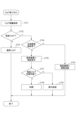
図7は、図5の印刷設定画面で設定されたジョブを受信した後の、印刷装置107の検品処理および正解画像登録のフローチャートを示したものである。図7の処理は、印刷装置107のCPU208が実行する。図7の処理を説明するにあたり、図4のソフトウェア構成図を使い説明する。ジョブは、外部コントローラ102において図5のOKボタンが押下されると外部コントローラから、印刷装置107へ送信される。ここで、図5で、511が「する」が選択されている場合は検品ジョブが発行される。また、512で正解画像を「登録済」を選ぶか、「未登録」を選ぶかでジョブの属性にそれぞれの設定を示す異なるフラグが設定される。
FIG. 7 shows a flowchart of inspection processing and correct image registration of the
511で「しない」が選択されると通常ジョブが発行される。また、そして、図7の処理は、印刷装置107のCPU208がジョブを受信すると開始する。ステップS701では、ジョブ制御401が外部コントローラ102から送信されたジョブ情報の解析を行う。
If "no" is selected in
ステップS702では、ジョブ制御401がステップS701で解析した結果検品ジョブかどうかを判別する。判別した結果、検品ジョブでなければ(ステップS702:N)、ステップS703に進み通常ジョブとして処理を実行する。通常ジョブとはいわゆる印刷ジョブや文書や画像を保存するような検品対象ではないジョブのことをここでは表す。すなわち、通常通りジョブに基づき画像形成を行い、印刷出力を印刷装置107で行う。そして、印刷装置107は排紙する。
In step S702, the
他方、検品ジョブであると判別した場合には(ステップS702:Y)、ステップS704に進み、ジョブ制御401がステップS701で解析した結果、ジョブの属性が、正解画像が登録済かどうかを判別する。判別した結果、登録済であった場合(ステップS704:Y)、ステップS706に進み検品装置に検品開始指示を行う。検品開始指示では外部コントローラ109から送信されたジョブ情報のうち、用紙サイズ、用紙種類など検品処理に必要な情報を送信する。ステップS706で検品指示した際の検品装置側の処理フローについては図8で説明する。
On the other hand, if it is determined that the job is an inspection job (step S702: Y), the process advances to step S704, and as a result of the
他方、ジョブの属性が、正解画像が未登録であった場合(ステップS704:N)、ステップS705に進み外部コントローラ102から送信された画像を検品装置に送信し、メモリ209に正解画像として登録する。ステップS707では、検品装置通信部404がステップS706において検品装置109に検品開始指示を出した結果、検品ジョブの印刷可能かを判別する。検品ジョブが印刷可能である場合(ステップS707:Y)、画像印刷部405がステップS708において検品対象のジョブをすべて印刷し処理を終了する。
On the other hand, if the job attribute indicates that the correct image has not been registered (step S704: N), the process advances to step S705, and the image sent from the
他方、印刷開始可能ではない場合(ステップS707:N)、印刷をせずステップS709で例外処理を実行する。印刷開始可能ではない理由は、一度検品を行ったが、検品装置側で登録されている正解画像を削除した場合がある。また、ステップS705の検品開始指示をした結果、印刷装置107と検品装置109と正しく通信できない、図8のステップS808に示すように正しく検品領域設定がされていない場合などが考えられる。
On the other hand, if it is not possible to start printing (step S707: N), exception processing is executed in step S709 without printing. The reason why it is not possible to start printing may be that the inspection was performed once, but the correct image registered on the inspection device side was deleted. Furthermore, as a result of the instruction to start inspection in step S705, there may be cases where the
そこで例外処理では、外部コントローラ102に対して通知しエラー画面を表示した上で、ユーザの指示に従って再度ジョブを投入してもよい。
Therefore, in the exception handling, the
または、印装装置107の操作部224にエラーを表示し、検品装置で正しく検品設定をさせるか、印刷を中止させるかをユーザに指示させてもよい。
Alternatively, an error may be displayed on the
または、検品装置の操作部242にエラーを表示し、検品装置で正しく検品設定をさせるか、印刷を中止させるかをユーザに指示させてもよい。
Alternatively, an error may be displayed on the
図8は、図7のステップS706において検品装置109に検品開始指示がきたときの、検品装置109での制御方法についてのフローチャートを示したものである。
FIG. 8 shows a flowchart of a control method in the
ステップS801では、印刷装置107から送信されたジョブの情報、および検品比較対象となる正解画像の検品設定情報を解析する。検品設定情報は、図6の検品画像の登録後検品画像を選択して検品設定画面601で事前に設定される。
In step S801, job information transmitted from the
ステップS802では、検品設定画面601の検品領域設定603で「詳細設定」が事前に選択され設定されているかを判別する。判別した結果、「詳細設定」が設定されていた場合(ステップS802:Y)、ステップS803で詳細領域を検品領域として設定する。詳細領域とは、606で指定された領域である。他方、判別した結果「詳細設定」が選択されていない場合には(ステップS802:N)、ステップS804で検品設定画面601の検品領域設定603で「自動」が選択されているかを判別する。判別の結果、「自動」が設定されていた場合(ステップS804:Y)、正解画像のサイズを検品領域に設定する。他方、「自動」が選択されていない場合(ステップS804:N)ステップS806に進み、ステップS801で解析した結果、印刷する用紙がタブ紙であるかどうかを判別する。判別した結果、タブ紙ではない(ステップS806:N)場合には、ステップS807に進み正解画像全体と印刷してスキャンした画像全体同士を検品領域として設定する。ここで、「タブ紙であるか否か」は、図5でジョブが事前にプリンタコントローラ側にて506でタブ紙が設定されたかどうかで判断される。他方、判別した結果、タブ紙である(ステップS806:Y)場合には、ステップS808に進み、検品領域設定不備を設定し処理を終了する。ステップS803、S805、S807を行った場合には、ステップS809で検品装置に読み込み開始を指示する。
In step S802, it is determined whether "detailed settings" have been selected and set in advance in the
図9は、検品時の検品装置109の基本動作を示す動作フローチャートである。
FIG. 9 is an operation flowchart showing the basic operation of the
ステップS901では、図7のステップS706、および図8のステップS809の検品開始指示を受け付け、カメラ331、カメラ332を作動させスキャン画像と正解画像の比較処理を作動させる。次にステップS902に進み、検品対象のシートがある場合はステップS903に進む。ステップS903にて、用紙の画像をカメラ331及びカメラ332を使用して読み取る。次にステップS904にて、メモリ239に事前に保存されている正解画像と、S903にて読み取った画像を比較する。
In step S901, the inspection start instruction in step S706 in FIG. 7 and step S809 in FIG. 8 is accepted, and the
なお、正解画像は、図7S705で送信された正解画像を検品装置109が受信する。そして、検品装置が109が正解画像を事前に登録してメモリ239に保存されているものとする。
Note that the
この比較の動作では、まず、画像の特徴的な点を位置合わせの基準点として使用して、正解画像と検品対象のスキャン画像の画像位置を合わせる。次に、検品対象のスキャン画像において、用紙の四隅とスキャン画像の位置合わせ基準点とを解析して用紙に対する画像の位置ずれがないか検出する。次に、正解画像と検品対象のスキャン画像の濃度値を画素ごとに比較する。以上の結果、欠陥が検出されなければ、検品結果OKとする。検品結果がOKであれば(ステップS905:Y)、ステップS906に進み、例えば大容量スタッカ110のスタックトレイ341への排紙を指示する。
In this comparison operation, first, the image positions of the correct image and the scanned image to be inspected are aligned using characteristic points of the images as reference points for alignment. Next, in the scanned image to be inspected, the four corners of the paper and the alignment reference points of the scanned image are analyzed to detect whether there is any positional deviation of the image with respect to the paper. Next, the density values of the correct image and the scanned image to be inspected are compared for each pixel. As a result of the above, if no defects are detected, the inspection result is determined to be OK. If the inspection result is OK (step S905: Y), the process advances to step S906, and instructs, for example, to eject the paper to the
他方、検品結果がNGであれば(ステップS905:N)、S907に進み、例えば大容量スタッカ110のイジェクトトレイ345への排紙を指示する。
On the other hand, if the inspection result is NG (step S905: N), the process advances to S907, and instructs to eject the paper to the
全てのシートの検品を終えるまでS902~S907を繰り返す。全てのシートの検品が終了したら本フローを終了する。 Steps S902 to S907 are repeated until all sheets have been inspected. This flow ends when all sheets have been inspected.
なお、ここでは、検品結果OKの場合はスタックトレイ341へ排紙、検品結果NGの場合はイジェクトトレイ345へ排紙する例を説明したが、ユーザの指示や印刷設定に応じて排紙先を切り替えてもよく、その形態を限定しない。
Note that here, we have explained an example in which the paper is ejected to the
図10は、図6検品設定画面601の検品領域設定欄603で選択した検品領域設定により、正解画像と印刷したスキャン画像の比較例を表している。ここでは正解画像、スキャン画像共にA4サイズで、正解画像が左、右はタブ紙のスキャン画像を表しており、点線が比較する領域を表している。
(a)詳細領域設定での比較例1001は、検品設定画面601の検品領域設定欄603で「詳細設定」を選択し、領域をユーザが詳細に決定した場合の比較例を表している。この場合、スキャン画像にタブ部があるが、検品領域を矩形で指定しているため問題なく比較を行うことが可能である。
(b)自動設定での比較例1002は、検品設定画面601の検品領域設定欄603で「自動」を選択し、検品領域は正解画像のサイズを用いることを示している。この場合、スキャン画像にタブ部があるが、点線のサイズは正解画像、スキャン画像ともにA4サイズであり、タブ部を検品しない場合には問題なく比較を行うことが可能である。
(c)設定なしでの比較例1003は、検品設定画面601の検品領域設定欄603で「領域設定しない」を選択し、検品領域は正解画像の全領域、スキャン画像の全領域での比較例を表している。この場合、正解画像はA4サイズ、タブ紙はA4サイズであるがタブ部があるため、タブ領域を含んだ幅分がスキャン領域となる。つまり、このまま検品を行うとNGとなってしまうため、図7のステップS707、S709および図8のステップS806およびステップS808で検品領域設定不備の設定を行い、例外処理を行う。
FIG. 10 shows an example of comparison between a correct image and a printed scanned image according to the inspection area setting selected in the inspection
(a) Comparative example 1001 in detailed area setting represents a comparative example in which "detailed setting" is selected in the inspection
(b) Comparative example 1002 with automatic setting indicates that “automatic” is selected in the inspection
(c) Comparison example 1003 without setting is a comparison example in which "Do not set area" is selected in the inspection
以上、検品設定画面601の検品領域設定欄603で選択した検品領域を詳細設定しておくことで、検品対象用紙がタブ紙のような特殊な形状の紙であっても、検品NGになる、または検品をスキップさせる必要もなく、検品処理を実行可能である。具体的には、例えば、タブ紙を検品したい場合、タブの部分を除いて例えば図10(a)のように図6を用いて606で囲む。これにより、囲んだ領域を検品対象とできる。また、606で囲まれていない領域(タブ部分含む)を検品対象外とできる。
As mentioned above, by making detailed settings for the inspection area selected in the inspection
次に、他の実施例を説明する。最初の実施例では、検品対象となる印刷用紙がタブ紙の場合でタブ部分に印字していない場合に、検品領域設定を正しく設定することで、検品NG、検品スキップすることなく検品処理を実行できる例を説明した。次に、他の実施例では、タブ紙のタブ部分に印字した場合の検品処理について説明をする。 Next, another embodiment will be described. In the first example, when the printing paper to be inspected is tab paper and there is no printing on the tab part, by setting the inspection area settings correctly, the inspection process is performed without rejecting the inspection or skipping the inspection. I explained an example of what can be done. Next, in another embodiment, an inspection process when printing is performed on the tab portion of tab paper will be described.
図11は、印刷設定画面501でタブ印字シフト量507を設定した場合の(a)タブ部分への印字例および、タブ部分へ印字した後の(b)タブ部分の検品例の2つを表している。
FIG. 11 shows two examples: (a) an example of printing on the tab portion when the tab
まず(a)タブ部分への印字例から説明する。原稿1101はA4サイズの原稿であり、タブ部分へ印字したいコンテンツ1102が原稿内に記録されている。この際、印刷したい用紙はタブ紙であるが、原稿はタブ紙のタブ部分はないため、A4の原稿サイズ内に印字したいコンテンツ1102を配置する。印刷後用紙1103は原稿1101をタブ紙に印字した後の状態を表している。タブ部分1104には、原稿1101のコンテンツ1102が印字されているが、その際、印刷装置107は1105のシフト量、つまりタブ印字シフト量507で指定された分、印字位置をずらしタブ紙のタブ部分へ印字を行う。このタブ印字シフト量507のような情報は図7のステップS701でジョブ情報を解析することで情報し印刷可能である。
First, an example of printing on the tab portion (a) will be explained. A
次に(b)タブ部分の検品例について説明する。正解画像1106は原稿1101と同等の画像データであり、正解画像のうち検品領域設定欄603で「詳細設定」を選択し、検品領域1107を設定していることを示している。スキャン画像1108は、印刷後用紙1103をスキャンした画像を表している。そのうち検品する個所は検品領域1109であり、正解画像の検品領域1107からシフト量1110分を移動した箇所を検品領域としている。シフト量1110は、印刷時に指定しているシフト量1105と同等の値を使えばよく、このシフト量を考慮することでタブ部分も検品可能となる。
Next, an example of inspection of the tab portion (b) will be explained. The
これらの例でわかるように、タブ部分の検品する場合には、検品領域設定欄603で「詳細設定」を選択することにより可能となる。「領域設定しない」および「自動」設定であっでは正しく検品することができない。
As can be seen from these examples, the tab portion can be inspected by selecting “detailed settings” in the inspection
次に、図11で示したタブ印字シフト量507が設定されていた場合の、図7のステップS706において検品装置109に正解画像が送信されたときの検品装置109の制御方法について図12を用いてフローチャートで説明する。以下、図8と異なる部分を中心に説明する。
Next, using FIG. 12, we will explain how to control the
ステップS1201では、印刷装置107から送信されたジョブの情報、および検品比較対象となる正解画像の検品設定情報(図6の検品設定画面601)を解析する。
In step S1201, job information transmitted from the
ステップS1202では、検品設定画面601の検品領域設定603で「詳細設定」が選択されているかどうかを判別する。判別した結果、「詳細設定」が設定されていた場合(ステップS1202:Y)、ステップS1203で詳細領域を検品領域として設定する。また、ステップS1203では、正解画像の詳細検品領域を設定するとともに、印字した紙をスキャンした画像に対しては詳細領域を図5のタブ印字シフト量507分移動した箇所を検品対象領域とする。タブ印字シフト量は設定されていなければ0であるため、詳細検品領域が設定されている場合には、気にせず反映してもよい。他方、判別した結果「詳細設定」が選択されていない場合(ステップS1202:N)には、ステップS1204でタブ印字シフト量が0より大きいかを判別する。判別の結果、0より大きい(ステップS1204:Y)場合、ステップS1209に進み、検品領域設定不備を設定し処理を終了する。つまり、タブ印字シフト量が0より大きい場合には、「詳細設定」が選択されている場合のみ検品できないことを意味している。他方、0より大きくない(ステップS1204:N)場合、ステップS1205に進み、検品設定画面601の検品領域設定603で「自動」が選択されているかを判別する。判別の結果、「自動」が設定されていた(ステップS1205:Y)場合、正解画像のサイズを検品領域に設定する。他方、「自動」が選択されていない場合(ステップS1205:N)ステップS1207に進み、ステップS1201で解析した結果、印刷する用紙がタブ紙であるかどうかを判別する。判別した結果、タブ紙ではない(ステップS1207:N)場合には、ステップS1208に進み正解画像全体と印刷してスキャンした画像全体同士を検品領域と設定する。他方、判別した結果、タブ紙である(ステップS1207:Y)場合には、ステップS1209に進み、検品領域設定不備を設定し処理を終了する。ステップS1203、S1206、S1208を行った場合には、ステップS1210で検品装置に読み込み開始を指示する。
In step S1202, it is determined whether "detailed settings" is selected in the inspection area setting 603 of the
以上、タブ紙のタブ部分の検品を行いたい場合でも、検品設定画面601の検品領域設定欄603で「詳細設定」を選択しておく。そうすると、検品対象用紙がタブ紙のような特殊な形状の紙であっても、検品NGになる、または検品をスキップさせる必要もなく、検品処理を実行可能である。
As described above, even when it is desired to inspect the tab portion of tab paper, "detailed settings" is selected in the inspection
以上説明したように、本実施形態では次を説明した。図2は検品システムの一例である。109,103,102はそれぞれ図示のごとく別筐体に実装されてもよいが、これらの要素の一部または全部を同一筐体にまとめてもよい。 As explained above, the following has been explained in this embodiment. FIG. 2 is an example of an inspection system. 109, 103, and 102 may each be mounted in separate casings as shown, but some or all of these elements may be combined into the same casing.
まず、正解画像に設定されたシートとは異なる形状のシートの検品領域を設定することができる図6のユーザインタフェースの一例を説明した。 First, an example of the user interface shown in FIG. 6 has been described, which can set an inspection area for a sheet having a shape different from that of the sheet set as the correct image.
また、前記正解画像に設定されたシートとは異なる形状のシートを読み取る読み取り手段の一例としてカメラ331を説明した。読み取りの結果、図10に示すようなスキャン画像が得られる。
Furthermore, the
また、図6の603の詳細設定により設定された検品領域606と、予め検品装置109内に記憶された正解画像と、カメラ331の読み取りの結果得られた画像とに基づいて、次を行う。すなわち、正解画像に設定されたシートとは異なる形状のシートへ出力された画像の検品処理を実行する。検品処理とは、例えば、正解画像と、スキャン画像のうち検品対象領域として指定された領域を比較して、差分があればNG,なければOKとCPU238が判断することである。
Further, the following is performed based on the
また、カメラ331は、印刷処理されたタブ紙を読み取って画像を得ることができる。
Further, the
また、図6のユーザインタフェースは、タブ紙の内部の領域を設定することができる。タブ紙の内部には、タブ紙のタブ部分を少なくとも除く領域であって尚且つ正解画像内の領域に対応する領域を含ませるようにする。 Further, the user interface shown in FIG. 6 can set the area inside the tab paper. The inside of the tab paper is made to include an area that excludes at least the tab portion of the tab paper and that corresponds to the area in the correct image.
また、CPU238は、画像において、図6のユーザインタフェースで設定した領域について、正解画像との検品処理を実行する。また、ユーザインタフェースで設定していない領域について、検品処理をCPU238は実行しないようにしてもよい。
Further, the
図6のユーザインタフェースにより設定された、タブ部分を除く検品領域と、予め記憶された正解画像と、カメラ読み取りの結果得られたスキャン画像とに基づいて、次を行う。例えば、正解画像に設定されたシートとは異なる形状のシートへ出力された画像の検品処理をCPU238は実行する。
The following is performed based on the inspection area excluding the tab portion set by the user interface of FIG. 6, the correct image stored in advance, and the scanned image obtained as a result of camera reading. For example, the
Claims (6)
前記正解画像に設定されたシートとは異なる形状のシートを読み取る読み取り手段と、
前記設定手段により設定された検品領域と、予め記憶された正解画像と、前記読み取り手段による読み取りの結果得られた画像とに基づいて、前記正解画像に設定されたシートとは異なる形状のシートへ出力された画像の検品処理を実行する実行手段と、
を備える検品システム。 a setting means for setting an inspection area for a sheet having a shape different from that of the sheet set in the correct image;
reading means for reading a sheet having a different shape from the sheet set as the correct image;
Based on the inspection area set by the setting means, the correct image stored in advance, and the image obtained as a result of reading by the reading means, a sheet having a shape different from that set in the correct image is selected. Execution means for performing inspection processing of the output image;
An inspection system equipped with
前記設定手段は、タブ紙のタブ部分を少なくとも除く領域であって尚且つ前記正解画像内の領域に対応する領域を含むタブ紙の内部の領域を前記設定手段は設定することを特徴とし、前記画像の前記設定手段が設定した領域について、前記正解画像との検品処理を前記実行手段は実行し、前記設定手段が設定していない領域について、検品処理を前記実行手段は実行しない請求項1に記載の検品システム。 The reading means reads the tab paper to obtain an image;
The setting means is characterized in that the setting means sets an area inside the tab paper that is an area excluding at least a tab portion of the tab paper and that includes an area corresponding to an area in the correct image, 2. The method according to claim 1, wherein the execution means executes the inspection process with the correct image for the area set by the setting means of the image, and does not perform the inspection process for the area not set by the setting means. Inspection system described.
前記正解画像に設定されたシートとは異なる形状のシートを読み取る読み取り工程と、
前記設定工程により設定された検品領域と、予め記憶された正解画像と、前記読み取り工程による読み取りの結果得られた画像とに基づいて、前記正解画像に設定されたシートとは異なる形状のシートへ出力された画像の検品処理を実行する実行工程と、
を備える検品システムの制御方法。 a setting step of setting an inspection area for a sheet having a shape different from that of the sheet set in the correct image;
a reading step of reading a sheet having a different shape from the sheet set as the correct image;
Based on the inspection area set in the setting step, the correct image stored in advance, and the image obtained as a result of reading in the reading step, a sheet having a shape different from the sheet set in the correct image is selected. an execution step of performing inspection processing of the output image;
A control method for an inspection system comprising:
前記設定工程は、タブ紙のタブ部分を少なくとも除く領域であって尚且つ前記正解画像内の領域に対応する領域を含むタブ紙の内部の領域を前記設定工程は設定することを特徴とし、前記画像の前記設定工程が設定した領域について、前記正解画像との検品処理を前記実行工程は実行し、前記設定工程が設定していない領域について、検品処理を前記実行工程は実行しない請求項4に記載の検品システムの制御方法。 The reading step reads the tab paper to obtain an image,
The setting step is characterized in that the setting step sets an area inside the tab paper that is an area excluding at least a tab portion of the tab paper and that includes an area corresponding to an area in the correct image, 5. The method according to claim 4, wherein the execution step performs an inspection process with respect to the correct image for the area set by the setting step of the image, and does not perform the inspection process for the area not set by the setting step. Control method for the inspection system described.
Priority Applications (2)
| Application Number | Priority Date | Filing Date | Title |
|---|---|---|---|
| JP2022134631A JP2024031210A (en) | 2022-08-26 | 2022-08-26 | Inspection system, control method |
| US18/451,006 US20240073324A1 (en) | 2022-08-26 | 2023-08-16 | Inspection system and control method |
Applications Claiming Priority (1)
| Application Number | Priority Date | Filing Date | Title |
|---|---|---|---|
| JP2022134631A JP2024031210A (en) | 2022-08-26 | 2022-08-26 | Inspection system, control method |
Publications (1)
| Publication Number | Publication Date |
|---|---|
| JP2024031210A true JP2024031210A (en) | 2024-03-07 |
Family
ID=89995133
Family Applications (1)
| Application Number | Title | Priority Date | Filing Date |
|---|---|---|---|
| JP2022134631A Pending JP2024031210A (en) | 2022-08-26 | 2022-08-26 | Inspection system, control method |
Country Status (2)
| Country | Link |
|---|---|
| US (1) | US20240073324A1 (en) |
| JP (1) | JP2024031210A (en) |
Family Cites Families (3)
| Publication number | Priority date | Publication date | Assignee | Title |
|---|---|---|---|---|
| JP5627222B2 (en) * | 2009-12-02 | 2014-11-19 | キヤノン株式会社 | Printing apparatus, printing apparatus control method, and program |
| JP2022107439A (en) * | 2021-01-08 | 2022-07-21 | キヤノン株式会社 | Image formation device, method for controlling the same and program |
| JP2023142389A (en) * | 2022-03-25 | 2023-10-05 | キヤノン株式会社 | Image forming apparatus, inspection device, information processing method, inspection system and program |
-
2022
- 2022-08-26 JP JP2022134631A patent/JP2024031210A/en active Pending
-
2023
- 2023-08-16 US US18/451,006 patent/US20240073324A1/en active Pending
Also Published As
| Publication number | Publication date |
|---|---|
| US20240073324A1 (en) | 2024-02-29 |
Similar Documents
| Publication | Publication Date | Title |
|---|---|---|
| JP7466280B2 (en) | Inspection device, control method thereof, and program | |
| US11556285B2 (en) | Verification system, information processing apparatus, and control methods thereof | |
| US20220329701A1 (en) | Image forming apparatus to verify printed image with master image, image forming method, and storage medium | |
| JP2021115744A (en) | Image forming device, information processing method and program | |
| US11343383B2 (en) | Image forming apparatus with registered correct answer image to verify printed image, image forming method, and storage medium | |
| US11422754B2 (en) | Image forming apparatus, verification apparatus, information processing method, and storage medium | |
| JP2022131198A (en) | Printing system, control method therefor, and program | |
| US20220276813A1 (en) | Image processing apparatus and image processing system | |
| JP7471841B2 (en) | Inspection system and method | |
| JP2022128230A (en) | Printing system, printer and information processing device and control method therefor, and program | |
| JP2023047137A (en) | Printing system, printer and method for controlling the same, and program | |
| JP2023034163A (en) | Printing system, information processing device, printing device and inspecting device, control method of information processing device, control method of printing device, as well as program | |
| JP2024031210A (en) | Inspection system, control method | |
| JP2021102322A (en) | Image formation apparatus, image formation method, and program | |
| JP2021097365A (en) | Information processing device, printing control method, image formation system, and program | |
| US11822279B2 (en) | Image forming apparatus, information processing method, printing system, and storage medium for performing reprinting | |
| US11838455B2 (en) | Inspection system to register image data in inspection apparatus and execution of an inspection job, printing apparatus, method for controlling inspection system | |
| US20230084850A1 (en) | Printing apparatus, image forming apparatus, and control method | |
| US20230168851A1 (en) | Image forming apparatus and image processing system | |
| JP2021182725A (en) | Image processing system and printing inspection method and program | |
| JP2022148533A (en) | Printing system, control method and program thereof | |
| JP2023047419A (en) | Printing system and method for controlling the same, printer, and program | |
| JP2023073010A (en) | Image forming device, image forming device control method and program | |
| JP2022161685A (en) | Image formation apparatus and image formation system | |
| JP2023084230A (en) | Image processing device, control method of image processing device, image processing system and program |
Legal Events
| Date | Code | Title | Description |
|---|---|---|---|
| RD01 | Notification of change of attorney |
Free format text: JAPANESE INTERMEDIATE CODE: A7421 Effective date: 20231213 |