JP2024029767A - Viewing panel and uses thereof - Google Patents
Viewing panel and uses thereof Download PDFInfo
- Publication number
- JP2024029767A JP2024029767A JP2023133979A JP2023133979A JP2024029767A JP 2024029767 A JP2024029767 A JP 2024029767A JP 2023133979 A JP2023133979 A JP 2023133979A JP 2023133979 A JP2023133979 A JP 2023133979A JP 2024029767 A JP2024029767 A JP 2024029767A
- Authority
- JP
- Japan
- Prior art keywords
- viewing panel
- particularly preferably
- panel
- range
- wavelength
- Prior art date
- Legal status (The legal status is an assumption and is not a legal conclusion. Google has not performed a legal analysis and makes no representation as to the accuracy of the status listed.)
- Pending
Links
- 238000000576 coating method Methods 0.000 claims abstract description 83
- 239000011248 coating agent Substances 0.000 claims abstract description 72
- 239000000758 substrate Substances 0.000 claims abstract description 32
- 230000003595 spectral effect Effects 0.000 claims abstract description 29
- 238000002834 transmittance Methods 0.000 claims abstract description 26
- 239000011521 glass Substances 0.000 claims description 45
- 238000005259 measurement Methods 0.000 claims description 27
- 230000005540 biological transmission Effects 0.000 claims description 22
- 239000000463 material Substances 0.000 claims description 13
- 238000003384 imaging method Methods 0.000 claims description 4
- 150000004767 nitrides Chemical class 0.000 claims description 4
- 229910052751 metal Inorganic materials 0.000 claims description 3
- 239000002184 metal Substances 0.000 claims description 3
- 229910052752 metalloid Inorganic materials 0.000 claims description 3
- 150000002738 metalloids Chemical class 0.000 claims description 3
- 150000001450 anions Chemical class 0.000 description 38
- 238000001228 spectrum Methods 0.000 description 27
- 230000003287 optical effect Effects 0.000 description 16
- 239000000203 mixture Substances 0.000 description 11
- 229910052700 potassium Inorganic materials 0.000 description 9
- 239000011591 potassium Substances 0.000 description 9
- 229910052708 sodium Inorganic materials 0.000 description 9
- 239000011734 sodium Substances 0.000 description 9
- DGAQECJNVWCQMB-PUAWFVPOSA-M Ilexoside XXIX Chemical compound C[C@@H]1CC[C@@]2(CC[C@@]3(C(=CC[C@H]4[C@]3(CC[C@@H]5[C@@]4(CC[C@@H](C5(C)C)OS(=O)(=O)[O-])C)C)[C@@H]2[C@]1(C)O)C)C(=O)O[C@H]6[C@@H]([C@H]([C@@H]([C@H](O6)CO)O)O)O.[Na+] DGAQECJNVWCQMB-PUAWFVPOSA-M 0.000 description 8
- ZLMJMSJWJFRBEC-UHFFFAOYSA-N Potassium Chemical compound [K] ZLMJMSJWJFRBEC-UHFFFAOYSA-N 0.000 description 8
- 150000001768 cations Chemical class 0.000 description 8
- 238000010586 diagram Methods 0.000 description 8
- 229910017052 cobalt Inorganic materials 0.000 description 7
- 239000010941 cobalt Substances 0.000 description 7
- GUTLYIVDDKVIGB-UHFFFAOYSA-N cobalt atom Chemical compound [Co] GUTLYIVDDKVIGB-UHFFFAOYSA-N 0.000 description 7
- PXHVJJICTQNCMI-UHFFFAOYSA-N Nickel Chemical compound [Ni] PXHVJJICTQNCMI-UHFFFAOYSA-N 0.000 description 6
- 229910052782 aluminium Inorganic materials 0.000 description 6
- XAGFODPZIPBFFR-UHFFFAOYSA-N aluminium Chemical compound [Al] XAGFODPZIPBFFR-UHFFFAOYSA-N 0.000 description 6
- 230000005670 electromagnetic radiation Effects 0.000 description 5
- 229910052710 silicon Inorganic materials 0.000 description 5
- VYPSYNLAJGMNEJ-UHFFFAOYSA-N Silicium dioxide Chemical compound O=[Si]=O VYPSYNLAJGMNEJ-UHFFFAOYSA-N 0.000 description 4
- XUIMIQQOPSSXEZ-UHFFFAOYSA-N Silicon Chemical compound [Si] XUIMIQQOPSSXEZ-UHFFFAOYSA-N 0.000 description 4
- 125000000129 anionic group Chemical group 0.000 description 4
- 239000011651 chromium Substances 0.000 description 4
- 150000004820 halides Chemical class 0.000 description 4
- 239000010703 silicon Substances 0.000 description 4
- 229910052814 silicon oxide Inorganic materials 0.000 description 4
- VYZAMTAEIAYCRO-UHFFFAOYSA-N Chromium Chemical compound [Cr] VYZAMTAEIAYCRO-UHFFFAOYSA-N 0.000 description 3
- 229910052581 Si3N4 Inorganic materials 0.000 description 3
- 239000006117 anti-reflective coating Substances 0.000 description 3
- 229910052804 chromium Inorganic materials 0.000 description 3
- 239000002131 composite material Substances 0.000 description 3
- 230000002209 hydrophobic effect Effects 0.000 description 3
- 238000000034 method Methods 0.000 description 3
- 229910052759 nickel Inorganic materials 0.000 description 3
- 230000010287 polarization Effects 0.000 description 3
- HQVNEWCFYHHQES-UHFFFAOYSA-N silicon nitride Chemical compound N12[Si]34N5[Si]62N3[Si]51N64 HQVNEWCFYHHQES-UHFFFAOYSA-N 0.000 description 3
- ZOXJGFHDIHLPTG-UHFFFAOYSA-N Boron Chemical compound [B] ZOXJGFHDIHLPTG-UHFFFAOYSA-N 0.000 description 2
- VEXZGXHMUGYJMC-UHFFFAOYSA-M Chloride anion Chemical compound [Cl-] VEXZGXHMUGYJMC-UHFFFAOYSA-M 0.000 description 2
- 229910004298 SiO 2 Inorganic materials 0.000 description 2
- 229910052796 boron Inorganic materials 0.000 description 2
- 230000001419 dependent effect Effects 0.000 description 2
- 230000000694 effects Effects 0.000 description 2
- 238000001914 filtration Methods 0.000 description 2
- -1 potassium cations Chemical class 0.000 description 2
- 239000000126 substance Substances 0.000 description 2
- 229910018072 Al 2 O 3 Inorganic materials 0.000 description 1
- 229910018068 Li 2 O Inorganic materials 0.000 description 1
- 238000005299 abrasion Methods 0.000 description 1
- PNEYBMLMFCGWSK-UHFFFAOYSA-N aluminium oxide Inorganic materials [O-2].[O-2].[O-2].[Al+3].[Al+3] PNEYBMLMFCGWSK-UHFFFAOYSA-N 0.000 description 1
- 230000002528 anti-freeze Effects 0.000 description 1
- 239000006121 base glass Substances 0.000 description 1
- 230000009286 beneficial effect Effects 0.000 description 1
- 230000007547 defect Effects 0.000 description 1
- 230000032798 delamination Effects 0.000 description 1
- 238000000151 deposition Methods 0.000 description 1
- 238000011049 filling Methods 0.000 description 1
- 238000007710 freezing Methods 0.000 description 1
- 238000010438 heat treatment Methods 0.000 description 1
- 238000011068 loading method Methods 0.000 description 1
- 238000001755 magnetron sputter deposition Methods 0.000 description 1
- 238000002156 mixing Methods 0.000 description 1
- TWNQGVIAIRXVLR-UHFFFAOYSA-N oxo(oxoalumanyloxy)alumane Chemical compound O=[Al]O[Al]=O TWNQGVIAIRXVLR-UHFFFAOYSA-N 0.000 description 1
- 238000005546 reactive sputtering Methods 0.000 description 1
- 238000002310 reflectometry Methods 0.000 description 1
- 150000003839 salts Chemical class 0.000 description 1
- 238000006748 scratching Methods 0.000 description 1
- 230000002393 scratching effect Effects 0.000 description 1
- 238000000926 separation method Methods 0.000 description 1
- 229910021332 silicide Inorganic materials 0.000 description 1
- FVBUAEGBCNSCDD-UHFFFAOYSA-N silicide(4-) Chemical compound [Si-4] FVBUAEGBCNSCDD-UHFFFAOYSA-N 0.000 description 1
- 238000004544 sputter deposition Methods 0.000 description 1
- 230000003068 static effect Effects 0.000 description 1
- XLYOFNOQVPJJNP-UHFFFAOYSA-N water Substances O XLYOFNOQVPJJNP-UHFFFAOYSA-N 0.000 description 1
Images

Classifications
-
- H—ELECTRICITY
- H01—ELECTRIC ELEMENTS
- H01S—DEVICES USING THE PROCESS OF LIGHT AMPLIFICATION BY STIMULATED EMISSION OF RADIATION [LASER] TO AMPLIFY OR GENERATE LIGHT; DEVICES USING STIMULATED EMISSION OF ELECTROMAGNETIC RADIATION IN WAVE RANGES OTHER THAN OPTICAL
- H01S3/00—Lasers, i.e. devices using stimulated emission of electromagnetic radiation in the infrared, visible or ultraviolet wave range
- H01S3/02—Constructional details
-
- G—PHYSICS
- G02—OPTICS
- G02B—OPTICAL ELEMENTS, SYSTEMS OR APPARATUS
- G02B1/00—Optical elements characterised by the material of which they are made; Optical coatings for optical elements
- G02B1/10—Optical coatings produced by application to, or surface treatment of, optical elements
- G02B1/11—Anti-reflection coatings
-
- C—CHEMISTRY; METALLURGY
- C03—GLASS; MINERAL OR SLAG WOOL
- C03C—CHEMICAL COMPOSITION OF GLASSES, GLAZES OR VITREOUS ENAMELS; SURFACE TREATMENT OF GLASS; SURFACE TREATMENT OF FIBRES OR FILAMENTS MADE FROM GLASS, MINERALS OR SLAGS; JOINING GLASS TO GLASS OR OTHER MATERIALS
- C03C17/00—Surface treatment of glass, not in the form of fibres or filaments, by coating
- C03C17/34—Surface treatment of glass, not in the form of fibres or filaments, by coating with at least two coatings having different compositions
- C03C17/3411—Surface treatment of glass, not in the form of fibres or filaments, by coating with at least two coatings having different compositions with at least two coatings of inorganic materials
- C03C17/3429—Surface treatment of glass, not in the form of fibres or filaments, by coating with at least two coatings having different compositions with at least two coatings of inorganic materials at least one of the coatings being a non-oxide coating
- C03C17/3435—Surface treatment of glass, not in the form of fibres or filaments, by coating with at least two coatings having different compositions with at least two coatings of inorganic materials at least one of the coatings being a non-oxide coating comprising a nitride, oxynitride, boronitride or carbonitride
-
- C—CHEMISTRY; METALLURGY
- C03—GLASS; MINERAL OR SLAG WOOL
- C03C—CHEMICAL COMPOSITION OF GLASSES, GLAZES OR VITREOUS ENAMELS; SURFACE TREATMENT OF GLASS; SURFACE TREATMENT OF FIBRES OR FILAMENTS MADE FROM GLASS, MINERALS OR SLAGS; JOINING GLASS TO GLASS OR OTHER MATERIALS
- C03C17/00—Surface treatment of glass, not in the form of fibres or filaments, by coating
- C03C17/34—Surface treatment of glass, not in the form of fibres or filaments, by coating with at least two coatings having different compositions
- C03C17/3411—Surface treatment of glass, not in the form of fibres or filaments, by coating with at least two coatings having different compositions with at least two coatings of inorganic materials
- C03C17/3429—Surface treatment of glass, not in the form of fibres or filaments, by coating with at least two coatings having different compositions with at least two coatings of inorganic materials at least one of the coatings being a non-oxide coating
- C03C17/3482—Surface treatment of glass, not in the form of fibres or filaments, by coating with at least two coatings having different compositions with at least two coatings of inorganic materials at least one of the coatings being a non-oxide coating comprising silicon, hydrogenated silicon or a silicide
-
- C—CHEMISTRY; METALLURGY
- C03—GLASS; MINERAL OR SLAG WOOL
- C03C—CHEMICAL COMPOSITION OF GLASSES, GLAZES OR VITREOUS ENAMELS; SURFACE TREATMENT OF GLASS; SURFACE TREATMENT OF FIBRES OR FILAMENTS MADE FROM GLASS, MINERALS OR SLAGS; JOINING GLASS TO GLASS OR OTHER MATERIALS
- C03C3/00—Glass compositions
- C03C3/04—Glass compositions containing silica
- C03C3/062—Glass compositions containing silica with less than 40% silica by weight
-
- C—CHEMISTRY; METALLURGY
- C03—GLASS; MINERAL OR SLAG WOOL
- C03C—CHEMICAL COMPOSITION OF GLASSES, GLAZES OR VITREOUS ENAMELS; SURFACE TREATMENT OF GLASS; SURFACE TREATMENT OF FIBRES OR FILAMENTS MADE FROM GLASS, MINERALS OR SLAGS; JOINING GLASS TO GLASS OR OTHER MATERIALS
- C03C3/00—Glass compositions
- C03C3/04—Glass compositions containing silica
- C03C3/076—Glass compositions containing silica with 40% to 90% silica, by weight
-
- C—CHEMISTRY; METALLURGY
- C03—GLASS; MINERAL OR SLAG WOOL
- C03C—CHEMICAL COMPOSITION OF GLASSES, GLAZES OR VITREOUS ENAMELS; SURFACE TREATMENT OF GLASS; SURFACE TREATMENT OF FIBRES OR FILAMENTS MADE FROM GLASS, MINERALS OR SLAGS; JOINING GLASS TO GLASS OR OTHER MATERIALS
- C03C4/00—Compositions for glass with special properties
- C03C4/02—Compositions for glass with special properties for coloured glass
-
- G—PHYSICS
- G01—MEASURING; TESTING
- G01B—MEASURING LENGTH, THICKNESS OR SIMILAR LINEAR DIMENSIONS; MEASURING ANGLES; MEASURING AREAS; MEASURING IRREGULARITIES OF SURFACES OR CONTOURS
- G01B11/00—Measuring arrangements characterised by the use of optical techniques
- G01B11/14—Measuring arrangements characterised by the use of optical techniques for measuring distance or clearance between spaced objects or spaced apertures
-
- G—PHYSICS
- G01—MEASURING; TESTING
- G01N—INVESTIGATING OR ANALYSING MATERIALS BY DETERMINING THEIR CHEMICAL OR PHYSICAL PROPERTIES
- G01N21/00—Investigating or analysing materials by the use of optical means, i.e. using sub-millimetre waves, infrared, visible or ultraviolet light
- G01N21/01—Arrangements or apparatus for facilitating the optical investigation
-
- G—PHYSICS
- G01—MEASURING; TESTING
- G01N—INVESTIGATING OR ANALYSING MATERIALS BY DETERMINING THEIR CHEMICAL OR PHYSICAL PROPERTIES
- G01N21/00—Investigating or analysing materials by the use of optical means, i.e. using sub-millimetre waves, infrared, visible or ultraviolet light
- G01N21/17—Systems in which incident light is modified in accordance with the properties of the material investigated
- G01N21/25—Colour; Spectral properties, i.e. comparison of effect of material on the light at two or more different wavelengths or wavelength bands
- G01N21/31—Investigating relative effect of material at wavelengths characteristic of specific elements or molecules, e.g. atomic absorption spectrometry
- G01N21/39—Investigating relative effect of material at wavelengths characteristic of specific elements or molecules, e.g. atomic absorption spectrometry using tunable lasers
-
- G—PHYSICS
- G01—MEASURING; TESTING
- G01N—INVESTIGATING OR ANALYSING MATERIALS BY DETERMINING THEIR CHEMICAL OR PHYSICAL PROPERTIES
- G01N21/00—Investigating or analysing materials by the use of optical means, i.e. using sub-millimetre waves, infrared, visible or ultraviolet light
- G01N21/84—Systems specially adapted for particular applications
-
- G—PHYSICS
- G02—OPTICS
- G02B—OPTICAL ELEMENTS, SYSTEMS OR APPARATUS
- G02B5/00—Optical elements other than lenses
- G02B5/20—Filters
-
- H—ELECTRICITY
- H01—ELECTRIC ELEMENTS
- H01S—DEVICES USING THE PROCESS OF LIGHT AMPLIFICATION BY STIMULATED EMISSION OF RADIATION [LASER] TO AMPLIFY OR GENERATE LIGHT; DEVICES USING STIMULATED EMISSION OF ELECTROMAGNETIC RADIATION IN WAVE RANGES OTHER THAN OPTICAL
- H01S5/00—Semiconductor lasers
- H01S5/02—Structural details or components not essential to laser action
- H01S5/022—Mountings; Housings
- H01S5/0239—Combinations of electrical or optical elements
-
- C—CHEMISTRY; METALLURGY
- C03—GLASS; MINERAL OR SLAG WOOL
- C03C—CHEMICAL COMPOSITION OF GLASSES, GLAZES OR VITREOUS ENAMELS; SURFACE TREATMENT OF GLASS; SURFACE TREATMENT OF FIBRES OR FILAMENTS MADE FROM GLASS, MINERALS OR SLAGS; JOINING GLASS TO GLASS OR OTHER MATERIALS
- C03C2217/00—Coatings on glass
- C03C2217/70—Properties of coatings
-
- C—CHEMISTRY; METALLURGY
- C03—GLASS; MINERAL OR SLAG WOOL
- C03C—CHEMICAL COMPOSITION OF GLASSES, GLAZES OR VITREOUS ENAMELS; SURFACE TREATMENT OF GLASS; SURFACE TREATMENT OF FIBRES OR FILAMENTS MADE FROM GLASS, MINERALS OR SLAGS; JOINING GLASS TO GLASS OR OTHER MATERIALS
- C03C2217/00—Coatings on glass
- C03C2217/70—Properties of coatings
- C03C2217/73—Anti-reflective coatings with specific characteristics
-
- C—CHEMISTRY; METALLURGY
- C03—GLASS; MINERAL OR SLAG WOOL
- C03C—CHEMICAL COMPOSITION OF GLASSES, GLAZES OR VITREOUS ENAMELS; SURFACE TREATMENT OF GLASS; SURFACE TREATMENT OF FIBRES OR FILAMENTS MADE FROM GLASS, MINERALS OR SLAGS; JOINING GLASS TO GLASS OR OTHER MATERIALS
- C03C2217/00—Coatings on glass
- C03C2217/70—Properties of coatings
- C03C2217/78—Coatings specially designed to be durable, e.g. scratch-resistant
-
- C—CHEMISTRY; METALLURGY
- C03—GLASS; MINERAL OR SLAG WOOL
- C03C—CHEMICAL COMPOSITION OF GLASSES, GLAZES OR VITREOUS ENAMELS; SURFACE TREATMENT OF GLASS; SURFACE TREATMENT OF FIBRES OR FILAMENTS MADE FROM GLASS, MINERALS OR SLAGS; JOINING GLASS TO GLASS OR OTHER MATERIALS
- C03C2217/00—Coatings on glass
- C03C2217/90—Other aspects of coatings
- C03C2217/94—Transparent conductive oxide layers [TCO] being part of a multilayer coating
- C03C2217/948—Layers comprising indium tin oxide [ITO]
-
- C—CHEMISTRY; METALLURGY
- C03—GLASS; MINERAL OR SLAG WOOL
- C03C—CHEMICAL COMPOSITION OF GLASSES, GLAZES OR VITREOUS ENAMELS; SURFACE TREATMENT OF GLASS; SURFACE TREATMENT OF FIBRES OR FILAMENTS MADE FROM GLASS, MINERALS OR SLAGS; JOINING GLASS TO GLASS OR OTHER MATERIALS
- C03C2218/00—Methods for coating glass
- C03C2218/10—Deposition methods
- C03C2218/15—Deposition methods from the vapour phase
- C03C2218/154—Deposition methods from the vapour phase by sputtering
- C03C2218/156—Deposition methods from the vapour phase by sputtering by magnetron sputtering
Landscapes
- Physics & Mathematics (AREA)
- Chemical & Material Sciences (AREA)
- General Physics & Mathematics (AREA)
- Life Sciences & Earth Sciences (AREA)
- Optics & Photonics (AREA)
- Engineering & Computer Science (AREA)
- Organic Chemistry (AREA)
- Materials Engineering (AREA)
- Geochemistry & Mineralogy (AREA)
- General Chemical & Material Sciences (AREA)
- Chemical Kinetics & Catalysis (AREA)
- General Health & Medical Sciences (AREA)
- Electromagnetism (AREA)
- Immunology (AREA)
- Pathology (AREA)
- Analytical Chemistry (AREA)
- Health & Medical Sciences (AREA)
- Biochemistry (AREA)
- Spectroscopy & Molecular Physics (AREA)
- Condensed Matter Physics & Semiconductors (AREA)
- Plasma & Fusion (AREA)
- Surface Treatment Of Glass (AREA)
- Surface Treatment Of Optical Elements (AREA)
- Laminated Bodies (AREA)
- Optical Filters (AREA)
Abstract
Description
本発明は、総じて、コーティングを備えた少なくとも1つのパネル状のガラス質基材を含むビューイングパネル、およびその使用に関する。 The present invention relates generally to viewing panels that include at least one panel-like vitreous substrate with a coating, and uses thereof.
発明の背景
ビューイングパネルとは、基材材料で構成された少なくとも1つのパネルを含むパネル状の構造体であって、該材料は、少なくとも選択された波長範囲に対して透明であるかまたは最低の透過率を有するものとする構造体であると理解される。この材料は通常は、非晶質材料であり、特にガラスである。パネル状の基材の片面または両面にコーティングを施すことができ、このコーティングは、その性質に応じて、ビューイングパネルの光学的特性および機械的特性の双方に影響を与えることができる。特にガラスの場合、1つ以上の適切なコーティングを施すことで、それぞれの用途に望ましい有利な、またはさらには必要な特性を得ることができる。例えば、適切なコーティングを施すことで、ガラスの機械的耐久性を著しく向上させることができる。例えば、適切にコーティングを施した板ガラスは、耐傷性の向上を示し得るため、機械的負荷の増大を考慮しなければならない用途にも、こうした板ガラスを使用することができる。
BACKGROUND OF THE INVENTION A viewing panel is a panel-like structure that includes at least one panel of substrate material that is transparent to at least a selected wavelength range or at least It is understood that the structure has a transmittance of . This material is usually an amorphous material, especially a glass. A coating can be applied to one or both sides of the panel-like substrate, and depending on its nature, this coating can influence both the optical and mechanical properties of the viewing panel. Particularly in the case of glass, the application of one or more suitable coatings can provide the advantageous or even necessary properties desired for the respective application. For example, the mechanical durability of glass can be significantly improved by applying appropriate coatings. For example, suitably coated glass sheets can exhibit improved scratch resistance, so that they can also be used in applications where increased mechanical loads must be considered.
原理的には、このようなビューイングパネルを、総じて、部品を保護するカバーパネルとして使用することもできる。例えば、このようなカバーパネルを、例えば車両の距離測定用のレーザを具備したシステムの保護に使用することもできる。 In principle, such a viewing panel could also be used as a cover panel to protect components in general. For example, such a cover panel can also be used to protect systems with lasers, for example for distance measurement in vehicles.
安全性の観点からは、レーザを具備したシステム向けのこのようなカバーパネルは、可視スペクトル範囲では低い透過率しか有しないことが有利となり得る。 From a safety point of view, it may be advantageous for such cover panels for systems equipped with lasers to have only a low transmission in the visible spectral range.
さらに、レーザの波長範囲では十分に高い透過率を有しつつ、可視スペクトル範囲では低い光透過率しか有しないフィルターガラスが知られている。多くの場合、これらの光学フィルターガラスは、自動車分野のカバーパネルに要求される十分な機械的および/または化学的安定性を有していない。要するに、このようなカバーの環境は過酷であり、こうした環境には、特に自動車分野での使用の場合、例えば、飛び石などの機械的負荷に加えて、洗車、湿気負荷、温度変動、塩霧、太陽光線も含まれる。 Furthermore, filter glasses are known that have sufficiently high transmittance in the laser wavelength range but only low light transmittance in the visible spectral range. In many cases, these optical filter glasses do not have sufficient mechanical and/or chemical stability required for cover panels in the automotive sector. In short, the environment for such covers is harsh, and these environments include, for example, mechanical loads such as flying stones, as well as car washes, moisture loads, temperature fluctuations, salt fog, especially when used in the automotive sector. This also includes sunlight.
適切ないわゆる「テクニカルガラス」、すなわち、追加のコーティングなしですでにビューイングパネルに使用できるガラス質材料は、多くの場合、十分なフィルター特性を有していない。 Suitable so-called "technical glasses", i.e. vitreous materials that can already be used in viewing panels without additional coatings, often do not have sufficient filtering properties.
そのため、電子部品、特にレーザを具備した電子部品には、良好な光学フィルター効果に加えて、自動車用途での使用に十分な機械的および化学的耐久性を有するカバーパネルが必要とされている。 Therefore, electronic components, especially electronic components equipped with lasers, require cover panels that, in addition to good optical filtering effects, have sufficient mechanical and chemical durability for use in automotive applications.
発明の課題
本発明の課題は、先行技術の前述の欠点を少なくとも部分的に緩和する、カバーパネルとして使用するためのビューイングパネルを提供することである。もう1つの態様は、該ビューイングパネルの使用に関する。
OBJECT OF THE INVENTION It is an object of the invention to provide a viewing panel for use as a cover panel, which at least partially alleviates the aforementioned disadvantages of the prior art. Another aspect relates to the use of the viewing panel.
発明の概要
本発明の課題は、独立請求項の主題によって解決される。好ましい実施形態および特定の実施形態は、従属請求項、明細書、図面およびさらなる開示に見出すことができる。
SUMMARY OF THE INVENTION The problem of the invention is solved by the subject matter of the independent claims. Preferred embodiments and specific embodiments can be found in the dependent claims, the description, the drawings and the further disclosure.
したがって、本開示は、パネル状のガラス質基材と、該基材の少なくとも一方の表面上に配置されたコーティングとを備えたビューイングパネルに関する。ビューイングパネルは、400~700nmの波長範囲において、15%未満、好ましくは10%未満の平均透過率τavg,400nm-700nmを有し、ここで、τavg,400nm-700nmは、

代替的または付加的に、ビューイングパネルは、各波長において、15%未満、好ましくは10%未満、特に好ましくは5%未満、非常に特に好ましくは1%未満の分光透過率を有する。 Alternatively or additionally, the viewing panel has a spectral transmission at each wavelength of less than 15%, preferably less than 10%, particularly preferably less than 5%, very particularly preferably less than 1%.
ビューイングパネルの透過率は、875nm~1600nmの波長範囲において、少なくとも1つの波長において、少なくとも75%、好ましくは80%、好ましくは少なくとも85%、好ましくは少なくとも90%、好ましくは少なくとも95%、さらに好ましくは少なくとも97%である。 The viewing panel has a transmittance of at least 75%, preferably 80%, preferably at least 85%, preferably at least 90%, preferably at least 95%, at least one wavelength in the wavelength range from 875 nm to 1600 nm, and Preferably it is at least 97%.
ビューイングパネルのパネル状の基材は、カラーガラスを含む。これには特に、パネル状の基材がカラーガラスからなる場合、またはカラーガラスから形成されている場合も含まれる。 The panel-shaped base material of the viewing panel includes colored glass. This includes in particular cases where the panel-shaped substrate consists of or is formed from colored glass.
可視スペクトル範囲で前述の透過特性を有するカラーガラスを使用することで、得られるビューイングパネルが人間の目に対して十分に不透明となるように調整される。そのため、何気なく見た人が、複合体の背後に何が配置されているかを認識することはできない。これにより、均一な色の印象が生まれる。さらに、場合により生じ得る、見る人の目の損傷を防ぐことができる。 The use of colored glass having the aforementioned transmission properties in the visible spectral range ensures that the resulting viewing panel is sufficiently opaque to the human eye. Therefore, a casual observer cannot recognize what is located behind the complex. This creates the impression of uniform color. Furthermore, possible damage to the viewer's eyes can be prevented.
ビューイングパネルは有利には、カラーガラスが、875nm~1600nmの範囲とすることができるレーザ波長の範囲において、少なくとも1つの波長において、少なくとも75%、好ましくは少なくとも80%、好ましくは少なくとも85%、好ましくは少なくとも90%、好ましくは少なくとも95%、さらに好ましくは少なくとも97%の非常に高い純透過率を有するように構成されている。言い換えれば、カラーガラスは、レーザ光に対して十分な透明性を有する。 Advantageously, the viewing panel has a colored glass which has at least 75%, preferably at least 80%, preferably at least 85%, at least one wavelength in the range of laser wavelengths, which may range from 875 nm to 1600 nm. It is configured to have a very high net transmission, preferably at least 90%, preferably at least 95%, more preferably at least 97%. In other words, colored glass has sufficient transparency for laser light.
一実施形態は、カチオンパーセント(Cat%)単位で以下のガラス組成を有するカラーガラスの使用を対象とする:
ケイ素 30~80、好ましくは35~75、特に好ましくは40~70
ホウ素 0~20
アルミニウム 0~2
ナトリウム 5~35、好ましくは7.5~30、特に好ましくは12~20、非常に特に好ましくは14~18
カリウム 2~25、好ましくは5~20、特に好ましくは6~15
ニッケル 0~0.5
クロム 0~0.5
コバルト 0.03~0.5
ここで、
Σナトリウム+カリウム 15~50、好ましくは20~45、特に好ましくは25~30
Σニッケル+クロム 0.1~0.5
であり、ニッケルとコバルトとの合計に対するナトリウムとカリウムとの合計の比に関して、
Σナトリウム+カリウム/Σニッケル+コバルト=70:1~200:1
が成り立つ。
One embodiment is directed to the use of a colored glass having the following glass composition in cation percent (Cat%):
Silicon 30-80, preferably 35-75, particularly preferably 40-70
Boron 0-20
Aluminum 0-2
Sodium 5-35, preferably 7.5-30, particularly preferably 12-20, very particularly preferably 14-18
Potassium 2-25, preferably 5-20, particularly preferably 6-15
Nickel 0-0.5
Chromium 0-0.5
Cobalt 0.03~0.5
here,
Σ Sodium + Potassium 15-50, preferably 20-45, particularly preferably 25-30
ΣNickel + Chromium 0.1~0.5
and regarding the ratio of the sum of sodium and potassium to the sum of nickel and cobalt,
Σ Sodium + Potassium / Σ Nickel + Cobalt = 70:1 to 200:1
holds true.
有利には、ガラスは、0.3:1~0.9:1の範囲、好ましくは0.4:1~0.8:1の範囲、非常に特に好ましくは0.6:1~0.7:1の範囲の、カリウムカチオン対ナトリウムカチオンのモル比を有する。 Advantageously, the glass has a molecular weight in the range 0.3:1 to 0.9:1, preferably in the range 0.4:1 to 0.8:1, very particularly preferably in the range 0.6:1 to 0.6:1. It has a molar ratio of potassium cations to sodium cations in the range of 7:1.
ここで、「カチオンパーセント」という表現は、全カチオン含有量(単位:モル)に対するそれぞれのカチオンの相対的なモル割合であると理解される。ガラスには、カチオンの他にアニオンも含まれている。アニオン含有量は、同様にアニオンパーセント(アニオン%)で示される。上記組成を有するガラスは、アニオンとして有利にはO2-アニオン、F-アニオン、Br-アニオン、Cl-アニオンおよび/またはSO4 2-アニオンを含む。有利には、O2-イオンの割合は、少なくとも50アニオン%、有利には少なくとも70アニオン%、特に好ましくは少なくとも90アニオン%である。特に好ましい一実施形態では、O2-イオンの割合が、少なくとも98アニオン%、またはさらには少なくとも99アニオン%であることが提供される。一実施形態によれば、ガラス全体が酸化物系であり、すなわち、O2-イオンの割合は、100アニオン%である。 Here, the expression "cation percentage" is understood to mean the relative molar proportion of the respective cation to the total cation content (in moles). In addition to cations, glass also contains anions. The anion content is likewise expressed in percent anion (% anion). Glasses having the abovementioned composition preferably contain as anions O 2 -anions, F 2 -anions, Br 2 -anions, Cl 2 -anions and/or SO 4 2 -anions. Advantageously, the proportion of O 2- ions is at least 50% anions, advantageously at least 70% anions, particularly preferably at least 90% anions. In one particularly preferred embodiment, it is provided that the proportion of O 2- ions is at least 98% anionic, or even at least 99% anionic. According to one embodiment, the entire glass is oxide-based, ie the proportion of O 2- ions is 100% anion.
さらなる一実施形態によれば、ガラスは、わずかな割合のハロゲン化物(Cl-、F-および/またはI-)しか含まない。有利には、ハロゲン化物の割合は、最大で3アニオン%、好ましくは最大で1アニオン%である。有利には、ガラスは、ハロゲン化物を含まない。他の実施形態は、少なくとも0.1アニオン%、好ましくは少なくとも0.2アニオン%、特に好ましくは0.5アニオン%、少なくとも1アニオン%、少なくとも2アニオン%、または少なくとも3アニオン%の塩化物含有量を対象とする。一実施形態によれば、ガラスは、0.5~10アニオン%の範囲、好ましくは1~5アニオン%の範囲の塩化物含有量を有する。 According to a further embodiment, the glass contains only a small proportion of halides (Cl − , F − and/or I − ). Advantageously, the proportion of halide is at most 3% anion, preferably at most 1% anion. Advantageously, the glass is halide-free. Other embodiments include at least 0.1% anions, preferably at least 0.2% anions, particularly preferably 0.5% anions, at least 1% anions, at least 2% anions, or at least 3% anions. Target quantity. According to one embodiment, the glass has a chloride content in the range 0.5-10% anions, preferably in the range 1-5% anions.
代替的な一実施形態は、カチオン%単位で以下のガラス組成を有するガラスの、基材としての使用を提供する:
ケイ素 40~80、好ましくは50~70、特に好ましくは60~70
ホウ素 0~20、好ましくは1~19、特に好ましくは5~15
アルミニウム 0~25、好ましくは2~20、特に好ましくは5~12
ナトリウム 2~22、好ましくは3~20、特に好ましくは4~18
カリウム 0.1~10、好ましくは1~8、特に好ましくは2~5
クロム 0.05~0.5、好ましくは0.1~0.4、特に好ましくは0.15~0.3
コバルト 0.03~0.5、好ましくは0.04~0.3、特に好ましくは0.05~0.2
ここで、
Σナトリウム+カリウム=10~25、好ましくは12~20、特に好ましくは15~20
Σクロム+コバルト=0.15~0.55、好ましくは0.17~0.5、特に好ましくは0.19~0.4
であり、ニッケルとコバルトとの合計に対するナトリウムとカリウムとの合計の比に関して、
Σナトリウム+カリウム/Σニッケル+コバルト=25:1~150:1、好ましくは30:1~125:1、特に好ましくは40:1~90:1
が成り立つ。
An alternative embodiment provides for the use as a substrate of a glass having the following glass composition in % cations:
Silicon 40-80, preferably 50-70, particularly preferably 60-70
Boron 0-20, preferably 1-19, particularly preferably 5-15
Aluminum 0-25, preferably 2-20, particularly preferably 5-12
Sodium 2-22, preferably 3-20, particularly preferably 4-18
Potassium 0.1-10, preferably 1-8, particularly preferably 2-5
Chromium 0.05-0.5, preferably 0.1-0.4, particularly preferably 0.15-0.3
Cobalt 0.03-0.5, preferably 0.04-0.3, particularly preferably 0.05-0.2
here,
Σ Sodium + Potassium = 10-25, preferably 12-20, particularly preferably 15-20
ΣChromium + cobalt = 0.15 to 0.55, preferably 0.17 to 0.5, particularly preferably 0.19 to 0.4
and regarding the ratio of the sum of sodium and potassium to the sum of nickel and cobalt,
Σ Sodium + Potassium / Σ Nickel + Cobalt = 25:1 to 150:1, preferably 30:1 to 125:1, particularly preferably 40:1 to 90:1
holds true.
ガラスには、カチオンの他にアニオンも含まれている。アニオン含有量は、同様にアニオンパーセント(アニオン%)で示される。上記組成を有するガラスは、アニオンとして有利にはO2-アニオン、F-アニオン、Br-アニオン、Cl-アニオンおよび/またはSO4 2-アニオンを含む。有利には、O2-イオンの割合は、少なくとも50アニオン%、有利には少なくとも70アニオン%、特に好ましくは少なくとも90アニオン%である。特に好ましい一実施形態では、O2-イオンの割合が、少なくとも98アニオン%、またはさらには少なくとも99アニオン%であることが提供される。一実施形態によれば、ガラス全体が酸化物系であり、すなわち、O2-イオンの割合は、100アニオン%である。 In addition to cations, glass also contains anions. The anion content is likewise expressed in percent anion (% anion). Glasses having the abovementioned composition preferably contain as anions O 2 -anions, F 2 -anions, Br 2 -anions, Cl 2 -anions and/or SO 4 2 -anions. Advantageously, the proportion of O 2- ions is at least 50% anions, advantageously at least 70% anions, particularly preferably at least 90% anions. In one particularly preferred embodiment, it is provided that the proportion of O 2- ions is at least 98% anionic, or even at least 99% anionic. According to one embodiment, the entire glass is oxide-based, ie the proportion of O 2- ions is 100% anion.
さらなる一実施形態によれば、ガラスは、わずかな割合のハロゲン化物(Cl-、F-および/またはI-)しか含まない。有利には、ハロゲン化物の割合は、最大で3アニオン%、好ましくは最大で1アニオン%である。有利には、ガラスは、ハロゲン化物を含まない。他の実施形態は、少なくとも0.1アニオン%、好ましくは少なくとも0.2アニオン%、特に好ましくは0.5アニオン%、少なくとも1アニオン%、少なくとも2アニオン%、または少なくとも3アニオン%の塩化物含有量を対象とする。一実施形態によれば、ガラスは、0.5~10アニオン%の範囲、好ましくは1~5アニオン%の範囲の塩化物含有量を有する。 According to a further embodiment, the glass contains only a small proportion of halides (Cl − , F − and/or I − ). Advantageously, the proportion of halide is at most 3% anion, preferably at most 1% anion. Advantageously, the glass is halide-free. Other embodiments include at least 0.1% anions, preferably at least 0.2% anions, particularly preferably 0.5% anions, at least 1% anions, at least 2% anions, or at least 3% anions. Target quantity. According to one embodiment, the glass has a chloride content in the range 0.5-10% anions, preferably in the range 1-5% anions.
さらなる一実施形態によれば、カラーガラスは、重量%単位で以下のガラス組成を有する:
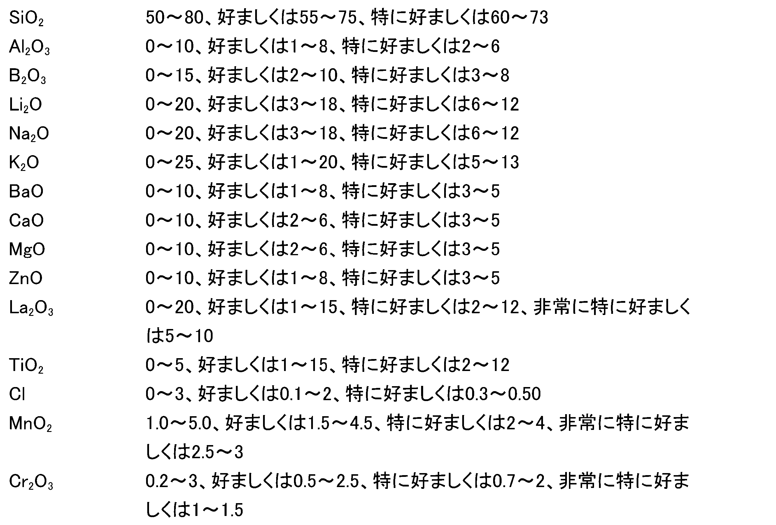
ΣNa2O+K2O+Li2O=5~30、好ましくは10~25、特に好ましくは15~20
である。有利には、ガラス組成は、以下の条件のうち少なくとも1つを満たす:
ΣMnO2+Cr2O3=2.7~8、好ましくは3~7、特に好ましくは3.5~5.5であり、かつ/または
MnO2/CrO3=1.5:1~12.5:1、好ましくは1.6:1~10:1、特に好ましくは1.7:1~7.5、非常に特に好ましくは1.9:1~4:1である。
According to a further embodiment, the colored glass has the following glass composition in weight %:
ΣNa 2 O+K 2 O+Li 2 O=5 to 30, preferably 10 to 25, particularly preferably 15 to 20
It is. Advantageously, the glass composition satisfies at least one of the following conditions:
ΣMnO 2 +Cr 2 O 3 =2.7 to 8, preferably 3 to 7, particularly preferably 3.5 to 5.5, and/or MnO 2 /CrO 3 =1.5:1 to 12.5 :1, preferably from 1.6:1 to 10:1, particularly preferably from 1.7:1 to 7.5, very particularly preferably from 1.9:1 to 4:1.
基材は、少なくとも0.5mmで最大で12mmの厚さを有する。有利な一実施形態によれば、基材の厚さは、0.5~6mmの範囲、有利には2mm~6mmの範囲、有利には2~4mmの範囲である。対応する基材の厚さにより、十分に高い強度が保証される。
The substrate has a thickness of at least 0.5 mm and at most 12 mm. According to one advantageous embodiment, the thickness of the substrate is in the range 0.5 to 6 mm, advantageously in the
基材は、パネル状でありかつ2つの面を有しており、これらの面を、以下では上面および下面と称する。ここで、上面とは、基材面のうち、基材がビューイングパネルの一部として使用されるときにビューイングパネルの動作前面を形成するものであると理解される。したがって、上面とは、基材面のうち、ビューイングパネルとして使用されるときに、見る人に面している方の面を形成するものである。下面とは、基材面のうち、コーティングされた基材が電子部品を覆うためにビューイングパネルとして使用されるときに動作背面を形成し、したがって電子部品に面した基材面を表すものであると理解される。ビューイングパネルは、両面のうち少なくとも一方に、金属および/または半金属の酸化物および/または窒化物および/または酸窒化物を含む少なくとも1つの層を有する。この層は有利には、コーティングまたはコーティングの一部として形成されている。好ましくは、この層状パネルは、少なくともカラーガラスの動作前面あるいは上面側にコーティングを有する。いくつかの実施形態において、本発明によるビューイングパネルは有利には、動作前面側のコーティングに加えて、いわゆる動作背面側にさらなるコーティングを有し、これは特に、反射防止コーティングおよび/または疎水性コーティングおよび/または撥油性コーティングおよび/または不凍性コーティングおよび/または防曇性コーティングおよび/または加熱可能なコーティングであり、特に反射防止コーティングおよび/または加熱可能なコーティングの機能を果たすコーティングである。 The substrate is panel-shaped and has two sides, which will be referred to below as the top and bottom sides. Here, the upper surface is understood to be that surface of the substrate which forms the operational front surface of the viewing panel when the substrate is used as part of the viewing panel. Therefore, the upper surface forms the surface of the base material that faces the viewer when used as a viewing panel. Bottom surface refers to the substrate surface that forms the active back surface when the coated substrate is used as a viewing panel to cover electronic components, and thus faces the electronic components. It is understood that there is. The viewing panel has on at least one of the two sides at least one layer comprising a metal and/or metalloid oxide and/or nitride and/or oxynitride. This layer is advantageously formed as a coating or as part of a coating. Preferably, the layered panel has a coating on at least the active front or top side of the colored glass. In some embodiments, the viewing panel according to the invention advantageously has, in addition to the coating on the active front side, a further coating on the so-called active rear side, which in particular includes an anti-reflective coating and/or a hydrophobic coating. coatings and/or oleophobic coatings and/or antifreeze coatings and/or antifog coatings and/or heatable coatings, in particular coatings that perform the function of antireflective coatings and/or heatable coatings.
コーティングは総じて、さらなる機能を有することができ、例えば、反射防止コーティングとして、傷防止コーティングとして、例えば色反射を伴う光学コーティングとして、耐候コーティングとして、イージークリーンコーティングとして、疎水性、撥油性、不凍性、防曇性および/または加熱可能なコーティングとして構成されていてよい。コーティングは、マルチレイヤーコーティングとして実施されていてよく、したがって複数の層を含むことができる。1つのコーティングが異なる機能を同時に果たすことが可能であり、例えば、反射防止効果を生み出すための光学コーティングがさらに、例えば防曇性または疎水性コーティングとして実施されている最上層を有する。 The coating as a whole can have further functions, for example as an anti-reflective coating, as an anti-scratch coating, as an optical coating, e.g. with color reflection, as a weather-resistant coating, as an easy-clean coating, hydrophobic, oleophobic, anti-freezing. It may be configured as a transparent, anti-fog and/or heatable coating. The coating may be implemented as a multilayer coating and therefore include multiple layers. It is possible for one coating to perform different functions at the same time, for example an optical coating for producing an anti-reflection effect, which further has a top layer which is implemented, for example, as an anti-fog or hydrophobic coating.
有利には、コーティングは、屈折率の異なる複数のレイヤーあるいは層から構成されたマルチレイヤー反射防止コーティングである。ここで、より高い屈折率を有するレイヤーと、より低い屈折率を有するレイヤーとが交互に存在する。低屈折率のレイヤーは、例えばケイ素酸化物を含む。さらなる一実施形態によれば、低屈折率のレイヤーは、ある割合のアルミニウムを含むケイ素酸化物をベースとする。有利な一実施形態によれば、低屈折率層は、以下の関係によるケイ素とアルミニウムとの物質量比を有する:
n(Al)/(n(Si)+n(Al))>0.02
ここで、n(Al)は、アルミニウムの物質量を表し、n(Si)は、ケイ素の物質量を表す。驚くべきことに、アルミニウムあるいはアルミニウム酸化物を混合することで、高屈折率のケイ素窒化物層と比較して軟質で低屈折率のケイ素酸化物層に、引掻きや摩耗に対する著しくより高い耐久性が付与されることが判明した。一実施形態によれば、比n(Al)/(n(Si)+n(Al))は0.05より大きく、有利には0.1より大きい。ここで、比n(Al)/(n(Si)+n(Al))が0.8未満、好ましくは0.5未満、特に好ましくは0.25未満であると有利であることが判明した。
Advantageously, the coating is a multilayer anti-reflection coating composed of several layers or layers with different refractive indices. Here, layers with a higher refractive index and layers with a lower refractive index alternate. The low refractive index layer includes, for example, silicon oxide. According to a further embodiment, the low refractive index layer is based on silicon oxide with a proportion of aluminum. According to one advantageous embodiment, the low refractive index layer has a material ratio of silicon to aluminum according to the following relationship:
n(Al)/(n(Si)+n(Al))>0.02
Here, n(Al) represents the amount of aluminum, and n(Si) represents the amount of silicon. Surprisingly, mixing aluminum or aluminum oxide gives the soft, low-index silicon oxide layer significantly greater resistance to scratching and abrasion compared to the high-index silicon nitride layer. It turned out that it was granted. According to one embodiment, the ratio n(Al)/(n(Si)+n(Al)) is greater than 0.05, advantageously greater than 0.1. It has proven advantageous here for the ratio n(Al)/(n(Si)+n(Al)) to be less than 0.8, preferably less than 0.5, particularly preferably less than 0.25.
より高い屈折率を有するレイヤーは有利には、ケイ化物、酸化物または窒化物を含む。高屈折率層には、窒化ケイ素が特に適している。 The layer with a higher refractive index advantageously comprises a silicide, oxide or nitride. Silicon nitride is particularly suitable for high refractive index layers.
反射防止コーティングのレイヤーの好ましい成膜方法としては、スパッタリング、特にマグネトロンスパッタリングが用いられる。この場合、低屈折率レイヤーのケイ素酸化物と高屈折率レイヤーの好ましく使用されるケイ素窒化物との双方を同じターゲットで製造できるため、反応性スパッタリングがここでは特に有利である。異なる層材料への切り替えは、プロセスパラメータの変更、特にプロセスガスの組成の変更を行うことで容易に可能である。 The preferred method of depositing the layer of anti-reflection coating is sputtering, especially magnetron sputtering. Reactive sputtering is particularly advantageous here, since both the silicon oxide of the low refractive index layer and the preferably used silicon nitride of the high refractive index layer can be produced in the same target. Switching to a different layer material is easily possible by changing the process parameters, in particular by changing the composition of the process gas.
コーティングは有利には、少なくとも125nmで最大で2500nm、好ましくは最大で1500nmの厚さを有する。驚くべきことに、対応する反射防止層は、比較的小さな層厚ですでに耐久性のある傷防止性を提供することが判明した。したがって、好ましい実施形態での反射防止コーティングは、合計で200nm~400nmの範囲の層厚を有する。特に好ましい層厚は、250nm~300nmの範囲である。比較のため、典型的な傷防止または硬質材料コーティングは一般に、1μmを超える厚さである。 The coating advantageously has a thickness of at least 125 nm and at most 2500 nm, preferably at most 1500 nm. Surprisingly, it has been found that the corresponding antireflection layers provide durable scratch protection even with relatively small layer thicknesses. The anti-reflection coating in a preferred embodiment therefore has a total layer thickness in the range of 200 nm to 400 nm. A particularly preferred layer thickness is in the range 250 nm to 300 nm. For comparison, typical anti-scratch or hard material coatings are generally greater than 1 μm thick.
例えばガラス組成やガラス厚などの基材の特性を選択し、またコーティングを選択することにより、ビューイングパネルを、それぞれの使用分野およびその要求に柔軟に適合させることができる。 By selecting the properties of the substrate, such as, for example, the glass composition and glass thickness, and also by selecting the coating, the viewing panel can be flexibly adapted to the respective field of use and its requirements.
一実施形態によれば、ビューイングパネルは、875nm~1600nmの範囲の少なくとも1つの波長において、最大で14%、好ましくは最大で12%、特に好ましくはまたはさらには最大で10%の分光反射率ρλを有する。ここで、波長λの反射率は、以下のように定義される:
ρλ=Pr/P0
ここで、Prは、反射力を表し、P0は、入射力を表す。
According to one embodiment, the viewing panel has a spectral reflectance of at most 14%, preferably at most 12%, particularly preferably or even at most 10%, in at least one wavelength in the range 875 nm to 1600 nm. ρ has λ . Here, the reflectance at wavelength λ is defined as follows:
ρ λ =P r /P 0
Here, P r represents the reflected power and P 0 represents the incident power.
代替的または付加的に、ビューイングパネルは、875nm~1600nmの範囲において、最大で14%、好ましくは最大で12%、特に好ましくは最大で10%の平均分光反射率ρmittelを有し、ここで、平均分光反射率ρmittelは、試験する波長範囲の個々の分光反射率ρλの算術平均値を表す。 Alternatively or additionally, the viewing panel has an average spectral reflectance ρ mittel of at most 14%, preferably at most 12%, particularly preferably at most 10% in the range 875 nm to 1600 nm, wherein where the average spectral reflectance ρ mittel represents the arithmetic mean value of the individual spectral reflectances ρ λ in the tested wavelength range.
ここで、反射率は有利には、0°~60°の測定角度、特に好ましくは0°~70°の測定角度で求められる。したがって、有利な一構成によれば、ビューイングパネルは、広い角度範囲にわたって低い反射性を示す。 Here, the reflectance is advantageously determined at a measuring angle of 0° to 60°, particularly preferably at a measuring angle of 0° to 70°. Therefore, according to one advantageous configuration, the viewing panel exhibits low reflectivity over a wide angular range.
代替的または付加的に、875nm~1600nmの波長範囲の少なくとも1つの波長の分光反射率ρλは、未コーティングの基材の対応する反射率よりも、少なくとも2%ポイント、好ましくは少なくとも4%ポイント、特に好ましくは少なくとも6%ポイント低い。 Alternatively or additionally, the spectral reflectance ρ λ for at least one wavelength in the wavelength range 875 nm to 1600 nm is at least 2 percentage points, preferably at least 4 percentage points, greater than the corresponding reflectance of the uncoated substrate. , particularly preferably at least 6 percentage points lower.
代替的または付加的に、1530nm~1570nm、好ましくは1540nm~1560nmの波長範囲における0°~45°の範囲の測定角度でのビューイングパネルの表面の平均分光反射率ρmittelは、最大で4%、好ましくは最大で2%、特に好ましくは最大で1%である。一実施形態によれば、60°の測定角度でのこの波長範囲における平均分光反射率ρmittelは、最大で7%、好ましくは最大で5%、特に好ましくは最大で4%、非常に特に好ましくは最大で3%である。
Alternatively or additionally, the average spectral reflectance ρ mittel of the surface of the viewing panel at measurement angles in the
一実施形態は、880nm~930nm、好ましくは890nm~920nmの波長範囲における0°~45°の範囲の測定角度でのビューイングパネルの表面の平均分光反射率ρmittelが、最大で4%、好ましくは最大で3%、特に好ましくは最大で2%、非常に特に好ましくは最大で1%であることを提供する。一実施形態によれば、60°の測定角度でのこの波長範囲における平均分光反射率ρmittelは、最大で7%、好ましくは最大で5%、特に好ましくは最大で4%、非常に特に好ましくは最大で3%である。
One embodiment provides that the average spectral reflectance ρ mittel of the surface of the viewing panel at measurement angles in the
さらなる一実施形態によれば、1300nm~1340nm、好ましくは1310nm~1330nmの波長範囲における0°~45°の範囲の測定角度でのビューイングパネルの表面の平均分光反射率ρmittelは、最大で4%、好ましくは最大で2%、特に好ましくは最大で1%である。一実施形態によれば、60°の測定角度でのこの波長範囲における平均分光反射率ρmittelは、最大で7%、好ましくは最大で5%、特に好ましくは最大で4%、非常に特に好ましくは最大で3%である。
According to a further embodiment, the average spectral reflectance ρ mittel of the surface of the viewing panel at measurement angles in the
ビューイングパネルは、平均透過率Tavgを有し、ここで、平均透過率Tavgとは、指定された波長範囲内の個々の波長の透過率の算術平均値である。一実施形態によれば、1530nm~1570nm、好ましくは1540~1560nmの波長範囲における平均透過率Tavgは、0°の測定角度で、少なくとも90%、少なくとも91%、好ましくは少なくとも93%、特に好ましくは少なくとも96%である。代替的または付加的に、45°の測定角度でのこの波長範囲における透過率Tavgは、少なくとも89%、好ましくは少なくとも90%、少なくとも92%、特に好ましくは少なくとも95%である。一実施形態によれば、ビューイングパネルは、60°の測定角度で前記波長範囲において、少なくとも87%、好ましくは少なくとも88%、特に好ましくは少なくとも90%、非常に特に好ましくは少なくとも93%の透過率Tavgを有する。ビューイングパネルは、上記波長範囲においてさらに、70°の測定角度で少なくとも84%、好ましくは少なくとも85%、特に好ましくは少なくとも87%、非常に特に好ましくは少なくとも90%の透過率Tavgを有することができる。 The viewing panel has an average transmittance T avg , where the average transmittance T avg is the arithmetic mean of the transmittances of individual wavelengths within a specified wavelength range. According to one embodiment, the average transmission T avg in the wavelength range from 1530 nm to 1570 nm, preferably from 1540 to 1560 nm, at a measurement angle of 0° is at least 90%, at least 91%, preferably at least 93%, particularly preferably is at least 96%. Alternatively or additionally, the transmission T avg in this wavelength range at a measurement angle of 45° is at least 89%, preferably at least 90%, at least 92%, particularly preferably at least 95%. According to one embodiment, the viewing panel has a transmission of at least 87%, preferably at least 88%, particularly preferably at least 90%, very particularly preferably at least 93% in said wavelength range at a measuring angle of 60°. has a rate T avg . The viewing panel furthermore has a transmission T avg of at least 84%, preferably at least 85%, particularly preferably at least 87%, very particularly preferably at least 90% in the wavelength range mentioned above at a measuring angle of 70°. I can do it.
1530nm~1570nmの範囲で高い透過率を示すため、ビューイングパネルは特に、前記波長範囲、特に1550nmに中心波長を有するレーザと組み合わせて使用するのに適している。この場合、干渉光学コーティングを施しているにもかかわらず、透過率は角度にほとんど依存しない。 Due to its high transmission in the range 1530 nm to 1570 nm, the viewing panel is particularly suitable for use in combination with lasers having a center wavelength in this wavelength range, in particular 1550 nm. In this case, despite the interference optical coating, the transmittance is almost independent of angle.
代替的または付加的に、ビューイングパネルは、890nm~930nm、好ましくは890~920nmの波長範囲において、0°の測定角度で、少なくとも91%、好ましくは少なくとも93%、特に好ましくは少なくとも96%の平均透過率Tavgを有する。代替的または付加的に、45°の測定角度でのこの波長範囲における透過率Tavgは、少なくとも89%、好ましくは少なくとも90%、特に好ましくは少なくとも95%である。一実施形態によれば、ビューイングパネルは、60°の測定角度で前記波長範囲において、少なくとも87%、好ましくは少なくとも88%、特に好ましくは少なくとも90%、非常に特に好ましくは少なくとも93%の透過率Tavgを有する。ビューイングパネルは、上記波長範囲においてさらに、70°の測定角度で少なくとも84%、好ましくは少なくとも85%、特に好ましくは少なくとも87%、非常に特に好ましくは少なくとも90%の透過率Tavgを有することができる。 Alternatively or additionally, the viewing panel is provided with at least 91%, preferably at least 93%, particularly preferably at least 96% of It has an average transmittance T avg . Alternatively or additionally, the transmission T avg in this wavelength range at a measuring angle of 45° is at least 89%, preferably at least 90%, particularly preferably at least 95%. According to one embodiment, the viewing panel has a transmission of at least 87%, preferably at least 88%, particularly preferably at least 90%, very particularly preferably at least 93% in said wavelength range at a measuring angle of 60°. has a rate T avg . The viewing panel furthermore has a transmission T avg of at least 84%, preferably at least 85%, particularly preferably at least 87%, very particularly preferably at least 90% in the wavelength range mentioned above at a measuring angle of 70°. I can do it.
890nm~930nmの範囲で高い透過率を示すため、ビューイングパネルは特に、前記波長範囲、特に905nmに中心波長を有するレーザと組み合わせて使用するのに適している。この場合にも、透過率は角度にほとんど依存しない。
Due to its high transmission in the
代替的または付加的に、ビューイングパネルは、1300nm~1340nm、好ましくは1310~1330nmの波長範囲において、0°の測定角度で、少なくとも91%、好ましくは少なくとも93%、特に好ましくは少なくとも96%の平均透過率Tavgを有する。代替的または付加的に、45°の測定角度でのこの波長範囲における透過率Tavgは、少なくとも89%、好ましくは少なくとも90%、特に好ましくは少なくとも95%である。一実施形態によれば、ビューイングパネルは、60°の測定角度で前記波長範囲において、少なくとも87%、好ましくは少なくとも88%、特に好ましくは少なくとも90%、非常に特に好ましくは少なくとも93%の透過率Tavgを有する。ビューイングパネルは、上記波長範囲においてさらに、70°の測定角度で少なくとも84%、好ましくは少なくとも85%、特に好ましくは少なくとも87%、非常に特に好ましくは少なくとも90%の透過率Tavgを有することができる。
Alternatively or additionally, the viewing panel has a wavelength range of at least 91%, preferably at least 93%, particularly preferably at least 96% at a measuring angle of 0° in the
1300nm~1340nmの範囲で高い透過率を示すため、ビューイングパネルは特に、前記波長範囲、特に1310nmおよび/または1320nmに中心波長を有するレーザと組み合わせて使用するのに適している。この場合にも、透過率は角度にほとんど依存しない。
Due to its high transmission in the
ビューイングパネルまたは干渉光学コーティングが、偏光分離を示さないかまたはわずかにしか示さないように形成されていると有利であることが判明した。したがって、一実施形態では、30~60°の少なくとも1つの測定角度での、875nm~1600nm、好ましくは880nm~1600nmの範囲の少なくとも1つの波長におけるビューイングパネルのs偏光の分光透過率とp偏光の分光透過率との差ΔTs-p,polが、3%ポイント未満、好ましくは2%ポイント未満、特に好ましくは1%ポイント未満であることが提供される。一実施形態では、30°~60°の範囲の少なくとも1つの測定角度での、890nm~910nm、1310nm~1330nmおよび/または1540nm~1560nmの波長範囲のうち少なくとも1つにおけるビューイングパネルのs偏光の分光透過率とp偏光の分光透過率との差ΔTs-p,polが、3%ポイント未満、好ましくは2%ポイント未満、特に好ましくは1%ポイント未満であることが提供される。
It has proven advantageous if the viewing panel or the interference optical coating is designed in such a way that it exhibits no or only a slight polarization separation. Thus, in one embodiment, the spectral transmission of s-polarized light and p-polarized light of the viewing panel at at least one wavelength in the range 875 nm to 1600 nm, preferably 880 nm to 1600 nm, at at least one measurement angle of 30 to 60°. It is provided that the difference ΔT sp,pol from the spectral transmittance of is less than 3 percentage points, preferably less than 2 percentage points, particularly preferably less than 1 percentage point. In one embodiment, the s-polarization of the viewing panel in at least one of the wavelength ranges 890 nm to 910 nm, 1310 nm to 1330 nm and/or 1540 nm to 1560 nm at at least one measurement angle in the
有利に、ガラス質基材は、-30℃~70℃の範囲の温度で3×10⁻⁶/K~14×10-6/Kの範囲の熱膨張係数を有するガラスを含む。好ましくは、熱膨張係数は、5×10-6/K~12×10-6/Kの範囲、特に好ましくは7×10-6/K~11×10-6/Kの範囲である。指定された値は、ISO 7991に準拠した公称平均線熱膨張係数であり、静的測定で求められる。その熱膨張係数ゆえ、ガラスは高い温度変化耐久性を有する。
Advantageously, the vitreous substrate comprises a glass having a coefficient of thermal expansion in the
上記のような構成は、ビューイングパネルで保護された電子部品の動作中に大きな温度変動が起こる場合に特に有利となり得る。なぜならば、この場合、基材の熱膨張係数とコーティングの熱膨張係数とが互いに適合しており、コーティングと基材との間および/またはコーティング内で剥離を引き起こすほど大きな機械的応力が発生し得ないためである。したがって、コーティングは、基材との良好な密着性を示し、このことは、ビューイングパネルの機械的耐久性に有利な効果をもたらす。 A configuration as described above may be particularly advantageous when large temperature fluctuations occur during operation of the electronic components protected by the viewing panel. This is because in this case the coefficients of thermal expansion of the substrate and the coating are matched to each other and mechanical stresses large enough to cause delamination between the coating and the substrate and/or within the coating do not occur. This is because you don't get it. The coating therefore exhibits good adhesion with the substrate, which has a beneficial effect on the mechanical durability of the viewing panel.
特に、層複合体、すなわち基材とコーティングとの複合体、および層複合体、すなわちコーティング内の個々の部分層の良好な機械的耐久性を、ベイヤー試験により実証することもできる。よって、変更された試験規格ASTM F735-11(変更されたベイヤー試験、8000サイクル、SiO2の代わりに2kgの溶融アルミナ(Al2O3)を装填;充填高さは2cm)に準拠してベイヤー試験を実施した後に、ビューイングパネルは、ベイヤー試験前に測定されたビューイングパネルのヘイズ値と比較して、最大で4%、好ましくは最大で2%、特に好ましくは最大で1%増加したヘイズ値を有する。ヘイズ値は、ASTM D1003-95に準拠して求められ、曇り具合の指標である。ここで、例えば傷などの表面欠陥は、ヘイズ値の増加につながる。 In particular, the good mechanical durability of the layer composite, ie the composite of substrate and coating, and of the layer composite, ie the individual partial layers within the coating, can also be demonstrated by the Bayer test. Therefore, Bayer was tested according to the modified test standard ASTM F735-11 (modified Bayer test, 8000 cycles, loading 2 kg of fused alumina (Al 2 O 3 ) instead of SiO 2 ; filling height is 2 cm). After carrying out the test, the viewing panel has an increase of at most 4%, preferably at most 2%, particularly preferably at most 1% compared to the haze value of the viewing panel measured before the Bayer test. Has a haze value. The haze value is determined in accordance with ASTM D1003-95 and is an index of cloudiness. Here, surface defects such as scratches, for example, lead to an increase in the haze value.
ビューイングパネルは、0°~30°の角度範囲で、明所視反射色、すなわちCIE 1931に準拠した視感度曲線で重み付けされた反射率を有し、ここで、色座標xは、0.20~0.4の範囲であり、yは、0.20~0.4の範囲であり、有利にはxは、0.25~0.33の範囲であり、yは、0.23~0.33の範囲である。これにより、ビューイングパネルは、見る人に黒色に見える。好ましい一実施形態によれば、ビューイングパネルは、0°~45°、またはさらには0°~60°の範囲の角度で上記の色座標を有する。
The viewing panel has a photopic reflection color, i.e. a reflectance weighted with a visibility curve according to CIE 1931, in the
実施形態によるビューイングパネルは特に、カバーパネルとして、特にレーザのカバーパネルとして、例えばLIDARシステムの一部としてのレーザのカバーパネルとして、または撮像システムのカバーパネルとして、特に環境の3D測定用もしくは速度測定用機器の撮像システムのカバーパネルとして使用することができる。 The viewing panel according to embodiments can be used in particular as a cover panel, in particular as a cover panel of a laser, e.g. as part of a LIDAR system, or as a cover panel of an imaging system, in particular for 3D measurements of the environment or speed. It can be used as a cover panel for the imaging system of measurement equipment.
図面の説明
以下、図1~図15を参照して、本発明を実施形態例につきより詳細に説明する。
DESCRIPTION OF THE DRAWINGS The present invention will now be described in more detail by way of example embodiments with reference to FIGS. 1 to 15.
図1は、一実施形態によるビューイングパネル1の概略図による断面を示す。ビューイングパネル1は、パネル状のガラス質基材2としてのカラーガラスと、基材2の表面4上に成膜されたコーティング30とを備えている。図1に示す例では、コーティング30は、4層で形成されている。コーティングは、少なくとも1つの金属および/または半金属の酸化物、窒化物および/または酸窒化物を含む。コーティング30は、低屈折率層34,32と、より高い屈折率を有する層31,33とを含む。ここで、層33は、材料SiN、SixOyNz、SixAlOyNz、SiXN:H、SixNyOz:Hおよび/またはAlxOyNzのうちの少なくとも1つを含む。
FIG. 1 shows a schematic cross-section of a
図1に示す実施形態は、電子発光部品のカバーに使用される。放出された電磁放射線は、矢印7で表され、層状パネル1を通過する。基材2の側面のうち、部品に面した方(図1では参照符号5を付与)は、下面または動作背面とも称される。これに応じて、基材の他方の側面4は、上面または動作前面とも称される。図1に示す実施形態では、コーティング30は、基材2の上面4に施されている。
The embodiment shown in FIG. 1 is used for covering electroluminescent components. The emitted electromagnetic radiation, represented by the
コーティング30の層厚は、125nm~2500nmの範囲、有利には125nm~1500nmの範囲である。ここで、最後から2番目の層33は、可能な限り大きな層厚を有し、有利には少なくとも100nm、好ましくは少なくとも150nm、特に好ましくは少なくとも200nmの層厚を有する。ここで、硬質材料層33の比較的大きな層厚が、コーティング30およびビューイングパネル1の双方の耐傷性および機械的耐久性に大きく寄与している。最上層34は好ましくは、可能な限り小さい層厚を有する。一実施形態によれば、層34の層厚は、300nm未満、またはさらには100nm未満である。
The layer thickness of the
ビューイングパネル1は、400~700nmの波長範囲において、15%未満、好ましくは10%未満の平均透過率τavg,400nm-700nmを有し、ここで、τavg,400nm-700nmは、

代替的または付加的に、ビューイングパネル1は、各波長において、10%未満、好ましくは5%未満、特に好ましくは1%未満の分光透過率を有する。
Alternatively or additionally, the
図2は、さらなる一実施形態によるビューイングパネルの概略図を示す。ここで、ビューイングパネルは、4つの各層31,32,33,34を有するコーティング30に加えて、さらなる層8を備えている。ここで、層8は、干渉光学コーティング8の層ではなく、その組成および機能の双方に関してコーティング30と異なることができる。図2に示す実施形態例では、水との接触角が105°を超える、いわゆる「イージークリーン」層である。
FIG. 2 shows a schematic diagram of a viewing panel according to a further embodiment. Here, the viewing panel comprises, in addition to the
図3は、ビューイングパネル1のさらなる一実施形態を示す。ここで、基材2は、動作前面4上の各層31,32,33,34を有する干渉光学コーティング30に加えて、さらなるコーティング40を有する。コーティング40は、干渉光学層41,42,43と、任意に導電層50とを含む。層41,42,43は、反射防止コーティングを形成しており、そのようにして放射光7の後方散乱を低減する。層50は、10~150Ω/sqの範囲のシート抵抗を有し、電源に接続可能な接点(図示せず)を有する。したがって、層50は、加熱層の機能を果たすことができる。
FIG. 3 shows a further embodiment of the
コーティング40は、カラーガラス2の下面5に施されている。コーティング40は、例えば、カラーガラス2を通過する前の放射光7の反射を低減する機能を果たすことができる。
The
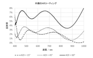
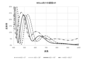
図4は、異なる反射角における、総層厚約530nmの(SiO2およびTa2O5の交互の)7層を含むコーティングを含む実施形態例の反射スペクトルを示す。本実施形態例は、905nmの範囲の発光波長を有するレーザとの併用に向けて最適化されている。したがって、この波長範囲での反射スペクトルは、特に低反射率を示す。ここで、この波長範囲では、60°の高反射角でも反射率はわずか4%である。 FIG. 4 shows the reflection spectra of an example embodiment comprising a coating comprising 7 layers (alternating SiO 2 and Ta 2 O 5 ) with a total layer thickness of about 530 nm at different reflection angles. This example embodiment is optimized for use with a laser having an emission wavelength in the 905 nm range. Therefore, the reflection spectrum in this wavelength range shows particularly low reflectance. Here, in this wavelength range, even at a high reflection angle of 60°, the reflectance is only 4%.
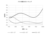
図5には、第2の実施形態例の反射スペクトルが示されている。本実施形態例では、ビューイングパネルは、動作背面上にさらなるコーティングを有する。このコーティングは、干渉光学反射防止コーティングとITO層とを含む。こうして、第2の実施形態例は、図3に示すような構造体を有する。ここでも、905nm付近の波長範囲の反射スペクトルは、特に低い反射率を示す。ここで、この波長範囲では、60°の高反射角でも反射率は4%未満である。 FIG. 5 shows the reflection spectrum of the second embodiment. In this example embodiment, the viewing panel has an additional coating on the active back surface. This coating includes an interferometric optical anti-reflection coating and an ITO layer. Thus, the second embodiment has a structure as shown in FIG. Again, the reflection spectrum in the wavelength range around 905 nm shows a particularly low reflectance. Here, in this wavelength range, the reflectance is less than 4% even at a high reflection angle of 60°.
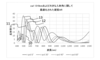
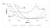
図6および図7は、異なる反射角での第2の実施形態例の反射スペクトルを示す。ここで、曲線10は、反射角6°での反射曲線に相当し、曲線11は、反射角30°での反射曲線に相当し、曲線12は、反射角40°での反射曲線に相当し、曲線13は、反射角60°での反射曲線に相当する。
6 and 7 show the reflection spectra of the second example embodiment at different reflection angles. Here,
ビューイングパネルは、ビューイングパネルの動作前面に総層厚約1050nmの4層の反射防止コーティング(SixAlyNz、SixAlyOz、SixAlyNz、SixAlyOz)を備えている。ビューイングパネルは、1310nmの発光波長を有するレーザとの併用に向けて、その透過率および反射率の点で最適化されている。そのため、ビューイングパネルは、1290~1330nmの範囲の波長について、試験したすべての反射角で特に低い反射率値を示す。以下の表1は、1290nm~1300nmの波長範囲で平均をとった平均反射率を、異なる反射角r-polについて示したものである。 The viewing panel has a four-layer anti-reflection coating (Six Al y N z , Si x Al y O z , Si x Al y N z , Si x Al y oz ). The viewing panel has been optimized in terms of its transmittance and reflectance for use with a laser having an emission wavelength of 1310 nm. The viewing panel therefore exhibits particularly low reflectance values at all tested reflection angles for wavelengths in the range 1290-1330 nm. Table 1 below shows the average reflectance averaged over the wavelength range 1290 nm to 1300 nm for different reflection angles r-pol.

表1から、45°までの角度での反射率は、角度にほとんど依存しないことがわかる。60°の大きな角度でも、非常に低い反射率値を得ることができる。 From Table 1 it can be seen that the reflectance at angles up to 45° is almost independent of angle. Even at angles as large as 60°, very low reflectance values can be obtained.
可視スペクトル範囲では、図6に示すすべての反射スペクトル10,11,12,13は、複数の反射極大を示す。コーティングのそれぞれの設計に応じて、これらの反射極大は、異なる強度および/または異なる波長範囲で発生し、したがって、見る人が感じるビューイングパネルの色の印象に影響を与える。
In the visible spectral range, all
図8は、異なる反射角での第3の実施形態例の反射スペクトルを示す。第3の実施形態例では、カチオン%単位で以下のガラス組成を有するカラーガラスを基材ガラスとして用いた:
反射防止コーティングは、4層(Si3N4、SiAlNxOy、Si3N4、SiAlNxOy、総層厚約620nm)を有し、これは、図1による実施形態例に対応する。
FIG. 8 shows the reflection spectra of the third example embodiment at different reflection angles. In the third embodiment, a colored glass having the following glass composition in cation % was used as the base glass:
The antireflection coating has four layers (Si 3 N 4 , SiAlN x O y , Si 3 N 4 , SiAlN x O y , total layer thickness of about 620 nm), which corresponds to the example embodiment according to FIG. .
第3の実施形態例は、特に890nm~920nmの範囲の波長の光源用のビューイングパネルとして適している。図8から、ここで該当する890nm~920nmの波長範囲では、測定角度0°、30°および45°において反射率がほぼ同じであることが明らかである。よって、この角度範囲では、反射率は角度にほとんど依存しない。測定角度が60.5°と大きくても、対応する波長範囲での反射率は、5%以下である。
The third example embodiment is particularly suitable as a viewing panel for light sources with wavelengths in the
図9は、ベイヤー試験の実施前後の第3の実施形態例の反射スペクトルを示す。ベイヤー試験により、表面の機械的耐久性、特にその耐傷性を評価することができる。図9から、ベイヤー試験の実施後の反射率が、ベイヤー試験前の反射率に比べて最小限度しか増加していないことが明らかである。例えば、ベイヤー試験後の反射スペクトルは、測定角度60°では1%以下の反射率の増加を示し、さらに、測定角度0°および45°では、反射率の増加は0.5%未満である。このように、ビューイングパネルは、極めて高い耐傷性を示している。 FIG. 9 shows the reflection spectra of the third embodiment before and after conducting the Bayer test. The Beyer test makes it possible to evaluate the mechanical durability of a surface, in particular its scratch resistance. From FIG. 9 it is clear that the reflectance after carrying out the Bayer test is only minimally increased compared to the reflectance before the Bayer test. For example, the reflection spectra after the Bayer test show an increase in reflectance of less than 1% at a measurement angle of 60°, and an increase in reflectance of less than 0.5% at measurement angles of 0° and 45°. The viewing panel thus exhibits extremely high scratch resistance.
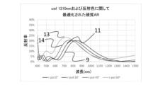
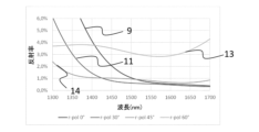
図10および図11に、第4の実施形態例の反射スペクトルを示す。ここでは、測定角度0°(曲線9)、30°(曲線11)、45°(曲線14)および60°(曲線13)で反射率を測定した。第4の実施形態例は、6層の干渉光学コーティングを有し、各層は、以下の組成を有する:SixAlyNz、SixAlyOz、SixAlyNz、SixAlyOz、SixAlyNz、SixAlyOz。総層厚は、約570nmである。ここで、コーティングは、1290nm~1330nmの波長範囲での可能な限り低い反射率、および約380~780nmの可視波長範囲での低減された反射率に関して、最適化されている。実施形態例1~実施形態例3と同様に、本実施形態例も、ほぼ角度に依存しない反射率を示している。表2に、1290nm~1330nmの波長範囲の平均反射率値を示す。 FIGS. 10 and 11 show reflection spectra of the fourth embodiment. Here, the reflectance was measured at measurement angles of 0° (curve 9), 30° (curve 11), 45° (curve 14) and 60° (curve 13). A fourth example embodiment has a six layer interference optical coating, each layer having the following composition: Si x Al y N z , Si x Al y O z , Si x Al y N z , Si x Al y O z , Si x Al y N z , Si x Al y O z . The total layer thickness is approximately 570 nm. Here, the coating is optimized for the lowest possible reflectance in the wavelength range of 1290 nm to 1330 nm and reduced reflectance in the visible wavelength range of about 380 to 780 nm. Similar to Embodiments 1 to 3, this embodiment also exhibits reflectance that is substantially independent of angle. Table 2 shows the average reflectance values in the wavelength range of 1290 nm to 1330 nm.

第6の実施形態例は、1530nm~1570nmの範囲での最適な光学特性と、青みがかった反射色とに関して設計されたものである。 The sixth embodiment is designed for optimal optical properties in the 1530 nm to 1570 nm range and a bluish reflective color.
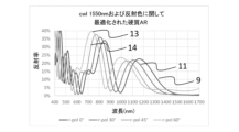
図12および図13は、異なる測定角度での反射スペクトルを示す。各層Si3N4、SixAlyOz、Si3N4、SixAlyOz、Si3N4、SixAlyOzを含む総層厚約1124nmの6層の干渉光学コーティングを用いた本実施形態例も、45°までの大きさの角度で、該当する波長範囲においてほぼ一定の反射挙動を示している。60°の角度でも、該当する1530~1570nmの波長範囲における平均反射率は、3%以下である。表3は、異なる角度での平均反射率値Ravgを示している。 12 and 13 show the reflection spectra at different measurement angles. Six-layer interference optical coating with a total layer thickness of about 1124 nm, each layer containing Si 3 N 4 , Si x Al y O z , Si 3 N 4 , Si x Al y O z , Si 3 N 4 , Si x Al y O z The present embodiment using the same also shows a substantially constant reflection behavior in the relevant wavelength range at angles of magnitude up to 45°. Even at an angle of 60°, the average reflectance in the corresponding wavelength range of 1530 to 1570 nm is 3% or less. Table 3 shows the average reflectance values R avg at different angles.

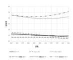
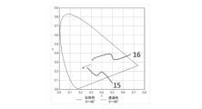
図14は、CIE 1931のx-y線図による0°~60°の範囲での反射色のシフト15、および0°~60°の範囲での透過色のシフト16を示す。図15から、本実施形態例のビューイングパネルが、青みがかった反射色を示すことが明らかである。
FIG. 14 shows the
1 ビューイングパネル
2 カラーガラス
4 動作前面
5 動作背面
7 レーザ光
8 コーティング
9 0°での反射スペクトル
10 6°での反射スペクトル
11 30°での反射スペクトル
12 40°での反射スペクトル
13 60°での反射スペクトル
14 45°での反射スペクトル
15 0°~60°での反射色のシフト
16 0°~60°での透過色のシフト
30 干渉光学コーティング
31,32,33,34 コーティング30の各層
40 第2の干渉光学コーティング
41,42,43 コーティング40の各層
50 ITOコーティング
1
Claims (11)
前記ビューイングパネルは、400~700nmの波長範囲において、15%未満、好ましくは10%未満の平均透過率τavg,400nm-700nmを有し、ここで、τavg,400nm-700nmは、

各波長において、15%未満、好ましくは10%未満、好ましくは5%未満、特に好ましくは1%未満の分光透過率を有し、
前記ビューイングパネルは、875nm~1600nmの波長範囲において、少なくとも1つの波長において、少なくとも75%、好ましくは少なくとも80%の透過率を有する、ビューイングパネル。 A viewing panel comprising a panel-shaped vitreous substrate and a coating disposed on at least one surface of the substrate, the viewing panel comprising:
Said viewing panel has an average transmittance τ avg,400nm-700nm of less than 15%, preferably less than 10% in the wavelength range of 400-700nm, where τ avg,400nm-700nm is
A viewing panel, wherein said viewing panel has a transmittance of at least 75%, preferably at least 80%, in at least one wavelength in the wavelength range of 875 nm to 1600 nm.
かつ/または
有利には0°~60°、好ましくは0~70°の測定角度で求められた、875nm~1600nmの範囲の少なくとも1つの波長における前記ビューイングパネルの前記分光反射率ρλが、前記ガラス質基材の(未コーティングの)表面の前記分光反射率よりも、少なくとも2%ポイント、好ましくは少なくとも4%ポイント、好ましくは少なくとも6%ポイント低く、
かつ/または
1530nm~1570nm、好ましくは1540nm~1560nmおよび/または880nm~930nm、好ましくは890nm~920nmおよび/または1300nm~1340nm、好ましくは1310~1330の波長範囲における前記ビューイングパネルの表面の平均分光反射率ρmittelが、0°~45°の測定角度では最大で4%、好ましくは最大で2%、特に好ましくは最大で1%であり、かつ/または60°の測定角度で測定した場合には最大で7%、好ましくは最大で5%、最大で4%である、請求項1から5までのいずれか1項記載のビューイングパネル。 The spectral reflectance ρ λ in at least one wavelength in the range 875 nm to 1600 nm, determined advantageously at a measuring angle of 0° to 60°, particularly preferably 0° to 70°, is at most 14%, preferably at most 12%, particularly preferably at most 10%,
and/or the spectral reflectance ρ λ of the viewing panel at at least one wavelength in the range 875 nm to 1600 nm, advantageously determined at a measurement angle of 0° to 60°, preferably 0 to 70°, at least 2% points, preferably at least 4% points, preferably at least 6% points lower than the spectral reflectance of the (uncoated) surface of the glassy substrate;
and/or the average spectral reflection of the surface of said viewing panel in the wavelength range of 1530 nm to 1570 nm, preferably 1540 nm to 1560 nm and/or 880 nm to 930 nm, preferably 890 nm to 920 nm and/or 1300 nm to 1340 nm, preferably 1310 to 1330 nm. If the rate ρ mittel is at most 4%, preferably at most 2%, particularly preferably at most 1% for measuring angles of 0° to 45° and/or when measured at a measuring angle of 60° Viewing panel according to any one of claims 1 to 5, characterized in that it is at most 7%, preferably at most 5%, at most 4%.
かつ/または
30~60°の少なくとも1つの測定角度での、875nm~1600nm、好ましくは880nm~1600nmの範囲の少なくとも1つの波長における前記ビューイングパネルのs偏光の前記分光透過率とp偏光の前記分光透過率との差ΔTs-p,polが、3%ポイント未満、好ましくは2%ポイント未満、特に好ましくは1%ポイント未満である、請求項1から6までのいずれか1項記載のビューイングパネル。 The average transmittance T avg in the wavelength range of 1530 nm to 1570 nm, preferably 1540 nm to 1560 nm and/or 880 nm to 930 nm, preferably 890 nm to 920 nm and/or 1300 nm to 1340 nm, preferably 1310 to 1330, is at a measurement angle of 0° at least 90%, preferably at least 91%, particularly preferably at least 93%, even more preferably at least 96%, and/or at least 89%, preferably at least 90%, particularly preferably at least 96% at a measuring angle of 45°. 92%, more preferably at least 95%, and/or at a measuring angle of 60° at least 87%, preferably at least 88%, preferably at least 90%, particularly preferably at least 93%, and/or at least 70%. at least 84%, preferably at least 85%, preferably at least 87%, more preferably 90% at a measuring angle of °;
and/or said spectral transmittance of said viewing panel for s-polarized light and said for p-polarized light at at least one wavelength in the range from 875 nm to 1600 nm, preferably from 880 nm to 1600 nm, at at least one measurement angle of 30 to 60°. 7. The view according to claim 1, wherein the difference ΔT sp,pol from the spectral transmittance is less than 3% points, preferably less than 2% points, particularly preferably less than 1% points. ing panel.
Applications Claiming Priority (2)
| Application Number | Priority Date | Filing Date | Title |
|---|---|---|---|
| DE102022121125.8 | 2022-08-22 | ||
| DE102022121125.8A DE102022121125A1 (en) | 2022-08-22 | 2022-08-22 | Visor and its use |
Publications (1)
| Publication Number | Publication Date |
|---|---|
| JP2024029767A true JP2024029767A (en) | 2024-03-06 |
Family
ID=89808836
Family Applications (1)
| Application Number | Title | Priority Date | Filing Date |
|---|---|---|---|
| JP2023133979A Pending JP2024029767A (en) | 2022-08-22 | 2023-08-21 | Viewing panel and uses thereof |
Country Status (4)
| Country | Link |
|---|---|
| US (1) | US20240069247A1 (en) |
| JP (1) | JP2024029767A (en) |
| CN (1) | CN117602848A (en) |
| DE (1) | DE102022121125A1 (en) |
Family Cites Families (5)
| Publication number | Priority date | Publication date | Assignee | Title |
|---|---|---|---|---|
| DE102014114315A1 (en) * | 2013-10-07 | 2015-04-16 | Schott Ag | Night vision compatible LED lighting device |
| CN104155712B (en) * | 2014-08-15 | 2017-01-25 | 中国科学院上海技术物理研究所 | Near-infrared filter for optical communication |
| DE102017118451A1 (en) * | 2016-12-23 | 2018-06-28 | Schott Ag | Hob with display |
| KR102908593B1 (en) * | 2019-08-23 | 2026-01-08 | 현대자동차주식회사 | Optic filter integrated with lidar window |
| EP4215499A1 (en) * | 2022-01-19 | 2023-07-26 | Schott Ag | Optical component and glass composition as well as use thereof |
-
2022
- 2022-08-22 DE DE102022121125.8A patent/DE102022121125A1/en active Pending
-
2023
- 2023-08-21 JP JP2023133979A patent/JP2024029767A/en active Pending
- 2023-08-22 CN CN202311060330.5A patent/CN117602848A/en active Pending
- 2023-08-22 US US18/453,730 patent/US20240069247A1/en active Pending
Also Published As
| Publication number | Publication date |
|---|---|
| CN117602848A (en) | 2024-02-27 |
| DE102022121125A1 (en) | 2024-02-22 |
| US20240069247A1 (en) | 2024-02-29 |
Similar Documents
| Publication | Publication Date | Title |
|---|---|---|
| KR101872906B1 (en) | Optical product and plastic eyeglass lens | |
| US6165598A (en) | Color suppressed anti-reflective glass | |
| US6124026A (en) | Anti-reflective, reduced visible light transmitting coated glass article | |
| JP5163742B2 (en) | Low reflection glass and protective plate for display | |
| EP0662458B1 (en) | Coatings on glass | |
| KR102500410B1 (en) | Anti-reflective coated glass article | |
| KR20210069700A (en) | Projection device for head-up display (HUD) with p-polarized radiation | |
| CN110650844A (en) | Laminated glass panel with conductive coating and anti-reflection coating | |
| KR101926960B1 (en) | Low Reflection Coating Glass | |
| AU2018201510A1 (en) | Mirror-coated lens | |
| US20230043367A1 (en) | Head up display system | |
| JPH05246737A (en) | Rearview mirror for vehicles, especially automobiles | |
| US7055954B2 (en) | Scratch masking coatings for optical substrates | |
| JP2021534457A (en) | Vehicle projection assembly with side panes | |
| KR20230020542A (en) | head-up display system | |
| KR102056339B1 (en) | Optical product and plastic eyeglass lens | |
| CN118339022B (en) | Windshield and windshield assembly | |
| KR20250067168A (en) | Car window glass and its manufacturing method, vehicle | |
| JP6611192B2 (en) | Glass plate with low reflection coating and laminated glass using the same | |
| JP7365905B2 (en) | coated glass articles | |
| CN218455808U (en) | S-polarized light transmitting and reflecting film, windshield window, display device and traffic equipment | |
| KR102177964B1 (en) | Low reflection coating glass | |
| US20240069247A1 (en) | Window and use thereof | |
| WO2025223491A1 (en) | A composite assembly, a preparation method thereof, and a window assembly comprising the same | |
| EA045707B1 (en) | WINDSHIELD INDICATOR SYSTEM |