JP2024029760A - Tibial prosthesis with distal mechanism for cementation - Google Patents
Tibial prosthesis with distal mechanism for cementation Download PDFInfo
- Publication number
- JP2024029760A JP2024029760A JP2023132605A JP2023132605A JP2024029760A JP 2024029760 A JP2024029760 A JP 2024029760A JP 2023132605 A JP2023132605 A JP 2023132605A JP 2023132605 A JP2023132605 A JP 2023132605A JP 2024029760 A JP2024029760 A JP 2024029760A
- Authority
- JP
- Japan
- Prior art keywords
- tibial
- keel
- flute
- distal
- fins
- Prior art date
- Legal status (The legal status is an assumption and is not a legal conclusion. Google has not performed a legal analysis and makes no representation as to the accuracy of the status listed.)
- Pending
Links
Images


Classifications
-
- A—HUMAN NECESSITIES
- A61—MEDICAL OR VETERINARY SCIENCE; HYGIENE
- A61F—FILTERS IMPLANTABLE INTO BLOOD VESSELS; PROSTHESES; DEVICES PROVIDING PATENCY TO, OR PREVENTING COLLAPSING OF, TUBULAR STRUCTURES OF THE BODY, e.g. STENTS; ORTHOPAEDIC, NURSING OR CONTRACEPTIVE DEVICES; FOMENTATION; TREATMENT OR PROTECTION OF EYES OR EARS; BANDAGES, DRESSINGS OR ABSORBENT PADS; FIRST-AID KITS
- A61F2/00—Filters implantable into blood vessels; Prostheses, i.e. artificial substitutes or replacements for parts of the body; Appliances for connecting them with the body; Devices providing patency to, or preventing collapsing of, tubular structures of the body, e.g. stents
- A61F2/02—Prostheses implantable into the body
- A61F2/30—Joints
- A61F2/38—Joints for elbows or knees
- A61F2/389—Tibial components
-
- A—HUMAN NECESSITIES
- A61—MEDICAL OR VETERINARY SCIENCE; HYGIENE
- A61F—FILTERS IMPLANTABLE INTO BLOOD VESSELS; PROSTHESES; DEVICES PROVIDING PATENCY TO, OR PREVENTING COLLAPSING OF, TUBULAR STRUCTURES OF THE BODY, e.g. STENTS; ORTHOPAEDIC, NURSING OR CONTRACEPTIVE DEVICES; FOMENTATION; TREATMENT OR PROTECTION OF EYES OR EARS; BANDAGES, DRESSINGS OR ABSORBENT PADS; FIRST-AID KITS
- A61F2/00—Filters implantable into blood vessels; Prostheses, i.e. artificial substitutes or replacements for parts of the body; Appliances for connecting them with the body; Devices providing patency to, or preventing collapsing of, tubular structures of the body, e.g. stents
- A61F2/02—Prostheses implantable into the body
- A61F2/28—Bones
- A61F2/2846—Support means for bone substitute or for bone graft implants, e.g. membranes or plates for covering bone defects
-
- A—HUMAN NECESSITIES
- A61—MEDICAL OR VETERINARY SCIENCE; HYGIENE
- A61F—FILTERS IMPLANTABLE INTO BLOOD VESSELS; PROSTHESES; DEVICES PROVIDING PATENCY TO, OR PREVENTING COLLAPSING OF, TUBULAR STRUCTURES OF THE BODY, e.g. STENTS; ORTHOPAEDIC, NURSING OR CONTRACEPTIVE DEVICES; FOMENTATION; TREATMENT OR PROTECTION OF EYES OR EARS; BANDAGES, DRESSINGS OR ABSORBENT PADS; FIRST-AID KITS
- A61F2/00—Filters implantable into blood vessels; Prostheses, i.e. artificial substitutes or replacements for parts of the body; Appliances for connecting them with the body; Devices providing patency to, or preventing collapsing of, tubular structures of the body, e.g. stents
- A61F2/02—Prostheses implantable into the body
- A61F2/30—Joints
- A61F2/30721—Accessories
-
- A—HUMAN NECESSITIES
- A61—MEDICAL OR VETERINARY SCIENCE; HYGIENE
- A61F—FILTERS IMPLANTABLE INTO BLOOD VESSELS; PROSTHESES; DEVICES PROVIDING PATENCY TO, OR PREVENTING COLLAPSING OF, TUBULAR STRUCTURES OF THE BODY, e.g. STENTS; ORTHOPAEDIC, NURSING OR CONTRACEPTIVE DEVICES; FOMENTATION; TREATMENT OR PROTECTION OF EYES OR EARS; BANDAGES, DRESSINGS OR ABSORBENT PADS; FIRST-AID KITS
- A61F2/00—Filters implantable into blood vessels; Prostheses, i.e. artificial substitutes or replacements for parts of the body; Appliances for connecting them with the body; Devices providing patency to, or preventing collapsing of, tubular structures of the body, e.g. stents
- A61F2/02—Prostheses implantable into the body
- A61F2/30—Joints
- A61F2/30767—Special external or bone-contacting surface, e.g. coating for improving bone ingrowth
-
- A—HUMAN NECESSITIES
- A61—MEDICAL OR VETERINARY SCIENCE; HYGIENE
- A61F—FILTERS IMPLANTABLE INTO BLOOD VESSELS; PROSTHESES; DEVICES PROVIDING PATENCY TO, OR PREVENTING COLLAPSING OF, TUBULAR STRUCTURES OF THE BODY, e.g. STENTS; ORTHOPAEDIC, NURSING OR CONTRACEPTIVE DEVICES; FOMENTATION; TREATMENT OR PROTECTION OF EYES OR EARS; BANDAGES, DRESSINGS OR ABSORBENT PADS; FIRST-AID KITS
- A61F2/00—Filters implantable into blood vessels; Prostheses, i.e. artificial substitutes or replacements for parts of the body; Appliances for connecting them with the body; Devices providing patency to, or preventing collapsing of, tubular structures of the body, e.g. stents
- A61F2/02—Prostheses implantable into the body
- A61F2/28—Bones
- A61F2002/2835—Bone graft implants for filling a bony defect or an endoprosthesis cavity, e.g. by synthetic material or biological material
-
- A—HUMAN NECESSITIES
- A61—MEDICAL OR VETERINARY SCIENCE; HYGIENE
- A61F—FILTERS IMPLANTABLE INTO BLOOD VESSELS; PROSTHESES; DEVICES PROVIDING PATENCY TO, OR PREVENTING COLLAPSING OF, TUBULAR STRUCTURES OF THE BODY, e.g. STENTS; ORTHOPAEDIC, NURSING OR CONTRACEPTIVE DEVICES; FOMENTATION; TREATMENT OR PROTECTION OF EYES OR EARS; BANDAGES, DRESSINGS OR ABSORBENT PADS; FIRST-AID KITS
- A61F2/00—Filters implantable into blood vessels; Prostheses, i.e. artificial substitutes or replacements for parts of the body; Appliances for connecting them with the body; Devices providing patency to, or preventing collapsing of, tubular structures of the body, e.g. stents
- A61F2/02—Prostheses implantable into the body
- A61F2/30—Joints
- A61F2002/30001—Additional features of subject-matter classified in A61F2/28, A61F2/30 and subgroups thereof
- A61F2002/30003—Material related properties of the prosthesis or of a coating on the prosthesis
- A61F2002/30004—Material related properties of the prosthesis or of a coating on the prosthesis the prosthesis being made from materials having different values of a given property at different locations within the same prosthesis
- A61F2002/30011—Material related properties of the prosthesis or of a coating on the prosthesis the prosthesis being made from materials having different values of a given property at different locations within the same prosthesis differing in porosity
-
- A—HUMAN NECESSITIES
- A61—MEDICAL OR VETERINARY SCIENCE; HYGIENE
- A61F—FILTERS IMPLANTABLE INTO BLOOD VESSELS; PROSTHESES; DEVICES PROVIDING PATENCY TO, OR PREVENTING COLLAPSING OF, TUBULAR STRUCTURES OF THE BODY, e.g. STENTS; ORTHOPAEDIC, NURSING OR CONTRACEPTIVE DEVICES; FOMENTATION; TREATMENT OR PROTECTION OF EYES OR EARS; BANDAGES, DRESSINGS OR ABSORBENT PADS; FIRST-AID KITS
- A61F2/00—Filters implantable into blood vessels; Prostheses, i.e. artificial substitutes or replacements for parts of the body; Appliances for connecting them with the body; Devices providing patency to, or preventing collapsing of, tubular structures of the body, e.g. stents
- A61F2/02—Prostheses implantable into the body
- A61F2/30—Joints
- A61F2002/30001—Additional features of subject-matter classified in A61F2/28, A61F2/30 and subgroups thereof
- A61F2002/30108—Shapes
- A61F2002/3011—Cross-sections or two-dimensional shapes
- A61F2002/30112—Rounded shapes, e.g. with rounded corners
- A61F2002/30133—Rounded shapes, e.g. with rounded corners kidney-shaped or bean-shaped
-
- A—HUMAN NECESSITIES
- A61—MEDICAL OR VETERINARY SCIENCE; HYGIENE
- A61F—FILTERS IMPLANTABLE INTO BLOOD VESSELS; PROSTHESES; DEVICES PROVIDING PATENCY TO, OR PREVENTING COLLAPSING OF, TUBULAR STRUCTURES OF THE BODY, e.g. STENTS; ORTHOPAEDIC, NURSING OR CONTRACEPTIVE DEVICES; FOMENTATION; TREATMENT OR PROTECTION OF EYES OR EARS; BANDAGES, DRESSINGS OR ABSORBENT PADS; FIRST-AID KITS
- A61F2/00—Filters implantable into blood vessels; Prostheses, i.e. artificial substitutes or replacements for parts of the body; Appliances for connecting them with the body; Devices providing patency to, or preventing collapsing of, tubular structures of the body, e.g. stents
- A61F2/02—Prostheses implantable into the body
- A61F2/30—Joints
- A61F2002/30001—Additional features of subject-matter classified in A61F2/28, A61F2/30 and subgroups thereof
- A61F2002/30316—The prosthesis having different structural features at different locations within the same prosthesis; Connections between prosthetic parts; Special structural features of bone or joint prostheses not otherwise provided for
- A61F2002/30329—Connections or couplings between prosthetic parts, e.g. between modular parts; Connecting elements
- A61F2002/30331—Connections or couplings between prosthetic parts, e.g. between modular parts; Connecting elements made by longitudinally pushing a protrusion into a complementarily-shaped recess, e.g. held by friction fit
-
- A—HUMAN NECESSITIES
- A61—MEDICAL OR VETERINARY SCIENCE; HYGIENE
- A61F—FILTERS IMPLANTABLE INTO BLOOD VESSELS; PROSTHESES; DEVICES PROVIDING PATENCY TO, OR PREVENTING COLLAPSING OF, TUBULAR STRUCTURES OF THE BODY, e.g. STENTS; ORTHOPAEDIC, NURSING OR CONTRACEPTIVE DEVICES; FOMENTATION; TREATMENT OR PROTECTION OF EYES OR EARS; BANDAGES, DRESSINGS OR ABSORBENT PADS; FIRST-AID KITS
- A61F2/00—Filters implantable into blood vessels; Prostheses, i.e. artificial substitutes or replacements for parts of the body; Appliances for connecting them with the body; Devices providing patency to, or preventing collapsing of, tubular structures of the body, e.g. stents
- A61F2/02—Prostheses implantable into the body
- A61F2/30—Joints
- A61F2002/30001—Additional features of subject-matter classified in A61F2/28, A61F2/30 and subgroups thereof
- A61F2002/30316—The prosthesis having different structural features at different locations within the same prosthesis; Connections between prosthetic parts; Special structural features of bone or joint prostheses not otherwise provided for
- A61F2002/30329—Connections or couplings between prosthetic parts, e.g. between modular parts; Connecting elements
- A61F2002/30426—Bayonet coupling
-
- A—HUMAN NECESSITIES
- A61—MEDICAL OR VETERINARY SCIENCE; HYGIENE
- A61F—FILTERS IMPLANTABLE INTO BLOOD VESSELS; PROSTHESES; DEVICES PROVIDING PATENCY TO, OR PREVENTING COLLAPSING OF, TUBULAR STRUCTURES OF THE BODY, e.g. STENTS; ORTHOPAEDIC, NURSING OR CONTRACEPTIVE DEVICES; FOMENTATION; TREATMENT OR PROTECTION OF EYES OR EARS; BANDAGES, DRESSINGS OR ABSORBENT PADS; FIRST-AID KITS
- A61F2/00—Filters implantable into blood vessels; Prostheses, i.e. artificial substitutes or replacements for parts of the body; Appliances for connecting them with the body; Devices providing patency to, or preventing collapsing of, tubular structures of the body, e.g. stents
- A61F2/02—Prostheses implantable into the body
- A61F2/30—Joints
- A61F2002/30001—Additional features of subject-matter classified in A61F2/28, A61F2/30 and subgroups thereof
- A61F2002/30316—The prosthesis having different structural features at different locations within the same prosthesis; Connections between prosthetic parts; Special structural features of bone or joint prostheses not otherwise provided for
- A61F2002/30329—Connections or couplings between prosthetic parts, e.g. between modular parts; Connecting elements
- A61F2002/30428—Connections or couplings between prosthetic parts, e.g. between modular parts; Connecting elements made by inserting a protrusion into a slot
-
- A—HUMAN NECESSITIES
- A61—MEDICAL OR VETERINARY SCIENCE; HYGIENE
- A61F—FILTERS IMPLANTABLE INTO BLOOD VESSELS; PROSTHESES; DEVICES PROVIDING PATENCY TO, OR PREVENTING COLLAPSING OF, TUBULAR STRUCTURES OF THE BODY, e.g. STENTS; ORTHOPAEDIC, NURSING OR CONTRACEPTIVE DEVICES; FOMENTATION; TREATMENT OR PROTECTION OF EYES OR EARS; BANDAGES, DRESSINGS OR ABSORBENT PADS; FIRST-AID KITS
- A61F2/00—Filters implantable into blood vessels; Prostheses, i.e. artificial substitutes or replacements for parts of the body; Appliances for connecting them with the body; Devices providing patency to, or preventing collapsing of, tubular structures of the body, e.g. stents
- A61F2/02—Prostheses implantable into the body
- A61F2/30—Joints
- A61F2002/30001—Additional features of subject-matter classified in A61F2/28, A61F2/30 and subgroups thereof
- A61F2002/30316—The prosthesis having different structural features at different locations within the same prosthesis; Connections between prosthetic parts; Special structural features of bone or joint prostheses not otherwise provided for
- A61F2002/30535—Special structural features of bone or joint prostheses not otherwise provided for
- A61F2002/30604—Special structural features of bone or joint prostheses not otherwise provided for modular
- A61F2002/30606—Sets comprising both cemented and non-cemented endoprostheses
-
- A—HUMAN NECESSITIES
- A61—MEDICAL OR VETERINARY SCIENCE; HYGIENE
- A61F—FILTERS IMPLANTABLE INTO BLOOD VESSELS; PROSTHESES; DEVICES PROVIDING PATENCY TO, OR PREVENTING COLLAPSING OF, TUBULAR STRUCTURES OF THE BODY, e.g. STENTS; ORTHOPAEDIC, NURSING OR CONTRACEPTIVE DEVICES; FOMENTATION; TREATMENT OR PROTECTION OF EYES OR EARS; BANDAGES, DRESSINGS OR ABSORBENT PADS; FIRST-AID KITS
- A61F2/00—Filters implantable into blood vessels; Prostheses, i.e. artificial substitutes or replacements for parts of the body; Appliances for connecting them with the body; Devices providing patency to, or preventing collapsing of, tubular structures of the body, e.g. stents
- A61F2/02—Prostheses implantable into the body
- A61F2/30—Joints
- A61F2002/30001—Additional features of subject-matter classified in A61F2/28, A61F2/30 and subgroups thereof
- A61F2002/30316—The prosthesis having different structural features at different locations within the same prosthesis; Connections between prosthetic parts; Special structural features of bone or joint prostheses not otherwise provided for
- A61F2002/30535—Special structural features of bone or joint prostheses not otherwise provided for
- A61F2002/30604—Special structural features of bone or joint prostheses not otherwise provided for modular
- A61F2002/30616—Sets comprising a plurality of prosthetic parts of different sizes or orientations
-
- A—HUMAN NECESSITIES
- A61—MEDICAL OR VETERINARY SCIENCE; HYGIENE
- A61F—FILTERS IMPLANTABLE INTO BLOOD VESSELS; PROSTHESES; DEVICES PROVIDING PATENCY TO, OR PREVENTING COLLAPSING OF, TUBULAR STRUCTURES OF THE BODY, e.g. STENTS; ORTHOPAEDIC, NURSING OR CONTRACEPTIVE DEVICES; FOMENTATION; TREATMENT OR PROTECTION OF EYES OR EARS; BANDAGES, DRESSINGS OR ABSORBENT PADS; FIRST-AID KITS
- A61F2/00—Filters implantable into blood vessels; Prostheses, i.e. artificial substitutes or replacements for parts of the body; Appliances for connecting them with the body; Devices providing patency to, or preventing collapsing of, tubular structures of the body, e.g. stents
- A61F2/02—Prostheses implantable into the body
- A61F2/30—Joints
- A61F2002/30001—Additional features of subject-matter classified in A61F2/28, A61F2/30 and subgroups thereof
- A61F2002/30621—Features concerning the anatomical functioning or articulation of the prosthetic joint
- A61F2002/30622—Implant for fusing a joint or bone material
-
- A—HUMAN NECESSITIES
- A61—MEDICAL OR VETERINARY SCIENCE; HYGIENE
- A61F—FILTERS IMPLANTABLE INTO BLOOD VESSELS; PROSTHESES; DEVICES PROVIDING PATENCY TO, OR PREVENTING COLLAPSING OF, TUBULAR STRUCTURES OF THE BODY, e.g. STENTS; ORTHOPAEDIC, NURSING OR CONTRACEPTIVE DEVICES; FOMENTATION; TREATMENT OR PROTECTION OF EYES OR EARS; BANDAGES, DRESSINGS OR ABSORBENT PADS; FIRST-AID KITS
- A61F2/00—Filters implantable into blood vessels; Prostheses, i.e. artificial substitutes or replacements for parts of the body; Appliances for connecting them with the body; Devices providing patency to, or preventing collapsing of, tubular structures of the body, e.g. stents
- A61F2/02—Prostheses implantable into the body
- A61F2/30—Joints
- A61F2/30767—Special external or bone-contacting surface, e.g. coating for improving bone ingrowth
- A61F2/30771—Special external or bone-contacting surface, e.g. coating for improving bone ingrowth applied in original prostheses, e.g. holes or grooves
- A61F2002/30795—Blind bores, e.g. of circular cross-section
- A61F2002/308—Blind bores, e.g. of circular cross-section oblong
- A61F2002/30802—Blind bores, e.g. of circular cross-section oblong arcuate
-
- A—HUMAN NECESSITIES
- A61—MEDICAL OR VETERINARY SCIENCE; HYGIENE
- A61F—FILTERS IMPLANTABLE INTO BLOOD VESSELS; PROSTHESES; DEVICES PROVIDING PATENCY TO, OR PREVENTING COLLAPSING OF, TUBULAR STRUCTURES OF THE BODY, e.g. STENTS; ORTHOPAEDIC, NURSING OR CONTRACEPTIVE DEVICES; FOMENTATION; TREATMENT OR PROTECTION OF EYES OR EARS; BANDAGES, DRESSINGS OR ABSORBENT PADS; FIRST-AID KITS
- A61F2/00—Filters implantable into blood vessels; Prostheses, i.e. artificial substitutes or replacements for parts of the body; Appliances for connecting them with the body; Devices providing patency to, or preventing collapsing of, tubular structures of the body, e.g. stents
- A61F2/02—Prostheses implantable into the body
- A61F2/30—Joints
- A61F2/30767—Special external or bone-contacting surface, e.g. coating for improving bone ingrowth
- A61F2/30771—Special external or bone-contacting surface, e.g. coating for improving bone ingrowth applied in original prostheses, e.g. holes or grooves
- A61F2002/30795—Blind bores, e.g. of circular cross-section
- A61F2002/30805—Recesses of comparatively large area with respect to their low depth
-
- A—HUMAN NECESSITIES
- A61—MEDICAL OR VETERINARY SCIENCE; HYGIENE
- A61F—FILTERS IMPLANTABLE INTO BLOOD VESSELS; PROSTHESES; DEVICES PROVIDING PATENCY TO, OR PREVENTING COLLAPSING OF, TUBULAR STRUCTURES OF THE BODY, e.g. STENTS; ORTHOPAEDIC, NURSING OR CONTRACEPTIVE DEVICES; FOMENTATION; TREATMENT OR PROTECTION OF EYES OR EARS; BANDAGES, DRESSINGS OR ABSORBENT PADS; FIRST-AID KITS
- A61F2/00—Filters implantable into blood vessels; Prostheses, i.e. artificial substitutes or replacements for parts of the body; Appliances for connecting them with the body; Devices providing patency to, or preventing collapsing of, tubular structures of the body, e.g. stents
- A61F2/02—Prostheses implantable into the body
- A61F2/30—Joints
- A61F2/30767—Special external or bone-contacting surface, e.g. coating for improving bone ingrowth
- A61F2/30771—Special external or bone-contacting surface, e.g. coating for improving bone ingrowth applied in original prostheses, e.g. holes or grooves
- A61F2002/30795—Blind bores, e.g. of circular cross-section
- A61F2002/30807—Plurality of blind bores
-
- A—HUMAN NECESSITIES
- A61—MEDICAL OR VETERINARY SCIENCE; HYGIENE
- A61F—FILTERS IMPLANTABLE INTO BLOOD VESSELS; PROSTHESES; DEVICES PROVIDING PATENCY TO, OR PREVENTING COLLAPSING OF, TUBULAR STRUCTURES OF THE BODY, e.g. STENTS; ORTHOPAEDIC, NURSING OR CONTRACEPTIVE DEVICES; FOMENTATION; TREATMENT OR PROTECTION OF EYES OR EARS; BANDAGES, DRESSINGS OR ABSORBENT PADS; FIRST-AID KITS
- A61F2/00—Filters implantable into blood vessels; Prostheses, i.e. artificial substitutes or replacements for parts of the body; Appliances for connecting them with the body; Devices providing patency to, or preventing collapsing of, tubular structures of the body, e.g. stents
- A61F2/02—Prostheses implantable into the body
- A61F2/30—Joints
- A61F2/30767—Special external or bone-contacting surface, e.g. coating for improving bone ingrowth
- A61F2/30771—Special external or bone-contacting surface, e.g. coating for improving bone ingrowth applied in original prostheses, e.g. holes or grooves
- A61F2002/30795—Blind bores, e.g. of circular cross-section
- A61F2002/30813—Stepped or enlarged blind bores, e.g. having discrete diameter changes
-
- A—HUMAN NECESSITIES
- A61—MEDICAL OR VETERINARY SCIENCE; HYGIENE
- A61F—FILTERS IMPLANTABLE INTO BLOOD VESSELS; PROSTHESES; DEVICES PROVIDING PATENCY TO, OR PREVENTING COLLAPSING OF, TUBULAR STRUCTURES OF THE BODY, e.g. STENTS; ORTHOPAEDIC, NURSING OR CONTRACEPTIVE DEVICES; FOMENTATION; TREATMENT OR PROTECTION OF EYES OR EARS; BANDAGES, DRESSINGS OR ABSORBENT PADS; FIRST-AID KITS
- A61F2/00—Filters implantable into blood vessels; Prostheses, i.e. artificial substitutes or replacements for parts of the body; Appliances for connecting them with the body; Devices providing patency to, or preventing collapsing of, tubular structures of the body, e.g. stents
- A61F2/02—Prostheses implantable into the body
- A61F2/30—Joints
- A61F2/30767—Special external or bone-contacting surface, e.g. coating for improving bone ingrowth
- A61F2/30771—Special external or bone-contacting surface, e.g. coating for improving bone ingrowth applied in original prostheses, e.g. holes or grooves
- A61F2002/3082—Grooves
- A61F2002/30827—Plurality of grooves
- A61F2002/30828—Plurality of grooves parallel
-
- A—HUMAN NECESSITIES
- A61—MEDICAL OR VETERINARY SCIENCE; HYGIENE
- A61F—FILTERS IMPLANTABLE INTO BLOOD VESSELS; PROSTHESES; DEVICES PROVIDING PATENCY TO, OR PREVENTING COLLAPSING OF, TUBULAR STRUCTURES OF THE BODY, e.g. STENTS; ORTHOPAEDIC, NURSING OR CONTRACEPTIVE DEVICES; FOMENTATION; TREATMENT OR PROTECTION OF EYES OR EARS; BANDAGES, DRESSINGS OR ABSORBENT PADS; FIRST-AID KITS
- A61F2/00—Filters implantable into blood vessels; Prostheses, i.e. artificial substitutes or replacements for parts of the body; Appliances for connecting them with the body; Devices providing patency to, or preventing collapsing of, tubular structures of the body, e.g. stents
- A61F2/02—Prostheses implantable into the body
- A61F2/30—Joints
- A61F2/30767—Special external or bone-contacting surface, e.g. coating for improving bone ingrowth
- A61F2/30771—Special external or bone-contacting surface, e.g. coating for improving bone ingrowth applied in original prostheses, e.g. holes or grooves
- A61F2002/30841—Sharp anchoring protrusions for impaction into the bone, e.g. sharp pins, spikes
-
- A—HUMAN NECESSITIES
- A61—MEDICAL OR VETERINARY SCIENCE; HYGIENE
- A61F—FILTERS IMPLANTABLE INTO BLOOD VESSELS; PROSTHESES; DEVICES PROVIDING PATENCY TO, OR PREVENTING COLLAPSING OF, TUBULAR STRUCTURES OF THE BODY, e.g. STENTS; ORTHOPAEDIC, NURSING OR CONTRACEPTIVE DEVICES; FOMENTATION; TREATMENT OR PROTECTION OF EYES OR EARS; BANDAGES, DRESSINGS OR ABSORBENT PADS; FIRST-AID KITS
- A61F2/00—Filters implantable into blood vessels; Prostheses, i.e. artificial substitutes or replacements for parts of the body; Appliances for connecting them with the body; Devices providing patency to, or preventing collapsing of, tubular structures of the body, e.g. stents
- A61F2/02—Prostheses implantable into the body
- A61F2/30—Joints
- A61F2/30767—Special external or bone-contacting surface, e.g. coating for improving bone ingrowth
- A61F2/30771—Special external or bone-contacting surface, e.g. coating for improving bone ingrowth applied in original prostheses, e.g. holes or grooves
- A61F2002/30878—Special external or bone-contacting surface, e.g. coating for improving bone ingrowth applied in original prostheses, e.g. holes or grooves with non-sharp protrusions, for instance contacting the bone for anchoring, e.g. keels, pegs, pins, posts, shanks, stems, struts
- A61F2002/30884—Fins or wings, e.g. longitudinal wings for preventing rotation within the bone cavity
-
- A—HUMAN NECESSITIES
- A61—MEDICAL OR VETERINARY SCIENCE; HYGIENE
- A61F—FILTERS IMPLANTABLE INTO BLOOD VESSELS; PROSTHESES; DEVICES PROVIDING PATENCY TO, OR PREVENTING COLLAPSING OF, TUBULAR STRUCTURES OF THE BODY, e.g. STENTS; ORTHOPAEDIC, NURSING OR CONTRACEPTIVE DEVICES; FOMENTATION; TREATMENT OR PROTECTION OF EYES OR EARS; BANDAGES, DRESSINGS OR ABSORBENT PADS; FIRST-AID KITS
- A61F2/00—Filters implantable into blood vessels; Prostheses, i.e. artificial substitutes or replacements for parts of the body; Appliances for connecting them with the body; Devices providing patency to, or preventing collapsing of, tubular structures of the body, e.g. stents
- A61F2/02—Prostheses implantable into the body
- A61F2/30—Joints
- A61F2/30767—Special external or bone-contacting surface, e.g. coating for improving bone ingrowth
- A61F2/30771—Special external or bone-contacting surface, e.g. coating for improving bone ingrowth applied in original prostheses, e.g. holes or grooves
- A61F2002/30878—Special external or bone-contacting surface, e.g. coating for improving bone ingrowth applied in original prostheses, e.g. holes or grooves with non-sharp protrusions, for instance contacting the bone for anchoring, e.g. keels, pegs, pins, posts, shanks, stems, struts
- A61F2002/30891—Plurality of protrusions
- A61F2002/30894—Plurality of protrusions inclined obliquely with respect to each other
-
- A—HUMAN NECESSITIES
- A61—MEDICAL OR VETERINARY SCIENCE; HYGIENE
- A61F—FILTERS IMPLANTABLE INTO BLOOD VESSELS; PROSTHESES; DEVICES PROVIDING PATENCY TO, OR PREVENTING COLLAPSING OF, TUBULAR STRUCTURES OF THE BODY, e.g. STENTS; ORTHOPAEDIC, NURSING OR CONTRACEPTIVE DEVICES; FOMENTATION; TREATMENT OR PROTECTION OF EYES OR EARS; BANDAGES, DRESSINGS OR ABSORBENT PADS; FIRST-AID KITS
- A61F2/00—Filters implantable into blood vessels; Prostheses, i.e. artificial substitutes or replacements for parts of the body; Appliances for connecting them with the body; Devices providing patency to, or preventing collapsing of, tubular structures of the body, e.g. stents
- A61F2/02—Prostheses implantable into the body
- A61F2/30—Joints
- A61F2/30767—Special external or bone-contacting surface, e.g. coating for improving bone ingrowth
- A61F2002/3092—Special external or bone-contacting surface, e.g. coating for improving bone ingrowth having an open-celled or open-pored structure
-
- A—HUMAN NECESSITIES
- A61—MEDICAL OR VETERINARY SCIENCE; HYGIENE
- A61F—FILTERS IMPLANTABLE INTO BLOOD VESSELS; PROSTHESES; DEVICES PROVIDING PATENCY TO, OR PREVENTING COLLAPSING OF, TUBULAR STRUCTURES OF THE BODY, e.g. STENTS; ORTHOPAEDIC, NURSING OR CONTRACEPTIVE DEVICES; FOMENTATION; TREATMENT OR PROTECTION OF EYES OR EARS; BANDAGES, DRESSINGS OR ABSORBENT PADS; FIRST-AID KITS
- A61F2/00—Filters implantable into blood vessels; Prostheses, i.e. artificial substitutes or replacements for parts of the body; Appliances for connecting them with the body; Devices providing patency to, or preventing collapsing of, tubular structures of the body, e.g. stents
- A61F2/02—Prostheses implantable into the body
- A61F2/30—Joints
- A61F2/30767—Special external or bone-contacting surface, e.g. coating for improving bone ingrowth
- A61F2002/30929—Special external or bone-contacting surface, e.g. coating for improving bone ingrowth having at least two superposed coatings
-
- A—HUMAN NECESSITIES
- A61—MEDICAL OR VETERINARY SCIENCE; HYGIENE
- A61F—FILTERS IMPLANTABLE INTO BLOOD VESSELS; PROSTHESES; DEVICES PROVIDING PATENCY TO, OR PREVENTING COLLAPSING OF, TUBULAR STRUCTURES OF THE BODY, e.g. STENTS; ORTHOPAEDIC, NURSING OR CONTRACEPTIVE DEVICES; FOMENTATION; TREATMENT OR PROTECTION OF EYES OR EARS; BANDAGES, DRESSINGS OR ABSORBENT PADS; FIRST-AID KITS
- A61F2/00—Filters implantable into blood vessels; Prostheses, i.e. artificial substitutes or replacements for parts of the body; Appliances for connecting them with the body; Devices providing patency to, or preventing collapsing of, tubular structures of the body, e.g. stents
- A61F2/02—Prostheses implantable into the body
- A61F2/30—Joints
- A61F2/3094—Designing or manufacturing processes
- A61F2002/30985—Designing or manufacturing processes using three dimensional printing [3DP]
Landscapes
- Health & Medical Sciences (AREA)
- Orthopedic Medicine & Surgery (AREA)
- Transplantation (AREA)
- Vascular Medicine (AREA)
- Oral & Maxillofacial Surgery (AREA)
- Engineering & Computer Science (AREA)
- Biomedical Technology (AREA)
- Heart & Thoracic Surgery (AREA)
- Cardiology (AREA)
- Life Sciences & Earth Sciences (AREA)
- Animal Behavior & Ethology (AREA)
- General Health & Medical Sciences (AREA)
- Public Health (AREA)
- Veterinary Medicine (AREA)
- Physical Education & Sports Medicine (AREA)
- Prostheses (AREA)
Abstract
Description
本主題は、整形外科的プロテーゼに関し、より具体的には、膝関節形成に際して使用されるベースプレートのような脛骨プロテーゼに関する。 TECHNICAL FIELD The present subject matter relates to orthopedic prostheses, and more specifically to tibial prostheses, such as base plates used during knee arthroplasty.
整形外科的な処置及びプロテーゼは、人体内の損傷した骨及び組織を修復かつ/又は置換するために広く利用される。例えば、大腿骨及び/又は脛骨の損傷又は病変関節面を修復することによって、生来の膝機能を回復させるために、膝関節形成術を使用することができる。関節を含む骨を露出するために、膝関節内を切開する。置換されるべき関節面の除去を案内するために切除ガイドが使用される。関節面を復元するためにプロテーゼが使用される。膝プロテーゼは、大腿骨の遠位端に植え込まれ、脛骨の近位端に植え込まれた脛骨支承コンポーネント及び脛骨コンポーネント(脛骨トレイ又は脛骨ベースプレートと呼ばれることがある)と関節結合する大腿骨コンポーネントを含むことができる。これらのコンポーネントは、まとまって、健常な生来の膝の機能を復元する。全膝関節形成術を含む様々なタイプの関節形成術が知られており、全ての関節の関節区画は、プロテーゼコンポーネントによって修復される。 Orthopedic procedures and prostheses are widely used to repair and/or replace damaged bone and tissue within the human body. For example, knee arthroplasty can be used to restore native knee function by repairing damaged or diseased articular surfaces of the femur and/or tibia. An incision is made within the knee joint to expose the bone containing the joint. A resection guide is used to guide the removal of the articular surface to be replaced. A prosthesis is used to restore the articular surface. A knee prosthesis includes a femoral component that is implanted at the distal end of the femur and articulates with a tibial bearing component and a tibial component (sometimes referred to as a tibial tray or tibial baseplate) that is implanted at the proximal end of the tibia. can include. Together, these components restore healthy native knee function. Various types of arthroplasty are known, including total knee arthroplasty, in which all joint compartments are repaired with prosthetic components.
概説
本開示は大まかに言えば、全膝関節形成術を含む膝関節形成術に際して使用される脛骨プロテーゼに関する。本発明者は、特に、脛骨ベースプレートを近位脛骨に固定的に保持できるように、骨セメントとのより良好な結合を容易にし得る遠位機構を含む脛骨ベースプレートを認識している。より良好な結合は、脛骨ベースプレートの微小運動を低減することができ、脛骨ベースプレートにより良好な耐久性を全体的にもたらすことができる。さらに、本発明者は、遠位機構が、脛骨ベースプレートにより高い剛性及びねじり強度を提供し得ると認識している。加えて、本発明者は、外科医が手術中に脛骨を準備するのを可能にするが、外科医が手術中にセメント固定型器具又は非セメント固定型器具を選択することも可能にする器具及びシステムを考える。特に、セメント固定型器具と非セメント固定型器具とは、同じ又は同様のストックサイズを共有でき、同じ又は同様の脛骨キール及び/又はフィンのジオメトリ(例えば、2つ以上の次元において実質的に同じ遠位プロファイル、形状、サイズなど)を共有できる。本明細書中では、様々な異なるストックサイズのセメント固定型器具及び様々な異なるストックサイズの非セメント固定型器具のシステムが提供される。しかしながら、これらはストックサイズに応じて実質的に同じジオメトリを共有することができる。一例としては、外科医は、第1のストックサイズの非セメント固定型器具から、同じ第1のストックサイズのセメント固定型器具へ、手術中に切り換える選択肢を有する。このことは、外科的処置の複雑さ及び時間を軽減し得る。
Overview The present disclosure generally relates to tibial prostheses used during knee arthroplasty, including total knee arthroplasty. The inventors particularly recognize a tibial baseplate that includes a distal feature that can facilitate better integration with bone cement so that the tibial baseplate can be held fixedly to the proximal tibia. A better bond can reduce micro-motion of the tibial baseplate and can provide better overall durability of the tibial baseplate. Additionally, the inventors have recognized that the distal feature may provide greater stiffness and torsional strength to the tibial baseplate. In addition, the inventors have developed an instrument and system that allows the surgeon to prepare the tibia during surgery, but also allows the surgeon to choose between cemented or non-cemented instruments during the surgery. think of. In particular, the cemented and uncemented devices can share the same or similar stock size and have the same or similar tibial keel and/or fin geometry (e.g., substantially the same in two or more dimensions). distal profile, shape, size, etc.). Provided herein are systems of cemented devices with a variety of different stock sizes and non-cemented devices with a variety of different stock sizes. However, they can share substantially the same geometry depending on stock size. As an example, a surgeon has the option of switching from a non-cemented instrument of a first stock size to a cemented instrument of the same first stock size during surgery. This may reduce the complexity and time of the surgical procedure.
本明細書中に提供される様々な実施例の追加的な特徴及び利点が論じられ、かつ/又は、当業者に明らかになる。 Additional features and advantages of the various embodiments provided herein are discussed and/or will be apparent to those skilled in the art.
本明細書中に開示された器具、システム、及び方法をさらに説明するために、下記の非限定的な実施例が提供される。これらは、以下において技術と称される。これらの実施例/技術の一部又は全部は、任意の方法で組み合わせることができる。 The following non-limiting examples are provided to further illustrate the devices, systems, and methods disclosed herein. These are referred to below as techniques. Some or all of these embodiments/techniques may be combined in any manner.
いくつかの態様では、本明細書中に記載された技術は、膝関節形成術のための脛骨プロテーゼであって、ベースプレートであって、脛骨の近位切除面を実質的に覆うように寸法決めされ、かつ、成形された遠位面、遠位面とは反対側の近位面であって、外側区画と、外側区画とは反対側の内側区画とを有する近位面、遠位面と近位面との間で延びる周縁部、ベースプレート内に形成され、遠位面からくぼんでいる第1のポケットであって、その中に骨セメントを受け入れるように構成されている第1のポケット、及び、ベースプレート内に形成され、第1のポケットからくぼんでいる第2のポケットであって、骨セメントの一部を受け入れるように構成されている第2のポケット、を含むベースプレートと、長手方向脛骨キール軸線を画定するために、遠位面から遠位方向に延びる脛骨キールとを任意に含む、膝関節形成術のための脛骨プロテーゼに関する。 In some aspects, the techniques described herein provide a tibial prosthesis for knee arthroplasty, the base plate being dimensioned to substantially cover a proximal resection surface of the tibia. a proximal surface opposite the distal surface, the proximal surface having an outer section and an inner section opposite the outer section; a first pocket formed in the base plate and recessed from the distal surface, the first pocket being configured to receive bone cement therein; and a second pocket formed in the baseplate and recessed from the first pocket and configured to receive a portion of the bone cement; The present invention relates to a tibial prosthesis for knee arthroplasty, optionally including a tibial keel extending distally from a distal surface to define a keel axis.
いくつかの態様では、本明細書中に記載された技術は、脛骨キールと遠位面との間の分岐点に跨る複数のフィンを任意にさらに含む、前述のような脛骨プロテーゼに関する。 In some aspects, the techniques described herein relate to a tibial prosthesis as described above, optionally further including a plurality of fins spanning the bifurcation between the tibial keel and the distal surface.
いくつかの態様では、本明細書中に記載された技術は、複数のフィンは、脛骨キールの後部にフルートを形成するように、前部-後部方向及び内側-外側方向に角度付けされていることを任意に含む、前述のような脛骨プロテーゼに関する。 In some aspects, the techniques described herein provide that the plurality of fins are angled in an anterior-posterior direction and a medial-lateral direction to form a flute in the posterior part of the tibial keel. tibial prosthesis as described above, optionally comprising:
いくつかの態様では、本明細書中に記載された技術は、脛骨キールは、脛骨キールの遠位先端へそれぞれが延びる第2のフルートと第3のフルートとを含み、第2のフルート及び第3のフルートは、脛骨キールの前部で前部フィンによって結合されていることを任意に含む、前述のような脛骨プロテーゼに関する。 In some aspects, the techniques described herein provide that the tibial keel includes a second flute and a third flute each extending to a distal tip of the tibial keel; The third flute relates to a tibial prosthesis as described above, optionally including being joined by a front fin at the front of the tibial keel.
いくつかの態様では、本明細書中に記載された技術は、複数のフィンは、フルートのために実質的に126度の角度を形成し、第2のフルート及び第3のフルートは、それぞれ実質的に126度未満の角度を有することを任意に含む、前述のような脛骨プロテーゼに関する。 In some aspects, the techniques described herein provide that the plurality of fins form a substantially 126 degree angle for the flute, and the second flute and the third flute each form a substantially 126 degree angle for the flute. tibial prosthesis as described above, optionally including having an angle of less than 126 degrees.
いくつかの態様では、本明細書中に記載された技術は、脛骨キールは、セメントマントルが脛骨キールの一部だけの周りに延びるように、脛骨と圧入を形成するように構成されていることを任意に含む、前述のような脛骨プロテーゼに関する。 In some aspects, the techniques described herein provide that the tibial keel is configured to form a press fit with the tibia such that the cement mantle extends around only a portion of the tibial keel. tibial prosthesis as described above, optionally comprising:
いくつかの態様では、本明細書中に記載された技術は、第2のポケットは、第2のポケットへの開口が第2のポケットの底部を形成する近位面よりも小さくなるようにアンダカットを含むことを任意に含む、前述のような脛骨プロテーゼに関する。 In some aspects, the techniques described herein provide that the second pocket is undersized such that the opening to the second pocket is smaller than the proximal surface forming the bottom of the second pocket. Relating to a tibial prosthesis as described above, optionally including including a cut.
いくつかの態様では、本明細書中に記載された技術は、第2のポケットは、それぞれ後部-内側方向角隅、後部-外側方向角隅、前部-外側方向角隅、及び、前部-内側方向角隅に位置する4つのポケットを含むことを任意に含む、前述のような脛骨プロテーゼに関する。 In some aspects, the techniques described herein provide that the second pockets each have a posterior-medial corner, a posterior-lateral corner, an anterior-lateral corner, and an anterior - to a tibial prosthesis as described above, optionally comprising four pockets located at the medial corners;
いくつかの態様では、本明細書中に記載された技術は、4つのポケットのそれぞれは、少なくとも外側に向いた側面に沿った曲率が、対応する位置の周縁部の曲率と実質的に一致することを任意に含む、前述のような脛骨プロテーゼに関する。 In some aspects, the techniques described herein provide that each of the four pockets has a curvature along at least an outwardly facing side that substantially matches a curvature of a peripheral edge at a corresponding location. tibial prosthesis as described above, optionally comprising:
いくつかの態様では、本明細書中に記載された技術は、複数のプロテーゼを任意に含む脛骨プロテーゼシステムであって、複数のプロテーゼは、それぞれ、ベースプレートであって、脛骨の近位切除面を実質的に覆うように寸法決めされ、かつ、成形された遠位面、遠位面とは反対側の近位面であって、外側区画と、外側区画とは反対側の内側区画とを有する近位面、及び、遠位面と近位面との間に延びる周縁部、を含み、複数のプロテーゼのそれぞれのサイズは、遠位面、近位面、及び、周縁部に対して異なっている、ベースプレートと、遠位面から遠位方向にドーム形の遠位先端へ延びる脛骨キールであって、近位-遠位方向で測定された細長い長さを有し、細長い長さに沿って延びる長手方向脛骨キール軸線を画定し、細長い長さは、遠位面、近位面、及び、周縁部に対する複数のプロテーゼのサイズの増加と共に、段階的に増加する、脛骨キールを含むことを任意に含む、脛骨プロテーゼシステムに関する。 In some aspects, the techniques described herein provide a tibial prosthesis system that optionally includes a plurality of prostheses, each of the plurality of prostheses comprising a base plate and a proximal resection surface of the tibia. a distal surface dimensioned and shaped to substantially overlie a proximal surface opposite the distal surface having an outer section and an inner section opposite the outer section; a proximal surface and a periphery extending between the distal surface and the proximal surface, each of the plurality of prostheses having a different size with respect to the distal surface, the proximal surface, and the periphery; a tibial keel extending distally from the distal surface to the domed distal tip, the tibial keel having an elongated length measured in a proximal-distal direction; optionally including a tibial keel defining an extending longitudinal tibial keel axis, the elongated length of which increases stepwise with increasing size of the plurality of prostheses relative to the distal surface, the proximal surface, and the periphery; tibial prosthesis system.
いくつかの態様では、本明細書中に記載された技術は、脛骨キールと遠位面との間の分岐点に跨る複数のフィンを任意にさらに含む、前述のようなシステムに関する。 In some aspects, the techniques described herein relate to a system as described above, optionally further including a plurality of fins spanning the bifurcation between the tibial keel and the distal surface.
いくつかの態様では、本明細書中に記載された技術は、複数のフィンは、脛骨キールの後部にフルートを形成するように、前部-後部方向及び内側-外側方向に角度付けされていることを任意に含む、前述のようなシステムに関する。 In some aspects, the techniques described herein provide that the plurality of fins are angled in an anterior-posterior direction and a medial-lateral direction to form a flute in the posterior part of the tibial keel. A system as described above, optionally including:
いくつかの態様では、本明細書中に記載された技術は、脛骨キールは、脛骨キールの遠位先端へそれぞれが延びる第2のフルートと第3のフルートとを含み、第2のフルート及び第3のフルートは、脛骨キールの前部において前部フィンによって結合されていることを任意に含む、前述のようなシステムに関する。 In some aspects, the techniques described herein provide that the tibial keel includes a second flute and a third flute each extending to a distal tip of the tibial keel; The three flutes relate to a system as described above, optionally including being joined by an anterior fin at the anterior part of the tibial keel.
いくつかの態様では、本明細書中に記載された技術は、各複数のプロテーゼは、ベースプレート内に形成され、遠位面からくぼんでいる第1のポケットであって、骨セメントを受け入れるように構成されている第1のポケットと、ベースプレート内に形成され、第1のポケットからくぼんでいる第2のポケットであって、骨セメントの一部を受け入れるように構成されている第2のポケットとを任意に含み、第2のポケットは、第2のポケットへの開口が第2のポケットの底部を形成する近位面よりも小さくなるように、アンダカットを含む、システムに関する。 In some aspects, the techniques described herein provide that each of the plurality of prostheses includes a first pocket formed in the base plate and recessed from a distal surface to receive bone cement. a first pocket configured in the base plate; a second pocket formed in the base plate and recessed from the first pocket, the second pocket configured to receive a portion of the bone cement; optionally, the second pocket includes an undercut such that the opening to the second pocket is smaller than a proximal surface forming a bottom of the second pocket.
いくつかの態様では、本明細書中に記載された技術は、第2のポケットは、それぞれ後部-内側方向角隅、後部-外側方向角隅、前部-外側方向角隅、及び前部-内側方向角隅に位置する4つのポケットを含むことを任意に含む、前述のようなシステムに関する。 In some aspects, the techniques described herein provide that the second pockets each have a posterior-medial corner, a posterior-lateral corner, an anterior-lateral corner, and an anterior-lateral corner, respectively. A system as described above, optionally including four pockets located at the medial corners.
いくつかの態様では、本明細書中に記載された技術は、第1の脛骨プロテーゼであって、第1の近位面と、第1の近位面とは反対側の第1の遠位面であって、脛骨の近位切除面を実質的に覆うように寸法決めされ、かつ、成形されている第1の遠位面と、第1の脛骨プロテーゼ内に形成され、第1の遠位面からくぼんでいる少なくとも1つのポケットであって、骨セメントを受け入れるように構成されている少なくとも1つのポケットと、第1の遠位面から遠位方向へ延びる第1のキールと、第1の脛骨キールと第1の遠位面との間の分岐点に跨る第1の複数のフィンとを含む第1の脛骨プロテーゼ、及び、第2の脛骨プロテーゼであって、第2の近位面と、第2の近位面とは反対側の第2の遠位面であって、脛骨の近位切除面を実質的に覆うように寸法決めされ、かつ、成形されている第2の遠位面と、第2の遠位面の少なくとも大部分を形成する多孔質材料から成る第1の層と、第2の脛骨プロテーゼの少なくとも一部を形成する非多孔質材料から成る第2の層と、第2の遠位面から遠位方向へ延びる第2のキールと、第2のキールと第2の遠位面との間の分岐点に跨る第2の複数のフィンとを含む第2の脛骨プロテーゼを任意に含み、第1のキール及び第1の複数のフィンは、第2のキール及び第2の複数のフィンと実質的に同じジオメトリを共有している、脛骨プロテーゼシステムに関する。 In some aspects, the techniques described herein provide a first tibial prosthesis, the first proximal surface and the first distal surface opposite the first proximal surface. a first distal surface sized and shaped to substantially cover a proximal resection surface of the tibia; and a first distal surface formed within the first tibial prosthesis. at least one pocket recessed from the distal surface and configured to receive bone cement; a first keel extending distally from the first distal surface; a first plurality of fins spanning a bifurcation between a tibial keel and a first distal surface; and a second tibial prosthesis, the second proximal surface comprising: and a second distal surface opposite the second proximal surface, the second distal surface being dimensioned and shaped to substantially cover the proximal resection surface of the tibia. a first layer of porous material forming at least a majority of the second distal surface; and a second layer of non-porous material forming at least a portion of the second tibial prosthesis. a second keel extending distally from the second distal surface; and a second plurality of fins spanning a bifurcation between the second keel and the second distal surface. tibial prosthesis system, the first keel and the first plurality of fins sharing substantially the same geometry as the second keel and the second plurality of fins.
いくつかの態様では、本明細書中に記載された技術は、実質的に同じジオメトリは、近位-遠位方向で測定した細長い長さ、遠位端プロファイル、及び、内側-外側方向幅のうちの少なくとも2つを含むことを任意に含む、前述のようなシステムに関する。 In some aspects, the techniques described herein have substantially the same geometry, elongated length measured in the proximal-distal direction, distal end profile, and width in the medial-lateral direction. and optionally including at least two of the foregoing.
いくつかの態様では、本明細書中に記載された技術は、第1の複数のフィンは、第1の脛骨キールの後部において第1のフルートを形成するように、前部-後部方向及び内側-外側方向に角度付けされており、第2の複数のフィンは、第2の脛骨キールの後部において第1のフルートを形成するように、前部-後部方向及び内側-外側方向に角度付けされており、第1の脛骨プロテーゼの第1のフルートと第2の脛骨プロテーゼの第1のフルートとが実質的に同じ角度を有していることを任意に含む、前述のようなシステムに関する。 In some aspects, the techniques described herein are such that the first plurality of fins are arranged in an anterior-posterior and medial direction such that the first plurality of fins form a first flute at the posterior portion of the first tibial keel. - angled in a lateral direction, the second plurality of fins being angled in an anterior-posterior direction and a medial-lateral direction to form a first flute at the posterior part of the second tibial keel; and optionally including the first flute of the first tibial prosthesis and the first flute of the second tibial prosthesis having substantially the same angle.
いくつかの態様では、本明細書中に記載された技術は、第1の複数のフィンは、第2の複数のフィンよりも比較的薄いことを任意に含む、前述のようなシステムに関する。 In some aspects, the techniques described herein relate to systems as described above, optionally including the first plurality of fins being relatively thinner than the second plurality of fins.
いくつかの態様では、本明細書中に記載された技術は、第1の脛骨キールは、それぞれが第1の脛骨キールの遠位先端へ延びる第2のフルートと第3のフルートとを含み、第2の脛骨キールは、それぞれが脛骨キールの遠位先端へ延びる第2のフルートと第3のフルートとを含み、第1の脛骨キールの第2のフルート及び第3のフルートが、第2の脛骨キールの第2のフルート及び第3のフルートと実質的に同じジオメトリを共有していることを任意に含む、前述のようなシステムに関する。 In some aspects, the techniques described herein provide that the first tibial keel includes a second flute and a third flute each extending to a distal tip of the first tibial keel; The second tibial keel includes a second flute and a third flute, each extending to a distal tip of the tibial keel, and the second flute and third flute of the first tibial keel are connected to the second flute. A system as described above, optionally including sharing substantially the same geometry with the second and third flutes of the tibial keel.
必ずしも原寸に比例しない図面において、同様の符号は異なる図面において類似のコンポーネントを表し得る。異なる添字を有する同様の符号は、類似のコンポーネントの様々な異なる事例を表し得る。図面は大まかに言えば、例えば、決して限定するものではないが、本明細書で論じられる様々な実施例を示す。 In the drawings, which are not necessarily to scale, like numerals may represent similar components in different drawings. Similar symbols with different subscripts may represent various different instances of similar components. The drawings generally illustrate, by way of example but not by way of limitation, various embodiments discussed herein.
本出願は脛骨プロテーゼ、特に、脛骨ベースプレート及びシステムに関する。本出願は、本明細書でさらに論じるように、脛骨ベースプレートの遠位態様及び遠位機構に重点を置く。前述のように、これらの遠位機構は、数ある利点の中でも脛骨ベースプレートの固定及び耐久性を改善し得る。 TECHNICAL FIELD This application relates to tibial prostheses and, more particularly, to tibial baseplates and systems. This application focuses on distal aspects and features of the tibial baseplate, as further discussed herein. As previously discussed, these distal features may improve fixation and durability of the tibial baseplate, among other benefits.
本明細書中に使用する「近位」及び「遠位」という用語には、一般に理解される解剖学的解釈が与えられるべきである。「近位」という用語は、概ね患者の胴へ向かう方向を意味し、「遠位」という用語は、近位とは反対の方向、すなわち患者の胴から離れる方向を意味する。「近位」及び「遠位」という用語を使用する場合、本明細書中に記載された装置が一般には膝関節を曲げた状態で使用されるにもかかわらず、患者が膝関節を延ばした状態で立っているかのように理解されるべきである。その意図は、「近位」及び「遠位」という用語を「前部」及び「後部」という用語から区別することである。本明細書中に使用される「前部」及び「後部」という用語には、一般に理解される解剖学的解釈が与えられるべきである。したがって「後部」は、患者の後ろ側、例えば膝の後ろ側を意味する。同様に、「前部」は患者の前側、例えば膝の前側を意味する。したがって、「後部」は「前部」の反対方向を意味する。同様に、「外側(lateral)」という用語は「内側(medial)」の反対方向を意味する。「内側-外側方向」という用語は内側から外側への方向、又は外側から内側への方向を意味する。「近位-遠位方向」という用語は、近位から遠位への方向又は遠位から近位への方向を意味する。「前部-後部方向」という用語は前部から後部への方向又は後部から前部への方向を意味する。 As used herein, the terms "proximal" and "distal" are to be given their commonly understood anatomical interpretation. The term "proximal" means in a direction generally toward the patient's torso, and the term "distal" means in the opposite direction from proximal, ie, away from the patient's torso. When using the terms "proximal" and "distal," we mean that the patient has extended the knee, even though the devices described herein are typically used with the knee in flexion. should be understood as if standing in a state. The intent is to distinguish the terms "proximal" and "distal" from the terms "anterior" and "posterior". As used herein, the terms "anterior" and "posterior" are to be given their commonly understood anatomical interpretation. "Posterior" therefore means the back side of the patient, eg, the back side of the knee. Similarly, "anterior" means the front side of the patient, eg, the front side of the knee. Therefore, "posterior" means the opposite direction of "front". Similarly, the term "lateral" means the opposite direction of "medial." The term "medial-lateral direction" means a direction from the inside to the outside or from the outside to the inside. The term "proximal-distal direction" means a proximal-to-distal direction or a distal-to-proximal direction. The term "front-to-back direction" means a front-to-back direction or a back-to-front direction.
本明細書中で使用される脛骨プロテーゼの「周縁部」は、上面図、例えば概ね横方向の解剖学的平面内で見たときの任意の周縁部を意味する。あるいは、脛骨プロテーゼの周縁部は、底面図、例えば概ね横方向の平面内で見たとき、及び、脛骨の切除近位面と接触するように構成された遠位面を見たときの任意の周縁部であってよい。下記脛骨ベースプレートのようなプロテーゼの文脈において、「ホーム軸線」は、ベースプレートを適切な回転方向及び空間方向で植え込んだ後に、ベースプレートのベースプレートホーム軸線が脛骨のホーム軸線と整列するように、ベースプレートに対して配向された軸線を意味する。本明細書中に例示されたものを含むいくつかのベースプレートのデザインでは、ホーム軸線は、脛骨プラトーの周縁部の後縁でPCL切り欠きを二分し、脛骨プラトーの周縁部の前縁で前縁を二分する。ホーム軸線は、他のベースプレートの機構へ方向づけることも考えられ、脛骨上のベースプレートの適切な整列及び配向が、ベースプレートのホーム軸線と脛骨のホーム軸線とが一致するように、ベースプレートのホーム軸線は配置されると理解される。 As used herein, "periphery" of a tibial prosthesis means any peripheral edge when viewed in top view, eg, in a generally lateral anatomical plane. Alternatively, the periphery of the tibial prosthesis can be any portion of the tibial prosthesis when viewed in bottom view, e.g., in a generally lateral plane, and when looking at a distal surface configured to contact the resected proximal surface of the tibia. It may be a peripheral portion. In the context of a prosthesis, such as the tibial baseplate described below, "home axis" refers to the axis relative to the baseplate such that the baseplate home axis of the baseplate is aligned with the tibial home axis after the baseplate is implanted in the appropriate rotational and spatial orientation. oriented axis. In some baseplate designs, including those exemplified herein, the home axis bisects the PCL notch at the posterior edge of the tibial plateau's periphery and at the anterior edge of the tibial plateau's periphery. Divide into two. The home axis may be oriented to other baseplate features, and the home axis of the baseplate is positioned such that proper alignment and orientation of the baseplate on the tibia is such that the home axis of the baseplate coincides with the home axis of the tibia. be understood when done.
ホーム軸線は、ベースプレートを脛骨上に植え込むと概ね前部及び後部へ延びることから、脛骨ベースプレートのホーム軸線は、前後方向軸線であると言える。脛骨ベースプレートは、また、ベースプレートのホーム軸線に対して垂直な、周縁部内部に含まれる最も長い線分に沿って位置する内外側方向軸線を画定する。後述するように、ホーム軸線と内外側方向軸線とは協働して、本開示に係る特定のベースプレートの機構を定量化するのに有用な座標系を画定する。加えて、キール及び1つ又は複数のフィンといった遠位機構は、前後方向軸線、内外側方向軸線、又は対称軸線、近位-遠位方向軸線といった他の軸線に対して整列させることもできる。 The home axis of the tibial baseplate can be said to be the anteroposterior axis since the home axis extends generally anteriorly and posteriorly when the baseplate is implanted on the tibia. The tibial baseplate also defines a mediolateral axis located along the longest line contained within the periphery that is perpendicular to the home axis of the baseplate. As discussed below, the home axis and the mediolateral axis together define a coordinate system useful for quantifying the features of particular baseplates according to the present disclosure. Additionally, the distal features, such as the keel and one or more fins, may be aligned with other axes, such as an anteroposterior axis, a mediolateral axis, or an axis of symmetry, a proximal-distal axis.
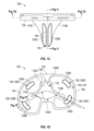
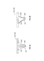
図1Aから図1Eは、脛骨ベースプレート100の様々な側面の平面図を示す。脛骨ベースプレート100は、近位面102、遠位面104、周縁部106を含むことができる。図1Bから図1Eに示されているように、脛骨ベースプレート100はキール108と複数のフィン110A及び110B(両方とも図1Dに示されている)とを含むことができる。
1A-1E show plan views of various sides of
図1Aは、脛骨ベースプレート100の近位側を示す平面図であり、近位面102と、前後方向軸線APと、周縁部106とを示している。脛骨支承コンポーネント(図示せず)と連結するためのボス、レール、ノッチ、及び/又は他の機構といった連結機構112を近位側で利用することができる。連結機構112の構造は、インディアナ州Warsaw在Zimmer Biomet Inc.の商業的に入手可能なPersona(登録商標)Total Knee Systemのものと同様であり得る。
FIG. 1A is a plan view of the proximal side of the
脛骨ベースプレート100は、ホーム軸線及び前後方向軸線APに対して、特定の非対称性を有することができる。このような形状は、米国特許出願公開第2013/0024001A1号明細書及び同第2013/0131820A1号明細書を含む、出願人による以前の様々な出願において論じられているように、膝関節置換候補の大部分に対して脛骨を最大限カバーするように設計されており、これらの特許出願の明細書は、その全体を参照することにより本明細書に組み込まれている。皮質骨の最大限の被覆により、脛骨ベースプレート100の優れた支持が容易になる。脛骨の皮質骨及び海綿骨との間の広い面積の接触によって、脛骨に対する脛骨ベースプレート100の強固かつ永続的な固定が容易になる。
The
前後方向軸線APは、脛骨ベースプレート100を内側区画114と外側区画116とに分割することができる。内側区画114は、周縁部106に沿って画定された外側区画116に対して非対称的に成形し、かつ、寸法決めすることができる。周縁部106は壁として成形することができ、そこでは1つ又は複数の選択個所に沿って連結機構112を有することができる。
Anteroposterior axis AP may divide
脛骨ベースプレート100は複数の標準サイズで利用することができる。これらの標準サイズは様々なサイズの脛骨に対する被覆を提供するように選択される。一例としては、脛骨ベースプレート100は、サイズ1(低身長)からサイズ9(高身長)までの9つのサイズを含むことができる。適切なサイズ選択を行うために、外科医は様々なサイズをシステムとして利用することができる。標準サイズは、本明細書中にさらに説明するように、近位側(例えば周縁部106、近位面102など)及び遠位側(例えば遠位面104、キール108、並びに複数のフィン110A及び110Bなど)に沿って異なるジオメトリを有している。
図1Bから図1Eは、様々な側面から見た脛骨ベースプレート100のさらなる平面図を示している。図1Bは、キール108と複数のフィン110Aの1つとを示している。フィン110Aは、キール108と遠位面104との間で延びることができる。キール108は、遠位面104及び脛骨ベースプレート100の残りの部分から概ね遠位方向へ延びることができる。フィン110Aは、キール108の組立体の一部であり得るが、本明細書では、ステム機構を含むキール108の残りの部分とは異なる機構として記述する。キール108は、遠位面104に対して(遠位面104からキール108の対称軸線S1まで測定して)角度θを成すことができる。図1Aの実施例によれば、角度θはほぼ90度であり得る。キール108の対称軸線S1は、近位-遠位方向軸線であり得る。
1B-1E show further plan views of the
図1Bは、キール108が、遠位先端118を有するステム機構を含み得ることを示している。この遠位先端118は、脛骨の管(canal)内へ挿入するように成形することができる。したがって、遠位先端118は、例えばドーム若しくは半球体、又は、鋭利な縁部を有しないように成形された他の形状として成形することができる。遠位先端118を形成する表面は、30度から70度(好ましくは、ほぼ50度)の角度αを形成するためのジオメトリを有することができる。遠位先端118を形成する表面は湾曲することができ、例えば3mmから6mmの曲率半径を有することができる。一実施例によれば、曲率半径は、例えばほぼ4.5mmであり得る。遠位先端118は、例えば頂部を含むことができる。なお、遠位先端118を有するキール108は、いくつかの膝関節全置換システム(total knee systems)において一般的であるようにステム延長部又は他の機構と連結するようには構成されていない。むしろ、キール108は大まかに言えば、脛骨ベースプレート100の標準サイズの増加に伴って近位-遠位方向長さを増加させる。
FIG. 1B shows that
図1C及び図1Dは、遠位面104から延びるキール108並びに複数のフィン110A及び110Bを示している。フィン110A及び110Bは、互いに対して、並びに、その対向する内側及び外側の側に配置されたキール108に対して、対称配置及び鏡像ジオメトリを有することができる。図1C及び図1Dには、2つのフィン110A及び110Bが示されてはいるものの、他の実施例では3つ以上のフィンが考えられる。キール108は、第1のフルート120Aを含む第1の溝と、第2のフルート120Bを含む第2の溝とを含むことができる。第1のフルート120A及び第2のフルート120Bは、遠位面104から遠位先端118へ数ミリメートル延びることができる。したがって、第1のフルート120A及び第2のフルート120Bは、キール108の近位-遠位方向長さの大部分(例えば、長さの50%から95%)にわたって延びることができる。第1のフルート120A及び第2のフルート120Bは、一般的に、前部に向くように、キール108の前部側に配置することができる。第1のフルート120A及び第2のフルート120Bは、互いに対して対称的な形状とすることができる。第1のフルート120A及び第2のフルート120Bのジオメトリについて、後でさらに論じる。
1C and ID show a
キール108並びにフィン110A及び110Bは、加えて、キール108並びにフィン110A及び110Bの後部側に沿って、第3のフルート120C(図1D)又は凹部を形成することができる。第3のフルート120Cは、主としてフィン110A及び110Bによって形成することができる。フィン110A及び110Bは、角度βを形成するように互いに角度付けすることができる。具体的には、フィン110A及び110Bは、(いくつかの実施例では、キール108として)近位-遠位方向に延びるだけではなく、内側-外側方向及び前部-後部方向に延びることもできる。角度βは例えば、実質的に105度から140度であり得る。一実施例によれば、角度βは実質的に126度であり得る。フィン110A及び110Bは、その後部側に沿ってキール108に対する曲率半径を有することができる。この曲率半径は実質的には5mmから10mmであり得る。一実施例によれば、曲率半径はほぼ7.6mmであり得る。フィン110A及び110Bの厚さT(図1D)は所望に応じて変化させることができる。
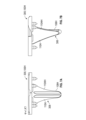
ここで図1Dを参照すると、遠位面104はセメントマントル(cement mantle)122と、第1のポケット124と、第2のポケット126とを含むことができる。マントル122はキール108とフィン110A及び110Bとを取り囲むことができ、周縁部106の周りに延びることができる。第1のポケット124は、実際には、マントル122によって分離された2つの別個の部分(内側及び外側)であり得る。第1のポケット124は、マントル122からほぼ0.25mmからほぼ2.0mmだけくぼませることができる。第1のポケット124は、鋭利な角隅を避けるように湾曲したその全ての縁部を有することができる。このことは、脛骨への組み付け時に、第1のポケット124を充填するための骨セメントの流れを容易にする。
Referring now to FIG. ID, the
第2のポケット126は、骨セメントを受け入れるように構成された複数のポケット126A,126B,126C及び126Dを含むことができる。ポケット126A,126B,126C及び126Dは、豆状又は湾曲形状であり得る。ポケット126A,126B,126C及び126Dは、周縁部106の前部-内側方向、後部-内側方向、後部-外側方向、及び、前部-外側方向の角隅に隣接して(5mm以内に)配置することができる。
The
ポケット126A,126B,126C及び126Dは、周縁部106に近接したそれぞれの外縁部128A,128B,128C及び128Dを有することができる。この縁部128A,128B,128C及び128Dは、外縁部126A,126B,128C及び128Dに隣接する周縁部106の形状に対応する湾曲形状又はその他の形状を有することができる。換言すれば、縁部128Aは、前部-内側方向の角隅における周縁部106の湾曲に対応するように湾曲させることができる。同様に、縁部128Bは、後部-内側方向の角隅における周縁部106の湾曲に対応するように湾曲させることができる。縁部128Cは、後部-外側方向の角隅における周縁部106の湾曲に対応するように湾曲させることができる。縁部128Dは、前部-外側方向の角隅における周縁部106の湾曲に対応するように湾曲させることができる。
第2のポケット126は、マントル122から1.5mmから5mmの間の深さであり得る。したがって、第2のポケット126は、第1のポケット124の底部(近位面)から0.5mmから3.5mmだけくぼませることができる。第2のポケット126のサイズ、形状、位置、及び数はポケット126A,126B,126C及び126Dから変化することができる。したがって、図示する第2のポケット126A,126B,126C及び126Dは一例である。一実施例によれば、第2のポケット126は幅に対して長さ寸法が細長くてよい。したがって、第2のポケット126は2.0mmから10mmの間の幅と、4.0mmから25mmの間の長さと、これらのそれぞれ対向する端部に沿った曲率半径とを有することができる。
The
図1Eは、後部-内側方向又は後部-外側方向の側から見た脛骨ベースプレート100の平面図を示しており、複数のフィン100A及び110Bの両方を示している。
FIG. 1E shows a plan view of the
図1Fは、第2のポケット126B及び脛骨ベースプレート100の他の機構を示す拡大断面図である。第2のポケット126B(及びポケット126A,126C及び126Dのいずれか)は開口130と、面取り部132と、突起134と、アンダカット領域136と、キャビティ137と、基底面138とを含むことができる。
FIG. 1F is an enlarged cross-sectional view showing the
開口130は、第1のポケット124からの骨セメント又は他の材料の連通を可能にする。面取り部132は、開口130を画定することができ、突起134へ向けて延びることができる。突起134は、キャビティ137の一部であり得るアンダカット領域136上に延びることができる。基底面138は、キャビティ137の底部を画定する近位面(植え込み時)を含むことができる。骨セメントは、開口130を通って流れ、突起134によって形成された制限部を通ってキャビティ137内へ流入することができる。流れは、硬化する前にアンダカット領域136を含むキャビティ137内へ入ることができる。アンダカット領域136及び突起134の形状は、持ち上がり、捩じれ、及び、脛骨ベースプレート100へ伝達される他の力に対して骨セメントが抵抗するのを助けることができる。第2のポケット126は、付加的な固定を提供するように、骨セメントを受け入れるための付加的なキャビティを設ける。
図1G及び図1Hは、第1のポケット124(図1D)と第2のポケット126(図1G)との間といったベースプレート100、及び、キール108(図1H)を通る、さらなる断面図を示す。図1Hは、フィンのないキール108の真の形状を示している。
1G and 1H show additional cross-sectional views through the
図1Iから図1Kは、第1のフルート120A、第2のフルート120B、及び第3のフルート120Cといった機構を示す、キール108並びに複数のフィン110A及び110Bの断面図を示している。図1Iから図1Kに示されているように、キール及び複数のフィン110A及び110Bは、遠位面に隣接した個所から遠位先端へ先細にすることができる。第1のフルート120Aと第2のフルート120Bとは、前部フィン140によって分離することができる。前部フィン140は、キール108の最前部分を形成することができ、キール108の近位遠位方向長さの少なくとも大部分にわたってほぼ均一な幅を有することができる。前部フィン140の幅は、例えばその長手方向長さの大部分にわたって、1mmから約3mmのオーダーにあってよい。前部フィン140の幅は、図1Iに示されたキール108の近位部分に隣接して増加することができる。第1のフルート120Aは、約100度から約140度の角度θ1を有することができる。一実施例によれば、角度θ1は約117度であり得る。同様に、第2のフルート120Bも、約100度から約140度の角度θ1を有することができる。一実施例によれば、角度θ1は約117度であり得る。キール108はテーパを有しなくてよく、その近位-遠位方向長さの少なくとも大部分又はそれよりも多くの長さに沿って実質的に先細になってなくてよい。フィン110A及び110Bは前述のようにテーパすることができる。
FIGS. 1I-1K illustrate cross-sectional views of the
一実施例によれば、キール108並びにフィン110A及び110Bは、第1のフルート120A、第2のフルート120B、及び/又は前部フィン140の位置又はその近傍において、脛骨管との圧入を形成するように構成されている。したがって、キール108並びにフィン110A及び110Bは、セメントマントルが脛骨管に対してキール108並びに/又はフィン110A及び110bの周りに完全には広がらないように構成されている。むしろ、骨に対する圧入保持は、いくつかの個所(例えば、第1のフルート120A、第2のフルート120B、及び/又は前部フィン140で、又はこれらの近傍)で利用され、セメントマントルは他の個所で使用される。
According to one embodiment,
フィン110A及び110Bは、遠位面104及びキール108を含む脛骨ベースプレート100の残りの部分とモノリシック又は一体的に形成することができる。したがって、フィン110A及び110Bは、上述のキール108の機構であり得る。しかしながら、フィン110A及び110Bは、脛骨ベースプレート100の他の機構に別個に取り付け可能であることも考えられる。あるいは、フィン110A及び110Bは、単一片としてモノリシックに一緒に形成することができ、キール108又は遠位面104と別個に連結することもできる。キール108並びに/又はフィン110A及び110Bは、レーザー焼結又はこれに類するものといった積層造形(additive manufacturing)によって(互いに一緒に又は互いに一緒ではなく、かつ、脛骨ベースプレート100の残りの部分と一緒に、又は残りの部分なしに)形成することができる。
図2は、様々なサイズの脛骨ベースプレート100A,100B及び100Cを含むシステム200を示す。脛骨ベースプレート100Aは、低身長に対応する膝を有する患者のために構成された標準サイズ1であり得る。脛骨ベースプレート100Bは、中程度の身長に対応する膝を有する患者のために構成された標準サイズ5であり得る。脛骨ベースプレート100Cは、高身長に対応する膝を有する患者のために構成された標準サイズ8であり得る。脛骨ベースプレート100A,100B及び100Cは、オーバーハング又は他の望ましくない取付配置がない状態で、切除された脛骨への所望の量の被覆を提供するように構成することができる。脛骨ベースプレート100A,100B及び100Cは、(例えば、周縁部の第1の最も内側方向の縁部から第2の最も外側方向の縁部まで測定した)内側-外側方向の範囲、(例えば、周縁部の第3の最も前部方向の縁部から第4の最も後部方向の縁部まで測定した)前部-後部方向の範囲のような寸法に対して異なり得る。しかしながら、脛骨ベースプレート100Aの内側-外側方向幅W1は、脛骨ベースプレート100B又は脛骨ベースプレート100Cの内側-外側方向幅と、例えば20mm以下だけ変化してもよい。したがって、内側-外側幅W1は、他の寸法(例えば周縁部の内側-外側方向の範囲、周縁部の前部-後部方向の範囲)と調和する(commiserate)形で標準サイズの変化に応じて増加しない可能性がある。脛骨ベースプレート100Aの近位-遠位方向長さL1は、図2及び2Aに示すように、脛骨ベースプレート100B又は脛骨ベースプレート100Cのものと実質的な量だけ変化してもよい。
FIG. 2 shows a
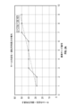
図2は、脛骨ベースプレート100A,100B及び100Cが、構造的に全てステム式(stemmable)ではないことを示す(しかし、ステム式の構造も考えられる)。したがって、キール108Aの近位-遠位方向長さは、一般的に標準サイズの増加と共に増加する。したがって、脛骨ベースプレート100Aのキール108Aの近位-遠位方向長さは、キール108B及び108Cの長さよりも比較的短い範囲となる。図2Aは、キール108Aの近位-遠位方向長さの増加は、異なる標準サイズのうちの2つ以上が、それぞれ標準サイズ群に対して同じ近位-遠位方向長さを共有する、段階的な増加であることが可能であることを示す。換言すれば、近位-遠位方向長さは、標準サイズの増加に伴って直線的に線形には増加せず、段階的に増加する。したがって、標準サイズのうちの少なくとも2つ(場合によっては標準サイズのうちの4つまで)が、同じ近位-遠位方向長さを共有する。
FIG. 2 shows that
標準サイズ毎のキールの模範的長さを図2Aに示す。なお、キール長さは直線状に滑らかに変化するのではなく、いくつかのサイズ(サイズ1から2、サイズ3から6、及びサイズ7から9)は、実質的に同じ近位-遠位方向長さを共有することができるようなステップ機能を有することに留意すべきである。しかしながら、最良のフィットカーブによって示される一般的な傾向は、サイズの変化に伴うキールの近位遠位方向長さの線形的な増加である。なお、フルートの角度、フルートの半径、フルートの内側-外側方向幅、前部フィンのサイズ(内側-外側方向幅)、及び/又はフィンの半径、後部フルートの角度(例えばフィン間の角度)、キールの遠位先端のジオメトリといった本明細書中で論じた他の機構、、標準サイズが変化してもジオメトリは実質的に一定のままであり得ることにも留意すべきである。したがって、例えば、標準サイズ1の脛骨ベースプレート100Aは、標準サイズ8の脛骨ベースプレート100C(図2参照)と同じサイズ(内側-外側方向)の前部溝を有することになる。
Exemplary keel lengths for each standard size are shown in Figure 2A. Note that the keel length does not change smoothly in a straight line, but rather some sizes (
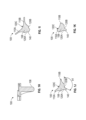
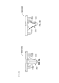
図3Aから図8Bは、脛骨ベースプレートのシステム300の別の態様を示す。特に、システム300は、例えば、脛骨ベースプレート100D(図3A及び図3B)、脛骨ベースプレート100E(図4A及び図4B)、脛骨ベースプレート100F(図5A及び図5B)、脛骨ベースプレート100G(図6A及び図6B)、脛骨ベースプレート100H(図7A及び図7B)、及び脛骨ベースプレート100I(図8A及び図8B)を含む。 3A-8B illustrate another embodiment of a tibial baseplate system 300. In particular, the system 300 includes, for example, tibial baseplate 100D (FIGS. 3A and 3B), tibial baseplate 100E (FIGS. 4A and 4B), tibial baseplate 100F (FIGS. 5A and 5B), and tibial baseplate 100G (FIGS. 6A and 6B). ), a tibial base plate 100H (FIGS. 7A and 7B), and a tibial base plate 100I (FIGS. 8A and 8B).
脛骨ベースプレート100D及び100Eは、同じ標準サイズ(例えば標準サイズ2)ではあるが、脛骨ベースプレート100Dは、セメント固定のために構成されている脛骨ベースプレート100Eと比較して、非セメント固定のために構成されている(むしろ骨内方成長を利用する)という点で異なる構造を有し得る。同様に、脛骨ベースプレート100F及び100Gは、同じ標準サイズ(例えば標準サイズ4)ではあるが、脛骨ベースプレート100Fは、セメント固定のために構成されている脛骨ベースプレート100Gと比較して、非セメント固定のために構成されている(むしろ骨内方成長を利用する)という点で異なる構造を有し得る。脛骨ベースプレート100H及び100Iは、同じ標準サイズ(例えば標準サイズ7)ではあるが、脛骨ベースプレート100Hは、セメント固定のために構成されている脛骨ベースプレート100Iと比較して、非セメント固定のために構成されている(むしろ骨内方成長を利用する)という点で異なる構造を有し得る。 Although tibial baseplates 100D and 100E are the same standard size (e.g., standard size 2), tibial baseplate 100D is configured for non-cemented fixation compared to tibial baseplate 100E, which is configured for cemented fixation. may have a different structure in that it uses bone ingrowth (rather than utilizes bone ingrowth). Similarly, although tibial baseplates 100F and 100G are of the same standard size (e.g., standard size 4), tibial baseplate 100F is configured for non-cemented fixation compared to tibial baseplate 100G, which is configured for cemented fixation. (rather utilize bone ingrowth). Although tibial baseplates 100H and 100I are the same standard size (e.g., standard size 7), tibial baseplate 100H is configured for non-cemented fixation compared to tibial baseplate 100I, which is configured for cemented fixation. may have a different structure in that it uses bone ingrowth (rather than utilizes bone ingrowth).
脛骨ベースプレート100D及び100Eは、実質的に同じサイズを共有することができる(例えば、周縁部の内側-外側方向の範囲は実質的に同じであり得る、周縁部の前部-後部方向の範囲は実質的に同じであり得る、など)。加えて、脛骨ベースプレート100D及び100Eの遠位機構のジオメトリも実質的に同じであり得る。このことは、脛骨ベースプレート100Eのキール108E及びフィン110E,110EEの対応する態様と比較した場合の、脛骨ベースプレート100Dのキール108D及びフィン110D,110DDの複数の態様のジオメトリを含む。したがって、図3Aから図4Bに示されているように、脛骨ベースプレート100Dのキール108D及びフィン110D,110DDは、(キール108D及びフィン110D,110DDの範囲に沿って内側-外側方向に移動する、キール108D及びフィン110D,110DDの最も遠位方向の面に沿って測定された)脛骨ベースプレート100Eのキール108E及びフィン110E,110EEと実質的に同じ遠位プロファイル302を共有することができる。換言すれば、キール108D及び108Eは、近位-遠位方向長さ、直径、溝の形状及びサイズ、フルートのサイズ及び形状、厚さといった同じジオメトリの特徴を共有することができる。同様に、フィン110D,110DDは、フィン110E,110EEと同じジオメトリ(角度形成、内側-外側方向幅、近位-遠位方向長さなど)を共有することができる。キール108D及びフィン110D,110DDとキール108E及びフィン110E,110EEとの実質的な形状の一致によって、外科医はセメント固定型器具又は非セメント固定型器具を手術中に選択できるようになる。このようにすると、さもなければセメント固定型器具から非セメント固定型器具へ(又はその逆)の切り換えのために実施する必要のあるリーミング又は他の外科的処置の必要がなくなり、時間及び複雑さを軽減する。いくつかの実施例によれば、フィン110D,110DDとフィン110E,110EEとは、フィン110D,110DDの厚さがフィン110E,110EEの対応する厚さよりもわずかに大きい点だけが異なっていてもよい。
Tibial baseplates 100D and 100E can share substantially the same size (e.g., the medial-lateral extent of the periphery can be substantially the same, the anterior-posterior extent of the periphery can be substantially the same, and the anterior-posterior extent of the periphery can be substantially the same. may be substantially the same, etc.). Additionally, the geometry of the distal features of tibial baseplates 100D and 100E may also be substantially the same. This includes the geometry of aspects of the
脛骨ベースプレート100D及び100Eを用いて論じたように、脛骨ベースプレート100F及び100Gは、実質的に同じサイズを共有することができる(例えば周縁部の内側-外側方向の範囲は実質的に同じであってもよく、周縁部の前部-後部方向の範囲は実質的に同じであってもよい、など)。さらに、脛骨ベースプレート100F及び100Gの遠位機構のジオメトリも実質的に同じであり得る。これは、脛骨ベースプレート100Gのキール108G及びフィン110G,110GGの対応する態様と比較した場合の、脛骨ベースプレート100Fのキール108F及びフィン110F,110FFの複数の態様のジオメトリを含む。したがって、図5Aから6Bに示されているように、脛骨ベースプレート100Fのキール108F及びフィン110F,110FFは、(キール108F及びフィン110F,110FFの範囲に沿って内側-外側方向に移動する、キール108F及びフィン110F,110FFの最も遠位方向の面に沿って測定された)脛骨ベースプレート100Gのキール108G及びフィン110G,110GGと実質的に同じ遠位プロファイル304を共有することができる。換言すれば、キール108F及び108Gは、近位-遠位方向長さ、直径、溝の形状及びサイズ、フルートのサイズ及び形状などの同じジオメトリ特徴を共有することができる。同様に、フィン110F,110FFは、フィン110G,110GGと同じジオメトリ(角度、内側-外側方向幅、近位-遠位方向長さ、厚さなど)を共有することができる。いくつかの実施例によれば、フィン110F,110FF及びフィン110G,110GGは、フィン110F,110FFの厚さがフィン110G,110GGの対応厚さよりもわずかに大きい点だけが異なっていてもよい。
As discussed with tibial baseplates 100D and 100E, tibial baseplates 100F and 100G can share substantially the same size (e.g., the medio-lateral extent of the periphery may be substantially the same). (the front-to-back extent of the periphery may be substantially the same, etc.). Additionally, the geometry of the distal features of tibial baseplates 100F and 100G may also be substantially the same. This includes the geometry of aspects of
脛骨ベースプレート100H及び100Iは実質的に同じサイズを共有することができる(例えば周縁部の内側-外側方向の範囲は実質的に同じであってもよく、周縁部の前部-後部方向の範囲は実質的に同じであってもよい、など)。加えて、脛骨ベースプレート100H及び100Iの遠位機構のジオメトリも実質的に同じであり得る。これは、脛骨ベースプレート100Iのキール108I及びフィン110I,110IIの対応する態様と比較した場合の、脛骨ベースプレート100Hのキール108H及びフィン110H,110HHの複数の態様のジオメトリを含む。したがって、図7Aから図8Bに示されているように、脛骨ベースプレート100Hのキール108H及びフィン110H,110HHは、(キール108H及びフィン110H,110HHの範囲に沿って内側-外側方向に移動する、キール108H及びフィン110H,110HHの最も遠位方向の面に沿って測定された)脛骨ベースプレート100Iのキール108I及びフィン110I,110IIと実質的に同じ遠位プロファイル306を共有することができる。換言すれば、キール108H及び108Iは、近位-遠位方向長さ、直径、溝の形状及びサイズ、フルートのサイズ及び形状といった機構の同じジオメトリを共有することができる。同様に、フィン110H,110HHは、フィン110I,110IIと同じジオメトリ(角度、内側-外側方向幅、近位-遠位方向長さ、厚さなど)を共有することができる。いくつかの実施例によれば、フィン110H,110HHとフィン110I,110IIとは、フィン110H,110HHの厚さがフィン110I,110IIの対応厚さよりもわずかに大きい点でだけが異なっていてもよい。
Tibial baseplates 100H and 100I can share substantially the same size (e.g., the medial-lateral extent of the periphery can be substantially the same, the anterior-posterior extent of the periphery can be may be substantially the same, etc.). Additionally, the geometry of the distal features of tibial baseplates 100H and 100I may also be substantially the same. This includes the geometry of aspects of the
本明細書中に提供される実施例によれば、脛骨ベースプレートは、後十字靭帯温存型(cruciate retaining (CR))デザインを備えることができる。したがって、脛骨ベースプレートは、植え込み中に後十字靭帯が切除されないためのリリーフ(relieve)を有することができる。しかしながら、例えば、後部安定化型(posterior-stabilized(PS))デザイン、中位拘束(mid-level constraint(MLC))又は拘束後部安定化型(constrained posterior stabilized(CPS))デザイン、及び超適合(ultra-congruent (UC))デザインを含む、他のプロテーゼデザインも考えられる。PS及びMLCデザインは、当業者に知られているようなスパイン及びカムを利用する。後十字靭帯は排除されるので、リリーフ(relief)を設ける必要はない。 According to examples provided herein, a tibial baseplate can include a cruciate retaining (CR) design. Thus, the tibial baseplate can have relief so that the posterior cruciate ligament is not resected during implantation. However, for example, posterior-stabilized (PS) designs, mid-level constraint (MLC) or constrained posterior stabilized (CPS) designs, and superconforming ( Other prosthesis designs are also possible, including ultra-congruent (UC) designs. PS and MLC designs utilize spines and cams as known to those skilled in the art. Since the posterior cruciate ligament is excluded, there is no need to provide relief.
補注
上記の詳細な説明は、添付の図面の参照を含む。これらの図面は詳細な説明の一部を形成する。図面は、本発明を実施し得る具体的な実施態様を実例として示す。これらの実施態様は本明細書中では「実施例」とも称される。このような実施例は図示又は記述されたものに加えられる要素を含み得る。しかしながら、本発明者は、また、図示又は記述された要素だけが提供される実施例をも考える。さらに、本発明者は、また、図示又は記述された特定の実施例(又はその1つ又は複数のアスペクト)に関して、又は他の実施例(又はこれらの1つ又は複数のアスペクト)に関して、図示され記述された要素(又はこれらの1つ又は複数のアスペクト)の組み合わせ又は置換を用いた実施例をも考える。
Additional Notes The above detailed description includes references to the accompanying drawings. These drawings form part of the detailed description. The drawings illustrate by way of example specific embodiments in which the invention may be practiced. These embodiments are also referred to herein as "Examples." Such embodiments may include elements in addition to those shown or described. However, the inventor also contemplates embodiments in which only the elements shown or described are provided. In addition, the inventors also make certain statements regarding the particular embodiment (or one or more aspects thereof) illustrated or described, or with respect to other embodiments (or one or more aspects thereof). Embodiments using combinations or permutations of the described elements (or one or more aspects thereof) are also contemplated.
本文献では、「概ね(generally)」、「ほぼ(substantially)」、「約(about)」という用語は、提供された値の15パーセント(±)以内を意味する。「a」又は「an」という用語は、特許文献において共通するように、「少なくとも1つ(at least one)」又は「1つ又は複数(one or more)」といういかなる他の例又は利用からも独立して、1つ又は1つよりも多い(one or more than one)ことを含むために使用される。本文献では、「又は」という用語は、非排他的orを意味し、これにより特に断りのない限り、「A又はB」が「AであるがBではない」、「BであるがAではない」、そして「AでありかつBである」を含むように使用される。本文献では「含む(including)」及び「そこには(in which)」という用語は、「含む(comprising)」及び「そこにおいて(wherein)」というそれぞれの用語と同等のプレイン・イングリッシュとして使用される。また、下記クレームにおいて、「含む(including)」及び「含む(comprising)」はオープンエンドであり、すなわち請求項におけるこのような用語の後に挙げられたものに加えられる要素を含むシステム、デバイス、物品、組成物、製剤、又はプロセスであり、これらの要素は、請求項の範囲に含まれるとまだ見なされる。さらに、下記請求項において、「第1の」、「第2の」、及び「第3の」などという用語は、単に標識として使用されるにすぎず、これらの対象物に数値的要件を課すものではない。 In this document, the terms "generally," "substantially," and "about" mean within 15 percent (±) of the provided value. The term "a" or "an" is used in conjunction with any other instance or usage of "at least one" or "one or more," as is common in the patent literature. Used independently to include one or more than one. In this document, the term "or" means non-exclusive or, whereby "A or B", "A but not B", "B but not A", unless otherwise specified. It is used to include "not" and "both A and B." In this document, the terms "including" and "in which" are used as the Plain English equivalent of the terms "comprising" and "wherein," respectively. Ru. Also, in the following claims, "including" and "comprising" are open-ended, i.e. systems, devices, articles containing elements in addition to those listed after such terms in the claims. , composition, formulation, or process, these elements are still considered to be within the scope of the claims. Furthermore, in the following claims, terms such as "first", "second", and "third" are used merely as indicators and do not impose numerical requirements on these objects. It's not a thing.
上記記述内容は、例示的なものであって、限定的ではないものと意図される。例えば、上記実施例(又はこれらの1つ又は複数の態様)は、相互の組み合わせにおいて用いることができる。上記記述を概観すれば、例えば当業者によって他の実施例を用いることができる。要約書は、読者が技術開示内容の性質を迅速に確認するのを可能にするために、米国特許法第1の.72(b)条を遵守するように提供されている。これは、請求項の範囲又は意味を解釈又は限定するためには使用されないという理解のもとに提出される。また、上記詳細な説明において、様々な特徴をまとめることにより、開示内容を簡素化することができる。このことは、請求項以外で開示された特徴がいずれの請求項にも必須であることを意図するものと解釈されるべきではない。むしろ、本発明の主題は、開示された特定の実施例の全ての特徴にあるわけではない。したがって、下記請求項はここでは実施例又は実施態様として詳細な説明に組み込まれる。各請求項はそれ自体別個の実施例として存在し、またこのような実施例は様々な組み合わせ又は置換において、互いに組み合わせることができる。本発明の範囲は、添付の請求項を、このような請求項に与えられた同等のものの全範囲と併せて参照することによって見極められるべきである。 The above description is intended to be illustrative, not restrictive. For example, the embodiments described above (or one or more aspects thereof) can be used in combination with each other. Other embodiments may be used, for example by those skilled in the art, upon reviewing the above description. The Abstract is provided in the United States Patent Act No. 1 to enable the reader to quickly ascertain the nature of the technical disclosure. 72(b). It is submitted with the understanding that it will not be used to interpret or limit the scope or meaning of the claims. Furthermore, in the above detailed description, various features may be grouped together to simplify the disclosure. This should not be interpreted as intending that any feature disclosed outside the claims is essential to any claim. Rather, inventive subject matter lies in less than all features of particular embodiments disclosed. Thus, the following claims are hereby incorporated into the Detailed Description as examples or embodiments. Each claim stands as its own separate embodiment, and such embodiments may be combined with one another in various combinations or permutations. The scope of the invention should be determined by reference to the appended claims, along with the full scope of equivalents to which such claims are entitled.
Claims (20)
ベースプレートであって、
脛骨の近位切除面を実質的に覆うように寸法決めされ、かつ、成形された遠位面、
前記遠位面とは反対側の近位面であって、外側区画と、前記外側区画とは反対側の内側区画とを有する近位面、
前記遠位面と前記近位面との間に延びる周縁部、
前記ベースプレート内に形成され、前記遠位面からくぼんでいる第1のポケットであって、骨セメントを受け入れるように構成されている第1のポケット、
前記ベースプレート内に形成され、前記第1のポケットからくぼんでいる第2のポケットであって、前記骨セメントの一部を受け入れるように構成されている第2のポケット、を備えるベースプレートと、
長手方向脛骨キール軸線を画定するために、前記遠位面から遠位方向へ延びる脛骨キールと、
を備える、膝関節形成術のための脛骨プロテーゼ。 A tibial prosthesis for knee arthroplasty, the tibial prosthesis comprising:
A base plate,
a distal surface dimensioned and shaped to substantially cover the proximal resection surface of the tibia;
a proximal surface opposite the distal surface, the proximal surface having an outer section and an inner section opposite the outer section;
a peripheral edge extending between the distal surface and the proximal surface;
a first pocket formed in the baseplate and recessed from the distal surface and configured to receive bone cement;
a second pocket formed in the base plate and recessed from the first pocket and configured to receive a portion of the bone cement;
a tibial keel extending distally from the distal surface to define a longitudinal tibial keel axis;
A tibial prosthesis for knee arthroplasty, comprising:
複数のプロテーゼであって、それぞれが、
ベースプレートであって、
脛骨の近位切除面を実質的に覆うように寸法決めされ、かつ、成形された遠位面、
前記遠位面とは反対側の近位面であって、外側区画と、前記外側区画とは反対側の内側区画とを有する近位面、及び
前記遠位面と前記近位面との間に延びる周縁部、
を備え、
各前記複数のプロテーゼのサイズは、前記遠位面、前記近位面、及び、前記周縁部に対して異なっている、ベースプレートと、
前記遠位面からドーム形遠位先端へ遠位方向に延びる脛骨キールであって、前記脛骨キールは、近位-遠位方向で測定された細長い長さを有し、前記細長い長さに沿って延びる長手方向脛骨キール軸線を画定し、前記細長い長さは、前記遠位面、前記近位面、及び、前記周縁部に対する前記複数のプロテーゼのサイズの増加と共に段階的に増加する、脛骨キールと、
を備える、脛骨プロテーゼシステム。 A tibial prosthesis system, comprising:
A plurality of prostheses, each of which
A base plate,
a distal surface dimensioned and shaped to substantially cover the proximal resection surface of the tibia;
a proximal surface opposite the distal surface, the proximal surface having an outer section and an inner section opposite the outer section; and between the distal surface and the proximal surface. a periphery extending to;
Equipped with
a base plate, each of the plurality of prostheses having a different size with respect to the distal surface, the proximal surface, and the peripheral portion;
a tibial keel extending distally from the distal surface to a domed distal tip, the tibial keel having an elongated length measured in a proximal-distal direction; a tibial keel defining a longitudinal tibial keel axis extending from the tibial keel, the elongate length increasing stepwise with increasing size of the plurality of prostheses relative to the distal surface, the proximal surface, and the circumference; and,
A tibial prosthesis system comprising:
前記ベースプレート内に形成され、前記遠位面からくぼんでいる第1のポケットであって、骨セメントを受け入れるように構成されている第1のポケットと、
前記ベースプレート内に形成され、前記第1のポケットからくぼんでいる第2のポケットであって、前記骨セメントの一部を受け入れるように構成されている第2のポケットと、を含み、
前記第2のポケットへの開口が、前記第2のポケットの底部を形成する近位面よりも小さくなるように、前記第2のポケットはアンダカットを含む、請求項10から請求項13の何れか1項に記載のシステム。 Each of said plurality of prostheses comprises:
a first pocket formed in the baseplate and recessed from the distal surface and configured to receive bone cement;
a second pocket formed in the base plate and recessed from the first pocket and configured to receive a portion of the bone cement;
14. Any of claims 10 to 13, wherein the second pocket includes an undercut such that the opening to the second pocket is smaller than a proximal surface forming a bottom of the second pocket. or the system described in item 1.
第1の脛骨プロテーゼであって、
第1の近位面と、
前記第1の近位面とは反対側の第1の遠位面であって、前記脛骨の近位切除面を実質的に覆うように寸法決めされ、かつ、成形されている第1の遠位面と、
前記第1の脛骨プロテーゼ内に形成され、前記第1の遠位面からくぼんでいる少なくとも1つのポケットであって、骨セメントを受け入れるように構成されている少なくとも1つのポケットと、
前記第1の遠位面から遠位方向へ延びる第1のキールと、
前記第1の脛骨キールと前記第1の遠位面との間の分岐点に跨る第1の複数のフィンと、
を備える第1の脛骨プロテーゼ、及び、
第2の脛骨プロテーゼであって、
第2の近位面と、
前記第2の近位面とは反対側の第2の遠位面であって、前記脛骨の近位切除面を実質的に覆うように寸法決めされ、かつ、成形されている、第2の遠位面と、
前記第2の遠位面の少なくとも大部分を形成する多孔質材料の第1の層と、
前記第2の脛骨プロテーゼの少なくとも一部を形成する非多孔質材料の第2の層と、
前記第2の遠位面から遠位方向へ延びる第2のキールと、
前記第2のキールと前記第2の遠位面との間の分岐点に跨る第2の複数のフィンと、
を備える第2の脛骨プロテーゼ、
を含み、
前記第1のキール及び前記第1の複数のフィンは、前記第2のキール及び前記第2の複数のフィンと実質的に同じジオメトリを共有している、脛骨プロテーゼシステム。 A tibial prosthesis system,
A first tibial prosthesis, the first tibial prosthesis comprising:
a first proximal surface;
a first distal surface opposite the first proximal surface, the first distal surface being dimensioned and shaped to substantially cover the proximal resection surface of the tibia; The face and
at least one pocket formed in the first tibial prosthesis and recessed from the first distal surface and configured to receive bone cement;
a first keel extending distally from the first distal surface;
a first plurality of fins spanning a bifurcation between the first tibial keel and the first distal surface;
a first tibial prosthesis comprising; and
A second tibial prosthesis, the second tibial prosthesis comprising:
a second proximal surface;
a second distal surface opposite the second proximal surface, the second distal surface being dimensioned and shaped to substantially cover the proximal resection surface of the tibia; a distal surface;
a first layer of porous material forming at least a majority of the second distal surface;
a second layer of non-porous material forming at least a portion of the second tibial prosthesis;
a second keel extending distally from the second distal surface;
a second plurality of fins spanning a bifurcation between the second keel and the second distal surface;
a second tibial prosthesis comprising;
including;
The first keel and the first plurality of fins share substantially the same geometry as the second keel and the second plurality of fins.
Applications Claiming Priority (2)
| Application Number | Priority Date | Filing Date | Title |
|---|---|---|---|
| US202263399902P | 2022-08-22 | 2022-08-22 | |
| US63/399,902 | 2022-08-22 |
Publications (1)
| Publication Number | Publication Date |
|---|---|
| JP2024029760A true JP2024029760A (en) | 2024-03-06 |
Family
ID=87760537
Family Applications (1)
| Application Number | Title | Priority Date | Filing Date |
|---|---|---|---|
| JP2023132605A Pending JP2024029760A (en) | 2022-08-22 | 2023-08-16 | Tibial prosthesis with distal mechanism for cementation |
Country Status (6)
| Country | Link |
|---|---|
| US (1) | US20240058133A1 (en) |
| EP (3) | EP4371531A3 (en) |
| JP (1) | JP2024029760A (en) |
| CN (1) | CN117598841A (en) |
| AU (2) | AU2023214376B2 (en) |
| CA (1) | CA3209018A1 (en) |
Families Citing this family (1)
| Publication number | Priority date | Publication date | Assignee | Title |
|---|---|---|---|---|
| EP4003238A1 (en) * | 2019-07-24 | 2022-06-01 | Waldemar Link GmbH & Co. KG | Combination of graft and replacement piece for filling a bone defect |
Citations (6)
| Publication number | Priority date | Publication date | Assignee | Title |
|---|---|---|---|---|
| US4298992A (en) * | 1980-01-21 | 1981-11-10 | New York Society For The Relief Of The Ruptured And Crippled | Posteriorly stabilized total knee joint prosthesis |
| US4938769A (en) * | 1989-05-31 | 1990-07-03 | Shaw James A | Modular tibial prosthesis |
| US20160278929A1 (en) * | 2015-03-23 | 2016-09-29 | Modal Manufacturing, LLC | Knee implants and instruments |
| DE102015109353A1 (en) * | 2015-06-12 | 2016-12-15 | Aesculap Ag | Joint part and knee joint endoprosthesis |
| US20180200066A1 (en) * | 2013-03-07 | 2018-07-19 | Howmedica Osteonics Corp. | Partially porous bone implant keel |
| JP2018187392A (en) * | 2017-05-09 | 2018-11-29 | デピュイ・アイルランド・アンリミテッド・カンパニーDepuy Ireland Unlimited Company | Tibial tray with fixation mechanism |
Family Cites Families (4)
| Publication number | Priority date | Publication date | Assignee | Title |
|---|---|---|---|---|
| US9011547B2 (en) * | 2010-01-21 | 2015-04-21 | Depuy (Ireland) | Knee prosthesis system |
| AU2012341026B2 (en) | 2011-11-21 | 2015-01-29 | Zimmer, Inc. | Tibial baseplate with asymmetric placement of fixation structures |
| CN104203160B (en) | 2012-01-30 | 2016-05-11 | 捷迈有限公司 | For the asymmetric shin bone part of knee-joint prosthesis |
| KR101700862B1 (en) * | 2015-08-10 | 2017-02-01 | 주식회사 코렌텍 | Method for Preparing Patient Customized Tibial Component |
-
2023
- 2023-08-10 CA CA3209018A patent/CA3209018A1/en active Pending
- 2023-08-11 AU AU2023214376A patent/AU2023214376B2/en active Active
- 2023-08-14 US US18/233,857 patent/US20240058133A1/en active Pending
- 2023-08-16 JP JP2023132605A patent/JP2024029760A/en active Pending
- 2023-08-21 EP EP24168856.3A patent/EP4371531A3/en active Pending
- 2023-08-21 EP EP25217131.9A patent/EP4674385A2/en active Pending
- 2023-08-21 EP EP23192491.1A patent/EP4327784B1/en active Active
- 2023-08-22 CN CN202311063515.1A patent/CN117598841A/en active Pending
-
2024
- 2024-10-14 AU AU2024227309A patent/AU2024227309A1/en active Pending
Patent Citations (6)
| Publication number | Priority date | Publication date | Assignee | Title |
|---|---|---|---|---|
| US4298992A (en) * | 1980-01-21 | 1981-11-10 | New York Society For The Relief Of The Ruptured And Crippled | Posteriorly stabilized total knee joint prosthesis |
| US4938769A (en) * | 1989-05-31 | 1990-07-03 | Shaw James A | Modular tibial prosthesis |
| US20180200066A1 (en) * | 2013-03-07 | 2018-07-19 | Howmedica Osteonics Corp. | Partially porous bone implant keel |
| US20160278929A1 (en) * | 2015-03-23 | 2016-09-29 | Modal Manufacturing, LLC | Knee implants and instruments |
| DE102015109353A1 (en) * | 2015-06-12 | 2016-12-15 | Aesculap Ag | Joint part and knee joint endoprosthesis |
| JP2018187392A (en) * | 2017-05-09 | 2018-11-29 | デピュイ・アイルランド・アンリミテッド・カンパニーDepuy Ireland Unlimited Company | Tibial tray with fixation mechanism |
Also Published As
| Publication number | Publication date |
|---|---|
| CA3209018A1 (en) | 2024-02-22 |
| EP4327784B1 (en) | 2025-12-31 |
| US20240058133A1 (en) | 2024-02-22 |
| EP4327784A3 (en) | 2024-05-08 |
| AU2023214376A1 (en) | 2024-03-07 |
| CN117598841A (en) | 2024-02-27 |
| EP4327784A2 (en) | 2024-02-28 |
| EP4371531A2 (en) | 2024-05-22 |
| AU2023214376B2 (en) | 2024-08-08 |
| EP4674385A2 (en) | 2026-01-07 |
| EP4371531A3 (en) | 2024-08-07 |
| AU2024227309A1 (en) | 2024-10-31 |
Similar Documents
| Publication | Publication Date | Title |
|---|---|---|
| US11672668B2 (en) | Humeral joint replacement component | |
| US9937058B2 (en) | Prosthetic implant and method of implantation | |
| US8911502B2 (en) | Implant for restoring normal range flexion and kinematics of the knee | |
| US7070622B1 (en) | Prosthesis having a modular soft tissue fixation mechanism | |
| US8157871B2 (en) | Femoral HIP prosthesis and method of implantation | |
| US8808375B2 (en) | Anti-backout arthroscopic uni-compartmental prosthesis | |
| US20220233321A1 (en) | Femoral prostheses with upsizing and downsizing capabilities | |
| CN101098666A (en) | Ankle Endoprosthetic Components | |
| JP2024029760A (en) | Tibial prosthesis with distal mechanism for cementation | |
| JP7730351B2 (en) | Tibial prosthesis with distal mechanism for uncemented fixation | |
| CN118236203A (en) | Tibial component for constrained prosthetic knee | |
| CN114206271B (en) | Bicompartmental knee prosthesis |
Legal Events
| Date | Code | Title | Description |
|---|---|---|---|
| A621 | Written request for application examination |
Free format text: JAPANESE INTERMEDIATE CODE: A621 Effective date: 20230816 |
|
| A131 | Notification of reasons for refusal |
Free format text: JAPANESE INTERMEDIATE CODE: A131 Effective date: 20240507 |
|
| A521 | Request for written amendment filed |
Free format text: JAPANESE INTERMEDIATE CODE: A523 Effective date: 20240806 |
|
| A02 | Decision of refusal |
Free format text: JAPANESE INTERMEDIATE CODE: A02 Effective date: 20241126 |