JP2024029726A - Structural body - Google Patents
Structural body Download PDFInfo
- Publication number
- JP2024029726A JP2024029726A JP2022143318A JP2022143318A JP2024029726A JP 2024029726 A JP2024029726 A JP 2024029726A JP 2022143318 A JP2022143318 A JP 2022143318A JP 2022143318 A JP2022143318 A JP 2022143318A JP 2024029726 A JP2024029726 A JP 2024029726A
- Authority
- JP
- Japan
- Prior art keywords
- fixing
- plate
- support column
- paper
- fixing plate
- Prior art date
- Legal status (The legal status is an assumption and is not a legal conclusion. Google has not performed a legal analysis and makes no representation as to the accuracy of the status listed.)
- Pending
Links
- 230000003014 reinforcing effect Effects 0.000 claims description 12
- 239000002023 wood Substances 0.000 abstract description 5
- 229920003002 synthetic resin Polymers 0.000 abstract description 4
- 239000000057 synthetic resin Substances 0.000 abstract description 4
- 239000000123 paper Substances 0.000 description 11
- 239000011111 cardboard Substances 0.000 description 4
- 239000000463 material Substances 0.000 description 4
- 239000012779 reinforcing material Substances 0.000 description 4
- 239000000853 adhesive Substances 0.000 description 3
- 230000001070 adhesive effect Effects 0.000 description 3
- 230000000694 effects Effects 0.000 description 3
- 230000002787 reinforcement Effects 0.000 description 3
- 239000011087 paperboard Substances 0.000 description 2
- 239000002184 metal Substances 0.000 description 1
Images

Landscapes
- Pallets (AREA)
Abstract
Description
本発明は、構造体に関するものであり、更に、詳しくは紙・ダンボールで支柱を構成した紙・ダンボールできた構造体に関するものであり、構造体として家具及びパレットで構成されたパレット家具が含まれるものである。 The present invention relates to a structure, and more specifically to a structure made of paper/cardboard with supports made of paper/cardboard, and the structure includes furniture and pallet furniture made of pallets. It is something.
従来、特許文献1に示す荷役用のパレットを実施例とする構造体は、構造体全体が木製又は合成樹脂で形成されており、重いため手で運ぶことは困難であるため、フォークリフトを使用しなければならないという問題点があった。 Conventionally, structures such as pallets for cargo handling as shown in Patent Document 1 have been made entirely of wood or synthetic resin, and are heavy and difficult to transport by hand, so forklifts have not been used. There was a problem that it had to be done.
本発明は、上記問題点を解消するためになされたものであり、手で運ぶことも可能な軽い構造体を提供することにある。 The present invention was made in order to solve the above problems, and an object thereof is to provide a lightweight structure that can be carried by hand.
上記課題を解決するために、本発明の構造体は、平板状で少なくとも四隅に固定穴が形成された固定板と、前記固定板の前記固定穴に装着される紙製の支柱とからなることを特徴とする。
又、本発明の構造体にあっては、前記支柱は、筒形の支柱の表面に固定される固定部と、前記支柱間に配設される補強板を取り付ける取付部とが形成された取付手段を備えているのが望ましい。
又、本発明の構造体にあっては、前記支柱は前記固定板に着脱自在に設けられているのが望ましい。
又、本発明の構造体にあっては、前記支柱の上端から下端にかけて形成された貫通孔に柱が挿入されるのが望ましい。
又、本発明の構造体にあっては、前記固定板は前記支柱の両端に設けられているのが望ましい。
又、本発明の構造体にあっては、前記固定板と前記支柱と前記補強板は紙で形成されているのが望ましい。 In order to solve the above problems, the structure of the present invention includes a fixing plate that is flat and has fixing holes formed in at least four corners, and a paper support that is attached to the fixing holes of the fixing plate. It is characterized by
Further, in the structure of the present invention, the support column has a mounting structure in which a fixing part is fixed to the surface of the cylindrical support column, and a mounting part is formed to attach a reinforcing plate arranged between the support columns. It is desirable to have the means.
Further, in the structure of the present invention, it is preferable that the support column is detachably attached to the fixed plate.
Further, in the structure of the present invention, it is desirable that the pillar be inserted into a through hole formed from the upper end to the lower end of the pillar.
Further, in the structure of the present invention, it is preferable that the fixing plates are provided at both ends of the support column.
Further, in the structure of the present invention, it is preferable that the fixed plate, the support column, and the reinforcing plate are made of paper.
本発明の構造体は、平板状で少なくとも四隅に固定穴が形成された固定板と、前記固定板の前記固定穴に装着される紙製の支柱とからなることを特徴とするものであるから、軽量であり手に持って運搬することも可能であるという効果があり、支柱間に支柱を配設することで平板状の固定板の強度を高めることが可能となるという効果がある。
又、請求項2のように、前記支柱は、筒形の支柱の表面に固定される固定部と、前記支柱間に配設される補強板を取り付ける取付部とが形成された取付手段を備えているものは、前記補強板を前記支柱間に配設することで、平板状の固定板の強度を高めることができるという効果がある。
又、請求項3のように、前記支柱は着脱自在に設けられたものは、運搬時や保管時には前記支柱を前記固定板から外すことで固定板と支柱間に発生しているデッドスペースを無くすことが可能となり、運搬効率や収納効率を上げることができるという効果がある。
又、請求項4のように、前記支柱の上端から下端にかけて形成された貫通孔に柱が挿入されるようにしたものは、パレットや固定板の構造体の荷崩れを防止することが出来るという効果がある。
又、請求項5のように、前記固定板は前記支柱の両端に設けられているものは、平板状の固定板の強度を高めることができるという効果がある。
又、請求項6のように、前記固定板と前記支柱と前記補強板は紙で形成されているものは、更に軽量であり手に持って運搬することも可能であるという効果がある。 The structure of the present invention is characterized by comprising a flat plate-shaped fixing plate with fixing holes formed in at least four corners, and paper supports that are attached to the fixing holes of the fixing plate. This has the advantage that it is lightweight and can be carried by hand, and the strength of the flat fixed plate can be increased by arranging columns between the columns.
Further, according to a second aspect of the present invention, the pillar includes a mounting means formed with a fixing part fixed to the surface of the cylindrical pillar and a mounting part to which a reinforcing plate arranged between the pillars is attached. This has the effect that the strength of the flat fixed plate can be increased by arranging the reinforcing plate between the pillars.
Further, as in
Further, according to claim 4, the pillar is inserted into the through hole formed from the upper end to the lower end of the pillar, which can prevent the structure of the pallet or fixed plate from collapsing. effective.
Further, as in claim 5, the fixing plate is provided at both ends of the support column, which has the effect of increasing the strength of the flat fixing plate.
Further, as in claim 6, when the fixing plate, the support column, and the reinforcing plate are made of paper, there is an advantage that it is even lighter and can be carried by hand.
以下本発明の実施をするための形態を図1乃至図4に基づいて詳述する。 DESCRIPTION OF THE PREFERRED EMBODIMENTS A mode for carrying out the present invention will be described in detail below with reference to FIGS. 1 to 4.
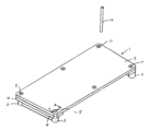
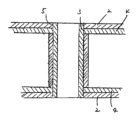
構造体1は、平板状で矩形形状の木質材の固定板2と、固定板2の少なくとも4隅に設けられた紙製の支柱3とからなっている。支柱3が取付けられる固定板2の対面する2辺には補強用の木質材でできた補強板4が設けられているが、少なくとも支柱3が取付けられる位置に固定板2の厚みを増加させる補強板4を設ければ良いものである。支柱3が取付けられる位置には支柱3が取付けられる支柱3の外形と同形状の固定穴5が形成されている。支柱3の外形形状は、円形状、四角形形状、三角形形状、五角形形状、楕円形状などに形成されている。支柱3は、複数層に形成されており、最も内側の第1支柱層3aを基台2の固定穴5の内側壁に接着により固定し、第1支柱層3aの外側の第2支柱層3bを第1支柱層3aの外側面に接着により固定するとともに、補強板4の上面に接着により固定しているが、第1支柱層3aを固定板2の固定穴5の内側壁に接着により固定しないで着脱自在にしても構わないものである。固定穴5は、実施例では固定板2の四隅に独立して形成されているが、連通した二個で形成したものでも構わないものである。支柱3は、紙管と呼ばれるもので形成したものでも構わないものである。構造体1は、テーブルのような家具、物を載置するパレット、パレットで構成されるパット家具のような物が含まれるものである。 The structure 1 consists of a flat
支柱3は、紙でできており、筒形の支柱3の表面に固定される固定部6と、支柱3間に配設される補強材7を取り付ける取付部8とが形成された取付手段9を備えており、固定板2に着脱自在に設けられている。固定部6は、支柱3の外形形状に対応した形状に形成されている。補強材7は紙でできており、先端縁が支柱3の端部と同一高さになっているのが支柱3を補強する点において望ましいが、支柱3の高さよりも低くても構わないものである。取付部8は、隣接する支柱3に向かって支柱3から離れる方向に立ち上がるようにヒンジ部10を介して固定部6に形成されているが、使用しない場合は、支柱3に密着させておくのが邪魔にならず望ましい。 The
支柱3の上端から下端にかけて形成された貫通孔11に貫通孔11と同形状の柱12が挿入されるようになっている。 A column 12 having the same shape as the through hole 11 is inserted into a through hole 11 formed from the upper end to the lower end of the
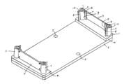
図4は、固定板2を支柱3の両端に設けているものであり、両端に設けることで、構造体1の強度を上げることが出来るものである。 In FIG. 4, the
実施例は、固定板2と支柱3と補強板4と補強材6と取付手段9はダンボールのような紙で形成されているが、固定板2及び補強板4とは紙材以外の木質材や合成樹脂材で形成されていても構わないものである。固定板2は、平板素材としてダンボールのような紙、木質材や合成樹脂材、軽量化を図った金属等全ての材料が使用できるものである。 In the embodiment, the
図示しないが、支柱3の貫通孔11にキャスターを着脱自在に設ける事で構造体を小さな力で移動させることが出来るものである。 Although not shown, by removably providing casters in the through holes 11 of the
1 構造体
2 固定板
3 支柱
4 補強板
5 固定穴
6 固定部
7 補強材
8 取付部
9 取付手段
10 ヒンジ部
11 貫通孔
12 柱 1
Claims (6)
Priority Applications (1)
| Application Number | Priority Date | Filing Date | Title |
|---|---|---|---|
| JP2022143318A JP2024029726A (en) | 2022-08-22 | 2022-08-22 | Structural body |
Applications Claiming Priority (1)
| Application Number | Priority Date | Filing Date | Title |
|---|---|---|---|
| JP2022143318A JP2024029726A (en) | 2022-08-22 | 2022-08-22 | Structural body |
Publications (1)
| Publication Number | Publication Date |
|---|---|
| JP2024029726A true JP2024029726A (en) | 2024-03-06 |
Family
ID=90104974
Family Applications (1)
| Application Number | Title | Priority Date | Filing Date |
|---|---|---|---|
| JP2022143318A Pending JP2024029726A (en) | 2022-08-22 | 2022-08-22 | Structural body |
Country Status (1)
| Country | Link |
|---|---|
| JP (1) | JP2024029726A (en) |
-
2022
- 2022-08-22 JP JP2022143318A patent/JP2024029726A/en active Pending
Similar Documents
| Publication | Publication Date | Title |
|---|---|---|
| TWI458662B (en) | Plastic pallet structure | |
| US4279204A (en) | Lightweight stackable pallet | |
| US3610173A (en) | Plastic pallet | |
| US3438342A (en) | Material-handling pallet and improved pallet leg or support and load-distributing attachment therefor | |
| US5154297A (en) | Foot assembly for simulated pallet | |
| US7677183B2 (en) | Pallet with walls hinged to support plate | |
| US3589548A (en) | Knockdown container | |
| US2673052A (en) | Molded pulp pallet support | |
| US4267780A (en) | Load supporting and handling means | |
| JP2024029726A (en) | Structural body | |
| JPH06278746A (en) | Cardboard made pallet | |
| KR19990044247A (en) | Palette | |
| JPH09315430A (en) | Box pallet | |
| JP3248519U (en) | palette | |
| JPH08175544A (en) | Paper pallet for cargo | |
| JP3014604U (en) | Paper pallet | |
| JP3234104U (en) | Cardboard pallet | |
| JPH0572729U (en) | Paper pallet | |
| KR102466862B1 (en) | Paper pallet | |
| JP3125740U (en) | Paper handling pallet | |
| JP2001261042A (en) | Roll product carrying container | |
| CN211919362U (en) | a durable tray | |
| GB2160494A (en) | Improvements in or relating to pallets | |
| TWM632632U (en) | High energy environmental protection heterogeneous composite pallet structure | |
| JP3144582U (en) | Pallet combination structure |