JP2024029717A - Posture maintenance device - Google Patents
Posture maintenance device Download PDFInfo
- Publication number
- JP2024029717A JP2024029717A JP2022132137A JP2022132137A JP2024029717A JP 2024029717 A JP2024029717 A JP 2024029717A JP 2022132137 A JP2022132137 A JP 2022132137A JP 2022132137 A JP2022132137 A JP 2022132137A JP 2024029717 A JP2024029717 A JP 2024029717A
- Authority
- JP
- Japan
- Prior art keywords
- contact
- chin
- chest
- shoulder
- contact part
- Prior art date
- Legal status (The legal status is an assumption and is not a legal conclusion. Google has not performed a legal analysis and makes no representation as to the accuracy of the status listed.)
- Granted
Links
- 238000012423 maintenance Methods 0.000 title claims abstract description 27
- 230000036544 posture Effects 0.000 description 29
- 238000010586 diagram Methods 0.000 description 4
- 206010028836 Neck pain Diseases 0.000 description 3
- 230000004048 modification Effects 0.000 description 3
- 238000012986 modification Methods 0.000 description 3
- 238000001356 surgical procedure Methods 0.000 description 3
- 230000000007 visual effect Effects 0.000 description 2
- 241001465754 Metazoa Species 0.000 description 1
- 230000000694 effects Effects 0.000 description 1
- 230000000474 nursing effect Effects 0.000 description 1
- 230000035939 shock Effects 0.000 description 1
Images

Landscapes
- Orthopedics, Nursing, And Contraception (AREA)
Abstract
Description
本発明は、頭部の姿勢維持のための頭部姿勢維持支援具に関する。 The present invention relates to a head posture maintenance support device for maintaining head posture.
身体の一部の姿勢を維持する姿勢維持補助具が提案されている(特許文献1)。 A posture maintenance aid that maintains the posture of a part of the body has been proposed (Patent Document 1).
本発明の目的は、簡易な構成で頭部の姿勢を維持することができる頭部姿勢維持支援具を提供することにある。 An object of the present invention is to provide a head posture maintenance support device that can maintain the head posture with a simple configuration.
本願発明者らは、手術の際に外科医は、頭部を動かさずに同じ姿勢で長時間にわたり手術対象部位や手術対象者の状況を示すモニターを見続けなければならないことが多くあり、その際に、首に負担がかかることから首を痛めることがよくあり、特に外科医にとって非常に悩ましい問題であることを確認した。 The inventors of the present application discovered that during surgery, surgeons often have to keep their heads in the same position for long periods of time while looking at a monitor that shows the surgical site and the status of the surgical patient. It was confirmed that neck pain is common due to the strain placed on the neck, which is a very troubling problem for surgeons in particular.
本願発明者らは、その問題をいかに簡易なデバイスで解決することができるかを考え、本発明に至った。 The inventors of the present application considered how this problem could be solved with a simple device, and arrived at the present invention.
本発明の頭部姿勢維持支援具は、
顎と当接され得る顎当接部と、
左肩と当接され得る左肩当接部と、
右肩と当接され得る右肩当接部と、
左胸と当接され得る左胸当接部と、
右胸と当接され得る右胸当接部と、を含むことができる。
The head posture maintenance support device of the present invention includes:
a chin abutment part that can be brought into contact with the chin;
a left shoulder contact portion that can come into contact with the left shoulder;
a right shoulder contact portion that can come into contact with the right shoulder;
a left chest contact portion that can be brought into contact with the left chest;
A right chest contact part that can be brought into contact with the right chest.
本発明において、
前記左胸当接部と前記左肩当接部とを接続する第1の接続部と、
前記右胸当接部と前記右肩当接部とを接続する第2の接続部と、
前記左胸当接部と前記顎当接部とを接続する第3の接続部と、
前記右胸当接部と前記顎当接部とを接続する第4の接続部とを含むことができる。
In the present invention,
a first connection part that connects the left chest contact part and the left shoulder contact part;
a second connection part that connects the right chest contact part and the right shoulder contact part;
a third connection part that connects the left chest contact part and the chin contact part;
The device may further include a fourth connection portion connecting the right chest contact portion and the chin contact portion.
本発明の頭部姿勢維持支援具は、
顎と当接され得る顎当接部と、
左肩と当接され得る左肩当接部と、
右肩と当接され得る右肩当接部と、
左胸と当接され得る左胸当接部と、
右胸と当接され得る右胸当接部と、
前記左胸当接部と前記左肩当接部とを接続する第1の接続部と、
前記右胸当接部と前記右肩当接部とを接続する第2の接続部と、を含み、
前記左胸当接部と前記右胸当接部とは同一の接続部により前記顎当接部に接続されていることができる。
The head posture maintenance support device of the present invention includes:
a chin abutment part that can be brought into contact with the chin;
a left shoulder contact portion that can come into contact with the left shoulder;
a right shoulder contact portion that can come into contact with the right shoulder;
a left chest contact portion that can be brought into contact with the left chest;
a right chest contact part that can be brought into contact with the right chest;
a first connection part that connects the left chest contact part and the left shoulder contact part;
a second connection part that connects the right chest contact part and the right shoulder contact part,
The left chest contact part and the right chest contact part may be connected to the chin contact part by the same connection part.
本発明において、
顎を前記顎当接部に置いたときに、首を左右に回すことができるように前記顎当接部が頭部姿勢維持支援具に対して回転または回動可能に設けられていることができる。
In the present invention,
The chin abutment part may be rotatably or rotatably provided with respect to the head posture maintenance support device so that the neck can be rotated from side to side when the chin is placed on the chin abutment part. can.
本発明において、
顎を前記顎当接部に置いたときに、首を前後に動かすことができるように前記顎当接部が前記頭部姿勢維持装置に対して回転または回動可能に設けられていることができる。
In the present invention,
The chin abutment part may be rotatably or rotatably provided with respect to the head posture maintaining device so that the neck can be moved back and forth when the chin is placed on the chin abutment part. can.
本発明によれば、作業をしながらでも頭部の姿勢を維持しやすい。 According to the present invention, it is easy to maintain the posture of the head even while working.
以下、本発明の実施の形態について図面を参照しながら説明する。 Embodiments of the present invention will be described below with reference to the drawings.
1.頭部姿勢維持支援具
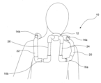
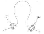
図1~図4に示すように、実施の形態に係る頭部姿勢維持支援具10は、顎と当接され得る顎当接部12と、左肩と当接され得る左肩当接部14aと、右肩と当接され得る右肩当接部14bと、左胸と当接され得る左胸当接部16aと、右胸と当接され得る右胸当接部16bと、を含む。
1. Head Posture Maintenance Support Device As shown in FIGS. 1 to 4, the head posture
頭部姿勢維持支援具10は、左胸当接部16aと左肩当接部14aとを接続する第1の接続部20と、右胸当接部16bと右肩当接部14bとを接続する第2の接続部22と、左胸当接部16aと顎当接部12とを接続する第3の接続部24と、右胸当接部16bと顎当接部12とを接続する第4の接続部26とを含むことができる。
The head posture
顎当接部12、左肩当接部14a、右肩当接部14b、左胸当接部16aおよび右胸当接部16bには、身体への負担を軽減するために、身体に当たる箇所に衝撃吸収部材が設けられていることができる。顎当接部12、左肩当接部14a、右肩当接部14b、左胸当接部16aおよび右胸当接部16bは、当接する身体の部位に沿ったかたちのものであることが好ましい。
The
第1の接続部20、第2の接続部22、第3の接続部24および第4の接続部26は、それぞれの接続機能を実現するものであれば特に限定されない。
The
左肩当接部14a、右肩当接部14b、左胸当接部16a、右胸当接部16b、第1の接続部20、第2の接続部22、第3の接続部24および第4の接続部26は、パイプにより構成することができる。隣り合うパイプの径を変えて、隣り合うパイプを嵌め合せて構成することができる。パイプは、重量との関係から、たとえばプラスチック製のものが好適である。
Left
顎当接部12、左肩当接部14a、右肩当接部14b、左胸当接部16a、右胸当接部16b、第1の接続部20、第2の接続部22、第3の接続部24および第4の接続部26は、それぞれ、隣接する機能部と一体的に設けることができる。
Chin contact
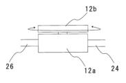
顎当接部12を頭部の左右方向、または、頭部の前後方向に回転または回動させるようにしてもよい。これにより、顎が顎当接部12に置かれた場合にて、首が回るように回転または回動させることができ、横を向いたり首を振ることができるように顎当接部12を構成してもよい。具体的には、顎を顎当接部12に置いたときに、首を左右に回すことができるように顎当接部12が頭部姿勢維持支援具10に対して回転または回動可能に設けることができる。また、顎を顎当接部12に置いたときに、首を前後に動かすことができるように顎当接部12が頭部姿勢維持装置に対して回転または回動可能に設けることができる。顎当接部12は、図5に示すように、基体12aと基体12aに対して回転または回動可能に設けられた顎載置部12bにより構成することができる。基体12aは、第3の接続部24および第4の接続部26に対して回転または回動可能に設けることができる。基体12aに第3の接続部24および第2の接続部26が接続されすることができる。
The
顎当接部12は、顎と当接する面を顎に沿った形状にする他に、顎の大きさよりも大きくして、顎を動かしやすい構成とし、いろいろな姿勢に対応し得るような面形状とすることができる。顎と当接する面を顎の大きさよりも大きくしたときには、顎当接部12が頭部姿勢維持具12に対して相対的に動かないように設定したときに特に効果的である。
The
2.作用効果
本願発明者らは、手術の際に外科医は、頭部を動かさずに同じ姿勢で長時間にわたり手術対象部位や手術対象者の状況を示すモニターを見続けなければならないことが多くあり、その際に、首に負担がかかることから首を痛めることがよくあり、特に外科医にとって非常に悩ましい問題であることを確認した。具体的には、手術中は患者や器材の関係でモニターを正面視できないことが多々ある。そのため、「モニターを正面しできず、頸部に無理のかかる横向きで頭位を固定するような姿勢」をとることが頸部に負担をかけ、肩こりや頸部痛の原因になっている。
2. Effects The inventors of the present application have discovered that during surgery, surgeons often have to keep their heads in the same position for a long time while looking at a monitor that shows the surgical site and the status of the surgical patient. At that time, it was confirmed that neck pain is common due to the strain placed on the neck, which is a particularly troubling problem for surgeons. Specifically, during surgery, it is often impossible to look directly at the monitor due to the patient and equipment. For this reason, ``a posture in which the monitor cannot be faced directly and the head is fixed in a sideways position that puts strain on the neck'' puts strain on the neck, causing stiff shoulders and neck pain.
本願発明者らは、その問題をいかに簡易なデバイスで解決することができるかを考え、本実施の形態に至った。 The inventors of the present application considered how this problem could be solved with a simple device, and arrived at the present embodiment.
顎を顎当接部12に載せることで、顎当接部12に下方向への力が作用し、その下方向への力を受けて左胸当接部16aおよび右胸当接部16bが胸部を押圧し、かつ、左肩当接部14aおよび右肩当接部14bが肩を押圧して、顎当接部12の位置が固定され、顎当接部12に顎が当接した頭部がその姿勢を維持することができる。
By placing the chin on the
本実施の形態に係る頭部姿勢維持支援具によれば、作業をしながらでも頭部の姿勢を維持することができる。 According to the head posture maintenance support device according to the present embodiment, the head posture can be maintained even while working.
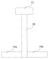
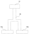
3.変形例
なお、図6に示すように、左胸当接部16aと右胸当接部16bとは同一の接続部28により顎当接部12に接続されていてもよい。図7に示すように、接続部28が左胸当接部16aおよび右胸当接部16bに接続するために分岐していてもよい。顎当接部12を接続部28との連結手段により360度方向の前後および左右に回転または回動させてもよい。連結手段としては、たとえばユニバーサルジョイントやボールジョイントを適用することができる。
3. Modifications Note that, as shown in FIG. 6, the left
実施の形態に係る頭部姿勢維持支援具10は、人のみでなく、動物においても適用可能である。実施の形態に係る頭部姿勢維持支援具10は、医師の他に、介護を必要とする者、工場の目視検査者、VDT(Visual Display Terminals)作業者を含むコンピュータ作業者などにも好適である。
The head posture
本実施の形態は、本発明の範囲内において種々の変形が可能である。 This embodiment can be modified in various ways within the scope of the present invention.
10 頭部姿勢維持支援具
12 顎当接部
12a 基体
12b 顎載置部
14a 左肩当接部
14b 右肩当接部
16a 左胸当接部
16b 右胸当接部
20 第1の接続部
22 第2の接続部
24 第3の接続部
26 第4の接続部
28 接続部
10 Head posture
Claims (5)
左肩と当接され得る左肩当接部と、
右肩と当接され得る右肩当接部と、
左胸と当接され得る左胸当接部と、
右胸と当接され得る右胸当接部と、を含む頭部姿勢維持支援具。 a chin abutment part that can be brought into contact with the chin;
a left shoulder contact portion that can come into contact with the left shoulder;
a right shoulder contact portion that can come into contact with the right shoulder;
a left chest contact portion that can be brought into contact with the left chest;
A head posture maintenance support device including: a right chest contact portion that can be brought into contact with the right chest;
前記左胸当接部と前記左肩当接部とを接続する第1の接続部と、
前記右胸当接部と前記右肩当接部とを接続する第2の接続部と、
前記左胸当接部と前記顎当接部とを接続する第3の接続部と、
前記右胸当接部と前記顎当接部とを接続する第4の接続部とを含む、頭部姿勢維持支援具。 In claim 1,
a first connection part that connects the left chest contact part and the left shoulder contact part;
a second connection part that connects the right chest contact part and the right shoulder contact part;
a third connection part that connects the left chest contact part and the chin contact part;
A head posture maintenance support device including a fourth connecting portion connecting the right chest contact portion and the chin contact portion.
左肩と当接され得る左肩当接部と、
右肩と当接され得る右肩当接部と、
左胸と当接され得る左胸当接部と、
右胸と当接され得る右胸当接部と、
前記左胸当接部と前記左肩当接部とを接続する第1の接続部と、
前記右胸当接部と前記右肩当接部とを接続する第2の接続部と、を含み、
前記左胸当接部と前記右胸当接部とは同一の接続部により前記顎当接部に接続されている頭部姿勢維持支援具。 a chin abutment part that can be brought into contact with the chin;
a left shoulder contact portion that can come into contact with the left shoulder;
a right shoulder contact portion that can come into contact with the right shoulder;
a left chest contact portion that can be brought into contact with the left chest;
a right chest contact part that can be brought into contact with the right chest;
a first connection part that connects the left chest contact part and the left shoulder contact part;
a second connection part that connects the right chest contact part and the right shoulder contact part,
In the head posture maintenance support device, the left chest contact portion and the right chest contact portion are connected to the chin contact portion through the same connection portion.
顎を前記顎当接部に置いたときに、首を左右に回すことができるように前記顎当接部が頭部姿勢維持支援具に対して回転または回動可能に設けられている頭部姿勢維持支援具。 In any one of claims 1 to 3, the chin abutment part rotates or rotates with respect to the head posture maintenance support device so that when the chin is placed on the chin abutment part, the neck can be rotated from side to side. A movable head posture maintenance support device.
顎を前記顎当接部に置いたときに、首を前後に動かすことができるように前記顎当接部が前記頭部姿勢維持装置に対して回転または回動可能に設けられている頭部姿勢維持支援具。
In any one of claims 1 to 3,
A head in which the chin abutment part is rotatably or rotatably provided with respect to the head posture maintaining device so that the neck can be moved back and forth when the chin is placed on the chin abutment part. Posture maintenance support device.
Priority Applications (1)
| Application Number | Priority Date | Filing Date | Title |
|---|---|---|---|
| JP2022132137A JP7453497B2 (en) | 2022-08-22 | 2022-08-22 | Posture maintenance device |
Applications Claiming Priority (1)
| Application Number | Priority Date | Filing Date | Title |
|---|---|---|---|
| JP2022132137A JP7453497B2 (en) | 2022-08-22 | 2022-08-22 | Posture maintenance device |
Publications (2)
| Publication Number | Publication Date |
|---|---|
| JP2024029717A true JP2024029717A (en) | 2024-03-06 |
| JP7453497B2 JP7453497B2 (en) | 2024-03-21 |
Family
ID=90104962
Family Applications (1)
| Application Number | Title | Priority Date | Filing Date |
|---|---|---|---|
| JP2022132137A Active JP7453497B2 (en) | 2022-08-22 | 2022-08-22 | Posture maintenance device |
Country Status (1)
| Country | Link |
|---|---|
| JP (1) | JP7453497B2 (en) |
Family Cites Families (6)
| Publication number | Priority date | Publication date | Assignee | Title |
|---|---|---|---|---|
| CN201775702U (en) | 2010-09-09 | 2011-03-30 | 筴彦雷 | Neck fixing and traction device |
| JP2012235993A (en) | 2011-05-11 | 2012-12-06 | Rakuhoku Gishi:Kk | Cervical orthosis |
| JP3194595U (en) | 2014-06-13 | 2014-12-04 | 合同会社うさぎ | Head holder |
| CN105342742A (en) | 2015-12-08 | 2016-02-24 | 浙江广播电视大学 | Folding head support frame |
| CN111228016B (en) | 2019-12-23 | 2025-05-16 | 安徽医科大学第一附属医院 | A posture health care device for office and study |
| JP7034563B2 (en) | 2020-02-12 | 2022-03-14 | 陶山 佳世 | Abdominal pressure vocal training equipment |
-
2022
- 2022-08-22 JP JP2022132137A patent/JP7453497B2/en active Active
Also Published As
| Publication number | Publication date |
|---|---|
| JP7453497B2 (en) | 2024-03-21 |
Similar Documents
| Publication | Publication Date | Title |
|---|---|---|
| JP7765574B2 (en) | exercise aid device | |
| US20190201273A1 (en) | Robotic upper limb rehabilitation device | |
| Pacifico et al. | An experimental evaluation of the proto-mate: a novel ergonomic upper-limb exoskeleton to reduce workers' physical strain | |
| CN105979919B (en) | Non-exoskeleton rehabilitation equipment with multiple active axes | |
| WO2018093448A2 (en) | Robotic upper limb rehabilitation device | |
| CN107028662B (en) | Remote operation device and remote operation system | |
| WO2017167349A1 (en) | Spherical joint mechanism with a double parallelogram mechanism | |
| Rossini et al. | Design and evaluation of a passive cable-driven occupational shoulder exoskeleton | |
| KR101471385B1 (en) | Wearable robot for arms | |
| Kooren et al. | Design and pilot validation of A-gear: a novel wearable dynamic arm support | |
| US10925798B2 (en) | Movable apparatus, movable sheet, and method of manufacturing movable apparatus | |
| JP6894497B2 (en) | Patient support and patient positioning system | |
| US11259981B2 (en) | Exoskeleton for lower-limbs | |
| US12377009B2 (en) | Exoskeleton for upper arm | |
| US6526331B2 (en) | Robot arm | |
| Zhang et al. | A spring-loaded compliant neck brace with adjustable supports | |
| US20100279249A1 (en) | Dental oral mirror | |
| TW202208130A (en) | Exoskeleton load handling device | |
| Buckingham | Robotics in surgery | |
| WO2005025709A1 (en) | Paper doll | |
| JP7453497B2 (en) | Posture maintenance device | |
| Demaree et al. | A structurally enhanced neck exoskeleton to assist with head-neck motion | |
| KR102325979B1 (en) | Mask type turtle neck posture corrector | |
| KR102721936B1 (en) | Femoral support module of muscle suppoert robot | |
| Cordella et al. | A biofeedback-based posture correction system for working environments |
Legal Events
| Date | Code | Title | Description |
|---|---|---|---|
| A621 | Written request for application examination |
Free format text: JAPANESE INTERMEDIATE CODE: A621 Effective date: 20230827 |
|
| A521 | Request for written amendment filed |
Free format text: JAPANESE INTERMEDIATE CODE: A523 Effective date: 20231108 |
|
| A871 | Explanation of circumstances concerning accelerated examination |
Free format text: JAPANESE INTERMEDIATE CODE: A871 Effective date: 20231108 |
|
| A131 | Notification of reasons for refusal |
Free format text: JAPANESE INTERMEDIATE CODE: A131 Effective date: 20231208 |
|
| A521 | Request for written amendment filed |
Free format text: JAPANESE INTERMEDIATE CODE: A523 Effective date: 20240122 |
|
| TRDD | Decision of grant or rejection written | ||
| A01 | Written decision to grant a patent or to grant a registration (utility model) |
Free format text: JAPANESE INTERMEDIATE CODE: A01 Effective date: 20240130 |
|
| A61 | First payment of annual fees (during grant procedure) |
Free format text: JAPANESE INTERMEDIATE CODE: A61 Effective date: 20240217 |
|
| R150 | Certificate of patent or registration of utility model |
Ref document number: 7453497 Country of ref document: JP Free format text: JAPANESE INTERMEDIATE CODE: R150 |
|
| S111 | Request for change of ownership or part of ownership |
Free format text: JAPANESE INTERMEDIATE CODE: R313113 |
|
| R350 | Written notification of registration of transfer |
Free format text: JAPANESE INTERMEDIATE CODE: R350 |