JP2024025974A - Process control systems, methods and information processing equipment - Google Patents
Process control systems, methods and information processing equipment Download PDFInfo
- Publication number
- JP2024025974A JP2024025974A JP2022129380A JP2022129380A JP2024025974A JP 2024025974 A JP2024025974 A JP 2024025974A JP 2022129380 A JP2022129380 A JP 2022129380A JP 2022129380 A JP2022129380 A JP 2022129380A JP 2024025974 A JP2024025974 A JP 2024025974A
- Authority
- JP
- Japan
- Prior art keywords
- location
- management target
- area
- tag
- target
- Prior art date
- Legal status (The legal status is an assumption and is not a legal conclusion. Google has not performed a legal analysis and makes no representation as to the accuracy of the status listed.)
- Pending
Links
- 238000000034 method Methods 0.000 title claims abstract description 245
- 238000004886 process control Methods 0.000 title claims description 18
- 230000010365 information processing Effects 0.000 title claims description 16
- 230000008569 process Effects 0.000 claims abstract description 222
- 238000004891 communication Methods 0.000 claims description 41
- 238000009434 installation Methods 0.000 claims description 16
- 238000010586 diagram Methods 0.000 abstract description 25
- 238000007726 management method Methods 0.000 description 245
- 235000019580 granularity Nutrition 0.000 description 71
- 238000005259 measurement Methods 0.000 description 35
- 239000000463 material Substances 0.000 description 20
- 238000001514 detection method Methods 0.000 description 19
- 238000012545 processing Methods 0.000 description 15
- 230000005540 biological transmission Effects 0.000 description 14
- 230000006870 function Effects 0.000 description 13
- 238000003860 storage Methods 0.000 description 12
- 238000001914 filtration Methods 0.000 description 10
- 239000004566 building material Substances 0.000 description 8
- 238000013523 data management Methods 0.000 description 8
- 230000004044 response Effects 0.000 description 7
- 230000001133 acceleration Effects 0.000 description 6
- 230000008859 change Effects 0.000 description 6
- 238000010276 construction Methods 0.000 description 6
- 238000012986 modification Methods 0.000 description 6
- 230000004048 modification Effects 0.000 description 6
- 238000004590 computer program Methods 0.000 description 5
- 238000005516 engineering process Methods 0.000 description 5
- 238000012795 verification Methods 0.000 description 5
- 238000004364 calculation method Methods 0.000 description 3
- 230000008520 organization Effects 0.000 description 3
- 230000003321 amplification Effects 0.000 description 2
- 230000010267 cellular communication Effects 0.000 description 2
- 238000011960 computer-aided design Methods 0.000 description 2
- 238000012790 confirmation Methods 0.000 description 2
- 230000001186 cumulative effect Effects 0.000 description 2
- 239000000284 extract Substances 0.000 description 2
- 230000008570 general process Effects 0.000 description 2
- 238000003199 nucleic acid amplification method Methods 0.000 description 2
- 230000003287 optical effect Effects 0.000 description 2
- 239000004065 semiconductor Substances 0.000 description 2
- 238000012384 transportation and delivery Methods 0.000 description 2
- 238000009435 building construction Methods 0.000 description 1
- 230000001413 cellular effect Effects 0.000 description 1
- 230000003247 decreasing effect Effects 0.000 description 1
- 238000012217 deletion Methods 0.000 description 1
- 230000037430 deletion Effects 0.000 description 1
- 238000009826 distribution Methods 0.000 description 1
- 230000005484 gravity Effects 0.000 description 1
- 238000003384 imaging method Methods 0.000 description 1
- 230000003993 interaction Effects 0.000 description 1
- 239000004973 liquid crystal related substance Substances 0.000 description 1
- 238000004519 manufacturing process Methods 0.000 description 1
- 238000013507 mapping Methods 0.000 description 1
- 239000003550 marker Substances 0.000 description 1
- 238000012015 optical character recognition Methods 0.000 description 1
- 230000002093 peripheral effect Effects 0.000 description 1
- 230000002123 temporal effect Effects 0.000 description 1
- 230000007704 transition Effects 0.000 description 1
- 230000000007 visual effect Effects 0.000 description 1
- 238000012800 visualization Methods 0.000 description 1
Images


Classifications
-
- G—PHYSICS
- G06—COMPUTING; CALCULATING OR COUNTING
- G06K—GRAPHICAL DATA READING; PRESENTATION OF DATA; RECORD CARRIERS; HANDLING RECORD CARRIERS
- G06K7/00—Methods or arrangements for sensing record carriers, e.g. for reading patterns
- G06K7/10—Methods or arrangements for sensing record carriers, e.g. for reading patterns by electromagnetic radiation, e.g. optical sensing; by corpuscular radiation
- G06K7/10009—Methods or arrangements for sensing record carriers, e.g. for reading patterns by electromagnetic radiation, e.g. optical sensing; by corpuscular radiation sensing by radiation using wavelengths larger than 0.1 mm, e.g. radio-waves or microwaves
- G06K7/10366—Methods or arrangements for sensing record carriers, e.g. for reading patterns by electromagnetic radiation, e.g. optical sensing; by corpuscular radiation sensing by radiation using wavelengths larger than 0.1 mm, e.g. radio-waves or microwaves the interrogation device being adapted for miscellaneous applications
-
- G—PHYSICS
- G06—COMPUTING; CALCULATING OR COUNTING
- G06Q—INFORMATION AND COMMUNICATION TECHNOLOGY [ICT] SPECIALLY ADAPTED FOR ADMINISTRATIVE, COMMERCIAL, FINANCIAL, MANAGERIAL OR SUPERVISORY PURPOSES; SYSTEMS OR METHODS SPECIALLY ADAPTED FOR ADMINISTRATIVE, COMMERCIAL, FINANCIAL, MANAGERIAL OR SUPERVISORY PURPOSES, NOT OTHERWISE PROVIDED FOR
- G06Q10/00—Administration; Management
-
- G—PHYSICS
- G06—COMPUTING; CALCULATING OR COUNTING
- G06K—GRAPHICAL DATA READING; PRESENTATION OF DATA; RECORD CARRIERS; HANDLING RECORD CARRIERS
- G06K19/00—Record carriers for use with machines and with at least a part designed to carry digital markings
- G06K19/06—Record carriers for use with machines and with at least a part designed to carry digital markings characterised by the kind of the digital marking, e.g. shape, nature, code
- G06K19/067—Record carriers with conductive marks, printed circuits or semiconductor circuit elements, e.g. credit or identity cards also with resonating or responding marks without active components
- G06K19/07—Record carriers with conductive marks, printed circuits or semiconductor circuit elements, e.g. credit or identity cards also with resonating or responding marks without active components with integrated circuit chips
- G06K19/077—Constructional details, e.g. mounting of circuits in the carrier
- G06K19/07749—Constructional details, e.g. mounting of circuits in the carrier the record carrier being capable of non-contact communication, e.g. constructional details of the antenna of a non-contact smart card
- G06K19/07758—Constructional details, e.g. mounting of circuits in the carrier the record carrier being capable of non-contact communication, e.g. constructional details of the antenna of a non-contact smart card arrangements for adhering the record carrier to further objects or living beings, functioning as an identification tag
-
- G—PHYSICS
- G06—COMPUTING; CALCULATING OR COUNTING
- G06Q—INFORMATION AND COMMUNICATION TECHNOLOGY [ICT] SPECIALLY ADAPTED FOR ADMINISTRATIVE, COMMERCIAL, FINANCIAL, MANAGERIAL OR SUPERVISORY PURPOSES; SYSTEMS OR METHODS SPECIALLY ADAPTED FOR ADMINISTRATIVE, COMMERCIAL, FINANCIAL, MANAGERIAL OR SUPERVISORY PURPOSES, NOT OTHERWISE PROVIDED FOR
- G06Q10/00—Administration; Management
- G06Q10/06—Resources, workflows, human or project management; Enterprise or organisation planning; Enterprise or organisation modelling
- G06Q10/063—Operations research, analysis or management
-
- G—PHYSICS
- G06—COMPUTING; CALCULATING OR COUNTING
- G06Q—INFORMATION AND COMMUNICATION TECHNOLOGY [ICT] SPECIALLY ADAPTED FOR ADMINISTRATIVE, COMMERCIAL, FINANCIAL, MANAGERIAL OR SUPERVISORY PURPOSES; SYSTEMS OR METHODS SPECIALLY ADAPTED FOR ADMINISTRATIVE, COMMERCIAL, FINANCIAL, MANAGERIAL OR SUPERVISORY PURPOSES, NOT OTHERWISE PROVIDED FOR
- G06Q10/00—Administration; Management
- G06Q10/08—Logistics, e.g. warehousing, loading or distribution; Inventory or stock management
- G06Q10/087—Inventory or stock management, e.g. order filling, procurement or balancing against orders
- G06Q10/0875—Itemisation or classification of parts, supplies or services, e.g. bill of materials
-
- G—PHYSICS
- G06—COMPUTING; CALCULATING OR COUNTING
- G06Q—INFORMATION AND COMMUNICATION TECHNOLOGY [ICT] SPECIALLY ADAPTED FOR ADMINISTRATIVE, COMMERCIAL, FINANCIAL, MANAGERIAL OR SUPERVISORY PURPOSES; SYSTEMS OR METHODS SPECIALLY ADAPTED FOR ADMINISTRATIVE, COMMERCIAL, FINANCIAL, MANAGERIAL OR SUPERVISORY PURPOSES, NOT OTHERWISE PROVIDED FOR
- G06Q50/00—Systems or methods specially adapted for specific business sectors, e.g. utilities or tourism
- G06Q50/04—Manufacturing
-
- G—PHYSICS
- G06—COMPUTING; CALCULATING OR COUNTING
- G06Q—INFORMATION AND COMMUNICATION TECHNOLOGY [ICT] SPECIALLY ADAPTED FOR ADMINISTRATIVE, COMMERCIAL, FINANCIAL, MANAGERIAL OR SUPERVISORY PURPOSES; SYSTEMS OR METHODS SPECIALLY ADAPTED FOR ADMINISTRATIVE, COMMERCIAL, FINANCIAL, MANAGERIAL OR SUPERVISORY PURPOSES, NOT OTHERWISE PROVIDED FOR
- G06Q50/00—Systems or methods specially adapted for specific business sectors, e.g. utilities or tourism
- G06Q50/08—Construction
Abstract
【課題】効率的且つより柔軟な工程管理の仕組みを提供すること。【解決手段】工程管理システムは、複数の区域を定義する区域データ、及び、前記複数の区域のうちで、管理対象の移動を伴う作業工程の完了時に前記管理対象が位置すべき予定地を示す工程データを管理する。第1読取装置は、前記管理対象に付された第1無線デバイスから、前記管理対象を識別するための第1識別情報を読取る。前記工程管理システムは、前記第1読取装置による前記読取りの結果に基づいて推定される前記管理対象の所在地を前記予定地と照合して、前記管理対象に関する前記作業工程のステータスを判定する判定部、を含む。前記区域データは、異なる空間的粒度で設定される第1レベル区域及び第2レベル区域を定義する。前記判定部は、前記管理対象に関連付けられる種別情報に依存して異なる粒度で、前記管理対象の前記所在地を前記予定地と照合する。【選択図】図20[Problem] To provide an efficient and more flexible process management system. A process management system includes area data defining a plurality of areas, and a planned location where the management target is to be located at the time of completion of a work process involving movement of the management target among the plurality of areas. Manage process data. The first reading device reads first identification information for identifying the management target from a first wireless device attached to the management target. The process management system includes a determination unit that compares the location of the management target estimated based on the reading result by the first reading device with the planned location to determine the status of the work process regarding the management target. ,including. The area data defines first level areas and second level areas that are established at different spatial granularity. The determination unit compares the location of the management target with the planned location at different granularity depending on type information associated with the management target. [Selection diagram] Figure 20
Description
本開示は、工程管理システム、方法及び情報処理装置に関する。 The present disclosure relates to a process management system, method, and information processing device.
RFID(Radio Frequency IDentification)は、タグとも呼ばれる小型のデバイス内に埋め込まれた情報を近距離無線通信によって外部のリーダから読取ることを可能にする技術である。例えば、一意な識別情報を埋め込んだRFIDタグを物品に付しておくことで、物品の所在を効率的に把握することが可能となり、管理下にある物品の情報を可視化することも容易となる。なかでも、リーダから放射される電磁波のエネルギーを利用して情報を送信するパッシブ型RFIDタグは、バッテリが不要であるために製造コストが安く、また半永久的に動作できることから、様々な場面での活用が広がっている。 RFID (Radio Frequency IDentification) is a technology that allows information embedded within a small device, also called a tag, to be read by an external reader using near field communication. For example, by attaching RFID tags embedded with unique identification information to goods, it becomes possible to efficiently ascertain the location of goods, and it is also easy to visualize information on goods under management. . Among these, passive RFID tags, which transmit information using the energy of electromagnetic waves emitted from a reader, are inexpensive to manufacture because they do not require batteries, and can operate semi-permanently, making them useful in a variety of situations. Its use is expanding.
特許文献1は、建設工事の進捗管理を効率化させるためにRFIDを活用する管理システムを開示している。特許文献1の管理システムでは、特定の場所にRFIDタグが設置され、建材にもRFIDタグが付与された状況で、ハンディ端末によりそれらRFIDタグから読取られた情報に基づいて、建材の最新の所在地及びステータスがユーザに提示される。
特許文献2は、遮蔽物の多い環境において不安定になり易いGPS(Global Positioning System)測位に頼ることなく管理対象の位置を推定するために、RFIDタグからの情報の読取りと自己位置推定法とを組合せる技術を開示している。特許文献2の技術によれば、固定的に設置された位置タグの既知の位置と、自己位置推定法(PDR(Pedestrian Dead Reckoning)ともいう)に従って算出される読取装置の相対的な移動量とに基づいて、管理対象の所在地が推定される。
特許文献1の管理システムでは、ある時点で、所定の場所にあるべき建材について、ハンディ端末により当該所定の場所のRFIDタグが検知されると共に当該建材のRFIDタグが検知されると、その建材が正しい場所にあると判定される。しかし、一般的な工程管理の場面において求められる所在地の判定の空間的粒度は、必ずしも一様でなない。例えば、ある種類の建材は、比較的広い工事現場に到着していれば十分であるのに対し、他の種類の建材は、より具体的な地点への配送を求められるかもしれない。あるいは、同じ種類の建材であっても、建設工事の前半の作業工程では比較的広い区域のどこに所在していてもよいのに対し、建設工事の後半の作業工程では特定の位置に取付けられていなければならないことがあり得る。既存のシステムは、こうした要件に柔軟に対処することができない。
In the management system of
本発明は、上述した点に鑑み、効率的且つより柔軟な工程管理の仕組みを提供しようとするものである。 In view of the above points, the present invention aims to provide an efficient and more flexible process management system.
ある観点によれば、実空間に設定される複数の区域を定義する区域データ、及び、前記複数の区域のうちで、管理対象の移動を伴う作業工程の完了時に前記管理対象が位置すべき予定地を示す工程データを管理する管理部と、前記管理対象に付され、前記管理対象を識別するための第1識別情報を記憶している第1無線デバイスと、無線デバイスから当該無線デバイスに記憶されている識別情報を読取可能な少なくとも1つの読取装置と、第1読取装置による前記第1無線デバイスからの前記第1識別情報の読取りの結果に基づいて推定される前記管理対象の所在地を前記工程データにより示される前記予定地と照合して、前記管理対象に関する前記作業工程のステータスを判定する判定部と、を含む工程管理システムが提供される。前記区域データは、第1の空間的粒度で前記実空間に設定される少なくとも1つの第1レベル区域、及び前記第1の空間的粒度よりも狭い第2の空間的粒度で前記少なくとも1つの第1レベル区域に設定される少なくとも1つの第2レベル区域を定義する。前記判定部は、前記管理対象に関連付けられる種別情報に依存して異なる粒度で、前記管理対象の前記所在地を前記予定地と照合する。対応する方法及び情報処理装置もまた提供される。 According to a certain point of view, area data defining a plurality of areas set in real space, and a schedule where the management target is to be located among the plurality of areas at the time of completion of a work process that involves movement of the management target. a first wireless device that stores first identification information attached to the management target for identifying the management target; and a first wireless device that stores first identification information from the wireless device to the wireless device. at least one reading device capable of reading the identification information that has been identified, and the location of the managed target estimated based on the result of reading the first identification information from the first wireless device by the first reading device; A process management system is provided, including a determination unit that determines the status of the work process related to the management target by comparing it with the planned location indicated by process data. The zone data includes at least one first level zone set in the real space at a first spatial granularity, and at least one first level zone set in the real space at a first spatial granularity, and at a second spatial granularity narrower than the first spatial granularity. Define at least one second level area set in the first level area. The determination unit compares the location of the management target with the planned location at different granularity depending on type information associated with the management target. Corresponding methods and information processing apparatus are also provided.
本発明によれば、効率的且つより柔軟な工程管理の仕組みを提供することができる。 According to the present invention, an efficient and more flexible process management system can be provided.
以下、添付図面を参照して実施形態を詳しく説明する。なお、以下の実施形態は特許請求の範囲に係る発明を限定するものではない。実施形態には複数の特徴が記載されているが、これらの複数の特徴の全てが発明に必須のものとは限らず、また、複数の特徴は任意に組み合わせられてもよい。さらに、添付図面においては、同一若しくは同様の構成に同一の参照番号を付し、重複した説明は省略する。 Hereinafter, embodiments will be described in detail with reference to the accompanying drawings. Note that the following embodiments do not limit the claimed invention. Although a plurality of features are described in the embodiments, not all of these features are essential to the invention, and the plurality of features may be arbitrarily combined. Furthermore, in the accompanying drawings, the same or similar components are designated by the same reference numerals, and redundant description will be omitted.
<1.システムの概要>
図1は、一実施形態に係る工程管理システム1の構成の一例を示す模式図である。工程管理システム1は、作業が進むにつれて日々変化し得る管理対象の所在地を追跡し、作業の進捗に関する情報の可視化を支援するシステムである。本明細書において取り扱う作業は、1つ以上の作業工程からなるものであり、少なくとも1つの作業工程が、管理対象の移動を伴う。以下の説明において、作業が行われる実空間を作業空間ともいう。一例として、建物の建設という作業は、現場への資材の搬入、フロア又は部屋への資材の分配、及び資材の取付けといった一連の作業工程を含み得る。管理対象は、実空間に所在する物品及び実空間において活動するユーザのうちの少なくとも一方を含んでよい。物品とは、無生物(例えば、機械、機器、器具、資材、消費財、部品、車両又はロボット)であっても生物(例えば、動物又は植物)であってもよい。以下では、建物の建設という作業の例を主に説明するが、本開示に係る技術は、例えば道路工事又はイベント会場の設営など、他の種類の作業にも適用可能である。
<1. System overview>
FIG. 1 is a schematic diagram showing an example of the configuration of a
本実施形態において、工程管理システム1は、各管理対象の所在地を示す位置情報を管理する。位置情報の管理のために、実空間に複数の区域が設定されるものとし、それら区域は各管理対象の所在地の候補となる。各管理対象の位置情報は、さらに、各管理対象が位置すると推定される地点の2次元又は3次元の位置座標をも含む。
In this embodiment, the
図1は、本実施形態に係る工程管理システム1の構成の一例を示す模式図である。図1の例では、実空間に複数の区域10a、10aa、10ab、10ac、10ad、10ae、10b、10ba、及び10bbが設定されている。区域10a及び区域10bは、例えば、地理的に互いに離れた地区(例えば、異なる工事現場)に相当し得る。区域10aa及び10adは、区域10aの空間的粒度よりも狭い空間的粒度で区域10aの内部に設定される区域であり、例えば、ある地区に建設される別個の建物に相当し得る。区域10ab及び10acは、区域10aaの空間的粒度よりも狭い空間的粒度で区域10aaの内部に設定される区域であり、例えば、ある建物を構成する別個のフロアに相当し得る。同様に、区域10aeは、区域10adの空間的粒度よりも狭い空間的粒度で区域10adの内部に設定される区域である。図1には示していないものの、各フロア内に、さらに狭い空間的粒度で、部屋に相当し得るさらなる区域が設定されてもよい。このように、作業空間に設定される複数の区域はツリー状の階層的関係を有し、後述する区域データがその階層的関係を定義する。以下の説明では、複数の区域の階層的関係において、相対的に広い空間的粒度で設定される区域を上位レベル区域、相対的に狭い空間的粒度で設定される区域を下位レベル区域ともいう。例えば、区域10aa、10ab、10ac、10ad及び10aeは、区域10aにとっての下位レベル区域である。
FIG. 1 is a schematic diagram showing an example of the configuration of a
図1の例において、ユーザ20aは、携帯システム100を携帯しながら、複数の区域の間を移動する。なお、本明細書において、ユーザが何らかの対象を携帯するとの表現は、ユーザがその対象と共に移動する様々な態様(例えば、対象を保持し又は装着した状態で移動するなど)を広く包含するものとする。また、物品30a、30b及び30cがそれぞれ区域10ab、10aa及び10bに存在する。これら物品は、工程管理システム1により位置情報を管理される対象である。物品に加えて、ユーザ(例えば、作業者、監督者及びその他の関係者)もまた管理対象であってよい。
In the example of FIG. 1,
工程管理システム1は、管理対象の所在地を追跡するために、タグとも呼ばれる無線デバイスを活用する。位置タグは、工程管理システム1において管理対象の所在地の候補となる区域の各々に設置される無線デバイス(第2無線デバイス)である。図中では、区域10aに位置タグ40a、区域10aaに位置タグ40aa、区域10abに位置タグ40ab、区域10acに位置タグ40ac、区域10adに位置タグ40ad、区域10aeに位置タグ40aeが設置されている。同様に、区域10bに位置タグ40bが設置されている。1つの区域に2つ以上の位置タグが設置されてもよく、図1の例において区域10baには2つの位置タグが設置されている。各位置タグは、対応する設置区域に関連付けられる識別情報(第2識別情報)を内部のメモリに記憶している。
The
対象タグは、工程管理システム1において管理対象の各々に付される無線デバイス(第1無線デバイス)である。図1には、物品30aに付された対象タグ50a、物品30bに付された対象タグ50b、及び物品30cに付された対象タグ50cが示されている。各対象タグは、当該対象タグが付された管理対象を識別するための識別情報(第1識別情報)を内部のメモリに記憶している。
The target tag is a wireless device (first wireless device) attached to each managed target in the
なお、以下の説明において、区域10a~10bbを相互に区別する必要のない場合には、符号の末尾のアルファベットを省略することにより、これらを区域10と総称する。物品30(物品30a、30b、...)、位置タグ40(40a、40b、...)、対象タグ50(対象タグ50a、50b...)、ユーザ20、並びに他の要素についても同様である。
In the following description, if there is no need to distinguish the
実空間に設定される区域の数、及び管理対象の数は、図1に示した例に限定されず、いかなる数であってもよい。同様に、工程管理システム1を利用するユーザの人数、及びユーザにより携帯される後述する携帯システム100の数もまた、いかなる数であってもよい。また、複数の区域の階層的関係において、階層の数は少なくとも2であればよい。階層の数が2、3、4又は5である場合の、階層の集合のいくつかの実例を以下に挙示する。なお、各括弧内のリストが1つの階層集合であり、リスト内で右にある階層がより下位の階層である:
・階層数=2:(地区,建物),(建物,フロア),(建物,部屋),(フロア,部屋)
・階層数=3:(地区,建物,フロア),(地区,建物,部屋),(建物,フロア,部屋)
・階層数=4:(地区,建物,フロア,部屋),(組織,建物,フロア,部屋)
・階層数=5:(組織,地区,建物,フロア,部屋)
The number of areas set in real space and the number of management targets are not limited to the example shown in FIG. 1, and may be any number. Similarly, the number of users who use the
・Number of floors = 2: (district, building), (building, floor), (building, room), (floor, room)
・Number of floors = 3: (district, building, floor), (district, building, room), (building, floor, room)
・Number of layers = 4: (district, building, floor, room), (organization, building, floor, room)
・Number of layers = 5: (organization, district, building, floor, room)
本実施形態において、位置タグ40及び対象タグ50といったタグの各々は、パッシブ型のRFIDタグ(パッシブタグ)であるものとする。パッシブタグは、メモリを内蔵する小型のIC(Integrated Circuit)チップ、及びアンテナで構成され、メモリ内に当該タグを識別する固有の識別情報その他の情報を記憶する。本明細書では、識別情報を単にID、タグを識別する識別情報をタグIDともいう。なお、タグIDは、タグが付された対象を識別する情報であるとみなされてもよい。パッシブタグのICチップは、タグリーダから放射される電磁波のエネルギーを利用して動作し、メモリ内に記憶されているタグID及びその他の情報を情報信号へと変調して、情報信号をアンテナから送信(返送)する。
In this embodiment, each of the tags such as the
なお、他の実施形態において、各タグは、アクティブ型のRFIDタグであってもよい。各タグが内蔵するバッテリからの電力を利用して能動的に(例えば、周期的に)情報を周囲へ送信する場合、当該タグはビーコンタグと呼ばれてもよい。また別の実施形態において、各タグは、リーダからの信号に応答して、例えばNFC(Near Field Communication)方式又はBluetooth(登録商標)方式で情報を返送する無線デバイスであってもよい。各タグは、ICタグ、ICカード又はレスポンダなど、いかなる名称で呼ばれてもよい。 Note that in other embodiments, each tag may be an active RFID tag. When each tag actively (eg, periodically) transmits information to its surroundings using power from its internal battery, the tag may be referred to as a beacon tag. In another embodiment, each tag may be a wireless device that responds to a signal from a reader and sends back information using, for example, an NFC (Near Field Communication) method or a Bluetooth (registered trademark) method. Each tag may be called by any name such as an IC tag, an IC card, or a responder.
工程管理システム1は、携帯システム100及び管理サーバ200を含む。携帯システム100及び管理サーバ200は、ネットワーク5へ接続される。ネットワーク5は、有線ネットワーク、無線ネットワーク、又はそれらの任意の組合せであってよい。ネットワーク5の例は、インターネット、イントラネット及びクラウドネットワークを含み得る。
The
携帯システム100は、少なくともタグリーダ110を含む。タグリーダ110は、RFIDタグなどの無線デバイスに記憶されている情報を読取可能な読取装置である。タグリーダ110は、例えば、対象タグ50からタグIDを読取ることにより、当該対象タグ50が付されている管理対象を検知することができる。タグリーダ110は、周期的に又はユーザ操作などの何らかのトリガに応じて読取りを試行し、タグ読取結果を管理サーバ200へ送信する。タグリーダ110は、管理サーバ200と直接的に通信可能であってもよく、又は何らかの中継装置(例えば、後述するユーザ端末160)を介して間接的に管理サーバ200と通信可能であってもよい。タグリーダ110の具体的な構成の一例について、後にさらに説明する。
図1に示した例において、携帯システム100は、ユーザ端末160をさらに含む。ユーザ端末160は、例えば、ノートブックPC(Personal Computer)、タブレットPC、スマートフォン又はスマートウォッチといった、任意の種類の端末装置又は情報処理装置であってよい。ユーザ端末160は、工程管理システム1によるユーザ20とのインタラクションのために利用され得る。ユーザ端末160の具体的な構成の一例について、後にさらに説明する。
In the example shown in FIG. 1,
管理サーバ200は、管理対象の位置情報、作業の進捗に関するステータス、及びその他の情報をデータベースにおいて管理する情報処理装置である。管理サーバ200は、例えば、高性能な汎用コンピュータを用いて、アプリケーションサーバ、データベースサーバ又はクラウドサーバとして実装されてよい。管理サーバ200は、タグリーダ110からタグ読取結果を受信し、受信したタグ読取結果に基づいてデータベースを更新する。管理サーバ200は、各管理対象のステータスの更新を行う際に、タグ読取結果に基づいて推定される各管理対象の所在地を、各作業工程における当該管理対象の予定地と照合する。管理サーバ200の具体的な構成の一例について、後にさらに説明する。
The
図1には単一の管理サーバ200を示しているが、後に詳しく説明する管理サーバ200の機能は、単一の装置により提供されてもよく、又は物理的に別個の複数の装置が相互に連携することにより提供されてもよい。また、本実施形態では、管理サーバ200がデータベースを保持する例を説明するが、管理サーバ200とは別個の装置がデータベースの一部又は全部を保持していてもよい。例えば、一部のデータは、無線デバイス(例えば、位置タグ若しくは対象タグ)、タグリーダ110又はユーザ端末160により保持されてもよい。
Although a
なお、図1には携帯システム100が別個の装置であるタグリーダ110及びユーザ端末160を含む例を示している。しかしながら、携帯システム100は、かかる例には限定されない。例えば、タグリーダ110が後述するユーザ端末160の機能の一部又は全部を有していてもよく、ユーザ端末160が後述するタグリーダ110の機能の一部又は全部を有していてもよい。また、本実施形態において説明する管理サーバ200の機能がユーザ端末160において実現されてもよい。
Note that FIG. 1 shows an example in which the
<2.携帯システムの構成例>
<2-1.タグリーダの構成例>
図2は、一実施形態に係る携帯システム100に含まれるタグリーダ110の構成の一例を示すブロック図である。図2を参照すると、タグリーダ110は、制御部111、記憶部112、通信部113、測定部114、操作部115、及び読取部116を備える。
<2. Mobile system configuration example>
<2-1. Tag reader configuration example>
FIG. 2 is a block diagram showing an example of the configuration of
制御部111は、コンピュータプログラムを記憶するメモリ、及びコンピュータプログラムを実行する1つ以上のプロセッサ(例えば、CPU(Central Processing Unit))からなる。制御部111は、本明細書で説明するタグリーダ110の機能全般を制御する。例えば、制御部111は、読取部116にタグ読取レンジ内のRFIDタグの読取りを実行させ、読取られた情報、読取時刻、及び信号の受信レベルを、読取結果データとして記憶部112に一時的に記憶させる。また、制御部111は、RFIDタグの読取りと並行して、測定部114にタグリーダ110の位置を測定させ、その測定結果を記憶部112に記憶させる。そして、制御部111は、記憶部112に記憶されている読取結果データ及び測定結果データを、自装置のリーダ識別情報(リーダIDともいう)と共に、通信部113を介して管理サーバ200へ送信する。
The
記憶部112は、例えば、ROM(Read Only Memory)若しくはRAM(Random Access Memory)などの半導体メモリ、光ディスク、又は磁気ディスクといった、任意の種類の記憶媒体を含んでよい。本実施形態において、記憶部112は、上述した読取結果データ、測定結果データ、及びタグリーダ110のリーダIDを記憶する。
The
通信部113は、タグリーダ110が管理サーバ200と通信するための通信インタフェースである。例えば、通信部113は、WLAN(Wireless Local Area Network)アクセスポイントと通信するWLANインタフェース、又はセルラー基地局と通信するセルラー通信インタフェースであってもよい。また、通信部113は、中継装置との接続用の接続インタフェース(例えば、Bluetooth(登録商標)インタフェース又はUSB(Universal Serial Bus)インタフェース)であってもよい。
The
測定部114は、タグリーダ110の位置を測定可能なユニットである。本実施形態において、測定部114は、PDRとも呼ばれる自己位置推定法を用いて、ある基準位置からのタグリーダ110の相対的な移動量を測定して、測定した移動量を制御部111へ出力する。相対移動量の測定の基準位置は、例えば、タグリーダ110が起動された時点のタグリーダ110の位置であってよい。タグリーダ110の相対移動量は、相対位置として扱われ得る。例えば、測定部114は、3軸加速度センサ114a、ジャイロセンサ114b、及び地磁気センサ114cを含む。3軸加速度センサ114aは、タグリーダ110に固有のデバイス座標系でタグリーダ110に加わる加速度を測定して、第1のセンサデータを出力する。ジャイロセンサ114bは、タグリーダ110の角速度、即ちタグリーダ110の姿勢の変化を測定して、第2のセンサデータを出力する。地磁気センサ114cは、実空間におけるタグリーダ110の方位を測定して、第3のセンサデータを出力する。測定部114は、これらセンサからのセンサデータに基づいて、タグリーダ110の加速度の方向を実空間の座標系における方向に換算しながら加速度を累積することで、タグリーダ110の相対的な移動量を測定することができる。測定部114から制御部111へ出力される相対移動量は、水平面内の2次元ベクトルであってもよく、又は高さ方向の成分も含む3次元ベクトルであってもよい。
The
後に説明するように、本実施形態において、各位置タグ40の設置位置の位置座標は、既知であってデータベースに登録されている。したがって、タグリーダ110がある位置タグ40を検知した時点から現在時点までの相対移動量と、当該位置タグ40の既知の位置座標とに基づいて、タグリーダ110が現在位置している地点の位置座標を推定することができる。本実施形態では、管理サーバ200がタグリーダ110の絶対位置を推定する例を主に説明するが、タグリーダ110の制御部111又は測定部114がデータベースへアクセスしてタグリーダ110の絶対位置を推定してもよい。
As will be explained later, in this embodiment, the position coordinates of the installation position of each
なお、タグリーダ110が測定部114を含む代わりに、携帯システム100がタグリーダ110とは別個の(例えば、自己位置推定法を用いて相対移動量を測定可能な)測定装置を含んでもよい。
Note that instead of the
ある変形例において、測定部114は、図2に破線で示した気圧センサ114dをさらに含んでもよい。気圧センサ114dは、大気圧を計測し、計測値を示す気圧データを制御部111へ出力する。この変形例において気圧センサ114dから出力される気圧データは、タグリーダ110が現在位置している地点の高さを推定するために利用され得る。例えば、線形的な気圧-高さモデルにおいて、基準地点の気圧値からの現在位置の気圧値の降下量に所定の係数を乗算することにより、基準地点からの現在位置の相対的な高さを導出することができる。地上に基準地点が設けられる場合には、この相対的な高さが、現在位置の地上高さを表す。基準地点の大気圧を計測する気圧センサが追加的に配備されてもよい。
In a modification, the
操作部115は、ユーザ20による操作を受付ける。操作部115は、例えば、タグリーダ110の筐体に配設されるボタン、スイッチ又はレバーのような物理的な入力デバイスを含む。操作部115は、入力デバイスを介してユーザ20による操作を受付け、操作信号を制御部111へ出力する。また、操作部115は、マイクロフォンのような音声入力インタフェースを含んでもよい。
The
読取部116は、工程管理システム1の管理下の位置タグ40及び対象タグ50の各々から当該タグが記憶している情報を読取可能なユニットである。図2を参照すると、読取部116は、RFコントローラ120、パワーアンプ121、フィルタ122、第1カプラ123、第2カプラ124、アンテナ125、電力検知部126及びキャンセラ127を含む。RFコントローラ120は、制御部111による制御に従って、TX端子からパワーアンプ121へ送信信号(例えば、UHF帯で変調された信号)を出力する。パワーアンプ121は、RFコントローラ120から入力された送信信号を増幅して、フィルタ122へ出力する。ここでの送信信号の増幅率は可変的に制御可能であってもよく、増幅率がより高いほどタグリーダ110から放射される電磁波の出力強度は高められる。フィルタ122は、例えばローパスフィルタであってよく、パワーアンプ121による増幅後の送信信号の不要な低周波成分を除去する。第1カプラ123は、フィルタ122を通過した送信信号を第2カプラ124及び電力検知部126へ分配する。第2カプラ124は、第1カプラ123から入力される送信信号をアンテナ125へ出力し、及びアンテナ125から入力される受信信号をRFコントローラ120へ出力する。アンテナ125は、カプラ124から入力される送信信号を空中へ電磁波として送信する。また、アンテナ125は、送信信号への応答としてタグリーダ110の読取レンジ内に存在するRFIDタグから返送される信号を受信し、受信信号をカプラ124へ出力する。電力検知部126は、第1カプラ123から入力される信号の電力レベルを検知し、検知した電力レベルを示す信号RF_DETECTを制御部111へ出力する。キャンセラ127は、搬送波の電力レベルを示す信号CARRIER_CANCELを制御部111から受け付ける。そして、キャンセラ127は、CARRIER_CANCELに基づき、送信信号の搬送波成分をキャンセルすることにより、RFコントローラ120のRX端子へ出力されるべき受信信号の所望の信号成分を抽出する。RFコントローラ120は、RX端子から入力される信号を復調して、RFIDタグから返送されたタグIDその他の情報を取得し、取得した情報を制御部111へ出力する。また、RFコントローラ120は、RX端子から入力される信号の受信レベル(受信強度ともいう)を測定し、測定結果を制御部111へ出力する。
The
本実施形態において、読取部116によるタグ読取りの試行は、ユーザによる明示的な指示を要することなく、(例えば、毎秒1回など)周期的に行われ得る。通信部113から管理サーバ200へのデータの送信もまた、ユーザによる明示的な指示を要することなく、(例えば、数秒ごとに1回など)周期的に、又はタグ読取りの都度行われ得る。制御部111は、冗長なデータの送信を省略して通信の負荷を削減するために、直近の所定の期間内に送信済みのレコードと同一のレコードを、送信されるデータから除外してもよい。なお、他の実施形態において、読取部116によるタグ読取りの試行、及び管理サーバ200へのデータの送信の一方又は双方が、操作部115を介するユーザ入力の検知に応じて行われてもよい。通信部113が中継装置を介して間接的に管理サーバ200と通信する場合、管理サーバ200へのデータの送信は、通信部113と中継装置との間の接続が有効である間にのみ行われてもよい。
In this embodiment, the
<2-2.ユーザ端末の構成例>
図3は、一実施形態に係る携帯システム100に含まれるユーザ端末160の構成の一例を示すブロック図である。図3を参照すると、ユーザ端末160は、制御部161、記憶部162、通信部163、撮影部164、操作部165、表示部171、音声出力部172及び振動部173を備える。
<2-2. Configuration example of user terminal>
FIG. 3 is a block diagram illustrating an example of the configuration of a
制御部161は、コンピュータプログラムを記憶するメモリ、及びコンピュータプログラムを実行する1つ以上のプロセッサからなる。プロセッサは、CPUであってもよく、又はマイクロコントローラ(例えば、1チップマイコン)のようなIC(Integrated Circuit)であってもよい。制御部161は、本明細書で説明するユーザ端末160の機能全般を制御する。例えば、制御部161は、工程管理システム1において、管理対象の位置情報又はステータスを閲覧することをユーザ20が望む場合に、求められた情報を提示する画面を表示部171に表示させる。ユーザ20に向けて表示される画面のいくつかの例について、後にさらに説明する。
The
記憶部162は、例えば、ROM若しくはRAMなどの半導体メモリ、光ディスク、又は磁気ディスクといった、任意の種類の記憶媒体を含んでよい。本実施形態において、記憶部162は、例えば、後述する管理サーバ200から受信される地図画像及び管理対象の所在地に関する情報を、画面表示のために一時的に記憶する。
The
通信部163は、ユーザ端末160が管理サーバ200と通信するための通信インタフェースである。例えば、通信部163は、WLANインタフェース又はセルラー通信インタフェースであってもよい。図3には示していないものの、ユーザ端末160は、周辺機器との接続用の接続インタフェース(例えば、Bluetooth(登録商標)インタフェース又はUSBインタフェース)をさらに備えてもよい。
The
撮影部164は、実空間の様子を撮影して静止画又は動画の画像データを生成する、いわゆるカメラユニットである。撮影部164は、生成した画像データを制御部161へ出力する。例えば、撮影部164により生成される画像データは、光学文字認識(Optical Character Recognition)、又は、バーコード若しくはQRコード(登録商標)のような可視的なコードの読取りのために利用されてもよい。
The photographing
操作部165は、ユーザ20による操作及び情報入力を受付ける。操作部165は、例えば、タッチセンサ、キーパッド、キーボード、ボタン又はポインティングデバイスといった入力デバイスを含む。操作部165は、入力デバイスを介してユーザ20による操作を受付け、操作信号を制御部161へ出力する。また、操作部165は、マイクロフォンのような音声入力インタフェース又は振動を検知するセンサなど、他の種類の入力デバイスをさらに含んでもよい。
The
表示部171は、画像及び情報を表示する。表示部171は、例えば、液晶ディスプレイ又はOLED(Organic Light-Emitting Diode)ディスプレイであってよい。音声出力部172は、音声を出力する。音声出力部172は、例えば、スピーカであってよい。振動部173は、ユーザ端末160を振動させる。振動部173は、例えば、偏心モータを含むバイブレータであってよい。
The
<3.管理サーバの構成例>
<3-1.基本的な構成>
図4は、一実施形態に係る管理サーバ200の構成の一例を示すブロック図である。図4を参照すると、管理サーバ200は、通信部210、作業データベース(DB)220及び管理部230を備える。
<3. Management server configuration example>
<3-1. Basic configuration>
FIG. 4 is a block diagram showing an example of the configuration of the
通信部210は、管理サーバ200が他の装置と通信するための通信インタフェースである。通信部210は、有線通信インタフェースであってもよく、又は無線通信インタフェースであってもよい。本実施形態において、通信部210は、携帯システム100(例えば、タグリーダ110及びユーザ端末160の一方又は双方)と通信する。作業DB220は、管理対象の位置の推定及び作業の進捗の管理のための様々なデータを記憶する、管理部230からアクセス可能なデータベースである。本実施形態において、作業DB220は、対象テーブル310、区域テーブル320、位置タグテーブル330、リーダテーブル340、作業工程テーブル350、移動量テーブル360、タグ検知テーブル370、及び粒度制御テーブル380を含む。管理部230は、位置推定及び進捗管理に関連する様々な処理を実行する、複数のソフトウェアモジュールの集合である。個々のソフトウェアモジュールは、管理サーバ200の1つ以上のプロセッサ(図示せず)がメモリ(図示せず)に記憶されるコンピュータプログラムを実行することにより動作し得る。本実施形態において、管理部230は、データ管理部231、推定部232、ステータス判定部233、及び表示制御部234を含む。
The
<3-2.データ管理>
(1)対象テーブル
図5は、作業DB220の対象テーブル310の構成の一例を示している。対象テーブル310は、タグID311、対象ID312、名称313、対象種別314、所在区域315、及び座標316という6つのデータ項目を有する。タグID311は、管理対象の各々に付された対象タグ50を一意に識別する識別情報である。タグID311の値は、対応する対象タグ50が内部で記憶しているタグIDの値と同一である。対象ID312は、各管理対象を一意に識別する識別情報である。名称313は、管理対象の各々の名称を表す。図5の例では、対象ID「IT11」で識別される管理対象に「資材A1」という名称が与えられている。対象種別314は、管理対象に関連付けられる種別情報の一態様である。図5の例では、「資材A1」及び「資材A2」は同じ対象種別「T1」に分類されている一方、「資材B1」は対象種別「T1」とは異なる対象種別「T2」に分類されている。所在区域315は、作業空間に設定される複数の区域のうちで各管理対象が所在すると推定される所在区域を、後述する区域テーブル320の区域ID321の値で識別する。図5の例では、「資材A1」及び「資材A2」は、区域ID「AA21」で識別される区域に所在していると推定されている一方、「資材B1」は区域ID「A000」で識別される区域に所在していると推定されている。座標316は、各管理対象が位置していると推定される地点の位置座標を表す。本明細書において、管理対象の「所在地」とは、所在区域315又は座標316の値により表される、当該管理対象の位置を意味する。所在区域315及び座標316の値は、後に説明するように、管理対象の移動がタグリーダ110により検知されると、推定部232により更新され得る。
<3-2. Data management>
(1) Target Table FIG. 5 shows an example of the configuration of the target table 310 of the
(2)区域テーブル
図6は、作業DB220の区域テーブル320の構成の一例を示している。区域テーブル320は、作業空間に設定される複数の区域を定義する区域データを収容する。区域テーブル320は、区域ID321、名称322、親区域323、レベル324、地図画像325、縮尺326、及び方位327という7つのデータ項目を有する。区域ID321は、複数の区域の各々を一意に識別する識別情報である。名称322は、各区域の名称を表す。図6の例では、区域ID「A000」で識別される区域に「地区A」という名称が与えられている。親区域323は、作業空間に設定された複数の区域の階層的関係において各区域を直接的に包含する区域を、区域テーブル320の他のレコードの区域ID321の値で識別する。図6の例では、区域ID「AA00」で識別される区域の親区域は「A000」であり、これは「建物A」が「地区A」に包含されることを意味する。換言すると、「地区A」は、「建物A」のすぐ上の上位レベル区域である。複数の区域の階層的関係における最上位の区域については、親区域323は空欄であってよい。レベル324は、各区域の空間的粒度の指標であり、最上位の区域からのツリー状の階層的関係における当該区域の深さを表す。「地区A」が「建物A」の親区域、「建物A」が「フロアA2」の親区域、「フロアA2」が「部屋A2-1」の親区域である図6の例では、「地区A」、「建物A」、「フロアA2」、「部屋A2-1」のレベルは、それぞれ1、2、3、4である。地図画像325は、各区域について利用可能な地図画像データがユーザにより登録された場合に、当該地図画像データを格納するためのデータ項目である。縮尺326は、地図画像325の地図上の距離を実空間における距離へ変換するための比率(例えば、画像の1画素が実空間における何メートルに相当するか)を表す。方位327は、地図画像325の地図における方位を示す方位情報を格納するためのデータ項目である。例えば、方位情報は、地図画像データの2次元座標において特定の方角(例えば、北)を指すベクトルを含んでもよい。図8(A)は、図6に例示した区域データにより定義される区域のうち「地区A」に属する区域の位置関係の例を概略的に示している。
(2) Area Table FIG. 6 shows an example of the configuration of the area table 320 of the
(3)位置タグテーブル
図7(A)は、作業DB220の位置タグテーブル330の構成の一例を示している。位置タグテーブル330は、タグID331、設置区域332、及びタグ位置333という3つのデータ項目を有する。タグID331は、作業空間に設置された位置タグ40の各々を一意に識別する識別情報である。タグID331の値は、対応する位置タグ40が内部で記憶しているタグIDの値と同一である。設置区域332は、各位置タグ40が設置された区域を、区域テーブル320の区域ID321の値で識別する。即ち、各位置タグ40のタグIDは、位置タグテーブル330において、当該位置タグ40に対応する設置区域に関連付けられる。図7(A)を参照すると、例えば、タグID「TG500」は区域ID「A000」に関連付けられている。これは、タグID「TG500」で識別される位置タグ40が区域ID「A000」で識別される区域に設置されていることを表す。タグ位置333は、各位置タグ40の設置位置の位置座標を表す。
(3) Position tag table FIG. 7A shows an example of the configuration of the position tag table 330 of the
図8(B)は、図8(A)に示した区域の位置関係を前提として、図7(A)の位置タグテーブル330のデータ例に対応する位置タグ40の配置の例を概略的に示している。図示したような建物において、壁面、床面及び天井面は、無線信号を遮蔽することが多い。こうした遮蔽物で互いに区切られた区域の各々に位置タグ40を設置すると、タグリーダ110がどの位置タグ40を検知したかに基づいて、タグリーダ110がその検知時点でどの区域に所在していたかを判定することが可能となる。本実施形態は、こうしたタグ読取りに基づく所在区域の簡易な判定と、後述する自己位置推定法を用いたより精細な位置の推定とを組合せたものである。比較的広い区域については、1つの位置タグ40の検知可能なレンジが十分な面積をカバーしないことがあるため、図8(B)の「フロアA1」のように、1つの区域に2つ以上の位置タグ40が設置され得る。
FIG. 8(B) schematically shows an example of the arrangement of the position tags 40 corresponding to the data example of the position tag table 330 of FIG. 7(A), assuming the positional relationship of the areas shown in FIG. 8(A). Showing. In buildings like the one shown, walls, floors, and ceilings often block wireless signals. When a
(4)リーダテーブル
図7(B)は、リーダテーブル340の構成の一例を示している。リーダテーブル340は、リーダID341、名称342、及びユーザ343という3つのデータ項目を有する。リーダID341は、システム内で利用されるタグリーダ110の各々を一意に識別する識別情報である。名称342は、各リーダの名称を表す。ユーザ343は、各タグリーダ110を利用するユーザ20を識別する識別情報である。図7(B)の例では、リーダID「RD01」で識別されるタグリーダ110は、「リーダA」という名称を有し、ユーザID「UR91」で識別されるユーザにより利用される。
(4) Leader Table FIG. 7(B) shows an example of the structure of the leader table 340. The reader table 340 has three data items:
(5)作業工程テーブル
図9は、作業工程テーブル350の構成の一例を示している。作業工程テーブル350は、管理対象の移動を伴う少なくとも1つの作業工程を含む作業の進捗に関するデータを収容するテーブルである。本実施形態において、作業工程テーブル350は、各作業において扱われる管理対象が当該作業を構成する作業工程の各々の完了時に位置すべき予定地を示す、作業工程ごとのデータ(工程データともいう)を含むものとする。作業工程テーブル350は、作業ID351、場所352、工程ID353、期日354、対象355、予定地356、工程ステータス357、完了日358、及び補助ステータス359という9つのデータ項目を有する。作業ID351は、各作業を一意に識別するための識別情報である。場所352は、各作業が行われる場所を、区域テーブル320において最も広い空間的粒度で設定された区域のうちの1つの区域ID321の値で識別する。工程ID353は、各作業を構成する作業工程の各々を一意に識別するための識別情報である。1つの作業に対し1つ以上の作業工程が存在してよい。期日354は、各作業工程の完了の期日を表す。対象355は、各作業工程において扱われる管理対象の各々を、対象テーブル310の対象ID312の値で識別する。1つの作業工程において1つ以上の管理対象が扱われてよい。予定地356は、各作業工程の完了時に対象355の値で識別される管理対象が位置すべき所在地を、区域テーブル320の区域ID321の値又は位置座標で表す。工程ステータス357は、各作業工程における各管理対象の予定地への移動に関するステータスを表す。例えば、工程ステータス357は、各管理対象の予定地への移動が完了したか否かを示す二値のフラグであってよい。工程ステータス357の値は、後に説明するように、ステータス判定部233により、各管理対象の所在値と予定地との照合の結果として更新され得る。完了日358は、各管理対象の予定地への移動が完了したと判定された日付を表す。補助ステータス359は、ユーザにより任意に設定され得る、各作業工程における各管理対象についての補助的なステータスを表す。後に説明するように、補助ステータス359は、例えば、各管理対象が予定地に実際に存在していることについての(例えば、目視での)受入れ確認が完了したか否かを表してもよい。この場合、補助ステータス359は、受入れステータスと呼ばれてもよい。図9の例では、作業ID「P1」で識別される作業は、工程ID「P11」~「P19」でそれぞれ識別される複数の作業工程を含む。工程ID「P11」で識別される作業工程では、対象ID「IT11」、「IT12」及び「IT21」で識別される管理対象が区域ID「AA00」で識別される区域へ移動する予定である。工程ステータス357の値が「完了」を示すことから、これら管理対象の移動は既に完了していることが分かる。
(5) Work process table FIG. 9 shows an example of the configuration of the work process table 350. The work process table 350 is a table that stores data regarding the progress of work that includes at least one work process that involves movement of a managed object. In the present embodiment, the work process table 350 includes data for each work process (also referred to as process data) indicating the planned location where the management target handled in each work should be located at the time of completion of each work process that constitutes the work. shall be included. The work process table 350 has nine data items:
(6)データの登録
データ管理部231は、上述したような作業DB220に記憶される様々なデータを管理する。作業DB220の各テーブルに登録すべきデータは、例えば、ユーザ又はエンジニアにより生成され得る。データ管理部231は、そうしたデータを記述したデータファイルを通信部210を介して受信して、各テーブルへのデータの登録を行ってもよい。各区域の地図画像データは、例えばCAD(Computer-Aided Design)図面に基づくデータであってもよい。また、データ管理部231は、データの登録、修正又は削除を受け付けるためのユーザインタフェース(UI)を、例えばユーザ端末160に提供してもよい。
(6) Data Registration The
図10は、位置タグの設置位置の登録のために提供され得るUIの一例を示す説明図である。図10に示した位置タグ登録画面510は、例えば、ユーザが作業空間内のある地点に位置タグ40を設置した際に呼び出され、ユーザ端末160の表示部171により表示され得る。位置タグ登録画面510は、地区選択フィールド511、建物選択フィールド512、フロア選択フィールド513、地図表示ボタン514、及び地図表示エリア515を含む。ユーザが位置タグ40を設置した地点の地区、建物及びフロアをフィールド511、512及び513において選択し、地図表示ボタン514を操作(例えば、タッチ又はクリック)すると、地図表示エリア515にそのフロアの地図画像が表示される。表示された地図画像は、そのフロアに2つの部屋が含まれることを示しており、設置且つ登録済みの位置タグ40を表すアイコン531が地図画像に重畳されている。位置タグ登録画面510は、さらに位置タグ選択フィールド521及びボタン551を含む。ユーザが位置タグ選択フィールド521において新たに設置した位置タグ40のタグIDを選択すると、選択された位置タグ40を表すアイコン532が地図表示エリア515の近傍に表示される。ユーザは、このアイコン532を位置タグ40を設置した地点へ動かす(例えば、ドラッグアンドドロップする)ことにより、新たな位置タグ40の設置位置を指定する(矢印540参照)。そして、ユーザがボタン551を操作すると、選択され又は指定されたタグID及び設置位置を含む登録情報がユーザ端末160から管理サーバ200へ送信される。データ管理部231は、このようにして受け付けた登録情報に基づいて、位置タグテーブル330に位置タグ40に関する新たなレコードを登録し得る。
FIG. 10 is an explanatory diagram showing an example of a UI that may be provided for registering the installation position of a location tag. The location
図11は、ある作業工程における管理対象の予定地の登録のために提供され得るUIの一例を示す説明図である。図11に示した予定地登録画面610は、例えば、ある作業の計画が決定した際に呼び出され、ユーザ端末160の表示部171により表示され得る。予定地登録画面610は、建物選択フィールド611、フロア選択フィールド612、地図表示ボタン613、及び地図表示エリア614を含む。ユーザが目的とする予定地の建物及びフロアをフィールド611及び612において選択し、地図表示ボタン613を操作すると、地図表示エリア614にそのフロアの地図画像が表示される。予定地登録画面610は、さらに工程選択フィールド621、対象選択フィールド622、及びボタン641を含む。ユーザが目的とする作業工程を工程選択フィールド621において選択すると、その作業工程で扱われる管理対象が対象選択フィールド622において選択可能となる。そして、ユーザが目的とする管理対象を対象選択フィールド622において選択すると、選択された管理対象を表すアイコン631が地図表示エリア614の近傍に表示される。ユーザは、このアイコン631を対応する管理対象の移動先となるべき予定地へ動かすことにより、選択した作業工程における当該管理対象の予定地を指定する(矢印640参照)。そして、ユーザがボタン641を操作すると、選択され又は指定された対象ID、作業ID、工程ID及び予定地を含む登録情報がユーザ端末160から管理サーバ200へ送信される。データ管理部231は、このようにして受け付けた登録情報に基づいて、作業工程テーブル350に作業工程と管理対象との各組合せに対応する予定地を登録し得る。
FIG. 11 is an explanatory diagram showing an example of a UI that may be provided for registering a planned location to be managed in a certain work process. The scheduled
管理サーバ200により管理されるデータベースの構成は、ここで説明される構成には限定されない。上述した2つ以上のテーブルが1つのテーブルへ統合されてもよく、上述した1つのテーブルが2つ以上のテーブルへ分離されてもよい。各テーブルは、追加的なデータ項目を有していてもよく、上述したデータ項目のうちの1つ以上を有していなくてもよい。
The configuration of the database managed by the
例えば、対象テーブル310は、管理対象としての物品の製造者及び所有者、並びにユーザの所属組織といった追加的なデータ項目を有していてもよい。また、作業工程テーブル350が保持するものとして説明したデータ項目が、対象テーブル310に統合されてもよい。その場合に、対象テーブル310は、複数の作業工程の各々について予定地及び工程ステータスを示すデータ項目のペアを有し得る。複数の作業工程のステータスをそれぞれ示す複数のデータ項目の代わりに、複数の作業工程に関連する複数のステータス値(例えば、「工程A完了」、「工程B完了」、...など)のうちの1つを択一的に示す単一のデータ項目が採用されてもよい。 For example, the target table 310 may include additional data items such as the manufacturer and owner of the item to be managed, and the organization to which the user belongs. Furthermore, the data items described as being held by the work process table 350 may be integrated into the target table 310. In that case, the target table 310 may have a pair of data items indicating the planned location and process status for each of the plurality of work processes. Instead of multiple data items each indicating the status of multiple work operations, one of multiple status values associated with multiple work operations (e.g., "Operation A Completed," "Operation B Completed," etc.) A single data item alternatively indicating one of the following may be employed.
また、区域テーブル320は、各フロアの地上高さを示すデータ項目を有していてもよい。また、区域テーブル320は、各地区又は各建物の地上面の標高を示すデータ項目を有していてもよい。こうした地上高さ又は標高は、例えば、ある管理対象が位置する地点の高さを、気圧の計測値から導出する際に活用されてもよい。 The area table 320 may also include a data item indicating the height above ground of each floor. Furthermore, the area table 320 may include a data item indicating the elevation of the ground level of each area or each building. Such height above ground or altitude may be utilized, for example, when deriving the height of a point where a certain management target is located from a measured value of atmospheric pressure.
<3-3.所在地の推定>
推定部232は、タグリーダ110(第1読取装置)による対象タグ50からのタグIDの読取りの結果、及び同じタグリーダ110による位置タグ40からのタグIDの読取りの結果に基づいて、当該対象タグ50が付されている管理対象の所在地を推定する。作業DB220の移動量テーブル360及びタグ検知テーブル370は、こうした所在地の推定のために利用される。
<3-3. Estimating location>
The
(1)移動量テーブル
図12(A)は、移動量テーブル360の構成の一例を示している。移動量テーブル360は、タグリーダ110から受信される測定結果データのレコード(以下、測定結果レコードという)を蓄積するためのテーブルである。移動量テーブル360は、測定時刻361、リーダID362、及び移動量363という3つのデータ項目を有する。測定時刻361は、各測定結果レコードにより示される測定結果について測定が行われた時刻を表す。リーダID362は、各測定結果レコードにより示される測定結果について測定を行ったタグリーダ110を、リーダテーブル340のリーダID341の値で示す。図12(A)の例では、移動量テーブル360の6つのレコードは、リーダID「RD01」で識別されるタグリーダ110が6つの異なる時刻「ymd1」~「ymd6」で行った移動量測定の結果を示している。移動量363は、測定結果としての相対移動量を表す。ここでは、移動量363は、作業空間の座標系における3次元ベクトルの形式で相対移動量を表している。
(1) Movement amount table FIG. 12A shows an example of the configuration of the movement amount table 360. The movement amount table 360 is a table for accumulating records of measurement result data (hereinafter referred to as measurement result records) received from the
(2)タグ検知テーブル
図12(B)は、タグ検知テーブル370の構成の一例を示している。タグ検知テーブル370は、タグリーダ110から受信される読取結果データのレコード(以下、読取結果レコードという)を蓄積するためのテーブルである。タグ検知テーブル370は、読取時刻371、タグID372、リーダID373、及び受信強度374という4つのデータ項目を有する。読取時刻371は、各読取結果レコードについてタグIDの読取りが行われた時刻を表す。タグID372は、各読取結果レコードについて読取られたタグIDを表す。リーダID373は、各読取結果レコードについてタグ読取りを行ったタグリーダ110を、リーダテーブル340のリーダID341の値で示す。図12(B)の例では、タグ検知テーブル370の1番目のレコードは、リーダID「RD01」で識別されるタグリーダ110が、時刻「ymd1」にタグID「TG511」(例えば、「フロアA1」の位置タグ40のタグID)を読取ったことを示している。2番目のレコードは、タグリーダ110が、時刻「ymd5」にタグID「TG011」(例えば、「資材A1」の対象タグ50のタグID)を読取ったことを示している。3番目のレコードは、タグリーダ110が、時刻「ymd6」にタグID「TG021」(例えば、「資材B1」の対象タグ50のタグID)を読取ったことを示している。受信強度374は、各読取結果レコードについてタグ読取り時にタグリーダ110により受信された信号の受信レベルを表す。
(2) Tag Detection Table FIG. 12(B) shows an example of the configuration of the tag detection table 370. The tag detection table 370 is a table for accumulating records of reading result data received from the tag reader 110 (hereinafter referred to as reading result records). The tag detection table 370 has four data items: reading
(3)所在地の推定
あるタグリーダ110が、第1時点で、ある対象タグ50からタグIDを読取り、さらに、第2時点で、ある位置タグ40からタグIDを読取ったものとする。第2時点は、第1時点の前であっても後であってもよい。推定部232は、このタグリーダ110の第1時点と第2時点との間の相対移動量と、検知された位置タグ40の既知の位置とに基づいて、検知された対象タグ50が付された管理対象の所在地の位置座標を推定することができる。
(3) Location Estimation It is assumed that a
具体的には、推定部232は、携帯システム100から通信部210を介して受信される測定結果データの各レコードを測定結果レコードとして移動量テーブル360に追加する。また、推定部232は、携帯システム100から通信部210を介して受信される読取結果データの各レコードを読取結果レコードとしてタグ検知テーブル370に追加する。タグリーダ110により対象タグ50が検知された場合、推定部232は、次の計算式に従って、対象タグ50がその時点で位置している地点の位置座標(u,v,h)を推定することができる:
(u,v,h)=(U0+(X-X0),V0+(Y-Y0),H0+(Z-Z0))
ここで、(X,Y,Z)は、対象タグ50からのタグIDの読取時刻におけるタグリーダ110の移動量を表す。また、(X0,Y0,Z0)は、推定の基準として選択される位置タグ(以下、基準位置タグという)からのタグIDの読取時刻におけるタグリーダ110の移動量を表す。また、(U0,V0,H0)は、基準位置タグの設置位置の既知の位置座標を表す。なお、上述した変形例において、高さ方向の成分Hは、上述した計算式の代わりに、大気圧の計測値を気圧-高さモデルを表す関係式に当てはめることにより導出されてもよい。推定部232は、このように推定される管理対象の最新の位置座標で、対象テーブル310の座標316の欄を更新する。
Specifically, the
(u, v, h) = (U 0 + (X-X 0 ), V 0 + (Y-Y 0 ), H 0 + (Z-Z 0 ))
Here, (X, Y, Z) represents the amount of movement of the
推定部232は、ある期間内に同じ対象タグ50が複数回検知された場合に、信号の受信強度が最も高かった時点のタグリーダ110の相対移動量に基づいて、対応する管理対象の位置座標を推定してもよい。また、推定部232は、ある期間内に同じ対象タグ50が複数回検知された場合に、上述した計算式を用いて導出される複数の検知位置の中央(例えば、重心位置)に、対応する管理対象が位置していると推定してもよい。
When the same target tag 50 is detected multiple times within a certain period, the
推定部232は、ある管理対象の対象タグ50からのタグIDの読取りの結果と、1つ以上の位置タグ40からのタグIDの読取りの結果との間の相関に基づいて、当該管理対象の所在地の推定に使用する基準位置タグを選択し得る。ここでの相関は、時間的相関及び空間的相関の一方又は双方を含んでよい。例えば、推定部232は、ある対象タグ50に対してタグIDの読取時刻の差が小さい順に各位置タグ40に注目し、最初に次の条件1及び2を共に満たす位置タグ40を基準位置タグとして選択し得る:
・条件1:2つの読取時刻におけるタグリーダの推定位置の間の直線距離が第1閾値を下回る(水平面内の距離及び高さ方向の距離について、別々に閾値判定が行われてもよい)
・条件2:2つの読取時刻の間のタグリーダの累積移動距離(移動経路に沿った延べ移動量)が第2閾値を下回る
The
- Condition 1: The straight-line distance between the estimated positions of the tag reader at the two reading times is less than the first threshold (threshold determination may be performed separately for the distance in the horizontal plane and the distance in the height direction)
・Condition 2: The cumulative travel distance of the tag reader (total travel distance along the travel route) between the two reading times is less than the second threshold
推定部232は、上述した条件に従って選択した基準位置タグのタグIDに関連付けられている区域に、対応する管理対象が所在すると推定する。即ち、ある管理対象の対象タグ50について選択される基準位置タグの、位置タグテーブル330における設置区域332の値が、当該管理対象の所在区域を識別する。推定部232は、このように推定される管理対象の最新の所在区域の区域IDで、対象テーブル310の所在区域315の欄を更新する。なお、推定部232は、上述した条件を満たす位置タグ40が存在しないために基準位置タグを選択できない管理対象については、所在地は不明であると判定し、所在区域315及び座標316の欄を空欄としてもよい。
The
<3-4.工程ステータスの更新>
ステータス判定部233は、タグリーダ110による対象タグ50からのタグIDの読取りの結果に基づいて推定される各管理対象の所在地を、作業工程テーブル350により示される予定地と照合して、当該管理対象に関する作業工程のステータスを判定する。本実施形態において、ステータス判定部233は、各管理対象に関連付けられる種別情報に依存して異なる粒度で、当該管理対象について推定される所在地を、作業工程の予定地と照合する。即ち、本実施形態において、各管理対象の所在地と予定地との照合の粒度(以下、照合レベルともいう)は、可変的である。作業DB220の粒度制御テーブル380は、各管理対象に関連付けられる種別情報と照合レベルとの間のマッピングを保持するテーブルである。
<3-4. Update process status>
The
例えば、粒度制御テーブル380が、ある種別について第1レベルで所在地を予定地と照合するように定義しているものとする。この場合、ステータス判定部233は、ある作業工程での予定地に対応する第1レベル区域、又は当該第1レベル区域に属するいずれかの下位レベル区域に、対応する管理対象の所在地が等しい場合に、当該管理対象に関してその作業工程が完了したと判定し得る。
For example, assume that the granularity control table 380 defines that a location is matched with a planned location at the first level for each type. In this case, the
第1実施例において、所在地と予定地との照合の粒度を左右する種別情報は、各管理対象の種別を示す対象種別(例えば、対象テーブル310の対象種別314の値)を含む。この場合、ステータス判定部233は、対象種別が第1種別を示す第1管理対象の所在地を第1の空間的粒度で予定地と照合し、対象種別が第1種別と異なる第2種別を示す第2管理対象の所在地を第1の空間的粒度と異なる第2の空間的粒度で予定地と照合する。
In the first embodiment, the type information that influences the granularity of matching between a location and a planned location includes a target type (for example, the value of the
図13(A)は、第1実施例に係る粒度制御テーブル380aの構成の一例を示している。ここでは、粒度制御テーブル380aは、対象種別381、種別名383、及び照合レベル385という3つのデータ項目を有する。対象種別381は、管理対象の種別として選択可能な対象種別の各々を一意に識別するための識別情報である。種別名383は、各対象種別の名称を表す。照合レベル385は、各対象種別について予め設定される照合の粒度を表す。照合レベル385の値は、区域テーブル320のレベル324の値に対応し、即ち複数の区域のツリー状の階層的関係における照合レベルの深さを示す。図13(A)の例において、対象種別「T1」に分類される管理対象の照合レベルは「2」である。したがって、ステータス判定部233は、対象種別「T1」に分類される管理対象について、区域テーブル320においてレベル324が「2」を示す区域の粒度で照合を行う。例えば、ある管理対象の対象種別が「T1」であり、ある作業工程におけるこの管理対象の予定地が「建物A」であるものとする。図6の区域テーブル320の例において、「建物A」のレベル324の値は「2」に等しい。よって、ステータス判定部233は、この管理対象について推定された所在区域が「建物A」又は「建物A」に属するいずれかの下位レベル区域に等しい場合に、当該管理対象に関して作業工程は完了したと判定する。ここでの「建物A」に対する「下位レベル区域」は、「フロアA1」、「フロアA2」、「部屋A2-1」、「部屋A2-2」などを含む。
FIG. 13A shows an example of the configuration of the grain size control table 380a according to the first example. Here, the granularity control table 380a has three data items:
いわゆる汎用材と呼ばれる物品は、建物の様々な部分に使用され、同種の物品の間で互換可能でもあるために、その移動に際して、比較的粗い粒度でその移動先が指定されることが多い。対照的に、個別仕様の専用品は、特定の地点で使用されることが前提とされるために、その移動に際して、比較的精細な粒度でその移動先が指定され得る。汎用材と専用品との間の中間的な役割を有する物品も存在する。ここで説明した第1実施例によれば、こうした物品あるいは管理対象の種別に左右されるステータス更新の多様な要件に柔軟に対処することができる。 Since so-called general-purpose materials are used in various parts of buildings and are interchangeable among the same type of materials, their destination is often specified in a relatively coarse grain size. In contrast, since it is assumed that a custom-made, dedicated item is to be used at a specific location, the destination of the item can be specified with relatively fine granularity when moving the item. There are also products that play an intermediate role between general-purpose materials and specialized products. According to the first embodiment described here, it is possible to flexibly deal with various requirements for status updates depending on the type of article or managed object.
第2実施例において、所在地と予定地との照合の粒度を左右する種別情報は、各管理対象に関連付けられる複数の作業工程の各々の種別を示す工程種別(例えば、作業工程テーブル350により示される種別)を含む。この場合、ステータス判定部233は、第1作業工程の工程種別が第1種別を示す場合に、第1作業工程に関連するステータスの更新に際して、管理対象の所在地を第1の空間的粒度で予定地と照合する。また、ステータス判定部233は、第2作業工程の工程種別が第1種別と異なる第2種別を示す場合に、第2作業工程に関連するステータスの更新に際して、管理対象の所在地を第1の空間的粒度よりも狭い第2の空間的粒度で予定地と照合する。典型的には、ここでの第2作業工程は、第1作業工程に後続する作業工程であり得る。
In the second embodiment, the type information that influences the granularity of matching the location and the planned location is the process type (for example, the type indicated by the work process table 350) that indicates the type of each of the plurality of work processes associated with each management target. (type). In this case, when the process type of the first work process indicates the first type, the
図13(B)は、第2実施例に係る粒度制御テーブル380bの構成の一例を示している。ここでは、粒度制御テーブル380bは、工程種別382、種別名384、及び照合レベル385という3つのデータ項目を有する。工程種別382は、作業工程の種別の各候補を一意に識別するための識別情報である。種別名384は、各工程種別の名称を表す。図13(B)の例では、工程種別382は、作業工程テーブル350の工程ID353のパターンを表す文字列として定義されており、xは任意の文字に当てはまる。例えば、工程ID「P11」は工程種別「Px1」に適合し、「現場搬入」という名称の工程種別に分類される。同様に、工程ID「P12」は工程種別「Px2」に適合し、「フロア分配」という名称の工程種別に分類される。図13(B)の例において、工程種別「Px2」に分類される工程種別における照合レベルは「3」である。したがって、ステータス判定部233は、工程ID「P12」で識別される作業工程のステータスの更新に際して、区域テーブル320においてレベル324が「3」を示す区域の粒度で照合を行う。例えば、この作業工程におけるある管理対象の予定地が「フロアA2」であるものとする。図6の区域テーブル320の例において、「フロアA2」のレベル324の値は「3」に等しい。よって、ステータス判定部233は、この管理対象について推定された所在区域が「フロアA2」又は「フロアA2」に属するいずれかの下位レベル区域に等しい場合に、当該管理対象に関してこの作業工程は完了したと判定する。ここでの「フロアA2」に対する「下位レベル区域」は、「部屋A2-1」、「部屋A2-2」などを含む。
FIG. 13(B) shows an example of the configuration of the grain size control table 380b according to the second embodiment. Here, the granularity control table 380b has three data items: a
建物若しくは交通インフラの建設、又はイベント会場の設営といった作業の多くで、関係する物品が位置すべき地点は、作業が進むにつれて変化していく。作業の前半には、個々の物品は比較的粗い粒度で作業場所に搬入されていればよい一方で、作業の後半には、個々の物品がその使用目的に応じた特定の地点に届けられている必要があり得る。ここで説明した第2実施例によれば、こうした作業工程ごとの管理対象の配置の多様な要件に柔軟に対処することができる。 BACKGROUND OF THE INVENTION In many operations, such as constructing a building or transportation infrastructure, or setting up an event venue, the locations at which related items must be located change as the operation progresses. In the first half of the work, it is sufficient that each item is delivered to the work site in a relatively coarse grain size, while in the second half of the work, each item is delivered to a specific point depending on its intended use. It may be necessary to be present. According to the second embodiment described here, it is possible to flexibly deal with various requirements for the arrangement of management targets for each work process.
上述した第1実施例及び第2実施例の組合せもまた想起され得る。図13(C)は、第1実施例及び第2実施例の組合せに係る粒度制御テーブル380cの構成の一例を示している。図13(C)の例では、粒度制御テーブル380cは、対象種別381、工程種別382、及び照合レベル385という3つのデータ項目を有する。このような粒度制御テーブル380cを用いることで、対象種別ごと且つ工程種別ごとに異なる粒度で、各管理対象の所在地を予定地と照合することが可能である。
Combinations of the first and second embodiments described above can also be envisaged. FIG. 13C shows an example of the configuration of the grain size control table 380c according to the combination of the first example and the second example. In the example of FIG. 13C, the granularity control table 380c has three data items:
ステータス判定部233は、ある管理対象に関連付けられる種別情報が所定の種別を示す場合に、当該管理対象の所在地を位置座標のレベルで予定地と照合してもよい。例えば、図9の例における工程ID「P19」がここでの所定の種別を示しているものとする。作業工程テーブル350において、工程ID「P19」に関連付けられる管理対象の予定地356の欄には、3次元の位置座標(u5,v5,h5)が登録されている。この場合、ステータス判定部233は、この管理対象について推定された位置座標と予定地としての位置座標(u5,v5,h5)との間の距離が予め設定される距離閾値を下回る場合に、当該管理対象に関してこの作業工程は完了したと判定し得る。このように、所在区域ではなく位置座標レベルの精細な照合を取り入れることで、ある作業工程にて特定の物品(例えば、専用品)が設計通りの地点に設置され又は取り付けられているかを自動的に判定してその結果をステータスに反映させることができる。
When the type information associated with a certain management target indicates a predetermined type, the
ステータス判定部233は、本節で説明した手法に従って、各作業工程で扱われる管理対象の各々の最新の所在地を予定地と照合し、予定地に適切に移動したと判定される管理対象の工程ステータス357の値を「完了」に更新する。
The
<3-5.位置情報の提示>
表示制御部234は、ユーザによる管理対象の所在地の把握及びステータスの確認を支援するために、複数の管理対象の各々に関する情報をユーザ端末160の表示部171に表示させることができる。とりわけ、本実施形態において、管理対象の所在地の大局的な又は概略的な把握を可能にするために、作業空間が複数の座標領域(グリッドともいう)に規則的に区分される。そして、表示制御部234は、各管理対象について推定される位置座標が属する座標領域に関する座標領域情報を画面上に表示可能とされる。加えて、表示制御部234は、各管理対象について推定される所在区域に関する所在区域情報を画面上に表示可能とされる。表示制御部234がこうした管理対象に関する情報の表示を制御し得ることから、工程管理システム1を表示制御システム1と呼ぶこともできる。
<3-5. Presentation of location information>
The
図14は、作業空間に設定される複数の座標領域の例を示している。図14に示した区域10cは、ある建物の1つのフロアに相当する。区域10cは、フロア内の部屋にそれぞれ相当する区域10ca、10cb、10cc及び10cdを含む。図中では、2×2の合計4個の矩形の座標領域GR1~GR4が規則的に区域10cに設定されている。これら座標領域の形状は均一であってよく、座標領域の間の境界線の間隔は各座標軸において一定であってよい。図中に一点鎖線で示した座標領域の境界線は、図中に太線で示した空間内の小区域(区域10ca、10cb、10cc及び10cd)の境界線には必ずしも一致しない。
FIG. 14 shows an example of a plurality of coordinate areas set in the work space. The
作業空間に設定される座標領域の数及びサイズは、図14に示した例には限定されない。座標領域のサイズは、予め固定的に設定されていてもよい。その代わりに、表示制御部234は、座標領域のサイズを、表示すべき区域のサイズに依存して異なる値に設定してもよい。また、表示制御部234は、座標領域のサイズを、ユーザ設定(例えば、ユーザ入力により指定される設定、又はユーザが保存した設定ファイルに記述される設定)に従って可変的に設定してもよい。それにより、ユーザは、後述する座標領域情報を閲覧の目的に適した様々な粒度で閲覧することができる。
The number and size of coordinate areas set in the work space are not limited to the example shown in FIG. 14. The size of the coordinate area may be fixedly set in advance. Alternatively, the
図14には、区域10cに設置されている複数の位置タグ(例えば、位置タグ40ca、40cf)の設置位置を表すアイコンも示されている。加えて、区域10cに所在する複数の管理対象(例えば、物品30ca)の推定位置を表すアイコンも示されている。例えば、物品30caは、区域10ccの外側ではあるものの、区域10ccのドアの近くの位置にある。そのために、区域10ccのドアを通過するタグリーダ110により短時間のうちに区域10ccに設置されている位置タグ40cf及び物品30caの対象タグが検知されると、物品30caの所在区域が区域10ccであると誤認される虞がある。後述する座標領域単位の情報の表示は、こうした所在区域の認識の誤りには影響を受けない点で有益である。
FIG. 14 also shows icons representing the installation positions of a plurality of position tags (for example, position tags 40ca and 40cf) installed in the
図15は、本実施形態において表示制御部234により提供され得る情報閲覧画面700の構成の第1の例を示している。情報閲覧画面700は、例えば、ユーザ端末160の操作部165を介するユーザ入力に応じて呼び出され、ユーザ端末160の表示部171により表示され得る。図15を参照すると、情報閲覧画面700は、建物選択フィールド701、フロア選択フィールド702、機能ボタン705、706、707、地図表示エリア710、及びリスト表示エリア720を含む。ユーザが位置情報を閲覧することを望む建物及びフロアをフィールド701及び702において選択すると、選択されたフロアの地図画像が地図表示エリア710に表示される。表示制御部234は、この地図画像に、複数の座標領域の境界を表す境界線(図中の破線)を重畳し、さらに座標領域情報を重畳する。図15の例では、3×3の合計9個の座標領域が、選択されたフロアに設定されている。
FIG. 15 shows a first example of the configuration of an
一例として、画面上に表示される座標領域情報は、各座標領域に位置すると推定される管理対象に関する統計情報を含み得る。ここでの統計情報は、例えば、次のうちの1つ以上を含んでよい:
1)各座標領域に現在位置していると推定される管理対象の個数
2)各座標領域に現在位置していると推定される管理対象の分類別個数
3)過去の一定期間において各座標領域に位置していると推定された管理対象の個数
4)過去の一定期間において各座標領域に位置していると推定された管理対象の分類別個数
5)特定のフィルタリング条件に適合する、1)~4)のいずれかの個数
フィルタリング条件は、例えば、管理対象に関連する条件、作業工程に関連する条件、及び管理対象を検知したタグリーダに関連する条件のうちの1つ以上を含み得る。例えば、管理対象に関連する条件は、管理対象の名称又は対象種別に関連する条件を含み得る。作業工程に関連する条件は、工程ID、期日、予定地、工程ステータス、完了日、又は補助ステータスに関連する条件を含み得る。タグリーダに関連する条件は、特定のタグリーダ(例えば、ログインユーザが利用しているタグリーダ)により検知された管理対象のみ、という条件を含み得る。
As an example, the coordinate area information displayed on the screen may include statistical information regarding the management target estimated to be located in each coordinate area. The statistical information here may include, for example, one or more of the following:
1) Number of managed objects estimated to be currently located in each coordinate area 2) Number of managed objects by classification estimated to be currently located in each coordinate area 3) Number of managed objects estimated to be currently located in each coordinate area 3) Number of managed objects estimated to be currently located in each coordinate area 3) Number of managed objects estimated to be currently located in each coordinate area 4) The number of managed objects estimated to be located in each coordinate area during a certain period in the past, classified by category. 5) Conforming to specific filtering conditions, 1) The number filtering conditions of any of items 4) to 4) may include, for example, one or more of conditions related to the managed object, conditions related to the work process, and conditions related to the tag reader that detected the managed object. For example, the conditions related to the managed object may include conditions related to the name or type of the managed object. Conditions related to a work process may include conditions related to a process ID, due date, scheduled location, process status, completion date, or auxiliary status. Conditions related to tag readers may include a condition that only managed targets are detected by a specific tag reader (for example, a tag reader used by a logged-in user).
情報閲覧画面700の機能ボタン705は、上述したフィルタリング条件をユーザに指定させるためのUIを呼び出すボタンである。そうしたUIは、公知のいかなる手法に従って構成されてもよいため、ここではその詳細な説明を省略する。図15の例では、地図表示エリア710の9個の座標領域の各々に、ボックス711が重畳されている。各ボックス711は、対応する座標領域に現在位置していると推定される物品の個数及びユーザの人数を示す。こうした座標領域単位の統計情報を提示することで、最新時点又はユーザにより指定される時点の管理対象の所在地の概略を、ユーザが簡易且つ迅速に把握することが可能となる。また、管理対象が多数存在する状況における、画面上での情報の輻輳を回避することもできる。
The
図15に示したように、表示制御部234は、情報閲覧画面700の第1部分(地図表示エリア710)に座標領域情報を表示させつつ、当該画面の第2部分(リスト表示エリア720)に所在区域情報を並列的に表示させてもよい。一例として、所在区域情報は、各区域に所在すると推定される管理対象のリストを含み得る。図15の例では、リスト表示エリア720は、展開可能且つ折畳み可能なリスト項目721a、721b、721c、721d及び721eを含む。リスト項目721aは、フロア選択フィールド702において選択された「フロア1F」に対応する。リスト項目721b、721c、721d及び721eは、「フロア1F」内の4つの部屋にそれぞれ対応する。ユーザがいずれかのリスト項目721を操作すると、操作されたリスト項目721に対応する区域に所在する管理対象のリストが表示される(もう一度同じリスト項目721が操作されると、一旦表示された管理対象のリストは非表示となる)。図15の例では、「102号室」に対応するリスト項目721cが展開され、「102号室」に所在する2つの物品に対応するリスト項目725a及び725bが表示されている。このような座標領域情報及び所在区域情報の並列的な表示を提供することで、ユーザが形式の異なる2通りの表示を見比べながら作業空間内のどこにどの管理対象が所在しているかをより詳しく調べることが可能となる。
As shown in FIG. 15, the
機能ボタン706は、情報表示関連の設定をユーザが変更することを可能にするUIを呼び出すボタンである。機能ボタン707は、何らかの補助的機能を起動することを可能にするUIを呼び出すボタンである。これらUIは、公知のいかなる手法に従って構成されてもよいため、ここではそれらの詳細な説明を省略する。情報表示関連の設定は、例えば、上述した座標領域のサイズを含み得る。補助的機能は、例えば、表示された管理対象に関する一覧データファイルのダウンロードを含み得る。
The
図15の例とは異なり、所在区域情報は、各区域に所在すると推定される管理対象に関する統計情報を含んでもよい。ここでの統計情報は、例えば、次のうちの1つ以上を含んでよい:
1)各区域に現在所在すると推定される管理対象の個数
2)各区域に現在所在すると推定される管理対象の分類別個数
3)過去の一定期間において各区域に所在すると推定された管理対象の個数
4)過去の一定期間において各区域に所在すると推定された管理対象の分類別個数
5)特定のフィルタリング条件に適合する、1)~4)のいずれかの個数
ここでのフィルタリング条件は、座標領域情報に関連して上で説明した条件と同様であってよい。
Unlike the example shown in FIG. 15, the location area information may include statistical information regarding managed objects estimated to be located in each area. The statistical information here may include, for example, one or more of the following:
1) Number of managed objects currently estimated to be located in each area 2) Number of managed objects estimated to be currently located in each area by category 3) Number of managed objects estimated to be located in each area during a certain period in the past Number 4) Number of managed objects by classification estimated to be located in each area during a certain period in the past 5) Number of any of 1) to 4) that meet specific filtering conditions The filtering conditions here are coordinates. The conditions may be similar to those described above in connection with area information.
図16は、本実施形態において表示制御部234により提供され得る情報閲覧画面700の構成の第2の例を示している。第2の例において、表示制御部234は、ユーザによる選択に従って、座標領域情報及び所在区域情報のうちの一方を、地図表示エリア710において地図画像に重畳して表示させる。図16を参照すると、情報閲覧画面700は、図15に関連して説明した構成要素に加えて、表示切替えボタン703を含む。表示切替えボタン703は、地図表示エリア710に表示される情報を、座標領域情報と所在区域情報との間で切替えるためのボタンである。例えば、地図表示エリア710に座標領域情報が表示されている状態で、ユーザが表示切替えボタン703を操作すると、表示制御部234は、座標領域情報の代わりに所在区域情報を地図表示エリア710に表示させる。地図表示エリア710に所在区域情報が表示されている状態で、ユーザが表示切替えボタン703を操作すると、表示制御部234は、所在区域情報の代わりに座標領域情報を地図表示エリア710に表示させる。図16の例では、地図表示エリア710において座標領域の境界線及びボックス711は消去されており、代わりに5個のボックス731が地図画像に重畳されている。各ボックス731は、対応する区域に現在所在すると推定される物品の個数及びユーザの人数を示す。
FIG. 16 shows a second example of the configuration of an
なお、ここでは座標領域情報を地図画像に重畳する第1表示モード、及び所在区域情報を地図画像に重畳する第2表示モードのうちの一方が選択可能とされる例を説明したが、管理対象の個別の位置座標を重畳する第3表示モードがさらに選択可能とされてもよい。第3表示モードでは、表示制御部234は、例えば、指定されたフィルタリング条件に適合する管理対象の位置座標に対応する地図表示エリア710内の地点に、それぞれの管理対象を表すアイコンを配置し得る。
Note that although an example has been described in which one of the first display mode in which coordinate area information is superimposed on a map image and the second display mode in which location area information is superimposed on a map image can be selected, the management target A third display mode that superimposes individual position coordinates may be further selectable. In the third display mode, the
概して、自己位置推定法に依拠する位置座標は、センサ出力の累積誤差の影響を受け易く、管理対象の位置を正確に捕捉できていないことがある。そのため、図16の例のように地図表示エリア710においてユーザ選択に従って所在区域情報を表示可能とすることで、位置座標の精度が十分でない場合にも有用な情報をユーザに提供して、管理対象の所在地の把握を効果的に支援することができる。
In general, position coordinates based on self-position estimation methods are susceptible to cumulative errors in sensor output, and the position of the managed object may not be accurately captured. Therefore, by making it possible to display location area information according to the user's selection in the
表示制御部234は、ユーザにより指定された特定の管理対象に関する詳細情報を画面上に表示させてもよい。図17は、そうした詳細情報の表示の一例を示している。例えば、ユーザが図15の情報閲覧画面700においてリスト項目725bを操作すると、表示制御部234は、情報閲覧画面700のリスト表示エリア720を図17の詳細表示エリア740に遷移させる。詳細表示エリア740には、ユーザにより指定された管理対象である「資材B7」に関する詳細情報が表示されている。例えば、その詳細情報は、「資材B7」の種別、所在区域、位置座標、最終検知日時、及びステータス情報を含む。
The
さらに、図17の例では、詳細表示エリア740に補助ステータスフィールド741及びボタン742が配置されている。ユーザは、補助ステータスフィールド741において、事前に設定される複数の候補ステータス値のうちの1つを選択することができる。補助ステータスフィールド741において選択されたステータス値は、例えばボタン742の操作に応じて、上述した作業工程テーブル350の補助ステータス359の欄に反映され得る。図17の例では、補助ステータスフィールド741において「受入完了」というステータス値が選択されている。例えば、ある作業工程において補助ステータスフィールド741を介する受入れ確認の登録が完了していることが、後続する作業工程のステータスの更新が開始される条件とされてもよい。
Furthermore, in the example of FIG. 17, an
表示制御部234は、画面上でユーザにより特定の管理対象が選択されたことに応じて、選択された当該管理対象が位置すると推定される座標領域(又は在区域)を指し示す標識を、地図表示エリア710に表示させてもよい。図17の例では、「資材B7」の位置座標が9個の座標領域のうちの右上の座標領域に含まれることから、右上の座標領域に重畳されたボックス711に、その枠を強調する標識712が付加されている。この標識712も座標領域情報の一種であってよい。標識712を視認したユーザは、関心を有する管理対象が作業空間のどの辺りに位置しているかを容易く知得することができる。
In response to a specific management target being selected by the user on the screen, the
<4.処理の流れ>
本節では、工程管理システム1において実行され得るいくつかの処理の流れの例を、図18~図22のフローチャートを用いて説明する。なお、以下の説明では、処理ステップをS(ステップ)と略記する。
<4. Processing flow>
In this section, examples of the flow of some processes that can be executed in the
<4-1.データ送信処理>
図18は、携帯システム100により実行されるデータ送信処理の流れの一例を示すフローチャートである。
<4-1. Data transmission process>
FIG. 18 is a flowchart illustrating an example of the flow of data transmission processing executed by the
まず、S11で、タグリーダ110の読取部116は、読取レンジ内に電磁波を放射することにより、近傍のRFIDタグからのタグIDの読取りを試行する。タグ読取りの試行の結果、電磁波のエネルギーを利用して近傍のRFIDタグからタグIDが受信されると(S12-YES)、処理はS16へ進む。一方、タグIDが受信されない場合(S12-NO)、処理はS13へ進む。
First, in S11, the
S13で、タグリーダ110の測定部114は、例えば3軸加速度センサ、ジャイロセンサ及び地磁気センサから出力されるセンサデータに基づいて、タグリーダ110の相対移動量を測定する。ここで、測定部114は、さらに気圧センサに大気圧を計測させてもよい。次いで、S14で、制御部111は、例えば内部のリアルタイムクロックを参照することにより、現在時刻を測定時刻として取得する。次いで、S15で、制御部111は、通信部113を介して管理サーバ200へ、測定部114により測定された相対移動量(及び気圧値)、測定時刻、並びにタグリーダ110のリーダIDを含む測定結果データを送信する。
In S13, the
S16で、制御部111は、現在時刻をタグIDの読取時刻として取得する。次いで、S17で、制御部111は、通信部113を介して管理サーバ200へ、読取ったタグID、読取時刻、受信レベル、及びタグリーダ110のリーダIDを含む読取結果データを送信する。
In S16, the
その後、処理はS11へ戻る。こうしたデータ送信処理は、携帯システム100においてタグ読取りの試行がアクティブ化されている期間中に反復的に行われ得る。
After that, the process returns to S11. Such a data transmission process may occur repeatedly during the period when a tag reading attempt is activated in the
<4-2.所在地推定処理>
図19は、管理サーバ200により実行される所在地推定処理の流れの一例を示すフローチャートである。図19の所在地推定処理が開始される時点で、移動量テーブル360にはいくつかの測定結果レコードが、タグ検知テーブル370にはいくつかの読取結果レコードが蓄積されているものとする。
<4-2. Location estimation process>
FIG. 19 is a flowchart illustrating an example of the flow of location estimation processing executed by the
まず、S21で、管理サーバ200の推定部232は、1つの管理対象に注目し、その管理対象に付された対象タグ50についての読取結果レコードをタグ検知テーブル370から取得する。次いで、S22で、推定部232は、取得した読取結果レコードと同じタグリーダ110から受信された1つ以上の位置タグ40についての読取結果レコードを、タグ検知テーブル370から抽出する。次いで、S23で、推定部232は、対象タグ50についての読取結果レコードと1つ以上の位置タグ40についての読取結果レコードとの間の相関に基づいて、所在地推定の基準とすべき1つの基準位置タグを選択する。
First, in S21, the estimating
次いで、S24で、推定部232は、対象タグ50の読取時刻と基準位置タグの読取時刻との間のタグリーダ110の相対移動量を、移動量テーブル360の測定結果レコードを参照することにより算出する。次いで、S25で、推定部232は、算出したタグリーダ110の相対移動量及び基準位置タグの既知の位置に基づいて、注目した管理対象の位置座標を推定する。さらに、S26で、推定部は、位置タグテーブル330において基準位置タグに関連付けられている区域が注目した管理対象の所在区域であると推定する。
Next, in S24, the
そして、S27で、推定部232は、S25で推定した位置座標の座標値、及びS26で推定した所在区域の区域IDで、対象テーブル310の座標316及び所在区域315の欄をそれぞれ更新する。
Then, in S27, the
推定部232は、ある期間内に移動した可能性のある1つ以上の管理対象の各々に順次注目して、上述した処理を反復し得る。こうした処理が定期的に実行されることで、作業DB220において、各管理対象の最新の所在地を示す位置情報が維持され得る。
The estimating
<4-3.ステータス更新処理>
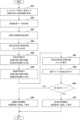
図20は、管理サーバ200により実行されるステータス更新処理の流れの一例を示すフローチャートである。図20のステータス更新処理は、例えば、図19の所在地推定処理と同様に定期的に実行されてもよく、又はユーザ端末160においてステータス更新の指示が入力されたことに応じて実行されてもよい。
<4-3. Status update process>
FIG. 20 is a flowchart illustrating an example of the flow of status update processing executed by the
まず、S31で、ステータス判定部233は、作業工程テーブル350において定義されている作業を構成する作業工程のうち進捗を更新すべき作業工程を選択する。ここで選択される作業工程は、例えば、所在地が変化した管理対象に関連付けられている作業工程、ユーザにより指定された作業工程、又はその期日が到来した作業工程であってよい。次いで、S32で、ステータス判定部233は、選択した作業工程についてステータスが未完了の1つの管理対象を選択する。
First, in S31, the
次いで、S33で、ステータス判定部233は、選択した管理対象の対象種別及び作業工程の工程種別の一方又は双方に基づいて、粒度制御テーブル380を参照することにより、所在地を予定地と照合するための照合レベルを決定する。次いで、S34で、ステータス判定部233は、選択した管理対象の最新の所在地(所在区域又は位置座標)を対象テーブル310から取得する。また、ステータス判定部233は、選択した作業工程におけるその管理対象の予定地を作業工程テーブル350から取得する。
Next, in S33, the
次いで、S35で、ステータス判定部233は、S33で決定した照合レベルで、選択した管理対象の所在地を予定地と照合する。例えば、予定地が区域IDで表され、その区域のレベルが照合レベルに等しいとすると、管理対象の所在区域の区域IDが予定地又は当該予定地に属するいずれかの下位レベル区域の区域IDに等しい場合に、所在地は予定地に適合すると判定され得る。予定地が位置座標で表され、照合レベルが位置座標レベルの照合を示す場合には、管理対象の位置座標と予定地の位置座標との間の距離が所定の距離閾値を下回るときに、所在地は予定地に適合すると判定され得る。所在地が予定地に適合する場合(S36-YES)、S37で、ステータス判定部233は、選択した作業工程における選択した管理対象のステータスを「完了」に更新する。照合が失敗した場合(S36-NO)、S37はスキップされ、ステータスは更新されない。
Next, in S35, the
次いで、S38で、ステータス判定部233は、S31で選択した作業工程についてステータスが未完了の残りの管理対象が存在するかを判定する。未完了の残りの管理対象が存在する場合、処理はS32へ戻り、ステータス判定部233は、残りの管理対象から新たな未完了の管理対象を選択して、S33~S38を反復する。ステータスが未完了の残りの管理対象が存在しない場合、S31で選択した作業工程についてのステータス更新処理は終了する。図示していないものの、当然ながら、他の作業工程について上述したステータス更新処理がさらに反復されてもよい。
Next, in S38, the
<4-4.表示制御処理>
(1)第1の例
図21は、ユーザ端末160及び管理サーバ200が互いに連携することにより実行される表示制御処理の流れの第1の例を示すフローチャートである。ここでは、図15を用いて説明した第1の例に係る情報閲覧画面700が、ユーザにより呼び出され、ユーザ端末160の制御部161による制御の下で表示部171により表示されるものとする。
<4-4. Display control processing>
(1) First Example FIG. 21 is a flowchart showing a first example of the flow of display control processing executed by the
まず、S41で、管理サーバ200の表示制御部234は、ユーザ端末160において指定され得るフィルタリング条件に適合する1つ以上の管理対象の位置情報を対象テーブル310から取得する。例えば、表示制御部234は、指定された区域に現時点で所在すると推定される管理対象の所在区域及び位置座標を対象テーブル310から取得し得る。次いで、S42で、表示制御部234は、指定された区域の地図画像データを区域テーブル320から取得する。次いで、S43で、表示制御部234は、指定された区域に複数の座標領域を設定する。
First, in S<b>41 , the
次いで、S44で、表示制御部234は、S41で取得した1つ以上の管理対象の所在区域に基づいて、所在区域情報として、所在区域別の管理対象のリストを生成する。また、S45で、表示制御部234は、S41で取得した1つ以上の管理対象の位置座標に基づいて、座標領域情報として、座標領域別の管理対象の統計情報を生成する。
Next, in S44, the
次いで、S46で、表示制御部234は、生成した所在区域情報を通信部210を介してユーザ端末160へ送信する。ユーザ端末160の制御部161は、情報閲覧画面700のリスト表示エリア720において所在区域別の管理対象のリストを表示するように表示部171を制御する。また、S47で、表示制御部234は、生成した座標領域情報を地図画像データと共に通信部210を介してユーザ端末160へ送信する。ユーザ端末160の制御部161は、同じ情報閲覧画面700の地図表示エリア710において地図画像に座標領域別の統計情報を重畳して表示するように表示部171を制御する。
Next, in S46, the
表示すべき管理対象のフィルタリング条件が変更された場合には、S41以降の表示制御処理が再実行され、画面表示が更新されてもよい。また、表示制御部234は、対象テーブル310に格納されている位置情報を監視し、位置情報に変化があった場合に、表示制御処理を再実行して、ユーザ端末160の制御部161に画面表示を更新させてもよい。
When the filtering conditions of the management target to be displayed are changed, the display control process from S41 onwards may be re-executed and the screen display may be updated. In addition, the
(2)第2の例
図22は、ユーザ端末160及び管理サーバ200が互いに連携することにより実行される表示制御処理の流れの第2の例を示すフローチャートである。ここでは、図16を用いて説明した第2の例に係る情報閲覧画面700が、ユーザにより呼び出され、ユーザ端末160の制御部161による制御の下で表示部171により表示されるものとする。
(2) Second Example FIG. 22 is a flowchart showing a second example of the flow of display control processing executed by the
まず、S51で、管理サーバ200の表示制御部234は、ユーザ端末160において指定され得るフィルタリング条件に適合する1つ以上の管理対象の位置情報を対象テーブル310から取得する。次いで、S52で、表示制御部234は、指定された区域の地図画像データを区域テーブル320から取得する。次いで、S53で、表示制御部234は、指定された区域に複数の座標領域を設定する。
First, in S51, the
次いで、S54で、表示制御部234は、管理対象の所在区域に基づいて、所在区域別の管理対象のリストを生成する。また、S55で、表示制御部234は、同じく管理対象の所在区域に基づいて、所在区域情報として、所在区域別の管理対象の統計情報を生成する。さらに、S56で、表示制御部234は、管理対象の位置座標に基づいて、座標領域情報として、座標領域別の管理対象の統計情報を生成する。
Next, in S54, the
次いで、S57で、表示制御部234は、生成した所在区域別の管理対象のリストを通信部210を介してユーザ端末160へ送信する。ユーザ端末160の制御部161は、情報閲覧画面700のリスト表示エリア720において所在区域別の管理対象のリストを表示するように表示部171を制御する。次いで、S58で、制御部161は、操作部165を介して、ユーザによる表示モードの指定を受付ける。座標領域情報を地図画像に重畳する第1表示モードが指定された場合には(S59-YES)、処理はS60へ進む。一方、所在区域情報を地図画像に重畳する第2表示モードが指定された場合には(S59-NO)、処理はS61へ進む。
Next, in S57, the
S60で、表示制御部234は、座標領域情報を地図画像データと共に通信部210を介してユーザ端末160へ送信する。ユーザ端末160の制御部161は、情報閲覧画面700の地図表示エリア710において地図画像に座標領域別の統計情報を重畳して表示するように表示部171を制御する。一方、S61では、表示制御部234は、所在区域情報を地図画像データと共に通信部210を介してユーザ端末160へ送信する。ユーザ端末160の制御部161は、情報閲覧画面700の地図表示エリア710において地図画像に所在区域別の統計情報を重畳して表示するように表示部171を制御する。
In S60, the
上述した第1の例と同様に、表示すべき管理対象のフィルタリング条件が変更された場合には、S51以降の表示制御処理が再実行され、画面表示が更新されてもよい。また、表示制御部234は、対象テーブル310に格納されている位置情報を監視し、位置情報に変化があった場合に、表示制御処理を再実行して、ユーザ端末160の制御部161に画面表示を更新させてもよい。
Similar to the first example described above, when the filtering conditions of the management target to be displayed are changed, the display control process from S51 onwards may be re-executed and the screen display may be updated. In addition, the
<5.まとめ>
ここまで、図1~図22を用いて、本開示に係る技術の様々な実施形態、実施例及び変形例について詳細に説明した。上述した実施形態では、区域データが、異なる複数の空間的粒度で実空間に設定される複数の区域を定義する。当該複数の区域は、第1の空間的粒度で実空間に設定される少なくとも1つの第1レベル区域、及び第1の空間的粒度よりも狭い第2の空間的粒度で少なくとも1つの第1レベル区域に設定される少なくとも1つの第2レベル区域を含む。そして、工程管理システムの管理対象に関連付けられる種別情報に依存して異なる粒度で、当該管理対象の所在地が作業工程の予定地と照合され、照合の結果に基づいて当該作業工程のステータスが更新される。かかる構成によれば、どの管理対象又はどの作業工程についてステータスを更新しようとしているのかに依存して、管理対象の所在地と予定地との照合の空間的粒度を自動的に切替えてステータスを判定することができる。そのため、一般的な工程管理の場面における必ずしも一様でなない所在地の照合の粒度に関する要件に柔軟に対処して、工程管理の効率性を向上させることができる。
<5. Summary>
Up to this point, various embodiments, examples, and modifications of the technology according to the present disclosure have been described in detail using FIGS. 1 to 22. In the embodiments described above, the area data defines multiple areas set in real space at multiple different spatial granularities. The plurality of zones includes at least one first level zone set in real space at a first spatial granularity and at least one first level zone at a second spatial granularity narrower than the first spatial granularity. and at least one second level zone defined in the zone. Then, the location of the management target is checked against the planned location of the work process at different granularities depending on the type information associated with the management target of the process management system, and the status of the work process is updated based on the verification results. Ru. According to this configuration, the spatial granularity of matching the location of the managed target and the planned location is automatically switched to determine the status depending on which managed target or which work process the status is about to be updated. be able to. Therefore, it is possible to flexibly deal with requirements regarding the granularity of location verification that is not always uniform in general process management situations, and improve the efficiency of process management.
非限定的な例を挙げると、いわゆる汎用材については、個別仕様の専用品と比較して、より広い空間的粒度でその移動先が指定され得る。あるいは、所在地の照合のための粒度は、作業の当初はより粗く(即ち、より広い空間的粒度)、作業が進行するにつれてより精細(即ち、より狭い空間的粒度)になっていくかもしれない。上述した実施形態では、広い空間的粒度での照合が許容される場合、管理対象の所在地が予定地に対応する上位レベル区域又は当該上位レベル区域に属するいずれかの下位レベル区域に等しいときに、当該管理対象に関して作業工程が完了したと判定され得る。したがって、上位レベル区域に属する地点であれば、どこへ管理対象が移動しても、作業工程のステータスを自動的に完了へ更新することができる。そのため、管理対象の移動に課せられる制約が緩和される結果として、作業の進行途上での管理対象の配置の自由度が増し、作業自体の効率性をも向上させることができる。 To give a non-limiting example, the destination of a so-called general-purpose material can be specified at a broader spatial granularity compared to a dedicated product with individual specifications. Alternatively, the granularity for location matching may be coarser (i.e., wider spatial granularity) at the beginning of the work and become finer (i.e., narrower spatial granularity) as the work progresses. . In the embodiments described above, if matching at a wide spatial granularity is allowed, when the location to be managed is equal to the upper level area corresponding to the planned location or any lower level area belonging to the upper level area, It may be determined that the work process regarding the management target is completed. Therefore, the status of the work process can be automatically updated to completed, no matter where the managed object moves to, as long as it belongs to a higher level area. Therefore, as a result of the relaxation of restrictions on the movement of managed objects, the degree of freedom in arranging managed objects during the progress of work increases, and the efficiency of the work itself can also be improved.
また、上述した実施形態では、管理対象を識別するための第1識別情報を記憶している第1無線デバイス(対象タグ)が当該管理対象に付され、対応する設置区域に関連付けられる第2識別情報を記憶している第2無線デバイス(位置タグ)が各区域に設置される。そして、第1読取装置による第1無線デバイス及び第2無線デバイスからの識別情報の読取りの結果に基づいて、管理対象がどの区域に所在しているかが推定される。とりわけ、無線デバイスからの識別情報の読取りは、GPS衛星又は無線基地局といった外部装置との通信を要しない。そのため、屋内、地下、又はトンネル内といった外部通信の困難な環境においても所在地推定のための記録を安定的に収集して、後のステータス更新及び位置情報の閲覧に役立てることができる。 Further, in the embodiment described above, a first wireless device (target tag) storing first identification information for identifying a management target is attached to the management target, and a second identification information associated with the corresponding installation area is attached to the first wireless device (target tag) that stores first identification information for identifying the management target. A second wireless device (location tag) storing information is installed in each area. Then, based on the results of reading of the identification information from the first wireless device and the second wireless device by the first reading device, it is estimated in which area the management target is located. Notably, reading identification information from a wireless device does not require communication with external devices such as GPS satellites or wireless base stations. Therefore, even in environments where external communication is difficult, such as indoors, underground, or in tunnels, records for location estimation can be stably collected and used for later status updates and location information viewing.
また、上述した実施形態では、実空間が複数の座標領域に規則的に区分され、複数の管理対象についてそれぞれ推定される位置座標が属する座標領域に関する座標領域情報が表示装置により表示され得る。かかる構成によれば、最新の時点又はユーザにより指定される時点の管理対象の所在地の概略を、ユーザが簡易且つ迅速に把握することができる。また、座標領域情報及び所在区域に関する所在区域情報を(並列的に又は選択的に)表示可能とすることで、ユーザによる管理対象の所在地の把握を一層効果的に支援することができる。 Further, in the embodiments described above, the real space is regularly divided into a plurality of coordinate regions, and the display device can display coordinate region information regarding the coordinate regions to which the position coordinates estimated for each of the plurality of management objects belong. According to this configuration, the user can easily and quickly grasp the outline of the location of the managed object at the latest point in time or at the point specified by the user. Furthermore, by being able to display coordinate area information and location area information regarding the location area (in parallel or selectively), it is possible to more effectively support the user in understanding the location of the management target.
<6.その他の実施形態>
上記実施形態は、1つ以上の機能を実現するプログラムをネットワーク又は記憶媒体を介してシステム又は装置に供給し、そのシステム又は装置のコンピュータにおける1つ以上のプロセッサがプログラムを読み出して実行する処理の形式でも実現可能である。また、1つ以上の機能を実現する回路(例えば、ASIC)によっても実現可能である。
<6. Other embodiments>
In the above embodiments, a program that implements one or more functions is supplied to a system or device via a network or a storage medium, and one or more processors in a computer of the system or device read and execute the program. It is also possible to implement the format. It can also be implemented by a circuit (eg, an ASIC) that implements one or more functions.
本明細書の開示は、少なくとも以下の工程管理システム、方法及び情報処理装置を含む。
(項目1)
実空間に設定される複数の区域を定義する区域データ、及び、前記複数の区域のうちで、管理対象の移動を伴う作業工程の完了時に前記管理対象が位置すべき予定地を示す工程データを管理する管理部と、
前記管理対象に付され、前記管理対象を識別するための第1識別情報を記憶している第1無線デバイスと、
無線デバイスから当該無線デバイスに記憶されている識別情報を読取可能な少なくとも1つの読取装置と、
第1読取装置による前記第1無線デバイスからの前記第1識別情報の読取りの結果に基づいて推定される前記管理対象の所在地を前記工程データにより示される前記予定地と照合して、前記管理対象に関する前記作業工程のステータスを判定する判定部と、
を含み、
前記区域データは、第1の空間的粒度で前記実空間に設定される少なくとも1つの第1レベル区域、及び前記第1の空間的粒度よりも狭い第2の空間的粒度で前記少なくとも1つの第1レベル区域に設定される少なくとも1つの第2レベル区域を定義し、
前記判定部は、前記管理対象に関連付けられる種別情報に依存して異なる粒度で、前記管理対象の前記所在地を前記予定地と照合する、
工程管理システム。
(項目2)
前記種別情報は、前記管理対象の種別を示す対象種別を含み、
前記判定部は、前記対象種別が第1種別を示す第1管理対象の所在地を前記第1の空間的粒度で前記予定地と照合し、前記対象種別が前記第1種別と異なる第2種別を示す第2管理対象の所在地を前記第2の空間的粒度で前記予定地と照合する、
項目1に記載の工程管理システム。
(項目3)
前記種別情報は、前記管理対象に関連付けられる複数の作業工程の各々の種別を示す工程種別を含み、
前記判定部は、前記複数の作業工程のうちの第1作業工程の前記工程種別が第1種別を示す場合に、前記管理対象の所在地を前記第1の空間的粒度で前記予定地と照合し、第2作業工程の前記工程種別が前記第1種別と異なる第2種別を示す場合に、前記管理対象の所在地を前記第2の空間的粒度で前記予定地と照合する、
項目1に記載の工程管理システム。
(項目4)
前記判定部は、前記工程データにより示される前記予定地に対応する第1レベル区域又は当該第1レベル区域に属するいずれかの下位レベル区域に、前記種別情報が前記第1種別を示している管理対象の所在地が等しい場合に、当該管理対象に関して前記作業工程が完了したと判定する、項目2又は3に記載の工程管理システム。
(項目5)
前記第2作業工程は、前記第1作業工程に後続する作業工程である、項目3に記載の工程管理システム。
(項目6)
前記工程管理システムは、
前記複数の区域のうちの1つ以上に設置され、対応する設置区域に関連付けられる第2識別情報を記憶している第2無線デバイスと、
前記第1読取装置による前記第1無線デバイスからの前記第1識別情報の読取りの結果、及び前記第1読取装置による前記第2無線デバイスからの前記第2識別情報の読取りの結果に基づいて、前記管理対象の前記所在地を推定する推定部と、
をさらに含む、項目1~5のいずれか1項に記載の工程管理システム。
(項目7)
前記推定部は、前記第1読取装置により前記第1無線デバイスから前記第1識別情報が読取られた時点と、前記第1読取装置により前記第2無線デバイスから前記第2識別情報が読取られた時点との間の前記第1読取装置の移動量に基づいて、前記管理対象の前記所在地の位置座標を推定し、
前記判定部は、前記管理対象に関連付けられる前記種別情報が所定の種別を示す場合に、前記管理対象の前記所在地を位置座標のレベルで前記予定地と照合する、
項目6に記載の工程管理システム。
(項目8)
前記第1レベル区域及び前記第2レベル区域は、地区、建物、フロア、及び部屋のうちのいずれか2つに対応する、項目1~7のいずれか1項に記載の工程管理システム。
(項目9)
情報処理装置により、実空間に設定される複数の区域において行われる作業の作業工程のステータスを判定する方法であって、
前記情報処理装置は、前記複数の区域を定義する区域データ、及び、前記複数の区域のうちで、管理対象の移動を伴う前記作業工程の完了時に前記管理対象が位置すべき予定地を示す工程データにアクセス可能であり、
前記区域データは、第1の空間的粒度で前記実空間に設定される少なくとも1つの第1レベル区域、及び前記第1の空間的粒度よりも狭い第2の空間的粒度で前記少なくとも1つの第1レベル区域に設定される少なくとも1つの第2レベル区域を定義し、
前記情報処理装置は、無線デバイスから当該無線デバイスに記憶されている識別情報を読取可能な少なくとも1つの読取装置と通信可能であり、
前記方法は、
第1読取装置による、前記管理対象に付された第1無線デバイスからの前記管理対象を識別するための第1識別情報の読取りの結果を取得することと、
取得された読取りの前記結果に基づいて、前記管理対象の所在地を推定することと、
推定された前記管理対象の前記所在地を、前記管理対象に関連付けられる種別情報に依存して異なる粒度で、前記工程データにより示される前記予定地と照合して、前記管理対象に関する前記作業工程の前記ステータスを判定することと、
を含む、方法。
(項目10)
実空間に設定される複数の区域を定義する区域データ、及び、前記複数の区域のうちで、管理対象の移動を伴う作業工程の完了時に前記管理対象が位置すべき予定地を示す工程データを管理する管理部と、
前記管理対象に付された第1無線デバイスから前記管理対象を識別する第1識別情報を読取った第1読取装置から、当該第1識別情報の読取りの結果を受信する通信部と、
前記通信部により受信された読取りの前記結果に基づいて、前記管理対象の所在地を推定する推定部と、
前記推定部により推定された前記管理対象の前記所在地を、前記工程データにより示される前記予定地と照合して、前記管理対象に関する前記作業工程のステータスを判定する判定部と、
を備え、
前記区域データは、第1の空間的粒度で前記実空間に設定される少なくとも1つの第1レベル区域、及び前記第1の空間的粒度よりも狭い第2の空間的粒度で前記少なくとも1つの第1レベル区域に設定される少なくとも1つの第2レベル区域を定義し、
前記判定部は、前記管理対象に関連付けられる種別情報に依存して異なる粒度で、前記管理対象の前記所在地を前記予定地と照合する、
情報処理装置。
The disclosure of this specification includes at least the following process control system, method, and information processing device.
(Item 1)
Area data defining a plurality of areas set in real space, and process data indicating a planned location where the management target is to be located at the completion of a work process involving movement of the management target among the plurality of areas. A management department that manages the
a first wireless device that is attached to the management target and stores first identification information for identifying the management target;
at least one reader capable of reading identification information stored in the wireless device from the wireless device;
The location of the management target estimated based on the result of reading the first identification information from the first wireless device by the first reader is compared with the planned location indicated by the process data, and the management target is a determination unit that determines the status of the work process related to;
including;
The zone data includes at least one first level zone set in the real space at a first spatial granularity, and at least one first level zone set in the real space at a first spatial granularity, and at a second spatial granularity narrower than the first spatial granularity. defining at least one second level area set in the first level area;
The determination unit compares the location of the management target with the planned location at different granularity depending on type information associated with the management target.
Process control system.
(Item 2)
The type information includes a target type indicating the type of the management target,
The determination unit compares the location of a first management target whose target type is a first type with the planned location at the first spatial granularity, and determines a location where the target type is a second type different from the first type. comparing the location of the second management target indicated with the planned location at the second spatial granularity;
Process control system described in
(Item 3)
The type information includes a process type indicating the type of each of the plurality of work processes associated with the management target,
The determination unit compares the location of the management target with the planned location at the first spatial granularity when the process type of a first work process among the plurality of work processes indicates a first type. , when the process type of the second work process indicates a second type different from the first type, comparing the location of the management target with the planned location at the second spatial granularity;
Process control system described in
(Item 4)
The determination unit may manage a first level area corresponding to the planned site indicated by the process data or any lower level area belonging to the first level area, the type information indicating the first type. The process management system according to
(Item 5)
The process management system according to
(Item 6)
The process control system includes:
a second wireless device installed in one or more of the plurality of areas and storing second identification information associated with the corresponding installation area;
Based on the result of reading the first identification information from the first wireless device by the first reading device and the result of reading the second identification information from the second wireless device by the first reading device, an estimation unit that estimates the location of the management target;
The process control system according to any one of
(Item 7)
The estimating unit is configured to determine when the first identification information is read from the first wireless device by the first reading device and when the second identification information is read from the second wireless device by the first reading device. estimating the positional coordinates of the location of the management target based on the amount of movement of the first reading device between the points in time;
The determination unit compares the location of the management target with the planned location at a position coordinate level when the type information associated with the management target indicates a predetermined type.
Process control system described in item 6.
(Item 8)
8. The process control system according to any one of
(Item 9)
A method for determining the status of a work process of work performed in a plurality of areas set in real space using an information processing device, the method comprising:
The information processing device includes area data defining the plurality of areas, and a step of indicating, among the plurality of areas, a planned location where the management target is to be located when the work process involving movement of the management target is completed. data is accessible and
The zone data includes at least one first level zone set in the real space at a first spatial granularity, and at least one first level zone set in the real space at a first spatial granularity, and at a second spatial granularity narrower than the first spatial granularity. defining at least one second level area set in the first level area;
The information processing device is capable of communicating with at least one reading device capable of reading identification information stored in the wireless device from the wireless device,
The method includes:
obtaining a result of reading first identification information for identifying the management target from a first wireless device attached to the management target by a first reading device;
estimating the location of the managed object based on the results of the obtained readings;
The estimated location of the management target is compared with the planned location indicated by the process data at different granularities depending on the type information associated with the management target, and the location of the work process related to the management target is determined. determining the status and
including methods.
(Item 10)
Area data defining a plurality of areas set in real space, and process data indicating a planned location where the management target is to be located at the completion of a work process involving movement of the management target among the plurality of areas. A management department that manages
a communication unit that receives a result of reading first identification information from a first reading device that has read first identification information that identifies the management target from a first wireless device attached to the management target;
an estimation unit for estimating the location of the managed object based on the result of the reading received by the communication unit;
a determination unit that compares the location of the management target estimated by the estimation unit with the planned location indicated by the process data to determine the status of the work process regarding the management target;
Equipped with
The area data includes at least one first level area set in the real space at a first spatial granularity, and at least one first level area set in the real space at a first spatial granularity, and at a second spatial granularity narrower than the first spatial granularity. defining at least one second level area set in the first level area;
The determination unit compares the location of the management target with the planned location at different granularity depending on type information associated with the management target.
Information processing device.
発明は上記実施形態に制限されるものではなく、発明の精神及び範囲から離脱することなく、様々な変更及び変形が可能である。従って、発明の範囲を公にするために請求項を添付する。 The invention is not limited to the embodiments described above, and various changes and modifications can be made without departing from the spirit and scope of the invention. Therefore, the following claims are hereby appended to disclose the scope of the invention.
1:工程管理システム、5:ネットワーク、10(10a,10b,...):区域、20(20a):ユーザ、30(30a,30b,...):物品、40(40a,40b,...):位置タグ(第2無線デバイス)、50(50a,50b,...):対象タグ(第1無線デバイス)、100:携帯システム、110:タグリーダ(読取装置)、160:ユーザ端末(端末装置/情報処理装置)、161:制御部、163:通信部、171:表示部(表示装置)、200:管理サーバ(情報処理装置)、210:通信部、220:作業DB(データベース)、231:データ管理部、232:推定部、233:ステータス判定部、234:表示制御部、320:区域テーブル(区域データ)、350:作業工程テーブル(工程データ)、357:工程ステータス、381:対象種別(種別情報)、382:工程種別(種別情報)、385:照合レベル、700:情報閲覧画面、GR1~GR4:座標領域 1: Process control system, 5: Network, 10 (10a, 10b,...): Area, 20 (20a): User, 30 (30a, 30b,...): Goods, 40 (40a, 40b, . ..): Location tag (second wireless device), 50 (50a, 50b, ...): Target tag (first wireless device), 100: Mobile system, 110: Tag reader (reading device), 160: User terminal (terminal device/information processing device), 161: control section, 163: communication section, 171: display section (display device), 200: management server (information processing device), 210: communication section, 220: work DB (database) , 231: Data management section, 232: Estimation section, 233: Status determination section, 234: Display control section, 320: Area table (area data), 350: Work process table (process data), 357: Process status, 381: Target type (type information), 382: Process type (type information), 385: Verification level, 700: Information viewing screen, GR1 to GR4: Coordinate area
Claims (10)
前記管理対象に付され、前記管理対象を識別するための第1識別情報を記憶している第1無線デバイスと、
無線デバイスから当該無線デバイスに記憶されている識別情報を読取可能な少なくとも1つの読取装置と、
第1読取装置による前記第1無線デバイスからの前記第1識別情報の読取りの結果に基づいて推定される前記管理対象の所在地を前記工程データにより示される前記予定地と照合して、前記管理対象に関する前記作業工程のステータスを判定する判定部と、
を含み、
前記区域データは、第1の空間的粒度で前記実空間に設定される少なくとも1つの第1レベル区域、及び前記第1の空間的粒度よりも狭い第2の空間的粒度で前記少なくとも1つの第1レベル区域に設定される少なくとも1つの第2レベル区域を定義し、
前記判定部は、前記管理対象に関連付けられる種別情報に依存して異なる粒度で、前記管理対象の前記所在地を前記予定地と照合する、
工程管理システム。 Area data defining a plurality of areas set in real space, and process data indicating a planned location where the management target is to be located at the completion of a work process involving movement of the management target among the plurality of areas. A management department that manages the
a first wireless device that is attached to the management target and stores first identification information for identifying the management target;
at least one reader capable of reading identification information stored in the wireless device from the wireless device;
The location of the management target estimated based on the result of reading the first identification information from the first wireless device by the first reader is compared with the planned location indicated by the process data, and the management target is a determination unit that determines the status of the work process related to;
including;
The zone data includes at least one first level zone set in the real space at a first spatial granularity, and at least one first level zone set in the real space at a first spatial granularity, and at a second spatial granularity narrower than the first spatial granularity. defining at least one second level area set in the first level area;
The determination unit compares the location of the management target with the planned location at different granularity depending on type information associated with the management target.
Process control system.
前記判定部は、前記対象種別が第1種別を示す第1管理対象の所在地を前記第1の空間的粒度で前記予定地と照合し、前記対象種別が前記第1種別と異なる第2種別を示す第2管理対象の所在地を前記第2の空間的粒度で前記予定地と照合する、
請求項1に記載の工程管理システム。 The type information includes a target type indicating the type of the management target,
The determination unit compares the location of a first management target whose target type is a first type with the planned location at the first spatial granularity, and determines a location where the target type is a second type different from the first type. comparing the location of the second management target indicated with the planned location at the second spatial granularity;
The process control system according to claim 1.
前記判定部は、前記複数の作業工程のうちの第1作業工程の前記工程種別が第1種別を示す場合に、前記管理対象の所在地を前記第1の空間的粒度で前記予定地と照合し、第2作業工程の前記工程種別が前記第1種別と異なる第2種別を示す場合に、前記管理対象の所在地を前記第2の空間的粒度で前記予定地と照合する、
請求項1に記載の工程管理システム。 The type information includes a process type indicating the type of each of the plurality of work processes associated with the management target,
The determination unit compares the location of the management target with the planned location at the first spatial granularity when the process type of a first work process among the plurality of work processes indicates a first type. , when the process type of the second work process indicates a second type different from the first type, comparing the location of the management target with the planned location at the second spatial granularity;
The process control system according to claim 1.
前記複数の区域のうちの1つ以上に設置され、対応する設置区域に関連付けられる第2識別情報を記憶している第2無線デバイスと、
前記第1読取装置による前記第1無線デバイスからの前記第1識別情報の読取りの結果、及び前記第1読取装置による前記第2無線デバイスからの前記第2識別情報の読取りの結果に基づいて、前記管理対象の前記所在地を推定する推定部と、
をさらに含む、請求項1に記載の工程管理システム。 The process control system includes:
a second wireless device installed in one or more of the plurality of areas and storing second identification information associated with the corresponding installation area;
Based on the result of reading the first identification information from the first wireless device by the first reading device and the result of reading the second identification information from the second wireless device by the first reading device, an estimation unit that estimates the location of the management target;
The process control system according to claim 1, further comprising:
前記判定部は、前記管理対象に関連付けられる前記種別情報が所定の種別を示す場合に、前記管理対象の前記所在地を位置座標のレベルで前記予定地と照合する、
請求項6に記載の工程管理システム。 The estimating unit is configured to determine when the first identification information is read from the first wireless device by the first reading device and when the second identification information is read from the second wireless device by the first reading device. estimating the positional coordinates of the location of the management target based on the amount of movement of the first reading device between the points in time;
The determination unit compares the location of the management target with the planned location at a position coordinate level when the type information associated with the management target indicates a predetermined type.
The process control system according to claim 6.
前記情報処理装置は、前記複数の区域を定義する区域データ、及び、前記複数の区域のうちで、管理対象の移動を伴う前記作業工程の完了時に前記管理対象が位置すべき予定地を示す工程データにアクセス可能であり、
前記区域データは、第1の空間的粒度で前記実空間に設定される少なくとも1つの第1レベル区域、及び前記第1の空間的粒度よりも狭い第2の空間的粒度で前記少なくとも1つの第1レベル区域に設定される少なくとも1つの第2レベル区域を定義し、
前記情報処理装置は、無線デバイスから当該無線デバイスに記憶されている識別情報を読取可能な少なくとも1つの読取装置と通信可能であり、
前記方法は、
第1読取装置による、前記管理対象に付された第1無線デバイスからの前記管理対象を識別する第1識別情報の読取りの結果を取得することと、
取得された読取りの前記結果に基づいて、前記管理対象の所在地を推定することと、
推定された前記管理対象の前記所在地を、前記管理対象に関連付けられる種別情報に依存して異なる粒度で、前記工程データにより示される前記予定地と照合して、前記管理対象に関する前記作業工程の前記ステータスを判定することと、
を含む、方法。 A method for determining the status of a work process of work performed in a plurality of areas set in real space using an information processing device, the method comprising:
The information processing device includes area data defining the plurality of areas, and a step of indicating, among the plurality of areas, a planned location where the management target is to be located when the work process involving movement of the management target is completed. data is accessible and
The zone data includes at least one first level zone set in the real space at a first spatial granularity, and at least one first level zone set in the real space at a first spatial granularity, and at a second spatial granularity narrower than the first spatial granularity. defining at least one second level area set in the first level area;
The information processing device is capable of communicating with at least one reading device capable of reading identification information stored in the wireless device from the wireless device,
The method includes:
obtaining a result of reading first identification information identifying the management target from a first wireless device attached to the management target by a first reading device;
estimating the location of the managed object based on the results of the obtained readings;
The estimated location of the management target is compared with the planned location indicated by the process data at different granularity depending on the type information associated with the management target, and the location of the work process related to the management target is compared with the planned location indicated by the process data. determining the status and
including methods.
前記管理対象に付された第1無線デバイスから前記管理対象を識別するための第1識別情報を読取った第1読取装置から、当該第1識別情報の読取りの結果を受信する通信部と、
前記通信部により受信された読取りの前記結果に基づいて、前記管理対象の所在地を推定する推定部と、
前記推定部により推定された前記管理対象の前記所在地を、前記工程データにより示される前記予定地と照合して、前記管理対象に関する前記作業工程のステータスを判定する判定部と、
を備え、
前記区域データは、第1の空間的粒度で前記実空間に設定される少なくとも1つの第1レベル区域、及び前記第1の空間的粒度よりも狭い第2の空間的粒度で前記少なくとも1つの第1レベル区域に設定される少なくとも1つの第2レベル区域を定義し、
前記判定部は、前記管理対象に関連付けられる種別情報に依存して異なる粒度で、前記管理対象の前記所在地を前記予定地と照合する、
情報処理装置。 Area data defining a plurality of areas set in real space, and process data indicating a planned location where the management target is to be located at the completion of a work process involving movement of the management target among the plurality of areas. A management department that manages the
a communication unit that receives a result of reading first identification information from a first reading device that has read first identification information for identifying the management target from a first wireless device attached to the management target;
an estimating unit that estimates the location of the managed object based on the result of the reading received by the communication unit;
a determination unit that compares the location of the management target estimated by the estimation unit with the planned location indicated by the process data to determine the status of the work process regarding the management target;
Equipped with
The zone data includes at least one first level zone set in the real space at a first spatial granularity, and at least one first level zone set in the real space at a first spatial granularity, and at a second spatial granularity narrower than the first spatial granularity. defining at least one second level area set in the first level area;
The determination unit compares the location of the management target with the planned location at different granularity depending on type information associated with the management target.
Information processing device.
Priority Applications (4)
| Application Number | Priority Date | Filing Date | Title |
|---|---|---|---|
| JP2022129380A JP2024025974A (en) | 2022-08-15 | 2022-08-15 | Process control systems, methods and information processing equipment |
| US18/449,101 US20240054301A1 (en) | 2022-08-15 | 2023-08-14 | Process management system, method and information processing apparatus |
| CN202311023335.0A CN117596541A (en) | 2022-08-15 | 2023-08-14 | Process management system, process management method, and information processing apparatus |
| EP23191252.8A EP4325402A1 (en) | 2022-08-15 | 2023-08-14 | Process management system, method and information processing apparatus |
Applications Claiming Priority (1)
| Application Number | Priority Date | Filing Date | Title |
|---|---|---|---|
| JP2022129380A JP2024025974A (en) | 2022-08-15 | 2022-08-15 | Process control systems, methods and information processing equipment |
Publications (1)
| Publication Number | Publication Date |
|---|---|
| JP2024025974A true JP2024025974A (en) | 2024-02-28 |
Family
ID=87571957
Family Applications (1)
| Application Number | Title | Priority Date | Filing Date |
|---|---|---|---|
| JP2022129380A Pending JP2024025974A (en) | 2022-08-15 | 2022-08-15 | Process control systems, methods and information processing equipment |
Country Status (4)
| Country | Link |
|---|---|
| US (1) | US20240054301A1 (en) |
| EP (1) | EP4325402A1 (en) |
| JP (1) | JP2024025974A (en) |
| CN (1) | CN117596541A (en) |
Family Cites Families (3)
| Publication number | Priority date | Publication date | Assignee | Title |
|---|---|---|---|---|
| US11308376B2 (en) * | 2017-11-28 | 2022-04-19 | Jfe Steel Corporation | Equipment management system |
| JP7221717B2 (en) | 2019-02-09 | 2023-02-14 | 株式会社長谷工コーポレーション | Building progress control method and progress control system |
| JP2021141415A (en) | 2020-03-04 | 2021-09-16 | キヤノン株式会社 | Communication apparatus, information processing apparatus, and location information management method |
-
2022
- 2022-08-15 JP JP2022129380A patent/JP2024025974A/en active Pending
-
2023
- 2023-08-14 US US18/449,101 patent/US20240054301A1/en active Pending
- 2023-08-14 EP EP23191252.8A patent/EP4325402A1/en active Pending
- 2023-08-14 CN CN202311023335.0A patent/CN117596541A/en active Pending
Also Published As
| Publication number | Publication date |
|---|---|
| CN117596541A (en) | 2024-02-23 |
| EP4325402A1 (en) | 2024-02-21 |
| US20240054301A1 (en) | 2024-02-15 |
Similar Documents
| Publication | Publication Date | Title |
|---|---|---|
| EP3213031B1 (en) | Simultaneous localization and mapping by using earth's magnetic fields | |
| CN107923960B (en) | System and method for locating tags in space | |
| CN101144722B (en) | Portable positioning and navigation system | |
| CN103229192B (en) | Rfid system and related operating method | |
| JP5402969B2 (en) | Mobile terminal and program | |
| CN105190345A (en) | Systems and methods for using three-dimensional location information to improve location services | |
| JP2015152483A (en) | Location information acquisition system and location information acquisition method | |
| JP2006266945A (en) | Position management system | |
| CN108151732A (en) | A kind of long-range position and behavior method of estimation | |
| JP2012208010A (en) | Positioning device, positioning system, positioning method, and program | |
| US20200296684A1 (en) | Terminal device for position measurement, computer program, and system | |
| CN102620730B (en) | Navigation implementation method and navigation system | |
| JP2024025974A (en) | Process control systems, methods and information processing equipment | |
| JP2024025973A (en) | Display control system, method and information processing device | |
| JP2006023129A (en) | Location information detection system, location information detection method, and server device | |
| WO2023013266A1 (en) | Article management system, article management method, and information processing apparatus | |
| JP2017143458A (en) | Facility management support system, facility management support method, information terminal, and program | |
| JP6288166B2 (en) | Mobile terminal and program | |
| JP6098659B2 (en) | Mobile terminal and program | |
| WO2023026649A1 (en) | Article inspection system, inspection method, and information processing device | |
| JP7450357B2 (en) | Object management system, object management device, object management method and program | |
| Ortakci et al. | Indoor navigation design integrated with smart phones and rfid devices | |
| JP5737362B2 (en) | Mobile terminal and program | |
| JP5953812B2 (en) | Mobile terminal and program | |
| WO2023032440A1 (en) | Article management system, method, and information processing device |