JP2023552826A - Systems, devices, and methods for creating curved tunnels in bone - Google Patents
Systems, devices, and methods for creating curved tunnels in bone Download PDFInfo
- Publication number
- JP2023552826A JP2023552826A JP2023534946A JP2023534946A JP2023552826A JP 2023552826 A JP2023552826 A JP 2023552826A JP 2023534946 A JP2023534946 A JP 2023534946A JP 2023534946 A JP2023534946 A JP 2023534946A JP 2023552826 A JP2023552826 A JP 2023552826A
- Authority
- JP
- Japan
- Prior art keywords
- flexible
- curved
- bone
- hollow
- needles
- Prior art date
- Legal status (The legal status is an assumption and is not a legal conclusion. Google has not performed a legal analysis and makes no representation as to the accuracy of the status listed.)
- Pending
Links
- 210000000988 bone and bone Anatomy 0.000 title claims abstract description 119
- 238000000034 method Methods 0.000 title abstract description 23
- 239000000463 material Substances 0.000 claims abstract description 28
- 230000007246 mechanism Effects 0.000 claims abstract description 23
- 238000005553 drilling Methods 0.000 claims description 18
- 238000003780 insertion Methods 0.000 claims description 8
- 230000037431 insertion Effects 0.000 claims description 8
- 239000007787 solid Substances 0.000 claims description 4
- 238000009987 spinning Methods 0.000 claims description 3
- 230000009471 action Effects 0.000 claims description 2
- 230000005641 tunneling Effects 0.000 description 39
- 229910001000 nickel titanium Inorganic materials 0.000 description 8
- 230000002787 reinforcement Effects 0.000 description 8
- 210000004872 soft tissue Anatomy 0.000 description 8
- 230000001788 irregular Effects 0.000 description 7
- 230000008439 repair process Effects 0.000 description 6
- 230000006378 damage Effects 0.000 description 5
- 230000033001 locomotion Effects 0.000 description 5
- 238000004519 manufacturing process Methods 0.000 description 5
- 210000002435 tendon Anatomy 0.000 description 5
- 208000023178 Musculoskeletal disease Diseases 0.000 description 4
- 208000027418 Wounds and injury Diseases 0.000 description 4
- 230000006870 function Effects 0.000 description 4
- 208000014674 injury Diseases 0.000 description 4
- HLXZNVUGXRDIFK-UHFFFAOYSA-N nickel titanium Chemical compound [Ti].[Ti].[Ti].[Ti].[Ti].[Ti].[Ti].[Ti].[Ti].[Ti].[Ti].[Ni].[Ni].[Ni].[Ni].[Ni].[Ni].[Ni].[Ni].[Ni].[Ni].[Ni].[Ni].[Ni].[Ni] HLXZNVUGXRDIFK-UHFFFAOYSA-N 0.000 description 4
- 210000001519 tissue Anatomy 0.000 description 4
- 210000001264 anterior cruciate ligament Anatomy 0.000 description 3
- 238000005452 bending Methods 0.000 description 3
- 230000015572 biosynthetic process Effects 0.000 description 3
- 230000000295 complement effect Effects 0.000 description 3
- 238000010586 diagram Methods 0.000 description 3
- 210000000968 fibrocartilage Anatomy 0.000 description 3
- 210000003041 ligament Anatomy 0.000 description 3
- 230000003014 reinforcing effect Effects 0.000 description 3
- 208000036487 Arthropathies Diseases 0.000 description 2
- 208000012659 Joint disease Diseases 0.000 description 2
- 208000026137 Soft tissue injury Diseases 0.000 description 2
- 238000013459 approach Methods 0.000 description 2
- 230000008901 benefit Effects 0.000 description 2
- 230000008859 change Effects 0.000 description 2
- 238000013461 design Methods 0.000 description 2
- 201000010099 disease Diseases 0.000 description 2
- 208000037265 diseases, disorders, signs and symptoms Diseases 0.000 description 2
- 238000010438 heat treatment Methods 0.000 description 2
- 210000001503 joint Anatomy 0.000 description 2
- 238000012986 modification Methods 0.000 description 2
- 230000004048 modification Effects 0.000 description 2
- 208000017445 musculoskeletal system disease Diseases 0.000 description 2
- 238000011160 research Methods 0.000 description 2
- 238000006467 substitution reaction Methods 0.000 description 2
- 238000001356 surgical procedure Methods 0.000 description 2
- 238000007669 thermal treatment Methods 0.000 description 2
- 206010065433 Ligament rupture Diseases 0.000 description 1
- 206010028391 Musculoskeletal Pain Diseases 0.000 description 1
- 208000024288 Rotator Cuff injury Diseases 0.000 description 1
- 208000007613 Shoulder Pain Diseases 0.000 description 1
- 210000001361 achilles tendon Anatomy 0.000 description 1
- 210000003484 anatomy Anatomy 0.000 description 1
- 210000003423 ankle Anatomy 0.000 description 1
- 230000002457 bidirectional effect Effects 0.000 description 1
- 230000005540 biological transmission Effects 0.000 description 1
- 230000001684 chronic effect Effects 0.000 description 1
- 230000001010 compromised effect Effects 0.000 description 1
- 238000010276 construction Methods 0.000 description 1
- 229910003460 diamond Inorganic materials 0.000 description 1
- 239000010432 diamond Substances 0.000 description 1
- 239000013013 elastic material Substances 0.000 description 1
- 238000009760 electrical discharge machining Methods 0.000 description 1
- 238000005516 engineering process Methods 0.000 description 1
- 230000001747 exhibiting effect Effects 0.000 description 1
- 230000004927 fusion Effects 0.000 description 1
- 230000036541 health Effects 0.000 description 1
- 239000007943 implant Substances 0.000 description 1
- 230000006872 improvement Effects 0.000 description 1
- 230000006698 induction Effects 0.000 description 1
- 238000007689 inspection Methods 0.000 description 1
- 230000008407 joint function Effects 0.000 description 1
- 238000003698 laser cutting Methods 0.000 description 1
- 230000003902 lesion Effects 0.000 description 1
- 210000003205 muscle Anatomy 0.000 description 1
- 210000002346 musculoskeletal system Anatomy 0.000 description 1
- 230000008520 organization Effects 0.000 description 1
- 230000035515 penetration Effects 0.000 description 1
- 238000000554 physical therapy Methods 0.000 description 1
- 238000003825 pressing Methods 0.000 description 1
- 238000012545 processing Methods 0.000 description 1
- 230000001737 promoting effect Effects 0.000 description 1
- 239000002994 raw material Substances 0.000 description 1
- 230000004043 responsiveness Effects 0.000 description 1
- 210000000513 rotator cuff Anatomy 0.000 description 1
- 230000001225 therapeutic effect Effects 0.000 description 1
- 230000001960 triggered effect Effects 0.000 description 1
Images


Classifications
-
- A—HUMAN NECESSITIES
- A61—MEDICAL OR VETERINARY SCIENCE; HYGIENE
- A61B—DIAGNOSIS; SURGERY; IDENTIFICATION
- A61B17/00—Surgical instruments, devices or methods, e.g. tourniquets
- A61B17/04—Surgical instruments, devices or methods, e.g. tourniquets for suturing wounds; Holders or packages for needles or suture materials
- A61B17/0469—Suturing instruments for use in minimally invasive surgery, e.g. endoscopic surgery
-
- A—HUMAN NECESSITIES
- A61—MEDICAL OR VETERINARY SCIENCE; HYGIENE
- A61B—DIAGNOSIS; SURGERY; IDENTIFICATION
- A61B17/00—Surgical instruments, devices or methods, e.g. tourniquets
- A61B17/16—Bone cutting, breaking or removal means other than saws, e.g. Osteoclasts; Drills or chisels for bones; Trepans
- A61B17/1604—Chisels; Rongeurs; Punches; Stamps
-
- A—HUMAN NECESSITIES
- A61—MEDICAL OR VETERINARY SCIENCE; HYGIENE
- A61B—DIAGNOSIS; SURGERY; IDENTIFICATION
- A61B17/00—Surgical instruments, devices or methods, e.g. tourniquets
- A61B17/16—Bone cutting, breaking or removal means other than saws, e.g. Osteoclasts; Drills or chisels for bones; Trepans
- A61B17/1642—Bone cutting, breaking or removal means other than saws, e.g. Osteoclasts; Drills or chisels for bones; Trepans for producing a curved bore
-
- A—HUMAN NECESSITIES
- A61—MEDICAL OR VETERINARY SCIENCE; HYGIENE
- A61B—DIAGNOSIS; SURGERY; IDENTIFICATION
- A61B17/00—Surgical instruments, devices or methods, e.g. tourniquets
- A61B2017/00526—Methods of manufacturing
-
- A—HUMAN NECESSITIES
- A61—MEDICAL OR VETERINARY SCIENCE; HYGIENE
- A61B—DIAGNOSIS; SURGERY; IDENTIFICATION
- A61B17/00—Surgical instruments, devices or methods, e.g. tourniquets
- A61B2017/00831—Material properties
- A61B2017/00867—Material properties shape memory effect
-
- A—HUMAN NECESSITIES
- A61—MEDICAL OR VETERINARY SCIENCE; HYGIENE
- A61B—DIAGNOSIS; SURGERY; IDENTIFICATION
- A61B17/00—Surgical instruments, devices or methods, e.g. tourniquets
- A61B17/32—Surgical cutting instruments
- A61B2017/320056—Tunnelers
Abstract
骨内に曲線状トンネルを生成するためのデバイスが、提供され、デバイスは、骨の表面と界面接触するように構成された遠位端を有する筐体と、少なくとも部分的に筐体内に配置されたインパクタであって、インパクタは、骨の中に挿入され、インパクタは、曲線状トンネルを生成するように構成され、堅い材料と湾曲した幾何学形状とを備えている、インパクタと、筐体内に配置され、インパクタを骨の中に誘導するように構成された内側チャネルと、インパクタを移動させるように構成された推進機構を備えているアクチュエータとを備えていることができる。A device for creating a curved tunnel in bone is provided, the device having a housing having a distal end configured to interface with a surface of the bone and disposed at least partially within the housing. an impactor inserted into a bone, the impactor configured to produce a curved tunnel, the impactor comprising a rigid material and a curved geometry; and an impactor within a housing. The method may include an inner channel disposed and configured to guide the impactor into the bone, and an actuator including a propulsion mechanism configured to move the impactor.
Description
本明細書に説明される主題は、概して、骨トンネルを生成するためのシステム、デバイス、および方法に関する。具体的に、骨内に曲線状トンネルを生成するように構成された骨トンネル作成デバイスおよびそれに関連する方法およびデバイスの実施形態が、本明細書において説明される。 The subject matter described herein generally relates to systems, devices, and methods for creating bone tunnels. Specifically, embodiments of bone tunneling devices and related methods and devices configured to create curved tunnels within bone are described herein.
関節症(関節機能を損わせる疾患)は、慢性筋骨格障害においてますます増大する世界的規模の傾向の一部である。2012年、Bone and Joint Initiativeが、米国人の2人に1人が筋骨格疾患であると診断され、数千億ドルの費用の原因となり、毎年、増大し続けるとの調査結果を公開した。2018年、世界保健機関(WHO)が、世界的な障害に対する2番目に大きい寄与要因を筋骨格疾患として識別した。罹患している人々の数の増加および治療費用の継続した上昇は、筋骨格系の病気を管理するためのより効果的な解決策を提供する新しい技術の重要な必要性を指し示す。 Arthropathy, a disease that impairs joint function, is part of a growing global trend in chronic musculoskeletal disorders. In 2012, the Bone and Joint Initiative released research showing that 1 in 2 Americans is diagnosed with a musculoskeletal condition, contributing to hundreds of billions of dollars in costs and continuing to grow each year. In 2018, the World Health Organization (WHO) identified musculoskeletal diseases as the second largest contributor to disability worldwide. The increasing number of people affected and the continued rise in treatment costs point to a critical need for new technologies that provide more effective solutions for managing diseases of the musculoskeletal system.
軟組織損傷(例えば、腱、靭帯、および/または線維軟骨の裂傷)によって引き起こされる関節症は、より広範囲の筋骨格疾患のカテゴリにおける症例の大部分を占める。肩の疼痛は、世界的に最も一般的な筋骨格系疾患であり、回旋腱板の裂傷は、肩の障害の主因である。とりわけ、唇の裂傷、半月板根部の裂傷、アキレス腱の裂離、前十字靱帯(ACL)の断裂、および外側足首靭帯の裂傷等の他のタイプの靭帯、腱、および線維軟骨の傷害は、若干少なく見られるが、確実に消耗性である。これらの傷害の大部分は、裂傷サイズまたは保存的治療(例えば、理学療法)に対する反応性の欠如に起因するかどうかにかかわらず、一次外科手術修復を要求する。2014年に、米国医療研究・品質庁(AHRQ)が、米国における「筋肉、腱、軟組織の手術室手技」および「関節の切開または癒合、または関節病変の破壊」を伴う180万件超の侵襲的な療法的外科手術を報告し、それは、ほぼ2,170万件の外来および入院患者外科手術手技の合計の8.3%に相当する。 Arthropathies caused by soft tissue injuries (eg, tears of tendons, ligaments, and/or fibrocartilage) account for the majority of cases in the broader musculoskeletal disease category. Shoulder pain is the most common musculoskeletal disease worldwide, and rotator cuff tears are the leading cause of shoulder disability. Other types of ligament, tendon, and fibrocartilage injuries such as labral tears, meniscal root tears, Achilles tendon tears, anterior cruciate ligament (ACL) tears, and lateral ankle ligament tears, among others, are slightly Although it is seen infrequently, it is definitely expendable. The majority of these injuries require primary surgical repair, whether due to tear size or lack of responsiveness to conservative treatment (e.g., physical therapy). In 2014, the Agency for Healthcare Research and Quality (AHRQ) estimated that in the United States there were more than 1.8 million interventions involving "muscle, tendon, and soft tissue operating room procedures" and "joint incision or fusion, or destruction of joint lesions." reported therapeutic surgical procedures, representing 8.3% of the total of nearly 21.7 million outpatient and inpatient surgical procedures.
そのような修復の目標は、それらのそれぞれの関節に安定性および運動を回復させるために、これらの組織内での力伝達の位置および方向を再確立することである。軟組織傷害に関して、これは、界面が時間とともに治癒し得るように、組織と骨との間に安定した接続および緊密な接触を生成するための固定方法を使用して、障害に応じてその解剖学的挿入部位から自然に引き離される軟組織(例えば、腱、靭帯、および/または線維軟骨)の引き裂かれたエリアを再度付着させることによって達成されることができる。 The goal of such repair is to reestablish the location and direction of force transmission within these tissues in order to restore stability and motion to their respective joints. Regarding soft tissue injuries, this is done by adjusting the anatomy depending on the injury, using fixation methods to create a stable connection and tight contact between tissue and bone so that the interface can heal over time. This can be accomplished by reattaching torn areas of soft tissue (eg, tendons, ligaments, and/or fibrocartilage) that naturally separate from the target insertion site.
いくつかの軟組織外科手術修復技法では、骨トンネルが、埋め込み物、縫合糸、または組織のいずれかの挿入のために要求される。例えば、ACL再建は、多くの場合、干渉ねじおよび/または骨プラグを使用したグラフト組織の大腿部および脛骨の両方の固定のために、直線状の骨トンネルの使用を採用する。別の例として、回旋腱板修復は、縫合糸が引き裂かれた腱を骨に引き戻すために通される曲線状または部片状の線形骨トンネルの生成を伴う経骨アプローチを利用し得る。 In some soft tissue surgical repair techniques, bone tunnels are required for the insertion of either implants, sutures, or tissue. For example, ACL reconstruction often employs the use of straight bone tunnels for both femoral and tibial fixation of graft tissue using interference screws and/or bone plugs. As another example, rotator cuff repair may utilize a transosseous approach with the creation of a curved or piecemeal linear bone tunnel through which sutures are passed to pull the torn tendon back into the bone.
これらのタイプの骨トンネルは、多くの場合において十分であり得るが、現在入手可能なデバイスを使用して発生させられ得るものと異なる幾何学的特徴を保有する曲線状骨トンネルを要求するであろう状況または新たに開発された技術およびアプローチが、存在し得る。したがって、追加の特別な機器の必要を伴わずにこれらの目的を達成し得る容易にスケーラブルなシステム、デバイス、および方法の必要性が、存在する。 Although these types of bone tunnels may be sufficient in many cases, they may require curved bone tunnels possessing different geometric characteristics than can be generated using currently available devices. There may be new or newly developed techniques and approaches. Therefore, a need exists for easily scalable systems, devices, and methods that can accomplish these objectives without the need for additional specialized equipment.
曲線状骨トンネルを発生させるためのシステム、デバイス、および方法の例示的実施形態が、本明細書において提供される。いくつかの実施形態によると、骨内に曲線状トンネルを生成するためのデバイスが、提供され、デバイスは、骨の表面と界面接触するように構成された遠位端を有する筐体と、少なくとも部分的に筐体内に配置されたインパクタであって、インパクタは、骨の中に挿入され、曲線状トンネルを生成するように構成され、堅い材料と湾曲した幾何学形状とを備えている、インパクタと、筐体内に配置され、インパクタを骨の中に誘導するように構成された内側チャネルと、インパクタを移動させるように構成された推進機構を備えているアクチュエータとを備えていることができる。 Exemplary embodiments of systems, devices, and methods for generating curved bone tunnels are provided herein. According to some embodiments, a device for creating a curved tunnel in bone is provided, the device comprising: a housing having a distal end configured for interfacial contact with a surface of the bone; An impactor disposed partially within a housing, the impactor being inserted into bone and configured to create a curved tunnel, the impactor comprising a rigid material and a curved geometry. an actuator disposed within the housing and configured to guide the impactor into the bone; and an actuator comprising a propulsion mechanism configured to move the impactor.
他の実施形態によると、骨内に曲線状トンネルを生成するためのデバイスが、提供され、デバイスは、骨の表面と界面接触するように構成された遠位端を有する筐体と、少なくとも部分的に筐体内に配置された少なくとも1つの湾曲針であって、少なくとも1つの曲針は、骨の中に挿入され、曲線状トンネルを生成するように構成され、少なくとも1つの湾曲針は、超弾性材料を備えている、少なくとも1つの湾曲針と、骨の表面下の所定の深度に少なくとも1つの湾曲針を導入するように構成された1つ以上の直線状の中空穴あけ具と、筐体内に配置された1つ以上の内側チャネルであって、1つ以上の内側チャネルの各々は、対応する湾曲針を骨の中に誘導するように構成されている、1つ以上の内側チャネルと、1つ以上の直線状の中空穴あけ具を移動させるように構成された1つ以上の打ち込み具の第1の組と、1つ以上の湾曲針を移動させるように構成された1つ以上の打ち込み具の第2の組とを備えていることができる。 According to other embodiments, a device for creating a curved tunnel in bone is provided, the device comprising: a housing having a distal end configured to interface with a surface of the bone; at least one curved needle disposed within the housing, the at least one curved needle configured to be inserted into the bone to create a curved tunnel, the at least one curved needle configured to at least one curved needle comprising an elastic material and one or more linear hollow borers configured to introduce the at least one curved needle to a predetermined depth below the surface of the bone; one or more inner channels disposed in the bone, each of the one or more inner channels being configured to guide a corresponding curved needle into the bone; a first set of one or more driving tools configured to move one or more straight hollow drilling tools and one or more driving tools configured to move one or more curved needles; and a second set of tools.
なおも他の実施形態によると、骨内に曲線状トンネルを生成するためのデバイスが、提供され、デバイスは、骨の表面と界面接触するように構成された遠位端を有する筐体と、骨の中への挿入中、曲がり、曲線状トンネルの経路を誘導するように構成された可撓性中空シャフトと、露出ヘッドを含む可撓性ドリルビットであって、露出ヘッドは、可撓性中空シャフトの先端部分に位置し、可撓性ドリルビットは、可撓性中空シャフト内で回転するように構成されたドリルシャフトを含む、可撓性ドリルビットと、可撓性中空シャフトを操向し、延長するための1つ以上の打ち込み具の第1の組と、可撓性ドリルビットをスピンさせ、かつ延長するための1つ以上の打ち込み具の第2の組とを備えていることができる。 According to yet other embodiments, a device for creating a curved tunnel in bone is provided, the device comprising: a housing having a distal end configured for interfacial contact with a surface of the bone; A flexible drill bit comprising a flexible hollow shaft configured to bend and guide a curved tunnel path during insertion into bone, and an exposed head, the exposed head being a flexible drill bit. a flexible drill bit located at a distal end portion of the hollow shaft, the flexible drill bit including a drill shaft configured to rotate within the flexible hollow shaft; and steering the flexible hollow shaft. a first set of one or more driving tools for spinning and extending the flexible drill bit; and a second set of one or more driving tools for spinning and extending the flexible drill bit. I can do it.
これらのシステム、方法、およびデバイスの種々の構成は、例にすぎない実施形態を用いて説明される。本明細書に説明される主題の他のシステム、デバイス、方法、特徴、改良点、および利点も、以下の図および詳細な説明の考察の結果、当業者に明白となる、またはそうなるであろう。そのような追加のシステム、デバイス、方法、特徴、および利点の全てが、本説明に含まれる本明細書に説明される主題の範囲内であること、および添付の請求項によって保護されることを意図する。例示的実施形態の特徴は、請求項内にそれらの特徴の明示的な規定が存在しない限り、添付の請求項を限定するものとして解釈されるべきではない。 Various configurations of these systems, methods, and devices are described using exemplary embodiments only. Other systems, devices, methods, features, improvements, and advantages of the subject matter described herein will or will become apparent to those skilled in the art upon consideration of the following figures and detailed description. Dew. It is intended that all such additional systems, devices, methods, features, and advantages be included within this description, be within the scope of the subject matter described herein, and be protected by the appended claims. intend. The features of the example embodiments should not be construed as limitations on the appended claims unless there is an express recitation of those features in the claims.
本明細書に記載される本主題の詳細は、その構造および動作の両方に関して、同様の参照番号が同様の部分を指す付随の図の精査によって明白となり得る。図の構成要素は、必ずしも縮尺通りではなく、代わりに、本主題の原理を図示することに重点が置かれている。また、全ての図が、概念を伝達することが意図され、相対サイズ、形状、および他の詳細な属性が、文字通りまたは精密にではなく、図式的に図示され得る。 Details of the subject matter described herein, both with respect to its structure and operation, may be apparent from inspection of the accompanying figures, in which like reference numbers refer to like parts. The components in the figures are not necessarily to scale, emphasis instead being placed upon illustrating the principles of the subject matter. Also, all figures are intended to convey concepts, and relative sizes, shapes, and other detailed attributes may be illustrated diagrammatically rather than literally or precisely.
本主題が詳細に説明される前に、本開示が、本明細書に説明される特定の実施形態に限定されず、したがって、当然ながら、変動し得ることを理解されたい。また、本開示の範囲が、添付の請求項のみによって限定されるであろうから、本明細書において使用される専門用語が、特定の実施形態を説明する目的のためのものにすぎず、限定することを意図していないことも理解されたい。 Before this subject matter is described in detail, it is to be understood that this disclosure is not limited to the particular embodiments described herein, as such may, of course, vary. It is also understood that the scope of the disclosure will be limited only by the appended claims, and that the terminology used herein is for the purpose of describing particular embodiments only and is not limiting. It should also be understood that this is not intended to be the case.
本明細書および添付の請求項で使用されるように、文脈が明確に別様に指示しない限り、単数形「a」、「an」、および「the(前記)」は、複数指示物を含む。 As used in this specification and the appended claims, the singular forms "a," "an," and "the" include plural referents unless the context clearly dictates otherwise. .
概して、本開示の実施形態は、骨内に曲線状トンネルを発生させるためのシステムと、デバイスと、方法とを含む。故に、トンネル作成デバイスが、湾曲した骨トンネルを生成するために提供される。ある実施形態において、トンネル作成デバイスは、先の尖ったインパクタを所定の経路に沿って誘導するように構成された湾曲したチャネルまたはガイド管を含むことができる。いくつかの実施形態において、例えば、湾曲した軌道またはガイド管の1つ以上の端部が、骨表面の標的エリアに隣接し、標的エリアは、骨内に生成されるべきトンネルの1つ以上の所定の入口点と、出口点とを備えている。いくつかの実施形態において、トンネル作成デバイスは、自動化されるか、手動で動作させられるかにかかわらず、例えば、空気圧式、磁気、電気、または機械的機構、またはそれらの組み合わせの使用を通してインパクタを推進する手段も含むことができる。 Generally, embodiments of the present disclosure include systems, devices, and methods for generating curved tunnels in bone. Thus, a tunneling device is provided for creating curved bone tunnels. In certain embodiments, the tunneling device can include a curved channel or guide tube configured to guide the pointed impactor along a predetermined path. In some embodiments, for example, one or more ends of the curved track or guide tube are adjacent to a target area of the bone surface, the target area being one or more of the ends of the tunnel to be created within the bone. It has a predetermined entry point and an exit point. In some embodiments, the tunneling device creates an impactor, whether automated or manually operated, e.g., through the use of pneumatic, magnetic, electrical, or mechanical mechanisms, or a combination thereof. It can also include means for promoting.
他の実施形態において、トンネル作成デバイスは、超弾性材料を備え得る鋭い先端の針を含む。超弾性材料の一例は、ニチノールとしても公知であるニッケルチタン合金である。実施形態によると、鋭い先端の針は、湾曲したまたは直線状のガイド管の中に後退させられ、次いで、トンネル作成デバイス内の手動または自動化機構のいずれかによってガイドから延長され、鋭い先端の針がガイド管から外に延び、それによって、その湾曲した構成を示すことを可能にし、曲線状骨トンネルを生成することができる。 In other embodiments, the tunneling device includes a sharp tipped needle that may be comprised of a superelastic material. An example of a superelastic material is a nickel titanium alloy, also known as Nitinol. According to an embodiment, the sharp tipped needle is retracted into a curved or straight guide tube and then extended from the guide either manually or by an automated mechanism within the tunneling device, and the sharp tipped needle extends out from the guide tube, thereby allowing it to exhibit its curved configuration and creating a curved bone tunnel.
別の実施形態において、トンネル作成デバイスは、操向可能な構成要素と、デバイスが制御可能な経路に沿って骨の中に前進することを可能にする延長構成要素とを含む。 In another embodiment, the tunneling device includes a steerable component and an extension component that allows the device to be advanced along a controllable path into the bone.
本明細書に開示される方法のすべての実施形態に関して、システムおよびデバイスは、本開示の範囲内に含まれるそれらの実施形態の各々を実施することが可能である。例えば、骨トンネルを生成するためのトンネル作成デバイスの実施形態が、開示され、これらのデバイスの各々は、1つ以上の内部推進機構を有することができる。
(トンネル作成デバイスおよびそれに関連する方法の例示的実施形態)
For all embodiments of the methods disclosed herein, systems and devices are capable of implementing each of those embodiments within the scope of this disclosure. For example, embodiments of tunneling devices for creating bone tunnels are disclosed, each of which can have one or more internal propulsion mechanisms.
(Exemplary Embodiments of Tunnel Creation Devices and Associated Methods)
骨トンネルを生成するためのトンネル作成デバイスおよびそれに関連する方法の例示的実施形態が、ここで説明されるであろう。 Exemplary embodiments of tunneling devices and associated methods for creating bone tunnels will now be described.
図1Aは、骨材料内に1つ以上の曲線状トンネルを生成するためのトンネル作成デバイス100の例示的実施形態を描写する斜視図である。いくつかの実施形態によると、トンネル作成デバイス100は、骨材料と界面接触するように構成された少なくとも1つの表面105を有する遠位端を備えている筐体110と、筐体110内に配置されたチャネル120と、チャネル120内で進行するように構成された湾曲したインパクタ130とを含む。チャネル120は、断面が円形であるように示されているが、当業者は、チャネル120およびその中に進行するように構成されたインパクタ130の断面形状が、任意の幾何学形状であり得ることを理解するであろう。いくつかの実施形態によると、トンネル作成デバイス100内のチャネル120の経路は、弧状の幾何学形状を有することができる。さらに、図1Aに見られるように、筐体110と、その中に配置されるチャネル120とを含むトンネル作成デバイス100は、180度の角度に対する半円形形状を備えている。しかしながら、当業者は、トンネル作成デバイス100、筐体110、またはチャネル120が、180度より大きいまたは小さい角度に対する円弧を備え得るまたは非円形形状を有し得ることを理解するであろう。加えて、湾曲したインパクタ130の長さは、トンネル作成デバイス100のチャネル120の長さを上回ることも、それを下回ることもできる。
FIG. 1A is a perspective view depicting an exemplary embodiment of a
いくつかの実施形態において、内部推進機構は、エネルギーをインパクタ130に伝達し、チャネル120内で双方向運動を発生させる。内部推進機構は、限定ではないが、電気機械アクチュエータ、圧電アクチュエータ、電気誘導アクチュエータ、磁気推進アクチュエータ、空気圧推進アクチュエータ、油圧推進アクチュエータ、機械推進(例えば、リンケージ、歯車等)アクチュエータ、またはそれらの任意の組み合わせを含む運動を発生させるために使用される技術を備えていることができる。さらに、いくつかの実施形態によると、内部推進機構は、完全に自動化されること、部分的に自動化されること、または手動で動力供給されることができる。図1Aは、インパクタ130を移動させるように構成された直流(DC)モータ150を備えているトンネル作成デバイス100の例示的実施形態の斜視部分分解図を描写する。実施形態の一側面によると、DCモータ150は、回転シャフト155を駆動する。シャフト155は、結合器160の中に挿入され、結合器160は、駆動シャフト165と結合され、駆動シャフト165は、DCモータ150からのトルクをマイタ歯車170に伝達するように構成されている。
In some embodiments, an internal propulsion mechanism transfers energy to
図1Bは、トンネル作成デバイス100の遠位端を描写する斜視図である。図1Bに最も詳細に示されるように、マイタ歯車170は、第2の相補的マイタ歯車175と動作可能に係合される。第2のマイタ歯車175の回転は、シャフト180およびウォームねじ185を回す。ウォームねじがウォーム歯車を回すウォーム駆動に類似する様式において、ウォームねじ185の回転方向は、インパクタ130の運動の順方向または逆方向を駆動し、インパクタ130は、その外側表面に沿ってウォームねじ185に相補的な歯135を保有する。実施形態の別の側面によると、インパクタ130は、1つ以上の先の尖った端部131および132を含み、骨材料を打つときまたはそれを通して掘り進むときのエネルギーが骨トンネルが長くなることを引き起こすように構成されている。実施形態が、スロート付きウォームねじ185および非スロート付きインパクタ130を使用するものとして図1Bに描写されるが、当業者は、ウォームねじ185およびインパクタ130の各々が、スロート付きまたは非スロート付きであり得ること、およびそのような実施形態も本開示の範囲内であることを認識するであろう。
FIG. 1B is a perspective view depicting the distal end of
いくつかの実施形態によると、インパクタ130は、各端部上に1つ以上の中実の円錐形先端131および132を含む中実構成要素を備えていることができ、中実構成要素は、ウォームねじ185に相補的な歯135を伴う。しかしながら、当業者は、インパクタ130が、縦溝およびテーパ状部等の他の先端特徴に加えて、限定ではないが、角錐形、中空の円筒形、半球状、または円錐台形の先端を含む異なる幾何学形状を有する1つ以上の先端131および132を保有し得ることを理解するであろう。加えて、インパクタ130の断面幾何学形状は、円形として描写されているが、限定ではないが、楕円形、多角形、または不規則形状を含む任意の形状であることができる。インパクタ130は、中空または部分的に中空であることもできる。トンネル作成デバイス100のいくつかの実施形態は、歯135を含まないこともあるが、該推進の手段による運動を達成するために、インパクタ130の他の物理的特徴または特性を導入することができる。トンネル作成デバイス100のある実施形態は、適切なサイズ、幾何学形状、および特性のインパクタ130を使用し、湾曲した骨トンネルを形成し、トンネルが形成された後、インパクタを埋め込み式デバイスとしてトンネル内に残すことができる。
According to some embodiments, the
図2Aおよび2Bは、それぞれ、後退構成および完全に展開された延長構成におけるトンネル作成デバイス200の別の実施形態の側面図を描写する。図2Cは、トンネル作成デバイス200の分解図を描写する。多くの実施形態の一側面によると、トンネル作成デバイス200は、骨の中に駆動され、湾曲した骨トンネルを生成するように構成された湾曲針260を備えていることができる。いくつかの実施形態において、湾曲針260は、その多数の例のうちの1つがニチノールとしても公知であるニッケルチタン合金を含む超弾性材料を備えていることができる。さらに、いくつかの実施形態によると、トンネル作成デバイス200は、骨材料と界面接触するように構成される少なくとも1つの表面215を備えている遠位端を含み得る筐体210と、湾曲針260が延長され、および後退させられるチャネル225を含むシャフト220と、主本体230とを備えていることができる。
2A and 2B depict side views of another embodiment of
実施形態のある側面によると、生成されるべき湾曲したトンネルの深度および形成を制御するための多数のサブアセンブリが、提供されることができる。いくつかの実施形態において、例えば、第1のサブアセンブリは、第1のプランジャ240と中空穴あけ具245とを備え、それらの両方は、互いに係合される。第1のプランジャ240は、主本体230および中空穴あけ具245を通して自由にスライドするように構成され、次に、シャフト220の中のチャネル225内で自由にスライドするように構成される。この点について、打ち込み具の第1の組が、ねじ機構によるか、衝撃によるかにかかわらず、かつ自動によるか、手動動作によるかにかかわらず、第1のプランジャ240を押すと、中空穴あけ具245が、表面215上のオリフィスから延び、中空穴あけ具245が骨材料に進入することを可能にするであろう。オリフィスからの中空穴あけ具245の延長は、骨と界面接触するトンネル作成デバイス200の領域の拡大図を示す、図2Bの挿入図内で最良に見られる。中空穴あけ具245の延長長は、ゼロ(延長なし)または筐体210およびその中の針260によって収容され得る任意の有限長であることができる。中空穴あけ具245は、断面が円形であるものとして描写されるが、当業者は、中空穴あけ具245の断面が、限定ではないが、楕円形、多角形、または任意の不規則形状を含む任意の幾何学形状であり得ることを認識するであろう。
According to certain aspects of embodiments, multiple subassemblies may be provided to control the depth and formation of the curved tunnel to be produced. In some embodiments, for example, the first subassembly includes a
いくつかの実施形態において、第2のサブアセンブリは、コネクタ255を介して湾曲針260に取り付けられる第2のプランジャ250を備えている。第2のプランジャ250はさらに、プランジャヘッド251と、プランジャシャフト252とを備えている。打ち込み具の第2の組が、ねじ機構によるか、衝撃によるかにかかわらず、かつ自動によるか、手動動作によるかにかかわらず、第1のサブアセンブリを通して第2のプランジャ250を押すと、これは、コネクタ255を用いてシャフト220内の中空穴あけ具245を通して湾曲針260が延びることを引き起こすことができる。湾曲針260の先端270は、中空穴あけ具が、ゼロの延長を有する場合、骨の表面における中空穴あけ具245の端部から出現するか、または中空穴あけ具が非ゼロの距離に延長される場合、骨の表面の下方に出現する。
In some embodiments, the second subassembly includes a
前に説明されるように、いくつかの実施形態によると、湾曲針260は、筐体210のシャフト220の中の中空穴あけ具245内に後退させられると、それが恒久的変形を殆どまたは全く伴うことなく直線状になることを可能にする超弾性材料を備えていることができる。湾曲針260は、断面が円形であるように示されるが、当業者は、湾曲針260の断面が、限定ではないが、楕円形、多角形、または任意の不規則形状を含む任意の幾何学形状であり得ることを理解するであろう。本実施形態は、コネクタ255を伴って描写され、説明されるが、当業者は、湾曲針260がプランジャシャフト252に直接取り付けられ得る場合、コネクタ255が省略され得ることも理解するであろう。当業者はまた、湾曲針260の先端270が、直径が湾曲針より大きいか、または小さくあり得ることも認識するであろう。当業者は、湾曲針260の先端270が、縦溝およびテーパ状部等の他の先端特徴に加えて、限定ではないが、円錐形、角錐形、中空の円筒形、半球状、または円錐台形の先端を含む任意の幾何学形状を有し得ることをさらに認識するであろう。
As previously described, according to some embodiments, the
当業者は、トンネル作成デバイス200内の中空穴あけ具245の延長が、表面215が骨と接触して設置された後に生じることを理解するであろう。代替として、トンネル作成デバイス200内の中空穴あけ具245は、表面215が骨と接触する前に延長されることができ、そして、中空穴あけ具245は、すでに延長されている間に強制的に骨の表面を穿通するために使用されることができる。当業者はまた、中空穴あけ具245が骨に進入する深度が、ユーザ調節可能であること、または事前設定され得ること、ゼロまたはトンネル作成デバイス200の設計によって収容され得る任意の深度であり得ることも理解するであろう。
Those skilled in the art will appreciate that extension of the hollow
依然として図2Aおよび2Bを参照すると、筐体210は、別個のシャフト220と主本体230との構成要素を備えているように図示される。しかしながら、当業者は、トンネル作成デバイス200内の筐体210が、より多いまたはより少ない構成要素を伴って、または単一の構成要素として製造され得ることを理解するであろう。同様に、トンネル作成デバイス200の第1のサブアセンブリも、より少ないまたはより多い構成要素を伴う任意のサイズおよび形状であることができ、その主目的は、中空穴あけ具245と相互作用し、それを移動させることである。同様に、第2のサブアセンブリも、より少ないまたはより多い構成要素を伴う任意のサイズおよび形状であることができ、その主目的は、トンネル作成デバイス200内の湾曲針260と相互作用し、それを移動させることである。加えて、当業者は、シャフト内で直線状であるように示される全てのチャネルが、湾曲し得、任意の断面幾何学形状を有し得、主本体の中に延び得ることを理解するであろう。当業者は、トンネル作成デバイス200内の湾曲針260が、任意の長さ、曲率、およびねじれであり得、任意の断面形状およびサイズであり得ることも理解するであろう。当業者は、例えば、空気圧式、磁気、電気、または機械アクチュエータを使用した、針の延長および後退のための機構が、デバイスの外部にあるか、またはそれと一体型であるかのいずれでもあり得、自動化されることも、手動で動作させられることも可能であることも認識するであろう。そのような機構は、各サブアセンブリ内の他の構成要素と併せて、またはその代わりに、デバイス内に組み込まれるか、またはその外側にあることができる。
Still referring to FIGS. 2A and 2B,
図3Aおよび3Bは、それぞれ、後退構成および完全展開構成におけるトンネル作成デバイス300の別の実施形態の側面図を描写する。トンネル作成デバイス300は、トンネル作成デバイス200に類似する原理を利用するが、2つの湾曲針360および361を採用し、2つの湾曲針360および361は、完全に延長されたとき出合い、連続的な曲線状骨トンネルを形成するように構成されている。いくつかの実施形態において、湾曲針360および361は、その多数の実施形態のうちの1つがニチノールとしても公知であるニッケルチタン合金を含む超弾性材料を備えていることができる。さらに、いくつかの実施形態によると、トンネル作成デバイス300は、ユニボディー構築物310の筐体を備え、ユニボディー構築物310において、2つのシャフト320および321は、主本体330と一緒に、単一の構成要素内の領域である。主本体330は、各湾曲針に関して1つずつ、2つのチャネルを有する。各チャネルは、主本体330から2つのシャフト320および321のうちの一方の中まで続く。
3A and 3B depict side views of another embodiment of
生成されるべき湾曲したトンネルの深度および形成を制御するための多数のサブアセンブリが、提供されることができる。いくつかの実施形態において、例えば、第1のサブアセンブリは、2つのプランジャシャフトを含む第1のプランジャ340を備え、2つのプランジャシャフトの各々は、中空穴あけ具345および346のうちの一方と直接係合される。第1のプランジャ340は、主本体330内の対応するチャネルを通して自由にスライドするように構成され、中空穴あけ具345および346の各々は、対応するシャフト320および321の中のそれらのそれぞれのチャネル325および326内で自由にスライドするように構成される。この点について、打ち込み具の第1の組が、ねじ機構によるか、衝撃によるかにかかわらず、かつ自動によるか、手動動作によるかにかかわらず、第1のプランジャ340を押すと、中空穴あけ具345および346の各々が、それぞれの表面315および316上のオリフィスから延び、中空穴あけ具345および346が骨材料に進入することを可能にするであろう。それらのそれぞれのオリフィスからの中空穴あけ具345および346の延長は、骨と界面接触するトンネル作成デバイス300の領域の拡大図を示す、図3Bの挿入図内で最良に見られる。中空穴あけ具345および346の延長長は、ゼロ(延長なし)、または筐体およびその中の針によって収容され得る任意の有限長であることができる。中空穴あけ具345および346は、断面が円形であるものとして描写されるが、当業者は、中空穴あけ具345および346の断面が、限定ではないが、楕円形、多角形、または任意の不規則形状を含む任意の幾何学形状であり得ることを認識するであろう。また、中空穴あけ具345および346は、同一の長さに延びるものとして描写されるが、当業者は、2つの中空穴あけ具が、2つの異なる長さに延び得ることを認識するであろう。
A number of subassemblies can be provided to control the depth and formation of the curved tunnel to be produced. In some embodiments, for example, the first subassembly includes a
第2のサブアセンブリは、湾曲針360および361に取り付けられた第2のプランジャ350を備えている。第2のプランジャ350は、プランジャヘッド351と、プランジャシャフト353および354とをさらに備えている。実施形態の一側面によると、打ち込み具の第2の組が、ねじ機構によるか、衝撃によるかにかかわらず、かつ自動によるか、手動動作によるかにかかわらず、主本体330を通して第2のプランジャ350を押すと、これは、湾曲針360および361が対応するシャフト320および321内の中空穴あけ具345および346を通して延びることを引き起こす。湾曲針360の先端370および湾曲針361の先端371は、中空穴あけ具がゼロの延長を有する場合に骨の表面においてそれらのそれぞれの中空穴あけ具345および346の端部から出現するか、または、中空穴あけ具345および346のうちのいずれかまたは両方が非ゼロの距離に延長されている場合に骨の表面の下方に出現する。
The second subassembly includes a
前に説明されるように、いくつかの実施形態によると、湾曲針360および361は、針が筐体310のシャフト320および321の中の中空穴あけ具345および346内に後退させられると、恒久的変形を殆どまたは全く伴うことなく直線状になることを可能にする超弾性材料を備えていることができる。湾曲針360および361は、断面が円形であるように示されるが、当業者は、湾曲針360および361の断面が、限定ではないが、楕円形、多角形、または任意の不規則形状を含む任意の幾何学形状であり得ることを理解するであろう。当業者は、それぞれの湾曲針360および361の先端370および371が、直径が湾曲針より大きくあり得ること、または小さくあり得ることも認識するであろう。当業者は、それぞれの湾曲針360および361の先端370および371が、縦溝およびテーパ状部等の他の先端特徴に加えて、限定ではないが、円錐形、角錐形、中空の円筒形、半球状、または円錐台形の先端を含む任意の幾何学形状を有し得ることをさらに認識するであろう。
As previously described, according to some embodiments, the
当業者は、トンネル作成デバイス300内の中空穴あけ具345および346の延長が表面315および316が骨と接触して設置された後に生じることを理解するであろう。代替として、トンネル作成デバイス300内の中空穴あけ具345および346は、表面315および316が骨と接触する前に延長されることができ、次いで、すでに延長されている間に強制的に骨の表面を穿通するために使用されることができる。当業者は、中空穴あけ具345および346が骨に進入する深度が、ユーザ調節可能であること、または事前設定され得ること、ゼロまたはトンネル作成デバイス300の設計によって収容され得る任意の深度であり得ることも理解するであろう。
Those skilled in the art will appreciate that extension of hollow
筐体310は、2つのシャフト320および321と、主本体330とを伴う単一の構成要素を備えているように示される。しかしながら、当業者は、トンネル作成デバイス300内の筐体が、より多い構成要素を用いて、または複数のチャネルを備えている単一のシャフトを用いて製造され得ることを理解するであろう。同様に、いずれかのトンネル作成デバイス300の第1のサブアセンブリも、より少ないまたはより多い構成要素を伴う任意のサイズおよび形状であることができ、その主目的は、中空穴あけ具345および346と相互作用し、それを移動させることである。同様に、第2のサブアセンブリも、より少ないまたはより多い構成要素を伴う任意のサイズおよび形状であることができ、その主目的は、トンネル作成デバイス300内の湾曲針360および361と相互作用し、それらを移動させることである。加えて、当業者は、シャフト内で直線状であるように示される全てのチャネルが、湾曲し得、任意の断面幾何学形状を有し得、主本体の中に延び得ることを理解するであろう。当業者は、トンネル作成デバイス300内の湾曲針360および361が、任意の長さ、曲率、およびねじれであり得、任意の断面形状およびサイズであり得ることも理解するであろう。当業者は、例えば、空気圧式、磁気、電気、または機械アクチュエータを使用した、針の延長および後退のための機構が、デバイスの外部にあるか、またはそれと一体型であるかのいずれでもあり得、自動化されること、または手動で動作させられることが可能であることも認識するであろう。そのような機構は、各サブアセンブリ内の他の構成要素と併せて、またはその代わりに、デバイス内に組み込まれるか、またはその外側にあることができる。
図4Aは、完全展開構成におけるトンネル作成デバイス400の別の実施形態の側面図を描写する。図4Bは、トンネル作成デバイス400の分解図を描写する。トンネル作成デバイス400は、トンネル作成デバイス200に類似する原理を利用するが、デバイスのより優れた機能性の目的のために、加えて、いくつかの部品を備えている。トンネル作成デバイス200と同様に、多くの実施形態の一側面によると、トンネル作成デバイス400は、骨材料と界面接触するように構成される少なくとも1つの表面415を備えている遠位端を含み得る筐体410と、骨材料を穿通するように構成された固定長の中空穴あけ具445とを備えていることができる。いくつかの実施形態によると、中空穴あけ具445は、シャフト420と結合された構成要素であることができる。当業者は、中空穴あけ具445の長さが、ゼロまたは筐体410およびその中の針460によって収容され得る任意の有限長であり得ることを理解することができる。中空穴あけ具445は、断面が円形であるものとして描写されるが、当業者は、中空穴あけ具445の断面が、限定ではないが、楕円形、多角形、または任意の不規則形状を含む任意の幾何学形状であり得ることを認識するであろう。中空穴あけ具445およびシャフト420内で連続的であるチャネル425が、湾曲針460が延長されることおよび後退させられることを可能にする。いくつかの実施形態において、湾曲針460は、その多数の例のうちの1つがニチノールとしても公知であるニッケルチタン合金を含む超弾性材料を備えていることができる。
FIG. 4A depicts a side view of another embodiment of
依然として図4Aおよび4Bを参照すると、実施形態の別の側面によると、サブアセンブリは、湾曲針460と直接結合されたプランジャ450を備えている。いくつかの実施形態において、第1の窓430が、プランジャ450と湾曲針460との間の取り付け点453へのアクセスを提供するために、筐体410内に作製されることができる。プランジャ450は、プランジャシャフト452と結合されたT字形状のプランジャヘッド451をさらに備えている。打ち込み具の組が、ねじ機構によるか、衝撃によるかにかかわらず、かつ自動によるか、手動動作によるかにかかわらず、プランジャ450を押すと、これは、湾曲針460がシャフト420内の中空穴あけ具445を通して延びることを引き起こすことができる。T字形状のプランジャヘッド451は、手動の後退が使用される状況では、プランジャの手動の後退を補助するためにT字形状である。しかしながら、当業者は、プランジャヘッドが、限定ではないが、1つ以上の指を収容するためのリング形状の引っ張り器、または手の圧搾によってアクティブにされるトリガを含む手動の後退を補助し得る他の幾何学形状または機構を有し得ることも理解するであろう。図4Bを参照すると、プランジャシャフト452は、プランジャシャフトと比較して幅がより小さい、ネックエリア455を保有する。ネックエリア455の幅より広く、プランジャシャフト452の幅より狭いU字形状の挿入体457(U字部のアーム間に間隙を伴う)が、U字形状の挿入体457のアームがネックエリア455の両側に広がって位置するように、筐体410内の第2の窓435の中に設置される。これは、プランジャ450の進行距離が、ネックエリア455の長さに制約されること、およびプランジャ450が、U字形状の挿入体457が筐体410の第2の窓435の中に位置している間に除去されることができないことを確実にする。進行距離を限定するための機構が、プランジャシャフト452のネックエリア455の両側に広がって位置するU字形状の挿入体457として描写されるが、当業者は、進行距離が、限定ではないが、筐体410内の異なる形状の第2の窓435を通して、およびプランジャシャフト452の長さに沿ったスロットを通して挿入されるピン、ロッド、またはビームを含む、他の手段によって限定され得ることも認識するであろう。
Still referring to FIGS. 4A and 4B, according to another aspect of the embodiment, the subassembly includes a
トンネル作成デバイス200、300、および400の例示的実施形態の各々は、1つ以上の湾曲針を備えている。前に説明されるように、これらの湾曲針260、360、361、および460は、任意の形状およびサイズの断面幾何学形状を伴い、任意の長さ、曲率、およびねじれを伴い、任意の幾何学形状のそれぞれの先端270、370、371、および470を伴い、他の先端特徴を備えている超弾性材料を備えていることができる。湾曲針260、360、361、および460は、湾曲針の側面に、湾曲針の長さに沿って、および湾曲針の先端の近傍または先端において、限定ではないが、デバイスの外部からの物体を捕捉するための能力を含む追加の機能性を可能にするような特徴をさらに備えていることができる。
Each of the exemplary embodiments of
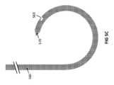
図5Aは、湾曲針の先端570の近傍に、細いワイヤまたは縫合糸を捕捉し得る鋭いフック様特徴を形成する、角度付けられたスロット特徴561を備えている湾曲針560の一例示的実施形態を描写する。実施形態の多くでは、角度付けられたスロット特徴561は、湾曲針560の凸面上に配置されることができる。他の実施形態において、角度付けられたスロット特徴561は、湾曲針560上の他所、例えば、湾曲針560の凹面等に配置されることができる。さらに、いくつかの実施形態において、角度付けられたスロット特徴561および湾曲針の先端570は、湾曲針560の長さに沿って弧を形成し、この弧は、約45度の角度に対している。しかしながら、当業者は、角度付けられたスロット特徴561が、湾曲針560に沿った任意の場所に位置付けられ、湾曲針の先端570を伴うより長いまたはより短い弧を形成し得ることを認識するであろう。また、本例示的実施形態において、角度付けられたスロット特徴561の中心線は、スロットの中心線において湾曲針の接線に対して30°に方向づけられ、針先端のほうへ向けられ、湾曲針の直径の33%の穿通深度を伴う。当業者は、スロットが、代わりに、先端から離れるように角度付けられ得、湾曲針560の長さに沿った任意の場所に位置付けられ得、湾曲針の接線に対して任意の値の角度に向けられ得、任意の深度であり得ることを理解するであろう。
FIG. 5A shows one exemplary embodiment of a
図5B、5C、および5Dは、それぞれ、デバイスに他の機能性を添えることが意図される湾曲針560の側面または表面上の特徴562、563、および564の追加の例示的実施形態を描写する。図5Bは、ブーツ形状の特徴562を備えている湾曲針560の例示的実施形態を描写し、特徴の「つま先」部分は、針先端570から離れるように向いている。図5Cは、針先端570のほうへ向いている特徴の「つま先」部分を伴うブーツ形状の特徴563を備えている湾曲針560の例示的実施形態を描写する。図5Dは、T字形状またはキノコ形状の特徴564を備えている湾曲針560の例示的実施形態を描写する。
5B, 5C, and 5D depict additional exemplary embodiments of
図5Eは、針先端570において単純なスロット付きフォーク特徴565を備えている湾曲針560の例示的実施形態を描写する。
FIG. 5E depicts an exemplary embodiment of a
図5Fは、菱形または人間の眼のように成形され得るオリフィス566を備えている湾曲針560の例示的実施形態を描写する。湾曲針が、トンネルまたは管またはチャネル等のタイトな空間の中に進入すると、オリフィス566を形成する湾曲針の外に曲がったセグメントが、デバイスの外部からの物体の捕捉を可能にするように、一緒に狭まるであろう。
FIG. 5F depicts an exemplary embodiment of a
本開示において説明されるもの等の湾曲針の製造に関して、図9は、製造のための方法の例示的実施形態のフロー図を描写する。湾曲針560を製造するために超弾性材料を使用するとき、オリフィス566を生成するための1つの例示的方法は、材料の直線状またはコイル状のワイヤ原料を取得することである(ステップ902)。超弾性ワイヤ原料から、超弾性ワイヤのセグメントが、次いで、限定ではないが、放電加工(EDM)またはレーザ切断を含む種々の技法によって機械加工され、超弾性ワイヤの長さに対して平行に所望の長さのスリットを導入することができる(ステップ904)。超弾性ワイヤは、次いで、湾曲針560の意図される形状を保持するであろう、金型の中に設置されることができる(ステップ906)。ワイヤ原料が、金型の中に固定されると、鋭い器具の先端が、スリットの中に挿入され、スリットをオリフィス566の所望の幅に広げることができる(ステップ908)。鋭い器具が依然として、超弾性ワイヤの拡張させられたスリット内の定位置にある状態で、超弾性ワイヤと、鋭い器具とを備えている金型は、次いで、超弾性ワイヤを形状設定するために、熱処置を受けることができる(ステップ910)。熱処置に続いて、鋭い器具が、新たに形状設定されたオリフィスから除去され、超弾性ワイヤが、金型から除去された後、オリフィスを備えている結果として生じる湾曲ワイヤが、次いで、任意の追加のプロセスを受け、湾曲針560を完成させることができる。当業者は、熱処置に先立ったステップの精密な順序が、変動し得ること、および超弾性ワイヤの異なる物理的操作中に複数の熱処置ステップを散在させることが、同一の結果を達成するために実施され得ることを認識するであろう。
Regarding manufacturing curved needles such as those described in this disclosure, FIG. 9 depicts a flow diagram of an exemplary embodiment of a method for manufacturing. When using a superelastic material to manufacture
図5A-5Fに示されるこれらの特徴の全ては、例示的実施形態の一般的概念を図示することが意図され、それらは、いかようにも、湾曲針によって備えられ得る特徴のタイプを限定する役割を果たすべきではない。当業者は、特徴が、任意の形状およびサイズであり得ること、湾曲針断面の任意の側面上に位置し得ること、任意の方向および向きに面し得ること、および湾曲針560の任意の直線部分を含む湾曲針の長さに沿った任意の位置にあり得ることを理解するであろう。当業者は、図5A-5Fに描写される特徴が、平行な縁、非平行な縁、湾曲した、フィレット付き、または丸みを帯びた縁、および、より広いまたはより狭い開口部を有し得ることも理解するであろう。
All of these features shown in FIGS. 5A-5F are intended to illustrate the general concept of the exemplary embodiments; they limit the types of features that may be provided by the curved needle in any way. should not play a role. Those skilled in the art will appreciate that the features can be of any shape and size, located on any side of the curved needle cross-section, facing any direction and orientation, and that the features can be of any straight line on the
図6は、骨材料内に1つ以上の曲線状トンネルを生成するためのトンネル作成デバイス600の別の例示的実施形態を描写する斜視図である。実施形態のある側面によると、打ち込み具の多数の組が、生成されるべき湾曲したトンネルの形成を制御することができる。トンネル作成デバイス600のいくつかの実施形態によると、可撓性ドリルビット620を含む可撓性中空シャフト610が、可撓性中空シャフト610の曲がりを生産するために、1つ以上の打ち込み具の第1の組によって、中空シャフト断面の円周上またはその近傍における1つ以上の領域630に対して長手方向に加えられる引っ張り、押し、または曲げ力を受けさせることによって、その長さの一部または全体に沿って湾曲するように誘発されることができる。1つ以上の打ち込み具のこの第1の組は、中空シャフトに取り付けられるか、付着させられるか、またはそれと別個であるかのいずれかである任意の要素による、引っ張り、押し、または曲げ力を加えることができるか、または、外部信号または刺激によってトリガされる中空シャフトの一体的特性であることができる。いくつかの実施形態において、可撓性中空シャフトは、その特性に基づいて、それが入れ子になっている堅い直線状シャフト640から延長されると、湾曲した構成を本質的に生産することができる。トンネル作成デバイス600のいくつかの実施形態によると、打ち込み具の第2の組は、可撓性中空シャフト610を延ばすことおよび後退させることができる。可撓性ドリルビット620のヘッドが、露出され、可撓性中空シャフト610の先端の外側にある。可撓性ドリルビット620のシャフトは、可撓性中空シャフト610内で回転し、可撓性中空シャフト610によって誘発または発生させられる任意の曲がりおよび湾曲に追従するように制約される。トンネル作成デバイス600のいくつかの実施形態によると、1つ以上の打ち込み具の第3の組が、可撓性中空シャフト610の任意の延長または後退と独立して、またはそれと協調して、可撓性ドリルビット620を延ばすことおよび後退させることができる。トンネル作成デバイス600の例示的実施形態のこれらの側面は、中空可撓性シャフト610および可撓性ドリルビット620を延ばし、後退させ、および曲げるためのいかなる具体的な機構も描写していないが、当業者は、単一または複数の空気圧式、磁気、電気、または機械的アクチュエータを使用してシャフトおよびドリルビットを延ばし、および後退させるための打ち込み具のこれらの多数の組が、デバイス600の外部にあるか、またはそれと一体型であるかのいずれかであり得、完全に自動化され得ること、部分的に自動化され得ること、または手動で動力供給され得ることを認識するであろう。デバイス本体650は、デバイス600の動作を可能にするための任意の機構を含むことができ、デバイス600を動作させるために必要である、外部機構からの任意の接続を含むことができる。
FIG. 6 is a perspective view depicting another exemplary embodiment of a
依然として図6を参照すると、実施形態の別の側面によると、トンネル作成が、可撓性中空シャフトから独立して、またはそれと連動してのいずれかにおいて、可撓性ドリルビット620の前進によって生産される。電動式アクチュエータが、可撓性中空シャフト610内で可撓性ドリルビット620をスピンさせる。可撓性中空シャフト610および堅い直線状シャフト640は、互いに一致する中心を有する円形の管腔を伴う円形断面の管として描写されるが、当業者は、可撓性中空シャフト610、堅い直線状シャフト640、および両方のそれらのそれぞれの管腔が、限定ではないが、楕円形、多角形、または任意の不規則形状を含む任意の断面形状であり得ること、およびそれらの管腔がシャフト断面に対して任意の場所に中心を外れて位置付けられ得ることを認識するであろう。当業者は、中空可撓性シャフト610、可撓性ドリルビット620、および堅い直線状シャフト640の各々が、ユニボディー構築物であり得るか、または、各々が、複数の部品から成り、および/または、各部品の長さに沿って、またはその断面にわたり材料または材料特性の変動を示すことによって、可撓性中空シャフト610および可撓性ドリルビット620の最適な屈曲性質を可能にし得ることも認識するであろう。
Still referring to FIG. 6, according to another aspect of the embodiment, tunnel creation is produced by advancement of a
図7は、骨トンネル作成デバイスにおけるアクチュエーの動作を制御するための例示的ブロック図を示す。コントローラ700は、電力供給源またはバッテリパック705と、入力モジュール710と、アクチュエータ720と、出力モジュール730と、センサ740とを備えている。入力モジュール710は、ユーザがアクチュエータ720の動作を開始し、アクチュエータの動作に関する種々のパラメータを調節することを可能にする。これらのパラメータは、限定ではないが、速度および電力を含むことができる。アクチュエータ720は、骨トンネルの生成のための機構に係合する。出力モジュール730は、動作中のアクチュエータの現在の状態を捕捉する。1つ以上のセンサ740は、デバイスの1つ以上の状態の変化を検出するために使用されることができ、デバイスは、アクチュエータ720の動作に影響を及ぼすために入力モジュール710への自動化された変化を要求し得る。これらのセンサ740は、限定ではないが、温度、位置、および力を含むことができる。 FIG. 7 shows an example block diagram for controlling the operation of actuators in a bone tunneling device. Controller 700 includes a power supply or battery pack 705, an input module 710, an actuator 720, an output module 730, and a sensor 740. Input module 710 allows a user to initiate operation of actuator 720 and adjust various parameters related to actuator operation. These parameters may include, but are not limited to, speed and power. Actuator 720 engages a mechanism for bone tunnel creation. Output module 730 captures the current state of the actuator during operation. One or more sensors 740 may be used to detect a change in one or more states of the device, and the device may be configured to provide automated input to input module 710 to affect operation of actuator 720. May require change. These sensors 740 can include, but are not limited to, temperature, position, and force.
図8は、骨への軟組織の付着を修復するための補強装置と併せた、骨トンネル作成デバイスの使用の方法に関する例示的フローチャートを図示する。傷害部位の識別(ステップ802)の後、損なわれた軟組織を縛りつけるために縫合が必要とされる具体的な数および場所が、決定される。骨トンネル作成デバイスが、次いで、骨内のそれらの場所において曲線状骨トンネルを生成するために使用される(ステップ804)。補強装置が、次いで、骨トンネル中に挿入されることができる(ステップ806)。縫合糸が、補強装置を通して挿入され(ステップ808)、所望の場所において軟組織を縛りつけるために使用される(ステップ810)。補強装置の挿入は、骨トンネルを生成するための後続のステップとして示されるが、当業者は、骨トンネル作成デバイスおよび補強装置のある実施形態が、これらの2つのステップを単一のステップで行うことを可能にし得ることを理解するであろう。同様に、補強装置を通した縫合糸の挿入も、骨トンネルの中への補強装置の挿入に対する後続のステップとして示されるが、当業者は、トンネル作成デバイスのある実施形態が、補強装置が骨トンネルの中に挿入される前、縫合糸が補強装置の中に予め装填されることを可能にするであろうことを理解するであろう。当業者は、補強装置の挿入が、使用方法から省略され得ること、ここでは、縫合糸が、補強装置がない状態で直接骨トンネルを通して挿入され、続いて、軟組織を縛りつけるために使用され得ること、または骨トンネルが任意の他の目的のために使用され得ることも認識するであろう。 FIG. 8 illustrates an exemplary flowchart for a method of using a bone tunneling device in conjunction with a reinforcement device to repair soft tissue attachments to bone. After identifying the injury site (step 802), the specific number and location of sutures needed to confine the compromised soft tissue is determined. A bone tunneling device is then used to create curved bone tunnels at those locations within the bone (step 804). A reinforcement device can then be inserted into the bone tunnel (step 806). Sutures are inserted through the reinforcement device (step 808) and used to tie down the soft tissue at the desired location (step 810). Although insertion of the reinforcement device is shown as a subsequent step to create a bone tunnel, those skilled in the art will appreciate that certain embodiments of the bone tunnel creation device and reinforcement device perform these two steps in a single step. You will understand that it is possible. Similarly, although the insertion of sutures through the reinforcement device is also shown as a subsequent step to the insertion of the reinforcement device into the bone tunnel, those skilled in the art will appreciate that certain embodiments of tunnel creation devices It will be appreciated that this will allow the suture to be preloaded into the reinforcing device before being inserted into the tunnel. Those skilled in the art will appreciate that the insertion of a reinforcing device can be omitted from the method of use, where the suture can be inserted directly through the bone tunnel without the reinforcing device and subsequently used to tie down the soft tissue. It will also be appreciated that the bone tunnel may be used for any other purpose.
本明細書に提供される任意の実施形態に関して説明される全ての特徴、要素、構成要素、機能、およびステップが、自由に組み合わせ可能であり、任意の他の実施形態からのものと代用可能であることを意図することに留意されたい。ある特徴、要素、構成要素、機能、またはステップが一実施形態のみに関して説明される場合、その特徴、要素、構成要素、機能、またはステップが、明示的に別様に記載されない限り、本明細書に説明される全ての他の実施形態と併用され得ることを理解されたい。本段落は、したがって、以下の説明が、特定の事例において、そのような組み合わせまたは代用が可能であることを明示的に記載しない場合でも、随時、異なる実施形態からの特徴、要素、構成要素、機能、およびステップを組み合わせる、または一実施形態からの特徴、要素、構成要素、機能およびステップを別のものと代用する請求項の導入のための前項および記述上の支援としての役割を果たす。特に、あらゆるそのような組み合わせおよび代用の許容性が、当業者によって容易に認識されるであろうことを前提として、あらゆる可能性として考えられる組み合わせおよび代用の列挙を表現することが、過度に負担になることを明示的に認識されたい。 All features, elements, components, functions, and steps described with respect to any embodiment provided herein may be freely combined and substituted with those from any other embodiments. Note that it is intended to be. When a feature, element, component, function, or step is described with respect to only one embodiment, the feature, element, component, function, or step is described herein unless explicitly stated otherwise. It is to be understood that it may be used in conjunction with any other embodiments described in . This paragraph therefore includes features, elements, components from different embodiments, The foregoing and serves as a descriptive aid for the introduction of claims combining features and steps or substituting features, elements, components, functions and steps from one embodiment for another. It would be unduly burdensome to express an enumeration of all possible combinations and substitutions, especially given that the permissibility of all such combinations and substitutions would be readily recognized by those skilled in the art. I would like to be explicitly recognized as being
実施形態は、種々の修正および代替形態を受け入れる余地があるが、その具体的な例が、図面に示され、本明細書に詳細に説明されている。しかしながら、これらの実施形態が、開示される特定の形態に限定されず、対照的に、これらの実施形態が、本開示の精神に該当する、全ての修正、均等物、および代替物を網羅すべきであることを理解されたい。さらに、実施形態の任意の特徴、機能、ステップ、または要素は、その範囲内にない特徴、機能、ステップ、または要素によって請求項の発明の範囲を定義する、負の限界と同様に、請求項内に列挙されるか、またはそれらに追加され得る。 While the embodiments are susceptible to various modifications and alternative forms, specific examples thereof are shown in the drawings and herein described in detail. However, it is understood that these embodiments are not limited to the particular forms disclosed, and on the contrary, these embodiments cover all modifications, equivalents, and alternatives falling within the spirit of the disclosure. I hope you understand that you should. Furthermore, any feature, feature, step, or element of an embodiment that is not within the scope of a claim as well as a negative limit defines the scope of the claimed invention by any feature, feature, step, or element that is not within the scope of the claimed invention. may be listed within or added to.
Claims (61)
前記骨の表面と界面接触するように構成された遠位端を有する筐体と、
少なくとも部分的に前記筐体内に配置された少なくとも1つの可撓性湾曲針であって、
前記少なくとも1つの可撓性湾曲針は、前記骨の中に挿入され、曲線状トンネルを生成するように構成され、
前記少なくとも1つの可撓性湾曲針は、超弾性材料を備え、
前記少なくとも1つの可撓性湾曲針は、前記湾曲針の先端の近位に表面特徴をさらに備えている、
少なくとも1つの可撓性湾曲針と、
前記骨の表面下の所定の深度に前記少なくとも1つの可撓性湾曲針を導入するように構成された中空穴あけ具と、
前記筐体内に配置されたチャネルであって、前記内側チャネルは、前記少なくとも1つの可撓性湾曲針を前記骨の中に誘導するように構成されている、チャネルと、
前記少なくとも1つの可撓性湾曲針を移動させるように構成された打ち込み具と
を備えている、デバイス。 A device for creating a curved tunnel in bone, the device comprising:
a housing having a distal end configured for interfacial contact with the bone surface;
at least one flexible curved needle disposed at least partially within the housing;
the at least one flexible curved needle is configured to be inserted into the bone and create a curved tunnel;
the at least one flexible curved needle comprises a superelastic material;
the at least one flexible curved needle further comprising a surface feature proximal to the tip of the curved needle;
at least one flexible curved needle;
a hollow boring tool configured to introduce the at least one flexible curved needle to a predetermined depth below the surface of the bone;
a channel disposed within the housing, the inner channel configured to guide the at least one flexible curved needle into the bone;
a driving tool configured to move the at least one flexible curved needle.
前記骨の表面と界面接触するように構成された遠位端を有する筐体と、
少なくとも部分的に前記筐体内に配置されたインパクタであって、前記インパクタは、前記骨の中に挿入され、前記インパクタは、曲線状トンネルを生成するように構成され、堅い材料と湾曲した幾何学形状とを備えている、インパクタと、
前記筐体内に配置され、前記インパクタを前記骨の中に誘導するように構成された内側チャネルと、
前記インパクタを移動させるように構成された推進機構を備えているアクチュエータと
を備えている、デバイス。 A device for creating a curved tunnel in bone, the device comprising:
a housing having a distal end configured for interfacial contact with the bone surface;
an impactor disposed at least partially within the housing, wherein the impactor is inserted into the bone, the impactor is configured to create a curved tunnel, and has a rigid material and a curved geometry. an impactor having a shape;
an inner channel disposed within the housing and configured to direct the impactor into the bone;
an actuator comprising a propulsion mechanism configured to move the impactor.
前記骨の表面と界面接触するように構成された遠位端を有する筐体と、
少なくとも部分的に前記筐体内に配置された1つ以上の可撓性湾曲針であって、前記1つ以上の可撓性湾曲針は、前記骨の中に挿入され、曲線状トンネルを生成するように構成され、前記1つ以上の可撓性湾曲針は、超弾性材料を備えている、1つ以上の可撓性湾曲針と、
前記1つ以上の可撓性湾曲針を前記骨の表面下の所定の深度に導入するように構成された1つ以上の直線状の中空穴あけ具と、
前記筐体内に配置された1つ以上の内側チャネルであって、前記1つ以上の内側チャネルのうちの各内側チャネルは、前記1つ以上の可撓性湾曲針のうちの対応する可撓性湾曲針を前記骨の中に誘導するように構成されている、1つ以上の内側チャネルと、
前記1つ以上の直線状の中空穴あけ具を移動させるように構成された1つ以上の打ち込み具の第1の組と、
前記1つ以上の可撓性湾曲針を移動させるように構成された1つ以上の打ち込み具の第2の組と
を備えている、デバイス。 A device for creating a curved tunnel in bone, the device comprising:
a housing having a distal end configured for interfacial contact with the bone surface;
one or more flexible curved needles disposed at least partially within the housing, the one or more flexible curved needles being inserted into the bone to create a curved tunnel; one or more flexible curved needles configured such that the one or more flexible curved needles comprise a superelastic material;
one or more linear hollow boring tools configured to introduce the one or more flexible curved needles to a predetermined depth below the surface of the bone;
one or more inner channels disposed within the housing, each inner channel of the one or more inner channels having a corresponding flexible curved needle of the one or more flexible curved needles; one or more inner channels configured to guide a curved needle into the bone;
a first set of one or more driving tools configured to move the one or more linear hollow drilling tools;
a second set of one or more driving tools configured to move the one or more flexible curved needles.
前記骨の表面と界面接触するように構成された遠位端を有する筐体と、
骨の中への挿入中、曲がり、曲線状トンネルの経路を誘導するように構成された可撓性中空シャフトと、
露出ヘッドを含む可撓性ドリルビットであって、前記露出ヘッドは、前記可撓性中空シャフトの先端部分に位置し、前記可撓性ドリルビットは、前記可撓性中空シャフト内で回転するように構成されたドリルシャフトを含む、可撓性ドリルビットと、
前記可撓性中空シャフトを操向するための1つ以上の打ち込み具の第1の組と、
前記可撓性中空シャフトを延長するための1つ以上の打ち込み具の第2の組と、
前記可撓性ドリルビットをスピンさせ、かつ延長するための1つ以上の打ち込み具の第3の組と
を備えている、デバイス。 A device for creating a curved tunnel in bone, the device comprising:
a housing having a distal end configured for interfacial contact with the bone surface;
a flexible hollow shaft configured to bend and guide a curved tunnel path during insertion into the bone;
A flexible drill bit including an exposed head, the exposed head located at a distal end portion of the flexible hollow shaft, and the flexible drill bit configured to rotate within the flexible hollow shaft. a flexible drill bit including a drill shaft configured to
a first set of one or more driving tools for steering the flexible hollow shaft;
a second set of one or more driving tools for extending the flexible hollow shaft;
a third set of one or more driving tools for spinning and extending the flexible drill bit.
前記骨の表面と界面接触するように構成された遠位端を有する筐体であって、前記筐体は、1つ以上の窓を備えている、筐体と、
プランジャシャフトを備えているプランジャと、
少なくとも部分的に前記筐体内に配置された1つ以上の可撓性湾曲針であって、前記1つ以上の可撓性湾曲針は、前記骨の中に挿入され、曲線状トンネルを生成するように構成され、前記1つ以上の可撓性湾曲針は、超弾性材料を備えている、1つ以上の可撓性湾曲針と、
前記1つ以上の可撓性湾曲針を前記骨の表面下の所定の深度に導入するように構成された1つ以上の中空穴あけ具と、
前記筐体内に配置された1つ以上の内側チャネルであって、前記1つ以上の内側チャネルのうちの各内側チャネルは、前記1つ以上の可撓性湾曲針のうちの対応する可撓性湾曲針を前記骨の中に誘導するように構成されている、1つ以上の内側チャネルと、
前記1つ以上の可撓性湾曲針を移動させるように構成された1つ以上の打ち込み具と
を備え、
前記筐体の1つ以上の窓は、前記プランジャと前記1つ以上の可撓性湾曲針との間の取り付け点へのアクセスを提供するように構成された第1の窓を備えている、デバイス。 A device for creating a curved tunnel in bone, the device comprising:
a housing having a distal end configured for interfacial contact with the bone surface, the housing comprising one or more windows;
a plunger comprising a plunger shaft;
one or more flexible curved needles disposed at least partially within the housing, the one or more flexible curved needles being inserted into the bone to create a curved tunnel; one or more flexible curved needles configured such that the one or more flexible curved needles comprise a superelastic material;
one or more hollow boring tools configured to introduce the one or more flexible curved needles to a predetermined depth below the surface of the bone;
one or more inner channels disposed within the housing, each inner channel of the one or more inner channels having a corresponding flexible curved needle of the one or more flexible curved needles; one or more inner channels configured to guide a curved needle into the bone;
one or more driving tools configured to move the one or more flexible curved needles;
the one or more windows of the housing comprising a first window configured to provide access to an attachment point between the plunger and the one or more flexible curved needles; device.
前記骨の表面と界面接触するように構成された遠位端を有する筐体と、
少なくとも部分的に前記筐体内に配置された1つ以上の可撓性湾曲針であって、
前記1つ以上の可撓性湾曲針は、前記骨の中に挿入され、曲線状トンネルを生成するように構成され、
前記1つ以上の可撓性湾曲針は、超弾性材料を備え、
前記1つ以上の可撓性湾曲針のうちの少なくとも1つの可撓性湾曲針は、前記少なくとも1つの可撓性湾曲針の端部部分が細いワイヤまたは縫合糸を捕捉するように構成された鋭いフック様特徴を形成するような湾曲針の先端を備え、
前記少なくとも1つの可撓性湾曲針は、前記湾曲針の先端の近位にある、またはその上に配置された表面特徴をさらに備えている、
1つ以上の可撓性湾曲針と、
前記1つ以上の可撓性湾曲針を前記骨の表面下の所定の深度に導入するように構成された1つ以上の中空穴あけ具と、
前記筐体内に配置された1つ以上の内側チャネルであって、前記1つ以上の内側チャネルのうちの各内側チャネルは、前記1つ以上の可撓性湾曲針のうちの対応する可撓性湾曲針を前記骨の中に誘導するように構成されている、1つ以上の内側チャネルと、
前記1つ以上の可撓性湾曲針を移動させるように構成された1つ以上の打ち込み具と
を備えている、デバイス。 A device for creating a curved tunnel in bone, the device comprising:
a housing having a distal end configured for interfacial contact with the bone surface;
one or more flexible curved needles disposed at least partially within the housing;
the one or more flexible curved needles are configured to be inserted into the bone and create a curved tunnel;
the one or more flexible curved needles comprising a superelastic material;
At least one flexible curved needle of the one or more flexible curved needles is configured such that an end portion of the at least one flexible curved needle captures a thin wire or suture. with a curved needle tip that forms a sharp hook-like feature;
the at least one flexible curved needle further comprises a surface feature proximal to or disposed on the tip of the curved needle;
one or more flexible curved needles;
one or more hollow boring tools configured to introduce the one or more flexible curved needles to a predetermined depth below the surface of the bone;
one or more inner channels disposed within the housing, each inner channel of the one or more inner channels having a corresponding flexible curved needle of the one or more flexible curved needles; one or more inner channels configured to guide a curved needle into the bone;
one or more driving tools configured to move the one or more flexible curved needles.
Applications Claiming Priority (3)
| Application Number | Priority Date | Filing Date | Title |
|---|---|---|---|
| US202063124313P | 2020-12-11 | 2020-12-11 | |
| US63/124,313 | 2020-12-11 | ||
| PCT/US2021/062776 WO2022125875A1 (en) | 2020-12-11 | 2021-12-10 | Systems, devices, and methods for creating curvilinear tunnels in bone |
Publications (1)
| Publication Number | Publication Date |
|---|---|
| JP2023552826A true JP2023552826A (en) | 2023-12-19 |
Family
ID=81973864
Family Applications (1)
| Application Number | Title | Priority Date | Filing Date |
|---|---|---|---|
| JP2023534946A Pending JP2023552826A (en) | 2020-12-11 | 2021-12-10 | Systems, devices, and methods for creating curved tunnels in bone |
Country Status (5)
| Country | Link |
|---|---|
| EP (1) | EP4259014A1 (en) |
| JP (1) | JP2023552826A (en) |
| CN (1) | CN116568226A (en) |
| CA (1) | CA3203758A1 (en) |
| WO (1) | WO2022125875A1 (en) |
Family Cites Families (5)
| Publication number | Priority date | Publication date | Assignee | Title |
|---|---|---|---|---|
| JP5243034B2 (en) * | 2004-10-15 | 2013-07-24 | バクサノ,インク. | Tissue removal device |
| US20100331883A1 (en) * | 2004-10-15 | 2010-12-30 | Schmitz Gregory P | Access and tissue modification systems and methods |
| US9820754B2 (en) * | 2011-08-24 | 2017-11-21 | Mininvasive Ltd. | Circular bone tunneling device employing a stabilizing element |
| IN2014DN06650A (en) * | 2012-01-08 | 2015-05-22 | Mininvasive Ltd | |
| US9642629B2 (en) * | 2012-11-20 | 2017-05-09 | Specialty Surgical Instrumentation Inc. | System and method for forming a curved tunnel in bone |
-
2021
- 2021-12-10 CA CA3203758A patent/CA3203758A1/en active Pending
- 2021-12-10 WO PCT/US2021/062776 patent/WO2022125875A1/en active Application Filing
- 2021-12-10 CN CN202180083356.4A patent/CN116568226A/en active Pending
- 2021-12-10 JP JP2023534946A patent/JP2023552826A/en active Pending
- 2021-12-10 EP EP21904457.5A patent/EP4259014A1/en active Pending
Also Published As
| Publication number | Publication date |
|---|---|
| EP4259014A1 (en) | 2023-10-18 |
| WO2022125875A1 (en) | 2022-06-16 |
| CA3203758A1 (en) | 2022-06-16 |
| CN116568226A (en) | 2023-08-08 |
Similar Documents
| Publication | Publication Date | Title |
|---|---|---|
| JP5815522B2 (en) | Bone microfracture generator | |
| US11903607B2 (en) | Flexible surgical device for tissue removal | |
| CN102112040B (en) | Paranasal ostium finder devices and methods | |
| JP2010508070A (en) | Surgical cutting device and method | |
| US20200330108A1 (en) | Arthroscopic drill blade and arthroscopic drill access system made therefrom | |
| JP2014516261A (en) | Bone drill | |
| JP2010510042A (en) | Tools for use in the placement of bone repair devices | |
| EP3253300B1 (en) | Articulating needle | |
| JP2001517508A (en) | Apparatus and method for performing transmyocardial revascularization | |
| JP2023552826A (en) | Systems, devices, and methods for creating curved tunnels in bone | |
| WO2017042914A1 (en) | Bone drill reamer | |
| CN107874820B (en) | Guiding sleeve for tibia tunnel traction line for posterior cruciate ligament reconstruction under arthroscope | |
| JPH09149907A (en) | Bone fixing tool, and bone fixing system | |
| KR102003055B1 (en) | Punching needle and handpiece for hair extraction | |
| JPH08103453A (en) | Turning preventive means for operation to lower thigh inferior fracture | |
| JP2004337474A (en) | Medical guiding manipulator |