JP2023540065A - Artificial valve for transplantation - Google Patents

Artificial valve for transplantation Download PDF

Info

Publication number
JP2023540065A
JP2023540065A JP2023513812A JP2023513812A JP2023540065A JP 2023540065 A JP2023540065 A JP 2023540065A JP 2023513812 A JP2023513812 A JP 2023513812A JP 2023513812 A JP2023513812 A JP 2023513812A JP 2023540065 A JP2023540065 A JP 2023540065A
Authority
JP
Japan
Prior art keywords
valve
frame
anchors
anchor
prosthetic valve
Prior art date
Legal status (The legal status is an assumption and is not a legal conclusion. Google has not performed a legal analysis and makes no representation as to the accuracy of the status listed.)
Pending
Application number
JP2023513812A
Other languages
Japanese (ja)
Inventor
マシュー・エー・ピーターソン
シドハース・ヴァド
スコット・ルイス・シェリー
テイラー・ジェイコブ・シェインブラム
ケヴィン・エム・ゴレモ
イェヴジェニー・ダヴィドヴィッチ・カウフマン
デイヴィッド・ロバート・ランドン
Current Assignee (The listed assignees may be inaccurate. Google has not performed a legal analysis and makes no representation or warranty as to the accuracy of the list.)
Edwards Lifesciences Corp
Original Assignee
Edwards Lifesciences Corp
Priority date (The priority date is an assumption and is not a legal conclusion. Google has not performed a legal analysis and makes no representation as to the accuracy of the date listed.)
Filing date
Publication date
Application filed by Edwards Lifesciences Corp filed Critical Edwards Lifesciences Corp
Publication of JP2023540065A publication Critical patent/JP2023540065A/en
Pending legal-status Critical Current

Links

Images

Classifications

    • AHUMAN NECESSITIES
    • A61MEDICAL OR VETERINARY SCIENCE; HYGIENE
    • A61FFILTERS IMPLANTABLE INTO BLOOD VESSELS; PROSTHESES; DEVICES PROVIDING PATENCY TO, OR PREVENTING COLLAPSING OF, TUBULAR STRUCTURES OF THE BODY, e.g. STENTS; ORTHOPAEDIC, NURSING OR CONTRACEPTIVE DEVICES; FOMENTATION; TREATMENT OR PROTECTION OF EYES OR EARS; BANDAGES, DRESSINGS OR ABSORBENT PADS; FIRST-AID KITS
    • A61F2/00Filters implantable into blood vessels; Prostheses, i.e. artificial substitutes or replacements for parts of the body; Appliances for connecting them with the body; Devices providing patency to, or preventing collapsing of, tubular structures of the body, e.g. stents
    • A61F2/02Prostheses implantable into the body
    • A61F2/24Heart valves ; Vascular valves, e.g. venous valves; Heart implants, e.g. passive devices for improving the function of the native valve or the heart muscle; Transmyocardial revascularisation [TMR] devices; Valves implantable in the body
    • A61F2/2409Support rings therefor, e.g. for connecting valves to tissue
    • AHUMAN NECESSITIES
    • A61MEDICAL OR VETERINARY SCIENCE; HYGIENE
    • A61FFILTERS IMPLANTABLE INTO BLOOD VESSELS; PROSTHESES; DEVICES PROVIDING PATENCY TO, OR PREVENTING COLLAPSING OF, TUBULAR STRUCTURES OF THE BODY, e.g. STENTS; ORTHOPAEDIC, NURSING OR CONTRACEPTIVE DEVICES; FOMENTATION; TREATMENT OR PROTECTION OF EYES OR EARS; BANDAGES, DRESSINGS OR ABSORBENT PADS; FIRST-AID KITS
    • A61F2/00Filters implantable into blood vessels; Prostheses, i.e. artificial substitutes or replacements for parts of the body; Appliances for connecting them with the body; Devices providing patency to, or preventing collapsing of, tubular structures of the body, e.g. stents
    • A61F2/02Prostheses implantable into the body
    • A61F2/24Heart valves ; Vascular valves, e.g. venous valves; Heart implants, e.g. passive devices for improving the function of the native valve or the heart muscle; Transmyocardial revascularisation [TMR] devices; Valves implantable in the body
    • A61F2/2412Heart valves ; Vascular valves, e.g. venous valves; Heart implants, e.g. passive devices for improving the function of the native valve or the heart muscle; Transmyocardial revascularisation [TMR] devices; Valves implantable in the body with soft flexible valve members, e.g. tissue valves shaped like natural valves
    • A61F2/2418Scaffolds therefor, e.g. support stents
    • AHUMAN NECESSITIES
    • A61MEDICAL OR VETERINARY SCIENCE; HYGIENE
    • A61FFILTERS IMPLANTABLE INTO BLOOD VESSELS; PROSTHESES; DEVICES PROVIDING PATENCY TO, OR PREVENTING COLLAPSING OF, TUBULAR STRUCTURES OF THE BODY, e.g. STENTS; ORTHOPAEDIC, NURSING OR CONTRACEPTIVE DEVICES; FOMENTATION; TREATMENT OR PROTECTION OF EYES OR EARS; BANDAGES, DRESSINGS OR ABSORBENT PADS; FIRST-AID KITS
    • A61F2/00Filters implantable into blood vessels; Prostheses, i.e. artificial substitutes or replacements for parts of the body; Appliances for connecting them with the body; Devices providing patency to, or preventing collapsing of, tubular structures of the body, e.g. stents
    • A61F2/02Prostheses implantable into the body
    • A61F2/24Heart valves ; Vascular valves, e.g. venous valves; Heart implants, e.g. passive devices for improving the function of the native valve or the heart muscle; Transmyocardial revascularisation [TMR] devices; Valves implantable in the body
    • A61F2/2442Annuloplasty rings or inserts for correcting the valve shape; Implants for improving the function of a native heart valve
    • A61F2/2454Means for preventing inversion of the valve leaflets, e.g. chordae tendineae prostheses
    • A61F2/2457Chordae tendineae prostheses
    • AHUMAN NECESSITIES
    • A61MEDICAL OR VETERINARY SCIENCE; HYGIENE
    • A61FFILTERS IMPLANTABLE INTO BLOOD VESSELS; PROSTHESES; DEVICES PROVIDING PATENCY TO, OR PREVENTING COLLAPSING OF, TUBULAR STRUCTURES OF THE BODY, e.g. STENTS; ORTHOPAEDIC, NURSING OR CONTRACEPTIVE DEVICES; FOMENTATION; TREATMENT OR PROTECTION OF EYES OR EARS; BANDAGES, DRESSINGS OR ABSORBENT PADS; FIRST-AID KITS
    • A61F2220/00Fixations or connections for prostheses classified in groups A61F2/00 - A61F2/26 or A61F2/82 or A61F9/00 or A61F11/00 or subgroups thereof
    • A61F2220/0008Fixation appliances for connecting prostheses to the body
    • A61F2220/0016Fixation appliances for connecting prostheses to the body with sharp anchoring protrusions, e.g. barbs, pins, spikes
    • AHUMAN NECESSITIES
    • A61MEDICAL OR VETERINARY SCIENCE; HYGIENE
    • A61FFILTERS IMPLANTABLE INTO BLOOD VESSELS; PROSTHESES; DEVICES PROVIDING PATENCY TO, OR PREVENTING COLLAPSING OF, TUBULAR STRUCTURES OF THE BODY, e.g. STENTS; ORTHOPAEDIC, NURSING OR CONTRACEPTIVE DEVICES; FOMENTATION; TREATMENT OR PROTECTION OF EYES OR EARS; BANDAGES, DRESSINGS OR ABSORBENT PADS; FIRST-AID KITS
    • A61F2250/00Special features of prostheses classified in groups A61F2/00 - A61F2/26 or A61F2/82 or A61F9/00 or A61F11/00 or subgroups thereof
    • A61F2250/0014Special features of prostheses classified in groups A61F2/00 - A61F2/26 or A61F2/82 or A61F9/00 or A61F11/00 or subgroups thereof having different values of a given property or geometrical feature, e.g. mechanical property or material property, at different locations within the same prosthesis
    • A61F2250/0039Special features of prostheses classified in groups A61F2/00 - A61F2/26 or A61F2/82 or A61F9/00 or A61F11/00 or subgroups thereof having different values of a given property or geometrical feature, e.g. mechanical property or material property, at different locations within the same prosthesis differing in diameter
    • AHUMAN NECESSITIES
    • A61MEDICAL OR VETERINARY SCIENCE; HYGIENE
    • A61FFILTERS IMPLANTABLE INTO BLOOD VESSELS; PROSTHESES; DEVICES PROVIDING PATENCY TO, OR PREVENTING COLLAPSING OF, TUBULAR STRUCTURES OF THE BODY, e.g. STENTS; ORTHOPAEDIC, NURSING OR CONTRACEPTIVE DEVICES; FOMENTATION; TREATMENT OR PROTECTION OF EYES OR EARS; BANDAGES, DRESSINGS OR ABSORBENT PADS; FIRST-AID KITS
    • A61F2250/00Special features of prostheses classified in groups A61F2/00 - A61F2/26 or A61F2/82 or A61F9/00 or A61F11/00 or subgroups thereof
    • A61F2250/0058Additional features; Implant or prostheses properties not otherwise provided for
    • A61F2250/0069Sealing means
    • A61F2250/007O-rings

Abstract

人工弁のための装置、システム、及び方法が記載されている。人工弁の実施形態は、弁葉アンカーが半径方向内側に移動するか、又は封止本体の壁を通過することを可能にするように構成された封止本体を含み得る。別の方法として、又は追加的に、封止本体は、周囲組織と接触するために、弁葉アンカーを半径方向外側に移動させるように構成され得る。この通過機構は、弁葉アンカーが天然弁葉を完全に捕捉できない場合に、封止本体が周囲の天然組織に対して緊密なシールを形成することを可能にする。密封、アンカー、及び弁機能の改善のための追加の実施形態は、モジュラー弁システム、及び、例えば、腱索、小柱、又は乳頭筋などの心臓構造に結合するためのアンカーを含む、人工弁を含み得る。実施形態はまた、患者の天然弁の石灰化を係合するために適合されたアンカーを含む、人工弁を含んでもよい。Devices, systems, and methods for prosthetic valves are described. Embodiments of the prosthetic valve may include a sealing body configured to allow the leaflet anchors to move radially inward or pass through a wall of the sealing body. Alternatively or additionally, the sealing body may be configured to move the leaflet anchor radially outward to contact surrounding tissue. This pass-through mechanism allows the sealing body to form a tight seal against the surrounding natural tissue when the leaflet anchor cannot completely capture the native leaflet. Additional embodiments for sealing, anchoring, and improving valve function include modular valve systems and prosthetic valves including anchors for coupling to cardiac structures such as, for example, chordae tendineae, trabeculae, or papillary muscles. may include. Embodiments may also include prosthetic valves that include anchors adapted to engage calcifications of a patient's natural valve.

Description

〔背景〕
本明細書に開示される特定の実施形態は、移植のための人工弁を含む、インプラントに概して関連する。特に、インプラントは、一部の実施形態において、他の特徴の中でも弁傍漏出(PVL)の可能性を低減し得る人工弁に関連する。
〔background〕
Certain embodiments disclosed herein relate generally to implants, including prosthetic valves for implantation. In particular, the implant relates, in some embodiments, to a prosthetic valve that may reduce the likelihood of paravalvular leakage (PVL), among other features.

ヒト心臓弁は、大動脈弁、肺弁、僧帽弁、及び三尖弁を含み、心臓の拍動と同期して動作する一方向弁として本質的に機能する。弁は、血液が下流に流れることを可能にするが、血液が上流に流れるのを遮断する。罹患した心臓弁は、弁の狭窄又は逆流などの障害を呈し、弁の血流を制御する能力を阻害する。このような障害は、心臓の血液ポンプ効率を低下させ、衰弱性かつ生命を脅かす状態となり得る。例えば、弁の機能不全は、心臓肥大及び心室の拡張などの状態につながることがある。そのため、障害のある心臓弁を修復又は置換するための方法及び装置を開発する広範な努力がなされてきた。 Human heart valves, including the aortic, pulmonary, mitral, and tricuspid valves, function essentially as one-way valves that operate in synchronization with the heart's beats. The valve allows blood to flow downstream but blocks blood from flowing upstream. Affected heart valves exhibit disorders such as valvular stenosis or regurgitation, which impede the valve's ability to control blood flow. Such disorders reduce the heart's blood pumping efficiency and can become a debilitating and life-threatening condition. For example, valve dysfunction can lead to conditions such as heart hypertrophy and ventricular dilatation. Therefore, extensive efforts have been made to develop methods and devices for repairing or replacing failed heart valves.

プロステーシスは、心臓弁の障害に関連する問題を是正するために存在する。例えば、機械的及び組織ベースの心臓弁プロステーシスを使用して、障害のある天然の心臓弁を置き換えることができる。最近では、心臓弁置換、特に、開心手術よりも患者への外傷が少ない状態で送達され得る組織ベースの心臓弁置換の開発に、かなりの努力が払われてきた。交換用の弁は、低侵襲的処置、更には経皮的処置を通して送達されるように設計されている。こうした置換弁は、しばしば、拡張可能フレームに接続され、その後、天然弁の弁輪に送達される、組織ベースの弁本体を含む。 Prostheses exist to correct problems associated with heart valve disorders. For example, mechanical and tissue-based heart valve prostheses can be used to replace failed natural heart valves. Recently, considerable effort has been devoted to developing heart valve replacements, particularly tissue-based heart valve replacements that can be delivered with less trauma to the patient than open-heart surgery. Replacement valves are designed to be delivered through minimally invasive procedures, even percutaneous procedures. Such replacement valves often include a tissue-based valve body that is connected to an expandable frame and then delivered to the annulus of the native valve.

これらの交換弁は、しばしば、血流を少なくとも部分的に遮断することを意図している。しかしながら、プロテーゼの外側の弁の周りに血液が流れると問題が生じる。例えば、心臓弁の交換において、弁傍漏出(PVL)は特に困難であることが実証されている。追加の課題は、例えば、非外傷的な様式で、任意の体腔又は空洞内の組織など、管腔内組織に対してこうしたプロステーシスが固定される能力に関連する。 These replacement valves are often intended to at least partially block blood flow. However, problems arise when blood flows around the external valve of the prosthesis. For example, paravalvular leakage (PVL) has proven to be particularly difficult in heart valve replacement. Additional challenges relate to the ability of such prostheses to be secured to endoluminal tissue, such as tissue within any body cavity or cavity, in an atraumatic manner.

人工弁の実施形態は、アンカーが少なくとも部分的に通過するように構成された封止本体を含み得る。アンカーが封止本体を通過する能力によって、アンカーによる弁葉の捕捉を損ねた場合に、封止本体が患者の心臓の一部分を封止することが可能となり得る。そのため、弁傍漏出(PVL)の可能性が低減され得る。封止本体は、アンカーによる弁葉の損ねた捕捉に局所的に適合するように構成された適応封止本体を含み得る。 Embodiments of the prosthetic valve may include a sealing body configured for the anchor to pass at least partially. The ability of the anchor to pass through the sealing body may allow the sealing body to seal off a portion of the patient's heart in the event of loss of capture of the valve leaflets by the anchor. Therefore, the possibility of paravalvular leakage (PVL) may be reduced. The sealing body may include an adaptive sealing body configured to locally accommodate compromised capture of the leaflet by the anchor.

本明細書の実施形態は、モジュラー弁システムを更に含み得る。こうしたモジュラー弁システムは、人工弁の構成の可変性を強化し、こうした人工弁を作製する能力を改善することができる。 Embodiments herein may further include a modular valve system. Such modular valve systems can enhance the variability in the configuration of prosthetic valves and improve the ability to create such prosthetic valves.

本明細書の実施形態は、患者の心臓の腱索、小柱、又は乳頭構造に結合するためのアンカーを含む、人工弁を更に含み得る。 Embodiments herein may further include a prosthetic valve that includes an anchor for coupling to chordae, trabeculae, or papillary structures of a patient's heart.

本明細書の実施形態は、天然弁の石灰化を係合して、人工弁を天然弁に固定するためのアンカーを含む、人工弁を更に含み得る。 Embodiments herein may further include a prosthetic valve that includes an anchor for engaging calcification of the natural valve to secure the prosthetic valve to the natural valve.

本明細書の実施形態は、人工弁の他の特徴を含み得る。 Embodiments herein may include other features of the prosthetic valve.

本明細書に開示されるような実施形態は、天然弁に展開されるように構成された人工弁を含み得る。人工弁は、複数の人工弁弁葉を含み得る。1つ以上のアンカーは、複数の人工弁弁葉に結合され得、かつ患者の心臓の一部分に固定するように各々が構成されている。封止本体は、複数の人工弁弁葉の半径方向外側に位置付けられており、かつ流体流を減少させるために患者の心臓の一部分に当接するように構成されてもよく、封止本体は、1つ以上のアンカーが半径方向内側方向に少なくとも部分的に通過するように構成されている。 Embodiments as disclosed herein may include a prosthetic valve configured to be deployed into a natural valve. A prosthetic valve may include multiple prosthetic valve leaflets. The one or more anchors may be coupled to multiple prosthetic valve leaflets and each configured to secure to a portion of the patient's heart. The sealing body may be positioned radially outwardly of the plurality of prosthetic valve leaflets and configured to abut a portion of the patient's heart to reduce fluid flow, the sealing body comprising: The one or more anchors are configured to pass at least partially in a radially inward direction.

方法は、患者の身体の天然弁に人工弁を展開することを含み得る。人工弁は、複数の人工弁弁葉を含み得る。1つ以上のアンカーは、複数の人工弁弁葉に結合され得、かつ患者の心臓の一部分に固定するように各々が構成されている。封止本体は、複数の人工弁弁葉の半径方向外側に位置付けられており、かつ流体流を減少させるために患者の心臓の一部分に当接するように構成されてもよく、封止本体は、1つ以上のアンカーが半径方向内側方向に少なくとも部分的に通過するように構成されている。 The method may include deploying a prosthetic valve to a natural valve in the patient's body. A prosthetic valve may include multiple prosthetic valve leaflets. The one or more anchors may be coupled to multiple prosthetic valve leaflets and each configured to secure to a portion of the patient's heart. The sealing body may be positioned radially outwardly of the plurality of prosthetic valve leaflets and configured to abut a portion of the patient's heart to reduce fluid flow, the sealing body comprising: The one or more anchors are configured to pass at least partially in a radially inward direction.

本明細書に開示されるような実施形態は、モジュラー人工弁システムを含み得る。システムは、遠位アンカーの複数の異なる構成を備え得る。システムは、近位アンカーの複数の異なる構成を備え得る。システムは、弁本体であって、複数の人工弁弁葉を含み、かつ遠位アンカーの複数の異なる構成から選択された遠位アンカーの構成のうちの1つに結合されるように構成されており、かつ近位アンカーの複数の異なる構成から選択された近位アンカーの構成のうちの1つに結合されるように構成されている、弁本体を備え得る。 Embodiments as disclosed herein may include a modular prosthetic valve system. The system may include multiple different configurations of distal anchors. The system may include a number of different configurations of proximal anchors. The system includes a valve body including a plurality of prosthetic valve leaflets and configured to be coupled to one of a plurality of different configurations of distal anchors selected from a plurality of different configurations of distal anchors. and a valve body configured to be coupled to one of a plurality of different configurations of proximal anchors selected from a plurality of different configurations of proximal anchors.

本明細書に開示されるような実施形態は、人工弁を形成する方法を含み得る。方法は、遠位アンカーの複数の異なる構成から遠位アンカーの構成を選択することを含み得る。方法は、近位アンカーの複数の異なる構成から近位アンカーの構成を選択することを含み得る。方法は、遠位アンカーの選択された構成及び選択された近位アンカーの構成を、複数の人工弁弁葉を含む弁本体に結合することと、を含み得る。 Embodiments as disclosed herein may include a method of forming a prosthetic valve. The method may include selecting a configuration of the distal anchor from a plurality of different configurations of the distal anchor. The method may include selecting a configuration of the proximal anchor from a plurality of different configurations of the proximal anchor. The method may include coupling a selected configuration of distal anchors and a selected configuration of proximal anchors to a valve body that includes a plurality of prosthetic valve leaflets.

本明細書に開示されるような実施形態は、天然弁に展開されるように構成された人工弁を含み得る。弁は、複数の人工弁弁葉を含み得る。弁は、人工弁弁葉を支持するフレームを含み得る。弁は、フレームに結合され、かつ人工弁を天然弁内に固定するために、1つ以上の腱索、小柱、又は乳頭構造に結合するように構成された、巻回特徴部を含む、1つ以上のアンカーを含み得る。 Embodiments as disclosed herein may include a prosthetic valve configured to be deployed into a natural valve. The valve may include multiple prosthetic valve leaflets. The valve may include a frame that supports the prosthetic valve leaflets. The valve includes a wrapping feature coupled to the frame and configured to couple to one or more chordae, trabeculae, or papillary structures to secure the prosthetic valve within the native valve. May contain one or more anchors.

本明細書に開示されるような実施形態は、患者の身体の天然弁に人工弁を展開することを含む、方法を含み得る。弁は、複数の人工弁弁葉を含み得る。弁は、人工弁弁葉を支持するフレームを含み得る。弁は、フレームに結合され、かつ人工弁を天然弁内に固定するために、1つ以上の腱索、小柱、又は乳頭構造に結合するように構成された、巻回特徴部を含む、1つ以上のアンカーを含み得る。方法は、巻回特徴部を、腱索又は小柱のうちの1つ以上に結合することを含み得る。 Embodiments as disclosed herein may include a method that includes deploying a prosthetic valve to a natural valve in a patient's body. The valve may include multiple prosthetic valve leaflets. The valve may include a frame that supports the prosthetic valve leaflets. The valve includes a wrapping feature coupled to the frame and configured to couple to one or more chordae, trabeculae, or papillary structures to secure the prosthetic valve within the native valve. May contain one or more anchors. The method may include coupling the wrapped feature to one or more of the chordae tendineae or trabeculae.

本明細書に開示されるような実施形態は、天然弁に展開されるように構成された人工弁を含み得る。弁は、複数の人工弁弁葉を含み得る。弁は、人工弁弁葉を支持するフレームを含み得る。弁は、フレームに結合され、かつ天然弁の石灰化と係合して人工弁を天然弁に固定するように構成されている、1つ以上のアンカーを含み得る。 Embodiments as disclosed herein may include a prosthetic valve configured to be deployed into a natural valve. The valve may include multiple prosthetic valve leaflets. The valve may include a frame that supports the prosthetic valve leaflets. The valve may include one or more anchors coupled to the frame and configured to engage calcification of the natural valve to secure the prosthetic valve to the natural valve.

本明細書に開示されるような実施形態は、患者の身体の天然弁に人工弁を展開することを含む、方法を含み得る。弁は、複数の人工弁弁葉を含み得る。弁は、人工弁弁葉を支持するフレームを含み得る。弁は、フレームに結合され、かつ天然弁の石灰化と係合して人工弁を天然弁に固定するように構成されている、1つ以上のアンカーを含み得る。方法は、石灰化を1つ以上のアンカーと係合させることを含み得る。 Embodiments as disclosed herein may include a method that includes deploying a prosthetic valve to a natural valve in a patient's body. The valve may include multiple prosthetic valve leaflets. The valve may include a frame that supports the prosthetic valve leaflets. The valve may include one or more anchors coupled to the frame and configured to engage calcification of the natural valve to secure the prosthetic valve to the natural valve. The method may include engaging the calcification with one or more anchors.

本明細書に開示されるような実施形態は、天然弁に展開されるように構成された人工弁を含み得る。弁は、複数の人工弁弁葉を含み得る。弁は、人工弁弁葉を支持するフレームを含み得る。弁は、フレームに結合され、かつ各々が先端を有し、かつフレームから半径方向外側に延在するように構成されている、1つ以上のアンカーを含み得、1つ以上のアンカーの各々は、アンカーの先端に向かう方向において下向きに先細りの厚さを有する一部分を有する。 Embodiments as disclosed herein may include a prosthetic valve configured to be deployed into a natural valve. The valve may include multiple prosthetic valve leaflets. The valve may include a frame that supports the prosthetic valve leaflets. The valve may include one or more anchors coupled to the frame and each having a tip and configured to extend radially outwardly from the frame, each of the one or more anchors having a , has a portion having a thickness that tapers downward in a direction toward the tip of the anchor.

本明細書に開示されるような実施形態は、患者の身体の天然弁に人工弁を展開することを含む、方法を含み得る。弁は、複数の人工弁弁葉を含み得る。弁は、人工弁弁葉を支持するフレームを含み得る。弁は、フレームに結合され、かつ各々が先端を有し、かつフレームから半径方向外側に延在するように構成されている、1つ以上のアンカーを含み得、1つ以上のアンカーの各々は、アンカーの先端に向かう方向において下向きに先細りの厚さを有する一部分を有する。 Embodiments as disclosed herein may include a method that includes deploying a prosthetic valve to a natural valve in a patient's body. The valve may include multiple prosthetic valve leaflets. The valve may include a frame that supports the prosthetic valve leaflets. The valve may include one or more anchors coupled to the frame and each having a tip and configured to extend radially outwardly from the frame, each of the one or more anchors having a , has a portion having a thickness that tapers downward in a direction toward the tip of the anchor.

本明細書に開示されるような実施形態は、天然弁に展開されるように構成された人工弁を含み得る。弁は、複数の人工弁弁葉を含み得る。弁は、人工弁弁葉を支持し、かつ近位部分及び遠位部分を含む、内側フレームを含み得る。弁は、内側フレームの半径方向外側に位置付けられており、かつ内側フレームの近位部分に結合された近位部分と、内側フレームの周りにリングを形成する複数の支柱セルを含む遠位部分と、を有する、外側フレームを含む、封止本体を含み得、外側フレームは、外側フレームの近位部分から複数の支柱セルまで延在する、複数の細長い支柱アームを含み、細長い支柱アームのうちの少なくとも1つは、複数の支柱セルが外側フレームの近位部分に対して偏向することを可能にするように構成されている、偏向特徴部を含む。 Embodiments as disclosed herein may include a prosthetic valve configured to be deployed into a natural valve. The valve may include multiple prosthetic valve leaflets. The valve may include an inner frame that supports the prosthetic valve leaflets and includes a proximal portion and a distal portion. The valve has a proximal portion positioned radially outwardly of the inner frame and coupled to the proximal portion of the inner frame, and a distal portion including a plurality of strut cells forming a ring around the inner frame. , the outer frame including a plurality of elongate strut arms extending from a proximal portion of the outer frame to a plurality of strut cells, the outer frame having a At least one includes a deflection feature configured to allow the plurality of strut cells to deflect relative to a proximal portion of the outer frame.

本明細書に開示されるような実施形態は、患者の身体の天然弁に人工弁を展開することを含む、方法を含み得る。弁は、複数の人工弁弁葉を含み得る。弁は、人工弁弁葉を支持し、かつ近位部分及び遠位部分を含む、内側フレームを含み得る。弁は、内側フレームの半径方向外側に位置付けられており、かつ内側フレームの近位部分に結合された近位部分と、内側フレームの周りにリングを形成する複数の支柱セルを含む遠位部分と、を有する、外側フレームを含む、封止本体を含み得、外側フレームは、外側フレームの近位部分から複数の支柱セルまで延在する、複数の細長い支柱アームを含み、細長い支柱アームのうちの少なくとも1つは、複数の支柱セルが外側フレームの近位部分に対して偏向することを可能にするように構成されている、偏向特徴部を含む。 Embodiments as disclosed herein may include a method that includes deploying a prosthetic valve to a natural valve in a patient's body. The valve may include multiple prosthetic valve leaflets. The valve may include an inner frame that supports the prosthetic valve leaflets and includes a proximal portion and a distal portion. The valve has a proximal portion positioned radially outwardly of the inner frame and coupled to the proximal portion of the inner frame, and a distal portion including a plurality of strut cells forming a ring around the inner frame. , the outer frame including a plurality of elongate strut arms extending from a proximal portion of the outer frame to a plurality of strut cells, the outer frame having a At least one includes a deflection feature configured to allow the plurality of strut cells to deflect relative to a proximal portion of the outer frame.

本明細書に開示されるような実施形態は、天然弁に展開されるように構成された人工弁を含み得る。弁は、複数の人工弁弁葉を含み得る。弁は、人工弁弁葉を支持し、かつ近位部分及び遠位部分を含む、内側フレームを含み得る。弁は、内側フレームの半径方向外側に位置付けられており、かつ複数の支柱を含む、外側フレームを含み得、複数の支柱のうちの少なくとも1つは、外側フレームの可撓性を増加させるように構成された起伏又は開口部を有する。 Embodiments as disclosed herein may include a prosthetic valve configured to be deployed into a natural valve. The valve may include multiple prosthetic valve leaflets. The valve may include an inner frame that supports the prosthetic valve leaflets and includes a proximal portion and a distal portion. The valve may include an outer frame positioned radially outwardly of the inner frame and including a plurality of struts, at least one of the plurality of struts configured to increase flexibility of the outer frame. It has structured undulations or openings.

本明細書に開示されるような実施形態は、患者の身体の天然弁に人工弁を展開することを含む、方法を含み得る。弁は、複数の人工弁弁葉を含み得る。弁は、人工弁弁葉を支持し、かつ近位部分及び遠位部分を含む、内側フレームを含み得る。弁は、内側フレームの半径方向外側に位置付けられており、かつ複数の支柱を含む、外側フレームを含み得、複数の支柱のうちの少なくとも1つは、外側フレームの可撓性を増加させるように構成された起伏又は開口部を有する。 Embodiments as disclosed herein may include a method that includes deploying a prosthetic valve to a natural valve in a patient's body. The valve may include multiple prosthetic valve leaflets. The valve may include an inner frame that supports the prosthetic valve leaflets and includes a proximal portion and a distal portion. The valve may include an outer frame positioned radially outwardly of the inner frame and including a plurality of struts, at least one of the plurality of struts configured to increase flexibility of the outer frame. It has structured undulations or openings.

本明細書に開示されるような実施形態は、天然弁に展開されるように構成された人工弁を含み得る。弁は、複数の人工弁弁葉を含み得る。弁は、人工弁弁葉に結合されたフレームを含み得、フレームは、近位端及び遠位端と、接合部で接合された複数の支柱と、を含み、複数の支柱のうちの少なくとも1つは、近位端から遠位端に向かって一方向に延在しており、かつ第1の軸に沿って延在する第1のセグメント、第2のセグメント、及び第2の軸に沿って延在する第3のセグメントと、第1のセグメントと第2のセグメントとをある角度で接合する、第1のキンク、及び第2のセグメントと第3のセグメントとをある角度で接合する、第2のキンクと、を含み、第2の軸は、第1の軸からオフセットされている。 Embodiments as disclosed herein may include a prosthetic valve configured to be deployed into a natural valve. The valve may include multiple prosthetic valve leaflets. The valve may include a frame coupled to the prosthetic valve leaflets, the frame including proximal and distal ends and a plurality of struts joined at a joint, at least one of the plurality of struts. one extending in one direction from the proximal end to the distal end and having a first segment extending along the first axis, a second segment extending along the second axis; a first kink joining the first segment and the second segment at an angle; and a first kink joining the second segment and the third segment at an angle; a second kink, the second axis being offset from the first axis.

本明細書に開示されるような実施形態は、患者の身体の天然弁に人工弁を展開することを含む、方法を含み得る。弁は、複数の人工弁弁葉を含み得る。弁は、人工弁弁葉に結合されたフレームを含み得、フレームは、近位端及び遠位端と、接合部で接合された複数の支柱と、を含み、複数の支柱のうちの少なくとも1つは、近位端から遠位端に向かって一方向に延在しており、かつ第1の軸に沿って延在する第1のセグメント、第2のセグメント、及び第2の軸に沿って延在する第3のセグメントと、第1のセグメントと第2のセグメントとをある角度で接合する、第1のキンク、及び第2のセグメントと第3のセグメントとをある角度で接合する、第2のキンクと、を含み、第2の軸は、第1の軸からオフセットされている。 Embodiments as disclosed herein may include a method that includes deploying a prosthetic valve to a natural valve in a patient's body. The valve may include multiple prosthetic valve leaflets. The valve may include a frame coupled to the prosthetic valve leaflets, the frame including proximal and distal ends and a plurality of struts joined at a joint, at least one of the plurality of struts. one extending in one direction from the proximal end to the distal end and having a first segment extending along the first axis, a second segment extending along the second axis; a first kink joining the first segment and the second segment at an angle; and a first kink joining the second segment and the third segment at an angle; a second kink, the second axis being offset from the first axis.

本明細書に開示されるような実施形態は、天然弁に展開されるように構成された人工弁を含み得る。弁は、複数の人工弁弁葉を含み得る。弁は、人工弁弁葉を支持する内側フレームを含み得る。弁は、内側フレームの半径方向外側に位置付けられており、かつ内側フレームから半径方向外側に延在する近位部分と、近位部分から軸方向に湾曲し、外側フレームの遠位端に対して軸方向に延在する遠位部分と、を有する、外側フレームを含む、封止本体を含み得る。弁は、外側フレームの遠位部分から半径方向外側に延在しており、かつ外側フレームの遠位移動を阻害するように構成されている、複数のアンカーを含み得る。 Embodiments as disclosed herein may include a prosthetic valve configured to be deployed into a natural valve. The valve may include multiple prosthetic valve leaflets. The valve may include an inner frame that supports the prosthetic valve leaflets. The valve is positioned radially outwardly of the inner frame and has a proximal portion extending radially outwardly from the inner frame and an axially curved portion from the proximal portion relative to a distal end of the outer frame. The sealing body may include an outer frame having an axially extending distal portion. The valve may include a plurality of anchors extending radially outwardly from a distal portion of the outer frame and configured to inhibit distal movement of the outer frame.

本明細書に開示されるような実施形態は、患者の身体の天然弁に人工弁を展開することを含む、方法を含み得る。弁は、複数の人工弁弁葉を含み得る。弁は、人工弁弁葉を支持する内側フレームを含み得る。弁は、内側フレームの半径方向外側に位置付けられており、かつ内側フレームから半径方向外側に延在する近位部分と、近位部分から軸方向に湾曲し、外側フレームの遠位端に対して軸方向に延在する遠位部分と、を有する、外側フレームを含む、封止本体を含み得る。弁は、外側フレームの遠位部分から半径方向外側に延在しており、かつ外側フレームの遠位移動を阻害するように構成されている、複数のアンカーを含み得る。 Embodiments as disclosed herein may include a method that includes deploying a prosthetic valve to a natural valve in a patient's body. The valve may include multiple prosthetic valve leaflets. The valve may include an inner frame that supports the prosthetic valve leaflets. The valve is positioned radially outwardly of the inner frame and has a proximal portion extending radially outwardly from the inner frame and an axially curved portion from the proximal portion relative to a distal end of the outer frame. The sealing body may include an outer frame having an axially extending distal portion. The valve may include a plurality of anchors extending radially outwardly from a distal portion of the outer frame and configured to inhibit distal movement of the outer frame.

本明細書に開示されるようなシステム、装置、及び方法の特徴及び利点は、本明細書、請求項、及び添付図面を参照してより良く理解されるように認識されるであろう。 The features and advantages of the systems, devices, and methods as disclosed herein will be better understood with reference to the specification, claims, and accompanying drawings.

本開示の実施形態による人工弁の側面斜視図を示している。1 illustrates a side perspective view of a prosthetic valve according to an embodiment of the present disclosure. FIG. 弁葉が図から除外された状態である、図1に示した人工弁の底面図を示している。Figure 2 shows a bottom view of the prosthetic valve shown in Figure 1 with the leaflets removed from the view; 図1に示した人工弁の断面概略図を示している。2 shows a schematic cross-sectional view of the artificial valve shown in FIG. 1. FIG. 天然心臓弁内に移植された人工弁の概略図を示している。Figure 2 shows a schematic diagram of a prosthetic valve implanted within a native heart valve. 本開示の実施形態による人工弁の概略図を示している。1 shows a schematic diagram of a prosthetic valve according to an embodiment of the present disclosure. FIG. 天然心臓弁内に移植された図1に示した人工弁の断面概略図を示している。Figure 2 shows a cross-sectional schematic view of the prosthetic valve shown in Figure 1 implanted within a native heart valve. 図1に示した人工弁の底面斜視図を示している。Figure 2 shows a bottom perspective view of the prosthetic valve shown in Figure 1; 弁本体が図から取り除かれた状態である、図1に示した封止本体の底面斜視図を示している。Figure 2 shows a bottom perspective view of the sealing body shown in Figure 1 with the valve body removed from the view. 図1に示した封止本体のフレーム、及びアンカー先端の相対的位置の平面図を示している。Figure 2 shows a plan view of the frame of the sealing body shown in Figure 1 and the relative positions of the anchor tips; 本開示の実施形態による、封止本体のフレーム、及びアンカー先端の相対的位置の平面図を示している。FIG. 6 illustrates a top view of a frame of a sealing body and the relative position of an anchor tip, according to an embodiment of the present disclosure. 図1に示した封止本体のセグメントの平面図を示している。Figure 2 shows a top view of a segment of the sealing body shown in Figure 1; 一緒に結合された図1に示した封止本体の複数のセグメントを示している。Figure 2 shows multiple segments of the sealing body shown in Figure 1 joined together; 本開示の実施形態による、封止本体の上面図を示している。FIG. 3 illustrates a top view of a sealing body, according to an embodiment of the present disclosure. 図13に示した封止本体内のアンカーの上部断面概略図を示している。Figure 14 shows a top cross-sectional schematic view of the anchor within the sealing body shown in Figure 13; 図13に示した封止本体内のアンカーの側面斜視図を示している。Figure 14 shows a side perspective view of the anchor within the sealing body shown in Figure 13; 本開示の実施形態による人工弁の側面概略図を示している。1 shows a side schematic view of a prosthetic valve according to an embodiment of the present disclosure. FIG. 図16に示した封止本体のスリットのクローズアップ斜視図を示している。Figure 17 shows a close-up perspective view of the slit of the sealing body shown in Figure 16; 図16に示した封止本体の半径方向外側に位置付けられたアンカーの上部断面概略図を示している。Figure 17 shows a top cross-sectional schematic view of an anchor positioned radially outward of the sealing body shown in Figure 16; 図18に示した封止本体内に位置付けられた図18に示したアンカーの上部断面概略図を示している。Figure 19 shows a top cross-sectional schematic view of the anchor shown in Figure 18 positioned within the sealing body shown in Figure 18; 本開示の実施形態による人工弁の側面斜視図を示している。1 illustrates a side perspective view of a prosthetic valve according to an embodiment of the present disclosure. FIG. 図20に示した人工弁の一部分の側面図を示している。21 shows a side view of a portion of the prosthetic valve shown in FIG. 20. 本開示の実施形態による、人工弁の一部分の側部断面概略図を示している。1 illustrates a side cross-sectional schematic view of a portion of a prosthetic valve, according to an embodiment of the present disclosure. FIG. 本開示の実施形態による、人工弁の一部分の側部断面概略図を示している。1 illustrates a side cross-sectional schematic view of a portion of a prosthetic valve, according to an embodiment of the present disclosure. FIG. 患者の身体内に延在する送達装置の概略図を示している。1 shows a schematic diagram of a delivery device extending within a patient's body. 本開示の一実施形態による、展開されている人工弁の側面概略図を示している。1 shows a side schematic view of a prosthetic valve being deployed, according to an embodiment of the present disclosure. FIG. 展開されている図25に示した人工弁の側面概略図を示している。Figure 26 shows a side schematic view of the prosthetic valve shown in Figure 25 deployed; 展開されている図25に示した人工弁の側面概略図を示している。Figure 26 shows a side schematic view of the prosthetic valve shown in Figure 25 deployed; 展開されている図25に示した人工弁の側面概略図を示している。Figure 26 shows a side schematic view of the prosthetic valve shown in Figure 25 deployed; 本開示の実施形態による、モジュラー人工弁の断面概略図を示している。1 shows a cross-sectional schematic diagram of a modular prosthetic valve, according to an embodiment of the present disclosure. FIG. 本開示の実施形態による、遠位アンカーに結合された近位アンカーの斜視図を示している。FIG. 4 illustrates a perspective view of a proximal anchor coupled to a distal anchor, according to an embodiment of the present disclosure. 本開示の実施形態による、近位アンカーと遠位アンカーとの間の結合の一部分のクローズアップ図を示している。FIG. 6 illustrates a close-up view of a portion of a connection between a proximal anchor and a distal anchor, according to an embodiment of the present disclosure. 線形化構成の図29に示した人工弁の側面概略図を示している。Figure 30 shows a side schematic view of the prosthetic valve shown in Figure 29 in a linearized configuration. 人工弁に結合されたスカートを含む、図29に示す人工弁の側部断面斜視図を示している。30 shows a side cross-sectional perspective view of the prosthetic valve shown in FIG. 29, including a skirt coupled to the prosthetic valve. 本開示の実施形態による人工弁の側面概略図を示している。1 shows a side schematic view of a prosthetic valve according to an embodiment of the present disclosure. FIG. 展開されている図34に示した人工弁の側面概略図を示している。Figure 35 shows a side schematic view of the prosthetic valve shown in Figure 34 deployed; 展開された図34に示した人工弁の側面概略図を示している。Figure 35 shows a side schematic view of the prosthetic valve shown in Figure 34 developed. 本開示の実施形態による人工弁の側面概略図を示している。1 shows a side schematic view of a prosthetic valve according to an embodiment of the present disclosure. FIG. 展開されている図37に示した人工弁の側面概略図を示している。Figure 38 shows a side schematic view of the prosthetic valve shown in Figure 37 deployed. 展開された図37に示した人工弁の側面概略図を示している。Figure 38 shows a side schematic view of the prosthetic valve shown in Figure 37 developed. 本開示の実施形態による人工弁の側面概略図を示している。1 shows a side schematic view of a prosthetic valve according to an embodiment of the present disclosure. FIG. 展開されている図40に示した人工弁の側面概略図を示している。41 shows a side schematic view of the prosthetic valve shown in FIG. 40 deployed; FIG. 展開された図40に示した人工弁の側面概略図を示している。41 shows a side schematic view of the prosthetic valve shown in FIG. 40 developed. 本開示の実施形態による、人工弁の断面概略図を示している。1 shows a cross-sectional schematic diagram of a prosthetic valve, according to an embodiment of the present disclosure. FIG. 図43に示した遠位アンカー又は心室アンカーの平面図を示している。44 shows a top view of the distal or ventricular anchor shown in FIG. 43. FIG. 図43に示した人工弁の上部側面概略図を示している。44 shows a schematic upper side view of the prosthetic valve shown in FIG. 43. FIG. 患者の天然弁に延在する送達装置の概略図を示している。Figure 3 shows a schematic diagram of a delivery device extending into a patient's native valve. 患者の天然弁内に移植された図43に示した人工弁の断面概略図を示している。Figure 44 shows a cross-sectional schematic view of the prosthetic valve shown in Figure 43 implanted within a patient's natural valve. バーブを含むアンカーの側面概略図を示している。Figure 3 shows a side schematic view of an anchor including barbs. 本開示の実施形態による、患者の天然弁内に移植された人工弁の断面概略図を示している。1 shows a cross-sectional schematic view of a prosthetic valve implanted within a patient's natural valve, according to an embodiment of the present disclosure. FIG. バーブを含む弁フレームの側面概略図を示している。Figure 3 shows a side schematic view of a valve frame including barbs. 本開示の実施形態による、患者の天然弁内に移植された人工弁の断面概略図を示している。1 shows a cross-sectional schematic view of a prosthetic valve implanted within a patient's natural valve, according to an embodiment of the present disclosure. FIG. 本開示の実施形態による、人工弁の断面概略図を示している。1 shows a cross-sectional schematic diagram of a prosthetic valve, according to an embodiment of the present disclosure. FIG. 人工弁の一部分の側面図を示している。Figure 3 shows a side view of a portion of a prosthetic valve. 図53Aに示したアンカーの上面図を示している。53B shows a top view of the anchor shown in FIG. 53A. 図53Aに示したアンカーの側面図を示している。Figure 53B shows a side view of the anchor shown in Figure 53A. 本開示の実施形態による、人工弁の一部分の側面図を示している。1 illustrates a side view of a portion of a prosthetic valve, according to an embodiment of the present disclosure. FIG. 図54Aに示したアンカーの上面図を示している。54B shows a top view of the anchor shown in FIG. 54A. 図54Aに示したアンカーの側面図を示している。54B shows a side view of the anchor shown in FIG. 54A. 本開示の実施形態による、人工弁の一部分の側面図を示している。1 illustrates a side view of a portion of a prosthetic valve, according to an embodiment of the present disclosure. FIG. 図55Aに示したアンカーの上面図を示している。55B shows a top view of the anchor shown in FIG. 55A. 図55Aに示したアンカーの側面図を示している。Figure 55B shows a side view of the anchor shown in Figure 55A. 本開示の実施形態による、人工弁の一部分の側面断面図を示している。1 illustrates a side cross-sectional view of a portion of a prosthetic valve, according to an embodiment of the present disclosure. FIG. 本開示の実施形態による、図56に示した人工弁のフレームの平面図を示している。57 illustrates a top view of the frame of the prosthetic valve shown in FIG. 56, according to an embodiment of the present disclosure. FIG. 本開示の実施形態による、フレームの平面図を示している。FIG. 3 illustrates a top view of a frame, according to an embodiment of the present disclosure. 本開示の実施形態による、フレームの平面図を示している。FIG. 3 illustrates a top view of a frame, according to an embodiment of the present disclosure. 本開示の実施形態による、フレームの平面図を示している。FIG. 3 illustrates a top view of a frame, according to an embodiment of the present disclosure. 本開示の実施形態による、フレームの平面図を示している。FIG. 3 illustrates a top view of a frame, according to an embodiment of the present disclosure. 非展開構成におけるフレームの側面図を示している。FIG. 6 shows a side view of the frame in an undeployed configuration. 拡張構成における図62Aに示したフレームの一部分の側面図を示している。62B shows a side view of a portion of the frame shown in FIG. 62A in an expanded configuration. 圧縮構成における図62Aに示したフレームの側面図を示している。62B shows a side view of the frame shown in FIG. 62A in a compressed configuration. 本開示の実施形態による、フレームの一部分の平面図を示している。FIG. 4 illustrates a top view of a portion of a frame, according to an embodiment of the present disclosure. 図63Aの63Bでマークされたフレームの一部分の図を示している。63B shows an illustration of a portion of the frame marked 63B in FIG. 63A. 図62Aの支柱に隣接する図63Aの支柱の側面図を示している。63A shows a side view of the strut of FIG. 63A adjacent to the strut of FIG. 62A. 図63Aに示したような支柱を含むフレームの側面図を示している。Figure 63A shows a side view of a frame including struts as shown in Figure 63A. 拡張された図65Aに示したようなフレームの一部分の側面図を示している。65B shows a side view of a portion of the frame as shown in FIG. 65A expanded. 圧縮された図65Aに示したフレームの側面図を示している。65B shows a side view of the frame shown in FIG. 65A compressed; FIG. 本開示の実施形態による、フレームの平面図を示している。FIG. 3 illustrates a top view of a frame, according to an embodiment of the present disclosure. 図66に示したフレームの一部分の側面図を示している。Figure 67 shows a side view of a portion of the frame shown in Figure 66; 図66に示したフレームを利用する人工弁の概略断面図を示している。Figure 67 shows a schematic cross-sectional view of a prosthetic valve utilizing the frame shown in Figure 66;

図1は、交換用心臓弁の形態の人工弁10の斜視図を示している。人工弁10は、患者の身体の一部分内に展開されるように構成されてもよい。人工弁10は、例えば、天然心臓弁弁輪内に展開されてもよく、これは、天然僧帽弁又は天然三尖弁を含んでもよい。実施形態では、大動脈弁若しくは肺弁内などの他の移植場所、又は所望される患者の身体内の他の弁若しくは場所を利用してもよい。 FIG. 1 shows a perspective view of a prosthetic valve 10 in the form of a replacement heart valve. Prosthetic valve 10 may be configured to be deployed within a portion of a patient's body. Prosthetic valve 10 may, for example, be deployed within a native heart valve annulus, which may include a native mitral valve or a native tricuspid valve. Embodiments may utilize other implantation locations, such as within the aortic or pulmonary valves, or other valves or locations within the patient's body as desired.

人工弁10は、近位端12及び遠位端14(図2にマークされる)、並びにその間の長さを含み得る。人工弁10は、弁10を通る流れを制御するための流れチャネルを囲むように構成された複数の人工弁弁葉16を更に含み得る。人工弁弁葉16は、開状態と閉状態との間を移動して、天然弁弁葉の作動を模倣し、かつ置換するように構成され得る。 Prosthetic valve 10 may include a proximal end 12 and a distal end 14 (marked in FIG. 2) and a length therebetween. Prosthetic valve 10 may further include a plurality of prosthetic valve leaflets 16 configured to surround a flow channel for controlling flow through valve 10. Prosthetic valve leaflets 16 may be configured to move between open and closed states to mimic and replace the operation of natural valve leaflets.

実施形態では、人工弁弁葉16は、図3の断面図に示されるような、及び図2の底面図に示されるような弁フレーム18に結合され得る。図3にマークされるように、弁フレーム18は、近位端19を含む近位部分及び遠位端21を含む遠位部分を含み得る。弁フレーム18は、近位端19と遠位端21との間で半径方向外側に湾曲する湾曲した本体を含む湾曲した構成を有してもよく、又は所望される実施形態で別の構成を有してもよい。 In embodiments, prosthetic valve leaflets 16 may be coupled to a valve frame 18, as shown in cross-sectional view in FIG. 3 and as shown in bottom view in FIG. As marked in FIG. 3, the valve frame 18 may include a proximal portion including a proximal end 19 and a distal portion including a distal end 21. As marked in FIG. Valve frame 18 may have a curved configuration including a curved body that curves radially outwardly between proximal end 19 and distal end 21, or alternative configurations in desired embodiments. May have.

弁フレーム18の近位部分は、人工弁弁葉16の近位部分に結合されてもよい。人工弁弁葉16は、弁フレーム18に結合されてもよく、弁フレーム18から半径方向内側に延在してもよい。人工弁弁葉16は、人工弁弁葉16を支持し得る中間本体23を介して弁フレーム18に結合されてもよく、また望ましい場合には、縫合又は別の方法を介して弁フレーム18に弁葉16を結合してもよい。 A proximal portion of valve frame 18 may be coupled to a proximal portion of prosthetic valve leaflets 16. Prosthetic valve leaflets 16 may be coupled to valve frame 18 and may extend radially inwardly from valve frame 18. The prosthetic valve leaflets 16 may be coupled to the valve frame 18 via an intermediate body 23 that can support the prosthetic valve leaflets 16 and, if desired, to the valve frame 18 via sutures or another method. The leaflets 16 may be joined.

人工弁弁葉16は、図3にマークされたように流れチャネル25を囲むことができ、流れチャネル25を通る流れを制御するために開状態と閉状態との間で移動することができる。図3に示すように、人工弁10の近位端は、弁10の流入端部を備えてもよく、また人工弁10の遠位端は、流出端部を備えてもよいが、他の構成が所望に応じて利用されてもよい。 Prosthetic valve leaflets 16 can surround flow channel 25 as marked in FIG. 3 and can be moved between open and closed states to control flow through flow channel 25. As shown in FIG. 3, the proximal end of the prosthetic valve 10 may include an inflow end of the valve 10, and the distal end of the prosthetic valve 10 may include an outflow end, but other Configurations may be utilized as desired.

図2は、弁10の底面図を示している。弁葉は、図2から除外されている。図2の底面図に示すように、弁フレーム18は、空間で互いに離間された複数の支柱を含み得る。こうした構成によって、弁フレーム18は、非展開構成、非拡張構成、又は直線化構成の間で展開又は拡張構成に移動することができる。例えば、弁フレーム18は、展開又は拡張構成に移動するように半径方向外側に拡張してもよく、ここで、弁フレーム18の直径の増加によって弁フレーム18の長さが減少する。弁フレーム18の他の構成は、所望に応じて利用され得る。 FIG. 2 shows a bottom view of valve 10. The valve leaflets have been excluded from Figure 2. As shown in the bottom view of FIG. 2, the valve frame 18 may include a plurality of spatially spaced struts. Such a configuration allows the valve frame 18 to move between a non-deployed configuration, a non-expanded configuration, or a straightened configuration to a deployed or expanded configuration. For example, the valve frame 18 may expand radially outwardly to move to a deployed or expanded configuration, where the length of the valve frame 18 decreases due to an increase in the diameter of the valve frame 18. Other configurations of valve frame 18 may be utilized as desired.

図1を参照すると、弁10は、複数の人工弁弁葉16に結合され得、かつ患者の心臓の一部分に固定するように各々が構成されている、1つ以上のアンカー17を含み得る。アンカー17は、患者の心臓の天然弁弁葉に固定するように特に構成され得る。アンカー17は、天然弁弁葉に固定するために、弁の周囲に延在してもよい。アンカー17は、弁10の遠位端14に位置付けられた遠位アンカーを備えてもよく、又は実施形態では、所望される別の位置に位置付けられてもよい。 Referring to FIG. 1, valve 10 may include one or more anchors 17 that may be coupled to a plurality of prosthetic valve leaflets 16 and each configured to secure to a portion of a patient's heart. Anchor 17 may be specifically configured to secure to the native valve leaflets of a patient's heart. Anchors 17 may extend around the valve to secure to the native valve leaflets. Anchor 17 may comprise a distal anchor located at distal end 14 of valve 10, or in embodiments may be located at another location as desired.

アンカー17は各々、流れチャネル25から半径方向外側に、かつ弁10の人工弁弁葉16から半径方向外側に延在し得る。図3は、例えば、アンカー17が、弁10の内部フレームを含む弁フレーム18に結合され得ることを示している。アンカー17は、弁フレーム18の遠位部分に結合されてもよい。アンカー17は各々、近位部分27及び遠位部分29を含み得、近位部分27は、弁フレーム18に結合され、遠位部分29は、それぞれのアンカー17の先端を備える。 Anchors 17 may each extend radially outwardly from flow channel 25 and radially outwardly from prosthetic leaflets 16 of valve 10. FIG. 3 shows, for example, that anchor 17 can be coupled to a valve frame 18, which includes the internal frame of valve 10. Anchor 17 may be coupled to a distal portion of valve frame 18. Anchors 17 may each include a proximal portion 27 and a distal portion 29, with proximal portion 27 coupled to valve frame 18 and distal portion 29 comprising the tip of the respective anchor 17.

図3は、弁10の断面概略図を示している。図3に示すように、各アンカー17は、遠位に延在し、その後、アンカー17のそれぞれのアンカーの先端に対して近位方向に湾曲するように構成されている。こうした構成は、アンカー17が天然弁葉の周りを延在し、弁葉の遠位部分の周りをフックすることを許容し得る。したがって、アンカー17は、弁10に対して近位方向に加えられる力に抵抗してもよく、弁10を天然弁弁輪内に固定してもよい。アンカー17の他の構成は、所望される実施形態で利用され得る。 FIG. 3 shows a cross-sectional schematic view of the valve 10. As shown in FIG. 3, each anchor 17 is configured to extend distally and then curve proximally relative to its respective anchor tip. Such a configuration may allow anchor 17 to extend around the natural leaflet and hook around the distal portion of the leaflet. Thus, anchor 17 may resist forces applied proximally to valve 10 and may secure valve 10 within the native valve annulus. Other configurations of anchor 17 may be utilized in desired embodiments.

アンカー17は、アンカー17の先端が近位に延在する展開又は拡張構成で図1~図3に示される。実施形態では、アンカーは、アンカー17の先端が遠位に延在する、非展開、非拡張、又は直線化構成であるように構成され得る。展開時、アンカー17は、非展開構成から半径方向外側に展開構成に移動するように構成されてもよく、先端は、近位方向に反転する。こうした動作によって、アンカー17が、展開中に、天然弁弁葉をひっくり返して、天然弁弁葉に固定することが可能になり得る。アンカー17に対する他の展開方法は、所望される実施形態で利用され得る。 Anchor 17 is shown in FIGS. 1-3 in a deployed or expanded configuration with the tip of anchor 17 extending proximally. In embodiments, the anchor may be configured in an undeployed, unexpanded, or straightened configuration with the tip of anchor 17 extending distally. Upon deployment, anchor 17 may be configured to move radially outward from an undeployed configuration to a deployed configuration, with the tip everting in a proximal direction. Such action may allow anchor 17 to flip and secure the native valve leaflet to the native valve leaflet during deployment. Other deployment methods for anchor 17 may be utilized in desired embodiments.

図1を参照すると、弁10は、封止本体20を含み得る。封止本体20は、弁16から半径方向外側に位置付けられてもよく、弁10の外面を含んでもよい。封止本体20は、弁10の外径を画定してもよく、弁10の外周部を含んでもよい。封止本体20は、近位端31を有する近位部分を含んでもよく、遠位端33(図2にマークされる)を有する遠位部分を含んでもよい。 Referring to FIG. 1, valve 10 may include a sealing body 20. Referring to FIG. The sealing body 20 may be positioned radially outwardly from the valve 16 and may include an outer surface of the valve 10. The sealing body 20 may define the outer diameter of the valve 10 and may include the outer circumference of the valve 10. The sealing body 20 may include a proximal portion having a proximal end 31 and a distal portion having a distal end 33 (marked in FIG. 2).

封止本体20は、図1に示すように、フレーム22及びスカート24を含んでもよく、又は実施形態では、所望の場合には、フレームのみ又はスカートのみを含んでもよい。フレーム22は、弁フレーム18から半径方向外側に位置付けられている外側フレームを備えてもよい。スカート24は、フレーム22に結合されてもよい。 The sealing body 20 may include a frame 22 and a skirt 24, as shown in FIG. 1, or in embodiments may include only a frame or only a skirt, if desired. Frame 22 may include an outer frame positioned radially outwardly from valve frame 18. Skirt 24 may be coupled to frame 22.

図3を参照すると、フレーム22は、弁フレーム18の近位端19に結合される近位部分35を有し得る。近位部分35は、弁フレーム18の近位端19から、及び人工弁弁葉16から半径方向外側に延在してもよい。フレーム22の遠位部分37は、間隙39を有して人工弁弁葉16及び弁フレーム18から離間されてもよい。間隙は、封止本体20のフレーム22と弁フレーム18の遠位部分との間に位置付けられてもよい。したがって、弁フレーム18は、内側フレームを備えてもよく、封止本体20のフレームは、内側フレームを囲む外側フレームを備えてもよい。封止本体20は、内側弁フレーム18及び人工弁弁葉16を囲むことができる。 Referring to FIG. 3, frame 22 may have a proximal portion 35 coupled to proximal end 19 of valve frame 18. Referring to FIG. Proximal portion 35 may extend radially outwardly from proximal end 19 of valve frame 18 and from prosthetic valve leaflets 16 . Distal portion 37 of frame 22 may be spaced apart from prosthetic valve leaflet 16 and valve frame 18 with a gap 39 . A gap may be located between frame 22 of sealing body 20 and a distal portion of valve frame 18. Thus, the valve frame 18 may include an inner frame and the frame of the sealing body 20 may include an outer frame surrounding the inner frame. The sealing body 20 can surround the inner valve frame 18 and the prosthetic valve leaflets 16.

図3に示すように、封止本体20のフレーム22は、弁フレーム18の遠位端よりも遠位に短い距離まで延在する長さを有してもよい。そのため、封止本体20のフレーム22は、弁フレーム18よりも短くてもよい。封止本体20のフレーム22は、弁フレーム18から外側に湾曲する湾曲した構成を更に有してもよく、フレーム22の最大直径は、フレーム22の遠位部分にある。 As shown in FIG. 3, the frame 22 of the sealing body 20 may have a length that extends a short distance distal to the distal end of the valve frame 18. As such, the frame 22 of the sealing body 20 may be shorter than the valve frame 18. The frame 22 of the sealing body 20 may further have a curved configuration that curves outwardly from the valve frame 18, with the maximum diameter of the frame 22 being at a distal portion of the frame 22.

図1を参照すると、封止本体20のフレーム22は、フレーム22を形成する複数の支柱46を含んでもよく、支柱は、空間によって分離される。こうした構成によって、フレーム22が、図1に示すように、非展開構成、非拡張構成、又は直線化構成の間で展開又は拡張構成に移動することができ、フレーム22及び封止本体20は、湾曲した球根状形状を有する。弁フレーム18と同様に、封止本体20のフレーム22の長さは、展開中に封止本体20のフレーム22の直径が増加するにつれて減少し得る。封止本体20のフレーム22の直径は、内側弁フレーム18から半径方向に外向きに同時に拡大してもよく、又は実施形態では内側弁フレーム18とは異なる時間又は速度で拡大してもよい。 Referring to FIG. 1, the frame 22 of the sealing body 20 may include a plurality of struts 46 forming the frame 22, the struts being separated by spaces. Such a configuration allows frame 22 to move between an undeployed, unexpanded, or straightened configuration to a deployed or expanded configuration, as shown in FIG. It has a curved bulbous shape. Similar to valve frame 18, the length of frame 22 of seal body 20 may decrease as the diameter of frame 22 of seal body 20 increases during deployment. The diameter of the frame 22 of the sealing body 20 may simultaneously expand radially outward from the inner valve frame 18 or may expand at a different time or rate than the inner valve frame 18 in embodiments.

封止本体20は、内側弁フレーム18及び人工弁弁葉16の周りに延在し得る、スカート24を含み得る。スカート24は、封止本体のフレーム22に結合されてもよく、又は実施形態ではフレーム22から解放されてもよい。スカート24は、封止本体20のフレーム22の近位部分に結合され、かつ弁フレーム18の近位部分に結合され得る、近位部分41を有してもよい。スカート24は、内側弁フレーム18の遠位端に結合されてもよく、かつアンカー17のうちの1つ以上に結合されてもよい、遠位部分43(図2にマークされる)を有してもよい。遠位部分43は、内側弁フレーム18に結合するための一部分を含んでもよく、弁フレーム18の周りで円周方向に交互に位置してもよいアンカー17のうちの1つ以上に結合するための一部分を含んでもよい。部分は、図12に示すようなタブを含んでもよく、又は所望される別の構成を有してもよい。 Seal body 20 may include a skirt 24 that may extend around inner valve frame 18 and prosthetic valve leaflets 16. Skirt 24 may be coupled to frame 22 of the sealing body, or may be free from frame 22 in embodiments. Skirt 24 may have a proximal portion 41 that is coupled to a proximal portion of frame 22 of sealing body 20 and may be coupled to a proximal portion of valve frame 18. Skirt 24 has a distal portion 43 (marked in FIG. 2) that may be coupled to the distal end of inner valve frame 18 and to one or more of anchors 17. You can. The distal portion 43 may include a portion for coupling to the inner valve frame 18 and for coupling to one or more of the anchors 17 that may be alternately positioned circumferentially around the valve frame 18. may include a portion of. The portion may include tabs as shown in FIG. 12, or may have another configuration as desired.

図3を参照すると、スカート24は、封止本体20のフレーム22に沿って延在し得る。スカート24は、一緒に結合され得る、複数の部分を含み得る。例えば、スカート24の第1の近位部分26は、封止本体20のフレーム22の半径方向内側に位置付けられてもよく、また、フレーム22の遠位端から少なくとも部分的に半径方向外側に位置付けられ、次いで、スカート24の遠位部分43に対してフレーム22の半径方向内側に延在する、スカート24の第2の遠位部分28に結合されてもよい。第2の遠位部分28は、アンカー17及び内側弁フレーム18に結合する、部分を備えてもよい。スカート24の第1の近位部分26及び第2の遠位部分28は、望ましいように、縫合又は別の形態の結合を介して一緒に結合されて、実施形態では連続的な表面を形成してもよい。 Referring to FIG. 3, skirt 24 may extend along frame 22 of sealing body 20. Referring to FIG. Skirt 24 may include multiple sections that may be joined together. For example, the first proximal portion 26 of the skirt 24 may be positioned radially inboard of the frame 22 of the sealing body 20 and at least partially radially outward from the distal end of the frame 22. and then coupled to a second distal portion 28 of the skirt 24 that extends radially inwardly of the frame 22 relative to the distal portion 43 of the skirt 24 . Second distal portion 28 may include a portion that couples to anchor 17 and inner valve frame 18 . The first proximal portion 26 and the second distal portion 28 of the skirt 24 are desirably joined together via sutures or another form of bonding to form a continuous surface in embodiments. You can.

スカートの第2の遠位部分28は、アンカー17の先端よりも更に遠位に延在してもよく、アンカー17及び弁フレーム18に、アンカー17の先端の遠位にある位置で結合してもよい。図3に示すように、アンカー17は、内側弁フレーム18から半径方向外側に、間隙39を横切ってそれぞれのアンカー17の先端まで延在するように構成されてもよい。 A second distal portion 28 of the skirt may extend further distally than the tip of the anchor 17 and is coupled to the anchor 17 and the valve frame 18 at a location distal to the tip of the anchor 17. Good too. As shown in FIG. 3, anchors 17 may be configured to extend radially outwardly from inner valve frame 18 across gap 39 to a distal end of each anchor 17.

スカート24、特にスカート24の第2の遠位部分28は、スカート24が所望のように移動する、特にアンカー17の位置に適合するように移動することを可能になるように、可撓性であるように構成され得る。スカート24は、布材料、織布材料、又はポリマーなどの他の材料、若しくはそれを通した流体流に耐える他の材料などの、それを通した流体流に抵抗する材料で作製され得る。様々な材料を、所望の場合にはスカート24に利用することができる。 The skirt 24, in particular the second distal portion 28 of the skirt 24, is flexible to allow the skirt 24 to move as desired, particularly to adapt to the position of the anchor 17. may be configured to be. Skirt 24 may be made of a material that resists fluid flow therethrough, such as a cloth material, woven material, or other material such as a polymer or other material that resists fluid flow therethrough. A variety of materials can be utilized for skirt 24 if desired.

封止本体20は、流体流を減少させるために患者の心臓の一部分に当接するように構成され得る。例えば、封止本体20は、封止本体20と天然弁葉との間の流体流を減少させるために、患者の天然弁弁葉の表面と当接してもよい。封止本体20は、患者の心臓の他の部分に当接して、所望により流体流を減少させるように構成され得る。 Seal body 20 may be configured to abut a portion of the patient's heart to reduce fluid flow. For example, sealing body 20 may abut the surface of a patient's natural valve leaflet to reduce fluid flow between sealing body 20 and the natural valve leaflet. Seal body 20 may be configured to abut other portions of the patient's heart to reduce fluid flow as desired.

スカート24の第2の遠位部分28は、半径方向内側に延在して、アンカー17が少なくとも部分的に半径方向内側方向に封止本体20を通過することを可能にし得る。封止本体20は、例えば、図3に示すように、アンカー17が半径方向内側方向に少なくとも部分的に通過するように構成されてもよい。アンカー17は各々、封止本体20の外径がアンカー17の直径以上となるように、封止本体20を少なくとも部分的に通過してもよい。このように、封止本体20の外周は、アンカー17の外周に位置付けられてもよく、又はそれより大きくてもよい。実施形態では、アンカー17の先端などのアンカー17の一部分は、封止本体20から突出してもよく、なおかつ少なくとも部分的に封止本体20を通過してもよい。 A second distal portion 28 of skirt 24 may extend radially inwardly to allow anchor 17 to pass at least partially radially inwardly through sealing body 20 . The sealing body 20 may be configured such that the anchor 17 passes at least partially in a radially inward direction, for example as shown in FIG. Each of the anchors 17 may pass at least partially through the sealing body 20 such that the outer diameter of the sealing body 20 is equal to or greater than the diameter of the anchor 17 . As such, the outer circumference of the sealing body 20 may be positioned at the outer circumference of the anchor 17 or may be larger. In embodiments, a portion of the anchor 17, such as the tip of the anchor 17, may protrude from the sealing body 20 and may still at least partially pass through the sealing body 20.

実施形態では、封止本体20は、半径方向外側に延在するように付勢されてもよい。例えば、封止本体20は、実施形態におけるアンカー17の外径よりも更に半径方向外側に延在するように形状設定されてもよい。こうした構成によって、封止本体20が、アンカー17の外径で、又はアンカー17の外径よりも更に半径方向外側に延在することが可能になり得る。封止本体20は、アンカー17のうちの1つ以上が実施形態では天然弁葉を適切に捕捉できるように、半径方向内側に移動するように偏向するように構成されてもよい。実施形態では、封止本体20の可撓性は、封止本体20が、弁葉の捕捉中に移動できるように調整されてもよい。実施形態では、封止本体20のフレーム22を含む封止本体20の移動は、展開手順の間に撮像されてもよい。撮像は、蛍光透視法、又は心エコー法などの他の形態の撮像であってもよい。封止本体の移動は、アンカー17のうちの1つ以上が天然弁葉を適切に捕捉したかどうかを決定するために撮像されてもよい。例えば、フレーム22の内向きのたわみは、アンカー17のうちの1つ以上が天然弁葉を適切に捕捉したかどうかを決定するために撮像されてもよい。実施形態では、蛍光透視法を利用して、1つ以上の天然弁弁葉の捕捉時にフレーム22の偏向を撮像してもよい。 In embodiments, the sealing body 20 may be biased to extend radially outwardly. For example, the sealing body 20 may be configured to extend further radially outward than the outer diameter of the anchor 17 in the embodiment. Such a configuration may allow sealing body 20 to extend radially outward at or further than the outer diameter of anchor 17 . The sealing body 20 may be configured to be deflected to move radially inward so that one or more of the anchors 17 can properly capture the native leaflets in embodiments. In embodiments, the flexibility of the sealing body 20 may be adjusted such that the sealing body 20 can move during leaflet capture. In embodiments, movement of the sealing body 20, including the frame 22 of the sealing body 20, may be imaged during the deployment procedure. Imaging may be fluoroscopy or other forms of imaging such as echocardiography. Movement of the sealing body may be imaged to determine whether one or more of the anchors 17 have properly captured the native leaflet. For example, the inward deflection of frame 22 may be imaged to determine whether one or more of anchors 17 have properly captured the native leaflet. In embodiments, fluoroscopy may be utilized to image the deflection of frame 22 upon acquisition of one or more native valve leaflets.

封止本体20は、アンカー17に対して移動して、天然弁葉の誤捕捉がある場合に、1つ以上のアンカー17が、封止本体20を少なくとも部分的に半径方向内側に通過することを可能にするように構成され得る。封止本体20の相対的な移動は、アンカー17に対して半径方向外側にあってもよい。したがって、アンカー17の相対的な移動は、封止本体20に対して半径方向内側であってもよい。 The sealing body 20 moves relative to the anchors 17 such that in the event of false capture of a native leaflet, one or more anchors 17 pass at least partially radially inwardly through the sealing body 20. may be configured to enable. The relative movement of the sealing body 20 may be radially outward with respect to the anchor 17. Therefore, the relative movement of the anchor 17 may be radially inward with respect to the sealing body 20.

様々な実施形態において、アンカー17のうちの1つ以上は、封止本体20に対して半径方向内側に偏向又は移動するように付勢されてもよい。このように、天然弁葉の誤捕捉(又は損ねた捕捉)がある場合、天然弁葉の捕捉を損ねたアンカーは、封止本体20を少なくとも部分的に「通過」するように、偏向するか、又はそうでなければ半径方向内側に移動し得る。そのため、アンカーの最終位置は、移植後及び使用中、封止本体の半径方向内側に位置する。アンカー全体は、封止本体又はアンカーの一部分のみの半径方向内側に位置してもよい。様々な実施形態において、半径方向外側に延在するように付勢された封止本体20と、封止本体20に対して半径方向内側に偏向するか、又はそうでなければ移動するように構成された1つ以上のアンカー17との組み合わせを利用して、アンカー17が少なくとも部分的に封止本体20を通過することを可能にすることができる。これらの特徴は、有利なことに、心臓における人工弁の展開中に、アンカー(又は複数のアンカー)が天然弁葉を捕捉できない場合に、逆流を防止するために改善されたシールを生成する手段を提供する。 In various embodiments, one or more of the anchors 17 may be biased to deflect or move radially inward relative to the sealing body 20. Thus, if there is false capture (or impaired capture) of a native leaflet, the anchor that has failed to capture the native leaflet will be deflected so as to at least partially "pass" through the sealing body 20. , or otherwise move radially inward. The final location of the anchor is therefore radially inward of the sealing body after implantation and during use. The entire anchor may be located radially inward of only a portion of the sealing body or anchor. In various embodiments, the sealing body 20 is biased to extend radially outwardly and configured to deflect or otherwise move radially inwardly relative to the sealing body 20. may be used in combination with one or more anchors 17 to allow the anchors 17 to at least partially pass through the sealing body 20. These features advantageously provide a means of creating an improved seal to prevent regurgitation when the anchor (or anchors) fail to capture the native valve leaflets during deployment of a prosthetic valve in the heart. I will provide a.

封止本体20は、弁葉の捕捉を損ねたアンカー17の位置において、封止本体20の外側の流体流を減少させる機能を提供し得る。封止本体のこうした特徴は、図4の実施例によって反映され、ここで、封止本体は、アンカーが少なくとも部分的に通過するように構成されていない。図4は、弁葉34の捕捉を損ねたアンカー32で配置された人工弁30を示している。こうした状況では、アンカー32は、天然弁弁葉と弁30の残りの部分との間に位置付けられたままであり得る。アンカー32は、弁内に留まるため、弁30と弁葉34との間の空間を開く。そのため、封止スカート47によってアンカー32の位置に流体シールは形成されない。アンカー32と弁尖34との間の弁傍漏出(流れ線36によってマークされる)が生じてもよく、これは、弁30の機能性を減少させ得る。 The sealing body 20 may serve to reduce fluid flow outside the sealing body 20 at the location of the anchor 17 that has compromised leaflet capture. These features of the sealing body are reflected by the embodiment of FIG. 4, where the sealing body is not configured for the anchor to at least partially pass therethrough. FIG. 4 shows a prosthetic valve 30 placed with an anchor 32 that has impaired capture of the leaflets 34. In these situations, anchor 32 may remain positioned between the native valve leaflets and the remainder of valve 30. Anchor 32 remains within the valve and thus opens a space between valve 30 and leaflets 34. Therefore, no fluid seal is formed at the anchor 32 by the sealing skirt 47. Paravalvular leakage (marked by flow lines 36) between anchor 32 and leaflets 34 may occur, which may reduce functionality of valve 30.

しかしながら、本明細書の実施形態による弁10は、弁葉の捕捉を損ねた場合に対処するように構成され得る。図5は、例えば、弁10の封止本体20が、アンカー17に対して移動するように構成されてもよく、その結果、封止本体20は、天然弁葉の捕捉の状況において、アンカー17の半径方向内側に外径で位置付けられてもよいことを示している。こうした構成は、図5の破線で参照番号20’によりマークされる。封止本体20’は、弁葉の捕捉中に半径方向内側に移動するためにバイアスを克服するように構成されてもよく、及び/又はアンカー17は、封止本体20’から半径方向外側に保持されてもよい。捕捉された弁葉のこうした構成では、天然弁葉は、アンカー17と封止本体20’との間に位置付けられてもよく、封止本体20’は、天然弁葉に当接して、その位置での流体流を低減する。封止本体20’は、天然弁葉に損傷が発生しないように可撓性であってもよい。 However, valve 10 according to embodiments herein may be configured to address the event of loss of leaflet capture. FIG. 5 shows, for example, that the sealing body 20 of the valve 10 may be configured to move relative to the anchor 17, such that the sealing body 20 moves relative to the anchor 17 in the situation of capture of a native leaflet. This indicates that the outer diameter may be positioned radially inward of the outer diameter. Such a configuration is marked in dashed lines in FIG. 5 by the reference numeral 20'. The sealing body 20' may be configured to overcome the bias to move radially inwardly during leaflet capture, and/or the anchors 17 may be configured to move radially outwardly from the sealing body 20'. May be retained. In such a configuration of the captured leaflet, the native leaflet may be positioned between the anchor 17 and the sealing body 20', where the sealing body 20' abuts the natural leaflet and maintains its position. Reduce fluid flow at The sealing body 20' may be flexible so that no damage occurs to the natural leaflets.

しかしながら、図5の実線で示されるように、封止本体20は、弁葉を捕捉できなかったアンカー17が封止本体20の少なくとも一部分を通過することを可能にするように構成されてもよい。封止本体20は、図5に示すように、アンカー17の外側半径方向の範囲よりも大きい外径を有してもよく、又はアンカー17の外側半径方向の範囲と同じであってもよい。このように、封止本体20は、アンカー32を有する図4に示す状況とは異なり、流体流を減少させるために天然弁葉に当接し続けるように位置付けられてもよい。 However, as shown in solid lines in FIG. 5, sealing body 20 may be configured to allow anchors 17 that fail to capture a leaflet to pass through at least a portion of sealing body 20. . The sealing body 20 may have an outer diameter that is greater than the outer radial extent of the anchor 17, as shown in FIG. 5, or may be the same as the outer radial extent of the anchor 17. In this way, the sealing body 20 may be positioned to continue to abut the natural leaflets to reduce fluid flow, unlike the situation shown in FIG. 4 with the anchors 32.

図6は、例えば、アンカー17と封止本体20との間に位置付けられた天然弁葉38をその弁葉38に位置付けた、図6の左側に示される捕捉された天然弁葉38の構成を示している。封止本体20は、天然弁葉38に当接して、封止本体20と天然弁葉38との間の流体流を減少させる。 FIG. 6 illustrates the configuration of the captured native leaflet 38 shown on the left side of FIG. It shows. Seal body 20 abuts natural leaflet 38 to reduce fluid flow between seal body 20 and natural leaflet 38 .

しかしながら、図6の右側は、その弁葉40でのアンカー17が、展開時に弁葉40の周りに延在できなかった、誤捕捉された天然弁葉40を示している。しかしながら、その弁葉40でのアンカー17は、封止本体20を少なくとも部分的に通過して、封止本体20がその位置で誤捕捉された天然弁葉40に当接して封止することを可能にする。そのため、弁傍漏出(PVL)の減少及び弁10の動作の改善が生じ得る。 However, the right side of FIG. 6 shows a mis-captured native leaflet 40 in which the anchor 17 on that leaflet 40 was unable to extend around the leaflet 40 during deployment. However, the anchor 17 at that leaflet 40 passes at least partially through the sealing body 20 to prevent the sealing body 20 from abutting and sealing against the mis-captured native leaflet 40 in that position. enable. As such, a reduction in paravalvular leakage (PVL) and improved operation of the valve 10 may occur.

封止本体20、特に、封止本体20のスカート24は、天然弁葉を捕捉できなかったアンカー17を囲むように構成されてもよい。封止本体20のこれらの部分は、天然弁葉に押し付けて、天然弁葉の捕捉を損ねたアンカー17の位置での流体流を低減し得る。 The sealing body 20, and in particular the skirt 24 of the sealing body 20, may be configured to surround the anchor 17 that has failed to capture a native leaflet. These portions of sealing body 20 may press against the natural leaflet to reduce fluid flow at the location of anchor 17 that has compromised capture of the natural leaflet.

図7は、例えば、アンカー17が封止本体20を少なくとも部分的に通過することを示す、弁10の側面斜視図を示している。封止本体20の部分は、患者の身体の局所表面と接触するために、アンカー17に、又はアンカー17から半径方向外側に位置付けられている。アンカー17の先端は、少なくとも部分的に、封止本体20を半径方向内側方向に通過してもよく、先端の一部は、封止本体20の半径方向外側に位置付けられている。 FIG. 7 shows, for example, a side perspective view of the valve 10 showing that the anchor 17 passes at least partially through the sealing body 20. A portion of sealing body 20 is positioned radially outwardly at or from anchor 17 for contacting a localized surface of the patient's body. The tip of the anchor 17 may pass, at least partially, through the sealing body 20 in a radially inward direction, with a portion of the tip being positioned radially outwardly of the sealing body 20.

図8は、弁10の残りの部分とは別個の封止本体20の底面斜視図を示している。フレーム22は、空間によって分離された複数の支柱を含むことが示されている。特定の支柱は、アンカー17が支柱間の空間を少なくとも部分的に通過するように構成され得る。例えば、フレーム22の遠位端における遠位支柱42は、アンカー17が通過することを可能にする支柱42間の空間44を有してもよい。図9は、例えば、アンカー17が通過できるように、その間に空間44を有する遠位支柱42を示している。アンカー17の両側の遠位支柱42の部分は、アンカーが少なくとも部分的に封止本体20を通過するときに、アンカー17の周りの封止本体20に対する追加的な支持を提供し得る。 FIG. 8 shows a bottom perspective view of the sealing body 20 separate from the remainder of the valve 10. Frame 22 is shown to include a plurality of struts separated by spaces. Certain struts may be configured such that anchor 17 passes at least partially through the space between the struts. For example, distal struts 42 at the distal end of frame 22 may have spaces 44 between the struts 42 that allow anchors 17 to pass through. FIG. 9 shows distal struts 42 having spaces 44 therebetween to allow passage of anchors 17, for example. Portions of distal struts 42 on either side of anchor 17 may provide additional support to sealing body 20 around anchor 17 as the anchor passes at least partially through sealing body 20.

図9に示す通り、支柱は、弁10の送達装置に固定するため、及び封止本体20のスカート24に固定するために、各々が固定装置50に結合する近位支柱46を含み得る。代替的な構成が図10に示されており、ここで、近位支柱48は固定装置52に結合されてもよく、又はフレームの近位部分で終了してもよい。図10に示す構成は、アンカー17が通過するためのフレームの遠位支柱56間の空間54を含み得る。 As shown in FIG. 9, the struts may include proximal struts 46 that each couple to a fixation device 50 for securing to the delivery device of the valve 10 and to the skirt 24 of the sealing body 20. An alternative configuration is shown in FIG. 10, where the proximal strut 48 may be coupled to a fixation device 52 or terminate in a proximal portion of the frame. The configuration shown in FIG. 10 may include a space 54 between the distal struts 56 of the frame for the anchor 17 to pass through.

図8に戻って参照すると、スカート24は、縫合又は他の形態の結合を介してフレーム22に結合されてもよい。スカート24は、近位部分41及び遠位部分43を含み得る。近位部分41は、フレーム22の半径方向内側に位置付けられてもよく、遠位部分43は、フレーム22の半径方向外側に少なくとも部分的に位置付けられてもよい。スカート24は、流体、特に血液に対する浸透性が低い又は全くない材料から作製されてもよく、これにより、スカート24が患者の心臓の一部分に対して封止され、流体流を減少させることができる。 Referring back to FIG. 8, skirt 24 may be coupled to frame 22 via stitching or other forms of bonding. Skirt 24 may include a proximal portion 41 and a distal portion 43. Proximal portion 41 may be positioned radially inward of frame 22 and distal portion 43 may be positioned at least partially radially outward of frame 22. Skirt 24 may be made from a material with low or no permeability to fluids, particularly blood, allowing skirt 24 to seal against a portion of the patient's heart and reduce fluid flow. .

遠位部分43は、環状形状の遠位部分43を形成するために一緒に結合され得る、複数のセグメント62を含み得る。複数のセグメント62は、継ぎ目64で一緒に結合されてもよく、継ぎ目64は、それぞれのアンカー17を受容するよう構成されている。各継ぎ目64は、アンカー17のうちの1つを受容するための受容部分に対応してもよい。各セグメント62は、スカート24を弁フレーム18に結合するための結合タブ66を含んでもよく、スカート24をアンカー17に結合するための結合タブ68を含んでもよい。 Distal portion 43 may include a plurality of segments 62 that may be joined together to form annularly shaped distal portion 43. The plurality of segments 62 may be joined together at a seam 64 that is configured to receive a respective anchor 17. Each seam 64 may correspond to a receiving portion for receiving one of the anchors 17. Each segment 62 may include a coupling tab 66 for coupling the skirt 24 to the valve frame 18 and may include a coupling tab 68 for coupling the skirt 24 to the anchor 17.

図11は、例えば、隣接するセグメントに結合するためのサイド継ぎ目部分70、72を示す、セグメント62を示している。図12は、互いに結合されてスカート24の遠位部分43を形成する、セグメント62を示している。 FIG. 11, for example, shows segment 62 showing side seam portions 70, 72 for joining adjacent segments. FIG. 12 shows segments 62 joined together to form distal portion 43 of skirt 24. FIG.

図7に戻って参照すると、スカート24の遠位部分43は、アンカー17を受容し、かつアンカー17を少なくとも部分的に包囲して、天然弁弁葉を誤捕捉するアンカー17の周りの流体流を減少させるように構成され得る。 Referring back to FIG. 7, the distal portion 43 of the skirt 24 receives and at least partially surrounds the anchor 17 to allow fluid flow around the anchor 17 to mis-capture the native valve leaflets. may be configured to reduce.

スカートの他の構成を利用してもよい。 Other configurations of skirts may also be utilized.

図13は、例えば、アンカー17を受容するためのスカート74内に形成されたポケット76の形態の受容部分を含む、スカート74の実施形態の上面図を示している。図14は、例えば、スカート74の形成されたポケット76内にアンカー17を有する、このようなスカート74の動作、及びスカート74がアンカー17の位置に弁10の外面を形成するように、アンカー17を包囲するスカート74の材料を示している。ポケット76は、アンカー17の形状に輪郭を描いてもよい。輪郭の形状は、ポケット76を含む材料を形成するために使用されるステッチを介して形成され得る。 FIG. 13 shows a top view of an embodiment of a skirt 74 including a receiving portion in the form of a pocket 76 formed within the skirt 74 for receiving the anchor 17, for example. FIG. 14 shows, for example, the operation of such a skirt 74 with the anchor 17 in a pocket 76 formed in the skirt 74 and the anchor 17 such that the skirt 74 forms the outer surface of the valve 10 at the location of the anchor 17. The material of the skirt 74 surrounding the is shown. Pocket 76 may be contoured to the shape of anchor 17. The contour shape may be formed through the stitching used to form the material containing pocket 76.

図15は、スカート74の形成されたポケット76内に位置付けられたアンカー17の側面斜視図を示している。 FIG. 15 shows a side perspective view of anchor 17 positioned within pocket 76 formed in skirt 74. FIG.

図16は、アンカー17が少なくとも部分的に通過する開口部としての役割を果たすスリット82の形態の受容部分を有するスカート80を含む、弁78の別の実施形態を示している。実施形態では、アンカー17は、スカート材料がアンカー17のポケットを形成することなくスリット82を通過してもよく、又は実施形態では、アンカー17のポケットが形成されてもよい。図17は、例えば、1つ以上のプリーツ86を形成するためにそれ自体の上に折り畳まれるスカート材料を含み得る、ポケット84を含む実施形態を示している。アンカー17は、ポケット84内に位置付けられるスカート80を少なくとも部分的に通過するように構成され得る。 FIG. 16 shows another embodiment of a valve 78 comprising a skirt 80 having a receiving portion in the form of a slit 82 that serves as an opening through which the anchor 17 at least partially passes. In embodiments, the anchor 17 may pass through the slit 82 without the skirt material forming a pocket for the anchor 17, or in an embodiment, a pocket for the anchor 17 may be formed. FIG. 17 shows an embodiment that includes a pocket 84 that may include skirt material that is folded over itself to form one or more pleats 86, for example. Anchor 17 may be configured to at least partially pass through skirt 80 positioned within pocket 84 .

図18は、ポケット84の外側に位置付けられたアンカー17を示しており、図19は、ポケット84内に位置付けられたアンカー17を示している。 18 shows anchor 17 positioned outside pocket 84, and FIG. 19 shows anchor 17 positioned within pocket 84.

図20は、スカート87が、アンカー17が少なくとも部分的に通過するための開口部88の形態の受容部分を含み得る、実施形態を示している。スカート87は、アンカー17の半径方向内側に位置付けられた材料を欠いてもよい。アンカー17は、ポケット内に位置付けられることなく、開口88を通過してもよい。図21は、アンカー17を囲んで示されたスカートの布材料を有する、図20に示した実施形態の正面図を示している。 FIG. 20 shows an embodiment in which the skirt 87 may include a receiving portion in the form of an opening 88 for the anchor 17 to pass at least partially. Skirt 87 may lack material located radially inward of anchor 17. Anchor 17 may pass through opening 88 without being positioned within the pocket. 21 shows a front view of the embodiment shown in FIG. 20 with the skirt fabric material shown surrounding the anchor 17. FIG.

実施形態では、アンカーは、封止本体を少なくとも部分的に通過するように半径方向内側に偏向するように構成され得る。図22は、例えば、アンカー90が可撓性材料から作製され、付勢されて屈曲して、封止本体92に向かって半径方向内側に偏向する実施形態を示している。アンカー90は、例えば、アンカー90を付勢して、封止本体92に向かって半径方向内側に偏向し、少なくとも部分的に封止本体92を通過させる、ニチノールなどの形状記憶材料から作製され得る。アンカー90は、例えば、弁フレームから分離して形成されるアンカーフレームに結合されてもよく、弁フレームよりも可撓性のある材料で作製されて、封止本体92に向かって内側に屈曲することができる。 In embodiments, the anchor may be configured to deflect radially inwardly at least partially through the sealing body. FIG. 22, for example, shows an embodiment in which the anchor 90 is made from a flexible material and is biased to flex and deflect radially inward toward the sealing body 92. Anchors 90 may be made of a shape memory material, such as Nitinol, that biases anchors 90 to deflect radially inward toward and at least partially pass through sealing body 92. . Anchors 90 may, for example, be coupled to an anchor frame formed separately from the valve frame, made of a more flexible material than the valve frame, and bent inwardly toward sealing body 92. be able to.

図23は、アンカー94が半径方向内側方向に偏向するためのアンカー94用のヒンジ96を含み得る、実施形態を示している。アンカー94は、半径方向内側に偏向して、少なくとも部分的に封止本体98を通過し得る。アンカー94は、ニチノールなどの形状記憶材料を介して、又は別の方法を介して、半径方向内側に偏向するように付勢されてもよい。 FIG. 23 illustrates an embodiment in which the anchor 94 may include a hinge 96 for the anchor 94 to deflect in a radially inward direction. Anchor 94 may be deflected radially inwardly to at least partially pass through sealing body 98 . Anchors 94 may be biased to deflect radially inward via a shape memory material such as Nitinol or via another method.

半径方向外側に延在するように構成された封止本体20と、半径方向内側に偏向するように構成された1つ以上のアンカーとの組み合わせが、実施形態で利用され得る。 A combination of a sealing body 20 configured to extend radially outward and one or more anchors configured to deflect radially inward may be utilized in embodiments.

図24~図28は、本明細書に開示されるような封止本体を含む弁を展開する例示的な方法を示している。実施形態では、所望の場合に、様々な他の実施形態から、工程の除去、工程の追加、又は工程、システム、若しくは装置の利用を含む方法は、所望の場合に修正されてもよい。 24-28 illustrate an exemplary method of deploying a valve including a sealing body as disclosed herein. In embodiments, the method may be modified, if desired, including removing steps, adding steps, or utilizing steps, systems, or devices from various other embodiments.

方法は、患者の身体の天然弁に人工弁を展開することを含み得る。図24を参照すると、送達装置100は、低侵襲的な様式で、患者の身体内に経皮的に通過されてもよい。他の実施形態では、より侵襲的な手段が、所望されるように利用されてもよい。 The method may include deploying a prosthetic valve to a natural valve in the patient's body. Referring to FIG. 24, delivery device 100 may be passed percutaneously into a patient's body in a minimally invasive manner. In other embodiments, more invasive means may be utilized as desired.

送達装置100は、弁の経カテーテル送達に利用され得る。送達装置100は及び、大腿動脈102又は患者の血管構造の別の部分を通して経静脈的を通過し得る。例えば、経頸静脈的進入又は他の進入方法が、所望のように利用されてもよい。送達装置100は、患者の心臓105を通過してもよい。 Delivery device 100 may be utilized for transcatheter delivery of valves. Delivery device 100 may then be passed intravenously through femoral artery 102 or another portion of the patient's vasculature. For example, transjugular or other access methods may be utilized as desired. Delivery device 100 may pass through the patient's heart 105.

送達装置100は、三尖弁に弁を送達するために使用されてもよく、そのため、三尖弁への送達のために患者の心臓の右房104内に位置付けられてもよい。送達が、僧帽弁への送達である実施形態では、送達装置100は、左房106への経中隔を通過して、僧帽弁への送達を行わせることができる。送達装置100は、僧帽弁送達のために、患者の心臓の左心室108に向かって前進してもよい。 Delivery device 100 may be used to deliver a valve to the tricuspid valve, and thus may be positioned within the right atrium 104 of a patient's heart for delivery to the tricuspid valve. In embodiments where the delivery is to the mitral valve, the delivery device 100 can be transseptal to the left atrium 106 for delivery to the mitral valve. Delivery device 100 may be advanced toward left ventricle 108 of a patient's heart for mitral valve delivery.

図25は、例えば、図1に示す弁10が、天然僧帽弁112などの天然弁に展開される送達装置100のカプセル110から排出され得ることを示している。人工弁10のアンカー17は、天然弁弁葉38、40の捕捉のために半径方向外側に展開及び延在してもよい。封止本体20は、カプセル110の収縮力によって外側に半径方向に拡張することから部分的又は完全に拘束されてもよい。 FIG. 25 shows, for example, that the valve 10 shown in FIG. Anchors 17 of prosthetic valve 10 may deploy and extend radially outward for capture of natural valve leaflets 38, 40. The sealing body 20 may be partially or completely restrained from expanding radially outwardly by the contraction forces of the capsule 110.

図26は、弁10が展開し続けており、アンカー17が弁葉38を捕捉し、アンカー17が弁葉40の捕捉を損ねていることを示している。弁葉38を捕捉するアンカー17は、弁葉38の周りに延在してもよい。弁葉40の捕捉を損ねたアンカー17は、この構成では、封止本体20と損ねた弁葉40との間に位置付けられてもよい。 FIG. 26 shows that the valve 10 continues to deploy, with the anchors 17 capturing the leaflets 38 and the anchors 17 failing to capture the leaflets 40. The anchor 17 that captures the leaflet 38 may extend around the leaflet 38. The anchor 17 that has compromised the capture of the leaflet 40 may be positioned between the sealing body 20 and the compromised leaflet 40 in this configuration.

図26に示すように、封止本体20はまだ、カプセル110の収縮力によって外側に半径方向に拡張することから部分的又は完全に拘束されてもよい。このように、封止本体20は、まだ外側に拡張されておらず、それによって、弁葉40の捕捉を損ねたアンカー17が封止本体20を通過し、アンカー17によって捕捉された弁葉38に当接して、かつそれに対して封止するためにまだ外側に拡張されていない。 As shown in FIG. 26, the sealing body 20 may still be partially or fully restrained from expanding radially outwardly by the contraction forces of the capsule 110. In this way, the sealing body 20 has not yet expanded outwardly, thereby causing the anchor 17 to pass through the sealing body 20 and thereby impairing the capture of the leaflet 40 , causing the leaflet 38 captured by the anchor 17 to pass through the sealing body 20 . has not yet expanded outwardly to abut and seal against.

図27は、封止本体20の継続的な拡張を示している。拡張によって、封止本体20が捕捉された弁葉38に当接し、かつそれに対して封止することが可能となり得る。図28は、弁10がカプセル110から解放される際の封止本体20の継続的な拡張を示している。誤捕捉された弁葉40のアンカー17は、少なくとも部分的に、封止本体20を半径方向内側方向に通過して、それにより、封止本体20がアンカー17の周りの弁葉40に対して封止し、それを通した流体流を減少させることを可能にする。弁葉40の捕捉を損ねたアンカーの封止本体20は、アンカー17を包囲することができ、弁葉40に当接し得る。 FIG. 27 shows continued expansion of the sealing body 20. The expansion may allow the sealing body 20 to abut and seal against the captured leaflet 38. FIG. 28 shows the continued expansion of the sealing body 20 as the valve 10 is released from the capsule 110. The anchor 17 of the mis-captured leaflet 40 passes at least partially through the sealing body 20 in a radially inward direction, thereby causing the sealing body 20 to tighten against the leaflet 40 around the anchor 17. making it possible to seal and reduce fluid flow through it. The sealing body 20 of the anchor, which has failed to capture the leaflet 40, can surround the anchor 17 and abut the leaflet 40.

実施形態では、弁葉の捕捉を損ねたアンカー17は、少なくとも部分的に封止本体20を通過するように内側に偏向するように構成され得る。 In embodiments, anchors 17 that have compromised leaflet capture may be configured to deflect inwardly at least partially through sealing body 20.

アンカー17のうちの1つ以上は、弁10が天然弁内に固定されたままになるように、弁葉を誤捕捉し得る。封止本体20は、弁葉を誤捕捉するアンカーのうちの1つ以上が少なくとも部分的に通過させるように構成され得る。 One or more of the anchors 17 may miscapture a leaflet such that the valve 10 remains fixed within the native valve. Seal body 20 may be configured to at least partially pass one or more of the anchors that miscapture the leaflets.

図24~図28の方法の変形は、所望に応じて提供されてもよく、構成要素の他の構成は、所望に応じて利用されてもよい。封止本体20及び人工弁10の構成は、実施形態では変化させてもよく、互いに別々に利用されてもよく、又は本明細書に開示される他の構成要素と組み合わせられてもよい。 Variations on the methods of FIGS. 24-28 may be provided as desired, and other configurations of components may be utilized as desired. The configurations of sealing body 20 and prosthetic valve 10 may vary in embodiments and may be utilized separately from each other or in combination with other components disclosed herein.

図29は、構成要素が別々に形成され、かつ互いに結合され得る、モジュール式である人工弁120の実施形態を示している。例えば、図29に示すように、弁120は、複数の人工弁弁葉124を有する弁本体122を含んでもよく、近位アンカー126及び遠位アンカー128を有してもよい。弁本体122は、弁葉124を支持するフレームを含み得る。弁本体122は、弁葉124が互いに適切な接合に係合するようにサイズ設定されてもよい。 FIG. 29 shows an embodiment of a prosthetic valve 120 that is modular, where components can be formed separately and coupled together. For example, as shown in FIG. 29, valve 120 may include a valve body 122 with a plurality of prosthetic valve leaflets 124 and may have a proximal anchor 126 and a distal anchor 128. Valve body 122 may include a frame that supports leaflets 124 . Valve body 122 may be sized so that leaflets 124 engage one another in proper coaptation.

近位アンカー126及び/又は遠位アンカー128は、弁本体122とは別個に形成されてもよく、実施形態では弁本体122に結合されてもよく、また互いに結合されてもよい。人工弁120は、それぞれの構成要素の所望の構成に基づいて構成要素を選択し、その後結合されて、弁120を形成することができる、モジュラーシステムから形成され得る。 Proximal anchor 126 and/or distal anchor 128 may be formed separately from valve body 122, may be coupled to valve body 122 in embodiments, or may be coupled to each other. Prosthetic valve 120 may be formed from a modular system in which components can be selected based on the desired configuration of each component and then combined to form valve 120.

例えば、近位アンカー126及び遠位アンカー128の構成は各々、それぞれ近位アンカー及び遠位アンカーの複数の異なる構成から選択され得る。異なる構成は、弁120の異なるサイズに対応し得るか、又は他の特徴を含み得る。例えば、異なる剛性又は固定方法が選択されてもよい。異なる壁厚の管が利用されてもよい。選択された各近位アンカー126は、選択されていない他の近位アンカーとは異なる構成を有してもよく、各遠位アンカー128は、選択されていない他の遠位アンカーとは異なる構成を有してもよい。 For example, the configurations of proximal anchor 126 and distal anchor 128 may each be selected from a plurality of different configurations of proximal and distal anchors, respectively. Different configurations may correspond to different sizes of valve 120 or include other features. For example, a different stiffness or fixation method may be selected. Tubes of different wall thickness may be utilized. Each selected proximal anchor 126 may have a different configuration than other unselected proximal anchors, and each distal anchor 128 may have a different configuration than other unselected distal anchors. It may have.

近位アンカー126は、近位アンカーの異なる構成の各々を含む在庫から選択されてもよく、遠位アンカー128は、遠位アンカーの異なる構成の各々を含む在庫から選択されてもよい。そのため、弁120の形成の間、製造業者、技術者、又は医療専門家などのユーザは、近位アンカーの複数の異なる構成から、近位アンカー126の所望の構成を選択してもよく、また、遠位アンカーの複数の異なる構成から、遠位アンカー128の所望の構成を選択してもよい。選択は、アンカー126、128の所望の構成に基づいてもよい。例えば、近位アンカー及び遠位アンカーの異なる構成は各々、異なるサイズの天然弁へのアンカー用であってもよい。選択は、他の特徴の中でも特に、アンカーが結合するように構成されている天然弁のサイズに基づいてもよい。 Proximal anchor 126 may be selected from an inventory that includes each of the different configurations of proximal anchors, and distal anchor 128 may be selected from an inventory that includes each of the different configurations of distal anchors. As such, during formation of valve 120, a user, such as a manufacturer, technician, or medical professional, may select a desired configuration of proximal anchor 126 from a number of different configurations of proximal anchors, and , the desired configuration of distal anchor 128 may be selected from a plurality of different configurations of distal anchors. The selection may be based on the desired configuration of anchors 126, 128. For example, different configurations of proximal and distal anchors may each be for anchoring to different sized natural valves. The selection may be based on the size of the natural valve to which the anchor is configured to couple, among other characteristics.

図29は、アンカー126、128が、図29の破線で示されるアンカーの他の構成から選択され得ることを示している。例えば、破線で示される近位アンカー126’は、アンカー126が結合するように構成されているよりも大きなサイズを有する天然弁に結合するように構成されてもよい。同様に、近位アンカー126’’は、更に大きなサイズを有する天然弁に結合するように構成されてもよい。アンカー126、126’、126’’が弁本体122から延在するそれぞれの距離は、図29にマークされるように、互いに異なる程度であってもよい。近位アンカー126、126’、126’’の各々の長さは、互いに変化し得る。 FIG. 29 shows that anchors 126, 128 may be selected from other configurations of anchors shown in dashed lines in FIG. For example, proximal anchor 126', shown in dashed lines, may be configured to couple to a natural valve having a larger size than anchor 126 is configured to couple. Similarly, proximal anchor 126'' may be configured to couple to a native valve having a larger size. The respective distances that anchors 126, 126', 126'' extend from valve body 122 may be of different degrees from one another, as marked in FIG. 29. The length of each proximal anchor 126, 126', 126'' may vary from one another.

同様に、例えば破線で示される遠位アンカー128’は、遠位アンカー128が結合するように構成されているよりも大きなサイズを有する天然弁に結合するように構成されてもよい。同様に、遠位アンカー128’’は、更に大きなサイズを有する天然弁に結合するように構成されてもよい。アンカー128、128’、128’’が弁本体122から延在するそれぞれの距離は、図29にマークされるように、互いに異なる程度であってもよい。遠位アンカー128、128’、128’’の各々の曲率の長さ及び半径は、互いに変化し得る。 Similarly, distal anchor 128', for example shown in dashed lines, may be configured to couple to a natural valve having a larger size than distal anchor 128 is configured to couple. Similarly, distal anchor 128'' may be configured to couple to a native valve having a larger size. The respective distances that anchors 128, 128', 128'' extend from valve body 122 may be of different degrees from one another, as marked in FIG. 29. The length and radius of curvature of each distal anchor 128, 128', 128'' may vary from one another.

このように、ユーザは、人工弁120が移植される天然弁のサイズを決定してもよく、そのサイズに対応する近位アンカー及び遠位アンカーの構成を選択してもよい。次に、ユーザは、それに応じて人工弁120を組み立ててもよく、遠位アンカー(例えば、アンカー128)の選択された構成と近位アンカー(例えば、アンカー126)の選択された構成とを弁本体122に結合してもよい。弁本体122は、遠位アンカー(例えば、128、128’、及び128’’)の複数の異なる構成から選択される遠位アンカー128の構成のうちの1つに結合されるように構成されてもよく、弁本体122は、近位アンカー(例えば、126、126’、及び126’’)の複数の異なる構成から選択される近位アンカー126の構成のうちの1つに結合されるように構成されてもよい。弁本体122は、単一のサイズ又は構成のままであってもよい。このように、人工弁120の製造の改善は、弁本体122の単一の構成が、近位アンカー及び遠位アンカーの所望の構成を選択することによって、様々なサイズの天然弁に結合されるように利用され得るため、結果として生じ得る。遠位アンカー128、128’、128’’の複数の異なる構成、及び近位アンカー126、126’、126’’の異なる構成に結合されるように構成されている、弁本体122用の単一の弁フレームを利用することができる。 In this manner, the user may determine the size of the native valve into which the prosthetic valve 120 will be implanted and may select proximal and distal anchor configurations that correspond to that size. The user may then assemble the prosthetic valve 120 accordingly, connecting the selected configuration of the distal anchor (e.g., anchor 128) and the selected configuration of the proximal anchor (e.g., anchor 126) to the valve. It may be coupled to body 122. Valve body 122 is configured to be coupled to one of a plurality of different configurations of distal anchors 128 selected from a plurality of different configurations of distal anchors (e.g., 128, 128', and 128''). Valve body 122 may be coupled to one of a plurality of different configurations of proximal anchors 126 selected from a plurality of different configurations of proximal anchors (e.g., 126, 126', and 126''). may be configured. Valve body 122 may remain of a single size or configuration. Thus, improvements in the manufacture of the prosthetic valve 120 allow a single configuration of the valve body 122 to be combined with various sizes of natural valves by selecting the desired configuration of the proximal and distal anchors. It can be used as a result. A single tube for valve body 122 that is configured to be coupled to multiple different configurations of distal anchors 128, 128', 128'' and different configurations of proximal anchors 126, 126', 126'' Valve frames can be used.

実施形態では、弁本体122の構成は、弁本体の様々な異なる構成から同様に選択されてもよい。 In embodiments, the configuration of valve body 122 may be similarly selected from a variety of different configurations of valve bodies.

実施形態では、近位アンカーは、天然弁の心房側上に位置するよう構成されている心房アンカーを備えてもよく、遠位アンカーは、天然弁弁葉の周りに延在するよう構成されている心室アンカーを備えてもよい。アンカーの他の構成は、所望に応じて利用され得る。人工弁は、天然僧帽弁又は天然三尖弁に移植されるように構成され得るが、弁の人工弁及びモジュラーシステムは、所望される移植の他の場所について利用され得る。 In embodiments, the proximal anchor may comprise an atrial anchor configured to sit on the atrial side of the native valve, and the distal anchor configured to extend around the native valve leaflets. A ventricular anchor may be provided. Other configurations of anchors may be utilized as desired. Although prosthetic valves can be configured to be implanted in the native mitral or tricuspid valve, the valve prosthesis and modular system of valves can be utilized for other locations of implantation as desired.

図30は、近位アンカー126を遠位アンカー128に結合する方法を示している。近位アンカー126の遠位端は、遠位アンカー128の近位端に結合されてもよく、また弁本体122に結合されてもよい。結合は、近位アンカー126の開口137を通って延在し得る、ピンを含み得る。遠位アンカー128は、遠位アンカー128の開口139を介して、同様の様式で弁本体122に結合することができる。アンカー126、128は各々、それぞれの開口を通って延在するピンを介して、又は別の方法で、弁本体122の弁フレームの外面に結合されてもよい。 FIG. 30 shows a method of coupling proximal anchor 126 to distal anchor 128. A distal end of proximal anchor 126 may be coupled to a proximal end of distal anchor 128 and may be coupled to valve body 122. The coupling may include a pin that may extend through an opening 137 in proximal anchor 126. Distal anchor 128 can be coupled to valve body 122 in a similar manner through an aperture 139 in distal anchor 128 . Anchors 126, 128 may each be coupled to an outer surface of the valve frame of valve body 122 via a pin extending through a respective aperture or otherwise.

アンカー126、128は各々、弁本体122から半径方向外側に湾曲してもよく、遠位アンカー128は、アンカー128の先端127を近位に位置付ける単一の曲線を有する。近位アンカー126は、半径方向外側に延在する初期曲線129を有してもよく、近位にアンカー126の先端を延在する曲線135につながり得る。アンカー126は、実施形態による、曲線129、135の間の中間部分133上のスカートを支持するように形状付けられてもよい。アンカー126は、スカートの張りを保持してもよい。 Anchors 126, 128 may each curve radially outwardly from valve body 122, with distal anchor 128 having a single curve that positions tip 127 of anchor 128 proximally. Proximal anchor 126 may have an initial curve 129 that extends radially outward, leading to a curve 135 that extends proximally to the tip of anchor 126. Anchor 126 may be shaped to support the skirt on intermediate portion 133 between curves 129, 135, according to embodiments. Anchors 126 may maintain tension in the skirt.

特に、図31に示すように、近位アンカー126を遠位アンカー128に結合し得る、ロック130が提供されてもよい。ロック130は、アンカー126、128が弁本体122に結合されたときに、遠位アンカー128に対する近位アンカー126の回転を防止するように構成され得る。ユーザは、アンカーの端部を互いに係止して、アンカーの選択された構成の回転を防止し得る。ロック130は、例えば、図31に示すように遠位アンカー128の近位端上に位置付けられ得る、又は実施形態で近位アンカー126の遠位端上に位置付けられ得る、凹部に入るインサートを備えてもよい。ロック130の存在は、アンカー126、128を互いに、かつ弁本体122に固定するために必要なピン及び開口の数を低減し得る。 In particular, as shown in FIG. 31, a lock 130 may be provided that can couple proximal anchor 126 to distal anchor 128. Lock 130 may be configured to prevent rotation of proximal anchor 126 relative to distal anchor 128 when anchors 126, 128 are coupled to valve body 122. A user may lock the ends of the anchors together to prevent rotation of the selected configuration of the anchors. Lock 130 includes an insert that enters a recess, which may be positioned, for example, on the proximal end of distal anchor 128 as shown in FIG. 31, or on the distal end of proximal anchor 126 in embodiments. It's okay. The presence of lock 130 may reduce the number of pins and openings required to secure anchors 126, 128 to each other and to valve body 122.

近位アンカー及び遠位アンカーは、アンカー126、128及び弁本体122が直線化構成の間に2つの円周層のみを形成するように、互いに、かつ弁本体122に結合されてもよい。こうした構成は、図32に示されている。円周層の数が減少すると、展開のために直線化構成にあるときに、弁の全体的な輪郭が減少し得る。 The proximal and distal anchors may be coupled to each other and to the valve body 122 such that the anchors 126, 128 and the valve body 122 form only two circumferential layers during the straightened configuration. Such a configuration is shown in FIG. Reducing the number of circumferential layers may reduce the overall profile of the valve when in the straightened configuration for deployment.

図33は、弁120の側面斜視断面図を示している。上部132及び側面部分134を含む、スカート131は、人工弁120が移植されたときに患者の身体の一部分に対してシールを形成するために提供され得る。 FIG. 33 shows a side perspective cross-sectional view of valve 120. Skirt 131, including top portion 132 and side portions 134, may be provided to form a seal against a portion of a patient's body when prosthetic valve 120 is implanted.

実施形態では、スカート131は、近位アンカー126、又は「流入アンカー」によって所望の直径に保持されてもよく、したがって、本明細書に開示されるような封止本体と類似した様式で動作し得る、拡張直径を達成してもよい。スカート131は、近位アンカー126を介してある角度で上向きに張力をかけてもよく、これは、近位アンカー126によって提供されるスカート131の張力を一次封止機構とし得る。遠位アンカー128又は「流出アンカー」に近接するスカート131の下端は、実施形態における開放端であってもよい。 In embodiments, skirt 131 may be held at a desired diameter by proximal anchor 126, or "inflow anchor," and thus operates in a manner similar to a sealing body as disclosed herein. obtain, an expanded diameter may be achieved. Skirt 131 may be tensioned upwardly at an angle via proximal anchor 126, which may make the tension in skirt 131 provided by proximal anchor 126 the primary sealing mechanism. The lower end of the skirt 131 proximate the distal anchor 128 or "outflow anchor" may be an open end in embodiments.

スカート131は、弁本体122の半径方向外側に位置付けられ、かつ遠位アンカー、近位アンカー、及び/又は弁本体のうちの1つ以上に結合されるように構成され得る。スカート131の構成は、各々が弁本体122の半径方向外側に位置付けられるように構成されたスカートの複数の異なる構成から選択されるように構成されてもよい。スカート131の構成は、アンカーの選択と同様に、すなわち、スカート131のサイズ又はその他の望ましい特性に基づいて選択され得る。 Skirt 131 may be positioned radially outwardly of valve body 122 and configured to be coupled to one or more of a distal anchor, a proximal anchor, and/or a valve body. The configuration of skirt 131 may be configured to be selected from a plurality of different configurations of skirts, each configured to be positioned radially outward of valve body 122. The configuration of skirt 131 may be selected similarly to the selection of anchors, ie, based on the size or other desired characteristics of skirt 131.

同様に、例えば、本明細書に開示されるような封止本体は、人工弁とともに利用され得る。封止本体の構成は、封止本体のサイズ又は別の構成などの特性を含む、封止本体の複数の異なる構成から選択されてもよい。封止本体は、弁本体122の人工弁弁葉の半径方向外側に位置付けられてもよい。封止本体は、本明細書に開示されるものと類似した様式で動作してもよく、また例えば、遠位アンカー128などのアンカーによる弁葉の損ねた捕捉により、流体流を封止してもよい。 Similarly, for example, a sealing body as disclosed herein may be utilized with a prosthetic valve. The configuration of the sealing body may be selected from a number of different configurations of the sealing body, including characteristics such as size or other configurations of the sealing body. The sealing body may be positioned radially outward of the prosthetic valve leaflets of the valve body 122. The sealing body may operate in a manner similar to that disclosed herein, and may also seal fluid flow by, for example, impaired capture of the leaflet by an anchor such as distal anchor 128. Good too.

人工弁120及びモジュラー人工弁システムの変形は、所望に応じて提供され得る。人工弁120及びモジュラー人工弁システムは、本明細書に開示される他の実施形態と組み合わせて、又は単独で利用され得る。人工弁120は、本明細書で論じる人工弁10と同様の方法を使用して移植されてもよいが、他の方法は、所望に応じて利用されてもよい。 Variations in prosthetic valve 120 and modular prosthetic valve systems may be provided as desired. Prosthetic valve 120 and modular prosthetic valve system may be utilized alone or in combination with other embodiments disclosed herein. Prosthetic valve 120 may be implanted using methods similar to prosthetic valve 10 discussed herein, although other methods may be utilized as desired.

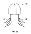
図34~図42は、遠位アンカー又は心室アンカーが、患者の心臓の腱索、小柱、又は乳頭構造に結合して、人工弁を天然弁内に固定するように構成された巻回特徴部を有するように構成されている、人工弁の実施形態を示している。 FIGS. 34-42 illustrate winding features in which a distal or ventricular anchor is configured to couple to chordae, trabeculae, or papillary structures of a patient's heart to secure the prosthetic valve within the native valve. 3 illustrates an embodiment of a prosthetic valve configured to have a section.

図34~図36に示す実施形態では、人工弁140は、アレイ内で互いに離間されてもよいワイヤ142を備え得る、巻回特徴部を含み得る。ワイヤ142は、患者の心臓の腱索、小柱、又は乳頭構造の間に延在し、かつそれら内に絡み合うように構成され得る。ワイヤ142は、展開前に非展開又は直線化構成であるように構成されてもよく、その後、腱索、小柱、又は乳頭構造に結合するように展開されてもよい。 In the embodiment shown in FIGS. 34-36, the prosthetic valve 140 may include a wrap feature that may include wires 142 that may be spaced apart from each other in an array. The wires 142 may be configured to extend between and intertwine within the chordae, trabeculae, or papillary structures of the patient's heart. Wires 142 may be configured to be in an undeployed or straightened configuration prior to deployment and then deployed to connect to chordae, trabeculae, or papillary structures.

図35は、例えば、ワイヤ142が直線化構成である状態で、送達装置のカプセルから展開される人工弁140を示している。展開時に、図36に示すように、ワイヤ142は、外側に延在し、患者の心臓の腱索、小柱、又は乳頭構造との間に延在し、かつそれらと絡み合うことができる。ワイヤ142は、患者の天然弁内に弁140を固定する役割を果たし得る。したがって、アンカーは、弁葉ではなく、むしろ患者の心臓の腱索、小柱、又は乳頭構造に固定され得る。 FIG. 35, for example, shows the prosthetic valve 140 being deployed from the capsule of the delivery device with the wires 142 in a straightened configuration. Upon deployment, the wires 142 can extend outward and intertwine with and intertwine with the chordae, trabeculae, or papillary structures of the patient's heart, as shown in FIG. Wire 142 may serve to secure valve 140 within the patient's native valve. Thus, the anchor may be secured to the chordae, trabeculae, or papillary structures of the patient's heart rather than to the valve leaflets.

実施形態では、ワイヤ142は、ニチノール又は別の形状記憶材料などの形状記憶材料から作製されてもよく、非展開構成から図36に示す展開構成に移動するように付勢される。ワイヤ142は、巻回特徴部が腱索、小柱、又は乳頭構造に結合する構成に付勢され得る。 In embodiments, the wires 142 may be made from a shape memory material, such as Nitinol or another shape memory material, and are biased to move from an undeployed configuration to the deployed configuration shown in FIG. 36. Wire 142 may be biased into a configuration in which the winding features connect to chordae tendineae, trabeculae, or papillary structures.

図37~図39に示す実施形態では、巻回特徴部は、患者の心臓の腱索、小柱、又は乳頭構造の周りを包囲し、かつそれに絡むように構成されたコイルを備え得る、ワイヤ150を備え得る。ワイヤ150は、展開前に非展開又は直線化構成であるように構成されてもよく、その後、スパイラルを形成することによって、腱索、小柱、又は乳頭構造に結合するように展開されてもよい。 In the embodiments shown in FIGS. 37-39, the winding feature may comprise a coil configured to wrap around and wrap around the chordae, trabeculae, or papillary structures of the patient's heart. 150. The wire 150 may be configured to be in an undeployed or straightened configuration prior to deployment and then deployed to connect to chordae, trabeculae, or papillary structures by forming a spiral. good.

図38は、例えば、ワイヤ150が直線化構成である状態で、送達装置のカプセルから展開される人工弁151を示している。展開時に、図39に示すように、ワイヤ150は次に、患者の心臓の腱索、小柱、又は乳頭構造の周りを包囲し、かつそれらと絡み合うことができる。ワイヤ150は、患者の天然弁内に弁を固定する役割を果たし得る。したがって、アンカーは、弁葉ではなく、むしろ患者の心臓の腱索、小柱、又は乳頭構造に固定され得る。 FIG. 38, for example, shows a prosthetic valve 151 being deployed from a capsule of a delivery device with wire 150 in a straightened configuration. Upon deployment, the wire 150 can then wrap around and intertwine with the chordae, trabeculae, or papillary structures of the patient's heart, as shown in FIG. Wire 150 may serve to secure the valve within the patient's native valve. Thus, the anchor may be secured to the chordae, trabeculae, or papillary structures of the patient's heart rather than to the valve leaflets.

実施形態では、ワイヤ150は、展開時に図39に示す構成に移動するために、ニチノール又は別の形状記憶材料などの形状記憶材料で作製されてもよい。例えば、ワイヤ150は、非展開又は直線化構成で真っ直ぐにされてもよく、その後、展開時に図39に示す展開又はコイル化構成に移動してもよい。 In embodiments, wire 150 may be made of a shape memory material, such as Nitinol or another shape memory material, to move to the configuration shown in FIG. 39 upon deployment. For example, wire 150 may be straightened in an undeployed or straightened configuration and then moved to the deployed or coiled configuration shown in FIG. 39 upon deployment.

図40~図42に示す実施形態では、巻回特徴部は、患者の心臓の腱索、小柱、又は乳頭構造に結合するように構成され得る、1つ以上のクランプ152を備え得る。クランプ152は、展開前に非展開又は直線化構成であるように構成されてもよく、その後、腱索、小柱、又は乳頭構造に結合するように展開されてもよい。 In the embodiment shown in FIGS. 40-42, the wrapping feature may include one or more clamps 152 that may be configured to couple to chordae, trabeculae, or papillary structures of the patient's heart. Clamp 152 may be configured to be in an undeployed or straightened configuration prior to deployment and then deployed to couple to chordae, trabeculae, or papillary structures.

図41は、例えば、クランプ152が直線化構成である状態で、送達装置のカプセルから展開される人工弁153を示している。展開時に、図42に示すように、クランプ152は、次に、延在して、患者の心臓の腱索、小柱、又は乳頭構造に押し付けてクランプし、腱索、小柱、又は乳頭構造に結合し得る。クランプ152は、患者の天然弁内に弁を固定する役割を果たし得る。したがって、アンカーは、弁葉ではなく、むしろ患者の心臓の腱索、小柱、又は乳頭構造に固定され得る。 FIG. 41, for example, shows a prosthetic valve 153 being deployed from a capsule of a delivery device with clamps 152 in a straightening configuration. Upon deployment, the clamp 152 is then extended and clamped against the chordae, trabeculae, or papillary structures of the patient's heart, as shown in FIG. can be combined with Clamp 152 may serve to secure the valve within the patient's native valve. Thus, the anchor may be secured to the chordae, trabeculae, or papillary structures of the patient's heart rather than to the valve leaflets.

実施形態では、クランプ152は、展開時に図42に示す展開構成に移動するために、ニチノール又は別の形状記憶材料などの形状記憶材料から作製されてもよい。例えば、クランプ152は、非展開又は直線化構成で真っ直ぐにされてもよく、その後、展開時に図42に示す展開又はクランプ構成に移動してもよい。実施形態では、別個の機構を利用して、クランプ152を展開及びクランプしてもよい。腱索、小柱、又は乳頭構造上のクランプ152の力は、それに応じて機構によって制御され得る。 In embodiments, clamp 152 may be made from a shape memory material, such as Nitinol or another shape memory material, to move to the deployed configuration shown in FIG. 42 upon deployment. For example, clamp 152 may be straightened in an undeployed or straightened configuration and then moved to the deployed or clamped configuration shown in FIG. 42 upon deployment. In embodiments, separate mechanisms may be utilized to deploy and clamp clamp 152. The force of the clamp 152 on the chordae, trabeculae, or papillary structures may be controlled by the mechanism accordingly.

人工弁は、僧帽弁又は三尖弁とともに展開するために利用されてもよく、又は実施形態では、所望される他の移植位置で利用されてもよい。巻回特徴部の特徴は、本明細書の他の実施形態で利用されてもよく、又は単独で利用されてもよい。人工弁は、本明細書で論じる人工弁10と同様の方法で移植されてもよいが、他の方法は、所望に応じて利用されてもよい。 The prosthetic valve may be utilized for deployment with the mitral or tricuspid valve, or in embodiments, in other implantation locations as desired. The features of the winding feature may be utilized in other embodiments herein, or may be utilized alone. The prosthetic valve may be implanted in a manner similar to prosthetic valve 10 discussed herein, although other methods may be utilized as desired.

図43~図51は、1つ以上のアンカーが、天然弁の石灰化と係合して、人工弁を天然弁に固定するように構成されている、人工弁の実施形態を示している。 43-51 illustrate embodiments of prosthetic valves in which one or more anchors are configured to engage calcification of the native valve to secure the prosthetic valve to the native valve.

図43は、例えば、天然弁の石灰化と係合して、人工弁160を天然弁に固定するように構成されている、アンカー162を含む、人工弁160の実施形態を示している。図43に示すように、人工弁160は、天然弁に展開されるように構成されてもよく、弁フレーム164の近位端を含む近位部分166及び弁フレーム164の遠位端を含む遠位部分168を有する、弁フレーム164を含み得る。弁フレーム164は、近位部分166から、実施形態で内側に弓状に曲がる遠位部分168までの形状を有してもよい。他の実施形態では、弁フレーム164の他の形状を、所望のように利用してもよい。 FIG. 43 illustrates an embodiment of a prosthetic valve 160 that includes an anchor 162 configured to secure the prosthetic valve 160 to the natural valve, eg, by engaging calcification of the natural valve. As shown in FIG. 43, the prosthetic valve 160 may be configured to be deployed into a native valve, with a proximal portion 166 including the proximal end of the valve frame 164 and a distal portion 166 including the distal end of the valve frame 164. The valve frame 164 may include a valve frame 164 having a vertical portion 168 . The valve frame 164 may have a shape from a proximal portion 166 to a distal portion 168 that arches inward in embodiments. In other embodiments, other shapes of the valve frame 164 may be utilized as desired.

弁フレーム164は、図3に示す中間本体23と同様に構成され得る、中間本体170に結合され得る。中間本体170は、図1に示す人工弁弁葉16と同様に構成され得る、複数の人工弁弁葉172に結合され得る。弁フレーム164は、人工弁160が移植されたときに、患者の天然弁内で人工弁弁葉172を支持するように構成され得る。 Valve frame 164 may be coupled to intermediate body 170, which may be configured similar to intermediate body 23 shown in FIG. Intermediate body 170 may be coupled to a plurality of prosthetic valve leaflets 172, which may be configured similar to prosthetic valve leaflets 16 shown in FIG. Valve frame 164 may be configured to support prosthetic valve leaflets 172 within a patient's natural valve when prosthetic valve 160 is implanted.

人工弁160及び人工弁弁葉172は、人工弁160の中心軸174の周りに延在するように構成され得る。中央軸174は、図3に示す流れチャネル25と同様の人工弁160の流れチャネル176を通って延在し得る。 Prosthetic valve 160 and prosthetic valve leaflets 172 may be configured to extend about a central axis 174 of prosthetic valve 160. Central axis 174 may extend through a flow channel 176 of prosthetic valve 160 similar to flow channel 25 shown in FIG.

弁フレーム164は、様々な形態を有してもよく、接合部で接合して、弁フレーム164を形成する、複数の支柱を含み得る。弁フレーム164の構成は、所望に応じて、本明細書に開示される弁フレームの他の実施形態の構成と類似し得る。 Valve frame 164 may have a variety of configurations and may include a plurality of struts that join at joints to form valve frame 164. The configuration of valve frame 164 may be similar to the configuration of other embodiments of valve frames disclosed herein, if desired.

人工弁160は、弁フレーム164から半径方向外側に延在し得る、心房又は近位アンカー188を含み得る。心房又は近位アンカー188は、実施形態では、弁フレーム164の近位部分166に位置付けられてもよく、近位部分166から半径方向外側に延在して、天然弁の心房側、特に天然弁弁輪の心房側に固定してもよい。心房又は近位アンカー188は、弁フレーム164から半径方向外側に延在するアームとして構成されてもよく、又は所望される実施形態における別の構成を有してもよい。 Prosthetic valve 160 may include an atrial or proximal anchor 188 that may extend radially outwardly from valve frame 164. An atrial or proximal anchor 188 may, in embodiments, be positioned in the proximal portion 166 of the valve frame 164 and extend radially outwardly from the proximal portion 166 to connect to the atrial side of the native valve, particularly the native valve. It may be fixed to the atrial side of the valve annulus. Atrial or proximal anchor 188 may be configured as an arm extending radially outwardly from valve frame 164 or may have another configuration in a desired embodiment.

封止本体204は、弁フレーム164に結合されてもよく、弁フレーム164から半径方向外側に位置付けられてもよい。封止本体204は、スカートを備えてもよく、弁フレーム190の近位部分166に位置付けられ得る、近位部分206を有してもよく、遠位アンカー162に結合され得る、遠位部分207を有してもよい。実施形態では、封止本体204の遠位部分207の結合点は変化してもよく、図43の破線に示されているように、弁フレーム164の遠位部分168に結合され得る。他の結合点は、所望されるような実施形態で利用され得る。 Seal body 204 may be coupled to valve frame 164 and may be positioned radially outwardly from valve frame 164. Seal body 204 may include a skirt, may have a proximal portion 206 that may be positioned on proximal portion 166 of valve frame 190, and may have a distal portion 207 that may be coupled to distal anchor 162. It may have. In embodiments, the point of attachment of the distal portion 207 of the sealing body 204 may vary and may be coupled to the distal portion 168 of the valve frame 164, as shown in dashed lines in FIG. Other attachment points may be utilized in embodiments as desired.

封止本体204は、図43に示すように、心房アンカー188又は近位アンカー188の半径方向外側に位置付けられてもよく、又は実施形態では、心房アンカー又は近位アンカー188の半径方向内側に位置付けられてもよい。封止本体204は、弁フレーム164の全体の周りに延在してもよく、実施形態では、天然弁の内面に押し付けて、天然弁の内面に封止するように構成されてもよい。 The sealing body 204 may be positioned radially outwardly of the atrial anchor 188 or proximal anchor 188, as shown in FIG. It's okay to be hit. The sealing body 204 may extend around the entirety of the valve frame 164 and, in embodiments, may be configured to press against and seal against the inner surface of the native valve.

アンカー162は、遠位アンカーを含んでもよく、人工弁160の遠位部分及び弁フレーム164の遠位部分168に位置付けられてもよい。アンカー162は、弁フレーム164から半径方向外側に延在するように構成されてもよく、アームの形態、又は弁フレーム164から半径方向外側に延在する他の形態のアンカーであってもよい。アンカー162は各々、近位部分208及び遠位部分211を含み得る。アンカー162の近位部分208は、弁フレーム164に結合されてもよく、アンカー162の遠位部分211は、弁フレーム164から半径方向外側に延在してもよい。 Anchors 162 may include distal anchors and may be positioned on a distal portion of prosthetic valve 160 and a distal portion 168 of valve frame 164. Anchor 162 may be configured to extend radially outwardly from valve frame 164 and may be in the form of an arm or other form of anchor extending radially outwardly from valve frame 164. Anchors 162 may each include a proximal portion 208 and a distal portion 211. A proximal portion 208 of anchor 162 may be coupled to valve frame 164 and a distal portion 211 of anchor 162 may extend radially outwardly from valve frame 164.

図44は、例えば、アンカー162のパターンの平面図を示している。アンカー162は、フレーム210に結合されてもよく、フレーム210の遠位部分に位置付けられてもよい。平面図は、アンカー162及びフレーム210の平坦なパターンの表現であり、使用するフレーム210は、円筒形状を有するように弁フレーム164の周りを包囲し、アンカー162は、半径方向外側に曲げられ、フレーム210から半径方向外側に延在する。フレーム210は、弁フレーム164の周りに延在し、かつ弁フレーム164に結合する、近位部分209を含み得る。アンカー162は、フレーム210から半径方向外側に延在してもよい。各アンカーは、図44に示すように細長いアームとして構成されてもよく、又は所望されるような別の構成を有してもよい。 FIG. 44 shows a top view of a pattern of anchors 162, for example. Anchor 162 may be coupled to frame 210 and may be located at a distal portion of frame 210. The plan view is a representation of a flat pattern of anchors 162 and frames 210, the frame 210 used wraps around the valve frame 164 to have a cylindrical shape, the anchors 162 are bent radially outward, Extending radially outwardly from frame 210. Frame 210 may include a proximal portion 209 that extends around and couples to valve frame 164. Anchors 162 may extend radially outwardly from frame 210. Each anchor may be configured as an elongated arm, as shown in FIG. 44, or may have another configuration as desired.

図45は、例えば、弁フレーム164に対するアンカー162の半径方向の延長を示している。近位アンカー188は、封止本体186内の破線で更にマークされている。アンカー162、188は、図45に示すような9つのアンカーを備えてもよく、又はより大きな若しくはより少ない数が、所望に応じて利用されてもよい。遠位アンカー162の間隔は、互いに等しくてもよく、又は実施形態で異なってもよい。近位アンカー188の間隔は、互いに等しくてもよく、又は実施形態で異なってもよい。近位アンカー188及び遠位アンカー162は、図45に示すものと同じ周方向位置に整列されてもよく、又は所望により互いに対して異なる位置を有してもよい。 FIG. 45, for example, shows the radial extension of anchor 162 relative to valve frame 164. Proximal anchor 188 is further marked with a dashed line within sealing body 186. Anchors 162, 188 may include nine anchors as shown in FIG. 45, or a greater or lesser number may be utilized as desired. The spacing of distal anchors 162 may be equal to each other, or may be different in embodiments. The spacing of proximal anchors 188 may be equal to each other or may be different in embodiments. Proximal anchor 188 and distal anchor 162 may be aligned in the same circumferential position as shown in FIG. 45, or may have different positions relative to each other as desired.

図44に戻って参照すると、各アンカー162の遠位先端212は、実施形態では可撓性であってもよい。先端212は、例えば、遠位先端212に可撓性を提供し得るラチス特徴部などの起伏特徴部213を含み得る。実施形態では、先端212のその他の構成は、所望されるような可撓性を提供し得る。例えば、先端212は、可撓性材料で作製されてもよく、又は可撓性を提供する別の構造を有してもよい。実施形態では、先端212は、それぞれのアンカー162の先端に可撓性を提供する、材料で覆われてもよい。 Referring back to FIG. 44, the distal tip 212 of each anchor 162 may be flexible in embodiments. Tip 212 may include a contoured feature 213, such as a lattice feature, which may provide flexibility to distal tip 212, for example. In embodiments, other configurations of tip 212 may provide flexibility as desired. For example, tip 212 may be made of a flexible material or have another structure that provides flexibility. In embodiments, the tip 212 may be covered with a material that provides flexibility to the tip of each anchor 162.

実施形態では、先端212は、アンカー162の近位部分208よりも幅が広くてもよい。こうした特徴は、実施形態で望ましくないほど患者の心臓壁の一部分を遠位先端212が穿刺する可能性を減少させるために、先端212の表面積を増大し得る。 In embodiments, tip 212 may be wider than proximal portion 208 of anchor 162. These features may increase the surface area of the tip 212 to reduce the likelihood that the distal tip 212 will puncture a portion of the patient's heart wall undesirably in some embodiments.

図43を参照すると、アンカー162は、アンカー162がそれぞれのアンカー162の先端212に対して中央軸174に対して水平に延在するように、フレーム164から半径方向外側に曲げられてもよい。こうした構成は、例えば、遠位アンカー17が、人工弁10の中心軸に対して垂直に延在して、図6の最も左の側面に示されるように、天然の弁葉の周りにフックする、図3に示したような構成とは異なる場合がある。図43に示すようなアンカー162の水平延長は、天然弁弁葉の半径方向外側に位置付けられた石灰化の存在を考慮してもよく、これは、図6の最も左側に示されている弁葉のフックをブロックする可能性がある。実施形態では、アンカー162は、中心軸174に対して垂直に延在するように構成されてもよく、又は所望の場合、別の角度で延在することができる。アンカー162は、直線であってもよく、又は図43に示すように、曲率がある場合がある。曲率は、実施形態における石灰化の形状に対して輪郭を描くように構成され得る。 Referring to FIG. 43, the anchors 162 may be bent radially outwardly from the frame 164 such that the anchors 162 extend horizontally to the central axis 174 relative to the distal end 212 of each anchor 162. Such a configuration may, for example, extend perpendicularly to the central axis of the prosthetic valve 10 so that the distal anchor 17 hooks around the natural leaflet, as shown in the left-most side of FIG. , may differ from the configuration shown in FIG. The horizontal extension of the anchor 162 as shown in FIG. 43 may take into account the presence of calcifications located radially outward of the native valve leaflets, which Leaf hooks may be blocked. In embodiments, anchor 162 may be configured to extend perpendicular to central axis 174 or at another angle if desired. Anchor 162 may be straight or may have a curvature, as shown in FIG. The curvature may be configured to contour to the shape of the calcification in embodiments.

アンカー162は、天然弁葉の遠位先端の上に、かつ天然弁葉の遠位先端からそれぞれの遠位アンカー162の先端212まで水平に延在するように構成され得る。こうした構成によって、アンカー162が石灰化と係合して、人工弁160を天然弁に固定することが可能になり得る。 Anchors 162 may be configured to extend horizontally over the distal tips of the native leaflets and from the distal tips of the native leaflets to the tips 212 of each distal anchor 162. Such a configuration may allow anchor 162 to engage the calcification and secure prosthetic valve 160 to the natural valve.

図46及び図47は、例えば、天然弁214に対する人工弁160の展開を示している。天然弁214は、天然弁214の心房側218と、天然弁214の心室側220との間に位置付けられた、天然弁弁葉216を含み得る。天然弁214は、石灰化222を有してもよく、これは、天然弁214の心室側220上の天然弁214の天然弁弁葉216のうちの1つ以上の半径方向外側に位置付けられてもよい。示されるように、石灰化222の位置及びサイズは、天然弁弁葉216と適切に係合する遠位アンカーを垂直に延在する能力を妨げ得る。こうした特徴は、遠位アンカーによる弁葉216のうちの1つ以上の誤捕捉をもたらし得る。石灰化222は、実施形態における、例えば、僧帽弁環状の石灰化、又は他の形態の石灰化など、環状の石灰化を含み得る。 46 and 47, for example, illustrate the deployment of prosthetic valve 160 relative to natural valve 214. Native valve 214 may include native valve leaflets 216 positioned between an atrial side 218 of native valve 214 and a ventricular side 220 of native valve 214 . The native valve 214 may have calcification 222 located radially outward of one or more of the native valve leaflets 216 of the native valve 214 on the ventricular side 220 of the native valve 214. Good too. As shown, the location and size of calcification 222 can interfere with the ability to vertically extend the distal anchor to properly engage native valve leaflets 216. These features may result in false capture of one or more of the leaflets 216 by the distal anchor. Calcification 222 may include annular calcification, such as, for example, mitral annular calcification, or other forms of calcification, in embodiments.

図46は、天然弁弁葉216に近接して位置付けられており、かつ人工弁160を展開するための定位置に位置付けられた、図25に示すカプセル及び送達装置に類似した、送達装置100のカプセル110を示している。図47は、送達装置100によって展開された人工弁160を示しており、石灰化222は、1つ以上のアンカー162と係合している。人工弁弁葉172などの人工弁160の特定の特徴は、図47のから除外されている。アンカー162は、アンカー162が石灰化222と係合して、人工弁160を天然弁214に固定するように、弁フレーム164から水平に、かつ中心軸174に対して延在している。1つ以上のアンカー162は、石灰化222の遠位に位置付けられ、かつ弁フレーム164から半径方向外側に延在する。1つ以上のアンカー162は、天然弁弁葉216の遠位端上に延在しており、天然弁弁葉216の遠位端からそれぞれのアンカー162の先端212まで水平に延在している。心房又は近位アンカー188などの追加のアンカーは、天然弁214への更なるアンカー付けに利用され得る。 FIG. 46 shows a delivery device 100, similar to the capsule and delivery device shown in FIG. A capsule 110 is shown. FIG. 47 shows the prosthetic valve 160 deployed by the delivery device 100, with the calcifications 222 engaged with one or more anchors 162. Certain features of the prosthetic valve 160, such as the prosthetic valve leaflets 172, have been excluded from FIG. 47. Anchors 162 extend horizontally from valve frame 164 and relative to central axis 174 such that anchors 162 engage calcifications 222 to secure prosthetic valve 160 to natural valve 214 . One or more anchors 162 are positioned distal to calcification 222 and extend radially outwardly from valve frame 164. The one or more anchors 162 extend over the distal end of the native valve leaflet 216 and extend horizontally from the distal end of the native valve leaflet 216 to the tip 212 of each anchor 162. . Additional anchors, such as atrial or proximal anchor 188, may be utilized for further anchoring to native valve 214.

各アンカー162は、石灰化222と係合するように構成され得る、近位表面224を含み得る。近位表面224は、例えば、図47に示すように、石灰化222に当接して、石灰化222と係合してもよい。近位表面224は、実施形態における石灰化222に当接するための係合表面を備えてもよい。こうした固定は、例えば、図6の最も左の側面に示されるように、天然弁弁葉の周りをフックし、かつ天然弁の外向き面に当接する、遠位アンカーによって提供される固定に置き換えられ得る。 Each anchor 162 can include a proximal surface 224 that can be configured to engage calcification 222. Proximal surface 224 may abut and engage calcification 222, as shown in FIG. 47, for example. Proximal surface 224 may include an engagement surface for abutting calcification 222 in embodiments. Such fixation replaces, for example, the fixation provided by a distal anchor that hooks around the native valve leaflets and abuts the outward facing surface of the native valve, as shown in the left-most side of FIG. It can be done.

実施形態では、アンカー162のうちの1つ以上は、石灰化222と係合するよう構成され得る、1つ以上のバーブ226を含み得る。図48は、例えば、アンカー162の近位表面224上など、アンカー162上に位置付けられ得る、1つ以上のバーブ226を示している。1つ以上のバーブ226は、アンカー162の近位表面224から近位に延在してもよい。バーブ226は、アンカー162の先端212に位置付けられて、アンカー162のうちの1つ以上に対して貫通先端を形成してもよい。必要に応じて、他の位置を利用してもよい。 In embodiments, one or more of anchors 162 may include one or more barbs 226 that may be configured to engage calcification 222. FIG. 48 shows one or more barbs 226 that can be positioned on anchor 162, such as on proximal surface 224 of anchor 162. One or more barbs 226 may extend proximally from proximal surface 224 of anchor 162. Barbs 226 may be positioned at the distal ends 212 of the anchors 162 to form a penetrating tip for one or more of the anchors 162. Other locations may be used if desired.

図49は、例えば、バーブ226が石灰化222と係合して、人工弁160を天然弁214に固定する、天然弁214に展開された人工弁160を示している。バーブ226は、石灰化222をバーブ226を含むアンカーで貫通することによって、石灰化222と係合する。 FIG. 49 shows the prosthetic valve 160 deployed to the native valve 214, for example, with the barbs 226 engaging the calcifications 222 to secure the prosthetic valve 160 to the native valve 214. Barb 226 engages calcification 222 by penetrating calcification 222 with an anchor that includes barb 226 .

実施形態では、石灰化と係合するように構成された1つ以上のバーブは、人工弁160のフレームから(例えば、弁フレーム164から)延在し得る。図50は、バーブ228を含む、弁フレーム164の一部分の側面断面図を示している。バーブ228は、弁フレーム164から半径方向外側に延在してもよく、天然弁214の天然弁弁葉の半径方向内側に位置付けられるように構成された人工弁の外面から半径方向外側に延在してもよい。 In embodiments, one or more barbs configured to engage the calcification may extend from the frame of the prosthetic valve 160 (eg, from the valve frame 164). FIG. 50 shows a side cross-sectional view of a portion of valve frame 164, including barb 228. FIG. The barbs 228 may extend radially outwardly from the valve frame 164 and extend radially outwardly from the outer surface of the prosthetic valve configured to be positioned radially inwardly of the native leaflets of the native valve 214. You may.

図51は、こうした構成の例を示している。人工弁230は、天然弁214に展開されており、バーブ228は、弁フレーム164から半径方向外側に、かつ天然弁214の天然弁弁葉216の半径方向内側に位置付けられるように構成された人工弁230の外面232から外側に延在している。外面232は、天然弁214の天然弁弁葉216の半径方向内側に位置付けられている。 FIG. 51 shows an example of such a configuration. A prosthetic valve 230 is deployed on the natural valve 214 and the barbs 228 are configured to be positioned radially outwardly from the valve frame 164 and radially inwardly of the natural valve leaflets 216 of the natural valve 214. Extending outwardly from an outer surface 232 of valve 230 . Outer surface 232 is positioned radially inward of native valve leaflets 216 of native valve 214 .

バーブ228は、天然弁214の天然弁弁葉216のうちの1つ以上を通過して、石灰化222と係合するように構成され得る。バーブ228は、天然弁弁葉216を通過し、かつ石灰化222と係合するのに十分な長さを有してもよい。バーブ228は、石灰化222をバーブ228の形態のアンカーで貫通することによって、石灰化222と係合する。 Barb 228 may be configured to pass through one or more of native valve leaflets 216 of native valve 214 and engage calcification 222 . Barbs 228 may have a length sufficient to pass through native valve leaflets 216 and engage calcifications 222. Barb 228 engages calcification 222 by penetrating calcification 222 with an anchor in the form of barb 228 .

バーブ228がアンカーとして利用される構成では、遠位アンカー162は、こうした実施形態から除外され得る。そのため、図51に示す人工弁230は、遠位アンカー162の使用を除外してもよい。実施形態では、バーブ228及び遠位アンカー162の組み合わせ、並びに所望される他のアンカーを利用してもよい。アンカーの様々な組み合わせを、所望に応じて利用することができる。 In configurations where barb 228 is utilized as an anchor, distal anchor 162 may be excluded from such embodiments. As such, the prosthetic valve 230 shown in FIG. 51 may exclude the use of distal anchor 162. Embodiments may utilize a combination of barbs 228 and distal anchors 162, as well as other anchors as desired. Various combinations of anchors can be utilized as desired.

人工弁は、僧帽弁又は三尖弁とともに展開するために利用されてもよく、又は実施形態では、所望される他の移植位置で利用されてもよい。人工弁は、実施形態における固着、又は他の形態の石灰化のために、例えば、僧帽弁環状の石灰化などの環状の石灰化を利用してもよい。人工弁を天然弁に固定するために天然弁の石灰化と係合するように構成されたアンカーの特徴は、本明細書の他の実施形態に利用されてもよく、又は単独で利用されてもよい。人工弁は、本明細書で論じる人工弁10と同様の方法で移植されてもよいが、他の方法は、所望に応じて利用されてもよい。 The prosthetic valve may be utilized for deployment with the mitral or tricuspid valve, or in embodiments, in other implantation locations as desired. Prosthetic valves may utilize annular calcification, for example, mitral annular calcification, for anchoring or other forms of calcification in embodiments. Features of the anchor configured to engage the calcification of the natural valve to secure the prosthetic valve to the natural valve may be utilized in other embodiments herein, or may be utilized alone. Good too. The prosthetic valve may be implanted in a manner similar to prosthetic valve 10 discussed herein, although other methods may be utilized as desired.

本明細書に開示される実施形態の様々な修正が提供されてもよい。実施形態にわたる特徴の組み合わせは、所望に応じて提供されてもよい。 Various modifications of the embodiments disclosed herein may be provided. Combinations of features across embodiments may be provided as desired.

図52は、天然弁に展開されるように構成された人工弁240の実施形態の概略断面図を示している。人工弁240は、複数の人工弁弁葉242を含んでもよく、複数の人工弁弁葉242を支持するフレーム244を含んでもよい。実施形態では、フレーム244は、近位部分246及び遠位部分248を含んでもよく、また人工弁240を通る流体流のための中央チャネル245を囲むことができる。実施形態の近位部分246は、人工弁240の流入部分を備えてもよく、遠位部分248は、実施形態では、人工弁240の流出部分を備えてもよい。 FIG. 52 shows a schematic cross-sectional view of an embodiment of a prosthetic valve 240 configured to be deployed into a natural valve. Prosthetic valve 240 may include a plurality of prosthetic valve leaflets 242 and a frame 244 that supports the plurality of prosthetic valve leaflets 242. In embodiments, the frame 244 may include a proximal portion 246 and a distal portion 248 and may surround a central channel 245 for fluid flow through the prosthetic valve 240. The proximal portion 246 in embodiments may comprise the inflow portion of the prosthetic valve 240 and the distal portion 248 may comprise the outflow portion of the prosthetic valve 240 in embodiments.

人工弁240は、外側フレーム252及びスカート254を含み得る、封止本体250を含み得る。実施形態では、人工弁240の構成は、図52に示す構成から変化する場合がある。 Prosthetic valve 240 may include a sealing body 250 that may include an outer frame 252 and a skirt 254. In embodiments, the configuration of prosthetic valve 240 may vary from the configuration shown in FIG. 52.

人工弁240は、人工弁を所望の移植部位に固定するために利用され得る、1つ以上のアンカー256を含み得る。図52に示すように、アンカー256は、フレーム244の遠位部分248に結合されてもよく、フレーム244から半径方向外側に延在してもよい。実施形態では、アンカー256は、フレーム244の別の部分に結合されてもよい。 Prosthetic valve 240 may include one or more anchors 256 that may be utilized to secure the prosthetic valve to the desired implantation site. As shown in FIG. 52, anchors 256 may be coupled to a distal portion 248 of frame 244 and may extend radially outwardly from frame 244. In embodiments, anchor 256 may be coupled to another portion of frame 244.

アンカー256の各々は、フレーム244の遠位部分248に結合され得る、近位端260を有する近位部分を含み得る。近位部分は、図52に示すように遠位に延在し得る。実施形態では、アンカー256は、近位部分に隣接し得る、曲げ部分262を含み得る。曲げ部分262は、それぞれのアンカー256を近位に方向付けるように構成され得る。曲げ部分262は、アンカー256の先端264を近位に方向付けるように構成された曲線を備えてもよい。曲げ部分262は、図52に示すように、実施形態で半径方向内側に延在するループを備えてもよく、又は所望される別の構成を有してもよい。曲げ部分262は、アンカー256を方向付けて、反対方向に延在させてもよい。例えば、図52に示すように、曲げ部分262は、アンカー256の近位部分から約180度で延在するようにアンカー256を方向付けてもよい。 Each of anchors 256 may include a proximal portion having a proximal end 260 that may be coupled to distal portion 248 of frame 244. The proximal portion may extend distally as shown in FIG. 52. In embodiments, anchor 256 may include a bent portion 262 that may be adjacent the proximal portion. Bent portions 262 may be configured to orient respective anchors 256 proximally. Bent portion 262 may include a curve configured to direct tip 264 of anchor 256 proximally. The bent portion 262 may include a radially inwardly extending loop in embodiments, as shown in FIG. 52, or may have another configuration as desired. Bent portion 262 may orient anchor 256 to extend in opposite directions. For example, as shown in FIG. 52, bent portion 262 may orient anchor 256 such that it extends approximately 180 degrees from a proximal portion of anchor 256.

実施形態では、曲げ部分262は、心臓の天然の弁葉のような心臓の一部分を受容するための凹部265を形成し得る。 In embodiments, the bent portion 262 may form a recess 265 for receiving a portion of the heart, such as the heart's natural valve leaflets.

アンカー256は、曲げ部分262から半径方向外側に延在し、かつそれぞれのアンカー256の先端264まで半径方向外側に延在し得る、延長部分266を含み得る。 Anchors 256 may include an extension portion 266 that extends radially outwardly from bent portion 262 and may extend radially outwardly to a tip 264 of each anchor 256.

実施形態では、アンカー256は、人工弁240の遠位部分に位置付けられた遠位アンカーを含み得る。アンカー256は、心室アンカーを含んでもよく、天然弁の天然弁葉の先端上に延在するように構成されてもよい。例えば、アンカー256は、天然弁葉が凹部265内に位置付けられた天然弁葉の先端と、天然弁葉から半径方向外側に位置付けられたアンカー256の先端264との周りをフックし得る。 In embodiments, anchor 256 may include a distal anchor positioned at a distal portion of prosthetic valve 240. Anchor 256 may include a ventricular anchor and may be configured to extend over the tips of the native leaflets of the native valve. For example, anchor 256 may hook around the tip of the native leaflet with the native leaflet positioned within recess 265 and the tip 264 of anchor 256 positioned radially outward from the native leaflet.

実施形態では、アンカー256は、非展開構成から展開構成に偏向するように構成され得る。例えば、非展開構成では、アンカー256は、細長い場合があり、直線状の構成を有してもよい。展開された構成では、アンカー256は、曲げ部分262の周りを偏向して、図52に示す構成を形成し得る。 In embodiments, anchor 256 may be configured to deflect from an undeployed configuration to a deployed configuration. For example, in a non-deployed configuration, anchor 256 may be elongated and may have a straight configuration. In the deployed configuration, anchor 256 may be deflected around bent portion 262 to form the configuration shown in FIG. 52.

図53Aは、アンカー256の側面図を示している。アンカー256は、アンカー256の長さに沿って一様である厚さ268を含み得る。図53Bは、非展開又は直線状の構成におけるアンカー256の上面図を示している。図56Cは、非展開又は直線状の構成におけるアンカー256の側面図を示しており、アンカー256の厚さ268は、アンカー256の長さ及び程度に沿って一様であることが示されている。 FIG. 53A shows a side view of anchor 256. Anchor 256 may include a thickness 268 that is uniform along the length of anchor 256. FIG. 53B shows a top view of anchor 256 in an undeployed or straight configuration. FIG. 56C shows a side view of anchor 256 in an undeployed or straight configuration, and the thickness 268 of anchor 256 is shown to be uniform along the length and extent of anchor 256. .

実施形態では、アンカーのうちの1つ以上は、アンカーの先端に向かう方向で下向きに先細りする厚さを有してもよい。図54Aは、例えば、アンカー270の先端276に向かう方向で下向きに先細りする厚さ274を有する一部分272を有する、アンカー270の側面図を示している。それ以外の場合は、アンカー270は、図53A~Cに示されているアンカー256と同様に構成され得、これは、別様に、図53aに示されているそれぞれの部分と同様に構成され得る、近位端278、曲げ部分280、及び延長部分282を含む、近位部分を含む。 In embodiments, one or more of the anchors may have a thickness that tapers downward in a direction toward the distal end of the anchor. FIG. 54A shows a side view of an anchor 270, for example, having a portion 272 having a thickness 274 that tapers downwardly in a direction toward a distal end 276 of the anchor 270. Otherwise, anchor 270 may be configured similar to anchor 256 shown in Figures 53A-C, which may otherwise be configured similar to the respective portions shown in Figure 53a. includes a proximal portion, including a proximal end 278, a bent portion 280, and an extension portion 282.

アンカー270は、先細りの厚さが先端276に向かう方向で開始する、延長部分282上の移行点284を含み得る。それに応じて、延長部分282の厚さは、アンカー270の先端276に向かって下向きに先細りしてもよく、図54Aに示すように、アンカー270の先端276まで下向きに延在してもよい。図54Cは、例えば、移行点284がマークされ、かつ示されている先端276に対する下向きの先細りの厚さを有する、細長いアンカー270の側面図を示している。図54Bは、図54Cに示したアンカー270の上面図を示している。アンカー270の幅は、均一であってもよく、又は望ましいように変化してもよい。 Anchor 270 may include a transition point 284 on extension portion 282 where the tapered thickness begins in a direction toward tip 276. Accordingly, the thickness of extension portion 282 may taper downwardly toward tip 276 of anchor 270 or may extend downwardly to tip 276 of anchor 270, as shown in FIG. 54A. FIG. 54C, for example, shows a side view of an elongate anchor 270 with a transition point 284 marked and a downwardly tapering thickness to the tip 276 shown. FIG. 54B shows a top view of anchor 270 shown in FIG. 54C. The width of anchor 270 may be uniform or may vary as desired.

実施形態では、先細りの厚さを有するアンカーの部分のサイズは変化し得る。図55Aは、例えば、アンカー286の曲げ部分285が、アンカー286の先端288に向かう方向で下向きに先細りする厚さを含む、実施形態を示している。移行点290は、例えば、曲げ部分285の近位端に位置付けられてもよく、テーパリングは、曲げ部分285の近位で開始されてもよく、曲げ部分285によって形成されるループを通って継続してもよい。実施形態では、先細りの厚さは、延長部分292を通って延在してもよく、アンカー286の先端288まで延在してもよい。図55Cは、例えば、移行点290がマークされ、かつ示されている先端288に対する下向きの先細りの厚さを有する、細長いアンカー286の側面図を示している。図55Bは、図55Cに示したアンカー286の上面図を示している。アンカー286の幅は、一様であってもよく、又は望ましいように変化してもよい。 In embodiments, the size of the portion of the anchor that has a tapered thickness may vary. FIG. 55A, for example, illustrates an embodiment in which the bent portion 285 of the anchor 286 includes a thickness that tapers downwardly in a direction toward a distal end 288 of the anchor 286. The transition point 290 may be located at the proximal end of the bending portion 285, for example, and the tapering may begin proximal to the bending portion 285 and continue through the loop formed by the bending portion 285. You may. In embodiments, the tapered thickness may extend through the extension portion 292 and may extend to the tip 288 of the anchor 286. FIG. 55C, for example, shows a side view of an elongate anchor 286 with a transition point 290 marked and a downwardly tapering thickness to the tip 288 shown. FIG. 55B shows a top view of anchor 286 shown in FIG. 55C. The width of anchor 286 may be uniform or may vary as desired.

実施形態では、アンカーの一部分は、アンカーの先端に向かう方向に下向きに先細の厚さを有して、アンカーに減衰機構を提供し得る。例えば、図53Aに示すように、アンカー256は、アンカー256の均一な厚さ268のために、その長さに沿って硬い場合がある。図54A及び図55Aに示すように、先細の厚さは、それぞれのアンカーの可撓性を高め、アンカーに適用される力の減衰を可能にし得る。それに応じてテーパリングは、アンカー又は人工弁に適用される負荷(半径方向負荷又は側方負荷であり得る)時に、アンカー及び人工弁に対して耐疲労性を生成し得る。負荷は、心室壁運動、又はアンカー又は人工弁に印加される他の力によって生成され得る。テーパリングは、疲労株がアンカーの長さに沿って放散することを可能にし得る。 In embodiments, a portion of the anchor may have a thickness that tapers downwardly in a direction toward the distal end of the anchor to provide a damping mechanism to the anchor. For example, as shown in FIG. 53A, anchor 256 may be stiff along its length due to a uniform thickness 268 of anchor 256. As shown in FIGS. 54A and 55A, the tapered thickness may increase the flexibility of the respective anchor and allow for attenuation of forces applied to the anchor. Accordingly, the taper may create fatigue resistance for the anchor and prosthetic valve upon loading (which may be radial or lateral loads) applied to the anchor or prosthetic valve. The load may be generated by ventricular wall movement or other forces applied to the anchor or prosthetic valve. Tapering may allow fatigue strains to dissipate along the length of the anchor.

実施形態では、テーパリングの量は変化し得る。例えば、アンカーの厚さの変動は、実施形態で20%~95%であり得るが、他の範囲が提供されてもよい。厚さの変動は、実施形態で50%であってもよい。 In embodiments, the amount of tapering may vary. For example, variation in anchor thickness may be from 20% to 95% in embodiments, although other ranges may be provided. The thickness variation may be 50% in embodiments.

テーパリングは、例えば、図54C及び図55Cに示すように、厚さの線形減少である可能性があり、又は非線形の減少である可能性がある。実施形態では、厚さの減少は、ラチス特徴などのアンカー内の起伏を含み得る。実施形態では、アンカーの一部分のみが、所望により先細りであってもよく、又はアンカー全体の厚さが減少していてもよい。 The taper can be a linear decrease in thickness, for example, as shown in FIGS. 54C and 55C, or it can be a non-linear decrease. In embodiments, the thickness reduction may include undulations within the anchor, such as lattice features. In embodiments, only a portion of the anchor may optionally be tapered or the entire anchor may have a reduced thickness.

実施形態では、人工弁240は、所望により他の移植部位の中でも特に、天然僧帽弁又は天然三尖弁に展開されるように構成された弁を備えてもよい。人工弁が天然僧帽弁又は天然三尖弁に展開される実施形態では、アンカーは、心室の力を減衰させるための先細りの厚さを有してもよい。 In embodiments, the prosthetic valve 240 may comprise a valve configured to be deployed to a native mitral valve or a native tricuspid valve, among other implantation sites, if desired. In embodiments where the prosthetic valve is deployed on the native mitral or tricuspid valve, the anchor may have a tapered thickness to attenuate ventricular forces.

人工弁240の特徴、及び人工弁のアンカーは、本明細書に開示される任意の他の実施形態と単独で又は組み合わせて利用され得る。人工弁240は、本明細書に開示される展開方法を利用して、移植部位に展開されてもよい。 The features of prosthetic valve 240 and the prosthetic valve anchors may be utilized alone or in combination with any other embodiments disclosed herein. Prosthetic valve 240 may be deployed at the implantation site using the deployment methods disclosed herein.

図56は、人工弁300の半分の断面概略図を示している(他の半分は、そのミラー画像を含み得る)。人工弁300は、天然弁に展開されるように構成されてもよい。人工弁300は、複数の人工弁弁葉(図示せず)と、複数の人工弁弁葉を支持し得る、内側フレーム302と、を含み得る。内側フレーム302は、近位部分304及び遠位部分306を含み得る。内側フレーム302は、例えば、図52に示すフレーム244と同様に構成されてもよい。内側フレーム302は、例えば、人工弁300の流れチャネル308を囲むことができる。人工弁300は、図52に示すアンカー256と同様に構成され得る、又は所望される別の構成を有し得る、遠位アンカー310を含み得る。人工弁300は、中心軸315の周りに延在してもよい。 FIG. 56 shows a cross-sectional schematic of one half of the prosthetic valve 300 (the other half may include a mirror image thereof). Prosthetic valve 300 may be configured to be deployed into a natural valve. Prosthetic valve 300 can include a plurality of prosthetic valve leaflets (not shown) and an inner frame 302 that can support the plurality of prosthetic valve leaflets. Inner frame 302 may include a proximal portion 304 and a distal portion 306. Inner frame 302 may be configured similarly to frame 244 shown in FIG. 52, for example. Inner frame 302 can surround flow channel 308 of prosthetic valve 300, for example. Prosthetic valve 300 may include a distal anchor 310, which may be configured similar to anchor 256 shown in FIG. 52, or may have another configuration as desired. Prosthetic valve 300 may extend around a central axis 315.

人工弁300は、内側フレーム302の半径方向外側に位置付けられ得る、封止本体312を含み得る。封止本体312は、内側フレーム302の半径方向外側に位置付けられ得る、外側フレーム314を含み得る。実施形態では、封止本体312は、本明細書に開示されるスカートと同様に構成され得る、スカート(図示せず)を含み得る。 Prosthetic valve 300 may include a sealing body 312 that may be positioned radially outward of inner frame 302. Sealing body 312 may include an outer frame 314 that may be positioned radially outwardly of inner frame 302. In embodiments, the sealing body 312 may include a skirt (not shown), which may be configured similar to the skirts disclosed herein.

図57は、図56に示されている外側フレーム314の平面図を示しており、外側フレーム314は、図57で平らになって示されている。図56及び図57を参照すると、外側フレーム314は、内側フレーム302の近位部分304に結合され得る、近位部分316を含み得る。例えば、近位部分316は、溶接又は縫合、又は所望される別の方法を介して、内側フレーム302の近位部分304に接合されるように構成されてもよい。近位部分316は、望ましい場合、展開手順中に送達装置の一部分に結合するように構成され得る、結合本体318を含み得る。 57 shows a top view of the outer frame 314 shown in FIG. 56, which is shown flattened in FIG. 57. 56 and 57, outer frame 314 may include a proximal portion 316 that may be coupled to proximal portion 304 of inner frame 302. Referring to FIGS. For example, proximal portion 316 may be configured to be joined to proximal portion 304 of inner frame 302 via welding or suturing, or another method as desired. Proximal portion 316 may include a coupling body 318 that may be configured to couple to a portion of the delivery device during a deployment procedure, if desired.

実施形態では、複数の細長い支柱アーム320は、外側フレーム314の近位部分316から半径方向外側に延在してもよい。細長い支柱アーム320は、例えば、図57に示されており、直線形状を有してもよい。図56を参照すると、細長い支柱アーム320は、中心軸315から半径方向外側に延在してもよく、図56に示すように、中央軸315の平面で放射状に外側に延在してもよい。中心軸315の平面は、垂直に延在してもよく、中心軸から半径方向外側に延在するスポークと同様に、中心軸315から外側に延在してもよい。 In embodiments, a plurality of elongated strut arms 320 may extend radially outwardly from the proximal portion 316 of the outer frame 314. Elongated strut arm 320 is shown, for example, in FIG. 57 and may have a straight shape. Referring to FIG. 56, the elongated strut arms 320 may extend radially outwardly from the central axis 315, and may extend radially outwardly in the plane of the central axis 315, as shown in FIG. . The plane of central axis 315 may extend vertically and may extend outwardly from central axis 315, similar to spokes extending radially outward from central axis.

細長い支柱アーム320の遠位部分は、軸方向及び遠位に延在するように湾曲してもよい。例えば、図56に示すように、遠位に湾曲し得る湾曲部分322が形成され得る。湾曲部分322は、外側フレーム314の遠位部分324を配向して、軸方向に遠位に延在することができる。 The distal portion of elongate strut arm 320 may be curved to extend axially and distally. For example, as shown in FIG. 56, a curved portion 322 can be formed that can curve distally. Curved portion 322 may orient distal portion 324 of outer frame 314 to extend axially distally.

図57を参照すると、外側フレーム314の遠位部分324は、複数の支柱326を含み得る。支柱326は、複数の支柱セル328を形成してもよい。支柱セル328は、内側フレーム302の周りにリングを形成してもよく、支柱セル328aは、支柱セル328bに結合され、遠位部分324は、図57に示す平坦化された構成から、内側のフレーム302の周りに巻き付けられる。 Referring to FIG. 57, the distal portion 324 of the outer frame 314 may include a plurality of struts 326. The struts 326 may form a plurality of strut cells 328. The strut cells 328 may form a ring around the inner frame 302, with strut cells 328a coupled to strut cells 328b and distal portions 324 extending from the flattened configuration shown in FIG. Wrapped around frame 302.

複数の支柱セル328は、内側フレーム302の周りにリングを形成するために互いに接合されてもよく、又は所望される別の構成を有してもよい。各支柱セル328は、開口部329に接する4つの側面を含んでもよく(例えば、支柱セル328bで示されるように)、又は所望される別の構成を有してもよい。各支柱セル328は、例えば、図57に示すようなひし形を有してもよく、又は所望される別の形状を有してもよい。 The plurality of strut cells 328 may be joined together to form a ring around the inner frame 302, or may have another configuration as desired. Each strut cell 328 may include four sides that abut an opening 329 (eg, as shown in strut cell 328b), or may have another configuration as desired. Each strut cell 328 may have a diamond shape, for example, as shown in FIG. 57, or may have another shape as desired.

細長い支柱アーム320は各々、外側フレーム314の遠位部分324で、外側フレーム314の近位部分316から複数の支柱セル328まで延在し得る。複数の支柱セル328は、細長い支柱アーム320の遠位部分に結合する近位部分330を含んでもよく、複数の支柱セル328は、外側フレーム314の遠位端332に延在してもよい。 Each elongate strut arm 320 may extend from a proximal portion 316 of outer frame 314 to a plurality of strut cells 328 at a distal portion 324 of outer frame 314 . The plurality of strut cells 328 may include a proximal portion 330 that couples to a distal portion of the elongated strut arm 320, and the plurality of strut cells 328 may extend to a distal end 332 of the outer frame 314.

実施形態では、外側フレーム314は、複数の支柱セル328が外側フレーム314の近位部分316に対して偏向することを可能にするように構成され得る、1つ以上の偏向特徴部334を含み得る。偏向特徴部334は、外側フレーム314上に望ましいように位置付けられてもよく、様々な構成を有してもよい。例えば、図57に示すように、実施形態では、偏向特徴部334は、細長い支柱アーム320の各々上に位置付けられてもよい。偏向特徴部334は、細長い支柱アームの遠位部分に位置付けられてもよく、細長い支柱アーム320と支柱セル328の近位部分330との間の結合点に位置付けられてもよい。 In embodiments, the outer frame 314 may include one or more deflection features 334 that may be configured to allow the plurality of strut cells 328 to deflect relative to the proximal portion 316 of the outer frame 314. . Deflection features 334 may be positioned as desired on outer frame 314 and may have a variety of configurations. For example, as shown in FIG. 57, in an embodiment, a deflection feature 334 may be positioned on each of the elongate strut arms 320. Deflection feature 334 may be located on the distal portion of the elongated strut arm and may be located at the connection point between the elongated strut arm 320 and the proximal portion 330 of the strut cell 328.

偏向特徴部334は、図56及び図57に示す線335の遠位の外側フレーム314の部分が、所望されるように偏向できるように位置付けられてもよい。実施形態では、偏向特徴部334は、所望される別の位置を有してもよい。 Deflection feature 334 may be positioned such that a portion of outer frame 314 distal to line 335 shown in FIGS. 56 and 57 can be deflected as desired. In embodiments, deflection feature 334 may have other positions as desired.

偏向特徴部は、細長い支柱アーム320の他の部分よりも可撓性である、細長い支柱アーム320の一部分を備えてもよい。したがって、偏向特徴部は、偏向特徴部の位置での偏向を可能にする細長い支柱アーム320の縮小された強度部分を備えてもよい。実施形態では、偏向特徴部は、細長い支柱アーム320上に含まれてもよく、又は所望の場合に、外側フレーム314の複数の支柱のうちの少なくとも1つ上に位置付けられてもよい。実施形態では、偏向特徴部は、例えば、支柱セル328の支柱上に位置付けられてもよい。実施形態では、偏向特徴部は、細長い支柱アーム320と支柱セル328の支柱との組み合わせ上に位置付けられてもよい。 The deflection feature may include a portion of the elongated strut arm 320 that is more flexible than other portions of the elongated strut arm 320. Accordingly, the deflection feature may include a reduced strength portion of the elongate strut arm 320 that allows for deflection at the location of the deflection feature. In embodiments, the deflection feature may be included on the elongate strut arm 320 or positioned on at least one of the plurality of struts of the outer frame 314, if desired. In embodiments, the deflection features may be positioned on the struts of strut cells 328, for example. In embodiments, the deflection features may be positioned on the combination of elongate strut arms 320 and struts of strut cells 328.

偏向特徴部は、細長い支柱アーム320のうちの1つ以上に、起伏を備え得る。図57を参照すると、例えば、起伏は、円周方向に延在してもよく、起伏のサイクル数は、所望の場合に1つ以上のサイクルであってもよい。起伏は、外側フレーム314の支柱のラチス特徴を含み得る。 The deflection feature may comprise undulations on one or more of the elongated strut arms 320. Referring to FIG. 57, for example, the undulations may extend circumferentially and the number of cycles of the undulations may be one or more cycles if desired. The undulations may include lattice features of the struts of the outer frame 314.

起伏の長さは、所望のように設定されてもよく、図57は、比較的短い起伏の長さを示している。起伏の長さは、偏向特徴部によって提供される可撓性の量を決定するように設定されてもよく、短い長さは、より可撓性の低いものに対応し、及び長い長さは、より可撓性の高いものに対応する。様々な他の構成は、所望に応じて利用され得る。 The length of the undulations may be set as desired, and FIG. 57 shows a relatively short undulation length. The length of the undulations may be set to determine the amount of flexibility provided by the deflection feature, with shorter lengths corresponding to less flexibility and longer lengths corresponding to less flexibility. , corresponds to more flexible items. Various other configurations may be utilized as desired.

偏向特徴部によって、支柱セル328が偏向して、支柱セル328によって形成されるリングの非円形形状を提供することができる。偏向は、様々な形態を有してもよい。例えば、図56を参照すると、支柱セル328は、図56に示す破線で表されるように、半径方向内側に偏向するように構成され得る。実施形態では、支柱セル328は、偏向特徴部によって許容される偏向に起因して、楕円形状又は「D」形状を形成するように偏向するように構成され得る。支柱セル328によって形成されるリングの様々な他の形状が提供されてもよい。 The deflection feature allows the strut cells 328 to deflect to provide a non-circular shape of the ring formed by the strut cells 328. Deflection may have various forms. For example, referring to FIG. 56, strut cells 328 may be configured to deflect radially inward, as represented by the dashed lines in FIG. In embodiments, strut cells 328 may be configured to deflect to form an elliptical or "D" shape due to the deflection allowed by the deflection features. Various other shapes of rings formed by strut cells 328 may be provided.

偏向特徴部は、支柱セル328が偏向して、天然弁の弁輪の形状に輪郭を描くことを可能にし得る。例えば、天然弁が楕円形又は「D」形状を有する場合、支柱セル328は、こうした形状に輪郭を描くように偏向し得る。天然弁弁輪が石灰化を有する場合、支柱セル328は、石灰化によって生成されるこのような形状に輪郭を描くように偏向し得る。偏向特徴部は、実施形態におけるLVOT障害物の可能性を低減してもよく、展開時に移植部位との外側フレーム314による許容される封止を強化してもよい。 The deflection feature may allow strut cells 328 to deflect to contour the shape of the native valve annulus. For example, if the native valve has an elliptical or "D" shape, strut cells 328 may be deflected to outline such shape. If the native valve annulus has calcification, strut cells 328 may be deflected to contour to such shape produced by the calcification. The deflection feature may reduce the possibility of LVOT obstruction in embodiments and may enhance the acceptable seal by the outer frame 314 with the implant site upon deployment.

偏向特徴部によって、実施形態では、支柱セル328が偏向して、封止本体312と心臓弁弁輪との間の弁傍漏出の可能性を低減することが可能になり得る。 The deflection feature may allow the strut cells 328 to deflect in embodiments to reduce the potential for paravalvular leakage between the sealing body 312 and the heart valve annulus.

偏向特徴部の構成は、実施形態によって変化し得る。図58は、例えば、偏向特徴部336が、図57に示されるよりも長い長さを有する起伏を含み、かつ起伏の長さの間により大きな間隔を有する、実施形態を示している。こうした特徴部は、図57に示される偏向特徴部334によって提供されるよりも高い可撓性を提供することができる。 The configuration of the deflection features may vary depending on the embodiment. FIG. 58, for example, illustrates an embodiment in which the deflection feature 336 includes undulations having a longer length than shown in FIG. 57 and has greater spacing between the lengths of the undulations. Such features can provide greater flexibility than provided by deflection feature 334 shown in FIG. 57.

図59は、円周方向に延在する起伏を有する偏向特徴部336と、半径方向に延在する起伏を有する偏向特徴部338とを提供することができる、実施形態を示している。半径方向に延在する起伏は、その起伏特徴部336の起伏よりも長く延在する長さを有してもよく、それに応じて、起伏特徴部336の起伏よりも大きな可撓性を有してもよい。実施形態では、細長い支柱アーム、又は外側フレーム314の他の支柱は、所望される他の組み合わせの中でも、円周方向に延在する第1の起伏と半径方向に延在する第2の起伏との組み合わせを含み得る。更に、様々な長さを有する起伏の組み合わせが、所望されるように提供されてもよい。 FIG. 59 illustrates an embodiment in which a deflection feature 336 having circumferentially extending undulations and a deflection feature 338 having radially extending undulations can be provided. The radially extending undulations may have a length that extends longer than the undulations of the undulating feature 336 and accordingly have greater flexibility than the undulations of the undulating feature 336. It's okay. In embodiments, the elongated strut arms, or other struts of the outer frame 314, include first circumferentially extending undulations and second radially extending undulations, among other desired combinations. may include a combination of. Additionally, combinations of undulations with varying lengths may be provided as desired.

実施形態では、偏向特徴部は、細長い支柱アームに1つ以上の開口部を含み得る。図60は、例えば、複数の開口部342を含む細長い支柱アーム340を示している。開口部342は、細長い支柱アーム340から材料を除去して、それに応じて細長い支柱アーム340の可撓性を増加させてもよい。開口部342は、図60に示すように、実施形態における細長い支柱アーム340の長さに沿って延在し得る細長い形状を有してもよく、又は所望される別の構成を有してもよい。 In embodiments, the deflection feature may include one or more openings in the elongate strut arm. FIG. 60, for example, shows an elongated strut arm 340 that includes a plurality of apertures 342. Opening 342 may remove material from elongate strut arm 340 and correspondingly increase the flexibility of elongate strut arm 340. The opening 342 may have an elongated shape that may extend along the length of the elongated strut arm 340 in embodiments, as shown in FIG. 60, or may have another configuration as desired. good.

図61は、細長い形状が細長い支柱アーム344の長さに沿って延在している、単一の開口部346を有する細長い支柱アーム344を示している。 FIG. 61 shows an elongated strut arm 344 having a single opening 346 with an elongated shape extending along the length of the elongated strut arm 344. FIG.

実施形態では、偏向特徴部の組み合わせが提供されてもよい。例えば、他の形態の偏向特徴部の中でも特に、起伏と開口部の組み合わせが、所望されるように提供されてもよい。実施形態では、外側フレーム314の少なくとも1つの支柱は、他の形態の偏向特徴部の中でも、フレームの可撓性、並びに起伏と開口部の組み合わせを増加させるように構成された起伏又は開口部を有してもよい。 In embodiments, combinations of deflection features may be provided. For example, a combination of undulations and apertures, among other forms of deflection features, may be provided as desired. In embodiments, at least one strut of the outer frame 314 includes undulations or apertures configured to increase the flexibility of the frame and the combination of undulations and apertures, among other forms of deflection features. May have.

実施形態における外側フレーム314は、天然弁の一部分と封止するように構成されてもよく、又は所望される実施形態における別の構成を有してもよい。実施形態では、天然弁の一部分とシールを形成するために、外側フレーム314上にスカートが提供されてもよい。 The outer frame 314 in embodiments may be configured to seal with a portion of the native valve, or may have another configuration in desired embodiments. In embodiments, a skirt may be provided on the outer frame 314 to form a seal with a portion of the natural valve.

実施形態では、人工弁300は、所望により他の移植部位の中でも特に、天然僧帽弁又は天然三尖弁に展開されるように構成された弁を備えてもよい。人工弁300の特徴は、本明細書に開示される任意の他の実施形態と単独で又は組み合わせて利用され得る。人工弁300は、本明細書に開示される展開方法を利用して、移植部位に展開されてもよい。 In embodiments, the prosthetic valve 300 may include a valve configured to be deployed to a native mitral valve or a native tricuspid valve, optionally among other implantation sites. Features of prosthetic valve 300 may be utilized alone or in combination with any other embodiments disclosed herein. Prosthetic valve 300 may be deployed at the implantation site using the deployment methods disclosed herein.

図62Aは、複数の支柱350を含む人工弁のフレームを示している。各支柱350は、真っ直ぐであってもよく、接合部354に結合された第1の端部352から、接合部358に結合された第2の端部356まで延在してもよい。支柱350は、開口部360を囲むことができ、開口部360の境界を形成して、支柱セルを形成してもよい。図62Bは、拡張又は展開された構成のフレームを示しており、支柱350は、互いに引き離され、開口部360のサイズは増大している。 FIG. 62A shows a prosthetic valve frame including a plurality of struts 350. Each strut 350 may be straight and may extend from a first end 352 coupled to a joint 354 to a second end 356 coupled to a joint 358. The struts 350 may surround the apertures 360 and may bound the apertures 360 to form strut cells. FIG. 62B shows the frame in an expanded or deployed configuration, with struts 350 being pulled apart from each other and openings 360 increasing in size.

図62Cは、支柱350が互いに向かって引き寄せられ、一緒に圧縮された、圧着構成又は非展開構成のフレームを示している。各支柱350が直線である場合、各支柱350の端部352、356に歪みが提供されてもよい。例えば、図62Aに示される構成で支柱350に半径方向の圧縮が加えられて、図62Cに示される圧着構成又は非展開構成に到達し、支柱350の端部352、356は曲がり、歪みを受け得る。 FIG. 62C shows the frame in a crimped or non-deployed configuration with struts 350 drawn toward each other and compressed together. If each strut 350 is straight, a strain may be provided at the ends 352, 356 of each strut 350. For example, when struts 350 are subjected to radial compression in the configuration shown in FIG. 62A to reach the crimped or undeployed configuration shown in FIG. 62C, ends 352, 356 of struts 350 are bent and strained. obtain.

図63Aは、例えば、図62Aに示されるように、真っ直ぐな支柱の不利な結果を減少させ得る支柱を有する、フレーム362の一部分の平面図を示している。図63Aは、接合点366で接合された複数の支柱364を含む、フレーム362の実施形態を示している。フレーム362は、近位端368及び遠位端370を含んでもよく、支柱364は、近位端368から遠位端370に向かって一方向に延在してもよい。 FIG. 63A shows a top view of a portion of frame 362 with struts that may reduce the disadvantages of straight struts, such as shown in FIG. 62A. FIG. 63A shows an embodiment of a frame 362 that includes a plurality of struts 364 joined at junctions 366. Frame 362 may include a proximal end 368 and a distal end 370, and struts 364 may extend in one direction from proximal end 368 toward distal end 370.

図63Bは、(図63Aの領域63Bでマークされたような)フレーム362の一部分のクローズアップ図を示している。複数の支柱364は、複数のセグメント372a、372b、及び372cを含み得る、支柱364aを含み得る。セグメントは、第1のセグメント372a、第2のセグメント372b、及び第3のセグメント372cを含んでもよい。第1のセグメント372aは、第1の軸375aに沿って延在してもよい。第2のセグメント372bは、第2の軸375bに沿って延在してもよい。支柱364aは、ある角度で第1のセグメント372aを第2のセグメント372bに接合し得る、第1のキンク374aを含み得る。支柱364aは、ある角度で第2のセグメント372bを第3のセグメント364cに接合し得る、第2のキンク374bを含み得る。第1の軸375aは、第2の軸375bからオフセットされてもよい。 FIG. 63B shows a close-up view of a portion of frame 362 (as marked by region 63B in FIG. 63A). The plurality of struts 364 may include strut 364a, which may include a plurality of segments 372a, 372b, and 372c. The segments may include a first segment 372a, a second segment 372b, and a third segment 372c. First segment 372a may extend along first axis 375a. Second segment 372b may extend along second axis 375b. Post 364a may include a first kink 374a that may join first segment 372a to second segment 372b at an angle. Post 364a may include a second kink 374b that may join second segment 372b to third segment 364c at an angle. First axis 375a may be offset from second axis 375b.

第2のセグメント372bは、第1のセグメント372aに対してある角度で延在し、それにより、第2のセグメント372bは、第1のセグメント372aに対して斜めに延在する。第1のセグメント372aと第2のセグメント372bとの間の角度は、鈍角であってもよい。鈍角は、第2のセグメント372bを、第1のセグメント372aに対して円周方向及び軸方向の両方に延在させ得る。第2のセグメント372bの円周方向の範囲は、第1のセグメント372aから第3のセグメント372cを円周方向にオフセットしてもよい。 The second segment 372b extends at an angle relative to the first segment 372a such that the second segment 372b extends diagonally relative to the first segment 372a. The angle between the first segment 372a and the second segment 372b may be obtuse. The obtuse angle may cause the second segment 372b to extend both circumferentially and axially relative to the first segment 372a. The circumferential extent of the second segment 372b may be circumferentially offset from the first segment 372a to the third segment 372c.

第3のセグメント372cは、第2のセグメント372bに対してある角度で延在してもよい。第3のセグメント372cと第2のセグメント372bとの間の角度は、鈍角であってもよく、第1のセグメント372aと第2のセグメント372bとの間の角度として反対方向であってもよい。鈍角は、第3のセグメント372cが、第1のセグメント372aと同様に軸方向に延在することを可能にし得るが、第2の軸375bが第1の軸375aからオフセットしている。 Third segment 372c may extend at an angle relative to second segment 372b. The angle between the third segment 372c and the second segment 372b may be obtuse or may be in the opposite direction as the angle between the first segment 372a and the second segment 372b. The obtuse angle may allow the third segment 372c to extend axially like the first segment 372a, but with the second axis 375b offset from the first axis 375a.

それに応じて、第1のキンク374a及び第2のキンク374bは、第1のセグメント372aの長さを第2のセグメント372bの長さから変位させてもよく、変位は、図63Bに示すように円周方向であってもよい。このように、図63Bに示される構成で支柱364aに半径方向の圧縮が加えられて、圧着構成又は非展開構成に達すると、例えば、図62Aに示されるような真っ直ぐな支柱よりも、支柱364aの歪みが少なくなり得る。第1のキンク374a及び第2のキンク374bを有する支柱の形状と、直線支柱350との比較を、例えば、図64に示す。 Accordingly, the first kink 374a and the second kink 374b may displace the length of the first segment 372a from the length of the second segment 372b, with the displacement being as shown in FIG. 63B. It may be in the circumferential direction. Thus, when struts 364a are subjected to radial compression in the configuration shown in FIG. 63B to reach a crimped or undeployed configuration, struts 364a are more compressed than, for example, straight struts as shown in FIG. distortion can be reduced. A comparison between the shape of a strut having a first kink 374a and a second kink 374b and a straight strut 350 is shown in FIG. 64, for example.

図63Bを参照して、実施形態では、支柱の第1のセグメント372aは、フレーム362の第1の接合部366aに結合し得る支柱の第1の端部セグメントを含み得る。支柱の第3のセグメント372cは、フレーム362の第2の接合部366bに結合し得る、第2の端部セグメントを含み得る。端部間の支柱の残りの部分は、フレーム362の任意の他の部分に接続されていない場合がある。 Referring to FIG. 63B, in embodiments, strut first segment 372a may include a strut first end segment that may couple to first joint 366a of frame 362. Referring to FIG. The third segment 372c of the strut may include a second end segment that may be coupled to a second joint 366b of the frame 362. The remaining portions of the struts between the ends may not be connected to any other portions of frame 362.

実施形態では、第1の軸375aは、第2の軸375bと平行に延在してもよい。実施形態では、第2の軸375bは、第1の軸375aに対してある角度で延在してもよく、なおかつ第1の軸375aからオフセットしたままである。第2のセグメント372bは、第1の軸375a及び第2の軸375bに対してある角度で延在する軸に沿って延在してもよい。 In embodiments, first axis 375a may extend parallel to second axis 375b. In embodiments, the second axis 375b may extend at an angle to the first axis 375a and still remain offset from the first axis 375a. The second segment 372b may extend along an axis that extends at an angle to the first axis 375a and the second axis 375b.

実施形態では、フレーム362を利用する人工弁は、中心軸(図56に示される中心軸315と同様)の周りに延在してもよい。第1の軸375a及び第2の軸375bは両方とも、実施形態で中心軸315と平行に延在してもよい。第2のセグメント372bは、中心軸に対してある角度で延在してもよい。 In embodiments, a prosthetic valve utilizing frame 362 may extend around a central axis (similar to central axis 315 shown in FIG. 56). Both the first axis 375a and the second axis 375b may extend parallel to the central axis 315 in embodiments. The second segment 372b may extend at an angle relative to the central axis.

フレーム362は、実施形態における支柱364aと同様に構成された他の支柱を含み得る。例えば、図63Bに示すように、フレーム362は、支柱364aに隣接して位置付けられ、かつ第1のセグメント376a、第2のセグメント376b、及び第3のセグメント376cを含む、支柱364bを含み得る。第1のセグメント376aは、第3の軸に沿って延在してもよく、第3のセグメント376cは、第4の軸に沿って延在してもよい。第1のキンク378aは、第2のセグメント376bが支柱364aに向かって延在するような角度で第1のセグメント376aを第2のセグメント376bに接合してもよい。第2のキンク378bは、ある角度で第2のセグメント376bを第3のセグメント376cに接合してもよい。第4の軸は、第3の軸からオフセットされてもよい。 Frame 362 may include other struts configured similarly to struts 364a in embodiments. For example, as shown in FIG. 63B, frame 362 may include strut 364b positioned adjacent strut 364a and including a first segment 376a, a second segment 376b, and a third segment 376c. First segment 376a may extend along a third axis and third segment 376c may extend along a fourth axis. The first kink 378a may join the first segment 376a to the second segment 376b at an angle such that the second segment 376b extends toward the post 364a. The second kink 378b may join the second segment 376b to the third segment 376c at an angle. The fourth axis may be offset from the third axis.

実施形態では、支柱364bは、支柱364aに円周方向に隣接して位置付けられた支柱364aの反転を含み得る。支柱364aの第3のセグメント372cは、接合部366bで支柱364bの第3のセグメント376cに接合されてもよい。 In embodiments, strut 364b may include an inversion of strut 364a positioned circumferentially adjacent strut 364a. Third segment 372c of strut 364a may be joined to third segment 376c of strut 364b at joint 366b.

実施形態では、フレーム362は、フレーム362の周りに円周方向に繰り返される、第2の支柱364bに隣接する第1の支柱364aの繰り返しパターンを含み得る。例えば、図65Aに示すように、パターンが円周方向に繰り返されて、人工弁の中心軸の周りに延在し得る円筒形フレーム362を形成し得る。そのため、図63Bに戻って参照すると、第2の支柱364bの繰り返しであり得る第3の支柱364cは、第1の支柱364aに円周方向に隣接して位置付けられ得る。第3の支柱364cは、第2の支柱364bよりも第1の支柱364aの他方の側に位置付けられてもよい。 In embodiments, the frame 362 may include a repeating pattern of first struts 364a adjacent to second struts 364b that repeat circumferentially around the frame 362. For example, as shown in FIG. 65A, the pattern may be repeated circumferentially to form a cylindrical frame 362 that may extend about the central axis of the prosthetic valve. As such, referring back to FIG. 63B, a third strut 364c, which may be a repeat of the second strut 364b, may be positioned circumferentially adjacent the first strut 364a. The third strut 364c may be positioned on the other side of the first strut 364a than the second strut 364b.

第2の支柱364bの繰り返しである第3の支柱364cは、第1のセグメント381a、第2のセグメント381b、及び第3のセグメント381cを含み得る。第1のセグメント381aは、第5の軸に沿って延在してもよく、第3のセグメント381cは、第6の軸に沿って延在してもよい。第1のキンクは、第2のセグメント381bが支柱364aから離れて延在するような角度で、第1のセグメント381aを第2のセグメント381bに接合してもよい。第2のキンクは、ある角度で第2のセグメント381bを第3のセグメント381cに接合してもよい。第5の軸は、第6の軸からオフセットされてもよい。第3の支柱364cの第1のセグメント381aは、接合部366aで第1の支柱364aの第1のセグメント372aに結合してもよい。 A third strut 364c, which is a repeat of the second strut 364b, may include a first segment 381a, a second segment 381b, and a third segment 381c. The first segment 381a may extend along the fifth axis and the third segment 381c may extend along the sixth axis. The first kink may join the first segment 381a to the second segment 381b at an angle such that the second segment 381b extends away from the strut 364a. The second kink may join the second segment 381b to the third segment 381c at an angle. The fifth axis may be offset from the sixth axis. The first segment 381a of the third strut 364c may be coupled to the first segment 372a of the first strut 364a at a joint 366a.

図65Aを参照すると、実施形態では、フレーム362は、近位部分380及び遠位部分382を含み得る。遠位部分382は、第1の支柱364a及び第2の支柱364bの円周方向の反復パターンを含み得る。近位部分380は、実施形態では、第1の支柱364a又は第2の支柱364bと同様に構成された支柱を含み得る。実施形態では、近位部分380は、第1の支柱364a及び第2の支柱364bの反転を含む、支柱を含み得る。支柱を一緒にして、開口部384の境界を形成する支柱セルを形成し得る。 Referring to FIG. 65A, in an embodiment, frame 362 may include a proximal portion 380 and a distal portion 382. Distal portion 382 may include a circumferential repeating pattern of first struts 364a and second struts 364b. Proximal portion 380 may include a strut configured similar to first strut 364a or second strut 364b in embodiments. In embodiments, proximal portion 380 may include struts, including an inversion of first strut 364a and second strut 364b. The struts may be taken together to form strut cells that bound the opening 384.

フレーム362は、実施形態では円筒形本体として構成されてもよく、複数の人工弁弁葉を囲むことができる。人工弁弁葉は、本明細書に開示される人工弁弁葉の実施形態と同様に構成され得る。実施形態におけるフレーム362は、所望の円筒形状とは異なる形状を有してもよい。 Frame 362 may be configured as a cylindrical body in embodiments and may surround a plurality of prosthetic valve leaflets. The prosthetic valve leaflets may be configured similar to the embodiments of prosthetic valve leaflets disclosed herein. Frame 362 in embodiments may have a shape other than the desired cylindrical shape.

フレーム362は、複数の人工弁弁葉を支持するように構成された内側フレームを備えてもよく、又は実施形態では、複数の人工弁弁葉を支持する内側フレームを囲むように構成された外側フレームを備えてもよい。実施形態では、内側フレーム及び外側フレームの両方は、支柱364aと同様に構成された1つ以上の支柱を含んでもよく、又は支柱364a、364bのパターンを含んでもよい。実施形態では、フレーム362は、人工弁とともに利用される単一のフレームを含んでもよい。 The frame 362 may include an inner frame configured to support a plurality of prosthetic valve leaflets, or in embodiments an outer frame configured to surround an inner frame that supports a plurality of prosthetic valve leaflets. It may also include a frame. In embodiments, both the inner frame and the outer frame may include one or more struts configured similarly to strut 364a, or may include a pattern of struts 364a, 364b. In embodiments, frame 362 may include a single frame utilized with a prosthetic valve.

支柱364a、364bの構成は、フレーム362の半径方向の圧縮の改善及び支柱364a、364bに適用される歪みの低減を可能にし得る。例えば、図65Aは、非圧縮構成のフレーム362を示している。図65Bは、拡張構成におけるフレーム362の一部分を示している。フレーム362は、半径方向に拡張されてもよく、支柱364a、364bは、互いから離れるように円周方向に移動してもよい。開口部384のサイズは増加している。 The configuration of struts 364a, 364b may enable improved radial compression of frame 362 and reduced strain applied to struts 364a, 364b. For example, FIG. 65A shows frame 362 in an uncompressed configuration. FIG. 65B shows a portion of frame 362 in an expanded configuration. Frame 362 may be expanded radially and struts 364a, 364b may be moved circumferentially away from each other. The size of opening 384 has increased.

図65Cは、圧縮状態におけるフレーム362を示している。フレーム362は、半径方向内側に圧縮されている。支柱364aは、フレーム362の半径方向の圧縮時に支柱364bに引き込まれる。支柱364a、364bの端部の歪みは、例えば、図62Cに示されるような支柱の構成から低減され得る。実施形態では、支柱364a、364bの部分が、互いに接触してもよい。支柱のそれぞれの隣接するキンク(例えば、第1の支柱364aの第2のキンク374b、及び第2の支柱364bの第2のキンク378b)は、フレーム362の半径方向の圧縮時に互いに接触して、支柱364a、364b上の歪みを更に緩和し得る。提供される歪みの程度は、キンク間の接触により減少し得る。更に、支柱の幅は、例えば、図62Aに示すような実施形態から減少され得る。 FIG. 65C shows frame 362 in a compressed state. Frame 362 is compressed radially inward. Struts 364a are retracted into struts 364b upon radial compression of frame 362. Distortion at the ends of struts 364a, 364b may be reduced from a strut configuration as shown in FIG. 62C, for example. In embodiments, portions of struts 364a, 364b may contact each other. Adjacent kinks of each of the struts (e.g., second kink 374b of first strut 364a and second kink 378b of second strut 364b) contact each other upon radial compression of frame 362; Strains on struts 364a, 364b may be further alleviated. The degree of strain provided may be reduced by contact between the kinks. Additionally, the width of the struts may be reduced from the embodiment as shown in FIG. 62A, for example.

更に、拡張すると、隣接する支柱間の角度(例えば、接合部366bにおける支柱364a、364b間の角度)は、例えば、図62Aに示すような実施形態よりも小さいままであり得る。こうした特徴は、支柱上の歪みを更に低減し得る。 Further, upon expansion, the angle between adjacent struts (eg, the angle between struts 364a, 364b at junction 366b) may remain smaller than in the embodiment as shown in, for example, FIG. 62A. Such features may further reduce distortion on the struts.

実施形態では、フレーム及び支柱を利用する人工弁は、所望により他の移植部位の中でも特に、天然僧帽弁又は天然三尖弁に展開されるように構成された弁を備えてもよい。人工弁の特徴は、本明細書に開示される任意の他の実施形態と単独で又は組み合わせて利用され得る。人工弁は、本明細書に開示される展開方法を利用して、移植部位に展開されてもよい。 In embodiments, a prosthetic valve utilizing a frame and struts may include a valve configured to be deployed into a native mitral valve or a native tricuspid valve, optionally among other implantation sites. Prosthetic valve features may be utilized alone or in combination with any other embodiments disclosed herein. The prosthetic valve may be deployed at the implantation site using the deployment methods disclosed herein.

図66は、人工弁389(図68でマークされる)とともに利用され得る、平坦化された外側フレーム390の平面図を示している。図67は、外側フレーム390の一部分の側面図を示している。図68は、人工弁389の概略断面図を示している。図66~図68を参照すると、人工弁389は、複数の人工弁弁葉を支持するように構成され得る、内側フレーム393を含み得る。人工弁弁葉は、本明細書に開示される他の人工弁弁葉と同様に構成され得る。内側フレーム393は、接合部で接続された複数の支柱を含む、本明細書に開示される他の内側フレームと同様に構成され得る。内側フレーム393は、近位部分405及び遠位部分407を含み得る。 FIG. 66 shows a top view of a flattened outer frame 390 that may be utilized with a prosthetic valve 389 (marked in FIG. 68). FIG. 67 shows a side view of a portion of outer frame 390. FIG. 68 shows a schematic cross-sectional view of the artificial valve 389. Referring to FIGS. 66-68, prosthetic valve 389 can include an inner frame 393 that can be configured to support multiple prosthetic valve leaflets. The prosthetic valve leaflet may be constructed similarly to other prosthetic valve leaflets disclosed herein. Inner frame 393 may be constructed similarly to other inner frames disclosed herein, including multiple struts connected at joints. Inner frame 393 may include a proximal portion 405 and a distal portion 407.

外側フレーム390は、心臓弁の一部分とのシールを形成するために利用され得る、封止本体391の一部分を備えてもよい。封止本体391は、内側フレーム393の半径方向外側に位置付けられてもよい。封止本体391は、外側フレーム390に結合されたスカートを含んでもよく、又は実施形態では、スカートは除外されてもよい。封止本体391及び外側フレーム390は、実施形態で内側フレーム393の周りに延在し得る。 Outer frame 390 may include a portion of sealing body 391 that may be utilized to form a seal with a portion of a heart valve. The sealing body 391 may be positioned radially outward of the inner frame 393. The sealing body 391 may include a skirt coupled to the outer frame 390, or in embodiments the skirt may be excluded. The sealing body 391 and outer frame 390 may extend around the inner frame 393 in embodiments.

外側フレーム390は、接合部394で接続された複数の支柱392を含んでもよく、支柱392の間に開口部396を含んでもよい。実施形態では、支柱392は、本明細書に開示される支柱セルの他の構成と同様に構成され得る、支柱セルを形成し得る。 Outer frame 390 may include a plurality of struts 392 connected at joints 394 and may include openings 396 between struts 392. In embodiments, struts 392 may form strut cells that may be configured similar to other configurations of strut cells disclosed herein.

外側フレーム390は、近位部分398及び遠位部分400を含み得る。図67を参照すると、外側フレーム390は、近位部分398が内側フレーム393から半径方向外側に延在するように構成されてもよい。外側フレーム390の近位部分398は、例えば、図68に示すように、内側フレーム393の近位部分405に結合するように構成され得る。 Outer frame 390 may include a proximal portion 398 and a distal portion 400. Referring to FIG. 67, outer frame 390 may be configured such that proximal portion 398 extends radially outwardly from inner frame 393. Referring to FIG. Proximal portion 398 of outer frame 390 may be configured to couple to proximal portion 405 of inner frame 393, as shown in FIG. 68, for example.

図67に示すように、外側フレーム390の遠位部分400は、近位部分398から軸方向に湾曲してもよく、外側フレーム390の遠位端402まで軸方向に延在してもよい。実施形態では、遠位部分400は、近位部分398から軸方向に湾曲し得る、湾曲部分404を含み得る。湾曲部分404は、例えば、図67に示すように、半径方向内側に湾曲して肩部406を形成するように構成され得る。肩部406は、外側フレーム390及び人工弁389の遠位移動を阻害するように構成され得る、外側フレーム390の突出部分を備えてもよい。肩部406は、外側フレーム390及び人工弁389の遠位移動を阻害するために、弁輪の側面上の心臓弁弁輪の一部分に接触するように構成され得る。肩部406は、例えば、心臓弁の心房側上に位置付けられてもよい。 As shown in FIG. 67, the distal portion 400 of the outer frame 390 may be axially curved from the proximal portion 398 and may extend axially to the distal end 402 of the outer frame 390. In embodiments, distal portion 400 may include a curved portion 404 that may curve axially from proximal portion 398. Curved portion 404 may be configured to curve radially inward to form a shoulder 406, for example, as shown in FIG. 67. Shoulder 406 may include a protruding portion of outer frame 390 that may be configured to inhibit distal movement of outer frame 390 and prosthetic valve 389. Shoulder 406 may be configured to contact a portion of the heart valve annulus on a side of the annulus to inhibit distal movement of outer frame 390 and prosthetic valve 389. Shoulder 406 may be positioned, for example, on the atrial side of the heart valve.

実施形態では、複数のアンカー410は、外側フレーム390の遠位部分400から半径方向外側に延在してもよく、外側フレーム390の遠位移動を阻害するように構成されてもよい。図66を参照すると、アンカー410は、外側フレーム390の接合部394に結合されてもよく、特に、最も遠位の支柱392a、bと最も遠位の支柱セル397a、bとの間の接合部394に結合されてもよい。アンカー410は、支柱392a、bの間に位置付けられてもよく、最も遠位の支柱392a、bの間で開口部396a内に位置付けられてもよい。アンカー410は、実施形態で外側フレーム390と一体型であってもよく、又はそうでなければ外側フレーム390に結合されてもよい。各アンカー410は、外側フレーム390からアームの先端まで延在する、アームを備えてもよい。 In embodiments, the plurality of anchors 410 may extend radially outwardly from the distal portion 400 of the outer frame 390 and may be configured to inhibit distal movement of the outer frame 390. Referring to FIG. 66, the anchors 410 may be coupled to the joints 394 of the outer frame 390, particularly the joints between the most distal struts 392a,b and the most distal strut cells 397a,b. It may be coupled to H.394. Anchor 410 may be positioned between struts 392a,b and within opening 396a between the most distal struts 392a,b. Anchors 410 may be integral with or otherwise coupled to outer frame 390 in embodiments. Each anchor 410 may include an arm extending from the outer frame 390 to the tip of the arm.

図67を参照すると、アンカー410は、外側フレーム390から半径方向外側に偏向されてもよい。アンカー410は、外側フレーム390から半径方向外側に延在してもよく、特に外側フレーム390の湾曲部分404から半径方向外側に延在してもよい。アンカー410は、外側フレーム390の肩部406に、かつ肩部406の最大の半径方向の範囲の遠位に位置付けられてもよい。実施形態におけるアンカー410は、図68にマークされた人工弁389の中心軸411に対してある角度で外側フレーム390から突出し得る。角度は、実施形態で遠位方向であってもよい。 Referring to FIG. 67, anchors 410 may be deflected radially outwardly from outer frame 390. Anchors 410 may extend radially outwardly from outer frame 390, and in particular may extend radially outwardly from curved portion 404 of outer frame 390. Anchor 410 may be positioned at shoulder 406 of outer frame 390 and distal to the maximum radial extent of shoulder 406. Anchors 410 in embodiments may protrude from outer frame 390 at an angle relative to the central axis 411 of prosthetic valve 389 marked in FIG. 68. The angle may be distal in embodiments.

アンカー410は、望ましい場合、実施形態において、等しい間隔又は他の間隔を用いて、円周方向に互いに離間されてもよい。 Anchors 410 may be circumferentially spaced from each other using equal spacing or other spacing in embodiments, if desired.

図68を参照すると、アンカー410は、心臓の一部分に接触することによって外側フレーム390の遠位移動を妨げ得る。部分は、心臓弁弁輪の一部分を含んでもよく、実施形態では、心臓弁弁輪の心房部分を含んでもよい。部分は、実施形態では、心臓弁弁葉の一部分を含んでもよい。アンカー410は、遠位運動の可能性を低減する軸方向力を提供し得る。こうした力は、適用され得る半径方向の力と区別され得るが、実施形態では、アンカー410によって軸方向及び半径方向の力が適用され得る。実施形態では、アンカー410による固定は、半径方向の力から独立していてもよい。アンカー410は、実施形態では心室移動であり得る、人工弁389の遠位移動の可能性を低減する役割を果たし得る。アンカー410の位置は、実施形態では、環状上又は環状内であってもよい。 Referring to FIG. 68, anchors 410 may impede distal movement of outer frame 390 by contacting a portion of the heart. The portion may include a portion of a heart valve annulus, and in embodiments may include an atrial portion of a heart valve annulus. The portion may, in embodiments, include a portion of a heart valve leaflet. Anchor 410 may provide an axial force that reduces the possibility of distal movement. Although such forces may be distinguished from radial forces that may be applied, in embodiments axial and radial forces may be applied by anchor 410. In embodiments, fixation by anchor 410 may be independent of radial forces. Anchor 410 may serve to reduce the likelihood of distal migration of prosthetic valve 389, which in embodiments may be ventricular migration. The location of anchor 410 may be on or within the annulus in embodiments.

実施形態では、人工弁389は、追加のアンカーを含み得る。例えば、実施形態では、アンカー410は、近位アンカーを備えてもよく、遠位アンカー412を利用してもよい。遠位アンカー412は、本明細書に開示される遠位アンカー412の他の実施形態と同様に構成されてもよく、また実施形態では、天然弁の天然弁葉の先端の上に延在するように構成されてもよい。実施形態では、他の形態の遠位アンカー及び/又は追加の近位アンカーを、所望に応じて利用してもよい。実施形態では、アンカー410は、天然弁の心房側上に位置するように構成されている心房アンカーを備えてもよく、遠位アンカー412は、心室アンカーを備えてもよい。アンカーの他の構成は、所望される実施形態で利用され得る。 In embodiments, prosthetic valve 389 may include additional anchors. For example, in embodiments, anchor 410 may include a proximal anchor and may utilize a distal anchor 412. Distal anchor 412 may be configured similar to other embodiments of distal anchor 412 disclosed herein, and in embodiments extends over the tips of the native leaflets of a native valve. It may be configured as follows. In embodiments, other forms of distal anchors and/or additional proximal anchors may be utilized as desired. In embodiments, anchor 410 may comprise an atrial anchor configured to sit on the atrial side of the native valve, and distal anchor 412 may comprise a ventricular anchor. Other configurations of anchors may be utilized in desired embodiments.

本明細書に開示されるアンカー及びフレームの様々な修正を、所望に応じて利用することができる。実施形態では、アンカーの構成は、人工弁弁葉を支持する単一のフレームで利用され得る。他の構成は、所望に応じて利用され得る。 Various modifications of the anchors and frames disclosed herein may be utilized as desired. In embodiments, the anchor configuration may be utilized in a single frame that supports the prosthetic valve leaflets. Other configurations may be utilized as desired.

実施形態では、人工弁389は、所望により他の移植部位の中でも特に、天然僧帽弁又は天然三尖弁に展開されるように構成された弁を備えてもよい。人工弁の特徴は、本明細書に開示される任意の他の実施形態と単独で又は組み合わせて利用され得る。人工弁は、本明細書に開示される展開方法を利用して、移植部位に展開されてもよい。 In embodiments, the prosthetic valve 389 may include a valve configured to be deployed to a native mitral valve or a native tricuspid valve, among other implantation sites, if desired. Prosthetic valve features may be utilized alone or in combination with any other embodiments disclosed herein. The prosthetic valve may be deployed at the implantation site using the deployment methods disclosed herein.

本明細書に開示されるインプラントは、とりわけ、人工心臓弁、又はステント若しくはフィルター、若しくは診断装置などの他の形態のインプラントを含み得る。インプラントは、圧縮状態又は非展開状態から拡張状態又は展開状態に移動するように構成された拡張可能なインプラントであってもよい。インプラントは、縮小された外側輪郭を有し、インプラントを圧縮状態又は非展開状態に移動するように、内側に圧縮されるように構成された圧縮可能なインプラントであってもよい。 The implants disclosed herein may include artificial heart valves or other forms of implants such as stents or filters, or diagnostic devices, among others. The implant may be an expandable implant configured to move from a compressed or undeployed state to an expanded or deployed state. The implant may be a compressible implant having a reduced outer profile and configured to be compressed inwardly to move the implant into a compressed or undeployed state.

様々な形態の送達装置が、本明細書に開示される実施形態で利用され得る。本明細書に開示されるような送達装置は、同様に大動脈、大動脈弁、三尖弁、並びに肺の置換及び修復に利用され得る。送達装置は、とりわけ、ステント若しくはフィルター、又は診断装置などの他の形態のインプラントの送達のための送達装置を含み得る。 Various forms of delivery devices may be utilized with the embodiments disclosed herein. Delivery devices as disclosed herein may similarly be utilized for aorta, aortic valve, tricuspid valve, and pulmonary replacement and repair. The delivery device may include a delivery device for the delivery of stents or filters, or other forms of implants such as diagnostic devices, among others.

本明細書に開示されるインプラント及びシステムは、経カテーテル大動脈弁移植(TAVI)又は他の天然心臓弁(例えば、僧帽弁、三尖弁、又は肺)の置換に使用され得る。本明細書に開示される送達装置及びシステムは、経大腿動脈的アクセスを含む患者の心臓への経動脈的アクセスに利用され得る。送達装置及びシステムは、経大腿又は経頸静脈的であり得る経動脈的処置を含む、経カテーテル的経皮的処置に利用され得る。経根的処置も、とりわけ利用され得る。所望に応じて、他の処置を利用してもよい。 The implants and systems disclosed herein can be used for transcatheter aortic valve implantation (TAVI) or replacement of other native heart valves (eg, mitral, tricuspid, or pulmonary). The delivery devices and systems disclosed herein may be utilized for transarterial access to a patient's heart, including transfemoral access. The delivery devices and systems may be utilized for transcatheter percutaneous procedures, including transarterial procedures that may be transfemoral or transjugular. Radical treatment may also be utilized, among others. Other treatments may be utilized as desired.

実施形態の特徴は、望ましいように、実施形態全体にわたって修正、置換、除外、又は組み合わされてもよい。 Features of the embodiments may be modified, substituted, excluded, or combined throughout the embodiments as desired.

更に、本明細書の方法は、具体的に記載する方法に限定されないが、本明細書に開示されるシステム及び装置を利用する方法を含み得る。方法のステップは、本明細書に開示されるシステム、装置、及び方法を用いて、修正、除外、又は追加されてもよい。 Additionally, the methods herein may include, but are not limited to, methods specifically described, utilizing the systems and apparatus disclosed herein. Method steps may be modified, omitted, or added using the systems, devices, and methods disclosed herein.

まとめると、本明細書の態様は、特定の実施形態を参照することによって強調されるが、当業者であれば、これらの開示された実施形態は、本明細書に開示される主題の原理の例示に過ぎないことを容易に認識されることが理解されるであろう。したがって、開示された主題は、本明細書に記述された特定の方法論、プロトコル、及び/又は試薬などに決して限定されないことが理解されるべきである。したがって、本開示の主題の様々な修正又は変更、又は代替的な構成は、本明細書の精神から逸脱することなく、本明細書の教示に従って行うことができる。最後に、本明細書で使用される用語は、特定の実施形態のみを記述する目的であり、本明細書に開示されるようなシステム、装置、及び方法の範囲を限定することを意図するものではなく、これは特許請求の範囲によってのみ定義される。したがって、システム、装置、及び方法は、図示及び記載されるように正確に限定されない。 In summary, although aspects of the specification are emphasized by reference to particular embodiments, those skilled in the art will appreciate that these disclosed embodiments are consistent with the principles of the subject matter disclosed herein. It will be understood that it will be readily appreciated that this is by way of example only. Accordingly, it should be understood that the disclosed subject matter is in no way limited to the particular methodologies, protocols, reagents, etc. described herein. Accordingly, various modifications or variations of the subject matter of this disclosure, or alternative configurations, may be made in accordance with the teachings herein without departing from the spirit thereof. Finally, the terminology used herein is for the purpose of describing particular embodiments only and is not intended to limit the scope of the systems, devices, and methods as disclosed herein. rather, it is defined only by the claims. Accordingly, the systems, apparatus, and methods are not limited to exactly as shown and described.

システム、装置、及び方法の特定の実施形態が本明細書に記載されており、それらを実行するための発明者に知られている最良のモードが含まれる。当然のことながら、これらの記載される実施形態の変形は、前述の記載を読んだときに当業者にとって明らかとなる。発明者は、当業者に、かかる変形を適宜採用することを期待し、発明者は、本明細書に具体的に記述される以外の方法で実施されるシステム、装置、及び方法を意図する。したがって、システム、装置、及び方法は、準拠法により許容される通り、本明細書に添付される特許請求の範囲に列挙される主題の全ての修正及び均等物を含む。更に、本明細書に別段の示唆がない限り、又は文脈によって明らかに矛盾しない限り、その全ての可能な変形における上述の実施形態の任意の組み合わせは、システム、装置、及び方法によって包含される。 Specific embodiments of systems, apparatus, and methods are described herein, including the best mode known to the inventors for carrying them out. Of course, variations on these described embodiments will be apparent to those skilled in the art upon reading the foregoing description. The inventors expect those skilled in the art to adopt such variations as appropriate, and the inventors contemplate systems, apparatus, and methods practiced otherwise than as specifically described herein. Accordingly, the systems, apparatus, and methods include all modifications and equivalents of the subject matter recited in the claims appended hereto as permitted by applicable law. Furthermore, unless otherwise indicated herein or clearly contradicted by context, any combination of the above-described embodiments in all possible variations thereof is encompassed by the systems, devices, and methods.

システム、装置、及び方法の代替的な実施形態、要素、又はステップのグループ化は、限定として解釈されるべきではない。各グループメンバーは、個別に、又は本明細書に開示される他のグループメンバーとの任意の組み合わせで、言及され、かつ請求されてもよい。グループの1つ以上のメンバーは、利便性及び/又は特許性を理由に、グループに含まれてもよく、又はグループから削除される可能性があることが予想される。こうした包含又は欠失が発生すると、本明細書は、修正されたグループを含有し、したがって添付の特許請求の範囲で使用される全てのマ-カッシュグループの記述を満たすとみなされる。 Alternative embodiments, elements, or groupings of steps of the systems, devices, and methods are not to be construed as limitations. Each group member may be referred to and claimed individually or in any combination with other group members disclosed herein. It is anticipated that one or more members of a group may be included in, or removed from, a group for reasons of convenience and/or patentability. When such inclusions or deletions occur, the specification is deemed to contain the modified group and thus satisfy all Markush group descriptions as used in the appended claims.

別段の示唆がない限り、本明細書及び特許請求の範囲において使用される特徴、アイテム、数量、パラメータ、特性、項などを表す全ての数字は、全ての場合で用語「約」によって修正されているものとして理解されるべきである。本明細書で使用される場合、用語「約」は、そのように修飾された特徴、アイテム、数量、パラメータ、特性、又は項が、変動し得る近似を包含することを意味するが、それでも、本明細書で論じる所望の動作又はプロセスを実施することができる。 Unless indicated otherwise, all numbers expressing features, items, quantities, parameters, characteristics, terms, etc., as used in this specification and the claims, are modified in all cases by the term "about." It should be understood that there are As used herein, the term "about" means that the feature, item, quantity, parameter, property, or term so modified encompasses approximations that may vary, but nevertheless Any desired operation or process discussed herein may be performed.

システム、装置、及び方法(特に以下の特許請求の範囲の文脈における)を記述する文脈で使用される用語「1つの(a)」、「1つの(an)」、「その(the)」、及び類似の参照語は、本明細書に別段の示唆がない限り、又は文脈によって明らかに矛盾しない限り、単数形及び複数形の両方を網羅するものとして解釈されるものとする。本明細書に記載される全ての方法は、本明細書に別段の示唆がない限り、又は文脈によってそうでなければ明らかに矛盾しない限り、任意の適切な順序で実施され得る。本明細書に提供される任意の及び全ての実施例、又は例示的な文言(例えば、「など(such as)」)の使用は、単にシステム、装置、及び方法をより良く照らすことを意図するものであり、そうでなければ請求されるシステム、装置、及び方法の範囲に制限をもたらさない。本明細書のいかなる文言も、システム、装置、及び方法の実践に必須であるいかなる請求されていない要素も示すものとして解釈されるべきではない。 The terms "a," "an," "the," and "the" used in the context of describing systems, apparatus, and methods (particularly in the context of the following claims); and similar reference words shall be construed as encompassing both the singular and plural forms, unless otherwise indicated herein or clearly contradicted by context. All methods described herein may be performed in any suitable order, unless indicated otherwise herein or otherwise clearly contradicted by context. The use of any and all examples or exemplary language (e.g., "such as") provided herein is merely intended to better illuminate the systems, apparatus, and methods. and does not otherwise limit the scope of the claimed systems, apparatus, and methods. No language in the specification should be construed as indicating any non-claimed element essential to the practice of the systems, devices, and methods.

本明細書において参照及び識別される全ての特許、特許刊行物、及びその他の刊行物は、例えば、システム、装置、及び方法に関連して使用され得る、かかる刊行物に記載される組成物及び方法論を記述及び開示する目的で、その全体が参照により個別に及び明示的に本明細書に組み込まれる。これらの刊行物は、本出願の出願日の前に、それらの開示のためにのみ提供される。この点に関するいかなる規定も、発明者が、先行発明を理由として、又はその他の任意の理由により、かかる開示を先行する権利を有するものではないことを認めるものとして解釈されるべきではない。これらの文書の内容に関する日付又は表明に関する全ての声明は、出願人が入手可能な情報に基づくものであり、これらの文書の日付又は内容の正確性を認めるものではない。 All patents, patent publications, and other publications referenced and identified herein refer to, for example, the compositions and materials described in such publications that may be used in connection with the systems, devices, and methods. For the purpose of describing and disclosing the methodology, the entirety of which is individually and expressly incorporated herein by reference. These publications are provided solely for their disclosure prior to the filing date of the present application. Nothing in this regard shall be construed as an admission that the inventors are not entitled to antedate such disclosure by virtue of prior invention or for any other reason. All statements regarding dates or representations regarding the contents of these documents are based on information available to the applicant and are not an admission of accuracy of the dates or contents of these documents.

10、16、230、240、300、389 人工弁
16、172、242 人工弁弁葉
17、126、128、162、256、270、286、410 アンカー
20、186、204、250、312、391 封止本体
10, 16, 230, 240, 300, 389 Artificial valve 16, 172, 242 Artificial valve leaflet 17, 126, 128, 162, 256, 270, 286, 410 Anchor 20, 186, 204, 250, 312, 391 Seal Stop body

Claims (210)

天然弁に展開されるように構成された人工弁であって、前記人工弁が、
複数の人工弁弁葉と、
前記複数の人工弁弁葉に結合され、かつ患者の心臓の一部分に固定するように各々が構成されている、1つ以上のアンカーと、
前記複数の人工弁弁葉の半径方向外側に位置付けられており、かつ流体流を減少させるために前記患者の心臓の一部分に当接するように構成されている、封止本体であって、前記1つ以上のアンカーが半径方向内側方向に少なくとも部分的に通過するように構成されている、封止本体と、を備える、人工弁。
An artificial valve configured to be deployed into a natural valve, the artificial valve comprising:
multiple artificial valve leaflets;
one or more anchors coupled to the plurality of prosthetic valve leaflets and each configured to secure to a portion of a patient's heart;
a sealing body positioned radially outwardly of the plurality of prosthetic valve leaflets and configured to abut a portion of the patient's heart to reduce fluid flow; a sealing body configured for at least a portion of the anchor to pass in a radially inward direction.
前記封止本体が、前記人工弁の外面を備える、請求項1に記載の人工弁。 The prosthetic valve of claim 1, wherein the sealing body comprises an outer surface of the prosthetic valve. 前記封止本体が、フレームを含む、請求項1又は2に記載の人工弁。 3. A prosthetic valve according to claim 1 or 2, wherein the sealing body includes a frame. 前記フレームが、空間によって分離された複数の支柱を含み、前記封止本体は、前記1つ以上のアンカーのうちの少なくとも1つが前記空間のうちの1つを少なくとも部分的に通過するように構成されている、請求項3に記載の人工弁。 the frame includes a plurality of struts separated by spaces, and the sealing body is configured such that at least one of the one or more anchors passes at least partially through one of the spaces. The artificial valve according to claim 3, wherein the artificial valve is 前記空間のうちの1つが、前記フレームの遠位端に位置付けられている、請求項4に記載の人工弁。 5. The prosthetic valve of claim 4, wherein one of the spaces is located at a distal end of the frame. 前記フレームが、近位部分及び遠位部分を含み、前記近位部分が、前記複数の人工弁弁葉から半径方向外側に延在しており、前記遠位部分が、前記複数の人工弁弁葉から間隙を有して離間されている、請求項3~5のいずれか一項に記載の人工弁。 The frame includes a proximal portion and a distal portion, the proximal portion extending radially outwardly from the plurality of prosthetic valve leaflets, and the distal portion extending from the plurality of prosthetic valve leaflets. A prosthetic valve according to any one of claims 3 to 5, which is spaced apart from the lobes. 前記フレームが、外側フレームであり、前記人工弁が、前記外側フレームによって囲まれた内側フレームを更に備える、請求項3~6のいずれか一項に記載の人工弁。 A prosthetic valve according to any one of claims 3 to 6, wherein the frame is an outer frame, and the prosthetic valve further comprises an inner frame surrounded by the outer frame. 前記複数の人工弁弁葉が、前記内側フレームに結合されており、かつ前記内側フレームから半径方向内側に延在している、請求項7に記載の人工弁。 8. The prosthetic valve of claim 7, wherein the plurality of prosthetic valve leaflets are coupled to and extend radially inwardly from the inner frame. 前記内側フレームが、前記外側フレームに結合された近位部分と、前記1つ以上のアンカーに結合され、かつ前記外側フレームから間隙を有して離間された遠位部分と、を含む、請求項7又は8に記載の人工弁。 10. The inner frame includes a proximal portion coupled to the outer frame and a distal portion coupled to the one or more anchors and spaced apart from the outer frame. 8. The artificial valve according to 7 or 8. 前記1つ以上のアンカーの各々が、前記内側フレームから半径方向外側に、かつ前記内側フレームの前記遠位部分と前記外側フレームとの間の前記間隙を横切って延在するように構成されている、請求項9に記載の人工弁。 Each of the one or more anchors is configured to extend radially outwardly from the inner frame and across the gap between the distal portion of the inner frame and the outer frame. , The artificial valve according to claim 9. 前記1つ以上のアンカーの各々が、遠位に延在し、その後、前記1つ以上のアンカーのそれぞれのアンカーの先端に対して近位方向に湾曲するように構成されている、請求項1~10のいずれか一項に記載の人工弁。 2. The one or more anchors are each configured to extend distally and then curve proximally relative to a tip of a respective one of the one or more anchors. The artificial valve according to any one of items 1 to 10. 前記先端が、前記封止本体を半径方向内側方向に少なくとも部分的に通過するように構成されている、請求項11に記載の人工弁。 12. The prosthetic valve of claim 11, wherein the tip is configured to at least partially pass radially inwardly through the sealing body. 前記封止本体が、スカートを含む、請求項1~12のいずれか一項に記載の人工弁。 A prosthetic valve according to any preceding claim, wherein the sealing body includes a skirt. 前記スカートは、前記1つ以上のアンカーが半径方向内側方向に少なくとも部分的に通過するように構成された1つ以上の受容部分を含む、請求項13に記載の人工弁。 14. The prosthetic valve of claim 13, wherein the skirt includes one or more receiving portions configured for the one or more anchors to pass at least partially in a radially inward direction. 前記1つ以上の受容部分が、ポケット又は開口のうちの1つ以上を含む、請求項14に記載の人工弁。 15. The prosthetic valve of claim 14, wherein the one or more receiving portions include one or more of a pocket or an aperture. 前記スカートが、近位部分及び遠位部分を含み、前記遠位部分は、前記1つ以上のアンカーが前記半径方向内側方向に少なくとも部分的に通過するように構成されている、請求項13~15のいずれか一項に記載の人工弁。 Claims 13 to 13, wherein the skirt includes a proximal portion and a distal portion, the distal portion being configured for the one or more anchors to pass at least partially in the radially inward direction. 16. The artificial valve according to any one of Item 15. 1つ以上のアンカーの各々が、非展開構成から半径方向外側に展開構成に移動するように構成されており、かつ前記展開構成で半径方向内側に偏向するように構成されている、請求項1~16のいずれか一項に記載の人工弁。 2. The anchor of claim 1, wherein each of the one or more anchors is configured to move radially outwardly from an undeployed configuration to a deployed configuration, and configured to deflect radially inwardly in the deployed configuration. 16. The artificial valve according to any one of items 16 to 16. 前記封止本体が、前記1つ以上のアンカーを包囲するように構成されている、請求項1~17のいずれか一項に記載の人工弁。 A prosthetic valve according to any preceding claim, wherein the sealing body is configured to surround the one or more anchors. 1つ以上のアンカーの各々が、前記1つ以上のアンカーが前記半径方向内側方向に偏向するためのヒンジを含む、請求項1~18のいずれか一項に記載の人工弁。 A prosthetic valve according to any preceding claim, wherein each of the one or more anchors includes a hinge for deflecting the one or more anchors in the radially inward direction. 前記封止本体が、前記1つ以上のアンカーの外径であるか、又はそれより大きい外径を有するように構成されている、請求項1~19のいずれか一項に記載の人工弁。 20. A prosthetic valve according to any preceding claim, wherein the sealing body is configured to have an outer diameter that is equal to or larger than the outer diameter of the one or more anchors. 方法であって、
患者の身体の天然弁に人工弁を展開することであって、前記人工弁が、
複数の人工弁弁葉と、
前記複数の人工弁弁葉に結合され、かつ前記患者の心臓の一部分に固定するように各々が構成されている、1つ以上のアンカーと、
前記複数の人工弁弁葉の半径方向外側に位置付けられており、かつ流体流を減少させるために前記患者の心臓の一部分に当接するように構成されている、封止本体であって、前記1つ以上のアンカーが半径方向内側方向に少なくとも部分的に通過するように構成されている、封止本体と、を含む、展開することを含む、方法。
A method,
Deploying an artificial valve to a natural valve in a patient's body, the artificial valve comprising:
multiple artificial valve leaflets;
one or more anchors coupled to the plurality of prosthetic valve leaflets and each configured to secure to a portion of the patient's heart;
a sealing body positioned radially outwardly of the plurality of prosthetic valve leaflets and configured to abut a portion of the patient's heart to reduce fluid flow; a sealing body configured to at least partially pass in a radially inward direction by the one or more anchors;
1つ以上の天然弁弁葉の周りに前記1つ以上のアンカーを延在することを更に含む、請求項21に記載の方法。 22. The method of claim 21, further comprising extending the one or more anchors around one or more native valve leaflets. 前記1つ以上のアンカーのうちの少なくとも1つで、1つ以上の天然弁弁葉の捕捉を損ねることを更に含む、請求項21又は22に記載の方法。 23. The method of claim 21 or 22, further comprising impairing capture of one or more native valve leaflets with at least one of the one or more anchors. 捕捉を損ねた前記少なくとも1つのアンカーに、前記封止本体を前記半径方向内側方向に少なくとも部分的に通過させることを更に含む、請求項23に記載の方法。 24. The method of claim 23, further comprising passing the sealing body at least partially in the radially inward direction through the at least one anchor that has lost capture. 捕捉を損ねた前記少なくとも1つのアンカーの周りを前記封止本体で封止することを更に含む、請求項23又は24に記載の方法。 25. The method of claim 23 or 24, further comprising sealing with the sealing body around the at least one anchor that has lost capture. 前記封止本体を前記1つ以上の天然弁弁葉に当接させることを更に含む、請求項23~25のいずれか一項に記載の方法。 26. The method of any one of claims 23-25, further comprising abutting the sealing body against the one or more native valve leaflets. 捕捉を損ねた前記少なくとも1つのアンカーを、前記封止本体内に包囲することを更に含む、請求項23~26のいずれか一項に記載の方法。 27. The method of any one of claims 23-26, further comprising enclosing the at least one anchor with impaired capture within the sealing body. 捕捉を損ねた前記少なくとも1つのアンカーを、前記封止本体に対して半径方向内側に移動させることを更に含む、請求項23~27のいずれか一項に記載の方法。 28. The method of any one of claims 23 to 27, further comprising moving the at least one anchor that has lost capture radially inward relative to the sealing body. 捕捉を損ねた前記少なくとも1つのアンカーを、半径方向内側に偏向させて、前記封止本体を少なくとも部分的に通過させることを更に含む、請求項28に記載の方法。 29. The method of claim 28, further comprising deflecting the at least one anchor with impaired capture radially inwardly at least partially through the sealing body. 前記天然弁が、天然僧帽弁又は天然三尖弁である、請求項21~29のいずれか一項に記載の方法。 The method according to any one of claims 21 to 29, wherein the native valve is a native mitral valve or a native tricuspid valve. 前記封止本体が、フレームを含む、請求項21~30のいずれか一項に記載の方法。 A method according to any one of claims 21 to 30, wherein the sealing body comprises a frame. 1つ以上の天然弁弁葉の捕捉時に前記フレームの偏向を撮像するために蛍光透視を利用することを更に含む、請求項31に記載の方法。 32. The method of claim 31, further comprising utilizing fluoroscopy to image deflection of the frame upon acquisition of one or more native valve leaflets. 前記フレームが、空間によって分離された複数の支柱を含み、前記封止本体は、前記1つ以上のアンカーのうちの少なくとも1つが前記空間のうちの1つを少なくとも部分的に通過するように構成されている、請求項31又は32に記載の方法。 the frame includes a plurality of struts separated by spaces, and the sealing body is configured such that at least one of the one or more anchors passes at least partially through one of the spaces. 33. The method according to claim 31 or 32, wherein: 前記フレームが、外側フレームであり、前記人工弁が、前記外側フレームによって囲まれた内側フレームを更に備える、請求項31~33のいずれか一項に記載の方法。 34. The method of any one of claims 31 to 33, wherein the frame is an outer frame and the prosthetic valve further comprises an inner frame surrounded by the outer frame. 前記1つ以上のアンカーが、前記内側フレームの遠位部分に結合されている、請求項34に記載の方法。 35. The method of claim 34, wherein the one or more anchors are coupled to a distal portion of the inner frame. モジュラー人工弁システムであって、
遠位アンカーの複数の異なる構成と、
近位アンカーの複数の異なる構成と、
弁本体であって、複数の人工弁弁葉を含み、かつ前記遠位アンカーの複数の異なる構成から選択された遠位アンカーの構成のうちの1つに結合されるように構成されており、かつ前記近位アンカーの複数の異なる構成から選択された近位アンカーの構成のうちの1つに結合されるように構成されている、弁本体と、を備える、モジュラー人工弁システム。
A modular prosthetic valve system, comprising:
Multiple different configurations of distal anchors and
Multiple different configurations of proximal anchors and
a valve body including a plurality of prosthetic valve leaflets and configured to be coupled to one of a distal anchor configuration selected from a plurality of different configurations of the distal anchor; and a valve body configured to be coupled to one of the proximal anchor configurations selected from a plurality of different proximal anchor configurations.
前記遠位アンカーが、天然弁弁葉の周りに延在するように構成された心室アンカーである、請求項36に記載のシステム。 37. The system of claim 36, wherein the distal anchor is a ventricular anchor configured to extend around native valve leaflets. 前記近位アンカーが、天然弁の心房側上に位置付けられるように構成された心房アンカーである、請求項36又は37に記載のシステム。 38. The system of claim 36 or 37, wherein the proximal anchor is an atrial anchor configured to be positioned on the atrial side of the native valve. 前記遠位アンカーの異なる構成の各々が、前記弁本体から半径方向外側に互いに異なる程度に延在するように構成されている、請求項36~38のいずれか一項に記載のシステム。 39. The system of any one of claims 36-38, wherein each of the different configurations of the distal anchors is configured to extend radially outwardly from the valve body to a different extent. 前記遠位アンカーの異なる構成の各々が、互いに異なる曲率半径を有する、請求項36~39のいずれか一項に記載のシステム。 40. The system of any one of claims 36-39, wherein each of the different configurations of the distal anchor has a different radius of curvature. 前記近位アンカーの異なる構成の各々が、前記弁本体から半径方向外側に互いに異なる程度に延在するように構成されている、請求項36~40のいずれか一項に記載のシステム。 41. The system of any one of claims 36-40, wherein each of the different configurations of the proximal anchors is configured to extend radially outwardly from the valve body to a different extent. 前記遠位アンカーの異なる構成の各々が、互いに異なる長さを有する、請求項36~41のいずれか一項に記載のシステム。 42. The system of any one of claims 36-41, wherein each of the different configurations of the distal anchor has a different length from each other. 前記近位アンカーの各々が、近位端及び遠位端を有し、前記遠位アンカーの各々が、近位端及び遠位端を有し、前記近位アンカーの前記遠位端が、前記遠位アンカーの前記近位端に結合するように構成されている、請求項36~42のいずれか一項に記載のシステム。 Each of the proximal anchors has a proximal end and a distal end, each of the distal anchors has a proximal end and a distal end, and the distal end of the proximal anchor has a 43. The system of any one of claims 36-42, configured to couple to the proximal end of a distal anchor. ロックは、前記近位アンカー及び遠位アンカーが前記弁本体に結合されたときに、前記近位アンカーが前記遠位アンカーに対して回転することを防止する、請求項43に記載のシステム。 44. The system of claim 43, wherein a lock prevents the proximal anchor from rotating relative to the distal anchor when the proximal and distal anchors are coupled to the valve body. 前記ロックが、前記近位アンカーの前記遠位端又は前記遠位アンカーの前記近位端の凹部内に挿入するように構成されたインサートを含む、請求項44に記載のシステム。 45. The system of claim 44, wherein the lock includes an insert configured to insert into the distal end of the proximal anchor or a recess in the proximal end of the distal anchor. 前記弁本体が、弁フレームを含み、前記弁フレームが、前記遠位アンカーの複数の異なる構成に結合されるように構成されており、かつ前記近位アンカーの複数の異なる構成に結合されるように構成されている、請求項36~45のいずれか一項に記載のシステム。 The valve body includes a valve frame configured to be coupled to a plurality of different configurations of the distal anchor and to be coupled to a plurality of different configurations of the proximal anchor. 46. A system according to any one of claims 36 to 45, configured to. 前記遠位アンカーの複数の異なる構成の各々が、前記弁フレームの外面に結合するように構成されており、前記近位アンカーの複数の異なる構成の各々が、前記弁フレームの外面に結合するように構成されている、請求項46に記載のシステム。 Each of a plurality of different configurations of the distal anchor is configured to couple to an outer surface of the valve frame, and each of the plurality of different configurations of the proximal anchor is configured to couple to an outer surface of the valve frame. 47. The system of claim 46, configured to. 前記弁本体の半径方向外側に位置付けられるように構成されたスカートを更に備える、請求項36~47のいずれか一項に記載のシステム。 48. The system of any one of claims 36-47, further comprising a skirt configured to be positioned radially outwardly of the valve body. 各々が前記弁本体の半径方向外側に位置付けられるように構成されたスカートの複数の異なる構成を更に備える、請求項36~48のいずれか一項に記載のシステム。 49. The system of any one of claims 36-48, further comprising a plurality of different configurations of skirts, each configured to be positioned radially outwardly of the valve body. 封止本体の複数の異なる構成を更に備え、前記封止本体の複数の異なる構成の各々が、前記弁本体の半径方向外側に位置付けられるように構成されており、かつ流体流を減少させるために患者の心臓の一部分に当接するように構成されており、かつ前記近位アンカーの複数の異なる構成が半径方向内側方向に少なくとも部分的に通過するように構成されている、請求項36~49のいずれか一項に記載のシステム。 further comprising a plurality of different configurations of sealing bodies, each of the plurality of different configurations of sealing bodies configured to be positioned radially outwardly of the valve body and for reducing fluid flow. 50. The plurality of different configurations of proximal anchors are configured to abut a portion of a patient's heart and configured to at least partially pass in a radially inward direction. A system according to any one of the clauses. 人工弁を形成する方法であって、前記方法が、
遠位アンカーの複数の異なる構成から遠位アンカーの構成を選択することと、
近位アンカーの複数の異なる構成から近位アンカーの構成を選択することと、
前記遠位アンカーの選択された構成及び前記近位アンカーの選択された構成を、複数の人工弁弁葉を含む弁本体に結合することと、を含む、方法。
A method of forming an artificial valve, the method comprising:
selecting a distal anchor configuration from a plurality of different distal anchor configurations;
selecting a proximal anchor configuration from a plurality of different proximal anchor configurations;
coupling a selected configuration of the distal anchor and a selected configuration of the proximal anchor to a valve body that includes a plurality of prosthetic valve leaflets.
前記遠位アンカーの異なる構成が、各々異なるサイズの天然弁への固定用であり、前記近位アンカーの異なる構成が、各々異なるサイズの天然弁への固定用である、請求項51に記載の方法。 52. The different configurations of the distal anchor are for fixation to each different size natural valve, and the different configurations of the proximal anchor are for fixation to each different size native valve. Method. 前記遠位アンカーの選択された構成、前記近位アンカーの選択された構成、又は前記弁本体のうちの1つ以上に、スカートを結合することを更に含む、請求項51又は52に記載の方法。 53. The method of claim 51 or 52, further comprising coupling a skirt to one or more of the selected configuration of the distal anchor, the selected configuration of the proximal anchor, or the valve body. . スカートの複数の異なる構成から、前記スカートの構成を選択することを更に含む、請求項53に記載の方法。 54. The method of claim 53, further comprising selecting the skirt configuration from a plurality of different skirt configurations. 封止本体の複数の異なる構成から封止本体の構成を選択することであって、前記封止本体の複数の異なる構成の各々が前記弁本体の半径方向外側に位置付けられるように構成されており、かつ流体流を減少させるために患者の心臓の一部分に当接するように構成されており、かつ前記近位アンカーの複数の異なる構成が半径方向内側方向に少なくとも部分的に通過するように構成されている、選択することと、
前記複数の人工弁弁葉の半径方向外側に前記封止本体の選択された構成を位置付けることと、を更に含む、請求項51~54のいずれか一項に記載の方法。
selecting a sealing body configuration from a plurality of different sealing body configurations, each of the plurality of different sealing body configurations being configured to be positioned radially outwardly of the valve body; , and configured to abut a portion of the patient's heart to reduce fluid flow, and configured to pass at least partially in a radially inward direction through a plurality of different configurations of the proximal anchor. have, choose, and
55. The method of any one of claims 51-54, further comprising positioning a selected configuration of the sealing body radially outwardly of the plurality of prosthetic valve leaflets.
前記遠位アンカーの異なる構成の各々を含む在庫から、遠位アンカーの構成を選択することと、前記近位アンカーの異なる構成の各々を含む在庫から、近位アンカーの構成を選択することと、を更に含む、請求項51~55のいずれか一項に記載の方法。 selecting a distal anchor configuration from an inventory that includes each of the different configurations of the distal anchor; and selecting a proximal anchor configuration from the inventory that includes each of the different configurations of the proximal anchor; 56. The method of any one of claims 51-55, further comprising: 前記弁本体が、フレームを含み、前記遠位アンカーの選択された構成の遠位端を前記フレームに結合することと、前記近位アンカーの選択された構成の近位端を前記フレームに結合することと、を更に含む、請求項51~56のいずれか一項に記載の方法。 The valve body includes a frame, coupling a distal end of a selected configuration of the distal anchors to the frame, and coupling a proximal end of the selected configuration of the proximal anchors to the frame. 57. The method according to any one of claims 51 to 56, further comprising: 前記近位アンカーの選択された構成の前記近位端に、前記遠位アンカーの選択された構成の前記遠位端を結合することを更に含む、請求項57に記載の方法。 58. The method of claim 57, further comprising coupling the distal end of the selected configuration of the distal anchors to the proximal end of the selected configuration of the proximal anchors. 前記近位アンカーの選択された構成の前記近位端に、前記遠位アンカーの選択された構成の前記遠位端を係止して、前記近位アンカーの選択された構成に対する前記遠位アンカーの選択された構成の回転を防止することを更に含む、請求項58に記載の方法。 locking the distal end of the selected configuration of the distal anchor to the proximal end of the selected configuration of the proximal anchor; 59. The method of claim 58, further comprising preventing rotation of the selected configuration of. 前記遠位アンカーが、天然弁弁葉の周りに延在するように構成された心室アンカーであり、
前記近位アンカーが、天然弁の心房側上に位置付けられるように構成された心房アンカーであり、
前記人工弁が、天然僧帽弁又は天然三尖弁に移植されるように構成されている、請求項51~59のいずれか一項に記載の方法。
the distal anchor is a ventricular anchor configured to extend around a native valve leaflet;
the proximal anchor is an atrial anchor configured to be positioned on the atrial side of the native valve;
60. The method of any one of claims 51 to 59, wherein the prosthetic valve is configured to be implanted into a native mitral valve or a native tricuspid valve.
天然弁に展開されるように構成された人工弁であって、前記人工弁が、
複数の人工弁弁葉と、
前記人工弁弁葉を支持するフレームと、
前記フレームに結合され、かつ前記人工弁を前記天然弁内に固定するために、1つ以上の腱索、小柱、又は乳頭構造に結合するように構成された、巻回特徴部を含む、1つ以上のアンカーと、を備える、人工弁。
An artificial valve configured to be deployed into a natural valve, the artificial valve comprising:
multiple artificial valve leaflets;
a frame that supports the artificial valve leaflet;
a wrap feature coupled to the frame and configured to couple to one or more chordae, trabeculae, or papillary structures to secure the prosthetic valve within the native valve; An artificial valve comprising one or more anchors.
前記巻回特徴部が、ワイヤを備える、請求項61に記載の人工弁。 62. The prosthetic valve of claim 61, wherein the winding feature comprises a wire. 各アンカーが、前記腱索、小柱、又は乳頭構造内に絡むように構成されている、複数の前記ワイヤを含む、請求項62に記載の人工弁。 63. The prosthetic valve of claim 62, wherein each anchor includes a plurality of the wires configured to wrap within the chordae, trabeculae, or papillary structures. 前記ワイヤが、前記腱索、小柱、又は乳頭構造の周りを包囲するように構成されている、請求項62に記載の人工弁。 63. The prosthetic valve of claim 62, wherein the wire is configured to wrap around the chordae, trabeculae, or papillary structures. 各ワイヤが、前記腱索、小柱、又は乳頭構造の周りにスパイラルを形成するように構成されている、請求項64に記載の人工弁。 65. The prosthetic valve of claim 64, wherein each wire is configured to form a spiral around the chordae, trabeculae, or papillary structures. 前記巻回特徴部が、1つ以上のクランプを含む、請求項61に記載の人工弁。 62. The prosthetic valve of claim 61, wherein the wrap feature includes one or more clamps. 前記1つ以上のアンカーが、非展開構成から展開構成に移動するように構成されている、請求項61~66のいずれか一項に記載の人工弁。 67. The prosthetic valve of any one of claims 61-66, wherein the one or more anchors are configured to move from an undeployed configuration to a deployed configuration. 前記巻回特徴部が、形状記憶を有し、かつ前記巻回特徴部が前記腱索、小柱、又は乳頭構造に結合する構成に付勢されている、請求項61~67のいずれか一項に記載の人工弁。 68. Any one of claims 61-67, wherein the coiled feature has shape memory and is biased into a configuration in which the coiled feature couples to the chordae, trabeculae, or papillary structures. Artificial valve as described in section. 前記1つ以上のアンカーが、天然弁弁葉に固定するように構成されていない、請求項61~68のいずれか一項に記載の人工弁。 69. A prosthetic valve according to any one of claims 61 to 68, wherein the one or more anchors are not configured to secure to natural valve leaflets. 前記人工弁が、天然僧帽弁又は天然三尖弁に展開されるよう構成されている、請求項61~69のいずれか一項に記載の人工弁。 70. A prosthetic valve according to any one of claims 61 to 69, wherein the prosthetic valve is configured to be deployed into a native mitral valve or a native tricuspid valve. 方法であって、
患者の身体の天然弁に人工弁を展開することであって、前記人工弁が、
複数の人工弁弁葉と、
前記人工弁弁葉を支持するフレームと、
前記フレームに結合され、かつ前記人工弁を前記天然弁内に固定するために、1つ以上の腱索、小柱、又は乳頭構造に結合するように構成された、巻回特徴部を含む、1つ以上のアンカーと、を含む、展開することと、
前記腱索、小柱、又は乳頭構造のうちの1つ以上に、前記巻回特徴部を結合することと、を含む、方法。
A method,
Deploying an artificial valve to a natural valve in a patient's body, the artificial valve comprising:
multiple artificial valve leaflets;
a frame that supports the artificial valve leaflet;
a wrap feature coupled to the frame and configured to couple to one or more chordae, trabeculae, or papillary structures to secure the prosthetic valve within the native valve; one or more anchors;
coupling the coiled feature to one or more of the chordae, trabeculae, or papillary structures.
前記巻回特徴部が、ワイヤを備える、請求項71に記載の方法。 72. The method of claim 71, wherein the wound feature comprises a wire. 各アンカーが、前記腱索、小柱、又は乳頭構造内に絡むように構成されている、複数の前記ワイヤを含む、請求項72に記載の方法。 73. The method of claim 72, wherein each anchor includes a plurality of the wires configured to wrap within the chordae, trabeculae, or papillary structures. 前記ワイヤが、前記腱索、小柱、又は乳頭構造の周りを包囲するように構成されている、請求項72に記載の方法。 73. The method of claim 72, wherein the wire is configured to wrap around the chordae, trabeculae, or papillary structures. 各ワイヤが、前記腱索、小柱、又は乳頭構造の周りにスパイラルを形成するように構成されている、請求項74に記載の方法。 75. The method of claim 74, wherein each wire is configured to form a spiral around the chordae, trabeculae, or papillary structures. 前記巻回特徴部が、1つ以上のクランプを含む、請求項71~75のいずれか一項に記載の方法。 76. The method of any one of claims 71-75, wherein the winding feature includes one or more clamps. 前記巻回特徴部が、形状記憶を有し、かつ前記巻回特徴部が前記腱索、小柱、又は乳頭構造に結合する構成に付勢されている、請求項71~76のいずれか一項に記載の方法。 77. Any one of claims 71-76, wherein the coiled feature has shape memory and is biased into a configuration in which the coiled feature couples to the chordae, trabeculae, or papillary structures. The method described in section. 天然弁弁葉に前記1つ以上のアンカーを固定しないことを更に含む、請求項71~77のいずれか一項に記載の方法。 78. The method of any one of claims 71-77, further comprising not securing the one or more anchors to native valve leaflets. 前記人工弁が、天然僧帽弁又は天然三尖弁に展開される、請求項71~78のいずれか一項に記載の方法。 79. A method according to any one of claims 71 to 78, wherein the prosthetic valve is deployed on a native mitral valve or a native tricuspid valve. 前記患者の心臓の心室内に前記巻回特徴部を拡張することを更に含む、請求項71~79のいずれか一項に記載の方法。 80. The method of any one of claims 71-79, further comprising expanding the wrapping feature within a ventricle of the patient's heart. 天然弁に展開されるように構成された人工弁であって、前記人工弁が、
複数の人工弁弁葉と、
前記人工弁弁葉を支持するフレームと、
前記フレームに結合され、かつ前記天然弁の石灰化と係合して前記人工弁を前記天然弁に固定するように構成されている、1つ以上のアンカーと、を備える、人工弁。
An artificial valve configured to be deployed into a natural valve, the artificial valve comprising:
multiple artificial valve leaflets;
a frame that supports the artificial valve leaflet;
one or more anchors coupled to the frame and configured to engage calcification of the natural valve to secure the prosthetic valve to the natural valve.
前記人工弁が、中心軸の周りに延在しており、前記1つ以上のアンカーが、それぞれの遠位アンカーの先端に対して前記中心軸に対して水平に延在するように構成された1つ以上の遠位アンカーを備える、請求項81に記載の人工弁。 The prosthetic valve extends about a central axis, and the one or more anchors are configured to extend horizontally to the central axis relative to a tip of each distal anchor. 82. The prosthetic valve of claim 81, comprising one or more distal anchors. 前記1つ以上の遠位アンカーが、天然弁弁葉の遠位先端の上に、かつ前記天然弁弁葉の前記遠位先端から前記それぞれの遠位アンカーの前記先端まで水平に延在するように構成されている、請求項82に記載の人工弁。 the one or more distal anchors extending horizontally over the distal tips of the native valve leaflets and from the distal tips of the native valve leaflets to the tips of the respective distal anchors; 83. The prosthetic valve of claim 82, wherein the prosthetic valve is configured to. 前記1つ以上の遠位アンカーが、前記中心軸に対して垂直に延在するように構成されている、請求項82又は83に記載の人工弁。 84. A prosthetic valve according to claim 82 or 83, wherein the one or more distal anchors are configured to extend perpendicular to the central axis. 前記1つ以上の遠位アンカーが、各々前記石灰化と係合するように構成された近位表面を含む、請求項82~84のいずれか一項に記載の人工弁。 85. The prosthetic valve of any one of claims 82-84, wherein the one or more distal anchors each include a proximal surface configured to engage the calcification. 前記1つ以上の遠位アンカーが、前記石灰化と係合し、かつ前記1つ以上のアンカーのそれぞれの近位表面から近位に延在するように構成された1つ以上のバーブを含む、請求項85に記載の人工弁。 The one or more distal anchors include one or more barbs configured to engage the calcification and extend proximally from a proximal surface of each of the one or more anchors. 86. The artificial valve of claim 85. それぞれの前記遠位アンカーの先端が、可撓性であるように構成されている、請求項82~86のいずれか一項に記載の人工弁。 87. A prosthetic valve according to any one of claims 82 to 86, wherein the tip of each said distal anchor is configured to be flexible. 前記1つ以上のアンカーが、前記石灰化と係合し、かつ前記天然弁の天然弁弁葉の半径方向内側に位置付けられるように構成された前記人工弁の外面から延在するように構成された1つ以上のバーブを含む、請求項81~87のいずれか一項に記載の人工弁。 The one or more anchors are configured to extend from an outer surface of the prosthetic valve configured to engage the calcification and to be positioned radially inward of the natural valve leaflets of the natural valve. 88. A prosthetic valve according to any one of claims 81 to 87, comprising one or more barbs. 前記1つ以上のバーブが、前記天然弁弁葉の1つ以上を通過するように構成されている、請求項88に記載の人工弁。 89. The prosthetic valve of claim 88, wherein the one or more barbs are configured to pass through one or more of the native valve leaflets. 前記人工弁が、僧帽弁又は三尖弁に展開されるように構成されている、請求項81~89のいずれか一項に記載の人工弁。 90. A prosthetic valve according to any one of claims 81 to 89, wherein the prosthetic valve is configured to be deployed in a mitral or tricuspid valve. 方法であって、
患者の身体の天然弁に人工弁を展開することであって、前記人工弁が、
複数の人工弁弁葉と、
前記人工弁弁葉を支持するフレームと、
前記フレームに結合され、かつ前記天然弁の石灰化と係合して前記人工弁を前記天然弁に固定するように構成されている、1つ以上のアンカーと、を含む、展開することと、
前記石灰化を前記1つ以上のアンカーと係合させることと、を含む、方法。
A method,
Deploying an artificial valve to a natural valve in a patient's body, the artificial valve comprising:
multiple artificial valve leaflets;
a frame that supports the artificial valve leaflet;
one or more anchors coupled to the frame and configured to engage calcification of the natural valve to secure the prosthetic valve to the natural valve;
engaging the calcification with the one or more anchors.
前記石灰化の遠位に前記1つ以上のアンカーを位置付けることを更に含む、請求項91に記載の方法。 92. The method of claim 91, further comprising positioning the one or more anchors distal to the calcification. 前記1つ以上のアンカーが、前記フレームから半径方向外側に延在している、請求項91又は92に記載の方法。 93. A method according to claim 91 or 92, wherein the one or more anchors extend radially outwardly from the frame. 前記石灰化が、前記天然弁の1つ以上の天然弁弁葉の半径方向外側に位置付けられている、請求項91~93のいずれか一項に記載の方法。 94. A method according to any one of claims 91 to 93, wherein the calcification is located radially outward of one or more native valve leaflets of the native valve. 前記人工弁が、中心軸の周りに延在しており、前記1つ以上のアンカーが、それぞれの遠位アンカーの先端に対して前記中心軸に対して水平に延在している1つ以上の遠位アンカーを備える、請求項91~94のいずれか一項に記載の方法。 one or more of the prosthetic valves extending about a central axis, and one or more of the one or more anchors extending horizontally to the central axis relative to a tip of each distal anchor; 95. The method of any one of claims 91-94, comprising a distal anchor of. 前記1つ以上の遠位アンカーが、天然弁弁葉の遠位先端の上に、かつ前記天然弁弁葉の前記遠位先端から前記それぞれの遠位アンカーの前記先端まで水平に延在している、請求項95に記載の方法。 the one or more distal anchors over the distal tips of the native valve leaflets and extending horizontally from the distal tips of the native valve leaflets to the tips of the respective distal anchors; 96. The method of claim 95. 前記1つ以上のアンカーで前記石灰化を貫通することによって、前記石灰化を係合することを更に含む、請求項91~96のいずれか一項に記載の方法。 97. The method of any one of claims 91-96, further comprising engaging the calcification by penetrating the calcification with the one or more anchors. 前記1つ以上のアンカーが、1つ以上のバーブを含み、前記方法が、前記1つ以上のバーブで前記石灰化を貫通することを含む、請求項97に記載の方法。 98. The method of claim 97, wherein the one or more anchors include one or more barbs, and the method includes penetrating the calcification with the one or more barbs. 前記1つ以上のバーブが、前記天然弁の天然弁弁葉の半径方向内側に位置付けられた前記人工弁の外面から延在している、請求項98に記載の方法。 99. The method of claim 98, wherein the one or more barbs extend from an outer surface of the prosthetic valve positioned radially inward of native leaflets of the native valve. 前記天然弁が、僧帽弁又は三尖弁である、請求項91~99のいずれか一項に記載の方法。 100. The method according to any one of claims 91 to 99, wherein the native valve is a mitral valve or a tricuspid valve. 天然弁に展開されるように構成された人工弁であって、前記人工弁が、
複数の人工弁弁葉と、
前記人工弁弁葉を支持するフレームと、
前記フレームに結合され、かつ各々が先端を有し、かつ前記フレームから半径方向外側に延在するように構成されている、1つ以上のアンカーであって、前記1つ以上のアンカーの各々が、前記アンカーの前記先端に向かう方向において下向きに先細りの厚さを有する一部分を有する、1つ以上のアンカーと、を備える、人工弁。
An artificial valve configured to be deployed into a natural valve, the artificial valve comprising:
multiple artificial valve leaflets;
a frame that supports the artificial valve leaflet;
one or more anchors coupled to the frame and each having a tip and configured to extend radially outwardly from the frame, each of the one or more anchors comprising: , one or more anchors having a portion having a thickness that tapers downward in a direction toward the distal end of the anchor.
前記厚さが、前記アンカーの前記先端に対して下向きに先細になっている、請求項101に記載の人工弁。 102. The prosthetic valve of claim 101, wherein the thickness tapers downwardly relative to the distal end of the anchor. 前記1つ以上のアンカーの各々が、曲げ部分と、前記曲げ部分から半径方向外側に延在している、延長部分と、を含み、前記延長部分の前記厚さが、前記アンカーの前記先端に向かって下向きに先細になっている、請求項101又は102に記載の人工弁。 Each of the one or more anchors includes a bent portion and an extended portion extending radially outwardly from the bent portion, the thickness of the extended portion being at the distal end of the anchor. 103. The prosthetic valve according to claim 101 or 102, wherein the prosthetic valve is tapered downward. 前記延長部分の前記厚さが、前記アンカーの前記先端に対して下向きに先細になっている、請求項103に記載の人工弁。 104. The prosthetic valve of claim 103, wherein the thickness of the extension tapers downwardly relative to the distal end of the anchor. 前記曲げ部分の厚さが、前記アンカーの前記先端に向かって下向きに先細になっている、請求項103又は104に記載の人工弁。 105. A prosthetic valve according to claim 103 or 104, wherein the thickness of the bent portion tapers downwardly towards the distal end of the anchor. 前記1つ以上のアンカーの各々が、前記フレームに結合されており、かつ遠位に延在している、近位部分を含み、前記曲げ部分が、前記先端を近位に方向付けるように構成された曲線を備える、請求項103~105のいずれか一項に記載の人工弁。 Each of the one or more anchors includes a proximal portion coupled to the frame and extending distally, the bending portion configured to proximally direct the tip. 106. A prosthetic valve according to any one of claims 103 to 105, comprising a curved line. 前記曲げ部分が、半径方向内側に延在するループを備える、請求項106に記載の人工弁。 107. The prosthetic valve of claim 106, wherein the bending portion comprises a radially inwardly extending loop. 前記フレームが、近位部分及び遠位部分を含み、前記1つ以上のアンカーが、前記フレームの前記遠位部分に結合されている、請求項101~107のいずれか一項に記載の人工弁。 108. The prosthetic valve of any one of claims 101-107, wherein the frame includes a proximal portion and a distal portion, and the one or more anchors are coupled to the distal portion of the frame. . 前記1つ以上のアンカーが、前記天然弁の天然弁弁葉の先端の上に延在するように構成された心室アンカーである、請求項101~108のいずれか一項に記載の人工弁。 109. A prosthetic valve according to any one of claims 101 to 108, wherein the one or more anchors are ventricular anchors configured to extend over the tips of native valve leaflets of the native valve. 前記人工弁が、天然僧帽弁又は天然三尖弁に展開されるよう構成されている、請求項101~109のいずれか一項に記載の人工弁。 110. A prosthetic valve according to any one of claims 101 to 109, wherein the prosthetic valve is configured to be deployed into a native mitral valve or a native tricuspid valve. 方法であって、
患者の身体の天然弁に人工弁を展開することであって、前記人工弁が、
複数の人工弁弁葉と、
前記人工弁弁葉を支持するフレームと、
前記フレームに結合され、かつ各々が先端を有し、かつ前記フレームから半径方向外側に延在するように構成されている、1つ以上のアンカーであって、前記1つ以上のアンカーの各々が、前記アンカーの前記先端に向かう方向において下向きに先細りの厚さを有する一部分を有する、1つ以上のアンカーと、を含む、展開することを含む、方法。
A method,
Deploying an artificial valve to a natural valve in a patient's body, the artificial valve comprising:
multiple artificial valve leaflets;
a frame that supports the artificial valve leaflet;
one or more anchors coupled to the frame and each having a tip and configured to extend radially outwardly from the frame, each of the one or more anchors comprising: , one or more anchors having a portion having a thickness that tapers downward in a direction toward the distal end of the anchor.
前記厚さが、前記アンカーの前記先端に対して下向きに先細になっている、請求項111に記載の方法。 112. The method of claim 111, wherein the thickness tapers downwardly relative to the tip of the anchor. 前記1つ以上のアンカーの各々が、曲げ部分と、前記曲げ部分から半径方向外側に延在している、延長部分と、を含み、前記延長部分の前記厚さが、前記アンカーの前記先端に向かって下向きに先細になっている、請求項111又は112に記載の方法。 Each of the one or more anchors includes a bent portion and an extended portion extending radially outwardly from the bent portion, the thickness of the extended portion being at the distal end of the anchor. 113. A method according to claim 111 or 112, tapering downwardly. 前記延長部分の前記厚さが、前記アンカーの前記先端に対して下向きに先細になっている、請求項113に記載の方法。 114. The method of claim 113, wherein the thickness of the extension tapers downwardly relative to the distal end of the anchor. 前記曲げ部分の厚みが、前記アンカーの前記先端に向かって下向きに先細になっている、請求項113又は114に記載の方法。 115. The method of claim 113 or 114, wherein the thickness of the bent portion tapers downwardly towards the distal end of the anchor. 前記1つ以上のアンカーの各々が、前記フレームに結合されており、かつ遠位に延在している、近位部分を含み、前記曲げ部分が、前記先端を近位に方向付けるように構成された曲線を備える、請求項113~115のいずれか一項に記載の方法。 Each of the one or more anchors includes a proximal portion coupled to the frame and extending distally, the bending portion configured to proximally direct the tip. 116. A method according to any one of claims 113 to 115, comprising a curved line. 前記曲げ部分が、半径方向内側に延在するループを備える、請求項116に記載の方法。 117. The method of claim 116, wherein the bending portion comprises a radially inwardly extending loop. 前記フレームが、近位部分及び遠位部分を含み、前記1つ以上のアンカーが、前記フレームの前記遠位部分に結合されている、請求項111~117のいずれか一項に記載の方法。 118. The method of any one of claims 111-117, wherein the frame includes a proximal portion and a distal portion, and the one or more anchors are coupled to the distal portion of the frame. 前記1つ以上のアンカーが、前記天然弁の天然弁弁葉の先端の上に延在するように構成された心室アンカーである、請求項111~118のいずれか一項に記載の方法。 119. The method of any one of claims 111-118, wherein the one or more anchors are ventricular anchors configured to extend over the tips of native valve leaflets of the native valve. 前記人工弁が、天然僧帽弁又は天然三尖弁に展開されるように構成されている、請求項111~119のいずれか一項に記載の方法。 120. The method of any one of claims 111-119, wherein the prosthetic valve is configured to be deployed into a native mitral or tricuspid valve. 天然弁に展開されるように構成された人工弁であって、前記人工弁が、
複数の人工弁弁葉と、
前記人工弁弁葉を支持し、かつ近位部分及び遠位部分を含む、内側フレームと、
前記内側フレームの半径方向外側に位置付けられており、かつ前記内側フレームの前記近位部分に結合された近位部分と、前記内側フレームの周りにリングを形成する複数の支柱セルを含む遠位部分と、を有する、外側フレームを含む、封止本体であって、前記外側フレームが、前記外側フレームの前記近位部分から前記複数の支柱セルまで延在する、複数の細長い支柱アームを含み、前記細長い支柱アームのうちの少なくとも1つが、前記複数の支柱セルが前記外側フレームの前記近位部分に対して偏向することを可能にするように構成されている、偏向特徴部を含む、封止本体と、を備える、人工弁。
An artificial valve configured to be deployed into a natural valve, the artificial valve comprising:
multiple artificial valve leaflets;
an inner frame supporting the prosthetic valve leaflets and including a proximal portion and a distal portion;
a proximal portion positioned radially outwardly of the inner frame and coupled to the proximal portion of the inner frame; and a distal portion including a plurality of strut cells forming a ring around the inner frame. and a plurality of elongate strut arms extending from the proximal portion of the outer frame to the plurality of strut cells; at least one of the elongate strut arms includes a deflection feature configured to allow the plurality of strut cells to deflect relative to the proximal portion of the outer frame; An artificial valve comprising:
前記人工弁が、中心軸の周りに延在しており、前記細長い支柱アームの各々が、前記中心軸の平面において前記外側フレームの前記近位部分から半径方向外側に延在している、請求項121に記載の人工弁。 wherein the prosthetic valve extends about a central axis, and each elongate strut arm extends radially outwardly from the proximal portion of the outer frame in the plane of the central axis. The artificial valve according to item 121. 前記複数の支柱セルが互いに接合されて、前記内側フレームの周りに前記リングを形成する、請求項121又は122に記載の人工弁。 123. A prosthetic valve according to claim 121 or 122, wherein the plurality of strut cells are joined together to form the ring around the inner frame. 前記複数の支柱セルの各々が、開口部の境界を形成する4つの側面を含む、請求項121~123のいずれか一項に記載の人工弁。 124. A prosthetic valve according to any one of claims 121 to 123, wherein each of the plurality of strut cells includes four sides bounding an opening. 前記偏向特徴部が、前記細長い支柱アームに起伏を含む、請求項121~124のいずれか一項に記載の人工弁。 125. A prosthetic valve according to any one of claims 121-124, wherein the deflection feature comprises undulations on the elongated strut arm. 前記起伏が、円周方向に延在している、請求項125に記載の人工弁。 126. The prosthetic valve of claim 125, wherein the undulations extend circumferentially. 前記起伏が、半径方向に延在している、請求項125に記載の人工弁。 126. The prosthetic valve of claim 125, wherein the undulations extend radially. 前記偏向特徴部が、前記細長い支柱アームに第1の起伏及び第2の起伏を含み、前記第1の起伏が、円周方向に延在しており、前記第2の起伏が、半径方向に延在している、請求項125~127のいずれか一項に記載の人工弁。 The deflection feature includes a first undulation and a second undulation on the elongate strut arm, the first undulation extending circumferentially and the second undulation extending radially. 128. A prosthetic valve according to any one of claims 125 to 127, which is elongated. 前記偏向特徴部が、前記細長い支柱アームに第1の起伏及び第2の起伏を含み、前記第1の起伏の長さが、前記第2の起伏よりも大きい、請求項125~128のいずれか一項に記載の人工弁。 129. Any of claims 125-128, wherein the deflection feature includes a first undulation and a second undulation on the elongate strut arm, the length of the first undulation being greater than the second undulation. The artificial valve according to paragraph 1. 前記偏向特徴部が、前記細長い支柱アームに1つ以上の開口部を含む、請求項121~129のいずれか一項に記載の人工弁。 130. The prosthetic valve of any one of claims 121-129, wherein the deflection feature includes one or more openings in the elongated strut arm. 前記1つ以上の開口部が、前記細長い支柱アームの長さに沿って延在する細長い形状を有する、請求項130に記載の人工弁。 131. The prosthetic valve of claim 130, wherein the one or more openings have an elongated shape extending along the length of the elongated strut arm. 前記偏向特徴部が、前記複数の支柱セルが偏向して、前記リングの非円形形状を形成することを可能にするように構成されている、請求項121~131のいずれか一項に記載の人工弁。 132. The deflection feature of any one of claims 121-131, wherein the deflection feature is configured to allow the plurality of strut cells to deflect to form a non-circular shape of the ring. Artificial valve. 前記非円形形状が、楕円形又は「D」形状である、請求項132に記載の人工弁。 133. The prosthetic valve of claim 132, wherein the non-circular shape is an elliptical or "D" shape. 前記偏向特徴部が、前記複数の支柱セルが偏向して、前記天然弁の弁輪の形状に輪郭を描くことを可能にするように構成されている、請求項121~133のいずれか一項に記載の人工弁。 134. Any one of claims 121-133, wherein the deflection feature is configured to allow the plurality of strut cells to deflect to contour the shape of the annulus of the native valve. Artificial valve described in. 前記人工弁が、天然僧帽弁又は天然三尖弁に展開されるよう構成されている、請求項121~134のいずれか一項に記載の人工弁。 135. A prosthetic valve according to any one of claims 121 to 134, wherein the prosthetic valve is configured to be deployed into a native mitral valve or a native tricuspid valve. 方法であって、
患者の身体の天然弁に人工弁を展開することであって、前記人工弁が、
複数の人工弁弁葉と、
前記人工弁弁葉を支持し、かつ近位部分及び遠位部分を含む、内側フレームと、
前記内側フレームの半径方向外側に位置付けられており、かつ前記内側フレームの前記近位部分に結合された近位部分と、前記内側フレームの周りにリングを形成する複数の支柱セルを含む遠位部分と、を有する、外側フレームを含む、封止本体であって、前記外側フレームが、前記外側フレームの前記近位部分から前記複数の支柱セルまで延在する、複数の細長い支柱アームを含み、前記細長い支柱アームのうちの少なくとも1つが、前記複数の支柱セルが前記外側フレームの前記近位部分に対して偏向することを可能にするように構成されている、偏向特徴部を含む、封止本体と、を含む、展開することを含む、方法。
A method,
Deploying an artificial valve to a natural valve in a patient's body, the artificial valve comprising:
multiple artificial valve leaflets;
an inner frame supporting the prosthetic valve leaflets and including a proximal portion and a distal portion;
a proximal portion positioned radially outwardly of the inner frame and coupled to the proximal portion of the inner frame; and a distal portion including a plurality of strut cells forming a ring around the inner frame. and a plurality of elongate strut arms extending from the proximal portion of the outer frame to the plurality of strut cells; at least one of the elongate strut arms includes a deflection feature configured to allow the plurality of strut cells to deflect relative to the proximal portion of the outer frame; and a method including developing.
前記人工弁が、中心軸の周りに延在しており、前記細長い支柱アームの各々が、前記中心軸の平面において前記外側フレームの前記近位部分から半径方向外側に延在している、請求項136に記載の方法。 wherein the prosthetic valve extends about a central axis, and each elongate strut arm extends radially outwardly from the proximal portion of the outer frame in the plane of the central axis. The method according to paragraph 136. 前記偏向特徴部が、前記細長い支柱アームに起伏を含む、請求項136又は137に記載の方法。 138. The method of claim 136 or 137, wherein the deflection feature comprises undulations on the elongate strut arm. 前記起伏が、円周方向に延在するか、又は半径方向に延在する、請求項138に記載の方法。 139. The method of claim 138, wherein the undulations are circumferentially extending or radially extending. 前記偏向特徴部が、前記細長い支柱アームに第1の起伏及び第2の起伏を含み、前記第1の起伏が、円周方向に延在しており、前記第2の起伏が、半径方向に延在している、請求項138又は139に記載の方法。 The deflection feature includes a first undulation and a second undulation on the elongate strut arm, the first undulation extending circumferentially and the second undulation extending radially. 140. The method of claim 138 or 139, extending. 前記偏向特徴部が、前記細長い支柱アームに第1の起伏及び第2の起伏を含み、前記第1の起伏の長さが、前記第2の起伏よりも大きい、請求項138~140のいずれか一項に記載の方法。 141. Any of claims 138-140, wherein the deflection feature includes a first undulation and a second undulation on the elongated strut arm, the length of the first undulation being greater than the second undulation. The method described in paragraph 1. 前記偏向特徴部が、前記細長い支柱アームに1つ以上の開口部を含む、請求項136~141のいずれか一項に記載の方法。 142. The method of any one of claims 136-141, wherein the deflection feature comprises one or more openings in the elongate strut arm. 前記偏向特徴部が、前記複数の支柱セルが偏向して、前記リングの非円形形状を形成することを可能にする、請求項136~142のいずれか一項に記載の方法。 143. The method of any one of claims 136-142, wherein the deflection feature allows the plurality of strut cells to deflect to form a non-circular shape of the ring. 前記偏向特徴部が、前記複数の支柱セルが偏向して、前記天然弁の弁輪の形状に輪郭を描くことを可能にする、請求項136~143のいずれか一項に記載の方法。 144. The method of any one of claims 136-143, wherein the deflection feature allows the plurality of strut cells to deflect to contour the shape of the annulus of the native valve. 前記人工弁が、天然僧帽弁又は天然三尖弁に展開されるように構成されている、請求項136~144のいずれか一項に記載の方法。 145. The method of any one of claims 136-144, wherein the prosthetic valve is configured to be deployed into a native mitral valve or a native tricuspid valve. 天然弁に展開されるように構成された人工弁であって、前記人工弁が、
複数の人工弁弁葉と、
前記人工弁弁葉を支持し、かつ近位部分及び遠位部分を含む、内側フレームと、
前記内側フレームの半径方向外側に位置付けられており、かつ複数の支柱を含む、外側フレームであって、前記複数の支柱のうちの少なくとも1つが、前記外側フレームの可撓性を増加させるように構成された起伏又は開口部を有する、外側フレームと、を備える、人工弁。
An artificial valve configured to be deployed into a natural valve, the artificial valve comprising:
multiple artificial valve leaflets;
an inner frame supporting the prosthetic valve leaflets and including a proximal portion and a distal portion;
an outer frame positioned radially outwardly of the inner frame and including a plurality of struts, at least one of the plurality of struts configured to increase flexibility of the outer frame; an outer frame having contoured undulations or openings.
前記外側フレームが、前記天然弁の一部分と封止するように構成されている、請求項146に記載の人工弁。 147. The prosthetic valve of claim 146, wherein the outer frame is configured to seal with a portion of the natural valve. 前記天然弁の一部分とシールを形成するために前記外側フレームに結合されたスカートを更に備える、請求項146又は147に記載の人工弁。 148. The prosthetic valve of claim 146 or 147, further comprising a skirt coupled to the outer frame to form a seal with a portion of the natural valve. 前記起伏が、円周方向に延在するか、又は半径方向に延在する、請求項146~148のいずれか一項に記載の人工弁。 149. A prosthetic valve according to any one of claims 146 to 148, wherein the undulations extend circumferentially or radially. 前記複数の支柱のうちの前記少なくとも1つが、第1の起伏及び第2の起伏を含み、前記第1の起伏の長さが、前記第2の起伏よりも大きい、請求項146~149のいずれか一項に記載の人工弁。 149. The at least one of the plurality of struts includes a first undulation and a second undulation, the length of the first undulation being greater than the second undulation. The artificial valve according to item (1). 前記開口部が、前記複数の支柱のうちの前記少なくとも1つの長さに沿って延在する細長い形状を有する、請求項146~150のいずれか一項に記載の人工弁。 151. A prosthetic valve according to any one of claims 146 to 150, wherein the opening has an elongated shape extending along the length of the at least one of the plurality of struts. 前記外側フレームが、近位部分と、前記内側フレームの周りにリングを形成する複数の支柱セルを含む遠位部分と、を有し、前記複数の支柱のうちの前記少なくとも1つが、前記外側フレームの前記近位部分から前記複数の支柱セルまで延在する細長い支柱アームを備える、請求項146~151のいずれか一項に記載の人工弁。 The outer frame has a proximal portion and a distal portion including a plurality of strut cells forming a ring around the inner frame, and the at least one of the plurality of struts is connected to the outer frame. 152. The prosthetic valve of any one of claims 146-151, comprising an elongate strut arm extending from the proximal portion of the valve to the plurality of strut cells. 前記起伏又は前記開口部が、前記外側フレームが偏向して、非円形形状を形成することを可能にするように構成されている、請求項146~152のいずれか一項に記載の人工弁。 153. A prosthetic valve according to any one of claims 146 to 152, wherein the undulations or openings are configured to allow the outer frame to deflect to form a non-circular shape. 前記起伏又は前記開口部が、前記外側フレームが偏向して、前記天然弁の弁輪の形状に輪郭を描くことを可能にするように構成されている、請求項146~153のいずれか一項に記載の人工弁。 154. Any one of claims 146-153, wherein the undulations or openings are configured to allow the outer frame to deflect to contour the shape of the annulus of the native valve. Artificial valve described in. 前記人工弁が、天然僧帽弁又は天然三尖弁に展開されるよう構成されている、請求項146~154のいずれか一項に記載の人工弁。 155. A prosthetic valve according to any one of claims 146 to 154, wherein the prosthetic valve is configured to be deployed into a native mitral valve or a native tricuspid valve. 方法であって、
患者の身体の天然弁に人工弁を展開することであって、前記人工弁が、
複数の人工弁弁葉と、
前記人工弁弁葉を支持し、かつ近位部分及び遠位部分を含む、内側フレームと、
前記内側フレームの半径方向外側に位置付けられており、かつ複数の支柱を含む、外側フレームであって、前記複数の支柱のうちの少なくとも1つが、前記外側フレームの可撓性を増加させるように構成された起伏又は開口部を有する、外側フレームと、を含む、展開することを含む、方法。
A method,
Deploying an artificial valve to a natural valve in a patient's body, the artificial valve comprising:
multiple artificial valve leaflets;
an inner frame supporting the prosthetic valve leaflets and including a proximal portion and a distal portion;
an outer frame positioned radially outwardly of the inner frame and including a plurality of struts, at least one of the plurality of struts configured to increase flexibility of the outer frame; and an outer frame having a contoured relief or opening.
前記外側フレームが、前記天然弁の一部分と封止するように構成されている、請求項156に記載の方法。 157. The method of claim 156, wherein the outer frame is configured to seal with a portion of the native valve. 前記天然弁の一部分とシールを形成するために前記外側フレームに結合されたスカートを更に備える、請求項156又は157に記載の方法。 158. The method of claim 156 or 157, further comprising a skirt coupled to the outer frame to form a seal with a portion of the natural valve. 前記起伏が、円周方向に延在するか、又は半径方向に延在する、請求項156~158のいずれか一項に記載の方法。 159. A method according to any one of claims 156 to 158, wherein the undulations extend circumferentially or radially. 前記複数の支柱のうちの前記少なくとも1つが、第1の起伏及び第2の起伏を含み、前記第1の起伏の長さが、前記第2の起伏よりも大きい、請求項156~159のいずれか一項に記載の方法。 160. Any one of claims 156-159, wherein the at least one of the plurality of struts includes a first undulation and a second undulation, the length of the first undulation being greater than the second undulation. The method described in paragraph (1). 前記開口部が、前記複数の支柱のうちの前記少なくとも1つの長さに沿って延在する細長い形状を有する、請求項156~160のいずれか一項に記載の方法。 161. The method of any one of claims 156-160, wherein the opening has an elongated shape extending along the length of the at least one of the plurality of struts. 前記外側フレームが、近位部分と、前記内側フレームの周りにリングを形成する複数の支柱セルを含む遠位部分と、を有し、前記複数の支柱のうちの前記少なくとも1つが、前記外側フレームの前記近位部分から前記複数の支柱セルまで延在する細長い支柱アームを備える、請求項156~161のいずれか一項に記載の方法。 The outer frame has a proximal portion and a distal portion including a plurality of strut cells forming a ring around the inner frame, and the at least one of the plurality of struts is connected to the outer frame. 162. The method of any one of claims 156-161, comprising an elongate strut arm extending from the proximal portion of the to the plurality of strut cells. 前記起伏又は前記開口部が、前記外側フレームが偏向して、非円形形状を形成することを可能にするように構成されている、請求項156~162のいずれか一項に記載の方法。 163. A method according to any one of claims 156 to 162, wherein the undulations or the openings are configured to allow the outer frame to deflect to form a non-circular shape. 前記起伏又は前記開口部が、前記外側フレームが偏向して、前記天然弁の弁輪の形状に輪郭を描くことを可能にするように構成されている、請求項156~163のいずれか一項に記載の方法。 164. Any one of claims 156-163, wherein the undulations or openings are configured to allow the outer frame to deflect to contour the shape of the annulus of the native valve. The method described in. 前記人工弁が、天然僧帽弁又は天然三尖弁に展開されるように構成されている、請求項156~164のいずれか一項に記載の方法。 165. The method of any one of claims 156-164, wherein the prosthetic valve is configured to be deployed into a native mitral valve or a native tricuspid valve. 天然弁に展開されるように構成された人工弁であって、前記人工弁が、
複数の人工弁弁葉と、
前記人工弁弁葉に結合されたフレームであって、前記フレームが、近位端及び遠位端と、接合部で接合された複数の支柱と、を含み、前記複数の支柱のうちの少なくとも1つが、前記近位端から前記遠位端に向かって一方向に延在しており、かつ第1の軸に沿って延在する第1のセグメント、第2のセグメント、及び第2の軸に沿って延在する第3のセグメントと、前記第1のセグメントと前記第2のセグメントとをある角度で接合する、第1のキンク、及び前記第2のセグメントと前記第3のセグメントとをある角度で接合する、第2のキンクと、を含み、前記第2の軸が、前記第1の軸からオフセットされている、フレームと、を備える、人工弁。
An artificial valve configured to be deployed into a natural valve, the artificial valve comprising:
multiple artificial valve leaflets;
a frame coupled to the prosthetic valve leaflet, the frame including proximal and distal ends and a plurality of struts joined at a joint, at least one of the plurality of struts; a first segment extending in one direction from the proximal end toward the distal end and extending along a first axis, a second segment, and a second axis; a first kink joining the first segment and the second segment at an angle; and a third segment extending along the second segment; a second kink joining at an angle, the second axis being offset from the first axis.
前記第1のセグメントが、前記フレームの第1の接合部に結合された端部セグメントであり、前記第3のセグメントが、前記フレームの第2の接合部に結合された端部セグメントである、請求項166に記載の人工弁。 the first segment is an end segment coupled to a first joint of the frame, and the third segment is an end segment coupled to a second joint of the frame; 167. The prosthetic valve of claim 166. 前記第1の軸が、前記第2の軸と平行に延在している、請求項166又は167に記載の人工弁。 168. A prosthetic valve according to claim 166 or 167, wherein the first axis extends parallel to the second axis. 前記人工弁が、中心軸の周りに延在しており、前記第1の軸及び前記第2の軸の両方が、前記中心軸と平行に延在している、請求項166~168のいずれか一項に記載の人工弁。 169. Any of claims 166 to 168, wherein the prosthetic valve extends about a central axis, and both the first axis and the second axis extend parallel to the central axis. The artificial valve according to item (1). 前記第2のセグメントが、前記中心軸に対してある角度で延在している、請求項169に記載の人工弁。 170. The prosthetic valve of claim 169, wherein the second segment extends at an angle relative to the central axis. 前記複数の支柱のうちの前記少なくとも1つが、第1の支柱であり、前記フレームが、前記第1の支柱に隣接して位置付けられており、かつ第3の軸に沿って延在する第1のセグメント、第2のセグメント、及び第4の軸に沿って延在する第3のセグメントと、前記第2のセグメントが前記第1の支柱に向かって延在するような角度で、前記第1のセグメントと前記第2のセグメントとを接合する、第1のキンク、及び前記第2のセグメントと前記第3のセグメントとをある角度で接合する、第2のキンクと、を含み、前記第4の軸が、前記第3の軸からオフセットされている、請求項166~170のいずれか一項に記載の人工弁。 The at least one of the plurality of struts is a first strut, and the frame is positioned adjacent to the first strut and extends along a third axis. a segment, a second segment, and a third segment extending along a fourth axis and the first segment at an angle such that the second segment extends toward the first strut. a first kink joining the segment and the second segment; and a second kink joining the second segment and the third segment at a certain angle; 171. A prosthetic valve according to any one of claims 166 to 170, wherein the axis of the valve is offset from the third axis. 前記第1の支柱の前記第3のセグメントが、接合部で第2の支柱の前記第3のセグメントに接合する、請求項171に記載の人工弁。 172. The prosthetic valve of claim 171, wherein the third segment of the first strut joins the third segment of the second strut at a junction. 前記フレームが、第2の支柱に隣接する前記第1の支柱のパターンを含み、前記パターンが、前記フレームの周りで円周方向に繰り返される、請求項171又は172に記載の人工弁。 173. A prosthetic valve according to claim 171 or 172, wherein the frame includes a pattern of the first struts adjacent to second struts, the pattern repeating circumferentially around the frame. 前記フレームが、近位部分及び遠位部分を含み、前記遠位部分が、前記第1の支柱及び前記第2の支柱を含み、前記近位部分が、前記第1の支柱及び前記第2の支柱の反転を備える、複数の支柱を含む、請求項173に記載の人工弁。 The frame includes a proximal portion and a distal portion, the distal portion includes the first strut and the second strut, and the proximal portion includes the first strut and the second strut. 174. The prosthetic valve of claim 173, comprising a plurality of struts, comprising strut inversion. 前記第1の支柱の前記第1のセグメントが、接合部で第3の支柱に接合し、前記第3の支柱が、前記第1の支柱に隣接して位置付けられており、かつ第5の軸に沿って延在する第1のセグメント、第2のセグメント、及び第6の軸に沿って延在する第3のセグメントと、前記第2のセグメントが前記第1の支柱から離れて延在するような角度で、前記第1のセグメントと前記第2のセグメントとを接合する、第1のキンク、及び前記第2のセグメントと前記第3のセグメントとをある角度で接合する、第2のキンクと、を含み、前記第5の軸が、前記第6の軸からオフセットされている、請求項171~174のいずれか一項に記載の人工弁。 the first segment of the first strut joins a third strut at a joint, the third strut is positioned adjacent to the first strut, and the third strut has a fifth axis; a first segment extending along a second axis, a second segment extending along a sixth axis, and a third segment extending along a sixth axis, the second segment extending away from the first strut. a first kink that joins the first segment and the second segment at an angle, and a second kink that joins the second segment and the third segment at an angle. 175. The prosthetic valve of any one of claims 171-174, wherein the fifth axis is offset from the sixth axis. 第1の支柱が、前記フレームの半径方向圧縮時に第2の支柱に引き込まれるように構成されている、請求項171~175のいずれか一項に記載の人工弁。 176. A prosthetic valve according to any one of claims 171 to 175, wherein the first strut is configured to retract into the second strut upon radial compression of the frame. 前記第1の支柱の前記第2のキンクが、前記フレームの半径方向圧縮時に第2の支柱の前記第2のキンクに接触するように構成されている、請求項171~176のいずれか一項に記載の人工弁。 177. Any one of claims 171-176, wherein the second kink of the first strut is configured to contact the second kink of the second strut upon radial compression of the frame. Artificial valve described in. 前記フレームが、円筒形状を有し、かつ前記複数の人工弁弁葉を囲む、請求項166~177のいずれか一項に記載の人工弁。 178. A prosthetic valve according to any one of claims 166 to 177, wherein the frame has a cylindrical shape and surrounds the plurality of prosthetic valve leaflets. 前記フレームが、前記複数の人工弁弁葉を支持する内側フレームを囲むように構成された外側フレームである、請求項166~178のいずれか一項に記載の人工弁。 179. The prosthetic valve of any one of claims 166-178, wherein the frame is an outer frame configured to surround an inner frame supporting the plurality of prosthetic valve leaflets. 前記人工弁が、天然僧帽弁又は天然三尖弁に展開されるよう構成されている、請求項166~179のいずれか一項に記載の人工弁。 180. A prosthetic valve according to any one of claims 166 to 179, wherein the prosthetic valve is configured to be deployed into a native mitral valve or a native tricuspid valve. 方法であって、
患者の身体の天然弁に人工弁を展開することであって、前記人工弁が、
複数の人工弁弁葉と、
前記人工弁弁葉に結合されたフレームであって、前記フレームが、近位端及び遠位端と、接合部で接合された複数の支柱と、を含み、前記複数の支柱のうちの少なくとも1つが、前記近位端から前記遠位端に向かって一方向に延在しており、かつ第1の軸に沿って延在する第1のセグメント、第2のセグメント、及び第2の軸に沿って延在する第3のセグメントと、前記第1のセグメントと前記第2のセグメントとをある角度で接合する、第1のキンク、及び前記第2のセグメントと前記第3のセグメントとをある角度で接合する、第2のキンクと、を含み、前記第2の軸が、前記第1の軸からオフセットされている、フレームと、を含む、展開することを含む、方法。
A method,
Deploying an artificial valve to a natural valve in a patient's body, the artificial valve comprising:
multiple artificial valve leaflets;
a frame coupled to the prosthetic valve leaflet, the frame including proximal and distal ends and a plurality of struts joined at a joint, at least one of the plurality of struts; a first segment extending in one direction from the proximal end toward the distal end and extending along a first axis, a second segment, and a second axis; a first kink joining the first segment and the second segment at an angle; and a third segment extending along the second segment; a second kink joining at an angle, the second axis being offset from the first axis.
前記第1のセグメントが、前記フレームの第1の接合部に結合された端部セグメントであり、前記第3のセグメントが、前記フレームの第2の接合部に結合された端部セグメントである、請求項181に記載の方法。 the first segment is an end segment coupled to a first joint of the frame, and the third segment is an end segment coupled to a second joint of the frame; 182. The method of claim 181. 前記第1の軸が、前記第2の軸と平行に延在している、請求項181又は182に記載の方法。 183. A method according to claim 181 or 182, wherein the first axis extends parallel to the second axis. 前記人工弁が、中心軸の周りに延在しており、前記第1の軸及び前記第2の軸の両方が、前記中心軸と平行に延在している、請求項181~183のいずれか一項に記載の方法。 184. Any of claims 181 to 183, wherein the prosthetic valve extends around a central axis, and both the first axis and the second axis extend parallel to the central axis. The method described in paragraph (1). 前記複数の支柱のうちの前記少なくとも1つが、第1の支柱であり、前記フレームが、前記第1の支柱に隣接して位置付けられており、かつ第3の軸に沿って延在する第1のセグメント、第2のセグメント、及び第4の軸に沿って延在する第3のセグメントと、前記第2のセグメントが前記第1の支柱に向かって延在するような角度で、前記第1のセグメントと前記第2のセグメントとを接合する、第1のキンク、及び前記第2のセグメントと前記第3のセグメントとをある角度で接合する、第2のキンクと、を含み、前記第4の軸が、前記第3の軸からオフセットされている、請求項181~184のいずれか一項に記載の方法。 The at least one of the plurality of struts is a first strut, and the frame is positioned adjacent to the first strut and extends along a third axis. a segment, a second segment, and a third segment extending along a fourth axis and the first segment at an angle such that the second segment extends toward the first strut. a first kink joining the segment and the second segment; and a second kink joining the second segment and the third segment at a certain angle; 185. A method according to any one of claims 181 to 184, wherein the axis of is offset from the third axis. 前記フレームが、第2の支柱に隣接する前記第1の支柱のパターンを含み、前記パターンが、前記フレームの周りで円周方向に繰り返される、請求項185に記載の方法。 186. The method of claim 185, wherein the frame includes a pattern of the first struts adjacent to second struts, the pattern repeating circumferentially around the frame. 前記フレームが、近位部分及び遠位部分を含み、前記遠位部分が、前記第1の支柱及び第2の支柱を含み、前記近位部分が、前記第1の支柱及び前記第2の支柱の反転を備える、複数の支柱を含む、請求項185又は186に記載の方法。 The frame includes a proximal portion and a distal portion, the distal portion includes the first strut and the second strut, and the proximal portion includes the first strut and the second strut. 187. The method of claim 185 or 186, comprising a plurality of struts comprising an inversion of. 前記第1の支柱の前記第2のキンクが、前記フレームの半径方向圧縮時に第2の支柱の前記第2のキンクに接触するように構成されている、請求項185~187のいずれか一項に記載の方法。 188. Any one of claims 185-187, wherein the second kink of the first strut is configured to contact the second kink of the second strut upon radial compression of the frame. The method described in. 前記フレームが、円筒形状を有し、かつ前記複数の人工弁弁葉を囲む、請求項181~188のいずれか一項に記載の方法。 189. The method of any one of claims 181-188, wherein the frame has a cylindrical shape and surrounds the plurality of prosthetic valve leaflets. 前記人工弁が、天然僧帽弁又は天然三尖弁に展開されるよう構成されている、請求項181~189のいずれか一項に記載の方法。 190. The method of any one of claims 181-189, wherein the prosthetic valve is configured to be deployed into a native mitral or tricuspid valve. 天然弁に展開されるように構成された人工弁であって、前記人工弁が、
複数の人工弁弁葉と、
前記人工弁弁葉を支持する内側フレームと、
前記内側フレームの半径方向外側に位置付けられており、かつ前記内側フレームから半径方向外側に延在する近位部分と、前記近位部分から軸方向に湾曲し、外側フレームの遠位端に対して軸方向に延在する遠位部分と、を有する、外側フレームを含む、封止本体と、
前記外側フレームの前記遠位部分から半径方向外側に延在しており、かつ前記外側フレームの遠位移動を阻害するように構成されている、複数のアンカーと、を備える、人工弁。
An artificial valve configured to be deployed into a natural valve, the artificial valve comprising:
multiple artificial valve leaflets;
an inner frame supporting the artificial valve leaflet;
a proximal portion located radially outwardly of and extending radially outwardly from the inner frame; and axially curved from the proximal portion relative to a distal end of the outer frame. a sealing body including an outer frame having an axially extending distal portion;
a plurality of anchors extending radially outwardly from the distal portion of the outer frame and configured to inhibit distal movement of the outer frame.
前記外側フレームの前記遠位部分の湾曲部分が、前記近位部分から軸方向に湾曲しており、前記複数のアンカーが、前記湾曲部分から半径方向外側に延在している、請求項191に記載の人工弁。 192. A curved portion of the distal portion of the outer frame is axially curved from the proximal portion, and the plurality of anchors extend radially outwardly from the curved portion. Artificial valve as described. 前記湾曲部分が、半径方向内側に湾曲して、前記外側フレームの肩部を形成する、請求項192に記載の人工弁。 193. The prosthetic valve of claim 192, wherein the curved portion curves radially inward to form a shoulder of the outer frame. 前記内側フレームが、近位部分及び遠位部分を含み、前記外側フレームの前記近位部分が、前記内側フレームの前記近位部分に結合する、請求項191~193のいずれか一項に記載の人工弁。 194. The method of any one of claims 191-193, wherein the inner frame includes a proximal portion and a distal portion, and the proximal portion of the outer frame is coupled to the proximal portion of the inner frame. Artificial valve. 前記複数のアンカーが、前記外側フレームと一体型である、請求項191~194のいずれか一項に記載の人工弁。 195. The prosthetic valve of any one of claims 191-194, wherein the plurality of anchors are integral with the outer frame. 前記外側フレームが、接合部で接合された複数の支柱を含み、前記複数のアンカーが、前記接合部に結合されている、請求項191~195のいずれか一項に記載の人工弁。 196. The prosthetic valve of any one of claims 191-195, wherein the outer frame includes a plurality of struts joined at a joint, and the plurality of anchors are coupled to the joint. 前記複数のアンカーの各々が、前記外側フレームから半径方向外側に偏向されたアームを備える、請求項191~196のいずれか一項に記載の人工弁。 197. The prosthetic valve of any one of claims 191-196, wherein each of the plurality of anchors comprises an arm deflected radially outwardly from the outer frame. 前記内側フレームに結合され、かつ前記天然弁の天然弁葉の先端の上に延在するように構成された、遠位アンカーを更に備える、請求項191~197のいずれか一項に記載の人工弁。 198. The prosthesis of any one of claims 191-197, further comprising a distal anchor coupled to the inner frame and configured to extend over the tips of the native leaflets of the native valve. valve. 前記人工弁が、天然僧帽弁又は天然三尖弁に展開されるよう構成されている、請求項191~198のいずれか一項に記載の人工弁。 199. A prosthetic valve according to any one of claims 191 to 198, wherein the prosthetic valve is configured to be deployed into a native mitral valve or a native tricuspid valve. 前記複数のアンカーが、天然弁の心房側上に位置付けられるように構成された心房アンカーを含む、請求項191~199のいずれか一項に記載の人工弁。 200. The prosthetic valve of any one of claims 191-199, wherein the plurality of anchors include an atrial anchor configured to be positioned on the atrial side of the native valve. 方法であって、
患者の身体の天然弁に人工弁を展開することであって、前記人工弁が、
複数の人工弁弁葉と、
前記人工弁弁葉を支持する内側フレームと、
前記内側フレームの半径方向外側に位置付けられており、かつ前記内側フレームから半径方向外側に延在する近位部分と、前記近位部分から軸方向に湾曲し、外側フレームの遠位端に対して軸方向に延在する遠位部分と、を有する、外側フレームを含む、封止本体と、
前記外側フレームの前記遠位部分から半径方向外側に延在しており、かつ前記外側フレームの遠位移動を阻害するように構成されている、複数のアンカーと、を含む、展開することを含む、方法。
A method,
Deploying an artificial valve to a natural valve in a patient's body, the artificial valve comprising:
multiple artificial valve leaflets;
an inner frame supporting the artificial valve leaflet;
a proximal portion located radially outwardly of and extending radially outwardly from the inner frame; and axially curved from the proximal portion relative to a distal end of the outer frame. a sealing body including an outer frame having an axially extending distal portion;
a plurality of anchors extending radially outwardly from the distal portion of the outer frame and configured to inhibit distal movement of the outer frame. ,Method.
前記外側フレームの前記遠位部分の湾曲部分が、前記近位部分から軸方向に湾曲しており、前記複数のアンカーが、前記湾曲部分から半径方向外側に延在している、請求項201に記載の方法。 202. A curved portion of the distal portion of the outer frame is axially curved from the proximal portion, and the plurality of anchors extend radially outwardly from the curved portion. Method described. 前記湾曲部分が、半径方向内側に湾曲して、前記外側フレームの肩部を形成する、請求項202に記載の方法。 203. The method of claim 202, wherein the curved portion curves radially inward to form a shoulder of the outer frame. 前記内側フレームが、近位部分及び遠位部分を含み、前記外側フレームの前記近位部分が、前記内側フレームの前記近位部分に結合する、請求項201~203のいずれか一項に記載の方法。 204. The method according to any one of claims 201-203, wherein the inner frame includes a proximal portion and a distal portion, and the proximal portion of the outer frame is coupled to the proximal portion of the inner frame. Method. 前記複数のアンカーが、前記外側フレームと一体型である、請求項201~204のいずれか一項に記載の方法。 205. The method of any one of claims 201-204, wherein the plurality of anchors are integral with the outer frame. 前記外側フレームが、接合部で接合された複数の支柱を含み、前記複数のアンカーが、前記接合部に結合されている、請求項201~205のいずれか一項に記載の方法。 206. The method of any one of claims 201-205, wherein the outer frame includes a plurality of struts joined at a joint, and the plurality of anchors are coupled to the joint. 前記複数のアンカーの各々が、前記外側フレームから半径方向外側に偏向されたアームを備える、請求項201~206のいずれか一項に記載の方法。 207. The method of any one of claims 201-206, wherein each of the plurality of anchors comprises an arm deflected radially outwardly from the outer frame. 前記内側フレームに結合され、かつ前記天然弁の天然弁葉の先端の上に延在するように構成された、遠位アンカーを更に備える、請求項201~207のいずれか一項に記載の方法。 208. The method of any one of claims 201-207, further comprising a distal anchor coupled to the inner frame and configured to extend over the tips of native leaflets of the native valve. . 前記人工弁が、天然僧帽弁又は天然三尖弁に展開されるよう構成されている、請求項201~208のいずれか一項に記載の方法。 209. The method of any one of claims 201-208, wherein the prosthetic valve is configured to be deployed into a native mitral valve or a native tricuspid valve. 前記複数のアンカーが、天然弁の心房側上に位置付けられた心房アンカーを含む、請求項201~209のいずれか一項に記載の方法。 210. The method of any one of claims 201-209, wherein the plurality of anchors includes an atrial anchor positioned on the atrial side of the native valve.
JP2023513812A 2020-08-28 2021-08-20 Artificial valve for transplantation Pending JP2023540065A (en)

Applications Claiming Priority (5)

Application Number Priority Date Filing Date Title
US202063071684P 2020-08-28 2020-08-28
US63/071,684 2020-08-28
US202063199267P 2020-12-16 2020-12-16
US63/199,267 2020-12-16
PCT/US2021/047000 WO2022046568A1 (en) 2020-08-28 2021-08-20 Prosthetic valves for implantation

Publications (1)

Publication Number Publication Date
JP2023540065A true JP2023540065A (en) 2023-09-21

Family

ID=77739147

Family Applications (1)

Application Number Title Priority Date Filing Date
JP2023513812A Pending JP2023540065A (en) 2020-08-28 2021-08-20 Artificial valve for transplantation

Country Status (6)

Country Link
US (1) US20230200980A1 (en)
EP (1) EP4175593A1 (en)
JP (1) JP2023540065A (en)
CN (1) CN116171142A (en)
CA (1) CA3191028A1 (en)
WO (1) WO2022046568A1 (en)

Families Citing this family (5)

* Cited by examiner, † Cited by third party
Publication number Priority date Publication date Assignee Title
WO2016016899A1 (en) 2014-07-30 2016-02-04 Mitraltech Ltd. Articulatable prosthetic valve
US10531866B2 (en) 2016-02-16 2020-01-14 Cardiovalve Ltd. Techniques for providing a replacement valve and transseptal communication
US11337803B2 (en) 2017-09-19 2022-05-24 Cardiovalve Ltd. Prosthetic valve with inner and outer frames connected at a location of tissue anchor portion
WO2023238130A1 (en) * 2022-06-08 2023-12-14 Cardiovalve Ltd. Implant with shape-conforming element
CN116869708A (en) * 2023-08-17 2023-10-13 上海傲流医疗科技有限公司 Valve replacement device

Family Cites Families (2)

* Cited by examiner, † Cited by third party
Publication number Priority date Publication date Assignee Title
US10441416B2 (en) * 2015-04-21 2019-10-15 Edwards Lifesciences Corporation Percutaneous mitral valve replacement device
US10172710B2 (en) * 2016-05-10 2019-01-08 William Joseph Drasler Two component mitral valve

Also Published As

Publication number Publication date
EP4175593A1 (en) 2023-05-10
US20230200980A1 (en) 2023-06-29
CA3191028A1 (en) 2022-03-03
WO2022046568A1 (en) 2022-03-03
CN116171142A (en) 2023-05-26

Similar Documents

Publication Publication Date Title
US20210137675A1 (en) Sealing member for prosthetic heart valve
US11690713B2 (en) Anti-paravalvular leakage component for a transcatheter valve prosthesis
US10299926B2 (en) Transcatheter valve with paravalvular leak sealing ring
US20220226111A1 (en) Prosthetic heart valve
JP2023540065A (en) Artificial valve for transplantation
CN111163727B9 (en) Artificial heart valve
US10835376B2 (en) Prosthetic valve support structure
JP6280936B2 (en) Artificial therapy device
JP2023181190A (en) Prosthetic mitral valve with improved anchors and seal
AU2014211978B2 (en) Prosthetic valve for replacing mitral valve
EP2943157B1 (en) Valve prosthesis and method for delivery
EP2698129A1 (en) Prosthetic heart valve
US20190029811A1 (en) Heart valve
JP2023543757A (en) Devices, systems, and methods for implantable heart valve adapters
US20230390052A1 (en) Prosthetic valve systems, components, and methods
US20220168097A1 (en) Sealing member for prosthetic heart valve
JP2023521684A (en) artificial heart valve