JP2023529109A - Fixed instrument management - Google Patents
Fixed instrument management Download PDFInfo
- Publication number
- JP2023529109A JP2023529109A JP2022573691A JP2022573691A JP2023529109A JP 2023529109 A JP2023529109 A JP 2023529109A JP 2022573691 A JP2022573691 A JP 2022573691A JP 2022573691 A JP2022573691 A JP 2022573691A JP 2023529109 A JP2023529109 A JP 2023529109A
- Authority
- JP
- Japan
- Prior art keywords
- basket
- endoscope
- force
- dithering
- basket device
- Prior art date
- Legal status (The legal status is an assumption and is not a legal conclusion. Google has not performed a legal analysis and makes no representation as to the accuracy of the status listed.)
- Pending
Links
Images


Classifications
-
- A—HUMAN NECESSITIES
- A61—MEDICAL OR VETERINARY SCIENCE; HYGIENE
- A61B—DIAGNOSIS; SURGERY; IDENTIFICATION
- A61B90/00—Instruments, implements or accessories specially adapted for surgery or diagnosis and not covered by any of the groups A61B1/00 - A61B50/00, e.g. for luxation treatment or for protecting wound edges
- A61B90/06—Measuring instruments not otherwise provided for
-
- A—HUMAN NECESSITIES
- A61—MEDICAL OR VETERINARY SCIENCE; HYGIENE
- A61B—DIAGNOSIS; SURGERY; IDENTIFICATION
- A61B17/00—Surgical instruments, devices or methods, e.g. tourniquets
- A61B17/22—Implements for squeezing-off ulcers or the like on the inside of inner organs of the body; Implements for scraping-out cavities of body organs, e.g. bones; Calculus removers; Calculus smashing apparatus; Apparatus for removing obstructions in blood vessels, not otherwise provided for
- A61B17/221—Gripping devices in the form of loops or baskets for gripping calculi or similar types of obstructions
-
- A—HUMAN NECESSITIES
- A61—MEDICAL OR VETERINARY SCIENCE; HYGIENE
- A61B—DIAGNOSIS; SURGERY; IDENTIFICATION
- A61B17/00—Surgical instruments, devices or methods, e.g. tourniquets
- A61B17/00234—Surgical instruments, devices or methods, e.g. tourniquets for minimally invasive surgery
-
- A—HUMAN NECESSITIES
- A61—MEDICAL OR VETERINARY SCIENCE; HYGIENE
- A61B—DIAGNOSIS; SURGERY; IDENTIFICATION
- A61B34/00—Computer-aided surgery; Manipulators or robots specially adapted for use in surgery
- A61B34/30—Surgical robots
-
- A—HUMAN NECESSITIES
- A61—MEDICAL OR VETERINARY SCIENCE; HYGIENE
- A61B—DIAGNOSIS; SURGERY; IDENTIFICATION
- A61B34/00—Computer-aided surgery; Manipulators or robots specially adapted for use in surgery
- A61B34/30—Surgical robots
- A61B34/35—Surgical robots for telesurgery
-
- A—HUMAN NECESSITIES
- A61—MEDICAL OR VETERINARY SCIENCE; HYGIENE
- A61B—DIAGNOSIS; SURGERY; IDENTIFICATION
- A61B17/00—Surgical instruments, devices or methods, e.g. tourniquets
- A61B2017/00017—Electrical control of surgical instruments
- A61B2017/00115—Electrical control of surgical instruments with audible or visual output
- A61B2017/00119—Electrical control of surgical instruments with audible or visual output alarm; indicating an abnormal situation
-
- A—HUMAN NECESSITIES
- A61—MEDICAL OR VETERINARY SCIENCE; HYGIENE
- A61B—DIAGNOSIS; SURGERY; IDENTIFICATION
- A61B17/00—Surgical instruments, devices or methods, e.g. tourniquets
- A61B17/00234—Surgical instruments, devices or methods, e.g. tourniquets for minimally invasive surgery
- A61B2017/00292—Surgical instruments, devices or methods, e.g. tourniquets for minimally invasive surgery mounted on or guided by flexible, e.g. catheter-like, means
- A61B2017/0034—Surgical instruments, devices or methods, e.g. tourniquets for minimally invasive surgery mounted on or guided by flexible, e.g. catheter-like, means adapted to be inserted through a working channel of an endoscope
-
- A—HUMAN NECESSITIES
- A61—MEDICAL OR VETERINARY SCIENCE; HYGIENE
- A61B—DIAGNOSIS; SURGERY; IDENTIFICATION
- A61B17/00—Surgical instruments, devices or methods, e.g. tourniquets
- A61B17/22—Implements for squeezing-off ulcers or the like on the inside of inner organs of the body; Implements for scraping-out cavities of body organs, e.g. bones; Calculus removers; Calculus smashing apparatus; Apparatus for removing obstructions in blood vessels, not otherwise provided for
- A61B17/221—Gripping devices in the form of loops or baskets for gripping calculi or similar types of obstructions
- A61B2017/2212—Gripping devices in the form of loops or baskets for gripping calculi or similar types of obstructions having a closed distal end, e.g. a loop
-
- A—HUMAN NECESSITIES
- A61—MEDICAL OR VETERINARY SCIENCE; HYGIENE
- A61B—DIAGNOSIS; SURGERY; IDENTIFICATION
- A61B34/00—Computer-aided surgery; Manipulators or robots specially adapted for use in surgery
- A61B34/30—Surgical robots
- A61B2034/301—Surgical robots for introducing or steering flexible instruments inserted into the body, e.g. catheters or endoscopes
-
- A—HUMAN NECESSITIES
- A61—MEDICAL OR VETERINARY SCIENCE; HYGIENE
- A61B—DIAGNOSIS; SURGERY; IDENTIFICATION
- A61B90/00—Instruments, implements or accessories specially adapted for surgery or diagnosis and not covered by any of the groups A61B1/00 - A61B50/00, e.g. for luxation treatment or for protecting wound edges
- A61B90/06—Measuring instruments not otherwise provided for
- A61B2090/064—Measuring instruments not otherwise provided for for measuring force, pressure or mechanical tension
-
- A—HUMAN NECESSITIES
- A61—MEDICAL OR VETERINARY SCIENCE; HYGIENE
- A61B—DIAGNOSIS; SURGERY; IDENTIFICATION
- A61B34/00—Computer-aided surgery; Manipulators or robots specially adapted for use in surgery
- A61B34/30—Surgical robots
- A61B34/37—Master-slave robots
Abstract
固着バスケット状況を検出する方法は、患者の解剖学的腔内で内視鏡を後退させることであって、内視鏡が、その作業チャネル内に少なくとも部分的に配設されたバスケットデバイスを有する、後退させることと、バスケットデバイス及び内視鏡のうちの少なくとも1つと関連付けられた力読み取り値が所定の閾値を超えると判定することと、力読み取り値が所定の閾値を超えるという判定に少なくとも部分的に基づいて、バスケットデバイスが固着状況にあると判定することと、を伴う。A method for detecting a stuck basket condition involves retracting an endoscope within an anatomical cavity of a patient, the endoscope having a basket device disposed at least partially within a working channel thereof; determining that a force reading associated with at least one of the basket device and the endoscope exceeds a predetermined threshold; and determining that the basket device is in a stuck condition based at least in part on determining that the force reading exceeds the predetermined threshold.
Description
(関連出願の相互参照)
本出願は、2020年6月01日に出願され、「STUCK INSTRUMENT MANAGEMENT」と題する米国特許仮出願第63/033,089号の優先権を主張するものであり、その開示は、参照によりその全体が本明細書に組み込まれる。
(Cross reference to related applications)
This application claims priority to U.S. Provisional Patent Application No. 63/033,089, filed June 01, 2020 and entitled "STUCK INSTRUMENT MANAGEMENT," the disclosure of which is incorporated by reference in its entirety. is incorporated herein.
(発明の分野)
本開示は、医療器具及び処置の分野に関する。
(Field of Invention)
The present disclosure relates to the field of medical devices and procedures.
様々な医療処置は、解剖学的腔における1つ又は2つ以上の医療器具の使用を伴う。解剖学的腔からのそのような器具の後退及び/又は除去は、生物学的組織、器具構成要素、及び/又は他の有害事象への損傷をもたらす、特定の合併症を提示する可能性がある。 Various medical procedures involve the use of one or more medical instruments in an anatomical cavity. Retraction and/or removal of such devices from an anatomical cavity can present certain complications resulting in damage to biological tissue, device components, and/or other adverse events. be.
本明細書に記載されているのは、器具後退などの特定の医療処置ステップの実行に関連した固着器具状況の管理及び/又は判定を容易にするシステム、デバイス、及び方法である。 Described herein are systems, devices, and methods that facilitate managing and/or determining stuck instrument status associated with performing certain medical procedure steps, such as instrument retraction.
いくつかの実装態様では、本開示は、固着バスケット状況を検出する方法に関する。本方法は、患者の解剖学的腔内で内視鏡を後退させることであって、内視鏡が、その作業チャネル内に少なくとも部分的に配設されたバスケットデバイスを有する、後退させることと、バスケットデバイス及び内視鏡のうちの少なくとも1つと関連付けられた力読み取り値が所定の閾値を超えると判定することと、力読み取り値が所定の閾値を超えるという判定に少なくとも部分的に基づいて、バスケットデバイスが固着状況にあると判定することと、を含む。 In some implementations, the present disclosure relates to methods of detecting a stuck basket condition. The method includes retracting an endoscope within an anatomical cavity of a patient, the endoscope having a basket device disposed at least partially within a working channel thereof. , based at least in part on determining that a force reading associated with at least one of the basket device and the endoscope exceeds a predetermined threshold; and determining that the force reading exceeds the predetermined threshold; determining that the basket device is in a stuck condition.
本方法は、バスケットデバイスを軸方向にディザリングすることを更に含み得、バスケットデバイス又は内視鏡のうちの少なくとも1つと関連付けられた力読み取り値が所定の閾値を超えると判定することは、バスケットデバイスをディザリングする間に実行される。本方法は、患者の尿路解剖学的構造を介して内視鏡を用いて、解剖学的腔にアクセスすることと、内視鏡の作業チャネルからバスケットデバイスを前進させることと、バスケットデバイスを用いて、解剖学的腔内に配設された物体を捕捉することと、バスケットデバイス及び内視鏡のうちの少なくとも1つが、危険ゾーンに入ったと判定することと、バスケットデバイス及び内視鏡のうちの少なくとも1つが危険ゾーンに入ったと判定することに応答して、バスケットデバイスの軸方向ディザリングを開始することと、を更に含むことができる。例えば、バスケットデバイス及び内視鏡のうちの少なくとも1つが危険ゾーンに入ったと判定することは、内視鏡及びバスケットデバイスのうちの1つ又は2つ以上を作動させるように構成された1つ又は2つ以上のロボットアクチュエータによって生成されたロボットアクチュエータデータに少なくとも部分的に基づく。いくつかの実装態様では、バスケットデバイス及び内視鏡のうちの少なくとも1つが危険ゾーンに入ったと判定することは、内視鏡及びバスケットデバイスのうちの1つ又は2つ以上と関連付けられた位置センサデータに少なくとも部分的に基づく。いくつかの実施形態では、危険ゾーンは、患者の腎臓の腎盂尿管移行部を含む。バスケットデバイスのディザリングは、内視鏡の遠位端に対するものであり得る。バスケットのディザリングは、内視鏡をディザリングすることを伴うことができる。 The method may further include axially dithering the basket device, wherein determining that a force reading associated with at least one of the basket device or the endoscope exceeds a predetermined threshold is performed by the basket device. Executed while dithering the device. The method comprises using an endoscope through a patient's urinary anatomy to access an anatomical cavity, advancing a basket device from a working channel of the endoscope, and removing the basket device. capturing an object disposed within the anatomical cavity using the device; determining that at least one of the basket device and the endoscope has entered the danger zone; initiating axial dithering of the basket devices in response to determining that at least one of them has entered the danger zone. For example, determining that at least one of the basket device and the endoscope has entered the danger zone includes one or more configured to activate one or more of the endoscope and the basket device. Based at least in part on robot actuator data generated by two or more robot actuators. In some implementations, determining that at least one of the basket device and the endoscope has entered the danger zone includes position sensors associated with one or more of the endoscope and the basket device. Based at least in part on data. In some embodiments, the danger zone comprises the renal pelvic ureteral junction of the patient's kidney. The dithering of the basket device can be to the distal end of the endoscope. Dithering the basket can involve dithering the endoscope.
本方法は、バスケットデバイスの判定された固着状況に少なくとも部分的に基づいて、内視鏡の後退速度を低減することを更に含み得る。いくつかの実施形態では、力読み取り値は、バスケットデバイスのシースの近位部分において経験される軸方向力を示す。いくつかの実施形態では、力読み取り値は、バスケットデバイスの1つ又は2つ以上のタインに対する軸方向力を示す。いくつかの実施形態では、力読み取り値は、内視鏡の近位部分において経験される軸方向力を示す。本方法は、判定された固着状況に応答して、警告を提示させることを更に含み得る。 The method may further include reducing the retraction rate of the endoscope based at least in part on the determined sticking condition of the basket device. In some embodiments, the force reading is indicative of the axial force experienced at the proximal portion of the sheath of the basket device. In some embodiments, force readings are indicative of axial forces on one or more tines of the basket device. In some embodiments, force readings are indicative of axial forces experienced in the proximal portion of the endoscope. The method may further include presenting an alert in response to the determined stuck condition.
いくつかの実装態様では、本開示は、1つ又は2つ以上のロボットアームと、1つ又は2つ以上のロボットアームのそれぞれに結合された1つ又は2つ以上の器具マニピュレータと、1つ又は2つ以上の器具マニピュレータのうちの少なくとも1つと関連付けられており、かつ内視鏡、内視鏡内に少なくとも部分的に配設されたバスケットデバイスのシース、及びバスケットデバイスのタインのうちの少なくとも1つの軸方向移動を引き起こすように構成された、1つ又は2つ以上のアクチュエータと、1つ又は2つ以上の器具マニピュレータと関連付けられており、かつ1つ又は2つ以上のアクチュエータが経験する力を示す信号を生成するように構成された、1つ又は2つ以上のセンサと、制御回路であって、1つ又は2つ以上の器具マニピュレータ及び1つ又は2つ以上のセンサに通信可能に結合され、バスケットデバイスをディザリング運動で前進及び後退させることと、バスケットデバイスがディザリング運動で移動している間に、1つ又は2つ以上のアクチュエータが経験する力を示す1つ又は2つ以上のセンサからの信号を受信することと、力が所定の閾値を超えると判定することと、力が所定の閾値を超えると判定することに応答して、応答動作を実行することと、を実行するように構成された、制御回路と、を備える、ロボットシステムに関する。 In some implementations, the present disclosure provides one or more robotic arms, one or more instrument manipulators coupled to each of the one or more robotic arms, and one or more or associated with at least one of the two or more instrument manipulators and at least of an endoscope, a basket device sheath disposed at least partially within the endoscope, and a basket device tine Associated with one or more actuators and one or more instrument manipulators configured to cause an axial movement and experienced by the one or more actuators One or more sensors configured to generate a signal indicative of force and a control circuit communicable to the one or more instrument manipulators and the one or more sensors to indicate advancing and retracting the basket device in a dithering motion and forces experienced by the one or more actuators while the basket device is moving in the dithering motion. receiving signals from the one or more sensors; determining that the force exceeds a predetermined threshold; performing a responsive action in response to determining that the force exceeds the predetermined threshold; and a control circuit configured to perform:
応答動作は、バスケットデバイスが固着状態にあることを示す警告をユーザに提供することを伴い得る。いくつかの実施形態では、応答動作は、内視鏡の後退速度を低減することを伴う。いくつかの実施形態では、応答動作は、内視鏡の後退を停止させることを伴う。1つ又は2つ以上のアクチュエータは、1つ又は2つ以上のバスケットシースアクチュエータを備え得る。いくつかの実施形態では、1つ又は2つ以上のアクチュエータは、1つ又は2つ以上のバスケットタインアクチュエータを備える。いくつかの実施形態では、1つ又は2つ以上のアクチュエータは、1つ又は2つ以上の内視鏡アクチュエータを備える。1つ又は2つ以上のセンサは、内視鏡に関する挿入力及び後退力のうちの少なくとも1つを判定するように構成することができる。 A responsive action may involve providing a warning to the user indicating that the basket device is stuck. In some embodiments, the responsive action involves reducing the retraction speed of the endoscope. In some embodiments, the responsive action involves stopping retraction of the endoscope. The one or more actuators may comprise one or more basket sheath actuators. In some embodiments, the one or more actuators comprise one or more basket tine actuators. In some embodiments, the one or more actuators comprise one or more endoscopic actuators. The one or more sensors can be configured to determine at least one of an insertion force and a retraction force for the endoscope.
いくつかの実装態様では、本開示は、医療器具の固着状況を検出する方法に関する。本方法は、医療器具がディザリング運動で後退させられている間に、医療器具の構成要素上の力が所定の力閾値を超えると判定することと、力が所定の閾値を超えるという判定に応答して、タイマを開始することと、タイマが所定の時間閾値を経過したと判定することと、タイマが所定の時間閾値を経過したという判定に応答して、応答動作を開始することと、を含む。 In some implementations, the present disclosure relates to methods of detecting a sticking condition of a medical device. The method comprises determining that a force on a component of the medical device exceeds a predetermined force threshold while the medical device is retracted in a dithering motion; and determining that the force exceeds the predetermined threshold. In response, starting a timer; determining that the timer has passed the predetermined time threshold; and in response to determining that the timer has passed the predetermined time threshold, starting a response action; including.
応答動作は、医療器具が固着状態にあることを示す警告を生成することを伴い得る。応答動作は、医療器具の後退を停止することを伴い得る。本方法は、医療器具の一部分が固着危険ゾーン内に位置決めされているという判定に応答して、医療器具の1つ又は2つ以上の構成要素のディザリングを開始することを更に含むことができる。例えば、本方法は、医療器具が少なくとも部分的に配設されるシースの遠位端の位置に少なくとも部分的に基づいて、固着危険ゾーンを判定することを更に含み得る。 The responsive action may involve generating an alert indicating that the medical device is stuck. The responsive action may involve stopping retraction of the medical device. The method may further include initiating dithering of one or more components of the medical device in response to determining that a portion of the medical device is positioned within a sticking danger zone. . For example, the method may further include determining a sticking danger zone based at least in part on the position of the distal end of the sheath in which the medical device is at least partially disposed.
いくつかの実装態様では、本開示は、ロボットシステムインターフェースと、ロボットシステムインターフェースに通信可能に結合され、1つ又は2つ以上のプロセッサ及び1つ又は2つ以上のデータ記憶デバイスを備える、制御回路と、を備える、コンピューティングデバイスに関する。制御回路は、バスケットデバイスが少なくとも部分的に配設されている内視鏡の作業チャネルに対してバスケットデバイスをディザリングさせ、かつバスケットデバイスがディザリングしている間に、バスケットデバイスの1つ又は2つ以上の構成要素が経験する力がバスケットデバイスの固着状態を示すと判定するように構成することができる。 In some implementations, the present disclosure provides a robot system interface and a control circuit communicatively coupled to the robot system interface and comprising one or more processors and one or more data storage devices. and a computing device. The control circuit causes the basket device to dither with respect to a working channel of an endoscope in which the basket device is at least partially disposed, and, while the basket device is dithering, one or more of the basket devices. It can be configured to determine that forces experienced by more than one component are indicative of a stuck basket device.
力が固着状態を示すという判定は、内視鏡を駆動するユーザの駆動挙動を示すデータ、及びバスケットデバイスによって捕捉された物体のサイズのうちの1つ又は2つ以上に基づき得る。いくつかの実施形態では、制御回路は、バスケットデバイス及び内視鏡がアクセスシース内で後退されたという判定に応答して、バスケットのディザリングを無効にするように更に構成されている。いくつかの実施形態では、制御回路は、固着状態に応答して、内視鏡の運動を停止するように更に構成されている。 A determination that the force is indicative of a stuck condition may be based on one or more of data indicative of the driving behavior of the user driving the endoscope and the size of the object captured by the basket device. In some embodiments, the control circuit is further configured to disable dithering of the basket in response to determining that the basket device and endoscope have been retracted within the access sheath. In some embodiments, the control circuitry is further configured to stop movement of the endoscope in response to the stuck condition.
本開示を要約する目的のために、ある特定の態様、利点、及び新規のフィーチャーが記載されている。必ずしも全てのかかる利点が任意の特定の実施形態に従って達成され得るわけではないことを理解されたい。したがって、開示された実施形態は、本明細書で教示又は提案され得るような他の利点を必ずしも達成することなく、本明細書で教示されるような1つの利点又は利点の群を達成又は最適化する様式で、実行され得る。 For purposes of summarizing the disclosure, certain aspects, advantages and novel features have been described. It is to be understood that not necessarily all such advantages may be achieved in accordance with any particular embodiment. Thus, the disclosed embodiments achieve or optimize one advantage or group of advantages as taught herein without necessarily achieving other advantages as may be taught or suggested herein. can be implemented in a manner that facilitates
様々な実施形態が、例解目的のために添付の図面に描写され、決して本発明の範囲を限定するものとして解釈されるべきではない。加えて、異なる開示された実施形態の様々な特徴は、本開示の一部である追加の実施形態を形成するために組み合わせることができる。図面の全体を通して、参照番号は、参照要素間の対応を示すために再利用され得る。
本明細書で提供される見出しは、単に便宜上のものであり、特許請求される発明の範囲又は意味に必ずしも影響を及ぼさない。特定の好ましい実施形態及び実施例が以下に開示されるが、発明の主題は、具体的に開示された実施形態を超えて他の代替実施形態及び/又は用途まで、並びにそれらの修正及び均等物まで拡張する。したがって、本明細書から生じ得る特許請求の範囲は、以下に記載される特定の実施形態のうちのいずれかによって限定されない。例えば、本明細書に開示される任意の方法又はプロセスでは、方法又はプロセスの行為又は動作は、任意の好適な順序で実施され得、必ずしも任意の特定の開示された順序に限定されない。様々な動作が、特定の実施形態を理解することに役立ち得る様式で、複数の別個の動作として説明され得る。しかしながら、説明の順序は、これらの動作が順序依存的であることを示唆すると解釈されるべきではない。加えて、本明細書に記載の構造、システム、及び/又はデバイスは、統合された構成要素として、又は別個の構成要素として具現化され得る。様々な実施形態を比較する目的のために、これらの実施形態の特定の態様及び利点が記載される。必ずしも全てのそのような態様又は利点が、任意の特定の実施形態によって達成されるわけではない。したがって、例えば、様々な実施形態は、本明細書で同様に教示又は提案され得るような他の態様又は利点を必ずしも達成することなく、本明細書で教示されるような1つの利点又は利点の群を達成又は最適化する様式で、実行され得る。 The headings provided herein are for convenience only and do not necessarily affect the scope or meaning of the claimed invention. Although certain preferred embodiments and examples are disclosed below, the inventive subject matter extends beyond the specifically disclosed embodiments to other alternative embodiments and/or applications, and modifications and equivalents thereof. extend up to Accordingly, the claims that may issue from this specification are not limited by any of the specific embodiments described below. For example, in any method or process disclosed herein, the acts or operations of the method or process may be performed in any suitable order and are not necessarily limited to any particular order disclosed. Various operations may be described as multiple discrete operations in a manner that may be helpful in understanding a particular embodiment. However, the order of description should not be construed to imply that these operations are order dependent. Additionally, the structures, systems, and/or devices described herein may be embodied as integrated components or as separate components. For purposes of comparing various embodiments, specific aspects and advantages of these embodiments are described. Not necessarily all such aspects or advantages are achieved in accordance with any particular embodiment. Thus, for example, various embodiments may achieve one benefit or advantage as taught herein without necessarily attaining other aspects or advantages as may also be taught or suggested herein. It can be done in a manner that achieves or optimizes the group.
場所の特定の標準的な解剖学的用語が、本明細書では、好ましい実施形態に関して、動物、すなわち、ヒトの解剖学的構造を指すために使用される。「外側」、「内側」、「上側」、「下側」、「下方」、「上方」、「垂直」、「水平」、「上部」、「底部」、及び同様の用語などの特定の空間的に相対的な用語は、本明細書では、1つのデバイス/要素又は解剖学的構造の別のデバイス/要素又は解剖学的構造との空間的関係を説明するために使用されるが、これらの用語は、図面に例解されるように、要素/構造の間の位置関係を説明するための説明を容易にするために本明細書で使用されることが理解される。空間的に相対的な用語は、図面に描写される配向に加えて、使用又は動作時の要素/構造の異なる配向を包含することを意図していると理解されたい。例えば、別の要素/構造の「上方」として記載される要素/構造は、対象患者又は要素/構造の代替配向に対してそのような他の要素/構造の下方にある、又はその傍にある位置を表し得、逆もまた同様である。 Certain standard anatomical terms of location are used herein to refer to animal, ie, human, anatomy with respect to the preferred embodiments. Specific spaces such as "outer", "inner", "upper", "lower", "lower", "upper", "vertical", "horizontal", "top", "bottom", and similar terms Although relatively relative terms are used herein to describe the spatial relationship of one device/element or anatomical structure to another device/element or anatomical structure, these It is understood that the terminology is used herein to facilitate discussion to describe positional relationships between elements/structures as illustrated in the drawings. It should be understood that spatially relative terms are intended to encompass different orientations of elements/structures in use or operation in addition to the orientation depicted in the drawings. For example, an element/structure described as "above" another element/structure is below or beside such other element/structure with respect to the target patient or alternative orientations of the element/structure. It can represent position and vice versa.
概説
本開示は、医療処置の実行中などに、患者の解剖学的構造における医療器具の後退及び/又は前進を管理するためのシステム、デバイス、及び方法に関する。本開示の特定の態様は、腎臓結石の除去/治療処置など腎臓、泌尿器、及び/又は腎臓病学的な処置という観点から本明細書に詳述するが、かかる観点は、便宜上及び明確性のために提供され、本明細書に開示する固着器具の判定及び/又は器具の後退/前進の概念は、任意の好適な医療処置に適用可能であることを理解されたい。しかしながら、述べられるように、腎臓/泌尿器系の解剖学的構造並びに関連する医療問題及び処置の説明が、本明細書に開示される発明の概念の説明を補助するために以下に提示される。
Overview The present disclosure relates to systems, devices, and methods for managing retraction and/or advancement of medical instruments in a patient's anatomy, such as during the performance of a medical procedure. Although certain aspects of the present disclosure are detailed herein in terms of renal, urological, and/or nephrological treatments, such as kidney stone removal/therapeutic treatments, such aspects are provided for convenience and clarity. It should be understood that the concepts of anchored device determination and/or device retraction/advancement provided herein are applicable to any suitable medical procedure. However, as noted, a description of the anatomy of the renal/urinary system and related medical problems and procedures is presented below to help explain the inventive concepts disclosed herein.
尿路結石症としても既知である腎臓結石疾患は、「腎臓結石」、「尿路結石」、「腎結石」、「腎臓結石症」、又は「腎結石症」と称される、物質の固体片の尿路における形成を伴う病状である。尿路結石は、腎臓、尿管、及び膀胱内で形成され、かつ/又は見出され得る(「膀胱結石」と称される)。そのような尿路結石は、尿液中のミネラルが濃縮された結果として形成され得、そのような結石が尿管又は尿道を通る尿流を妨げるのに十分な大きさになると、著しい腹痛を引き起こし得る。尿路結石は、カルシウム、マグネシウム、アンモニア、尿酸、システイン、及び/又は他の化合物、又はそれらの組み合わせから形成され得る。 Kidney stone disease, also known as urolithiasis, is a solid body of matter called "kidney stone," "urolithiasis," "nephrolithiasis," "kidney stone disease," or "nephrolithiasis." It is a condition involving formations in the segmental urinary tract. Uroliths can form and/or be found in the kidneys, ureters, and bladder (referred to as "bladder stones"). Such urinary stones may form as a result of the concentration of minerals in the allantoic fluid, and when such stones become large enough to obstruct the flow of urine through the ureter or urethra, they cause significant abdominal pain. can cause. Urinary stones can be formed from calcium, magnesium, ammonia, uric acid, cysteine, and/or other compounds, or combinations thereof.
一般に、腎臓結石を有する患者を治療するためのいくつかの方法があり、観察、医療的治療(排出療法など)、非侵襲的治療(体外衝撃波結石破砕(extracorporeal shock wave lithotripsy、ESWL)など)、及び外科的治療(尿管鏡検査及び経皮的腎切石術(percutaneous nephrolithotomy、「PCNL」)など)が含まれる。外科的アプローチ(例えば、尿管鏡検査及びPCNL)では、医師は、除去される物体(例えば、腎臓結石)にアクセスし、物体は、より小さい破片又は破片に破壊され、相対的に小さい結石断片/微粒子は、腎臓内から機械的に抽出される。 In general, there are several methods for treating patients with kidney stones: observation, medical treatment (such as drainage therapy), non-invasive treatment (such as extracorporeal shock wave lithotripsy (ESWL)), and surgical treatments such as ureteroscopy and percutaneous nephrolithotomy (“PCNL”). In surgical approaches (e.g., ureteroscopy and PCNL), a physician accesses the object to be removed (e.g., a kidney stone), which is broken into smaller pieces or fragments, and relatively small stone fragments. / Microparticles are mechanically extracted from within the kidney.
膀胱及び尿管から尿結石を除去するために、外科医は、尿道を通って尿路に尿管鏡を挿入し得る。典型的には、尿管鏡は、その遠位端に尿路の可視化を可能にするように構成されたスコープ/カメラを含む。尿管鏡はまた、尿路結石を捕捉又は破砕するための砕石デバイスを含むことができる。尿管鏡処置中に、1人の医師/技師が、尿管鏡の位置を制御し得る一方で、別の医師/技師は、砕石デバイスを制御し得る。 To remove urinary stones from the bladder and ureters, a surgeon may insert a ureteroscope through the urethra and into the urinary tract. Typically, a ureteroscope includes a scope/camera at its distal end configured to allow visualization of the urinary tract. A ureteroscope can also include a lithotripsy device for capturing or crushing urinary stones. During a ureteroscope procedure, one doctor/technical person can control the position of the ureteroscope, while another doctor/technician can control the lithotripsy device.
腎臓から相対的に大きい石を除去するために、医師は、皮膚(すなわち、経皮的に)及び介在する組織を通して腎盂尿管鏡を挿入し、石を破壊及び/又は除去するために治療部位へのアクセスを提供することを伴う、経皮的腎石切除(「PCNL」)技法を使用し得る。標的解剖学的部位へのアクセスチャネルを提供するために使用される経皮的アクセス器具(例えば、腎盂尿管鏡、シース、及び/又はカテーテル)(及び/又は直接進入内視鏡)は、標的部位に灌注流体流を提供するため、並びに/又は(例えば、受動的流出及び/若しくは能動的吸引を通して)標的部位から流体を吸引するための、1つ又は2つ以上の流体チャネルを含み得る。 To remove relatively large stones from the kidney, a physician inserts a pyeloscope through the skin (i.e., percutaneously) and intervening tissues to break up and/or remove the stone at the treatment site. A percutaneous nephrolithectomy (“PCNL”) technique may be used, which entails providing access to the percutaneous nephrolithectomy (“PCNL”). Percutaneous access devices (e.g., pyeloscopes, sheaths, and/or catheters) (and/or direct-entry endoscopes) used to provide access channels to the target anatomy may It may include one or more fluid channels for providing irrigation fluid flow to the site and/or for aspirating fluid from the target site (eg, through passive outflow and/or active aspiration).
ロボットデバイス及び/又はシステムは、腎臓結石除去処置など様々な医療処置に関連して採用することができ、ロボットツールは、医師/泌尿器科医が内視鏡(例えば、尿管鏡)標的アクセス、並びに経皮的アクセス/治療、又は医療処置の他の態様を実行することを可能にすることができる。有利に、本開示の態様は、ロボットデバイス及びシステムを利用して、固着器具状況を検出及び管理するためのシステム、デバイス、及び方法に関する。「固着器具」、「固着バスケット」、「固着石」、「捕取器具」、「捕取バスケット」、及び「捕取石」という用語は、本明細書では、それらの広義及び通常の意味に従って使用され、医療器具又は病理(例えば、腎臓結石又は除去のための他の物体)の少なくとも一部分が、何らかの方法でその前進又は後退中に、少なくとも部分的に妨げられ、妨害され、ブロックされ、捕取され、固着され、抑制され、又は別様で連続移動を防止される、任意の状況又は発生を指し得る。 Robotic devices and/or systems can be employed in connection with a variety of medical procedures, such as kidney stone removal procedures, where the robotic tools enable physicians/urologists to perform endoscopic (e.g., ureteroscope) targeted access, As well as percutaneous access/therapy or other aspects of medical procedures can be performed. Advantageously, aspects of the present disclosure relate to systems, devices, and methods for detecting and managing fixation instrument status utilizing robotic devices and systems. The terms “fixation device,” “fixation basket,” “fixation stone,” “capture device,” “capture basket,” and “capture stone” are used herein according to their broad and ordinary meanings. and at least a portion of a medical instrument or pathology (e.g., a kidney stone or other object for removal) is in any way at least partially impeded, impeded, blocked, or trapped during its advancement or retraction. It may refer to any circumstance or occurrence where it is held, affixed, restrained, or otherwise prevented from continuous movement.
尿管鏡検査中の尿管鏡及び/又は関連付けられたバスケットデバイスの前進及び後退は、処置で利用される1つ又は2つ以上の医療器具の特定の解剖学的特徴及び/又は構成要素に損傷を与える可能性がある。例えば、腎臓結石又は他の物体が抽出される又は抽出されようとする場合において、石/物体は、その1つ又は2つ以上の寸法に関して、標的解剖学的構造にアクセスするために用いられる尿管/尿管アクセスシースのサイズ/寸法より大きく、石/物体、及び/又は石/物体が捕捉されるバスケット構成要素が、例えば石/物体のサイズに少なくとも部分的に起因して組織と接触する場所又はその付近で、尿管/腎組織の引き裂き又は他の損傷が生じる可能性がある。 Advancement and retraction of the ureteroscope and/or associated basket device during ureteroscopy may depend on specific anatomical features and/or components of one or more medical instruments utilized in the procedure. Damage may occur. For example, where a kidney stone or other object is or is about to be extracted, the stone/object may be extracted with respect to one or more of its dimensions from the urine used to access the target anatomy. A stone/object and/or a basket component in which the stone/object is trapped that is larger than the size/dimension of the tubular/ureteral access sheath contacts tissue, e.g., due at least in part to the size of the stone/object Tearing or other damage to ureteral/renal tissue may occur at or near the location.
本明細書に説明される例のうちのいくつかでは、物体除去処置は、腎臓からの腎臓結石の除去に関する。しかしながら、本開示は、腎臓結石除去及び関連付けられた器具類のみに限定されない。例えば、以下の説明は、経皮的及び/又は内視鏡的アクセスを介して治療部位又は患者腔(例えば、食道、尿管、腸、眼など)から除去することができる任意の物体を含む、患者からの物体の除去に関する他の外科手術若しくは医療手術又は医療処置、例えば、胆嚢結石除去、肺(肺疾患/経胸腔)腫瘍生検、又は白内障摘出などにも適用可能である。すなわち、本明細書で開示される固着器具管理概念は、そのような処置のいずれかの間に固着され得る器具に適用可能である。 In some of the examples described herein, the object removal procedure relates to removal of kidney stones from the kidney. However, the present disclosure is not limited solely to kidney stone removal and associated instrumentation. For example, the description below includes any object that can be removed from a treatment site or patient cavity (eg, esophagus, ureter, intestine, eye, etc.) via percutaneous and/or endoscopic access. , other surgical or medical procedures or procedures involving the removal of an object from a patient, such as gallbladder stone removal, pulmonary (lung disease/transthoracic) tumor biopsy, or cataract extraction. That is, the anchored instrument management concepts disclosed herein are applicable to instruments that may be anchored during any of such procedures.
医療システム
図1は、本開示の態様による、様々な医療処置を実施するための例示的な医療システム100を例解する。医療システム100は、例えば、内視鏡(例えば、尿管鏡)処置に使用され得る。上記で言及し、説明したように、特定の尿管鏡処置は、腎臓結石の治療/除去を伴う。いくつかの実装態様では、腎臓結石治療は、図1に示し、以下に詳述するものと同様であり得るものなど、特定のロボット技術/デバイスの支援から利益を得ることができる。ロボット医療ソリューションは、厳密に手動の処置と比較して、特定の器具に対して相対的に高い精度、より優れた制御、及び/又はより優れた手と眼との協調を提供することができる。例えば、いくつかの処置による、腎臓へのロボット支援尿管鏡のアクセスは、有利に、泌尿器科医が内視鏡制御及びバスケット制御の両方を実行することを可能にする。
Medical System FIG. 1 illustrates an exemplary
図1のシステム100は、尿管鏡処置の観点から提示されるが、本明細書に開示される原理は、任意のタイプの内視鏡及び/又は経皮的処置において実装され得ることを理解されたい。更に、本明細書で説明される例のうちのいくつかは、腎臓からの腎臓結石の除去を伴う物体除去処置に関する。しかしながら、本開示は、腎結石除去のみに限定されない。例えば、以下の説明は、経皮的及び/又は内視鏡的アクセスを介して治療部位又は患者腔(例えば、食道、尿管、腸、眼など)から除去することができる任意の物体を含む、患者からの物体の除去に関する他の外科手術若しくは医療手術又は医療処置、例えば、胆嚢結石除去、肺(肺疾患/経胸腔)腫瘍生検、又は白内障摘出などにも適用可能である。
Although the
医療システム100は、医療器具40(例えば、尿管鏡)と係合し、かつ/又はそれを制御し、患者7で直接進入処置を実行するように構成されたロボットシステム10(例えば、移動式ロボットカート)を含む。「直接進入」という用語は、本明細書では、その広義かつ通常の意味に従って使用され、患者の身体の天然又は人工開口部を通した器具類の任意の進入を指し得る。例えば、図1を参照すると、患者7の尿路内へのスコープ40の直接進入は、尿道65を介して行われ得る。
The
直接進入器具40は、内視鏡(尿管鏡など)、カテーテル(操縦可能又は非操縦可能カテーテルなど)、腎盂尿管鏡、腹腔鏡、又は他の種類の医療器具を含む、任意の種類の医療器具であり得ることを理解されたい。尿管アクセスシース(例えば、尿管アクセスシース90)を通して腎臓結石を除去するための尿管鏡処置に関連して実装されるバスケットソリューションに関する本開示の実施形態はまた、経皮アクセスシースを通すなど、経皮的アクセスを通して物体を除去するためのソリューションに適用可能である。例えば、器具は、腎臓結石を捕捉して除去するために、例えば経皮アクセスシースを通して経皮的に腎臓にアクセスし得、そのような石を捕捉するために使用される器具は、内部腎解剖学的構造及び/又は経皮アクセスシース上に(例えば、経皮アクセスシースの開口部において)固着する可能性がある。「経皮アクセス」という用語は、本明細書では、その広く通常の意味に従って使用され、患者の皮膚、及び処置と関連付けられた標的の解剖学的な場所(例えば、腎臓70の腎杯網)に到達するために必要な任意の他の身体層を通した器具の穿刺及び/又は小切開などによる進入を指し得る。
Direct-
医療システム100は、ロボットシステム10と連動し、処置に関する情報を提供し、かつ/又は種々の他の動作を実行するように構成された制御システム50を含む。例えば、制御システム50は、医師5及び/又は他の技師若しくは個人を支援するために特定の情報を提示するように構成された1つ又は2つ以上のディスプレイ56を含むことができる。医療システム100は、患者7を保持するように構成された台15を含むことができる。システム100は、ロボットシステム10のロボットアーム12のうちの1つ又は2つ以上によって保持され得るか、又は独立型デバイスであり得る、電磁(electromagnetic、EM)場発生器18を更に含み得る。様々なロボットアームが様々な位置で示され、様々な器具類に結合されているが、そのような構成は、便宜上及び例解目的上、図示されており、そのようなロボットアームは、経時的に、かつ/又は医療処置中の異なる時点で異なる構成を有し得ることを理解されたい。更に、ロボットアーム12は、図1に示されるものとは異なる器具に結合され得、いくつかの場合又は期間において、アームのうちの1つ又は2つ以上は、医療器具(例えば、器具マニピュレータ/カップリング)に利用又は結合されない場合がある。
The
例示的な使用例では、患者7が腎臓70に位置する腎臓結石80を有する場合、医師は、尿管(63、60、65)を通して石80を除去するための処置を実行し得る。いくつかの実施形態では、医師5は、制御システム50及び/又はロボットシステム10と相互作用して、ロボットシステム10に、尿道65から、膀胱60を通って、尿管63の上方へと、かつ石80が位置する腎盂71及び/又は腎臓70の杯網内へと医療器具40(例えば、スコープ)を前進させ、ナビゲートすることができる/ロボットシステム10をそのように制御することができる。医師5は更に、制御システム50及び/又はロボットシステム10と相互作用して、器具40の作業チャネルを通したバスケットデバイス30の前進を引き起こす/制御することができ、バスケットデバイス30は、腎臓結石の捕捉及び除去を容易にするように構成されている。制御システム50は、医師5がそのような器具をナビゲート/制御するのを支援するために、医療器具40及び/又はシステム100の他の器具と関連付けられた情報、例えば、それで捕捉されたリアルタイムの内視鏡画像を、ディスプレイ56を介して提供し得る。
In an exemplary use case, if patient 7 has a
腎解剖学的構造は、本発明の概念の態様に関連する特定の医療処置に関して参考のために本明細書に記載されている。図1の典型的な解剖学的位置に大まかに示された腎臓70は、概して、後腹膜腔内でそれぞれ左側及び右側に位置する2つの豆形状の器官を含む。成人のヒトでは、腎臓は、概して、高さ/長さが約11cmである。腎臓は、対の腎動脈69から血液を受容し、血液は、対の腎静脈67を介して腎臓から出る。各腎臓70は、腎臓70から膀胱60に排出された尿を運ぶ管を一般的に含む、それぞれの尿管63と流体結合している。
Renal anatomy is described herein for reference with respect to certain medical procedures related to aspects of the present inventive concept.
腎臓70は、典型的には、腹腔内で相対的に高く位置し、わずかに斜めの角度で後腹膜位置にある。概して肝臓の位置によって生じる腹腔内の非対称性は、(図1に詳細に示すように)典型的には、右腎臓を左よりわずかに低く、かつ小さくし、左腎臓よりもわずかに中央に配置させる。各腎臓の上部には、副腎(図示せず)がある。腎臓70の上部は、第11肋骨及び第12肋骨によって部分的に保護される(図示せず)。その副腎を伴う各腎臓は、脂肪の2つの層、すなわち、腎筋膜と腎被膜との間に存在する腎周囲脂肪、及び腎筋膜の上方にある腎傍脂肪によって概して囲繞される。
The
腎臓70は、様々な体液区画の体積、流体浸透圧、酸塩基平衡、様々な電解質濃度、及び毒素の除去の制御に関与する。腎臓70は、特定の物質を分泌し、他の物質を再吸収することによって、濾過機能を提供する。尿中に分泌される物質の例は、水素、アンモニウム、カリウム、及び尿酸である。加えて、腎臓はまた、ホルモン合成及びその他などの様々な他の機能も実行する。
The
腎臓70の凹状境界上の陥凹領域は、腎動脈69(腎臓70の詳細図には図示せず)が腎臓70に進入し、腎静脈67(詳細図には図示せず)及び尿管63が退出する、腎門81である。腎臓70は、頑丈な線維組織である、腎被膜74によって囲繞され、これは、それ自体が腎周囲脂肪、腎筋膜、及び腎傍脂肪によって囲繞される。これらの組織の前(正)面が、腹膜である一方で、後(裏)面は、横筋筋膜である。
The recessed area on the concave border of
腎臓70の機能基質又は実質は、2つの主要な構造、すなわち、外側腎皮質77及び内側腎髄質87に分割される。これらの構造は、それぞれ、腎錐体72と呼ばれる髄質の一部を囲繞する腎皮質を含有する、複数の略円錐形の腎葉の形状を採る。腎錐体72の間には、腎柱73と呼ばれる皮質の突起がある。腎臓の尿産生機能構造である、ネフロン(図1に詳細に図示せず)は、皮質77及び髄質87にまたがる。ネフロンの初期フィルタリング部分は、皮質に位置する腎小体であり、皮質から髄様ピラミッドの奥へと入る腎管が続く。腎皮質の一部である、髄線は、単一の集合管の中に排出する尿細管の集合である。
The functional matrix or parenchyma of the
各腎錐体の先端/頂部、又は乳頭79は、尿をそれぞれの小腎杯75に出し、小腎杯75は、大腎杯76の中に出し、大腎杯76は、尿管63に移行する腎盂71の中に出す。小腎杯及び大腎杯のマニホールド型の集合は、本明細書では、腎臓の「腎杯網」と称され得る。腎門81では、尿管63及び腎静脈67が腎臓から出て、腎動脈69が入る。腎門脂肪及びリンパ節を伴うリンパ組織は、これらの構造を囲繞する。腎門脂肪は、腎洞と呼ばれる脂肪で充填された空洞と隣接している。腎洞は、腎盂71及び杯75、76を集合的に含有し、これらの構造を腎髄組織から分離する。杯に関連する漏斗状/管状解剖学的構造は、漏斗と称され得る。すなわち、漏斗は概して、乳頭が杯内で曝露される杯の終端部をもたらす。
The tip/apex of each renal pyramid, or
医療システム100を更に参照すると、医療器具40(例えば、スコープ、直接進入器具など)は、尿路を通して腎臓70の中に前進させることができる。具体的には、尿管アクセスシース90は、腎臓70の近くの領域への尿路内に配設され得る。医療器具40は、示されるように、腎臓70の内部解剖学的構造へアクセスするために尿管アクセスシース90を通過され得る。腎臓結石80の部位に(例えば、石80にアクセス可能である腎臓70の標的杯75内に)来ると、医療器具40を使用して、バスケットデバイス30を標的場所に導く/方向付けることができる。石80がバスケットデバイス30の遠位バスケット部分35内に捕捉されると、利用された尿管アクセス経路を使用して、腎臓結石80を患者7から摘出し得る。
With further reference to
システム100は、有利に、本明細書で詳細に開示されるような特定の固着器具検出/判定機能を実装するように構成され得る。そのような器具固着検出/判定は、有利に、固着器具状況の効果的な検出/判定、固着器具状況に関するユーザ警告の生成及び/又は提供、並びに/若しくは場合によっては、その後退中の固着医療器具の発生の防止又はリスク低減を提供し得る。本開示の態様による固着器具検出機能は、有利に、少なくとも部分的にロボットによるバスケットの実装態様に関して安全性の層を提供することができる。例えば、様々な実施形態に関連して本明細書で詳細に説明されるように、ロボット支援固着器具検出は、手術する医師又は技術者の注意及び判断を超える、固着器具検出の追加の層を提供することができ、それによって、患者のための改善された安全条件を提供し、かつ/又は器具損傷のリスクを低減することができる。更に、特定の手動バスケットソリューションと比較して、器具アクチュエータ力読み取り値に基づく強化された固着バスケット検出機能性を提供する本開示のシステム/実施形態は、ユーザがバスケットデバイスを操作して捕捉した物体/石を安全に後退させることを可能にすることができ、そのようなソリューションは、必要となるのが一人のオペレータのみである一方で、ロボットシステムからの視覚フィードバック及び力フィードバックの両方により、固着器具状況からの損傷に対して、同じ又はより多くの保護量を提供する。
システム100のスコープ40など、本明細書に開示される様々なスコープタイプの器具は、ヒトの解剖学的構造の自然口又は管腔内など、ヒトの解剖学的構造内でナビゲートするように構成することができる。「スコープ」及び「内視鏡」という用語は、それらの広義かつ通常の意味に従って本明細書で使用され、画像生成、視認、及び/又は捕捉機能を有し、かつ身体の任意のタイプの器官、空洞、管腔、小室、又は空間に導入されるように構成された任意のタイプの細長い医療器具を指し得る。スコープは、例えば、(例えば、尿路にアクセスするための)尿管鏡、腹腔鏡、(例えば、腎臓にアクセスするための)腎盂尿管鏡、(例えば、気管支などの気道にアクセスするための)気管支鏡、(例えば、結腸にアクセスするための)結腸鏡、(例えば、関節にアクセスするための)関節鏡、(例えば、膀胱にアクセスするための)膀胱鏡、(例えば、結腸及び/又は直腸にアクセスするための)結腸鏡、ボアスコープなどを含むことができる。スコープ/内視鏡は、いくつかの事例では、剛性又は可撓性チューブを備え得、外側シース、カテーテル、導入器、若しくは他の管腔型デバイス内を通過させられるように定寸され得るか、又はそのようなデバイスを用いることなく使用され得る。
Various scope-type instruments disclosed herein, such as
図1、及び本開示の1つ又は2つ以上の実施形態による、図1の制御システム50の例示的な実施形態を示す図2を参照すると、制御システム50は、様々な機能を提供して医療処置の実施時に支援するように構成することができる。いくつかの実施形態では、制御システム50は、ロボットシステム10に結合され、ロボットシステム10と協働して動作して、患者7に医療処置を実行することができる。例えば、制御システム50は、(例えば、ロボットシステム10を制御するために)無線又は有線接続を介してロボットシステム10と通信することができる。更に、いくつかの実施形態では、制御システム50は、ロボットシステム10と通信して、そこからスコープ40、アクセスシース90、又はバスケットデバイス30の遠位端の位置に関する位置データを受信することができる。スコープ40、アクセスシース90、又はバスケットデバイス30の位置に関するそのような位置データは、それぞれの構成要素と関連付けられた1つ又は2つ以上の電磁センサを使用して導出され得る。更に、いくつかの実施形態では、制御システム50は、テーブル15と通信して、テーブル15を特定の配向に位置決めするか、又は別様にテーブル15を制御することができる。いくつかの実施形態では、制御システム50は、EM場発生器18と通信して、患者7の周囲の領域内のEM場の生成を制御することができる。
1 and 2, which illustrates an exemplary embodiment of
図2は、本開示の1つ又は2つ以上の実施形態による、図1のロボットシステム10の例示的な実施形態を更に示す。ロボットシステム10は、医療処置の実行を少なくとも部分的に容易にするように構成することができる。ロボットシステム10は、特定の処置に応じて種々の方法で配置することができる。ロボットシステム10は、例えばスコープ40及び/又はバスケットシステム30と係合及び/又は制御して、処置の1つ又は2つ以上の態様を実行するように構成された1つ又は2つ以上のロボットアーム12を含むことができる。図示するように、各ロボットアーム12は、複数の移動度/自由度を提供し得る、関節24に結合された複数のアームセグメント23を含み得る。図1の例では、ロボットシステム10は、患者の脚に近接して位置決めされ、ロボットアーム12は、患者7の尿道65などアクセス開口内へのアクセスのために、スコープ40と係合し、それを位置決めするように作動される。ロボットシステム10が適切に位置決めされると、スコープ40は、ロボットアーム12を使用してロボット制御で、医師5によって手動で、又はそれらの組み合わせで、患者7に挿入することができる。スコープ-ドライバ器具カップリング11(すなわち、器具デバイスマニピュレータ(instrument device manipulator、IDM))は、アーム12bのうちの1つの遠位部分に取り付けられて、スコープ32のロボット制御/前進を容易にすることができる。アームのうちの別のもの12cは、バスケットデバイス30の前進及び操作を容易にするように構成されている器具カップリング/マニピュレータ19を関連付けさせ得る。スコープ40は、1つ又は2つ以上の作業チャネルを含み得、この作業チャネルを通して、砕石器、バスケットデバイス、鉗子などの更なるツールを治療部位に導入することができる。
FIG. 2 further illustrates an exemplary embodiment of
ロボットシステム10は、制御システム50、台15、EM場発生器18、スコープ40、バスケットシステム30、及び/又は経皮的アクセス器具(例えば、針、カテーテル、腎盂尿管鏡など)など、医療システム100の任意の構成要素に結合させることができる。いくつかの実施形態では、ロボットシステム10は、制御システム50に通信可能に結合されている。例えば、ロボットシステム10は、制御システム50から制御信号を受信して、特定の様式でロボットアーム12のうちの1つ又は2つ以上を位置決めする、スコープ40を操作する、バスケットシステム30を操作するなど、特手の動作を実行するように構成され得る。それに応答して、ロボットシステム10は、ロボットシステム10の特定の制御回路211、アクチュエータ217、及び/又は他の構成要素を使用して、ロボットシステム10の構成要素を制御して、動作を実施することができる。いくつかの実施形態では、ロボットシステム10及び/又は制御システム50は、患者7の内部解剖学的構造、すなわち、図1の特定の描写に関する泌尿器系を表す画像及び/又は画像データをスコープ40から受信し、かつ/若しくはそれに基づいて画像を表示するように構成されている。
The
図2を参照すると、ロボットシステム10は、概して、細長い支持構造14(「カラム」とも称される)、ロボットシステム基部25、及びカラム14の上部にあるコンソール13を含む。カラム14は、1つ又は2つ以上のロボットアーム12(図2には3つが示されている)の展開を支持するための1つ又は2つ以上のアーム支持体17(「キャリッジ」とも称される)を含み得る。アーム支持体17は、患者に対するより所望の位置決めのために、垂直軸に沿って回転してロボットアーム12の基部を調整する、個別に構成可能なアームマウントを含み得る。
Referring to FIG. 2, the
アーム支持体17は、カラム14に沿って垂直に並進するように構成され得る。いくつかの実施形態では、アーム支持体17は、アーム支持体17の垂直方向の並進を誘導するためにカラム14の両側に位置決めされる、スロット20を通してカラム14に接続することができる。スロット20は、ロボットシステム基部25に対して様々な垂直方向の高さにおいてアーム支持体17を位置決めし、保持するための垂直方向の並進インターフェースを含有する。アーム支持体17の垂直方向の並進は、ロボットシステム10が、種々の台の高さ、患者のサイズ、及び医師の選好を満たすようにロボットアーム12の到達範囲を調整することを可能にする。同様に、アーム支持体17上の個別に構成可能なアームマウントは、ロボットアーム12のロボットアーム基部21が種々の構成で角度付けられることを可能にすることができる。
ロボットアーム12は、概して、各関節が1つ又は2つ以上の独立したアクチュエータ217を備える、一連の関節24によって接続される一連の連結アームセグメント23によって分離されたロボットアーム基部21及びエンドエフェクタ22を備え得る。各アクチュエータは、独立して制御可能なモータを備え得る。各独立して制御可能な関節24は、ロボットアームに利用可能な独立した自由度を提供するか、又は表すことができる。いくつかの実施形態では、アーム12の各々は、7つの関節を有し、したがって、「冗長」自由度を含む7つの自由度を提供する。冗長自由度は、ロボットアーム12が、異なる結合位置及び関節角度を使用して空間内の特定の位置、配向、及び軌道で、それらのそれぞれのエンドエフェクタ22を位置決めすることを可能にする。これにより、システムが空間内の所望のポイントから医療用器具を位置決めし、方向付けることが可能になると同時に、医師がアーム関節を患者から離れる臨床的に有利な位置へと移動させて、アームの衝突を回避しながらよりよいアクセスを生み出すことを可能にする。
The
ロボットシステム基部25は、床の上のカラム14、アーム支持体17、及びアーム12の重量の平衡を保つ。したがって、ロボットシステム基部25は、電子機器、モータ、電源、並びに移動を選択的に可能にするか、又はロボットシステムを固定化する構成要素などの特定の相対的により重い構成要素を収容し得る。例えば、ロボットシステム基部25は、処置前にロボットシステムが手術室中をあちこちに容易に移動することを可能にする、ホイール形状のキャスタ28を含むことができる。適切な位置に到達した後、キャスタ28は、処置中にロボットシステム10を適所に保持するためのホイールロックを使用して、固定化され得る。
カラム14の上端に位置決めされると、コンソール13は、ユーザ入力を受信するためのユーザインターフェース並びに術前及び術中データの両方を医師/ユーザに提供するためのディスプレイ画面16(又は、例えば、タッチスクリーンなどの二重目的デバイス)の両方を提供することができる。コンソール/ディスプレイ16又はディスプレイ56上の潜在的な術前データは、術前計画、術前コンピュータ断層撮影(computerized tomography、CT)スキャンから導出されたナビゲーション及びマッピングデータ、並びに/又は術前の患者への問診からのメモを含み得る。ディスプレイ上の術中データは、ツールから提供される光学情報、センサからのセンサ及び座標情報、並びに呼吸、心拍数、及び/又はパルスなどの不可欠な患者統計を含み得る。コンソール13は、医師がアーム支持体17の反対側のカラム14側からコンソールにアクセスすることを可能にするように位置決めされ、傾転され得る。この位置から、医師は、コンソール13をロボットシステム10の背後から操作しながら、コンソール13、ロボットアーム12、及び患者を視認し得る。示すように、コンソール13はまた、ロボットシステム10の操作及び安定化を支援するためのハンドル27を含むことができる。
When positioned at the top of
ロボットアーム12の各々のエンドエフェクタ213は、機構交換器インターフェース(mechanism changer interface、MCI)を使用して取り付けられ得る、器具デバイスマニピュレータ(IDM)を備えるか、又はそれに結合されるように構成され得る。いくつかの実施形態では、IDMは、除去され、異なるタイプのIDMと交換することができ、例えば、第1のタイプ11のIDMが、内視鏡を操作し得る一方で、第2のタイプ19のIDMは、バスケットデバイスを操作し得る。別のタイプのIDMは、電磁場発生器18を保持するように構成され得る。MCIは、電力及び制御インターフェースを提供することができる。例えば、インターフェースは、空気圧、電力、電気信号、及び/又は光信号をロボットアーム12からIDMに伝達するためのコネクタを含むことができる。IDM 213は、例えば、直接駆動、高調波駆動、ギア駆動、ベルト及びプーリ、磁気駆動、及び同等物を含む技法を使用して、スコープ40などの医療器具(例えば、外科用ツール/器具)を操作するように構成され得る。いくつかの実施形態では、医療デバイスマニピュレータ213は、ロボットアーム212のそれぞれに取り付けることができ、ロボットアーム212は、それぞれの結合された医療器具を治療部位の中に挿入するか又は治療部位から後退させるように構成されている。
Each
上で言及されるように、システム100は、ロボットシステム10の制御回路211及び制御システム50の制御回路251を含む、本明細書に記載の特定の機能を実行するように構成された、特定の制御回路を含むことができる。つまり、システム100の制御回路は、ロボットシステム10、制御システム50、又はそのいくつかの組み合わせの一部であり得る。したがって、本明細書における制御回路への全ての言及は、ロボットシステム、制御システム、又は図1に示す医療システム100など医療システムの任意の他の構成要素に具現化された回路を指し得る。「制御回路」という用語は、その広義かつ通常の意味に従って本明細書で使用され、プロセッサ、処理回路、処理モジュール/ユニット、チップ、ダイ(例えば、1つ又は2つ以上の能動及び/又は受動デバイス並びに/若しくは接続性回路を含む、半導体ダイ)、マイクロプロセッサ、マイクロコントローラ、デジタル信号プロセッサ、マイクロコンピュータ、中央処理ユニット、フィールドプログラマブルゲートアレイ、プログラマブル論理デバイス、状態機械(例えば、ハードウェア状態機械)、論理回路、アナログ回路、デジタル回路、及び/又は回路のハードコーディング並びに/若しくは動作命令に基づいて信号(アナログ及び/又はデジタル)を操作する任意のデバイスの任意の集合を指し得る。本明細書で言及される制御回路は、1つ若しくは2つ以上の回路基板(例えば、プリント回路基板)、導電性トレース及びビア、並びに/又は搭載パッド、コネクタ、並びに/又は構成要素を更に含み得る。本明細書で言及される制御回路は、単一のメモリデバイス、複数のメモリデバイス、及び/又はデバイスの埋め込まれた回路で具現化され得る、1つ又は2つ以上の記憶デバイスを更に備え得る。そのようなデータ記憶装置は、読み取り専用メモリ、ランダムアクセスメモリ、揮発性メモリ、不揮発性メモリ、スタティックメモリ、ダイナミックメモリ、フラッシュメモリ、キャッシュメモリ、データ記憶レジスタ、及び/又はデジタル情報を記憶する任意のデバイスを備え得る。制御回路が、ハードウェア及び/又はソフトウェア状態機械、アナログ回路、デジタル回路、並びに/若しくは論理回路を備える、実施形態では、任意の関連動作命令を記憶するデータ記憶デバイス/レジスタは、状態機械、アナログ回路、デジタル回路、及び/又は論理回路を備える回路内に埋め込まれるか、又はその外部にあり得ることに留意されたい。
As noted above, the
制御回路211、251は、本図のうちの1つ又は2つ以上に例解され、かつ/又は本明細書に記載されたステップ及び/又は機能のうちの少なくともいくつかに対応する、ハードコード化及び/又は動作命令を記憶する、及び/又はそれらを記憶するように構成されたコンピュータ可読媒体を備え得る。そのようなコンピュータ可読媒体は、いくつかの事例では、製造物品に含めることができる。制御回路211/251は、完全にローカルに維持/配設され得るか、又は少なくとも部分的に遠隔に位置し得る(例えば、ローカルエリアネットワーク及び/又は広域ネットワークを介して間接的に通信可能に結合されている)。制御回路211、251のうちのいずれかは、以下に説明されるように、図9及び図11に示されるプロセスを含む、本明細書に開示される様々なプロセスの任意の態様を実行するように構成され得る。
The
ロボットシステム10に関して、制御回路211の少なくとも一部分は、ロボットシステム10の基部25、カラム14、及び/若しくはコンソール13、並びに/又はロボットシステム10に通信可能に結合された別のシステムと統合され得る。制御システム50に関して、制御回路251の少なくとも一部分は、制御システム50のコンソール基部51及び/又はディスプレイユニット56と統合され得る。機能的制御回路又は関連機能の本明細書におけるいかなる説明も、ロボットシステム10、制御システム50、若しくはその任意の組み合わせで、かつ/又は少なくとも部分的に1つ又は2つ以上の他のローカル若しくは遠隔システム/デバイスで具現化されると理解され得ることを理解されたい。
With respect to
図2を更に参照すると、制御システム50は、医療処置の実行時に医師5又は他者を支援するように構成された様々なI/O構成要素258を含むことができる。例えば、入力/出力(input/output、I/O)構成要素258は、ユーザ入力が、患者7内でスコープ40及び/又はバスケットシステムを制御/ナビゲートすることを可能にするように構成することができる。いくつかの実施形態では、例えば、医師5は、制御システム50及び/又はロボットシステム10に入力を提供することができ、そのような入力に応答して、制御信号をロボットシステム10に送信して、スコープ40及び/又はカテーテルバスケットシステム30を操作することができる。制御システム50は、処置に関する様々な情報を提供するために1つ又は2つ以上のディスプレイデバイス56を含み得る。例えば、ディスプレイ56は、スコープ40及び/又はバスケットシステム30に関する情報を提供し得る。例えば、制御システム50は、スコープ40によって捕捉されたリアルタイム画像を受信し、ディスプレイ56を介してリアルタイム画像を表示することができる。追加的又は代替的に、制御システム50は、患者7と関連付けられた医療モニタ及び/又はセンサから信号(例えば、アナログ、デジタル、電気、音響/音波、空気圧、触覚、油圧など)を受信することができ、ディスプレイ56は、患者7の健康又は環境に関する情報を提示することができる。かかる情報は、例えば、心拍数(例えば、ECG、HRVなど)、血圧/血流速度、筋肉生体信号(例えば、EMG)、体温、血液酸素飽和度(例えば、SpO2)、CO2、脳波(例えば、EEG)、環境及び/又は局所若しくは中核体温に関する情報など、医療モニタを介して表示される情報を含み得る。
Still referring to FIG. 2,
制御システム50の機能を促進するために、制御システムは、様々な構成要素(「サブシステム」と称されることもある)を含むことができる。例えば、制御システム50は、制御電子機器/回路251、並びに1つ若しくは2つ以上の電源/電源インターフェース259、空気圧デバイス、光源、アクチュエータ、データ記憶デバイス、及び/又は通信インターフェース254を含み得る。いくつかの実施形態では、制御システム50が、可動である一方で、他の実施形態では、制御システム50は、実質的に静止したシステムである。様々な機能及び構成要素が、制御システム50によって実装されるものとして考察されているが、かかる機能及び/又は構成要素のうちのいずれも、例えば、ロボットシステム10、バスケットシステム30、台15、及び/若しくは他のものなど他のシステム及び/若しくはデバイスに統合され、かつ/又はそれによって実施することができる。
To facilitate the functions of
更に図1を参照すると、医療システム100は、処置の実行時に医師を支援するために誘導(例えば、器具追跡、器具整合情報など)を提供すること、医師がぎこちないアーム運動及び/又は位置を必要とすることなく人間工学的位置から処置を実行することを可能にすること、1人の医師が1つ又は2つ以上の医療器具を用いて処置を実行することを可能にすること、(例えば、蛍光透視技法と関連付けられた)放射線曝露を回避すること、処置が単一動作設定で実行されることを可能にすること、連続吸引を提供し、より効率的に物体を除去する(例えば、腎臓結石を除去する)ことなどの種々の利益を提供することができる。例えば、医療システム100は、出血及び/又は解剖学的構造(例えば、決定器官、血管など)への損傷を最小限に抑えながら、医師が様々な医療器具を使用して、標的解剖学的特徴にアクセスすることを支援するための誘導情報を提供することができる。更に、医療システム100は、医師及び患者の放射線への曝露を低減し、かつ/又は手術室内の機器の量を低減するための非放射線ベースのナビゲーション並びに/若しくは位置特定技法を提供することができる。更に、医療システム100は、制御システム50と、独立して可動であり得るロボットシステム10との間に分散する機能を提供することができる。機能及び/又は移動性のかかる分散は、制御システム50及び/又はロボットシステム10が、特定の医療処置に対して最適である場所に配置されることを可能にすることができ、これにより、患者7の周囲の作業領域を最大化し、かつ/又は医師5が処置を実行するための最適化された場所を提供することができる。
Still referring to FIG. 1, the
システム100の様々な構成要素は、ネットワーク上で相互に通信可能に結合することができ、これは、無線及び/又は有線ネットワークを含むことができる。例示的なネットワークは、1つ又は2つ以上のパーソナルエリアネットワーク(personal area network、PAN)、ローカルエリアネットワーク(local area network、LAN)、ワイドエリアネットワーク(wide area network、WAN)、インターネットエリアネットワーク(Internet area network、IAN)、セルラネットワーク、インターネット、パーソナルエリアネットワーク(personal area network、PAN)、ボディエリアネットワーク(body area network、BAN)などを含む。例えば、図2のシステムの様々な通信インターフェースは、無線及び/又は有線ネットワーク接続上などで、1つ又は2つ以上のデバイス/センサ/システムと通信するように構成することができる。いくつかの実施形態では、様々な通信インターフェースは、Bluetooth、Wi-Fi、近距離無線通信(near field communication、NFC)などの無線技術を実装することができる。更に、いくつかの実施形態では、システム100の様々な構成要素は、1つ又は2つ以上の支持ケーブル、管などを介して、データ通信、流体交換、電力交換などのために接続することができる。
The various components of
制御システム50、バスケットシステム30、及び/又はロボットシステム10は、1つ又は2つ以上のボタン、キー、ジョイスティック、ハンドヘルドコントローラ(例えば、ビデオゲーム型コントローラ)、コンピュータマウス、トラックパッド、トラックボール、制御パッド、並びに/又は手のジェスチャ及び指のジェスチャを捕捉するセンサ(例えば、モーションセンサ若しくはカメラ)など任意のタイプのユーザ入力(及び/又は出力)デバイス若しくはデバイスインターフェース、タッチスクリーン、並びに/又はそのためのインターフェース/コネクタを備え得る、特定のユーザ制御(例えば、制御55)を含むことができる。そのようなユーザ制御は、それぞれの制御回路に通信可能に及び/又は物理的に結合される。
いくつかの実施形態では、ユーザは、電子ユーザ制御装置を使用することなく、ロボットシステム10のロボットアーム12を手動で操作することができる。例えば、外科手術室内の設定中に、ユーザは、ロボットアーム12及び/又は任意の他の医療器具を動かして、患者への所望のアクセスを提供し得る。ロボットシステム10は、ユーザからの力フィードバック及び慣性制御に依拠して、ロボットアーム12及び関連計装の適切な構成を判定し得る。
In some embodiments, a user can manually operate the
バスケットシステム30は、様々なハードウェア及び制御構成要素を備える。例えば、図2に示されるように、処理システム30は、1つ又は2つ以上のワイヤタイン36から形成されるバスケット35を備えることができる。例えば、バスケットシステム30は、バスケットシース37内にその長さにわたって配設された4つのワイヤタインを備え得、タインはシース37の遠位端から突出してバスケット形状35を形成する。タイン36は、シース37の近位端から更に延在する。タイン36は、ある程度の摩擦抵抗を受けて、バスケットシース37内で摺動可能であるように構成され得る。タイン36及びシース37は、バスケットカートリッジ構成要素32のそれぞれのアクチュエータ75に結合することができる。バスケットカートリッジ32のアクチュエータ75とタイン36及びシース37との間の関係を、図4A~図4Eに関して以下に詳細に説明する。バスケットカートリッジ32は、バスケットシステム30のハンドル部分/構成要素31に物理的に及び/又は通信可能に結合され得る。ハンドル構成要素31は、手動で、又はロボット制御を通してバスケット制御を支援するために使用されるように構成され得る。
バスケットシステム30は、電力インターフェース39を通して電力供給され得、かつ/又は制御インターフェース38を通して制御され得、それらの各々又は両方は、ロボットシステム10のロボットアーム/構成要素と連動し得る。バスケットシステム30は、圧力及び/又は他の力読み取りセンサなど、1つ又は2つ以上のセンサ72を更に備え得、センサ72は、アクチュエータ75及び/又はバスケットシステム30の他のカップリングのうちの1つ又は2つ以上において/によって経験される力を示す信号を生成するように構成され得る。そのようなセンサ読み取り値は、本明細書で詳細に説明されるように、固着バスケット状況を判定するために使用され得る。いくつかの実施形態では、センサ72は、タイン36のバスケット部分35において、又はその近くにある力を直接測定するように構成された1つ又は2つ以上のセンサを含む。例えば、バスケット35の先端上、及び/又はバスケットデバイス30が標的解剖学的構造にアクセスするアクセスシースの先端にある力センサを使用して、バスケット35が解剖学的構造又はアクセスシースの端部における開口に固着することから生じるバスケット35に対する力を直接検出することができる。
バスケット制御
図3は、本開示の1つ又は2つ以上の実施形態による、患者の泌尿器系の部分に配設された尿管鏡40を例解する。上で言及されるように、尿管鏡処置は、ヒトの尿管内の異常を調査し、かつ/又は同異常を治療するために実装することができる。例えば、尿管鏡処置は、腎臓結石を治療及び/又は除去するために実装することができる。かかる処置は、少なくとも部分的に手動で実施され得、かつ/又は図1に示すロボットシステム10などロボット技術を少なくとも部分的に使用して実施され得る。例えば、特定の内視鏡処置のためのロボットデバイス及び/又はシステムの使用は、厳密に手動の処置と比較して、相対的に高い精度、制御、及び/又は協調を提供することができる。いくつかの実施形態では、スコープ40は、バスケットデバイス30(例えば、バスケット構成要素35)をスコープの遠位端における動作領域に展開するための作業チャネル44を含む。
Basket Control FIG. 3 illustrates a
標的解剖学的構造にアクセスするためにスコープ40が通されるアクセスシース90は、有利に、物体/石のサイズが大きすぎないときにバスケット35内に捕捉された物体に加えて、スコープ40を通すのに十分な直径を有することができる。アクセスシース90は、尿管63を通して、腎盂71及び/又は腎盂尿管移行部71付近の位置まで前進され得る。アクセスシース90の遠位端は、尿管63及び/又は腎盂71内の位置に留置され得、そのような留置位置は、少なくとも部分的に解剖学的構造に依存し得る。すなわち、アクセスシース90は、その特定の部分内で多少蛇行し得る尿路経路によって許容される範囲で、可能な限り腎臓の解剖学的構造内の奥に配置され得る。概して、アクセスシース90は、スコープ40が関節運動できる程度には関節運動することができない場合があり、したがって、アクセスシース90を腎臓にナビゲート/駆動することは実用的でない場合がある。
スコープ40、スコープをヒトの解剖学的構造内で操縦することができるように、スコープの少なくとも遠位部分に対してなど、関節運動可能であり得る。いくつかの実施形態では、スコープ40は、例えば、XYZ座標移動、並びにピッチ及びヨーを含む、5自由度で関節運動されるように構成されている。いくつかの実施形態では、スコープ40は、XYZ座標移動、並びにピッチ、ヨー、及びロールを含む、6自由度で関節運動可能である。スコープ40の位置センサは同様に、それらが生成/提供する位置情報に関して同様の自由度を有し得る。
ロボット実装態様のために、ロボットシステムのロボットアームは、細長い移動部材を使用してスコープ40を操作するように構成することができる/構成可能とすることができる。細長い移動部材は、1つ又は2つ以上のプルワイヤ(例えば、プル若しくはプッシュワイヤ)、ケーブル、ファイバ、及び/又は可撓性シャフを含み得る。例えば、ロボットアームは、スコープ40に結合された複数のプルワイヤ(図示せず)を作動させて、スコープ40の先端42を偏向させるように構成され得る。プルワイヤは、ステンレス鋼、ケブラー、タングステン、炭素繊維、及び同等物などの金属及び非金属材料などの任意の好適な又は望ましい材料を含み得る。いくつかの実施形態では、スコープ40は、細長い移動部材によって印加された力に応答して、非直線的挙動を呈するように構成されている。非直線的挙動は、スコープの剛性及び圧縮性、並びに異なる細長い移動部材間の緩み又は剛性の変動性に基づき得る。
For robotic implementations, the robotic arm of the robotic system can be/can be configured to manipulate the
スコープ(例えば、内視鏡/尿管鏡)40は、解剖学的構造の画像を捕捉するために患者の解剖学的構造に挿入されるように構成されている、管状かつ可撓性の医療器具を備え得る。いくつかの実施形態では、スコープ40は、光学カメラなど撮像デバイス48を含むことができる、光学アセンブリ及びスコープ40の遠位端42へ/から信号を伝達するためのワイヤ及び/又は光ファイバを収容することができる。スコープ40は、LED又は光ファイバ光源/レンズなどの光源49を更に含むことができる。
A scope (e.g., endoscope/ureteroscope) 40 is a tubular, flexible medical scope configured to be inserted into a patient's anatomy to capture images of the anatomy. can be equipped. In some embodiments, the
カメラ/撮像デバイス48を使用して、腎臓70の標的杯など、内部解剖学的空間の画像を捕捉することができる。スコープ40は、発光ダイオードなど近位に位置する光源からスコープの遠位端42に光を運ぶための光ファイバを収容するように更に構成され得る。スコープ40の遠位端42は、カメラ/撮像デバイスを使用するときに解剖学的空間を照明するための光源用のポートを含むことができる。いくつかの実施形態では、スコープ40は、1つ又は2つ以上の点で図1及び図2に示すロボットシステム10と同様のロボットシステムによって制御されるように構成されている。撮像デバイス48は、光ファイバ、ファイバアレイ、及び/又はレンズを備え得る。光学構成要素は、スコープの先端の移動が撮像デバイス48によって捕捉された画像に変化をもたらすように、スコープ40の先端とともに移動する。
Camera/
いくつかの実施形態では、医療器具(例えば、スコープ)40は、センサ位置データを生成し、かつ/又は別のデバイスに送信し、又は電磁場に検出可能な歪み又はシグネチャを生成するように構成されているセンサを含む。センサ位置データは、医療器具40(例えば、その遠位端42)の位置及び/若しくは配向を示すことができ、かつ/又は医療器具の位置/配向を判定/推定するために使用することができる。例えば、センサ(「位置センサ」と称されることもある)は、導電性材料のコイルを有する電磁(EM)センサ、又はアンテナの他の形態/実施形態を含むことができる。いくつかの実施形態では、スコープ40は、スコープ40の遠位及び42に埋め込まれた電磁センサを備える。電磁センサ(図示せず)は、電磁場の存在下で電流を誘導するように構成された、ワイヤの終端又は他の導電性要素を備え得る。更に、医療器具/スコープ40及び/又はバスケットデバイス30は、形状感知ファイバ、加速度計、ジャイロスコープ、衛星ベースの測位センサ(例えば、全地球測位システム(global positioning system、GPS)センサ)、高周波トランシーバなど他のタイプのセンサを含むことができる。いくつかの実施形態では、医療器具上のセンサは、センサデータを制御システムに提供することができ、これは、次いで、医療器具の位置及び/又は配向を判定するために使用される。スコープ40又はバスケットデバイス30と関連付けられた1つ又は2つ以上の位置センサを使用して導出された位置データは、本明細書に詳細に説明されるように、スコープ及び/又はバスケット35が、固着器具危険ゾーン内又はその近傍にあるときを判定するために使用されることができる。
In some embodiments, the medical instrument (eg, scope) 40 is configured to generate and/or transmit sensor position data to another device, or to generate detectable distortions or signatures in the electromagnetic field. including sensors that are The sensor position data can indicate the position and/or orientation of the medical device 40 (eg, its distal end 42) and/or can be used to determine/estimate the position/orientation of the medical device. . For example, a sensor (sometimes referred to as a "position sensor") may include an electromagnetic (EM) sensor having a coil of conductive material, or other form/embodiment of an antenna. In some embodiments,
スコープ40及び/又はバスケットデバイス30は、ハンドル構成要素の手動操作、電子ユーザ入力、又は自動的のいずれかに基づいて、任意の好適又は望ましい方法で制御可能であり得る。例えば、画像311は、スコープ40及び/又はバスケットデバイス30を制御するための例示的なロボット制御構成を示し、画像312は、例示的な手動制御構成を示す。いくつかの実施形態では、スコープ40及び/又はバスケットデバイス30は、図1に示されるように、両手コントローラ55を使用して制御することができる。コントローラ55は、ハンドヘルドコントローラとして示されているが、ユーザ入力は、タッチスクリーン/パッド、マウス、キーボード、マイクロフォンなど任意のタイプのI/Oデバイスを使用して受信され得る。
図4A~図4Dは、1つ又は2つ以上の実施形態による様々な構成のバスケット制御システムを例解する。本開示の様々な実施形態に関連して、図4A~図4Dに示すように、バスケットは、スコープドライバIDM 11及びバスケットIDM 19などの1つ又は2つ以上のロボット器具デバイスマニピュレータ(IDM)を少なくとも部分的に使用して実行され得る。IDM 11、19は、ロボットシステムの1つ又は2つ以上のロボットアームに結合され得る。IDM 11、19と関連付けられた様々なアクチュエータを制御するための制御信号は、IDMとそれに結合されたそれぞれのロボットアームとの間の制御インターフェースを使用して提供され得る。
4A-4D illustrate various configurations of basket control systems in accordance with one or more embodiments. In connection with various embodiments of the present disclosure, as shown in FIGS. 4A-4D, the basket carries one or more robotic instrument device manipulators (IDMs), such as scope driver IDM 11 and
いくつかの実施形態では、バスケットIDM 19は、ハンドル構成要素31及びバスケットカートリッジ構成要素32を含むことができる。ハンドル構成要素31は、スコープの近位端においてスコープ40に結合され得、バスケットデバイスシース37がスコープ40に進入し得るチャネルを含み得、図3に関して上述したように、バスケットシース37は(そこに配設されたバスケットタインとともに)スコープ40の作業チャネル44内に少なくとも部分的に配設され得る。スコープ40及びバスケットデバイス30は、概して、ハンドル構成要素31において相対的に固定された位置にあり得、スコープ40とバスケット30との間の相対位置は、バスケットカートリッジ32のアクチュエータ33、34のうちの1つ又は2つ以上の作動を通して変更され得る。バスケットシースアクチュエータ33の作動は、スコープ40に対するバスケットデバイス30の挿入及び後退を引き起こすことができる。
In some embodiments,
いくつかの実施形態では、スコープ及び/又はバスケット後退プロセスのいくつかの実装態様では、バスケットデバイス30は、固着器具検出感度を向上させること、及び/又は器具固着を防止することを含む、様々な目的のために、スコープ40に対してディザリングされ得る。本明細書に開示される様々な固着器具検出ソリューションに関連して以下に詳細に説明されるように、バスケットデバイス30のディザリング運動は、バスケット35がスコープ40の遠位端に対して前後に移動するように、バスケットシースアクチュエータ33を前後に(例えば、遠位及び近位に)摺動させることによって少なくとも部分的に実装され得る。
In some embodiments, in some implementations of the scope and/or basket retraction process, the
スコープ40は、スコープドライバIDM 11と関連付けられた1つ又は2つ以上のアクチュエータ38を駆動することによって、アクセスシース90の遠位端から前進させられ得る。例えば、そのようなアクチュエータ38は、車輪型アクチュエータなどを備え得る。アクチュエータ38は、スコープ40を前進及び後退させるために使用され得る。腎臓結石除去処置中、アクチュエータ38は、図4Eに示されるように、バスケット35内の腎臓結石80の達成できた捕捉に続いて、スコープ40を後退させるために利用され得る。いくつかの実施形態では、アクセスシース90は、シースカップリング構成要素91を使用して、固定的にスコープドライバIDM 11に結合される。
バスケットカートリッジ32は、複数のアクチュエータ33、34を備え得る。例えば、アクチュエータ33、34は、摺動キャリッジ型アクチュエータを備え得る。具体的には、カートリッジ32は、バスケットデバイス30のシース構成要素37に固定された第1のアクチュエータ33、並びにバスケットデバイス30のワイヤ/タイン36に固定された第2のアクチュエータ34を含み得、タイン36は、バスケットシース37を通過し得、かつ/又は別様で少なくとも部分的にバスケットシース37内に配設され得る。いくつかの実施形態では、バスケット35は、その遠位部分において、バスケットシース37の遠位端から突出するタイン36から形成される。
シースアクチュエータ33を摺動させることによって、バスケットデバイス30をスコープ40の遠位端から突出させることができる。例えば、図4Bに示されるように、アクチュエータ30は、前方に摺動されて、バスケットデバイス30及びバスケット35の対応する前方前進を生成し得る。バスケットアクチュエータ34は、タインを近位に引っ張ることによってバスケット35を開くために使用することができ、それによって、バスケット35の遠位端39がシース37の遠位開口部に向かって引っ張られ、それによって、タインのバスケット部分35の外向きの湾曲/拡張がもたらされる。タイン35が図4Bに示す拡張/開放位置にある状態で、バスケット35は、石/物体80の周りに配置され、それによって石/物体80をバスケットタイン35内に捕捉し得る。
The
図4Cに示されるように、バスケット35は、石80の周囲で折り畳まれ、それによって、その中に石を捕捉し得る。例えば、バスケットタインアクチュエータ34は、シースアクチュエータ33に対してある量だけ前進させられ得、それによって、バスケットタインをシース37のその遠位端から更に押し出し、それによって、バスケット35を伸長/延長し、タインをバスケットデバイス30の軸に近づける。シースアクチュエータ33を近位方向に引いて、バスケットデバイス30をスコープ40の遠位端のより近くに戻し得る。例えば、スコープ及びバスケットデバイス30の後退中に、バスケット35をスコープ40の遠位端に近接して/隣接して配設することが望ましくあり得る。
As shown in FIG. 4C,
いくつかの実装態様では、バスケット35は、タイン36を更に近位に引くことによって石80の周りに更に締め付け/折り畳まれ、それによってタイン35をシース37の中に更に引き込み、バスケットシース37の遠位端から遠位に突出するタインの長さを低減させ得る。図4Dは、アクチュエータ33に対してアクチュエータ34を近位方向に移動させることによってサイズが低減されたバスケット35を示す。
In some implementations, the
石80が捕捉され、バスケット35がスコープ40の遠位端付近の所望の位置に運ばれると、アクチュエータ38は、図4Eに示されるように、アクセスシース90の開口部93を通して、更にアクセスシース90を通してスコープ40を後退させるように係合され得る。いくつかの実施形態では、バスケットデバイス30は、スコープ40が近位に引かれるときにスコープ40とともに後退させられ得る。例えば、バスケットシース37とスコープ40の作業チャネル44との間の摩擦力は、スコープ40が後退/移動するときに、バスケットデバイス30にスコープ40を伴わせるようなものであり得る。
Once
1つ又は2つ以上の力センサは、図40A~図40Eに示されるバスケットシステムのアクチュエータ及び/又はカップリングインターフェースのうちの1つ又は2つ以上と関連付けられ得る。例えば、力センサ(例えば、圧力センサ)は、バスケットタインアクチュエータ34、バスケットシースアクチュエータ33、スコープドライバアクチュエータ38、及び/又はアクセスシースカップリング91のうちの1つ又は2つ以上と関連付けられ得る。例えば、いくつかの実施形態では、バスケットタインアクチュエータ34に存在する、及び/又は感知される力は、バスケットタイン35が、スコープ40の後退中にアクチュエータ34上で捕取され、及び/又は遠位に引っ張られる、固着器具状況を示し得る。いくつかの実施形態では、バスケットシースアクチュエータ33における力の読み取り値は、固着器具状況を示し得る。例えば、バスケットタイン35がバスケットシース37の遠位開口部に対して、及び/又はその1つ若しくは2つ以上の部分に沿って引っ張られるとき、そのような力/摩擦は、シースアクチュエータ33において少なくとも部分的に現れ得る。したがって、本開示の実施形態は、器具固着状況を判定/識別するために、バスケットシースアクチュエータ33と関連付けられたセンサ読み取り値を評価/分析することを伴うことができる。一般に、シースアクチュエータ33の移動によりバスケットシース37及びタイン36が縦一列に移動させられる。
One or more force sensors may be associated with one or more of the actuators and/or coupling interfaces of the basket system shown in FIGS. 40A-40E. For example, force sensors (eg, pressure sensors) may be associated with one or more of
いくつかの実施形態では、スコープドライバアクチュエータ38と関連付けられたセンサは、固着器具状況を示す信号を提供することができる。例えば、バスケット35が解剖学的構造上又はアクセスシース90の開口部に固着した状態では、バスケットデバイス30とスコープ40の作業チャネル44との間の摩擦により、スコープの後退を阻止することができる。例えば、いくつかの実施形態では、バスケットデバイス30は、ハンドル構成要素31の部分において、又はその付近など、スコープ40の1つ若しくは2つ以上の部分にクランプされるか、又は別様で固定され得る。したがって、固着したバスケットと関連付けられた力は、スコープ40に結合されたアクチュエータ38において感じることができ、かつ/又は読み取ることができる。いくつかの実施形態では、アクセスシース90が経験する力は、シースカップリング91において少なくとも部分的に感じられ/感知され得、固着器具状況の指標を提供することができる。本明細書に開示される実施形態のいずれかは、バスケットタインアクチュエータ34、バスケットシースアクチュエータ33、スコープドライバアクチュエータ38、及び/又はシースカップリング91、又はそれらの任意の組み合わせと関連付けられたセンサ読み取り値に基づいて、固着器具状況を判定するように実装され得ることを理解されたい。
In some embodiments, a sensor associated with the
いくつかの実施形態において、バスケットデバイス30のタイン36のバスケット部分35は、バスケット35の遠位端39などにおいて、1つ又は2つ以上の力センサをそれと関連付けさせ得る。そのようなセンサは、バスケットシステムの他のアクチュエータ/カップリングと関連付けられたより近位の構成要素/位置において経験/生成される信号と比較して、摩擦損失が低減された信号を提供し得る。したがって、バスケットデバイス30の遠位バスケット部分35と関連付けられた力センサを実装する本開示の実施形態は、固着器具状況を示す相対的に感度が高い読み取り値を提供することができる。いくつかの実施形態では、1つ又は2つ以上の力センサは、バスケットシース37の遠位開口部における、又はその近くのバスケット35の基部に配設され得る。そのようなセンサは、本開示の実施形態による固着器具の判定の基礎として機能し得る読み取り値を提供し得る。
In some embodiments, the
図5は、1つ又は2つ以上の実施形態による、患者の腎解剖学的構造の部分内に配設された特定のバスケットデバイス構成要素を含む、様々な医療器具を例解する。特に、図5は、本開示の態様による、石/物体の捕捉及び除去処置と関連付けられた様々な位置におけるスコープ40及びバスケットデバイス30を示す。
FIG. 5 illustrates various medical instruments including specific basket device components disposed within portions of a patient's renal anatomy, according to one or more embodiments. In particular, FIG. 5 shows
上で言及されるように、相対的に大きい石を摘出しようとすると、尿管及び/又は他の解剖学的特徴に裂傷又は他の損傷をもたらす可能性がある。図5の図解に関して、石80が大きすぎてアクセスシース90(例えば、尿管アクセスシース)内に適合せず、それによって、バスケット35cがアクセスシース90の遠位端又は他の部分において捕取される場合、スコープ40及び/又はバスケットデバイス30上の抜去力は、アクセスシース90を移動させ、場合によっては、尿管63の内壁上の摩耗をもたらし得る。更に、バスケット35内に捕捉された石80のサイズに起因してバスケットがアクセスシース90内にきれいに嵌まらない状況で、バスケット35をアクセスシース90内に引き込もうとすると、バスケットタイン35が損傷又は破損する可能性がある。
As noted above, attempts to remove relatively large stones can result in lacerations or other damage to the ureter and/or other anatomical features. With respect to the illustration of FIG. 5,
標的石/物体80が大きすぎて、様々な理由で、腎盂尿管移行部78を通して、アクセスシース90内にきれいに後退させることができない状況では、本開示の実施形態は、固着器具状況、又は器具固着/捕取のリスクを検出するための有効なソリューションを提供することができる。例示的な使用事例として、(例えば、砕石術処置の一部としてレーザを使用して)標的石/物体が破壊されると、手術医は、石の正確なサイズ又は直径、並びに/若しくは石/破片が尿管及び/又は尿管アクセスシースを通過するのに十分に小さいか否かを確信を持って判定することができない場合がある。いくつかの手動の処置により、医師は、そのような処置に関する個人的経験に基づいて、腎盂尿管移行部78及びアクセスシース90を通してきれいに嵌合するのに十分に小さい石断片を生成するように、石/物体をレーザ切断することを試み得る。それにもかかわらず、そのような医師は、時間が経つにつれて処置中に固着器具状況に直面し得る。手動の処置のために、固着器具状況に直面すると、尿管鏡を保持し、リアルタイムのスコープカメラ画像を監視する医師は、特定の解剖学的構造上及び/又はアクセスシース90の開口部において固着したバスケット/石に起因し得る、予期されるよりもスコープカメラ視野から更に離れて石/バスケットが現れることをカメラ上で識別/通知することが可能であり得る。更に、バスケット制御が同様に手動で操作される場合、固着器具/石の状況は、スコープ及び/又はバスケットの後退に対抗する力の形態で制御器具上で触覚的に感じられ得る。
In situations where the target stone/
上で言及されるように、石80の1つ又は2つ以上の寸法に対する石80のサイズは、石80を患者の解剖学的構造内に、及び/又は、スコープ40、バスケット35、及びバスケット内に捕捉された物体80が引き込まれるアクセスシース90の開口部において固着される可能性がある。しかしながら、特定のソリューションによれば、位置及び/又はシステムが石80の正確なサイズを判定することが可能ではない場合がある。したがって、場合によっては、器具の固着/捕取のリスクは、完全には回避可能ではない場合がある。更に、ロボット支援尿管鏡処置に関して、内視鏡カメラからのカメラビューは、医師/技術者による監視のために利用可能であり得るが、スコープ及び/又はバスケットデバイスは、ヒト手術スタッフメンバによって保持されるのではなく、ロボット制御され、力フィードバックは、ヒトのユーザによっては感じられない場合がある。したがって、固着器具/石の状況の検出/判定は、ロボットによって実装されるスコープ駆動及び/又はバスケット処置に関して、特定の点でより困難であり得る。
As mentioned above, the size of the
石80及び/又はバスケット35が患者の解剖学的構造内で固着した場合、固着した位置からのバスケット35の更なる後退は、組織断裂(例えば、尿管断裂)をもたらす可能性がある。更に、バスケット35cがアクセスシース90の開口部において固着する場合、バスケット35c及び/又はスコープ40cの更なる後退は、アクセスシース90のその留置位置からの移動/除去、及び/又はバスケット35への損傷をもたらし得る。
If
本開示の実施形態は、アクセスシース90、スコープ40、及び/又はバスケットデバイス30の1つ又は2つ以上の構成要素と関連付けられたアクチュエータ及び/又はカップリングと関連付けられた力読み取り値に基づいて、固着器具検出を提供する。例えば、物体80がバスケット35によって捕捉されるとスコープ40が後退させられるとき、器具の1つ又は2つ以上の構成要素についての力読み取り値は、そのような力が、固着器具状況を示す所定の閾値を超えるかどうかを判定するために分析され得る。いくつかの実装態様では、そのような固着器具判定の感度は、本開示の実施形態によるバスケットディザリングを実装することによって改善させることができる。
Embodiments of the present disclosure are based on force readings associated with actuators and/or couplings associated with one or more components of
バスケットディザリングは、スコープ40及び/又はバスケット35が危険ゾーン99に入るときに実装され得、危険ゾーン99は、器具の固着/捕取のリスクが相対的に高いエリアであり得る。例えば、固着器具危険ゾーン99は、腎盂尿管移行部78における、又はその付近の領域、及び/又はアクセスシース90の開口部の直前(すなわち、遠位)の領域を概ね覆い得、これは、それぞれ、尿路解剖学的構造及びアクセスシース90の開口部に捕取されるより高いリスクと概ね関連付けられ得る。例えば、解剖学的構造が腎盂71から尿管63内に移動する際の尿路の狭窄は、チャネル/腔の狭窄を提示し、それは、バスケット35及び/又はその中に捕捉された石/物体80が、解剖学的通路の特定の寸法よりも大きい幅/直径又は他の寸法を有する場所で、器具捕取をもたらし得る。更に、アクセスシース90の開口部は、バスケット35が後退してアクセスシース90に至る解剖学的構造よりも概ね狭い。したがって、アクセスシース90は、相対的に狭い通路を表し、バスケット35及び/又はその中に捕捉された石/物体80は、その寸法がアクセスシース開口部の直径よりも大きいときに固着する可能性がある。したがって、危険ゾーン99は、有利に、腎盂尿管移行部78の狭窄領域及びアクセスシース90の開口部93の直前の領域の一方又は両方を含む。いくつかの実施形態では、危険ゾーン99の領域は、危険ゾーン99がアクセスシース90の前方の所定距離の領域を占めるように、アクセスシース90の開口部/遠位端の位置に少なくとも部分的に基づいて判定され得る。
Basket dithering may be implemented when
固着器具状況と非固着状況との間の力信号の差を増幅するために、バスケットディザリングが実装され得る。例えば、スコープ及びバスケットが後退している間にバスケットをわずかに前進及び後退させることは、固着器具センサ読み取り値が明確に識別可能であることを確実にするのに役立ち得る。例えば、本明細書で詳細に説明されるように、バスケットディザリングを使用すると、様々な器具上の力読み取り値の雑音の低減及び/又は感度の改善がもたらされ得る。例えば、バスケット35を振動させるようにある程度の距離を前進及び後退させるバスケットディザリングを実装することで、静止摩擦力の影響を低減又は回避することができる。概して、静止摩擦力は、バスケット35が相対的に静止した位置にあり、解剖学的構造の壁と接触しているときに存在し得る。バスケット35が振動するように移動すると、器具上で経験する摩擦は、主に動摩擦の形態であり得、動摩擦は、典型的には静止摩擦と比較してより小さい摩擦係数と関連付けられる。したがって、バスケットディザリングが採用されると、様々な器具構成要素に及ぼされる力の信号対雑音比は、スコープ40及び/又はバスケット35がバスケットディザリングなしで後退させられるソリューションと比較して、相対的に高くなり得る。
Basket dithering may be implemented to amplify the difference in force signal between a stuck instrument situation and a non-stick situation. For example, advancing and retracting the basket slightly while the scope and basket are retracted can help ensure that the fixation device sensor readings are clearly identifiable. For example, as described in detail herein, using basket dithering may result in reduced noise and/or improved sensitivity of force readings on various instruments. For example, by implementing basket dithering that advances and retracts the
バスケットが危険ゾーン99内に後退し、そこを通過するとき、バスケットシステム30、スコープ40、及び/又はシース90の1つ又は2つ以上の構成要素と関連付けられたアクチュエータ上の力フィードバック読み取り値を分析して、そのような力が固着器具状況及び/又はそれと関連付けられたリスクと一致するように増加するのはいつかを判定することができる。力読み取り値が所与の閾値レベルを超えて上昇したときなど、そのような判定が行われたとき、スコープ40及び/又はバスケット30の後退速度を自動的に低減させることができ、それによって、ユーザ/オペレータを、より注意を払ってスコープの操作及び/又は後退を継続するように案内することができる。
Take force feedback readings on actuators associated with one or more components of
いくつかの実施形態では、バスケット35は、1つ又は2つ以上の電磁センサを含み、そのようなセンサは、センサ信号を提供し得、かつ/又は別様でバスケット35の位置を示し得、そのような位置情報は、バスケット35が危険ゾーン99にある、若しくはその近くにあるときを判定するための基礎として機能し得る。更に、バスケット35と関連付けられた電磁センサを使用して判定された位置情報は、固着器具検出のためのディザリング開始をトリガするために使用することができる。
In some embodiments,
固着器具状況の効果的な検出を提供し、ユーザにいら立ち又は気を散らす原因となり得る固着器具検出に関する誤検出の発生率を低減するために、固着器具危険ゾーン99は、固着器具リスクを特に受けやすいと判定される領域をカバーするように構成可能であり得る。例えば、危険ゾーン99は、アクセスシース90の位置に基づいて構成可能であり得、危険ゾーン99は、アクセスシース90の遠位開口部の前及び/又は周囲の特定の距離をカバーする。アクセスシース90の周りのバスケット30cのディザリングアクションは、アクセスシース90の入口/開口部における固着バスケット35cの検出の感度を有利に改善することができ、一方、アクセスシース90から遠く離れたバスケット35bのディザリングは、腎盂尿管移行部78の相対的に狭い開口部において、又はその付近における固着バスケット状況の検出の感度を改善することができる。
In order to provide effective detection of a stuck device condition and reduce the incidence of false positives related to stuck device detection that can cause irritation or distraction to the user, the stuck
場合によっては、スコープ40及び/又はアクセスシース90の正確な位置は、不明である。例えば、スコープ及び/又はシース位置の推定は、ロボットアーム/機構位置のうちの1つ又は2つ以上、スコープ長、シース長、及び/又は他の既知のデータを示す知識/データ、スコープは、考えられるよりも長く/遠く、UASを保持するフィードローラアームにより不確実性が増大し得る、1つ又は2つ以上の位置センサを使用して生成されたデータに基づいて判定された位置データ、カメラ画像分析、及び/又は同等のものに基づき得る。しかしながら、そのような測定は、場合によっては、十分に厳しい公差と関連付けられないことがある。概して、本明細書に開示された固着器具判定特徴が、アクセスシース90の遠位端を含むゾーン/領域で実装されることを確実にして、バスケットがアクセスシース内に安全に収まるまでそのような特徴が実装されることを確実にするために、関連する公差チェーン全体を考慮することが望ましい場合がある。
In some cases, the exact location of
いくつかの実装態様では、画像処理は、特定の固着器具検出機構を中断する前に、スコープ40がアクセスシース90内にあることを識別するために、実装され得る。例えば、本明細書に開示される固着器具判定機構のうちの1つ又は2つ以上の中断は、アクセスシースの内側及び/又は遠位端と関連付けられる1つ又は2つ以上の特徴の視覚的識別(例えば、医師/技術者分析又はデジタル画像処理のいずれかによる)によって少なくとも部分的にトリガされ得る。
In some implementations, image processing may be implemented to identify that
アクセスシースの位置公差が、アクセスシースの遠位端が位置し得る領域の範囲をもたらす状況では、アクセスシースが少なくとも部分的にそこに位置決めされることを確実にするために、相対的に拡大した危険ゾーンに従って操作することが望ましくあり得る。したがって、例解された危険ゾーン99は、アクセスシース90の開口部93の実際の位置において、又はその近くで終了するように示されているが、いくつかの実装態様では、本明細書に開示されている、開示された固着器具判定機構のうちのいくつかが実行されるゾーンは、図5に示されているよりも更に尿管63内に延在し得、かつ/又はアクセスシース90の遠位端に重なる領域をカバーし得ることを理解されたい。いくつかの実施形態では、特定の固着器具判定機構が実行される危険領域99は、スコープ40の範囲に対応する領域を含む。すなわち、危険ゾーン99は、スコープ40及び/若しくはバスケット30が到達することができる、かつ/又は到達する限り、腎臓70内に延在し得る。
In situations where the positional tolerance of the access sheath results in a range of areas in which the distal end of the access sheath may be positioned, the relatively enlarged It may be desirable to operate according to danger zones. Thus, although the illustrated
本明細書に詳細に説明されるように、固着器具状況を判定するための入力として利用され得る力読み取り値は、スコープ駆動(すなわち、挿入及び/又は後退)アクチュエータ/プーリ、アクセスシースカップリング、バスケットシース挿入/後退アクチュエータ、バスケットタイン挿入/後退アクチュエータ、及び/又は1つ又は2つ以上のロボットアーム又は他のロボット構成要素(例えば、挿入/後退レール型システム)上のトルクセンサのうちの1つ又は2つ以上に存在する力を示す力読み取り値を含むことができる。例えば、図4A~図4Eに戻って参照すると、遠位駆動フィードローラ/プーリ38への力を分解して、固着器具状況を判定することができる。本開示を通じて力センサが説明されるが、そのようなセンサは、直接トルクセンサ、電流センサ、及び/又は同等物を含む、機械及び/又はロボットシステム/デバイスのアクチュエータ、カップリング、及び/又は他の機械コンポーネント上で経験される力を示す信号を生成及び/又は提供するように構成された任意のタイプのセンサであり得ることが理解されるべきである。
As described in detail herein, force readings that can be utilized as inputs for determining fixation device status include scope drive (i.e., insertion and/or retraction) actuators/pulleys, access sheath couplings, One of a basket sheath insertion/retraction actuator, a basket tine insertion/retraction actuator, and/or a torque sensor on one or more robotic arms or other robotic components (e.g., an insertion/retraction rail-type system) Force readings can be included that indicate the forces present in one or more. For example, referring back to Figures 4A-4E, the force on the distal drive feed roller/
開示される実施形態のうちのいずれかに関連して、固着器具状況は、任意のタイプの挿入及び/又は後退機構に対する力を示すセンサ読み取り値に基づいて、そのような機構が、アクセスシース、内視鏡、バスケットシース、バスケットタイン、又は外科手術システムの他の構成要素の挿入及び/又は後退を駆動するかどうかを判定することができる。例えば、固着器具状況の判定が基づき得るセンサデータは、レールベースの器具駆動システムと関連付けられたセンサによって生成及び/又は提供され得る。そのようなセンサデータは、有利に、システムの1つ又は2つ以上の構成要素に対する牽引力を示し得る。いくつかの実施形態では、そのような挿入/後退機構は、仮想又は実際のレールシステムとして実装されることができ、そのようなシステムは、外科手術システムの1つ又は2つ以上の構成要素の線形(すなわち、レールタイプ)運動を生成するように構成されている。そのようなセンサを使用して検出される挿入/後退力は、固着器具状況の判定の基礎としての役割を果たすことができる。 In connection with any of the disclosed embodiments, anchoring device status is determined based on sensor readings indicative of forces on any type of insertion and/or retraction mechanism, whether such mechanism is an access sheath, It can be determined whether to drive the insertion and/or retraction of the endoscope, basket sheath, basket tines, or other components of the surgical system. For example, sensor data on which a determination of a fixed instrument status may be based may be generated and/or provided by sensors associated with a rail-based instrument drive system. Such sensor data may advantageously indicate traction forces on one or more components of the system. In some embodiments, such an insertion/retraction mechanism may be implemented as a virtual or real rail system, such system may be used for one or more components of a surgical system. It is configured to produce linear (ie rail-type) motion. Insertion/retraction forces detected using such sensors can serve as the basis for determination of fixation device status.
視覚ベースの固着器具判定
いくつかの実装態様では、内視鏡カメラ画像は、固着器具判定のための基礎を提供することができる。そのような視覚ベースの器具固着判定機能は、特定の画像処理技法を使用して、医療システムの制御回路によって実装され得る。図6Aは、本開示の1つ又は2つ以上の実施形態による、内部で視認可能なバスケットデバイス35を伴う内視鏡カメラの視野701を示す。図6Bは、1つ又は2つ以上の実施形態による、図6Aの画像701を捕捉するために使用される内視鏡カメラ48に対するバスケットデバイス35の構成に対応する医療器具アセンブリの側面図を示す。画像701において、バスケット35及び石80は、バスケット35がスコープカメラ48に近接しているため、視野において相対的に大きい。
Vision-Based Fixed Device Determination In some implementations, endoscopic camera images can provide the basis for fixed device determination. Such vision-based instrument fixation determination functionality may be implemented by the medical system's control circuitry using specific image processing techniques. FIG. 6A shows an
図7Aは、本開示の1つ又は2つ以上の実施形態による、内部で視認可能な固着状況のバスケットデバイス35を伴う内視鏡カメラ48の視野702を示す。図7Bは、1つ又は2つ以上の実施形態による、図7Aに示す内視鏡カメラ48に対するバスケットデバイス35の構成に対応する図6Bの医療器具アセンブリの側面図を示す。図6Aの画像701内のバスケット35及び石80の画像と比較して、図7Aの画像702内のバスケット35及び石80の画像は、画像フレーム702内でサイズがより小さく、より高く位置決めされている。画像サイズ及び/又は位置のそのような変化は、スコープ40が後退させられるにつれて、バスケット35が固着したことによって引き起こされ、その指標を提供することができる。したがって、バスケットタイン及び/又は捕捉された物体に対する画像のサイズ及び/又は位置の重大な変化を識別するように構成された画像処理機構は、固着器具状況を判定するために実装され得る。
FIG. 7A shows a field of
固着器具状況を検出/判定するためにバスケットシステムアクチュエータ力のみが使用されるソリューションとは異なり、本開示のいくつかの実施形態は、固着器具状況を判定するために視覚分析/処理を実装することを伴う。例えば、内視鏡カメラによって捕捉された画像は、固着器具状況に関する情報を提供することができる。例えば、スコープ画像は、スコープのカメラ48、したがってユーザに提示されるカメラビューウィンドウ701、702に概ね関連付けられ得るスコープ40の遠位端/先端と、バスケット35若しくはその部分、又は石80との間の距離を判定及び/又は推定するように処理され得る。
Unlike solutions where only basket system actuator forces are used to detect/determine stuck instrument status, some embodiments of the present disclosure implement visual analysis/processing to determine stuck instrument status. Accompanied by For example, images captured by an endoscopic camera can provide information regarding the fixation device status. For example, the scope image is between the distal end/tip of the
図6Aと関連付けられた内視鏡画像701は、内視鏡40によって捕捉された画像を表し得、バスケット35は、固着しておらず、したがって視野701内の内視鏡40のカメラ48に相対的に近いものとして視認可能である。図6Aに示されるスコープカメラ48によって捕捉される画像701に対応すると概ね見なされ得る、図6Bに示されるように、石80は、スコープ40の遠位端に相対的に近い距離d1であり得る。
図7Aの画像702は、スコープ40の端部からより大きい距離d2にある石80を示す。そのようなより大きい距離d2は、バスケット35及び/又は石80が特定の解剖学的構造又は器具類に固着した結果であり得、したがって、スコープ40の後退により、バスケットデバイス30がスコープ40の作業チャネル44から引き抜かれる。したがって、画像702では、石80及びバスケット35は、相対的に小さいサイズで示されており、石80及びバスケット35がスコープカメラ48から遠ざかる距離が増加することにより、スコープカメラ48から更に離れる石80及びバスケット35の位置を示す。
いくつかの実装態様では、医療デバイス又はシステムの制御回路は、カメラビュー内で可視である石及び/又はバスケット特徴と関連付けられる形状及び/又はサイズを判定するように構成され得、そのような形状及び/又は距離情報は、内視鏡のカメラに対する石及び/又はバスケットの距離の変化、及び/又はその絶対距離判定を判定するために使用され得る。したがって、以前に捕捉された画像と比較して、後続の画像でバスケット及び/又は石が小さくなっていると判定された場合、固着器具状況が存在することを示し得る。特定の修復アクションは、本明細書で詳細に説明されるように、そのような判定に応答して実装され得る。 In some implementations, the control circuitry of the medical device or system may be configured to determine shapes and/or sizes associated with stone and/or basket features that are visible within the camera view; and/or the distance information may be used to determine changes in the distance of the stone and/or basket relative to the endoscope camera and/or its absolute distance determination. Therefore, if it is determined that the basket and/or stones are smaller in subsequent images compared to previously captured images, it may indicate that a stuck instrument condition exists. Certain remedial actions may be implemented in response to such determinations, as described in detail herein.
いくつかの実施形態では、バスケット35及び/又はバスケットデバイス30と関連付けられた電磁センサ、又は他の位置センサは、スコープ40の位置に対するバスケット35の位置を判定するために使用され得、これは、スコープ40の遠位端と関連付けられた位置センサによって示され得る。そのような位置情報は、バスケット35とスコープ40との間の距離を判定するために使用され得、そのような距離は、固着器具状況を示し得る。
In some embodiments, electromagnetic sensors or other position sensors associated with
いくつかの実施形態では、バスケットタインは、少なくとも部分的に応力依存である色タイプ特性を有し得る。例えば、そのようなタインは、固着バスケット状況によって引き起こされる応力負荷の存在下で、変化が、内視鏡のカメラの視野内で視認可能なように、バスケットの視覚特性において明白となるように構成され得る。すなわち、ユーザに提示される表示カメラ画像は、バスケットによって経験される応力をユーザに示し、したがって、固着器具状況を示す、着色特性を有し得る。いくつかの実施形態では、光ファイバが、形状感知機能を提供するために利用され得る。例えば、バスケットには、例えば光のパルス列で刺激することによって調べることができるグレーディングを有する相対的に細い光ファイバが取り付けられ得、システムの制御回路は、そのような読み取り値を解釈し、少なくとも部分的にそれに基づいて固着器具の判定を行うように構成されている。 In some embodiments, a basket tine can have a color type characteristic that is at least partially stress dependent. For example, such tines are configured such that in the presence of stress loads caused by a stuck basket condition, changes are evident in the visual properties of the basket such that they are visible within the field of view of the endoscopic camera. can be That is, the display camera image presented to the user may have coloring properties that indicate to the user the stresses experienced by the basket and thus the fixture status. In some embodiments, optical fibers may be utilized to provide shape sensing functionality. For example, the basket may be fitted with a relatively thin optical fiber having a grading that can be interrogated, for example, by stimulating it with a pulse train of light, and the control circuitry of the system interprets such readings and at least partially It is configured to make a fixation device determination based thereon.
図8は、1つ又は2つ以上の実施形態による、固着器具アーキテクチャ800を例解する。アーキテクチャ800は、本開示の1つ又は2つ以上の実施形態による、固着器具状況をその特性に基づいて動的に判定/識別するために、内視鏡カメラ画像における1つ又は2つ以上の器具、解剖学的特徴、及び/又は石/物体の特徴、並びに/若しくはロボット外科システムの1つ又は2つ以上の構成要素と関連付けられた1つ又は2つ以上のロボットアクチュエータ/カップリングを識別するためのフレームワーク(例えば、特徴識別及び/又は力センサ分析フレームワーク)を提供する。フレームワーク800は、1つ又は2つ以上のプロセッサ、データ記憶デバイス、接続性特徴、基板、受動及び/又は能動ハードウェア回路デバイス、チップ/ダイ、並びに/若しくは同等物などを含む、特定の制御回路で具現化され得る。例えば、フレームワーク800は、図2に示され、上記に記載される制御回路251及び/又は制御回路211で少なくとも部分的に具現化され得る。フレームワーク800は、機械学習機能を採用して、例えば、内部腎臓解剖学的構造の尿管鏡画像上で、自動的な固着器具状況の判定/検出を行い得、画像は、特定の器具構成要素及び/又は腎臓結石又は他の物体を含む。追加的に又は代替的に、フレームワーク800は、本明細書において詳細に説明されるように、例えば、ロボット内視鏡及び/又はバスケットアクチュエータの力について、自動的な固着器具状況の判定/検出を行うために機械学習機能を採用し得る。
FIG. 8 illustrates a
フレームワーク800は、1つ又は2つ以上の医療処置、及び/又はそのような処置で使用される器具構成要素と関連付けられた治療部位の少なくとも一部分を表す画像データなど、特定の画像タイプのデータ構造上で動作するように構成され得る。いくつかの実施形態では、フレームワーク800は、本明細書に説明されるように、ロボットアクチュエータ力プロファイルデータ上で動作するように構成され得る。そのような入力データ/データ構造は、フレームワーク800の画像処理部分と関連付けられた特定の変換回路820によって、ある様式で動作され得る。変換回路820は、任意の好適な又は望ましい人工ニューラルネットワークアーキテクチャなどの任意の好適な若しくは望ましい変換及び/又は分類アーキテクチャを備え得る。
The
変換回路820は、既知の画像及び/又はアクチュエータ/カップリング力プロファイル812に従って訓練され得る。例えば、画像データは、医療器具構成要素(例えば、バスケット)及び/又は腎臓結石又は他の物体の表現と、入力/出力対としてそれぞれの画像812に対応する標的ラベル832と、を包含し得、変換/分類フレームワーク820は、それと関連付けられた1つ又は2つ以上のパラメータ又は重みを調整して、既知の入力及び出力画像データを関連付けるよう構成されている。追加的に又は代替的に、データ812は、変換/分類フレームワーク820への入力及び変換/分類フレームワーク820として提供され得る、ロボットアクチュエータ/カップリング力読み取り値プロファイルを備え得、変換回路は、既知の力プロファイルを既知の固着器具出力ラベルと相関させるように構成されている。例えば、変換回路820(例えば、畳み込みニューラルネットワーク)は、ラベル付けされたデータセット及び/又は機械学習を使用して訓練され得る。いくつかの実装態様では、機械学習フレームワークは、任意の好適な又は望ましい様式で学習/訓練を実行するように構成され得る。
既知の標的ラベル832は、少なくとも部分的に、画像及び/又は力プロファイルを固着器具状況と関連付けられているか否かを手動でラベル付けすることによって生成され得る。例えば、手動ラベルは、例えば、バスケット構成要素/構造が画像内のどこにあるか、並びに/若しくはバスケット構成要素/構造及び/又は力プロファイルの表現が固着器具状況を示すかどうかをラベル付けするために、関連する医療専門家によって判定及び/又は適用され得る。既知の入力/出力対は、変換回路820のパラメータを示すことができ、これは、いくつかの実施形態では動的に更新可能であり得る。
Known target labels 832 may be generated, at least in part, by manually labeling images and/or force profiles as associated or not with fixed instrument conditions. For example, manual labeling may be used, for example, to label where the basket component/structure is within the image and/or whether the representation of the basket component/structure and/or force profile indicates a fixed device condition. , may be determined and/or applied by the relevant medical professional. Known input/output pairs may indicate parameters of
既知の固着器具ラベル832は、その中に存在する標的器具特徴の境界及び/又は内部領域を識別し得、並びに/又は関連する画像が固着器具状況に対応するかどうかを示し得る。いくつかの実施形態では、フレームワーク800は、リアルタイムデータ815の特定の画像及び/又は力プロファイルが固着器具状況を示すか否かをバイナリ方式で示すような方式でリアルタイム標的ラベル835を生成するように構成され得る。
A known fixed
フレームワーク800は、変換回路820の訓練されたバージョンを使用して、リアルタイムスコープ画像815と関連付けられたリアルタイム標的ラベル835を生成するように更に構成され得る。例えば、医療処置中の医療器具(例えば、バスケット及び/又はスコープ)の後退中に、変換回路820を使用して、医療器具を示すリアルタイムスコープ画像を処理して、リアルタイム画像内の固着器具状況の存在を識別するリアルタイム標的ラベル835を生成し得る。例えば、いくつかの実装態様では、尿管鏡画像は、固着バスケットを識別するために、変換回路820によって処理され得る。同じことのユーザ通知が、リアルタイムの固着器具ラベル判定835に応答して提供され得る。
変換フレームワーク820は、畳み込みニューラルネットワークなどの人工ニューラルネットワークを備え得る。例えば、フレームワーク820は、入力画像内に取り込む深層学習アーキテクチャを実装し、学習可能な重み/バイアスを画像内の様々な態様/物体に割り当て、一方を他方から区別し得る。フレームワーク820のフィルタ/特性は、手動設計され得るか、又は機械学習を通して学習され得る。
フレームワーク820は、入力画像の視覚領域をカバーする入力画像の重複領域に対応する複数のニューロン825(例えば、図8に示されるようなニューロンの層)を含み得る。フレームワーク820は、ある様式で入力画像又はその部分を平坦化するように更に動作し得る。フレームワーク820は、特定のフィルタの適用を通して、入力画像815内の空間的及び/又は時間的依存性を捕捉するように構成され得る。そのようなフィルタは、所望の出力データを達成するように様々な畳み込み演算で実行され得る。そのような畳み込み演算は、エッジ、輪郭、及び同等物などの特徴を抽出するために使用され得る。フレームワーク820は、任意の数の畳み込み層を含み得、より多くの層が、より高いレベルの特徴の識別を提供し得る。フレームワーク820は、畳み込みされた特徴の空間サイズを低減するように構成され得る、1つ又は2つ以上のプーリング層を更に含み得、これは、特定の解剖学的特徴と同様に、回転及び/又は位置不変である特徴を抽出するために有用であり得る。平坦化、プール、及び/又は他のプロセスを通して作成されると、画像データは、マルチレベルパーセプトロン及び/又はフィードフォワードニューラルネットワークによって処理され得る。更に、逆伝搬が、訓練の各反復に適用され得る。フレームワークは、入力画像内の支配的特徴と特定の低レベル特徴とを区別し、任意の好適な又は望ましい技法を使用してそれらを分類することが可能であり得る。いくつかの実施形態では、ニューラルネットワークアーキテクチャは、以下の既知の畳み込みニューラルネットワークアーキテクチャである、LeNet、AlexNet、VGGNet、GoogLeNet、ResNet、又はZFNetのいずれかを備える。
フレームワーク800は、内視鏡画像データなど、十分な量の駆動データを用いて訓練され得、真理値表は、固着器具状況及び非固着器具状況の既知のラベルに基づいて生成され得る。動作中、リアルタイム画像815及び/又は他の駆動情報は、システム820への入力として使用されて、リアルタイムの固着器具予測/結果を出力835として提供し得る。
固着石状況管理プロセス
図9-1及び図9-2は、1つ又は2つ以上の実施形態による、固着器具状況を管理するためのプロセス900を例解するフロー図を示す。図10-1及び図10-2は、1つ又は2つ以上の実施形態による、図9-1及び図9-2のプロセス900と関連付けられた様々なブロック、状態、及び/又は動作に対応する特定の画像を示す。図9のプロセス900を実行する際に、ユーザは、ロボットバスケットシステム(例えば、バスケットデバイス及び/又はスコープを制御するためにロボットシステムに結合された1つ又は2つ以上の器具デバイスマニピュレータ(IDM)を有するロボットシステム)に結合された制御システムを通じて特定の制御を提供し得る。そのような制御システムは、リアルタイム内視鏡カメラ画像、及び/又は処置に関する他の情報を提供し得る。いくつかの実施形態では、プロセス900の1つ又は2つ以上の態様は、ロボットバスケットシステムに結合された制御システムの制御回路、及び/又はロボットバスケットシステムと関連付けられた制御回路によって実装され得る。プロセス900の様々な動作ステップに関連する様々な力センサ読み取り値は、ロボットシステムによって提供することができ、ロボットシステムは、ロボットバスケットシステムの1つ又は2つ以上のアクチュエータのトルク/力読み取り値を判定するように構成され得る。
Sticky Stone Status Management Process FIGS. 9-1 and 9-2 show a flow diagram illustrating a
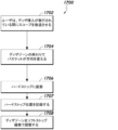
ブロック901において、プロセス900は、患者の解剖学的腔内でバスケット35を用いて石を捕捉することを伴う。例えば、石80は、図10-1の画像1001に示されるように、腎盂尿管移行部78を越えた腎臓の解剖学的構造の領域において捕捉され得る。ブロック902において、プロセス900は、図10-1の画像1003に示されるように、スコープ40及び/又はバスケット35を固着器具危険ゾーン99内に後退させることを伴う。
At
バスケット35が固着器具危険ゾーン99に入ったという判定は、解剖学的構造内のバスケット35の位置及び/又は処置の特定の段階を位置特定するために使用することができる1つ又は2つ以上のバスケット位置特定機構に少なくとも部分的に基づくことができる。危険ゾーン99は、例えば、腎盂尿管移行部78及び/又はアクセスシース90の開口部93のすぐ遠位/前方の領域を含み得る。バスケット35が危険ゾーン99内にあるという判定は、任意の好適な又は望ましい方法で達成され得る。いくつかの実施形態では、バスケット35の位置は、スコープ40及び/又はバスケット35を制御するロボットシステムのコマンドによって示され得る。例えば、シース90の遠位端93に対するスコープ40の位置に関する追加の既知の情報は、バスケット35及び/又はスコープ40の遠位端の位置を示す情報を提供し得る。バスケット35の位置は、任意の好適な又は望ましい位置特定機構を使用して判定され得る。いくつかの実施形態では、バスケットディザリング及び/又はバスケット位置特定は、バスケット35及び/又はスコープ40の腎盂尿管移行部78及び/又は危険ゾーン99への進入時にトリガされ得る。いくつかの実装態様では、バスケット35の位置特定及び/又はバスケットディザリングは、石80の捕捉成功の判定に応答して、自動的にトリガされ得る。
A determination that the
ブロック904において、プロセス900は、図10-1の画像1005に示すように、バスケット35のディザリングを作動させることを伴う。そのようなディザリングアクションは、スコープ40及び/又はバスケットデバイス30を制御するために使用されるロボット機構のうちの1つ又は2つ以上のアクチュエータ/カップリングと関連付けられた関連力センサ読み取り値の感度を有利に改善し得る。ディザリングは、本明細書に開示される実施形態のいずれかに従って実装され得る。例えば、ディザリングは、スコープ40に対するバスケット35の前進及び後退の相対的に遅い運動を伴い得る。ディザリング距離は、有利に、ユーザ制御/経験に対するディザリングの影響を低減するために、相対的に短くあり得る。実装されるディザリング速度は、スコープ40の通常の駆動速度よりも遅い速度に設定され得る。更に、ディザリング距離は、バスケット後退中に手術する医師/技術者を妨害又は混乱させることを回避するために、全体的なバスケット移動範囲/距離の一部であるように設定され得る。
At
図9のフロー図は、バスケット35を危険ゾーン99内に後退させることを説明しているが、いくつかの実装態様では、バスケットディザリング及び/又は他の固着器具検出機能は、石80がバスケット35によって捕捉されたときに自動的にトリガされ得、及び/又はそのような機能は、バスケット35がアクセスシース90内に安全に進入したときに停止され得る。いくつかの実装態様では、ロボット制御アクチュエータ又はカップリングと関連付けられたセンサからの力読み取り値に基づく固着バスケット判定は、バスケットディザリングを実装することなく実装され得る。すなわち、固着器具判定のための本明細書に開示される実施形態のいずれも、バスケットディザリングを伴って、又は伴わずに、実行/実装され得る。
Although the flow diagram of FIG. 9 describes retracting the
いくつかの実装態様では、固着器具状況を防止するために、特定の予防措置/機能が実装され得る。例えば、いくつかの実施形態は、ロボットシステムが、固着器具力が検出されたときに手動バスケット調整を模倣する、又はそれに類似する様式で、バスケットを前方にスリップ/前進させるように構成されている、機構を提供する。このようにして、生理学的及び/又は器具類の損傷をもたらし得る固着器具力は、そのようなスリップ力よりも大きく設定することができ、固着器具状況が検出された後、ユーザは、固着器具状況を手動で解決し、バスケットを非スリップ位置に配置し戻すことができる。 In some implementations, certain precautions/features may be implemented to prevent a stuck device situation. For example, some embodiments configure the robotic system to slip/advance the basket forward in a manner that mimics or resembles a manual basket adjustment when an anchoring device force is detected. , providing the mechanism. In this way, anchoring device forces that can lead to physiological and/or instrumentation damage can be set greater than such slip forces, and after a stuck device condition is detected, the user can The situation can be manually resolved and the basket placed back into the non-slip position.
ブロック906において、プロセス900は、バスケット35及び/又はスコープ40の遠位端を、腎盂尿管移行部/尿管移行領域/小孔を通して後退させることを伴う。例えば、ブロック906の動作に関連する後退は、画像1005に示されるように、バスケット35がディザリングしている間に実行することができ、これは、固着器具の推論のために所望のセンサ感度を提供し得る。バスケットデバイス30及び/又は内視鏡40と関連付けられた1つ又は2つ以上のアクチュエータにおいて検出された力が固着器具状況を示す場合、プロセス900はブロック910に進み得、そこで、特定の固着器具修復アクションが実装され得る。
At
固着器具検出は、(例えば、バスケットシースと係合された)バスケット挿入ドライバ/アクチュエータにおいて経験されるトルク/力など、ロボットバスケットシステムと関連付けられた1つ又は2つ以上の軸/アクチュエータについての1つ又は2つ以上のトルク/力読み取り値に基づき得る。いくつかの実装態様では、固着器具状況が存在するという判定は、バスケットシース及び/又はバスケットタインと関連付けられた1つ又は2つ以上のアクチュエータにおいて経験されるバスケット挿入軸力が、閾値時間にわたって所定の閾値よりも大きいという判定に基づき得る。例えば、いくつかの実施形態では、第1の力及び/又は時間閾値が満たされるとき、修復アクションは、スコープ後退速度を減速させて、固着器具検出機能が実装されるのに十分な時間を可能にすること、及び/又は固着バスケットによって生成される力を低減して、それによって引き起こされる危害の大きさ及び/又はリスクを低減することを伴う。いくつかの実施形態では、後退速度が減速された後、バスケット力が、障害閾値レベルなどの別の所定の閾値レベルを越えて増加し続ける場合、スコープの後退は、損傷を防止し、固着器具状況の修正を可能にするために停止され得る。 Fixed instrument detection may be performed on one or more axes/actuators associated with a robotic basket system, such as torques/forces experienced in a basket insertion driver/actuator (e.g., engaged with a basket sheath). May be based on one or more torque/force readings. In some implementations, the determination that a fixed device condition exists is determined if the basket insertion axial force experienced at one or more actuators associated with the basket sheath and/or basket tines has exceeded a predetermined threshold time. is greater than a threshold of . For example, in some embodiments, when the first force and/or time thresholds are met, the repair action slows down the scope retraction speed to allow enough time for the stuck instrument detection feature to be implemented. and/or reducing the force generated by the sticking basket to reduce the magnitude and/or risk of harm caused thereby. In some embodiments, if the basket force continues to increase beyond another predetermined threshold level, such as an obstacle threshold level, after the retraction speed is slowed, retraction of the scope prevents damage and secures the fixation device. It can be stopped to allow correction of the situation.
ブロック910と関連付けられた修復アクションが、判定された固着器具状況に応答してスコープの後退を停止/中断することを伴う実施形態では、そのような動作は、医師/技術者がスコープ40及び/又はバスケット30を後退させるときに内視鏡画像及び/又は器具類の触感に十分な注意を払っていないときに起こり得るなど、ユーザエラーのリスクを防止又は低減するのに役立ち得る。
In embodiments where the remedial action associated with
器具固着状況が判定されない場合、プロセス900はブロック908に進み、バスケット35及び/又はスコープ40の遠位端は、アクセスシース90の遠位開口部93を通してアクセスシース90内に後退させられる。シース90内への後退に関連して固着器具状況が検出された場合、プロセス900はブロック910に進み得、そこで、固着器具状況と関連付けられた修復アクションが、任意の好適な又は望ましい方法で実装され得る。
If an instrument fixation condition is not determined,
ブロック910と関連付けられた修復アクションは、ユーザが、固着器具障害をクリアし、バスケット/石位置を再調整し、回復を可能にするいくつかの場合において後退を継続することを可能にすることができる。ブロック910の修復アクションの後、プロセス900は、プロセスの後続のステップのいずれかに戻って継続し得、かつ/又はブロック916でプロセスの終了をもたらし得る。ブロック910に関連して修復アクションが正常に行われた後、関連する閾値レベルを超える更なる力読み取り値は、ブロック910における修復アクションの再トリガ及び/又は修復アクションへの復帰をもたらし得る。
The repair action associated with
ブロック912において、プロセス900は、バスケットディザリングを解除することを伴う。例えば、ディザリングのそのような解除は、バスケット35及び/又はスコープ40の遠位端がアクセスシース90に入ったという判定によってトリガされ得る。ブロック914において、プロセス900は、アクセスシース90を通してバスケットを後退させることを伴う。アクセスシース90を通したそのような後退は、いくつかの実装態様では、加速された速度で行われ得る。すなわち、一旦アクセスシース90内に入ると、処置時間を低減するために、かつ/又は利便性及び/若しくは効率に関する他の目的のために、後退速度は、増加され得る。バスケットがアクセスシース90を通して後退させられると、プロセス900は、ブロック916で終了され得る。
At
図11は、1つ又は2つ以上の実施形態による、固着器具状況を扱うためのプロセス600を例解するフロー図である。ブロック602において、プロセス600は、その中に捕捉された物体(例えば、石)を有するバスケットを尿管アクセスシースに向かって後退させることを伴う。例えば、バスケットは、内視鏡とともに後退され得、バスケットは、内視鏡の作業チャネル内に置かれる。
FIG. 11 is a flow diagram illustrating a
ブロック604において、プロセス600は、ロボットスコープ及び/又はバスケット制御アクチュエータと関連付けられたセンサからの力読み取り値に基づいて、バスケットが固着器具状況にあるかどうかを判定することを伴う。例えば、決定ブロック604における判定は、バスケットシステムの1つ又は2つ以上のアクチュエータにおける力読み取り値が所定の固着器具検出閾値よりも大きいと判定することを伴い得る。いくつかの実装態様では、ブロック604における判定は、バスケットがディザリング運動で動作している間に実行され得、これは、本明細書で詳細に説明するように、固着器具の検出/判定に対して相対的に高い感度を提供し得る。
At
バスケット及び/又はロボットシステムのうちの1つ又は2つ以上のアクチュエータで経験した力が、固着器具状況を示すかどうかの判定は、処置及び/又はユーザに関する特定の他の情報/データによって補足及び/又は通知され得る。例えば、患者の特定の解剖学的構造に関する情報、オペレータの駆動挙動、及び/又は石サイズ情報は、決定ブロック604に関連して、現在の状況が固着器具状況を示すかどうかを判定するための入力として使用され得る。いくつかの実装態様では、固着器具状況を判定するように構成された制御回路は、少なくとも部分的に適応型であり、起こり得る固着器具状況を予測し、そのような判定と関連付けられた入力パラメータを調整して、固着器具検出精度を更に改善するように構成され得る。
Determining whether forces experienced by one or more actuators of the basket and/or robotic system indicate a stuck instrument condition may be supplemented and /or may be notified. For example, information regarding the patient's particular anatomy, operator driving behavior, and/or stone size information may be used in conjunction with
ブロック604に関連して分析された力読み取り値が固着器具状況を示す場合、ブロック605においてタイマが開始され得る。タイマは、力読み取り値が関連閾値を超える期間にわたって動作し得る。すなわち、ブロック605と関連付けられた期間は、ロボットバスケットシステムの1つ又は2つ以上のアクチュエータと関連付けられた力読み取り値が、固着器具閾値レベルを上回ったままである期間に対応し得る。
A timer may be started at
関連するアクチュエータに及ぼされる力が所定の閾値を上回ったままである時間が、決定ブロック607で判定されるように、障害閾値よりも大きい場合、プロセス600はブロック608に進み得る。例えば、固着器具タイマによって示されるように、バスケット及び/又はスコープ上の力が固着器具閾値を超える時間が、障害閾値よりも大きい場合、軽度の障害がスローされ得、オペレータは、ブロック608において固着器具状況が解決されるまで、バスケット/スコープを更に後退させることを許容されない。
If the amount of time that the force exerted on the associated actuator remains above the predetermined threshold is greater than the fault threshold, as determined at
アクチュエータへの力が固着器具閾値よりも大きい期間が、ブロック608と関連付けられた障害状況をトリガするほど長くはないが、所定の警告閾値よりも大きい場合、プロセス600は、ブロック610に進み、そこで、固着器具状況及び/又はそのリスクを示す警告又は他の通知が、生成され得、かつ/又はユーザに提供され得る。そのような警告は、オペレータ/ユーザに、バスケットの調整及び/又はバスケットの後退を注意深く進めるように促し得る。
If the period during which the force on the actuator is greater than the fixation device threshold is not long enough to trigger the fault condition associated with
ユーザ警告を提供することに加えて、いくつかの実装態様では、プロセス600は、ブロック604における固着器具状況が存在するという判定、ブロック609におけるタイマ期間が警告閾値よりも大きいという判定、及び/又はブロック607におけるタイマ期間が障害閾値よりも大きいという判定のうちの1つ又は2つ以上に応答して、スコープ及び/又はバスケットデバイスの後退速度を低減することを伴う。後退の速度を低減させることは、後退を停止させるのに十分な時間がないまま力が急上昇するのを防止し、生理学的損傷及び/又は器具損傷を防止するのに役立つことができる。いくつかの実施形態では、ノイズの多いデータがフィルタリングされ、バスケット力の単一のスパイクが誤警報をトリガするリスクを低減するために、検出された力が事前定義された固着器具力閾値を下回るたびに、固着器具タイマがリセットされ得る。ブロック612において、プロセス600は、バスケット及びスコープをアクセスシース内に後退させることを伴う。
In addition to providing a user warning, in some
ボックス607又は609のいずれかで固着器具状況が満たされる場合、又はブロック604で固着器具状況が判定されない場合、プロセス600はブロック606に進み得、ここで、現在動作している場合、固着器具タイマが停止される。決定ブロック611において、プロセス600は、バスケット及び/又は内視鏡の遠位端が固着器具危険ゾーン内にあるかどうかを判定することを伴う。そうである場合、プロセス600は、ブロック613において、本開示の態様によるバスケットディザリングを始動させることを伴う。バスケット及び/又は内視鏡の遠位端が、依然として、固着器具危険ゾーン内にない場合、プロセス600は、ブロック602に戻り得、ここで、バスケット/スコープの尿管アクセスシースに向かう後退が継続する。
If the fixation device status is met in either
誤検出の対処
図12は、1つ又は2つ以上の実施形態による、バスケットデバイス挿入軸上の誤検出センサ読み取り値を管理するためのプロセス1200を例解するフロー図である。ブロック1202において、プロセス1200は、患者の腎臓内でバスケットデバイスを用いて石を捕捉することを伴う。例えば、複数の石片のうちの1つの石片が捕捉され得る。石は、バスケットデバイスの開放軸を作動させることによって捕捉され得、開放軸は、バスケットデバイスのシースからタイン/ワイヤを延在させる、かつ/又はその中に後退させることによって、バスケットタイン/ワイヤの開閉を制御し得る。石を捕捉することは、更に、バスケットデバイスの挿入軸を作動させることを伴い得、これは、バスケットシースの作動を引き起こして、(例えば、スコープの作業チャネル内で)バスケットデバイスが配設されている内視鏡に対するバスケットの挿入及び/又は後退を引き起こし得る。
Addressing False Positives FIG. 12 is a flow diagram illustrating a
サブプロセスブロック1204において、プロセス1200は、本明細書で詳細に説明されるように、スコープの遠位端に対してバスケットをディザリングしながら、スコープ及びバスケットを後退させることを伴う。そのようなディザリングは、固着器具危険ゾーン内で実装することができ、ディザリングプロセスは、本開示全体を通して詳細に説明されるように、固着石検出のために実装され得る。標的解剖学的構造(例えば、尿管アクセスシース)にアクセスするために使用されるアクセスシース、及び/又はアクセスシースの遠位端/開口部の遠位/外側の特定の距離内で、スコープ及びバスケットを近位に後退させることを伴い得る、スコープ後退中、バスケット挿入軸は、上記で詳細に説明されるように、固着器具検出のための改良された感度を提供するように、前後にディザリングされ得る。概して、ディザリング距離/運動範囲は、ユーザによって気づかれないような相対的に小さい距離に設定され得る一方で、依然として、バスケット挿入軸の動的な動きを生成して、改善された固着器具検出感度を提供し得る。
At
ブロック1206において、上昇した力が、バスケットデバイスと関連付けられた挿入軸上で検出されたかどうかが判定される。例えば、バスケットデバイスのシースと関連付けられた1つ又は2つ以上の力センサは、固着石状況を潜在的に示し得る上昇した力を示し得る。挿入軸は、バスケットデバイスと関連付けられたハンドル/カートリッジのスライダ/アクチュエータと関連付けられ得、スライダアクチュエータは、バスケットがスコープの作業チャネル内に配設されるとき、スコープに対するバスケット及び/又はそのシースの挿入及び後退を制御するように構成可能である。
At
上記で詳細に説明したように、ロボットマニピュレータ(例えば、ロボット器具デバイスマニピュレータ(IDM)、エンドエフェクタなど)トルク感知は、固着器具検出のための入力源として使用され得る。例えば、本開示の態様による固着器具検出機能は、真の固着器具状況が存在するときに発生し得る挿入軸力ピーク/レベルを検出するように実装され得、それにより、ユーザは、器具類及び/又は解剖学的構造に対する損傷又は傷害が発生する前に、潜在的な固着器具状況が通知され得る。ブロック1206と関連付けられた上昇した力の検出は、挿入軸上の力が閾値レベルに達するほど高くなることに関連し得、その時点で、スコープの減速が、場合によっては、固着器具の修復アクションとして実装され得、スコープの後退速度を低減して、挿入軸力があまりに速く上昇することを回避して、システムに、障害をスローさせ得、固着器具の修復アクションをトリガする。ブロック1206において、挿入軸上に上昇した力が検出されない場合、プロセス1200はブロック1216に進み、標的解剖学的構造にアクセスするために使用されるアクセスシースの近位など、捕捉された石が収集される。
As described in detail above, robotic manipulator (eg, robotic instrument device manipulator (IDM), end effector, etc.) torque sensing can be used as an input source for stuck instrument detection. For example, a stuck instrument detection feature according to aspects of the present disclosure may be implemented to detect insertion axial force peaks/levels that may occur when a true stuck instrument condition exists, thereby allowing the user to detect instrumentation and /or Potential fixation device situations may be notified before damage or injury to the anatomy occurs. The detection of increased force associated with
ブロック1206において、挿入軸上で上昇した力が検出された場合、プロセス1200は決定ブロック1208に進み、そこで、挿入軸に関してソフトストップ位置(例えば、可能なハードストップ位置からの緩衝距離を提供するソフトストップ位置)が以前に設定されたかどうかが判定される(例えば、挿入軸スライダ/アクチュエータの移動に関連するソフトストップ位置)。例えば、ソフトストップ位置は、挿入軸(例えば、バスケットシース挿入/後退)を制御するように構成されたバスケットスライダ/アクチュエータの運動(例えば、近位運動及び/又は後退運動)に対するソフトウェア制限として機能し得る。したがって、ソフトストップ位置が設定されている場合、バスケットデバイスの挿入軸のディザリング及び/又は他の運動(例えば、後退)は、物理的なハードストップ位置ではない位置で人為的に制限され得る。いくつかの実装態様では、挿入軸上の上昇した力の検出は、潜在的な物理的ハードストップと関連付けられた位置として将来参照するためのハードストップ挿入軸アクチュエータ位置の記録/設定をトリガする。
At
ソフトストップ位置が以前に設定されている場合、プロセス1200はブロック1210に進み、そこで、固着器具の修復アクションが実装される。すなわち、ソフトストップ位置が以前に設定された後に、上昇した力が挿入軸上で検出される場合、挿入軸上の上昇した力は、真の固着器具状況を示すと判定することができ、したがって、修復アクションが保証される。固着器具の修復アクションは、挿入軸力があまりに速く上昇することを回避して、システムに、障害をスローさせるように、スコープの後退を減速させることを伴い得る。低速のスコープ後退が実装されている間に挿入軸力が上昇し続ける場合、潜在的な固着器具状況をユーザに通知し、スコープ後退の中断/停止をトリガするために、固着器具の警告/障害がスローされ得る。固着器具の修復アクションは、固着器具状況及び/又はその解決の承認をユーザ/施術者に要請することを伴い得る。
If a soft-stop position has been previously set,
ソフトストップ位置が以前に設定/記録されていない場合、ブロック1206において挿入軸上で検出された上昇した力が、実際には固着器具状況の結果ではなく、むしろ挿入軸アクチュエータによる物理的ハードストップとの接触によって生じる可能性がある誤検出状況を表すかどうかを判定するために、特定の動作が実装され得る。例えば、スライダ/アクチュエータは、それが摺動/作動するトラックの物理的限界(例えば、後方/近位限界)に当たる可能性がある。バスケットデバイス/システムは、挿入軸アクチュエータ及び/又は開放軸アクチュエータ(バスケットシース内のバスケットタインの動きを制御し、図19及び図20に関して以下でより詳細に説明される)など、1つ又は2つ以上のアクチュエータを含む近位バスケットカートリッジ/ハンドルを含み得る。バスケットカートリッジ/ハンドルがロボットマニピュレータ(例えば、エンドエフェクタ)に結合又は係合されるとき、アクチュエータの位置は、不明であり得るか、又は任意の位置若しくはオフセット位置にあり得、それにより、プロセス1200の様々な段階中に、それらの位置は、それぞれのトラック内のハードストップ位置の近距離内にある場合、又はない場合がある。したがって、上昇した挿入軸力が感知され、ソフトストップ位置が以前に設定されていない場合、プロセス1200はブロック1212に進み、挿入軸及び/又はバスケットは、何らかの所定の距離/量だけスコープに対して前方に付勢され得る。すなわち、バスケットは、上昇した挿入軸力が検出された位置からバスケット及び関連するアクチュエータをオフセットするために、ある量(例えば、公称量)だけ前方に前進され得る。力の上昇が挿入軸上のハードストップとの接触によって引き起こされた場合、挿入軸の前方への付勢により、挿入軸アクチュエータを真のハードストップ境界から更に遠くに移動させ、その結果、バスケットをスコープの遠位端から相対的に遠くに突出させることができる。
If the soft stop position has not been previously set/recorded, the increased force detected on the insertion axis at
スコープの遠位端に対してバスケットを前進させる/前方に付勢することに加えて、プロセス1200は、ブロック1214において、挿入軸上の上昇した力が検出されたときの挿入軸/バスケットの位置と関連付けられたソフトストップ位置を設定することを伴い得る。例えば、ソフトストップ位置は、判定された/疑わしいハードストップ位置にあり得るか、又は記録されたソフトストップ位置は、有利に、判定された/疑わしいハードストップ位置から離れた緩衝距離(すなわち、ソフトストップ緩衝)に位置決めされ得る。すなわち、設定/記録されるソフトストップ位置は、上昇した力が検出された時間/点におけるバスケットの位置に対して遠位の(すなわち、更に挿入された)位置であり得る。ソフトストップ位置は、それによって、ソフトストップ位置と、上昇した力が検出された潜在的なハードストップ位置との間に緩衝を提供する位置に設定され得る。ソフトストップを設定することは、挿入軸アクチュエータが、上昇した挿入軸力が検出された位置に移動することを防止し得、これは、挿入軸アクチュエータ/スライダの物理的ハードストップと関連付けられ得る。
In addition to advancing/biasing the basket forward relative to the distal end of the scope, the
ソフトストップ位置の設定に加えて、及び/又はソフトストップ位置の設定の結果として、プロセス1200は、挿入軸上の上昇した力が挿入軸アクチュエータ/スライダのハードストップからであり、したがって、潜在的に誤検出読み取り値が真の固着器具状況を示していないかどうかを判定する手段として、バスケットをソフトストップ位置より遠位の領域にディザリングするときに、ディザリング運動範囲を実装態様のために前方にシフトさせることを更に伴い得る。修正されたディザリングゾーンは、記録されたソフトストップ位置及び/又は識別されたハードストップ位置によって、一端(例えば、近位端)が制限され得る。
In addition to and/or as a result of setting the soft stop position,
バスケットの前方への付勢、ソフトストップ位置の設定、及び/又はディザリングゾーンの前方へのシフトの後、プロセス1200は、バスケットディザリングを実装しながらバスケット及びスコープを後退させるサブプロセス1204に戻り得るか、又はプロセス1200は、ブロック1210で固着器具の修復アクションに進み得る。図12のフロー図は、サブプロセス1204をバスケットのディザリングを伴うものとして説明しているが、プロセス1200は、バスケットディザリングを実装することなく、及び/又はディザリングゾーンをシフトすることなく実装され得ることを理解されたい。プロセス1200は、サブプロセス1204から継続することができ、ソフトストップ位置が以前に設定されているので、ブロック1206で、挿入軸上で上昇した力が続いて検出される場合、プロセス1200は、ブロック1210での修復アクション動作に進み、そのような上昇した力は、真の固着器具状況の兆候として解釈され得る。挿入軸/バスケットを前方に付勢した後に更なる上昇力が検出されない場合、以前に検出された上昇力が挿入軸アクチュエータに対する真のハードストップ状況と関連付けられたと判定され得る。いくつかの実装態様では、挿入軸に対するハードストップ位置は、少なくともバスケットカートリッジ/ハンドルとロボットマニピュレータ(例えば、エンドエフェクタ)との結合が解除されるまでの間、何らかの方法で記録/維持することができる。
After biasing the basket forward, setting the soft stop position, and/or shifting the dithering zone forward,
ブロック1216において捕捉された石を収集した後、ブロック1218において、更なる石及び/又は石片が収集されずに残っているか否かを判定することができる。そうである場合、プロセスはブロック1220に進むことができ、以前に設定されたソフトストップ位置をクリア/リセットすることができ、かつ/又はディザリングゾーンをデフォルト範囲/ゾーンに戻す/リセットすることができる。スコープ及びバスケットはブロック1222で標的解剖学に再び挿入され、その後ブロック1202で追加の石/破片が捕捉される。
After collecting the captured stones at
図13は、1つ又は2つ以上の実施形態による、バスケットデバイス挿入軸上の誤検出センサ読み取り値を管理するためのプロセス1300を例解するフロー図である。ブロック1302において、プロセス1300は、患者の腎臓内でバスケットデバイスを用いて石を捕捉することを伴う。例えば、複数の石片のうちの1つの石片が、捕捉され得る。石は、バスケットデバイスの開放軸を作動させることによって捕捉され得、開放軸は、バスケットデバイスのシースからタイン/ワイヤを延在させること、かつ/又はその中に後退させることによって、バスケットタイン/ワイヤの開閉を制御し得る。石を捕捉することは、更に、バスケットデバイスの挿入軸を作動させることを伴うことができ、これは、バスケットシースの作動を引き起こして、(例えば、スコープの作業チャネル内で)バスケットデバイスが配設されている内視鏡に対するバスケットの挿入及び/又は後退を引き起こすことができる。
FIG. 13 is a flow diagram illustrating a
図13を更に参照すると、プロセス1300のブロック1305及び1307は、ユーザがバスケットを最初に設定されたディザゾーンの外側(又は内側)に移動させた場合に、バスケットデバイスの挿入軸のディザリング作動に関して、バスケットデバイスのディザゾーンをリセットするように実装され得る。決定ブロック1305において、ユーザがバスケットをデフォルト位置から挿入したか、又は後退させたかが判定される。例えば、ブロック1305における判定は、ユーザが、挿入軸アクチュエータ/スライダを手動で、又はロボットで操作することなどによって、バスケットデバイスの挿入軸を作動させたかどうかを判定することを伴い得る。例えば、スコープが後退させられているとき、バスケットは、概して、所定のディザゾーン/範囲内でディザリングし得る。ユーザがバスケットのディザリング動作とは無関係に何らかの理由でバスケットを挿入又は後退させ、その後スコープ後退を継続する場合、ディザゾーンの範囲を修正することが望ましい場合がある。
Still referring to FIG. 13, blocks 1305 and 1307 of
バスケットがユーザによって挿入又は後退された場合、プロセス1300はブロック1307に進み、バスケットのディザリングゾーンは、ユーザによって実装されたバスケットの挿入又は後退を補償するように修正/設定することができる。例えば、ユーザがある量だけバスケットを挿入した場合、ディザリングゾーンは、相応の量だけ前方に移動させることができ、後退の場合にも同様の修正を実装することができる。
If the basket has been inserted or retracted by the user, the
サブプロセスブロック1304において、プロセス1300は、本明細書で詳細に説明されるように、スコープの遠位端に対してバスケットをディザリングしながら、スコープ及びバスケットを後退させることを伴う。そのようなディザリングは、固着器具危険ゾーン内で実装することができ、ディザリングプロセスは、本開示全体を通して詳細に説明されるように、固着石検出のために実装することができる。標的解剖学的構造(例えば、尿管アクセスシース)にアクセスするために使用されるアクセスシース、及び/又はアクセスシースの遠位端/開口部の遠位/外側の特定の距離内で、スコープ及びバスケットをともに近位に後退させることを伴い得る、スコープ後退中、バスケット挿入軸は、上記で詳細に説明されるように、固着器具検出のための改良された感度を提供するように、前後にディザリングされ得る。概して、ディザリング距離/運動範囲は、ユーザが気づかないような相対的に小さい距離に設定され得る一方で、バスケット挿入軸の動的な動きを生成して、改善された固着器具検出感度を提供することができる。図13のフロー図は、サブプロセス1304をバスケットのディザリングを伴うものとして説明しているが、プロセス1300は、バスケットディザリングを実装することなく、及び/又はディザリングゾーンをシフトすることなく実装され得ることを理解されたい。
At
ブロック1306において、上昇した力が、バスケットデバイスと関連付けられた挿入軸上で検出されたかどうかが判定される。例えば、バスケットデバイスのシースと関連付けられた1つ又は2つ以上の力センサは、固着石状況を潜在的に示し得る上昇した力を示し得る。挿入軸は、バスケットデバイスと関連付けられたハンドル/カートリッジのスライダ/アクチュエータと関連付けられ得、スライダアクチュエータは、バスケットがスコープの作業チャネル内に配設されるとき、スコープに対するバスケット及び/又はそのシースの挿入及び後退を制御するように構成可能である。
At
上記で詳細に説明したように、ロボットマニピュレータ(例えば、ロボット器具デバイスマニピュレータ(IDM)、エンドエフェクタなど)トルク感知は、固着器具検出のための入力源として使用され得る。例えば、本開示の態様による固着器具検出機能は、真の固着器具状況が存在するときに発生し得る挿入軸力ピーク/レベルを検出するように実装され得、それにより、ユーザは、器具類及び/又は解剖学的構造に対する損傷又は傷害が発生する前に、潜在的な固着器具状況が通知され得る。ブロック1306と関連付けられた上昇した力の検出は、挿入軸上の力が閾値レベルに達するほど高くなることに関連し得、その時点で、スコープの減速を、場合によっては、固着器具の修復アクションとして実装することができ、スコープの後退速度を低減して、挿入軸力があまりに速く上昇することを回避して、システムに、障害をスローさせ得、固着器具の修復アクションをトリガする。ブロック1306において、挿入軸上に上昇した力が検出されない場合、プロセス1300はブロック1316に進み、標的解剖学的構造にアクセスするために使用されるアクセスシースの近位など、捕捉された石が収集される。
As described in detail above, robotic manipulator (eg, robotic instrument device manipulator (IDM), end effector, etc.) torque sensing can be used as an input source for stuck instrument detection. For example, a stuck instrument detection feature according to aspects of the present disclosure may be implemented to detect insertion axial force peaks/levels that may occur when a true stuck instrument condition exists, thereby allowing the user to detect instrumentation and /or Potential fixation device situations may be notified before damage or injury to the anatomy occurs. The detection of increased force associated with
ブロック1306において、挿入軸上で上昇した力が検出された場合、プロセス1300は決定ブロック1308に進み、そこで、挿入軸に関してハードストップ位置が以前に設定/記録されたかどうかが判定される(例えば、挿入軸スライダ/アクチュエータの移動に関連するハードストップ位置)。参照ハードストップ位置は、実際に確認された物理的ハードストップ限界、又は潜在的ハードストップ限界として識別される別の位置限界であり得る。
At
ハードストップ位置が以前に設定されている場合、プロセス1300はブロック1310に進み、そこで、固着器具の修復アクションが実装される。すなわち、ハードストップ位置が以前に記録された後に、上昇した力が挿入軸上で検出される場合、挿入軸上の上昇した力は、真の固着器具状況を示すと判定され得、したがって、修復アクションが保証される。固着器具の修復アクションは、挿入軸力があまりに速く上昇することを回避して、システムに、障害をスローさせるように、スコープの後退を減速させることを伴い得る。低速のスコープ後退が実装されている間に挿入軸力が上昇し続ける場合、潜在的な固着器具状況をユーザに通知し、スコープ後退の中断/停止をトリガするために、固着器具の警告/障害がスローされ得る。固着器具の修復アクションは、固着器具状況及び/又はその解決の承認をユーザ/施術者に要請することを伴い得る。
If a hard stop position has been previously set, the
ハードストップ限界/位置が以前に設定/記録されていない場合、ブロック1306において挿入軸上で検出された上昇した力が、実際には固着器具状況の結果ではなく、むしろ挿入軸アクチュエータによる物理的ハードストップとの接触によって生じる可能性がある誤検出状況を表す可能性を説明するために、特定の動作が実装され得る。例えば、スライダ/アクチュエータは、それが摺動/作動するトラックの物理的限界(例えば、後方/近位限界)に当たる可能性がある。バスケットデバイス/システムは、挿入軸アクチュエータ及び/又は開放軸アクチュエータ(バスケットシース内のバスケットタインの動きを制御し、図19及び図20に関して以下でより詳細に説明される)など、1つ又は2つ以上のアクチュエータを含む近位バスケットカートリッジ/ハンドルを含み得る。バスケットカートリッジ/ハンドルがロボットマニピュレータ(例えば、エンドエフェクタ)に結合又は係合されるとき、アクチュエータの位置は、不明であり得るか、又は任意の位置若しくはオフセット位置にあり得、それにより、プロセス1300の様々な段階中に、それらの位置は、それぞれのトラック内のハードストップ位置の近距離内にある場合、又はない場合がある。したがって、上昇した挿入軸力が感知され、潜在的なハードストップ限界が以前に設定されていない場合、プロセス1300はブロック1312に進み、挿入軸及び/又はバスケットは、何らかの所定の距離/量だけスコープに対して前方に付勢され得る。すなわち、バスケットは、上昇した挿入軸力が検出された位置(すなわち、潜在的なハードストップ限界)からバスケット及び関連するアクチュエータをオフセットするために、ある量だけ前方に前進され得る。挿入軸の前方への付勢は、力の上昇が挿入軸上のハードストップとの接触によって引き起こされた場合、挿入軸アクチュエータを真のハードストップ境界から更に遠くに移動させ、その結果、バスケットをスコープの遠位端から相対的に遠くに突出させることができる。バスケットの前方への付勢は、バスケットに、挿入軸の近位の物理的ハードストップからの緩衝(又はより大きい緩衝)を与えることができる。
If the hard stop limits/positions have not been previously set/recorded, the increased force detected on the insertion axis at
スコープの遠位端に対してバスケットを前進させる/前方に付勢することに加えて、プロセス1300は、ブロック1314において、挿入軸上の上昇した力が検出されたときの挿入軸/バスケットの位置と関連付けられた潜在的なハードストップ位置を記録することを伴い得る。プロセス1300は、更に、バスケットをある距離だけ更に遠位にある領域にディザリングする際の実装態様のために、ディザリングゾーン/可動域を前方にシフトすることを伴い得る。そのような距離は、記録されたハードストップ位置から離れた緩衝距離であり得、それにより、ディザゾーン/範囲の近位限界は、ハードストップ位置から緩衝距離だけ離れたソフトストップ位置である。潜在的なハードストップ位置を記録した後、挿入軸が物理的なハードストップなしにそのような限界を越えて駆動することができると後に判定された場合、記録したハードストップ位置はそれに応じて修正することができる。
In addition to advancing/biasing the basket forward relative to the distal end of the scope, the
バスケットの前方への付勢、ハードストップ位置の記録、及び/又はディザリングゾーンの前方へのシフトの後、プロセス1300は、ブロック1310と関連付けられた修復動作に進み、最終的に更に、ブロック1304に関連してスコープの継続的な後退を可能にすることができる。プロセス1300は、サブプロセス1304から継続することができ、ハードストップ位置が以前に記録されているので、ブロック1306で、挿入軸上で上昇した力がその後に検出される場合、プロセス1300は、ブロック1310での修復アクション動作に進み、そのような上昇した力は、真の固着器具状況の兆候として解釈され得る。挿入軸/バスケットを前方に付勢した後に更なる上昇した力が検出されない場合、プロセス1300は、何事もなく収集まで進み得る。ブロック1310において、システムは、障害をスローし得、その後、ユーザは、障害を承認して(ブロック1311)、真の固着器具状況が存在するかどうかを検証し得る。障害が承認されると、ユーザは、スコープを再び駆動することを許容され得る(例えば、ブロック1302又は1304に戻る)。
After urging the basket forward, recording the hard stop position, and/or shifting the dithering zone forward, the
ブロック1316において捕捉された石を収集した後、ブロック1318において、更なる石及び/又は石片が収集されずに残っているか否かが判定され得る。そうである場合、プロセスは、ブロック1322に進み得、そこで、スコープ及びバスケットが標的の解剖学的構成の中に再び挿入され、その後、ブロック1302において、追加の結石/破片が捕捉される。
After collecting the captured stones at
図14は、1つ又は2つ以上の実施形態によるハードストップ力検出修復アクションを示す図である。図14の図は、ページの上部から下部に移動する時間軸を含み、時間はそのような方向に進み、挿入軸は左から右に延びて増加し、スコープの遠位端に対するバスケットの相対距離を表す。線1401のジグザグ移動は、本明細書で詳細に説明されるように、挿入軸アクチュエータ/スライダの作動によるスコープに対するバスケットのディザリング運動を示す。バスケットのディザリングアクションは、第1の時間窓1409の間、所定のディザリングゾーン/運動範囲1405内にあり得る。
FIG. 14 is a diagram illustrating hard stop force detection remedial actions according to one or more embodiments. The illustration in FIG. 14 includes a time axis moving from top to bottom of the page, time progressing in that direction, and an insertion axis extending left to right and increasing, relative distance of the basket to the distal end of the scope. represents The zig-zag movement of
バスケット及び/又は対応するバスケット挿入位置1403をディザリングしている間の特定の時点を表す点1402において、上昇した力が挿入軸上で検出され、これは、真の固着器具状況によって引き起こされ得るか、又は挿入軸アクチュエータ/スライダが物理的なハードストップ位置に当たることによって引き起こされる誤検出読み取り値であり得る。例えば、スライダ/アクチュエータは、それが摺動/作動するトラックの後方/物理的限界に当たる可能性がある。それに応答して、挿入軸上の上昇した力が検出された位置は、ハードストップ位置として記憶、設定、及び/又は別様で記録され得る。
At
挿入軸上の検出された上昇した力に応答して、バスケットは、例解された距離D1に等しい及び/又は関連し得る距離だけ前方に付勢され得、バスケットのそのような前方への付勢は、線分1407及び/又は線分1408の少なくとも一部分によって表される。ソフトストップ挿入軸位置1404は、設定及び/又は実施/実装され得、そのようなソフトストップバスケット挿入位置1404は、ハードストップ位置1403と同じであり得るか、又は示されるように、ハードストップ位置1403に対して距離D1だけ前方に付勢され得る。更に、バスケットのディザリングのためのディザリングゾーン/運動範囲は、修正されたゾーン/範囲1406へと前方に付勢され得、修正されたディザリングゾーン/範囲1406は、それと関連付けられたディザリングアクション中の最近位挿入位置がソフトストップ境界1404を越えないように判定及び/又は位置決めされ得る。
In response to a detected elevated force on the insertion axis, the basket may be urged forward a distance that may be equal to and/or related to the illustrated distance D1 , such forward displacement of the basket. Biasing is represented by at least a portion of line segment 1407 and/or
図15は、上述のプロセス1200及び1300に関連して実装され得るような、本開示の1つ又は2つ以上の実施形態によるディザリングゾーン/範囲を調整するためのプロセス1500を例解するフロー図を示す。図16は、1つ又は2つ以上の実施形態による、図15のプロセス1500と関連付けられた様々なブロック、状態、及び/又は動作に対応する特定の画像を示す。図16において、例解された片側矢印は、スコープ103に対する運動など、バスケットの運動を表し得る。
FIG. 15 is a
プロセス1500は、スコープ後退中のバスケットのディザリング運動がバスケット挿入軸を遠位ハードストップ内に突き通す場合など、ディザゾーンの調整を提供する。例えば、ブロック1502は、ユーザが、バスケットをディザリングしながらスコープを後退させることを伴い、バスケットのディザリングが応答システムプロセスとして自動的に実装され得るので、ユーザは、それを認識する場合、又はしない場合がある。画像1602は、ディザゾーン内でディザリングしているバスケットタイン101及び/又はバスケットシース102の遠位端を示す。バスケットシースの遠位端102及び/又はシース102の遠位にあるバスケット101の1つ又は2つ以上の部分は、以下でバスケット104と称され、そのような参照は、そのような構成要素/部分のいずれかを指し得る。
ブロック1504において、プロセス1500は、ディザリング運動に関連してバスケットを前方に挿入するときにハードストップを検出することを伴う。例えば、バスケット挿入時に生成される上昇した挿入軸力読み取り値は、アクチュエータハードストップ接触の結果である可能性が高いか、又は確実であることが理解され得、真の固着石状況では、概ね、バスケット挿入中に相対的に高い力を生成することができない。ブロック1505において、プロセス1500は、ハードストップと関連付けられた挿入軸位置105を記録することを伴う。
At
ブロック1506において、プロセス1500は、ディザゾーンを近位に調整することを伴う。いくつかの実装態様では、そのようなディザゾーン調整は、ハードストップ位置105と調整されたディザゾーンの遠位端106との間の緩衝を含み得る。例えば、ディザゾーンを調整することに関連して、挿入軸は、挿入軸アクチュエータのドライバ(例えば、バスケットデバイスカートリッジ/ハンドルの入力と駆動係合して結合されているロボットマニピュレータ/エンドエフェクタドライバ)上の張力を解放するために、ある距離だけ後方に駆動され得る。距離D2は、ソフトストップ緩衝と見なされ得、これは、デバイス上の張力を解放し、デバイス/システムの物理的限界に継続的に突き当たることを防止するために、バスケット104が後方に駆動される距離を表す。
At
図17は、上述のプロセス1200及び1300に関連して実装され得るような、本開示の1つ又は2つ以上の実施形態によるディザリングゾーン/範囲を調整するためのプロセス1700を例解するフロー図を示す。図18は、1つ又は2つ以上の実施形態による、図17のプロセス1700と関連付けられた様々なブロック、状態、及び/又は動作に対応する特定の画像を示す。図18において、例解された片側矢印は、スコープ103に対する運動など、バスケットの運動を表し得る。
FIG. 17 is a
プロセス1700は、スコープ後退中のバスケットのディザリング運動がバスケット挿入軸を近位ハードストップ内に突き通す場合など、ディザゾーンの調整を提供する。例えば、ブロック1702は、ユーザが、バスケットをディザリングしながらスコープを後退させることを伴い、バスケットのディザリングが応答システムプロセスとして自動的に実装され得るので、ユーザは、それを認識する場合、又はしない場合がある。画像1802は、ディザゾーン内でディザリングしているバスケットタイン101及び/又はバスケットシース102の遠位端を示す。バスケットシースの遠位端102及び/又はシース102の遠位にあるバスケット101の1つ又は2つ以上の部分は、以下でバスケット104と称され、そのような参照は、そのような構成要素/部分のいずれかを指し得る。
ブロック1704において、プロセス1700は、バスケット104がディザゾーンの遠位境界に到達した結果として、ディザリング方向が前方への挿入から後方への後退に変化することを伴う。ブロック1706において、プロセス1700は、ディザリング運動に関連してバスケットを後方に後退するときにハードストップを検出することを伴う。ブロック1705において、プロセス1700は、ハードストップと関連付けられた挿入軸位置107を記録することを伴う。
At
ブロック1706において、プロセス1700は、ディザゾーンを遠位に調整することを伴う。いくつかの実装態様では、そのようなディザゾーン調整は、ハードストップ位置107と調整されたディザゾーンの近位端108との間の緩衝を含み得る。例えば、ディザゾーンを調整することに関連して、挿入軸は、挿入軸アクチュエータのドライバ(例えば、バスケットデバイスカートリッジ/ハンドルの入力と駆動係合して結合されているロボットマニピュレータ/エンドエフェクタドライバ)上の張力を解放するために、ある距離だけ前方に駆動され得る。距離D3は、ソフトストップ緩衝と見なされ得、これは、デバイス上の張力を解放し、デバイス/システムの物理的限界に継続的に突き当たることを防止するために、バスケット104が前方に駆動される距離を表す。
At
図19は、1つ又は2つ以上の実施形態による、開放軸上の誤検出センサ読み取り値を管理するためのプロセス1900を例解するフロー図である。上で言及されるように、固着器具状況は、バスケット開放軸に伝達されている相対的に高い力をもたらし得、したがって、本開示の実施形態のいずれかに関して、固着器具管理に関連して開放軸上の力を監視することが有利であり得る。例えば、バスケットシースに対してバスケットタインを作動させるように構成されているバスケットスライダ/アクチュエータを作動させることは、石捕捉のために実装することができる。上述したように、このような作動は、「開放軸」作動とみなすことができ、この場合、それに関連する力及び作動は、バスキングシステムの「開放軸」とみなし得るものに対するものである。
FIG. 19 is a flow diagram illustrating a
ブロック1902において、プロセス1900は、内視鏡(本明細書では便宜上「スコープ」と称される)の作業チャネルから展開されたバスキングデバイスを用いて、石又は石片を捕捉することを伴う。例えば、バスケットで石を捕捉することは、バスケットデバイスの開放軸を操作して、1つ又は2つ以上のワイヤタイン又は他のバスケット構成要素を、バスキングシースの中に(又は外に)、かつ/又は捕捉された石の周りに引き込むことを伴い得る。スコープの周囲でのバスケットタインの閉鎖は、バスケットスライダ/アクチュエータを近位に(又は別の様式で)作動させることによって少なくとも部分的に実装され得、そのようなアクチュエータは、バスキングデバイス/システムの近位部分と関連付けられ、ロボットマニピュレータによって駆動されるバスケットカートリッジと関連付けられ得る。場合によっては、石/破片の周囲でバスケットタインを閉じるとき、タインは、開放軸上で感知された力の量を低減するように、バスケットシースの側面に対して押し込まれる。しかしながら、いくつかの事例では、タインは、捕捉された石片の周囲で十分に緊密に閉じない場合があり、それにより、開放軸上の力読み取り値に対する感度がより高くなり、いくつかのそのような例では、開放軸上での固着器具状況を感じることができる。
At
ブロック1904では、プロセス1900は、アクセスシースの遠位開口部に向かって、かつ/又はその中に、スコープ及びバスケットをともに近位に後退させることを伴い、アクセスシースを通して、スコープ及びバスケットは、標的の解剖学的室/場所にアクセスする。決定ブロック1906は、ブロック1904に関連して後退中に、バスキングシステムの開放軸上で上昇した力が検出されたかどうかに関する。例えば、バスケットデバイス/システムは、開放軸と関連付けられており、バスケットタインを引っ張る力など、開放軸上で経験する力を示す信号を生成するように構成されている1つ又は2つ以上の力センサを含み得る。
At
上昇した力が開放軸上で検出されない場合、プロセス1900は、ブロック1912と関連付けられた動作に関連して、スコープ及びバスケットの後退を完了し、石/破片を収集するように進行し得る。決定ブロック1919で示されるように、追加の石/破片が収集されていないままの場合、プロセスは、ブロック1918で示されるように、アクセスシースを通して標的解剖学的室(例えば、腎臓の腎杯網)にスコープ及びバスケットを再び挿入し、更に、バスケットによる1つ又は2つ以上の追加の石/破片の更なる捕捉に関するサブプロセス1902にループバックすることを伴い得る。
If no increased force is detected on the open axis,
ブロック1906で判定されるように、スコープ及びバスケット後退中に、上昇した力が開放軸上で検出される場合、プロセスは、ブロック1908に続き得、開放軸が現在、前方に付勢された位置にあるかどうかが判定され得る。例えば、開放軸(例えば、バスケットタイン)の前方への付勢は、開放軸上で以前に検出された上昇した力に関連して、以前に実装されている可能性がある。
If increased force is detected on the opening axis during scope and basket retraction, as determined at
ブロック1908で判定されるように、開放軸が以前に前方に付勢されていなかった場合、プロセス1900は、開放軸上で検出された上昇した力が、スコープ及びバスケットの後退中に開放軸アクチュエータ/スライダがハードストップに接触する結果であり得るような、真の固着器具状況を示さない誤検出状況と関連付けられた可能性を識別及び/又は管理することを目的とする、特定の動作に進み得る。例えば、そのような動作は、ブロック1910に示されるように、開放軸アクチュエータ/スライダを前方/遠位方向に、1~5mm、5~10mm、又はそれ以上などの所定の距離だけ作動させることなどによって、開放軸を前方に付勢することを伴い得る。開放軸を前方に付勢することは、開放軸の前方へ付勢された位置と関連付けられたソフトストップ位置を設定し、そのような位置に駆動することとして考慮し、かつ/又は実装することができる。
If the opening axis has not been previously biased forward, as determined at
開放アクセスを前方に付勢した後、プロセス1900は、プロセス1900の後退1904及び/又は石の捕捉1902動作に戻ることができる。ブロック1910において開放軸を前方に付勢した後、石の捕捉及び/又はスコープ/バスケットの後退中に開放軸上で上昇した力が検出された場合、決定ブロック1908からの経路は、固着器具の修復に関するブロック1916に進むことができる。例えば、開放軸アクチュエータの予防的な前方への付勢が実装された後に、上昇した力が開軸上で検出された場合、上昇した力が真の固着器具状況を示すと判定することができ、したがって、プロセス1900は、本明細書の領域で詳細に説明されるように、固着器具状況の修復アクションと関連付けられた動作を実装することに進むことができる。
After urging the open access forward, the
図20は、1つ又は2つ以上の実施形態による、開放軸上の誤検出センサ読み取り値を管理するためのプロセス2000を例解するフロー図である。上で言及されるように、固着器具状況は、バスケット開放軸に伝達されている相対的に高い力をもたらし得、したがって、本開示の実施形態のいずれかに関して、固着器具管理に関連して開放軸上の力を監視することが有利であり得る。例えば、バスケットシースに対してバスケットタインを作動させるように構成されているバスケットスライダ/アクチュエータを作動させることは、石捕捉のために実施することができる。上述したように、このような作動は、「開放軸」作動とみなすことができ、この場合、それに関連する力及び作動は、バスキングシステムの「開放軸」と見なされ得るものに対するものである。
FIG. 20 is a flow diagram illustrating a
ブロック2002において、プロセス2000は、内視鏡(本明細書では便宜上「スコープ」と称される)の作業チャネルから展開されたバスキングデバイスを用いて、石又は石片を捕捉することを伴う。例えば、バスケットで石を捕捉することは、バスケットデバイスの開放軸を操作して、1つ又は2つ以上のワイヤタイン又は他のバスケット構成要素を、バスキングシースの中に(若しくは外に)、かつ/又は捕捉された石の周りに引き込むことを伴い得る。スコープの周囲でのバスケットタインの閉鎖は、バスケットスライダ/アクチュエータを近位に(又は別の様式で)作動させることによって少なくとも部分的に実装され得、そのようなアクチュエータは、バスキングデバイス/システムの近位部分と関連付けられ、ロボットマニピュレータによって駆動されるバスケットカートリッジと関連付けられ得る。場合によっては、石/破片の周囲でバスケットタインを閉じるとき、タインは、開放軸上で感知された力の量を低減するように、バスケットシースの側面に対して押し込まれる。しかしながら、いくつかの事例では、タインは、捕捉された石片の周囲で十分に緊密に閉じない場合があり、それにより、開放軸上の力読み取り値に対する感度がより高くなり、いくつかのそのような例では、開放軸上での固着器具状況を感じることができる。
At
ブロック2004では、プロセス2000は、アクセスシースの遠位開口部に向かって、かつ/又はその中に、スコープ及びバスケットをともに近位に後退させることを伴い、アクセスシースを通して、スコープ及びバスケットは、標的の解剖学的室/場所にアクセスする。決定ブロック2006は、ブロック2004に関連して後退中に、バスキングシステムの開放軸上で上昇した力(例えば、所定の閾値を上回る力)が検出されたかどうかに関する。例えば、バスケットデバイス/システムは、開放軸と関連付けられ、バスケットタインを引っ張る力など、開放軸上で経験する力を示す信号を生成するように構成されている1つ又は2つ以上の力センサを含み得る。
At
上昇した力が開放軸上で検出されない場合、プロセス2000は、ブロック2012と関連付けられた動作に関連して、スコープ及びバスケットの後退を完了し、石/破片を収集するように進行し得る。決定ブロック2019で示されるように、追加の石/破片が収集されていないままの場合、プロセス2000は、ブロック2018で示されるように、アクセスシースを通して標的解剖学的室(例えば、腎臓の腎杯網)にスコープ及びバスケットを再び挿入し、更に、バスケットによる1つ又は2つ以上の追加の石/破片の更なる捕捉に関するサブプロセス2002にループバックすることを伴い得る。
If no increased force is detected on the open axis,
ブロック2006で判定されるように、スコープ及びバスケット後退中に開放軸上で上昇した力が検出された場合、プロセスはブロック2010に続くことができ、これは、開放軸アクチュエータ/スライダを前方/遠位方向に所定の距離(例えば、1~5mm、5~10mm、又はそれ以上)作動させることなどによって、開放軸を所定のソフトストップ緩衝距離だけ前方に駆動することを伴うことができる。開放軸の前方への駆動/付勢は、ブロック2006で検出された上昇した力と関連付けられた可能なハードストップ境界/限界からのいくらかのクリアランスを提供するように実装され得る。
If increased force on the open axis is detected during scope and basket retraction, as determined at
上昇した力が、固着器具状況に起因するのか、単にハードストップ衝突/接触に起因するのかが不明である可能性がある場合であっても、プロセス2000は、ブロック2016に関連するものと同様の固着器具関連修復アクションに進むことができる。開放軸の前方への駆動は、ブロック2016と関連付けられた固着器具修復アクションの一部と見なされ得る。とりわけ、ブロック2016と関連付けられた修復アクションは、潜在的な固着器具状況をユーザに通知することを伴うことができる。次に、ユーザは、カメラビュー及び/又は他のパラメータをチェックして、真の固着器具状況が存在するかどうかを確認し得る。そうである場合、ユーザは、バスケット、スコープ、及び/又は他の器具を操作して、固着器具状況を解決し得る。ユーザが、もしあれば、固着器具状況(ブロック2011)が解決されたことを承認すると、システムは、スコープの更なる駆動(例えば、後退)を許容し得る。例えば、プロセス2000は、ブロック2002、2004、2012、2019のいずれかに進むか、又は何らかの方法で終了させることができる。
図12、図12、図20、及び/又は図20に表されるような誤検出の対処が実装されない場合、上昇した挿入力及び/又は開放軸力は、それぞれのアクチュエータ/スライダに対する物理的ハードストップ状態に起因してトリガされ、そのような上昇した力が固着器具状態に起因する誤認に起因して、繰り返される障害がスローされる結果となる。したがって、図12~図20に例解されるプロセスは、致命的又は問題となるハードストップ干渉/逸脱のリスクなしに、本開示の実施形態による固着器具管理を可能にすることができる。 12, 12, 20, and/or 20 are not implemented, the increased insertion force and/or release axial force may result in physical hardening of the respective actuator/slider. Triggered due to a stop condition, such increased force results in repeated failures being thrown due to misidentification due to a fixed device condition. Accordingly, the processes illustrated in FIGS. 12-20 can enable fixation instrument management according to embodiments of the present disclosure without the risk of catastrophic or problematic hard stop interference/deviation.
追加の実施形態
実施形態に応じて、本明細書に記載されるプロセス又はアルゴリズムのうちのいずれかの特定の行為、事象、又は機能は、異なる順序で実施することができ、追加、マージ、又は完全に除外され得る。したがって、特定の実施形態では、全ての記載された行為又は事象が、プロセスの実践のために必要であるわけではない。
Additional Embodiments Depending on the embodiment, certain acts, events, or functions of any of the processes or algorithms described herein may be performed in different orders, added, merged, or combined. can be excluded entirely. Thus, not all illustrated acts or events may be required to practice the process in any particular embodiment.
とりわけ、「することができる(can)」、「することができる(could)」、「し得る(might)」、「し得る(may)」、「例えば(e.g.)」、及び同等物などの本明細書で使用される条件的文言は、別途具体的に記述されない限り、又は使用される文脈内で別途理解されない限り、その通常の意味で意図され、一般的に、ある特定の実施形態が、ある特定の特徴、要素、及び/又はステップを含むが、他の実施形態が含まないことを伝達することを意図している。したがって、そのような条件的文言は、一般的に、特徴、要素、及び/又はステップが、1つ若しくは2つ以上の実施形態のために任意の方法で必要とされること、又は1つ若しくは2つ以上の実施形態が、オーサ入力若しくはプロンプティングの有無を問わず、これらの特徴、要素、及び/若しくはステップが任意の特定の実施形態に含まれるか、又は実施されるかどうかを決定するための論理を必ず含むことを示唆することを意図しない。「備える(comprising)」、「含む(including)」、「有する(having)」、及び同等物などの用語、それらの通常の意味で使用され、非限定的な様式で包括的に使用され、追加の要素、特徴、行為、動作などを除外しない。また、「又は」という用語は、使用される場合、例えば、要素の列挙を接続するために、「又は」という用語は、列挙された要素のうちの1つ、いくつか、又は全てを意味するように、その包含的な意味で(かつその排他的な意味ではなく)使用される。別途具体的に記述されない限り、「X、Y及びZのうちの少なくとも1つ」という句などの接続的文言は、アイテム、用語、要素などがX、Y、又はZのいずれかであり得ることを伝えるために、一般的に使用されるような文脈で理解される。したがって、そのような接続的文言は、一般に、特定の実施形態が、Xのうちの少なくとも1つ、Yのうちの少なくとも1つ、及びZのうちの少なくとも1つが、それぞれ存在することを要求することを示唆することを意図しない。 Among other things, "can", "could", "might", "may", "e.g.", and equivalents Conditional terms used herein, such as objects, are intended in their ordinary meaning, unless specifically stated otherwise or otherwise understood within the context of use, and generally include certain It is intended to convey that some embodiments include certain features, elements and/or steps, but others do not. Thus, such conditional language generally states that the feature, element and/or step is required in any way for one or more embodiments, or that one or more More than one embodiment determines whether these features, elements and/or steps are included or implemented in any particular embodiment, with or without author input or prompting. It is not intended to imply that the logic for Terms such as "comprising," "including," "having," and equivalents are used in their ordinary sense and are used generically in a non-limiting manner, and additional does not exclude any element, feature, act, behavior, etc. of Also, when the term "or" is used, e.g., to connect a listing of elements, the term "or" means one, some, or all of the listed elements. is used in its inclusive sense (and not its exclusive sense), as in Unless specifically stated otherwise, conjunctive language such as the phrase "at least one of X, Y and Z" indicates that the item, term, element, etc. can be either X, Y, or Z. understood in the context in which it is commonly used to convey Thus, such conjunctive language generally requires that certain embodiments have at least one of X, at least one of Y, and at least one of Z each present. not intended to imply that
実施形態の上記の説明では、様々な特徴は、時として、本開示を合理化し、様々な発明の態様のうちの1つ又は2つ以上の理解を補助する目的で、単一の実施形態、図、又はその説明においてともにグループ化されることを理解されたい。しかしながら、本開示の方法は、任意の請求項がその請求項に明示的に記載されているよりも多くの特徴を必要とするという意図を反映すると解釈されるべきではない。更に、本明細書の特定の実施形態に例解及び/又は記載される任意の構成要素、特徴、又はステップは、任意の他の実施形態に適用されるか、又はそれとともに使用することができる。更に、いずれの構成要素、特徴、ステップ、又は構成要素、特徴、若しくはステップの群も、各実施形態のために必要又は不可欠ではない。したがって、本明細書に開示さて、以下に特許請求される本発明の範囲は、上記の特定の実施形態によって限定されるべきではなく、以下の特許請求の範囲を公正に読むことによってのみ判定されるべきであることが意図される。 In the above descriptions of the embodiments, various features are sometimes referred to as a single embodiment, for the purpose of streamlining the disclosure and aiding in understanding one or more of the various inventive aspects. It should be understood that they are grouped together in the figures or description thereof. This method of disclosure, however, is not to be interpreted as reflecting an intention that any claim requires more features than are expressly recited in that claim. Moreover, any component, feature, or step illustrated and/or described in a particular embodiment herein may be applied to or used with any other embodiment. . Moreover, no component, feature, step, or group of components, features, or steps is necessary or essential for each embodiment. Accordingly, the scope of the invention disclosed herein and claimed below should not be limited by the specific embodiments described above, but should be determined solely by a fair reading of the following claims. It is intended that
特定の序数用語(例えば、「第1」又は「第2」)が参照を容易にするために提供され得、必ずしも物理的特性又は順序付けを示唆するわけではないことを理解されたい。したがって、本明細書で使用される場合、構造、構成要素、動作などの要素を修正するために使用される序数用語(例えば、「第1」、「第2」、「第3」など)は、必ずしも任意の他の要素に対する要素の優先順位又は順序を示すわけではなく、むしろ、一般に、要素を(序数用語の使用を別として)同様又は同一の名称を有する別の要素と区別し得る。更に、本明細書で使用される場合、不定冠詞(「a」及び「an」)は、「1つ」ではなく「1つ又は2つ以上」を示し得る。更に、条件又は事象に「基づいて」実施される動作はまた、明示的に列挙されていない1つ又は2つ以上の他の条件又は事象に基づいて実施され得る。 It should be understood that specific ordinal terms (e.g., "first" or "second") may be provided for ease of reference and do not necessarily imply physical properties or ordering. Thus, as used herein, ordinal terms (e.g., "first," "second," "third," etc.) used to modify elements of structure, component, operation, etc. are does not necessarily indicate a priority or order of elements relative to any other elements, but rather may generally distinguish an element (apart from the use of ordinal terminology) from another element having a similar or identical name. Further, as used herein, the indefinite articles (“a” and “an”) may refer to “one or more” rather than “one”. Further, an action performed "based on" a condition or event may also be performed based on one or more other conditions or events not explicitly listed.
別途定義されない限り、本明細書で使用されている全ての用語(技術的及び科学的用語を含む)は、例示的な実施形態が属する分野の当業者によって一般的に理解されるものと同じ意味を有している。一般的に使用される辞書で定義されているものなどの用語は、関連技術の文脈におけるそれらの意味と一致する意味を有するものとして解釈されるべきであり、本明細書で明示的にそのように定義されない限り、理想的な意味又は過度に形式的な意味で解釈されるべきではないことを更に理解されたい。 Unless otherwise defined, all terms (including technical and scientific terms) used herein have the same meaning as commonly understood by one of ordinary skill in the art to which the exemplary embodiments belong. have. Terms such as those defined in commonly used dictionaries are to be construed as having a meaning consistent with their meaning in the context of the relevant art and are expressly defined herein as such. should not be construed in an idealized or overly formal sense, unless defined in .
「外側」、「内側」、「上側」、「下側」、「下方」、「上方」、「垂直」、「水平」という空間的に相対的な用語、及び同様の用語は、図面に例解されるような1つの要素又は構成要素と別の要素又は構成要素との間の関係を説明するための説明を容易にするために、本明細書で使用され得る。空間的に相対的な用語は、図面に描写される配向に加えて、使用又は動作時のデバイスの異なる配向を包含することを意図していると理解されたい。例えば、図面に示されるデバイスが反転される場合、別のデバイスの「下方」又は「下に」位置決めされたデバイスは、別のデバイスに「上方」に配置され得る。したがって、「下方」という例解的用語は、下側及び上側位置の両方を含み得る。デバイスはまた、他の方向に配向され得、したがって、空間的に相対的な用語は、配向に応じて異なって解釈され得る。 Spatially relative terms such as "outer", "inner", "upper", "lower", "lower", "upper", "vertical", "horizontal" and like terms are illustrated in the drawings. may be used herein to facilitate description to describe the relationship between one element or component and another as may be construed. It should be understood that spatially relative terms are intended to encompass different orientations of the device in use or operation in addition to the orientation depicted in the drawings. For example, if the devices shown in the drawings are inverted, a device positioned "below" or "below" another device may be placed "above" another device. Thus, the illustrative term "lower" can include both lower and upper positions. The device may also be oriented in other directions, and thus spatially relative terms may be interpreted differently depending on the orientation.
別途明記されない限り、「より少ない」、「より多い」、「より大きい」などの比較及び/又は定量的用語は、平等の概念を包含することを意図している。例えば、「より少ない」は、厳密な数学的意味では「より少ない」だけでなく、「以下」も意味することができる。 Unless otherwise specified, comparative and/or quantitative terms such as "less than", "more", "greater than" are intended to encompass the concept of equality. For example, "less than" can mean "less than" as well as "less than" in the strict mathematical sense.
〔実施の態様〕
(1) 固着バスケット状況を検出する方法であって、
患者の解剖学的腔内で内視鏡を後退させることであって、前記内視鏡が、その作業チャネル内に少なくとも部分的に配設されたバスケットデバイスを有する、後退させることと、
前記バスケットデバイス又は前記内視鏡のうちの少なくとも1つと関連付けられた力読み取り値が閾値を超えると判定することと、
前記力読み取り値が前記所定の閾値を超えるという前記判定に少なくとも部分的に基づいて、前記バスケットデバイスが固着状況にあると判定することと、を含む、方法。
(2) 前記バスケットデバイスを軸方向にディザリングすること(dithering)を更に含み、前記バスケットデバイス又は前記内視鏡のうちの前記少なくとも1つと関連付けられた前記力読み取り値が前記所定の閾値を超えると前記判定することが、前記バスケットデバイスをディザリングする間に実行される、実施態様1に記載の方法。
(3) 前記患者の尿路を介して、前記内視鏡を用いて、前記解剖学的腔にアクセスすることと、
前記内視鏡の前記作業チャネルから前記バスケットデバイスを前進させることと、
前記バスケットデバイスを用いて、前記解剖学的腔内に配設された物体を捕捉することと、
前記バスケットデバイス及び前記内視鏡のうちの前記少なくとも1つが、危険ゾーンに入ったと判定することと、
前記バスケットデバイス又は前記内視鏡のうちの前記少なくとも1つが前記危険ゾーンに入ったと前記判定することに応答して、前記バスケットデバイスの前記軸方向ディザリングを開始することと、を更に含む、実施態様2に記載の方法。
(4) 前記バスケットデバイス又は前記内視鏡のうちの前記少なくとも1つが前記危険ゾーンに入ったと前記判定することが、前記内視鏡又は前記バスケットデバイスのうちの1つ又は2つ以上を作動させるように構成された1つ又は2つ以上のロボットアクチュエータによって生成されたロボットアクチュエータデータに少なくとも部分的に基づく、実施態様3に記載の方法。
(5) 前記バスケットデバイス又は前記内視鏡のうちの前記少なくとも1つが前記危険ゾーンに入ったと前記判定することが、前記内視鏡又は前記バスケットデバイスのうちの1つ又は2つ以上と関連付けられた位置センサデータに少なくとも部分的に基づく、実施態様3に記載の方法。
[Mode of implementation]
(1) A method for detecting a stuck basket condition, comprising:
retracting an endoscope within an anatomical cavity of a patient, said endoscope having a basket device disposed at least partially within its working channel;
determining that a force reading associated with at least one of the basket device or the endoscope exceeds a threshold;
determining that the basket device is in a stuck condition based at least in part on the determination that the force reading exceeds the predetermined threshold.
(2) further comprising axially dithering the basket device, wherein the force reading associated with the at least one of the basket device or the endoscope exceeds the predetermined threshold; 2. The method of embodiment 1, wherein the determining is performed while dithering the basket device.
(3) using the endoscope to access the anatomical cavity through the patient's urinary tract;
advancing the basket device from the working channel of the endoscope;
capturing an object disposed within the anatomical cavity with the basket device;
determining that the at least one of the basket device and the endoscope has entered a danger zone;
initiating the axial dithering of the basket device in response to the determining that the at least one of the basket device or the endoscope has entered the danger zone. A method according to aspect 2.
(4) said determining that said at least one of said basket device or said endoscope has entered said danger zone activates one or more of said endoscope or said basket device; 4. The method of embodiment 3, based at least in part on robot actuator data generated by one or more robot actuators configured to:
(5) said determining that said at least one of said basket device or said endoscope has entered said danger zone is associated with one or more of said endoscope or said basket device; 4. The method of embodiment 3, based at least in part on the position sensor data obtained.
(6) 前記危険ゾーンが、前記患者の腎臓の腎盂尿管移行部を含む、実施態様3に記載の方法。
(7) 前記バスケットデバイスの前記ディザリングが、前記内視鏡の遠位端に対して行われる、実施態様2に記載の方法。
(8) 前記バスケットの前記ディザリングが、前記内視鏡をディザリングすることを伴う、実施態様2に記載の方法。
(9) 前記バスケットデバイスの前記判定された固着状況に少なくとも部分的に基づいて、前記内視鏡の後退速度を低減することを更に含む、実施態様1に記載の方法。
(10) 前記力読み取り値が、前記バスケットデバイスのシースの近位部分において経験される軸方向力を示す、実施態様1に記載の方法。
(6) The method of embodiment 3, wherein the danger zone comprises the renopelvic ureteral junction of the patient's kidney.
(7) The method of claim 2, wherein said dithering of said basket device is performed with respect to a distal end of said endoscope.
Clause 8. The method of clause 2, wherein the dithering of the basket involves dithering the endoscope.
Aspect 9. The method of aspect 1, further comprising reducing a retraction rate of the endoscope based at least in part on the determined sticking condition of the basket device.
(11) 前記力読み取り値が、前記バスケットデバイスの1つ又は2つ以上のタインに対する軸方向力を示す、実施態様1に記載の方法。
(12) 前記力読み取り値が、前記内視鏡の近位部分において経験される軸方向力を示す、実施態様1に記載の方法。
(13) 前記バスケットデバイスと関連付けられた開放軸又は挿入軸のうちの少なくとも1つと関連付けられたハードストップ力読み取り値を検出することと、
前記ハードストップ力読み取り値に応答して、前記開放軸又は前記挿入軸のうちの前記少なくとも1つを所定の距離だけ前方に駆動することと、を更に含む、実施態様1に記載の方法。
(14) ロボットシステムであって、
1つ又は2つ以上のロボットアームと、
前記1つ又は2つ以上のロボットアームのそれぞれに結合された1つ又は2つ以上の器具マニピュレータと、
前記1つ又は2つ以上の器具マニピュレータのうちの少なくとも1つと関連付けられており、かつ内視鏡、前記内視鏡内に少なくとも部分的に配設されたバスケットデバイスのシース、又は前記バスケットデバイスのタインのうちの少なくとも1つの軸方向移動を引き起こすように構成されている、1つ又は2つ以上のアクチュエータと、
前記1つ又は2つ以上の器具マニピュレータと関連付けられており、かつ前記1つ又は2つ以上のアクチュエータが経験する力を示す信号を生成するように構成されている、1つ又は2つ以上のセンサと、
制御回路であって、前記1つ又は2つ以上の器具マニピュレータ及び前記1つ又は2つ以上のセンサに通信可能に結合されており、かつ
前記バスケットデバイスをディザリング運動で前進及び後退させることと、
前記バスケットデバイスが前記ディザリング運動で移動している間に、前記1つ又は2つ以上のアクチュエータが経験する前記力を示す前記1つ又は2つ以上のセンサからの前記信号を受信することと、
前記力が所定の閾値を超えると判定することと、
前記力が前記所定の閾値を超えると前記判定することに応答して、応答動作を実行することと、を実行するように構成されている、制御回路と、を備える、ロボットシステム。
(15) 前記応答動作が、前記バスケットデバイスが固着状態にあることを示す警告をユーザに提供することを伴う、実施態様14に記載のロボットシステム。
Aspect 11. The method of aspect 1, wherein the force readings are indicative of axial forces on one or more tines of the basket device.
(13) detecting hard stop force readings associated with at least one of an opening axis or an insertion axis associated with the basket device;
2. The method of claim 1, further comprising driving the at least one of the opening axis or the insertion axis forward a predetermined distance in response to the hard stop force reading.
(14) A robot system comprising:
one or more robotic arms;
one or more instrument manipulators coupled to each of the one or more robotic arms;
associated with at least one of the one or more instrument manipulators and an endoscope, a sheath of a basket device disposed at least partially within the endoscope, or a basket device sheath of the basket device; one or more actuators configured to cause axial movement of at least one of the tines;
one or more instrument manipulators associated with the one or more instrument manipulators and configured to generate signals indicative of forces experienced by the one or more actuators a sensor;
a control circuit communicatively coupled to the one or more instrument manipulators and the one or more sensors and for advancing and retracting the basket device in a dithering motion; ,
receiving the signals from the one or more sensors indicative of the forces experienced by the one or more actuators while the basket device is moving in the dithering motion; ,
determining that the force exceeds a predetermined threshold;
and a control circuit configured to perform a responsive action in response to said determining that said force exceeds said predetermined threshold.
(16) 前記応答動作が、前記内視鏡の後退速度を低減することを伴う、実施態様14に記載のロボットシステム。
(17) 前記応答動作が、前記内視鏡の後退を停止させることを伴う、実施態様14に記載のロボットシステム。
(18) 前記1つ又は2つ以上のアクチュエータが、1つ又は2つ以上のバスケットシースアクチュエータを備える、実施態様14に記載のロボットシステム。
(19) 前記1つ又は2つ以上のアクチュエータが、1つ又は2つ以上のバスケットタインアクチュエータを備える、実施態様14に記載のロボットシステム。
(20) 前記1つ又は2つ以上のアクチュエータが、1つ又は2つ以上の内視鏡アクチュエータを備える、実施態様14に記載のロボットシステム。
(18) The robotic system of
(19) The robotic system of
(20) The robotic system of
(21) 前記制御回路が、
前記バスケットデバイスと関連付けられた開放軸又は挿入軸のうちの少なくとも1つと関連付けられたハードストップ力読み取り値を検出することと、
前記ハードストップ力読み取り値に応答して、前記1つ又は2つ以上のアクチュエータのうちの少なくとも1つを使用して、前記開放軸又は前記挿入軸のうちの前記少なくとも1つを前方に駆動することと、を実行するように更に構成されている、実施態様14に記載のロボットシステム。
(22) 医療器具の固着状況を検出する方法であって、
医療器具がディザリング運動で後退させられている間に、前記医療器具の構成要素上の力が所定の力閾値を超えると判定することと、
前記力が前記所定の閾値を超えるという前記判定に応答して、タイマを開始することと、
前記タイマが所定の時間閾値を経過したと判定することと、
前記タイマが前記所定の時間閾値を経過したという前記判定に応答して、応答動作を開始することと、を含む、方法。
(23) 前記応答動作が、前記医療器具が固着状態にあることを示す警告を生成することを伴う、実施態様22に記載の方法。
(24) 前記応答動作が、前記医療器具の後退を停止させることを伴う、実施態様22に記載の方法。
(25) 前記医療器具の一部分が固着危険ゾーン内に位置決めされているという判定に応答して、前記医療器具の1つ又は2つ以上の構成要素のディザリングを開始することを更に含む、実施態様22に記載の方法。
(21) The control circuit
detecting a hard stop force reading associated with at least one of an opening axis or an insertion axis associated with the basket device;
At least one of the one or more actuators is used to drive the at least one of the opening axis or the insertion axis forward in response to the hard stop force reading. 15. The robotic system of
(22) A method for detecting a sticking state of a medical device, comprising:
determining that a force on a component of the medical device exceeds a predetermined force threshold while the medical device is being retracted in a dithering motion;
starting a timer in response to the determination that the force exceeds the predetermined threshold;
determining that the timer has passed a predetermined time threshold;
initiating a response action in response to the determination that the timer has exceeded the predetermined time threshold.
23. The method of
25. Initiating dithering of one or more components of the medical device in response to determining that a portion of the medical device is positioned within a sticking danger zone. 23. The method of
(26) 前記医療器具が少なくとも部分的に配設されるシースの遠位端の位置に少なくとも部分的に基づいて、前記固着危険ゾーンを判定することを更に含む、実施態様25に記載の方法。
(27) コンピューティングデバイスであって、
ロボットシステムインターフェースと、
前記ロボットシステムインターフェースに通信可能に結合されており、かつ1つ又は2つ以上のプロセッサ及び1つ又は2つ以上のデータ記憶デバイスを含む、制御回路であって、
バスケットデバイスを、前記バスケットデバイスが少なくとも部分的に配設されている内視鏡の作業チャネルに対してディザリングさせることと、
前記バスケットデバイスがディザリングしている間に、前記バスケットデバイスの1つ又は2つ以上の構成要素が経験する力が前記バスケットデバイスの固着状態を示すと判定することと、を実行するように構成されている、制御回路と、を備える、コンピューティングデバイス。
(28) 前記力が前記固着状態を示すという前記判定が、前記内視鏡を駆動するユーザの駆動挙動を示すデータ、及び前記バスケットデバイスによって捕捉された物体のサイズのうちの1つ又は2つ以上に基づく、実施態様27に記載のコンピューティングデバイス。
(29) 前記制御回路が、前記バスケットデバイス及び前記内視鏡がアクセスシース内で後退されたという判定に応答して、前記バスケットのディザリングを無効にするように更に構成されている、実施態様27に記載のコンピューティングデバイス。
(30) 前記制御回路が、前記固着状態に応答して、前記内視鏡の運動を停止するように更に構成されている、実施態様27に記載のコンピューティングデバイス。
26. The method of
(27) A computing device comprising:
a robot system interface;
a control circuit communicatively coupled to the robot system interface and comprising one or more processors and one or more data storage devices,
dithering a basket device with respect to a working channel of an endoscope in which the basket device is at least partially disposed;
determining that forces experienced by one or more components of the basket device while the basket device is dithering are indicative of a sticking condition of the basket device. A computing device comprising: a control circuit;
(28) the determination that the force is indicative of the fixation is one or two of data indicative of driving behavior of a user driving the endoscope and a size of an object captured by the basket device; Based on the foregoing, the computing device of
29. Embodiment wherein the control circuit is further configured to disable dithering of the basket in response to determining that the basket device and the endoscope have been retracted within the access sheath. 28. The computing device according to 27.
Claims (30)
1つ又は2つ以上のロボットアームと、
前記1つ又は2つ以上のロボットアームのそれぞれに結合された1つ又は2つ以上の器具マニピュレータと、
前記1つ又は2つ以上の器具マニピュレータのうちの少なくとも1つと関連付けられており、かつ内視鏡、前記内視鏡内に少なくとも部分的に配設されたバスケットデバイスのシース、又は前記バスケットデバイスのタインのうちの少なくとも1つの軸方向移動を引き起こすように構成されている、1つ又は2つ以上のアクチュエータと、
前記1つ又は2つ以上の器具マニピュレータと関連付けられており、かつ前記1つ又は2つ以上のアクチュエータが経験する力を示す信号を生成するように構成されている、1つ又は2つ以上のセンサと、
制御回路であって、前記1つ又は2つ以上の器具マニピュレータ及び前記1つ又は2つ以上のセンサに通信可能に結合されており、かつ
前記バスケットデバイスをディザリング運動で前進及び後退させることと、
前記バスケットデバイスが前記ディザリング運動で移動している間に、前記1つ又は2つ以上のアクチュエータが経験する前記力を示す前記1つ又は2つ以上のセンサからの前記信号を受信することと、
前記力が所定の閾値を超えると判定することと、
前記力が前記所定の閾値を超えると前記判定することに応答して、応答動作を実行することと、を実行するように構成されている、制御回路と、を備える、ロボットシステム。 a robot system,
one or more robotic arms;
one or more instrument manipulators coupled to each of the one or more robotic arms;
associated with at least one of the one or more instrument manipulators and an endoscope, a sheath of a basket device disposed at least partially within the endoscope, or a basket device sheath of the basket device; one or more actuators configured to cause axial movement of at least one of the tines;
one or more instrument manipulators associated with the one or more instrument manipulators and configured to generate signals indicative of forces experienced by the one or more actuators a sensor;
a control circuit communicatively coupled to the one or more instrument manipulators and the one or more sensors and for advancing and retracting the basket device in a dithering motion; ,
receiving the signals from the one or more sensors indicative of the forces experienced by the one or more actuators while the basket device is moving in the dithering motion; ,
determining that the force exceeds a predetermined threshold;
and a control circuit configured to perform a responsive action in response to said determining that said force exceeds said predetermined threshold.
前記バスケットデバイスと関連付けられた開放軸又は挿入軸のうちの少なくとも1つと関連付けられたハードストップ力読み取り値を検出することと、
前記ハードストップ力読み取り値に応答して、前記1つ又は2つ以上のアクチュエータのうちの少なくとも1つを使用して、前記開放軸又は前記挿入軸のうちの前記少なくとも1つを前方に駆動することと、を実行するように更に構成されている、請求項1に記載のロボットシステム。 The control circuit
detecting a hard stop force reading associated with at least one of an opening axis or an insertion axis associated with the basket device;
At least one of the one or more actuators is used to drive the at least one of the opening axis or the insertion axis forward in response to the hard stop force reading. 2. The robotic system of claim 1, further configured to perform:
ロボットシステムインターフェースと、
前記ロボットシステムインターフェースに通信可能に結合されており、かつ1つ又は2つ以上のプロセッサ及び1つ又は2つ以上のデータ記憶デバイスを含む、制御回路であって、
バスケットデバイスを、前記バスケットデバイスが少なくとも部分的に配設されている内視鏡の作業チャネルに対してディザリングさせることと、
前記バスケットデバイスがディザリングしている間に、前記バスケットデバイスの1つ又は2つ以上の構成要素が経験する力が前記バスケットデバイスの固着状態を示すと判定することと、を実行するように構成されている、制御回路と、を備える、コンピューティングデバイス。 a computing device,
a robot system interface;
a control circuit communicatively coupled to the robot system interface and comprising one or more processors and one or more data storage devices,
dithering a basket device with respect to a working channel of an endoscope in which the basket device is at least partially disposed;
determining that forces experienced by one or more components of the basket device while the basket device is dithering are indicative of a sticking condition of the basket device. A computing device comprising: a control circuit;
患者の解剖学的腔内で内視鏡を後退させることであって、前記内視鏡が、その作業チャネル内に少なくとも部分的に配設されたバスケットデバイスを有する、後退させることと、
前記バスケットデバイス又は前記内視鏡のうちの少なくとも1つと関連付けられた力読み取り値が閾値を超えると判定することと、
前記力読み取り値が前記所定の閾値を超えるという前記判定に少なくとも部分的に基づいて、前記バスケットデバイスが固着状況にあると判定することと、を含む、方法。 A method for detecting a stuck basket condition, comprising:
retracting an endoscope within an anatomical cavity of a patient, said endoscope having a basket device disposed at least partially within its working channel;
determining that a force reading associated with at least one of the basket device or the endoscope exceeds a threshold;
determining that the basket device is in a stuck condition based at least in part on the determination that the force reading exceeds the predetermined threshold.
前記内視鏡の前記作業チャネルから前記バスケットデバイスを前進させることと、
前記バスケットデバイスを用いて、前記解剖学的腔内に配設された物体を捕捉することと、
前記バスケットデバイス及び前記内視鏡のうちの前記少なくとも1つが、危険ゾーンに入ったと判定することと、
前記バスケットデバイス又は前記内視鏡のうちの前記少なくとも1つが前記危険ゾーンに入ったと前記判定することに応答して、前記バスケットデバイスの前記軸方向ディザリングを開始することと、を更に含む、請求項14に記載の方法。 accessing the anatomical cavity via the patient's urinary tract using the endoscope;
advancing the basket device from the working channel of the endoscope;
capturing an object disposed within the anatomical cavity with the basket device;
determining that the at least one of the basket device and the endoscope has entered a danger zone;
initiating the axial dithering of the basket device in response to the determining that the at least one of the basket device or the endoscope has entered the danger zone. Item 15. The method according to Item 14.
前記ハードストップ力読み取り値に応答して、前記開放軸又は前記挿入軸のうちの前記少なくとも1つを所定の距離だけ前方に駆動することと、を更に含む、請求項13に記載の方法。 detecting a hard stop force reading associated with at least one of an opening axis or an insertion axis associated with the basket device;
14. The method of claim 13, further comprising driving the at least one of the opening axis or the insertion axis forward a predetermined distance in response to the hard stop force reading.
医療器具がディザリング運動で後退させられている間に、前記医療器具の構成要素上の力が所定の力閾値を超えると判定することと、
前記力が前記所定の閾値を超えるという前記判定に応答して、タイマを開始することと、
前記タイマが所定の時間閾値を経過したと判定することと、
前記タイマが前記所定の時間閾値を経過したという前記判定に応答して、応答動作を開始することと、を含む、方法。 A method for detecting a sticking state of a medical device, comprising:
determining that a force on a component of the medical device exceeds a predetermined force threshold while the medical device is being retracted in a dithering motion;
starting a timer in response to the determination that the force exceeds the predetermined threshold;
determining that the timer has passed a predetermined time threshold;
initiating a response action in response to the determination that the timer has exceeded the predetermined time threshold.
Applications Claiming Priority (3)
| Application Number | Priority Date | Filing Date | Title |
|---|---|---|---|
| US202063033089P | 2020-06-01 | 2020-06-01 | |
| US63/033,089 | 2020-06-01 | ||
| PCT/IB2021/054800 WO2021245553A1 (en) | 2020-06-01 | 2021-06-01 | Stuck instrument management |
Publications (1)
| Publication Number | Publication Date |
|---|---|
| JP2023529109A true JP2023529109A (en) | 2023-07-07 |
Family
ID=78707392
Family Applications (1)
| Application Number | Title | Priority Date | Filing Date |
|---|---|---|---|
| JP2022573691A Pending JP2023529109A (en) | 2020-06-01 | 2021-06-01 | Fixed instrument management |
Country Status (6)
| Country | Link |
|---|---|
| US (1) | US20210369384A1 (en) |
| EP (1) | EP4157112A1 (en) |
| JP (1) | JP2023529109A (en) |
| KR (1) | KR20230018467A (en) |
| CN (1) | CN115666419A (en) |
| WO (1) | WO2021245553A1 (en) |
Families Citing this family (5)
| Publication number | Priority date | Publication date | Assignee | Title |
|---|---|---|---|---|
| EP3644885B1 (en) | 2017-06-28 | 2023-10-11 | Auris Health, Inc. | Electromagnetic field generator alignment |
| WO2019005696A1 (en) | 2017-06-28 | 2019-01-03 | Auris Health, Inc. | Electromagnetic distortion detection |
| US10016900B1 (en) * | 2017-10-10 | 2018-07-10 | Auris Health, Inc. | Surgical robotic arm admittance control |
| CN114641252B (en) | 2019-09-03 | 2023-09-01 | 奥瑞斯健康公司 | Electromagnetic Distortion Detection and Compensation |
| US20230039326A1 (en) * | 2021-08-09 | 2023-02-09 | Easyendo Surgical, Inc. | Stone removing apparatus and stone size measuring method |
Family Cites Families (5)
| Publication number | Priority date | Publication date | Assignee | Title |
|---|---|---|---|---|
| US5176688A (en) * | 1991-07-17 | 1993-01-05 | Perinchery Narayan | Stone extractor and method |
| US9232956B2 (en) * | 2013-04-16 | 2016-01-12 | Calcula Technologies, Inc. | Device for removing kidney stones |
| US10368886B2 (en) * | 2014-03-07 | 2019-08-06 | The University Of Akron | Surgical apparatus with force sensor for extraction of substances within the body |
| CN108124423B (en) * | 2015-06-25 | 2020-12-04 | 美国奥林匹斯外科技术吉鲁斯阿克米公司 | Retraction force sensing basket |
| US10736646B2 (en) * | 2017-02-06 | 2020-08-11 | Boston Scientific Scimed, Inc. | Stone capture devices and methods |
-
2021
- 2021-06-01 WO PCT/IB2021/054800 patent/WO2021245553A1/en unknown
- 2021-06-01 KR KR1020227046080A patent/KR20230018467A/en unknown
- 2021-06-01 CN CN202180039532.4A patent/CN115666419A/en active Pending
- 2021-06-01 US US17/335,341 patent/US20210369384A1/en active Pending
- 2021-06-01 EP EP21818272.3A patent/EP4157112A1/en active Pending
- 2021-06-01 JP JP2022573691A patent/JP2023529109A/en active Pending
Also Published As
| Publication number | Publication date |
|---|---|
| WO2021245553A1 (en) | 2021-12-09 |
| EP4157112A1 (en) | 2023-04-05 |
| KR20230018467A (en) | 2023-02-07 |
| US20210369384A1 (en) | 2021-12-02 |
| CN115666419A (en) | 2023-01-31 |
Similar Documents
| Publication | Publication Date | Title |
|---|---|---|
| US11298195B2 (en) | Anatomical feature identification and targeting | |
| CN111432856B (en) | Directed jet technology | |
| JP2023529109A (en) | Fixed instrument management | |
| US11439419B2 (en) | Advanced basket drive mode | |
| JP2024507804A (en) | Engagement control of instrument feeder devices | |
| US20210330309A1 (en) | Case-specific fluid management | |
| KR20230109712A (en) | Automated procedural evaluation | |
| KR20230061461A (en) | Robot collision boundary determination | |
| US20230202040A1 (en) | Robotic instrument drive control | |
| US20230101211A1 (en) | Imedical instrument drive assembly and docking system | |
| CN116916849A (en) | Robotic instrument drive control | |
| US20230082310A1 (en) | Ai-based triggering of automated actions | |
| KR20230108310A (en) | AI-assisted workflow segmentation | |
| CN116669648A (en) | AI-based triggering of automated actions | |
| CN116456924A (en) | Automated procedure assessment | |
| JP2024503315A (en) | catheter tip | |
| CN116456923A (en) | AI-assisted workflow segmentation | |
| KR20230128053A (en) | Robotic and Manual Aspiration Catheters |