JP2023515220A - Selective transmission and reception in a centralized radio access network (C-RAN) employing beamforming - Google Patents
Selective transmission and reception in a centralized radio access network (C-RAN) employing beamforming Download PDFInfo
- Publication number
- JP2023515220A JP2023515220A JP2022551769A JP2022551769A JP2023515220A JP 2023515220 A JP2023515220 A JP 2023515220A JP 2022551769 A JP2022551769 A JP 2022551769A JP 2022551769 A JP2022551769 A JP 2022551769A JP 2023515220 A JP2023515220 A JP 2023515220A
- Authority
- JP
- Japan
- Prior art keywords
- rus
- ues
- reference signal
- subset
- transmissions
- Prior art date
- Legal status (The legal status is an assumption and is not a legal conclusion. Google has not performed a legal analysis and makes no representation as to the accuracy of the status listed.)
- Pending
Links
- 230000005540 biological transmission Effects 0.000 title claims description 121
- 230000008054 signal transmission Effects 0.000 claims abstract description 73
- 238000005259 measurement Methods 0.000 claims abstract description 72
- 238000000034 method Methods 0.000 claims description 246
- 230000008569 process Effects 0.000 claims description 38
- 230000008878 coupling Effects 0.000 claims description 20
- 238000010168 coupling process Methods 0.000 claims description 20
- 238000005859 coupling reaction Methods 0.000 claims description 20
- 241001519451 Abramis brama Species 0.000 claims description 8
- 238000010586 diagram Methods 0.000 description 9
- 238000013459 approach Methods 0.000 description 6
- 238000012545 processing Methods 0.000 description 6
- 230000008859 change Effects 0.000 description 4
- 238000010408 sweeping Methods 0.000 description 4
- 230000004044 response Effects 0.000 description 2
- 238000012360 testing method Methods 0.000 description 2
- 230000006978 adaptation Effects 0.000 description 1
- 238000004891 communication Methods 0.000 description 1
- 239000012141 concentrate Substances 0.000 description 1
- 230000001066 destructive effect Effects 0.000 description 1
- 230000007774 longterm Effects 0.000 description 1
- 238000012986 modification Methods 0.000 description 1
- 230000004048 modification Effects 0.000 description 1
- 238000000638 solvent extraction Methods 0.000 description 1
Images


Classifications
-
- H—ELECTRICITY
- H04—ELECTRIC COMMUNICATION TECHNIQUE
- H04B—TRANSMISSION
- H04B7/00—Radio transmission systems, i.e. using radiation field
- H04B7/02—Diversity systems; Multi-antenna system, i.e. transmission or reception using multiple antennas
- H04B7/022—Site diversity; Macro-diversity
- H04B7/024—Co-operative use of antennas of several sites, e.g. in co-ordinated multipoint or co-operative multiple-input multiple-output [MIMO] systems
-
- H—ELECTRICITY
- H04—ELECTRIC COMMUNICATION TECHNIQUE
- H04W—WIRELESS COMMUNICATION NETWORKS
- H04W36/00—Hand-off or reselection arrangements
- H04W36/08—Reselecting an access point
-
- H—ELECTRICITY
- H04—ELECTRIC COMMUNICATION TECHNIQUE
- H04B—TRANSMISSION
- H04B7/00—Radio transmission systems, i.e. using radiation field
- H04B7/02—Diversity systems; Multi-antenna system, i.e. transmission or reception using multiple antennas
- H04B7/04—Diversity systems; Multi-antenna system, i.e. transmission or reception using multiple antennas using two or more spaced independent antennas
- H04B7/06—Diversity systems; Multi-antenna system, i.e. transmission or reception using multiple antennas using two or more spaced independent antennas at the transmitting station
- H04B7/0602—Diversity systems; Multi-antenna system, i.e. transmission or reception using multiple antennas using two or more spaced independent antennas at the transmitting station using antenna switching
- H04B7/0608—Antenna selection according to transmission parameters
- H04B7/061—Antenna selection according to transmission parameters using feedback from receiving side
-
- H—ELECTRICITY
- H04—ELECTRIC COMMUNICATION TECHNIQUE
- H04B—TRANSMISSION
- H04B7/00—Radio transmission systems, i.e. using radiation field
- H04B7/02—Diversity systems; Multi-antenna system, i.e. transmission or reception using multiple antennas
- H04B7/04—Diversity systems; Multi-antenna system, i.e. transmission or reception using multiple antennas using two or more spaced independent antennas
- H04B7/06—Diversity systems; Multi-antenna system, i.e. transmission or reception using multiple antennas using two or more spaced independent antennas at the transmitting station
- H04B7/0686—Hybrid systems, i.e. switching and simultaneous transmission
- H04B7/0691—Hybrid systems, i.e. switching and simultaneous transmission using subgroups of transmit antennas
-
- H—ELECTRICITY
- H04—ELECTRIC COMMUNICATION TECHNIQUE
- H04B—TRANSMISSION
- H04B7/00—Radio transmission systems, i.e. using radiation field
- H04B7/02—Diversity systems; Multi-antenna system, i.e. transmission or reception using multiple antennas
- H04B7/04—Diversity systems; Multi-antenna system, i.e. transmission or reception using multiple antennas using two or more spaced independent antennas
- H04B7/06—Diversity systems; Multi-antenna system, i.e. transmission or reception using multiple antennas using two or more spaced independent antennas at the transmitting station
- H04B7/0686—Hybrid systems, i.e. switching and simultaneous transmission
- H04B7/0695—Hybrid systems, i.e. switching and simultaneous transmission using beam selection
-
- H—ELECTRICITY
- H04—ELECTRIC COMMUNICATION TECHNIQUE
- H04W—WIRELESS COMMUNICATION NETWORKS
- H04W24/00—Supervisory, monitoring or testing arrangements
- H04W24/02—Arrangements for optimising operational condition
-
- H—ELECTRICITY
- H04—ELECTRIC COMMUNICATION TECHNIQUE
- H04W—WIRELESS COMMUNICATION NETWORKS
- H04W36/00—Hand-off or reselection arrangements
- H04W36/0005—Control or signalling for completing the hand-off
- H04W36/0083—Determination of parameters used for hand-off, e.g. generation or modification of neighbour cell lists
- H04W36/0085—Hand-off measurements
-
- H—ELECTRICITY
- H04—ELECTRIC COMMUNICATION TECHNIQUE
- H04W—WIRELESS COMMUNICATION NETWORKS
- H04W36/00—Hand-off or reselection arrangements
- H04W36/06—Reselecting a communication resource in the serving access point
-
- H—ELECTRICITY
- H04—ELECTRIC COMMUNICATION TECHNIQUE
- H04W—WIRELESS COMMUNICATION NETWORKS
- H04W36/00—Hand-off or reselection arrangements
- H04W36/24—Reselection being triggered by specific parameters
- H04W36/30—Reselection being triggered by specific parameters by measured or perceived connection quality data
- H04W36/302—Reselection being triggered by specific parameters by measured or perceived connection quality data due to low signal strength
-
- H—ELECTRICITY
- H04—ELECTRIC COMMUNICATION TECHNIQUE
- H04W—WIRELESS COMMUNICATION NETWORKS
- H04W24/00—Supervisory, monitoring or testing arrangements
- H04W24/10—Scheduling measurement reports ; Arrangements for measurement reports
-
- H—ELECTRICITY
- H04—ELECTRIC COMMUNICATION TECHNIQUE
- H04W—WIRELESS COMMUNICATION NETWORKS
- H04W88/00—Devices specially adapted for wireless communication networks, e.g. terminals, base stations or access point devices
- H04W88/08—Access point devices
- H04W88/085—Access point devices with remote components
Abstract
一実施形態では、システムは、分散ユニット(DU)および複数の遠隔ユニット(RU)を含む。すべてのRUは、同じセルにサービス提供するために使用される。システムが、RUの第1のサブセットおよび第1のビームを使用して、少なくともいくつかのユーザデータを第1のユーザデバイスに無線で送信するように構成されており、RUの第1のサブセットが、同じセルにサービス提供するために別様に使用されるすべてのRUより少ないRUを含む。こうした実施形態では、システムが、複数のビームを使用して送信された基準信号送信の第1のユーザデバイスによって作成された測定レポートに基づいて、当該少なくともいくつかのユーザデータを第1のユーザデバイスに送信するために使用されるRUの第1のサブセットに、どのRUが含まれるかを判定するように構成されており、基準信号送信の少なくともいくつかが、すべてのRUより少ないRUから送信される。In one embodiment, the system includes a distributed unit (DU) and multiple remote units (RU). All RUs are used to serve the same cell. A system is configured to wirelessly transmit at least some user data to a first user device using a first subset of RUs and a first beam, wherein the first subset of RUs is , contains fewer RUs than all RUs that are otherwise used to serve the same cell. In such embodiments, the system transmits the at least some user data to the first user device based on measurement reports made by the first user device of reference signal transmissions transmitted using multiple beams. wherein at least some of the reference signal transmissions are transmitted from fewer RUs than all RUs; be.
Description
関連出願の相互参照
本出願は、2020年2月27日に出願された米国仮特許出願第62/982,590号、および2021年2月11日に出願された米国仮特許出願第63/148,491号の利益を主張し、全体が参照により本明細書に組み込まれる。
CROSS REFERENCES TO RELATED APPLICATIONS This application is part of U.S. Provisional Patent Application No. 62/982,590, filed February 27, 2020, and U.S. Provisional Patent Application No. 63/148, filed February 11, 2021. , 491, which is hereby incorporated by reference in its entirety.
集中型無線アクセスネットワーク(C-RAN)を使用して、ユーザ機器(UE)のアイテムに無線サービスを提供するために使用される基地局機能を実装することができる。典型的には、C-RANによって実装される各セルについて、1つ以上のベースバンドユニット(BBU)は、複数の遠隔ユニット(RU)と相互作用する。各BBUは、フロントホール通信リンクまたはフロントホールネットワークを介してRUに結合されている。 A Converged Radio Access Network (C-RAN) may be used to implement the base station functionality used to provide wireless services to items of user equipment (UE). Typically, for each cell implemented by C-RAN, one or more baseband units (BBU) interact with multiple remote units (RU). Each BBU is coupled to an RU via a fronthaul communication link or fronthaul network.
本明細書で使用される場合、「再使用」とは、セルにサービス提供するC-RANが、同じ時間-周波数のリソースを使用して、複数のUEへ別個のデータを同時に送信するか、または別個のデータを受信する状況を指す。これを行うために、複数のUEのそれぞれは、異なるRUのセットによってサービス提供される。再使用を使用できる状況は、通常、異なる無線送信が互いに著しく干渉しないように、UEが互いに十分に物理的に分離されているときに生じる。このタイプの再使用は、従来、第4世代の無線規格(ロングタームエボリューション(LTE)など)をサポートするC-RANシステムで使用されてきた。 As used herein, “reuse” means that the C-RAN serving a cell uses the same time-frequency resource to transmit separate data to multiple UEs simultaneously, or Or refers to the situation in which separate data is received. To do this, each of the multiple UEs is served by a different set of RUs. Situations where reuse can be used typically occur when UEs are sufficiently physically separated from each other such that different radio transmissions do not significantly interfere with each other. This type of reuse has traditionally been used in C-RAN systems supporting 4th generation wireless standards such as Long Term Evolution (LTE).
このタイプの再使用をサポートするC-RANシステムは、通常、UEと無線で通信するために使用されるビームフォーミングを考慮に入れていない。 C-RAN systems that support this type of reuse do not take into account the beamforming that is typically used to wirelessly communicate with UEs.
1つの実施形態は、同じセルを使用してユーザデバイスに無線サービスを提供するためのシステムを対象とする。システムは、システムをコアネットワークに通信可能に結合する分散ユニット(DU)を備える。DUは、無線インターフェースに対する少なくともいくつかのLAYER2機能、および無線インターフェースに対する少なくともいくつかのLAYER1機能を実装するように構成されている。システムは、複数の遠隔ユニット(RU)であって、RUの各々が、1つ以上のアンテナのそれぞれのセットと関連付けられている、複数の遠隔ユニットを備える。システムは、RUのすべてを使用して、同じセルにサービス提供するように構成されている。システムは、RUの第1のサブセットおよび第1のビームを使用して、少なくともいくつかのユーザデータを第1のユーザデバイスに無線で送信するように構成されており、RUの第1のサブセットが、同じセルにサービス提供するために別様に使用されるすべてのRUより少ないRUを含む。システムは、複数のビームを使用して送信された基準信号送信の第1のユーザデバイスによって作成された測定レポートに基づいて、少なくともいくつかのユーザデータを第1のユーザデバイスに送信するために使用されるRUの第1のサブセットに、どのRUが含まれるかを判定するように構成されており、基準信号送信のうちの少なくともいくつかが、すべてのRUより少ないRUから送信される。 One embodiment is directed to a system for providing wireless service to user devices using the same cell. The system comprises a distribution unit (DU) that communicatively couples the system to a core network. The DU is configured to implement at least some LAYER2 functionality for the air interface and at least some LAYER1 functionality for the air interface. The system comprises a plurality of remote units (RUs), each RU associated with a respective set of one or more antennas. The system is configured to use all of the RUs to serve the same cell. The system is configured to wirelessly transmit at least some user data to a first user device using a first subset of RUs and a first beam, wherein the first subset of RUs is , contains fewer RUs than all RUs that are otherwise used to serve the same cell. The system is used to transmit at least some user data to a first user device based on measurement reports made by the first user device of reference signal transmissions transmitted using multiple beams. At least some of the reference signal transmissions are transmitted from fewer than all RUs.
別の実施形態は、分散ユニット(DU)を含むシステムを使用して実行される方法を対象とし、システムはコアネットワークに通信可能に結合されている。DUは、無線インターフェースに対する少なくともいくつかのLAYER2機能、および無線インターフェースに対する少なくともいくつかのLAYER1機能を実装するように構成されている。システムはさらに、無線インターフェースを使用して、かつビームフォーミングを使用して、複数のユーザデバイスの間で無線周波数信号を無線で送信および受信する、複数の遠隔ユニット(RU)を備える。RUの各々は、1つ以上のアンテナのそれぞれのセットと関連付けられている。各RUが、DUに実装されていない無線インターフェースに対するLAYER1機能を実装するように構成されている。DUおよびRUが、フロントホールを介して互いに通信可能に結合されている。システムは、RUのすべてを使用して、同じセルにサービス提供するように構成されている。方法は、複数のビームを使用して基準信号を送信することであって、基準信号のうちの少なくともいくつかが、すべてのRUより少ないRUから送信する、送信することを含む。本方法は、基準信号の第1のユーザデバイスによって作成された測定レポートを受信し、どのRUがRUの第1のサブセットに含まれるかを判定し、RUの第1のサブセットは、同じセルにサービス提供するために別様に使用されるすべてのRUより少ないRUを含む。本方法は、RUの第1のサブセットおよび第1のビームを使用して、少なくともいくつかのユーザデータを第1のユーザデバイスに無線で送信することと、をさらに含む。 Another embodiment is directed to a method performed using a system including distributed units (DUs), the system communicatively coupled to a core network. The DU is configured to implement at least some LAYER2 functionality for the air interface and at least some LAYER1 functionality for the air interface. The system further comprises a plurality of remote units (RUs) that wirelessly transmit and receive radio frequency signals among a plurality of user devices using an air interface and using beamforming. Each RU is associated with a respective set of one or more antennas. Each RU is configured to implement LAYER1 functionality for radio interfaces not implemented in the DU. A DU and an RU are communicatively coupled to each other via a fronthaul. The system is configured to use all of the RUs to serve the same cell. The method includes transmitting reference signals using multiple beams, wherein at least some of the reference signals transmit from fewer than all RUs. The method receives a measurement report produced by a first user device of a reference signal, determines which RUs are included in a first subset of RUs, and determines which RUs are included in the first subset of RUs in the same cell. Contains less than all RUs that are otherwise used to provide the service. The method further includes wirelessly transmitting at least some user data to the first user device using the first subset of RUs and the first beam.
別の実施形態は、同じセルを使用してユーザデバイスに無線サービスを提供するためのシステムを対象とする。システムは、システムをコアネットワークに通信可能に結合する分散ユニット(DU)を備える。DUは、無線インターフェースに対する少なくともいくつかのLAYER2機能、および無線インターフェースに対する少なくともいくつかのLAYER1機能を実装するように構成されている。システムは、複数の遠隔ユニット(RU)であって、RUの各々が、1つ以上のアンテナのそれぞれのセットと関連付けられている、複数の遠隔ユニットと、を備える。システムは、RUのすべてを使用して、同じセルにサービス提供するように構成されている。システムは、RUの第1のサブセットおよび第1のビームを使用して、少なくともいくつかのユーザデータを第1のユーザデバイスから無線で受信するように構成されており、RUの第1のサブセットが、同じセルにサービス提供するために別様に使用されるすべてのRUより少ないRUを含む。システムは、複数のビームを使用して送信された基準信号送信の第1のユーザデバイスによって作成された測定レポートに基づいて、少なくともいくつかのユーザデータを第1のユーザデバイスから受信するために使用されるRUの第1のサブセットに、どのRUが含まれるかを判定するように構成されており、基準信号送信のうちの少なくともいくつかが、すべてのRUより少ないRUから送信される。 Another embodiment is directed to a system for providing wireless service to user devices using the same cell. The system comprises a distribution unit (DU) that communicatively couples the system to a core network. The DU is configured to implement at least some LAYER2 functionality for the air interface and at least some LAYER1 functionality for the air interface. The system comprises a plurality of remote units (RUs), each RU associated with a respective set of one or more antennas. The system is configured to use all of the RUs to serve the same cell. The system is configured to wirelessly receive at least some user data from a first user device using a first subset of RUs and a first beam, wherein the first subset of RUs is , contains fewer RUs than all RUs that are otherwise used to serve the same cell. The system is used to receive at least some user data from a first user device based on measurement reports made by the first user device of reference signal transmissions transmitted using multiple beams. At least some of the reference signal transmissions are transmitted from fewer than all RUs.
別の実施形態は、分散ユニット(DU)を含むシステムを使用して実行される方法を対象とし、システムはコアネットワークに通信可能に結合されている。DUは、無線インターフェースに対する少なくともいくつかのLAYER2機能、および無線インターフェースに対する少なくともいくつかのLAYER1機能を実装するように構成されている。システムはさらに、無線インターフェースを使用して、かつビームフォーミングを使用して、複数のユーザデバイスの間で無線周波数信号を無線で送信および受信する、複数の遠隔ユニット(RU)を備え、RUの各々は、1つ以上のアンテナのそれぞれのセットと関連付けられている。各RUが、DUに実装されていない無線インターフェースに対するLAYER1機能を実装するように構成されている。DUおよびRUが、フロントホールを介して互いに通信可能に結合されている。システムは、RUのすべてを使用して、同じセルにサービス提供するように構成されている。方法は、複数のビームを使用して基準信号を送信することであって、基準信号のうちの少なくともいくつかが、すべてのRUより少ないRUから送信する、送信することを含む。本方法は、基準信号の第1のユーザデバイスによって作成された測定レポートを受信し、どのRUがRUの第1のサブセットに含まれるかを判定し、RUの第1のサブセットは、同じセルにサービス提供するために別様に使用されるすべてのRUより少ないRUを含む。本方法は、RUの第1のサブセットおよび第1のビームを使用して、少なくともいくつかのユーザデータを第1のユーザデバイスから無線で受信することと、をさらに含む。 Another embodiment is directed to a method performed using a system including distributed units (DUs), the system communicatively coupled to a core network. The DU is configured to implement at least some LAYER2 functionality for the air interface and at least some LAYER1 functionality for the air interface. The system further comprises a plurality of remote units (RUs) for wirelessly transmitting and receiving radio frequency signals among a plurality of user devices using an air interface and using beamforming, each of the RUs is associated with each set of one or more antennas. Each RU is configured to implement LAYER1 functionality for radio interfaces not implemented in the DU. A DU and an RU are communicatively coupled to each other via a fronthaul. The system is configured to use all of the RUs to serve the same cell. The method includes transmitting reference signals using multiple beams, wherein at least some of the reference signals transmit from fewer than all RUs. The method receives a measurement report produced by a first user device of a reference signal, determines which RUs are included in a first subset of RUs, and determines which RUs are included in the first subset of RUs in the same cell. Contains less than all RUs that are otherwise used to provide the service. The method further includes wirelessly receiving at least some user data from the first user device using the first subset of RUs and the first beam.
別の実施形態は、コアネットワークに通信可能に結合するために、分散ユニット(DU)を含むシステムを対象とする。DUは、無線インターフェースに対する少なくともいくつかのLAYER2機能、および無線インターフェースに対する少なくともいくつかのLAYER1機能を実装するように構成されている。システムはさらに、無線インターフェースを使用して、かつビームフォーミングを使用して、複数のユーザ機器(UE)のアイテム間で無線周波数信号を無線で送信および受信する、複数の遠隔ユニット(RU)を備え、RUの各々は、1つ以上のアンテナのそれぞれのセットと関連付けられている。各RUが、DUに実装されていない無線インターフェースに対するLAYER1機能を実装するように構成されている。DUおよびRUが、フロントホールを介して互いに通信可能に結合されている。DUは、ビームフォーミングが使用されるときに、UEの各々にサービス提供するために使用されるべきである、RUのサービス提供セットを判定するように構成されている。システムは、同じ時間-周波数リソースを使用して、複数のUEと同時に通信するように構成されている。システムは、UEの再使用セットに含まれる各UEにサービス提供するために使用されるRUのそれぞれのサービス提供セット、およびUEの再使用セットに含まれる各UEにサービス提供するために使用されるそれぞれのビームに基づいて、同じ時間-周波数リソースを使用するように、UEの再使用セットをスケジュールすることができるかどうかを判定するように構成されている。 Another embodiment is directed to a system that includes a distributed unit (DU) to communicatively couple to a core network. The DU is configured to implement at least some LAYER2 functionality for the air interface and at least some LAYER1 functionality for the air interface. The system further comprises a plurality of remote units (RUs) that wirelessly transmit and receive radio frequency signals between a plurality of user equipment (UE) items using an air interface and using beamforming. , RU is associated with a respective set of one or more antennas. Each RU is configured to implement LAYER1 functionality for radio interfaces not implemented in the DU. A DU and an RU are communicatively coupled to each other via a fronthaul. The DU is configured to determine the serving set of RUs that should be used to serve each of the UEs when beamforming is used. The system is configured to communicate simultaneously with multiple UEs using the same time-frequency resources. The system is used to serve each UE in the UE reuse set and each serving set of RUs used to serve each UE in the UE reuse set. Based on each beam, it is configured to determine whether a reuse set of UEs can be scheduled to use the same time-frequency resource.
別の実施形態は、分散ユニット(DU)を含むシステムを使用して実行される方法を対象とし、システムはコアネットワークに通信可能に結合されている。DUは、無線インターフェースに対する少なくともいくつかのLAYER2機能、および無線インターフェースに対する少なくともいくつかのLAYER1機能を実装するように構成されている。システムはさらに、無線インターフェースを使用して、かつビームフォーミングを使用して、複数のユーザ機器(UE)のアイテム間で無線周波数信号を無線で送信および受信する、複数の遠隔ユニット(RU)を備え、RUの各々は、1つ以上のアンテナのそれぞれのセットと関連付けられている。各RUが、DUに実装されていない無線インターフェースに対するLAYER1機能を実装するように構成されている。DUおよびRUが、フロントホールを介して互いに通信可能に結合されている。本方法は、基準信号送信のセットを作成するためにUEをスケジュールすることと、RUの2つ以上の候補セットの各々で、複数のビームのセットのそれぞれの少なくとも1つを使用して受信されたUEからの基準信号送信のそれぞれの受信信号強度を測定することと、受信信号強度測定値を使用して、RUの1つ以上のサービス提供セット、およびUEにサービス提供するビームを判定することと、を含む。 Another embodiment is directed to a method performed using a system including distributed units (DUs), the system communicatively coupled to a core network. The DU is configured to implement at least some LAYER2 functionality for the air interface and at least some LAYER1 functionality for the air interface. The system further comprises a plurality of remote units (RUs) that wirelessly transmit and receive radio frequency signals between a plurality of user equipment (UE) items using an air interface and using beamforming. , RU is associated with a respective set of one or more antennas. Each RU is configured to implement LAYER1 functionality for radio interfaces not implemented in the DU. A DU and an RU are communicatively coupled to each other via a fronthaul. The method includes scheduling a UE to create a set of reference signal transmissions and receiving using at least one of each of a plurality of beam sets in each of two or more candidate sets of RUs. and using the received signal strength measurements to determine one or more serving sets of RUs and beams serving the UE. and including.
別の実施形態は、分散ユニット(DU)を含むシステムを使用して実行される方法を対象とし、システムはコアネットワークに通信可能に結合されている。DUは、無線インターフェースに対する少なくともいくつかのLAYER2機能、および無線インターフェースに対する少なくともいくつかのLAYER1機能を実装するように構成されている。システムはさらに、無線インターフェースを使用して、かつビームフォーミングを使用して、複数のユーザ機器(UE)のアイテム間で無線周波数信号を無線で送信および受信する、複数の遠隔ユニット(RU)を備え、RUの各々は、1つ以上のアンテナのそれぞれのセットと関連付けられている。各RUが、DUに実装されていない無線インターフェースに対するLAYER1機能を実装するように構成されている。DUおよびRUが、フロントホールを介して互いに通信可能に結合されている。本方法は、基準信号送信を行うようにUEをスケジュールすることと、2つ以上のRUの候補セットの各々で、無指向性ビームまたは広幅ビームを使用して受信されたUEからの基準信号送信のそれぞれの受信信号強度を測定することと、受信信号強度測定値を使用して、UEにサービス提供する1つ以上のRUのサービス提供セットを判定することと、を含む。 Another embodiment is directed to a method performed using a system including distributed units (DUs), the system communicatively coupled to a core network. The DU is configured to implement at least some LAYER2 functionality for the air interface and at least some LAYER1 functionality for the air interface. The system further comprises a plurality of remote units (RUs) that wirelessly transmit and receive radio frequency signals between a plurality of user equipment (UE) items using an air interface and using beamforming. , RU is associated with a respective set of one or more antennas. Each RU is configured to implement LAYER1 functionality for radio interfaces not implemented in the DU. A DU and an RU are communicatively coupled to each other via a fronthaul. The method includes scheduling a UE to perform a reference signal transmission and reference signal transmissions from the UE received using an omnidirectional beam or a wide beam in each of a candidate set of two or more RUs. and using the received signal strength measurements to determine a serving set of one or more RUs serving the UE.
別の実施形態は、分散ユニット(DU)を含むシステムを使用して実行される方法を対象とし、システムはコアネットワークに通信可能に結合されている。DUは、無線インターフェースに対する少なくともいくつかのLAYER2機能、および無線インターフェースに対する少なくともいくつかのLAYER1機能を実装するように構成されている。システムはさらに、無線インターフェースを使用して、かつビームフォーミングを使用して、複数のユーザ機器(UE)のアイテム間で無線周波数信号を無線で送信および受信する、複数の遠隔ユニット(RU)を備える。RUの各々は、1つ以上のアンテナのそれぞれのセットと関連付けられている。各RUが、DUに実装されていない無線インターフェースに対するLAYER1機能を実装するように構成されている。DUおよびRUが、フロントホールを介して互いに通信可能に結合されている。本方法は、直近のビームスイーププロセス(beam-sweep process)中に最も高い受信信号強度を報告したビームと同じ方向の送信を使用して基準信号送信を行うように、UEをスケジュールすることと、RUのうちの2つ以上の候補セットの各々で、無指向性ビームまたは広幅ビームを使用して受信したUEからの基準信号送信のそれぞれの受信信号強度を測定することと、受信した信号強度の測定値を使用して、UEにサービス提供する1つ以上のRUのサービス提供セットを判定することと、を含む。 Another embodiment is directed to a method performed using a system including distributed units (DUs), the system communicatively coupled to a core network. The DU is configured to implement at least some LAYER2 functionality for the air interface and at least some LAYER1 functionality for the air interface. The system further comprises a plurality of remote units (RUs) that wirelessly transmit and receive radio frequency signals between a plurality of items of user equipment (UE) using an air interface and using beamforming. . Each RU is associated with a respective set of one or more antennas. Each RU is configured to implement LAYER1 functionality for radio interfaces not implemented in the DU. A DU and an RU are communicatively coupled to each other via a fronthaul. The method includes scheduling a UE to transmit a reference signal using a transmission in the same direction as the beam that reported the highest received signal strength during a recent beam-sweep process; measuring the received signal strength of each of the reference signal transmissions from the UE received using the omni-directional beam or the wide beam at each of the candidate sets of two or more of the RUs; using the measurements to determine a serving set of one or more RUs serving the UE.
別の実施形態は、分散ユニット(DU)を含むシステムを使用して実行される方法を対象とし、システムはコアネットワークに通信可能に結合されている。DUは、無線インターフェースに対する少なくともいくつかのLAYER2機能、および無線インターフェースに対する少なくともいくつかのLAYER1機能を実装するように構成されている。システムはさらに、無線インターフェースを使用して、かつビームフォーミングを使用して、複数のユーザ機器(UE)のアイテム間で無線周波数信号を無線で送信および受信する、複数の遠隔ユニット(RU)を備え、RUの各々は、1つ以上のアンテナのそれぞれのセットと関連付けられている。各RUが、DUに実装されていない無線インターフェースに対するLAYER1機能を実装するように構成されている。DUおよびRUが、フロントホールを介して互いに通信可能に結合されている。本方法は、RUが基準信号送信を行うだけの時間-周波数リソースの間に、複数のビームのセットを使用して、基準信号送信を行うように、RUの2つ以上の候補セットの各々をスケジュールすることと、候補セットにおけるRUからの基準信号送信の信号強度測定値を別個に報告するようにUEに指示することと、システムにて、基準信号送信に対してUEによって作成されたUEからの別個の測定レポートを受信することと、測定レポートを使用して、RUの1つ以上の提供セットと、UEにサービス提供するためのビームとを判定することと、を含む。 Another embodiment is directed to a method performed using a system including distributed units (DUs), the system communicatively coupled to a core network. The DU is configured to implement at least some LAYER2 functionality for the air interface and at least some LAYER1 functionality for the air interface. The system further comprises a plurality of remote units (RUs) that wirelessly transmit and receive radio frequency signals between a plurality of user equipment (UE) items using an air interface and using beamforming. , RU is associated with a respective set of one or more antennas. Each RU is configured to implement LAYER1 functionality for radio interfaces not implemented in the DU. A DU and an RU are communicatively coupled to each other via a fronthaul. The method uses sets of multiple beams to each of the two or more candidate sets of RUs to perform reference signal transmissions during time-frequency resources only for the RUs to perform reference signal transmissions. instructing the UE to separately report signal strength measurements of reference signal transmissions from RUs in the candidate set; and using the measurement report to determine one or more serving sets of RUs and beams for serving the UE.
別の実施形態は、分散ユニット(DU)を含むシステムを使用して実行される方法を対象とし、システムはコアネットワークに通信可能に結合されている。DUは、無線インターフェースに対する少なくともいくつかのLAYER2機能、および無線インターフェースに対する少なくともいくつかのLAYER1機能を実装するように構成されている。システムはさらに、無線インターフェースを使用して、かつビームフォーミングを使用して、複数のユーザ機器(UE)のアイテム間で無線周波数信号を無線で送信および受信する、複数の遠隔ユニット(RU)を備え、RUの各々は、1つ以上のアンテナのそれぞれのセットと関連付けられている。各RUが、DUに実装されていない無線インターフェースに対するLAYER1機能を実装するように構成されている。DUおよびRUが、フロントホールを介して互いに通信可能に結合されている。方法は、UEのセットに含まれる各UEに、そのUEにサービス提供するために使用されるRUのそれぞれのセットと、そのUEにサービス提供するように使用されるそれぞれのビームと、を含む、それぞれのRU-ビームタプルを割り当てること、を含む。本方法はさらに、UEのセットが、以下を行うことによって、同じ時間-周波数リソースを使用するように、UEのセットをスケジュールできるかどうかを判定することと、UEのセットに含まれるいずれかのUEが、UEのセットに含まれる1つ以上の他のUEにも割り当てられている、そのUEに割り当てられたRUビームタプルを有するかを判定することであって、UEのセットに含まれる任意のUEが、それらのUEに割り当てられる同じRUビームタプルを有する場合には、その使用をスケジュールすることはできない、判定することと、当該UEのセットのいずれも、同じRUビームタプルをその中に割り当てていない場合、当該UEのセットのいずれかに割り当てたそれぞれのビームが、当該UEのセットに含まれる他のUEのいずれかに割り当てたビームと交差するかどうかを判定することであって、当該UEのセットに含まれている任意のUEが、それに割り当てられた交差ビームを有することが、同じ時間-周波数リソースを使用するようにスケジュールすることができない、判定することと、当該UEのセットのいずれも、それに割り当てられた交差ビームを有しない場合、当該UEのセットに含まれるいずれかのUEが、当該UEのセットに含まれている1つ以上の他のUEにも割り当てられているRUを有しているかを判定することと、UEのセットに含まれているいずれかのUEが、UEのセットに含まれている1つ以上の他のUEにも割り当てられているRUを有している場合、RUが、UEが割り当てられているUEのセットに含まれているすべてのUEに同時に送信できるかどうかを判定することと、を行うことによって、判定することであって、UEのセットに含まれているUEのいずれも、割り当てられた同じRUを有していないと判定された場合、UEのセットが、同じ時間-周波数のリソースを使用するようにスケジュールされ得、UEのセットに含まれているUEが、UEのセットに含まれている1つ以上の他のUEにも割り当てられているRUを有している場合、RUが、そこに割り当てられているそのRUを有するUEのすべてに同時に送信されることができ、UEのセットが時間-周波数リソースを使用するようにスケジュールされることができる。そうでない場合、そこに割り当てられている同じRUを有するUEが、同じ時間-周波数のリソースを使用するようにスケジュールすることができない。 Another embodiment is directed to a method performed using a system including distributed units (DUs), the system communicatively coupled to a core network. The DU is configured to implement at least some LAYER2 functionality for the air interface and at least some LAYER1 functionality for the air interface. The system further comprises a plurality of remote units (RUs) that wirelessly transmit and receive radio frequency signals between a plurality of user equipment (UE) items using an air interface and using beamforming. , RU is associated with a respective set of one or more antennas. Each RU is configured to implement LAYER1 functionality for radio interfaces not implemented in the DU. A DU and an RU are communicatively coupled to each other via a fronthaul. The method includes, for each UE in a set of UEs, a respective set of RUs used to serve the UE and a respective beam used to serve the UE; allocating each RU-beam tuple. The method further includes determining whether the set of UEs can be scheduled to use the same time-frequency resource by: Determining whether the UE has an RU beam tuple assigned to it that is also assigned to one or more other UEs included in the set of UEs, wherein any UEs cannot be scheduled for use if they have the same RU beam tuple assigned to them, determining that none of the set of UEs has the same RU beam tuple assigned to them. In that case, determining whether each beam assigned to any of the set of the UE intersects the beam assigned to any of the other UEs included in the set of the UE, Determining that any UE in the set that has cross beams assigned to it cannot be scheduled to use the same time-frequency resource, and any of the set of UEs , any UE in the set of UEs has an RU that is also assigned to one or more other UEs in the set of UEs if it has no cross beams assigned to it. and any UE in the set of UEs has an RU that is also assigned to one or more other UEs in the set of UEs. if the RU is able to transmit simultaneously to all UEs in the set of UEs to which the UE is assigned; If it is determined that none of the included UEs have the same assigned RU, then the set of UEs may be scheduled to use the same time-frequency resource, and the set of UEs includes If the UE being assigned has an RU that is also assigned to one or more other UEs in the set of UEs, then the RU of the UE that has that RU assigned to it All can be transmitted simultaneously, and a set of UEs can be scheduled to use the time-frequency resource. Otherwise, UEs with the same RU assigned thereto cannot be scheduled to use the same time-frequency resource.
他の実施形態が開示される。 Other embodiments are disclosed.
様々な実施形態の詳細については、添付図面および以下の説明に記載されている。他の特徴および利点は、明細書、図面、および特許請求の範囲から明らかとなるであろう。 The details of various embodiments are set forth in the accompanying drawings and the description below. Other features and advantages will be apparent from the specification, drawings, and claims.
様々な図面における同様の参照番号および名称は、同様の要素を示す。 Like reference numbers and designations in the various drawings indicate like elements.
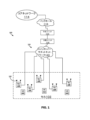
図1は、ビームフォーミングを用いて再使用を実装するための、本明細書に説明された技術を使用できる、無線アクセスネットワーク(RAN)システム100の1つの例示的な実施形態を例示するブロック図である。図1に示すRANシステム100は、基地局を実装する。RANシステム100は、また、本明細書では「基地局」または「基地局システム」と呼ぶこともできる。
FIG. 1 is a block diagram illustrating one exemplary embodiment of a radio access network (RAN)
図1に示す例示的な実施形態では、システム100は、システム100によってサービス提供される各セル(またはセクタ)102に対して、少なくとも1つの制御ユニット(CU)104、少なくとも1つの少なくとも1つの分散ユニット(DU)106、および複数の遠隔ユニット(RU)108を使用する、集中型またはクラウドRAN(C-RAN)アーキテクチャを使用して、少なくとも部分的に実装される。システム100は、また、本明細書では、「C-RANシステム」100と称され得る。各RU108は、各CU104およびDU106から遠隔に配置され、それにサービス提供する。また、この例示的な実施形態では、RU108のうちの少なくとも1つは、そのセル102にサービス提供する少なくとも1つの他のRU108から遠隔に配置される。
In the exemplary embodiment shown in FIG. 1, the
RANシステム100は、1つ以上の公開規格および仕様に従って実装することができる。図1に関連して本明細書に記載する例示的な実施形態では、RANシステム100は、O-RANアライアンスによって定義される論理RANノード、機能的分割、およびフロントホールインターフェースを使用して実装される。こうしたO-RANの例では、各CU104、DU106、およびRU108は、O-RAN仕様に従って、それぞれO-RAN制御ユニット(CU)、O-RAN分散ユニット(DU)、およびO-RAN遠隔ユニット(RU)として実装することができる。すなわち、各CU104は、パケットデータ収束プロトコル(PDCP)、無線リソース制御(RRC)、サービスデータ適応プロトコル(SDAP)、および他の制御機能をホストする論理ノードを含む。各DU106は、無線リンクコントロール(RLC)層、およびメディアアクセスコントロール(MAC)層、ならびに物理(PHY)層の上部分またはより高い部分(PHY層がDU106とRU108の間で分割される)を備える。各RU108は、DU106に実装されていないPHY層の一部(すなわち、PHY層の下部分)をホストする論理ノードを備え、基本的なRFおよびアンテナ機能を実装する。
CU104、DU106、およびRU108は、別個の論理エンティティとして説明されているが、それらのうちの1つ以上は、共有された物理ハードウェアおよび/またはソフトウェアを使用して一緒に実装することができる。例えば、図1に示す例示的な実施形態では、各セル102について、そのセル102にサービス提供するCU104およびDU106は、共有ハードウェアおよび/またはソフトウェアを使用して一緒に物理的に実装されるのに対し、各RU108は、別個のハードウェアおよび/またはソフトウェアを使用して物理的に実装される。
Although
また、図1に関連して本明細書に記載する例示的な実施形態では、RANシステム100は、無線インターフェースをサポートする第5世代新無線(5G NR)RANとして実装されるが、これは、第3世代パートナーシッププロジェクト(3GPP(登録商標))によって公布される5G NR仕様およびプロトコルに従う。したがって、この実施形態では、RANシステム100は、また、「次世代ノードB」100または「gNB」100と称され得る。
Also, in the exemplary embodiment described herein in connection with FIG. 1,
各RU108は、1つ以上のアンテナ110を含むか、または、これに結合され、これを介して、ダウンリンクRF信号が様々なアイテムのユーザ機器(UE)112に放射され、それを介して、UE112によって送信されるアップリンクRF信号が受信される。
Each
システム100は、適切なバックホール116(インターネットなど)を介して、無線ネットワークオペレータのコアネットワーク114に結合されている。また、各DU106は、フロントホール118を使用し、RU108にサービス提供するように通信可能に結合されている。DU106およびRU108の各々は、DU106およびRU108がフロントホール118を介して通信できるように、1つ以上のネットワークインターフェース(図示せず)を含む。
一実装形態では、DU106をRU108に通信可能に結合するフロントホール118は、スイッチトイーサネット(登録商標)ネットワーク120を使用して実装される。こうした実装形態では、各DU106およびRU108は、フロントホール118に使用されるスイッチトイーサネットネットワーク120を介して通信するための1つ以上のイーサネットインターフェースを含む。しかしながら、各DU106とそれによってサービス提供されるRU108との間のフロントホールは、他の方法で実装され得ることが理解されるべきである。
In one implementation, the
各CU104、DU106、およびRU108(および、そこに含まれる機能)、さらに、より一般的には、システム100、および上記のいずれかによって実装されている、本明細書に記載する特定の特徴のいずれかは、ハードウェア、ソフトウェア、またはハードウェアとソフトウェアの組み合わせにおいて、実装することができ、さらに様々な実装(ハードウェア、ソフトウェア、またはハードウェアとソフトウェアの組み合わせ)は、関連する機能のうちの少なくとも一部を実装するよう構成されている、少なくともいくつかの関連する機能を実行するように構成されている、概して「回路」または「複数回路」と称され得る。ソフトウェアに実装される場合、こうしたソフトウェアは、1つ以上の好適なプログラム可能プロセッサ上で実行されるソフトウェアもしくはファームウェアに実装され得るか、またはプログラム可能デバイス(例えば、専用ハードウェア、汎用ハードウェア、および/もしくは仮想プラットフォームに含有もしくは実装されるプロセッサもしくはデバイス)を構成することができる。こうしたハードウェアまたはソフトウェア(または、その一部)は、他の方法(例えば、特定用途向け集積回路(ASIC)など)で実装することができる。また、RF機能は、1つ以上のRF集積回路(RFIC)および/またはディスクリート構成要素を使用して実装することができる。各CU104、DU106、RU108、およびシステム100は、より一般には、他の方法で実装することができる。
Each
他の実施形態は、他の方法で実装することができる。 Other embodiments can be implemented in other ways.
上述のように、図1に関連して本明細書に記載する例示的な実施形態では、RANシステム100は、UE112と無線通信するための5G NR無線インターフェースをサポートする5G NR RANとして実装される。
As noted above, in the exemplary embodiment described herein with respect to FIG. 1,
より具体的には、図1に関連して本明細書に記載する例示的な実施形態では、5G NR無線インターフェースは、5G NR(周波数範囲2または「FR2」)に対して定義されるミリ波(mmWave)無線周波数(RF)範囲を使用して、ダウンリンクおよびアップリンク方向の両方においてUE112と無線通信するためのビームフォーミングの使用をサポートする。5G NR RANシステムは通常、ビームおよびビーム形成を使用するが、特にFR2が使用されている場合に使用される。
More specifically, in the exemplary embodiment described herein with respect to FIG. 1, the 5G NR radio interface is millimeter wave as defined for 5G NR (frequency range 2 or “FR2”). (mmWave) radio frequency (RF) range to support the use of beamforming to wirelessly communicate with the
こうしたビーム形成を実施するために、各RU108は、空間的に分離された複数のアンテナ110のアレイを備える。FR2が使用される場合、アレイ内のアンテナ110の間隔は、数ミリメートル(FR1(以下に説明)が使用される場合とは異なる数センチメートル)のオーダであり、便利な様式で実施することができる。
To implement such beamforming, each
各ビームは、単一の狭い方向にエネルギーを集中させ、それによって、そのビーム内にあるUE112に対して、より優れた信号品質を提供する。ダウンリンク方向(すなわち、gNB100がUE112に送信するとき)では、アレイの方向性は、波面に建設的干渉および相殺的干渉のパターンを作り出すために、各アンテナ110から送信される信号の位相および相対振幅を調節することによって制御される。アップリンク方向(すなわち、gNB100がUE112から送信を受信するとき)では、アレイの方向性は、得られた結合信号(アレイ中のアンテナ110のすべてを介して受信された信号を組み合わせることから生じる)に建設的および相殺的干渉のパターンを作り出すために、各アンテナ110を介して受信された信号の位相および相対振幅を調節することによって同様に制御される。つまり、ダウンリンクとアップリンクの両方について、各「ビーム」は関連する方向を有する。
Each beam concentrates energy in a single narrow direction, thereby providing better signal quality to UEs 112 within that beam. In the downlink direction (i.e., when the
ビームフォーミングは、アナログ方式(例えば、各RU108のRFフロントエンド回路に位相重みおよび相対振幅重みを適用することによって)、デジタル方式(例えば、各RU108で実行されるより低いPHY層処理の一部として、そのUE112の各アンテナ110に対して生成される周波数ドメインデータに位相重みおよび相対振幅重みを適用することによって)、またはアナログおよびデジタルビームフォーミングの組み合わせで行うことができる。 Beamforming can be analog (e.g., by applying phase and relative amplitude weights to the RF front-end circuitry of each RU 108), digital (e.g., as part of the lower PHY layer processing performed in each RU 108). , by applying phase and relative amplitude weights to the frequency domain data generated for each antenna 110 of that UE 112), or with a combination of analog and digital beamforming.
以下の実施例は、FR2を使用して実装されているものとして記載されているが、他の周波数範囲も理論上使用することができることが理解されるべきである(例えば、5G NRに対して定義されるサブ6ギガヘルツ(GHz)の周波数範囲(周波数範囲1または「FR1」))。
Although the examples below are described as being implemented using FR2, it should be understood that other frequency ranges could theoretically be used (e.g., for 5G NR A defined sub-6 gigahertz (GHz) frequency range (
gNB100は、所定の数のビームを使用して、それによってサービス提供される様々なUE112に送信するように構成される。所定の各ビームは、所定のビームの方向に最も近い方向に配向された「近隣」ビームのセットを有する。
The
特定のUE112と通信するためにどのビームを使用するかを判定するために、gNB100は、関連する5G NR仕様によって定義されるビームスイーププロセスを定期的に実行するように構成される。特定のUE112と通信するために使用される特定のビームは、本明細書では、そのUE112について「サービス提供する」ビームとも称されている。
To determine which beam to use to communicate with a
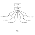
図2に示すように、このビームスイーププロセスの一部として、gNB100は、gNB100によって現在使用されているすべての所定のビームを使用して、同期信号ブロック(SSB)を送信する。各ビームを使用して作成されたSSB送信は、そのビームに割り当てられた識別子(本明細書では「ビーム識別子」または「ビームID」とも称される)を含む。各UE112は、各ビームを使用して行われたSSB送信の受信信号強度を測定し、各ビームの測定値をgNB100に報告する。特定のUE112と通信するためにどのビームを使用するかの判定は、UE112で受信されたチャネル状態情報基準信号(CSI-RS)送信の測定、およびRU108で受信されたサウンディング基準信号(SRS)送信の測定を使用しても行われる。gNB100は、UE112に対して判定されたビームを使用して、データのみを(ダウンリンクで)に送信し、UE112から(アップリンクで)データを受信する。このビーム判定は、UE112の現在の位置を与えられたそのUE112と通信するためにgNB100が使用するビームを判定するために定期的に実施される。
As part of this beam sweeping process, the
上述のように、図1に示すgNB100は、複数のRU108を含む。gNB100は、RU108のセットを使用して各UE112にサービス提供するように構成されている。各RU108は、他のRU108とは独立してビーム形成を行うことができる(アナログおよび/またはデジタルビーム形成を使用する)。すなわち、各時間-周波数リソースに対して、各RU108は異なるビームを使用できる。図3に示すように、上述のビームスイーププロセスは、セル102にサービス提供するすべてのRU108から同時に実施される。つまり、このプロセス中、RU108のすべてが、同じ時間-周波数リソースの間に同じビームを使用して同じSSB送信を行う。各UE112は、各ビームを使用して行われたSSB送信の受信信号強度を測定し、各ビームについての受信信号強度の測定値をgNB100に報告する。このビームスイープ情報を使用して、gNB100は、各UE112にサービス提供するのに使用するビームを判定することができるが、UE112にサービス提供するのに使用するRU108のセットを判定することはできない。
As mentioned above, the
また、図1に示されるgNB100は、再使用をサポートするように構成される。上述したように、「再使用」とは、セル102にサービス提供するgNB100が、同じ時間-周波数のリソースを使用して、複数のUE112へ別個のデータを同時に送信するか、または別個のデータを受信する状況を称し、複数のUEの各々が異なるRU108のセットによってサービス提供される。
The
通常、FR2を使用する場合、各UE112にサービス提供するRU108のセットには、1つのRU108が含まれる可能性があるが、場合によっては、2つのRU108が含まれる可能性があり(一部の環境では、特定のUE112にサービス提供するRU108のセットには、より多くのRU108が含まれる可能性がある)。
Typically, when using FR2, the set of
図4、6、および8は、それぞれ、ビームフォーミングが使用される場合にUE112にサービス提供するために使用すべきRU108のセットを判定する3つの異なる方法400、600、および800を示す。3つの異なる方法400、600、および800はすべて、各UE112によって生成されたサウンディング基準信号(SRS)送信に基づく。これら3つの異なる方法400、600、および800のそれぞれを、gNB100によってサービス提供されるすべてのUE112に対して、常に定期的に実施することができる。代替的に、これら三つの異なる方法400、600、および800の各々は、特定の状態または事象の発生に応答して、必要に応じて実施することができる。例えば、第1のビームを使用して現在サービス提供されているUE112が、第1のビームの隣接ビームのうちの1つではない、異なる(第2の)ビームに対する良好な受信信号強度を、(上述のビームスイーププロセスの一部として)今報告したという判定は、UE112が、異なるRU108から第2のビームを受けているという表示として使用することができる。こうした判定に応答して、gNB100は、方法400、600、および800のうちの1つを実施することができる。さらに、より粗い(およびよりリソース効率の高い)方法(方法600など)は、定期的に実施することができ、より正確な(しかし、リソース効率がより低い)方法(方法400など)は、特定の状態または事象に必要に応じて実行される(例えば、粗い方法の結果が高い信頼レベルを有していないとき、(例えば、サービス提供するRU108のセットが、あまりにも多くのRU108を含むか、またはRU108が、十分に良好な受信信号強度でSRS送信を受信しないからである))。
Figures 4, 6, and 8 show three
図4は、ビームフォーミングが使用される場合に、UE112にサービス提供するために使用されるべきRU108のセット、ならびに、サービス提供するRU108のセットの各々が、UE112にサービス提供するために使用するべきビームを、判定する方法400の1つの例示的な実施形態を例示する高レベルフローチャートを含む。
FIG. 4 illustrates the set of
図4に示す方法400の実施形態は、図1に関連して上述されたタイプのマルチRU gNB100によって実行される。より具体的には、方法400の処理は、ここで、gNB100のDU106によって実行されるものとして説明される。
The embodiment of
また、図4に示す方法400の実施形態は、特定のUE112に対して実施されるものとして本明細書に説明されているが、方法400は、gNB100によってサービス提供される各UE112に対して実施され得ることが理解される。さらに、本明細書で使用される場合、「候補」RU108のセットは、方法400を使用してチェックされるRU108を含み、それらのRU108がUE112にサービス提供するべきかどうかを調べる。
Also, although the embodiment of
図4に示されるフロー図のブロックは、説明を容易にするために概して順次配置されているが、この配置は単に例示的なものであることが理解されるべきであり、方法400(および図4に示すブロック)に関連する処理は、異なる順番(例えば、ブロックに関連する少なくとも一部の処理が並列および/またはイベント駆動様式で実施される場合)で発生し得ることが認識されるべきである。また、ほとんどの標準的な例外処理は、説明を容易にするために説明されていないが、方法400は、こうした例外処理をすることができ、また典型的には含むことが理解されるべきである。
Although the blocks of the flow diagram shown in FIG. 4 are generally arranged sequentially for ease of explanation, it is to be understood that this arrangement is merely exemplary, and the method 400 (and FIG. 4) may occur in different orders (e.g., if at least some of the processing associated with the block is performed in parallel and/or in an event-driven manner). be. Also, most standard exception handling has not been described for ease of explanation, but it should be understood that the
方法400は、SRS送信のセットを作成するためにUE112をスケジューリングすることを含む(ブロック402)。gNB100は、物理ダウンリンク制御チャネル(PDCCH)を介して適切なメッセージをUE112に送信することによって、UE112にSRS送信のセットを作成するように指示することができる。この実施形態では、gNB100は、SRS送信にどのタイプのビーム形成を使用するかについて、UE112に指示しない。
方法400は、すべての候補RU108で、それぞれの異なるビームを使用して、UE112から受信されたこのようなSRS送信の各々の受信信号強度を測定することをさらに含む(ブロック404)。候補RU108のセットは、セル102にサービス提供するために使用されるすべてのRU108を含み得る。代替的に、方法400の性能を最適化するため、UE112の「近隣」にあるRU108(すなわち、UE112に物理的に近いRU108のみ)のみが候補RU108のセットに含まれ得、UE112から受信された各SRS送信の受信した信号強度は、隣接するRU108でのみ測定される。
また、UE112から受信されたSRS送信の受信信号強度は、所定のビームのうちのすべてを使用して、すべての候補RU108で測定することができる。代替的に、方法400の性能を最適化するため、UE112から受信されたSRS送信の受信信号強度は、UE112が、直近のブリームスイーププロセス(bream-sweep process)中に有意な受信信号強度を有すると報告したビームのみを使用して、すべての候補RU108で測定することができる。これにより、方法400の各実行に必要なSRS送信の量を低減することができる。
Also, the received signal strength of SRS transmissions received from
さらに、方法400の性能を最適化するため、所与のSRS送信が複数のシンボルを含む場合、各候補RU108は、異なるビームを使用して、このような多シンボルSRS送信の中のシンボルの各々を受信することができる。これにより、方法400の各実行に必要なSRS送信の量を低減することもできる。
Further, to optimize the performance of
方法400は、SRS送信測定値を使用して、UE112にサービス提供するために使用されるべきRU108のセット、およびUE112にサービス提供するためにそれらのRU108の各々で使用されるそれぞれのビームを判定すること(ブロック406)をさらに含む。
The
一実装形態では、これは、UE112からのSRS送信の最も高い受信信号強度を測定するために使用されるRU108とビームの組み合わせ(ここでは、「RU-ビームタプル」とも称される)を識別し、RU108のセットでのRU108が、UE112にサービス提供するのを使用し、そのビームを使用してそのRU108からのUE112にサービス提供することを含む。この実装形態では、次に高い測定受信信号強度が所定の最小閾値を超え、かつ最も高い測定受信信号強度が所定の最大量未満の場合、この次に高い測定受信信号強度が測定されたRU108も、UE112にサービス提供するために使用されるべきRU108のセットに含まれ、この測定を行うためにそのRU108によって使用されるビームは、UE112にサービス提供するために使用される。この最後のステップは、上述した試験のうちの1つが失敗するまで、次に連続的に測定される最高受信信号強度ごとに繰り返すことができる(ただし、FR2が使用されている場合、RU108のサービス提供セットは、RU108を1つのみ、おそらくは、RU108を2つのみ有する可能性が高いと考えられる)。他の方法を使用することもできる。
In one implementation, it identifies the
図5は、図4に示されている方法400の動作の一例を例示する。この例では、gNB100は、(SRS送信について使用するビームフォーミングのタイプについてUE112に指示することなく)SRS送信のセットを作成するように、UE112をスケジュールする。すべての候補RU108は、それぞれの異なるビームを使用して、UE112から受信されたこのようなSRS送信の各々の受信信号強度を測定する。この例では、UE112から受信したSRS送信の最も高い受信信号強度は、ビームID#2を有するビームを使用してRU ID#0を有するRU108によって測定され、他のRUビームの組み合わせを使用して測定されたUE112から受信したSRS送信の受信信号強度は、所定の最小閾値を超えない。結果として、UE112についてのRU108のサービス提供セットは、RU ID#0を有するRU108のみを含み、RU108は、ビームID#2を有するビームを使用してUE112にサービス提供する。
FIG. 5 illustrates an example of the operation of
図4に示す方法400を使用することにより、UE112に対するサービス提供RU108のセットの両方を判定することができるが、また、そのUE112にサービス提供するために、サービス提供RU108の各々によって使用されるそれぞれのビームも判定することができる。しかしながら、これは、複数のSRS送信が、各RU108(それぞれ異なるビームを使用する)で複数の測定を可能にするために必要となる可能性が高いというトレードオフを伴う。図6は、リソース効率がより高い別のアプローチを示すが、このアプローチは、UE112のサービス提供RU108のセットのみを判定することができるというトレードオフを伴う。
By using the
図6は、ビームフォーミングが使用されるときにUE112にサービス提供するために使用されるべきRUのセットを判定する方法600の1つの例示的な実施形態を示す高レベルフローチャートを含み、また、サービス提供RU108のセットの各々が、UE112にサービス提供するために使用すべきビームを判定する。
FIG. 6 includes a high-level flowchart illustrating one exemplary embodiment of a
図6に示す方法600の実施形態は、図1に関連して上述されたタイプのマルチRU gNB100によって実行される。より具体的には、方法600の処理は、ここで、gNB100のDU106によって実行されるものとして説明される。
The embodiment of
また、図6に示す方法600の実施形態は、特定のUE112に対して実施されるものとして本明細書に説明されているが、方法600は、gNB100によってサービス提供される各UE112に対して実施され得ることが理解される。さらに、本明細書で使用される場合、「候補」RU108のセットは、方法600を使用してチェックされるRU108を含み、それらのRU108がUE112にサービス提供するべきかどうかを調べる。
Also, although the embodiment of
図6に示されるフロー図のブロックは、説明を容易にするために概して順次配置されているが、この配置は単に例示的なものであることが理解されるべきであり、方法600(および図6に示すブロック)に関連する処理は、異なる順番(例えば、ブロックに関連する少なくとも一部の処理が並列および/またはイベント駆動様式で実施される場合)で発生し得ることが認識されるべきである。また、ほとんどの標準的な例外処理は、説明を容易にするために説明されていないが、方法600は、こうした例外処理をすることができ、また典型的には含むことが理解されるべきである。
Although the blocks of the flow diagram shown in FIG. 6 are generally arranged sequentially for ease of explanation, it is to be understood that this arrangement is merely exemplary and the method 600 (and FIG. 6) may occur in different orders (e.g., if at least some of the processing associated with the block is performed in parallel and/or in an event-driven manner). be. Also, most standard exception handling has not been described for ease of explanation, but it should be understood that the
方法600は、SRS送信を行うためにUE112をスケジューリングすることを含む(ブロック602)。gNB100は、PDCCHを介して適切なメッセージをUE112に送信することによって、UE112にSRS送信を行うように指示することができる。この実施形態では、gNB100は、SRS送信にどのタイプのビーム形成を使用するかについて、UE112に指示しない。
方法600は、すべての候補RU108で、無指向性ビームまたは広幅ビームを使用して、UE112から受信されたSRS送信の受信信号強度を測定することをさらに含む(ブロック604)。方法400でのように、方法600にて使用される、候補RU108のセットは、セル102にサービス提供するために使用されるすべてのRU108を含み得る。代替的に、方法600の性能を最適化するため、UE112の「近隣」にあるRU108のみ(すなわち、UE112に物理的に近いRU108のみ)が候補RU108のセットに含まれ得、UE112から受信されたSRS送信の受信した信号強度は、隣接するRU108でのみ測定される。
方法600は、SRS送信測定値を使用して、UE112にサービス提供するために使用されるべきRU108のセットを判定すること(ブロック606)をさらに含む。これは、図4のブロック406に関連付けられて上述された同じ一般的な方式において行われる。
方法600は、直近のビームスイーププロセス中にUE112によって報告された測定値に基づいて、RU108のサービス提供セットを使用して、UE112にサービス提供するビームを判定すること(ブロック608)をさらに含む。一実装形態では、サービス提供RU108のセットに含まれるすべてのRU108は、UE112が、直近のビームスイーププロセス中に最も高い受信信号強度を報告したビームを使用するように構成される。
The
図7は、図6に示されている方法の動作の一例を例示する。この例では、gNB100は、(SRS送信について使用するビームフォーミングのタイプについてUE112に指示することなく)SRS送信を行うように、UE112をスケジュールする。すべての候補RU108で、無指向性ビームまたは広幅ビームを使用して、UE112から受信されたSRS送信の受信信号強度を測定する。この例では、UE112から受信したSRS送信の最も高い受信信号強度は、RU ID#0を有するRU108によって測定され、他のRU108を使用して測定されたUE112から受信したSRS送信の受信信号強度は、所定の最小閾値を超えない。結果として、UE112についてのRU108のサービス提供セットには、RU ID#0を有するRU108のみが含まれる。この例では、UE112が、直近のビームスイーププロセス中に最も高い受信信号強度を報告したビームは、ビームID#2を有するビームである(図7には示されていない)。結果として、RU108のサービス提供セットは、RU ID#0を有するRU108のみを含み、RU108は、ビームID#2を有するビームを使用してUE112にサービス提供する。
FIG. 7 illustrates an example of the operation of the method shown in FIG. In this example,
5G NRでは、UE112はビームフォーミングを使用して送信するよう構成することもできる。図8は、5G NRのこの機能を使用する別のアプローチを示す。
In 5G NR,
図8は、ビームフォーミングが使用される場合にUE112にサービス提供するために使用されるべきRU108のセットを判定する方法600の1つの例示的な実施形態を示す、高レベルのフローチャートを含む。
FIG. 8 includes a high-level flowchart illustrating one exemplary embodiment of a
図8に示す方法800の実施形態は、図1に関連して上述されたタイプのマルチRU gNB100によって実行される。より具体的には、方法800の処理は、ここで、gNB100のDU106によって実行されるものとして説明される。
The embodiment of
また、図8に示す方法800の実施形態は、特定のUE112に対して実施されるものとして本明細書に説明されているが、方法800は、gNB100によってサービス提供される各UE112に対して実施され得ることが理解される。さらに、本明細書で使用される場合、「候補」RU108のセットは、方法800を使用してチェックされるRU108を含み、それらのRU108がUE112にサービス提供するべきかどうかを調べる。
Also, although the embodiment of
図8に示されるフロー図のブロックは、説明を容易にするために概して順次配置されているが、この配置は単に例示的なものであることが理解されるべきであり、方法800(および図8に示すブロック)に関連する処理は、異なる順番(例えば、ブロックに関連する少なくとも一部の処理が並列および/またはイベント駆動様式で実施される場合)で発生し得ることが認識されるべきである。また、ほとんどの標準的な例外処理は、説明を容易にするために説明されていないが、方法800は、こうした例外処理をすることができ、また典型的には含むことが理解されるべきである。
Although the blocks of the flow diagram shown in FIG. 8 are generally arranged sequentially for ease of explanation, it should be understood that this arrangement is merely exemplary, and method 800 (and the 8) may occur in different orders (e.g., if at least some of the processing associated with the block is performed in parallel and/or in an event-driven manner). be. Also, most standard exception handling has not been described for ease of explanation, but it should be understood that the
方法800は、UE112が、直近のビームスイーププロセス中に最も高い受信信号強度を報告したビームと同じ方向の透過を使用して、SRS送信を行うように、UE112をスケジューリングすることを含む(ブロック802)。gNB100は、PDCCHを介して適切なメッセージをUE112に送信することによって、UE112にこの指向性SRS送信を行うように指示することができる。
方法800は、すべての候補RU108で、無指向性ビームまたは広幅ビームを使用して、UE112から受信されたSRS送信の受信信号強度を測定することをさらに含む(ブロック804)。方法400でのように、方法600にて使用される、候補RU108のセットは、セル102にサービス提供するために使用されるすべてのRU108を含み得る。代替的に、方法800の性能を最適化するため、UE112の「近隣」にあるRU108のみ(すなわち、UE112に物理的に近いRU108のみ)が候補RU108のセットに含まれ得、UE112から受信されたSRS送信の受信した信号強度は、隣接するRU108でのみ測定される。
方法800は、SRS送信測定値を使用して、UE112にサービス提供するために使用されるべきRU108のセットを判定すること(ブロック806)をさらに含む。これは、図4のブロック406に関連付けられて上述された同じ一般的な方式において行われる。
方法800は、直近のビームスイーププロセス中にUE112によって報告された測定値に基づいて、RU108のサービス提供セットを使用して、UE112にサービス提供するビームを判定すること(ブロック808)をさらに含む。一実装形態では、サービス提供RU108のセットに含まれるすべてのRU108は、UE112が、直近のビームスイーププロセス中に最も高い受信信号強度を報告したビームを使用するように構成される。
The
図9は、図8に示されている方法800の動作の一例を例示する。この例で、gNB100が、直近のビームスイーププロセス中に最も高い受信信号強度を報告したビームと同じ方向の透過を使用して、SRS送信を行うように、UE112をスケジューリングする。すべての候補RU108で、無指向性ビームまたは広幅ビームを使用して、UE112から受信された指向性SRS送信の受信信号強度を測定する。この例では、UE112から受信したSRS送信の最も高い受信信号強度は、RU ID#0を有するRU108によって測定され、他のRU108を使用して測定されたUE112から受信した指向性SRS送信の受信信号強度は、所定の最小閾値を超えない。結果として、UE112についてのRU108のサービス提供セットには、RU ID#0を有するRU108のみが含まれる。この例では、UE112が、直近のビームスイーププロセス中に最も高い受信信号強度を報告したビームは、ビームID#2を有するビームである(図9には示されていない)。結果として、RU108のサービス提供セットは、RU ID#0を有するRU108のみを含み、RU108は、ビームID#1を有するビームを使用してUE112にサービス提供する。
FIG. 9 illustrates an example of the operation of
図4、6、および8に関連して上述した方法400、600、および800はそれぞれ、各UE112からのSRS送信を利用して、サービス提供RU108のセットを判定する。サービス提供RU108のセットは、また、他のタイプの基準信号送信を使用して判定することができる。例えば、5G NRでは、異なる時間-周波数リソースの間に異なるチャネル状態情報基準信号(CSI-RS)を送信するように、異なるRU108を構成することができる。サービス提供RU108のセットは、こうしたCSI-RSを使用して判定することができる。図10は、これを行うための1つのアプローチを示す。
The
図10は、ビームフォーミングが使用される場合に、UE112にサービス提供するために使用されるべきRU108のセット、ならびに、サービス提供するRU108のセットの各々が、UE112にサービス提供するために使用するべきビームを、判定する方法1000の1つの例示的な実施形態を例示する高レベルフローチャートを含む。
FIG. 10 illustrates the set of
図10に示す方法1000の実施形態は、図1に関連して上述されたタイプのマルチRU gNB100によって実行される。より具体的には、方法1000の処理は、ここで、gNB100のDU106によって実行されるものとして説明される。
The embodiment of
また、図10に示す方法1000の実施形態は、特定のUE112に対して実施されるものとして本明細書に説明されているが、方法1000は、gNB100によってサービス提供される各UE112に対して実施され得ることが理解される。さらに、本明細書で使用される場合、「候補」RU108のセットは、方法1000を使用してチェックされるRU108を含み、それらのRU108がUE112にサービス提供するべきかどうかを調べる。
Also, although the embodiment of
図10に示されるフロー図のブロックは、説明を容易にするために概して順次配置されているが、この配置は単に例示的なものであることが理解されるべきであり、方法1000(および図10に示すブロック)に関連する処理は、異なる順番(例えば、ブロックに関連する少なくとも一部の処理が並列および/またはイベント駆動様式で実施される場合)で発生し得ることが認識されるべきである。また、ほとんどの標準的な例外処理は、説明を容易にするために説明されていないが、方法1000は、こうした例外処理をすることができ、また典型的には含むことが理解されるべきである。
Although the blocks of the flow diagram shown in FIG. 10 are generally arranged sequentially for ease of explanation, it is to be understood that this arrangement is merely exemplary, and the method 1000 (and 10) may occur in different orders (e.g., if at least some of the processing associated with the blocks are performed in parallel and/or in an event-driven manner). be. Also, most standard exception handling has not been described for ease of explanation, but it should be understood that the
方法1000は、候補RU108のセットの各々を、そのRU108のみがCSI-RS送信を行う時間-周波数リソース中に様々なビームを使用してCSI-RS送信を行うようにスケジューリングし(ブロック1002)、UE112に、様々な候補RU108からの様々なCSI-RS送信の信号強度測定値を別個に報告するよう指示すること(ブロック1004)を含む。こうすることで、UE112が、特定のRU108(および、そのRU108のみ)からのこのようなCSI-RS送信の各々について測定レポートを作成すると、DU106は、そのRU108と測定レポートを関連付けることができる。このアプローチは、同じ時間-周波数リソースの間にRU108のすべてが同時に同じ基準信号を送信するビームスイーププロセスと対比することができ、結果として、こうした基準信号に対してUE112によって提供される測定報告書は、いかなる特定のRU108とも関連付けることができない。
The
候補RU108のセットは、セル102にサービス提供するために使用されるすべてのRU108を含み得る。代替的に、方法1000の性能を最適化するため、UE112の近隣にあるRU108のみが候補RU108のセットに含まれ得、UE112へのCSI-RS送信は、そのような隣接するRU108でのみ作成される。
The set of
方法1000は、gNB100で、様々なCSI-RS送信について、UE112から別個の測定報告書を受信すること(ブロック1006)、および、UE112にサービス提供するために使用されるべきRU108のセット、およびUE112にサービス提供するための、サービス提供RU108の各々で使用される各々のビームを判定すること(ブロック1008)をさらに含む。
一実装形態では、この判定は、UE112が最も高い受信信号強度を測定したCSI-RS送信の送信に使用されるRU108とビームの組み合わせを識別し、UE112に対するサービス提供RU108のセットにそのRU108を含み、そのRU108からUE112へのサービス提供にそのビームを使用することによって行われる。この実装形態では、UE112によって報告された、次に高い測定受信信号強度が所定の最小閾値を超え、かつ最も高い測定受信信号強度と、所定の最大量未満だけ異なる場合、UE112が次に高い受信信号強度を測定したCSI-RS送信を送信するために使用されるRU108もまた、UE112に対してサービス提供するRUのセットに含まれ、そのRU108からのそのCSI-RS送信を送信するために使用されるビームは、UE112にサービス提供するために使用される。この最後のステップは、上述した試験のうちの1つが失敗するまで、次に連続的に測定される最高受信信号強度ごとに繰り返すことができる(ただし、FR2が使用されている場合、RU108のサービス提供セットは、RU108を1つのみ、おそらくは、RU108を2つのみ有する可能性が高いと考えられる)。他の方法を使用することもできる。
In one implementation, this determination identifies the
図11は、図10に示されている方法1000の動作の一例を例示する。この例では、gNB100は、候補RU108のセットの各々をスケジュールして、RU108のみがCSI-RS送信を行う時間-周波数リソース中に様々なビームを使用して、UE112へのCSI-RS送信を行う。UE112は、異なるCSI-RS送信の受信信号強度を別個に測定し、それらの測定値を別個にgNB100に報告する。この例では、UE112が最も高い受信信号強度を測定したCSI-RS送信の送信に使用されるRU108とビームの組み合わせは、RU ID#0のRU108とビームID#1のビームである。この例では、他のCSI-RS送信についてUE112によって測定される受信信号強度は、所定の最小閾値を超えない。結果として、UE112についてのRU108のサービス提供セットは、RU ID#0を有するRU108のみを含み、ビームID#2を有するビームを使用して各UE112にサービス提供する。
FIG. 11 illustrates an example of the operation of
次に、各UE112にサービス提供するために使用されるRU108のセット(および、このようなRU108各々によって使用される対応するビーム)を、複数RUのgNB100での再使用に採用する。図12は、これを行うための1つのアプローチを示す。
The set of RUs 108 (and the corresponding beams used by each such RU 108 ) used to serve each
図12は、複数RUのgNB100で再使用を採用する方法1200の1つの例示的な実施形態を示す高レベルフローチャートを含む。
FIG. 12 includes a high-level flowchart illustrating one exemplary embodiment of a
図12に示す方法1200の実施形態は、図1に関連して上述されたタイプのマルチRU gNB100によって実行される。より具体的には、方法1200の処理は、ここで、gNB100のDU106によって実行されるものとして説明される。
The embodiment of
また、方法1200は、同じ時間-周波数リソースを使用するようにスケジュールされていると考慮されている、UE112の特定のセットに対して実施されるものとして説明されているが、方法800は、gNB100によって提供される、様々な可能性のあるUE112のセットに対して実施され得ることが理解されるべきである。
Also, while
図12に示されるフロー図のブロックは、説明を容易にするために概して順次配置されているが、この配置は単に例示的なものであることが理解されるべきであり、方法1200(および図12に示すブロック)に関連する処理は、異なる順番(例えば、ブロックに関連する少なくとも一部の処理が並列および/またはイベント駆動様式で実施される場合)で発生し得ることが認識されるべきである。また、ほとんどの標準的な例外処理は、説明を容易にするために説明されていないが、方法1200は、こうした例外処理をすることができ、また典型的には含むことが理解されるべきである。
Although the blocks of the flow diagram shown in FIG. 12 are generally arranged sequentially for ease of explanation, it is to be understood that this arrangement is merely exemplary, and method 1200 (and the 12) may occur in different orders (e.g., if at least some of the processing associated with the blocks are performed in parallel and/or in an event-driven manner). be. Also, most standard exception handling has not been described for ease of explanation, but it should be understood that the
方法1200は、UE112のセットに含まれるいずれかのUE112が、UE112のセットに含まれている1つ以上の他のUE112にも割り当てられているRU-ビームを有しているかを判定することを含む(ブロック1202)。その場合、同じRU-ビームタプルが割り当てられているUE112のセットに含まれるUE112は、同じ時間-周波数リソースを使用するようにスケジュールすることはできない(ブロック1204)。
方法1200は、UE112のセットのいずれも、それらに割り当てられたのと同じRUビームタプルを有しないと判定される場合、UE112のセットのいずれかに割り当てられたビームが、その集合に含まれる他のUE112のいずれかに割り当てられたビームと交差するかどうかを判定すること(ブロック1206)をさらに含む。その場合、それらに割り当てられている交差ビームを有するUE112のセットに含まれるUE112は、同じ時間-周波数リソースを使用するようにスケジュールすることはできない(ブロック1208)。
If
方法1200はさらに、UE112のセットのいずれにも、交差するビームが割り当てられていないと判定された場合、UE112のセットに含まれる任意のUE112が、UE112のセットに含まれる1つ以上の他のUE112にも割り当てられている、RU108を有するかどうかを判定すること(ブロック1210)と、また、そうである場合、そのRU108を割り当てられたUE112のすべてに、そのRU108を、同時に送信することができるかを判定すること(ブロック1212)を、含む。UE112のセットに含まれているUE112のいずれも、割り当てられた同じRU108を有していないと判定された場合、UE112のセットが、同じ時間-周波数のリソースを使用するようにスケジュールされ得る(ブロック1214)。UE112のセットに含まれているUE112が、UE112のセットに含まれている1つ以上の他のUE112にも割り当てられているRU108を有している場合、RU108が、そこに割り当てられているそのRU108を有するUE112のすべてに同時に送信されることができ、UE112のセットが同じ時間-周波数リソースを使用するようにスケジュールされている(ブロック1214)。そうでない場合、割り当てられている同じRU108を有するUE112が、同じ時間-周波数リソースを使用するようにスケジュールされることができない(ブロック1216)。
The
図13Aおよび13Bは、図12に示された方法1200の動作の例を例示する。
13A and 13B illustrate example operations of the
図13Aに示される例では、同じ時間-周波数リソースを使用するようにスケジュールされているUE112のセットには、UE A、UE B、およびUE Cという3つのUE112が含まれる。この例では、RU ID#0を有するRU108とビームID#0を有するビームとを使用してUE A(すなわち、UE Aに割り当てられたRU-ビームタプルが[RU ID#0、ビームID#0]を備える)にサービス提供し、RU ID#0を有するRU108とビームID#4を有するビームとを使用してUE B(すなわち、UE Bに割り当てられたRU-ビームタプルが[RU ID#0、ビームID#4]を備える)にサービス提供し、RU ID#1を有するRU108とビームID#5を有するビームとを使用してUE C(すなわち、UE Cに割り当てられたRU-ビームタプルが[RU ID#1、ビームID#5]を備える)にサービス提供する。
In the example shown in FIG. 13A, the set of
図13Aに示す例では、UE A、UE B、UE Cのいずれも、それらに割り当てられている同じRU-ビームタプルを有していないか、またそれらのいずれも、それらに割り当てられた交差ビームを有していない。また、UE AとUE Bが、割り当てられた同じRU108を有していても(RU#0)、RU108(RU#0)は2つのUE112に同時に送信することができる。そのため、そのUE112のセット(UE A、UE B、およびUE C)を、同じ時間-周波数リソースを使用するようにスケジュールすることができる。
In the example shown in FIG. 13A, none of UE A, UE B, and UE C have the same RU-beam tuple assigned to them, nor do any of them have cross beams assigned to them. do not have. Also, even though UE A and UE B have the
図13Bに示される例では、同じ時間頻度リソースを使用するようにスケジュールされているUE112のセットには、UE B、およびUE Dという2つのUE112が含まれる。この例では、RU ID#0を有するRU108とビームID#4を有するビームとを使用してUE B(すなわち、UE Bに割り当てられたRU-ビームタプルが[RU ID#0、ビームID#4]を備える)にサービス提供し、RU ID#1を有するRU108とビームID#1を有するビームとを使用してUE C(すなわち、UE Cに割り当てられたRU-ビームタプルが[RU ID#1、ビームID#1]を備える)にサービス提供する。
In the example shown in FIG. 13B, the set of
図13Bでは、UE BおよびUE Dのいずれも、それらに割り当てられた同じRUビームタプルを有していない。しかし、この実施例では、UE BおよびUE Dに割り当てられたビームは交差する。そのため、そのUE112のセット(UE B、およびUE D)を、同じ時間-周波数リソースを使用するようにスケジュールすることができない。 In FIG. 13B, neither UE B nor UE D have the same RU beam tuple assigned to them. However, in this example, the beams assigned to UE B and UE D intersect. Therefore, the set of UEs 112 (UE B and UE D) cannot be scheduled to use the same time-frequency resource.
他の実施形態は、他の方法で実装することができる。例えば、一実施形態では、システム100は、RU108のすべてを使用して、同じセル102にサービス提供するように構成され得る。システム100が、RU108の第1のサブセットおよび第1のビームを使用して、少なくともいくつかのユーザデータを第1のユーザデバイス112に無線で送信するように構成されており、RU108の第1のサブセットが、同じセル102にサービス提供するために別様に使用されるすべてのRU108より少ないRU108を含む。こうした実施形態では、システム100が、複数のビームを使用して送信された基準信号送信の第1のユーザデバイス112によって作成された測定レポートに基づいて、少なくともいくつかのユーザデータを第1のユーザデバイス112に送信するために使用されるRU108の第1のサブセットに、どのRU108が含まれるかを判定するように構成されており、基準信号送信の少なくともいくつかが、すべてのRU108より少ないRU108から送信される。このような実施形態では、DU106が、少なくとも1つの中間ノードを介して複数のRU108に結合されている。中間ノードは、スイッチトイーサネットネットワーク120で使用されるイーサネットスイッチを含むことができる。
Other embodiments can be implemented in other ways. For example, in one embodiment,
基準信号送信は、CSI-RS送信を含み得る。第1のユーザデバイス112に無線で送信するために使用されるRU108の第1のサブセットは、(例えば、第1のユーザデバイス112の移動により)変更することができる。
Reference signal transmissions may include CSI-RS transmissions. The first subset of
このような実施形態では、システム100が、RU108の第2のサブセットおよび第2のビームを使用して、少なくともいくつかのユーザデータを第2のユーザデバイス112に無線で送信するように構成されることができ、RU108の第2のサブセットが、同じセル102にサービス提供するために別様に使用されるすべてのRU108より少ないRU108を含む。システム100が、複数のビームを使用して送信された基準信号送信の第2のユーザデバイス112によって作成された測定レポートに基づいて、少なくともいくつかのユーザデータを第2のユーザデバイス112に送信するために使用されるRU108の第2のサブセットに、どのRU108が含まれるかを判定するようにさらに構成されている。RU108の第1のサブセットは、RU108の第2のサブセットとは異なり得る。また、第1のビームは、第2のビームとは異なり得る。第2のユーザデバイス112に無線で送信するために使用されるRU108の第2のサブセットは、(例えば、第2のユーザデバイス112の移動により)変更することができる。
In such embodiments, the
同様に、別の実施形態では、システム100が、同じセル102にサービス提供するためにRU108のすべてを使用し、RU108の第1のサブセットおよび第1のビームを使用して、少なくともいくつかのユーザデータを第1のユーザデバイス112から無線で受信するよう構成されており、RU108の第1のサブセットが、同じセル102にサービス提供するために別様に使用されるすべてのRU108より少ないRU108を含む。こうした実施形態では、システム100が、複数のビームを使用して送信された基準信号送信の第1のユーザデバイス112によって作成された測定レポートに基づいて、少なくともいくつかのユーザデータを第1のユーザデバイス112から受信するために使用されるRU108の第1のサブセットに、どのRU108が含まれるかを判定するように構成されており、基準信号送信の少なくともいくつかが、すべてのRU108より少ないRU108から送信される。このような実施形態では、DU106が、少なくとも1つの中間ノードを介して複数のRU108に結合されている。中間ノードは、スイッチトイーサネットネットワーク120で使用されるイーサネットスイッチを含むことができる。
Similarly, in another embodiment, the
基準信号送信は、CSI-RS送信を含み得る。第1のユーザデバイス112から無線で受信するために使用されるRU108の第1のサブセットは、(例えば、第1のユーザデバイス112の移動により)変更することができる。
Reference signal transmissions may include CSI-RS transmissions. The first subset of
このような実施形態では、システム100が、RU108の第2のサブセットおよび第2のビームを使用して、少なくともいくつかのユーザデータを第2のユーザデバイス112から無線で受信するように構成することができ、RU108の第2のサブセットが、同じセル102にサービス提供するために別様に使用されるすべてのRU108より少ないRU108を含む。システム100が、複数のビームを使用して送信された基準信号送信の第2のユーザデバイス112によって作成された測定レポートに基づいて、少なくともいくつかのユーザデータを第2のユーザデバイス112から受信するために使用されるRU108の第2のサブセットに、どのRU108が含まれるかを判定するようにさらに構成されている。RU108の第1のサブセットは、RU108の第2のサブセットとは異なり得る。また、第1のビームは、第2のビームとは異なり得る。第2のユーザデバイス112から無線で受信するために使用されるRU108の第2のサブセットは、(例えば、第2のユーザデバイス112の移動により)変更することができる。
In such embodiments, the
他の実施形態は、他の方法で実装することができる。 Other embodiments can be implemented in other ways.
以下の特許請求の範囲によって定義される本発明のいくつかの実施形態が説明されてきた。それにもかかわらず、説明される実施形態に対する様々な修正は、特許請求される発明の範囲および趣旨から逸脱することなく行われ得ることが理解されるであろう。したがって、他の実施形態は、以下の特許請求の範囲の範囲内にある。 A number of embodiments of the invention defined by the following claims have been described. Nevertheless, it will be understood that various modifications to the described embodiments can be made without departing from the scope and spirit of the claimed invention. Accordingly, other embodiments are within the scope of the following claims.
例示的な実施形態
実施例1は、同じセルを使用してユーザデバイスに無線サービスを提供するためのシステムを含み、システムが、システムをコアネットワークに通信可能に結合するための分散ユニット(DU)であって、DUが、無線インターフェースに対する少なくともいくつかのLAYER2機能、および無線インターフェースに対する少なくともいくつかのLAYER1機能を実装するように構成されている、分散ユニット(DU)と、複数の遠隔ユニット(RU)であって、RUの各々が、1つ以上のアンテナのそれぞれのセットと関連付けられている、複数の遠隔ユニットと、を備え、システムが、RUのすべてを使用して、同じセルにサービス提供するように構成されており、システムが、RUの第1のサブセットおよび第1のビームを使用して、少なくともいくつかのユーザデータを第1のユーザデバイスに無線で送信するように構成されており、RUの第1のサブセットが、同じセルにサービス提供するために別様に使用されるすべてのRUより少ないRUを含み、システムが、複数のビームを使用して送信された基準信号送信の第1のユーザデバイスによって作成された測定レポートに基づいて、少なくともいくつかのユーザデータを第1のユーザデバイスに送信するために使用されるRUの第1のサブセットに、どのRUが含まれるかを判定するように構成されており、基準信号送信のうちの少なくともいくつかが、すべてのRUより少ないRUから送信される、システムである。
Exemplary Embodiments Example 1 includes a system for providing wireless service to user devices using the same cell, the system comprising a distribution unit (DU) for communicatively coupling the system to a core network a distributed unit (DU) and a plurality of remote units (RU ), each of the RUs being associated with a respective set of one or more antennas, wherein the system uses all of the RUs to serve the same cell and the system is configured to wirelessly transmit at least some user data to the first user device using the first subset of RUs and the first beam , the first subset of RUs includes fewer RUs than all RUs that are otherwise used to serve the same cell, and the system detects the first of the reference signal transmissions transmitted using multiple beams. Determining which RUs are included in a first subset of RUs used to transmit at least some user data to the first user device based on measurement reports generated by one user device and wherein at least some of the reference signal transmissions are transmitted from fewer than all RUs.
実施例2は、DUが、少なくとも1つの中間ノードを介して複数のRUに結合されている、実施例1に記載のシステムを含む。 Example 2 includes the system of example 1, wherein a DU is coupled to multiple RUs via at least one intermediate node.
実施例3は、中間ノードが、イーサネットスイッチを備える、実施例2に記載のシステムを含む。 Example 3 includes the system of example 2, wherein the intermediate node comprises an Ethernet switch.
実施例4は、基準信号送信が、チャネルステータス情報基準信号(CSI-RS)送信を含む、実施例1~3のいずれか一例に記載のシステムを含む。 Example 4 includes the system of any one of Examples 1-3, wherein the reference signal transmissions include channel status information reference signal (CSI-RS) transmissions.
実施例5は、第1のユーザデバイスへの無線送信に使用されるRUの第1のサブセットが変化する、実施例1~4のいずれか一例に記載のシステムを含む。 Example 5 includes the system of any one of Examples 1-4, wherein the first subset of RUs used for wireless transmission to the first user device is changed.
実施例6は、システムが、RUの第2のサブセットおよび第2のビームを使用して、少なくともいくつかのユーザデータを第2のユーザデバイスに無線で送信するようにさらに構成されており、RUの第2のサブセットが、同じセルにサービス提供するために別様に使用されるすべてのRUより少ないRUを含み、システムが、複数のビームを使用して送信された基準信号送信の第2のユーザデバイスによって作成された測定レポートに基づいて、少なくともいくつかのユーザデータを第2のユーザデバイスに送信するために使用されるRUの第2のサブセットに、どのRUが含まれるかを判定するようにさらに構成されている、実施例1~5のいずれか一例に記載のシステムを含む。 Example 6 is further configured to wirelessly transmit at least some user data to the second user device using the second subset of RUs and the second beam, wherein the RUs contains fewer than all RUs otherwise used to serve the same cell, and the system detects a second subset of reference signal transmissions transmitted using multiple beams to determine which RUs are included in a second subset of RUs used to transmit at least some user data to a second user device based on measurement reports generated by the user device; including the system of any one of Examples 1-5, further configured to:
実施例7は、RUの第1のサブセットが、RUの第2のサブセットとは異なる、実施例6に記載のシステムを含む。 Example 7 includes the system of Example 6, wherein the first subset of RUs is different than the second subset of RUs.
実施例8は、第1のビームが、第2のビームとは異なる、実施例6または7に記載のシステムを含む。 Example 8 includes the system of Example 6 or 7, wherein the first beam is different than the second beam.
実施例9は、第2のユーザデバイスへの無線送信に使用されるRUの第2のサブセットが変化する、実施例6~8のいずれか一例に記載のシステムを含む。 Example 9 includes the system of any one of Examples 6-8, wherein the second subset of RUs used for wireless transmission to the second user device is varied.
実施例10は、RUの各々が、DUおよび少なくとも1つの他のRUから遠隔に位置する、実施例1~9のいずれか一例に記載のシステムを含む。 Example 10 includes the system of any one of Examples 1-9, wherein each RU is remotely located from the DU and at least one other RU.
実施例11は、システムを使用して実行される方法であって、システムが、コアネットワークに通信可能に結合するための分散ユニット(DU)であって、DUが、無線インターフェースに対する少なくともいくつかのLAYER2機能、および無線インターフェースに対する少なくともいくつかのLAYER1機能を実装するように構成されている、分散ユニット(DU)と、無線インターフェースを使用して、かつビームフォーミングを使用して、複数のユーザデバイス間で無線周波数信号を無線で送信および受信するための複数の遠隔ユニット(RU)であって、RUの各々が、1つ以上のアンテナのそれぞれのセットに関連付けられており、各RUが、DUにおいて実装されない無線インターフェースに対するLAYER1機能を実行するように構成されており、DUおよびRUが、フロントホールを介して互いに通信可能に結合されている、複数の遠隔ユニットと、を備え、システムが、同じセルにサービス提供するようにRUのすべてを使用するように構成されており、方法が、複数のビームを使用して基準信号を送信することであって、基準信号のうちの少なくともいくつかが、すべてのRUより少ないRUから送信される、送信することと、基準信号の第1のユーザデバイスによって作成された測定レポートを受信することと、どのRUがRUの第1のサブセットに含まれるかを判定することであって、RUの第1のサブセットが、同じセルにサービス提供するために別様に使用されるすべてのRUより少ないRUを含む、判定することと、RUの第1のサブセットおよび第1のビームを使用して、少なくともいくつかのユーザデータを第1のユーザデバイスに無線で送信することと、を含む、方法を含む。 Example 11 is a method performed using a system, the system being a distributed unit (DU) for communicatively coupling to a core network, the DU having at least some Between a distributed unit (DU) configured to implement LAYER2 functionality and at least some LAYER1 functionality over the air interface and multiple user devices using the air interface and using beamforming a plurality of remote units (RUs) for wirelessly transmitting and receiving radio frequency signals at the DU, each RU associated with a respective set of one or more antennas, each RU at the a plurality of remote units configured to perform LAYER1 functions for the unimplemented radio interface, the DUs and RUs being communicatively coupled to each other via a fronthaul; and the method is to transmit reference signals using a plurality of beams, wherein at least some of the reference signals are configured to use all of the RUs to serve the receiving a measurement report generated by the first user device of the reference signal; determining which RUs are included in the first subset of RUs; determining that the first subset of RUs contains fewer RUs than all RUs that are otherwise used to serve the same cell; and the first subset of RUs and the first wirelessly transmitting at least some user data to a first user device using one beam.
実施例12は、DUが、少なくとも1つの中間ノードを介して複数のRUに結合されている、実施例11に記載の方法を含む。 Example 12 includes the method of example 11, wherein the DU is coupled to multiple RUs via at least one intermediate node.
実施例13は、中間ノードが、イーサネットスイッチを備える、実施例12に記載の方法を含む。 Example 13 includes the method of example 12, wherein the intermediate node comprises an Ethernet switch.
実施例14は、基準信号が、チャネルステータス情報基準信号(CSI-RS)送信を含む、実施例11~13のいずれか一例に記載の方法を含む。 Example 14 includes the method of any one of Examples 11-13, wherein the reference signal comprises a Channel Status Information Reference Signal (CSI-RS) transmission.
実施例15は、第1のユーザデバイスへの無線送信に使用されるRUの第1のサブセットが変化する、実施例11~14のいずれか一例に記載の方法を含む。 Example 15 includes the method of any one of Examples 11-14, wherein the first subset of RUs used for wireless transmission to the first user device is changed.
実施例16は、方法が、基準信号の第2のユーザデバイスによって作成された測定レポートを受信することと、どのRUがRUの第2のサブセットに含まれるかを判定することであって、RUの第2のサブセットが、同じセルにサービス提供するために別様に使用されるすべてのRUより少ないRUを含む、判定することと、RUの第2のサブセットおよび第2のビームを使用して、少なくともいくつかのユーザデータを第2のユーザデバイスに無線で送信することと、をさらに含む、実施例11~15のいずれか一例に記載の方法を含む。 Example 16 is the method receiving a measurement report produced by a second user device of a reference signal and determining which RUs are included in the second subset of RUs, wherein the RUs the second subset of contains fewer than all RUs that are otherwise used to serve the same cell; and using the second subset of RUs and the second beam and wirelessly transmitting at least some user data to the second user device.
実施例17は、RUの第1のサブセットが、RUの第2のサブセットとは異なる、実施例16に記載の方法を含む。 Example 17 includes the method of example 16, wherein the first subset of RUs is different than the second subset of RUs.
実施例18は、第1のビームが、第2のビームとは異なる、実施例16または17に記載の方法を含む。 Example 18 includes the method of Example 16 or 17, wherein the first beam is different than the second beam.
実施例19は、第2のユーザデバイスへの無線送信に使用されるRUの第2のサブセットが変化する、実施例16~18のいずれか一例に記載の方法を含む。 Example 19 includes the method of any one of Examples 16-18, wherein the second subset of RUs used for wireless transmission to the second user device is changed.
実施例20は、同じセルを使用してユーザデバイスに無線サービスを提供するためのシステムであって、システムが、システムをコアネットワークに通信可能に結合するための分散ユニット(DU)であって、DUが、無線インターフェースに対する少なくともいくつかのLAYER2機能、および無線インターフェースに対する少なくともいくつかのLAYER1機能を実装するように構成されている、分散ユニット(DU)と、複数の遠隔ユニット(RU)であって、RUの各々が、1つ以上のアンテナのそれぞれのセットと関連付けられている、複数の遠隔ユニットと、を備え、システムが、RUのすべてを使用して、同じセルにサービス提供するように構成されており、システムが、RUの第1のサブセットおよび第1のビームを使用して、少なくともいくつかのユーザデータを第1のユーザデバイスから無線で受信するように構成されており、RUの第1のサブセットが、同じセルにサービス提供するために別様に使用されるすべてのRUより少ないRUを含み、システムが、複数のビームを使用して送信された基準信号送信の第1のユーザデバイスによって作成された測定レポートに基づいて、当該少なくともいくつかのユーザデータを第1のユーザデバイスから受信するために使用されるRUの第1のサブセットに、どのRUが含まれるかを判定するように構成されており、基準信号送信のうちの少なくともいくつかが、すべてのRUより少ないRUから送信される、システムを含む。 Example 20 is a system for providing wireless service to user devices using the same cell, the system being a distribution unit (DU) for communicatively coupling the system to a core network, a distributed unit (DU) and a plurality of remote units (RUs), wherein the DU is configured to implement at least some LAYER2 functionality for the air interface and at least some LAYER1 functionality for the air interface; , each of the RUs is associated with a respective set of one or more antennas, and the system is configured to use all of the RUs to serve the same cell. and the system is configured to wirelessly receive at least some user data from the first user device using the first subset of RUs and the first beam; A subset of 1 includes fewer RUs than all RUs otherwise used to serve the same cell, and the system detects the first user device of the reference signal transmission transmitted using multiple beams. determining which RUs are included in the first subset of RUs used to receive the at least some user data from the first user device based on the measurement report produced by configured, wherein at least some of the reference signal transmissions are transmitted from fewer than all RUs.
実施例21は、DUが、少なくとも1つの中間ノードを介して複数のRUに結合されている、実施例20に記載のシステムを含む。 Example 21 includes the system of example 20, wherein a DU is coupled to multiple RUs via at least one intermediate node.
実施例22は、中間ノードが、イーサネットスイッチを備える、実施例21に記載のシステムを含む。 Example 22 includes the system of example 21, wherein the intermediate node comprises an Ethernet switch.
実施例23は、基準信号送信が、チャネルステータス情報基準信号(CSI-RS)送信を含む、実施例20~22のいずれか一例に記載のシステムを含む。 Example 23 includes the system of any one of Examples 20-22, wherein the reference signal transmissions include channel status information reference signal (CSI-RS) transmissions.
実施例24は、第1のユーザデバイスからの無線受信に使用されるRUの第1のサブセットが変化する、実施例20~23のいずれか一例に記載のシステムを含む。 Example 24 includes the system of any one of Examples 20-23, wherein the first subset of RUs used for wireless reception from the first user device is changed.
実施例25は、システムが、RUの第2のサブセットおよび第2のビームを使用して、少なくともいくつかのユーザデータを第2のユーザデバイスから無線で受信するようにさらに構成されており、RUの第2のサブセットが、同じセルにサービス提供するために別様に使用されるすべてのRUより少ないRUを含み、システムが、複数のビームを使用して送信された基準信号送信の第2のユーザデバイスによって作成された測定レポートに基づいて、当該少なくともいくつかのユーザデータを第2のユーザデバイスから受信するために使用されるRUの第2のサブセットに、どのRUが含まれるかを判定するようにさらに構成されている、実施例20~24のいずれか一例に記載のシステムを含む。 Example 25 is further configured to wirelessly receive at least some user data from the second user device using the second subset of RUs and the second beam, the RUs contains fewer than all RUs otherwise used to serve the same cell, and the system detects a second subset of reference signal transmissions transmitted using multiple beams Based on measurement reports generated by the user device, determine which RUs are included in a second subset of RUs used to receive the at least some user data from the second user device. including the system of any one of Examples 20-24, further configured to:
実施例26は、RUの第1のサブセットが、RUの第2のサブセットとは異なる、実施例25に記載のシステムを含む。 Example 26 includes the system of example 25, wherein the first subset of RUs is different than the second subset of RUs.
実施例27は、第1のビームが、第2のビームとは異なる、実施例25または26に記載のシステムを含む。 Example 27 includes the system of Examples 25 or 26, wherein the first beam is different than the second beam.
実施例28は、第2のユーザデバイスからの無線受信に使用されるRUの第2のサブセットが変化する、実施例25~27のいずれか一例に記載のシステムを含む。 Example 28 includes the system of any one of Examples 25-27, wherein the second subset of RUs used for wireless reception from the second user device is changed.
実施例29は、RUの各々が、DUおよび少なくとも1つの他のRUから遠隔に位置する、実施例20~28のいずれか一例に記載のシステムを含む。 Example 29 includes the system of any one of Examples 20-28, wherein each RU is remotely located from the DU and at least one other RU.
実施例30は、システムを使用して実行される方法であって、システムが、コアネットワークに通信可能に結合するための分散ユニット(DU)であって、DUが、無線インターフェースに対する少なくともいくつかのLAYER2機能、および無線インターフェースに対する少なくともいくつかのLAYER1機能を実装するように構成されている、分散ユニット(DU)と、無線インターフェースを使用して、かつビームフォーミングを使用して、複数のユーザデバイス間で無線周波数信号を無線で送信および受信するための複数の遠隔ユニット(RU)であって、RUの各々が、1つ以上のアンテナのそれぞれのセットに関連付けられており、各RUが、DUにおいて実装されない無線インターフェースに対するLAYER1機能を実行するように構成されており、DUおよびRUが、フロントホールを介して互いに通信可能に結合されている、複数の遠隔ユニットと、を備え、システムが、同じセルにサービス提供するようにRUのすべてを使用するように構成されており、方法が、複数のビームを使用して基準信号を送信することであって、基準信号のうちの少なくともいくつかが、すべてのRUより少ないRUから送信される、送信することと、基準信号の第1のユーザデバイスによって作成された測定レポートを受信することと、どのRUがRUの第1のサブセットに含まれるかを判定することであって、RUの第1のサブセットが、同じセルにサービス提供するために別様に使用されるすべてのRUより少ないRUを含む、判定することと、RUの第1のサブセットおよび第1のビームを使用して、少なくともいくつかのユーザデータを第1のユーザデバイスから無線で受信することと、を含む、方法を含む。 Example 30 is a method performed using a system, the system being a distribution unit (DU) for communicatively coupling to a core network, the DU having at least some Between a distributed unit (DU) configured to implement LAYER2 functionality and at least some LAYER1 functionality over the air interface and multiple user devices using the air interface and using beamforming a plurality of remote units (RUs) for wirelessly transmitting and receiving radio frequency signals at the DU, each RU associated with a respective set of one or more antennas, each RU at the a plurality of remote units configured to perform LAYER1 functions for the unimplemented radio interface, the DUs and RUs being communicatively coupled to each other via a fronthaul; and the method is to transmit reference signals using a plurality of beams, wherein at least some of the reference signals are configured to use all of the RUs to serve the receiving a measurement report generated by the first user device of the reference signal; determining which RUs are included in the first subset of RUs; determining that the first subset of RUs contains fewer RUs than all RUs that are otherwise used to serve the same cell; and the first subset of RUs and the first wirelessly receiving at least some user data from a first user device using one beam.
実施例31は、DUが、少なくとも1つの中間ノードを介して複数のRUに結合されている、実施例30に記載の方法を含む。 Example 31 includes the method of example 30, wherein the DU is coupled to multiple RUs via at least one intermediate node.
実施例32は、中間ノードが、イーサネットスイッチを備える、実施例31に記載の方法を含む。 Example 32 includes the method of example 31, wherein the intermediate node comprises an Ethernet switch.
実施例33は、基準信号が、チャネルステータス情報基準信号(CSI-RS)送信を含む、実施例30~32のいずれか一例に記載の方法を含む。 Example 33 includes the method of any one of examples 30-32, wherein the reference signal comprises a channel status information reference signal (CSI-RS) transmission.
実施例34は、第1のユーザデバイスからの無線受信に使用されるRUの第1のサブセットが変化する、実施例30~33のいずれか一例に記載の方法を含む。 Example 34 includes the method of any one of examples 30-33, wherein the first subset of RUs used for wireless reception from the first user device is changed.
実施例35は、方法が、基準信号の第2のユーザデバイスによって作成された測定レポートを受信することと、どのRUがRUの第2のサブセットに含まれるかを判定することであって、RUの第2のサブセットが、同じセルにサービス提供するために別様に使用されるすべてのRUより少ないRUを含む、判定することと、RUの第2のサブセットおよび第2のビームを使用して、少なくともいくつかのユーザデータを第2のユーザデバイスから無線で受信することと、をさらに含む、実施例30~34のいずれか一例に記載の方法を含む。 Example 35 is the method receiving a measurement report produced by a second user device of a reference signal and determining which RUs are included in the second subset of RUs, wherein the RUs the second subset of contains fewer than all RUs that are otherwise used to serve the same cell; and using the second subset of RUs and the second beam and wirelessly receiving at least some user data from the second user device.
実施例36は、RUの第1のサブセットが、RUの第2のサブセットとは異なる、実施例35に記載の方法を含む。 Example 36 includes the method of example 35, wherein the first subset of RUs is different than the second subset of RUs.
実施例37は、第1のビームが、第2のビームとは異なる、実施例35または36に記載の方法を含む。 Example 37 includes the method of Example 35 or 36, wherein the first beam is different than the second beam.
実施例38は、第2のユーザデバイスからの無線受信に使用されるRUの第2のサブセットが変化する、実施例35~37のいずれか一例に記載の方法を含む。 Example 38 includes the method of any one of Examples 35-37, wherein the second subset of RUs used for wireless reception from the second user device is changed.
実施例39は、システムであって、コアネットワークに通信可能に結合するための分散ユニット(DU)であって、DUが、無線インターフェースに対する少なくともいくつかのLAYER2機能、および無線インターフェースに対する少なくともいくつかのLAYER1機能を実装するように構成されている、分散ユニット(DU)と、無線インターフェースを使用して、かつビームフォーミングを使用して、無線周波数信号を、複数のユーザ機器(UE)のアイテム間で、無線で送信および受信するための複数の遠隔ユニット(RU)であって、RUの各々が、1つ以上のアンテナのそれぞれのセットと関連付けられている、複数の遠隔ユニットと、を備え、各RUが、DUにおいて実装されない無線インターフェースに対するLAYER1機能を実装するように構成されており、DUおよびRUが、フロントホールを介して互いに通信可能に結合されており、DUが、ビームフォーミングが使用されるときに、UEの各々にサービス提供するために使用されるべきである、RUのサービス提供セットを判定するように構成されており、システムが、同じ時間-周波数リソースを使用して、複数のUEと同時に通信するように構成されており、システムが、UEの再使用セットに含まれる各UEにサービス提供するために使用されるRUのそれぞれのサービス提供セット、およびUEの再使用セットに含まれる各UEにサービス提供するために使用されるそれぞれのビームに基づいて、同じ時間-周波数リソースを使用するように、UEの再使用セットをスケジュールすることができるかどうかを判定するように構成されている、システムを含む。 Example 39 is a system, a distribution unit (DU) for communicatively coupling to a core network, the DU providing at least some LAYER2 functions for the air interface and at least some Distributed Units (DUs) configured to implement LAYER1 functionality, and using an air interface and using beamforming, to transmit radio frequency signals between multiple user equipment (UE) items. , a plurality of remote units (RUs) for wirelessly transmitting and receiving, each of the RUs being associated with a respective set of one or more antennas; The RU is configured to implement LAYER1 functionality for the radio interface not implemented in the DU, the DU and RU are communicatively coupled to each other via fronthaul, and the DU uses beamforming Sometimes, the system is configured to determine the serving set of RUs that should be used to serve each of the UEs, and the system uses the same time-frequency resources to provide multiple UEs and the system is configured to communicate simultaneously with each serving set of RUs used to serve each UE included in the UE's reuse set and included in the UE's reuse set configured to determine whether a reuse set of UEs can be scheduled to use the same time-frequency resources based on respective beams used to serve each UE; including the system.
実施例40は、システムが、アナログビームフォーミングおよびデジタルビームフォーミングのうちの少なくとも1つを使用するように構成されている、実施例39に記載のシステムを含む。 Example 40 includes the system of example 39, wherein the system is configured to use at least one of analog beamforming and digital beamforming.
実施例41は、システムが、第5世代新無線(5G NR)無線インターフェースを使用して、複数のUEと無線通信するように構成されている、実施例39または40に記載のシステムを含む。 Example 41 includes the system of example 39 or 40, wherein the system is configured to wirelessly communicate with a plurality of UEs using a fifth generation new radio (5G NR) air interface.
実施例42は、システムが、基準信号送信のセットを作成するためにUEをスケジュールし、RUのうちの2つ以上の候補セットの各々で、複数ビームのセットのうちのそれぞれの少なくとも1つを使用して受信された当該UEからの基準信号送信の各々のそれぞれの受信信号強度を測定し、受信した信号強度測定値を使用して、当該UEにサービス提供するRUの1つ以上のサービス提供セットおよびそれぞれのビームを判定するように構成されている、実施例39~41のいずれか一例に記載のシステムを含む。 Example 42 is a system in which the system schedules a UE to create a set of reference signal transmissions, in each of two or more candidate sets of RUs, at least one of each of a set of multiple beams. measuring the received signal strength of each of the received reference signal transmissions from the UE using the received signal strength measurements, and using the received signal strength measurements to serve one or more serving RUs of the RU serving the UE 42. A system according to any one of embodiments 39-41, configured to determine the set and respective beams.
実施例43は、基準送信のセットが、サウンディング基準信号(SRS)送信のセットを含む、実施例42に記載のシステムを含む。 Example 43 includes the system of example 42, wherein the set of reference transmissions includes a set of sounding reference signal (SRS) transmissions.
実施例44は、RUの2つ以上の候補セットが、RUのすべてと、UEの近隣におけるRUのみとのうちの1つを含む、実施例42または43に記載のシステムを含む。 Example 44 includes the system of examples 42 or 43, wherein the two or more candidate sets of RUs include one of all of the RUs and only the RUs in the UE's neighborhood.
実施例45は、複数ビームのセットが、システムが、使用するように構成されている、所定のビームのうちの一セットのすべてと、当該UEが、当該UEに対して実施された直近のブリームスイーププロセス中に、著しい受信信号強度を有していると報告したビームとのうちの1つを含む、実施例42~44のいずれか一例に記載のシステムを含む。 Example 45 is a set of multiple beams, all of which are a set of predetermined beams that the system is configured to use, and the UE 45. The system according to any one of Examples 42-44, comprising one of the beams that reported having significant received signal strength during the sweep process.
実施例46は、システムが、基準信号送信を行うためにUEをスケジュールし、RUのうちの2つ以上の候補セットの各々で、無指向性ビームまたは広幅ビームを使用して受信された当該UEから基準信号送信のそれぞれの受信信号強度を測定し、受信した信号強度測定値を使用して、当該UEにサービス提供するRUの1つ以上のそれぞれのサービス提供セットを判定するように構成されている、実施例39~45のいずれか一例に記載のシステムを含む。 Example 46 shows that the system schedules a UE for reference signal transmission, and in each of the candidate sets of two or more of the RUs, the UE received using an omni-directional beam or a wide beam and using the received signal strength measurements to determine a respective serving set of one or more RUs serving the UE. including the system described in any one of Examples 39-45.
実施例47は、基準送信のセットが、サウンディング基準信号(SRS)送信のセットを含む、実施例46に記載のシステムを含む。 Example 47 includes the system of example 46, wherein the set of reference transmissions includes a set of sounding reference signal (SRS) transmissions.
実施例48は、RUの2つ以上の候補セットが、RUのすべてと、当該UEの近隣におけるRUのみとのうちの1つを含む、実施例46または47に記載のシステムを含む。 Example 48 includes the system of examples 46 or 47, wherein the two or more candidate sets of RUs include one of all RUs and only RUs in the UE's neighborhood.
実施例49は、当該UEにサービス提供するために使用されるRUの1つ以上のサービス提供セットの各々が、当該UEにサービス提供するために、当該UEについて実行された直近のブリームスイーププロセスによって判定されるビームを使用する、実施例46~48のいずれか一例に記載のシステムを含む。 Example 49 shows that each of the one or more serving sets of RUs used to serve the UE is processed by the most recent Bream Sweep process performed for the UE to serve the UE 49. Including the system according to any one of Examples 46-48, using the determined beam.
実施例50は、システムが、直近のビームスイーププロセス中に最も高い受信信号強度が報告された当該UEに対するビームと同じ方向で指向性送信を使用して基準信号送信を行うようにUEをスケジュールし、RUのうちの2つ以上の候補セットの各々で、無指向性ビームまたは広幅ビームを使用して受信された当該UEから基準信号送信のそれぞれの受信信号強度を測定し、受信した信号強度測定値を使用して、当該UEにサービス提供するRUの1つ以上のサービス提供セットを判定する、ように構成されている、実施例39~49のいずれか一例に記載のシステムを含む。 Example 50 schedules a UE such that the system makes reference signal transmissions using directional transmissions in the same direction as the beam for that UE on which the highest received signal strength was reported during the most recent beam sweep process. , in each of the candidate sets of two or more of the RUs, measuring the received signal strength of each of the reference signal transmissions from the UE received using the omni-directional beam or the wide beam, and the received signal strength measurements 50. Includes the system as in any one of embodiments 39-49, configured to use the values to determine one or more serving sets of RUs serving the UE.
実施例51は、基準送信のセットが、サウンディング基準信号(SRS)送信のセットを含む、実施例50に記載のシステムを含む。 Example 51 includes the system of example 50, wherein the set of reference transmissions includes a set of sounding reference signal (SRS) transmissions.
実施例52は、RUの2つ以上の候補セットが、RUのすべてと、当該UEの近隣におけるRUのみとのうちの1つを含む、実施例50または51に記載のシステムを含む。 Example 52 includes the system of examples 50 or 51, wherein the two or more candidate sets of RUs include one of all RUs and only RUs in the UE's neighborhood.
実施例53は、当該UEにサービス提供するために使用されるRUの1つ以上のサービス提供セットの各々が、当該UEにサービス提供するために、直近のビームスイーププロセス中に、最も高い受信信号強度が報告された当該UEについてビームを使用する、実施例50~52のいずれか一例に記載のシステムを含む。 Example 53 is that each of the one or more serving sets of RUs used to serve the UE receives the highest received signal during the most recent beam sweep process to serve the UE. 53. Includes the system according to any one of embodiments 50-52, wherein the beam is used for the UE for which the intensity is reported.
実施例54は、システムが、そのRUのみが基準信号送信を行う時間-周波数リソースの間、複数ビームのセットを使用して基準信号送信を行うために、RUのうちの2つ以上の候補セットの各々をスケジュールし、候補セットにおけるRUからの基準信号送信の信号強度測定値を別個に報告するようにUEに指示し、システムで、基準信号送信に対する当該UEによって作成された当該UEから別個の測定レポートを受信し、測定レポートを使用して、当該UEにサービス提供するRUの1つ以上のそれぞれのサービス提供セットおよびそれぞれのビームを判定する、ように構成されている、実施例39~53のいずれか一例に記載のシステムを含む。 Example 54 uses two or more candidate sets of RUs for the system to perform reference signal transmissions using sets of multiple beams during time-frequency resources on which only that RU has reference signal transmissions. and instruct the UE to separately report the signal strength measurements of the reference signal transmissions from the RUs in the candidate set; configured to receive a measurement report and use the measurement report to determine one or more respective serving sets and respective beams of RUs serving the UE, Examples 39-53 including the system according to any one of the examples.
実施例55は、基準送信のセットが、チャネルステータス情報基準信号(CSI-RS)送信を含む、実施例54に記載のシステムを含む。 Example 55 includes the system of example 54, wherein the set of reference transmissions includes channel status information reference signal (CSI-RS) transmissions.
実施例56は、RUのうちの2つ以上の候補セットが、RUのすべてと、当該UEの近隣におけるRUのみとのうちの1つを含む、実施例54または55に記載のシステムを含む。 Example 56 includes the system of example 54 or 55, wherein the candidate set of two or more of the RUs includes one of all of the RUs and only the RUs in the UE's neighborhood.
実施例57は、複数ビームのセットが、システムが、使用するように構成されている、所定のビームのうちの一セットのすべてと、当該UEが、当該UEに対して実施された直近のブリームスイーププロセス中に、著しい受信信号強度を有していると報告したビームとのうちの1つを含む、実施例54~56のいずれか一例に記載のシステムを含む。 Example 57 is a set of multiple beams, all of a set of predetermined beams that the system is configured to use, and the UE 57. The system according to any one of Examples 54-56, comprising one of the beams that reported having significant received signal strength during the sweep process.
実施例58は、当該UEのセットの各々が、そのUEにサービス提供するために使用されているRUのそれぞれのセットと、そのUEにサービス提供するように使用されているそれぞれのビームとを備える、そのUEに割り当てられたそれぞれのRU-ビームタプルを有し、システムが、当該UEのセットに含まれる各UEにサービス提供するために使用されるそれぞれのRUのセット、および当該UEのセットに含まれる各UEにサービス提供するために使用されるそれぞれのビームに基づいて、同じ時間-周波数リソースを使用するように、当該UEのセットをスケジュールできるかどうかを判定するように構成されており、UEのセットに含まれているいずれかのUEが、UEのセットに含まれている1つ以上の他のUEにも割り当てられている、そのUEに割り当てられているRU-ビームタプルを有するかを判定することであって、UEのセットに含まれる任意のUEが、それらのUEに割り当てられたのと同じRU-ビームタプルを有する場合、同じ時間-周波数のリソースを使用するようにスケジュールすることができない、判定することと、当該UEのセットのいずれも、同じRUビームタプルをその中に割り当てていない場合、当該UEのセットのいずれかに割り当てたそれぞれのビームが、当該UEのセットに含まれる他のUEのいずれかに割り当てたビームと交差するかどうかを判定することであって、当該UEのセットに含まれている任意のUEが、それに割り当てられた交差ビームを有することが、同じ時間-周波数リソースを使用するようにスケジュールすることができない、判定することと、当該UEのセットのいずれも、それに割り当てられた交差ビームを有しない場合、当該UEのセットに含まれるいずれかのUEが、当該UEのセットに含まれている1つ以上の他のUEにも割り当てられているRUを有しているかを判定することと、当該UEのセットに含まれているいずれかのUEが、当該UEのセットに含まれている1つ以上の他のUEにも割り当てられているRUを有している場合、RUが、UEが割り当てられている当該UEのセットに含まれているすべてのUEに同時に送信できるかどうかを判定することと、を行うことによって、判定することであって、当該UEのセットに含まれているUEのいずれも、割り当てられた同じRUを有していないと判定された場合、当該UEのセットが、同じ時間-周波数のリソースを使用するようにスケジュールされ得、当該UEのセットに含まれているUEが、当該UEのセットに含まれている1つ以上の他のUEにも割り当てられているRUを有している場合、RUが、そこに割り当てられているそのRUを有するUEのすべてに同時に送信されることができ、当該UEのセットが時間-周波数リソースを使用するようにスケジュールされており、そうでない場合、そこに割り当てられている同じRUを有するUEが、同じ時間-周波数のリソースを使用するようにスケジュールすることができない、実施例39に記載のシステムを含む。 Example 58 provides that each set of such UEs comprises a respective set of RUs being used to serve that UE and a respective beam being used to serve that UE. , with respective RU-beam tuples assigned to that UE, the set of each RU used by the system to serve each UE in that set of UEs, and is configured to determine whether a set of UEs can be scheduled to use the same time-frequency resource based on respective beams used to serve each UE in the UE; determines if any UE in the set of UEs has an RU-beam tuple assigned to it that is also assigned to one or more other UEs in the set of UEs. and any UEs in the set of UEs cannot be scheduled to use the same time-frequency resource if they have the same RU-beam tuple assigned to them. , and determining that if none of the UE sets has assigned the same RU beam tuple therein, each beam assigned to any of the UE sets is assigned to any other beam included in the UE set. Determining whether any of the UEs intersects the beam assigned to it, wherein any UE in the set of UEs having an intersecting beam assigned to it is the same time-frequency Determining that it cannot be scheduled to use the resource, and if none of the set of UEs has cross beams assigned to it, any UE in the set of UEs Determining whether it has an RU that is also assigned to one or more other UEs included in the UE set, and any UE included in the UE set is the UE RU is assigned to all UEs in the set of UEs to which the UE is assigned determining whether it is possible to transmit simultaneously; and determining that none of the UEs in the set of UEs has the same RU assigned. , the set of UEs may be scheduled to use the same time-frequency resource, and the UEs included in the set of UEs may be scheduled to use one or more other , the RU can be transmitted simultaneously to all of the UEs that have that RU assigned to them, and the set of UEs has time-frequency resources , otherwise the UE having the same RU assigned there cannot be scheduled to use the same time-frequency resource, according to Example 39. Including system.
実施例59は、RUの各々が、DUおよび少なくとも1つの他のRUから遠隔に位置する、実施例39~58のいずれか一例に記載のシステムを含む。 Example 59 includes the system of any one of Examples 39-58, wherein each RU is remotely located from the DU and at least one other RU.
実施例60は、システムを使用して実行される方法であって、システムが、コアネットワークに通信可能に結合するための分散ユニット(DU)であって、DUが、無線インターフェースに対する少なくともいくつかのLAYER2機能、および無線インターフェースに対する少なくともいくつかのLAYER1機能を実装するように構成されている、分散ユニット(DU)と、無線インターフェースを使用して、かつビームフォーミングを使用して、無線周波数信号を、複数のユーザ機器(UE)のアイテム間で、無線で送信および受信するための複数の遠隔ユニット(RU)であって、RUの各々が、1つ以上のアンテナのそれぞれのセットに関連付けられており、各RUが、DUにおいて実装されない無線インターフェースに対するLAYER1機能を実行するように構成されており、DUおよびRUが、フロントホールを介して互いに通信可能に結合されている、複数の遠隔ユニットと、を備え、方法が、RUのうちの2つ以上の候補セットの各々で、複数ビームのセットのうちのそれぞれの少なくとも1つを使用して受信された当該UEからの基準信号送信の各々のそれぞれの受信信号強度を測定することと、受信した信号強度測定値を使用して、当該UEにサービス提供するRUおよびビームのうちの1つ以上のサービス提供セットを判定すること、を含む、方法を含む。 Example 60 is a method performed using a system, the system being a distribution unit (DU) for communicatively coupling to a core network, the DU having at least some a distribution unit (DU) configured to implement the LAYER2 functionality and at least some LAYER1 functionality to the air interface, and a radio frequency signal using the air interface and using beamforming to A plurality of remote units (RUs) for wirelessly transmitting and receiving between a plurality of user equipment (UE) items, each RU associated with a respective set of one or more antennas , a plurality of remote units, each RU configured to perform LAYER1 functions for an air interface not implemented in the DU, the DUs and RUs being communicatively coupled to each other via a fronthaul; wherein the method comprises, in each of the two or more candidate sets of RUs, each respective reference signal transmission from the UE received using at least one of each of the sets of multiple beams; measuring a received signal strength; and using the received signal strength measurements to determine a serving set of one or more of RUs and beams serving the UE. .
実施例61は、基準送信のセットが、サウンディング基準信号(SRS)送信のセットを含む、実施例60に記載の方法を含む。 Example 61 includes the method of example 60, wherein the set of reference transmissions includes a set of sounding reference signal (SRS) transmissions.
実施例62は、RUのうちの2つ以上の候補セットが、RUのすべてと、当該UEの近隣におけるRUのみとのうちの1つを含む、実施例60または61に記載のシステムを含む。 Example 62 includes the system of examples 60 or 61, wherein the candidate set of two or more of the RUs includes one of all RUs and only RUs in the UE's neighborhood.
実施例63は、複数ビームのセットが、システムが、使用するように構成されている、所定のビームのうちの一セットのすべてと、当該UEが、当該UEに対して実施された直近のブリームスイーププロセス中に、著しい受信信号強度を有していると報告したビームとのうちの1つを含む、実施例60~62のいずれか一例に記載のシステムを含む。 Example 63 shows that a set of multiple beams is all of a set of predetermined beams that the system is configured to use, and the UE 63. The system according to any one of Examples 60-62, including one of the beams that reported having significant received signal strength during the sweep process.
実施例64は、システムを使用して実行される方法であって、システムが、コアネットワークに通信可能に結合するための分散ユニット(DU)であって、DUが、無線インターフェースに対する少なくともいくつかのLAYER2機能、および無線インターフェースに対する少なくともいくつかのLAYER1機能を実装するように構成されている、分散ユニット(DU)と、無線インターフェースを使用して、かつビームフォーミングを使用して、複数のユーザ機器(UE)のアイテム間で無線周波数信号を無線で送信および受信するための複数の遠隔ユニット(RU)であって、RUの各々が、1つ以上のアンテナのそれぞれのセットに関連付けられており、各RUが、DUにおいて実装されない無線インターフェースに対するLAYER1機能を実行するように構成されている、複数の遠隔ユニットと、を備え、DUおよびRUが、フロントホールを介して互いに通信可能に結合されており、方法が、基準信号送信のセットを作成するためにUEをスケジュールすることと、RUのうちの2つ以上の候補セットの各々で、無指向性ビームまたは広幅ビームを使用して受信された当該UEから基準信号送信のそれぞれの受信信号強度を測定することと、受信した信号強度測定値を使用して、当該UEにサービス提供する1つ以上のRUのサービス提供セットを判定すること、を含む、方法を含む。 Example 64 is a method performed using a system, the system being a distributed unit (DU) for communicatively coupling to a core network, the DU having at least some A distributed unit (DU) configured to implement LAYER2 functionality and at least some LAYER1 functionality to the air interface, and a plurality of user equipments (DUs) using the air interface and using beamforming ( a plurality of remote units (RUs) for wirelessly transmitting and receiving radio frequency signals between items of equipment (UE), each RU being associated with a respective set of one or more antennas; a plurality of remote units, wherein the RU is configured to perform LAYER1 functions for air interfaces not implemented in the DU, the DU and the RU being communicatively coupled to each other via a fronthaul; A method schedules a UE to create a set of reference signal transmissions, and in each of two or more candidate sets of RUs, the UE received using an omni-directional beam or a wide beam. and using the received signal strength measurements to determine a serving set of one or more RUs serving the UE; including methods.
実施例65は、基準送信のセットが、サウンディング基準信号(SRS)送信のセットを含む、実施例64に記載の方法を含む。 Example 65 includes the method of example 64, wherein the set of reference transmissions includes a set of sounding reference signal (SRS) transmissions.
実施例66は、RUのうちの2つ以上の候補セットが、RUのすべてと、当該UEの近隣におけるRUのみとのうちの1つを含む、実施例64または65に記載のシステムを含む。 Example 66 includes the system of examples 64 or 65, wherein the candidate set of two or more of the RUs includes one of all RUs and only RUs in the UE's neighborhood.
実施例67は、当該UEにサービス提供するために使用されるRUの1つ以上のサービス提供セットの各々が、当該UEにサービス提供するために、当該UEについて実行された直近のブリームスイーププロセスによって判定されるビームを使用する、実施例64~66のいずれか一例に記載の方法を含む。 Example 67 shows that each of the one or more serving sets of RUs used to serve the UE is processed by the most recent Bream Sweep process performed on the UE to serve the UE 67 including the method of any one of Examples 64-66, using the determined beam.
実施例68は、システムを使用して実行される方法であって、システムが、コアネットワークに通信可能に結合するための分散ユニット(DU)であって、DUが、無線インターフェースに対する少なくともいくつかのLAYER2機能、および無線インターフェースに対する少なくともいくつかのLAYER1機能を実装するように構成されている、分散ユニット(DU)と、無線インターフェースを使用して、かつビームフォーミングを使用して、無線周波数信号を、複数のユーザ機器(UE)のアイテム間で、無線で送信および受信するための複数の遠隔ユニット(RU)であって、RUの各々が、1つ以上のアンテナのそれぞれのセットに関連付けられており、各RUが、DUにおいて実装されない無線インターフェースに対するLAYER1機能を実行するように構成されており、DUおよびRUが、フロントホールを介して互いに通信可能に結合されている、複数の遠隔ユニットと、を備え、方法が、直近のビームスイーププロセス中に最も高い受信信号強度が報告された当該UEに対してビームと同じ方向で指向性送信を使用して基準信号送信を行うようにUEをスケジュールすることと、RUのうちの2つ以上の候補セットの各々で、無指向性ビームまたは広幅ビームを使用して受信された当該UEから基準信号送信のそれぞれの受信信号強度を測定することと、受信した信号強度測定値を使用して、当該UEにサービス提供する1つ以上のRUのサービス提供セットを判定すること、を含む、方法を含む。 Example 68 is a method performed using a system, the system being a distribution unit (DU) for communicatively coupling to a core network, the DU having at least some a distribution unit (DU) configured to implement the LAYER2 functionality and at least some LAYER1 functionality to the air interface, and a radio frequency signal using the air interface and using beamforming to A plurality of remote units (RUs) for wirelessly transmitting and receiving between a plurality of user equipment (UE) items, each RU associated with a respective set of one or more antennas , a plurality of remote units, each RU configured to perform LAYER1 functions for an air interface not implemented in the DU, the DUs and RUs being communicatively coupled to each other via a fronthaul; wherein the method schedules the UE to perform a reference signal transmission using directional transmission in the same direction as the beam for that UE that reported the highest received signal strength during the most recent beam sweep process. and, in each of the candidate sets of two or more of the RUs, measuring the received signal strength of each of the reference signal transmissions from the UE received using the omni-directional beam or the wide beam; using the signal strength measurements to determine a serving set of one or more RUs serving the UE.
実施例69は、基準送信のセットが、サウンディング基準信号(SRS)送信のセットを含む、実施例68に記載の方法を含む。 Example 69 includes the method of example 68, wherein the set of reference transmissions includes a set of sounding reference signal (SRS) transmissions.
実施例70は、RUのうちの2つ以上の候補セットが、RUのすべてと、当該UEの近隣におけるRUのみとのうちの1つを含む、実施例68または69に記載の方法を含む。 Example 70 includes the method of example 68 or 69, wherein the candidate set of two or more of RUs includes one of all RUs and only RUs in the UE's neighborhood.
実施例71は、当該UEにサービス提供するために使用されるRUの1つ以上のサービス提供セットの各々が、当該UEにサービス提供するために、直近のビームスイーププロセス中に、最も高い受信信号強度が報告された当該UEについてビームを使用している、実施例68~70のいずれか一例に記載の方法を含む。 Example 71 is that each of the one or more serving sets of RUs used to serve the UE receives the highest received signal during the most recent beam sweep process to serve the UE. 71. Include the method of any one of Examples 68-70, wherein the beam is used for the UE for which the intensity is reported.
実施例72は、システムを使用して実行される方法であって、システムが、コアネットワークに通信可能に結合するための分散ユニット(DU)であって、DUが、無線インターフェースに対する少なくともいくつかのLAYER2機能、および無線インターフェースに対する少なくともいくつかのLAYER1機能を実装するように構成されている、分散ユニット(DU)と、無線インターフェースを使用して、かつビームフォーミングを使用して、無線周波数信号を、複数のユーザ機器(UE)のアイテム間で、無線で送信および受信するための複数の遠隔ユニット(RU)であって、RUの各々が、1つ以上のアンテナのそれぞれのセットに関連付けられており、各RUが、DUにおいて実装されない無線インターフェースに対するLAYER1機能を実行するように構成されており、DUおよびRUが、フロントホールを介して互いに通信可能に結合されている、複数の遠隔ユニットと、を備え、方法が、そのRUのみが基準信号送信を行う時間-周波数リソースの間、複数ビームのセットを使用して基準信号送信を行うために、RUのうちの2つ以上の候補セットの各々をスケジュールすることと、候補セット内のRUからの基準信号送信の信号強度測定値を別個に報告するようにUEに指示することと、システムで、基準信号送信について当該UEによって作成された当該UEから別個の測定レポートを受信することと、測定レポートを使用して、当該UEにサービス提供するRUおよびビームのうちの1つ以上のサービス提供セットを判定すること、を含む、方法を含む。 Example 72 is a method performed using a system, the system being a distribution unit (DU) for communicatively coupling to a core network, the DU having at least some a distribution unit (DU) configured to implement the LAYER2 functionality and at least some LAYER1 functionality to the air interface, and a radio frequency signal using the air interface and using beamforming to A plurality of remote units (RUs) for wirelessly transmitting and receiving between a plurality of user equipment (UE) items, each RU associated with a respective set of one or more antennas , a plurality of remote units, each RU configured to perform LAYER1 functions for an air interface not implemented in the DU, the DUs and RUs being communicatively coupled to each other via a fronthaul; wherein the method selects each of the two or more candidate sets of RUs to perform reference signal transmission using a set of multiple beams during time-frequency resources on which only that RU has reference signal transmission; instructing the UE to separately report signal strength measurements of reference signal transmissions from RUs in the candidate set; A method includes receiving a separate measurement report and using the measurement report to determine a serving set of one or more of RUs and beams serving the UE.
実施例73は、基準送信のセットが、チャネルステータス情報基準信号(CSI-RS)送信を含む、実施例72に記載の方法を含む。 Example 73 includes the method of example 72, wherein the set of reference transmissions includes channel status information reference signal (CSI-RS) transmissions.
実施例74は、RUの2つ以上の候補セットが、RUのすべてと、当該UEの近隣におけるRUのみとのうちの1つを含む、実施例72または73に記載の方法を含む。 Example 74 includes the method of example 72 or 73, wherein the two or more candidate sets of RUs include one of all RUs and only RUs in the UE's neighborhood.
実施例75は、複数ビームのセットが、システムが、使用するように構成されている、所定のビームのうちの一セットのすべてと、当該UEが、当該UEに対して実施された直近のブリームスイーププロセス中に、著しい受信信号強度を有していると報告したビームとのうちの1つを含む、実施例72~74のいずれか一例に記載のシステムを含む。 Example 75 is a set of multiple beams, all of which are a set of predetermined beams that the system is configured to use, and the UE 75. The system according to any one of Examples 72-74, comprising one of the beams that reported having significant received signal strength during the sweep process.
実施例76は、システムを使用して実行される方法であって、システムが、コアネットワークに通信可能に結合するための分散ユニット(DU)であって、DUが、無線インターフェースに対する少なくともいくつかのLAYER2機能、および無線インターフェースに対する少なくともいくつかのLAYER1機能を実装するように構成されている、分散ユニット(DU)と、無線インターフェースを使用して、かつビームフォーミングを使用して、無線周波数信号を、複数のユーザ機器(UE)のアイテム間で、無線で送信および受信するための複数の遠隔ユニット(RU)であって、RUの各々が、1つ以上のアンテナのそれぞれのセットに関連付けられており、各RUが、DUにおいて実装されない無線インターフェースに対するLAYER1機能を実行するように構成されており、DUおよびRUが、フロントホールを介して互いに通信可能に結合されている、複数の遠隔ユニットと、を備え、方法が、UEのセットに含まれる各UEに、そのUEにサービス提供するために使用されるRUのそれぞれのセットと、そのUEにサービス提供するように使用されるそれぞれのビームと、を含む、それぞれのRU-ビームタプルを割り当てることと、当該UEのセットが同じ時間-周波数リソースを使用するようにスケジュールできるかを判定することであって、当該UEのセットに含まれているいずれかのUEが、当該UEのセットに含まれている1つ以上の他のUEにも割り当てられている、そのUEに割り当てられているRU-ビームタプルを有するかを判定することであって、当該UEのセットに含まれる任意のUEが、それらのUEに割り当てられたのと同じRU-ビームタプルを有する場合、同じ時間-周波数のリソースを使用するようにスケジュールすることができない、判定することと、当該UEのセットのいずれも、同じRUビームタプルをその中に割り当てていない場合、当該UEのセットのいずれかに割り当てたそれぞれのビームが、当該UEのセットに含まれる他のUEのいずれかに割り当てたビームと交差するかどうかを判定することであって、当該UEのセットに含まれている任意のUEが、それに割り当てられた交差ビームを有することが、同じ時間-周波数リソースを使用するようにスケジュールすることができない、判定することと、当該UEのセットのいずれも、それに割り当てられた交差ビームを有しない場合、当該UEのセットに含まれるいずれかのUEが、当該UEのセットに含まれている1つ以上の他のUEにも割り当てられているRUを有しているかを判定することと、当該UEのセットに含まれているいずれかのUEが、当該UEのセットに含まれている1つ以上の他のUEにも割り当てられているRUを有している場合、RUが、UEが割り当てられている当該UEのセットに含まれているすべてのUEに同時に送信できるかどうかを判定することと、を行うことによって、判定することであって、当該UEのセットに含まれているUEのいずれも、割り当てられた同じRUを有していないと判定された場合、当該UEのセットが、同じ時間-周波数のリソースを使用するようにスケジュールされ得、当該UEのセットに含まれているUEが、当該UEのセットに含まれている1つ以上の他のUEにも割り当てられているRUを有している場合、RUが、そこに割り当てられているそのRUを有するUEのすべてに同時に送信されることができ、当該UEのセットが時間-周波数リソースを使用するようにスケジュールされており、そうでない場合、そこに割り当てられている同じRUを有するUEが、同じ時間-周波数のリソースを使用するようにスケジュールすることができない、方法を含む。 Example 76 is a method performed using a system, the system being a distributed unit (DU) for communicatively coupling to a core network, the DU having at least some a distribution unit (DU) configured to implement the LAYER2 functionality and at least some LAYER1 functionality to the air interface, and a radio frequency signal using the air interface and using beamforming to A plurality of remote units (RUs) for wirelessly transmitting and receiving between a plurality of user equipment (UE) items, each RU associated with a respective set of one or more antennas , a plurality of remote units, each RU configured to perform LAYER1 functions for an air interface not implemented in the DU, the DUs and RUs being communicatively coupled to each other via a fronthaul; wherein the method provides, for each UE in the set of UEs, a respective set of RUs used to serve the UE and a respective beam used to serve the UE; assigning each RU-beam tuple, and determining whether the set of UEs can be scheduled to use the same time-frequency resource, wherein any included in the set of UEs Determining whether the UE has an RU-beam tuple assigned to the UE that is also assigned to one or more other UEs included in the set of the UE, determining that any UEs included in the set cannot be scheduled to use the same time-frequency resource if they have the same RU-beam tuple assigned to those UEs; If none of the sets of UEs have assigned the same RU beam tuple therein, then each beam assigned to any of the UE's sets is a beam assigned to any of the other UEs in the UE's set. wherein any UE in the set of UEs having an intersecting beam assigned to it schedules to use the same time-frequency resource It is not possible to determine that any UE included in the set of UEs is included in the set of UEs if none of the set of UEs has a cross beam assigned to it. determining whether it has an RU that is also assigned to one or more other UEs; If it has an RU that is also assigned to more than one other UE, determine if the RU can simultaneously transmit to all UEs in the set of UEs to which the UE is assigned. and, if it is determined that none of the UEs in the set of UEs have the same RU assigned, then the set of UEs is determined to , can be scheduled to use the same time-frequency resource, and the UEs included in the set of UEs are also assigned to one or more other UEs included in the set of UEs If it has an RU, the RU can be sent simultaneously to all of the UEs that have that RU assigned to it, with that set of UEs scheduled to use the time-frequency resource. otherwise, UEs having the same RU assigned thereto cannot be scheduled to use the same time-frequency resource.
Claims (76)
前記システムをコアネットワークに通信可能に結合するための分散ユニット(DU)であって、前記DUが、無線インターフェースに対する少なくともいくつかのLAYER2機能、および前記無線インターフェースに対する少なくともいくつかのLAYER1機能を実装するように構成されている、分散ユニット(DU)と、
複数の遠隔ユニット(RU)であって、前記RUの各々が、1つ以上のアンテナのそれぞれのセットと関連付けられている、複数の遠隔ユニットと、を備え、
前記システムが、前記RUのすべてを使用して、前記同じセルにサービス提供するように構成されており、
前記システムが、前記RUの第1のサブセットおよび第1のビームを使用して、少なくともいくつかのユーザデータを第1のユーザデバイスに無線で送信するように構成されており、前記RUの前記第1のサブセットが、前記同じセルにサービス提供するために別様に使用されるすべての前記RUより少ないRUを含み、
前記システムが、複数のビームを使用して送信された基準信号送信の前記第1のユーザデバイスによって作成された測定レポートに基づいて、前記少なくともいくつかのユーザデータを前記第1のユーザデバイスに送信するために使用される前記RUの前記第1のサブセットに、どのRUが含まれるかを判定するように構成されており、前記基準信号送信のうちの少なくともいくつかが、すべての前記RUより少ないRUから送信される、
システム。 1. A system for providing wireless service to user devices using the same cell, the system comprising:
A distribution unit (DU) for communicatively coupling the system to a core network, the DU implementing at least some LAYER2 functionality for an air interface and at least some LAYER1 functionality for the air interface. a distribution unit (DU) configured to:
a plurality of remote units (RUs), each remote unit associated with a respective set of one or more antennas;
the system is configured to serve the same cell using all of the RUs;
The system is configured to wirelessly transmit at least some user data to a first user device using a first subset of the RUs and a first beam; a subset of 1 contains fewer RUs than all said RUs that are otherwise used to serve said same cell;
The system transmits the at least some user data to the first user device based on measurement reports generated by the first user device of reference signal transmissions transmitted using multiple beams. and wherein at least some of the reference signal transmissions are less than all of the RUs. sent from the RU;
system.
前記システムが、前記複数のビームを使用して送信された前記基準信号送信の前記第2のユーザデバイスによって作成された測定レポートに基づいて、前記少なくともいくつかのユーザデータを前記第2のユーザデバイスに送信するために使用される前記RUの前記第2のサブセットに、どのRUが含まれるかを判定するようにさらに構成されている、請求項1に記載のシステム。 The system is further configured to wirelessly transmit at least some user data to a second user device using a second subset of the RUs and a second beam; a second subset includes less than all the RUs that are otherwise used to serve the same cell;
said system transmitting said at least some user data to said second user device based on measurement reports made by said second user device of said reference signal transmissions transmitted using said plurality of beams; 2. The system of claim 1, further configured to determine which RUs are included in the second subset of RUs used to transmit to.
複数のビームを使用して基準信号を送信することであって、前記基準信号のうちの少なくともいくつかが、すべての前記RUより少ないRUから送信される、送信することと、
前記基準信号の第1のユーザデバイスによって作成された測定レポートを受信することと、
どのRUがRUの第1のサブセットに含まれるかを判定することであって、前記RUの前記第1のサブセットが、前記同じセルにサービス提供するために別様に使用されるすべての前記RUより少ないRUを含む、判定することと、
前記RUの前記第1のサブセットおよび第1のビームを使用して、少なくともいくつかのユーザデータを前記第1のユーザデバイスに無線で送信することと、
を含む、方法。 A method performed using a system, said system being a distributed unit (DU) for communicatively coupling to a core network, said DU providing at least some LAYER2 functions to an air interface; and a distribution unit (DU) configured to implement at least some LAYER1 functionality for said radio interface; and between a plurality of user devices using said radio interface and using beamforming: A plurality of remote units (RUs) for wirelessly transmitting and receiving radio frequency signals, each RU associated with a respective set of one or more antennas, each RU a plurality of remote units configured to perform the LAYER1 functions for the radio interface not implemented in the The system is configured to use all of the RUs to serve the same cell, the method comprising:
transmitting reference signals using multiple beams, wherein at least some of the reference signals are transmitted from fewer than all of the RUs;
receiving a measurement report generated by a first user device of the reference signal;
determining which RUs are included in a first subset of RUs, wherein the first subset of RUs is all the RUs that are otherwise used to serve the same cell determining including fewer RUs;
wirelessly transmitting at least some user data to the first user device using the first subset of the RUs and a first beam;
A method, including
前記基準信号の第2のユーザデバイスによって作成された測定レポートを受信することと、
どのRUがRUの第2のサブセットに含まれるかを判定することであって、前記RUの前記第2のサブセットが、前記同じセルにサービス提供するために別様に使用されるすべての前記RUより少ないRUを含む、判定することと、
前記RUの前記第2のサブセットおよび第2のビームを使用して、少なくともいくつかのユーザデータを前記第2のユーザデバイスに無線で送信することと、
をさらに含む、請求項11に記載の方法。 said method comprising:
receiving a measurement report generated by a second user device of the reference signal;
determining which RUs are included in a second subset of RUs, wherein the second subset of RUs is all the RUs that are otherwise used to serve the same cell determining including fewer RUs;
wirelessly transmitting at least some user data to the second user device using the second subset of the RUs and a second beam;
12. The method of claim 11, further comprising:
前記システムをコアネットワークに通信可能に結合するための分散ユニット(DU)であって、前記DUが、無線インターフェースに対する少なくともいくつかのLAYER2機能、および前記無線インターフェースに対する少なくともいくつかのLAYER1機能を実装するように構成されている、分散ユニット(DU)と、
複数の遠隔ユニット(RU)であって、前記RUの各々が、1つ以上のアンテナのそれぞれのセットと関連付けられている、複数の遠隔ユニットと、を備え、
前記システムが、前記RUのすべてを使用して、前記同じセルにサービス提供するように構成されており、
前記システムが、前記RUの第1のサブセットおよび第1のビームを使用して、少なくともいくつかのユーザデータを第1のユーザデバイスから無線で受信するように構成されており、前記RUの第1のサブセットが、前記同じセルにサービス提供するために別様に使用されるすべての前記RUより少ないRUを含み、
前記システムが、複数のビームを使用して送信された基準信号送信の前記第1のユーザデバイスによって作成された測定レポートに基づいて、前記少なくともいくつかのユーザデータを前記第1のユーザデバイスから受信するために使用される前記RUの第1のサブセットに、どのRUが含まれるかを判定するように構成されており、前記基準信号送信のうちの少なくともいくつかが、すべての前記RUより少ないRUから送信される、
システム。 1. A system for providing wireless service to user devices using the same cell, the system comprising:
A distribution unit (DU) for communicatively coupling the system to a core network, the DU implementing at least some LAYER2 functionality for an air interface and at least some LAYER1 functionality for the air interface. a distribution unit (DU) configured to:
a plurality of remote units (RUs), each remote unit associated with a respective set of one or more antennas;
the system is configured to serve the same cell using all of the RUs;
The system is configured to wirelessly receive at least some user data from a first user device using a first subset of the RUs and a first beam; includes fewer RUs than all said RUs that are otherwise used to serve said same cell;
The system receives the at least some user data from the first user device based on measurement reports generated by the first user device of reference signal transmissions transmitted using multiple beams. wherein at least some of the reference signal transmissions are configured to determine which RUs are included in a first subset of the RUs used to sent from
system.
前記システムが、複数のビームを使用して送信された前記基準信号送信の前記第2のユーザデバイスによって作成された測定レポートに基づいて、前記少なくともいくつかのユーザデータを前記第2のユーザデバイスから受信するために使用される前記RUの前記第2のサブセットに、どのRUが含まれるかを判定するようにさらに構成されている、
請求項20に記載のシステム。 The system is further configured to wirelessly receive at least some user data from a second user device using a second subset of the RUs and a second beam; a subset of 2 contains fewer RUs than all said RUs that are otherwise used to serve said same cell;
the system extracting the at least some user data from the second user device based on measurement reports made by the second user device of the reference signal transmissions transmitted using multiple beams; further configured to determine which RUs are included in the second subset of the RUs used to receive;
21. System according to claim 20.
複数のビームを使用して基準信号を送信することであって、前記基準信号のうちの少なくともいくつかが、すべての前記RUより少ないRUから送信される、送信することと、
前記基準信号の第1のユーザデバイスによって作成された測定レポートを受信することと、
どのRUがRUの第1のサブセットに含まれるかを判定することであって、前記RUの前記第1のサブセットが、同じセルにサービス提供するために別様に使用されるすべての前記RUより少ないRUを含む、判定することと、
前記RUの前記第1のサブセットおよび第1のビームを使用して、少なくともいくつかのユーザデータを前記第1のユーザデバイスから無線で受信することと、
を含む、方法。 A method performed using a system, said system being a distributed unit (DU) for communicatively coupling to a core network, said DU providing at least some LAYER2 functions to an air interface; and a distribution unit (DU) configured to implement at least some LAYER1 functionality for said radio interface; and between a plurality of user devices using said radio interface and using beamforming: A plurality of remote units (RUs) for wirelessly transmitting and receiving radio frequency signals, each RU associated with a respective set of one or more antennas, each RU a plurality of remote units configured to perform the LAYER1 functions for the radio interface not implemented in the The system is configured to use all of the RUs to serve the same cell, the method comprising:
transmitting reference signals using multiple beams, wherein at least some of the reference signals are transmitted from fewer than all of the RUs;
receiving a measurement report generated by a first user device of the reference signal;
determining which RUs are included in a first subset of RUs, wherein the first subset of RUs outnumbers all the RUs that are otherwise used to serve the same cell determining including fewer RUs;
wirelessly receiving at least some user data from the first user device using the first subset of the RUs and a first beam;
A method, including
前記基準信号の第2のユーザデバイスによって作成された測定レポートを受信することと、
どのRUがRUの第2のサブセットに含まれるかを判定することであって、前記RUの前記第2のサブセットが、前記同じセルにサービス提供するために別様に使用されるすべての前記RUより少ないRUを含む、判定することと、
前記RUの前記第2のサブセットおよび第2のビームを使用して、少なくともいくつかのユーザデータを前記第2のユーザデバイスから無線で受信することと、
をさらに含む、請求項30に記載の方法。 said method comprising:
receiving a measurement report generated by a second user device of the reference signal;
determining which RUs are included in a second subset of RUs, wherein the second subset of RUs is all the RUs that are otherwise used to serve the same cell determining including fewer RUs;
wirelessly receiving at least some user data from the second user device using the second subset of the RUs and a second beam;
31. The method of claim 30, further comprising:
コアネットワークに通信可能に結合するための分散ユニット(DU)であって、前記DUが、無線インターフェースに対する少なくともいくつかのLAYER2機能、および前記無線インターフェースに対する少なくともいくつかのLAYER1機能を実装するように構成されている、分散ユニット(DU)と、
前記無線インターフェースを使用して、かつビームフォーミングを使用して、無線周波数信号を、複数のユーザ機器(UE)のアイテム間で、無線で送信および受信するための複数の遠隔ユニット(RU)であって、前記RUの各々が、1つ以上のアンテナのそれぞれのセットと関連付けられている、複数の遠隔ユニットと、を備え、
各RUが、前記DUにおいて実装されない前記無線インターフェースに対する前記LAYER1機能を実装するように構成されており、
前記DUおよびRUが、フロントホールを介して互いに通信可能に結合されており、
前記DUが、ビームフォーミングが使用されるときに、前記UEの各々にサービス提供するために使用されるべきである、RUのサービス提供セットを判定するように構成されており、
前記システムが、同じ時間-周波数リソースを使用して、複数のUEと同時に通信するように構成されており、
前記システムが、UEの再使用セットに含まれる各UEにサービス提供するために使用されるRUのそれぞれの前記サービス提供セット、および前記UEの再使用セットに含まれる各UEにサービス提供するために使用されるそれぞれのビームに基づいて、同じ時間-周波数リソースを使用するように、前記UEの再使用セットをスケジュールすることができるかどうかを判定するように構成されている、
システム。 a system,
A distributed unit (DU) for communicatively coupling to a core network, said DU configured to implement at least some LAYER2 functionality for an air interface and at least some LAYER1 functionality for said air interface. a distributed unit (DU), wherein
a plurality of remote units (RUs) for wirelessly transmitting and receiving radio frequency signals between a plurality of items of user equipment (UE) using said radio interface and using beamforming; a plurality of remote units, each of said RUs being associated with a respective set of one or more antennas;
each RU is configured to implement the LAYER1 functionality for the radio interface not implemented in the DU;
said DU and RU being communicatively coupled to each other via a fronthaul;
the DU is configured to determine a serving set of RUs to be used to serve each of the UEs when beamforming is used;
wherein the system is configured to communicate simultaneously with multiple UEs using the same time-frequency resources;
for each said serving set of RUs used by said system to serve each UE in a reuse set of UEs, and each UE in said UE's reuse set; configured to determine whether a reuse set of the UE can be scheduled to use the same time-frequency resource based on each beam used;
system.
基準信号送信のセットを作成するために前記UEをスケジュールし、
前記RUのうちの2つ以上の候補セットの各々で、複数ビームのセットのうちのそれぞれの少なくとも1つを使用して受信された前記UEからの前記基準信号送信の各々のそれぞれの受信信号強度を測定し、
前記受信した信号強度測定値を使用して、前記UEにサービス提供する前記RUの1つ以上のそれぞれの前記サービス提供セットおよび前記それぞれのビームを判定する、
ように構成されている、請求項39に記載のシステム。 said system
schedule the UE to create a set of reference signal transmissions;
a respective received signal strength of each of the reference signal transmissions from the UE received using at least one respective of a set of multiple beams in each of the two or more candidate sets of the RUs; to measure
using the received signal strength measurements to determine the respective serving set of one or more of the RUs and the respective beams serving the UE;
40. The system of claim 39, configured to:
前記RUのすべてと、
前記UEの近隣における前記RUのみと、
のうちの1つを含む、請求項42に記載のシステム。 the candidate set of two or more of the RUs,
all of the RUs; and
only the RUs in the UE's neighborhood; and
43. The system of claim 42, comprising one of:
前記システムが、使用するように構成されている、所定のビームのうちの一セットのすべてと、
前記UEが、前記UEに対して実施された直近のブリームスイーププロセス中に、著しい受信信号強度を有していると報告したビームと、
のうちの1つを含む、請求項42に記載のシステム。 The set of multiple beams comprises:
all of a set of predetermined beams that the system is configured to use;
a beam that the UE reported having significant received signal strength during the most recent Bream Sweep process performed on the UE;
43. The system of claim 42, comprising one of:
基準信号送信を行うために前記UEをスケジュールし、
前記RUのうちの2つ以上の候補セットの各々で、無指向性ビームまたは広幅ビームを使用して受信された前記UEから前記基準信号送信のそれぞれの受信信号強度を測定し、
前記受信した信号強度測定値を使用して、前記UEにサービス提供する前記RUの1つ以上のそれぞれの前記サービス提供セットを判定する、
ように構成されている、請求項39に記載のシステム。 said system
schedule the UE for reference signal transmission;
measuring the received signal strength of each of the reference signal transmissions from the UE received using an omni-directional beam or a wide beam in each of the candidate sets of two or more of the RUs;
using the received signal strength measurements to determine the respective serving set of one or more of the RUs serving the UE;
40. The system of claim 39, configured to:
前記RUのすべてと、
前記UEの近隣における前記RUのみと、
のうちの1つを含む、請求項46に記載のシステム。 the candidate set of two or more of the RUs,
all of the RUs; and
only the RUs in the UE's neighborhood; and
47. The system of claim 46, comprising one of:
直近のビームスイーププロセス中に最も高い受信信号強度が報告されたUEに対するビームと同じ方向で指向性送信を使用して基準信号送信を行うように前記UEをスケジュールし、
前記RUのうちの2つ以上の候補セットの各々で、無指向性ビームまたは広幅ビームを使用して受信された前記UEから前記基準信号送信のそれぞれの受信信号強度を測定し、
前記受信した信号強度測定値を使用して、前記UEにサービス提供する前記RUの1つ以上の前記サービス提供セットを判定する、
ように構成されている、請求項39に記載のシステム。 said system
schedule the UE to make a reference signal transmission using directional transmission in the same direction as the beam for the UE that reported the highest received signal strength during the most recent beam sweep process;
measuring the received signal strength of each of the reference signal transmissions from the UE received using an omni-directional beam or a wide beam in each of the candidate sets of two or more of the RUs;
using the received signal strength measurements to determine the serving set of one or more of the RUs serving the UE;
40. The system of claim 39, configured to:
前記RUのすべてと、
前記UEの近隣における前記RUのみと、
のうちの1つを含む、請求項50に記載のシステム。 the candidate set of two or more of the RUs,
all of the RUs; and
only the RUs in the UE's neighborhood; and
51. The system of claim 50, comprising one of:
そのRUのみが基準信号送信を行う時間-周波数リソースの間、複数ビームのセットを使用して前記基準信号送信を行うために、前記RUのうちの2つ以上の候補セットの各々をスケジュールし、
前記候補セットにおける前記RUからの前記基準信号送信の信号強度測定値を別個に報告するように前記UEに指示し、
前記システムで、前記基準信号送信に対する前記UEによって作成された前記UEから前記別個の測定レポートを受信し、
前記測定レポートを使用して、前記UEにサービス提供する前記RUの1つ以上のそれぞれの前記サービス提供セットおよび前記それぞれのビームを判定する、
ように構成されている、請求項39に記載のシステム。 said system
scheduling each of two or more candidate sets of said RUs to conduct said reference signal transmission using a set of multiple beams during time-frequency resources on which only that RU carries out reference signal transmission;
instructing the UE to separately report signal strength measurements of the reference signal transmissions from the RUs in the candidate set;
receiving, in the system, the separate measurement report from the UE generated by the UE for the reference signal transmission;
using the measurement reports to determine the respective serving set of one or more of the RUs serving the UE and the respective beams;
40. The system of claim 39, configured to:
前記RUのすべてと、
前記UEの近隣における前記RUのみと、
のうちの1つを含む、請求項54に記載のシステム。 the candidate set of two or more of the RUs,
all of the RUs; and
only the RUs in the UE's neighborhood; and
55. The system of claim 54, comprising one of:
前記システムが、使用するように構成されている、所定のビームのうちの一セットのすべてと、
前記UEが、前記UEに対して実施された直近のブリームスイーププロセス中に、著しい受信信号強度を有していると報告したビームと、
のうちの1つを含む、請求項54に記載のシステム。 The set of multiple beams comprises:
all of a set of predetermined beams that the system is configured to use;
a beam that the UE reported having significant received signal strength during the most recent Bream Sweep process performed on the UE;
55. The system of claim 54, comprising one of:
前記システムが、前記UEのセットに含まれる各UEにサービス提供するために使用されるRUの前記それぞれのセット、および前記UEのセットに含まれる各UEにサービス提供するために使用される前記それぞれのビームに基づいて、前記同じ時間-周波数リソースを使用するように、前記UEのセットをスケジュールできるかどうかを判定するように構成されており、
前記UEのセットに含まれているいずれかのUEが、前記UEのセットに含まれている1つ以上の他のUEにも割り当てられている、そのUEに割り当てられているRU-ビームタプルを有するかを判定することであって、前記UEのセットに含まれる任意のUEが、それらのUEに割り当てられたのと同じRU-ビームタプルを有する場合、同じ時間-周波数のリソースを使用するようにスケジュールすることができない、判定することと、
前記UEのセットのいずれも、前記同じRUビームタプルをその中に割り当てていない場合、前記UEのセットのいずれかに割り当てたそれぞれのビームが、前記UEのセットに含まれる前記他のUEのいずれかに割り当てた前記ビームと交差するかどうかを判定することであって、前記UEのセットに含まれている任意のUEが、それに割り当てられた交差ビームを有することが、前記同じ時間-周波数リソースを使用するようにスケジュールすることができない、判定することと、
前記UEのセットのいずれも、それに割り当てられた交差ビームを有しない場合、
前記UEのセットに含まれるいずれかのUEが、前記UEのセットに含まれている1つ以上の他のUEにも割り当てられているRUを有しているかを判定することと、
前記UEのセットに含まれているいずれかのUEが、前記UEのセットに含まれている1つ以上の他のUEにも割り当てられているRUを有している場合、前記RUが、前記UEが割り当てられている前記UEのセットに含まれているすべてのUEに同時に送信できるかどうかを判定することと、を行うことによって、判定することであって、
前記UEのセットに含まれている前記UEのいずれも、割り当てられた前記同じRUを有していないと判定された場合、前記UEのセットが、前記同じ時間-周波数のリソースを使用するようにスケジュールされ得、
前記UEのセットに含まれているUEが、前記UEのセットに含まれている1つ以上の他のUEにも割り当てられているRUを有している場合、前記RUが、そこに割り当てられているそのRUを有する前記UEのすべてに同時に送信されることができ、前記UEのセットが前記時間-周波数リソースを使用するようにスケジュールされており、
そうでない場合、そこに割り当てられている前記同じRUを有する前記UEが、前記同じ時間-周波数のリソースを使用するようにスケジュールすることができない、
請求項39に記載のシステム。 each of said sets of UEs comprising said respective set of RUs being used to serve said UE and said respective beams being used to serve said UE; with each RU-beam tuple assigned to
the respective set of RUs that the system uses to serve each UE in the set of UEs; and the respective set of RUs that the system uses to serve each UE in the set of UEs. is configured to determine whether the set of UEs can be scheduled to use the same time-frequency resource based on the beams of
Any UE included in the set of UEs has an RU-beam tuple assigned to it that is also assigned to one or more other UEs included in the set of UEs. and scheduling any UEs in the set of UEs to use the same time-frequency resource if they have the same RU-beam tuple assigned to those UEs. incapable of judging and
If none of the set of UEs has assigned therein the same RU beam tuple, then each beam assigned to any of the set of UEs is assigned to any of the other UEs included in the set of UEs. and determining whether any UE in the set of UEs has a crossing beam assigned to it intersects the same time-frequency resource. determining that it cannot be scheduled for use;
if none of the set of UEs has a cross beam assigned to it,
determining whether any UE in the set of UEs has an RU that is also assigned to one or more other UEs in the set of UEs;
If any UE included in the UE set has an RU that is also assigned to one or more other UEs included in the UE set, the RU determining whether a UE can transmit simultaneously to all UEs in the set of UEs to which it has been assigned;
If it is determined that none of the UEs in the set of UEs has the same RU assigned, the set of UEs use the same time-frequency resource. can be scheduled,
If a UE included in the UE set has an RU that is also assigned to one or more other UEs included in the UE set, the RU is assigned to it. can be simultaneously transmitted to all of the UEs whose RUs are running, and a set of the UEs are scheduled to use the time-frequency resource;
otherwise, the UE having the same RU assigned thereto cannot be scheduled to use the same time-frequency resource;
40. A system according to claim 39.
基準信号送信のセットを作成するために前記UEをスケジュールすることと、
前記RUのうちの2つ以上の候補セットの各々で、複数ビームのセットのうちのそれぞれの少なくとも1つを使用して受信された前記UEからの前記基準信号送信の各々のそれぞれの受信信号強度を測定することと、
前記受信した信号強度測定値を使用して、前記UEにサービス提供する1つ以上の前記RUおよびビームのうちのサービス提供セットを判定することと、
を含む、方法。 A method performed using a system, said system being a distributed unit (DU) for communicatively coupling to a core network, said DU providing at least some LAYER2 functions to an air interface; and a distribution unit (DU) configured to implement at least some LAYER1 functionality for said radio interface; a plurality of remote units (RUs) for transmitting and receiving wirelessly between items of user equipment (UE) in each of said RUs, each said RU being associated with a respective set of one or more antennas , each RU configured to perform said LAYER1 function for said radio interface not implemented in said DU, said DU and RU being communicatively coupled to each other via a fronthaul. and a unit, wherein the method includes:
scheduling the UE to create a set of reference signal transmissions;
a respective received signal strength of each of the reference signal transmissions from the UE received using at least one respective of a set of multiple beams in each of the two or more candidate sets of the RUs; and
using the received signal strength measurements to determine a serving set of one or more of the RUs and beams serving the UE;
A method, including
前記RUのすべてと、
前記UEの近隣の前記RUのみと、
のうちの1つを含む、請求項60に記載の方法。 the candidate set of two or more of the RUs,
all of the RUs; and
only the RUs in the neighborhood of the UE; and
61. The method of claim 60, comprising one of:
前記システムが、使用するように構成されている、所定のビームのうちの一セットのすべてと、
前記UEが、前記UEに対して実施された直近のブリームスイーププロセス中に、著しい受信信号強度を有していると報告したビームと、
のうちの1つを含む、請求項60に記載の方法。 The set of multiple beams comprises:
all of a set of predetermined beams that the system is configured to use;
a beam that the UE reported having significant received signal strength during the most recent Bream Sweep process performed on the UE;
61. The method of claim 60, comprising one of:
基準信号送信を行うために前記UEをスケジュールすることと、
前記RUのうちの2つ以上の候補セットの各々で、無指向性ビームまたは広幅ビームを使用して受信された前記UEから前記基準信号送信のそれぞれの受信信号強度を測定することと、
前記受信した信号強度測定値を使用して、前記UEにサービス提供する1つ以上の前記RUのサービス提供セットを判定することと、
を含む、方法。 A method performed using a system, said system being a distributed unit (DU) for communicatively coupling to a core network, said DU providing at least some LAYER2 functions to an air interface; and a distribution unit (DU) configured to implement at least some LAYER1 functionality on said radio interface; and a plurality of user equipments (UE ), each remote unit (RU) associated with a respective set of one or more antennas and each a plurality of remote units, wherein the RU is configured to perform the LAYER1 functions for the radio interface not implemented in the DU, the DU and RU being communicatively coupled to each other via a fronthaul; , wherein the method comprises:
scheduling the UE for reference signal transmission;
measuring the received signal strength of each of the reference signal transmissions from the UE received using an omni-directional beam or a wide beam in each of the candidate sets of two or more of the RUs;
using the received signal strength measurements to determine a serving set of one or more of the RUs serving the UE;
A method, including
前記RUのすべてと、
前記UEの近隣の前記RUのみと、
のうちの1つを含む、請求項64に記載の方法。 the candidate set of two or more of the RUs,
all of the RUs; and
only the RUs in the neighborhood of the UE; and
65. The method of claim 64, comprising one of:
直近のビームスイーププロセス中に最も高い受信信号強度が報告された前記UEに対してビームと同じ方向で指向性送信を使用して基準信号送信を行うように前記UEをスケジュールすることと、
前記RUのうちの2つ以上の候補セットの各々で、無指向性ビームまたは広幅ビームを使用して受信された前記UEから前記基準信号送信のそれぞれの受信信号強度を測定することと、
前記受信した信号強度測定値を使用して、前記UEにサービス提供する1つ以上の前記RUのサービス提供セットを判定することと、
を含む、方法。 A method performed using a system, said system being a distributed unit (DU) for communicatively coupling to a core network, said DU providing at least some LAYER2 functions to an air interface; and a distribution unit (DU) configured to implement at least some LAYER1 functionality for said radio interface; a plurality of remote units (RUs) for transmitting and receiving wirelessly between items of user equipment (UE) in each of said RUs, each said RU being associated with a respective set of one or more antennas , each RU configured to perform said LAYER1 function for said radio interface not implemented in said DU, said DU and RU being communicatively coupled to each other via a fronthaul. and a unit, wherein the method includes:
scheduling the UE to perform a reference signal transmission using directional transmission in the same direction as the beam for the UE that reported the highest received signal strength during the most recent beam sweep process;
measuring the received signal strength of each of the reference signal transmissions from the UE received using an omni-directional beam or a wide beam in each of the candidate sets of two or more of the RUs;
using the received signal strength measurements to determine a serving set of one or more of the RUs serving the UE;
A method, including
前記RUのすべてと、
前記UEの近隣の前記RUのみと、
のうちの1つを含む、請求項68に記載の方法。 the candidate set of two or more of the RUs,
all of the RUs; and
only the RUs in the neighborhood of the UE; and
69. The method of claim 68, comprising one of:
そのRUのみが基準信号送信を行う時間-周波数リソースの間、複数ビームのセットを使用して前記基準信号送信を行うために、前記RUのうちの2つ以上の候補セットの各々をスケジュールすることと、
前記候補セット内の前記RUからの前記基準信号送信の信号強度測定値を別個に報告するように前記UEに指示することと、
前記システムで、前記基準信号送信について前記UEによって作成された前記UEから前記別個の測定レポートを受信することと、
前記測定レポートを使用して、前記UEにサービス提供する前記RUおよびビームのうちの1つ以上のサービス提供セットを判定することと、
を含む、方法。 A method performed using a system, said system being a distributed unit (DU) for communicatively coupling to a core network, said DU providing at least some LAYER2 functions to an air interface; and a distribution unit (DU) configured to implement at least some LAYER1 functionality for said radio interface; a plurality of remote units (RUs) for transmitting and receiving wirelessly between items of user equipment (UE) in each of said RUs, each said RU being associated with a respective set of one or more antennas , each RU configured to perform said LAYER1 function for said radio interface not implemented in said DU, said DU and RU being communicatively coupled to each other via a fronthaul. and a unit, wherein the method includes:
scheduling each of two or more candidate sets of said RUs to perform said reference signal transmission using a set of multiple beams during time-frequency resources on which only that RU performs said reference signal transmission; and,
instructing the UE to separately report signal strength measurements of the reference signal transmissions from the RUs in the candidate set;
receiving, at the system, the separate measurement report from the UE generated by the UE for the reference signal transmission;
using the measurement report to determine a serving set of one or more of the RUs and beams serving the UE;
A method, including
前記RUのすべてと、
前記UEの近隣の前記RUのみと、
のうちの1つを含む、請求項72に記載のシステム。 the candidate set of two or more of the RUs,
all of the RUs; and
only the RUs in the neighborhood of the UE; and
73. The system of claim 72, comprising one of:
前記システムが、使用するように構成されている、所定のビームのうちの一セットのすべてと、
前記UEが、前記UEに対して実施された直近のブリームスイーププロセス中に、著しい受信信号強度を有していると報告したビームと、
のうちの1つを含む、請求項72に記載の方法。 The set of multiple beams comprises:
all of a set of predetermined beams that the system is configured to use;
a beam that the UE reported having significant received signal strength during the most recent Bream Sweep process performed on the UE;
73. The method of claim 72, comprising one of:
UEのセットに含まれる各UEに、そのUEにサービス提供するために使用されるRUのそれぞれのセットと、そのUEにサービス提供するように使用されるそれぞれのビームと、を含む、それぞれのRU-ビームタプルを割り当てることと、
前記UEのセットが同じ時間-周波数リソースを使用するようにスケジュールできるかを判定することであって、
前記UEのセットに含まれているいずれかのUEが、前記UEのセットに含まれている1つ以上の他のUEにも割り当てられている、そのUEに割り当てられているRU-ビームタプルを有するかを判定することであって、前記UEのセットに含まれる任意のUEが、それらのUEに割り当てられたのと同じRU-ビームタプルを有する場合、同じ時間-周波数のリソースを使用するようにスケジュールすることができない、判定することと、
前記UEのセットのいずれも、前記同じRUビームタプルをその中に割り当てていない場合、前記UEのセットのいずれかに割り当てたそれぞれのビームが、前記UEのセットに含まれる前記他のUEのいずれかに割り当てた前記ビームと交差するかどうかを判定することであって、前記UEのセットに含まれている任意のUEが、それに割り当てられた交差ビームを有することが、前記同じ時間-周波数リソースを使用するようにスケジュールすることができない、判定することと、
前記UEのセットのいずれも、それに割り当てられた交差ビームを有しない場合、
前記UEのセットに含まれるいずれかのUEが、前記UEのセットに含まれている1つ以上の他のUEにも割り当てられているRUを有しているかを判定することと、
前記UEのセットに含まれているいずれかのUEが、前記UEのセットに含まれている1つ以上の他のUEにも割り当てられているRUを有している場合、前記RUが、前記UEが割り当てられている前記UEのセットに含まれているすべてのUEに同時に送信できるかどうかを判定することと、を行うことによって、判定することであって、
前記UEのセットに含まれている前記UEのいずれも、割り当てられた前記同じRUを有していないと判定された場合、前記UEのセットが、前記同じ時間-周波数のリソースを使用するようにスケジュールされ得、
前記UEのセットに含まれているUEが、前記UEのセットに含まれている1つ以上の他のUEにも割り当てられているRUを有している場合、前記RUが、そこに割り当てられているそのRUを有する前記UEのすべてに同時に送信されることができ、前記UEのセットが前記時間-周波数リソースを使用するようにスケジュールされており、
そうでない場合、そこに割り当てられている前記同じRUを有する前記UEが、前記同じ時間-周波数のリソースを使用するようにスケジュールすることができない、
方法。 A method performed using a system, said system being a distributed unit (DU) for communicatively coupling to a core network, said DU providing at least some LAYER2 functions to an air interface; and a distribution unit (DU) configured to implement at least some LAYER1 functionality for said radio interface; a plurality of remote units (RUs) for transmitting and receiving wirelessly between items of user equipment (UE) in each of said RUs, each said RU being associated with a respective set of one or more antennas , each RU configured to perform said LAYER1 function for said radio interface not implemented in said DU, said DU and RU being communicatively coupled to each other via a fronthaul. and a unit, wherein the method includes:
For each UE in the set of UEs, each RU including a respective set of RUs used to serve that UE and each beam used to serve that UE - assigning beam tuples;
determining if the set of UEs can be scheduled to use the same time-frequency resource,
Any UE included in the set of UEs has an RU-beam tuple assigned to it that is also assigned to one or more other UEs included in the set of UEs. and scheduling any UEs in the set of UEs to use the same time-frequency resource if they have the same RU-beam tuple assigned to those UEs. incapable of judging and
If none of the set of UEs has assigned therein the same RU beam tuple, then each beam assigned to any of the set of UEs is assigned to any of the other UEs included in the set of UEs. and determining whether any UE in the set of UEs has a crossing beam assigned to it intersects the same time-frequency resource. determining that it cannot be scheduled for use;
if none of the set of UEs has a cross beam assigned to it,
determining whether any UE in the set of UEs has an RU that is also assigned to one or more other UEs in the set of UEs;
If any UE included in the UE set has an RU that is also assigned to one or more other UEs included in the UE set, the RU determining whether a UE can transmit simultaneously to all UEs in the set of UEs to which it has been assigned;
If it is determined that none of the UEs in the set of UEs has the same RU assigned, the set of UEs use the same time-frequency resource. can be scheduled,
If a UE included in the set of UEs has an RU that is also assigned to one or more other UEs included in the set of UEs, the RU is assigned to it. can be simultaneously transmitted to all of the UEs whose RUs are running, and a set of the UEs are scheduled to use the time-frequency resource;
otherwise, the UE having the same RU assigned thereto cannot be scheduled to use the same time-frequency resource;
Method.
Applications Claiming Priority (5)
| Application Number | Priority Date | Filing Date | Title |
|---|---|---|---|
| US202062982590P | 2020-02-27 | 2020-02-27 | |
| US62/982,590 | 2020-02-27 | ||
| US202163148491P | 2021-02-11 | 2021-02-11 | |
| US63/148,491 | 2021-02-11 | ||
| PCT/US2021/019171 WO2021173516A1 (en) | 2020-02-27 | 2021-02-23 | Selective transmission and reception in centralized radio access network (c-ran) employing beamforming |
Publications (2)
| Publication Number | Publication Date |
|---|---|
| JP2023515220A true JP2023515220A (en) | 2023-04-12 |
| JPWO2021173516A5 JPWO2021173516A5 (en) | 2024-03-04 |
Family
ID=77464195
Family Applications (1)
| Application Number | Title | Priority Date | Filing Date |
|---|---|---|---|
| JP2022551769A Pending JP2023515220A (en) | 2020-02-27 | 2021-02-23 | Selective transmission and reception in a centralized radio access network (C-RAN) employing beamforming |
Country Status (4)
| Country | Link |
|---|---|
| US (1) | US11812317B2 (en) |
| EP (1) | EP4111597A4 (en) |
| JP (1) | JP2023515220A (en) |
| WO (1) | WO2021173516A1 (en) |
Families Citing this family (3)
| Publication number | Priority date | Publication date | Assignee | Title |
|---|---|---|---|---|
| EP4020823A1 (en) * | 2020-12-22 | 2022-06-29 | INTEL Corporation | A distributed radiohead system |
| EP4020853A1 (en) * | 2020-12-24 | 2022-06-29 | INTEL Corporation | A distributed radiohead system |
| US11729654B2 (en) * | 2021-05-05 | 2023-08-15 | Qualcomm Incorporated | Communication techniques between a radio unit and a distributed unit via an application programming interface |
Family Cites Families (20)
| Publication number | Priority date | Publication date | Assignee | Title |
|---|---|---|---|---|
| US9414399B2 (en) | 2013-02-07 | 2016-08-09 | Commscope Technologies Llc | Radio access networks |
| US9380466B2 (en) | 2013-02-07 | 2016-06-28 | Commscope Technologies Llc | Radio access networks |
| US9936470B2 (en) | 2013-02-07 | 2018-04-03 | Commscope Technologies Llc | Radio access networks |
| WO2015016455A1 (en) | 2013-08-01 | 2015-02-05 | 엘지전자 주식회사 | Method for performing random access by terminal, and terminal |
| CN106797641B (en) * | 2014-06-09 | 2021-07-16 | 艾尔瓦纳有限合伙公司 | Scheduling identical resources in a radio access network |
| US9954591B2 (en) * | 2015-01-16 | 2018-04-24 | RF DSP Inc. | Beamforming in a MU-MIMO wireless communication system |
| WO2016138655A1 (en) | 2015-03-05 | 2016-09-09 | Mediatek (Beijing) Inc. | Methods and apparatus for cell selection/reselection in millimeter wave system |
| EP3832973A1 (en) | 2015-03-11 | 2021-06-09 | CommScope, Inc. of North Carolina | Distributed radio access network with adaptive fronthaul |
| CN106255222B (en) * | 2015-06-15 | 2019-12-27 | 株式会社Kt | Wireless communication system, UE information transmitting method and base station information receiving method |
| WO2017070635A1 (en) | 2015-10-22 | 2017-04-27 | Phluido, Inc. | Virtualization and orchestration of a radio access network |
| US10057787B2 (en) * | 2016-04-06 | 2018-08-21 | Futurewei Technologies, Inc. | System and method for millimeter wave communications |
| WO2018017468A1 (en) | 2016-07-18 | 2018-01-25 | Phluido, Inc. | Synchronization of radio units in radio access networks |
| US10454543B2 (en) * | 2016-12-05 | 2019-10-22 | Electronics And Telecommunications Research Institute | Method and apparatus for transmitting signal using multiple radio units |
| KR20180096135A (en) * | 2017-02-20 | 2018-08-29 | 삼성전자주식회사 | Interface appratuse and method in an wireless communication network |
| US20190208575A1 (en) | 2018-01-04 | 2019-07-04 | Phluido, Inc. | Management of a Split Physical Layer in a Radio Area Network |
| KR20190099841A (en) * | 2018-02-20 | 2019-08-28 | 삼성전자주식회사 | Apparatus and method for transmitting control channel in wireless communication system |
| US11539115B2 (en) * | 2018-04-03 | 2022-12-27 | Asocs Ltd. | User aware distributed antenna system |
| CN114208102B (en) * | 2019-07-02 | 2023-03-28 | 康普技术有限责任公司 | Forwarding interface for use with cloud radio access networks |
| US11115866B2 (en) * | 2019-07-31 | 2021-09-07 | Corning Research & Development Corporation | Coordination of shared spectrum distribution to remote units in distributed radio communications systems |
| US11637620B2 (en) * | 2019-08-21 | 2023-04-25 | Commscope Technologies Llc | Coverage enhancement for distributed antenna systems and repeaters by time-division beamforming |
-
2021
- 2021-02-23 EP EP21760322.4A patent/EP4111597A4/en active Pending
- 2021-02-23 JP JP2022551769A patent/JP2023515220A/en active Pending
- 2021-02-23 US US17/182,488 patent/US11812317B2/en active Active
- 2021-02-23 WO PCT/US2021/019171 patent/WO2021173516A1/en unknown
Also Published As
| Publication number | Publication date |
|---|---|
| EP4111597A1 (en) | 2023-01-04 |
| EP4111597A4 (en) | 2024-03-20 |
| US11812317B2 (en) | 2023-11-07 |
| WO2021173516A1 (en) | 2021-09-02 |
| US20210274405A1 (en) | 2021-09-02 |
Similar Documents
| Publication | Publication Date | Title |
|---|---|---|
| CN110476396B (en) | System and method for beam management in spatial quasi co-located high frequency multi-carrier operation | |
| US11546020B2 (en) | Communication method, communications apparatus, network device, and terminal | |
| JP7014803B2 (en) | Base station controlled beam management | |
| JP6984707B2 (en) | Base stations, communication equipment and methods | |
| CN107852772B (en) | System and method for transmitting beamforming reference/control signals | |
| CN111226481A (en) | Quasi-co-location architecture enhancement for multiple transmit-receive point operation | |
| US11589245B2 (en) | Technologies for spatial sharing in wireless communications system | |
| JP2023515220A (en) | Selective transmission and reception in a centralized radio access network (C-RAN) employing beamforming | |
| CN107409397B (en) | Interference coordination system and method in wireless communication system | |
| CN108810928A (en) | A kind of method and the network equipment receiving wave beam recovery request | |
| US20190253119A1 (en) | Channel status information reporting method and detecting method and communication device and base station therefor | |
| WO2022206670A1 (en) | Mobility management method and communication apparatus | |
| JP2017169127A (en) | Communication system, communication system control method, base station device, and radio terminal device | |
| KR20200036014A (en) | Method and apparatus for indicating and determining beam information, and communication system | |
| EP3869897B1 (en) | Methods and apparatus of spatial relation switching in new radio system | |
| JP5766338B2 (en) | Wireless terminal and wireless communication method | |
| WO2023189072A1 (en) | Terminal device, network node, control method, and program, for communication control considering antenna placement | |
| JP5583512B2 (en) | Radio base station and radio communication method | |
| KR102449735B1 (en) | Method and apparatus for transmitting pilot in multi-antenna communication system, and method and apparatus for allocating pilot in multi-antenna communication system | |
| CN117042166A (en) | Information transmission method and device | |
| CN117042104A (en) | Timing indication method and communication device | |
| WO2024035665A2 (en) | Methods and devices for beam directivity at network-controlled repeaters | |
| JP2014180029A (en) | Radio terminal, radio communication method and transmission program |
Legal Events
| Date | Code | Title | Description |
|---|---|---|---|
| A521 | Request for written amendment filed |
Free format text: JAPANESE INTERMEDIATE CODE: A523 Effective date: 20240222 |
|
| A621 | Written request for application examination |
Free format text: JAPANESE INTERMEDIATE CODE: A621 Effective date: 20240222 |