JP2023512760A - Hand-held robotic surgical instrument system with visual indicator and method of controlling same - Google Patents
Hand-held robotic surgical instrument system with visual indicator and method of controlling same Download PDFInfo
- Publication number
- JP2023512760A JP2023512760A JP2022547691A JP2022547691A JP2023512760A JP 2023512760 A JP2023512760 A JP 2023512760A JP 2022547691 A JP2022547691 A JP 2022547691A JP 2022547691 A JP2022547691 A JP 2022547691A JP 2023512760 A JP2023512760 A JP 2023512760A
- Authority
- JP
- Japan
- Prior art keywords
- handheld
- range
- hand
- motion
- freedom
- Prior art date
- Legal status (The legal status is an assumption and is not a legal conclusion. Google has not performed a legal analysis and makes no representation as to the accuracy of the status listed.)
- Pending
Links
- 230000000007 visual effect Effects 0.000 title claims abstract description 269
- 238000000034 method Methods 0.000 title claims description 56
- 230000033001 locomotion Effects 0.000 claims abstract description 346
- 239000013598 vector Substances 0.000 claims description 204
- 230000008859 change Effects 0.000 claims description 28
- 238000013519 translation Methods 0.000 description 79
- 230000014616 translation Effects 0.000 description 79
- 238000005520 cutting process Methods 0.000 description 39
- 230000036544 posture Effects 0.000 description 24
- 210000003484 anatomy Anatomy 0.000 description 23
- 239000007943 implant Substances 0.000 description 17
- 210000000988 bone and bone Anatomy 0.000 description 16
- 238000010586 diagram Methods 0.000 description 16
- 230000006870 function Effects 0.000 description 15
- 238000001356 surgical procedure Methods 0.000 description 15
- 210000001519 tissue Anatomy 0.000 description 13
- 238000004891 communication Methods 0.000 description 11
- 238000005286 illumination Methods 0.000 description 10
- 230000006399 behavior Effects 0.000 description 9
- 230000008878 coupling Effects 0.000 description 9
- 238000010168 coupling process Methods 0.000 description 9
- 238000005859 coupling reaction Methods 0.000 description 9
- 210000000689 upper leg Anatomy 0.000 description 9
- 230000005355 Hall effect Effects 0.000 description 8
- 101100409308 Neurospora crassa (strain ATCC 24698 / 74-OR23-1A / CBS 708.71 / DSM 1257 / FGSC 987) adv-1 gene Proteins 0.000 description 8
- 230000008569 process Effects 0.000 description 8
- 238000012545 processing Methods 0.000 description 8
- 210000003127 knee Anatomy 0.000 description 7
- 238000005259 measurement Methods 0.000 description 7
- 230000007246 mechanism Effects 0.000 description 7
- 230000009466 transformation Effects 0.000 description 7
- 238000003491 array Methods 0.000 description 6
- 238000004364 calculation method Methods 0.000 description 6
- 238000004590 computer program Methods 0.000 description 6
- 238000003384 imaging method Methods 0.000 description 6
- 238000000844 transformation Methods 0.000 description 6
- 101100144644 Arabidopsis thaliana RMV1 gene Proteins 0.000 description 5
- 210000002303 tibia Anatomy 0.000 description 5
- 230000001133 acceleration Effects 0.000 description 4
- 238000013459 approach Methods 0.000 description 4
- 238000004422 calculation algorithm Methods 0.000 description 4
- 239000000969 carrier Substances 0.000 description 4
- 230000000295 complement effect Effects 0.000 description 4
- 230000006855 networking Effects 0.000 description 4
- 238000003860 storage Methods 0.000 description 4
- 238000002604 ultrasonography Methods 0.000 description 4
- 241000500290 Ribgrass mosaic virus Species 0.000 description 3
- 230000003287 optical effect Effects 0.000 description 3
- 230000004044 response Effects 0.000 description 3
- 230000003068 static effect Effects 0.000 description 3
- 238000012285 ultrasound imaging Methods 0.000 description 3
- 241000699670 Mus sp. Species 0.000 description 2
- 210000003423 ankle Anatomy 0.000 description 2
- 229910052799 carbon Inorganic materials 0.000 description 2
- 238000006243 chemical reaction Methods 0.000 description 2
- 239000003086 colorant Substances 0.000 description 2
- 230000001186 cumulative effect Effects 0.000 description 2
- 230000007423 decrease Effects 0.000 description 2
- 239000000835 fiber Substances 0.000 description 2
- 230000003993 interaction Effects 0.000 description 2
- 239000000463 material Substances 0.000 description 2
- 230000013011 mating Effects 0.000 description 2
- 238000002360 preparation method Methods 0.000 description 2
- 238000003825 pressing Methods 0.000 description 2
- 230000001360 synchronised effect Effects 0.000 description 2
- 238000004804 winding Methods 0.000 description 2
- 101100123053 Arabidopsis thaliana GSH1 gene Proteins 0.000 description 1
- 241000699666 Mus <mouse, genus> Species 0.000 description 1
- 230000004913 activation Effects 0.000 description 1
- 239000000853 adhesive Substances 0.000 description 1
- 230000001070 adhesive effect Effects 0.000 description 1
- 230000000712 assembly Effects 0.000 description 1
- 238000000429 assembly Methods 0.000 description 1
- 230000003542 behavioural effect Effects 0.000 description 1
- 230000008901 benefit Effects 0.000 description 1
- 230000005540 biological transmission Effects 0.000 description 1
- 230000001112 coagulating effect Effects 0.000 description 1
- 239000011248 coating agent Substances 0.000 description 1
- 238000000576 coating method Methods 0.000 description 1
- 239000013256 coordination polymer Substances 0.000 description 1
- 238000013461 design Methods 0.000 description 1
- 229910003460 diamond Inorganic materials 0.000 description 1
- 239000010432 diamond Substances 0.000 description 1
- 239000012636 effector Substances 0.000 description 1
- 238000004836 empirical method Methods 0.000 description 1
- 238000005516 engineering process Methods 0.000 description 1
- 230000005484 gravity Effects 0.000 description 1
- 230000001939 inductive effect Effects 0.000 description 1
- 230000002452 interceptive effect Effects 0.000 description 1
- 238000004519 manufacturing process Methods 0.000 description 1
- 239000003550 marker Substances 0.000 description 1
- 230000003278 mimic effect Effects 0.000 description 1
- 238000012544 monitoring process Methods 0.000 description 1
- 230000010355 oscillation Effects 0.000 description 1
- 230000003534 oscillatory effect Effects 0.000 description 1
- 230000002980 postoperative effect Effects 0.000 description 1
- 230000001902 propagating effect Effects 0.000 description 1
- ZLIBICFPKPWGIZ-UHFFFAOYSA-N pyrimethanil Chemical compound CC1=CC(C)=NC(NC=2C=CC=CC=2)=N1 ZLIBICFPKPWGIZ-UHFFFAOYSA-N 0.000 description 1
- 238000002271 resection Methods 0.000 description 1
- 101150030826 rml2 gene Proteins 0.000 description 1
- 238000005096 rolling process Methods 0.000 description 1
- 239000010979 ruby Substances 0.000 description 1
- 210000004872 soft tissue Anatomy 0.000 description 1
- 238000002560 therapeutic procedure Methods 0.000 description 1
- 230000008719 thickening Effects 0.000 description 1
- 238000012800 visualization Methods 0.000 description 1
Images


Classifications
-
- A—HUMAN NECESSITIES
- A61—MEDICAL OR VETERINARY SCIENCE; HYGIENE
- A61B—DIAGNOSIS; SURGERY; IDENTIFICATION
- A61B34/00—Computer-aided surgery; Manipulators or robots specially adapted for use in surgery
- A61B34/20—Surgical navigation systems; Devices for tracking or guiding surgical instruments, e.g. for frameless stereotaxis
-
- A—HUMAN NECESSITIES
- A61—MEDICAL OR VETERINARY SCIENCE; HYGIENE
- A61B—DIAGNOSIS; SURGERY; IDENTIFICATION
- A61B17/00—Surgical instruments, devices or methods, e.g. tourniquets
- A61B17/14—Surgical saws ; Accessories therefor
- A61B17/142—Surgical saws ; Accessories therefor with reciprocating saw blades, e.g. with cutting edges at the distal end of the saw blades
-
- A—HUMAN NECESSITIES
- A61—MEDICAL OR VETERINARY SCIENCE; HYGIENE
- A61B—DIAGNOSIS; SURGERY; IDENTIFICATION
- A61B17/00—Surgical instruments, devices or methods, e.g. tourniquets
- A61B17/14—Surgical saws ; Accessories therefor
- A61B17/15—Guides therefor
-
- A—HUMAN NECESSITIES
- A61—MEDICAL OR VETERINARY SCIENCE; HYGIENE
- A61B—DIAGNOSIS; SURGERY; IDENTIFICATION
- A61B34/00—Computer-aided surgery; Manipulators or robots specially adapted for use in surgery
- A61B34/25—User interfaces for surgical systems
-
- A—HUMAN NECESSITIES
- A61—MEDICAL OR VETERINARY SCIENCE; HYGIENE
- A61B—DIAGNOSIS; SURGERY; IDENTIFICATION
- A61B34/00—Computer-aided surgery; Manipulators or robots specially adapted for use in surgery
- A61B34/30—Surgical robots
-
- A—HUMAN NECESSITIES
- A61—MEDICAL OR VETERINARY SCIENCE; HYGIENE
- A61B—DIAGNOSIS; SURGERY; IDENTIFICATION
- A61B50/00—Containers, covers, furniture or holders specially adapted for surgical or diagnostic appliances or instruments, e.g. sterile covers
- A61B50/10—Furniture specially adapted for surgical or diagnostic appliances or instruments
- A61B50/13—Trolleys, e.g. carts
-
- A—HUMAN NECESSITIES
- A61—MEDICAL OR VETERINARY SCIENCE; HYGIENE
- A61B—DIAGNOSIS; SURGERY; IDENTIFICATION
- A61B90/00—Instruments, implements or accessories specially adapted for surgery or diagnosis and not covered by any of the groups A61B1/00 - A61B50/00, e.g. for luxation treatment or for protecting wound edges
- A61B90/36—Image-producing devices or illumination devices not otherwise provided for
- A61B90/37—Surgical systems with images on a monitor during operation
-
- A—HUMAN NECESSITIES
- A61—MEDICAL OR VETERINARY SCIENCE; HYGIENE
- A61B—DIAGNOSIS; SURGERY; IDENTIFICATION
- A61B90/00—Instruments, implements or accessories specially adapted for surgery or diagnosis and not covered by any of the groups A61B1/00 - A61B50/00, e.g. for luxation treatment or for protecting wound edges
- A61B90/50—Supports for surgical instruments, e.g. articulated arms
-
- A—HUMAN NECESSITIES
- A61—MEDICAL OR VETERINARY SCIENCE; HYGIENE
- A61B—DIAGNOSIS; SURGERY; IDENTIFICATION
- A61B17/00—Surgical instruments, devices or methods, e.g. tourniquets
- A61B2017/00367—Details of actuation of instruments, e.g. relations between pushing buttons, or the like, and activation of the tool, working tip, or the like
- A61B2017/00398—Details of actuation of instruments, e.g. relations between pushing buttons, or the like, and activation of the tool, working tip, or the like using powered actuators, e.g. stepper motors, solenoids
-
- A—HUMAN NECESSITIES
- A61—MEDICAL OR VETERINARY SCIENCE; HYGIENE
- A61B—DIAGNOSIS; SURGERY; IDENTIFICATION
- A61B17/00—Surgical instruments, devices or methods, e.g. tourniquets
- A61B2017/00477—Coupling
-
- A—HUMAN NECESSITIES
- A61—MEDICAL OR VETERINARY SCIENCE; HYGIENE
- A61B—DIAGNOSIS; SURGERY; IDENTIFICATION
- A61B34/00—Computer-aided surgery; Manipulators or robots specially adapted for use in surgery
- A61B34/10—Computer-aided planning, simulation or modelling of surgical operations
- A61B2034/107—Visualisation of planned trajectories or target regions
-
- A—HUMAN NECESSITIES
- A61—MEDICAL OR VETERINARY SCIENCE; HYGIENE
- A61B—DIAGNOSIS; SURGERY; IDENTIFICATION
- A61B34/00—Computer-aided surgery; Manipulators or robots specially adapted for use in surgery
- A61B34/20—Surgical navigation systems; Devices for tracking or guiding surgical instruments, e.g. for frameless stereotaxis
- A61B2034/2046—Tracking techniques
- A61B2034/2055—Optical tracking systems
-
- A—HUMAN NECESSITIES
- A61—MEDICAL OR VETERINARY SCIENCE; HYGIENE
- A61B—DIAGNOSIS; SURGERY; IDENTIFICATION
- A61B90/00—Instruments, implements or accessories specially adapted for surgery or diagnosis and not covered by any of the groups A61B1/00 - A61B50/00, e.g. for luxation treatment or for protecting wound edges
- A61B90/39—Markers, e.g. radio-opaque or breast lesions markers
- A61B2090/3983—Reference marker arrangements for use with image guided surgery
Abstract
手術ツールと共に使用されるロボット器具を備えるシステムを提供する。このロボット器具は、ユーザが保持する手持ち部分と、手持ち部分に移動可能に結合されて手術ツールを支持するツール支持体とを含む。複数のアクチュエータが、ツール支持体と手持ち部分とを作動的に相互接続して、ツール支持体を手持ち部分に対して3自由度で動かす。任意選択的な制約アセンブリが、ツール支持体と手持ち部分とを作動的に相互接続して、手持ち部分に対するツール支持体の動きを3自由度で制約してもよい。視覚インジケータは、システムの有用性を最大限にするようにユーザが器具の手持ち部分を位置決めするのを支援する。【選択図】図2A system is provided that includes a robotic instrument for use with a surgical tool. The robotic instrument includes a hand-held portion for being held by a user and a tool support movably coupled to the hand-held portion for supporting a surgical tool. A plurality of actuators operatively interconnect the tool support and the hand-held portion to move the tool support relative to the hand-held portion in three degrees of freedom. An optional constraint assembly may operatively interconnect the tool support and the hand-held portion to constrain movement of the tool support relative to the hand-held portion in three degrees of freedom. Visual indicators assist the user in positioning the handheld portion of the instrument to maximize the utility of the system. [Selection drawing] Fig. 2
Description
本願は、包括的には、手術用手持ち式ロボット器具システム及び使用方法に関する。 This application relates generally to hand-held surgical robotic instrument systems and methods of use.
患者から組織を切除するとき、手術ツールを拘束するために物理的切断ガイドが使用される。いくつかの場合では、物理的切断ガイドは、置換インプラントを受け入れるように関節を準備する目的で、こうした手術ツールを拘束する。物理的切断ガイドを患者に対して位置決めして固定するのに要する時間は、外科処置を行うのに必要な時間全体のかなりの部分を占める可能性がある。 Physical cutting guides are used to constrain surgical tools when resecting tissue from a patient. In some cases, the physical cutting guide constrains these surgical tools for the purpose of preparing the joint to receive the replacement implant. The time required to position and secure a physical cutting guide to the patient can be a significant portion of the total time required to perform a surgical procedure.
(追跡システム(tracking system)とも称する)ナビゲーションシステム(navigation system)を使用して、治具を適切に位置合せして固定するとともに、患者から組織を切除するために使用される手術ツールの位置及び/又は向き(位置又は向きあるいはそれらの両方)を追跡することができる。追跡システムは、通常、ツール及び切除されている組織と関連する1つ以上のトラッカを採用する。そして、ユーザが、ディスプレイを見て、除去すべき組織の所望の切断経路に対するツールの現時点の位置を決定することができる。ディスプレイは、ツールの進行を視覚化するために、ユーザが組織及び手術部位から目をそらさなければならなくなるような様式で、配置されている可能性がある。これにより、ユーザが、手術部位に集中することから注意がそらされる可能性がある。また、ユーザが所望の様式でツールを配置することが困難である可能性がある。 A navigation system (also referred to as a tracking system) is used to properly align and secure the jig, as well as the location and location of the surgical tools used to resect tissue from the patient. /Or orientation (position and/or orientation) can be tracked. Tracking systems typically employ one or more trackers associated with the tool and the tissue being resected. A user can then look at the display and determine the current position of the tool relative to the desired cutting path of the tissue to be removed. The display may be arranged in such a manner that the user must look away from the tissue and surgical site to visualize the progress of the tool. This can distract the user from concentrating on the surgical site. Also, it can be difficult for the user to arrange the tools in a desired fashion.
ロボット支援手術は、通常、6自由度(DOF:degrees of freedom)で動くことができるロボットアームを備えた大型ロボットに依存する。これらの大型のロボットは、手術室で操作及び操縦するには扱いにくい可能性がある。 Robotic-assisted surgery typically relies on large robots with robotic arms that can move in six degrees of freedom (DOF). These large robots can be cumbersome to operate and maneuver in the operating room.
これらの難しい課題のうちの1つ以上に対処するシステム及び方法が必要とされている。 Systems and methods are needed that address one or more of these difficult challenges.
1つの全体的な態様は、手術ツールと共に使用される手持ち式ロボットシステム(hand-held robotic system)を含む。手持ち式ロボットシステムはまた、ユーザが保持する手持ち部分と、手持ち部分に結合されたツール支持体とを含む器具とを含む。ツール支持体は、手術ツールの運動を駆動するツール駆動モータを含んでもよい。器具は、ツール支持体と手持ち部分とを作動的に相互接続して、手術ツールを手持ち部分に対して複数の自由度で動かすようにツール支持体を動かすためのアクチュエータアセンブリを含んでもよい。アクチュエータアセンブリは、複数のアクチュエータを含む。本システムはまた、手持ち部分を配置すべき場所にユーザを誘導する視覚インジケータを含んでもよい。複数のアクチュエータ及び視覚インジケータに制御システムを結合してもよく、制御システムは、既知の座標系において第1の自由度における手持ち部分の位置及び/又は向きを決定するように構成されている。制御システムはまた、第1の自由度における手持ち部分の位置及び/又は向きに基づき、第2の自由度におけるツール支持体の可動域を決定してもよい。制御システムはまた、既知の座標系において第2の自由度における手持ち部分の位置及び/又は向きを決定してもよい。制御システムはまた、第2の自由度における手持ち部分の位置及び/又は向きと可動域とに基づき、視覚インジケータを制御してもよい。 One general aspect involves a hand-held robotic system for use with surgical tools. The hand-held robotic system also includes an instrument including a hand-held portion for a user to hold and a tool support coupled to the hand-held portion. The tool support may include a tool drive motor that drives movement of the surgical tool. The instrument may include an actuator assembly operatively interconnecting the tool support and the hand-held portion for moving the tool support to move the surgical tool relative to the hand-held portion in multiple degrees of freedom. The actuator assembly includes multiple actuators. The system may also include a visual indicator to direct the user to where the hand-held portion should be placed. A control system may be coupled to the plurality of actuators and visual indicators, the control system configured to determine the position and/or orientation of the handheld portion in the first degree of freedom in a known coordinate system. The control system may also determine the range of motion of the tool support in the second degree of freedom based on the position and/or orientation of the handheld portion in the first degree of freedom. The control system may also determine the position and/or orientation of the handheld portion in the second degree of freedom in a known coordinate system. The control system may also control the visual indicators based on the position and/or orientation of the handheld portion in the second degree of freedom and range of motion.
別の全体的な態様は、手術ツールと共に使用される手持ち式ロボットシステムを含む。手持ち式ロボットシステムは、ユーザが保持する手持ち部分と手持ち部分に結合されたツール支持体とを含む、器具も含む。ツール支持体は、手術ツールの運動を駆動するツール駆動モータを含んでもよい。器具はまた、ツール支持体と手持ち部分とを作動的に相互接続して、ツールを手持ち部分に対して複数の自由度で動かすようにツール支持体を動かす、アクチュエータアセンブリを含んでもよく、アクチュエータアセンブリは複数のアクチュエータを含む。手持ち式ロボットシステムはまた、手持ち部分を配置すべき場所にユーザを誘導する視覚インジケータを含んでもよい。本システムは、複数のアクチュエータ及び視覚インジケータに結合された制御システムを更に含んでもよい。制御システムは、既知の座標系において手持ち部分の第1の姿勢を決定するように構成してもよい。制御システムはまた、第1の姿勢に基づき第1の自由度における第1の可動域を決定し、既知の座標系において手持ち部分の第2の姿勢を決定するように構成してもよい。制御システムはまた、第2の姿勢に基づき第1の自由度における第2の可動域を決定してもよく、第1の可動域と第2の可動域とは異なり、第1の姿勢と第2の姿勢とは異なる。制御システムはまた、第1の自由度における第1の姿勢に基づき手持ち部分の第1の位置及び/又は向きを決定し、第1の位置及び/又は向きと第1の可動域とに基づき視覚インジケータを制御し、第1の自由度における第2の姿勢に基づき手持ち部分の第2の位置及び/又は向きを決定し、第2の位置及び/又は向きと第2の可動域とに基づき視覚インジケータを制御してもよい。 Another general aspect includes a handheld robotic system for use with surgical tools. The hand-held robotic system also includes an instrument including a hand-held portion for a user to hold and a tool support coupled to the hand-held portion. The tool support may include a tool drive motor that drives movement of the surgical tool. The instrument may also include an actuator assembly operatively interconnecting the tool support and the hand-held portion to move the tool support to move the tool relative to the hand-held portion in multiple degrees of freedom, contains multiple actuators. The hand-held robotic system may also include visual indicators that guide the user to where the hand-held portion should be placed. The system may further include a control system coupled to the plurality of actuators and visual indicators. The control system may be configured to determine a first orientation of the handheld portion in a known coordinate system. The control system may also be configured to determine a first range of motion in the first degree of freedom based on the first pose and to determine a second pose of the handheld portion in the known coordinate system. The control system may also determine a second range of motion in the first degree of freedom based on the second pose, wherein the first pose and the second range of motion are different than the first range of motion and the second range of motion. It is different from the posture of 2. The control system also determines a first position and/or orientation of the hand-held portion based on the first pose in the first degree of freedom, and determines the visual field based on the first position and/or orientation and the first range of motion. controlling the indicator to determine a second position and/or orientation of the hand-held portion based on a second orientation in the first degree of freedom; visualizing based on the second position and/or orientation and a second range of motion; Indicators may be controlled.
別の全体的な態様は、鋸刃と共に使用される手持ち式ロボットシステムの視覚インジケータを制御する方法である。ロボットシステムは、ユーザが保持する手持ち部分と、手持ち部分に移動可能に結合されて鋸刃を支持する刃支持体とを有する、手持ち式器具を含んでもよい。手持ち式器具は、刃支持体と手持ち部分とを作動的に相互接続するアクチュエータアセンブリを含んでもよい。アクチュエータアセンブリは、複数のアクチュエータを含んでもよい。刃支持体は、鋸駆動モータを含んでもよい。本方法は、既知の座標系において第1の自由度における手持ち部分の位置及び/又は向きを決定するステップと、既知の座標系において第1の自由度における手持ち部分の位置及び/又は向きに基づき第2の自由度における刃支持体の可動域を決定するステップとを含んでもよい。本方法はまた、既知の座標系において第2の自由度における手持ち部分の位置及び/又は向きを決定することを含んでもよい。本方法は、第2の自由度における手持ち部分の位置及び/又は向きと可動域とに基づき視覚インジケータを制御することを含んでもよい。 Another general aspect is a method of controlling a visual indicator of a handheld robotic system used with a saw blade. The robotic system may include a hand-held instrument having a hand-held portion for a user to hold and a blade support movably coupled to the hand-held portion for supporting a saw blade. The hand-held instrument may include an actuator assembly operatively interconnecting the blade support and the hand-held portion. The actuator assembly may include multiple actuators. The blade support may include a saw drive motor. The method includes determining a position and/or orientation of the handheld portion in a first degree of freedom in a known coordinate system; and based on the position and/or orientation of the handheld portion in the first degree of freedom in the known coordinate system. and determining a range of motion of the blade support in the second degree of freedom. The method may also include determining the position and/or orientation of the handheld portion in the second degree of freedom in the known coordinate system. The method may include controlling the visual indicator based on the position and/or orientation of the handheld portion in the second degree of freedom and the range of motion.
別の全体的な態様は、ツールと共に使用される手持ち式ロボットシステムである。本システムは、ユーザが保持する手持ち部分と手持ち部分に結合されたツール支持体とを特徴とする器具を含んでもよい。ツール支持体は、ツールの運動を駆動するツール駆動モータを含んでもよい。器具は、ツール支持体と手持ち部分とを作動的に相互接続して、ツールを手持ち部分に対して複数の自由度で動かしてツールを位置合せするようにツール支持体を動かすアクチュエータアセンブリを含んでもよい。アクチュエータアセンブリは、複数のアクチュエータを含む。本システムは、手持ち部分を配置すべき場所にユーザを誘導する視覚インジケータを含んでもよい。本システムは、複数のアクチュエータに結合された制御システムを含んでもよい。制御システムは、既知の座標系において第1の自由度及び第2の自由度における手持ち部分の位置及び/又は向きを決定するように構成してもよい。制御システムは、第1の自由度及び第2の自由度における手持ち部分の位置及び/又は向きと、第1の自由度及び第2の自由度における手持ち部分に対するツール支持体の可動域とに基づき、視覚インジケータを制御するように構成してもよい。方法も同様に企図される。 Another general aspect is a handheld robotic system used with the tool. The system may include an instrument featuring a hand-held portion for a user to hold and a tool support coupled to the hand-held portion. The tool support may include a tool drive motor that drives movement of the tool. The instrument may include an actuator assembly operatively interconnecting the tool support and the hand-held portion to move the tool support to move the tool relative to the hand-held portion in multiple degrees of freedom to align the tool. good. The actuator assembly includes multiple actuators. The system may include visual indicators to direct the user to where the hand-held portion should be placed. The system may include a control system coupled to the plurality of actuators. The control system may be configured to determine the position and/or orientation of the handheld portion in the first degree of freedom and the second degree of freedom in a known coordinate system. The control system is based on the position and/or orientation of the hand-held portion in the first and second degrees of freedom and the range of motion of the tool support relative to the hand-held portion in the first and second degrees of freedom. , may be configured to control the visual indicator. Methods are also contemplated.
本開示の利点は、添付図面とともに考慮したときに、以下の詳細な説明を参照することで本開示がより良く理解されるにつれて、容易に理解されるであろう。 The advantages of the present disclosure will be readily appreciated as the disclosure is better understood by reference to the following detailed description when considered in conjunction with the accompanying drawings.
(概要)
図1を参照すると、ロボットシステム10が示されている。ロボットシステム10は、患者12が全膝関節インプラントIMを受けることができるように、患者12の大腿骨F及び脛骨Tの一部を切除するための全膝関節処置を患者12に対して行っているように示されている。ロボットシステム10を使用して、硬組織/軟組織の除去を伴う処置、又は他の形態の治療を含む、他のタイプの外科処置を行ってもよい。例えば、処置には、組織の切断、組織の凝固、組織の焼灼、組織のステープル留め、組織の縫合等が含まれてもよい。いくつかの例では、外科処置は、膝関節手術、股関節手術、肩関節手術、脊椎手術又は足関節手術を含み、膝関節インプラント、股関節インプラント、肩関節インプラント、脊椎インプラント又は足関節インプラント等の外科的インプラントによって置換されるように組織を除去することを含んでもよい。本明細書に開示するロボットシステム10及び技法は、外科又は非外科の他の処置を行うために使用してもよく、産業用途又はロボットシステムが利用される他の用途で使用してもよい。
(overview)
Referring to FIG. 1, a
図1及び図2を参照すると、ロボットシステム10は、器具(instrument)14を含む。いくつかの例では、ユーザは、(図1に示すように)手で器具14を保持し支持する。いくつかの例では、器具が受動アーム(例えば、ロックジョイントを有するリンク型アーム、重量平衡式アーム)、能動アーム等の補助デバイスによって少なくとも部分的に、又は完全に支持されている間、ユーザは器具14を手で保持することができる。図1及び図2に最もよく示すように、器具14は、手で把持される、又はユーザ、補助デバイス若しくは両方によって支持される手持ち部分16を含む。
Referring to FIGS. 1 and 2,
器具14は、ガイドアームの補助なしにユーザが自由に動かし且つ支持してもよく、例えば、物質の物理的除去を実施している間、処置中にツールの重量がユーザの手のみによって支持されるように、人間のユーザによって保持されるように構成してもよい。言い換えれば、器具14は、ユーザの手が重力の力に逆らって器具14を支持しているように保持されるように構成してもよい。器具14は、8ポンド(3.63キログラム)以下、6ポンド(2.72キログラム)以下、5ポンド(2.27キログラム)以下又は3ポンド(1.36キログラム)以下の重量であってもよい。器具14は、ANSI/AAMI HE75:2009に対応する重量を有していてもよい。器具14は、ツール20を受けるツール支持体18も備える。いくつかの例では、ツール20が鋸刃380である場合、ツール支持体18は刃支持体と称してもよい。器具14を操作する方法は、ユーザが、受動アーム又はロボットアームからいかなる補助もなしに器具14の重量を吊り下げることを含んでもよい。代替的に、器具14の重量は、ユーザが器具の全重量を支持する必要がないように、平衡受動アーム、補助デバイス又は能動ロボットアームを使用することにより支持してもよい。こうした場合、ユーザは、器具14と相互作用するか又は器具14を誘導するために、依然として手持ち部分16を把持してもよい。Kangらの米国特許第9,060,794号の受動アーム及び内容は、引用することにより本明細書の一部をなすものとする。さらに、いくつかの例では、ロボットシステム10には、直列の2つ以上の関節を有するロボットアームがなくてもよい。
ツール20は、用具支持体18に結合して、更に後述するロボットシステム10の或る特定の動作において解剖学的構造と相互作用する。ツール20は、エンドエフェクタとも称してもよい。ツール20は、必要なときに新しいツール又は異なるツール20を取り付けることができるように、ツール支持体18から取外し可能であってもよい。ツール20は、ツール支持体18に恒久的に固定してもよい。ツール20は、患者12の組織に接触するように設計されたエネルギーアプリケータを含んでもよい。いくつかの例では、ツール20は、図1及び図2に示すような鋸刃、又は他のタイプの切断付属品であってもよい。こうした例では、ツール支持体は、刃支持体と称してもよい。刃支持体に言及するいかなる場合においても、それは「ツール支持体」という用語に置き換えてもよく、その逆もまた同様であることが理解されるべきである。しかしながら、引用することにより本明細書の一部をなすものとするBozungの米国特許第9,707,043号の内容等、他のツールを企図してもよい。いくつかの例では、ツール20は、ドリルビット、超音波振動チップ、バー、ステープラ等であってもよい。ツール20は、引用することにより本明細書の一部をなすものとするWalenらの米国特許第9,820,753号又は米国特許第10,687,823号に示すように、刃の振動運動を引き起こす刃アセンブリ及び駆動モータを備えていてもよい。こうした駆動構成要素は、駆動モータMからの回転運動をツール20の振動運動に変換する、駆動モータMに結合された伝達装置TMを含んでもよい。
The
2020年7月15日に出願された「Robotic Handheld Surgical Instrument Systems and Methods」と題するPCT/US2020/042128号に記載されているシステム及び方法もまた、引用することにより本明細書の一部をなすものとする。 The systems and methods described in PCT/US2020/042128 entitled "Robotic Handheld Surgical Instrument Systems and Methods" filed July 15, 2020 are also incorporated herein by reference. shall be
1つ以上のアクチュエータ21、22、23を含むアクチュエータアセンブリ400が、ツール支持体18を手持ち部分16に対して3自由度で動かして、ユーザが手持ち部分16を保持している間に、ツール20を所望の位置又は向きに(例えば、切除中に大腿骨F、脛骨T又は両方に対して所望の姿勢で)配置するのを支援するロボット運動を提供する。アクチュエータアセンブリ400は、並列、直列又はそれらの組合せで配置されるアクチュエータ21、22、23を含んでもよい。いくつかの例では、アクチュエータ21、22、23は、ツール支持体18を手持ち部分16に対して3自由度以上で動かす。いくつかの例では、アクチュエータアセンブリ400は、ピッチ及びz軸並進等の少なくとも2自由度で、ツール支持体18を手持ち部分16に対して動かすように構成されている。本明細書に示すようないくつかの例では、アクチュエータ21、22、23は、ツール支持体18及びその関連するツール支持体座標系TCSを、手持ち部分16及びその関連するベース座標系BCSに対して3自由度でのみ動かす。例えば、ツール支持体18及びそのツール支持体座標系TCSは、そのy軸を中心に回転してピッチ運動を提供し、x軸を中心に回転してロール運動を提供し、ベース座標系BCSのz軸と一致する軸Zに沿って並進してz軸並進運動を提供してもよい。ピッチ、ロール及びz軸並進における許容される運動は、図2、並びに図3A~図3C、図4A~図4C及び図5A~図5Cの概略図において、それぞれ矢印で示す。図6は、器具14の可動域内におけるツール支持体18の姿勢及び手持ち部分16の姿勢の1つの例を示す。図に示さないいくつかの例では、アクチュエータは、ツール支持体18を手持ち部分16に対して4自由度以上で動かしてもよい。
図2に戻ると、残りの3自由度において手持ち部分16に対するツール支持体18の動きを制約するために、受動連結機構26を有する制約アセンブリ24を使用してもよい。制約アセンブリ24は、本明細書に記載するように運動を制約する任意の好適な連結機構(例えば、任意の好適な形状又は構成を有する1つ以上のリンク)を含んでもよい。図2に示す例では、制約アセンブリ24は、ヨー運動を制約するようにベース座標系BCSのz軸を中心とする回転を制約すること、x軸並進を制約するようにベース座標系BCSのx軸方向の並進を制約すること、及びy軸並進を制約するようにベース座標系BCSのy軸方向の並進を制約することにより、ツール支持体座標系TCSの運動を制限するように動作する。アクチュエータ21、22、23及び制約アセンブリ24は、更に後述する或る特定の状況において、物理的な鋸切断ガイド等、物理的な切断ガイドの機能を効果的に模倣するように制御される。
Returning to FIG. 2, a
図7を参照すると、制御システムは、器具コントローラ28を含んでもよく、又は他のタイプの制御ユニットが、器具14を制御するために設けられる。器具コントローラ28は、1つ以上のコンピュータ、又は、器具14の動作及び手持ち部分16に対するツール支持体18(及びツール20)の運動を指示する他の任意の好適な形態のコントローラを含んでもよい。器具コントローラ28は、中央処理装置(CPU)又は他のプロセッサ、メモリ、及び記憶装置(図示せず)を有していてもよい。器具コントローラ28には、後述するようなソフトウェアがロードされている。プロセッサは、器具14の動作を制御する1つ以上のプロセッサを含んでもよい。プロセッサは、任意のタイプのマイクロプロセッサ、マルチプロセッサ又はマルチコア処理システムであってもよい。器具コントローラ28は、付加的又は代替的に、1つ以上のマイクロコントローラ、フィールドプログラマブルゲートアレイ、システムオンチップ、ディスクリート回路、又は本明細書に記載する機能を実行することができる他の好適なハードウェア、ソフトウェア若しくはファームウェアを含んでもよい。プロセッサという用語は、いかなる実施形態も単一のプロセッサに限定するようには意図されていない。また、器具14は、1つ以上のディスプレイ又は入力デバイス(例えば、トリガ、押しボタン、フットスイッチ、キーボード、マウス、マイクロホン(音声作動)、ジェスチャ制御デバイス、タッチスクリーン等)を有するユーザインタフェースUIを備えてもよい。
Referring to FIG. 7, the control system may include an
制御システム60は、1つ以上のソフトウェアプログラム及びソフトウェアモジュールを更に含む。ソフトウェアモジュールは、ロボットシステム10の制御を支援するようにデータを処理するように、ナビゲーションコントローラ36、器具コントローラ28又は両方で動作する単数又は複数のプログラムの一部であってもよい。ソフトウェアプログラム又はモジュールは、器具コントローラ28又はナビゲーションコントローラ36の1つ以上のプロセッサ70によって実行されるように、ナビゲーションコントローラ36、器具コントローラ28又は両方の非一時的メモリ64に記憶されたコンピュータ可読命令を含む。メモリ64は、RAM、不揮発性メモリ等の任意の好適な構成のメモリであってよく、ローカルに又はリモートサーバから実装してもよい。さらに、ユーザを促すか又はユーザと通信するソフトウェアモジュールは、単数又は複数のプログラムの一部を形成してもよく、ナビゲーションコントローラ36、器具コントローラ28又は両方のメモリ64に記憶された命令を含んでもよい。ユーザは、ナビゲーションユーザインタフェースUI又は他のユーザインタフェースUIの入力デバイスのうちの任意のものとインタラクトして、ソフトウェアモジュールと通信してもよい。ユーザインタフェースソフトウェアは、ナビゲーションコントローラ36又は器具コントローラ28とは別個のデバイスで実行してもよい。
器具コントローラ28は、ツール20への(例えば、切断運動を制御するツール20の駆動モータMへの)電力を制御することと、手持ち部分16に対するツール支持体18の動きを(例えば、アクチュエータ21、22、23を制御することにより)制御すること等により、ツール20の動作を制御する。器具コントローラ28は、手持ち部分16に対するツール支持体18及びツール20の状態(例えば、位置又は向き)を制御する。器具コントローラ28は、速度(線又は角)、加速度、又はアクチュエータ21、22、23によって引き起こされる手持ち部分16に対する又は解剖学的構造に対するツール20の運動の他の派生物を制御することができる。視覚インジケータがツール支持体又は手持ち部分に結合される、視覚インジケータの実施態様の場合、器具コントローラは、視覚インジケータを制御してもよい。しかしながら、いくつかの代替形態では、制御システム内の異なるプロセッサが視覚インジケータを制御してもよい。
図2に示すように、器具コントローラ28は、ツール支持体18若しくは手持ち部分16又はそれらの組合せに取り付けられた制御ハウジング29を備えてもよく、制御ハウジング29の内部には1つ以上の制御基板31(例えば、1つ以上のプリント回路基板及び関連する電子部品)が位置している。制御基板31は、アクチュエータ21、22、23及び(例えば、モータコントローラを介して)駆動モータMを制御する、マイクロコントローラ、フィールドプログラマブルゲートアレイ(FPGA)、ドライバ、メモリ、センサ又は他の電子部品を備えていてもよい。また、器具コントローラ28は、器具とは別個であってもよいが制御基板31とデータ通信及び電力通信を行う、制御コンソール33を備えていてもよい。本明細書に記載するセンサS、アクチュエータ21、22、23又は駆動モータMは、制御基板31に信号を供給してもよく、制御基板31はデータ信号を処理のためにコンソール33に送信し、コンソール33は、アクチュエータ21、22、23又は駆動モータMに電力を供給してそれらを制御するために、制御基板31に制御コマンド(例えば、電流コマンド、トルクコマンド、速度コマンド、角度コマンド、位置コマンド又はそれらの組合せとともに、様々な制御及び構成パラメータ)をフィードバックしてもよい。処理は、制御ハウジングの(複数の場合もある)制御基板で実行してもよいことが企図される。いくつかの例では、コンソールと制御ハウジングとの間で制御アルゴリズムの処理を分散してもよい。1つの例では、位置制御及び速度制御の計算はコンソールで行ってもよく、電流制御は、制御ハウジングに位置するフィールドプログラマブルゲートアレイで行ってもよい。当然ながら、別個の制御ハウジングは必要ではなく、又は、処理を任意の数の異なる場所で実行することができることが企図される。
As shown in FIG. 2, the
いくつかのバージョンでは、コンソール33は、アクチュエータ21、22、23及び駆動モータMに電力を供給するとともにそれらを制御する、単一のコンソールを含んでもよい。いくつかのバージョンでは、コンソール33は、アクチュエータ21、22、23に電力を供給するとともにそれらを制御する1つのコンソールと、駆動モータMに電力を供給するとともにそれを制御する別のコンソールとを含んでもよい。駆動モータMに電力を供給するとともにそれを制御するこうした1つのコンソールは、引用することにより本明細書の一部をなすものとする、「Control Console to which Powered Surgical Handpieces are Connected, the Console Configured to Simultaneously Energize more than one and less than all of the Handpieces」と題する、2004年9月30日に出願された米国特許第7,422,582号に記載されているようなものであってもよい。フレックス回路としても知られるフレキシブル回路FCが、アクチュエータ21、22、23又は他の構成要素を器具コントローラ28と相互接続してもよい。例えば、フレキシブル回路FCは、アクチュエータ21、22、23と制御基板31との間に設けてもよい。付加的又は代替的に、構成要素間に有線又は無線の他の形態の接続が存在してもよい。
In some versions,
再び簡単に図1を参照すると、ロボットシステム10は、ナビゲーションシステム32を更に含む。ナビゲーションシステム32の1つの例は、引用することにより本明細書の一部をなすものとする、「Navigation System Including Optical and Non-Optical Sensors」と題する、2013年9月24日に出願された米国特許第9,008,757号に記載されている。ナビゲーションシステム32は、様々な対象の動きを追跡する。こうした対象としては、例えば、器具14、ツール20、及び解剖学構造、例えば、大腿骨F及び脛骨Tが挙げられる。ナビゲーションシステム32は、これらの対象を追跡して、(ナビゲーション)ローカライザ座標系LCLZに対する各対象の状態情報を収集する。本願で使用する対象の状態とは、限定されないが、追跡された対象の位置、向き若しくは両方を定義するデータ(例えば、その座標系)、又は位置、向き若しくは両方の等価物/派生物を含む。例えば、状態は、対象の姿勢であってもよく、又は、線速度データ、角速度データ等を含んでもよい。
Referring again briefly to FIG. 1,
ナビゲーションシステム32は、ナビゲーションコントローラ36又は他のタイプの制御ユニットを収容するカートアセンブリ34を含んでもよい。ナビゲーションユーザインタフェースUIが、ナビゲーションコントローラ36と作動的に通信する。ナビゲーションユーザインタフェースUIは、1つ以上のディスプレイ38を含む。ナビゲーションシステム32は、1つ以上のディスプレイ38を使用して、追跡された対象の相対的な状態のグラフィカルな表現をユーザに表示することができる。ナビゲーションユーザインタフェースUIは、ナビゲーションコントローラ36に情報を入力するため、又は他の方法でナビゲーションコントローラ36の特定の態様を選択/制御するための1つ以上の入力デバイスを更に含む。こうした入力デバイスは、対話型タッチスクリーンディスプレイを含む。しかしながら、入力デバイスは、押しボタン、ポインタ、フットスイッチ、キーボード、マウス、マイクロホン(音声作動)、ジェスチャ制御デバイス等のうちの任意の1つ以上を含んでもよい。いくつかの例では、ユーザは、ポインタ上に位置するボタンを使用して、ユーザインタフェースUIのアイコン及びメニューを通じてナビゲートして選択を行い、ロボットシステム10を構成するか又はワークフローを進めてもよい。後述するように、表示画面を含む視覚インジケータのうちの任意のものを、ディスプレイ38のうちの1つ以上等、ナビゲーションユーザインタフェースUI上に表示してもよい。
Navigation system 32 may include a cart assembly 34 that houses a
ナビゲーションシステム32は、ナビゲーションコントローラ36に結合されたローカライザ44も含む。1つの例では、ローカライザ44は、光学ローカライザであり、カメラユニット46を含む。カメラユニット46は、1つ以上の光学センサ50を収容する外側ケーシング48を有する。ローカライザ44は、それ自身のローカライザコントローラ49を備えていてもよく、ビデオカメラVCを更に備えていてもよい。
Navigation system 32 also includes a
ナビゲーションシステム32は、1つ以上のトラッカを含む。いくつかの例では、トラッカは、ポインタトラッカPT、ツールトラッカ52、第1の患者トラッカ54、及び第2の患者トラッカ56を含む。図1の図示する例では、ツールトラッカ52は、器具14に堅固に取り付けられ、第1の患者トラッカ54は、患者12の大腿骨Fに堅固に貼り付けられ、第2の患者トラッカ56は、患者12の脛骨Tに堅固に貼り付けられている。この例では、患者トラッカ54、56は、骨の部分に堅固に貼り付けられている。トラッカ52、54、56及びポインタトラッカは、それらのそれぞれの対象(例えば、骨、ツール)及びナビゲーションシステム32に、手で、自動で、又はそれらの組合せでレジストレーションされる。いくつかの例では、ポインタトラッカPTは、ポインタ57に堅固に貼り付けられ、ローカライザ座標系LCLZを含む1つ以上の座標系に解剖学的構造をレジストレーションするために使用されるか、又は他の較正及びレジストレーション機能のために使用される。1つの例では、ポインタ57を使用して、患者トラッカ54、56をトラッカ54、56が取り付けられている骨にそれぞれレジストレーションし、ツールトラッカ52(及び任意選択的に53)をツール支持体18、ツール20、手持ち部分16又はそれらの組合せにレジストレーションしてもよい。いくつかの例では、ポインタトラッカPTを使用して、トラッカ座標系に対して器具14のTCPをツールトラッカ52にレジストレーションしてもよい。このように、ローカライザ44が位置から位置に動かされる場合、器具14のレジストレーションは、ツールトラッカ52に対して位置付けられる。しかしながら、トラッカ52、54、56のレジストレーションの他の手段が企図され、ポインタトラッカPTとともに又は別個に実装してもよい。他のトラッカ位置も企図される。
Navigation system 32 includes one or more trackers. In some examples, the trackers include a pointer tracker PT, a
本明細書を通して、「骨からトラッカへ」又は「器具TCPからトラッカへ」等の様々な変換、すなわち、カメラ座標系(C)に対してではなく、「トラッカ座標系」に対する変換が記載される。ローカライザ座標系は、すべての追跡された対象がCを基準として測定されるため、レジストレーション及び骨準備中に中間座標系として使用してもよい。レジストレーション中、最終的に、様々なローカライザ参照姿勢が数学的に結合され、レジストレーション結果は、カメラ(すなわちC)が移動する場合にレジストレーションが依然として有効であるように「トラッカを基準として」記憶される。 Throughout this specification, various transformations such as "bone to tracker" or "instrument TCP to tracker" are described, i.e. transformations to the "tracker coordinate system" rather than to the camera coordinate system (C). . The localizer coordinate system may be used as an intermediate coordinate system during registration and bone preparation, since all tracked objects are measured relative to C. During registration, finally, the various localizer reference poses are mathematically combined and the registration result is "relative to the tracker" such that the registration is still valid when the camera (i.e. C) is moved. remembered.
ツールトラッカ52は、器具14の任意の好適な構成要素に貼り付けてもよく、いくつかのバージョンでは、手持ち部分16、ツール支持体18、ツール20に直接、又はそれらの組合せに取り付けてもよい。トラッカ52、54、56、PTは、締結具、クランプ等による任意の好適な方法で、それぞれの構成要素に固定してもよい。例えば、トラッカ52、54、56、PTは、関連する対象に対するそのそれぞれのトラッカの関係(測定)を決定する好適な(補足的な)方法がある限り、固く固定してもよく、柔軟に接続してもよく(光ファイバ)、又は物理的にまったく接続しなくてもよい(超音波)。トラッカ52、54、56、PTのうちの任意の1つ以上は、アクティブマーカ58を含んでもよい。アクティブマーカ58は、発光ダイオード(LED)を含んでもよい。代替的に、トラッカ52、54、56、PTは、カメラユニット46から放出される光を反射する、反射器等のパッシブマーカを有していてもよい。また、印刷されたマーカ、又は本明細書に具体的に記載していない他の好適なマーカを利用してもよい。
対象を追跡する目的で、様々な座標系を採用してもよい。例えば、座標系は、ローカライザ座標系C、ツール支持体座標系TCS、ベース座標系BCS、トラッカ52、54、56、PTのそれぞれに関連する座標系、解剖学的構造に関連する1つ以上の座標系、術前若しくは術中画像(例えば、CT画像、MRI画像等)又は解剖学的構造のモデル(例えば、2D又は3Dモデル)(例えば、インプラント座標系)に関連する1つ以上の座標系、及びTCP(ツール中心点)座標系等を含んでもよい。いくつかの例では、ロボットシステム10は、標的骨の2D又は3Dモデルを作成するために、術前撮影又は術中撮像に依存しない。むしろ、ロボットシステムは、ポインタトラッカPTを使用して、標的解剖学的構造をレジストレーションし、様々な解剖学的ランドマークを取り込む撮像なしシステムで使用してもよく、そして、取り込まれたデータは、制御システム60により、取り込まれたデータに一致するように公称骨モデルをモーフィングするために処理される。他の例では、術前撮影及び術中撮像を使用して患者の標的領域を撮像し、そして2D又は3D画像を標的骨の3Dモデルに変換する。ロボットシステム10が、標的手術領域の3Dモデルを作成する際に、撮像ありの手順と撮像なしの手順との組合せを使用してもよいこともまた企図される。1つの例示的なシステムは、引用することにより本明細書の一部をなすものとする米国特許第8,617,174号に記載されている。様々な座標系における座標は、例えば、レジストレーション、較正、幾何学的関係、測定等を介して、座標系間の関係を確立する際に変換を使用して他の座標系に変換してもよい。
Various coordinate systems may be employed for the purpose of tracking an object. For example, the coordinate systems may include a localizer coordinate system C, a tool support coordinate system TCS, a base coordinate system BCS,
図2に示すように、いくつかの例では、TCPは、ツール20の遠位端で画定されるTCP座標系の所定の基準点又は原点である。ツール20の幾何学的形状は、TCP座標系に対して、又はツール支持体座標系TCSに対して定義してもよい。ツール20は、TCP座標系に対して、又はツール支持体座標系TCSに対して定義され、器具14の制御ハウジング29内の制御基板31、ナビゲーションシステム32、器具コントローラ28、又はそれらの組合せの不揮発性メモリに記憶された、1つ以上の幾何学特徴、例えば外周、円周、半径、直径、幅、長さ、高さ、体積、面積、表面/平面、(いずれか1つ以上の軸に沿った)可動域包絡線等を含んでもよい。ツール中心点(TCP)は、1つの例では、ツール20で定義された所定の基準点及び対応する座標系である。TCPは、他の座標系に対する既知の、又は計算可能な(すなわち、必ずしも静的ではない)姿勢を有する。TCP座標系は、原点と、TCPの姿勢を定義する一組の軸(例えば、x軸、y軸、z軸)とを含む。TCPを追跡する(又はTCPの姿勢を知る)ことによって、ロボットシステム10は、TCPの姿勢及びTCPと器具14の特徴との既知の位置関係に基づいて器具14の位置及び向きを計算してもよい。いくつかの例では、ツール20は、刃面(例えば、鋸刃の場合)を有し、これは、便宜上且つ例示を容易にするために記載するが、ツール20をいかなる特定の形態にも限定するようには意図されていない。点、他のプリミティブ、メッシュ、他の3Dモデル等を用いて、ツール20を仮想的に表現することができる。TCP座標系の原点は、TCP座標系がツール20の遠位先端上の原点に対して追跡されるように、ツール20のバーの球面中心又は鋸刃27の遠位端に位置してもよい。代替的に、TCPは、複数の追跡された点を用いて追跡してもよい。TCPは、ツール20の構成に応じて様々な方法で定義してもよい。器具は、関節/モータエンコーダ、又は他の任意の非エンコーダ位置検知方法を採用してもよく、そのため、制御システム60は、手持ち部分16及びBCSに対するTCPの姿勢又は位置を決定してもよい。ツール支持体18は、TCPの姿勢を決定するために関節測定を使用してもよく、又は、TCPの姿勢を直接測定する技法を採用することができる。ツール20の制御は、中心点に限定されない。例えば、任意の好適なプリミティブ、メッシュ等を使用して、ツール20を表現することができる。TCPは、代替的に、座標系とは対照的に、点として定義してもよいことが理解されるべきである。TCP座標系により、鋸刃又は他のツールの姿勢を決定した後に、ツールの任意の必要な基準点又は幾何学的態様を計算することができる。
As shown in FIG. 2, in some examples the TCP is the predetermined reference point or origin of the TCP coordinate system defined at the distal end of
TCP座標系、ツール支持体座標系TCS、及びツールトラッカ52の座標系は、ツール20の構成に応じて様々な方法で定義することができる。例えば、ポインタ57は、ツール支持体18又はツール20内の較正ディボットCDとともに、ツールトラッカ52の座標系に対するツール支持体座標系TCSの姿勢をレジストレーション(較正)し、ツールトラッカ52の座標系に対するTCP座標系の姿勢を決定し、又はツール支持体座標系TCSに対するTCP座標系の姿勢を決定するために、使用してもよい。他の技法を使用して、1つ以上の追加のトラッカ/マーカをツール20に直接取り付けて固定すること等により、TCP座標系の姿勢を直接測定することができる。いくつかのバージョンでは、トラッカ/マーカはまた、手持ち部分16、ツール支持体18又は両方に取り付けて固定してもよい。手持ち部分がトラッカを含む場合では、ローカライザ/カメラ座標系LCTZに対する手持ち部分の姿勢を直接測定してもよい。さらに他の代替形態では、中間ツール支持体座標系TCSを使用して、ツールトラッカに対してTCPを定義してもよい。
The TCP coordinate system, the tool support coordinate system TCS, and the
ツール支持体18は、アクチュエータ21、22、23を介して手持ち部分16に対して多自由度で移動可能であるため、器具14は、エンコーダ、(アナログ又はデジタル出力を有する)ホール効果センサ、又は他の任意の位置検知方法を採用して、ベース座標系BCSに対するTCP座標系又はツール支持体座標系TCSの姿勢を測定してもよい。1つの例では、器具14は、更に後述するように、アクチュエータ21、22、23の作動を測定するセンサからの測定値を使用して、ベース座標系BCSに対するTCP座標系又はツール支持体座標系TCSの姿勢を決定してもよい。
ローカライザ44は、トラッカ52、54、56、PT(例えば、その座標系)をモニタリングして、トラッカ52、54、56、PTのそれぞれの状態を決定し、その状態は、それがそれぞれに取り付けられた対象の状態にそれぞれ対応する。ローカライザ44は、トラッカ52、54、56、PT、及び関連する対象(ツール、患者、ツール支持体及び手持ち部分等)の状態を決定するために、既知の技法を実行してもよい。ローカライザ44は、トラッカ52、54、56、PTの状態をナビゲーションコントローラ36に提供する。いくつかの例では、ナビゲーションコントローラ36は、トラッカ52、54、56、PTの状態を決定し、器具コントローラ28に通信する。
The
ナビゲーションコントローラ36は、1つ以上のコンピュータ、又は他の任意の好適な形態のコントローラを含んでもよい。ナビゲーションコントローラ36は、中央処理装置(CPU)又は他のプロセッサ、メモリ及び記憶装置(図示せず)を有する。プロセッサは、任意のタイプのプロセッサ、マイクロプロセッサ又はマルチプロセッサシステムであり得る。ナビゲーションコントローラ36には、ソフトウェアがロードされている。ソフトウェアは、例えば、ローカライザ44から受信した信号を、追跡されている対象の位置又は向きを表すデータに変換する。ナビゲーションコントローラ36は、付加的又は代替的に、1つ以上のマイクロコントローラ、フィールドプログラマブルゲートアレイ、システムオンチップ、ディスクリート回路、又は本明細書に記載する機能を実行することができる他の好適なハードウェア、ソフトウェア若しくはファームウェアを含んでもよい。プロセッサという用語は、いかなる実施形態も単一のプロセッサに限定するように意図されていない。
ナビゲーションシステム32の1つの例を対象の状態を決定するように示すが、ナビゲーションシステム32は、器具14、ツール20又は患者12を追跡する他の任意の好適な構成を有していてもよい。別の例では、ナビゲーションシステム32又はローカライザ44は、超音波ベースである。例えば、ナビゲーションシステム32は、ナビゲーションコントローラ36に結合された超音波撮像装置を含んでもよい。超音波撮像装置は、上述した対象、例えば、器具14、ツール20又は患者12のうちの任意のものを撮像し、超音波画像に基づいてナビゲーションコントローラ36への状態信号を生成する。超音波画像は、2D、3D又は両方の組合せであってもよい。ナビゲーションコントローラ36は、対象の状態を決定するために、画像をほぼリアルタイムで処理してもよい。超音波撮像装置は、任意の好適な構成を有してよく、図1に示すようなカメラユニット46とは異なるものであってもよい。
Although one example of navigation system 32 is shown for determining the condition of a subject, navigation system 32 may have any other suitable configuration for tracking
別の例では、ナビゲーションシステム32又はローカライザ44は、無線周波数(RF)ベースである。例えば、ナビゲーションシステム32は、ナビゲーションコントローラ36に結合されたRFトランシーバを備えていてもよい。器具14、ツール20又は患者12に、RFエミッタ又はトランスポンダを取り付けてもよい。RFエミッタ又はトランスポンダは、受動的又は能動的に通電してもよい。RFトランシーバは、RF追跡信号を送信し、RFエミッタから受信したRF信号に基づいてナビゲーションコントローラ36への状態信号を生成する。ナビゲーションコントローラ36は、受信したRF信号を解析して、それに相対的な状態を関連付けてもよい。RF信号は、任意の好適な周波数であってよい。RFトランシーバは、RF信号を効果的に使用して対象を追跡するために、任意の好適な場所に位置決めしてもよい。さらに、RFエミッタ又はトランスポンダは、図1に示すトラッカ52、54、56、PTとははるかに異なってもよい任意の好適な構造的構成を有していてもよい。
In another example, navigation system 32 or
更に別の例では、ナビゲーションシステム32又はローカライザ44は、電磁気ベースである。例えば、ナビゲーションシステム32は、ナビゲーションコントローラ36に結合されたEMトランシーバを含んでもよい。器具14、ツール20又は患者12に、任意の好適な磁気トラッカ、電磁トラッカ、誘導トラッカ等、EM構成要素を取り付けてもよい。トラッカは、受動的に又は能動的に通電してもよい。EMトランシーバは、EM場を発生させ、トラッカから受信したEM信号に基づいて、ナビゲーションコントローラ36への状態信号を生成する。ナビゲーションコントローラ36は、受信したEM信号を解析して、それに相対的な状態を関連付けてもよい。この場合もまた、ナビゲーションシステム32の例は、図1に示すナビゲーションシステム32の構成とは異なる構造的構成を有していてもよい。
In yet another example, navigation system 32 or
ナビゲーションシステム32は、本明細書に具体的に記載していない他の任意の好適な構成要素又は構造を有していてもよい。さらに、図示するナビゲーションシステム32に関して上述した技法、方法又は構成要素のうちの任意ものを、本明細書に記載するナビゲーションシステム32の他の例のうちの任意のものに対して、実施又は提供してもよい。例えば、ナビゲーションシステム32は、慣性追跡のみ、又は追跡技法の任意の組合せを利用してもよく、付加的又は代替的に、光ファイバベースの追跡、マシンビジョン追跡等を含んでいてもよい。 Navigation system 32 may have any other suitable components or structures not specifically described herein. Moreover, any of the techniques, methods or components described above with respect to the illustrated navigation system 32 may be implemented or provided for any of the other examples of navigation system 32 described herein. may For example, navigation system 32 may utilize inertial tracking alone, or any combination of tracking techniques, and may additionally or alternatively include fiber optic-based tracking, machine vision tracking, and the like.
図7を参照すると、ロボットシステム10は、他の構成要素の中でもとりわけ、器具コントローラ28及びナビゲーションコントローラ36を備える制御システム60を含む。制御システム60は、1つ以上のソフトウェアプログラム及びソフトウェアモジュールを更に含む。ソフトウェアモジュールは、ロボットシステム10の制御を支援するようにデータを処理するように、器具コントローラ28、ナビゲーションコントローラ36又はそれらの組合せ上で動作する単数又は複数のプログラムの一部であってもよい。ソフトウェアプログラム又はモジュールは、器具コントローラ28の1つ以上のプロセッサ70によって実行されるように、器具コントローラ28、ナビゲーションコントローラ36又はそれらの組合せ上のメモリ64に記憶されたコンピュータ可読命令を含む。メモリ64は、非一時的メモリ、RAM、不揮発性メモリ等の任意の好適な構成のメモリであってもよく、ローカルに、又はリモートデータベースから実装してもよい。さらに、ユーザを促すか又はユーザと通信するソフトウェアモジュールは、単数又は複数のプログラムの一部を形成してもよく、器具コントローラ28、ナビゲーションコントローラ36又はそれらの組合せ上のメモリ64に記憶された命令を含んでもよい。ユーザは、ソフトウェアモジュールと通信するために、ナビゲーションユーザインタフェースUI又は他のユーザインタフェースUIの入力デバイスのうちの任意のものとインタラクトしてもよい。ユーザインタフェースソフトウェアは、器具コントローラ28又はナビゲーションコントローラ36とは別個のデバイスで実行してもよい。器具14は、電力接続、データ接続又は両方を介して器具コントローラ28と通信してもよい。電力接続、データ接続又は両方は、図7のBUS/COMM接続37として示すように、ナビゲーションシステム32によって生成され器具コントローラ28に送信される位置及び向きデータに基づいて器具14を制御するために使用される入力及び出力のための経路を提供してもよい。
Referring to FIG. 7, the
制御システム60は、本明細書に記載する機能及び方法を実行するのに好適な入力デバイス、出力デバイス及び処理デバイスの任意の好適な構成を備えてもいてもよい。制御システム60は、器具コントローラ28、ナビゲーションコントローラ36又はそれらの組合せを備えていてもよく、又は、これらのコントローラのうちの1つのみ、若しくは追加のコントローラを備えていてもよい。コントローラは、図7のBUS/COMM接続37として1つの例で示すような有線バス又は通信ネットワークを介して、無線通信を介して、又は他の方法で通信してもよい。制御システム60は、コントローラとも称してもよい。制御システム60は、1つ以上のマイクロコントローラ、フィールドプログラマブルゲートアレイ、システムオンチップ、ディスクリート回路、センサ、ディスプレイ、ユーザインタフェース、インジケータ、又は本明細書に記載する機能を実行することができる他の好適なハードウェア、ソフトウェア若しくはファームウェアを含んでいてもよい。
(器具)
1つの例示的な構成において、図8及び図9に、1つの例示的な器具14を最もよく示す。器具14は、ユーザが保持する手持ち部分16と、ツール20を支持するために手持ち部分16に移動可能に結合されたツール支持体18と、ツール支持体18を手持ち部分16に対して少なくとも3自由度で動かすようにツール支持体18及び手持ち部分16を作動的に相互接続する複数のアクチュエータ21、22、23を有するアクチュエータアセンブリ400と、ツール支持体18及び手持ち部分16を作動的に相互接続する受動連結機構26を有する制約アセンブリ24とを備える。図を通して特定のロボット器具を記載しているが、本明細書に記載する視覚インジケータは、器具14と異なる自由度を有するものを含む、任意の多自由度のロボット手術器具内で使用してもよい。
(instrument)
In one exemplary configuration, one
手持ち部分16は、多くの場合、ユーザが器具14を操作し、誘導し、又は把持することができるように、ユーザが把持するグリップ72を備える。手持ち部分16は、ユーザの手が保持するグリップ、濡れているか又は血まみれであるときにユーザの手が滑るのを防止するテクスチャコーティング又は混合材料コーティング等の人間工学的特徴部があるように構成してもよい。手持ち部分16は、手のサイズの異なるユーザに適応するような、ユーザの手又は指の輪郭と合致するような輪郭のテーパを含んでもよい。手持ち部分16は、グリップ72が1つ以上の締結具、接着剤、溶接等によって取り付けられるベース74も備える。図示するバージョンでは、ベース74は、概して中空の円筒状の形状を有するスリーブ76を含む。スリーブ76から、関節支持体77、78、79が延在している。アクチュエータ21、22、23は、関節支持体77、78、79において、更に後述する関節を介してベース74に移動可能に結合してもよい。
The hand-held
ツール支持体18は、ツール支持体本体80を含み、そこに、1つ以上の取付場所82でツール支持体18に固定された1つ以上のトラッカ取付具を介して、ツールトラッカ52を固定し又は取外し可能に取り付けることができる。1つの例では、ツールトラッカ52は、ツール支持体18と一体化されている。別の例では、ツールトラッカ52は、1つ以上の取付場所82に取外し可能に取り付けられる。ツール20は、図示するバージョンではツール支持体18に取外し可能に結合されている。特に、ツール支持体18は、引用することにより本明細書の一部をなすものとするWalenらの米国特許第9,820,753号に記載されているように、ツール20が取り付けられるヘッド84等のツール連結器を備える。ヘッド84は、振動式の鋸刃と同様に、矢状式の鋸刃又は鋸刃カートリッジを利用するように構成してもよい。ツール20の動作を駆動する駆動モータMは、(例えば、いくつかのバージョンにおいて鋸刃の振動を駆動するために)ツール支持体80に配置される。ツール20は、引用することにより本明細書の一部をなすものとするWalenらの米国特許第9,820,753号に開示されている方法で、ヘッド84に取り付けるとともにヘッド84から解放してもよい。図9に最もよく示すように、ツール支持体18は、更に後述するように、アクチュエータ21、22、23が関節を介してツール支持体18に移動可能に結合されるべき複数のアクチュエータ取付具86、88、90も備える。アクチュエータ取付具86、88、90は、ツール支持体18が手持ち部分16に対して少なくとも3自由度で動くことができるようにアクチュエータ21、22、23を取り付けるのに好適な、ブラケット等を含んでもよい。
アクチュエータ21、22、23は、図示するバージョンでは、ベース74とツール支持体80との間に延在する電動リニアアクチュエータを含む。作動すると、アクチュエータ21、22、23の有効長が変化して、アクチュエータ21、22、23の対応する軸に沿ってツール支持体80とベース74との間の距離を変更する。したがって、制御システム60は、制御システム60によって各アクチュエータ21、22、23にそれぞれ与えられた個々の入力に応答して、それらの有効長を変化させ、手持ち部分16に対して少なくとも3自由度でツール支持体18を目標姿勢になるように動かすように、アクチュエータ21、22、23に連携して動作するように指令する。図示するバージョンでは、3つのアクチュエータ21、22、23が設けられており、第1のアクチュエータ21、第2のアクチュエータ22及び第3のアクチュエータ23、又は前部アクチュエータ21、22及び後部アクチュエータ23と称してもよい。第1のアクチュエータ21、第2のアクチュエータ22及び第3のアクチュエータ23は、第1の能動軸AA1、第2の能動軸AA2及び第3の能動軸AA3(図9を参照)に沿って有効長が調整可能である。第1のアクチュエータ21、第2のアクチュエータ22及び第3のアクチュエータ23は、上述したように、手持ち部分16に対するツール支持体18のピッチの向き、ロールの向き及びz軸並進位置のうちの1つ以上を調整するために、独立して有効長が調整可能である。いくつかの例では、より多くのアクチュエータを設けてもよい。アクチュエータは、いくつかの例では、回転式アクチュエータを含んでもよい。アクチュエータ21、22、23は、任意の好適なサイズ又は形状の1つ以上のリンクを有する連結機構を備えてもよい。アクチュエータ21、22、23は、少なくとも3自由度で手持ち部分16に対するツール支持体18の動きを可能にするのに好適な任意の構成を有していてもよい。例えば、いくつかのバージョンでは、1つの前部アクチュエータと2つの後部アクチュエータ、又はアクチュエータの何らかの他の配置があってもよい。
このバージョンでは、アクチュエータ21、22、23は、複数の能動関節を介してベース74及びツール支持体80に結合される。能動関節は、アクチュエータ取付具86、88、90においてアクチュエータ21、22、23をツール支持体80に結合する一組の第1の能動関節92を含む。1つのバージョンでは、図9に示すように、第1の能動関節92は、能動自在継手を含む。自在継手は、第1のピボットピン94及び継手ブロック96を含む。第1のピボットピン94は、継手ブロック96の貫通ボア98を介して、継手ブロック96をアクチュエータ取付具86、88、90に枢動可能に接続する。止めねじ100が、第1のピボットピン94をアクチュエータ取付具86、88、90に固定してもよい。自在継手はまた、第2のピボットピン104を含んでもよい。継手ブロック96は、第2のピボットピン104を受けるための十字ボア102を有する。第2のピボットピン104は、第1のピボットピン94を受ける貫通ボア103を有し、第1のピボットピン94、継手ブロック96及び第2のピボットピン104が自在継手の十字を形成するようにする。各自在継手の第1のピボットピン94及び第2のピボットピン104は、交差するピボット軸PAを画定する。第2のピボットピン104は、アクチュエータ21、22、23のピボットヨーク106を継手ブロック96に枢動可能に接続する。その結果、アクチュエータ21、22、23は、ツール支持体80に対して2自由度で動くことができる。ピンを受けるスロットを有するボールを含む能動球面関節等、他のタイプの能動関節も企図される。
In this version,
図9を参照すると、能動関節は、前部の2つのアクチュエータ21、22を手持ち部分16のベース74に結合する一組の第2の能動関節108も含む。図示するバージョンでは、第2の能動関節108は、関節支持体77、78で支持されている。第2の能動関節108のそれぞれは、スイベル軸(swivel axis)SAを中心に手持ち部分16の基部74に対して旋回するように配置されたスイベルヨーク(swivel yoke)110を含む。各スイベルヨーク110は、スイベルヘッド(swivel head)112と、スイベルヘッド112から延在して関節支持体77、78のうちの1つにおいてベース74に枢動可能に係合する(pivotally engage)ポスト114とを有する。ナット115が、ポスト114の一端にねじ式に接続されて、ベース74にポスト114を捕捉する一方で、それぞれのスイベルヨーク110がそのそれぞれの関節支持体77、78内で自由に回転することができるようにする。
Referring to FIG. 9, the active joints also include a set of second
第2の能動関節108のそれぞれは、スイベルヨーク110のうちの1つに枢動可能に結合されたキャリア116を備える。キャリア116は、更に後述するように、前部の2つのアクチュエータ21、22の送りねじ150を受けるめねじ付き貫通ボア(internally threaded throughbore)117を有する。キャリア116のそれぞれは、スイベルヨーク110内のポケットに着座することによって、キャリア116がスイベルヨーク110に対してピボット軸PA(図9を参照)を中心に枢動するのを可能にする、対向するトラニオン(trunnion)118も備える。いくつかのバージョンでは、第2の能動関節108のそれぞれについて、スイベル軸SAは、ピボット軸PAと交差して、アクチュエータ21、22が2自由度で動く際の中心である単一の頂点を画定する。
Each of the second
カバーが、スイベルヘッド112に締結され、ポケットの一方を画定し、一方で、スイベルヘッド112は、他方のポケットを画定する。組立中、キャリアは、最初に、トラニオンの一方がスイベルヘッド112内のポケットに配置された状態で位置決めされ、次いで、キャリアが、カバーとスイベルヘッド112との間に捕捉され、トラニオン及びポケットを介してスイベルヨーク110に対して枢動することができるように、カバーが他方のトラニオン上に締結される。スイベルヨーク110及び関連するキャリアの構成、すなわち、キャリアがスイベル軸SAを中心に旋回するとともにピボット軸PAを中心に枢動することができることにより、第2の能動関節108は、ベース74に対する前部の2つアクチュエータ21、22の2自由度の動きを可能にする。前部の2つのアクチュエータ21、22とベース74との間の他の関節配置も可能である。
A cover is fastened to swivel
能動関節はまた、後部(第3)のアクチュエータ23を手持ち部分16のベース74に結合する第3の能動関節124も含む。図示するバージョンでは、第3の能動関節124は、関節支持体79で支持されている。第3の能動関節124は、ベース74の関節支持体79に固定されたピボットハウジング126を備える。
The active joints also include a third active joint 124 that couples the rear (third)
第3の能動関節124は、トラニオンを介してピボットハウジング126に枢動可能に結合されたキャリアを備える。ポケットを有する締結具が、トラニオンと係合するように貫通ボアを介してピボットハウジング126の両側に取り付けられる。締結具は、キャリアが組立後にポケット内に位置しているトラニオンを介して枢動することができるように配置されている。キャリアは、更に後述するように、後部アクチュエータ23の送りねじ150を受けるめねじ付き貫通ボアを有する。ピボットハウジング126及び関連するキャリアの構成、すなわち、関連するキャリアがピボット軸PAを中心としてのみ枢動することができる(例えば、旋回しない)ことにより、第3の能動関節124は、ベース74に対する後部アクチュエータ23の1自由度のみの動きを可能にする。後部アクチュエータ23とベース74との間の他の関節配置も可能である。
A third active joint 124 comprises a carrier pivotally coupled to pivot
アクチュエータ21、22、23のそれぞれは、ハウジングを備える。ハウジングは、キャニスタと、キャニスタにねじ式に接続されたキャップとを備える。第1の能動関節92の一部を形成するピボットヨーク106は、ハウジング及びピボットヨーク106が第1の能動関節92を介してツール支持体18に対してともに動くことができるように、ハウジングに固定されている。キャップは、ピボットヨーク106の環状肩部を捕捉して、ピボットヨーク106をキャニスタに固定する。
Each of the
いくつかのバージョンでは、ピボットヨーク106及びキャニスタは、各ピボットヨーク106をそのそれぞれのキャニスタに予め規定された相対的な向きで位置合せするための1つ以上の位置合せ機構を備える。こうした位置合せ機構は、嵌合部分、キー/キー溝等を含んでもよい。組立中、ピボットヨーク106は、最初に、その予め規定された相対的な向きでキャニスタに固定されてもよく、次いで、キャニスタにキャップを(例えば、嵌合するおねじ及びめねじを介して)ねじ込んで、ピボットヨーク106を予め規定された相対的向きでキャニスタに捕捉してもよい。この予め規定された関係は、フレックス回路FCを配線又は位置合せする際、キャニスタに対してピボットヨーク106の転がりを防止するため、又は他の目的のために有用である場合がある。
In some versions, the pivot yokes 106 and canisters include one or more alignment features for aligning each
アクチュエータ21、22、23のそれぞれは、各ハウジング内に配置されたモータも備える。モータは、ハウジング内に配置されたケーシングと、ケーシング内に配置されたモータ巻線アセンブリとを有する。モータ巻線アセンブリはまた、上述したもの等の止めねじ又は他の位置合せ機構等を介して、キャニスタに対して予め規定された、相対的な向きに位置合せしてもよい。各モータは、送りねじ150に固定されたロータも有する。送りねじ150は、1つ以上のブッシング又はベアリングによってハウジング内で回転するように支持されている。ロータ及び関連する送りねじ150は、モータの選択的な通電時に、ハウジングに対して回転するように構成されている。送りねじ150は、バックドライブを防止するために微細なピッチ及びリード角を有する(すなわち、それらはセルフロック式である)。その結果、ツール20にかかる負荷は、容易にモータをバックドライブしない。いくつかの例では、送りねじ150は、0.02インチ(0.508ミリメートル)/回転~0.03インチ(0.762ミリメートル)/回転のリードをもたらす8~36のクラス3のねじ山を有する。他のねじ山タイプ又はサイズを採用してもよい。
Each of the
アクチュエータ21、22、23のそれぞれは、別個のモータコントローラによって制御してもよい。モータコントローラは、各アクチュエータ21、22、23を所与の目標位置に個別に向けるように、アクチュエータ21、22、23にそれぞれ別個に配線してもよい。いくつかの例では、モータコントローラは、比例積分微分(PID)コントローラである。いくつかの例では、モータコントローラは、位置、速度及びトルク(電流)に関するカスケード制御ループを含んでもよい。付加的又は代替的に、モータコントローラは、トルク(電流)制御ループのみを含んでもよい。別の例では、位置制御ループは、トルク(電流)制御ループに直接入力してもよい。これらの制御段のそれぞれは、PIDコントローラ、状態空間コントローラとして実装してもよく、又は代替的な若しくは追加の制御技法(例えば、速度フィードフォワード、トルクフィードフォワード等)を利用してもよい。いくつかの場合では、トルク(電流)制御ループは、フィールド指向制御及び空間ベクトル変調を使用して実装される。制御ループの段は、システムの様々な構成要素の間に分散させることができる。いくつかの例では、位置ループ及び速度ループは、器具コントローラに実装され、トルク制御ループは、器具14上の制御ハウジング29の一部として制御基板31に直接実装され、電流制御ループがコンソール33を介するいかなるデータフィードバックも必要としないため、コンソール33への接続を介して器具14からのデータ通信レイテンシの影響を軽減する。位置制御ループ及び速度制御ループは、通信レイテンシにそれほど影響されやすくないため、コンソール33に実装することができる。いくつかの例では、モータコントローラは、器具コントローラ28と統合することができ、又は器具コントローラ28の一部を形成することができる。説明を容易にするために、本明細書では、モータコントローラは、器具コントローラ28の一部であるものとして記載するものとする。
Each of
電源は、コンソール33を介して、例えば、32VDC電力信号をモータに提供する。32VDC信号は、器具コントローラ28を介してモータに印加される。器具コントローラ28は、各モータに電力信号を選択的に提供してモータを選択的に作動させる。このモータの選択的作動により、ツール20が位置決めされる。モータは、ブラシレスDCサーボモータ、永久磁石同期モータ、他の形態のDCモータ等、任意の好適なタイプのモータであってもよい。電源はまた、器具コントローラ28に電力を供給して、器具コントローラ28の内部の構成要素に通電する。いくつかの例では、アクチュエータモータは、3相ブラシレスモータであってもよい。アクチュエータモータは、DCモータであってもよい。アクチュエータモータは、永久磁石同期モータであってもよい。アクチュエータモータのそれぞれは、機械的なコギングの制限を達成するように構成された正弦波逆起電力を有するように構成して、トルクリップルを制限して、平滑且つ特定の運動を可能にしてもよい。しかしながら、他のモータタイプも企図される。電源は、例えば、12VDC、24VDC、40VDC等の他のタイプの電力信号を提供できることが理解されるべきである。器具は、電子スイッチ、例えば、MOSFET又はGaN FETを使用して、3相モータへの電圧信号を高周波、例えば典型的には少なくとも16kHz、最大256kHz又はそれ以上のレートでオン/オフしてパルス幅変調してもよい。
A power supply provides, for example, a 32 VDC power signal to the motor via
1つのあり得る実施態様では、1つ以上のセンサS(図7も参照)が、器具コントローラ28に戻すように信号を送信し、それにより、器具コントローラ28は、関連するアクチュエータ21、22、23の現時点の位置又は角度(すなわち、測定位置)を決定することができる。これらの信号のレベルは、関連するロータの回転位置の関数として変化してもよい。1つの実施態様では、(複数の場合もある)センサSは、所与のターン内のロータの回転位置を高分解能で解像してもよい。これらのセンサSは、ロータからの、又は送りねじ150に配置された他の磁石(例えば、2極磁石)からの検知された磁界に基づいてアナログ又はデジタル信号を出力する、ホール効果センサであってもよい。ホール効果センサに通電するための低電圧信号、例えば、5VDCは、ホール効果センサが関連しているモータに関連するモータコントローラから供給してもよい。いくつかの例では、2つのホール効果センサがハウジング内に配置され、ロータの周囲に互いに90度間隔を空けて配置され、器具コントローラ28が位置を決定してロータの増分するターンをカウントすることができるように関節位置を検知する。いくつかのバージョンでは、ホール効果センサは、増分カウントを表すデジタル信号を出力する。様々なタイプのモータ及びセンサ配置が可能である。いくつかの例では、モータはブラシレスDCサーボモータであり、ロータの周囲で互いに90度、120度、又は他の任意の好適な間隔で、2つ以上の内部ホール効果センサを配置してもよい。センサSはまた、ロータの回転位置を検出するとともにロータのターンをカウントするために使用してもよい、絶対値エンコーダ又はインクリメンタルエンコーダを含んでもよい。1つ以上のセンサとして他のタイプのエンコーダを使用してもよい。センサは、ハウジング、ナット、ねじ等、調整される各アクチュエータの位置を決定するのに好適な、アクチュエータ及びその周辺構成要素の任意の好適な位置に配置してもよい。更に別の構成では、センサレスモータ制御を利用してもよい。こうした実施態様では、各ロータの位置は、モータの逆起電力又はインダクタンスを測定することによって決定してもよい。1つの好適な例は、引用することにより本明細書の一部をなすものとする米国特許第7,422,582号に見出すことができる。
In one possible implementation, one or more sensors S (see also FIG. 7) send signals back to the
いくつかの例では、センサ又はエンコーダは、器具14の運動学的モデルとともに使用されるとき、関節位置制御のために、又は手持ち部分16に対するツール支持体18の位置を決定するために、位置フィードバックを測定してもよい。いくつかの例では、センサ又はエンコーダは、マルチターン測定値に依存し、マルチターン測定値は、回転毎に蓄積し、アクチュエータ21、22、23の絶対位置をその軸に沿って決定するために使用され、既知のピッチ(すなわち、送りねじのインチあたりの回転数)とともに使用される。付加的又は代替的に、センサ又はエンコーダを使用して、モータの電子整流に使用される「ロータの電気角」を決定してもよい。例えば、センサ又はエンコーダを使用して、ロータ位置を決定し、最適な(効率的な)トルク発生を実現するために適切な通電信号を印加してもよい。この例では、センサ又はエンコーダは、各電気的回転にわたる(1回の電気的回転内の)シングルターン又はサブターン測定を利用してもよい。電気的回転の数は、機械的回転の数をモータの磁極の数(例えば、磁極対の数)で割った数に等しい。しかしながら、センサレス方法を実施することも企図される。
In some examples, the sensors or encoders provide positional feedback for joint position control or to determine the position of the
いくつかの例では、ホール効果センサからの出力信号は、器具コントローラ28に送信される。器具コントローラ28は、受信した信号についてそのレベルの変化をモニタリングする。これらの信号に基づいて、器具コントローラ28は、関節位置を決定する。関節位置は、初期位置すなわちホームポジションからのロータの回転度とみなしてもよい。ロータは、複数回の360度回転することができる。したがって、関節位置は360度を超える可能性がある。カウントと称するスカラ値が、ホームポジションからの関節位置を表す。ロータは時計回り及び反時計回りの両方向に回転する。複数の信号(アナログ又はデジタル)の信号レベルが規定された状態変化を起こすたびに、器具コントローラ28は、カウントをインクリメント又はデクリメントして関節位置の変化を示す。ロータが完全に360度回転するごとに、器具コントローラ28は、カウントの値を固定カウント数だけインクリメント又はデクリメントする。いくつかの例では、カウントは、ロータの360度の回転ごとに100~3000だけインクリメント又はデクリメントされる。いくつかの例では、関節位置をモニタリングするためにインクリメンタルエンコーダが使用される場合等には、ロータの360度の回転ごとに1024の位置(カウント)が存在する。器具コントローラ28の内部には、各アクチュエータ21、22、23に関連するカウンタがある。カウンタは、インクリメント又はデクリメントされたカウントの累積数に等しい値を記憶する。カウント値は、正、ゼロ、又は負であり得る。いくつかのバージョンでは、カウント値は、ロータの漸増的な動きを規定する。したがって、アクチュエータ21、22、23のロータは、最初に、それらのホームポジションと称する既知の位置(以下に更に説明する)まで移動させてもよく、その後、カウント値を使用してロータの現時点の位置を規定してもよい。
In some examples, output signals from the Hall effect sensors are sent to the
上述したように、キャリアは、送りねじ150をねじ式に受けるめねじ付き貫通ボアを有し、それにより、送りねじ150のそれぞれは、キャリアのうちの対応する1つに対して回転して、複数のアクチュエータ21、22、23のうちの対応する1つの有効長を調整し、それにより、器具コントローラ28によって測定されるカウントを変更することができる。ハウジング及び対応するキャリアのそれぞれは、送りねじ150がキャリアに対して相対的に回転するのを可能にするように、少なくとも1自由度の相対的な動きが制約される。より具体的には、送りねじ150は、以下の理由により、キャリアに対して回転することができる。すなわち、ピボットヨーク106は、関連する能動軸AA1、AA2、AA3を中心に回転することができず(すなわち、ピボットヨーク106は、第1の能動関節92の構成により、こうした回転移動が制限され)、キャリアは、関連する能動軸AA1、AA2、AA3を中心に回転することができない(すなわち、キャリアは、第2の能動関節108及び第3の能動関節124の構成により、こうした回転移動が制限される)からである。
As noted above, the carriers have internally threaded through bores that threadably receive the lead screws 150 such that each of the lead screws 150 rotates relative to a corresponding one of the carriers to The effective length of a corresponding one of
送りねじ150には、送りねじ150に形成されたねじ付き締結具又は肩部等の止め具152が固定されている。止め具152は、各送りねじ150の移動の終端でキャリア116と当接するようなサイズである。
Secured to the
上述したように、アクチュエータ21、22、23は、手持ち部分16に対するツール支持体18の動きを可能にするように有効長が能動的に調整可能である。この有効長の1つの例は、第3のアクチュエータ23に「EL」と表示されている。ここで、有効長ELは、ピボット軸PAから、関連する第1の能動関節92の中心まで測定される。各アクチュエータ21、22、23が調整されると、送りねじ150がその関連するキャリア内に又はキャリアからどの程度まで螺入又は螺出したかを変化させ、それにより関連するキャリアの中心から関連する第1の能動関節92の中心までの距離を変化させることにより、有効長ELが変化する。アクチュエータ21、22、23は、有効長ELの最小値と最大値との間で調整可能である。各アクチュエータ21、22、23の有効長ELは、手持ち部分16に対するツール支持体18の様々な動きを引き起こすように変化する能動軸AA1、AA2、AA3に沿ったツール支持体18と手持ち部分16との間の距離を示すのに任意の好適な方法で、表すか又は測定することができる。
As noted above,
制約アセンブリ24は、アクチュエータ21、22、23と協働して、アクチュエータ21、22、23によって提供される動きを制約する。アクチュエータ21、22、23は3自由度の動きを提供し、一方、制約アセンブリ24は3自由度の動きを制約する。図示するバージョンでは、制約アセンブリ24は、受動連結機構26とともに、受動連結機構26をツール支持体18に結合する受動連結関節156を含む。
Constraining
1つのバージョンでは、図9に示すように、受動連結関節156は、受動連結自在継手を含む。自在継手は、第1のピボットピン158と継手ブロック160とを含む。第1のピボットピン158は、継手ブロック160の貫通ボア164を介して、継手ブロック160をツール支持体80の受動連結取付具162に枢動可能に接続する。止めねじ166が、第1のピボットピン158を受動連結取付具162に固定してもよい。自在継手は、第2のピボットピン170も含む。継手ブロック160は、第2のピボットピン170を受ける十字ボア168を有する。第2のピボットピン170は、受動連結機構26の受動連結ピボットヨーク172を継手ブロック160に枢動可能に接続する。第2のピボットピン170は、第1のピボットピン158、継手ブロック160及び第2のピボットピン170が自在継手の十字を形成するように、第1のピボットピン158を受ける貫通ボア171を有する。第1のピボットピン158及び第2のピボットピン170は、交差するピボット軸PAを画定する。その結果、受動連結機構26は、ツール支持体本体80に対して2自由度で動くことができる。ピンを受けるスロットを有するボールを含む受動連結球面関節等、他のタイプの受動連結関節も企図される。
In one version, as shown in FIG. 9, the passive articulation joint 156 comprises a passive articulation universal joint. The universal joint includes a
受動連結機構26は、受動連結ピボットヨーク172に固定されたシャフト174を備える。受動連結機構26は、制約軸CAに沿ってシャフト174を受けるように構成されている、ベース74のスリーブ76も備える。受動連結機構26は、シャフト174がスリーブ76に対して制約軸CAに沿って軸方向に摺動するのを可能にするように、且つ、アクチュエータ21、22、23のうちの1つ以上の作動中に制約軸CAに対するシャフト174の半径方向の動きを制約するように構成されている。
受動連結機構26は、制約軸CAを中心とするスリーブ76に対するシャフト174の回転を制約するキーを更に備える。キーは、シャフト174及びスリーブ76の対向するキー溝に嵌って、シャフト174をスリーブ76に回転しないようにロックする。一体型キー/スロット配置等、シャフト174とスリーブ76との相対的な回転を防止する他の配置も企図される。受動連結機構26は、アクチュエータ21、22、23とは独立して、ツール支持体18及び手持ち部分16を作動的に相互接続する。受動連結機構は、アクチュエータ21、22、23のうちの1つ以上の作動中に、制約軸CAに沿った有効長ELが受動的に調節可能である。スリーブ76、シャフト174及びキー176は、受動連結機構26のためのリンクの1つの組合せを表している。受動連結機構26に対して、任意の好適な方法で接続された他のサイズ、形状及び数のリンクを採用してもよい。
図示するバージョンでは、受動連結関節156は、ツール支持体18に対して2つのピボット軸PAを中心に枢動することができる。他の構成が可能である。
In the version shown, the passive articulation joint 156 can pivot about two pivot axes PA with respect to the
また、図示するバージョンでは、第1の能動関節92及び受動連結関節156は、共通の平面上に配置されたピボット軸PAを画定する。非平行ピボット軸PA、異なる平面上に配置された平行ピボット軸PA、それらの組合せ、又は他の構成も企図される。 Also, in the illustrated version, the first active joint 92 and the passive articulation joint 156 define a pivot axis PA that is disposed on a common plane. Non-parallel pivot axes PA, parallel pivot axes PA arranged on different planes, combinations thereof, or other configurations are also contemplated.
いくつかのバージョンでは、ツール支持体18のヘッド84は、ツール20がツール支持体18に結合されたときに、共通平面に平行な刃面BP(例えば、刃面)上に位置するように配置される。いくつかの例では、刃面BPは、共通平面CPから2.0インチ(50.8ミリメートル)以下、1.0インチ(25.4ミリメートル)以下、0.8インチ(20.32ミリメートル)以下、又は0.5インチ(12.7ミリメートル)以下だけ間隔が空けられる。
In some versions, the
図示するバージョンでは、アクチュエータ21、22、23は、能動軸AA1、AA2、AA3が、ホームポジションにある場合を含むアクチュエータ21、22、23のすべての位置において、制約軸CAに対して傾斜構成であるように配置されている。軸AA1、AA2、AA3を傾斜させることにより、概して、よりスリムであり且つより小型のベース74及び関連するグリップ72を可能にするように、アクチュエータ配置がテーパ状になる。能動軸AA1、AA2、AA3が制約軸CAに対して傾斜構成にないものを含む、他の構成が企図される。こうした構成は、アクチュエータ軸AA1、AA2、AA3がそれらのホームポジションにおいて互いに平行であるものを含んでもよい。
In the illustrated version, the
アクチュエータ、能動関節及び制約アセンブリのさらなる構成が可能である。記載する制御技法は、言及していない他の機械的構成、特に、1自由度以上で手持ち部分に対してツール又は鋸刃を制御する構成に適用してもよいことが企図される。いくつかのバージョンでは、制約アセンブリが存在しなくてもよく、器具14のツール支持体18は、手持ち部分16に対して追加の自由度で動くことができてもよい。例えば、器具は、リニアアクチュエータ、ロータリアクチュエータ、又はそれらの組合せを含んでもよい。器具は、並列又は直列に配置された2、3、4、5、6又はそれ以上の異なるアクチュエータを含んでもよい。
Further configurations of actuators, active joints and constraint assemblies are possible. It is contemplated that the control techniques described may be applied to other mechanical configurations not mentioned, particularly configurations that control a tool or saw blade relative to a handheld portion with one or more degrees of freedom. In some versions, there may be no constraint assembly and the
(仮想境界)
器具14の動作を制御するように制御システム60によって採用されるソフトウェアは、境界生成器182(図7を参照)を含む。境界生成器182は、器具コントローラ28、ナビゲーションコントローラ36、又は別個のコントローラ等の他の構成要素に実装してもよい。境界生成器182は、器具14から遠隔で動作する別個のシステムの一部であってもよい。図7を参照すると、境界生成器182は、器具14の動き又は動作を制約する1つ以上の仮想境界184を生成するソフトウェアプログラム又はモジュールである。いくつかの例では、境界生成器182は、仮想切断ガイド(例えば、仮想鋸切断ガイド)を画定する仮想境界184を提供する。仮想境界184はまた、後述するような様々な制御領域の輪郭を描くように提供してもよい。仮想境界184は、1次元(1D)、2次元(2D)、3次元(3D)であってもよく、点、線、軸、軌跡、平面(解剖学的構造又は他の境界によって囲まれた無限平面又は平面セグメント)、体積、又は複合的な幾何学的形状を含む他の形状を含んでもよい。仮想境界184は、ピクセル、点群、ボクセル、三角メッシュ、他の2D又は3Dモデル、それらの組合せ等によって表現してもよい。米国特許公開第2018/0333207号及び米国特許第8,898,043号は、引用することにより本明細書の一部をなすものとし、それらの特徴のうちの任意のものを使用して、外科処置の計画又は実行を容易にしてもよい。
(virtual boundary)
The software employed by
様々な方法で仮想境界184を使用してもよい。例えば、制御システム60は、境界の内側に留まるようにツール20の特定の動きを制御し、境界の外側に留まるようにツール20の或る特定の動きを制御し、境界上に留まる(例えば、点、軌跡又は平面上に留まる)ようにツール20の或る特定の動きを制御し、境界に近づくように(誘引境界)又は境界から反発されるように(反発境界)ツール20の或る特定の動きを制御し、又は境界に対する器具14の関係(例えば、空間、速度等)に基づいて器具14の或る特定の機能を制御してもよい。仮想境界184の他の使用も企図される。
Virtual boundaries 184 may be used in various ways. For example, the
いくつかの例では、仮想境界184のうちの1つは、図2に示すように、所望の切断面である。制御システム60は、いくつかのバージョンにおいて、最終的にツール20を所望の切断面上に維持するように機能する。ツール20の位置決めを制御する仮想境界184はまた、図2に示すように、境界内及び所望の切断面上に留まるように鋸刃を制約するように刃の厚さよりもわずかに大きい厚さを有するもの等、容積境界であってもよい。したがって、所望の切断面は、仮想平面境界、仮想容積境界、又は他の形態の仮想境界によって画定することができる。仮想境界184は、仮想オブジェクトと称してもよい。仮想境界184は、3D骨モデル(解剖学的モデルAMが、それらのレジストレーションにより実際の大腿骨Fに仮想的に重ねられていることを示す、図2を参照)等の解剖学的モデルAMに関して画定してもよい。言い換えれば、仮想境界184に関連付けられる点、線、軸、軌跡、平面、体積等は、解剖学的モデルAMの(例えば、それがレジストレーションされる関連する解剖学的構造の追跡を介する)追跡が仮想境界184の追跡も可能にするように、解剖学的モデルAMの座標系に対して固定される座標系において画定してもよい。
In some examples, one of the virtual boundaries 184 is the desired cutting plane, as shown in FIG.
解剖学的モデルAMは、仮想境界184が解剖学的モデルAM及び関連する座標系に関連付けられるように、第1の患者トラッカ54にレジストレーションされる。仮想境界184は、インプラント特有であって、例えば、インプラントのサイズ、形状、体積等に基づいて画定してもよく、又は、患者特有であって、例えば、患者の解剖学的構造に基づいて画定してもよい。仮想境界184は、術前、術中、又はそれらの組合せで作成される境界であってもよい。言い換えれば、仮想境界184は、外科処置が開始する前、外科処置中(組織除去中を含む)、又はそれらの組合せで画定してもよい。仮想境界184は、制御システム60が作成するか、他のソース又はシステムから受け取る等、多数の方法で提供してもよい。仮想境界184は、検索又は更新のためにメモリに記憶してもよい。
Anatomical model AM is registered to first
全膝関節インプラントIM(図1を参照)を受ける大腿骨Fを準備するとき等のいくつかの場合、仮想境界184は、全膝関節インプラントIMのための複数の切断面(例えば、5つの切断面)の輪郭を描くために使用することができる複数の平面境界を含み、大腿骨Fの遠位端の3Dモデルと関連付けられる。これらの複数の仮想境界184を制御システム60が一度に1つだけ作動させて、一度に1つの平面に切断を制約することができる。
In some cases, such as when preparing a femur F to receive a total knee implant IM (see FIG. 1), the virtual boundary 184 may include multiple cutting planes (e.g., 5 cutting planes) for the total knee implant IM. plane) and associated with the 3D model of the distal end of the femur F. These multiple virtual boundaries 184 can be actuated one at a time by
器具コントローラ28又はナビゲーションコントローラ36は、仮想境界184に対するツール20の状態を追跡する。1つの例では、TCP座標系の状態(例えば、鋸刃の姿勢)は、ツール20が所望の状態であり続けるようにアクチュエータ21、22、23の目標位置を決定する目的で、仮想境界184に対して相対的に測定される。いくつかの場合では、制御システム60は、物理的な境界が存在するときに物理的なハンドピースが反応する方法を模倣する様式で、器具14を制御する。
図7に戻ると、2つの追加のソフトウェアプログラム又はモジュールが、器具コントローラ28又はナビゲーションコントローラ36上で実行される。1つのソフトウェアモジュールは、挙動制御部186を実行する。挙動制御部186は、ツール20に対して次の指令位置又は向き(例えば、所望の姿勢)を示すデータを計算するプロセスである。いくつかの場合では、TCPの所望の位置のみが挙動制御部186から出力され、いくつかの場合では、ツール20の指令姿勢(commanded pose)が出力される。境界生成器182からの出力(例えば、座標系のうちの1つ以上における仮想境界184の現時点の位置又は向き)は、アクチュエータ21、22、23の次の指令位置又はツール20に対する向きを決定するために、挙動制御部186への入力として供給してもよい。挙動制御部186は、この入力を、更に後述する1つ以上の他の入力とともに処理して、指令姿勢を決定してもよい。
Returning to FIG. 7, two additional software programs or modules run on
器具コントローラ28は、各アクチュエータ21、22、23にコマンド信号を送信して、ツール20を所望の姿勢に向かって調整することにより、1つ以上のアクチュエータ21、22、23を制御してもよい。器具コントローラ28は、アクチュエータ21、22、23が手持ち部分16に対してツール支持体18を調整してもよい全長を知っていてもよい。いくつかの例では、器具コントローラ28は、アクチュエータ21、22、23が調整することができる全長を知っており、位置間の測定距離を動くようにアクチュエータ21、22、23にコマンド信号を送信してもよい。測定位置は、既知の位置であってもよく、アクチュエータ21、22、23の現時点の位置とアクチュエータ制限との間の距離であってもよい。アクチュエータ21、22、23が動いていく各位置は、アクチュエータ移動の正の制限及び負の制限からの測定距離(すなわち、送りねじの両端間の位置)であってもよい。器具コントローラ28は、アクチュエータ21、22、23を後述するような測定位置まで及び測定位置から動くように指令してもよい。
The
器具コントローラ28は、各アクチュエータ21、22、23にコマンド信号を送信して、アクチュエータ21、22、23を第1の位置から、ツール20を所望の姿勢にする指令位置まで動かしてもよい。いくつかの例では、器具コントローラ28によりナビゲーションシステム32とともに指令位置を決定して、ツール20及びツール支持体18の、手持ち部分16、患者トラッカPT、54、56、所望の切断面等の仮想オブジェクト、又はそれらの組合せに対する位置を決定し、ツール20を所望の姿勢にするために或る一定の距離又は指令位置を調整するようにアクチュエータ21、22、23に信号を送信してもよい。器具コントローラは、ツール20の所望の調整に到達するために、アクチュエータ21、22、23をある位置まで動くように指令してもよい。器具コントローラ28は、ツール20を所望の姿勢に向かって調整するように、計算された距離を直線的に動くようにアクチュエータ21、22、23を制御してもよい。絶対値エンコーダが使用される場合等、他の例では、器具コントローラは、絶対値エンコーダによって決定された手持ち部分に対するツール支持体18の既知の位置に基づいて、各アクチュエータ21、22、23を指令位置に配置するようにアクチュエータ21、22、23に信号を送信してもよい。
The implement
器具コントローラ28は、アクチュエータ21、22、23が手持ち部分16に対してツール支持体18を調整してもよい全長を知っていてもよい。いくつかの例では、器具コントローラ28は、アクチュエータ21、22、23が調整することができる全長を知っており、位置間の測定距離を移動するように(例えば、指令回転を介して所望の量の直線移動を指令することにより)アクチュエータ21、22、23にコマンド信号を送信してもよい。測定位置は、既知の位置であってもよく、又は、アクチュエータ21、22、23の現時点の位置とアクチュエータ制限との間の距離であってもよい。アクチュエータ21、22、23が動いていく各位置は、アクチュエータ移動の正の制限及び負の制限からの測定距離(すなわち、送りねじの両端間の位置)であってもよい。器具コントローラ28は、アクチュエータ21、22、23を後述するような位置まで及び位置から動くように指令してもよい。器具コントローラは、ツール20の所望の調整に到達するために、アクチュエータ21、22、23を或る位置まで動くように指令してもよい。器具コントローラ28は、ツール20を所望の姿勢に向かって調整するように、計算された距離を直線的に動くようにアクチュエータ21、22、23を制御してもよい。絶対値エンコーダが使用される場合等、他の例では、器具コントローラは、絶対値エンコーダによって決定されるそれぞれのアクチュエータ移動制限の間のアクチュエータ21、22、23の既知の位置に基づいて、各アクチュエータ21、22、23を指令位置に配置するようにアクチュエータ21、22、23に信号を送信してもよい。代替的に、1つの例では、引用することにより本明細書の一部をなすものとする米国特許公開第2017/0156799号に記載されているように、システムセットアップ中に実行される原点復帰手順と組み合わせてインクリメンタルエンコーダを使用してもよい。原点復帰手順を使用して、アクチュエータ21、22、23及び関節をそれらの中心合せされた位置に配置してもよく、原点復帰手順は、その後、インクリメンタルエンコーダの絶対値オフセットを決定する。インクリメンタルエンコーダのオフセットを決定することにより、インクリメンタルエンコーダは、前進する絶対値エンコーダとして機能することができる。
いくつかの例では、原点復帰位置が使用される場合、原点復帰プロセスは、アクチュエータ21、22、23の初期ロータ位置(ゼロ位置)を確立する。ホームポジションは、事実上、能動軸AA1、AA2、AA3に沿った各方向におけるあり得る最大の移動を提供するロータ148の位置である。いくつかの例では、ホームポジションは、概して、止め具152の中間に中心合せして配置された送りねじ150の原点HPが、関連するキャリア116に中心合せして配置されるように位置している。絶対値エンコーダによる等、原点復帰手順が使用されない場合でも、他のモード(更に後述するアプローチモード等)の実行前又は実行後にアクチュエータ21、22、23を原点HPに設定することを含んでもよい。器具コントローラ28は、アクチュエータ21、22、23の有効長ELの最小値と最大値との間でアクチュエータ21、22、23をそれらのホームポジションに戻るように制御するように構成してもよい。
In some examples, when homing positions are used, the homing process establishes initial rotor positions (zero positions) for the
ホームポジションにあるとき、アクチュエータ21、22、23の調節可能性の量は、ツール20を所望の姿勢で維持するために最大化される。器具14の特定の幾何学的形状及び構成に応じて、様々なレベルの調整が可能である。いくつかの例では、すべてのアクチュエータ21、22、23がそれらのホームポジションにあるとき、ロールの向きの変化がゼロであるとともにz軸並進がないと想定して、ツール20に対して、ホームポジションに対して約±18度ピッチの向きを調整してもよい。いくつかの例では、すべてのアクチュエータ21、22、23がそれらのホームポジションにあるとき、ピッチの向きの変化がゼロであるとともにz軸並進がないと想定して、ツール20に対して、ホームポジションに対して約±33度ロールの向きを調整してもよい。いくつかの例では、すべてのアクチュエータ21、22、23がそれらのホームポジションにあるとき、ピッチの向き及びロールの向きの変化がゼロであると想定して、ツール20に対して、ホームポジションに対して約±0.37インチ(9.398ミリメートル)z軸並進を調整してもよい。当然ながら、ツール20は、動作中に、ピッチ、ロール、及びz軸並進を同時に、逐次、又はそれらの組合せで調整してもよい。或る特定の場合では、ホームポジションは、ツール支持体がホームポジションにあることも指す。ツール支持体がホームポジションにあるとき、アクチュエータアセンブリの各アクチュエータもそれらのホームポジションにあり、すなわち、アクチュエータのそれぞれの調整可能性は、すべての自由度において最大の動きを提供するために最大化される。
When in the home position, the amount of adjustability of
いくつかの例では、アクチュエータ21、22、23のうちの1つ以上がその機械的限界又はソフトウェアによって課せられる限界に達したとき、器具コントローラ28は、アクチュエータがツール20を所望の姿勢に向かって調整することができる範囲にツール20を戻すために、手持ち部分16が調整されるよう要求してもよい。こうした場合、ツール20及びアクチュエータ21、22、23を所望の姿勢と再度位置合せされるために手持ち部分16をいかに動かすべきかをユーザに示すために、シミュレートされた指令位置を使用してもよい。シミュレートされた指令位置は、アクチュエータ21、22、23を調整することなくツール20を所望の姿勢に向かって調整するために手持ち部分16を動かさなければならない、ナビゲーションシステム32からのナビゲーションデータと関連して器具コントローラ28が決定する位置であってもよい。シミュレートされた指令位置は、1つ以上のディスプレイ38と協働して、ツール20を所望の姿勢にするために手持ち部分16を特定の方法で動かす必要があることをユーザに通知する。本明細書に記載する視覚インジケータを使用して、アクチュエータ21、22、23がツール20を調節しているかのように同じ様式で、手持ち部分16を動かすようにユーザに通知してもよいが、アクチュエータが適所にあり続ける間に手持ち部分16を操作することにより、ツール20の姿勢を修正することはユーザに頼る。
In some examples, when one or more of
第2のソフトウェアモジュールは、運動制御部188を実行する。運動制御部188の1つの態様は、器具14の制御である。運動制御部188は、挙動制御部186から次の指令姿勢を定義するデータを受け取る。これらのデータに基づいて、動作制御部188は、器具14が、挙動制御部186が指令するように、例えば、指令姿勢で、ツール20を位置決めすることができるように、(例えば、逆運動学によって)各アクチュエータ21、22、23のロータ148の次のロータ位置を決定する。言い換えれば、運動制御部188は、デカルト空間で定義してもよい指令姿勢を処理して、器具14のアクチュエータ位置(ロータ位置等)にし、それにより、器具コントローラ28は、それに応じてモータ142に指令して、器具14のアクチュエータ21、22、23を、ツール20の指令姿勢に対応する指令ロータ位置等、指令位置まで動かすことができる。1つのバージョンでは、動作制御部188は、各モータ142のロータ位置を調節し、モータ142が関連するアクチュエータ21、22、23を指令ロータ位置まで駆動するのを可能な限り厳密に確実にするように、各モータ142が出力するトルクを連続的に調整する。デカルト空間で定義されるこの生成された指令姿勢を使用して、後述するように視覚インジケータを制御してもよい。
A second software module implements the
いくつかのバージョンでは、器具コントローラ28は、各アクチュエータ21、22、23に対して、ロータ148の測定位置と指令位置との差を決定する。器具コントローラ28は、(ロータのトルクに比例する)目標電流を出力し、電圧を変化させてアクチュエータにおける電流を初期電流から目標電流に調整する。目標電流は、アクチュエータ21、22、23の動きを実現し、ツール20を測定姿勢(measured pose)から指令姿勢まで動かす。これは、指令姿勢が関節位置に変換された後に発生してもよい。1つの例では、各ロータ148の測定位置は、エンコーダ等、上述したセンサSから導出してもよい。
In some versions,
境界生成器182、挙動制御部186及び運動制御部188は、ソフトウェアプログラムのサブセットであってもよい。代替的に、それぞれ、それらの任意の組合せで個別に又は独立して動作するソフトウェアプログラムであってもよい。本明細書において、「ソフトウェアプログラム」という用語は、記載する技術的解決策の様々な機能を実行するように構成されたコンピュータ実行可能命令を説明のために使用する。簡単のために、「ソフトウェアプログラム」という用語は、少なくとも、境界生成器182、挙動制御部186又は運動制御部188のうちの任意の1つ以上を包含するように意図されている。ソフトウェアプログラムは、器具コントローラ28、ナビゲーションコントローラ36又はそれらの任意の組合せに実装することができ、又は制御システム60によって任意の好適な方法で実装してもよい。
ユーザとのインタラクションを処理するために、臨床アプリケーション190を設けてもよい。臨床アプリケーション190は、ユーザインタラクションの多くの態様を処理し、術前計画、インプラント配置、レジストレーション、骨準備の可視化、及びインプラント適合の術後評価等を含む、手術ワークフローを調整する。臨床アプリケーション190は、ディスプレイ38に出力するように構成される。臨床アプリケーション190は、それ自体の別個のプロセッサ上で実行してもよく、又は、器具コントローラ28若しくはナビゲーションコントローラ36と並行して実行してもよい。1つの例では、臨床アプリケーション190は、ユーザによってインプラント配置が設定された後に境界生成器182とインタフェースし、その後、境界生成器182によって返された仮想境界184を実行のために器具コントローラ28に送信する。
A
ベース座標系BCSの初期位置は、アクチュエータ21、22、23がそれらのホームポジション又は他の所定の位置にあるときのツール支持体座標系TCSとベース座標系BCSとの間の既知の幾何学的関係に基づいて、決定することができる。この関係は、アクチュエータ21、22、23が調整されるときに変化し、関連する変化は、ロボットシステム10の(例えば、これらの座標系間の動的変換を確立する)運動学に基づいて決定することができる。代替的又は付加的に、ツール支持体座標系TCSに対するベース座標系BCSの姿勢を直接追跡するために、ベース座標系BCSに対して別のトラッカを取り付けて固定することができる。したがって、ロボットシステム10は、ホームポジション等のツール20の位置と、手持ち部分16の姿勢との関係とを知っている。したがって、ユーザがツール20を動かし、その姿勢がツールトラッカ52を用いて追跡されるとき、ロボットシステム10は、手持ち部分16の姿勢及びそのベース座標系BCSも追跡する。いくつかの例では、事前の較正プロセスの結果として、ツール支持体18に対するツール20の位置は既知であると想定される。
The initial position of the base coordinate system BCS is the known geometry between the tool support coordinate system TCS and the base coordinate system BCS when the
いくつかのバージョンでは、ホームポジションは、最初に、手持ち部分16に固定された別個のトラッカを採用することによって、共通座標系におけるツール支持体18に対する(例えば、ツール支持体座標系TCSに対する)手持ち部分16の(例えば、ベース座標系BCSの)姿勢を決定することによって、決定される。手持ち部分16とツール支持体18との間のこの空間的関係は、ポインタ57と手持ち部分16上の既知の較正ディボットとを用いるレジストレーションによって、又は他のナビゲーション方法を介して決定することもできる。次いで、器具14の運動学に基づいてこの空間的関係から、アクチュエータ21、22、23のそれぞれの現時点のロータ位置を導出することができる。器具コントローラ28は、現時点のロータ位置を知り、エンコーダ(及び対応するエンコーダ信号)を使用して現時点のロータ位置からの変化を測定することにより、その後、アクチュエータ21、22、23のそれぞれを、それらのホームポジションに到達するまで動作させることができる。ホームポジションは、器具コントローラ28のメモリに記憶することができる。
In some versions, the home position is first determined relative to the
本質的に、器具コントローラ28は、ナビゲーションシステムシステム32によって、器具14上のツール支持体18及び手持ち部分16に結合されたトラッカ52から得られた追跡データを使用して、アクチュエータ21、22、23の位置を決定し、それにより、その後、インクリメンタルエンコーダは絶対値エンコーダとして動作することができる。
Essentially, the
例えば、器具コントローラ28のコンソール33又は別の構成要素から等、指示データパケットがモータコントローラに送信される。これらの指示データパケットは、モータ142のロータ148の目標位置(又はアクチュエータの目標位置)を含む。ここで、各目標位置は、関連するロータ148の目標累積カウントを表す正又は負の数であってもよい。器具コントローラ28のコンソール33又は他の構成要素は、0.05ミリ秒~4ミリ秒ごとに1パケットのレートで、これらの指示データパケットを生成して各モータコントローラに送信する。いくつかの例では、各モータコントローラは、少なくとも0.125ミリ秒ごとに1回、指示データパケットを受信する。
For example, an instruction data packet is sent to the motor controller, such as from
使用中、ロボットシステム10は、ツールトラッカ52がツール支持体18上に位置していることにより、ナビゲーションシステム32でツール20の姿勢(現時点の姿勢)を決定する。器具コントローラ28はまた、アクチュエータ21、22、23のそれぞれに位置する1つ以上のエンコーダからの出力エンコーダ信号に基づいて、アクチュエータ21、22、23のそれぞれの現時点の位置を決定してもよい。器具コントローラ28は、アクチュエータ21、22、23のそれぞれの現時点の位置が受信されると、手持ち部分16の現時点の姿勢(例えば、アクチュエータ位置から姿勢に変換するために順運動学を用いるTCP座標系(BCSに対するTCP)等、所望の座標系に対するベース座標系BCSの現時点の姿勢)を計算してもよい。器具コントローラ28が所望の座標系におけるツール支持体18及び手持ち部分16の現時点の相対姿勢を有すると、器具コントローラ28は、ナビゲーションシステム32によって決定されるツール20の現時点の姿勢、アクチュエータ21、22、23のそれぞれの現時点の位置によって計算される手持ち部分16の現時点の姿勢に基づくとともに、計画された仮想オブジェクト、すなわち所望の切断面としての対象の位置又は向きに基づき、ツール20の指令姿勢を決定してもよい。器具は、TCPが所望の平面上にあるか又は計画された仮想オブジェクトと位置合せされる結果となる、BCSに対するTCPの姿勢(指令姿勢)を計算する。器具コントローラ28は、指令位置まで動くようにアクチュエータ21、22、23にコマンド命令を送信し、それによりツール支持体18及びツール20の姿勢を変更してもよい。1つの例では、ツール20の指令姿勢は目標切断面に更に基づき、そのため、器具コントローラ28は、手持ち部分16の現時点の姿勢を決定するために、ツール支持体18の現時点の姿勢とアクチュエータ21、22、23の現時点の位置とを計算する。ツール支持体18の現時点の姿勢、アクチュエータ21、22、23の現時点の位置、及び手持ち部分16の現時点の姿勢が分かると、器具コントローラ28は、所望の平面に基づいてツール支持体18及びツール20を調整するためにアクチュエータ21、22、23にコマンド信号を送信することができる。コントローラは、(1回の反復の間)瞬間的に、手持ち部分の姿勢(BCS)が患者の解剖学的構造に対して静止していると想定して、指令姿勢を計算する。対応する姿勢を毎回更新することにより、BCSの実際の動きが調整される。
During use,
図10を参照すると、様々な変換に関して例示的な制御が記載されている。TCPは、Cにおけるツールトラッカ52(C-TT)を用いてツール20を追跡し、レジストレーションデータを用いてツールトラッカ52と鋸等のツール20のTCPの間の変換(TT-TCP)を決定することによって決定される。同様に、Cにおける患者トラッカPT(54として示す)(LCLZ-PT)を用いて、患者を追跡する。患者トラッカPTと各計画された仮想オブジェクト(TP)との間の変換(PT-TP)が、レジストレーションデータ及び計画情報を用いて決定される。上述したように、BCSとTCPとの間の変換(BCS-TCP)は、(上述した)各アクチュエータの現時点の位置に基づいて計算される。BCSに対して指令姿勢を決定してもよいため、BCSとTCPとの間の変換は、様々な座標系を手持ち部分16に再び関連付けるために利用される。概念的に、指令姿勢は、この例では、TCPが、1つ以上の仮想境界184を含んでもよい計画された仮想オブジェクト(目標平面TP)と位置合せされる結果となる、BCSからTCPへの変換に対する更新である。
Referring to FIG. 10, exemplary controls are described for various transformations. TCP tracks the
「器具のTCP」という言い回しは、「鋸刃の位置」という言い回しと同義に使用されていることが理解されるべきである。したがって、器具/ツールのTCPが使用されるいかなる場合においても、それは鋸刃の位置と置き換えてもよく、その逆もまた可能である。当然ながら、「鋸刃」の位置は、代替的に、ドリル、バー、ガイドチューブ、ピン等、任意の好適な構成のツールの位置であってもよいことも企図される。 It should be understood that the phrase "instrument TCP" is used interchangeably with the phrase "saw blade position". Therefore, wherever the TCP of the instrument/tool is used, it may replace the position of the saw blade and vice versa. Of course, it is also contemplated that the "saw blade" location may alternatively be the location of a tool of any suitable configuration, such as a drill, bur, guide tube, pin, or the like.
本明細書を通して、別段の断りのない限り、姿勢のいずれの場合も、指令姿勢、現時点の姿勢、過去の姿勢、又は過去の指令姿勢であってもよい。これらの姿勢のそれぞれは互いに異なる可能性があるが、制御の頻度に起因して、これらの姿勢間の位置又は向きの差は各制御反復において最小であり得る。 Throughout this specification, unless otherwise specified, any instance of posture may be the commanded posture, the current posture, the past posture, or the past commanded posture. Each of these poses can be different from each other, but due to the frequency of control, the difference in position or orientation between these poses can be minimal in each control iteration.
オブジェクトの位置及び向きの組合せは、オブジェクトの姿勢と称されることが理解されるべきである。本明細書を通して、本明細書に記載する概念の好適な代替形態を達成するために、姿勢という用語を位置又は向きに置き換えてもよく、その逆もまた企図されている。言い換えれば、姿勢という用語のいかなる使用も、位置と置き換えることができ、位置という用語のいかなる使用も、姿勢と置き換えてもよい。 It should be understood that the combination of an object's position and orientation is referred to as the object's pose. Throughout this specification, the term posture or orientation may be substituted for position or orientation, and vice versa, to achieve preferred alternatives to the concepts described herein. In other words, any use of the term pose may be replaced with position, and any use of the term position may be replaced with pose.
(動作)
動作中、ロボットシステム10は、最初に電源が投入され、システムを動作させるソフトウェアアプリケーションが起動する。トラッカ52、54、56、PTは初期化され、トラッカ52、54、56は、器具14上及び標的解剖学的構造(例えば、大腿骨F及び脛骨T)上に配置される。患者トラッカ54、56が解剖学的構造に取り付けられた状態で、解剖学的構造又は関連する画像/モデルが、既知のレジストレーション技法を使用して、患者トラッカ54、56にレジストレーションされる。これには、ユーザがポインタ57で解剖学的構造上の或る特定の表面又はランドマークに触れることが必要である場合がある。例えば、これには、ユーザが、ポインタ57の選択ボタンを押すか、又はナビゲーションシステム32のフットスイッチを押しながら、解剖学的構造の表面のいくつかの点に触れることが必要である場合がある。これにより、解剖学的構造の術前又は術中画像/モデルと照合するために、ナビゲーションシステム32において表面上に点が「描かれる」。解剖学的構造の術前画像又は術中画像/モデルは、ナビゲーションシステム32にロードされる。解剖学的構造の追跡される部分は、術前又は術中画像/モデルにレジストレーションされる。さらには、これにより、ロボットシステム10は、解剖学的構造が動くのに伴って、ディスプレイ38上に解剖学的構造の実際の位置及び向きのグラフィカルな表現を提示することができる。
(motion)
During operation, the
較正手順では、ツールトラッカ52の向き及び位置は、較正ディボットCD又は他の基準点の固定された既知の位置を参照することによって、ツール支持体18に対して較正される。いくつかの例では、1つ以上のツールトラッカ52がツール支持体18、手持ち部分16又は両方に位置してもよく、それにより、ツール支持体18又は手持ち部分16の位置がナビゲーションシステム32によって追跡される。ツールトラッカ52が器具14に統合されている例では、ツールトラッカ52のツール支持体18に対する相対位置が既知であるため、こうした較正は不要である。
In the calibration procedure, the orientation and position of the
器具14の動作を制御するために使用されている仮想オブジェクト(例えば、仮想境界184)も定義される。器具コントローラ28上で実行しているソフトウェア(例えば、境界生成器182)は、仮想オブジェクトの初期定義を生成する。ユーザは、必要に応じて仮想オブジェクトの配置を調整することができ、そうしたオプションを有していてもよい。
A virtual object (eg, virtual boundary 184) that is being used to control the movement of
1つの例示的な構成では、制御システム60は、標的部位又は解剖学的構造から予め規定された距離又は位置に様々な領域を画定する。これらの領域のそれぞれは、解剖学的構造又は仮想境界184に関連する座標系において画定してもよい。いくつかの場合では、これらの領域は、標的部位又は解剖学的構造に関する球体又は他の幾何学的プリミティブとして画定される。他の例では、領域(及び後述する他のもの)は、器具14、ツール支持体18、手持ち部分16、ツール20、標的又はそれらの組合せに関して画定してもよい。制御システム60は、手持ち部分16、ツール支持体18、ツール20、標的又はそれらの組合せによって画定される領域が特定の仮想境界に近づいたときに、器具14を制御してもよい。
In one exemplary configuration,
特に、器具コントローラ28は、ツール20を所望の姿勢で維持するために、モータ142と一体化したロータ148が回転しなければならない一組の目標ロータ位置を生成する。言い換えれば、ユーザが、ツール20をその所望の姿勢から遠ざけるように手持ち部分16を動かした場合、これは、ナビゲーションシステム32によって検出される。この動きに応答して、器具コントローラ28は、ナビゲーションシステム32からのデータに基づいて、ツール20が所望の姿勢からどれくらい離れたかを決定し、ツール20を所望の姿勢に戻すために必要に応じてアクチュエータ21、22、23を駆動することによって、こうした動きを補償する。器具コントローラ28は、所望の姿勢からのこうしたずれを実質的にリアルタイムで連続的に考慮するように高い周波数(例えば、フレームレート)で動作していることになるため、こうしたずれは通常小さくなることが理解されるべきである。
In particular,
目標ロータ位置は、アクチュエータ21、22、23の作動と、結果として生じる動き(例えば、運動学)との関係に基づいて決定される。例えば、所望の姿勢に対して、手持ち部分16に対するz軸並進が必要である場合、ツール20がz軸において動く程度と各ロータ148の回転の量(例えば、こうしたz軸移動に関連するカウント数)との間には一次関係がある。第3のアクチュエータ23が、単独で作動するか、又は第1のアクチュエータ21及び第2のアクチュエータ22のうちの一方若しくは両方と組み合わせて作動することに応答して、ツール20がそのピッチの向きを変化させる程度の間の関係も存在する。最後に、第3のアクチュエータ23の作動の有無にかかわらず、第1のアクチュエータ21及び第2のアクチュエータ22の一方又は両方の作動に応答して、ツール20がそのロールの向きを変化させる程度の間の関係が存在する。これらの関係に基づいて、器具コントローラ28は、ツール20の所望の姿勢を維持するために必要とされる各ロータ148の目標ロータ位置を決定する。器具コントローラ28は、これらの目標ロータ位置に基づいて、モータ142を動作させる。例えば、コンソール33は、これらの目標ロータ位置を含むパケットをモータコントローラに送信してもよく、各モータコントローラは、適切な通電信号を関連するモータ142に印加してもよい。これらの通電信号により、ロータ148の回転が引き起こされ、その結果、ツール20を所望の姿勢に維持するために必要に応じてツール支持体18/ツール20を変位させる送りねじ150の再位置決めがもたらされる。
A target rotor position is determined based on the relationship between the actuation of the
上述したように、ユーザが手持ち部分16を所望の平面に向けて配置する際に、アクチュエータ21、22、23は、ホームポジション又は他の所定の位置に保持される。アクチュエータ21、22、23をそれらのホームポジション又は他の所定の位置に維持することにより、ユーザは、所望の平面及び標的に対する器具の姿勢でツール20を調整して並べることがより容易であると感じる可能性がある。しかしながら、ツールが所望の姿勢にあるとき、視覚インジケータは、アクチュエータ21、22、23をそれらのホームポジション又は他の所定の位置の近くで維持することにより、器具14に十分な調整可能性を与えるために手持ち部分16をいかに動かすかについて、ユーザを誘導するように意図されている。例えば、ユーザは、ツール20を所望の姿勢で維持しながら、すべてのアクチュエータ21、22、23をそれらのホームポジションに近づけるために、手持ち部分16をz軸方向において上方に動かす必要がある場合がある。言い換えれば、アクチュエータ21、22、23は、ほぼ完全に伸展する場合がある。これを実現するために、視覚インジケータからの方向指示は上向きである。この場合、視覚インジケータは、実際には、アクチュエータ21、22、23の調整可能性を最大にするために、アクチュエータ21、22、23がそのホームポジションに向かって動作するように、手持ち部分16を上方に動かすようにユーザを誘導している。ユーザが手持ち部分16を上方に動かすと、アクチュエータ21、22、23は、ツール20を所望の姿勢で(例えば、仮想境界184上で)維持するように動作し続ける。その結果、アクチュエータ21、22、23は、ホームポジションに向かって後退する等、後退する。理想的には、ユーザが骨の切断を開始したとき、各アクチュエータ21、22、23について、いずれの方向においても最大の移動量が利用可能である。そうでない場合、アクチュエータ21、22、23のうちの1つ以上が、いずれの方向においても利用可能な移動量にほぼ達している場合、手持ち部分16のわずかな動きであっても、器具コントローラ28がツール20を所望の姿勢に維持することができず、不正確な切断がなされる可能性がある。
As described above,
付加的又は代替的に、いくつかのバージョンでは、ツール20は、所望の姿勢まで動いてもよく、その後、ユーザは、ツール20がその所望の位置に維持されている間に切断を実施するために、アクチュエータ21、22、23の利用可能な移動量の閾値内でより快適な位置に手持ち部分16を調整してもよい。次いで、ユーザは、ボタン又はフットスイッチ等の入力デバイスを作動させるか、又はタッチスクリーン上で選択することにより、ツール20の姿勢に対する手持ち部分16の姿勢がその現時点の空間関係で保持又は固定されるフリーハンドモードに移行することを選択してもよい。ツール20の姿勢に対する手持ち部分16の保持された姿勢は、アクチュエータ21、22、23の仮想閾値を変化させ、ユーザが動作モードを選択すると保持された姿勢を維持することにより、アクチュエータの動きを抑制することが企図される。
Additionally or alternatively, in some versions, the
(視覚的誘導)
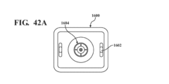
図8に示すように、ロボットシステム10は、視覚インジケータ201も含む。他の例示的な視覚インジケータを、図21~図24、図26~図42Cに示す。視覚インジケータは、ユーザの選好に応じて異なるように構成してもよい。1つの構成において、図8を参照すると、視覚インジケータは、器具に結合してもよい。より詳細には、視覚インジケータは、ツール支持体、手持ち部分又はそれらの組合せに結合してもよい。代替的に、図1を参照すると、視覚インジケータは、UI上等、器具とは別に位置決めしてもよい。例えば、視覚インジケータは、外科医が見やすいように手術室に位置決めされた表示画面の形態をとってもよい。より詳細には、視覚インジケータは、ナビゲーションカートに結合された表示画面の形態であってもよい。システムの(複数の場合もある)コントローラに対する視覚インジケータの位置に応じて、視覚インジケータは、送信器ユニットに結合してもよい。送信器ユニットは、処理部及び電源を含むことができる。理解されるべきであるように、上記構成要素のうちの任意ものを、1つ以上の別個のデバイス又は場所に分散させてもよい。送信器ユニットは、送信器ユニットとディスプレイの視覚インジケータとの間に有線又は無線の電気接続を確立するように、視覚インジケータに電気的に結合してもよい。
(visual guidance)
As shown in FIG. 8,
視覚インジケータの使用により、1自由度以上における可動域の限界が満たされた姿勢を回避する等、外科処置の中断に繋がる可能性がある姿勢を回避することにより、設計に更なるロバストネスを提供することができる。これは、制御システムが、駆動モータへのオーバライドが必要であるか否かを判断するように構成されてもよい、という事実による。 Use of visual indicators provides additional robustness to the design by avoiding postures that may lead to disruption of the surgical procedure, such as avoiding postures where limits of range of motion in one or more degrees of freedom are met be able to. This is due to the fact that the control system may be arranged to determine if an override to the drive motor is required.
制御システム60は、TCPを目標姿勢まで動かすための各アクチュエータに対する指令位置又は指令関節角度を決定すると、複数のアクチュエータ又はツール支持体の1つ以上の位置に基づいて駆動モータMの作動を制御してもよい。1つ以上のアクチュエータの位置は、少なくとも1つのアクチュエータの指令関節位置、少なくとも1つのアクチュエータの測定位置、少なくとも1つのアクチュエータの以前の指令位置、少なくとも1つのアクチュエータの以前の測定位置、又はそれらの組合せに基づいてもよい。1つの例では、駆動モータMは、アクチュエータ21、22、23のうちの少なくとも1つの指令位置に基づいて制御される。少なくとも1つのアクチュエータ21、22、23の指令関節位置は、少なくとも1つのアクチュエータ21、22、23のアクチュエータモータオーバライド制限値と比較される。モータオーバライド制限値は、或る範囲の外側境界線を定義する1つの値、又は一連の値であってもよい。この例では、1つのアクチュエータのモニタリングを論証しているが、制御システムは、各アクチュエータ21、22、23の指令位置とアクチュエータモータオーバライド制限値とをモニタリングしてもよい。アクチュエータモータオーバライド制限値の上限及び下限は、各アクチュエータの動作範囲に対するアクチュエータの位置に対応する値であってもよい。上限は、駆動モータパラメータが調整される前の、第1の方向において許容される最大移動量に対応してもよく、下限は、駆動モータパラメータが調整される前の、第2の反対方向において許容される最大移動量に対応してもよい。より具体的には、制御システム60は、指令関節位置がアクチュエータ位置をモータオーバライド制限値の上限と下限の間に維持するか否かに基づいて、駆動モータMのモータパラメータを第1の値及び第2の値で制御する。制御システム60は、駆動モータMの1つ以上のモータパラメータを制御してもよく、1つ以上のモータパラメータは、速度、トルク、動作時間、電流又はそれらの組合せであってもよい。1つの例では、制御システム60によって制御されるモータパラメータは、モータ速度であり、第1の値はゼロであり(駆動モータMはオフであり)、第2の値はゼロよりも大きい(駆動モータMはオンである)。制御システム60は、アクチュエータ21、22、23の指令位置に基づいて、モータパラメータを第1の値と第2の値との間で切り替える。アクチュエータ21、22、23の指令位置により、アクチュエータがモータオーバライド制限値の上限及び下限内になるとき、制御システム60は、駆動モータパラメータの第2の値を指令して、駆動モータMを作動させるか又は通電を継続させることを可能にしてもよい。指令アクチュエータ位置がモータオーバライド制限値の下限と上限の間にある場合、関節速度コマンドのオーバライドは変更されない。
Once the
いくつかの例では、駆動モータオーバライドは、受信したアクチュエータ位置(P)データに基づいて評価されるルックアップテーブル又は関数として実装してもよい。関節位置速度オーバライドの例では、これにより、関節位置がそのモータオーバライド制限値に近づくと、駆動モータの速度が比例して低下する。いくつかの例では、アクチュエータ位置が下限及び上限モータオーバライド制限値内にあるときは、変更はなくてもよい。他の例では、アクチュエータ21、22、23のうちの1つ以上が80%移動量範囲~95%移動量範囲の位置にあるとき、駆動モータM速度は比例して低下してもよく、95%を超える移動量で完全に無効にしてもよく、これにより、ツール20が動作限界(下限及び上限モータオーバライド閾値)に近づいているという連続的且つ段階的なフィードバックをユーザに提供してもよい。こうした実施態様では、複数の下限モータオーバライド閾値と複数の上限モータオーバライド閾値とがあってもよく、各閾値はモータパラメータ(モータ速度等)に対応する。いくつかの場合では、駆動モータM速度は完全にゼロまで低下せず、むしろ一定の低速度まで低下してもよく、それにより、外科医に警告することができるが、外科医の裁量で進めるか否かについての判断が可能となる。アクチュエータ21、22、23の指令位置により、アクチュエータがモータオーバライド制限値の上限及び下限の外になると、制御システム60は、駆動モータパラメータの第1の値を指令し、駆動モータMが作動するか又は通電が継続するのを阻止してもよい。各アクチュエータに対するモータオーバライド制限値は、上述した各アクチュエータの関節閾値と異なっていてもよい。例えば、モータオーバライド制限値は、関節閾値として定義された範囲よりも狭い範囲を定義してもよく、モータオーバライド制限値の範囲は、全体的に関節閾値の範囲内であってもよい。この視覚インジケータを利用することにより、ユーザは、各アクチュエータに起因するモータオーバライド制限値の上限及び下限をより容易に回避し、駆動モータの停止によって引き起こされる中断を最小限にすることができる。
In some examples, the drive motor override may be implemented as a lookup table or function that is evaluated based on received actuator position (P) data. In the joint position velocity override example, this causes the speed of the drive motor to decrease proportionally as the joint position approaches its motor override limit. In some examples, when the actuator position is within the lower and upper motor override limits, no change may be required. In another example, when one or more of the
目標平面等の所望の場所にツールを配置するように複数のアクチュエータを制御するために、限定されないが、インピーダンス制御、アドミタンス制御、位置制御、又は複数の異なる制御実施態様を使用するハイブリッド制御を含む、異なる制御方法を使用してもよい。アドミタンス制御実施態様を詳細に記載するが、他の方法を使用してもよいことは理解されるべきである。アドミタンス制御モードでは、制御システムは、(仮想又は測定された)力入力を受け入れ、位置(又は運動)出力を指令する。例えば、アドミタンス制御の場合、システムは、仮想質量上の特定の位置における力又はトルクをモデル化し、ツールの所望の目標状態を達成するように仮想質量の姿勢を変更するように作用する。インピーダンス制御モードでは、制御システムは、位置(又は運動)入力を受け入れ、力又はトルク出力を指令する。例えば、インピーダンス制御システムは、器具の位置(すなわち、位置、向き、速度又は加速度)を測定し、検知し、又は計算し、ツールの所望の目標状態を達成するようにアクチュエータのそれぞれに適切な対応するトルクを適用してもよい。或る特定の挙動を実施する方向に複数のアクチュエータを制御するために、位置制御を使用してもよい。これらの制御方式を実施するためには、挙動コントローラ及び運動コントローラの両方に対する変更が必要であることが理解されるべきである。 Including, but not limited to, impedance control, admittance control, position control, or hybrid control using multiple different control implementations to control multiple actuators to position the tool at a desired location, such as a target plane. , different control methods may be used. Although admittance control implementations are described in detail, it should be understood that other methods may be used. In admittance control mode, the control system accepts (virtual or measured) force inputs and commands position (or motion) outputs. For example, for admittance control, the system models a force or torque at a particular location on a virtual mass and acts to change the attitude of the virtual mass to achieve the desired target state of the tool. In impedance control mode, the control system accepts position (or motion) input and commands force or torque output. For example, the impedance control system may measure, sense, or calculate the position (i.e., position, orientation, velocity or acceleration) of the instrument and respond appropriately to each of the actuators to achieve the desired target state of the tool. may be applied. Position control may be used to control multiple actuators in directions that implement certain behaviors. It should be appreciated that changes to both the behavioral and motion controllers are required to implement these control schemes.
制御システムは、既知の座標系における手持ち部分の姿勢を決定するように構成してもよい。手持ち部分の姿勢は、指令姿勢、シミュレートされた指令姿勢、測定姿勢、以前の指令姿勢、以前の測定姿勢又はそれらの組合せであってもよい。1つの特定の実施態様では、手持ち部分の姿勢は指令姿勢であり、手持ち部分の指令姿勢は、鋸刃と手持ち部分との間の関係である。代替的に、制御システムは、同様の方法で、既知の座標系におけるツール支持体の姿勢を決定するように構成してもよい。後述する例では、指令姿勢は、手持ち部分に対して目標平面(TP)を基準として計算される。指令姿勢を計算するために利用される変換に関する追加の詳細については、図10を参照して説明し、また、それは、引用することにより本明細書の一部をなすものとする、2020年9月30日に出願された米国仮出願第63/085,651号において記載されている。視覚インジケータは、システムの異なる構成要素を基準として計算された姿勢を含む、他の姿勢に基づいて制御してもよいことが理解されるべきである。 The control system may be configured to determine the orientation of the hand-held portion in a known coordinate system. The pose of the handheld portion may be a command pose, a simulated command pose, a measured pose, a previous command pose, a previous measured pose, or a combination thereof. In one particular embodiment, the orientation of the hand-held portion is the commanded orientation, and the commanded orientation of the hand-held portion is the relationship between the saw blade and the hand-held portion. Alternatively, the control system may be configured to determine the orientation of the tool support in a known coordinate system in a similar manner. In the examples described below, the commanded pose is calculated relative to the target plane (TP) for the handheld part. Additional details regarding the transformations utilized to calculate the command attitude are described with reference to FIG. US Provisional Application No. 63/085,651 filed May 30. It should be appreciated that the visual indicator may control based on other poses, including poses calculated relative to different components of the system.
目標平面に対する手持ち部分の計算された姿勢に基づいて、制御システムは、ピッチ値、ロール値、高さ値又はそれらの組合せを決定してもよい。言い換えれば、制御システムは、指令姿勢を構成する並進における位置(本明細書では高さ(elevation)と称するz軸並進等)、ロールにおける向き、及びピッチにおける向き等、1自由度以上における手持ち部分の位置又は向きを決定してもよい。付加的又は代替的に、アクチュエータアセンブリの性質に応じて、手持ち部分の位置及び向きは、ヨー、x軸並進及びy軸並進等の他の自由度で計算してもよい。これらの値は、手持ち部分のデカルト空間で表現してもよい。以下の説明は、手持ち部分の位置又は向き及び手持ち部分の可動域に基づいて視覚インジケータが制御される一例であることを理解されるべきである。しかしながら、ツール支持体又はツール等の器具の他の部分に関して同様の計算を行うことができることも企図される。このため、本明細書全体を通して、手持ち部分の特徴(姿勢又は位置又は向き又は可動域等)に基づいて視覚インジケータを制御するという任意の言及は、ツール支持体又はツールの姿勢/位置/向き又は可動域に基づいて視覚インジケータを制御する等、器具の他の部分の特徴に基づいて視覚インジケータを制御することと置き換えることができる。これらの実施態様の例については、簡潔にするために省略している。 Based on the calculated attitude of the hand-held portion relative to the target plane, the control system may determine pitch values, roll values, height values, or a combination thereof. In other words, the control system controls the hand-held portion in one or more degrees of freedom, such as position in translation (such as z-axis translation, referred to herein as elevation), orientation in roll, and orientation in pitch, which constitutes the commanded attitude. may determine the position or orientation of Additionally or alternatively, depending on the nature of the actuator assembly, the position and orientation of the handheld portion may be calculated in other degrees of freedom such as yaw, x-axis translation and y-axis translation. These values may be expressed in the Cartesian space of the handheld part. It should be understood that the following description is an example in which the visual indicators are controlled based on the position or orientation of the hand-held portion and the range of motion of the hand-held portion. However, it is also contemplated that similar calculations can be made for other parts of the instrument such as tool supports or tools. Thus, throughout this specification, any reference to controlling the visual indicator based on the characteristics of the hand-held portion (such as attitude or position or orientation or range of motion) refers to the attitude/position/orientation of the tool support or tool or Controlling the visual indicator based on characteristics of other parts of the instrument can be substituted, such as controlling the visual indicator based on range of motion. Examples of these implementations have been omitted for the sake of brevity.
制御システムはまた、ツール支持体に対する手持ち部分の理論的な可動域を決定又は受信するように構成してもよい。或る特定の場合では、手持ち部分の理論的な可動域は、手持ち部分の特定の姿勢に基づいてもよい。これは、1自由度以上での可動域が、別の自由度における手持ち部分の位置又は向きに基づいて変化する可能性があるという事実による。例えば、ロール自由度及びピッチ自由度における可動域は、高さ自由度における手持ち部の位置に基づいて変化する可能性がある。言い換えれば、ロールにおける可動域は、第1の高さ値において第2の高さ値よりも小さい可能性がある。理論的な可動域のデータセットは、経験的に取得しても数学的に取得してもよい。こうした経験的方法の1つは、ツール支持体と手持ち部分との種々の関係を表す統計的に有意な数の姿勢で、手持ち部分の実際の姿勢をプロットすることであってよい。経験的に収集されたデータセットに基づいて理論的な可動域をプロットし計算するために、様々な曲線当てはめアルゴリズム及び回帰を使用してもよい。代替的に、理論的な可動域は、アクチュエータアセンブリの運動学に基づいて数学的に計算してもよい。 The control system may also be configured to determine or receive a theoretical range of motion of the hand-held portion relative to the tool support. In certain cases, the theoretical range of motion of the hand-held portion may be based on the particular pose of the hand-held portion. This is due to the fact that the range of motion in one or more degrees of freedom can change based on the position or orientation of the handheld portion in another degree of freedom. For example, the range of motion in the roll and pitch degrees of freedom can change based on the position of the hand in the height degrees of freedom. In other words, the range of motion in roll can be less at the first height value than at the second height value. The theoretical range of motion data set may be obtained empirically or mathematically. One such empirical method may be to plot the actual orientation of the handpiece at a statistically significant number of orientations representing various relationships between the tool support and the handpiece. Various curve-fitting algorithms and regression may be used to plot and calculate theoretical range of motion based on empirically collected data sets. Alternatively, the theoretical range of motion may be calculated mathematically based on the kinematics of the actuator assembly.
1つの例では、制御システムは、複数の自由度のそれぞれについて、独立して可動域を計算してもよい。例えば、制御システムは、ピッチの可動域、ロールの可動域、及び高さの可動域を計算する。図12を参照すると、手持ち部分の可動域は、既知の座標系におけるデカルトモデル(Cartesian model)200によって定義される体積であってもよい。デカルトモデル200は、ツール支持体に対する手持ち部分又はその逆の3次元作業空間を表す。デカルトモデルは、手持ち部分のピッチ、ロール、並進等を決定するために使用される姿勢と同じ座標系で計算される。デカルトモデル200は、理論的な可動域を理解するために使用される。デカルトモデルは、ツール支持体の姿勢をピッチ値、ロール値又は高さ値、すなわち第1の自由度、第2の自由度又は第3の自由度に関して表現するために用いられるデカルト座標にマッピングされる。デカルトモデル200は、x座標、y座標及びz座標によって定義され、ロール値、ピッチ値及び高さ値にマッピングすることができる。上述したように、ツール支持体の3次元作業空間を表すデカルトモデル200は、経験的なデータから導出してもよい。デカルトモデル200について菱形形状を示しているが、デカルトモデルは好適な3次元形状を有することができ、必ずしも対称ではないことが理解されるべきである。さらに、デカルトモデルは、複数の交差する線で表してもよく、それらの交差する線のそれぞれに対する方程式は、経験的データ(empirical data)からの様々な回帰に基づいて、又はアクチュエータアセンブリの運動学に基づいて計算することができることが理解されるべきである。
In one example, the control system may calculate the range of motion independently for each of the multiple degrees of freedom. For example, the control system calculates pitch excursion, roll excursion, and height excursion. Referring to FIG. 12, the range of motion of the hand-held portion may be the volume defined by the
所定のデカルトモデルの形状は、八面体、非対称八面体、球体、立方体、円柱等の体積として実施してもよい。特に、いくつかの例では、アクチュエータのそれぞれがホームポジションにあるときのツール支持体18と手持ち部分16との間の平面位置について非対称である等、体積として定義される場合のデカルトモデルが、デカルト体積が平面の下方よりも平面の上方の方が大きいように、形状が非対称であってもよい。この例では、体積は、複数のデカルト点によって定義してもよい。この体積は、器用な作業空間よりも小さく(すべての到達可能な構成よりも小さく)てもよい。代替的に、所定のデカルトモデルは、各自由度において別個に定義してもよい。例えば、デカルトモデルは、複数のデカルト点を用いて定義してもよい。所定のデカルト空間は、軸、すなわち、その軸に沿って又はその軸を中心に鋸刃を変位させることができる軸(x、y、z)のうちの任意の1つ、2つ又は3つに基づいて、1つ以上の向きによって定義してもよい。
The shape of a given Cartesian model may be implemented as a volume such as an octahedron, an asymmetric octahedron, a sphere, a cube, a cylinder, and the like. In particular, in some examples, the Cartesian model, when defined as a volume, is asymmetric with respect to the planar position between the
本質的に、手持ち部分の姿勢を表現するために使用されるデカルトモデル200と、理論的な可動域を理解するために使用されるデカルト座標系との関係は既知である。計算を簡単にするために、2つのデカルト座標系の原点は互いに位置合せされるか、又は互いに対して既知であり、本明細書を通じて同義に言及される場合があると想定する。アクチュエータの構成に応じて、或る特定の自由度の可動域が重要でない場合があるため、すべての自由度における位置又は姿勢を理論的な可動域と比較する必要はない。
In essence, the relationship between the
デカルトモデル200は、複数の2次元スライスを含むと理解してもよく、各スライスは、第3の自由度における位置又は向きに基づいて、2自由度における可動域を表す。図12において、各2次元スライス(202’、202’’)は、特定の高さ値におけるピッチ自由度及びロール自由度における可動域を表す。図12を参照すると、下方の高さのスライスは、上方の高さのスライスよりもピッチ及びロールの追加の可動域に対応することが容易に明らかである。全体としてデカルトモデルに関して上述したように、各2次元スライスは、4本の線等、複数の線によって表してもよい。各線には、方程式が定義されている。それらの線の交点で囲まれた領域は、2次元スライス領域と理解することができる。
ここで図13~図20を参照すると、手持ち部分の理論的な可動域に関して、複数の2次元スライス202’’’及び202’’’’は、複数の2次元領域として理解することができ、各領域は特定の高さでそれ自身の原点を定義している。したがって、2次元スライスのそれぞれは、極座標系で理解することができる。ピッチ値及びロール値(x1,y1;x2,y2;x*,y*...)に対応する2次元領域の外側境界線は、その特定の高さにおける手持ち部分の可動域の最外限界にある。2次元スライスの数は特に限定されず(図12では2つのみ示す)、0.1mm等の離散的な高さ間隔でプロットしてもよい。言い換えれば、デカルトモデル全体について、0.1mmの間隔で、あり得る最小の高さ値から最大の高さ値まで2次元領域を計算してもよい。当然ながら、任意の好適な間隔を使用してもよい。制御システムは、その指令姿勢の高さ値に最も密接に対応する2次元領域を選択してもよい。 Referring now to FIGS. 13-20, multiple two-dimensional slices 202''' and 202'''' can be understood as multiple two-dimensional regions with respect to the theoretical range of motion of the hand-held portion, Each region defines its own origin at a particular height. Therefore, each of the two-dimensional slices can be understood in terms of a polar coordinate system. The outer boundary of the two-dimensional region corresponding to the pitch and roll values (x1, y1; x2, y2; x * , y * ...) is the outermost limit of the range of motion of the handheld part at that particular height. It is in. The number of two-dimensional slices is not particularly limited (only two are shown in FIG. 12), and may be plotted at discrete height intervals such as 0.1 mm. In other words, a two-dimensional region may be calculated from the smallest possible height value to the largest possible height value at intervals of 0.1 mm for the entire Cartesian model. Of course, any suitable spacing may be used. The control system may select the two-dimensional region that most closely corresponds to the commanded pose height value.
概して、制御システムは、1自由度以上における手持ち部分の実際の位置又は向き、及び1自由度以上における可動域に基づいて、視覚インジケータを制御するように構成されている。これは、第1の自由度における手持ち部分の位置又は向き及び可動域に基づき、第2の自由度における手持ち部分の位置又は向き及び可動域に基づき、第3の自由度における手持ち部分の位置又は向き及び可動域に基づき、視覚インジケータを制御することを含んでもよい。上述したように、視覚インジケータはまた、他の自由度における位置及び向きに基づいて制御することもできる。 Generally, the control system is configured to control the visual indicator based on the actual position or orientation of the handheld portion in one or more degrees of freedom and the range of motion in the one or more degrees of freedom. This is based on the position or orientation and range of motion of the hand-held portion in the first degree of freedom, based on the position or orientation and range of motion of the hand-held portion in the second degree of freedom, and the position or orientation of the hand-held portion in the third degree of freedom. Controlling a visual indicator based on orientation and range of motion may also be included. As noted above, visual indicators can also be controlled based on position and orientation in other degrees of freedom.
さらに、制御システムは、手持ち部分の第1の姿勢と、第1の姿勢に基づく第1の可動域とを決定し、手持ち部分の第2の姿勢を決定し、第2の姿勢に基づく第2の可動域を決定するように構成してもよいことが理解されるべきである。第1の可動域と第2の可動域とは異なることと、第1の姿勢と第2の姿勢とは互いに異なり、すなわち、2つの異なる時間の事例における手持ち部分の姿勢を表すこととが理解されるべきである。1自由度以上における可動域は、別の自由度における手持ち部分の位置又は向きによって決まる可能性があるため、可動域は、第1の可動域と第2の可動域とで異なる可能性がある。制御システムは、第1の自由度における第1の姿勢に基づいて手持ち部分の位置又は向きを決定し、第1の位置又は向き及び第1の可動域に基づいて視覚インジケータを制御し、第1の自由度における第2の姿勢に基づいて手持ち部分の第2の位置又は向きを決定し、第2の位置又は向き及び第2の可動域に基づいて視覚インジケータを制御してもよい。例えば、制御システムは、第1の時点でのロールにおける手持ち部分の向きとロールにおける手持ち部分の向きの可動域とを決定し、第2の時点でのロールにおける手持ち部分の向きとロールにおける手持ち部分の可動域とを決定してもよく、第1の時点と第2の時点とでロールは異なり、第1の時点と第2の時点とでロールにおける可動域も異なり、それに応じて視覚インジケータが制御される。この例はロールについて提供されているが、ピッチ、並進(高さ等)、又は他の自由度において同じ計算を行うことができることが理解されるべきである。これにより、視覚インジケータが、手持ち式手術器具の可動域の正確な表示を常に伝えることができ、これにより、器具がより適切に利用されることが可能になり、ユーザが十分な可動域が存在しなくなった場所で器具を動かしたために外科処置が中断されることを低減させることができる。 Further, the control system determines a first pose of the hand-held portion and a first range of motion based on the first pose, determines a second pose of the hand-held portion, and a second pose based on the second pose. It should be understood that it may be configured to determine the range of motion of the . It is understood that the first range of motion and the second range of motion are different, and that the first and second postures are different from each other, i.e. represent the posture of the hand-held part at two different instances of time. It should be. The range of motion in one or more degrees of freedom can be determined by the position or orientation of the hand-held portion in another degree of freedom, so the range of motion can differ between the first range of motion and the second range of motion. . A control system determines a position or orientation of the hand-held portion based on a first attitude in a first degree of freedom, controls a visual indicator based on the first position or orientation and a first range of motion, and controls a first A second position or orientation of the handheld portion may be determined based on the second pose in the degree of freedom, and the visual indicator may be controlled based on the second position or orientation and the second range of motion. For example, the control system determines the orientation of the hand-held portion in the roll and the range of motion of the orientation of the hand-held portion in the roll at a first time, and the orientation of the hand-held portion in the roll and the hand-held portion in the roll at a second time. and the range of motion of the roll is different between the first and second time points, and the range of motion in the roll is also different between the first and second time points, and a visual indicator is provided accordingly. controlled. Although this example is provided for roll, it should be understood that the same calculations can be made for pitch, translation (such as height), or other degrees of freedom. This allows the visual indicator to always convey an accurate indication of the range of motion of the hand-held surgical instrument, thereby allowing the instrument to be better utilized and allowing the user to determine if there is sufficient range of motion. Interruptions to the surgical procedure due to moving the instrument where it no longer works can be reduced.
例として、各高さ値において、ピッチ及びロールの特定の理論的な可動域が達成可能である。したがって、上述したように、ピッチ又はロールの可動域は、それがプロットされる高さ値によって決まる可能性があることが企図される。言い換えれば、第1の高さ(図13~図18を参照)において、手持ち部分は、ピッチ及びロール値の第1の範囲に達することができてもよく、第2の高さ(図19及び図20を参照)において、手持ち部分は、ピッチ及びロール値の第2の範囲に達することができてもよく、ピッチ及びロール値の第1の範囲は、ピッチ及びロール値の第2の範囲とは異なっている。異なる高さにおけるこの可動域の差は、アクチュエータアセンブリの運動学と、ツール支持体と手持ち部分との間で複数のアクチュエータを結合するために使用される関節とに基づく。 By way of example, at each height value a certain theoretical range of pitch and roll is achievable. Thus, as noted above, it is contemplated that pitch or roll excursion may depend on the height value for which it is plotted. In other words, at a first height (see FIGS. 13-18) the hand-held portion may be able to reach a first range of pitch and roll values, and at a second height (see FIGS. 19 and 18). 20), the handheld portion may be capable of reaching a second range of pitch and roll values, the first range of pitch and roll values being equal to the second range of pitch and roll values. is different. This difference in range of motion at different heights is based on the kinematics of the actuator assembly and the joints used to couple the multiple actuators between the tool support and the handpiece.
手持ち部分の可動域が高さ値で異なる可能性があるため、様々な2次元スライス領域の外側境界も互いに異なる可能性があり、したがって、2次元スライス領域の形状及びサイズも互いに異なる可能性がある。例えば、或る特定の2次元スライス領域は対称であってもよく、一方で、他の2次元スライス領域は非対称であってもよく、或る特定の2次元スライス領域は多角形であってもよく、一方で、他の2次元スライス領域は円形であってもよい等である。図19及び図20に示すように、2次元スライス領域は本質的に三角形であり、一方、図13~図18では、2次元スライス領域は本質的に五角形である。より詳細には、再び図13~図18及び図19及び図20を参照すると、手持ち部分の可動域をまとめて定義する複数の2次元領域の中で、2次元領域のうちの1つは、第1の高さにおけるピッチ及びロールの第1の可動域に対応し、2次元領域のうちの別の1つは、第2の高さにおけるピッチ及びロールの第2の可動域に対応する。 Since the range of motion of the hand-held portion may differ in height values, the outer boundaries of the various 2D slice regions may also differ from each other, and thus the shape and size of the 2D slice regions may also differ from each other. be. For example, certain 2D slice regions may be symmetrical, while other 2D slice regions may be asymmetric, and certain 2D slice regions may be polygonal. Well, while other two-dimensional slice regions may be circular, and so on. As shown in Figures 19 and 20, the two-dimensional slice areas are essentially triangular, while in Figures 13-18, the two-dimensional slice areas are essentially pentagonal. More specifically, referring again to FIGS. 13-18 and 19 and 20, among the plurality of two-dimensional regions collectively defining the range of motion of the hand-held portion, one of the two-dimensional regions is A first range of motion for pitch and roll at a first height and another one of the two-dimensional regions corresponding to a second range of motion for pitch and roll at a second height.
手持ち部分の姿勢と理論的な可動域との関係をスケーリングにより理解するために、手持ち部分の1つ以上の位置又は向きを、複数の2次元スライス領域に基づいて、極座標系でモデル化してもよい。各2次元領域の外側境界は、ピッチ及びロールを表す座標の4つの対等、座標の少なくとも4つの対に基づいて定義してもよいが、それぞれがそれ自体の方程式を有する一連の線によって表されることが多い。より詳細には、上述したように、姿勢は、ピッチ値、ロール値、高さ値、又は他の自由度における値を含んでもよい。最初に、手持ち部分の指令姿勢に対応する2次元領域が選択される。1つの例では、これは、手持ち部分の指令姿勢の高さ値に対応する理論的な可動域の2次元領域を選択することによって行われる。 One or more positions or orientations of the hand-held part may be modeled in a polar coordinate system based on multiple two-dimensional slice regions to understand the relationship between the pose of the hand-held part and the theoretical range of motion by scaling. good. The outer boundary of each two-dimensional region, which may be defined based on at least four pairs of coordinates, four equal pairs of coordinates representing pitch and roll, is represented by a series of lines, each with its own equation. often More specifically, pose may include pitch values, roll values, height values, or values in other degrees of freedom, as described above. First, a two-dimensional region corresponding to the commanded pose of the hand-held part is selected. In one example, this is done by selecting a two-dimensional region of theoretical range of motion that corresponds to the commanded pose height value of the hand-held part.
指令姿勢の高さ値に対応するピッチ値及びロール値は、2次元スライス領域に描かれるベクトルとして理解することができる。このベクトルは、実際の偏差ベクトルと称され、2次元領域の原点から、デカルト空間における指令姿勢のピッチ値及びロール値によって定義される端点まで延びる。より全体的には、実際の偏差ベクトルは、複数の2次元領域のうちの少なくとも1つの原点から、第2の自由度における手持ち部分の位置と第3の自由度における手持ち部分の位置とによって極座標系で定義される点まで延びると理解することができ、第1の自由度は、実際の偏差ベクトルのプロットのために複数の2次元領域のうちのいずれが選択されるかを定義する。或る特定の例では、偏差ベクトルの端部は、実際の偏差ベクトルが無限の大きさを有した場合に実際の偏差ベクトルと交差する2次元スライスの境界の部分を定義する1つ以上の方程式によって特徴付けてもよい。 The pitch and roll values corresponding to the height values of the command pose can be understood as vectors drawn on a two-dimensional slice area. This vector, called the actual deviation vector, extends from the origin of the two-dimensional area to the endpoints defined by the pitch and roll values of the command attitude in Cartesian space. More generally, the actual deviation vector is polar coordinates from the origin of at least one of the plurality of two-dimensional regions by the position of the hand-held portion in the second degree of freedom and the position of the hand-held portion in the third degree of freedom. The first degree of freedom, which can be understood to extend to a point defined by the system, defines which of the multiple two-dimensional regions is selected for plotting the actual deviation vector. In one particular example, the ends of the deviation vector are one or more equations that define the portion of the two-dimensional slice boundary that would intersect the actual deviation vector if the actual deviation vector had infinite magnitude. may be characterized by
実際の偏差ベクトルは、大きさ及び方向を示す。図14において、実際の偏差ベクトルはADV1として表示され、x1のロール値及びy1のピッチ値、すなわち、およそ8度のピッチ及び14度のロールに対応する。ADV1は、およそ30度の角度θ2と、16という大きさとを有する。図16において、実際の偏差ベクトルはADV2として表示され、x2,y2に対応し、これは、-10度のロール及び-6度のピッチに等しい。ADV2は、およそ210度の角度θ4と、12という大きさとを有する。図17において、実際の偏差ベクトルはADV3として表示され、x3,y3に対応し、これは、-4度のロール及び-2度のピッチに関係する。ADV3は、およそ210度の角度θ5と、5という大きさを有する。図20において、実際の偏差ベクトルはADV4として表示され、x4及びy4、すなわち、およそ12度のロール及び4度のピッチに対応する。ADV4は、およそ30度の角度θ8と、13という大きさを有する。 The actual deviation vector indicates magnitude and direction. In FIG. 14, the actual deviation vector is labeled as ADV1 and corresponds to a roll value of x1 and a pitch value of y1, or approximately 8 degrees of pitch and 14 degrees of roll. ADV1 has an angle θ2 of approximately 30 degrees and a magnitude of 16; In FIG. 16, the actual deviation vector is labeled as ADV2 and corresponds to x2,y2, which equates to -10 degrees roll and -6 degrees pitch. ADV2 has an angle θ4 of approximately 210 degrees and a magnitude of 12; In FIG. 17, the actual deviation vector is labeled as ADV3 and corresponds to x3,y3, which relates to -4 degrees roll and -2 degrees pitch. ADV3 has an angle θ5 of approximately 210 degrees and a magnitude of five. In FIG. 20, the actual deviation vector is labeled as ADV4 and corresponds to x4 and y4, or approximately 12 degrees of roll and 4 degrees of pitch. ADV4 has an angle θ8 of approximately 30 degrees and a magnitude of thirteen.
図13、図15、図18及び図19を参照すると、或る特定の実施態様では、制御システムは、実際の偏差ベクトルをモデル化するために使用された同じ2次元スライス領域、すなわち同じ高さに関して、可動域ベクトル(RMV1~4)又は可動域線(RML1~RML4)を更に決定する。可動域線(RML1~4)の長さは、ピッチ値とロール値との特定の組合せでその高さ値に対して可能な可動域を表し、一方、可動域ベクトルの長さは、ピッチ値とロール値との特定の組合せで原点の片側にあるその高さ値に対して可能な可動域を表す。より詳細には、制御システムは、第1の自由度における手持ち部分の位置又は向きに基づいて、極座標系における可動域線を決定するように構成されている。可動域線は、2次元領域の境界点から、同じ2次元領域の、その境界点の反対側の角度にある境界点まで延びる。言い換えれば、可動域線は、2つの線分として理解することができ、第1の線分は第1の角度を有し、第2の線分は第1の角度+180度での線分を有する。このように、第1の線分及び第2の線分は、いずれも同じ原点から延び、いずれも原点から2次元スライスの外側境界上の点まで延びている。第1の角度は、各計算における偏差ベクトルの角度と常に等しい。この構成に基づき、可動域線は常に実際の偏差ベクトルと同一線上であるが、実際の偏差ベクトルと完全に同一の広がりは有していない。可動域線の大きさは、様々な方法で計算してもよい。一例では、可動域線と2次元スライス領域を定義する1つの線との間の交点である。可動域線は同様に方程式で表してもよく、可動域線と、可動域と交差する境界領域の部分を画定する線とに対する方程式を解いて、可動域線の両端における可動域線と2次元スライス領域との交点の2組のx,y値を求めることができると理解されるべきである。これらの2組のx,y値に基づいて、可動域線の大きさを計算することができる。可動域ベクトルは、実際の偏差ベクトルの角度に等しい角度を有する。可動域線の1つの線分は、可動域ベクトルから構成してもよい。 13, 15, 18 and 19, in certain implementations, the control system uses the same two-dimensional slice area, i.e. the same height, that was used to model the actual deviation vector. , further determine range of motion vectors (RMV1-4) or range of motion lines (RML1-RML4). The length of the range of motion lines (RML1-4) represents the range of motion possible for that height value at a particular combination of pitch and roll values, while the length of the range of motion vector represents the pitch value. and roll values represent the possible range of motion for that height value on one side of the origin. More particularly, the control system is configured to determine range-of-motion lines in a polar coordinate system based on the position or orientation of the hand-held portion in the first degree of freedom. A range of motion line extends from a boundary point in a two-dimensional region to a boundary point in the same two-dimensional region at the opposite angle to that boundary point. In other words, the range of motion line can be understood as two line segments, the first having a first angle and the second having a line at the first angle plus 180 degrees. have. Thus, the first line segment and the second line segment both extend from the same origin and both extend from the origin to a point on the outer boundary of the two-dimensional slice. The first angle is always equal to the angle of the deviation vector in each calculation. Based on this configuration, the range of motion line is always collinear with the actual deviation vector, but is not exactly coextensive with the actual deviation vector. The range of motion line magnitude may be calculated in a variety of ways. One example is the intersection between the range of motion line and one line that defines the two-dimensional slice region. The range of motion line may similarly be represented by an equation, where the equations for the range of motion line and the lines defining the portions of the bounding region that intersect the range of motion are solved to obtain the range of motion line and two-dimensional It should be understood that two sets of x,y values of the intersection with the slice region can be determined. Based on these two sets of x,y values, the magnitude of the range of motion line can be calculated. The range of motion vector has an angle equal to the angle of the actual deviation vector. One line segment of the range-of-motion line may be composed of the range-of-motion vector.
図13において、可動域ベクトルはRMV1として表示され、y5のピッチ値及びx5のロール値、すなわちおよそ10度のピッチ及び18度のロールに対応する。RMV1は、およそ30度の角度θ1と、21という大きさとを有する。図15において、可動域ベクトルはRMV2として表示され、x3,y3に対応し、これは、-12度のロール及び-7度のピッチに等しい。RMV2は、およそ210度の角度θ3と、14という大きさとを有する。図18において、可動域ベクトルは、RMV3として表示され、x9,y9に対応し、これは、18度のロール及び12度のピッチに関係する。RMV3は、およそ30度の角度θ6と、22という大きさとを有する。図19において、可動域ベクトルはRMV4として表示され、x11,y11、すなわち、およそ20度のロール及び6度のピッチに対応する。RMV4は、およそ30度の角度θ7と、21という大きさとを有する。RML1(x6,y6で終端)、RML2(x7,y7で終端)、RML3(x10,y10で終端)、RML4(x12,y12で終端)はそれぞれ、それぞれのRMVよりも大きい。しかしながら、図から理解することができるように、RMLの大きさは、必ずしもRMVの大きさの2倍ではない。この理由は、2次元領域が、RMVの各角度において、その原点について必ずしも対称ではないためである。後述する具体例は、可動域ベクトルの大きさと実際の偏差ベクトルの大きさとの比較に基づいて視覚インジケータを制御することに言及しているが、可動域線の大きさ(すなわち、長さ)に基づいて視覚インジケータを制御してもよいことも企図される。 In FIG. 13, the range of motion vector is labeled as RMV1 and corresponds to a pitch value of y5 and a roll value of x5, or approximately 10 degrees of pitch and 18 degrees of roll. RMV1 has an angle θ1 of approximately 30 degrees and a magnitude of 21; In FIG. 15, the range of motion vector is labeled as RMV2 and corresponds to x3, y3, which equates to -12 degrees roll and -7 degrees pitch. RMV2 has an angle θ3 of approximately 210 degrees and a magnitude of 14. In FIG. 18, the range of motion vector is labeled as RMV3 and corresponds to x9, y9, which relates to roll of 18 degrees and pitch of 12 degrees. RMV3 has an angle θ6 of approximately 30 degrees and a magnitude of 22; In FIG. 19, the range of motion vector is labeled as RMV4 and corresponds to x11, y11, or approximately 20 degrees of roll and 6 degrees of pitch. RMV4 has an angle θ7 of approximately 30 degrees and a magnitude of 21; RML1 (terminated at x6, y6), RML2 (terminated at x7, y7), RML3 (terminated at x10, y10), and RML4 (terminated at x12, y12) are each greater than their respective RMVs. However, as can be seen from the figure, the magnitude of RML is not necessarily twice the magnitude of RMV. The reason for this is that the two-dimensional region is not necessarily symmetrical about its origin at each angle of RMV. Although the specific examples described below refer to controlling the visual indicator based on a comparison of the magnitude of the range of motion vector and the magnitude of the actual deviation vector, the size (i.e., length) of the range of motion line It is also contemplated that the visual indicator may be controlled based on.
可動域線又はベクトルと実際の偏差ベクトルとを適切に比較するために、偏差ベクトルの方向は、可動域線の線分の方向又は偏差ベクトルの角度と等しくなければならず、言い換えれば、それぞれの角度θが互いに等しくなければならない。言い換えれば、可動域線又は可動域ベクトルは、実際の偏差ベクトルの方向に基づいて計算される。同様に、2つのベクトルの大きさを適切に比較するか、又は実際の偏差ベクトルと可動域線の大きさとを適切に比較するために、可動域線は、2次元領域において実際の偏差ベクトルが延びるのと同じ原点を通って延びなければならず、可動域ベクトルは、実際の偏差ベクトルが延びるのと同じ原点から延びなければならない。可動域線は、1自由度以上における手持ち部分の位置に基づく2次元領域の2つの境界点まで延びているものと理解してもよく、一方、可動域ベクトルは、2次元領域の単一の境界点まで延びているものと理解してもよい。可動域の大きさは、2次元領域に基づくとともに、2次元領域上における可動域線の端部、すなわち境界点を画定する座標の2つの対に基づいて計算してもよく、一方、可動域ベクトルの大きさは、2次元領域の原点に基づくとともに、2次元領域上の可動域ベクトルの端部、すなわち境界点を画定する座標の対に基づいて計算してもよい。 In order to properly compare the range of motion line or vector with the actual deviation vector, the direction of the deviation vector must equal the direction of the segment of the range of motion line or the angle of the deviation vector, in other words, the respective The angles θ must be equal to each other. In other words, the range of motion line or vector is calculated based on the direction of the actual deviation vector. Similarly, in order to properly compare the magnitudes of two vectors, or to properly compare the magnitudes of an actual deviation vector and a range of motion line, the range of motion line is defined in a two-dimensional region where the actual deviation vector is It must extend through the same origin as it extends, and the excursion vector must extend from the same origin as the actual deviation vector extends. The range-of-motion line may be understood to extend to two boundary points of a two-dimensional region based on the position of the hand-held part in one or more degrees of freedom, while the range-of-motion vector is a single point of the two-dimensional region. It may be understood as extending to the boundary point. The extent of the range of motion may be calculated based on the two-dimensional region and two pairs of coordinates that define the ends of the range-of-motion line, i.e. the boundary points, on the two-dimensional region, while the range of motion The magnitude of the vector may be calculated based on the origin of the two-dimensional region and based on pairs of coordinates that define the ends, or boundary points, of the range-of-motion vector on the two-dimensional region.
図13及び図14に関して、θ1はθ2に等しく、ADV1の大きさはRMV1よりも小さいことが理解されるべきである。制御システムは、RMV1とADV1との大きさを数学的に比較することにより、最も近い可動域境界に対する手持ち部分の任意の所与の姿勢において、手持ち部分に残っている可動域の割合を概算することができる。例えば、ADV1の大きさをRMV1の大きさで割ることにより、最も近い可動域境界に対する手持ち部分のその姿勢において、手持ち部分に対しておよそ22パーセントの可動域が残っていることを理解することができる。可動域ベクトルのこれらの大きさと実際の偏差ベクトルとを使用して、全体を通して記載する視覚インジケータを制御することができる。 13 and 14, it should be understood that θ1 is equal to θ2 and the magnitude of ADV1 is less than RMV1. By mathematically comparing the magnitudes of RMV1 and ADV1, the control system approximates the percentage of range of motion remaining in the hand-held part at any given orientation of the hand-held part relative to the nearest range-of-motion boundary. be able to. For example, by dividing the magnitude of ADV1 by the magnitude of RMV1, it can be seen that at that pose of the hand-held portion relative to the nearest range-of-motion boundary, approximately 22 percent of the range of motion remains for the hand-held portion. can. These magnitudes of the range of motion vector and the actual deviation vector can be used to control the visual indicators described throughout.
図15及び図16に関して、θ3はθ4に等しく、ADV2の大きさはRMV2よりも小さいことが理解されるべきである。制御システムは、RMV2とADV2との大きさを数学的に比較することにより、最も近い可動域境界に対する手持ち部分の任意の所与の姿勢において、手持ち部分に残っている可動域の割合を概算することができる。例えば、ADV2の大きさをRMV2の大きさで割ることにより、手持ち部分のその姿勢において、手持ち部分に対しておよそ17パーセントの可動域が残っていることを理解することができる。可動域ベクトルのこれらの大きさと実際の偏差ベクトルとを使用して、全体を通して記載する視覚インジケータを制御することができる。 15 and 16, it should be understood that θ3 is equal to θ4 and the magnitude of ADV2 is less than RMV2. By mathematically comparing the magnitudes of RMV2 and ADV2, the control system approximates the percentage of range of motion remaining in the hand-held part at any given orientation of the hand-held part relative to the nearest range-of-motion boundary. be able to. For example, by dividing the magnitude of ADV2 by the magnitude of RMV2, it can be seen that at that pose of the hand-held portion there is approximately 17 percent range of motion remaining for the hand-held portion. These magnitudes of the range of motion vector and the actual deviation vector can be used to control the visual indicators described throughout.
図15及び図17に関して、θ3はθ5に等しく、ADV3の大きさはRMV2よりも小さいことが理解されるべきである。制御システムは、RMV2とADV3との大きさを数学的に比較することにより、最も近い可動域境界に対する手持ち部分の任意の所与の姿勢において、手持ち部分に残っている可動域の割合を概算することができる。例えば、ADV3の大きさをRMV2の大きさで割ることにより、最も近い可動域境界に対する手持ち部分のその姿勢において、手持ち部分に対して可動域のおよそ66パーセントが残っていることを理解することができる。可動域ベクトルのこれらの大きさと実際の偏差ベクトルとを使用して、全体を通して記載する視覚インジケータを制御することができる。 15 and 17, it should be understood that θ3 is equal to θ5 and the magnitude of ADV3 is less than RMV2. By mathematically comparing the magnitudes of RMV2 and ADV3, the control system approximates the percentage of range of motion remaining in the hand-held part at any given pose of the hand-held part relative to the nearest range-of-motion boundary. be able to. For example, by dividing the magnitude of ADV3 by the magnitude of RMV2, we can see that at that pose of the hand-held portion relative to the nearest range-of-motion boundary, approximately 66 percent of the range of motion remains for the hand-held portion. can. These magnitudes of the range of motion vector and the actual deviation vector can be used to control the visual indicators described throughout.
図14及び図18に関して、θ2はθ6に等しく、ADV1の大きさはRMV3よりも小さいことが理解されるべきである。制御システムは、RMV3とADV1との大きさを数学的に比較することにより、手持ち部分の任意の所与の姿勢において、手持ち部分に残っている可動域の割合を概算することができる。例えば、ADV1の大きさをRMV3の大きさで割ることにより、最も近い可動域境界に対する手持ち部分のその姿勢において、手持ち部分に対して可動域のおよそ26パーセントが残っていることを理解することができる。可動域ベクトルのこれらの大きさと実際の偏差ベクトルとを使用して、全体を通して記載する視覚インジケータを制御することができる。13と14の偏差ベクトルの原点は異なっており、その結果、ベクトルのそれぞれの大きさが変化する可能性があることが理解されるべきである。 14 and 18, it should be understood that θ2 is equal to θ6 and the magnitude of ADV1 is less than RMV3. By mathematically comparing the magnitudes of RMV3 and ADV1, the control system can approximate the percentage of range of motion remaining in the hand-held portion at any given pose of the hand-held portion. For example, by dividing the magnitude of ADV1 by the magnitude of RMV3, it can be seen that at that pose of the hand-held portion relative to the nearest range-of-motion boundary, approximately 26 percent of the range of motion remains for the hand-held portion. can. These magnitudes of the range of motion vector and the actual deviation vector can be used to control the visual indicators described throughout. It should be understood that the origins of the deviation vectors of 13 and 14 are different, which may result in a change in the magnitude of each of the vectors.
原点は、実際の偏差値ベクトルに対して、いくつかの異なる方法で設定してもよい。1つの例では、原点は、2次元領域の質量中心として設定してもよい。代替的に、原点は、幾何学的中心等、2次元領域の質量中心以外の点として設定してもよい。代替的にさらに、原点は、特定の自由度における可動域が、原点の両側で偏るように設定してもよい。例えば、図14と図18とを比較すると、ピッチの自由度に対して、原点よりも上方の可動域が原点よりも下方の可動域よりも大きい可能性がある。これにより、可動域の一方側又は他方側を好むようにユーザを導くように、視覚インジケータを非対称に制御することになる可能性がある。この理由は、図18と比較して、図14では、ユーザが自身の手を上方よりも下方に動かすように促される可能性が高いためである。これは、ロール自由度においても当てはまる可能性がある。こうした構成は、ユーザが自身の手を或る一定の方向に傾けるか又は捻る傾向がある場合、又は、ユーザが選択した切断に基づいて、有利である可能性がある。言い換えれば、制御システムは、ユーザによっていずれの切断が選択されたかに基づき、実際の偏差ベクトルの原点を設定するように動作してもよい。代替的に、制御システムは、ユーザが原点を変更する構成を選択することができるユーザインタフェースを提示してもよい。 The origin may be set in several different ways with respect to the actual deviation vector. In one example, the origin may be set as the center of mass of the two-dimensional area. Alternatively, the origin may be set as a point other than the center of mass of the two-dimensional area, such as the geometric center. Alternatively, the origin may also be set such that the range of motion in a particular degree of freedom is offset on either side of the origin. For example, comparing FIG. 14 and FIG. 18, there is a possibility that the range of motion above the origin is larger than the range of motion below the origin with respect to the degree of freedom of the pitch. This can lead to asymmetric control of the visual indicators to guide the user to prefer one side of the range of motion or the other. The reason for this is that the user is more likely to be encouraged to move their hands downwards than upwards in FIG. 14 as compared to FIG. This may also be true for roll degrees of freedom. Such a configuration may be advantageous if the user tends to tilt or twist their hand in a certain direction, or based on the cut selected by the user. In other words, the control system may operate to set the origin of the actual deviation vector based on which cut was selected by the user. Alternatively, the control system may present a user interface that allows the user to select a configuration that changes the origin.
図19及び図20に関して、θ7はθ8に等しく、ADV4の大きさはRMV4よりも小さいことが理解されるべきである。制御システムは、RMV4とADV4との大きさを数学的に比較することにより、最も近い可動域境界に対する手持ち部分の任意の所与の姿勢において、手持ち部分に残っている可動域の割合を概算することができる。例えば、ADV4の大きさをRMV4の大きさで割ることにより、最も近い可動域境界に対する手持ち部分のその姿勢において、手持ち部分に対して可動域のおよそ60パーセントが残っていることを理解することができる。可動域線のこれらの大きさと実際の偏差ベクトルとを使用して、全体を通して記載する視覚インジケータを制御することができる。 19 and 20, it should be understood that θ7 is equal to θ8 and the magnitude of ADV4 is less than RMV4. By mathematically comparing the magnitudes of RMV4 and ADV4, the control system approximates the percentage of range of motion remaining in the hand-held part at any given orientation of the hand-held part relative to the nearest range-of-motion boundary. be able to. For example, by dividing the magnitude of ADV4 by the magnitude of RMV4, we can see that at that pose of the hand-held portion relative to the nearest range-of-motion boundary, approximately 60 percent of the range of motion remains for the hand-held portion. can. These magnitudes of range of motion lines and actual deviation vectors can be used to control the visual indicators described throughout.
制御システムは、実際の偏差ベクトルの大きさ、可動域ベクトルの大きさ、実際の偏差ベクトルの方向、可動域のベクトルの方向、又はそれらの組合せに基づいて、視覚インジケータを制御するように構成されている。 The control system is configured to control the visual indicator based on the actual deviation vector magnitude, the range of motion vector magnitude, the direction of the actual deviation vector, the direction of the range of motion vector, or a combination thereof. ing.
さらに、制御システムは、実際の偏差ベクトルの(ロールに対応する)x成分と(ピッチに対応する)y成分とを分離して比較することにより、ピッチ自由度又はロール自由度(又は他の自由度)に残っている可動域に基づいて、視覚インジケータを独立して制御することもできる。言い換えれば、視覚インジケータのピッチ指標は、実際の偏差ベクトルのy成分に基づいてもよい。同様に、ロール指標は、実際の偏差ベクトルのx成分に基づいて制御してもよい。さらに、実際の偏差ベクトルの両成分に基づいて、本明細書ではピッチロール指標と称する、ピッチ及びロールを同時に示す指標を制御してもよい。 In addition, the control system can determine the pitch or roll degrees of freedom (or other degrees of freedom) by separately comparing the x (corresponding to roll) and y (corresponding to pitch) components of the actual deviation vector. The visual indicators can also be independently controlled based on the range of motion remaining in degrees. In other words, the visual indicator's pitch index may be based on the y component of the actual deviation vector. Similarly, the roll index may be controlled based on the x component of the actual deviation vector. Further, based on both components of the actual deviation vector, an index that simultaneously indicates pitch and roll, referred to herein as the pitch roll index, may be controlled.
再び図14、図16及び図17を参照すると、可動域ベクトルの態様に基づいて視覚インジケータを制御することに対する代替形態として、制御システムはまた、可動域の他の計算に基づいて視覚インジケータを制御してもよい。この代替方法は、各自由度に対して別個の視覚インジケータが使用され制御される場合において、特に有用である。この代替例では、特定の自由度における可動域は、手持ち部分の姿勢に基づいて(より詳細には、指令姿勢の1自由度以上に基づいて)計算される。例えば、図14を参照すると、指令姿勢が特定のロール、ピッチ及び高さとして定義される場合、指令姿勢の態様に基づいて、ピッチ可動域が生成され、ロール可動域が生成される。ピッチ及びロールにおける指令姿勢は、x1,y1(14度のロール、8度のピッチ)で表される。この姿勢に基づくピッチ自由度における可動域は、点P1と点P2との間を伸びる直線の大きさとして理解することができる。言い換えれば、ピッチ自由度において利用可能な可動域の大きさは、指令姿勢におけるロール自由度の向き(ロール14度で、ピッチにおいて利用可能な角度(-6度~+12.5度))によって定義される。特定の自由度における可動域を表すこの代替方法は、異なる自由度(この例ではロール)における姿勢に基づくとともに、可動域のデカルトモデルに基づいて、自由度(ピッチ等)の可動域を選択する。 Referring again to FIGS. 14, 16 and 17, as an alternative to controlling the visual indicators based on aspects of the range of motion vector, the control system may also control the visual indicators based on other calculations of range of motion. You may This alternative method is particularly useful when separate visual indicators are used and controlled for each degree of freedom. In this alternative, the range of motion in a particular degree of freedom is calculated based on the attitude of the hand-held part (more specifically, based on one or more degrees of freedom of the commanded attitude). For example, referring to FIG. 14, if a command pose is defined as a particular roll, pitch and height, then a pitch excursion is generated and a roll excursion is generated based on aspects of the command pose. The command attitude in pitch and roll is represented by x1, y1 (14 degree roll, 8 degree pitch). The range of motion in the pitch freedom based on this posture can be understood as the size of a straight line extending between points P1 and P2. In other words, the amount of range of motion available in the pitch degree of freedom is defined by the orientation of the roll degree of freedom in the commanded attitude (with 14 degrees of roll, the angle available in pitch (-6 degrees to +12.5 degrees)). be done. This alternative method of representing the range of motion in a particular degree of freedom selects the range of motion for a degree of freedom (such as pitch) based on posture in a different degree of freedom (roll in this example) and based on a Cartesian model of the range of motion. .
更に図14を参照すると、別の例として、制御システムは、指令姿勢等のピッチにおける姿勢に基づいて、ロールにおける可動域を決定してもよい。ピッチにおける指令姿勢は、8度である。この姿勢に基づくロールにおける可動域は、点R1と点R2との間を延びる直線の大きさとして理解することができる。言い換えれば、ピッチが+8度で、ロールにおける可動域は-22度~+22度の範囲であると理解することができる。 Still referring to FIG. 14, as another example, the control system may determine the range of motion in roll based on the attitude in pitch, such as the command attitude. The command attitude on the pitch is 8 degrees. The range of motion in roll based on this posture can be understood as the size of a straight line extending between points R1 and R2. In other words, it can be understood that the pitch is +8 degrees and the range of motion in roll is in the range of -22 degrees to +22 degrees.
ここで図16を参照すると、手持ち部分の指令姿勢は、ロールが-10度、ピッチが-6度と決定される(x2,y2を参照)。ロール自由度における-10度の値に基づき、ピッチ自由度における可動域は、+13度~-9度までの範囲、すなわち(P3からP4まで延びる線の大きさによって画定される)22度の大きさである。ピッチ自由度の-6度という値に基づき、ロール自由度の可動域は-15度~+15度、すなわち(R3からR4まで延びる直線の大きさによって画定される)30度であると計算される。 Referring now to FIG. 16, the commanded attitude of the handheld portion is determined to be -10 degrees for roll and -6 degrees for pitch (see x2, y2). Based on a value of -10 degrees in the roll degree of freedom, the range of motion in the pitch degree of freedom ranges from +13 degrees to -9 degrees, or a magnitude of 22 degrees (defined by the line size extending from P3 to P4). It is. Based on the value of -6 degrees of pitch freedom, the roll freedom range of motion is calculated to be -15 degrees to +15 degrees, or 30 degrees (defined by the magnitude of the line extending from R3 to R4). .
ここで図17を参照すると、手持ち部分の指令姿勢は、ロールが-4度、ピッチが-2度と決定される(x3,y3を参照)。ロール自由度における-4度の値に基づき、ピッチ自由度における可動域は、+12.5度~-14度の範囲、すなわち(P5からP6まで延びる線の大きさによって画定される)26.5度の大きさである。ピッチ自由度の-2度という値に基づき、ロール自由度の可動域は-19度~+19度、すなわち(R5からR6まで延びる直線の大きさによって画定される)38度であると計算される。 Referring now to FIG. 17, the commanded attitude of the handheld portion is determined to be -4 degrees for roll and -2 degrees for pitch (see x3, y3). Based on a value of -4 degrees in the roll degree of freedom, the range of motion in the pitch degree of freedom ranges from +12.5 degrees to -14 degrees, or 26.5 degrees (defined by the line size extending from P5 to P6). degree. Based on a value of -2 degrees for the pitch degree of freedom, the range of motion for the roll degree of freedom is calculated to be -19 degrees to +19 degrees, or 38 degrees (defined by the magnitude of the line extending from R5 to R6). .
さらに、ロール可動域の大きさが指令姿勢のピッチ成分に基づくと記載しているが、ロール可動域の大きさは、高さ、ヨー、x軸並進又はy軸並進等、指令姿勢の他の成分に基づいて決定することもできることが理解されるべきである。同じことが、ピッチ可動域にも当てはまり、それは、ピッチ可動域の大きさもまた、高さ、ヨー、x軸並進又はy軸並進等、指令姿勢の他の成分に基づいて決定することができることが理解されるべきであるという点にある。 Further, while the roll excursion magnitude is described as being based on the pitch component of the commanded pose, the roll excursion magnitude is based on other parameters of the commanded pose, such as height, yaw, x-axis translation or y-axis translation. It should be understood that the determination can also be made on a component basis. The same applies to the pitch excursion, which may also be determined based on other components of the command attitude, such as height, yaw, x-axis translation or y-axis translation. The point is that it should be understood.
上述したように、可動域の大きさは、異なる視覚インジケータの構成に対して異なるように決定してもよい。後述するように、視覚インジケータの或る特定の実施態様、特に、各自由度に対して単一の指標を含むものについて、特定の自由度における可動域の大きさは、異なる自由度に対する自由度の値に基づくとともに、デカルトモデルに基づいて、決定してもよい。ピッチ及びロールをまとめて示す光源の配列等の視覚インジケータの他の実施態様では、上述した可動域ベクトルの大きさに依拠してもよく、又は、可動域線の大きさに基づいてもよい。 As noted above, the range of motion magnitude may be determined differently for different visual indicator configurations. As will be discussed below, for certain implementations of visual indicators, particularly those that include a single index for each degree of freedom, the magnitude of the range of motion in a particular degree of freedom is the degree of freedom for different degrees of freedom. may be determined based on the value of and based on a Cartesian model. Other implementations of visual indicators, such as an array of light sources that collectively indicate pitch and roll, may rely on the magnitude of the excursion vector described above, or may be based on the magnitude of the excursion line.
図1、図21~図24及び図26~図27Cを参照すると、視覚インジケータは、1つ以上の表示画面300、401、500、600、700UIを含んでもよい。各表示画面は、様々な形態をとってもよい。 1, 21-24 and 26-27C, the visual indicator may include one or more of the display screens 300, 401, 500, 600, 700 UI. Each display screen may take various forms.
図21を参照すると、制御システムは、第1の自由度(並進自由度)における手持ち部分の位置に基づいて、並進指標302を表示するように表示画面300を制御するように更に構成してもよい。表示画面は、並進範囲内の閾値を示すようなサイズの並進基準オブジェクト304を更に含んでもよい。並進指標302は、並進自由度における手持ち部分の位置又は向きと並進閾値とに基づき、並進基準オブジェクト304内に又は並進基準オブジェクト304に対して位置決めしてもよい。並進閾値は、並進閾値の範囲に基づいてもよく、すなわち、並進閾値は、実際には、上限並進閾値と下限並進閾値とを含んでもよい。並進閾値の範囲は、上述した3次元作業空間を表すデカルトモデルに基づいてもよい。或る特定の場合では、表示画面300は、2つ以上の並進基準オブジェクト304を表示するように構成され、少なくとも1つの並進基準オブジェクト304は表示画面300の各側に位置している。並進基準オブジェクト304のそれぞれは、高さ自由度等、並進自由度における手持ち部分の位置に基づく並進指標302を含んでもよい。1つの例では、手持ち部分の位置が(指令姿勢から決定されるように)高さ自由度において5であると決定され、高さ自由度における可動域が+10~-10であると決定される場合、並進指標は、並進基準オブジェクトの高さのおよそ75%に位置決めしてもよい。言い換えれば、並進基準オブジェクト内の並進指標の位置は、高さに利用可能な可動域に対する指令高さ位置のスケーリングされた理解を提供する。
Referring to FIG. 21, the control system may be further configured to control the
図22を参照すると、制御システムは、ロール自由度における実際の偏差ベクトルの大きさと、ロール自由度における可動域の大きさとの成分に基づいて、ロール指標402を表示するように表示画面400を制御するように構成してもよい。上述したように、ロール自由度における可動域の大きさは、指令姿勢のピッチ成分に基づいてもよい。さらに、表示画面401は、ロール基準オブジェクト404を表示するように構成され、そこでは、ロール指標402は、実際の偏差ベクトルのx成分とピッチ自由度における可動域の大きさとに基づいてロール基準オブジェクトに対して位置決めされる。ロール基準オブジェクト404は、円弧に関する指示された場所に位置決めされた複数の空間的注釈406を含んでもよく、各空間的注釈406はそれに関連する既知の角度を特定し、それにより各空間的注釈406によってツール支持体に対する手持ち部分のロールを視覚的に評価することができる。
Referring to FIG. 22, the control system controls the
図23及び図24を参照すると、制御システムは、実際の偏差ベクトルのx成分及びy成分(ピッチ成分及びロール成分)の大きさと、ロール自由度における可動域の大きさ及びピッチ自由度における可動域の大きさとに基づき、ピッチロール指標502、602を表示するように更に構成してもよい。特定の場合では、ピッチロール指標502、602は、3次元仮想オブジェクトの2次元表現であり、この2次元表現は、実際の偏差ベクトルの大きさ及び方向と、可動域線の大きさ及び方向とに基づいて構成される。例示的な3次元オブジェクトは、鋸刃を表す多角形であり、多角形は正面と背面とを有し、多角形の背面は、多角形の正面の反対側の位置決めされ、多角形の正面又は背面は、実際の偏差ベクトルのx成分及びy成分(ピッチ成分及びロール成分)と、ロール自由度における可動域の大きさ及びピッチ自由度における可動域の大きさとに基づいて位置決めされる。1つの実施態様では、制御システムは、実際の偏差ベクトルのy成分(ピッチ成分等)と、ピッチ自由度における手持ち部分の可動域の大きさとを決定し、実際の偏差ベクトルのy成分と可動域のピッチ成分の大きさとに基づいて、ピッチロール指標を表示するように構成してもよい。より詳細には、2D表現の位置は、これらの値の比に基づいて、表示画面内の適切な位置に(垂直方向に)スケーリングしてもよい。同様に、制御システムは、実際の偏差ベクトルのx成分(ロール成分等)と、ロール自由度における手持ち部分の可動域の大きさとを決定するように構成してもよく、表示画面は、実際の偏差ベクトルのx成分とロール自由度における可動域の大きさとの比に基づいて、2D表現を適切な位置に(回転可能に)スケーリングするように構成してもよい。
23 and 24, the control system calculates the magnitude of the x and y components (pitch and roll components) of the actual deviation vector, the magnitude of the range of motion in the roll degree of freedom, and the range of motion in the pitch degree of freedom. It may further be configured to display the
図23の最左の表示500に関して、手持ち部分のピッチとピッチ可動域の大きさとの比は、実際の偏差ベクトルのy成分が可動域の底部に近く(ピッチ自由度内にあり)、したがって、ピッチロール指標502の正面が画面の底部に近いことを示す。図23の中央の表示502’では、手持ち部分のピッチは、ピッチ自由度において、最上可動域に近く、したがって、正面のピッチロール指標502’は、表示の頂部に近い。また、図23の最右の表示502’’を参照すると、手持ち部分のピッチ成分は、ピッチ自由度における可動域の中央にあり、したがって、ピッチロール指標の正面は、表示画面の中央にある。これらのそれぞれについて、背面であるものが見えないように仮想オブジェクトが表示される。
With respect to the
図24に関して、ピッチロール指標602は、指令姿勢のピッチ成分がピッチ自由度における可動域の大きさの下半分にあることを示す位置で、表示画面600上に位置決めされる。見ることができるように、ピッチ可動域の中心は、下部ピッチ制限#2と上部ピッチ制限#1との間(すなわち、ピッチ可動域の大きさの中央値)にある。これらの上部ピッチ制限及び下部ピッチ制限は、ピッチ可動域の大きさの外側境界線に対応してもよい。
With reference to Figure 24, the
ここで図27A~図27Cを参照すると、手持ち部分及びツール支持体が3つの異なる形態にある器具が示されている。図27A~図27Cに関して、各表示画面は、ロール指標702、高さ指標704、及びピッチロール指標706を示す。図27Aは、手持ち部分が、ピッチ及びロールがずれており高さが中心合せされていることに基づく、ロール指標702、高さ指標704及びピッチロール指標706の状態を示す。より詳細には、図27Aは、手持ち部分が可動域の左下隅にある状態を示す。図27Bは、手持ち部分が、ピッチ及びロールがずれており高さが中心から外れていることに基づく、ロール指標702、高さ指標704及びピッチロール指標706の状態を示す。より詳細には、図27Bは、手持ち部分が可動域の右上隅にあることに対応するピッチロール指標706を示す。図27Cは、手持ち部分が、ピッチがずれており高さ自由度が所望の位置にあることに基づく、ロール指標702、高さ指標704及びピッチロール指標706の状態を示す。
Referring now to Figures 27A-27C, there is shown an instrument with three different configurations of hand-held portion and tool support. 27A-27C, each display screen shows a
或る特定の構成において、図28~図31、図33A、図34、図37及び図42Bを参照すると、視覚インジケータは、複数の光源を含む。より詳細には、図28~図30を参照すると、視覚インジケータ800は、ピッチロールインジケータ804として知られるピッチ及びロール自由度に対応する1つ以上の光源と、並進視覚インジケータ802として知られる並進自由度(すなわち高さ)に対応する1つ以上の光源と、手持ち部分が2自由度以上でホームポジションの或る一定の閾値内にあるか否かを示すよう構成された光源806とを含んでもよい。制御システムは、複数の光源のうちの少なくとも1つの状態を制御するように構成してもよい。制御システムは、実際の偏差ベクトルの大きさ、実際の偏差ベクトルの方向、可動域ベクトルの大きさ、又は可動域線の大きさ、可動域ベクトルの方向、又はそれらの組合せに基づいて、複数の光源802、804、806の状態を制御して、ピッチの向き、ロールの向き、及び並進位置のうちの1つ以上における1つ以上の所望の変化を同時にユーザに示してもよい。代替的に、上述したように、視覚インジケータは、高さ、ピッチ及びロール以外の自由度における所望の変化を示すように、上述したものよりも少ないか又は追加の光源を含んでもよい。
In one particular configuration, referring to FIGS. 28-31, 33A, 34, 37 and 42B, the visual indicator includes multiple light sources. More specifically, referring to FIGS. 28-30,
複数の光源802、804、806の状態は、複数の光源のうちの少なくとも1つの光源がオンかオフか、少なくとも1つの光源によって放出される光パルスの周波数、少なくとも1つの光源によって放出される光の強度、少なくとも1つの光源の色、又はそれらの組合せを含んでもよい。これらの状態は、光源に特定のコマンドを送信すること、又は複数の光源に供給される電流、電圧若しくはそれらの組合せを制御することによって制御してもよい。
The state of the plurality of
視覚インジケータは、直感的な様式での外科医への情報の供給を最大限にするように、互いに対して特定の様式で配置された複数の光源を含んでもよい。1つの構成では、複数の光源のうちの少なくとも3つのピッチロール光源804は、互いに共通の平面上にある。これにより、外科医は、ピッチロール光源804が手持ち部分16の平面を表していることを直感的に理解することができる可能性がある。ここでは、3つの光源を言及しているが、任意の数の光源を互いに共通の平面上に位置決めしてもよく、例えば、少なくとも4つ、6つ、8つ、10個又は12個の光源を、互いに共通の平面上に位置決めしてもよい。ピッチロールの複数の光源804のうち少なくとも3つは、中心軸808を包囲するように配置してもよく、これらを総じてアレイ805と称する。言い換えれば、アレイの複数の光源は、円の外観を与えるように中心点から等距離量だけ放射状に間隔を空けて配置してもよく、より全体的には、複数の光源は中心軸808を取り囲むように配置してもよい。
The visual indicator may include multiple light sources arranged in a particular fashion relative to each other to maximize the presentation of information to the surgeon in an intuitive fashion. In one configuration, at least three pitch-
上述したように、光源の囲みアレイ805は、実際の偏差ベクトルの大きさに基づいて制御システムによって制御してもよい。光源の囲みアレイ805はまた、可動域ベクトルの大きさに基づいて制御してもよい。言い換えれば、制御システムは、実際の偏差ベクトルの大きさと可動域のベクトルの大きさとを比較し、その比較に基づいて、アレイ805を構成する1つ以上の光源804を照明してもよい。可動域ベクトルの大きさは、4分の1、3分の1、又は他の一定の割合の間隔等、所定の等しい分数に分割してもよい。可動域ベクトルの大きさのこれらの分数を使用して、複数の光源の制御を容易にすることができる1つ以上の偏差閾値を生成してもよい。例えば、偏差閾値は、上限偏差閾値と下限偏差閾値とを含んでもよい。しかしながら、その大きさを使用して、上限偏差閾値及び下限偏差閾値に加えて閾値を含む、任意の数の閾値を生成してもよい。加えて、その大きさを使用して、例えば、可動域ベクトルの大きさの中心から20%以内の、一組の入れ子になった閾値の範囲を生成してもよく、それは、第1の入れ子範囲であり、可動域ベクトルの大きさの中心から80%以内であってもよい。
As noted above, the enclosing
上限及び下限の偏差閾値又は範囲は、望ましいとされる特定の自由度における位置又は向きに基づいて設定してもよい。より詳細には、例えばピッチに関して、下限入れ子範囲は、(可動域ベクトルの大きさの20%に対応する)可動域の中央値20%に設定してもよい。言い換えれば、ピッチの可動域が-10度~10度である場合、下限偏差閾値は、-2度~+2度に設定してもよい。実際の偏差ベクトルのピッチ成分が-2度~+2度の範囲内にある場合、制御システムは、すべての光源がオンである、すべての光源がオフである、又は光源が特定の色を照明するように制御される等、特定の照明パターンを提示するようにアレイ805を制御してもよい。ロール自由度に関して、下限入れ子範囲は、ロール自由度における可動域の中央値20%に設定してもよい。言い換えれば、ロールの可動域が-10度~10度である場合、下限入れ子範囲は、-2度~+2度に設定してもよい。実際の偏差ベクトルのロール成分が-2度~+2度の範囲内にある場合、制御システムは、すべての光源がオンである、すべての光源がオフである、又はすべての光源が特定の色を照明するように制御される等、特定の照明パターンを提示するようにアレイ805を制御してもよい。制御システムにより、2自由度以上に対する下限偏差値範囲に基づいてアレイ805を同時に制御してもよいことも企図される。言い換えれば、制御システムは、ピッチ及びロールと、ピッチ及びロールに対応する入れ子範囲とに基づいて、アレイ805を制御してもよい。したがって、アレイは、指令姿勢のピッチ成分及びロール成分の両方が下限入れ子範囲値内にある場合、全照明オン又は全照明オフ等の特定のパターンを提示するのみとしてもよい。同様に、指令姿勢のピッチ成分及びロール成分の両方が入れ子範囲値の上限の組内にある場合、又は指令姿勢のピッチ成分及びロール成分が入れ子範囲値の下限の組及び入れ子範囲値の上限の組の両方の外にある場合、全照明オン又は全照明オフ等の有無に基づいて、アレイを制御してもよい。
Upper and lower deviation thresholds or ranges may be set based on the desired position or orientation in a particular degree of freedom. More specifically, for pitch, for example, the lower nested range may be set at 20% of the median range of motion (corresponding to 20% of the magnitude of the range of motion vector). In other words, if the range of motion of the pitch is -10 degrees to 10 degrees, the lower deviation threshold may be set to -2 degrees to +2 degrees. If the pitch component of the actual deviation vector is within the range of -2 degrees to +2 degrees, the control system indicates that all light sources are on, all light sources are off, or the light sources illuminate a particular color.
図25を参照すると、視覚インジケータ800のアレイ805の概略図が描かれている。制御システムは、光源の囲みアレイ805におけるルート光源810を特定するように更に構成してもよい。これは、実際の偏差ベクトルの方向に基づいて計算してもよい。ルート光源810は、偏差ベクトルの角度に最も近いピッチロール光源804であってもよい。ルート光源810は、実光源としても仮想光源としてもよい。仮想光源である場合、いずれの実光源が仮想光源に最も近いかを特定する別のステップが必要である。実光源及び仮想光源でモデル化することにより、照明アレイの機械的構成に応じてアルゴリズムをスケーリングすることができる(同じアルゴリズムをLEDのすべての異なる空間配置に適用することができる)。図25では、簡単のために、すべてのピッチロール光源804が実光源であると想定する。実際の偏差ベクトルのθは、最上光源から時計回りに第2の光源に対応する角度に最も近いため、第2の光源をルート光源810とみなす。
Referring to FIG. 25, a schematic diagram of an
制御システムは、ルート光源810に第1の側及び第2の側で、すなわちルート光源810の右及び左で隣接する少なくとも2つの隣接光源812を特定するように更に構成してもよい。隣接光源812が特定されると、制御システムは、実際の偏差ベクトルの大きさ及び可動域ベクトルの大きさに基づいて、少なくとも2つの隣接光源の状態を制御するように構成してもよい。2つの隣接光源812の状態は、少なくとも2つの隣接光源がオンであるかオフであるかであってもよい。代替的に、制御システムは、少なくとも2つの隣接光源によって放出される光パルスの周波数、少なくとも2つの隣接光源によって放出される光の強度、少なくとも2つの隣接光源の色、又はそれらの組合せを制御してもよい。隣接光源812は、アレイ805において、ルート光源に対して時計回り方向の光源、及びルート光源に対して反時計回り方向の光源を含んでもよい。1つの例では、ピッチの可動域が(可動域ベクトルから導出される)-10~+10であり、ピッチ値(すなわち、偏差ベクトルのy成分)が(-4~+4の入れ子範囲外の)8である場合、制御システムは、隣接光源812を照明してもよい。ピッチの可動域が-10~+10であり、入れ子範囲がピッチにおいて-4~+4であり、指令姿勢のピッチ成分が、範囲内である2である場合、制御システムは、隣接光源812を照明しなくてもよい。他の自由度、特にロール自由度に同様の制御を採用してもよいことは理解されるべきである。
The control system may be further configured to identify at least two adjacent
或る特定の実施態様において、制御システムは、上述した隣接光源812(「一次隣接光源」)に隣接する隣接光源の追加のグループ(「二次隣接光源」814)を特定するように更に設計してもよい。この隣接光源814の追加のグループの状態は、実際の偏差ベクトルの大きさと可動域ベクトルの大きさとに基づいて更に制御してもよい。例えば、制御システムは、入れ子範囲との比較に基づいて、一次隣接光源812及び二次隣接光源814の状態を制御してもよいことが企図される。より詳細には、制御システムは、実際の偏差ベクトルの大きさが範囲の内側の組の範囲内にある場合、一次隣接光源812をオンにするが、二次隣接光源814をオンにしなくてもよい。さらに、制御システムは、実際の偏差ベクトルの大きさが内側の入れ子範囲外であるが外側の入れ子範囲内である場合、二次隣接光源814及び一次隣接光源812をオンにしてもよい。二次隣接光源814は、ルート光源810及び一次隣接光源812以外の任意の数の光源を含んでもよいことが理解されるべきである。例えば、二次隣接光源814は、囲みアレイ805におけるピッチロール光源804の完全な残りを含むことができる。言い換えれば、ルート光源810、一次隣接光源812及び二次隣接光源814がすべて照明されるとき、囲みアレイ805内のすべての光源を照明してもよいことが理解されるべきである。さらに、制御システムは、隣接光源の更に別のグループ(「三次隣接光源」816)を特定するように構成することができ、制御システムは、同様の様式で、すなわち、第3の入れ子範囲又は第4の入れ子範囲を用いて、三次隣接光源816を制御することができることが企図される。一次隣接光源及び二次隣接光源は、それぞれ独立して任意の数の光源を含んでもよいが、典型的には、ルート光源810に対して反時計回り及び時計回り方向に対称的な数の光源を含んでもよいこともまた企図される。
In certain embodiments, the control system is further designed to identify an additional group of adjacent light sources (“secondary adjacent light sources” 814) adjacent to adjacent light sources 812 (“primary adjacent light sources”) described above. may The state of this additional group of adjacent
再び図28を参照すると、視覚インジケータ800は、囲みアレイ805とは異なるように制御してもよい並進視覚インジケータ802もまた含んでもよい。制御システムは、決定された並進値及び1つ以上の並進閾値又は並進範囲に基づいて、並進視覚インジケータ802に関連する光源の状態を制御してもよい。入れ子並進範囲を含む並進閾値又は並進範囲は、並進可動域の大きさの一定の間隔又は一部であってもよい。決定された並進値は、指令姿勢に基づいて決定してもよい、並進自由度における手持ち部分の位置である。並進視覚インジケータ802は、複数の光源を含んでもよい。光源のそれぞれは、並進視覚インジケータの1つ以上のセグメント803a、803bに対応してもよい。したがって、並進視覚インジケータ802は、第1のセグメント、第2のセグメント、及び任意選択的に追加のセグメントを含んでもよく、セグメントのそれぞれは、1つ以上の光源を含む。制御システムは、第1のセグメント803a、第2のセグメント803b、及び他のセグメントに対応する光源の状態を制御して、手持ち部分の並進位置を変更するようにユーザに示してもよい。1つの構成において、第1のセグメント及び第2のセグメントは、並進視覚インジケータ802の中線Mの両側にある。こうした実施態様において、制御システムは、第1のセグメント803a又は第2のセグメント803bに対応する光源を照射して、手持ち部分の所望の動きの方向を示すように構成されている。
Referring again to FIG. 28,
並進視覚インジケータ802の第1のセグメント803a及び第2のセグメント803bは、軸808上で整列してもよい。並進視覚インジケータ802の軸は、ツール支持体18又はツール20によって画定される平面に対して垂直であってよい。並進視覚インジケータ802の少なくとも一部は、光源の囲みアレイ805によって包囲してもよい。加えて、並進視覚インジケータ802の軸は、光源の囲みアレイ805によって画定される平面に垂直であってもよい。制御システムは、並進視覚インジケータに関連するそれらの光源のうちのルート並進光源を特定するように更に構成してもよい。
しかしながら、ルート並進光源は、偏差ベクトルの角度を用いて特定されるのではなく、並進値に基づくとともに、1つ以上の並進閾値に基づいて特定される。制御システムは、指令姿勢の並進成分と並進閾値又は入れ子並進範囲とに基づいて、並進インジケータに対応する光セグメントの状態を制御してもよい。入れ子並進範囲のそれぞれは、上限並進閾値と下限並進閾値とを含んでもよい。 However, rather than being identified using the angle of the deviation vector, the root translational light source is identified based on translation values and based on one or more translation thresholds. The control system may control the state of the light segment corresponding to the translation indicator based on the translation component of the command pose and the translation threshold or nested translation range. Each of the nested translation ranges may include an upper translation threshold and a lower translation threshold.
図29A~図29Gに関して、例示的な空間配置を参照して視覚インジケータの状態について説明する。図29Aは、手持ち部分が全ての自由度においてツール支持体と位置合せされていることを表す。これは、並進視覚インジケータの光セグメント803c、すなわち中央の光セグメントを照明することにより、視覚インジケータ800上に示され、これは、手持ち部分16がピッチ自由度における可動域のほぼ中心内にある(又は最内の並進入れ子範囲内にある)ことを示す。光源806もまた照明され、その理由は、手持ち部分16がピッチ自由度及びロール自由度について所望の可動域内にある(手持ち部分のピッチ成分が最内のピッチ入れ子範囲内にあり、手持ち部分のロール成分が最内のロール入れ子範囲内にある)ためである。さらに、光源804a~804h等のアレイ805内のすべての光源が照明されて、手持ち部分がツール支持体とピッチ自由度及びロール自由度における所望の可動域まで概して位置合せされていることを示す。
Visual indicator states are described with reference to exemplary spatial arrangements with respect to FIGS. 29A-29G. FIG. 29A depicts the hand-held portion being aligned with the tool support in all degrees of freedom. This is indicated on
図29Bに関して、手持ち部分は、ツール支持体に対してピッチングしており、ユーザは、所望の可動域に到達するために手持ち部分を前方に傾けることが望まれる。この場合、ピッチの変化のみが望まれるため、並進視覚インジケータの光セグメント803cが照明される。さらに、ピッチのみの変化が望まれる(実際の偏差ベクトルはおよそ0度)ため、ルート光源804aは照明される。手持ち部分のピッチが第1の閾値を超えるため、隣接光源のうち2つも照明された光セグメント804b、804hである。
With respect to FIG. 29B, the handpiece is pitched with respect to the tool support and the user desires to tilt the handpiece forward to reach the desired range of motion. In this case, only pitch changes are desired, so the translational visual
図29Cに関して、ユーザは、手持ち部分をピッチ方向において後方に傾け、手持ち部分を上方に引き上げることが望まれる。手持ち部分の引上げに対処するために、並進が最下並進閾値に近いため、並進インジケータの光源803eが照明される。所望のピッチの変化に対処するために、ルート光源は、804e(およそ180度の角度を有する実際の偏差ベクトル)として特定される。所望のピッチの変化の大きさに基づいて、隣接光源804d及び804fも照明される。
With respect to FIG. 29C, the user is desired to tilt the handheld portion backward in the pitch direction and pull the handheld portion upward. To account for the lifting of the handheld part, the translation
図29Dに関して、ユーザは、ロール自由度において手持ち部分を時計回りに捻ることが望まれ、高さの変化は要求されない。これは、並進視覚インジケータの光セグメント803cを照明することによって視覚インジケータ800上に示され、これは、手持ち部分16がピッチ自由度における可動域のほぼ中心内にあることを示す。ルート光源804gが、特定され照明される(実際の偏差ベクトルはおよそ270度の方向を有する)。要求されるロールの動きの程度に基づいて、隣接するピッチロール光源804h及び804fも照明される。
With respect to FIG. 29D, the user desires to twist the handpiece clockwise in the roll degree of freedom and no height change is required. This is indicated on
図29Eに関して、ユーザは、ロール自由度において、手持ち部分を反時計回りに捻ることが望まれる。手持ち部分の引上げに対処するために、並進が最下並進閾値に近いため、並進インジケータの光源803eが照明される。ルート光源804cが、特定され照明される(実際の偏差ベクトルはおよそ90度の方向を有する)。要求されるロールの動きの程度に基づいて、光源804b及び804dも照明され、これは、隣接光源又は隣接光セグメントとみなすことができる。
With respect to Figure 29E, the user is desired to twist the handpiece counterclockwise in the roll degree of freedom. To account for the lifting of the handheld part, the translation
図29Fに関して、ユーザは、手持ち部分を上に引き上げる、すなわち、高さを変更することが望まれ、ピッチ及びロールの自由度には変更が望まれない。手持ち部分の引上げに対処するために、並進が最下並進閾値に近いか又は最外並進入れ子範囲の下方で外側であるため、並進インジケータの光源803eが照明される。手持ち部分16の指令姿勢のピッチ成分及びロール成分が、ピッチ及びロールの自由度に対して最内の入れ子範囲内にあるため、光源806もまた照明される。さらに、手持ち部分がピッチ及びロールの自由度における所望の可動域までツール支持体と概して位置合せされていることを示すために、光源804a~804h等のアレイ805内のすべての光源が照明される。
With respect to FIG. 29F, the user wants to lift the handheld portion up, ie change the height, and not change the pitch and roll degrees of freedom. To account for the pull-up of the hand-held portion, the translation
図29Gに関して、ユーザは、手持ち部分を下に下げる、すなわち、高さを変更することが望まれ、ピッチ及びロールの自由度には変更が望まれない。手持ち部分の引下げに対処するために、並進が最上並進閾値に近いため、並進インジケータのセグメント803aが照明される。手持ち部分16がピッチ及びロールの自由度の所望の可動域内にあるため、光源806もまた照明される。さらに、手持ち部分がピッチ及びロールの自由度における所望の可動域までツール支持体と概して位置合せされていることを示すために、光源804a~804h等のアレイ805内のすべての光源が照明される。
With respect to FIG. 29G, the user wishes to lower the handheld portion, ie change the height, and not change the pitch and roll degrees of freedom.
図30A~図30Eに関して、並進視覚インジケータ802について更に説明する。並進視覚インジケータ802は、複数の光セグメント803a~803eを含むことができる。各光セグメントは、1つ以上の光源に関連してもよい。(複数の場合もある)並進閾値は、並進閾値の範囲を含んでもよい。並進閾値の範囲は、手持ち部分に対するツール支持体の3次元作業空間を表すデカルトモデルに基づいてもよい。例えば、手持ち部分の並進値が5であり、並進の可動域が-10~+10である場合、制御システムは、並進インジケータの一部として示す5つのセグメントのうちの第2のセグメント(803b)を特定する(図30Bを参照)。並進値が10である場合、並進視覚インジケータ802における最上光源(803a)を照明してもよい(図30Aを参照)。光セグメント803a~803eのうちの1つ以上は、他の光セグメントとは異なる色を発するように構成してもよい。例えば、最上光セグメント(803a)及び最下光セグメント803(e)は、同じ色を発するように構成してもよく、一方、中央光セグメント803cは、最上光セグメント及び最下光セグメントと異なる色を発するように構成してもよい。さらに、中間光セグメント(803b及び803d)は、第3の色の光を発するように構成してもよい。並進値に応じて異なる色の光を発することにより、ユーザは、並進における可動域制限にどの程度近いかを理解することができる。図30Aは、高さ値が高さに対する可動域制限の最上部に近いことを示す。図30Bは、高さ値が、可動域閾値の最上部(803aの照明を引き起こす)と、可動域の中心閾値(803cの照明を引き起こす)との間にあることを示す。図30Cは、803cが照明されており、これは、高さ値が可動域の中心閾値の範囲にあることを示す。図30Dは、図30Bの逆(セグメント803dが照明されている)であり、図30Eは、図30Aの逆であって、803eが照明されている。
Translation
図31は、視覚インジケータ900の別の図である。中央柱902は、上述した並進視覚インジケータ802のように機能し、図30A~図30Eに関して上述したように制御される複数のセグメントを含んでもよい。視覚インジケータ900は、複数の光源を含んでもよいアレイ905を更に含んでもよい。アレイ905は、アレイ805に関して上述したように機能してもよく、アレイ805と同様の複数の光源を含んでもよい。
FIG. 31 is another view of
重要なことは、上述した視覚インジケータに基づいて、手持ち式ロボットシステムのオペレータは、刃支持体18が手持ち部分16に対して所望の可動域を有するか否かを視覚的に理解することができることである。特に、ホームポジションにあるとき、アクチュエータ21、22、23の調節可能性の量は、ツール20を所望の姿勢に維持するために最大化される。器具14の特定の幾何学的形状及び構成に応じて、様々なレベルの調整が可能である。いくつかの例では、すべてのアクチュエータ21、22、23がそれらのホームポジションにあるとき、ツール20は、ロールの向きの変化がゼロであるとともにz軸並進がないと想定して、ホームポジションに対して約±18度のピッチの向きで調整してもよい。いくつかの例では、すべてのアクチュエータ21、22、23がそれらのホームポジションにあるとき、ツール20は、ピッチの向きの変化がゼロであるとともにz軸並進がないと想定して、ホームポジションに対して約±33度のロールの向きで調整してもよい。いくつかの例では、すべてのアクチュエータ21、22、23がそれらのホームポジションにあるとき、ツール20は、ピッチの向き及びロールの向きの変化がゼロであると想定して、ホームポジションに対して約±0.37インチ(9.398ミリメートル)のz軸並進で調整してもよい。ツール20に対して、動作中、ピッチ、ロール及びz軸並進を同時に、順次、又はそれらの組合せで調整してもよい。
Importantly, based on the visual indicators described above, the operator of the hand-held robotic system can visually see whether the
図32A~図32Cは、指標が、手持ち部分のピッチ及びロール、又は手持ち部分の高さに関する直感的な情報をユーザに提供する、表示画面の図である。提供される指標は、以前に導入した所望の切断面に対する手持ち部分の平面を示すものであってもよい。指標は、所望の切断面を表す円又は他のマーキングを含んでもよい。この円は静的であってもよい。指標は、円に対して移動可能な「X」又は他のタイプのマーキングを更に含んでもよい。手持ち部分の平面がピッチ、ロール又は両方において所望の切断面から逸脱する場合、Xを円の外側に表示してもよい。例えば、ピッチの逸脱は、Xが円の上方又は下方に表示されることを含んでもよく、ロールの逸脱は、Xが円の右側又は左側に表示されることを含んでもよい。上記の決まりにより、図32Bは、手持ち部分の平面が所望の切断面に対して上方に角度が付けられ、所望の切断面より左側にローリングしていることを示す。図32Cは、図32Bよりも逸脱が小さいことを示す。指標は、所望の切断面に対する手持ち部分のz軸位置を組み込んでもよい。特定の実施態様では、円の厚さは、所望の平面に対する手持ち部分のz軸位置に基づいて変更してもよい。例えば、図32Bに示すように、手持ち部分が上方又は下方に動かされるに従い、円の厚さが増大する。円は、所望の切断面に対して手持ち部分がある一定の姿勢に到達すると、所定の最大値まで厚さを増大させるか、又は完全に埋めてもよい。表示は、指標が重ね合わされた視覚的作業ゾーンを提供してもよい。 32A-32C are views of display screens in which indicators provide the user with intuitive information regarding the pitch and roll of the hand-held portion, or the height of the hand-held portion. The index provided may indicate the plane of the handpiece relative to the previously introduced desired cutting plane. The indicator may include a circle or other marking representing the desired cutting plane. This circle may be static. The indicator may further include an "X" or other type of marking that is movable with respect to the circle. If the plane of the handheld portion deviates from the desired cutting plane in pitch, roll, or both, the X may appear outside the circle. For example, a pitch deviation may include the X being displayed above or below the circle, and a roll deviation may include the X being displayed to the right or left of the circle. By virtue of the above convention, FIG. 32B shows that the plane of the hand-held portion is angled upward to the desired cutting plane and rolls to the left of the desired cutting plane. FIG. 32C shows less deviation than FIG. 32B. The index may incorporate the z-axis position of the handheld portion relative to the desired cutting plane. In certain implementations, the thickness of the circle may vary based on the z-axis position of the handheld relative to the desired plane. For example, as shown in FIG. 32B, the thickness of the circle increases as the handheld portion is moved upward or downward. The circle may increase in thickness to a predetermined maximum value or fill completely once the hand reaches a certain orientation with respect to the desired cutting plane. The display may provide a visual working zone overlaid with indicators.
図33Aは、LED光のアレイ、例えば5×5のアレイに表示されている指標を示す。アレイは、器具に組み込まれているように示すが、代替的に、以前に導入したディスプレイ上に表示してもよい。LED光の選択的な照明は、手持ち部分のピッチ、ロール及びz軸位置が正確であるか又は所望の位置にあるとき、アレイの単一の中心に配置されたLED光が照明されるようなものであってよい。そうでない場合は、照明されたLED光は、手持ち部分の姿勢の態様のうちのいずれの1つ以上が不正確であるかについて直感的な情報を提供する。手持ち部分のピッチ及びロールの逸脱は、照明されているLED光の完全な正方形に満たないことによって示してもよい。さらに、手持ち部分のピッチ及びロールの逸脱は、照明されたLED光がアレイの中心に配置されていないことによって示してもよい。上記決まりにより、図33A(1)は、手持ち部分がピッチ及びロールのうちのいずれか一方において逸脱していることを示す。言い換えると、LEDの完全な正方形に満たない部分が照明されているが、(ピッチ又はロールが正確である場合の)完全であるはずの正方形はアレイに中心合せされている。さらに、正方形の右下隅がないことは、ピッチ、ロール又は両方を修正するために、手持ち部分を右下方向において概して調整する必要があることをユーザに示す。図33A(2)及び図33A(3)は、手持ち部分がピッチ及びロールの両方において逸脱していることを示す。照明されているLEDが完全な正方形でないだけでなく、完全であるはずの正方形の照明されているLEDがアレイに中心合せされていない。図33A(4)では、手持ち部分のピッチ及びロールは正確であるが、手持ち部分16はz軸又は高さにおいて逸脱している。器具14が上方又は下方に動かされ、手持ち部分が所望の平面に近づくと、図33A(4)~(6)に段階的に示すように、正方形のサイズが小さくなる。図33A(6)は、アレイの単一の中心合せされたLED光が照明されており、上述したように、手持ち部分のピッチ、ロール及びz軸位置が正確であるときを示す。
FIG. 33A shows the indicia displayed on an array of LED lights, eg, a 5×5 array. The array is shown as being built into the instrument, but may alternatively be displayed on a previously installed display. Selective illumination of the LED light is such that a single centrally located LED light of the array is illuminated when the pitch, roll and z-axis position of the handheld is at the correct or desired position. can be anything. Otherwise, the illuminated LED light provides intuitive information as to which one or more of the aspects of the handpiece's attitude are inaccurate. Pitch and roll deviations of the hand-held portion may be indicated by less than a perfect square of illuminated LED light. Additionally, deviations in pitch and roll of the hand-held portion may be indicated by the illuminated LED light not being centered in the array. By virtue of the above convention, FIG. 33A(1) shows that the hand-held portion deviates in either pitch or roll. In other words, less than a perfect square of LEDs is illuminated, but what should be a perfect square (if the pitch or roll is correct) is centered on the array. Further, the absence of the lower right corner of the square indicates to the user that the handpiece should generally be adjusted in the lower right direction to correct pitch, roll, or both. Figures 33A(2) and 33A(3) show that the hand portion deviates in both pitch and roll. Not only are the illuminated LEDs not perfectly square, but the square illuminated LEDs that should be perfect are not centered in the array. In FIG. 33A(4), the handheld portion pitch and roll are correct, but the
図33Bは、正方形のアレイとは対照的に、徐々に照明される円を有する同様の配置を利用する。手持ち部分のピッチ及びロールの逸脱は、完全な円に満たない部分が照明されていることによって示してもよい。円の左下円弧がない図33B(1)は、ピッチ、ロール又は両方を修正するために、手持ち部分を左下方向に概して調整する必要があることをユーザに示す。z軸すなわち高さは、円を分岐する垂直線に沿ったドット又は他のマーキングの位置によって示してもよい。したがって、図33B(2)は、円が照明されているため、手持ち部分のピッチ及びロールは正確であるが、ドットが垂直線上で中心合せされていないため、z軸において逸脱していることを示す。手持ち部分が上方又は下方に動かされると、ドットは円の中心に向かって移動する。図33B(3)は、円が照明され、ドットが円内の垂直線に沿って中心合せされている状態を示し、これは、手持ち部分のピッチ、ロール及びz軸位置が正確であるときを示す。 FIG. 33B utilizes a similar arrangement with progressively illuminated circles as opposed to square arrays. Pitch and roll deviations in the hand-held portion may be indicated by illumination of less than a complete circle. FIG. 33B(1), without the lower left arc of the circle, indicates to the user that the handhold portion generally needs to be adjusted in the lower left direction to correct pitch, roll, or both. The z-axis or height may be indicated by the position of dots or other markings along the vertical lines that branch the circle. Thus, FIG. 33B(2) shows that the pitch and roll of the handheld part are correct because the circles are illuminated, but deviate in the z-axis because the dots are not centered on the vertical line. show. As the hand-held portion is moved up or down, the dots move toward the center of the circle. FIG. 33B(3) shows the circle illuminated and the dot centered along a vertical line within the circle, which indicates when the pitch, roll and z-axis position of the hand-held part is correct. show.
ここで図34を参照すると、視覚インジケータは、第1の視覚インジケータ1000、第2の視覚インジケータ1000’、第3の視覚インジケータ1000’’、及び第4の視覚インジケータ1000’’’を含んでもよい。図示するバージョンでは、視覚インジケータ1000、1000’、1000’’、1000’’’のそれぞれは、制御システムに結合された1つ以上の照明源を含む。いくつかのバージョンでは、照明源は、異なる強度/色で照明することができる1つ以上のLEDを含む。図34に示す視覚インジケータ1000、1000’、1000’’、1000’’’は、柱状の構造であってもよく、ツール支持体18の上面から上方に延在している。視覚インジケータ1000、1000’、1000’’、1000’’’は、図示するような矩形配置、又は正方形若しくは他の好適な配置で提供してもよい。視覚インジケータ1000、1000’、1000’’、1000’’’の色、より詳細には視覚インジケータ1000、1000’、1000’’、1000’’’間の色の相違は、所望の平面に対する手持ち部分のピッチ及びロールを示してもよい。例えば、視覚インジケータ1000、1000’、1000’’、1000’’’のうちの遠位側の2つが少なくとも主に黄色であり、視覚インジケータ1000、1000’、1000’’、1000’’のうちの近位側の2つが少なくとも主に赤色であることは、所望の切断面に対するピッチの逸脱を示してもよい。同様に、視覚インジケータ1000、1000’、1000’’、1000’’’のうちの左側の2つが少なくとも主に黄色であり、視覚インジケータ1000、1000’、1000’’、1000’’’のうちの右側の2つが少なくとも主に赤であることは、切断面に対するロールの逸脱を示してもよい。言い換えれば、視覚インジケータ1000、1000’、1000’’、1000’’’のすべての色を同じにすることは、所望の切断面に対する手持ち部分の向きが正確であることを示してもよい。視覚インジケータ1000、1000’、1000’’、1000’’’のうち4つ未満を照明して、ピッチ、ロール又は両方における逸脱を示してもよいことが企図される。視覚インジケータ1000、1000’、1000’’、1000’’’の色(必ずしも色の相違ではない)は、所望の切断面に対するz軸位置を示してもよい。例えば、視覚インジケータ1000、1000’、1000’’、1000’’’が赤色又は黄色であることは、所望の切断面に対するz軸位置の逸脱を示してもよく、視覚インジケータ1000、1000’、1000’’、1000’’’が緑色であることは、手持ち部分が所望の位置にあることを示してもよい。合わせて、視覚インジケータ1000、1000’、1000’’、1000’’’のそれぞれが同じ色、すなわち緑色であることは、手持ち部分がピッチ、ロール及びz軸位置において正確であることを表してもよい。
Referring now to FIG. 34, the visual indicators may include a first
図35A、図35B及び図35Cは、それぞれ、中心合せされたドットが正確なz軸位置を示す、垂直線を含む表示画面を示す。図35A及び図35Bの指標は、中心点で垂直線と交差する水平線と、中心点と交差する弓形の線とを含む。指標は、所望の切断面に対するピッチ及びロールの位置を示す追加のドット又はマーキングを更に含んでもよい。より詳細には、水平線上のドットの水平位置は、所望の切断面に対するピッチを表してもよく、弓状線上のドットの位置は、所望の切断面に対するロールを表してもよい。弓状線の使用は、ロール、すなわちx軸を中心とした回転の逸脱をもたらす動きを考慮すると、特に直感的である可能性がある。手持ち部分のピッチ、ロール及びz軸位置が正確である場合、ドットは交点に集まる。図35Aは、手持ち部分がピッチ、ロール及びz軸位置においてずれていることを表す。弓状線上のドットが水平線上のドットよりも交点から遠いため、ロールの逸脱はピッチの逸脱よりも大きい。図35Bは、手持ち部分のピッチ及びロールは正確であるが、手持ち部分がz軸位置において逸脱していることを表す。図35Cは、指標が交点における単一ドットとして現れているため、手持ち部分がピッチ、ロール及びz軸位置において正確であることを表す。 Figures 35A, 35B and 35C each show a display screen containing vertical lines with centered dots indicating the correct z-axis position. The indicators in Figures 35A and 35B include horizontal lines that intersect the vertical lines at the center point, and arcuate lines that intersect the center point. The indicia may further include additional dots or markings indicating the pitch and roll position relative to the desired cutting plane. More specifically, the horizontal position of the dots on the horizontal line may represent the pitch relative to the desired cutting plane, and the position of the dots on the arcuate line may represent the roll relative to the desired cutting plane. The use of arcuate lines can be particularly intuitive when considering roll, ie, motion that results in rotational deviation about the x-axis. If the pitch, roll and z-axis positions of the handheld are correct, the dots will cluster at the intersection. FIG. 35A shows that the hand-held portion is offset in pitch, roll and z-axis position. The roll deviation is greater than the pitch deviation because the dots on the arcuate line are farther from the intersection than the dots on the horizontal line. FIG. 35B shows that the pitch and roll of the handheld portion are correct, but the handheld portion deviates in z-axis position. FIG. 35C shows that the hand-held part is accurate in pitch, roll and z-axis position as the indicators appear as single dots at the intersection points.
図36A~図36Cは、十字線を利用して、所望の切断面に対する任意の逸脱ピッチ、ロール及びz軸位置を表す。十字線の水平線がピッチを表してもよく、十字線の垂直線がロールを表してもよい。水平線と垂直線との交点が、原点、例えば、図36A~図36Cに示す破線ボックスの中心に対するz軸位置を表してもよい。水平線及び垂直線のうちの一方又は両方が徐々に太くなることは、ピッチの逸脱を示してもよい。したがって、図36Aは、十字線の垂直線が遠近法で描かれ、十字線が回転しているため、手持ち部分がピッチ及びロールにおいて逸脱していることを表す。図36Bは、十字線がボックス内に中心合せされていないため、手持ち部分がz軸位置において逸脱していることを更に表す。図36Bは、手持ち部分がピッチ及びロールにおいて正確であるが、z軸位置において逸脱していることを表す。図36Cは、手持ち部分がピッチ、ロール及びz軸位置において正確であることを表す。図36Cは、手持ち部分がすべての制御された自由度において所望の位置にある状態で、ボックスが変形していることも示す。 Figures 36A-36C utilize crosshairs to represent arbitrary deviation pitch, roll and z-axis positions relative to the desired cutting plane. The horizontal line of the crosshair may represent pitch and the vertical line of the crosshair may represent roll. The intersection of the horizontal and vertical lines may represent the z-axis position relative to the origin, eg, the center of the dashed box shown in FIGS. 36A-36C. A gradual thickening of one or both of the horizontal and vertical lines may indicate a deviation in pitch. Thus, FIG. 36A represents that the hand-held portion deviates in pitch and roll because the vertical lines of the crosshairs are drawn in perspective and the crosshairs are rotated. FIG. 36B further illustrates that the hand-held portion deviates in z-axis position because the crosshairs are not centered within the box. FIG. 36B shows that the handheld portion is accurate in pitch and roll, but deviates in z-axis position. FIG. 36C shows that the handheld portion is accurate in pitch, roll and z-axis position. FIG. 36C also shows the box deforming with the hand held portion in the desired position in all controlled degrees of freedom.
図37を参照すると、視覚インジケータ1100は、第1の視覚インジケータ1102、第2の視覚インジケータ1104及び第3の視覚インジケータ1106を含んでもよい。図示する実施態様の視覚インジケータ1102、1104、1106は、ツール支持体に結合され、前後方向に直線状に配置された、球形状のLEDである。視覚インジケータ1100は、第4の視覚インジケータ1108及び第5の視覚インジケータ1110を含んでもよい。図示する実施態様の視覚インジケータ1108、1110は、ツール支持体に結合された球形状のLEDであり、直径が第1のインジケータ1102、第2のインジケータ1104及び第3の視覚インジケータ1106よりも相対的に小さい。視覚インジケータ1102、1104、1106、1108、1110は、例えば、白色、青色、灰色、黒色等の単一色で照明するように構成してもよい。視覚インジケータ1102、1104、1106は、所望の切断面に対する手持ち部分のピッチ及びz軸位置を示すように指示してもよいが、視覚インジケータ1102、1104、1106の組合せを使用する他の方式が企図される。第4の視覚インジケータ1108及び第5の視覚インジケータ1110は、所望の切断面に対する手持ち部分のロールを示すように指示し、したがって、第1の視覚インジケータ1102、第2の視覚インジケータ1104及び第3の視覚インジケータ1106の列の反対側に位置決めしてもよい。したがって、第1の視覚インジケータ1102、第2の視覚インジケータ1104及び第3の視覚インジケータ1106の左側に位置決めされた第4の視覚インジケータ1108の或る一定の色での照明は、反時計回りのロールを示してもよく、第1の視覚インジケータ1102、第2の視覚インジケータ1104及び第3の視覚インジケータ1106の右側に位置決めされた第5の視覚インジケータ1110の或る一定の色での照明は、時計回りのロールを示してもよい。第1の視覚インジケータ1102、第2の視覚インジケータ1104及び第3の視覚インジケータ1106について、1つ以上をある一定の色で照明することは、ピッチ、高さ又は両方における逸脱を示してもよい。1つの例では、最前方の視覚インジケータ1102が青色になり、第2の視覚インジケータ1104及び第3の視覚インジケータ1106が黒色になり、それにより、ユーザに対して単一の焦点がもたらされるまで、手持ち部分を操作してもよい。
Referring to FIG. 37,
ここで図38を参照すると、視覚インジケータ1200は、機械的な形態であってもよい。特に、視覚インジケータ1200は、器具14の手持ち部分16と器具14のツール支持体18とのそれぞれにある位置合せ機構を使用する。誘導アレイ1200が、ツール支持体18が手持ち部分16に対していかに位置決めされているかに関して、直感的で慣れた様式で、ユーザに視覚的フィードバックを与える。器具14が、ツール20が地面に対して平行に向けられている鋸刃である、矢状鋸である場合、器具14が公称位置又は「ホーム」ポジションにあるとき、手持ち部分16における後述する機構は、ツール20のものと同じ平面上にあってもよい。手持ち部分16に、レベラ1210が結合されている。レベラ1210は、凹部1214又は空隙によって分離された2つのプレート1212を含んでもよい。プレート1212は、互いに同一平面上に配置されている。レベラ1210は、ツール20がホームポジションにあるとき、ツール20がプレート1212に平行であるように、手持ち部分16に結合されている。1つの例では、ツール20はプレート1212と同一平面上であってもよい。ピッチ及びロールの逸脱は、レベラ1210のプレート1212に対するツール20の相対的な向きに基づいて、視覚的に容易に確かめることができる。
Referring now to FIG. 38,
図39は、レベラ1310が手持ち部分16に結合されている、視覚インジケータ1300の別の実施態様を示す。レベラ1310は、ツール支持体18に隣接する照準器1314まで延在している、手持ち部分16に結合されたアーム1312を含む。照準器1314は、十字線が周囲に配置された開口部であってもよい。ツール支持体18にビーコン1316を結合し、ツール20がホームポジションにあるときに照準器1314と位置合せされるように配置してもよい。また、ビーコン1316は、照準器1314の十字線に位置合せされるように構成された十字線を含んでもよい。器具14の操作中にツール20及びツール支持体18が手持ち部分16に対して移動すると、ビーコン1316は照準器1314に対して移動することが理解される。器具14が上述したように所望の切断面を維持している状態で、ユーザは、ビーコン1316を照準1314と位置合せするように手持ち部分16を操作することができる。
FIG. 39 shows another embodiment of
図40は、視覚インジケータ1400の別の実施態様を有する器具14の別の概略図を示す。視覚インジケータ1400は、手持ち部分16に結合された少なくとも1つのアーム1402を含む。図示する実施態様は、任意選択的に星状パターンに等角で配置された複数のアーム1402を含む。視覚インジケータ1400は、ツール支持体18に結合された少なくとも1つのフォーク1408を含み、図示する実施態様は、アーム1402の星状パターンと相補的な星状パターンに等角で配置された他のアーム1404の端部に、5つのフォーク1408を含む。各アーム1402の端部には、ツール20がホームポジションにあるときにフォーク1408のタイン間に位置するように構成された、幾何学的構造体1460、例えば球体がある。より詳細には、幾何学的構造体1406は、ツール20がホームポジションにあるときに、フォーク1408の対向するタインと同一平面上にあるとともに、そこから等しく離隔してもよい。この場合もまた、ツール20及びツール支持体18は、器具14の操作中に手持ち部分16に対して相対的に移動する。幾何学的構造体1406は、フォーク1408に対して移動する。位置合せされなくなることは、ユーザにとって視覚的に容易に明らかであり、ユーザは、フォーク1408と幾何学的構造体1406を再度位置合せするように手持ち部分16を操作してもよい。
FIG. 40 shows another schematic view of
図41を参照すると、ツール支持体18に隣接する手持ち部分16内に窓1502が配置されている視覚インジケータ1500を有する、器具14の別の概略図を示す。より具体的には、ツール支持体18の近位端は、窓1502を通して見ることができる。手持ち部分16及びツール支持体18の近位端230は、ツール20がホームポジションにあるときに位置合せされるように構成された相補的なマーキングを含んでもよい。ツール支持体18の近位端のマーキングは、水平線であってもよく、手持ち部分16のマーキングは、窓1502に隣接する対向する突起であってもよい。ツール20がホームポジションにある状態では、水平線と対向する突起とは同一平面上にある。ツール20及びツール支持体18が手持ち部分16に対して相対的に移動するとすれば、相補的なマーキングは位置合せされなくなる。
Referring to FIG. 41, there is shown another schematic view of
図42Aを参照すると、表示画面上に別の例示的な視覚インジケータ1600が示されている。これは、上述したものと同様の並進指標1602を含み、ピッチ及びロール指標1604に対して異なるように視覚化されている。円及び十字線はそれぞれ、ピッチ値、ロール値又は両方、及び実際の偏差ベクトルの角度に基づいて、互いに対して移動してもよい。同様に、実際の偏差ベクトル又は可動域ベクトルの大きさ、方向又は両方に基づいて、円又は十字線の位置を制御してもよいことが企図される。
Referring to FIG. 42A, another exemplary
図42Bを参照すると、視覚インジケータ1700は、互いに交差する視覚インジケータ1702、1704、1706の3つの線形配置を含んでもよい。視覚インジケータの各セグメントの色、より詳細には視覚インジケータ間の色の相違は、所望の切断面に対するツール20のピッチ及びロールを示してもよい。図29及び図30に関して上述した様式で、複数の光源を制御してもよい。ツール支持体に視覚インジケータ1700を結合してもよい。
Referring to FIG. 42B,
図42Cを参照すると、別の例示的な視覚インジケータ1800が示されている。十字線の位置は、手持ち部分のピッチ、ロール又は両方に基づいて変化してもよい。図24、図26及び図27に関して上述したピッチロール指標と同じ様式で、十字線の位置を制御してもよい。
Referring to FIG. 42C, another exemplary
器具コントローラ28は、入力デバイス(例えば、フットスイッチ、トリガ、マウスクリック、又はナビゲーションUI38上のタッチスクリーン押下等)の作動等、入力信号に基づいて、視覚インジケータを有効にするように切り替えてもよい。代替的に、器具コントローラ28は、ツール20の位置と、患者トラッカ54、56等、既知の座標系における骨の基準場所の位置とに基づいて、視覚インジケータを有効にするように構成してもよい。基準場所は、標的対象等、標的状態に対して器具14を位置付けるために使用される座標系における点、表面又は体積であってもよい。1つの特定の実施態様では、基準場所は、骨の計画された進入部である。例えば、基準場所は、骨の表面、骨内の点、既知の座標系内の想像又は仮想点、座標系における体積、又はそれらの組合せであってもよい。基準場所の位置又は向きは、レジストレーション及び好適な計画ステップを通して患者トラッカに関して既知である。器具コントローラ28は、ツールと基準場所との間の距離等、2つの対象間で計算された距離パラメータに基づいて、モードを切り替えるか、又は異なるように動作してもよい。距離パラメータは、距離(例えば、2つの対象がどれくらい離れているか)、大きさ(1つの対象に対する距離の方向)、又はその両方であってよい。いくつかの例では、器具コントローラ28は、距離パラメータが骨から離れる方向と第1の閾値よりも大きい大きさとを有するとき、モードを切り替えてもよい。
The
以下の定義を含む本出願では、「コントローラ」という用語は、「回路」という用語で置き換えることができる。「コントローラ」という用語は、特定用途向け集積回路(ASIC)、デジタル、アナログ、又は混合アナログ/デジタルディスクリート回路、デジタル、アナログ、又は混合アナログ/デジタル集積回路、組み合わせ論理回路、フィールドプログラマブルゲートアレイ(FPGA)、コードを実行するプロセッサ回路(共有、専用、又はグループ)、プロセッサ回路によって実行されるコードを記憶するメモリ回路(共有、専用、又はグループ)、説明された機能を提供する他の好適なハードウェア構成要素、又はシステムオンチップ等における上記の一部又は全ての組み合わせを指すか、その一部であるか、又はそれを含み得る。 In this application, including the definitions below, the term "controller" can be replaced with the term "circuit." The term "controller" includes application specific integrated circuits (ASICs), digital, analog, or mixed analog/digital discrete circuits, digital, analog, or mixed analog/digital integrated circuits, combinatorial logic circuits, field programmable gate arrays (FPGAs). ), processor circuitry (shared, dedicated, or grouped) that executes code, memory circuitry (shared, dedicated, or grouped) that stores code executed by processor circuitry, or other suitable hardware that provides the described functionality. may refer to, be part of, or include any combination of any or all of the above in a hardware component, system-on-chip, or the like.
(複数の場合もある)コントローラ/制御システムは、1つ以上のインタフェース回路を含み得る。いくつかの例では、(複数の場合もある)インタフェース回路は、ローカルエリアネットワーク(LAN)又は無線パーソナルエリアネットワーク(WPAN)に接続する有線又は無線インタフェースを実装してもよい。LANの例は、電気電子技術者協会(IEEE)規格802.11-2016(WIFI無線ネットワーキング規格としても既知である)及びIEEE規格802.3-2015(ETHERNET有線ネットワーキング規格としても既知である)である。WPANの例は、Bluetooth Special Interest GroupのBLUETOOTH無線ネットワーキング規格及びIEEE規格802.15.4である。 The controller/control system(s) may include one or more interface circuits. In some examples, the interface circuit(s) may implement a wired or wireless interface that connects to a local area network (LAN) or wireless personal area network (WPAN). Examples of LANs are Institute of Electrical and Electronics Engineers (IEEE) Standard 802.11-2016 (also known as the WIFI wireless networking standard) and IEEE Standard 802.3-2015 (also known as the ETHERNET wired networking standard). be. Examples of WPANs are the Bluetooth Special Interest Group's BLUETOOTH wireless networking standard and IEEE standard 802.15.4.
コントローラは、(複数の場合もある)インタフェース回路を使用して他のコントローラと通信することができる。コントローラは、他のコントローラと論理的に直接通信するものとして本明細書で描写され得るが、様々な構成において、コントローラは、実際には、通信システムを介して通信してもよい。通信システムは、ハブ、スイッチ、ルータ、及びゲートウェイ等の物理及び/又は仮想ネットワーキング機器を含む。いくつかの構成において、通信システムは、インターネット等のワイドエリアネットワーク(WAN)に接続するか、又はそれを横断する。例えば、通信システムは、マルチプロトコルラベルスイッチング(MPLS)及び仮想プライベートネットワーク(VPN)を含む技術を使用して、インターネット又はポイントツーポイント専用回線を介して互いに接続された複数のLANを含み得る。 Controllers may communicate with other controllers using interface circuit(s). Although controllers may be depicted herein as logically communicating directly with other controllers, in various configurations the controllers may actually communicate via a communication system. A communication system includes physical and/or virtual networking equipment such as hubs, switches, routers, and gateways. In some configurations, the communication system connects to or traverses a wide area network (WAN), such as the Internet. For example, a communication system may include multiple LANs connected together via the Internet or point-to-point leased lines using technologies including Multiprotocol Label Switching (MPLS) and Virtual Private Networks (VPN).
様々な構成において、コントローラの機能は、通信システムを介して接続された複数のコントローラに分散されてもよい。例えば、複数のコントローラが、負荷分散システムによって分散された同じ機能を実装してもよい。更なる例では、コントローラの機能は、サーバ(リモート又はクラウドとしても既知である)コントローラとクライアント(又はユーザ)コントローラとの間で分割することができる。 In various configurations, the functionality of a controller may be distributed across multiple controllers connected via a communication system. For example, multiple controllers may implement the same functionality distributed by a load balancing system. In a further example, controller functionality can be split between a server (also known as remote or cloud) controller and a client (or user) controller.
コントローラの一部又は全てのハードウェア機能は、ハードウェア記述のための言語、例えばIEEE規格1364-2005(概して「Verilog」と称される)及びIEEE規格10182-2008(概して「VHDL」と称される)等を使用して定義することができる。ハードウェア記述言語は、ハードウェア回路を製造及び/又はプログラムするために使用され得る。いくつかの構成において、コントローラの一部又は全ての特徴は、以下で説明するコードとハードウェア記述との両方を包含するIEEE1666-2005(概して「SystemC」と称される)等の言語によって定義され得る。 Some or all of the hardware functionality of the controller may be written in a language for describing hardware, such as IEEE Std 1364-2005 (generally referred to as "Verilog") and IEEE Std 10182-2008 (generally referred to as "VHDL"). ), etc. A hardware description language may be used to manufacture and/or program hardware circuits. In some configurations, some or all features of the controller are defined by a language such as IEEE 1666-2005 (generally referred to as "SystemC") that encompasses both the code and hardware descriptions described below. obtain.
様々なコントローラープログラムは、メモリ回路に記憶されていてもよい。メモリ回路という用語は、コンピュータ可読媒体という用語のサブセットである。コンピュータ可読媒体という用語は、本明細書で使用される場合、(搬送波上等の)媒体を通って伝搬する一時的な電気信号又は電磁信号を包含しない。したがって、コンピュータ可読媒体という用語は、有形かつ非一時的とみなされ得る。非一時的コンピュータ可読媒体の非限定的な例は、不揮発性メモリ回路(フラッシュメモリ回路、消去可能プログラマブル読み出し専用メモリ回路、又はマスク読み出し専用メモリ回路等)、揮発性メモリ回路(スタティックランダムアクセスメモリ回路又はダイナミックランダムアクセスメモリ回路等)、磁気記憶媒体(アナログ若しくはデジタル磁気テープ又はハードディスクドライブ等)、及び光記憶媒体(CD、DVD、又はBlu-rayディスク等)である。 Various controller programs may be stored in the memory circuit. The term memory circuit is a subset of the term computer-readable medium. The term computer-readable medium, as used herein, does not encompass transitory electrical or electromagnetic signals propagating through a medium (such as on a carrier wave). As such, the term computer readable medium may be considered tangible and non-transitory. Non-limiting examples of non-transitory computer readable media include non-volatile memory circuits (such as flash memory circuits, erasable programmable read-only memory circuits, or masked read-only memory circuits), volatile memory circuits (such as static random access memory circuits). or dynamic random access memory circuits), magnetic storage media (such as analog or digital magnetic tape or hard disk drives), and optical storage media (such as CD, DVD or Blu-ray discs).
本出願で説明される装置及び方法は、コンピュータプログラムで具現化される1つ以上の特定の機能を実行するように汎用コンピュータを構成することによって作成された専用コンピュータによって、部分的に又は完全に実装され得る。上述した機能ブロック及びフローチャート要素は、ソフトウェア仕様として機能し、熟練技術者又はプログラマのルーチン作業によってコンピュータプログラムに変換することができる。 The apparatus and methods described in this application may be partially or wholly implemented by a special purpose computer created by configuring a general purpose computer to perform one or more of the specified functions embodied in the computer program. can be implemented. The functional blocks and flowchart elements described above serve as software specifications and can be converted into computer programs by the routine work of a skilled technician or programmer.
コンピュータプログラムは、少なくとも1つの非一時的コンピュータ可読媒体に記憶されたプロセッサ実行可能命令を含む。コンピュータプログラムはまた、記憶されたデータを含むか、又はそれに依存し得る。コンピュータプログラムは、専用コンピュータのハードウェアとインタラクトする基本入出力システム(BIOS)、専用コンピュータの特定のデバイスとインタラクトするデバイスドライバ、1つ以上のオペレーティングシステム、ユーザアプリケーション、バックグラウンドサービス、バックグラウンドアプリケーション等を包含することができる。 The computer program comprises processor-executable instructions stored on at least one non-transitory computer-readable medium. Computer programs may also include or rely on stored data. A computer program may be a basic input/output system (BIOS) that interacts with the hardware of the dedicated computer, device drivers that interact with specific devices of the dedicated computer, one or more operating systems, user applications, background services, background applications, etc. can include
コンピュータプログラムとして、(i)HTML(ハイパーテキストマークアップ言語)、XML(拡張可能マークアップ言語)、又はJSON(JavaScript Object Notation)等の解析される記述テキスト、(ii)アセンブリコード、(iii)コンパイラによってソースコードから生成されるオブジェクトコード、(iv)インタプリタによる実行のためのソースコード、(v)ジャストインタイムコンパイラによるコンパイル及び実行のためのソースコード等が挙げられ得る。単なる例として、ソースコードは、C、C++、C#、Objective C、Swift、Haskell、Go、SQL、R、Lisp、Java(商標)、Fortran、Perl、Pascal、Curl、OCaml、JavaScript(商標)、HTML5(ハイパーテキストマークアップ言語5th revision)、Ada、ASP(Active Server Pages)、PHP(Hypertext Preprocessor)、Scala、Eiffel、Smalltalk、Erlang、Ruby、Flash(商標)、Visual Basic(商標)、Lua、MATLAB、SENSORLINK、及びPython(商標)を含む言語からの構文を使用して記述することができる。 The computer program may include (i) parsed descriptive text such as HTML (Hypertext Markup Language), XML (Extensible Markup Language), or JSON (JavaScript Object Notation), (ii) assembly code, (iii) a compiler (iv) source code for execution by an interpreter; (v) source code for compilation and execution by a just-in-time compiler; By way of example only, the source code may be in C, C++, C#, Objective C, Swift, Haskell, Go, SQL, R, Lisp, Java(TM), Fortran, Perl, Pascal, Curl, OCaml, JavaScript(TM), HTML5 (Hypertext Markup Language 5th revision), Ada, ASP (Active Server Pages), PHP (Hypertext Preprocessor), Scala, Eiffel, Smalltalk, Erlang, Ruby, Flash™, Visual Basic™, Lua, MATLAB , SENSORLINK, and Python™.
項目I.鋸刃と共に使用される手持ち式ロボットシステムの視覚的指標(a visual indicia)を制御する方法であって、ロボットシステムは、ローカライザと、ユーザが保持する手持ち部分と手持ち部分に移動可能に結合されて鋸刃を支持する刃支持体とを含む手持ち式器具と、刃支持体と手持ち部分とを作動的に相互接続し、複数のアクチュエータを含む、アチュエータアセンブリとを含み、刃支持体は鋸駆動モータを含むものであり、既知の座標系において第1の自由度における手持ち部分の位置又は向きを決定するステップと、第1の自由度における手持ち部分の位置又は向きに基づき、第2の自由度における刃支持体の可動域を決定するステップと、既知の座標系において第2の自由度における手持ち部分の位置及び/又は向き(位置又は向きあるいはそれらの両方)を決定するステップと、第2の自由度における手持ち部分の位置及び/又は向きと可動域とに基づき視覚的指標を制御するステップとを含んでなる、手持ち式ロボットシステムの視覚的指標を制御する方法。 Item I. A method of controlling a visual indicia of a hand-held robotic system for use with a saw blade, the robotic system being movably coupled to a localizer and a hand-held portion held by a user. a hand-held instrument including a blade support supporting a saw blade; and an actuator assembly operatively interconnecting the blade support and the hand-held portion and including a plurality of actuators, the blade support providing a saw drive. determining a position or orientation of the hand-held portion in a first degree of freedom in a known coordinate system, including a motor; and determining a second degree of freedom based on the position or orientation of the hand-held portion in the first degree of freedom. determining the range of motion of the blade support in a known coordinate system; determining the position and/or orientation (position and/or orientation) of the handheld portion in the second degree of freedom in a known coordinate system; controlling the visual indicators of a hand-held robotic system, comprising: controlling the visual indicators based on the position and/or orientation of the hand-held portion in degrees of freedom and the range of motion.
項目II.ツールと共に使用される手持ち式ロボットシステムであって、ユーザが保持する手持ち部分及び手持ち部分に結合されており、ツールの運動を駆動するツール駆動モータを備えるツール支持体と、ツール支持体と手持ち部分とを作動的に相互接続して、ツールを手持ち部分に対して複数の自由度で動かしてツールを位置合せするようにツール支持体を動かすための、複数のアクチュエータを含むアクチュエータアセンブリとを備える器具と、ユーザを誘導する視覚インジケータと、複数のアクチュエータに結合された制御システムであって、既知の座標系において第1の自由度及び第2の自由度における手持ち部分の位置及び/又は向きを決定し、第1の自由度及び第2の自由度における手持ち部分の位置及び/又は向きと、第1の自由度及び第2の自由度における手持ち部分に対するツール支持体の可動域とに基づき視覚インジケータを制御するように構成されている制御システムとを備えてなる手持ち式ロボットシステム。 Item II. A hand-held robotic system for use with a tool, comprising a hand-held portion held by a user and a tool support comprising a tool drive motor coupled to the hand-held portion for driving movement of the tool, the tool support and the hand-held portion and an actuator assembly including a plurality of actuators for moving the tool support in multiple degrees of freedom relative to the hand-held portion to align the tool. and a visual indicator to guide the user and a control system coupled to the plurality of actuators for determining the position and/or orientation of the handheld portion in a first degree of freedom and a second degree of freedom in a known coordinate system. and a visual indicator based on the position and/or orientation of the hand-held portion in the first and second degrees of freedom and the range of motion of the tool support relative to the hand-held portion in the first and second degrees of freedom. and a control system configured to control a handheld robotic system.
項目III.鋸刃と共に使用される手持ち式ロボットシステムの視覚的指標を制御する方法であって、ロボットシステムは、ローカライザと、ユーザが保持する手持ち部分及び手持ち部分に移動可能に結合されて鋸刃を支持する刃支持体とを含む手持ち式器具と、刃支持体と手持ち部分とを作動的に相互接続し、複数のアクチュエータを含む、アチュエータアセンブリとを含み、刃支持体は鋸駆動モータを含み、方法は、既知の座標系において手持ち部分の第1の姿勢を決定するステップと、第1の姿勢に基づき第1の自由度における第1の可動域を決定するステップと、既知の座標系において手持ち部分の第2の姿勢を決定するステップと、第2の姿勢に基づき第1の自由度における第2の可動域を決定するステップであって、第1の可動域と第2の可動域とは異なり、第1の姿勢と第2の姿勢とは異なる、ステップと、第1の自由度における第1の姿勢に基づき手持ち部分の第1の位置及び/又は向きを決定し、第1の位置及び/又は向きと第1の可動域とに基づき視覚的指標を制御するステップと、第1の自由度における第2の姿勢に基づき手持ち部分の第2の位置及び/又は向きを決定し、第2の位置及び/又は向きと第2の可動域とに基づき視覚的指標を制御するステップとを含んでなる、手持ち式ロボットシステムの視覚的指標を制御する方法。 Item III. A method of controlling a visual indicator of a handheld robotic system for use with a saw blade, the robotic system comprising a localizer and a hand held by a user and movably coupled to the hand held to support the saw blade. an actuator assembly operatively interconnecting the blade support and the hand-held portion and including a plurality of actuators, the blade support including a saw drive motor; determines a first pose of the hand-held portion in a known coordinate system; determines a first range of motion in a first degree of freedom based on the first pose; and determining a second range of motion in the first degree of freedom based on the second posture, wherein the first range of motion and the second range of motion are different from , determining a first position and/or orientation of the hand-held portion based on a step and a first pose in a first degree of freedom, different from the first pose and the second pose; or controlling a visual indicator based on the orientation and the first range of motion; determining a second position and/or orientation of the handheld portion based on a second pose in the first degree of freedom; and controlling the visual indicators based on the position and/or orientation and the second range of motion.
項目IV.手術ツールと共に使用される手持ち式ロボットシステムであって、ユーザが保持する手持ち部分及び手持ち部分に結合されており、ツールの運動を駆動するツール駆動モータを備えるツール支持体と、ツール支持体と手持ち部分とを作動的に相互接続して、ツールを手持ち部分に対して複数の自由度で動かすようにツール支持体を動かすための、複数のアクチュエータを含むアクチュエータアセンブリとを備える器具と、手持ち部分を配置すべき場所にユーザを誘導する視覚インジケータと、複数のアクチュエータ及び視覚インジケータに結合された制御システムであって、既知の座標系において第1の自由度におけるツール支持体及び/又は手持ち部分の位置及び/又は向きを決定し、第1の自由度におけるツール支持体及び/又は手持ち部分の位置及び/又は向きに基づき、第2の自由度におけるツール支持体の可動域を決定し、既知の座標系において第2の自由度におけるツール支持体及び/又は手持ち部分の位置及び/又は向きを決定し、第2の自由度における手持ち部分及び/又はツール支持体の位置及び/又は向きと可動域とに基づき視覚インジケータを制御するように構成されている制御システムとを備えてなる手持ち式ロボットシステム。 Item IV. A hand-held robotic system for use with a surgical tool, comprising a hand-held portion held by a user and a tool support comprising a tool drive motor coupled to the hand-held portion for driving movement of the tool, the tool support and the hand-held an actuator assembly including a plurality of actuators for operatively interconnecting a portion to move the tool support to move the tool relative to the hand portion in multiple degrees of freedom; A visual indicator for guiding a user to where to place it and a control system coupled to the plurality of actuators and the visual indicator for positioning the tool support and/or handholding portion in a first degree of freedom in a known coordinate system. and/or determining an orientation, and determining a range of motion of the tool support in a second degree of freedom based on the position and/or orientation of the tool support and/or the hand-held portion in the first degree of freedom; determining the position and/or orientation of the tool support and/or the hand-held portion in the second degree of freedom in the system, and determining the position and/or orientation of the hand-held portion and/or the tool support in the second degree of freedom and the range of motion; and a control system configured to control the visual indicator according to.
項目V.手術ツールと共に使用される手持ち式ロボットシステムであって、ユーザが保持する手持ち部分及び手持ち部分に結合されており、ツールの運動を駆動するツール駆動モータを備えるツール支持体と、ツール支持体と手持ち部分とを作動的に相互接続して、ツールを手持ち部分に対して複数の自由度で動かすようにツール支持体を動かすための、複数のアクチュエータを含むアクチュエータアセンブリとを備える器具と、手持ち部分を配置すべき場所にユーザを誘導する視覚インジケータと、複数のアクチュエータ及び視覚インジケータに結合された制御システムであって、既知の座標系においてツール支持体の第1の姿勢を決定し、第1の姿勢に基づき第1の自由度における第1の可動域を決定し、既知の座標系においてツール支持体の第2の姿勢を決定し、第2の姿勢に基づき第1の自由度における第2の可動域を決定し、第1の可動域と第2の可動域とは異なり、第1の姿勢と第2の姿勢とは異なり、第1の自由度における第1の姿勢に基づきツール支持体の第1の位置及び/又は向きを決定し、第1の位置及び/又は向きと第1の可動域とに基づき視覚インジケータを制御し、第1の自由度における第2の姿勢に基づきツール支持体の第2の位置及び/又は向きを決定し、第2の位置及び/又は向きと第2の可動域とに基づき視覚インジケータを制御するように構成されている制御システムとを備えてなる手持ち式ロボットシステム。 Item V. A hand-held robotic system for use with a surgical tool, comprising a hand-held portion held by a user and a tool support comprising a tool drive motor coupled to the hand-held portion for driving movement of the tool, the tool support and the hand-held an actuator assembly including a plurality of actuators for operatively interconnecting a portion to move the tool support to move the tool relative to the hand portion in multiple degrees of freedom; A visual indicator for guiding a user to a location to be placed, and a control system coupled to the plurality of actuators and the visual indicator for determining a first orientation of the tool support in a known coordinate system; determine a first range of motion in the first degree of freedom based on the second pose of the tool support in a known coordinate system; determine a second pose in the first degree of freedom based on the second pose; determining a range of motion of the tool support based on the first pose in the first degree of freedom, different from the first range of motion and the second range of motion, different from the first pose and the second pose; determining a position and/or orientation of one; controlling a visual indicator based on the first position and/or orientation and a first range of motion; and controlling a tool support based on a second orientation in the first degree of freedom. a control system configured to determine a second position and/or orientation and control a visual indicator based on the second position and/or orientation and the second range of motion. system.
本明細書を通して、特定の自由度とともに、或る一定の指標、例えば、ピッチロール指標について記載している。全体を通して記載する指標のいずれも、ヨー、x軸並進又はy軸並進等の他の自由度における位置及び/又は向きを同様の方法で示すために使用することができることが理解されるべきである。使用するアクチュエータアセンブリと、手持ち部分に対するツールの動きに利用可能な自由度とに応じて、これらの他の自由度の位置及び/又は向きを伝えることが有用である可能性がある。 Throughout this specification, certain indicators are described, eg, pitch roll indicators, along with specific degrees of freedom. It should be understood that any of the indices described throughout can be used to indicate position and/or orientation in other degrees of freedom such as yaw, x-axis translation or y-axis translation in a similar manner. . Depending on the actuator assembly used and the degrees of freedom available for movement of the tool relative to the handpiece, it may be useful to convey the position and/or orientation of these other degrees of freedom.
また、本明細書で請求する制御システムのいずれも、後述する特徴のうちの1つ以上を有していてもよい。制御システムは、既知の座標系において、鋸刃の姿勢、手持ち部分の姿勢、鋸刃の目標姿勢、及び境界を決定し、手持ち部分の姿勢及び鋸刃の目標姿勢に基づいて、複数の制御された自由度において鋸刃を位置合せするように複数のアクチュエータを制御するように、更に構成してもよい。目標姿勢は、少なくとも3自由度で画定される目標平面であってもよい。境界は、境界メッシュであってもよく、鋸駆動モータを制御することは、鋸駆動モータのモータパラメータを第1の値及び第2の値で制御することを含み、第1の値は、第2の値とは異なり、コントローラは、境界メッシュに基づくとともに鋸刃の姿勢に基づいて第1の値から第2の値に動作を変更するように動作可能である。モータパラメータは、速度、トルク、電流、加速度又はそれらの組合せを含む群から選択してもよい。制御システムは、鋸刃の一部及び境界に関する距離パラメータを決定し、鋸駆動モータを制御することはその距離パラメータに基づく。制御システムは、複数のアクチュエータのうちのアクチュエータのそれぞれの位置を決定し、鋸刃の姿勢及び複数のアクチュエータのそれぞれの位置に基づいて、手持ち部分の姿勢を決定するように構成してもよい。制御システムは、既知の座標系において刃支持体に結合されたトラッカの姿勢を決定し、既知の座標系において刃支持体に結合されたトラッカの姿勢に基づいて鋸刃の姿勢を決定するように構成してもよい。制御システムはまた、既知の座標系において手持ち部分に結合されたトラッカの姿勢を決定し、既知の座標系において手持ち部分に結合されたトラッカの姿勢に基づいて手持ち部分の姿勢を決定するように構成してもよい。 Additionally, any of the control systems claimed herein may have one or more of the features described below. The control system determines a saw blade pose, a handheld pose, a desired saw blade pose, and a boundary in a known coordinate system, and based on the handheld pose and the desired saw blade pose, a plurality of controlled motions. It may further be configured to control a plurality of actuators to align the saw blades in multiple degrees of freedom. The target pose may be a target plane defined by at least three degrees of freedom. The boundary may be a boundary mesh, and controlling the saw drive motor includes controlling a motor parameter of the saw drive motor with a first value and a second value, the first value being the first Unlike a value of 2, the controller is operable to change the motion from the first value to the second value based on the boundary mesh and based on the saw blade pose. Motor parameters may be selected from a group including speed, torque, current, acceleration or combinations thereof. A control system determines a distance parameter for the portion and boundary of the saw blade, and controlling the saw drive motor is based on the distance parameter. The control system may be configured to determine the position of each actuator of the plurality of actuators and to determine the orientation of the handheld portion based on the orientation of the saw blade and the position of each of the plurality of actuators. The control system determines the orientation of the tracker coupled to the blade support in a known coordinate system and determines the orientation of the saw blade based on the orientation of the tracker coupled to the blade support in the known coordinate system. may be configured. The control system is also configured to determine an orientation of the tracker coupled to the hand-held portion in the known coordinate system and to determine the orientation of the hand-held portion based on the orientation of the tracker coupled to the hand-held portion in the known coordinate system. You may
また、本明細書で請求する制御システムのいずれも、後述する特徴のうちの1つ以上を有していてもよい。制御システムは、既知の座標系において、鋸刃の姿勢、手持ち部分の姿勢、鋸刃の目標姿勢、及び境界を決定し、手持ち部分の姿勢及び鋸刃の目標姿勢に基づいて、複数の制御された自由度において鋸刃を位置合せするように複数のアクチュエータを制御するように、更に構成してもよい。目標姿勢は、少なくとも3自由度で画定される目標平面であってもよい。境界は、境界メッシュであってもよく、鋸駆動モータを制御することは、鋸駆動モータのモータパラメータを第1の値及び第2の値で制御することを含み、第1の値は、第2の値とは異なり、コントローラは、境界メッシュに基づくとともに鋸刃の姿勢に基づいて第1の値から第2の値に動作を変更するように動作可能である。モータパラメータは、速度、トルク、電流、加速度又はそれらの組合せを含む群から選択してもよい。制御システムは、鋸刃の一部及び境界に関する距離パラメータを決定し、鋸駆動モータを制御することはその距離パラメータに基づく。制御システムは、複数のアクチュエータのうちのアクチュエータのそれぞれの位置を決定し、鋸刃の姿勢及び複数のアクチュエータのそれぞれの位置に基づいて、手持ち部分の姿勢を決定するように構成してもよい。制御システムは、既知の座標系において刃支持体に結合されたトラッカの姿勢を決定し、既知の座標系において刃支持体に結合されたトラッカの姿勢に基づいて鋸刃の姿勢を決定するように構成してもよい。制御システムはまた、既知の座標系において手持ち部分に結合されたトラッカの姿勢を決定し、既知の座標系において手持ち部分に結合されたトラッカの姿勢に基づいて手持ち部分の姿勢を決定するように構成してもよい。
なお、本願の出願当初の開示事項を維持するために、本願の出願当初の請求項1~62の記載内容を以下に追加する。
(請求項1)
ユーザが保持する手持ち部分及び該手持ち部分に結合されており、手術ツールの運動を駆動するツール駆動モータを備えるツール支持体と、該ツール支持体と前記手持ち部分とを作動的に相互接続して、前記手術ツールを前記手持ち部分に対して複数の自由度で動かすように前記ツール支持体を動かすための、複数のアクチュエータを含むアクチュエータアセンブリとを備える器具と、
前記手持ち部分を配置すべき場所に前記ユーザを誘導する視覚インジケータと、
前記複数のアクチュエータ及び前記視覚インジケータに結合された制御システムであって、既知の座標系において第1の自由度における前記手持ち部分の位置、向き又はそれらの組合せを決定し、前記第1の自由度における前記手持ち部分の前記位置又は向きに基づき、第2の自由度における前記ツール支持体の可動域を決定し、前記既知の座標系において前記第2の自由度における前記手持ち部分の位置又は向きを決定し、前記第2の自由度における前記手持ち部分の前記位置又は向きと前記可動域とに基づき前記視覚インジケータを制御するように構成されている制御システムと
を備えてなる手術ツールと共に使用される手持ち式ロボットシステム。
(請求項2)
前記制御システムは、前記第1の自由度での前記手持ち部分の前記位置又は向きに基づき、第3の自由度における前記ツール支持体の可動域を決定し、前記既知の座標系において前記第3の自由度における前記手持ち部分の位置又は向きを決定し、前記第2の自由度における前記手持ち部分の前記位置又は向きと前記可動域とに基づくとともに、前記第3の自由度における前記手持ち部分の前記位置又は向きと前記可動域とに基づき、前記視覚インジケータを制御するように更に構成されている、請求項1に記載の手持ち式ロボットシステム。
(請求項3)
前記制御システムは、前記第1の自由度における前記手持ち部分の前記位置に基づくとともに、前記手持ち部分に対する前記ツール支持体の3次元作業空間を表すデカルトモデルに基づき、前記第2の自由度における前記ツール支持体の前記可動域を決定するように更に構成されている、請求項2に記載の手持ち式ロボットシステム。
(請求項4)
前記モデルは、複数のロール値、ピッチ値及び高さ値によって定義される、請求項3に記載の手持ち式ロボットシステム。
(請求項5)
前記ツール支持体の前記3次元作業空間を表す前記モデルは、経験的データから導出される、請求項3又は4に記載の手持ち式ロボットシステム。
(請求項6)
前記制御システムは、前記既知の座標系において前記手持ち部分の姿勢を決定するように構成され、前記制御システムは、前記手持ち部分の前記姿勢に基づいて、前記第1の自由度における前記手持ち部分の前記位置と、前記第2の自由度における前記手持ち部分の前記位置又は向きとを計算するように構成されている、請求項1~5のいずれか一項に記載の手持ち式ロボットシステム。
(請求項7)
前記手持ち部分の前記姿勢は、指令姿勢、シミュレートされた指令姿勢、測定姿勢、以前の指令姿勢、以前の測定姿勢又はそれらの組合せである、請求項6に記載の手持ち式ロボットシステム。
(請求項8)
前記手持ち部分の前記姿勢は指令姿勢であり、前記手術ツールは鋸刃であり、前記ツール支持体は刃支持体として定義され、前記鋸刃は前記刃支持体に結合され、前記手持ち部分の前記指令姿勢は、前記鋸刃と前記手持ち部分との関係である、請求項7に記載の手持ち式ロボットシステム。
(請求項9)
前記制御システムは、前記第2の自由度における前記手持ち部分の前記向きと、前記第3の自由度における前記手持ち部分の前記向きとに基づき、極座標系において実際の偏差ベクトルを決定するように更に構成され、前記実際の偏差ベクトルは大きさ及び方向を有し、前記制御システムは、前記実際の偏差ベクトルの前記大きさ、前記実際の偏差ベクトルの前記方向又はそれらの組合せに基づいて、前記視覚インジケータを制御するように構成されている、請求項3~5のいずれか一項に記載の手持ち式ロボットシステム。
(請求項10)
前記デカルトモデルは複数の2次元領域を含み、該複数の2次元領域の各領域はそれ自体の原点を包囲し、前記実際の偏差ベクトルは、前記複数の2次元領域のうちの少なくとも1つの前記原点から、前記第2の自由度における前記手持ち部分の前記向きと前記第3の自由度における前記手持ち部分の前記向きとにより極座標系において定義された点まで延びる、請求項9に記載の手持ち式ロボットシステム。
(請求項11)
前記複数の2次元領域の各領域は、複数のロール値及び複数のピッチ値によって定義される、請求項10に記載の手持ち式ロボットシステム。
(請求項12)
前記制御システムは、前記第1の自由度における前記手持ち部分の前記位置に基づき、前記極座標系において可動域ベクトルを決定するように更に構成され、前記可動域ベクトルは大きさを有し、前記可動域ベクトルは、前記複数の2次元領域のうちの少なくとも1つの前記原点から前記2次元領域の境界点まで延び、前記制御システムは、前記実際の偏差ベクトルの前記大きさ、前記可動域ベクトルの前記大きさ、前記実際の偏差ベクトルの前記方向又はそれらの組合せに基づき、前記視覚インジケータを制御するように構成されている、請求項11に記載の手持ち式ロボットシステム。
(請求項13)
前記実際の偏差ベクトルの前記方向と前記可動域ベクトルの前記方向とは、互いに等しく、前記実際の偏差ベクトルの前記原点は、前記可動域ベクトルの前記原点と同じである、請求項12に記載の手持ち式ロボットシステム。
(請求項14)
前記制御システムは、前記実際の偏差ベクトルの前記大きさと前記可動域ベクトルの前記大きさとに基づき、前記視覚インジケータを制御するように構成されている、請求項12に記載の手持ち式ロボットシステム。
(請求項15)
前記第1の自由度は高さであり、前記制御システムは、前記第1の自由度における前記手持ち部分の前記位置に基づき、前記2次元領域の境界点を決定するように構成されている、請求項12に記載の手持ち式ロボットシステム。
(請求項16)
前記制御システムは、前記2次元領域の前記境界点を画定する一対の座標に基づき、前記可動域ベクトルの前記大きさを決定するように構成されている、請求項15に記載の手持ち式ロボットシステム。
(請求項17)
前記2次元領域は複数の線によって画定される、請求項14に記載の手持ち式ロボットシステム。
(請求項18)
前記2次元領域は前記原点について非対称である、請求項16に記載の手持ち式ロボットシステム。
(請求項19)
前記原点は、前記2次元領域の質量中心以外の点である、請求項17に記載の手持ち式ロボットシステム。
(請求項20)
前記複数の2次元領域のうちの少なくとも2つは、互いに対して異なる形状、サイズ又はそれらの組合せを有する、請求項18に記載の手持ち式ロボットシステム。
(請求項21)
前記複数の2次元領域のうちの前記少なくとも2つのうちの1つは、第1の高さでのピッチ及びロールにおける第1の可動域に対応し、前記複数の2次元領域のうちの前記少なくとも2つのうちの少なくとも1つは、第2の高さでのピッチ及びロールにおける第2の可動域に対応する、請求項20に記載の手持ち式ロボットシステム。
(請求項22)
前記視覚インジケータは複数の光源を備え、前記制御システムは、前記実際の偏差ベクトルの前記大きさ、前記実際の偏差ベクトルの前記方向又はそれらの組合せに基づき、前記複数の光源のうちの少なくとも1つの状態を制御して、ピッチの向き、ロールの向き及び並進位置のうちの1つ以上における1つ以上の所望の変化をユーザに示すように構成されている、請求項12に記載の手持ち式ロボットシステム。
(請求項23)
前記複数の光源のうちの少なくとも3つの光源は、互いに共通の平面にある、請求項22に記載の手持ち式ロボットシステム。
(請求項24)
前記複数の光源のうちの少なくとも3つは、中心軸を包囲するアレイに配置され、前記制御システムは、前記実際の偏差ベクトルの前記大きさに基づき、前記アレイを画定する前記光源を制御するように構成されている、請求項23に記載の手持ち式ロボットシステム。
(請求項25)
前記制御システムは、前記実際の偏差ベクトルの前記大きさと偏差閾値とに基づき、前記アレイを制御するように更に構成されている、請求項24に記載の手持ち式ロボットシステム。
(請求項26)
前記偏差閾値は、前記手持ち部分の前記姿勢に基づく前記極座標系における可動域ベクトルの大きさに基づき、前記可動域ベクトルは、前記複数の2次元領域のうちの少なくとも1つの前記原点から前記少なくとも1つの2次元領域の境界点まで延びる、請求項25に記載の手持ち式ロボットシステム。
(請求項27)
前記制御システムは、前記実際の偏差ベクトルの前記方向に基づき前記アレイにおけるルート光源を特定し、前記ルート光源に第1の側及び第2の側で隣接している少なくとも2つの隣接光源を特定するように構成され、前記実際の偏差ベクトルの前記大きさに基づき、前記少なくとも2つの隣接光源の状態を制御するように構成されている、請求項24に記載の手持ち式ロボットシステム。
(請求項28)
前記視覚インジケータは、前記アレイとは別個の並進インジケータを含み、前記並進インジケータは並進光源を備え、前記制御システムは、前記第1の自由度における前記手持ち部分の前記位置と並進閾値とに基づき、該並進光源の状態を制御するように構成されている、請求項26に記載の手持ち式ロボットシステム。
(請求項29)
前記並進視覚インジケータは第1のセグメント及び第2のセグメントを含み、前記第1のセグメントは第1の並進光源を含み、前記第2のセグメントは第2の並進光源を含み、前記制御システムは、前記第1の並進光源及び前記第2の並進光源の状態を制御して、前記手持ち部分の前記並進位置を変更するように前記ユーザに示すように構成されている、請求項28に記載の手持ち式ロボットシステム。
(請求項30)
前記第1のセグメント及び前記第2のセグメントは、前記並進視覚インジケータの中線の両側にあり、前記制御システムは、前記手持ち部分の所望の動きの方向を示すように前記第1のセグメント及び前記第2のセグメントのうちの少なくとも一方を照明するように構成されている、請求項29に記載の手持ち式ロボットシステム。
(請求項31)
前記第1のセグメント及び前記第2のセグメントは、第1の軸上に垂直に配置され、前記第1の軸は、前記ツール支持体によって画定される平面に垂直である、請求項30に記載の手持ち式ロボットシステム。
(請求項32)
前記並進光源は複数の並進光源を含み、前記制御システムは、前記第1の自由度における前記手持ち部分の前記位置と前記並進閾値とに基づき、前記複数の並進光源からルート並進光源を特定し、前記ルート並進光源に第1の側及び第2の側で隣接している少なくとも2つの隣接光源を特定するように構成され、前記第1の自由度における前記手持ち部分の前記位置と前記並進閾値とに基づき、前記少なくとも2つの隣接光源の状態を制御するように構成されている、請求項28に記載の手持ち式ロボットシステム。
(請求項33)
前記並進光源の前記状態は、前記複数の並進光源がオンであるかオフであるか、前記光源によって放出される光パルスの周波数、前記光源によって放出される前記光の強度、前記光源の色、又はそれらの組合せである、請求項32に記載の手持ち式ロボットシステム。
(請求項34)
前記並進閾値は並進閾値の範囲を含む、請求項28に記載の手持ち式ロボットシステム。
(請求項35)
前記並進閾値の範囲は、前記手持ち部分の3次元作業空間を表すデカルトモデルに基づく、請求項34に記載の手持ち式ロボットシステム。
(請求項36)
前記手持ち部分の前記3次元作業空間を表す前記デカルトモデルは、経験的データから導出される、請求項35に記載の手持ち式ロボットシステム。
(請求項37)
前記視覚インジケータは表示画面を含み、前記制御システムは、前記手持ち部分の指令姿勢のロール成分に基づきロール指標を表示するように前記表示画面を制御するように構成されている、請求項9に記載の手持ち式ロボットシステム。
(請求項38)
前記表示画面は、ロール基準オブジェクトを表示するように構成され、前記ロール指標は、前記手持ち部分の前記指令姿勢の前記ロール成分とロール可動域とに基づき、前記ロール基準オブジェクトに対して位置決めされる、請求項37に記載の手持ち式ロボットシステム。
(請求項39)
前記制御システムは、前記手持ち部分の前記指令姿勢のロール以外の成分に基づき、前記ロール可動域を決定するように構成されている、請求項38に記載の手持ち式ロボットシステム。
(請求項40)
前記視覚インジケータは表示画面を含み、前記制御システムは、並進指標を表示するように前記表示画面を制御するように更に構成され、前記制御システムは、前記第1の自由度における前記手持ち部分の前記位置又は向きに基づき、前記並進指標を制御するように構成されている、請求項9に記載の手持ち式ロボットシステム。
(請求項41)
前記表示画面は、並進範囲を示す並進基準オブジェクトを含み、前記並進指標は、前記第1の自由度における前記手持ち部分の前記位置と並進可動域とに基づき、前記並進基準オブジェクト内に位置決めされる、請求項40に記載の手持ち式ロボットシステム。
(請求項42)
前記第1の自由度は高さである、請求項41に記載の手持ち式ロボットシステム。
(請求項43)
前記並進可動域は、前記手持ち部分の3次元作業空間を表すデカルトモデルに基づく、請求項42に記載の手持ち式ロボットシステム。
(請求項44)
前記表示画面は、2つ以上の並進基準オブジェクトを表示するように構成され、少なくとも1つの並進基準オブジェクトは前記表示画面の各側に位置する、請求項41に記載の手持ち式ロボットシステム。
(請求項45)
前記視覚インジケータは表示画面を含み、前記制御システムは、前記手持ち部分の指令姿勢のピッチ成分と、前記指令姿勢のロール成分と、ピッチ可動域と、ロール可動域とに基づき、ピッチロール指標を表示するように、前記表示画面を制御するように構成されている、請求項12に記載の手持ち式ロボットシステム。
(請求項46)
前記ピッチロール指標は、3次元仮想オブジェクトの2次元表現であり、該2次元表現は、前記指令姿勢の前記ピッチ成分と前記ピッチ可動域とに基づき垂直方向に位置決めされ、前記2次元表現は、前記指令姿勢の前記ロール成分と前記ロール可動域とに基づき回転方向に位置決めされる、請求項45に記載の手持ち式ロボットシステム。
(請求項47)
前記制御システムは、前記指令姿勢の前記ロール成分に基づき前記ピッチ可動域を決定し、前記指令姿勢の前記ピッチ成分に基づき前記ロール可動域を決定するように構成されている、請求項46に記載の手持ち式ロボットシステム。
(請求項48)
前記3次元仮想オブジェクトは多角形であり、該多角形は正面及び背面を有し、前記多角形の前記背面は前記多角形の前記正面の反対側に位置決めされ、前記多角形の前記正面及び前記背面のうちの一方は、前記実際の偏差ベクトルの大きさ、方向又はそれらの組合せに基づいて位置決めされる、請求項46に記載の手持ち式ロボットシステム。
(請求項49)
前記視覚インジケータは、前記ツール支持体、前記手持ち部分又はそれらの組合せに結合されている、請求項1~48のいずれか一項に記載の手持ち式ロボットシステム。
(請求項50)
前記視覚インジケータは、前記器具とは別個の表示画面である、請求項1~49のいずれか一項に記載の手持ち式ロボットシステム。
(請求項51)
前記表示画面はナビゲーションカートに結合されている、請求項50に記載の手持ち式ロボットシステム。
(請求項52)
ユーザが保持する手持ち部分及び該手持ち部分に結合されており、手術ツールの運動を駆動するツール駆動モータを備えるツール支持体と、該ツール支持体と前記手持ち部分とを作動的に相互接続して、前記ツールを前記手持ち部分に対して複数の自由度で動かすように前記ツール支持体を動かすための、複数のアクチュエータを含むアクチュエータアセンブリとを備える器具と、
前記手持ち部分を配置すべき場所に前記ユーザを誘導する視覚インジケータと、
前記複数のアクチュエータ及び前記視覚インジケータに結合された制御システムであって、既知の座標系において前記手持ち部分の第1の姿勢を決定し、前記第1の姿勢の成分に基づき第1の自由度における第1の可動域を決定し、前記既知の座標系において前記手持ち部分の第2の姿勢を決定し、前記第2の姿勢の成分に基づき前記第1の自由度における第2の可動域を決定し、前記第1の可動域と前記第2の可動域とは異なり、前記第1の姿勢と前記第2の姿勢とは異なり、前記第1の自由度における前記第1の姿勢に基づき前記手持ち部分の第1の位置又は向きを決定し、前記第1の位置又は向きと前記第1の可動域とに基づき前記視覚インジケータを制御し、前記第1の自由度における前記第2の姿勢に基づき前記手持ち部分の第2の位置又は向きを決定し、該第2の位置又は向きと前記第2の可動域とに基づき前記視覚インジケータを制御するように構成されている制御システムと
を備えてなる手術ツールと共に使用される手持ち式ロボットシステム。
(請求項53)
前記制御システムは、
前記第1の姿勢の成分に基づき第2の自由度における第3の可動域を決定し、
前記第2の姿勢の成分に基づき前記第2の自由度における第4の可動域を決定し、
前記第2の自由度における前記第1の姿勢に基づき前記手持ち部分の第3の位置又は向きを決定し、前記第3の位置又は向きと前記第3の可動域とに基づき前記視覚インジケータを制御し、
前記第2の自由度における前記第2の姿勢に基づき前記手持ち部分の第4の位置又は向きを決定し、前記第4の位置又は向きと前記第4の可動域とに基づき前記視覚インジケータを制御する
ように更に構成されている、請求項52に記載の手持ち式ロボットシステム。
(請求項54)
前記制御システムは、前記手持ち部分に対する前記ツール支持体の3次元作業空間を表すデカルトモデルに基づき前記第1の可動域を決定するように更に構成されている、請求項53に記載の手持ち式ロボットシステム。
(請求項55)
前記モデルは、複数のロール値、ピッチ値及び高さ値によって定義される、請求項54に記載の手持ち式ロボットシステム。
(請求項56)
前記デカルトモデルは、経験的データから導出される、請求項54に記載の手持ち式ロボットシステム。
(請求項57)
前記手持ち部分の前記姿勢は、指令姿勢、シミュレートされた指令姿勢、測定姿勢、以前の指令姿勢、以前の測定姿勢又はそれらの組合せである、請求項56に記載の手持ち式ロボットシステム。
(請求項58)
前記手持ち部分の前記姿勢は指令姿勢であり、前記手術ツールは鋸刃であり、前記ツール支持体は刃支持体として定義され、前記鋸刃は前記刃支持体に結合され、前記手持ち部分の前記指令姿勢は、前記鋸刃と前記手持ち部分との関係である、請求項57に記載の手持ち式ロボットシステム。
(請求項59)
前記制御システムは、前記第1の自由度における前記手持ち部分の前記第1の位置又は向き及び前記第2の位置又は向きと、前記第2の自由度における前記手持ち部分の前記第3の位置又は向き及び前記第4の位置又は向きとに基づき、極座標系において実際の偏差ベクトルを決定するように更に構成され、前記実際の偏差ベクトルは大きさ及び方向を有し、前記制御システムは、前記実際の偏差ベクトルの前記大きさ、前記実際の偏差ベクトルの前記方向、又はそれらの組合せに基づき前記視覚インジケータを制御するように構成されている、請求項57に記載の手持ち式ロボットシステム。
(請求項60)
前記制御システムは、前記第1の自由度における前記可動域に基づき、前記極座標系において可動域ベクトルを決定するように更に構成され、前記可動域ベクトルは大きさを有し、前記可動域ベクトルは、前記デカルトモデルの複数の2次元領域のうちの少なくとも1つの原点から前記2次元領域の境界点まで延び、前記制御システムは、前記実際の偏差ベクトルの前記大きさ、前記可動域ベクトルの前記大きさ、前記実際の偏差ベクトルの前記方向又はそれらの組合せに基づき、前記視覚インジケータを制御するように構成されている、請求項59に記載の手持ち式ロボットシステム。
(請求項61)
前記実際の偏差ベクトルの前記方向と前記可動域ベクトルの前記方向とは、互いに等しく、前記実際の偏差ベクトルの前記原点は、前記可動域ベクトルの前記原点と同じである、請求項60に記載の手持ち式ロボットシステム。
(請求項62)
前記制御システムは、前記実際の偏差ベクトルの前記大きさと前記可動域ベクトルの前記大きさとに基づき、前記視覚インジケータを制御するように構成されている、請求項61に記載の手持ち式ロボットシステム。
Additionally, any of the control systems claimed herein may have one or more of the features described below. The control system determines a saw blade pose, a handheld pose, a desired saw blade pose, and a boundary in a known coordinate system, and based on the handheld pose and the desired saw blade pose, a plurality of controlled motions. It may further be configured to control a plurality of actuators to align the saw blades in multiple degrees of freedom. The target pose may be a target plane defined by at least three degrees of freedom. The boundary may be a boundary mesh, and controlling the saw drive motor includes controlling a motor parameter of the saw drive motor with a first value and a second value, the first value being the first Unlike a value of 2, the controller is operable to change the motion from the first value to the second value based on the boundary mesh and based on the saw blade pose. Motor parameters may be selected from a group including speed, torque, current, acceleration or combinations thereof. A control system determines a distance parameter for the portion and boundary of the saw blade, and controlling the saw drive motor is based on the distance parameter. The control system may be configured to determine the position of each actuator of the plurality of actuators and to determine the orientation of the handheld portion based on the orientation of the saw blade and the position of each of the plurality of actuators. The control system determines the orientation of the tracker coupled to the blade support in a known coordinate system and determines the orientation of the saw blade based on the orientation of the tracker coupled to the blade support in the known coordinate system. may be configured. The control system is also configured to determine an orientation of the tracker coupled to the hand-held portion in the known coordinate system and to determine the orientation of the hand-held portion based on the orientation of the tracker coupled to the hand-held portion in the known coordinate system. You may
In order to maintain the disclosure of the original application of this application, the descriptions of
(Claim 1)
a tool support comprising a hand-held portion held by a user and a tool drive motor coupled to the hand-held portion for driving movement of a surgical tool; operatively interconnecting the tool support and the hand-held portion; an actuator assembly including a plurality of actuators for moving the tool support to move the surgical tool relative to the handheld portion in multiple degrees of freedom;
a visual indicator that directs the user to where the hand-held portion should be placed;
A control system coupled to the plurality of actuators and the visual indicator for determining a position, orientation, or combination thereof, of the handheld portion in a first degree of freedom in a known coordinate system; determining the range of motion of the tool support in a second degree of freedom based on the position or orientation of the hand-held portion in the known coordinate system; a control system configured to determine and control the visual indicator based on the position or orientation of the handheld portion in the second degree of freedom and the range of motion;
A handheld robotic system for use with a surgical tool comprising:
(Claim 2)
The control system determines a range of motion of the tool support in a third degree of freedom based on the position or orientation of the hand-held portion in the first degree of freedom; determining the position or orientation of the hand-held portion in the second degree of freedom, based on the position or orientation of the hand-held portion in the second degree of freedom and the range of motion, and determining the position or orientation of the hand-held portion in the third degree of
(Claim 3)
The control system controls the position of the hand-held portion in the second degree of freedom based on the position of the hand-held portion in the first degree of freedom and based on a Cartesian model representing a three-dimensional workspace of the tool support relative to the hand-held portion. 3. The handheld robotic system of
(Claim 4)
4. The handheld robotic system of
(Claim 5)
5. A hand-held robotic system according to
(Claim 6)
The control system is configured to determine an orientation of the hand-held portion in the known coordinate system, the control system determining the orientation of the hand-held portion in the first degree of freedom based on the orientation of the hand-held portion. A hand-held robotic system according to any one of the preceding claims, arranged to calculate the position and the position or orientation of the hand-held portion in the second degree of freedom.
(Claim 7)
7. The handheld robotic system of
(Claim 8)
the orientation of the hand held portion is a command orientation, the surgical tool is a saw blade, the tool support is defined as a blade support, the saw blade is coupled to the blade support, and the 8. The hand-held robotic system of
(Claim 9)
The control system further to determine an actual deviation vector in a polar coordinate system based on the orientation of the handheld portion in the second degree of freedom and the orientation of the handheld portion in the third degree of freedom. wherein the actual deviation vector has a magnitude and a direction, and the control system controls the visual field based on the magnitude of the actual deviation vector, the direction of the actual deviation vector, or a combination thereof; A hand-held robotic system according to any one of claims 3-5, configured to control an indicator.
(Claim 10)
The Cartesian model includes a plurality of two-dimensional regions, each region of the plurality of two-dimensional regions encompassing its own origin, and the actual deviation vector is defined in at least one of the plurality of two-dimensional regions. 10. The handheld of
(Claim 11)
11. The handheld robotic system of
(Claim 12)
The control system is further configured to determine a range-of-motion vector in the polar coordinate system based on the position of the handheld portion in the first degree of freedom, the range-of-motion vector having a magnitude; A range vector extends from the origin of at least one of the plurality of two-dimensional regions to a boundary point of the two-dimensional region, and the control system controls the magnitude of the actual deviation vector, the 12. The handheld robotic system of claim 11, configured to control the visual indicator based on magnitude, the direction of the actual deviation vector, or a combination thereof.
(Claim 13)
13. The method of claim 12, wherein the direction of the actual deviation vector and the direction of the range of motion vector are equal to each other and the origin of the actual deviation vector is the same as the origin of the range of motion vector. handheld robotic system.
(Claim 14)
13. The handheld robotic system of claim 12, wherein the control system is configured to control the visual indicator based on the magnitude of the actual deviation vector and the magnitude of the range of motion vector.
(Claim 15)
wherein the first degree of freedom is height, and the control system is configured to determine boundary points of the two-dimensional area based on the position of the handheld portion in the first degree of freedom; 13. The handheld robotic system of claim 12.
(Claim 16)
16. The handheld robotic system of
(Claim 17)
15. The handheld robotic system of
(Claim 18)
17. The handheld robotic system of
(Claim 19)
18. The handheld robotic system of claim 17, wherein the origin is a point other than the center of mass of the two-dimensional area.
(Claim 20)
19. The handheld robotic system of
(Claim 21)
one of the at least two of the plurality of two-dimensional regions corresponds to a first range of motion in pitch and roll at a first height; 21. The handheld robotic system of
(Claim 22)
The visual indicator comprises a plurality of light sources, and the control system selects at least one of the plurality of light sources based on the magnitude of the actual deviation vector, the direction of the actual deviation vector, or a combination thereof. 13. The handheld robot of claim 12, configured to control state to indicate to the user one or more desired changes in one or more of pitch orientation, roll orientation and translational position. system.
(Claim 23)
23. The handheld robotic system of
(Claim 24)
At least three of the plurality of light sources are arranged in an array surrounding a central axis, and the control system controls the light sources defining the array based on the magnitude of the actual deviation vector. 24. The handheld robotic system of
(Claim 25)
25. The handheld robotic system of
(Claim 26)
The deviation threshold is based on the magnitude of a range-of-motion vector in the polar coordinate system based on the posture of the hand-held portion, and the range-of-motion vector is the range-of-motion vector from the origin of at least one of the plurality of two-dimensional regions. 26. The handheld robotic system of
(Claim 27)
The control system identifies a root light source in the array based on the direction of the actual deviation vector and identifies at least two adjacent light sources adjacent to the root light source on first and second sides. 25. The handheld robotic system of
(Claim 28)
wherein the visual indicator comprises a translational indicator separate from the array, the translational indicator comprising a translational light source, the control system based on the position of the handheld portion in the first degree of freedom and a translational threshold; 27. The handheld robotic system of
(Claim 29)
The translational visual indicator includes a first segment and a second segment, the first segment including a first translational light source and the second segment including a second translational light source, the control system comprising: 29. The handheld of
(Claim 30)
The first segment and the second segment are on opposite sides of a midline of the translational visual indicator, and the control system directs the first segment and the second segment to indicate a desired direction of movement of the handheld portion. 30. The handheld robotic system of
(Claim 31)
31. The method of
(Claim 32)
wherein the translational light source comprises a plurality of translational light sources, the control system identifying a root translational light source from the plurality of translational light sources based on the position of the handheld portion in the first degree of freedom and the translational threshold; configured to identify at least two neighboring light sources adjacent to the root translational light source on a first side and a second side, wherein the position of the handheld portion in the first degree of freedom and the translational threshold; 29. The handheld robotic system of
(Claim 33)
The state of the translational light source is whether the plurality of translational light sources is on or off, the frequency of light pulses emitted by the light source, the intensity of the light emitted by the light source, the color of the light source, or a combination thereof.
(Claim 34)
29. The handheld robotic system of
(Claim 35)
35. The handheld robotic system of claim 34, wherein the range of translational thresholds is based on a Cartesian model representing a three-dimensional workspace of the hand-held portion.
(Claim 36)
36. The handheld robotic system of claim 35, wherein the Cartesian model representing the three-dimensional workspace of the hand-held portion is derived from empirical data.
(Claim 37)
10. The visual indicator of
(Claim 38)
The display screen is configured to display a roll reference object, and the roll indicator is positioned relative to the roll reference object based on the roll component of the commanded posture of the handheld portion and a roll range of motion. 38. The handheld robotic system of claim 37.
(Claim 39)
39. The handheld robotic system of
(Claim 40)
The visual indicator includes a display screen, the control system is further configured to control the display screen to display a translational indication, and the control system controls the movement of the hand-held portion in the first degree of freedom. 10. The hand-held robotic system of
(Claim 41)
The display screen includes a translational reference object indicating a translational range, and the translational index is positioned within the translational reference object based on the position and translational range of motion of the handheld portion in the first degree of freedom. 41. The handheld robotic system of
(Claim 42)
42. The handheld robotic system of claim 41, wherein the first degree of freedom is height.
(Claim 43)
43. The hand-held robotic system of claim 42, wherein the translational range of motion is based on a Cartesian model representing a three-dimensional workspace of the hand-held portion.
(Claim 44)
42. The handheld robotic system of claim 41, wherein the display screen is configured to display two or more translational reference objects, at least one translational reference object located on each side of the display screen.
(Claim 45)
The visual indicator includes a display screen, and the control system displays a pitch roll indicator based on a pitch component of the commanded attitude of the hand-held portion, a roll component of the commanded attitude, a pitch range of motion, and a roll range of motion. 13. The handheld robotic system of claim 12, configured to control the display screen to do so.
(Claim 46)
The pitch roll index is a two-dimensional representation of a three-dimensional virtual object, the two-dimensional representation positioned vertically based on the pitch component of the command pose and the pitch range of motion, the two-dimensional representation comprising: 46. The handheld robotic system of claim 45, wherein rotational positioning is based on the roll component of the commanded pose and the roll range of motion.
(Claim 47)
47. The control system of claim 46, wherein the control system is configured to determine the pitch range of motion based on the roll component of the commanded attitude and to determine the roll range of motion based on the pitch component of the commanded attitude. handheld robotic system.
(Claim 48)
The three-dimensional virtual object is a polygon, the polygon having a front surface and a back surface, the back surface of the polygon being positioned opposite the front surface of the polygon, and the front surface of the polygon and the back surface of the polygon. 47. The handheld robotic system of claim 46, wherein one of the back surfaces is positioned based on the magnitude, direction, or a combination thereof of the actual deviation vector.
(Claim 49)
A hand-held robotic system according to any one of the preceding claims, wherein said visual indicator is coupled to said tool support, said hand-held portion or a combination thereof.
(Claim 50)
49. The hand-held robotic system of any one of claims 1-49, wherein the visual indicator is a display screen separate from the instrument.
(Claim 51)
51. The handheld robotic system of
(Claim 52)
a tool support comprising a hand-held portion held by a user and a tool drive motor coupled to the hand-held portion for driving movement of a surgical tool; operatively interconnecting the tool support and the hand-held portion; an actuator assembly including a plurality of actuators for moving the tool support to move the tool with respect to the hand held portion in multiple degrees of freedom;
a visual indicator that directs the user to where the hand-held portion should be placed;
A control system coupled to the plurality of actuators and the visual indicator for determining a first pose of the hand-held portion in a known coordinate system, and in a first degree of freedom based on components of the first pose. determining a first range of motion; determining a second pose of the handheld portion in the known coordinate system; determining a second range of motion in the first degree of freedom based on components of the second pose; different from the first range of motion and the second range of motion, and different from the first posture and the second posture, based on the first posture in the first degree of freedom. determining a first position or orientation of a portion; controlling the visual indicator based on the first position or orientation and the first range of motion; and based on the second pose in the first degree of freedom. a control system configured to determine a second position or orientation of the handheld portion and control the visual indicator based on the second position or orientation and the second range of motion;
A handheld robotic system for use with a surgical tool comprising:
(Claim 53)
The control system is
determining a third range of motion in a second degree of freedom based on the components of the first posture;
determining a fourth range of motion in the second degree of freedom based on the components of the second posture;
determining a third position or orientation of the handheld portion based on the first pose in the second degree of freedom, and controlling the visual indicator based on the third position or orientation and the third range of motion; death,
determining a fourth position or orientation of the handheld portion based on the second pose in the second degree of freedom, and controlling the visual indicator based on the fourth position or orientation and the fourth range of motion; do
53. The handheld robotic system of
(Claim 54)
54. The handheld robot of claim 53, wherein the control system is further configured to determine the first range of motion based on a Cartesian model representing a three-dimensional workspace of the tool support relative to the handheld portion. system.
(Claim 55)
55. The handheld robotic system of
(Claim 56)
55. The handheld robotic system of
(Claim 57)
57. The handheld robotic system of
(Claim 58)
the orientation of the hand held portion is a command orientation, the surgical tool is a saw blade, the tool support is defined as a blade support, the saw blade is coupled to the blade support, and the 58. A hand-held robotic system according to claim 57, wherein a commanded pose is a relationship between said saw blade and said hand-held portion.
(Claim 59)
The control system controls the first position or orientation and the second position or orientation of the hand-held portion in the first degree of freedom and the third position or orientation of the hand-held portion in the second degree of freedom. further configured to determine an actual deviation vector in a polar coordinate system based on the orientation and the fourth position or orientation, the actual deviation vector having a magnitude and a direction; 58. The handheld robotic system of claim 57, configured to control the visual indicator based on the magnitude of the deviation vector of , the direction of the actual deviation vector, or a combination thereof.
(Claim 60)
The control system is further configured to determine a range of motion vector in the polar coordinate system based on the range of motion in the first degree of freedom, the range of motion vector having a magnitude, the range of motion vector comprising: , from the origin of at least one of the plurality of two-dimensional regions of the Cartesian model to a boundary point of the two-dimensional region, the control system controlling the magnitude of the actual deviation vector, the magnitude of the range of motion vector, 60. The handheld robotic system of claim 59, wherein the visual indicator is controlled based on the orientation of the actual deviation vector, or a combination thereof.
(Claim 61)
61. The method of
(Claim 62)
62. The handheld robotic system of claim 61, wherein the control system is configured to control the visual indicator based on the magnitude of the actual deviation vector and the magnitude of the range of motion vector.
Claims (62)
前記手持ち部分を配置すべき場所に前記ユーザを誘導する視覚インジケータと、
前記複数のアクチュエータ及び前記視覚インジケータに結合された制御システムであって、既知の座標系において第1の自由度における前記手持ち部分の位置、向き又はそれらの組合せを決定し、前記第1の自由度における前記手持ち部分の前記位置又は向きに基づき、第2の自由度における前記ツール支持体の可動域を決定し、前記既知の座標系において前記第2の自由度における前記手持ち部分の位置又は向きを決定し、前記第2の自由度における前記手持ち部分の前記位置又は向きと前記可動域とに基づき前記視覚インジケータを制御するように構成されている制御システムと
を備えてなる手術ツールと共に使用される手持ち式ロボットシステム。 a tool support comprising a hand-held portion for being held by a user and a tool drive motor coupled to the hand-held portion for driving movement of a surgical tool; operatively interconnecting the tool support and the hand-held portion; an actuator assembly including a plurality of actuators for moving the tool support to move the surgical tool relative to the handheld portion in multiple degrees of freedom;
a visual indicator that directs the user to where the hand-held portion should be placed;
A control system coupled to the plurality of actuators and the visual indicator for determining a position, orientation, or combination thereof, of the handheld portion in a first degree of freedom in a known coordinate system; determining the range of motion of the tool support in a second degree of freedom based on the position or orientation of the hand-held portion in the known coordinate system; a control system configured to determine and control the visual indicator based on the position or orientation of the handheld portion in the second degree of freedom and the range of motion. handheld robotic system.
前記手持ち部分を配置すべき場所に前記ユーザを誘導する視覚インジケータと、
前記複数のアクチュエータ及び前記視覚インジケータに結合された制御システムであって、既知の座標系において前記手持ち部分の第1の姿勢を決定し、前記第1の姿勢の成分に基づき第1の自由度における第1の可動域を決定し、前記既知の座標系において前記手持ち部分の第2の姿勢を決定し、前記第2の姿勢の成分に基づき前記第1の自由度における第2の可動域を決定し、前記第1の可動域と前記第2の可動域とは異なり、前記第1の姿勢と前記第2の姿勢とは異なり、前記第1の自由度における前記第1の姿勢に基づき前記手持ち部分の第1の位置又は向きを決定し、前記第1の位置又は向きと前記第1の可動域とに基づき前記視覚インジケータを制御し、前記第1の自由度における前記第2の姿勢に基づき前記手持ち部分の第2の位置又は向きを決定し、該第2の位置又は向きと前記第2の可動域とに基づき前記視覚インジケータを制御するように構成されている制御システムと
を備えてなる手術ツールと共に使用される手持ち式ロボットシステム。 a tool support comprising a hand-held portion for being held by a user and a tool drive motor coupled to the hand-held portion for driving movement of a surgical tool; operatively interconnecting the tool support and the hand-held portion; an actuator assembly including a plurality of actuators for moving the tool support to move the surgical tool relative to the handheld portion in multiple degrees of freedom;
a visual indicator that directs the user to where the hand-held portion should be placed;
A control system coupled to the plurality of actuators and the visual indicator for determining a first pose of the hand-held portion in a known coordinate system, and in a first degree of freedom based on components of the first pose. determining a first range of motion; determining a second pose of the handheld portion in the known coordinate system; determining a second range of motion in the first degree of freedom based on components of the second pose; different from the first range of motion and the second range of motion, and different from the first posture and the second posture, based on the first posture in the first degree of freedom. determining a first position or orientation of a portion; controlling the visual indicator based on the first position or orientation and the first range of motion; and based on the second pose in the first degree of freedom. a control system configured to determine a second position or orientation of the handheld portion and control the visual indicator based on the second position or orientation and the second range of motion. A handheld robotic system used with surgical tools.
前記第1の姿勢の成分に基づき第2の自由度における第3の可動域を決定し、
前記第2の姿勢の成分に基づき前記第2の自由度における第4の可動域を決定し、
前記第2の自由度における前記第1の姿勢に基づき前記手持ち部分の第3の位置又は向きを決定し、前記第3の位置又は向きと前記第3の可動域とに基づき前記視覚インジケータを制御し、
前記第2の自由度における前記第2の姿勢に基づき前記手持ち部分の第4の位置又は向きを決定し、前記第4の位置又は向きと前記第4の可動域とに基づき前記視覚インジケータを制御する
ように更に構成されている、請求項52に記載の手持ち式ロボットシステム。 The control system is
determining a third range of motion in a second degree of freedom based on the components of the first posture;
determining a fourth range of motion in the second degree of freedom based on the components of the second posture;
determining a third position or orientation of the handheld portion based on the first pose in the second degree of freedom, and controlling the visual indicator based on the third position or orientation and the third range of motion; death,
determining a fourth position or orientation of the handheld portion based on the second pose in the second degree of freedom, and controlling the visual indicator based on the fourth position or orientation and the fourth range of motion; 53. The handheld robotic system of claim 52, further configured to:
Applications Claiming Priority (5)
| Application Number | Priority Date | Filing Date | Title |
|---|---|---|---|
| US202062970074P | 2020-02-04 | 2020-02-04 | |
| US62/970,074 | 2020-02-04 | ||
| US202063059517P | 2020-07-31 | 2020-07-31 | |
| US63/059,517 | 2020-07-31 | ||
| PCT/US2021/014205 WO2021158367A1 (en) | 2020-02-04 | 2021-01-20 | Robotic hand-held surgical instrument systems with a visual indicator and methods of controlling the same |
Publications (2)
| Publication Number | Publication Date |
|---|---|
| JP2023512760A true JP2023512760A (en) | 2023-03-29 |
| JPWO2021158367A5 JPWO2021158367A5 (en) | 2024-01-04 |
Family
ID=74572885
Family Applications (1)
| Application Number | Title | Priority Date | Filing Date |
|---|---|---|---|
| JP2022547691A Pending JP2023512760A (en) | 2020-02-04 | 2021-01-20 | Hand-held robotic surgical instrument system with visual indicator and method of controlling same |
Country Status (5)
| Country | Link |
|---|---|
| US (1) | US20230068121A1 (en) |
| EP (1) | EP4099924A1 (en) |
| JP (1) | JP2023512760A (en) |
| AU (1) | AU2021216849A1 (en) |
| WO (1) | WO2021158367A1 (en) |
Families Citing this family (5)
| Publication number | Priority date | Publication date | Assignee | Title |
|---|---|---|---|---|
| US11537219B2 (en) | 2018-08-07 | 2022-12-27 | The Research Foundation For The State University Of New York | Feedback input apparatus and method for use thereof |
| AU2021342049A1 (en) * | 2020-09-08 | 2023-01-19 | Mako Surgical Corp. | Systems and methods for guiding movement of a handheld medical robotic instrument |
| US20220193903A1 (en) * | 2020-12-18 | 2022-06-23 | The Boeing Company | End effector compensation of a robotic system |
| CN113893035A (en) * | 2021-10-27 | 2022-01-07 | 杭州柳叶刀机器人有限公司 | Joint replacement surgery navigation system and computer readable storage medium |
| WO2024020088A1 (en) * | 2022-07-20 | 2024-01-25 | Mako Surgical Corp. | Robotic hand-held surgical instrument systems and methods |
Family Cites Families (13)
| Publication number | Priority date | Publication date | Assignee | Title |
|---|---|---|---|---|
| US7422582B2 (en) | 2004-09-29 | 2008-09-09 | Stryker Corporation | Control console to which powered surgical handpieces are connected, the console configured to simultaneously energize more than one and less than all of the handpieces |
| US7704254B2 (en) | 2005-09-10 | 2010-04-27 | Stryker Corporation | Surgical sagittal saw with indexing head and toolless blade coupling assembly for actuating an oscillating tip saw blade |
| US8382765B2 (en) | 2007-08-07 | 2013-02-26 | Stryker Leibinger Gmbh & Co. Kg. | Method of and system for planning a surgery |
| GB0803514D0 (en) | 2008-02-27 | 2008-04-02 | Depuy Int Ltd | Customised surgical apparatus |
| EP3656317A1 (en) * | 2011-09-02 | 2020-05-27 | Stryker Corporation | Surgical system including an instrument and method for using the instrument |
| US9060794B2 (en) | 2011-10-18 | 2015-06-23 | Mako Surgical Corp. | System and method for robotic surgery |
| US9008757B2 (en) | 2012-09-26 | 2015-04-14 | Stryker Corporation | Navigation system including optical and non-optical sensors |
| EP3007637B1 (en) * | 2013-06-11 | 2017-11-08 | Minmaxmedical | System for the treatment of a planned volume of a body part |
| EP3294152A2 (en) | 2015-05-12 | 2018-03-21 | Stryker European Holdings I, LLC | Surgical sagittal blade cartridge with a reinforced guide bar |
| WO2017091380A1 (en) * | 2015-11-24 | 2017-06-01 | Think Surgical, Inc. | Active robotic pin placement in total knee arthroplasty |
| EP3551099B1 (en) * | 2016-12-08 | 2024-03-20 | Orthotaxy | Surgical system for cutting an anatomical structure according to at least one target plane |
| US11071590B2 (en) | 2017-04-14 | 2021-07-27 | Stryker Corporation | Surgical systems and methods for facilitating ad-hoc intraoperative planning of surgical procedures |
| AU2020315615A1 (en) * | 2019-07-15 | 2022-02-17 | Stryker Corporation | Robotic hand-held surgical instrument systems and methods |
-
2021
- 2021-01-20 AU AU2021216849A patent/AU2021216849A1/en active Pending
- 2021-01-20 US US17/759,927 patent/US20230068121A1/en active Pending
- 2021-01-20 EP EP21704379.3A patent/EP4099924A1/en active Pending
- 2021-01-20 WO PCT/US2021/014205 patent/WO2021158367A1/en unknown
- 2021-01-20 JP JP2022547691A patent/JP2023512760A/en active Pending
Also Published As
| Publication number | Publication date |
|---|---|
| US20230068121A1 (en) | 2023-03-02 |
| WO2021158367A1 (en) | 2021-08-12 |
| EP4099924A1 (en) | 2022-12-14 |
| AU2021216849A1 (en) | 2022-09-01 |
Similar Documents
| Publication | Publication Date | Title |
|---|---|---|
| US20220273396A1 (en) | Robotic Hand-Held Surgical Instrument Systems And Methods | |
| JP2023512760A (en) | Hand-held robotic surgical instrument system with visual indicator and method of controlling same | |
| US20230255708A1 (en) | Robotic System And Method For Removing A Volume Of Material From A Patient | |
| US11207099B2 (en) | Intelligent positioning system and methods therefor | |
| EP2879608B1 (en) | Systems for robotic surgery | |
| CN113811258A (en) | Robotic system and method for manipulating a cutting guide of a surgical instrument | |
| US20230165649A1 (en) | A collaborative surgical robotic platform for autonomous task execution | |
| US20230255701A1 (en) | Systems And Methods For Guiding Movement Of A Handheld Medical Robotic Instrument | |
| CA2948719A1 (en) | Intelligent positioning system and methods therefore | |
| US20240108358A1 (en) | Robotic Hand-Held Surgical Instrument Systems And Methods | |
| US20240008910A1 (en) | Robotic Hand-Held Surgical Instrument Systems And Methods | |
| WO2023141265A2 (en) | Robotic hand-held surgical system | |
| US20240090957A1 (en) | Robotic Hand-Held Surgical Instrument Systems And Methods | |
| US20230329813A1 (en) | Systems And Methods For Guided Placement Of A Robotic Manipulator | |
| WO2024020088A1 (en) | Robotic hand-held surgical instrument systems and methods |
Legal Events
| Date | Code | Title | Description |
|---|---|---|---|
| A521 | Request for written amendment filed |
Free format text: JAPANESE INTERMEDIATE CODE: A523 Effective date: 20221005 |
|
| A521 | Request for written amendment filed |
Free format text: JAPANESE INTERMEDIATE CODE: A523 Effective date: 20231221 |
|
| A621 | Written request for application examination |
Free format text: JAPANESE INTERMEDIATE CODE: A621 Effective date: 20231221 |