JP2023511220A - Personal protection system and method - Google Patents
Personal protection system and method Download PDFInfo
- Publication number
- JP2023511220A JP2023511220A JP2022555081A JP2022555081A JP2023511220A JP 2023511220 A JP2023511220 A JP 2023511220A JP 2022555081 A JP2022555081 A JP 2022555081A JP 2022555081 A JP2022555081 A JP 2022555081A JP 2023511220 A JP2023511220 A JP 2023511220A
- Authority
- JP
- Japan
- Prior art keywords
- hook
- hole
- face shield
- user
- support
- Prior art date
- Legal status (The legal status is an assumption and is not a legal conclusion. Google has not performed a legal analysis and makes no representation as to the accuracy of the status listed.)
- Granted
Links
- 238000000034 method Methods 0.000 title claims description 27
- 230000001681 protective effect Effects 0.000 claims abstract description 25
- 210000003128 head Anatomy 0.000 claims description 123
- 239000004606 Fillers/Extenders Substances 0.000 claims description 29
- 229920000642 polymer Polymers 0.000 claims description 15
- 239000004744 fabric Substances 0.000 claims description 9
- 210000000613 ear canal Anatomy 0.000 claims description 4
- 230000008878 coupling Effects 0.000 claims description 3
- 238000010168 coupling process Methods 0.000 claims description 3
- 238000005859 coupling reaction Methods 0.000 claims description 3
- 210000000883 ear external Anatomy 0.000 claims description 3
- 229920001971 elastomer Polymers 0.000 claims description 2
- 238000012800 visualization Methods 0.000 claims description 2
- 239000000806 elastomer Substances 0.000 claims 1
- 230000007613 environmental effect Effects 0.000 description 31
- 239000003570 air Substances 0.000 description 27
- 239000000463 material Substances 0.000 description 25
- 238000004891 communication Methods 0.000 description 18
- 239000000853 adhesive Substances 0.000 description 17
- 230000001070 adhesive effect Effects 0.000 description 17
- -1 polyethylene terephthalate Polymers 0.000 description 13
- 210000005069 ears Anatomy 0.000 description 11
- 229920001296 polysiloxane Polymers 0.000 description 10
- 238000001914 filtration Methods 0.000 description 9
- 239000004743 Polypropylene Substances 0.000 description 8
- 229920000139 polyethylene terephthalate Polymers 0.000 description 8
- 239000005020 polyethylene terephthalate Substances 0.000 description 8
- 229920001155 polypropylene Polymers 0.000 description 8
- 239000004593 Epoxy Substances 0.000 description 5
- 229920003023 plastic Polymers 0.000 description 5
- 239000004033 plastic Substances 0.000 description 5
- 229920000515 polycarbonate Polymers 0.000 description 5
- 239000004417 polycarbonate Substances 0.000 description 5
- 229920000728 polyester Polymers 0.000 description 5
- 239000002759 woven fabric Substances 0.000 description 5
- LYCAIKOWRPUZTN-UHFFFAOYSA-N Ethylene glycol Chemical compound OCCO LYCAIKOWRPUZTN-UHFFFAOYSA-N 0.000 description 4
- 230000006870 function Effects 0.000 description 4
- 229920001903 high density polyethylene Polymers 0.000 description 4
- 239000004700 high-density polyethylene Substances 0.000 description 4
- 241000282461 Canis lupus Species 0.000 description 3
- 230000009471 action Effects 0.000 description 3
- 230000004888 barrier function Effects 0.000 description 3
- 238000005520 cutting process Methods 0.000 description 3
- 238000004519 manufacturing process Methods 0.000 description 3
- 230000002093 peripheral effect Effects 0.000 description 3
- 229920005644 polyethylene terephthalate glycol copolymer Polymers 0.000 description 3
- 230000008569 process Effects 0.000 description 3
- 230000002441 reversible effect Effects 0.000 description 3
- 239000012780 transparent material Substances 0.000 description 3
- CURLTUGMZLYLDI-UHFFFAOYSA-N Carbon dioxide Chemical compound O=C=O CURLTUGMZLYLDI-UHFFFAOYSA-N 0.000 description 2
- 229920002292 Nylon 6 Polymers 0.000 description 2
- 244000025272 Persea americana Species 0.000 description 2
- 235000008673 Persea americana Nutrition 0.000 description 2
- 239000004952 Polyamide Substances 0.000 description 2
- 239000004775 Tyvek Substances 0.000 description 2
- 229920000690 Tyvek Polymers 0.000 description 2
- 238000005452 bending Methods 0.000 description 2
- 229920002678 cellulose Polymers 0.000 description 2
- 239000001913 cellulose Substances 0.000 description 2
- 238000004140 cleaning Methods 0.000 description 2
- 201000010099 disease Diseases 0.000 description 2
- 208000037265 diseases, disorders, signs and symptoms Diseases 0.000 description 2
- 230000004438 eyesight Effects 0.000 description 2
- 239000006260 foam Substances 0.000 description 2
- 230000036541 health Effects 0.000 description 2
- WGCNASOHLSPBMP-UHFFFAOYSA-N hydroxyacetaldehyde Natural products OCC=O WGCNASOHLSPBMP-UHFFFAOYSA-N 0.000 description 2
- 230000006872 improvement Effects 0.000 description 2
- 230000036512 infertility Effects 0.000 description 2
- 230000002452 interceptive effect Effects 0.000 description 2
- 239000002648 laminated material Substances 0.000 description 2
- 239000004745 nonwoven fabric Substances 0.000 description 2
- 229920002647 polyamide Polymers 0.000 description 2
- 230000001012 protector Effects 0.000 description 2
- 230000000241 respiratory effect Effects 0.000 description 2
- 230000029058 respiratory gaseous exchange Effects 0.000 description 2
- 238000007789 sealing Methods 0.000 description 2
- 238000009958 sewing Methods 0.000 description 2
- 238000012414 sterilization procedure Methods 0.000 description 2
- 230000000007 visual effect Effects 0.000 description 2
- 208000025721 COVID-19 Diseases 0.000 description 1
- JOYRKODLDBILNP-UHFFFAOYSA-N Ethyl urethane Chemical compound CCOC(N)=O JOYRKODLDBILNP-UHFFFAOYSA-N 0.000 description 1
- CWYNVVGOOAEACU-UHFFFAOYSA-N Fe2+ Chemical compound [Fe+2] CWYNVVGOOAEACU-UHFFFAOYSA-N 0.000 description 1
- 229910000831 Steel Inorganic materials 0.000 description 1
- 230000004308 accommodation Effects 0.000 description 1
- NIXOWILDQLNWCW-UHFFFAOYSA-N acrylic acid group Chemical group C(C=C)(=O)O NIXOWILDQLNWCW-UHFFFAOYSA-N 0.000 description 1
- 239000012080 ambient air Substances 0.000 description 1
- 239000006117 anti-reflective coating Substances 0.000 description 1
- QVGXLLKOCUKJST-UHFFFAOYSA-N atomic oxygen Chemical compound [O] QVGXLLKOCUKJST-UHFFFAOYSA-N 0.000 description 1
- 230000003190 augmentative effect Effects 0.000 description 1
- 230000008901 benefit Effects 0.000 description 1
- 239000008280 blood Substances 0.000 description 1
- 210000004369 blood Anatomy 0.000 description 1
- 210000001124 body fluid Anatomy 0.000 description 1
- 230000036760 body temperature Effects 0.000 description 1
- 229910002092 carbon dioxide Inorganic materials 0.000 description 1
- 239000001569 carbon dioxide Substances 0.000 description 1
- 230000008859 change Effects 0.000 description 1
- 238000000576 coating method Methods 0.000 description 1
- 238000011109 contamination Methods 0.000 description 1
- 239000003814 drug Substances 0.000 description 1
- 229940079593 drug Drugs 0.000 description 1
- 230000000694 effects Effects 0.000 description 1
- 210000000887 face Anatomy 0.000 description 1
- 230000001815 facial effect Effects 0.000 description 1
- 239000007789 gas Substances 0.000 description 1
- 239000011521 glass Substances 0.000 description 1
- 231100001261 hazardous Toxicity 0.000 description 1
- 238000005286 illumination Methods 0.000 description 1
- 208000015181 infectious disease Diseases 0.000 description 1
- 238000001746 injection moulding Methods 0.000 description 1
- 238000009434 installation Methods 0.000 description 1
- 229920000126 latex Polymers 0.000 description 1
- 239000004816 latex Substances 0.000 description 1
- 210000003141 lower extremity Anatomy 0.000 description 1
- 230000007246 mechanism Effects 0.000 description 1
- 238000002483 medication Methods 0.000 description 1
- 239000012528 membrane Substances 0.000 description 1
- 238000010295 mobile communication Methods 0.000 description 1
- 238000000465 moulding Methods 0.000 description 1
- 229910052760 oxygen Inorganic materials 0.000 description 1
- 239000001301 oxygen Substances 0.000 description 1
- 230000036961 partial effect Effects 0.000 description 1
- 239000013618 particulate matter Substances 0.000 description 1
- 229920002635 polyurethane Polymers 0.000 description 1
- 239000004814 polyurethane Substances 0.000 description 1
- 238000003825 pressing Methods 0.000 description 1
- 230000009467 reduction Effects 0.000 description 1
- 230000002829 reductive effect Effects 0.000 description 1
- 230000036387 respiratory rate Effects 0.000 description 1
- 230000000717 retained effect Effects 0.000 description 1
- 238000006748 scratching Methods 0.000 description 1
- 230000002393 scratching effect Effects 0.000 description 1
- 229940125723 sedative agent Drugs 0.000 description 1
- 239000000932 sedative agent Substances 0.000 description 1
- 230000003584 silencer Effects 0.000 description 1
- 229910001220 stainless steel Inorganic materials 0.000 description 1
- 239000010935 stainless steel Substances 0.000 description 1
- 239000010959 steel Substances 0.000 description 1
- 230000001954 sterilising effect Effects 0.000 description 1
- 238000004659 sterilization and disinfection Methods 0.000 description 1
- 230000001960 triggered effect Effects 0.000 description 1
- 230000001755 vocal effect Effects 0.000 description 1
Images


Classifications
-
- A—HUMAN NECESSITIES
- A41—WEARING APPAREL
- A41D—OUTERWEAR; PROTECTIVE GARMENTS; ACCESSORIES
- A41D13/00—Professional, industrial or sporting protective garments, e.g. surgeons' gowns or garments protecting against blows or punches
- A41D13/05—Professional, industrial or sporting protective garments, e.g. surgeons' gowns or garments protecting against blows or punches protecting only a particular body part
- A41D13/11—Protective face masks, e.g. for surgical use, or for use in foul atmospheres
- A41D13/1184—Protective face masks, e.g. for surgical use, or for use in foul atmospheres with protection for the eyes, e.g. using shield or visor
-
- A—HUMAN NECESSITIES
- A41—WEARING APPAREL
- A41D—OUTERWEAR; PROTECTIVE GARMENTS; ACCESSORIES
- A41D13/00—Professional, industrial or sporting protective garments, e.g. surgeons' gowns or garments protecting against blows or punches
- A41D13/05—Professional, industrial or sporting protective garments, e.g. surgeons' gowns or garments protecting against blows or punches protecting only a particular body part
- A41D13/11—Protective face masks, e.g. for surgical use, or for use in foul atmospheres
- A41D13/1161—Means for fastening to the user's head
-
- A—HUMAN NECESSITIES
- A42—HEADWEAR
- A42B—HATS; HEAD COVERINGS
- A42B3/00—Helmets; Helmet covers ; Other protective head coverings
- A42B3/04—Parts, details or accessories of helmets
- A42B3/18—Face protection devices
- A42B3/22—Visors
- A42B3/221—Attaching visors to helmet shells, e.g. on motorcycle helmets
-
- A—HUMAN NECESSITIES
- A61—MEDICAL OR VETERINARY SCIENCE; HYGIENE
- A61F—FILTERS IMPLANTABLE INTO BLOOD VESSELS; PROSTHESES; DEVICES PROVIDING PATENCY TO, OR PREVENTING COLLAPSING OF, TUBULAR STRUCTURES OF THE BODY, e.g. STENTS; ORTHOPAEDIC, NURSING OR CONTRACEPTIVE DEVICES; FOMENTATION; TREATMENT OR PROTECTION OF EYES OR EARS; BANDAGES, DRESSINGS OR ABSORBENT PADS; FIRST-AID KITS
- A61F9/00—Methods or devices for treatment of the eyes; Devices for putting-in contact lenses; Devices to correct squinting; Apparatus to guide the blind; Protective devices for the eyes, carried on the body or in the hand
- A61F9/04—Eye-masks ; Devices to be worn on the face, not intended for looking through; Eye-pads for sunbathing
- A61F9/045—Eye-shades or visors; Shields beside, between or below the eyes
-
- A—HUMAN NECESSITIES
- A42—HEADWEAR
- A42B—HATS; HEAD COVERINGS
- A42B3/00—Helmets; Helmet covers ; Other protective head coverings
- A42B3/04—Parts, details or accessories of helmets
- A42B3/18—Face protection devices
- A42B3/22—Visors
- A42B3/225—Visors with full face protection, e.g. for industrial safety applications
Abstract
保護ヘッドギアシステムは、使用者の頭部に係合するように構成された支持体と、支持体に結合された上部分、下末端部を有する下部分を有するフェースシールドと、フェースシールドに結合された可撓性シートと、支持体によって担持されたベースと、フェースシールドの下末端部の下方に担持され、使用者から離れて優先的に配向された第1の拡音器と、ベースによって担持され、使用者を優先的に配向する第2の拡音器と、使用者の少なくとも1つの耳によって感知されることが可能な第1の音声発生器と、拡声器がフェースシールドの下末端部の下方に置かれ、優先的な音エネルギ送出のために一般的に使用者から離れて配向されるように、ベースによって担持された拡声器を含む第2の音声発生器と、を含む。【選択図】 図46A protective headgear system includes a support configured to engage a user's head, a face shield having an upper portion coupled to the support, a lower portion having a lower terminal end, and a face shield coupled to the face shield. a base carried by a support; a first loudspeaker carried below the lower end of the face shield and preferentially oriented away from the user; and carried by the base. a second loudspeaker for preferentially orienting the user, a first sound generator capable of being detected by at least one ear of the user, and the loudspeaker at the lower end of the face shield. and a second sound generator including a loudspeaker carried by the base so as to be placed below and oriented generally away from the user for preferential sound energy delivery. [Selection drawing] Fig. 46
Description
[発明の分野] [Field of Invention]
[0001]本発明の分野は、一般に、個人の環境保護システムを含むが、これに限定されない個人保護システムに関する。個人保護システムは、多くの場合、粒子状物質から保護するために個人が着けるヘッドギア構造を含む。個人保護システムは、濾過された空気を使用者に提供することができる。 [0001] The field of the invention relates generally to personal protection systems, including, but not limited to, personal environmental protection systems. Personal protection systems often include headgear structures worn by individuals to protect against particulate matter. A personal protection system can provide filtered air to the user.
[0002]本開示の一実施形態において、保護ヘッドギアシステムは、使用者の頭部に係合するように構成された支持体と、支持体に結合された上部分と下末端部を有する下部分とを有するフェースシールドと、フェースシールドの少なくとも下部分に結合された可撓性シートであって、使用者の上胴部の少なくとも一部分を覆うように構成された可撓性シートと、支持体によって担持され、少なくともフェースシールドの下末端部の位置または隣接する位置まで下方に延びるベースと、第1の音エネルギセンサを含み、第1の信号を発生するように構成された第1の拡音器であって、第1の音エネルギセンサがフェースシールドの下末端部の下方に置かれ、使用者から離れて優先的に配向されるように、ベースによって担持される、第1の拡音器と、第2の音エネルギセンサを含み、第2の信号を発生するように構成された第2の拡音器であって、第2の音エネルギセンサが使用者に対して優先的に配向されるように、ベースによって担持される、第2の拡音器と、使用者の少なくとも1つの耳によって感知可能な第1の振動を発生するように構成された第1の音声発生器であって、第1の振動は、第1の信号から少なくとも部分的に発生される、第1の音声発生器と、第2の音声発生器は、第2の信号から少なくとも部分的に発生される第2の振動を発生するように構成された拡声器を含む、第2の音声発生器であって、拡声器は、拡声器がフェースシールドの下末端部より下方に置かれ、一般に使用者から離れて優先的な音エネルギ送出のために配向されるように、ベースによって担持される、第2の音声発生器と、を含む。 [0002] In one embodiment of the present disclosure, a protective headgear system includes a support configured to engage a user's head, and a lower portion having an upper portion and a lower terminal end coupled to the support. a flexible sheet coupled to at least a lower portion of the face shield and configured to cover at least a portion of the upper torso of a user; A first loudspeaker including a base carried and extending downwardly to at least a location at or adjacent to the lower extremity of the face shield and a first sound energy sensor configured to generate a first signal. a first loudspeaker carried by the base such that the first sound energy sensor is positioned below the lower end of the face shield and is preferentially oriented away from the user; , a second loudspeaker comprising a second sound energy sensor and configured to generate a second signal, wherein the second sound energy sensor is preferentially oriented toward the user. a second loudspeaker carried by the base and a first sound generator configured to generate a first vibration detectable by at least one ear of a user, A first sound generator, wherein the first vibration is at least partially generated from a first signal; and a second sound generator, a second sound generator at least partially generated from a second signal. A second sound generator including a loudspeaker configured to generate vibrations, the loudspeaker being positioned below the lower end of the face shield and generally spaced away from the user. a second sound generator carried by the base so as to be oriented for effective sound energy delivery.
[0003]本開示の他の実施形態において、保護ヘッドギアシステムは、使用者の頭部に係合するように構成された支持体と、支持体に結合されるように構成された上部分と下末端部を有する下部分とを有するポリマーシートを含むフェースシールドであって、上部分は第1の穴、第2の穴、および第3の穴を含み、第1の穴、第2の穴、および第3の穴のそれぞれは第1の穴、第2の穴、および第3の穴の他の2つの穴から実質的に間隔を置いて配置され、第1の穴および第2の穴はそれぞれ実質的に延びており、第1のフックが支持体に担持され、第1の穴は第1のフックと係合するように構成され、第2のフックは支持体に担持され、第2の穴は第2のフックと係合するように構成され、第3のフックは支持体に担持され、第3の穴は第3のフックと係合するように構成され、第1のフックは最大フック幅を有するフック部分を含み、第1のフックは第2のフックと第3のフックとの間の支持体の周囲に置かれ、第1の穴は第1の穴隙間と第1の穴幅とを有し、第1の穴の第1の穴幅は第1のフックのフック部分の最大フック幅よりも少なくとも約25%大きい、フェースシールドと、を含む。 [0003] In another embodiment of the present disclosure, a protective headgear system includes a support configured to engage a user's head, upper and lower portions configured to be coupled to the support. a face shield comprising a polymer sheet having a bottom portion having an end portion, the top portion including first, second and third holes, the first hole, second hole and and a third hole substantially spaced from the other two holes of the first hole, the second hole, and the third hole, the first hole and the second hole Each substantially extending, a first hook carried by the support, a first hole configured to engage the first hook, a second hook carried by the support, a second The hole is configured to engage a second hook, the third hook is carried on the support, the third hole is configured to engage the third hook, the first hook is A hook portion having a maximum hook width, the first hook being positioned around the support between the second hook and the third hook, the first hole being between the first hole gap and the first hook. a hole width, wherein the first hole width of the first hole is at least about 25% greater than the maximum hook width of the hook portion of the first hook.
[0004]本開示の更に別の実施形態において、保護ヘッドギアシステムは、使用者の頭部と係合するように構成された支持体と、支持体に結合されるように構成された上部分と下末端部を有する下部分とを有するポリマーシートを含むフェースシールドと、を含み、上部分は第1の穴、第2の穴、および第3の穴を含み、第1の穴、第2の穴、および第3の穴のそれぞれは、第1の穴、第2の穴、および第3の穴の他の2つの穴から横方向に間隔を置いて配置され、第1のフックは支持体に担持され、第1の穴は第1のフックと係合するように構成され、第2のフックは支持体に担持され、第2の穴は第2のフックと係合するように構成され、第3のフックは支持体に担持され、第3の穴は第3のフックと係合するように構成され、第1のフックは第2のフックと第3のフックとの間の支持体の周囲に配置され、第1のフックは最大フック幅を有するフック部分を含み、第1の穴は第1のフックのフック部分の最大フック幅よりも大きい横幅を有し、フェースシールドは、第1の穴が第1のフックのフック部分の上に配置可能であり、かつ第2の穴が第2のフックに結合されるように配向されない為に、支持体に対して第1の位置を有し、第1の穴は、フェースシールドが第1の穴を介して第1のフックにロックされるように、またフェースシールドが支持体に対して第2の位置を有するように、第1のフックに対して横方向にスライド可能であり、第2の穴は第2のフックに結合されるように配向される。 [0004] In yet another embodiment of the present disclosure, a protective headgear system includes a support configured to engage a user's head and an upper portion configured to be coupled to the support. a face shield comprising a polymer sheet having a lower portion having a lower terminal end, the upper portion including a first hole, a second hole, and a third hole, the first hole, the second hole; Each of the hole and the third hole is laterally spaced from the other two holes of the first hole, the second hole, and the third hole, and the first hook is located on the support. a first hole configured to engage the first hook, a second hook carried by the support, and a second hole configured to engage the second hook , the third hook is carried on the support, the third hole is configured to engage the third hook, the first hook is on the support between the second hook and the third hook The first hook includes a hook portion having a maximum hook width, the first hole has a lateral width greater than the maximum hook width of the hook portion of the first hook, and the face shield comprises a first A first position relative to the support such that one hole is positionable over the hook portion of the first hook and the second hole is not oriented to be coupled to the second hook. and the first hole defines a first hook such that the face shield is locked to the first hook through the first hole and such that the face shield has a second position relative to the support. and the second hole is oriented to be coupled to the second hook.
[0005]本実施の更に別の実施形態において、使用者の頭部と係合するように構成された支持体、支持体に担持された第1のフック、第2のフックおよび第3のフックを含む、保護ヘッドギアシステム用のフェースシールドであって、第1のフックは、第2のフックと第3のフックとの間の支持体の周囲に置かれ、第1のフックは、最大垂直寸法を有するフック部分と、支持体に結合され、垂直ベース厚さを有するベースとを含む、フェースシールドは、支持体に結合されるように構成された上部分と、下末端部を有する下部分とを有するポリマーシートを含み、上部分は、第1の穴、第2の穴、および第3の穴を含み、第1の穴、第2の穴、および第3の穴のそれぞれは、第1の穴、第2の穴、および第3の穴の他の2つの穴から横方向に間隔を置いて配置され、第1の穴は、第1の穴隙間を有する第1区域と、第1区域に横方向に隣接し、第2の穴隙間を有する第2区域とを含み、第1の穴の第1の穴隙間が、第1のフックの最大垂直寸法以上であり、第1の穴の第2の穴隙間は、第1のフックのベースの垂直ベース厚さよりも大きく、かつ第1のフックの最大垂直寸法よりも小さい。 [0005] In yet another embodiment of the present practice, a support configured to engage the head of a user, a first hook carried by the support, a second hook and a third hook. A face shield for a protective headgear system comprising and a base coupled to the support and having a vertical base thickness, a face shield having an upper portion configured to be coupled to the support and a lower portion having a lower terminal end. and the upper portion includes a first hole, a second hole, and a third hole, each of the first hole, the second hole, and the third hole having a first laterally spaced from the other two holes of the first hole, the second hole, and the third hole, the first hole having a first section having a first hole gap; a second section laterally adjacent to the section and having a second hole gap, wherein the first hole gap of the first hole is greater than or equal to the maximum vertical dimension of the first hook; is greater than the vertical base thickness of the base of the first hook and less than the maximum vertical dimension of the first hook.
[0006]本開示の更に別の実施形態において、使用者の頭部と係合するように構成された支持体と、支持体に担持された第1のフック、第2のフック、および第3のフックとを含む保護ヘッドギアシステムを装着する為の方法であって、第1のフックは、第2のフックと第3のフックとの間の支持体の周囲に置かれ、第1のフックは、最大垂直寸法を有するフック部分と、支持体に結合された垂直ベース厚さを有するベースとを含む、方法は、支持体に結合されるように構成された上部分と、下末端部を有する下部分とを有するポリマーシートを準備するステップであって、上部分は、第1の穴、第2の穴、および第3の穴を含み、第1の穴、第2の穴、および第3の穴のそれぞれは、第1の穴、第2の穴、および第3の穴の他の2つの穴から横方向に間隔を置いて配置され、第1の穴は、第1の穴隙間を有する第1区域と、第1区域に横方向に隣接し、第2の穴隙間を有する第2区域とを含み、第1の穴の第1の穴隙間は、第1のフックの最大垂直寸法以上であり、第1の穴の第2の穴隙間は、第1のフックのベースの垂直ベース厚さよりも大きく、第1のフックの最大垂直寸法よりも小さい、ステップと、第1の穴を第1のフック上に配置するステップと、ポリマーシートを支持体に対してスライドさせて第1の穴を第1のフックにロックするステップと、第2のフックを第2の穴に取り付けるステップと、第3のフックを第3の穴に取り付けるステップと、を含む。 [0006] In yet another embodiment of the present disclosure, a support configured to engage a user's head and a first hook, a second hook, and a third hook carried by the support. A method for donning a protective headgear system comprising: a first hook positioned around a support between a second hook and a third hook, the first hook comprising , a hook portion having a maximum vertical dimension, and a base having a vertical base thickness coupled to the support, the method having an upper portion configured to be coupled to the support and a lower end portion. a lower portion, the upper portion including a first hole, a second hole, and a third hole, the first hole, the second hole, and the third hole; each of the holes is laterally spaced from the other two holes of the first hole, the second hole, and the third hole, the first hole separating the first hole gap and a second section laterally adjacent to the first section and having a second hole gap, the first hole gap of the first hole being the maximum vertical dimension of the first hook and wherein the second hole clearance of the first hole is greater than the vertical base thickness of the base of the first hook and less than the maximum vertical dimension of the first hook; placing on the first hook; sliding the polymer sheet against the support to lock the first hole to the first hook; and attaching the second hook to the second hole. , attaching a third hook to the third hole.
[0076]当技術分野で知られている幾つかのタイプの空気流、濾過および保護システムがある。幾つかのタイプのこのようなシステムが、外科用アリーナ、「クリーンルーム」環境、または危険/汚染環境で使用するために現在市場で利用可能になっている。 [0076] There are several types of airflow, filtration and protection systems known in the art. Several types of such systems are currently available on the market for use in surgical arenas, "clean room" environments, or hazardous/contaminated environments.
[0077]一部の既存のシステムは、衣服用フード、ガウン、フィルタ等を含む。場合によっては、エアフィルタがヘルメット構造に組み込まれている。既知のユニットは、しばしば、チューブ、ホース等によってヘルメット構造体に接続されたガスボンベ、送風管等のような外部空気源を含む。現在利用可能なレンズ/フェースシールの組み合わせは、時にはルーズフィット衣服用フードとして知られているが、フェースシールがレンズに取り付けられるために必要とされる幾何学的形状が、着用者の顔/頭部に対してシールに垂直な平面内で湾曲しているため、製造が高価である。フェースシールドとヘッドギア(ヘルメットなど)との間の界面に関連して本明細書に記載される改善は、清潔なまたは無菌の装着技術に適応し、保護具および衣服の装着の全体的な容易性を改善する。滅菌処置において、接触を少なくしたり最小限にしたり、あるいは単純に装着するステップを改善することによって、滅菌の達成と維持の可能性を著しく改善することができる。また、これらの改善は、他の部位への不必要な汚染を最小限にすることができる。また、本明細書に記載されるシステムは、一般的な健康管理使用または一般的な実験室使用、ならびに外科医業、医療処置または歯科使用に利用することができる。システムは、モータを備えた送風器を備えるPAPR(動力式空気清浄用呼吸保護具)システムを備えることができるが、建設工事または空港または軌道通信および/または保護に使用されるような物理的または音響的な保護システムを含む非動力式システムを備えることもできる。本明細書に記載されるシステムは、一般的なPPE(個人保護具)においても利用することができる。 [0077] Some existing systems include apparel hoods, gowns, filters, and the like. In some cases, air filters are incorporated into the helmet structure. Known units often include an external air source such as a gas cylinder, flue or the like connected to the helmet structure by tubes, hoses or the like. Currently available lens/face seal combinations are sometimes known as loose-fit garment hoods, but the geometry required for the face seal to attach to the lens is determined by the wearer's face/head. It is expensive to manufacture because it is curved in the plane perpendicular to the seal relative to the part. The improvements described herein in relation to the interface between the face shield and headgear (such as helmets) accommodate clean or sterile donning techniques and improve the overall ease of donning protective gear and clothing. improve. Reducing or minimizing contact during the sterilization procedure, or simply improving the donning step, can significantly improve the likelihood of achieving and maintaining sterility. These improvements can also minimize unnecessary contamination of other sites. Also, the systems described herein can be utilized for general healthcare use or general laboratory use, as well as for surgical practice, medical procedures or dental use. The system may comprise a PAPR (powered air purifying respirator) system with a motorized blower, but a physical or Non-powered systems can also be provided, including acoustic protection systems. The system described herein can also be used in general PPE (personal protective equipment).
[0078]図1は、個人環境保護システム14を着けた使用者12を例示する。使用者12は、他の点では標準的な、保護されていない環境において伝染性である疾患を有する外科医業に対する患者または他の医療処置に参加する外科医、医師、または他の医療関係者であってもよい。これには、流行またはパンデミック時の病院または医療施設の環境も含まれるが、この環境は、2020年のCOVID-19パンデミックのように、患者を感染源として含む場合と含まない場合がある。個人環境保護システム14は、使用者12の頭部22と係合するように構成された最上部分18および凹形下面20を有する頭部支持体16を備える。頭部支持体16は、ヘルメットまたは他のタイプのヘッドギアを含むことができ、これらのヘッドギアは、一定の除去、調整または交換の必要性を回避するために、全医療処置の間、使用者12の頭部22上に確実かつ快適に維持可能である。実質的に光学的に透明な材料を含むフェースシールド518(またはレンズ)は、使用者12の顔30の下方に延びるように構成された下末端部26と、頭部支持体16に結合するように構成された上部分28とを含む。使用者12は、頭部支持体16が使用者12の頭部22と係合している間、フェースシールド518を通してはっきり見ることができる。そのため、使用者12の頭部22が移動すると、頭部支持体16は、フェースシールド518を使用者12の顔30の前方に維持する。一部の実施形態において、ガウン32またはトーガ(toga)は、使用者12によって使用されて、頭部および頸部より下方の使用者12の身体の一部、大部分、または全部を保護するか、または少なくとも使用者12の上胴部を覆うことができる。一部の実施態様において、ガウン32は、フェースシールド518、頭部支持体16、又はフェースシールド518及び頭部支持体16の両方に直接結合することができる。個人環境保護システム14は、空気濾過、流入および/または流出を介して使用12の呼吸環境を実質的に制御するように構成することができ、2012年11月6日に発行された「フィルタプロテクタを備えた保護ヘッドギアシステム」と題するGreen氏に対する米国特許第8302599号に記載された実施形態のいずれかにおいて、空気濾過、流入および/または流出のための作動要素を利用することができる。個人環境保護システム14は、2013年6月4日に発行された「パーソナル環境保護装置」と題するGreen氏に対する米国特許第8453262号に記載された実施形態のいずれかにおいて、空気濾過、流入、および/または流出のための作動要素を追加的または代替的に利用することができ、これは、全ての目的のためにその全体が参照により本明細書に組み込まれる。
[0078] FIG. 1 illustrates a
[0079]フェースシールド518は、ポリエチレンテレフタレートグリコール(PETG)、ポリエチレンテレフタレート12(PET)、または他のポリエステルもしくはポリエステルコポリマー、またはアクリルもしくはポリカーボネートなどの高透明度ポリマーを含むシートを備えてもよく、その結果、使用者12の視界を著しく妨げない比較的薄いが丈夫なバリアを提供することができる。一部の実施形態において、フェースシールド518は、空気濾過、流入、および/または流出を介して使用者12の呼吸環境を実質的に制御するように構成されてもよく、また、いずれの実施形態においても、空気濾過、流入、および/または流出のための作動要素を利用してもよく、使用者12に向かう不変の凹形状を有し、使用者12から離れる不変の凸形状を有する。しかしながら、図1において、フェースシールド518は、ダイ切断または他の高速プロセスによって生産することができる平坦な可撓性シートを備える。フェースシールド518は、可撓性があり、頭部支持体16と一致させるために必要とされる曲線のような様々な曲線に適合することができる。一部の実施態様において、フェースシールド518は、約0.010インチ~約0.020インチ、または約0.012インチ~約0.018インチ、または約0.014インチ~約0.016インチの厚さを有するポリカーボネートを備えることができる。一部の実施態様において、フェースシールド518は、約0.004インチ~約0.012インチ、または約0.006インチ~約0.010インチ、または約0.007インチ~約0.009インチの厚さを有するPETを備えることができる。
[0079] The
[0080]ガウン32は、多数の異なる材料および構成を備えることができる。ガウン32用の材料は、2層の不織プラスチック布の間に保持されたフィルムを含む三層積層体を含むことができる。フィルム層および不織プラスチック布を備える材料などの二層積層材料も可能である。一部の実施態様において、不織層は、セルローズを備えることができる。一部の実施態様において、不織層は、スパンボンド高密度ポリエチレン(例えば、Tyvek(登録商標)、DuPont de Nemours,Inc.の商標)のようなスパン材料を含むことができる。一実施形態において、一般にSMSとして知られるスパンボンドメルトブローンスパンボンドを使用することができ、スパンボンドポリプロピレンの最上層、メルトブローンポリプロピレンの中間層およびスパンボンドポリプロピレンの最下層を備えた三重積層不織布を備える。他の実施形態において、一つ又は複数の不織布層は、織布層で置換されてもよい。
[0080]
[0081]顎バー42は、頭部支持体16の第1の部分48に接続された第1の端部44と、頭部支持体16の第2の部分50に接続された第2の端部46とを有する。顎バー42は、ポリアミド(たとえば、ナイロン6、またはポリカーボネートなど)の硬質ポリマー材料を備えることができる。実質的な剛性により、顎バー42の寸法の1つを比較的薄くすることができ、したがって、顎バー42は、ほぼ長方形の横断面を有する。あるいは、顎バー42は高密度ポリエチレンまたはポリプロピレンを備えることができるが、薄い寸法は、十分な剛性および極端な曲げに対する抵抗を維持するために幾らか厚くされる可能性が高い。顎バー42は、第1の端部44と第2の端部46との間で、下頂部54を有するほぼU字形52に延びている。下頂部54は、外向き表面58と内向き表面60とを有する顎バー42の下部分56の中央に置かれる。
[0081] The
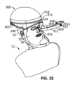
[0082]図2は、個人環境保護システム14の分解図を例示する。フィルタフレーム760は、頭部支持体16に担持され、濾過された空気の循環を可能にするように構成されたリブ762の間の空間764を画定する一連のリブ762を含む。ファン(図66の送風器903参照)は、システム14内に空気の流れを生じさせるように構成される。フィルタカートリッジ/フードアセンブリ(図67のフィルタカートリッジ907を参照)は、フード内部にフィルタカートリッジを備え、フィルタフレーム760上に密封可能に着座するように構成される。
[0082] FIG. 2 illustrates an exploded view of the personal
[0083]図3を参照すると、頭部支持体16は、中央フック508と2つの側部フック510a、510bとを担持している。フック508、510a、510bは、図6に例示されるフェースシールド518の穴512、514、516に係合するように構成される。フェースシールド518は、本明細書に前述した材料の透明シートを備えることができる。中央フック508(図4)は、頭部支持体16の外表面522に結合するように構成されたベース520と、上フック部分524aおよび下フック部分524bを備え、高さh1および最大幅W1を有するフック部分524とを有する。側部フック510a、510b(側部フック510、図5)の各々は、頭部支持体16の外表面522に結合するように構成されたベース526と、最大幅W2を有するフック部分528とを有する。穴514、516は、それぞれ、最大幅W2よりも大きい幅W3を有する。穴514、516は、それぞれ、ベースの高さb2よりも大きい隙間g2を有する。
[0083] Referring to Figure 3, the
[0084]中央フック524の上フック部分524a及び下フック部分508bは、それぞれ、最大厚さt1を有している。側部フック510のフック部分528は、上フック部分540と下フック部分542とを備えている。側部フック510の上フック部分540は、最大厚さt2を有する。穴512は、第1区域501と、第1区域501に隣接する第2区域503とを含む。本明細書に記載される穴512、514、516のいずれかは、ダイ切断プロセスの一部として形成されてもよく、またはパンチツールの使用によって付加されてもよい。
[0084]
[0085]図7を参照すると、穴512の第1区域501は、中央フック508の高さh1よりも少なくとも僅かに大きい最大隙間g1を有する円形を備える。そのため、図7に示すように、フェースシールド518の穴512の第1区域501は、完全に中央フック508上に配置されてもよい。次に、フェースシールド518を中央フック508(矢印、図8)に対してスライドさせることにより、上境界505および下境界507が、それぞれ上フック部分524aおよび下フック部分524bの下にスライドされ、これにより、穴512を介して、中央フック508がフェースシールド518にロックされる。穴514、516の各々は、側部フック510の上フック部分540の最大厚さt2よりも少なくとも僅かに大きい隙間g2を有し、これにより、各穴514、516が各側部フック510a、510b上に完全にフィットすることが可能となる。中央フック508は、ベース520と上フック部分524aおよび下フック部分524bとの間に、それぞれ上凹部530および下凹部532(図4)を有する。
[0085] Referring to FIG. 7, the
[0086]フェースシールド518を頭部支持体16に取り付けるために、穴512は、図7の場合と同様に、最初に中央フック508上に挿入され、次に、図8内で矢印の方向に移動されて、穴512が中央フック508にスライドしてロックする。穴512の第2区域503は、ベース520の直径よりも大きい隙間g3を有する。一部の実施形態において、ベース520は非円形であってもよく、したがって、隙間g3はベース520の垂直高さよりも大きい。ここで、穴512の第2区域503は、ベース526にまたがる。示されるように、穴512の第1区域501が図7のように中央フック508の周りにあり、フェースシールド518が頭部支持体16の外表面522(周囲)の周りに巻かれている場合、穴514は側部フック510aと整列せず、穴516は側部フック510bと整列しない。しかしながら、フェースシールド518が図8の位置にロックされた後、穴512の第2区域503がベース526を跨ぐようにして、穴514は側部フック510aと整列し、穴516は側部フック510bと整列する。そのため、使用者12または支援要員は、最初にフェースシールド518を中央フック508にロックし、次にフェースシールド518を中央フック508の周りにしっかりと結合してバランスさせた状態で、使用者12または支援要員は、フェースシールド518を側部フック510a、510bに完全に取り付けることができる。
[0086] To attach the
[0087]穴514を側部フック510aに取り付けるには、穴514をフック510aのフック部分528の上フック部分540の端部538(図5)に挿入し、フェースシールド518の右側部511をベース526に向けて上フック部分540に引き下げる。穴514の上縁部544は、ベース526の上縁部546に押し付けられ、フェースシールド518の右側部511は、更に下方に押され、隙間g2を僅かに開放して、穴514の下縁部548がフック部分528の下フック部分542の底面550をクリアするようにする。穴514が解放され、そのわずかな変形を失うと、穴514の下縁部548は、底面550の上方でベース526の下レッジ552の下方で、そのロックされた静止位置にスナップ留めされる。このようにして、穴514は、上フック部分540と下フック部分542の両方に対してロックされる。そのため、フェースシールド518は、その中央だけでなくで実質的に垂直下方に延びる。必要または望ましい場合、フェースシールド518は、ここで、(例えば、フェースシールド518の左側部513または右側部511を引っ張ることによって)僅かに左または右に移動させることができ、穴514は、(まだロック位置にあるが)側部フック510aに沿ってスライドし、穴512の第2区域503は、(まだロック位置にあるが)中央フック508のベース520に沿ってスライドする。フック508、510a、510bに対する穴512、514、516の合計幅は、ロック状態における横方向の遊びの量を決定する。穴514および側部フック510aのスナップ処理は、フェースシールド518の左側部513上の穴516および側部フック510bで繰り返すことができる。全ての穴512、514、516がフック508、510a、510bに結合されると、フェースシールド518は、図23に示されるように、幾つかの迅速かつ単純なスナップおよびスライド作用によって、頭部支持体16の所定の位置にしっかりと固定される。さらに、フェースシールド518は、使用者または支援要員(器具を組み立てる誰か)がいかなる方法でも頭部支持体16に触れる必要なく、頭部支持体16に取り付けられる。これは、効果的な滅菌の可能性を著しく増大させることができる。多くの場合、頭部支持体16は再使用可能なアイテムであり、フェースシールド518は無菌状態で供給される。頭部支持体16は洗浄可能であり、さらには滅菌可能であってもよいが、接触を回避することにより、滅菌処置の可能性をより高くすることができる。パンデミック時または制御不能な戦争や災害時のいずれかに、過度に負担がかかり、圧倒された緊急治療室や手術室では、設置の簡素さが重要である。そうでなければ、失敗は容易に起こり、滅菌の喪失も起こりうる結果の一つである。
[0087] To attach the
[0088]図9は、フェースシールド518を頭部支持体16に取り付けるための方法100を示す。ステップ102において、組立者104(図15)は、使用者または支援要員でもよく、フェースシールド518の穴512の第1区域501を中央フック508上に整列させる。第1区域501および第2区域503は、図15では右から左に向けられており、図6では左から右に示されていることに留意されたい。フェースシールド518は、いずれかの方法で頭部支持体16に向けることができるように、可逆的でもよい。他の実施形態において、フェースシールド518は、片側面のみに非反射コーティングを有してもよく、可逆的または非可逆的であってもよい。他の実施形態において、フェースシールド518は、外表面に一つ又は複数の透明な剥離可能な接着して取り付けられた被覆を有してもよく、この被覆は、汚れたり汚染されたりした場合、例えば、はねたり、引っ掻いたりすることによって除去することができる。図10を参照すると、穴512の第1区域501の直径(隙間g1)が、ステップ102の間に中央フック508の高さh1をちょうどクリアするように示されている。この位置は、図7にも見られる。一部の実施態様において、隙間g1は、フェースシールド518がその上に配置されるときに、第1区域501が中央フック508から離れることができるように、高さh1よりも少なくとも僅かに大きくなっている。一部の実施形態において、フェースシールド518は、組立者104からの多大な努力なしに中央フック508を越えて押し付けることができるように、隙間g1(図6)は、高さh1と同じ寸法であるか、または、高さh1よりも僅かに小さくなっている。
[0088] FIG. 9 illustrates a
[0089]ステップ106において、組立者104は、図16に示すように、頭部支持体を図8に示す位置に左(矢印)にスライドさせることによって、フェースシールド518を頭部支持体16にロックする。ここで、穴512の第2の部分503は、中心フック508の基部520の周りに配向される。そのため、中央フック508は、隙間g3(図6)が高さh1よりも小さいので、フェースシールド518を頭部支持体16にロックする。これは、図11でより詳細に見ることができる。図15-図22の組立者104は、頭部支持体16の外側を向いて示されているが、頭部支持体16を頭上に有する使用者は、たとえば、ミラーまたはビデオモニタで自分を見ながら、同じステップを実行することができる。図15および図7に示される位置において、フェースシールド518が頭部支持体16の外表面522に巻き付けられる場合、穴516を側部フック510a(図15の破線参照)の上に配置することができない。側部フック510aおよび穴516(破線)の中心は距離L1だけオフセットされているだけでなく、穴516の全体は、側部フック510aの全体から距離L2だけオフセットされている。しかしながら、フェースシールド518を図16-図18に示す位置にスライドさせると、穴516を側部フック510aの上に配置することができる。そのため、組み立てて穴516を中央フック510にロックする前に、穴512を側部フック508aに組み立てることは不可能である。穴512は、中央フック509に取り付けられ、ロックされなければならない。そのため、フェースシールド518を頭部支持体16に最初にロックして固定する間、フェースシールド518は、損傷、汚れ、または汚染される可能性があるところで、著しく低く吊り下げることができる部分がないように、著しく中心合わせされてバランスが保たれることが保証される。これについては、以下のステップで更に説明する。
[0089] At
[0090]一つの特別な実施形態において、距離D1は、約12.5インチから約18.5インチの間、または約14インチから約17インチの間、または約14.5インチから約16.5インチの間、または約15.5インチであり、穴514の水平中心と穴516の水平中心との間の距離D2は、約11インチから約15インチ、または約12インチから約14インチ、または約12.5インチから約13.5インチ、または約12.75インチから約13.25インチ、または約13インチであり、隙間g1は、約0.60インチと約0.75インチとの間、または約0.675インチであり、約0.60インチと約0.75インチとの間、または約0.675インチ以上の直径を有する穴によって形成され、隙間g2は、約0.225インチと約0.680インチとの間、または約0.300インチと約0.450インチとの間、または約0.325インチと約0.425インチとの間、または約0.375インチであり、隙間g3は、約0.325インチと約0.425インチとの間、または約0.375インチであり、幅W1は、約0.30インチと約0.40インチとの間、または約0.35インチであり、幅W2は、約0.35インチと約0.45インチとの間、または約0.40インチであり、幅W3は、約0.70インチと約0.80インチとの間、または約0.75インチであり、高さh1は、約0.61インチと約0.74インチとの間、または約0.65インチと約0.71インチとの間、または約0.68インチであり、厚さt1は、約0.10インチと約0.18インチとの間、または約0.12インチと約0.16インチとの間、または約0.14インチであり、厚さt2は、約0.06インチと約0.14インチとの間、または約0.08インチと約0.12インチとの間、または約0.10インチであり、ベースの高さb2は、約0.225インチと約0.325インチとの間、または約0.250インチと約0.300インチとの間、または約0.275インチであり、ほぼ区域501が区域503に移行する穴512の水平中心と穴514の水平中心との間の距離D3は、約6.0インチと約7.0インチとの間、または約6.25インチと約6.75インチとの間、または約6.50インチである。他の実施形態において、隙間g1は0.68インチ以上である。
[0090] In one particular embodiment, the distance D1 is between about 12.5 inches and about 18.5 inches, or between about 14 inches and about 17 inches, or between about 14.5 inches and about 16.5 inches. is between 5 inches, or about 15.5 inches, and the distance D2 between the horizontal centers of
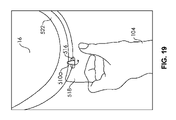
[0091]ステップ108において、組立者104は、図17に示されるように、フェースシールド518を頭部支持体16の外表面522の周りに巻き付け、穴516を側部フック510aの上フック部分540の上に配置する。図12に詳細に示されているように、組立者104は、穴516を端部538を越えて、フック510aのフック部分528の上フック部分540上に通過させる。ステップ110において、組立者104は、フェースシールド518を下方(矢印、図18)に引っ張り、図13および図19に示されるように、フック部分528の下フック部分542の底面550上の穴516を囲む材料の下マージン517を押し付ける。穴516の上縁部544は、ベース526の上縁部546に押し付けられ、フェースシールド518の右側は、さらに下方に押されて、隙間g2(図6)を僅かに開き、穴516の下縁部548がフック部分528の下フック部分542の底面550をクリアする。図14を参照すると、穴516が解放され、その僅かな変形が失われると、穴516の下縁部548は、底面550の上方で、ベース526の下レッジ552の下方で、そのロックされた静止位置にスナップ留めされる。このようにして、穴516は、上フック部分540と下フック部分542の両方に対してロックされる。
[0091] At
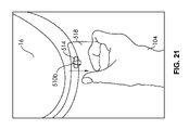
[0092]ステップ112において、組立者104は、図20に示されるように、フェースシールド518の反対側を頭部支持体16の外表面522の周りに巻き付け、穴514を側部フック510bの上フック部分540上に配置する。図12に詳細に示されているように、組立者104は、穴514を端部538を越えて、フック510bのフック部分528の上フック部分540上に通過させる。ステップ114において、組立者104は、フェースシールド518を下方(矢印、図21)に引っ張り、図13および図22に示されるように、フック部分528の下フック部分542の底面550上の穴514を囲む材料の下マージン517を押し付ける。穴514の上縁部544は、ベース526の上縁部546に押し付けられ、フェースシールド518の右側は、さらに下方に押されて、隙間g2(図6)を僅かに開き、穴514の下縁部548がフック部分528の下フック部分542の底面550をクリアする。図14を参照すると、穴514が解放され、その僅かな変形が失われると、穴514の下縁部548は、底面550の上方で、ベース526の下レッジ552の下方で、そのロックされた静止位置にスナップ留めされる。このようにして、穴514は、上フック部分540と下フック部分542の両方に対してロックされる。図23は、頭部支持体16上に完全に組み立てられたフェースシールド518を例示する。図15-図22に示すように、フェースシールド518は、頭部支持体16に全く触れることなく、容易かつ確実に頭部支持体16に取り付けることができる。
[0092] At
[0093]図9は、頭部支持体16からフェースシールド518を取り外すための方法116を更に例示する。ステップ118において、使用者104は、穴514をスナップ解除し、フェースシールド518を側部フック510bから取り外す。ステップ120において、使用者104は、穴516をスナップ解除し、フェースシールド518を側部フック510aから取り外す。ステップ122において、使用者は、頭部支持体16に対してフェースシールド518をスライドさせて、穴512を中央フック508からロック解除し、それによってフェースシールド518を図7、図10および図15の位置に配置する。ステップ124において、使用者104は、フェースシールド518を頭部支持体16から完全に取り外す。ステップ126において、使用者14はフェースシールド126を廃棄する。場合によっては、使用者104はまた、頭部支持体16を廃棄することを選択してもよい。
[0093] FIG. 9 further illustrates the
[0094]他の実施形態において、穴512、穴514、穴516のいずれか1つまたは複数は、水平方向に延びるのではなく、垂直方向に延びてもよい。1つまたは複数の穴512、穴514、穴516は、斜めに延びてもよい。フェースシールド518は、標準的なシート材料から生産することができ、ダイ切断処理によって大量生産することができるので、従来の湾曲した単一形状のフェースシールドと比較してコストを大幅に低減することができる。フック508、フック510および穴512、穴514、穴516を利用するロックおよびロック解除は、迅速かつ確実な組み立ておよび迅速な取り外しおよび洗浄または廃棄を提供する。
[0094] In other embodiments, any one or more of
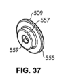
[0095]図36-図39に示すように、代替フック509をフック508の代わりに使用してもよい。フック509は、それを頭部支持体16に取り付けるように構成された近位穴559を含む。フック508は、頭部支持体16上のファスナにスナップするか、または頭部支持体16上のファスナにねじ込むか、または頭部支持体16上のファスナにスライドするか、または頭部支持体16に接着またはエポキシ接着されるように構成されてもよい。フック509は、穴512の第1区域501の最大隙間g1よりも小さい直径を有する円形の第1区域555を有する円形形状を備える。フック509は、穴512の第2区域503の隙間g3よりも小さい直径を有する円形の第2区域557を更に備える。円形の第1区域555の直径は、穴512の第2区域503の隙間g3よりも大きい。そのため、フック509は、フェースシールド518の穴512と同様のロック/ロック解除機能を維持する。
[0095] Alternative hooks 509 may be used in place of
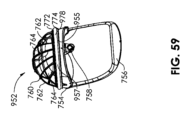
[0096]個人環境保護システム602は、図24-図27に例示されており、支持部分604(例えば、頭部支持体)および顎バー606を備える。支持部分604は、中央フック608と2つの側部フック610a、610bとを担持している。フック608、610a、610bは、図27に例示されるフェースシールド618の上末端部627を貫通して延びる穴612、614、616に係合するように構成される。フェースシールド618は、本明細書に前述した材料の透明シートを備えることができる。しかしながら、フェースシールド618は更にカフ629を備えるが、このカフ629は、織布保護バリアを備えることができる。カフ629は、フェースシールド618の右側611に沿って実質的に垂直に、下末端部625に沿って実質的に水平に、および左側613に沿って実質的に垂直に延びる継ぎ目631によってフェースシールドに固着される。カフ629は、保護された内部空間643(図28)を作り出すするために、使用者の首または下頭部の周囲にぴったりフィットするように構成された弾性内周部633を含む。図25を参照すると、中央フック608は、支持部分604の外表面622に結合するように構成されたベース620と、最大幅W4を有するフック部分624とを有する。フック部分624は、J形状またはL形状、またはある程度のフックを生じさせることができる任意の他の形状を有することができる。側部フック610a、610bの各々は、支持部分604の外表面622に結合するように構成されたベース626と、最大幅W5を有するフック部分628とを有する。各穴614、616は、最大幅W5よりも大きい幅W6を有し、穴612は、最大幅W4よりも大きい幅W7を有し、これにより、各穴612、614、616は、各フック608、610a、610bに完全にフィットすることができる。一部の実施態様において、幅W6は、幅W5より少なくとも10%大きく、又は、幅W5より少なくとも25%大きくなるように構成することができる。一部の実施態様において、幅W7は、幅W4より少なくとも25%大きい、若しくは幅W4より少なくとも50%大きい、若しくは幅W4より少なくとも75%大きい、若しくはW4より少なくとも100%大きいように構成することができる。一部の実施態様において、幅W6は、幅W5よりも約25%~約100%大きいように構成することができる。一部の実施態様において、幅W7は、幅W4よりも約25%~約100%大きいように構成することができる。一部の実施態様において、穴616は、第1の側縁部617及び第2の側縁部619を有する。穴614も同様に説明することができる。一部の実施態様において、第1の側縁部617及び第2の側縁部619は、穴612が中央フック608に係合したままである間、側部フック610b(又は側部フック610a)の上フック部分640の上フック部分最大幅(幅W5)の外側に同時に配置することができるが、これはフェースシールド618が中央フック608に対して特定の側方位置にある場合に限られる。この関係は、スライド調整によって調整することができる。
[0096] A personal
[0097]中央フック608のフック部分624は最大厚さt3を有し、側部フック610のフック部分628は最大厚さt4を有する。穴612は、最大厚さt3よりも少なくとも僅かに大きい間隙g3を有し、これにより、穴612が中央フック608上に完全にフィットすることが可能になる。穴614、616は、それぞれ、最大厚さt4よりも少なくとも僅かに大きい間隙g4を有しており、これにより、各穴614、616は、各側部フック610a、610b上に完全にフィットすることができる。中央フック608は、張出し部630と、張出し部630とベース626との間にある凹部632とを有する。フェースシールド618を支持部分604に取り付けるために、まず、穴612が張出し部630の端部634上に挿入され、フェースシールド618がフック部分624上をベース620に向かって引き下ろして、フェースシールド618の境界部分636、すなわち穴612の周辺部が凹部632内部に完全にフィットし、フェースシールド618が実質的に垂直に下方に延びる。ここで、穴612は、穴512の第2区域503が図11の中央フック508上にロックされる方法と同じではないが、幾分類似した方法で中央フック608のベース620上にロックされる。ただし、ロックは張力によってのみ発生し、スライドは必要ない。一部の実施形態において、穴612の底部分641は、変形または撓み、図13-図14の底面550上の下縁部548のスナップ留めと同様に、中央フック608の下縁部649上にスナップ留めするように構成することができる。
[0097] Hook portion 624 of
[0098]次に、フェースシールド618を左に移動させて、穴612を中央フック608のフック部分624上の左端にスライドさせる。穴612は、スライドしながら中央フック608にロックされたままである。次に、側部フック610aのフック部分628の上フック部分640の端部638に穴614を挿入し、フェースシールド618の右側611を上フック部分640を介してベース626側に引き下ろす。穴614の上縁部644は、ベース626の上レッジ646に押し付けられ、フェースシールド618の右側611は、さらに下方に押され、隙間g4を僅かに開放して、穴614の下縁部648が、側部フック610aのフック部分628の下フック部分642の底面650をクリアするようにする。穴614が解放され、その僅かな変形を失うと、穴614の下縁部648は、底面650の上方でベース626の下レッジ652の下方で、そのロックされた静止位置にスナップ留めされる。このようにして、穴614は、上フック部分640と下フック部分642の両方に対してロックされる。そのため、フェースシールド618は、その中央だけでなく、その右側611においても実質的に垂直下方に延びる。必要に応じて、フェースシールド618をここで僅かに左に移動させることができ、穴614は側部フック610aに沿って(ロック位置で)スライドし、穴612は中央フック608に沿って(ロック位置で)スライドする。ここで、穴614および側部フック610aのスナップ留め処理を、穴616および側部フック610bで繰り返すことができる。フェースシールド618は、図28に示されるように、幾つかの迅速かつ単純なスナップ留めおよびスライド動作によって、支持部分604上の所定の位置にしっかりと固定される。フェースシールド618の取り外しは、作用およびステップを実質的に逆にすることによって行うことができる。他の実施形態において、穴612、614、616のいずれか1つまたは複数は、水平方向に延びるのではなく、垂直方向に延びてもよい。1つまたは複数の穴612、614、616は、斜めに延びてもよい。
[0098] Next, the
[0099]個人保護システム240は、図28および図29に組み立てられた構成で例示されている。カフ629は、継ぎ目631から延び、弾性内周部633で終端し、弧状の弾性窓を形成する。弾性バンド637は、カフ629に(例えば、裁縫によって)結合され、カフ629を支持部分604に保持された協働スナップ(隣接しているが図示していない)を介して支持部分604に固定するように構成された中央スナップ635を有する。弾性内周部633は、保護された内部空間643を作り出すために、使用者の首または下頭部の周囲にぴったりとフィットするように構成される。場合によっては、弾性内周部633を使用者の耳に着けることができる。他の場合には、弾性外周部を使用者の耳の下方に着けることができる。他の場合において、弾性内周部633は、使用者の耳の完全に上方に又は使用者の耳の実質的上方に引っ張ることができる。耳の上方における、この特定の位置決めは、たとえば、使用者が聴診器を使用する必要がある場合に有用であり、聴診器は、両耳にアクセスすることを必要とし、耳の下方に延びる。位置決めは、使用者が一つ又は複数のイヤホン(例えば、オーバーイヤーまたは差込み型イヤホン)を使用している場合にも有用であり、その結果、補助者が処置の特定の時点でイヤホンの1つを取り外すことができる。あるいは、使用者が1つのイヤホンのみを使用している場合、使用者は、弾性内周部633を一方の耳の上方および他方の耳の下方に引っ張るように選択することができる。一部の実施態様において、織布被覆639を支持部分604に担持することができる。他の実施形態において、カフ629は、弾性内周部633によって形成された窓が最初に使用者の頭部の上に配置され、その後、織布被覆639が支持部分604の最上部に取り付けられ(例えば、その上に延伸され)、フェースシールド618が支持部分604に取り付けられるように、織布カバー639と一体であってもよい。調整可能なストラップ645を使用して、使用者の頭部の周りに適切なフィットを作り出すことができる。カフ629をフェースシールド618に組み合わせることにより、洗浄または維持するのがより困難な個人用環境保護システム602の部分(フェースシールド618、カフ629、織布被覆639)を廃棄することが可能となる一方、洗浄および再使用がより容易な支持部分604の再使用可能性を維持することが可能となる。本明細書に記載されるフェースシールドまたはカフのいずれかは、生分解性材料から構成されてもよい。本明細書に記載される任意の材料は、再利用可能な材料から構成されてもよい。他の実施形態において、カフ629は、図6のフェースシールド518と一体化されてもよい。代替的な実施形態において、穴512、514、516、612、614、616のいずれかを、フェースシールド518、618に取り付けられた別個のスタンドオフまたはブラケット内の、またはスタンドオフまたはブラケットのように作用するフェースシールド518、618の厚肉部分内の、穴、ノッチ、または溝に置き換えることができる。他の代替的な実施形態において、穴/フック関係の1つ以上は、磁石/鉄材料関係、または磁石/磁石関係によって置換または増強されてもよい。たとえば、フェースシールド518、618は、外表面522、622によって担持される1つ以上の磁石に取り外し可能に取り付けられるように構成された1つ以上の鋼または400シリーズのステンレス鋼ボタンまたは皿を担持する。
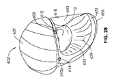
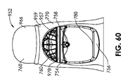
[0099] Personal protection system 240 is illustrated in the assembled configuration in FIGS.
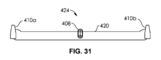
[00100]図30は、図1の個人環境保護システム14と同様の個人環境保護システム414を着けた使用者12を示す。しかしながら、図31に例示するように、中央フック408および2つの側部フック410a、410bは、フックアセンブリ424として担持される。中央フック408および2つの側部フック410a、410bは、可撓性ストリップ420に取り付けられて担持される。可撓性ストリップ420の後方表面は、頭部支持体416の外表面422に取り付けられる。最初にフックアセンブリ424を構成することによって、各フック408、410a、410bの間の正確な間隔を達成することができる。各フック408、410a、410bを収容するために輪郭(スリットおよび/または突出部)を有する必要がないので、頭部支持体416の製造も簡略化することができる。可撓性ストリップ420は、その後方表面に担持された接着ストリップを有してもよい。使用者は、接着ストリップから保護カバーを取り外し、次に、可撓性ストリップを接着ストリップを介して頭部支持体416の外表面422に取り付けることができる。フックアセンブリは、中央フック408の位置に対応する頭部支持体416の中央にあるマークを介して、頭部支持体416上で中心合わせされ、配向可能である。頭部支持体416は、各フックを収容するための追加の特徴を有する必要がないので、頭部支持体416は、より容易に洗浄可能であり、適切な場合には滅菌可能である。フックアセンブリ424は、使い捨てであってもよく、または再使用可能であってもよいが、頭部支持体416よりも再使用が少ないように構成されてもよい。代替実施形態において、可撓性ストリップ420の裏当ては、頭部支持体416の外表面422に担持されたフックおよびループ構造に対応するフックおよびループ構造を備えることができる。
[00100] FIG. 30 shows a
[00101]図32-図35は、使用者12の頭部22に配置された個人保護システム800の代替実施形態を例示する。個人保護システム800は、頭部支持体802およびフェースシールド804を含むので、本明細書に前述した個人保護システムの他の実施形態と同様である。また、システム800は、顎バー42を備えることができる。エクステンダ806は、図32および図33に示すように、頭部支持体802に直接結合されるように構成される。エクステンダ806は、凹部810を有する内側808と、第1の凸部814を有する外側812とを含む。凹部810は、頭部支持体802の腹側表面818上の第2の凸部816と密接に一致するように構成される。中央フック822は、エクステンダ806の外側812上の中央部分820(図34)に担持され、外側816から外面に延びる。エクステンダ806は、中央部分820に厚さTH(図35)を有する。厚さTHは、中央フック822を頭部支持体802から更に離して配置するのに役立ち、したがって、(取り付けられている場合)フェースシールド804の後方により多くの空間824を作り出す。増大した空間は、使用者12の顔30からの増大した距離および/または使用者12の顔30を囲む増大した体積(フェースシールド804の後方)を含むことができる。したがって、本明細書に更に記載されるように、通信システムまたは照明システムなどの他の構成要素のために追加の部屋/空間が作り出される。また、この追加の空間は、顔のより大きな特徴(鼻、口ひげ、顎ひげなど)またはアクセサリ(眼鏡、ルーペなど)を収容することができる。さらに、追加の空間は、容量性の意味で作用し、内部に供給される空気または酸素のより良い制御または流れを可能にし、フェースシールド804の曇化(例えば、鼻および口からフェースシールド804までの距離の増加による)を回避し、または内部二酸化炭素レベルの望ましくない増加を回避ことができる。
[00101] FIGS. 32-35 illustrate an alternative embodiment of a
[00102]エクステンダ806は、切欠き空間828に隣接して、その内側808に穴826を含む。切欠き空間828は、延長部材を軽量化するのに役立ち、射出成形などの製作または低コスト化を助けることができる。穴826は、空間828の他方の側において、外壁832に対向する内壁830を貫通する。穴826は、頭部支持体802の腹側表面818上のフック834(図32)に係合するように構成される。側部の穴836、838は、頭部支持体802に担持された側部フック840に係合するように構成されている。側部フック840は、エクステンダ806が(側部の穴836、838を介して)頭部支持体に取り付けられることを可能にするだけでなく、フェースシールド804の端部穴842の端部穴の係合を可能にするように構成されてもよい。本明細書に記載されたフック構成および/または機構のいずれかを、中央フック822、フック834、または側部フック840に使用することができる。一部の実施態様において、中央フック822は、フェースシールド804の中央穴844にロックできるように回転可能であってもよい。たとえば、フック834は、フェースールド804を適所にロックするために、フェースシールド804の配置後に90°回転されてもよい。使用後、エクステンダ806は再使用可能(洗浄可能、再滅菌可能)であってもよく、またはフェースシールド804とともに取り外し可能かつ使い捨て可能であってもよい。エクステンダ806は、頭部支持体802を様々な異なるセットアップに適応可能にするように働く。エクステンダ806は、図49-図52の実施形態においてより詳細に開示されているように、光(例えば、LED)および/またはカメラを担持するように構成されてもよい。
[00102] The
[00103]特定の実施形態は、以下の節において説明される。 [00103] Specific embodiments are described in the following sections.
[00104]第1項-保護ヘッドギアシステムにおいて、使用者の頭部に係合するように構成された支持体と、支持体に結合されるように構成された上部分と、下末端部を有する下部分とを有するポリマーシートを含むフェースシールドであって、上部分は、第1の穴、第2の穴、および第3の穴を含み、第1の穴、第2の穴、および第3の穴のそれぞれは、第1の穴、第2の穴、および第3の穴のうちの他の2つの穴から実質的に間隔を置いて配置され、第1の穴および第2の穴は、それぞれ実質的に細長い、フェースシールドと、支持体に担持された第1のフックであって、第1の穴は、第1のフックと係合するように構成されている、第1のフックと、支持体に担持された第2のフックであって、第2の穴は、第2のフックと係合するように構成される、第2のフックと、支持体に担持された第3のフックであって、第3の穴は、第3のフックと係合するように構成されている、第3のフックと、を含み、第1のフックは、最大フック幅を有するフック部分を含み、第1のフックは、第2フックと第3のフックとの間の支持体の周囲に置かれ、第1の穴は、第1の穴隙間および第1の穴幅を有し、第1の穴の第1の穴幅は、第1のフックのフック部分の最大フック幅よりも少なくとも約25%大きい、システム。 [00104] Clause 1 - A protective headgear system having a support configured to engage a user's head, an upper portion configured to be coupled to the support, and a lower end a face shield comprising a polymer sheet having a lower portion, the upper portion including first, second and third holes, the first, second and third holes; is substantially spaced from the other two of the first, second and third holes, the first and second holes being , a face shield, each substantially elongated, and a first hook carried by the support, wherein the first hole is configured to engage the first hook. and a second hook carried by the support, wherein the second hole is configured to engage the second hook; and a third hook carried by the support. wherein the third hole is configured to engage the third hook, the first hook having a hook portion having a maximum hook width; wherein the first hook is positioned around the support between the second and third hooks, the first hole has a first hole gap and a first hole width; The system, wherein the first hole width of the one hole is at least about 25% greater than the maximum hook width of the hook portion of the first hook.
[00105]第2項-第1の穴が実質的に水平に延びる、第1項に記載のシステム。 [00105] Clause 2 - The system of Clause 1, wherein the first hole extends substantially horizontally.
[00106]第3項-第2の穴が実質的に水平に延びる第2項に記載のシステム。 [00106] Clause 3 - The system of clause 2, wherein the second hole extends substantially horizontally.
[00107]第4項-第3の穴が実質的に長く、実質的に水平に延びる、第3項に記載のシステム。 [00107] Clause 4 - The system of Clause 3, wherein the third hole is substantially long and extends substantially horizontally.
[00108]第5項-第2のフックは、支持体に結合されたベースと、ベースから実質的に垂直上方に延びる上フック部分と、ベースから実質的に垂直下方に延びる下フック部分とを含む、第1項に記載のシステム。 [00108] Section 5 - The second hook has a base coupled to the support, an upper hook portion extending substantially vertically upward from the base, and a lower hook portion extending substantially vertically downward from the base. 2. The system of paragraph 1, comprising:
[00109]第6項-第3のフックは、支持体に結合されたベースと、ベースから実質的に上方に延びる上フック部分と、ベースから実質的に下方に延びる下フック部分とを含む、第5項に記載のシステム。 [00109] Section 6 - The third hook includes a base coupled to the support, an upper hook portion extending substantially upwardly from the base, and a lower hook portion extending substantially downwardly from the base; A system according to Clause 5.
[00110]第7項-第2のフックの上フック部分は、上フック部分の最大厚さおよび上フック部分の最大幅を有し、第2の穴は、第2の穴隙間および第2の穴幅を有し、第2の穴の第2の穴幅は、第2のフックの上フック部分の最大幅よりも少なくとも約25%大きい、第5項に記載のシステム。 [00110] Clause 7—The top hook portion of the second hook has a maximum thickness of the top hook portion and a maximum width of the top hook portion, and the second hole has a second hole gap and a second 6. The system of clause 5, having a hole width, wherein the second hole width of the second hole is at least about 25% greater than the maximum width of the upper hook portion of the second hook.
[00111]第8項-第2の穴の第2の穴幅が、第2のフックの上フック部分の最大幅よりも約25%から約100%大きい、第7項のシステム。 [00111] Clause 8—The system of Clause 7, wherein the second hole width of the second hole is about 25% to about 100% greater than the maximum width of the upper hook portion of the second hook.
[00112]第9項-第2のフックの上フック部分の上フック部分最大厚さが、第2の穴の第2の穴隙間よりも小さい、第7項に記載のシステム。 [00112] Clause 9—The system of Clause 7, wherein the upper hook portion maximum thickness of the upper hook portion of the second hook is less than the second hole clearance of the second hole.
[00113]第10項-第2の穴は、第1の側縁および第2の側縁を有し、前記第2の穴の前記第1および第2の側縁は、前記第に、前記第2の穴の前記第1および第2の側縁が、前記第2のフックの前記上部フック部分の前記上部フック部分最大幅の外側に同時に配置され得る、第7項に記載のシステム。 [00113] Clause 10 - The second hole has a first side edge and a second side edge, wherein said first and second side edges of said second hole 8. The system of clause 7, wherein the first and second side edges of the second hole can be simultaneously positioned outside the maximum upper hook portion width of the upper hook portion of the second hook.
[00114]第11項-第2のフックのベースは、上フック部分および下フック部分の一方または両方に隣接する穴担持部分を含み、穴担持部分は、第2の穴の第2の穴隙間よりも小さい垂直方向の厚さを有し、穴担持部分は、さらに、第2の穴の第2の穴幅よりも小さい水平方向の厚さを有する、第5項に記載のシステム。 [00114] Clause 11 - The base of the second hook includes a hole bearing portion adjacent to one or both of the upper hook portion and the lower hook portion, the hole bearing portion in the second hole clearance of the second hole 6. The system of clause 5, wherein the hole-carrying portion has a vertical thickness less than the second hole width of the second hole and the horizontal thickness less than the second hole width.
[00115]第12条-第2のフックの下フック部分が、第2のフックのベースの下部分からの垂直延長長さを有し、(a)第2のフックの下フック部分の垂直延長長さと、(b)第2のフックのベースの穴担持部分の垂直厚さとの合計が、(c)第2の穴の第2の穴隙間よりも大きい、第11項に記載のシステム。
[00115]
[00116]第13項-第1のフックがJ字形状を含む、第1項に記載のシステム。 [00116] Clause 13—The system of Clause 1, wherein the first hook comprises a J-shape.
[00117]第14項-第1のフックがL字形状を含む、第1項に記載のシステム。
[00117]
[00118]第15項-第1の穴の第1の穴幅が、第1のフックのフック部分の最大幅よりも約25%から約100%大きい、第1項に記載のシステム。 [00118] Clause 15 - The system of Clause 1, wherein the first hole width of the first hole is about 25% to about 100% greater than the maximum width of the hook portion of the first hook.
[00119]第16項-第1のフックのフック部分が、第1の穴の第1の穴隙間よりも小さい最大厚さを有する、第1項に記載のシステム。
[00119]
[00120]第17項-第2のフックおよび第3のフックのそれぞれが支持体の周囲に置かれる、第1項に記載のシステム。 [00120] Clause 17—The system of Clause 1, wherein each of the second hook and the third hook is positioned around the support.
[00121]第18項-フェースシールドが、ポリエステルを含む、第1項に記載のシステム。
[00121]
[00122]第19項-フェースシールドが、PETGを含む、第18項に記載のシステム。
[00122]
[00123]第20項-フェースシールドが、PETを含む、第18項に記載のシステム。
[00123]
[00124]第21項-フェースシールドの下部分に穴を含まない、第1項に記載のシステム。 [00124] Clause 21—The system of Clause 1, wherein the bottom portion of the face shield does not include holes.
[00125]第22項-フェースシールドが、高透明ポリマーを含む、第1項に記載のシステム。
[00125]
[00126]第23項-フェースシールドが、ダイカットシートを含む、第1項に記載のシステム。 [00126] Clause 23—The system of Clause 1, wherein the face shield comprises a die-cut sheet.
[00127]第24項-第1の穴、第2の穴および第3の穴が、ダイカットされる、第23項に記載のシステム。 [00127] Clause 24 - The system of Clause 23, wherein the first, second and third holes are die cut.
[00128]第25項-第1の穴、第2の穴および第3の穴が、パンチ形成される、第23項に記載のシステム。 [00128] Clause 25 - The system of Clause 23, wherein the first hole, the second hole and the third hole are punched.
[00129]第26項-フェースシールドの厚さが、約0.010インチから約0.020インチの間である、第1項に記載のシステム。
[00129]
[00130]第27項-支持体により担持され、空気を濾過することができるフィルタを更に含む、第1項に記載のシステム。 [00130] Clause 27—The system of Clause 1, further comprising a filter carried by the support and capable of filtering air.
[00131]第28項-支持体が使用者の頭部に係合されたときに、フィルタを通して使用者とフェースシールドとの間の空間に更に空気を入れるように構成されたファンを更に含む、第27項に記載のシステム。
[00131]
[00132]第29項-フェースシールドが、生分解性である、第1項に記載のシステム。 [00132] Clause 29—The system of Clause 1, wherein the face shield is biodegradable.
[00133]第30項-フェースシールドが、再使用可能である、第1項に記載のシステム。
[00133]
[00134]第31項-フェースシールドの下部分に結合されたカフを更に含む、第1項に記載のシステム。
[00134]
[00135]第32項-カフは、フェースシールドの下部分に結合された第1の部分と、第1の部分に対向して、使用者の首に係合するように構成された第2の部分とを含む、第31項に記載のシステム。
[00135]
[00136]第33項-保護ヘッドギアシステムにおいて、使用者の頭部に係合するように構成された支持体と、支持体に結合されるように構成された上部分、下末端部を有する下部分を有するポリマーシートを含むフェースシールドであって、上部分は、第1の穴、第2の穴、および第3の穴を含み、第1の穴、第2の穴、および第3の穴のそれぞれは、第1の穴、第2の穴、および第3の穴の他の2つの穴から横方向に間隔を置いて配置される、フェースシールドと、支持体に担持された第1のフックであって、第1の穴は、第1のフックと係合するように構成されている、第1のフックと、支持体に担持された第2のフックであって、第2の穴は、第2のフックと係合するように構成される、第2のフックと、支持体に担持された第3のフックであって、第3の穴が第3のフックと係合するように構成され、第1のフックが、前記第2のフックと第3のフックとの間の支持体の外周上に置かれる、第3のフックと、を含み、第1のフックは、最大フック幅を有するフック部分を含み、第1の穴は、第1のフックのフック部分の最大フック幅よりも大きい横幅を有し、フェースシールドは、第1の穴が第1のフックのフック部分の上に配置され、第2の穴が第2のフックに結合されるように配向されない為に、支持体に対して第1の位置を有し、第1の穴は、フェースシールドが第1の穴を介して第1のフックにロックされるように、またフェースシールドが支持体に対して第2の位置を有するように、第1のフックに対して横方向にスライド可能であり、第2の穴は第2のフックに結合されるように配向される、システム。
[00136]
[00137]第34項-フェースシールドが支持体に対して第2の位置にあるとき、第3のフックに結合される位置に第3の穴を配置することができる、第33項に記載のシステム。
[00137] Clause 34 -
[00138]第35項-第2のフックは、支持体に結合されたベースと、ベースから実質的に垂直上方に延びる上フック部分と、ベースから実質的に垂直下方に延びる下フック部分とを含む、第33項に記載のシステム。
[00138] Clause 35 - The second hook has a base coupled to the support, an upper hook portion extending substantially vertically upward from the base, and a lower hook portion extending substantially vertically downward from the base. 34. The system of
[00139]第36項-第3のフックは、支持体に結合されたベースと、ベースから実質的に上方に延びる上フック部分と、ベースから実質的に下方に延びる下フック部分とを含む、第35項に記載のシステム。 [00139] Clause 36 - The third hook includes a base coupled to the support, an upper hook portion extending substantially upwardly from the base, and a lower hook portion extending substantially downwardly from the base. 36. The system of clause 35.
[00140]第37項-第2の穴は、第2の穴隙間および第2の穴幅を有し、第2のフックのベースは、上フック部分および下フック部分の一方または両方に隣接して、垂直方向の厚さが第2の穴の第2の穴隙間よりも小さく、水平方向の厚さが第2の穴の第2の穴幅よりも小さい穴担持部分を含む、第35項に記載のシステム。 [00140] Clause 37 - The second hole has a second hole gap and a second hole width, and the base of the second hook is adjacent one or both of the upper hook portion and the lower hook portion. Clause 35, comprising a hole bearing portion having a vertical thickness less than the second hole gap of the second hole and a horizontal thickness less than the second hole width of the second hole The system described in .
[00141]第38項-第2のフックの下フック部分が、第2のフックのベースの下部分からの垂直延長長さを有し、(a)第2のフックの下フック部分の垂直延長長さと(b)第2のフックのベースの穴担持部分の垂直厚さとの合計が、(c)第2の穴の第2の穴隙間よりも大きい、第37項に記載のシステム。
[00141]
[00142]第39項-第2の穴は、第2のフックの上フック部分上をスライドし、第2のフックの下フック部分上でスナップ留めされるように構成され、それによってフェースシールドを2の穴を介して第2のフックにロックする、第35項に記載のシステム。
[00142]
[00143]第40項-第3の穴は、第3のフックの上フック部分上をスライドし、第3のフックの下フック部分上でスナップ留めされるように構成され、それによってフェースシールドを第3の穴を介して第3のフックにロックする、第36項に記載のシステム。
[00143] Clause 40 - The third hole is configured to slide over the upper hook portion of the third hook and snap onto the lower hook portion of the third hook, thereby removing the face shield. 37. The system of
[00144]第41項-第1のフックは、支持体に結合されたベースと、ベースから実質的に上方に延びる上フック部分と、ベースから実質的に下方に延びる下フック部分とを含む、第33項に記載のシステム。
[00144] Clause 41 - The first hook includes a base coupled to the support, an upper hook portion extending substantially upwardly from the base, and a lower hook portion extending substantially downwardly from the base. 34. The system of
[00145]第42項-第1のフックは、最大垂直寸法および垂直ベース厚さを有し、第1の穴は、第1の穴隙間を有する第1区域と、第1区域に横方向に隣接し、第2の穴隙間を有する第2区域とを有し、第1の穴の第1の穴隙間は、第1のフックの最大垂直寸法以上であり、第1の穴の第2の穴隙間は、垂直ベース厚さよりも大きく、最大垂直寸法よりも小さい、第41項に記載のシステム。
[00145]
[00146]第43項-第2のフックと第3のフックとの間の周囲に沿った距離が約12インチと約14インチとの間である、第33項に記載のシステム。
[00146] Clause 43 - The system of
[00147]第44項-第2の穴の水平中心と第3の穴の水平中心との間の距離が約12インチから約14インチである、第33項に記載のシステム。
[00147]
[00148]第45項-フェースシールドの下部分に結合されたカフを更に含む、第33項に記載のフェースシールド。
[00148] Clause 45—The face shield of
[00149]第46項-カフは、フェースシールドの下部分に結合された第1の部分と、第1の部分に対向して使用者の首に係合するように構成された第2の部分とを含む、第45項に記載のフェースシールド。
[00149] Clause 46 - The cuff has a first portion coupled to the lower portion of the face shield and a second portion opposite the first portion and configured to engage the user's
[00150]第47項-保護ヘッドギアシステムの為のフェースシールドにおいて、使用者の頭部に係合するように構成された支持体と、支持体に担持された第1のフック、第2のフック、および第3のフックとを含み、第1のフックは、第2のフックと第3のフックとの間の支持体の周囲に置かれ、第1のフックは、最大垂直寸法を有するフック部分と、支持体に結合された垂直ベース厚さを有するベース部分とを含み、フェースシールドは、支持体に結合されるように構成された上部分と、下末端部を有する下部分とを有するポリマーシートであって、上部分は、第1の穴、第2の穴、および第3の穴を含み、第1の穴、第2の穴、および第3の穴のそれぞれは、第1の穴、第2の穴、および第3の穴の他の2つの穴から横方向に間隔を置いて配置されている、ポリマーシートと、第1の穴は、第1の穴隙間を有する第1区域と、第1区域に横方向に隣接し、第2の穴隙間を有する第2区域とを含み、第1の穴の第1の穴隙間は、第1のフックの最大垂直寸法以上であり、第1の穴の第2の穴隙間は、第1のフックのベースの垂直ベース厚さよりも大きく、第1のフックの最大垂直寸法よりも小さい、フェースシールド。 [00150] Section 47—A Face Shield for a Protective Headgear System, a Support Configured to Engage a User's Head, and First and Second Hooks Carried by the Support , and a third hook, the first hook being positioned around the support between the second hook and the third hook, the first hook being the hook portion having the largest vertical dimension. and a base portion having a vertical base thickness bonded to the support, the face shield having a top portion configured to be bonded to the support and a bottom portion having a bottom terminal end. A sheet, the upper portion including a first hole, a second hole, and a third hole, each of the first hole, the second hole, and the third hole a polymer sheet laterally spaced from the other two of the holes, the second hole, and the third hole; the first hole having a first hole gap in a first region; and a second section laterally adjacent to the first section and having a second hole gap, wherein the first hole gap of the first hole is greater than or equal to the maximum vertical dimension of the first hook; The face shield, wherein a second hole clearance of the first hole is greater than a vertical base thickness of the base of the first hook and less than a maximum vertical dimension of the first hook.
[00151]第48項-第2の穴隙間が、約0.225インチから約0.68インチの間である、第47項に記載のフェースシールド。 [00151] Clause 48 - The face shield of clause 47, wherein the second hole clearance is between about 0.225 inches and about 0.68 inches.
[00152]第49項-第2の穴隙間が、約0.30インチから約0.45インチの間である、第48項に記載のフェースシールド。
[00152] Clause 49 - The face shield of
[00153]第50項-第1の穴隙間が、0.68インチ以上である、第47項に記載のフェースシールド。 [00153] Clause 50 - The face shield of Clause 47, wherein the first hole clearance is 0.68 inch or greater.
[00154]第51項-第2の穴が、水平に延びる、第47項に記載のフェースシールド。 [00154] Clause 51 - The face shield of clause 47, wherein the second hole extends horizontally.
[00155]第52項-3の穴が、水平に延びている、第51項に記載のフェースシールド。 [00155] The face shield of clause 51, wherein the hole of clause 52-3 extends horizontally.
[00156]第53項-ポリマーシートの下部分に結合されたカフを更に含む、第47項に記載のフェースシールド。 [00156] Paragraph 53—The face shield of Paragraph 47, further comprising a cuff coupled to a lower portion of the polymer sheet.
[00157]第54項-カフは、ポリマーシートの下部分に結合された第1の部分と、第1の部分に対向して、使用者の首に係合するように構成された第2の部分とを含む、第53項に記載のフェースシールド。
[00157]
[00158]第55項-第2の穴が、第2のフックとスナップ係合可能である、第47項に記載のフェースシールド。 [00158] Clause 55—The face shield of clause 47, wherein the second hole is snap-engageable with the second hook.
[00159]第56項-第3の穴が、第3のフックとスナップ係合可能である、第55項に記載のフェースシールド。 [00159] Clause 56 - The face shield of Clause 55, wherein the third hole is snap-engageable with the third hook.
[00160]第57項-フェースシールドは、第1の穴が第1のフックのフック部分上に配置可能であり、かつ第2の穴が第2のフックに結合されるように配向されないように、支持体に対して第1の位置を有し、第1の穴は、フェースシールドが第1の穴を介して第1のフックにロックされ、かつフェースシールドが支持体に対して第2の位置を有するように、第1のフックに対して横方向にスライド可能であり、第2の穴は、第2のフックに結合されるように配向される、第47項に記載のフェースシールド。
[00160] Clause 57—The face shield is oriented such that the first hole is positionable over the hook portion of the first hook and the second hole is not oriented to be coupled to the second hook. , has a first position with respect to the support, a first hole with the face shield locked to the first hook through the first hole, and a second position with the face shield relative to the support.
[00161]第58項-ポリマーシートが、約0.010インチから約0.020インチの間の厚さを有する、第47項に記載のシステム。
[00161]
[00162]第59項-フェースシールドが、使用者または使用者を補助する人が支持体に手で触れることを必要とすることなく、支持体に結合されるように構成される、第47項に記載のシステム。 [00162] Clause 59 - Clause 47, wherein the face shield is configured to be coupled to the support without requiring the user or a person assisting the user to touch the support. The system described in .
[00163]第60項-フェースシールドが、手袋または手を支持体に接触することを必要とすることなく、支持体に結合されるように構成される、第47項に記載のシステム。
[00163]
[00164]第61項-保護ヘッドギアシステムを着けるための方法において、保護ヘッドギアシステムは、使用者の頭部に係合するように構成された支持体と、支持体に担持された第1のフック、第2のフック、および第3のフックとを含み、第1のフックが、第2のフックと第3のフックとの間の支持体の周囲に置かれ、第1のフックが、最大垂直寸法を有するフック部分と、支持体に結合された垂直ベース厚さを有するベース部分とを含み、当該方法は、支持体に結合されるように構成された上部分と、下末端部を有する下部分とを有するポリマーシートを準備するステップであって、上部分は、第1の穴、第2の穴、および第3の穴を含み、第1の穴、第2の穴、および第3の穴のそれぞれは、第1の穴、第2の穴、および第3の穴のうちの他の2つの穴から横方向に間隔を置いて配置され、第1の穴は、第1の穴隙間を有する第1区域と、第1区域に横方向に隣接し、かつ第2の穴隙間を有する第2区域とを含み、第1の穴の第1の穴隙間は、第1のフックの最大垂直寸法以上であり、第1の穴の第2の穴隙間は、第1のフックのベースの垂直ベース厚さよりも大きく、第1のフックの最大垂直寸法よりも小さい、ステップと、第1の穴を第1のフックの上に配置するステップと、ポリマーシートを支持体に対してスライドさせて第1の穴を第1のフックにロックするステップと、第2のフックを第2の穴に取り付けるステップと、第3のフックを第3の穴に取り付けるステップと、を含む、方法。 [00164] Clause 61 - A method for donning a protective headgear system, the protective headgear system comprising: a support configured to engage a user's head; and a first hook carried by the support. , a second hook, and a third hook, the first hook being positioned around the support between the second hook and the third hook, the first hook extending up to a vertical A hook portion having a dimension and a base portion having a vertical base thickness coupled to the support, the method comprising: a top portion configured to be coupled to the support; and a bottom portion having a bottom end. wherein the upper portion includes first, second and third holes, and wherein the first, second and third holes are Each of the holes is laterally spaced from two other holes of the first hole, the second hole, and the third hole, the first hole having a first hole gap and a second region laterally adjacent to the first region and having a second hole gap, wherein the first hole gap of the first hole is the maximum of the first hook a step greater than or equal to the vertical dimension, wherein the second hole clearance of the first hole is greater than the vertical base thickness of the base of the first hook and less than the maximum vertical dimension of the first hook; placing the hole over the first hook; sliding the polymer sheet against the support to lock the first hole to the first hook; and locking the second hook to the second hole. and attaching a third hook to the third hole.
[00165]第62項-第2のフックを第2の穴に取り付けるステップは、第2の穴を第2のフックにスナップ留めする工程を含む、第61項に記載の方法。 [00165] Clause 62 - The method of Clause 61, wherein attaching the second hook to the second hole comprises snapping the second hole to the second hook.
[00166]第63項-第3のフックを第3の穴に取り付けるステップは、第3の穴を第3のフックにスナップ留めする工程を含む、第62項に記載の方法。
[00166] Clause 63 - The method of
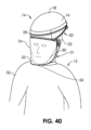
[00167]図40は、個人環境保護システム14を着けた使用者12を例示する。使用者12は、他の点では標準的な、保護されていない環境において伝染性である疾患を有する外科医業に対する患者または他の医療処置に参加する外科医、医師、または他の医療関係者であってもよい。個人環境保護システム14は、使用者12の頭部22と係合するように構成された最上部分18および凹形下側20を有する頭部支持体16を備える。頭部支持体16は、ヘルメットまたは他のタイプのヘッドギアを含むことができ、これらのヘッドギアは、一定の取外し、調整または交換の必要性を回避するために、全医療処置の間、使用者12の頭部22上に確実かつ快適に維持可能である。実質的に光学的に透明な材料を含むフェースシールド24(またはレンズ)は、使用者12の顔30の下方に延びるように構成された下末端部26と、頭部支持体16に結合するように構成された上部分28とを含む。頭部支持体16が使用者12の頭部22に係合している間、フェースシールド24を通してはっきりと使用者12を見ることができる。そのため、使用者12の頭部22が移動すると、頭部支持体16は、フェースシールド24を使用者12の顔30の前方に維持する。一部の実施形態において、ガウン32またはトーガは、使用者12によって使用されて、頭部および頸部より下方の使用者12の身体の一部、大部分、または全部を保護するか、または少なくとも使用者12の上胴部を覆うことができる。一部の実施形態において、ガウン32は、フェースシールド24、頭部支持体16、またはフェースシールド24と頭部支持体16の両方に直接結合することができる。個人環境保護システム14は、空気濾過、流入、および/または流出を介して使用者の12の呼吸環境を実質的に制御するように構成することができ、2012年11月6日に発行された「Protective Headgear System with Filter Protector」と題するGreen氏に対する米国特許第8302599号に記載された実施形態のいずれかの一部または全ての特徴を含むことができる。個人環境保護システム14は、2013年6月4日年6月4日に発行された「Personal Environmental Protection Apparatus」と題するグリーン氏に対する米国特許第8453262号に記載された実施形態のいずれかの一部または全ての特徴を含むことができる。
[00167] FIG. 40 illustrates the
[00168]図41は、フード350を含む代替の個人環境保護システム34を着けた使用者12を例示する。フード350は、使用者12の頭部22と係合するように構成された支持部分36を含む。支持部分36は、フード350の直接の延長部であり、使用者12の頭部22に可逆的に結合するための最上部分38および凹状の下側40を含む。フード350は、実質的に光学的に透明な材料を備えたフェースシールド200を備える。支持部分36が使用者12の頭部22に係合している間、フェースシールド200を通してはっきりと使用者12を見ることができる。フェースシールド200は、保護されかつ隔離された内部空間41を提供するために、フード350内の窓39に密封できるように固定される外周部37を有する。フェースシールド200は、使用者12の目15の少なくとも下方に延びるように構成された下末端部46を含む。図41に例示する実施形態において、フェースシールド200の下末端部46は、使用者12の目15の実質的に下方に延び、使用者12の顎(図示せず)に近い区域まで延びている。フェースシールド200は、さらに、支持部分36に(例えば、接着剤、エポキシ、またはヒートシールなどの密封された固定によって)結合されるように構成された上部48を含む。したがって、使用者12の頭部22が移動すると、支持部分36は、使用者12の顔30の前方にフェースシールド200を維持する。また、フード350は、使用者12の肩19でガウン50上に形成してフィットするように構成された左切抜き部352および右切抜き部(図示せず)を含む。一部の実施態様において、フード350は、使用者12の身体の大部分又は全てを実質的に覆うようにシュラウドのように延びることができる。
[00168] FIG. 41 illustrates a
[00169]フェースシールド24、200は、一般に、ポリエチレンテレフタレートグリコール(PETG)、ポリエチレンテレフタレート(PET)、又は他のポリエステル若しくはポリエステルコポリマー、又はポリカーボネートのような実質的に硬質で高透明度のポリマーを含み、使用者の視界を著しく妨げない比較的薄いが丈夫なバリアを提供することができる。一部の実施態様において、フェースシールド24、200は、使用者12に向かって凹形状を有し、使用者12から離れて凸形状を有する。図40には、凹部31と凸部33とが表示されている。フェースシールド24、200の材料、厚さおよび形状は、独立した要因として、または任意の組合せにおける協力的な要因として、フェースシールド24、200を音響反射板とし、発生された音の顕著な部分を反射させることができる。場合によっては、使用者12の音の大部分が内部空間41内側に反射されて戻ってくるので、使用者12は、他の医療関係者または覚醒している患者には理解されないコマンドを与えることができる。他の場合、使用者12から離れて多くの音を反射する、フェースシールド24、200の同じ反射特性のために、使用者12または他の医療関係者の声をよく聞こえない可能性がある。他の要因は、使用者12が他人の話を聞くことができない状態を悪化させることがある。起きている患者は病気である場合もあれば、鎮静剤またはその他の薬剤を投与されている場合もあり、そのために話し言葉が遅くなったり不明瞭になったりする。他の場合、患者は、通常の話し言葉の仕組みに寄与しない処置の目的のために特定の位置にいてもよい。これらの理由の全ては、発音の明瞭さと同様に、話し言葉がフェースシールド24、200を通して使用者12の耳に伝わる(運ばれる)ときに、患者が十分な音エネルギを生み出すことを困難にする。そのため、医師はしばしば患者を理解するのに苦労することがある。部屋にいる他の医療関係者は、話している間に動き回ったり、使用者12から離れて向き合ったりすることがある従って、これはまた、話し言葉がフェースシールド24、200を通して使用者12の耳に伝わる(運ばれる)ときに、これらの人員が十分な音エネルギを生み出すことを困難にする可能性がある。
[00169] Face shields 24, 200 generally comprise a substantially rigid, high clarity polymer such as polyethylene terephthalate glycol (PETG), polyethylene terephthalate (PET), or other polyester or polyester copolymers, or polycarbonate, A relatively thin yet strong barrier can be provided that does not significantly impede the user's vision. In some embodiments,
[00170]ガウン32、50は、多数の異なる材料および構成を含むことができる。ガウン32、50のための材料は、2層の不織プラスチック布の間に保持されたフィルムを備えた三重積層体を含むことができる。フィルム層および不織プラスチック布を備えた材料などの二層積層材料も可能である。一部の実施態様において、不織布層は、セルローズを備えることができる。一部の実施態様において、不織層は、スパンボンド高密度ポリエチレン(例えば、Tyvek(登録商標)、DuPont de Nemours,Inc.の商標)のようなスパン材料を備えることができる。一実施形態において、一般にSMSとして知られるスパンボンドメルトブローンスパンボンドを使用することができ、スパンボンドポリプロピレンの最上層、メルトブローンポリプロピレンの中間層およびスパンボンドポリプロピレンの最下層を備えた三重積層不織布を備える。他の実施形態において、一つ又は複数の不織布層は、織布層で置換されてもよい。
[00170]
[00171]図42および図43は、内部の詳細をより良く視覚化するために、フェースシールド24およびガウン32が視界から除去された状態で、使用者12上に配置された図40の個人環境保護システム14を例示する。フェースシールド24の下末端部26は、一般にライン25まで延びる。顎バー42は、頭部支持体16の第1の部分48に接続された第1の端部44と、頭部支持体16の第2の部分50に接続された第2の端部46とを有する。顎バー42は、ポリアミド(たとえば、ナイロン6、またはポリカーボネート)のような硬質ポリマー材料を備えることができ、顎バー42の寸法の1つを比較的薄くすることができ、その結果、顎バー42は、ほぼ長方形の横断面を有する。あるいは、顎バー42は高密度ポリエチレンまたはポリプロピレンを備えることができるが、薄い寸法は、十分な剛性および極端な曲げに対する抵抗を維持するために幾分か厚くされる可能性が高い。顎バー42は、第1の端部44と第2の端部46との間で、下側の最上部54を有するほぼU字形状52に延びている。下頂部54は、外向き表面58と内向き表面60とを有する顎バー42の下部分56の中央に置かれる。下部分56は、一般に、使用者12の頭部22に対して横方向に延びる。
[00171] Figures 42 and 43 show the personal environment of Figure 40 placed on the
[00172]個人環境保護システム14は、フェースシールド24によって引き起こされる音の問題を解決する双方向通信システムを提供するように構成される。顎バー42は、制御された双方向言語通信を提供するように構成された拡音器62、64および拡声器66、68のための制御された装着構造として働く。第1の拡音器62は、下部分56で顎バー42の外向き表面58に担持され、個人環境保護システム14の外側の手術室または処置室の環境から来る音を感知するように構成される。第1の拡音器62は、音エネルギのダイアフラム70、またはピックアップ、または他のセンサを含み、使用者12から離れて優先的に配向されて、それによって、周囲の領域内の音波を受信する。第1の拡音器62は、測定された音に基づいて、第1の信号を出力するように構成されている。第1の拡声器66は、下部分56において顎バー42の内向き表面60に担持され、第1の信号を、個人環境保護システム14の内部環境内で使用者12が聞くことができる音声に変換するように構成される。一部かの実施態様において、第1の拡声器66は、使用者12の外耳道に挿入されるように構成された内部イヤホン若しくは差込み型イヤホン、又は使用者12の外耳に担持されるように構成された外部イヤホンのいずれかのイヤホンで置き換えることができる。一部の実施形態において、拡声器とイヤホンの両方を使用することができる。第1の拡音器62(または複数のアレイ型拡音器)および第1の拡声器66、または代替的に一つ又は複数の拡音器62および一つ又は複数のイヤホンの組み合わせは、フェースシールド24の外部で最初に発生された音の情報を、耳がフェースシールド24内部にある使用者12に提供するのに役立つ。
[00172] The personal
[00173]第2の拡音器64は、顎バー42の内向き表面60に担持され、使用者12のボイスから来る音を感知するように構成される。第2の拡音器64は、音エネルギのダイアフラム72、またはピックアップ、または他のセンサを含み、使用者12の口または喉に優先的に向けられて、使用者12の話し言葉によって発生された局所領域の音波を受信する。第2の拡音器64は、測定された音に基づいて第2の信号を出力するように構成されている。第2の拡声器68は、下部分56において顎バー42の外向き表面58に担持され、第2の信号を、個人環境保護システム14の内部環境の外側で、医療関係者または患者が聞くことができる音声に変換するように構成される。一部の実施形態にいて、一人又は複数の医療従事者または患者さえも、イヤホン、外耳道に挿入されるように構成された内部イヤホンまたは差込み型イヤホン、または外耳に担持されるように構成された外部イヤホンのいずれかを使用することができる。一部の実施形態において、拡声器とイヤホンの両方を使用することができる。第2の拡音器64(または複数のアレイ型拡音器)および第2の拡声器68、または代替的に一つ又は複数の拡音器64および一つ又は複数のイヤホンの組み合わせは、フェースシールド24内の使用者12によって発生された音の情報をフェースシールド24の外部の人に提供する役割を果たす。他の実施形態において、拡音器62、64および拡声器66、68の一つ又は複数は、本明細書に記載される機能に必要な同じ一般的な配向を維持しながら、顎バー42の他の部分に取り付けられてもよく、または他のアイテムに完全に取り付けられてもよい。
[00173] A
[00174]可撓性回路74は、内向き表面60(図示されているように)または外向き表面58のいずれかにおいて、顎バー42に担持される。可撓性回路74、第1の拡音器62、第2の拡音器64、ならびに第1の拡声器66および第2の拡声器68は、それぞれ、(例えば、エポキシ、締結具、接着剤、または機械的スナップによって)顎バー42に直接結合されてもよく、または、それぞれが、図42および図43に示されるのとほぼ同じ位置で顎バー42に隣接するように、個人環境保護システム14の別の部分から吊り下げられてもよい。エポキシまたは接着剤で顎バー42に固着される場合、拡音器62、64または拡声器66、68などの音響構成要素は、(設定または硬化された場合)音響構成要素に顕著な音の干渉が与えられないように特定の音響インピーダンスを有するエポキシまたは接着剤で固着される。一部の実施形態において、音響インピーダンス整合が使用される。他の実施形態において、音響インピーダンス不整合が使用される。可撓性回路74は、第1の信号および/または第2の信号を増幅するように構成された一つ又は複数の増幅器76を含むことができる。また、可撓性回路74は、測定され、増幅され、または発生された任意の音声情報をデジタル的に記録するように構成されたプロセッサ78およびメモリ80を含むことができる。記録は処置のディクテーションとして使用することができ、医師の時間を節約し、医師の記憶の中で最も新鮮なときに重要な情報を得ることができる。使用者はボイスコマンドを与えて、音の記録dBを増加させたり、拡声器またはイヤホンのボリュームを大きくすることができる。
[00174] The
[00175]代替的な個人環境保護システム14が図44および図45に例示されており、図40、図42および図43の個人環境保護システム14と同様の要素を有する。しかしながら、一対の拡音器62a、62bは、外向き表面58上の2つの異なる場所に担持されており、一対の拡声器68a、68bは、外向き表面58上の2つの異なる場所に担持されている。また、拡声器66は、左イヤホン69および右イヤホン71に置き換えられている。イヤホン69、71は、それぞれ信号を送出するための導電性ワイヤ77、79を有するように示されているが、代替実施形態では、イヤホン69、71は、たとえば、Bluetooth(登録商標)(Bluetooth SIG,Inc.)によって無線で信号を受信してもよい。一対の拡音器62a、62bおよび一対の拡声器68a、68bは、平行でない2つの軸に沿って配向される。換言すれば、拡音器62aは拡音器62bに対して非平行に配向され、拡声器68aは拡声器68bに対して非平行に配向される。そのため、拡音器62aは、部屋の第1の部分からの音を優先的に感知し、拡音器62bは、部屋の第2の異なる部分からの音を優先的に感知することができる。一部の実施形態において、一方向拡音器を利用することができる。同様に、拡声器68aは音声を優先的に部屋の第1部に送出し、拡声器68bは音声を優先的に部屋の第2部に送出する。一部の実施形態において、拡音器62a、拡音器62b、拡声器68a、および拡声器62bのそれぞれは、異なる固有の中心軸に沿って配向可能であり、そのため、4つの非平行軸を生み出す。しかしながら、場合によっては、たとえば、単一の拡音器の軸と単一の拡声器の軸との間に並列性が存在してもよい。複数の軸の作成は、顎バー42の下部分56の凸状の湾曲部73によって促進される。したがって、拡音器62および拡声器68のそれぞれを、顎バー42に沿った異なる場所に装着することによって、優先軸のそれぞれを容易に達成することができる。一部の実施形態において、拡音器62および拡声器68のそれぞれは、3つの軸で旋回可能であってもよく、その結果、それぞれに対して好ましい配向を達成することができる。個人環境保護システム14では、バッテリ67が、外向き表面58に隣接する顎バー42上の中央の場所75に担持されている。中央の場所75は、バッテリ67の重量を分配し、使用者12上に個人環境保護システム14の良好なバランスを作り出す。これにより、使用者12の快適性と人間工学が向上する。拡音器62および拡声器68は、共に、約500グラム未満、約200グラム未満、約100グラム未満、または約50グラム未満の質量を有する。一部の実施形態において、イヤホン69、71は、さらなる明瞭性のためにノイズキャンセルシステムを組み込むことができる。他の実施形態において、イヤホン69、71または代替的に内部拡声器は、システムの循環空気を使用者12の耳から離すように移動させるか、または循環空気からその領域を単にブロックするために、追加のバッフルまたはチャネルによって補助されてもよい。
[00175] An alternative personal
[00176]図46は、中央面に近接しているかまたは中央面を含む前後面に沿った顎バー42の横断面図であり、第1の拡音器62および第2の拡声器68がフェースシールド24による音響反射に関連する問題を回避することを可能にする特定の装着場所を示す。第1の拡音器62および第2の拡声器68は、それぞれ、フェースシールド24の下末端部26の完全に下方に置かれる。ガウン32の上端部82は、フェースシールド24と顎バー42との間に固定される。ガウン32を製作するために記載された材料は、フェースシールド24に使用される材料よりも有意に多くの音エネルギを伝達し、そのため、ガウン32内部の第1の拡音器62および第2の拡声器68の場所によって、第1の拡音器62および第2の拡声器68を、それらの機能に有意に影響することなく、物理的に(血液または体液の跳ね返りまたは物理的損傷から)保護することができる。
[00176] FIG. 46 is a cross-sectional view of the
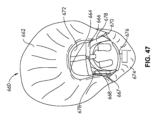
[00177]個人保護システム660は、図47で組み立てられた構成で例示されている。カフ662は、円弧状の弾性窓を形成する弾性内周部664で終端するように延びている。弾性バンド666は、カフ662に(例えば、裁縫によって)結合され、中央スナップ668を有するが、この中央スナップ668は、カフ662を支持部分670に保持された(隣接しているが図示していない)協働スナップを介して支持部分に固定するように構成される。弾性内周部664は、保護された内部空間672を形成するために、使用者の首または下頭部の周囲にぴったりとフィットするように構成される。場合によっては、弾性内周部664を使用者の耳に着けることができる。他の場合、弾性外周部を使用者の耳の下方に着けることができる。他の場合、弾性内周部664は、使用者の耳の完全な上方に又は使用者の耳の実質的に上方に引っ張ることができる。耳の上方における、この特定の位置決めは、たとえば、使用者が聴診器を使用する必要がある場合に有用であり、聴診器は、両耳にアクセスすることを必要とし、耳の下方に延びる。場合によっては、差込み型イヤホン付きで無線の為にブルートゥース(登録商標)を利用した聴診器を利用してもよい。位置決めは、使用者が一つ又は複数のイヤホン(例えば、オーバーイヤーまたは差込み型イヤホン)を使用している場合にも有用であり、その結果、補助者が処置の一定の時点でイヤホンの1つを取り外すことができる。あるいは、使用者が1つのイヤホンのみを使用している場合、使用者は、弾性内周部664を一方の耳の上方および他方の耳の下方に引っ張るように選択することができる。一部の実施態様において、織布被覆674を支持部分670に担持することができる。他の実施形態において、カフ662は、弾性内周部664によって形成された窓が最初に使用者の頭部の上に配置され、次いで織布被覆674が支持部分670の最上部に取り付けられ(例えば、その上に延伸され)、フェースシールド(図示せず)が支持部分670に取り付けられるように、織布被覆674と一体であってもよい。調整可能なストラップ676を使用して、使用者の頭部の周りに適切なフィットを作り出すことができる。カフ662をフェースシールドに組み合わせることにより、洗浄または維持することがより困難であり得る個人環境保護システム660の部分(フェースシールド、カフ662、織布被覆674)の使い捨てが可能となる一方で、より容易に洗浄および再使用可能な支持部分670の再使用可能性が維持される。図44-図45の実施形態のバッテリ67が顎バー42に担持されることの代替として、バッテリ667は、支持部分670内部の凹部678またはポケット内部に担持される。支持部分670は、一つ又は複数の凹部678と共に成形されて、全体の重量を最小にし、成形の容易性(一定の壁厚など)を増大させることができる。そのため、凹部678内部にバッテリ667を配置することは、バッテリを隠して保護するために、この隠れた場所を利用する。
[00177]
[00178]図48は、頭部支持体902およびフェースシールド904を備えた個人保護システム900を例示する。ビデオプロジェクタ906は、プロジェクタ906の投影レンズ908がフェースシールド904の内部表面910を向くように、頭部支持体902により担持されている。そのため、フェースシールド904は、使用者12のための投影スクリーンとして機能する。代替的な実施形態において、個人投影システム900は、フェースシールド904の内部表面910と使用者12の目15との間により大きな距離を作り出すために、図32-図35のエクステンダ806を組み込むことができる。プロジェクタ906は、任意の標準的な手のひらサイズまたはマイクロプロジェクタを含むことができ、バッテリ67、667によって、または電源ケーブルを介して外部電源によって電力を供給することができる。代替的な実施形態において、プロジェクタ906(または追加のプロジェクタ)は、フェースシールド904の外側に延びてもよく、フェースシールド904の外部表面912上に投影するように構成されてもよく、たとえば、情報または手続きビデオの視覚化を部屋の他の人に提供する。一定の実施形態において、図42-図46の実施形態で説明したもののうちの1つのような音声通信システム914が、視覚通信システム916(内部表面910およびプロジェクタ906)とともに提供され、これにより、使用者12に完全な自己完結型通信能力を与える。一部の実施形態において、NIOSH(米国労働安全衛生研究所)PAPR100通信性能基準が含まれる。
[00178] FIG. 48 illustrates a
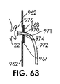
[00179]音声通信システム914および/または視覚通信システム916は、音声メッセージまたはテキストメッセージなどのメッセージを使用者12に提供するように構成されてもよい。音声通信システム914は、使用者12によって話された音声メッセージまたはコマンドを記録および/または送信するように構成することができる。また、音声通信システム914は、たとえば、ブルートゥース(登録商標)を介して、使用者12のスマートフォンまたは任意の移動通信システムと通信することができる。(例えば、GPS追跡を介して)使用者12の場所およびパルス(心拍数)、呼吸数および体温などの使用者12の生体特性などの他の情報は、プロセッサ918上で収集され、記憶され、更新されてもよく、また、頭部支持体902に担持されてもよい。従って、心拍用モニタ、拡音器、または体温計を利用することができる。通信システムは、iOSデバイス、アンドロイドデバイス、または内部ネットワーク上で動作するように構成されてもよい。図68は、個人保護システム935と同様であるが、さらに染められたフェースシールド939を備える個人保護システム900の代替実施形態を示しており、このフェースシールドは、着色または染められたプラスチックを含むことができる。この着色は、たとえば、レーザ光曝露による損傷から保護するために、追加の目の保護を必要とする状況において有用である。これには、健康管理又は一般工業用を含むことができる。図69は、個人保護システム937と同様であるが、さらに、透明シート943から形成されるが、着色または染められた被覆シート945を有するフェースシールド941を有する個人保護システム900の代替実施形態を示す。被覆シート945は、接着裏当て949によって透明シート943に固定されており、透明シート943から剥離可能であるが、剥離タブ947を使用して剥離可能である。一部の実施形態にいて、2枚以上の被覆シート945を利用することができ、第1の被覆シート945は透明シート943に接着され、各連続する被覆シート945は前の被覆シート945の上に取り付けられる。
[00179]
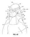
[00180]図49は、頭部支持体922およびフェースシールド924を備えた個人保護システム920を例示する。フェースシールド924は、図32-図35のエクステンダ806と同様のエクステンダ926を介して頭部支持体922に結合される。カフ928は、図28-図29および図47の実施形態のカフ629、662と同様に、フェースシールド924に結合される。使用者12は、処方または非処方レンズを有することができる眼鏡931に接続されたインレンズルーペ930を着けている。エクステンダ926は、使用者12とフェースシールド924との間の空間を増大させて、ルーペ930を容易に収容し、それを調整することを可能にする。使用者12は、カフ928を使用者の手とルーペ930との間に保持することによって、ルーペ930に触れることなくルーペを調整することができる。換言すれば、使用者12は、カフ928をハンドカバーとしてルーペ930を把持する。また、ルーペ930は、ライト932を利用してもよい。ライト932は、ルーペ930とは別個のものとして図49に示されているが、代替的にまたは追加的に、ルーペ930自体がライトを担持してもよい。また、頭部支持体922は、カメラ933を担持してもよい(図52参照)。
[00180] FIG. 49 illustrates a
[00181]代替ライト932a、932bは、図50に示されており、エクステンダ926に担持され、視野領域に収束するビーム934a、934bを提供する。従って、一対のライト932a、932bは、強度を最大化し、視野に焦点を合わせる能力を最適化する。一部の実施態様において、ライト932a、932bは、ビーム934a、934bが幾つかの重なりを有するか又は重複を有さない異なる領域に配向されるように、それぞれ調整可能である。図51は、エクステンダ926の前部分の詳細を示す。エクステンダ926は、使用者12が操作のために容易にアクセス可能な幾つかの制御部936を提供する。制御部936は、膜スイッチを備えてもよく、オン/オフトグルまたはホールドダウンオン/リリースオフに設定されてもよい。電話ダイヤラ938ボタンは、通話を開始するか、一時停止するか、または通話を終了することができる。第1の接続ボタン940は、双方向通信のために、第1の個人またはオフィス(例えば、管理)に接続するように構成されてもよい。第2の接続ボタン942は、第2の個人またはオフィス(例えば、報告)に接続するように構成されてもよいし、症例報告を指示するための記録を自動的に開始するように構成されてもよい。これらの制御部936のいずれかのオン/オフは、代わりにボイスで起動されてもよい。
[00181]
[00182]ライトオン/オフボタン944は、ライト932をオンまたはオフすることができるように構成される。他の実施形態において、ボタン944は、代替的にまたは追加的に、処置室の照明を暗くするかまたはオンまたはオフにする能力を含む他の照明を操作してもよい。カメラボタン946は、カメラ933を起動、一時停止、または停止するように構成される。記録ボタン948は、ビデオおよび/または音声の記録を開始、一時停止、または停止するように構成される。図52を参照すると、カメラ933は、エクステンダ926の上部に装着されて、処置が行われたときの記録を可能にする。訓練材料は、手順の重要なポイントでカメラをオンにし、最も重要な要素のみを記録することによって開発することができる。対応する音声コメントも、(例えば、音声通信システム914を介して)同時に記録することができる。エクステンダ926は、頭部支持体922を様々な異なるセットアップに適応可能にするように働く。第1のセットアップは、エクステンダ926を有することなく、頭部支持体922に直接取り付けられたフェースシールド924を使用して組み込まれてもよい。たとえば、ルーペ930または他の機器またはフェイスウェア/眼鏡を収容するために、より多くの空間が必要とされる場合、フェースシールド924と頭部支持体922との間にエクステンダ926を使用して組み込まれてもよい。使用者12は、ボイスコマンドを与えて、カメラ933をオンにするかオフにするか、ライト932をオンまたはオフにするか、または他の方法(暗さ、明るさ)でそれらの使い方を変えることができる。一部の実施形態において、ルーペの倍率を変更するためにボイスコマンドを使用することができる。たとえば、「3倍にズーム」や「5倍にズーム」などである。
[00182] The light on/off
[00183]図53-図55は、フード350の下部分86に担持された1つ又は複数の接着ストリップ84を有するフード350を例示する。接着ストリップ84は、図53において剥離部90によって取り外されることが示されている剥離可能被覆ストリップ88を含む。使用者(または補助者)は、フード350を使用者の頭上に配置し、次に被覆ストリップ88を剥がす(または他のものによって剥がさせる)。図54に示されるように、使用者または補助者は、ガウン50をフード350の上に配置して、第1の開口部分91がフード350の最上部を滑るようにし、次いで、開口部92および内表面94を有するガウン50の開口上部分351がフード350の上を滑るようにする。次に、図55に示すように、内表面94が接着ストリップ84に接着され、フード350の最上部分38からガウン50の下部分96まで実質的に連続した被覆93を形成する。結合する必要のある結合は存在せず、接着ストリップ84に内表面94を接合することによって、ガウン装着処理が著しく短縮される。一つ又は複数の接着ストリップ84は、フード350の下部分86上に単一の実質的に円周の外ストリップを備えることができ、またはフード350の下部分86の周囲に配列された一連のより小さなストリップを備えることができる。フード350およびガウン50の使用が完了すると、使用者または補助者は、フード350およびガウン50を備えた実質的に連続した被覆93を単に取り外す。汚染された場合、フード350およびガウン50は汚染された部分と接触する可能性を有することなく取り外すことができるので、これは多くの標準的な着脱ステップを省くことができる。また、ステップ数が大幅に削減されるため、時間を大幅に節約できる。
[00183] FIGS. 53-55 illustrate a
[00184]図56は、支持部分754および顎バー756を備えた個人環境保護システム752を例示する。ライト758は、支持部分754によって担持され、使用者によって実行される処置のための追加の照明を提供するように構成される。フィルタフレーム760は、支持部分754に担持され、一連のリブ762を含むが、これらのリブ762は、濾過された空気の循環を可能にするように構成されたリブ762間の空間764を画定する。ファン(図示せず)は、システム752内部に空気の流れを引き起こすように構成される。フィルタカートリッジ/フードアセンブリ766(図57)は、フード770内部にフィルタカートリッジ768を備え、フィルタフレーム760の上に密封可能に着座するように構成される。図57では、フィルタカートリッジ/フードアセンブリ766が支持部分754の上に配置され、図58では、フィルタカートリッジ/フードアセンブリ766がフィルタフレーム760に密封可能に結合される。図56に戻ると、円周側溝またはシート772が、フィルタフレーム760のリップ774の周囲に連続的に延びている。図57に見られるように、内周突出部776は、側溝772内に着座するように構成されている。場合によっては、突出部776は、側溝772にスナップ留めされるように構成される。代替実施形態において、フィルタフレーム760のリップ774は突出部776を有し、フィルタカートリッジ/フードアセンブリ766は側溝772を有してもよい。円形リテーナ778(O-リング、または代替的に連続円形バネまたは弾性/ゴムバンド)は、フィルタカートリッジ/フードアセンブリ766の外部分765の周りに強制的にスナップ留めされて、円周突出部776を円周側溝772内に押し込み、フィルタカートリッジ/フードアセンブリ766およびフィルタフレーム760を密封状態で一緒に保持するように構成される。さらに、リテーナ778は、フィルタカートリッジ768が力を加えて接触しても変位しないことを保証する。図58に示すように、フード770は垂直に延び、少なくとも使用者の肩領域を覆うように構成されている。フィルタカートリッジ/フードアセンブリ766は、リテーナ778を取り外し、次いでフィルタカートリッジ/フードアセンブリ766をフィルタフレーム760から引き離すことによって取り外すことができる。
[00184] FIG. 56 illustrates a personal
[00185]LED780は、顎バー756上に配列され、特定の出来事を使用者または他の医療関係者に通知するために点灯するように構成される。たとえば、十分な空気の流れを維持することができない場合には、一つ又は複数の黄色LEDを点灯させることができる。バッテリ充電のレベルは、点灯している緑色LEDの数(例えば、完全に充電されている場合は3個、充電されていない場合は2個または1個)によって表示することができる。赤色LEDは、充電がない場合、または充電が非常に少ない場合(例えば、残りほぼ15分)に点灯することができる。LEDは、ボイス制御と組み合わせることができ、使用者/担当医師によって決定され、説明されるように、処置の状態を示すことができる。ライト758が一つ又は複数のLED自体を含む場合、個人環境保護システム752内の空気の流れは、さらに、強制対流を用いてライト758内のLEDを冷却するように構成(成形、配向)されてもよい。
[00185]
[00186]図59-図61は、個人環境保護システム952と同様であるが、逆の密封表面を有する個人環境保護システム752の代替実施形態を例示する。Oリングシール978は、円周側溝またはシート772に担持されている。一部の実施態様において、Oリングシール978の内径955は、たとえば、可撓性シリコーン又はウレタン接着剤を用いて、シート772に恒久的に固着されてもよい。フィルタカートリッジ/フードアセンブリ966の内側の内周表面959は、Oリングシール978の外径957と一致するように構成される。図61に示されるように、O-リングシール978が内周表面959と一致して密封されると、フィルタカートリッジ/フードアセンブリ966の外側部分961が膨張する。一部の実施態様において、O-リングシール978は、代わりに、支持部分754上に直接成形又は固着される弾性の円形リッジによってもよい。
[00186] Figures 59-61 illustrate an alternative embodiment of a personal
[00187]図53-図61に示す実施形態において、接着ストリップ84、円形リテーナ778、またはOリングシール978は、より簡単なセットアップ、洗浄、および取外しを可能にするだけでなく、より確実な密封を提供して、空気が所望の領域内でのみ循環することを可能にする。
[00187] In the embodiments shown in FIGS. 53-61, adhesive strips 84,
[00188]図62は、図41のシステム34およびフード350に類似しているが、音響特性を改善するように構成されているフード962を含む代替的な個人環境保護システム960を着けている使用者12を例示する。フード962は、円形継ぎ目967に沿って、スリット970を有するシリコーン環(circle)968に固定される。他の実施形態において、継ぎ目967およびシリコーン環968は、非円形形状(正方形、長方形など)とすることができる。シリコーン環968は、約0.25cm-約2cm、または約0.50cm-約1cmの厚さを有するシリコーンシートを備えることができる。シリコーンは、ポリウレタンまたはラテックスのような別のエラストマーまたは柔軟な材料の代わりに用いることができる。継ぎ目967はシリコーンに密封して固着し、スリット970は通常閉じている。図63に示されるように、聴診器972のシャフト971(耳管)が、スリット970を通して配置され、これは、イヤーピース974の通過を可能にし、次いで、使用者12の耳976内に滑り込ませることができる。シリコーンは膨張または伸長し、スリット970は、フード962の内部を周囲空気から実質的に隔離された状態に維持するのに十分な程度に、シャフト971の周囲を実質的に密封または少なくとも閉鎖する。図示されていないが、スリット970を有する2つのシリコーン環968があり、フード962の両側に1つずつ、両耳聴診器972の両方のシャフト971を収容するようになっている。聴診器972の使用がもはや必要でないとき、シャフト971およびイヤーピース974は取り外されてもよく、スリット970は実質的にそれらの元の閉じた構成に戻る。シリコーン環968は、フード962の材料の外側に取り付けられた図63に示されているが、これに代えて、内側に取り付けられてもよいし、両側に取り付けられてもよいし、同じ平面上(in a flush manner)でさえもよい。
[00188] FIG. 62 is a wearable use of an alternative personal
[00189]図64は、リブ979間の空間977内に湾曲した空気チャネル975を有する個人環境保護システム960用の支持部分36(例えば、ヘルメット)の実施形態を例示する。チャネル975は、成形によって予め形成されるか、または一部かの実施形態では、空間977内の一定の部分で滑り込まされた(slipped)チューブまたはバッフル表面を備えることができる。チャネル975は、渦流または乱流領域を最小にし、層流を増加させて、空気流によって発生される音の強度を低下させるように働く。そのため、干渉の少ない内部音を有する使用者12によって、通信が改善される。さらに、本明細書に開示された音声通信システムと共に使用される場合、他の人が聞くことになる内部拡音器によってピックアップされる干渉内部音はより少ない。各チャネル975は、入口985および出口987を有することができる。図65は、チャネル975を伴うまたは伴わない支持部分36と共に利用可能な代替の特徴部を例示する。外音響消音器981は、支持部36の上部38内に組み込まれている。消音器981は、音響発泡体および/または音響接着剤を備えることができる。支持部分36の内部分にある第2の消音器983を利用してもよい(または代替的に利用してもよい)。第2の消音器983は、使用者12の頭部22をもぴったりと掴むように形成された音響発泡体を含むことができる。チャネル975または消音器981、983は、使用者12の耳976によって聴取される音の強度を3dBだけ、または6dBだけ、または約3dBと約6dBとの間で低下させるように構成することができる。一部の実施態様において、チャネル975は、内部に防音材料を有する薄い硬質チューブを備えた消音器を備えることができる。
[00189] FIG. 64 illustrates an embodiment of a support portion 36 (eg, helmet) for a personal
[00190]図66は、頭部支持体16およびフェースシールド518を有する個人保護システム901を示す。送風器903は、モータ905を備え、フィルタカートリッジ907(図67)を通して空気を循環させるように構成される。本明細書に記載されるように、個人保護設定における通信は重要であり得る。さらに、使用者12は、聴診器を聴くことによって得られるような、なめらかな(soft)または正確な音を聞く必要がある場合がある。そのため、時には、送風器903を含む力-空気システムによって作られるノイズを静かにして、聴覚精度のために使用者12による聴取をより良好に可能にすることが望ましい場合がある。ノイズは、空気の流れおよび/またはモータの動作を含む場合がある。顎バー42に担持されたボタン909は、送風器903のモータ905に電気的に結合されたスイッチを備える。広範囲の活動レベルおよび付随する様々な呼吸速度にわたって正の圧力を維持するために、PAPRシステムは、時々、毎分約200リットルを超える空気の流れを必要とすることがある。ボタン909は、送風器操作のレベルを低減、従って、発生するノイズの量を低減するために、使用者12(または支援要員)によって押されてもよい。一部の実施態様において、ボタン909を押すことにより、送風器903の出力が125リットル/分未満に減少し、強制空気によって引き起こされる音の強度が著しく低下する。一部の実施形態において、ボタン909は、以下の設定を含む三位スイッチ(three-position switch)であってもよい。オフ、底、高。他の実施形態では、4つ以上の位置があってもよい。オフ、低、中、高。
[00190] FIG. 66 shows a
[00191]他の実施形態において、マイクロプロセッサ911は、ボタン909および送風器903に結合され、特定の時間(例えば、5分、3分、1分、30秒、または15秒)の間、送風器の操作を自動的に低下させる(例えば、低速にする)サブルーチンを実行するように構成される。その後、高レベルへの増加が自動的にトリガーされる。一部の実施態様において、マイクロプロセッサ911に結合された音の強度計(dBメータ)913は、頭部支持体16およびフェースシールド518の内領域の内部で音の強度を測定し、内部の音の強度を目標量よりも低くするように、送風器903に供給される電力を比例的に調整する。一部の実施形態において、マイクロプロセッサ911は論理コントローラを備える。このように、フィードバックループは、音のレベルの自動調整を可能にする。ボタン909は、第1の位置(またはトグル)がフィードバックループを操作させ、第2の位置(またはトグル)がフィードバックループをオフにするように構成することができる。一部の実施形態において、ボタン909は、ブルートゥース(登録商標)通信または他の無線手段を介して、送風器903および/またはマイクロプロセッサ911に結合されてもよい。一部の実施形態において、操作はボイス制御を介して制御されてもよい。「フィードバックループを操作する」、「送風器を低レベルで運転する」など。
[00191] In other embodiments, the
[00192]以上は本開示の実施形態に向けられているが、その基本的な範囲から逸脱することなく、他の実施形態および更なる実施形態を案出することができる。たとえば、通信システム(音声、視覚など)を有する実施形態は、フェースシールドのスタイル(スナップオン、シール、染色など)のいずれかを組み込むことができる。 [00192] While the foregoing is directed to embodiments of the present disclosure, other and further embodiments may be devised without departing from its basic scope. For example, embodiments with communication systems (audio, visual, etc.) can incorporate any of the face shield styles (snap-on, seal, stain, etc.).
[00193]また、本明細書に開示される範囲は、任意および全ての重複、下位の範囲、およびそれらの組み合わせを包含する。「~まで」、「少なくとも」、「より大きい」、「より小さい」、「~の間」などの言語は、列挙された数を含む。本明細書中で使用される「ほぼ」、「約」、および「実質的に」のような用語が先行する数は、列挙された数(例えば、約10%=10%)を含み、また、依然として所望の機能を実行するかまたは所望の結果を達成する、記載された量に近い量を表す。たとえば、「ほぼ」、「約」および「実質的に」という用語は、記載された量の10%未満、5%未満、1%未満、0.1%未満、および0.01%未満である量を指すことができる。 [00193] The ranges disclosed herein also include any and all overlaps, subranges, and combinations thereof. Language such as "until", "at least", "greater than", "less than", "between" includes the enumerated numbers. As used herein, numbers preceded by terms such as "approximately," "about," and "substantially" include the recited number (e.g., about 10% = 10%), and , represents an amount approximating the stated amount that will still perform the desired function or achieve the desired result. For example, the terms "approximately," "about," and "substantially" are less than 10%, less than 5%, less than 1%, less than 0.1%, and less than 0.01% of the stated amount. You can point to quantity.
[00194]本開示および添付の特許請求の範囲の目的のために、「または」という接続詞は、包括的に解釈されるべきである(例えば、「リンゴまたはオレンジ」は、「リンゴ、またはオレンジ、またはその両方」と解釈される)。例えば、「リンゴ、オレンジ、またはアボガド」は、以下の場合を除き、「リンゴ、オレンジ、またはアボガド、または任意の2つ、または全ての3つ」として解釈される。(i)明示的に別段の定めをすること。例えば、「…若しくは」、「の一方のみ」又はこれらに類する用語を用いること。または(ii)列挙された選択肢の2つ以上が特定の文脈において相互に排他的であり、その場合、「または」は、相互に排他的でない選択肢を含む組み合わせのみを包含する。本開示および添付された特許請求の範囲の目的のために、「備える」、「含む」、「有する」という語およびその変形は、それらが現れるところであればどこでも、「少なくとも」という句がその各例の後に添付された場合と同じ意味で、制限のない用語として解釈されるものとする。 [00194] For the purposes of this disclosure and the appended claims, the conjunctive "or" should be interpreted inclusively (e.g., "apple or orange" means "apple or orange, or both”). For example, "apple, orange, or avocado" is interpreted as "apple, orange, or avocado, or any two or all three," except where: (i) expressly stipulate otherwise; For example, using “… or”, “only one of” or similar terms. or (ii) two or more of the listed options are mutually exclusive in the particular context, in which case "or" includes only combinations containing non-mutually exclusive options. For the purposes of this disclosure and the appended claims, the terms "comprising," "including," "having," and variations thereof, wherever they appear, include the phrase "at least." shall be construed as open-ended terms in the same sense as if appended after the examples.
Claims (37)
使用者の頭部に係合するように構成された支持体と、
前記支持体に結合された上部分、下末端部を有する下部分を有するフェースシールドと、
前記フェースシールドの少なくとも前記下部分に結合され、前記使用者の上胴の少なくとも一部分を覆うように構成された可撓性シートと、
前記支持体によって担持され、前記フェースシールドの前記下末端部の少なくとも位置に又は隣接して下方に延びるベースと、
第1の音エネルギセンサを備え、第1の信号を発生させるように構成された第1の拡音器であって、前記第1の音エネルギセンサが前記フェースシールドの下末端部の下方に置かれ、前記使用者から離れて優先的に配向されるように、前記ベースによって担持される、第1の拡音器と、
第2の音エネルギセンサを備え、第2の信号を発生させるように構成された第2の拡音器であって、前記第2の音エネルギセンサが優先的に前記使用者に配向されるように、前記ベースによって担持される、第2の拡音器と、
使用者の少なくとも1つの耳によって感知可能な第1の振動を発生するように構成された第1の音声発生器であって、前記第1の振動は、前記第1の信号から少なくとも部分的に発生される、第1の音声発生器と、
前記第2の信号から少なくとも部分的に発生される第2の振動を発生するように構成された拡声器を備える、第2の音声発生器であって、前記拡声器は、前記拡声器が前記フェースシールドの前記下末端部より下方に置かれ、一般に前記使用者から離れて優先的な音エネルギ送出のために配向されるように、前記ベースによって担持される、第2の音声発生器と、
を備える、システム。 In the protective headgear system,
a support configured to engage a user's head;
a face shield having an upper portion coupled to the support and a lower portion having a lower terminal end;
a flexible sheet coupled to at least the lower portion of the face shield and configured to cover at least a portion of the user's upper torso;
a base carried by the support and extending downwardly at or adjacent to at least the lower end of the face shield;
A first loudspeaker comprising a first sound energy sensor and configured to generate a first signal, wherein the first sound energy sensor is positioned below the lower end of the face shield. a first loudspeaker carried by the base such that it is preferentially oriented away from the user;
A second loudspeaker comprising a second sound energy sensor and configured to generate a second signal, wherein the second sound energy sensor is preferentially directed toward the user. a second loudspeaker carried by said base;
A first sound generator configured to generate first vibrations perceivable by at least one ear of a user, said first vibrations being at least partially derived from said first signal. a first audio generator generated;
A second sound generator comprising a loudspeaker configured to generate second vibrations at least partially generated from the second signal, the loudspeaker being the a second sound generator carried by the base such that it is positioned below the lower end of the face shield and is generally oriented away from the user for preferential sound energy delivery;
A system comprising:
前記保護ヘッドギアシステムは、使用者の頭部に係合するように構成された支持体と、
前記支持体の周囲に担持され、水平に間隔を置いて配置された第1のフック、第2のフックおよび第3のフックとを備え、
前記第1のフックは、前記支持体の前記周囲に沿って前記第2のフックと前記第3のフックとの間に置かれ、前記第1のフックは、最大垂直寸法を有するフック部分と、前記支持体に結合され、垂直方向ベース厚さを有するベースとを備え、前記フェースシールドはポリマーシートを備え、前記ポリマーシートは、前記支持体に結合されるように構成された上部分と、下末端部を有する下部分とを有し、前記上部分は、第1の穴、第2の穴、および第3の穴を備え、前記第1の穴、前記第2の穴、および前記第3の穴のそれぞれは、前記第1の穴、前記第2の穴、および前記第3の穴の他の2つから水平に間隔を置いて配置され、前記第1の穴は、第1区域の垂直方向隙間を有する第1区域と、前記第1区域と水平に隣接し、第2区域の垂直方向隙間を有する第2区域とを備え、第1の穴の前記第1区域の垂直方向隙間は、前記第1のフックの前記最大垂直寸法以上であり、前記第1の穴の前記第2区域の垂直方向隙間は、前記第1のフックの前記ベースの前記垂直方向ベース厚さよりも大きく、前記第1のフックの前記最大垂直寸法よりも小さい、フェースシールド。 A face shield for a protective headgear system, comprising:
The protective headgear system includes a support configured to engage a user's head;
a first hook, a second hook and a third horizontally spaced hook carried about the support;
said first hook positioned between said second hook and said third hook along said perimeter of said support, said first hook having a hook portion having a maximum vertical dimension; a base coupled to the support and having a vertical base thickness, the face shield comprising a polymer sheet, the polymer sheet configured to be coupled to the support; a lower portion having a distal end, said upper portion having a first hole, a second hole and a third hole, said first hole, said second hole and said third hole; is horizontally spaced from the other two of said first hole, said second hole, and said third hole, said first hole being located in the first section of A first section having a vertical gap and a second section horizontally adjacent to the first section and having a second section vertical gap, wherein the first section vertical gap of the first hole is , the vertical gap of the second section of the first hole is greater than or equal to the maximum vertical dimension of the first hook, and the vertical gap of the second section of the first hole is greater than the vertical base thickness of the base of the first hook; A face shield that is less than the maximum vertical dimension of the first hook.
使用者の頭部に係合するように構成された支持体であって、前方部分と後方部分と外周とを有する、支持体と、
前記支持体に結合されるように構成されたエクステンダであって、前記エクステンダは、凹部を備える内側と、前記内側に対向する外側とを有し、前記凹部は、前記支持体の前記前方部分の表面に対して配置されるように構成されたエクステンダと、
前記エクステンダに担持された少なくとも1つのフックであって、前記エクステンダの前記外側から外面に延びるフックと、
前記エクステンダの少なくとも1つのフックに結合されるように構成された上部分と、
下末端部を有する下部分とを有するフェースシールドであって、前記エクステンダは、使用者の顔に隣接するフェースシールド内部内の空間の量を増加させるように構成された少なくとも1つのフックにおける厚さを有する、フェースシールドと、
を備える、システム。 In the protective headgear system,
a support configured to engage a user's head, the support having a front portion, a rear portion, and an outer perimeter;
An extender configured to be coupled to the support, the extender having an inner side with a recess and an outer side facing the inner side, the recess extending into the front portion of the support. an extender configured to be positioned against a surface;
at least one hook carried by the extender, the hook extending from the outer side to the outer surface of the extender;
an upper portion configured to be coupled to at least one hook of the extender;
a lower portion having a lower terminal end, wherein the extender has a thickness at the at least one hook configured to increase the amount of space within the face shield interior adjacent to a user's face; a face shield having
A system comprising:
Priority Applications (1)
| Application Number | Priority Date | Filing Date | Title |
|---|---|---|---|
| JP2023135330A JP2023162299A (en) | 2020-03-13 | 2023-08-23 | Personal protection system and method |
Applications Claiming Priority (5)
| Application Number | Priority Date | Filing Date | Title |
|---|---|---|---|
| US202062989416P | 2020-03-13 | 2020-03-13 | |
| US62/989,416 | 2020-03-13 | ||
| US16/925,770 US11219254B2 (en) | 2020-03-13 | 2020-07-10 | Personal protection system and method |
| US16/925,770 | 2020-07-10 | ||
| PCT/US2021/022259 WO2021183984A1 (en) | 2020-03-13 | 2021-03-13 | Personal protection system and method |
Related Child Applications (1)
| Application Number | Title | Priority Date | Filing Date |
|---|---|---|---|
| JP2023135330A Division JP2023162299A (en) | 2020-03-13 | 2023-08-23 | Personal protection system and method |
Publications (2)
| Publication Number | Publication Date |
|---|---|
| JP2023511220A true JP2023511220A (en) | 2023-03-16 |
| JP7338076B2 JP7338076B2 (en) | 2023-09-04 |
Family
ID=77664008
Family Applications (2)
| Application Number | Title | Priority Date | Filing Date |
|---|---|---|---|
| JP2022555081A Active JP7338076B2 (en) | 2020-03-13 | 2021-03-13 | Personal protection system and method |
| JP2023135330A Pending JP2023162299A (en) | 2020-03-13 | 2023-08-23 | Personal protection system and method |
Family Applications After (1)
| Application Number | Title | Priority Date | Filing Date |
|---|---|---|---|
| JP2023135330A Pending JP2023162299A (en) | 2020-03-13 | 2023-08-23 | Personal protection system and method |
Country Status (7)
| Country | Link |
|---|---|
| US (2) | US11219254B2 (en) |
| EP (1) | EP4117477A4 (en) |
| JP (2) | JP7338076B2 (en) |
| AU (1) | AU2021234356A1 (en) |
| CA (1) | CA3175300A1 (en) |
| IL (1) | IL296345A (en) |
| WO (1) | WO2021183984A1 (en) |
Families Citing this family (5)
| Publication number | Priority date | Publication date | Assignee | Title |
|---|---|---|---|---|
| US20220273066A1 (en) * | 2019-01-25 | 2022-09-01 | Stryker Corporation | Personal Protection System Including Medical Garment With A Shield |
| US20220160057A1 (en) * | 2020-11-20 | 2022-05-26 | David Schugar | Combined face shield and mask assembly |
| US20220202128A1 (en) * | 2020-12-31 | 2022-06-30 | Erb Industries, Inc. | Safety helmet with disposable sanitary face shield and method |
| US11318333B1 (en) * | 2021-04-17 | 2022-05-03 | Christopher T. Ellerbrake | Respiratory protection system |
| US20230066913A1 (en) * | 2021-09-02 | 2023-03-02 | Ramiro M. Perez | Protective apparatus face shield |
Citations (4)
| Publication number | Priority date | Publication date | Assignee | Title |
|---|---|---|---|---|
| US3214767A (en) * | 1962-12-20 | 1965-11-02 | Chicago Eye Shield Company | Face shield |
| US5765223A (en) * | 1996-06-04 | 1998-06-16 | Mccausland; Mary L. | Face shield |
| US5970514A (en) * | 1999-02-05 | 1999-10-26 | Wang-Lee; Min-Young | Face mask |
| JP2002505895A (en) * | 1998-03-10 | 2002-02-26 | ミネソタ マイニング アンド マニュファクチャリング カンパニー | Face seal for respiratory mask |
Family Cites Families (33)
| Publication number | Priority date | Publication date | Assignee | Title |
|---|---|---|---|---|
| SE356900B (en) | 1972-01-14 | 1973-06-12 | A Persson | |
| US4701965A (en) * | 1985-10-11 | 1987-10-27 | Landis Timothy J | Visor-type mask for dentists |
| US4821340A (en) | 1988-02-08 | 1989-04-18 | Johnson April E | Face shield |
| US5538014A (en) | 1994-01-10 | 1996-07-23 | James W. Wilson | Deformable face shield with mouthpiece |
| US5711033A (en) | 1995-10-05 | 1998-01-27 | Bio-Medical Devices, Inc. | Air filtration and control system including head gear |
| US6536045B1 (en) * | 1999-11-24 | 2003-03-25 | Racing Optics | Tear-off optical stack having peripheral seal mount |
| DE60133811T2 (en) | 2000-01-18 | 2009-06-25 | Stryker Corp., Kalamazoo | AIR FILTER SYSTEM WITH A HELMET OF AT LEAST TWO AIR OUTPUTS FOR DISTRIBUTING THE AIR TO THE HEAD OF THE USER |
| US6622309B1 (en) * | 2001-04-10 | 2003-09-23 | Joseph Edmonds | Athletic face shield |
| GB0216284D0 (en) | 2002-07-15 | 2002-08-21 | 3M Innovative Properties Co | Eye-wear articles for use with respiratory masks |
| US6918141B2 (en) | 2003-09-23 | 2005-07-19 | Pabbon Development, Inc. | Protective headgear system |
| DE202006021261U1 (en) | 2005-01-12 | 2014-02-28 | Resmed Limited | Forehead supports for face masks |
| EP1865799B1 (en) | 2005-03-24 | 2010-06-09 | Stryker Corporation | Personal protection system |
| CA2615192C (en) | 2005-07-14 | 2014-02-18 | Stryker Corporation | Medical/surgical personal protection system providing ventilation, illumination and communication |
| US7937775B2 (en) | 2005-08-09 | 2011-05-10 | Microtek Medical, Inc. | Surgical protective head gear assembly including high volume air delivery system |
| US20070050898A1 (en) | 2005-08-09 | 2007-03-08 | Larson Keith A | Surgical protective system and assembly having a head gear assembly supporting a surgical garment and air delivery system |
| US8234722B2 (en) | 2007-12-14 | 2012-08-07 | Stryker Corporation | Personal protection system with head unit having easy access controls and protective covering having glare avoiding face shield |
| NZ624599A (en) | 2008-03-04 | 2014-08-29 | Resmed Ltd | Mask system |
| US8453262B2 (en) | 2008-11-24 | 2013-06-04 | Pabban Development, Inc. | Personal environmental protection apparatus |
| US8291512B2 (en) | 2010-04-28 | 2012-10-23 | Walter Stoll | Face shield |
| US8336123B2 (en) * | 2011-05-20 | 2012-12-25 | Honeywell International, Inc. | Latching mechanism for retention of face shield lens |
| US8434167B2 (en) | 2011-08-03 | 2013-05-07 | Honeywell International Inc. | Universal dual-pivot face shield assembly for a hard hat |
| US20140053308A1 (en) | 2012-01-30 | 2014-02-27 | Mubeen A. Cutchi | Face Shield Attachment for Winter Jacket Hoods |
| US10722403B2 (en) * | 2012-06-25 | 2020-07-28 | Good.B, Llc | Headwear with storable accessory |
| US20140053307A1 (en) * | 2012-08-27 | 2014-02-27 | Polison Corporation | Protecting mask |
| US10149511B2 (en) * | 2012-09-28 | 2018-12-11 | Matscitechno Licensing Company | Protective headgear system |
| CA2905946A1 (en) | 2013-03-14 | 2014-10-02 | Stryker Corporation | Medical/surgical personal protection system including an ultraviolet light for purifying air drawn into the system |
| WO2015065750A1 (en) * | 2013-10-30 | 2015-05-07 | Balboa Manufacturing Company, Llc | Balaclava with removable face mask |
| BR112018013870B1 (en) | 2016-01-07 | 2022-03-15 | Thi Total Healthcare Innovation Gmbh | Barrier system and method of controlling a device within a barrier system |
| US10384084B2 (en) | 2017-10-18 | 2019-08-20 | Stryker Corporation | Personal protection system with control member |
| US10881943B2 (en) | 2018-01-11 | 2021-01-05 | Jonathan Isserow | Protective headgear with adjustable faceshield |
| US10420386B1 (en) | 2019-01-25 | 2019-09-24 | Stryker Corporation | Medical garment including a shield |
| WO2021202607A1 (en) | 2020-03-30 | 2021-10-07 | AeroMed Leasing, LLC | Upper body positive pressure protection system |
| US20210308499A1 (en) | 2020-04-06 | 2021-10-07 | Whirlpool Corporation | Powered air-purifying respirator |
-
2020
- 2020-07-10 US US16/925,770 patent/US11219254B2/en active Active
-
2021
- 2021-03-13 EP EP21767874.7A patent/EP4117477A4/en active Pending
- 2021-03-13 WO PCT/US2021/022259 patent/WO2021183984A1/en active Application Filing
- 2021-03-13 IL IL296345A patent/IL296345A/en unknown
- 2021-03-13 JP JP2022555081A patent/JP7338076B2/en active Active
- 2021-03-13 CA CA3175300A patent/CA3175300A1/en active Pending
- 2021-03-13 AU AU2021234356A patent/AU2021234356A1/en active Pending
- 2021-11-30 US US17/539,009 patent/US20220079271A1/en active Pending
-
2023
- 2023-08-23 JP JP2023135330A patent/JP2023162299A/en active Pending
Patent Citations (4)
| Publication number | Priority date | Publication date | Assignee | Title |
|---|---|---|---|---|
| US3214767A (en) * | 1962-12-20 | 1965-11-02 | Chicago Eye Shield Company | Face shield |
| US5765223A (en) * | 1996-06-04 | 1998-06-16 | Mccausland; Mary L. | Face shield |
| JP2002505895A (en) * | 1998-03-10 | 2002-02-26 | ミネソタ マイニング アンド マニュファクチャリング カンパニー | Face seal for respiratory mask |
| US5970514A (en) * | 1999-02-05 | 1999-10-26 | Wang-Lee; Min-Young | Face mask |
Also Published As
| Publication number | Publication date |
|---|---|
| EP4117477A1 (en) | 2023-01-18 |
| EP4117477A4 (en) | 2024-04-10 |
| WO2021183984A1 (en) | 2021-09-16 |
| US20220079271A1 (en) | 2022-03-17 |
| US20210282476A1 (en) | 2021-09-16 |
| IL296345A (en) | 2022-11-01 |
| JP2023162299A (en) | 2023-11-08 |
| JP7338076B2 (en) | 2023-09-04 |
| CA3175300A1 (en) | 2021-09-16 |
| US11219254B2 (en) | 2022-01-11 |
| AU2021234356A1 (en) | 2022-10-06 |
Similar Documents
| Publication | Publication Date | Title |
|---|---|---|
| JP7338076B2 (en) | Personal protection system and method | |
| US6250299B1 (en) | Protective system for face and respiratory protection | |
| US6257235B1 (en) | Face mask with fan attachment | |
| JP2020532666A (en) | Face mask with a piece of clear plastic | |
| TW201350167A (en) | Respiration apparatus | |
| US20210289851A1 (en) | Personal Air Filtration System with Smart App | |
| US10980297B1 (en) | Protective face shield with respirator | |
| US20230120007A1 (en) | Personal protection system and method | |
| WO2014030643A1 (en) | Protective clothing | |
| US20220295935A1 (en) | Head Covering Device with Communication Hardware | |
| US20230074044A1 (en) | G- mask | |
| US20230029404A1 (en) | Balanced Device Providing Filtered Air for a User | |
| CN212036243U (en) | Protective helmet with air purification function and protective system | |
| WO2023086609A1 (en) | Combined face shield and mask assembly | |
| US20220238132A1 (en) | Face Mask with Integrated Communication System | |
| US20220016451A1 (en) | Personal Air Filtering Device with Air Mover Pulling Air Out of the Device | |
| US20220296939A1 (en) | Head Covering Device Providing Filtered Intake and Exhaust Air | |
| US20220016450A1 (en) | Head Covering Device Providing Filtered Intake and Exhaust Air | |
| CN111659048A (en) | Multifunctional gas-proof dust-proof loudspeaker mask | |
| RU2749047C1 (en) | Individual protective mask | |
| CN115768298A (en) | Personal air filtration device with safety feature | |
| CN212260620U (en) | Integrated medical protective head cover | |
| US20220295923A1 (en) | Head Covering Device Providing Filtered Intake and Exhaust Air | |
| CN211882300U (en) | Medical protective mask | |
| JP2022032900A (en) | Positive pressure face shield |
Legal Events
| Date | Code | Title | Description |
|---|---|---|---|
| A521 | Request for written amendment filed |
Free format text: JAPANESE INTERMEDIATE CODE: A523 Effective date: 20221003 |
|
| A621 | Written request for application examination |
Free format text: JAPANESE INTERMEDIATE CODE: A621 Effective date: 20221003 |
|
| A871 | Explanation of circumstances concerning accelerated examination |
Free format text: JAPANESE INTERMEDIATE CODE: A871 Effective date: 20221003 |
|
| A131 | Notification of reasons for refusal |
Free format text: JAPANESE INTERMEDIATE CODE: A131 Effective date: 20230221 |
|
| A521 | Request for written amendment filed |
Free format text: JAPANESE INTERMEDIATE CODE: A523 Effective date: 20230427 |
|
| TRDD | Decision of grant or rejection written | ||
| A01 | Written decision to grant a patent or to grant a registration (utility model) |
Free format text: JAPANESE INTERMEDIATE CODE: A01 Effective date: 20230725 |
|
| A61 | First payment of annual fees (during grant procedure) |
Free format text: JAPANESE INTERMEDIATE CODE: A61 Effective date: 20230823 |
|
| R150 | Certificate of patent or registration of utility model |
Ref document number: 7338076 Country of ref document: JP Free format text: JAPANESE INTERMEDIATE CODE: R150 |