JP2023169116A - Spine relaxation medical equipment - Google Patents
Spine relaxation medical equipment Download PDFInfo
- Publication number
- JP2023169116A JP2023169116A JP2023076354A JP2023076354A JP2023169116A JP 2023169116 A JP2023169116 A JP 2023169116A JP 2023076354 A JP2023076354 A JP 2023076354A JP 2023076354 A JP2023076354 A JP 2023076354A JP 2023169116 A JP2023169116 A JP 2023169116A
- Authority
- JP
- Japan
- Prior art keywords
- spring
- cylinder
- hook
- chair
- side support
- Prior art date
- Legal status (The legal status is an assumption and is not a legal conclusion. Google has not performed a legal analysis and makes no representation as to the accuracy of the status listed.)
- Pending
Links
- 230000005540 biological transmission Effects 0.000 description 3
- 230000002040 relaxant effect Effects 0.000 description 3
- 230000000694 effects Effects 0.000 description 2
- 239000013013 elastic material Substances 0.000 description 2
- 229920001971 elastomer Polymers 0.000 description 2
- 239000004816 latex Substances 0.000 description 2
- 229920000126 latex Polymers 0.000 description 2
- 239000000463 material Substances 0.000 description 2
- 210000003423 ankle Anatomy 0.000 description 1
- 210000001217 buttock Anatomy 0.000 description 1
- 210000002683 foot Anatomy 0.000 description 1
- 230000014509 gene expression Effects 0.000 description 1
- 239000002184 metal Substances 0.000 description 1
- 229920003002 synthetic resin Polymers 0.000 description 1
- 239000000057 synthetic resin Substances 0.000 description 1
- 239000002023 wood Substances 0.000 description 1
Images


Classifications
-
- A—HUMAN NECESSITIES
- A61—MEDICAL OR VETERINARY SCIENCE; HYGIENE
- A61H—PHYSICAL THERAPY APPARATUS, e.g. DEVICES FOR LOCATING OR STIMULATING REFLEX POINTS IN THE BODY; ARTIFICIAL RESPIRATION; MASSAGE; BATHING DEVICES FOR SPECIAL THERAPEUTIC OR HYGIENIC PURPOSES OR SPECIFIC PARTS OF THE BODY
- A61H1/00—Apparatus for passive exercising; Vibrating apparatus ; Chiropractic devices, e.g. body impacting devices, external devices for briefly extending or aligning unbroken bones
- A61H1/02—Stretching or bending or torsioning apparatus for exercising
- A61H1/0218—Drawing-out devices
- A61H1/0229—Drawing-out devices by reducing gravity forces normally applied to the body, e.g. by lifting or hanging the body or part of it
-
- A—HUMAN NECESSITIES
- A61—MEDICAL OR VETERINARY SCIENCE; HYGIENE
- A61F—FILTERS IMPLANTABLE INTO BLOOD VESSELS; PROSTHESES; DEVICES PROVIDING PATENCY TO, OR PREVENTING COLLAPSING OF, TUBULAR STRUCTURES OF THE BODY, e.g. STENTS; ORTHOPAEDIC, NURSING OR CONTRACEPTIVE DEVICES; FOMENTATION; TREATMENT OR PROTECTION OF EYES OR EARS; BANDAGES, DRESSINGS OR ABSORBENT PADS; FIRST-AID KITS
- A61F5/00—Orthopaedic methods or devices for non-surgical treatment of bones or joints; Nursing devices; Anti-rape devices
- A61F5/01—Orthopaedic devices, e.g. splints, casts or braces
- A61F5/02—Orthopaedic corsets
- A61F5/028—Braces for providing support to the lower back, e.g. lumbo sacral supports
-
- A—HUMAN NECESSITIES
- A61—MEDICAL OR VETERINARY SCIENCE; HYGIENE
- A61H—PHYSICAL THERAPY APPARATUS, e.g. DEVICES FOR LOCATING OR STIMULATING REFLEX POINTS IN THE BODY; ARTIFICIAL RESPIRATION; MASSAGE; BATHING DEVICES FOR SPECIAL THERAPEUTIC OR HYGIENIC PURPOSES OR SPECIFIC PARTS OF THE BODY
- A61H1/00—Apparatus for passive exercising; Vibrating apparatus ; Chiropractic devices, e.g. body impacting devices, external devices for briefly extending or aligning unbroken bones
- A61H1/02—Stretching or bending or torsioning apparatus for exercising
- A61H1/0292—Stretching or bending or torsioning apparatus for exercising for the spinal column
-
- A—HUMAN NECESSITIES
- A61—MEDICAL OR VETERINARY SCIENCE; HYGIENE
- A61H—PHYSICAL THERAPY APPARATUS, e.g. DEVICES FOR LOCATING OR STIMULATING REFLEX POINTS IN THE BODY; ARTIFICIAL RESPIRATION; MASSAGE; BATHING DEVICES FOR SPECIAL THERAPEUTIC OR HYGIENIC PURPOSES OR SPECIFIC PARTS OF THE BODY
- A61H2201/00—Characteristics of apparatus not provided for in the preceding codes
- A61H2201/01—Constructive details
- A61H2201/0119—Support for the device
- A61H2201/0138—Support for the device incorporated in furniture
- A61H2201/0149—Seat or chair
-
- A—HUMAN NECESSITIES
- A61—MEDICAL OR VETERINARY SCIENCE; HYGIENE
- A61H—PHYSICAL THERAPY APPARATUS, e.g. DEVICES FOR LOCATING OR STIMULATING REFLEX POINTS IN THE BODY; ARTIFICIAL RESPIRATION; MASSAGE; BATHING DEVICES FOR SPECIAL THERAPEUTIC OR HYGIENIC PURPOSES OR SPECIFIC PARTS OF THE BODY
- A61H2201/00—Characteristics of apparatus not provided for in the preceding codes
- A61H2201/16—Physical interface with patient
- A61H2201/1602—Physical interface with patient kind of interface, e.g. head rest, knee support or lumbar support
- A61H2201/1614—Shoulder, e.g. for neck stretching
- A61H2201/1616—Holding means therefor
-
- A—HUMAN NECESSITIES
- A61—MEDICAL OR VETERINARY SCIENCE; HYGIENE
- A61H—PHYSICAL THERAPY APPARATUS, e.g. DEVICES FOR LOCATING OR STIMULATING REFLEX POINTS IN THE BODY; ARTIFICIAL RESPIRATION; MASSAGE; BATHING DEVICES FOR SPECIAL THERAPEUTIC OR HYGIENIC PURPOSES OR SPECIFIC PARTS OF THE BODY
- A61H2201/00—Characteristics of apparatus not provided for in the preceding codes
- A61H2201/16—Physical interface with patient
- A61H2201/1602—Physical interface with patient kind of interface, e.g. head rest, knee support or lumbar support
- A61H2201/1623—Back
- A61H2201/1626—Holding means therefor
-
- A—HUMAN NECESSITIES
- A61—MEDICAL OR VETERINARY SCIENCE; HYGIENE
- A61H—PHYSICAL THERAPY APPARATUS, e.g. DEVICES FOR LOCATING OR STIMULATING REFLEX POINTS IN THE BODY; ARTIFICIAL RESPIRATION; MASSAGE; BATHING DEVICES FOR SPECIAL THERAPEUTIC OR HYGIENIC PURPOSES OR SPECIFIC PARTS OF THE BODY
- A61H2201/00—Characteristics of apparatus not provided for in the preceding codes
- A61H2201/16—Physical interface with patient
- A61H2201/1602—Physical interface with patient kind of interface, e.g. head rest, knee support or lumbar support
- A61H2201/1628—Pelvis
- A61H2201/1633—Seat
-
- A—HUMAN NECESSITIES
- A61—MEDICAL OR VETERINARY SCIENCE; HYGIENE
- A61H—PHYSICAL THERAPY APPARATUS, e.g. DEVICES FOR LOCATING OR STIMULATING REFLEX POINTS IN THE BODY; ARTIFICIAL RESPIRATION; MASSAGE; BATHING DEVICES FOR SPECIAL THERAPEUTIC OR HYGIENIC PURPOSES OR SPECIFIC PARTS OF THE BODY
- A61H2201/00—Characteristics of apparatus not provided for in the preceding codes
- A61H2201/16—Physical interface with patient
- A61H2201/1602—Physical interface with patient kind of interface, e.g. head rest, knee support or lumbar support
- A61H2201/1635—Hand or arm, e.g. handle
- A61H2201/1638—Holding means therefor
-
- A—HUMAN NECESSITIES
- A61—MEDICAL OR VETERINARY SCIENCE; HYGIENE
- A61H—PHYSICAL THERAPY APPARATUS, e.g. DEVICES FOR LOCATING OR STIMULATING REFLEX POINTS IN THE BODY; ARTIFICIAL RESPIRATION; MASSAGE; BATHING DEVICES FOR SPECIAL THERAPEUTIC OR HYGIENIC PURPOSES OR SPECIFIC PARTS OF THE BODY
- A61H2201/00—Characteristics of apparatus not provided for in the preceding codes
- A61H2201/16—Physical interface with patient
- A61H2201/1602—Physical interface with patient kind of interface, e.g. head rest, knee support or lumbar support
- A61H2201/165—Wearable interfaces
-
- A—HUMAN NECESSITIES
- A61—MEDICAL OR VETERINARY SCIENCE; HYGIENE
- A61H—PHYSICAL THERAPY APPARATUS, e.g. DEVICES FOR LOCATING OR STIMULATING REFLEX POINTS IN THE BODY; ARTIFICIAL RESPIRATION; MASSAGE; BATHING DEVICES FOR SPECIAL THERAPEUTIC OR HYGIENIC PURPOSES OR SPECIFIC PARTS OF THE BODY
- A61H2203/00—Additional characteristics concerning the patient
- A61H2203/04—Position of the patient
- A61H2203/0425—Sitting on the buttocks
-
- A—HUMAN NECESSITIES
- A61—MEDICAL OR VETERINARY SCIENCE; HYGIENE
- A61H—PHYSICAL THERAPY APPARATUS, e.g. DEVICES FOR LOCATING OR STIMULATING REFLEX POINTS IN THE BODY; ARTIFICIAL RESPIRATION; MASSAGE; BATHING DEVICES FOR SPECIAL THERAPEUTIC OR HYGIENIC PURPOSES OR SPECIFIC PARTS OF THE BODY
- A61H2205/00—Devices for specific parts of the body
- A61H2205/08—Trunk
- A61H2205/081—Back
Abstract
Description
本開示は、脊椎を弛緩させることで、脊椎に加えられる負荷を低減させる医療器具に関する。 TECHNICAL FIELD The present disclosure relates to a medical device that relaxes the spine, thereby reducing the load placed on the spine.
韓国登録実用新案公報第20-0176863号(2000.04.15.公告)には、脊椎を弛緩させることで、脊椎に加えられる負荷を低減させる医療器具の例が掲載されている。 Korean Registered Utility Model Publication No. 20-0176863 (published on April 15, 2000) describes an example of a medical device that reduces the load applied to the spine by relaxing the spine.
同公報に掲載された健康用脊椎弛緩装置(以下「従来の脊椎弛緩用医療器具」という)は、互いに平行に立設された2つのガイド柱と、スイッチの作動によって正回転または逆回転する動力を発生するギヤードモータと、前記ギヤードモータの動力によって作動して回転力を伝達する動力伝達手段と、前記動力伝達手段により回転し、前記ガイド柱の内部の下端部にそれぞれ回転可能に設置される第1のスプロケットと、前記ガイド柱の内部の上端部にそれぞれ回転可能に設置される第2のスプロケットと、前記第1のスプロケットと第2のスプロケットとの間に設置され、第1のスプロケットと第2のスプロケットとを連動させるチェーンと、上端部が前記チェーンの一側に回転可能に設置され、下端部にローラーが設置されて前記チェーンの作動で傾斜するベッドと、前記ベッドの上端部に固定設置され、ヒトの足を固定する足首固定手段と、を含む。 The health-use spinal relaxation device (hereinafter referred to as "conventional spinal relaxation medical device") published in the same bulletin consists of two guide columns erected parallel to each other, and a power source that rotates forward or backward by operating a switch. a geared motor that generates a rotational force; a power transmission means that is operated by the power of the geared motor and transmits rotational force; and a power transmission means that is rotated by the power transmission means and is rotatably installed at a lower end inside the guide column. a first sprocket, a second sprocket rotatably installed at the upper end of the inside of the guide column, and a second sprocket installed between the first sprocket and the second sprocket; a chain that interlocks the second sprocket; an upper end rotatably installed on one side of the chain; a bed that has a roller installed on the lower end and tilts when the chain is actuated; an ankle fixing means fixedly installed and fixing the human foot.
一方、従来の脊椎弛緩用医療器具は、その大きさと重さのため、移動と保管が容易ではない。また、従来の脊椎弛緩用医療器具を使用しようとするときは、別途の時間を割かなければならない。 On the other hand, conventional medical devices for spinal relaxation are difficult to move and store due to their size and weight. Additionally, additional time must be spent when using conventional spinal relaxation medical devices.
本開示の目的は、移動と保管が容易であり、かつ実生活においても使い勝手のよい脊椎弛緩用医療器具を提供することである。 An object of the present disclosure is to provide a medical device for spinal relaxation that is easy to move and store, and is convenient to use in real life.
本開示の実施形態による脊椎弛緩用医療器具が記述される。 A spinal relaxation medical device according to embodiments of the present disclosure is described.
第1の実施形態による脊椎弛緩用医療器具は、座板および背板を有する椅子と、前記椅子の左側に設けられる第1の脇支持台と、前記椅子の右側に設けられる第2の脇支持台と、を含み、前記第1の脇支持台と前記第2の脇支持台のそれぞれは、前記椅子に垂直方向に結合されるシリンダーと、前記シリンダーの内部に設けられ、一方向に軸回転させるとき、前記シリンダーの上方に引き出される第1のばねと、前記第1のばねの上端に結合され、前記第1のばねのばね定数よりも小さいばね定数を有する第2のばねと、前記第2のばねの上部に設けられ、脇に密着するバーと、を含むことを特徴とする。 A medical device for spinal relaxation according to a first embodiment includes a chair having a seat plate and a back plate, a first armpit support provided on the left side of the chair, and a second armpit support provided on the right side of the chair. a base, each of the first side support and the second side support includes a cylinder vertically coupled to the chair; and a cylinder provided inside the cylinder and pivotable in one direction. a first spring that is pulled out above the cylinder; a second spring that is coupled to the upper end of the first spring and has a spring constant that is smaller than the spring constant of the first spring; It is characterized by including a bar provided on the upper part of the spring 2 and closely attached to the armpit.
第1の実施形態による脊椎弛緩用医療器具は、前記第1の脇支持台の上部に設けられる第1のフックと、前記第2の脇支持台の上部に設けられる第2のフックと、ユーザの腰を包むものであって、右端に第1の雌バックルが備えられ、左端に第2の雌バックルが具備された弾性腰バンドと、一端が前記第1のフックに締結され、他端に第1の雌バックルと締結される第1の雄バックルが備えられた第1の胸バンドと、一端が前記第2のフックに締結され、他端に第2の雌バックルと締結される第2の雄バックルが備えられたた第2の胸バンドと、前記第1のフックと前記第2のフックとを連結する弾性連結バンドと、をさらに含むことができる。 The medical device for spinal relaxation according to the first embodiment includes a first hook provided on the top of the first armpit support, a second hook provided on the top of the second armpit support, and a second hook provided on the top of the second armpit support. an elastic waistband that wraps around the waist of a person, the elastic waistband having a first female buckle on the right end and a second female buckle on the left end; one end fastened to the first hook; a first chest band having a first male buckle fastened to the first female buckle; and a second chest band having one end fastened to the second hook and the other end fastened to the second female buckle. The device may further include a second chest band having a male buckle, and an elastic connecting band connecting the first hook and the second hook.
幾つかの実施形態において、前記バーの下部には、前記第2のばねの内部に挿入されるロッドがさらに設けられることができる。 In some embodiments, a rod inserted into the second spring may be further provided at a lower portion of the bar.
第2の実施形態による脊椎弛緩用医療器具は、腰保護ベルトと、前記腰保護ベルトの左側に設けられる第1の脇支持台と、前記腰保護ベルトの右側に設けられる第2の脇支持台と、を含み、前記第1の脇支持台および前記第2の脇支持台のそれぞれは、前記腰保護ベルトに垂直方向に結合されるシリンダーと、前記シリンダーの内部に設けられ、一方向に軸回転させるとき、前記シリンダーの上方に引き出される第1のばねと、前記第1のばねの上端に結合され、前記第1のばねのばね定数よりも小さいばね定数を有する第2のばねと、前記第2のばねの上部に設けられ、脇に密着するバーと、を含むことを特徴とする。 A medical device for spinal relaxation according to a second embodiment includes a lower back protection belt, a first armpit support provided on the left side of the lower back protection belt, and a second armpit support provided on the right side of the lower back protection belt. each of the first armpit support and the second armpit support includes a cylinder vertically coupled to the waist protection belt; a first spring that is pulled out above the cylinder when rotated; a second spring that is coupled to the upper end of the first spring and has a spring constant that is smaller than the spring constant of the first spring; It is characterized by including a bar provided on the upper part of the second spring and closely attached to the side.
第2の実施形態による脊椎弛緩用医療器具は、前記第1の脇支持台の上部に設けられる第1のフックと、前記第2の脇支持台の上部に設けられる第2のフックと、ユーザの腰を包むものであって、右端に第1の雌バックルが具備され、左端に第2の雌バックルが具備された弾性腰バンドと、一端が前記第1のフックに締結され、他端に第1の雌バックルと締結される第1の雄バックルが具備された第1の胸バンドと、一端が前記第2のフックに締結され、他端に第2の雌バックルと締結される第2の雄バックルが具備された第2の胸バンドと、前記第1のフックと前記第2のフックとを連結する弾性連結バンドと、をさらに含むことができる。 The medical device for spinal relaxation according to the second embodiment includes a first hook provided at the top of the first armpit support, a second hook provided at the top of the second armpit support, and a second hook provided at the top of the second armpit support. an elastic waistband that wraps around the waist of a person, the elastic waistband having a first female buckle on the right end and a second female buckle on the left end; one end fastened to the first hook; a first chest band having a first male buckle fastened to the first female buckle; and a second chest band having one end fastened to the second hook and the other end fastened to the second female buckle. The device may further include a second chest band having a male buckle, and an elastic connecting band connecting the first hook and the second hook.
幾つかの実施形態において、前記バーの下部には、前記第2のばねの内部に挿入されるロッドがさらに設けられることができる。 In some embodiments, a rod inserted into the second spring may be further provided at a lower portion of the bar.
本発明の多様な実施形態による脊椎弛緩用医療器具は、脊椎を弛緩させることで、脊椎に加えられる負荷を低減させ、ユーザの姿勢を矯正するという効果がある。 Medical devices for spinal relaxation according to various embodiments of the present invention have the effect of relaxing the spine, reducing the load applied to the spine, and correcting the user's posture.
本発明の多様な実施形態による脊椎弛緩用医療器具は、椅子(または腰保護ベルト)の形態で構成されるため、移動と保管が容易であり、実生活においても活用可能である。 Since the medical device for spinal relaxation according to various embodiments of the present invention is configured in the form of a chair (or a waist protection belt), it is easy to move and store, and can be used in real life.
以下、添付図面を参照して、多様な実施形態による脊椎弛緩用医療器具を具体的に説明する。 Hereinafter, medical devices for spinal relaxation according to various embodiments will be described in detail with reference to the accompanying drawings.
図1は、第1の実施形態による脊椎弛緩用医療器具100(以下、「脊椎弛緩用医療器具」100という)の斜視図であり、図2は、脊椎弛緩用医療器具100の分解斜視図である。
FIG. 1 is a perspective view of a medical device for spinal relaxation 100 (hereinafter referred to as "medical device for spinal relaxation" 100) according to the first embodiment, and FIG. 2 is an exploded perspective view of the medical device for
図1及び図2に示されているように、脊椎弛緩用医療器具100は、椅子110、第1の脇支持台120、及び第2の脇支持台130を含む。
As shown in FIGS. 1 and 2, the spinal relaxation
<各方向の定義>本発明における構成の方向を示す表現(たとえば、前面、背面、左(側)、右(側)など)は、図1を基準とする。 <Definition of Each Direction> Expressions indicating directions of the configuration in the present invention (for example, front, back, left (side), right (side), etc.) are based on FIG. 1.
椅子110は、ユーザの尻を支持する座板111と、ユーザの背中を支持する背板112とを含む。椅子110は、合成樹脂材質、原木材質、金属材質などで作製されることができる。座板111および背板112は、互いに異なる材質で作製されても構わない。
第1の脇支持台120は、所定の長さを有し、椅子110の左側に結合され、ユーザの左脇を支持する機能を果たす。
The
第2の脇支持台130は、所定の長さを有し、椅子110の右側に結合され、ユーザの右脇を支持する機能を果たす。
The
第1の脇支持台120と第2の脇支持台130とは、図面に示されているように、背板112に結合されることができ、図面には示されていないが、製作者の意図によって座板111に結合されてもよい。
The
第1の脇支持台120と第2の脇支持台130とは、同一の大きさと形態で構成されることができる。この場合、第1の脇支持台120および第2の脇支持台130の位置は入れ替わってもよい。
The first armpit support 120 and the
第1の脇支持台120は、シリンダー121、第1のばね122、第2のばね123、及びバー124で構成されることができる。
The
シリンダー121は、所定の長さを有する。シリンダー121は、背板112に結合されることができる。シリンダー121は地面と垂直を成す。
第1のばね122は、所定の長さを有し、シリンダー121の内部に設けられる。第1のばね122は、一方向に軸回転させる時、シリンダー121の上方に引き出されるように構成される。すなわち、第1のばね122は、シリンダー121を基準に高さ調節が可能に構成される。具体的な例として、図3に示されているように、第1のばね122の径は、シリンダー121の内径に対応し、シリンダー121の内部には、斜め方向にひだが形成されることができる。第1のばね122は、ユーザの上体の動きに応じて、前後左右方向に屈曲することができる。
The
また、図1及び図2を参照すると、第2のばね123は、第1のばね122の上部に設けられる。第2のばね123は、第1のばね122に比べて、短い長さを有する。第2のばね123のばね定数は、第1のばね122のばね定数よりも小さい値を持つ。具体的に、第1のばね122は、ユーザの体重によって垂直方向に圧縮されないばね定数を有し、第2のばね123は、ユーザの体重によって垂直方向に容易に圧縮されるばね定数を有する。すなわち、第1のばね122は、ユーザの上体を安定に支持し、第2のばね123は、脇と第1のばね122との間の空間を違和感なく埋める機能をする。
Also, referring to FIGS. 1 and 2, the
バー124は、第2のばね123の上部に設けられる。バー124は、側面視、弧線状であることができる。バー124は、ユーザの脇に密着する。バー124の全体または表面は、クッション感のある材質で構成されることができる。
A
バー124の前端、後端、中央上部には、指圧部124a、124b、124cが突設されることができる。
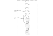
図3を参照すれば、バー124は、第2のばね123に着脱自在に構成されることができる。例えば、バー124の下部には、第2のばね123の内部に挿入されるロッドがさらに設けられ、第2のばね123の上部には、リングプレートが具備されることができる。
Referring to FIG. 3, the
ロッドは、第2のばね123よりも長い長さを有するように構成されることができ、この時、ロッドは、ユーザの上体の動きに起因する第2のばね123の前後左右の変形を防止する。
The rod can be configured to have a longer length than the
第2の脇支持台130も、第1の脇支持台120と同様に、シリンダー131、第1のばね132、第2のばね133、及びバー134で構成されることができる。
Similarly to the
引き続き、脊椎弛緩用医療器具100は、第1のフック140、第2のフック150、弾性腰バンド160、第1の胸バンド170、第2の胸バンド180、及び弾性連結バンド190をさらに含むことができる。
Subsequently, the spinal relaxation
第1のフック140は、第1の脇支持台120の上部に設けられる。具体的に、第1のフック140は、バー124の下方に設けられることができる。第1のフック140は、バー124に一体に構成されてもよい。
The
第2のフック150は、第2の脇支持台130の上部に設けられる。具体的に、第2のフック150は、バー134の下方に設けられることができる。第2のフック150は、バー134に一体に構成されてもよい。
The
弾性腰バンド160は、所定の長さを有し、ユーザの腰を包む。弾性腰バンド160は、ゴム、ラテックスなどの弾性を有する材質で構成され、弾性腰バンド160の内部には、所定の剛性を有し、腰を支持する支持片163が具備されることができる。
The
弾性腰バンド160の右側端部には、第1の雌バックル161が具備され、弾性腰バンド160の左側端部には、第2の雌バックル162が具備される。第1の雌バックル161および第2の雌バックル162は、同一の仕様で構成されることができる。
A first
第1の胸バンド170の一端は、第1のフック140に締結され、第1の胸バンド170の他端には、第1の雌バックル161と締結される第1の雄バックル171が具備される。すなわち、第1の胸バンド170は、ユーザの左脇と左胸を通って右腰に向かう。
One end of the
第1の胸バンド170には、長さ調節部172がさらに設けられ、長さ調節可能に構成されることができる。
The
第2の胸バンド180の一端は、第2のフック150に締結され、第2の胸バンド180の他端には、第2の雌バックル162と締結される第2の雄バックル181が具備される。すなわち、第2の胸バンド180は、ユーザの右脇と右胸を通って左腰に向かう。
One end of the
第2の胸バンド180には、長さ調節部182がさらに設けられ、長さ調節可能に構成されることができる。
The
第1の胸バンド170および第2の胸バンド180は、同一の仕様で構成されることができる。
The
弾性腰バンド160、第1の胸バンド170、第2の胸バンド180は、椅子110に着座したユーザの腰(腰椎)を前方に押し付けることで、ユーザの脊椎をS字形に維持させ、第1の脇支持台140および第2の脇支持台150をユーザの胴体方向に密着させる。
The
弾性連結バンド190は、ゴム、ラテックスなど弾性を有する材質で構成され、第1のフック140と第2のフック150とを直接連結し、ユーザの背中上部の後ろに位置付けられる。弾性連結バンド190は、第1の脇支持台140および第2の脇支持台150をユーザの胴体方向に集める機能をする。
The elastic connecting
図4は、第2の実施形態による脊椎弛緩用医療器具200(以下、「脊椎弛緩用医療器具」200という)の斜視図であり、図5は、脊椎弛緩用医療器具200の分解斜視図である。
FIG. 4 is a perspective view of a spinal relaxation medical device 200 (hereinafter referred to as "spinal relaxation medical device" 200) according to the second embodiment, and FIG. 5 is an exploded perspective view of the spinal relaxation
図4及び図5を参照すれば、脊椎弛緩用医療器具100の椅子110は、腰保護ベルト210に代えられる。腰保護ベルト210は、帯の形状をし、両端はバックル、ベルクロ、ジッパーなどを介して締結されるように構成可能である。腰保護ベルト210の外側面には、第1の脇支持台120および第2の脇支持台130の下部を収容するポケット211が具備されることができ、第1の脇支持台120および第2の脇支持台130は、腰保護ベルト210に着脱自在に構成されることができる。
Referring to FIGS. 4 and 5, the
弾性腰バンド160は、ユーザの好みによって、腰保護ベルト210の内外側のいずれの箇所に位置されてもよい。
The
前述した多様な実施形態による脊椎弛緩用医療器具100、200は、脊椎を弛緩させることで、脊椎に加えられる負荷を低減させるとともに、ユーザの姿勢を矯正する効果がある。
The spinal relaxation
また、多様な実施形態による脊椎弛緩用医療器具100、200は、椅子(または腰保護ベルト)の形態で構成されるため、移動と保管が容易であり、実生活においても活用可能である。
In addition, since the
100 脊椎弛緩用医療器具
110 椅子
120 第1の脇支持台
130 第2の脇支持台
140 第1のフック
150 第2のフック
160 弾性腰バンド
170 第1の胸バンド
180 第2の胸バンド
190 弾性連結バンド
200 脊椎弛緩用医療器具
210 腰保護ベルト
100 Medical device for
Claims (4)
前記椅子の左側に設けられる第1の脇支持台と、
前記椅子の右側に設けられる第2の脇支持台と、を含み、
前記第1の脇支持台と前記第2の脇支持台のそれぞれは、
前記椅子に垂直方向に結合されるシリンダーと、
前記シリンダーの内部に設けられ、一方向に軸回転させるとき、前記シリンダーの上方に引き出される第1のばねと、
前記第1のばねの上端に結合され、前記第1のばねのばね定数よりも小さいばね定数を有する第2のばねと、
前記第2のばねの上部に設けられ、脇に密着するバーと、
前記第2のばねよりも長い長さを有し、前記バーの下部に設けられ、前記第2のばねの内部に挿入されて前記第2のばねの前後左右の歪みを防止するロッドと、を含むことを特徴とする、脊椎弛緩用医療器具。 a chair having a seat and a back;
a first side support provided on the left side of the chair;
a second side support provided on the right side of the chair,
Each of the first side support stand and the second side support stand,
a cylinder vertically coupled to the chair;
a first spring provided inside the cylinder and pulled out above the cylinder when the cylinder is rotated in one direction;
a second spring coupled to an upper end of the first spring and having a spring constant less than a spring constant of the first spring;
a bar provided on the upper part of the second spring and closely attached to the armpit;
a rod that has a longer length than the second spring, is provided at the lower part of the bar, and is inserted into the second spring to prevent distortion of the second spring in the front, back, right, and left directions; A medical device for spinal relaxation, comprising:
前記腰保護ベルトの左側に設けられる第1の脇支持台と、
前記腰保護ベルトの右側に設けられる第2の脇支持台と、を含み、
前記第1の脇支持台および前記第2の脇支持台のそれぞれは、
前記腰保護ベルトに垂直方向に結合されるシリンダーと、
前記シリンダーの内部に設けられ、一方向に軸回転させるとき、前記シリンダーの上方に引き出される第1のばねと、
前記第1のばねの上端に結合され、前記第1のばねのばね定数よりも小さいばね定数を有する第2のばねと、
前記第2のばねの上部に設けられ、脇に密着するバーと、
前記第2のばねよりも長い長さを有し、前記バーの下部に設けられ、前記第2のばねの内部に挿入されて前記第2のばねの前後左右の歪みを防止するロッドと、を含むことを特徴とする、脊椎弛緩用医療器具。 waist protection belt,
a first armpit support provided on the left side of the waist protection belt;
a second armpit support provided on the right side of the waist protection belt;
Each of the first side support stand and the second side support stand,
a cylinder vertically coupled to the waist protection belt;
a first spring provided inside the cylinder and pulled out above the cylinder when the cylinder is rotated in one direction;
a second spring coupled to an upper end of the first spring and having a spring constant less than a spring constant of the first spring;
a bar provided on the upper part of the second spring and closely attached to the armpit;
a rod that has a longer length than the second spring, is provided at the lower part of the bar, and is inserted into the second spring to prevent distortion of the second spring in the front, back, right, and left directions; A medical device for spinal relaxation, comprising:
前記第2の脇支持台の上部に設けられる第2のフックと、
ユーザの腰を包むものであって、右端に第1の雌バックルが具備され、左端に第2の雌バックルが具備された弾性腰バンドと、
一端が前記第1のフックに締結され、他端に第1の雌バックルと締結される第1の雄バックルが具備された第1の胸バンドと、
一端が前記第2のフックに締結され、他端に第2の雌バックルと締結される第2の雄バックルが具備された第2の胸バンドと、をさらに含むことを特徴とする、請求項1または2に記載の脊椎弛緩用医療器具。 a first hook provided on the top of the first side support;
a second hook provided at the top of the second side support;
an elastic waistband that wraps around the user's waist and has a first female buckle on its right end and a second female buckle on its left end;
a first chest band having one end fastened to the first hook and the other end provided with a first male buckle fastened to the first female buckle;
A second chest band having one end fastened to the second hook and the other end provided with a second male buckle fastened to a second female buckle. 3. The medical device for spinal relaxation according to 1 or 2.
Applications Claiming Priority (2)
| Application Number | Priority Date | Filing Date | Title |
|---|---|---|---|
| KR10-2022-0059319 | 2022-05-16 | ||
| KR1020220059319A KR102530190B1 (en) | 2022-05-16 | 2022-05-16 | Medical apparatus for spinal relaxation |
Publications (1)
| Publication Number | Publication Date |
|---|---|
| JP2023169116A true JP2023169116A (en) | 2023-11-29 |
Family
ID=86331287
Family Applications (1)
| Application Number | Title | Priority Date | Filing Date |
|---|---|---|---|
| JP2023076354A Pending JP2023169116A (en) | 2022-05-16 | 2023-05-02 | Spine relaxation medical equipment |
Country Status (6)
| Country | Link |
|---|---|
| US (1) | US20230363934A1 (en) |
| EP (1) | EP4279039A1 (en) |
| JP (1) | JP2023169116A (en) |
| KR (2) | KR102530190B1 (en) |
| CN (1) | CN117064607A (en) |
| WO (1) | WO2023224339A1 (en) |
Families Citing this family (1)
| Publication number | Priority date | Publication date | Assignee | Title |
|---|---|---|---|---|
| KR102530190B1 (en) * | 2022-05-16 | 2023-05-10 | 박장형 | Medical apparatus for spinal relaxation |
Family Cites Families (11)
| Publication number | Priority date | Publication date | Assignee | Title |
|---|---|---|---|---|
| KR20000000400A (en) | 1999-10-19 | 2000-01-15 | 김수정 | Backbone relaxation device for health |
| WO2005107658A2 (en) * | 2004-04-21 | 2005-11-17 | Washington University | Cervical brace |
| JP2006180972A (en) * | 2004-12-27 | 2006-07-13 | Koichi Tanaka | Health maintenance assist and its usage |
| CN202950801U (en) * | 2012-11-30 | 2013-05-29 | 沈世辉 | Vertical traction physical therapy instrument for lumbar intervertibral disc |
| CN103284865A (en) * | 2013-05-22 | 2013-09-11 | 崔学晨 | Wearable lumbar traction device |
| KR101481811B1 (en) * | 2014-08-19 | 2015-01-16 | 하정록 | Chair assistance device |
| KR101725227B1 (en) * | 2015-04-22 | 2017-04-11 | 김응주 | Apparatus for spine traction and support |
| CN106109067B (en) * | 2016-06-14 | 2018-09-18 | 刘茂生 | Lumbar supporting device |
| US20180360641A1 (en) * | 2017-06-14 | 2018-12-20 | Paul W. Budge | Back-traction device and exercise system |
| KR20210055029A (en) * | 2021-04-23 | 2021-05-14 | 박장형 | Chair with armpit support |
| KR102530190B1 (en) * | 2022-05-16 | 2023-05-10 | 박장형 | Medical apparatus for spinal relaxation |
-
2022
- 2022-05-16 KR KR1020220059319A patent/KR102530190B1/en active IP Right Grant
-
2023
- 2023-02-02 KR KR1020230014468A patent/KR20230160161A/en unknown
- 2023-05-02 JP JP2023076354A patent/JP2023169116A/en active Pending
- 2023-05-10 EP EP23172509.4A patent/EP4279039A1/en active Pending
- 2023-05-10 CN CN202310524452.9A patent/CN117064607A/en active Pending
- 2023-05-15 US US18/317,520 patent/US20230363934A1/en active Pending
- 2023-05-15 WO PCT/KR2023/006552 patent/WO2023224339A1/en unknown
Also Published As
| Publication number | Publication date |
|---|---|
| CN117064607A (en) | 2023-11-17 |
| KR102530190B1 (en) | 2023-05-10 |
| WO2023224339A1 (en) | 2023-11-23 |
| US20230363934A1 (en) | 2023-11-16 |
| EP4279039A1 (en) | 2023-11-22 |
| KR20230160161A (en) | 2023-11-23 |
Similar Documents
| Publication | Publication Date | Title |
|---|---|---|
| JP5161036B2 (en) | Walking assist device | |
| US3843980A (en) | Mattress or mattress covering of novel shape | |
| KR101618638B1 (en) | Chair equipped with supporter for shoulder | |
| JP2022518824A (en) | Chair, pressing device | |
| JP2023169116A (en) | Spine relaxation medical equipment | |
| US20190358112A1 (en) | Decompression chair | |
| KR101725227B1 (en) | Apparatus for spine traction and support | |
| US5637079A (en) | Traction apparatus | |
| US6601922B2 (en) | Apparatus with lower leg restraints for contributing to support of a handicapped person | |
| JP2006192069A (en) | Chair | |
| KR20230019668A (en) | Product having near infrared ray emitting and heating and chair including the same | |
| KR200456599Y1 (en) | supporting unit of vertebra | |
| TW553742B (en) | Sex aid device | |
| KR101879490B1 (en) | spine protector | |
| JP2020130198A (en) | Cushion for low back pain measure and mobile cushion | |
| AU2005201183B2 (en) | Physical Therapy Support Surface and Method of Providing Physical Therapy | |
| JP6682211B2 (en) | Upper limb support cushion | |
| JP3241135U (en) | Back pain countermeasure cushion and portable cushion | |
| CN216854219U (en) | Healthy bionical beam waist cushion of lumbar vertebrae and seat | |
| KR102554976B1 (en) | Heating belt for balancing the body | |
| CN216725154U (en) | Exoskeleton mechanical leg | |
| JP7440901B2 (en) | Training equipment, training methods, and training chairs | |
| KR101982873B1 (en) | Exercise appartus with prone position | |
| KR20160128201A (en) | Chair equipped with supporter for shoulder | |
| JP2017038659A (en) | Abdominal exercise assisting implement |
Legal Events
| Date | Code | Title | Description |
|---|---|---|---|
| A621 | Written request for application examination |
Free format text: JAPANESE INTERMEDIATE CODE: A621 Effective date: 20230502 |
|
| A977 | Report on retrieval |
Free format text: JAPANESE INTERMEDIATE CODE: A971007 Effective date: 20240327 |
|
| A01 | Written decision to grant a patent or to grant a registration (utility model) |
Free format text: JAPANESE INTERMEDIATE CODE: A01 Effective date: 20240416 |