JP2023165324A - Abnormal noise diagnosis system, image formation device, abnormal noise diagnosis method and program - Google Patents
Abnormal noise diagnosis system, image formation device, abnormal noise diagnosis method and program Download PDFInfo
- Publication number
- JP2023165324A JP2023165324A JP2022076221A JP2022076221A JP2023165324A JP 2023165324 A JP2023165324 A JP 2023165324A JP 2022076221 A JP2022076221 A JP 2022076221A JP 2022076221 A JP2022076221 A JP 2022076221A JP 2023165324 A JP2023165324 A JP 2023165324A
- Authority
- JP
- Japan
- Prior art keywords
- abnormal noise
- drive
- unit
- sound
- abnormal
- Prior art date
- Legal status (The legal status is an assumption and is not a legal conclusion. Google has not performed a legal analysis and makes no representation as to the accuracy of the status listed.)
- Pending
Links
- 230000002159 abnormal effect Effects 0.000 title claims abstract description 262
- 238000000034 method Methods 0.000 title claims abstract description 74
- 238000003745 diagnosis Methods 0.000 title claims abstract description 59
- 230000015572 biosynthetic process Effects 0.000 title claims description 11
- 238000012545 processing Methods 0.000 claims description 41
- 239000000463 material Substances 0.000 claims description 24
- 238000001514 detection method Methods 0.000 claims description 16
- 230000014509 gene expression Effects 0.000 claims description 4
- 238000005259 measurement Methods 0.000 description 49
- 230000008569 process Effects 0.000 description 48
- 238000012546 transfer Methods 0.000 description 42
- 239000000123 paper Substances 0.000 description 25
- 238000004364 calculation method Methods 0.000 description 22
- 230000006870 function Effects 0.000 description 15
- 238000004140 cleaning Methods 0.000 description 14
- 238000010586 diagram Methods 0.000 description 13
- 230000010365 information processing Effects 0.000 description 12
- 108091008695 photoreceptors Proteins 0.000 description 11
- 239000013598 vector Substances 0.000 description 11
- 230000032258 transport Effects 0.000 description 4
- 239000002699 waste material Substances 0.000 description 4
- 238000012935 Averaging Methods 0.000 description 3
- 230000008859 change Effects 0.000 description 3
- 239000003086 colorant Substances 0.000 description 3
- 230000001360 synchronised effect Effects 0.000 description 3
- 239000000284 extract Substances 0.000 description 2
- 230000007246 mechanism Effects 0.000 description 2
- 230000009471 action Effects 0.000 description 1
- 230000003321 amplification Effects 0.000 description 1
- 238000004458 analytical method Methods 0.000 description 1
- 239000011111 cardboard Substances 0.000 description 1
- 238000006243 chemical reaction Methods 0.000 description 1
- 230000003111 delayed effect Effects 0.000 description 1
- 238000011161 development Methods 0.000 description 1
- 230000018109 developmental process Effects 0.000 description 1
- 238000006073 displacement reaction Methods 0.000 description 1
- 230000012447 hatching Effects 0.000 description 1
- 239000000203 mixture Substances 0.000 description 1
- 238000012986 modification Methods 0.000 description 1
- 230000004048 modification Effects 0.000 description 1
- 238000003199 nucleic acid amplification method Methods 0.000 description 1
- 239000011087 paperboard Substances 0.000 description 1
- 230000004044 response Effects 0.000 description 1
- 238000000926 separation method Methods 0.000 description 1
Images


Classifications
-
- G—PHYSICS
- G06—COMPUTING; CALCULATING OR COUNTING
- G06F—ELECTRIC DIGITAL DATA PROCESSING
- G06F3/00—Input arrangements for transferring data to be processed into a form capable of being handled by the computer; Output arrangements for transferring data from processing unit to output unit, e.g. interface arrangements
- G06F3/12—Digital output to print unit, e.g. line printer, chain printer
- G06F3/1201—Dedicated interfaces to print systems
- G06F3/1202—Dedicated interfaces to print systems specifically adapted to achieve a particular effect
- G06F3/121—Facilitating exception or error detection and recovery, e.g. fault, media or consumables depleted
-
- G—PHYSICS
- G03—PHOTOGRAPHY; CINEMATOGRAPHY; ANALOGOUS TECHNIQUES USING WAVES OTHER THAN OPTICAL WAVES; ELECTROGRAPHY; HOLOGRAPHY
- G03G—ELECTROGRAPHY; ELECTROPHOTOGRAPHY; MAGNETOGRAPHY
- G03G15/00—Apparatus for electrographic processes using a charge pattern
- G03G15/55—Self-diagnostics; Malfunction or lifetime display
-
- G—PHYSICS
- G06—COMPUTING; CALCULATING OR COUNTING
- G06F—ELECTRIC DIGITAL DATA PROCESSING
- G06F3/00—Input arrangements for transferring data to be processed into a form capable of being handled by the computer; Output arrangements for transferring data from processing unit to output unit, e.g. interface arrangements
- G06F3/12—Digital output to print unit, e.g. line printer, chain printer
- G06F3/1201—Dedicated interfaces to print systems
- G06F3/1223—Dedicated interfaces to print systems specifically adapted to use a particular technique
- G06F3/1229—Printer resources management or printer maintenance, e.g. device status, power levels
-
- G—PHYSICS
- G03—PHOTOGRAPHY; CINEMATOGRAPHY; ANALOGOUS TECHNIQUES USING WAVES OTHER THAN OPTICAL WAVES; ELECTROGRAPHY; HOLOGRAPHY
- G03G—ELECTROGRAPHY; ELECTROPHOTOGRAPHY; MAGNETOGRAPHY
- G03G2215/00—Apparatus for electrophotographic processes
- G03G2215/00362—Apparatus for electrophotographic processes relating to the copy medium handling
- G03G2215/00535—Stable handling of copy medium
- G03G2215/00611—Detector details, e.g. optical detector
- G03G2215/00637—Acoustic detector
Landscapes
- Engineering & Computer Science (AREA)
- Theoretical Computer Science (AREA)
- Physics & Mathematics (AREA)
- General Physics & Mathematics (AREA)
- Human Computer Interaction (AREA)
- General Engineering & Computer Science (AREA)
- Control Or Security For Electrophotography (AREA)
- Accessory Devices And Overall Control Thereof (AREA)
- Measurement Of Mechanical Vibrations Or Ultrasonic Waves (AREA)
- Cleaning In Electrography (AREA)
Abstract
Description
本発明は、異音診断システム、画像形成装置、異音診断方法およびプログラムに関する。 The present invention relates to an abnormal noise diagnosis system, an image forming apparatus, an abnormal noise diagnosis method, and a program.
複写機、レーザープリンタ等の画像形成装置は、その寿命により交換される交換ユニットを有する。交換ユニットが寿命を超えて使用されると、ユニットの状態に応じて異音を発生させることがある。例えば、シートを搬送する搬送ユニットに配置された搬送ローラは、ローラ軸と軸受との摩耗により、異音を生じさせることがある。異音の発生は、交換ユニットが寿命を超えていることや、故障が発生する予兆の1つの指標であったり、使用しているユーザに不快感を与えたりする。したがって、異音の発生を判定し、かつ、異音を発生させている交換ユニットを特定することが望まれる。 Image forming apparatuses such as copying machines and laser printers have replacement units that are replaced at the end of their service life. If a replacement unit is used beyond its lifespan, it may generate abnormal noise depending on the condition of the unit. For example, a conveyance roller disposed in a conveyance unit that conveys a sheet may generate abnormal noise due to wear of the roller shaft and bearing. The occurrence of abnormal noise may be an indicator that the replacement unit has exceeded its lifespan or that a failure will occur, or may cause discomfort to the user. Therefore, it is desirable to determine the occurrence of abnormal noise and to identify the replacement unit that is generating the abnormal noise.
特許文献1は、画像形成装置の内部に配置された集音器を用いて、所定のタイミングで動作音を取得することにより、異音の発生を検知し、異音を発生させている部品を特定する技術が開示されている。所定のタイミングは、部品の状態を判定するために開発者が把握している既知の異音が発生するタイミングである。
しかしながら、特許文献1の技術では、既知の異音しか判定することができず、未知の異音、すなわち装置開発中に開発者が把握していない異音を判定することができなかった。
However, the technique disclosed in
本発明は、既知の異音か未知の異音かに関係なく、異音の発生とその原因を特定することを可能とする技術を提供する。 The present invention provides a technique that makes it possible to identify the occurrence of abnormal noise and its cause, regardless of whether the abnormal noise is known or unknown.
本発明の一態様による異音診断システムは以下の構成を備える。すなわち、
所定の動作を行う複数の動作部と、前記複数の動作部を駆動する複数の駆動部と、を有する装置における異音の原因を特定する異音診断システムであって、
前記装置内に発生する音の、複数の時間区間の各々において測定された音波レベルに基づいて、前記複数の時間区間の各々における異音の発生を判定する判定手段と、
前記複数の時間区間の各々における、前記複数の駆動部のそれぞれの駆動部の駆動状態を取得する取得手段と、
前記判定手段により判定された異音の発生状態と、前記取得手段により取得された前記駆動状態とに基づいて、発生した異音に対応する駆動部を前記複数の駆動部から特定する特定手段と、を備え、
前記特定手段は、前記所定の動作の異なるタイミングにおいて得られる前記駆動状態と前記発生状態とを比較することにより前記異なるタイミングに対応する複数の比較結果を取得し、前記複数の比較結果に基づいて異音の発生に対応する駆動部を特定する。
An abnormal sound diagnosis system according to one aspect of the present invention has the following configuration. That is,
An abnormal noise diagnosis system for identifying the cause of abnormal noise in a device having a plurality of operating parts that perform predetermined operations and a plurality of driving parts that drive the plurality of operating parts, the system comprising:
determination means for determining the occurrence of abnormal noise in each of the plurality of time intervals based on the sound wave level of the sound generated in the device measured in each of the plurality of time intervals;
acquisition means for acquiring the drive state of each of the plurality of drive units in each of the plurality of time intervals;
identification means for identifying a drive unit corresponding to the generated abnormal noise from among the plurality of drive units, based on the generation state of the abnormal noise determined by the determination unit and the drive state acquired by the acquisition unit; , comprising;
The identifying means obtains a plurality of comparison results corresponding to the different timings by comparing the driving state and the occurrence state obtained at different timings of the predetermined operation, and based on the plurality of comparison results, Identify the drive unit that is causing the abnormal noise.
本発明によれば、既知の異音か未知の異音かに関係なく、異音の発生とその原因を特定することが可能となる。 According to the present invention, it is possible to identify the occurrence of abnormal noise and its cause, regardless of whether the abnormal noise is known or unknown.
以下、添付図面を参照して実施形態を詳しく説明する。尚、以下の実施形態は特許請求の範囲に係る発明を限定するものでない。実施形態には複数の特徴が記載されているが、これらの複数の特徴の全てが発明に必須のものとは限らず、また、複数の特徴は任意に組み合わせられてもよい。さらに、添付図面においては、同一若しくは同様の構成に同一の参照番号を付し、重複した説明は省略する。 Hereinafter, embodiments will be described in detail with reference to the accompanying drawings. Note that the following embodiments do not limit the claimed invention. Although a plurality of features are described in the embodiments, not all of these features are essential to the invention, and the plurality of features may be arbitrarily combined. Furthermore, in the accompanying drawings, the same or similar components are designated by the same reference numerals, and redundant description will be omitted.
<第一実施形態>
[画像形成装置の説明]
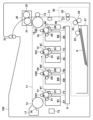
本発明の実施形態が適用可能である電子写真方式の画像形成装置について概略を説明する。図1は、中間転写ベルトを採用し複数の画像形成部を並列に構成したプリンタ100の概略構成例を示す図である。
<First embodiment>
[Description of image forming apparatus]
An outline of an electrophotographic image forming apparatus to which embodiments of the present invention are applicable will be described. FIG. 1 is a diagram showing a schematic configuration example of a
プリンタ100は、タンデム式のカラーレーザビームプリンタであり、イエロー(Y)、マゼンダ(M)、シアン(C)、ブラック(K)の4色のトナーを重ね合わせることでカラー画像を出力できるように構成されている。以下の説明において、特にイエロー、マゼンタ、シアン、ブラックを区別する必要のない部材については、説明の便宜上、符号の添え字のY、M、C、Kを省略する。
The
プロセスカートリッジ5は、トナー容器6、像担持体である感光体ドラム1、帯電ローラ2、現像ローラ3、ドラムクリーニングブレード4、ドラム廃トナー容器7を有している。レーザユニット8は、プロセスカートリッジ5の下方に配置され、画像信号に基づく露光を感光体ドラム1に対して行う。感光体ドラム1は、帯電ローラ2に所定の負極性の電圧を印加することで、所定の負極性の電位に帯電された後、レーザユニット8によってそれぞれ静電潜像が形成される。この静電潜像は現像ローラ3に所定の負極性の電圧を印加することで反転現像されて感光体ドラム1上に、それぞれY、M、C、Kのトナー像が形成される。なお、本実施形態で使用するトナーは、負極性に帯電されている。
The
中間転写体ユニットは、中間転写体11、テンションローラ13、駆動ローラ15、中間転写体クリーニングブレード16、廃トナー回収容器17を含んで構成されている。また、感光体ドラム1に対向して、中間転写体11の内側に一次転写ローラ10が配設されており、不図示の電圧印加手段により転写電圧を印加する構成となっている。感光体ドラム1上に形成されたトナー像は、各感光体ドラム1および中間転写体11が矢印方向に回転し、さらに一次転写ローラ10に正極性の電圧を印加することにより、中間転写体11上に一次転写される。感光体ドラム1上のトナー像はY、M、C、Kの順に、中間転写体11上に一次転写され、4色のトナー像が重なった状態で二次転写ローラ14まで搬送される。感光体ドラム1および中間転写体11には、転写できなかった残トナーが残っている。それをドラムクリーニングブレード4、中間転写体クリーニングブレード16でクリーニングし、それぞれドラム廃トナー容器7、廃トナー回収容器17に回収する。
The intermediate transfer body unit includes an
給紙機構20は、給紙カセット21内に収容された記録材Sを給紙する給紙ローラ22と、給紙された記録材Sを搬送する搬送ローラ23および記録材Sを1枚ずつ分離搬送する分離ローラ24、レジストローラ対25を有している。給紙機構20から搬送された記録材Sはレジストローラ対25によって二次転写ローラ14に搬送される。その際、搬送センサ90により記録材Sがレジストローラ対25下流を搬送されていることを検知する。中間転写体11から記録材Sへトナー像を転写するために、二次転写ローラ14に正極性の電圧を印加する。これにより、搬送されている記録材Sに、中間転写体11上のトナー像を二次転写する。トナー像が転写された記録材Sは、定着ユニット30に搬送され、定着フィルム31と加圧ローラ32とによって加熱、加圧されて表面にトナー像が定着される。定着された記録材Sは排紙ローラ対33によって排出される。
The
プリンタ100は、音波を受信する受信部71が搬送センサ90と二次転写ローラ14の間に配置されている。受信部71は、圧力による振動板の振動変位を電圧変化に変換して出力するMEMS(Micro Electro Mechanical System)マイクロフォンを有する。なお、音波を受信することが可能であるならば、例えば、コンデンサマイクロフォン等、MEMSマイクロフォン以外のマイクロフォンを用いることもできる。温度検出部72は、プリンタ100の内部における温度を検出する。温度検出部72は、第三実施形態で用いられる構成であり、第三実施形態以外の実施形態では省略され得る。
In the
[ハードウェア構成の説明]
図2は本実施形態における画像形成システムのハードウェア構成例を示すブロック図である。本実施形態のハードウェア構成は、図2に示すように、プリンタ100、ホストコンピュータ200およびサーバ300により構成される。ホストコンピュータ200は、ネットワークを介してプリンタ100へプリントを指示する本体部201と操作表示部202を有する。ここで、ホストコンピュータ200が有する操作表示部202には、不図示のディスプレイ、キーボード、マウスなどが含まれる。画像形成装置としてのプリンタ100と、情報処理装置としてのサーバ300は、画像形成装置における異音の発生とその原因を特定する異音診断システムを構成する。
[Description of hardware configuration]
FIG. 2 is a block diagram showing an example of the hardware configuration of the image forming system in this embodiment. The hardware configuration of this embodiment includes a
プリンタ100は、ビデオコントローラ101と操作表示部102とプリンタエンジン103を有する。ここで、プリンタ100が有する操作表示部102には、不図示のオペレーションパネルや操作ボタンなどが含まれる。ビデオコントローラ101は、ホストコンピュータ200からの送信されたプリントデータやプリント指示、記録材の種類等のプリント設定情報をプリンタエンジン103に送信する。
The
プリンタエンジン103は、CPU180とROM181とRAM182を含むエンジン制御部110と、システムバス104、IOポート105で構成される。CPU180は、ROM181に格納されているプログラムを、RAM182を作業領域として用いて実行する。前述した構成要素は、双方向にアクセス可能なシステムバス104を介してIOポート105へアクセス可能となっている。IOポート105には、搬送センサ90および各種モータが接続されている。
The printer engine 103 includes an
本実施形態によるプリンタ100の例において、モータは、以下の4種類を有する。給紙モータ91は、シートSを搬送する給紙ローラ22、搬送ローラ23、レジストローラ対25を駆動する。中間転写体/K感光体ドラムモータ92は駆動ローラ15を駆動することで、中間転写体11を図1の矢印方向に回転させる。同時に、K感光体ドラム1Kを図1の矢印方向に回転させる。YMC感光体ドラムモータ93はYMC感光体ドラム1Y、1M、1Cを図1の矢印方向に駆動する。中間転写体/K感光体ドラムモータ92および、YMC感光体ドラムモータ93は、不図示の駆動ユニットに配置されている。定着モータ95は定着ユニット30の加圧ローラ32を駆動する。
In the example of the
エンジン制御部110(CPU180)は、ホストコンピュータ200から送信されたプリント設定情報等に基づき、IOポート105を介してこれらのアクチュエータを制御する。例えば、プリント設定情報のうち、記録材の種類の情報が普通紙(坪量が80g/m2前後の記録材)だった場合は、アクチュエータの速度をプリンタに設定されている普通紙用に制御してプリントする。厚紙(坪量が120g/m2前後)だった場合は、アクチュエータの速度設定を普通紙用の1/2の速度に設定し、定着ユニットによる定着性能を向上させる。
The engine control unit 110 (CPU 180) controls these actuators via the
サーバ300は、演算装置311と記憶装置312を含むサーバ制御部301を有し、プリンタ100と双方向にアクセス可能なネットワークで接続されている。演算装置311は、記憶装置312に保存されたプログラムの実行や、各種データの読み書きを行う。演算装置311はCPUやGPU、記憶装置312にはRAM、HDDやSSDなどを直接割り当てても良いし、仮想マシンなどの仮想環境を割り当てても良い。サーバ制御部301は、ビデオコントローラ101を経由することで、エンジン制御部110と情報の受け渡しを行うことが可能である。
The
[機能ブロック図の説明]
エンジン制御部110およびサーバ制御部301の機能について説明する。図3は、エンジン制御部110とサーバ制御部301の機能構成例を示すブロック図である。エンジン制御部110の機能は、例えば、CPU180がROM181に記憶されている所定のプログラムを実行することにより実現され得る。また、サーバ制御部301の機能は、演算装置311が記憶装置312に記憶されている所定のプログラムを実行することにより実現され得る。なお、エンジン制御部110とサーバ制御部301の機能は、それぞれ専用のハードウェアにより実現されてもよいし、ソフトウェアとハードウェアの協働により実現されてもよい。エンジン制御部110は、受信音を処理する機能、受信音を処理して得られた音の情報にセンサやモータの情報を付与して音データを得る機能を有する。また、サーバ制御部301は、音データから異音が発生したかどうかを特定する機能、異音を発生させている部材を特定する機能を有する。それぞれ順に説明する。
[Description of functional block diagram]
The functions of
エンジン制御部110は、受信音処理部140、音波情報処理部150、状態通知部160を有する。プリンタエンジン103がプリント指示を受けると、エンジン制御部110は後述する所定のタイミングで、受信部71を用いて受信音を測定する。その後、受信音処理部140が有する各機能部は、受信部71により受信された受信音を以下のように処理する。受信音増幅部141は、受信部71により受信された受信音(プリンタ100の内部の動作音)のレベルを示す電圧を増幅する。A-D変換部142は、受信音増幅部141が出力する電圧をデジタル信号に変換する。受信部71が出力する電圧は正の値であるため、DC成分を除去し、音の圧力変動を抽出する必要がある。基準値設定部143は、A-D変換部142より入力されるデジタル信号が示す各値から基準値を減じ、音の圧力変動を抽出する。
The
自乗演算部144は、基準値設定部143により基準値が設定された後のデジタル信号の自乗演算を行う。区間平均演算部145は、自乗演算部144により自乗演算がなされた後のデジタル信号について区間平均演算を行う。例えば、区間平均演算を行う時間区間は、100msである。区間平均演算を行う時間長はこれに限らず、測定ごとに異ならせることもできる。自乗演算及び区間平均演算により、基準値が設定された後のデジタル信号は、時間区間ごとの音圧変動の大きさを示す時系列の音波レベルデータとなる。音波レベルデータは音波情報処理部150に格納される。状態通知部160は、センサからの情報、モータ等の駆動状態を表す情報(以下、アクチュエータ情報)を音波情報処理部150に通知する。音波情報処理部150は、受信音処理部140からの音波レベルデータに、状態通知部160から通知されたアクチュエータ情報により示されるアクチュエータの駆動状態を同期させる。詳細は後述する。音波情報処理部150で処理された音データ(音波レベルデータにアクチュエータの状態を関連付けたデータ)は、ビデオコントローラ101を経由してサーバ制御部301の記憶装置312にも保存される。駆動制御部170は、複数のアクチュエータ(例えば、上述した4種類のモータ)の駆動を制御する。なお、状態通知部160は、各アクチュエータからアクチュエータ情報を取得してもよいし、駆動制御部170が出力するアクチュエータへの駆動指示信号からアクチュエータ情報を取得してもよい。
The
音診断部320は、音データを分析して異音が発生しているか否かを判定し、異音を発している原因を特定する。音診断部320は、分類部321、統計量算出部322、閾値設定部323、異音判定部324、原因特定部325を有する。分類部321は、記憶装置312に保存された音データの集合を所定の基準に基づき複数の部分集合に分類する。統計量算出部322は、分類されたそれぞれの部分集合から統計値を算出する。閾値設定部323は、統計量算出部322によって算出された統計値をさらに統計処理して閾値を設定する。異音判定部324は、部分集合において異音が発生しているか否かを判定する。原因特定部325は、異音判定部324による複数の異音判定結果から、異音を発しているユニットや部材を特定する(原因特定)。原因特定の結果は、報知部330によってユーザやディーラ等のホストコンピュータ200、不図示のプリンタ管理ツール等に報知される。
The
次に受信部71での受信音測定のタイミングと音波情報処理部150で同期される音の情報について説明する。
Next, the timing of reception sound measurement in the receiving
受信音処理部140は、記録材に対する画像形成動作における異なるタイミングでプリンタ100の内部の音を測定する。本実施形態の受信音処理部140は、例えば、以下の2つのタイミング(第1の測定と第2の測定)で、受信部71を用いてプリンタ100の内部の音を測定する。第1の測定では、プリント指示され、給紙ローラ22によって記録材Sを給紙した時点から、記録材Sが二次転写ローラ14に到達する1600ms経過後まで受信音の測定が実施される。第2の測定では、最終記録材の後端が、搬送センサ90を抜けたタイミングからプリンタが動作を停止する1600ms経過後まで、受信音の測定が実施される。測定時間およびタイミングはこの例に限られるものではない。なお、測定時間は任意に設定することが可能であるが、測定時間を限定することで、プリンタ100やサーバ制御部301にかかる負荷及び測定データの増加によるメモリ容量の制約を軽減できる。先述の通り、本実施形態では区間平均演算部145が区間平均演算を行う間隔を100msとしているので、第1の測定と第2の測定ともに、1600msの測定時間で16区間分のデータが収集される。
The received
第1、第2の測定において、受信音処理部140は、測定を開始すると、前述の区間平均演算を行うことにより各区間の音波レベルデータを取得し、記憶する。これにより、データ1からデータ16までの16個の時間区間の音波レベルデータが取得、記憶される。また、音波情報処理部150は、状態通知部160から通知されるアクチュエータ情報を、音波レベルデータが算出される区間平均演算と同じ時間区間(100ms)について取得し、音波レベルデータとアクチュエータ情報を関連付ける。こうして、音波情報処理部150は、音波レベルデータとアクチュエータ情報を同期させたデータ(以下、音データという)を取得し、サーバ制御部301(音診断部320)に提供する。なお、プリンタ100やサーバ制御部301の負荷を軽減する必要が無ければ常時測定し続け、後述する音診断部320での処理で分析区間を指定しても良い。なお、音波レベルデータとアクチュエータ情報の時間間隔を100msとしたがこれに限られるものではない。例えば、さらに細かい時間区間で音波レベルデータとアクチュエータ情報を同期させてもよい。
In the first and second measurements, when the received
[音診断部320の動作説明]
図4は本実施形態においてサーバ300により実行される統計生成処理のうち、音データの分類に関する処理の一例を示すフローチャートである。以下の説明では処理ステップをS(ステップ)と略記する。
[Explanation of operation of sound diagnosis section 320]
FIG. 4 is a flowchart illustrating an example of processing related to classification of sound data among the statistical generation processing executed by the
S101で、分類部321は、サーバ制御部301の記憶装置312に新たに入力された音データがあるかを確認する。新たな入力データがあった場合、分類部321は、新たな音データの分類を開始する。S102にて、分類部321は、測定タイミングによって音データを異なるグループへ分類する。本実施形態では、上述した第1の測定と第2の測定の2種類に分類される。次にS103にて、分類部321は、記録材の種類等のプリント設定情報に従って音データを異なるグループへ分類する。例えば、普通紙や厚紙等の記録材の種類によってアクチュエータの動作速度が変化するため、記録材の種類によって音データが異なるグループへ分類される。S104では、分類部321は、音データのデータ1からデータ16の16個の区間に対するアクチュエータの駆動および停止の状態がすべて同じとなるグループへ音データを分類する。本実施形態では、状態通知部160により通知されるすべてのアクチュエータの動作タイミングが一致するように分類しているが、これに限られるものではなく、一部のアクチュエータの動作タイミングが同じもので分類しても良い。つまり、同じグループに属する音データについてすべてのアクチュエータの動作タイミングが一致している必要はない。少なくとも一つのアクチュエータの動作タイミングに注目して音データをグループに分類してもよい。なお、分類の方法は上記に限られるものではない。例えば、上記分類に加えて画像形成動作が単色画像形成(モノクロ動作)か複数色画像形成(カラー動作)かによりデータを分類するステップが加えられてもよい。
In S101, the
統計量算出部322は、分類部321によって分類された音波レベルデータの各部分集合に対して、16個の時間区間それぞれの統計値Pを算出する。S105において、統計量算出部322は、部分集合ごと(分類ごと)に音波レベルデータの直近の所定数のデータの統計値Pを算出する。本実施形態では、直近の100個のデータの上位5%位置のデータ(音波レベルデータの上位5番目のデータ)を統計値Pとする。
The
S106にて、閾値設定部323は、統計値Pが100データ以上算出されているか判定する。つまり、この段階で100×100=10000個の音波レベルデータが取得されていることになる。統計値Pが100データ以上あると判定された場合(S106でYES)、処理はS107に進み、閾値設定部323は、閾値TH-Pが設定されているかどうかを判定する。閾値TH-Pが設定されていないと判定された場合(S107でNO)、処理はS108に進む。S108において、閾値設定部323は、100個の統計値Pを統計処理して、閾値TH-Pを設定する。例えば、閾値設定部323は、100データある統計値Pの平均値を算出する。図5は横軸にプリント枚数、縦軸に音波レベルデータを示したグラフである。実線で示す統計値Pの平均値から10dBの値を閾値TH-Pと設定する。S107にて閾値TH-Pが設定済みであった場合(S107でYES)、または、S106にて統計値Pが100データに満たないと判定された場合(S106でNO)、閾値設定部323は閾値設定をせず、本処理を終了する。なお、統計値Pの算出方法は、上記方法に限定されない。例えば、統計値Pは、直近の任意の音波レベルデータの中央値や、最大値とすることができる。同様に、閾値TH-Pの設定方法は、上記方法に限定されない。例えば、閾値TH-Pは、任意の数の統計値Pの中央値や最大値を、所定の方法で増加させたものとすることができる。
In S106, the threshold
図6は、音波レベルデータとアクチュエータ情報の取得例を示す図である。音波レベルデータとアクチュエータの駆動の有無を表す情報が、複数の時間区間(本例では、データ1~16の16個の時間区間)について取得された様子が示されている。また、図6では、S104において、分類部321が、第2の測定で得られた音データを、アクチュエータの動作状態を用いて分類した結果の例が示されている。給紙モータから定着モータまでの項目群610はアクチュエータ情報であり、各時間区間における各モータの駆動の有無を表している。アクチュエータ情報において、『1』は駆動している状態を表現し、『0』は停止している状態を表現する。図6に示す通り、本実施形態では、アクチュエータ情報により第2の測定がグループAとグループBの2グループに分類されている。グループAとグループBでは表中のハッチングで示したYMC感光体ドラムモータの停止タイミングが異なっている。このようにアクチュエータの動作状態によって分類することで、音波レベルデータのばらつきが少なく、安定した音波レベルの部分集合を形成することができる。
FIG. 6 is a diagram showing an example of acquiring sound wave level data and actuator information. It is shown that sound wave level data and information indicating whether or not the actuator is driven are acquired for a plurality of time intervals (in this example, 16 time intervals of
図7は本実施形態における、異音判定部324の処理の一例を示すフローチャートである。S201~S207の処理は、S102~S104で行われる分類ごとに16個の時間区間それぞれで行われる異音判定の処理である。S202において、異音判定部324は、S108により閾値TH-Pが設定済みであるか否かを判定する。まだ閾値TH-Pが設定されていない場合(S202でNO)、処理はS208へ進み、異音判定部324は、当該分類に関して異音レベルが『不明』であると判定する。閾値TH-Pが設定済みであった場合(S202でYES)、処理はS203に進む。S203において、異音判定部324は、S105により新たな統計値Pが算出されているかどうかを判定する。処理対象の分類に関して新たな統計値Pが算出されていないと判定された場合(S203でNO)、異音判定部324は次の分類へ処理を移す。新たな統計値Pが算出されていると判定された場合(S203でYES)、処理はS204へ進む。S204において、異音判定部324は、その新たな統計値Pが閾値TH-P以上かどうかを判定する。閾値以上と判定された場合(S204でYES)、処理はS205へ進み、異音判定部324は、異音発生と判定し、その分類に対して異音レベル『1』を設定する。新たな統計値Pが閾値未満と判定された場合(S204でNO)、異音判定部324は、正常と判定し、S206においてその分類の異音レベルを『0』に設定する。以上の処理をすべての分類について、上記判定が完了するまで繰り返す(S207)。
FIG. 7 is a flowchart illustrating an example of processing by the abnormal
原因特定部325は、測定タイミングごとに異音の発生状態とアクチュエータの駆動状態を比較して複数の比較結果を得て、複数の比較結果に基づいて異音の原因を特定する。以下、発生状態と駆動状態の比較から異音の原因を特定する処理の具体例を説明する。図8は本実施形態における、原因特定部325の処理の一例を示すフローチャートである。S301~S303の処理は、異音判定部324(S205、S206)で異音レベルが判定された音データに関して、測定タイミングごと、且つ、アクチュエータごとに実行される。S302で、原因特定部325は、異音の発生状態とアクチュエータの駆動状態を比較し、その比較結果により類似性を判定する。類似性判定の具体的方法の一例を説明する。原因特定部325は、データ1からデータ16の異音の有無の表現の並び(発生状態)と、特定のアクチュエータの駆動の有無の表現の並び(駆動状態)をそれぞれ16次元のベクトルと見立て、両者のコサイン(以下、COS)類似度を算出する。異音レベルをベクトルA、アクチュエータの動作状態をベクトルBとした場合のCOS類似度は以下の式[数1]で表される。
The

本実施形態においては、COS類似度が1に近いほど、すなわち、COS類似度が大きいほどそのアクチュエータが異音を発している可能性が高いと判定する。なお、異音が発生しておらず、データ1から16の異音レベルが0の場合は、異音レベルのベクトルAもゼロになるため、上記のCOS類似度を算出することができない。したがって、本実施形態では、異音レベルのベクトルAがゼロになる場合に、COS類似度をゼロと設定している。なお、本実施形態では類似性を判定するための方法として、COS類似度を採用したが、これに限らず他の方法であってもよい。
In this embodiment, it is determined that the closer the COS similarity is to 1, that is, the larger the COS similarity is, the higher the possibility that the actuator is emitting abnormal noise. Note that if no abnormal sound is occurring and the abnormal sound level of
以降の説明では、複数の分類から第1の測定と第2の測定のそれぞれ一つの分類を用いて説明していく。図9(a)、(b)は第1、第2の測定タイミングにおける、アクチュエータのCOS類似度を算出した結果であり、データ1~16の16個の時間区間における異音レベルとアクチュエータの駆動状態が示されている。第1の測定において、異音レベルはデータ1から16まですべて異音レベル『1』である。一方、YMC感光体ドラムモータの動作状態は、データ1から13までは停止状態である『0』を示し、データ14からデータ16までが駆動状態である『1』を示す。以上2つのデータをベクトルと見立てて算出したCOS類似度は0.43となる。原因特定部325は、以上の処理をすべての測定タイミング、アクチュエータについて実行し終えるまで繰り返す。
In the following description, one classification of the first measurement and one of the second measurement will be used from among the plurality of classifications. Figures 9(a) and 9(b) show the results of calculating the COS similarity of the actuators at the first and second measurement timings, and show the abnormal noise level and actuator drive in 16 time intervals of
図8に戻り、S304~S306において、原因特定部325は、アクチュエータごとに、S301~S303で計算されたCOS類似度の平均を算出する。S304とS306は、全てのアクチュエータのそれぞれを処理するように、処理が繰り替えされることを示す。図9(a)(b)の例では、原因特定部325は、2つの測定タイミングのCOS類似度を算出した結果を基に、原因を特定する。S305において、原因特定部325は、各アクチュエータについて、全ての測定タイミングについて算出されたCOS類似度の平均値を算出する。原因特定部325は、このようなCOS類似度の平均化をすべてのアクチュエータについて実行し終えるまで繰り返す(S306)。原因特定部325がすべてのアクチュエータを平均化した結果を図9(c)に示す。ステップS307において、原因特定部325は、平均化されたCOS類似度に基づいて、複数のアクチュエータの内異音の発生に対応するアクチュエータを特定する。本実施形態においては、定着モータ95のCOS類似度が1.00となっているため、原因特定部325は、それを異音の原因となっているアクチュエータと判定する。また、原因特定部325は、複数の動作部のうち、異音の原因と判定されたアクチュエータにより少なくともその一部が駆動される動作部を異音の原因として特定する。本例では、定着モータ95が駆動しているのは定着ユニット30であるため、原因特定部325は、定着ユニット30を異音の原因となっているユニットとして特定する。ステップS308において、報知部330は、原因の特定結果を、エンジン制御部110、ユーザやディーラ等のホストコンピュータ200、不図示のプリンタ管理ツール等に通信することにより報知する。なお、報知部330により、サーバ300が備える表示装置に報知を行うようにしてもよい。また、報知部330がプリンタ100に原因の特定結果を報知し、プリンタ100の表示部により表示されるようにしてもよい。
Returning to FIG. 8, in S304 to S306, the
なお、測定タイミングによっては、データが少なく異音レベル判定ができていない場合が存在することが想定される。その場合、COS類似度に不明を示す『-1』が設定され、平均化したCOS類似度が低くなるようにしている。これにより、全ての測定タイミングのデータがそろっていない場合に、原因が特定されてしまうことが防止され得る。 Note that, depending on the measurement timing, it is assumed that there may be cases where the abnormal sound level cannot be determined due to insufficient data. In that case, the COS similarity is set to "-1" indicating unknown, so that the averaged COS similarity becomes low. This can prevent the cause from being identified when data for all measurement timings are not available.
以上のように、第一実施形態によれば、異音が未知であっても既知であっても、異音を発しているアクチュエータやユニットを特定することができる。なお、上記では二つの測定タイミングにおける異音の発生状態とアクチュエータの駆動状態に基づいて(COS類似度の平均値に基づいて)異音の原因を特定したがこれに限られるものではない。例えば、一つの測定タイミングにおける異音の発生状態とアクチュエータの駆動状態に基づいて異音の原因が特定されてもよい。但し、複数の測定タイミングを用いることで、異音の原因特定精度を高めることができる。例えば、本実施形態において、第1の測定だけでは異音の原因をCOS類似度が高い給紙モータと定着モータと2つのアクチュエータまでしか絞り込むことができなかったものを定着モータと一つに特定することができる。 As described above, according to the first embodiment, whether the abnormal noise is unknown or known, the actuator or unit emitting the abnormal noise can be identified. In addition, although the cause of the abnormal noise was identified above based on the generation state of the abnormal noise and the driving state of the actuator at the two measurement timings (based on the average value of COS similarity), the present invention is not limited to this. For example, the cause of the abnormal noise may be identified based on the occurrence state of the abnormal noise and the driving state of the actuator at one measurement timing. However, by using a plurality of measurement timings, it is possible to improve the accuracy of identifying the cause of the abnormal noise. For example, in this embodiment, the cause of the abnormal noise could only be narrowed down to the paper feed motor, fusing motor, and two actuators with high COS similarity by the first measurement, but it was identified as the fusing motor. can do.
また、異音発生時にユーザやディーラは、異音の原因が報知されることで、短時間で対処することが可能になる。特にディーラは、一度のユーザ訪問でプリンタ100の不具合に対応することができ、不要な訪問を防止できる。
Furthermore, when an abnormal noise occurs, the user or dealer is informed of the cause of the abnormal noise, thereby enabling them to take action in a short time. In particular, the dealer can deal with problems with the
なお、アクチュエータはモータだけでなく、センサやソレノイド、電磁クラッチ等も含めることができ、それらの動作状態と異音レベルから、より詳細な原因特定をすることも可能である。また、上記では、原因特定部325は、COS類似度が1.00の場合に異音の発生に対応するアクチュエータであると特定したが、これに限られるものではない。所定の閾値より大きいCOS類似度が得られたアクチュエータが、異音の発生に対応するアクチュエータとして特定されるようにしてもよい。また、本実施形態では、閾値TH-Pを一つだけ設定したが、これに限られるものではない。例えば、閾値TH-Pを2段階設け、異音レベルを『0』、『1』、『2』と3段階にしてもよい。この場合、COS類似度を算出する際には、異音レベル『1』および『2』を1として異音レベルのベクトルAを生成する。なぜならば、ベクトルAの成分に『1』と『2』が混在していると、成分が『1』だけで構成されているベクトルAよりもCOS類似度が低下してしまうからである。同じタイミングで異音が発生しているにもかかわらず、COS類似度が変化してしまうのは好ましくない。そのため、COS類似度の計算をする際には、上述したように『1』と『2』のベクトル成分を全て『1』に置き換える。そして、原因特定部325により異音の発生源が特定された後、音データに異音レベル『2』が含まれる場合には、報知部330はディーラに重度の異音が発生していることを報知し、即座に対応を促すようにする。一方、音データに異音レベル『1』しか含まれない場合には、報知部330はディーラに軽微な異音が発生していることを報知し、対応の準備を促すようにしてもよい。また、異音レベル『1』、『2』をそのままに異音レベルのベクトルAを生成し、COS類似度を計算して原因特定してもよい。
Note that the actuator can include not only a motor but also a sensor, a solenoid, an electromagnetic clutch, etc., and it is also possible to identify the cause in more detail from the operating status and noise level of these. Further, in the above description, the
<第二実施形態>
第一実施形態では、通常のプリント動作(画像形成動作)の間に音を測定し、異音の原因を特定していた。第二実施形態では、適切な画像形成ができるように、トナーの濃度を補正するキャリブレーションと呼ばれる動作中の音を測定し、その結果で異音の原因特定をする。以下、第二実施形態について第一実施形態との相違点を中心に説明する。
<Second embodiment>
In the first embodiment, the sound is measured during normal printing operation (image forming operation) to identify the cause of the abnormal noise. In the second embodiment, in order to form an appropriate image, sounds during an operation called calibration for correcting toner density are measured, and the cause of the abnormal noise is identified based on the results. The second embodiment will be described below, focusing on the differences from the first embodiment.
キャリブレーションには、単色の条件補正をする単色動作(以下、モノクロ動作)と、複数色の条件補正をする複数色動作(以下、フルカラー動作)の2種類の動作があり、ユーザのプリント状況に応じて実行される。例えば、フルカラーでのプリントが多いユーザは、フルカラーでのキャリブレーションの割合が多くなる。また、モノクロ動作とフルカラー動作ではそれぞれ駆動するアクチュエータが異なる。モノクロ動作の場合は、中間転写体/K感光体ドラムモータ92が駆動され、フルカラー動作の場合は、モノクロ動作でのモータにYMC感光体ドラムモータ93が追加される。
There are two types of calibration operations: single-color operation (hereinafter referred to as monochrome operation) that corrects conditions for a single color, and multi-color operation (hereinafter referred to as full-color operation) that corrects conditions for multiple colors. executed accordingly. For example, a user who often prints in full color will have to calibrate in full color at a high rate. Further, the actuators that are driven are different for monochrome operation and full color operation. In the case of monochrome operation, the intermediate transfer member/K
キャリブレーション動作中の音の測定では、モノクロまたフルカラーの動作状態で駆動するアクチュエータが常に駆動しているタイミングでの音が測定される。よって、異音が発生している場合は、駆動しているすべてのモータが異音の原因であると推定される。 In measuring the sound during the calibration operation, the sound is measured at the timing when the actuator that is driven in the monochrome or full color operating state is constantly being driven. Therefore, if an abnormal noise is occurring, it is presumed that all the motors being driven are the cause of the abnormal noise.
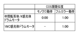
図10は、キャリブレーション中の音を測定し、第一実施形態で説明した原因特定部325でCOS類似度を算出した結果を示した表である。表に示す通り、フルカラー動作では、中間転写体/K感光体ドラムモータ92、YMC感光体ドラムモータ93のCOS類似度が高くなっている。すなわち中間転写体ユニット、YMCKの各プロセスカートリッジ、または、それらのモータが配置されている駆動ユニットのいずれかで異音が発生している可能性があると判定できる。一方、モノクロ動作でのCOS類似度は中間転写体/K感光体ドラムモータ92において0.0、つまり異音が発生していない状態となっている。以上のようなCOS類似度の算出結果を基に、異音の原因を特定していく。
FIG. 10 is a table showing the results of measuring the sound during calibration and calculating the COS similarity degree by the
図11は、原因特定部325による、キャリブレーションでの異音の原因を特定する処理を示すフローチャートである。S401で、原因特定部325は、異音の原因となり得る複数の候補のそれぞれについて、異音の原因であるかどうかを判定するために、各候補に対する処理を開始する。複数の候補とは、例えば、中間転写体ユニットまたはKプロセスカートリッジ、YMCの各プロセスカートリッジ、駆動ユニット(中間転写体/K感光体ドラムモータ92またはYMC感光体ドラムモータ93)である。
FIG. 11 is a flowchart showing a process performed by the
駆動ユニットが異音の原因であるか否かを特定するために、S402で、原因特定部325は、モノクロ動作(フローチャート上ではモノと表示)、フルカラー動作(同フル)いずれかで異音が発生しているかを判定する。これは、モノクロ動作、フルカラー動作のいずれで異音が発生している場合であっても、それらを駆動している駆動ユニットで異音が発生している可能性があるためである。S402で異音が発生していると判定された場合(S402でYES)、処理はS403に進み、原因特定部325は、駆動ユニットが異音の原因である可能性があると判定する。異音が発生していないと判定された場合(S402でNO)、S404において、原因特定部325は、駆動ユニットが正常であると判定する。図10のCOS類似度の結果の場合、フルカラー動作で異音が発生しているため、原因特定部325は、駆動ユニットが異音の原因である可能性があると判定する。
In order to identify whether the drive unit is the cause of the abnormal noise, in S402, the
次に、中間転写体ユニットまたはKプロセスカートリッジが異音の原因であるか否かを特定する処理を説明する。中間転写体ユニットまたはKプロセスカートリッジが原因の場合、モノクロ動作とフルカラー動作の両方で異音が発生しているはずである。まずS405で、原因特定部325は、モノクロ動作とフルカラー動作の両方についてデータ(算出されたCOS類似度)があるかを判定する。両方のデータ(COS類似度)があると判定された場合(S405でYES)、S406において、原因特定部325は、モノクロ動作とフルカラー動作の両方で異音が発生しているか否かを判定する。両方で異音が発生していると判定された場合(S406でYES)、処理はS407に進み、原因特定部325は、中間転写体ユニットまたはKプロセスカートリッジが異音の原因である可能性があると判定する。モノクロ動作またはフルカラー動作の少なくとも一方で異音が発生していないと判定された場合(S406でNO)、つまり片方のみで異音が発生したか、両方とも異音が発生していなかった場合は、処理はS408に進む。S408において、原因特定部325は、中間転写体ユニットまたはKプロセスカートリッジは正常であると判定する。例えば、図10のCOS類似度の場合、モノクロ動作で異音が発生していないため、中間転写体ユニットまたはKプロセスカートリッジは正常と判定される。
Next, a process for determining whether the intermediate transfer unit or the K process cartridge is the cause of the abnormal noise will be described. If the cause is the intermediate transfer unit or the K process cartridge, the noise should be occurring in both monochrome and full color operations. First, in S405, the
S405で、モノクロ動作とフルカラー動作の両方のデータが揃ってはいないと判定された場合(S405でNO)、処理はS409に進む。S409において、原因特定部325は、データが存在する動作モードにおいて異音が発生しているか否かを判定する。異音が発生していると判定された場合(S409でYES)、処理はS407に進み、原因特定部325は、中間転写体ユニットまたはKプロセスカートリッジが異音の原因である可能性があると判定する。異音が発生していないと判定された場合(S409でNO)、処理はS408に進み、原因特定部325は、中間転写体ユニットおよびKプロセスカートリッジは正常であると判定する。
If it is determined in S405 that the data for both the monochrome operation and the full color operation are not complete (NO in S405), the process advances to S409. In S409, the
次に、YMCの各プロセスカートリッジが異音の原因か否かを特定する処理を説明する。YMCの各プロセスカートリッジが異音の原因である場合は、フルカラー動作でのみ異音が発生するはずである。そのため、S410で、原因特定部325は、フルカラー動作で異音が発生しているか否かを判定する。フルカラー動作で異音が発生していると判定されると(S410でYES)、S411において、原因特定部325は、YMCの各プロセスカートリッジのいずれかが異音の原因である可能性があると判定する。フルカラー動作で異音が発生していないと判定された場合(S410でNO)、S412において、原因特定部325は、YMCの各プロセスカートリッジは正常であると判定する。
Next, a process for determining whether each YMC process cartridge is the cause of the abnormal noise will be described. If each YMC process cartridge is the cause of the noise, the noise should only occur during full color operation. Therefore, in S410, the
以上の処理により原因特定部325が原因を特定した結果、図10に示されるようなCOS類似度が得られた場合は、異音の原因を、YMCの各プロセスカートリッジ、または駆動ユニットに絞り込むことができる。
As a result of the
以上のように、第二実施形態によれば、モノクロ動作、またはフルカラー動作それぞれ単独で異音の原因特定をするよりも、異音の原因を効果的に絞り込むことができる。なお、本実施形態では、キャリブレーションを例に説明したが、これに限らず、例えば電源を入れた直後や、感光体ドラムや中間転写体をクリーニングするクリーニングシーケンス等の動作音を測定し、原因特定に適用してもよい。 As described above, according to the second embodiment, the cause of the abnormal noise can be narrowed down more effectively than when the cause of the abnormal noise is identified in monochrome operation or full-color operation alone. In this embodiment, the explanation is given using calibration as an example, but the present invention is not limited to this. For example, the operation sound can be measured immediately after the power is turned on, or during a cleaning sequence for cleaning the photoreceptor drum or intermediate transfer body, and the cause can be determined. May be applied specifically.
<第三実施形態>
第三実施形態の画像形成装置は、ドラムクリーニングブレード4と中間転写体クリーニングブレード16の二種類のクリーニングブレードを備えている。これらのクリーニングブレードはブレードをドラムや中間転写体に当接させてトナーをかき取るため、当接部に摩擦力が発生する。この摩擦力によって、クリーニングブレードの先端が振動し、異音が発生することがある。特に低温(10℃以下)の場合には、クリーニングブレードのゴムが硬化するため、異音が発生しやすい。一方、画像形成装置が常に動作するような連続プリント中は、クリーニングブレードが摩擦力によって昇温し、異音が発生しにくい状況になる。第三実施形態では、この原理を適用することで、異音の原因特定精度を高める。以下、第三実施形態について第一および第二実施形態との相違点を中心に説明する。
<Third embodiment>
The image forming apparatus of the third embodiment includes two types of cleaning blades: a
第三実施形態による、プリンタ100の概略構成は図1に示したとおりである。本実施形態のプリンタ100は、内部に温度を検出するための温度検出部72を有している。なお、本実施形態では、閾値を10℃とし、温度検出部72により検出される温度が閾値以下の場合は低温状態と判定され、閾値よりも高い場合は高温状態と判定されるものとするが、もちろんこれに限られるものではない。
The schematic configuration of the
図12は、温度検出部72による検出結果に基づいて低温状態と判定された場合と高温状態と判定された場合とでキャリブレーション中の音を測定し、原因特定部325でCOS類似度を算出した結果を示した表である。本実施形態では表に示す通り、低温状態のフルカラー動作においてのみCOS類似度が高くなっている。
In FIG. 12, the sound during calibration is measured in a case where a low temperature state is determined and a case where a high temperature state is determined based on the detection result by the
図13は第三実施形態による原因特定の処理を示すフローチャートである。なお図13において、フローチャートの一部は第二実施形態(図11)と同様のため、省略されている。 FIG. 13 is a flowchart showing cause identification processing according to the third embodiment. Note that in FIG. 13, a part of the flowchart is omitted because it is similar to the second embodiment (FIG. 11).
低温状態でのみ異音が発生している場合、前述の原理の通り、クリーニングブレードが異音を発生しており、駆動ユニットでは異音が発生していないと判定され得る。そのため、まず、S501で、原因特定部325は、低温状態でのみ異音が発生しているかを判定する。低温状態でのみ異音が発生している場合(S501でYES)、処理はS502に進み、原因特定部325は、駆動ユニットが正常である判定する。一方、低温状態以外でも異音が発生している場合(S501でNO)、処理はS503に進み、原因特定部325は、モノクロ動作、フルカラー動作のいずれかで異音が発生しているかを判定する。異音が発生していないと判定された場合(S503でNO)、処理はS502に進み、原因特定部325は、駆動ユニットが正常であると判定する。異音が発生していると判定された場合(S503でYES)、処理はS504に進み、原因特定部325は、駆動ユニットが異音の原因である可能性があると判定する。その他のユニットに関する判定処理については、第二実施形態と同様である。すなわち、S505はS405~S409に対応しており、S506はS410~S412に対応している。図12に示した例では、低温状態でのフルカラー動作でのみCOS類似度が高い(異音が発生している)ため、駆動ユニットは正常であり(S502)、異音の原因はYMCの各プロセスカートリッジのいずれかであると特定することができる。
If the abnormal noise is generated only in a low temperature state, it can be determined that the cleaning blade is generating the abnormal noise and the drive unit is not generating the abnormal noise, according to the above-mentioned principle. Therefore, first, in S501, the
以上のように、第三実施形態によれば、低温時と高温時の二種類の状態での異音の発生状況を原因特定に適用することで、例えば、駆動ユニットが異音の原因であることの可能性を判定することができ、原因特定精度を高めることができる。なお、本実施形態では、第二実施形態で説明したモノクロ動作とフルカラー動作の2種類の動作と、内部温度の状態で原因特定したが、これに限らず例えば、モノクロ動作でのデータしか存在しない場合であっても原因特定精度を高めることができる。また、本実施形態では、温度検出部72を装置内部に配置したが、これに限らず、例えば、温度検出部72を配置せず、連続プリント枚数や頻度から、内部温度を予測する予測アルゴリズムを適用してもよい。
As described above, according to the third embodiment, by applying the occurrence of abnormal noise in two types of conditions, namely low temperature and high temperature, to identify the cause, for example, the drive unit is the cause of the abnormal noise. It is possible to determine the possibility of a problem occurring, and the accuracy of identifying the cause can be improved. In addition, in this embodiment, the causes were identified based on the two types of operations, monochrome operation and full-color operation described in the second embodiment, and the state of the internal temperature, but the cause is not limited to this, for example, there is only data for monochrome operation. It is possible to improve the precision of cause identification even in cases where Further, in the present embodiment, the
<第四実施形態>
第一実施形態では、画像形成動作に合わせて音を測定し異音の原因特定をしていた。第四実施形態では、最終記録材の後端が受信部71を通過後の比較的のノイズの少ない状態で測定している第2の測定のみで異音の原因をより精度よく特定できる構成を説明する。以下、第四実施形態について第一実施形態との相違点を中心に説明する。
<Fourth embodiment>
In the first embodiment, the cause of the abnormal noise is identified by measuring the sound in accordance with the image forming operation. In the fourth embodiment, a configuration is adopted in which the cause of abnormal noise can be identified with higher accuracy only by the second measurement, which is performed in a state where there is relatively little noise after the trailing edge of the final recording material passes through the receiving
例えば、第2の測定で原因特定する場合、図14(a)に示すように、異音レベルの状況と給紙モータ91の動作のタイミングが一致している場合は、このデータだけで、給紙モータ91が異音の原因であると特定できる。しかしながら、音波やモータの駆動タイミングを区間平均演算しているため、図14(b)に示すように、異音レベルとアクチュエータの状態(モータの動作タイミング)が完全には一致しないこともある(測定上の区間がずれて記録される)。そのような場合、最もCOS類似度が高い給紙モータ91であっても、完全に一致した状態よりも低い類似度(0.87)が得られるため、異音の原因として給紙モータ91を特定できない場合がある。このような課題を解決するために、本実施形態では、画像形成動作が繰り返される際に、複数のアクチュエータの少なくとも一つの動作状態を変化させて類似度を取得することにより、異音の原因の特定精度を向上する。
For example, when identifying the cause using the second measurement, if the abnormal noise level and the timing of the operation of the
図14(c)は給紙モータ91の停止タイミングをずらした具体例である。給紙モータ91の停止タイミングをデータ3からデータ6に変更することで、異音レベルもデータ7まで『1』(異音発生状態)となっている。本実施形態では、給紙モータ91の停止タイミングが異なるこれら2つのCOS類似度を用いて、異音の原因を特定する。
FIG. 14(c) is a specific example in which the stop timing of the
図15は第四実施形態による音測定処理の手順を示すフローチャートである。プリントが開始されると、まずS601にて、駆動制御部170は、第2の測定中に駆動する4種類のモータのカウントの初期値が設定済みかを判定する。設定済みでないと判定された場合(S601でNO)、処理はS602に進み、駆動制御部170は各モータのカウントに初期値を設定する。例えば、給紙モータ91のカウントの初期値を6、中間転写体/K感光体ドラムモータ92のカウントの初期値を4というように、2ずつずらした初期値が設定される。
FIG. 15 is a flowchart showing the procedure of sound measurement processing according to the fourth embodiment. When printing is started, first in S601, the
S603において、駆動制御部170は、4種類のモータのうち、カウントが所定の閾値(本実施形態では8)以上となったモータがあるか否かを判定する。カウントが閾値以上のモータがある場合(S603でYES)、処理はS604に進み、駆動制御部170は、そのモータの停止タイミングをずらす。この制御により、カウントが所定の閾値以上になったモータの停止タイミングをずらして第2の測定が実行される。その後、S605で、駆動制御部170は当該モータのカウントをゼロに設定する。S606で、駆動制御部170は、それ以外のモータのカウントに1を加算する。一方、カウントが閾値以上のモータが無い場合(S603でNO)、処理はS607に進み、駆動制御部170は各モータを通常どおりのタイミングで動作させる。そして、S608にて、駆動制御部170は4種すべてのモータのカウントに1を加算する。以上の駆動制御により第2の測定を行うことで、通常の測定と、カウントが閾値を超えた一つのモータの停止タイミングを変更した状態での測定とを交互に実行することができる。
In S603, the
原因特定部325は、各モータの通常の測定と、モータ停止タイミングをずらした測定の結果から、それぞれのCOS類似度を算出し、それぞれのCOS類似度が閾値(本例では0.8とする)以上であった場合は、そのモータが異音の原因だと特定する。本実施形態では、図14(b)、(c)に示すように、給紙モータ91の停止タイミングを変更する前後のCOS類似度がそれぞれ0.8以上であるため、給紙モータ91が異音の原因となっているアクチュエータとして特定される。また、第2の測定において給紙モータ91が駆動しているのは、レジストローラ対25であるため、原因特定部325は、レジストローラ対25を異音の原因となっているユニットとして特定する。
The
以上のように、第四実施形態によれば、モータの動作タイミングが異なる二つの状態での異音の発生状況から原因特定することで、原因特定精度を高めることができる。なお、本実施形態では、モータの停止タイミングを遅らせた例を示したがこれに限らず、モータの停止タイミングを早めてもよい。或いは、モータの動作開始タイミング、動作開始と停止の両方のタイミングを変更するようにしてもよい。また、モータ停止タイミングを変更する頻度はこれに限らず、例えば、通紙枚数をカウントし、所定の枚数に到達した時点で、あらかじめ設定された順番に応じて一つのモータの停止タイミングを変更してもよい。 As described above, according to the fourth embodiment, the accuracy of cause identification can be improved by identifying the cause from the occurrence of abnormal noise in two states in which the motor operation timings are different. In addition, in this embodiment, the example in which the timing of stopping the motor is delayed is shown, but the present invention is not limited to this, and the timing of stopping the motor may be advanced. Alternatively, the timing at which the motor starts operating or the timing at which the motor starts and stops may be changed. Furthermore, the frequency of changing the motor stop timing is not limited to this, for example, the number of sheets passed is counted, and when a predetermined number of sheets is reached, the stop timing of one motor is changed according to a preset order. It's okay.
<その他の実施形態>
上記各実施形態において、サーバ300に備えられた音診断部320で実行していたが、これに限らず、例えばプリンタ100のエンジン制御部110が音診断部320の少なくとも一部の機能を実行しても良い。また、プリンタ100のエンジン制御部110における受信音処理部140の機能の一部(例えば、基準値設定部143、自乗演算部144、区間平均演算部145)と音波情報処理部150をサーバ300に設けてもよい。この場合、プリンタ100は、ネットワークを介して、受信部71が受信した音を示す情報(例えば、デジタル値)を、サーバ300に備えられた受信音処理部に送信する。また、状態通知部160は、動作状態を示すアクチュエータ情報を、ネットワークを介してサーバ300に設けられた音波情報処理部150に送信する。サーバ300の受信音処理部は、プリンタ100から受信した情報に基づき音波レベルデータを算出し、音波情報処理部150は状態通知部160から受信したアクチュエータ情報に基づいて、音データを生成する。音診断部320は、生成された音データに基づいてプリンタ100で異音が発生しているか否か、或いは、異音を発しているユニットを特定する。以上のように、プリンタ100のエンジン制御部110が音診断部320の少なくとも一部の機能を実行してもよいし、サーバ300が受信音処理部140等の機能の少なくとも一部を実行してもよい。
<Other embodiments>
In each of the above embodiments, the function is executed by the
また、原因特定結果は、報知部330によってユーザやディーラ等のホストコンピュータ200、不図示のプリンタ管理ツール等に報知される構成としたが、これに限られるものではない。例えば、操作表示部102に含まれるオペレーションパネル等のプリンタの表示部に原因特定結果が報知されてもよい。
Further, although the cause identification result is notified by the
また、上述した複数の実施形態を組みあわせて、より原因特定精度を高めてもよい。例えば、第一実施形態と第二実施形態を組み合わせて、プリント動作中の異音の原因特定にモノクロ動作、フルカラー動作の原因特定処理を追加してもよい。或いは、第一実施形態と第三実施形態を組わせて、高温状態のプリント動作と低温状態のプリント動作において、駆動ユニットが異音の原因であるか否かを特定する処理を加えてもよい。 Further, the accuracy of cause identification may be further improved by combining the plurality of embodiments described above. For example, the first embodiment and the second embodiment may be combined to add cause identification processing for monochrome operation and full color operation to identification of the cause of abnormal noise during printing operation. Alternatively, the first embodiment and the third embodiment may be combined to add processing to identify whether or not the drive unit is the cause of the abnormal noise in the printing operation in a high temperature state and the printing operation in a low temperature state. .
また、異音発生の原因を特定する対象、すなわち、異音診断の対象として画像形成動作を行う画像形成装置(プリンタ100)を例示したが、これに限られるものではない。複数の駆動部と複数の動作部を有し、同じシーケンスの動作が繰り返し実行される装置であれば、上記各実施形態で説明した異音診断の対象となり得る。 Further, although an image forming apparatus (printer 100) that performs an image forming operation is illustrated as a target for identifying the cause of abnormal noise generation, that is, as a target for abnormal noise diagnosis, the present invention is not limited to this. Any device that has a plurality of drive units and a plurality of operation units and that repeatedly executes the same sequence of operations can be a target of the abnormal noise diagnosis described in each of the above embodiments.
本発明は、上述の実施形態の1以上の機能を実現するプログラムを、ネットワーク又は記憶媒体を介してシステム又は装置に供給し、そのシステム又は装置のコンピュータにおける1つ以上のプロセッサーがプログラムを読出し実行する処理でも実現可能である。また、1以上の機能を実現する回路(例えば、ASIC)によっても実現可能である。 The present invention provides a system or device with a program that implements one or more of the functions of the embodiments described above via a network or a storage medium, and one or more processors in the computer of the system or device reads and executes the program. This can also be achieved by processing. It can also be realized by a circuit (for example, ASIC) that realizes one or more functions.
本明細書の開示は、以下の異音診断システム、画像形成装置、異音診断方法及びプログラムを含む。
(項目1)
所定の動作を行う複数の動作部と、前記複数の動作部を駆動する複数の駆動部と、を有する装置における異音の原因を特定する異音診断システムであって、
前記装置内に発生する音の、複数の時間区間の各々において測定された音波レベルに基づいて、前記複数の時間区間の各々における異音の発生を判定する判定手段と、
前記複数の時間区間の各々における、前記複数の駆動部のそれぞれの駆動部の駆動状態を取得する取得手段と、
前記判定手段により判定された異音の発生状態と、前記取得手段により取得された前記駆動状態とに基づいて、発生した異音に対応する駆動部を前記複数の駆動部から特定する特定手段と、を備え、
前記特定手段は、前記所定の動作の異なるタイミングにおいて得られる前記駆動状態と前記発生状態とを比較することにより前記異なるタイミングに対応する複数の比較結果を取得し、前記複数の比較結果に基づいて異音の発生に対応する駆動部を特定することを特徴とする異音診断システム。
(項目2)
前記駆動状態は、前記複数の時間区間の各々におけるそれぞれの駆動部の駆動の有無を表す表現の並びであり、前記発生状態は前記複数の時間区間の各々における異音発生の有無を表す表現の並びであることを特徴とする項目1に記載の異音診断システム。
(項目3)
前記特定手段は、前記発生状態と、前記駆動状態との類似度に基づいて、発生した異音に対応する駆動部を特定することを特徴とする項目1または2に記載の異音診断システム。
(項目4)
前記所定の動作は画像形成に関連する動作を含み、
前記特定手段は、前記画像形成に関連する動作の異なるタイミングにおいて得られる前記駆動状態と前記発生状態とを比較することにより前記異なるタイミングに対応する複数の比較結果を取得し、前記複数の比較結果に基づいて異音の発生に対応する駆動部を特定することを特徴とする項目1乃至3のいずれか一項に記載の異音診断システム。
(項目5)
前記異なるタイミングは、記録材に対して行われる画像形成動作における複数のタイミングを含むことを特徴とする項目4に記載の異音診断システム。
(項目6)
前記異なるタイミングは、トナーの濃度を補正するためのキャリブレーションをモノクロ動作で実行している間のタイミングと、フルカラー動作で実行している間のタイミングとを含むことを特徴とする項目4または5に記載の異音診断システム。
(項目7)
前記装置の内部の温度を検出する検出手段をさらに備え、
前記異なるタイミングは、前記検出手段により検出された温度に基づいて区別されるタイミングを含むことを特徴とする項目4乃至6のいずれか1項に記載の異音診断システム。
(項目8)
画像形成動作ごとに前記複数の駆動部の少なくとも一つの動作タイミングを変更する駆動制御手段をさらに備え、
前記異なるタイミングは、前記複数の駆動部の少なくとも一つの駆動部について動作タイミングを変更した前後の画像形成動作における所定のタイミングを含むことを特徴とする項目4乃至7のいずれか1項に記載の異音診断システム。
(項目9)
前記判定手段は、前記複数の時間区間の時間区間ごとに前記測定された音波レベルを収集し、統計処理することにより、前記時間区間ごとに異音の発生を判定することを特徴とする項目1乃至8のいずれか1項に記載の異音診断システム。
(項目10)
前記統計処理では、前記時間区間ごとに、収集された音波レベルに基づいて閾値を設定し、直近の所定数の音波レベルの統計値が前記閾値以上となる場合に異音が発生していると判定することを特徴とする項目9に記載の異音診断システム。
(項目11)
前記判定手段は、画像形成動作に関して設定されている記録材の情報に基づいて測定された音波レベルを分類し、分類ごとに前記統計処理を行うことを特徴とする項目9または10に記載の異音診断システム。
(項目12)
前記判定手段は、測定された音波レベルを前記複数の時間区間における前記複数の駆動部のうち、一つ以上の駆動部の駆動状態が一致しているグループへ分類し、分類ごとに前記統計処理を行うことを特徴とする項目9乃至11のいずれか1項に記載の異音診断システム。
(項目13)
前記特定手段は、前記複数の動作部のうち、前記特定された駆動部により少なくとも一部が駆動される動作部を、異音に対応する動作部として特定することを特徴とする項目1乃至12のいずれか一項に記載の異音診断システム。
(項目14)
前記特定手段により特定された駆動部、または、前記特定された駆動部により少なくとも一部が駆動される動作部を報知する報知手段をさらに備えることを特徴とする項目1乃至13のいずれか一項に記載の異音診断システム。
(項目15)
画像形成に係る複数の動作部と、前記複数の動作部を駆動する複数の駆動部と、を有する画像形成装置であって、
前記複数の駆動部のそれぞれの駆動を制御する駆動制御手段と、
前記画像形成装置において発生する音波レベルを検出する検出手段と、
複数の時間区間の各々において前記検出手段により検出される音波レベルに基づいて、前記複数の時間区間の各々における異音の発生を判定する判定手段と、
前記複数の時間区間の各々における、前記複数の駆動部のそれぞれの駆動部の駆動状態を取得する取得手段と、
前記判定手段により判定された異音の発生状態と、前記取得手段により取得された前記駆動状態とに基づいて、発生した異音に対応する駆動部を前記複数の駆動部から特定する特定手段と、を備え、
前記特定手段は、前記画像形成に関連する動作の異なるタイミングにおいて得られる前記駆動状態と前記発生状態とを比較することにより前記異なるタイミングに対応する複数の比較結果を取得し、前記複数の比較結果に基づいて異音の発生に対応する駆動部を特定することを特徴とする画像形成装置。
(項目16)
所定の動作を行う複数の動作部と、前記複数の動作部を駆動する複数の駆動部と、を有する装置において発生した異音の原因を特定する異音診断方法であって、
前記装置内に発生する音の、複数の時間区間の各々において測定された音波レベルに基づいて、前記複数の時間区間の各々における異音の発生を判定する判定工程と、
前記複数の時間区間の各々における、前記複数の駆動部のそれぞれの駆動部の駆動状態を取得する取得工程と、
前記判定工程により判定された異音の発生状態と、前記取得工程により取得された前記駆動状態とに基づいて、発生した異音に対応する駆動部を前記複数の駆動部から特定する特定工程と、を備え、
前記特定工程では、前記所定の動作の異なるタイミングにおいて得られる前記駆動状態と前記発生状態とを比較することにより前記異なるタイミングに対応する複数の比較結果を取得し、前記複数の比較結果に基づいて異音の発生に対応する駆動部を特定することを特徴とする異音診断方法。
(項目17)
項目16に記載された異音診断方法をコンピュータに実行させるためのプログラム。
The disclosure of this specification includes the following abnormal sound diagnosis system, image forming apparatus, abnormal sound diagnosis method, and program.
(Item 1)
An abnormal noise diagnosis system for identifying the cause of abnormal noise in a device having a plurality of operating parts that perform predetermined operations and a plurality of driving parts that drive the plurality of operating parts, the system comprising:
determination means for determining the occurrence of abnormal noise in each of the plurality of time intervals based on the sound wave level of the sound generated in the device measured in each of the plurality of time intervals;
acquisition means for acquiring the drive state of each of the plurality of drive units in each of the plurality of time intervals;
identification means for identifying a drive unit corresponding to the generated abnormal noise from among the plurality of drive units, based on the generation state of the abnormal noise determined by the determination unit and the drive state acquired by the acquisition unit; , comprising;
The identifying means obtains a plurality of comparison results corresponding to the different timings by comparing the driving state and the occurrence state obtained at different timings of the predetermined operation, and based on the plurality of comparison results, An abnormal noise diagnosis system characterized by identifying a drive unit that corresponds to the generation of abnormal noise.
(Item 2)
The driving state is a sequence of expressions representing whether or not each driving unit is driven in each of the plurality of time intervals, and the occurrence state is a sequence of expressions representing the presence or absence of abnormal noise generation in each of the plurality of time intervals. The abnormal noise diagnosis system according to
(Item 3)
3. The abnormal noise diagnosis system according to
(Item 4)
The predetermined operation includes an operation related to image formation,
The identifying means obtains a plurality of comparison results corresponding to the different timings by comparing the driving state and the occurrence state obtained at different timings of the operation related to the image formation, and obtains a plurality of comparison results corresponding to the different timings. The abnormal noise diagnosis system according to any one of
(Item 5)
(Item 6)
(Item 7)
Further comprising a detection means for detecting the temperature inside the device,
7. The abnormal noise diagnosis system according to any one of
(Item 8)
Further comprising a drive control means for changing the operation timing of at least one of the plurality of drive units for each image forming operation,
According to any one of
(Item 9)
(Item 10)
In the statistical processing, a threshold value is set based on the collected sound wave level for each time interval, and when the statistical value of the most recent predetermined number of sound wave levels is equal to or greater than the threshold value, it is determined that abnormal noise is occurring. The abnormal sound diagnosis system according to
(Item 11)
The difference according to
(Item 12)
The determining means classifies the measured sound wave level into groups in which the drive states of one or more of the plurality of drive units match in the plurality of time intervals, and performs the statistical processing for each classification. The abnormal noise diagnosis system according to any one of
(Item 13)
(Item 14)
Any one of
(Item 15)
An image forming apparatus including a plurality of operating units related to image formation and a plurality of driving units that drive the plurality of operating units,
Drive control means for controlling the drive of each of the plurality of drive units;
detection means for detecting a sound wave level generated in the image forming apparatus;
determination means for determining the occurrence of abnormal noise in each of the plurality of time intervals based on the sound wave level detected by the detection means in each of the plurality of time intervals;
acquisition means for acquiring the drive state of each of the plurality of drive units in each of the plurality of time intervals;
identification means for identifying a drive unit corresponding to the generated abnormal noise from among the plurality of drive units, based on the generation state of the abnormal noise determined by the determination unit and the drive state acquired by the acquisition unit; , comprising;
The identifying means obtains a plurality of comparison results corresponding to the different timings by comparing the driving state and the occurrence state obtained at different timings of the operation related to the image formation, and obtains a plurality of comparison results corresponding to the different timings. An image forming apparatus characterized in that a drive unit corresponding to generation of abnormal noise is identified based on the following.
(Item 16)
An abnormal noise diagnosis method for identifying the cause of abnormal noise generated in a device having a plurality of operating parts that perform predetermined operations and a plurality of driving parts that drive the plurality of operating parts, the method comprising:
a determination step of determining the occurrence of abnormal noise in each of the plurality of time intervals based on the sound wave level of the sound generated in the device measured in each of the plurality of time intervals;
an acquisition step of acquiring the drive state of each of the plurality of drive units in each of the plurality of time intervals;
a specifying step of identifying a drive unit corresponding to the generated abnormal noise from among the plurality of drive units, based on the abnormal noise generation state determined in the determination step and the drive state acquired in the acquisition step; , comprising:
In the identifying step, a plurality of comparison results corresponding to the different timings are obtained by comparing the driving state and the occurrence state obtained at different timings of the predetermined operation, and based on the plurality of comparison results, A method for diagnosing abnormal noises, characterized by identifying a drive unit that corresponds to the generation of abnormal noises.
(Item 17)
A program for causing a computer to execute the abnormal noise diagnosis method described in
発明は上記実施形態に制限されるものではなく、発明の精神及び範囲から離脱することなく、様々な変更及び変形が可能である。従って、発明の範囲を公にするために請求項を添付する。 The invention is not limited to the embodiments described above, and various changes and modifications can be made without departing from the spirit and scope of the invention. Therefore, the following claims are hereby appended to disclose the scope of the invention.
100:プリンタ、200:ホストコンピュータ、300:サーバ、101:ビデオコントローラ、102:操作表示部、103:プリンタエンジン、104:システムバス、105IOポート、110:エンジン制御部、140:受信音処理部 100: printer, 200: host computer, 300: server, 101: video controller, 102: operation display section, 103: printer engine, 104: system bus, 105 IO port, 110: engine control section, 140: received sound processing section
Claims (17)
前記装置内に発生する音の、複数の時間区間の各々において測定された音波レベルに基づいて、前記複数の時間区間の各々における異音の発生を判定する判定手段と、
前記複数の時間区間の各々における、前記複数の駆動部のそれぞれの駆動部の駆動状態を取得する取得手段と、
前記判定手段により判定された異音の発生状態と、前記取得手段により取得された前記駆動状態とに基づいて、発生した異音に対応する駆動部を前記複数の駆動部から特定する特定手段と、を備え、
前記特定手段は、前記所定の動作の異なるタイミングにおいて得られる前記駆動状態と前記発生状態とを比較することにより前記異なるタイミングに対応する複数の比較結果を取得し、前記複数の比較結果に基づいて異音の発生に対応する駆動部を特定することを特徴とする異音診断システム。 An abnormal noise diagnosis system for identifying the cause of abnormal noise in a device having a plurality of operating parts that perform predetermined operations and a plurality of driving parts that drive the plurality of operating parts, the system comprising:
determination means for determining the occurrence of abnormal noise in each of the plurality of time intervals based on the sound wave level of the sound generated in the device measured in each of the plurality of time intervals;
acquisition means for acquiring the drive state of each of the plurality of drive units in each of the plurality of time intervals;
identification means for identifying a drive unit corresponding to the generated abnormal noise from among the plurality of drive units, based on the generation state of the abnormal noise determined by the determination unit and the drive state acquired by the acquisition unit; , comprising;
The identifying means obtains a plurality of comparison results corresponding to the different timings by comparing the driving state and the occurrence state obtained at different timings of the predetermined operation, and based on the plurality of comparison results, An abnormal noise diagnosis system characterized by identifying a drive unit that corresponds to the generation of abnormal noise.
前記特定手段は、前記画像形成に関連する動作の異なるタイミングにおいて得られる前記駆動状態と前記発生状態とを比較することにより前記異なるタイミングに対応する複数の比較結果を取得し、前記複数の比較結果に基づいて異音の発生に対応する駆動部を特定することを特徴とする請求項1乃至3のいずれか一項に記載の異音診断システム。 The predetermined operation includes an operation related to image formation,
The identifying means obtains a plurality of comparison results corresponding to the different timings by comparing the driving state and the occurrence state obtained at different timings of the operation related to the image formation, and obtains a plurality of comparison results corresponding to the different timings. The abnormal noise diagnosis system according to any one of claims 1 to 3, characterized in that the drive unit corresponding to the occurrence of the abnormal noise is specified based on the abnormal noise.
前記異なるタイミングは、前記検出手段により検出された温度に基づいて区別されるタイミングを含むことを特徴とする請求項4に記載の異音診断システム。 Further comprising a detection means for detecting the temperature inside the device,
5. The abnormal noise diagnosis system according to claim 4, wherein the different timings include timings that are differentiated based on the temperature detected by the detection means.
前記異なるタイミングは、前記複数の駆動部の少なくとも一つの駆動部について動作タイミングを変更した前後の画像形成動作における所定のタイミングを含むことを特徴とする請求項4に記載の異音診断システム。 Further comprising a drive control means for changing the operation timing of at least one of the plurality of drive units for each image forming operation,
5. The abnormal noise diagnosis system according to claim 4, wherein the different timing includes a predetermined timing in an image forming operation before and after changing the operation timing of at least one of the plurality of drive units.
前記複数の駆動部のそれぞれの駆動を制御する駆動制御手段と、
前記画像形成装置において発生する音波レベルを検出する検出手段と、
複数の時間区間の各々において前記検出手段により検出される音波レベルに基づいて、前記複数の時間区間の各々における異音の発生を判定する判定手段と、
前記複数の時間区間の各々における、前記複数の駆動部のそれぞれの駆動部の駆動状態を取得する取得手段と、
前記判定手段により判定された異音の発生状態と、前記取得手段により取得された前記駆動状態とに基づいて、発生した異音に対応する駆動部を前記複数の駆動部から特定する特定手段と、を備え、
前記特定手段は、前記画像形成に関連する動作の異なるタイミングにおいて得られる前記駆動状態と前記発生状態とを比較することにより前記異なるタイミングに対応する複数の比較結果を取得し、前記複数の比較結果に基づいて異音の発生に対応する駆動部を特定することを特徴とする画像形成装置。 An image forming apparatus including a plurality of operating units related to image formation and a plurality of driving units that drive the plurality of operating units,
Drive control means for controlling the drive of each of the plurality of drive units;
detection means for detecting a sound wave level generated in the image forming apparatus;
determination means for determining the occurrence of abnormal noise in each of the plurality of time intervals based on the sound wave level detected by the detection means in each of the plurality of time intervals;
acquisition means for acquiring the drive state of each of the plurality of drive units in each of the plurality of time intervals;
identification means for identifying a drive unit corresponding to the generated abnormal noise from among the plurality of drive units, based on the generation state of the abnormal noise determined by the determination unit and the drive state acquired by the acquisition unit; , comprising;
The identifying means obtains a plurality of comparison results corresponding to the different timings by comparing the driving state and the occurrence state obtained at different timings of the operation related to the image formation, and obtains a plurality of comparison results corresponding to the different timings. An image forming apparatus characterized in that a drive unit corresponding to generation of abnormal noise is identified based on the following.
前記装置内に発生する音の、複数の時間区間の各々において測定された音波レベルに基づいて、前記複数の時間区間の各々における異音の発生を判定する判定工程と、
前記複数の時間区間の各々における、前記複数の駆動部のそれぞれの駆動部の駆動状態を取得する取得工程と、
前記判定工程により判定された異音の発生状態と、前記取得工程により取得された前記駆動状態とに基づいて、発生した異音に対応する駆動部を前記複数の駆動部から特定する特定工程と、を備え、
前記特定工程では、前記所定の動作の異なるタイミングにおいて得られる前記駆動状態と前記発生状態とを比較することにより前記異なるタイミングに対応する複数の比較結果を取得し、前記複数の比較結果に基づいて異音の発生に対応する駆動部を特定することを特徴とする異音診断方法。 An abnormal noise diagnosis method for identifying the cause of abnormal noise generated in a device having a plurality of operating parts that perform predetermined operations and a plurality of driving parts that drive the plurality of operating parts, the method comprising:
a determination step of determining the occurrence of abnormal noise in each of the plurality of time intervals based on the sound wave level of the sound generated in the device measured in each of the plurality of time intervals;
an acquisition step of acquiring the drive state of each of the plurality of drive units in each of the plurality of time intervals;
a specifying step of identifying a drive unit corresponding to the generated abnormal noise from among the plurality of drive units, based on the abnormal noise generation state determined in the determination step and the drive state acquired in the acquisition step; , comprising;
In the identifying step, a plurality of comparison results corresponding to the different timings are obtained by comparing the driving state and the occurrence state obtained at different timings of the predetermined operation, and based on the plurality of comparison results, A method for diagnosing abnormal noises, characterized by identifying a drive unit that corresponds to the generation of abnormal noises.
Priority Applications (3)
| Application Number | Priority Date | Filing Date | Title |
|---|---|---|---|
| JP2022076221A JP2023165324A (en) | 2022-05-02 | 2022-05-02 | Abnormal noise diagnosis system, image formation device, abnormal noise diagnosis method and program |
| US18/305,835 US11842095B2 (en) | 2022-05-02 | 2023-04-24 | Abnormal sound diagnosis system provides a technique that can specify occurrence of abnormal sound in a plurality of time periods, image forming apparatus, abnormal sound diagnosis method, and a non-transitory computer-readable storage medium |
| US18/499,775 US20240061625A1 (en) | 2022-05-02 | 2023-11-01 | Abnormal sound diagnosis system, image forming apparatus, abnormal sound diagnosis method, and storage medium |
Applications Claiming Priority (1)
| Application Number | Priority Date | Filing Date | Title |
|---|---|---|---|
| JP2022076221A JP2023165324A (en) | 2022-05-02 | 2022-05-02 | Abnormal noise diagnosis system, image formation device, abnormal noise diagnosis method and program |
Publications (1)
| Publication Number | Publication Date |
|---|---|
| JP2023165324A true JP2023165324A (en) | 2023-11-15 |
Family
ID=88513116
Family Applications (1)
| Application Number | Title | Priority Date | Filing Date |
|---|---|---|---|
| JP2022076221A Pending JP2023165324A (en) | 2022-05-02 | 2022-05-02 | Abnormal noise diagnosis system, image formation device, abnormal noise diagnosis method and program |
Country Status (2)
| Country | Link |
|---|---|
| US (2) | US11842095B2 (en) |
| JP (1) | JP2023165324A (en) |
Family Cites Families (8)
| Publication number | Priority date | Publication date | Assignee | Title |
|---|---|---|---|---|
| JPH06167385A (en) | 1992-11-30 | 1994-06-14 | Hitachi Ltd | Sound diagnosing method |
| JP4349290B2 (en) | 2005-01-26 | 2009-10-21 | セイコーエプソン株式会社 | Abnormal sound determination system, server, information device, and abnormal sound determination program |
| JP5113620B2 (en) * | 2008-01-30 | 2013-01-09 | 株式会社リコー | Image forming apparatus |
| JP2016014818A (en) | 2014-07-03 | 2016-01-28 | 株式会社リコー | Device and image forming apparatus |
| JP2016078299A (en) * | 2014-10-15 | 2016-05-16 | 株式会社リコー | Unusual sound operation control device, image formation device, unusual sound operation control method and unusual operation control program |
| JP6992478B2 (en) | 2017-12-15 | 2022-01-13 | コニカミノルタ株式会社 | Abnormality diagnosis device, mobile terminal device, abnormality diagnosis system and program |
| JP2019109433A (en) * | 2017-12-20 | 2019-07-04 | コニカミノルタ株式会社 | Abnormality determination device, image formation apparatus, abnormality determination system and program |
| JP2021120701A (en) | 2020-01-30 | 2021-08-19 | キヤノン株式会社 | Image forming system and method |
-
2022
- 2022-05-02 JP JP2022076221A patent/JP2023165324A/en active Pending
-
2023
- 2023-04-24 US US18/305,835 patent/US11842095B2/en active Active
- 2023-11-01 US US18/499,775 patent/US20240061625A1/en active Pending
Also Published As
| Publication number | Publication date |
|---|---|
| US20240061625A1 (en) | 2024-02-22 |
| US20230350614A1 (en) | 2023-11-02 |
| US11842095B2 (en) | 2023-12-12 |
Similar Documents
| Publication | Publication Date | Title |
|---|---|---|
| JP4810389B2 (en) | Remote management system for image forming apparatus | |
| JP5369949B2 (en) | Failure diagnosis apparatus, failure diagnosis method and recording medium | |
| US20050100374A1 (en) | Detector, cleaning device, process cartridge and image forming apparatus | |
| US20100135680A1 (en) | Paper wrinkle sign monitoring device, paper wrinkle sign monitoring method, and computer readable medium | |
| JP2011145486A (en) | Image forming apparatus | |
| US20220276600A1 (en) | Image forming apparatus, abnormality diagnosis method, and image forming system | |
| JP5598293B2 (en) | Image forming system, prediction reference setting device, prediction device, image forming device, and program | |
| JP5716403B2 (en) | Failure prediction apparatus, image forming apparatus, and program | |
| US11514283B2 (en) | Image forming system | |
| US10877421B2 (en) | Image forming apparatus and image forming method | |
| JP2023165324A (en) | Abnormal noise diagnosis system, image formation device, abnormal noise diagnosis method and program | |
| JP5942401B2 (en) | Failure prediction system, failure prediction device, and program | |
| JP2015081975A (en) | Determination device for stains on charging member, and determination program for stains on charging member | |
| JP2019158661A (en) | Abnormality determination device, image forming apparatus, and program | |
| JP7481932B2 (en) | Image forming system, abnormality determination method, image forming apparatus, and information processing apparatus | |
| JP2010175831A (en) | Image forming apparatus, lifetime determination method, and lifetime determination control program | |
| EP4246239A1 (en) | Sound diagnosis system, information processing apparatus, and computer-readable storage medium | |
| JP7410689B2 (en) | Image forming system and maintenance support equipment | |
| US20230393515A1 (en) | Image forming system | |
| JP2023178215A (en) | image forming system | |
| US20240056532A1 (en) | Image forming apparatus, detection method, and program | |
| JP2019085222A (en) | Image forming apparatus and method and program for predicting roller service life | |
| KR101817699B1 (en) | Image forming apparatus for providing efficient printing speed and Printing method thereof | |
| JP2021196539A (en) | Image forming apparatus | |
| JP2022076169A (en) | Management system, image forming apparatus, and control method for these, and program |