JP2023161162A - Liquid ejection head, liquid ejection device, and manufacturing method for liquid ejection head - Google Patents
Liquid ejection head, liquid ejection device, and manufacturing method for liquid ejection head Download PDFInfo
- Publication number
- JP2023161162A JP2023161162A JP2022071342A JP2022071342A JP2023161162A JP 2023161162 A JP2023161162 A JP 2023161162A JP 2022071342 A JP2022071342 A JP 2022071342A JP 2022071342 A JP2022071342 A JP 2022071342A JP 2023161162 A JP2023161162 A JP 2023161162A
- Authority
- JP
- Japan
- Prior art keywords
- layer
- nozzle
- liquid
- ejection head
- liquid ejection
- Prior art date
- Legal status (The legal status is an assumption and is not a legal conclusion. Google has not performed a legal analysis and makes no representation as to the accuracy of the status listed.)
- Pending
Links
- 239000007788 liquid Substances 0.000 title claims abstract description 183
- 238000004519 manufacturing process Methods 0.000 title claims abstract description 21
- 229920005989 resin Polymers 0.000 claims abstract description 28
- 239000011347 resin Substances 0.000 claims abstract description 28
- 239000010410 layer Substances 0.000 claims description 269
- 239000000463 material Substances 0.000 claims description 103
- 239000005871 repellent Substances 0.000 claims description 82
- 230000002940 repellent Effects 0.000 claims description 52
- 238000000034 method Methods 0.000 claims description 26
- 239000002346 layers by function Substances 0.000 claims description 13
- XLYOFNOQVPJJNP-UHFFFAOYSA-N water Substances O XLYOFNOQVPJJNP-UHFFFAOYSA-N 0.000 claims description 13
- 238000007599 discharging Methods 0.000 claims description 6
- 230000001678 irradiating effect Effects 0.000 claims description 5
- 238000005304 joining Methods 0.000 claims description 2
- 238000000059 patterning Methods 0.000 claims 1
- 230000015572 biosynthetic process Effects 0.000 abstract description 4
- 230000005764 inhibitory process Effects 0.000 abstract 2
- 238000012545 processing Methods 0.000 description 32
- 230000000694 effects Effects 0.000 description 31
- 238000010586 diagram Methods 0.000 description 11
- 239000000203 mixture Substances 0.000 description 8
- 238000010438 heat treatment Methods 0.000 description 7
- 239000003822 epoxy resin Substances 0.000 description 6
- 229920000647 polyepoxide Polymers 0.000 description 6
- 238000011161 development Methods 0.000 description 5
- 238000005530 etching Methods 0.000 description 5
- 239000000853 adhesive Substances 0.000 description 4
- 230000001070 adhesive effect Effects 0.000 description 4
- 230000000052 comparative effect Effects 0.000 description 4
- 239000002904 solvent Substances 0.000 description 4
- 239000010935 stainless steel Substances 0.000 description 4
- 229910001220 stainless steel Inorganic materials 0.000 description 4
- 206010034972 Photosensitivity reaction Diseases 0.000 description 3
- 239000000945 filler Substances 0.000 description 3
- 230000006870 function Effects 0.000 description 3
- 230000005499 meniscus Effects 0.000 description 3
- 230000036211 photosensitivity Effects 0.000 description 3
- 239000000758 substrate Substances 0.000 description 3
- 238000009623 Bosch process Methods 0.000 description 2
- 241000237509 Patinopecten sp. Species 0.000 description 2
- BLRPTPMANUNPDV-UHFFFAOYSA-N Silane Chemical compound [SiH4] BLRPTPMANUNPDV-UHFFFAOYSA-N 0.000 description 2
- MCMNRKCIXSYSNV-UHFFFAOYSA-N Zirconium dioxide Chemical compound O=[Zr]=O MCMNRKCIXSYSNV-UHFFFAOYSA-N 0.000 description 2
- 238000004026 adhesive bonding Methods 0.000 description 2
- 239000011248 coating agent Substances 0.000 description 2
- 238000000576 coating method Methods 0.000 description 2
- 230000008878 coupling Effects 0.000 description 2
- 238000010168 coupling process Methods 0.000 description 2
- 238000005859 coupling reaction Methods 0.000 description 2
- 239000013078 crystal Substances 0.000 description 2
- 238000013461 design Methods 0.000 description 2
- 238000001312 dry etching Methods 0.000 description 2
- 238000010894 electron beam technology Methods 0.000 description 2
- 238000013007 heat curing Methods 0.000 description 2
- 238000010884 ion-beam technique Methods 0.000 description 2
- 229910052451 lead zirconate titanate Inorganic materials 0.000 description 2
- HFGPZNIAWCZYJU-UHFFFAOYSA-N lead zirconate titanate Chemical compound [O-2].[O-2].[O-2].[O-2].[O-2].[Ti+4].[Zr+4].[Pb+2] HFGPZNIAWCZYJU-UHFFFAOYSA-N 0.000 description 2
- 238000001459 lithography Methods 0.000 description 2
- 230000035515 penetration Effects 0.000 description 2
- 238000005191 phase separation Methods 0.000 description 2
- 238000009832 plasma treatment Methods 0.000 description 2
- 238000007639 printing Methods 0.000 description 2
- 239000002994 raw material Substances 0.000 description 2
- 235000020637 scallop Nutrition 0.000 description 2
- 229910000077 silane Inorganic materials 0.000 description 2
- 230000001629 suppression Effects 0.000 description 2
- 238000001039 wet etching Methods 0.000 description 2
- 229910017083 AlN Inorganic materials 0.000 description 1
- 229910052580 B4C Inorganic materials 0.000 description 1
- 238000000018 DNA microarray Methods 0.000 description 1
- 239000004593 Epoxy Substances 0.000 description 1
- JOYRKODLDBILNP-UHFFFAOYSA-N Ethyl urethane Chemical compound CCOC(N)=O JOYRKODLDBILNP-UHFFFAOYSA-N 0.000 description 1
- 239000004642 Polyimide Substances 0.000 description 1
- 229910052581 Si3N4 Inorganic materials 0.000 description 1
- 229910034327 TiC Inorganic materials 0.000 description 1
- ATJFFYVFTNAWJD-UHFFFAOYSA-N Tin Chemical compound [Sn] ATJFFYVFTNAWJD-UHFFFAOYSA-N 0.000 description 1
- 230000005856 abnormality Effects 0.000 description 1
- NIXOWILDQLNWCW-UHFFFAOYSA-N acrylic acid group Chemical group C(C=C)(=O)O NIXOWILDQLNWCW-UHFFFAOYSA-N 0.000 description 1
- 230000004913 activation Effects 0.000 description 1
- 239000000654 additive Substances 0.000 description 1
- 239000012790 adhesive layer Substances 0.000 description 1
- 239000000956 alloy Substances 0.000 description 1
- 229910045601 alloy Inorganic materials 0.000 description 1
- PNEYBMLMFCGWSK-UHFFFAOYSA-N aluminium oxide Inorganic materials [O-2].[O-2].[O-2].[Al+3].[Al+3] PNEYBMLMFCGWSK-UHFFFAOYSA-N 0.000 description 1
- 238000004458 analytical method Methods 0.000 description 1
- 229910052804 chromium Inorganic materials 0.000 description 1
- 238000004891 communication Methods 0.000 description 1
- 229910052593 corundum Inorganic materials 0.000 description 1
- 238000005520 cutting process Methods 0.000 description 1
- 230000003247 decreasing effect Effects 0.000 description 1
- 229910003460 diamond Inorganic materials 0.000 description 1
- 239000010432 diamond Substances 0.000 description 1
- 230000005484 gravity Effects 0.000 description 1
- LNEPOXFFQSENCJ-UHFFFAOYSA-N haloperidol Chemical compound C1CC(O)(C=2C=CC(Cl)=CC=2)CCN1CCCC(=O)C1=CC=C(F)C=C1 LNEPOXFFQSENCJ-UHFFFAOYSA-N 0.000 description 1
- 229910052741 iridium Inorganic materials 0.000 description 1
- 229910052742 iron Inorganic materials 0.000 description 1
- 239000003595 mist Substances 0.000 description 1
- 229910003465 moissanite Inorganic materials 0.000 description 1
- 229910052750 molybdenum Inorganic materials 0.000 description 1
- 229910052759 nickel Inorganic materials 0.000 description 1
- 239000003960 organic solvent Substances 0.000 description 1
- 229920002120 photoresistant polymer Polymers 0.000 description 1
- 229920001721 polyimide Polymers 0.000 description 1
- 229920001296 polysiloxane Polymers 0.000 description 1
- 239000011241 protective layer Substances 0.000 description 1
- 229910052707 ruthenium Inorganic materials 0.000 description 1
- 238000005488 sandblasting Methods 0.000 description 1
- 238000007790 scraping Methods 0.000 description 1
- 238000007650 screen-printing Methods 0.000 description 1
- 239000004065 semiconductor Substances 0.000 description 1
- 229910010271 silicon carbide Inorganic materials 0.000 description 1
- 238000004528 spin coating Methods 0.000 description 1
- 238000005507 spraying Methods 0.000 description 1
- 238000005728 strengthening Methods 0.000 description 1
- 239000000126 substance Substances 0.000 description 1
- 229910052715 tantalum Inorganic materials 0.000 description 1
- 229910052718 tin Inorganic materials 0.000 description 1
- 238000011282 treatment Methods 0.000 description 1
- 229910052721 tungsten Inorganic materials 0.000 description 1
- 229910001845 yogo sapphire Inorganic materials 0.000 description 1
Images


Abstract
Description
本発明は、液体吐出ヘッド、液体吐出装置、及び液体吐出ヘッドの製造方法に関する。 The present invention relates to a liquid ejection head, a liquid ejection device, and a method of manufacturing a liquid ejection head.
液体吐出装置としてのインクジェットプリンタにおいて、より高精細で高品位な印刷を実現するには、液体吐出ヘッドの加工精度を向上させ、液体吐出ヘッドを高精細化することが求められる。 In an inkjet printer as a liquid ejection device, in order to achieve higher definition and higher quality printing, it is required to improve the processing accuracy of the liquid ejection head and make the liquid ejection head more precise.
特許文献1には、液体吐出ヘッドのノズルプレートを感光性樹脂で形成することで、エッチングによる加工よりも加工精度を高められ、高精細化が可能となる、圧電方式の液体吐出ヘッドの製造方法が記載されている。また、ノズルプレートとして感光性樹脂を用いていることで、撥液層とノズルプレートへノズルを一度にパターニング可能となる。これにより、ノズル形成後に撥液層を形成する手法と比べて、ノズル内への撥水層の入り込みが防がれるために、高精細化に加えて低コスト化を実現できることも記載されている。
特許文献1に記載の製造方法で製造された圧電方式の液体吐出ヘッドでは、感光性樹脂で形成されたノズルプレートが変形しやすいため圧電素子から液体に加えられる吐出エネルギーの損失が大きくなり、吐出に影響を及ぼすことがある。
In the piezoelectric liquid ejection head manufactured by the manufacturing method described in
したがって、本発明は、高精細化とノズルプレート変形抑制を両立する液体吐出ヘッド及びその製造方法を提供することを目的とする。 Therefore, an object of the present invention is to provide a liquid ejection head that achieves both high definition and suppression of nozzle plate deformation, and a method for manufacturing the same.
上記課題を解決するために本発明は、液体を吐出するための吐出口が設けられたノズルプレートと、前記ノズルプレートと隣接し、かつ、前記吐出口とノズルを介して接続する圧力室が設けられた流路形成部材と、前記圧力室へ前記液体を吐出するためのエネルギーを発生するように構成されたエネルギー発生素子と、を有する液体吐出ヘッドにおいて、前記ノズルプレートは、樹脂層と、ヤング率が50GPa以上である変形抑制層と、を有する液体吐出ヘッドを提供する。 In order to solve the above problems, the present invention includes a nozzle plate provided with a discharge port for discharging liquid, and a pressure chamber adjacent to the nozzle plate and connected to the discharge port via a nozzle. In the liquid ejection head, the nozzle plate includes a flow path forming member configured to eject the liquid into the pressure chamber, and an energy generating element configured to generate energy for ejecting the liquid into the pressure chamber. Provided is a liquid ejection head having a deformation suppressing layer having a deformation rate of 50 GPa or more.
また、本発明は、液体を吐出するための吐出口が設けられたノズルプレートと、前記ノズルプレートと隣接し、かつ、前記吐出口とノズルを介して接続する圧力室が設けられた流路形成部材と、前記圧力室へ前記液体を吐出するためのエネルギーを発生するように構成されたエネルギー発生素子と、を有する液体吐出ヘッドであって、前記ノズルプレートが、撥液層と、感光性材料層と、ヤング率が50GPa以上である変形抑制層と、を有する液体吐出ヘッドの製造方法であって、前記感光性材料層及び前記撥液層の少なくとも一方をドライフィルムレジストで形成する工程を有する液体吐出ヘッドの製造方法を提供する。 Further, the present invention provides a nozzle plate provided with a discharge port for discharging a liquid, and a flow path formed with a pressure chamber adjacent to the nozzle plate and connected to the discharge port via a nozzle. and an energy generating element configured to generate energy for ejecting the liquid into the pressure chamber, wherein the nozzle plate includes a liquid repellent layer and a photosensitive material. and a deformation suppressing layer having a Young's modulus of 50 GPa or more, the method includes forming at least one of the photosensitive material layer and the liquid repellent layer with a dry film resist. A method of manufacturing a liquid ejection head is provided.
本発明によれば、高精細化とノズルプレート変形抑制を両立する液体吐出ヘッド、液体吐出装置、及び液体吐出ヘッドの製造方法が提供される。 According to the present invention, a liquid ejection head, a liquid ejection device, and a method for manufacturing a liquid ejection head that achieve both high definition and suppression of nozzle plate deformation are provided.
以下、本発明の好ましい実施の形態の例について説明する。本発明の液体吐出ヘッドは、プリンタ、複写機、通信システムを有するファクシミリ、プリンタ部を有するワードプロセッサ等の装置、さらには各種処理装置と複合的に組み合わされた産業記録装置に適用可能である。本発明の液体吐出ヘッドは、例えば、バイオチップ作製や電子回路印刷等の用途にも用いることができる。以下に述べる各実施形態は、本発明の適切な具体例であり、技術的に好ましい様々な構成要件を有している。しかし、本発明は、以下に記す実施形態やその他の具体例に限定されるものではなく、技術的思想を逸脱しない範囲で様々な変更が可能である。 Examples of preferred embodiments of the present invention will be described below. The liquid ejection head of the present invention can be applied to devices such as printers, copying machines, facsimiles with communication systems, word processors with printer sections, and even industrial recording devices that are combined with various processing devices. The liquid ejection head of the present invention can also be used for applications such as biochip production and electronic circuit printing, for example. Each of the embodiments described below is a suitable example of the present invention, and has various technically preferable structural features. However, the present invention is not limited to the embodiments and other specific examples described below, and various changes can be made without departing from the technical idea.
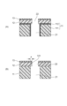
図1は、本発明の液体吐出ヘッドの一例を示す図である。図1に示すように、液体吐出ヘッドは、液体を吐出するための吐出口30が設けられたノズルプレート10と、ノズルプレート10に接続し、かつ吐出口30とノズル20を介して接続する圧力室2が設けられた流路形成部材1とを有する。前記流路形成部材1はさらに、前記圧力室2に前記液体を吐出するためのエネルギーを発生するように構成されたエネルギー発生素子を有する。エネルギー発生素子としては、液体吐出ヘッドの分野において公知の素子を適宜用いることができる。例えば、加熱ヒーター素子や、超音波素子、電気エネルギーや磁気エネルギーで液体を吐出する素子等が挙げられる。本実施形態においては、エネルギー発生素子として圧電素子3を用いる場合について記載する。また、前記ノズルプレート10は、変形抑制層11と感光性材料層12を有し、さらに撥液層13を有してもよい。加えて、ノズルプレート10において、ノズル20は、変形抑制層11に形成されるノズルの第1部分21と、変形抑制層11以外に形成されるノズルの第2部分22を有する。
FIG. 1 is a diagram showing an example of a liquid ejection head of the present invention. As shown in FIG. 1, the liquid ejection head includes a
圧電素子を用いる液体吐出ヘッドにおいては一般に、圧電素子を振動させて液体に吐出エネルギーを加える際、ノズルプレートの変形によるエネルギー損失が課題となる。そのため、圧電素子から発生した圧力を、液体を介して受けるノズルプレートや流路形成部材には、ヤング率が比較的大きいSiやステンレス鋼等が用いられることが多い。一方で、本発明では、ノズルプレートの加工精度を向上させて液体吐出ヘッドを高精細化させることを目的に、ノズルプレートに感光性材料層12を用いる。感光性材料層12は、加工精度を高める観点から感光性樹脂を用いた樹脂層であることが好ましく、特に、耐久性を高める観点から、ネガ型感光性樹脂を用いた樹脂層であることがより好ましい。感光性樹脂としては、UV硬化型のエポキシ、アクリル、ウレタン、ポリイミド、シリコーンあるいはこれらを組合せた分子構造を有する樹脂が挙げられる。これらの樹脂の混合物を用いても良い。
In a liquid ejection head using a piezoelectric element, energy loss due to deformation of the nozzle plate is generally a problem when applying ejection energy to liquid by vibrating the piezoelectric element. Therefore, Si, stainless steel, or the like, which has a relatively large Young's modulus, is often used for the nozzle plate and flow path forming member that receive the pressure generated from the piezoelectric element via the liquid. On the other hand, in the present invention, the
ここで、加工精度向上を目的としてノズルプレート10に樹脂を用いた感光性材料層12を用いるにあたり、ノズルプレート10の柔らかさを補うことを目的に、ノズルプレート10は変形抑制層11を有する。これにより、圧電素子3から液体に力を加えた際のノズルプレート10の変形が低減する効果が得られる。液体吐出時に、圧電素子3から液体を介してノズルプレート10に加えられる圧力を前記変形抑制層11で受ける構成をとることで、ノズルプレート10の変形が抑制される。
Here, when using the
変形抑制層11のヤング率は、50GPa以上が好ましい。一般に、樹脂のヤング率はSiやステンレス鋼と比べて低く、エポキシ樹脂で2GPa程度であり、ヤング率の大きな樹脂でも5GPa未満と報告されている。そのため、変形抑制層11のヤング率が50GPaであれば、ヤング率の高い樹脂よりも10倍以上の値となる。さらに、変形抑制層11のヤング率は130GPa以上がより好ましく、193GPa以上が特に好ましい。130GPaであれば、Si以上のヤング率が得られ、さらに193GPa以上であれば、ステンレス鋼以上のヤング率が得られる。
The Young's modulus of the
前記変形抑制層11の材料としては、ウェットエッチングでもドライエッチングでも加工できて加工精度を高めやすい点から、Siを用いることが好ましい。Si単結晶基板を用いる場合は、ヤング率の高い結晶方位である111面が圧力室2に重なることがより好ましい。ステンレス鋼、Ni、Ir、Ta、W、Mo、Cr、Co、Fe、Ru、SiC、TiC、WC、B4C、ZrO2、Al2O3、AlN、Si3N4、TiN、ダイアモンド等を用いてもよい。また、これらの合金、積層構造や混合材料を用いても良い。これら材料の加工は、ウェットエッチングあるいはドライエッチングで行えばよい。エッチング加工が難しい場合は、レーザー加工、電子ビーム加工、イオンビーム加工、サンドブラスト、切削加工等を用いても良く、これらの中では、加工時の熱影響を低減可能なフェムト秒レーザー加工あるいは水ジェットレーザー加工が好ましい。
As the material for the
次に、撥液層13について説明する。本発明の構成を用いて、ノズルプレート10が、表面側から撥液層13、感光性材料層12、変形抑制層11の順に積層された構成とすることで、撥液層13と感光性材料層12へノズルの第2部分22を一括で形成でき、撥液層13のノズルの第1部分21内部への入り込みが低減される効果が得られるためより好ましい。また、撥液層13による撥液効果を得て、良好に液体吐出を行うためにも、撥液層13が表面に露出している構成が好ましい。
Next, the
なお、撥液層13を形成する工程における熱や溶媒が、感光性材料層12に影響を及ぼす可能性がある。本実施形態の構成においては、変形抑制層11が感光性材料層12で支えられていることにより、感光性材料層12の軟化や内部応力による変形が低減され、ノズルプレート10の高精細な加工が可能となる効果が得られる。
Note that heat and solvent in the process of forming the liquid-
撥液層13の材料としては、感光性材料層12と同様の理由から、感光性材料を含むことが好ましく、感光性樹脂を含むことがより好ましく、ネガ型感光性樹脂を含むことがさらに好ましい。また、撥液層13と感光性材料層12を同時に露光する場合においてもそれぞれの寸法を合わせられるよう、感光性材料層12と撥液層13の光感度が同等であることがより好ましい。
For the same reason as the
また、変形抑制層11における純水の接触角が90°未満であり、かつ、感光性材料層12における純水の接触角が90°未満であることが好ましい。この場合、液体は変形抑制層11と感光性材料層12に濡れやすい。したがって、ノズルの第2部分22内で液体がメニスカスを張り、吐出が安定化される。ここで、純水以外の液体における接触角は純水よりも低い傾向があり、添加物を加えた水系の液体あるいは有機溶媒を多く含む液体等における接触角も90°未満になることが多いことから、接触角を判断する基準として純水を使用した。各種液体の接触角を測定した結果が90°未満の場合であっても同等の効果が得られる。さらに、変形抑制層11における純水の接触角と感光性材料層12における純水の接触角との差が小さいことが好ましく、差が50°以下が好ましく、30°以下がより好ましい。また、ノズル20へ液体を供給する力を強める効果が得られるように、液体吐出ヘッドのノズル20を重力方向下方に向けることが好ましい。液体吐出ヘッドに接続されるポンプ等を用いて、液体に加える圧力を加圧あるいは減圧に調整することで、メニスカスの状態を制御しても良い。
Further, it is preferable that the contact angle of pure water on the
また、撥液層13と感光性材料層12の結合を強める効果を有する層を、感光性材料層12内、撥液層13内及び感光性材料層12と撥液層13の界面のいずれか1つに導入しても良い。例えば、シランカップリング材料を用いたり、あるいはプラズマ処理やUV処理等を組み合わせたりすることで、撥液層13と感光性材料層12の結合を強める層を導入できる。
Further, a layer having the effect of strengthening the bond between the
また、感光性材料層12あるいは撥液層13に、フィラー材料を添加することでも、ノズルプレート10の変形を抑制する効果を高められる。フィラー材料としては、感光性材料層12あるいは撥液層13よりもヤング率が高い材料が好ましい。フィラー材料のヤング率としては、変形抑制層11と同様に50GPa以上が好ましく、130GPa以上がより好ましく、193GPa以上が特に好ましい。
Further, by adding a filler material to the
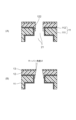
また、図2(A)に示すように、変形抑制層11は、ヤング率が50GPa以上の支持層111と、機能層112とを有していてもよい。機能層112は、複数層で形成されていてもよく、支持層111に対して部分的に形成されていてもよく、2層以上の支持層111に挟まれて変形抑制層11の内部に形成されていても良い。例えば、感光性材料層12が感光する波長の光において、機能層112が支持層111よりも低い反射率を有することで、感光性材料層12が変形抑制層11より受ける反射光が低減される効果が得られる。また、機能層112の表面がシロキサン結合を有し、感光性材料12と機能層13の界面にシランカップリング材料を用いることで化学結合を形成することができ、感光性材料層12と撥液層13との密着を向上させる効果が得られる。機能層112には、例えば、配線層、絶縁層、半導体層、反射防止層、拡散防止層、保護層、平坦化層、密着向上層、接着剤層あるいはエッチングストップ層としての機能を付与してもよい。あるいは、機能層112をパターニングして回路、センサ、メモリ、電池等の各種電子部品を組み合わせた機能を付与しても良い。なお、機能層112にはヤング率が50GPa未満の材料を用いても良い。
Further, as shown in FIG. 2(A), the
次に、ノズルプレート10の詳細な構成について説明する。ノズル20断面の形状は、種々の公知の形状を用いればよい。具体的には、略円や楕円や多角形あるいは種々の直線や曲線で構成される形状が使用可能である。また、ミストを低減する等の目的で吐出口30に突起を設けても良い。
Next, the detailed configuration of the
加えて、メニスカスを張る位置をノズルの第2部分22の最表面に安定化させるためには、第1のノズルの第1部分21の内径よりも第2のノズルの第2部分22の内径が小さく、ノズル21とノズル22の中心軸が実質的に同一であることが好ましい。ここで、ノズルの内径としては、例えばノズル形状が略円の場合は直径を、楕円の場合は長径を用いればよい。また、後述するように、ノズルの第1部分21が多段構造やテーパー構造を有する場合には、変形抑制層12と接する面における内径を用いればよい。これにより、ノズルの第2部分22の最表面の加工精度が感光性材料12のリソグラフィ精度となり、リソグラフィとエッチングで形成される変形抑制層11内のノズルの第1部分21に比べて加工精度を高めやすい効果が得られるためより好ましい。
In addition, in order to stabilize the position of the meniscus at the outermost surface of the
上述のように、ノズルの第1部分21に対してノズルの第2部分22の内径が小さく、かつ、ノズル21とノズル22の中心軸が実質的に同一である場合、図2(B)に示すように、感光性材料層12には、変形抑制層11と接しない変形抑制層11からのせり出し部121ができる。ここで、感光性材料層12と撥液層13の内部応力により、感光性材料層12と撥液層13に変形が生じる。せり出し部121は変形抑制層11と固定されていないために変形しやすく、せり出し部121の長さaが大きいほど前記内部応力による変形が大きくなる。ここで、せり出し部の長さaが感光性材料層12と撥液層13の合計厚み以下であれば、変形できるせり出し部の割合を低減することができ、せり出し部121の変形が小さくなる効果が得られるためより好ましい。また、ノズルの第1部分21の内径に対する、せり出し部の長さaの割合を小さくすることで、ノズル内硬化異物を低減させる効果が得られる。そのため、せり出し部121の長さaの値が、ノズルの第1部分21の内径に対して6%以下であれば好ましく、5%以下であればより好ましく、4%以下であればさらに好ましく、3%以下であればよりさらに好ましい。この場合、ノズルの第1部分21の内径とノズルの第2部分22の内径の差が、ノズルの第1部分21の内径に対して12%以下であれば好ましく、10%以下であればより好ましく、8%以下であればさらに好ましく、6%以下であればよりさらに好ましい。ここでノズル内硬化異物とは、感光性材料を硬化させたくない領域において感光性材料が硬化した異物である。
As described above, when the inner diameter of the
また、変形抑制層11の厚みを、感光性材料層12と撥液層13の合計厚みよりも大きくすることで、ノズルプレート10の変形抑制効果が高まるが、ノズル20の長さが変わるために吐出へ影響を及ぼす。そのため、変形抑制効果と液体の良好な吐出を両立するためには、変形抑制層11の厚みが200μm以下であれば好ましく、100μm以下であればより好ましく、50μm以下であればさらに好ましく、20μm以下であればよりさらに好ましい。その上で、変形抑制効果を有効に得るためには、変形抑制層11の厚みが5μm以上であれば好ましく、10μm以上であればより好ましい。
Further, by making the thickness of the
また、感光性材料層11と撥液層13の合計厚みは10μm以下が好ましく、5μm以下がより好ましく、1μm以下がより好ましい。このとき、感光性材料層11と撥液層13の合計厚みを薄くすることで、液体吐出の異常を低減できる場合がある。加えて、撥液性を安定して発現させるために、前記合計厚みは0.02μm以上が好ましく、0.05μm以上がより好ましい。
Further, the total thickness of the
次に、ノズル20の詳細な構成について説明する。図3(A)、(B)は、本発明におけるノズル20を拡大した図である。
Next, the detailed configuration of the
図3(A)に示すように、ノズルの第1部分21を多段構造にすることで、変形抑制効果と良好な吐出を両立する設計範囲を広げることができる。具体的には、変形抑制のために変形抑制層11を厚くしても、液体の吐出速度、吐出量の設計範囲を調整可能となる効果、あるいは吐出不良防止のために液体を循環させる際の循環効率を高める効果が得られる。ノズルの第1部分21がテーパー形状でも同様の効果が得られ、多段構造とテーパー構造を組合せても良い。
As shown in FIG. 3A, by forming the
図3(A)に示すように、感光性材料12がノズルの第2部分22からノズルの第1部分21に入り込んだノズル壁密着部122を形成させることによって、感光性材料層12と変形抑制層11の密着面積が広くなり密着が向上する効果が得られるためより好ましい。ノズルの第1部分21を多段構造にし、ノズル壁密着部122が接する段と接しない段があってもよい。感光性材料層12がノズルの第1部分21に入り込むように形成されているかどうかは、ノズル20断面の観察や組成分析によって判断することができる。
As shown in FIG. 3A, the
図3(B)に示すように、感光性材料層12と撥液層13でテーパー形状を形成しても良い。テーパー角度θが大きいと吐出速度を高められるため、2°以上であることがより好ましく、5°以上であればさらに好ましく、10°以上であればよりさらに好ましい。ここで感光性材料層12は多段構造であっても良く、多段構造とテーパー形状を組み合わせた構造であっても良い。
As shown in FIG. 3(B), the
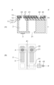
次に、本発明における吐出ヘッドの構成例について説明する。図4は、本発明の液体吐出ヘッドの一例を示す図である。図4(A)に示すように、圧力室2を有する流路形成部材1にノズルプレート10が接続され、圧力室2とノズルプレート10が隣接する構成をとる。圧電素子3を駆動して液体に吐出エネルギーを加える際、液体を介してノズルプレート10に圧力が加わる。このとき、本発明の変形抑制層11が有効に働き、ノズルプレート10の変形が抑制される。
Next, an example of the configuration of the ejection head in the present invention will be described. FIG. 4 is a diagram showing an example of a liquid ejection head of the present invention. As shown in FIG. 4(A), a
図4(B)に示すように、圧電素子3とノズルプレート10間に流路が存在する構成を用いることもできる。この場合においても、圧電素子3を駆動して液体にエネルギーを加えると、液体を介してノズルプレート10に圧力が加わる。よって、流路を含めて圧力室2とみなすことができ、本発明の変形抑制層11が有効に働く。
As shown in FIG. 4(B), a configuration in which a flow path exists between the
図4(C)に示すように、圧電素子3とノズルプレート10が離れる別の構成を用いることもできる。この場合においても、圧電素子3を駆動して液体に加わるエネルギーは、液体を介してノズルプレート10に加わるため、流路を含めて圧力室2とみなすことができる。よって、本発明の変形抑制層11が有効に働く。また、圧力室2へと液体を供給する流路である液体供給口31の方向にも液体を介して圧力が伝搬する。本構成のように、液体供給口31の流路の途中に、ノズルプレート10と隣接した部分がある場合は、液体を介してノズルプレート10に圧力が加わる本発明の変形抑制層11が有効に働く。
As shown in FIG. 4C, another configuration in which the
また、液体吐出ヘッドには、ノズル20以外の加工を施してもよい。図5は、本発明の液体吐出ヘッドの一例を示す図である。図5(A)は断面図であり、図5(B)は図5(A)中のA-A’に対応する上面図である。
Further, the liquid ejection head may be processed other than the
図5(A)に示すように、変形抑制層11が支持層111と機能層112から構成されている。機能層112は、例えば、エッチングストップ層として用いることができる。変形抑制層11にはノズルの第1部分21が形成されている。また、感光性材料層12と撥液層13にもノズルの第2部分22が形成されている。流路形成部材1は、圧力室2と圧電素子3と液体供給口31を有する。
As shown in FIG. 5(A), the
ここで、変形抑制層11、感光性材料層12及び撥液層13の少なくともいずれかに1つに、ノズル20以外の加工パターンを形成して、種々の機能をもたせることができる。例えば、ノズルプレート10にスリット41を形成することで、基板全体の剛性バランスを整える効果や、ノズルプレート10と流路形成部材1を接着剤で接合する場合に接着剤の流動を整える効果あるいはアンカー効果による密着向上の効果が得られる。また、ノズルプレート10に対してパターン42を形成しても良い。この場合、さらにパターン42の近傍の感光性材料層12と撥液層13を除去することで、パターン42の視認性が向上する効果が得られる。加工パターン42のない部分において、感光性材料層12と撥液層13を加工したパターン43を形成してよい。これらの加工パターンは、ノズルの第1部分21あるいはノズルの第2部分22と同時に加工することができるため、本発明においては新たに加工工程を設けることなく加工が可能である。これらの加工パターンは、加工されるウェハやチップの識別、パターンの幅や深さの測定、加工途中の状態あるいは加工後の状態のモニタリング、加工パターンをアライメントマークとして用いた、ウェハやチップのアライメント等に用いることができる。
Here, a processing pattern other than the
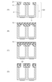
次に、本発明における液体吐出ヘッドの製造方法の実施例について説明する。図6は、本発明の液体吐出ヘッドの製造方法の一例を示す図である。 Next, an example of a method for manufacturing a liquid ejection head according to the present invention will be described. FIG. 6 is a diagram showing an example of a method for manufacturing a liquid ejection head of the present invention.
図6(A)に示すように、圧力室2及び圧電素子3を有する流路形成部材1と、ノズルの第1部分21を有する変形抑制層11と、を有する構造体120を準備する。なお、流路形成部材1と変形抑制層11の接合方法には、接着剤による接着、陽極接合、表面活性化接合等があるが、変形抑制層11の材質選択の自由度及び加工における自由度が高まるため、接着剤による接合を用いることが好ましい。
As shown in FIG. 6A, a
ここで、変形抑制層11としてSiを用い、ノズルの第1部分21をボッシュプロセスで加工することで、ノズルの第1部分21の壁面にスカロップを形成することができる。後述する感光性材料層12を形成する工程において、このスカロップに感光性材料層12が接するように加工することで、アンカー効果による変形抑制層11と感光性材料層12との密着が向上する効果が得られるため好ましい。
Here, by using Si as the
次に、図6(B)に示すように、構造体120に感光性材料層12を形成する。ここで感光性材料層12は公知の方法で形成すれば良いが、ノズルの第1部分21あるいは圧力室2への入り込み量を制御しやすい点から、ドライフィルムレジストを用いて形成することが好ましい。この場合、変形抑制層11のノズルの第1部分21の形状を多段にし、感光性材料層12をノズルの第1部分21の最上段を埋めるように形成することで、感光性材料がノズルの第1部分21の2段目以降の段に入りにくいように制御しても良い。
Next, as shown in FIG. 6(B), a
また、感光性材料層12は、感光性の異なる複数の材料を有する多層構造をとってもよい。例えば、撥液層13側に感光性の高い層を、変形抑制層11側に感光性が低い層を配置する構成をとることで、後述する撥液層13形成後の露光時において、撥液層13が感光性材料層12や変形抑制層11より受ける反射影響を低減する効果が得られる。
Further, the
次に、図6(C)に示すように、撥液層13を形成する。ここで撥液層13は公知の方法で形成すれば良く、例えばスリットコート、スピンコート、スプレーコート、スクリーン印刷等を用いることができる。撥液層13形成時の感光性材料層12の変形を低減するには、撥液層13形成時の溶媒を低減させた状態で形成することが好ましく、撥液層13をドライフィルムレジストで形成がより好ましい。また、感光性材料層12の変形を低減する別の方法としては、感光性材料層12をノズルの第1部分21に入り込むように形成することが好ましい。これにより、感光性材料が、撥液層13の形成時の溶媒あるいは熱により流動することを低減できる。また、撥液層13を塗布で形成する際には、撥液層13形成時の溶媒が感光性材料層12を溶解しにくい組成であることが好ましい。このような工夫をすることで、感光性材料層12の変形を低減できる効果が得られる。
Next, as shown in FIG. 6(C), a
また、撥液層13形成後に撥液層13にエネルギーを照射することで、撥液層13内の撥液成分を表面に偏析させることができ、撥液性能を高められる効果が得られる。エネルギー照射は、ホットプレートやオーブンを用いた熱処理を用いることができる。あるいはランプやレーザーやマイクロ波等の電磁波を用いても良く、電子線やイオンビームやガスジェットの照射やプラズマ処理等を用いても良い。これらのエネルギーは連続的に照射しても良く、瞬間的に高出力で照射しても良い。
Further, by irradiating the
次に、図6(D)に示すように、撥液層13と感光性材料層12にノズルの第2部分22を形成する。ノズルの第2部分22は公知の方法を用いて形成すればよい。例えば、露光、PEB(Post exposure bake)、現像、といった一連の工程を用いることができる。ここで、PEBをはじめとする各種の熱処理においては、段階的に加熱温度を上げることで、感光性材料層12の変形を低減する効果が得られるため好ましい。現像後に追加の熱処理を行っても良い。
Next, as shown in FIG. 6(D), a
次に、本発明における液体吐出ヘッドの製造方法について、図6とは異なる実施例を説明する。図7は、本発明の液体吐出ヘッドの製造方法の一例を示す図である。図7(A)に示すように、構造体120を準備する。次に、図7(B)に示すように、支持部材50上に形成したフィルム14を構造体120に転写する。ここで、フィルム14は、感光性材料層12用の層と撥液層13用の層の積層物を用いることができる。
Next, an embodiment different from that shown in FIG. 6 will be described regarding the method of manufacturing a liquid ejection head according to the present invention. FIG. 7 is a diagram showing an example of a method for manufacturing a liquid ejection head of the present invention. As shown in FIG. 7(A), a
次に、図7(C)に示すように、支持部材50を剥がしながらフィルム14をパターニングしてノズルの第2部分22を形成する。ノズルの第1部分21を覆うように転写されたフィルム14に対して、支持部材50を介して力を加えることでノズルの第1部分21の縁でフィルム14に凝集破壊を発生させ、フィルム14がパターニングされてノズルの第2部分22が形成される。ここで、ノズルの第1部分21の縁からノズルの第2部分22がずれないようフィルム14をパターニングするためには、フィルム14の厚みを薄くすることが効果的である。そのため、フィルム14の厚みは、1μm以下が好ましく、0.5μm以下がより好ましく、0.2μm以下がさらに好ましく、0.1μm以下がよりさらに好ましい。
Next, as shown in FIG. 7C, the
また、図7(D)に示すように、フィルム14にエネルギーを照射することで、撥液成分を偏析させて感光性材料層12と撥液層13が十分に分離した状態を形成することもできる。ここで撥液層13は純水の接触角が90°以上になる組成を有し、感光性材料層12は純水の接触角が90°未満になる組成を有する。そのため、相分離しているかどうかは、感光性材料層12と撥液層13を削り、純水の接触角を測定することで評価できる。あるいは、ノズルプレート10の深さ方向の組成分析から推定することもできる。
Furthermore, as shown in FIG. 7(D), by irradiating the
また、フィルム14には、感光性材料層12と撥液層13のそれぞれの原料の混合物を用いることもできる。フィルム14として感光性材料層12と撥液層13の積層物を用いた場合と同様、フィルム14にエネルギーを照射することにより、感光性材料層12と撥液層13が十分に分離した状態を形成することができる。感光性材料層12と撥液層13を一括で形成する本実施形態を用いることで、感光性材料層12と撥液層13の合計厚みを薄く形成でき、加えて、形成工程数を低減できる。また、感光性材料層12と撥液層13それぞれの原料の混合物として、常温25℃において液体の材料を用いると、常温での相分離が可能となり、工程が簡便化する効果が得られる。
Further, for the
ノズル20の形成過程においては、露光は全面照射で行っても良く、これにより工程が簡便化する効果が得られる。また、PEB、現像又は追加の熱硬化を行うことができる。なお、現像は必ずしも行わなくても良いし、PEBと追加の熱硬化を兼ねた熱処理を行っても良く、いずれの場合においても工程が簡便化する効果が得られる。
In the process of forming the
なお、各層の形成の順番としては、図6、図7で示したように、変形抑制層11と流路形成部材1とを接合した後に感光性材料層12と撥液層13を形成することが好ましい。先に感光性材料層12と撥液層13を変形抑制層11上に形成する場合は、変形抑制層11単体に加工することとなるが、変形抑制層11単体では薄くてハンドリングしにくいため支持部材が必要になる場合が多い。そのため、先に変形抑制層11を流路形成部材1と接合しておくことで、流路形成部材1が変形抑制層11の支持部材として働きハンドリングがしやすくなる。
As shown in FIGS. 6 and 7, the order of forming each layer is to form the
上記の実施形態では、液体を吐出するためのエネルギー発生素子として圧電素子を用いた液体吐出ヘッドについて説明したが、エネルギー発生素子として圧電素子以外を用いても、本発明は有効に働く。ここで、図8にエネルギー発生素子として加熱ヒーター素子を用いた場合の液体吐出ヘッドを示す。 In the above embodiments, a liquid ejection head using a piezoelectric element as an energy generating element for ejecting liquid has been described, but the present invention works effectively even when a device other than a piezoelectric element is used as an energy generating element. Here, FIG. 8 shows a liquid ejection head when a heating element is used as the energy generating element.
図8に示すように、液体吐出ヘッドは、流路形成部材1と、流路形成部材1に接続されたノズルプレート10とを有する。流路形成部材1は、圧力室2と、ヒーター4と、液体供給口31と、を有し、ノズルプレート10は、変形抑制層11と、感光性材料層12と、撥液層13と、を有する。ノズルプレート10はノズル20を有し、ノズル20は、変形抑制層11に形成されるノズルの第1部分21と、変形抑制層11以外で形成されるノズルの第2部分22を有する。本構成においても、エネルギー発生素子として圧力素子を用いる液体吐出ヘッドと同様に、変形抑制層11によりノズルプレート10の変形を抑制する効果が得られる。
As shown in FIG. 8, the liquid ejection head includes a flow
以下、実施例を挙げて本発明をより具体的に説明するが、本発明は実施例に限定されるものではない。 EXAMPLES Hereinafter, the present invention will be described in more detail with reference to Examples, but the present invention is not limited to the Examples.
<実施例>
図1に示す構成の液体吐出ヘッドを形成した。流路形成部材1としてはSi基板を用い、ここに、PZT(チタン酸ジルコン酸鉛)からなる圧電素子3、駆動回路(不図示)、液体供給口(不図示)及び圧力室2を形成した。変形抑制層11の材料にはSiを用いた。前記流路形成部材1と前記変形抑制層11を、接着剤を用いて接合した後、前記変形抑制層11を厚さ100μmまで薄化した。続いて変形抑制層11に、フォトレジストをマスク部材とし、ボッシュプロセスで直径30μmのノズルの第1部分21を形成した。
<Example>
A liquid ejection head having the configuration shown in FIG. 1 was formed. A Si substrate was used as the flow
次に、感光性材料層12として、厚み5μmにドライフィルム化したネガ型感光性エポキシ樹脂を変形抑制層11上へ転写した。続いて、ネガ型感光性エポキシ樹脂を含む撥液剤を、スリットコーターを用いて感光性材料層12上に塗布して撥液層13を形成しベークした。次に、直径29μmになるようにサイズ調整したフォトマスクを用いて感光性材料層12と撥液層13を露光し、PEB、現像及び追加の熱処理を行ってノズルの第2部分22を形成した。以上の工程により、液体吐出ヘッドを得た。得られた液体吐出ヘッドをインクジェットプリンタ本体(不図示)に取り付け、液体吐出ヘッドにはインクの収容されたインクタンク(不図示)が取り付けられた。このように、液体吐出装置としてのインクジェットプリンタを構成した。
Next, a negative photosensitive epoxy resin formed into a dry film with a thickness of 5 μm was transferred onto the
<比較例>
図1に示す変形抑制層11を感光性樹脂に変更した液体吐出ヘッドを形成した。なお、感光性樹脂としては、ネガ型感光性エポキシ樹脂を用いた。エポキシ樹脂のヤング率は本発明の変形抑制層に求められる50GPa以下である。流路形成部材1には、前記実施例と同じ構成のものを形成した。変形抑制層11に相当する部材には、厚み20μmにドライフィルム化したネガ型感光性エポキシ樹脂を5枚貼り合わせたものを用いた。続いて、ドライフィルムの露光、PEB及び現像を行い、直径30μmのノズルの第1部分21を形成した。次に、感光性材料層12、撥液層13及びノズルの第2部分22を実施例と同様にして形成し、液体吐出ヘッドを得た。得られた液体吐出ヘッドを用い、実施例と同様にインクジェットプリンタを構成した。実施例と比較例のインクジェットプリンタとを比較したところ、実施例の液体吐出ヘッドを用いた場合に、比較例の液体吐出ヘッドを用いた場合よりも、吐出の周波数を高められる結果が得られた。また、比較例の液体吐出ヘッドでは、吐出速度低下の割合と、不吐の割合とが増加する場合があった。
<Comparative example>
A liquid ejection head was formed in which the
1 流路形成部材
2 圧力室
3 圧電素子
4 ヒーター
10 ノズルプレート
11 変形抑制層
12 感光性材料層
13 撥液層
111 支持層
112 機能層
20 ノズル
21 ノズルの第1部分
22 ノズルの第2部分
30 吐出口
31 液体供給口
50 支持部材
121 せり出し部
a せり出し部の長さ
122 ノズル壁密着部
1
Claims (18)
前記ノズルプレートと隣接し、かつ、前記吐出口とノズルを介して接続する圧力室が設けられた流路形成部材と、
前記圧力室へ前記液体を吐出するためのエネルギーを発生するように構成されたエネルギー発生素子と、を有する液体吐出ヘッドにおいて、
前記ノズルプレートは、樹脂層と、ヤング率が50GPa以上である変形抑制層と、を有する液体吐出ヘッド。 a nozzle plate provided with a discharge port for discharging liquid;
a flow path forming member provided with a pressure chamber adjacent to the nozzle plate and connected to the discharge port via a nozzle;
A liquid ejection head comprising: an energy generating element configured to generate energy for ejecting the liquid into the pressure chamber;
The nozzle plate is a liquid ejection head including a resin layer and a deformation suppressing layer having a Young's modulus of 50 GPa or more.
前記ノズルの第2部分は前記ノズルの第1部分よりも内径が小さく、かつ、
前記ノズルの第1部分の内径と前記ノズルの第2部分の内径の差が、前記ノズルの第1部分の内径に対して12%以下である、請求項1に記載の液体吐出ヘッド。 The nozzle has a first part of the nozzle formed on the deformation suppressing layer, and a second part of the nozzle formed on a part other than the deformation suppressing layer,
The second portion of the nozzle has a smaller inner diameter than the first portion of the nozzle, and
The liquid ejection head according to claim 1, wherein the difference between the inner diameter of the first portion of the nozzle and the inner diameter of the second portion of the nozzle is 12% or less with respect to the inner diameter of the first portion of the nozzle.
前記樹脂層における純水の接触角が、90°未満である、請求項1に記載の液体吐出ヘッド。 The contact angle of pure water on the deformation suppressing layer is less than 90°, and
The liquid ejection head according to claim 1, wherein a contact angle of pure water on the resin layer is less than 90°.
前記樹脂層が、前記ノズルの第2部分から前記ノズルの第1部分に入り込むように形成された、請求項1に記載の液体吐出ヘッド。 The nozzle has a first part of the nozzle formed on the deformation suppressing layer, and a second part of the nozzle formed on a part other than the deformation suppressing layer,
The liquid ejection head according to claim 1, wherein the resin layer is formed so as to enter the first part of the nozzle from the second part of the nozzle.
前記樹脂層が感光する波長の光において前記機能層は、前記支持層よりも低い反射率を有する、請求項1に記載の液体吐出ヘッド。 The deformation suppressing layer has a support layer having a Young's modulus of 50 GPa or more and a functional layer,
The liquid ejection head according to claim 1, wherein the functional layer has a lower reflectance than the support layer for light having a wavelength to which the resin layer is sensitive.
前記ノズルプレートと隣接し、かつ、前記吐出口とノズルを介して接続する圧力室が設けられた流路形成部材と、
前記圧力室へ前記液体を吐出するためのエネルギーを発生するように構成されたエネルギー発生素子と、を有する液体吐出ヘッドであって、
前記ノズルプレートが、撥液層と、感光性材料層と、ヤング率が50GPa以上である変形抑制層と、を有する液体吐出ヘッドの製造方法であって、
前記感光性材料層及び前記撥液層の少なくとも一方をドライフィルムレジストで形成する工程を有する液体吐出ヘッドの製造方法。 a nozzle plate provided with a discharge port for discharging liquid;
a flow path forming member provided with a pressure chamber adjacent to the nozzle plate and connected to the discharge port via a nozzle;
A liquid ejection head comprising: an energy generating element configured to generate energy for ejecting the liquid into the pressure chamber;
A method for manufacturing a liquid ejection head in which the nozzle plate includes a liquid repellent layer, a photosensitive material layer, and a deformation suppressing layer having a Young's modulus of 50 GPa or more,
A method for manufacturing a liquid ejection head, comprising the step of forming at least one of the photosensitive material layer and the liquid repellent layer using a dry film resist.
前記感光性材料層を形成する工程において、前記感光性材料層が、前記ノズルの第2部分から前記ノズルの第1部分に入り込むように形成される工程を有する、請求項14に記載の液体吐出ヘッドの製造方法。 The nozzle has a first part of the nozzle formed on the deformation suppressing layer, and a second part of the nozzle formed on a part other than the deformation suppressing layer,
Liquid ejection according to claim 14, wherein the step of forming the photosensitive material layer includes the step of forming the photosensitive material layer so as to enter the first portion of the nozzle from the second portion of the nozzle. Head manufacturing method.
Priority Applications (1)
| Application Number | Priority Date | Filing Date | Title |
|---|---|---|---|
| JP2022071342A JP2023161162A (en) | 2022-04-25 | 2022-04-25 | Liquid ejection head, liquid ejection device, and manufacturing method for liquid ejection head |
Applications Claiming Priority (1)
| Application Number | Priority Date | Filing Date | Title |
|---|---|---|---|
| JP2022071342A JP2023161162A (en) | 2022-04-25 | 2022-04-25 | Liquid ejection head, liquid ejection device, and manufacturing method for liquid ejection head |
Publications (1)
| Publication Number | Publication Date |
|---|---|
| JP2023161162A true JP2023161162A (en) | 2023-11-07 |
Family
ID=88650174
Family Applications (1)
| Application Number | Title | Priority Date | Filing Date |
|---|---|---|---|
| JP2022071342A Pending JP2023161162A (en) | 2022-04-25 | 2022-04-25 | Liquid ejection head, liquid ejection device, and manufacturing method for liquid ejection head |
Country Status (1)
| Country | Link |
|---|---|
| JP (1) | JP2023161162A (en) |
-
2022
- 2022-04-25 JP JP2022071342A patent/JP2023161162A/en active Pending
Similar Documents
| Publication | Publication Date | Title |
|---|---|---|
| US7300596B2 (en) | Method of manufacturing liquid discharge head | |
| JP3833989B2 (en) | Inkjet printhead manufacturing method | |
| US8148049B2 (en) | Ink jet recording head and manufacturing method of the same | |
| JP4981491B2 (en) | Ink jet head manufacturing method and through electrode manufacturing method | |
| US8091234B2 (en) | Manufacturing method for liquid discharge head substrate | |
| US8904639B2 (en) | Method of producing liquid ejection head | |
| JP5224771B2 (en) | Manufacturing method of recording head substrate | |
| JP2008149649A (en) | Inkjet head and its manufacturing method | |
| JP4659898B2 (en) | Manufacturing method of substrate for liquid discharge head | |
| JP2023161162A (en) | Liquid ejection head, liquid ejection device, and manufacturing method for liquid ejection head | |
| JP6929657B2 (en) | Manufacturing method of liquid discharge head | |
| JP2002240307A (en) | Method for manufacturing ink jet recording head and ink jet recording head manufactured by the method | |
| JP5294657B2 (en) | Inkjet recording head | |
| JP6157180B2 (en) | Ink jet recording head and manufacturing method thereof | |
| US8430476B2 (en) | Method for manufacturing liquid discharge head | |
| KR101376402B1 (en) | Liquid discharge head manufacturing method | |
| JP2010260233A (en) | Manufacturing method for liquid discharge head | |
| US7735961B2 (en) | Liquid discharge head and method of producing the same | |
| JP2009233955A (en) | Method for manufacturing microstructural body and method for manufacturing liquid ejection head | |
| JP2007050583A (en) | Droplet delivering head and method for manufacturing droplet delivering head | |
| JP2008126481A (en) | Method for manufacturing substrate for inkjet recording head and method for manufacturing inkjet recording head | |
| WO2008075715A1 (en) | Method of producing nozzle plate for liquid discharge head, nozzle plate for liquid discharge head, and liquid discharge head | |
| JP2014198386A (en) | Method of manufacturing ink discharge head | |
| JP2014128923A (en) | Method for manufacturing liquid discharge head | |
| JP4671330B2 (en) | Method for manufacturing ink jet recording head |
Legal Events
| Date | Code | Title | Description |
|---|---|---|---|
| RD01 | Notification of change of attorney |
Free format text: JAPANESE INTERMEDIATE CODE: A7421 Effective date: 20231213 |