JP2023155835A - Game machine - Google Patents
Game machine Download PDFInfo
- Publication number
- JP2023155835A JP2023155835A JP2022065417A JP2022065417A JP2023155835A JP 2023155835 A JP2023155835 A JP 2023155835A JP 2022065417 A JP2022065417 A JP 2022065417A JP 2022065417 A JP2022065417 A JP 2022065417A JP 2023155835 A JP2023155835 A JP 2023155835A
- Authority
- JP
- Japan
- Prior art keywords
- unit
- door frame
- frame
- display
- decorative
- Prior art date
- Legal status (The legal status is an assumption and is not a legal conclusion. Google has not performed a legal analysis and makes no representation as to the accuracy of the status listed.)
- Pending
Links
- 230000000694 effects Effects 0.000 claims description 1317
- 238000004519 manufacturing process Methods 0.000 claims description 575
- 230000033001 locomotion Effects 0.000 claims description 81
- 230000008901 benefit Effects 0.000 claims description 4
- 230000002093 peripheral effect Effects 0.000 description 1168
- 238000000034 method Methods 0.000 description 654
- 230000008569 process Effects 0.000 description 600
- 238000005034 decoration Methods 0.000 description 410
- 238000012545 processing Methods 0.000 description 376
- 238000001514 detection method Methods 0.000 description 303
- 230000005540 biological transmission Effects 0.000 description 297
- 238000003860 storage Methods 0.000 description 281
- 238000010586 diagram Methods 0.000 description 261
- 239000000779 smoke Substances 0.000 description 203
- 230000006870 function Effects 0.000 description 197
- 230000007123 defense Effects 0.000 description 166
- 239000003990 capacitor Substances 0.000 description 113
- 230000008859 change Effects 0.000 description 86
- 238000004891 communication Methods 0.000 description 82
- 239000011521 glass Substances 0.000 description 78
- 238000013500 data storage Methods 0.000 description 76
- 241001419253 Spathiphyllum cochlearispathum Species 0.000 description 65
- 239000004973 liquid crystal related substance Substances 0.000 description 65
- 238000004880 explosion Methods 0.000 description 64
- 230000003014 reinforcing effect Effects 0.000 description 63
- 238000012544 monitoring process Methods 0.000 description 60
- 230000004044 response Effects 0.000 description 55
- 229910052751 metal Inorganic materials 0.000 description 53
- 239000002184 metal Substances 0.000 description 53
- 239000002243 precursor Substances 0.000 description 52
- 230000007423 decrease Effects 0.000 description 47
- 230000001186 cumulative effect Effects 0.000 description 45
- 230000007257 malfunction Effects 0.000 description 40
- 238000010304 firing Methods 0.000 description 39
- 239000000758 substrate Substances 0.000 description 39
- 230000005856 abnormality Effects 0.000 description 37
- 238000009792 diffusion process Methods 0.000 description 36
- 238000003825 pressing Methods 0.000 description 36
- 230000015654 memory Effects 0.000 description 35
- 230000006378 damage Effects 0.000 description 33
- 230000001360 synchronised effect Effects 0.000 description 33
- 238000007689 inspection Methods 0.000 description 29
- 238000012790 confirmation Methods 0.000 description 27
- 238000000605 extraction Methods 0.000 description 27
- 238000004088 simulation Methods 0.000 description 27
- 239000012141 concentrate Substances 0.000 description 26
- 238000012546 transfer Methods 0.000 description 26
- 239000000057 synthetic resin Substances 0.000 description 24
- 229920003002 synthetic resin Polymers 0.000 description 24
- 230000002159 abnormal effect Effects 0.000 description 23
- 230000001276 controlling effect Effects 0.000 description 22
- 230000007246 mechanism Effects 0.000 description 22
- 230000000149 penetrating effect Effects 0.000 description 22
- 238000012986 modification Methods 0.000 description 21
- 230000004048 modification Effects 0.000 description 21
- 239000013078 crystal Substances 0.000 description 20
- 238000007726 management method Methods 0.000 description 20
- 230000002829 reductive effect Effects 0.000 description 18
- 239000000725 suspension Substances 0.000 description 18
- 238000012937 correction Methods 0.000 description 16
- 230000000630 rising effect Effects 0.000 description 16
- 230000007704 transition Effects 0.000 description 16
- 230000014759 maintenance of location Effects 0.000 description 15
- 238000005259 measurement Methods 0.000 description 15
- 238000011084 recovery Methods 0.000 description 15
- 230000000670 limiting effect Effects 0.000 description 14
- 238000012360 testing method Methods 0.000 description 14
- 230000004397 blinking Effects 0.000 description 13
- 230000001976 improved effect Effects 0.000 description 13
- 230000000717 retained effect Effects 0.000 description 13
- 238000004458 analytical method Methods 0.000 description 12
- 230000003247 decreasing effect Effects 0.000 description 11
- 238000010248 power generation Methods 0.000 description 11
- 238000003780 insertion Methods 0.000 description 10
- 230000037431 insertion Effects 0.000 description 10
- 230000002250 progressing effect Effects 0.000 description 10
- 101000614399 Homo sapiens Serine/threonine-protein phosphatase 2A regulatory subunit B'' subunit beta Proteins 0.000 description 9
- 102100040471 Serine/threonine-protein phosphatase 2A regulatory subunit B'' subunit beta Human genes 0.000 description 9
- 238000004364 calculation method Methods 0.000 description 9
- 230000003068 static effect Effects 0.000 description 9
- 230000001960 triggered effect Effects 0.000 description 9
- 230000000007 visual effect Effects 0.000 description 9
- 230000002087 whitening effect Effects 0.000 description 9
- 101100522110 Oryza sativa subsp. japonica PHT1-10 gene Proteins 0.000 description 8
- 101100522109 Pinus taeda PT10 gene Proteins 0.000 description 8
- 239000003086 colorant Substances 0.000 description 8
- 210000000887 face Anatomy 0.000 description 8
- 230000006872 improvement Effects 0.000 description 8
- 238000011022 operating instruction Methods 0.000 description 8
- 238000005192 partition Methods 0.000 description 8
- 238000007493 shaping process Methods 0.000 description 8
- 101100153168 Arabidopsis thaliana TIC21 gene Proteins 0.000 description 7
- 102100033270 Cyclin-dependent kinase inhibitor 1 Human genes 0.000 description 7
- 241000587161 Gomphocarpus Species 0.000 description 7
- 101100273813 Homo sapiens CDKN1A gene Proteins 0.000 description 7
- 108700038981 SUMO-1 Proteins 0.000 description 7
- 101100083337 Schizosaccharomyces pombe (strain 972 / ATCC 24843) pic1 gene Proteins 0.000 description 7
- 238000001994 activation Methods 0.000 description 7
- 238000005452 bending Methods 0.000 description 7
- 235000009508 confectionery Nutrition 0.000 description 7
- 238000013016 damping Methods 0.000 description 7
- 238000009499 grossing Methods 0.000 description 7
- 239000000463 material Substances 0.000 description 7
- 230000036961 partial effect Effects 0.000 description 7
- 230000008093 supporting effect Effects 0.000 description 7
- 101000893549 Homo sapiens Growth/differentiation factor 15 Proteins 0.000 description 6
- 101000692878 Homo sapiens Regulator of MON1-CCZ1 complex Proteins 0.000 description 6
- 101000885321 Homo sapiens Serine/threonine-protein kinase DCLK1 Proteins 0.000 description 6
- 102100026436 Regulator of MON1-CCZ1 complex Human genes 0.000 description 6
- 102100039758 Serine/threonine-protein kinase DCLK1 Human genes 0.000 description 6
- 230000004308 accommodation Effects 0.000 description 6
- 230000009471 action Effects 0.000 description 6
- 230000015556 catabolic process Effects 0.000 description 6
- 238000005520 cutting process Methods 0.000 description 6
- 238000013461 design Methods 0.000 description 6
- 239000002360 explosive Substances 0.000 description 6
- 239000002932 luster Substances 0.000 description 6
- 230000008450 motivation Effects 0.000 description 6
- 230000003466 anti-cipated effect Effects 0.000 description 5
- 239000000284 extract Substances 0.000 description 5
- 230000002265 prevention Effects 0.000 description 5
- 230000009467 reduction Effects 0.000 description 5
- 238000005096 rolling process Methods 0.000 description 5
- 238000004904 shortening Methods 0.000 description 5
- 101100368146 Arabidopsis thaliana SYNC2 gene Proteins 0.000 description 4
- 241001465754 Metazoa Species 0.000 description 4
- 101100205847 Mus musculus Srst gene Proteins 0.000 description 4
- 235000008331 Pinus X rigitaeda Nutrition 0.000 description 4
- 235000011613 Pinus brutia Nutrition 0.000 description 4
- 241000018646 Pinus brutia Species 0.000 description 4
- 101000964052 Rattus norvegicus 5-hydroxytryptamine receptor 5B Proteins 0.000 description 4
- 210000000078 claw Anatomy 0.000 description 4
- 238000009795 derivation Methods 0.000 description 4
- 230000005284 excitation Effects 0.000 description 4
- PCHJSUWPFVWCPO-UHFFFAOYSA-N gold Chemical compound [Au] PCHJSUWPFVWCPO-UHFFFAOYSA-N 0.000 description 4
- 239000010931 gold Substances 0.000 description 4
- 229910052737 gold Inorganic materials 0.000 description 4
- 210000003128 head Anatomy 0.000 description 4
- 238000009434 installation Methods 0.000 description 4
- 239000011120 plywood Substances 0.000 description 4
- 229920005989 resin Polymers 0.000 description 4
- 239000011347 resin Substances 0.000 description 4
- 239000002023 wood Substances 0.000 description 4
- 101000761576 Homo sapiens Serine/threonine-protein phosphatase 2A 55 kDa regulatory subunit B gamma isoform Proteins 0.000 description 3
- 101000614400 Homo sapiens Serine/threonine-protein phosphatase 2A regulatory subunit B'' subunit alpha Proteins 0.000 description 3
- 206010029216 Nervousness Diseases 0.000 description 3
- 101710204573 Protein phosphatase PP2A regulatory subunit B Proteins 0.000 description 3
- 102100024926 Serine/threonine-protein phosphatase 2A 55 kDa regulatory subunit B gamma isoform Human genes 0.000 description 3
- 102100040446 Serine/threonine-protein phosphatase 2A regulatory subunit B'' subunit alpha Human genes 0.000 description 3
- 238000013459 approach Methods 0.000 description 3
- 230000006866 deterioration Effects 0.000 description 3
- 210000005069 ears Anatomy 0.000 description 3
- 210000003811 finger Anatomy 0.000 description 3
- 230000007274 generation of a signal involved in cell-cell signaling Effects 0.000 description 3
- 239000007788 liquid Substances 0.000 description 3
- 238000007747 plating Methods 0.000 description 3
- 238000007789 sealing Methods 0.000 description 3
- 229910000859 α-Fe Inorganic materials 0.000 description 3
- 229920000178 Acrylic resin Polymers 0.000 description 2
- 239000004925 Acrylic resin Substances 0.000 description 2
- 101100309766 Arabidopsis thaliana SDR3a gene Proteins 0.000 description 2
- 229910001369 Brass Inorganic materials 0.000 description 2
- 241000274965 Cyrestis thyodamas Species 0.000 description 2
- 102100027626 Ferric-chelate reductase 1 Human genes 0.000 description 2
- 208000001613 Gambling Diseases 0.000 description 2
- 101000862406 Homo sapiens Ferric-chelate reductase 1 Proteins 0.000 description 2
- 101000604054 Homo sapiens Neuroplastin Proteins 0.000 description 2
- 101001135826 Homo sapiens Serine/threonine-protein phosphatase 2A activator Proteins 0.000 description 2
- 101000806155 Homo sapiens Short-chain dehydrogenase/reductase 3 Proteins 0.000 description 2
- 101000831940 Homo sapiens Stathmin Proteins 0.000 description 2
- 208000002693 Multiple Abnormalities Diseases 0.000 description 2
- 102100036782 Serine/threonine-protein phosphatase 2A activator Human genes 0.000 description 2
- 102100037857 Short-chain dehydrogenase/reductase 3 Human genes 0.000 description 2
- 102100024237 Stathmin Human genes 0.000 description 2
- 208000027418 Wounds and injury Diseases 0.000 description 2
- 238000009825 accumulation Methods 0.000 description 2
- 230000004913 activation Effects 0.000 description 2
- 230000032683 aging Effects 0.000 description 2
- 230000000903 blocking effect Effects 0.000 description 2
- 239000010951 brass Substances 0.000 description 2
- 230000007547 defect Effects 0.000 description 2
- 238000007599 discharging Methods 0.000 description 2
- 230000005611 electricity Effects 0.000 description 2
- 230000014509 gene expression Effects 0.000 description 2
- 208000014674 injury Diseases 0.000 description 2
- 230000002452 interceptive effect Effects 0.000 description 2
- 230000001678 irradiating effect Effects 0.000 description 2
- 230000009191 jumping Effects 0.000 description 2
- 239000000113 methacrylic resin Substances 0.000 description 2
- 230000036651 mood Effects 0.000 description 2
- 238000000465 moulding Methods 0.000 description 2
- 238000011017 operating method Methods 0.000 description 2
- 229920001230 polyarylate Polymers 0.000 description 2
- 239000004431 polycarbonate resin Substances 0.000 description 2
- 229920005668 polycarbonate resin Polymers 0.000 description 2
- 230000002787 reinforcement Effects 0.000 description 2
- 238000009877 rendering Methods 0.000 description 2
- 230000011664 signaling Effects 0.000 description 2
- 239000011343 solid material Substances 0.000 description 2
- 230000035882 stress Effects 0.000 description 2
- 210000003813 thumb Anatomy 0.000 description 2
- IQVNEKKDSLOHHK-FNCQTZNRSA-N (E,E)-hydramethylnon Chemical compound N1CC(C)(C)CNC1=NN=C(/C=C/C=1C=CC(=CC=1)C(F)(F)F)\C=C\C1=CC=C(C(F)(F)F)C=C1 IQVNEKKDSLOHHK-FNCQTZNRSA-N 0.000 description 1
- 102100037425 17-beta-hydroxysteroid dehydrogenase 14 Human genes 0.000 description 1
- 241000191291 Abies alba Species 0.000 description 1
- 229910000838 Al alloy Inorganic materials 0.000 description 1
- 101100309767 Arabidopsis thaliana SDR3b gene Proteins 0.000 description 1
- 101100532854 Arabidopsis thaliana SDR4 gene Proteins 0.000 description 1
- 206010011971 Decreased interest Diseases 0.000 description 1
- 101150072282 HSD17B14 gene Proteins 0.000 description 1
- 101000874179 Homo sapiens Syndecan-1 Proteins 0.000 description 1
- 101000692109 Homo sapiens Syndecan-2 Proteins 0.000 description 1
- 101000692107 Homo sapiens Syndecan-3 Proteins 0.000 description 1
- 241000755266 Kathetostoma giganteum Species 0.000 description 1
- 101150064138 MAP1 gene Proteins 0.000 description 1
- 101001058457 Mus musculus Glycosylation-dependent cell adhesion molecule 1 Proteins 0.000 description 1
- 241000283973 Oryctolagus cuniculus Species 0.000 description 1
- 240000007643 Phytolacca americana Species 0.000 description 1
- 241000282941 Rangifer tarandus Species 0.000 description 1
- 102100035721 Syndecan-1 Human genes 0.000 description 1
- 102100026087 Syndecan-2 Human genes 0.000 description 1
- 102100026084 Syndecan-3 Human genes 0.000 description 1
- 206010047571 Visual impairment Diseases 0.000 description 1
- 238000010521 absorption reaction Methods 0.000 description 1
- 230000001133 acceleration Effects 0.000 description 1
- NIXOWILDQLNWCW-UHFFFAOYSA-N acrylic acid group Chemical group C(C=C)(=O)O NIXOWILDQLNWCW-UHFFFAOYSA-N 0.000 description 1
- 230000002238 attenuated effect Effects 0.000 description 1
- 230000006399 behavior Effects 0.000 description 1
- 230000009286 beneficial effect Effects 0.000 description 1
- 210000004899 c-terminal region Anatomy 0.000 description 1
- 244000145845 chattering Species 0.000 description 1
- 238000006243 chemical reaction Methods 0.000 description 1
- 230000001055 chewing effect Effects 0.000 description 1
- 238000004140 cleaning Methods 0.000 description 1
- 150000001875 compounds Chemical class 0.000 description 1
- 230000008602 contraction Effects 0.000 description 1
- 230000008094 contradictory effect Effects 0.000 description 1
- 239000006071 cream Substances 0.000 description 1
- 230000002950 deficient Effects 0.000 description 1
- 230000000994 depressogenic effect Effects 0.000 description 1
- 230000002542 deteriorative effect Effects 0.000 description 1
- 238000011038 discontinuous diafiltration by volume reduction Methods 0.000 description 1
- 238000009826 distribution Methods 0.000 description 1
- 235000012489 doughnuts Nutrition 0.000 description 1
- 239000000428 dust Substances 0.000 description 1
- 230000005489 elastic deformation Effects 0.000 description 1
- 230000007613 environmental effect Effects 0.000 description 1
- 230000003203 everyday effect Effects 0.000 description 1
- 238000007667 floating Methods 0.000 description 1
- 230000005484 gravity Effects 0.000 description 1
- 210000004247 hand Anatomy 0.000 description 1
- 230000020169 heat generation Effects 0.000 description 1
- 238000007654 immersion Methods 0.000 description 1
- 230000001771 impaired effect Effects 0.000 description 1
- 238000002513 implantation Methods 0.000 description 1
- 238000011068 loading method Methods 0.000 description 1
- 238000012423 maintenance Methods 0.000 description 1
- 230000000414 obstructive effect Effects 0.000 description 1
- 230000035515 penetration Effects 0.000 description 1
- 239000011295 pitch Substances 0.000 description 1
- 239000000843 powder Substances 0.000 description 1
- 238000002360 preparation method Methods 0.000 description 1
- 238000007639 printing Methods 0.000 description 1
- 230000001681 protective effect Effects 0.000 description 1
- 238000004080 punching Methods 0.000 description 1
- 230000001105 regulatory effect Effects 0.000 description 1
- 239000011435 rock Substances 0.000 description 1
- 238000010079 rubber tapping Methods 0.000 description 1
- 230000008054 signal transmission Effects 0.000 description 1
- 239000007787 solid Substances 0.000 description 1
- 230000004936 stimulating effect Effects 0.000 description 1
- 230000001629 suppression Effects 0.000 description 1
- 235000019640 taste Nutrition 0.000 description 1
- 229920001169 thermoplastic Polymers 0.000 description 1
- 239000004416 thermosoftening plastic Substances 0.000 description 1
- 230000009466 transformation Effects 0.000 description 1
- 238000011144 upstream manufacturing Methods 0.000 description 1
- XLYOFNOQVPJJNP-UHFFFAOYSA-N water Substances O XLYOFNOQVPJJNP-UHFFFAOYSA-N 0.000 description 1
- 230000003442 weekly effect Effects 0.000 description 1
Images


Classifications
-
- Y—GENERAL TAGGING OF NEW TECHNOLOGICAL DEVELOPMENTS; GENERAL TAGGING OF CROSS-SECTIONAL TECHNOLOGIES SPANNING OVER SEVERAL SECTIONS OF THE IPC; TECHNICAL SUBJECTS COVERED BY FORMER USPC CROSS-REFERENCE ART COLLECTIONS [XRACs] AND DIGESTS
- Y02—TECHNOLOGIES OR APPLICATIONS FOR MITIGATION OR ADAPTATION AGAINST CLIMATE CHANGE
- Y02E—REDUCTION OF GREENHOUSE GAS [GHG] EMISSIONS, RELATED TO ENERGY GENERATION, TRANSMISSION OR DISTRIBUTION
- Y02E60/00—Enabling technologies; Technologies with a potential or indirect contribution to GHG emissions mitigation
- Y02E60/10—Energy storage using batteries
Abstract
Description
本発明は、弾球遊技機(一般的に「パチンコ機」とも称する。)や回胴式遊技機(一般的に「パチスロ機」とも称する。)等の遊技機に関するものである。 The present invention relates to gaming machines such as pinball gaming machines (generally referred to as "pachinko machines") and reel-type gaming machines (generally referred to as "pachislot machines").
表示演出を実行することが可能な遊技機が従来知られている(例えば、特許文献1)。 2. Description of the Related Art Gaming machines capable of executing display effects are conventionally known (for example, Patent Document 1).
しかしながら、演出にはまだまだ工夫の余地がある。 However, there is still room for improvement in the production.
本発明は、そのような実情に鑑み、工夫が施された演出を実行可能な遊技機を提供することを目的とする。 In view of such circumstances, it is an object of the present invention to provide a gaming machine that can perform elaborate performances.
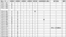
[手段1]
始動条件の成立に基づいて当りに関する抽選情報を取得し、前記抽選情報に基づいて当りか否かの判定を実行する判定手段と、
演出を実行する演出実行手段と、
所定の画像を表示可能な表示装置と、
遊技者が操作可能な操作手段と、
装飾図柄を前記表示装置に表示し、開始条件の成立に基づいて前記装飾図柄の変動表示を実行し、前記装飾図柄の変動表示の終了時に前記判定の結果を示す装飾図柄変動手段と、
前記始動条件の成立は満たされたものの前記開始条件の成立が満たされなかった場合には、所定数を上限として前記抽選情報を記憶する保留手段と、
前記開始条件の成立が満たされるよりも前に、前記保留手段によって記憶されている前記抽選情報に基づいて当りか否かの判定を行う事前判定手段と、
前記保留手段によって前記抽選情報が記憶されていることを保留表示として前記表示装置に表示する保留表示手段と、を備え、
前記装飾図柄の変動表示の態様として、前記装飾図柄の認識が困難もしくは不能である第1表示態様と、前記装飾図柄の認識が容易である第2表示態様とがあり、
前記表示装置に表示されている前記保留表示を移動することを可能とし、
前記操作手段の操作を促す操作促進表示の表示を可能とし、
前記演出には、第1演出と第2演出があり、
前記第1演出は、
前記表示装置に表示されている前記保留表示の移動を開始するとき、前記装飾図柄の変動表示の態様が前記第2表示態様であり、
前記表示装置に表示されている前記保留表示の移動が終了するときも、前記装飾図柄の変動表示の態様が前記第2表示態様であり、
前記表示装置に表示されている前記保留表示の移動が終了した後に所定時間が経過するまでは前記装飾図柄の変動表示の態様が前記第2表示態様である演出であり、
前記第2演出は、
前記表示装置に表示されている前記保留表示の表示態様が変化することを示唆する示唆演出によって表示される示唆表示が表示されているときに少なくともひとつの前記装飾図柄が前記第1表示態様とされ、
前記示唆表示の表示が終了して変化したあとの表示態様で前記保留表示が示されているときにはすべての前記装飾図柄が前記第1表示態様とされている演出であり、
前記表示装置に表示されている前記保留表示の移動が終了した後に前記所定時間が経過すると前記装飾図柄の変動表示の態様を前記第1表示態様とし、当該第1表示態様とされているときに前記操作促進表示の表示を可能とし、
前記操作促進表示の表示に応じて所定の音を出力することを可能とし、
前記当りには、有利度合いが異なる複数の種別がある
ことを特徴とする。
[Measure 1]
A determining means for acquiring lottery information regarding a win based on the establishment of a starting condition, and determining whether or not it is a win based on the lottery information;
a performance execution means for performing the performance;
a display device capable of displaying a predetermined image;
An operation means that can be operated by a player;
Decorative pattern changing means that displays a decorative pattern on the display device, executes variable display of the decorative pattern based on establishment of a start condition, and indicates the result of the determination at the end of the variable display of the decorative pattern;
holding means for storing the lottery information up to a predetermined number if the starting condition is satisfied but not the starting condition;
Prior determination means for determining whether or not it is a win based on the lottery information stored by the holding means before the start condition is satisfied;
a hold display means for displaying on the display device as a hold indication that the lottery information is stored by the hold means;
As modes of the variable display of the decorative pattern, there are a first display mode in which the decorative pattern is difficult or impossible to recognize, and a second display mode in which the decorative pattern is easy to recognize,
enabling the pending display displayed on the display device to be moved;
displaying an operation promotion display that prompts the user to operate the operation means;
The production includes a first production and a second production,
The first performance is
When starting to move the pending display displayed on the display device, the fluctuating display mode of the decorative pattern is the second display mode,
Even when the movement of the pending display displayed on the display device ends, the fluctuating display mode of the decorative pattern is the second display mode,
an effect in which the fluctuating display mode of the decorative pattern is the second display mode until a predetermined time has elapsed after the movement of the pending display displayed on the display device is completed;
The second performance is
At least one of the decorative patterns is set in the first display mode when a suggestion display is displayed by a suggestion effect suggesting that the display mode of the pending display displayed on the display device is changed. ,
When the pending display is shown in the display mode after the display of the suggestion display ends and changes, all the decorative patterns are in the first display mode,
When the predetermined period of time has elapsed after the movement of the pending display displayed on the display device is completed, the variable display mode of the decorative pattern is set to the first display mode, and when the display mode is set to the first display mode, enabling the display of the operation promotion display;
It is possible to output a predetermined sound in accordance with the display of the operation promotion display,
The above-mentioned hit is characterized in that there are a plurality of types having different degrees of advantage.
本発明によれば、工夫が施された演出を実行可能な遊技機を提供することができる。 According to the present invention, it is possible to provide a gaming machine that can perform elaborate performances.
[1.パチンコ機の全体構造]
本発明の一実施形態であるパチンコ機1について、図面を参照して詳細に説明する。まず、図1乃至図10を参照して本実施形態のパチンコ機1の全体構成について説明する。図1は本発明の一実施形態であるパチンコ機の正面図である。図2はパチンコ機の右側面図であり、図3はパチンコ機の左側面図であり、図4はパチンコ機の背面図である。図5はパチンコ機を右前から見た斜視図であり、図6はパチンコ機を左前から見た斜視図であり、図7はパチンコ機を後ろから見た斜視図である。また、図8は本体枠から扉枠を開放させると共に、外枠から本体枠を開放させた状態で前から見たパチンコ機の斜視図である。図9はパチンコ機を扉枠、遊技盤、本体枠、及び外枠に分解して前から見た分解斜視図であり、図10はパチンコ機を扉枠、遊技盤、本体枠、及び外枠に分解して後ろから見た分解斜視図である。
[1. Overall structure of pachinko machine]
A
本実施形態のパチンコ機1は、遊技店の島設備(図示しない)に設置される枠状の外枠2と、外枠2の前面を開閉可能に閉鎖する扉枠3と、扉枠3を開閉可能に支持していると共に外枠2に開閉可能に取付けられている本体枠4と、本体枠4に前側から着脱可能に取付けられると共に扉枠3を通して遊技者側から視認可能とされ遊技者によって遊技球が打込まれる遊技領域5aを有した遊技盤5と、を備えている。
The
パチンコ機1の外枠2は、図9及び図10等に示すように、上下に離間しており左右に延びている上枠部材10及び下枠部材20と、上枠部材10及び下枠部材20の両端同士を連結しており上下に延びている左枠部材30及び右枠部材40と、を備えている。上枠部材10、下枠部材20、左枠部材30、及び右枠部材40は、前後の幅が同じ幅に形成されている。また、上枠部材10及び下枠部材20の左右の長さに対して、左枠部材30及び右枠部材40の上下の長さが、長く形成されている。
As shown in FIGS. 9 and 10, the
また、外枠2は、左枠部材30及び右枠部材40の下端同士を連結し下枠部材20の前側に取付けられる幕板部材50と、上枠部材10の正面視左端部側に取付けられている外枠側上ヒンジ部材60と、幕板部材50の正面視左端側上部と左枠部材30とに取付けられている外枠側下ヒンジ部材70と、を備えている。外枠2の外枠側上ヒンジ部材60と外枠側下ヒンジ部材70とによって、本体枠4及び扉枠3が開閉可能に取付けられている。
The
パチンコ機1の扉枠3は、正面視の外形が上下に延びた四角形で前後に貫通している貫通口111を有した枠状の扉枠ベースユニット100と、扉枠ベースユニット100の貫通口111よりも下側で前面右下隅に取付けられており遊技球を遊技盤5の遊技領域5a内へ打込むために遊技者が操作可能なハンドルユニット300と、扉枠ベースユニット100の貫通口111よりも下側で前面下部に取付けられている皿ユニット320と、皿ユニット320の中央に取付けられており遊技領域5a内に遊技球が打込まれることで変化する遊技状態に応じて遊技者に参加型の演出を提示することが可能な演出操作ユニット400と、皿ユニット320の上側で扉枠ベースユニット100における貫通口111よりも左側の前面左部に取付けられている扉枠左サイドユニット530と、皿ユニット320の上側で扉枠ベースユニット100における貫通口111よりも右側の前面右部に取付けられている扉枠右サイドユニット550と、扉枠左サイドユニット530及び扉枠右サイドユニット550の上側で扉枠ベースユニット100における貫通口111よりも上側の前面上部に取付けられている扉枠トップユニット570と、を備えている。
The
パチンコ機1の本体枠4は、一部が外枠2の枠内に挿入可能とされると共に遊技盤5の外周を支持可能とされた枠状の本体枠ベース600と、本体枠ベース600の正面視左側の上下両端に取付けられ外枠2の外枠側上ヒンジ部材60及び外枠側下ヒンジ部材70に夫々回転可能に取付けられると共に扉枠3の扉枠側上ヒンジ部材140及び扉枠側下ヒンジ部材150が夫々回転可能に取付けられる本体枠側上ヒンジ部材620及び本体枠側下ヒンジ部材640と、本体枠ベース600の正面視左側面に取付けられる補強フレーム660と、本体枠ベース600の前面下部に取付けられており遊技盤5の遊技領域5a内に遊技球を打込むための球発射装置680と、本体枠ベース600の正面視右側面に取付けられており外枠2と本体枠4、及び扉枠3と本体枠4の間を施錠する施錠ユニット700と、本体枠ベース600の正面視上辺及び左辺に沿って後側に取付けられており遊技者側へ遊技球を払出す逆L字状の払出ユニット800と、本体枠ベース600の後面下部に取付けられている基板ユニット900と、本体枠ベース600の後側に開閉可能に取付けられ本体枠ベース600に取付けられた遊技盤5の後側を覆う裏カバー980と、を備えている。
The
本体枠4の払出ユニット800は、本体枠ベース600の後側に取付けられる逆L字状の払出ユニットベース801と、払出ユニットベース801の上部に取付けられており上方へ開放された左右に延びた箱状で図示しない島設備から供給される遊技球を貯留する球タンク802と、球タンク802の下側で払出ユニットベース801に取付けられており球タンク802内の遊技球を正面視左方向へ誘導する左右に延びたタンクレール803と、払出ユニットベース801における正面視左側上部の後面に取付けられタンクレール803からの遊技球を蛇行状に下方へ誘導する球誘導ユニット820と、球誘導ユニット820の下側で払出ユニットベース801から着脱可能に取付けられており球誘導ユニット820により誘導された遊技球を払出制御基板ボックス950に収容された払出制御基板951からの指示に基づいて一つずつ払出す払出装置830と、払出ユニットベース801の後面に取付けられ払出装置830によって払出された遊技球を下方へ誘導すると共に皿ユニット320における上皿321での遊技球の貯留状態に応じて遊技球を通常放出口850d又は満タン放出口850eの何れかから放出させる上部満タン球経路ユニット850と、払出ユニットベース801の下端に取付けられ上部満タン球経路ユニット850の通常放出口850dから放出された遊技球を前方へ誘導して前端から扉枠3の貫通球通路273へ誘導する通常誘導路861及び満タン放出口850eから放出された遊技球を前方へ誘導して前端から扉枠3の満タン球受口274へ誘導する満タン誘導路862を有した下部満タン球経路ユニット860と、を備えている。
The dispensing
本体枠4の基板ユニット900は、本体枠ベース600の後側に取付けられる基板ユニットベース910と、基板ユニットベース910の正面視左側で本体枠ベース600の後側に取付けられ内部に低音用の下部スピーカ921を有したスピーカユニット920と、基板ユニットベース910の後側で正面視右側に取付けられ内部に電源基板が収容されている電源基板ボックス930と、スピーカユニット920の後側に取付けられており内部にインターフェイス制御基板が収容されているインターフェイス制御基板ボックス940と、電源基板ボックス930及びインターフェイス制御基板ボックス940に跨って取付けられており内部に遊技球の払出しを制御する払出制御基板951が収容された払出制御基板ボックス950と、を備えている。
The
パチンコ機1の遊技盤5は、図9及び図10等に示すように、遊技球が打込まれる遊技領域5aの外周を区画し球発射装置680から発射された遊技球を遊技領域5aの上部に案内する外レール1001及び内レール1002を有した前構成部材1000と、前構成部材1000の後側に取付けられると共に遊技領域5aの後端を区画する平板状の遊技パネル1100と、を備えている。
As shown in FIGS. 9 and 10, the
本実施形態のパチンコ機1は、上皿321に遊技球を貯留した状態で、遊技者がハンドル302を回転操作すると、球発射装置680によってハンドル302の回転角度に応じた強さで遊技球が遊技盤5の遊技領域5a内へ打込まれる。そして、遊技領域5a内に打込まれた遊技球が、入賞口に受入れられると、受入れられた入賞口に応じて、所定数の遊技球が払出装置830によって上皿321に払出される。この遊技球の払出しによって遊技者の興趣を高めることができるため、上皿321内の遊技球を遊技領域5a内へ打込ませることができ、遊技者に遊技を楽しませることができる。
In the
[2.外枠の全体構成]
パチンコ機1の外枠2について、図11乃至図16を参照して説明する。図11はパチンコ機における外枠の正面図であり、図12は外枠の右側面図である。また、図13は外枠を前から見た斜視図であり、図14は外枠を後ろから見た斜視図である。図15は、外枠を分解して前から見た分解斜視図である。図16(a)は外枠における外枠側上ヒンジ部材の部位を、左枠部材を省略して下側から見た斜視図であり、(b)は(a)を分解して示す分解斜視図である。外枠2は、遊技店等のパチンコ機1が設置される島設備(図示は省略)に取付けられるものである。
[2. Overall configuration of outer frame]
The
外枠2は、図示するように、上下に離間しており左右に延びている上枠部材10及び下枠部材20と、上枠部材10及び下枠部材20の両端同士を連結しており上下に延びている左枠部材30及び右枠部材40と、を備えている。上枠部材10、下枠部材20、左枠部材30、及び右枠部材40は、前後の幅が同じ幅に形成されている。また、上枠部材10及び下枠部材20の左右の長さに対して、左枠部材30及び右枠部材40の上下の長さが、長く形成されている。また、外枠2は、上枠部材10及び下枠部材20の左右両端面と、左枠部材30及び右枠部材40の左右方向の外側を向いた側面とが、同一面となるように組立てられている。
As shown in the figure, the
また、外枠2は、上枠部材10の正面視左端部側に取付けられている外枠側上ヒンジ部材60と、外枠側上ヒンジ部材60の下面に取付けられているロック部材66と、幕板部材50の正面視左端側上部と左枠部材30とに取付けられている外枠側下ヒンジ部材70と、を備えている。外枠2の外枠側上ヒンジ部材60と外枠側下ヒンジ部材70とによって、本体枠4及び扉枠3を開閉可能に取付けることができる。
The
また、外枠2は、左枠部材30及び右枠部材40の下端同士を連結し下枠部材20の前側に取付けられる幕板部材50と、幕板部材50の後側に取付けられていると共に両端が左枠部材30及び右枠部材40に夫々取付けられる幕板補強部材80と、幕板部材50の上面における左右中央から左寄りの位置に取付けられている平板状の左滑り部材81と、幕板部材50の上面における右端付近の位置に取付けられている平板状の右滑り部材82と、を備えている。幕板補強部材80は、中実の部材(例えば、木材、合板、等)によって形成されており、下枠部材20、左枠部材30、及び右枠部材40に、取付けられている。
The
更に、外枠2は、上枠部材10と左枠部材30、上枠部材10と右枠部材40、下枠部材20と左枠部材30、及び下枠部材20と右枠部材40を、夫々連結している連結部材85を備えている。また、外枠2は、右枠部材40の内側(左側面側)に取付けられており後述する施錠ユニット700の外枠用鉤703が係止される上鉤掛部材90及び下鉤掛部材91を、備えている。
Furthermore, the
[2-1.上枠部材]
外枠2の上枠部材10は、所定厚さの無垢(中実)の材料(例えば、木材、合板、等)によって形成されている。この上枠部材10は、左右両端における前後方向の中央に、上下に貫通しており左右方向中央側へ窪んだ係合切欠部11を備えている。この係合切欠部11内には、連結部材85の後述する左上連結部材85A及び右上連結部材85Bの上横固定部87が取付けられる。また、上枠部材10は、正面視左側端部の上面と前面に、一般面よりも窪んだ取付段部12を備えている。この取付段部12には、外枠側上ヒンジ部材60が取付けられる。
[2-1. Upper frame member]
The
[2-2.下枠部材]
外枠2の下枠部材20は、所定厚さの無垢(中実)の材料(例えば、木材、合板、等)によって形成されている。この下枠部材20は、左右の長さ及び上下の厚さが、上枠部材10の左右の長さ及び上下の厚さと同じ寸法に形成されていると共に、前後の幅が、上枠部材10の前後の幅よりも長く形成されている。下枠部材20は、左右両端における前後方向の中央よりも後側寄りの位置に、上下に貫通しており左右方向中央側へ窪んだ係合切欠部21を備えている。この係合切欠部21内には、連結部材85の後述する左下連結部材85C及び右下連結部材85Dの下横固定部88が取付けられる。
[2-2. Bottom frame member]
The
また、下枠部材20は、左右両端の前面から後方へ窪んだ前端切欠部22を備えている。下枠部材20において、前端切欠部22の後端から下枠部材20の後面までの前後方向の幅が、上枠部材10の前後方向の幅と同じ寸法に形成されている。この下枠部材20は、外枠2に組立てた状態で、左右の前端切欠部22同士の間の部位が、幕板部材50内に挿入される。
The
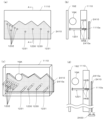
[2-3.左枠部材及び右枠部材]
外枠2の左枠部材30及び右枠部材40は、一定の断面形状で上下に延びており、アルミ合金等の金属の押出形材によって形成されている。左枠部材30及び右枠部材40は、平面視において互いに対称の形状に形成されている。左枠部材30及び右枠部材40は、外枠2として組立てた時に、左右方向の外側となる側面において、前後方向中央に対して後寄りの位置から後端付近までの間に、内側へ窪んだ凹部31,41と、凹部31,41の反対側の側面から膨出しており内部が空洞に形成されている突出部32,42と、を備えている。この左枠部材30及び右枠部材40は、突出部32,42によって、強度・剛性が高められている。また、突出部32,42内には、連結部材85の後述する左上連結部材85A及び右上連結部材85Bの後側の下横固定部88が挿入されて取付けられる。
[2-3. Left frame member and right frame member]
The
また、左枠部材30及び右枠部材40は、表面に上下に延びた複数の溝が形成されている。この複数の溝によって、パチンコ機1を遊技店等の島設備に設置したり運搬したりする等の際に、作業者の指掛りとなってパチンコ機1を持ち易くすることができると共に、パチンコ機1の外観の意匠性を高めることとができる。
Furthermore, the
[2-4.幕板部材]
外枠2の幕板部材50は、後側が開放された箱状に形成されている。幕板部材50は、上面における正面視左端付近に後方へ平板状に延出している後方延出部51と、後方延出部51の左端から遊技球が通過可能な大きさでU字状に切欠かれており上下に貫通している左排出孔52と、後方延出部51における左排出孔52の右側において遊技球が通過可能な大きさで上下に貫通している右排出孔53と、後方延出部51の後端を含む幕板部材50の上面の後端から上方へ平板状に延出している立壁部54と、立壁部54の上端付近から前方へ膨出しており前面が上方へ向かうに従って後方へ向かうように傾斜している返し部55と、を備えている。
[2-4. Curtain plate components]
The
幕板部材50は、後方延出部51の前側の上面と、後方延出部51の上面とに、外枠側下ヒンジ部材70が載置されるように、外枠側下ヒンジ部材70の後述する水平部71が取付けられる。また、幕板部材50の左排出孔52は、外枠2に組立てた状態で外枠側下ヒンジ部材70の後述する排出孔74と一致する位置に形成されている。また、右排出孔53は、外枠2に組立てた状態で外枠側下ヒンジ部材70よりも右側となる位置に形成されている。右排出孔53は、左排出孔52よりも大きく形成されている。
The
また、幕板部材50は、後方延出部51よりも右側の上面が、前端側が低くなるように傾斜している。また、幕板部材50は、上面における後方延出部51よりも右側の部位に左滑り部材81を取付けるための左取付部56と、上面における右端付近に右滑り部材82を取付けるための右取付部57と、を備えている。幕板部材50は、上面に、左滑り部材81及び右滑り部材82を介して本体枠4の下面が載置される。
Further, the upper surface of the
この幕板部材50は、図示するように、前面に浅いレリーフ状の装飾が形成されている。また、幕板部材50は、図示は省略するが、箱状の内部が複数のリブによって格子状に仕切られており、強度・剛性が高められている。また、幕板部材50は、幕板補強部材80の前側半分を、内部に収容可能に形成されている。
As shown in the figure, this
[2-5.外枠側上ヒンジ部材]
外枠2の外枠側上ヒンジ部材60は、図示するように、水平に延びた平板状で外形が四角形の上固定部61と、上固定部61の前端から前方へ延出している平板状の前方延出部62と、前方延出部62の右端から前方へ向かうに従って前方延出部62の左右中央へ延びており上下に貫通している軸受溝63と、上固定部61の平面視左辺から下方へ延びている平板状の横固定部64と、前方延出部62の左端から前端を周って軸受溝63が開口している部位までの端辺から下方へ延びており横固定部64と連続している平板状の垂下部65と、を備えている(図16(b)等を参照)。
[2-5. Outer frame side upper hinge member]
As shown in the figure, the outer frame-side
外枠側上ヒンジ部材60は、外枠2が組立てられた状態で、上固定部61が、上枠部材10の取付段部12の上面に載置されており、図示しないビスによって固定されている。また、前方延出部62は、上枠部材10の前端よりも前方へ延出している。また、横固定部64は、左枠部材30の外側側面の凹部31内に上側から挿入された状態で、ビスによって左枠部材30に固定されている。
In the outer frame side
この外枠側上ヒンジ部材60は、軸受溝63内に本体枠側上ヒンジ部材620の本体枠上ヒンジピン622を挿入させることで、外枠側下ヒンジ部材70と協働して本体枠4を開閉可能に支持することができる。この外枠側上ヒンジ部材60は、金属板をプレス成型により屈曲させて形成されている。
This outer frame side
[2-6.ロック部材]
外枠2のロック部材66は、図16に示すように、左右が所定幅で前後に延びている帯板状のロック本体66aと、ロック本体66aの後端から右方へ突出している操作部66bと、ロック本体66aの後端から左方へ延びた後に斜め左前方へ延びている弾性変形可能な棒状の弾性部66cと、ロック本体66aの後端付近で上下に貫通している取付孔66dと、を備えている。このロック部材66は、合成樹脂によって形成されている。ロック部材66は、取付ビス67によって、外枠側上ヒンジ部材60における前方延出部62の下面に回動可能に取付けられる。
[2-6. Lock member]
As shown in FIG. 16, the
このロック部材66は、取付孔66dを通して、ロック本体66aの後端が、外枠側上ヒンジ部材60の前方延出部62における軸受溝63よりも後側の位置に取付けられる。また、ロック部材66を外枠側上ヒンジ部材60に取付けた状態では、ロック本体66aが、平面視で軸受溝63を遮ることができると共に、前端付近の右側面が、外枠側上ヒンジ部材60の垂下部65における軸受溝63の開口まで延びている部位と当接可能となるように前方へ延びている(図18を参照)。
The
また、ロック本体66aの後端から左方へ延びている弾性部66cの先端は、外枠側上ヒンジ部材60における垂下部65の内周面に当接している。このロック部材66は、弾性部66cの付勢力によって取付孔66dを中心に、前端が左方へ回動する方向に付勢されている。従って、通常の状態では、ロック部材66のロック本体66aの前端付近の右側面が、垂下部65に当接している(図18を参照)。この状態では、軸受溝63におけるロック本体66aよりも前側の部位に、本体枠側上ヒンジ部材620の後述する本体枠上ヒンジピン622を収容可能な空間が形成される。
Further, the tip of the
このロック部材66は、操作部66bを操作することで、弾性部66cの付勢力に抗してロック本体66aを回動させることができる。そして、操作部66bの操作によって、ロック本体66aを、その前端が左方へ移動する方向へ回動させることで、平面視において軸受溝63からロック本体66aを後退させることができ、軸受溝63が全通している状態とすることができる。これにより、軸受溝63内に本体枠上ヒンジピン622を挿入したり、軸受溝63内から本体枠上ヒンジピン622を外したりすることができる。
This
[2-7.外枠側下ヒンジ部材]
外枠2の外枠側下ヒンジ部材70は、図示するように、水平に延びている平板状の水平部71と、水平部71の左辺において前後方向中央よりも後側の部位から上方へ立上っている平板状の立上り部72と、水平部71の前端付近から上方へ突出している外枠下ヒンジピン73と、水平部71を上下に貫通しており遊技球が一つのみ通過可能な大きさの排出孔74と、を備えている。この外枠側下ヒンジ部材70は、金属板をプレス成型により屈曲させて形成されている。
[2-7. Outer frame side lower hinge member]
As shown in the figure, the outer frame side
外枠側下ヒンジ部材70の水平部71は、平面視において、左辺を底辺とした台形に形成されている。外枠下ヒンジピン73は、円柱状で、上下方向中央よりも上部が、上端が窄まった円錐台状に形成されている。この外枠下ヒンジピン73は、水平部71の前端付近における左寄りの位置に取付けられている。排出孔74は、水平部71において、立上り部72の前後方向中央の部位と接し、水平部71の左辺から右方へ逆U字状に延びるように形成されている。この排出孔74は、幕板部材50の左排出孔52と、略同じ大きさに形成されている。
The
外枠側下ヒンジ部材70は、外枠2が組立てられた状態では、水平部71が、幕板部材50の左端付近の上面と後方延出部51上に載置されており、水平部71が、幕板部材50の上面を貫通する図示しないビスによって幕板補強部材80に固定されている。また、外枠2が組立てられた状態では、立上り部72が、左枠部材30の内側側面における突出部32よりも前側の部位に、図示しないビスによって取付けられている。この外枠側下ヒンジ部材70は、外枠下ヒンジピン73を、本体枠4の本体枠側下ヒンジ部材640における本体枠用下ヒンジ孔(図示は省略)に挿通させることで、外枠側上ヒンジ部材60と協働して本体枠4を開閉可能に取付けることができる。
In the outer frame side
また、外枠2が組立てられた状態では、排出孔74が、幕板部材50の左排出孔52と一致している。これにより、水平部71上の遊技球を、排出孔74及び左排出孔52を通して、幕板部材50の後側へ落下(排出)させることができる。詳述すると、外枠2に対して本体枠4を閉じる時に、外枠2と本体枠4との間に落下した遊技球が、本体枠4が閉じられるのに従って、外枠2と本体枠4との間が徐々に狭くなることから、間隔が広い後方側へ転動とすることとなり、排出孔74から排出させることができる。この際に、排出孔74が、パチンコ機1に組立てた状態で、外枠2に対して本体枠4を閉じた時に、本体枠4の後端と略同じとなる位置に形成されているため、外枠2と本体枠4との間に落下した遊技球を、排出孔74から排出させることで本体枠4よりも後側へ転動するのを阻止し易くすることができ、外枠側下ヒンジ部材70の部位に遊技球が留まり難くすることができる。
Furthermore, when the
[2-8.連結部材]
外枠2の連結部材85は、上枠部材10と左枠部材30とを連結する左上連結部材85Aと、上枠部材10と右枠部材40とを連結する右上連結部材85Bと、下枠部材20と左枠部材30とを連結する左下連結部材85Cと、下枠部材20と右枠部材40とを連結する右下連結部材85Dと、がある。
[2-8. Connecting member]
The connecting
連結部材85は、水平に延びた平板状の水平固定部86と、水平固定部86の左右側辺の何れか一方から上方へ延出している平板状の上横固定部87と、水平固定部86における上横固定部87が延出している部位と同じ側から下方へ延出している平板状の下横固定部88と、を備えている。この連結部材85は、平板状の金属板を屈曲させて形成されている。
The connecting
左上連結部材85A及び右上連結部材85Bでは、水平固定部86の前後方向の中央から上横固定部87が上方へ延出していると共に、上横固定部87の前後両側から下横固定部88が下方へ延出している。つまり、左上連結部材85A及び右上連結部材85Bでは、下横固定部88が前後に離間して二つ備えられている。左上連結部材85A及び右上連結部材85Bの水平固定部86は、上枠部材10の下面に当接した状態で上枠部材10に固定される。また、左上連結部材85A及び右上連結部材85Bの上横固定部87は、上枠部材10の係合切欠部21内に挿入されて、上枠部材10の左右方向の端部に固定される。また、左上連結部材85A及び右上連結部材85Bの前側の下横固定部88は、左枠部材30及び右枠部材40の突出部32,42よりも前側の内側側面に夫々固定される。更に、左上連結部材85A及び右上連結部材85Bの後側の下横固定部88は、左枠部材30及び右枠部材40の突出部32,42内に挿入されて外側側面から捩じ込まれるビスにより左枠部材30及び右枠部材40に夫々固定される。
In the upper
左下連結部材85C及び右下連結部材85Dでは、上横固定部87の後端が、水平固定部86の後端よりも後方へ突出していると共に、上横固定部87の水平固定部86よりも後方へ突出している部位の下端から下横固定部88が水平固定部86よりも下方へ延出している。また、左下連結部材85C及び右下連結部材85Dでは、上横固定部87の後端から水平固定部86と同じ側へ突出している屈曲部89を更に備えている。左下連結部材85C及び右下連結部材85Dの水平固定部86は、下枠部材20の上面に当接した状態で固定される。また、左下連結部材85C及び右下連結部材85Dの上横固定部87は、左枠部材30及び右枠部材40の突出部32,42よりも前側の内側側面に夫々固定される。更に、左下連結部材85C及び右下連結部材85Dの下横固定部88は、下枠部材20の係合切欠部21内に挿入されて下枠部材20の左右方向の端部面に夫々固定される。
In the lower
[2-9.外枠側上ヒンジ部材のロック機構]
次に、本実施形態のパチンコ機1の外枠2において、外枠側上ヒンジ部材60におけるロック部材66による本体枠4の本体枠側上ヒンジ部材620に対するロック機構について、図17及び図18を参照して説明する。図17(a)は外枠の外枠側上ヒンジ部材に対して本体枠の本体枠側上ヒンジ部材が取外されている状態を拡大して示す斜視図であり、(b)は外側上ヒンジ部材に本体側上ヒンジ部材が取付けられている状態を拡大して示す斜視図である。図18は、外枠におけるロック部材の作用を示す説明図である。
[2-9. Locking mechanism of upper hinge member on outer frame side]
Next, in the
外枠2におけるロック部材66は、外枠側上ヒンジ部材60の前方延出部62に取付けた状態(通常の状態)では、弾性部66cの先端が垂下部65の内周面と当接しており、ロック本体66aがく字状に屈曲した軸受溝63の一部を閉塞するようになっていると共に、ロック本体66aの先端部分が、軸受溝63の最深部分を閉塞した状態とはならず、軸受溝63の最深部分に本体枠4の本体枠側上ヒンジ部材620の本体枠上ヒンジピン622を挿入可能な空間が形成された状態となっている。
When the locking
本実施形態における外枠側上ヒンジ部材60とロック部材66とを用いた本体枠上ヒンジピン622の支持機構は、本体枠上ヒンジピン622が軸受溝63の最深部分に挿入されてロック本体66aの前端の右側面が、右側の垂下部65と接近している状態(この状態ではロック本体66aの前端の右側面と右側の垂下部65との間に僅かな隙間があり当接した状態となっていない)である通常の軸支状態においては、屈曲している軸受溝63の最深部分に位置する本体枠上ヒンジピン622とロック本体66aの前端面との夫々の中心が斜め方向にずれて対向した状態となっている。
In this embodiment, the support mechanism of the main body frame
そして、この通常の軸支状態においては、重量のある本体枠4を軸支している本体枠上ヒンジピン622が軸受溝63の前端部分に当接した状態となっているので、本体枠上ヒンジピン622からロック本体66aの前端面への負荷がほとんどかかっていない。つまり、ロック部材66の弾性部66cに対し負荷がかかっていない状態となっている。なお、ロック本体66aの前端面が円弧状に形成されているため、ロック部材66を回動させるために操作部66bを回動操作した時に、ロック部材66がスムーズに回動するようになっている。また、図示では、ロック本体66aの前端面の円弧中心が、取付孔66dの中心(ロック部材66の回転中心)とされている。
In this normal pivoting state, the main body frame
従って、本体枠上ヒンジピン622がく字状に形成された軸受溝63の傾斜に沿って抜ける方向に作用力Fがかかって、ロック本体66aの円弧状の前端面に当接したとき、その作用力Fを、本体枠上ヒンジピン622と円弧状の前端面との当接部分に作用する分力F1(ロック本体66aの前端面の円弧の法線方向)と、本体枠上ヒンジピン622と軸受溝63の一側内面との当接部分に作用する分力F2と、に分けたときに、分力F1の方向が取付孔66d(取付ビス67)の中心(ロック部材66の回転中心)を向くため、ロック部材66のロック本体66aの前端が、右側の垂下部65から離れる方向に回転させるモーメントが働かず、本体枠上ヒンジピン622がロック部材66のロック本体66aの前端部と軸受溝63の一側内面との間に挟持された状態が保持される。
Therefore, when the
このため、通常の軸支状態、或は、本体枠上ヒンジピン622の作用力がロック部材66にかかった状態でも、ロック部材66の弾性部66cに常時負荷がかからず、合成樹脂で一体形成される弾性部66cのクリープによる塑性変形を防止し、長期間に亘って本体枠上ヒンジピン622の軸受溝63からの脱落を防止することができる。なお、仮に無理な力がかかってロック部材66のロック本体66aの前端部が右方へ移動する方向へ回転させられても、ロック本体66aの前端右側面が垂下部65に当接してそれ以上回転しないので、ロック部材66が前方延出部62の外側にはみ出ないようになっている。
Therefore, even in a normal pivoting state or a state in which the acting force of the
なお、ロック本体66aの前端面の形状は円弧状でなくても、上記した分力F1の作用により回転モーメントが生じない位置又はロック部材66をその前端部が前方延出部62の外側に向って回転させる回転モーメントが生ずる位置にロック部材66の回転中心(取付ビス67により固定される軸)を位置させることにより、常時ロック部材66の弾性部66cに対しても負荷がかかることはないし、ロック部材66が回転してもロック本体66aの前端の右側面が垂下部65に当接するだけであるため、ロック部材66が前方延出部62の外側にはみ出ることもない。
Note that even if the shape of the front end surface of the
外枠側上ヒンジ部材60の軸受溝63に、本体枠側上ヒンジ部材620の本体枠上ヒンジピン622を支持させる場合は、軸受溝63の開放されている側から軸受溝63内に本体枠上ヒンジピン622を挿入する。軸受溝63内に本体枠上ヒンジピン622を挿入すると、ロック部材66のロック本体66aの右側面に本体枠上ヒンジピン622が当接し、弾性部66cの付勢力に抗してロック本体66aの前端が左方へ移動するようにロック部材66が取付ビス67を中心に回動する。これにより、軸受溝63を閉鎖していたロック本体66aが後退して軸受溝63が開放され、軸受溝63の最深部(前端)へ本体枠上ヒンジピン622を移動させることができるようになる。
When supporting the main body frame
そして、軸受溝63の最深部に本体枠上ヒンジピン622を移動させると、本体枠上ヒンジピン622とロック部材66のロック本体66aとの当接が解除され、弾性部66cの付勢力によってロック本体66aの前端が右方へ移動するようにロック部材66が回動し、ロック部材66が通常の状態に復帰する。これにより、本体枠上ヒンジピン622が、軸受溝63内におけるロック本体66aの前端よりも前側の空間に収容された状態となり、本体枠上ヒンジピン622が、軸受溝63の最深部において回動可能な状態で保持(ロック)された状態となる。
Then, when the main body frame
軸受溝63内から本体枠上ヒンジピン622を取外す場合は、ロック部材66の操作部66bを操作して、ロック本体66aの前端が左方へ移動するようにロック部材66を回動させ、弾性部66cの付勢力に抗して軸受溝63からロック本体66aを後退させる。これにより、軸受溝63の最深部と開口部とが連通した状態となり、軸受溝63から本体枠上ヒンジピン622を取外すことができる。
When removing the
[2-10.外枠側下ヒンジ部材の部位における防犯機構と球噛み防止機構]
本実施形態のパチンコ機1における外枠2の外枠側下ヒンジ部材70の部位における防犯機構と外枠2と本体枠4との間に遊技球が挟まれるのを防止するための球噛み防止機構について説明する。
[2-10. Security mechanism and ball bite prevention mechanism at the lower hinge member on the outer frame side]
A security mechanism at the
外枠2は、組立てた状態では、幕板部材50の上面における正面視左端部に外枠側下ヒンジ部材70が取付けられている。外枠側下ヒンジ部材70の水平部71は、幕板部材50の上面の左端付近と後方延出部51の上面とに載置された状態で取付けられている。この幕板部材50には、上面の後端から上方へ立上っている立壁部54を備えている。これにより、外枠側下ヒンジ部材70と本体枠側下ヒンジ部材640との間の隙間を通して、本体枠4(パチンコ機1)の後側へピアノ線等の不正な工具を侵入させようとしても、不正な工具の先端が幕板部材50の上面の後端から上方へ延出している立壁部54に当接するため、不正な工具がこれ以上後側へ挿入されるのを阻止することができ、外枠側下ヒンジ部材70の部位を介して不正行為が行われるのを防止することができる。
In the assembled state of the
また、立壁部54の上端に、前方へ延出している返し部55を備えているため、立壁部54に当接した不正な工具が上方へ曲がった場合、返し部55によって不正な工具の先端を更に前方へ折返させることができるため、本体枠4の後側に不正な工具が侵入させられるのを阻止することができ、外枠側下ヒンジ部材70の部位を介して不正行為が行われるのを確実に阻止することができる。
In addition, since the upper end of the
ところで、幕板部材50の上面の後端に上方へ延出している立壁部54を備えるようにした場合、外枠2に対して本体枠4を開いている状態で、遊技球が外枠側下ヒンジ部材70(水平部71)上に落下した場合、水平部71上の遊技球が、立壁部54の存在によって水平部71の後端から後方へ排出されないため、外枠2と本体枠4との間に挟まれてしまう虞がある。これに対して、本実施形態では、外枠側下ヒンジ部材70の水平部71と、幕板部材50の後方延出部51とに、遊技球が通過可能な排出孔74、左排出孔52、及び右排出孔53を備えているため、外枠側下ヒンジ部材70の水平部71上の遊技球を、排出孔74等から下方へ排出することができ、外枠2と本体枠4との間に遊技球が挟まれるのを低減させることができる。
By the way, when the rear end of the upper surface of the
従って、外枠2と本体枠4との間に遊技球が挟まれることで、外枠側下ヒンジ部材70の周りが破損したり、本体枠4が正常な状態で閉まらずに外枠2と本体枠4との間に隙間ができてしまい、その隙間を使って不正行為が行われてしまったりするのを防止することができる。
Therefore, if the game ball is caught between the
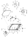
[3.扉枠の全体構成]
パチンコ機1の扉枠3について、図19乃至図30を参照して説明する。図19はパチンコ機における扉枠の正面図であり、図20は扉枠の右側面図であり、図21は扉枠の左側面図であり、図22は扉枠の背面図である。図23は扉枠を右前から見た斜視図であり、図24は扉枠を左前から見た斜視図であり、図25は扉枠を後ろから見た斜視図である。図26は図19におけるA-A線で切断した断面図であり、図27は図19におけるB-B線で切断した断面図であり、図28は図19におけるC-C線で切断した断面図である。図29は扉枠を主な部材毎に分解して前から見た分解斜視図であり、図30は扉枠を主な部材毎に分解して後ろから見た分解斜視図である。
[3. Overall configuration of door frame]
The
扉枠3は、図29及び図30等に示すように、正面視の外形が上下に延びた四角形で枠状の扉枠ベースユニット100と、扉枠ベースユニット100の前面右下隅に取付けられているハンドルユニット300と、扉枠ベースユニット100の前面下部に取付けられている皿ユニット320と、皿ユニット320の中央に取付けられている演出操作ユニット400と、皿ユニット320の上側で扉枠ベースユニット100の前面左部に取付けられている扉枠左サイドユニット530と、皿ユニット320の上側で扉枠ベースユニット100の前面右部に取付けられている扉枠右サイドユニット550と、扉枠左サイドユニット530及び扉枠右サイドユニット550の上側で扉枠ベースユニット100の前面上部に取付けられている扉枠トップユニット570と、を備えている。
As shown in FIGS. 29, 30, etc., the
扉枠3の扉枠ベースユニット100は、詳細は後述するが、正面視の外形が上下に延びた長方形(四角形)で前後に貫通している貫通口111を有した板状の扉枠ベース110と、扉枠ベース110の後側に取付けられている枠状の補強ユニット130と、補強ユニット130の正面視左端側の上下両端に取付けられており本体枠4に対してヒンジ回転可能に取付けられる扉枠側上ヒンジ部材140及び扉枠側下ヒンジ部材150と、扉枠ベース110の後面に取付けられ貫通口111を閉鎖するガラスユニット190と、ガラスユニット190の後面下部を覆う防犯カバー200と、扉枠ベース110の後面に扉枠ベース110を貫通して前方に突出するように取付けられ開閉可能とされている扉枠3と本体枠4、及び本体枠4と外枠2との間を施錠するための開閉シリンダユニット210と、扉枠ベース110の後面下部に取付けられ遊技球を球発射装置680に送るための球送りユニット250と、扉枠ベース110の後面下部に取付けられ球発射装置680により発射されて遊技領域5a内に到達しなかった遊技球を受けて下皿322へ排出させるファールカバーユニット270と、を備えている。
The door
扉枠3のハンドルユニット300は、詳細は後述するが、回転可能なハンドル302を遊技者が回転操作することで、上皿321内に貯留されている遊技球を、ハンドル302の回転角度に応じた強さで遊技盤5の遊技領域5a内に打込むことができるものである。
Although the details will be described later, the
扉枠3の皿ユニット320は、詳細は後述するが、扉枠ベースユニット100における扉枠ベース110の前面において貫通口111の下側の部位に取付けられ、前面が前方へ膨出していると共に、左右方向中央の前端に演出操作ユニット400が取付けられる。皿ユニット320は、遊技領域5a内に打込むための遊技球を貯留する上皿321と、上皿321の下側に配置されており上皿321やファールカバーユニット270から供給される遊技球を貯留可能な下皿322と、上皿321に貯留されている遊技球を下皿322へ抜くための上皿球抜きボタン327と、球貸機に投入した現金やプリペイドカードの残金の範囲内で遊技者に遊技球を貸し出すための球貸ボタン328と、球貸機から貸出された遊技球の分を差し引いた現金やプリペイドカードを返却させるための返却ボタン329と、球貸機に投入した現金やプリペイドカードの残数等を表示する球貸返却表示部330と、演出提示時に遊技者の操作が受付可能とされている演出選択左ボタン331及び演出選択右ボタン332と、下皿322内の遊技球を皿ユニット320の下方へ排出するための下皿球抜きボタン333と、を備えている。
The
扉枠3の演出操作ユニット400は、皿ユニット320の正面視左右方向中央の前部に取付けられるものであり、遊技者が押圧操作することができると共に、遊技者に対して演出画像を提示することができるものである。この演出操作ユニット400は、詳細は後述するが、遊技者が操作可能な大型の操作ボタン410と、操作ボタン410内に遊技者側から視認可能に配置され演出画像を表示可能な扉枠側演出表示装置460と、を備えている。
The
扉枠3の扉枠左サイドユニット530は、詳細な内容は後述するが、皿ユニット320の上側で扉枠ベースユニット100における貫通口111よりも左側の前面左部に取付けられ、貫通口111(遊技領域5a)の左外側を装飾するものである。扉枠左サイドユニット530は、発光装飾可能な左ユニット装飾レンズ部材(図示は省略)を備えている。
Although the details will be described later, the door frame left
扉枠3の扉枠右サイドユニット550は、詳細な内容は後述するが、皿ユニット320の上側で扉枠ベースユニット100における貫通口111よりも右側の前面右部に取付けられ、貫通口111(遊技領域5a)の右外側を装飾するものである。この扉枠右サイドユニット550は、扉枠左サイドユニット530よりも前方へ大きく突出しており、左右両面側に備えられている右ユニット左装飾部材554及び右ユニット右装飾部材557と、前端に備えられている右ユニット装飾レンズ部材561と、を備えている。扉枠右サイドユニット550は、右ユニット左装飾部材554、右ユニット右装飾部材557、及び右ユニット装飾レンズ部材561を発光装飾させることができる。
Although the details will be described later, the door frame
扉枠3の扉枠トップユニット570は、扉枠左サイドユニット530及び扉枠右サイドユニット550の上側で扉枠ベースユニット100の扉枠ベース110の前面における貫通口111の上側に取付けられ、扉枠3の上部を装飾するものである。扉枠トップユニット570は、詳細な内容は後述するが、左右に離間した一対の上部スピーカ573と、前面中央で前方へ突出しているトップ中装飾部材576と、トップ中装飾部材576の左右両側を装飾しているトップ左装飾レンズ部材579及びトップ右装飾レンズ部材580と、を備えている。扉枠トップユニット570は、トップ中装飾部材576、トップ左装飾レンズ部材579、及びトップ右装飾レンズ部材580を発光装飾させることができる。
The door
[3-1.扉枠ベースユニットの全体構成]
扉枠3の扉枠ベースユニット100について、図31乃至図33を参照して詳細に説明する。図31(a)は扉枠における扉枠ベースユニットを前から見た斜視図であり、(b)は扉枠ベースユニットを後ろから見た斜視図である。図32は扉枠ベースユニットを主な部材毎に分解して前から見た分解斜視図であり、図33は扉枠ベースユニットを主な部材毎に分解して後ろから見た分解斜視図である。
[3-1. Overall configuration of door frame base unit]
The door
扉枠ベースユニット100は、正面視左辺側が本体枠4の前面を閉鎖するように本体枠4に対して開閉可能(ヒンジ回転可能)に取付けられるものである。扉枠ベースユニット100は、前面下隅にハンドルユニット300が、貫通口111の下側前面に演出操作ユニット400が取付けられる皿ユニット320が、貫通口111の左外側前面に扉枠左サイドユニット530が、貫通口111の右外側前面に扉枠右サイドユニット550が、貫通口111の上外側前面に扉枠トップユニット570が、夫々取付けられるものである。
The door
扉枠ベースユニット100は、図32及び図33に等に示すように、正面視の外形が上下に延びた長方形で前後に貫通している貫通口111を有した板状の扉枠ベース110と、扉枠ベース110の後側に取付けられている枠状の補強ユニット130と、補強ユニット130の正面視左端側の上下両端に取付けられており扉枠ベース110から前方へ突出して本体枠4の本体枠側上ヒンジ部材620及び本体枠側下ヒンジ部材640に回転可能に取付けられる扉枠側上ヒンジ部材140及び扉枠側下ヒンジ部材150と、扉枠ベース110の前面で貫通口111の正面視左側に取付けられており前面に複数のLEDが実装されている扉枠左サイド装飾基板160と、扉枠ベース110の後側に回動可能に取付けられておりガラスユニット190を着脱可能に取付けるためのガラスユニット取付部材170と、を備えている。
As shown in FIGS. 32 and 33, the door
また、扉枠ベースユニット100は、扉枠ベース110の前面で正面視右下隅に取付けられておりハンドルユニット300を取付けるための筒状のハンドル取付部材180と、扉枠ベース110の後面に取付けられ貫通口111を閉鎖するガラスユニット190と、ガラスユニット190の後面下部を覆う防犯カバー200と、扉枠ベース110の後面に扉枠ベース110を貫通して前方に突出するように取付けられる開閉シリンダユニット210と、扉枠ベース110の後面下部に取付けられる球送りユニット250と、扉枠ベース110の後面下部に取付けられるファールカバーユニット270と、を備えている。
The door
更に、扉枠ベースユニット100は、図示は省略するが、扉枠3に備えられている各種の装飾基板、球送ソレノイド255、ハンドル回転検知センサ307、ハンドルタッチセンサ310、単発ボタン操作センサ312、球貸ボタン328、返却ボタン329、球貸返却表示部330、演出選択左ボタン331、演出選択右ボタン332、振動モータ424、押圧検知センサ440、扉枠側演出表示装置460(液晶表示装置461)、上部スピーカ573、等と、本体枠4における基板ユニット900の扉枠用中継基板911との接続を中継するための扉本体中継基板を備えている。
Furthermore, although not shown, the door
[3-1a.扉枠ベース]
扉枠3における扉枠ベースユニット100の扉枠ベース110について、主に図31乃至図33を参照して詳細に説明する。扉枠ベース110は、正面視の外形が上下に延びた四角形(長方形)に形成されている。扉枠ベース110は、前後に貫通しており、正面視における内周形状が上下に延びた略四角形に形成された貫通口111を備えている。貫通口111は、内周を形成している上辺及び左右両辺が、扉枠ベース110の外周辺に夫々接近しており、内周を形成している下辺が、扉枠ベース110の下端から上下方向の約1/3の高さに位置している。従って、扉枠ベース110は、前後に貫通している貫通口111により全体が枠状に形成されている。この扉枠ベース110は、合成樹脂により一体成形されている。
[3-1a. Door frame base]
The
扉枠ベース110は、前面における正面視右下隅に形成されており左端側が右端側よりも前方へやや突出するように傾斜しているハンドル取付座面112と、ハンドル取付座面112と貫通口111との間で正面視右端付近に後面から前方へ向かって窪み、開閉シリンダユニット210のシリンダ取付板金213が取付けられるシリンダ取付部113と、シリンダ取付部113において前後に貫通しており開閉シリンダユニット210のシリンダ錠211が挿通されるシリンダ挿通孔114と、シリンダ挿通孔114及びハンドル取付座面112の正面視左側で前後に貫通しており球送りユニット250の進入口251a及び球抜口251bを前方に臨ませるための球送り開口115と、を備えている。
The
また、扉枠ベース110は、扉枠ベース110の左右方向中央より左寄りで且つハンドル取付座面112と略同じ高さで前後に貫通しておりファールカバーユニット270の球放出口276を前方に臨ませる下皿用通過口116と、扉枠ベース110の正面視左端付近で貫通口111の下辺に隣接するように前後に貫通しておりファールカバーユニット270の貫通球通路273を前方に臨ませる上皿用通過口117と、貫通口111の内周に沿って後面から前方へ向かって窪み、ガラスユニット190のガラス枠191が挿入されるガラスユニット取付部118と、扉枠ベース110の左右両上隅において前後に貫通しており扉枠トップユニット570の上部スピーカ573の後端が挿通されるスピーカ挿通口119と、を備えている。
Further, the
[3-1b.補強ユニット]
扉枠ベースユニット100の補強ユニット130について、図31及び図33等を参照して詳細に説明する。補強ユニット130は、扉枠ベース110の後側に取付けられることで扉枠ベース110を補強して、扉枠ベース110(扉枠3)の強度剛性を高めている。補強ユニット130は、扉枠ベース110の後面における上辺に沿って取付けられる左右に延びた上補強板金131と、扉枠ベース110の後面における貫通口111の下側に取付けられる左右に延びた中補強板金132と、扉枠ベース110の後面における正面視左辺に沿って取付けられる上下に延びた左補強板金133と、扉枠ベース110の後面における正面視右辺に沿って取付けられる上下に延びた右補強板金134と、右補強板金134の後面に取付けられており施錠ユニット700の扉枠用鉤702が係止される施錠係止部135と、を備えている。
[3-1b. Reinforcement unit]
The reinforcing
補強ユニット130は、上補強板金131の左右両端が左補強板金133及び右補強板金134の夫々の上端にビスによって連結固定されており、中補強板金132の左端が左補強板金133にビスによって連結固定されている。中補強板金132の右端は、後述する開閉シリンダユニット210のシリンダ取付板金213を介して右補強板金134に連結固定されている。従って、補強ユニット130は、上補強板金131、中補強板金132、左補強板金133、及び右補強板金134等によって、枠状に形成されている。
In the reinforcing
補強ユニット130の上補強板金131、中補強板金132、左補強板金133、右補強板金134、及び施錠係止部135は、夫々金属板を適宜屈曲させて形成されている。中補強板金132は、扉枠ベース110の上皿用通過口117と対応する位置に、前後に貫通した切欠部132aが形成されている。
The upper reinforcing
補強ユニット130は、詳細な図示は省略するが、各上補強板金131、中補強板金132、左補強板金133、及び右補強板金134において、夫々前後方向に屈曲された部位を有しており、その部位によって、強度剛性が高められていると共に、外部からのピアノ線やマイナスドライバー等の不正な工具の侵入を防止している。
Although detailed illustrations are omitted, the reinforcing
[3-1c.扉枠側上ヒンジ部材]
扉枠ベースユニット100の扉枠側上ヒンジ部材140について、主に図31乃至図33等を参照して詳細に説明する。扉枠側上ヒンジ部材140は、扉枠ベース110に取付けられ上下に離間している一対の突出片141aを有した扉枠上ヒンジ軸ブラケット141と、扉枠上ヒンジ軸ブラケット141の一対の突出片141aを貫通しており、上端が本体枠側上ヒンジ部材620の扉枠用上ヒンジ孔623に挿入される円柱状の扉枠上ヒンジピン142と、扉枠上ヒンジピン142における一対の突出片141aの間の位置に取付けられている円盤状の鍔部材143と、鍔部材143と一対の突出片141aのうちの下側の突出片141aとの間に介装されていると共に扉枠上ヒンジピン142が挿通されており、扉枠上ヒンジピン142を上方へ付勢しているロックバネ144と、を備えている。
[3-1c. Door frame side upper hinge member]
The door frame side
扉枠上ヒンジ軸ブラケット141は、図示は省略するが一対の突出片141aの後端同士を連結している平板状の取付片を有しており、側面視の形状が前方へ開放されたコ字状に形成されている。扉枠上ヒンジ軸ブラケット141は、一対の突出片141a同士を連結している取付片が、ビスによって扉枠ベース110の後面に取付けられている。
Although not shown, the
扉枠上ヒンジピン142は、上側の突出片141aよりも上方に突出している部位(上端)が、本体枠側上ヒンジ部材620の扉枠用上ヒンジ孔623に対して回転可能に挿入される。また、扉枠上ヒンジピン142は、図示は省略するが、下側の突出片141aよりも下方に突出している部位が水平方向に屈曲している。この屈曲している部位が下側の突出片141aの下面に当接することで、扉枠上ヒンジピン142の上方への移動を規制している。
The door frame
鍔部材143は、Eリングとされており、扉枠上ヒンジピン142の外周に形成されている溝内に挿入保持されている。ロックバネ144は、扉枠上ヒンジピン142を挿通可能なコイルスプリングとされており、上端が鍔部材143に当接していると共に、下端が下側の突出片141aに当接している。このロックバネ144は、鍔部材143と下側の突出片141aとの間に、圧縮された状態で介装されており、鍔部材143を介して扉枠上ヒンジピン142を上方へ付勢している。
The
扉枠側上ヒンジ部材140は、扉枠上ヒンジピン142がロックバネ144により上方へ付勢された状態となっており、扉枠上ヒンジピン142における下端の水平に屈曲している部位が下側の突出片141aの下面に当接することで、これ以上の上方への移動が規制されている。この状態では、扉枠上ヒンジピン142の上端が、上側の突出片141aの上面よりも所定量上方に突出している。
In the door frame
扉枠側上ヒンジ部材140は、扉枠上ヒンジピン142における下端の水平に屈曲している部位を作業者が持って、ロックバネ144の付勢力に抗してその部位を下方へ引っ張ると、扉枠上ヒンジピン142を全体的に下方へ移動させることができ、扉枠上ヒンジピン142の上端を、上側の突出片141aの上面よりも下方へ没入させることができる。従って、扉枠側上ヒンジ部材140は、扉枠上ヒンジピン142の上端を、本体枠側上ヒンジ部材620の扉枠用上ヒンジ孔623に対して下方から挿入させたり、下方へ抜いたりすることができる。これにより、扉枠側上ヒンジ部材140の扉枠上ヒンジピン142の上端を、本体枠側上ヒンジ部材620の扉枠用上ヒンジ孔623に挿入させることで、扉枠3の正面視上部左端を、本体枠4に対してヒンジ回転可能に支持させることができる。
When an operator holds the horizontally bent portion of the lower end of the door frame
また、扉枠側上ヒンジ部材140は、扉枠上ヒンジピン142における扉枠上ヒンジ軸ブラケット141の一対の突出片141aにより支持されている部位が、後述する扉枠側下ヒンジ部材150の扉枠下ヒンジピン152と同軸上に支持されている。これにより、扉枠側上ヒンジ部材140と扉枠側下ヒンジ部材150とによって、扉枠3を本体枠4に対して良好な状態でヒンジ回転させることができる。
Further, in the door frame side
[3-1d.扉枠側下ヒンジ部材]
扉枠ベースユニット100の扉枠側下ヒンジ部材150について、主に図31及び図32等を参照して詳細に説明する。扉枠側下ヒンジ部材150は、扉枠ベース110に取付けられ前方に延出している平板状の延出片151aを有している扉枠下ヒンジ軸ブラケット151と、扉枠下ヒンジ軸ブラケットにおける延出片151aの前端部付近から下方に突出している円柱状の扉枠下ヒンジピン152(図21及び図22を参照)と、を備えている。
[3-1d. Door frame side lower hinge member]
The door frame side
扉枠下ヒンジ軸ブラケット151は、水平に延びた平板状の延出片151aの後端から上方に延出した平板状の取付片(図示は省略)を有しており、側面視の全体形状が略L字状に形成されている。この扉枠下ヒンジ軸ブラケット151は、図示しない取付片がビスによって扉枠ベース110の後面に取付けられている。
The door frame lower
扉枠下ヒンジピン152は、下端部が、下方へ向かうほど窄まる円錐台状に形成されている。この扉枠下ヒンジピン152は、後述する本体枠4における本体枠側下ヒンジ部材640の扉枠用ヒンジ孔644に、上方から回転可能に挿入される。扉枠下ヒンジピン152は、扉枠側上ヒンジ部材140の扉枠上ヒンジピン142と同軸上に配置されている。
The lower end of the door frame
この扉枠側下ヒンジ部材150は、扉枠下ヒンジピン152が本体枠側下ヒンジ部材640の扉枠用ヒンジ孔644に挿入されることで、扉枠3を本体枠4に対してヒンジ回転可能に支持することができる。
This door frame side
[3-1e.扉枠左サイド装飾基板]
扉枠ベースユニット100の扉枠左サイド装飾基板160について、主に図31及び図32等を参照して詳細に説明する。扉枠左サイド装飾基板160は、扉枠ベース110の前面において、貫通口111の正面視左側に取付けられている。扉枠左サイド装飾基板160は、扉枠ベース110における正面視左側のスピーカ挿通口119よりも下側の位置の高さから貫通口111の上下方向の中央付近の高さまで上下に延びている扉枠左サイド上装飾基板161と、扉枠左サイド上装飾基板161の下側の位置の高さから上皿用通過口117の下端と略同じ高さまで上下に延びている扉枠左サイド下装飾基板162と、を備えている。
[3-1e. Door frame left side decorative board]
The door frame left side
扉枠左サイド装飾基板160の扉枠左サイド上装飾基板161及び扉枠左サイド下装飾基板162は、夫々前面に、前方へ光を照射可能な複数のLED161a,162aを備えている。これらLED161a,162aは、フルカラーLEDとされている。
The door frame left side upper
扉枠左サイド装飾基板160は、扉枠3を組立てた状態で、後述する扉枠左サイドユニット530の後方に位置しており、前面に備えられた(実装された)複数のLED161a,162aを適宜発光させることで、扉枠左サイドユニット530の左ユニット装飾レンズ部材を発光装飾させることができる。
The door frame left side
[3-1f.ガラスユニット取付部材]
扉枠ベースユニット100のガラスユニット取付部材170について、主に図31(b)等を参照して詳細に説明する。ガラスユニット取付部材170は、扉枠ベース110の後側に回動可能に取付けられておりガラスユニット190を着脱可能に取付けるためのものである。ガラスユニット取付部材170は、扉枠ベース110の後側で前後に延びた軸線周りに対して回転可能に取付けられる円盤状の基部171と、基部171から回転軸線に対して直角方向へ棒状に突出している突出部172と、を有している。
[3-1f. Glass unit mounting parts]
The glass
ガラスユニット取付部材170は、扉枠ベース110の後面における一対のスピーカ挿通口119の下側で、ガラスユニット取付部118よりも外側の部位に、夫々回転可能に取付けられている。
The glass
ガラスユニット取付部材170は、突出部172が基部171から上方へ突出するように回転させた状態とすることで、背面視において扉枠ベース110のガラスユニット取付部118よりも突出部172が外側に位置した状態となり、扉枠ベース110のガラスユニット取付部118に対してガラスユニット190を挿入したり、ガラスユニット取付部118からガラスユニット190を取外したりすることができる。
The glass
ガラスユニット取付部材170は、ガラスユニット190を扉枠ベース110のガラスユニット取付部118に挿入させた状態で、突出部172が基部171から下方へ突出するように回転させると、突出部172がガラスユニット190の取付片191aの後側と当接し、ガラスユニット190上部の後方への移動を規制した状態となり、ガラスユニット190を扉枠ベース110に取付けることができる。
When the glass
ガラスユニット取付部材170は、扉枠ベース110に回転可能に取付けられる円盤状の基部171から突出部172が突出しているため、ガラスユニット取付部材170の重心位置が突出部172内に位置している。このことから、ガラスユニット取付部材170が自由に回転できる状態では、突出部172が基部171から下方へ突出した状態で安定することとなる。そして、ガラスユニット取付部材170では、突出部172が基部171から下方へ突出している回転位置の時に、突出部172によりガラスユニット190の後方への移動を規制させるようにしているため、ガラスユニット取付部材170に振動等が作用しても、突出部172が基部171から上方へ突出するように全体が回転することはなく、ガラスユニット190の後方への移動の規制が自然に解除されることはない。
Since the glass
なお、扉枠ベース110からガラスユニット190を取外す場合は、ガラスユニット取付部材170を、突出部172が基部171から上方へ突出するように回転させて、突出部172をガラスユニット190の取付片191aよりも外側へ移動させることで、ガラスユニット190の上部側を後方へ移動させることができるようになり、扉枠ベース110からガラスユニット190を取外すことができる。
In addition, when removing the
[3-1g.ハンドル取付部材]
扉枠ベースユニット100のハンドル取付部材180について、主に図31乃至図33等を参照して詳細に説明する。ハンドル取付部材180は、扉枠ベース110の前面にハンドルユニット300を取付けるためのものである。ハンドル取付部材180は、図32及び図33等に示すように、前後方向へ延びた円筒状の筒部181と、筒部181の後端から筒部181の軸に対して直角方向外方へ延びた円環状のフランジ部182と、筒部181内に突出していると共に筒部181の軸方向全長に亘って延びており筒部181の周方向に対して不等間隔に配置された複数(本例では三つ)の突条183と、筒部181の外周面とフランジ部182の前面とを繋ぎ、筒部181の周方向に対して複数配置された補強リブ184と、を備えている。
[3-1g. Handle mounting parts]
The
ハンドル取付部材180は、フランジ部182の後面を、扉枠ベース110におけるハンドル取付座面112の前面に当接させた状態で、ビスによってハンドル取付座面112に取付けられる。
The
筒部181は、内径がハンドルユニット300におけるハンドルベース301の基部301aの外径よりも若干大きく形成されている。三つの突条183は、一つが筒部181内の上側に備えられており、残り二つが筒部181内の下側に備えられている。これら三つの突条183は、ハンドルベース301における三つの溝部301cと対応する位置に形成されている。従って、ハンドル取付部材180は、三つの突条183と、ハンドルベース301の三つの溝部301cとを一致させた状態でのみ、筒部181内にハンドルベース301の基部301aを挿入させることができ、扉枠ベース110に対してハンドルベース301(ハンドルユニット300)の回転位置を規制することができる。
The
なお、ハンドル取付部材180は、フランジ部182の後面に対して、筒部181の軸線が垂直に延びていることから、扉枠ベース110の傾斜したハンドル取付座面112に取付けることで、筒部181の軸線が右前方へ延びるように傾いた状態となり、ハンドルユニット300を同様に傾いた状態で扉枠ベース110に取付けることができる。
In addition, since the axis of the
[3-1h.ガラスユニット]
扉枠ベースユニット100のガラスユニット190について、主に図31乃至図33等を参照して詳細に説明する。ガラスユニット190は、扉枠ベース110の貫通口111を、前方から後方が視認できるように閉鎖するものである。ガラスユニット190は、扉枠ベース110の貫通口111の内周形状よりも大きくガラスユニット取付部118に取付可能な枠状のガラス枠191と、ガラス枠191の枠内を閉鎖し外周がガラス枠191に取付けられている透明な二つのガラス板192と、を備えている。二つのガラス板192は、ガラス枠191の前端側と後端側とに夫々取付けられており、互いの間に空間が形成されるように前後に離間している(図26等を参照)。
[3-1h. Glass unit]
The
ガラス枠191は、正面視左右上隅よりも下側の位置から外方へ平板状に延出している一対の取付片191aと、下端から下方へ突出していると共に下辺に沿って延びている帯板状の係止片191bと、を有している。ガラス枠191の取付片191aは、ガラスユニット取付部材170の突出部172と当接可能とされている。係止片191bは、扉枠ベース110と補強ユニット130の中補強板金132との間の空間内に挿入可能とされている(図26を参照)。
The
このガラスユニット190は、扉枠ベース110の後側から、ガラス枠191の係止片191bを、扉枠ベース110と補強ユニット130の中補強板金132との間の隙間に上方から挿入した上で、ガラス枠191の前端を扉枠ベース110のガラスユニット取付部118の後面に当接させ、ガラスユニット取付部材170を回転させてガラスユニット取付部材170の突出部172をガラス枠191の取付片191aの後面と当接させることで、扉枠ベース110に取付けられる。
This
ガラスユニット190を扉枠ベース110から取外す場合は、上記と逆の手順により、取外すことができる。これにより、ガラスユニット190は、扉枠ベース110に対して着脱可能となっている。
When removing the
[3-1i.防犯カバー]
扉枠ベースユニット100の防犯カバー200について、主に図31乃至図33等を参照して詳細に説明する。防犯カバー200は、ガラスユニット190の後面下部を覆うように扉枠ベース110の後側に取付けられ、透明な合成樹脂により形成されている。防犯カバー200は、外周が所定形状に形成された平板状の本体部201と、本体部201の外周縁に沿って後方へ短く突出した平板状の後方突片202と、左右に離間して配置され本体部201よりも前方に突出し、扉枠ベース110の後側に係止可能とされている一対の係止片203と、を備えている。
[3-1i. Security cover]
The
防犯カバー200の本体部201は、扉枠ベース110に取付けた状態で下端がガラスユニット190の下端よりも下方へ突出するように形成されている。また、本体部201は、上端が、パチンコ機1に組立てた状態で、遊技盤5における遊技領域5aの下端に沿った形状に形成されている。詳述すると、本体部201の上端は、後述する前構成部材1000の内レール1002の一部、アウト誘導部1003、右下レール1004の一部、及び右レール1005に沿った形状に形成されており、パチンコ機1に組立てた状態で遊技領域5a内に突出しないように形成されている。
The
後方突片202は、本体部201の外周縁の略全周に亘って形成されている。従って、防犯カバー200は、本体部201と後方突片202とによって、後方へ開放された浅い箱状に形成されており、強度・剛性が高くなっている。また、後方突片202は、図33に示すように、本体部201の外周縁とは異なる本体部201の後面の一部からも後方に突出している。この本体部201の後面の一部から後方に突出している後方突片202は、パチンコ機1に組立てた状態で遊技盤5の前構成部材1000における外レール1001の一部と沿うように形成されている。
The rear projecting
なお、後方突片202は、パチンコ機1に組立てた状態で、遊技盤5における外レール1001と内レール1002との間に位置する部位には形成されていない。これにより、外レール1001と内レール1002との間を通る遊技球(球発射装置680により発射された遊技球)が、防犯カバー200の後方突片202に当接することはなく、遊技領域5a内への遊技球の打込みを阻害することはない。
Note that the rear projecting
一対の係止片203は、扉枠ベース110の後側に弾性係止される。これにより、防犯カバー200は、扉枠ベース110に対して容易に着脱することができる。
The pair of locking
防犯カバー200は、パチンコ機1に組立てた状態で、本体部201の前面がガラスユニット190の後面(ガラス枠191の後端)と当接し、本体部201の下辺から後方へ突出している部位を除いた後方突片202が、後述する前構成部材1000の防犯凹部1008内に挿入された状態となる。また、防犯カバー200は、本体部201の下辺から後方に突出している後方突片202が、前構成部材1000の下面と接するように前構成部材1000の前面よりも後方へ突出している状態となる。これにより、防犯カバー200と遊技盤5(前構成部材1000)との間が、防犯カバー200の後方突片202と前構成部材1000の防犯凹部1008とによって複雑に屈曲した状態となるため、遊技盤5の前面下方より防犯カバー200と前構成部材1000との間を通してピアノ線等の不正な工具を遊技領域5a内に侵入させようとしても、後方突片202や防犯凹部1008に阻まれることとなり、遊技領域5a内への不正な工具の侵入を阻止することができる。
When the
[3-1j.開閉シリンダユニット]
扉枠ベースユニット100の開閉シリンダユニット210について、主に図31乃至図33等を参照して説明する。開閉シリンダユニット210は、正面視において扉枠ベース110の右端付近で貫通口111とハンドル取付座面112との間の位置のシリンダ取付部113に後側から取付けられ、後述する施錠ユニット700と協働して、扉枠3と本体枠4との開閉、及び、外枠2と本体枠4との開閉に使用されるものである。
[3-1j. Opening/closing cylinder unit]
The opening/
開閉シリンダユニット210は、前面に鍵穴211aを有し前後に延びた円筒状のシリンダ錠211と、シリンダ錠211の後端に取付けられており鍵穴211aに挿入された鍵の回動操作を施錠ユニット700の鍵シリンダ710に伝達させる回転伝達部材212と、シリンダ錠211を扉枠ベース110(補強ユニット130)に取付けるシリンダ取付板金213と、を備えている。
The opening/
シリンダ錠211は、対応する鍵(図示は省略)を鍵穴211aに差し込むことで、鍵を回転させることができるものであり、対応する鍵であれば、正面視において時計回り及び反時計回りの何れの方向へも所定角度回転させることができる。
The
回転伝達部材212は、後方が開放された円筒状(詳しくは、後方へ向かうに従って直径が大きくなる円錐筒状)に形成されており、中心軸を挟んで対向した位置に後端から前方へ向かって切欠かれた一対の切欠部212aを有している。この回転伝達部材212は、本体枠4における施錠ユニット700の鍵シリンダ710が後方から挿入されるように形成されており、施錠ユニット700の鍵シリンダ710の突起が一対の切欠部212a内に挿入されることで、回転伝達部材212(シリンダ錠211の鍵穴211aに挿入された鍵)の回転を、施錠ユニット700の鍵シリンダ710に伝達させて鍵シリンダ710を回転させることができる。
The
シリンダ取付板金213は、一枚の金属板を屈曲させて形成されており、平面視の形状が前方へ突出している凸形状に形成されている。詳述すると、シリンダ取付板金213は、正面視において上下に延びた長方形で平板状の前板部213aと、前板部213aの左右両辺から後方へ平板状に延出している一対の側板部213bと、一対の側板部213bの夫々の後辺から互いに遠ざかる方向へ平板状に延出している一対の取付板部213cと、を備えている。シリンダ取付板金213の前板部213aは、上下方向略中央の位置で後方からシリンダ錠211が貫通し、前板部213aの後面にシリンダ錠211の後端が取付けられる。シリンダ取付板金213の一対の取付板部213cは、正面視左側の取付板部213cが補強ユニット130の中補強板金132の右端部に取付けられ、正面視右側の取付板部213cが補強ユニット130の右補強板金134に取付けられる。これにより、シリンダ取付板金213によって、補強ユニット130の中補強板金132と右補強板金134とが連結される。
The cylinder mounting
開閉シリンダユニット210は、扉枠ベースユニット100に組立てた状態では、シリンダ取付板金213の前板部213aから前方に突出しているシリンダ錠211の前端が、扉枠ベース110の後側からシリンダ挿通孔114に挿通されて扉枠ベース110の前方へ突出していると共に、シリンダ取付板金213の前板部213a及び一対の側板部213bが後方へ開放されている箱状のシリンダ取付部113内に収容されている。
When the opening/
[3-4.演出操作ユニットの全体構成]
扉枠3における演出操作ユニット400の全体構成について、主に図34乃至図41等を参照して詳細に説明する。図34(a)は扉枠における演出操作ユニットの正面図であり、(b)は演出操作ユニットの右側面図である。また、図35(a)は演出操作ユニットを前から見た斜視図であり、(b)は演出操作ユニットを後ろから見た斜視図である。図36は、演出操作ユニットを操作ボタンの中心軸の延びている方向から見た説明図である。図37は図34(a)におけるD-D線で切断した断面図であり、図38は図34(b)におけるE-E線で切断した断面図である。図39(a)は図34(b)におけるF-F線で切断した断面図であり、(b)は(a)におけるA部の拡大図である。図40は演出操作ユニットを主な部材毎に分解して前から見た分解斜視図であり、図41は演出操作ユニットを主な部材毎に分解して後ろから見た分解斜視図である。演出操作ユニット400は、皿ユニット320の正面視左右方向中央の前部に取付けられるものであり、遊技者が押圧操作することができると共に、遊技者に対して演出画像を提示することができるものである。
[3-4. Overall configuration of production operation unit]
The overall configuration of the
演出操作ユニット400は、外形が円形で外周縁を除いた中央側が透明に形成されており遊技者が押圧操作可能な操作ボタン410と、操作ボタン410の外周を囲み皿ユニットカバー326の演出操作ユニット取付部326aに取付けられる枠状のフレームユニット415と、操作ボタン410よりも後方に配置されており操作ボタン410の外周縁及びフレームユニット415を発光装飾させることが可能な装飾基板ユニット420と、フレームユニット415の後側に取付けられており操作ボタン410及び装飾基板ユニット420が前面に取付けられているベースユニット430と、操作ボタン410を通して遊技者側から視認可能にベースユニット430に取付けられており演出画像を表示可能な扉枠側演出表示装置460と、を備えている。
The
[3-4a.操作ボタン]
演出操作ユニット400の操作ボタン410について、主に図39乃至図42等を参照して詳細に説明する。図42(a)は操作ボタンを分解して前から見た分解斜視図であり、(b)は操作ボタンを分解して後ろから見た分解斜視図である。操作ボタン410は、外形が皿ユニット320の上下方向の高さよりも若干小さい直径の円形に形成されており、外周縁を除いた中央側が透明に形成されている。操作ボタン410は、外周が円形で中央側が前方へ膨出するように湾曲面状(球面の一部の形状)に形成されている透明なボタンレンズ411と、ボタンレンズ411の外周縁の前側に取付けられている円環状のボタンフレーム412と、ボタンフレーム412の後側にボタンレンズ411の外周縁を挟持するように取付けられている円筒状のボタンベース413と、を備えている。ボタンフレーム412及びボタンベース413は、光を通し難い部材によって形成されている。
[3-4a. Manual operation button]
The
ボタンレンズ411は、全体が略一定の厚さに形成されている。また、ボタンレンズ411は、表面側が凹凸の無い滑らかな湾曲面状に形成されている。ボタンレンズ411は、ボタンフレーム412の内周側となる位置に裏面から断面W字状に窪んだ状態で中央側(内側)へ所定長さで延びていると共に周方向に列設されている第一ボタン装飾部411aと、第一ボタン装飾部411aよりも外周側の位置に裏面から断面円弧状に窪んだ状態で中央側へ向かう軸線上に延びていると共に周方向に所定角度範囲内で列設されている複数(六つ)の第二ボタン装飾部411bと、を備えている。
The
ボタンレンズ411の第一ボタン装飾部411aは、図示するように、操作ボタン410に組立てた状態では、ボタンフレーム412の内周から中央側へ延びており、左右両側の一群が、上下両側の一群よりも中央側へ長く延びている。
As shown in the figure, the first
ボタンレンズ411の複数の第二ボタン装飾部411bは、夫々が同一の円周上において円弧状に延びており、左右両側に夫々三つずつ形成されている。これらの第二ボタン装飾部411bは、ボタンフレーム412のフレーム開口部412aから臨むように形成されていると共に、前面側がボタンフレーム412の前面と略同一面上となるように前方へ突出している。
The plurality of second
ボタンレンズ411は、第一ボタン装飾部411a及び第二ボタン装飾部411bの部位において、裏面に形成されている断面W字状や断面円弧状の凹凸により、光が屈折するレンズ効果が発揮されるため、後側が明瞭に見えないようになっている。
The
ボタンフレーム412は、円環状に形成されており、前後方向に貫通し周方向へ所定長さで円弧状に延びた複数(六つ)のフレーム開口部412aを備えている。六つのフレーム開口部412aは、左右両側に夫々三つずつ備えられており、ボタンレンズ411の六つの第二ボタン装飾部411bと対応している。このボタンフレーム412は、表面に金属光沢を有したメッキ層を備えている。
The
ボタンベース413は、前後方向に短く延びた略円筒状の本体部413aと、本体部413aの前端から外方へ突出している円環状のフランジ部413bと、フランジ部413bの後側から本体部413aの外周に沿って後方へ円柱状に突出しており周方向に略等間隔で複数(四つ)配置されているガイドボス部413cと、フランジ部413bの後側から本体部413aの外周に沿って後方へ帯板状に突出しており周方向に複数(三つ)配置されている検知片413dと、本体部413aよりも外側でフランジ部413bを前後に貫通していると共に外周に沿って所定長さで延びており周方向に複数(六つ)形成されているベース開口部413eと、本体部413aの前端から前方へ筒状に延出しており前端側がボタンレンズ411の内面に沿うように内側(中央側)へ窄まっている内側延出部413fと、を備えている。
The
ボタンベース413における内側延出部413fの外周面と、フランジ部413bの前面とにボタンレンズ411の外周縁及びボタンフレーム412が取付けられる。四つのガイドボス部413cは、本体部413aの周方向に対して、上下左右の四隅に相当する部位に夫々配置されている。これら四つのガイドボス部413cは、ベースユニット430におけるユニットベース431の保持孔431b内に夫々摺動可能に挿入される。三つの検知片413dは、本体部413aの周方向に対して、上側に二つ、下側に一つ、配されるように、周方向へ略等間隔に配置されている。これら三つの検知片413dは、操作ボタン410が押圧されると、ベースユニット430の押圧検知センサ440により検知される。
The outer circumferential edge of the
六つのベース開口部413eは、左右両側に夫々三つずつ備えられており、ボタンレンズ411の第二ボタン装飾部411b及びボタンフレーム412のフレーム開口部412aと対応している。ボタンベース413におけるベース開口部413eの部位では、本体部413a及び内側延出部413fの一部が、外周側から内側へ窪んでいる。内側延出部413fは、内側へ窄まっている前端の内径が、ボタンフレーム412の内径と略一致している。
The six
この操作ボタン410は、前面が前方へ湾曲面状(略球面の一部の形状)に膨出していると共に、透明に形成されており、後側に配置されている扉枠側演出表示装置460の表示画面を前方から視認することができる。操作ボタン410は、四つのガイドボス部413cがベースユニット430におけるユニットベース431の保持孔431bに摺動可能に挿入されていると共に、ユニットベース431の保持孔431bに挿入されている操作ボタンバネ438により前方へ付勢されている。操作ボタン410は、ベースユニット430の操作ボタンバネ438の付勢力により、外周縁の前面側がフレームユニット415に当接することで、前方へのこれ以上の移動が規制されており、操作ボタンバネ438の付勢力に抗して押圧操作することで、後端がベースユニット430の前面に当接するまで後方へ移動する。操作ボタン410は、押圧操作して後方へ移動させると、三つの検知片413dの少なくとも一つがベースユニット430の押圧検知センサ440に検知される。この押圧検知センサ440による検知片413dの検知によって、操作ボタン410が操作されたこととなる。
This
また、操作ボタン410は、演出操作ユニット400を組立てた状態で、透明なボタンレンズ411におけるボタンフレーム412の内周端から中央側へ延びるように全周に亘って形成されている第一ボタン装飾部411aによって、ボタンベース413の内周面と、ベースユニット430の操作ボタン内装飾部材432との間の隙間を、遊技者側から見え難くすることができる。
In addition, the
更に、操作ボタン410は、円筒状のボタンベース413の前端開口を、ボタンレンズ411とボタンフレーム412とで閉鎖しており、ボタンレンズ411の外周縁に取付けられているボタンフレーム412により、操作ボタン410の外径に対して、後方が視認可能な透明な部分が、外周から内側へ窄まったように形成されている。このボタンフレーム412の存在によっても、ボタンベース413の内周面と、ベースユニット430の操作ボタン内装飾部材432との間の隙間を、遊技者側から見え難くしている。
Further, the
また、操作ボタン410は、演出操作ユニット400に組立てた状態では、筒状のボタンベース413(本体部413a)の後端が、装飾基板ユニット420の内周側を通して装飾基板ユニット420の前面よりも後方へ突出した状態となる。これにより、装飾基板ユニット420の操作ボタン左外装飾基板422及び操作ボタン右外装飾基板423に夫々実装されている第一LED422a,423a及び第二LED422b,423bから前方へ照射された光が、ボタンベース413の外側から内側へ漏れるのを防止することができると共に、ベースユニット430の操作ボタン左内装飾基板433、操作ボタン右内装飾基板434、操作ボタン上内装飾基板435、及び操作ボタン下内装飾基板436に実装されたLEDから前方へ照射された光がボタンベース413の内側から外側へ漏れるのを防止することができる。従って、装飾基板ユニット420の第一LED422a,423a及び第二LED422b,423bやベースユニット430の操作ボタン左内装飾基板433、操作ボタン右内装飾基板434、操作ボタン上内装飾基板435、及び操作ボタン下内装飾基板436に実装されたLEDが、発光装飾対象としている部位以外が発光装飾されてしまうのを防止することができ、見栄え良く発光装飾を行うことができる。
In addition, when the
[3-4b.フレームユニット]
演出操作ユニット400のフレームユニット415について、主に図39乃至図41等を参照して詳細に説明する。フレームユニット415は、操作ボタン410の前方側から外周を囲むように、皿ユニット320における皿ユニットカバー326の演出操作ユニット取付部326aに前側から取付けられ、操作ボタン410の外側を装飾している。フレームユニット415は、外形が演出操作ユニット取付部326aの前端側に合せた形状に形成されている。
[3-4b. Frame unit]
The
フレームユニット415は、皿ユニット320における皿ユニットカバー326の演出操作ユニット取付部326aに取付けられ円形の中央開口部416aを有する枠状のフレーム本体416と、中央開口部416aの左右両側でフレーム本体416に後側から取付けられる透光性を有した一対のフレームサイドレンズ417と、中央開口部416aの上側でフレーム本体416に前側から取付けられる透光性を有したフレームトップレンズ418と、を備えている。
The
フレーム本体416は、操作ボタン410の外径よりも小径で前後に貫通している円形の中央開口部416aと、中央開口部416aよりも左右両外側で前後に貫通していると共に中央開口部416aの周縁に沿って円弧状に延びており周方向に列設されている複数(六つ)の外周開口部416bと、中央開口部416aの上側前面において所定幅で切欠かれている切欠部416cと、を備えている。中央開口部416aは、操作ボタン410におけるボタンフレーム412のフレーム開口部412aの外周側の直径と略同じ大きさに形成されている。これにより、フレーム開口部412aの外周後側に操作ボタン410におけるボタンベース413のフランジ部413bの前端側が当接できるようになっている。
The
六つの外周開口部416bは、中央開口部416aの左右両外側に、夫々三つずつ備えられており、後側からフレームサイドレンズ417によって閉鎖されている。切欠部416cは、前後方向にも貫通しており、前側からフレームトップレンズ418が嵌込まれている。
The six outer
また、フレーム本体416は、中央開口部416aの周縁よりも若干外側の位置から後方へ延出している略筒状の内側筒部416dを備えている。内側筒部416dは、中央開口部416aと外周開口部416bとの間の位置から後方へ延出しており、切欠部416cと対応している部位が切欠かれている。内側筒部416dは、演出操作ユニット400を組立てた状態では、装飾基板ユニット420の操作ボタン左外装飾基板422及び操作ボタン右外装飾基板423における夫々の第一LED422a,423aと第二LED422b,423bとの間に位置しており、第一LED422a,423aと第二LED422b,423bとの間を仕切っている(図38を参照)。
Further, the frame
更に、フレーム本体416は、外周の左右両側上部において夫々外方へ延出しており、皿ユニット320の皿ユニットカバー326の演出操作ユニット取付部326aに取付けられる一対の取付部416eを備えている。フレーム本体416(演出操作ユニット400)は、一対の取付部416eと切欠部416cの左右両側の部位が、皿ユニット320における皿ユニットカバー326の演出操作ユニット取付部326aに取付けられる。
Furthermore, the
フレーム本体416は、中央開口部416aを間にして切欠部416c側(フレームトップレンズ418が取付けられる側)とは反対側で切欠部416cと同じ幅の部位を除いて、表面の略全体に金属光沢を有したメッキ層が形成されている。
The
フレームサイドレンズ417は、フレーム本体416の左右に夫々三つずつ形成されている外周開口部416bを後側から閉鎖している。フレームサイドレンズ417は、前面側が凹凸の無い滑らかな面に形成されており、後面側に中央開口部416aの周縁に沿った複数の凹凸が形成されている(図39及び図46を参照)。これら複数の凹凸によって光が屈折することで、フレームサイドレンズ417の後側が見えないようになっている。
The
フレームトップレンズ418は、フレーム本体416の切欠部416cに前側から嵌込まれるように、外形が略四角形に形成されている。フレームトップレンズ418は、前面側が滑らかに形成されている。また、フレームトップレンズ418は、後面側に中央開口部416aの周縁に沿ってジグザグ状に延びた複数の凹凸が中央開口部416aの半径方向に複数列設されている(図37及び図46を参照)。これら複数の凹凸によって光が屈折することで、フレームトップレンズ418の後側が見えないようになっている。
The
フレームユニット415は、演出操作ユニット400を組立てた状態で、一対のフレームサイドレンズ417が装飾基板ユニット420の操作ボタン左外装飾基板422及び操作ボタン右外装飾基板423における夫々の第二LED422b,423bの前方に位置すると共に、フレームトップレンズ418がベースユニット430のフレームトップレンズ装飾基板437の前方に位置し、それらに実装されている第二LED422b,423b等によって夫々が発光装飾可能となっている。
In the
[3-4c.装飾基板ユニット]
演出操作ユニット400の装飾基板ユニット420について、主に図39乃至図43等を参照して詳細に説明する。図43は、演出操作ユニットの装飾基板ユニットを分解して前から見た分解斜視図である。装飾基板ユニット420は、フレームユニット415の下方でベースユニット430の前面に取付けられ、操作ボタン410の第二ボタン装飾部411b及びフレームユニット415のフレームサイドレンズ417を発光装飾させることができると共に、演出操作ユニット400に振動を付与させることができるものである。
[3-4c. Decorative board unit]
The
装飾基板ユニット420は、上方側が開放されたC字状の基板ベース421と、基板ベース421における左右両側の前面に夫々取付けられている操作ボタン左外装飾基板422及び操作ボタン右外装飾基板423と、基板ベース421の前面下部に取付けられている振動モータ424と、振動モータ424の前側を覆うように基板ベース421の前面に取付けられているモータカバー425と、を備えている。
The
基板ベース421は、内周側が操作ボタン410のボタンベース413における筒状の本体部413aの外径よりも若干大きく形成されていると共に、外周側がボタンベース413におけるフランジ部413bの外径よりも大きく且つフレームユニット415の外径よりも小さく形成されている。
The
操作ボタン左外装飾基板422は、基板ベース421の前面に沿って円弧状に延びている。操作ボタン左外装飾基板422は、前面側に、基板ベース421の内周に沿って実装された複数の第一LED422aと、複数の第一LED422aよりも半径方向外側で基板ベース421の内周に沿って実装された複数の第二LED422bと、を備えている。操作ボタン右外装飾基板423は、基板ベース421の前面に沿って円弧状に延びている。操作ボタン右外装飾基板423は、前面側に、基板ベース421の内周に沿って実装された複数の第一LED423aと、複数の第一LED423aよりも半径方向外側で基板ベース421の内周に沿って実装された複数の第二LED423bと、を備えている。これら操作ボタン左外装飾基板422及び操作ボタン右外装飾基板423は、前後両面が白色とされている。
The operation button left outer
振動モータ424は、回転軸に偏芯した錘424aが取付けられており、この錘424aを回転させることで振動を発生させることができる。
The
装飾基板ユニット420は、演出操作ユニット400に組立てた状態では、基板ベース421の内側に、操作ボタン410におけるボタンベース413の筒状の本体部413a後端側が挿入されている。また、装飾基板ユニット420は、操作ボタン左外装飾基板422及び操作ボタン右外装飾基板423における夫々の第一LED422a,423aが操作ボタン410の第二ボタン装飾部411bの後方に位置し、夫々の第二LED422b,423bがフレームユニット415のフレームサイドレンズ417の後方に位置している。また、演出操作ユニット400に組立てた状態では、操作ボタン左外装飾基板422及び操作ボタン右外装飾基板423の夫々の第一LED422a,423aと、夫々の第二LED422b,423bとの間に、フレームユニット415の内側筒部416dが位置している(図38を参照)。
When the
従って、装飾基板ユニット420は、操作ボタン左外装飾基板422及び操作ボタン右外装飾基板423における夫々の第一LED422a,423aからの光によって操作ボタン410の第二ボタン装飾部411bのみを発光装飾させることができると共に、夫々の第二LED422b,423bからの光によってフレームユニット415のフレームサイドレンズ417のみを発光装飾させることができる。
Therefore, the
また、装飾基板ユニット420は、振動モータ424の錘424aを回転させることで、振動を発生させて、演出操作ユニット400全体を振動させることができる。
Further, the
[3-4d.演出操作ユニットの作用効果]
演出操作ユニット400の作用効果について、主に図44乃至図46等を参照して詳細に説明する。図44は、図37の演出操作ユニットの断面図において操作ボタンを押圧した状態を示す説明図である。図45(a)は演出操作ユニットを操作ボタンの中心軸の延びている方向から見た図において操作ボタンの一部を切欠いて操作ボタンの第一ボタン装飾部やボタンフレーム等によって隠そうとしている部位を示す説明図であり、(b)は演出操作ユニットの断面図において操作ボタンの第一ボタン装飾部やボタンフレーム等によって隠そうとしている部位を示す説明図である。図46(a)は演出操作ユニットの外観を前から見た斜視図で示す説明図であり、(b)は演出操作ユニットの外観を操作ボタンの中心軸の延びている方向から見た説明図である。
[3-4d. Effects of production operation unit]
The effects of the
本実施形態の演出操作ユニット400は、遊技盤5の遊技領域5a内に遊技球が打込まれることで変化する遊技状態に応じて演出画像を遊技者に見せることができると共に、遊技者に操作ボタン410の操作をさせて遊技者に提示した演出に遊技者を参加させて楽しませることができるものである。
The
演出操作ユニット400は、全高が、扉枠3の扉枠ベースユニット100における扉枠ベース110の貫通口111の下側の部位の高さと略同じ高さに形成されている。また、演出操作ユニット400は、全幅が、扉枠3の全幅の1/3よりも若干大きく形成されている。演出操作ユニット400は、正面視において、遊技領域5a(扉枠ベース110の貫通口111)の下側で左右方向の中央に配置されている。
The overall height of the
演出操作ユニット400は、フレームユニット415のフレーム本体416の上部が、皿ユニット320における皿ユニットカバー326の演出操作ユニット取付部326aに取付けられている。演出操作ユニット400は、皿ユニット320に取付けた状態で、底面となる中継基板カバー442の脚部442aの下面が、皿ユニット320の皿ユニットカバー326における底板部326iの上面との間に、隙間が形成されている。つまり、演出操作ユニット400は、皿ユニット320に対して上部のみが取付けられており、吊下げられた状態に取付けられている。
In the
また、演出操作ユニット400は、フレームユニット415の前面(フレーム本体416の中央開口部416aの前端内周により形成される面)が、演出操作ユニット取付部326aの前端開口の傾斜面と平行になるように取付けられている。これにより、演出操作ユニット400は、湾曲面状(略球面の一部の形状)に前方へ膨出している透明な操作ボタン410の中心軸線CLが、垂直線に対して63度の角度で、前方へ向かうに従って上方へ移動するように傾斜している。これにより、本パチンコ機1を用いて遊技を行うために本パチンコ機1の前で遊技者が着座すると、遊技者の頭部が皿ユニット320(演出操作ユニット400)の上方に配置されている遊技盤5における遊技領域5aの中央の前方に位置するため、操作ボタン410の中心軸線CLが、遊技者の頭部付近を通ることとなる。従って、遊技者が遊技領域5aから演出操作ユニット400(操作ボタン410)に視線を落すと、操作ボタン410がその正面視(中心軸線CLと平行な方向からの投影視)に可及的に近い状態で見えることとなり、操作ボタン410や操作ボタン410内の扉枠側演出表示装置460等を良好な状態で視認することができる。
In addition, in the
演出操作ユニット400は、操作ボタン410の四つのガイドボス部413cがベースユニット430の四つの保持孔431bに夫々摺動可能に挿入されていると共に、操作ボタンバネ438により前方へ付勢されている。演出操作ユニット400は、通常の状態(操作ボタン410を押圧操作していない状態)では、操作ボタンバネ438の付勢力によって、操作ボタン410のボタンベース413のフランジ部413bの前端が、フレームユニット415のフレーム本体416の後面における中央開口部416a付近の部位に当接している。
In the
演出操作ユニット400は、通常の状態では、操作ボタン410におけるボタンフレーム412の内周付近から中央側(中心軸線CL側)が、フレームユニット415におけるフレーム本体416の中央開口部416aから前方へ突出している。換言すると、操作ボタン410における湾曲面状(略球面の一部の形状)に前方へ膨出している透明なボタンレンズ411において、ボタンフレーム412の内周(内側)から前方へ突出している部位が、フレームユニット415のフレーム本体416の中央開口部416aから前方へ突出している(図37等を参照)。
In the normal state, the
因みに、本実施形態では、フレームユニット415におけるフレーム本体416の中央開口部416aの直径が約15cmとされており、操作ボタン410の中心軸線CL方向に対してボタンレンズ411(の前端)がフレームユニット415の前面から約4cm前方へ突出している。
Incidentally, in this embodiment, the diameter of the
通常の状態において、遊技者が演出操作ユニット400の操作ボタン410を押圧操作すると、操作ボタン410は操作ボタンバネ438の付勢力に抗して中心軸線CLに沿って後方へ移動する。そして、操作ボタン410の後端がベースユニット430のユニットベース431の前面に当接すると、後方への移動が規制されて操作ボタン410の後方への移動が停止する。遊技者が操作ボタン410を押圧操作する時には、湾曲面状(略球面の一部の形状)に前方へ膨出しているボタンレンズ411を押圧する。
In a normal state, when a player presses the
この操作ボタン410は、従来のパチンコ機に備えられている演出用の操作ボタンと比較して、外径が非常に大きく形成されているため、ボタンレンズ411の中央部分から離れた周縁付近が押圧される可能性が高い。詳述すると、従来のパチンコ機における演出用の操作ボタンは、その中心軸線が垂直線と略平行に延びるように取付けられているのに対して、本実施形態の演出操作ユニット400の操作ボタン410は、中心軸線CLが垂直線に対して傾いて取付けられているため、遊技者が従来のパチンコ機と同様に上方から操作ボタン410を押圧すると、図44において白抜きの矢印で示すように、操作ボタン410の中心軸線CLから離れた部位を押圧することとなる。
This
ところで、従来のパチンコ機における演出用の操作ボタンは、遊技者が押圧操作する面が平坦な面に形成されていることから、押圧操作する部位を平坦な面としたまま操作ボタンを大きくした場合、操作ボタンの中央から外れた部位を押圧すると、その押圧された部位が先に後退するように押圧操作する面が傾いてしまい、操作ボタンが真直ぐに後退することができなくなって、操作ボタンを押圧操作することができなくなる虞がある。 By the way, the operation buttons for performance in conventional pachinko machines are formed on a flat surface for the player to press, so if the operation buttons are made larger while keeping the part pressed on the flat surface, If you press a part of the operation button that is off the center of the button, the pressed surface will tilt so that the pressed part retreats first, making it impossible for the operation button to move back straight. There is a possibility that the pressing operation will not be possible.
これに対して、本実施形態の演出操作ユニット400の操作ボタン410は、遊技者が押圧操作する部位(ボタンレンズ411)が、前方へ膨出した湾曲面状(略球面の一部の形状)としているため、操作ボタン410の中央から離れた位置を押圧操作した場合、その力が操作ボタン410の全体に分散されて操作ボタン410が傾き難くなり、操作ボタン410が真直ぐに後方へ移動することができる。従って、操作ボタン410の前面側のどの位置を押圧操作しても、操作ボタン410が傾くことなくスムーズに後退することができるため、押圧操作を確実に検知させることができ、操作ボタン410を押圧操作する演出を十分に楽しませることができる。
On the other hand, the
また、演出操作ユニット400は、装飾基板ユニット420における基板ベース421の前面下部に振動モータ424が取付けられている上で、上述したように、演出操作ユニット400が吊下げられるように上部のみが皿ユニットカバー326の演出操作ユニット取付部326aに取付けられているため、振動モータ424により錘424aを回転させて振動を発生させると、取付けられている部位から最も離れた部位で振動が発生することから、演出操作ユニット400全体を大きく(強く)振動させることができ、演出操作ユニット400に触れている遊技者に対して振動を伝達させることができる。また、振動モータ424を、比較的遊技者が押圧操作し易い位置(図44において白抜きの矢印の位置)の直下に配置しているため、操作ボタン410を押圧操作している遊技者に対して強い振動を伝達させることができ、遊技者を驚かせて演出を楽しませることができる。
In addition, the
更に、演出操作ユニット400は、吊下げられたような状態で皿ユニットカバー326に取付けられていると共に、下面を形成している中継基板カバー442の脚部442aの下面と皿ユニットカバー326の底板部326iの上面との間に隙間が形成されているため、操作ボタン410を強く下方へ押圧したり叩いたりした時に、脚部442aの下面が底板部326iの上面に当接するまでの間、フレームユニット415の取付部416eや皿ユニットカバー326の演出操作ユニット取付部326a等が下方へ撓むことで衝撃を吸収することができる。また、脚部442aの下面が底板部326iの上面に当接した後では、演出操作ユニット400の下方への移動を規制し、フレームユニット415の取付部416eや皿ユニットカバー326の演出操作ユニット取付部326a等に無理な力が作用するのを回避させることができ、演出操作ユニット400等の破損を防止することができる。従って、演出操作ユニット400の操作ボタン410を押圧操作する演出を遊技者に提示した時等に、強い力で操作ボタン410が押圧操作されたり叩かれたりしても、操作ボタン410や演出操作ユニット400等が破損することはないため、破損による遊技の中断を回避させることができ、遊技者の興趣の低下を抑制させることができると共に、破損し難くすることで遊技店側の負担の増加を抑制させることができる。
Furthermore, the
なお、上述したように、遊技者が押圧操作する操作ボタン410のボタンレンズ411を、前方へ突出している湾曲面状(略球面の一部の形状)に形成しているため、平板状とした場合と比較して強度・剛性が高くなっていると共に、強く叩かれても、その衝撃をボタンレンズ411全体へ分散させることができ、破損し難くなっている。
Note that, as described above, the
また、演出操作ユニット400は、図46に示すように、ボタンレンズ411、フレームサイドレンズ417、フレームトップレンズ418、及び操作ボタン内装飾部材432が、透明な部材で構成されているため、それらの裏面側に形成されている第一ボタン装飾部411a、第二ボタン装飾部411b、第一ボタン内装飾部432f、及び第二ボタン内装飾部432g等の凹凸による装飾が、前方側(遊技者側)から視認することができる。また、それら凹凸の装飾が形成されている部位では、板厚が変化していることら光が複雑に屈折するため、凹凸の装飾が形成されている部位を通しては後側が視認し難くなっている。
Furthermore, as shown in FIG. 46, the
演出操作ユニット400は、操作ボタン410のボタンレンズ411におけるボタンフレーム412の内周から中央側へ延びている第一ボタン装飾部411aを備えているため、この第一ボタン装飾部411aの凹凸の装飾によりボタンレンズ411の内側となる部位の外周縁の部位において後方を見え辛くすることができる。第一ボタン装飾部411aが形成されている部位の後方(中心軸線CL方向の後方)には、操作ボタン410のボタンベース413の本体部413aの内周面と操作ボタン内装飾部材432の周壁部432aの外周面との間の隙間が位置しているが、その隙間の前方に位置する第一ボタン装飾部411aによって前方側(遊技者側)から、操作ボタン内装飾部材432の外周の隙間を見え難くすることができる。これにより、押圧操作可能な操作ボタン410内に、位置が固定されている操作ボタン内装飾部材432を備えても、操作ボタン410の見栄えの悪化を防止することができ、操作ボタン410を見た遊技者が不快感を抱くのを防止することができると共に、透明な操作ボタン410内に操作ボタン内装飾部材432を問題なく配置することができ、操作ボタン410の見栄えを良くすることができる。
Since the
詳述すると、演出操作ユニット400は、操作ボタン410におけるボタンレンズ411の第一ボタン装飾部411a、第二ボタン装飾部411b、及びボタンフレーム412によって、ベースユニット430の操作ボタン内装飾部材432の外周よりも外側で後方側(奥側)にあるユニットベース431や装飾基板ユニット420等が、透明なボタンレンズ411を通して遊技者側から見えないように形成されている。具体的には、図45において、一点鎖線で囲んだクロスハッチの部位が、遊技者側から見えないようにしている。このように、操作ボタン410に第一ボタン装飾部411a、第二ボタン装飾部411b、及びボタンフレーム412等を備えているため、操作ボタン内装飾部材432の外側や奥側を見え難くして隠すことができ、操作ボタン410、ひいては、演出操作ユニット400全体の見栄えを良くすることができる。
To be more specific, the
また、演出操作ユニット400は、操作ボタン410におけるボタンレンズ411の第一ボタン装飾部411aが、操作ボタン410の中心軸線CLへ向かうように延びていると共に周方向に列設されているのに対して、操作ボタン410の内側後方に配置されている操作ボタン内装飾部材432の前板部432bに形成されている第二ボタン内装飾部432gが中心軸線CLを中心とした変八角形状に延びていると共に同心円状に列設されているため、図46に示すように、第一ボタン装飾部411aの凹凸線と第二ボタン内装飾部432gの凹凸線とが交差することとなり、幾何学的な装飾を遊技者に見せることができる。
In addition, in the
また、演出操作ユニット400は、第一ボタン装飾部411aと第二ボタン内装飾部432gとが、前後方向(中心軸線CLの延びている方向)に離れているため、第一ボタン装飾部411aと第二ボタン内装飾部432gとによって奥行のある立体的な感じの幾何学模様を遊技者に見せることができ、操作ボタン410内を含む装飾を楽しませることができる。
In addition, in the
更に、演出操作ユニット400では、第一ボタン装飾部411aと第二ボタン内装飾部432gとが前後方向に離れているため、遊技者の目の位置が移動すると、第一ボタン装飾部411aの凹凸線と、第二ボタン内装飾部432gの凹凸線との重なり具合が変化するため、動きのある装飾を遊技者に見せることができ、遊技者を楽しませることができる。
Furthermore, in the
このように、演出操作ユニット400は、操作ボタン410の第一ボタン装飾部411aと操作ボタン内装飾部材432の第二ボタン内装飾部432gとによって、動きがあり立体感のある装飾を遊技者に見せることができるため、遊技者の関心を強く引付けることができ、訴求力の高いパチンコ機1とすることができる。
In this way, the
また、演出操作ユニット400は、操作ボタン410内(ボタンフレーム412の内側)で、操作ボタン内装飾部材432の後方には、操作ボタン左内装飾基板433、操作ボタン右内装飾基板434、操作ボタン上内装飾基板435、及び操作ボタン下内装飾基板436が配置されており、それらの前面に実装されている複数のLEDを発光させることで、操作ボタン410内の操作ボタン内装飾部材432を発光装飾させることができる。つまり、操作ボタン左内装飾基板433、操作ボタン右内装飾基板434、操作ボタン上内装飾基板435、及び操作ボタン下内装飾基板436によって、操作ボタン410内を発光装飾させることができる。これら操作ボタン左内装飾基板433、操作ボタン右内装飾基板434、操作ボタン上内装飾基板435、及び操作ボタン下内装飾基板436の前面に実装されているLEDは、図38に示すように、中心軸線CLの延びている方向から見て、操作ボタン410のボタンベース413における筒状の本体部413aの内側に配置されているため、それらからの光が本体部413aの外側に漏れることはなく、操作ボタン410内のみを良好に発光装飾させることができる。
In addition, in the
また、演出操作ユニット400は、操作ボタン410の外周付近に位置するボタンフレーム412のフレーム開口部412aから臨む第二ボタン装飾部411bの後方に、装飾基板ユニット420における操作ボタン左外装飾基板422の第一LED422a及び操作ボタン右外装飾基板423の第一LED423aが配置されており、それら第一LED422a,423aを発光させることで、操作ボタン410の六つの第二ボタン装飾部411bを発光装飾させることができる。操作ボタン左外装飾基板422の第一LED422a及び操作ボタン右外装飾基板423の第一LED423aは、図38に示すように、操作ボタン410のボタンベース413における筒状の本体部413aと、フレームユニット415のフレーム本体416における筒状の内側筒部416dとの間に位置しており、第一LED422a,423aからの光が本体部413aの内側や内側筒部416dの外側へ漏れることはなく、操作ボタン410の第二ボタン装飾部411bのみを良好に発光装飾させることができる。
In addition, the
更に、演出操作ユニット400は、フレームユニット415におけるフレーム本体416の六つの外周開口部416bから臨むフレームサイドレンズ417の後方に、操作ボタン左外装飾基板422の第二LED422b及び操作ボタン右外装飾基板423の第二LED423bが配置されており、それら第二LED422b,423bを発光させることでフレームサイドレンズ417を発光装飾させることができる。操作ボタン左外装飾基板422の第二LED422b及び操作ボタン右外装飾基板423の第二LED423bは、フレームユニット415のフレーム本体416における筒状の内側筒部416dとフレーム本体416の外周との間に位置しており、第二LED422b,423bからの光が内側筒部416dの内側やフレーム本体416の外側へ漏れることはなく、フレームユニット415のフレームサイドレンズ417のみを良好に発光装飾させることができる。
Furthermore, the
また、演出操作ユニット400は、フレームユニット415のフレームトップレンズ418の後方に、ベースユニット430におけるフレームトップレンズ装飾基板437が配置されており、フレームトップレンズ装飾基板437の前面に実装されている複数のLEDを発光させることで、フレームトップレンズ418を発光装飾させることができる。ベースユニット430におけるユニットベース431のフレームトップレンズ装飾基板437が取付けられている部位の下側からは、フレームトップレンズ418の下端後方付近まで平板状の遮光壁部431cが前方へ突出しており、フレームトップレンズ装飾基板437のLEDからの光が操作ボタン410やフレームサイドレンズ417側へ漏れることはなく、フレームユニット415のフレームトップレンズ418のみを良好に発光装飾させることができる。
In addition, in the
[3-5.扉枠左サイドユニット]
扉枠3の扉枠左サイドユニット530について、主に図47乃至図50を参照して詳細に説明する。図47(a)は扉枠における扉枠左サイドユニットの正面図であり、(b)は扉枠左サイドユニットを前から見た斜視図であり、(c)は扉枠左サイドユニットを後ろから見た斜視図である。図48は扉枠左サイドユニットを分解して前から見た分解斜視図であり、図49は扉枠左サイドユニットを分解して後ろから見た分解斜視図である。図50は図47(a)におけるL-L線で切断した断面図である。扉枠左サイドユニット530は、皿ユニット320の上側で扉枠左サイド上装飾基板161及び扉枠左サイド下装飾基板162(扉枠左サイド装飾基板160)の前側を覆うように扉枠ベースユニット100における貫通口111よりも左側の前面左部に取付けられるものである。扉枠左サイドユニット530は、扉枠ベース110の貫通口111の正面視左側を装飾するためのものである。
[3-5. Door frame left side unit]
The door frame left
扉枠左サイドユニット530は、扉枠ベースユニット100における扉枠ベース110の前面で貫通口111の正面視左側に取付けられる上下に延びた帯板状の左ユニットベース531と、左ユニットベース531の前面に取付けられている透明な帯板状の左ユニット拡散レンズ部材532と、左ユニット拡散レンズ部材532の前方に配置されており前端部に多面体状の装飾を有している透光性を有する左ユニット装飾レンズ部材(図示は省略)と、左ユニット装飾レンズ部材の前側から左ユニットベース531の前面上部に取付けられており前方へ筒枠状に突出していると共に上下に延びている左ユニット上装飾ベース534と、左ユニット装飾レンズ部材の前側から左ユニットベース531の前面下部に取付けられており左ユニット上装飾ベース534よりも短く前方へ枠状に突出している左ユニット下装飾ベース535と、左ユニット上装飾ベース534及び左ユニット下装飾ベース535の前側から左ユニット装飾レンズ部材の前端側を覆うように左ユニットベース531の前側に取付けられている透明な左ユニット装飾カバー536と、左ユニット装飾カバー536の前側に取付けられている複数の飾り部材537と、を備えている。
The door frame left
扉枠左サイドユニット530の左ユニットベース531は、後側が開放された浅い箱状に形成されており、前面に前後に貫通している複数の開口部531aを有している。複数の開口部531aは、図示するように、円形状の穴と、上下に延びた四角形状の穴とがある。左ユニットベース531は、扉枠左サイド装飾基板160(扉枠左サイド上装飾基板161及び扉枠左サイド下装飾基板162)の前面に実装されているLED161a,162aが、複数の開口部531aから前方へ臨むように、扉枠ベース110の前面左側に取付けられる。左ユニットベース531の各開口部531aは、扉枠3に組立てた時に、扉枠左サイド装飾基板160の各LED161a,162aが上下方向の略中央に位置するように夫々形成されている。この左ユニットベース531は、不透光性の部材によって形成されている。
The
また、左ユニットベース531は、上記貫通口111を塞ぐように配設されるガラス板192から手前側に向けて立設された左側反射立壁部538(図5、図23を参照)を有している。この左側反射立壁部538では、平らな面状をなし上記貫通口111に対して臨むように設けられる内側面が光を反射可能な反射面として設けられている。なお、この反射面は、左側反射立壁部538の内側面これ自体を金属や樹脂などの反射用素材から設けることのほか、同内側面に対して反射用シールを取り付けることなどによっても設けることが可能である。そして後述するが、この左側反射立壁部538は、左ユニットベース531によって形成されて、上述した反射立壁部33の一部(左側部分)を担う部分となっている。
Furthermore, the
左ユニット拡散レンズ部材532は、透明な部材によって形成されており、上拡散レンズ部材532Aと下拡散レンズ部材532Bとに上下に分割されている。左ユニット拡散レンズ部材532は、左ユニットベース531における円形状の開口部531aと対応している正面視円形の円形レンズ部532aと、四角形状の開口部531aと対応している正面視四角形の角形レンズ部532bと、を備えている。扉枠左サイドユニット530は、扉枠3に組立てた状態で、円形レンズ部532a及び角形レンズ部532bの中央の直後に、扉枠左サイド装飾基板160の夫々のLED161a,162aが位置するように形成されている。
The left unit
左ユニット拡散レンズ部材532の円形レンズ部532aは、前面及び後面が滑らかな凸レンズ状に形成されている。この円形レンズ部532aによって、後方に配置されているLED161a,162aからの光を、点状のまま前方へ照射させることができる。この円形レンズ部532aから前方へ照射された光によって、左ユニット装飾レンズ部材の円形装飾部を発光装飾させることができる。
The
左ユニット拡散レンズ部材532の角形レンズ部532bは、前面中央において円錐状に後方へ窪んだ中央拡散反射部532cと、前面における中央拡散反射部532cの外側に形成されている前面拡散レンズ部532dと、後面中央(中央拡散反射部532cの直後)において湾曲面状に後方へ膨出している入力レンズ部532eと、後面における入力レンズ部532eの外側で全体的に入力レンズ部532eから遠ざかるに従って前方へ移動するように傾斜している前方反射部532fと、を備えている。
The
角形レンズ部532bの前面拡散レンズ部532dは、中央拡散反射部532cを中心にした放射状に延びている線により周方向へ分割されている同心円弧状の複数の溝により形成されている。更に詳述すると、前面拡散レンズ部532dは、半径方向に沿って切断した時の断面形状に、溝の部分が後方へ円弧状に窪んでおり、溝と溝の間の山の部分が前方へ円弧状に膨出しており、前面が滑らかな波状に形成されている。また、前面拡散レンズ部532dは、周方向へ分割している放射状に延びた線を境に、溝の部分と山の部分とが周方向へ交互に位置するように形成されている。
The front
角形レンズ部532bの前方反射部532fは、入力レンズ部532eを中心にした放射状に延びている線により周方向へ分割されている同心円弧状の複数の溝により形成されている。これら複数の溝は、後方から前方へ向かってV字状に窪んでおり、最深部が円弧状に形成されている。前方反射部532fは、半径方向に沿って切断した時の断面形状が、溝と溝との間の山の部分が後方へ尖った三角形状に形成されており、鋸状に形成されている。前方反射部532fは、中心から遠ざかるに従って溝及び山の部分が前方へ移動するように形成されている。また、前方反射部532fは、周方向へ分割している放射状に延びた線を境に、溝の部分と山の部分とが周方向へ交互に位置するように形成されている。この周方向へ分割している放射状に延びた線は、前面拡散レンズ部532dにおける放射状に延びた分割線と一致している。
The
この角形レンズ部532bは、扉枠3に組立てた状態で、入力レンズ部532eの直後に、扉枠左サイド装飾基板160の対応しているLED161a,162aが位置している。
When the
角形レンズ部532bは、LED161a,162aから前方へ照射された光が、入力レンズ部532eから角形レンズ部532b内に入力される。この入力レンズ部532eは、後方へ湾曲面状(凸レンズ状)に膨出していることから、LED161a,162aから前方へ広がる光を、前方へ平行に進むように屈折させて、入力された光の略全てを円錐状の中央拡散反射部532cへ導くことができる。そして、中央拡散反射部532cへ導かれた光は、中央拡散反射部532cの傾斜している円錐面により、前後に延びた軸線に対して直角方向(扉枠左サイド装飾基板160の前面と平行な方向)へ拡散するように反射させられ、角形レンズ部532b内をその前面に沿って中央側から外側へ向かって進むこととなる。また、中央拡散反射部532cで反射した光は、角形レンズ部532bの前後方向の厚さ全体に亘って、中央側から外側(中央拡散反射部532cの中心線から遠ざかる方向)へ進む。
In the
角形レンズ部532b内を扉枠左サイド装飾基板160の前面と略平行に中央側から外側へ向かって反射した光が、鋸状の前方反射部532fに到達すると、前方反射部532fの面により前方側へ反射する。この際に、前方反射部532fは、後面が中央拡散反射部532cから遠ざかるに従って前方へ移動するように傾斜していることから、角形レンズ部532bの前後方向の厚が、中央から遠ざかるに従って薄くなっている(図50を参照)。これにより、中央拡散反射部532cにおいて角形レンズ部532bの前後方向の厚さ全体に亘って外側へ向かって反射している光を、中心側から外側へ向かうに従って、前方反射部532fにより順次前方へ反射させることができる。
When the light reflected from the center to the outside in the
そして、前方反射部532fにより前方へ向かって反射させられた光は、前面拡散レンズ部532dを通って角形レンズ部532bから前方へ照射される。この際に、前面拡散レンズ部532dは、断面が波状に形成されているため、前方反射部532fで前方へ向かって反射させられた光を様々な方向へ拡散させることができ、角形レンズ部532bの前面から略均一に光を前方(左ユニット装飾レンズ部材の後面)へ照射させることができる。
The light reflected forward by the
この角形レンズ部532bは、前面拡散レンズ部532d及び前方反射部532fでは、同心円状の複数の溝を放射状に延びた複数の線で分割した上で、分割線を境に同心円弧状の複数の溝を半径方向へずらして、同心円弧状の溝を周方向において交互に配置するようにしているため、角形レンズ部532bの前面から前方へ照射される光が、同心円状の縞模様の濃淡を有した光となるのを回避させることができ、より濃淡の均一な光を前方へ照射させることができる。これにより、左ユニット装飾レンズ部材における角形レンズ部532bの前方の多面装飾部を略均一に発光装飾させることができる。
In the front
図示しない左ユニット装飾レンズ部材は、左ユニット装飾カバー536の前面に沿うように形成されている。左ユニット装飾レンズ部材は、左ユニット拡散レンズ部材532の円形レンズ部532aの前方の位置する部位に形成されている円形装飾部と、左ユニット拡散レンズ部材532の角形レンズ部532bの前方に位置する部位に形成されている多面装飾部と、を備えている。円形装飾部は、前面が窪み前後に短く延びた円柱状の部位の外周に三角形のリブを周方向に複数備えた形状に形成されている。多面装飾部は、上下に延びた直方体の前面に四角錘状の部位が上下方向に複数列設されていると共に、直方体の部位の左右両側に複数の三角形からなる多面体が上下方向に複数列設したような形状に形成されている。円形装飾部及び多面装飾部は、扉枠右サイドユニット550における右ユニット装飾レンズ部材561の円形装飾部561a及び多面装飾部561bと、同じ形状に形成されている。
A left unit decorative lens member (not shown) is formed along the front surface of the left unit
左ユニット装飾レンズ部材は、透明な左ユニット装飾カバー536を通して前方側(遊技者側)から視認することができる。また、左ユニット装飾レンズ部材は、円形装飾部が左ユニット拡散レンズ部材532の円形レンズ部532aから前方へ照射された光により、多面装飾部が左ユニット拡散レンズ部材532の角形レンズ部532bから前方へ照射された光により、夫々発光装飾させられる。
The left unit decorative lens member can be visually recognized from the front side (player side) through the transparent left unit
左ユニット上装飾ベース534は、正面視の形状が上下に延びた四角形で、前後に延びた角筒状に形成されている。左ユニット上装飾ベース534は、外周における下面を構成する部位が、前端側から後端側へ向かうに従って下方へ突出するように傾斜しており、その部位の下部が前後に貫通している。この左ユニット上装飾ベース534は、不透光性の部材によって形成されている。
The left unit upper
左ユニット下装飾ベース535は、正面視の形状が、上方へ開放されているコ字状に形成されている。左ユニット下装飾ベース535は、前端における上下方向略中央から上側が、上方へ向かうに従って後方へ移動するように後端まで傾斜している。この左ユニット下装飾ベース535は、不透光性の部材によって形成されている。
The left unit
左ユニット装飾カバー536は、扉枠左サイドユニット530の全高に亘って上下に延びている。左ユニット装飾カバー536は、上下方向の中間部が後方へ凹むように屈曲しており、左ユニット上装飾ベース534の前端に沿うように下部が後方へ折れ曲がっているく字状の部位と、左ユニット下装飾ベース535の前端に沿うように上部が後方へ折れ曲がっているく字状の部位と、上側のく字状の部位の下端と下側のく字状の部位の上端とを結んでいる直線状の部位と、で構成されている。
The left unit
左ユニット装飾カバー536は、上下両端が左ユニット上装飾ベース534の前面と、左ユニット下装飾ベース535の前面とに夫々取付けられる。この左ユニット装飾カバー536は、透明な部材によって形成されており、後側に配置されている左ユニット装飾レンズ部材を前方側から視認することができる。
Both upper and lower ends of the left unit
飾り部材537は、上下に短く延びており、上下方向へ所定間隔で左ユニット装飾カバー536の前面に取付けられている。飾り部材537は、不透光性の部材によって形成されている。
The
[3-6.扉枠右サイドユニット]
扉枠3の扉枠右サイドユニット550について、主に図51乃至図55等を参照して詳細に説明する。図51(a)は扉枠における扉枠右サイドユニットの正面図であり、(b)は扉枠右サイドユニットを前から見た斜視図であり、(c)は扉枠右サイドユニットを後ろから見た斜視図である。図52は扉枠右サイドユニットを分解して前から見た分解斜視図であり、図53は扉枠右サイドユニットを分解して後ろから見た分解斜視図である。図54は、図51(a)におけるM-M線で切断した断面図である。図55(a)は図51(a)におけるN-N線で切断した断面図であり、(b)は図51(a)におけるO-O線で切断した断面図である。扉枠右サイドユニット550は、皿ユニット320の上側で扉枠ベースユニット100の扉枠ベース110の前面における貫通口111の右側に取付けられるものである。
[3-6. Door frame right side unit]
The door frame
扉枠右サイドユニット550は、扉枠ベースユニット100における扉枠ベース110の前面で貫通口111の正面視右側に取付けられる上下に延びた箱状の右ユニットベース551と、右ユニットベース551の前面に取付けられている扉枠右サイド装飾基板552と、扉枠右サイド装飾基板552の前側で右ユニットベース551の前面における正面視中央より左側に取付けられており上下方向及び前後方向に延びている透明平板状の右ユニット左拡散レンズ部材553と、右ユニット左拡散レンズ部材553の左側面に取付けられており装飾が施されているシート状の右ユニット左装飾部材554と、右ユニット左装飾部材554の左側を覆うように右ユニット左拡散レンズ部材553に取付けられている透明平板状の右ユニット左カバー555と、を備えている。
The door frame
また、扉枠右サイドユニット550は、扉枠右サイド装飾基板552の前側且つ右ユニット左拡散レンズ部材553の正面視右側で右ユニットベース551の前面における正面視中央より右側と右ユニット左拡散レンズ部材553とに取付けられており上下方向及び前後方向に延びている透明平板状の右ユニット右拡散レンズ部材556と、右ユニット右拡散レンズ部材556の右側面に取付けられており装飾が施されているシート状の右ユニット右装飾部材557と、右ユニット右装飾部材557の右側を覆うように右ユニット右拡散レンズ部材556に取付けられている透明平板状の右ユニット右カバーと558、を備えている。
Further, the door frame
更に、扉枠右サイドユニット550は、右ユニット左拡散レンズ部材553と右ユニット右拡散レンズ部材556との間に配置されており前方及び右方が開放された上下方向及び前後方向に延びた浅い箱状で不透光性の右ユニット左遮光部材559と、右ユニット右拡散レンズ部材556の左側で右ユニット左遮光部材559の開放されている右側を閉鎖するように取付けられている不透光性で平板状の右ユニット右遮光部材560と、を備えている。
Furthermore, the door frame
また、扉枠右サイドユニット550は、右ユニット左拡散レンズ部材553及び右ユニット右拡散レンズ部材556の前端に取付けられており前端部に多面体状の装飾を有している透光性を有する右ユニット装飾レンズ部材561と、右ユニット装飾レンズ部材561の左右両側と右ユニット左拡散レンズ部材553及び右ユニット右拡散レンズ部材556の前端側を覆うように右ユニットベース551の前面に取付けられている前後に貫通した枠状の右ユニット装飾ベース562と、右ユニット装飾ベース562の前端開口を閉鎖するように右ユニット装飾ベース562の前側に取付けられている透明な右ユニットカバー563と、右ユニットカバー563の前側に取付けられている複数の飾り部材564と、を備えている。なお、図示は省略するが、扉枠右サイドユニット550は、右ユニットベース551を上下に貫通するように取付けられ、扉枠ベースユニット100の扉本体中継基板と、扉枠トップユニット570の扉枠トップユニット中継基板589とを接続するための接続ケーブルを備えている。
Further, the door frame
扉枠右サイドユニット550の右ユニットベース551は、正面視の形状が上下に長く延びた四角形で、前後に短く角筒状に延びており、前後方向の中央付近が閉鎖された箱状に形成されている。この右ユニットベース551は、不透光性の部材によって形成されている。
The
また、右ユニットベース551は、上記貫通口111を塞ぐように配設されるガラス板192から手前側に向けて立設された右側反射立壁部568(図6、図24を参照)を有している。この右側反射立壁部568では、平らな面状をなし上記貫通口111に対して臨むように設けられる内側面が光を反射可能な反射面として設けられている。なお、この反射面は、左側反射立壁部538の内側面と同様、右側反射立壁部568の内側面これ自体を金属や樹脂などの反射用素材から設けることのほか、同内側面に対して反射用シールを取り付けることなどによっても設けることが可能である。そして後述するが、この右側反射立壁部568は、右ユニットベース551によって形成されて、上述した反射立壁部33の一部(右側部分)を担う部分となっている。
Further, the
扉枠右サイド装飾基板552は、上下に延びた帯板状に形成されている。扉枠右サイド装飾基板552は、前面における左右方向中央より左側に実装されている複数の左LED552aと、前面における左右方向中央より右側に実装されている右LED552bと、前面における左右方向中央に実装されている複数の中LED552cと、を備えている。扉枠右サイド装飾基板552の左LED552aは、右ユニット左拡散レンズ部材553を介して右ユニット左装飾部材554を発光装飾させためのものである。また、右LED552bは、右ユニット右拡散レンズ部材556を介して右ユニット右装飾部材557を発光装飾させるためのものである。中LED552cは、右ユニット装飾レンズ部材561を発光装飾させるためのものである。
The door frame right side
扉枠右サイド装飾基板552は、前後両面が白色に形成されている。扉枠右サイド装飾基板552は、上側の扉枠右サイド上装飾基板552Aと、下側の扉枠右サイド下装飾基板552Bとに上下に分割されている。図示は省略するが、扉枠右サイド下装飾基板552Bは、扉枠ベースユニット100の扉本体中継基板に接続されており、扉枠右サイド上装飾基板552Aは、扉枠右サイド下装飾基板552Bに接続されている。
The door frame right side
右ユニット左拡散レンズ部材553は、上下方向及び前後方向に延びた平板状の本体部553aと、本体部553aの後辺から正面視右方へ短く平板状に突出している後壁部553bと、後壁部553bの正面視右端側から左方へ四角形状に切欠かれており上下方向に所定間隔で複数形成されている切欠部553cと、本体部553aの正面視左面側において右ユニット左装飾部材554を収容可能に浅く窪んでいる収容凹部553dと、本体部553aの後端面から後方へ突出しており上下方向に複数備えられている入力レンズ部553eと、本体部553aの正面視右面側において各入力レンズ部553eが上下方向の中央となるように上下方向に複数配置されている側面反射部553fと、を備えている。
The right unit left
右ユニット左拡散レンズ部材553の本体部553aは、側面視の形状が、上下に延びた四角形の前端側の上隅がC面取り状に斜めに切欠かれていると共に、下辺が前方へ向かうに従って上方へ移動するように傾斜している形状に形成されている。また、本体部553aは、図55に示すように、後端側から前方へ向かうに従って、正面視右方へ移動するように全体が、扉枠右サイド装飾基板552の前面の垂直線に対して僅かに傾斜している。本体部553aの前端は、扉枠3に組立てた状態で、扉枠左サイドユニット530の前端よりも大きく前方へ突出している。
The
後壁部553bは、扉枠右サイドユニット550に組立てた状態で、その右端が、右ユニットベース551の左右方向略中央まで延びている。この後壁部553bの右端には、右ユニット右拡散レンズ部材556の後壁部556bの左端が当接する。
When the
複数の切欠部553cは、上下方向へ所定間隔で複数形成されており、一部が扉枠右サイド装飾基板552の中LED552cと対応している。扉枠右サイドユニット550に組立てた状態では、複数の切欠部553cから扉枠右サイド装飾基板552の中LED552cが前方に臨んでおり、複数の中LED552cによって右ユニット装飾レンズ部材561を良好に発光装飾させることができる。
The plurality of
収容凹部553dは、底面が平坦面に形成されており、外周の形状が右ユニット左装飾部材554の外形形状に略一致している。これにより、右ユニット左装飾部材554を収容することができる。
The
複数の入力レンズ部553eは、本体部553aの後端面から上下方向へ所定間隔で後方へ突出している。具体的には、右ユニット左拡散レンズ部材553を上下方向へ6等分した時の夫々の上下方向略中央に形成されている。入力レンズ部553eは、詳細な図示は省略するが、上下に延びた四角形が後方へ突出した直方体の部位と、その直方体の部位の後面から球面状に湾曲するように前方へ向かって窪んでいる部位と、を有している。これら入力レンズ部553eは、扉枠右サイドユニット550に組立てた状態で、扉枠右サイド装飾基板552の左LED552aの直前に夫々位置している。これにより、左LED552aからの光を、本体部553a内で広く拡散されるように入力させることができる。
The plurality of
側面反射部553fは、上下方向に複数(六つ)備えられている。各側面反射部553fは、入力レンズ部553eを中心にした放射状に延びている線により周方向へ分割されている同心円弧状の複数の溝により形成されている。これら同心円弧状の複数の溝は、夫々の溝において、入力レンズ部553eに近い側の面が本体部553aの面に対して傾斜していると共に、入力レンズ部553eから遠い側の面が本体部553aの面に対して垂直に延びており、最深部が円弧状に形成されている。側面反射部553fは、入力レンズ部553eを中心とした半径方向に切断した時に断面形状が、溝と溝との間の山の部分が中心側へ向くような尖った三角形状に形成されており、全体が鋸状に形成されている。また、側面反射部553fは、複数の同心円弧状の溝を周方向に分割している放射状の線を境に、溝の部分と山の部分とが周方向へ交互に配置されるように形成されている。
A plurality (six) of side
この右ユニット左拡散レンズ部材553は、扉枠右サイド装飾基板552の左LED552aから前方へ照射された光が、入力レンズ部553eの後面から右ユニット左拡散レンズ部材553の本体部553a内へと入射される。この入力レンズ部553eの後端は、前方へ向かって湾曲状に窪んでいることから、その湾曲面により左LED552aからの光が広がるように屈折し、本体部553a内において、各入力レンズ部553eを中心として前方へ向かって放射状に拡散することとなる。
This right unit left
本体部553aは、全体が前方へ向かうに従って正面視右方へ移動するように、扉枠右サイド装飾基板552の前面から垂直に延びている線に対して僅かに傾斜しているため、扉枠右サイド装飾基板552の前面に実装されている左LED552aから照射されて入力レンズ部553eから本体部553a内に入射された光が、本体部553a内の平坦な左面に当ることとなる。しかしながら、左LED552aからの直接光は、本体部553aの左面に対する入射角度の関係で、本体部553aの左面から外部へ放射されることはなく、左面の内面で側面反射部553f側へ反射することとなる。
The
そして、入力レンズ部553eから本体部553a内に前方へ向かって入射された光は、鋸状の側面反射部553fに当ることで正面視左方へ反射し、本体部553aの左面から外方へ照射されることとなる。なお、本体部553aの右面(側面反射部553f)からも外方(正面視右方)へ光が照射されるが、本体部553aの右側に配置されている右ユニット左遮光部材559が白色の部材とされているため、右ユニット左遮光部材559の左面が明るく照らされることとなり、右ユニット左遮光部材559で反射した間接光が本体部553aを通って左方側へ照射されることとなる。従って、本体部553aの左面からは、本体部553a内において側面反射部553fにより左方へ反射された光と、側面反射部553fから右方へ照射されて右ユニット左遮光部材559の左面で左方へ反射して本体部553aを通過した光とが、左方へ照射されるため、本体部553aの左側に取付けられている右ユニット左装飾部材554を良好な明るさで発光装飾させることができる。
The light incident forward into the
また、側面反射部553fでは、同心円状の複数の溝を放射状に延びた複数の線で分割した上で、分割線を境に同心円弧状の複数の溝を半径方向へずらして、同心円弧状の溝を周方向において交互に配置するようにしているため、本体部553aの左面から外方(左方)へ照射される光が、同心円状の縞模様の濃淡を有した光となるのを回避させることができ、より濃淡の均一な光を左方へ照射させることができる。これにより、本体部553aの左面の収容凹部553dに収容されている右ユニット左装飾部材554を、略均一に発光装飾させることができる。
In addition, in the
なお、右ユニット左拡散レンズ部材553は、透明な部材により形成されているため、本体部553aの正面視左側(収容凹部553dが形成されている側)から、反対側に形成されている側面反射部553fの複数の同心円弧状の溝と放射状に延びている線とからなる模様を視認することができる。従って、右ユニット左装飾部材554において、透明な部分を形成した場合、その透明な部分を通して右ユニット左拡散レンズ部材553の側面反射部553fの模様が視認できることとなり、右ユニット左装飾部材554における透明な部分を側面反射部553fによって装飾することができる。
In addition, since the right unit left
右ユニット左装飾部材554は、薄いシート状に形成されており、パチンコ機1のメーカーロゴや、遊技盤5において遊技者に提示する演出のコンセプトに沿ったロゴ、等の装飾が、透光性を有するように施されている。右ユニット左カバー555は、扉枠右サイドユニット550に組立てた状態で、右ユニット左装飾部材554の外面を保護している。
The right unit left
右ユニット右拡散レンズ部材556は、右ユニット左拡散レンズ部材553とは略左右対称に形成されており、同じような構成を備えている。詳述すると、右ユニット右拡散レンズ部材556は、上下方向及び前後方向に延びた平板状の本体部556aと、本体部556aの後辺から正面視左方へ短く平板状に突出している後壁部556bと、後壁部556bの正面視左端側から右方へ四角形状に切欠かれており上下方向に所定間隔で複数形成されている切欠部556cと、本体部556aの正面視右面側において右ユニット右装飾部材557を収容可能に浅く窪んでいる収容凹部556dと、本体部556aの後端面から後方へ突出しており上下方向に複数備えられている入力レンズ部556eと、本体部556aの正面視左面側において各入力レンズ部556eが上下方向の中央となるように上下方向に複数配置されている側面反射部556fと、を備えている。
The right unit right
右ユニット右拡散レンズ部材556の本体部556aは、側面視の形状が、上下に延びた四角形の前端側の上隅がC面取り状に斜めに切欠かれていると共に、下辺が前方へ向かうに従って上方へ移動するように傾斜している形状に形成されており、右ユニット左拡散レンズ部材553の本体部553aと外形が略同じ形状に形成されている。また、本体部556aは、図55に示すように、後端側から前方へ向かうに従って、正面視左方へ移動するように全体が、扉枠右サイド装飾基板552の前面の垂直線に対して僅かに傾斜している。本体部556aの前端は、扉枠3に組立てた状態で、扉枠左サイドユニット530の前端よりも大きく前方へ突出している。
The
後壁部556bは、扉枠右サイドユニット550に組立てた状態で、その左端が、右ユニットベース551の左右方向略中央まで延びている。この後壁部556bの左端には、右ユニット左拡散レンズ部材553の後壁部553bの右端が当接する。
When the
複数の切欠部556cは、上下方向へ所定間隔で複数形成されており、一部が扉枠右サイド装飾基板552の中LED552cと対応している。これら複数の切欠部556cは、右ユニット左拡散レンズ部材553の複数の切欠部553cと対応した位置に形成されている。従って、扉枠右サイドユニット550に組立てた状態では、右ユニット左拡散レンズ部材553の切欠部553cと、右ユニット右拡散レンズ部材556の切欠部556cとで、前後に貫通している四角い開口部が形成され、その開口部から扉枠右サイド装飾基板552の中LED552cが前方に臨み、複数の中LED552cによって右ユニット装飾レンズ部材561を良好に発光装飾させることができる。
The plurality of
収容凹部556dは、底面が平坦面に形成されており、外周の形状が右ユニット右装飾部材557の外形形状に略一致している。これにより、右ユニット右装飾部材557を収容することができる。
The
複数の入力レンズ部556eは、本体部556aの後端面から上下方向へ所定間隔で後方へ突出している。具体的には、右ユニット右拡散レンズ部材556を上下方向へ6等分した時の夫々の上下方向略中央に形成されている。入力レンズ部556eは、詳細な図示は省略するが、上下に延びた四角形が後方へ突出した直方体の部位と、その直方体の部位の後面から球面状に湾曲するように前方へ向かって窪んでいる部位と、を有している。これら入力レンズ部556eは、扉枠右サイドユニット550に組立てた状態で、扉枠右サイド装飾基板552の右LED552bの直前に夫々位置している。これにより、右LED552bからの光を、本体部556a内で広く拡散されるように入力させることができる。
The plurality of
側面反射部556fは、上下方向に複数(六つ)備えられている。各側面反射部556fは、入力レンズ部556eを中心にした放射状に延びている線により周方向へ分割されている同心円弧状の複数の溝により形成されている。これら同心円弧状の複数の溝は、夫々の溝において、入力レンズ部556eに近い側の面が本体部556aの面に対して傾斜していると共に、入力レンズ部556eから遠い側の面が本体部556aの面に対して垂直に延びており、最深部が円弧状に形成されている。側面反射部556fは、入力レンズ部556eを中心とした半径方向に切断した時に断面形状が、溝と溝との間の山の部分が中心側へ向くような尖った三角形状に形成されており、全体が鋸状に形成されている。また、側面反射部556fは、複数の同心円弧状の溝を周方向に分割している放射状の線を境に、溝の部分と山の部分とが周方向へ交互に配置されるように形成されている。
A plurality (six) of side
この右ユニット右拡散レンズ部材556は、扉枠右サイド装飾基板552の右LED552bから前方へ照射された光が、入力レンズ部556eの後面から右ユニット右拡散レンズ部材556の本体部556a内へと入射される。この入力レンズ部556eの後端は、前方へ向かって湾曲状に窪んでいることから、その湾曲面により右LED552bからの光が広がるように屈折し、本体部556a内において、各入力レンズ部556eを中心として前方へ向かって放射状に拡散することとなる。
This right unit right
本体部556aは、全体が前方へ向かうに従って正面視左方へ移動するように、扉枠右サイド装飾基板552の前面から垂直に延びている線に対して僅かに傾斜しているため、扉枠右サイド装飾基板552の前面に実装されている右LED552bから照射されて入力レンズ部556eから本体部556a内に入射された光が、本体部556a内の平坦な右面に当ることとなる。しかしながら、右LED552bからの直接光は、本体部556aの右面に対する入射角度の関係で、本体部556aの左面から外部へ放射されることはなく、右面の内面で側面反射部556f側へ反射することとなる。
The
そして、入力レンズ部556eから本体部556a内に前方へ向かって入射された光は、鋸状の側面反射部556fに当ることで正面視右方へ反射し、本体部556aの右面から外方へ照射されることとなる。なお、本体部556aの右面(側面反射部556f)からも外方(正面視左方)へ光が照射されるが、本体部556aの左側に配置されている右ユニット右遮光部材560が白色の部材とされているため、右ユニット右遮光部材560の右面が明るく照らされることとなり、右ユニット右遮光部材560で反射した間接光が本体部556aを通って右方側へ照射されることとなる。従って、本体部556aの右面からは、本体部556a内において側面反射部556fにより右方へ反射された光と、側面反射部556fから左方へ照射されて右ユニット右遮光部材560の右面で右方へ反射して本体部556aを通過した光とが、右方へ照射されるため、本体部556aの右側に取付けられている右ユニット右装飾部材557を良好な明るさで発光装飾させることができる。
The light incident forward into the
また、側面反射部556fでは、同心円状の複数の溝を放射状に延びた複数の線で分割した上で、分割線を境に同心円弧状の複数の溝を半径方向へずらして、同心円弧状の溝を周方向において交互に配置するようにしているため、本体部556aの右面から外方(右方)へ照射される光が、同心円状の縞模様の濃淡を有した光となるのを回避させることができ、より濃淡の均一な光を右方へ照射させることができる。これにより、本体部556aの右面の収容凹部556dに収容されている右ユニット右装飾部材557を、略均一に発光装飾させることができる。
In addition, in the
なお、右ユニット右拡散レンズ部材556は、透明な部材により形成されているため、本体部556aの正面視右側(収容凹部556dが形成されている側)から、反対側に形成されている側面反射部556fの複数の同心円弧状の溝と放射状に延びている線とからなる模様を視認することができる。従って、右ユニット右装飾部材557において、透明な部分を形成した場合、その透明な部分を通して右ユニット右拡散レンズ部材556の側面反射部556fの模様が視認できることとなり、右ユニット右装飾部材557における透明な部分を側面反射部556fによって装飾することができる。
In addition, since the right unit right
右ユニット右装飾部材557は、薄いシート状に形成されており、パチンコ機1のメーカーロゴや、遊技盤5において遊技者に提示する演出のコンセプトに沿ったロゴ、等の装飾が、透光性を有するように施されている。右ユニット右カバー558は、扉枠右サイドユニット550に組立てた状態で、右ユニット右装飾部材557の外面を保護している。右ユニット右装飾部材557及び右ユニット右カバー558は、右ユニット左装飾部材554及び右ユニット左カバー555とは、略左右対称に形成されている。また、右ユニット左装飾部材554と右ユニット右装飾部材557とに施される装飾は、同じ装飾であっても良いし、異なる装飾であっても良い。
The right unit right
右ユニット左遮光部材559は、側面視の形状が右ユニット左拡散レンズ部材553及び右ユニット右拡散レンズ部材556の側面視の形状と、略同じ形状に形成されている。右ユニット左遮光部材559は、前方及び右方が開放された浅い箱状に形成されている。右ユニット左遮光部材559は、上下方向及び前後方向に延びた平板状の本体部559aと、本体部559aの後辺から正面視右方へ短く平板状に突出している後壁部559bと、後壁部559bの正面視右端側から左方へ四角形状に切欠かれており上下方向に所定間隔で複数形成されている切欠部559cと、本体部559aの右面から右方へ延出していると共に後壁部559bから本体部559aの前端まで延びている平板状の複数の補強部559dと、を備えている。
The right unit left
右ユニット左遮光部材559の本体部559aは、側面視の形状が、上下に延びた四角形の前端側の上隅がC面取り状に斜めに切欠かれていると共に、下辺が前方へ向かうに従って上方へ移動するように傾斜している形状に形成されており、右ユニット左拡散レンズ部材553及び右ユニット右拡散レンズ部材556の本体部553a,556aと外形が略同じ形状に形成されている。
The
後壁部559bは、扉枠右サイドユニット550に組立てた状態で、その左端が、右ユニットベース551の左右方向略中央よりも右側へ延出している。この後壁部559bの右端には、右ユニット右遮光部材560の左面が当接する。
When the
複数の切欠部559cは、上下方向へ所定間隔で複数形成されており、一部が扉枠右サイド装飾基板552の中LED552cと対応している。これら複数の切欠部559cは、右ユニット左拡散レンズ部材553及び右ユニット右拡散レンズ部材556の複数の切欠部553c,556cと対応した位置に形成されている。従って、扉枠右サイドユニット550に組立てた状態では、複数の切欠部559cから扉枠右サイド装飾基板552の中LED552cが前方に臨み、複数の中LED552cによって右ユニット装飾レンズ部材561を良好に発光装飾させることができる。
The plurality of
複数の補強部559dは、左右の幅と略同じ高さで上下方向に離間している一対の補強部559dを一組として、上下方向へ所定距離離間して三組備えられている。各組の補強部559dは、右ユニットカバー563に取付けられる飾り部材564の後方となる位置に夫々形成されている。これら複数の補強部559dによって、扉枠右サイドユニット550の全体の強度・剛性を高めている。
The plurality of reinforcing
右ユニット右遮光部材560は、側面視の形状が、上下に延びた四角形の前端側の上隅がC面取り状に斜めに切欠かれていると共に、下辺が前方へ向かうに従って上方へ移動するように傾斜している形状に形成されており、右ユニット左遮光部材559における本体部559aと略同じ形状に形成されている。右ユニット右遮光部材560は、扉枠右サイドユニット550に組立てた状態で、浅い箱状に形成されている右ユニット左遮光部材559の右方へ開放されている右側開口を閉鎖している。
The right unit right
右ユニット左遮光部材559及び右ユニット右遮光部材560は、白色の部材によって夫々形成されている。右ユニット左遮光部材559及び右ユニット右遮光部材560は、図55に示すように、扉枠右サイドユニット550に組立てた状態で、夫々の本体部559a及び右ユニット右遮光部材560が、右ユニット左拡散レンズ部材553及び右ユニット右拡散レンズ部材556の本体部553a,556aと近接するように配置されている。これにより、右ユニット左遮光部材559の本体部559a及び右ユニット右遮光部材560同士が左右方向に離間しており、左右方向に所定幅で上下方向及び前後方向に延びた空間を形成している。この右ユニット左遮光部材559の本体部559a及び右ユニット右遮光部材560同士の間に形成された空間を通して、扉枠右サイド装飾基板552の中LED552cから前方へ放射された光が、右ユニット装飾レンズ部材561の後側に照射される。
The right unit left
また、右ユニット左遮光部材559及び右ユニット右遮光部材560は、不透光性の部材によって形成されており、扉枠右サイド装飾基板552における左LED552a、中LED552c、右LED552bから夫々前方へ照射される光が、互いに干渉するのを防止しており、右ユニット左装飾部材554、右ユニット右装飾部材557、及び右ユニット装飾レンズ部材561を、夫々対応している左LED552a、右LED552b、及び中LED552cによってのみ発光装飾させることができる。
In addition, the right unit left
更に、右ユニット左遮光部材559及び右ユニット右遮光部材560は、三組の補強部559dによって内部空間が上下方向へ四つに分割されているため、分割された夫々の空間の後側に配置されている扉枠右サイド装飾基板552の中LED552cによって、各空間同士の間で光が干渉しないようにすることができ、右ユニット装飾レンズ部材561の各空間の前方に位置している部位を、夫々独立して発光装飾させることができる。つまり、扉枠右サイドユニット550の前端側において、上下方向へ複数(四つ)の領域に分割して夫々を独立して発光装飾させることができる。
Furthermore, since the internal space is vertically divided into four parts by the three sets of reinforcing
右ユニット装飾レンズ部材561は、右ユニット左拡散レンズ部材553及び右ユニット右拡散レンズ部材556の前端形状に沿った形状に形成されている。右ユニット装飾レンズ部材561は、正面視において円形状に形成されている円形装飾部561aと、上下に延びており複数の多面体が形成されている多面装飾部561bと、を備えている。円形装飾部561aは、前面が窪み前後に短く延びた円柱状の部位の外周に三角形のリブを周方向に複数備えた形状に形成されている。多面装飾部561bは、上下に延びた直方体の前面に四角錘状の部位が上下方向に複数列設されていると共に、直方体の部位の左右両側に複数の三角形からなる多面体が上下方向に複数列設したような形状に形成されている。
The right unit
詳述すると、右ユニット装飾レンズ部材561は、複数の円形装飾部561a及び多面装飾部561bが、右ユニット左遮光部材559における三組の補強部559dによって四つに分割されている夫々の空間の前方に位置する部位において、上から三つの部位では、上下方向の中央に配置された円形装飾部561aの上下両側に一つずつ多面装飾部561bが配置され、最も下側の部位では、多面装飾部561bのみが配置されるように形成されている。
To be more specific, the right unit
右ユニット装飾レンズ部材561は、右ユニット左拡散レンズ部材553及び右ユニット右拡散レンズ部材556の前端に取付けられている。右ユニット装飾レンズ部材561は、透明な右ユニットカバー563を通して前方側(遊技者側)から視認することができる。この右ユニット装飾レンズ部材561は、後方に配置されている扉枠右サイド装飾基板552の中LED552cによって、発光装飾させられる。
The right unit
右ユニット装飾ベース562は、前後方向に貫通している筒枠状に形成されている。右ユニット装飾ベース562は、右ユニット左拡散レンズ部材553及び右ユニット右拡散レンズ部材556の前端及び上端の形状に沿った形状に形成されている。右ユニット装飾ベース562は、右ユニット左拡散レンズ部材553及び右ユニット右拡散レンズ部材556における前端付近の左右両外側と、右ユニット装飾レンズ部材561の左右両側を被覆可能に形成されている。扉枠右サイドユニット550に組立てた状態で、右ユニット装飾ベース562の前端よりも、右ユニット装飾レンズ部材561の前端が、僅かに前方へ突出している。この右ユニット装飾ベース562は、不透光性の部材によって形成されている。
The right
右ユニットカバー563は、右ユニット装飾ベース562の前端開口を閉鎖可能に形成されている。この右ユニットカバー563は、透明な部材によって形成されており、後側に配置されている右ユニット装飾レンズ部材561を前方側から視認することができる。
The
飾り部材564は、上下に短く延びており、上下方向へ所定間隔で右ユニットカバー563の前面に取付けられている。飾り部材564は、不透光性の部材によって形成されている。三つの飾り部材564は、右ユニットカバー563(右ユニット装飾レンズ部材561)を上下方向へ四つに分割している。
The
扉枠右サイドユニット550は、扉枠3に組立てた状態で、扉枠左サイドユニット530よりも前方へ大きく板状に突出しており、皿ユニット320の上皿321前端よりも若干前方へ突出している。扉枠右サイドユニット550は、突出した左右両面側に備えられている右ユニット左装飾部材554及び右ユニット右装飾部材557と、前端に備えられている右ユニット装飾レンズ部材561と、を夫々独立して発光装飾させることができる。
When the door frame
扉枠右サイドユニット550は、板状で前方へ大きく突出していることから、本パチンコ機1を遊技店の島設備に設置すると、扉枠右サイドユニット550が右側に隣接しているパチンコ機との間で仕切りのような作用効果を発揮することができる。これにより、本パチンコ機1で遊技する遊技者に対して、個室で遊技しているように錯覚させることができ、周りの他の遊技者に気兼ねすることなくリラックスした雰囲気で遊技を行わせることができる。
Since the door frame
また、扉枠右サイドユニット550は、前方へ大きく突出していることから、パチンコ機1が並んだ状態で設置される遊技店では、本パチンコ機1の前方に位置していなくても、島設備に沿った横方向からでも視認することができ、多数のパチンコ機が列設されている遊技店内において本パチンコ機1を目立たせることができる。従って、扉枠右サイドユニット550の左右両面側の右ユニット左装飾部材554や右ユニット右装飾部材557を発光装飾させると、本パチンコ機1の前方近辺に位置していなくても、遠くから本パチンコ機1の存在を知らせることができ、遊技者に対する訴求力の高いパチンコ機1とすることができる。
In addition, since the door frame
更に、扉枠右サイドユニット550において、本パチンコ機1で球詰りやエラー等の不具合が発生した時に、左右両面側の右ユニット左装飾部材554や右ユニット右装飾部材557、及び右ユニット装飾レンズ部材561等を特有な態様で発光装飾させるようにすることで、遊技店の店員に対して、不具合の発生を直ちに知らせて認識させることができ、不具合に対して素早い対応ができるようになることから、遊技者の遊技の中断を早期に解決させることができ、遊技者が苛立ちを覚えて遊技に対する興趣の低下を抑制させることができる。
Furthermore, in the door frame
[3-7.扉枠トップユニット]
扉枠3の扉枠トップユニット570について、主に図56乃至図59等を参照して詳細に説明する。図56(a)は扉枠における扉枠トップユニットの正面図であり、(b)は扉枠トップユニットを前から見た斜視図であり、(c)は扉枠トップユニットを後ろから見た斜視図である。図57は扉枠トップユニットを分解して前から見た分解斜視図であり、図58は扉枠トップユニットを分解して後ろから見た分解斜視図である。図59は、図56におけるP-P線で切断した断面図である。扉枠トップユニット570は、扉枠左サイドユニット530及び扉枠右サイドユニット550の上側で扉枠ベースユニット100の扉枠ベース110の前面における貫通口111の上側に取付けられるものである。
[3-7. Door frame top unit]
The door
扉枠トップユニット570は、扉枠ベースユニット100の扉枠ベース110の前面における貫通口111の上側で左右方向の中央に取付けられる中央ベース571と、中央ベース571の左右両側に取付けられていると共に扉枠ベース110の前面に取付けられる一対のサイドベース572と、一対のサイドベース572の前面に夫々取付けられている一対の上部スピーカ573と、左右に延びていると共に左右方向中央が前方へ突出しており後方が開放されている箱状で一対の上部スピーカ573の前方位置で前後に夫々貫通している一対の開口部574a、及び一対の開口部574aよりも左右方向中央寄りの位置から中央付近まで夫々延びていると共に前後方向に夫々貫通しており上下に離間している複数(左右夫々三つ)のスリット574bを有しており中央ベース571及び一対のサイドベース572の前側に取付けられているユニット本体271と、一対の上部スピーカ573の前側に夫々配置されており一対の開口部574aを閉鎖するようにユニット本体271の後側に取付けられているパンチングメタルからなるスピーカカバー575と、を備えている。
The door
また、扉枠トップユニット570は、ユニット本体271の左右方向中央の前面に取付けられており透光性を有しているトップ中装飾部材576と、トップ中装飾部材576の後側に取付けられており前面に複数のLEDが実装されている扉枠トップ中装飾基板577と、ユニット本体271の前面に夫々取付けられており複数のスリット574bを夫々閉鎖していると共にトップ中装飾部材576の左右両端付近から開口部574aを跨いでユニット本体271の左右両端付近まで夫々延びている透明平板状の複数(左右夫々三つ)の導光部材578と、ユニット本体271の前面におけるトップ中装飾部材576の左右両側に夫々取付けられており複数(三つ)の導光部材578の前面を夫々覆っているトップ左装飾レンズ部材579及びトップ右装飾レンズ部材580と、トップ左装飾レンズ部材579及びトップ右装飾レンズ部材580の夫々の前方側からユニット本体271の前面に夫々取付けられておりトップ中装飾部材576の左右両側から開口部574aの中央側端部付近まで夫々延びているトップ中左装飾部材581及びトップ中右装飾部材582と、を備えている。
The door
更に、扉枠トップユニット570は、ユニット本体271における左右両側面の内側に夫々取付けられており複数(三つ)の導光部材578における左右方向外側端部と対面する部位にLEDが夫々実装されている扉枠トップ左装飾基板583及び扉枠トップ右装飾基板584と、ユニット本体271の後側における左右方向中央の左右両側に夫々形成されている複数(三つ)のスリット574bが貫通している部位に夫々取付けられている一対の基板ベース585と、一対の基板ベース585の前面に夫々取付けられておりユニット本体271のスリット574bの後方となる位置に複数のLED586a,587aが実装されている扉枠トップ中左装飾基板586及び扉枠トップ中右装飾基板587と、扉枠トップ中左装飾基板586及び扉枠トップ中右装飾基板587の前側でユニット本体271の後側に夫々取付けられている一対の遮光部材588と、を備えている。
Furthermore, the door
また、扉枠トップユニット570は、ユニット本体271内で中央ベース571の前面に取付けられている扉枠トップユニット中継基板589と、扉枠トップユニット中継基板589の前面を覆うように中央ベース571に取付けられている中継基板カバー590と、ユニット本体271の上開口部574cを閉鎖するようにユニット本体271に取付けられている上カバー591と、ユニット本体271の下開口部574dを閉鎖するようにユニット本体271に取付けられている下カバー592と、を備えている。
Furthermore, the door
扉枠トップユニット570の中央ベース571は、正面視の形状が左右に延びた四角形に形成されている。中央ベース571は、後方へ開放された箱状に形成されており、前面に複数の凹凸を備えている。一対のサイドベース572は、中央ベース571の左右両端に夫々取付けられる。一対の上部スピーカ573は、各サイドベース572の前面に夫々取付けられる。一対の上部スピーカ573は、扉枠トップユニット570に組立てた状態で、夫々の前面が、扉枠トップユニット570の左右方向中央に近い側が後方へ移動するように斜めに取付けられている。一対の上部スピーカ573は、広い周波数帯域で音を出力可能なフルレンジのコーン型スピーカである。
The
ユニット本体271は、正面視の形状が、左右に延びた四角形の左右両端付近の下部が下方へ膨出したような形状に形成されている。換言すると、ユニット本体271は、正面視の形状が、左右に延びた四角形を、下端辺側から上方へ窄まった台形で切欠いたような形状に形成されている。ユニット本体271は、平面視の形状が、左右に延びた四角形と、その四角形の前端辺側における左右方向中央を中心にして全幅(左右方向の長さ)の約1/2の部位を底辺とする前方へ突出した台形と、その台形の前端辺を長辺として前方へ短く突出した四角形と、を組合せた形状に形成されている。従って、ユニット本体271は、前面における左右方向中央で前方へ突出した部位の両側が、ユニット本体271の左右方向の端部と、前方へ突出した部位の前端の左右方向端部とを結んだ線よりも後方に位置している(窪んでいる)。
The unit
ユニット本体271は、前面における左右方向両端から前方へ突出している部位よりも外側の位置までの部位に、夫々前後に貫通している開口部574aが形成されている。また、ユニット本体271は、前面における前方へ台形に突出している部位の斜めに延びている部位に、上下方向に所定の高さで左右に延びていると共に前後方向に貫通している複数のスリット574bが形成されている。複数のスリット574bは、ユニット本体271の前面における前方へ斜めに延びている部位の前端付近から、開口部574a付近まで左右に延びている。また、複数のスリット574bは、ユニット本体271の左右方向中央の両側に、夫々三つずつ上下に離間して形成されている。
The unit
また、ユニット本体271は、上面における左右方向中央に後端から前方へ向かって四角く切欠かれた上開口部574cと、下面における左右方向に後端から前方へ向かって切欠かれた下開口部574dと、を備えている。ユニット本体271の上開口部574cは、上カバー591によって閉鎖される。また、下開口部574dは、下カバー592によって閉鎖される。
The unit
また、ユニット本体271は、左右両端に上下に延びたトップ左装飾部574e及びトップ右装飾部574fを備えている。トップ左装飾部574eは、その前面が、開口部574aの形成されている部位の前面と、前後方向が略同じ位置に形成されている。トップ右装飾部574fは、その前面が、開口部574aの形成されている部位の前面よりも前方へ位置するように形成されている。このユニット本体271は、不透光性の部材によって形成されている。
The
トップ中装飾部材576は、ユニット本体271の前面における左右方向中央において前方へ突出している部位の前端に取付けられる。トップ中装飾部材576は、正面視の形状が、略正方形の下辺の左右方向中央部が下方へ位置するように折れ曲がった変五角形と、変五角形の左右の辺の上端から左右方向外側へ延出した辺の先端と辺五角形の左右の辺の下端とを結んだ略直角三角形と、を組合せたような形状に形成されている。トップ中装飾部材576は、前面の変五角形の部位が、下方へ向かうに従って後方へ移動するように傾斜している。このトップ中装飾部材576は、全体が立体的な形状に形成されており、透光性を有している。
The top middle
扉枠トップ中装飾基板577は、前面が、トップ中装飾部材576の変五角形の部位の前面と沿うように、下方へ向かうに従って後方へ移動するように傾斜した状態でトップ中装飾部材576の後側に取付けられる。扉枠トップ中装飾基板577は、前面に複数のLEDが実装されており、それらLEDを発光させることで、トップ中装飾部材576を発光装飾させることができる。
The door frame top middle
導光部材578は、透明な部材によって形成されている。導光部材578は、ユニット本体271の前面における前方へ突出した部位の前端よりも左右両外側の形状に沿った形状に形成されている。ユニット本体271の左右方向両端部に近い側を端部側、中央に近い側を中央側として説明すると、導光部材578は、端部側から中央側へ向かって左右に真っすぐに延びた直部578aと、直部578aの中央側の端部側から中央側へ向かうに従って前方へ移動するように半径の大きい円弧状に延びた円弧部578bと、で構成されている。導光部材578は、直部578aでは前後方向の奥行きが上下方向の高さよりも小さく形成されており、円弧部578bでは前後方向の奥行きが上下方向の高さよりも大きく形成されている。また、導光部材578は、直部578aでは上下方向の高さが一定に形成されており、円弧部578bでは上下方向の高さが中央側へ向かうに従って小さくなるように形成されている。導光部材578は、扉枠トップユニット570に組立てた状態で、直部578aがユニット本体271の開口部574aの直前に位置し、円弧部578bがユニット本体271のスリット574bを前方から閉鎖している。
The
導光部材578は、直部578aの後面に形成されている鋸状の凹凸からなる拡散反射部578cと、円弧部578bの後面側に形成されている複数の凹凸からなる拡散入力部578dと、を備えている。
The
導光部材578は、扉枠トップユニット570に組立てた状態で、左右方向両外側の端部が、扉枠トップ左装飾基板583又は扉枠トップ右装飾基板584のLED583a,584aと対面していると共に、拡散入力部578dが扉枠トップ中左装飾基板586又は扉枠トップ中右装飾基板587のLED586a,587aと対面している。この導光部材578は、左右方向両外側の端部から、扉枠トップ左装飾基板583又は扉枠トップ右装飾基板584のLED583a,584aからの光が入射されると、その光が直部578a内を中央側へ進むと共に、直部578aの後面に形成されている拡散反射部578cにより端部側から順次前方へ反射され、直部578aの前面全体から光が前方へ照射される。導光部材578の前方にはトップ左装飾レンズ部材579又はトップ右装飾レンズ部材580が配置されており、それらのうちの直部578aの前方となる部位が発光装飾させられる。
When the
また、導光部材578は、円弧部578bの後面に形成されている拡散入力部578dから、扉枠トップ中左装飾基板586又は扉枠トップ中右装飾基板587のLED586a,587aからの光が入射されると、その光が拡散入力部578dの凹凸により円弧部578b内へ広く拡散され、円弧部578bの前面全体から光が前方へ照射される。これにより、トップ左装飾レンズ部材579又はトップ右装飾レンズ部材580における円弧部578bの前方に位置している部位を発光装飾させることができる。
In addition, light from the
このように、導光部材578は、扉枠トップ左装飾基板583及び扉枠トップ中左装飾基板586のLED583a,586a、又は、扉枠トップ右装飾基板584及び扉枠トップ中右装飾基板587のLED584a,587a、からの光を導いて、前方に配置されているトップ左装飾レンズ部材579又はトップ右装飾レンズ部材580の全体を良好(均一)な状態で発光装飾させることができる。
In this way, the
トップ左装飾レンズ部材579は、ユニット本体271の前面における左右方向中央より左側に配置される三つの導光部材578の前方を覆うように、ユニット本体271の前面に取付けられる。トップ左装飾レンズ部材579は、三つの導光部材578を夫々独立して前方から収容する三つの装飾レンズ部579aを有している。トップ左装飾レンズ部材579の装飾レンズ部579aは、導光部材578に倣った形状に形成されており、導光部材578の前面及び上下両面を被覆している。各装飾レンズ部579aの前面には、前方へ突出した四角錘台の凹凸が左右に列設されている。
The top left
トップ左装飾レンズ部材579は、扉枠トップユニット570におけるトップ中装飾部材576の左端から、ユニット本体271のトップ左装飾部574eの右端まで延びている。つまり、トップ左装飾レンズ部材579は、扉枠トップユニット570におけるトップ中装飾部材576よりも左側の略全体を装飾している。このトップ左装飾レンズ部材579は、三つの導光部材578を介して扉枠トップ左装飾基板583及び扉枠トップ中左装飾基板586のLED583a,586aによって発光装飾させられる。
The top left
トップ右装飾レンズ部材580は、ユニット本体271の前面における左右方向中央より右側に配置される三つの導光部材578の前方を覆うように、ユニット本体271の前面に取付けられる。トップ右装飾レンズ部材580は、三つの導光部材578を夫々独立して前方から収容する三つの装飾レンズ部580aを有している。トップ右装飾レンズ部材580の装飾レンズ部580aは、導光部材578に倣った形状に形成されており、導光部材578の前面及び上下両面を被覆している。各装飾レンズ部580aの前面には、前方へ突出した四角錘台の凹凸が左右に列設されている。
The top right
トップ右装飾レンズ部材580は、扉枠トップユニット570におけるトップ中装飾部材576の右端から、ユニット本体271のトップ右装飾部574fの左端まで延びている。つまり、トップ右装飾レンズ部材580は、扉枠トップユニット570におけるトップ中装飾部材576よりも右側の略全体を装飾している。このトップ右装飾レンズ部材580は、三つの導光部材578を介して扉枠トップ右装飾基板584及び扉枠トップ中右装飾基板587のLED584a,587aによって発光装飾させられる。
The top right
トップ中左装飾部材581は、ユニット本体271の前面における左側の開口部574aとトップ中装飾部材576との間で、トップ左装飾レンズ部材579の前方からユニット本体271の前面に取付けられる。トップ中左装飾部材581は、扉枠トップユニット570に組立てた状態で、トップ左装飾レンズ部材579の三つの装飾レンズ部579aの間を埋めるように取付けられており、前面の中央寄りがトップ左装飾レンズ部材579の前面よりも前方に突出している。このトップ中左装飾部材581は、不透光性の部材によって形成されている。
The top middle left
トップ中右装飾部材582は、ユニット本体271の前面における右側の開口部574aとトップ中装飾部材576との間で、トップ右装飾レンズ部材580の前方からユニット本体271の前面に取付けられる。トップ中右装飾部材582は、扉枠トップユニット570に組立てた状態で、トップ右装飾レンズ部材580の三つの装飾レンズ部580aの間を埋めるように取付けられており、前面の中央寄りがトップ右装飾レンズ部材580の前面よりも前方に突出している。このトップ中右装飾部材582は、不透光性の部材によって形成されている。
The top middle right
扉枠トップ左装飾基板583は、ユニット本体271内における左側面(トップ左装飾部574e)の内側に、LED583aが実装されている面を右方へ向けて取付けられている。扉枠トップ左装飾基板583は、ユニット本体271の左右方向中央より左側の前面に取付けられている三つの導光部材578の左端面と対向する位置にLED583aが実装されている(図59を参照)。三つのLED583aは、夫々独立して発光させることができる。扉枠トップ左装飾基板583のLED583aにより、三つの導光部材578の直部578aを介して、トップ左装飾レンズ部材579におけるユニット本体271の左側の開口部574aの前方に位置している部位を発光装飾させることができる。
The door frame top left
扉枠トップ右装飾基板584は、ユニット本体271内における右側面(トップ右装飾部574f)の内側に、LED584aが実装されている面を左方へ向けて取付けられている。扉枠トップ右装飾基板584は、ユニット本体271の左右方向中央より右側の前面に取付けられている三つの導光部材578の右端面と対向する位置にLED584aが実装されている(図59を参照)。三つのLED584aは、夫々独立して発光させることができる。扉枠トップ右装飾基板584のLED584aにより、三つの導光部材578の直部578aを介して、トップ右装飾レンズ部材580におけるユニット本体271の右側の開口部574aの前方に位置している部位を発光装飾させることができる。
The door frame top right
一対の基板ベース585は、ユニット本体271内における複数のスリット574bが形成されている部位の後側に取付けられるものである。一対の基板ベース585は、互いが略左右対称に形成されている。基板ベース585は、上下及び前後に延びた辺を有する側面視略正方形の側壁と、側壁の後辺から直角に左右方向外方へ延びた正面視四角形の後壁と、側壁の上辺の前端から側壁の上辺途中までを結んだ線を斜辺として側壁と後壁の上辺同士を結んでいる略直角三角形の上壁と、上壁とは反対側で側壁と後壁の下辺同士を結んでいる略直角三角形の下壁と、を備え、上下の斜辺同士の間が開放された三角柱状の箱状に形成されている。基板ベース585は、開放されている部位が、ユニット本体271によって閉鎖されるようにユニット本体271に取付けられる。この基板ベース585は、開放されている部位が閉鎖されるように、扉枠トップ中左装飾基板586又は扉枠トップ中右装飾基板587が取付けられる。
The pair of
扉枠トップ中左装飾基板586は、ユニット本体271における左右中央より左側の後側に取付けられる基板ベース585において、箱状の開放されている部位を前方から閉鎖するように、基板ベース585に取付けられる。扉枠トップ中左装飾基板586は、基板ベース585の前面に取付けられることで、前面が、ユニット本体271の左右方向中央側へ向かうに従って前方へ移動するように、左右に延びた面に対して傾斜した状態となる。これにより、扉枠トップ中左装飾基板586は、扉枠トップユニット570に組立てた状態で、その前面が、ユニット本体271の左右方向中央より左側の三つのスリット574bが形成されている部位の面と略平行な状態となる。
The door frame top middle left
扉枠トップ中左装飾基板586は、ユニット本体271の三つのスリット574bと対応している位置に、複数のLED586aが実装されている。これにより、扉枠トップ中左装飾基板586は、扉枠トップユニット570に組立てた状態で、ユニット本体271の中央より左側の三つのスリット574bから、複数のLED586aが前方に臨んだ状態となる。扉枠トップ中左装飾基板586は、複数のLED586aを発光させることで、導光部材578の円弧部578bを介して、トップ左装飾レンズ部材579のトップ中装飾部材576に近い部位を発光装飾させることができる。
A plurality of
扉枠トップ中右装飾基板587は、ユニット本体271における左右中央より右側の後側に取付けられる基板ベース585において、箱状の開放されている部位を前方から閉鎖するように、基板ベース585に取付けられる。扉枠トップ中右装飾基板587は、基板ベース585の前面に取付けられることで、前面が、ユニット本体271の左右方向中央側へ向かうに従って前方へ移動するように、左右に延びた面に対して傾斜した状態となる。これにより、扉枠トップ中右装飾基板587は、扉枠トップユニット570に組立てた状態で、その前面が、ユニット本体271の左右方向中央より右側の三つのスリット574bが形成されている部位の面と略平行な状態となる。
The door frame top center right
扉枠トップ中右装飾基板587は、ユニット本体271の三つのスリット574bと対応している位置に、複数のLED587aが実装されている。これにより、扉枠トップ中右装飾基板587は、扉枠トップユニット570に組立てた状態で、ユニット本体271の中央より右側の三つのスリット574bから、複数のLED587aが前方に臨んだ状態となる。扉枠トップ中右装飾基板587は、複数のLED587aを発光させることで、導光部材578の円弧部578bを介して、トップ右装飾レンズ部材580のトップ中装飾部材576に近い部位を発光装飾させることができる。
A plurality of
一対の遮光部材588は、扉枠トップ中左装飾基板586及び扉枠トップ中右装飾基板587とユニット本体271との間の位置で、ユニット本体271の前面後側に取付けられるものである。一対の遮光部材588は、不透光性の部材によって、互いが略左右対称に形成されている。遮光部材588は、ユニット本体271における三つのスリット574bと対応して列設されている扉枠トップ中左装飾基板586及び扉枠トップ中右装飾基板587の複数のLED586a,587aの上下の間を仕切っている。この遮光部材588により、各導光部材578の直後に位置しているLED586a,587aによってのみ、その導光部材578により光を前方へ誘導させることができ、トップ左装飾レンズ部材579及びトップ右装飾レンズ部材580の夫々の装飾レンズ部579a,580aを夫々独立させた状態で良好に発光装飾させることができる。
The pair of
扉枠トップユニット中継基板589は、中央ベース571の前面に取付けられている。扉枠トップユニット中継基板589は、一対の上部スピーカ573、扉枠トップ中装飾基板577、扉枠トップ左装飾基板583、扉枠トップ右装飾基板584、扉枠トップ中左装飾基板586、及び扉枠トップ中右装飾基板587と、扉枠ベースユニット100の扉本体中継基板との接続を中継している。扉枠トップユニット中継基板589は、扉枠右サイドユニット550に備えられている図示しない接続ケーブルを介して、扉本体中継基板と接続されている。この扉枠トップユニット中継基板589は、前側が中継基板カバー590によって覆われている。
The door frame top
この扉枠トップユニット570は、左右方向中央において前方へ突出したトップ中装飾部材576を備えていると共に、トップ中装飾部材576の左右両側の前面が後方へ抉れているように湾曲しているため、トップ中装飾部材576のみが前方へ大きく突出しているように遊技者を錯覚させることができ、遊技者の関心を本パチンコ機1に対して強く引付けさせることができる。
This door
また、扉枠トップユニット570は、中央に配置されているトップ中装飾部材576の左右両側を装飾しているトップ左装飾レンズ部材579及びトップ右装飾レンズ部材580を、トップ中装飾部材576の左右両側から、ユニット本体271の左右両端に形成されているトップ左装飾部574e及びトップ右装飾部574fまで延びるように形成している。これにより、扉枠トップユニット570によって、扉枠3の前面上部を全体的に装飾することができる。
The door
この際に、扉枠トップユニット570では、トップ左装飾レンズ部材579及びトップ右装飾レンズ部材580が配置されている左右方向両端付近の夫々の後方に、パンチングメタルからなるスピーカカバー575により前面が保護された上部スピーカ573を備え、トップ左装飾レンズ部材579及びトップ右装飾レンズ部材580の上下に離間している三つの装飾レンズ部579a,580aの間からスピーカカバー575が前方へ臨むようにしているため、左右の上部スピーカ573から出力されるサウンドを、良好な状態で遊技者に聴かせることができ、良質なステレオサウンドを楽しませることができる。
At this time, in the door
また、扉枠トップユニット570は、トップ左装飾レンズ部材579及びトップ右装飾レンズ部材580の後側に備えられた複数の導光部材578により、扉枠トップ左装飾基板583、扉枠トップ右装飾基板584、扉枠トップ中左装飾基板586、及び扉枠トップ中右装飾基板587からの光を、トップ左装飾レンズ部材579及びトップ右装飾レンズ部材580に導くことができ、トップ左装飾レンズ部材579及びトップ右装飾レンズ部材580の前面全体を良好に発光装飾させることができる。従って、扉枠トップユニット570は、左右の上部スピーカ573の前方を含む扉枠3の上部の前面全体を発光装飾させることができる。
Furthermore, the door
[3-8.扉枠の作用効果]
扉枠3の作用効果について説明する。本実施形態のパチンコ機1における扉枠3は、扉枠ベースユニット100における扉枠ベース110の前後に貫通している貫通口111を、従来のパチンコ機よりは上下及び左右方向へ大きくしており、貫通口111の拡大に合せて、皿ユニット320及び扉枠トップユニット570の上下方向の高さを小さくしていると共に、扉枠左サイドユニット530及び扉枠右サイドユニット550の左右方向の幅を小さくしている。これにより、貫通口111(ガラスユニット190)を通して、本体枠4に取付けられた遊技盤5(遊技領域5a)の前面を、可及的に広く遊技者(前方)から見えるようにすることができ、遊技領域5aの広い遊技盤5に対応している。
[3-8. Effects of door frame]
The functions and effects of the
扉枠3は、貫通口111の下側において、前方へ膨出している皿ユニット320の左右方向中央に大きな半球面状の操作ボタン410を有した演出操作ユニット400を備え、演出操作ユニット400の左右両側における下半分(上皿321よりも下側の部分)の前面(皿前下装飾部326cの前面)を、後方へ抉れるように窪んだ形状(皿ユニット320の左右両端の前端と、演出操作ユニット400の左右両端の前端とを結んだ直線よりも、演出操作ユニット400の左右両側の前面が後方へ位置するように凹状に湾曲した形状)に形成されている。これにより、皿ユニット320の左右方向中央の前面に取付けられている演出操作ユニット400が前方へ大きく突出しているように見えるため、遊技者に対して演出操作ユニット400を目立たせて強調して見せることができ、演出操作ユニット400に強く注目させることができる。
The
扉枠3は、貫通口111よりも下側の皿ユニット320の前面に配置されている演出操作ユニット400を、大きな半球面状の透明な操作ボタン410が、斜め上前方を向くように傾けた状態で取付けているため、本パチンコ機1の前で遊技者が着座すると、操作ボタン410が遊技者の頭部(顔)を向いた状態となり、遊技者が視線を落として演出操作ユニット400を見ると、操作ボタン410が略正面に近い状態で見えることとなり、大きくて丸い操作ボタン410を強烈に視認させることができ、操作ボタン410を用いた演出に対して期待感を高めさせることができると共に、透明な操作ボタン410内に配置されている扉枠側演出表示装置460に表示される演出画像を良好な状態で視認させることができ、演出画像を十分に楽しませることができる。
In the
また、扉枠3は、皿ユニット320の全高と略同じ直径の大きくて前方へ丸く膨出した操作ボタン410を備えているため、操作ボタン410を操作する際に、短い距離の手の移動で操作ボタン410の何れかの部位に触れることができ、操作ボタン410の「早押し」を比較的容易に行うことができる。また、大径で前方へ丸く膨出した操作ボタン410を、傾けた状態で取付けているため、従来のパチンコ機の操作ボタンのように上から押圧操作することができるだけでなく、左方や右方、或いは、前方からでも良好に操作することができ、操作性の良い操作ボタン410によって操作ボタン410を用いた演出をより楽しませることができる。
Furthermore, since the
また、扉枠3は、皿ユニット320によって演出操作ユニット400を、吊り下げたような状態で取付けていると共に、演出操作ユニット400の下部に振動を発生させる振動モータ424を備えているため、遊技状態に応じて振動モータ424を回転させて振動を発生させると、操作ボタン410の上部に触れている遊技者の手に対して、強い振動を伝達させることができ、遊技者を驚かせて操作ボタン410を用いた演出をより一層楽しませることができる。
In addition, the
更に、扉枠3は、皿ユニット320の前面中央に、皿ユニット320の全高に亘る大きな操作ボタン410(演出操作ユニット400)を備えていることから、従来のパチンコ機と比較して上皿321の下にある下皿322が目立ち難くなるため、従来のパチンコ機を見慣れた遊技者に対して、明らかに異なっていると認識させ易くすることができ、遊技者の関心を強く引付けられる訴求力の高いパチンコ機1とすることができる。
Furthermore, the
また、扉枠3は、皿ユニット320の前面における演出操作ユニット400の左側に開口している下皿開口部326dに対して、下皿322を、演出操作ユニット400の後側へ回り込むように形成しているため、下皿開口部326dの大きさに対して、下皿322の容積を大きくすることができ、下皿322での遊技球の貯留数を十分に確保することができる。また、下皿322の後部が演出操作ユニット400の後側へ回り込んでいることから、遊技者が下皿322内に左手を入れたり、下皿開口部326dに左手の指を掛けたりした時に、指先が下皿322の後の壁に触れ難くなるため、遊技者に対して違和感を与え難くすることができ、遊技に対する興趣の低下を抑制させることができると共に、下皿開口部326dの大きさに比べて下皿322の容積が大きいことを触覚でも認識させることができる。
Further, the
更に、扉枠3は、上皿321からの遊技球が下皿322に放出される下皿球供給口323cと下皿322の遊技球を皿ユニット320の下方のドル箱等に抜くための下皿球抜き孔322aとを、前後に直線状に配置すると共に、正面視において下皿開口部326dの右外側(演出操作ユニット400のフレームユニット415の左端よりも右側)に配置している。つまり、下皿球供給口323c及び下皿球抜き孔322aを、演出操作ユニット400、皿ユニットカバー326における演出操作ユニット取付部326a(下皿開口部326dの右外側)、下皿カバー340の前端側、等の後方に配置しているため、遊技者側から下皿球供給口323cや下皿球抜き孔322aが見えず、皿ユニット320(パチンコ機1)の外観をスッキリさせることができ、パチンコ機1の見栄えを良くすることができる。
Furthermore, the
また、扉枠3は、下皿322において、下皿球供給口323cの前方(真正面)の下方に下皿球抜き孔322aを配置しているため、下皿球抜き孔322aを開いた状態とすると、上皿321等から下皿322へ放出された遊技球が、下皿322に入ると直ぐに下皿球抜き孔322aから下方のドル箱等へ排出されることとなる。この際に、遊技者側からは、下皿球供給口323cや下皿球抜き孔322aが見えないため、上皿321等から下皿322を通ってドル箱へ排出される遊技球の流れも見ることができない。これにより、遊技者に対して上皿321の遊技球や上皿321が満タンな状態で払出装置830から払出された遊技球等が、直接ドル箱へ排出されているように錯覚させることができるため、遊技球が下皿322を通る煩わしさを感じさせ難くすることができ、遊技者を遊技(遊技球の打込操作や演出画像等)に専念させて興趣の低下を抑制させることができる。
In addition, in the
また、扉枠3は、下皿322において、下皿球供給口323cの前方左寄りの位置に下皿球抜き孔322aを配置すると共に、下皿球抜き孔322aよりも右側の下皿322の立上った壁部を下皿球抜き孔322aの方向を向くように斜めに湾曲させているため、下皿球供給口323cから下皿322へ供給された遊技球を、直接的に下皿球抜き孔322aへ誘導したり、右側の壁部に反射させて間接的に下皿球抜き孔322aへ誘導したりすることができる。これにより、下皿球抜き孔322aが開いたままの状態では、下皿球供給口323cから下皿322に供給された遊技球が、下皿322における下皿球抜き孔322aよりも左側の領域(下皿第一領域A1)へ侵入することなく、下皿球抜き孔322aから下方へ排出させることができるため、下皿322内を流通する遊技球を遊技者に見せることなく下皿322の下方(ドル箱)へ遊技球を排出させることができ、上述と同様の作用効果を奏することができる。
In addition, the
また、扉枠3は、下皿322が前方へ臨む皿ユニットカバー326の下皿開口部326dを、演出操作ユニット取付部326a(演出操作ユニット400)と下スピーカ口326eとの間に備えているため、遊技者が下皿開口部326dに手を掛けたり、下皿322に手を入れたりしても、下スピーカ口326eの前方が遊技者の手によって遮られることはないため、本体枠4の基板ユニット900における下部スピーカ921からのサウンドを、良好に前方へ出力させることができ、本パチンコ機1によるサウンドを楽しませることができる。また、遊技者が下皿322に手を入れたり近付けたりすると、下スピーカ口326eから前方へ出力される下部スピーカ921からの重低音による振動を、遊技者に触覚的に感じさせることができ、遊技者を楽しませて興趣の低下を抑制させることができる。
Further, the
また、扉枠3は、貫通口111の右側から板状で前方へ大きく突出している扉枠右サイドユニット550を備えていることから、本パチンコ機1を遊技店の島設備に設置すると、扉枠右サイドユニット550が右側に隣接しているパチンコ機との間で仕切りのような作用効果を発揮することができるため、本パチンコ機1で遊技する遊技者に対して、個室で遊技しているような感じに錯覚させることができ、周りの他の遊技者に気兼ねすることなくリラックスした雰囲気で遊技を行わせることができる。
Furthermore, since the
更に、扉枠3は、板状で前方へ大きく突出している扉枠右サイドユニット550の前端や左右両面を、発光装飾させることができるため、パチンコ機1が並んだ状態で設置される遊技店内において、本パチンコ機1の前方に位置していなくても、島設備に沿った横方向から等の遠くからでも本パチンコ機1の存在を知らせることができ、遊技者に対する訴求力の高いパチンコ機1とすることができる。
Furthermore, the
また、扉枠3は、貫通口111の上側の扉枠トップユニット570において、左右方向中央で前方へ突出しているトップ中装飾部材576を備えると共に、トップ中装飾部材576の左右両側の前面を、後方へ抉れるように窪んだ形状(扉枠トップユニット570の左右両端の前端と、トップ中装飾部材576の左右両端の前端とを結んだ直線よりも、扉枠トップユニット570におけるトップ中装飾部材576の左右両側の前面が後方へ位置するように凹状に湾曲した形状)に形成されている。これにより、扉枠トップユニット570のトップ中装飾部材576のみが前方へ大きく突出しているように見えるため、遊技者に対してトップ中装飾部材576を目立たせて強調して見せることができ、トップ中装飾部材576に強く注目させることができる。
In addition, the
ところで、従来のパチンコ機における扉枠の上部には、左右に離間した一対の上部スピーカが備えられており二つの上部スピーカが目立っていた。これに対して、本実施形態の扉枠3は、貫通口111の上側に取付けられている扉枠トップユニット570において、左右両端にパンチングメタルからなるスピーカカバー575により前面が保護された一対の上部スピーカ573を備えた上で、中央のトップ中装飾部材576の左右両側からスピーカカバー575の前を通って左右方向両端まで延びたトップ左装飾レンズ部材579及びトップ右装飾レンズ部材580を備え、トップ左装飾レンズ部材579及びトップ右装飾レンズ部材580の前面全体を、発光装飾できるようにしている。これにより、扉枠3の前面上部を全体的に装飾することができるため、扉枠3の上部において、一対の上部スピーカ573が目立たなくなり、従来のパチンコ機とは明らかに異なる装飾が施されていることを一見して遊技者に認識させることができ、遊技者に対する訴求力の高いパチンコ機1とすることができると共に、一対の上部スピーカ573により良質なステレオサウンドを遊技者に楽しませることができる。
By the way, the upper part of the door frame of a conventional pachinko machine is provided with a pair of upper speakers spaced apart from each other on the left and right, and the two upper speakers stand out. In contrast, in the
このように、本実施形態の扉枠3は、貫通口111より下側と上側において、皿ユニット320に取付けられている演出操作ユニット400と、扉枠トップユニット570のトップ中装飾部材576とが、夫々左右方向の中央で前方へ大きく突出しているため、左右方向中央を通る仮想線が目立つような上下において統一感のある装飾を遊技者に見せることができると共に、洗練された感じの装飾により他のパチンコ機よりも目立たせることができ、訴求力の高いパチンコ機1とすることができる。
In this way, in the
また、扉枠3は、左右方向の中央において上下に配置されている扉枠トップユニット570のトップ中装飾部材576と演出操作ユニット400とを、前方へ突出させているため、トップ中装飾部材576及び演出操作ユニット400を発光装飾させると、扉枠3の前面の左右方向中央で上下に延びたような発光ラインを遊技者に見せることができ、遊技者の視線を左右方向中央に配置された演出操作ユニット400の操作ボタン410等に誘導させることができる。
In addition, since the
[5.遊技盤の全体構成]
次に、パチンコ機1の遊技盤5の全体構成について、図60乃至図66等を参照して詳細に説明する。図60は、遊技盤の正面図である。図61は遊技盤を主な構成毎に分解して前から見た分解斜視図であり、図62は遊技盤を主な構成毎に分解して後ろから見た分解斜視図である。図63は表ユニットと裏ユニットを除いた遊技盤の正面図であり、図64は図63の遊技盤を分解して前から見た分解斜視図であり、図65は図63の遊技盤を分解して後ろから見た分解斜視図である。図66は、遊技盤をパチンコ機に取付けた状態で機能表示ユニットの部位を正面から拡大して示す説明図である。
[5. Overall configuration of game board]
Next, the overall configuration of the
遊技盤5は、遊技者がハンドルユニット300のハンドル302を操作することで遊技球が打込まれる遊技領域5aを有している。また、遊技盤5は、遊技領域5aの外周を区画し外形が正面視略四角形状とされた前構成部材1000と、前構成部材1000の後側に取付けられており遊技領域5aの後端を区画する板状の遊技パネル1100と、遊技パネル1100の後側下部に取付けられている基板ホルダ1200と、基板ホルダ1200の後面に取付けられており遊技球を遊技領域5a内へ打込むことで行われる遊技内容を制御する主制御基板1310を有している主制御ユニット1300と、を備えている。遊技パネル1100の前面において遊技領域5a内となる部位には、遊技球と当接する複数の障害釘が所定のゲージ配列で植設されている(図示は省略)。
The
また、遊技盤5は、主制御基板1310からの制御信号に基づいて遊技状況を表示し前構成部材1000の左下隅に遊技者側へ視認可能に取付けられている機能表示ユニット1400と、遊技パネル1100の後側に取付けられている周辺制御ユニット1500と、正面視において遊技領域5aの中央に配置されており所定の演出画像を表示可能な遊技盤側演出表示装置1600と、遊技パネル1100の前面に取付けられる表ユニット2000と、遊技パネル1100の後面に取付けられる裏ユニット3000と、を更に備えている。裏ユニット3000の後面に遊技盤側演出表示装置1600が取付けられていると共に、遊技盤側演出表示装置1600の後面に周辺制御ユニット1500が取付けられている。
The
遊技パネル1100は、外周が枠状の前構成部材1000の内周よりもやや大きく形成されていると共に透明な平板状のパネル板1110と、パネル板1110の外周を保持しており前構成部材1000の後側に取付けられると共に後面に裏ユニット3000が取付けられる枠状のパネルホルダ1120と、を備えている。
The
表ユニット2000は、遊技領域5a内に打込まれた遊技球を受入可能に常時開口している複数の一般入賞口2001と、複数の一般入賞口2001とは遊技領域5a内の異なる位置で遊技球を受入可能に常時開口している第一始動口2002と、遊技領域5a内の所定位置に取付けられており遊技球の通過を検知するゲート部2003と、遊技球がゲート部2003を通過することにより抽選される普通抽選結果に応じて遊技球の受入れが可能となる第二始動口2004と、普通抽選結果に応じて第二始動口2004への遊技球の受け入れが可能となるよう駆動される可動片2004aと、第一始動口2002又は第二始動口2004への遊技球の受入れにより抽選される第一特別抽選結果又は第二特別抽選結果に応じて遊技球の受入れが何れかにおいて可能となる大入賞口2005と、を備えている。
The
また、表ユニット2000は、遊技領域5a内の左右方向中央でアウト口1126の直上に取付けられており第一始動口2002及び大入賞口2005を有している始動口ユニット2100と、始動口ユニット2100の正面視左方で内レール1002に沿って取付けられており複数の一般入賞口2001を有しているサイドユニット下2200と、サイドユニット下2200の正面視左端上方に取付けられているサイドユニット上2300と、遊技領域5a内の略中央に取付けられておりゲート部2003、及び第二始動口2004を有している枠状のセンター役物2500と、を備えている。
In addition, the
裏ユニット3000は、パネルホルダ1120の後面に取付けられ前方が開放されている箱状で後壁に四角い開口部3010aを有している裏箱3010と、裏箱3010の後面に取付けられており遊技盤側演出表示装置1600を着脱可能に取付けるためのロック機構3020と、を備えている。
The
更に、裏ユニット3000は、裏箱3010内の前端で正面視左辺側の上下方向中央から上寄りに取付けられている裏左中装飾ユニット3050と、裏箱3010内における開口部3010aの下方で裏箱3010の後壁付近に取付けられている裏下後可動演出ユニット3100と、裏箱3010内における開口部3010aの上方で正面視左側に取付けられている裏上左可動演出ユニット3200と、裏箱3010内で開口部3010aの正面視左側に取付けられている裏左可動演出ユニット3300と、裏箱3010内における開口部3010aの上方で左右方向中央から正面視右端までにかけて取付けられている裏上中可動演出ユニット3400と、裏箱3010内における開口部3010aの下方で裏下後可動演出ユニット3100の前方に取付けられている裏下前可動演出ユニット3500と、を備えている。
Furthermore, the
[5-1.前構成部材]
次に、前構成部材1000について、主に図64及び図65等を参照して説明する。前構成部材1000は、正面視の外形が略正方形とされ、内形が略円形状に前後方向へ貫通しており、内形の内周によって遊技領域5aの外周を区画している。この前構成部材1000は、正面視で左右方向中央から左寄りの下端から時計回りの周方向へ沿って円弧状に延び正面視左右方向中央上端を通り過ぎて右斜め上部まで延びた外レール1001と、外レール1001に略沿って前構成部材1000の内側に配置され正面視左右方向中央下部から正面視左斜め上部まで円弧状に延びた内レール1002と、内レール1002の下端の正面視右側で遊技領域5aの最も低くなった位置に形成されており後方へ向かって低くなるように傾斜しているアウト誘導部1003と、を備えている。
[5-1. Front component]
Next, the
また、前構成部材1000は、アウト誘導部1003の正面視右端から前構成部材1000の右辺付近まで右端側が僅かに高くなるように直線状に傾斜している右下レール1004と、右下レール1004の右端から前構成部材1000の右辺に沿って外レール1001の上端の下側まで延びており上部が前構成部材1000の内側へ湾曲している右レール1005と、右レール1005の上端と外レール1001の上端とを繋いでおり外レール1001に沿って転動して来た遊技球が当接する衝止部1006と、を備えている。
The
また、前構成部材1000は、内レール1002の上端に回動可能に軸支され、外レール1001との間を閉鎖するように内レール1002の上端から上方へ延出した閉鎖位置と正面視時計回りの方向へ回動して外レール1001との間を開放した開放位置との間でのみ回動可能とされると共に閉鎖位置側へ復帰するように図示しないバネによって付勢された逆流防止部材1007を、備えている。
The
更に、前構成部材1000は、外レール1001及び内レール1002における下端から略垂直に延びた付近の部位の外側、アウト誘導部1003及び右下レール1004の下側、及び右レール1005の外側、の夫々の部位において、前端から後方へ窪んだ防犯凹部1008を備えている。この防犯凹部1008は、遊技盤5を本体枠4に取付けて、本体枠4に対して扉枠3を閉じた状態とすると、扉枠3における防犯カバー200の後方へ突出した後方突片202が挿入された状態となる。これにより、防犯カバー200と遊技盤5(前構成部材1000)との間が、防犯カバー200の後方突片202と前構成部材1000の防犯凹部1008とによって複雑に屈曲した状態となるため、遊技盤5の前面下方より防犯カバー200と前構成部材1000との間を通してピアノ線等の不正な工具を遊技領域5a内に侵入させようとしても、後方突片202や防犯凹部1008に阻まれることとなり、遊技領域5a内への不正な工具の侵入を阻止することができる。
Furthermore, the
また、前構成部材1000は、内レール1002の後端から後方へ突出している複数の位置決め突起1009を備えている。これら位置決め突起1009は、遊技パネル1100におけるパネル板1110に形成されている内レール固定孔1116に挿入させることで、内レール1002をパネル板1110の前面に位置決め固定することができる。
Further, the
更に、前構成部材1000は、後面から後方へ突出している複数の取付ボス1010を備えている。複数の取付ボス1010は、遊技パネル1100におけるパネルホルダ1120の取付孔1128に挿入されることで、パネルホルダ1120(遊技パネル1100)との間を位置決めすることができる。
Further, the
また、前構成部材1000は、正面視左下隅において下端から上方へ切欠かれている切欠部1011を備えている。この切欠部1011は、遊技パネル1100におけるパネルホルダ1120の切欠部1127と一致しており、遊技盤5を本体枠4に取付けた時に、これら切欠部1011,1127を貫通して下部満タン球経路ユニット860の通常誘導路861及び満タン誘導路862の前端開口が前方へ臨むようになっている。
Further, the
[5-2.遊技パネル]
次に、遊技パネル1100について、主に図61及び図62、図64及び図65等を参照して説明する。遊技パネル1100は、外周が枠状の前構成部材1000の内周よりもやや大きく形成されていると共に透明な合成樹脂で形成されている平板状のパネル板1110と、パネル板1110の外周を保持しており前構成部材1000の後側に取付けられると共に後面に裏ユニット3000が取付けられる枠状のパネルホルダ1120と、を備えている。
[5-2. Game panel]
Next, the
遊技パネル1100のパネル板1110は、アクリル樹脂、ポリカーボネイト樹脂、ポリアリレート樹脂、メタクリル樹脂等の合成樹脂板や、ガラスや金属等の無機質板により形成されている。このパネル板1110の板厚は、パネルホルダ1120(遊技パネル1150)よりも薄く、障害釘を前面に植設したり表ユニット2000を取付けたりしても十分に保持可能な必要最低限の厚さ(8~10mm)とされている。なお、本例では、透明な合成樹脂板によってパネル板1110が形成されている。
The
パネル板1110は、遊技領域5a内において最も低い位置となる部位に下端から上方へ窪んだアウト凹部1111が形成されている。また、パネル板1110には、前後に貫通しており表ユニット2000を取付けるための開口部1112が複数形成されている。
The
また、パネル板1110は、外周近傍に配置され前後方向に貫通する丸孔からなる複数の嵌合孔1113と、左下部の外周近傍に配置され前後方向に貫通し上下方向に延びる長孔1114と、を備えている。これら嵌合孔1113及び長孔1114は、遊技領域5aよりも外側に配置されており、パネルホルダ1120との位置決めを行うものである。また、パネル板1110は、上辺の両端と下辺の両端に、前側が窪んだ段状の係合段部1115が夫々備えられている。これら係合段部1115は、パネル板1110の板厚の略半分まで切欠いた形態とされると共に、嵌合孔1113及び長孔1114と同様に、遊技領域5aよりも外側に配置されており、パネル板1110をパネルホルダ1120へ係合固定するためのものである。
The
また、パネル板1110は、所定位置に内レール固定孔1116が複数備えられている。この内レール固定孔1116に内レール1002の後側から突出する位置決め突起1009を嵌合固定させることで、内レール1002を所定の位置に固定することができる。
Furthermore, the
遊技パネル1100のパネルホルダ1120は、パネル板1110を包含する大きさで外形が略四角形状とされ、パネル板1110よりも厚く(本例では、約20mm)形成されている。パネルホルダ1120は、合成樹脂(例えば、熱可塑性合成樹脂)により形成されている。このパネルホルダ1120は、パネル板1110を着脱可能に保持し前面側から後方側に向かって凹んだ保持段部1121と、保持段部1121の内側において略遊技領域5aと同等の大きさで前後方向に貫通する貫通口1122と、を備えている。
The
パネルホルダ1120の保持段部1121は、前面からの深さがパネル板1110の厚さと略同じ深さとされており、保持段部1121内に保持されたパネル板1110の前面が、パネルホルダ1120の前面と略同一面となる。また、保持段部1121は、その前側内周面が、パネル板1110の外周面に対して所定量のクリアランスが形成される大きさに形成されている。このクリアランスにより、温度変化や経時変化により相対的にパネル板1110が伸縮しても、その伸縮を吸収できるようになっている。
The depth of the holding
また、パネルホルダ1120は、保持段部1121に保持されるパネル板1110に形成されている嵌合孔1113及び長孔1114と対応する位置に配置され、保持段部1121の前面から前方に向かって延びており、パネル板1110の嵌合孔1113及び長孔1114に嵌合及び挿通可能な複数の突出ピン1123を備えている。これらの突出ピン1123をパネル板1110の嵌合孔1113及び長孔1114に嵌合及び挿通することで、パネルホルダ1120とパネル板1110とを互いに位置決めすることができる。
Further, the
更に、パネルホルダ1120は、パネル板1110の係合段部1115と対応する位置に、係合段部1115と係合する係合爪1124及び係合片1125を備えている。詳述すると、係合爪1124は、パネルホルダ1120の保持段部1121の上部に配置されており、パネル板1110における上側の係合段部1115と対応し、保持段部1121の前面から前方に向かって突出し、係合段部1115と弾性係合するようになっている。この係合爪1124は、先端がパネルホルダ1120の前面から突出しない大きさとされている。
Furthermore, the
パネルホルダ1120の係合片1125は、パネルホルダ1120の保持段部1121の下部に配置され、パネル板1110における下側の係合段部1115と対応している。この係合片1125は、保持段部1121の前面との間にパネル板1110の係合段部1115が挿入可能な大きさの隙間を形成した状態で、パネルホルダ1120の前面に沿って上側(中心側)に向かって所定量延びている。これら係合爪1124及び係合片1125にパネル板1110の係合段部1115を係合させることで、パネル板1110がパネルホルダ1120に対して着脱可能に保持される。
The
また、パネルホルダ1120は、遊技領域5a内において最も低い位置となる部位に前後に貫通しているアウト口1126を備えている。パネルホルダ1120は、アウト口1126の後面下側が、アウト口1126と同じ幅で下端まで前方へ窪んでいる。
Furthermore, the
更に、パネルホルダ1120は、正面視左下隅において下端から上方へ切欠かれている切欠部1127を備えている。この切欠部1127は、前構成部材1000の切欠部1011と一致しており、遊技盤5を本体枠4に取付けた時に、これら切欠部1011,1127を貫通して下部満タン球経路ユニット860の通常誘導路861及び満タン誘導路862の前端開口が前方へ臨むようになっている。
Furthermore, the
また、パネルホルダ1120は、前構成部材1000における複数の取付ボス1010と対応している位置に、前後に貫通した複数の取付孔1128を備えている。これら複数の取付孔1128に、前構成部材1000の取付ボス1010を挿入することで、パネルホルダ1120を前構成部材1000の後側に取付けることができると共に、前構成部材1000との間でパネルホルダ1120(遊技パネル1100)を位置決めすることができる。
Furthermore, the
また、パネルホルダ1120は、切欠部1127の上側で前後方向に貫通している四角い挿通孔1129を備えている。この挿通孔1129は、機能表示ユニット1400の後端が挿通される。
Furthermore, the
遊技パネル1100は、前構成部材1000の後側に取付けた状態では、前構成部材1000のアウト誘導部1003の後側にパネルホルダ1120のアウト口1126が開口した状態となる。これにより、遊技領域5aの下端へ流下した遊技球が、アウト誘導部1003によって後側のアウト口1126へ誘導され、アウト口1126を通って遊技パネル1100の後側へ排出される。
When the
[5-2a.遊技パネルの第二実施形態]
次に、上記の遊技パネル1100とは異なる実施形態の遊技パネル1150について、主に図67及び図68を参照して詳細に説明する。図67は、図63とは異なる形態の遊技パネルを、前構成部材、基板ホルダ、及び主制御ユニットと共に前から見た分解斜視図である。図68は、図67を後ろから見た分解斜視図である。この遊技パネル1150は、所定厚さ(例えば、18mm~21mm)のベニヤ合板等の木質板材によって形成されている。この遊技パネル1150は、上記の遊技パネル1100のパネルホルダ1120と同じ厚さに形成されている。
[5-2a. Second embodiment of game panel]
Next, a
遊技パネル1150は、外形が前構成部材1000の外形と略同形状に形成されている。遊技パネル1150は、正面視左右方向略中央の下部で前構成部材1000のアウト誘導部1003と対応した位置に前後方向へ貫通するアウト口1151を備えている。遊技パネル1150は、アウト口1151の後面下側が、アウト口1151と同じ幅で下端まで前方へ窪んでいる。
The
また、遊技パネル1150は、下端の正面視左側に前後方向へ横長に貫通すると共に下方へ開放され前構成部材1000の切欠部1011と同形状の切欠部1152と、切欠部1152の上側で上下方向に貫通しており機能表示ユニット1400の後端が挿通される四角い挿通孔1153と、を備えている。
In addition, the
また、遊技パネル1150は、前構成部材1000の内レール1002から後方へ突出している複数の位置決め突起1009と対応する位置に、位置決め突起1009を嵌合可能な前後に貫通している複数の内レール固定孔1154を備えている。また、遊技パネル1150は、前構成部材1000における複数の取付ボス1010と対応している位置に、前後に貫通した複数の取付孔1155を備えている。これら複数の取付孔1155に、前構成部材1000の取付ボス1010を挿入することで、遊技パネル1150を前構成部材1000の後側に取付けることができると共に、前構成部材1000との間で遊技パネル1150を位置決めすることができる。
In addition, the
更に、遊技パネル1150は、図示は省略するが、上記の遊技パネル1100におけるパネル板1110の開口部1112と同様に、表ユニット2000を取付けるための前後に貫通している複数の開口部が備えられている。
Furthermore, although not shown in the drawings, the
遊技パネル1150は、前構成部材1000の後側に取付けた状態で、前構成部材1000のアウト誘導部1003の後側にアウト口1151が開口した状態となる。これにより、遊技領域5aの下端へ流下した遊技球が、アウト誘導部1003によって後側のアウト口1151へ誘導され、アウト口1151を通って遊技パネル1150の後側へ排出される。
When the
[5-3.基板ホルダ]
次に、基板ホルダ1200について、主に図64乃至図65等を参照して説明する。基板ホルダ1200は、上方及び前方が開放された横長の箱状に形成されており、底面が左右方向中央へ向かって低くなるように傾斜している。この基板ホルダ1200は、遊技盤5に組立てた状態で、遊技パネル1100の後側に取付けられている裏ユニット3000の下部を下側から覆うことができる。これにより、アウト口1126を通って遊技パネル1100の後側へ排出された遊技球、及び、表ユニット2000及び裏ユニット3000から下方へ排出された遊技球、を全て受けることができ、底面に形成された排出部1201から下方へ排出させることができる。
[5-3. Board holder]
Next, the
[5-4.主制御基板ユニット]
次に、主制御ユニット1300について、主に図64乃至図65等を参照して説明する。主制御ユニット1300は、基板ホルダ1200の後面に着脱可能に取付けられている。この主制御ユニット1300は、遊技内容及び遊技球の払出し等を制御する主制御基板1310と、主制御基板1310を収容しており基板ホルダ1200に取付けられる主制御基板ボックス1320と、を備えている。
[5-4. Main control board unit]
Next, the
主制御基板ボックス1320は、複数の封印機構を備えており、一つの封印機構を用いて主制御基板ボックス1320を閉じると、次に、主制御基板ボックス1320を開けるためにはその封印機構を破壊する必要があり、主制御基板ボックス1320の開閉の痕跡を残すことができる。従って、開閉の痕跡を見ることで、主制御基板ボックス1320の不正な開閉を発見することができ、主制御基板1310への不正行為に対する抑止力が高められている。
The main
なお、主制御基板ボックス1320をはじめとした各種の基板ボックス930,950,1320,1520,3042はいずれも、外部からの目視確認が可能とされるように透過性をもった部材として設けられている。すなわち後述するが、この実施の形態にかかるパチンコ機1では、特に、上記払出制御基板ボックス950内の払出制御基板951や上記主制御基板ボックス1320内の主制御基板1310において不正抑制性能で劣る表面実装領域が設けられるようになっていることから、後述の不正対策に関わる各種の作用効果を得る上でこのような透過性を確保しておくことは重要である。
The
[5-5.機能表示ユニット]
次に、機能表示ユニット1400について、主に図64乃至図66等を参照して説明する。機能表示ユニット1400は、図示するように、遊技領域5aの外側で前構成部材1000の左下隅に取付けられている。機能表示ユニット1400は、遊技盤5をパチンコ機1に組立てた状態で、扉枠3の貫通口111を通して前方(遊技者側)から視認することができる(図66を参照)。この機能表示ユニット1400は、主制御基板1310からの制御信号に基づき複数のLEDを用いて、遊技状態(遊技状況)や、普通抽選結果や特別抽選結果等を表示するものである。
[5-5. Function display unit]
Next, the
機能表示ユニット1400は、図66に示すように、遊技状態を表示する一つのLEDからなる状態表示器1401と、ゲート部2003に対する遊技球の通過により抽選される普通抽選結果を表示する四つのLEDからなる普通図柄表示器1402と、ゲート部2003に対する遊技球の通過に係る保留数を表示する二つのLEDからなる普通保留表示器1408と、第一始動口2002への遊技球の受入れにより抽選された第一特別抽選結果を表示する八つのLEDからなる第一特別図柄表示器1403と、第一始動口2002への遊技球の受入れに係る保留数を表示する二つのLEDからなる第一特別保留数表示器1404と、第二始動口2004への遊技球の受入れにより抽選された第二特別抽選結果を表示する八つのLEDからなる第二特別図柄表示器1405と、第二始動口2004への遊技球の受入れに係る保留数を表示する二つのLEDからなる第二特別保留数表示器1406と、第一特別抽選結果又は第二特別抽選結果が「大当り」等の時に、大入賞口2005の開閉パターンの繰返し回数(ラウンド数)を表示する三つのLEDからなるラウンド表示器1407と、を主に備えている。
As shown in FIG. 66, the
この機能表示ユニット1400では、備えられているLEDを、適宜、点灯、消灯、及び、点滅、等させることにより、保留数や図柄等を表示することができる。
In this
[5-6.周辺制御ユニット]
次に、周辺制御ユニット1500について、図62を参照して説明する。周辺制御ユニット1500は、裏ユニット3000の裏箱3010の後面に取付けられる遊技盤側演出表示装置1600の後側に取付けられている。周辺制御ユニット1500は、主制御基板1310からの制御信号に基いて遊技者に提示する演出を制御する周辺制御基板1510と、周辺制御基板1510を収容している周辺制御基板ボックス1520と、を備えている。周辺制御基板1510は、図示は省略するが、発光演出、サウンド演出、及び可動演出、等を制御するための周辺制御部と、演出画像を制御するための演出表示制御部と、を備えている。
[5-6. Peripheral control unit]
Next, the
[5-7.遊技盤側演出表示装置]
次に、遊技盤側演出表示装置1600について、図61乃至図62を参照して説明する。遊技盤側演出表示装置1600は、正面視において遊技領域5aの中央に配置されており、遊技パネル1100の後側に、裏ユニット3000の裏箱3010を介して取付けられている。詳述すると、遊技盤側演出表示装置1600は、裏箱3010の後壁の略中央の後面に対して、着脱可能に取付けられている。この遊技盤側演出表示装置1600は、遊技盤5を組立てた状態で、枠状のセンター役物2500の枠内を通して、前側(遊技者側)から視認することができる。この遊技盤側演出表示装置1600は、白色LEDをバックライトとしたフルカラーの液晶表示装置であり、静止画像や動画を表示することができる。
[5-7. Game board side performance display device]
Next, the game board side
遊技盤側演出表示装置1600は、正面視左側面から外方へ突出している二つの左固定片1601と、正面視右側面から外方へ突出している右固定片1602と、を備えている。この遊技盤側演出表示装置1600は、液晶画面を前方へ向けた状態で、後述する裏箱3010の枠状の液晶取付部3010b内の正面視左内周面に開口している二つの固定溝3010cに、裏箱3010の斜め後方から二つの左固定片1601を挿入した上で、右固定片1602側を前方へ移動させて、右固定片1602をロック機構3020の開口部内に挿入し、ロック機構3020を下方へスライドさせることにより、裏箱3010に取付けられる。
The game board side
[5-8.表ユニット]
次に、表ユニット2000について、図60乃至図62を参照して説明する。遊技盤5の表ユニット2000は、遊技パネル1100におけるパネル板1110に、前方から取付けられており、前端がパネル板1110の前面よりも前方へ突出していると共に、後端が開口部1112を貫通してパネル板1110の後面よりも後方へ突出している。
[5-8. Front unit]
Next, the
本実施形態の表ユニット2000は、遊技領域5a内に打込まれた遊技球を受入可能としており常時開口している複数の一般入賞口2001と、複数の一般入賞口2001とは遊技領域5a内の異なる位置で遊技球を受入可能に常時開口している第一始動口2002と、遊技領域5a内の所定位置に取付けられており遊技球の通過を検知するゲート部2003と、遊技球がゲート部2003を通過することにより抽選される普通抽選結果に応じて遊技球の受入れが可能となる第二始動口2004と、第一始動口2002又は第二始動口2004への遊技球の受入れにより抽選される第一特別抽選結果又は第二特別抽選結果に応じて遊技球の受入れが可能となる大入賞口2005と、を備えている。
The
複数の一般入賞口2001は、遊技領域5a内の下部に配置されている。第一始動口2002は、遊技領域5a内の左右方向中央でアウト口1126の直上に配置されている。ゲート部2003は、遊技領域5a内における正面視右上で衝止部1006の略直下に配置されている。第二始動口2004は、ゲート部2003の直下から正面視右寄りに配置されている。大入賞口2005は、第一始動口2002とアウト口1126との間に配置されている。
The plurality of general winning
また、表ユニット2000は、遊技領域5a内の左右方向中央でアウト口1126の直上に取付けられており第一始動口2002及び大入賞口2005を有している始動口ユニット2100と、始動口ユニット2100の正面視左方で内レール1002に沿って取付けられており複数の一般入賞口2001を有しているサイドユニット下2200と、サイドユニット下2200の正面視左端上方に取付けられているサイドユニット上2300と、遊技領域5a内の略中央に取付けられており、ゲート部2003、及び第二始動口2004を有している枠状のセンター役物2500と、を備えている。
In addition, the
始動口ユニット2100は、遊技領域5a内において、左右方向中央の下端部付近でアウト口1126の直上に配置されており、パネル板1110に前方から取付けられている。この始動口ユニット2100は、第一始動口2002が、遊技球を一度に一つのみ受入可能な大きさで上方に向かって開口しており、大入賞口2005が、遊技球を一度に複数(例えば、4個~6個)受入可能な大きさで左右に延びており、遊技状態に応じて開閉可能に形成されている。
The starting
サイドユニット下2200は、遊技領域5a内において、始動口ユニット2100の左方で内レール1002に沿って円弧状に延びており、パネル板1110に前方から取付けられている。サイドユニット下2200は、常時遊技球を受入可能な複数の一般入賞口2001を有している。
The
サイドユニット上2300は、遊技領域5a内において、サイドユニット下2200の正面視左上方で上下方向中央からやや下寄りに前方からパネル板1110に取付けられている。サイドユニット上2300は、パネル板1110の前面に取付けた状態で、棚部の左端が内レール1002に接近しており、内レール1002に沿って流下してきた遊技球を、右方(遊技領域5aの左右方向中央)へ誘導させることができる。
The
センター役物2500は、遊技領域5a内において、始動口ユニット2100、及びサイドユニット下2200よりも上方で、正面視略中央やや上寄りに配置されており、遊技パネル1100のパネル板1110の前面に取付けられている。センター役物2500は、枠状に形成されており、枠内を通して遊技パネル1100の後方に配置された遊技盤側演出表示装置1600や裏ユニット3000に備えられている演出ユニット等を前方から視認することができる。センター役物2500は、ゲート部2003、及び第二始動口2004を有している。
The
枠状のセンター役物2500は、下辺を除いた全周が、遊技パネル1100のパネル板1110の前面よりも前方へ突出しており、遊技領域5a内に打込まれた遊技球が、枠内に侵入できないようになっている。
The entire circumference of the frame-shaped
センター役物2500は、正面視左側の外周面に、遊技領域5a内の遊技球が進入可能に開口しているワープ入口2520と、ワープ入口2520に進入した遊技球を放出可能とされ枠内に開口しているワープ出口2522と、ワープ出口2522から放出された遊技球を左右方向に転動させた後に遊技領域5a内へ放出するステージ2530と、を備えている。ステージ2530の直下に始動口ユニット2100が配置されており、ステージ2530の中央から遊技球が下方へ放出されると、極めて高い確率で第一始動口2002に遊技球が受入れられる。
The
[5-9.裏ユニット]
次に、遊技盤5における裏ユニット3000について、図60乃至図62を参照して説明する。裏ユニット3000は、遊技パネル1100におけるパネルホルダ1120の後面に取付けられている。また、裏ユニット3000の後側に遊技盤側演出表示装置1600及び周辺制御ユニット1500が取付けられている。
[5-9. Back unit]
Next, the
裏ユニット3000は、パネルホルダ1120の後面に取付けられ前方が開放されている箱状で後壁に四角い開口部3010aを有している裏箱3010と、裏箱3010の後面で開口部3010aの下辺に沿って左右に延びた軸周りに回動可能に取付けられており演出駆動基板を収容している箱状の演出駆動基板ボックス3042と、を備えている。
The
また、裏ユニット3000は、裏箱3010内の前端で正面視左辺側の上下方向中央から上寄りに取付けられている裏左中装飾ユニット3050と、裏箱3010内における開口部3010aの下方で裏箱3010の後壁付近に取付けられている裏下後可動演出ユニット3100と、裏箱3010内における開口部3010aの上方で正面視左側に取付けられている裏上左可動演出ユニット3200と、裏箱3010内で開口部3010aの正面視左側に取付けられている裏左可動演出ユニット3300と、裏箱3010内における開口部3010aの上方で左右方向中央から正面視右端までにかけて取付けられている裏上中可動演出ユニット3400と、裏箱3010内における開口部3010aの下方で裏下後可動演出ユニット3100の前方に取付けられている裏下前可動演出ユニット3500と、を備えている。
In addition, the
裏ユニット3000の裏箱3010は、前方が開放されている箱状で後壁に四角く貫通している開口部3010aと、開口部3010aの周縁から間隔を開けて後方へ突出している平板枠状の液晶取付部3010bと、液晶取付部3010bにおける背面視左辺において枠内の内側から外方へ向かって窪んでおり遊技盤側演出表示装置1600の左固定片1601が挿入される二つの固定溝3010cと、液晶取付部3010bの背面視右辺の上下方向中央において後端から裏箱3010の後壁まで切欠かれロック機構3020が取付けられる切欠部3010dと、を備えている。
The
開口部3010aは、遊技盤側演出表示装置1600の表示画面と略同じ大きさに形成されている。また、液晶取付部3010bは、枠内に遊技盤側演出表示装置1600を嵌め込むことが可能な大きさに形成されている。裏箱3010は、後面における切欠部3010dの背面視左側にロック機構3020が上下にスライド可能に取付けられる。
The
また、裏箱3010は、前端から外方へ延出している平板状の固定片部3010eを備えている。この固定片部3010eは、前面が遊技パネル1100のパネルホルダ1120の後面に当接した状態で、パネルホルダ1120に取付けられる。裏箱3010は、各可動演出ユニット等を取付けるためのボスや取付孔等が適宜位置に形成されている。
Further, the
裏ユニット3000は、裏下後可動演出ユニット3100、裏上左可動演出ユニット3200、裏左可動演出ユニット3300、裏上中可動演出ユニット3400、及び裏下前可動演出ユニット3500、等を適宜用いて、発光演出、可動演出、表示演出、等を行うことが可能であり、各種の演出によっても遊技者を楽しませることができ、遊技者の遊技に対する興趣が低下するのを抑制することができる。
The
[6.遊技内容]
次に、本実施形態のパチンコ機1による遊技内容について、図60等を参照して説明する。本実施形態のパチンコ機1は、扉枠3の前面右下隅に配置されたハンドルユニット300のハンドル302を遊技者が回転操作することで、皿ユニット320の上皿321に貯留された遊技球が、遊技盤5における外レール1001と内レール1002との間を通って遊技領域5a内の上部へと打ち込まれて、遊技球による遊技が開始される。遊技領域5a内の上部へ打ち込まれた遊技球は、その打込強さによってセンター役物2500の左側、或いは、右側の何れかを流下する。なお、遊技球の打込み強さは、ハンドル302の回転量によって調整することができ、時計回りの方向へ回転させるほど強く打込むことができ、連続で一分間に最大100個の遊技球、つまり、0.6秒間隔で遊技球を打込むことができる。
[6. Game content]
Next, the content of the game played by the
また、遊技領域5a内には、適宜位置に所定のゲージ配列で複数の障害釘(図示は省略)が遊技パネル1100(パネル板1110)の前面に植設されており、遊技球が障害釘に当接することで、遊技球の流下速度が抑制されると共に、遊技球に様々な動きが付与されて、その動きを楽しませられるようになっている。また、遊技領域5a内には、障害釘の他に、遊技球の当接により回転する風車(図示は省略)が適宜位置に備えられている。
In addition, in the
センター役物2500の上部へ打込まれた遊技球は、センター役物2500の外周面のうち、最も高くなった部位よりも正面視左側へ進入すると、図示しない複数の障害釘に当接しながら、センター役物2500よりも左側の領域を流下することとなる。そして、センター役物2500の左側の領域を流下する遊技球が、センター役物2500の外周面に開口しているワープ入口2520に進入すると、ワープ出口2522からステージ2530に供給される。
When the game ball hit into the upper part of the
ステージ2530に供給された遊技球は、ステージ2530上を転動して左右に行ったり来たりして前方へ放出される。ステージ2530の中央から遊技球が遊技領域5a内に放出されと、第一始動口2002の直上に位置していることから、高い確率で第一始動口2002に受入れられる。この第一始動口2002に遊技球が受入れられると、主制御基板1310及び払出制御基板951を介して払出装置830から所定数(例えば、3個)の遊技球が、上皿321に払出される。
The game ball supplied to the
ステージ2530を転動している遊技球が、中央以外から遊技領域5a内に放出されと、始動口ユニット2100へ向かって流下する。センター役物2500のステージ2530から遊技領域5a内に放出された遊技球は、始動口ユニット2100の第一始動口2002や、開状態の大入賞口2005等に受入れられる可能性がある。
When the game ball rolling on the
ところで、センター役物2500の左側へ流下した遊技球が、ワープ入口2520に進入しなかった場合、サイドユニット上2300により左右方向中央側へ寄せられ、サイドユニット下2200の一般入賞口2001や第一始動口2002等に受入れられる可能性がある。そして、一般入賞口2001に遊技球が受入れられると、主制御基板1310及び払出制御基板951を介して払出装置830から所定数(例えば、10個)の遊技球が、上皿321に払出される。
By the way, if the game ball that has flown down to the left side of the
一方、遊技領域5a内においてセンター役物2500の上部に打込まれた遊技球が、センター役物2500の外周面の最も高くなった部位よりも右側に進入する(所謂、右打ちする)と、その下流側に、ゲート部2003と第二始動口2004とが備えられている領域を流下することとなる。
On the other hand, when the game ball hit into the upper part of the
そして、右打した遊技球が、ゲート部2003を通過すると、主制御基板1310において普通抽選が行われ、抽選された普通抽選結果が「普通当り」の場合、第二始動口2004が所定時間(例えば、0.3~10秒)の間、開状態となり、第二始動口2004への遊技球の受入れが可能となる。そして、第二始動口2004に遊技球が受入れられると、主制御基板1310及び払出制御基板951を介して払出装置830から所定数(例えば、4個)の遊技球が、上皿321に払出される。
Then, when the game ball hit to the right passes through the
本実施形態では、ゲート部2003を遊技球が通過することで行われる普通抽選において、普通抽選を開始してから普通抽選結果を示唆するまでにある程度の時間を設定している(例えば、0.01~60秒、普通変動時間とも称す)。この普通抽選結果の示唆は、遊技盤5の機能表示ユニット1400に表示される。第二始動口2004では、普通変動時間の経過後に開状態となる。
In this embodiment, in the normal lottery performed when game balls pass through the
また、遊技球がゲート部2003を通過してから普通抽選結果が示唆されるまでの間に、遊技球がゲート部2003を通過すると、普通抽選結果の示唆を開始することができないため、普通抽選結果の示唆の開始を、先の普通抽選結果の示唆が終了するまで保留するようにしている。また、普通抽選結果の保留数は、4つまでを上限とし、それ以上については、ゲート部2003を遊技球が通過しても、保留せずに破棄している。これにより、保留が貯まることで遊技店側の負担の増加を抑制している。
Furthermore, if the game ball passes through the
本実施形態のパチンコ機1は、第一始動口2002及び第二始動口2004に遊技球が受入れられると、主制御基板1310において、遊技者に有利な有利遊技状態(例えば、「大当り」、「中当り」、「小当り」、「確率変動当り」、「時間短縮当り」、等)を発生させる特別抽選結果の抽選が行われる。そして、抽選された特別抽選結果を、所定時間(例えば、0.1~360秒、特別変動時間とも称す)かけて遊技者に示唆する。なお、第一始動口2002及び第二始動口2004に遊技球が受入れられることで抽選される特別抽選結果には、「ハズレ」、「小当り」、「2R大当り」、「5R大当り」、「15R大当り」、「確変(確率変更)当り」、「時短(時間短縮)当り」、「確変時短当り」、「確変時短無し当り」、等がある。
In the
第一始動口2002及び第二始動口2004への遊技球の受入れにより抽選された特別抽選結果(第一特別抽選結果及び第二特別抽選結果)が、有利遊技状態を発生させる特別抽選結果の場合、特別変動時間の経過後に、大入賞口2005が所定の開閉パターンで遊技球の受入れが可能な状態となる。大入賞口2005が開状態の時に、大入賞口2005に遊技球が受入れられると、主制御基板1310及び払出制御基板951によって払出装置830から所定数(例えば、10個、又は、13個)の遊技球が、上皿321に払出される。従って、大入賞口2005が遊技球を受入可能としている時に、大入賞口2005に遊技球を受入れさせることで、多くの遊技球を払出させることができ、遊技者を楽しませることができる。
When the special lottery results (first special lottery result and second special lottery result) drawn by receiving game balls into the
特別抽選結果が「小当り」の場合、大入賞口2005が、所定短時間(例えば、0.2秒~0.6秒の間)の間、遊技球を受入可能な開状態となってから閉鎖する開閉パターンを複数回(例えば、2回)繰返す。一方、特別抽選結果が「大当り」の場合、大入賞口2005が、遊技球を受入可能な開状態となった後に、所定時間(例えば、約30秒)経過、或いは、大入賞口2005への所定個数(例えば、10個)の遊技球の受入れ、の何れかの条件が充足すると、遊技球を受入不能な閉状態とする開閉パターン(一回の開閉パターンを1ラウンドと称す)を、所定回数(所定ラウンド数)繰返す。例えば、「2R大当り」であれば2ラウンド、「5R大当り」であれば5ラウンド、「15R大当り」であれば15ラウンド、夫々繰返して、遊技者に有利な有利遊技状態を発生させる。
If the special lottery result is a "small win", after the
なお、「大当り」では、大当り遊技の終了後に、「大当り」等の特別抽選結果が抽選される確率を変更(「確変当り」)したり、特別抽選結果を示唆する演出画像の表示時間を変更(「時短当り」)したりする「当り」がある。 In addition, in "Jackpot", after the end of the jackpot game, the probability that a special lottery result such as "Jackpot" will be drawn will be changed ("probable winning"), and the display time of the effect image that suggests the special lottery result will be changed. There is a ``win'' (``time saving hit'').
本実施形態では、第一始動口2002及び第二始動口2004への遊技球の受入れにより特別抽選の開始から抽選された特別抽選結果が示唆されるまでの間に、第一始動口2002及び第二始動口2004に遊技球が受入れられると、特別抽選結果の示唆を開始することができないため、先に抽選された特別抽選結果の示唆が完了するまで、特別抽選結果の示唆の開始が保留される。この保留される特別抽選結果の保留数は、第一始動口2002及び第二始動口2004に対して、夫々4つまでを上限とし、それ以上については、第一始動口2002及び第二始動口2004に遊技球が受入れられても特別抽選結果を保留せずに、破棄している。これにより、保留が貯まることで遊技店側の負担の増加を抑制している。
In this embodiment, the
この特別抽選結果の示唆は、機能表示ユニット1400と遊技盤側演出表示装置1600とで行われる。機能表示ユニット1400では、主制御基板1310によって直接制御されて特別抽選結果の示唆が行われる。機能表示ユニット1400での特別抽選結果の示唆は、複数のLEDを、点灯・消灯を繰返して所定時間点滅させ、その後に、点灯しているLEDの組合せによって特別抽選結果を示唆する。
This suggestion of the special lottery result is performed by the
一方、遊技盤側演出表示装置1600では、主制御基板1310からの制御信号に基いて、周辺制御基板1510によって間接的に制御され演出画像として特別抽選結果の示唆が行われる。遊技盤側演出表示装置1600での特別抽選結果を示唆する演出画像は、複数の図柄からなる図柄列を、左右方向へ三つ並べて表示した状態で、各図柄列を変動させ、変動表示されている図柄列を順次停止表示させ、停止表示される三つの図柄列の図柄が、特別抽選結果と対応した組合せとなるように夫々の図柄列が停止表示される。特別抽選結果が「ハズレ」以外の場合は、三つの図柄列が停止して各図柄が停止表示された後に、特別抽選結果を示唆する確定画像が遊技盤側演出表示装置1600に表示されて、抽選された特別抽選結果に応じた有利遊技状態(例えば、小当り遊技、大当り遊技、等)が発生する。
On the other hand, the game board side
なお、機能表示ユニット1400での特別抽選結果を示唆する時間(LEDの点滅時間(変動時間))と、遊技盤側演出表示装置1600での特別抽選結果を示唆する時間(図柄列が変動して確定画像が表示されるまでの時間)とは、異なっており、機能表示ユニット1400の方が長い時間に設定されている。
In addition, there is a time period (LED blinking time (fluctuation time)) indicating a special lottery result on the
また、周辺制御基板1510では、遊技盤側演出表示装置1600による特別抽選結果を示唆するための演出画像の表示の他に、抽選された特別抽選結果に応じて、扉枠3における演出操作ユニット400の操作ボタン410や扉枠側演出表示装置460、センター役物2500の各種装飾体、裏ユニット3000の各種装飾体、裏下後可動演出ユニット3100、裏上左可動演出ユニット3200、裏左可動演出ユニット3300、裏上中可動演出ユニット3400、及び裏下前可動演出ユニット3500、等を適宜用いて、発光演出、可動演出、表示演出、等を行うことが可能であり、各種の演出によっても遊技者を楽しませることができ、遊技者の遊技に対する興趣が低下するのを抑制することができる。
In addition, in the
このように、本実施形態のパチンコ機1によると、扉枠3における前方に膨出している皿ユニット320の前面に取付けられている演出操作ユニット400の操作ボタン410のボタンレンズ411を外方から見ると、第一ボタン装飾部411aと操作ボタン内装飾部材432の第二ボタン内装飾部432gとが重なった装飾、第一ボタン装飾部411aと扉枠側演出表示装置460とが重なった装飾、等のこれまでにない遠近感のある装飾性に溢れた装飾を遊技者に見せることができるため、遊技者の関心を強く引付けることができ、他のパチンコ機との差別化を図ることが可能な訴求力の高いパチンコ機1とすることができる。
In this way, according to the
また、ボタンレンズ411(操作ボタン410)の移動方向に操作ボタン内装飾部材432、及び扉枠側演出表示装置460等を配置していると共に、ユニットベース431によりボタンレンズ411を遊技者の操作によって移動させることができるように支持されているため、遊技者がボタンレンズ411を操作(押圧)して移動させると、第一ボタン装飾部411aと第二ボタン内装飾部432gとが近付いたり離れたりすることとなるため、第一ボタン装飾部411aと第二ボタン内装飾部432gとの距離の変化により第一ボタン装飾部411aと第二ボタン内装飾部432g)とが重なって見える装飾の遠近感を変化させることが可能となり、第一ボタン装飾部411aと第二ボタン内装飾部432gとによる装飾(交差態様)を、遊技者自身によって変化させることができ、遊技者を楽しませて興趣の低下を抑制させることができる。
In addition, an
また、ボタンレンズ411の中央を、操作ボタン内装飾部材432とは反対側となる外方へ膨出させていることから、これらの間に空間が形成されることとなるため、遊技者から見た時に、ボタンレンズ411の第一ボタン装飾部411aまでの距離と、操作ボタン内装飾部材432の第二ボタン内装飾部432gまでの距離とが、より大きく異なることとなり、ボタンレンズ411を操作して移動させていない状態でも、遊技者の目の位置が移動すると、第一ボタン装飾部411aと第二ボタン内装飾部432gとの交差態様(重なり具合)が変化するため、動きのある装飾を遊技者に見せることができ、遊技者の関心を強く引付けることができる。
In addition, since the center of the
更に、透明なボタンレンズ411の外周縁に、中央へ向かう放射状の装飾を有した第一ボタン装飾部411aを備えているため、ボタンレンズ411における第一ボタン装飾部411aが備えられていない中央側を通して奥側の操作ボタン内装飾部材432や扉枠側演出表示装置460を、良好に視認させることができると共に、第一ボタン装飾部411aの放射状の装飾によって遊技者の視線をボタンレンズ411の中央へ向けさせることができ、透明なボタンレンズ411の中央を通して操作ボタン内装飾部材432や扉枠側演出表示装置460に対して遊技者の関心を強く向けさせることができる。
Furthermore, since the outer peripheral edge of the
また、操作ボタン内装飾部材432に、中央を中心とした同心円状の複数の多角形の装飾を有した第二ボタン内装飾部432gを備えているため、外方から見た時に、ボタンレンズ411の第一ボタン装飾部411aの装飾と、操作ボタン内装飾部材432の第二ボタン内装飾部432gの装飾とが、互いに交差することとなり、第一ボタン装飾部411aと第二ボタン内装飾部432gとによる装飾の遠近感を確実に発揮させることができ、第一ボタン装飾部411aと第二ボタン内装飾部432gとによる装飾を目立たせて遊技者に対する訴求力の高いパチンコ機1とすることができる。
In addition, since the operation button
また、操作ボタン内装飾部材432の第二ボタン内装飾部432gの装飾に、中央を中心とした同心円状の複数の多角形の装飾を有するようにしているため、第二ボタン内装飾部432gの装飾によって遊技者の視線や関心を操作ボタン内装飾部材432の中央に見える扉枠側演出表示装置460へ向けさせることができ、扉枠側演出表示装置460の装飾(演出画像)を楽しませることができる。
Moreover, since the decoration of the second button
更に、操作ボタン左内装飾基板433、操作ボタン右内装飾基板434、操作ボタン上内装飾基板435、及び操作ボタン下内装飾基板436に実装されている各LEDを発光させると、その光によって操作ボタン内装飾部材432を発光装飾させることができると共に、更に、ボタンレンズ411も発光装飾させることができるため、第一ボタン装飾部411aや第二ボタン内装飾部432gの装飾に加えて発光装飾によっても遊技者を楽しませることができる。この際に、第二ボタン内装飾部432gによって操作ボタン左内装飾基板433、操作ボタン右内装飾基板434、操作ボタン上内装飾基板435、及び操作ボタン下内装飾基板436の各LEDからの光を拡散させることができることから、第二ボタン内装飾部432gでは、操作ボタン左内装飾基板433、操作ボタン右内装飾基板434、操作ボタン上内装飾基板435、及び操作ボタン下内装飾基板436の各LEDからの直接的な光により発光装飾させられるのに対して、第一ボタン装飾部411aでは、第二ボタン内装飾部432gにより拡散された間接的な光により発光装飾させられることとなり、第二ボタン内装飾部432gが強く発光装飾されるのに対して第一ボタン装飾部411aが弱く発光装飾されるため、操作ボタン左内装飾基板433、操作ボタン右内装飾基板434、操作ボタン上内装飾基板435、及び操作ボタン下内装飾基板436の各LEDを発光させた状態で、外方から第一ボタン装飾部411aと第二ボタン内装飾部432gとを見ると、より遠近感が強調された装飾を遊技者に見せることができ、遊技者の関心を強く引付けさせられる訴求力の高いパチンコ機1とすることができる。
Furthermore, when each LED mounted on the operation button left
また、ボタンレンズ411の移動する方向に操作ボタン内装飾部材432を配置しているため、ボタンレンズ411や操作ボタン内装飾部材432の外周よりも外側の部位に、ボタンレンズ411が移動するためのスペースを確保する必要がなく、ボタンレンズ411や操作ボタン内装飾部材432を外側に広げて、可及的に大きくすることが可能となり、大型化できることでボタンレンズ411や操作ボタン内装飾部材432を目立たせることができる。また、上述したように、ボタンレンズ411の外側に、移動させるためのスペースを確保する必要がないため、ボタンレンズ411の外側の部位に、フレームユニット415を配置することで、パチンコ機1全体の装飾性を高めることができ、見栄えを良くして遊技者の関心を強く引付けられる訴求力の高いパチンコ機1とすることができる。
In addition, since the operation button
また、ボタンレンズ411の中央を外方へ膨出させていることから、遊技者がボタンレンズ411を叩いたりして表面の一部に衝撃を加えた場合、ボタンレンズ411を平坦な形状とした場合と比較して、加えられた衝撃力が、ボタンレンズ411の全体に分散し易くなるため、ボタンレンズ411を壊れ難く(破損し難く)することができる。従って、遊技中にボタンレンズ411が破損することで、遊技が中断してしまい、遊技者によっては苛立ちを覚えて興趣を低下させてしまうのを回避させることができると共に、ボタンレンズ411が破損し難くなることで、本パチンコ機1を設置している遊技店側の負担の増加を抑制させることができる。
In addition, since the center of the
更に、本実施形態のパチンコ機1によると、本体枠4内に配置されている遊技盤5の遊技領域5aを、前方から貫通口111を通して視認可能としている扉枠3において、貫通口111の下側で前方に膨出している皿ユニット320の皿ユニットカバー326に取付けられている演出操作ユニット400のユニットベース431に、外径が10cm~30cmの範囲内である約15cmの円形状で遊技者が操作することで可動する(進退する)操作ボタン410と、操作ボタン410の透明なボタンレンズ411を通して前方から視認可能な操作ボタン内装飾部材432及び扉枠側演出表示装置460と、操作ボタン410が枠内に配置される枠状のフレームユニット415と、を取付けていることから、従来のパチンコ機において遊技球の貯留皿が目立った位置に、可及的に大きな操作ボタン410を有した演出操作ユニット400が見えるため、遊技者に対して一見しただけで従来のパチンコ機とは異なっていることを認識させることができ、訴求力の高いパチンコ機1とすることができる。そして、フレームユニット415に透光性を有したフレームサイドレンズ417を備えると共に、フレームサイドレンズ417と隣接するように操作ボタン410(ボタンレンズ411)の外縁に透光性を有した第二ボタン装飾部411bを備え、フレームサイドレンズ417と第二ボタン装飾部411bの後側でユニットベース431に取付けられた操作ボタン左外装飾基板422及び操作ボタン右外装飾基板423に第二ボタン装飾部411bを発光装飾させるための第一LED422a,423aと、フレームサイドレンズ417を発光装飾させるための第二LED422b,423bと、を備えた上で、フレームサイドレンズ417と第二ボタン装飾部411bとの間を仕切るフレーム本体416の内側筒部416dと、第二ボタン装飾部411bとボタンレンズ411の中央側とを仕切るボタンベース413の本体部413a及び内側延出部413fとを備えるようにしているため、内側筒部416dと本体部413a及び内側延出部413fとにより、第一LED422a,423aからの光がフレームサイドレンズ417やボタンレンズ411の中央側を照らしたり、第二LED422b,423bからの光が第二ボタン装飾部411bを照らしたりするのを防止することができ、隣接しているフレームサイドレンズ417と第二ボタン装飾部411bとを夫々独立させて発光装飾させることができる。従って、フレームサイドレンズ417や第二ボタン装飾部411bを、夫々くっきりと発光装飾させることができ、見栄えの良い発光演出を行うことができる。また、隣接しているフレームサイドレンズ417と第二ボタン装飾部411bとに対して、消灯、点灯、点滅、明るさ、色、等を適宜組合せることで、多彩なパターンの発光演出を行うことができ、遊技者を飽きさせ難くすることができると共に、遊技者を楽しませることができ、遊技者の遊技に対する興趣の低下を抑制させることができる。
Furthermore, according to the
また、操作ボタン410の第二ボタン装飾部411bを発光装飾させる第一LED422a,423aと、フレームユニット415のフレームサイドレンズ417を発光装飾させる第二LED422b,423bとを、一つの操作ボタン左外装飾基板422及び操作ボタン右外装飾基板423に備え、操作ボタン左外装飾基板422及び操作ボタン右外装飾基板423をユニットベース431に取付けているため、第二ボタン装飾部411b(操作ボタン410)に基板を備えた場合と比較して、第二ボタン装飾部411bから第一LED422a,423aを可及的に遠ざけることができ、第一LED422a,423aからの光を十分に拡散させた状態で第二ボタン装飾部411bに照射させることができる。従って、第二ボタン装飾部411bを均一に発光装飾させることができるため、第二ボタン装飾部411bやフレームサイドレンズ417の発光装飾の見栄えを良くすることができ、遊技者の関心を強く引付けさせることができると共に、遊技者を楽しませることができ、遊技者の興趣の低下を抑制させることができる。
In addition, the
更に、操作ボタン左外装飾基板422及び操作ボタン右外装飾基板423を、ユニットベース431に取付けているため、操作ボタン410の進退に伴って操作ボタン左外装飾基板422及び操作ボタン右外装飾基板423に接続されている配線が屈曲したり伸展したりすることはなく、疲労による配線の断線を無くすことができる。従って、操作ボタン410(第二ボタン装飾部411b)を可動させても、配線が断線することはないため、操作ボタン410の可動(操作)や、フレームサイドレンズ417及び第二ボタン装飾部411bの発光装飾を、問題なく遊技者に楽しませることができ、遊技者の興趣の低下を抑制させることができる。
Furthermore, since the operating button left outer
また、操作ボタン410の透明なボタンレンズ411の外縁に第二ボタン装飾部411bが備えられていることから、透明なボタンレンズ411を通して後方の操作ボタン内装飾部材432及び扉枠側演出表示装置460を見た時に、操作ボタン内装飾部材432及び扉枠側演出表示装置460の外縁を第二ボタン装飾部411bが装飾している状態となり、パチンコ機1の見栄えを良くすることができる。そして、第一LED422a,423aや第二LED422b,423bを適宜発光させることで、後方に操作ボタン内装飾部材432及び扉枠側演出表示装置460が見える透明なボタンレンズ411の外縁を装飾している第二ボタン装飾部411bやフレームサイドレンズ417を、上述したように、様々なパターンで発光装飾させることができるため、遊技者の関心を操作ボタン410や扉枠側演出表示装置460に強く引付けさせることができ、発光演出や操作ボタン410の操作、及び扉枠側演出表示装置460による演出画像等を楽しませて興趣の低下を抑制させることができる。
In addition, since the second
また、外縁に第二ボタン装飾部411bが備えられたボタンレンズ411(操作ボタン410)を、遊技者によって操作可能としているため、遊技者参加型演出の実行中に、操作ボタン410を遊技者に操作させるようにすることで、遊技者に対して操作ボタン410の操作(遊技者参加型演出)を楽しませることができ、遊技者の遊技に対する興趣の低下を抑制させることができる。そして、遊技者参加型演出の実行時に、操作ボタン410の第二ボタン装飾部411bやフレームユニット415のフレームサイドレンズ417を発光装飾させることで、遊技者の関心を操作ボタン410に引付けることができるため、遊技者に対して操作ボタン410の操作を促すことができ、遊技者を遊技者参加型演出に参加させて楽しませることができる。
In addition, since the button lens 411 (operation button 410), which is provided with the second
更に、操作ボタン410の第二ボタン装飾部411bのみを第一LED422a,423aによって発光装飾可能としている不透光性の本体部413a及び内側延出部413fを備えていため、操作ボタン410における第二ボタン装飾部411bよりも中央側の部位が第一LED422a,423aによって発光装飾させられる(照らされる)ことはなく、操作ボタン410(ボタンレンズ411)の中央側が明るくなることで後方に配置されている操作ボタン内装飾部材432及び扉枠側演出表示装置460が前方から見辛くなるのを防止することができる。従って、第二ボタン装飾部411bを良好な状態で発光装飾させることができると共に、透明なボタンレンズ411を通して後方の操作ボタン内装飾部材432及び扉枠側演出表示装置460を良好な状態で視認させることができ、遊技者に対して装飾や発光演出等を十分に楽しませて遊技に対する興趣の低下を抑制させることができる。
Furthermore, since only the second
また、内側筒部416dを、フレームサイドレンズ417を備えたフレームユニット415の後側から延びるようにしているため、フレームユニット415の後側では、フレームサイドレンズ417と操作ボタン410の第二ボタン装飾部411bとの間を内側筒部416dによって完全に仕切ることができる。一方、内側筒部416dにおける操作ボタン左外装飾基板422及び操作ボタン右外装飾基板423に近い側の端部(後端部)では、第一LED422a,423aや第二LED422b,423bからの光が拡散範囲よりも内側筒部416dの後端が、操作ボタン左外装飾基板422及び操作ボタン右外装飾基板423に近い側に位置しているため、操作ボタン左外装飾基板422及び操作ボタン右外装飾基板423の前面との間に隙間が形成されていても、第一LED422a,423aからの光がフレームサイドレンズ417を照らしたり、第二LED422b423bからの光が第二ボタン装飾部411bを照らしたりすることはない。従って、内側筒部416dによって光を確実に遮ることができ、上述した作用効果を確実に奏するパチンコ機1を具現化することができる。
Further, since the
また、ボタンベース413の本体部413a及び内側延出部413fを、操作ボタン410(ボタンレンズ411)の後側から延びるようにしているため、操作ボタン410の後側では、第二ボタン装飾部411bとボタンレンズ411の中央側との間を、本体部413a及び内側延出部413fによって完全に仕切ることができる。一方、本体部413aにおける操作ボタン左外装飾基板422及び操作ボタン右外装飾基板423に近い側の端部(後端部)では、操作ボタン左外装飾基板422及び操作ボタン右外装飾基板423よりも後方へ延びているため、第一LED422a,423aからの光が本体部413aの後端を潜ることはなく、操作ボタン410のボタンレンズ411の中央側への光の浸入を完全に遮断することができる。従って、第一LED422a,423aによって第二ボタン装飾部411bを良好な状態で発光装飾させることができると共に、透明なボタンレンズ411を通して後方の操作ボタン内装飾部材432及び扉枠側演出表示装置460を良好な状態で視認させることができ、遊技者に対して装飾や発光演出等を十分に楽しませて遊技に対する興趣の低下を抑制させることができる。
In addition, since the
また、前方から見た時に、操作ボタン410(ボタンレンズ411)の後方に配置された操作ボタン内装飾部材432の外側の部位の前方に第二ボタン装飾部411bが位置することとなるため、ボタンレンズ411と操作ボタン内装飾部材432との間の隙間から、操作ボタン内装飾部材432の外側にある部材や後側(奥側)を第二ボタン装飾部411bによって見え難くすることができ、操作ボタン410の見栄えの悪化を防止することができる。また、この際に、第一LED422a,423aによって第二ボタン装飾部411bを発光装飾させると、第二ボタン装飾部411bの明るさに対して、操作ボタン内装飾部材432の外側や後側が相対的に暗くなるため、操作ボタン内装飾部材432の外側や後側にある部材を見え難くすることができる。従って、操作ボタン410、フレームユニット415、操作ボタン内装飾部材432及び扉枠側演出表示装置460、等の見栄えをより向上させることができ、遊技者の興趣の低下を抑制させることができる。
Further, when viewed from the front, the second
また、操作ボタン410の外周形状を円形状としているため、操作ボタン410(ボタンレンズ411)の外縁に備えられている第二ボタン装飾部411bと、第二ボタン装飾部411bに隣接しているフレームサイドレンズ417が、円弧状に延びた形態となる。従って、第一LED422a,423aや第二LED422b,423bを適宜発光させることで、操作ボタン410の外縁を光がグルグル回るような発光演出や、操作ボタン410の内側から外側へ光が広がるような発光演出や、操作ボタン410の外側から内側へ光が収束するような発光演出、等を遊技者に見せることができるため、多彩な発光演出によって遊技者を飽き難くさせることができ、遊技者を楽しませて興趣の低下を抑制させることができる。
Moreover, since the outer circumference of the
更に、本実施形態のパチンコ機1によると、扉枠3における皿ユニット320の皿ユニットカバー326に、貯留されている遊技球が遊技領域5a内に打込まれて遊技に用いられる上皿321を取付けると共に、上皿321の前側且つ下方に演出操作ユニット400を着脱可能に取付けて演出操作ユニット400の後方に所定広さの取付空間326jの残りの空間を形成し、その取付空間326jの残りの空間の左側に下皿本体325における下皿第一領域A1に対応する部位を配置すると共に、その部位から取付空間326jの残りの空間内に下皿本体325における下皿第二領域A2に対応する部位を延出させて遊技球を貯留可能な下皿322を取付けるようにしているため、前方から見た時に下皿322が小さく見えることとなり、下皿322を目立ち難くすることができ、相対的に演出操作ユニット400を目立ち易くすることができる。従って、本パチンコ機1を前方から見た時に、従来のパチンコ機では上皿と下皿とが上下に並んで見えていた位置に、演出操作ユニット400が見えるため、遊技者に対して一見しただけで従来のパチンコ機とは異なっていることを認識させることができ、遊技者の関心を強く引付けることが可能な訴求力の高いパチンコ機1とすることができる。
Furthermore, according to the
また、下皿322の下皿本体325における下皿第二領域A2の部位において、外周から上方へ延出した本体立壁部325bの上端から上方へ延出し、取付空間326jの残りの空間側への遊技球の移動を規制する下皿カバー340,340Aを備えているため、下皿322内の遊技球が演出操作ユニット400の後側に接触するのを阻止することができ、下皿322内に供給された遊技球や下皿322に貯留されている遊技球が、演出操作ユニット400の後側に当接したり押圧したりするのを防止することができる。従って、遊技球が演出操作ユニット400の後側に当接することはなく、遊技球によって演出操作ユニット400の後側が破損することはないため、演出操作ユニット400の破損により遊技が中断することで遊技者の興趣を低下させてしまうのを防止することができると共に、本パチンコ機1を設置している遊技店側の負担の増加を抑制させることができる。
Further, in the lower plate second region A2 of the lower plate
また、下皿322の下皿本体325における下皿第二領域A2の部位に、本体立壁部325bと取付空間326jの残りの空間側へ遊技球が移動するのを規制する下皿カバー340,340Aとを備えているため、遊技球が下皿本体325から取付空間326jの残りの空間内へ侵入する(こぼれる)のを防止することがでる。従って、遊技球が取付空間326jの残りの空間内に侵入することで、遊技者が損した気分になったり、不快な気分になったりするのを防止することができ、遊技者の遊技に対する興趣の低下を抑制させることができる。
In addition, lower plate covers 340, 340A are provided in the lower plate second region A2 of the lower plate
また、下皿カバー340,340Aによって、下皿322における下皿本体325の下皿第二領域A2の部位を覆っているため、下皿322内に供給され遊技球が、下皿322内で跳ねて飛び上がっても、取付空間326jの残りの空間側へ侵入するのを確実に防止することができ、上述した作用効果を確実に奏することができる。また、下皿カバー340,340Aによって下皿本体325の下皿第二領域A2の部位を覆っていることから、遊技者が、下皿本体325の下皿第一領域A1側(下皿開口部326d)から下皿第二領域A2の部位内に手を入れた時に、下皿カバー340,340Aにより指先等が取付空間326jの残りの空間側へ侵入するのを規制することができるため、指先等が上皿321の下面や演出操作ユニット400の後側等に触れて怪我をするのを防止することができ、遊技者に対して安全な状態で遊技させることができる。
In addition, since the lower plate covers 340 and 340A cover the lower plate second region A2 of the lower plate
更に、下皿カバー340,340Aと演出操作ユニット400との間に隙間を有しているため、下皿カバー340,340Aに遊技球の当接による衝撃や圧力等が作用しても、下皿カバー340,340Aから演出操作ユニット400へ伝達されることはなく、演出操作ユニット400の破損を確実に防止することができる。
Furthermore, since there is a gap between the lower plate covers 340, 340A and the
また、下皿322の下皿本体325における下皿第二領域A2の部位において、下皿球供給口323cの前方に下皿球抜き孔322aを備えているため、下皿球抜き孔322aが開いている状態では、下皿球供給口323cから放出された遊技球をそのまま下皿球抜き孔322aに進入させて下方(ドル箱)へ排出させることができ、遊技球を下皿本体325の本体立壁部325bの前端側に到達し難くすることができる。たとえ、遊技球が下皿球抜き孔322aを飛び越えたとしても、上述したように下皿カバー340,340Aを備えていることから、遊技球が演出操作ユニット400の後側に当接するのを阻止することができるため、演出操作ユニット400の破損を防止することができ、遊技の中断を低減させて遊技者の遊技に対する興趣の低下を抑制させることができる。
In addition, in the lower plate second region A2 of the lower plate
また、下皿322の前端付近の下皿本体325の底壁部325aが、前方へ向かうほど高くなっているため、下皿本体325の本体立壁部325bの前端側へ向かう遊技球が、傾斜した底面を登ることとなり、遊技球の移動速度を減衰させることができる。従って、下皿カバー340,340Aに当接する遊技球の速度を遅くすることができるため、下皿カバー340,340Aによって遊技球が取付空間326jの残りの空間側へ移動するのを確実に規制することができると共に、遊技球が下皿カバー340,340Aや本体立壁部325bに当接した時の衝撃を小さくしてそれらが破損するのを抑制させることができる。
In addition, since the
また、少なくとも下皿カバー340,340Aを別部材としているため、下皿カバー340,340Aが破損した時に、下皿カバー340,340Aを交換するだけで、容易に修復することができ、本パチンコ機1を設置している遊技店側の負担の増加を軽減させることができる。
In addition, since at least the lower plate covers 340, 340A are separate members, if the lower plate covers 340, 340A are damaged, they can be easily repaired by simply replacing the lower plate covers 340, 340A, and this
更に、本実施形態のパチンコ機1によると、一般入賞口2001等に遊技球を受入させるような遊技が行われる遊技盤5の遊技領域5aの下方に、前面の左右方向中央が最も前方へ膨出した皿ユニット320の皿ユニットカバー326に備えた上で、その最も前方へ膨出した部位に演出操作ユニット400を着脱可能に取付けると共に、皿ユニットカバー326に上皿321と下皿322とからなる遊技球を貯留可能な貯留皿を備え、貯留皿(上皿321及び下皿322)に、正面視において演出操作ユニット400の外方に位置する下皿第一領域A1と正面視において演出操作ユニット400の後方となる取付空間326jの後部の空間内に位置する下皿第二領域A2とを有するようにしているため、前方から見た時に、演出操作ユニット400を目立たせることができると共に、貯留皿(上皿321及び下皿322)を小さく見せて目立ち難くすることができる。従って、従来のパチンコ機では上皿と下皿とが見えていた部位に目立つ演出操作ユニット400が見えるため、遊技者に対して従来のパチンコ機とは異なる遊技機であることを一見して認識させることができ、遊技者の関心を強く引付けることが可能な訴求力の高いパチンコ機1とすることができる。
Furthermore, according to the
また、皿ユニットカバー326の前面の左右方向中央に演出操作ユニット400が取付けられていることから、皿ユニットカバー326の表面における下皿322が開口している部位が小さくなるが、正面視において演出操作ユニット400の後方となる取付空間326jの後部の空間内に位置する下皿第二領域A2を有した下皿本体325の第一増設部325B、第二増設部325C、及び下皿カバー340,340Aを、備えているため、下皿322における前方から見えない範囲(下皿第二領域A2)にも遊技球を貯留することができる。従って、前方からの見た目に反して遊技球の貯留量を十分に確保することができるため、遊技者に対して、下皿322内における遊技球の残量を気にさせることなく遊技に専念させることができ、遊技を楽しませて興趣の低下を抑制させることができる。
In addition, since the
更に、下皿第一領域A1を有している下皿本体325や本体部325Aに、下皿第二領域A2を有している下皿カバー340,340Aや第一増設部325B及び第二増設部325Cを取付けて(組合せて)下皿322を構成しているため、予め大きさの異なる複数の下皿カバー340,340Aや第一増設部325B及び第二増設部325C等を用意しておき、パチンコ機1のコンセプトや皿ユニットカバー326内の取付空間326jの広さ等に応じた大きさの下皿カバー340,340Aや第一増設部325B及び第二増設部325Cを取付けることで、下皿322の容積を最適なものとすることができる。また、上述したように、下皿カバー340,340Aや第一増設部325B及び第二増設部325Cを組替える(取替える)ことで、取付空間326jの後部の空間の広さに対応させることができ、この後部の空間の広さが演出操作ユニット400の後方への突出量に依存していることから、後方の突出量の異なる様々な演出操作ユニット400に対応可能な下皿322とすることができ、パチンコ機1の汎用性を高めることができる。
Furthermore, the
また、下皿322に、底壁部325aと、底壁部325aの外周端から立上った本体立壁部325bとを備えているため、下皿322が下方へ窪んだ容器状となり、遊技球を確実に貯留させることができる。また、下皿カバー340,340Aに、下皿本体325の本体立壁部325bの上端から立上ったカバー立壁部340aを有しているため、予め様々な形状の下皿カバー340,340Aを用意しておき、パチンコ機1のコンセプトや取付空間326jの後部の空間の広さ(形状)等に応じた形状の下皿カバー340,340Aを組合せる(取付ける)ことで、様々な形態に対応させることができ、上述と同様の作用効果を奏することができる。
In addition, since the
また、下皿本体325と下皿カバー340,340Aとで構成されている下皿322において、下皿本体325の本体立壁部325bの上端に下皿カバー340,340Aを組合せて(取付けて)いることから、下皿322における遊技球が載置される部位が下皿本体325となるため、貯留により多くの遊技球の荷重がかかる部位に、下皿本体325と下皿カバー340,340Aとの境界(繋ぎ目、分割線PL)が位置することはない。従って、貯留された遊技球の荷重を下皿本体325でのみ受けることとなるため、多くの遊技球を貯留させても下皿本体325から下皿カバー340,340Aが引離されるような力が作用することはなく、下皿本体325から下皿カバー340,340Aが外れるのを防止することができる。
Further, in the
更に、本実施形態のパチンコ機1によると、一般入賞口2001等に遊技球を受入させるような遊技が行われる遊技盤5の遊技領域5aの下方且つ前方に、遊技球を貯留可能な上皿321と下皿322とを備えていると共に、左右方向中央に配置された演出操作ユニット400によって下皿322内の下皿球供給口323cと下皿球抜き孔322aとを含む下皿322の半分以上を前方(遊技者)から視認困難としている(見え難くしている)ため、パチンコ機1の外観をすっきりさせて見栄えを良くすることができ、遊技者の関心を強く引付けることが可能な訴求力の高いパチンコ機1とすることができる。また、演出操作ユニット400によって下皿球供給口323cから下皿球抜き孔322aへ向かう遊技球を視認困難としているため、遊技者に対して下皿322内における遊技球の流れに気付かせ難くして気が散るのを防止することができ、遊技に対する興趣の低下を抑制させることができる。
Furthermore, according to the
また、演出操作ユニット400によって、下皿球供給口323cから下皿球抜き孔322aへ遊技球を誘導する下皿322における底面の下皿球供給口323cと下皿球抜き孔322aとの間の部位、球誘導部322c及び緩衝部322d等の誘導手段により誘導されている遊技球を視認困難としているため、下皿球抜き孔322aを開いたままの状態とすると、下皿球供給口323cから下皿322に供給された遊技球が、誘導手段に誘導されてスムーズ(即座)に下皿球抜き孔322aから下方へ排出されることとなり、遊技者に対して下皿322を通ることなく遊技球が下皿322の下方(ドル箱)へ排出されているように錯覚させることができる。これにより、遊技者に対して、遊技球が下皿322を通る煩わしさを感じさせ難くすることができ、遊技者を遊技に専念させて興趣の低下を抑制させることができる。
In addition, the
更に、演出操作ユニット400によって、下皿球供給口323cや下皿球抜き孔322a等を含む下皿322の半分以上を前方から視認困難としていることから、蓋然的に、下皿球供給口323cや下皿球抜き孔322a等が演出操作ユニット400の後方に位置している。つまり、下皿322の半分以上を、演出操作ユニット400の後方へ回り込ませるようにしているため、前方から見える下皿322の大きさに対して、実際の下皿322の大きさ(容量)が大きくなっているため、見た目に比べて下皿322内における遊技球の貯留量を十分に確保することができる。
Furthermore, since the
また、下皿球抜き孔322aが開いている状態では、下皿球供給口323cから下皿322内に放出された遊技球を、下皿322における底面の下皿球供給口323cと下皿球抜き孔322aとの間の部位、球誘導部322c及び緩衝部322d等の誘導手段によって下皿球抜き孔322aへスムーズに誘導して下皿322の下方(ドル箱)へ排出させることができるため、遊技球が下皿322内を回るように流通するのを防止することができ、下皿322内を流通する遊技球を前方(遊技者)から確実に視認困難な状態とすることができる。従って、遊技者に対して下皿322内における遊技球の流れに気付かせ難くすることができ、遊技者の気が散るのを防止して遊技に対する興趣の低下を抑制させることができる。
In addition, when the lower plate
更に、下皿球抜き孔322aを開いたままの状態とすると、下皿球供給口323cから下皿322に供給された遊技球を、球誘導部322c等によって遊技者に気付かせることなく即座に下皿球抜き孔322aから下方へ排出させることができるため、遊技者に対して下皿322を通ることなく遊技球が下皿322の下方(ドル箱)へ排出されているように錯覚させることができる。これにより、遊技者に対して、遊技球が下皿322を通る煩わしさを感じさせ難くすることができ、遊技者を遊技に専念させて興趣の低下を抑制させることができる。
Furthermore, if the lower tray
また、演出操作ユニット400によって、下皿322の平面視における遊技球の貯留領域(貯留面積)の半分以上を前方から視認困難としていることから、前方から見える下皿322の大きさに対して、実際の下皿322は、見える大きさの倍以上あるため、従来のパチンコ機の下皿と同様に、遊技球の貯留量を十分に確保することができる。
In addition, since the
更に、本実施形態のパチンコ機1によると、一般入賞口2001等に遊技球を受入させるような遊技が行われる遊技盤5の遊技領域5aの正面視下方で前方へ膨出している扉枠3の皿ユニット320における皿ユニットカバー326の前面の左右方向中央に、皿ユニットカバー326の全高と同じ高さの大型の演出操作ユニット400を取付けるための演出操作ユニット取付部326aを備えていると共に、皿ユニットカバー326の前面における演出操作ユニット取付部326aの左右両側で上下方向略中央よりも下側の皿前下装飾部326cを、後方へ抉れるように凹んだ形状としているため、演出操作ユニット取付部326aに取付けられた演出操作ユニット400が、前方へ大きく突出しているように見せることができ、演出操作ユニット400を目立たせることができる。従って、従来のパチンコ機において上皿と下皿とが上下に並んで見えていた位置に、大型の演出操作ユニット400が強調された状態で見えるため、遊技者に対して一見しただけで従来のパチンコ機とは異なっていることを認識させることができ、訴求力の高いパチンコ機1とすることができる。そして、皿ユニットカバー326の前面における演出操作ユニット400の左右両外側で後方へ凹んでいる皿前下装飾部326cから、下皿322を後方へ窪ませていると共に一部を演出操作ユニット400の後方へ回り込ませており、下皿322内における遊技球の貯留量(下皿322の容積)を十分に確保することができるため、下皿322が遊技球で満杯になるのを気にしながら遊技しなくても良く、遊技者を遊技に専念させることができ、遊技を楽しませて興趣の低下を抑制させることができる。
Furthermore, according to the
また、下皿322の一部が演出操作ユニット400の後方へ回り込んでいるため、遊技者が前方から下皿322内に手を入れた時に、指先が下皿322の後壁(皿ユニットベース323の前面)や下皿カバー340等に触れ難くすることができる。これにより、遊技者に対して触覚でも遊技球の貯留量が十分に確保されていることを認識させることができると共に、下皿322内に遊技球が貯留されている状態では、下皿322内に多くの遊技球が貯留されていることを認識できるため、遊技者に対して満足感を付与させることができ、遊技を楽しませて興趣の低下を抑制させることができる。また、下皿322に入れた手の指先が、下皿322の後壁や下皿カバー340等に触れ難いことから、遊技者に対して従来のパチンコ機における下皿と同じような感覚を与えることができるため、従来のパチンコ機に慣れた遊技者に対して、違和感を与えてしまうのを低減させることができ、遊技者を安心させて遊技に対する興趣の低下を抑制させることができる。
In addition, since a part of the
更に、下皿322を、奥側(後方)へ行くほど広くなるように形成しているため、前側が小さくても、遊技球の貯留量を十分に確保することができる。換言すると、下皿322の前端側の部位を小さくしているため、下皿322が開口している皿ユニットカバー326の前面(皿前下装飾部326c)において、下皿322を目立ち難くすることができ、相対的に、演出操作ユニット400を目立ち易くすることができる。従って、下皿322における遊技球の貯留量を十分に確保しつつ演出操作ユニット400を備えることができ、遊技者に対する訴求力を高めることができると共に、遊技者を楽しませて興趣の低下を抑制させることができる。
Furthermore, since the
また、下皿322における演出操作ユニット400の後方に回り込んでいる部位の側方及び上方を下皿カバー340で覆っているため、遊技者が下皿322内に手を入れた時に、指先等が皿ユニットカバー326の内面や演出操作ユニット400の後面等に触れて怪我をするのを防止することができ、遊技者に対して安全な状態で遊技させることができる。また、下皿カバー340により、下皿322から皿ユニットカバー326内へ遊技球が侵入する(こぼれる)のを防止することができる。
In addition, since the sides and upper part of the
更に、演出操作ユニット400を、皿ユニットカバー326の前面の左右方向中央に配置しているため、遊技者側から演出操作ユニット400をより目立たせることができ、遊技者の関心を強く引付けることが可能な訴求力の高いパチンコ機1とすることができると共に、演出操作ユニット400による装飾を見え易くすることができ、演出操作ユニット400の装飾や演出を楽しませて遊技者の興趣の低下を抑制させることができる。
Furthermore, since the
また、下皿322に、上皿321と連通可能な下皿球供給口323cと、開閉可能に上下へ貫通している下皿球抜き孔322aと、を備えていることから、従来のパチンコ機における下皿と同じ機能を有しているため、従来のパチンコ機に慣れた遊技者が、本パチンコ機1で遊技した時に、下皿322の機能に対して戸惑うことはなく、従来と同じような感じで遊技を行うことができ、遊技者を遊技に専念させて遊技を楽しませることができる。また、下皿球供給口323cと下皿球抜き孔322aとを演出操作ユニット400の後方に夫々配置しているため、正面から見ると下皿球供給口323cと下皿球抜き孔322aとが、遊技者側から見えず、パチンコ機1の外観をすっきりさせて見栄えを良くすることができ、遊技者の関心を強く引付けることが可能な訴求力の高いパチンコ機1とすることができる。
In addition, since the
更に、本実施形態のパチンコ機1によると、扉枠3における遊技領域5aが臨む扉枠ベースユニット100の扉枠ベース110の貫通口111の下側で、前方に膨出している皿ユニット320の皿ユニットカバー326に取付けられている演出操作ユニット400のベースユニット430に、遊技者に演出を提示可能な扉枠側演出表示装置460の外側を装飾している操作ボタン内装飾部材432を取付けると共に、操作ボタン内装飾部材432の外周を囲むように外径が約15cmで中央がベースユニット430から遠ざかる方向(外方)へ膨出している透明なボタンレンズ411を有した操作ボタン410を取付け、ボタンレンズ411の外周縁に第一ボタン装飾部411a、第二ボタン装飾部411b、及びボタンフレーム412を備えていると共に、ボタンレンズ411側からベースユニット430側へ突出している筒状のボタンベース413を備えているため、第一ボタン装飾部411aやボタンベース413等によってボタンレンズ411と操作ボタン内装飾部材432との間の隙間から操作ボタン内装飾部材432の外縁や奥側(後側)等が見えるのを低減させることができ、操作ボタン410の見栄えを良くすることができる。従って、操作ボタン410や内部に備えられた操作ボタン内装飾部材432や扉枠側演出表示装置460等の見栄えをより向上させることができ、遊技者の興趣の低下を抑制させることができる。
Furthermore, according to the
また、操作ボタン410における第一ボタン装飾部411a、第二ボタン装飾部411b、ボタンフレーム412、及びボタンベース413によってボタンレンズ411と操作ボタン内装飾部材432との間の隙間から操作ボタン内装飾部材432の外縁や奥側等を見え難くすることができることから、操作ボタン410の外径を大きくすることでボタンレンズ411と操作ボタン内装飾部材432との間の隙間が相対的に大きくなっても、第一ボタン装飾部411a等によって良好に隠すことができるため、見栄えの悪化を防止しつも、外径が約15cmの大型の操作ボタン410(ボタンレンズ411)を問題なく具現化することができる。従って、操作ボタン410や扉枠側演出表示装置460を大型化することができるため、本パチンコ機1を目立たせることができ、遊技者の関心を強く引付けて訴求力の高いパチンコ機1とすることができる。
In addition, the first
更に、ボタンレンズ411側からベースユニット430側へ筒状に突出しているボタンベース413(本体部413a)を備えているため、ボタンレンズ411と操作ボタン内装飾部材432の間の隙間を斜めから見た時に、ボタンベース413の内壁によって操作ボタン内装飾部材432よりも外側にあるものを遮蔽して見えなくすることができ、操作ボタン410の見栄えをより一層良くすることができる。
Furthermore, since the button base 413 (
また、透明なボタンレンズ411を、ベースユニット430から遠ざかる方向(外方)へ膨出した立体形状(半球面体状)としていることから、ボタンレンズ411の外周縁付近の表面が、ボタンベース413の前端側の開口により形成される平面(ベースユニット430とボタンレンズ411とが並んでいる方向と直交する平面、つまり、操作ボタン410の進退方向と直交する平面)に対して傾斜している状態となるため、遊技者側から見ると光が屈折し易くなる。従って、外周縁に備えられている第一ボタン装飾部411a、第二ボタン装飾部411b、及びボタンフレーム412とボタンベース413とを合せて、ボタンレンズ411と操作ボタン内装飾部材432との間の隙間から操作ボタン内装飾部材432の外縁や奥側等を見え難くすることができ、上述した作用効果を確実に奏することができる。
In addition, since the
また、ボタンレンズ411を外方へ膨出した立体形状に形成していることから、操作ボタン410内の容積が大きくなるため、操作ボタン410内に配置される操作ボタン内装飾部材432や扉枠側演出表示装置460を、より大きくしたり可動させ易くしたりすることが可能となり、操作ボタン410内により遊技者を楽しませられる扉枠側演出表示装置460を備え易くすることができ、より遊技者を楽しませられるパチンコ機1を具現化することができる。
In addition, since the
更に、ボタンレンズ411を立体形状に形成しているため、操作ボタン410に意匠性(装飾性)が付与されることとなるため、本パチンコ機1において操作ボタン410を目立たせて遊技者の関心を向けさせることができ、遊技するパチンコ機として本パチンコ機1を選択させ易くすることができる。
Furthermore, since the
また、ボタンレンズ411の外周縁に備えられている第一ボタン装飾部411a、第二ボタン装飾部411b、及びボタンフレーム412において、ボタンフレーム412を不透明としているため、ボタンフレーム412の部位では、ボタンレンズ411と操作ボタン内装飾部材432との間の隙間から操作ボタン410や操作ボタン内装飾部材432等の奥側が見えるのを確実に隠すことができ、操作ボタン410等の見栄えの悪化を低減させて見栄えを良くすることができる。
Moreover, in the first
また、ボタンレンズ411の外周端から内側へ所定幅で全周に亘って不透明なボタンフレーム412を備えており、第一ボタン装飾部411a及び第二ボタン装飾部411bと協働して、遊技者側から操作ボタン410におけるボタンベース413の本体部413aと操作ボタン内装飾部材432との間の隙間を見え難くすることができるため、本体部413aと操作ボタン内装飾部材432との間の隙間を大きくすることが可能となり、その分、操作ボタン410が動くスペースを確保し易くすることができ、それらを良好に可動させることができる。
The
更に、ボタンレンズ411の外周を円筒状としているため、多角形状とした場合と比較して、外周に方向性が無くなることから操作ボタン410をスムーズに可動させ易くすることができる。従って、操作ボタン410を大型化しても問題なく押圧操作することができ、遊技者に対して操作ボタン410を用いる遊技者参加型演出を確実に楽しませて興趣の低下を抑制させることができる。
Furthermore, since the outer periphery of the
また、操作ボタン410を大型化していることから、遊技者に対して操作ボタン410を操作させる遊技者参加型演出を実行した時に、操作ボタン410の位置を確認しながら操作しなくても容易に操作ボタン410に触れて押圧操作させ易くすることができるため、遊技者に対して操作ボタン410を用いた遊技者参加型演出に参加させ易くすることができ、遊技者を楽しませて興趣の低下を抑制させることができる。
In addition, since the
更に、操作ボタン410内に扉枠側演出表示装置460を備えているため、遊技状態に応じて演出画像を提示することで、遊技者の関心を操作ボタン410内の扉枠側演出表示装置460に強く引付けさせることができ、扉枠側演出表示装置460による演出を楽しませることができると共に、扉枠側演出表示装置460による演出画像や発光演出等により遊技者に対して操作ボタン410の操作を促すことができ、遊技者参加型演出に遊技者を積極的に参加させて楽しませることで興趣の低下を抑制させることができる。また、操作ボタン410内で演出が実行されることで、遊技者によっては何か良いことがあるのではないかと思わせることができ、遊技に対する期待感を高めさせて興趣の低下を抑制させることができる。
Furthermore, since the door frame side
また、大型の操作ボタン410の透明なボタンレンズ411(第一ボタン装飾部411aよりも内側の部位)を通して扉枠側演出表示装置460を視認することができるため、遊技者に対して本パチンコ機1の操作ボタン410が、従来のパチンコ機の操作ボタンとは明らかに異なるものであることを即座に認識させることができ、遊技者に対する訴求力の高いパチンコ機1とすることができると共に、遊技者の操作ボタン410や操作ボタン410内の扉枠側演出表示装置460を用いた演出に対する期待感を高めさせることができ、遊技者の興趣の低下を抑制させることができる。
In addition, since the door frame side
また、上記の実施形態では、操作ボタン410におけるボタンレンズ411において、ボタンフレーム412の内周側となる部位に第一ボタン装飾部411aを形成したものを示したが、これに限定するものではなく、第一ボタン装飾部411aが形成されていないボタンレンズ411を採用しても良い。
Further, in the above embodiment, the
また、上記の実施形態では、操作ボタン410におけるボタンレンズ411の外周縁に不透明なボタンフレーム412を取付けたものを示したが、これに限定するものではなく、ボタンフレーム412を取付けずに、ボタンレンズ411におけるボタンフレーム412と対応する部位に、全周に亘って後側を隠すための装飾部を形成するようにしても良い。
Further, in the above embodiment, the
更に、上記の実施形態では、操作ボタン410において、ボタンレンズ411の外周縁から操作ボタン内装飾部材432の外周の全周を囲むようにベースユニット430側へ筒状に突出したボタンベース413(本体部413a)を備えたものを示したが、これに限定するものではなく、操作ボタン内装飾部材432の外周の全周に対して一部のみ囲むように少なくとも一つベースユニット430側へ突出したものであっても良い。このボタンベース413の形状としては、ボタンレンズ411の外周に沿った形状としても良いし、ボタンレンズ411の外周に沿っていない形状としても良い。ボタンベース413は少なくとも内壁側に装飾を有していても良い。
Furthermore, in the above embodiment, in the
また、上記の実施形態では、下皿322が、皿ユニットカバー326の前面における演出操作ユニット400の左外側の部位からのみ後方へ窪んだ例を示したが、これに限定するものではなく、演出操作ユニット400の左右両側から後方へ窪み、演出操作ユニット400の後方において互いに繋がっているような下皿322としても良いし、演出操作ユニット400の右外側の部位からのみ後方へ窪み、一部が演出操作ユニット400の後方へ回り込んでいるようにしても良い。
Further, in the above embodiment, an example was shown in which the
更に、上記の実施形態では、皿ユニットカバー326の前面における下皿322が後方へ窪んでいる部位(皿前下装飾部326c)の形状(下皿322の前端の形状)を、後方へ湾曲面状に凹んだ例を示したが、これに限定するものではなく、多角柱面状、或いは、多面体状に凹んだ前面としても良い。
Furthermore, in the above embodiment, the shape of the portion of the front surface of the
また、上記の実施形態では、皿ユニットカバー326の前面に演出操作ユニット400を取付けた例を示したが、これに限定するものではなく、「操作ダイヤル、タッチパネル等の操作装置を備えたもの」、「表面に装飾を有した回転体を備えたもの」、「装飾を有した装飾体と、装飾体を可動させる可動装置と、を備えたもの」、「遊技機のコンセプトに沿ったキャラクタ、アイテム、ロゴ、及びシーン(ジオラマ)等を立体的に模した装飾体を備えたもの」、「遊技機のコンセプトに沿ったキャラクタ、アイテム、ロゴや、所定の模様、等の装飾がシールや印刷等によって施されたもの」、等を備えたユニット或いはパネル等の部材を取付けても良い。また、取付空間326j(演出操作ユニット取付部326a)に取付けられる部材は、一つである必要はなく、複数(二つ以上)の部材を取付けても良い。例えば、取付空間326jの上半分に取付けられる部材と、取付空間326jの下半分に取付けられる部材とのように、別々の部材を取付けるようにしても良い。
In addition, in the above embodiment, an example was shown in which the
また、上記の実施形態では、皿ユニットカバー326に、演出操作ユニット400を取付けるための前方へ開口した演出操作ユニット取付部326aを形成したものを示したが、これに限定するものではなく、演出操作ユニット400を取付けるための開口(演出操作ユニット取付部326a)を有していない皿ユニットカバー(例えば、パネル状のカバー部)とし、皿ユニットカバーの後方に、取付空間326j(或いは、取付空間326jの残りの空間)に相当する空間を形成する構成としても良い。なお、このような皿ユニットカバーの前面には、遊技機のコンセプトに沿ったキャラクタ、アイテム、ロゴ、所定の模様、等の装飾を、シール、印刷、装飾部材の取付け、等によって施すことが望ましい。
In addition, in the above embodiment, the
更に、上記の実施形態では、下皿322の平面視における遊技球の貯留領域(貯留面積)の半分よりも若干大きい領域を、被覆部としての演出操作ユニット400により前方から視認困難に被覆する例を示したが、これに限定するものではなく、下皿322における遊技球の貯留領域の半分以下の領域を前方から視認困難とするようにしても良いし、下皿322の全体を前方から視認困難とするようにしても良い。
Furthermore, in the above embodiment, an example in which an area slightly larger than half of the storage area (storage area) of game balls in a plan view of the
また、上記の実施形態では、操作ボタン410の第二ボタン装飾部411b、及びフレームユニット415のフレームサイドレンズ417を、周方向に対して部分的に備えた円弧状のものを示したが、これに限定するものではなく、第二ボタン装飾部411bやフレームサイドレンズ417が全周に亘って延びた円環状のものとしても良い。
Further, in the above embodiment, the second
また、上記の実施形態では、演出操作ユニット400における操作ボタン内装飾部材432の第二ボタン内装飾部432gとして、中央を中心とした同心円状の複数の多角形を有した装飾を示したが、これに限定するものではなく、第二ボタン内装飾部432gとして、中央を中心とした同心円状の複数の円形(楕円形を含む)を有した装飾としても良い。
Further, in the above embodiment, the second button
[7.主制御基板、払出制御基板及び周辺制御基板]
次に、パチンコ機1の各種制御を行う制御基板について、図69~図74を参照して説明する。図69は主制御基板、払出制御基板及び周辺制御基板のブロック図であり、図70は図69のつづきを示すブロック図であり、図71は主基板を構成する払出制御基板とCRユニット及び度数表示板との電気的な接続を中継する遊技球等貸出装置接続端子板に入出力される各種検出信号の概略図であり、図72は図69のつづきを示すブロック図であり、図73は周辺制御MPUの概略を示すブロック図であり、図74は液晶表示制御部における音源内蔵VDP周辺のブロック図である。
[7. Main control board, payout control board and peripheral control board]
Next, the control board that performs various controls of the
パチンコ機1は、その制御構成として、図69に示すように、制御用電源(例えば、+5Vなど)の生成処理のほか、賞球の払出しを含めた遊技に関する制御を行う第1制御部MCGと、該第1制御部MCGによって進行される遊技に関する演出を行う第2制御部SCGとを備えている。
As shown in FIG. 69, the control configuration of the
より具体的には、この実施の形態にかかるパチンコ機1では、複数の基板を用意することにより各種制御が分担される構造を採用しており、上記第1制御部MCGとして、主制御基板1310、払出制御基板951、及び電源基板931を備えており、上記第2制御部SCGとして、周辺制御基板1510を備えている。以下、この実施の形態にかかるパチンコ機1の制御構成を説明するにあたり、まず、主制御基板1310、払出制御基板951、電源基板931の順に上記第1制御部MCGについて説明し、その後、上記第2制御部SCG(周辺制御基板1510)について説明する。
More specifically, the
[7-1.主制御基板]
上記第1制御部MCGのうち、遊技の進行を制御する主制御基板1310は、図69に示すように、電源投入時に実行される電源投入時処理を制御するとともに電源投入時から所定時間が経過した後に実行されるとともに遊技動作を制御するメイン制御プログラムなどの各種制御プログラムや各種コマンドを記憶するROMや一時的にデータを記憶するRAM等が内蔵されるマイクロプロセッサである主制御MPU1310aと、各種検出スイッチからの検出信号が入力される主制御入力回路1310bと、各種信号を外部の基板等へ出力するための主制御出力回路1310cと、各種ソレノイドを駆動するための主制御ソレノイド駆動回路1310dと、予め定めた電圧の停電又は瞬停の兆候を監視する停電監視回路1310eと、を主として備えている。
[7-1. Main control board]
Of the first control unit MCG, the
主制御MPU1310aには、その内蔵されているRAM(以下、「主制御内蔵RAM」と記載する。)や、その内蔵されているROM(以下、「主制御内蔵ROM」と記載する。)のほかに、その動作(システム)を監視するウォッチドッグタイマ1310af(以下、「主制御内蔵WDT1310af」と記載する。)や不正を防止するための機能等も内蔵されている。
The
また、主制御MPU1310aは、不揮発性のRAMが内蔵されている。この不揮発性のRAMには、主制御MPU1310aを製造したメーカによって個体を識別するためのユニークな符号(世界で1つしか存在しない符号)が付された固有のIDコードが予め記憶されている。この一度付されたIDコードは、不揮発性のRAMに記憶されるため、外部装置を用いても書き換えることができない。主制御MPU1310aは、不揮発性のRAMからIDコードを取り出して参照することができるようになっている。
Furthermore, the
また、主制御MPU1310aは、遊技に関する各種乱数のうち、大当り遊技状態を発生させるか否かの決定に用いるための大当り判定用乱数をハードウェアにより更新するハード乱数回路1310an(以下、「主制御内蔵ハード乱数回路1310an」と記載する。)が内蔵されている。この主制御内蔵ハード乱数回路1310anは、予め定めた数値範囲(本実施形態では、最小値として値0~最大値として値32767という数値範囲が予め設定されている。)内において乱数を生成し、初期値として予め定めた値が固定されておらず(つまり、初期値が固定されておらず)、主制御MPU1310aがリセットされるごとに異なる値がセットされるように回路構成されている。具体的には、主制御内蔵ハード乱数回路1310anは、主制御MPU1310aがリセットされると、まず、予め定めた数値範囲内における一の値を初期値として、主制御MPU1310aに入力されるクロック信号(後述する主制御水晶発振器から出力されるクロック信号)に基づいて高速に予め定めた数値範囲内における他の値を重複することなく次々に抽出し、予め定めた数値範囲内におけるすべての値を抽出し終えると、再び、予め定めた数値範囲内における一の値を抽出して、主制御MPU1310aに入力されるクロック信号に基づいて高速に予め定めた数値範囲内における他の値を重複することなく次々に抽出する。このような高速な抽選を主制御内蔵ハード乱数回路1310anが繰り返し行い、主制御MPU1310aは、主制御内蔵ハード乱数回路1310anから値を取得する時点における主制御内蔵ハード乱数回路1310anが抽出した値を大当り判定用乱数としてセットするようになっている。
The
主制御入力回路1310bは、その各種入力端子に各種検出スイッチからの検出信号がそれぞれ入力された情報を強制的にリセットするためのリセット端子が設けられず、リセット機能を有していない。このため、主制御入力回路1310bは、後述する主制御システムリセットからのシステムリセット信号が入力されない回路として構成されている。つまり、主制御入力回路1310bは、その各種入力端子に入力されている各種検出スイッチからの検出信号に基づく情報が後述する主制御システムリセットによりリセットされないことによって、その情報に基づく各種信号がその各種出力端子から出力される回路として構成されている。
The main
主制御出力回路1310cは、エミッタ端子がグランド(GND)と接地されたオープンコレクタ出力タイプとして回路構成されており、その各種入力端子に各種信号を外部の基板等へ出力するための各種信号が入力された情報を強制的にリセットするためのリセット端子が設けられるリセット機能を有するリセット機能付き主制御出力回路1310caと、リセット端子が設けられていないリセット機能を有しないリセット機能なし主制御出力回路1310cbと、から構成されている。リセット機能付き主制御出力回路1310caは、後述する主制御システムリセットからのシステムリセット信号が入力される回路として構成されている。つまり、リセット機能付き主制御出力回路1310caは、その各種入力端子に入力されている各種信号を外部の基板等へ出力するための情報が後述する主制御システムリセットによりリセットされることによって、その情報に基づく信号がその各種出力端子から全く出力されない回路として構成されている。これに対して、リセット機能なし主制御出力回路1310cbは、後述する主制御システムリセットからのシステムリセット信号が入力されない回路として構成されている。つまり、リセット機能なし主制御出力回路1310cbは、その各種入力端子に入力されている各種信号を外部の基板等へ出力するための情報が後述する主制御システムリセットによりリセットされないことによって、その情報に基づく信号がその各種出力端子から出力される回路として構成されている。
The main
図60に示した、第一始動口2002に入球した遊技球を検出する第一始動口センサ4002、第二始動口2004に入球した遊技球を検出する第二始動口センサ4004、及び一般入賞口2001に入球した遊技球を検出する一般入賞口センサ4020からの検出信号や停電監視回路1310eからの信号は、主制御入力回路1310bを介して主制御MPU1310aの所定の入力ポートの入力端子に入力されている。また、図60に示した、ゲート部2003を通過した遊技球を検出するゲートセンサ4003、大入賞口2005に入球した遊技球を検出するカウントセンサ4005、及び図69に示した裏ユニット3000に取り付けられて磁石を用いた不正行為を検出する磁気検出センサ4024からの検出信号は、遊技盤5に取り付けられたパネル中継基板4161、そして主制御入力回路1310bを介して主制御MPU1310aの所定の入力ポートの入力端子に入力されている。
A first
主制御MPU1310aは、これらの各スイッチからの検出信号に基づいて、その所定の出力ポートの出力端子からリセット機能付き主制御出力回路1310caに駆動信号を出力することにより、リセット機能付き主制御出力回路1310caから主制御ソレノイド駆動回路1310dに制御信号を出力し、主制御ソレノイド駆動回路1310dからパネル中継基板4161を介して始動口ソレノイド2107及びアタッカソレノイド2108に駆動信号を出力したり、その所定の出力ポートの出力端子からリセット機能付き主制御出力回路1310caに駆動信号を出力することにより、リセット機能付き主制御出力回路1310caからパネル中継基板4161、そして機能表示ユニット1400を介して第一特別図柄表示器1403、第二特別図柄表示器1405、第一特別保留数表示器1404、第二特別保留数表示器1406、普通図柄表示器1402、状態表示器1401、及びラウンド表示器1407に駆動信号を出力したりする。
The
また、主制御MPU1310aは、その所定の出力ポートの出力端子からリセット機能付き主制御出力回路1310caに遊技に関する各種情報(遊技情報)を出力することにより、リセット機能付き主制御出力回路1310caから払出制御基板951に遊技に関する各種情報(遊技情報)を出力したり、その所定の出力ポートの出力端子からリセット機能付き主制御出力回路1310caに信号(停電クリア信号)を出力することにより、リセット機能付き主制御出力回路1310caから停電監視回路1310eに信号(停電クリア信号)を出力したりする。
In addition, the
なお、本実施形態において、第一始動口センサ4002、第二始動口センサ4004、ゲートセンサ4003、及びカウントセンサ4005には、非接触タイプの電磁式の近接スイッチを用いているのに対して、一般入賞口センサ4020には、接触タイプのON/OFF動作式のメカニカルスイッチを用いている。これは、遊技球が第一始動口2002や第二始動口2004に頻繁に入球するし、ゲート部2003を頻繁に通過するため、第一始動口センサ4002、第二始動口センサ4004、及びゲートセンサ4003による遊技球の検出も頻繁に発生する。このため、第一始動口センサ4002、第二始動口センサ4004、及びゲートセンサ4003には、寿命の長い近接スイッチを用いている。また、遊技者にとって有利となる大当り遊技状態が発生すると、大入賞口2005が開放されて遊技球が頻繁に入球するため、カウントセンサ4005による遊技球の検出も頻繁に発生する。このため、カウントセンサ4005にも、寿命の長い近接スイッチを用いている。これに対して、遊技球が頻繁に入球しない一般入賞口2001には、一般入賞口センサ4020による検出も頻繁に発生しない。このため、一般入賞口センサ4020には、近接スイッチより寿命が短いメカニカルスイッチを用いている。
Note that in this embodiment, non-contact type electromagnetic proximity switches are used for the first
また、主制御MPU1310aは、その所定のシリアル出力ポートの出力端子からリセット機能なし主制御出力回路1310cbに払い出しに関する各種コマンドをシリアルデータとして送信することにより、リセット機能なし主制御出力回路1310cbから払出制御基板951に各種コマンドをシリアルデータとして送信する。払出制御基板951は、主制御基板1310からの各種コマンドをシリアルデータとして正常受信完了すると、その旨を伝える信号(払主ACK信号)を主制御基板1310に出力する。この信号(払主ACK信号)が主制御入力回路1310bを介して主制御MPU1310aの所定の入力ポートの入力端子に入力されるようになっている。
The
また、主制御MPU1310aは、払出制御基板951からのパチンコ機1の状態に関する各種コマンドをシリアルデータとして主制御入力回路1310bで受信することにより、主制御入力回路1310bからその所定のシリアル入力ポートの入力端子で各種コマンドをシリアルデータとして受信する。主制御MPU1310aは、払出制御基板951からの各種コマンドをシリアルデータとして正常受信完了すると、その旨を伝える信号(主払ACK信号)を、その所定の出力ポートの出力端子からリセット機能付き主制御出力回路1310caに出力し、リセット機能付き主制御出力回路1310caから払出制御基板951に信号(主払ACK信号)を出力する。
In addition, the
また、主制御MPU1310aは、その所定のシリアル出力ポートの出力端子からリセット機能なし主制御出力回路1310cbに遊技演出の制御に関する各種コマンド及びパチンコ機1の状態に関する各種コマンドをシリアルデータとして送信することにより、リセット機能なし主制御出力回路1310cbから周辺制御基板1510に各種コマンドをシリアルデータとして送信する。
In addition, the
ここで、周辺制御基板1510へ各種コマンドをシリアルデータとして送信する主周シリアル送信ポートについて簡単に説明する。主制御MPU1310aは、主制御CPUコア1310aaを中心として構成されており、主制御内蔵RAMのほかに、主制御各種シリアルI/Oポートの1つである主周シリアル送信ポート1310ae等がバス1310ahを介して回路接続されている(図79を参照)。主周シリアル送信ポート1310aeは、周辺制御基板1510へ各種コマンドを主周シリアルデータとして送信するものであり、送信シフトレジスタ1310aea、送信バッファレジスタ1310aeb、シリアル管理部1310aec等を主として構成されている(図79を参照)。主制御CPUコア1310aaは、コマンドを送信バッファレジスタ1310aebにセットして送信開始信号をシリアル管理部1310aecに出力すると、このシリアル管理部1310aecが送信バッファレジスタ1310aebにセットされたコマンドを送信バッファレジスタ1310aebから送信シフトレジスタ1310aeaに転送して主周シリアルデータとして周辺制御基板1510に送信開始する。本実施形態では、送信バッファレジスタ1310aebの記憶容量として32バイトを有している。主制御CPUコア1310aaは、送信バッファレジスタ1310aebに複数のコマンドをセットした後にシリアル管理部1310aecに送信開始信号を出力することによって複数のコマンドを連続的に周辺制御基板1510に送信している。
Here, the main serial transmission port that transmits various commands as serial data to the
なお、主制御基板1310に各種電圧を供給する電源基板931は、電源遮断時にでも所定時間、主制御基板1310に電力を供給するためのバックアップ電源としての電気二重層キャパシタ(以下、単に「キャパシタ」と記載する。)BC0(図75を参照)を備えている。このキャパシタBC0により主制御MPU1310aは、電源遮断時にでも電源断時処理において各種情報を主制御内蔵RAMに記憶することができるようになっている。主制御内蔵RAMに記憶される各種情報は、電源投入時から予め定めた期間内に後述する払出制御基板951の操作スイッチ954が操作されると、操作スイッチ954からの操作信号(RAMクリア信号)が払出制御基板951から出力され、主制御入力回路1310bを介して、主制御MPU1310aの所定の入力ポートの入力端子に入力され、これを契機として、主制御MPU1310aによって主制御内蔵RAMから完全に消去(クリア)されるようになっている。
Note that the
[7-2.払出制御基板]
上記第1制御部MCGのうち、遊技球の払い出し等を制御する払出制御基板951は、図70に示すように、払い出しに関する各種制御を行う払出制御部952と、各種機能を兼用する操作スイッチ954と、パチンコ機1の状態を表示するエラーLED表示器860bと、を備えている。また、RAMクリアスイッチとしての機能を兼ね備える操作スイッチ954は、操作されることによって出力された検出信号に基づいて、主制御MPU1310aに内蔵されているRAM(以下、「主制御内蔵RAM」と記載する。)に記憶された情報を完全に消去するためのRAMクリア信号を出力する。
[7-2. Payout control board]
Of the first control unit MCG, a payout control board 951 that controls the payout of game balls, etc. includes a payout control unit 952 that performs various controls related to payout, and an
[7-2-1.払出制御部]
払い出しに関する各種制御を行う払出制御部952は、図70に示すように、電源投入時に実行される電源投入時処理を制御するとともに電源投入時から所定時間が経過した後に実行される遊技媒体の払出動作を制御する払出制御プログラムを含む各種制御プログラムや各種コマンドを記憶するROMや一時的にデータを記憶するRAM等が内蔵されるマイクロプロセッサである払出制御MPU952aと、払い出しに関する各種検出スイッチからの検出信号が入力される払出制御入力回路952bと、各種信号を外部の基板等へ出力するための払出制御出力回路952cと、払出装置830の払出モータ834に駆動信号を出力するための払出モータ駆動回路952dと、CRユニット6との各種信号をやり取りするためのCRユニット入出力回路952eと、を備えている。払出制御MPU952aには、その内蔵されているRAM(以下、「払出制御内蔵RAM」と記載する。)や、その内蔵されているROM(以下、「払出制御内蔵ROM」と記載する。)のほかに、その動作(システム)を監視するウォッチドッグタイマや不正を防止するための機能等も内蔵されている。
[7-2-1. Payout control section]
As shown in FIG. 70, the payout control unit 952 that performs various controls related to payouts controls the power-on processing that is executed when the power is turned on, and also controls the payout of game media that is executed after a predetermined time has elapsed since the power is turned on. Detection from the
払出制御プログラムは、払出制御MPU952aの制御によって、主制御基板1310からの遊技に関する各種情報(遊技情報)及び払い出しに関する各種コマンドをそれぞれ払出制御入力回路952bを介して主払シリアルデータ受信信号としてシリアル方式でシリアルデータを受信する。また、払出制御プログラムは、遊技球の払出動作にエラーが発生したことを契機として枠状態1コマンド(第1のエラー発生コマンドに相当)を生成したり、エラー解除部としての操作スイッチ954の操作信号(検出信号)に基づいて16ビット(2バイト)のエラー解除ナビコマンド(第1のエラー解除コマンドに相当)を作成し、これらエラー発生コマンド及びエラー解除ナビコマンドをそれぞれ、払主シリアルデータ送信信号としてシリアル方式のシリアルデータとして、払出制御I/Oポート952bを介して主制御基板1310の受信ポートに対して出力する(コマンド送信手段)。また、この払出制御プログラムは、電源投入時から所定時間が経過した後、即ち、払出制御部メイン処理が実行されたり払出制御部タイマ割り込み処理が実行されて払出制御が開始された後に、その払出動作に関してエラーが発生した場合、操作スイッチ954の操作に伴って発生した検出信号に基づいて当該エラーを解除するとともに当該エラーに応じた警告情報の出力などを停止させる(エラー解除制御手段)。
Under the control of the
また、この払出制御プログラムは、扉枠開放スイッチ618からその開放操作に伴う検出信号(扉枠開放検出信号)が入力されると扉枠開放コマンドの(第1の扉開放コマンド)を出力するともに、本体枠開放スイッチ619からその開放操作に伴う検出信号(本体枠開放検出信号)が入力されると本体枠開放コマンド(第1の本体枠開放コマンド)を出力する。一方、また、この払出制御プログラムは、扉枠開放スイッチ618からその閉鎖操作に伴う検出信号(扉枠閉鎖検出信号)が入力されると扉枠閉鎖コマンド(第1の扉枠閉鎖コマンド)のを出力するともに、本体枠開放スイッチ619からその閉鎖操作に伴う検出信号(本体枠閉鎖検出信号)が入力されると本体枠閉鎖コマンド(第1の本体枠閉鎖コマンド)を出力する。
In addition, this payout control program outputs a door frame opening command (first door opening command) when a detection signal (door frame opening detection signal) associated with the opening operation is input from the door
払出制御入力回路952bは、その各種入力端子に各種検出スイッチからの検出信号がそれぞれ入力された情報を強制的にリセットするためのリセット端子が設けられず、リセット機能を有していない。このため、払出制御入力回路952bは、後述する払出制御システムリセットからのシステムリセット信号が入力されない回路として構成されている。つまり、払出制御入力回路952bは、その各種入力端子に入力されている各種検出スイッチからの検出信号に基づく情報が後述する払出制御システムリセットによりリセットされないことによって、その情報に基づく各種信号がその各種出力端子から出力される回路として構成されている。
The payout
払出制御出力回路952cは、エミッタ端子がグランド(GND)と接地されたオープンコレクタ出力タイプとして回路構成されており、その各種入力端子に各種信号を外部の基板等へ出力するための各種信号が入力された情報を強制的にリセットするためのリセット端子が設けられるリセット機能を有するリセット機能付き払出制御出力回路952caと、リセット端子が設けられていないリセット機能を有しないリセット機能なし払出制御出力回路952cbと、から構成されている。リセット機能付き払出制御出力回路952caは、後述する払出制御システムリセットからのシステムリセット信号が入力される回路として構成されている。つまり、リセット機能付き払出制御出力回路952caは、その各種入力端子に入力されている各種信号を外部の基板等へ出力するための情報が後述する払出制御システムリセットによりリセットされることによって、その情報に基づく信号がその各種出力端子から全く出力されない回路として構成されている。これに対して、リセット機能なし払出制御出力回路952cbは、後述する払出制御システムリセットからのシステムリセット信号が入力されない回路として構成されている。つまり、リセット機能なし払出制御出力回路952cbは、その各種入力端子に入力されている各種信号を外部の基板等へ出力するための情報が後述する払出制御システムリセットによりリセットされないことによって、その情報に基づく信号がその各種出力端子から出力される回路として構成されている。
The payout
払出ユニット800の球誘導ユニット820の供給通路内の遊技球の球切れを検知する球切れ検知センサ827、及び払出装置830の払出出口831b,832bから放出される遊技球を検知する払出検知センサ842、払出羽根839の回転を検知する羽根回転検知センサ840からの検出信号は、払出制御入力回路952bを介して払出制御MPU952aの所定の入力ポートの入力端子に入力されている。なお、後述の説明上、羽根回転検知センサ840を、この明細書において単に回転検知センサ840ということにする。
A ball
また、本体枠4に対する扉枠3の開放を検出する扉枠開放スイッチ618、及び外枠2に対する本体枠4の開放を検出する本体枠開放スイッチ619からの検出信号は、払出制御入力回路952bを介して払出制御MPU952aの所定の入力ポートの入力端子に入力されている。
Furthermore, the detection signals from the door
また、ファールカバーユニット270の収容空間が貯留された遊技球で満タンであるか否かを検出する満タン検知センサ279からの検出信号は、まずハンドル中継端子板315、電源基板931、そして払出制御入力回路952bを介して払出制御MPU952aの所定の入力ポートの入力端子に入力されている。
In addition, a detection signal from a full
払出制御MPU952aは、主制御基板1310からの払い出しに関する各種コマンドを、払出制御入力回路952bを介して、そのシリアル入力ポートの入力端子でシリアルデータ方式で受信したり、操作スイッチ954の操作信号(検出信号)を払出制御入力回路952bを介して主制御基板1310に対して出力する。払出制御MPU952aは、主制御基板1310からの各種コマンドをシリアルデータとして正常受信完了すると、その旨を伝える信号(払主ACK信号)を、その所定の出力ポートの出力端子からリセット機能付き払出制御出力回路952caに出力することにより、リセット機能付き払出制御出力回路952caから主制御基板1310に信号(払主ACK信号)を出力する。
The
また、払出制御MPU952aは、そのシリアル出力ポートの出力端子から、パチンコ機1の状態を示すための各種コマンドをシリアルデータとしてリセット機能なし払出制御出力回路952cbに送信することにより、リセット機能なし払出制御出力回路952cbから主制御基板1310に各種コマンドをシリアルデータとして送信する。主制御基板1310は、払出制御基板951からの各種コマンドをシリアルデータとして正常受信完了すると、その旨を伝える信号(主払ACK信号)を払出制御基板951に出力する。この信号(主払ACK信号)が払出制御入力回路952bを介して払出制御MPU952aの所定の入力ポートの入力端子に入力されるようになっている。
The
また、払出制御MPU952aは、その所定の出力ポートの出力端子から、払出モータ834を駆動するための駆動信号をリセット機能付き払出制御出力回路952caに出力することにより、リセット機能付き払出制御出力回路952caから駆動信号を払出モータ駆動回路952dに出力し、払出モータ駆動回路952dから駆動信号を払出モータ834に出力したり、その所定の出力ポートの出力端子から、パチンコ機1の状態をエラーLED表示器860bに表示するための駆動信号をリセット機能付き払出制御出力回路952caに出力することにより、リセット機能付き払出制御出力回路952caから駆動信号をエラーLED表示器860bに出力したりする。
Further, the
エラーLED表示器860bは、セグメント表示器であり、英数字や図形等を表示してパチンコ機1の状態を表示している。エラーLED表示器860bが表示して報知する内容としては、次のようなものがある。例えば、図形「-」が表示されているときには「正常」である旨を報知し、数字「0」が表示されているときには「接続異常」である旨(具体的には、主制御基板1310と払出制御基板951との基板間において電気的な接続に異常が生じている旨)を報知し、数字「1」が表示されているときには「球切れ」である旨(具体的には、球切れ検知センサ827からの検出信号に基づいて払出装置830の供給通路内に遊技球がない旨)を報知し、数字「2」が表示されているときには「球がみ」である旨(具体的には、回転検知センサ840からの検出信号に基づいて払出装置830の供給通路と連通する振分空間の入り口において払出回転体と遊技球とがその入り口近傍でかみ合って払出回転体が回転困難となっている旨)を報知し、数字「3」が表示されているときには「払出検知センサエラー」である旨(具体的には、払出検知センサ842からの検出信号に基づいて払出検知センサ842に不具合が生じている旨)を報知し、数字「5」が表示されているときには「リトライエラー」である旨(具体的には、払い出し動作のリトライ回数が予め設定された上限値に達した旨)を報知し、数字「6」が表示されているときには「満タン」である旨(具体的には、満タン検知センサ279からの検出信号に基づいてファールカバーユニット270の収容空間が貯留された遊技球で満タンである旨)を報知し、数字「7」が表示されているときには「CR未接続」である旨(払出制御基板951からCRユニット6までに亘るいずれかにおいて電気的な接続が切断されている旨)を報知し、数字「9」が表示されているときには「ストック中(賞球ストック(未払出)あり)」である旨(具体的には、まだ払い出していない遊技球の球数が予め定めた球数に達している旨)を報知している。
The
また、払出制御MPU952aは、その所定の出力ポートの出力端子から、実際に払い出した遊技球の球数等をリセット機能付き払出制御出力回路952caに出力することにより、リセット機能付き払出制御出力回路952caから図示しない抵抗を介して外部端子板784に実際に払い出した遊技球の球数等を出力したりする。
Further, the
また、払出制御基板951は、主制御基板1310からの遊技に関する各種情報(遊技情報)を図示しない抵抗を介して外部端子板784に出力している。外部端子板784は、図示しない複数のフォトカプラ(赤外LEDとフォトICとが内蔵されて構成されている。)が設けられており、これらの複数のフォトカプラを介して、遊技店(ホール)に設置されたホールコンピュータに遊技球の球数等及び各種情報(遊技情報、遊技球の払出動作に関するエラー内容或いはエラーがあった旨)をそれぞれ伝えるようになっている。外部端子板784とホールコンピュータとは、複数のフォトカプラにより電気的に絶縁された状態となっており、パチンコ機1の外部端子板784を経由してホールコンピュータへ異常な電圧が印加されてホールコンピュータが誤動作したり故障したりしないようになっているとともに、ホールコンピュータからパチンコ機1の外部端子板784を経由して遊技を進行する主制御基板1310や払出等を制御する払出制御基板951に異常な電圧が印加されて誤動作したり故障したりしないようになっている。ホールコンピュータは、パチンコ機1が払い出した遊技球の球数等やパチンコ機1の遊技情報を把握することにより遊技者の遊技を監視している。
Further, the payout control board 951 outputs various information regarding the game (gaming information) from the
球貸ボタン328からの遊技球の球貸要求信号、及び返却ボタン329からのプリペイドカードの返却要求信号は、まず度数表示板365、主扉中継端子板880、そして遊技球等貸出装置接続端子板869を介してCRユニット6に入力されるようになっている。CRユニット6は、球貸要求信号に従って貸し出す遊技球の球数を指定した信号を、遊技球等貸出装置接続端子板869を介して払出制御基板951にシリアル方式で送信し、この信号がCRユニット入出力回路952eを介して払出制御MPU952aの所定の入力ポートの入力端子に入力されるようになっている。また、CRユニット6は、貸し出した遊技球の球数に応じて挿入されたプリペイドカードの残度を更新するとともに、その残度を球貸返却表示部330に表示するための信号を、遊技球等貸出装置接続端子板869、主扉中継端子板880、そして度数表示板365に出力し、この信号が球貸返却表示部330に入力されるようになっている。また、球貸返却表示部330に隣接するCRユニットランプ365dは、CRユニット6からの供給電圧が遊技球等貸出装置接続端子板869そして主扉中継端子板880を介して入力されるようになっている。
The game ball rental request signal from the
なお、払出制御基板951に各種電圧を供給する電源基板931は、電源遮断時にでも所定時間、払出制御基板951に電力を供給するためのバックアップ電源としてのキャパシタBC1(図75を参照)を備えている。このキャパシタBC1により払出制御MPU952aは、電源遮断時にでも電源断時処理において各種情報を払出制御内蔵RAM(払出記憶部)に記憶することができるようになっている。払出制御内蔵RAMに記憶される各種情報は、電源投入時から予め定めた期間内に操作スイッチ954が操作されると、その操作信号が払出制御入力回路952bを介して、払出制御MPU952aの所定の入力ポートの入力端子に入力され、払出制御MPU952aは払出制御内蔵RAMに記憶された情報を完全に消去するためのRAMクリア信号として判断し、これを契機として、払出制御MPU952aによって払出制御内蔵RAMから完全に消去(クリア)されるようになっている。この操作信号(RAMクリア信号)は、リセット機能なし払出制御出力回路952cbに出力され、リセット機能なし払出制御出力回路952cbから主制御基板1310に出力されるようにもなっている。
Note that the
[7-2-2.遊技球等貸出装置接続端子板との各種信号のやり取り]
ここで、払出制御部952とCRユニット6とにおける各種信号のやり取り、及びCRユニット6と度数表示板365とにおける各種信号のやり取りについて、図71に基づいて説明する。遊技球等貸出装置接続端子板869は、図71に示すように、CRユニット6と払出制御基板951との基板間の電気的な接続を中継するほかに、CRユニット6と度数表示板365との基板間の電気的な接続も中継している(正確には、遊技球等貸出装置接続端子板869は、主扉中継端子板880を介して度数表示板365と電気的に接続されており、CRユニット6と遊技球等貸出装置接続端子板869とが電気的に接続され、遊技球等貸出装置接続端子板869と主扉中継端子板880とが電気的に接続され、そして主扉中継端子板880と度数表示板365とが電気的に接続されている)。CRユニット6と遊技球等貸出装置接続端子板869との基板間、遊技球等貸出装置接続端子板869と払出制御基板951との基板間、遊技球等貸出装置接続端子板869と主扉中継端子板880との基板間、及び遊技球等貸出装置接続端子板869と度数表示板365との基板間は、各配線(ハーネス)によって電気的にそれぞれ接続されている。また、電源基板931からの後述するAC24Vが遊技球等貸出装置接続端子板869を介してCRユニット6に供給されている。CRユニット6は、この供給されたAC24Vから所定電圧VL(本実施形態では、直流+12V(DC+12V、以下「+12V」記載する。))を、内蔵する図示しない電圧作成回路により作成してグランドLGとともに、遊技球等貸出装置接続端子板869を介して払出制御基板951に供給する一方、遊技球等貸出装置接続端子板869そして主扉中継端子板880を介して度数表示板365に供給している。
[7-2-2. Exchange of various signals with the connection terminal board for rental equipment such as game balls, etc.]
Here, the exchange of various signals between the payout control section 952 and the
度数表示板365の部品面には、球貸ボタン328と対応する位置に押ボタンスイッチが実装され、返却ボタン329と対応する位置に押ボタンスイッチが実装され、球貸返却表示部330として機能するセグメント表示器が実装されている。また、度数表示板365の部品面にはCRユニットランプ365dが実装されている。セグメント表示器の表示態様、CRユニットランプ365dの発光態様は、遊技者から視認可能に構成されており、遊技者や遊技店の店員が表示態様や発光態様を確認することが可能となっている。
On the component surface of the frequency display board 365, a pushbutton switch is mounted at a position corresponding to the
球貸ボタン328及び返却ボタン329は、CRユニット6からのグランドLGが遊技球等貸出装置接続端子板869そして主扉中継端子板880を介して電気的に接続されている。球貸ボタン328が押圧操作されると、球貸ボタン328のスイッチが入り(ONし)、球貸ボタン328からの球貸操作信号TDSが主扉中継端子板880そして遊技球等貸出装置接続端子板869を介してCRユニット6に入力されるようになっている。返却ボタン329が押圧操作されると、返却ボタン329のスイッチが入り(ONし)、返却ボタン329からの返却操作信号RESが主扉中継端子板880そして遊技球等貸出装置接続端子板869を介してCRユニット6に入力されるようになっている。
The
球貸返却表示部330は、セグメント表示器が3個一列に並設されたものであり、これら3桁のセグメント表示器のうち1桁のセグメント表示器ずつ順次駆動する、いわゆるダイナミック点灯方式によって3桁のセグメント表示器が点灯制御されるようになっている。このような点灯制御によって、球貸返却表示部330は、CRユニット6に挿入されたプリペイドカードの残額を表示したり、CRユニット6のエラーを表示したりする。球貸返却表示部330は、3桁のセグメント表示器のうち1桁のセグメント表示器を指定するためのデジット信号DG0~DG2(計3本の信号)と、この指定した1桁のセグメント表示器を点灯させて表示させる内容を指定するためのセグメント駆動信号SEG-A~SEG-G(計7本の信号)と、がCRユニット6から遊技球等貸出装置接続端子板869そして主扉中継端子板880を介して入力されると、この入力された、デジット信号DG0~DG2及びセグメント駆動信号SEG-A~SEG-Gに従って1桁のセグメント表示器が順次発光され、これらの3桁のセグメント表示器の発光により示される内容を外部から視認することができる。
The ball rental/
度数表示板365には、球貸返却表示部330に隣接する位置にCRユニットランプ365dが実装されている。CRユニットランプ365dは、CRユニット6からの所定電圧VLが遊技球等貸出装置接続端子板869そして主扉中継端子板880を介して入力されている。所定電圧VLは、CRユニットランプ365dを介して遊技球等貸出装置接続端子板869に実装された電流制限抵抗を通って球貸可能信号TDLとしてCRユニット6に入力されている。CRユニット6は、内蔵する電圧作成回路で電源基板931から供給されたAC24Vから所定電圧VLを作成しており、球貸ボタン328及び返却ボタン329が有効である球貸可能な状態である場合には球貸可能信号TDLの論理を制御してCRユニットランプ365dを発光させ、その発光態様は外部から視認することができるようになっている。また、セグメント駆動信号SEG-A~SEG-Gは、遊技球等貸出装置接続端子板869に実装された電流制限抵抗を通って球貸返却表示部330に入力されている。
A
CRユニット6は、球貸ボタン328が押圧操作されて球貸ボタン328からの球貸操作信号TDSが度数表示板365から主扉中継端子板880そして遊技球等貸出装置接続端子板869を介して入力されると、貸球要求信号であるBRDYを、遊技球等貸出装置接続端子板869を介して、払出制御基板951(払出制御MPU952a)に出力するようになっている。そしてCRユニット6は、1回の払出動作で所定の貸球数(本実施形態では、25球であり、金額として100円に相当する。)を払い出すための1回の払出動作開始要求信号であるBRQを、遊技球等貸出装置接続端子板869を介して、払出制御基板951(払出制御MPU952a)に出力するようになっている。BRDY及びBRQが入力される払出制御基板951(払出制御MPU952a)は、1回の払出動作を開始した旨又は終了した旨を伝えるための信号であるEXSを、遊技球等貸出装置接続端子板869を介して、CRユニット6に出力したり、貸球を払い出すための払出動作が可能である旨又は不可能である旨を伝えるための信号であるPRDYを、遊技球等貸出装置接続端子板869を介して、CRユニット6に出力したりする。なお、例えば、球貸ボタン328が押圧操作されると、200円分の遊技球が払い出されるように、ホールの店員等がCRユニット6に予め設定している場合には、1回の払出動作が連続して2回行われるようになっており、100円分の25球が払い出されると、続けて100円分の25球が払い出され、計200円分の50球が払い出されることとなる。
In the
CRユニット6は、返却ボタン329が押圧操作されて返却ボタン329からの返却操作信号RESが度数表示板365から主扉中継端子板880そして遊技球等貸出装置接続端子板869を介して入力されると、プリペイドカードを図示しない挿入口から排出して返却するようになっている。この返却されたプリペイドカードは、球貸ボタン328が押圧操作された結果、払い出された遊技球の球数に相当する金額が減算された残額が記憶されている。
In the
[7-3.電源基板]
次に、上記第1制御部MCGのうち、電源基板931について簡単に説明する。電源基板931は、パチンコ島設備から供給され交流24ボルト(AC24V)を電気的に接続したり、電気的に遮断したりすることができる電源スイッチ934と、各種電源を生成する電源制御部935と、球発射装置680の発射ソレノイド682による発射制御及び球送りユニット250の球送ソレノイド255による球送制御を行う発射制御部953と、を備えている。
[7-3. Power supply board]
Next, the
[7-3-1.電源制御部]
電源制御部935は、電源スイッチ934が操作されてパチンコ島設備から供給される交流24ボルト(AC24V)を整流する同期整流回路935aと、同期整流回路935aで整流された電力の力率を改善する力率改善回路935bと、力率改善回路935bで力率が改善された電力を平滑化する平滑化回路935cと、平滑化回路935cで平滑化された電力から各種基板に供給するための各種直流電源を作成する電源作成回路935dと、を備えている。
[7-3-1. Power control section]
The power supply control unit 935 includes a
[7-3-2.発射制御部]
発射ソレノイド682による発射制御と、球送ソレノイド255による球送制御と、を行う発射制御部953は、発射制御回路953aを主として構成されている。発射制御回路953aは、ハンドル302の回転位置に応じて遊技球を遊技領域5aに向かって打ち出す強度(発射強度)を電気的に調節するハンドル回転検知センサ307からの操作信号と、ハンドル302に手のひらや指が触れているか否かを検出するハンドルタッチセンサ310からの検出信号と、遊技者の意志によって遊技球の打ち出し(発射)を強制的に停止するか否かを検出する単発ボタン操作センサ312からの検出信号と、がハンドル中継端子板315を介して、入力されている。また、発射制御回路953aは、CRユニット6と遊技球等貸出装置接続端子板869とが電気的に接続されると、その旨を伝えるCR接続信号が払出制御基板951を介して入力されている。
[7-3-2. Launch control section]
The firing control section 953, which performs firing control by the firing
発射制御回路953aは、ハンドル回転検知センサ307からの操作信号に基づいて遊技球を遊技領域5aに向かって打ち出す(発射する)ための駆動電流を調整して発射ソレノイド682に出力する制御を行っている一方、ハンドル中継端子板315を介して球送ソレノイド255に一定電流を出力することにより球送りユニット250の球送部材が皿ユニット320の上皿321に貯留された遊技球を1球受け入れ、球送部材が受け入れた遊技球を球発射装置680側へ送る制御を行っている。
The
[7-4.周辺制御基板]
こうした第1制御部MCGに対し、上記第2制御部SCGのうちの周辺制御基板1510では、図72に示すように、主制御基板1310からの各種コマンドに基づいて演出制御を行い、かつ、図19に示す扉枠側演出表示装置460の表示領域の描画を行う演出表示駆動基板4450と制御コマンドや各種情報(各種データ)をやり取りする周辺制御部1511と、遊技盤側演出表示装置1600及び扉枠側演出表示装置460の描画制御を行う一方、下部スピーカ921及び上部スピーカ573から流れる音楽や効果音等の音制御を行う液晶表示制御部1512と、年月日を特定するカレンダー情報と時分秒を特定する時刻情報とを保持するリアルタイムクロック(以下、「RTC」と記載する。)制御部4165と、下部スピーカ921及び上部スピーカ573から流れる音楽や効果音等の音量をつまみ部を回動操作することにより調節する音量調整ボリューム4140aと、を備えている。
[7-4. Peripheral control board]
For such first control unit MCG, the
[7-4-1.周辺制御部]
演出制御を行う周辺制御部1511は、図72に示すように、マイクロプロセッサとしての周辺制御MPU1511aと、電源投入時に実行される電源投入時処理を制御するとともに電源投入時から所定時間が経過した後に実行されるとともに演出動作を制御するサブ制御プログラムなどの各種制御プログラム、各種データ、各種制御データ及び各種スケジュールデータを記憶する周辺制御ROM1511bと、後述する液晶表示制御部1512の音源内蔵VDP1512aからのVブランク信号が入力されるごとに実行される周辺制御部定常処理をまたいで継続される各種情報(例えば、遊技盤側演出表示装置1600に描画する画面を規定するスケジュールデータや各種LED等の発光態様を規定するスケジュールデータなどを管理するための情報など)を記憶する周辺制御RAM1511cと、日をまたいで継続される各種情報(例えば、大当り遊技状態が発生した履歴を管理するための情報や特別な演出フラグの管理するための情報など)を記憶する周辺制御SRAM1511dと、周辺制御MPU1511aが正常に動作しているか否かを監視するための周辺制御外部ウォッチドッグタイマ1511e(以下、「周辺制御外部WDT1511e」と記載する。)と、を備えている。
[7-4-1. Peripheral control section]
As shown in FIG. 72, the
周辺制御RAM1511cは、瞬停が発生して電力がすぐ復帰する程度の時間しか記憶された内容を保持することができず、電力が長時間遮断された状態(長時間の電断が発生した場合)ではその内容を失うのに対して、周辺制御SRAM1511dは、電源基板931に設けられた図示しない大容量の電解コンデンサ(以下、「SRAM用電解コンデンサ」と記載する。)によりバックアップ電源が供給されることにより、記憶された内容を50時間程度、保持することができるようになっている。電源基板931にSRAM用電解コンデンサが設けられることにより、遊技盤5をパチンコ機1から取り外した場合には、周辺制御SRAM1511dにバックアップ電源が供給されなくなるため、周辺制御SRAM1511dは、記憶された内容を保持することができなくなってその内容を失う。
The
周辺制御外部WDT1511eは、周辺制御MPU1511aのシステムが暴走していないかを監視するためのタイマであり、このタイマがタイマアップすると、ハードウェア的にリセットをかけるようになっている。つまり、周辺制御MPU1511aは、一定期間内(タイマがタイマアップするまで)に周辺制御外部WDT1511eのタイマをクリアするクリア信号を周辺制御外部WDT1511eに出力しないときには、リセットがかかることとなる。周辺制御MPU1511aは、一定期間内にクリア信号を周辺制御外部WDT1511eに出力するときには、周辺制御外部WDT1511eのタイマカウントを再スタートさせることができるため、リセットがかからない。
The peripheral control
周辺制御MPU1511aは、パラレルI/Oポート、シリアルI/Oポート等を複数内蔵しており、主制御基板1310からの各種コマンドを受信すると、この各種コマンドに基づいて、遊技盤5の各装飾基板に設けた複数のLED等への点灯信号、点滅信号又は階調点灯信号を出力するための遊技盤側発光データをランプ駆動基板用シリアルI/Oポートから図示しない周辺制御出力回路を介してランプ駆動基板4170に送信したり、遊技盤5に設けた各種可動体を作動させるモータやソレノイド等の電気的駆動源への駆動信号を出力するための遊技盤側モータ駆動データをモータ駆動基板用シリアルI/Oポートから周辺制御出力回路を介してモータ駆動基板4180に送信したり、扉枠3に設けたダイヤル駆動モータ414等の電気的駆動源への駆動信号を出力するための扉側モータ駆動データを枠装飾駆動アンプ基板モータ用シリアルI/Oポートから周辺制御出力回路、枠周辺中継端子板868、そして周辺扉中継端子板882を介して枠装飾駆動アンプ基板194に送信したり、扉枠3の各装飾基板に設けた複数のLED等への点灯信号、点滅信号又は階調点灯信号を出力するための扉側発光データを枠装飾駆動アンプ基板LED用シリアルI/Oポートから周辺制御出力回路、枠周辺中継端子板868、そして周辺扉中継端子板882を介して枠装飾駆動アンプ基板194に送信したりする。
The
主制御基板1310からの各種コマンドは、図示しない周辺制御入力回路を介して、周辺制御MPU1511aの主制御基板用シリアルI/Oポートに入力されている。また、演出選択左ボタン331の操作を検出するための押圧検出スイッチからの検出信号、演出選択右ボタン332の操作を検出するための押圧検出スイッチからの検出信号、及び押圧操作ボタン410の操作を検出するための押圧検出スイッチからの検出信号は、枠装飾駆動アンプ基板194に設けた図示しない扉側シリアル送信回路でシリアル化され、このシリアル化された演出操作ユニット検出データが扉側シリアル送信回路から、周辺扉中継端子板882、枠周辺中継端子板868、そして周辺制御入力回路を介して、周辺制御MPU1511aの演出操作ユニット検出用シリアルI/Oポートに入力されている。
Various commands from the
遊技盤5に設けた各種可動体の原位置や可動位置等を検出するための各種検出スイッチ(例えば、フォトセンサなど。)からの検出信号は、モータ駆動基板4180に設けた図示しない遊技盤側シリアル送信回路でシリアル化され、このシリアル化された可動体検出データが遊技盤側シリアル送信回路から周辺制御入力回路を介して、周辺制御MPU1511aのモータ駆動基板用シリアルI/Oポートに入力されている。周辺制御MPU1511aは、モータ駆動基板用シリアルI/Oポートの入出力を切り替えることにより周辺制御基板1510とモータ駆動基板4180との基板間における各種データのやり取りを行うようになっている。
Detection signals from various detection switches (for example, photo sensors, etc.) for detecting the original position and movable position of various movable bodies provided on the
なお、周辺制御MPU1511aは、ウォッチドッグタイマを内蔵(以下、「周辺制御内蔵WDT」と記載する。)しており、周辺制御内蔵WDTと周辺制御外部WDT1511eとを併用して自身のシステムが暴走しているか否かを診断している。
The
[7-4-1a.周辺制御MPU]
次に、マイクロコンピュータである周辺制御MPU1511aについて説明する。周辺制御MPU1511aは、図73に示すように、周辺制御CPUコア1511aaを中心として、周辺制御内蔵RAM1511ab、周辺制御DMA(Direct Memory Accessの略)コントローラ1511ac、周辺制御バスコントローラ1511ad、周辺制御各種シリアルI/Oポート1511ae、周辺制御内蔵WDT1511af、周辺制御各種パラレルI/Oポート1511ag、及び周辺制御アナログ/デジタルコンバータ(以下、周辺制御A/Dコンバータと記載する)1511ak等から構成されている。
[7-4-1a. Peripheral control MPU]
Next, the
周辺制御CPUコア1511aaは、周辺制御内蔵RAM1511ab、周辺制御DMAコントローラ1511acに対して、内部バス1511ahを介して、各種データを読み書きする一方、周辺制御各種シリアルI/Oポート1511ae、周辺制御内蔵WDT1511af、周辺制御各種パラレルI/Oポート1511ag、及び周辺制御A/Dコンバータ1511akに対して、内部バス1511ah、周辺制御バスコントローラ1511ad、そして周辺バス1511aiを介して、各種データを読み書きする。 The peripheral control CPU core 1511aa reads and writes various data to and from the peripheral control built-in RAM 1511ab and the peripheral control DMA controller 1511ac via the internal bus 1511ah, while also reading and writing various data from the peripheral control built-in RAM 1511ab, the peripheral control built-in WDT 1511af, Various data are read and written to and from peripheral control various parallel I/O ports 1511ag and peripheral control A/D converter 1511ak via internal bus 1511ah, peripheral control bus controller 1511ad, and peripheral bus 1511ai.
また、周辺制御CPUコア1511aaは、周辺制御ROM1511bに対して、内部バス1511ah、周辺制御バスコントローラ1511ad、そして外部バス1511hを介して、各種データを読み込む一方、周辺制御RAM1511c、及び周辺制御SRAM1511dに対して、内部バス1511ah、周辺制御バスコントローラ1511ad、そして外部バス1511hを介して、各種データを読み書きする。
Additionally, the peripheral control CPU core 1511aa reads various data into the
周辺制御DMAコントローラ1511acは、周辺制御内蔵RAM1511ab、周辺制御ROM1511b、周辺制御RAM1511c、及び周辺制御SRAM1511d等の記憶装置と、周辺制御各種シリアルI/Oポート1511ae、周辺制御内蔵WDT1511af、周辺制御各種パラレルI/Oポート1511ag、及び周辺制御A/Dコンバータ1511ak等の入出力装置と、の装置間において、周辺制御CPUコア1511aaを介すことなく、独立してデータ転送を行う専用のコントローラであり、DMA0~DMA3という4つのチャンネルを有している。
The peripheral control DMA controller 1511ac includes storage devices such as a peripheral control built-in RAM 1511ab, a
具体的には、周辺制御DMAコントローラ1511acは、周辺制御MPU1511aに内蔵される周辺制御内蔵RAM1511abの記憶装置と、周辺制御MPU1511aに内蔵される、周辺制御各種シリアルI/Oポート1511ae、周辺制御内蔵WDT1511af、周辺制御各種パラレルI/Oポート1511ag、及び周辺制御A/Dコンバータ1511ak等の入出力装置と、の装置間において、周辺制御CPUコア1511aaを介すことなく、独立してデータ転送を行うために、周辺制御内蔵RAM1511abの記憶装置に対して、内部バス1511ahを介して、読み書きする一方、周辺制御各種シリアルI/Oポート1511ae、周辺制御内蔵WDT1511af、周辺制御各種パラレルI/Oポート1511ag、及び周辺制御A/Dコンバータ1511ak等の入出力装置に対して、周辺制御バスコントローラ1511ad及び周辺バス1511aiを介して、読み書きする。
Specifically, the peripheral control DMA controller 1511ac includes a peripheral control built-in RAM 1511ab storage device built into the
また、周辺制御DMAコントローラ1511acは、周辺制御MPU1511aに外付けされる、周辺制御ROM1511b、周辺制御RAM1511c、及び周辺制御SRAM1511d等の記憶装置と、周辺制御MPU1511aに内蔵される、周辺制御各種シリアルI/Oポート1511ae、周辺制御内蔵WDT1511af、周辺制御各種パラレルI/Oポート1511ag、及び周辺制御A/Dコンバータ1511ak等の入出力装置と、の装置間において、周辺制御CPUコア1511aaを介すことなく、独立してデータ転送を行うために、周辺制御ROM1511b、周辺制御RAM1511c、及び周辺制御SRAM1511d等の記憶装置に対して、周辺制御バスコントローラ1511ad及び外部バス1511hを介して、読み書きする一方、周辺制御各種シリアルI/Oポート1511ae、周辺制御内蔵WDT1511af、周辺制御各種パラレルI/Oポート1511ag、及び周辺制御A/Dコンバータ1511ak等の入出力装置に対して、周辺制御バスコントローラ1511ad及び周辺バス1511aiを介して、読み書きする。
The peripheral control DMA controller 1511ac also includes storage devices such as a
周辺制御バスコントローラ1511adは、内部バス1511ah、周辺バス1511ai、及び外部バス1511hをコントロールして周辺制御MPUコア1511aaの中央処理装置と、周辺制御内蔵RAM1511ab、周辺制御ROM1511b、周辺制御RAM1511c、及び周辺制御SRAM1511d等の記憶装置と、周辺制御各種シリアルI/Oポート1511ae、周辺制御内蔵WDT1511af、周辺制御各種パラレルI/Oポート1511ag、及び周辺制御A/Dコンバータ1511ak等の入出力装置と、の各種装置間において、各種データのやり取りを行う専用のコントローラである。
The peripheral control bus controller 1511ad controls the internal bus 1511ah, the peripheral bus 1511ai, and the external bus 1511h, and controls the central processing unit of the peripheral control MPU core 1511aa, the peripheral control built-in RAM 1511ab, the
周辺制御各種シリアルI/Oポート1511aeは、ランプ駆動基板用シリアルI/Oポート、モータ駆動基板用シリアルI/Oポート、枠装飾駆動アンプ基板モータ用シリアルI/Oポート、枠装飾駆動アンプ基板LED用シリアルI/Oポート、枠装飾駆動アンプ基板モータ用シリアルI/Oポート、主制御基板用シリアルI/Oポート、演出操作ユニット情報取得用シリアルI/Oポートを有している。 The various peripheral control serial I/O ports 1511ae include a serial I/O port for a lamp drive board, a serial I/O port for a motor drive board, a serial I/O port for a frame decoration drive amplifier board motor, and a frame decoration drive amplifier board LED. A serial I/O port for the frame decoration drive amplifier board motor, a serial I/O port for the main control board, and a serial I/O port for obtaining information on the production operation unit.
周辺制御内蔵ウォッチドッグタイマ(周辺制御内蔵WDT)1511afは、周辺制御MPU1511aのシステムが暴走していないかを監視するためのタイマであり、このタイマがタイマアップすると、ハードウェア的にリセットをかけるようになっている。つまり、周辺制御CPUコア1511aaは、ウォッチドッグタイマをスタートさせた場合には、一定期間内(タイマがタイマアップするまで)にそのタイマをクリアするクリア信号を周辺制御内蔵WDT1511afに出力しないときには、リセットがかかることとなる。周辺制御CPUコア1511aaは、ウォッチドッグタイマをスタートさせて一定期間内にクリア信号を周辺制御内蔵WDT1511afに出力するときには、タイマカウントを再スタートさせることができるため、リセットがかからない。
The watchdog timer with built-in peripheral control (WDT with built-in peripheral control) 1511af is a timer for monitoring whether the system of the
周辺制御各種パラレルI/Oポート1511agは、遊技盤側モータ駆動ラッチ信号、扉側モータ駆動発光ラッチ信号等の各種ラッチ信号を出力するほかに、周辺制御外部WDT1511eにクリア信号を出力したり、遊技盤5に設けた各種可動体の原位置や可動位置等を検出するための各種検出スイッチからの検出信号をモータ駆動基板4180に設けた図示しない遊技盤側シリアル送信回路でシリアル化して、このシリアル化された可動体検出データを遊技盤側シリアル送信回路から周辺制御MPU1511aのモータ駆動基板用シリアルI/Oポートで受信するための可動体情報取得ラッチ信号を出力したりする。このLEDは、高輝度の白色LEDであり、大当り遊技状態の発生が確定している旨を伝えるための確定告知ランプとなっている。本実施形態では、LEDと周辺制御各種パラレルI/Oポート1511agとが電気的に直接接続された構成を採用することにより、LEDと周辺制御各種パラレルI/Oポート1511agとの経路を短くすることで遊技上重要な意味を持つLEDの点灯制御についてノイズ対策を講ずることができる。なお、LEDの点灯制御については、後述する周辺制御部1msタイマ割り込み処理において実行されるようになっており、このLEDを除く他のLED等は、後述する周辺制御部定常処理において実行されるようになっている。
The peripheral control various parallel I/O ports 1511ag not only output various latch signals such as the game board side motor drive latch signal and the door side motor drive light emitting latch signal, but also output a clear signal to the peripheral control
周辺制御A/Dコンバータ1511akは、音量調整ボリューム4140aと電気的に接続されており、音量調整ボリューム4140aのつまみ部が回動操作されることにより抵抗値が可変し、つまみ部の回転位置における抵抗値により分圧された電圧を、アナログ値からデジタル値に変換して、値0~値1023までの1024段階の値に変換している。本実施形態では、1024段階の値を7つに分割して基板ボリューム0~6として管理している。基板ボリューム0では消音、基板ボリューム6では最大音量に設定されており、基板ボリューム0から基板ボリューム6に向かって音量が大きくなるようにそれぞれ設定されている。基板ボリューム0~6に設定された音量となるように液晶表示制御部1512(後述する音源内蔵VDP1512a)を制御して下部スピーカ921及び上部スピーカ573から音楽や効果音が流れるようになっている。このように、つまみ部の回動操作に基づく音量調整により下部スピーカ921及び上部スピーカ573から音楽や効果音が流れるようになっている。
The peripheral control A/D converter 1511ak is electrically connected to the
なお、本実施形態では、音楽や効果音のほかに、パチンコ機1の不具合の発生やパチンコ機1に対する不正行為をホールの店員等に報知するための報知音や、遊技演出に関する内容等を告知する(例えば、遊技盤側演出表示装置1600に繰り広げられている画面をより迫力あるものとして演出したり、遊技者にとって有利な遊技状態に移行する可能性が高いこと告知したりする等。)ための告知音も下部スピーカ921及び上部スピーカ573から流れるが、報知音や告知音は、つまみ部の回動操作に基づく音量調整に全く依存されずに流れる仕組みとなっており、消音から最大音量までの音量をプログラムにより液晶表示制御部1512(後述する音源内蔵VDP1512a)を制御して調整することができるようになっている。このプログラムにより調整される音量は、上述した7段階に分けられた基板ボリュームと異なり、消音から最大音量までを滑らかに変化させることができるようになっている。
これにより、例えば、ホールの店員等が音量調整ボリューム4140aのつまみ部を回動操作して音量を小さく設定した場合であっても、下部スピーカ921及び上部スピーカ573から流れる音楽や効果音等の演出音が小さくなるものの、パチンコ機1に不具合が発生しているときや遊技者が不正行為を行っているときには大音量(本実施形態では、最大音量)に設定した報知音を流すことができる。したがって、演出音の音量を小さくしても、報知音によりホールの店員等が不具合の発生や遊技者の不正行為を気付き難くなることを防止することができる。また、つまみ部の回動操作に基づく音量調整により設定されている現在の基板ボリュームに基づいて、広告音を流す音量を小さくして音楽や効果音の妨げとならないようにしたりする一方、広告音を流す音量を大きくして音楽や効果音に加えて遊技盤側演出表示装置1600で繰り広げられている画面をより迫力あるものとして演出したり、遊技者にとって有利な遊技状態に移行する可能性が高いこと告知したりすることもできる。
In this embodiment, in addition to music and sound effects, notification sounds are used to notify the hall staff of malfunctions in the
As a result, even if, for example, a hall clerk or the like turns the knob of the
[7-4-1b.周辺制御ROM]
周辺制御ROM1511bは、周辺制御部1511、液晶表示制御部1512、RTC制御部4165等を制御する各種制御プログラム、各種データ、各種制御データ、及び各種スケジュールデータを予め記憶されている。各種スケジュールデータには、遊技盤側演出表示装置1600及び扉枠側演出表示装置460に描画する画面を生成する画面生成用スケジュールデータ、各種LEDの発光態様を生成する発光態様生成用スケジュールデータ、音楽や効果音等を生成する音生成用スケジュールデータ、及びモータやソレノイド等の電気的駆動源の駆動態様を生成する電気的駆動源スケジュールデータ等がある。画面生成用スケジュールデータは、画面の構成を規定する画面データが時系列に配列されて構成されており、遊技盤側演出表示装置1600及び扉枠側演出表示装置460に描画する画面の順序が規定されている。発光態様生成用スケジュールデータは、各種LEDの発光態様を規定する発光データが時系列に配列されて構成されている。音生成用スケジュールデータは、音指令データが時系列に配列されて構成されており、音楽や効果音が流れる順番が規定されている。この音指令データには、後述する液晶表示制御部1512の音源内蔵VDP1512aの内蔵音源における複数の出力チャンネルのうち、どの出力チャンネルを使用するのかを指示するための出力チャンネル番号と、音源内蔵VDP1512aの内蔵音源における複数のトラックのうち、どのトラックに音楽及び効果音等の音データを組み込むのかを指示するためのトラック番号と、が規定されている。電気的駆動源スケジュールデータは、モータやソレノイド等の電気的駆動源の駆動データが時系列に配列されて構成されており、モータやソレノイド等の電気的駆動源の動作が規定されている。
[7-4-1b. Peripheral control ROM]
The
なお、周辺制御ROM1511bに記憶されている各種制御プログラムは、周辺制御ROM1511bから直接読み出されて実行されるものもあれば、後述する周辺制御RAM1511cの各種制御プログラムコピーエリアに電源投入時等においてコピーされたものが読み出されて実行されるものもある。また周辺制御ROM1511bに記憶されている、各種データ、各種制御データ及び各種スケジュールデータも、周辺制御ROM1511bから直接読み出されるものもあれば、後述する周辺制御RAM1511cの各種制御データコピーエリアに電源投入時等においてコピーされたものが読み出されるものもある。
Note that some of the various control programs stored in the
また、周辺制御ROM1511bには、RTC制御部4165を制御する各種制御プログラムの1つとして、遊技盤側演出表示装置1600の使用時間に応じて遊技盤側演出表示装置1600の輝度を補正するための輝度補正プログラムが含まれている。この輝度補正プログラムは、遊技盤側演出表示装置1600のバックライトがLEDタイプのものが装着されている場合には、遊技盤側演出表示装置1600の経年変化にともなう輝度低下を補正するものであり、後述するRTC制御部4165の内蔵RAMから遊技盤側演出表示装置1600を最初に電源投入した日時、現在の日時、輝度設定情報等を取得して、この取得した輝度設定情報を補正情報に基づいて補正する。この補正情報は、周辺制御ROM1511bに予め記憶されている。輝度設定情報は、後述するように、遊技盤側演出表示装置1600のバックライトであるLEDの輝度が100%~70%までに亘る範囲を5%刻みで調節するための輝度調節情報と、現在設定されている遊技盤側演出表示装置1600のバックライトであるLEDの輝度と、が含まれているものであり、例えば、遊技盤側演出表示装置1600を最初に電源投入した日時と現在の日時とから、遊技盤側演出表示装置1600を最初に電源投入した日時からすでに6月を経過している場合には、周辺制御ROM1511bから対応する補正情報(例えば、5%)を取得するとともに、輝度設定情報に含まれるLEDの輝度が75%で遊技盤側演出表示装置1600のバックライトを点灯するときには、この75%に対して取得した補正情報である5%だけさらに上乗せした80%の輝度となるように、輝度設定情報に含まれる輝度調節情報に基づいて遊技盤側演出表示装置1600のバックライトの輝度を調節して点灯し、遊技盤側演出表示装置1600を最初に電源投入した日時からすでに12月を経過している場合には、周辺制御ROM1511bから対応する補正情報(例えば、10%)を取得するとともに、輝度設定情報に含まれるLEDの輝度が75%で遊技盤側演出表示装置1600のバックライトを点灯するときには、この75%に対して取得した補正情報である10%だけさらに上乗せした85%の輝度となるように、輝度設定情報に含まれる輝度調節情報に基づいて遊技盤側演出表示装置1600のバックライトの輝度を調節して点灯する。
In addition, the
[7-4-1c.周辺制御RAM]
周辺制御MPU1511aに外付けされる周辺制御RAM1511cは、図73に示すように、各種制御プログラムが実行されることにより更新される各種情報のうち、バックアップ対象となっているものを専用に記憶するバックアップ管理対象ワークエリア1511caと、このバックアップ管理対象ワークエリア1511caに記憶されている各種情報がコピーされたものを専用に記憶するバックアップ第1エリア1511cb及びバックアップ第2エリア1511ccと、周辺制御ROM1511bに記憶されている各種制御プログラムがコピーされたものを専用に記憶する各種制御プログラムコピーエリア1511cdと、周辺制御ROM1511bに記憶されている、各種データ、各種制御データ、及び各種スケジュールデータ等がコピーされたものを専用に記憶する各種制御データコピーエリア1511ceと、各種制御プログラムが実行されることにより更新される各種情報のうち、バックアップ対象となっていないものを専用に記憶するバックアップ非管理対象ワークエリア1511cfと、が設けられている。
[7-4-1c. Peripheral control RAM]
As shown in FIG. 73, the
なお、パチンコ機1の電源投入時(瞬停や停電による復電時も含む。)には、バックアップ非管理対象ワークエリア1511cfに対して値0が強制的に書き込まれてゼロクリアされる一方、バックアップ管理対象ワークエリア1511ca、バックアップ第1エリア1511cb、及びバックアップ第2エリア1511ccについては、パチンコ機1の電源投入時に主制御基板1310からの電源投入時状態コマンド(図89を参照)がRAMクリア演出開始及び遊技状態を指示するものである(例えば、電源投入時から予め定めた期間内に図69に示した操作スイッチ954が操作された時における演出の開始を指示したりするものである)であるときにはゼロクリアされる。
Note that when the power is turned on to the pachinko machine 1 (including when the power is restored due to a momentary power outage or power outage), the
バックアップ管理対象ワークエリア1511caは、後述する液晶表示制御部1512の音源内蔵VDP1512aからのVブランク信号が入力されるごとに実行される周辺制御部定常処理において更新される各種情報である演出情報(1fr)をバックアップ対象として専用に記憶するBank0(1fr)と、後述する1msタイマ割り込みが発生するごとに実行される周辺制御部1msタイマ割り込み処理において更新される各種情報である演出情報(1ms)をバックアップ対象として専用に記憶するBank0(1ms)と、から構成されている。ここで、Bank0(1fr)及びBank0(1ms)の名称について簡単に説明すると、「Bank」とは、各種情報を記憶するための記憶領域の大きさを表す最小管理単位であり、「Bank」に続く「0」は、各種制御プログラムが実行されることにより更新される各種情報を記憶するための通常使用する記憶領域であることを意味している。つまり「Bank0」とは、通常使用する記憶領域の大きさを最小管理単位としているという意味である。そして、後述するバックアップ第1エリア1511cbからバックアップ第2エリア1511ccに亘るエリアに設けられる、「Bank1」、「Bank2」、「Bank3」、及び「Bank4」とは、「Bank0」と同一の記憶領域の大きさを有していることを意味している。「(1fr)」は、後述するように、音源内蔵VDP1512aが1画面分(1フレーム分)の描画データを遊技盤側演出表示装置1600及び扉枠側演出表示装置460に出力すると、周辺制御MPU1511aからの画面データを受け入れることができる状態である旨を伝えるVブランク信号を周辺制御MPU1511aに出力するようになっているため、Vブランク信号が入力されるごとに、換言すると、1フレーム(1frame)ごとに周辺制御部定常処理が実行されるところから、「Bank0」、「Bank1」、「Bank2」、「Bank3」、及び「Bank4」にそれぞれ付記されている(演出情報(1fr)や後述する演出バックアップ情報(1fr)についても、同一の意味で用いる)。「(1ms)」は、後述するように、1msタイマ割り込みが発生するごとに周辺制御部1msタイマ割り込み処理が実行されるところから、「Bank0」、「Bank1」、「Bank2」、「Bank3」、及び「Bank4」にそれぞれ付記されている(演出情報(1ms)や後述する演出バックアップ情報(1ms)についても、同一の意味で用いる)。
The backup management target work area 1511ca contains performance information (1fr ) is stored exclusively as a backup target, and the effect information (1ms), which is various information updated in the peripheral control unit 1ms timer interrupt processing that is executed every time a 1ms timer interrupt occurs, which will be described later, is backed up. Bank 0 (1 ms) is stored exclusively as a target. Here, to briefly explain the names Bank0 (1fr) and Bank0 (1ms), "Bank" is the minimum management unit that represents the size of the storage area for storing various information. The following "0" means a normally used storage area for storing various information that is updated by executing various control programs. In other words, "Bank0" means that the size of the normally used storage area is the minimum management unit. "Bank1", "Bank2", "Bank3", and "Bank4" provided in the area extending from the backup first area 1511cb to the backup second area 1511cc, which will be described later, are in the same storage area as "Bank0". It means that it has a size. "(1fr)" means that when the sound source built-in
Bank0(1fr)には、ランプ駆動基板側送信データ記憶領域1511caa、枠装飾駆動アンプ基板側LED用送信データ記憶領域1511cab、受信コマンド記憶領域1511cac、RTC情報取得記憶領域1511cad、及びスケジュールデータ記憶領域1511cae等が設けられている。ランプ駆動基板側送信データ記憶領域1511caaには、遊技盤5の各装飾基板に設けた複数のLEDへの点灯信号、点滅信号又は階調点灯信号を出力するための遊技盤側発光データSL-DATがセットされる記憶領域であり、枠装飾駆動アンプ基板側LED用送信データ記憶領域1511cabには、扉枠3の各装飾基板に設けた複数のLED等への点灯信号、点滅信号又は階調点灯信号を出力するための扉側発光データSTL-DATがセットされる記憶領域であり、受信コマンド記憶領域1511cacには、主制御基板1310から送信される各種コマンドを受信してその受信した各種コマンドがセットされる記憶領域であり、RTC情報取得記憶領域1511cadには、RTC制御部4165(後述するRTC4165aのRTC内蔵RAM4165aa)から取得した各種情報がセットされる記憶領域であり、スケジュールデータ記憶領域1511caeには、主制御基板1310(主制御MPU1310a)から受信したコマンドに基づいて、この受信したコマンドと対応する各種スケジュールデータがセットされる記憶領域である。スケジュールデータ記憶領域1511caeには、周辺制御ROM1511bから各種制御データコピーエリア1511ceにコピーされた各種スケジュールデータが読み出されてセットされるものもあれば、周辺制御ROM1511bから各種スケジュールデータが直接読み出されてセットされるものもある。
Bank0 (1fr) includes a lamp drive board side transmission data storage area 1511caa, a frame decoration drive amplifier board side LED transmission data storage area 1511cab, a reception command storage area 1511cac, an RTC information acquisition storage area 1511cad, and a schedule data storage area 1511cae. etc. are provided. The lamp drive board side transmission data storage area 1511caa contains game board side light emission data SL-DAT for outputting lighting signals, blinking signals, or gradation lighting signals to the plurality of LEDs provided on each decorative board of the
Bank0(1ms)には、枠装飾駆動アンプ基板側モータ用送信データ記憶領域1511caf、モータ駆動基板側送信データ記憶領域1511cag、可動体情報取得記憶領域1511cah、及び演出操作ユニット情報取得記憶領域1511cai、及び描画状態情報取得記憶領域1511cak等が設けられている。枠装飾駆動アンプ基板側モータ用送信データ記憶領域1511cafには、扉枠3に設けたダイヤル駆動モータ414等の電気的駆動源への駆動信号を出力するための扉側モータ駆動データSTM-DATがセットされる記憶領域であり、モータ駆動基板側送信データ記憶領域1511cagには、遊技盤5に設けた各種可動体を作動させるモータやソレノイド等の電気的駆動源への駆動信号を出力するための遊技盤側モータ駆動データSM-DATがセットされる記憶領域であり、可動体情報取得記憶領域1511cahには、遊技盤5に設けた各種検出スイッチからの検出信号に基づいて遊技盤5に設けた各種可動体の原位置や可動位置等を取得した各種情報がセットされる記憶領域であり、演出操作ユニット情報取得記憶領域1511caiには、演出選択左ボタン331、演出選択右ボタン332、操作ボタン410の操作を検出する各種検出スイッチからの検出信号に基づいて演出選択左ボタン331、演出選択右ボタン332、操作ボタン410の操作等を取得した各種情報(例えば、演出選択左ボタン331、演出選択右ボタン332、操作ボタン410の操作を検出する各種検出スイッチからの検出信号に基づいて作成する操作履歴情報など。)がセットされる記憶領域であり、描画状態情報取得記憶領域1511cakには、演出表示駆動基板4450が周辺制御基板1510の音源内蔵VDP1512aからの描画データを受信し、この受信した描画データが異常なデータであると判断すると、その旨を伝えるために出力する後述するLOCKN信号に基づいて周辺制御基板1510と演出表示駆動基板4450との接続間における不具合の頻度や不具合の発生状態を取得した各種情報がセットされる記憶領域である。
Bank0 (1ms) includes a frame decoration drive amplifier board side motor transmission data storage area 1511caf, a motor drive board side transmission data storage area 1511cag, a movable body information acquisition storage area 1511cah, a performance operation unit information acquisition storage area 1511cai, and A drawing state information acquisition storage area 1511cak and the like are provided. The frame decoration drive amplifier board side motor transmission data storage area 1511caf contains door side motor drive data STM-DAT for outputting a drive signal to an electric drive source such as the dial drive motor 414 provided in the
なお、Bank0(1fr)のランプ駆動基板側送信データ記憶領域1511caa及び枠装飾駆動アンプ基板側LED用送信データ記憶領域1511cabと、Bank0(1ms)の枠装飾駆動アンプ基板側モータ用送信データ記憶領域1511caf及びモータ駆動基板側送信データ記憶領域1511cagとは、第1領域及び第2領域という2つの領域にそれぞれ分割されている。 Note that the lamp drive board side transmission data storage area 1511caa of Bank0 (1fr), the LED transmission data storage area 1511cab of the frame decoration drive amplifier board side, and the transmission data storage area 1511caf for the frame decoration drive amplifier board side motor of Bank0 (1ms). and the motor drive board side transmission data storage area 1511cag are each divided into two areas, a first area and a second area.
ランプ駆動基板側送信データ記憶領域1511caaは、後述する周辺制御部定常処理が実行されると、ランプ駆動基板側送信データ記憶領域1511caaの第1領域に、遊技盤側発光データSL-DATがセットされ、次の周辺制御部定常処理が実行されると、ランプ駆動基板側送信データ記憶領域1511caaの第2領域に遊技盤側発光データSL-DATがセットされるようになっており、周辺制御部定常処理が実行されるごとに、ランプ駆動基板側送信データ記憶領域1511caaの第1領域、第2領域に遊技盤側発光データSL-DATが交互にセットされる。周辺制御部定常処理が実行され、例えば、今回の周辺制御部定常処理においてランプ駆動基板側送信データ記憶領域1511caaの第2領域に遊技盤側発光データSL-DATがセットされるときには、前回の周辺制御部定常処理が実行された際に、ランプ駆動基板側送信データ記憶領域1511caaの第1領域にセットした遊技盤側発光データSL-DATに基づいて処理を進行するようになっている。 In the lamp drive board side transmission data storage area 1511caa, when the peripheral control unit steady processing described later is executed, game board side light emission data SL-DAT is set in the first area of the lamp drive board side transmission data storage area 1511caa. , when the next peripheral control unit steady state processing is executed, game board side light emission data SL-DAT is set in the second area of the lamp drive board side transmission data storage area 1511caa, and the peripheral control unit steady state processing is performed. Every time the process is executed, game board side light emission data SL-DAT is alternately set in the first area and second area of the lamp drive board side transmission data storage area 1511caa. The peripheral control unit steady processing is executed, and for example, when the game board side light emission data SL-DAT is set in the second area of the lamp drive board side transmission data storage area 1511caa in the current peripheral control unit steady processing, the previous peripheral When the control unit steady processing is executed, the processing is proceeded based on the game board side light emission data SL-DAT set in the first area of the lamp drive board side transmission data storage area 1511caa.
枠装飾駆動アンプ基板側LED用送信データ記憶領域1511cabは、周辺制御部定常処理が実行されると、枠装飾駆動アンプ基板側LED用送信データ記憶領域1511cabの第1領域に、扉側発光データSTL-DATがセットされ、次の周辺制御部定常処理が実行されると、枠装飾駆動アンプ基板側LED用送信データ記憶領域1511cabの第2領域に扉側発光データSTL-DATがセットされるようになっており、周辺制御部定常処理が実行されるごとに、枠装飾駆動アンプ基板側LED用送信データ記憶領域1511cabの第1領域、第2領域に扉側発光データSTL-DATが交互にセットされる。周辺制御部定常処理が実行され、例えば、今回の周辺制御部定常処理において枠装飾駆動アンプ基板側LED用送信データ記憶領域1511cabの第2領域に扉側発光データSTL-DATがセットされるときには、前回の周辺制御部定常処理が実行された際に、枠装飾駆動アンプ基板側LED用送信データ記憶領域1511cabの第1領域にセットした扉側発光データSTL-DATに基づいて処理を進行するようになっている。 The frame decoration drive amplifier board side LED transmission data storage area 1511cab stores the door side light emission data STL in the first area of the frame decoration drive amplifier board side LED transmission data storage area 1511cab when the peripheral control unit steady processing is executed. - When DAT is set and the next peripheral control unit steady process is executed, the door side light emission data STL-DAT is set in the second area of the LED transmission data storage area 1511cab on the frame decoration drive amplifier board side. Each time the peripheral control unit steady processing is executed, the door side light emission data STL-DAT is set alternately in the first area and the second area of the frame decoration drive amplifier board side LED transmission data storage area 1511cab. Ru. When the peripheral control unit steady processing is executed and, for example, the door side light emission data STL-DAT is set in the second area of the frame decoration drive amplifier board side LED transmission data storage area 1511cab in the current peripheral control unit steady processing, Processing is now performed based on the door side light emission data STL-DAT set in the first area of the LED transmission data storage area 1511cab on the frame decoration drive amplifier board side when the previous peripheral control unit steady process was executed. It has become.
枠装飾駆動アンプ基板側モータ用送信データ記憶領域1511cafは、後述する周辺制御部1msタイマ割り込み処理が実行されると、枠装飾駆動アンプ基板側モータ用送信データ記憶領域1511cafの第1領域に、扉側モータ駆動データSTM-DATがセットされ、次の周辺制御部1msタイマ割り込み処理が実行されると、枠装飾駆動アンプ基板側モータ用送信データ記憶領域1511cafの第2領域に扉側モータ駆動データSTM-DATがセットされるようになっており、周辺制御部1msタイマ割り込み処理が実行されるごとに、枠装飾駆動アンプ基板側モータ用送信データ記憶領域1511cafの第1領域、第2領域に扉側モータ駆動データSTM-DATが交互にセットされる。周辺制御部1msタイマ割り込み処理が実行され、例えば、今回の周辺制御部1msタイマ割り込み処理において枠装飾駆動アンプ基板側モータ用送信データ記憶領域1511cafの第2領域に扉側モータ駆動データSTM-DATがセットされるときには、前回の周辺制御部1msタイマ割り込み処理が実行された際に、枠装飾駆動アンプ基板側モータ用送信データ記憶領域1511cafの第1領域にセットした扉側モータ駆動データSTM-DATに基づいて処理を進行するようになっている。 When the frame decoration drive amplifier board side motor transmission data storage area 1511caf executes the peripheral control unit 1ms timer interrupt processing described later, the door When the side motor drive data STM-DAT is set and the next peripheral control unit 1ms timer interrupt process is executed, the door side motor drive data STM is stored in the second area of the frame decoration drive amplifier board side motor transmission data storage area 1511caf. - DAT is set, and every time the peripheral control unit 1ms timer interrupt processing is executed, the door side is set in the first area and second area of the transmission data storage area 1511caf for the motor on the frame decoration drive amplifier board side. Motor drive data STM-DAT is set alternately. The peripheral control unit 1ms timer interrupt process is executed, and for example, in the current peripheral control unit 1ms timer interrupt process, the door side motor drive data STM-DAT is stored in the second area of the frame decoration drive amplifier board side motor transmission data storage area 1511caf. When set, the door side motor drive data STM-DAT that was set in the first area of the frame decoration drive amplifier board side motor transmission data storage area 1511caf when the previous peripheral control unit 1ms timer interrupt processing was executed. Based on this, the process proceeds.
モータ駆動基板側送信データ記憶領域1511cagは、周辺制御部1msタイマ割り込み処理が実行されると、モータ駆動基板側送信データ記憶領域1511cagの第1領域に、遊技盤側モータ駆動データSM-DATがセットされ、次の周辺制御部1msタイマ割り込み処理が実行されると、モータ駆動基板側送信データ記憶領域1511cagの第2領域に遊技盤側モータ駆動データSM-DATがセットされるようになっており、周辺制御部1msタイマ割り込み処理が実行されるごとに、モータ駆動基板側送信データ記憶領域1511cagの第1領域、第2領域に遊技盤側モータ駆動データSM-DATが交互にセットされる。周辺制御部1msタイマ割り込み処理が実行され、例えば、今回の周辺制御部1msタイマ割り込み処理においてモータ駆動基板側送信データ記憶領域1511cagの第2領域に遊技盤側モータ駆動データSM-DATがセットされるときには、前回の周辺制御部1msタイマ割り込み処理が実行された際に、モータ駆動基板側送信データ記憶領域1511cagの第1領域にセットした遊技盤側モータ駆動データSM-DATに基づいて処理を進行するようになっている。 In the motor drive board side transmission data storage area 1511cag, when the peripheral control unit 1ms timer interrupt processing is executed, game board side motor drive data SM-DAT is set in the first area of the motor drive board side transmission data storage area 1511cag. When the next peripheral control unit 1ms timer interrupt process is executed, game board side motor drive data SM-DAT is set in the second area of the motor drive board side transmission data storage area 1511cag. Every time the peripheral control unit 1ms timer interrupt process is executed, game board side motor drive data SM-DAT is alternately set in the first area and second area of the motor drive board side transmission data storage area 1511cag. The peripheral control unit 1ms timer interrupt process is executed, and for example, in the current peripheral control unit 1ms timer interrupt process, game board side motor drive data SM-DAT is set in the second area of the motor drive board side transmission data storage area 1511cag. Sometimes, the process proceeds based on the game board side motor drive data SM-DAT set in the first area of the motor drive board side transmission data storage area 1511cag when the previous peripheral control unit 1ms timer interrupt process was executed. It looks like this.
次に、バックアップ管理対象ワークエリア1511caに記憶されている各種情報である演出情報がコピーされたものを専用に記憶するバックアップ第1エリア1511cb及びバックアップ第2エリア1511ccについて説明する。バックアップ第1エリア1511cb及びバックアップ第2エリア1511ccは、2つのバンクを1ペアとする2ペアが1ページとして管理されている。通常使用する記憶領域であるBank0(1fr)に記憶される内容である演出情報(1fr)は、演出バックアップ情報(1fr)として、1フレーム(1frame)ごとに周辺制御部定常処理が実行されるごとに、バックアップ第1エリア1511cb及びバックアップ第2エリア1511ccに周辺制御DMAコントローラ1511acにより高速にコピーされるとともに、通常使用する記憶領域であるBank0(1ms)に記憶される内容である演出情報(1ms)は、演出バックアップ情報(1ms)として、1msタイマ割り込みが発生するごとに周辺制御部1msタイマ割り込み処理が実行されるごとに、バックアップ第1エリア1511cb及びバックアップ第2エリア1511ccに周辺制御DMAコントローラ1511acにより高速にコピーされる。1ページの整合性は、そのページを構成する2つのバンクの内容が一致しているか否かにより行う。 Next, a description will be given of the backup first area 1511cb and the backup second area 1511cc, which exclusively store copies of production information, which are various types of information stored in the backup management target work area 1511ca. In the backup first area 1511cb and the backup second area 1511cc, two pairs of two banks are managed as one page. The production information (1fr), which is the content stored in Bank0 (1fr), which is a normally used storage area, is stored as production backup information (1fr) every time the peripheral control unit steady processing is executed for each frame (1 frame). , the production information (1ms) is copied at high speed to the backup first area 1511cb and the backup second area 1511cc by the peripheral control DMA controller 1511ac, and is stored in Bank0 (1ms), which is a normally used storage area. is, as production backup information (1ms), sent by the peripheral control DMA controller 1511ac to the backup first area 1511cb and the backup second area 1511cc every time a 1ms timer interrupt occurs and every time the peripheral control unit 1ms timer interrupt processing is executed. Copied quickly. The consistency of one page is determined by whether or not the contents of two banks constituting the page match.
具体的には、バックアップ第1エリア1511cbは、Bank1(1fr)及びBank2(1fr)を1ペアとし、Bank1(1ms)及びBank2(1ms)を1ペアとする、計2ペアが1ページとして管理されている。通常使用する記憶領域であるBank0(1fr)に記憶される内容は、1フレーム(1frame)ごとに周辺制御部定常処理が実行されるごとに、Bank1(1fr)及びBank2(1fr)に周辺制御DMAコントローラ1511acにより高速にコピーされるとともに、通常使用する記憶領域であるBank0(1ms)に記憶される記憶は、1msタイマ割り込みが発生するごとに周辺制御部1msタイマ割り込み処理が実行されるごとに、Bank1(1ms)及びBank2(1ms)に周辺制御DMAコントローラ1511acにより高速にコピーされ、このページの整合性は、Bank1(1fr)及びBank2(1fr)の内容が一致しているか否かにより行うとともに、Bank1(1ms)及びBank2(1ms)の内容が一致しているか否かにより行う。 Specifically, in the backup first area 1511cb, a total of two pairs are managed as one page, with Bank1 (1fr) and Bank2 (1fr) as one pair, and Bank1 (1ms) and Bank2 (1ms) as one pair. ing. The contents stored in Bank0 (1fr), which is a normally used storage area, are stored in the peripheral control DMA in Bank1 (1fr) and Bank2 (1fr) every time the peripheral control unit steady processing is executed for each frame (1 frame). The memory that is copied at high speed by the controller 1511ac and stored in Bank0 (1ms), which is a normally used storage area, is copied every time a 1ms timer interrupt occurs and every time the peripheral control unit 1ms timer interrupt processing is executed. It is copied at high speed to Bank1 (1ms) and Bank2 (1ms) by the peripheral control DMA controller 1511ac, and the consistency of this page is determined by checking whether the contents of Bank1 (1fr) and Bank2 (1fr) match. This is done depending on whether the contents of Bank1 (1ms) and Bank2 (1ms) match.
また、バックアップ第2エリア1511ccは、Bank3(1fr)及びBank4(1fr)を1ペアとし、Bank3(1ms)及びBank4(1ms)を1ペアとする、計2ペアが1ページとして管理されている。通常使用する記憶領域であるBank0(1fr)に記憶される内容は、1フレーム(1frame)ごとに周辺制御部定常処理が実行されるごとに、Bank3(1fr)及びBank4(1fr)に周辺制御DMAコントローラ1511acにより高速にコピーされるとともに、通常使用する記憶領域であるBank0(1ms)に記憶される記憶は、1msタイマ割り込みが発生するごとに周辺制御部1msタイマ割り込み処理が実行されるごとに、Bank3(1ms)及びBank4(1ms)に周辺制御DMAコントローラ1511acにより高速にコピーされ、このページの整合性は、Bank3(1fr)及びBank4(1fr)の内容が一致しているか否かにより行うとともに、Bank3(1ms)及びBank4(1ms)の内容が一致しているか否かにより行う。 In addition, in the backup second area 1511cc, a total of two pairs are managed as one page, with Bank3 (1fr) and Bank4 (1fr) as one pair, and Bank3 (1ms) and Bank4 (1ms) as one pair. The contents stored in Bank0 (1fr), which is a normally used storage area, are stored in the peripheral control DMA in Bank3 (1fr) and Bank4 (1fr) every time the peripheral control unit steady processing is executed for each frame (1 frame). The memory that is copied at high speed by the controller 1511ac and stored in Bank0 (1ms), which is a normally used storage area, is copied every time a 1ms timer interrupt occurs and every time the peripheral control unit 1ms timer interrupt processing is executed. It is copied to Bank3 (1ms) and Bank4 (1ms) at high speed by the peripheral control DMA controller 1511ac, and the consistency of this page is determined by checking whether the contents of Bank3 (1fr) and Bank4 (1fr) match. This is done depending on whether the contents of Bank3 (1ms) and Bank4 (1ms) match.
このように、本実施形態では、バックアップ第1エリア1511cbは、Bank1(1fr)及びBank2(1fr)を1ペアとし、Bank1(1ms)及びBank2(1ms)を1ペアとする、計2ペアを1ページとして管理するためのエリアであり、バックアップ第2エリア1511ccは、Bank3(1fr)及びBank4(1fr)を1ペアとし、Bank3(1ms)及びBank4(1ms)を1ペアとする、計2ペアを1ページとして管理するためのエリアである。各ページの先頭と終端とには、つまりバックアップ第1エリア1511cb及びバックアップ第2エリア1511ccの先頭と終端とには、それぞれ異なるIDコートが記憶されるようになっている。 As described above, in the present embodiment, the backup first area 1511cb has a total of two pairs, Bank1 (1fr) and Bank2 (1fr) as one pair, and Bank1 (1ms) and Bank2 (1ms) as one pair. This is an area to be managed as a page, and the backup second area 1511cc has a total of two pairs: Bank3 (1fr) and Bank4 (1fr) as one pair, and Bank3 (1ms) and Bank4 (1ms) as one pair. This is an area for managing as one page. Different ID codes are stored at the beginning and end of each page, that is, at the beginning and end of the backup first area 1511cb and the backup second area 1511cc.
また、本実施形態では、通常使用する記憶領域であるBank0(1fr)に記憶される内容である演出情報(1fr)は、演出バックアップ情報(1fr)として、1フレーム(1frame)ごとに周辺制御部定常処理が実行されるごとに、バックアップ第1エリア1511cb及びバックアップ第2エリア1511ccに周辺制御DMAコントローラ1511acにより高速にコピーされるとともに、通常使用する記憶領域であるBank0(1ms)に記憶される内容である演出情報(1ms)は、演出バックアップ情報(1ms)として、1msタイマ割り込みが発生するごとに周辺制御部1msタイマ割り込み処理が実行されるごとに、バックアップ第1エリア1511cb及びバックアップ第2エリア1511ccに周辺制御DMAコントローラ1511acにより高速にコピーされるようになっているが、これらの周辺制御DMAコントローラ1511acによる高速コピーを実行するプログラムは共通化されている。つまり本実施形態では、演出情報(1fr)、演出情報(1ms)を、共通の管理手法(共通のプログラムの実行)で情報を管理している。 In addition, in this embodiment, the effect information (1fr), which is the content stored in Bank0 (1fr), which is a normally used storage area, is stored in the peripheral control unit every frame (1 frame) as effect backup information (1fr). Every time regular processing is executed, the content is copied at high speed to the backup first area 1511cb and the backup second area 1511cc by the peripheral control DMA controller 1511ac, and is stored in Bank0 (1ms), which is a normally used storage area. The performance information (1ms) is stored as the performance backup information (1ms) in the backup first area 1511cb and the backup second area 1511cc every time a 1ms timer interrupt occurs and each time the peripheral control unit 1ms timer interrupt processing is executed. The peripheral control DMA controller 1511ac performs high-speed copying, but the program for executing high-speed copying by these peripheral control DMA controllers 1511ac is shared. That is, in this embodiment, the performance information (1fr) and the performance information (1ms) are managed using a common management method (execution of a common program).
[7-4-1d.周辺制御SRAM]
周辺制御MPU1511aに外付けされる周辺制御SRAM1511dは、各種制御プログラムが実行されることにより更新される各種情報のうち、バックアップ対象となっているものを専用に記憶するバックアップ管理対象ワークエリア1511daと、このバックアップ管理対象ワークエリア1511daに記憶されている各種情報がコピーされたものを専用に記憶するバックアップ第1エリア1511db及びバックアップ第2エリア1511dcと、が設けられている。なお、周辺制御SRAM1511dに記憶された内容は、パチンコ機1の電源投入時(瞬停や停電による復電時も含む。)に主制御基板1310からの電源投入時状態コマンド(図89を参照)がRAMクリア演出開始及び遊技状態を指示するものである(例えば、電源投入時から予め定めた期間内に図69に示した操作スイッチ954が操作された時における演出の開始を指示したりするものである)ときにおいても、ゼロクリアされない。この点については、上述した周辺制御RAM1511cのバックアップ管理対象ワークエリア1511ca、バックアップ第1エリア1511cb、及びバックアップ第2エリア1511ccがゼロクリアされる点と、全く異なる。また、パチンコ機1の電源投入後、所定時間内において、演出選択左ボタン331、演出選択右ボタン332や操作ボタン410を操作すると、設定モードを行うための画面が遊技盤側演出表示装置1600に表示されるようになっている。この設定モードの画面に従って演出選択左ボタン331、演出選択右ボタン332や操作ボタン410を操作することで、周辺制御SRAM1511dに記憶されている内容(項目)ごとに(例えば、大当り遊技状態が発生した履歴など。)クリアすることができる一方、周辺制御RAM1511cに記憶されている内容(項目)については、全く表示されず、設定モードにおいてクリアすることができないようになっている。この点についても、周辺制御RAM1511cと周辺制御SRAM1511dとで全く異なる。
[7-4-1d. Peripheral control SRAM]
The
バックアップ管理対象ワークエリア1511daは、日をまたいで継続される各種情報である演出情報(SRAM)(例えば、大当り遊技状態が発生した履歴を管理するための情報や特別な演出フラグの管理するための情報など)をバックアップ対象として専用に記憶するBank0(SRAM)から構成されている。ここで、Bank0(SRAM)の名称について簡単に説明すると、「Bank」とは、上述したように、各種情報を記憶するための記憶領域の大きさを表す最小管理単位であり、「Bank」に続く「0」は、各種制御プログラムが実行されることにより更新される各種情報を記憶するための通常使用する記憶領域であることを意味している。つまり「Bank0」とは、通常使用する記憶領域の大きさを最小管理単位としているという意味である。そして、後述するバックアップ第1エリア1511dbからバックアップ第2エリア1511dcに亘るエリアに設けられる、「Bank1」、「Bank2」、「Bank3」、及び「Bank4」とは、「Bank0」と同一の記憶領域の大きさを有していることを意味している。「(SRAM)」は、周辺制御MPU1511aに外付けされる周辺制御SRAM1511dに記憶されている各種情報がバックアップ対象となっていることから、「Bank0」、「Bank1」、「Bank2」、「Bank3」、及び「Bank4」にそれぞれ付記されている(演出情報(SRAM)や後述する演出バックアップ情報(SRAM)についても、同一の意味で用いる)。
The backup management target work area 1511da stores performance information (SRAM), which is various information that continues over days (for example, information for managing the history of occurrence of jackpot gaming states and information for managing special performance flags). It consists of Bank 0 (SRAM) that exclusively stores information (information, etc.) as a backup target. Here, to briefly explain the name Bank0 (SRAM), as mentioned above, "Bank" is the minimum management unit that represents the size of the storage area for storing various information. The following "0" means a normally used storage area for storing various information that is updated by executing various control programs. In other words, "Bank0" means that the size of the normally used storage area is the minimum management unit. "Bank1", "Bank2", "Bank3", and "Bank4" provided in the area extending from the backup first area 1511db to the backup second area 1511dc, which will be described later, are in the same storage area as "Bank0". It means that it has a size. "(SRAM)" is "Bank0", "Bank1", "Bank2", "Bank3" because various information stored in the
次に、バックアップ管理対象ワークエリア1511daに記憶されている各種情報である演出情報(SRAM)がコピーされたものを専用に記憶するバックアップ第1エリア1511db及びバックアップ第2エリア1511dcについて説明する。バックアップ第1エリア1511db及びバックアップ第2エリア1511dcは、2つのバンクを1ペアとする、この1ペアを1ページとして管理されている。通常使用する記憶領域であるBank0(SRAM)に記憶される内容である演出情報(SRAM)は、演出バックアップ情報(SRAM)として、1フレーム(1frame)ごとに周辺制御部定常処理が実行されるごとに、バックアップ第1エリア1511db及びバックアップ第2エリア1511dcに周辺制御DMAコントローラ1511acにより高速にコピーされる。1ページの整合性は、そのページを構成する2つのバンクの内容が一致しているか否かにより行う。 Next, a description will be given of the backup first area 1511db and the backup second area 1511dc, which exclusively store copies of production information (SRAM), which is various information stored in the backup management target work area 1511da. The first backup area 1511db and the second backup area 1511dc are managed with two banks as one pair, and each pair as one page. Performance information (SRAM), which is the content stored in Bank0 (SRAM), which is a normally used storage area, is stored as performance backup information (SRAM) every time peripheral control unit steady processing is executed for each frame. Then, it is copied at high speed to the backup first area 1511db and the backup second area 1511dc by the peripheral control DMA controller 1511ac. The consistency of one page is determined by whether or not the contents of two banks constituting the page match.
具体的には、バックアップ第1エリア1511dbは、Bank1(SRAM)及びBank2(SRAM)を1ペアとする、この1ペアが1ページとして管理されている。通常使用する記憶領域であるBank0(SRAM)に記憶される内容は、1フレーム(1frame)ごとに周辺制御部定常処理が実行されるごとに、Bank1(SRAM)及びBank2(SRAM)に周辺制御DMAコントローラ1511acにより高速にコピーされ、このページの整合性は、Bank1(SRAM)及びBank2(SRAM)の内容が一致しているか否かにより行う。 Specifically, in the backup first area 1511db, one pair is Bank1 (SRAM) and Bank2 (SRAM), and one pair is managed as one page. The contents stored in Bank0 (SRAM), which is a normally used storage area, are stored in the peripheral control DMA in Bank1 (SRAM) and Bank2 (SRAM) every time the peripheral control unit steady processing is executed for each frame. The page is copied at high speed by the controller 1511ac, and the consistency of this page is determined by checking whether the contents of Bank1 (SRAM) and Bank2 (SRAM) match.
また、バックアップ第2エリア1511dcは、Bank3(SRAM)及びBank4(SRAM)を1ペアとする、この1ペアが1ページとして管理されている。通常使用する記憶領域であるBank0(SRAM)に記憶される内容は、1フレーム(1frame)ごとに周辺制御部定常処理が実行されるごとに、Bank3(SRAM)及びBank4(SRAM)に周辺制御DMAコントローラ1511acにより高速にコピーされ、このページの整合性は、Bank3(SRAM)及びBank4(SRAM)の内容が一致しているか否かにより行う。 Further, in the backup second area 1511dc, one pair includes Bank3 (SRAM) and Bank4 (SRAM), and one pair is managed as one page. The contents stored in Bank0 (SRAM), which is a normally used storage area, are stored in the peripheral control DMA in Bank3 (SRAM) and Bank4 (SRAM) every time the peripheral control unit steady processing is executed for each frame. The page is copied at high speed by the controller 1511ac, and the consistency of this page is determined by checking whether the contents of Bank 3 (SRAM) and Bank 4 (SRAM) match.
このように、本実施形態では、バックアップ第1エリア1511dbは、Bank1(SRAM)及びBank2(SRAM)を1ペアとする、この1ペアを1ページとして管理するためのエリアであり、バックアップ第2エリア1511dcは、Bank3(SRAM)及びBank4(SRAM)を1ペアとする、この1ペアを1ページとして管理するためのエリアである。各ページの先頭と終端とには、つまりバックアップ第1エリア1511db及びバックアップ第2エリア1511dcの先頭と終端とには、それぞれ異なるIDコートが記憶されるようになっている。 As described above, in this embodiment, the backup first area 1511db is an area for managing Bank1 (SRAM) and Bank2 (SRAM) as one pair as one page, and the backup second area 1511db is an area for managing this pair as one page. 1511dc is an area where Bank3 (SRAM) and Bank4 (SRAM) form a pair, and this pair is managed as one page. Different ID codes are stored at the beginning and end of each page, that is, at the beginning and end of the backup first area 1511db and the backup second area 1511dc.
[7-4-2.液晶表示制御部]
遊技盤側演出表示装置1600及び扉枠側演出表示装置460の描画制御と下部スピーカ921及び上部スピーカ573から流れる音楽や効果音等の音制御とを行う液晶表示制御部1512は、図72に示すように、音楽や効果音等の音制御を行うための音源が内蔵(以下、「内蔵音源」と記載する。)されるとともに遊技盤側演出表示装置1600及び扉枠側演出表示装置460の描画制御を行う音源内蔵VDP(Video Display Processorの略)1512aと、遊技盤側演出表示装置1600及び扉枠側演出表示装置460に表示される画面の各種キャラクタデータに加えて音楽や効果音等の各種音データを記憶する液晶及び音制御ROM1512bと、シリアル化された音楽や効果音等をオーディオデータとして枠装飾駆動アンプ基板194に向かって送信するオーディオデータ送信IC1512cと、扉枠側演出表示装置460へシリアル化された描画データを扉枠3の皿ユニット320の右側に取り付けられている扉枠側演出表示装置460の下方近傍に配置されて皿ユニット320内に収納される演出表示駆動基板4450へ向かって送信する扉枠側演出用トランスミッタIC1512dと、周辺制御部1511の周辺制御MPU1511aから出力されるシリアルデータであるLOCKN信号出力要求データをプラス信号とマイナス信号とに差動化する差動化回路1512eと、扉枠側演出用トランスミッタIC1512dから出力される信号のほかに、差動化回路1512eからの信号が入力されるとともに、差動化回路1512eからの信号が入力されているときには、この信号を伝送するように回路接続する一方、差動化回路1512eからの信号が入力されていないときには、扉枠側演出用トランスミッタIC1512dから出力される信号を伝送するように回路接続する強制切替回路1512fと、を備えている。この液晶及び音制御ROM1512bには、遊技盤側演出表示装置1600及び扉枠側演出表示装置460の表示領域に表示される画像の表示に用いる画像データとして、例えば、装飾図柄の表示に用いる装飾図柄画像データ、背景画像の表示に用いる背景画像データ、音量調整画像の表示に用いる音調調整画像データ、待機中画像の表示に用いる待機中画像データ等がキャラクタデータとして格納されている。
[7-4-2. LCD display control section]
A liquid crystal display control unit 1512 that controls the drawings of the game board side
周辺制御部1511の周辺制御MPU1511aは、主制御基板1310からのコマンドと対応する画面生成用スケジュールデータを、周辺制御部1511の周辺制御ROM1511b又は周辺制御RAM1511cの各種制御データコピーエリア1511ceから抽出して周辺制御RAM1511cのスケジュールデータ記憶領域に1511caeにセットし、このスケジュールデータ記憶領域1511caeにセットされた画面生成用スケジュールデータの先頭の画面データを、周辺制御部1511の周辺制御ROM1511b又は周辺制御RAM1511cの各種制御データコピーエリア1511ceから抽出して音源内蔵VDP1512aに出力した後に、後述するVブランク信号が入力されたことを契機として、スケジュールデータ記憶領域1511caeにセットされた画面生成用スケジュールデータに従って先頭の画面データに続く次の画面データを、周辺制御部1511の周辺制御ROM1511b又は周辺制御RAM1511cの各種制御データコピーエリア1511ceから抽出して音源内蔵VDP1512aに出力する。このように、周辺制御MPU1511aは、スケジュールデータ記憶領域1511caeにセットされた画面生成用スケジュールデータに従って、この画面生成用スケジュールデータに時系列に配列された画面データを、Vブランク信号が入力されるごとに、先頭の画面データから1つずつ音源内蔵VDP1512aに出力する。
The
また、周辺制御MPU1511aは、主制御基板1310からのコマンドと対応する音生成用スケジュールデータの先頭の音指令データを、周辺制御部1511の周辺制御ROM1511b又は周辺制御RAM1511cの各種制御データコピーエリア1511ceから抽出して周辺制御RAM1511cのスケジュールデータ記憶領域に1511caeにセットし、このスケジュールデータ記憶領域1511caeにセットされた音生成用スケジュールデータの先頭の音指令データを、周辺制御部1511の周辺制御ROM1511b又は周辺制御RAM1511cの各種制御データコピーエリア1511ceから抽出して音源内蔵VDP1512aに出力した後に、Vブランク信号が入力されたことを契機として、スケジュールデータ記憶領域1511caeにセットされた音生成用スケジュールデータに従って先頭の音指令データに続く次の音指令データを、周辺制御部1511の周辺制御ROM1511b又は周辺制御RAM1511cの各種制御データコピーエリア1511ceから抽出して音源内蔵VDP1512aに出力する。このように、周辺制御MPU1511aは、スケジュールデータ記憶領域1511caeにセットされた音生成用スケジュールデータに従って、この音生成用スケジュールデータに時系列に配列された音指令データを、Vブランク信号が入力されるごとに、先頭の音指令データから1つずつ音源内蔵VDP1512aに出力する。
Additionally, the
[7-4-2a.音源内蔵VDP]
音源内蔵VDP1512aは、上述した内蔵音源のほかに、周辺制御MPU1511aから画面データが入力されると、この入力された画面データに基づいて、図74に示すように、液晶及び音制御ROM1512bから遊技盤側キャラクタデータ及び上皿側キャラクタデータを抽出してスプライトデータを作成して遊技盤側演出表示装置1600及び扉枠側演出表示装置460に表示する1画面分(1フレーム分)の描画データを生成するためのVRAMも内蔵(以下、「内蔵VRAM」と記載する。)している。音源内蔵VDP1512aは、内蔵VRAM上に生成した描画データのうち、遊技盤側演出表示装置1600に対する描画データをチャンネルCH1から遊技盤側演出表示装置1600に出力するとともに、扉枠側演出表示装置460に対する描画データをチャンネルCH2から、図示しない周辺制御出力回路、枠周辺中継端子板868、周辺扉中継端子板882、そして扉枠3の皿ユニット320内に収納される演出表示駆動基板4450を介して、扉枠側演出表示装置460に出力(送信)することで、遊技盤側演出表示装置1600と扉枠側演出表示装置460との同期化を図っている。
[7-4-2a. VDP with built-in sound source]
In addition to the built-in sound source described above, the
チャンネルCH1から出力される描画データは、周辺制御基板1510から遊技盤側演出表示装置1600に出力されるのに対して、チャンネルCH2から出力される描画データは、周辺制御基板1510から、枠周辺中継端子板868、周辺扉中継端子板882、そして扉枠3の皿ユニット320の右側に取り付けられている扉枠側演出表示装置460の下方近傍に配置されて皿ユニット320内に収納される演出表示駆動基板4450を介して扉枠側演出表示装置460に出力(送信)される。このように、チャンネルCH1から出力される描画データは、上述したように、周辺制御基板1510から遊技盤側演出表示装置1600に出力されるため、周辺制御基板1510及び遊技盤側演出表示装置1600は遊技盤5にそれぞれ取り付けられていることによりチャンネルCH1から遊技盤側演出表示装置1600までの経路に要する配線の長さが短いものの、チャンネルCH2から出力される描画データは、上述したように、周辺制御基板1510から扉枠3の皿ユニット320内に収納される演出表示駆動基板4450を介して扉枠側演出表示装置460に出力されるため、周辺制御基板1510は遊技盤5に取り付けられているのに対して、演出表示駆動基板4450は扉枠3の皿ユニット320内に収納されていることによりチャンネルCH2から枠周辺中継端子板868、周辺扉中継端子板882、そして演出表示駆動基板4450までの経路に要する配線の長さがチャンネルCH1と比べて極めて長くなることでノイズの影響を極めて受けやすくなる。このため、描画データを送るための配線の長さがチャンネルCH1と比べて極めて長くなるというチャンネルCH2に対しては、扉枠側演出用トランスミッタIC1512dにおいてザインエレクトロニクス株式会社の「V-by-One(登録商標)」というディファレンシャル方式の通信を採用することにより、ノイズの影響を受け難い仕組みとなっている。
The drawing data output from channel CH1 is output from the
チャンネルCH1は、LVDS(Low Voltage Differential Signaling)というシリアル方式による差動インターフェースを使用しているのに対して、チャンネルCH2は、パラレル方式によるインターフェースを使用している。チャンネルCH2から出力される描画データは、赤色映像信号、緑色映像信号、及び青色映像信号という3つの映像信号と、水平同期信号、垂直同期信号、及びクロック信号という3つの同期信号と、から構成されており、扉枠側演出用トランスミッタIC4610dでシリアル化されて、図示しない周辺制御出力回路、枠周辺中継端子板868、周辺扉中継端子板882、そして扉枠3の皿ユニット320内に収納される演出表示駆動基板4450に送信される。そして、このシリアル化された各種信号は、演出表示駆動基板4450においてパラレル信号に復元されて扉枠側演出表示装置460に出力されるようになっている。
Channel CH1 uses a serial differential interface called LVDS (Low Voltage Differential Signaling), while channel CH2 uses a parallel interface. The drawing data output from channel CH2 is composed of three video signals: a red video signal, a green video signal, and a blue video signal, and three synchronization signals: a horizontal synchronization signal, a vertical synchronization signal, and a clock signal. It is serialized by the door frame side production transmitter IC4610d, and is stored in the peripheral control output circuit (not shown), the frame peripheral relay terminal board 868, the peripheral door relay terminal board 882, and the
このように、周辺制御MPU1511aが遊技盤側演出表示装置1600及び扉枠側演出表示装置460に表示する1画面分(1フレーム分)の画面データを音源内蔵VDP1512aに出力すると、音源内蔵VDP1512aは、この入力された画面データに基づいて液晶及び音制御ROM1512bからキャラクタデータを抽出してスプライトデータを作成して遊技盤側演出表示装置1600及び扉枠側演出表示装置460に表示する1画面分(1フレーム分)の描画データを内蔵VRAM上で生成し、この生成した描画データうち、遊技盤側演出表示装置1600に対する画像データをチャンネルCH1から遊技盤側演出表示装置1600に出力するとともに、扉枠側演出表示装置460に対する画像データをチャンネルCH2から図示しない周辺制御出力回路、枠周辺中継端子板868、周辺扉中継端子板882、そして扉枠3の皿ユニット320内に収納される演出表示駆動基板4450を介して扉枠側演出表示装置460に出力(送信)する。つまり、「1画面分(1フレーム分)の画面データ」とは、遊技盤側演出表示装置1600及び扉枠側演出表示装置460に表示する1画面分(1フレーム分)の描画データを内蔵VRAM上で生成するためのデータのことである。
In this way, when the
また、音源内蔵VDP1512aは、1画面分(1フレーム分)の描画データを、チャンネルCH1から遊技盤側演出表示装置1600に出力するとともに、扉枠側演出表示装置460に対する画像データをチャンネルCH2から図示しない周辺制御出力回路、枠周辺中継端子板868、周辺扉中継端子板882、そして扉枠3の皿ユニット320内に収納される演出表示駆動基板4450を介して扉枠側演出表示装置460に出力(送信)すると、周辺制御MPU1511aからの画面データを受け入れることができる状態である旨を伝えるVブランク信号を周辺制御MPU1511aに出力する。本実施形態では、遊技盤側演出表示装置1600及び扉枠側演出表示装置460のフレーム周波数(1秒間あたりの画面更新回数)として概ね秒間30fpsに設定しているため、Vブランク信号が出力される間隔は、約33.3ms(=1000ms÷30fps)となっている。周辺制御MPU1511aは、このVブランク信号が入力されたことを契機として、後述する周辺制御部Vブランク信号割り込み処理を実行するようになっている。ここで、Vブランク信号が出力される間隔は、遊技盤側演出表示装置1600及び扉枠側演出表示装置460の液晶サイズによって多少変化する。また、周辺制御MPU1511aと音源内蔵VDP1512aとが実装された周辺制御基板1510の製造ロットにおいてもVブランク信号が出力される間隔が多少変化する場合がある。
In addition, the
なお、音源内蔵VDP1512aは、フレームバッファ方式が採用されている。この「フレームバッファ方式」とは、遊技盤側演出表示装置1600及び扉枠側演出表示装置460の画面に描画する1画面分(1フレーム分)の描画データをフレームバッファ(内蔵VRAM)に保持し、このフレームバッファ(内蔵VRAM)に保持した1画面分(1フレーム分)の描画データを、遊技盤側演出表示装置1600及び扉枠側演出表示装置460に出力する方式である。
Note that the
また、音源内蔵VDP1512aは、主制御基板1310からのコマンドに基づいて周辺制御MPU1511aから上述した音指令データが入力されると、図74に示すように、液晶及び音制御ROM1512bに記憶されている音楽や効果音等の音データを抽出して内蔵音源を制御することにより、音指令データに規定された、トラック番号に従って音楽及び効果音等の音データをトラックに組み込むとともに、出力チャンネル番号に従って使用する出力チャンネルを設定して下部スピーカ921及び上部スピーカ573から流れる音楽や効果音等をシリアル化してオーディオデータとしてオーディオデータ送信IC1512cに出力する。
Furthermore, when the sound command data described above is input from the
なお、音指令データには、音データを組み込むトラックの音量を調節するためのサブボリューム値も含まれており、音源内蔵VDP1512aの内蔵音源における複数のトラックには、音楽や効果音等の演出音の音データとその音量を調節するサブボリューム値のほかに、パチンコ機1の不具合の発生やパチンコ機1に対する不正行為をホールの店員等に報知するための報知音の音データとその音量を調節するサブボリューム値が組み込まれる。具体的には、演出音に対しては、上述した、音量調整ボリューム4140aのつまみ部が回動操作されて調節された基板ボリュームがサブボリューム値として設定され、報知音に対しては、音量調整ボリューム4140aのつまみ部の回動操作に基づく音量調整に全く依存されず最大音量がサブボリューム値として設定されるようになっている。演出音のサブボリューム値は、演出選択左ボタン331、演出選択右ボタン332や操作ボタン410を操作することで設定モードへ移行して調節することができるようになっている。設定モードにおいては、例えば、演出選択左ボタン331の操作によってサブボリューム値が減り、演出選択右ボタン332の操作によってサブボリューム値が増え、操作ボタン410によってサブボリューム値が決定される。
Note that the sound command data also includes a sub-volume value for adjusting the volume of the track in which the sound data is installed, and multiple tracks in the built-in sound source of the
また、音指定データには、出力するチャンネルの音量を調節するためのマスターボリューム値も含まれており、音源内蔵VDP1512aの内蔵音源における複数の出力チャンネルには、音源内蔵VDP1512aの内蔵音源における複数のトラックうち、使用するトラックに組み込まれた演出音の音データと、使用するトラックに組み込まれた演出音の音量を調節するサブボリューム値と、を合成して、この合成した演出音の音量を、実際に、下部スピーカ921及び上部スピーカ573から流れる音量となるマスターボリューム値まで増幅し、この増幅した演出音をシリアル化してオーディオデータとしてオーディオデータ送信IC1512cに出力するようになっている。
The sound specification data also includes a master volume value for adjusting the volume of the output channel. Of the tracks, the sound data of the effect sound incorporated in the track to be used and the sub-volume value that adjusts the volume of the effect sound incorporated in the track to be used are synthesized, and the volume of the synthesized effect sound is In fact, it is amplified to the master volume value that corresponds to the volume flowing from the
本実施形態では、マスターボリューム値は一定値に設定されており、合成した演出音の音量が最大音量であるときに、マスターボリューム値まで増幅されることにより、下部スピーカ921及び上部スピーカ573から流れる音量が許容最大音量となるように設定されている。具体的には、演出音に対しては、複数のトラックのうち、使用するトラックに組み込まれた演出音の音データと、使用するトラックに組み込まれた演出音の音量を調節するサブボリューム値として設定された音量調整ボリューム4140aのつまみ部が回動操作されて調節された基板ボリュームと、を合成して、この合成した演出音の音量を、実際に、下部スピーカ921及び上部スピーカ573から流れる音量となるマスターボリューム値まで増幅し、この増幅した演出音をシリアル化してオーディオデータとしてオーディオデータ送信IC1512cに出力し、報知音に対しては、使用するトラックに組み込まれた報知音の音データと、使用するトラックに組み込まれた報知音の音量を調節するサブボリューム値として設定された音量調整ボリューム4140aのつまみ部の回動操作に基づく音量調整に全く依存されず最大音量と、を合成して、この合成した報知音の音量を、実際に、下部スピーカ921及び上部スピーカ573から流れる音量となるマスターボリューム値まで増幅し、この増幅した報知音をシリアル化してオーディオデータとしてオーディオデータ送信IC1512cに出力する。
In this embodiment, the master volume value is set to a constant value, and when the volume of the synthesized performance sound is at the maximum volume, it is amplified to the master volume value and is output from the
ここで、演出音が下部スピーカ921及び上部スピーカ573から流れている場合に、パチンコ機1の不具合の発生やパチンコ機1に対する不正行為をホールの店員等に報知するため報知音を流す制御について簡単に説明すると、まず演出音が組み込まれているトラックのサブボリューム値を強制的に消音に設定し、この演出音が組み込まれたトラックの音データと、その消音に設定したサブボリューム値と、報知音が組み込まれたトラックの音データと、報知音の音量が最大音量に設定されたサブボリューム値と、を合成し、この合成した演出音の音量と報知音の音量とを、実際に、下部スピーカ921及び上部スピーカ573から流れる音量となるマスターボリューム値まで増幅し、この増幅した演出音及び報知音をシリアル化してオーディオデータとしてオーディオデータ送信IC1512cに出力する。
Here, we will briefly explain the control for playing a notification sound in order to notify the hall clerk of a malfunction in the
つまり、実際に、下部スピーカ921及び上部スピーカ573から流れる音は、最大音量の報知音だけが流れることとなる。このとき、演出音は消音となっているため、下部スピーカ921及び上部スピーカ573から流れないものの、演出音は、上述した音生成用スケジュールデータに従って進行している。本実施形態では、報知音は所定期間(例えば、90秒)だけ下部スピーカ921及び上部スピーカ573から流れるようになっており、この所定期間経過すると、これまで消音に強制的に設定された音生成用スケジュールデータに従って進行している演出音の音量が、音量調整ボリューム4140aのつまみ部が回動操作されて調節された基板ボリュームがサブボリューム値として再び設定され(このとき、演出選択左ボタン331、演出選択右ボタン332や操作ボタン410を操作することで設定モードへ移行して調節されている場合には、その調節された演出音のサブボリューム値に設定され)、下部スピーカ921及び上部スピーカ573から流れるようになっている。
In other words, only the maximum volume notification sound is actually heard from the
このように、演出音が下部スピーカ921及び上部スピーカ573から流れている場合に、パチンコ機1の不具合の発生やパチンコ機1に対する不正行為をホールの店員等に報知するため報知音が流れるときには、演出音の音量が消音になって報知音が下部スピーカ921及び上部スピーカ573から流れるものの、この消音となった演出音は、音生成用スケジュールデータに従って進行しているため、報知音が所定期間経過して下部スピーカ921及び上部スピーカ573から流れなくなると、演出音は、報知音が流れ始めたところから再び流れ始めるのではなく、報知音が流れ始めて所定期間経過した時点まで音生成用スケジュールデータに従って進行したところから再び流れ始めるようになっている。
In this way, when the production sound is being played from the
[7-4-2b.液晶及び音制御ROM]
液晶及び音制御ROM1512bは、図74に示すように、遊技盤側演出表示装置1600の表示領域に描画するための遊技盤側キャラクタデータと、扉枠側演出表示装置460の表示領域に描画するための上皿側キャラクタデータと、が予め記憶されるとともに、音楽、効果音、報知音、及び告知音等の各種の音データも予め記憶されている。
[7-4-2b. LCD and sound control ROM]
As shown in FIG. 74, the liquid crystal and
[7-4-2c.オーディオデータ送信IC]
オーディオデータ送信IC1512cは、音源内蔵VDP1512aからのシリアル化したオーディオデータが入力されると、右側オーディオデータをプラス信号、マイナス信号とする差分方式のシリアルデータとして、図示しない周辺制御出力回路、枠周辺中継端子板868、そして周辺扉中継端子板882を介して、枠装飾駆動アンプ基板194に送信するとともに、左側オーディオデータをプラス信号、マイナス信号とする差分方式のシリアルデータとして、図示しない周辺制御出力回路、枠周辺中継端子板868、そして周辺扉中継端子板882を介して、枠装飾駆動アンプ基板194に送信する。これにより、下部スピーカ921及び上部スピーカ573から各種演出に合わせた音楽や効果音等がステレオ再生されるようになっている。
[7-4-2c. Audio data transmission IC]
When the audio
なお、オーディオデータ送信IC1512cは、周辺制御基板1510から枠装飾駆動アンプ基板194に亘る基板間を、左右それぞれ差分方式のシリアルデータとしてオーディオデータを出力することにより、例えば、左側オーディオデータのプラス信号、マイナス信号にノイズの影響を受けても、プラス信号に乗ったノイズ成分と、マイナス信号に乗ったノイズ成分と、を枠装飾駆動アンプ基板194で合成して1つの左側オーディオデータにする際に、互いにキャンセルし合ってノイズ成分が除去されるようになっているため、ノイズ対策を講じることができる。
Note that the audio
[7-4-2d.扉枠側演出用トランスミッタIC]
扉枠側演出用トランスミッタIC1512dは、図74に示すように、音源内蔵VDP1512aのチャンネルCH2から出力される描画データが入力されている。チャンネルCH2は、上述したように、パラレル方式によるインターフェースが使用されている。描画データは、赤色映像信号、緑色映像信号、及び青色映像信号という3つの映像信号と、水平同期信号、垂直同期信号、及びクロック信号という3つの同期信号と、から構成されており、赤色映像信号、緑色映像信号、及び青色映像信号がそれぞれ8ビット、計24ビットで構成されている。本実施形態では、扉枠側演出用トランスミッタIC1512dに入力可能な赤色映像信号、緑色映像信号、及び青色映像信号がそれぞれ6ビット、計18ビットであるため、各映像信号における上位6ビットが扉枠側演出用トランスミッタIC1512dに入力されている。下位2ビットは、人間の目にとって判別困難な極めて微弱な色情報であるため、音源内蔵VDP1512aから出力されているものの、微弱な色情報を含む下位2ビットを無効化している。
[7-4-2d. Transmitter IC for door frame side production]
As shown in FIG. 74, the door frame side
音源内蔵VDP1512aのチャンネルCH2から出力される描画データである、赤色映像信号、緑色映像信号、及び青色映像信号という3つの映像信号と、水平同期信号、垂直同期信号、及びクロック信号という3つの同期信号と、が扉枠側演出用トランスミッタIC1512dに入力されると、扉枠側演出用トランスミッタIC1512dは、赤色映像信号、緑色映像信号、及び青色映像信号という3つの映像信号と、水平同期信号、垂直同期信号、及びクロック信号という3つの同期信号と、がザインエレクトロニクス株式会社の「V-by-One(登録商標)」というディファレンシャル方式のシリアル信号(シリアルデータ)にシリアル化して差動1ペアケーブルのみでこれらの各種信号を、周辺制御基板1510から枠周辺中継端子板868、周辺扉中継端子板882、そして扉枠3の皿ユニット320内に収納される演出表示駆動基板4450に送信する。
Three video signals, a red video signal, a green video signal, and a blue video signal, which are drawing data output from channel CH2 of the VDP1512a with a built-in sound source, and three synchronization signals, a horizontal synchronization signal, a vertical synchronization signal, and a clock signal. When , is input to the door frame side
上述したように、音源内蔵VDP1512aのチャンネルCH1から出力される描画データは、周辺制御基板1510から遊技盤側演出表示装置1600に出力されるため、チャンネルCH1から遊技盤側演出表示装置1600までの経路(第1経路)に要する配線の長さが短いものの、音源内蔵VDP1512aのチャンネルCH2から出力される描画データは、周辺制御基板1510から枠周辺中継端子板868、周辺扉中継端子板882、そして扉枠3の皿ユニット320内に収納される演出表示駆動基板4450を介して扉枠側演出表示装置460に出力(送信)されるため、チャンネルCH2から扉枠側演出表示装置460までの経路(第2経路)に要する配線の長さが第1経路に要する配線の長さより極めて長くなることによりノイズの影響を極めて受けやすくなる。
As described above, the drawing data output from the channel CH1 of the
具体的には、本体枠4に対して開閉自在に扉枠3が軸支されているため、本体枠4の開放側辺に沿って設けられている施錠ユニット700の反対側である閉塞側に、例えば本体枠4に装着される遊技盤5に備える周辺制御基板1510から扉枠3に備える皿ユニット320に収納される演出表示駆動基板4450などの、本体枠4側に備える各種基板と扉枠3側に備える各種基板とを電気的に接続する各種配線を通す必要がある。ところが、本体枠4の閉塞側には、払出装置830のほかに、この払出装置830によって払出された遊技球を、皿ユニット320の上皿321へ誘導することができると共に上皿321が遊技球で満タンになると払出された遊技球を下皿322側へ分岐誘導することができる満タン分岐ユニット770が配置されている。また、本体枠4の下側には、パチンコ島設備から電源が供給される電源基板931等を一纏めにしてユニット化した払出ユニット800が配置されている。このように、本体枠4側に備える各種基板と扉枠3側に備える各種基板とを電気的に接続する各種配線は、払出装置830、満タン分岐ユニット770、電源基板931等の近傍に引き回されることとなり、払出装置830に備える払出モータ834が駆動されることによるノイズのほかに、遊技球による静電放電によるノイズやパチンコ機1が設置されるパチンコ島設備から供給される電源ラインに侵入したノイズ等を受ける環境下にある。
Specifically, since the
このため、描画データを送るための配線の長さがチャンネルCH1と比べて極めて長くなるというチャンネルCH2に対しては、周辺制御基板1510に備える扉枠側演出用トランスミッタIC1512dにおいてザインエレクトロニクス株式会社の「V-by-One(登録商標)」というディファレンシャル方式の通信を採用することにより、ノイズの影響を受け難い仕組みとなっている。本実施形態では、周辺制御基板1510に備える扉枠側演出用トランスミッタIC1512dと、扉枠3の皿ユニット320内に収納される演出表示駆動基板4450に備える後述する扉枠側演出用レシーバICSDIC0と、の接続間、つまりトランスミッタとレシーバとの間を電気的に接続するための配線として、上述したように、差動1ペアケーブルを用いているが、この差動1ペアケーブルは、2本の配線が単に平行に設けられる平行線ではなく、ツイストペアケーブルである。このツイストペアケーブルは、2本の配線を撚り合わせたケーブルであって、撚り対線とも呼ばれるものである。
Therefore, for channel CH2, where the length of the wiring for transmitting drawing data is extremely long compared to channel CH1, the door frame side
ここで、トランスミッタとレシーバとの間を電気的に接続する差動1ペアケーブルとして平行線を採用した場合について簡単に説明する。描画データを送るための配線の長さが音源内蔵VDP1512aのチャンネルCH1と比べて極めて長くなるという音源内蔵VDP1512aのチャンネルCH2に対して、周辺制御基板1510に備える扉枠側演出用トランスミッタIC1512dにおいてザインエレクトロニクス株式会社の「V-by-One(登録商標)」というディファレンシャル方式の通信を採用してノイズの影響を受け難い仕組みとしても、このようなハードウェアによる構成だけでは、遊技球の静電放電によるノイズ、パチンコ機1が設置されるパチンコ島設備から供給される電源ラインに侵入したノイズ等により、平行線におけるシリアルデータが影響を受けると、扉枠3の皿ユニット320内に収納される演出表示駆動基板4450に備える扉枠側演出用レシーバICSDIC0で受信する際にそのノイズがキャンセル(除去)されないため、シリアルデータが影響を受けた状態のまま扉枠側演出用レシーバICSDIC0で受信されることとなり、音源内蔵VDP1512aのチャンネルCH2から出力される描画データが正規なものと異なる乱れたものとして扉枠側演出用レシーバICSDIC0で受信され、扉枠側演出表示装置460の表示領域では、いわゆる砂嵐のような画像が表示されて何の画像であるのかを全く認識することができなくなるという問題がある。
Here, a case will be briefly described in which a parallel wire is used as a differential one-pair cable that electrically connects a transmitter and a receiver. For channel CH2 of the VDP1512a with a built-in sound source, where the length of the wiring for sending drawing data is much longer than that of channel CH1 of the VDP1512a with a built-in sound source, THine Electronics has developed a transmitter IC1512d for the door frame side performance provided on the
そこで、本実施形態では、描画データを送るための配線の長さが音源内蔵VDP1512aのチャンネルCH1と比べて極めて長くなるという音源内蔵VDP1512aのチャンネルCH2に対して、周辺制御基板1510に備える扉枠側演出用トランスミッタIC1512dにおいてザインエレクトロニクス株式会社の「V-by-One(登録商標)」というディファレンシャル方式の通信を採用してノイズの影響を受け難い仕組みとするとともに、このようなハードウェアによる構成に加えて、ディファレンシャル方式によるシリアルデータが配線に侵入したノイズの影響を受けたとしても受信側においてそのノイズをキャンセル(除去)することができるツイストペアケーブルを、トランスミッタとレシーバとの間を電気的に接続する差動1ペアケーブルとして採用した。これにより、遊技球の静電放電によるノイズ、パチンコ機1が設置されるパチンコ島設備から供給される電源ラインに侵入したノイズ等により、ツイストペアケーブルにおいてシリアルデータが影響を受けたとしても、扉枠3の皿ユニット320内に収納される演出表示駆動基板4450に備える扉枠側演出用レシーバICSDIC0で受信する際にそのノイズがキャンセル(除去)されるようになっているため、音源内蔵VDP1512aのチャンネルCH2から出力される描画データは、扉枠3の皿ユニット320内に収納される演出表示駆動基板4450に備える扉枠側演出用レシーバICSDIC0で確実に受信されて扉枠側演出表示装置460に出力されることにより、扉枠側演出表示装置460において、液晶表示制御部1512の音源内蔵VDP1512aが生成した画像を確実に表示することができる。ノイズをキャンセル(除去)することにより、砂嵐のような何の画像であるのかを全く認識することができなくなるような画像が扉枠側演出表示装置460で表示されることを防止することができるため、遊技者の遊技意欲の低下を抑制することができる。したがって、ノイズの影響による遊技者の遊技意欲の低下を抑制することができる。
Therefore, in this embodiment, for channel CH2 of the
なお、本実施形態では、周辺制御基板1510に備える扉枠側演出用トランスミッタIC1512dと、扉枠3の皿ユニット320内に収納される演出表示駆動基板4450に備える後述する扉枠側演出用レシーバICSDIC0と、の接続間、つまりトランスミッタとレシーバとの間においては、枠周辺中継端子板868、そして周辺扉中継端子板882が介在している。これは、本体枠4と扉枠3とが一体的に構成されるものではなく、別々に組み立てられたものを、本体枠4に扉枠3を取り付けるという構造を採用しているため、本体枠4に扉枠3を取り付ける作業のあとに、扉枠3側に備える各種基板からのハーネスやツイストケーブルなどの各種配線を本体枠4側に備える周辺扉中継端子板882に電気的に接続することによって、本体枠4側に備える各種基板と、扉枠3側に備える各種基板と、を電気的に接続することができるようになっている。このような構成により、本体枠4から扉枠3を開放して各種配線を取り外す作業を行ったあとに、本体枠4から扉枠3を取り外すことで、本体枠4や扉枠3のメンテナンスを行うことができるし、扉枠3に生じた不具合が解消することができない場合には、この不具合のある扉枠3に替えて他の扉枠3’を本体枠4に取り付けて、扉枠3’側に備える各種基板からの各種配線を本体枠4側に備える周辺扉中継端子板882に電気的に接続することによって、本体枠4側に備える各種基板と、扉枠3’側に備える各種基板と、を電気的に接続することができる。
In addition, in this embodiment, a
また、本実施形態では、上述したように、周辺制御基板1510に備える扉枠側演出用トランスミッタIC1512dにおいてザインエレクトロニクス株式会社の「V-by-One(登録商標)」というディファレンシャル方式の通信を採用してノイズの影響を受け難い仕組みとするとともに、このようなハードウェアによる構成に加えて、ディファレンシャル方式によるシリアルデータが配線に侵入したノイズの影響を受けたとしても受信側においてそのノイズをキャンセル(除去)することができるツイストペアケーブルを、トランスミッタとレシーバとの間を電気的に接続する差動1ペアケーブルとして採用した。具体的には、周辺制御基板1510と枠周辺中継端子板868との基板間、枠周辺中継端子板868と周辺扉中継端子板882との基板間、そして周辺扉中継端子板882と演出表示駆動基板4450との基板間においては、それぞれツイストペアケーブルにより電気的に接続されているのに対して、電源配線やその他の各種信号を伝える配線においては、それぞれハーネスにより電気的に接続されている。これにより、枠周辺中継端子板868と周辺扉中継端子板882とには、扉枠側演出用トランスミッタIC1512dにより送信されるディファレンシャル方式によるシリアルデータを伝送するための映像伝送用配線パターンのほかに、電源用配線パターンやその他の各種信号を伝送するための各種信号用配線パターンと、が混在している。このため、枠周辺中継端子板868、及び周辺扉中継端子板882には、電源用配線パターンや各種信号用配線パターンから所定寸法だけ離して上述した映像伝送用配線パターンがそれぞれ形成されている。トランスミッタからレシーバまでの経路には、枠周辺中継端子板868、及び周辺扉中継端子板882という複数の中継端子板をまたぐこととなるため、これらの複数の中継端子板に形成される映像伝送用配線パターンの入出力間において、扉枠側演出用トランスミッタIC1512dにより送信されるディファレンシャル方式によるシリアルデータを伝送する信号の一部が反射されてノイズとなったり、その信号の出力レベルが低下するという問題が生ずる。そこで、本実施形態では、これらの複数の中継端子板に形成される映像伝送用配線パターンには、インピーダンス整合が施されている。
Furthermore, in this embodiment, as described above, the door frame side
また、本実施形態では、上述したように、周辺制御基板1510と枠周辺中継端子板868との基板間、枠周辺中継端子板868と周辺扉中継端子板882との基板間、そして周辺扉中継端子板882と演出表示駆動基板4450との基板間においては、それぞれツイストペアケーブルにより電気的に接続されているのに対して、電源配線やその他の各種信号を伝える配線においては、それぞれハーネスにより電気的に接続されているが、ツイストペアケーブルのうち、一方の配線を赤色とし、他方の配線を灰色とするとともに、ハーネスのうち、電源を供給する配線を赤色とし、他の複数の配線を灰色としている。なお、電源を供給する配線を赤色とせず、黄色としてもよい。
In addition, in this embodiment, as described above, between the
[7-4-2e.強制切替回路、差動化回路]
扉枠側演出用トランスミッタIC1512dから出力される信号は、強制切替回路1512f、図示しない周辺制御出力回路、枠周辺中継端子板868、周辺扉中継端子板882、そして扉枠3の皿ユニット320内に収納される演出表示駆動基板4450に送信されるようになっている。この強制切替回路1512fには、扉枠側演出用トランスミッタIC1512dから出力される信号のほかに、周辺制御基板1510の周辺制御部1511の周辺制御MPU1511aから出力されるシリアルデータであるLOCKN信号出力要求データが差動化回路1512eにおいてプラス信号とマイナス信号とに差動化されて入力されている。この差動化回路1512eでは、LOCKN信号出力要求データをディファレンシャル方式のシリアル信号(シリアルデータ)にシリアル化している。このLOCKN信号出力要求データは、パチンコ機1の電源投入時における起動画面を遊技盤側演出表示装置1600に表示している期間や、客待ち状態となって遊技盤側演出表示装置1600によるデモンストレーションを行っている期間において、周辺制御基板1510に備える扉枠側演出用トランスミッタIC1512dと、扉枠3の皿ユニット320内に収納される演出表示駆動基板4450に備える後述する扉枠側演出用レシーバICSDIC0と、の接続間、つまりトランスミッタとレシーバとの間の接続に不具合が発生しているか否かを確認するために、扉枠側演出表示装置460の動作確認要求として送信されるものである。強制切替回路1512fは、差動化回路1512eにおいてプラス信号とマイナス信号とに差動化された2つの信号が入力されているときには、この2つの信号を伝送するように回路接続する一方、差動化回路1512eにおいてプラス信号とマイナス信号とに差動化された2つの信号が入力されていないときには、扉枠側演出用トランスミッタIC1512dから出力される信号を伝送するように回路接続するように回路構成されている。これにより、差動化回路1512eにおいてプラス信号とマイナス信号とに差動化された2つの信号が入力されているときには、その2つの信号を伝送するように回路接続するため、その2つの信号が、周辺制御基板1510から枠周辺中継端子板868、周辺扉中継端子板882、そして扉枠3の皿ユニット320内に収納される演出表示駆動基板4450に送信される一方、差動化回路1512eにおいてプラス信号とマイナス信号とに差動化された2つの信号が入力されていないときには、扉枠側演出用トランスミッタIC1512dから出力される信号を伝送するように回路接続するため、扉枠側演出用トランスミッタIC1512dから出力される信号が、周辺制御基板1510から枠周辺中継端子板868、周辺扉中継端子板882、そして扉枠3の皿ユニット320内に収納される演出表示駆動基板4450に送信される。周辺制御MPU1511aは、パチンコ機1の電源投入時における起動画面を遊技盤側演出表示装置1600に表示している期間や、客待ち状態となって遊技盤側演出表示装置1600によるデモンストレーションを行っている期間において、LOCKN信号出力要求データを、扉枠3の皿ユニット320内に収納される演出表示駆動基板4450(実際には、周辺制御基板1510に備える差動化回路1512e)に向かって送信する。
[7-4-2e. Forced switching circuit, differential circuit]
The signal output from the door frame side
扉枠3の皿ユニット320内に収納される演出表示駆動基板4450は、周辺制御基板1510からのシリアル信号(シリアルデータ)を後述する扉枠側演出用レシーバICSDIC0で受信すると、シリアル化された各種信号をパラレル信号に復元して扉枠側演出表示装置460に出力する液晶モジュール回路4450Vと、から主として構成されている。
When the effect display drive board 4450 housed in the
扉枠側演出用レシーバICSDIC0は、音源内蔵VDP1512aからの描画データを受信し、この受信した描画データが異常なデータであると判断すると、その旨を伝える後述するLOCKN信号を周辺扉中継端子板882、そして枠周辺中継端子板868を介して、周辺制御基板1510に出力する。このLOCKN信号は、周辺制御基板1510の図示しない周辺制御入力回路を介して、周辺制御基板1510の周辺制御部1511の周辺制御MPU1511aに入力される。周辺制御MPU1511aは、入力されるLOCKN信号に基づいて、所定の条件が成立すると、その旨を伝えるための画像を音源内蔵VDP1512aを制御して生成して遊技盤側演出表示装置1600に出力することにより遊技盤側演出表示装置1600の表示領域に表示して報知する。
The door frame side performance receiver ICSDIC0 receives the drawing data from the
また、扉枠側演出用レシーバICSDIC0は、受信したその2つの信号がLOCKN信号出力要求データであると判断したときには、後述するLOCKN信号を周辺扉中継端子板882、そして枠周辺中継端子板868を介して、周辺制御基板1510に出力する。このLOCKN信号は、周辺制御基板1510の図示しない周辺制御入力回路を介して、周辺制御基板1510の周辺制御部1511の周辺制御MPU1511aに入力される。これにより、周辺制御MPU1511aは、LOCKN信号出力要求データの送信に対する応答信号として、LOCKN信号が入力されているときにはトランスミッタとレシーバとの間の接続に不具合が発生していないとして扉枠3の皿ユニット320内に収納される演出表示駆動基板4450に不具合が発生していないと判断することができる一方、LOCKN信号が入力されていないときにはトランスミッタとレシーバとの間の接続に不具合が発生しているとして扉枠3の皿ユニット320内に収納される演出表示駆動基板4450に不具合が発生していると判断して、その旨を伝える報知画像(例えば、「扉枠側演出表示装置に不具合が発生しました。店員をお呼びください。」)を、音源内蔵VDP1512aを制御して遊技盤側演出表示装置1600に出力するとともに、その旨を伝える報知音(例えば、「扉枠側演出表示装置に不具合が発生しています。」)を、音源内蔵VDP1512aを制御してオーディオデータ送信IC1512cに出力することにより扉枠3に設けたスピーカから報知音が流れる。これにより、遊技盤側演出表示装置1600の表示領域に表示される報知画像と、扉枠3に設けたスピーカ等から繰り返し流れる報知音と、により報知を行うことができるようになっている。このとき、扉枠3に備える発光装飾用のLEDや遊技盤5に備える各種装飾基板に実装される各種LEDをすべて点灯してもよい。
Furthermore, when the door frame side production receiver ICSDIC0 determines that the two received signals are LOCKN signal output request data, the LOCKN signal, which will be described later, is sent to the peripheral door relay terminal board 882 and the frame peripheral relay terminal board 868. It is output to the
[7-4-3.RTC制御部]
年月日を特定するカレンダー情報と時分秒を特定する時刻情報とを保持するRTC制御部4165は、図72に示すように、RTC4165aを中心として構成されている。このRTC4165aには、カレンダー情報と時刻情報とが保持されるRAM4165aaが内蔵(以下、「RTC内蔵RAM4165aa」と記載する。)されている。RTC4165aは、駆動用電源及びRTC内蔵RAM4165aaのバックアップ用電源として電池4165b(本実施形態では、ボタン電池を採用している。)から電力が供給されるようになっている。つまりRTC4165aは、周辺制御基板1510(パチンコ機1)からの電力が全く供給されずに、周辺制御基板1510(パチンコ機1)と独立して電池4165bから電力が供給されている。これにより、RTC4165aは、パチンコ機1の電力が遮断されても、電池4165bからの電力供給により、カレンダー情報や時刻情報を更新保持することができるようになっている。
[7-4-3. RTC control section]
As shown in FIG. 72, the RTC control unit 4165 that holds calendar information that specifies the year, month, and day and time information that specifies the hour, minute, and second is configured with an
周辺制御部1511の周辺制御MPU1511aは、RTC4165aのRTC内蔵RAM4165aaからカレンダー情報や時刻情報を取得して上述した周辺制御RAM1511cのRTC情報取得記憶領域1511cadにセットし、この取得したカレンダー情報や時刻情報に基づく演出を遊技盤側演出表示装置1600及び扉枠側演出表示装置460で繰り広げることができるようになっている。このような演出としては、例えば、12月25日であればクリスマスツリーやトナカイの画面が遊技盤側演出表示装置1600及び扉枠側演出表示装置460で繰り広げられたり、大晦日であれば新年カウントダウンを実行する画面が遊技盤側演出表示装置1600及び扉枠側演出表示装置460で繰り広げられたりする等を挙げることができる。カレンダー情報や時刻情報は、工場出荷時に設定される。
The
なお、RTC内蔵RAM4165aaには、カレンダー情報や時刻情報のほかに、遊技盤側演出表示装置1600のバックライトがLEDタイプのものが装着されている場合にはLEDの輝度設定情報が記憶保持されている。周辺制御MPU1511aは、遊技盤側演出表示装置1600のバックライトがLEDタイプのものが装着されている場合には、RTC内蔵RAM4165aaから輝度設定情報を取得してバックライトの輝度調整をPWM制御により行う。輝度設定情報は、遊技盤側演出表示装置1600のバックライトであるLEDの輝度が100%~70%までに亘る範囲を5%刻みで調節するための輝度調節情報と、現在設定されている遊技盤側演出表示装置1600及び扉枠側演出表示装置460のバックライトであるLEDの輝度と、が含まれている。
In addition, in addition to calendar information and time information, the RTC built-in RAM 4165aa stores and holds LED brightness setting information if the backlight of the game board side
また、RTC内蔵RAM4165aaには、カレンダー情報、時刻情報や輝度設定情報のほかに、カレンダー情報、時刻情報、及び輝度設定情報をRTC内蔵RAM4165aaに最初に記憶した年月日及び時分秒の情報として入力日時情報も記憶されている。 Additionally, in addition to calendar information, time information, and brightness setting information, the RTC built-in RAM 4165aa also stores calendar information, time information, and brightness setting information as information on the year, month, day, hour, minute, and second when it was first stored in the RTC built-in RAM 4165aa. Input date and time information is also stored.
周辺制御MPU1511aは、遊技盤側演出表示装置1600及び扉枠側演出表示装置460のバックライトが冷陰極管タイプのものが装着されている場合には、バックライトのON/OFF制御もしくはONのみとするようになっている。
The
RTC内蔵RAM4165aaに記憶される、カレンダー情報、時刻情報、輝度設定情報、及び入力日時情報等の各種情報は、遊技機メーカの製造ラインにおいて設定される。製造ラインにおいては、例えば遊技盤側演出表示装置1600の表示テスト等の各種テストを行うため、遊技盤側演出表示装置1600を最初に電源投入した日時として入力日時情報が製造ラインで入力された年月日及び時分秒である製造日時に設定される。
Various information stored in the RTC built-in RAM 4165aa, such as calendar information, time information, brightness setting information, and input date and time information, is set on the manufacturing line of the gaming machine manufacturer. On the manufacturing line, in order to perform various tests such as a display test of the game board side
このように、RTC内蔵RAM4165aaには、カレンダー情報や時刻情報のほかに、遊技盤側演出表示装置1600のバックライトがLEDタイプのものが装着されている場合における輝度設定情報、及び入力日時情報等、パチンコ機1の機種情報(例えば、低確率や高確率における大当り遊技状態が発生する確率など)とは独立して維持が必要な情報を記憶保持することができるようになっている。
In this way, the RTC built-in RAM 4165aa stores, in addition to calendar information and time information, brightness setting information when the backlight of the game board side
また、RTC内蔵RAM4165aaに記憶保持される輝度設定情報等は、パチンコ機1が設置されるホールの環境によっては製造日時に設定された遊技盤側演出表示装置1600のバックライトの輝度では明るすぎたり、暗すぎたりする場合もある。そこで、演出選択左ボタン331、演出選択右ボタン332や操作ボタン410を操作することで設定モードへ移行してバックライトの輝度を所定の輝度に調節することができるようになっている。設定モードにおいては、例えば、演出選択左ボタン331の操作によって輝度が減少し、演出選択右ボタン332の輝度が上昇し、操作ボタン410によって輝度が決定される。パチンコ機1の電源投入後、所定時間内において、演出選択左ボタン331、演出選択右ボタン332や操作ボタン410を操作すると、設定モードを行うための画面が遊技盤側演出表示装置1600に表示されるほかに、客待ち状態となって遊技盤側演出表示装置1600によるデモンストレーションが行われている期間内において、演出選択左ボタン331、演出選択右ボタン332や操作ボタン410を操作すると、設定モードを行うための画面が遊技盤側演出表示装置1600に表示されるようになっている。この設定モードの画面に従って演出選択左ボタン331、演出選択右ボタン332や操作ボタン410を操作することでカレンダー情報、時刻情報を再設定したり、遊技盤側演出表示装置1600のバックライトの輝度を所望の輝度に調節したりすることができる。この調節された遊技盤側演出表示装置1600のバックライトの所望の輝度は、輝度設定情報に記憶されるLEDの輝度としてそれぞれ上書き(更新記憶)されるようになっている。
Also, depending on the environment of the hall where the
なお、設定モードでは、周辺制御MPU1511aは、上述した輝度補正プログラムを実行することにより、遊技盤側演出表示装置1600のバックライトがLEDタイプのものが装着されている場合には、遊技盤側演出表示装置1600の経年変化にともなう輝度低下を補正する。周辺制御MPU1511aは、RTC制御部4165のRTC内蔵RAM4165aaから、入力日時情報を取得して遊技盤側演出表示装置1600を最初に電源投入した日時を特定し、年月日を特定するカレンダー情報と時分秒を特定する時刻情報とを取得して現在の日時を特定し、遊技盤側演出表示装置1600のバックライトであるLEDの輝度が100%~70%までに亘る範囲を5%刻みで調節するための輝度調節情報と現在設定されている遊技盤側演出表示装置1600のバックライトであるLEDの輝度とを有する輝度設定情報を取得する。この取得した輝度設定情報を周辺制御ROM1511bに予め記憶されている補正情報に基づいて補正する。
In addition, in the setting mode, the
例えば、遊技盤側演出表示装置1600を最初に電源投入した日時と現在の日時とから、遊技盤側演出表示装置1600を最初に電源投入した日時からすでに6月を経過している場合には、周辺制御ROM1511bから対応する補正情報(例えば、5%)を取得するとともに、輝度設定情報に含まれるLEDの輝度が75%で遊技盤側演出表示装置1600のバックライトを点灯するときには、この75%に対して取得した補正情報である5%だけさらに上乗せした80%の輝度となるように、輝度設定情報に含まれる輝度調節情報に基づいて遊技盤側演出表示装置1600のバックライトの輝度を調節して点灯し、遊技盤側演出表示装置1600を最初に電源投入した日時からすでに12月を経過している場合には、周辺制御ROM1511bから対応する補正情報(例えば、10%)を取得するとともに、輝度設定情報に含まれるLEDの輝度が75%で遊技盤側演出表示装置1600のバックライトを点灯するときには、この75%に対して取得した補正情報である10%だけさらに上乗せした85%の輝度となるように、輝度設定情報に含まれる輝度調節情報に基づいて遊技盤側演出表示装置1600のバックライトの輝度を調節して点灯する。
For example, if six months have already passed from the date and time when the game board side
なお、RTC制御部4165のRTC内蔵RAM4165aaから、直接、年月日を特定するカレンダー情報と時分秒を特定する時刻情報とを取得して現在の日時を特定してもいいし、後述する周辺制御部電源投入時処理におけるステップS1002の現在時刻情報取得処理において周辺制御RAM1511cのRTC情報取得記憶領域1511cadにおける、カレンダー情報記憶部にセットされて周辺制御基板1510のシステムにより更新される現在のカレンダー情報と、時刻情報記憶部にセットされて周辺制御基板1510のシステムにより更新される現在の時刻情報と、を取得して現在の日時を特定してもいい。
Note that the current date and time may be specified by directly acquiring calendar information that specifies the year, month, and day and time information that specifies the hour, minute, and second from the RTC built-in RAM 4165aa of the RTC control unit 4165, or by using the peripheral information described later. Current calendar information set in the calendar information storage unit in the RTC information acquisition storage area 1511cad of the
[7-4-4.音量調整ボリューム]
音量調整ボリューム4140aは、上述したように、下部スピーカ921及び上部スピーカ573から流れる音楽や効果音等の音量をつまみ部を回動操作することにより調節することができるようになっている。音量調整ボリューム4140aは、上述したように、そのつまみ部が回動操作されることにより抵抗値が可変するようになっており、電気的に接続された周辺制御A/Dコンバータ1511akがつまみ部の回転位置における抵抗値により分圧された電圧を、アナログ値からデジタル値に変換して、値0~値1023までの1024段階の値に変換している。本実施形態では、上述したように、1024段階の値を7つに分割して基板ボリューム0~6として管理している。基板ボリューム0では消音、基板ボリューム6では最大音量に設定されており、基板ボリューム0から基板ボリューム6に向かって音量が大きくなるようにそれぞれ設定されている。基板ボリューム0~6に設定された音量となるように液晶表示制御部1512(音源内蔵VDP1512a)を制御して下部スピーカ921及び上部スピーカ573から音楽や効果音が流れるようになっている。
[7-4-4. Volume adjustment volume]
As described above, the
このように、つまみ部の回動操作に基づく音量調整により下部スピーカ921及び上部スピーカ573から音楽や効果音が流れるようになっている。また、本実施形態では、上述したように、音楽や効果音のほかに、パチンコ機1の不具合の発生やパチンコ機1に対する不正行為をホールの店員等に報知するための報知音や、遊技演出に関する内容等を告知する(例えば、遊技盤側演出表示装置1600に繰り広げられている画面をより迫力あるものとして演出したり、遊技者にとって有利な遊技状態に移行する可能性が高いことを告知したり等。)ための告知音も下部スピーカ921及び上部スピーカ573から流れるが、報知音や告知音は、つまみ部の回動操作に基づく音量調整に全く依存されずに流れる仕組みとなっており、消音から最大音量までの音量をプログラムにより液晶表示制御部1512(音源内蔵VDP1512a)を制御して調整することができるようになっている。
In this way, music and sound effects are made to flow from the
このプログラムにより調整される音量は、上述した7段階に分けられた基板ボリュームと異なり、消音から最大音量までを滑らかに変化させることができるようになっている。これにより、例えば、ホールの店員等が音量調整ボリューム4140aのつまみ部を回動操作して音量を小さく設定した場合であっても、下部スピーカ921及び上部スピーカ573から流れる音楽や効果音等の演出音が小さくなるものの、パチンコ機1に不具合が発生しているときや遊技者が不正行為を行っているときには大音量(本実施形態では、最大音量)に設定した報知音を流すことができる。したがって、演出音の音量を小さくしても、報知音によりホールの店員等が不具合の発生や遊技者の不正行為を気付き難くなることを防止することができる。
The volume adjusted by this program is different from the above-mentioned board volume which is divided into seven levels, and can smoothly change from mute to maximum volume. As a result, even if, for example, a hall clerk or the like turns the knob of the
また、つまみ部の回動操作に基づく音量調整により設定されている現在の基板ボリュームに基づいて、広告音を流す音量を小さくして音楽や効果音の妨げとならないようにしたりする一方、広告音を流す音量を大きくして音楽や効果音に加えて遊技盤側演出表示装置1600及び扉枠側演出表示装置460で繰り広げられている画面をより迫力あるものとして演出したり、遊技者にとって有利な遊技状態に移行する可能性が高いこと告知したりすることもできる。
In addition, based on the current board volume set by volume adjustment based on the rotation of the knob, the volume of the advertising sound can be lowered so that it does not interfere with the music or sound effects. In addition to the music and sound effects, the volume of the playback may be increased to make the screens displayed on the game board side
なお、本実施形態では、音量調整ボリューム4140aのつまみ部を回動操作することにより音楽や効果音の音量を調節するようになっていることに加えて、演出選択左ボタン331、演出選択右ボタン332や操作ボタン410を操作することで設定モードへ移行して音楽や効果音の音量を調節することができるようになっている。パチンコ機1の電源投入後、所定時間内において、演出選択左ボタン331、演出選択右ボタン332や操作ボタン410を操作すると、設定モードを行うための画面が遊技盤側演出表示装置1600に表示されるほかに、客待ち状態となって遊技盤側演出表示装置1600によるデモンストレーションが行われている期間内において、演出選択左ボタン331、演出選択右ボタン332や操作ボタン410を操作すると、設定モードを行うための画面が遊技盤側演出表示装置1600に表示されるようになっている。この設定モードの画面に従って演出選択左ボタン331、演出選択右ボタン332や操作ボタン410を操作することで音楽や効果音の音量を所望の音量に調節することができる。具体的には、音量調整ボリューム4140aのつまみ部の回転位置における抵抗値により分圧された電圧を、周辺制御A/Dコンバータ1511akがアナログ値からデジタル値に変換して、この変換した値に対して、演出選択左ボタン331、演出選択右ボタン332や操作ボタン410の操作に応じて所定値を加算又は減算することによって、基板ボリュームの値を増やしたり、又は減らしたりすることができるようになっている。この調節された音量は、音源内蔵VDP1512aの内蔵音源における複数のトラックのうち、音楽や効果音等の演出音の音データが組み込まれたトラックに対して、サブボリューム値として設定更新されて演出音の音量の調節に反映されるものの、上述した報知音や告知音の音量に調節に反映されないようになっている。
In this embodiment, in addition to adjusting the volume of music and sound effects by rotating the knob of the
このように、本実施形態では、音量調整ボリューム4140aのつまみ部を直接回動操作することにより音楽や効果音の音量を調節する場合と、演出選択左ボタン331、演出選択右ボタン332や操作ボタン410の操作に応じて所定値を加算又は減算することによって、基板ボリュームの値を増やしたり、又は減らしたりすることにより音楽や効果音の音量を調節する場合と、の2つの方法がある。音量調整ボリューム4140aは、周辺制御基板1510に実装されているため、本体枠4を外枠2から必ず開放した状態にする必要がある。そうすると、音量調整ボリューム4140aのつまみ部を回動操作することができるのは、ホールの店員となる。ところが、ホールの店員が調節した音量では、遊技者にとって小さく感じて音楽や効果音を聞き取り難い場合もあるし、遊技者にとって大きく感じて音楽や効果音をうるさく感じる場合もある。そこで、パチンコ機1の電源投入後、所定時間内において、演出選択左ボタン331、演出選択右ボタン332や操作ボタン410を操作したり、客待ち状態となって遊技盤側演出表示装置1600によるデモンストレーションが行われている期間内において、演出選択左ボタン331、演出選択右ボタン332や操作ボタン410を操作したりした場合には、設定モードを行うための画面が遊技盤側演出表示装置1600に表示され、この設定モードの画面に従って演出選択左ボタン331、演出選択右ボタン332や操作ボタン410を操作することで音楽や効果音の音量を所望の音量に調節することができるようになっている。これにより、遊技者は所望の音量に音楽や効果音の音量を調節することができるため、ホールの店員が調節した音量を小さく感じて音楽や効果音を聞き取り難い場合には、演出選択左ボタン331、演出選択右ボタン332や操作ボタン410を操作して所望の音量まで大きくすることができるし、ホールの店員が調節した音量を大きく感じて音楽や効果音をうるさく感じる場合には、演出選択左ボタン331、演出選択右ボタン332や操作ボタン410を操作して所望の音量まで小さくすることができる。
As described above, in this embodiment, the volume of music and sound effects is adjusted by directly rotating the knob of the
また、本実施形態では、パチンコ機1において遊技が行われていない状態が所定時間継続され、客待ち状態となって遊技盤側演出表示装置1600によるデモンストレーションが繰り返し行われると(例えば、10回)、前回、パチンコ機1の前面に着座して遊技を行っていた遊技者が調節した音量がキャンセルされて、音量が初期化されるようになっている。この音量の初期化では、ホールの店員が調節した音量、つまりホールの店員が音量調整ボリューム4140aのつまみ部を直接回動操作して調節した音量となるようになっている。これにより、前回、パチンコ機1の前面に着座して遊技を行っていた遊技者が調節した音量を小さく感じて音楽や効果音を聞き取り難い場合には、今回、パチンコ機1の前面に着座して遊技を行う遊技者が演出選択左ボタン331、演出選択右ボタン332や操作ボタン410を操作して所望の音量まで大きくすることができるし、前回、パチンコ機1の前面に着座して遊技を行っていた遊技者が調節した音量を大きく感じて音楽や効果音をうるさく感じる場合には、今回、パチンコ機1の前面に着座して遊技を行う遊技者が演出選択左ボタン331、演出選択右ボタン332や操作ボタン410を操作して所望の音量まで小さくすることができる。
Furthermore, in the present embodiment, if the
[8.電源システム]
次に、パチンコ機1の電源システムについて、図75及び図76を参照して説明する。図75はパチンコ機の電源システムを示すブロック図であり、図76は図75のつづきを示すブロック図である。まず、電源基板931について説明し、続いて各制御基板等に供給される電源について説明する。なお、各種基板のグランド(GND)や各種端子板のグランド(GND)は、電源基板931のグランド(GND)と電気的に接続されており、同一グランド(GND)となっている。
[8. Power system]
Next, the power supply system of the
[8-1.電源基板]
電源基板931は、電源コードと電気的に接続されており、この電源コードのプラグがパチンコ島設備の電源コンセントに差し込まれている。電源スイッチ934を操作すると、パチンコ島設備から供給されている電力が電源基板931に供給され、パチンコ機1の電源投入を行うことができる。
[8-1. Power supply board]
The
電源基板931は、図75に示すように、電源制御部935、発射制御部953を備えている。電源制御部935は、パチンコ島設備から供給される交流24ボルト(AC24V)から各種直流電圧を作成したり、主制御基板1310や払出制御基板951へのバックアップ電源を供給する回路であり、発射制御部953は、球発射装置680の発射ソレノイド682や球送りユニット250の球送ソレノイド255を駆動制御する回路である。
The
電源制御部935は、同期整流回路935a、力率改善回路935b、平滑化回路935c、電源作成回路935d、キャパシタBC0,BC1を備えている。パチンコ島設備から供給されているAC24Vは、電源基板931を介して遊技球等貸出装置接続端子板869に供給されるとともに、同期整流回路935aに供給されている。この同期整流回路935aは、パチンコ島設備から供給され交流24ボルト(AC24V)を整流して力率改善回路935bに供給している。この力率改善回路935bは、整流された電力の力率を改善して直流+37V(DC+37V、以下、「+37V」と記載する。)を作成して平滑化回路935cに供給している。この平滑化回路935cは、供給される+37Vのリップルを除去して+37Vを平滑化させて発射制御部953の発射制御回路953a及び電源作成回路935dにそれぞれ供給している。
The power supply control section 935 includes a
キャパシタBC0は、主制御基板1310の主制御MPU1310aに内蔵されたRAM(主制御内蔵RAM)へのバックアップ電源を供給し、キャパシタBC1は、払出制御基板951における払出制御部952の払出制御MPU952aに内蔵されたRAM(払出制御内蔵RAM)へのバックアップ電源を供給している。
The capacitor BC0 supplies backup power to the RAM (main control built-in RAM) built in the
発射制御部953の発射制御回路953aは、平滑化回路935cから供給される+37Vを駆動電源として、ハンドル302の回転位置に見合う打ち出し強度(発射強度)で遊技球を図5に示した遊技領域5aに向かって打ち出す(発射する)ための駆動電流を調整して発射ソレノイド682に出力する制御を行う一方、球送りユニット250の球送ソレノイド255に一定電流を出力することにより球送りユニット250の球送部材が皿ユニット320の上皿321に貯留された遊技球を1球受け入れ、球送部材が受け入れた遊技球を球発射装置680側へ送る制御を行う。
The
電源作成回路935dは、平滑化回路935cから供給される+37Vから直流+5V(DC+5V、以下、「+5V」と記載する。)、直流+12V(DC+12V、以下、「+12V」と記載する。)、及び直流+24V(DC+24V、以下、「+24V」と記載する。)をそれぞれ作成して払出制御基板951及び枠周辺中継端子板868にそれぞれ供給している。+5Vが印加されて供給される電源系統が+5V電源ライン、+12Vが印加されて供給される電源系統が+12V電源ライン、そして+24Vが印加されて供給される電源系統が+24V電源ラインとなる。
The
電源作成回路935dで作成される+5Vは、後述するように、払出制御基板951に供給されている。払出制御基板951に供給される+5Vは、払出制御フィルタ回路951aを介して払出制御MPU952aの電源端子に印加されるとともに、ダイオードPD0を介して払出制御内蔵RAMの電源端子に印加されるようになっている。電源作成回路935dで作成される+12Vは、払出制御基板951を介して主制御基板1310の+5V作成回路1310gに供給されている。この+5V作成回路1310gは、払出制御基板951からの+12Vから主制御MPU1310aの制御基準電圧である+5Vを作成している。+5V作成回路1310gで作成される+5Vは、主制御フィルタ回路1310hを介して主制御MPU1310aの電源端子に供給されるとともに、ダイオードMD0を介して主制御内蔵RAMの電源端子に供給されるようになっている。
+5V generated by the
電源基板931のキャパシタBC1のマイナス端子は、グランド(GND)と接地される一方、キャパシタBC1のプラス端子は、払出制御基板951の払出制御内蔵RAMの電源端子と電気的に接続されるとともに、払出制御基板951のダイオードPD0のカソード端子とも電気的に接続されている。つまり、電源基板931の電源作成回路935dで作成される+5Vは、払出制御MPU952aの電源端子に向かって電流が流れるとともに、ダイオードPD0により順方向である払出制御内蔵RAMの電源端子と、キャパシタBC1のプラス端子と、に向かって電流が流れるようになっている。このように、キャパシタBC1は、電源基板931の電源作成回路935dで作成される+5Vが払出制御基板951、そして再び払出制御基板951から電源基板931に戻ってくるという電気的な接続方法により、+5Vが供給されて充電することができるようになっている。これにより、電源作成回路935dで作成される+5Vが払出制御基板951に供給されなくなった場合には、キャパシタBC1に充電された電荷が払VBBとして払出制御基板951に供給されるようになっているため、払出制御MPU952aの電源端子にはダイオードPD0により電流が妨げられて流れず払出制御MPU952aが作動しないものの、払出制御内蔵RAMの電源端子には払VBBが供給されることにより記憶内容が保持されるようになっている。
The negative terminal of the capacitor BC1 on the
電源基板931のキャパシタBC0のマイナス端子は、グランド(GND)と接地される一方、キャパシタBC0のプラス端子は、払出制御基板951を介して主制御基板1310の主制御内蔵RAMの電源端子と電気的に接続されるとともに、主制御基板1310のダイオードMD0のカソード端子とも電気的に接続されている。つまり、+5V作成回路1310gで作成される+5Vは、主制御MPU1310aの電源端子に向かって電流が流れるとともに、ダイオードMD0により順方向である主制御内蔵RAMの電源端子と、キャパシタBC0のプラス端子と、に向かって電流が流れるようになっている。このように、キャパシタBC0は、+5V作成回路1310gで作成される+5Vが主制御基板1310、そして払出制御基板951から電源基板931に供給されるという電気的な接続方法により、+5Vが供給されて充電することができるようになっている。これにより、電源基板931の電源作成回路935dで作成される+12Vが払出制御基板951を介して主制御基板1310の+5V作成回路1310gに供給されなくなって+5V作成回路1310gが+5Vを作成することができなくなった場合には、キャパシタBC0に充電された電荷が主VBBとして、払出制御基板951を介して、主制御基板1310に供給されるようになっているため、主制御MPU1310aの電源端子にはダイオードMD0により電流が妨げられて流れず主制御MPU1310aが作動しないものの、主制御内蔵RAMの電源端子には主VBBが供給されることにより記憶内容が保持されるようになっている。このように、この実施の形態にかかるパチンコ機1にあって、主制御内蔵RAMに対してバックアップ電源を供給するバックアップ電源回路は、上記ダイオードMD0と上記キャパシタBC0とによって構成されている。
The negative terminal of the capacitor BC0 of the
[8-2.各制御基板等に供給される電圧]
次に、各制御基板等に供給される電圧についての概要を説明し、続いて、主として払出制御基板に供給される電圧、そして主制御基板に供給される電圧について説明する。
[8-2. Voltage supplied to each control board, etc.]
Next, the outline of the voltages supplied to each control board etc. will be explained, and then the voltages mainly supplied to the payout control board and the voltages supplied to the main control board will be explained.
電源基板931の電源作成回路935dで作成された+5V、+12V、及び+24Vという3種類の電圧は、図75に示すように、払出制御基板951に供給され、これら3種類の電圧のうち、+12V及び+24Vという2種類の電圧は、払出制御基板951を介して主制御基板1310に供給されている。また電源基板931の電源作成回路935dで作成された+5V、+12V、及び+24Vという3種類の電圧は、枠周辺中継端子板868に供給されるとともに、この枠周辺中継端子板868を介して、周辺制御基板1510及び周辺扉中継端子板882にそれぞれ供給されている。
Three types of voltages, +5V, +12V, and +24V created by the power
周辺制御基板1510に供給される+5V、+12V、及び+24Vという3種類の電圧は、図76(a)に示すように、ランプ駆動基板4170のランプ駆動回路4170a及びモータ駆動基板4180の駆動源駆動回路4180aにそれぞれ供給されている。ランプ駆動基板4170のランプ駆動回路4170aは、遊技盤5の各種装飾基板に点灯信号、点滅信号や階調点灯信号等の各種信号を出力し、モータ駆動基板4180の駆動源駆動回路4180aは、遊技盤5のモータやソレノイド等の電気的駆動源に駆動信号を出力する。
Three types of voltages, +5V, +12V, and +24V supplied to the
周辺制御基板1510は、枠周辺中継端子板868から供給される+5Vから直流3.3V(DC+3.3V、以下、「+3.3V」と記載する。)を作成する+3.3V作成回路1510bを備えている。+3.3V作成回路1510bが作成する+3.3Vは、遊技盤側演出表示装置1600の液晶モジュール1600aに供給されている。また、周辺制御基板1510に供給される+12Vは、遊技盤側演出表示装置1600のバックライト電源1600bに供給されている。
The
これに対して、周辺扉中継端子板882に供給される+5V、+12V、及び+24Vという3種類の電圧は、図76(b)に示すように、枠装飾駆動アンプ基板194に供給されている。枠装飾駆動アンプ基板194は、周辺扉中継端子板882から供給される+12Vから直流+9V(DC+9V、以下、「+9V」と記載する。)を作成する+9V作成回路194aを備えている。+9V作成回路194aが作成する+9Vとともに、周辺扉中継端子板882から供給される+5V、+12V、及び+24Vという計4種類の電圧が扉枠3の各種装飾基板等に供給されている。
On the other hand, the three types of voltages +5V, +12V, and +24V supplied to the peripheral door relay terminal board 882 are supplied to the frame decoration drive amplifier board 194, as shown in FIG. 76(b). The frame decoration drive amplifier board 194 includes a +9V generation circuit 194a that generates +9V DC (hereinafter referred to as "+9V") from +12V supplied from the peripheral door relay terminal board 882. In addition to the +9V generated by the +9V generation circuit 194a, a total of four types of voltages, +5V, +12V, and +24V, supplied from the peripheral door relay terminal board 882 are supplied to various decorative boards of the
また、周辺扉中継端子板882に供給される+12Vは、上皿側液晶モジュール電源回路4450xに供給されている。上皿側液晶モジュール電源回路4450xは、+12Vから+3.3Vを作成している。上皿側液晶モジュール電源回路4450xが作成した+3.3Vは、図74に示した液晶モジュール回路4450Vを構成する各種電子部品にそれぞれ供給されているほかに、上皿側液晶モジュールバックライト電源回路4450yや扉枠側演出表示装置460にそれぞれ供給されている。上皿側液晶モジュールバックライト電源回路4450yが作成した電圧は、扉枠側演出表示装置460に供給されている。
Further, +12V supplied to the peripheral door relay terminal plate 882 is supplied to the upper plate side liquid crystal module power supply circuit 4450x. The upper plate side liquid crystal module power supply circuit 4450x generates +3.3V from +12V. The +3.3V generated by the upper plate side liquid crystal module power supply circuit 4450x is supplied to various electronic components configuring the liquid crystal module circuit 4450V shown in FIG. 74, and also to the upper plate side liquid crystal module backlight power supply circuit 4450y and the door frame side
[8-2-1.払出制御基板に供給される電圧]
払出制御基板951は、図75に示すように、払出制御MPU952a等のほかに、払出制御フィルタ回路951a等を備えている。この払出制御フィルタ回路951aは、電源基板931からの+5Vが供給されており、この+5Vからノイズを除去している。この+5Vは、ダイオードPD0を介して電源基板931のキャパシタBC1に供給されるほかに、例えば、払出制御部952の払出制御MPU952a等に供給されている。電源基板931からの+12Vは、例えば、払出制御部952の払出制御入力回路952b等に供給されるとともに、払出制御基板951を介して、外部端子板784の外部通信回路784aに供給されている。この外部端子板784の外部通信回路784aは、パチンコ機1が払い出した遊技球の球数やパチンコ機1の遊技情報等を伝える信号を遊技店(ホール)に設置されたホールコンピュータへ出力する回路である。ホールコンピュータは、外部通信回路784aから出力される信号から、パチンコ機1が払い出した遊技球の球数やパチンコ機1の遊技情報等を把握することにより遊技者の遊技を監視している。なお、電源基板931からの+24は、払出制御基板951において何ら使用されずに、払出制御基板951を介して、主制御基板1310に供給されている。
[8-2-1. Voltage supplied to payout control board]
As shown in FIG. 75, the payout control board 951 includes a payout control filter circuit 951a and the like in addition to a
[8-2-2.主制御基板に供給される電圧]
主制御基板1310は、図75に示すように、主制御MPU1310a等のほかに、+5V作成回路1310g、主制御フィルタ回路1310h、停電監視回路1310e等を備えている。+5V作成回路1310gは、電源基板931からの+12Vが払出制御基板951を介して供給され、この+12Vから主制御MPU1310aの制御基準電圧である+5Vを作成している。主制御基板1310において、+5V作成回路1310gが作成する+5Vが印加されて供給される電源系統が+5V電源ラインとなる。本実施形態では、電源基板931の電源作成回路935dで作成される+5V電源ラインと、主制御基板1310の+5V作成回路1310gで作成される+5V電源ラインと、が電気的に接続されることがないように回路構成されているため、電源基板931の電源作成回路935dで作成される+5V電源ラインが主制御基板1310の各種電子部品と電気的に接続されることがないし、主制御基板1310の+5V作成回路1310gで作成される+5V電源ラインが主制御基板1310を除く他の基板等の各種電子部品と電気的に接続されることもない。
[8-2-2. Voltage supplied to main control board]
As shown in FIG. 75, the
主制御フィルタ回路1310hは、+5V作成回路1310gで作成される+5Vが供給されており、この+5Vからノイズを除去している。この+5Vは、ダイオードMD0を介して電源基板931のキャパシタBC0に供給されるほかに、例えば、主制御MPU1310a等に供給されている。払出制御基板951からの+12Vは、例えば、主制御入力回路1310b等に供給され、払出制御基板951からの+24Vは、例えば、主制御ソレノイド駆動回路1310d等に供給されている。
The main control filter circuit 1310h is supplied with +5V generated by the +5V generation circuit 1310g, and removes noise from this +5V. This +5V is supplied to the capacitor BC0 of the
停電監視回路1310eは、電源基板931からの+12V及び+24Vが払出制御基板951を介して供給されており、これら+12V及び+24Vの停電又は瞬停の兆候を監視している。停電監視回路1310eは、+12V及び+24Vの停電又は瞬停の兆候を検出すると、停電予告として停電予告信号を主制御MPU1310aに出力する。停電予告信号は、主制御基板1310、そして払出制御基板951の払出制御入力回路952bを介して払出制御MPU952aに入力される。また、停電予告信号は、主制御基板1310を介して周辺制御基板1510に入力される。また、停電予告信号は、周辺制御基板1510、枠周辺中継端子板868、そして周辺扉中継端子板882を介して、図76(b)に示すように、枠装飾駆動アンプ基板194に入力されるとともに、この枠装飾駆動アンプ基板194を介して、扉枠の装飾基板等にそれぞれ入力されるようになっている。
The power
本実施形態では、停電監視回路1310eは、+12V電源ラインと+24V電源ラインとの2つの電源ラインに印加される電圧をそれぞれ監視することによって、+12V電源ライン又は+24V電源ラインの一方の電源ラインに印加される電圧を監視する場合と比べて、停電又は瞬停等の電源断の兆候をより正確に把握することができる。
In this embodiment, the power
[9.主制御基板の回路]
次に、図69に示した主制御基板1310の回路等について、図77~図79を参照して説明する。図77は主制御基板の回路を示す回路図であり、図78は停電監視回路を示す回路図であり、図79は主制御基板と周辺制御基板との基板間の通信用インターフェース回路を示す回路図である。まず、図75に示した主制御フィルタ回路1310hについて説明し、続いて主制御基板1310で作成された電源、主制御システムリセット、主制御水晶発振器、主制御入力回路、停電監視回路、主制御MPUへの各種入出力信号、そして主制御基板1310と周辺制御基板1510との基板間の通信用インターフェース回路について説明する。
[9. Main control board circuit]
Next, the circuit etc. of the
主制御基板1310は、図69及び図75に示した、主制御MPU1310a、主制御入力回路1310b、主制御出力回路1310c、主制御ソレノイド駆動回路1310d、停電監視回路1310e、+5V作成回路1310g、及び主制御フィルタ回路1310hのほかに、周辺回路として、図77に示すように、リセット信号を出力する主制御システムリセットMIC1、クロック信号を出力する主制御水晶発振器MX0(本実施形態では、24メガヘルツ(MHz))を主として構成されている。
The
[9-1.主制御フィルタ回路]
主制御フィルタ回路1310hは、図77に示すように、主制御3端子フィルタMIC0を主として構成されている。この主制御3端子フィルタMIC0は、T型フィルタ回路であり、フェライトで磁気シールドした減衰特性の優れたものである。主制御3端子フィルタMIC0は、その1番端子に、+5V作成回路1310gで作成される+5Vが印加され、その2番端子がグランド(GND)と接地され、その3番端子からノイズ成分を除去した+5Vが出力されている。1番端子に印加される+5Vは、一端がグランド(GND)と接地されるコンデンサMC0の他端と電気的に接続されることにより、まずリップル(電圧に畳重された交流成分)が除去されて平滑化されている。
[9-1. Main control filter circuit]
The main control filter circuit 1310h, as shown in FIG. 77, mainly includes a main control three-terminal filter MIC0. This main control three-terminal filter MIC0 is a T-type filter circuit, and is magnetically shielded with ferrite and has excellent attenuation characteristics. The main control three-terminal filter MIC0 has its No. 1 terminal applied with +5V created by the +5V creation circuit 1310g, its No. 2 terminal is grounded (GND), and the noise component is removed from its No. 3 terminal. +5V is being output. One end of the +5V applied to
3番端子から出力される+5Vは、一端がグランド(GND)と接地される、コンデンサMC1及び電解コンデンサMC2(本実施形態では、静電容量:470マイクロファラッド(μF))の他端とそれぞれ電気的に接続されることにより、さらにリップルが除去されて平滑化されている。この平滑化された+5Vは、主制御システムリセットMIC1の電源端子、主制御水晶発振器MX0の電源端子であるVDD端子、主制御MPU1310aの電源端子であるVDD端子等にそれぞれ印加されている。なお、主制御MPU1310aの電源端子であるVDD端子には、停電又は瞬停が発生してパチンコ島設備からの電源が遮断された場合に、電解コンデンサMC2に充電された電荷が停電又は瞬停が発生してから約7ミリ秒(ms)という期間に亘って+5Vとして印加されるようになっている。
The +5V output from the No. 3 terminal is electrically connected to the capacitor MC1 and the electrolytic capacitor MC2 (in this embodiment, capacitance: 470 microfarads (μF)), one end of which is grounded (GND). By connecting it to , ripples are further removed and smoothed. This smoothed +5V is applied to the power terminal of the main control system reset MIC1, the VDD terminal which is the power terminal of the main control crystal oscillator MX0, the VDD terminal which is the power terminal of the
主制御MPU1310aのVDD端子は一端がグランド(GND)と接地されるコンデンサMC3の他端と電気的に接続され、VDD端子に印加される+5Vはさらにリップルが除去されて平滑化されている。主制御MPU1310aの接地端子であるVSS端子はグランド(GND)と接地されている。
The VDD terminal of the
また、主制御MPU1310aのVDD端子は、コンデンサMC3と電気的に接続されるほかに、ダイオードMD0のアノード端子と電気的に接続されている。ダイオードMD0のカソード端子は、主制御MPU1310aに内蔵されているRAM(主制御内蔵RAM)の電源端子であるVBB端子と電気的に接続されるとともに、一端がグランド(GND)と接地されるコンデンサMC4の他端と電気的に接続されている。この主制御内蔵RAMのVBB端子は、ダイオードMD0のカソード端子及びコンデンサMC4の他端と電気的に接続されるほかに、抵抗MR0を介して、図75に示した電源基板931のキャパシタBC0のプラス端子と電気的に接続されている。つまり、主制御フィルタ回路1310hによりノイズ成分が除去されて平滑化された+5Vは、主制御MPU1310aのVDD端子に印加されるとともに、ダイオードMD0を介して、主制御内蔵RAMのVBB端子と、キャパシタBC0のプラス端子と、に印加されるようになっている。これにより、上述したように、図75に示した電源基板931の電源作成回路935dで作成される+12Vが払出制御基板951を介して主制御基板1310の+5V作成回路1310gに供給されなくなって+5V作成回路1310gが+5Vを作成することができなくなった場合には、キャパシタBC0に充電された電荷が主VBBとして主制御基板1310に供給されるようになっているため、主制御MPU1310aのVDD端子にはダイオードMD0により電流が妨げられて流れず主制御MPU1310aが作動しないものの、主制御内蔵RAMのVBB端子には主VBBが印加されることにより記憶内容が保持されるようになっている。
Further, the VDD terminal of the
[9-2.主制御システムリセット]
主制御フィルタ回路1310hによりノイズ成分が除去されて平滑化された+5Vは、図77に示すように、主制御システムリセットMIC1の電源端子に印加されている。主制御システムリセットMIC1は、主制御MPU1310a及びリセット機能付き主制御出力回路1310caにそれぞれリセットをかけるものであり、遅延回路が内蔵されている。主制御システムリセットMIC1の遅延容量端子には、一端がグランド(GND)と接地されるコンデンサMC5の他端と電気的に接続されており、このコンデンサMC5の容量によって遅延回路による遅延時間を設定することができるようになっている。具体的には、主制御システムリセットMIC1は、電源端子に入力された+5Vがしきい値(例えば、4.25V)に達すると、遅延時間経過後に出力端子からシステムリセット信号を出力する。
[9-2. Main control system reset]
+5V, whose noise components have been removed and smoothed by the main control filter circuit 1310h, is applied to the power supply terminal of the main control system reset MIC1, as shown in FIG. The main control system reset MIC1 resets the
主制御システムリセットMIC1の出力端子は、主制御MPU1310aのリセット端子であるSRST端子及びリセット機能付き主制御出力回路1310caのリセット端子とそれぞれ電気的に接続されている。出力端子は、オープンコレクタ出力タイプであり、一端が+5V電源ラインと電気的に接続されるプルアップ抵抗MR1の他端と電気的に接続されるとともに、一端がグランド(GND)と接地されるコンデンサMC6の他端と電気的に接続されている。このコンデンサMC6によりリップルが除去されて平滑化されている。出力端子は、電源端子に入力される電圧がしきい値より大きいときにはプルアップ抵抗MR1により+5V側に引き上げられて論理がHIとなり、この論理が主制御MPU1310aのSRST端子及びリセット機能付き主制御出力回路1310caのリセット端子にそれぞれ入力される一方、電源端子に入力される電圧がしきい値より小さいときには論理がLOWとなり、この論理が主制御MPU1310aのSRST端子及びリセット機能付き主制御出力回路1310caのリセット端子にそれぞれ入力される。主制御MPU1310aのSRST端子及びリセット機能付き主制御出力回路1310caのリセット端子はそれぞれ負論理入力であるため、電源端子に入力される電圧がしきい値より小さい状態となると、主制御MPU1310a及びリセット機能付き主制御出力回路1310caにリセットがかかる。なお、電源端子は一端がグランド(GND)と接地されるコンデンサMC7の他端と電気的に接続されており、電源端子に入力される+5Vはリップルが除去されて平滑化されている。また、接地端子はグランド(GND)と接地されており、NC端子は外部と電気的に未接続の状態となっている。
The output terminal of the main control system reset MIC1 is electrically connected to the SRST terminal, which is the reset terminal of the
[9-3.主制御水晶発振器]
主制御フィルタ回路1310hによりノイズ成分が除去されて平滑化された+5Vは、図77に示すように、主制御水晶発振器MX0の電源端子であるVDD端子に印加されている。このVDD端子は、一端がグランド(GND)と接地されるコンデンサMC8の他端と電気的に接続されており、VDD端子に入力される+5Vは、さらにリップルが除去されて平滑化されている。また、この平滑化された+5Vは、VDD端子のほかに、出力周波数選択端子であるA端子、B端子、C端子及びST端子にもそれぞれ印加されている。主制御水晶発振器MX0は、これらのA端子、B端子、C端子及びST端子に+5Vがそれぞれ印加されることにより、24MHzのクロック信号を出力端子であるF端子から出力する。
[9-3. Main control crystal oscillator]
The +5V from which noise components have been removed and smoothed by the main control filter circuit 1310h is applied to the VDD terminal, which is the power supply terminal of the main control crystal oscillator MX0, as shown in FIG. This VDD terminal is electrically connected to the other end of a capacitor MC8 whose one end is grounded (GND), and the +5V input to the VDD terminal is smoothed by further removing ripples. Further, this smoothed +5V is applied not only to the VDD terminal but also to the A terminal, B terminal, C terminal, and ST terminal, which are output frequency selection terminals. The main control crystal oscillator MX0 outputs a 24 MHz clock signal from the F terminal, which is the output terminal, by applying +5V to each of these terminals A, B, C, and ST.
主制御水晶発振器MX0のF端子は、主制御MPU1310aのクロック端子であるCLK端子と電気的に接続されており、24MHzのクロック信号が入力されている。なお、主制御水晶発振器MX0の接地端子であるGND端子はグランド(GND)と接地されており、主制御水晶発振器MX0のF端子の分周波を出力するD端子は外部と電気的に未接続の状態となっている。
The F terminal of the main control crystal oscillator MX0 is electrically connected to the CLK terminal, which is the clock terminal of the
[9-4.主制御入力回路]
主制御入力回路1310bは、図69に示した、振動センサ2405、一般入賞口センサ4020、第一始動口センサ4002、第二始動口センサ4004、磁気検出センサ4024、カウントセンサ4005、ゲートセンサ4003からの検出信号のほかに、図70に示した払出制御基板951に備える操作スイッチ954からの操作信号(RAMクリア信号)等が入力される回路である。各スイッチからの検出信号が入力される回路構成は、同一であるため、ここでは、操作スイッチ954からの操作信号(RAMクリア信号)が入力される回路について説明する。
[9-4. Main control input circuit]
The main
[9-4-1.操作スイッチからの操作信号(RAMクリア信号)が入力される回路]
まず、操作スイッチ954は、上述したように、電源投入時から予め定めた期間内において払出制御基板951の払出制御MPU952aに内蔵されるRAM(払出制御内蔵RAM)、及び主制御基板1310の主制御MPU1310aに内蔵されるRAM(主制御内蔵RAM)をクリアする場合に操作されたり、電源投入後においてエラー報知されている際に、そのエラーを解除するために操作されたりするようになっており、電源投入時から予め定めた期間内におけるRAMクリアを行う機能と、電源投入後(RAMクリアとして機能を奏する期間を経過した後、つまり電源投入時から予め定めた期間が経過した後)におけるエラー解除を行う機能と、を有している。主制御基板1310には、払出制御基板951が有するエラー解除を行う機能を有していないため、電源投入時から予め定めた期間内に操作スイッチ954からの操作信号が入力されると、主制御内蔵RAMをクリアするためのRAMクリア信号として判断して主制御内蔵RAMをクリアする処理を行う。
[9-4-1. Circuit where the operation signal (RAM clear signal) from the operation switch is input]
First, as described above, the
主制御基板1310には、操作スイッチ954が操作されていないときには払出制御基板951から論理がLOWとなった操作信号が入力される一方、操作スイッチ954が操作されているときには払出制御基板951から論理がHIとなった操作信号が払出制御基板951から入力されるようになっている(この点の詳細な説明について後述する)。
When the
電源投入時から予め定めた期間内において払出制御基板951に備える操作スイッチ954からの操作信号を伝える伝送ラインは、図77に示すように、一端が+12V電源ラインと電気的に接続されるプルアップ抵抗MR2の他端と電気的に接続されるとともに抵抗MR3を介してトランジスタMTR0のベース端子と電気的に接続されている。トランジスタMTR0のベース端子は、抵抗MR3と電気的に接続されるほかに、一端がグランド(GND)と接地される抵抗MR4の他端と電気的に接続されている。トランジスタMTR0のエミッタ端子は、グランド(GND)と接地され、トランジスタMTR0のコレクタ端子は、一端が+5V電源ラインと電気的に接続される抵抗MR5の他端と電気的に接続されるとともに非反転バッファICMIC10(非反転バッファICMIC10は、8つの非反転バッファ回路を備えており、その1つ(MIC10A)に入力された信号波形の論理を反転させることなく整形して出力する。)を介して主制御MPU1310aの入力ポートPAの入力端子PA0と電気的に接続されている。
As shown in FIG. 77, the transmission line that transmits the operation signal from the
払出制御基板951における操作スイッチ954からの操作信号を出力する回路は、エミッタ端子がグランド(GND)と接地されるオープンコレクタ出力タイプとして回路構成されており、操作スイッチ954からの操作信号を伝える伝送ラインがプルアップ抵抗MR2により+12V側に引き上げられている。主制御基板1310は、操作スイッチ954が操作されていないときには払出制御基板951からの操作信号がグランド(GND)側に引き下げられて論理がLOWとなって入力される一方、操作スイッチ954が操作されているときには払出制御基板951からの操作信号がプルアップ抵抗MR2により+12V側に引き上げられて論理がHIとなって入力される。
The circuit that outputs the operation signal from the
抵抗MR3,MR4、及びトランジスタMTR0から構成される回路は、操作スイッチ954からの操作信号によりON/OFFするスイッチ回路である。
A circuit composed of resistors MR3, MR4, and transistor MTR0 is a switch circuit that is turned on/off by an operation signal from
操作スイッチ954が操作されていないときには、論理がLOWとなった操作信号がトランジスタMTR0のベース端子に入力されることでトランジスタMTR0がOFFし、スイッチ回路もOFFすることとなる。これにより、トランジスタMTR0のコレクタ端子に印加される電圧が抵抗MR5により+5V側に引き上げられて論理がHIとなった操作スイッチ954からの操作信号が主制御MPU1310aの入力ポートPAの入力端子PA0に入力される。主制御MPU1310aは、入力端子PA0に入力される操作スイッチ954からの操作信号の論理値がHIであるときには主制御内蔵RAMに記憶される情報を消去するRAMクリアを行うことを指示するものでないと判断する。
When the
一方、操作スイッチ954が操作されているときには、プルアップ抵抗MR2により+12V側に引き上げられて論理がHIとなった操作信号がトランジスタMTR0のベース端子に入力されることでトランジスタMTR0がONし、スイッチ回路もONすることとなる。これにより、トランジスタMTR0のコレクタ端子に印加される電圧がグランド(GND)側に引き下げられて論理がLOWとなった操作スイッチ954からの操作信号が主制御MPU1310aの入力ポートPAの入力端子PA0に入力される。主制御MPU1310aは、入力端子PA0に入力される操作スイッチ954からの操作信号の論理値がLOWであるときには主制御内蔵RAMに記憶される情報を消去するRAMクリアを行うことを指示するものであると判断する。
On the other hand, when the
なお、操作スイッチ954からの操作信号は、プルアップ抵抗MR2により+12V側に引き上げられている。これは、操作スイッチ954からの操作信号が払出制御基板951を介して入力されているためである。つまり、主制御基板1310と払出制御基板951との基板間においては、基板間を電気的に接続する配線(ハーネス)に侵入するノイズの影響を抑えるために、制御基準電圧である+5Vよりも高い電圧である+12Vを用いて信号の信頼性を高めている。そこで、本実施形態では、主制御基板1310に直接入力される、一般入賞口センサ4020、第一始動口センサ4002、及び第二始動口センサ4004からの検出信号は、プルアップ抵抗により+5V側に引き上げられる一方、図69に示したパネル中継基板4161を介して入力される、磁気検出センサ4024、カウントセンサ4005、一般入賞口センサ4020、及びゲートセンサ4003からの検出信号は、主制御基板1310に直接入力されないため、操作スイッチ954からの操作信号と同様に、プルアップ抵抗により+12V側に引き上げられている。
Note that the operation signal from the
[9-5.停電監視回路]
主制御基板1310は、図75に示したように、電源基板931から+12V及び+24Vという2種類の電圧が払出制御基板951を介して供給されており、+12V及び+24Vが停電監視回路1310eに入力されている。停電監視回路1310eは、+12V及び+24Vの停電又は瞬停の兆候を監視しており、停電又は瞬停の兆候を検出すると、停電予告として停電予告信号を、主制御MPU1310aのほかに、払出制御基板951の払出制御MPU952aや周辺制御基板1510に出力する。ここでは、まず停電監視回路の構成について説明し、続いて+24Vの停電又は瞬停の監視、+12Vの停電又は瞬停の監視、そして停電予告信号の出力について説明する。
[9-5. Power outage monitoring circuit]
As shown in FIG. 75, the
[9-5-1.停電監視回路の構成]
停電監視回路1310eは、図78に示すように、シャント式安定化電源回路MIC20、オープンコレクタ出力タイプのコンパレータMIC21、DタイプフリップフロップMIC22、トランジスタMTR20~MTR23を主として構成されている。
[9-5-1. Configuration of power failure monitoring circuit]
As shown in FIG. 78, the power
シャント式安定化電源回路MIC20の基準電圧入力端子であるREF端子、及びカソード端子であるK端子は、一端が+5V電源ラインと電気的に接続される抵抗MR20の他端と電気的に接続されて+5Vが印加されており、REF端子に入力される電流が抵抗MR20により制限されている。K端子は、コンパレータMIC21の比較基準電圧となるリファレンス電圧Vref(本実施形態では、2.495Vが設定されている。)を出力する。K端子は、一端がグランド(GND)と接地されるコンデンサMC20の他端と電気的に接続されており、K端子から出力されるリファレンス電圧Vrefは、コンデンサMC20によりリップル(電圧に畳重された交流成分)が除去されて平滑化されている。なお、シャント式安定化電源回路MIC20のアノード端子であるA端子はグランド(GND)と接地されている。 The REF terminal, which is the reference voltage input terminal, and the K terminal, which is the cathode terminal, of the shunt type stabilized power supply circuit MIC20 are electrically connected to the other end of the resistor MR20, one end of which is electrically connected to the +5V power supply line. +5V is applied, and the current input to the REF terminal is limited by the resistor MR20. The K terminal outputs a reference voltage Vref (in this embodiment, 2.495V is set) which becomes a comparison reference voltage of the comparator MIC21. The K terminal is electrically connected to the other end of the capacitor MC20 whose one end is grounded (GND), and the reference voltage Vref output from the K terminal is rippled (superimposed on the voltage) by the capacitor MC20. AC components) are removed and smoothed. Note that the A terminal, which is the anode terminal of the shunt type stabilized power supply circuit MIC20, is grounded (GND).
コンパレータMIC21は、2つの電圧比較回路を備えており、その1つ(MIC21A)を、+24Vの監視電圧V1とリファレンス電圧Vrefとを比較するために用いているとともに、残りの1つ(MIC21B)を、+12Vの監視電圧V2とリファレンス電圧Vrefとを比較するために用いている。MIC21Aのプラス端子である3番端子は、+24Vの監視電圧V1が印加され、MIC21Aのマイナス端子である2番端子は、リファレンス電圧Vrefが印加されている。MIC21Bのプラス端子である5番端子は、+12Vの監視電圧V2が印加され、MIC21Bのマイナス端子である6番端子は、リファレンス電圧Vrefが印加されている。これらの比較結果は、DタイプフリップフロップMIC22に入力されている。このDタイプフリップフロップMIC22は、2つのDタイプフリップフロップ回路を備えており、その1つ(MIC22A)を本実施形態に用いている。コンパレータMIC21の電源端子であるVcc端子は、一端がグランド(GND)と接地されるコンデンサMC21の他端と電気的に接続されており、コンパレータMIC21の電源端子であるVcc端子に印加される+5Vは、コンデンサMC21によりリップルが除去されて平滑化され、コンパレータMIC21のグランド端子であるGND端子は、グランド(GND)と接地されている。 The comparator MIC21 is equipped with two voltage comparison circuits, one of which (MIC21A) is used to compare the +24V monitoring voltage V1 and the reference voltage Vref, and the remaining one (MIC21B) is used to compare the +24V monitoring voltage V1 with the reference voltage Vref. , is used to compare the monitoring voltage V2 of +12V and the reference voltage Vref. A monitoring voltage V1 of +24V is applied to the No. 3 terminal, which is the positive terminal of the MIC 21A, and a reference voltage Vref is applied to the No. 2 terminal, which is the negative terminal of the MIC 21A. A monitoring voltage V2 of +12V is applied to the 5th terminal, which is the positive terminal of the MIC 21B, and a reference voltage Vref is applied to the 6th terminal, which is the negative terminal of the MIC 21B. These comparison results are input to the D-type flip-flop MIC22. This D-type flip-flop MIC22 includes two D-type flip-flop circuits, one of which (MIC22A) is used in this embodiment. The Vcc terminal which is the power supply terminal of the comparator MIC21 is electrically connected to the other end of the capacitor MC21 whose one end is grounded (GND), and the +5V applied to the Vcc terminal which is the power supply terminal of the comparator MIC21 is , ripples are removed and smoothed by the capacitor MC21, and the GND terminal, which is the ground terminal of the comparator MIC21, is connected to the ground (GND).
[9-5-2.+24Vの停電又は瞬停の監視]
+24Vの停電又は瞬停の監視は、上述したように、コンパレータMIC21のMIC21Aが+24Vの監視電圧V1とリファレンス電圧Vrefとを比較することにより行われている。+24Vの監視電圧V1が印加されるコンパレータMIC21のMIC21Aのプラス端子である3番端子は、図78に示すように、一端が+24V電源ラインと電気的に接続される抵抗MR21の他端と、一端がグランド(GND)に接地される抵抗MR22の他端と、が電気的に接続されるとともに抵抗MR21,MR22の他端と、一端がグランド(GND)と接地されるコンデンサMC23の他端と、が電気的に接続されている。コンパレータMIC21のMIC21Aのプラス端子である3番端子に印加される+24Vの監視電圧V1は、抵抗MR21,MR22による抵抗比によって+24Vが分圧され、コンデンサMC23によりリップルが除去されて平滑化されている。抵抗MR21,MR22の値は、+24Vが停電又は瞬停した際に、その電圧が+24Vから落ち始めて予め設定した停電検知電圧V1pf(本実施形態では、21.40Vに設定されている。)となったときに、+24Vの監視電圧V1がリファレンス電圧Vrefと同値になるように設定されている。
[9-5-2. +24V power outage or momentary power outage monitoring]
As described above, the +24V power outage or instantaneous power outage is monitored by the MIC21A of the comparator MIC21 comparing the +24V monitoring voltage V1 with the reference voltage Vref. As shown in FIG. 78, the No. 3 terminal, which is the positive terminal of MIC21A of the comparator MIC21 to which the +24V monitoring voltage V1 is applied, is connected to the other end of the resistor MR21, one end of which is electrically connected to the +24V power supply line, and the other end of the resistor MR21, which is electrically connected to the +24V power supply line. is electrically connected to the other end of the resistor MR22, which is grounded to the ground (GND); and the other end of the capacitor MC23, which is electrically connected to the other end of the resistor MR21 and MR22, and whose one end is grounded to the ground (GND); are electrically connected. The +24V monitoring voltage V1 applied to the No. 3 terminal, which is the positive terminal of MIC21A of the comparator MIC21, is divided by +24V by the resistance ratio of resistors MR21 and MR22, and is smoothed by removing ripples by capacitor MC23. . The values of resistors MR21 and MR22 are such that when there is a power outage or momentary power outage of +24V, the voltage starts to drop from +24V and becomes the preset power failure detection voltage V1pf (in this embodiment, it is set to 21.40V). The monitoring voltage V1 of +24V is set to have the same value as the reference voltage Vref.
コンパレータMIC21のMIC21Aの出力端子である1番端子は、オープンコレクタ出力となっており、一端が+5V電源ラインと電気的に接続されるプルアップ抵抗MR23の他端と電気的に接続されるとともに、一端がグランド(GND)と接地されるコンデンサMC24の他端と電気的に接続されてDタイプフリップフロップMIC22のプリセット端子であるPR端子と電気的に接続されている。コンデンサMC24は、ローパスフィルタとしての役割を担っている。 The No. 1 terminal, which is the output terminal of MIC21A of the comparator MIC21, is an open collector output, and one end is electrically connected to the other end of the pull-up resistor MR23, which is electrically connected to the +5V power supply line. One end is electrically connected to the other end of a capacitor MC24 which is grounded (GND), and is electrically connected to a PR terminal which is a preset terminal of the D-type flip-flop MIC22. Capacitor MC24 plays a role as a low-pass filter.
+24Vの電圧が停電検知電圧V1pfより大きいときには、+24Vの監視電圧V1がリファレンス電圧Vrefより大きくなり、コンパレータMIC21のMIC21Aの出力端子である1番端子に印加される電圧は、プルアップ抵抗MR23により+5V側に引き上げられ、論理がHIとなった信号がDタイプフリップフロップMIC22のプリセット端子であるPR端子に入力される。 When the +24V voltage is greater than the power failure detection voltage V1pf, the +24V monitoring voltage V1 becomes greater than the reference voltage Vref, and the voltage applied to the No. 1 terminal, which is the output terminal of MIC21A of the comparator MIC21, is increased to +5V by the pull-up resistor MR23. The signal whose logic is HI is input to the PR terminal which is the preset terminal of the D-type flip-flop MIC22.
一方、+24Vの電圧が停電検知電圧V1pfより小さいときには、+24Vの監視電圧V1がリファレンス電圧Vrefより小さくなり、コンパレータMIC21のMIC21Aの出力端子である1番端子に印加される電圧は、グランド(GND)側に引き下げられ、論理がLOWとなった信号がDタイプフリップフロップMIC22のプリセット端子であるPR端子に入力される。 On the other hand, when the voltage of +24V is smaller than the power failure detection voltage V1pf, the monitoring voltage V1 of +24V becomes smaller than the reference voltage Vref, and the voltage applied to the No. 1 terminal which is the output terminal of MIC21A of the comparator MIC21 is ground (GND). A signal whose logic is LOW is input to the PR terminal, which is the preset terminal of the D-type flip-flop MIC22.
[9-5-3.+12Vの停電又は瞬停の監視]
+12Vの停電又は瞬停の監視は、上述したように、コンパレータMIC21のMIC21Bが+12Vの監視電圧V2とリファレンス電圧Vrefとを比較することにより行われている。+12Vの監視電圧V2が印加されるコンパレータMIC21のMIC21Bのプラス端子である5番端子は、図78に示すように、一端が+12V電源ラインと電気的に接続される抵抗MR24の他端と、一端がグランド(GND)に接地される抵抗MR25の他端と、が電気的に接続されるとともに抵抗MR24,MR25の他端と、一端がグランド(GND)と接地されるコンデンサMC25の他端と、が電気的に接続されている。コンパレータMIC21のMIC21Bのプラス端子である5番端子に印加される+12Vの監視電圧V2は、抵抗MR24,MR25による抵抗比によって+12Vが分圧され、コンデンサMC25によりリップルが除去されて平滑化されている。抵抗MR24,MR25の値は、+12Vが停電又は瞬停した際に、その電圧が+12Vから落ち始めて予め設定した停電検知電圧V2pf(本実施形態では、10.47Vに設定されている。)となったときに、+12Vの監視電圧V2がリファレンス電圧Vrefと同値になるように設定されている。
[9-5-3. +12V power outage or momentary power outage monitoring]
As described above, the +12V power outage or instantaneous power outage is monitored by the MIC21B of the comparator MIC21 comparing the +12V monitoring voltage V2 with the reference voltage Vref. As shown in FIG. 78, the No. 5 terminal, which is the positive terminal of MIC21B of the comparator MIC21 to which the +12V monitoring voltage V2 is applied, is connected to the other end of the resistor MR24, one end of which is electrically connected to the +12V power supply line, and the other end of the resistor MR24, which is electrically connected to the +12V power supply line. is electrically connected to the other end of the resistor MR25 and the other end of the resistor MR25 is grounded to the ground (GND), and the other end of the capacitor MC25 is electrically connected to the other end of the resistor MR24 and MR25, and one end of the capacitor MC25 is grounded to the ground (GND). are electrically connected. The +12V monitoring voltage V2 applied to the 5th terminal, which is the positive terminal of MIC21B of the comparator MIC21, is divided by +12V by the resistance ratio of resistors MR24 and MR25, and is smoothed by removing ripples by capacitor MC25. . The values of the resistors MR24 and MR25 are such that when there is a power outage or momentary power outage of +12V, the voltage starts to drop from +12V and becomes the preset power failure detection voltage V2pf (in this embodiment, it is set to 10.47V). The monitoring voltage V2 of +12V is set to have the same value as the reference voltage Vref.
コンパレータMIC21のMIC21Bの出力端子である7番端子は、オープンコレクタ出力となっており、上述したMIC21Aの出力端子である1番端子と電気的に接続されているため、一端が+5V電源ラインと電気的に接続されるプルアップ抵抗MR23の他端と電気的に接続されるとともに、一端がグランド(GND)と接地されるコンデンサMC24の他端と電気的に接続されてDタイプフリップフロップMIC22のプリセット端子であるPR端子と電気的に接続されている。コンデンサMC24は、上述したように、ローパスフィルタとしての役割を担っている。 The No. 7 terminal, which is the output terminal of MIC21B of the comparator MIC21, is an open collector output, and is electrically connected to the No. 1 terminal, which is the output terminal of MIC21A mentioned above, so that one end is connected to the +5V power line and electricity. The other end of the pull-up resistor MR23 is electrically connected to the ground (GND), and the other end of the capacitor MC24 is electrically connected to the ground (GND) to preset the D-type flip-flop MIC22. It is electrically connected to the PR terminal which is a terminal. As described above, the capacitor MC24 plays a role as a low-pass filter.
+12Vの電圧が停電検知電圧V2pfより大きいときには、+12Vの監視電圧V2がリファレンス電圧Vrefより大きくなり、コンパレータMIC21のMIC21Bの出力端子である7番端子に印加される電圧は、プルアップ抵抗MR23により+5V側に引き上げられ、論理がHIとなった信号がDタイプフリップフロップMIC22のプリセット端子であるPR端子に入力される。 When the +12V voltage is greater than the power failure detection voltage V2pf, the +12V monitoring voltage V2 becomes greater than the reference voltage Vref, and the voltage applied to the No. 7 terminal, which is the output terminal of MIC21B of the comparator MIC21, is increased to +5V by the pull-up resistor MR23. The signal whose logic is HI is input to the PR terminal which is the preset terminal of the D-type flip-flop MIC22.
一方、+12Vの電圧が停電検知電圧V2pfより小さいときには、+12Vの監視電圧V2がリファレンス電圧Vrefより小さくなり、コンパレータMIC21のMIC21Bの出力端子である7番端子に印加される電圧は、グランド(GND)側に引き下げられ、論理がLOWとなった信号がDタイプフリップフロップMIC22のプリセット端子であるPR端子に入力される。 On the other hand, when the +12V voltage is smaller than the power failure detection voltage V2pf, the +12V monitoring voltage V2 becomes smaller than the reference voltage Vref, and the voltage applied to the No. 7 terminal, which is the output terminal of MIC21B of the comparator MIC21, is ground (GND). A signal whose logic is LOW is input to the PR terminal, which is the preset terminal of the D-type flip-flop MIC22.
[9-5-4.停電予告信号の出力]
DタイプフリップフロップMIC22は、クロック入力端子である1CK端子に入力されるクロック信号のエッジの変化により、D入力端子である1D端子に入力される信号の値(論理)を記憶し、この記憶値(論理)を、出力端子である1Q端子から出力するとともに、その記憶値(論理)を反転させた値を、出力端子である負論理1Q端子から出力する。また、DタイプフリップフロップMIC22は、クリア端子であるCLR端子に論理がLOWとなった信号が入力されると、ラッチ状態を解除してプリセット端子であるPR端子に入力されている信号の論理を反転させた信号を出力端子である1Q端子から出力する(このとき、1Qから出力される信号の論理を反転させた信号、つまりプリセット端子であるPR端子に入力されている信号の論理と同一の論理となった信号を負論理1Q端子から出力する)一方、クリア端子であるCLR端子に論理がHIとなった信号が入力されると、ラッチ状態をセットする。また、DタイプフリップフロップMIC22は、クリア端子であるCLR端子に論理がHIとなった信号が入力されてラッチ状態をセットするようになっている際に、プリセット端子であるPR端子に論理がLOWとなった信号が入力されると、論理をHIとする信号を出力端子である1Q端子から出力する状態を維持する(このとき、1Qから出力される信号の論理を反転させた信号を負論理1Q端子から出力する状態を維持する)。
[9-5-4. Power outage warning signal output]
The D-type flip-flop MIC22 stores the value (logic) of the signal input to the 1D terminal, which is a D input terminal, based on a change in the edge of the clock signal input to the 1CK terminal, which is a clock input terminal, and stores this stored value. (logic) is output from the 1Q terminal which is the output terminal, and a value obtained by inverting the stored value (logic) is output from the
DタイプフリップフロップMIC22は、本実施形態において、D入力端子である1D端子、及びクロック入力端子である1CK端子は、グランド(GND)とそれぞれ接地されているため、クロック入力端子である1CK端子に入力されるクロック信号のエッジの変化がなく、D入力端子である1D端子に入力される信号の値(論理)を記憶して出力端子である1Q端子から出力することがないように回路構成されている。DタイプフリップフロップMIC22は、プリセット端子であるPR端子に、上述したように、+24Vの停電又は瞬停の監視を行うコンパレータMIC21のMIC21Aの出力端子である1番端子からの信号と、+12Vの停電又は瞬停の監視を行うコンパレータMIC21のMIC21Bの出力端子である7番端子からの信号と、が入力され、これらの信号に基づいて、出力端子である1Q端子から信号を出力する。なお、電源端子であるVcc端子は、一端がグランド(GND)と接地されるコンデンサMC22の他端と電気的に接続されており、DタイプフリップフロップMIC22の電源端子であるVcc端子に印加される+5Vは、コンデンサMC22によりリップルが除去されて平滑化され、接地端子であるGND端子は、グランド(GND)と接地され、出力端子である1Q端子の論理を反転する負論理1Q端子は外部と電気的に未接続の状態となっている。
In this embodiment, the D type flip-flop MIC22 has a 1D terminal which is a D input terminal and a 1CK terminal which is a clock input terminal, which are each grounded (GND). The circuit is configured so that the edge of the input clock signal does not change, and the value (logic) of the signal input to the 1D terminal, which is the D input terminal, is not stored and output from the 1Q terminal, which is the output terminal. ing. The D-type flip-flop MIC22 has the PR terminal, which is a preset terminal, receives a signal from the No. 1 terminal, which is the output terminal of MIC21A of the comparator MIC21, which monitors a +24V power outage or instantaneous power outage, and a +12V power outage, as described above. Alternatively, a signal from the No. 7 terminal which is the output terminal of MIC21B of the comparator MIC21 that monitors instantaneous power outages is input, and based on these signals, a signal is output from the 1Q terminal which is the output terminal. Note that the Vcc terminal, which is the power supply terminal, is electrically connected to the other end of the capacitor MC22, one end of which is grounded (GND), and is applied to the Vcc terminal, which is the power supply terminal of the D-type flip-flop MIC22. +5V is smoothed by removing ripples by capacitor MC22, the GND terminal which is the grounding terminal is grounded (GND), and the
DタイプフリップフロップMIC22は、本実施形態において、クリア端子であるCLR端子に主制御MPU1310aからの停電クリア信号がリセット機能付き主制御出力回路1310caを介して入力されている。この停電クリア信号は、主制御MPU1310aが行う後述する主制御側電源投入時処理において、出力開始されて所定時間経過後に停止されるようになっている。CLR端子は負論理入力であるため、主制御MPU1310aからの停電クリア信号は、リセット機能付き主制御出力回路1310caを介してその論理がLOWとなってCLR端子に入力される。DタイプフリップフロップMIC22は、CLR端子に停電クリア信号が入力されると、ラッチ状態を解除するようになっており、このとき、プリセット端子であるPR端子に入力された論理を反転して出力端子である1Q端子から出力する。
In the present embodiment, the D-type flip-flop MIC22 has a power failure clear signal inputted from the
一方、主制御MPU1310aからの停電クリア信号の出力が停止されると、リセット機能付き主制御出力回路1310caを介してその論理がHIとなってCLR端子に入力される。DタイプフリップフロップMIC22は、CLR端子に停電クリア信号が入力されないときには、ラッチ状態をセットするようになっており、PR端子に論理がLOWとなって入力された状態をラッチする。
On the other hand, when the output of the power outage clear signal from the
DタイプフリップフロップMIC22の出力端子である1Q端子は、主制御入力回路1310bを介して主制御MPU1310aの入力ポートPAの入力端子PA1と電気的に接続され、DタイプフリップフロップMIC22の出力端子である1Q端子から出力される信号が停電予告信号として主制御MPU1310aの入力ポートPAの入力端子PA1に入力されるようになっている。また、DタイプフリップフロップMIC22の出力端子である1Q端子は、リセット機能なし主制御出力回路1310cbと電気的に接続され、DタイプフリップフロップMIC22の出力端子である1Q端子から出力される信号をリセット機能なし主制御出力回路1310cbから払出制御基板951に払出停電予告信号として出力するとともに、周辺制御基板1510に周辺停電予告信号として出力する。
The 1Q terminal, which is the output terminal of the D-type flip-flop MIC22, is electrically connected to the input terminal PA1 of the input port PA of the
DタイプフリップフロップMIC22の出力端子である1Q端子と、主制御MPU1310aの入力ポートPAの入力端子PA1と、を電気的に接続する主制御入力回路1310bは、図78に示すように、DタイプフリップフロップMIC22の出力端子である1Q端子が、一端が+5V電源ラインと電気的に接続される抵抗MR26の他端と電気的に接続されるとともに抵抗MR27を介してトランジスタMTR20のベース端子と電気的に接続されている。トランジスタMTR20のベース端子は、抵抗MR27と電気的に接続されるほかに、一端がグランド(GND)と接地される抵抗MR28の他端と電気的に接続されている。トランジスタMTR20のエミッタ端子は、グランド(GND)と接地され、トランジスタMTR20のコレクタ端子は、一端が+5V電源ラインと電気的に接続される抵抗MR29の他端と電気的に接続されるとともに非反転バッファICMIC23(非反転バッファICMIC23は、8つの非反転バッファ回路を備えており、その1つ(MIC23A)に入力された信号波形の論理を反転させることなく整形して出力する。)を介して主制御MPU1310aの入力ポートPAの入力端子PA1と電気的に接続されている。
As shown in FIG. 78, the main
抵抗MR27,MR28、及びトランジスタMTR20から構成される回路は、DタイプフリップフロップMIC22の出力端子である1Q端子から出力される信号によりON/OFFするスイッチ回路である。 A circuit made up of resistors MR27, MR28, and transistor MTR20 is a switch circuit that is turned on/off by a signal output from the 1Q terminal, which is the output terminal of the D-type flip-flop MIC22.
DタイプフリップフロップMIC22の出力端子である1Q端子から出力される信号の論理がLOWであるときには、トランジスタMTR20のベース端子に印加される電圧がグランド(GND)側に引き下げられてトランジスタMTR20がOFFし、スイッチ回路もOFFすることとなる。一方、DタイプフリップフロップMIC22の出力端子である1Q端子から出力される信号の論理がHIであるときには、トランジスタMTR20のベース端子に印加される電圧が+5V側に引き上げられてトランジスタMTR20がONし、スイッチ回路もONすることとなる。 When the logic of the signal output from the 1Q terminal, which is the output terminal of the D-type flip-flop MIC22, is LOW, the voltage applied to the base terminal of the transistor MTR20 is pulled down to the ground (GND) side, and the transistor MTR20 is turned off. , the switch circuit will also be turned off. On the other hand, when the logic of the signal output from the 1Q terminal, which is the output terminal of the D-type flip-flop MIC22, is HI, the voltage applied to the base terminal of the transistor MTR20 is pulled up to the +5V side, and the transistor MTR20 is turned on. The switch circuit will also be turned on.
+24Vの電圧が停電検知電圧V1pfより大きいという条件、及び+12Vの電圧が停電検知電圧V2pfより大きいという条件の両方の条件が成立したときには、論理がHIとなった信号がDタイプフリップフロップMIC22のプリセット端子であるPR端子に入力されるため、DタイプフリップフロップMIC22の出力端子である1Q端子から出力される信号がその論理がLOWとなってトランジスタMTR20のベース端子に入力されることでトランジスタMTR20がOFFする。これにより、トランジスタMTR20のコレクタ端子に印加される電圧が抵抗MR29により+5V側に引き上げられて非反転バッファICMIC23を介して論理がHIとなった停電予告信号が主制御MPU1310aの入力ポートPAの入力端子PA1に入力される。
When both the conditions that the +24V voltage is greater than the power failure detection voltage V1pf and the condition that the +12V voltage is greater than the power failure detection voltage V2pf are satisfied, the signal whose logic becomes HI is the preset of the D type flip-flop MIC22. Since the signal is input to the PR terminal, which is the terminal, the signal output from the 1Q terminal, which is the output terminal of the D-type flip-flop MIC22, becomes LOW and is input to the base terminal of the transistor MTR20. Turn off. As a result, the voltage applied to the collector terminal of the transistor MTR20 is pulled up to the +5V side by the resistor MR29, and the power failure notice signal whose logic becomes HI is transmitted to the input terminal of the input port PA of the
一方、+24Vの電圧が停電検知電圧V1pfより小さいという条件、及び+12Vの電圧が停電検知電圧V2pfより小さいという条件のうち、いずれか一方の条件が成立したときには、論理がLOWとなった信号がDタイプフリップフロップMIC22のプリセット端子であるPR端子に入力されるため、DタイプフリップフロップMIC22の出力端子である1Q端子から出力される信号がその論理がHIとなってトランジスタMTR20のベース端子に入力されることでトランジスタMTR20がONする。これにより、トランジスタMTR20のコレクタ端子に印加される電圧がグランド(GND)側に引き下げられて非反転バッファICMIC23を介して論理がLOWとなった停電予告信号が主制御MPU1310aの入力ポートPAの入力端子PA1に入力される。
On the other hand, when either one of the conditions that the voltage of +24V is lower than the power failure detection voltage V1pf and the condition that the voltage of +12V is lower than the power failure detection voltage V2pf is satisfied, the signal whose logic is LOW is Since the signal is input to the PR terminal, which is the preset terminal of the D-type flip-flop MIC22, the signal output from the 1Q terminal, which is the output terminal of the D-type flip-flop MIC22, becomes HI and is input to the base terminal of the transistor MTR20. This turns on the transistor MTR20. As a result, the voltage applied to the collector terminal of the transistor MTR20 is lowered to the ground (GND) side, and the power failure warning signal whose logic becomes LOW is transmitted to the input terminal of the input port PA of the
また、DタイプフリップフロップMIC22の出力端子である1Q端子から出力される信号を払出制御基板951に払出停電予告信号として出力するリセット機能なし主制御出力回路1310cbは、図78に示すように、オープンコレクタ出力タイプとして回路構成されており、DタイプフリップフロップMIC22の出力端子である1Q端子が上述した主制御入力回路1310bの抵抗MR26と電気的に接続されて抵抗MR30を介して前段のトランジスタMTR21のベース端子と電気的に接続されている。前段のトランジスタMTR21のベース端子は、抵抗MR30と電気的に接続されるほかに、一端がグランド(GND)と接地される抵抗MR31の他端と電気的に接続されている。前段のトランジスタMTR21のエミッタ端子は、グランド(GND)と接地され、前段のトランジスタMTR21のコレクタ端子は、一端が+5V電源ラインと電気的に接続される抵抗MR32の他端と電気的に接続されるとともに抵抗MR33を介して後段のトランジスタMTR22のベース端子と電気的に接続されている。後段のトランジスタMTR22のベース端子は、抵抗MR33と電気的に接続されるほかに、一端がグランド(GND)と接地される抵抗MR34の他端と電気的に接続されている。後段のトランジスタMTR22のエミッタ端子は、グランド(GND)と接地され、後段のトランジスタMTR22のコレクタ端子は、一端がグランド(GND)と接地されるコンデンサMC26の他端と電気的に接続され、そして配線(ハーネス)を介して払出制御基板951と電気的に接続されている。なお、後段のトランジスタMTR22のコレクタ端子は、配線(ハーネス)を介して、払出制御基板951と電気的に接続されると、払出制御基板951における図70に示した払出制御部952の払出制御入力回路952bにおいて、一端が+12V電源ラインと電気的に接続される図示しないプルアップ抵抗の他端と電気的に接続されるとともに図70に示した払出制御MPU952aの所定の入力ポートの入力端子と電気的に接続される。
In addition, the main control output circuit 1310cb without a reset function that outputs the signal output from the 1Q terminal, which is the output terminal of the D-type flip-flop MIC22, to the dispensing control board 951 as a dispensing power outage notice signal is open as shown in FIG. The circuit is configured as a collector output type, and the 1Q terminal, which is the output terminal of the D-type flip-flop MIC22, is electrically connected to the resistor MR26 of the main
抵抗MR30,MR31、及び前段のトランジスタMTR21から構成される回路は前段のスイッチ回路であり、抵抗MR33,MR34、及び後段のトランジスタMTR22から構成される回路は後段のスイッチ回路であり、DタイプフリップフロップMIC22の出力端子である1Q端子から出力される信号によりON/OFFするものである。
The circuit composed of resistors MR30, MR31 and the transistor MTR21 in the previous stage is a switch circuit in the former stage, and the circuit composed of resistors MR33, MR34 and the transistor MTR22 in the latter stage is a switch circuit in the latter stage, and is a D-type flip-flop. It is turned on/off by a signal output from the 1Q terminal which is the output terminal of the
DタイプフリップフロップMIC22の出力端子である1Q端子から出力される信号の論理がLOWであるときには、前段のトランジスタMTR21のベース端子に印加される電圧がグランド(GND)側に引き下げられて前段のトランジスタMTR21がOFFし、前段のスイッチ回路もOFFすることとなり、後段のトランジスタMTR22のベース端子に印加される電圧である、前段のトランジスタMTR21のコレクタ端子に印加される電圧が抵抗MR32により+5V側に引き上げられることで後段のトランジスタMTR22がONし、後段のスイッチ回路もONすることとなる。一方、DタイプフリップフロップMIC22の出力端子である1Q端子から出力される信号の論理がHIであるときには、トランジスタMTR21のベース端子に印加される電圧が+5V側に引き上げられてトランジスタMTR21がONし、前段のスイッチ回路もONすることとなり、後段のトランジスタMTR22のベース端子に印加される電圧である、前段のトランジスタMTR21のコレクタ端子に印加される電圧がグランド(GND)側に引き下げられることで後段のトランジスタMTR22がOFFし、後段のスイッチ回路もOFFすることとなる。 When the logic of the signal output from the 1Q terminal, which is the output terminal of the D-type flip-flop MIC22, is LOW, the voltage applied to the base terminal of the previous stage transistor MTR21 is pulled down to the ground (GND) side, and the previous stage transistor MTR21 is lowered to the ground (GND) side. MTR21 turns OFF, and the switch circuit in the previous stage also turns OFF, and the voltage applied to the collector terminal of the transistor MTR21 in the previous stage, which is the voltage applied to the base terminal of the transistor MTR22 in the latter stage, is pulled up to the +5V side by the resistor MR32. As a result, the transistor MTR22 in the subsequent stage is turned on, and the switch circuit in the subsequent stage is also turned on. On the other hand, when the logic of the signal output from the 1Q terminal, which is the output terminal of the D-type flip-flop MIC22, is HI, the voltage applied to the base terminal of the transistor MTR21 is pulled up to the +5V side, and the transistor MTR21 is turned on. The switch circuit in the previous stage is also turned on, and the voltage applied to the base terminal of the transistor MTR22 in the subsequent stage, which is the voltage applied to the collector terminal of the transistor MTR21 in the previous stage, is pulled down to the ground (GND) side, so that the switch circuit in the latter stage is The transistor MTR22 is turned off, and the subsequent switch circuit is also turned off.
+24Vの電圧が停電検知電圧V1pfより大きいという条件、及び+12Vの電圧が停電検知電圧V2pfより大きいという条件の両方の条件が成立したときには、論理がHIとなった信号がDタイプフリップフロップMIC22のプリセット端子であるPR端子に入力されるため、DタイプフリップフロップMIC22の出力端子である1Q端子から出力される信号がその論理がLOWとなって前段のトランジスタMTR21のベース端子に入力されることで前段のトランジスタMTR21がOFFする。これにより、前段のトランジスタMTR21のコレクタ端子に印加される電圧が抵抗MR32により+5V側に引き上げられて後段のトランジスタMTR22のベース端子に印加されることで後段のトランジスタMTR22がONする。これにより、後段のトランジスタMTR22のコレクタ端子に印加される電圧が配線(ハーネス)を介して払出制御基板951においてグランド(GND)側に引き下げられることで論理がLOWとなった払出停電予告信号が払出制御基板951に入力される。 When both the conditions that the +24V voltage is greater than the power failure detection voltage V1pf and the condition that the +12V voltage is greater than the power failure detection voltage V2pf are satisfied, the signal whose logic becomes HI is the preset of the D type flip-flop MIC22. Since the signal is input to the PR terminal, which is the terminal, the signal output from the 1Q terminal, which is the output terminal of the D-type flip-flop MIC22, becomes LOW and is input to the base terminal of the transistor MTR21 in the previous stage. The transistor MTR21 is turned off. As a result, the voltage applied to the collector terminal of the transistor MTR21 in the previous stage is pulled up to the +5V side by the resistor MR32 and applied to the base terminal of the transistor MTR22 in the latter stage, thereby turning on the transistor MTR22 in the latter stage. As a result, the voltage applied to the collector terminal of the transistor MTR22 in the subsequent stage is pulled down to the ground (GND) side in the payout control board 951 via wiring (harness), and the payout power outage warning signal whose logic becomes LOW is issued. It is input to the control board 951.
一方、+24Vの電圧が停電検知電圧V1pfより小さいという条件、及び+12Vの電圧が停電検知電圧V2pfより小さいという条件のうち、いずれか一方の条件が成立したときには、論理がLOWとなった信号がDタイプフリップフロップMIC22のプリセット端子であるPR端子に入力されるため、DタイプフリップフロップMIC22の出力端子である1Q端子から出力される信号がその論理がHIとなって前段のトランジスタMTR21のベース端子に入力されることで前段のトランジスタMTR21がONする。これにより、前段のトランジスタMTR21のコレクタ端子に印加される電圧がグランド(GND)に引き下げられて後段のトランジスタMTR22のベース端子に印加されることで後段のトランジスタMTR22がOFFする。これにより、後段のトランジスタMTR22のコレクタ端子に印加される電圧が配線(ハーネス)を介して払出制御基板951における払出制御部952の払出制御入力回路952bにおいてプルアップ抵抗により+12V側に引き上げられることで論理がHIとなった払出停電予告信号が払出制御基板951に入力される。
On the other hand, when either one of the conditions that the voltage of +24V is lower than the power failure detection voltage V1pf and the condition that the voltage of +12V is lower than the power failure detection voltage V2pf is satisfied, the signal whose logic is LOW is Since the signal is input to the PR terminal, which is the preset terminal of the D-type flip-flop MIC22, the signal output from the 1Q terminal, which is the output terminal of the D-type flip-flop MIC22, becomes HI and is input to the base terminal of the transistor MTR21 in the previous stage. By inputting the signal, the transistor MTR21 in the previous stage is turned on. As a result, the voltage applied to the collector terminal of the transistor MTR21 in the previous stage is lowered to ground (GND) and applied to the base terminal of the transistor MTR22 in the latter stage, thereby turning off the transistor MTR22 in the latter stage. As a result, the voltage applied to the collector terminal of the transistor MTR22 in the subsequent stage is pulled up to the +12V side by the pull-up resistor in the payout
また、DタイプフリップフロップMIC22の出力端子である1Q端子から出力される信号を周辺制御基板1510に周辺停電予告信号として出力するリセット機能なし主制御出力回路1310cbは、図78に示すように、オープンコレクタ出力タイプとして回路構成されており、DタイプフリップフロップMIC22の出力端子である1Q端子が上述した主制御入力回路1310bの抵抗MR26と電気的に接続されて抵抗MR35を介してトランジスタMTR23のベース端子と電気的に接続されている。トランジスタMTR23のベース端子は、抵抗MR35と電気的に接続されるほかに、一端がグランド(GND)と接地される抵抗MR36の他端と電気的に接続されている。トランジスタMTR23のエミッタ端子は、グランド(GND)と接地され、トランジスタMTR23のコレクタ端子は、配線(ハーネス)を介して周辺制御基板1510と電気的に接続されている。なお、トランジスタMTR23のコレクタ端子は、配線(ハーネス)を介して周辺制御基板1510と電気的に接続されると、図72に示した周辺制御基板1510における周辺制御部1511の図示しない周辺制御入力回路において、一端が+12V電源ラインと電気的に接続される図示しないプルアップ抵抗の他端と電気的に接続されるとともに図72に示した周辺制御MPU1511aの所定の入力ポートの入力端子と電気的に接続される。
In addition, the main control output circuit 1310cb without a reset function that outputs the signal output from the 1Q terminal, which is the output terminal of the D-type flip-flop MIC22, to the
抵抗MR35,MR36、及びトランジスタMTR23から構成される回路は、DタイプフリップフロップMIC22の出力端子である1Q端子から出力される信号によりON/OFFするスイッチ回路である。 A circuit made up of resistors MR35, MR36, and transistor MTR23 is a switch circuit that is turned on/off by a signal output from the 1Q terminal, which is the output terminal of the D-type flip-flop MIC22.
DタイプフリップフロップMIC22の出力端子である1Q端子から出力される信号の論理がLOWであるときには、トランジスタMTR23のベース端子に印加される電圧がグランド(GND)側に引き下げられてトランジスタMTR23がOFFし、スイッチ回路もOFFすることとなる。一方、DタイプフリップフロップMIC22の出力端子である1Q端子から出力される信号の論理がHIであるときには、トランジスタMTR23のベース端子に印加される電圧が+5V側に引き上げられてトランジスタMTR23がONし、スイッチ回路もONすることとなる。 When the logic of the signal output from the 1Q terminal, which is the output terminal of the D-type flip-flop MIC22, is LOW, the voltage applied to the base terminal of the transistor MTR23 is pulled down to the ground (GND) side, and the transistor MTR23 is turned off. , the switch circuit will also be turned off. On the other hand, when the logic of the signal output from the 1Q terminal, which is the output terminal of the D-type flip-flop MIC22, is HI, the voltage applied to the base terminal of the transistor MTR23 is pulled up to the +5V side, and the transistor MTR23 is turned on. The switch circuit will also be turned on.
+24Vの電圧が停電検知電圧V1pfより大きいという条件、及び+12Vの電圧が停電検知電圧V2pfより大きいという条件の両方の条件が成立したときには、論理がHIとなった信号がDタイプフリップフロップMIC22のプリセット端子であるPR端子に入力されるため、DタイプフリップフロップMIC22の出力端子である1Q端子から出力される信号がその論理がLOWとなってトランジスタMTR23のベース端子に入力されることでトランジスタMTR23がOFFする。これにより、トランジスタMTR23のコレクタ端子に印加される電圧が配線(ハーネス)を介して周辺制御基板1510における周辺制御部1511の払出制御入力回路においてプルアップ抵抗により+12V側に引き上げられることで論理がHIとなった周辺停電予告信号が周辺制御基板1510に入力される。
When both the conditions that the +24V voltage is greater than the power failure detection voltage V1pf and the condition that the +12V voltage is greater than the power failure detection voltage V2pf are satisfied, the signal whose logic becomes HI is the preset of the D type flip-flop MIC22. Since the signal is input to the PR terminal which is the terminal, the signal output from the 1Q terminal which is the output terminal of the D type flip-flop MIC22 becomes LOW and is input to the base terminal of the transistor MTR23. Turn off. As a result, the voltage applied to the collector terminal of the transistor MTR23 is pulled up to the +12V side by the pull-up resistor in the output control input circuit of the
一方、+24Vの電圧が停電検知電圧V1pfより小さいという条件、及び+12Vの電圧が停電検知電圧V2pfより小さいという条件のうち、いずれか一方の条件が成立したときには、論理がLOWとなった信号がDタイプフリップフロップMIC22のプリセット端子であるPR端子に入力されるため、DタイプフリップフロップMIC22の出力端子である1Q端子から出力される信号がその論理がHIとなってトランジスタMTR23のベース端子に入力されることでトランジスタMTR23がONする。これにより、トランジスタMTR23のコレクタ端子に印加される電圧が配線(ハーネス)を介して周辺制御基板1510においてグランド(GND)側に引き下げられることで論理がLOWとなった周辺停電予告信号が周辺制御基板1510に入力される。
On the other hand, when either one of the conditions that the voltage of +24V is lower than the power failure detection voltage V1pf and the condition that the voltage of +12V is lower than the power failure detection voltage V2pf is satisfied, the signal whose logic is LOW is Since the signal is input to the PR terminal, which is the preset terminal of the D-type flip-flop MIC22, the signal output from the 1Q terminal, which is the output terminal of the D-type flip-flop MIC22, becomes HI and is input to the base terminal of the transistor MTR23. This turns on the transistor MTR23. As a result, the voltage applied to the collector terminal of the transistor MTR23 is pulled down to the ground (GND) side in the
このように、DタイプフリップフロップMIC22の出力端子である1Q端子から出力される信号を主制御MPU1310aに停電予告信号として伝える主制御入力回路1310bと、DタイプフリップフロップMIC22の出力端子である1Q端子から出力される信号を周辺制御基板1510に周辺停電予告信号として出力するリセット機能なし主制御出力回路1310cbと、にはトランジスタがそれぞれ1つであり、主制御MPU1310aに入力される停電予告信号と周辺制御基板1510に入力される周辺停電予告信号との論理が同一論理となっているのに対して、DタイプフリップフロップMIC22の出力端子である1Q端子から出力される信号を払出制御基板951に払出停電予告信号として出力するリセット機能なし主制御出力回路1310cbにはトランジスタが前段と後段との2つであり、払出停電予告信号の論理は、主制御MPU1310aに入力される停電予告信号の論理と周辺制御基板1510に入力される周辺停電予告信号の論理とを反転させた論理となっており、停電予告信号の論理及び周辺停電予告信号の論理と異なっている。
In this way, the main
また、主制御入力回路1310bのトランジスタMTR20のコレクタ端子は、一端が+5V電源ラインと電気的に接続される抵抗MR29の他端と電気的に接続されるとともに非反転バッファICMIC23を介して主制御MPU1310aの入力ポートPAの入力端子PA1と電気的に接続されているのに対して、リセット機能なし主制御出力回路1310cbの後段のトランジスタMTR22のコレクタ端子は、配線(ハーネス)を介して、払出制御基板951における払出制御部952の払出制御入力回路952bにおいて、一端が+12V電源ラインと電気的に接続されるプルアップ抵抗の他端と電気的に接続されているとともに、リセット機能なし主制御出力回路1310cbのトランジスタMTR23のコレクタ端子は、配線(ハーネス)を介して、周辺制御基板1510における周辺制御部1511の払出制御入力回路において、一端が+12V電源ラインと電気的に接続されるプルアップ抵抗と電気的に接続されている。これは、主制御入力回路1310bのトランジスタMTR20のコレクタ端子と主制御MPU1310aの入力ポートPAの入力端子PA1との端子間においては、主制御入力回路1310bのトランジスタMTR20と主制御MPU1310aとが主制御基板1310に実装されているため、主制御MPU1310aの制御基準電圧である+5Vを用いた停電予告信号の論理(ON/OFF信号)によって停電予告を行うのに対して、主制御基板1310と払出制御基板951との基板間、及び主制御基板1310と周辺制御基板1510との基板間においては、基板間を電気的に接続する配線(ハーネス)に侵入するノイズの影響を抑えるために、主制御MPU1310a、払出制御MPU952a、及び周辺制御MPU1511aの制御基準電圧である+5Vよりも高い電圧である+12Vを用いた停電予告信号の論理(ON/OFF信号)によって停電予告を行っている。
Further, the collector terminal of the transistor MTR20 of the main
[9-6.主制御MPUへの各種入出力信号]
次に、主制御MPU1310aへの各種入出力信号について、図77を参照して説明する。主制御MPU1310aのシリアル入力ポートのシリアルデータ入力端子であるRXA端子は、図69に示した払出制御基板951からのシリアルデータが主制御入力回路1310bを介して払主シリアルデータ受信信号として受信される。一方、主制御MPU1310aのシリアル出力ポートのシリアルデータ出力端子であるTXA端子及びTXB端子は、TXA端子から、払出制御基板951に送信するシリアルデータを主払シリアルデータ送信信号としてリセット機能なし主制御出力回路1310cbに送信してリセット機能なし主制御出力回路1310cbから払出制御基板951に主払シリアルデータ送信信号を送信し、TXB端子から、図69に示した周辺制御基板1510に送信するシリアルデータを主周シリアルデータ送信信号としてリセット機能なし主制御出力回路1310cbに送信してリセット機能なし主制御出力回路1310cbから周辺制御基板1510に主周シリアルデータ送信信号を送信する。
[9-6. Various input/output signals to main control MPU]
Next, various input/output signals to the
主制御MPU1310aの所定の入力ポートの各入力端子には、上述した操作信号(RAMクリア信号)が入力されるほかに、例えば、上述した主払シリアルデータ受信信号の正常受信完了の旨を伝える払出制御基板951からの払主ACK信号が主制御入力回路1310bを介して入力されたり、図69に示した第一始動口センサ4002等の各種スイッチからの検出信号が主制御入力回路1310bを介してそれぞれ入力されたり等する。
In addition to inputting the above-mentioned operation signal (RAM clear signal) to each input terminal of a predetermined input port of the
一方、主制御MPU1310aの所定の出力ポートの各出力端子からは、例えば、上述した払主シリアルデータ受信信号の正常受信完了の旨を伝える主払ACK信号をリセット機能付き主制御出力回路1310caに出力してリセット機能付き主制御出力回路1310caから主払ACK信号を払出制御基板951に出力したり、図69に示した、始動口ソレノイド2107に対して、リセット機能付き主制御出力回路1310caに駆動信号を出力してリセット機能付き主制御出力回路1310caから主制御ソレノイド駆動回路1310dを介して始動口ソレノイド2107に駆動信号を出力したり、図69に示した第一特別図柄表示器1403等の各種表示器に対して、リセット機能付き主制御出力回路1310caにそれぞれ駆動信号を出力してリセット機能付き主制御出力回路1310caから各種表示器に駆動信号をそれぞれ出力したり、遊技に関する各種情報(遊技情報)をリセット機能付き主制御出力回路1310caに出力してリセット機能付き主制御出力回路1310caから遊技に関する各種情報(遊技情報)を払出制御基板951に出力したり等する。
On the other hand, each output terminal of a predetermined output port of the
[9-7.主制御基板と周辺制御基板との基板間の通信用インターフェース回路]
次に、主制御基板1310と周辺制御基板1510との基板間の通信用インターフェース回路について、図79を参照して説明する。主制御基板1310は、図75に示した電源基板931からの+12Vが払出制御基板951を介して供給され、+5V作成回路1310gは、この+12Vから主制御MPU1310aの制御基準電圧である+5Vを作成している。主制御基板1310から周辺制御基板1510へ送信される主周シリアルデータ送信信号は、主制御基板1310と周辺制御基板1510との基板間を電気的に接続する配線(ハーネス)に侵入するノイズの影響を抑えるために、主制御MPU1310aの制御基準電圧である+5Vよりも高い電圧である+12Vを用いて送信されることによってその信頼性が高められている。
[9-7. Communication interface circuit between the main control board and peripheral control board]
Next, a communication interface circuit between the
具体的には、主制御基板1310は、リセット機能なし主制御出力回路1310cbを通信用インターフェース回路として機能させており、通信用インターフェース回路は、抵抗MR50、抵抗MR51,MR52、及びトランジスタMTR50を主として構成されている。これに対して、周辺制御基板1510には、通信用インターフェース回路として、ダイオードAD10、電解コンデンサAC10(本実施形態では、静電容量:47μF)、フォトカプラAIC10(赤外LEDとフォトICとが内蔵されて構成されている。)を主として構成されている。
Specifically, the
主制御基板1310のダイオードMD50のアノード端子には、電源基板931から供給される+12Vが払出制御基板951を介して印加され、ダイオードMD50のカソード端子には、マイナス端子がグランド(GND)と接地される電解コンデンサMC50(本実施形態では、静電容量:220マイクロファラッド(μF))のプラス端子と電気的に接続されている。ダイオードMD50のカソード端子は、電解コンデンサMC50のプラス端子と電気的に接続されるほかに、配線(ハーネス)を介して、周辺制御基板1510のフォトカプラAIC10のアノード端子(1番端子)と電気的に接続されている。これにより、例えば停電又は瞬停が発生することにより、電源基板931からの電力が払出制御基板951を介して主制御基板1310に供給されなくなった場合には、電解コンデンサMC50に充電された電荷が+12Vとして主制御基板1310から周辺制御基板1510のフォトカプラAIC10のアノード端子に印加し続けることができるようになっている。
+12V supplied from the
このように、主制御MPU1310aの電源端子であるVDD端子には、停電又は瞬停が発生した場合に、図77に示した電解コンデンサMC2(本実施形態では、静電容量:470μF)に充電された電荷が+5Vとして印加されるようになっているため、主制御MPU1310aに内蔵される主周シリアル送信ポート1310aeは、少なくとも、その送信バッファレジスタ1310aebに主制御CPUコア1310aaがセットしたコマンドをシリアル管理部1310aecにより送信シフトレジスタ41aeaに転送して送信シフトレジスタ1310aeaから主周シリアルデータとして送信完了することができる。
In this way, when a power outage or instantaneous power outage occurs, the VDD terminal, which is the power supply terminal of the
主制御基板1310から周辺制御基板1510へ送信される主周シリアルデータ送信信号は、上述したように、主制御基板1310と周辺制御基板1510との基板間を電気的に接続する配線(ハーネス)に侵入するノイズの影響を抑えるために、主制御MPU1310aの制御基準電圧である+5Vよりも高い電圧である+12Vを用いて送信されることによってその信頼性が高められている。
As described above, the main serial data transmission signal sent from the
そこで、本実施形態では、停電又は瞬停が発生した場合に、電解コンデンサMC50に充電された電荷が+12Vとして主制御基板1310から周辺制御基板1510のフォトカプラAIC10のアノード端子に印加されるようになっているため、主制御MPU1310aに内蔵される主周シリアル送信ポート1310aeは、その送信バッファレジスタ1310aebに主制御CPUコア1310aaがセットしたコマンドをシリアル管理部1310aecにより送信シフトレジスタ41aeaに転送して送信シフトレジスタ1310aeaから主周シリアルデータとして送信すると、トランジスタMTR50のコレクタ端子から+12Vにより論理をHIとする主周シリアルデータ送信信号を送信することができるようになっている。
Therefore, in this embodiment, when a power outage or instantaneous power outage occurs, the charge charged in the electrolytic capacitor MC50 is applied as +12V from the
なお、本実施形態では、主制御MPU1310aに内蔵される主周シリアル送信ポート1310aeの送信バッファレジスタ1310aebの記憶容量が32バイトを有しており、また1パケットが3バイトのデータから構成されているため、送信バッファレジスタ1310aebに最大で10パケット分のデータが記憶されるようになっている。また、本実施形態では、主制御MPU1310aから送信される主周シリアルデータの転送ビットレートが19200bpsに設定されている。
In this embodiment, the storage capacity of the transmission buffer register 1310aeb of the main serial transmission port 1310ae built in the
フォトカプラAIC10のカソード端子(3番端子)は、抵抗AR10、そしてその配線(ハーネス)を介して、主制御基板1310のトランジスタMTR50のコレクタ端子と電気的に接続されている。周辺制御基板1510の抵抗AR10は、フォトカプラAIC10の内蔵赤外LEDに流れる電流を制限するための制限抵抗である。
The cathode terminal (terminal 3) of the photocoupler AIC10 is electrically connected to the collector terminal of the transistor MTR50 of the
図77に示した主制御MPU1310aから主周シリアルデータ送信信号を出力するTXB端子は、一端が+5V電源ラインと電気的に接続される抵抗MR50の他端と電気的に接続されるとともに抵抗MR51を介してトランジスタMTR50のベース端子と電気的に接続されている。トランジスタMTR50のベース端子は、抵抗MR51と電気的に接続されるほかに、一端がグランド(GND)と接地される抵抗MR52の他端と電気的に接続されている。トランジスタMTR50のエミッタ端子は、グランド(GND)と接地されている。
The TXB terminal that outputs the main frequency serial data transmission signal from the
抵抗MR51,MR52、及びトランジスタMTR50から構成される回路はスイッチ回路であり、主周シリアルデータ送信信号の論理がHIであるときには、トランジスタMTR50のベース端子に印加される電圧がグランド(GND)側に引き下げられてトランジスタMTR50がOFFし、スイッチ回路もOFFすることとなる。これにより、周辺制御基板1510のフォトカプラAIC10の内蔵赤外LEDに順方向の電流が流れないため、フォトカプラAIC10がOFFする。一方、主周シリアルデータ送信信号の論理がLOWであるときには、トランジスタMTR50のベース端子に印加される電圧が抵抗MR50により+5V側に引き上げられてトランジスタMTR50がONし、スイッチ回路もONすることとなる。これにより、周辺制御基板1510のフォトカプラAIC10の内蔵赤外LEDに順方向の電流が流れるため、フォトカプラAIC10がONする。
The circuit composed of resistors MR51, MR52, and transistor MTR50 is a switch circuit, and when the logic of the main serial data transmission signal is HI, the voltage applied to the base terminal of transistor MTR50 is switched to the ground (GND) side. As a result, the transistor MTR50 is turned off, and the switch circuit is also turned off. As a result, no forward current flows through the built-in infrared LED of the photocoupler AIC10 of the
周辺制御基板1510のダイオードAD10のアノード端子には、電源基板931から供給される+5Vが枠周辺中継端子板868を介して印加されて、ダイオードAD10のカソード端子が、マイナス端子がグランド(GND)と接地される電解コンデンサAC10のプラス端子と電気的に接続されている。ダイオードAD10のカソード端子は、電解コンデンサAC10のプラス端子と電気的に接続されるほかに、フォトカプラAIC10の電源端子であるVcc端子(6番端子)と電気的に接続されている。フォトカプラAIC10のエミッタ端子(4番端子)は、グランド(GND)と接地され、フォトカプラAIC10のコレクタ端子(5番端子)は、電解コンデンサAC10のプラス端子と電気的に接続されるプルアップ抵抗AR11により+5V側に引き上げられて周辺制御MPU1511aの主制御基板用シリアルI/Oポートの入力端子と電気的に接続されている。フォトカプラAIC10がON/OFFすることによりフォトカプラAIC10のコレクタ端子から出力される信号の論理が変化し、その信号が主周シリアルデータ送信信号として周辺制御MPU1511aの主制御基板用シリアルI/Oポートの入力端子に入力される。
+5V supplied from the
これにより、上述したように、例えば停電又は瞬停が発生することにより、電源基板931から供給される+5Vが枠周辺中継端子板868を介して周辺制御基板1510に供給されなくなった場合には、電解コンデンサAC10に充電された電荷が+5VとしてフォトカプラAIC10のVcc端子に印加し続けることができるようになっている。停電又は瞬停が発生した際に、電解コンデンサAC10からの+5Vが印加されることにより、主制御MPU1310aのTXB端子から周辺制御基板1510へ送信される主周シリアルデータ送信信号は、主制御MPU1310aに内蔵される主周シリアル送信ポート1310aeの送信バッファレジスタ1310aebにセットされたデータが送信完了することができるようになっており、送信途中の主周シリアルデータ送信信号、つまり主周シリアルデータが寸断されることなく、また欠落されることなく周辺制御基板1510で確実に受信されるようになっている。
As a result, as described above, if +5V supplied from the
主制御MPU1310aのTXB端子から周辺制御基板1510へ送信される主周シリアルデータ送信信号の論理がHIであるときには、トランジスタMTR50のベース端子に印加される電圧がグランド(GND)側に引き下げられてトランジスタMTR50がOFFすることでフォトカプラAIC10がOFFするようになっているため、フォトカプラAIC10のコレクタ端子に印加される電圧がプルアップ抵抗AR11により+5V側に引き上げられて論理がHIとなった主周シリアルデータ送信信号が周辺制御MPU1511aの主制御基板用シリアルI/Oポートの入力端子に入力される一方、主制御MPU1310aのTXB端子から周辺制御基板1510へ送信される主周シリアルデータ送信信号の論理がLOWであるときには、トランジスタMTR50のベース端子に印加される電圧が抵抗MR50により+5V側に引き上げられてトランジスタMTR50がONすることでフォトカプラAIC10がONするようになっているため、フォトカプラAIC10のコレクタ端子に印加される電圧がグランド(GND)側に引き下げられて論理がLOWとなった主周シリアルデータ送信信号が周辺制御MPU1511aの主制御基板用シリアルI/Oポートの入力端子に入力される。このように、フォトカプラAIC10のコレクタ端子から出力される主周シリアルデータ送信信号の論理は、主制御MPU1310aのTXB端子から周辺制御基板1510へ送信される主周シリアルデータ送信信号の論理と、同一の論理となっている。
When the logic of the main frequency serial data transmission signal transmitted from the TXB terminal of the
このように、本実施形態では、主制御MPU1310aの制御基準電圧である+5Vが印加される+5V電源ラインと、ダイオードMD50を介して印加される通信用電圧である+12Vが印加される+12V電源ラインと、が停電又は瞬停が発生して制御基準電圧及び通信用電圧が低下した際の対策が施されている。つまり、主制御MPU1310aに内蔵される主周シリアル送信ポート1310aeに対しては、+5V電源ラインと、主制御フィルタ回路1310hの電解コンデンサMC2を第1の補助電源とする電解コンデンサMC2のプラス端子と、が電気的に並列接続されることにより、停電又は瞬停が発生して+5V電源ラインから印加される制御基準電圧が低下しても、第1の補助電源である主制御フィルタ回路1310hの電解コンデンサMC2のプラス端子からの制御基準電圧が印加されることによって、制御基準電圧が印加された状態を維持することができるようになっているし、抵抗MR50、抵抗MR51,MR52、及びトランジスタMTR50から構成されて通信用インターフェース回路として機能させるリセット機能なし主制御出力回路1310cbに対しては、+12V電源ラインに印加される+12Vが通信用電圧としてダイオードMD50のアノード端子に印加され、このダイオードMD50のカソード端子と、第2の補助電源である電解コンデンサMC50のプラス端子と、が電気的に並列接続されることにより、停電又は瞬停が発生して+12V電源ラインからダイオードMD50を介して印加される通信用電圧が低下しても、第2の補助電源である電解コンデンサMC50のプラス端子からの通信用電圧が印加されることによって、通信用電圧が印加された状態を維持することができるようになっている。これにより、主制御基板1310から周辺制御基板1510へ送信中のコマンドの寸断を防止することができ、また欠落を防止することができるため、周辺制御基板1510は、送信中のコマンドを確実に受信することができる。したがって、停電の発生直後や瞬停時におけるコマンドの取りこぼしを解消することができる。
In this way, in this embodiment, there is a +5V power line to which +5V, which is the control reference voltage of the
また、主制御MPU1310aに内蔵される主周シリアル送信ポート1310aeの送信バッファレジスタ1310aebにセットされた複数のコマンドを主周シリアルデータとしてすべて、抵抗MR50、抵抗MR51,MR52、及びトランジスタMTR50から構成されて通信用インターフェース回路として機能させるリセット機能なし主制御出力回路1310cbを介して、周辺制御基板1510へ送信完了することができるように、主制御フィルタ回路1310hの電解コンデンサMC2の静電容量として470μFが設定され、電解コンデンサMC50の静電容量として220μFが設定されている。これにより、主制御基板1310から周辺制御基板1510へ送信中に停電又は瞬停が発生しても、送信バッファレジスタ1310aebにセットされた複数のコマンドを主周シリアルデータとしてすべてインターフェース回路として機能させるリセット機能なし主制御出力回路1310cbを介して周辺制御基板1510へ送信完了することができるため、周辺制御基板1510は、送信バッファレジスタ1310aebにセットされた複数のコマンドを寸断することなく、また欠落することなく確実に受信することができる。
In addition, the plurality of commands set in the transmission buffer register 1310aeb of the main serial transmission port 1310ae built in the
[10.払出制御基板の回路]
次に、図70に示した払出制御基板951の回路等について、図80~図85を参照して説明する。図80は払出制御部の回路等を示す回路図であり、図81は払出制御入力回路を示す回路図であり、図82は図81の続きを示す回路図であり、図83は払出モータ駆動回路を示す回路図であり、図84はCRユニット入出力回路を示す回路図であり、図85は主制御基板1310との各種入出力信号、及び外部端子板784への各種出力信号を示す入出力図である。まず、払出制御フィルタ回路951aについて説明し、続いて払出制御部の回路、そして主制御基板1310との各種入出力信号及び外部端子板784への各種出力信号について説明する。
[10. Payout control board circuit]
Next, the circuit etc. of the payout control board 951 shown in FIG. 70 will be explained with reference to FIGS. 80 to 85. FIG. 80 is a circuit diagram showing the circuit of the payout control section, etc., FIG. 81 is a circuit diagram showing the payout control input circuit, FIG. 82 is a circuit diagram showing the continuation of FIG. 81, and FIG. 83 is a circuit diagram showing the payout motor drive. 84 is a circuit diagram showing the CR unit input/output circuit, and FIG. 85 is a circuit diagram showing various input/output signals to the
[10-1.払出制御フィルタ回路]
払出制御フィルタ回路951aは、図80に示すように、払出制御3端子フィルタPIC0を主として構成されている。この払出制御3端子フィルタPIC0は、T型フィルタ回路であり、フェライトで磁気シールドした減衰特性の優れたものである。払出制御3端子フィルタPIC0の1番端子は、図75に示した電源基板931からの+5Vが印加されるとともに、一端がグランド(GND)と接地されるコンデンサPC0の他端と電気的に接続されており、電源基板931からの+5VがコンデンサPC0により、まずリップル(電圧に畳重された交流成分)が除去されて平滑化されている。払出制御3端子フィルタPIC0の2番端子は、グランド(GND)と接地され、払出制御3端子フィルタPIC0の3番端子は、ノイズ成分を除去した+5Vを出力している。
[10-1. Payout control filter circuit]
As shown in FIG. 80, the payout control filter circuit 951a mainly includes a payout control three-terminal filter PIC0. This output control three-terminal filter PIC0 is a T-type filter circuit, and is magnetically shielded with ferrite and has excellent attenuation characteristics.
払出制御3端子フィルタPIC0の3番端子は、一端がグランド(GND)と接地される、コンデンサPC1、及び電解コンデンサPC2(本実施形態では、静電容量:180マイクロファラッド(μF))の他端とそれぞれ電気的に接続されることにより、払出制御3端子フィルタPIC0の3番端子から出力される+5Vからさらにリップルが除去されて平滑化されている。この平滑化された+5Vは、後述する、払出制御システムリセットPIC1の電源端子、払出制御水晶発振器PX0の電源端子であるVCC端子、払出制御MPU952aの電源端子であるVDD端子等にそれぞれ印加されている。なお、払出制御MPU952aの電源端子であるVDD端子には、停電又は瞬停が発生してパチンコ島設備からの電源が遮断された場合に、電解コンデンサPC2に充電された電荷が停電又は瞬停が発生してから約7ミリ秒(ms)という期間に亘って+5Vとして印加されるようになっている。
The third terminal of the output control three-terminal filter PIC0 is connected to the capacitor PC1 and the other end of the electrolytic capacitor PC2 (in this embodiment, capacitance: 180 microfarads (μF)), one end of which is grounded (GND). By electrically connecting them, ripples are further removed and smoothed from the +5V output from the third terminal of the payout control three-terminal filter PIC0. This smoothed +5V is applied to the power supply terminal of the payout control system reset PIC1, the VCC terminal which is the power supply terminal of the payout control crystal oscillator PX0, the VDD terminal which is the power supply terminal of the
払出制御MPU952aのVDD端子は、一端がグランド(GND)と接地されるコンデンサPC3の他端と電気的に接続され、VDD端子に印加される+5VはコンデンサPC3によりさらにリップルが除去されて平滑化されている。払出制御MPU952aの接地端子であるVSS端子はグランド(GND)と接地されている。
The VDD terminal of the
また、払出制御MPU952aのVDD端子は、コンデンサPC3と電気的に接続されるほかに、ダイオードPD0のアノード端子と電気的に接続されている。ダイオードPD0のカソード端子は、払出制御MPU952aに内蔵されているRAM(払出制御内蔵RAM)の電源端子であるVBB端子と電気的に接続されるとともに、一端がグランド(GND)と接地されるコンデンサPC4の他端と電気的に接続されている。この払出制御内蔵RAMのVBB端子は、ダイオードPD0のカソード端子及びコンデンサPC4の他端と電気的に接続されるほかに、抵抗PR0を介して、図75に示した電源基板931のキャパシタBC1のプラス端子と電気的に接続されている。つまり、払出制御フィルタ回路951aによりノイズ成分が除去されて平滑化された+5Vは、払出制御MPU952aのVDD端子に印加されるとともに、ダイオードPD0を介して、払出制御内蔵RAMのVBB端子と、キャパシタBC1のプラス端子と、に印加されるようになっている。これにより、上述したように、図75に示した電源基板931の電源作成回路935dで作成される+5Vが払出制御基板951に供給されなくなった場合には、キャパシタBC1に充電された電荷が払VBBとして払出制御基板951に供給されるようになっているため、払出制御MPU952aのVDD端子にはダイオードPD0により電流が妨げられて流れず払出制御MPU952aが作動しないものの、払出制御内蔵RAMのVBB端子には払VBBが印加されることにより記憶内容が保持されるようになっている。このように、この実施の形態にかかるパチンコ機1にあって、払出制御内蔵RAMに対してバックアップ電源を供給するバックアップ電源回路は、上記ダイオードPD0と上記キャパシタBC1とによって構成されている。
Further, the VDD terminal of the
[10-2.払出制御部の回路]
払出制御部952は、払出制御MPU952a、払出制御入力回路952b、払出制御出力回路952c、払出モータ駆動回路952d、CRユニット入出力回路952eのほかに、周辺回路として、図80に示すように、リセット信号を出力する払出制御システムリセットPIC1、クロック信号を出力する払出制御水晶発振器PX0(本実施形態では、8メガヘルツ(MHz))を主として構成されている。ここでは、まず払出制御システムリセットについて説明し、続いて払出制御水晶発振器、払出制御入力回路、払出モータ駆動回路、CRユニット入出力回路、そして払出制御MPUへの各種入出力信号について説明する。
[10-2. Payout control unit circuit]
The payout control unit 952 includes a
[10-2-1.払出制御システムリセット]
払出制御フィルタ回路951aによりノイズ成分が除去されて平滑化された+5Vは、図80に示すように、払出制御システムリセットPIC1の電源端子に印加されている。払出制御システムリセットPIC1は、払出制御MPU952a及びリセット機能付き払出制御出力回路952caにそれぞれリセットをかけるものであり、遅延回路が内蔵されている。払出制御システムリセットPIC1の遅延容量端子には、一端がグランド(GND)と接地されるコンデンサPC5の他端と電気的に接続されており、このコンデンサPC5の容量によって遅延回路による遅延時間を設定することができるようになっている。具体的には、払出制御システムリセットPIC1は、電源端子に入力された+5Vがしきい値(例えば、4.25V)に達すると、遅延時間経過後に出力端子からシステムリセット信号を出力する。
[10-2-1. Payout control system reset]
+5V, whose noise components have been removed and smoothed by the payout control filter circuit 951a, is applied to the power supply terminal of the payout control system reset PIC1, as shown in FIG. The payout control system reset PIC1 resets the
払出制御システムリセットPIC1の出力端子は、払出制御MPU952aのリセット端子であるSRT0端子及びリセット機能付き払出制御出力回路952caのリセット端子とそれぞれ電気的に接続されている。出力端子は、オープンコレクタ出力タイプであり、一端が+5V電源ラインと電気的に接続されるプルアップ抵抗PR1の他端と電気的に接続されるとともに、一端がグランド(GND)と接地されるコンデンサPC6の他端と電気的に接続されている。このコンデンサPC6は、ローパスフィルタとしての役割を担っている。出力端子は、電源端子に入力される電圧がしきい値より大きいときにはプルアップ抵抗PR1により+5V側に引き上げられて論理がHIとなり、この論理が払出制御MPU952aのSRT0端子及びリセット機能付き払出制御出力回路952caのリセット端子にそれぞれ入力される一方、電源端子に入力される電圧がしきい値より小さいときには論理がLOWとなり、この論理が払出制御MPU952aのSRT0端子及びリセット機能付き払出制御出力回路952caのリセット端子にそれぞれ入力される。払出制御MPU952aのSRT0端子及びリセット機能付き払出制御出力回路952caのリセット端子はそれぞれ負論理入力であるため、電源端子に入力される電圧がしきい値より小さい状態となると、払出制御MPU952a及びリセット機能付き払出制御出力回路952caにリセットがかかる。なお、電源端子は一端がグランド(GND)と接地されるコンデンサPC7の他端と電気的に接続されており、電源端子に入力される+5Vはリップルが除去されて平滑化されている。また、接地端子はグランド(GND)と接地されており、NC端子は外部と電気的に未接続の状態となっている。
The output terminal of the payout control system reset PIC1 is electrically connected to the SRT0 terminal, which is the reset terminal of the
[10-2-2.払出制御水晶発振器]
払出制御フィルタ回路951aによりノイズ成分が除去されて平滑化された+5Vは、図80に示すように、払出制御水晶発振器PX0の電源端子であるVCC端子に入力されている。このVCC端子は、一端がグランド(GND)と接地されるコンデンサPC8の他端と電気的に接続されており、VCC端子に入力される+5Vはさらにリップルが除去されて平滑化されている。また、この平滑化された+5Vは、VCC端子のほかに、払出制御水晶発振器PX0の出力許可(Output Enable)端子であるOE端子にも印加されている。払出制御水晶発振器PX0は、そのOE端子に+5Vが印加されることにより、8MHzのクロック信号を出力端子であるOUT端子から出力する。
[10-2-2. Payout control crystal oscillator]
The +5V from which noise components have been removed and smoothed by the payout control filter circuit 951a is input to the VCC terminal, which is the power supply terminal of the payout control crystal oscillator PX0, as shown in FIG. This VCC terminal is electrically connected to the other end of a capacitor PC8 whose one end is grounded (GND), and the +5V input to the VCC terminal is smoothed by further removing ripples. Further, this smoothed +5V is applied not only to the VCC terminal but also to the OE terminal which is the output enable terminal of the payout control crystal oscillator PX0. The payout control crystal oscillator PX0 outputs an 8 MHz clock signal from its output terminal, ie, the OUT terminal, when +5V is applied to its OE terminal.
払出制御水晶発振器PX0のOUT端子は、払出制御MPU952aのクロック端子であるMCLK端子と電気的に接続されており、8MHzのクロック信号が払出制御MPU952aに入力されている。なお、払出制御水晶発振器PX0の接地端子であるGND端子はグランド(GND)と接地されている。
The OUT terminal of the payout control crystal oscillator PX0 is electrically connected to the MCLK terminal which is the clock terminal of the
[10-2-3.払出制御入力回路]
払出制御入力回路952bは、図70に示した、扉枠開放スイッチ618、本体枠開放スイッチ619、図75に示した主制御基板1310に備える停電監視回路1310eからの払出停電予告信号が入力される回路、図70に示したハンドル中継端子板315、そして電源基板931を介して満タン検知センサ279からの検出信号が入力される回路、操作スイッチ954からの操作信号が入力される回路等である。まず、扉枠開放スイッチからの検出信号が入力される回路について説明し、続いて本体枠開放スイッチからの検出信号が入力される回路、停電監視回路からの払出停電予告信号が入力される回路、満タン検知センサからの検出信号が入力される回路、そして操作スイッチからの操作信号が入力される回路について説明する。なお、満タン検知センサ279や、図70に示した、球切れ検知センサ827、払出検知センサ842、回転検知センサ840等の各種検出スイッチは、出力端子がオープンコレクタ出力タイプであるため、各種検出スイッチからの検出信号が入力される回路構成はほぼ同一であるため、ここでは、満タン検知センサからの検出信号が入力される回路について説明する。
[10-2-3. Payout control input circuit]
The dispensing
[10-2-3a.扉枠開放スイッチからの検出信号が入力される回路]
扉枠開放スイッチ618は、常閉形(ノーマルクローズ(NC))を用いており、扉枠3が本体枠4から開放された状態でスイッチがON(導通)し、扉枠3が本体枠4に閉鎖された状態でスイッチがOFF(切断)するようになっている。扉枠開放スイッチ618の2番端子は、グランド(GND)に接地される一方、扉枠開放スイッチ618の1番端子は、一端が+5V電源ラインと電気的に接続されるプルアップ抵抗PR20の他端と電気的に接続されるとともに抵抗PR21を介してトランジスタPTR20のベース端子と電気的に接続されている。トランジスタPTR20のベース端子は抵抗PR21と電気的に接続されるほかに、一端がグランド(GND)と接地される抵抗PR22の他端と電気的に接続されている。また、扉枠開放スイッチ618の1番端子は、プルアップ抵抗PR20と電気的に接続されるほかに、一端がグランド(GND)と接地されるコンデンサPC20の他端と電気的に接続されている。トランジスタPTR20のエミッタ端子は、グランド(GND)と接地され、トランジスタPTR20のコレクタ端子は、一端が+5V電源ラインと電気的に接続される抵抗PR23の他端と電気的に接続されるとともに非反転バッファICPIC20(非反転バッファICPIC20は、8つの非反転バッファ回路を備えており、その1つ(PIC20A)に入力された信号波形の論理を反転させることなく整形して出力する。)を介して払出制御MPU952aの入力ポートPAの入力端子PA0と電気的に接続されている。トランジスタPTR20がON/OFFすることによりトランジスタPTR20のコレクタ端子から出力される信号の論理が変化し、その信号が扉開放信号として払出制御MPU952aの入力ポートPAの入力端子PA0に入力される。
[10-2-3a. Circuit where the detection signal from the door frame release switch is input]
The door
また、扉枠開放スイッチ618の1番端子は、プルアップ抵抗PR20により+5V側に引き上げられて抵抗PR21を介してトランジスタPTR20のベース端子と電気的に接続されるほか、プルアップ抵抗PR20により+5V側に引き上げられて抵抗PR24を介してトランジスタPTR21のベース端子と電気的に接続されている。トランジスタPTR21のベース端子は抵抗PR24と電気的に接続されるほかに、一端がグランド(GND)と接地される抵抗PR25の他端と電気的に接続されている。トランジスタPTR21のエミッタ端子は、グランド(GND)と接地され、トランジスタPTR21のコレクタ端子は、配線(ハーネス)を介して外部端子板784と電気的に接続されている。なお、トランジスタPTR21のコレクタ端子は、配線(ハーネス)を介して外部端子板784と電気的に接続されると、外部端子板784において、一端が+12V電源ラインと電気的に接続される図示しないプルアップ抵抗の他端と電気的に接続される。トランジスタPTR21がON/OFFすることによりトランジスタPTR21のコレクタ端子から出力される信号の論理が変化し、その信号が外端枠扉開放情報出力信号として外部端子板784に入力される。
In addition, the No. 1 terminal of the door
更に、扉枠開放スイッチ618の1番端子は、プルアップ抵抗PR20により+5V側に引き上げられて抵抗PR21を介してトランジスタPTR20のベース端子と電気的に接続されるとともに、プルアップ抵抗PR20により+5V側に引き上げられて抵抗PR24を介してトランジスタPTR21のベース端子と電気的に接続されるほか、プルアップ抵抗PR20により+5V側に引き上げられて抵抗PR26を介してトランジスタPTR22のベース端子と電気的に接続されている。トランジスタPTR22のベース端子は抵抗PR26と電気的に接続されるほかに、一端がグランド(GND)と接地される抵抗PR27の他端と電気的に接続されている。トランジスタPTR22のエミッタ端子は、グランド(GND)と接地され、トランジスタPTR22のコレクタ端子は、配線(ハーネス)を介して図69に示した主制御基板1310と電気的に接続されている。なお、トランジスタPTR22のコレクタ端子は、配線(ハーネス)を介して主制御基板1310と電気的に接続されると、図69に示した主制御基板1310の主制御入力回路1310bにおいて、一端が+12V電源ラインと電気的に接続される図示しないプルアップ抵抗の他端と電気的に接続される。トランジスタPTR22がON/OFFすることによりトランジスタPTR22のコレクタ端子から出力される信号の論理が変化し、その信号が主枠扉開放信号として主制御基板1310に入力される。
Furthermore, the No. 1 terminal of the door
プルアップ抵抗PR20及びコンデンサPC20から構成される回路は、スイッチ信号発生回路であり、扉枠3が本体枠4から開放される際に、又は扉枠3が本体枠4に閉鎖される際に、扉枠開放スイッチ618を構成する接点が短時間ON/OFFを繰り返すバタつき現象による扉枠開放スイッチ618からの電圧の変動を吸収する機能も有する回路として構成されている。
The circuit composed of the pull-up resistor PR20 and the capacitor PC20 is a switch signal generation circuit, and when the
抵抗PR21,PR22、及びトランジスタPTR20から構成される回路と、抵抗PR24,PR25、及びトランジスタPTR21から構成される回路と、抵抗PR26,PR27、及びトランジスタPTR22から構成される回路と、は扉枠開放スイッチ618からの検出信号によりON/OFFするスイッチ回路である。 A circuit consisting of resistors PR21, PR22 and transistor PTR20, a circuit consisting of resistors PR24, PR25 and transistor PTR21, and a circuit consisting of resistors PR26, PR27 and transistor PTR22 are door frame opening switches. This is a switch circuit that is turned ON/OFF by the detection signal from 618.
扉枠3が本体枠4から開放された状態では、扉枠開放スイッチ618がONしているため、トランジスタPTR20のベース端子に印加される電圧がグランド(GND)側に引き下げられることでトランジスタPTR20がOFFし、スイッチ回路もOFFすることとなる。これにより、トランジスタPTR20のコレクタ端子に印加される電圧がプルアップ抵抗PR23により+5V側に引き上げられて論理がHIとなった扉枠開放信号が払出制御MPU952aの入力ポートPAの入力端子PA0に入力される。また、扉枠3が本体枠4から開放された状態では、扉枠開放スイッチ618がONしているため、トランジスタPTR21のベース端子に印加される電圧がグランド(GND)側に引き下げられることでトランジスタPTR21がOFFし、スイッチ回路もOFFすることとなる。これにより、トランジスタPTR21のコレクタ端子に印加される電圧が配線(ハーネス)を介して外部端子板784のプルアップ抵抗により+12V側に引き上げられて論理がHIとなった外端枠扉開放情報出力信号が外部端子板784に入力される。また、扉枠3が本体枠4から開放された状態では、扉枠開放スイッチ618がONしているため、トランジスタPTR22のベース端子に印加される電圧がグランド(GND)側に引き下げられることでトランジスタPTR22がOFFし、スイッチ回路もOFFすることとなる。これにより、トランジスタPTR22のコレクタ端子に印加される電圧が配線(ハーネス)を介して主制御基板1310の主制御入力回路1310bのプルアップ抵抗により+12V側に引き上げられて論理がHIとなった主枠扉開放信号が主制御基板1310に入力される。
When the
一方、扉枠3が本体枠4から閉鎖された状態では、扉枠開放スイッチ618がOFFしているため、トランジスタPTR20のベース端子に印加される電圧がプルアップ抵抗PR20により+5V側に引き上げられることでトランジスタPTR20がONし、スイッチ回路もONすることとなる。これにより、トランジスタPTR20のコレクタ端子に印加される電圧がグランド(GND)側に引き下げられて論理がLOWとなった扉枠開放信号が払出制御MPU952aの入力ポートPAの入力端子PA0に入力される。また、扉枠3が本体枠4から閉鎖された状態では、扉枠開放スイッチ618がOFFしているため、トランジスタPTR21のベース端子に印加される電圧が+5V側に引き上げられることでトランジスタPTR21がONし、スイッチ回路もONすることとなる。これにより、トランジスタPTR21のコレクタ端子に印加される電圧がグランド(GND)側に引き下げられて論理がLOWとなった外端枠扉開放情報出力信号が外部端子板784に入力される。また、扉枠3が本体枠4から閉鎖された状態では、扉枠開放スイッチ618がOFFしているため、トランジスタPTR22のベース端子に印加される電圧が+5V側に引き上げられることでトランジスタPTR22がONし、スイッチ回路もONすることとなる。これにより、トランジスタPTR22のコレクタ端子に印加される電圧がグランド(GND)側に引き下げられて論理がLOWとなった主枠扉開放信号が主制御基板1310に入力される。
On the other hand, when the
このように、扉枠3が本体枠4から開放された状態では、扉枠開放スイッチ618がONすることにより、論理がHIとなった扉枠開放信号が払出制御MPU952aの入力ポートPAの入力端子PA0に入力され、論理がHIとなった外端枠扉開放情報出力信号が外部端子板784に入力され、論理がHIとなった主枠扉開放信号が主制御基板1310に入力される一方、扉枠3が本体枠4に閉鎖された状態では、扉枠開放スイッチ618がOFFすることにより、論理がLOWとなった扉枠開放信号が払出制御MPU952aの入力ポートPAの入力端子PA0に入力され、論理がLOWとなった外端枠扉開放情報出力信号が外部端子板784に入力され、論理がLOWとなった主枠扉開放信号が主制御基板1310に入力される。
In this way, when the
[10-2-3b.本体枠開放スイッチからの検出信号が入力される回路]
本体枠開放スイッチ619は、常閉形(ノーマルクローズ(NC))を用いており、本体枠4が外枠2から開放された状態でスイッチがON(導通)し、本体枠4が外枠2に閉鎖された状態でスイッチがOFF(切断)するようになっている。本体枠開放スイッチ619の2番端子は、グランド(GND)に接地される一方、本体枠開放スイッチ619の1番端子は、一端が+5V電源ラインと電気的に接続されるプルアップ抵抗PR28の他端と電気的に接続されるとともに抵抗PR29を介してトランジスタPTR23のベース端子と電気的に接続されている。トランジスタPTR23のベース端子は抵抗PR29と電気的に接続されるほかに、一端がグランド(GND)と接地される抵抗PR30の他端と電気的に接続されている。また、本体枠開放スイッチ619の1番端子は、プルアップ抵抗PR28と電気的に接続されるほかに、一端がグランド(GND)と接地されるコンデンサPC21の他端と電気的に接続されている。トランジスタPTR23のエミッタ端子は、グランド(GND)と接地され、トランジスタPTR23のコレクタ端子は、上述したトランジスタPTR21のコレクタ端子と電気的に接続されるとともに、配線(ハーネス)を介して外部端子板784と電気的に接続されている。なお、トランジスタPTR23のコレクタ端子は、配線(ハーネス)を介して外部端子板784と電気的に接続されると、外部端子板784において、一端が+12V電源ラインと電気的に接続される図示しないプルアップ抵抗の他端と電気的に接続される。トランジスタPTR23がON/OFFすることによりトランジスタPTR23のコレクタ端子から出力される信号の論理が変化し、その信号が外端枠扉開放情報出力信号として外部端子板784に入力される。
[10-2-3b. Circuit where the detection signal from the main frame release switch is input]
The main body
また、本体枠開放スイッチ619の1番端子は、プルアップ抵抗PR28により+5V側に引き上げられて抵抗PR29を介してトランジスタPTR23のベース端子と電気的に接続されるほか、プルアップ抵抗PR28により+5V側に引き上げられて抵抗PR31を介してトランジスタPTR24のベース端子と電気的に接続されている。トランジスタPTR24のベース端子は抵抗PR31と電気的に接続されるほかに、一端がグランド(GND)と接地される抵抗PR32の他端と電気的に接続されている。トランジスタPTR24のエミッタ端子は、グランド(GND)と接地され、トランジスタPTR24のコレクタ端子は、上述したトランジスタPTR22のコレクタ端子と電気的に接続されるとともに、配線(ハーネス)を介して図69に示した主制御基板1310と電気的に接続されている。なお、トランジスタPTR24のコレクタ端子は、配線(ハーネス)を介して主制御基板1310と電気的に接続されると、図69に示した主制御基板1310の主制御入力回路1310bにおいて、一端が+12V電源ラインと電気的に接続される図示しないプルアップ抵抗の他端と電気的に接続される。トランジスタPTR24がON/OFFすることによりトランジスタPTR24のコレクタ端子から出力される信号の論理が変化し、その信号が主枠扉開放信号として主制御基板1310に入力される。
In addition, the No. 1 terminal of the main body
プルアップ抵抗PR28及びコンデンサPC21から構成される回路は、スイッチ信号発生回路であり、本体枠4が外枠2から開放される際に、又は本体枠4が外枠2に閉鎖される際に、本体枠開放スイッチ619を構成する接点が短時間ON/OFFを繰り返すバタつき現象による本体枠開放スイッチ619からの電圧の変動を吸収する機能も有する回路として構成されている。
The circuit composed of the pull-up resistor PR28 and the capacitor PC21 is a switch signal generation circuit, and when the
抵抗PR29,PR30、及びトランジスタPTR23から構成される回路と、抵抗PR31,PR32、及びトランジスタPTR24から構成される回路と、は本体枠開放スイッチ619からの検出信号によりON/OFFするスイッチ回路である。
The circuit made up of resistors PR29 and PR30 and transistor PTR23 and the circuit made up of resistors PR31 and PR32 and transistor PTR24 are switch circuits that are turned on and off by a detection signal from body
本体枠4が外枠2から開放された状態では、本体枠開放スイッチ619がONしているため、トランジスタPTR23のベース端子に印加される電圧がグランド(GND)側に引き下げられることでトランジスタPTR23がOFFし、スイッチ回路もOFFすることとなる。これにより、トランジスタPTR23のコレクタ端子に印加される電圧が配線(ハーネス)を介して外部端子板784のプルアップ抵抗により+12V側に引き上げられて論理がHIとなった外端枠扉開放情報出力信号が外部端子板784に入力される。また、本体枠4が外枠2から開放された状態では、本体枠開放スイッチ619がONしているため、トランジスタPTR24のベース端子に印加される電圧がグランド(GND)側に引き下げられることでトランジスタPTR24がOFFし、スイッチ回路もOFFすることとなる。これにより、トランジスタPTR24のコレクタ端子に印加される電圧が配線(ハーネス)を介して主制御基板1310の主制御入力回路1310bのプルアップ抵抗により+12V側に引き上げられて論理がHIとなった主枠扉開放信号が主制御基板1310に入力される。
When the
一方、本体枠4が外枠2に閉鎖された状態では、本体枠開放スイッチ619がOFFしているため、トランジスタPTR23のベース端子に印加される電圧がプルアップ抵抗PR28により+5V側に引き上げられることでトランジスタPTR23がONし、スイッチ回路もONすることとなる。これにより、トランジスタPTR23のコレクタ端子に印加される電圧が配線(ハーネス)を介して外部端子板784においてグランド(GND)側に引き下げられて論理がLOWとなった外端枠扉開放情報出力信号が外部端子板784に入力される。また、本体枠4が外枠2に閉鎖された状態では、本体枠開放スイッチ619がOFFしているため、トランジスタPTR24のベース端子に印加される電圧がプルアップ抵抗PR28により+5V側に引き上げられることでトランジスタPTR24がONし、スイッチ回路もONすることとなる。これにより、トランジスタPTR24のコレクタ端子に印加される電圧が配線(ハーネス)を介して主制御基板1310においてグランド(GND)側に引き下げられて論理がLOWとなった主枠扉開放信号が主制御基板1310に入力される。
On the other hand, when the
このように、本体枠4が外枠2から開放された状態では、本体枠開放スイッチ619がONすることにより、論理がHIとなった外端枠扉開放情報出力信号が外部端子板784に入力され、論理がHIとなった主枠扉開放信号が主制御基板1310に入力される一方、本体枠4が外枠2に閉鎖された状態では、本体枠開放スイッチ619がOFFすることにより、論理がLOWとなった外端枠扉開放情報出力信号が外部端子板784に入力され、論理がLOWとなった主枠扉開放信号が主制御基板1310に入力される。
In this manner, when the
本実施形態では、上述したように、扉枠3が本体枠4に閉鎖された状態と、本体枠4が外枠2から開放された状態と、のうち、いずれか一方の状態又は両方の状態となった場合でも、主制御基板1310に対しては主枠扉開放信号が入力されるようになっているため、図69に示した主制御基板1310の主制御MPU1310aは、主枠扉開放信号に基づいて、扉枠3が本体枠4から開放された状態であるか、それとも本体枠4が外枠2から開放された状態であるかを判別することができないものの、扉枠3及び/又は本体枠4が開放されているという遊技者が通常遊技中に生じない状態が発生していることを判断することができるし、外部端子板784に対しては外端枠扉開放情報出力信号が入力されるようになっているため、この外端枠扉開放情報出力信号が外部端子板784を介してホールコンピュータに伝わり、ホールコンピュータは、外端枠扉開放情報出力信号に基づいて、扉枠3が本体枠4から開放された状態であるか、それとも本体枠4が外枠2から開放された状態であるかを判別することができないものの、扉枠3及び/又は本体枠4が開放されているという遊技者が通常遊技中に生じない状態が発生していることを判断することができる。
In this embodiment, as described above, either one or both of the states in which the
また、本実施形態では、上述したように、扉枠開放スイッチ618、本体枠開放スイッチ619をノーマルクローズのスイッチを採用したことにより、何らかの原因により扉枠開放スイッチ618が短絡してスイッチがON(導通)する状態となっても、扉枠3が本体枠4から開放された状態となり、何らかの原因により本体枠開放スイッチ619が短絡してスイッチがON(導通)する状態となっても、本体枠4が外枠2から開放された状態となる。このように、扉枠開放スイッチ618及び本体枠開放スイッチ619をノーマルクローズのスイッチを採用することにより、短絡時にでも、主枠扉開放信号を主制御基板1310に出力することができるとともに、外端枠扉開放情報出力信号を外部端子板784を介してホールコンピュータに伝えることができる。
In addition, in this embodiment, as described above, by adopting normally closed switches for the door
なお、扉枠開放スイッチ618及び本体枠開放スイッチ619をノーマルクローズのスイッチから、常開形(ノーマルオープン(NO))のスイッチ(扉枠開放スイッチ618’及び本体枠開放スイッチ619’)に替えると、扉枠開放スイッチ618’は、扉枠3が本体枠4から閉鎖された状態でスイッチがON(導通)し、扉枠3が本体枠4に開放された状態でスイッチがOFF(切断)する。本体枠開放スイッチ619’は、本体枠4が外枠2から閉鎖された状態でスイッチがON(導通)し、本体枠4が外枠2に開放された状態でスイッチがOFF(切断)する。そうすると、何らかの原因により扉枠開放スイッチ618’が断線してスイッチがOFF(切断)する状態となっても、扉枠3が本体枠4から開放された状態となるし、また、何らかの原因により本体枠開放スイッチ619’が断線してスイッチがOFF(切断)する状態となっても、本体枠4が外枠2から開放された状態となる。このように、扉枠開放スイッチ618’及び本体枠開放スイッチ619’をノーマルオープンのスイッチを採用しても、断線時にでも、主枠扉開放信号を主制御基板1310に出力することができるとともに、外端枠扉開放情報出力信号を外部端子板784を介してホールコンピュータに伝えることができる。
In addition, if the door
[10-2-3c.停電監視回路からの払出停電予告信号が入力される回路]
主制御基板1310に備える停電監視回路1310eからの払出停電予告信号を伝える伝送ラインは、一端が+12V電源ラインと電気的に接続されるプルアップ抵抗PR40の他端と電気的に接続されるとともに抵抗PR41を介してトランジスタPTR40のベース端子と電気的に接続されている。トランジスタPTR40のベース端子は抵抗PR41と電気的に接続されるほかに、一端がグランド(GND)と接地される抵抗PR42の他端と電気的に接続されている。トランジスタPTR40のエミッタ端子は、グランド(GND)と接地され、トランジスタPTR40のコレクタ端子は、一端が+5V電源ラインと電気的に接続される抵抗PR43の他端と電気的に接続されるとともに非反転バッファICPIC40(非反転バッファICPIC40は、8つの非反転バッファ回路を備えており、その1つ(PIC40A)に入力された信号波形の論理を反転させることなく整形して出力する。)を介して払出制御MPU952aの入力ポートPAの入力端子PA1と電気的に接続されている。トランジスタPTR40がON/OFFすることによりトランジスタPTR40のコレクタ端子から出力される信号の論理が変化し、その信号が払出停電予告信号として払出制御MPU952aの入力ポートPAの入力端子PA1に入力される。
[10-2-3c. Circuit into which the power outage warning signal issued from the power outage monitoring circuit is input]
A transmission line that transmits a power outage warning signal issued from a power
抵抗PR41,PR42、及びトランジスタPTR40から構成される回路は、主制御基板1310に備える停電監視回路1310eからの払出停電予告信号によりON/OFFするスイッチ回路である。
A circuit composed of resistors PR41, PR42, and transistor PTR40 is a switch circuit that is turned on/off by a power outage warning signal issued from power
停電監視回路1310eは、上述したように、電源基板931からの+12V及び+24Vという2種類の電圧の停電又は瞬停の兆候を監視しており、停電又は瞬停の兆候を検出すると、リセット機能なし主制御出力回路1310cbを介して停電予告として払出停電予告信号を払出制御基板951に出力する。停電監視回路1310eは、+12V及び+24Vの電圧の停電又は瞬停の兆候を監視し、上述したように、+24Vの電圧が停電検知電圧V1pfより大きいという条件、及び+12Vの電圧が停電検知電圧V2pfより大きいという条件の両方の条件が成立したときには、後段のトランジスタMTR22のコレクタ端子に印加される電圧が配線(ハーネス)を介して払出制御基板951においてグランド(GND)側に引き下げられて論理がLOWとなった払出停電予告信号が払出制御基板951に入力される一方、+24Vの電圧が停電検知電圧V1pfより小さいという条件、及び+12Vの電圧が停電検知電圧V2pfより小さいという条件のうち、いずれか一方の条件が成立したときには、後段のトランジスタMTR22のコレクタ端子に印加される電圧が配線(ハーネス)を介して上述したプルアップ抵抗PR40により+12V側に引き上げられることで論理がHIとなった払出停電予告信号が払出制御基板951に入力される。
As described above, the power
+24Vの電圧が停電検知電圧V1pfより大きいという条件、及び+12Vの電圧が停電検知電圧V2pfより大きいという条件の両方の条件が成立したときには、つまり+12V及び+24Vの電圧の停電又は瞬停の兆候がないときには、論理がLOWとなった払出停電予告信号が払出制御基板951に入力されるため、トランジスタPTR40のベース端子に印加される電圧がグランド(GND)側に引き下げられることでトランジスタPTR40がOFFし、トランジスタPTR40のコレクタ端子に印加される電圧が抵抗PR43により+5V側に引き上げられる。これにより、トランジスタPTR40のコレクタ端子から論理がHIとなった払出停電予告信号が払出制御MPU952aの入力ポートPAの入力端子PA1に入力される。
When both the conditions that the +24V voltage is greater than the power failure detection voltage V1pf and the condition that the +12V voltage is greater than the power failure detection voltage V2pf are satisfied, that is, there is no sign of a power failure or instantaneous power failure of the +12V and +24V voltages. Sometimes, a payout power outage warning signal with logic LOW is input to the payout control board 951, so the voltage applied to the base terminal of the transistor PTR40 is pulled down to the ground (GND) side, turning off the transistor PTR40. The voltage applied to the collector terminal of the transistor PTR40 is pulled up to +5V by the resistor PR43. As a result, a payout power failure notice signal whose logic is HI is input from the collector terminal of the transistor PTR40 to the input terminal PA1 of the input port PA of the
一方、+24Vの電圧が停電検知電圧V1pfより小さいという条件、及び+12Vの電圧が停電検知電圧V2pfより小さいという条件のうち、いずれか一方の条件が成立したときには、つまり+12V及び/又は+24Vの電圧の停電又は瞬停の兆候があるときには、論理がHIとなった払出停電予告信号が払出制御基板951に入力されるため、停電監視回路1310eからの払出停電予告信号によりトランジスタPTR40のベース端子に印加される電圧がプルアップ抵抗PR40により+12V側に引き上げられることでトランジスタPTR40がONし、トランジスタPTR40のコレクタ端子に印加される電圧がグランド(GND)側に引き下げられる。これにより、トランジスタPTR40のコレクタ端子の論理がLOWとなった払出停電予告信号が払出制御MPU952aの入力ポートPAの入力端子PA1に入力される。
On the other hand, when either one of the conditions that the voltage of +24V is lower than the power failure detection voltage V1pf and the condition that the voltage of +12V is lower than the power failure detection voltage V2pf is satisfied, that is, the voltage of +12V and/or +24V is When there is a sign of a power outage or instantaneous power outage, a power outage warning signal whose logic is HI is input to the power outage control board 951, so that the power outage warning signal from the power
このように、+12V及び/又は+24Vの電圧の停電又は瞬停の兆候があるときには、論理がHIとなった払出停電予告信号が払出制御MPU952aの入力ポートPAの入力端子PA1に入力される一方、+12V及び+24Vの電圧の停電又は瞬停の兆候がないときには、論理がLOWとなった払出停電予告信号が払出制御MPU952aの入力ポートPAの入力端子PA1に入力されるようになっている。これは、上述したように、+12V及び/又は+24Vの電圧の停電又は瞬停の兆候があるときには、論理がHIとなった停電予告信号が主制御MPU1310aの入力ポートPAの入力端子PA1に入力される一方、+12V及び+24Vの電圧の停電又は瞬停の兆候がないときには、停電予告信号が主制御MPU1310aの入力ポートPAの入力端子PA1に入力されるようになっているため、停電監視回路1310eからの停電予告による、払出制御MPU952aに入力される払出停電予告信号の論理と、主制御MPU1310aに入力される停電予告信号の論理と、が同一論理となっている。
In this way, when there is a sign of a power outage or instantaneous power outage of +12V and/or +24V voltage, a payout power outage notice signal whose logic is HI is input to the input terminal PA1 of the input port PA of the
[10-2-3d.満タン検知センサからの検出信号が入力される回路]
ファールカバーユニット270に備える満タン検知センサ279からの検出信号は、ハンドル中継端子板315、電源基板931を介して、払出制御基板951に入力されている。この満タン検知センサ279の出力端子は、エミッタ端子がグランド(GND)と接地されるオープンコレクタ出力タイプとして回路構成されており、払出制御基板951において、一端が+12V電源ラインと電気的に接続されるプルアップ抵抗PR44aの他端と電気的に接続されるとともに満タン検知センサ用3端子フィルタPIC50の1番端子と電気的に接続されている。この満タン検知センサ用3端子フィルタPIC50は、T型フィルタ回路であり、フェライトで磁気シールドした減衰特性の優れたものである。
[10-2-3d. Circuit into which the detection signal from the full tank detection sensor is input]
A detection signal from a full
満タン検知センサ用3端子フィルタPIC50の2番端子は、グランド(GND)と接地され、満タン検知センサ用3端子フィルタPIC50の3番端子は、抵抗PR44bを介して、満タン検知センサ用3端子フィルタPIC50の1番端子と電気的に接続されるとともに、抵抗PR45を介してトランジスタPTR41のベース端子と電気的に接続されている。これにより、満タン検知センサ279の検出信号は、満タン検知センサ用3端子フィルタPIC50において、ノイズ成分が除去されてトランジスタPTR41のベース端子に入力される。トランジスタPTR41のベース端子は、抵抗PR45が電気的に接続されるほかに、一端がグランド(GND)に接地される抵抗PR46の他端と電気的に接続されるとともに、一端がグランド(GND)と電気的に接続されるコンデンサPC40の他端と電気的に接続されている。コンデンサPC40は、ローパスフィルタとしての役割を担っている。トランジスタPTR41のエミッタ端子は、グランド(GND)に接地され、トランジスタPTR41のコレクタ端子は、一端が+5V電源ラインと電気的に接続される抵抗PR47の他端と電気的に接続されるとともに非反転バッファICPIC40(非反転バッファICPIC40は、8つの非反転バッファ回路を備えており、その1つ(PIC40B)に入力された信号波形の論理を反転させることなく整形して出力する。)を介して払出制御MPU952aの入力ポートPAの入力端子PA2と電気的に接続されている。トランジスタPTR41がON/OFFすることによりトランジスタPTR41のコレクタ端子から出力される信号の論理が変化し、その信号が満タン信号として払出制御MPU952aの入力ポートPAの入力端子PA2に入力される。
The 2nd terminal of the 3-terminal filter PIC50 for the full-tank detection sensor is connected to the ground (GND), and the 3rd terminal of the 3-terminal filter PIC50 for the full-tank detection sensor is connected to the 3-terminal filter for the full-tank detection sensor via the resistor PR44b. It is electrically connected to the No. 1 terminal of the terminal filter PIC50, and is also electrically connected to the base terminal of the transistor PTR41 via a resistor PR45. Thereby, the detection signal of the full
抵抗PR45,PR46、及びトランジスタPTR41から構成される回路は、満タン検知センサ279からの検出信号によりON/OFFするスイッチ回路である。
A circuit composed of resistors PR45, PR46, and transistor PTR41 is a switch circuit that is turned on/off by a detection signal from full
満タン検知センサ279は、上述したように、ファールカバーユニット270の第二球通路における収容空間が貯留された遊技球で満タンとなっているか否かを検出するものである。本実施形態では、収容空間が貯留された遊技球で満タンとなっていないときには、満タン検知センサ279の出力端子に印加される電圧がハンドル中継端子板315、そして電源基板931を介して、払出制御基板951においてプルアップ抵抗44aにより+12V側に引き上げられて論理がHIとなった信号が払出制御基板951に入力される一方、収容空間が貯留された遊技球で満タンとなっているときには、満タン検知センサ279の出力端子に印加される電圧がハンドル中継端子板315、そして電源基板931を介して、払出制御基板951においてグランド(GND)側に引き下げられて論理がLOWとなった信号が払出制御基板951に入力される。
As described above, the full
収容空間が貯留された遊技球で満タンとなっていないときには、満タン検知センサ279の出力端子に印加される電圧がハンドル中継端子板315、そして電源基板931を介して、払出制御基板951においてプルアップ抵抗44aにより+12V側に引き上げられて論理がHIとなった信号が上述したトランジスタPTR41のベース端子に入力されることでトランジスタPTR41がONし、スイッチ回路もONすることとなる。これにより、トランジスタPTR41のコレクタ端子に印加される電圧がグランド(GND)側に引き下げられて論理がLOWとなった満タン信号が払出制御MPU952aの入力ポートPAの入力端子PA2に入力される。
When the storage space is not full of stored game balls, the voltage applied to the output terminal of the full
一方、収容空間が貯留された遊技球で満タンとなっているときには、満タン検知センサ279の出力端子に印加される電圧がハンドル中継端子板315、そして電源基板931を介して、払出制御基板951においてグランド(GND)側に引き下げられて論理がLOWとなった信号が上述したトランジスタPTR41のベース端子に入力されることでトランジスタPTR41がOFFし、スイッチ回路もOFFすることとなる。これにより、トランジスタPTR41のコレクタ端子に印加される電圧が抵抗PR47により+5V側に引き上げられて論理がHIとなった満タン信号が払出制御MPU952aの入力ポートPAの入力端子PA2に入力される。
On the other hand, when the storage space is full of stored game balls, the voltage applied to the output terminal of the full
なお、本実施形態では、満タン検知センサ279からの検出信号は、満タン検知センサ用3端子フィルタPIC50を介して、抵抗PR45、抵抗PR46、及びトランジスタPTR41から構成されるスイッチ回路に入力される回路構成としていたが、図70に示した、球切れ検知センサ827、払出検知センサ842等の各種検出スイッチからの検出信号は、満タン検知センサ用3端子フィルタPIC50のようなT型フィルタ回路を介さずに各スイッチ回路に直接入力される回路構成となっている。満タン検知センサ279は、扉枠3に取り付けられるファールカバーユニット270に設けられているため、本体枠4に取り付けられる払出装置830に設けられる球切れ検知センサ827、払出検知センサ842等と比べると、検出信号を伝送する経路が極めて長くなり、ノイズの影響を極めて受けやすい。
Note that in this embodiment, the detection signal from the full
満タン検知センサ279は、ファールカバーユニット270の第二球通路における収容空間が貯留された遊技球で満タンとなっているか否かを検出するものであり、払出制御MPU952aは、満タン検知センサ279からの検出信号に基づいて、収容空間が貯留された遊技球で満タンであると判断すると、払出モータ834の駆動制御を強制的に停止して払出回転体による遊技球の払い出しを停止する制御を行うようになっている。つまり、満タン検知センサ279からの検出信号を伝える伝送経路(伝送ライン)にノイズが侵入すると、払出制御MPU952aは、収容空間が貯留された遊技球で満タンでもないのに、払出モータ834の駆動制御を強制的に停止して払出回転体による遊技球の払い出しを停止するという場合もあるし、収容空間が貯留された遊技球で満タンであるにもかからず、払出モータ834を駆動制御して払出回転体を回転させて遊技球の払い出しを継続することにより上述した賞球通路の上流側まで遊技球で満たされると、払出回転体そのものが回転することができなくなって払出モータ834に負荷が異常にかかり、払出モータ834が過負荷となって異常発熱して故障したり、払出モータ834の回転軸を払出回転体の回転運動に伝達する機構等が故障したりするという場合もある。そこで、本実施形態では、このような問題が発生しないように、満タン検知センサ279からの検出信号を、まず満タン検知センサ用3端子フィルタPIC50において、ノイズ成分が除去するように回路構成を採用した。
The full
[10-2-3e.操作スイッチからの操作信号が入力される回路]
操作スイッチ954の出力端子である1番端子及び2番端子は、グランド(GND)に接地され、操作スイッチ954の出力端子である3番端子及び4番端子は、プルアップ抵抗PR48により+5V側に引き上げられて抵抗PR49を介して前段のトランジスタPTR42のベース端子と電気に接続されている。前段のトランジスタPTR42のベース端子は、抵抗PR49と電気的に接続されるほかに、一端がグランド(GND)と接地される抵抗PR50の他端と電気的に接続されている。また、操作スイッチ954の出力端子である4番端子は、プルアップ抵抗PR48と電気的に接続されるほかに、一端がグランド(GND)と接地されるコンデンサPC41の他端と電気的に接続されている。前段のトランジスタPTR42のエミッタ端子は、グランド(GND)と接地され、前段のトランジスタPTR42のコレクタ端子は、一端が+5V電源ラインと電気的に接続される抵抗PR51の他端と電気的に接続されるとともに抵抗PR52を介して後段のトランジスタPTR43のベース端子と電気的に接続されている。後段のトランジスタPTR43のベース端子は、抵抗PR52と電気的に接続されるほかに、一端がグランド(GND)と接地される抵抗PR53の他端と電気的に接続されている。後段のトランジスタPTR43のエミッタ端子は、グランド(GND)と接地され、後段のトランジスタPTR43のコレクタ端子は、一端が+5V電源ラインと電気的に接続される抵抗PR54の他端と電気的に接続されるとともに非反転バッファICPIC40(非反転バッファICPIC40は、8つの非反転バッファ回路を備えており、その1つ(PIC40C)に入力された信号波形の論理を反転させることなく整形して出力する。)を介して払出制御MPU952aの入力ポートPAの入力端子PA3と電気的に接続されている。前段及び後段のトランジスタPTR42,PTR43がON/OFFすることにより後段のトランジスタPTR43のコレクタ端子から出力される信号の論理が変化し、その信号がRWMCLR信号として払出制御MPU952aの入力ポートPAの入力端子PA3に入力される。
[10-2-3e. [Circuit into which the operation signal from the operation switch is input]
The 1st and 2nd terminals, which are the output terminals of the
また、操作スイッチ954の出力端子である3番端子及び4番端子は、プルアップ抵抗PR48により+5V側に引き上げられて抵抗PR49を介して前段のトランジスタPTR42のベース端子と電気に接続されるほか、プルアップ抵抗PR48により+5V側に引き上げられて抵抗PR55を介してトランジスタPTR44のベース端子と電気に接続されている。トランジスタPTR44のベース端子は、抵抗PR55と電気的に接続されるほかに、一端がグランド(GND)と接地される抵抗PR56の他端と電気的に接続されている。トランジスタPTR44のエミッタ端子は、グランド(GND)と接地され、トランジスタPTR44のコレクタ端子は、配線(ハーネス)を介して主制御基板1310と電気的に接続されている。なお、トランジスタPTR44のコレクタ端子は、配線(ハーネス)を介して主制御基板1310と電気的に接続されると、図77に示した、主制御基板1310の主制御入力回路1310bにおいて、一端が+12V電源ラインと電気的に接続されるプルアップ抵抗MR2の他端と電気的に接続される。トランジスタPTR44がON/OFFすることによりトランジスタPTR44のコレクタ端子から出力される信号の論理が変化し、その信号がRAMクリア信号として主制御MPU1310aの入力ポートPAの入力端子PA0に入力される。
In addition, the third and fourth terminals, which are the output terminals of the
プルアップ抵抗PR48及びコンデンサPC41から構成される回路は、スイッチ信号発生回路であり、操作スイッチ954が押圧操作される際に、操作スイッチ954を構成する接点が短時間ON/OFFを繰り返すバタつき現象による操作スイッチ954からの電圧の変動を吸収する機能も有する回路として構成されている。
The circuit composed of the pull-up resistor PR48 and the capacitor PC41 is a switch signal generation circuit, and when the
抵抗PR49,PR50、及びトランジスタPTR42から構成される回路は前段のスイッチ回路であり、抵抗PR52,PR53、及びトランジスタPTR43から構成される回路は後段のスイッチ回路であり、抵抗PR55,PR56、及びトランジスタPTR44から構成される回路はスイッチ回路であり、操作スイッチ954からの操作信号によりON/OFFするものである。
The circuit consisting of resistors PR49, PR50 and transistor PTR42 is a front-stage switch circuit, and the circuit consisting of resistors PR52, PR53 and transistor PTR43 is a rear-stage switch circuit, including resistors PR55, PR56, and transistor PTR44. The circuit consisting of is a switch circuit, and is turned on/off by an operation signal from the
操作スイッチ954は、上述したように、電源投入時から予め定めた期間内において払出制御基板951の払出制御MPU952aに内蔵されるRAM(払出制御内蔵RAM)、及び主制御基板1310の主制御MPU1310aに内蔵されるRAM(主制御内蔵RAM)をクリアする場合に操作されたり、電源投入後においてエラー報知されている際に、そのエラーを解除するために操作されたりするようになっており、電源投入時から予め定めた期間内におけるRAMクリアを行う機能と、電源投入後(RAMクリアとして機能を奏する期間を経過した後、つまり電源投入時から予め定めた期間が経過した後)におけるエラー解除を行う機能と、を有している。操作スイッチ954からの操作信号は、電源投入時から予め定めた期間内におけるRAMクリアを行う機能においては、RAMクリア信号となる一方、電源投入後(電源投入時から予め定めた期間が経過した後)におけるエラー解除を行う機能においては、エラー解除信号となる。
As described above, the
操作スイッチ954が操作されていないときには、操作スイッチ954の出力端子である3番端子及び4番端子がプルアップ抵抗PR48により+5V側に引き上げられることで論理がHIとなった操作信号が前段のトランジスタPTR42のベース端子に入力されて前段のトランジスタPTR42がONし、前段のスイッチ回路もONすることとなり、後段のトランジスタPTR43のベースに印加される電圧である、前段のトランジスタPTR43のコレクタ端子に印加される電圧がグランド(GND)側に引き下げられることで後段のトランジスタPTR43がOFFし、後段のスイッチ回路もOFFすることとなる。これにより、後段のトランジスタPTR43のコレクタ端子に印加される電圧が抵抗PR54により+5V側に引き上げられて論理がHIとなったRWMCLR信号が払出制御MPU952aの入力ポートPAの入力端子PA3に入力される。払出制御MPU952aは、電源投入時から予め定めた期間内において、入力端子PA3に入力されるRWMCLR信号の論理がHIであるときには払出制御内蔵RAMに記憶される情報を消去するRAMクリアを行うことを指示するものではないと判断し、電源投入後(電源投入時から予め定めた期間が経過した後)において、入力端子PA3に入力されるRWMCLR信号の論理がHIであるときにはエラー解除を行うことを指示するものではないと判断する。
When the
また、操作スイッチ954が操作されていないときには、操作スイッチ954の出力端子である3番端子及び4番端子がプルアップ抵抗PR48により+5V側に引き上げられて論理がHIとなった操作信号がトランジスタPTR44のベース端子に入力されてトランジスタPTR44がONし、スイッチ回路もONすることとなる。これにより、トランジスタPTR44のコレクタ端子に印加される電圧が配線(ハーネス)を介して主制御基板1310においてグランド(GND)側に引き下げられて論理がLOWとなったRAMクリア信号が主制御基板1310に入力される。主制御基板1310の主制御MPU1310aは、電源投入時から予め定めた期間内に論理がLOWであるRAMクリア信号が入力されているときには、上述したように、図77に示した、この論理がLOWであるRAMクリア信号がトランジスタMTR0のベース端子に入力されることでトランジスタMTR0がOFFし、スイッチ回路もOFFすることとなる。これにより、トランジスタMTR0のコレクタ端子に印加される電圧が抵抗MR5により+5V側に引き上げられて論理がHIとなったRAMクリア信号が主制御MPU1310aの入力ポートPAの入力端子PA0に入力される。主制御MPU1310aは、入力端子PA0に入力されるRAMクリア信号の論理がHIであるときには主制御内蔵RAMに記憶される情報を消去するRAMクリアを行うことを指示するものではないと判断する。
Further, when the
一方、操作スイッチ954が操作されているときには、操作スイッチ954の出力端子である3番端子及び4番端子がグランド(GND)側に引き下げられることで論理がLOWとなった操作信号が前段のトランジスタPTR42のベース端子に入力されて前段のトランジスタPTR42がOFFし、前段のスイッチ回路もOFFすることとなり、後段のトランジスタPTR43のベースに印加される電圧である、前段のトランジスタPTR42のコレクタ端子に印加される電圧が抵抗PR51により+5V側に引き上げられることで後段のトランジスタPTR43がONし、後段のスイッチ回路もONすることとなる。これにより、後段のトランジスタPTR43のコレクタ端子に印加される電圧がグランド(GND)側に引き下げられて論理がLOWとなったRWMCLR信号が払出制御MPU952aの入力ポートPAの入力端子PA3に入力される。払出制御MPU952aは、電源投入時から予め定めた期間内において、入力端子PA3に入力されるRWMCLR信号の論理がLOWであるときには払出制御内蔵RAMに記憶される情報を消去するRAMクリアを行うことを指示するものであると判断し、電源投入後(電源投入時から予め定めた期間が経過した後)において、入力端子PA3に入力されるRWMCLR信号の論理がLOWであるときにはエラー解除を行うことを指示するものであると判断する。
On the other hand, when the
また、操作スイッチ954が操作されているときには、操作スイッチ954の出力端子である3番端子及び4番端子がプルアップ抵抗PR48によりグランド(GND)側に引き下げられることで論理がLOWとなった操作信号がトランジスタPTR44のベース端子に入力されてトランジスタPTR44がOFFし、スイッチ回路もOFFすることとなる。これにより、トランジスタPTR44のコレクタ端子に印加される電圧が配線(ハーネス)を介して主制御基板1310の主制御入力回路1310bのプルアップ抵抗MR2により+12V側に引き上げられて論理がHIとなったRAMクリア信号が主制御基板1310に入力される。主制御基板1310の主制御MPU1310aは、電源投入時から予め定めた期間内に論理がHIであるRAMクリア信号が入力されているときには、上述したように、図77に示した、この論理がHIであるRAMクリア信号がトランジスタMTR0のベース端子に入力されることでトランジスタMTR0がONし、スイッチ回路もONすることとなる。これにより、トランジスタMTR0のコレクタ端子に印加される電圧がグランド(GND)側に引き下げられて論理がLOWとなったRAMクリア信号が主制御MPU1310aの入力ポートPAの入力端子PA0に入力される。主制御MPU1310aは、入力端子PA0に入力されるRAMクリア信号の論理がLOWであるときには主制御内蔵RAMに記憶される情報を消去するRAMクリアを行うことを指示するものであると判断する。
In addition, when the
[10-2-4.払出モータ駆動回路]
次に、払出装置830の払出モータ834に駆動信号を出力するための払出モータ駆動回路952dについて説明する。払出モータ駆動回路952dは、図83に示すように、電圧切替回路952da、ドライブICPIC60を主として構成されている。電圧切替回路952daの電源入力端子1,2は、+12V電源ライン及び+5V電源ラインとそれぞれ電気的に接続されて+12及び+5Vがそれぞれ印加され、電圧切替回路952daの接地端子は、グランド(GND)と接地されている。電圧切替回路952daの電源切替入力端子は、電圧切替信号が入力される。この電圧切替信号は、払出制御MPU952aの所定の出力ポートの出力端子からリセット機能付き払出制御出力回路952caに出力され、リセット機能付き払出制御出力回路952caから電圧切替回路952daの電源切替入力端子に出力されるようになっている。電圧切替回路952daの電源出力端子は、ツェナーダイオードPZD60を介して、ドライブICPIC60のカソード端子である3番端子及び10番端子とそれぞれ電気的に接続されるとともに、払出モータ834の電源端子と電気的に接続され、電圧切替回路952daの電圧切替入端子に入力される電圧切替信号に基づいて、+12V又は+5Vを、モータ駆動電圧として、ツェナーダイオードPZD60を介して、ドライブICPIC60のカソード端子である3番端子及び10番端子にそれぞれ供給するとともに、払出モータ834に供給する。
[10-2-4. Dispensing motor drive circuit]
Next, a dispensing
ドライブICPIC60は、4つのダーリントンパワートランジスタを備えており、本実施形態では、ドライブICPIC60のエミッタ端子である6番端子及び7番端子は、それぞれグランド(GND)と接地され、ドライブICPIC60のベース端子である1番端子、5番端子、8番端子、そして12番端子は、払出モータ駆動信号が抵抗PR60~PR63を介してそれぞれ入力される。ドライブICPIC60のコレクタ端子である2番端子、4番端子、9番端子、そして11番端子は、ドライブICPIC60のベース端子である1番端子、5番端子、8番端子、そして12番端子とそれぞれ対応しており、ドライブICPIC60のベース端子である1番端子、5番端子、8番端子、そして12番端子に払出モータ駆動信号が抵抗PR60~PR63を介してそれぞれ入力されると、励磁信号である駆動パルスを払出モータ834と対応する各相(/B相、B相、A相、/A相)にそれぞれ出力する。この払出モータ駆動信号は、払出制御MPU952aの所定の出力ポートの出力端子からリセット機能付き払出制御出力回路952caに出力され、リセット機能付き払出制御出力回路952caから抵抗PR60~PR63を介してドライブICPIC60のベース端子である1番端子、5番端子、8番端子、そして12番端子にそれぞれ出力されるようになっている。これらの駆動パルスは、払出モータ834の各相(/B相、B相、A相、/A相)に流す励磁電流のスイッチングにより行われ、払出モータ834を回転させる。なお、このスイッチングにより各相(/B相、B相、A相、/A相)の駆動パルス(励磁信号)を遮断したときには逆起電力が発生する。この逆起電力がドライブICPIC60の耐圧を超えると、ドライブICPIC60が破損するため、保護として、ドライブICPIC60のカソード端子である3番端子及び10番端子の前段に上述したツェナーダイオードPZD0を電気的に接続する回路構成を採用した。
The
[10-2-5.CRユニット入出力回路]
次に、図71に示したCRユニット6との各種信号を入出力するためのCRユニット入出力回路952eについて説明する。払出制御基板951は、CRユニット6から、上述したように、遊技球等貸出装置接続端子板869を介して、貸球要求信号であるBRDYと、1回の払出動作開始要求信号であるBRQと、が入力され、また図71に示した電源基板931から供給されるAC24Vから作成した、所定電圧VL(+12V)及びグランドLGが供給される一方、払出制御基板951から、遊技球等貸出装置接続端子板869を介して、1回の払出動作を開始した旨又は終了した旨を伝えるEXS信号と、貸球を払い出すための払出動作が可能である旨又は不可能である旨を伝えるPRDY信号と、を出力する。これらの各種信号等を入出力する入出力回路は、図84に示すように、フォトカプラPIC70~PIC74(赤外LEDとフォトトランジスタとが内蔵されている。)を主として構成されている。
[10-2-5. CR unit input/output circuit]
Next, the CR unit input/
CRユニット6からの所定電圧VLは、抵抗PR70を介して、フォトカプラPIC70のアノード端子に印加されている。フォトカプラPIC70のカソード端子は、CRユニット6からのグランドLGと電気的に接続されている。抵抗PR60は、フォトカプラPIC70の内蔵赤外LEDに流れる電流を制限するための制限抵抗である。フォトカプラPIC70のアノード端子にCRユニット6からの所定電圧VLが印加されているときには、フォトカプラPIC70がONする一方、フォトカプラPIC70のアノード端子にCRユニット6からの所定電圧VLが印加されていないときには、フォトカプラPIC70がOFFするようになっている。フォトカプラPIC70のエミッタ端子は、グランド(GND)と接地され、フォトカプラPIC70のコレクタ端子は、抵抗PR71を介してトランジスタPTR70のベース端子と電気的に接続されるほかに、抵抗PR72を介してトランジスタPTR71のベース端子と電気的に接続されている。フォトカプラPIC70のコレクタ端子は、抵抗PR71と電気的に接続されるほかに、一端が+5V電源ラインと電気的に接続されるプルアップ抵抗PR73の他端と電気的に接続されている。
A predetermined voltage VL from the
トランジスタPTR70のベース端子は、抵抗PR71と電気的に接続されるほかに、一端がグランド(GND)と接地される抵抗PR74の他端と電気的に接続されている。トランジスタPTR70のエミッタ端子は、グランド(GND)に接地され、トランジスタPTR70のコレクタ端子は、一端が+5V電源ラインと電気的に接続される抵抗PR75の他端と電気的に接続されるとともに非反転バッファICPIC80(非反転バッファICPIC80は、8つの非反転バッファ回路を備えており、その1つ(PIC80A)に入力された信号波形の論理を反転させることなく整形して出力する。)を介して図80に示した払出制御MPU952aの所定の入力ポートの入力端子と電気的に接続されている。トランジスタPTR70がON/OFFすることによりトランジスタPTR70のコレクタ端子から出力される信号の論理が変化し、その信号がCR接続信号1として払出制御MPU952aの所定の入力ポートの入力端子に入力される。
The base terminal of the transistor PTR70 is electrically connected not only to the resistor PR71 but also to the other end of a resistor PR74 whose one end is grounded (GND). The emitter terminal of the transistor PTR70 is grounded (GND), and the collector terminal of the transistor PTR70 is electrically connected to the other end of a resistor PR75, one end of which is electrically connected to the +5V power supply line, and a non-inverting buffer. FIG. 80 It is electrically connected to the input terminal of a predetermined input port of the
一方、トランジスタPTR71のベース端子は、抵抗PR72と電気的に接続されるほかに、一端がグランド(GND)と接地される抵抗PR76の他端と電気的に接続されている。トランジスタPTR71のエミッタ端子は、グランド(GND)に接地され、トランジスタPTR71のコレクタ端子は、配線(ハーネス)を介して電源基板931と電気的に接続されている。なお、トランジスタPTR71のコレクタ端子は、配線(ハーネス)を介して電源基板931と電気的に接続されると、電源基板931において、一端が+12V電源ラインと電気的に接続される図示しないプルアップ抵抗の他端と電気的に接続される。トランジスタPTR71がON/OFFすることによりトランジスタPTR71のコレクタ端子から出力される信号の論理が変化し、その信号がCR接続信号として電源基板931に入力される。
On the other hand, the base terminal of the transistor PTR71 is electrically connected not only to the resistor PR72 but also to the other end of the resistor PR76 whose one end is grounded (GND). The emitter terminal of the transistor PTR71 is grounded (GND), and the collector terminal of the transistor PTR71 is electrically connected to the
抵抗PR71,PR74、及びトランジスタPTR70から構成される回路は、フォトカプラPIC70のON/OFFによりON/OFFするスイッチ回路である。 A circuit composed of resistors PR71, PR74, and transistor PTR70 is a switch circuit that is turned ON/OFF by turning ON/OFF the photocoupler PIC70.
CRユニット6からの所定電圧VLがフォトカプラPIC70のアノード端子に印加されていないときには、フォトカプラPIC70がOFFし、プルアップ抵抗PR73により+5V側に引き上げられることでトランジスタPTR70がONし、スイッチ回路もONすることとなる。これにより、トランジスタPTR70のコレクタ端子に印加される電圧がグランド(GND)側に引き下げられて論理がLOWとなったCR接続信号1が払出制御MPU952aの所定の入力ポートの入力端子に入力される。
When the predetermined voltage VL from the
一方、CRユニット6からの所定電圧VLがフォトカプラPIC70のアノード端子に印加されているときには、フォトカプラPIC70がONし、トランジスタPTR70のベース端子に印加される電圧がグランド(GND)側に引き下げられることでトランジスタPTR70がOFFし、スイッチ回路もOFFすることとなる。これにより、トランジスタPTR70のコレクタ端子に印加される電圧がプルアップ抵抗PTR75により+5V側に引き上げられて論理がHIとなったCR接続信号1が払出制御MPU952aの所定の入力ポートの入力端子に入力される。
On the other hand, when the predetermined voltage VL from the
抵抗PR72,PR76、及びトランジスタPTR71から構成される回路も、フォトカプラPIC70のON/OFFによりON/OFFするスイッチ回路である。 The circuit composed of resistors PR72, PR76, and transistor PTR71 is also a switch circuit that is turned ON/OFF by turning ON/OFF the photocoupler PIC70.
CRユニット6からの所定電圧VLがフォトカプラPIC70のアノード端子に印加されていないときには、フォトカプラPIC70がOFFし、プルアップ抵抗PR73により+5V側に引き上げられることでトランジスタPTR71がONし、スイッチ回路もONすることとなる。これにより、トランジスタPTR71のコレクタ端子に印加される電圧が配線(ハーネス)を介して電源基板931においてグランド(GND)側に引き下げられて論理がLOWとなったCR接続信号が電源基板931に入力される。
When the predetermined voltage VL from the
一方、CRユニット6からの所定電圧VLがフォトカプラPIC70のアノード端子に印加されているときには、フォトカプラPIC70がONし、トランジスタPTR71のベース端子に印加される電圧がグランド(GND)側に引き下げられることでトランジスタPTR71がOFFし、スイッチ回路もOFFすることとなる。これにより、トランジスタPTR71のコレクタ端子に印加される電圧が配線(ハーネス)を介して電源基板931のプルアップ抵抗により+12V側に引き上げられて論理がHIとなったCR接続信号が電源基板931に入力される。
On the other hand, when the predetermined voltage VL from the
CRユニット6からの所定電圧VLは、フォトカプラPIC70のアノード端子のほかに、抵抗PR77を介して、フォトカプラPIC71のアノード端子にも印加されている。フォトカプラPIC71のカソード端子は、CRユニット6からのBRDYが入力されている。抵抗PR77は、フォトカプラPIC71の内蔵赤外LEDに流がれる電流を制限するための制限抵抗である。フォトカプラPIC71のアノード端子にCRユニット6からの所定電圧VLが印加されているときであって、CRユニット6からのBRDYの論理がLOWとなっているときには、フォトカプラPIC71がONする一方、フォトカプラPIC71のアノード端子にCRユニット6からの所定電圧VLが印加されているときであって、CRユニット6からのBRDYの論理がHIとなっているときには、フォトカプラPIC71がOFFするようになっている。フォトカプラPIC71のエミッタ端子は、グランド(GND)と接地され、フォトカプラPIC71のコレクタ端子は、一端が+5V電源ラインと電気的に接続されるプルアップ抵抗PR78の他端と電気的に接続されるとともに非反転バッファICPIC80(非反転バッファICPIC80は、8つの非反転バッファ回路を備えており、その1つ(PIC80B)に入力された信号波形の論理を反転させることなく整形して出力する。)を介して払出制御MPU952aの所定の入力ポートの入力端子と電気的に接続されている。フォトカプラPIC71がON/OFFすることによりフォトカプラPIC71のコレクタ端子から出力される信号の論理が変化し、その信号がBRDY信号として払出制御MPU952aの所定の入力ポートの入力端子に入力される。
The predetermined voltage VL from the
フォトカプラPIC71のアノード端子にCRユニット6からの所定電圧VLが印加されているときであって、CRユニット6からのBRDYの論理がLOWとなっているときには、フォトカプラPIC71がONするため、フォトカプラPIC71のコレクタ端子に印加される電圧がグランド(GND)側に引き下げられて論理がLOWとなったBRDY信号が払出制御MPU952aの所定の入力ポートの入力端子に入力される。一方、フォトカプラPIC71のアノード端子にCRユニット6からの所定電圧VLが印加されているときであって、CRユニット6からのBRDYの論理がHIとなっているときには、フォトカプラPIC71がOFFするため、フォトカプラPIC71のコレクタ端子に印加される電圧がプルアップ抵抗PR78により+5V側に引き上げられて論理がHIとなったBRDY信号が払出制御MPU952aの所定の入力ポートの入力端子に入力される。このように、フォトカプラPIC71のコレクタ端子から出力されるBRDY信号の論理は、CRユニット6からのBRDYの論理と同一の論理となっている。
When the predetermined voltage VL from the
CRユニット6からの所定電圧VLは、フォトカプラPIC70のアノード端子、及びフォトカプラPIC71のアノード端子のほかに、抵抗PR79を介して、フォトカプラPIC72のアノード端子にも印加されている。フォトカプラPIC72のカソード端子は、CRユニット6からのBRQが入力されている。抵抗PR79は、フォトカプラPIC72の内蔵赤外LEDに流がれる電流を制限するための制限抵抗である。フォトカプラPIC72のアノード端子にCRユニット6からの所定電圧VLが印加されているときであって、CRユニット6からのBRQの論理がLOWとなっているときには、フォトカプラPIC72がONする一方、フォトカプラPIC72のアノード端子にCRユニット6からの所定電圧VLが印加されているときであって、CRユニット6からのBRQの論理がHIとなっているときには、フォトカプラPIC72がOFFするようになっている。フォトカプラPIC72のエミッタ端子は、グランド(GND)と接地され、フォトカプラPIC72のコレクタ端子は、一端が+5V電源ラインと電気的に接続されるプルアップ抵抗PR80の他端と電気的に接続されるとともに非反転バッファICPIC80(非反転バッファICPIC80は、8つの非反転バッファ回路を備えており、その1つ(PIC80C)に入力された信号波形の論理を反転させることなく整形して出力する。)を介して払出制御MPU952aの所定の入力ポートの入力端子と電気的に接続されている。フォトカプラPIC72がON/OFFすることによりフォトカプラPIC72のコレクタ端子から出力される信号の論理が変化し、その信号がBRQ信号として払出制御MPU952aの所定の入力ポートの入力端子に入力される。
The predetermined voltage VL from the
フォトカプラPIC72のアノード端子にCRユニット6からの所定電圧VLが印加されているときであって、CRユニット6からのBRQの論理がLOWとなっているときには、フォトカプラPIC72がONするため、フォトカプラPIC72のコレクタ端子に印加される電圧がグランド(GND)側に引き下げられて論理がLOWとなったBRQ信号が払出制御MPU952aの所定の入力ポートの入力端子に入力される。一方、フォトカプラPIC72のアノード端子にCRユニット6からの所定電圧VLが印加されているときであって、CRユニット6からのBRQの論理がHIとなっているときには、フォトカプラPIC72がOFFするため、フォトカプラPIC72のコレクタ端子に印加される電圧がプルアップ抵抗PR80により+5V側に引き上げられて論理がHIとなったBRQ信号が払出制御MPU952aの所定の入力ポートの入力端子に入力される。このように、フォトカプラPIC72のコレクタ端子から出力されるBRQ信号の論理は、CRユニット6からのBRQの論理と同一の論理となっている。
When the predetermined voltage VL from the
払出制御MPU952aの所定の出力ポートの出力端子から1回の払出動作を開始した旨又は終了した旨を伝えるEXS信号は、リセット機能なし払出制御出力回路952cbに出力され、リセット機能なし払出制御出力回路952cbから抵抗PR81を介してフォトカプラPIC73のカソード端子に入力されている。フォトカプラPIC73のアノード端子は、一端が+12V電源ラインと電気的に接続される抵抗PR82の他端と電気的に接続されている。抵抗PR82は、フォトカプラPIC73の内蔵赤外LEDに流がれる電流を制限するための制限抵抗である。フォトカプラPIC73のアノード端子に抵抗PR82を介して+12Vが印加されているときであって、払出制御MPU952aの所定の出力ポートの出力端子からリセット機能なし払出制御出力回路952cbを介して出力されるEXS信号の論理がLOWとなっているときには、フォトカプラPIC73がONする一方、フォトカプラPIC73のアノード端子に抵抗PR82を介して+12Vが印加されているときであって、払出制御MPU952aの所定の出力ポートの出力端子からリセット機能なし払出制御出力回路952cbを介して出力されるEXS信号の論理がHIとなっているときには、フォトカプラPIC73がOFFするようになっている。フォトカプラPIC73のエミッタ端子は、CRユニット6からのグランドLGと接地され、フォトカプラPIC73のコレクタ端子は、プルアップ抵抗PR83により、遊技球等貸出装置接続端子板869を介して、CRユニット6内において所定電圧VLに引き上げられてその内蔵制御装置と電気的に接続されている。フォトカプラPIC73がON/OFFすることによりフォトカプラPIC73のコレクタ端子から出力される信号の論理が変化し、その信号がEXSとしてCRユニット6の内蔵制御装置に入力される。
An EXS signal from the output terminal of a predetermined output port of the
フォトカプラPIC73のアノード端子に抵抗PR82を介して+12Vが印加されているときであって、払出制御MPU952aの所定の出力ポートの出力端子からリセット機能なし払出制御出力回路952cbを介して出力されるEXS信号の論理がLOWとなっているときには、フォトカプラPIC73がONするため、フォトカプラPIC73のコレクタ端子に印加される電圧がグランド(GND)側に引き下げられて論理がLOWとなったEXSがCRユニット6の内蔵制御装置に入力される。一方、フォトカプラPIC73のアノード端子に抵抗PR82を介して+12Vが印加されているときであって、払出制御MPU952aの所定の出力ポートの出力端子からリセット機能なし払出制御出力回路952cbを介して出力されるEXS信号の論理がHIとなっているときには、フォトカプラPIC73がOFFするため、フォトカプラPIC73のコレクタ端子に印加される電圧がプルアップ抵抗PR83により所定電圧VLに引き上げられて論理がHIとなったEXSがCRユニット6の内蔵制御装置に入力される。このように、フォトカプラPIC73のコレクタ端子から出力されるEXSの論理は、払出制御MPU952aの所定の出力ポートの出力端子からリセット機能なし払出制御出力回路952cbを介して出力されるEXS信号の論理と同一の論理となっている。
When +12V is applied to the anode terminal of the photocoupler PIC73 via the resistor PR82, EXS is output from the output terminal of a predetermined output port of the
払出制御MPU952aの所定の出力ポートの出力端子から貸球を払い出すための払出動作が可能である旨又は不可能である旨を伝えるPRDY信号は、抵抗PR84を介して、フォトカプラPIC74のカソード端子に入力されている。フォトカプラPIC74のアノード端子は、一端が+12V電源ラインと電気的に接続される抵抗PR85の他端と電気的に接続されている。抵抗PR85は、フォトカプラPIC74の内蔵赤外LEDに流がれる電流を制限するための制限抵抗である。フォトカプラPIC74のアノード端子に抵抗PR85を介して+12Vが印加されているときであって、払出制御MPU952aの所定の出力ポートの出力端子からリセット機能なし払出制御出力回路952cbを介して出力されるPRDY信号の論理がLOWとなっているときには、フォトカプラPIC74がONする一方、フォトカプラPIC74のアノード端子に抵抗PR85を介して+12Vが印加されているときであって、払出制御MPU952aの所定の出力ポートの出力端子からリセット機能なし払出制御出力回路952cbを介して出力されるPRDY信号の論理がHIとなっているときには、フォトカプラPIC74がOFFするようになっている。フォトカプラPIC74のエミッタ端子は、CRユニット6からのグランドLGと接地され、フォトカプラPIC74のコレクタ端子は、プルアップ抵抗PR86により、遊技球等貸出装置接続端子板869を介して、CRユニット6内において所定電圧VLに引き上げられてその内蔵制御装置と電気的に接続されている。フォトカプラPIC74がON/OFFすることによりフォトカプラPIC74のコレクタ端子から出力される信号の論理が変化し、その信号がPRDYとしてCRユニット6の内蔵制御装置に入力される。
A PRDY signal that informs that the payout operation for paying out rental balls is possible or impossible from the output terminal of a predetermined output port of the payout control MPU952a is sent to the cathode terminal of the photocoupler PIC74 via the resistor PR84. has been entered. The anode terminal of the photocoupler PIC74 is electrically connected to the other end of a resistor PR85, one end of which is electrically connected to the +12V power supply line. The resistor PR85 is a limiting resistor for limiting the current flowing through the built-in infrared LED of the photocoupler PIC74. When +12V is applied to the anode terminal of the photocoupler PIC74 via the resistor PR85, PRDY is output from the output terminal of a predetermined output port of the
フォトカプラPIC74のアノード端子に抵抗PR85を介して+12Vが印加されているときであって、払出制御MPU952aの所定の出力ポートの出力端子からリセット機能なし払出制御出力回路952cbを介して出力されるPRDY信号の論理がLOWとなっているときには、フォトカプラPIC74がONするため、フォトカプラPIC74のコレクタ端子に印加される電圧がグランド(GND)側に引き下げられて論理がLOWとなったPRDYがCRユニット6の内蔵制御装置に入力される。一方、フォトカプラPIC74のアノード端子に抵抗PR85を介して+12Vが印加されているときであって、払出制御MPU952aの所定の出力ポートの出力端子からリセット機能なし払出制御出力回路952cbを介して出力されるPRDY信号の論理がHIとなっているときには、フォトカプラPIC74がOFFするため、フォトカプラPIC74のコレクタ端子に印加される電圧がプルアップ抵抗PR86により所定電圧VLに引き上げられて論理がHIとなったPRDYがCRユニット6の内蔵制御装置に入力される。このように、フォトカプラPIC74のコレクタ端子から出力されるPRDYの論理は、払出制御MPU952aの所定の出力ポートの出力端子からリセット機能なし払出制御出力回路952cbを介して出力されるPRDY信号の論理と同一の論理となっている。
When +12V is applied to the anode terminal of the photocoupler PIC74 via the resistor PR85, PRDY is output from the output terminal of a predetermined output port of the
[10-2-6.払出制御MPUへの各種入出力信号]
次に、払出制御MPU952aの各種入出力ポートの入出力端子から入出力される各種入出力信号について説明する。
[10-2-6. Various input/output signals to the payout control MPU]
Next, various input/output signals input/output from input/output terminals of various input/output ports of the
払出制御MPU952aのシリアル入力ポートのシリアルデータ入力端子であるRXD端子は、図80に示すように、主制御基板1310からのシリアルデータが払出制御入力回路952bを介して主払シリアルデータ受信信号として受信される。一方、払出制御MPU952aのシリアル出力ポートのシリアルデータ出力端子であるTXD端子からは、主制御基板1310に送信するシリアルデータを払主シリアルデータ送信信号としてリセット機能なし払出制御出力回路952cbに送信してリセット機能なし払出制御出力回路952cbから主制御基板1310に払主シリアルデータ送信信号を送信する。
As shown in FIG. 80, the RXD terminal, which is the serial data input terminal of the serial input port of the
払出制御MPU952aの所定の入力ポートの各入力端子には、上述した、RWMCLR信号、払出停電予告信号、扉開放信号、満タン信号、CRユニット6からの各種信号(BRQ信号、BRDY信号、CR接続信号1等)等がそれぞれ入力されるほかに、例えば、上述した払主シリアルデータ受信信号の正常受信完了の旨を伝える主制御基板1310からの主払ACK信号が払出制御入力回路952bを介して入力されたり、図70に示した、球切れ検知センサ827、払出検知センサ842、回転検知センサ840等からの検出信号が払出制御入力回路952bを介してそれぞれ入力されたり等する。
Each input terminal of a predetermined input port of the dispensing
一方、払出制御MPU952aの所定の出力ポートの各出力端子からは、上述したEXS信号及びPRDY信号をリセット機能なし払出制御出力回路952cbにそれぞれ出力してリセット機能なし払出制御出力回路952cbからEXS信号及びPRDY信号をCRユニット入出力回路952eに出力したり、上述した電圧切替信号をリセット機能付き払出制御出力回路952caに出力してリセット機能付き払出制御出力回路952caから電圧切替信号を電圧切替回路952daに出力したり、払出モータ駆動信号をリセット機能付き払出制御出力回路952caに出力してリセット機能付き払出制御出力回路952caから払出モータ駆動信号を払出モータ駆動回路952dを介して払出モータ834に出力したりするほかに、例えば、上述した主払シリアルデータ受信信号の正常受信完了の旨を伝える払主ACK信号をリセット機能付き払出制御出力回路952caに出力してリセット機能付き払出制御出力回路952caから払主ACK信号を主制御基板1310に出力したり、図70に示したエラーLED表示器860bの駆動信号をリセット機能付き払出制御出力回路952caに出力してリセット機能付き払出制御出力回路952caから駆動信号をエラーLED表示器860bに出力したり等する。
On the other hand, each output terminal of a predetermined output port of the
[10-3.主制御基板との各種入出力信号及び外部端子板への各種出力信号]
次に、払出制御基板951と主制御基板1310との各種入出力信号と、払出制御基板951から外部端子板784への各種出力信号について、図85を参照して説明する。
[10-3. Various input/output signals to the main control board and various output signals to the external terminal board]
Next, various input/output signals between the payout control board 951 and the
[10-3-1.主制御基板との各種入出力信号]
払出制御基板951は、主制御基板1310と各種入出力信号のやり取りを行う。具体的には、図85(a)に示すように、払出制御基板951は、上述した、払主シリアルデータ送信信号、払主ACK信号、操作信号(RAMクリア信号)、主枠扉開放信号等を、主制御基板1310に出力する。これらの出力される信号は、主制御基板1310の主制御入力回路1310bのプルアップ抵抗により+12V側に引き上げられている。
[10-3-1. Various input/output signals with main control board]
The payout control board 951 exchanges various input/output signals with the
一方、払出制御基板951は、上述した、主払シリアルデータ受信信号、主払ACK信号、及び操作信号(RAMクリア信号)のほかに、メイン賞球数情報出力信号、15ラウンド大当り情報出力信号、及び2ラウンド大当り情報出力信号等の大当り情報出力信号、確率変動中情報出力信号、特別図柄表示情報出力信号、普通図柄表示情報出力信号、時短中情報出力信号、始動口入賞情報出力信号等の遊技に関する遊技情報信号や払出停電予告信号等が主制御基板1310から入力される。これらの入力される信号は、払出制御基板951の払出制御部952の払出制御入力回路952bのプルアップ抵抗により+12V側に引き上げられている。
On the other hand, in addition to the above-mentioned main payment serial data reception signal, main payment ACK signal, and operation signal (RAM clear signal), the payout control board 951 outputs a main prize ball number information output signal, a 15 round jackpot information output signal, And games such as jackpot information output signals such as 2 round jackpot information output signal, probability fluctuation information output signal, special symbol display information output signal, normal symbol display information output signal, time saving information output signal, starting opening winning information output signal, etc. A game information signal, a payout power outage warning signal, etc. related to the game are input from the
[10-3-2.外部端子板への各種出力信号]
払出制御基板951は、外部端子板784に各種信号を出力する。具体的には、図85(b)に示すように、上述した外端枠扉開放情報出力信号のほかに、払出モータ834が賞球として実際に払い出した遊技球の球数が10球に達するごとに出力される賞球数情報出力信号、主制御基板1310から払出制御基板951を介して、メイン賞球数情報出力信号、15ラウンド大当り情報出力信号と2ラウンド大当り情報出力信号との大当り情報出力信号、確率変動中情報出力信号、特別図柄表示情報出力信号、普通図柄表示情報出力信号、時短中情報出力信号、及び始動口入賞情報出力信号等の遊技情報信号を、外部端子板784に出力する。これらの出力される信号は、外部端子板784のプルアップ抵抗により+12V側に引き上げられている。つまり外部端子板784には、払出制御基板951側からの外端枠扉開放情報出力信号、及び賞球数情報出力信号という2つの信号が出力され、主制御基板1310側からのメイン賞球数情報出力信号、15ラウンド大当り情報出力信号、2ラウンド大当り情報出力信号、確率変動中情報出力信号、特別図柄表示情報出力信号、普通図柄表示情報出力信号、時短中情報出力信号、及び始動口入賞情報出力信号という8つの信号が払出制御基板951を介して(通過して)出力されるようになっている。
[10-3-2. Various output signals to external terminal board]
The payout control board 951 outputs various signals to the external terminal board 784. Specifically, as shown in FIG. 85(b), in addition to the above-mentioned outer end frame door open information output signal, the number of game balls actually put out as prize balls by the
外部端子板784から出力される信号は、図示しない遊技店(ホール)に設置されたホールコンピュータに伝わるようになっており、ホールコンピュータは、遊技者の遊技等を監視している。なお、15ラウンド大当り情報出力信号又は2ラウンド大当り情報出力信号を1つの大当り情報出力信号としてホールコンピュータに出力する場合には、ホールコンピュータは、ラウンドが2回となった大当りの回数(2ラウンド大当りの発生回数)と、ラウンドが15回となった大当りの回数(15ラウンド大当りの発生回数)と、が合算されたものがパチンコ機1の大当りの回数となる。このため、ホールコンピュータは、その合算された大当り回数から、2ラウンド大当りの発生回数や15ラウンド大当りの発生回数を把握することができないので、実際にパチンコ機1で発生した大当り回数が多いのが、2ラウンド大当りであるのか、それとも15ラウンド大当りであるのかを、把握することができない。またパチンコ機1の上方に図示しないデータカウンタが配置されており、遊技者の中には、このデータカウンタに表示された大当り遊技状態の発生回数等を参考にして遊技を行うか否かを選択する者もいる。
The signal output from the external terminal board 784 is transmitted to a hall computer installed in a game parlor (hall), not shown, and the hall computer monitors the games played by the players. In addition, when outputting the 15-round jackpot information output signal or the 2-round jackpot information output signal to the hall computer as one jackpot information output signal, the hole computer outputs the number of jackpots in which there are 2 rounds (2-round jackpot information output signal). The number of jackpots in the
ところが、データカウンタに表示された大当り遊技状態の発生回数は、実際には2ラウンド大当りの発生回数に偏っている場合もあるので、遊技者が遊技を開始しても、2ラウンド大当りばかり発生して15ラウンド大当りがなかなか発生しないこともある。このように、データカウンタに表示された大当り遊技状態の発生回数は、遊技者に期待感を与えることはできるものの、必要以上に遊技者の射幸心をあおりかねない。 However, the number of jackpot game states displayed on the data counter may actually be biased toward the number of two-round jackpots, so even if the player starts playing, only two-round jackpots will occur. Sometimes it is difficult to hit the jackpot after 15 rounds. In this way, although the number of occurrences of the jackpot game state displayed on the data counter can give the player a sense of expectation, it may unnecessarily agitate the player's gambling spirit.
そこで、本実施形態では、大当り情報出力信号として、15ラウンド大当り情報出力信号と2ラウンド大当り情報出力信号とを別々にホールコンピュータに出力することにより、ホールコンピュータは、2ラウンド大当りの発生回数と、15ラウンド大当り発生回数と、を正確に把握することができるようになっている。したがって、ホールコンピュータは、実際にパチンコ機1で発生した大当り回数の多いのが、2ラウンド大当りであるのか、それとも15ラウンド大当りであるのかを、把握することができるし、データカウンタには15ラウンド大当りの発生回数と2ラウンド大当りの発生回数とを別々に又は15ラウンド大当りの発生回数のみを大当り遊技状態の発生回数として表示することができるので、必要以上に遊技者の射幸心をあおることもない。
Therefore, in this embodiment, by separately outputting the 15-round jackpot information output signal and the 2-round jackpot information output signal to the hall computer as the jackpot information output signal, the hall computer can determine the number of occurrences of the 2-round jackpot, It is now possible to accurately grasp the number of 15-round jackpots. Therefore, the hall computer can determine whether the highest number of jackpots actually occurred in
なお、本実施形態では、2ラウンド大当り情報出力信号は2ラウンド大当りが発生して終了するまでの期間においてホールコンピュータに出力された状態となっており、15ラウンド大当り情報出力信号も15ラウンド大当りが発生して終了するまでの期間においてホールコンピュータに出力された状態となっている。本実施形態のように、2ラウンド大当り情報出力信号及び15ラウンド大当り情報出力信号をホールコンピュータに出力する方法のほかに、例えば、2ラウンド大当りが発生すると、2ラウンド大当り情報出力信号が所定期間だけホールコンピュータに出力される状態とし、15ラウンド大当りが発生すると、15ラウンド大当り情報出力信号が所定期間だけホールコンピュータに出力される状態とする、このような2ラウンド大当り情報出力信号及び15ラウンド大当り情報出力信号を同一の所定期間だけホールコンピュータに出力する方法も挙げることができる。 In this embodiment, the 2nd round jackpot information output signal is output to the hole computer during the period from when the 2nd round jackpot occurs until the end of the round, and the 15th round jackpot information output signal is also output when the 15th round jackpot occurs. The state is output to the hall computer during the period from the occurrence to the end. In addition to the method of outputting the 2 round jackpot information output signal and the 15 round jackpot information output signal to the hall computer as in this embodiment, for example, when a 2 round jackpot occurs, the 2 round jackpot information output signal is output for a predetermined period. The 2-round jackpot information output signal and the 15-round jackpot information are output to the hole computer, and when a 15-round jackpot occurs, the 15-round jackpot information output signal is output to the hole computer for a predetermined period. Another example is a method in which the output signal is output to the hall computer for the same predetermined period.
[11.外部端子板の出力端子の配列]
次に、遊技店(ホール)に設置されたホールコンピュータへ各種信号を出力する外部端子板784の出力端子の配列について、図86を参照して説明する。外部端子板784は、本体枠ベース600の後面に取り付けられる賞球ベースの後面に取り付けられるとともに、その後側が外部端子板カバー786により覆われている。図86は外部端子板の出力端子の配列を示す図である。
[11. Arrangement of output terminals on external terminal board]
Next, the arrangement of the output terminals of the external terminal board 784 that outputs various signals to the hall computer installed in the game parlor (hall) will be explained with reference to FIG. The external terminal board 784 is attached to the rear surface of the prize ball base attached to the rear surface of the main
外部端子板784は、上述したように、外端枠扉開放情報出力信号、賞球数情報出力信号、メイン賞球数情報出力信号、15ラウンド大当り情報出力信号と2ラウンド大当り情報出力信号との大当り情報出力信号、確率変動中情報出力信号、特別図柄表示情報出力信号、普通図柄表示情報出力信号、時短中情報出力信号、及び始動口入賞情報出力信号を払出制御基板951から入力されると、パチンコ機1の外部へ出力するものである。
As described above, the external terminal board 784 outputs the outer end frame door opening information output signal, the prize ball number information output signal, the main prize ball number information output signal, the 15th round jackpot information output signal, and the 2nd round jackpot information output signal. When a jackpot information output signal, a probability fluctuation information output signal, a special symbol display information output signal, a normal symbol display information output signal, a time saving information output signal, and a starting opening winning information output signal are input from the payout control board 951, This is output to the outside of the
これらの各種信号について、簡単に説明すると、外端枠扉開放情報出力信号は、扉枠3及び/又は本体枠4が開放されているという遊技者が通常遊技中に生じない状態が発生していることを伝える信号であり、賞球数情報出力信号は、図70に示した払出モータ834が賞球として実際に払い出した遊技球の球数が10球に達するごとにその旨を伝える信号であり、メイン賞球数情報出力信号は、図60に示した第一始動口2002、第二始動口2004、一般入賞口2001、及び大入賞口2005等の各種入賞口に入球した遊技球に基づいて賞球として払い出す予定の遊技球の球数が10球に達するごとにその旨を伝える信号であり、15ラウンド大当り情報出力信号は、15ラウンド大当りが発生している状態である旨を伝える信号であり、2ラウンド大当り情報出力信号は、2ラウンド大当りが発生している状態である旨を伝える信号であり、確率変動中情報出力信号は、確率変動が発生している状態である旨を伝える信号であり、特別図柄表示情報出力信号は、図66に示した機能表示ユニット1400の第一特別図柄表示器1403や第二特別図柄表示器1405で特別図柄の変動表示を終了(停止)した状態である旨を伝える信号であり、普通図柄表示情報出力信号は、図66に示した機能表示ユニット1400の普通図柄表示器1402で普通図柄の変動表示を終了(停止)した状態である旨を伝える信号であり、時短中情報出力信号は、時短状態が発生している旨を伝える信号であり、始動口入賞情報出力信号は、図60に示した第一始動口2002又は第二始動口2004に遊技球が入球するごとにその旨を伝える信号である。
To briefly explain these various signals, the outer end frame door open information output signal indicates that the
外部端子板784には、図86に示すように、出力端子PT1~PT10が一列に水平に並んで配置されている。出力端子PT1は、白色に施されて賞球数情報出力信号が出力されるものである。賞球数情報出力信号は、上述したように、払出モータ834が賞球として実際に払い出した遊技球の球数が10球に達するごとにその旨を伝える信号であり、本実施形態では、出力端子PT1から0.105秒間、出力されるようになっている。外部端子板784からの賞球数情報出力信号がホールコンピュータへ入力されると、ホールコンピュータは、賞球数情報出力信号が入力されるごとに、パチンコ機1の払出モータ834が賞球として10球の遊技球を賞球として払い出したことを把握することができるとともに、その払い出した遊技球の球数をカウントしてパチンコ機1が払い出した遊技球の総球数を把握することができる。
On the external terminal board 784, output terminals PT1 to PT10 are arranged horizontally in a row, as shown in FIG. The output terminal PT1 is colored white and outputs a prize ball number information output signal. As described above, the prize ball number information output signal is a signal that notifies each time the number of game balls actually put out as prize balls by the
出力端子PT2は、緑色に施されて外端枠扉開放情報出力信号が出力されるものである。外端枠扉開放情報出力信号は、上述したように、扉枠3及び/又は本体枠4が開放されているという遊技者が通常遊技中に生じない状態が発生していることを伝える信号であり、本実施形態では、出力端子PT2から扉枠3及び/又は本体枠4が開放されている間、出力されるようになっている。外部端子板784からの外端枠扉開放情報出力信号がホールコンピュータへ入力されると、ホールコンピュータは、外端枠扉開放情報出力信号が入力されている間、パチンコ機1の扉枠3及び/又は本体枠4が開放されていることを把握することができる。
The output terminal PT2 is colored green and outputs an outer end frame door opening information output signal. As described above, the outer end frame door open information output signal is a signal that informs the player that the
出力端子PT3は、灰色に施されて特別図柄表示情報出力信号が出力されるものである。特別図柄表示情報出力信号は、上述したように、図66に示した機能表示ユニット1400の第一特別図柄表示器1403や第二特別図柄表示器1405で特別図柄の変動表示を終了(停止)した状態である旨を伝える信号であり、本実施形態では、出力端子PT3から機能表示ユニット1400の第一特別図柄表示器1403や第二特別図柄表示器1405における特別図柄の変動表示の終了(停止)時に0.128秒間、出力されるようになっている。外部端子板784からの特別図柄表示情報出力信号がホールコンピュータへ入力されると、ホールコンピュータは、特別図柄表示情報出力信号が入力されると、パチンコ機1の機能表示ユニット1400の第一特別図柄表示器1403や第二特別図柄表示器1405において特別図柄の変動表示が終了(停止)したことを把握することができるとともに、その回数をカウントしてパチンコ機1の機能表示ユニット1400の第一特別図柄表示器1403や第二特別図柄表示器1405において特別図柄を変動表示した総回数を把握することができる。
The output terminal PT3 is colored gray and outputs a special symbol display information output signal. As described above, the special symbol display information output signal indicates that the variable display of the special symbol is finished (stopped) on the first
出力端子PT4は、黄色に施されて始動口入賞情報出力信号が出力されるものである。始動口入賞情報出力信号は、上述したように、図60に示した第一始動口2002又は第二始動口2004に遊技球が入球するごとにその旨を伝える信号であり、本実施形態では、出力端子PT4から第一始動口2002又は第二始動口2004に遊技球が入球するごとに0.128秒間、出力されるようになっている。外部端子板784からの始動口入賞情報出力信号がホールコンピュータへ入力されると、ホールコンピュータは、始動口入賞情報出力信号が入力されるごとに、パチンコ機1の第一始動口2002又は第二始動口2004に遊技球が入球したことを把握することができるとともに、始動口入賞情報出力信号が入力された回数をカウントしてパチンコ機1の第一始動口2002又は第二始動口2004に入球した遊技球の総球数を把握することができる。
The output terminal PT4 is colored yellow and outputs a starting slot winning information output signal. As described above, the starting hole winning information output signal is a signal that notifies each time a game ball enters the
出力端子PT5は、黒色に施されて15ラウンド大当り情報出力信号が出力されるものである。15ラウンド大当り情報出力信号は、上述したように、15ラウンド大当りが発生している状態である旨を伝える信号であり、本実施形態では、出力端子PT5から15ラウンド大当りが発生している間、出力されるようになっている。外部端子板784からの15ラウンド大当り情報出力信号がホールコンピュータへ入力されると、ホールコンピュータは、15ラウンド大当り情報出力信号が入力されている間、パチンコ機1に15ラウンド大当りが発生している状態であることを把握することができるとともに、15ラウンド大当り情報出力信号が入力された回数をカウントしてパチンコ機1に15ラウンド大当りが発生した総回数を把握することができる。
The output terminal PT5 is colored black and outputs a 15 round jackpot information output signal. As described above, the 15 round jackpot information output signal is a signal that conveys that the 15 round jackpot is occurring, and in this embodiment, while the 15 round jackpot is occurring from the output terminal PT5, It is now output. When the 15 round jackpot information output signal from the external terminal board 784 is input to the hall computer, the hall computer detects that a 15 round jackpot has occurred in the
出力端子PT6は、桃色に施されて2ラウンド大当り情報出力信号が出力されるものである。2ラウンド大当り情報出力信号は、上述したように、2ラウンド大当りが発生している状態である旨を伝える信号であり、本実施形態では、出力端子PT6から2ラウンド大当りが発生している間、出力されるようになっている。外部端子板784からの2ラウンド大当り情報出力信号がホールコンピュータへ入力されると、ホールコンピュータは、2ラウンド大当り情報出力信号が入力されている間、パチンコ機1に2ラウンド大当りが発生している状態であることを把握することができるとともに、2ラウンド大当り情報出力信号が入力された回数をカウントしてパチンコ機1に2ラウンド大当りが発生した総回数を把握することができる。
The output terminal PT6 is colored pink and outputs a 2nd round jackpot information output signal. As mentioned above, the 2nd round jackpot information output signal is a signal that conveys that a 2nd round jackpot is occurring, and in this embodiment, while the 2nd round jackpot is occurring from the output terminal PT6, It is now output. When the 2-round jackpot information output signal from the external terminal board 784 is input to the hall computer, the hall computer detects that a 2-round jackpot has occurred in the
出力端子PT7は、青色に施されて普通図柄表示情報出力信号が出力されるものである。普通図柄表示情報出力信号は、上述したように、図66に示した機能表示ユニット1400の普通図柄表示器1402で普通図柄の変動表示を終了(停止)した状態である旨を伝える信号であり、本実施形態では、出力端子PT7から機能表示ユニット1400の普通図柄表示器1402における普通図柄の変動表示の終了(停止)時に0.128秒間、出力されるようになっている。外部端子板784からの普通図柄表示情報出力信号がホールコンピュータへ入力されると、ホールコンピュータは、普通図柄表示情報出力信号が入力されると、パチンコ機1の機能表示ユニット1400の普通図柄表示器1402において普通図柄の変動表示が終了(停止)したことを把握することができるとともに、その回数をカウントしてパチンコ機1の機能表示ユニット1400の普通図柄表示器1402において普通図柄を変動表示した総回数を把握することができる。
The output terminal PT7 is colored blue and outputs a normal symbol display information output signal. As mentioned above, the normal symbol display information output signal is a signal that conveys that the fluctuating display of the normal symbols has been finished (stopped) on the
出力端子PT8は、赤色に施されて時短中情報出力信号が出力されるものである。時短中情報出力信号は、上述したように、時短状態が発生している旨を伝える信号であり、本実施形態では、出力端子PT8から時短状態が発生している間、出力されるようになっている。外部端子板784からの時短中情報出力信号がホールコンピュータへ入力されると、ホールコンピュータは、時短中情報出力信号が入力されると、パチンコ機1に時短状態が発生していることを把握することができるとともに、時短中情報出力信号が入力された回数をカウントしてパチンコ機1に時短状態が発生した総回数を把握することができる。
The output terminal PT8 is colored red and outputs a time saving information output signal. As mentioned above, the time saving information output signal is a signal that conveys that the time saving state is occurring, and in this embodiment, it is output from the output terminal PT8 while the time saving state is occurring. ing. When the time saving information output signal from the external terminal board 784 is input to the hall computer, the hall computer recognizes that the time saving state has occurred in the
出力端子PT9は、橙色に施されて確率変動中情報出力信号が出力されるものである。確率変動中情報出力信号は、上述したように、確率変動が発生している状態である旨を伝える信号であり、本実施形態では、出力端子PT9から確率変動が発生している間、出力されるようになっている。外部端子板784からの確率変動中情報出力信号がホールコンピュータへ入力されると、ホールコンピュータは、確率変動中情報出力信号が入力されると、パチンコ機1に確率変動が発生している状態であることを把握することができるとともに、確率変動中情報出力信号が入力された回数をカウントしてパチンコ機1に確率変動が発生した総回数を把握することができる。
The output terminal PT9 is colored orange and outputs a probability fluctuation information output signal. As described above, the probability fluctuation information output signal is a signal that conveys that a probability fluctuation is occurring, and in this embodiment, the information output signal during probability fluctuation is output from the output terminal PT9 while a probability fluctuation is occurring. It has become so. When the probability fluctuation information output signal from the external terminal board 784 is input to the hall computer, the hall computer determines that the probability fluctuation is occurring in the
出力端子PT10は、水色に施されてメイン賞球数情報出力信号が出力されるものである。メイン賞球数情報出力信号は、上述したように、図60に示した第一始動口2002、第二始動口2004、一般入賞口2001、及び大入賞口2005等の各種入賞口に入球した遊技球に基づいて賞球として払い出される予定の遊技球の球数が10球に達するごとにその旨を伝える信号であり、本実施形態では、出力端子PT10から0.128秒間、出力されるようになっている。外部端子板784からのメイン賞球数情報出力信号がホールコンピュータへ入力されると、ホールコンピュータは、メイン賞球数情報出力信号が入力されるごとに、パチンコ機1が賞球として10球の遊技球を賞球として払い出す予定であることを把握することができるとともに、その払い出す予定の遊技球の球数をカウントしてパチンコ機1が払い出す予定の遊技球の総球数を把握することができる。なお、例えば第一始動口2002、第二始動口2004、一般入賞口2001、及び大入賞口2005等の各種入賞口に入球した遊技球に基づいて賞球として払い出す予定の遊技球の球数が20球以上に達してメイン賞球数情報出力信号を複数回出力するとき場合には、メイン賞球数情報出力信号が0.256(=0.128秒間×2回)秒間、1つの連続した信号とならないように、0.128秒間という間隔をあけて出力するようになっている。
The output terminal PT10 is colored light blue and outputs a main prize ball number information output signal. As described above, the main prize ball number information output signal is the number of balls that enter the various winning holes such as the
外部端子板784の出力端子PT1~PT10のうち、出力端子PT1,PT2は、払出制御基板951側において出力される各種信号が出力されるのに対して、出力端子PT3~PT10は、主制御基板1310側において出力される各種信号が払出制御基板951を介して(通過して)出力されるように配置されている。出力端子PT1~PT10は、それぞれ色が施され、これらの色と同一色に施されたコネクタを有する配線を出力端子PT1~PT10にそれぞれ電気的に接続することにより、他の配線を誤って電気的に接続することを防止することができるようになっている。そして、払出制御基板951側において出力される各種信号と、主制御基板1310側において出力される各種信号と、を混在しないように、払出制御基板951側において出力される各種信号をホールコンピュータへ伝えるための出力端子PT1,PT2を外部端子板784の左側に一列に配置するとともに、主制御基板1310側において出力される各種信号をホールコンピュータへ伝えるための出力端子PT3~PT10を外部端子板784の中央左寄りから右側に向かって一列に配置することにより、この点においても、払出制御基板951側において出力される各種信号をホールコンピュータへ伝えるための配線と、主制御基板1310側において出力される各種信号をホールコンピュータへ伝えるための配線と、を誤って電気的に接続することを防止することができるようになっている。
Among the output terminals PT1 to PT10 of the external terminal board 784, the output terminals PT1 and PT2 output various signals output on the payout control board 951 side, whereas the output terminals PT3 to PT10 output the various signals output from the main control board 951 side. It is arranged so that various signals output on the 1310 side are output via (pass through) the payout control board 951. The output terminals PT1 to PT10 are colored, and by electrically connecting wires with connectors colored in the same color to the output terminals PT1 to PT10, it is possible to avoid accidentally connecting other wires with electricity. It is now possible to prevent a connection from occurring. Then, various signals output from the payout control board 951 side are transmitted to the hall computer so that various signals output from the payout control board 951 side and various signals output from the
なお、本実施形態では、払出制御基板951側において出力される賞球数情報出力信号と、主制御基板1310側において出力されるメイン賞球数情報出力信号と、がそれぞれ外部端子板784からホールコンピュータへ伝えるように構成されている。これは、例えば、パチンコ島設備における何らかのトラブルにより賞球タンク802にパチンコ島設備側からの遊技球が供給されなくなっている状態において、賞球タンク802に貯留されている遊技球が残り少なくなった時点において、たまたまパチンコ機1に15ラウンド大当りが発生すると、遊技球を賞球として払い出すための賞球タンク802に貯留されている遊技球の球数が不足するため、払い出すことができなくなる(また、例えば払出装置830内において球詰まりや球がみが発生すると、これを解消することができないと、遊技球を払い出すことができない)。そうすると、払出制御基板951側において出力される賞球数情報出力信号は、上述したように、図70に示した払出モータ834が賞球として実際に払い出した遊技球の球数が10球に達するごとにその旨を伝える信号であるため、遊技球を払い出すことができなくなることにより払出制御基板951は賞球数情報出力信号を出力して外部端子板784を介してホールコンピュータへ伝えることができなくなる。遊技球が払い出されない状態となると、遊技者がホールの店員等を呼び出す。ホールの店員等は、例えば、パチンコ島設備から賞球タンク802へ遊技球を供給するためのホース状の補給ノズル等をチェックして球詰まりの位置を特定(また、例えば払出装置830内において発生した、球詰まりの位置や球がみの位置を特定)して解消することにより、遊技球が払い出される状態に復帰することとなる。
In addition, in this embodiment, the prize ball number information output signal output on the payout control board 951 side and the main prize ball number information output signal output on the
しかし、ホールの店員等が作業をすすめている状況であっても、主制御基板1310による遊技は進行しているため、15ラウンド大当りが終了したのちに、ホールの店員等の作業により遊技球が払い出される状態に復帰すると、払出制御基板951は未払い出しの遊技球を次々と払い出すこととなり、15ラウンド大当りが終了して15ラウンド大当りが発生していない時期であるにもかかわらず、払出制御基板951は、払出モータ834が賞球として実際に払い出した遊技球の球数が10球に達するごとにその旨を伝える賞球数情報出力信号を出力して外部端子板784を介してホールコンピュータへ伝えることとなる。そうすると、15ラウンド大当りが発生していない時期であるにもかかわらず、極めて多くの遊技球を払い出すこととなるため、パチンコ機1の遊技状態と、パチンコ機1が払い出した遊技球の球数と、の関係をホールコンピュータが正確に把握することができないという問題が生ずる。
However, even if the hall clerk is working, the game is still in progress using the
そこで、本実施形態では、払出制御基板951により払出モータ834が駆動制御されて賞球として実際に払い出したか否かに関係なく、つまり払出制御基板951が出力する賞球数情報出力信号とは別の信号として、主制御基板1310は、図60に示した第一始動口2002、第二始動口2004、一般入賞口2001、及び大入賞口2005等の各種入賞口に入球した遊技球に基づいて賞球として払い出す予定の遊技球の球数が10球に達するごとにその旨を伝える信号としてメイン賞球数情報出力信号を出力して払出制御基板951、そして外部端子板784を介して、ホールコンピュータへ伝えるという仕組みを採用した。これにより、仮に、上述したトラブル(補給ノズル等における球詰まり、払出装置830内における球詰まりや球がみ等のトラブル)が発生したとしても、パチンコ機1の遊技状態と、この遊技状態における払い出す予定の遊技球の球数と、の関係を正確にホールコンピュータへ伝えることができる。したがって、パチンコ機1の遊技状態と、遊技状態における払い出される遊技球の球数と、の関係をホールコンピュータが正確に把握することができる。
Therefore, in this embodiment, the
[12.演出表示駆動基板の回路]
次に、扉枠側演出表示装置460の表示領域の描画を行う演出表示駆動基板4450の回路について、図87を参照して説明する。演出表示駆動基板4450は、上述したように、扉枠3の皿ユニット320の右側に取り付けられている扉枠側演出表示装置460の下方近傍に配置されて皿ユニット320内に収納されており、扉枠側演出表示装置460の表示領域の描画を行う液晶モジュール回路4450Vを主として構成されている。図87は扉枠側演出表示装置460の表示領域の描画を行う液晶モジュール回路4450Vを示す回路図である。
[12. Production display drive board circuit]
Next, the circuit of the effect display drive board 4450 that draws the display area of the door frame side
[12-1.液晶モジュール回路]
演出表示駆動基板4450の液晶モジュール回路4450Vは、図87に示すように、扉枠側演出用レシーバICSDIC0を主として構成されている。
[12-1. LCD module circuit]
As shown in FIG. 87, the liquid crystal module circuit 4450V of the effect display drive board 4450 mainly includes a door frame side effect receiver ICSDIC0.
液晶モジュール回路4450Vは、図74に示した周辺制御基板1510の扉枠側演出用トランスミッタIC1512dからザインエレクトロニクス株式会社の「V-by-One(登録商標)」というディファレンシャル方式によるシリアル信号(シリアルデータ)がプラス信号とマイナス信号として送信されると、枠周辺中継端子板868、そして周辺扉中継端子板882を介して、コモンモードチョークコイルSDL0にそれぞれ入力され、このコモンモードチョークコイルSDL0によりプラス信号とマイナス信号とからノイズをそれぞれ分離することができるようになっている。ノイズが分離されたプラス信号とマイナス信号とは、扉枠側演出用レシーバICSDIC0のRXIN+端子とRXIN-端子とにそれぞれ入力されている。RXIN+端子とRXIN-端子との間には抵抗SDR0が電気的に接続されている。この抵抗SDR0は、終端抵抗(ターミネータ)であり、プラス信号とマイナス信号とがRXIN+端子とRXIN-端子とにおいてそれぞれ反射するのを防ぎ、シリアル信号の乱れを防止している。
The liquid crystal module circuit 4450V receives a serial signal (serial data) from the door frame side
扉枠側演出用レシーバICSDIC0は、RXIN+端子とRXIN-端子とにおいてそれぞれ入力されたシリアル信号(シリアルデータ)に基づいて、赤色映像信号、緑色映像信号、及び青色映像信号という3つの映像信号と、水平同期信号、垂直同期信号、及びクロック信号という3つの同期信号と、に復元する(つまり、シリアル化される前のパラレル信号に復元する)。なお、赤色映像信号、緑色映像信号、及び青色映像信号は、上述したように、音源内蔵VDP1512aのチャンネルCH2から出力される赤色映像信号、緑色映像信号、及び青色映像信号がそれぞれ8ビットであるものの、扉枠側演出用トランスミッタIC1512dに入力可能な赤色映像信号、緑色映像信号、及び青色映像信号がそれぞれ6ビット、計18ビットであるため、各映像信号における上位6ビットの信号となっている。
The door frame side performance receiver ICSDIC0 receives three video signals, a red video signal, a green video signal, and a blue video signal, based on the serial signals (serial data) input at the RXIN+ terminal and the RXIN- terminal, respectively. Three synchronization signals, a horizontal synchronization signal, a vertical synchronization signal, and a clock signal, are restored (that is, restored to a parallel signal before being serialized). Note that the red video signal, green video signal, and blue video signal are, as described above, although the red video signal, green video signal, and blue video signal each output from channel CH2 of the
液晶モジュール回路4450Vは、周辺制御基板1510の扉枠側演出用トランスミッタIC1512dからの信号のほかに、上述したように、周辺制御基板1510の周辺制御部1511の周辺制御MPU1511aから出力されるシリアルデータであるLOCKN信号出力要求データが周辺制御基板1510の差動化回路1512eにおいてプラス信号とマイナス信号とに差動化された2つの信号も入力されるようになっている。周辺制御基板1510の強制切替回路1512fは、上述したように、差動化回路1512eにおいてプラス信号とマイナス信号とに差動化された2つの信号が入力されているときには、この2つの信号を伝送するように回路接続する一方、差動化回路1512eにおいてプラス信号とマイナス信号とに差動化された2つの信号が入力されていないときには、扉枠側演出用トランスミッタIC1512dから出力される信号を伝送するように回路接続するように回路構成されている。これにより、差動化回路1512eにおいてプラス信号とマイナス信号とに差動化された2つの信号が入力されているときには、その2つの信号を伝送するように回路接続するため、その2つの信号が、周辺制御基板1510から枠周辺中継端子板868、周辺扉中継端子板882、そして扉枠3の皿ユニット320内に収納される演出表示駆動基板4450の液晶モジュール回路4450Vに送信される一方、差動化回路1512eにおいてプラス信号とマイナス信号とに差動化された2つの信号が入力されていないときには、扉枠側演出用トランスミッタIC1512dから出力される信号を伝送するように回路接続するため、扉枠側演出用トランスミッタIC1512dから出力される信号が、周辺制御基板1510から枠周辺中継端子板868、周辺扉中継端子板882、そして扉枠3の皿ユニット320内に収納される演出表示駆動基板4450の液晶モジュール回路4450Vに送信される。
The liquid crystal module circuit 4450V receives signals from the door frame side
強制切替回路1512fは、差動化回路1512eにおいてプラス信号とマイナス信号とに差動化された2つの信号が入力されていないときには、扉枠側演出用トランスミッタIC1512dから出力される信号、つまり扉枠側演出用トランスミッタIC1512dからザインエレクトロニクス株式会社の「V-by-One(登録商標)」というディファレンシャル方式によるシリアル信号(シリアルデータ)がプラス信号とマイナス信号として、周辺制御基板1510から枠周辺中継端子板868、そして周辺扉中継端子板882を介して、コモンモードチョークコイルSDL0に入力され、そして扉枠側演出用レシーバICSDIC0のRXIN+端子とRXIN-端子とにそれぞれ入力される一方、差動化回路1512eにおいてプラス信号とマイナス信号とに差動化された2つの信号が周辺制御基板1510から枠周辺中継端子板868、そして周辺扉中継端子板882を介して入力されているときには、この2つの信号がコモンモードチョークコイルSDL0に入力され、そして扉枠側演出用レシーバICSDIC0のRXIN+端子とRXIN-端子とにそれぞれ入力される。扉枠側演出用レシーバICSDIC0は、差動化回路1512eにおいてプラス信号とマイナス信号とに差動化された2つの信号が入力されているときには、LOCKN信号の出力要求であることを判断して、後述するLOCKN端子からLOCKN信号を周辺扉中継端子板882、そして枠周辺中継端子板868を介して、周辺制御基板1510に出力する。このLOCKN信号は、周辺制御基板1510の図示しない周辺制御入力回路を介して、周辺制御基板1510の周辺制御部1511の周辺制御MPU1511aに入力される。
The forced
なお、周辺制御基板1510の周辺制御部1511の周辺制御MPU1511aから出力されるシリアルデータであるLOCKN信号出力要求データは、上述したように、パチンコ機1の電源投入時における起動画面を遊技盤側演出表示装置1600に表示している期間や、客待ち状態となって遊技盤側演出表示装置1600によるデモンストレーションを行っている期間において、周辺制御基板1510に備える扉枠側演出用トランスミッタIC1512dと、演出表示駆動基板4450に備える扉枠側演出用レシーバICSDIC0と、の接続間、つまりトランスミッタとレシーバとの間の接続に不具合が発生しているか否かを確認するために、扉枠側演出表示装置460の動作確認要求として送信されるものである。本実施形態におけるLOCKN信号出力要求データは、差動化回路1512eにおいてプラス信号とマイナス信号とに差動化されるものの、扉枠側演出用トランスミッタIC1512dから出力される信号、つまり上述したザインエレクトロニクス株式会社の「V-by-One(登録商標)」というディファレンシャル方式のシリアル信号(シリアルデータ)とデータ形式が全く異なる構造としている。このため、LOCKN信号出力要求データが扉枠側演出用レシーバICSDIC0で受信されると、扉枠側演出用レシーバICSDIC0が扉枠側演出用トランスミッタIC1512dから出力される信号でないものと判断し、異常なデータであるとして、後述するLOCKN端子からLOCKN信号を出力することとなる。換言すると、本実施形態では、受信したデータが異常なデータであると判断したときにLOCKN信号を出力するという扉枠側演出用レシーバICSDIC0の機能を利用して、後述するLOCKN端子からLOCKN信号を強制的に出力させるために、わざわざ、扉枠側演出用トランスミッタIC1512dから出力される信号とデータ形式が異なる構造のLOCKN信号出力要求データを、周辺制御基板1510の周辺制御部1511の周辺制御MPU1511aから出力することにより、扉枠側演出用レシーバICSDIC0というデバイスが正常に動作しているか否かを確認することができるようになっている。これにより、トランスミッタとレシーバとの間の接続に不具合が発生しているか否かを確認することができる。
Note that, as described above, the LOCKN signal output request data, which is serial data output from the
扉枠側演出用レシーバICSDIC0のVDD端子、VDDO端子、LVDSVDD端子、PLLVDD端子、及びPDWN端子は、図76に示した上皿側液晶モジュール電源回路4450xが作成した+3.3Vがそれぞれ供給され、扉枠側演出用レシーバICSDIC0のGND端子、GNDO端子、LVDSGND願紙、PLLGND端子、EDGE端子、OE端子、MODE0、及びMODE1端子がそれぞれグランドに接地されている。 The VDD terminal, VDDO terminal, LVDSVDD terminal, PLLVDD terminal, and PDWN terminal of the door frame side presentation receiver ICSDIC0 are each supplied with +3.3V generated by the upper plate side liquid crystal module power supply circuit 4450x shown in FIG. The GND terminal, GNDO terminal, LVDSGND request paper, PLLGND terminal, EDGE terminal, OE terminal, MODE0, and MODE1 terminal of the frame side performance receiver ICSDIC0 are each grounded.
VDD端子は、デジタル回路用の電源端子であり、このデジタル回路用のグランドとなるGND端子との端子間にコンデンサSDC0が電気的に接続されており、VDD端子に供給される+3.3Vの電源ラインから高周波ノイズを除去している。 The VDD terminal is a power supply terminal for the digital circuit, and a capacitor SDC0 is electrically connected between the terminal and the GND terminal, which serves as the ground for this digital circuit, and the +3.3V power supply supplied to the VDD terminal. High frequency noise is removed from the line.
VDDO端子は、TTL(Transistor-Transistor Logic)出力用の電源端子であり、このTTL出力用のグランドとなるGNDO端子との端子間にコンデンサSDC1が電気的に接続されており、VDDO端子に供給される+3.3Vの電源ラインから高周波ノイズを除去している。 The VDDO terminal is a power supply terminal for TTL (Transistor-Transistor Logic) output, and a capacitor SDC1 is electrically connected between the terminals and the GNDO terminal, which serves as the ground for this TTL output, and the voltage is supplied to the VDDO terminal. High frequency noise is removed from the +3.3V power supply line.
LVDSVDD端子は、LVDS(Low Voltage Differential Signaling)入力用の電源端子であり、このLVDS入力用のグランドとなるLVDSGND端子との端子間にコンデンサSDC2が電気的に接続されており、LVDSVDD端子に供給される+3.3Vの電源ラインから高周波ノイズを除去している。 The LVDSVDD terminal is a power supply terminal for LVDS (Low Voltage Differential Signaling) input, and a capacitor SDC2 is electrically connected between the terminal and the LVDSGND terminal, which serves as the ground for this LVDS input. High frequency noise is removed from the +3.3V power supply line.
PLLVDD端子は、PLL(Phase Locked Loop)回路用の電源端子であり、このPLL回路用のグランドとなるPLLGND端子との端子間にコンデンサSDC3が電気的に接続されており、PLLVDD端子に供給される+3.3Vの電源ラインから高周波ノイズを除去している。 The PLLVDD terminal is a power supply terminal for a PLL (Phase Locked Loop) circuit, and a capacitor SDC3 is electrically connected between the terminals and the PLLGND terminal, which serves as the ground for this PLL circuit, and the power is supplied to the PLLVDD terminal. High frequency noise is removed from the +3.3V power supply line.
PDWN端子は、+3.3Vが供給(印加)されることにより論理がHIとなって通常動作する旨を伝える一方、+3.3の供給が停止されて論理がLOWとなってパワーダウンする旨を伝える端子である。PDWN端子は、+3.3Vが抵抗SDR1を介して供給されるとともに、一端がグランドに接地されたバリスタSDZ0の他端と電気的に接続されている。このバリスタSDZ0は、抵抗SDR1を介して供給される+3.3Vの電源ラインのノイズや過電圧を抑えている。 When +3.3V is supplied (applied) to the PDWN terminal, the logic becomes HI, which indicates normal operation, and when the supply of +3.3 is stopped, the logic becomes LOW, indicating power down. It is a terminal for transmitting information. The PDWN terminal is supplied with +3.3V via the resistor SDR1, and is electrically connected to the other end of the varistor SDZ0, one end of which is grounded. This varistor SDZ0 suppresses noise and overvoltage of the +3.3V power supply line supplied via the resistor SDR1.
EDGE端子は、後述する、CLKOUT端子から出力されるクロック信号DCLKに基づく各種出力端子(DE端子、SYNC0端子~SYNC2端子、及びD0端子~D17端子)から出力される各種信号の伝送を、立ち上がりエッジとする(論理がLOWからHIへ遷移する)場合、又は立ち下がりエッジとする(論理がHIからLOWへ遷移する)場合のいずれかを指定するための端子であり、本実施形態では、上述したように、EDGE端子をグランドに接地することにより立ち下がりエッジを指定している。因みに、EDGE端子を+3.3Vに接続すると、立ち上がりエッジを指定することができる。 The EDGE terminal uses a rising edge to transmit various signals output from various output terminals (DE terminal, SYNC0 terminal to SYNC2 terminal, and D0 terminal to D17 terminal) based on the clock signal DCLK output from the CLKOUT terminal, which will be described later. This is a terminal for specifying either the case where the logic is transitioned from LOW to HI or the case where it is a falling edge (the logic is transitioned from HI to LOW), and in this embodiment, the above-mentioned The falling edge is specified by grounding the EDGE terminal. Incidentally, by connecting the EDGE terminal to +3.3V, a rising edge can be specified.
OE端子は、後述する各種出力端子(DE端子、SYNC0端子~SYNC2端子、D0端子~D17端子、及びCLKOUT端子)の出力を許可するか否かを指示するものであり、本実施形態では、上述したように、OE端子をグランドに接地することにより、常に、出力可能状態としている。因みに、OE端子を+3.3Vに接続すると、出力することができない状態となる。 The OE terminal is used to instruct whether or not to permit output from various output terminals (DE terminal, SYNC0 terminal to SYNC2 terminal, D0 terminal to D17 terminal, and CLKOUT terminal), which will be described later. As described above, by grounding the OE terminal, the output is always enabled. Incidentally, if the OE terminal is connected to +3.3V, no output will be possible.
MODE0端子、及びMODE1端子は、動作モードを選択する端子であり、ともにグランドに接地することで動作モードを選択することができる。動作モードには、ノーマルモードとシェイクハンドモードとがある。ノーマルモードでは、RXIN+端子とRXIN-端子とにおいてそれぞれ入力されたシリアル信号(シリアルデータ)に基づいて、赤色映像信号、緑色映像信号、及び青色映像信号という3つの映像信号(18ビットの映像信号)と、水平同期信号、垂直同期信号、及びクロック信号という3つの同期信号(3ビットの同期信号)と、から構成されるパラレル信号に扉枠側演出用レシーバICSDIC0が復元するという通常動作するモードである。シェイクハンドモードでは、周辺制御基板1510に備える扉枠側演出用トランスミッタIC1512dと、演出表示駆動基板4450に備える扉枠側演出用レシーバICSDIC0と、の接続間、つまりトランスミッタとレシーバとの間の接続を確認(回復)するための所定のデータパターン(SYNCパターン)を送信要求する旨をLOCKN端子からLOCKN信号を出力するモードである。このシェイクハンドモードは、自動的に切り替わるようになっている。
The MODE0 terminal and the MODE1 terminal are terminals for selecting an operation mode, and when both are grounded, the operation mode can be selected. The operation modes include normal mode and shakehand mode. In normal mode, three video signals (18-bit video signal), a red video signal, a green video signal, and a blue video signal, are generated based on the serial signals (serial data) input to the RXIN+ and RXIN- terminals, respectively. In the normal operating mode, the door frame side performance receiver ICSDIC0 restores the parallel signal consisting of three synchronization signals (3-bit synchronization signal): horizontal synchronization signal, vertical synchronization signal, and clock signal. be. In the shake hand mode, the connection between the door frame side effect transmitter IC1512d provided on the
例えば、RXIN+端子とRXIN-端子とにおいてそれぞれ入力されたシリアル信号(シリアルデータ)に基づいて、赤色映像信号、緑色映像信号、及び青色映像信号という3つの映像信号(18ビットの映像信号)と、水平同期信号、垂直同期信号、及びクロック信号という3つの同期信号(3ビットの同期信号)と、から構成されるパラレル信号に扉枠側演出用レシーバICSDIC0が復元したものが、何らかの理由により、異常なデータで扉枠側演出表示装置460に描画することが困難である場合には、ノーマルモードからシェイクハンドモードに自動的に切り替わってLOCKN端子からLOCKN信号を出力する。このLOCKN信号は、ダンピング抵抗である抵抗SDR2、周辺扉中継端子板882、そして枠周辺中継端子板868を介して、周辺制御基板1510に入力され、周辺制御基板1510の図示しない周辺制御入力回路を介して、周辺制御基板1510の周辺制御部1511の周辺制御MPU1511aに入力される。周辺制御MPU1511aは、入力されるLOCKN信号に基づいて、所定の条件が成立すると、その旨を扉枠側演出用トランスミッタIC1512dに伝えるために、扉枠側演出用トランスミッタIC1512dのINIT端子に接続確認信号を出力する。この接続確認信号がINIT端子に入力されると、扉枠側演出用トランスミッタIC1512dは、演出表示駆動基板4450に備える扉枠側演出用レシーバICSDIC0との接続間、つまりトランスミッタとレシーバとの間の接続を回復するための所定のデータパターン(SYNCパターン)を、周辺制御基板1510から枠周辺中継端子板868、そして周辺扉中継端子板882を介して、演出表示駆動基板4450に備える扉枠側演出用レシーバICSDIC0に送信する。このような所定のデータパターン(SYNCパターン)が扉枠側演出用レシーバICSDIC0で受信されることにより、トランスミッタとレシーバとの間の接続を容易に回復することができるようになっている。所定のデータパターン(SYNCパターン)は、扉枠側演出用トランスミッタIC1512dに予め記憶されている。なお、周辺制御基板1510に備える扉枠側演出用トランスミッタIC1512dのINIT端子と、演出表示駆動基板4450に備える扉枠側演出用レシーバICSDIC0のLOCKN端子と、を枠周辺中継端子板868、そして周辺扉中継端子板882を介して電気的に直接接続してもよい。
For example, three video signals (18-bit video signals), a red video signal, a green video signal, and a blue video signal, are generated based on the serial signals (serial data) input at the RXIN+ terminal and the RXIN- terminal, respectively. For some reason, the door frame side performance receiver ICSDIC0 restores the parallel signal consisting of three synchronization signals (3-bit synchronization signal): horizontal synchronization signal, vertical synchronization signal, and clock signal, and the error occurs. If it is difficult to draw data on the door frame side
LOCKN端子は、上述したように、周辺制御基板1510に備える扉枠側演出用トランスミッタIC1512dと、演出表示駆動基板4450に備える扉枠側演出用レシーバICSDIC0と、の接続間、つまりトランスミッタとレシーバとの間の接続を確認(回復)するための所定のデータパターン(SYNCパターン)を送信要求する旨を出力する端子である。LOCKN端子から出力されるLOCKN信号は、演出表示駆動基板4450のダンピング抵抗である抵抗SDR2、周辺扉中継端子板882、そして枠周辺中継端子板868を介して、周辺制御基板1510に入力され、周辺制御基板1510の図示しない周辺制御入力回路を介して、周辺制御基板1510の周辺制御部1511の周辺制御MPU1511aに入力される。
As described above, the LOCKN terminal is connected between the door frame side effect transmitter IC1512d provided on the
SYNC0端子~SYNC2端子は、RXIN+端子とRXIN-端子とにおいてそれぞれ入力されたシリアル信号(シリアルデータ)に基づいて復元された水平同期信号、垂直同期信号、及びクロック信号という3つの同期信号を出力する端子である。本実施形態では、復元された、水平同期信号、垂直同期信号、及びクロック信号という3つの同期信号を使用しないため、SYNC0端子~SYNC2端子が未接続端子となっている。 The SYNC0 to SYNC2 terminals output three synchronization signals: a horizontal synchronization signal, a vertical synchronization signal, and a clock signal, which are restored based on the serial signals (serial data) input at the RXIN+ and RXIN- terminals, respectively. It is a terminal. In this embodiment, the three restored synchronization signals, the horizontal synchronization signal, the vertical synchronization signal, and the clock signal, are not used, so the SYNC0 to SYNC2 terminals are unconnected terminals.
DE端子は、後述する、CLKOUT端子から出力されるクロック信号、データ出力端子であるD0端子~D17端子から出力されるデータが有効又は無効であることを伝えるDE信号を出力する端子である。DE端子から出力されるDE信号は、ダンピング抵抗である抵抗SDR3を介して扉枠側演出表示装置460に入力される。
The DE terminal is a terminal that outputs a DE signal that indicates whether a clock signal output from the CLKOUT terminal and data output from terminals D0 to D17, which are data output terminals, are valid or invalid, which will be described later. The DE signal output from the DE terminal is input to the door frame side
CLKOUT端子は、扉枠側演出用レシーバICSDIC0に内蔵されるPLL回路により生成されるクロック信号DCLKを出力する端子である。CLKOUT端子から出力されるクロック信号DCLKは、ダンピング抵抗である抵抗SDR4を介して扉枠側演出表示装置460に入力される。
The CLKOUT terminal is a terminal that outputs a clock signal DCLK generated by a PLL circuit built in the door frame side performance receiver ICSDIC0. The clock signal DCLK output from the CLKOUT terminal is input to the door frame side
D0端子~D17端子は、RXIN+端子とRXIN-端子とにおいてそれぞれ入力されたシリアル信号(シリアルデータ)に基づいて復元された赤色映像信号、緑色映像信号、及び青色映像信号という3つの映像信号(18ビットの映像信号)を出力するデータ出力端子である。D0端子~D5端子という6ビットのデータ出力端子から青色映像信号B0~B5(6ビット)をクロック信号DCLKと同期して出力し、この青色映像信号B0~B5の各信号線がダンピング抵抗であるラダー抵抗SDRA0を介して扉枠側演出表示装置460にそれぞれ入力される。D6端子~D11端子という6ビットのデータ出力端子から緑色映像信号G0~G5(6ビット)をクロック信号DCLKと同期して出力し、この緑色映像信号G0~G5の各信号線がダンピング抵抗であるラダー抵抗SDRA1を介して扉枠側演出表示装置460にそれぞれ入力される。D12端子~D17端子という6ビットのデータ出力端子から赤色映像信号R0~R5(6ビット)をクロック信号DCLKと同期して出力し、この赤色映像信号R0~R5の各信号線がダンピング抵抗であるラダー抵抗SDRA2を介して扉枠側演出表示装置460にそれぞれ入力される。
The D0 to D17 terminals receive three video signals (18 This is a data output terminal that outputs a bit video signal. Blue video signals B0 to B5 (6 bits) are output from 6-bit data output terminals called D0 to D5 terminals in synchronization with the clock signal DCLK, and each signal line for the blue video signals B0 to B5 is a damping resistor. Each is input to the door frame side
なお、周辺制御基板1510、枠周辺中継端子板868、周辺扉中継端子板882、演出表示駆動基板4450、及び扉枠側演出表示装置460のグランドは、電気的に接続されており、同一グランドとなっている。
The grounds of the
[13.主制御基板の送受信に関する各種コマンド]
次に、主制御基板1310から払出制御基板951へ送信される各種コマンドと、主制御基板1310から周辺制御基板1510へ送信される各種コマンドについて、図88~図91を参照して説明する。図88は主制御基板から払出制御基板へ送信される各種コマンドの一例を示すテーブルであり、図89は主制御基板から周辺制御基板へ送信される各種コマンドの一例を示すテーブルであり、図90は図89の主制御基板から周辺制御基板へ送信される各種コマンドのつづきを示すテーブルであり、図91は主制御基板が受信する払出制御基板からの各種コマンドの一例を示すテーブルである。まず、主制御基板から払出制御基板へ送信される払い出しに関するコマンドである賞球コマンドについて説明し、続いて主制御基板から周辺制御基板へ送信される各種コマンドについて説明し、主制御基板が受信する払出制御基板からの各種コマンドについて説明する。
[13. Various commands related to transmission and reception of the main control board]
Next, various commands sent from the
[13-1.主制御基板から払出制御基板へ送信される各種コマンド]
主制御基板1310の主制御MPU1310aは、図69に示した、一般入賞口センサ4020、第一始動口センサ4002、第二始動口センサ4004、及びカウントセンサ4005等の各種入賞スイッチからの検出信号が入力されると、これらの検出信号に基づいて、予め定めた球数の遊技球を賞球として払い出すための賞球コマンドを払出制御基板へ送信する。この賞球コマンドは、1バイト(8ビット)の記憶容量を有するコマンドである。本実施形態では、パチンコ機1とCRユニット6(パチンコ機1と通信して、パチンコ機1(払出装置830)の払出モータ834を駆動して貯留皿である、上皿321や下皿322に貸球として遊技球を払い出す装置)とが電気的に接続されている場合には(このようなパチンコ機を「CR機」という。)、図88(a)に示すように、主制御基板1310から払出制御基板951に送信する賞球コマンドには、コマンド10H~コマンド1EH(「H」は16進数を表す。)が用意されており、コマンド10Hでは賞球1個が指定され、コマンド11Hでは賞球2個が指定され、・・・、コマンド1EHでは賞球15個が指定されている。この指定された賞球数だけ、払出制御基板951は、払出モータ834を駆動して遊技球を払い出す制御を行う。
[13-1. Various commands sent from the main control board to the payout control board]
The
また、パチンコ機1と球貸し機(遊技球を貯留皿である、上皿321や下皿322に貸球として直接払い出す装置)とが遊技店(ホール)に隣接して設置され、パチンコ機1と球貸し機が電気的に接続されている場合には(このようなパチンコ機を「一般機」という。)、図88(b)に示すように、主制御基板1310から払出制御基板951に送信する賞球コマンドには、コマンド20H~コマンド2EHが用意されており、コマンド20Hでは賞球1個が指定され、コマンド21Hでは賞球2個が指定され、・・・、コマンド2EHでは賞球15個が指定されている。この指定された賞球数だけ、払出制御基板951は、払出モータ834を駆動して遊技球を払い出す制御を行う。
In addition, a
なお、CR機及び一般機の共通のコマンドとして、図88(c)に示すように、コマンド30Hが用意されており、このコマンド30Hではセルフチェックが指定されている。送信側は、コマンド送信後、所定期間、受信側からコマンドの受け取り確認として出力するACK信号が入力されない場合に、コマンド30Hを送信して、ACK信号が入力されるか否かをチェックすることで接続状態を確認する。本実施形態におけるCR機の場合では、払出制御基板951がCRユニット6との接続状態を確認する。
Note that as a common command for the CR machine and the general machine, a
[13-2.主制御基板から周辺制御基板へ送信される各種コマンド]
次に、主制御基板1310から周辺制御基板1510へ送信される各種コマンドについて説明する。主制御基板1310の主制御MPU1310aは、遊技の進行に基づいて周辺制御基板1510に各種コマンドを送信する。これらの各種コマンドは、2バイト(16ビット)の記憶容量を有するコマンドであり、図89及び図90に示すように、1バイト(8ビット)の記憶容量を有するコマンドの種類を示すステータスと、1バイト(8ビット)の記憶容量を有する演出のバリエーションを示すモードと、から構成されている。
[13-2. Various commands sent from the main control board to the peripheral control board]
Next, various commands sent from the
各種コマンドは、図89及び図90に示すように、特図1同調演出関連、特図2同調演出関連、大当り関連、電源投入、普図同調演出関連、普通電役演出関連、報知表示、状態表示、及びその他に区分されている。 As shown in FIGS. 89 and 90, the various commands are related to special figure 1 synchronized performance, special figure 2 synchronized performance related, jackpot related, power on, general pattern synchronized performance related, normal electric role performance related, notification display, and status. It is classified into Display, and Others.
[13-2-1.特図1同調演出関連]
特図1同調演出関連は、図69に示した第一始動口センサ4002からの検出信号に基づくものであり、その区分には、図89に示すように、図69に示した機能表示ユニット1400の第一特別図柄表示器1403に関する、特図1同調演出開始、特別図柄1指定、特図1同調演出終了、及び変動時状態指定という名称のコマンドから構成されている。これらの各種コマンドには、ステータスとして「A*H」、モードとして「**H」(「H」は16進数を表す。)が割り振られている(「*」は、特定の16進数であることを示し、パチンコ機1の仕様内容によって予め定められたものである)。
[13-2-1. Special figure 1 synchronized production related]
Special figure 1 synchronized production related is based on the detection signal from the first
特図1同調演出開始コマンドは、モードで指定された演出パターンで特図同調演出開始を指示するものであり、特別図柄1指定コマンドは、はずれ、特定大当り、非特定大当りを指定するものであり、特図1同調演出終了コマンドは、特図1同調演出終了を指示するものであり、変動時状態指定コマンドは、確率及び時短状態を指示するものである。なお、確率及び時短状態には、低確率状態であって時短状態であることを指示する低確率時短状態と、高確率状態であって時短状態であることを指示する高確率時短状態と、低確率状態であって時短状態でないことを指示する低確率非時短状態と、高確率状態であって時短状態でないことを指示する高確率非時短状態と、から構成されている(通常遊技状態としては、低確率非時短状態が設定されている)。ここで、高確率状態は、大当りする確率が低確率状態(通常遊技状態)と比べて高く設定されるという状態であり、時短状態は、例えば、図66に示した普通図柄表示器1402による普通図柄を変動表示する時間を、非時短状態(通常遊技状態)と比べて、短くして普通抽選結果に対応した発光パターンで停止表示することにより、所定時間における後述する普通抽選による普通抽選結果の停止表示回数を非時短状態と比べて多くするとともに、さらに、図60に示した第二始動口2004が有する可動片2004aを開閉動作させる期間を、非時短状態(通常遊技状態)と比べて、長くして図60に示した第二始動口2004への遊技球の受入率(入球率)を高めることにより持ち球を減らさず特別図柄の抽選機会を得ることができるという状態(換言すると、非時短状態と比べて、可動片2004aを開閉動作させるか否かの決定を多くするとともに、可動片2004aを開閉動作させる場合には可動片2004aの開閉動作の期間を長くすることにより、第二始動口2004への遊技球の受入率(入球率)を高めるという状態)である。
The
これらの各種コマンドの送信タイミングとして、特図1同調演出開始コマンドは、特別図柄1変動開始時に送信され、特別図柄1指定コマンドは、特図1同調演出開始の直後に送信され、特図1同調演出終了コマンドは、特別図柄1変動時間経過時(特別図柄1確定時)に送信され、変動時状態指定コマンドは、特図当落情報指定の直後に送信される。なお、これらの各種コマンドは、実際には後述する主制御側タイマ割り込み処理におけるステップS120の周辺制御基板コマンド送信処理で送信される。
As for the transmission timing of these various commands, the
[13-2-2.特図2同調演出関連]
特図2同調演出関連は、図69に示した第二始動口センサ4004からの検出信号に基づくものであり、その区分には、図89に示すように、図69に示した機能表示ユニット1400の第二特別図柄表示器1405に関する、特図2同調演出開始、特別図柄2指定、及び特図2同調演出終了という名称のコマンドから構成されている。これらの各種コマンドには、ステータスとして「B*H」、モードとして「**H」(「H」は16進数を表す。)が割り振られている(「*」は、特定の16進数であることを示し、パチンコ機1の仕様内容によって予め定められたものである)。
[13-2-2. Special figure 2 synchronized production related]
Special figure 2 synchronized production related is based on the detection signal from the second
特図2同調演出開始コマンドは、モードで指定された演出パターンで特図同調演出開始を指示するものであり、特別図柄2指定コマンドは、はずれ、特定大当り、非特定大当りを指定するものであり、特図2同調演出終了は、特図2同調演出終了を指示するものである。
The
これらの各種コマンドの送信タイミングとして、特図2同調演出開始コマンドは、特別図柄2変動開始時に送信され、特別図柄2指定コマンドは、特図2同調演出開始の直後に送信され、特図2同調演出終了コマンドは、特別図柄2変動時間経過時(特別図柄2確定時)に送信される。なお、これらの各種コマンドは、実際には主制御側タイマ割り込み処理におけるステップS120の周辺制御基板コマンド送信処理で送信される。
As for the transmission timing of these various commands, the
[13-2-3.大当り関連]
大当り関連という区分には、図89に示すように、大当りオープニング、大入賞口1開放N回目表示、大入賞口1閉鎖表示、大入賞口1カウント表示、大当りエンディング、大当り図柄表示、小当りオープニング、小当り開放表示、小当りカウント表示、及び小当りエンディングという名称のコマンドから構成されている。これらの各種コマンドには、ステータスとして「C*H」、モードとして「**H」(「H」は16進数を表す。)が割り振られている(「*」は、特定の16進数であることを示し、パチンコ機1の仕様内容によって予め定められたものである)。
[13-2-3. Jackpot related]
As shown in Figure 89, the categories related to jackpots include jackpot opening,
大当りオープニングコマンドは、大当りオープニング開始を指示するものであり、大入賞口1開放N回目表示コマンドは、1~16ラウンド目の大入賞口1開放中開始(図60に示した、始動口ユニット2100の大入賞口2005のN回目のラウンドの開放中又は開放開始)を指示するものであり、大入賞口1閉鎖表示コマンドは、ラウンド間の大入賞口1閉鎖中開始(始動口ユニット2100の大入賞口2005のラウンド間の閉鎖中又は閉鎖開始)を指示するものであり、大入賞口1カウント表示コマンドは、カウント0~10個の遊技球の球数をカウントした旨(図69に示したカウントセンサ4005によって検出された、大入賞口2005に入球した遊技球の球数)を伝えるものであり、大当りエンディングコマンドは、大当りエンディング開始を指示するものであり、大当り図柄表示コマンドは、大当り図柄情報表示を指示するものである。
The jackpot opening command instructs the start of the jackpot opening, and the N-th opening jackpot opening command command starts during the opening of the
また、小当りオープニングコマンドは、小当りオープニング開始を指示するものであり、小当り開放表示コマンドは、小当り開放中開始(小当り時における、始動口ユニット2100の大入賞口2005の開放中又は開放開始)を指示するものであり、小当りカウント表示コマンドは、小当り中大入賞口入賞演出(小当り中における、大入賞口2005に入球した遊技球がカウントセンサ4005によって検出された場合における演出)を指示するものであり、小当りエンディングコマンドは、小当りエンディング開始を指示するものである。
In addition, the small win opening command is for instructing the start of the small win opening, and the small win opening display command is for instructing the opening of the small win. The small win count display command is used to instruct the small win medium/large prize opening winning presentation (when a game ball entering the
これらの各種コマンドの送信タイミングとして、大当りオープニングコマンドは、大当りオープニング開始時に送信され、大入賞口1開放N回目表示コマンドは、1~16ラウンド目の大入賞口1開放時(始動口ユニット2100の大入賞口2005のN回目のラウンドの開放時)に送信され、大入賞口1閉鎖表示コマンドは、大入賞口1閉鎖時(始動口ユニット2100の大入賞口2005の閉鎖開始)に送信され、大入賞口1カウント表示コマンドは、大入賞口1開放時及び大入賞口1へのカウント変化時(始動口ユニット2100の大入賞口2005の開放時、及び大入賞口2005に入球した遊技球がカウントセンサ4005によって検出された時)に送信され、大当りエンディングコマンドは、大当りエンディング開始時に送信され、大当り図柄表示コマンドは、大入賞口開放時(始動口ユニット2100の大入賞口2005の開放時)に送信される。
As for the transmission timing of these various commands, the jackpot opening command is sent at the start of the jackpot opening, and the N-th time display command when the
また、小当りオープニングコマンドは、小当りオープニング開始時に送信され、小当り開放表示コマンドは、小当り開放時(小当り時における、始動口ユニット2100の大入賞口2005の開放時)に送信され、小当りカウント表示コマンドは、小当り中大入賞口入賞時(小当り中における、大入賞口2005に入球した遊技球がカウントセンサ4005によって検出された時)に送信され、小当りエンディングコマンドは、小当りエンディング開始時に送信される。なお、これらの各種コマンドは、実際には主制御側タイマ割り込み処理におけるステップS120の周辺制御基板コマンド送信処理で送信される。
In addition, the small win opening command is sent at the start of the small win opening, and the small win opening display command is sent when the small win is opened (when the
[13-2-4.電源投入]
電源投入という区分には、図89に示すように、電源投入時状態、及び電源投入時主制御復帰先という名称のコマンドから構成されている。これらの各種コマンドには、ステータスとして「D*H」、モードとして「**H」(「H」は16進数を表す。)が割り振られている(「*」は、特定の16進数であることを示し、パチンコ機1の仕様内容によって予め定められたものである)。
[13-2-4. Power on]
As shown in FIG. 89, the power-on category includes commands named "state at power-on" and "main control return destination at power-on". These various commands are assigned a status of "D*H" and a mode of "**H"("H" represents a hexadecimal number) ("*" is a specific hexadecimal number). (This is predetermined according to the specifications of the pachinko machine 1).
電源投入時状態コマンドは、RAMクリア演出開始及び遊技状態を指示するものである。電源投入時状態コマンドは、電源投入時(電源投入する場合のほかに、停電や瞬停が発生して電力が回復する復電時も含む。)に、図70に示した払出制御基板951の操作スイッチ954が操作されてRAMクリアを行う場合にその旨を指示する情報と、電源投入時(電源投入する場合のほかに、停電や瞬停が発生して電力が回復する復電時も含む。)に、上述した、低確率時短状態、高確率時短状態、低確率非時短状態、及び高確率非時短状態のうち、いずれの状態(確率及び時短状態)で復帰するかを指示する情報と、パチンコ機の機種コードを示す情報と、から構成されている。このパチンコ機の機種コードは、例えば、いわゆる、マックスタイプ、ミドルタイプ、甘デジタイプをそれぞれ作成するときに、どの作品の版権に対するものであるのか、どのような遊技仕様(例えば、確率変動が生ずると、次回大当り遊技状態が発生するまでその状態が継続されるという遊技仕様のほかに、特別図柄の変動回数が限定(例えば、30回や70回)された状態で確率変動が生ずるという遊技仕様(いわゆる、ST機)など)であるのか、を特定するものである。つまり、パチンコ機の機種コードの情報は、機種タイプを示すマックスタイプ、ミドルタイプ、及び甘デジタイプのうち、いずれのタイプであるかを特定するためのシリーズコードと、作品の版権を特定するための版権コードと、遊技仕様(例えば、確率変動が生ずると、次回大当り遊技状態が発生するまでその状態が継続されるという遊技仕様のほかに、特別図柄の変動回数が限定された状態で確率変動が生ずるという遊技仕様(ST機)など)を特定するための遊技仕様コードと、から主として構成されている。
The power-on state command is for instructing the start of the RAM clear effect and the gaming state. The power-on status command is used to control the payout control board 951 shown in FIG. Information that instructs when the
電源投入時主制御復帰先コマンドは、主制御基板1310自体の復帰先を指示するものである。電源投入時主制御復帰先コマンドは、図69に示した始動口ソレノイド2107の駆動状態を指示する情報と、図69に示したアタッカソレノイド2108の駆動状態を指示する情報と、を主としてから構成されている。
The main control return destination command at power-on indicates the return destination of the
電源投入時状態コマンドと電源投入時主制御復帰先コマンドとの送信タイミングとして、主制御基板電源投入時(電源投入する場合のほかに、停電や瞬停が発生して電力が回復する復電時も含む。)に送信される。具体的には、パチンコ機1の電源投入時、停電又は瞬停から復帰するときに、後述する主制御側電源投入時処理が実行されて主制御側タイマ割り込み処理におけるステップS120の周辺制御基板コマンド送信処理で電源投入時状態コマンドと電源投入時主制御復帰先コマンドとが送信される。
The transmission timing of the power-on status command and the power-on main control return destination command is when the main control board is powered on (in addition to when the power is turned on, when the power is restored after a power outage or instantaneous power outage occurs) ). Specifically, when the
[13-2-5.普図同調演出関連]
普図同調演出関連は、図69に示したゲートセンサ4003からの検出信号に基づくものであり、その区分には、図89に示すように、図69に示した機能表示ユニット1400の普通図柄表示器1402に関する、普図同調演出開始、普図柄指定、普図同調演出終了、及び変動時状態指定という名称のコマンドから構成されている。これらの各種コマンドには、ステータスとして「E*H」、モードとして「**H」(「H」は16進数を表す。)が割り振られている(「*」は、特定の16進数であることを示し、パチンコ機1の仕様内容によって予め定められたものである)。
[13-2-5. Futu synchronization related]
The normal pattern synchronization performance related is based on the detection signal from the
普図同調演出開始コマンドは、モードで指定された演出パターンで普図同調演出開始を指示するものであり、普図柄指定コマンドは、はずれ、特定大当り、非特定大当りを指定するものであり、普図同調演出終了コマンドは、普図同調演出終了を指示するものであり、変動時状態指定コマンドは、確率及び時短状態を指示するものである。なお、確率及び時短状態には、上述したように、低確率状態であって時短状態であることを指示する低確率時短状態と、高確率状態であって時短状態であることを指示する高確率時短状態と、低確率状態であって時短状態でないことを指示する低確率非時短状態と、高確率状態であって時短状態でないことを指示する高確率非時短状態と、から構成されている(通常遊技状態としては、低確率非時短状態が設定されている)。 The general pattern synchronization performance start command instructs to start the general pattern synchronized performance with the performance pattern specified in the mode, and the general pattern designation command specifies a loss, a specific jackpot, or a non-specific jackpot. The figure synchronization performance end command is for instructing the end of the general figure synchronization performance, and the fluctuation state designation command is for instructing the probability and time saving state. As mentioned above, the probability and time saving states include a low probability time saving state which is a low probability state and indicates a time saving state, and a high probability state which indicates a time saving state which is a high probability state. It consists of a time-saving state, a low-probability non-time-saving state that indicates a low-probability state and not a time-saving state, and a high-probability non-time-saving state that indicates a high-probability state and not a time-saving state ( As the normal gaming state, a low probability non-time saving state is set).
これらの各種コマンドの送信タイミングとして、普図同調演出開始コマンドは、普通図柄1変動開始時に送信され、普図柄指定コマンドは、普図同調演出開始の直後に送信され、普図同調演出終了コマンドは、普通図柄変動時間経過時(普通図柄確定時)に送信され、変動時状態指定コマンドは、普図当落情報指定の直後に送信される。なお、これらの各種コマンドは、実際には主制御側タイマ割り込み処理におけるステップS120の周辺制御基板コマンド送信処理で送信される。
As for the transmission timing of these various commands, the common symbol synchronization performance start command is sent at the start of the
[13-2-6.普通電役演出関連]
普通電役演出関連は、図69に示した始動口ソレノイド2107の駆動により開閉される、図60に示した第二始動口2004が有する可動片2004aに関するものであり、その区分には、図89に示すように、普図当りオープニング、普電開放表示、及び普図当りエンディングという名称のコマンドから構成されている。これらの各種コマンドには、ステータスとして「F*H」、モードとして「**H」(「H」は16進数を表す。)が割り振られている(「*」は、特定の16進数であることを示し、パチンコ機1の仕様内容によって予め定められたものである)。
[13-2-6. Ordinary electric role production related]
The normal electric effect related is related to the
普図当りオープニングコマンドは、普図当りオープニング開始を指示するものであり、普電開放表示コマンドは、普電開放中開始(可動片2004aが始動口ソレノイド2107の駆動により左右方向へ拡開した状態、又は拡開する時)を指示するものであり、普図当りエンディングコマンドは、普図当りエンディング開始を指示するものである。
The general power opening command is for instructing the start of normal power opening, and the general power opening display command is for starting the general power opening (when the
これらの各種コマンドの送信タイミングとして、普図当りオープニングコマンドは、普図当りオープニング開始時に送信され、普電開放表示コマンドは、普電開放時(可動片2004aが始動口ソレノイド2107の駆動により左右方向へ拡開する時)に送信され、普図当りエンディングコマンドは、普図当りエンディング開始時に送信される。なお、これらの各種コマンドは、実際には主制御側タイマ割り込み処理におけるステップS120の周辺制御基板コマンド送信処理で送信される。
As for the transmission timing of these various commands, the normal power opening command is sent at the start of the normal power opening, and the normal power release display command is transmitted when the general power is released (the
[13-2-7.報知表示]
報知表示の区分には、図90に示すように、入賞異常表示、接続異常表示、断線・短絡異常表示、磁気検出スイッチ異常表示、扉開放、及び扉閉鎖という名称のコマンドから構成されている。これらの各種コマンドには、ステータスとして「6*H」、モードとして「**H」(「H」は16進数を表す。)が割り振られている(「*」は、特定の16進数であることを示し、パチンコ機1の仕様内容によって予め定められたものである)。
[13-2-7. Notification display]
As shown in FIG. 90, the notification display classification includes commands named winning abnormality display, connection abnormality display, disconnection/short circuit abnormality display, magnetic detection switch abnormality display, door open, and door close. These various commands are assigned a status of "6*H" and a mode of "**H"("H" represents a hexadecimal number) ("*" is a specific hexadecimal number). (This is predetermined according to the specifications of the pachinko machine 1).
入賞異常表示コマンドは、大当り中(条件装置作動中)以外に大入賞口に入賞した時(大当り中でもないのに、始動口ユニット2100の大入賞口2005に遊技球が入球してその遊技球をカウントセンサ4005が検出した時)に入賞異常報知の開始を指示するものであり、接続異常表示コマンドは、例えば、主制御基板1310と払出制御基板951との基板間に亘る経路において電気的な接続異常がある場合に接続異常報知の開始を指示するものであり、断線・短絡異常表示コマンドは、例えば、主制御基板1310と、第一始動口センサ4002、第二始動口センサ4004、カウントセンサ4005等との電気的な接続の断線・短絡が生じた場合に断線・短絡異常表示の開始を指示するものであり、磁気検出スイッチ異常表示コマンドは、図69に示した磁気検出センサ4024に異常が生じた場合に磁気検出スイッチ異常報知の開始を指示するものである。また、振動センサ2405に異常が生じた場合には、振動検出スイッチ異常報知の開始を指示する振動検出スイッチ異常表示コマンドを送信する。
The winning abnormality display command is used when a game ball enters the
また、扉開放コマンドは、図70に示した、払出制御基板951を介して入力される扉枠開放スイッチ618からの検出信号(開放信号)に基づいて、扉枠3が本体枠4に対して開放された状態である場合に、扉開放報知を指示するものであり、扉枠閉鎖コマンドは、その扉枠開放スイッチ618からの検出信号に基づいて、扉枠3が本体枠4に対して閉鎖された状態である場合に扉開放報知終了を指示するものである。一方、本体枠開放コマンドは、図70に示した、払出制御基板951を介して入力される本体枠開放スイッチ619からの検出信号(開放信号)に基づいて、本体枠4が外枠2に対して開放された状態である場合に、本体枠開放報知を指示するものであり、本体枠閉鎖コマンドは、その本体枠開放スイッチ619からの検出信号に基づいて、本体枠4が外枠2に対して閉鎖された状態である場合に本体枠開放報知終了を指示するものである。
Further, the door open command is executed when the
これらの各種コマンドの送信タイミングとして、入賞異常表示コマンドは、大当り中(条件装置作動中)以外に大入賞口に入賞した時に送信され、接続異常表示コマンドは、主制御基板1310から払出制御基板951へのコマンド送信時に払出制御基板951からのACK返信(ACK信号)がなかった時に送信され、断線・短絡異常表示コマンドは、第一始動口センサ4002、第二始動口センサ4004、カウントセンサ4005等のうち、いずれが断線または短絡状態となった時に送信され、磁気検出スイッチ異常表示コマンドは、磁気検出センサ4024の異常を検知した時に送信される。また、扉開放コマンドは、扉開放を検知した時(扉枠開放スイッチ618からの検出信号に基づいて、扉枠3が本体枠4に対して開放された状態である場合)に送信され、扉枠閉鎖コマンドは、扉閉鎖を検知した時(扉枠開放スイッチ618からの検出信号に基づいて、扉枠3が本体枠4に対して閉鎖された状態である場合)に送信される。本体枠開放コマンドは、本体枠開放を検知した時(本体枠開放スイッチ619からの検出信号に基づいて、本体枠4が外枠2に対して開放された状態である場合)に送信され、本体枠閉鎖コマンドは、本体枠閉鎖を検知した時(本体枠開放スイッチ619からの検出信号に基づいて、本体枠4が外枠2に対して閉鎖された状態である場合)に送信される。なお、これらの各種コマンドは、実際には主制御側タイマ割り込み処理におけるステップS120の周辺制御基板コマンド送信処理で送信される。
As for the transmission timing of these various commands, the winning abnormality display command is sent when a prize is won in the big winning opening other than during a jackpot (when the conditional device is operating), and the connection abnormality display command is transmitted from the
[13-2-8.状態表示]
状態表示の区分には、図90に示すように、枠状態1コマンド(エラー発生コマンドに相当)、エラー解除ナビコマンド(エラー解除コマンドに相当)及び枠状態2コマンドという名称のコマンドから構成されている。これらの各種コマンドには、ステータスとして「7*H」、モードとして「**H」(「H」は16進数を表す。)が割り振られている(「*」は、特定の16進数であることを示し、パチンコ機1の仕様内容によって予め定められたものである)。
[13-2-8. Status display]
As shown in FIG. 90, the status display classification consists of commands named
枠状態1コマンド、エラー解除ナビコマンド及び枠状態2コマンドは、それぞれ、払出制御基板951から送信された1バイト(8ビット)の記憶容量を有するコマンドであり、これらの詳細な説明は、後述する。なお、主制御基板1310の主制御MPU1310aは、払出制御基板951からの枠状態1コマンド、エラー解除ナビコマンド、及び枠状態2コマンドを受信すると、図90に示すように、「7*H」をステータスとして設定するとともに、その受信したコマンドをそのままモードとして設定する。つまり、主制御MPU1310aは、払出制御基板951からの枠状態1コマンド、エラー解除ナビコマンド、及び枠状態2コマンドを受信すると、これら受信したコマンドに付加情報である「7*H」を付加することにより、2バイト(16ビット)の記憶容量を有するコマンドに整形する。
The
整形された、枠状態1コマンドは、電源復旧時、枠状態の変化時、及びエラー解除ナビ時に送信され、エラー解除ナビコマンドは、エラー解除ナビ時に送信され、枠状態2コマンドは、電源復旧時、及び枠状態の変化時に送信される。なお、これら整形された、枠状態1コマンド、エラー解除ナビコマンド、及び枠状態2コマンドは、実際には主制御側タイマ割り込み処理におけるステップS120の周辺制御基板コマンド送信処理で送信される。
The formatted
[13-2-9.テスト関連]
テスト関連の区分には、図90に示すように、テストという名称の各種コマンドから構成されている。このテストコマンドには、ステータスとして「8*H」、モードとして「**H」(「H」は16進数を表す。)が割り振られている(「*」は、特定の16進数であることを示し、パチンコ機1の仕様内容によって予め定められたものである)。
[13-2-9. Test related]
As shown in FIG. 90, the test-related category includes various commands named test. This test command is assigned "8*H" as the status and "**H"("H" represents a hexadecimal number) as the mode ("*" indicates a specific hexadecimal number). , which is predetermined according to the specifications of the pachinko machine 1).
テストコマンドは、周辺制御基板1510の各種検査を指示するものである(例えば、図72に示した、周辺制御部1511、液晶表示制御部1512、ランプ駆動基板4170、モータ駆動基板4180、及び枠装飾駆動アンプ基板194等の各種基板の検査を行うものである)。
The test command instructs various inspections of the peripheral control board 1510 (for example, the
テストコマンドの送信タイミングとして、主制御基板電源投入時RAMクリア及びRAMクリア以外の時に送信される。具体的には、パチンコ機1の電源投入時、停電又は瞬停から復帰するときであって、払出制御基板951の操作スイッチ954が操作されたときに、後述する主制御側電源投入時処理が実行されて主制御側タイマ割り込み処理におけるステップS120の周辺制御基板コマンド送信処理でテストコマンドが送信される。
The test command is sent at times other than RAM clear when the main control board is powered on and RAM clear. Specifically, when the power is turned on to the
[13-2-10.その他]
その他の区分には、図90に示すように、始動口入賞、変動短縮作動終了指定、高確率終了指定、特別図柄1記憶、特別図柄2記憶、普通図柄記憶、特別図柄1記憶先読み演出、及び特別図柄2記憶先読み演出という名称のコマンドから構成されている。これらの各種コマンドには、ステータスとして「9*H」、モードとして「**H」(「H」は16進数を表す。)が割り振られている(「*」は、特定の16進数であることを示し、パチンコ機1の仕様内容によって予め定められたものである)。
[13-2-10. others]
Other classifications include, as shown in Figure 90, starting opening winning, variation reduction operation end designation, high probability end designation,
始動口入賞コマンドは、始動口入賞演出開始を指示するものであって、第一始動口センサ4002からの検出信号に基づいて第一始動口2002に遊技球が入球した場合における演出の開始と、第二始動口センサ4004からの検出信号に基づいて第二始動口2004に遊技球が入球した場合における演出の開始と、をそれぞれ指示するものであり、変動短縮作動終了指定コマンドは、変動短縮作動状態から変動短縮非作動状態への状態移行を指示するものであり、高確率終了指定コマンドは、高確率状態から低確率状態への状態移行を指示するものであり、特別図柄1記憶コマンドは、特別図柄1保留0~4個(図60に示した第一始動口2002に遊技球が入球して機能表示ユニット1400の第一特別図柄表示器1403で特別図柄の変動表示に未だ使用されていない球数(保留数))を伝えるものであり、特別図柄2記憶コマンドは、特別図柄2保留0~4個(図60に示した第二始動口2004に遊技球が入球して機能表示ユニット1400の第二特別図柄表示器1405で特別図柄の変動表示に未だ使用されていない球数(保留数))を伝えるものであり、普通図柄記憶コマンドは、普通図柄1保留0~4個(図60に示したゲート部2003を遊技球が通過して機能表示ユニット1400の普通図柄表示器1402で普通図柄の変動表示に未だ使用されていない球数(保留数))を伝えるものであり、特別図柄1記憶先読み演出コマンドは、特別図柄1保留が機能表示ユニット1400の第一特別図柄表示器1403で特別図柄の変動表示に使用される前に、先読みしてその特別図柄1保留に基づく第一特別図柄表示器1403による表示結果の予告を報知する先読み演出開始を指示するものであり、特別図柄2記憶先読み演出コマンドは、特別図柄2保留が機能表示ユニット1400の第二特別図柄表示器1405で特別図柄の変動表示に使用される前に、先読みしてその特別図柄2保留に基づく第二特別図柄表示器1405による表示結果の予告を報知する先読み演出開始を指示するものである。
The starting hole winning command instructs the start of the starting hole winning performance, and is the command to start the performance when a game ball enters the
これらの各種コマンドの送信タイミングとして、始動口入賞コマンドは、始動口入賞時(第一始動口センサ4002からの検出信号に基づいて第一始動口2002に遊技球が入球した時や、第二始動口センサ4004からの検出信号に基づいて第二始動口2004に遊技球が入球した時)に、下部スピーカ921及び上部スピーカ573から主に音声でその旨を報知するために送信され、変動短縮作動終了指定コマンドは、規定回数の変動短縮を消化した変動確定後の停止期間終了時(はずれ停止期間経過後)に送信され、高確率終了指定コマンドは、「高確率N回」の場合の高確率回数を消化した変動確定後の停止期間終了時(はずれ停止期間経過後)に送信され、特別図柄1記憶コマンドは、特別図柄1作動保留球数変化時(第一始動口2002に遊技球が入球して機能表示ユニット1400の第一特別図柄表示器1403で特別図柄の変動表示に未だ使用されていない保留数がある状態において、さらに第一始動口2002に遊技球が入球して保留数が増加した時や、その保留数から第一特別図柄表示器1403で特別図柄の変動表示に使用してその保留数が減少した時)に送信され、特別図柄2記憶コマンドは、特別図柄2作動保留球数変化時(第二始動口2004に遊技球が入球して機能表示ユニット1400の第二特別図柄表示器1405で特別図柄の変動表示に未だ使用されていない保留数がある状態において、さらに第二始動口2004に遊技球が入球して保留数が増加した時や、その保留数から第二特別図柄表示器1405で特別図柄の変動表示に使用してその保留数が減少した時)に送信され、普通図柄記憶コマンドは、普通図柄1作動保留球数変化時(ゲート部2003を遊技球が通過して機能表示ユニット1400の普通図柄表示器1402で普通図柄の変動表示に未だ使用されていない保留数がある状態において、さらにゲート部2003を遊技球が通過して保留数が増加した時や、その保留数から普通図柄表示器1402で普通図柄の変動表示に使用してその保留数が減少した時)に送信され、特別図柄1記憶先読み演出コマンドは、特別図柄1作動保留球数増加時(第一始動口2002に遊技球が入球して保留数が増加した時)に送信され、特別図柄2記憶先読み演出コマンドは、特別図柄2作動保留球数増加時(第二始動口2004に遊技球が入球して保留数が増加した時)に送信される。なお、これらの各種コマンドは、実際には主制御側タイマ割り込み処理におけるステップS120の周辺制御基板コマンド送信処理で送信される。
As for the transmission timing of these various commands, the starting hole winning command is transmitted at the time of starting hole winning (when a game ball enters the
ところで、始動口入賞コマンドは、上述したように、始動口入賞時(第一始動口センサ4002からの検出信号に基づいて第一始動口2002に遊技球が入球した時や、第二始動口センサ4004からの検出信号に基づいて第二始動口2004に遊技球が入球した時)に、下部スピーカ921及び上部スピーカ573から主に音声でその旨を報知するために送信されるが、図72に示した周辺制御基板1510が始動口入賞コマンドをどのように利用するかについては、パチンコ機の仕様によって異なる場合もある。例えば、本実施形態におけるパチンコ機1では、下部スピーカ921及び上部スピーカ573から音声で報知するほかに、不正行為の有無を監視するためにも利用するという仕様のものである。これに対して、他のパチンコ機では、周辺制御基板1510が始動口入賞コマンドを単に受信するだけで、下部スピーカ921及び上部スピーカ573から音声で報知しない仕様のものもある。
By the way, as mentioned above, the starting hole winning command is used when a starting hole is won (when a game ball enters the
[13-3.主制御基板が受信する払出制御基板からの各種コマンド]
次に、主制御基板1310が受信する払出制御基板951からの各種コマンドについて説明する。
[13-3. Various commands from the payout control board that the main control board receives]
Next, various commands from the payout control board 951 that the
払出制御基板951からの各種コマンドの区分には、図91に示すように、枠状態1、エラー解除ナビ及び枠状態2という名称のコマンドから構成されており、枠状態1、エラー解除ナビ、そして枠状態2の順で優先順位が設定されている。
As shown in FIG. 91, the classification of various commands from the payout control board 951 includes commands named
枠状態1コマンド(エラー発生コマンドに相当)には、球切れ、満タン、50個以上のストック中、接続異常及びCR未接続が用意されており、球切れではビット0(B0、「B」はビットを表す。)に値1がセットされ、満タンではビット1(B1)に値1がセットされ、50個以上のストック中ではビット2(B2)に値1がセットされ、接続異常ではビット3(B3)に値1がセットされ、CR未接続ではビット4(B4)に値1がセットされる。枠状態1コマンドのビット5(B5)~ビット7(B7)には、B5に値1、B6に値0、そしてB7に値0がセットされている。
エラー解除ナビコマンド(エラー解除コマンドに相当)には、球がみ、払出検知センサエラー及びリトライエラーが用意されており、球がみではビット2(B2)に値1がセットされ、払出検知センサエラーではビット3(B3)に値1がセットされ、リトライエラーではビット4(B4)に値1がセットされる。ここで、「払出検知センサエラー」とは、図70に示した払出検知センサ842の不具合が生じているか否かを示すものである。「リトライエラー」とは、リトライ動作によるつじつまの合わない遊技球の払い出しが繰り返し行われたことを示すものである。エラー解除ナビコマンドのビット(B0)、ビット(B1)、及びビット5(B5)~ビット7(B7)には、B0に値0、B1に値0、B5に値0、B6に値1、そしてB7に値0がセットされている。
The error cancellation navigation command (equivalent to the error cancellation command) includes ball gumming, payout detection sensor error, and retry error. In ball gumming, bit 2 (B2) is set to
枠状態2コマンドには、球抜き中が用意されており、球抜き中ではビット0(B0)に値1がセットされる。枠状態2コマンドのビット1(B1)~ビット7(B7)には、B1に値0、B2に値0、B3に値0、B4に値0、B5に値1、B6に値1、そしてB7に値0がセットされている。
The
これらの各種コマンドの送信タイミングとして、枠状態1コマンドは、電源復旧時、枠状態の変化時、及びエラー解除ナビ時に送信され、エラー解除ナビコマンドは、エラー解除ナビ時に送信され、枠状態2コマンドは、電源復旧時、及び枠状態の変化時に送信される。なお、これらの各種コマンドは、実際には後述する払出制御部電源投入時処理の払出制御部メイン処理におけるステップS558のコマンド送信処理で送信される。
As for the transmission timing of these various commands, the
[14.主制御基板の各種制御処理]
次に、パチンコ機1の遊技の進行に応じて、図69に示した主制御基板1310が行う各種制御処理について、図92~図94を参照して説明する。図92は主制御側電源投入時処理の一例を示すフローチャートであり、図93は図92の主制御側電源投入時処理のつづきを示すフローチャートであり、図94は主制御側タイマ割り込み処理の一例を示すフローチャートである。まず、遊技制御に用いられる各種乱数について説明し、続いて初期値更新型のカウンタの動き、主制御側電源投入時処理、主制御側タイマ割り込み処理について説明する。
[14. Various control processing of main control board]
Next, various control processes performed by the
[14-1.各種乱数]
遊技制御に用いられる各種乱数として、大当り遊技状態を発生させるか否かの決定に用いるための大当り判定用乱数と、大当り遊技状態を発生させないときにリーチ(リーチはずれ)を発生させるか否かの決定に用いるためのリーチ判定用乱数と、図69に示した、第一特別図柄表示器1403及び第二特別図柄表示器1405で変動表示される特別図柄の変動表示パターンの決定に用いるための変動表示パターン用乱数と、大当り遊技状態を発生させるときに第一特別図柄表示器1403及び第二特別図柄表示器1405で導出表示される大当り図柄の決定に用いるための大当り図柄用乱数と、この大当り図柄用乱数の初期値の決定に用いるための大当り図柄用初期値決定用乱数、小当り遊技状態を発生させるときに第一特別図柄表示器1403及び第二特別図柄表示器1405で導出表示される小当り図柄の決定に用いるための小当り図柄用乱数、この小当り図柄用乱数の初期値の決定に用いるための小当り図柄用初期値決定用乱数等が用意されている。またこれらの乱数に加えて、図60に示した第二始動口2004が有する可動片2004aを開閉動作させるか否かの決定に用いるための普通図柄当り判定用乱数と、この普通図柄当り判定用乱数の初期値の決定に用いるための普通図柄当り判定用初期値決定用乱数と、図69に示した普通図柄表示器1402で変動表示される普通図柄の変動表示パターンの決定に用いるための普通図柄変動表示パターン用乱数等が用意されている。
[14-1. Various random numbers]
Various random numbers used for game control include random numbers for jackpot determination, which are used to determine whether or not to generate a jackpot gaming state, and random numbers for determining whether or not to generate a reach (out of reach) when a jackpot gaming state does not occur. Random numbers for reach determination to be used for determination and fluctuations for use in determining the fluctuation display pattern of special symbols that are variably displayed on the first
このような遊技制御に用いられる各種乱数のうち、大当り判定用乱数はハードウェアにより更新されるのに対して、他の各種乱数はソフトウェアにより更新されるようになっている。 Among the various random numbers used for such game control, the jackpot determination random number is updated by hardware, while the other various random numbers are updated by software.
例えば、大当り判定用乱数は、図69に示した主制御MPU1310aに内蔵される主制御内蔵ハード乱数回路1310anによりハードウェアにより直接更新されるようになっている。この主制御内蔵ハード乱数回路1310anは、上述したように、主制御MPU1310aがリセットされると、まず、予め定めた数値範囲内における一の値を初期値として、主制御MPU1310aに入力されるクロック信号(図77に示した主制御水晶発振器MX0から出力されるクロック信号)に基づいて高速に予め定めた数値範囲内における他の値を次々に抽出し、予め定めた数値範囲内におけるすべての値を抽出し終えると、再び、予め定めた数値範囲内における一の値を抽出して、主制御MPU1310aに入力されるクロック信号に基づいて高速に予め定めた数値範囲内における他の値を次々に抽出する。このような高速な抽選を主制御内蔵ハード乱数回路1310anが繰り返し行い、主制御MPU1310aは、主制御内蔵ハード乱数回路1310anから値を取得する時点における主制御内蔵ハード乱数回路1310anが抽出した値を大当り判定用乱数としてセットするようになっている。
For example, the jackpot determination random number is directly updated by hardware by a main control built-in hardware random number circuit 1310an built in the
これに対して、普通図柄当り判定用乱数を更新するカウンタは、最小値から最大値までに亘る予め定めた固定数値範囲内において更新され、この最小値から最大値までに亘る範囲を、後述する主制御側タイマ割り込み処理が行われるごとに値1ずつ加算されることでカウントアップする。このカウンタは、普通図柄当り判定用初期値決定用乱数から最大値に向かってカウントアップし、続いて最小値から普通図柄当り判定用初期値決定用乱数に向かってカウントアップする。普通図柄当り判定用乱数の最小値から最大値までに亘る範囲をカウンタがカウントアップし終えると、普通図柄当り判定用初期値決定用乱数は更新される。このようなカウンタの更新方法を「初期値更新型のカウンタ」という。普通図柄当り判定用初期値決定用乱数は、普通図柄当り判定用乱数を更新するカウンタの固定数値範囲から一の値を抽選する初期値抽選処理を実行して得ることができるようになっている。 On the other hand, the counter that updates the random number for normal symbol hit determination is updated within a predetermined fixed numerical value range from the minimum value to the maximum value, and the range from the minimum value to the maximum value will be described later. Each time the main control side timer interrupt processing is performed, the value is incremented by 1, thereby counting up. This counter counts up from the random number for determining the initial value for normal symbol hit determination toward the maximum value, and then counts up from the minimum value toward the random number for determining the initial value for normal symbol hit determination. When the counter finishes counting up the range from the minimum value to the maximum value of the random number for normal symbol hit determination, the random number for determining the initial value for normal symbol hit determination is updated. This method of updating a counter is called an "initial value update type counter." The random number for determining the initial value for normal symbol hit determination can be obtained by executing an initial value lottery process in which one value is drawn from the fixed numerical range of the counter that updates the normal symbol hit determination random number. .
なお、本実施形態では、図70に示した払出制御基板951の操作スイッチ954が電源投入時に操作された場合や、後述する、主制御側電源投入時処理において図69に示した主制御MPU1310aの主制御内蔵RAMに記憶されている遊技情報を数値とみなしてその合計を算出して得たチェックサムの値(サム値)が主制御側電源断時処理(電源断時)において記憶されているチェックサムの値(サム値)と一致していない場合など、主制御内蔵RAMの全領域をクリアする場合には、普通図柄当り判定用初期値決定用乱数は、図69に示した主制御MPU1310aがその内蔵する不揮発性のRAMからIDコードを取り出し、この取り出したIDコードに基づいて普通図柄当り判定用乱数を更新するカウンタの固定数値範囲から常に同一の固定値を導出する初期値導出処理を実行し、この導出した固定値がセットされる仕組みとなっている。つまり、普通図柄当り判定用初期値決定用乱数は、初期値導出処理の実行によりIDコードに基づいて導出された同一の固定値が常に上書き更新されるようになっている。このように、普通図柄当り判定用初期値決定用乱数にセットされる値は、IDコードを利用して導出されており、主制御MPU1310aを製造したメーカによって主制御MPU1310aに内蔵する不揮発性のRAMにIDコードを記憶させるとIDコードが外部装置を用いても書き換えられないという第1のセキュリティー対策と、主制御内蔵RAMの全領域をクリアする場合に初期値導出処理を実行することによってIDコードに基づいて同一の固定値を導出するという第2のセキュリティー対策と、による2段階のセキュリティー対策が講じられることよって解析されるのを防止している。
In this embodiment, when the
ここで、主制御MPU1310aに内蔵する不揮発性のRAMからIDコードを取り出し、この取り出したIDコードを普通図柄当り判定用初期値決定用乱数として用いる利点について説明する。例えば、賞球として払い出される遊技球を不正に獲得しようとする者が何らかの方法で遊技盤5を入手して分解し、主制御MPU1310aに内蔵する不揮発性のRAMに予め記憶されているIDコードを不正に取得し、普通図柄当り判定用乱数を更新するカウンタの値と普通図柄当り判定値とが一致するタイミングを把握することができたとしても、そのIDコードが個体を識別するためのユニークな符号が付されたものであるため、他の遊技盤5’に備える主制御MPU1310a’に内蔵する不揮発性のRAMに予め記憶されているIDコードとまったく異なるものとなる。つまり他の遊技盤5’においては、普通図柄当り判定用乱数を更新するカウンタの値と普通図柄当り判定値とが一致するタイミングも、入手した遊技盤5のものとまったく異なる。換言すると、入手した遊技盤5を分解して解析して得たIDコードは、他の遊技盤5’、つまり他のパチンコ機1’において、まったく役に立たないものであるため、分解して解析した得た所定間隔ごとに瞬停を発生させ、その所定間隔ごとに、図60に示したゲート部2003に遊技球を通過させたとしても、図60に示した第二始動口2004が有する可動片2004aを開閉動作させて第二始動口2004へ遊技球が受入可能となる遊技状態を発生させることができない。
Here, the advantage of extracting the ID code from the non-volatile RAM built in the
[14-2.主制御側電源投入時処理]
まず、パチンコ機1に電源が投入されると、デフォルトとして予め定めたアドレスにスタックポインタが設定されるように主制御MPU1310aが回路構成されている。このスタックポインタは、例えば、使用中の記憶素子(レジスタ)の内容を一時記憶するためにスタックに積んだアドレスを示したり、サブルーチンを終了して本ルーチンに復帰するときの本ルーチンの復帰アドレスを一時記憶するためにスタックに積んだアドレスを示したりするものであり、スタックが積まれるごとにスタックポインタが進む。
[14-2. Main control side power-on processing]
First, when the power is turned on to the
そして上述したメイン制御プログラムが、主制御基板1310の主制御MPU1310aによる制御の下、図92及び図93に示すように、主制御側電源投入時処理を行う。この主制御側電源投入時処理が開始されると、メイン制御プログラムは、主制御MPU1310aの制御の下、RAMアクセス許可の設定を行う(ステップS10)。このRAMアクセス許可の設定により主制御内蔵RAM(遊技記憶部)に対する更新を行うことができる。
Then, the above-mentioned main control program performs the main control side power-on processing under the control of the
ステップS10に続いて、メイン制御プログラムは、図69に示した主制御内蔵WDT1310afの初期値設定及び起動設定を行う(ステップS12)。ここでは、主制御MPU1310aの動作(システム)が正常動作しているか否かを監視する主制御内蔵WDT1310afに初期値を設定するために主制御MPU1310aに内蔵されるウオッチドッグタイマコントロールレジスタ(以下、「WDTコントロールレジスタ」と記載する。)にタイマ設定値を設定して主制御内蔵WDT1310afを起動させて主制御MPU1310aをリセットするまでの計時を開始する。主制御内蔵WDT1310afが起動すると、主制御内蔵WDT1310afによる計時が開始され、この計時された時間がタイマ設定値で設定された時間に達するまでに、主制御MPU1310aに内蔵されるウオッチドッグタイマクリアレジスタ(以下、「WDTクリアレジスタ」と記載する。)にタイマクリア設定値をセットしないと、主制御内蔵WDT1310afにより主制御MPU1310aが強制的にリセットされるようになっている。これに対して、主制御内蔵WDT1310afが起動して計時が開始されると、この計時された時間がタイマ設定値で設定された時間に達するまでにWDTクリアレジスタにタイマクリア設定値をセットすると、主制御内蔵WDT1310afによる計時がクリアされて、再び計時が開始されるようになっている。このように、主制御内蔵WDT1310afによる計時をタイマ設定値で設定された時間に達するまでにクリアして再び計時を開始するという処理を繰り返し行うことにより主制御MPU1310aの動作(システム)が正常動作しているか否かを監視することができる。
Following step S10, the main control program performs initial value setting and startup setting of the main control built-in WDT 1310af shown in FIG. 69 (step S12). Here, a watchdog timer control register (hereinafter referred to as " A timer setting value is set in the "WDT control register"), the main control built-in WDT 1310af is activated, and time measurement is started until the
ステップS12に続いて、メイン制御プログラムは、停電クリア処理を行う(ステップS14)。この停電クリア処理では、まず、図78に示した停電監視回路1310eに停電クリア信号の出力を開始する。この停電監視回路1310eは、電圧比較回路であるコンパレータMIC21と、DタイプフリップフロップMIC22と、から構成されている。電圧比較回路であるコンパレータMIC21は、+24Vとリファレンス電圧との電圧を比較したり、+12Vとリファレンス電圧との電圧を比較したりすることで、その比較結果を出力する。この比較結果は、停電又は瞬停が発生していない場合ではその論理がHIとなってDタイプフリップフロップMIC22のプリセット端子であるPR端子に入力される一方、停電又は瞬停が発生した場合ではその論理がLOWとなってDタイプフリップフロップMIC22のプリセット端子であるPR端子に入力されるようになっている。
Following step S12, the main control program performs a power outage clearing process (step S14). In this power outage clearing process, first, output of a power outage clear signal to the power
停電クリア処理では、まず停電監視回路1310eに停電クリア信号の出力を開始することにより、このDタイプフリップフロップMIC22のクリア端子であるCLR端子に停電クリア信号の出力を開始する。この停電クリア信号は、主制御MPU1310aの所定の出力ポートの出力端子からその論理をLOWとして、リセット機能付き主制御出力回路1310caを介して、DタイプフリップフロップICのクリア端子であるCLR端子に入力される。これにより、主制御MPU1310aは、DタイプフリップフロップMIC22のラッチ状態を解除することができ、ラッチ状態をセットするまでの間、DタイプフリップフロップMIC22のプリセット端子であるPR端子に入力された論理を反転して出力端子である1Q端子から出力する状態とすることができ、その1Q端子からの信号を監視することができる。
In the power outage clearing process, first, by starting to output a power outage clearing signal to the power
続いて、停電クリア処理では、ウェイトタイマ処理を行い、停電予告信号が入力されているか否かを判定する。電源投入時から所定電圧となるまでの間では電圧がすぐに上がらない。一方、停電又は瞬停(電力の供給が一時停止する現象)となるときでは電圧が下がり、停電予告電圧より小さくなると、停電監視回路1310eから停電予告として停電予告信号が入力される。電源投入時から所定電圧に上がるまでの間では同様に電圧が停電予告電圧より小さくなると、停電監視回路1310eから停電予告信号が入力される。そこで、ウェイトタイマ処理では、電源投入後、電圧が停電予告電圧より大きくなって安定するまで待つための処理であり、本実施形態では、待ち時間(ウェイトタイマ)として200ミリ秒(ms)が設定されている。停電予告信号が入力されているか否かの判定では、停電予告信号として、上述したDタイプフリップフロップMIC22の出力端子である1Q端子から出力されている信号に基づいて行う。
Subsequently, in the power outage clearing process, wait timer processing is performed to determine whether or not a power outage notice signal has been input. The voltage does not rise immediately from when the power is turned on until it reaches the predetermined voltage. On the other hand, in the event of a power outage or instantaneous power outage (a phenomenon in which the supply of power is temporarily stopped), the voltage drops, and when it becomes lower than the power outage warning voltage, a power outage warning signal is input as a power outage warning from the power
電源投入後に電圧が停電予告電圧より大きくなって安定するまで待っても停電予告信号の入力がなかったときには、メイン制御プログラムは、DタイプフリップフロップMIC22のクリア端子であるCLR端子に停電クリア信号の出力を停止する。ここでは、停電クリア信号は、主制御MPU1310aの所定の出力ポートの出力端子からその論理をHIとして、リセット機能付き主制御出力回路1310caを介して、DタイプフリップフロップICのクリア端子であるCLR端子に入力される。これにより、主制御MPU1310aは、DタイプフリップフロップMIC22をラッチ状態にセットすることができる。DタイプフリップフロップMIC22は、そのプリセット端子であるPR端子に論理がLOWとなって入力された状態をラッチすると、出力端子である1Q端子から停電予告信号を出力する。
If the power failure warning signal is not input even after waiting until the voltage becomes higher than the power failure warning voltage and stabilizes after the power is turned on, the main control program sends the power failure clear signal to the CLR terminal, which is the clear terminal of the D-type flip-flop MIC22. Stop output. Here, the power failure clear signal is sent from the output terminal of a predetermined output port of the
ステップS14に続いて、メイン制御プログラムは、電源投入時から所定時間に亘って主制御内蔵RAM(遊技記憶部)の初期化を行うRAMクリア処理を実行可能な状態とする(遊技側電源投入時操作制御手段)。具体的には、メイン制御プログラムは、まず、図70に示した払出制御基板951の操作スイッチ954が操作されているか否かを判定する(ステップS16)。この判定では、メイン制御プログラムが、払出制御基板951の操作スイッチ954が操作されたことに伴う操作信号(検出信号)に基づくエラー解除ナビコマンド(第1のエラー解除コマンド)が主制御MPU1310aに入力されているか否かにより行う。メイン制御プログラムは、その操作信号の論理値に基づいて、操作スイッチ954からの操作信号の論理値がHIであるときにはRAMクリアを行うことを指示するものではないと判断して操作スイッチ954が操作されていないと判定する一方、操作スイッチ954からの操作信号の論理値がLOWであるときにはRAMクリアを行うことを指示するものであると判断して操作スイッチ954が操作されていると判定する。
Following step S14, the main control program makes it possible to execute a RAM clear process that initializes the main control built-in RAM (gaming storage unit) for a predetermined period of time from the time the power is turned on (when the game side power is turned on). operation control means). Specifically, the main control program first determines whether or not the
ステップS16において、メイン制御プログラムは、上記操作スイッチ954が操作されているときには、RAMクリア報知フラグRCL-FLGに値1をセットする(ステップS18)。一方、メイン制御プログラムは、ステップS16で操作スイッチ954が操作されていないときには、RAMクリア報知フラグRCL-FLGに値0をセットする(ステップS20)。即ち、メイン制御プログラムは、電源投入時から所定時間に亘って、主制御MPU1310aに内蔵されたRAM(つまり、主制御内蔵RAM(遊技記憶部))の初期化を行うRAMクリア処理を実行可能な状態とする(遊技制御側電源投入時操作制御手段)。上述したRAMクリア報知フラグRCL-FLGは、主制御MPU1310aの主制御内蔵RAM(遊技記憶部)に記憶されている、確率変動、未払い出し賞球等の遊技に関する遊技情報を消去するか否かを示すフラグであり、遊技情報を消去するとき値1、遊技情報を消去しないとき値0にそれぞれ設定される。なお、ステップS18及びステップS20でセットされたRAMクリア報知フラグRCL-FLGの値は、主制御MPU1310aの汎用記憶素子(汎用レジスタ)に記憶される。
In step S16, the main control program sets the RAM clear notification flag RCL-FLG to a value of 1 when the
ステップS18又はステップS20に続いて、メイン制御プログラムは、ウェイト時間待機処理を行う(ステップS22)。このウェイト時間待機処理では、図72に示した、周辺制御基板1510の液晶表示制御部1512による遊技盤側演出表示装置1600及び扉枠側演出表示装置460の描画制御を行うシステムが起動する(ブートする)まで待っている。本実施形態では、ブートするまでの待機時間(ブートタイマ)として2.5秒(s)が設定されている。
Following step S18 or step S20, the main control program performs wait time waiting processing (step S22). In this wait time standby process, the system that controls the drawing of the game board side
ステップS22に続いて、メイン制御プログラムは、停電予告信号が入力されているか否かを判定する(ステップS24)。上述したように、パチンコ機1の電源を遮断したり、停電又は瞬停したりするときには、電圧が停電予告電圧以下となると、停電予告として停電予告信号が停電監視回路1310eから入力される。ステップS24の判定は、この停電予告信号に基づいて行う。ステップS24の判定で停電予告信号の入力があるときには、メイン制御プログラムは、ステップS24の判定に再び戻り、停電予告信号の入力があり続ける限り、ステップS24の判定を繰り返し行う。これにより、ステップS12において起動した主制御内蔵WDT1310afに対して主制御MPU1310aに内蔵されるWDTクリアレジスタにタイマクリア設定値をセットし、主制御内蔵WDT1310afによる計時をクリアして再び計時を開始させることができなくなることによって、主制御内蔵WDT1310afにより主制御MPU1310aが強制的にリセットされることとなる。その後メイン制御プログラムが、主制御基板1310の主制御MPU1310aによる制御の下、この主制御側電源投入時処理を再び行う。なお、ステップS24の判定がステップS22のウェイト時間待機処理に続いて行われる点についての詳細な説明を後述する。
Following step S22, the main control program determines whether a power outage warning signal has been input (step S24). As described above, when the power to the
ステップS24の判定で停電予告信号の入力がないときには、メイン制御プログラムは、RAMクリア報知フラグRCL-FLGが値0である否かを判定する(ステップS26)。上述したように、RAMクリア報知フラグRCL-FLGは、遊技情報を消去するとき値1、遊技情報を消去しないとき値0にそれぞれ設定される。ステップS26でRAMクリア報知フラグRCL-FLGが値0であるとき、つまり遊技情報を消去しないときには、チェックサムの算出を行う(ステップS28)。このチェックサムは、主制御内蔵RAMに記憶されている遊技情報を数値とみなしてその合計を算出するものである。
If it is determined in step S24 that no power outage warning signal is input, the main control program determines whether the RAM clear notification flag RCL-FLG is 0 (step S26). As described above, the RAM clear notification flag RCL-FLG is set to the
ステップS28に続いて、メイン制御プログラムは、算出したチェックサムの値(サム値)が後述する主制御側電源断時処理(電源断時)において記憶されているチェックサムの値(サム値)と一致しているか否かを判定する(ステップS30)。一致しているときには、このメイン制御プログラムは、バックアップフラグBK-FLGが値1であるか否かを判定する(ステップS32)。このバックアップフラグBK-FLGは、遊技情報、チェックサムの値(サム値)及びバックアップフラグBK-FLGの値等の遊技バックアップ情報を後述する主制御側電源断時処理において主制御内蔵RAMに記憶保持したか否かを示すフラグであり、主制御側電源断時処理を正常に終了したとき値1、主制御側電源断時処理を正常に終了していないとき値0にそれぞれ設定される。なお、主制御基板1310の製造ラインの検査工程において、検査のために製造してから最初に主制御基板1310が電源投入される際における、ステップS28のチェックサムの算出と、ステップS30の判定と、についての詳細な説明を後述する。
Following step S28, the main control program compares the calculated checksum value (sum value) with the checksum value (sum value) stored in main control side power-off processing (power-off time), which will be described later. It is determined whether they match (step S30). If they match, the main control program determines whether the backup flag BK-FLG has a value of 1 (step S32). This backup flag BK-FLG stores and retains game backup information such as game information, checksum value (sum value), and backup flag BK-FLG value in the main control built-in RAM in the main control side power-off processing described later. This is a flag indicating whether or not the main control side power off process has been completed normally, and is set to a value of 1 when the main control side power off process has been completed normally, and is set to a value of 0 when the main control side power off process has not been normally completed. In the inspection process of the
ステップS32でバックアップフラグBK-FLGが値1であるとき、つまり主制御側電源断時処理を正常に終了したときには、メイン制御プログラムは、復電時として主制御内蔵RAMの作業領域を設定する(ステップS34)。この設定は、主制御MPU1310aに内蔵されたROM(主制御内蔵ROM)から復電時情報を読み出し、この復電時情報を主制御内蔵RAMの作業領域にセットする。これにより、遊技バックアップ情報から遊技情報を読み出してこの遊技情報に応じた各種コマンドを主制御内蔵RAMの所定記憶領域に記憶する。なお、「復電」とは、電源を遮断した状態から電源を投入した状態のほかに、停電又は瞬停からその後の電力の復旧した状態、不正手段(例えば、不正行為者が腕の裾に隠した高周波出力装置)からの高周波が主制御基板1310に照射されて主制御MPU1310a自体がリセットし、その後に復帰した状態も含める。
When the backup flag BK-FLG has a value of 1 in step S32, that is, when the main control side power-off processing has ended normally, the main control program sets the work area of the main control built-in RAM for when the power is restored ( Step S34). In this setting, power restoration information is read from the ROM (main control built-in ROM) built into the
ステップS34に続いて、メイン制御プログラムは、バックアップフラグBK-FLGに値0をセットする(ステップS36)。これにより、これ以後の各種処理が行われることにより遊技情報、チェックサムの値(サム値)等が変更されるため、後述する主制御側電源断時処理を正常に終了してバックアップフラグBK-FLGに値1がセットされないと、後述するように、主制御内蔵RAMの全領域がクリアされることとなる。
Following step S34, the main control program sets the backup flag BK-FLG to the value 0 (step S36). As a result, the game information, checksum value (sum value), etc. are changed as various processes are performed after this, so the main control side power-off process described later is normally completed and the backup flag BK- If the
一方、ステップS26でRAMクリア報知フラグRCL-FLGが値0でない(値1である)とき、つまり遊技情報を消去するときには、或いはステップS30でチェックサムの値(サム値)が一致していないときには、又はステップS32でバックアップフラグBK-FLGが値1でない(値0である)とき、つまり主制御側電源断時処理を正常に終了していないときには、メイン制御プログラムは、主制御内蔵RAMの全領域をクリアする(ステップS38)。即ち、メイン制御プログラムは、上述した操作スイッチ954の操作に伴う検出信号の入力を契機として遊技制御側RAMクリア処理を実行している(払出制御側電源投入時操作制御手段)。具体的には、メイン制御プログラムは、値0を主制御内蔵RAMに書き込むことよって行う。なお、その代わりに、メイン制御プログラムは、初期値として主制御内蔵ROMから所定値を読み出して、セットしてもよい。また、主制御MPU1310aは、操作スイッチ954からの操作信号の論理値がRAMクリアを指示するもので遊技情報を消去するとき、サム値が一致していないとき、又は主制御側電源断時処理を正常に終了していないときには、主制御MPU1310aの不揮発性のRAMに予め記憶された固有のIDコードを取り出し、この取り出したIDコードに基づいて普通図柄当り判定用乱数を更新するカウンタの固定数値範囲から常に同一の固定値を導出する初期値導出処理を行い、この固定値を、上述した普通図柄当り判定用乱数の初期値の決定に用いるための普通図柄当り判定用初期値決定用乱数にセットする。
On the other hand, when the RAM clear notification flag RCL-FLG is not 0 (value 1) in step S26, that is, when erasing gaming information, or when the checksum values (sum values) do not match in step S30, , or when the backup flag BK-FLG is not 1 (value 0) in step S32, that is, when the main control side power-off processing has not been completed normally, the main control program erases all of the main control built-in RAM. The area is cleared (step S38). That is, the main control program executes the gaming control side RAM clearing process triggered by the input of the detection signal accompanying the operation of the
ステップS38に続いて、メイン制御プログラムは、初期設定として主制御内蔵RAMの作業領域を設定する(ステップS40)。この設定は、主制御内蔵ROMから初期情報を読み出してこの初期情報を主制御内蔵RAMの作業領域にセットされることにより実施される。 Following step S38, the main control program sets the work area of the main control built-in RAM as an initial setting (step S40). This setting is carried out by reading initial information from the main control built-in ROM and setting this initial information in the work area of the main control built-in RAM.
ステップS36又はステップS40に続いて、メイン制御プログラムは、割り込み初期設定を行う(ステップS42)。この設定は、後述する主制御側タイマ割り込み処理が行われるときの割り込み周期を設定するものである。本実施形態では、4ミリ秒(ms)に設定されている。 Following step S36 or step S40, the main control program performs interrupt initialization (step S42). This setting sets the interrupt cycle when main control side timer interrupt processing, which will be described later, is performed. In this embodiment, it is set to 4 milliseconds (ms).
ステップS42に続いて、メイン制御プログラムは、シリアル通信初期設定を行う(ステップS44)。ここでは、主制御MPU1310aに内蔵される各種シリアル入出力ポート(例えば、払出制御基板951に対するシリアル入出力ポート(受信チャンネル及び送信チャンネル)、周辺制御基板1510に対するシリアル入出力ポート(受信チャンネル及び送信チャンネル)に対応する、送信シリアルポートプリスケーラに通信速度の設定やパリティ有無の設定等を行うとともに、送信シリアルポートコントロールレジスタに送信回路の初期化の設定や送信許可の設定等を行う。
Following step S42, the main control program performs serial communication initial settings (step S44). Here, various serial input/output ports built into the
ステップS44に続いて、メイン制御プログラムは、試験信号出力ポート初期化設定を行う(ステップS46)。ここでは、遊技機の試験機関において、各種検査情報を出力するための図示しない試験信号出力ポートを、電源投入時に初期化設定(OFFデータ出力に設定)等を行う。 Following step S44, the main control program performs test signal output port initialization settings (step S46). Here, in a gaming machine testing institute, a test signal output port (not shown) for outputting various inspection information is initialized (set to OFF data output) when the power is turned on.
ステップS46に続いて、メイン制御プログラムは、図69に示した主制御内蔵ハード乱数回路1310anの起動設定を行う(ステップS48)。ここでは、遊技に関する各種乱数のうち、大当り遊技状態を発生させるか否かの決定に用いるための大当り判定用乱数を、ハードウェアにより更新するために主制御MPU1310aに内蔵される、ハード乱数コントロールレジスタに乱数をラッチして取得するという設定等を行うとともに、ハード乱数設定レジスタに主制御内蔵ハード乱数回路1310anの起動等を設定する。これらの設定により主制御内蔵ハード乱数回路1310anが起動すると、主制御MPU1310aに入力されるクロック信号(図77に示した主制御水晶発振器MX0から出力されるクロック信号)に基づいて高速に予め定めた数値範囲内における他の値を重複することなく次々に抽出し、予め定めた数値範囲内におけるすべての値を抽出し終えると、再び、予め定めた数値範囲内における一の値を抽出して、主制御MPU1310aに入力されるクロック信号に基づいて高速に予め定めた数値範囲内における他の値を重複することなく次々に抽出する。なお、主制御MPU1310aは、主制御内蔵ハード乱数回路1310anから乱数(乱数値)を取得するときには、主制御内蔵ハード乱数回路1310anにラッチ信号を出力し、このラッチ信号が入力された際における主制御内蔵ハード乱数回路1310anが抽出した乱数(乱数値)を、主制御内蔵主制御MPU1310aに内蔵されるハード乱数ラッチレジスタから取得するようになっている。主制御MPU1310aは、この取得した乱数値を大当り判定用乱数としてセットする。
Following step S46, the main control program performs activation settings for the main control built-in hard random number circuit 1310an shown in FIG. 69 (step S48). Here, among various random numbers related to games, a hardware random number control register built in the
ステップS48に続いて、メイン制御プログラムは、電源投入時に送信するコマンドの予約設定を行う(ステップS50)。ここでは、ステップS34の主制御内蔵RAMの作業領域の設定において主制御内蔵RAMの作業領域にセットされた復電時情報に基づいて、電源投入(復電)した旨を伝えるために、図89に示した電源投入に区分される電源投入時状態コマンドと電源投入時主制御復帰先コマンドとを作成して送信情報として主制御内蔵RAMの送信情報記憶領域に記憶する。主制御内蔵RAMの送信情報記憶領域には、ステップS34の主制御内蔵RAMの作業領域の設定において、遊技バックアップ情報から遊技情報を読み出してこの遊技情報に応じた各種コマンドが記憶されている場合もある。このような場合には、まず遊技情報に応じた各種コマンドの送信完了後に、続いて電源投入時状態コマンドと電源投入時主制御復帰先コマンドとが送信されることとなる。これらのコマンドは、後述する主制御側タイマ割り込み処理において送信されるようになっている。なお、ステップS50において電源投入時に送信するコマンドの予約設定が行われる点についての詳細な説明を後述する。 Following step S48, the main control program performs reservation settings for commands to be transmitted when the power is turned on (step S50). Here, in order to notify that the power has been turned on (power restored) based on the power restoration information set in the work area of the main control built-in RAM in the setting of the work area of the main control built-in RAM in step S34, FIG. A power-on state command classified as power-on and a power-on main control return destination command are created and stored as transmission information in the transmission information storage area of the main control built-in RAM. In the setting of the work area of the main control built-in RAM in step S34, the transmission information storage area of the main control built-in RAM may read out game information from the game backup information and store various commands corresponding to this game information. be. In such a case, first, after the transmission of various commands according to the game information is completed, the power-on state command and the power-on main control return destination command are subsequently transmitted. These commands are sent in the main control side timer interrupt process, which will be described later. A detailed explanation will be given later regarding the reservation setting of the command to be transmitted when the power is turned on in step S50.
ステップS50に続いて、メイン制御プログラムは、割り込み許可設定を行う(ステップS52)。この設定によりステップS42で設定した割り込み周期、つまり4msごとに後述する主制御側タイマ割り込み処理が繰り返し行われる。 Following step S50, the main control program performs interrupt permission setting (step S52). With this setting, the main control side timer interrupt process, which will be described later, is repeatedly performed at the interrupt cycle set in step S42, that is, every 4 ms.
ステップS52に続いて、メイン制御プログラムは、電源投入時から所定時間を経過すると、つまり、主制御側メイン処理が開始されると、操作スイッチ954(操作スイッチ)の操作に伴うエラー解除ナビコマンドの受け取りを契機とした遊技制御側RAMクリア処理の実行を規制することとなる(通常時操作制御手段)。以上のように、メイン制御プログラムは、操作スイッチ954の操作に伴って入力される検出信号を、タイムシェアリングの概念により、上述のように電源投入時から所定時間に亘ってエラー解除ナビコマンドの入力を契機としてRAMクリア処理を実行させたり(遊技制御側電源投入時操作制御手段)、当該所定時間の経過後は当該エラー解除ナビコマンドの入力があってもRAMクリア処理の実行を規制し(遊技制御側通常時操作制御手段)、発生したエラーに伴うエラー報知を解除するための解除スイッチとして取り扱っている。つまり、本来、払出動作に関して発生したエラーを解除するために使用されるはずであった操作スイッチ954(エラー解除部)を、電源投入時から所定時間に亘って、その代わりに、遊技記憶部としての主制御内蔵RAM(及び払出記憶部としての払出制御内蔵RAM)の初期化を開始させるためのRAMクリア処理を実行するための操作部として機能させたり、当該所定時間の経過後に、遊技球の払出動作に関して発生したエラーを解除するための操作部として機能させることができるようになっている。
Following step S52, the main control program executes an error cancellation navigation command associated with the operation of the operation switch 954 (operation switch) when a predetermined time has elapsed since the power was turned on, that is, when the main control side main processing has started. This will restrict the execution of the gaming control side RAM clearing process triggered by the receipt (normal operation control means). As described above, based on the concept of time sharing, the main control program uses the detection signal inputted with the operation of the
次にメイン制御プログラムは、停電予告信号が入力されているか否かを判定する(ステップS54)。上述したように、パチンコ機1の電源を遮断したり、停電又は瞬停したりするときには、電圧が停電予告電圧以下となると、停電予告として停電予告信号が停電監視回路1310eから入力される。ステップS54の判定は、この停電予告信号に基づいて行う。
Next, the main control program determines whether a power outage warning signal has been input (step S54). As described above, when the power to the
ステップS54で停電予告信号の入力がないときには、メイン制御プログラムは非当落乱数更新処理を行う(ステップS56)。この非当落乱数更新処理では、上述した、リーチ判定用乱数、変動表示パターン用乱数、大当り図柄用初期値決定用乱数、及び小当り図柄用初期値決定用乱数等を更新する。このように、非当落乱数更新処理では、当落判定(大当り判定)にかかわらない乱数をソフトウェアにより更新する。なお、上述した、普通図柄当り判定用乱数、普通図柄当り判定用初期値決定用乱数及び普通図柄変動表示パターン用乱数等もこの非当落乱数更新処理により更新される。 If no power outage warning signal is input in step S54, the main control program performs a non-winning random number update process (step S56). In this non-winning/losing random number updating process, the above-mentioned random numbers for reach determination, random numbers for variable display patterns, random numbers for determining initial values for jackpot symbols, random numbers for determining initial values for small winning symbols, etc. are updated. In this way, in the non-winning random number updating process, random numbers that are not related to winning/losing determination (jackpot determining) are updated by software. In addition, the above-mentioned random numbers for normal symbol hit determination, random numbers for determining the initial value for normal symbol hit determination, random numbers for normal symbol fluctuation display patterns, etc. are also updated by this non-winning random number update process.
ステップS56に続いて、再びステップS54に戻り、メイン制御プログラムは、停電予告信号の入力があるか否かを判定し、この停電予告信号の入力がなければ、ステップS56で非当落乱数更新処理を行い、ステップS54~ステップS56を繰り返し行う。なお、このステップS54~ステップS56の処理を「主制御側メイン処理」という。 Following step S56, the process returns to step S54 again, and the main control program determines whether or not a power outage warning signal has been input. If the power outage warning signal has not been input, the non-winning random number update process is performed in step S56. and repeat steps S54 to S56. Note that the processing from step S54 to step S56 is referred to as "main processing on the main control side."
一方、ステップS54で停電予告信号の入力があったときには、メイン制御プログラムは、割り込み禁止設定を行う(ステップS58)。この設定により後述する主制御側タイマ割り込み処理が行われなくなり、主制御内蔵RAMへの書き込みを防ぎ、遊技情報の書き換えを保護している。 On the other hand, when a power outage warning signal is input in step S54, the main control program sets interrupt prohibition (step S58). This setting prevents the main control side timer interrupt processing, which will be described later, from being performed, prevents writing to the main control built-in RAM, and protects game information from being rewritten.
ステップS58に続いて、メイン制御プログラムは、停電クリア信号を出力開始する(ステップS60)。ここでは、ステップS14の停電クリア処理において停電クリア信号を出力開始した処理と同一の処理を行う。これにより、メイン制御プログラムは、主制御MPU1310aの制御の下、DタイプフリップフロップMIC22のラッチ状態を解除することができる。
Following step S58, the main control program starts outputting a power outage clear signal (step S60). Here, the same process as that for starting output of the power outage clear signal in the power outage clearing process in step S14 is performed. Thereby, the main control program can release the latched state of the D-type flip-flop MIC22 under the control of the
ステップS60に続いて、メイン制御プログラムは、図69に示した、始動口ソレノイド2107、アタッカソレノイド2108、第一特別図柄表示器1403、第二特別図柄表示器1405、第一特別保留数表示器1404、第二特別保留数表示器1406、普通図柄表示器1402、普通図柄記憶表示器1188、状態表示器1401、ラウンド表示器1407等に出力している駆動信号を停止する(ステップS62)。
Following step S60, the main control program is as shown in FIG. , the drive signals output to the second special
ステップS62に続いて、メイン制御プログラムは、チェックサムの算出を行ってこの算出した値を記憶する(ステップS64)。このチェックサムは、上述したチェックサムの値(サム値)及びバックアップフラグBK-FLGの値の記憶領域を除く、主制御内蔵RAMの作業領域の遊技情報を数値とみなしてその合計を算出する。 Following step S62, the main control program calculates a checksum and stores the calculated value (step S64). This checksum is calculated by considering the game information in the work area of the main control built-in RAM as a numerical value, excluding the storage area for the above-mentioned checksum value (sum value) and backup flag BK-FLG value.
ステップS64に続いて、メイン制御プログラムは、バックアップフラグBK-FLGに値1をセットする(ステップS66)。これにより、遊技バックアップ情報の記憶が完了する。 Following step S64, the main control program sets the backup flag BK-FLG to a value of 1 (step S66). This completes the storage of game backup information.
ステップS66に続いて、メイン制御プログラムは、RAMアクセス禁止の設定を行う(ステップS68)。このRAMアクセス禁止の設定により主制御内蔵RAM(遊技記憶部)に対するアクセスが行うことができなくなることよって主制御内蔵RAM(遊技記憶部)の内容の更新を防止することができる。 Following step S66, the main control program sets RAM access prohibition (step S68). This RAM access prohibition setting makes it impossible to access the main control built-in RAM (game storage section), thereby preventing the contents of the main control built-in RAM (game storage section) from being updated.
ステップS68に続いて、無限ループに入る。この無限ループでは、ステップS12において起動した主制御内蔵WDT1310afに対して主制御MPU1310aに内蔵されるWDTクリアレジスタにタイマクリア設定値をセットし、主制御内蔵WDT1310afによる計時をクリアして再び計時を開始させることができなくなることによって、主制御内蔵WDT1310afにより主制御MPU1310aが強制的にリセットされることとなる。その後メイン制御プログラムが、主制御基板1310の主制御MPU1310aによる制御の下、この主制御側電源投入時処理を再び行う。なお、ステップS58~ステップS68の処理及び無限ループを「主制御側電源断時処理」という。
Following step S68, an infinite loop is entered. In this infinite loop, a timer clear setting value is set in the WDT clear register built in the
パチンコ機1(主制御MPU1310a)は、停電したとき又は瞬停したときにはリセットがかかり、その後の電力の復旧により主制御側電源投入時処理を行う。
The pachinko machine 1 (
なお、ステップS30では主制御内蔵RAMに記憶されている遊技バックアップ情報が正常なものであるか否かを検査し、続いてステップS32では主制御側電源断時処理が正常に終了された否かを検査している。このように、主制御内蔵RAMに記憶されている遊技バックアップ情報を2重にチェックすることにより遊技バックアップ情報が不正行為により記憶されたものであるか否かを検査している。 In addition, in step S30, it is checked whether the game backup information stored in the main control built-in RAM is normal or not, and then in step S32, it is checked whether the main control side power-off processing has been completed normally. is being inspected. In this way, by double checking the game backup information stored in the main control built-in RAM, it is examined whether the game backup information has been stored due to fraudulent activity.
ここで、ステップS24の停電予告信号の有無の判定をステップS22のウェイト時間待機処理に続いて行う点について説明する。まず、ステップS24の停電予告信号の有無の判定がない場合における問題点について、つまりステップS22のウェイト時間待機処理に続いてステップS26のRAMクリアフラグの値の判定を行ってその後の処理をすすめる場合における問題点について説明する。 Here, a description will be given of the fact that the determination of the presence or absence of a power outage warning signal in step S24 is performed subsequent to the wait time waiting process in step S22. First, regarding the problem in the case where there is no determination of the presence or absence of a power outage warning signal in step S24, that is, when the value of the RAM clear flag in step S26 is determined following the wait time waiting process in step S22 and the subsequent processing is proceeded. We will explain the problems in .
主制御MPU1310aの電源端子であるVDD端子には、上述したように、停電又は瞬停が発生してパチンコ島設備からの電源が遮断された場合に、図77に示した電解コンデンサMC2に充電された電荷が停電又は瞬停が発生してから約7ミリ秒(ms)という期間に亘って+5Vとして印加されるようになっている。つまり、瞬停や停電によりパチンコ島設備からの電源が遮断された状態であっても、電解コンデンサMC2というハードウェアに充電された電荷が+5Vとして印加されることにより、パチンコ島設備からの電源が遮断されてから約7msという時間が経過するまでの期間内に、主制御側電源断時処理を完了することができるようになっている。これは、遊技者が遊技を行っている際に、つまり、主制御側メイン処理又は後述する主制御側タイマ割り込み処理を行っている際に、停電又は瞬停が発生してパチンコ島設備からの電源が遮断された場合において、主制御側電源断時処理を確実に完了することができるようになっている。
As mentioned above, the VDD terminal, which is the power supply terminal of the
ところが、極めて稀な現象として、復電時にステップS22のウェイト時間待機処理において、図72に示した、周辺制御基板1510の液晶表示制御部1512による遊技盤側演出表示装置1600及び扉枠側演出表示装置460の描画制御を行うシステムが起動する(ブートする)までの待機時間(ブートタイマ:本実施形態では、2.5秒が設定されている。)を計時開始し、その待機時間に達する直前で、仮に瞬停又は停電が発生すると、主制御MPU1310aの電源端子であるVDD端子に電解コンデンサMC2というハードウェアに充電された電荷が+5Vとして印加されるものの、約7msという期間内に、ステップS42で割り込み初期設定が行われ、その後、ステップS52で割り込み許可設定が行われることにより、後述する主制御側タイマ割り込み処理が行われて、主制御内蔵RAMの内容が更新されても、主制御側電源投入時処理における主制御側電源断時処理を完了することができなくなる場合がある。このため、主制御内蔵RAMの内容に基づく、チェックサムを算出した値が記憶されることなく再び復電時に主制御側電源投入時処理を開始することとなる。
However, as an extremely rare phenomenon, in the wait time waiting process of step S22 when the power is restored, the game board side
そうすると、今回の復電時において主制御側電源投入時処理を開始して、瞬停や停電が発生することなく、ステップS22のウェイト時間待機処理を完了し、その後、ステップS28で主制御内蔵RAMの内容に基づくチェックサムを算出した値と、瞬停又は停電が発生した直前における主制御内蔵RAMに記憶されている値と、をステップS30で比較判定すると、チェックサムの値が一致するはずがなく、ステップS38で主制御内蔵RAMの全領域をクリアすることなる。換言すると、復電時に操作スイッチ954がホールの店員等により操作されてRAMクリアというホールの店員等による意思表示がなくても、強制的に主制御内蔵RAMに記憶されている情報を消去(クリア)することとなるという問題がある。
Then, when the power is restored this time, the main control side power-on process is started, the wait time standby process in step S22 is completed without an instantaneous power outage or power outage, and then, in step S28, the main control built-in RAM When the value calculated based on the contents of the checksum is compared with the value stored in the main control built-in RAM immediately before the instantaneous power outage or power outage occurs in step S30, it is found that the checksum values should match. Instead, the entire area of the main control built-in RAM is cleared in step S38. In other words, when the power is restored, the
そこで、本実施形態では、ステップS22のウェイト時間待機処理の直後に、停電予告信号が入力されているか否かの判定を行う処理をステップS24として設けて、停電予告信号が入力されているときには、ステップS24の判定に再び戻り、停電予告信号の入力があり続ける限り、ステップS24の判定を繰り返し行うようになっている。これにより、ステップS12において起動した主制御内蔵WDT1310afに対して主制御MPU1310aに内蔵されるWDTクリアレジスタにタイマクリア設定値をセットし、主制御内蔵WDT1310afによる計時をクリアして再び計時を開始させることができなくなることによって、主制御内蔵WDT1310afにより主制御MPU1310aが強制的にリセットさせることができるようになっている。ステップS22のウェイト時間待機処理を行う前に、ステップS18又はステップS20においてRAMクリア報知フラグRCL-FLGに値が設定されるものの、RAMクリア報知フラグRCL-FLGの値は、上述したように、主制御MPU1310aの汎用記憶素子(汎用レジスタ)に記憶されるため、ステップS10でRAMアクセス許可の設定が行われていても、主制御内蔵RAMの内容(遊技情報)が全く変更されない。
Therefore, in this embodiment, immediately after the wait time waiting process in step S22, a process for determining whether or not a power outage warning signal has been input is provided as step S24, and when a power outage warning signal is being input, Returning again to the determination in step S24, the determination in step S24 is repeated as long as the power outage warning signal continues to be input. As a result, the timer clear setting value is set in the WDT clear register built in the
このように、ステップS22のウェイト時間待機処理の直後に、停電予告信号が入力されているか否かの判定を行う処理をステップS24として設けて、停電予告信号が入力されているときには(つまり、ステップS22のウェイト時間待機処理で待機した後にパチンコ機1への電源が遮断されるとステップS24の判定により判定されたときには)、ステップS24の判定に再び戻り、停電予告信号の入力があり続ける限り、ステップS24の判定を繰り返し行うことにより、主制御基板1310の主制御MPU1310aを強制的にリセットして主制御基板1310を再起動することができるようになっているため、遊技の進行を行うことができず、遊技情報が更新されることを防止することができ、チェックサムの算出結果に変動が生ずることがないようになっている。これにより、主制御基板1310の主制御MPU1310aは、再起動した際に、ステップS28のチェックサムの算出結果と、ステップS64のチェックサムの算出記憶した値と、が一致していると判定することとなるため、主制御内蔵RAMに記憶保持される瞬停や停電が発生する直前の遊技情報を初期化することがない。したがって、復電時において、瞬停や停電が発生する直前の遊技情報が初期化されることを防止することができる。
In this way, immediately after the wait time standby process in step S22, a process for determining whether or not a power outage warning signal has been input is provided as step S24, and when a power outage warning signal has been input (that is, step When it is determined in step S24 that the power to the
また、ステップS22のウェイト時間待機処理の直後に、停電予告信号が入力されているか否かの判定を行う処理をステップS24として設けて、停電予告信号が入力されていないときには(つまり、ステップS22のウェイト時間待機処理で待機した後にパチンコ機1への電源が遮断されないとステップS24の判定により判別されたときには)、主制御基板1310の主制御MPU1310aが遊技の進行を行っている際に、パチンコ機1への電源が遮断されても、主制御MPU1310aの電源端子であるVDD端子に、図77に示した電解コンデンサMC2による電源の供給により、この遊技の進行による遊技情報を記憶するためのバックアップ処理であるステップS58~ステップS68の処理及び無限ループにより構成される主制御側電源断時処理を主制御基板1310の主制御MPU1310aが完了することができるようになっているため、主制御MPU1310aの主制御MPU1310aは、再起動した際に、ステップS28のチェックサムの算出結果と、バックアップ処理においてチェックサムの算出結果(つまり、ステップS64のチェックサムの算出記憶した値)と、が一致していると判定することとなるため、主制御内蔵RAMに記憶保持される瞬停や停電が発生する直前の遊技情報を初期化することがない。つまり、瞬停や停電が発生する直前の遊技情報に復元されて主制御基板1310を起動することができるようになっている。
Immediately after the wait time standby process in step S22, a process for determining whether or not a power outage warning signal has been input is provided as step S24, and if the power outage warning signal has not been input (that is, in step S22) (When it is determined in step S24 that the power to the
更に、ステップS22のウェイト時間待機処理の直後に、ステップS24で停電予告信号が入力されていると判定したときには主制御内蔵WDT1310afにより主制御MPU1310aが強制的にリセットさせることで主制御内蔵RAMの内容を全く更新することなく再び主制御側電源断時処理を開始することができる一方、ステップS22のウェイト時間待機処理の直後に、ステップS24で停電予告信号が入力されていないと判定したときにはこれまで通りハードウェアによる約7msという「瞬停又は停電時電源確保期間」以内に主制御側電源断時処理を確実に完了することができるようになっている。つまり、本実施形態では、復電時に主制御側電源投入時処理を行っている際に瞬停や停電が発生してパチンコ島設備からの電源が遮断された場合であって、主制御MPU1310aの電源端子であるVDD端子に、図77に示した電解コンデンサMC2に充電された電荷が停電又は瞬停が発生してから約7ミリ秒(ms)という期間に亘って+5Vとして印加されるようになっているため、電解コンデンサMC2というハードウェアによる約7msという「瞬停又は電源確保期間」内において主制御側電源断時処理を完了することができない場合においては、ステップS22のウェイト時間待機処理の直後におけるステップS24で停電予告信号が入力されているか否かの判定を行い、停電予告信号が入力されているときには、ステップS24の判定に再び戻り、停電予告信号の入力があり続ける限り、ステップS24の判定を繰り返し行うことにより、ステップS12において起動した主制御内蔵WDT1310afに対して主制御MPU1310aに内蔵されるWDTクリアレジスタにタイマクリア設定値をセットし、主制御内蔵WDT1310afによる計時をクリアして再び計時を開始させることができなくなることによって、主制御内蔵WDT1310afにより主制御MPU1310aが強制的にリセットさせることができるようになっている。このようなソフトウェアによる主制御内蔵WDT1310afにより主制御MPU1310aが強制的にリセットされることでステップS24より後のステップ(具体的には、ステップS42で割り込み初期設定を行って、その後に、ステップS52で割り込み許可を設定して後述する主制御側タイマ割り込み処理を開始するという制御フロー)への進行を阻止することで主制御内蔵RAMの内容(遊技情報)が更新されることを回避することができるという仕組みを採用した。このように停電又は瞬停が発生してパチンコ島設備からの電源が遮断された際に、主制御内蔵RAMの内容(遊技情報)が全く変更されないようにソフトウェアで賄う部分と、主制御側電源断時処理を確実に完了して主制御内蔵RAMの内容(遊技情報)が全く変更されないようにハードウェアで賄う部分と、に2つに分けて構成することにより、主制御内蔵RAMの内容(遊技情報)が変更されることを確実に防止することができるようになっている。
Furthermore, immediately after the wait time standby process in step S22, if it is determined in step S24 that a power outage notice signal has been input, the
次に、ステップS50において電源投入時に送信するコマンドの予約設定が行われる点について説明する。ステップS50では、上述したように、ステップS34の主制御内蔵RAMの作業領域の設定において主制御内蔵RAMの作業領域にセットされた復電時情報に基づいて、電源投入(復電)した旨を伝えるために、図89に示した電源投入に区分される電源投入時状態コマンドと電源投入時主制御復帰先コマンドとを作成して送信情報として主制御内蔵RAMの送信情報記憶領域に記憶する。この電源投入時主制御復帰先コマンドは、上述したように、始動口ソレノイド2107の駆動状態を指示する情報と、図69に示したアタッカソレノイド2108の駆動状態を指示する情報と、主として構成されている。ここでは、まず電源投入時主制御復帰先コマンドに、始動口ソレノイド2107の駆動状態を指示する情報と、図69に示したアタッカソレノイド2108の駆動状態を指示する情報と、が含まれていない場合における問題点、つまり、ステップS50において電源投入時主制御復帰先コマンドが電源投入時に送信するコマンドの予約設定が行われない場合における問題点について説明する。
Next, a description will be given of the reservation setting of a command to be transmitted when the power is turned on in step S50. In step S50, as described above, the fact that the power has been turned on (restored) is determined based on the power restoration information set in the work area of the main control built-in RAM in the setting of the work area of the main control built-in RAM in step S34. In order to transmit the message, a power-on state command and a power-on main control return destination command classified as power-on shown in FIG. 89 are created and stored as transmission information in the transmission information storage area of the main control built-in RAM. As described above, this power-on main control return destination command mainly consists of information instructing the driving state of the starting
例えば、周辺制御基板1510が大当り遊技状態の画面(例えば、大当り遊技演出の画面)を図60に示した遊技盤側演出表示装置1600の表示領域に表示制御している際に、主制御基板1310がアタッカソレノイド2108を駆動して図60に示した大入賞口2005が開閉部材2005aにより開放されているときに瞬停や停電が発生して、その後に復電すると、主制御基板1310は、ステップS34の主制御内蔵RAMの作業領域の設定において主制御内蔵RAMの作業領域にセットされた復電時情報に基づいて、瞬停又は停電が発生する直前の遊技状態に復元されることにより、アタッカソレノイド2108の駆動を開始して大入賞口2005が開閉部材2005aにより閉鎖されている状態から開放されている状態へ移行することとなる。
For example, when the
ところが、瞬停や停電が発生すると、周辺制御基板1510は、復電時において、主制御基板1310からの各種コマンドを受信して復帰するようになっているため、瞬停や停電が発生して、その後に復電すると、周辺制御基板1510は、復電時において主制御基板1310から受信した電源投入時状態コマンドが指示する確率及び時短状態に基づいて復帰することができる。しかし、主制御基板1310が遊技状態として大当り遊技状態を発生させているときに、瞬停や停電が発生して、その後に復電すると、周辺制御基板1510は、復電時において主制御基板1310から受信した電源投入時状態コマンドが指示する確率及び時短状態に基づいて、確率及び時短状態に応じて画面を遊技盤側演出表示装置1600の表示領域に表示して復帰することができても、大当り遊技状態のどのラウンドであるか全く表示することができない。つまり、例えば大入賞口2005に遊技球が入球して図69に示したカウントセンサ4005によって検出され、大入賞口2005に入球した遊技球の球数を伝える大入賞口1カウント表示コマンドを主制御基板1310が周辺制御基板1510に送信して周辺制御基板1510が受信したとしても、周辺制御基板1510は、確率及び時短状態に応じて画面に大入賞口2005に入球した遊技球の球数が遊技盤側演出表示装置1600の表示領域に表示することができても、大当り遊技状態のどのラウンド(つまり、何回目のラウンド)であるか全く表示することができない。
However, when a momentary power outage or power outage occurs, the
このような状況において、主制御基板1310は、例えば大当り遊技状態の4ラウンド(4回目のラウンド)を終了するときには、アタッカソレノイド2108の駆動を停止して大入賞口2005が開閉部材2005aにより開放されている状態から閉鎖されている状態へ移行する旨(つまり、始動口ユニット2100の大入賞口2005のラウンド間の閉鎖開始)を指示する大入賞口1閉鎖表示コマンドを主制御基板1310から周辺制御基板1510に送信し、主制御基板1310が大当り遊技状態の5ラウンド(5回目のラウンド)を開始するときには、アタッカソレノイド2108の駆動を開始して大入賞口2005が開閉部材2005aにより閉鎖されている状態から開放されている状態へ移行する旨(つまり、大入賞口2005の5回目のラウンドの開放開始)を指示する大入賞口開放5回目表示コマンドを主制御基板1310から周辺制御基板1510へ送信する。これにより、周辺制御基板1510は、大当り遊技状態の5ラウンドの開始という画面を、上述した確率及び時短状態に応じた画面からようやく切り替えて遊技盤側演出表示装置1600の表示領域に表示することととなる。
In such a situation, the
また、例えば、第二始動口2004へ遊技球が受入可能となる遊技状態となって遊技者に有利な遊技状態となっている旨を伝える画面(例えば、可動片2004aが拡開されている旨を遊技者に伝える画面)を周辺制御基板1510が遊技盤側演出表示装置1600の表示領域に表示制御している際に、主制御基板1310が始動口ソレノイド2107を駆動して図60に示した第二始動口2004が有する可動片2004aを左右方向へ拡開させた状態となっているときに瞬停や停電が発生して、その後に復電すると、主制御基板1310は、ステップS34の主制御内蔵RAMの作業領域の設定において主制御内蔵RAMの作業領域にセットされた復電時情報に基づいて、瞬停又は停電が発生する直前の遊技状態に復元されることにより、始動口ソレノイド2107の駆動を開始して可動片2004aが略垂直に立上った状態から左右方向へ拡開させた状態へ移行することとなる。
In addition, for example, a screen informing the player that the gaming state is such that the game ball can be received into the
ところが、瞬停や停電が発生すると、周辺制御基板1510は、復電時において、主制御基板1310からの各種コマンドを受信して復帰するようになっているため、瞬停や停電が発生して、その後に復電すると、周辺制御基板1510は、復電時において主制御基板1310から受信した電源投入時状態コマンドに基づいて復帰することができる。しかし、主制御基板1310が遊技状態として第二始動口2004へ遊技球が受入可能となる遊技状態となって遊技者に有利な遊技状態を発生させているときに、瞬停や停電が発生して、その後に復電すると、周辺制御基板1510は、復電時において主制御基板1310から受信した電源投入時状態コマンドが指示する確率及び時短状態に基づいて、確率及び時短状態に応じて画面を遊技盤側演出表示装置1600の表示領域に表示して復帰することができても、第二始動口2004へ遊技球が受入可能となる遊技状態となって遊技者に有利な遊技状態となっている旨を伝える画面を周辺制御基板1510が遊技盤側演出表示装置1600の表示領域に全く表示することができない。このため、パチンコ機の前面に着座する遊技者は、瞬停や停電が発生したことに驚いて、復電時において、瞬停や停電が発生する直前における第二始動口2004へ遊技球が受入可能となる遊技状態であることを忘れている場合もあり、このような場合には、復電時における遊技状態として第二始動口2004へ遊技球が受入可能となる遊技状態に復帰されているにもかかわらず、復電時に遊技盤側演出表示装置1600の表示領域に遊技を指示する画面(つまり、第二始動口2004へ遊技球を入球させるという遊技を指示する画面)が表示されないことにより、遊技者がどのような遊技を行えば分からなくなるという問題もあった。
However, when a momentary power outage or power outage occurs, the
このように、上述した2つの例においては、瞬停又は停電直前における遊技状態に、復電後、速やかに復帰することができないという問題があった。換言すると、パチンコ機の前面に着座する遊技者は、瞬停や停電が発生して、その後に復電すると、パチンコ機のシステムがかたまった状態、いわゆるフリーズした状態に見えて故障したと勘違いするという問題があった。 As described above, in the two examples described above, there was a problem in that the gaming state immediately before the instantaneous power failure or power outage could not be returned to immediately after the power was restored. In other words, when a momentary power outage or power outage occurs and the power is restored, a player seated in front of a pachinko machine will see the pachinko machine system in a frozen state, mistakenly thinking that it has malfunctioned. There was a problem.
そこで、本実施形態では、主制御基板1310が電源投入時(電源投入する場合のほかに、停電や瞬停が発生して電力が回復する復電時も含む。)において、電源投入時状態コマンドと電源投入時主制御復帰先コマンドとを周辺制御基板1510に送信するために、ステップS50において、図89に示した電源投入に区分される電源投入時状態コマンドと電源投入時主制御復帰先コマンドとを作成して送信情報として主制御内蔵RAMの送信情報記憶領域に記憶するようになっている。そして、これらのコマンドは、後述する主制御側タイマ割り込み処理において送信されるようになっている。
Therefore, in this embodiment, when the
これにより、周辺制御基板1510は、主制御基板1310から受信した電源投入時状態コマンドと電源投入時主制御復帰先コマンドとに基づいて、例えば、上述した例では、大当り遊技状態の4ラウンドにおいて、瞬停や停電が発して、その後に復電すると、主制御基板1310の復帰先として、アタッカソレノイド2108の駆動を開始して大入賞口2005が開閉部材2005aにより閉鎖されている状態から開放されている状態へ移行する旨を周辺制御基板1510に伝えることができるため、周辺制御基板1510は、大当り遊技状態の4ラウンドである旨を特定した画面(つまり、何回目のラウンドであるかを示す画面)を遊技盤側演出表示装置1600の表示領域に表示することができないものの、大当り遊技状態であってアタッカソレノイド2108の駆動を開始して大入賞口2005が開閉部材2005aにより開放されている状態である旨を伝える画面(例えば、「大当りです。大入賞口が開放されています。大入賞口に遊技球を入球させるように遊技を行ってください。」というメッセージを遊技者に伝える画面)を遊技盤側演出表示装置1600の表示領域に表示してパチンコ機の前面に着座する遊技者に復電後において大入賞口2005に遊技球を入球させるという遊技を指示することができるし、また例えば、上述した例では、第二始動口2004へ遊技球が受入可能となる遊技状態となって遊技者に有利な遊技状態となっている状態において、瞬停や停電が発して、その後に復電すると、主制御基板1310の復帰先として、始動口ソレノイド2107の駆動を開始して一対の可動片2004aを左右方向へ拡開させた状態となっている旨を伝える画面(例えば、「可動片を拡開させています。開いた始動口に遊技球を入球させるように遊技を行ってください。」というメッセージを遊技者に伝える画面)を周辺制御基板1510が遊技盤側演出表示装置1600の表示領域に表示してパチンコ機の前面に着座する遊技者に復電後において第二始動口2004へ遊技球を入球させるという遊技を指示することができる。これにより、瞬停や停電が発して、その後に復電する際に、周辺制御基板1510の復帰先を主制御基板1310側で細かく指示することができる。したがって、瞬停又は停電直前における遊技状態に、復電後、速やかに復帰することができる。換言すると、パチンコ機の前面に着座する遊技者は、瞬停や停電が発生して、その後に復電すると、パチンコ機のシステムがかたまった状態、いわゆるフリーズした状態に見えて故障したと勘違いすることを防止することができる。
Thereby, the
次に、主制御基板1310の製造ラインの検査工程である主制御基板検査工程において、検査のために製造してから最初に主制御基板1310が電源投入される際における、ステップS28のチェックサムの算出と、ステップS30の判定と、について説明する。主制御基板検査工程において、検査のために製造してから最初に主制御基板1310が電源投入されると、上述した、バックアップ処理であるステップS58~ステップS68の処理及び無限ループにより構成される主制御側電源断時処理を主制御基板1310の主制御MPU1310aは、一度も実行していない状態であるため、ステップS28で主制御内蔵RAMの内容に基づくチェックサムを算出しても、ステップS30で比較判定において、チェックサムの値が一致するはずがなく、ステップS38で主制御内蔵RAMの全領域を必ずクリアすることなる。これにより、ステップS50において電源投入時に送信するコマンドの予約設定が行われると、図89に示した電源投入に区分される電源投入時状態コマンドと電源投入時主制御復帰先コマンドとを作成して送信情報として主制御内蔵RAMの送信情報記憶領域に記憶することにより、電源投入時状態コマンドと電源投入時主制御復帰先コマンドという2つのコマンドのみが送信情報として主制御内蔵RAMの送信情報記憶領域に記憶される状態となる。そして、これらのコマンドは、後述する主制御側タイマ割り込み処理において、まず電源投入時状態コマンドが送信され、続いて電源投入時主制御復帰先コマンドが送信されるようになっている。これを利用して、主制御基板検査工程においては、検査のために製造してから最初に主制御基板1310が電源投入されると、主制御基板1310から最初のコマンドとして電源投入時状態コマンドが主制御基板検査工程の検査装置へ送信されることとなる。
Next, in the main control board inspection process which is the inspection process of the
ところで、電源投入時状態コマンドは、上述したように、電源投入時(電源投入する場合のほかに、停電や瞬停が発生して電力が回復する復電時も含む。)に、図70に示した払出制御基板951の操作スイッチ954が操作されてRAMクリアを行う場合にその旨を指示する情報と、電源投入時(電源投入する場合のほかに、停電や瞬停が発生して電力が回復する復電時も含む。)に、上述した、低確率時短状態、高確率時短状態、低確率非時短状態、及び高確率非時短状態のうち、いずれの状態(確率及び時短状態)で復帰するかを指示する情報と、パチンコ機の機種コードを示す情報と、から構成されている。ここでは、電源投入時状態コマンドにパチンコ機の機種コードを示す情報が含まれていない場合における問題点について説明する。
By the way, as mentioned above, the power-on state command is executed as shown in FIG. Information that instructs when the
パチンコ機の機種コードは、上述したように、パチンコ機1(正確には、主制御基板1310)として、いわゆる、マックスタイプ、ミドルタイプ、甘デジタイプをそれぞれ作成するときに、どの作品の版権に対するものであるのか、どのような遊技仕様(例えば、確率変動が生ずると、次回大当り遊技状態が発生するまでその状態が継続されるという遊技仕様のほかに、特別図柄の変動回数が限定(例えば、30回や70回)された状態で確率変動が生ずるという遊技仕様(いわゆる、ST機)など)であるのか、を特定することができるものである。 As mentioned above, the model code of the pachinko machine is determined when creating the so-called max type, middle type, and sweet digital type as the pachinko machine 1 (more precisely, the main control board 1310). What kind of game specifications (for example, when a probability change occurs, that state will continue until the next jackpot game state occurs), and what kind of game specifications (for example, a game specification in which the state will continue until the next jackpot game state occurs), as well as a limited number of changes in special symbols (for example, It is possible to specify whether the game is a game specification (such as a so-called ST machine) in which a probability change occurs when the game is played 30 times or 70 times.
パチンコ機1を製造するメーカの製造ラインにおいては、主制御基板1310を製造する際に、複数種類の作品の版権に対する主制御基板1310が混在する場合がある。そうすると、製造ラインの作業者は、複数種類の作品の版権(例えば、映画A、映画B、ドラマC、映画D、漫画E、及び漫画Fという作品の版権)のうち、どの作品の版権に対する主制御基板1310を製造するために主制御基板1310が製造ラインに流れているのか分からなくなったり、複数種類の作品の版権のうち、一の版権(例えば、映画Dという作品の版権)に対する主制御基板1310を製造するために主制御基板1310が製造ラインに流れているにもかかわらず、他の版権(例えば、漫画Fという作品の版権)に対する主制御基板1310を製造するために主制御基板1310が製造ラインに流れているという思い込みや勘違いもある。このため、パチンコ機1を製造するメーカの製造ラインにおいて、主制御基板1310を製造する際に、複数種類の作品の版権に対する主制御基板1310が混在すると、製造ラインの作業者は、製造ラインで製造した主制御基板1310がどの作品の版権に対するものなのかを確認することができないし、同一作品の版権に対しても、どの機種タイプ(マックスタイプ、ミドルタイプ、甘デジタイプのうち、いずれのタイプ)であるのか、そしてどのような遊技仕様(確率変動が生ずると、次回大当り遊技状態が発生するまでその状態が継続されるという遊技仕様やST機)であるのかを確認することもできない。これにより、パチンコ機1を製造するメーカの製造ラインにおいて、主制御基板1310を製造する際に、複数種類の作品の版権に対する主制御基板1310が混在すると、複数種類の作品の版権に対する主制御基板1310が混在したまま、遊技盤5に主制御基板1310を取り付けるための遊技盤組立ラインへ送られることとなる。このため、遊技盤組立ラインの作業者は、作品の版権に対する遊技盤5と対応しない主制御基板1310を遊技盤5に取り付ける場合もあった。これにより、結果として、遊技盤5の生産効率が低下するという問題があった。
In the manufacturing line of a manufacturer that manufactures the
そこで、本実施形態では、主制御基板1310が電源投入時(電源投入する場合のほかに、停電や瞬停が発生して電力が回復する復電時も含む。)において、パチンコ機の機種コードを示す情報を含む電源投入時状態コマンドを周辺制御基板1510に送信するために、ステップS50において、図89に示した電源投入に区分される電源投入時状態コマンドと電源投入時主制御復帰先コマンドとを作成して送信情報として主制御内蔵RAMの送信情報記憶領域に記憶するようになっている。そして、これらのコマンドは、後述する主制御側タイマ割り込み処理において送信されるようになっている。
Therefore, in this embodiment, the
これにより、パチンコ機1を製造するメーカの製造ラインの作業者は、製造ラインの検査工程である主制御基板検査工程において、主制御基板1310を電源投入することにより、検査装置が主制御基板1310から受信した電源投入時状態コマンドに含まれるパチンコ機の機種コードを示す情報に基づいて、つまり、パチンコ機の機種コードを示す情報を構成する、上述した、機種タイプを示すマックスタイプ、ミドルタイプ、及び甘デジタイプのうち、いずれのタイプであるかを特定するためのシリーズコードと、作品の版権を特定するための版権コードと、遊技仕様(例えば、確率変動が生ずると、次回大当り遊技状態が発生するまでその状態が継続されるという遊技仕様のほかに、特別図柄の変動回数が限定された状態で確率変動が生ずるという遊技仕様(ST機)など)を特定するための遊技仕様コードと、に基づいて、検査モニタに表示する詳細な機種情報を目視することにより、主制御基板1310がどの作品の版権に対するものなのかを判別することができるとともに、同一作品の版権に対しても、どの機種タイプ(マックスタイプ、ミドルタイプ、及び甘デジタイプのうち、いずれのタイプ)であるのか、そしてどのような遊技仕様(確率変動が生ずると、次回大当り遊技状態が発生するまでその状態が継続されるという遊技仕様やST機)であるのかを判別することもできるようになっている。これにより、パチンコ機1を製造するメーカの製造ラインにおいて、主制御基板1310を製造する際に、複数種類の作品の版権に対する主制御基板1310が混在しても、製造ラインの主制御基板検査工程の作業者は、検査モニタを目視して主制御基板1310の機種タイプ、作品の版権、及び遊技仕様を正確に判別することができることによって、作品の版権に対する主制御基板1310ごとに分別して後続の遊技盤組立ラインへ送ることができる。そして、遊技盤組立ラインの作業者は、作品の版権に対する遊技盤5と対応する主制御基板1310を遊技盤5に確実に取り付けることができ、作品の版権に対する遊技盤5と対応しない主制御基板1310を遊技盤5に取り付けるという作業によって生ずる遊技盤5の生産効率の低下を防止することができる。したがって、遊技盤5の生産効率の向上に寄与することができる。
As a result, a worker on the production line of the manufacturer that manufactures the
[14-3.主制御側タイマ割り込み処理]
次に、主制御側タイマ割り込み処理について説明する。この主制御側タイマ割り込み処理は、図92及び図93に示した主制御側電源投入時処理において設定された割り込み周期(本実施形態では、4ms)ごとに繰り返し行われる。
[14-3. Main control side timer interrupt processing]
Next, the main control side timer interrupt processing will be explained. This main control side timer interrupt process is repeated at every interrupt cycle (4 ms in this embodiment) set in the main control side power-on process shown in FIGS. 92 and 93.
主制御側タイマ割り込み処理が開始されると、主制御基板1310では、メイン制御プログラムが、主制御MPU1310aの制御の下、図94に示すように、レジスタバンクの切替を行う(ステップS100)。主制御MPU1310aの汎用記憶素子(汎用レジスタ)には、第1のレジスタバンクと第2のレジスタバンクとから構成される2つのレジスタバンクがある。第1のレジスタバンクは上述した主制御側電源投入時処理における主制御メイン処理において使用される一方、第のレジスタバンクは本ルーチンである主制御側タイマ割り込み処理において使用される。ステップS100では、本ルーチンである主制御側タイマ割り込み処理において第2のレジスタバンクを使用するため、主制御側電源投入時処理における主制御メイン処理において使用されている第1のレジスタバンクから第2のレジスタバンクへのレジスタバンクの切り替えを行う。なお、本実施形態では、本ルーチンである主制御側タイマ割り込み処理が開始されるときに、各レジスタをスタックに退避する処理は必要ないようになっている。
When the main control side timer interrupt processing is started, in the
ステップS100に続いて、メイン制御プログラムは、タイマ減算処理を行う(ステップS102)。このタイマ減算処理では、例えば、後述する特別図柄及び特別電動役物制御処理で決定される変動表示パターンに従って第一特別図柄表示器1403及び第二特別図柄表示器1405が点灯する時間、後述する普通図柄及び普通電動役物制御処理で決定される普通図柄変動表示パターンに従って普通図柄表示器1402が点灯する時間のほかに、主制御基板1310(主制御MPU1310a)が送信した各種コマンドを払出制御基板951が正常に受信した旨を伝える払主ACK信号が入力されているか否かを判定する際にその判定条件として設定されているACK信号入力判定時間等の時間管理を行う。具体的には、変動表示パターン又は普通図柄変動表示パターンの変動時間が5秒間であるときには、タイマ割り込み周期が4msに設定されているので、このタイマ減算処理を行うごとに変動時間を4msずつ減算し、その減算結果が値0になることで変動表示パターン又は普通図柄変動表示パターンの変動時間を正確に計っている。
Following step S100, the main control program performs timer subtraction processing (step S102). In this timer subtraction processing, for example, the time during which the first special symbol display 1403 and the second
本実施形態では、ACK信号入力判定時間が100msに設定されている。このタイマ減算処理を行うごとにACK信号入力判定時間が4msずつ減算し、その減算結果が値0になることでACK信号入力判定時間を正確に計っている。なお、これらの各種時間及びACK信号入力判定時間は、時間管理情報として主制御内蔵RAMの時間管理情報記憶領域に記憶される。 In this embodiment, the ACK signal input determination time is set to 100 ms. Each time this timer subtraction process is performed, the ACK signal input determination time is subtracted by 4 ms, and the ACK signal input determination time is accurately measured when the subtraction result becomes 0. Note that these various times and ACK signal input determination time are stored as time management information in the time management information storage area of the main control built-in RAM.
ステップS102に続いて、メイン制御プログラムは、スイッチ入力処理を行う(ステップS104)。このスイッチ入力処理では、主制御MPU1310aの各種入力ポートの入力端子に入力されている各種信号を読み取り、入力情報として主制御内蔵RAMの入力情報記憶領域に記憶する。具体的には、このメイン制御プログラムは、例えば、図60に示した一般入賞口2001に入球した遊技球を検出する図69に示した一般入賞口センサ4020からの検出信号、図60に示した大入賞口2005に入球した遊技球を検出する図69に示したカウントセンサ4005からの検出信号、図60に示した第一始動口2002に入球した遊技球を検出する図69に示した第一始動口センサ4002からの検出信号、図60に示した第二始動口2004に入球した遊技球を検出する図69に示した第二始動口センサ4004からの検出信号、図60に示したゲート部2003を通過した遊技球を検出する図69に示したゲートセンサ4003からの検出信号、図69に示した磁石を用いた不正行為を検出する磁気検出センサ4024からの検出信号、図69に示した遊技機に対して振動を与えた不正行為を検出する振動センサ2405や後述する賞球制御処理で送信した賞球コマンドを図69に示した払出制御基板951が正常に受信した旨を伝える払出制御基板951からの払主ACK信号、をそれぞれ読み取り、入力情報として入力情報記憶領域に記憶する。また、第一始動口2002に入球した遊技球を検出する第一始動口センサ4002からの検出信号、第二始動口2004に入球した遊技球を検出する第二始動口センサ4004からの検出信号をそれぞれ読み取ると、これと対応する図90に示したその他に区分される始動口入賞コマンドを送信情報として上述した送信情報記憶領域に記憶する。つまり、第一始動口センサ4002からの検出信号があると、これと対応する始動口入賞コマンドが送信情報として送信情報記憶領域に記憶されるし、第二始動口センサ4004からの検出信号があると、これと対応する始動口入賞コマンドが送信情報として送信情報記憶領域に記憶されるようになっている。
Following step S102, the main control program performs switch input processing (step S104). In this switch input processing, various signals input to input terminals of various input ports of the
なお、本実施形態では、一般入賞口2001に入球した遊技球を検出する一般入賞口センサ4020からの検出信号、大入賞口2005に入球した遊技球を検出するカウントセンサ4005からの検出信号、第一始動口2002に入球した遊技球を検出する第一始動口センサ4002からの検出信号、第二始動口2004に入球した遊技球を検出する第二始動口センサ4004からの検出信号、及びゲート部2003を通過した遊技球を検出するゲートセンサ4003からの検出信号は、このスイッチ入力処理が開始されると、まず1回目としてそれぞれ読み取られ、所定時間(例えば、10μs)経過した後、2回目としてそれぞれ再び読み取られる。そして、この2回目に読み取られた結果と、1回目に読み取られた結果と、を比較する。この比較結果のうち、同結果となっているものがあるか否かを判定する。同結果でないものについては、さらに、3回目として再び読み取られ、この3回目に読み取られた結果と、2回目に読み取られた結果と、を比較する。この比較結果のうち、同結果となっているものがあるか否かを再び判定する。同結果でないものについては、さらに、4回目として再び読み取られ、この4回目に読み取られた結果と、3回目に読み取られた結果と、を比較する。この比較結果のうち、同結果となっているものがあるか否かを再び判定する。同結果とならいものについては、遊技球の入球がないものとして扱う。
In addition, in this embodiment, the detection signal from the general winning a
このように、スイッチ入力処理では、メイン制御プログラムが、一般入賞口センサ4020、カウントセンサ4005、第一始動口センサ4002、第二始動口センサ4004、及びゲートセンサ4003からの検出信号を、1回目~3回目に亘って比較する2度読み取りと、2回目~4回目に亘って比較する2度読み込みと、による計2回の2度読み取りを行うことによって、チャタリングやノイズ等の影響による誤検出を回避することができるようになっているため、一般入賞口センサ4020、カウントセンサ4005、第一始動口センサ4002、第二始動口センサ4004、及びゲートセンサ4003からの検出信号の信頼性を高めることができる。
In this way, in the switch input process, the main control program receives the detection signals from the general
ステップS104に続いて、メイン制御プログラムは、当落乱数更新処理を行う(ステップS106)。この当落乱数更新処理では、上述した、大当り図柄用乱数、及び小当り図柄用乱数を更新する。またこれらの乱数に加えて、図93に示した主制御側電源投入時処理(主制御側メイン処理)におけるステップS56の非当落乱数更新処理で更新される、大当り図柄用初期値決定用乱数、及び小当り図柄用初期値決定用乱数も更新する。これらの大当り図柄用初期値決定用乱数、及び小当り図柄用初期値決定用乱数は、主制御側メイン処理及びこの主制御側タイマ割り込み処理においてそれぞれ更新されることでランダム性をより高めている。これに対して、大当り図柄用乱数、及び小当り図柄用乱数は、当落判定(大当り判定)にかかわる乱数であるためこの当落乱数更新処理が行われるごとにのみ、それぞれのカウンタがカウントアップする。なお、上述した、普通図柄当り判定用乱数、普通図柄当り判定用初期値決定用乱数もこの当落乱数更新処理により更新される。 Following step S104, the main control program performs win/loss random number update processing (step S106). In this win/loss random number update process, the above-mentioned random numbers for jackpot symbols and random numbers for small win symbols are updated. In addition to these random numbers, a random number for determining the initial value for the jackpot symbol, which is updated in the non-winning random number update process of step S56 in the main control side power-on process (main control side main process) shown in FIG. And the random number for determining the initial value for small winning symbols is also updated. These random numbers for determining the initial value for the jackpot symbol and the random number for determining the initial value for the small winning symbol are updated in the main control side main processing and this main control side timer interrupt processing to further enhance randomness. . On the other hand, since the random number for the jackpot symbol and the random number for the small prize symbol are random numbers related to the win/loss determination (jackpot determination), their respective counters count up only every time this win/loss random number update process is performed. In addition, the above-mentioned random numbers for normal symbol hit determination and initial value determination random numbers for normal symbol hit determination are also updated by this win/loss random number update process.
例えば、普通図柄当り判定用乱数を更新するカウンタは、上述したように、初期値更新型のカウンタであり、最小値から最大値までに亘る予め定めた固定数値範囲内において更新され、この最小値から最大値までに亘る範囲を、この主制御側タイマ割り込み処理が行われるごとに値1ずつ加算されることでカウントアップする。普通図柄当り判定用初期値決定用乱数から最大値に向かってカウントアップし、続いて最小値から普通図柄当り判定用初期値決定用乱数に向かってカウントアップする。普通図柄当り判定用乱数の最小値から最大値までに亘る範囲をカウンタがカウントアップし終えると、この当落乱数更新処理により大当り判定用初期値決定用乱数は更新される。普通図柄当り判定用初期値決定用乱数は、普通図柄当り判定用乱数を更新するカウンタの固定数値範囲から一の値を抽選する初期値抽選処理を実行して得ることができるようになっている。 For example, the counter that updates the random number for normal symbol hit determination is, as mentioned above, an initial value update type counter, and is updated within a predetermined fixed numerical range from the minimum value to the maximum value. The range from 1 to the maximum value is counted up by incrementing the value by 1 each time this main control side timer interrupt processing is performed. It counts up from the random number for determining the initial value for normal symbol hit determination toward the maximum value, and then counts up from the minimum value toward the random number for determining the initial value for normal symbol hit determination. When the counter finishes counting up the range from the minimum value to the maximum value of the random number for normal symbol hit determination, the random number for determining the initial value for jackpot determination is updated by this win/loss random number update process. The random number for determining the initial value for normal symbol hit determination can be obtained by executing an initial value lottery process in which one value is drawn from the fixed numerical range of the counter that updates the normal symbol hit determination random number. .
本実施形態では、大当り図柄用初期値決定用乱数、及び小当り図柄用初期値決定用乱数を、図93に示した主制御側電源投入時処理(主制御側メイン処理)におけるステップS56の非当落乱数更新処理、及び本ルーチンである主制御側タイマ割り込み処理におけるステップS106の当落乱数更新処理でそれぞれ更新しているが、割り込みタイマが発生するごとに本ルーチンの処理時間にムラが生じて次の割り込みタイマが発生するまでの残り時間内において主制御側メイン処理を繰り返し実行することによりステップS56の非当落乱数更新処理の実行回数がランダムとなる場合には、大当り図柄用初期値決定用乱数、及び小当り図柄用初期値決定用乱数をステップS56の非当落乱数更新処理においてのみ更新する仕組みとしてもよい。 In this embodiment, the random number for determining the initial value for the jackpot symbol and the random number for determining the initial value for the small winning symbol are used as the random numbers for determining the initial value for the small winning symbol in step S56 in the main control side power-on process (main control side main process) shown in FIG. The winning/losing random number updating process and the winning/losing random number updating process of step S106 in the main control side timer interrupt process which is this routine are updated, but each time the interrupt timer occurs, the processing time of this routine becomes uneven and the next If the number of executions of the non-winning random number update process in step S56 becomes random by repeatedly executing the main control side main process within the remaining time until the interrupt timer is generated, the random number for determining the initial value for the jackpot symbol , and the random number for determining the initial value for small winning symbols may be updated only in the non-winning random number updating process of step S56.
ステップS106に続いて、メイン制御プログラムは、賞球制御処理を行う(ステップS108)。この賞球制御処理では、上述した入力情報記憶領域から入力情報を読み出してこの入力情報に基づいて遊技球を払い出すための図88に示した賞球コマンドを作成するとともに、賞球として払い出す予定の遊技球の球数が10球に達している場合には、その旨を伝えるためにメイン賞球数情報出力信号の出力を設定し、出力情報として出力情報記憶領域に記憶したり、主制御基板1310と払出制御基板951との基板間の接続状態を確認するための図88に示したセルフチェックコマンドを作成したりする。そして作成した賞球コマンドやセルフチェックコマンドを主払シリアルデータとして払出制御基板951に送信する。例えば、図60に示した大入賞口2005に遊技球が1球、入球すると、賞球として15球を払い出す賞球コマンドを作成するとともに、賞球として払い出す予定の遊技球の球数が10球に達しているため、その旨を伝えるためにメイン賞球数情報出力信号の出力を設定し、出力情報として出力情報記憶領域に記憶し、賞球コマンドを払出制御基板951に送信したり、この賞球コマンドを払出制御基板951が正常に受信完了した旨を伝える払主ACK信号が所定時間内に入力されないときには主制御基板1310と払出制御基板951との基板間の接続状態を確認するセルフチェックコマンドを作成して払出制御基板951に送信したりする。なお、賞球として15球を払い出す賞球コマンドを作成する場合のように、賞球として払い出す遊技球の球数が10球を超える場合には、その超えた球数に、次回のこの賞球制御処理において、上述した入力情報記憶領域から入力情報を読み出してこの入力情報に基づいて賞球として払い出す予定の遊技球の球数が加算されて、この加算された遊技球の球数がに達しているときには、その旨を伝えるためにメイン賞球数情報出力信号の出力を設定し、出力情報として出力情報記憶領域に記憶することとなる。
Following step S106, the main control program performs prize ball control processing (step S108). In this prize ball control process, the input information is read from the input information storage area mentioned above, and the prize ball command shown in FIG. 88 for paying out game balls based on this input information is created, and the prize balls are paid out as prize balls. When the planned number of game balls has reached 10 balls, the output of the main prize ball number information output signal is set to notify that fact, and it is stored as output information in the output information storage area, or A self-check command shown in FIG. 88 for checking the connection state between the
ステップS108に続いて、メイン制御プログラムは、枠コマンド受信処理を行う(ステップS110)。払出制御基板951では、払出制御プログラムが、図91に示した状態表示に区分される1バイト(8ビット)の各種コマンド(例えば、枠状態1コマンド、エラー解除ナビコマンド、及び枠状態2コマンド)を送信する。一方、後述するように払出制御プログラムは、払出動作にエラーが発生した場合にエラー発生コマンドを出力したり、操作スイッチ954の検出信号に基づいてエラー解除ナビコマンドを出力する。上述した枠コマンド受信処理では、メイン制御プログラムが、この各種コマンドを払主シリアルデータとして正常に受信すると、その旨を払出制御基板951に伝える情報を、出力情報として主制御内蔵RAMの出力情報記憶領域に記憶する。また、メイン制御プログラムは、その正常に払主シリアルデータとして受信したコマンドを2バイト(16ビット)のコマンドに整形し(図90の状態表示に区分される各種コマンド(枠状態1コマンド、エラー解除ナビコマンド、及び枠状態2コマンド))、送信情報として上述した送信情報記憶領域に記憶する。なお、ここでいう枠状態1コマンドは第1のエラー発生コマンドに相当するとともに、エラー解除ナビコマンドは第1のエラー解除コマンドに相当する。
Following step S108, the main control program performs frame command reception processing (step S110). In the payout control board 951, the payout control program includes various 1-byte (8-bit) commands classified into status displays shown in FIG. 91 (for example,
ステップS110に続いて、メイン制御プログラムは、不正行為検出処理を行う(ステップS112)。この不正行為検出処理では、賞球に関する異常状態を確認する。例えば、上述した入力情報記憶領域から入力情報を読み出し、大当り遊技状態でない場合にカウントセンサ4005からの検出信号が入力されているとき(大入賞口2005に遊技球が入球するとき)等には、異常状態として図90に示した報知表示に区分される入賞異常表示コマンドを作成し、送信情報として上述した送信情報記憶領域に記憶する。
Following step S110, the main control program performs fraud detection processing (step S112). In this fraud detection process, an abnormal state regarding the prize ball is checked. For example, when input information is read from the above-mentioned input information storage area and the detection signal from the
ステップS112に続いて、メイン制御プログラムは、特別図柄及び特別電動役物制御処理を行う(ステップS114)。この特別図柄及び特別電動役物制御処理では、図69に示した主制御内蔵ハード乱数回路1310anにラッチ信号を出力し、ラッチ信号が入力された際における主制御内蔵ハード乱数回路1310anが抽出した乱数(乱数値)を、主制御内蔵主制御MPU1310aに内蔵されるハード乱数ラッチレジスタから取得し、この取得した乱数値を大当り判定用乱数としてセットする。そして大当り判定用乱数(つまり、主制御内蔵主制御MPU1310aに内蔵されるハード乱数ラッチレジスタから取得した乱数値)と、主制御内蔵ROMに予め記憶されている大当り判定値と、が一致するか否かを判定(大当り遊技状態を発生させるか否かを判定(「特別抽選」という。))したり、大当り図柄用乱数を更新するカウンタの値を取り出して主制御内蔵ROMに予め記憶されている確変当り判定値と一致するか否かを判定(確率変動を発生させるか否かの判定)したりする。ここで、「確率変動」とは、大当りする確率が通常時(低確率)にくらべて高く設定された高確率(確変時)に変化することである。本実施形態では、上述した大当り判定値の範囲(大当り判定範囲)として、低確率では値32668~値32767が設定されており、通常時判定テーブルから読み出されるのに対して、高確率では値31768~値32767が設定されており、確変時判定テーブルから読み出される。このように、ステップS114の特別図柄及び特別電動役物制御処理では、大当り判定用乱数(つまり、主制御内蔵主制御MPU1310aに内蔵されるハード乱数ラッチレジスタから取得した乱数値)と、主制御内蔵ROMに予め記憶されている大当り判定値と、が一致するか否かを判定するときには、大当り判定用乱数(つまり、主制御内蔵主制御MPU1310aに内蔵されるハード乱数ラッチレジスタから取得した乱数値)が大当り判定範囲に含まれているか否かにより行う。
Following step S112, the main control program performs special symbol and special electric accessory control processing (step S114). In this special symbol and special electric accessory control process, a latch signal is output to the main control built-in hard random number circuit 1310an shown in FIG. 69, and the random number extracted by the main control built in hard random number circuit 1310an when the latch signal is input. (Random number value) is obtained from the hard random number latch register built into the main control built-in
これらの判定結果が第一始動口センサ4002によるものである場合には図89に示した特図1同調演出関連の各種コマンドを作成する一方、その抽選結果が第二始動口センサ4004によるものである場合には図89に示した特図2同調演出関連の各種コマンドを作成し、送信情報として送信情報記憶領域に記憶するするとともに、その決定した特別図柄の変動表示パターンに従って第一特別図柄表示器1403又は第二特別図柄表示器1405を点灯させるよう第一特別図柄表示器1403又は第二特別図柄表示器1405への点灯信号の出力を設定し、出力情報として上述した出力情報記憶領域に記憶する。また、発生させる遊技状態に応じて、例えば大当り遊技状態となるときには、図89に示した大当り関連に区分される各種コマンド(大当りオープニングコマンド、大入賞口1開放N回目表示コマンド、大入賞口1閉鎖表示コマンド、大入賞口1カウント表示コマンド、大当りエンディングコマンド、及び大当り図柄表示コマンド)を作成し、送信情報として送信情報記憶領域に記憶したり、図60に示した大入賞口2005の開閉部材2005aを開閉動作させるようアタッカソレノイド2108への駆動信号の出力を設定し、出力情報として出力情報記憶領域に記憶したり、大入賞口2005が閉鎖状態から開放状態となる回数(ラウンド)が2回であるときには、図66に示したラウンド表示器1407の2ラウンド表示ランプ1407aを点灯させるよう2ラウンド表示ランプ1407aへの点灯信号の出力を設定し、出力情報として出力情報記憶領域に記憶したり、ラウンドが15回であるときには、図66に示したラウンド表示器1407の15ラウンド表示ランプ1407bを点灯させるよう15ラウンド表示ランプ1407bへの点灯信号の出力を設定し、出力情報として出力情報記憶領域に記憶したり、確率変動の発生の有無を所定の色で点灯させるよう状態表示器1401への点灯信号の出力を設定し、出力情報として出力情報記憶領域に記憶したりする。
If these determination results are based on the first
ステップS114に続いて、メイン制御プログラムは、普通図柄及び普通電動役物制御処理を行う(ステップS116)。この普通図柄及び普通電動役物制御処理では、上述した入力情報記憶領域から入力情報を読み出してこの入力情報に基づいてゲート入賞処理を行う。このゲート入賞処理では、入力情報からゲートセンサ4003からの検出信号が入力端子に入力されていたか否かを判定する。この判定結果に基づいて、検出信号が入力端子に入力されていたときには、上述した普通図柄当り判定用乱数を更新するカウンタの値等を抽出してゲート情報として主制御内蔵RAMのゲート情報記憶領域に記憶する。
Following step S114, the main control program performs normal symbol and normal electric accessory control processing (step S116). In this normal symbol and normal electric accessory control process, input information is read from the above-mentioned input information storage area and gate winning processing is performed based on this input information. In this gate winning process, it is determined from the input information whether a detection signal from the
このゲート情報記憶領域には、第0区画~第3区画(4つの区画)が設けられており、第0区画、第1区画、第2区画、そして第3区画の順にゲート情報が格納されるようになっている。例えばゲート情報がゲート情報記憶の第0区画~第2区画に格納されている場合、ゲートセンサ4003からの検出信号が入力端子に入力されていたときにはゲート情報をゲート情報記憶の第3区画に格納する。
This gate information storage area is provided with 0th section to 3rd section (4 sections), and gate information is stored in the order of 0th section, 1st section, 2nd section, and 3rd section. It looks like this. For example, if the gate information is stored in the 0th section to the 2nd section of the gate information storage, and the detection signal from the
ゲート情報はゲート情報記憶の第0区画に格納されているものが主制御内蔵RAMの作業領域にセットされる。このゲート情報がセットされると、ゲート情報記憶の第1区画のゲート情報がゲート情報記憶の第0区画に、ゲート情報記憶の第2区画のゲート情報がゲート情報記憶の第1区画に、ゲート情報記憶の第3区画のゲート情報がゲート情報記憶の第2区画に、それぞれシフトされてゲート情報記憶の第3区画が空き領域となる。例えば、ゲート情報記憶の第1区画~第2区画にゲート情報が記憶されている場合には、ゲート情報記憶の第1区画のゲート情報がゲート情報記憶の第0区画に、ゲート情報記憶の第2区画のゲート情報がゲート情報記憶の第1区画にそれぞれシフトされてゲート情報記憶の第2区画及びゲート情報記憶の第3区画が空き領域となる。ここで、ゲート情報記憶の第1区画~第3区画にゲート情報が格納されていると、格納されたゲート情報の総数を保留球として普通図柄記憶表示器1188を点灯させるよう、上述したゲート情報に基づいて普通図柄記憶表示器1188の点灯信号の出力を設定し、出力情報として上述した出力情報記憶領域に記憶する。 The gate information stored in the 0th section of the gate information storage is set in the work area of the main control built-in RAM. When this gate information is set, the gate information in the first section of the gate information storage is placed in the 0th section of the gate information storage, the gate information in the second section of the gate information storage is placed in the first section of the gate information storage, and the gate information in the second section of the gate information storage is placed in the first section of the gate information storage. The gate information in the third section of information storage is shifted to the second section of gate information storage, and the third section of gate information storage becomes a free area. For example, if gate information is stored in the first to second sections of the gate information storage, the gate information in the first section of the gate information storage is stored in the 0th section of the gate information storage. The gate information of the two sections is shifted to the first section of gate information storage, respectively, and the second section of gate information storage and the third section of gate information storage become empty areas. Here, if gate information is stored in the first to third sections of the gate information storage, the above-mentioned gate information is stored so that the total number of stored gate information is reserved and the normal symbol storage display 1188 is lit. Based on this, the output of the lighting signal of the normal symbol storage display 1188 is set and stored as output information in the output information storage area mentioned above.
ゲート入賞処理に続いて、主制御内蔵RAMの作業領域にセットされたゲート情報を読み出し、この読み出したゲート情報から普通図柄当り判定用乱数の値を取り出して主制御内蔵ROMに予め記憶されている普通図柄当り判定値と一致するか否かを判定する(「普通抽選」という)。この判定結果(普通抽選による抽選結果)により可動片2004aを開閉動作させるか否かが決定する。この決定で開閉動作をさせる場合には、可動片2004aが左右方向へ拡開した状態となることで第二始動口2004へ遊技球が受入可能となる遊技状態となって遊技者に有利な遊技状態なる。この決定と対応する普通図柄の変動表示パターンを上述した普通図柄変動表示パターン用乱数に基づいて決定し、図89に示した普図同調演出関連に区分される各種コマンドを作成し、送信情報として上述した送信情報記憶領域に記憶するとともに、その決定した普通図柄の変動表示パターンに従って普通図柄表示器1402を点灯させるよう普通図柄表示器1402への点灯信号の出力を設定し、出力情報として上述した出力情報記憶領域に記憶する。また、例えばその取り出した普通図柄当り判定用乱数の値が主制御内蔵ROMに予め記憶されている普通図柄当り判定値と一致しているときには、図89に示した普通電役演出関連の各種コマンドを作成し、送信情報として送信情報記憶領域に記憶するとともに、可動片2004aを開閉動作させるよう始動口ソレノイド2107への駆動信号の出力を設定し、出力情報として上述した出力情報記憶領域に記憶する一方、その取り出した普通図柄当り判定用乱数の値が主制御内蔵ROMに予め記憶されている普通図柄当り判定値と一致していないときには、上述した普通図柄変動表示パターン用乱数に基づいて普通図柄変動表示パターンを決定し、図89に示した普図同調演出関連に区分される各種コマンドを作成し、送信情報として上述した送信情報記憶領域に記憶するとともに、その決定した普通図柄変動表示パターンに従って普通図柄表示器1402を点灯させるよう普通図柄表示器1402への点灯信号の出力を設定し、出力情報として上述した出力情報記憶領域に記憶する。
Following the gate winning process, the gate information set in the work area of the main control built-in RAM is read out, and from this read gate information, the random number value for normal symbol hit determination is extracted and stored in the main control built-in ROM in advance. It is determined whether or not it matches the normal symbol hit determination value (referred to as "normal lottery"). Based on the result of this determination (the result of a general lottery), it is determined whether the
ステップS116に続いて、メイン制御プログラムは、ポート出力処理を行う(ステップS118)。このポート出力処理では、主制御MPU1310aの各種出力ポートの出力端子から、上述した出力情報記憶領域から出力情報を読み出してこの出力情報に基づいて各種信号を出力する。このメイン制御プログラムは、例えば、出力情報に基づいて主制御MPU1310aの所定の出力ポートの出力端子から、払出制御基板951からの各種コマンドを正常に受信完了したときには主払ACK信号を払出制御基板951に出力したり、大当り遊技状態であるときには大入賞口2005の開閉部材2005aの開閉動作を行うアタッカソレノイド2108に駆動信号を出力したり、可動片2004aの開閉動作を行う始動口ソレノイド2107に駆動信号を出力したりするほかに、メイン賞球数情報出力信号、15ラウンド大当り情報出力信号、2ラウンド大当り情報出力信号、確率変動中情報出力信号、特別図柄表示情報出力信号、普通図柄表示情報出力信号、時短中情報出力情報、始動口入賞情報出力信号等の遊技に関する各種情報(遊技情報)信号を払出制御基板951に出力したりする。
Following step S116, the main control program performs port output processing (step S118). In this port output processing, output information is read from the output information storage area mentioned above from the output terminals of various output ports of the
ステップS118に続いて、メイン制御プログラムは、周辺制御基板コマンド送信処理を行う(ステップS120)。この周辺制御基板コマンド送信処理では、このメイン制御プログラムが、上述した送信情報記憶領域から送信情報を読み出してこの送信情報を主周シリアルデータとして周辺制御基板1510に送信する。この送信情報には、本ルーチンである主制御側タイマ割り込み処理で作成した、図89に示した、特図1同調演出関連に区分される各種コマンド、特図2同調演出関連に区分される各種コマンド、大当り関連に区分される各種コマンド(例えば、大入賞口2005(図8参照)に入球した遊技球を検出した際にカウントセンサ4005(図69参照)からの検出信号に基づき大入賞口カウントコマンドに相当する大入賞口1カウント表示コマンド)、電源投入に区分される各種コマンド、普図同調演出関連に区分される各種コマンド、普通電役演出関連に区分される各種コマンド、図90に示した、報知表示に区分される各種コマンド(扉開放コマンド、扉枠閉鎖コマンド、本体枠開放コマンド、本体枠閉鎖コマンドなど)、状態表示に区分される各種コマンド(枠状態1コマンド、エラー解除ナビコマンド及び枠状態2コマンド)、テスト関連に区分される各種コマンド及びその他に区分される各種コマンドが記憶されている。主周シリアルデータは、1パケットが3バイトに構成されている。具体的には、主周シリアルデータは、1バイト(8ビット)の記憶容量を有するコマンドの種類を示すステータスと、1バイト(8ビット)の記憶容量を有する演出のバリエーションを示すモードと、ステータス及びモードを数値とみなしてその合計を算出したサム値と、から構成されており、このサム値は、送信時に作成されている。
Following step S118, the main control program performs peripheral control board command transmission processing (step S120). In this peripheral control board command transmission process, this main control program reads transmission information from the above-mentioned transmission information storage area and transmits this transmission information to
この周辺制御基板コマンド送信処理では、メイン制御プログラムが、主周シリアルデータとして各種コマンドを構成する、ステータス、モード、そしてサム値という順番で周辺制御基板1510に送信する。主制御MPU1310aの電源端子であるVDD端子には、上述したように、停電又は瞬停が発生した場合に、図77に示した電解コンデンサMC2に充電された電荷が+5Vとして印加されるようになっているため、図79に示した、主制御MPU1310aに内蔵される主周シリアル送信ポート1310aeは、少なくとも、その送信バッファレジスタ1310aebに主制御CPUコア1310aaがセットしたコマンドをシリアル管理部1310aecにより送信シフトレジスタ41aeaに転送して送信シフトレジスタ1310aeaから主周シリアルデータとして送信完了することができるようになっている。停電又は瞬停が発生して電力が回復する復電時には、図93に示した主制御側電源投入時処理におけるステップS50の電源投入時に送信するコマンドの予約設定において、復電した旨を伝えるために、図89に示した電源投入に区分される電源投入時状態コマンドと電源投入時主制御復帰先コマンドとを作成して送信情報として主制御内蔵RAMの送信情報記憶領域に記憶しているため、主周シリアルデータとして、電源投入時状態コマンドを構成する、ステータス、モード、そしてサム値という順番で周辺制御基板1510に送信し、続いて電源投入時主制御復帰先コマンドを構成する、ステータス、モード、そしてサム値という順番で周辺制御基板1510に送信する。なお、主制御内蔵RAMの送信情報記憶領域には、主制御側電源投入時処理におけるステップS34の主制御内蔵RAMの作業領域の設定において、遊技バックアップ情報から遊技情報を読み出してこの遊技情報に応じた各種コマンドが記憶されている場合もある。このような場合には、まず遊技情報に応じた各種コマンドの送信完了後に、続いて電源投入時状態コマンドと電源投入時主制御復帰先コマンドとが送信されることとなる。
In this peripheral control board command transmission process, the main control program transmits the status, mode, and sum value, which constitute various commands, to the
この周辺制御基板コマンド送信処理では、メイン制御プログラムが、RXA端子の受信ポートによって払出制御基板951から枠状態1コマンド(第1のエラー発生コマンド)を受信した場合、周辺制御基板1510(演出制御部)に対して枠状態1コマンド(第2のエラー発生コマンド)を送信する(エラーコマンド送出手段)。この場合、メイン制御プログラムは、払出制御基板951から受け取った図91に示す形態である枠状態1コマンドを、図90に示す形態の枠状態1コマンドとして周辺制御基板1510に転送している。
In this peripheral control board command transmission process, when the main control program receives the
またその一方、この周辺制御基板コマンド送信処理では、メイン制御プログラムが、RXA端子の受信ポートによって払出制御基板951からエラー解除ナビコマンド(第1のエラー解除コマンド)を受信した場合、周辺制御基板1510に対してエラー解除ナビコマンド(第2のエラー解除コマンド)を送信する(エラーコマンド送出手段)。この場合、メイン制御プログラムは、払出制御基板951から受け取った図91に示す形態であるエラー解除ナビコマンドを、図90に示す形態のエラー解除ナビコマンドとして周辺制御基板1510に転送している。
On the other hand, in this peripheral control board command transmission process, when the main control program receives an error cancellation navigation command (first error cancellation command) from the payout control board 951 through the receiving port of the RXA terminal, the
またさらに、この周辺制御基板コマンド送信処理では、メイン制御プログラムが、RXA端子の受信ポートによって払出制御基板951から本体枠開放コマンド(第1の本体枠開放コマンド)を受信した場合、周辺制御基板1510(演出制御部)に対して本体枠開放コマンド(第2の本体枠開放コマンド)を送信する(本体枠コマンド送出手段、第2の本体枠送出手段)。この場合、メイン制御プログラムは、払出制御基板951から受け取った図91に示す形態である本体枠開放コマンドを、図90に示す形態である本体枠開放コマンドとして周辺制御基板1510に転送している。一方、この周辺制御基板コマンド送信処理では、メイン制御プログラムが、RXA端子の受信ポートによって払出制御基板951から本体枠閉鎖コマンド(第1の本体枠閉鎖コマンド)を受信した場合、周辺制御基板1510(演出制御部)に対して本体枠閉鎖コマンド(第2の本体枠閉鎖コマンド)を送信する(本体枠コマンド送出手段、第2の本体枠コマンド送出手段)。この場合、メイン制御プログラムは、払出制御基板951から受け取った図91に示す形態である本体枠閉鎖コマンドを、図90に示す形態である本体枠閉鎖コマンドとして周辺制御基板1510に転送している。
Furthermore, in this peripheral control board command transmission process, when the main control program receives a main body frame opening command (first main body frame opening command) from the payout control board 951 through the reception port of the RXA terminal, the peripheral control board 151 A main body frame opening command (second main body frame opening command) is transmitted to the (presentation control unit) (main body frame command sending means, second main body frame sending means). In this case, the main control program transfers the main body frame opening command received from the payout control board 951 in the form shown in FIG. 91 to the
また、この周辺制御基板コマンド送信処理では、メイン制御プログラムが、RXA端子の受信ポートによって払出制御基板951から扉開放コマンド(第1の扉開放コマンド)を受信した場合、周辺制御基板1510(演出制御部)に対して扉開放コマンド(第2の扉枠開放コマンド)を送信する(扉枠コマンド送出手段、第2の扉枠コマンド送出手段)。この場合、メイン制御プログラムは、払出制御基板951から受け取った図91に示す形態である扉枠閉鎖コマンドを、図90に示す形態である扉閉鎖コマンドとして周辺制御基板1510に転送している。一方、この周辺制御基板コマンド送信処理では、メイン制御プログラムが、RXA端子の受信ポートによって払出制御基板951から扉閉鎖コマンド(第1の扉閉鎖コマンド)を受信した場合、周辺制御基板1510(演出制御部)に対して扉閉鎖コマンド(第2の扉閉鎖コマンド)を送信する(扉枠コマンド送出手段、第2の扉枠コマンド送出手段)。この場合、メイン制御プログラムは、払出制御基板951から受け取った図91に示す形態である扉閉鎖コマンドを、図90に示す形態である扉閉鎖コマンドとして周辺制御基板1510に転送している。
In addition, in this peripheral control board command transmission process, when the main control program receives a door opening command (first door opening command) from the payout control board 951 through the reception port of the RXA terminal, the peripheral control board 1510 (presentation control (door frame command sending means, second door frame command sending means). In this case, the main control program transfers the door frame close command received from the payout control board 951 in the form shown in FIG. 91 to the
ステップS120に続いて、メイン制御プログラムは、図69に示した主制御内蔵WDT1310afのクリアを行い(ステップS122)、このルーチンを終了する。ステップS22の主制御内蔵WDT1310afのクリアは、主制御MPU1310aに内蔵されるWDTクリアレジスタにタイマクリア設定値をセットすることにより行う。これにより、主制御内蔵WDT1310afによる計時がクリアされる。そして、主制御内蔵WDT1310afによる計時が再び開始されることによって、主制御内蔵WDT1310afにより主制御MPU1310aが強制的にリセットされずに済む。
Following step S120, the main control program clears the main control built-in WDT 1310af shown in FIG. 69 (step S122), and ends this routine. Clearing of the main control built-in WDT 1310af in step S22 is performed by setting a timer clear setting value in the WDT clear register built in the
なお、主制御基板1310は、上述したように、遊技の進行を行っている際に、パチンコ機1への電源が遮断される前に、遊技の進行による遊技情報を記憶するための上述したバックアップ処理を実行して完了することができるとともに、復電時において、主制御基板1310による遊技の進行の復帰先として、バックアップ処理を実行した遊技情報に基づいて、パチンコ機1への電源が遮断される際における、本ルーチンにおけるステップS118のポート出力処理による電気的駆動源である始動口ソレノイド2107やアタッカソレノイド2108の駆動状態を指示する図89の電源投入時主制御復帰先コマンドを周辺制御基板1510へ出力することができるようになっている。つまり、主制御基板1310は、図93の主制御側電源投入時処理におけるステップS50の電源投入時に送信するコマンドの予約設定において、同処理におけるステップS34の主制御内蔵RAMの作業領域の設定において主制御内蔵RAMの作業領域にセットされた復電時情報に基づいて、電源投入(復電)した旨を伝えるために、図89の電源投入に区分される電源投入時状態コマンドと電源投入時主制御復帰先コマンドとを作成して送信情報として主制御内蔵RAMの送信情報記憶領域に記憶し、本ルーチンにおけるステップS120の周辺制御基板コマンド送信処理において、主周シリアルデータとして、電源投入時状態コマンドを構成する、ステータス、モード、そしてサム値という順番で周辺制御基板1510に送信し、続いて電源投入時主制御復帰先コマンドを構成する、ステータス、モード、そしてサム値という順番で周辺制御基板1510に送信する。このため、周辺制御基板1510は、主制御基板1310からの電源投入時主制御復帰先コマンドに基づいて、復電時における主制御基板1310による遊技の進行の復帰先を遊技盤側演出表示装置1600の表示領域において演出表示することができる。これにより、遊技者が遊技を行っている際に、瞬停や停電が発生して、その後に復電するときに、瞬停又は停電直前における遊技状態に、復電後、速やかに復帰することができるとともに、主制御基板1310による遊技の進行の復帰先を遊技盤側演出表示装置1600の表示領域において演出表示して報知することができるため、パチンコ機1のシステムがかたまった状態、いわゆるフリーズした状態に遊技者に見えて故障したと勘違いされることを防止することができる。したがって、瞬停又は停電直前における遊技状態に、復電後、速やかに復帰することにより、遊技者に故障したと勘違いされることを防止することができる。
Note that, as described above, the
また、主制御基板1310の製造ラインの検査工程である主制御基板検査工程において、検査のために製造してから最初に主制御基板1310が電源投入されると、上述したように、図92の主制御側電源投入時処理におけるステップS38で主制御内蔵RAMの全領域を必ずクリアすることなる。これにより、同処理におけるステップS50の電源投入時に送信するコマンドの予約設定において、電源投入時に送信するコマンドの予約設定が行われると、図89に示した電源投入に区分される電源投入時状態コマンドと電源投入時主制御復帰先コマンドとを作成して送信情報として主制御内蔵RAMの送信情報記憶領域に記憶することにより、電源投入時状態コマンドと電源投入時主制御復帰先コマンドという2つのコマンドのみが送信情報として主制御内蔵RAMの送信情報記憶領域に記憶される状態となり、本ルーチンにおけるステップS120の周辺制御基板コマンド送信処理において、主周シリアルデータとして、電源投入時状態コマンドを構成する、ステータス、モード、そしてサム値という順番で主制御基板検査工程の検査装置に送信し、続いて電源投入時主制御復帰先コマンドを構成する、ステータス、モード、そしてサム値という順番で主制御基板検査工程の検査装置に送信する。主制御基板検査工程の検査装置は、主制御基板1310から受信した電源投入時状態コマンドに含まれるパチンコ機の機種コードを示す情報に基づいて、つまり、パチンコ機の機種コードを示す情報を構成する、上述した、機種タイプを示すマックスタイプ、ミドルタイプ、及び甘デジタイプのうち、いずれのタイプであるかを特定するためのシリーズコードと、作品の版権を特定するための版権コードと、遊技仕様(例えば、確率変動が生ずると、次回大当り遊技状態が発生するまでその状態が継続されるという遊技仕様のほかに、特別図柄の変動回数が限定された状態で確率変動が生ずるという遊技仕様(ST機)など)を特定するための遊技仕様コードと、に基づいて、主制御基板検査工程の検査モニタに詳細な機種情報を表示するようになっている。
In addition, in the main control board inspection process that is the inspection process of the
[15-1.周辺制御部の各種制御処理]
[15-1-1.周辺制御部電源投入時処理]
まず、周辺制御部電源投入時処理について、図95を参照して説明する。パチンコ機1に電源が投入されると、図72に示した周辺制御部1511の周辺制御MPU1511aは、図95に示すように、周辺制御部電源投入時処理を行う。この周辺制御部電源投入時処理が開始されると、演出制御プログラムが周辺制御MPU1511aの制御の下、初期設定処理を行う(ステップS1000)。この初期設定処理では、演出制御プログラムが、周辺制御MPU1511a自身を初期化する処理と、ホットスタート/コールドスタートの判定処理と、リセット後のウェイトタイマを設定する処理等を行う。周辺制御MPU1511aは、まず自身を初期化する処理を行うが、この周辺制御MPU1511aを初期化する処理にかかる時間は、マイクロ秒(μs)オーダーであり、極めて短い時間で周辺制御MPU1511aを初期化することができる。これにより、周辺制御MPU1511aは、割り込み許可が設定された状態となることによって、例えば、後述する周辺制御部コマンド受信割り込み処理において、主制御基板1310から出力される、図89及び図90に示した、遊技演出の制御に関するコマンドやパチンコ機1の状態に関するコマンド等の各種コマンドを受信することができる状態となる。
[15-1. Various control processes of peripheral control unit]
[15-1-1. Peripheral control unit power-on processing]
First, the peripheral control unit power-on processing will be described with reference to FIG. 95. When the power is turned on to the
ホットスタート/コールドスタートの判定処理では、図73に示した周辺制御RAM1511cについては、そのバックアップ第1エリア1511cbにおける、Bank1(1fr)及びBank2(1fr)にバックアップされている内容である演出バックアップ情報(1fr)を比較するとともに、Bank1(1ms)及びBank2(1ms)にバックアップされている内容である演出バックアップ情報(1ms)を比較し、そのバックアップ第2エリア1511ccにおける、Bank3(1fr)及びBank4(1fr)にバックアップされている内容である演出バックアップ情報(1fr)を比較するとともに、Bank3(1ms)及びBank4(1ms)にバックアップされている内容である演出バックアップ情報(1ms)を比較し、この比較した内容が一致しているときには図73に示した周辺制御RAM1511cの通常使用する記憶領域である、Bank0(1fr)に対してBank1(1fr)に記憶されている内容である演出バックアップ情報(1fr)と、Bank0(1ms)に対してBank1(1ms)に記憶されている内容である演出バックアップ情報(1ms)と、をそれぞれコピーバックしてホットスタートとする一方、比較した内容が一致していないとき(つまり、不一致であるとき)には周辺制御RAM1511cの通常使用する記憶領域である、Bank0(1fr)及びBank0(1ms)に対してそれぞれ値0を強制的に書き込んでコールドスタートとする。
In the hot start/cold start determination process, regarding the
またホットスタート/コールドスタートの判定処理では、図73に示した周辺制御SRAM1511dについても、そのバックアップ第1エリア1511dbにおける、Bank1(SRAM)及びBank2(SRAM)にバックアップされている内容である演出バックアップ情報(SRAM)を比較するとともに、そのバックアップ第2エリア1511dcにおける、Bank3(SRAM)及びBank4(SRAM)にバックアップされている内容である演出バックアップ情報(SRAM)を比較する。この比較した内容が一致しているときには図73に示した周辺制御SRAM1511dの通常使用する記憶領域であるBank0(SRAM)に対してBank0(SRAM)に記憶されている内容である演出バックアップ情報(SRAM)をコピーバックしてホットスタートとする一方、比較した内容が一致していないとき(つまり、不一致であるとき)には周辺制御SRAM1511dの通常使用する記憶領域であるBank0(SRAM)に対して値0を強制的に書き込んでコールドスタートとする。このようなホットスタート又はコールドスタートに続いて、図73に示した周辺制御RAM1511cのバックアップ非管理対象ワークエリア1511cfに対して値0を強制的に書き込んでゼロクリアする。そして周辺制御MPU1511aは、この初期化設定処理を行った後に、図73に示した周辺制御内蔵WDT1511afと、図72に示した周辺制御外部WDT1511eと、にクリア信号を出力して周辺制御MPU1511aにリセットがかからないようにしている。
In addition, in the hot start/cold start determination process, regarding the
ステップS1000に続いて、演出制御プログラムは現在時刻情報取得処理を行う(ステップS1002)。この現在時刻情報取得処理では、図72に示したRTC制御部4165のRTC41654aのRTC内蔵RAM4165aaから、年月日を特定するカレンダー情報と時分秒を特定する時刻情報とを取得して、図73に示した周辺制御RAM1511cのRTC情報取得記憶領域1511cadに、現在のカレンダー情報としてカレンダー情報記憶部にセットするとともに、現在の時刻情報として時刻情報記憶部にセットする。また、現在時刻情報取得処理では、液晶表示装置の輝度設定処理も行う。この液晶表示装置の輝度設定処理では、周辺制御MPU1511aがRTC制御部4165のRTC内蔵RAM4165aaから輝度設定情報を取得して、この取得した輝度設定情報に含まれるLEDの輝度となるように、遊技盤側演出表示装置1600のバックライトの輝度を調節して点灯する処理を行う。輝度設定情報は、上述したように、遊技盤側演出表示装置1600のバックライトであるLEDの輝度が100%~70%までに亘る範囲を5%刻みで調節するための輝度調節情報と、現在設定されている遊技盤側演出表示装置1600のバックライトであるLEDの輝度と、が含まれているものである。
Following step S1000, the production control program performs current time information acquisition processing (step S1002). In this current time information acquisition process, calendar information that specifies the year, month, and day and time information that specifies the hour, minute, and second are acquired from the RTC built-in RAM 4165aa of the RTC 41654a of the RTC control unit 4165 shown in FIG. In the RTC information acquisition storage area 1511cad of the
液晶表示装置の輝度設定処理では、具体的には、RTC制御部4165のRTC内蔵RAM4165aaに記憶されている輝度設定情報に含まれるLEDの輝度が75%で遊技盤側演出表示装置1600のバックライトを点灯するときには、輝度設定情報に含まれる輝度調節情報に基づいて遊技盤側演出表示装置1600のバックライトの輝度を調節して点灯し、RTC制御部4165のRTC内蔵RAM4165aaに記憶されている輝度設定情報に含まれるLEDの輝度が80%で遊技盤側演出表示装置1600のバックライトを点灯するときには、輝度設定情報に含まれる輝度調節情報に基づいて遊技盤側演出表示装置1600のバックライトの輝度を調節して点灯する。なお、この液晶表示装置の輝度設定処理では、上述した、遊技盤側演出表示装置1600の使用時間に応じて遊技盤側演出表示装置1600の輝度を補正するための輝度補正プログラムと同様な補正が全く行われないようになっている。これは、この液晶表示装置の輝度設定処理に輝度補正プログラムと同様な補正プログラムが組み込まれることにより、液晶表示装置の輝度設定処理が実行されるごとに、LEDの輝度が100%に向かって補正されるのを防止するためである。
Specifically, in the brightness setting process of the liquid crystal display device, when the brightness of the LED included in the brightness setting information stored in the RTC built-in RAM 4165aa of the RTC control unit 4165 is 75%, the backlight of the game board side
本実施形態では、周辺制御MPU1511aがRTC4165aのRTC内蔵RAM4165aaからカレンダー情報と時刻情報とを取得するのは、電源投入時の1回のみとなっている。また周辺制御MPU1511aは、この現在時刻情報取得処理を行った後に、周辺制御内蔵WDT1511afと周辺制御外部WDT1511eとにクリア信号を出力して周辺制御MPU1511aにリセットがかからないようにしている。
In this embodiment, the
ステップS1002に続いて、演出制御プログラムは、Vブランク信号検出フラグVB-FLGに値0をセットする(ステップS1006)。このVブランク信号検出フラグVB-FLGは、後述する周辺制御部定常処理を実行するか否かを決定するためのフラグであり、周辺制御部定常処理を実行するとき値1、周辺制御部定常処理を実行しないとき値0にそれぞれ設定される。Vブランク信号検出フラグVB-FLGは、周辺制御MPU1511aからの画面データを受け入れることができる状態である旨を伝えるVブランク信号が音源内蔵VDP1512aから入力されたことを契機として実行される後述する周辺制御部Vブランク信号割り込み処理において値1がセットされるようになっている。このステップS1006では、Vブランク信号検出フラグVB-FLGに値0をセットすることによりVブランク信号検出フラグVB-FLGを一度初期化している。また周辺制御MPU1511aは、このVブランク信号検出フラグVB-FLGに値0をセットした後に、周辺制御内蔵WDT1511afと周辺制御外部WDT1511eとにクリア信号を出力して周辺制御MPU1511aにリセットがかからないようにしている。
Following step S1002, the production control program sets the V blank signal detection flag VB-FLG to the value 0 (step S1006). This V blank signal detection flag VB-FLG is a flag for determining whether or not to execute peripheral control section steady processing, which will be described later.When executing peripheral control section steady processing, the value is 1; When not executed, each is set to the
ステップS1006に続いて、演出制御プログラムは、Vブランク信号検出フラグVB-FLGが値1であるか否かを判定する(ステップS1008)。このVブランク信号検出フラグVB-FLGが値1でない(値0である)ときには、再びステップS1008に戻ってVブランク信号検出フラグVB-FLGが値1であるか否かを繰り返し判定する。このような判定を繰り返すことにより、周辺制御部定常処理を実行するまで待機する状態となる。また周辺制御MPU1511aは、このVブランク信号検出フラグVB-FLGが値1であるか否かを判定した後に、周辺制御内蔵WDT1511afと周辺制御外部WDT1511eとにクリア信号を出力して周辺制御MPU1511aにリセットがかからないようにしている。
Following step S1006, the production control program determines whether the V blank signal detection flag VB-FLG is the value 1 (step S1008). When this V blank signal detection flag VB-FLG is not the value 1 (value 0), the process returns to step S1008 again and it is repeatedly determined whether or not the V blank signal detection flag VB-FLG is the
ステップS1008でVブランク信号検出フラグVB-FLGが値1であるとき、つまり周辺制御部定常処理を実行するときには、まず定常処理中フラグSP-FLGに値1をセットする(ステップS1009)。この定常処理中フラグSP-FLGは、周辺制御部定常処理を実行中であるとき値1、周辺制御部定常処理を実行完了したとき値0にそれぞれセットされる。 When the V blank signal detection flag VB-FLG is 1 in step S1008, that is, when the peripheral control section steady processing is to be executed, the steady processing flag SP-FLG is first set to the value 1 (step S1009). The steady processing flag SP-FLG is set to a value of 1 when the peripheral control section steady processing is being executed, and is set to a value of 0 when the peripheral control section steady processing has been executed.
ステップS1009に続いて、演出制御プログラムは1ms割り込みタイマ起動処理を行う(ステップS1010)。この1ms割り込みタイマ起動処理では、後述する周辺制御部1msタイマ割り込み処理を実行するための1ms割り込みタイマを起動するとともに、この1ms割り込みタイマが起動して周辺制御部1msタイマ割り込み処理が実行された回数をカウントするための1msタイマ割り込み実行回数STNに値1をセットして1msタイマ割り込み実行回数STNの初期化も行う。この1msタイマ割り込み実行回数STNは周辺制御部1msタイマ割り込み処理で更新される。
Following step S1009, the production control program performs a 1ms interrupt timer activation process (step S1010). In this 1ms interrupt timer activation process, a 1ms interrupt timer is activated to execute the peripheral control unit 1ms timer interrupt process described later, and the number of times this 1ms interrupt timer is activated and the peripheral control unit 1ms timer interrupt process is executed. The 1ms timer interrupt execution count STN is also initialized by setting the
ステップS1010に続いて、演出制御プログラムは、ランプデータ出力処理を行う(ステップS1012)。このランプデータ出力処理では、演出制御プログラムが図72に示したランプ駆動基板4170へのDMAシリアル連続送信を行う。ここでは、図73に示した周辺制御MPU1511aの周辺制御DMAコントローラ1511acを利用してランプ駆動基板用シリアルI/Oポート連続送信を行う。このランプ駆動基板用シリアルI/Oポート連続送信が開始されるときには、図73に示した周辺制御MPU1511aに外付けされる周辺制御RAM1511cのランプ駆動基板側送信データ記憶領域1511caaに、図60に示した遊技盤5に設けた各種装飾基板の複数のLEDへの点灯信号、点滅信号、又は階調点灯信号を出力するための遊技盤側発光データSL-DATが後述するランプデータ作成処理で作成されてセットされた状態となっている。
Following step S1010, the production control program performs lamp data output processing (step S1012). In this lamp data output process, the production control program performs continuous DMA serial transmission to the lamp drive board 4170 shown in FIG. 72. Here, continuous transmission is performed using the peripheral control DMA controller 1511ac of the
図73に示した周辺制御MPU1511aの周辺制御CPUコア1511aaは、周辺制御DMAコントローラ1511acの要求要因にランプ駆動基板用シリアルI/Oポートの送信を指定し、ランプ駆動基板側送信データ記憶領域1511caaの先頭アドレスに格納された遊技盤側発光データSL-DATのうちの最初の1バイトを、外部バス1511h、周辺制御バスコントローラ1511ad、そして周辺バス1511aiを介して、ランプ駆動基板用シリアルI/Oポートの送信バッファレジスタに転送して書き込む。これにより、ランプ駆動基板用シリアルI/Oポートは、この書き込まれた送信バッファレジスタのデータを送信シフトレジスタに転送し、遊技盤側発光クロック信号SL-CLKと同期して送信シフトレジスタの1バイトのデータを、1ビットずつ送信開始する。
The peripheral control CPU core 1511aa of the
周辺制御DMAコントローラ1511acは、ランプ駆動基板用シリアルI/Oポートの送信割り込み要求が発生するごとに、これを契機として(本実施形態では、ランプ駆動基板用シリアルI/Oポートの送信バッファレジスタに書き込まれた1バイトのデータが送信シフトレジスタに転送され、その送信バッファレジスタに1バイトのデータがなくなって空となったことを契機としている。)、周辺制御CPUコア1511aaがバスを使用していない場合に、ランプ駆動基板側送信データ記憶領域1511caaに格納された残りの遊技盤側発光データSL-DATを1バイトずつ、外部バス1511h、周辺制御バスコントローラ1511ad、そして周辺バス1511aiを介して、ランプ駆動基板用シリアルI/Oポートの送信バッファレジスタに転送して書き込むことで、ランプ駆動基板用シリアルI/Oポートは、この書き込まれた送信バッファレジスタのデータを送信シフトレジスタに転送し、遊技盤側発光クロック信号SL-CLKと同期して送信シフトレジスタの1バイトのデータを、1ビットずつ送信開始し、ランプ駆動基板用シリアルI/Oポートによる連続送信を行っている。 The peripheral control DMA controller 1511ac uses this as a trigger (in this embodiment, the transmission buffer register of the lamp drive board serial I/O port is This is triggered by the fact that the written 1-byte data is transferred to the transmission shift register, and the 1-byte data in the transmission buffer register becomes empty.), the peripheral control CPU core 1511aa uses the bus. If not, the remaining game board side light emission data SL-DAT stored in the lamp drive board side transmission data storage area 1511caa is sent one byte at a time via the external bus 1511h, the peripheral control bus controller 1511ad, and the peripheral bus 1511ai. By transferring and writing to the transmission buffer register of the lamp drive board serial I/O port, the lamp drive board serial I/O port transfers the written data of the transmission buffer register to the transmission shift register, and Transmission of 1 byte of data from the transmission shift register is started bit by bit in synchronization with the panel side light emission clock signal SL-CLK, and continuous transmission is performed by the serial I/O port for the lamp drive board.
またランプデータ出力処理では、演出制御プログラムが、図72に示した枠装飾駆動アンプ基板194へのDMAシリアル連続送信処理を行う。ここでも、周辺制御MPU1511aの周辺制御DMAコントローラ1511acを利用して枠装飾駆動アンプ基板LED用シリアルI/Oポート連続送信を行う。この枠装飾駆動アンプ基板LED用シリアルI/Oポート連続送信が開始されるときには、図73に示した周辺制御MPU1511aに外付けされる周辺制御RAM1511cの枠装飾駆動アンプ基板側LED用送信データ記憶領域1511cabに、扉枠3に設けた各種装飾基板の複数のLEDへの点灯信号、点滅信号又は階調点灯信号を出力するための扉側発光データSTL-DATが後述するランプデータ作成処理で作成されてセットされた状態となっている。
In the lamp data output process, the effect control program performs a DMA serial continuous transmission process to the frame decoration drive amplifier board 194 shown in FIG. 72. Here, too, the peripheral control DMA controller 1511ac of the
周辺制御MPU1511aの周辺制御CPUコア1511aaは、周辺制御DMAコントローラ1511acの要求要因に枠装飾駆動アンプ基板LED用シリアルI/Oポートの送信を指定し、枠装飾駆動アンプ基板側LED用送信データ記憶領域1511cabの先頭アドレスに格納された扉側発光データSTL-DATのうちの最初の1バイトを、外部バス1511h、周辺制御バスコントローラ1511ad、そして周辺バス1511aiを介して、枠装飾駆動アンプ基板LED用シリアルI/Oポートの送信バッファレジスタに転送して書き込む。これにより、枠装飾駆動アンプ基板LED用シリアルI/Oポートは、この書き込まれた送信バッファレジスタのデータを送信シフトレジスタに転送し、扉側発光クロック信号STL-CLKと同期して送信シフトレジスタの1バイトのデータを、1ビットずつ送信開始する。
The peripheral control CPU core 1511aa of the
周辺制御DMAコントローラ1511acは、枠装飾駆動アンプ基板LED用シリアルI/Oポートの送信割り込み要求が発生するごとに、これを契機として(本実施形態では、枠装飾駆動アンプ基板LED用シリアルI/Oポートの送信バッファレジスタに書き込まれた1バイトのデータが送信シフトレジスタに転送され、その送信バッファレジスタに1バイトのデータがなくなって空となったことを契機としている。)、周辺制御CPUコア1511aaがバスを使用していない場合に、枠装飾駆動アンプ基板側LED用送信データ記憶領域1511cabに格納された残りの扉側発光データSTL-DATを1バイトずつ、外部バス1511h、周辺制御バスコントローラ1511ad、そして周辺バス1511aiを介して、枠装飾駆動アンプ基板LED用シリアルI/Oポートの送信バッファレジスタに転送して書き込むことで、枠装飾駆動アンプ基板LED用シリアルI/Oポートは、この書き込まれた送信バッファレジスタのデータを送信シフトレジスタに転送し、扉側発光クロック信号STL-CLKと同期して送信シフトレジスタの1バイトのデータを、1ビットずつ送信開始し、枠装飾駆動アンプ基板LED用シリアルI/Oポートによる連続送信を行っている。 Peripheral control DMA controller 1511ac uses this as a trigger every time a transmission interrupt request of the frame decoration drive amplifier board LED serial I/O port occurs (in this embodiment, the frame decoration drive amplifier board LED serial I/O This is triggered by the fact that 1 byte of data written in the transmit buffer register of the port is transferred to the transmit shift register, and the transmit buffer register no longer has 1 byte of data and becomes empty.), Peripheral control CPU core 1511aa is not using the bus, the remaining door side light emission data STL-DAT stored in the frame decoration drive amplifier board side LED transmission data storage area 1511cab is sent one byte at a time to the external bus 1511h and the peripheral control bus controller 1511ad. , and then transfers and writes to the transmission buffer register of the serial I/O port for frame decoration driving amplifier board LED via the peripheral bus 1511ai. Transfers the data in the transmission buffer register to the transmission shift register, and starts transmitting 1 byte of data in the transmission shift register bit by bit in synchronization with the door side light emission clock signal STL-CLK. Continuous transmission is performed using the serial I/O port.
ステップS1012に続いて、演出制御プログラムは、演出操作ユニット監視処理を行う(ステップS1014)。この演出操作ユニット監視処理では、後述する周辺制御部1msタイマ割り込み処理における演出操作ユニット情報取得処理において、演出操作ユニット400に設けられた各種検出スイッチからの検出信号に基づいて操作ボタン410の操作等を取得した各種情報がセットされる図73に示した周辺制御RAM1511cの演出操作ユニット情報取得記憶領域1511caiに基づいて、操作ボタン410の操作有無を監視し、操作ボタン410の操作の状態を遊技演出に反映するか否かを適宜決定する。
Following step S1012, the production control program performs production operation unit monitoring processing (step S1014). In this performance operation unit monitoring process, in the performance operation unit information acquisition process in the peripheral control unit 1ms timer interrupt process described later, the operation of the
ステップS1014に続いて、演出制御プログラムは、表示データ出力処理を行う(ステップS1016)。この表示データ出力処理では、後述する表示データ作成処理で音源内蔵VDP1512aの内蔵VRAM上に生成した1画面分(1フレーム分)の描画データを音源内蔵VDP1512aが図74に示したチャンネルCH1,2から遊技盤側演出表示装置1600及び扉枠側演出表示装置460に出力する。これにより、遊技盤側演出表示装置1600及び扉枠側演出表示装置460にさまざまな画面が描画される。なお、表示データ出力処理では、音源内蔵VDP1512aの描画能力を超える描画を行った場合には、生成した1画面分(1フレーム分)の描画データを遊技盤側演出表示装置1600及び扉枠側演出表示装置460に出力することをキャンセルするようになっている。これにより、処理時間の遅れを防止することができるが、いわゆるコマ落ちが発生することとなるものの、ステップS1012のランプデータ出力処理による、図60に示した遊技盤5に設けた各種装飾基板の複数のLED、及び扉枠3に設けた各種装飾基板の複数のLEDによる演出と、後述する音データ出力処理による、下部スピーカ921及び上部スピーカ573から各種演出に合わせた音楽や効果音等による演出と、の同期を優先することができる仕組みとなっている。
Following step S1014, the production control program performs display data output processing (step S1016). In this display data output process, the
ステップS1016に続いて、演出制御プログラムは、音データ出力処理を行う(ステップS1018)。この音データ出力処理では、演出制御プログラムが、後述する音データ作成処理で音源内蔵VDP1512aに設定された音楽及び効果音等の音データをシリアル化したオーディオデータとしてオーディオデータ送信IC1512cに出力したり、音楽及び効果音のほかに報知音や告知音の音データをシリアル化したオーディオデータとしてオーディオデータ送信IC1512cに出力したりする。このオーディオデータ送信IC1512cは、音源内蔵VDP1512aからのシリアル化したオーディオデータが入力されると、右側オーディオデータを、プラス信号及びマイナス信号とする差分方式のシリアルデータとして枠装飾駆動アンプ基板194に向かって送信するとともに、左側オーディオデータを、プラス信号及びマイナス信号とする差分方式のシリアルデータとして枠装飾駆動アンプ基板194に向かって送信する。これにより、下部スピーカ921及び上部スピーカ573から各種演出に合わせた音楽や効果音等がステレオ再生されたりするほかに報知音や告知音もステレオ再生されたりする。
Following step S1016, the production control program performs sound data output processing (step S1018). In this sound data output processing, the production control program outputs sound data such as music and sound effects set in the sound source built-in
ステップS1018に続いて、演出制御プログラムはスケジューラ更新処理を行う(ステップS1020)。このスケジューラ更新処理では、演出制御プログラムが図73に示した周辺制御RAM1511cのスケジュールデータ記憶領域1511caeにセットされた各種スケジュールデータを更新する。例えば、スケジューラ更新処理では、スケジュールデータ記憶領域1511caeにセットされた画面生成用スケジュールデータを構成する時系列に配列された画面データのうち、先頭の画面データから何番目の画面データを音源内蔵VDP1512aに出力するのかを指示するために、ポインタを更新する。
Following step S1018, the production control program performs scheduler update processing (step S1020). In this scheduler update process, the production control program updates various schedule data set in the schedule data storage area 1511cae of the
またスケジューラ更新処理では、スケジュールデータ記憶領域1511caeにセットされた発光態様生成用スケジュールデータを構成する時系列に配列された発光データのうち、先頭の発光データから何番目の発光データを各種LEDの発光態様とするのかを指示するために、ポインタを更新する。 In addition, in the scheduler update process, among the light emission data arranged in chronological order constituting the schedule data for light emission mode generation set in the schedule data storage area 1511cae, the number of light emission data from the first light emission data is selected for the light emission of various LEDs. The pointer is updated to indicate the mode.
またスケジューラ更新処理では、スケジュールデータ記憶領域1511caeにセットされた音生成用スケジュールデータを構成する時系列に配列された、音楽や効果音等の音データ、報知音や告知音の音データを指示する音指令データのうち、先頭の音指令データから何番目の音指令データを音源内蔵VDP1512aに出力するのかを指示するために、ポインタを更新する。
In addition, in the scheduler update process, the sound data such as music, sound effects, etc., and the sound data of notification sounds and notification sounds arranged in chronological order that constitute the sound generation schedule data set in the schedule data storage area 1511cae are specified. The pointer is updated in order to instruct which number of sound command data from the first one of the sound command data is to be output to the
またスケジューラ更新処理では、スケジュールデータ記憶領域1511caeにセットされた電気的駆動源スケジュールデータを構成する時系列に配列されたモータやソレノイド等の電気的駆動源の駆動データのうち、先頭の駆動データから何番目の駆動データを出力対象とするのかを指示するために、ポインタを更新する。電気的駆動源スケジュールデータを構成する時系列に配列されたモータやソレノイド等の電気的駆動源の駆動データは、後述する、1msタイマ割り込みが発生するごとに繰り返し実行される周辺制御部1msタイマ割り込み処理におけるモータ及びソレノイド駆動処理で更新される。この1msタイマ割り込みが発生するごとに繰り返し実行されるモータ及びソレノイド駆動処理では、ポインタが指示する駆動データに従ってモータやソレノイド等の電気的駆動源を駆動するとともに、時系列に規定された次の駆動データにポインタを更新し、自身の処理を実行するごとに、ポインタを更新する。つまり、モータ及びソレノイド駆動処理において更新したポインタの指示する駆動データは、スケジューラ更新処理において強制的に更新される仕組みとなっているため、仮に、モータ及びソレノイド駆動処理においてポインタが何らかの原因で本来指示するはずの駆動データから他の駆動データを指示することとなっても、スケジューラ更新処理において強制的に本来指示するはずの駆動データに指示するように強制的に更新されるようになっている。 In addition, in the scheduler update process, among the drive data of electric drive sources such as motors and solenoids arranged in time series that constitute the electric drive source schedule data set in the schedule data storage area 1511cae, the first drive data is The pointer is updated to indicate which drive data is to be output. The drive data for electrical drive sources such as motors and solenoids arranged in time series, which constitutes the electrical drive source schedule data, is a peripheral control unit 1ms timer interrupt that is repeatedly executed every time a 1ms timer interrupt occurs, which will be described later. Updated in motor and solenoid drive processing. In the motor and solenoid drive process that is repeatedly executed every time this 1ms timer interrupt occurs, the electric drive source such as the motor or solenoid is driven according to the drive data indicated by the pointer, and the next drive specified in chronological order is performed. Updates the pointer to the data, and updates the pointer each time it executes its own processing. In other words, the drive data pointed to by the pointer updated in the motor and solenoid drive process is forcibly updated in the scheduler update process, so if for some reason the pointer points to the original point in the motor and solenoid drive process, Even if the drive data that is supposed to be used is used to instruct other drive data, the scheduler update process is forcibly updated to instruct the originally intended drive data.
ステップS1020に続いて、演出制御プログラムは、受信コマンド解析処理を行う(ステップS1022)。この受信コマンド解析処理では、演出制御プログラムが、演出表示駆動基板4450から周辺扉中継端子板882、そして枠周辺中継端子板868を介して送信された情報や、主制御基板1310から送信された各種コマンドを、後述する周辺制御部コマンド受信割り込み処理(コマンド受信手段)において受信した各種コマンドの解析を行う(コマンド解析手段)。演出制御プログラムは、演出表示駆動基板4450から周辺扉中継端子板882、そして枠周辺中継端子板868を介して送信された情報に基づいて、画面生成用スケジュールデータ、発光態様生成用スケジュールデータ、音生成用スケジュールデータ、及び電気的駆動源スケジュールデータ等を、周辺制御部1511の周辺制御ROM1511b又は周辺制御RAM1511cの各種制御データコピーエリア1511ceから抽出して周辺制御RAM1511cのスケジュールデータ記憶領域に1511caeにセットする。また、演出制御プログラムは、この周辺制御部コマンド割り込み処理で受信された主制御基板1310からのコマンドが、例えば、始動口入賞演出の開始を指示するための始動口入賞コマンド、普通図柄の保留数(0~4個)を識別するための普通図柄記憶コマンド、図柄同調演出の開始を指示するための図柄同調演出開始コマンド、始動保留数が変化すると出力される図柄記憶コマンド、大入賞口2005に遊技球が受け入れられる度に出力された大入賞口1カウント表示コマンド(大入賞口カウントコマンド)、または、図90に示される満タンという内容を示す枠状態1コマンド(第2のエラー発生コマンド、満タンエラー発生コマンド)であるか否かを解析し(コマンド解析手段)、現在、どの遊技状態であるかを認識する。また、この演出制御プログラムは、電源投入時から所定時間が経過した後、この周辺制御部コマンド受信割り込み処理によって受信されたコマンドが本体枠開放コマンド、本体枠閉鎖コマンド、扉開放コマンドまたは扉枠閉鎖コマンドであるか否かを解析する。主制御基板1310からの各種コマンドは、周辺制御部コマンド受信割り込み処理で受信されて図73に示した周辺制御RAM1511cの受信コマンド記憶領域1511cacに記憶されるようになっており、受信コマンド解析処理では、演出制御プログラムが、受信コマンド記憶領域1511cacに記憶された各種コマンドの解析を行う。各種コマンドには、図89に示した、特図1同調演出関連に区分される各種コマンド、特図2同調演出関連に区分される各種コマンド、大当り関連に区分される各種コマンド、電源投入に区分される各種コマンド、普図同調演出関連に区分される各種コマンド、普通電役演出関連に区分される各種コマンド、図90に示した、報知表示に区分される各種コマンド、上述した扉枠開放コマンド、扉枠閉鎖コマンド、本体枠開放コマンド及び本体枠閉鎖コマンド並びにエラー解除ナビコマンド(第2のエラー解除コマンドに相当)及び枠状態1コマンド(第2のエラー発生コマンドに相当)などの状態表示に区分される各種コマンド、テスト関連に区分される各種コマンド及びその他に区分される各種コマンドがある。
Following step S1020, the production control program performs received command analysis processing (step S1022). In this received command analysis process, the production control program uses information transmitted from the production display drive board 4450 via the peripheral door relay terminal board 882 and the frame peripheral relay terminal board 868, and various information transmitted from the
ステップS1022に続いて、演出制御プログラムが警告処理を行う(ステップS1024)。この警告処理では、さらに、演出制御プログラムが、上述のようにステップS1022の受信コマンド解析処理で解析したコマンドに、図90に示した報知表示に区分される各種コマンドが含まれているときには、各種異常報知を実行するための異常表示態様に設定されている、画面生成用スケジュールデータ、発光態様生成用スケジュールデータ、音生成用スケジュールデータ、及び電気的駆動源スケジュールデータ等を、周辺制御部1511の周辺制御ROM1511b又は周辺制御RAM1511cの各種制御データコピーエリア1511ceから抽出して周辺制御RAM1511cのスケジュールデータ記憶領域に1511caeにセットする。なお、警告処理では、複数の異常が同時に発生した場合には、予め登録した優先度の高い順から異常報知から行われ、その異常が解決して残っている他の異常報知に自動的に遷移するようになっている。これにより、一の異常が発生した後であってその異常を解決する前に他の異常が発生して一の異常が発生しているという情報を失うことなく、複数の異常を同時に監視することができる。
Following step S1022, the production control program performs a warning process (step S1024). In this warning process, if the command analyzed in the received command analysis process of step S1022 as described above includes various commands categorized as the notification display shown in FIG. The
またさらに、この警告処理では、電源投入時から所定時間が経過した後に、演出制御プログラムが、上述した受信コマンド解析処理(ステップS1022)において解析したコマンドが、図90に示した状態表示に区分される各種コマンド、例えばエラー解除ナビコマンド(第2のエラー解除コマンド)である場合、演出動作に伴う通常の演出態様とは異なる態様で液晶表示制御部1512を制御することにより、例えば、遊技盤側演出表示装置1600(演出装置)、扉枠側演出表示装置460(演出装置)、ランプ(演出装置)を用いて視覚的に外部に警告したり、スピーカを用いて聴覚的に外部に警告する(エラー報知手段)。このようにすると、悪意のある遊技者が、遊技状態であるにも拘わらず払出制御基板951の操作スイッチ954を操作することにより主制御基板1310にエラー解除ナビコマンドを入力しようと試行した際に、パチンコ機1が外部に警告を行う構成となっているため、遊技の進行に影響を及ぼしかねない主制御基板1310に対する不正行為が抑止されるようになる。
Furthermore, in this warning process, after a predetermined period of time has passed since the power was turned on, the production control program classifies the command analyzed in the received command analysis process (step S1022) described above into the status display shown in FIG. In the case of various commands such as the error cancellation navigation command (second error cancellation command), for example, by controlling the liquid crystal display control unit 1512 in a manner different from the normal presentation mode accompanying the presentation operation, for example, the game board side A visual warning is given to the outside using the effect display device 1600 (the effect device), a door frame side effect display device 460 (the effect device), and a lamp (the effect device), and an auditory warning is given to the outside using the speaker ( error notification means). In this way, when a malicious player tries to input an error cancellation navigation command to the
次に、上述したステップS1024に続いて、演出制御プログラムはRTC取得情報更新処理を行う(ステップS1026)。このRTC取得情報更新処理では、演出制御プログラムが、ステップS1002の現在時刻情報取得処理で取得して図73に示した周辺制御RAM1511cのRTC情報取得記憶領域1511cadにセットした、カレンダー情報記憶部に記憶されたカレンダー情報と時刻情報記憶部に記憶された時刻情報とを更新する。このRTC取得情報更新処理により、時刻情報記憶部に記憶される時刻情報である時分秒が更新され、この更新される時刻情報に基づいてカレンダー情報記憶部に記憶されるカレンダー情報である年月日が更新される。
Next, following step S1024 described above, the production control program performs RTC acquisition information update processing (step S1026). In this RTC acquisition information update process, the production control program stores it in the calendar information storage unit acquired in the current time information acquisition process of step S1002 and set in the RTC information acquisition storage area 1511cad of the
ステップS1026に続いて、演出制御プログラムは先読み演出制御処理を行う(ステップS1027)。先読み演出制御処理は、ステップS1022の受信コマンド解析処理において解析された演出コマンドに基づいて、先読み演出にかかる処理を実行する。具体的には、図30に示したように、特別図柄1記憶先読み演出コマンド又は特別図柄2記憶先読み演出コマンド(以下、「先読み演出コマンド」)を受信した場合に、先読み演出を実行するための設定を行う。先読み演出制御処理の詳細については後述する。
Following step S1026, the production control program performs a pre-read production control process (step S1027). The pre-read effect control process executes the process related to the pre-read effect based on the effect command analyzed in the received command analysis process of step S1022. Specifically, as shown in FIG. 30, when a
先読み演出コマンドは、第一始動口2002,第二始動口2004に遊技球が入賞した場合に主制御基板1310から周辺制御基板1510に送信される。本実施形態では、周辺制御基板1510が先読み演出コマンドを受信すると、ステップS1022の受信コマンド解析処理において先読み演出実行フラグが設定される。先読み演出制御処理では、先読み演出実行フラグが設定されていると、先読み演出コマンドの内容に基づいて、先読み演出を実行するか否かを決定する。すなわち、本実施形態では、主制御基板1310から先読み演出コマンドを受信した場合であっても、周辺制御基板1510において実際に先読み演出を実行するか否かを決定する。
The pre-read performance command is transmitted from the
そして、先読み演出を実行する場合には、遊技盤側演出表示装置1600の表示領域に表示されている始動記憶の保留表示の態様を該先読み演出として変更する(通常先読み演出)。また、通常先読み演出が実行された後、所定の条件を充足した場合には、先行して変動表示が実行される始動記憶が消化されるたびに保留表示の態様を変更させる連続先読み演出を実行する。先読み演出制御処理では、通常先読み演出を実行するための処理が行われるとともに、連続先読み演出を実行するか否かを決定する。所定の条件は、例えば、消化されていない始動記憶数が一定数以上の場合であってもよいし、先読み対象の始動記憶に基づく変動表示ゲームの結果が大当りとなる期待度が高い場合であってもよい。
When performing a pre-read effect, the mode of displaying the start memory withholding displayed in the display area of the game board-side
なお、先読み演出の内容としては、保留表示の表示態様を変更するだけでなく、キャラクタの表示や背景画像の変更する表示演出、扉枠側演出表示装置460における表示演出、ランプなどの発光演出、スピーカーからの音声出力による演出、可動体の動作などの演出であってもよい。
In addition, the contents of the pre-reading effect include not only changing the display mode of the pending display, but also display effects that change the display of characters and background images, display effects on the door frame side
ステップS1027に続いて、演出制御プログラムはランプデータ作成処理を行う(ステップS1028)。このランプデータ作成処理では、この演出制御プログラムが、ステップS1020のスケジューラ更新処理においてポインタが更新されて、発光態様生成用スケジュールデータを構成する時系列に配列された発光データのうち、そのポインタが指示する発光データに基づいて、図60に示した遊技盤5に設けた各種装飾基板の複数のLEDへの点灯信号、点滅信号、又は階調点灯信号を出力するための遊技盤側発光データSL-DATを、周辺制御部1511の周辺制御ROM1511b又は周辺制御RAM1511cの各種制御データコピーエリア1511ceから抽出して作成するとともに、図73に示した周辺制御RAM1511cのランプ駆動基板側送信データ記憶領域1511caaにセットするとともに、扉枠3に設けた各種装飾基板の複数のLEDへの点灯信号、点滅信号又は階調点灯信号を出力するための扉側発光データSTL-DATを、周辺制御部1511の周辺制御ROM1511b又は周辺制御RAM1511cの各種制御データコピーエリア1511ceから抽出して作成して、図73に示した周辺制御RAM1511cの枠装飾駆動アンプ基板側LED用送信データ記憶領域1511cabにセットする。
Following step S1027, the production control program performs lamp data creation processing (step S1028). In this lamp data creation process, the pointer is updated in the scheduler update process of step S1020, and the pointer is specified among the light emission data arranged in chronological order that constitutes the schedule data for light emission mode generation. Game board side light emitting data SL- for outputting lighting signals, blinking signals, or gradation lighting signals to a plurality of LEDs of various decorative boards provided on the
ステップS1028に続いて、演出制御プログラムは表示データ作成処理を行う(ステップS1030)。この表示データ作成処理では、演出制御プログラムが、ステップS1020のスケジューラ更新処理においてポインタが更新されて、画面生成用スケジュールデータを構成する時系列に配列された画面データのうち、そのポインタが示す画面データを、周辺制御部1511の周辺制御ROM1511b又は周辺制御RAM1511cの各種制御データコピーエリア1511ceから抽出して音源内蔵VDP1512aに出力する。音源内蔵VDP1512aは、周辺制御MPU1511aから画面データが入力されると、この入力された画面データに基づいて液晶及び音制御ROM1512bからキャラクタデータを抽出してスプライトデータを作成して遊技盤側演出表示装置1600及び扉枠側演出表示装置460に表示する1画面分(1フレーム分)の描画データを内蔵VRAM上に生成する。
Following step S1028, the production control program performs display data creation processing (step S1030). In this display data creation process, the production control program selects the screen data indicated by the pointer from among the screen data arranged in chronological order that constitutes the screen generation schedule data whose pointer has been updated in the scheduler update process of step S1020. is extracted from the various control data copy area 1511ce of the
ステップS1030に続いて、演出制御プログラムは音データ作成処理を行う(ステップS1032)。この音データ作成処理では、演出制御プログラムが、ステップS1020のスケジューラ更新処理においてポインタが更新されて、音生成用スケジュールデータを構成する時系列に配列された音指令データのうち、そのポインタが指示する音指令データを、周辺制御部1511の周辺制御ROM1511b又は周辺制御RAM1511cの各種制御データコピーエリア1511ceから抽出して音源内蔵VDP1512aに出力する。音源内蔵VDP1512aは、周辺制御MPU1511aから音指令データが入力されると、液晶及び音制御ROM1512bに記憶されている音楽や効果音等の音データを抽出して内蔵音源を制御することにより、音指令データに規定された、トラック番号に従って音楽及び効果音等の音データを組み込むとともに、出力チャンネル番号に従って使用する出力チャンネルを設定する。
Following step S1030, the production control program performs sound data creation processing (step S1032). In this sound data creation process, the production control program selects the pointer that is updated in the scheduler update process of step S1020, and the pointer points out of the sound command data arranged in chronological order that constitutes the sound generation schedule data. The sound command data is extracted from the various control data copy area 1511ce of the
なお、音データ作成処理では、この音データ作成処理を行うごとに(つまり、周辺制御部定常処理を行うごとに)、図73に示した周辺制御A/Dコンバータ1511akを起動し、音量調整ボリューム4140aのつまみ部の回転位置における抵抗値により分圧された電圧を、値0~値1023までの1024段階の値に変換している。本実施形態では、1024段階の値を7つに分割して基板ボリューム0~6として管理しており、基板ボリューム0では消音、基板ボリューム6では最大音量に設定されており、基板ボリューム0から基板ボリューム6に向かって音量が大きくなるようにそれぞれ設定されている。基板ボリューム0~6に設定された音量となるように液晶表示制御部1512の音源内蔵VDP1512aを制御して、上述したステップS1018の音データ出力処理で音データをシリアル化したオーディオデータとしてオーディオデータ送信IC1512cに出力することにより、下部スピーカ921及び上部スピーカ573から音楽や効果音が流れるようになっている。
In addition, in the sound data creation process, each time this sound data creation process is performed (that is, each time the peripheral control unit steady process is performed), the peripheral control A/D converter 1511ak shown in FIG. 73 is activated, and the volume adjustment volume is The voltage divided by the resistance value at the rotational position of the
また、報知音や告知音は、つまみ部の回動操作に基づく音量調整に全く依存されずに流れる仕組みとなっており、消音から最大音量までの音量をプログラムにより液晶表示制御部1512の音源内蔵VDP1512aを制御して調整することができるようになっている。このプログラムにより調整される音量は、上述した7段階に分けられた基板ボリュームと異なり、消音から最大音量までを滑らかに変化させることができるようになっている。例えば、ホールの店員等が音量調整ボリューム4140aのつまみ部を回動操作して音量を小さく設定した場合であっても、下部スピーカ921及び上部スピーカ573から流れる音楽や効果音等の演出音が小さくなるものの、パチンコ機1に不具合が発生しているときや遊技者が不正行為を行っているときには大音量(本実施形態では、最大音量)に設定した報知音を流すことができる。したがって、演出音の音量を小さくしても、報知音によりホールの店員等が不具合の発生や遊技者の不正行為を気付き難くなることを防止することができる。また、つまみ部の回動操作に基づく音量調整により設定されている現在の基板ボリュームに基づいて、広告音を流す音量を小さくして音楽や効果音の妨げとならないようにしたりする一方、広告音を流す音量を大きくして音楽や効果音に加えて遊技盤側演出表示装置1600及び扉枠側演出表示装置460で繰り広げられている画面をより迫力あるものとして演出したり、遊技者にとって有利な遊技状態に移行する可能性が高いこと告知したりすることもできる。
In addition, the notification sound and notification sound are played without depending on the volume adjustment based on the turning operation of the knob, and the sound source built in the liquid crystal display control unit 1512 is used to program the volume from mute to maximum volume. The
ステップS1032に続いて、演出制御プログラムはバックアップ処理を行う(ステップS1034)。このバックアップ処理では、演出制御プログラムが、図73に示した、周辺制御MPU1511aと外付けされる周辺制御RAM1511cに記憶されている内容を、バックアップ第1エリア1511cbと、バックアップ第2エリア1511ccと、にそれぞれコピーしてバックアップするとともに、周辺制御MPU1511aと外付けされる周辺制御SRAM1511dに記憶されている内容を、バックアップ第1エリア1511dbと、バックアップ第2エリア1511dcと、にそれぞれコピーしてバックアップする。
Following step S1032, the production control program performs backup processing (step S1034). In this backup process, the production control program transfers the contents stored in the
具体的には、バックアップ処理では、周辺制御RAM1511cについて、図73に示した、バックアップ対象ワークエリア1511caにおける、1フレーム(1frame)ごとに、つまり周辺制御部定常処理が実行されるごとに、バックアップ対象となっているBank0(1fr)に含まれる、ランプ駆動基板側送信データ記憶領域1511caa、枠装飾駆動アンプ基板側LED用送信データ記憶領域1511cab、受信コマンド記憶領域1511cac、RTC情報取得記憶領域1511cad、及びスケジュールデータ記憶領域1511caeに記憶されている内容である演出情報(1fr)を、演出バックアップ情報(1fr)として、バックアップ第1エリア1511cbのBank1(1fr)及びBank2(1fr)に周辺制御DMAコントローラ1511acが高速にコピーし、そしてバックアップ第2エリア1511ccのBank3(1fr)及びBank4(1fr)に周辺制御DMAコントローラ1511acが高速にコピーする。
Specifically, in the backup process, the
この周辺制御DMAコントローラ1511acによるBank0(1fr)に記憶されている内容の高速コピーについて簡単に説明すると、図73に示した周辺制御MPU1511aの周辺制御MPUコア1511aaが周辺制御DMAコントローラ1511acの要求要因にBank0(1fr)に記憶されている内容を、バックアップ第1エリア1511cbのBank1(1fr)へのコピーを指定し、Bank0(1fr)の先頭アドレスに格納された内容からBank0(1fr)の終端アドレスに格納された内容までを、所定バイト(例えば、1バイト)ずつ連続してバックアップ第1エリア1511cbのBank1(1fr)の先頭アドレスから順番にすべてコピーし、そして周辺制御MPUコア1511aaが周辺制御DMAコントローラ1511acの要求要因にBank0(1fr)に記憶されている内容を、バックアップ第1エリア1511cbのBank2(1fr)へのコピーを指定し、Bank0(1fr)の先頭アドレスに格納された内容からBank0(1fr)の終端アドレスに格納された内容までを、所定バイト(例えば、1バイト)ずつ連続してバックアップ第1エリア1511cbのBank2(1fr)の先頭アドレスから順番にすべてコピーする。
To briefly explain the high-speed copying of the contents stored in Bank0 (1fr) by the peripheral control DMA controller 1511ac, the peripheral control MPU core 1511aa of the
続いて、周辺制御MPUコア1511aaが周辺制御DMAコントローラ1511acの要求要因にBank0(1fr)に記憶されている内容を、バックアップ第2エリア1511ccのBank3(1fr)へのコピーを指定し、Bank0(1fr)の先頭アドレスに格納された内容からBank0(1fr)の終端アドレスに格納された内容までを、所定バイト(例えば、1バイト)ずつ連続してバックアップ第2エリア1511ccのBank3(1fr)の先頭アドレスから順番にすべてコピーし、そして周辺制御MPUコア1511aaが周辺制御DMAコントローラ1511acの要求要因にBank0(1fr)に記憶されている内容を、バックアップ第2エリア1511ccのBank4(1fr)へのコピーを指定し、Bank0(1fr)の先頭アドレスに格納された内容からBank0(1fr)の終端アドレスに格納された内容までを、所定バイト(例えば、1バイト)ずつ連続してバックアップ第2エリア1511ccのBank4(1fr)の先頭アドレスから順番にすべてコピーする。 Subsequently, the peripheral control MPU core 1511aa specifies copying of the contents stored in Bank0 (1fr) to Bank3 (1fr) of the backup second area 1511cc in the request factor of the peripheral control DMA controller 1511ac, and copies the contents stored in Bank0 (1fr) to Bank0 (1fr). ) from the content stored at the start address of Bank0 (1fr) to the content stored at the end address of Bank0 (1fr), sequentially backed up by a predetermined byte (for example, 1 byte) at the start address of Bank3 (1fr) of the second area 1511cc. Then, the peripheral control MPU core 1511aa specifies that the contents stored in Bank0 (1fr) be copied to Bank4 (1fr) of the backup second area 1511cc in the request factor of the peripheral control DMA controller 1511ac. Then, the contents stored at the start address of Bank0 (1fr) to the contents stored at the end address of Bank0 (1fr) are successively stored in a predetermined byte (for example, 1 byte) at a time in Bank4 (of the backup second area 1511cc). 1fr) in order from the first address.
またバックアップ処理では、周辺制御SRAM1511dについて、図73に示した、バックアップ対象ワークエリア1511daにおける、1フレーム(1frame)ごとに、つまり周辺制御部定常処理が実行されるごとに、バックアップ対象となっているBank0(SRAM)に記憶されている内容である演出情報(SRAM)を、演出バックアップ情報(SRAM)として、バックアップ第1エリア1511dbのBank1(SRAM)及びBank2(SRAM)に周辺制御DMAコントローラ1511acが高速にコピーし、そしてバックアップ第2エリア1511dcのBank3(SRAM)及びBank4(SRAM)に周辺制御DMAコントローラ1511acが高速にコピーする。
In addition, in the backup process, the
この周辺制御DMAコントローラ1511acによるBank0(SRAM)に記憶されている内容の高速コピーについて簡単に説明すると、図73に示した周辺制御MPU1511aの周辺制御MPUコア1511aaが周辺制御DMAコントローラ1511acの要求要因にBank0(SRAM)に記憶されている内容を、バックアップ第1エリア1511dbのBank1(SRAM)へのコピーを指定し、Bank0(SRAM)の先頭アドレスに格納された内容からBank0(SRAM)の終端アドレスに格納された内容までを、所定バイト(例えば、1バイト)ずつ連続してバックアップ第1エリア1511dbのBank1(SRAM)の先頭アドレスから順番にすべてコピーし、そして周辺制御MPUコア1511aaが周辺制御DMAコントローラ1511acの要求要因にBank0(SRAM)に記憶されている内容を、バックアップ第1エリア1511dbのBank2(SRAM)へのコピーを指定し、Bank0(SRAM)の先頭アドレスに格納された内容からBank0(SRAM)の終端アドレスに格納された内容までを、所定バイト(例えば、1バイト)ずつ連続してバックアップ第1エリア1511dbのBank2(SRAM)の先頭アドレスから順番にすべてコピーする。
To briefly explain the high-speed copying of the contents stored in Bank0 (SRAM) by the peripheral control DMA controller 1511ac, the peripheral control MPU core 1511aa of the
続いて、周辺制御MPUコア1511aaが周辺制御DMAコントローラ1511acの要求要因にBank0(SRAM)に記憶されている内容を、バックアップ第2エリア1511dcのBank3(SRAM)へのコピーを指定し、Bank0(SRAM)の先頭アドレスに格納された内容からBank0(SRAM)の終端アドレスに格納された内容までを、所定バイト(例えば、1バイト)ずつ連続してバックアップ第2エリア1511dcのBank3(SRAM)の先頭アドレスから順番にすべてコピーし、そして周辺制御MPUコア1511aaが周辺制御DMAコントローラ1511acの要求要因にBank0(SRAM)に記憶されている内容を、バックアップ第2エリア1511dcのBank4(SRAM)へのコピーを指定し、Bank0(SRAM)の先頭アドレスに格納された内容からBank0(SRAM)の終端アドレスに格納された内容までを、所定バイト(例えば、1バイト)ずつ連続してバックアップ第2エリア1511dcのBank4(SRAM)の先頭アドレスから順番にすべてコピーする。 Next, the peripheral control MPU core 1511aa specifies copying of the contents stored in Bank0 (SRAM) to Bank3 (SRAM) of the backup second area 1511dc as a request factor of the peripheral control DMA controller 1511ac, and copies the contents stored in Bank0 (SRAM) to Bank3 (SRAM) of the backup second area 1511dc. ) from the content stored at the start address of Bank0 (SRAM) to the content stored at the end address of Bank0 (SRAM), successively backup a predetermined byte (for example, 1 byte) at the start address of Bank3 (SRAM) of the second area 1511dc. Then, the peripheral control MPU core 1511aa specifies that the contents stored in Bank0 (SRAM) be copied to Bank4 (SRAM) of the backup second area 1511dc in the request factor of the peripheral control DMA controller 1511ac. Then, the contents stored in the first address of Bank0 (SRAM) to the contents stored in the last address of Bank0 (SRAM) are successively stored in a predetermined byte (for example, 1 byte) at a time in Bank4 (of the second backup area 1511dc). Copy everything in order starting from the first address of SRAM).
ステップS1034に続いて、WDTクリア処理を行う(ステップS1036)。このWDTクリア処理では、周辺制御内蔵WDT1511afと、周辺制御外部WDT1511eと、にクリア信号を出力して周辺制御MPU1511aにリセットがかからないようにしている。
Following step S1034, WDT clear processing is performed (step S1036). In this WDT clear processing, a clear signal is output to the peripheral control built-in WDT 1511af and the peripheral control
ステップS1036に続いて、演出制御プログラムが、周辺制御部定常処理の実行完了として定常処理中フラグSP-FLGに値0をセットし(ステップS1038)、再びステップS1006に戻り、Vブランク信号検出フラグVB-FLGに値0をセットして初期化し、後述する周辺制御部Vブランク信号割り込み処理においてVブランク信号検出フラグVB-FLGに値1がセットされるまで、ステップS1008の判定を繰り返し行う。つまりステップS1008では、Vブランク信号検出フラグVB-FLGに値1がセットされるまで待機し、ステップS1008でVブランク信号検出フラグVB-FLGが値1であると判定されると、ステップS1009~ステップS1038の処理を行い、再びステップS1006に戻る。このように、ステップS1008でVブランク信号検出フラグVB-FLGが値1であると判定されると、ステップS1009~ステップS1038の処理を行うようになっている。ステップS1009~ステップS1038の処理を「周辺制御部定常処理」という。
Following step S1036, the performance control program sets the
この周辺制御部定常処理は、演出制御プログラムが、まずステップS1009で周辺制御部定常処理を実行中であるとして定常処理中フラグSP-FLGに値1をセットすることから開始し、ステップS1010で1ms割り込みタイマ起動処理を行い、ステップS1012、ステップS1014、・・・、そしてステップS1036の各処理を行って最後にステップS1038において周辺制御部定常処理の実行完了として定常処理中フラグSP-FLGに値0をセットすると、完了することとなる。周辺制御部定常処理は、ステップS1008でVブランク信号検出フラグVB-FLGが値1であるときに実行される。このVブランク信号検出フラグVB-FLGは、上述したように、周辺制御MPU1511aからの画面データを受け入れることができる状態である旨を伝えるVブランク信号が音源内蔵VDP1512aから入力されたことを契機として実行される後述する周辺制御部Vブランク信号割り込み処理において値1がセットされるようになっている。本実施形態では、遊技盤側演出表示装置1600及び扉枠側演出表示装置460のフレーム周波数(1秒間あたりの画面更新回数)として、上述したように、概ね秒間30fpsに設定しているため、Vブランク信号が入力される間隔は、約33.3ms(=1000ms÷30fps)となっている。つまり、周辺制御部定常処理は、約33.3msごとに繰り返し実行されるようになっている。
This peripheral control section steady processing starts with the production control program first setting the
[15-1-2.周辺制御部Vブランク信号割り込み処理]
次に、図72に示した、周辺制御部1511の周辺制御MPU1511aからの画面データを受け入れることができる状態である旨を伝えるVブランク信号が液晶表示制御部1512の音源内蔵VDP1512aから入力されたことを契機として実行する周辺制御部Vブランク信号割り込み処理について説明する。この周辺制御部Vブランク信号割り込み処理が開始されると、周辺制御部1511の周辺制御MPU1511aは、図96に示すように、定常処理中フラグSP-FLGが値0であるかを判定する(ステップS1045)。この定常処理中フラグSP-FLGは、上述したように、図95の周辺制御部電源投入時処理におけるステップS1009~ステップS1038の周辺制御部定常処理を実行中であるとき値1、周辺制御部定常処理を実行完了したとき値0にそれぞれセットされる。
[15-1-2. Peripheral control unit V blank signal interrupt processing]
Next, a V blank signal indicating that the screen data from the
ステップS1045で定常処理中フラグSP-FLGが値0でない(値1である)とき、つまり周辺制御部定常処理を実行中であるときには、そのままこのルーチンを終了する。一方、ステップS1045で定常処理中フラグSP-FLGが値0であるとき、つまり周辺制御部定常処理を実行完了したときには、Vブランク信号検出フラグVB-FLGに値1をセットし(ステップS1050)、このルーチンを終了する。このVブランク信号検出フラグVB-FLGは、上述したように、周辺制御部定常処理を実行するか否かを決定するためのフラグであり、周辺制御部定常処理を実行するとき値1、周辺制御部定常処理を実行しないとき値0にそれぞれ設定される。 If the steady processing flag SP-FLG is not 0 (value 1) in step S1045, that is, if the peripheral control section steady processing is being executed, this routine is immediately terminated. On the other hand, when the steady processing flag SP-FLG is 0 in step S1045, that is, when the peripheral control unit steady processing has been executed, the V blank signal detection flag VB-FLG is set to 1 (step S1050); Exit this routine. As mentioned above, this V blank signal detection flag VB-FLG is a flag for determining whether or not to execute the peripheral control section steady processing, and when the peripheral control section steady processing is executed, the value is 1; They are each set to a value of 0 when no stationary processing is executed.
本実施形態では、ステップS1045で定常処理中フラグSP-FLGが値0であるか否か、つまり周辺制御部定常処理を実行完了したか否かを判定し、周辺制御部定常処理を実行完了したときにはステップS1050でVブランク信号検出フラグVB-FLGに値1をセットするようになっているが、これは、周辺制御部定常処理を実行中であるときに、Vブランク信号が入力されてVブランク信号検出フラグVB-FLGに値1をセットすると、図95の周辺制御部電源投入時処理におけるステップS1008の判定で周辺制御部定常処理を実行するものとして、現在実行中の周辺制御部定常処理を途中で強制的にキャンセルして周辺制御部定常処理を最初から実行開始するため、これを防止する目的で、図95の周辺制御部電源投入時処理(周辺制御部定常処理)におけるステップS1009で定常処理中フラグSP-FLGに値1をセットすることで周辺制御部定常処理を実行中である旨を、本ルーチンである周辺制御部Vブランク信号割り込み処理に伝えるとともに、図95の周辺制御部電源投入時処理(周辺制御部定常処理)におけるステップS1038で定常処理中フラグSP-FLGに値0をセットすることで周辺制御部定常処理を実行完了した旨を、本ルーチンである周辺制御部Vブランク信号割り込み処理に伝えることにより、本ルーチンである周辺制御部Vブランク信号割り込み処理におけるステップS1045の判定で定常処理中フラグSP-FLGが値0であるか否か、つまり周辺制御部定常処理を実行完了したか否かを判定するようになっている。換言すると、Vブランク信号が入力されて次のVブランク信号が入力されるまでに周辺制御部定常処理を実行完了することができず、いわゆる処理落ちした場合の処置である。
In this embodiment, in step S1045, it is determined whether the steady processing flag SP-FLG is 0, that is, whether the peripheral control section steady processing has been executed, and the peripheral control section steady processing has been executed. Sometimes, the
これにより、今回の周辺制御部定常処理においては、約33.3msという時間でその処理を完了できず処理落ちした場合には、図95の周辺制御部電源投入時処理におけるステップS1008の判定で次回のVブランク信号が入力されるまで待機する状態となる。つまり、処理落ちした今回の周辺制御部定常処理を実行するための時間が約66.6msとなる。通常、図95の周辺制御部電源投入時処理(周辺制御部定常処理)におけるステップS1010で1ms割り込みタイマの起動により1ms割り込みタイマが発生するごとに繰り返し実行する、後述する周辺制御部1msタイマ割り込み処理は1回の周辺制御部定常処理に対して32回だけ実行されるものの、上述した処理落ちした今回の周辺制御部定常処理が存在する場合には、周辺制御部1msタイマ割り込み処理が64回ではなく、32回だけ実行されるようになっている。つまり、周辺制御部定常処理が処理落ちした場合であっても、周辺制御部定常処理による演出の進行状態とタイマ割り込み制御である周辺制御部1msタイマ割り込み処理による演出の進行状態との整合性が崩れないようになっている。したがって、周辺制御部定常処理が処理落ちした場合であっても演出の進行状態を確実に整合させることができる。 As a result, in the current peripheral control unit steady processing, if the processing cannot be completed in approximately 33.3 ms and the processing fails, the next It is in a standby state until the V blank signal is input. In other words, it takes about 66.6 ms to execute the current peripheral control section steady processing that has failed. Peripheral control unit 1ms timer interrupt processing, which will be described later, is normally executed repeatedly each time the 1ms interrupt timer is generated by starting the 1ms interrupt timer in step S1010 in the peripheral control unit power-on processing (peripheral control unit steady processing) in FIG. is executed only 32 times for one peripheral control unit steady process, but if there is a current peripheral control unit steady process that has failed as described above, the peripheral control unit 1ms timer interrupt process will be executed 64 times. It is executed only 32 times. In other words, even if the steady processing of the peripheral control unit fails, the progress state of the effect caused by the steady processing of the peripheral control unit and the progress state of the effect caused by the peripheral control unit 1ms timer interrupt processing, which is timer interrupt control, are not consistent. It is designed not to collapse. Therefore, even if the peripheral control unit steady processing fails, the progress of the performance can be reliably matched.
[15-1-3.周辺制御部1msタイマ割り込み処理]
次に、図95の周辺制御部電源投入時処理の周辺制御部定常処理におけるステップS1010で1ms割り込みタイマの起動により1ms割り込みタイマが発生するごとに繰り返し実行する周辺制御部1msタイマ割り込み処理について説明する。この周辺制御部1msタイマ割り込み処理が開始されると、図72に示した周辺制御部1511の周辺制御MPU1511aは、図97に示すように、1msタイマ割り込み実行回数STNが33回より小さいか否かを判定する(ステップS1100)。この1msタイマ割り込み実行回数STNは、上述したように、図95の周辺制御部電源投入時処理の周辺制御部定常処理におけるステップS1010の1ms割り込みタイマ起動処理で1ms割り込みタイマが起動して本ルーチンである周辺制御部1msタイマ割り込み処理が実行された回数をカウントするカウンタである。本実施形態では、遊技盤側演出表示装置1600及び扉枠側演出表示装置460のフレーム周波数(1秒間あたりの画面更新回数)として、上述したように、概ね秒間30fpsに設定しているため、Vブランク信号が入力される間隔は、約33.3ms(=1000ms÷30fps)となっている。つまり、周辺制御部定常処理は、約33.3msごとに繰り返し実行されるようになっているため、周辺制御部定常処理におけるステップS1010で1ms割り込みタイマを起動した後、次の周辺制御部定常処理が実行されるまでに、周辺制御部1msタイマ割り込み処理が32回だけ実行されるようになっている。具体的には、周辺制御部定常処理におけるステップS1010で1ms割り込みタイマが起動されると、まず1回目の1msタイマ割り込みが発生し、2回目、・・・、そして32回目の1msタイマ割り込みが順次発生することとなる。
[15-1-3. Peripheral control unit 1ms timer interrupt processing]
Next, a description will be given of the peripheral control unit 1ms timer interrupt process that is repeatedly executed each time the 1ms interrupt timer is generated by starting the 1ms interrupt timer in step S1010 in the peripheral control unit steady process of the peripheral control unit power-on process in FIG. 95. . When this peripheral control unit 1ms timer interrupt processing is started, the
ステップS1100で1msタイマ割り込み実行回数STNが33回より小さくないとき、つまり33回目の1msタイマ割り込みが発生してこの周辺制御部1msタイマ割り込み処理が開始されたときには、そのままこのルーチンを終了する。33回目の1msタイマ割り込みの発生が次回のVブランク信号の発生よりたまたま先行した場合には、本実施形態では、割り込み処理の優先順位として、周辺制御部1msタイマ割り込み処理の方が周辺制御部Vブランク割り込み処理と比べて高く設定されているものの、この33回目の1msタイマ割り込みによる周辺制御部1msタイマ割り込み処理の開始を強制的にキャンセルするようになっている。換言すると、本実施形態では、Vブランク信号が周辺制御基板1510のシステム全体を支配する信号であるため、33回目の1msタイマ割り込みの発生が次回のVブランク信号の発生よりたまたま先行した場合には、周辺制御部Vブランク割り込み処理を実行するために33回目の1msタイマ割り込みによる周辺制御部1msタイマ割り込み処理の開始が強制的にキャンセルさせられている。そして、Vブランク信号の発生により周辺制御部定常処理におけるステップS1010で1ms割り込みタイマを再び起動した後、新たに1回目の1msタイマ割り込みの発生による周辺制御部1msタイマ割り込み処理を開始するようになっている。
If the number of 1ms timer interrupt executions STN is not smaller than 33 in step S1100, that is, when the 33rd 1ms timer interrupt occurs and the peripheral control unit 1ms timer interrupt processing is started, this routine is immediately terminated. If the occurrence of the 33rd 1ms timer interrupt happens to occur earlier than the next occurrence of the V blank signal, in this embodiment, the peripheral control unit 1ms timer interrupt processing has priority over the peripheral control unit V blank signal. Although it is set higher than the blank interrupt processing, the start of the peripheral control unit 1ms timer interrupt processing due to this 33rd 1ms timer interrupt is forcibly canceled. In other words, in this embodiment, since the V blank signal is a signal that governs the entire system of the
一方、ステップS1100で1msタイマ割り込み実行回数STNが33回より小さいときには、1msタイマ割り込み実行回数STNに値1だけ足す(インクリメントする、ステップS1102)。この1msタイマ割り込み実行回数STNに値1が足されることにより、図95の周辺制御部電源投入時処理の周辺制御部定常処理におけるステップS1010の1ms割り込みタイマ起動処理で1ms割り込みタイマが起動して本ルーチンである周辺制御部1msタイマ割り込み処理が実行された回数が1回分だけ増えることとなる。
On the other hand, if the 1ms timer interrupt execution count STN is smaller than 33 in step S1100, the
ステップS1102に続いて、モータ及びソレノイド駆動処理を行う(ステップS1104)。このモータ及びソレノイド駆動処理では、図73に示した、周辺制御MPU1511aと外付けされる周辺制御RAM1511cのスケジュールデータ記憶領域1511caeにセットされた電気的駆動源スケジュールデータを構成する時系列に配列されたモータやソレノイド等の電気的駆動源の駆動データのうち、ポインタが指示する駆動データに従って、図72に示した、枠装飾駆動アンプ基板194及びモータ駆動基板4180のモータやソレノイド等の電気的駆動源を駆動するとともに、時系列に規定された次の駆動データにポインタを更新し、このモータ及びソレノイド駆動処理を実行するごとに、ポインタを更新する。
Following step S1102, motor and solenoid drive processing is performed (step S1104). In this motor and solenoid drive processing, the electrical drive source schedule data arranged in time series that constitutes the schedule data storage area 1511cae of the
具体的には、モータ及びソレノイド駆動処理では、枠装飾駆動アンプ基板194へのDMAシリアル連続送信処理を行う。ここでは、図73に示した周辺制御MPU1511aの周辺制御DMAコントローラ1511acを利用して枠装飾駆動アンプ基板モータ用シリアルI/Oポート連続送信を行う。この枠装飾駆動アンプ基板モータ用シリアルI/Oポート連続送信が開始されるときには、まず周辺制御MPU1511aと外付けされる周辺制御RAM1511cのスケジュールデータ記憶領域1511caeにセットされた電気的駆動源スケジュールデータを構成する時系列に配列されたモータやソレノイド等の電気的駆動源の駆動データのうち、ポインタが指示する駆動データに基づいて、演出操作ユニット400のダイヤル駆動モータ414への駆動信号を出力するための扉側モータ駆動データSTM-DATを、周辺制御部1511の周辺制御ROM1511b又は周辺制御RAM1511cの各種制御データコピーエリア1511ceから抽出して作成するとともに、図73に示した周辺制御RAM1511cの枠装飾駆動アンプ基板側モータ用送信データ記憶領域1511cafにセットする。そして周辺制御MPU1511aの周辺制御CPUコア1511aaは、周辺制御DMAコントローラ1511acの要求要因に枠装飾駆動アンプ基板モータ用シリアルI/Oポートの送信を指定し、枠装飾駆動アンプ基板側モータ用送信データ記憶領域1511cafの先頭アドレスに格納された扉側モータ駆動データSTM-DATのうちの最初の1バイトを、外部バス1511h、周辺制御バスコントローラ1511ad、そして周辺バス1511aiを介して、枠装飾駆動アンプ基板モータ用シリアルI/Oポートの送信バッファレジスタに転送して書き込む。これにより、枠装飾駆動アンプ基板モータ用シリアルI/Oポートは、この書き込まれた送信バッファレジスタのデータを送信シフトレジスタに転送し、扉側モータ駆動クロック信号STM-CLKと同期して送信シフトレジスタの1バイトのデータを、1ビットずつ送信開始する。
Specifically, in the motor and solenoid drive processing, DMA serial continuous transmission processing to the frame decoration drive amplifier board 194 is performed. Here, the peripheral control DMA controller 1511ac of the
周辺制御DMAコントローラ1511acは、枠装飾駆動アンプ基板モータ用シリアルI/Oポートの送信割り込み要求が発生するごとに、これを契機として(本実施形態では、枠装飾駆動アンプ基板モータ用シリアルI/Oポートの送信バッファレジスタに書き込まれた1バイトのデータが送信シフトレジスタに転送され、その送信バッファレジスタに1バイトのデータがなくなって空となったことを契機としている。)、周辺制御CPUコア1511aaがバスを使用していない場合に、枠装飾駆動アンプ基板側モータ用送信データ記憶領域1511cafに格納された残りの扉側モータ駆動データSTM-DATを1バイトずつ、外部バス1511h、周辺制御バスコントローラ1511ad、そして周辺バス1511aiを介して、枠装飾駆動アンプ基板モータ用シリアルI/Oポートの送信バッファレジスタに転送して書き込むことで、枠装飾駆動アンプ基板モータ用シリアルI/Oポートは、この書き込まれた送信バッファレジスタのデータを送信シフトレジスタに転送し、扉側モータ駆動クロック信号STM-CLKと同期して送信シフトレジスタの1バイトのデータを、1ビットずつ送信開始し、枠装飾駆動アンプ基板モータ用シリアルI/Oポートによる連続送信を行っている。 The peripheral control DMA controller 1511ac uses this as a trigger (in this embodiment, the frame decoration drive amplifier board motor serial I/O This is triggered by the fact that 1 byte of data written in the transmit buffer register of the port is transferred to the transmit shift register, and the transmit buffer register no longer has 1 byte of data and becomes empty.), Peripheral control CPU core 1511aa is not using the bus, the remaining door side motor drive data STM-DAT stored in the frame decoration drive amplifier board side motor transmission data storage area 1511caf is transferred one byte at a time to the external bus 1511h and the peripheral control bus controller. 1511ad and peripheral bus 1511ai to the transmission buffer register of the serial I/O port for the frame decoration drive amplifier board motor. Transfers the data in the transmission buffer register to the transmission shift register, starts transmitting 1 byte of data in the transmission shift register bit by bit in synchronization with the door side motor drive clock signal STM-CLK, and transfers the data of the transmission buffer register to the transmission shift register. Continuous transmission is performed using the motor serial I/O port.
またモータ及びソレノイド駆動処理では、モータ駆動基板4180へのDMAシリアル連続送信処理を行う。ここでも、図73に示した周辺制御MPU1511aの周辺制御DMAコントローラ1511acを利用してモータ駆動基板用シリアルI/Oポート連続送信を行う。このモータ駆動基板用シリアルI/Oポート連続送信が開始されるときには、まず周辺制御MPU1511aと外付けされる周辺制御RAM1511cのスケジュールデータ記憶領域1511caeにセットされた電気的駆動源スケジュールデータを構成する時系列に配列されたモータやソレノイド等の電気的駆動源の駆動データのうち、ポインタが指示する駆動データに基づいて、図60に示した遊技盤5に設けられる各種可動体を可動させるためのモータやソレノイドへの駆動信号を出力するための遊技盤側モータ駆動データSM-DATを、周辺制御部1511の周辺制御ROM1511b又は周辺制御RAM1511cの各種制御データコピーエリア1511ceから抽出して作成するとともに、図73に示した周辺制御RAM1511cのモータ駆動基板側送信データ記憶領域1511cagにセットする。そして周辺制御MPU1511aの周辺制御CPUコア1511aaは、周辺制御DMAコントローラ1511acの要求要因にモータ駆動基板用シリアルI/Oポートの送信を指定し、モータ駆動基板側送信データ記憶領域1511cagの先頭アドレスに格納された遊技盤側モータ駆動データSM-DATのうちの最初の1バイトを、外部バス1511h、周辺制御バスコントローラ1511ad、そして周辺バス1511aiを介して、モータ駆動基板用シリアルI/Oポートの送信バッファレジスタに転送して書き込む。これにより、モータ駆動基板用シリアルI/Oポートは、この書き込まれた送信バッファレジスタのデータを送信シフトレジスタに転送し、遊技盤側モータ駆動クロック信号SM-CLKと同期して送信シフトレジスタの1バイトのデータを、1ビットずつ送信開始する。
Further, in the motor and solenoid drive processing, DMA serial continuous transmission processing to the motor drive board 4180 is performed. Also here, continuous transmission is performed using the peripheral control DMA controller 1511ac of the
周辺制御DMAコントローラ1511acは、モータ駆動基板用シリアルI/Oポートの送信割り込み要求が発生するごとに、これを契機として(本実施形態では、モータ駆動基板用シリアルI/Oポートの送信バッファレジスタに書き込まれた1バイトのデータが送信シフトレジスタに転送され、その送信バッファレジスタに1バイトのデータがなくなって空となったことを契機としている。)、周辺制御CPUコア1511aaがバスを使用していない場合に、モータ駆動基板側送信データ記憶領域1511cagに格納された残りの遊技盤側モータ駆動データSM-DATを1バイトずつ、外部バス1511h、周辺制御バスコントローラ1511ad、そして周辺バス1511aiを介して、モータ駆動基板用シリアルI/Oポートの送信バッファレジスタに転送して書き込むことで、モータ駆動基板用シリアルI/Oポートは、この書き込まれた送信バッファレジスタのデータを送信シフトレジスタに転送し、遊技盤側モータ駆動クロック信号SM-CLKと同期して送信シフトレジスタの1バイトのデータを、1ビットずつ送信開始し、モータ駆動基板用シリアルI/Oポートによる連続送信を行っている。 Peripheral control DMA controller 1511ac uses this as a trigger (in this embodiment, interrupts the transmission buffer register of the motor drive board serial I/O port) whenever a transmission interrupt request of the motor drive board serial I/O port occurs. The 1-byte written data is transferred to the transmission shift register, and the transmission buffer register becomes empty because there is no more 1-byte of data.), the peripheral control CPU core 1511aa uses the bus. If not, the remaining game board side motor drive data SM-DAT stored in the motor drive board side transmission data storage area 1511cag is sent one byte at a time via the external bus 1511h, the peripheral control bus controller 1511ad, and the peripheral bus 1511ai. , by transferring and writing to the transmission buffer register of the motor drive board serial I/O port, the motor drive board serial I/O port transfers the written data of the transmission buffer register to the transmission shift register, Transmission of one byte of data from the transmission shift register is started bit by bit in synchronization with the motor drive clock signal SM-CLK on the game board side, and continuous transmission is performed through the serial I/O port for the motor drive board.
ステップS1104に続いて、可動体情報取得処理を行う(ステップS1106)。この可動体情報取得処理では、遊技盤5に設けた各種検出スイッチからの検出信号が入力されているか否かを判定することにより各種検出スイッチからの検出信号の履歴情報(例えば、原位置履歴情報、可動位置履歴情報など。)を作成し、図73に示した、周辺制御MPU1511aと外付けされる周辺制御RAM1511cの可動体情報取得記憶領域1511cahにセットする。この可動体情報取得記憶領域1511cahにセットされる各種検出スイッチからの検出信号の履歴情報から遊技盤5に設けた各種可動体の原位置や可動位置等を取得することができる。
Following step S1104, movable body information acquisition processing is performed (step S1106). In this movable body information acquisition process, history information of detection signals from various detection switches (for example, original position history information) is determined by determining whether or not detection signals from various detection switches provided on the
ステップS1106に続いて、演出操作ユニット情報取得処理を行う(ステップS1108)。この演出操作ユニット情報取得処理では、演出操作ユニット400に設けられた各種検出スイッチからの検出信号が入力されているか否かを判定することにより各種検出スイッチからの検出信号の履歴情報(例えば、操作ボタン410の操作履歴情報など。)を作成し、図73に示した、周辺制御MPU1511aと外付けされる周辺制御RAM1511cの演出操作ユニット情報取得記憶領域1511caiにセットする。この演出操作ユニット情報取得記憶領域1511caiにセットされる各種検出スイッチからの検出信号の履歴情報から操作ボタン410の操作有無を取得することができる。
Following step S1106, performance operation unit information acquisition processing is performed (step S1108). In this production operation unit information acquisition process, history information of detection signals from various detection switches (for example, operation (operation history information of the
ステップS1108に続いて、描画状態情報取得処理を行う(ステップS1110)。この描画状態情報取得処理では、図87に示した演出表示駆動基板4450に備える扉枠側演出用レシーバICSDIC0のLOCKN端子から出力されるLOCKN信号の履歴情報を作成し、図73に示した、周辺制御MPU1511aと外付けされる周辺制御RAM1511cの描画状態情報取得記憶領域1511cakにセットする。LOCKN信号は、上述したように、演出表示駆動基板4450に備える扉枠側演出用レシーバICSDIC0が、周辺制御基板1510に備える扉枠側演出用トランスミッタIC1512dから受信した描画データが異常なデータであると判断すると、その旨を伝えるために出力する信号であり、具体的には、周辺制御基板1510に備える扉枠側演出用トランスミッタIC1512dと、演出表示駆動基板4450に備える扉枠側演出用レシーバICSDIC0と、の接続間、つまりトランスミッタとレシーバとの間の接続を確認(回復)するための所定のデータパターン(SYNCパターン)を送信要求するために出力する信号である。描画状態情報取得記憶領域1511cakにセットされるLOCKN信号の履歴情報から周辺制御基板1510と演出表示駆動基板4450との接続間における不具合の頻度や不具合の発生状態を取得して扉枠側演出表示装置460の描画状態を取得することができる。
Following step S1108, drawing state information acquisition processing is performed (step S1110). In this drawing state information acquisition process, history information of the LOCKN signal output from the LOCKN terminal of the door frame side effect receiver ICSDIC0 provided in the effect display drive board 4450 shown in FIG. It is set in the drawing state information acquisition storage area 1511cak of the
ステップS1110に続いて、バックアップ処理を行い(ステップS1112)、このルーチンを終了する。このバックアップ処理では、図73に示した、周辺制御MPU1511aと外付けされる周辺制御RAM1511cに記憶されている内容を、バックアップ第1エリア1511cbと、バックアップ第2エリア1511ccと、にそれぞれコピーしてバックアップするとともに、周辺制御MPU1511aと外付けされる周辺制御SRAM1511dに記憶されている内容を、バックアップ第1エリア1511dbと、バックアップ第2エリア1511dcと、にそれぞれコピーしてバックアップする。
Following step S1110, backup processing is performed (step S1112), and this routine ends. In this backup process, the contents stored in the
具体的には、バックアップ処理では、周辺制御RAM1511cについて、図73に示した、バックアップ対象ワークエリア1511caにおける、1ms割り込みタイマが発生するごとに、つまり本ルーチンである周辺制御部1msタイマ割り込み処理が実行されるごとに、バックアップ対象となっているBank0(1ms)に含まれる、枠装飾駆動アンプ基板側モータ用送信データ記憶領域1511caf、モータ駆動基板側送信データ記憶領域1511cag、可動体情報取得記憶領域1511cah、及び演出操作ユニット情報取得記憶領域1511caiに記憶されている内容である演出情報(1ms)を、演出バックアップ情報(1ms)として、バックアップ第1エリア1511cbのBank1(1ms)及びBank2(1ms)に周辺制御DMAコントローラ1511acが高速にコピーし、そしてバックアップ第2エリア1511ccのBank3(1ms)及びBank4(1ms)に周辺制御DMAコントローラ1511acが高速にコピーする。
Specifically, in the backup process, for the
この周辺制御DMAコントローラ1511acによるBank0(1ms)に記憶されている内容の高速コピーについて簡単に説明すると、図73に示した周辺制御MPU1511aの周辺制御MPUコア1511aaが周辺制御DMAコントローラ1511acの要求要因にBank0(1ms)に記憶されている内容を、バックアップ第1エリア1511cbのBank1(1ms)へのコピーを指定し、Bank0(1ms)の先頭アドレスに格納された内容からBank0(1ms)の終端アドレスに格納された内容までを、所定バイト(例えば、1バイト)ずつ連続してバックアップ第1エリア1511cbのBank1(1ms)の先頭アドレスから順番にすべてコピーし、そして周辺制御MPUコア1511aaが周辺制御DMAコントローラ1511acの要求要因にBank0(1ms)に記憶されている内容を、バックアップ第1エリア1511cbのBank2(1ms)へのコピーを指定し、Bank0(1ms)の先頭アドレスに格納された内容からBank0(1ms)の終端アドレスに格納された内容までを、所定バイト(例えば、1バイト)ずつ連続してバックアップ第1エリア1511cbのBank2(1ms)の先頭アドレスから順番にすべてコピーする。
To briefly explain the high-speed copying of the contents stored in Bank0 (1 ms) by the peripheral control DMA controller 1511ac, the peripheral control MPU core 1511aa of the
続いて、周辺制御MPUコア1511aaが周辺制御DMAコントローラ1511acの要求要因にBank0(1ms)に記憶されている内容を、バックアップ第2エリア1511ccのBank3(1ms)へのコピーを指定し、Bank0(1ms)の先頭アドレスに格納された内容からBank0(1ms)の終端アドレスに格納された内容までを、所定バイト(例えば、1バイト)ずつ連続してバックアップ第2エリア1511ccのBank3(1ms)の先頭アドレスから順番にすべてコピーし、そして周辺制御MPUコア1511aaが周辺制御DMAコントローラ1511acの要求要因にBank0(1ms)に記憶されている内容を、バックアップ第2エリア1511ccのBank4(1ms)へのコピーを指定し、Bank0(1ms)の先頭アドレスに格納された内容からBank0(1ms)の終端アドレスに格納された内容までを、所定バイト(例えば、1バイト)ずつ連続してバックアップ第2エリア1511ccのBank4(1ms)の先頭アドレスから順番にすべてコピーする。 Next, the peripheral control MPU core 1511aa specifies copying of the contents stored in Bank0 (1ms) to Bank3 (1ms) of the backup second area 1511cc in the request factor of the peripheral control DMA controller 1511ac, and copies the contents stored in Bank0 (1ms) to Bank0 (1ms). ) from the content stored at the start address of Bank0 (1ms) to the content stored at the end address of Bank0 (1ms), sequentially backed up by a predetermined byte (for example, 1 byte) at the start address of Bank3 (1ms) of the second area 1511cc. Then, the peripheral control MPU core 1511aa specifies that the contents stored in Bank0 (1ms) be copied to Bank4 (1ms) of the backup second area 1511cc in the request factor of the peripheral control DMA controller 1511ac. Then, the contents stored at the start address of Bank0 (1ms) to the contents stored at the end address of Bank0 (1ms) are successively stored in a predetermined byte (for example, 1 byte) at a time in Bank4 (of the backup second area 1511cc). 1ms) in order from the first address.
このように、周辺制御部1msタイマ割り込み処理では、1msという期間内において、演出の進行として上述したステップS1104~ステップS1108の演出に関する各種処理を実行している。これに対して、図95の周辺制御部電源投入時処理における周辺制御部定常処理では、約33.3msという期間内において、演出の進行として上述したステップS1012~ステップS1032の演出に関する各種処理を実行している。周辺制御部1msタイマ割り込み処理では、ステップS1100で1msタイマ割り込み実行回数STNが値33より小さくないとき、つまり33回目の1msタイマ割り込みが発生してこの周辺制御部1msタイマ割り込み処理が開始されたときには、そのままこのルーチンを終了するようになっているため、仮に、33回目の1msタイマ割り込みの発生が次回のVブランク信号の発生よりたまたま先行した場合でも、この33回目の1msタイマ割り込みによる周辺制御部1msタイマ割り込み処理の開始を強制的にキャンセルし、Vブランク信号の発生により周辺制御部定常処理におけるステップS1010で1ms割り込みタイマを再び起動した後、新たに1回目の1msタイマ割り込みの発生による周辺制御部1msタイマ割り込み処理を開始するようになっている。つまり、周辺制御部定常処理による演出の進行状態とタイマ割り込み制御である周辺制御部1msタイマ割り込み処理による演出の進行状態との整合性が崩れないようになっている。したがって、演出の進行状態を確実に整合させることができる。
As described above, in the peripheral control unit 1ms timer interrupt process, various processes related to the effects of steps S1104 to S1108 described above as the progress of the effects are executed within a period of 1ms. On the other hand, in the peripheral control unit steady processing in the peripheral control unit power-on process in FIG. 95, various processes related to the effect from step S1012 to step S1032 described above as the progress of the effect are executed within a period of about 33.3 ms. are doing. In the peripheral control unit 1ms timer interrupt processing, when the 1ms timer interrupt execution count STN is not smaller than the
また、上述したように、Vブランク信号が出力される間隔は、遊技盤側演出表示装置1600及び扉枠側演出表示装置460の液晶サイズによって多少変化するし、周辺制御MPU1511aと音源内蔵VDP1512aとが実装された周辺制御基板1510の製造ロットにおいてもVブランク信号が出力される間隔が多少変化する場合もある。本実施形態では、Vブランク信号が周辺制御基板1510のシステム全体を支配する信号であるため、33回目の1msタイマ割り込みの発生が次回のVブランク信号の発生よりたまたま先行した場合には、周辺制御部Vブランク割り込み処理を実行するために33回目の1msタイマ割り込みによる周辺制御部1msタイマ割り込み処理の開始が強制的にキャンセルさせられている。つまり本実施形態では、Vブランク信号が出力される間隔が多少変化する場合であっても、33回目の1msタイマ割り込みによる周辺制御部1msタイマ割り込み処理の開始を強制的にキャンセルすることによって、このVブランク信号が出力される間隔が多少変化することによる時間ズレを吸収することができるようになっている。
In addition, as described above, the interval at which the V blank signal is output varies somewhat depending on the liquid crystal size of the game board side
[15-1-4.周辺制御部コマンド受信割り込み処理]
次に、主制御基板1310からの各種コマンドを受信する周辺制御部コマンド受信割り込み処理について説明する。図72に示した周辺制御部1511の周辺制御MPU1511aは、主制御基板1310からの各種コマンドがシリアルデータとして送信開始されると、これを契機として主周シリアルデータを周辺制御MPU1511aに内蔵する主制御基板用シリアルI/Oポートで1バイト(8ビット)の情報を受信バッファに取り込み、この取り込みが完了すると、これを契機として割り込みが発生し、周辺制御部コマンド受信割り込み処理を行う。主周シリアルデータは、1パケットが3バイトに構成されており、1バイト目としてステータスが割り振られ、2バイト目としてモードが割り振られ、3バイト目としてステータスとモードとを数値とみなしてその合計を算出したサム値が割り振られている。
[15-1-4. Peripheral control unit command reception interrupt processing]
Next, peripheral control unit command reception interrupt processing for receiving various commands from the
周辺制御部コマンド受信割り込み処理が開始されると、周辺制御部1511の周辺制御MPU1511aは、図98に示すように、1バイト受信期間タイマがタイムアウトしたか否かを判定する(ステップS1200)。この1バイト受信期間タイマは、主制御基板1310から送信される主周シリアルデータのうち、1バイト(8ビット)の情報を受信し得る期間を設定するものである。
When the peripheral control unit command reception interrupt processing is started, the
ステップS1200で1バイト受信期間タイマがタイムアウトしていないとき、つまり主制御基板1310から送信される主周シリアルデータのうち、1バイト(8ビット)の情報を受信し得る期間内であるときには、周辺制御MPU1511aの内蔵する主制御基板用シリアルI/Oポートの受信バッファから受信した1バイトの情報を取り込み(ステップS1202)、受信カウンタSRXCに値1を加える(インクリメントする、ステップS1204)。この受信カウンタSRXCは、受信バッファから取り出した回数を示すカウンタであり、主周シリアルデータの1バイト目であるステータスを受信バッファから取り出すと値1、主周シリアルデータの2バイト目であるモードを受信バッファから取り出すと値2、主周シリアルデータの3バイト目であるサム値を受信バッファから取り出すと値3となる。なお、受信カウンタSRXCは、電源投入時等に初期値0がセットされる。
When the 1-byte reception period timer has not timed out in step S1200, that is, when it is within the period in which 1-byte (8-bit) information of the main frequency serial data transmitted from the
ステップS1204に続いて、受信カウンタSRXCが値3であるか否か、つまり主周シリアルデータの3バイト目であるサム値を受信バッファから取り出したか否かを判定する(ステップS1206)。この判定では、主周シリアルデータの1バイト目であるステータスに続いて、主周シリアルデータの2バイト目であるモード、そして主周シリアルデータの3バイト目であるサム値を、順に受信バッファから取り出したか否かを判定している。 Following step S1204, it is determined whether the reception counter SRXC has a value of 3, that is, whether the sum value, which is the third byte of the main cycle serial data, has been taken out from the reception buffer (step S1206). In this judgment, the status, which is the first byte of the main serial data, the mode, which is the second byte of the main serial data, and the sum value, which is the third byte of the main serial data, are sequentially read from the receive buffer. It is determined whether or not it has been taken out.
ステップS1206で受信カウンタSRXCが値3でないとき、つまり主周シリアルデータの1バイト目であるステータスに続いて、まだ主周シリアルデータの2バイト目であるモード、そして主周シリアルデータの3バイト目であるサム値を、順に受信バッファから取り出していないときには、1バイト受信期間タイマのセットを行い(ステップS1208)、このルーチンを終了する。ステップS1208で1バイト受信期間タイマがセットされることで、主周シリアルデータの2バイト目であるモード又は主周シリアルデータの3バイト目であるサム値を受信し得る期間が設定される。
When the reception counter SRXC is not
一方、ステップS1206で受信カウンタSRXCが値3であるとき、つまり主周シリアルデータの1バイト目であるステータスに続いて、主周シリアルデータの2バイト目であるモード、そして主周シリアルデータの3バイト目であるサム値を、順に受信バッファから取り出したときには、受信カウンタSRXCに初期値0をセットし(ステップS1210)、サム値を算出する(ステップS1212)。この算出は、ステップS1202で受信バッファからすでに取り出した、主周シリアルデータの1バイト目であるステータスと、主周シリアルデータの2バイト目であるモードと、を数値とみなしてその合計(サム値)を算出する。 On the other hand, when the reception counter SRXC has a value of 3 in step S1206, that is, following the status which is the first byte of the main cycle serial data, the mode which is the second byte of the main cycle serial data, and the third byte of the main cycle serial data. When the sum value of the byte is taken out from the reception buffer in order, the reception counter SRXC is set to an initial value of 0 (step S1210), and the sum value is calculated (step S1212). In this calculation, the status, which is the first byte of the main cycle serial data, which has already been taken out from the reception buffer in step S1202, and the mode, which is the second byte of the main cycle serial data, are regarded as numerical values, and their sum (sum value ) is calculated.
ステップS1212に続いて、ステップS1202で受信バッファからすでに取り出した主周シリアルデータの3バイト目であるサム値と、ステップS1212で算出したサム値と、が一致しているか否かを判定する(ステップS1214)。ステップS1202で受信バッファからすでに取り出した主周シリアルデータの3バイト目であるサム値は、主制御基板1310からの主周シリアルデータのうち、主周シリアルデータの3バイト目として割り振られたサム値であるため、ステップS1212で算出したサム値と一致しているはずである。ところが、パチンコ機1は、パチンコ島設備から遊技球が供給されており、遊技球は、互いにこすれ合って帯電すると、静電放電してノイズを発生するため、パチンコ機1はノイズの影響を受けやすり環境下にある。そこで、本実施形態では、周辺制御部1511側において、受信した主周シリアルデータの1バイト目として割り振られたステータスと、主周シリアルデータの2バイト目として割り振られたモードと、を数値とみなしてその合計(サム値)を算出し、この算出したサム値が、主制御基板1310からの主周シリアルデータのうち、主周シリアルデータの3バイト目として割り振られたサム値と一致しているか否かを判定している。これにより、周辺制御MPU1511aは、主制御基板1310と周辺制御基板1510との基板間において、主周シリアルデータがノイズの影響を受けて正規と異なる主周シリアルデータに変化したか否かを判定することができる。
Following step S1212, it is determined whether the sum value, which is the third byte of the main cycle serial data already taken out from the reception buffer in step S1202, and the sum value calculated in step S1212 match (step S1214). The sum value that is the third byte of the main frequency serial data already taken out from the reception buffer in step S1202 is the sum value allocated as the third byte of the main frequency serial data among the main frequency serial data from the
ステップS1214で、ステップS1202で受信バッファからすでに取り出した主周シリアルデータの3バイト目であるサム値と、ステップS1212で算出したサム値と、が一致しているときには、受信した、主周シリアルデータの1バイト目として割り振られたステータスと、主周シリアルデータの2バイト目として割り振られたモードとを、図73に示した、周辺制御MPU1511aと外付けされる周辺制御RAM1511cの受信コマンド記憶領域1511cacに記憶し(ステップS1216)、このルーチンを終了する。この受信コマンド記憶領域1511cacは、リングバッファとして用いており、主周シリアルデータの1バイト目として割り振られたステータスと、主周シリアルデータの2バイト目として割り振られたモードとは、受信コマンド記憶領域1511cacの周辺制御部受信リングバッファに記憶される。この「周辺制御部受信リングバッファ」とは、バッファの最後と先頭が繋がっているように使われるバッファのことであり、バッファの先頭から順次データを記憶し、バッファの最後まできたら最初に戻って記憶する。なお、周辺制御MPU1511aは、ステップS1216で周辺制御部受信リングバッファに記憶する際に、受信した、主周シリアルデータの1バイト目として割り振られたステータスと、主周シリアルデータの2バイト目として割り振られたモードと、を対応付けて記憶しており、3バイト目として割り振られたサム値を破棄する。
In step S1214, if the sum value that is the third byte of the main cycle serial data already taken out from the reception buffer in step S1202 and the sum value calculated in step S1212 match, the received main cycle serial data The status allocated as the first byte of the main serial data and the mode allocated as the second byte of the main cycle serial data are stored in the received command storage area 1511cac of the
一方、ステップS1200で1バイト受信期間タイマがタイムアウトしていないとき、つまり主制御基板1310から送信される主周シリアルデータのうち、1バイト(8ビット)の情報を受信し得る期間を超えているときには、又はステップS1214で、ステップS1202で受信バッファからすでに取り出した主周シリアルデータの3バイト目であるサム値と、ステップS1212で算出したサム値と、が一致していないときには、そのままこのルーチンを終了する。
On the other hand, if the 1-byte reception period timer has not timed out in step S1200, that is, the period has exceeded the period during which 1-byte (8-bit) information of the main frequency serial data transmitted from the
[15-1-5.周辺制御部停電予告信号割り込み処理]
次に、図75に示した、主制御基板1310の停電監視回路1310eからの停電予告信号(周辺停電予告信号)が主制御基板1310から入力されたことを契機として実行する周辺制御部停電予告信号割り込み処理について説明する。この周辺制御部停電予告信号割り込み処理が開始されると、図72に示した周辺制御部1511の周辺制御MPU1511aは、まず2マイクロ秒タイマを起動し(ステップS1300)、停電予告信号(周辺停電予告信号)が入力されているか否かを判定する(ステップS1302)。この判定で停電予告信号(周辺停電予告信号)が入力されていないときには、そのままこのルーチンを終了する。
[15-1-5. Peripheral control unit power outage warning signal interrupt processing]
Next, the peripheral control unit power outage warning signal is executed when the power outage warning signal (peripheral power outage warning signal) from the power
一方、ステップS1302で停電予告信号が入力されているときには、2マイクロ秒経過したか否かを判定する(ステップS1304)。この判定では、ステップS1300で起動したタイマが2マイクロ秒経過した否かを判定している。ステップS1304で2マイクロ秒経過していないときには、ステップS1302に戻り、停電予告信号が入力されているか否かを判定し、停電予告信号が入力されていないときにはそのままこのルーチンを終了する一方、停電予告信号が入力されているときには、再びステップS1304で2マイクロ秒経過したか否かを判定する。つまりステップS1304の判定では、本ルーチンである周辺制御部停電予告信号割り込み処理が開始されて2マイクロ秒間、停電予告信号が入力され続けているか否かを判定している。 On the other hand, if the power outage warning signal is input in step S1302, it is determined whether 2 microseconds have elapsed (step S1304). In this determination, it is determined whether or not the timer activated in step S1300 has elapsed for 2 microseconds. If 2 microseconds have not elapsed in step S1304, the process returns to step S1302, and it is determined whether or not a power outage warning signal has been input, and if the power outage warning signal has not been input, this routine is directly terminated; If a signal is being input, it is determined again in step S1304 whether 2 microseconds have elapsed. In other words, in the determination in step S1304, it is determined whether or not the power outage warning signal continues to be input for 2 microseconds after the peripheral control unit power outage warning signal interrupt processing, which is this routine, is started.
ステップS1304で本ルーチンである周辺制御部停電予告信号割り込み処理が開始されて2マイクロ秒間、停電予告信号が入力され続けているときには、節電処理を行う(ステップS1306)。この節電処理では、遊技盤側演出表示装置1600及び扉枠側演出表示装置460のバックライトの消灯、遊技盤5に設けられるモータやソレノイドへの励磁OFF、各種LEDの消灯等を順次実行することによりパチンコ機1のシステム全体の消費電力を抑えることによって、パチンコ機1の電力が遮断されても周辺制御MPU1511aが動作可能な時間である20ミリ秒の期間だけ安定動作を確保している。
If the power outage warning signal continues to be input for 2 microseconds after the peripheral control unit power outage warning signal interrupt process, which is the main routine, is started in step S1304, power saving processing is performed (step S1306). In this power saving process, the backlights of the game board side
ステップS1306に続いて、コマンド受信待機処理を行う(ステップS1308)。このコマンド受信待機処理では、主制御基板1310が送信中の各種コマンドがある場合を想定して、送信中のコマンドを周辺制御MPU1511aが受信することができるように、少なくとも、17ミリ秒の期間だけ待機するようになっている。コマンドを受信すると、上述した、周辺制御部コマンド受信割り込み処理が開始されて、図73に示した、周辺制御MPU1511aと外付けされる周辺制御RAM1511cの受信コマンド記憶領域1511cac(周辺制御部受信リングバッファ)に受信したコマンドが記憶される。
Following step S1306, command reception standby processing is performed (step S1308). In this command reception standby process, assuming that there are various commands being sent by the
ステップS1308に続いて、コマンドのバックアップ処理を行う(ステップS1310)。このコマンドのバックアップ処理では、図73に示した、バックアップ対象ワークエリア1511caにおけるBank0(1fr)に含まれる受信コマンド記憶領域1511cacに記憶されている内容を、バックアップ第1エリア1511cbのBank1(1fr)及びBank2(1fr)に周辺制御DMAコントローラ1511acが高速にコピーし、そしてバックアップ第2エリア1511ccのBank3(1fr)及びBank4(1fr)に周辺制御DMAコントローラ1511acが高速にコピーする。 Following step S1308, command backup processing is performed (step S1310). In the backup process of this command, the contents stored in the received command storage area 1511cac included in Bank0 (1fr) in the backup target work area 1511ca shown in FIG. 73 are transferred to Bank1 (1fr) and The peripheral control DMA controller 1511ac copies data to Bank2 (1fr) at high speed, and the peripheral control DMA controller 1511ac copies data to Bank3 (1fr) and Bank4 (1fr) of the backup second area 1511cc at high speed.
この周辺制御DMAコントローラ1511acによるBank0(1fr)に含まれる受信コマンド記憶領域1511cacに記憶されている内容の高速コピーについて簡単に説明すると、図73に示した周辺制御MPU1511aの周辺制御MPUコア1511aaが周辺制御DMAコントローラ1511acの要求要因にBank0(1fr)に含まれる受信コマンド記憶領域1511cacに記憶されている内容を、バックアップ第1エリア1511cbのBank1(1fr)に含まれる受信コマンド記憶領域へのコピーを指定し、Bank0(1fr)に含まれる受信コマンド記憶領域1511cacの先頭アドレスに格納された内容からBank0(1fr)に含まれる受信コマンド記憶領域1511cacの終端アドレスに格納された内容までを、所定バイト(例えば、1バイト)ずつ連続してバックアップ第1エリア1511cbのBank1(1fr)に含まれる受信コマンド記憶領域の先頭アドレスから順番にすべてコピーし、そして周辺制御MPUコア1511aaが周辺制御DMAコントローラ1511acの要求要因にBank0(1fr)に含まれる受信コマンド記憶領域1511cacに記憶されている内容を、バックアップ第1エリア1511cbのBank2(1fr)に含まれる受信コマンド記憶領域へのコピーを指定し、Bank0(1fr)に含まれる受信コマンド記憶領域1511cacの先頭アドレスに格納された内容からBank0(1fr)に含まれる受信コマンド記憶領域1511cacの終端アドレスに格納された内容までを、所定バイト(例えば、1バイト)ずつ連続してバックアップ第1エリア1511cbのBank2(1fr)に含まれる受信コマンド記憶領域の先頭アドレスから順番にすべてコピーする。
To briefly explain the high-speed copying of the contents stored in the received command storage area 1511cac included in Bank0 (1fr) by the peripheral control DMA controller 1511ac, the peripheral control MPU core 1511aa of the
続いて、周辺制御MPUコア1511aaが周辺制御DMAコントローラ1511acの要求要因にBank0(1fr)に含まれる受信コマンド記憶領域1511cacに記憶されている内容を、バックアップ第2エリア1511ccのBank3(1fr)に含まれる受信コマンド記憶領域へのコピーを指定し、Bank0(1fr)に含まれる受信コマンド記憶領域1511cacの先頭アドレスに格納された内容からBank0(1fr)に含まれる受信コマンド記憶領域1511cacの終端アドレスに格納された内容までを、所定バイト(例えば、1バイト)ずつ連続してバックアップ第2エリア1511ccのBank3(1fr)に含まれる受信コマンド記憶領域の先頭アドレスから順番にすべてコピーし、そして周辺制御MPUコア1511aaが周辺制御DMAコントローラ1511acの要求要因にBank0(1fr)に含まれる受信コマンド記憶領域1511cacに記憶されている内容を、バックアップ第2エリア1511ccのBank4(1fr)に含まれる受信コマンド記憶領域へのコピーを指定し、Bank0(1fr)に含まれる受信コマンド記憶領域1511cacの先頭アドレスに格納された内容からBank0(1fr)に含まれる受信コマンド記憶領域1511cacの終端アドレスに格納された内容までを、所定バイト(例えば、1バイト)ずつ連続してバックアップ第2エリア1511ccのBank4(1fr)に含まれる受信コマンド記憶領域の先頭アドレスから順番にすべてコピーする。 Subsequently, the peripheral control MPU core 1511aa includes the contents stored in the received command storage area 1511cac included in Bank0 (1fr) as a request factor of the peripheral control DMA controller 1511ac in Bank3 (1fr) of the backup second area 1511cc. The content stored at the start address of the received command storage area 1511cac included in Bank0 (1fr) is stored to the end address of the received command storage area 1511cac included in Bank0 (1fr). The received command storage area is sequentially copied by a predetermined number of bytes (for example, 1 byte) from the start address of the received command storage area included in Bank 3 (1fr) of the backup second area 1511cc, and then the peripheral control MPU core The peripheral control DMA controller 1511aa transfers the contents stored in the received command storage area 1511cac included in Bank0 (1fr) to the received command storage area included in Bank4 (1fr) of the backup second area 1511cc as a request factor of the peripheral control DMA controller 1511ac. Copy is specified, and the content stored at the start address of the received command storage area 1511cac included in Bank0 (1fr) to the content stored at the end address of the received command storage area 1511cac included in Bank0 (1fr) is copied to a specified value. All bytes (for example, 1 byte) are sequentially copied starting from the start address of the received command storage area included in Bank 4 (1fr) of the backup second area 1511cc.
ステップS1310に続いて、停電予告信号(周辺停電予告信号)が入力されているか否かを判定する(ステップS1312)。この判定で停電予告信号が入力されているときには、WDTクリア処理を行う(ステップS1314)。このWDTクリア処理では、周辺制御MPU1511aは、図73に示した周辺制御内蔵WDT1511afと、図72に示した周辺制御外部WDT1511eと、にクリア信号を出力して周辺制御MPU1511aにリセットがかからないようにする。
Following step S1310, it is determined whether a power outage warning signal (peripheral power outage warning signal) has been input (step S1312). If it is determined that a power outage warning signal has been input, WDT clear processing is performed (step S1314). In this WDT clear processing, the
一方、ステップS1312で停電予告信号が入力されていないとき、又はステップS1314に続いて、再びステップS1312に戻り、停電予告信号が入力されているか否かを判定する。つまり、停電予告信号(周辺停電予告信号)が入力されているか否かを無限に判定し続けることとなる。このように無限に判定し続けることにより、ステップS1312で停電予告信号(周辺停電予告信号)が入力されていないときには、周辺制御MPU1511aは、周辺制御内蔵WDT1511afと、周辺制御外部WDT1511eと、にクリア信号を出力することができなくなり、周辺制御MPU1511aにリセットがかかる一方、ステップS1312で停電予告信号が入力されているときには、ステップS1314でWDTクリア処理を行い、周辺制御MPU1511aにリセットがかからない。なお、周辺制御MPU1511aにリセットがかかると、図95に示した周辺制御部電源投入時処理が再び開始されることとなる。
On the other hand, if the power outage warning signal is not input in step S1312, or following step S1314, the process returns to step S1312 again and it is determined whether the power outage warning signal is being input. In other words, it continues to be determined indefinitely whether or not a power outage warning signal (peripheral power outage warning signal) has been input. By continuing to make the determination infinitely in this way, when the power outage warning signal (peripheral power outage warning signal) is not input in step S1312, the
このように、ステップS1312による判定で無限ループにおいて停電予告信号(周辺停電予告信号)の入力が継続する場合には、ステップS1314でWDTクリア処理が実行されることによって停電状態になる直前で周辺制御MPU1511aにリセットがかからないようになっている。これに対して、ステップS1312による判定で無限ループにおいて停電予告信号の入力が継続されず解除された場合には、WDTクリア処理が実行されないため、周辺制御内蔵WDT1511afと、周辺制御外部WDT1511eと、にクリア信号を出力が中断されるようになっている。これにより、ノイズなどで本ルーチンである周辺制御部停電予告信号割り込み処理が誤って開始され、そのノイズが2マイクロ秒の期間を超えて発生することでステップS1302の判定を通過したとしても、ステップS1312による判定で無限ループにおいて停電予告信号(周辺停電予告信号)の入力が継続されず解除された場合には、ステップS1314のWDTクリア処理が実行されないことにより周辺制御MPU1511aにリセットがかかるようになっているため、そのようなノイズに対して自動的にリセット復帰することで対応することができるようになっている。
In this way, if the determination in step S1312 is that the input of the power outage warning signal (peripheral power outage warning signal) continues in the infinite loop, the WDT clearing process is executed in step S1314, so that peripheral control is performed immediately before the power outage occurs. The
[15-1-6.LOCKN信号履歴作成処理]
次に、図97に示した周辺制御部1msタイマ割り込み処理におけるステップS1110の描画状態情報取得処理の一処理として実行するLOCKN信号履歴作成処理について説明する。このLOCKN信号履歴作成処理では、図87に示した演出表示駆動基板4450に備える扉枠側演出用レシーバICSDIC0のLOCKN端子から出力されるLOCKN信号の履歴を作成する。このLOCKN信号は、上述したように、演出表示駆動基板4450に備える扉枠側演出用レシーバICSDIC0が、図74に示した周辺制御基板1510に備える扉枠側演出用トランスミッタIC1512dから受信した描画データが異常なデータであると判断すると、その旨を伝えるために出力する信号であり、具体的には、周辺制御基板1510に備える扉枠側演出用トランスミッタIC1512dと、演出表示駆動基板4450に備える扉枠側演出用レシーバICSDIC0と、の接続間、つまりトランスミッタとレシーバとの間の接続を確認(回復)するための所定のデータパターン(SYNCパターン)を送信要求するために出力する信号である。
[15-1-6. LOCKN signal history creation process]
Next, the LOCKN signal history creation process executed as part of the drawing state information acquisition process in step S1110 in the peripheral control unit 1ms timer interrupt process shown in FIG. 97 will be described. In this LOCKN signal history creation process, a history of the LOCKN signal output from the LOCKN terminal of the door frame side performance receiver ICSDIC0 provided in the performance display drive board 4450 shown in FIG. 87 is created. As described above, this LOCKN signal is the drawing data that the door frame side effect receiver ICSDIC0 provided in the effect display drive board 4450 receives from the door frame side effect transmitter IC1512d provided in the
LOCKN信号履歴作成処理が開始されると、図72に示した周辺制御部1511の周辺制御MPU1511aは、図100に示すように、図73に示した、周辺制御MPU1511aと外付けされる周辺制御RAM1511cの描画状態情報取得記憶領域1511cakからLOCKN信号検出履歴情報LOCKN-HISTを読み出す(ステップS1500)。このLOCKN信号検出履歴情報LOCKN-HISTは、1バイト(8ビット:最上位ビットB7、B6、B5、B4、B3、B2、B1、最下位ビットB0、「B」はビットを表す。)の記憶容量を有しており、演出表示駆動基板4450に備える扉枠側演出用レシーバICSDIC0のLOCKN端子から出力されるLOCKN信号の履歴がLOCKN信号検出履歴情報LOCKN-HISTとして描画状態情報取得記憶領域1511cakに記憶されている。
When the LOCKN signal history creation process is started, the
ステップS1500に続いて、演出表示駆動基板4450に備える扉枠側演出用レシーバICSDIC0のLOCKN端子から出力されるLOCKN信号があるか否かを判定する(ステップS1502)。この判定は、扉枠側演出用レシーバICSDIC0からのLOCKN信号があるときには、扉枠側演出用レシーバICSDIC0が、扉枠側演出用トランスミッタIC1512dから受信した描画データが異常なデータであると判断して、扉枠側演出用トランスミッタIC1512dと扉枠側演出用レシーバICSDIC0との接続間、つまりトランスミッタとレシーバとの間の接続を確認(回復)するための所定のデータパターン(SYNCパターン)を送信要求していると判定する一方、扉枠側演出用レシーバICSDIC0からのLOCKN信号がないときには、扉枠側演出用レシーバICSDIC0が、扉枠側演出用トランスミッタIC1512dから受信した描画データが異常なデータでない(正常なデータである)と判断して、扉枠側演出用トランスミッタIC1512dと扉枠側演出用レシーバICSDIC0との接続間、つまりトランスミッタとレシーバとの間の接続を確認(回復)するための所定のデータパターン(SYNCパターン)を送信要求していないと判定する。 Following step S1500, it is determined whether there is a LOCKN signal output from the LOCKN terminal of the door frame side effect receiver ICSDIC0 provided in the effect display drive board 4450 (step S1502). This determination is made because when there is a LOCKN signal from the door frame side effect receiver ICSDIC0, the door frame side effect receiver ICSDIC0 determines that the drawing data received from the door frame side effect transmitter IC1512d is abnormal data. , requests transmission of a predetermined data pattern (SYNC pattern) for confirming (recovering) the connection between the door frame side performance transmitter IC1512d and the door frame side performance receiver ICSDIC0, that is, the connection between the transmitter and the receiver. On the other hand, when there is no LOCKN signal from the door frame side effect receiver ICSDIC0, the door frame side effect receiver ICSDIC0 determines that the drawing data received from the door frame side effect transmitter IC1512d is not abnormal data (normal data). This data is used to confirm (recover) the connection between the door frame side effect transmitter IC1512d and the door frame side effect receiver ICSDIC0, that is, the connection between the transmitter and the receiver. It is determined that the pattern (SYNC pattern) is not requested to be transmitted.
ステップS1502で扉枠側演出用レシーバICSDIC0からのLOCKN信号があるときには、LOCKN信号検出履歴情報のシフト処理を行う(ステップS1504)。このLOCKN信号検出履歴情報のシフト処理では、扉枠側演出用レシーバICSDIC0からのLOCKN信号があるときには、ステップS1500で読み出したLOCKN信号検出履歴情報LOCKN-HISTを、最上位ビットB7←B6、B6←B5、B5←B4、B4←B3、B3←B2、B2←B1、B1←最下位ビットB0という具合に、最下位ビットB0から最上位ビットB7に向かって1ビットずつシフトする。 When there is a LOCKN signal from the door frame side performance receiver ICSDIC0 in step S1502, a shift process of LOCKN signal detection history information is performed (step S1504). In this LOCKN signal detection history information shift process, when there is a LOCKN signal from the door frame side performance receiver ICSDIC0, the most significant bits B7←B6, B6← B5, B5←B4, B4←B3, B3←B2, B2←B1, B1←least significant bit B0, and so on, shifting one bit at a time from the least significant bit B0 toward the most significant bit B7.
ステップS1504でLOCKN信号検出履歴情報LOCKN-HISTをシフトした場合には、LOCKN信号検出履歴情報LOCKN-HISTの最下位ビットB0に値1をセットし(ステップS1506)、このルーチンを終了する。 If the LOCKN signal detection history information LOCKN-HIST is shifted in step S1504, the least significant bit B0 of the LOCKN signal detection history information LOCKN-HIST is set to the value 1 (step S1506), and this routine ends.
一方、ステップS1502で扉枠側演出用レシーバICSDIC0からのLOCKN信号がないときには、LOCKN信号検出履歴情報のシフト処理を行う(ステップS1508)。このLOCKN信号検出履歴情報のシフト処理では、ステップS1504のLOCKN信号検出履歴情報のシフト処理と同一の処理を行い、扉枠側演出用レシーバICSDIC0からのLOCKN信号がないときには、ステップS1500で読み出したLOCKN信号検出履歴情報LOCKN-HISTを、最上位ビットB7←B6、B6←B5、B5←B4、B4←B3、B3←B2、B2←B1、B1←最下位ビットB0という具合に、最下位ビットB0から最上位ビットB7に向かって1ビットずつシフトする。 On the other hand, when there is no LOCKN signal from the door frame side effect receiver ICSDIC0 in step S1502, a shift process of LOCKN signal detection history information is performed (step S1508). In this shift processing of the LOCKN signal detection history information, the same processing as the shift processing of the LOCKN signal detection history information in step S1504 is performed, and when there is no LOCKN signal from the door frame side performance receiver ICSDIC0, the LOCKN signal read out in step S1500 is Signal detection history information LOCKN-HIST is changed to the least significant bit B7←B6, B6←B5, B5←B4, B4←B3, B3←B2, B2←B1, B1←least significant bit B0. Shift one bit at a time toward the most significant bit B7.
ステップS1508でLOCKN信号検出履歴情報LOCKN-HISTをシフトした場合には、LOCKN信号検出履歴情報LOCKN-HISTの最下位ビットB0に値0をセットし(ステップS1510)、このルーチンを終了する。 If the LOCKN signal detection history information LOCKN-HIST is shifted in step S1508, the least significant bit B0 of the LOCKN signal detection history information LOCKN-HIST is set to the value 0 (step S1510), and this routine ends.
このように、このLOCKN信号履歴作成処理が実行されるごとに、LOCKN信号検出履歴情報LOCKN-HISTを最下位ビットB0から最上位ビットB7に向かって1ビットずつシフトしたのち、最下位ビットB0に値1又は値0がセットされるため、扉枠側演出用レシーバICSDIC0からのLOCKN信号の履歴を作成することができる。
In this way, each time this LOCKN signal history creation process is executed, the LOCKN signal detection history information LOCKN-HIST is shifted one bit at a time from the least significant bit B0 to the most significant bit B7, and then shifted to the least significant bit B0. Since the
[15-1-7.接続不具合判定処理]
次に、図95に示した周辺制御部電源投入時処理の周辺制御部定常処理におけるステップS1024の警告処理の一処理として実行する接続不具合判定処理について説明する。この接続不具合判定処理では、図87に示した演出表示駆動基板4450に備える扉枠側演出用レシーバICSDIC0のLOCKN端子から出力されるLOCKN信号の履歴に基づいて、周辺制御基板1510に備える扉枠側演出用トランスミッタIC1512dと、演出表示駆動基板4450に備える扉枠側演出用レシーバICSDIC0と、の接続間、つまりトランスミッタとレシーバとの間の接続に不具合が発生しているか否か判定する。
[15-1-7. Connection failure determination process]
Next, a description will be given of a connection failure determination process executed as part of the warning process in step S1024 in the peripheral control unit steady process of the peripheral control unit power-on process shown in FIG. In this connection failure determination process, based on the history of the LOCKN signal output from the LOCKN terminal of the door frame side effect receiver ICSDIC0 provided on the effect display drive board 4450 shown in FIG. 87, the door frame side provided on the
接続不具合判定処理が開始されると、図72に示した周辺制御部1511の周辺制御MPU1511aは、図101に示すように、図73に示した、周辺制御MPU1511aと外付けされる周辺制御RAM1511cの描画状態情報取得記憶領域1511cakからLOCKN信号検出履歴情報LOCKN-HISTを読み出す(ステップS1520)。このLOCKN信号検出履歴情報LOCKN-HISTには、上述したように、演出表示駆動基板4450に備える扉枠側演出用レシーバICSDIC0のLOCKN端子から出力されるLOCKN信号の履歴が記憶されている。このLOCKN信号は、上述したように、演出表示駆動基板4450に備える扉枠側演出用レシーバICSDIC0が、周辺制御基板1510に備える扉枠側演出用トランスミッタIC1512dから受信した描画データが異常なデータであると判断すると、その旨を伝えるために出力する信号であり、具体的には、周辺制御基板1510に備える扉枠側演出用トランスミッタIC1512dと、演出表示駆動基板4450に備える扉枠側演出用レシーバICSDIC0と、の接続間、つまりトランスミッタとレシーバとの間の接続を確認(回復)するための所定のデータパターン(SYNCパターン)を送信要求するために出力する信号である。
When the connection failure determination process is started, the
ステップS1520に続いて、扉枠側演出用レシーバICSDIC0からのLOCKN信号があるか否かを判定する(ステップS1522)。この判定は、ステップS1520で読み出したLOCKN信号検出履歴情報LOCKN-HISTが接続確認判定値と一致しているか否かを判定する。この接続確認判定値は、図72に示した周辺制御ROM1511bに予め記憶されており、本実施形態では、「00001111B(「B」はビットを表す。)」であり、上位4ビットのB7~B4が値0、下位4ビットのB3~B0が値1となっている。ステップS1522の判定では、LOCKN信号検出履歴情報LOCKN-HISTの下位4ビットB3~B0と接続確認判定値の下位4ビットB3~B0とが一致しているか否かの判定を行う。
Following step S1520, it is determined whether there is a LOCKN signal from the door frame side performance receiver ICSDIC0 (step S1522). This determination is made by determining whether the LOCKN signal detection history information LOCKN-HIST read in step S1520 matches the connection confirmation determination value. This connection confirmation judgment value is stored in advance in the
ステップS1522で、ステップS1520で読み出したLOCKN信号検出履歴情報LOCKN-HISTの下位4ビットB3~B0と接続確認判定値の下位4ビットB3~B0とが一致していないときには、周辺制御基板1510に備える扉枠側演出用トランスミッタIC1512dと、演出表示駆動基板4450に備える扉枠側演出用レシーバICSDIC0と、の接続間、つまりトランスミッタとレシーバとの間の接続に不具合が発生していない状態であると判定して、そのままこのルーチンを終了する。
In step S1522, if the lower 4 bits B3 to B0 of the LOCKN signal detection history information LOCKN-HIST read in step S1520 and the lower 4 bits B3 to B0 of the connection confirmation determination value do not match, the
一方、ステップS1522で、ステップS1520で読み出したLOCKN信号検出履歴情報LOCKN-HISTの下位4ビットB3~B0と接続確認判定値の下位4ビットB3~B0とが一致しているときには、周辺制御基板1510に備える扉枠側演出用トランスミッタIC1512dと、演出表示駆動基板4450に備える扉枠側演出用レシーバICSDIC0と、の接続間、つまりトランスミッタとレシーバとの間の接続に不具合が発生している状態であると判定して通信チェックカウンタCC-CNTに値1だけ足す(インクリメントする、ステップS1524)。この通信チェックカウンタCC-CNTは、本ルーチンが実行されるごとに、ステップS1522の判定において、トランスミッタとレシーバとの間の接続に不具合が発生している状態であると判定した回数をカウントアップする(累積回数を数える)ものである。なお、通信チェックカウンタCC-CNTは、パチンコ機1が電源投入されると、値0がセットされてリセットされるようになっているのに対して、瞬停や停電によってリセットされず、復電時において瞬間や停電となる直前の通信チェックカウンタCC-CNTの値に復元されるようになっている。
On the other hand, in step S1522, if the lower 4 bits B3 to B0 of the LOCKN signal detection history information LOCKN-HIST read in step S1520 match the lower 4 bits B3 to B0 of the connection confirmation determination value, the
ステップS1524に続いて、通信チェックカウンタCC-CNTの値が累積回数上限値CC-LMTより小さいか否かを判定する(ステップS1526)。この判定では、通信チェックカウンタCC-CNTの値が累積回数上限値CC-LMTより小さいときには、トランスミッタとレシーバとの間の接続に不具合が発生している状態であると判定した累積回数が累積回数上限値CC-LMTに達していないと判定する一方、通信チェックカウンタCC-CNTの値が累積回数上限値CC-LMTより小さくない(大きい)ときには、トランスミッタとレシーバとの間の接続に不具合が発生している状態であると判定した累積回数が累積回数上限値CC-LMTに達していると判定する。 Following step S1524, it is determined whether the value of the communication check counter CC-CNT is smaller than the cumulative count upper limit value CC-LMT (step S1526). In this determination, when the value of the communication check counter CC-CNT is smaller than the cumulative count upper limit value CC-LMT, the cumulative count of times it is determined that a problem has occurred in the connection between the transmitter and the receiver is the cumulative count. While it is determined that the upper limit value CC-LMT has not been reached, if the value of the communication check counter CC-CNT is not smaller (larger) than the cumulative count upper limit value CC-LMT, a problem occurs in the connection between the transmitter and receiver. It is determined that the cumulative number of times it has been determined that this state has reached the cumulative number upper limit value CC-LMT.
ステップS1526で通信チェックカウンタCC-CNTの値が累積回数上限値CC-LMTより小さいとき、つまりトランスミッタとレシーバとの間の接続に不具合が発生している状態であると判定した累積回数が累積回数上限値CC-LMTに達していないときには、通信異常フラグCC-FLGに値0をセットし(ステップS1528)、このルーチンを終了する。一方、ステップS1526で通信チェックカウンタCC-CNTの値が累積回数上限値CC-LMTより小さくない(大きい)とき、つまりトランスミッタとレシーバとの間の接続に不具合が発生している状態であると判定した累積回数が累積回数上限値CC-LMTに達しているときには、通信異常フラグCC-FLGに値1をセットし(ステップS1530)、このルーチンを終了する。通信異常フラグCC-FLGは、トランスミッタとレシーバとの間の接続に不具合が発生している状態であると判定した累積回数が累積回数上限値CC-LMTに達してトランスミッタとレシーバとの間の接続に確実に不具合が発生しているか否かを示すフラグであり、トランスミッタとレシーバとの間の接続に確実に不具合が発生しているとき値1、トランスミッタとレシーバとの間の接続に不具合が発生している状態であると判定した累積回数が累積回数上限値CC-LMTに達していないとき値0にそれぞれ設定される。なお、通信異常フラグCC-FLGは、パチンコ機1が電源投入されると、値0がセットされてリセットされるようになっているのに対して、瞬停や停電によってリセットされず、復電時において瞬間や停電となる直前の通信異常フラグCC-FLGの値に復元されるようになっている。
When the value of the communication check counter CC-CNT is smaller than the cumulative number upper limit value CC-LMT in step S1526, that is, the cumulative number of times it is determined that a problem has occurred in the connection between the transmitter and the receiver is the cumulative number of times. If the upper limit value CC-LMT has not been reached, the communication abnormality flag CC-FLG is set to the value 0 (step S1528), and this routine is ended. On the other hand, in step S1526, when the value of the communication check counter CC-CNT is not smaller (larger) than the cumulative count upper limit value CC-LMT, it is determined that a problem has occurred in the connection between the transmitter and the receiver. When the cumulative number of times has reached the cumulative number upper limit value CC-LMT, the communication abnormality flag CC-FLG is set to the value 1 (step S1530), and this routine is ended. The communication error flag CC-FLG indicates that the connection between the transmitter and receiver is interrupted when the cumulative number of times it has been determined that a problem has occurred in the connection between the transmitter and receiver has reached the cumulative number upper limit value CC-LMT. This is a flag that indicates whether a problem has definitely occurred in the connection between the transmitter and receiver, and the value is 1 when there is definitely a problem in the connection between the transmitter and receiver. When the cumulative number of times it is determined that the current state is in the current state has not reached the cumulative number upper limit value CC-LMT, the value is set to 0. Note that the communication error flag CC-FLG is set to a value of 0 and reset when the power is turned on to the
[15-1-8.接続回復処理]
次に、図95に示した周辺制御部電源投入時処理の周辺制御部定常処理におけるステップS1024の警告処理の一処理として実行する接続回復処理について説明する。この接続回復処理では、図101に示した接続不具合判定処理に続いて実行され、周辺制御基板1510に備える扉枠側演出用トランスミッタIC1512dと、演出表示駆動基板4450に備える扉枠側演出用レシーバICSDIC0と、の接続間、つまりトランスミッタとレシーバとの間の接続を確認(回復)するために所定のデータパターン(SYNCパターン)を出力する一方、トランスミッタとレシーバとの間の接続が異常であるときにその旨を報知する。
[15-1-8. Connection recovery processing]
Next, a connection recovery process executed as part of the warning process in step S1024 in the peripheral control unit steady process of the peripheral control unit power-on process shown in FIG. 95 will be described. In this connection recovery process, which is executed following the connection failure determination process shown in FIG. A predetermined data pattern (SYNC pattern) is output to confirm (recover) the connection between the transmitter and the receiver, that is, the connection between the transmitter and the receiver. We will notify you to that effect.
接続回復処理が開始されると、図72に示した周辺制御部1511の周辺制御MPU1511aは、図102に示すように、図95に示した周辺制御部電源投入時処理の周辺制御部定常処理におけるステップS1020のスケジューラ更新処理において、図73に示した周辺制御RAM1511cのスケジュールデータ記憶領域1511caeにセットされた各種スケジュールデータのうち、画面生成用スケジュールデータを起動中であるか否かを判定する(ステップS1540)。この判定では、スケジューラ更新処理において、画面生成用スケジュールデータを構成する時系列に配列された画面データのうち、先頭の画面データから何番目の画面データを音源内蔵VDP1512aに出力するのかを指示するために、ポインタが更新されているか否かを判定する。換言すると、スケジューラ更新処理において、ポインタを更新しているときには画面生成用スケジュールデータに沿って演出が進行しているため、画面生成用スケジュールデータが起動中であると判定する一方、画面生成用スケジュールデータに沿って演出が完了してポインタの更新がすべて終了しているときには画面生成用スケジュールデータが未起動であると判定する。なお、この判定では、パチンコ機1の電源投入時における起動画面を遊技盤側演出表示装置1600に表示している期間や、客待ち状態となって遊技盤側演出表示装置1600によるデモンストレーションを行っている期間であるか否かを、画面生成用スケジュールデータに基づいて判断することができるようになっており、パチンコ機1の電源投入時における起動画面を遊技盤側演出表示装置1600に表示している期間や、客待ち状態となって遊技盤側演出表示装置1600によるデモンストレーションを行っている期間であるときには、後述するステップS1542へ進む一方、パチンコ機1の電源投入時における起動画面を遊技盤側演出表示装置1600に表示している期間や、客待ち状態となって遊技盤側演出表示装置1600によるデモンストレーションを行っている期間でないとき(単なる、客待ちの待機した状態であるとき)には、そのままこのルーチンを終了するようになっている。
When the connection recovery process is started, the
ステップS1540で画面生成用スケジュールデータに沿って演出が進行しているとき、つまり画面生成用スケジュールデータが起動中であるときには、そのままこのルーチンを終了する一方、ステップS1540で画面生成用スケジュールデータに沿って演出が完了してポインタの更新がすべて終了しているとき、つまり画面生成用スケジュールデータが未起動であるときには、通信チェックカウンタCC-CNTの値が値0でないか否かを判定する(ステップS1542)。この通信チェックカウンタCC-CNTは、上述したように、図101に示した接続不具合判定処理が実行されるごとに、同処理におけるステップS1522の判定において、周辺制御基板1510に備える扉枠側演出用トランスミッタIC1512dと、演出表示駆動基板4450に備える扉枠側演出用レシーバICSDIC0と、の接続間、つまりトランスミッタとレシーバとの間の接続に不具合が発生している状態であると判定した回数をカウントアップする(累積回数を数える)ものである。この判定では、トランスミッタとレシーバとの間の接続に不具合が発生している状態であると判定した回数が1回でもあったか否かを判定する。 In step S1540, when the performance is progressing in accordance with the screen generation schedule data, that is, when the screen generation schedule data is being activated, this routine is immediately terminated, while in step S1540, the performance is progressing in accordance with the screen generation schedule data. When the effect has been completed and all pointer updates have been completed, that is, when the schedule data for screen generation has not been activated, it is determined whether the value of the communication check counter CC-CNT is not 0 (step S1542). As described above, each time the connection failure determination process shown in FIG. 101 is executed, the communication check counter CC-CNT is set to Counts up the number of times it is determined that a problem has occurred in the connection between the transmitter IC1512d and the door frame side effect receiver ICSDIC0 provided in the effect display drive board 4450, that is, the connection between the transmitter and the receiver. (counts the cumulative number of times). In this determination, it is determined whether it has been determined that a problem has occurred in the connection between the transmitter and the receiver even once.
ステップS1542で通信チェックカウンタCC-CNTの値が値0であるとき、つまりトランスミッタとレシーバとの間の接続に不具合が発生している状態であると判定した回数が1回もないときには、そのままこのルーチンを終了する一方、ステップS1542で通信チェックカウンタCC-CNTの値が値0でないとき、つまりトランスミッタとレシーバとの間の接続に不具合が発生している状態であると判定した回数が1回でもあったときには、通信異常フラグCC-FLGの値が値0であるか否かを判定する(ステップS1544)。この通信異常フラグCC-FLGは、上述したように、トランスミッタとレシーバとの間の接続に不具合が発生している状態であると判定した累積回数が累積回数上限値CC-LMTに達してトランスミッタとレシーバとの間の接続に確実に不具合が発生しているか否かを示すフラグであり、トランスミッタとレシーバとの間の接続に確実に不具合が発生しているとき値1、トランスミッタとレシーバとの間の接続に不具合が発生している状態であると判定した累積回数が累積回数上限値CC-LMTに達していないとき値0にそれぞれ設定される。 If the value of the communication check counter CC-CNT is 0 in step S1542, that is, if it has not been determined that a problem has occurred in the connection between the transmitter and the receiver, then the While the routine ends, if the value of the communication check counter CC-CNT is not 0 in step S1542, that is, the number of times it is determined that a problem has occurred in the connection between the transmitter and the receiver is even 1. If so, it is determined whether the value of the communication abnormality flag CC-FLG is 0 (step S1544). As described above, this communication error flag CC-FLG indicates that the cumulative number of times it has been determined that a problem has occurred in the connection between the transmitter and the receiver has reached the cumulative number upper limit value CC-LMT, and the transmitter This flag indicates whether or not there is definitely a problem in the connection between the transmitter and the receiver.The value is 1 when there is definitely a problem in the connection between the transmitter and receiver. When the cumulative number of times it has been determined that a problem has occurred in the connection has not reached the cumulative number upper limit value CC-LMT, the value is set to 0.
ステップS1544で通信異常フラグCC-FLGの値が値0であるとき、つまりトランスミッタとレシーバとの間の接続に不具合が発生している状態であると判定した累積回数が累積回数上限値CC-LMTに達していないときには、SYNCパターン出力処理を行い(ステップS1546)、このルーチンを終了する。このSYNCパターン出力処理では、周辺制御MPU1511aが周辺制御基板1510に備える扉枠側演出用トランスミッタIC1512dのINIT端子に対して接続確認信号を出力することにより、周辺制御基板1510に備える扉枠側演出用トランスミッタIC1512dが演出表示駆動基板4450に備える扉枠側演出用レシーバICSDIC0に対して所定のデータパターン(SYNCパターン)を出力する。この所定のデータパターン(SYNCパターン)は、扉枠側演出用トランスミッタIC1512dに予め記憶されているものであって扉枠側演出用レシーバICSDIC0に対して出力されるものであり、扉枠側演出用トランスミッタIC1512dと扉枠側演出用レシーバICSDIC0との接続間、つまりトランスミッタとレシーバとの間の接続を回復するものである。
When the value of the communication abnormality flag CC-FLG is 0 in step S1544, that is, the cumulative number of times it is determined that a problem has occurred in the connection between the transmitter and the receiver is the cumulative number upper limit CC-LMT. If the value has not been reached, SYNC pattern output processing is performed (step S1546), and this routine is ended. In this SYNC pattern output processing, the
一方、ステップS1544で通信異常フラグCC-FLGの値が値0でない(値1である)とき、つまりトランスミッタとレシーバとの間の接続に確実に不具合が発生しているときには、通信エラー表示処理を行い(ステップS1548)、このルーチンを終了する。この通信エラー表示処理では、トランスミッタとレシーバとの間の接続に確実に不具合が発生している旨を伝えるために、図60に示した遊技盤5に備える遊技盤側演出表示装置1600の表示領域に描画する処理を行う。例えば、遊技盤側演出表示装置1600の表示領域に「扉枠側演出表示装置に不具合が発生しました。店員をお呼びください。」というメッセージが表示される。また、通信エラー表示処理では、パチンコ機1の電源投入時における起動画面を遊技盤側演出表示装置1600に表示している期間や、客待ち状態となって遊技盤側演出表示装置1600によるデモンストレーションを行っている期間において、周辺制御基板1510に備える扉枠側演出用トランスミッタIC1512dと、演出表示駆動基板4450に備える扉枠側演出用レシーバICSDIC0と、の接続間、つまりトランスミッタとレシーバとの間の接続に不具合が発生しているか否かを確認するために、扉枠側演出表示装置460の動作確認要求として、周辺制御MPU1511aからLOCKN信号出力要求データを送信し、扉枠側演出用レシーバICSDIC0がLOCKN信号出力要求データの送信に対する応答信号として、LOCKN端子からLOCKN信号を周辺制御MPU1511aに出力し、このLOCKN信号が入力されていないときには、トランスミッタとレシーバとの間の接続に不具合が発生しているとして扉枠側演出表示装置460に不具合が発生していると判断し、その旨を、報知画像(例えば、「扉枠側演出表示装置に不具合が発生しました。店員をお呼びください。」)が遊技盤側演出表示装置1600の表示領域に表示する処理を行うとともに、報知音(例えば、「扉枠側演出表示装置に不具合が発生しています。」)が扉枠3に設けたスピーカ等から繰り返し流れる処理を行う。このとき、扉枠3に備える発光装飾用のLEDや遊技盤5に備える各種装飾基板に実装される各種LEDをすべて点灯する処理を行うようにしてもよい。
On the other hand, if the value of the communication error flag CC-FLG is not 0 (value 1) in step S1544, that is, if a problem has definitely occurred in the connection between the transmitter and receiver, the communication error display process is performed. (step S1548), and this routine ends. In this communication error display process, in order to reliably notify that a problem has occurred in the connection between the transmitter and the receiver, the display area of the game board side
次に、周辺制御MPU1511aが図74に示した周辺制御基板1510に備える扉枠側演出用トランスミッタIC1512dのINIT端子に対して接続確認信号を出力するタイミングについて図103のタイミングチャートを用いて説明する。
Next, the timing at which the
まず、図60に示した遊技盤5に備える遊技盤側演出表示装置1600の表示領域に変動表示される装飾図柄について簡単に説明すると、図95に示した周辺制御部電源投入時処理の周辺制御部定常処理等により装飾図柄の変動表示が実行されるようになっており、図69に示した主制御基板1310の主制御MPU1310aよる図93に示した主制御側電源投入時処理の主制御側メイン処理や図94に示した主制御側タイマ割り込み処理等により図60に示した第一始動口2002への遊技球の受入れにより抽選された第一特別抽選結果、又は図60に示した第二始動口2004への遊技球の受入れにより抽選された第二特別抽選結果が「大当り」となると、図60に示した大入賞口2005の開閉動作の繰返し回数(ラウンド数)が1ラウンド~15ラウンドまでの計15ラウンドとなり、各ラウンドでは、所定時間(例えば、30秒間)内において、大入賞口2005に遊技球が入球して、その球数が所定個数(例えば、9球)となると、そのラウンドが消化するようになっており、大入賞口2005に遊技球が1球入球するごとに、所定個数(例えば、15球)の遊技球が払い出されるようになっている。
First, to briefly explain the decorative patterns that are variably displayed in the display area of the game board side
第一始動口2002への遊技球の受入れにより抽選された第一特別抽選結果、又は第二始動口2004への遊技球の受入れにより抽選された第二特別抽選結果は、主制御基板1310からのコマンドに基づいて、周辺制御基板1510の周辺制御部1511が液晶表示制御部1512を制御することにより、遊技盤側演出表示装置1600の表示領域の左側には左装飾図柄、中央には中装飾図柄、そして右側には右装飾図柄の変動表示が開始され、所定時間経過した後に左装飾図柄、中装飾図柄、及び右装飾図柄の変動表示が停止されて第一特別抽選結果又は第二特別抽選結果を遊技者が認識することができるようになっており、このとき、図66に示した機能表示ユニット1400の第一特別図柄表示器1403又は第二特別図柄表示器1405で表示された第一特別図柄又は第二特別図柄においても第一特別抽選結果又は第二特別抽選結果を確認することができるようになっている。左装飾図柄、中装飾図柄、及び右装飾図柄が変動表示されているときには背景画像が視認できる程度に左装飾図柄、中装飾図柄、及び右装飾図柄が半透明な態様となり、左装飾図柄は表示領域の左上側から左下側に向かって、中装飾図柄は表示領域の中央上側から中央下側に向かって、右装飾図柄は表示領域の右上側から右下側に向かってそれぞれリールが回転しているかのような態様で変動表示されるとともに、左装飾図柄、中装飾図柄、及び右装飾図柄が停止表示されると、停止表示された左装飾図柄、中装飾図柄、及び右装飾図柄と対応する位置における背景画像が視認困難となるように左装飾図柄、中装飾図柄、及び右装飾図柄が不透明な態様となるようになっている。このように、図66に示した機能表示ユニット1400の第一特別図柄表示器1403又は第二特別図柄表示器1405において変動表示開始されて停止表示される第一特別図柄又は第二特別図柄と、遊技盤側演出表示装置1600の表示領域で変動表示開始されて停止表示される左装飾図柄、中装飾図柄、及び右装飾図柄と、が同期化されている。
The first special lottery result drawn by receiving a game ball into the
周辺制御基板1510の周辺制御部1511は、第一始動口2002への遊技球の受入れにより抽選された第一特別抽選結果、又は第二始動口2004への遊技球の受入れにより抽選された第二特別抽選結果を伝える主制御基板1310からのコマンドを受信すると、この受信したコマンドに基づいて、液晶表示制御部1512を制御することにより、図103に示すように、図60に示した遊技盤側演出表示装置1600の表示領域に左装飾図柄、中装飾図柄、及び右装飾図柄の変動表示が開始されると(タイミングK0)、図95に示した周辺制御部電源投入時処理の周辺制御部定常処理におけるステップS1020のスケジューラ更新処理において、図73に示した周辺制御RAM1511cのスケジュールデータ記憶領域1511caeにセットされた画面生成用スケジュールデータを構成する時系列に配列された画面データのうち、先頭の画面データから何番目の画面データを音源内蔵VDP1512aに出力するのかを指示するために、ポインタが更新されているため、つまりスケジューラ更新処理において、ポインタを更新しているときには画面生成用スケジュールデータに沿って演出が進行しているため、画面生成用スケジュールデータが起動中であり、画面生成用スケジュールデータが起動中である間、つまり左装飾図柄、中装飾図柄、及び右装飾図柄の変動表示が開始されて停止表示されるまでの間においては、図95に示した周辺制御部電源投入時処理の周辺制御部定常処理におけるステップS1024の警告処理において、図102に示した接続回復処理を実行しても、この接続回復処理におけるステップS1540の判定で、そのままルーチンを強制的に終了するようになっている。
The
これにより、遊技盤側演出表示装置1600の表示領域に左装飾図柄、中装飾図柄、及び右装飾図柄の変動表示が開始されて停止表示されるまでの間においては、通信チェックカウンタCC-CNTの値が値0でないときであっても、つまり周辺制御基板1510に備える扉枠側演出用トランスミッタIC1512dと、演出表示駆動基板4450に備える扉枠側演出用レシーバICSDIC0と、の接続間(つまりトランスミッタとレシーバとの間の接続)に不具合が発生している状態であると判定した回数が1回でもある場合であっても、接続回復処理におけるステップS1546のSYNCパターン出力処理を行わず、トランスミッタとレシーバとの間の接続を回復する処理を行わないようになっているし、接続回復処理におけるステップS1548の通信エラー表示処理を行わず、例えば、遊技盤側演出表示装置1600の表示領域に「扉枠側演出表示装置に不具合が発生しました。店員をお呼びください。」というメッセージが表示されないようになっているため、扉枠側演出用トランスミッタIC1512dから受信した描画データが異常なデータであることを伝える扉枠側演出用レシーバICSDIC0からのLOCKN信号を無効化するとともに、扉枠側演出表示装置460は、扉枠側演出用レシーバICSDIC0が扉枠側演出用トランスミッタIC1512dから受信した描画データに基づいて画像を表示する。
As a result, from the start of the variable display of the left decorative symbol, the middle decorative symbol, and the right decorative symbol to the display area of the game board side
遊技盤側演出表示装置1600の表示領域に左装飾図柄、中装飾図柄、及び右装飾図柄の変動表示が開始されて停止表示されると(タイミングK1)、図95に示した周辺制御部電源投入時処理の周辺制御部定常処理におけるステップS1020のスケジューラ更新処理において、図73に示した周辺制御RAM1511cのスケジュールデータ記憶領域1511caeにセットされた画面生成用スケジュールデータに沿って演出が完了してポインタの更新がすべて終了しているため、つまりスケジューラ更新処理において、画面生成用スケジュールデータが未起動であり、画面生成用スケジュールデータが未起動である間においては、図95に示した周辺制御部電源投入時処理の周辺制御部定常処理におけるステップS1024の警告処理の一処理として実行する図102に示した接続回復処理におけるステップS1540の判定で、同処理におけるステップS1542の処理へ進み、通信チェックカウンタCC-CNTの値が値0であるとき、つまりトランスミッタとレシーバとの間の接続に不具合が発生している状態であると判定した回数が1回もないときには、そのままルーチンを終了する一方、通信チェックカウンタCC-CNTの値が値0でないとき、つまりトランスミッタとレシーバとの間の接続に不具合が発生している状態であると判定した回数が1回でもあったときには、同処理におけるステップS1544の処理へ進み、通信異常フラグCC-FLGの値が値0であるとき、つまりトランスミッタとレシーバとの間の接続に不具合が発生している状態であると判定した累積回数が累積回数上限値CC-LMTに達していないときには、同処理におけるステップS1546の処理へ進み、上述したSYNCパターン出力処理を行い、ルーチンを終了する一方、通信異常フラグCC-FLGの値が値0でない(値1である)とき、つまりトランスミッタとレシーバとの間の接続に確実に不具合が発生しているときには、同処理におけるステップS1548の処理へ進み、上述した通信エラー表示処理を行い、ルーチンを終了する。換言すると、遊技盤側演出表示装置1600の表示領域に左装飾図柄、中装飾図柄、及び右装飾図柄が停止表示されている間においては、扉枠側演出用トランスミッタIC1512dと扉枠側演出用レシーバICSDIC0との接続間、つまりトランスミッタとレシーバとの間の接続に不具合が発生している状態が1回でもある場合であって、トランスミッタとレシーバとの間の接続に不具合が発生している状態であると判定した累積回数が累積回数上限値CC-LMTに達していないときには、SYNCパターン出力処理を必ず行うことにより、扉枠側演出用トランスミッタIC1512dと扉枠側演出用レシーバICSDIC0との接続間、つまりトランスミッタとレシーバとの間の接続を回復する処理を行う一方、トランスミッタとレシーバとの間の接続に不具合が発生している状態であると判定した累積回数が累積回数上限値CC-LMTに達しているとき(つまりトランスミッタとレシーバとの間の接続に確実に不具合が発生している)には、通信エラー表示処理を必ず行うことにより、例えば、遊技盤側演出表示装置1600の表示領域に「扉枠側演出表示装置に不具合が発生しました。店員をお呼びください。」というメッセージを表示して報知する処理を行うようになっており、扉枠側演出用トランスミッタIC1512dから受信した描画データが異常なデータであることを伝える扉枠側演出用レシーバICSDIC0からのLOCKN信号を有効化している。
When the variable display of the left decorative symbol, middle decorative symbol, and right decorative symbol is started and stopped in the display area of the game board side performance display device 1600 (timing K1), the peripheral control unit power is turned on as shown in FIG. In the scheduler update process of step S1020 in the peripheral control unit steady process of the time process, the effect is completed in accordance with the schedule data for screen generation set in the schedule data storage area 1511cae of the
遊技盤側演出表示装置1600の表示領域に左装飾図柄、中装飾図柄、及び右装飾図柄の変動表示が開始されて停止表示され、再び左装飾図柄、中装飾図柄、及び右装飾図柄の変動表示が開始されるまでのインターバル期間においては、遊技盤側演出表示装置1600の表示領域に左装飾図柄、中装飾図柄、及び右装飾図柄が停止表示されている間であるため、上述したように、扉枠側演出用トランスミッタIC1512dから受信した描画データが異常なデータであることを伝える扉枠側演出用レシーバICSDIC0からのLOCKN信号が有効化され、扉枠側演出用トランスミッタIC1512dと扉枠側演出用レシーバICSDIC0との接続間、つまりトランスミッタとレシーバとの間の接続に不具合が発生している状態が1回でもある場合であって、トランスミッタとレシーバとの間の接続に不具合が発生している状態であると判定した累積回数が累積回数上限値CC-LMTに達していないときには、SYNCパターン出力処理を必ず行うことにより、扉枠側演出用トランスミッタIC1512dと扉枠側演出用レシーバICSDIC0との接続間、つまりトランスミッタとレシーバとの間の接続を回復する処理を行う一方、トランスミッタとレシーバとの間の接続に不具合が発生している状態であると判定した累積回数が累積回数上限値CC-LMTに達しているとき(つまりトランスミッタとレシーバとの間の接続に確実に不具合が発生している)には、通信エラー表示処理を必ず行うことにより、例えば、遊技盤側演出表示装置1600の表示領域に「扉枠側演出表示装置に不具合が発生しました。店員をお呼びください。」というメッセージを表示して報知する処理を行うようになっている。
In the display area of the game board side
再び左装飾図柄、中装飾図柄、及び右装飾図柄の変動表示が開始されると(タイミングK2)、上述したように、画面生成用スケジュールデータが起動中であるため、左装飾図柄、中装飾図柄、及び右装飾図柄が停止表示される(タイミングK3)までの間においては、通信チェックカウンタCC-CNTの値が値0でないときであっても、つまり周辺制御基板1510に備える扉枠側演出用トランスミッタIC1512dと、演出表示駆動基板4450に備える扉枠側演出用レシーバICSDIC0と、の接続間(つまりトランスミッタとレシーバとの間の接続)に不具合が発生している状態であると判定した回数が1回でもある場合であっても、接続回復処理におけるステップS1546のSYNCパターン出力処理を行わず、トランスミッタとレシーバとの間の接続を回復する処理を行わないようになっているし、接続回復処理におけるステップS1548の通信エラー表示処理を行わず、例えば、遊技盤側演出表示装置1600の表示領域に「扉枠側演出表示装置に不具合が発生しました。店員をお呼びください。」というメッセージが表示されないようになっているため、扉枠側演出用トランスミッタIC1512dから受信した描画データが異常なデータであることを伝える扉枠側演出用レシーバICSDIC0からのLOCKN信号を無効化するとともに、扉枠側演出表示装置460は、扉枠側演出用レシーバICSDIC0が扉枠側演出用トランスミッタIC1512dから受信した描画データに基づいて画像を表示する。
When the variable display of the left decorative pattern, the middle decorative pattern, and the right decorative pattern starts again (timing K2), as described above, the schedule data for screen generation is being activated, so the left decorative pattern, the middle decorative pattern, and the right decorative pattern are displayed. , and until the right decorative pattern is stopped and displayed (timing K3), even if the value of the communication check counter CC-CNT is not 0, that is, the door frame side effect provided in the
このように、遊技盤側演出表示装置1600の表示領域に左装飾図柄、中装飾図柄、及び右装飾図柄の変動表示が開始されて停止表示され、再び左装飾図柄、中装飾図柄、及び右装飾図柄の変動表示が開始されるまでのインターバル期間においては、扉枠側演出用トランスミッタIC1512dから受信した描画データが異常なデータであることを伝える扉枠側演出用レシーバICSDIC0からのLOCKN信号が有効化される一方、遊技盤側演出表示装置1600の表示領域に左装飾図柄、中装飾図柄、及び右装飾図柄の変動表示が開始されて停止表示されるまでの間においては、扉枠側演出用トランスミッタIC1512dから受信した描画データが異常なデータであることを伝える扉枠側演出用レシーバICSDIC0からのLOCKN信号が無効化されるようになっている。これは、遊技盤側演出表示装置1600の表示領域において左装飾図柄、中装飾図柄、及び右装飾図柄の停止表示される組み合わせ結果が遊技者には最も関心のある情報であり、遊技者に利益が付与される大当り遊技状態が発生するか否かを遊技者が判断することができるため、遊技盤側演出表示装置1600の表示領域に左装飾図柄、中装飾図柄、及び右装飾図柄が変動表示されると、左装飾図柄、中装飾図柄、及び右装飾図柄が停止表示されるまでは、扉枠側演出表示装置460の表示領域に描画される演出の画像がノイズの影響等により乱れて正しく描画できない状態となったとしても、途中で演出を中断し、正しく描画できる状態に回復する処理を行うのではなく、遊技盤側演出表示装置1600の表示領域に左装飾図柄、中装飾図柄、及び右装飾図柄を停止表示させることにより、遊技者の最も関心のある情報を描画完了させている。
In this way, the left decorative pattern, the middle decorative pattern, and the right decorative pattern are started and stopped in the display area of the game board side
この点においては、周辺制御基板1510の周辺制御部1511の周辺制御MPU1511aが、パチンコ機1の電源投入時における起動画面を遊技盤側演出表示装置1600に表示している期間や、客待ち状態となって遊技盤側演出表示装置1600によるデモンストレーションを行っている期間において、LOCKN信号出力要求データを、周辺制御基板1510に備える差動化回路1512eに送信する場合と大きく異なっている。このLOCKN信号出力要求データは、パチンコ機1の電源投入時における起動画面を遊技盤側演出表示装置1600に表示している期間や、客待ち状態となって遊技盤側演出表示装置1600によるデモンストレーションを行っている期間において、周辺制御MPU1511aから送信されるものであって、周辺制御基板1510に備える扉枠側演出用トランスミッタIC1512dと、演出表示駆動基板4450に備える扉枠側演出用レシーバICSDIC0と、の接続間、つまりトランスミッタとレシーバとの間の接続に不具合が発生しているか否かを確認するために、扉枠側演出表示装置460の動作確認要求として送信されるものである。
In this regard, the
周辺制御MPU1511aから出力されるシリアルデータであるLOCKN信号出力要求データが周辺制御基板1510に備える差動化回路1512eにおいてプラス信号とマイナス信号とに差動化されると、上述したように、差動化回路1512eにおいてプラス信号とマイナス信号とに差動化された2つの信号が周辺制御基板1510に備える強制切替回路1512fに入力される。強制切替回路1512fは、差動化回路1512eにおいてプラス信号とマイナス信号とに差動化された2つの信号が入力されているときには、その2つの信号を伝送するように回路接続するため、その2つの信号が、周辺制御基板1510から扉枠3の皿ユニット320内に収納される演出表示駆動基板4450に送信される。そして演出表示駆動基板4450に備える液晶モジュール回路4450Vの扉枠側演出用レシーバICSDIC0は、受信したその2つの信号がLOCKN信号出力要求データであると判断したときには、そもそも、LOCKN信号出力要求データは、上述したように、扉枠側演出用トランスミッタIC1512dから出力される信号とデータ形式が異なる構造であるため、異常なデータであると判断され、LOCKN信号を周辺制御基板1510の周辺制御部1511の周辺制御MPU1511aに出力する。これにより、周辺制御MPU1511aは、LOCKN信号出力要求データの送信に対する応答信号として、LOCKN信号が入力されているときにはトランスミッタとレシーバとの間の接続に不具合が発生していないとして演出表示駆動基板4450に不具合が発生していないと判断することができる一方、LOCKN信号が入力されていないときにはトランスミッタとレシーバとの間の接続に不具合が発生しているとして演出表示駆動基板4450に不具合が発生していると判断して、その旨を伝える報知画像(例えば、「扉枠側演出表示装置に不具合が発生しました。店員をお呼びください。」)を、音源内蔵VDP1512aを制御して遊技盤側演出表示装置1600に出力するとともに、その旨を伝える報知音(例えば、「扉枠側演出表示装置に不具合が発生しています。」)を、音源内蔵VDP1512aを制御してオーディオデータ送信IC1512cに出力することにより扉枠3に設けたスピーカ等から報知音が流れる。これにより、遊技盤側演出表示装置1600の表示領域に表示される報知画像と、扉枠3に設けたスピーカ等から繰り返し流れる報知音と、により報知を行うことができるようになっている。このとき、扉枠3に備える発光装飾用のLEDや遊技盤5に備える各種装飾基板に実装される各種LEDをすべて点灯してもよい。
When the LOCKN signal output request data, which is serial data output from the
このように、周辺制御部1511の周辺制御MPU1511aは、シリアルデータであるLOCKN信号出力要求データを送信すると、強制切替回路1512fがLOCKN信号出力要求データを扉枠側演出用レシーバICSDIC0で受信することができるように回路接続し、LOCKN信号出力要求データを受信した扉枠側演出用レシーバICSDIC0が応答信号として扉枠側演出用レシーバICSDIC0のLOCKN端子からLOCKN信号を周辺制御MPU1511aに出力するようになっているため、LOCKN信号が入力されているときにはトランスミッタとレシーバとの間の接続に不具合が発生していないとして扉枠側演出表示装置460に不具合が発生していないと判断することができる一方、LOCKN信号が入力されていないときにはトランスミッタとレシーバとの間の接続に不具合が発生しているとして扉枠側演出表示装置460に不具合が発生していると判断することができる。そして、周辺制御MPU1511aは、扉枠側演出表示装置460に不具合が発生していると判断したときには報知処理として、図102の接続回復処理におけるステップS1548の通信エラー表示処理を実行することができるようになっている。換言すると、周辺制御MPU1511aは、扉枠側演出表示装置460の不具合を発見すると、その旨を、報知処理を実行することにより、ホールの店員等に報知することができるようになっているため、ホールの店員等は、遊技者が遊技を行う前に、扉枠側演出表示装置460に不具合が発生しているか否かを極めて簡単にチェックすることができ、そのチェックに手間がかからないようになっている。したがって、扉枠側演出表示装置460の不具合を手間をかけずに発見することができる。
In this way, when the
また、LOCKN信号は、上述したように、演出表示駆動基板4450に備える扉枠側演出用レシーバICSDIC0が、周辺制御基板1510に備える扉枠側演出用トランスミッタIC1512dから受信した描画データが異常なデータであると判断すると、その旨を伝えるために出力する信号であり、具体的には、周辺制御基板1510に備える扉枠側演出用トランスミッタIC1512dと、演出表示駆動基板4450に備える扉枠側演出用レシーバICSDIC0と、の接続間、つまりトランスミッタとレシーバとの間の接続を確認(回復)するための所定のデータパターン(SYNCパターン)を送信要求するために出力する信号であるため、扉枠側演出用レシーバICSDIC0は、扉枠側演出用トランスミッタIC1512dから送信される画像を正常に受信できないときには扉枠側演出用レシーバICSDIC0と扉枠側演出用トランスミッタIC1512dとの画像通信間において通信不具合が発生して受信した描画データが異常なデータとなる旨を伝えるために、LOCKN信号を周辺制御部1511の周辺制御MPU1511aに出力することができるようになっている。これにより、LOCKN信号が入力される周辺制御MPU1511aは、所定のデータパターン(SYNCパターン)を扉枠側演出用トランスミッタIC1512dから扉枠側演出用レシーバICSDIC0へ送信開始する旨を伝える接続確認信号を扉枠側演出用トランスミッタIC1512dに出力することにより、画像通信間における通信不具合を解消させることができるようになっている。換言すると、周辺制御MPU1511aは、画像通信間における通信不具合による扉枠側演出表示装置460の不具合を早期に発見して、その不具合を解消させるように扉枠側演出用トランスミッタIC1512dに働きかけることができるようになっている。したがって、扉枠側演出表示装置460の不具合を発見して解消することにより遊技者の遊技意欲の低下を抑制することができる。
Further, as described above, the LOCKN signal indicates that the drawing data received by the door frame side effect receiver ICSDIC0 provided in the effect display drive board 4450 from the door frame side effect transmitter IC1512d provided in the
更に、扉枠側演出用トランスミッタIC1512dから送信される画像を受信して扉枠側演出表示装置460に出力する扉枠側演出用レシーバICSDIC0は、扉枠側演出用トランスミッタIC1512dから送信される画像を正常に受信できないときには扉枠側演出用レシーバICSDIC0と扉枠側演出用トランスミッタIC1512dとの画像通信間において通信不具合が発生している旨を伝える通信不具合発生信号であるLOCKN信号を演出制御マイクロプロセッサである周辺制御部1511の周辺制御MPU1511aに出力することができるようになっているため、LOCKN信号が入力される周辺制御MPU1511aは、液晶表示制御部1512の音源内蔵VDP1512aを制御して通信不具合が発生している旨を伝える画像である「扉枠側演出表示装置に不具合が発生しました。店員をお呼びください。」というメッセージを生成し、この生成した画像を遊技盤側演出表示装置1600の表示領域に表示して報知することができるようになっている。換言すると、周辺制御MPU1511aは、画像通信間における通信不具合による扉枠側演出表示装置460の不具合を早期に発見して、その旨を、パチンコ機1の前面に着座する遊技者に報知してその遊技者がホールの店員等に伝えたり、パチンコ機1の前をたまたま通りかかったホールの店員等に直接報知することができるようになっているため、ホールの店員等は、その不具合が発生して早い段階でその不具合を解消するための作業に取り掛かることができる。したがって、扉枠側演出表示装置460の不具合を早期発見して解消することにより遊技者の遊技意欲の低下を抑制することができる。
Furthermore, the door frame side effect receiver ICSDIC0, which receives the image transmitted from the door frame side effect transmitter IC1512d and outputs it to the door frame side
更にまた、周辺制御部1511の周辺制御MPU1511aは、タイミングK1~タイミングK2の期間(インターバル期間)において、周辺制御基板1510に備える扉枠側演出用トランスミッタIC1512dと、演出表示駆動基板4450に備える扉枠側演出用レシーバICSDIC0と、の接続間、つまりトランスミッタとレシーバとの間の接続に不具合が発生している状態が1回でもある場合であって、トランスミッタとレシーバとの間の接続に不具合が発生している状態であると判定した累積回数が累積回数上限値CC-LMTに達していないときには、LOCKN信号を有効化して画像通信間における通信不具合を解消するための所定のデータパターン(SYNCパターン)を扉枠側演出用トランスミッタIC1512dから扉枠側演出用レシーバICSDIC0に送信開始する旨を伝える接続確認信号を扉枠側演出用トランスミッタIC1512dに、その累積回数が累積回数上限値CC-LMTに達するまで、繰り返し出力し続けることができるようになっている。これにより、周辺制御部1511の周辺制御MPU1511aは、主制御基板1310の主制御MPU1310aが第一特別図柄表示器1403又は第二特別図柄表示器1405において第一特別図柄又は第二特別図柄遊技を変動開始して停止表示して遊技の進行を実行していない期間に限って、繰り返し接続確認信号を出力し続けることができるため、通信不具合が解消される方向へ向かわせることができる。
Furthermore, the
そして、周辺制御部1511の周辺制御MPU1511aは、タイミングK1~タイミングK2の期間(インターバル期間)において、周辺制御基板1510に備える扉枠側演出用トランスミッタIC1512dと、演出表示駆動基板4450に備える扉枠側演出用レシーバICSDIC0と、の接続間、つまりトランスミッタとレシーバとの間の接続に不具合が発生している状態が1回でもある場合であって、トランスミッタとレシーバとの間の接続に不具合が発生している状態であると判定した累積回数が累積回数上限値CC-LMTに達していないときには、LOCKN信号を有効化して画像通信間における通信不具合を解消するための所定のデータパターン(SYNCパターン)を扉枠側演出用トランスミッタIC1512dから扉枠側演出用レシーバICSDIC0に送信開始する旨を伝える接続確認信号を扉枠側演出用トランスミッタIC1512dに、その累積回数が累積回数上限値CC-LMTに達するまで、繰り返し出力し続けている際に、主制御基板1310の主制御MPU1310aが第一特別図柄表示器1403又は第二特別図柄表示器1405において第一特別図柄又は第二特別図柄遊技を変動開始して遊技の進行を再び実行開始したときには接続確認信号の出力を停止し、扉枠側演出用トランスミッタIC1512dは、周辺制御MPU1511aから出力される接続確認信号が停止されて接続確認信号が入力されなくなると、所定のデータパターン(SYNCパターン)を扉枠側演出用レシーバICSDIC0に送信するのを停止して液晶表示制御部1512の音源内蔵VDP1512aが生成する画像を扉枠側演出用レシーバICSDIC0に出力することができるようになっている。これにより、周辺制御部1511の周辺制御MPU1511aは、主制御基板1310の主制御MPU1310aが第一特別図柄表示器1403又は第二特別図柄表示器1405において第一特別図柄又は第二特別図柄遊技を変動開始して停止表示して遊技の進行を実行していない期間に限って、繰り返し不具合解消信号である接続確認信号を出力し続けることにより、通信不具合が解消される方向へ向かわせることができるようになっているため、主制御基板1310の主制御MPU1310aが第一特別図柄表示器1403又は第二特別図柄表示器1405において第一特別図柄又は第二特別図柄遊技を変動開始して停止表示して遊技の進行を実行していない期間に限って、繰り返し接続確認信号を出力し続けている際に、主制御基板1310の主制御MPU1310aが第一特別図柄表示器1403又は第二特別図柄表示器1405において第一特別図柄又は第二特別図柄遊技を変動開始して遊技の進行を再び実行開始したとしても、扉枠側演出表示装置460の表示画面において進行する演出の歪み(画像の乱れ)は、主制御基板1310の主制御MPU1310aが遊技の進行を再び実行開始して終了するごと(タイミングK1~タイミングK2の期間(インターバル期間)となるごと)に、解消する方向へ向かわせることができる。
Then, during the period from timing K1 to timing K2 (interval period), the
このように、パチンコ機1は主制御基板1310及び払出制御基板951を備えている。主制御基板1310には、遊技盤5に区画形成される遊技領域5aに向かって球発射装置680によって発射される遊技球が遊技領域5aに設けられる始動領域である第一始動口2002や第二始動口2004に入球したことに基づいて遊技の進行を制御する遊技制御マイクロプロセッサである主制御MPU1310aが実装されている。払出制御基板951には、主制御基板1310から出力された賞球コマンドに基づいて払出装置830による遊技球の払い出しを制御する払出制御マイクロプロセッサである払出制御MPU952aが実装されている。
In this way, the
遊技制御マイクロプロセッサである主制御MPU1310aは主制御内蔵RAMを備えており、主制御内蔵RAMは電源遮断後においても遊技に関する情報を記憶することができるようになっている。
The
払出制御マイクロプロセッサである払出制御MPU952aは払出制御内蔵RAMを備えており、払出制御内蔵RAMは、電源遮断後においても払い出しに関する情報を記憶することができるようになっている。
The
また、パチンコ機1は操作スイッチ954を備えている。操作スイッチ954は、電源投入時から図92の主制御側電源投入時処理におけるステップS16の判定処理が行われる期間内に操作されると、主制御内蔵RAMに記憶されている遊技に関する情報を消去するための図77のRAMクリア信号を遊技制御マイクロプロセッサである主制御MPU1310aに出力するとともに、電源投入時から払出制御部電源投入時処理が行われる期間内に操作されると、払出制御内蔵RAMに記憶されている払い出しに関する情報を消去するためのRAMクリア信号として図82のRWMCLR信号を払出制御マイクロプロセッサである払出制御MPU952aに出力するRAMクリア機能と、電源投入時から図92の主制御側電源投入時処理におけるステップS16の判定処理が行われる期間(又は、電源投入時から払出制御部電源投入時処理が行われる期間)が経過した後に操作されると、払出装置830に関して発生したエラーを解除するためのエラー解除信号として図82のRWMCLR信号を遊技制御マイクロプロセッサである主制御MPU1310aに出力せずに払出制御マイクロプロセッサである払出制御MPU952aに出力するエラー解除機能と、を兼備するものである。
The
このように、操作スイッチ954は、電源投入時から図92の主制御側電源投入時処理におけるステップS16の判定処理が行われる期間内に操作されると、主制御内蔵RAMに記憶されている遊技に関する情報を消去するための図77のRAMクリア信号を遊技制御マイクロプロセッサである主制御MPU1310aに出力するとともに、電源投入時から払出制御部電源投入時処理が行われる期間内に操作されると、払出制御内蔵RAMに記憶されている払い出しに関する情報を消去するためのRAMクリア信号として図82のRWMCLR信号を払出制御マイクロプロセッサである払出制御MPU952aに出力するRAMクリア機能と、電源投入時から図92の主制御側電源投入時処理におけるステップS16の判定処理が行われる期間(又は、電源投入時から払出制御部電源投入時処理が行われる期間)が経過した後に操作されると、払出装置830に関して発生したエラーを解除するためのエラー解除信号として図82のRWMCLR信号を遊技制御マイクロプロセッサである主制御MPU1310aに出力せずに払出制御マイクロプロセッサである払出制御MPU952aに出力するエラー解除機能と、を兼備しているため、1つの操作スイッチ954による操作により、RAMクリア機能とエラー解除機能との2つの異なる機能をそれぞれパチンコ機1に設けることができる。したがって、コスト削減に寄与しながらRAMクリア機能及びエラー解除機能を設けることができる。
In this way, when the
以下、この実施の形態にかかるパチンコ機1において、遊技進行や演出にかかる制御について総括する。
In the
主制御基板1310は、パチンコ機1全体を制御するための各種処理を実行するとともに、その処理結果に応じた各種の制御信号(制御コマンド)を出力する。また、周辺制御基板1510は、主制御基板1310が出力した制御信号(制御コマンド)に基づいて、遊技盤側演出表示装置1600の表示態様(装飾図柄、背景画像、文字、キャラクタなどの表示画像など)や、演出に寄与する各種部材(演出操作ユニット400や可動部材など)の表示態様や動作態様を制御する。
The
主制御基板1310では、割込処理が行われる都度、特別図柄プロセス処理を行う。この特別図柄プロセス処理では、まず、第一・第二始動口入賞処理を行う。この第一・第二始動口入賞処理では、第一始動口2002または第二始動口2004に遊技球が入賞したか否かの判断が行われ、入賞した旨判断したときには該当する特別図柄側の保留数を1増加させる処理などが行われる。
The
第一・第二始動口入賞処理を終えたとき、処理フラグが「0」であれば、変動開始処理を実行する。この変動開始処理では、保留数が1以上であることを条件に、保留状態にある大当り判定を消化してこれを実行し、この大当り判定(当落や、その種別など)の結果を記憶した後、処理フラグを「1」に更新する。 When the first and second starting opening winning processes are finished, if the processing flag is "0", a fluctuation start process is executed. In this fluctuation start process, on the condition that the number of pendings is 1 or more, the jackpot judgment in the pending state is completed and executed, and the result of this jackpot judgment (win, loss, its type, etc.) is memorized, and then , updates the processing flag to "1".
一方、第一・第二始動口入賞処理を終えたとき、処理フラグが「1」であれば、変動パターン設定処理を実行する。この変動パターン設定処理では、上記記憶した大当り判定の結果や現在の遊技状態などに基づいて第一特別図柄表示器1403または第二特別図柄表示器1405に表示される特別図柄(識別図柄)の変動パターン(特別図柄の変動表示を開始してから停止表示するまでの変動時間など)や停止図柄(大当り図柄やハズレ図柄など)を決定・設定した後、処理フラグを「2」に更新する。
On the other hand, when the first and second starting opening winning processes are finished, if the processing flag is "1", a variation pattern setting process is executed. In this variation pattern setting process, the special symbols (identification symbols) displayed on the first
また一方、第一・第二始動口入賞処理を終えたとき、処理フラグが「2」であれば、変動中処理を実行する。この変動中処理では、変動パターン設定処理にて決定・設定された変動時間をタイマにより監視し、タイムアウトしたことに基づいて第一特別図柄表示器1403または第二特別図柄表示器1405における特別図柄の変動表示を停止させる。そしてこの後、変動開始処理にて記憶した大当り判定の結果が大当りであるときには、処理選択フラグを「3」に更新し、変動開始処理にて記憶した大当り判定の結果が大当りでないとき(ハズレ)には、処理選択フラグを「0」に更新する。すなわちこの場合、次の割込処理では、変動開始処理から再びやり直すこととなる。
On the other hand, when the first and second starting slot winning processes are finished, if the process flag is "2", the fluctuating process is executed. In this process during fluctuation, a timer monitors the fluctuation time determined and set in the fluctuation pattern setting process, and based on the timeout, the special symbol on the first
また一方、第一・第二始動口入賞処理を終えたとき、処理フラグが「3」であれば、大当り遊技処理を実行する。この大当り遊技処理では、大当り遊技を実行するための条件の一つである条件装置を作動させて、当選した大当りの種別に基づいて決定された大当り遊技の態様(例えばラウンド数)をセットし、これに基づいて開閉部材2005aにかかる開閉動作が制御される。また、大当り遊技が終了する場合には、条件装置の作動を停止させる処理を行ったり、当選した大当りの種別が特別種別であるときには時短状態や確変状態などの有利状態に制御されていることを示すように遊技状態フラグの更新を行った後、処理フラグが「0」に更新される。すなわちこの場合、次の割込処理では、変動開始処理から再びやり直すこととなる。 On the other hand, when the first and second starting opening winning processes are completed, if the processing flag is "3", the jackpot game process is executed. In this jackpot game process, a condition device, which is one of the conditions for executing the jackpot game, is activated to set the jackpot game aspect (for example, the number of rounds) determined based on the type of jackpot won, Based on this, the opening/closing operation of the opening/closing member 2005a is controlled. In addition, when the jackpot game ends, a process is performed to stop the operation of the conditional device, and if the type of jackpot won is a special type, it is controlled to be in an advantageous state such as a time saving state or a variable probability state. After updating the gaming status flag as shown, the processing flag is updated to "0". That is, in this case, in the next interrupt process, the process will be restarted from the fluctuation start process.
なお、変動パターンとしては、複数種類の変動パターンが記憶されている。変動パターンは、特別図柄の図柄変動が開始してから終了するまでの時間を決定付けるものであるほか、周辺制御基板1510に対してその情報が送信されることで、遊技盤側演出表示装置1600において現れる演出パターンの種類を決定しうるものである。本実施形態において、複数種類の変動パターンは、大当り変動用変動パターン、はずれリーチ変動用変動パターン、及びはずれ変動用変動パターンに分類できる。大当り変動は、大当り判定の結果が大当りであるときに行われる変動であり、遊技盤側演出表示装置1600では、リーチ演出を経て、装飾図柄の変動表示が最終的に大当り図柄を確定停止表示させるように展開される演出が実行される。はずれリーチ変動は、大当り判定の結果がハズレであり、且つリーチ乱数に基づくリーチ判定にてリーチを行う旨判断されたときに行われる変動であり、遊技盤側演出表示装置1600では、リーチ演出を経て、装飾図柄の変動表示が最終的にはずれ図柄を確定停止表示させるように展開される演出が実行される。はずれ変動は、大当り判定の結果がハズレであり、且つリーチ乱数に基づくリーチ判定にてリーチを行う旨判断されなかったときに行われる変動であり、遊技盤側演出表示装置1600では、リーチ演出を経ないで、装飾図柄の変動表示が最終的にはずれ図柄を確定停止表示させるように展開される演出が実行される。また、変動パターンは、第1特別図柄側と第2特別図柄側とのいずれの変動パターンであるかを特定可能なように規定されている。なお、大当り判定の結果として小当りが発生するように構成してもよく、この場合、変動パターンとして、小当り変動用変動パターンが選択され、小当り変動用変動パターンに対応した変動が行われて、最終的に小当り図柄を確定停止表示するようにするとよい。
Note that a plurality of types of variation patterns are stored as the variation patterns. The fluctuation pattern determines the time from the start to the end of the symbol fluctuation of the special symbol, and by transmitting the information to the
周辺制御基板1510は、主制御基板1310から大当り判定の結果などの遊技情報を取得してこれを参照することで、変動パターンに基づく装飾図柄の変動表示を、遊技盤側演出表示装置1600において実行することを可能としている。また、周辺制御基板1510は、該取得した遊技情報に基づいて遊技盤側演出表示装置1600にて、演出表示(背景や保留画像)の態様を変化させて期待度に関する表示を実行したり、演出操作ユニット400における態様(表示態様や動作態様)を変化させたり、裏下後可動演出ユニット3100などの可動部材を動作させたりする制御を実行する。
The
また、周辺制御基板1510では、操作ボタン410に対する操作情報や、センター役物2500近傍における遊技者の操作情報を取得し、これらの情報に応じた演出にかかる制御も実行しうる。
Further, the
次に、パチンコ機1の遊技制御について詳述する。図104は、特別図柄及び特別電動役物制御処理(図94:ステップS114)についてその手順を示すフローチャートである。
Next, game control of the
いま、メイン制御プログラムにおいて、特別図柄及び特別電動役物制御処理(図94:ステップS114)に移行されたとすると、主制御基板1310の主制御MPU1310aはまず、図104に示されるように、上記第一始動口センサ4002による検出信号がオン状態(第一始動口2002への入球あり)にあることを条件に(ステップS5231におけるYES)、第一大当り判定用乱数を上記乱数カウンタから取得してこれを主制御内蔵RAMの第一特別図柄保留記憶領域に格納するなどの第一始動口通過処理を実行する(ステップS5232)。また、上記第二始動口センサ4004による検出信号がオン状態(第二始動口2004への入球あり)にあることを条件に(ステップS5233におけるYES)、第二特別図柄の第二特別乱数(第二大当り判定用乱数)を上記乱数カウンタから取得してこれを主制御内蔵RAMの第二特別図柄保留記憶領域に格納するなどの第二始動口通過処理を実行する(ステップS5234)。
Now, if the main control program moves to the special symbol and special electric accessory control process (FIG. 94: Step S114), the
次いで、大当り遊技状態に制御している旨を示す大当り実行中フラグがセットされているか否かを判別し(ステップS5235)、大当り実行中フラグがセットされていれば、大当り遊技状態の制御を行う大当り制御処理(ステップS5240a)を実行する。 Next, it is determined whether the jackpot execution flag indicating that the jackpot gaming state is being controlled is set (step S5235), and if the jackpot execution flag is set, the jackpot gaming state is controlled. The jackpot control process (step S5240a) is executed.
なお、この実施の形態にかかる大当り制御処理では、図110に示されるように、
・第一特別図柄の変動表示停止時における表示態様についての判定処理の結果が「8R確変大当りA」、及び「8R通常大当り」のいずれかを示唆する態様となったときに、大入賞口2005を長時間開放(例えば28.5秒)した後又は大入賞口2005に遊技球が9個入賞したことがカウントセンサ4005で検出されたときに閉鎖させる開閉パターン(ラウンド遊技)を8回繰り返す8R大当り遊技状態に制御し、
・第二特別図柄の変動表示停止時における表示態様についての判定処理の結果が「16R確変大当り」を示唆する態様となったときに、大入賞口2005を長時間開放(例えば28.5秒)した後又は大入賞口2005に遊技球が9個入賞したことがカウントセンサ4005で検出されたときに閉鎖させる開閉パターン(ラウンド遊技)を16回繰り返す16R大当り遊技状態に制御し、
・第二特別図柄の変動表示停止時における表示態様についての判定処理の結果が「8R確変大当りB」を示唆する態様となったときに、大入賞口2005を長時間開放(例えば28.5秒)した後又は大入賞口2005に遊技球が9個入賞したことがカウントセンサ4005で検出されたときに閉鎖させる開閉パターン(ラウンド遊技)を8回繰り返す8R大当り遊技状態に制御し、
・第二特別図柄の変動表示停止時における表示態様についての判定処理の結果が「2R通常大当り」を示唆する態様となったときに、大入賞口2005を短時間開放(例えば0.6秒)した後に閉鎖させる開閉パターン(ラウンド遊技)を2回繰り返す2R大当り遊技状態に制御する。
In addition, in the jackpot control process according to this embodiment, as shown in FIG.
・When the result of the judgment process regarding the display mode when the variable display of the first special symbol is stopped is a mode that suggests either "8R definite variable jackpot A" or "8R normal jackpot", the
・When the result of the judgment process regarding the display mode when the variable display of the second special symbol is stopped is a mode that suggests "16R variable jackpot", the
- When the result of the judgment process regarding the display mode when the variable display of the second special symbol is stopped is a mode that suggests "8R guaranteed variable jackpot B", the
・When the result of the judgment process regarding the display mode when the variable display of the second special symbol is stopped is a mode that suggests "2R normal jackpot", the
この実施の形態においては、センター役物2500の左側を通過した遊技球とセンター役物2500の右側を通過した遊技球のいずれであっても、大入賞口2005に入球する場合があるように遊技領域5aが構成されている。なお、センター役物2500の左側を通過した遊技球のみが、大入賞口2005に入球できるようにしてもよい。あるいは、センター役物2500の右側を通過した遊技球のみが、大入賞口2005に入球できるようにしてもよい。
In this embodiment, it is arranged so that either a game ball that passes on the left side of the
この実施の形態にかかるパチンコ機1では、時短制御が実行される状況においては左打ちよりも右打ちが遊技者にとって有利であり、時短制御が実行されない状況においては右打ちよりも左打ちが遊技者にとって有利である。左打ち状態では、第一始動口2002への遊技球の受け入れに応じた第一特別図柄についての抽選の結果として大当りが当選されたとしても最大で8ラウンドの長時間開放の大当り遊技状態(概ね1000個の遊技球が獲得可能)しか発生しない。
In the
これに対し、右打ち状態では、第二始動口2004への遊技球の受け入れに応じた第二特別図柄についての抽選において、大当りが当選されると、概ね50%の確率(当選種の割り振り率)で16ラウンドの長時間開放の大当り遊技状態(概ね2000個の遊技球が獲得可能)が実行されるようになっているなど、大当りに当選したときに獲得可能とされる賞球の期待値が多くなっているため、右打ち状態に移行制御された場合には左打ち状態にあるときよりも多量の賞球獲得が期待できるようになっている。
On the other hand, in the right-handed state, if a jackpot is won in the lottery for the second special symbol according to the acceptance of the game ball into the
なお、大当り制御処理では、このような大入賞口2005の開放制御を開始させるにあたり、まず、条件装置の作動を開始させる処理、後述の変動回数カウンタをリセットする処理、等々といった処理が行われる。
In the jackpot control process, in order to start the opening control of the
また、大当り制御処理では、このような大入賞口2005の開放制御を行った後、図110に示されるように、当該大当り遊技が行われる契機となった大当りの種類に応じて、高確率フラグ、時短フラグの各セット処理を実行する。
In addition, in the jackpot control process, after controlling the opening of the
高確率フラグは、高確率状態であることを示すフラグであって、後述する図109に示す大当り判定処理で用いられるものであり、大当り遊技状態終了後に確変制御する大当り(8R確変大当りA、16R確変大当り、8R確変大当りB)に基づく大当り遊技状態を終了するときにセットされ、次に大当りとなったときに後述する図114に示す第一特別図柄停止処理又は図示しない第二特別図柄停止処理でリセットされる。 The high probability flag is a flag indicating a high probability state, and is used in the jackpot determination process shown in FIG. 109, which will be described later. It is set when ending the jackpot game state based on Probable Variable Jackpot, 8R Probable Variable Jackpot B), and when the next jackpot occurs, the first special symbol stop process shown in FIG. 114 or the second special symbol stop process (not shown) shown in FIG. will be reset.
時短フラグは、時短制御の実行中(低確率時短状態、高確率時短状態)であることを示すフラグであり、図110に示されるように、大当り遊技状態終了後に時短制御(高確率時短状態)する大当り(8R確変大当りA、16R確変大当り、8R確変大当りB)に基づく大当り遊技状態を終了するときにセットされ、次に大当りとなったときに後述する図114に示す第一特別図柄停止処理又は図示しない第二特別図柄停止処理でリセットされる。若しくは、低確率時短状態が発生してから大当りに当選しないままで特別図柄(第一特別図柄、第二特別図柄)が100回消化されたときに後述する図114に示す第一特別図柄停止処理又は図示しない第二特別図柄停止処理でリセットされる。 The time saving flag is a flag indicating that time saving control is being executed (low probability time saving state, high probability time saving state), and as shown in FIG. 110, time saving control (high probability time saving state) is performed after the jackpot game state ends. It is set when ending the jackpot game state based on the jackpot (8R probability variable jackpot A, 16R probability variable jackpot, 8R probability variable jackpot B), and when the next jackpot occurs, the first special symbol stop process shown in FIG. 114, which will be described later. Or it is reset by the second special symbol stop processing (not shown). Alternatively, when the special symbols (first special symbol, second special symbol) are digested 100 times without winning the jackpot after the low probability time saving state occurs, the first special symbol stop process shown in FIG. 114 described later Or it is reset by the second special symbol stop processing (not shown).
変動回数カウンタは、該変動回数カウンタがリセットされてからの特別図柄の変動回数を示すカウンタであって、後述する図112に示す第1変動パターン設定処理(第2変動パターン設定処理)で用いられるものであり、特別図柄(第一特別図柄、第二特別図柄)の変動が行われるときに更新(例えば、カウントアップ)されるとともに、少なくとも特定種別の大当り(16R確変大当り、8R確変大当りB)に基づく大当り遊技状態を開始するときにリセットされる。 The variation counter is a counter that indicates the number of variations of the special symbol after the variation counter is reset, and is used in the first variation pattern setting process (second variation pattern setting process) shown in FIG. 112, which will be described later. It is updated (for example, counting up) when the special symbols (first special symbol, second special symbol) change, and at least a specific type of jackpot (16R probability variable jackpot, 8R probability variable jackpot B). It is reset when starting a jackpot gaming state based on .
また、大当り実行中フラグがセットされていなければ(ステップS5235におけるNO)、次にステップS5236の処理として、小当り遊技状態に制御している旨を示す小当り実行中フラグがセットされているか否かを判別する。そしてこの結果、小当り実行中フラグがセットされていれば、小当り遊技状態の制御を行う小当り制御処理(ステップS5240b)を実行する。なお、小当り制御処理では、大入賞口2005を特定の開放時間(例えば1.8秒)だけ開放させる処理が行われる。
In addition, if the jackpot execution flag is not set (NO in step S5235), then as a process of step S5236, whether or not the small hit execution flag indicating that the control is in a small win gaming state is set. Determine whether As a result, if the small winning execution flag is set, a small winning control process (step S5240b) for controlling the small winning gaming state is executed. In addition, in the small hit control process, a process is performed in which the
ここで、小当り制御処理(ステップS5240b)では、大当り制御処理(ステップS5240a)の場合とは異なり、このような大入賞口2005の開放制御が行われた後、高確率フラグ、時短フラグ、時短回数カウンタなどの各セット処理が行われることはない。ただし、この実施の形態にかかるパチンコ機1では、図110(A)に示されるように、大当り判定にて小当りに当選することはない。
Here, in the small hit control process (step S5240b), unlike the case of the jackpot control process (step S5240a), after the opening control of the
また、小当り実行中フラグがセットされていなければ(ステップS5236におけるNO)、第二特別図柄保留記憶領域に記憶される第二大当り判定用乱数の個数を示す第二特別保留数カウンタの値が「0」であることを条件に(ステップS5237)、第一特別図柄の変動表示停止時における表示態様にかかる抽選処理を含む第一特別図柄プロセス処理を実行する(ステップS5238)。 Further, if the small hit execution flag is not set (NO in step S5236), the value of the second special reservation number counter indicating the number of second jackpot determination random numbers stored in the second special symbol reservation storage area is On the condition that it is "0" (step S5237), the first special symbol process process including the lottery process related to the display mode when the variable display of the first special symbol is stopped is executed (step S5238).
これに対し、第二特別図柄保留記憶領域に記憶される第二大当り判定用乱数の個数を示す第二特別保留数カウンタの値が「0」でない場合は(ステップS5237)、第二特別図柄の変動表示停止時における表示態様にかかる抽選処理を含む第二特別図柄プロセス処理を実行する(ステップS5239)。これにより、保留状態にされている第二特別図柄についての抽選が無くならないように遊技している限りは(第二特別保留数カウンタの値が「0」でない限りは)、第一特別図柄についての抽選の保留状況にかかわらず、第二大当り判定用乱数についての抽選のみが途切れることなく連続して行われるようになる(優先実行)。 On the other hand, if the value of the second special reservation number counter indicating the number of random numbers for second jackpot determination stored in the second special symbol reservation storage area is not "0" (step S5237), the second special symbol A second special symbol process process including a lottery process related to the display mode when the variable display is stopped is executed (step S5239). As a result, as long as the game is played so that the lottery for the second special symbol that is in a pending state is not lost (as long as the value of the second special pending number counter is not "0"), the first special symbol Regardless of the pending status of the lottery, only the lottery for the second jackpot determination random number will be held continuously without interruption (priority execution).
したがって、この実施の形態にかかるパチンコ機1では、遊技者は、時短状態(低確率時短状態、高確率時短状態)においてはセンター役物2500の右側への遊技球の打込み(右打ち)を維持するだけで、第二大当り判定用乱数についての抽選(判定処理)のみを途切れることなく連続して行うことができるようになる。
Therefore, in the
なお、第二特別図柄の変動表示が第一特別図柄の変動表示よりも優先して実行されるものに限定されず、例えば、第一始動口2002や第二始動口2004を遊技球が進入(通過)して始動入賞が発生した順に、特別図柄の変動表示が開始されるようにしてもよい。この場合には、始動入賞が発生した順番を特定可能なデータを記憶するテーブルを設けて、その記憶データから第一特別図柄と第二特別図柄のいずれを用いた変動表示の実行を開始するかを決定するとよい。
Note that the variable display of the second special symbol is not limited to being executed with priority over the variable display of the first special symbol, and for example, when a game ball enters the
図105は、第一始動口通過処理(ステップS5232)についてその手順を示すフローチャートである。 FIG. 105 is a flowchart showing the procedure for the first starting port passing process (step S5232).
いま、ステップS5231の処理において、第一始動口センサ4002がオン状態にあり、第一始動口2002への遊技球の入球があったと判断されたとすると、図105に示されるように、主制御基板1310の主制御MPU1310aは、ステップS5241の処理として、まず、第一特別図柄側の各乱数(大当り判定用乱数、リーチ判定用乱数、大当り図柄用乱数、変動表示パターン用乱数)を乱数カウンタから取得する。
Now, in the process of step S5231, if it is determined that the first
次いで、主制御基板1310の主制御MPU1310aは、第一特別保留数カウンタによるカウンタ値を主制御内蔵RAMから取得し、このカウンタ値に基づいて第一特別図柄の保留数がその最大値(上限値)である「4」であるか否かの判断を行う(ステップS5242)。このステップS5242の処理において、第一特別図柄の保留数がその最大値でないと判断された場合には、第一特別図柄の変動表示(第一特別図柄についての判定処理)を新たに保留の状態とすべく、以下のステップS5243~S5245の処理を行うこととなる。
Next, the
まず、ステップS5243の処理として、第一特別保留数カウンタをカウントアップ(1加算)する。次いで、ステップS5244の処理として、ステップS5241で取得された各乱数を、主制御内蔵RAMの記憶領域のうちの第一特別保留数カウンタによるカウンタ値に対応する第一特別図柄保留記憶領域に格納する。 First, as processing in step S5243, the first special reservation number counter is counted up (increased by 1). Next, as the process of step S5244, each random number acquired in step S5241 is stored in the first special symbol reservation storage area corresponding to the counter value by the first special reservation number counter in the storage area of the main control built-in RAM. .
次に、第1特図側の先読み演出を実行するための第1特図先読み処理を実行し、処理を終了する(ステップS5245)。後述するが、第1特図側の先読み演出は、第一特別図柄の変動表示を開始する前に第一特別図柄の判定結果(若しくは、その期待度)を事前に示唆する演出である。この第1特図先読み処理では、周辺制御基板1510側で先読み演出の実行有無や演出内容などを決定するために必要とされる情報(先読み判定用の当落に関する情報、先読み判定用の図柄種別に関する情報、先読み判定用の変動パターン番号に関する情報等)を生成し、周辺制御基板1510に対する送信情報として対応する記憶領域に記憶する。この際、第一特別図柄の判定結果そのものの代わりに、大当り遊技の種別を示唆している情報として特別図柄の停止図柄に関する情報をコマンドに含めるようにしてもよい。例えば、変動パターンのうちのSPリーチ群、ノーマルリーチ群、図柄種別のうちの潜確当り群、小当り群といった、最終的に決定される前の段階の情報を先読みコマンドとして送信してもよい。
Next, the first special figure pre-reading process for executing the first special figure side pre-reading effect is executed, and the process is ended (step S5245). As will be described later, the look-ahead performance on the first special symbol side is a performance that suggests the determination result (or its expectation level) of the first special symbol in advance before starting the variable display of the first special symbol. In this first special figure pre-reading process, information required on the
一方、ステップS5242の処理において、第一特別図柄の保留数がその最大値であると判断された場合には、第一特別図柄の変動表示は新たに保留されない。すなわち、ステップS5243~ステップS5245の処理を実行することなく処理を終了することで、第一特別図柄の変動表示を新たに保留の状態としない。 On the other hand, in the process of step S5242, if it is determined that the number of reservations of the first special symbol is the maximum value, the variable display of the first special symbol is not newly reserved. That is, by ending the process without executing the process of steps S5243 to S5245, the variable display of the first special symbol is not newly put on hold.
図106は、第二始動口通過処理(ステップS5234)についてその手順を示すフローチャートである。 FIG. 106 is a flowchart showing the procedure for the second starting port passing process (step S5234).
いま、ステップS5233の処理において、第二始動口センサ4004がオン状態にあり、第二始動口2004への遊技球の入球があったと判断されたとすると、図106に示されるように、主制御基板1310の主制御MPU1310aは、ステップS5251の処理として、まず、第二特別図柄側の各乱数(第二大当り判定用乱数、第二リーチ判定用乱数、第二大当り図柄用乱数、第二変動表示パターン用乱数)を上記乱数カウンタから取得する。
Now, in the process of step S5233, if it is determined that the second
次いで、主制御基板1310の主制御MPU1310aは、第二特別保留数カウンタによるカウンタ値を主制御内蔵RAMから取得し、このカウンタ値に基づいて第二特別図柄の保留数がその最大値である「4」であるか否かの判断を行う(ステップS5252)。このステップS5252の処理において、第二特別図柄の保留数がその最大値でないと判断された場合には、第二特別図柄の変動表示制御(第二特別図柄についての抽選)を新たに保留の状態とすべく、以下のステップS5253~S5255の処理を行うこととなる。
Next, the
まず、ステップS5253の処理として、第二特別保留数カウンタをカウントアップ(1加算)する。次いで、ステップS5254の処理として、ステップS5251で取得された各乱数を、主制御内蔵RAMの記憶領域のうちの第二特別保留数カウンタによるカウンタ値に対応する第二特別図柄保留記憶領域に格納する。 First, as processing in step S5253, the second special reservation number counter is counted up (increased by 1). Next, as the process of step S5254, each random number acquired in step S5251 is stored in a second special symbol reservation storage area corresponding to the counter value by the second special reservation number counter in the storage area of the main control built-in RAM. .
次に、第2特図側の先読み演出を実行するための第2特図先読み処理を実行し、処理を終了する(ステップS5255)。後述するが、第2特図側の先読み演出は、第二特別図柄の変動表示を開始する前に第二特別図柄の判定結果(若しくは、その期待度)を事前に示唆する演出である。この第2特図先読み処理では、周辺制御基板1510側で先読み演出の実行有無や演出内容などを決定するために必要とされる情報(当落情報、図柄種別、変動パターン番号等)を生成し、周辺制御基板1510に対する送信情報として対応する記憶領域に記憶する。この際、第二特別図柄の判定結果そのものの代わりに、大当り遊技の種別を示唆している情報として特別図柄の停止図柄に関する情報をコマンドに含めるようにしてもよい。例えば、変動パターンのうちのSPリーチ群、ノーマルリーチ群、図柄種別のうちの潜確当り群、小当り群といった、最終的に決定される前の段階の情報を先読みコマンドとして送信してもよい。
Next, a second special symbol pre-reading process for executing a pre-reading effect on the second special symbol side is executed, and the process is ended (step S5255). As will be described later, the pre-read performance on the second special symbol side is a performance that suggests the determination result (or its expectation level) of the second special symbol in advance before starting the variable display of the second special symbol. In this second special symbol pre-reading process, the
一方、ステップS5252の処理において、第二特別図柄の保留数がその最大値であると判断された場合には、第二特別図柄の変動表示制御は新たに保留されない。すなわち、ステップS5253~ステップS5255の処理を実行することなく処理を終了することで、第二特別図柄の変動表示制御を新たに保留の状態としない。 On the other hand, in the process of step S5252, if it is determined that the number of pending second special symbols is the maximum value, the variable display control of the second special symbols is not newly suspended. That is, by ending the process without executing the process of steps S5253 to S5255, the variable display control of the second special symbol is not newly put on hold.
第一始動口2002へ遊技球が入球したことに基づいて第一特別図柄の保留数が変化すると周辺制御基板コマンド送信処理(ステップS120)にて第一特別図柄の保留数を指示するコマンド(第一保留数指定コマンド0~4)をセットして周辺制御基板1510に送信する。また、第二始動口2004へ遊技球が入球したことに基づいて第二特別図柄の保留数が変化すると周辺制御基板コマンド送信処理(ステップS120)にて第二特別図柄の保留数を指示するコマンド(第二保留数指定コマンド0~4)をセットして周辺制御基板1510に送信する。
When the number of reserved first special symbols changes based on the game ball entering the
図107は、第一特別図柄プロセス処理(ステップS5238)についてその手順を示すフローチャートである。なお、特別図柄及び特別電動役物制御処理のステップS5238で実行される第一特別図柄プロセス処理と特別図柄及び特別電動役物制御処理のステップS5239で実行される第二特別図柄プロセス処理とは同様のプログラムモジュールであり、判定に用いる乱数やテーブルが異なるだけであるため、ここでは特別図柄及び特別電動役物制御処理のステップS5238で実行される第一特別図柄プロセス処理についてのみ説明する。第一特別図柄プロセス処理では、第一特別図柄プロセスフラグに応じて、以下の5つのプロセス処理のうち1つを選択的に実行することとなる。 FIG. 107 is a flowchart showing the procedure for the first special symbol process process (step S5238). In addition, the first special symbol process process executed in step S5238 of the special symbol and special electric accessory control process and the second special symbol process process executed in step S5239 of the special symbol and special electric accessory control process are the same. This program module differs only in the random numbers and tables used for determination, so only the first special symbol process process executed in step S5238 of the special symbol and special electric accessory control process will be described here. In the first special symbol process process, one of the following five process processes will be selectively executed according to the first special symbol process flag.
1.主制御内蔵RAMに格納されている第一特別図柄に対応する大当り判定用乱数を読み出し、読み出した大当り判定用乱数に基づいて上記第一特別図柄の変動制御停止時における表示態様についての抽選処理などが行われる第一特別図柄通常処理(ステップS5280) 1. A random number for jackpot determination corresponding to the first special symbol stored in the main control built-in RAM is read out, and based on the read random number for jackpot determination, a lottery process is performed regarding the display mode when the fluctuation control of the first special symbol is stopped, etc. The first special symbol normal processing (step S5280)
2.第一特別図柄の変動制御停止時における表示態様についての判定処理の結果に基づいて第一特別図柄の変動制御停止時の態様の決定処理などが行われる第一特別図柄停止図柄設定処理(ステップS5281) 2. The first special symbol stop symbol setting process (step S5281 )
3.変動表示パターン用乱数に基づいて上記第一特別図柄表示器1403に表示される第一特別図柄の変動態様や、上記演出表示装置(遊技盤側演出表示装置)1600に特別図柄に対応して実行される演出表示の変動態様についての抽選処理などが行われる第一変動パターン設定処理(ステップS5282)
3. It is executed in accordance with the variation mode of the first special symbol displayed on the first
4.第一特別図柄表示器1403における上記第一特別図柄の変動表示が停止されるまで待機する第一特別図柄変動処理(ステップS5283)
4. First special symbol variation processing (step S5283) that waits until the variable display of the first special symbol on the first
5.第一特別図柄の変動制御停止時における表示態様についての判定処理の結果に基づいて決定された第一特別図柄の変動制御停止時の態様が上記第一特別図柄表示器1403に表示されるように上記第一特別図柄の変動表示を停止させる第一特別図柄停止処理(ステップS5284)
5. The mode when the variation control of the first special symbol is stopped, which is determined based on the result of the determination process regarding the display mode when the variation control of the first special symbol is stopped, is displayed on the first
なお、第一特別図柄プロセスフラグの初期値は、第一特別図柄通常処理(ステップS5280)を行うべき旨を示すよう設定されている。 The initial value of the first special symbol process flag is set to indicate that the first special symbol normal process (step S5280) should be performed.
図108は、第一特別図柄通常処理(ステップS5280)についてその手順を示すフローチャートである。 FIG. 108 is a flowchart showing the procedure for the first special symbol normal process (step S5280).
第一特別図柄プロセスフラグが第一特別図柄通常処理を行うべき旨を示しているときは、図108に示されるように、主制御基板1310の主制御MPU1310aは、まず、ステップS5301の処理として、第一特別保留数カウンタによるカウンタ値に基づいて保留の状態にある第一特別図柄の変動表示があるか否かの判断を行う。この結果、保留の状態にある第一特別図柄の変動表示があると判断された場合には、次にステップS5302の処理として、主制御内蔵RAMの第一特別図柄保留記憶領域に格納されている第一特別図柄の表示態様に関わる乱数(例えば、第一大当り判定用乱数、第一リーチ判定用乱数、第一大当り図柄用乱数、第一変動表示パターン用乱数)のうちの最先の記憶領域に格納された乱数を主制御内蔵RAMから読み出す。次に、ステップS5303及びS5304の処理として、第一特別保留数カウンタをカウントダウンするとともに、主制御内蔵RAMの第一特別図柄保留記憶領域の各記憶領域に格納されている第一特別図柄の変動表示停止時における表示態様に関わる乱数(例えば、第一大当り判定用乱数、第一リーチ判定用乱数、第一大当り図柄用乱数、第一変動表示パターン用乱数)を先入れ先出し(First-In First-Out)の態様にてシフト操作する。 When the first special symbol process flag indicates that the first special symbol normal process should be performed, as shown in FIG. Based on the counter value of the first special pending number counter, it is determined whether or not there is a variable display of the first special symbol in a pending state. As a result, if it is determined that there is a variable display of the first special symbol in the pending state, then as a process of step S5302, the first special symbol is stored in the first special symbol pending storage area of the main control built-in RAM. The earliest storage area of the random numbers related to the display mode of the first special symbol (for example, the first random number for jackpot determination, the first random number for reach determination, the first random number for jackpot symbol, the random number for first variable display pattern) The random number stored in is read from the main control built-in RAM. Next, as the processing of steps S5303 and S5304, the first special reservation number counter is counted down, and the first special symbol stored in each storage area of the first special symbol reservation storage area of the main control built-in RAM is displayed as a fluctuation. Random numbers related to the display mode at the time of stop (for example, first jackpot determination random number, first reach determination random number, first jackpot symbol random number, first fluctuation display pattern random number) are first-in first-out. Perform the shift operation in the manner shown below.
具体的には、第一特別図柄保留記憶領域は4つの記憶領域(第一特別図柄保留記憶領域a~第一特別図柄保留記憶領域d)を有し、第一始動口2002への始動入賞の発生に応じて抽出した乱数を1番目(最先)の領域から順に記憶する。そして、n番目(n=1~3)の記憶領域に乱数が記憶されている場合に始動入賞が発生するとn+1番目(n=1~3)の記憶領域に抽出した乱数を記憶し、1番目の記憶領域に格納された乱数に基づく変動表示の開始条件が成立すると1番目の記憶領域に記憶されている各種乱数を読み出すとともにN番目(N=2~4)の記憶領域に記憶されている各種乱数をN-1番目(N=2~4)番目の記憶領域に移動させる。これにより、第一特別図柄の変動表示の保留が発生した順序を特定可能に記憶されるとともに最先の保留(最も先に発生した保留)から順に変動表示の保留が解除されるようになる。同様に第二特別図柄保留記憶領域は4つの記憶領域(第二特別図柄保留記憶領域a~第二特別図柄保留記憶領域d)を有し、第二始動口2004への始動入賞の発生に応じて抽出した乱数を1番目(最先)の領域から順に記憶する。そして、n番目(n=1~3)の記憶領域に乱数が記憶されている場合に始動入賞が発生するとn+1番目(n=1~3)の記憶領域に抽出した乱数を記憶し、1番目の記憶領域に格納された乱数に基づく変動表示の開始条件が成立すると1番目の記憶領域に記憶されている各種乱数を読み出すとともにN番目(N=2~4)の記憶領域に記憶されている各種乱数をN-1番目(N=2~4)番目の記憶領域に移動させる。これにより、第二特別図柄の変動表示の保留が発生した順序を特定可能に記憶されるとともに最先の保留(最も先に発生した保留)から順に変動表示の保留が解除されるようになる。
Specifically, the first special symbol retention storage area has four storage areas (first special symbol retention storage area a to first special symbol retention storage area d), and the first special symbol retention storage area has four storage areas (first special symbol retention storage area a to first special symbol retention storage area d), and the first special symbol retention storage area has four storage areas (first special symbol retention storage area a to first special symbol retention storage area d). Random numbers extracted according to occurrences are stored in order from the first (earliest) area. Then, when a starting winning occurs when a random number is stored in the nth (n = 1 to 3) storage area, the extracted random number is stored in the n+1st (n = 1 to 3) storage area, and the first When the conditions for starting a variable display based on the random numbers stored in the storage area are met, the various random numbers stored in the first storage area are read out and are stored in the Nth (N=2 to 4) storage area. Move various random numbers to the N-1st (N=2 to 4)th storage area. As a result, the order in which the suspension of the variable display of the first special symbol has occurred is stored in a specifiable manner, and the suspension of the variable display is released in order from the earliest suspension (the suspension that occurred first). Similarly, the second special symbol retention storage area has four storage areas (second special symbol retention storage area a to second special symbol retention storage area d), and is responsive to the occurrence of a starting prize to the
そしてその後、ステップS5305の処理として、上記読み出された第一大当り判定用乱数に基づいて大当りの当落についての判定処理である大当り判定処理を行う。その後、第一特別図柄停止図柄設定処理(ステップS5281)にプロセスが移行されるように第一特別図柄プロセスフラグが更新された時点で(ステップS5306)、この処理を終了する。 Thereafter, as the process of step S5305, a jackpot determination process is performed, which is a process for determining whether or not the jackpot has been won, based on the first jackpot determination random number that has been read out. Thereafter, at the time when the first special symbol process flag is updated (step S5306) so that the process is transferred to the first special symbol stop symbol setting process (step S5281), this process is ended.
図109は、大当り判定処理(ステップS5305)についてその手順を示すフローチャートである。 FIG. 109 is a flowchart showing the procedure for the jackpot determination process (step S5305).
主制御基板1310の主制御MPU1310aは、現在の遊技状態が高確率状態(高確率時短状態、高確率非時短状態)であれば(ステップS5311)、図110(A)に示す高確率時の大当り判定テーブルを選択し(ステップS5312)、現在の遊技状態が低確率状態であれば(ステップS5311)、図110(A)に示す低確率時の大当り判定テーブルを選択し(ステップS5313)、選択した大当り判定テーブルと第一特別図柄通常処理のステップS5302で読み出した大当り判定用乱数とを比較する(ステップS5314)。
If the current gaming state is a high probability state (high probability time saving state, high probability non time saving state) (step S5311), the
図110(A)に示すように大当り判定テーブルは、主制御内蔵ROMに記憶され、特別乱数の種類毎(第一大当り判定用乱数、第二大当り判定用乱数)に遊技状態が低確率時(低確率非時短状態、低確率時短状態)の場合に使用する低確率時の大当り判定テーブルと、遊技状態が高確率時(高確率非時短状態、高確率時短状態)の場合に使用する高確率時の大当り判定テーブルと、を備えている。そして、第一大当り判定用乱数と比較するために参照される低確率時の大当り判定テーブルでは、204種類の第一大当り判定用乱数が大当りに当選したことを示す大当り判定値と一致し、65332種類の第一大当り判定用乱数が上記ハズレであることを示すはずれ判定値と一致するように上記第一大当り判定用乱数(65536種類)がそれぞれ関連付けされている(低確率時の大当り確率;概ね「321分の1」)。これに対し、特別図柄及び特別電動役物制御処理のステップS5239で実行される第二特別図柄プロセス処理内において第二特別図柄の大当り判定用乱数(第二大当り判定用乱数)と比較するために参照される低確率時の大当り判定テーブルでは、204種類の第二大当り判定用乱数が大当りに当選したことを示す大当り判定値と一致し、65332種類の第二大当り判定用乱数が上記ハズレであることを示すはずれ判定値と一致するように上記第二大当り判定用乱数がそれぞれ関連付けされている(低確率時の大当り確率;概ね「321分の1」)。 As shown in FIG. 110(A), the jackpot determination table is stored in the main control built-in ROM, and when the gaming state is low probability ( Low probability jackpot determination table used when the gaming state is high probability (high probability non-time saving state, high probability time saving state) It is equipped with a time jackpot determination table. Then, in the low probability jackpot judgment table that is referred to for comparison with the first jackpot judgment random numbers, 204 types of first jackpot judgment random numbers match the jackpot judgment value indicating that the jackpot has been won, and 65332 The first jackpot judgment random numbers (65,536 types) are associated with each other so that the first jackpot judgment random number of the type matches the loss judgment value indicating the loss (jackpot probability at low probability; approximately "1/321"). On the other hand, in order to compare with the random number for jackpot determination (second random number for jackpot determination) of the second special symbol in the second special symbol process processing executed in step S5239 of the special symbol and special electric accessory control processing. In the referenced low-probability jackpot judgment table, 204 types of second jackpot judgment random numbers match the jackpot judgment value indicating that the jackpot has been won, and 65,332 types of second jackpot judgment random numbers are the above-mentioned losses. The second jackpot judgment random numbers are respectively associated with each other so as to match the failure judgment value indicating that the winning probability is low (jackpot probability at low probability; approximately "1/321").
また、第一大当り判定用乱数と比較するために参照される高確率時の大当り判定テーブルでは、2040種類の第一大当り判定用乱数が大当り判定値と一致し、63496種類の第一大当り判定用乱数がはずれ判定値と一致するように上記第一大当り判定用乱数がそれぞれ関連付けされている(高確率時の大当り確率;概ね「32分の1」)。これに対し、特別図柄及び特別電動役物制御処理のステップS5239で実行される第二特別図柄プロセス処理内において第二大当り判定用乱数と比較するために参照される高確率時の大当り判定テーブルでは、2040種類の第二大当り判定用乱数が大当りに当選したことを示す大当り判定値と一致し、63496種類の第二大当り判定用乱数が上記ハズレであることを示すはずれ判定値と一致するように上記第二大当り判定用乱数がそれぞれ関連付けされている(高確率時の大当り確率;概ね「32分の1」)。なお、第一大当り判定用乱数と比較するために参照される大当り判定テーブルと、第二大当り判定用乱数と比較するために参照される大当り判定テーブルに設定される大当り判定値(大当り判定値の個数を同数として大当り判定値を異ならせるものであってもよいし(大当り確率は同一)、大当り判定値の個数を異ならせるものであってもよい(大当り確率を異ならせる))を異ならせるようにしてもよく、この場合には低確率時の大当り判定テーブルと高確率時の大当り判定テーブルのうち少なくとも一方の大当り判定値を異ならせるようにすればよい(両方異ならせるようにしてもよい)。 In addition, in the high probability jackpot judgment table that is referred to for comparison with the first jackpot judgment random number, 2040 types of first jackpot judgment random numbers match the jackpot judgment value, and 63496 types of first jackpot judgment random numbers match the jackpot judgment value. The first jackpot judgment random numbers are associated with each other so that the random numbers match the loss judgment value (jackpot probability at high probability; approximately "1/32"). On the other hand, in the high probability jackpot judgment table that is referred to for comparison with the second jackpot judgment random number in the second special symbol process processing executed in step S5239 of the special symbol and special electric accessory control processing. , 2040 kinds of second jackpot determination random numbers match the jackpot determination value indicating that the jackpot has been won, and 63496 kinds of second jackpot determination random numbers match the loss determination value indicating the above-mentioned loss. The second random numbers for determining a jackpot are associated with each other (probability of jackpot at high probability; approximately "1/32"). In addition, the jackpot judgment value (the jackpot judgment value The number of jackpot judgment values may be the same (the jackpot probability is the same), or the number of jackpot judgment values may be different (the jackpot probability is different). In this case, the jackpot judgment value of at least one of the jackpot judgment table for low probability and the jackpot judgment table for high probability may be made different (both may be made different). .
上記主制御基板1310の主制御MPU1310aは、選択した大当り判定テーブルと第一特別図柄通常処理のステップS5302で読み出した大当り判定用乱数との比較の結果、大当りとすると判定した場合には(ステップS5315)、当該変動が大当りに当選していることを示す大当りフラグをセットし(ステップS5316)、大当り判定処理を終了する。
The
また、上記ステップS5315で、大当りに落選した旨判断された場合は、選択した大当り判定テーブルに基づいて、上記読み出した大当り判定用乱数が小当りに当選したことを示す小当り判定値と一致するか否かの判断を行う(ステップS5317)。ただし上述の通り、本例の第一特別図柄通常処理(第二特別図柄プロセス処理)のステップS5302においては小当り判定値と一致する大当り判定用乱数が読み出されることはないので(小当り確率;65536分の0)、このステップS5317では、小当りに当選されていない旨判断される(ハズレ判定される)こととなる。 In addition, if it is determined in step S5315 that the jackpot has been won, the jackpot judgment random number read above matches the small hit judgment value indicating that the small hit has been won, based on the selected jackpot judgment table. It is determined whether or not (step S5317). However, as mentioned above, in step S5302 of the first special symbol normal process (second special symbol process) of this example, the random number for jackpot determination that matches the small hit determination value is not read out (small hit probability; 0/65536), and in this step S5317, it is determined that the small hit has not been won (it is determined that it is a loss).
一方、上記ステップS5317で、ハズレとすると判定した場合には、リーチ判定テーブルとステップS5302で読み出したリーチ判定用乱数とを比較する(ステップS5319)。 On the other hand, if it is determined that the game loses in step S5317, the reach determination table is compared with the random number for reach determination read out in step S5302 (step S5319).
図示しないリーチ判定テーブルは、主制御内蔵ROMに記憶され、遊技状態が高確率非時短状態時の場合に使用する高確率非時短状態時のリーチ判定テーブルと、遊技状態が高確率時短状態時の場合に使用する高確率時短状態時のリーチ判定テーブルと、遊技状態が低確率状態時(低確率非時短状態)の場合に使用する低確率状態時のリーチ判定テーブルと、を備えている。 The reach determination table (not shown) is stored in the main control built-in ROM and is used when the gaming state is in the high probability non-time saving state, and the reach determination table when the gaming state is in the high probability non-time saving state. A reach determination table in a high probability time saving state used when the game state is low probability state (low probability non time saving state) is provided.
ここで、高確率時短状態時のリーチ判定テーブルでは、1種類のリーチ判定用乱数がリーチすることを示すリーチ判定値と一致し、71種類のリーチ判定用乱数がリーチしないことを示すリーチ判定値と一致するようにリーチ判定用乱数がそれぞれ関連付けされている。ただし、高確率時短状態時のリーチ判定テーブルでは、時短状態にあるときの遊技の進行スピードを最大限まで高めるべく、72種類のリーチ判定用乱数の全てがリーチしないことを示すリーチ判定値と一致するようにして、リーチすることを示すリーチ判定値と一致することがないようにしてもよい。 Here, in the reach determination table in the high probability time saving state, one type of reach determination random number matches the reach determination value indicating reach, and 71 types of reach determination random numbers match the reach determination value indicating not reach. Random numbers for reach determination are associated with each other so that they match. However, in the reach judgment table in the high probability time saving state, in order to maximize the speed of game progress when in the time saving state, all 72 types of reach judgment random numbers match the reach judgment value indicating that there is no reach. In this way, it may be possible to avoid a match with the reach determination value indicating reach.
また、低確率状態時のリーチ判定テーブルでは、高確率時短状態時のリーチ判定テーブルに設定されるリーチ判定用乱数と同一のリーチ判定用乱数を含む5種類のリーチ判定用乱数がリーチすることを示すリーチ判定値と一致し、67種類のリーチ判定用乱数がリーチしないことを示すリーチ判定値と一致するようにリーチ判定用乱数がそれぞれ関連付けされている。このように、この実施の形態では、低確率状態時では、リーチすることを示すリーチ判定値が高確率時短状態時よりも高められ、所定の確率で得られるようになっている。 In addition, in the reach determination table in the low probability state, five types of reach determination random numbers including the same reach determination random number as the reach determination random number set in the reach determination table in the high probability time saving state are used to determine reach. Random numbers for reach determination are associated with each other so as to match the reach determination value indicating that there is no reach, and the 67 types of random numbers for reach determination match the reach determination value indicating that there is no reach. In this manner, in this embodiment, in the low probability state, the reach determination value indicating reaching is higher than in the high probability time saving state, and is obtained with a predetermined probability.
さらに、高確率非時短状態時のリーチ判定テーブルでは、高確率時短状態時及び低確率状態時のリーチ判定テーブルに設定されるリーチ判定用乱数と同一のリーチ判定用乱数を含む5種類のリーチ判定用乱数がリーチすることを示すリーチ判定値と一致し、67種類のリーチ判定用乱数がリーチしないことを示すリーチ判定値と一致するようにリーチ判定用乱数がそれぞれ関連付けされている。このように、この実施の形態では、高確率非時短状態時では、リーチすることを示すリーチ判定値が低確率非時短状態と同じとされている。 Furthermore, in the reach determination table in the high probability non-time saving state, there are five types of reach determination including the same reach determination random numbers as the reach determination table set in the high probability time saving state and the low probability state. The random numbers for reach determination are associated with each other so that the random number for reach determination matches the reach determination value indicating that reaching is possible, and the 67 types of random numbers for reach determination match the reach determination value indicating not reaching. In this manner, in this embodiment, in the high probability non-time saving state, the reach determination value indicating reaching is the same as in the low probability non-time saving state.
主制御基板1310の主制御MPU1310aは、選択したリーチ判定テーブルとステップS5302で読み出したリーチ判定用乱数との比較の結果(ステップS5319)、リーチハズレとすると判定した場合には(ステップS5320におけるYES)、当該変動がリーチとなることを示すリーチフラグをセットして処理を終了する(ステップS5321)。
The
図111は、第一特別図柄停止図柄設定処理(ステップS5281)についてその手順を示すフローチャートである。 FIG. 111 is a flowchart showing the procedure for the first special symbol stop symbol setting process (step S5281).
第一特別図柄プロセスフラグが第一特別図柄停止図柄設定処理を行うべき旨を示しているときは、図111に示されるように、主制御基板1310の主制御MPU1310aは、まず、第一特別図柄の変動表示停止時における表示態様の抽選処理の結果、すなわち上記大当り判定処理(ステップS5305)の結果を判別する。抽選処理結果の判別は、大当りフラグがセットされているか否か(ステップS5331)を判別することにより行う。
When the first special symbol process flag indicates that the first special symbol stop symbol setting process should be performed, as shown in FIG. 111, the
主制御MPU1310aは、ステップS5331で大当りフラグがセットされていれば、図110(B)に示す図柄決定テーブルを選択して、第一特別図柄通常処理のステップS5302で読み出した第一大当り図柄用乱数と選択した図柄決定テーブルとを比較することにより第一特別図柄の変動制御停止時の態様(第一特別図柄の停止図柄)としての大当り図柄を決定する(ステップS5332)。
If the jackpot flag is set in step S5331, the
図110(B)に示すように、第一特別図柄側の図柄決定テーブルには、判定結果(8R確変大当りA,8R通常大当り)に対して第一大当り図柄用乱数(ここでは、総数200個の第一大当り図柄用乱数)がそれぞれ関連付けされるかたちで記憶されている。なお、図110(C)に示すように、第二特別図柄側の図柄決定テーブルには、判定結果(16R確変大当り,8R確変大当りB,2R通常大当り)に対して第二大当り図柄用乱数(ここでは、総数200個の第二大当り図柄用乱数)がそれぞれ関連付けされるかたちで記憶されている。 As shown in FIG. 110(B), the first special symbol side symbol determination table contains random numbers for the first jackpot symbol (here, a total of 200 (Random numbers for the first jackpot symbol) are stored in a manner that they are associated with each other. In addition, as shown in FIG. 110(C), the second special symbol side symbol determination table has a random number for the second jackpot symbol (16R probability variable jackpot, 8R probability variable jackpot B, 2R normal jackpot). Here, a total of 200 second jackpot symbol random numbers) are stored in a manner that they are associated with each other.
主制御基板1310の主制御MPU1310aでは、取得した大当り図柄用乱数に対応して関連付けされている判定結果を特定することにより、大当りの種類を決定する。なお、本例の図柄決定テーブルでは、第一大当り図柄用乱数に基づいて決定される大当りの種類と第二大当り図柄用乱数に基づいて決定される大当りの種類とが異なるように設定している。より具体的には、高確率状態への移行契機となる確変大当りと、高確率状態への移行契機とならない通常大当りとの振分け率(割り振り)は同じとされているが、第一大当り図柄用乱数に基づいて決定される大当りによって獲得可能とされる遊技球の期待値よりも、第二大当り図柄用乱数に基づいて決定される大当りによって獲得可能とされる遊技球の期待値のほうが大きくなっている。
The
大当りの種類毎の具体的な遊技・演出内容を簡潔にまとめると以下の通りである。 The specific game/performance contents for each type of jackpot are briefly summarized as follows.
1.遊技盤側演出表示装置1600において大当り図柄組合わせが現れてから、大入賞口2005を長時間開放(例えば28.5秒)した後又は大入賞口2005に遊技球が9個入賞したことがカウントセンサ4005で検出されたときに閉鎖させる開閉パターン(ラウンド遊技)を8回繰り返すことで遊技球が大入賞口2005に入球可能(容易)な8R大当り遊技状態に制御し、この8R大当り遊技状態の後は、次に大当り遊技状態が発生するまで高確率時短状態に制御するとともに、8R大当り遊技状態の実行期間中は特定のキャラクタが勝利するバトル演出(バトル勝利演出)を行い、高確率時短状態においては相対的に有利な状態であることが遊技盤側演出表示装置1600において示される演出モードに制御される8R確変大当りA
1. It is counted that after the jackpot symbol combination appears on the game board side
2.遊技盤側演出表示装置1600において大当り図柄組合わせが現れてから、大入賞口2005を長時間開放(例えば28.5秒)した後又は大入賞口2005に遊技球が9個入賞したことがカウントセンサ4005で検出されたときに閉鎖させる開閉パターン(ラウンド遊技)を8回繰り返すことで遊技球が大入賞口2005に入球可能(容易)な8R大当り遊技状態に制御し、この8R大当り遊技状態の後は、特別図柄の変動表示が100回消化される(若しくは、100回消化されるまでの期間内で大当りに当選する)まで低確率時短状態に制御するとともに、8R大当り遊技状態の実行期間中は特定のキャラクタが敗北するバトル演出(バトル敗北演出)を行い、低確率時短状態においては、相対的に不利な状態であることが遊技盤側演出表示装置1600において示される演出モードに制御される8R通常大当り
2. It is counted that after the jackpot symbol combination appears on the game board side
3.遊技盤側演出表示装置1600において大当り図柄組合わせが現れてから、大入賞口2005を長時間開放(例えば28.5秒)した後又は大入賞口2005に遊技球が9個入賞したことがカウントセンサ4005で検出されたときに閉鎖させる開閉パターン(ラウンド遊技)を16回繰り返すことで遊技球が大入賞口2005に入球可能(容易)な16R大当り遊技状態に制御し、この16R大当り遊技状態の後は、次に大当り遊技状態が発生するまで高確率時短状態に制御するとともに、16R大当り遊技状態の実行期間中はラウンド数が8ラウンドを超えるか(16ラウンドになるか)についての演出(成功演出)が行われる上乗せチャレンジ演出を行い、高確率時短状態に制御されてからの所定期間が経過した以降は相対的に有利な状態であることが遊技盤側演出表示装置1600において示される演出モードに制御される16R確変大当り
3. It is counted that after the jackpot symbol combination appears on the game board side
4.遊技盤側演出表示装置1600において大当り図柄組合わせが現れてから、大入賞口2005を長時間開放(例えば28.5秒)した後又は大入賞口2005に遊技球が9個入賞したことがカウントセンサ4005で検出されたときに閉鎖させる開閉パターン(ラウンド遊技)を8回繰り返すことで遊技球が大入賞口2005に入球可能(容易)な8R大当り遊技状態に制御し、この8R大当り遊技状態の後は、次に大当り遊技状態が発生するまで高確率時短状態に制御するとともに、8R大当り遊技状態の実行期間中はラウンド数が8ラウンドを超えるか(16ラウンドになるか)についての演出(失敗演出)が行われる上乗せチャレンジ演出を行い、高確率時短状態に制御されてからの所定期間が経過した以降は相対的に有利な状態であることが遊技盤側演出表示装置1600において示される演出モードに制御される8R確変大当りB
4. It is counted that after the jackpot symbol combination appears on the game board side
5.遊技盤側演出表示装置1600において大当り図柄組合わせが現れてから、大入賞口2005を短時間開放(例えば0.6秒)した後又は大入賞口2005に遊技球が9個入賞したことが上記カウントセンサ4005で検出されたときに閉鎖させる開閉パターン(ラウンド遊技)を2回繰り返すことで遊技球が大入賞口2005に入球され難い2R大当り遊技状態に制御し、この2R大当り遊技状態の後は、特別図柄の変動表示が100回消化される(若しくは、100回消化されるまでの期間内で大当りに当選する)まで低確率時短状態に制御するとともに、2R大当り遊技状態の実行期間中は特定のキャラクタが敗北するバトル演出(バトル敗北演出)を行い、低確率時短状態においては、相対的に不利な状態であることが遊技盤側演出表示装置1600において示される演出モードに制御される2R通常大当り
5. After the jackpot symbol combination appears on the game board side
なお、左打ち状態では遊技球がゲート部2003を通過することがなく、第二始動口2004を開状態にする可動片2004aの駆動は行われない。そのため、左打ち状態では第二始動口2004への遊技球の入賞は発生せず、第一始動口2002への遊技球の入賞のみが発生することになり、第二特別図柄の保留球がある場合を除き第一特別図柄表示器1403における第一特別図柄の変動表示のみが実行され、第一特別図柄に関連した大当り(8R確変大当りA,8R通常大当り)が発生することになる。同様に、右打ち状態では第一始動口2002に遊技球は入賞しない。そのため、右打ち状態では第二始動口2004への遊技球の入賞のみが発生することになり、第一特別図柄の保留球がある場合を除き第二特別図柄表示器1405における第二特別図柄の変動表示のみが実行され、第二特別図柄に関連した大当り(16R確変大当り,8R確変大当りB,2R通常大当り)が発生することになる。
In addition, in the left-handed state, the game ball does not pass through the
また、第一特別図柄に関連した大当りでは最大で大入賞口2005を長時間開放(例えば28.5秒)する開閉パターンを8回繰り返して概ね1000個の遊技球しか払い出されないのに対し、第二特別図柄に関連した大当りでは最大で大入賞口2005を長時間開放(例えば28.5秒)する開閉パターンを16回繰り返して概ね2000個の遊技球を払い出し可能である。
In addition, in the jackpot related to the first special symbol, the opening and closing pattern of opening the
なお、第一特別図柄停止図柄設定処理において8R確変大当りAに決定した場合には大当り図柄として8R確変大当りA図柄に決定し、8R通常大当りに決定した場合には大当り図柄として8R通常大当り図柄に決定する。また、図示しないが第二特別図柄停止図柄設定処理において16R確変大当りに決定した場合には大当り図柄として16R確変大当り図柄に決定し、8R確変大当りBに決定した場合には大当り図柄として8R確変大当りB図柄に決定し、2R通常大当りに決定した場合には大当り図柄として2R通常大当り図柄に決定する。 In addition, in the first special symbol stop pattern setting process, if it is determined to be 8R definite variable jackpot A, the 8R definite variable jackpot A symbol is determined as the jackpot symbol, and if it is determined to be 8R normal jackpot, the jackpot symbol is set to 8R normal jackpot symbol. decide. Also, although not shown, in the second special symbol stop pattern setting process, if the 16R probability variable jackpot is determined, the 16R probability variation jackpot symbol is determined as the jackpot symbol, and if the 8R probability variation jackpot B is determined, the 8R probability variation jackpot symbol is determined as the jackpot symbol. When the B symbol is determined and the 2R normal jackpot is determined, the 2R normal jackpot symbol is determined as the jackpot symbol.
また、主制御基板1310の主制御MPU1310aは、ステップS5331で大当りフラグがセットされていなければ、次にステップS5333の処理として、小当りフラグがセットされているか否かを判断する。そしてこの結果、第二特別図柄プロセス処理(ステップS5239)内の当該ステップS5333に相当する処理にて小当りフラグがセットされていれば、第二特別図柄の変動停止時の態様として小当り図柄(特有の図柄停止態様)に決定した後(ステップS5334)、ステップS5337に移行する。
Furthermore, if the jackpot flag is not set in step S5331, the
また、主制御基板1310の主制御MPU1310aは、ステップS5333で小当りフラグがセットされていなければ、特別図柄の変動停止時の態様としてハズレ図柄に決定した後(ステップS5336)、ステップS5337に移行する。
In addition, if the small hit flag is not set in step S5333, the
そして、こうして停止図柄についての決定処理が行われた後は、主制御基板1310の主制御MPU1310aは、ステップS5337の処理として、抽選結果(大当りの種類、小当り、リーチはずれ、はずれのいずれか)が周辺制御基板1510に送信されるように、抽選結果のそれぞれに応じた判定結果通知コマンドをセットする。そしてその後は、ステップS5338の処理として、第1変動パターン設定処理(ステップS5282)にプロセス移行されるよう上記第一特別図柄プロセスフラグを更新した時点で、この処理を終了する。なお、抽選結果に対応した第一特別図柄の停止図柄の態様を指示するコマンドをセットするようにしてもよい。
After the process of determining the stop symbols is performed in this way, the
なお、周辺制御MPU1511aは、受信した判定結果通知コマンド及び変動パターンコマンドに基づいて遊技盤側演出表示装置1600において装飾図柄を変動表示した後停止表示する制御を行う。具体的には、左・中・右の装飾図柄を変動表示して左装飾図柄、右装飾図柄、中装飾図柄の順序で停止表示させる。なお、左・中・右の装飾図柄を同一図柄で同期して変動表示し同時に停止表示させてもよい。周辺制御MPU1511aは、大当りとして2R通常大当り以外の種別に当選した場合には左・中・右の装飾図柄が3つ揃いとなる組合わせに決定する。これに対し、2R通常大当りに当選した場合は、特定の図柄組合わせ(左・中・右の装飾図柄の少なくとも1つが他の図柄と同じとならない組合わせ)に決定する。また、リーチはずれを特定した場合にはリーチを伴ったはずれ図柄(左・右の装飾図柄が「0」~「9」の同一の図柄の組み合わせであって中装飾図柄が異なる図柄の組み合わせ;リーチハズレ図柄)に決定し、はずれを特定した場合には、リーチを伴わないはずれ図柄(左・中・右の装飾図柄のうち少なくとも左・右の装飾図柄が異なる図柄となる組合せ)に決定する。こうして決定された停止図柄は、変動パターンコマンドから特定される変動時間の経過時(遊技演出の終了時)において遊技盤側演出表示装置1600に表示される。
The
いずれにせよ、周辺制御MPU1511aは、遊技が進行された結果として当りが得られたときは、大当り遊技が開始されるよりも前に当り時の演出表示(特別表示態様)を出現させ、大当り遊技が開始された後に大当り遊技中の演出表示を出現させるようになっている。
In any case, when a win is obtained as a result of the progress of the game, the
図112は、第一変動パターン設定処理(ステップS5282)についてその手順を示すフローチャートである。 FIG. 112 is a flowchart showing the procedure for the first fluctuation pattern setting process (step S5282).
第一特別図柄プロセスフラグが当該第一変動パターン設定処理を行うべき旨を示しているときは、図112に示されるように、主制御基板1310の主制御MPU1310aは、大当りフラグがセットされていれば(ステップS5341)、第一特別図柄停止図柄設定処理のステップS5332で決定した大当りの種類に応じた大当り時の変動パターンテーブル(図示しない)を選択し(ステップS5342)、小当りフラグがセットされていれば(ステップS5343)、小当り時の変動パターンテーブル(図示しない)を選択し(ステップS5344)、リーチフラグがセットされていれば(ステップS5345)、リーチ時の変動パターンテーブル(図示しない)を選択し(ステップS5346)、大当りフラグと小当りフラグとリーチフラグとのいずれもセットされていない場合、すなわち通常のはずれ(リーチ演出を実行しないはずれ)となる場合には、はずれ時の変動パターンテーブル(図示しない)を選択する(ステップS5347)。 When the first special symbol process flag indicates that the first variation pattern setting process should be performed, as shown in FIG. (Step S5341), a fluctuation pattern table (not shown) at the time of jackpot corresponding to the type of jackpot determined in Step S5332 of the first special symbol stop symbol setting process is selected (Step S5342), and the small hit flag is set. If so (step S5343), a fluctuation pattern table (not shown) at the time of a small hit is selected (step S5344), and if the reach flag is set (step S5345), a fluctuation pattern table (not shown) at the time of a reach is selected. is selected (step S5346), and if none of the jackpot flag, small hit flag, and reach flag are set, that is, if it is a normal loss (a failure without executing the reach effect), the fluctuation pattern at the time of loss is selected. A table (not shown) is selected (step S5347).
そして、選択した変動パターンテーブルと第一特別図柄通常処理のステップS5302で読み出した変動表示パターン用乱数とを比較することにより実行する変動パターンを決定し(ステップS5348)、決定した変動パターンを開始することを周辺制御基板1510に通知する変動パターンコマンドをセットして第一特別図柄表示器1403に表示される第一特別図柄の変動表示を開始する(ステップS5349)。また、主制御MPU1310aは、変動パターンを決定すると決定した変動パターンに対応して設定されている変動時間を変動タイマに設定する(ステップS5350)。そして、第一特別図柄変動処理(ステップS5283)にプロセス移行されるよう第一特別図柄プロセスフラグを更新した時点で(ステップS5355)、この処理を終了する。これにより、こうして決定された変動時間だけ第一特別図柄表示器1403にて第一特別図柄の変動表示制御が行われるとともに該特別図柄の変動表示に同期して、遊技盤側演出表示装置1600にて演出制御が行われるようになる。
Then, by comparing the selected variation pattern table with the random number for variation display pattern read out in step S5302 of the first special symbol normal process, a variation pattern to be executed is determined (step S5348), and the determined variation pattern is started. A variable pattern command is set to notify the
なお、変動パターンテーブルは、大当り判定用乱数(第一大当り判定用乱数、第二大当り判定用乱数)及び大当り図柄用乱数(第一大当り図柄用乱数、第二大当り図柄用乱数)に基づく判定結果毎に複数種類設けられている。また、各変動パターンテーブルに設定される変動パターンには特別図柄(第一特別図柄、第二特別図柄)の変動表示制御に要する所定の時間(変動時間)を示す複数の変動時間情報が第一変動表示パターン用乱数にそれぞれ対応して関連付けされるかたちで記憶されている。しかして、主制御MPU1310aは、大当り判定用乱数及び大当り図柄用乱数に基づく判定結果に応じた複数種類の変動パターンテーブルのうち、選択した変動パターンテーブルと第一特別図柄通常処理のステップS5302で読み出した変動表示パターン用乱数とを比較し、読み出した変動表示パターン用乱数に関連付けされている変動時間情報をこのテーブルから取得することで、特別図柄(第一特別図柄、第二特別図柄)の変動パターンを決定する。これにより、特別図柄(第一特別図柄、第二特別図柄)の変動パターンについての判定処理が行われるようになる。なお、変動パターンテーブルは、主制御内蔵ROMに記憶されている。
In addition, the fluctuation pattern table is a judgment result based on random numbers for jackpot judgment (first jackpot judgment random number, second jackpot judgment random number) and jackpot symbol random numbers (first jackpot symbol random number, second jackpot symbol random number). There are multiple types for each. In addition, in the variation pattern set in each variation pattern table, a plurality of pieces of variation time information indicating a predetermined time (variation time) required for variation display control of the special symbols (first special symbol, second special symbol) are included in the first one. The random numbers for the variable display pattern are stored in association with each other. Therefore, the
ただし上述の通り、本例では小当りに当選することがないことから、小当り時の変動パターンテーブルが用いられることはない。本例では、小当りに当選することはないが、小当りに当選するようにしてもよい。 However, as mentioned above, in this example, there is no chance of winning a small hit, so the fluctuation pattern table at the time of a small win is not used. In this example, the small prize is not won, but the small prize may be won.
また、本例のリーチ時の変動パターンテーブルでは、いずれのリーチ演出を実行するかを示す判定値と変動表示パターン用乱数とを比較することにより実行するリーチ演出の態様種別を決定するように設定されている。例えば、非時短状態においては、241種類の変動表示パターン用乱数のうち164種類の変動表示パターン用乱数がノーマルリーチ演出のいずれかを実行することを示す判定値(0~163)として設定され、59種類の変動表示パターン用乱数が大当り期待度の低いスーパーリーチ演出のいずれかを実行することを示す判定値(164~222)として設定され、18種類の変動表示パターン用乱数が大当り期待度の高いスーパーリーチ演出のいずれかを実行することを示す判定値(223~240)として設定される。 In addition, in the variation pattern table during reach in this example, the mode type of the reach effect to be executed is determined by comparing the judgment value indicating which reach effect to execute and the random number for the variation display pattern. has been done. For example, in the non-time saving state, 164 types of random numbers for variable display patterns out of 241 types of random numbers for variable display patterns are set as judgment values (0 to 163) indicating that any of the normal reach effects will be executed, and 59 The random number for the 18 types of variable display patterns is set as a judgment value (164 to 222) indicating that one of the super reach effects with a low expectation of a jackpot will be executed, and the random numbers for the 18 types of variable display patterns are set as a judgment value (164 to 222) indicating that one of the super reach effects with a low expectation of a jackpot will be executed. It is set as a determination value (223 to 240) indicating that one of the super reach effects is to be executed.
なお、スーパーリーチ演出(SP演出)とは、ノーマルリーチ演出よりも大当り期待度が高く、大当り遊技状態の発生を望む遊技者に対してはスーパーリーチ演出が実行されたときに大当り遊技状態に対する遊技者の期待度が高まるようになっている。すなわち、このようなスーパーリーチ演出は、大当り時の変動パターンテーブルにおいて最も選択率が高いものとなっており、これによって最終的にはハズレが表示されたとしても大当り遊技状態に対する遊技者の期待度を高めることができるようになる。ただし実際には、大当り遊技状態に対する遊技者の期待度を十分に高める上では、スーパーリーチ演出が実行されている期間中に、変動パターンとは別抽選とされている高期待の予告演出が出現する(複合する)ことが求められる。 In addition, super reach performance (SP performance) is a game in which the expectation of a jackpot is higher than that of normal reach performance, and for players who desire the occurrence of a jackpot gaming state, when the super reach performance is executed, the player who is in a jackpot gaming state Expectations are increasing. In other words, this kind of super reach effect has the highest selection rate in the fluctuation pattern table at the time of jackpot, and even if a loss is displayed in the end, the player's expectation level for the jackpot game state will decrease. You will be able to increase your However, in reality, in order to sufficiently raise players' expectations for a jackpot gaming state, a highly anticipated preview performance that is a separate lottery from the fluctuating pattern appears during the period when the super reach performance is being executed. It is required to do (compound).
また、第一大当り判定用乱数及び第一大当り図柄用乱数に対応して設けられて第一特別図柄の変動時間を決定するときに用いられるはずれ時の変動パターンテーブルでは、非時短状態と時短状態とに共通して12秒の変動時間が設定されている。一方、第二大当り判定用乱数及び第二図柄乱数に対応して設けられて第二特別図柄の変動時間を決定するときに用いられるはずれ時の変動パターンテーブルでは、時短状態として0.1秒~12秒の変動時間が設定可能とされ、非時短状態として12秒の変動時間が設定されている。このように第一特別図柄の変動時間は、時短状態中と非時短状態中とで同一とされ、時短状態において第一特別図柄の変動中に、第二始動口2004への遊技球の入賞を促すとともに遊技者が第二始動口2004へ遊技球を入賞させるための時間を確保している。
In addition, in the fluctuation pattern table at the time of loss, which is provided corresponding to the first jackpot determination random number and the first jackpot symbol random number and is used when determining the fluctuation time of the first special symbol, the non-time saving state and the time saving state A common variation time of 12 seconds is set for both. On the other hand, in the variation pattern table at the time of loss, which is provided corresponding to the second jackpot determination random number and the second symbol random number and is used to determine the variation time of the second special symbol, the time saving state is 0.1 seconds to A variation time of 12 seconds can be set, and a variation time of 12 seconds is set as a non-time saving state. In this way, the fluctuation time of the first special symbol is the same in the time-saving state and in the non-time-saving state, and when the first special symbol is fluctuating in the time-saving state, the winning of the game ball to the
また、第二特別図柄のハズレ時の変動時間のうち0.1秒が選択される場合、時短状態(高確率時短状態など)において遊技領域5aに0.6秒間隔で打ち込まれる各遊技球が抽選処理に供されないままで排出されてしまうようなことが抑制されるようになる。
In addition, if 0.1 seconds is selected from the fluctuation time when the second special symbol loses, each game ball that is hit into the
すなわち、右打ちされた遊技球は、ゲート部2003の直上となる領域に供給される。そして、時短状態(高確率時短状態、低確率時短状態)にあるときに、この領域からゲート部2003に遊技球が受け入れられると、普通図柄としての当りが得られて(例えば、当選確率が100%)、第二始動口2004の開閉に関わる可動片2004aが長期間(本例では5.5秒間)に亘って開状態にて維持されるようになる。これにより、第二始動口2004に連続して次々と受け入れられうる状況下(センター役物2500の右側へ打込まれた遊技球の略全てが第二始動口2004に受け入れられうる時短状態)にあっても、それら遊技球の受け入れがある都度、「概ね32分の1」前後の高い大当り確率(高確率状態での確率)で第二特別図柄側の抽選が次々と消化されうる制御が実行可能とされるようになる。
That is, the game ball hit right is supplied to the area directly above the
そして本例では、遊技者がハンドル302を操作しているときには0.6秒間隔で遊技球が発射されるようになっていることから、時短状態(高確率時短状態など)においては、第二始動口2004には0.6秒間隔で遊技球が受け入れられることが多くなる。この点、本例では上記したように第二始動口2004への遊技球の入賞に基づく第二特別図柄のはずれ時の変動パターンテーブルには時短状態(高確率時短状態など)の変動時間として極めて短い0.1秒に設定可能とされている。すなわちこの場合、ハズレが得られたときは、遊技球の発射間隔(0.6秒)未満の時間(0.1秒)だけで図柄変動が終了されるようになることから、0.6秒間隔で打ち出される遊技球が第二始動口2004に次々と受け入れるような状況であっても、それらの遊技球が抽選処理に供されないままで排出されてしまうようなことが抑制されるようになる。
In this example, when the player is operating the
図113は、上記第一特別図柄変動処理(ステップS5283)についてその手順を示すフローチャートである。 FIG. 113 is a flowchart showing the procedure for the first special symbol variation process (step S5283).
第一特別図柄プロセスフラグが当該第一特別図柄変動処理を行うべき旨を示しているときは、図113に示されるように、主制御基板1310の主制御MPU1310aは、まず、ステップS5371の処理として、変動パターンについての抽選処理(ステップS5282)で決定した変動パターンに応じた変動時間が設定される変動タイマを1減算する。そしてこの結果、変動時間タイマが0、すなわち、上記抽選された変動時間が経過したと判断されると(ステップS5372)、次にステップS5373の処理に移行する。すなわち、このステップS5373の処理において、第一特別図柄停止処理(ステップS5284)にプロセス移行されるよう第一特別図柄プロセスフラグを更新した時点で、この処理を終了する。 When the first special symbol process flag indicates that the first special symbol variation process should be performed, as shown in FIG. , the variable timer in which the variable time is set according to the variable pattern determined in the lottery process for the variable pattern (step S5282) is subtracted by 1. As a result, when it is determined that the variable time timer is 0, that is, the selected variable time has elapsed (step S5372), the process proceeds to step S5373. That is, in the process of this step S5373, this process ends when the first special symbol process flag is updated so that the process is transferred to the first special symbol stop process (step S5284).
なお、変動タイマを1減算したにもかかわらず(ステップS5371)、変動時間タイマが0になっていないときは、変動時間タイマが0になるまで(図柄を確定停止させるべき時間になるまで)、当該タイマ割り込み処理が行われる都度、上記ステップS5371,S5372の処理が行われることとなる。 In addition, even though the variable timer has been subtracted by 1 (step S5371), if the variable time timer has not reached 0, until the variable time timer reaches 0 (until the time when the symbol should be fixed and stopped), Each time the timer interrupt process is performed, the processes in steps S5371 and S5372 are performed.
図114は、第一特別図柄停止処理(ステップS5284)についてその手順を示すフローチャートである。 FIG. 114 is a flowchart showing the procedure for the first special symbol stop processing (step S5284).
第一特別図柄プロセスフラグが第一特別図柄停止処理を行うべき旨を示しているときは、図114に示されるように、主制御基板1310の主制御MPU1310aは、まず、ステップS5381の処理として、第一特別図柄停止図柄設定処理にて決定された停止図柄を上記第一特別図柄表示器1403に表示させるための表示制御を行うとともに、遊技盤側演出表示装置1600に第一特別図柄の停止図柄に応じた装飾図柄の表示結果の導出表示を指示する停止表示コマンドを上記周辺制御基板1510へのコマンドとしてセットする(ステップS5382)。
When the first special symbol process flag indicates that the first special symbol stop process should be performed, as shown in FIG. Display control is performed to display the stop symbol determined in the first special symbol stop symbol setting process on the first
また、主制御基板1310の主制御MPU1310aは、大当りフラグがセットされているときは(ステップS5386におけるYES)、大当り遊技状態を開始することを示す大当り開始コマンドをセットし(ステップS5387)、大当り遊技状態の開始までの待機時間(大当り遊技状態を開始する旨の表示等を行う時間)をインターバルタイマにセットする(ステップS5388)。そして、大当り遊技状態の実行中であることを示す大当り実行中フラグをセットするとともに高確率フラグがセットされていれば高確率フラグをリセットし、また、時短フラグがセットされていれば時短フラグをリセットし(ステップS5389)、さらに変動回数カウンタをリセットし、第一特別図柄プロセスフラグを初期値である第一特別図柄通常処理にプロセス移行されるように更新した時点で(ステップS5394)、この処理を終了する。すなわちこの場合、次の割り込み制御が行われる際に、上記ステップS5235の処理にて大当り実行中フラグがセットされている旨判断されることとなり、上述の大当り制御処理(ステップS5240a)にて大当り遊技状態が実行されるようになる。
Further, when the jackpot flag is set (YES in step S5386), the
なお、大当り開始コマンドは、周辺制御基板1510に送信されるコマンドであり、大当りの種類に応じて個々に用意されている。ステップS5387では、大当りの種類(8R確変大当りA、8R通常大当り、16R確変大当り、8R確変大当りB、2R通常大当り)に応じた大当り開始コマンド(8R確変大当りAコマンド、8R通常大当りコマンド、16R確変大当りコマンド、8R確変大当りBコマンド、2R通常大当りコマンド)をセットする。これにより、大当り開始コマンドによって指示された大当りの種類に応じた大当り遊技状態の演出(バトル演出や上乗せチャレンジ演出)が遊技盤側演出表示装置1600、各ランプ・LED及び各スピーカ等により実行される。
Note that the jackpot start command is a command sent to the
一方、上記ステップS5386の処理において、大当りフラグがセットされていない旨判断されたときは(ステップS5386におけるNO)、まず、低確率時短状態にあるか否かを判断する(ステップS5390)。そして、低確率時短状態にあるときには、低確率時短状態に制御されてから消化した特別図柄の変動回数が予め定められている上限値(ここでは100回)に達したか否かを判断する(ステップS5391)。すなわち、低確率時短状態に制御されてから消化した特別図柄の変動回数が予め定められている上限値(100回)に達したときには、低確率時短状態を終了させるべき条件が成立したとして、時短機能を停止させて通常遊技状態(低確率非時短遊技状態)に移行させることとなる(ステップS5392)。 On the other hand, in the process of step S5386, if it is determined that the jackpot flag is not set (NO in step S5386), first, it is determined whether or not the process is in a low probability time saving state (step S5390). Then, when in the low-probability time-saving state, it is determined whether the number of variations of the special symbol consumed after being controlled to the low-probability time-saving state has reached a predetermined upper limit (here, 100 times) ( Step S5391). In other words, when the number of variations of the special symbol consumed after being controlled to the low probability time saving state reaches a predetermined upper limit (100 times), it is assumed that the conditions for ending the low probability time saving state are satisfied, and the time saving state is The function is stopped and a transition is made to the normal gaming state (low probability non-time saving gaming state) (step S5392).
そして、こうして時短機能に関する処理が行われた後は、小当りフラグがセットされているか否かを判断する(ステップS5393)。そしてこの結果、小当りフラグがセットされている旨判断されたときは(ステップS5393におけるYES)、小当り遊技状態を開始することを示す小当り開始コマンドをセットし(ステップS5394)、小当り遊技状態の開始までの待機時間(小当り遊技状態を開始する旨の表示等を行う時間)をインターバルタイマにセットする(ステップS5395)。そして、小当り遊技状態の実行中であることを示す小当り実行中フラグをセットし(ステップS5396)、第一特別図柄プロセスフラグを初期値である第一特別図柄通常処理にプロセス移行されるように更新した時点で(ステップS5394)、この処理を終了する。すなわちこの場合、次の割り込み制御が行われる際に、上記ステップS5236の処理にて小当り実行中フラグがセットされている旨判断されることとなり、上述の小当り制御処理(ステップS5240b)にて小当り遊技状態が実行されるようになる。なお、大当りが当選された場合とは異なり、このような小当り遊技状態の実行に際しては、遊技状態が変更されるようなことはない。 After the processing related to the time saving function is thus performed, it is determined whether or not the small hit flag is set (step S5393). As a result, when it is determined that the small win flag is set (YES in step S5393), a small win start command indicating to start the small win game state is set (step S5394), and the small win flag is set. The waiting time until the start of the state (the time for displaying the start of the small winning game state, etc.) is set in the interval timer (step S5395). Then, the small winning execution flag indicating that the small winning gaming state is being executed is set (step S5396), and the first special symbol process flag is set so that the process is transferred to the first special symbol normal processing which is the initial value. When updated to (step S5394), this process ends. In other words, in this case, when the next interrupt control is performed, it will be determined in the process of step S5236 that the small hit execution flag is set, and the small win control process (step S5240b) will be executed. A small winning game state is now executed. Note that, unlike when a jackpot is won, the gaming state is not changed when such a small winning gaming state is executed.
他方、大当りフラグと小当りフラグとのいずれもセットされていない旨判断されたときは(ステップS5393におけるNO)、ハズレであるとして、大当りや小当りに関する処理を行うことなく、第一特別図柄プロセスフラグを初期値である第一特別図柄通常処理にプロセス移行されるように更新した時点で(ステップS5394)、この処理を終了する。すなわちこの場合、次の割り込み制御が行われる際に、大当り実行中フラグや小当り実行中フラグがセットされていない旨判断されることとなり(ステップS5235,S5236)、保留の状況にしたがって新たな遊技(抽選や図柄制御)の進行にかかる処理が行われるようになる(ステップS5237~S5239)。 On the other hand, when it is determined that neither the jackpot flag nor the small hit flag is set (NO in step S5393), it is considered a loss and the first special symbol process is performed without performing any processing related to the jackpot or small win. At the time when the flag is updated so that the process is transferred to the first special symbol normal process which is the initial value (step S5394), this process ends. In other words, in this case, when the next interrupt control is performed, it will be determined that the jackpot execution flag and the small hit execution flag are not set (steps S5235, S5236), and a new game will be started according to the pending status. Processing related to the progress of (lottery and symbol control) begins to be performed (steps S5237 to S5239).
図115は、普通図柄及び普通電動役物制御処理(ステップS116)についてその手順を示すフローチャートである。 FIG. 115 is a flowchart showing the procedure for the normal symbol and normal electric accessory control processing (step S116).
いま、ステップS5401の処理において、ゲートセンサ4003による検出信号がオン状態にあり、ゲート部2003への遊技球の通過があったと判断されたとすると、図115に示されるように、主制御基板1310の主制御MPU1310aは、ステップS5402の処理として、まず、普通図柄の普通乱数を乱数カウンタから取得してこれを主制御内蔵RAMの普通図柄保留記憶領域に格納するなどのゲート部通過処理を実行する。
Now, in the process of step S5401, if it is determined that the detection signal by the
次いで、普通図柄プロセス処理では、普通図柄プロセスフラグに応じて、以下の5つのプロセス処理の1つを選択的に実行する。 Next, in the normal symbol process process, one of the following five process processes is selectively executed according to the normal symbol process flag.
1.主制御MPU1310aの主制御内蔵RAMに格納されている普通乱数を読み出し、読み出した普通乱数に基づいて普通図柄の変動制御停止時における表示態様についての抽選処理などが行われる普通図柄通常処理(ステップS5403)
2.普図変動乱数に基づいて普通図柄表示器1402に表示される普通図柄の変動態様(変動時間)についての抽選処理などが行われる普通図柄変動時間決定処理(ステップS5404)
3.普通図柄表示器1402における普通図柄の変動表示が停止されるまで待機する普通図柄変動処理(ステップS5405)
4.普通図柄の変動制御停止時における表示態様についての抽選処理の結果に基づいて決定された普通図柄の変動制御停止時の態様が普通図柄表示器1402に表示されるように普通図柄の変動表示を停止させる普通図柄停止処理(ステップS5406)
5.普通図柄の変動制御停止時の態様についての抽選処理の結果が「普図当り」を示唆する態様となったとき、可動片2004aが開状態になって第二始動口2004への遊技球の受け入れを可能に制御する処理を実行する普通電動役物開放処理(ステップS5407)
1. Normal symbol normal processing (step S5403) in which a normal random number stored in the main control built-in RAM of the
2. Normal symbol fluctuation time determination processing (step S5404) in which a lottery process for the fluctuation mode (fluctuation time) of the normal symbols displayed on the
3. Normal symbol variation processing (step S5405) that waits until the variable display of the normal symbols on the
4. The variable display of the normal symbols is stopped so that the mode of display when the variable control of the normal symbols is stopped is displayed on the
5. When the result of the lottery process regarding the mode at the time of stopping the variation control of the normal symbol is in a mode that suggests a "normal symbol hit", the
なお、普通図柄プロセスフラグは、その初期値が、普通図柄通常処理(ステップS5403)を行うべき旨を示すよう設定されている。 In addition, the initial value of the normal symbol process flag is set to indicate that the normal symbol normal process (step S5403) should be performed.
図116は、ゲート部通過処理(ステップS5402)についてその手順を示すフローチャートである。 FIG. 116 is a flowchart showing the procedure for the gate passage process (step S5402).
いま、ステップS5401の処理において、ゲートセンサ4003による検出信号がオン状態にあり、ゲート部2003への遊技球の通過があったと判断されたとすると、図116に示されるように、主制御基板1310の主制御MPU1310aは、ステップS5411の処理として、まず、普通保留数カウンタによるカウンタ値を主制御MPU1310aの主制御内蔵RAMから取得する。そして、このカウンタ値に基づいて普通図柄の保留数がその最大値である「4」であるか否かの判断を行う。
Now, in the process of step S5401, if it is determined that the detection signal by the
このステップS5411の処理において、普通図柄の保留数がその最大値でないと判断された場合には、普通図柄の変動表示制御を新たに保留の状態とすべく、以下のステップS5412~S5414の処理を行うこととなる。すなわち、まず、ステップS5412の処理として、普通保留数カウンタをカウントアップ(1加算)する。次いで、ステップS5413の処理として、普通乱数、普図変動乱数を乱数カウンタから取得する。そして次に、ステップS5414の処理として、こうして取得された各乱数を、主制御MPU1310aの主制御内蔵RAMの記憶領域のうちの普通保留数カウンタによるカウンタ値に対応する普通図柄保留記憶領域に格納する。
In the process of step S5411, if it is determined that the number of normal symbols on hold is not the maximum value, the following steps S5412 to S5414 are performed in order to put the normal symbol fluctuation display control into a new pending state. I will do it. That is, first, as processing in step S5412, the normal pending number counter is counted up (increased by 1). Next, as processing in step S5413, a normal random number and a normal pattern fluctuation random number are obtained from the random number counter. Then, as the process of step S5414, each random number thus obtained is stored in the normal symbol holding storage area corresponding to the counter value by the normal holding number counter in the storage area of the main control built-in RAM of the
ただし、ステップS5411の処理において、普通図柄の保留数がその最大値であると判断された場合には、普通図柄の変動表示制御は新たに保留されない。すなわち、ステップS5412~ステップS5414の処理を実行しないことで、普通図柄の変動表示制御を新たに保留の状態としない。 However, in the process of step S5411, if it is determined that the number of pending normal symbols is the maximum value, the variable display control of normal symbols is not newly suspended. That is, by not executing the processes of steps S5412 to S5414, the variable display control of the normal symbols is not newly put on hold.
図117は、普通図柄通常処理(ステップS5403)についてその手順を示すフローチャートである。 FIG. 117 is a flowchart showing the procedure for normal symbol normal processing (step S5403).
上記普通図柄プロセスフラグが当該普通図柄通常処理を行うべき旨を示しているときは、図117に示されるように、主制御基板1310の主制御MPU1310aは、まず、ステップS5421の処理として、普通保留数カウンタによるカウンタ値に基づいて保留の状態にある普通図柄の変動表示制御があるか否かの判断を行う。この結果、保留の状態にある普通図柄の変動表示制御があると判断された場合には、次にステップS5422の処理として、上記主制御MPU1310aの主制御内蔵RAMの普通図柄保留記憶領域に格納されている普通図柄の表示態様に関わる乱数(普通乱数、普図変動乱数)のうちの最先の記憶領域に格納された乱数を主制御内蔵RAMから読み出す。次に、ステップS5423及びS5424の処理として、普通保留数カウンタをカウントダウンするとともに、主制御MPU1310aの主制御内蔵RAMの普通図柄保留記憶領域の各記憶領域に格納されている普通図柄の変動表示停止時における表示態様に関わる乱数(普通乱数、普図変動乱数)を先入れ先出し(First-In First-Out)の態様にてシフト操作する。
When the normal symbol process flag indicates that the normal symbol normal process should be performed, as shown in FIG. 117, the
具体的には、普通図柄保留記憶領域は1~4の4つの記憶領域を有し、ゲート部2003への遊技球の通過に応じて抽出した乱数を1番目(最先)の領域から順に記憶する。そして、n番目(n=1~3)の記憶領域に乱数が記憶されている場合にゲート部2003に遊技球が通過するとn+1番目(n=1~3)の記憶領域に抽出した乱数を記憶し、1番目の記憶領域に格納された乱数に基づく変動表示の開始条件が成立すると1番目の記憶領域に記憶されている各種乱数を読み出すとともにN番目(N=2~4)の記憶領域に記憶されている各種乱数をN-1番目(N=2~4)番目の記憶領域に移動させる。これにより、普通図柄の変動表示制御の保留が発生した順序を特定可能に記憶されるとともに最先の保留(最も先に発生した保留)から順に変動表示制御の保留が解除されるようになる。
Specifically, the normal symbol retention storage area has four
次いで、主制御基板1310の主制御MPU1310aは、現在の遊技状態が時短状態(高確率時短状態、低確率時短状態)であれば(ステップS5425)、時短時の普図当り判定テーブル(図示しない)を選択し(ステップS5426)、現在の遊技状態が非時短状態(低確率非時短状態、高確率非時短状態)であれば(ステップS5425)、非時短時の普図当り判定テーブル(図示しない)を選択し(ステップS5427)、選択した普図当り判定テーブルと普通図柄通常処理のステップS5422で読み出した普通乱数とを比較する(ステップS5428)。
Next, the
なお、普図当り判定テーブルは、主制御MPU1310aの主制御内蔵ROMに記憶され、遊技状態が時短時(高確率時短状態、低確率時短状態)の場合に使用する時短時の普図当り判定テーブルと、遊技状態が非時短時(低確率非時短状態、高確率非時短状態)の場合に使用する非時短時の普図当り判定テーブルと、を備えている。そして、普通乱数と比較するために参照される時短時の普図当り判定テーブルでは、255種類の全ての普通乱数が普図当りに当選したことを示す普図当り判定値と一致し、普図はずれであることを示す普図はずれ判定値と一致することがないように普通乱数がそれぞれ関連付けされている。このように、時短時では、上記ゲート部2003への遊技球の通過があったとき、普図当りに必ず当選し、可動片2004aが開状態になって第二始動口2004への遊技球の受け入れを可能に制御している。255種類の全てではなく、非時短状態のときよりも多くの普通乱数が普図当りに当選したことを示す普図当り判定値と一致するようにしてもよい。
The normal figure hit determination table is stored in the main control built-in ROM of the
また、普通乱数と比較するために参照される非時短時の普図当り判定テーブルでは、255種類の全ての普通乱数が普図当りに当選したことを示す普図当り判定値と一致することがなく、普図はずれであることを示す普図はずれ判定値と一致するように普通乱数がそれぞれ関連付けされている。このように、非時短時では、ゲート部2003への遊技球の通過があったとしても、普図当りに当選することがないため、可動片2004aが開状態になって第二始動口2004への遊技球の受入れを可能に制御することがない。ただし上述の通り、非時短状態においても普通図柄の当りが得られるようにしてもよく、この場合には時短状態よりも低い当選確率(例えば50%)とし、普通図柄の抽選結果が当りとなったときに第二始動口2004の可動片2004aを時短状態よりも短い時間、例えば、2秒間開状態にさせて第二始動口2004への遊技球の受入れを可能とした後に、可動片2004aを閉状態にさせて第二始動口2004への遊技球の受入れを不能にするようにしてもよい。
In addition, in the non-time-saving normal pattern winning judgment table that is referred to for comparison with normal random numbers, it is possible that all 255 types of normal random numbers match the normal pattern winning judgment value indicating that a winning pattern has been won. A random number is associated with each of the ordinary figures so as to match the ordinary figure deviation judgment value indicating that the ordinary figure is not correct. In this way, in the non-time-saving time, even if a game ball passes through the
主制御基板1310の主制御MPU1310aは、選択した普図当り判定テーブルと普通図柄通常処理のステップS5422で読み出した普通乱数との比較の結果、普図当りとすると判定した場合には(ステップS5429)、当該変動が普図当りに当選していることを示す普図当りフラグをセットした後(ステップS5430)、普通図柄の変動制御停止時の態様(普通図柄の停止図柄)としての普図当り図柄を決定する(ステップS5431)、一方、選択した普図当り判定テーブルと普通図柄通常処理のステップS5422で読み出した普通乱数との比較の結果、はずれとすると判定した場合には、普通図柄の変動制御停止時の態様(普通図柄の停止図柄)としての普図はずれ図柄を決定する(ステップS5432)。そしてその後、普通図柄変動時間決定処理(ステップS5404)にプロセス移行されるよう上述の普通図柄プロセスフラグが更新された時点で(ステップS5433)、この処理を終了する。
The
そして、このような主制御MPU1310aによる制御が行われるなかで、周辺制御MPU1511aでは、主制御MPU1310aから送信される上述の各種コマンドを取得することで周辺制御部定常処理(受信コマンド解析処理(ステップS1022))内でその都度の遊技状況を把握し、遊技状況に応じた演出を実行可能としている。
While such control is performed by the
具体的には、周辺制御MPU1511aは、まず、始動入賞が発生した状況にあるかを判断し、該状況にあるときには始動入賞に応じた保留表示や先読み演出に関する制御を行う。その後、把握した遊技状況に基づいてプロセスフラグを更新することで、以下の変動パターン指定コマンド受信待ち処理、演出図柄変動開始処理、演出図柄変動中処理、演出図柄変動停止処理、大当り表示処理、大当り遊技中処理、及び大当り終了演出処理のいずれかを実行する。
Specifically, the
変動パターン指定コマンド受信待ち処理:主制御MPU1310aから変動パターンに関する変動パターンコマンドを受信するまでの間、図柄が変動状態になく且つ大当りに関する制御が行われていないときの演出(デモ演出など)にかかる制御を行うとともに、主制御MPU1310aから変動パターンに関する変動パターンコマンドを受信するとプロセスフラグを演出図柄変動開始処理に対応した値に変更する。
Waiting process for reception of a fluctuation pattern designation command: Until a fluctuation pattern command related to a fluctuation pattern is received from the
演出図柄変動開始処理:変動パターンコマンドなどに基づいて図柄変動期間における各種の演出内容(演出パターンや予告演出など)を決定するとともに、該決定した演出内容に基づいて装飾図柄の変動が開始されるように制御する。そしてこの後、プロセスフラグの値を演出図柄変動中処理に対応した値に更新する。 Production pattern variation start processing: Various production contents (production pattern, preview production, etc.) during the pattern variation period are determined based on a variation pattern command, etc., and variation of decorative symbols is started based on the determined production contents. Control as follows. After this, the value of the process flag is updated to a value corresponding to the processing during effect pattern variation.
演出図柄変動中処理:演出図柄変動開始処理にて決定した各種の演出内容を、図柄変動期間中のそれぞれのタイミングで開始させる制御などを行うとともに、変動時間が終了するとプロセスフラグの値を演出図柄変動停止処理に対応した値に更新する。 Processing during production symbol fluctuation: Performs control to start various production contents determined in the production symbol variation start processing at respective timings during the symbol variation period, and when the variation time ends, changes the value of the process flag to the production symbol. Update to a value compatible with fluctuation stop processing.
演出図柄変動停止処理:全図柄停止を指示するコマンド(図柄確定コマンド)の受信に基づいて装飾図柄の変動を停止し表示結果(停止図柄)を導出表示する制御などを行う。そして、装飾図柄を大当り図柄で停止させる場合はプロセスフラグの値を大当り表示処理に対応した値に更新し、装飾図柄をハズレ図柄で停止させる場合はプロセスフラグの値を変動パターン指定コマンド受信待ち処理に対応した値に更新する。 Effect pattern fluctuation stop processing: Based on the reception of a command (design confirmation command) instructing to stop all patterns, control is performed to stop the fluctuation of decorative patterns and derive and display the display result (stop pattern). Then, if the decorative pattern is to be stopped at a jackpot pattern, the value of the process flag is updated to a value corresponding to the jackpot display process, and if the decorative pattern is to be stopped at a loss pattern, the value of the process flag is updated to the value corresponding to the reception of the fluctuation pattern designation command. Update to the corresponding value.
大当り表示処理:装飾図柄が大当り図柄で停止してから大当り遊技が開始されるまでの期間における演出(遊技盤側演出表示装置1600における大当りの発生を報知する表示演出など)を制御する。その後、プロセスフラグの値を大当り遊技中処理に対応した値に更新する。 Jackpot display processing: Controls the performance (such as the display performance for notifying the occurrence of a jackpot on the game board side performance display device 1600) during the period from when the decorative pattern stops at the jackpot pattern until the start of the jackpot game. Thereafter, the value of the process flag is updated to a value corresponding to the process during the jackpot game.
大当り遊技中処理:大当り遊技状態の発生期間中における各種演出にかかる制御を行う。大当り遊技状態が終了すると、プロセスフラグの値を大当り終了演出処理に対応した値に更新する。 Processing during the jackpot game: Controls various performances during the period when the jackpot game state occurs. When the jackpot game state ends, the value of the process flag is updated to a value corresponding to the jackpot end effect processing.
大当り終了演出処理:遊技盤側演出表示装置1600において、大当り遊技状態が終了してから変動許容状態になるまでの期間における演出(大当り遊技状態が終了したことを遊技者に報知する表示演出など)を制御する。そして、プロセスフラグの値を変動パターン指定コマンド受信待ち処理に対応した値に更新する。
Jackpot end performance processing: In the game board side
ここで、始動入賞時に実行される先読み演出の制御について説明する。 Here, the control of the look-ahead effect executed at the time of starting winning will be explained.
始動入賞口(第一始動口2002、第二始動口2004)に遊技球が入賞すると、主制御基板1310は、遊技球が入賞した始動口に応じて第一始動口通過処理(図105)又は第二始動口通過処理(図106)を実行し、始動記憶として乱数値を抽出(取得)する(ステップS5241、S5251)。そして、第1特図先読み処理(S5245)又は第2特図先読み処理(S5255)において、抽出された乱数値又は当該乱数値に基づく抽選結果に基づいて、特別図柄1記憶先読み演出コマンド又は特別図柄2記憶先読み演出コマンド(図90参照、以下、「特図先読み演出コマンド」)を周辺制御基板1510に送信する。
When a game ball wins a prize in the starting winning opening (first starting
周辺制御基板1510では、特図先読み演出コマンドを受信すると、受信したコマンドに基づいて先読み演出を実行するか否かを判定する。主制御基板1310からのコマンドは、周辺制御部コマンド受信割り込み処理(図98)によって、周辺制御部受信リングバッファに記憶される。そして、受信したコマンドは、周辺制御部電源投入時処理(図95)における周辺制御部定常処理の受信コマンド解析処理(S1022)によって解析される。
When the
特図先読み演出コマンドを受信すると、周辺制御基板1510は、受信コマンド解析処理において、先読み演出制御処理を実行する。先読み演出制御処理では、保留表示の表示態様を変更する通常先読み演出を実行するための処理を実行する。なお、先読み演出制御処理は、受信コマンド解析処理で先読み演出コマンドを受信したことを示すフラグを設定し、周辺制御部電源投入時処理(図95)における周辺制御部定常処理で呼び出すようにしてもよい。
Upon receiving the special figure pre-read effect command, the
保留表示を変更する通常先読み演出を実行するための処理では、特図先読み演出コマンドに基づいて抽選し、当該抽選結果に基づいて変化後の保留表示の表示態様を選択する。このとき、特図先読み演出コマンドに対応する特別図柄の変動表示においてリーチ状態に移行する場合にのみ保留表示の表示態様を変化させるようにしてもよい。保留表示の表示態様の変化としては、例えば、保留表示の色や形状を変化させるとよい。そして、保留憶表示の態様を変化させるための通常先読み演出設定処理を実行する。通常先読み演出設定処理では、保留表示の表示態様を変化させる設定を行うとともに、保留表示の表示態様を変化させるタイミングで、効果音を出力させたり、ランプを点灯させたり、役物を可動させたりするための設定を行う。 In the process for executing the normal pre-reading effect that changes the pending display, a lottery is drawn based on the special figure pre-reading effect command, and a display mode of the changed pending display is selected based on the lottery result. At this time, the display mode of the pending display may be changed only when shifting to the ready-to-win state in the variable display of the special symbol corresponding to the special symbol pre-reading performance command. The display mode of the hold display may be changed, for example, by changing the color or shape of the hold display. Then, a normal prefetch effect setting process is executed to change the mode of pending storage display. In the normal look-ahead effect setting process, settings are made to change the display mode of the hold display, and at the same time the display mode of the hold display is changed, sound effects are output, lamps are lit, and accessories are moved. Make settings to do so.
図1~図8などを参照して、パチンコ機1が備える扉枠3に扉枠左サイドユニット530、扉枠右サイドユニット550、扉枠トップユニット570等を設ける実施形態を示したが、以下に、パチンコ機1が備える扉枠3に対して演出や装飾に用いられる可動体(以下、枠可動体という場合がある。)を設ける実施形態を示す。
With reference to FIGS. 1 to 8, an embodiment has been shown in which the
図118(A)~図118(E)は、扉枠3を構成する扉枠トップユニット570に枠可動体として、動物(具体的にはウサギ)の耳を模した右耳枠可動体7100と左耳枠可動体7200を設けた実施形態を示している。右耳枠可動体7100と左耳枠可動体7200は上下方向に移動可能であるが、具体的な構造や動作態様については後述する。
118(A) to FIG. 118(E) show that a right ear frame
図118(A)、図118(B)は、パチンコ機1の正面図である。図118(C)は、パチンコ機1の平面図である。図118(D)、図118(E)は、パチンコ機1の右側面図である。図118(A)、図118(C)、図118(D)は、扉枠トップユニット570内に右耳枠可動体7100と左耳枠可動体7200が収納された状態を示している。図118(B)、図118(E)は、扉枠トップユニット570から右耳枠可動体7100と左耳枠可動体7200が上方に突出した状態を示している。図118(D)は、扉枠トップユニット570内に右耳枠可動体7100と左耳枠可動体7200が収納された状態を示している。
118(A) and FIG. 118(B) are front views of the
本実施形態において、扉枠3の上部には、扉枠トップユニット570が設けられている。扉枠3の中央部にはガラスユニット190が設けられており、ガラスユニット190を介して、後方に位置する遊技領域5a、遊技盤側演出表示装置1600の表示領域、各種の遊技盤内可動体が視認可能である。扉枠3の下部には、皿ユニット320とハンドルユニット300が設けられている。また、演出操作ユニット400は操作ボタン410を備えており、遊技者による操作入力を受け付けることが可能である。なお、図中において、上皿321、下皿322、球貸ボタン328、返却ボタン329等については図示を省略してある。
In this embodiment, a door
扉枠トップユニット570は、横長の直方体形状であり、その上面、右側面及び左側面は、それぞれ、外枠2及び扉枠3を構成する扉枠ベースユニット100の上面、右側面及び左側面と正面視で重なるように設けられている。扉枠トップユニット570は白色で半透明な合成樹脂によって数mm程度の厚さで形成されており、光を透過することが可能である。扉枠トップユニット570は、上下方向に移動可能な右耳枠可動体7100に対応した扉枠トップユニット上右耳開口部7000と、上下方向に移動可能な左耳枠可動体7200に対応した扉枠トップユニット上左耳開口部7010とを備えている。
The door
図118(A)~図118(E)に示すように本実施形態における扉枠トップユニット570は正面視において、左側に右耳枠可動体7100を、右側に左耳枠可動体7200を備えている。以下にこれらの具体的な構造及び動作態様を示す。なお、右耳枠可動体7100と左耳枠可動体7200は基本的に構造が同一であるため、以下の説明においては、右耳枠可動体7100のみを代表して説明する場合がある。
As shown in FIGS. 118(A) to 118(E), the door
右耳枠可動体7100は正面視において、縦長の長方形の形状であり、前方を向いた右耳枠可動体第1面7110と後方を向いた右耳枠可動体第2面7120とを有している。右耳枠可動体第1面7110は、内側の有色(具体的には桃色)透明の合成樹脂からなる右耳枠可動体第1面内側装飾部7112と、外側の白色半透明の合成樹脂からなる右耳枠可動体第1面外側装飾部7114とを有している。右耳枠可動体7100が有する右耳枠可動体第1面7110以外の面(上面、左側面、右側面、右耳枠可動体第2面7120)は、右耳枠可動体第1面外側装飾部7114と同じ白色半透明の合成樹脂により形成されている。なお、左耳枠可動体7200も右耳枠可動体7100と同一のこのような構造を備えている。
The right ear frame
右耳枠可動体7100の内部には、右耳枠可動体第1面内側装飾部7112に対して正面視において重なる位置に右耳枠可動体内側発光部7116が設けられている。また、右耳枠可動体第1面外側装飾部7114に対して正面視において重なる位置に右耳枠可動体外側発光部7118が設けられている。右耳枠可動体内側発光部7116は、具体的には、白色の保護膜が両面に塗布されたプリント基板により構成されており、遊技者側に向けて発光可能な発光ダイオードがその表面に実装されている。右耳枠可動体内側発光部7116と右耳枠可動体外側発光部7118は、周辺制御基板1510による制御により、前方に向けて、所定の発光態様で発光することが可能であり、右耳枠可動体内側発光部7116によって右耳枠可動体第1面内側装飾部7112を、右耳枠可動体外側発光部7118によって右耳枠可動体第1面外側装飾部7114を発光装飾することが可能である。なお、左耳枠可動体7200も右耳枠可動体7100と同一のこのような構造を備えている。
Inside the right ear frame
右耳枠可動体7100と左耳枠可動体7200は、周辺制御基板1510によって制御される図示しない駆動機構によって、それぞれ図118(A)、図118(C)、図118(D)に示すような扉枠トップユニット570内の待機位置に収納された状態(第1状態)から、図118(B)、図118(E)に示すような扉枠トップユニット570の上面から上方に向けて垂直に突出した状態(第2状態)へと制御することが可能である。右耳枠可動体7100と左耳枠可動体7200の上面は、右耳枠可動体7100と左耳枠可動体7200が待機位置にある状態において、扉枠トップユニット570の上面と面一に形成されている。右耳枠可動体7100と左耳枠可動体7200は動物の耳を模した形状となっており、扉枠トップユニット570に収納された状態と扉枠トップユニット570の上面から垂直に上方に突出した状態とを取ることで動物の耳が動いた状態を装飾的に表現することが可能なものとなっている。
The right ear frame
本実施形態において扉枠トップユニット570は、白色で半透明な合成樹脂により数mm程度の厚さで形成されている。そのため、図118(A)に示すように右耳枠可動体7100と左耳枠可動体7200が扉枠トップユニット570に収納された状態で、右耳枠可動体内側発光部7116、右耳枠可動体外側発光部7118、左耳枠可動体内側発光部7216、左耳枠可動体外側発光部7218を所定の態様で発光させた場合には、扉枠トップユニット570の前面をぼんやりと発光させた状態で遊技者に視認させることが可能となっている。
In this embodiment, the door
一方、右耳枠可動体7100と左耳枠可動体7200が扉枠トップユニット570から飛び出した状態において、右耳枠可動体内側発光部7116、右耳枠可動体外側発光部7118、左耳枠可動体内側発光部7216、左耳枠可動体外側発光部7218を所定の態様で発光させた場合には、右耳枠可動体第1面7110が有する右耳枠可動体第1面内側装飾部7112と右耳枠可動体第1面外側装飾部7114、左耳枠可動体第1面7210が有する左耳枠可動体第1面内側装飾部7212と左耳枠可動体第1面外側装飾部7214とを所定の発光演出状態で遊技者に直接視認させることが可能となっている。
On the other hand, in a state where the right ear frame
このように、右耳枠可動体7100と左耳枠可動体7200(以下、枠可動体という場合がある)が移動することで枠可動体の一部が外枠2や扉枠ベースユニット100の上面よりも上方に位置することになるため、遊技者が見上げた際の視界に対する占有面積が増え、筐体の体積が増えたように見えることで、従来にない驚きや面白さを遊技者に対して与えることが可能となる。
In this way, by moving the right ear frame
次いで、図119(A)~図120(B)を参照して、右耳枠可動体7100と左耳枠可動体7200の具体的な動作態様、枠可動体の動作態様に合わせて遊技盤側演出表示装置1600において表示される右耳枠可動体7100や左耳枠可動体7200を模した画像である枠可動体模擬画像の表示態様、操作ボタン410(以下、操作部という場合がある)に対する遊技者の操作受付態様、右耳枠可動体内側発光部7116、右耳枠可動体外側発光部7118、左耳枠可動体内側発光部7216、左耳枠可動体外側発光部7218(以下、枠可動体発光部という場合がある)における発光態様等を組み合わせた演出例を示す。
Next, with reference to FIGS. 119(A) to 120(B), the game board side is adjusted according to the specific operation mode of the right ear frame
図119(A)~図120(B)は、それぞれ、枠可動体の動作態様と、遊技盤側演出表示装置1600に表示される枠可動体を模した画像である枠可動体模擬画像の表示状態と、操作部の受け付け状態と、遊技盤側演出表示装置1600に表示される操作指示表示の表示状態と、枠可動体発光部の発光演出状態とを示したタイムチャートである。
119(A) to FIG. 120(B) respectively show the operation mode of the frame movable body and the display of a frame movable body simulated image that is an image simulating the frame movable body displayed on the game board side
なお、図119(A)~図120(B)に示すタイムチャートにおいては演出のタイミングを説明するために時間経過に応じてt0、t1~t34、t35等と表記してある。各タイミング間の時間はそれぞれ1秒である。また、これらの点は、本実施形態に限らず、後述する他の実施形態で同様の表記を用いている場合においても同様である。 In addition, in the time charts shown in FIGS. 119(A) to 120(B), in order to explain the timing of the effect, t0, t1 to t34, t35, etc. are indicated according to the passage of time. The time between each timing is 1 second. Further, these points are not limited to this embodiment, and are the same even when similar notations are used in other embodiments to be described later.
図119(A)は、特別抽選結果が大当りであり、操作部に対する操作受付が有効となっている期間中に遊技者によって操作部への操作が行われたときの演出パターンの例を示している。図119(B)は、特別抽選結果がハズレであり、操作部に対する操作受付が有効となっている期間中に遊技者によって操作部への操作が行われたときの演出パターンの例を示している。図120(A)は、特別抽選結果が大当りであり、操作部に対する操作受付が有効となっている期間中に遊技者によって操作部への操作が行われなかったときの演出パターンの例を示している。図120(B)は、特別抽選結果がハズレであり、操作部に対する操作受付が有効となっている期間中に遊技者によって操作部への操作が行われなかったときの演出パターンの例を示している。 FIG. 119(A) shows an example of a performance pattern when the special lottery result is a jackpot and the player operates the operation unit during the period when operation reception on the operation unit is valid. There is. FIG. 119(B) shows an example of a production pattern when the special lottery result is a loss and the player operates the operation unit during the period when operation reception on the operation unit is valid. There is. FIG. 120(A) shows an example of a performance pattern when the special lottery result is a jackpot and the player does not operate the operation unit during the period when operation reception on the operation unit is valid. ing. FIG. 120(B) shows an example of a performance pattern when the special lottery result is a loss and the player does not operate the operation unit during the period when operation reception on the operation unit is valid. ing.
図119(A)~図120(B)に示す各演出パターンにおいて、枠可動体が移動する態様、枠可動体模擬画像の表示態様、操作部に対する操作受付が有効となるタイミング、操作指示表示が開始されるタイミング、枠可動体が有する発光部が発光演出状態から消灯状態となるタイミングは同一である。一方、操作指示表示が終了するタイミング、枠可動体が有する発光部が消灯状態から発光演出状態や特定発光演出状態となるタイミングは演出パターンによって相違する場合がある。以下に、図119(A)~図120(B)を参照して各演出パターンにおける具体的な演出例を示す。 In each production pattern shown in FIGS. 119(A) to 120(B), the manner in which the frame movable body moves, the display manner of the frame movable body simulated image, the timing at which operation reception on the operation unit becomes effective, and the operation instruction display are The timing at which it starts and the timing at which the light-emitting section of the frame movable body changes from the light-emitting effect state to the light-out state are the same. On the other hand, the timing at which the operation instruction display ends and the timing at which the light emitting section of the frame movable body changes from the unlit state to the light emitting effect state or the specific light emitting effect state may differ depending on the effect pattern. Specific performance examples for each performance pattern will be shown below with reference to FIGS. 119(A) to 120(B).
図119(A)~図120(B)に示す演出パターンにおいては、右耳枠可動体7100と左耳枠可動体7200は初期状態(タイミングt0以前)において、扉枠トップユニット570に収納された状態(以下、第1状態、待機状態という場合がある)となっている。この状態において、特別抽選結果に対応したリーチ演出状態がタイミングt0~タイミングt7の間の所定のタイミング(例えばタイミングt4)で発生すると、右耳枠可動体7100と左耳枠可動体7200が同時に上昇を開始する(タイミングt7)。
In the performance patterns shown in FIGS. 119(A) to 120(B), the right ear frame
同時に、遊技盤側演出表示装置1600の中央において、枠可動体模擬画像の表示が開始される。また、同時に、扉枠トップユニット570を模した画像である扉枠トップユニット模擬画像の表示も開始される。枠可動体模擬画像は、具体的には右耳枠可動体7100を模した画像、左耳枠可動体7200を模した画像とから構成されている。枠可動体模擬画像は現実の右耳枠可動体7100と左耳枠可動体7200の上昇に合わせて、右耳枠可動体7100を模した画像、左耳枠可動体7200を模した画像が上昇する態様で動的に表示される。枠可動体模擬画像は現実の右耳枠可動体7100と左耳枠可動体7200の上昇が終了するタイミング(タイミングt9)に合わせて、右耳枠可動体7100を模した画像、左耳枠可動体7200を模した画像の上昇が終了し、その後は停止した状態を示す態様で表示され続ける(タイミングt9以降)。右耳枠可動体7100と左耳枠可動体7200はタイミングt7において上昇を開始してから2秒後のタイミングt9において上昇を完了した状態(以下、第2状態、上昇状態という場合がある)となる。
At the same time, display of the frame movable body simulated image is started at the center of the game board side
一方、タイミングt9においては、操作部に対する操作受付が有効となるとともに、遊技盤側演出表示装置1600に操作部に対する操作を指示する画像の表示(以下、操作指示表示という場合がある)が開始される。操作指示表示としては、例えば、操作ボタン410の外観を模した画像を表示してもよいし、操作部を操作することを指示する文字列(例えば「プッシュ!!」という文字列)を表示してもよい。なお、操作有効期間は、操作部に対して操作受付が行われるまで(以下に示す例においては、タイミングt14)、あるいは、所定時間が経過するまで(タイミングt18まで)継続する。また、タイミングt9においては、すべての枠可動体発光部が発光演出を行った状態から消灯状態となる。
On the other hand, at timing t9, the acceptance of the operation on the operation unit becomes valid, and display of an image instructing the operation on the operation unit on the game board side effect display device 1600 (hereinafter sometimes referred to as operation instruction display) starts. Ru. As the operation instruction display, for example, an image imitating the appearance of the
図119(A)、図119(B)は、操作部への操作が有効となる期間が開始された(タイミングt9)のち、タイミングt14において操作部への操作が行われた場合の演出態様を示している。これらの演出パターンにおいては、タイミングt14において操作指示表示が終了するとともに、枠可動体発光部が特別抽選結果に対応した所定の発光演出状態となる。 FIG. 119(A) and FIG. 119(B) show the production mode when the operation on the operation unit is performed at timing t14 after the period in which the operation on the operation unit is valid has started (timing t9). It shows. In these effect patterns, the operation instruction display ends at timing t14, and the frame movable body light emitting section enters a predetermined light emitting effect state corresponding to the special lottery result.
図119(A)は、特別抽選結果が大当りである場合の演出パターンであり、操作部への操作が行われたとき(タイミングt14)に枠可動体が有する発光部が、消灯状態から通常の発光演出状態とは異なる特定発光演出状態となる。このように、枠可動体発光部が特定発光演出状態となることにより遊技者に対して特別抽選結果が大当りであることが示されることとなる。 FIG. 119(A) is an effect pattern when the special lottery result is a jackpot, and when the operation section is operated (timing t14), the light emitting section of the frame movable body changes from the off state to the normal state. A specific light emitting effect state that is different from the light emitting effect state is obtained. In this way, when the frame movable body light emitting section enters the specific light emitting performance state, it is shown to the player that the special lottery result is a jackpot.
一方、図119(B)は、特別抽選結果が外れである場合の演出パターンであり、操作部への操作が行われたとき(タイミングt14)に、枠可動体発光部が消灯状態から通常の発光演出状態となる。このように、枠可動体発光部が通常の発光演出状態となることにより遊技者に対して特別抽選結果がハズレであることが示されることとなる。 On the other hand, FIG. 119(B) shows an effect pattern when the special lottery result is a loss, and when the operation section is operated (timing t14), the frame movable body light emitting section changes from the off state to the normal state. It will be in a light emitting state. In this way, when the frame movable body light emitting section enters the normal light emitting performance state, it is indicated to the player that the special lottery result is a loss.
特定発光演出状態においては、通常の発光演出状態における発光態様と比べて、光の点滅態様が速くなったり、光量が強くなったり、色数が多くなったりする遊技者がより刺激を感じるような発光態様を採用するとよい。このように通常とは異なる特定の発光態様の演出状態が遊技者に視認される状態となることで遊技者に対して特別抽選結果が大当りであることが示されることとなる。なお、具体的には、特定発光演出状態において、枠可動体の内側の部分と、枠可動体の外側の部分とを異なる態様で発光演出状態とするように構成してもよい。例えば、枠可動体の内側の部分については、枠可動体の外側の部分よりも、より刺激が強い発光態様で視認可能となるように構成するとよい。なお、特定発光演出状態、通常の発光演出状態についてのこの定義を他の実施形態に適用するように構成してもよい。 In the specific light emission state, compared to the light emission mode in the normal light emission state, the light blinks faster, the light intensity is stronger, and the number of colors increases, making the player feel more stimulated. It is preferable to adopt a light emitting mode. In this way, when the performance state of the specific light emitting mode different from normal is visually recognized by the player, it is shown to the player that the special lottery result is a jackpot. Specifically, in the specific light emitting effect state, the inner part of the frame movable body and the outer part of the frame movable body may be configured to be in the light emitting effect state in different ways. For example, the inner part of the frame movable body may be configured to be visible in a more stimulating light emitting manner than the outer part of the frame movable body. Note that this definition of the specific light emitting effect state and the normal light emitting effect state may be configured to be applied to other embodiments.
図120(A)、図120(B)は、操作部への操作が有効となる期間が開始された(タイミングt9)のち、操作有効期間中に遊技者によって操作部への操作が行われず、予め定められた所定時間が経過してタイミングt18において操作有効期間が終了した場合の演出態様を示している。これらの演出パターンにおいては、タイミングt18において操作指示表示が終了するとともに、枠可動体発光部が特別抽選結果に応じた所定の発光演出状態となる。 FIGS. 120(A) and 120(B) show that after the period in which operations on the operating section are valid has started (timing t9), the player does not operate the operating section during the valid operation period; This shows a performance mode when the operation valid period ends at timing t18 after a predetermined time period has elapsed. In these effect patterns, the operation instruction display ends at timing t18, and the frame movable body light emitting section enters a predetermined light emitting effect state according to the special lottery result.
図120(A)は、特別抽選結果が大当りである場合の演出パターンであり、操作有効期間が終了したタイミング(タイミングt18)において、枠可動体発光部が通常の発光演出状態とは異なる特定発光演出状態となる。このように、枠可動体発光部が特定発光演出状態となることにより遊技者に対して特別抽選結果が大当りであることが示されることとなる。 FIG. 120(A) shows a production pattern when the special lottery result is a jackpot, in which the frame movable body light emitting section emits a specific light emission state different from the normal light emission production state at the timing when the valid operation period ends (timing t18). It becomes a performance state. In this way, when the frame movable body light emitting section enters the specific light emitting performance state, it is shown to the player that the special lottery result is a jackpot.
一方、図120(B)は、特別抽選結果がハズレである場合の演出パターンであり、操作有効期間が終了したタイミング(タイミングt18)において、枠可動体の発光部が通常の発光演出状態となる。このように、発光部が通常の発光演出状態となることにより遊技者に対して特別抽選結果がハズレであることが示されることとなる。 On the other hand, FIG. 120(B) is an effect pattern when the special lottery result is a loss, and at the timing when the valid operation period ends (timing t18), the light emitting part of the frame movable body returns to the normal light emitting effect state. . In this way, the light emitting section enters the normal light emitting performance state, thereby indicating to the player that the special lottery result is a loss.
図119(A)~図120(B)に示す各演出パターンにおいては、操作有効期間終了後の予め定められたタイミング(タイミングt20)において、変動していた装飾図柄が特別抽選結果に対応した態様で停止表示される。例えば、図119(A)、図120(A)に示す演出パターンの場合は、特別抽選結果が大当りであることを示すぞろ目の態様(例えば、「7」「7」「7」)で装飾図柄が停止表示され、図119(B)、図120(B)に示す演出パターンの場合は、特別抽選結果がハズレであることを示すリーチハズレ態様(例えば、「7」「6」「7」)で装飾図柄が停止表示される。 In each production pattern shown in FIGS. 119(A) to 120(B), at a predetermined timing (timing t20) after the operation validity period ends, the decorative symbols that have been changing correspond to the special lottery results. It will stop and be displayed. For example, in the case of the performance patterns shown in FIG. 119(A) and FIG. 120(A), the special lottery result is in the form of a row of eyes (for example, "7", "7", "7") indicating that the result is a jackpot. In the case of the performance patterns shown in FIGS. 119(B) and 120(B) in which the decorative symbols are stopped and displayed, the reach loss mode (for example, "7", "6", "7") indicating that the special lottery result is a loss is displayed. ), the decorative pattern will be stopped and displayed.
装飾図柄が停止してから2秒が経過したタイミング(タイミングt22)において、枠可動体は、特定発光演出状態あるいは通常の発光演出状態のいずれかの発光態様を維持したまま上昇位置(第2状態)から収納位置(第1状態)へと移動を開始する。同時に、枠可動体模擬画像は現実の右耳枠可動体7100と左耳枠可動体7200の下降する動作に合わせて、下降していく表示態様となる。枠可動体の収納位置への移動が終了したタイミング(タイミングt24)で、枠可動体模擬画像は現実の枠可動体の下降する動作に合わせて、下降が終了しきった表示態様となるとともに、その表示が終了する。
At the timing (timing t22) when two seconds have elapsed since the decorative pattern stopped, the frame movable body moves to the raised position (second state) while maintaining the light emitting mode of either the specific light emitting effect state or the normal light emitting effect state. ) to the storage position (first state). At the same time, the frame movable body simulated image takes on a display mode in which it descends in accordance with the downward movement of the actual right ear frame
特別抽選結果が大当りの場合、枠可動体の発光状態を大当たり中の所定のタイミングで特定発光演出状態から通常の発光演出状態へと変化させるように構成するとよい。特別抽選結果がハズレの場合は、通常の発光演出状態が継続され、次の装飾図柄の変動が開始される。 When the special lottery result is a jackpot, the light emitting state of the frame movable body may be configured to change from the specific light emitting effect state to the normal light emitting effect state at a predetermined timing during the jackpot. If the special lottery result is a loss, the normal light emitting effect state is continued and the next decorative pattern variation is started.
図121(A)~図121(C)は、図119(A)に示す演出パターンが実行されたときの枠可動体の移動状態と、枠可動体模擬画像の表示態様と、操作部の受け付け状態と、操作指示表示の状態と、枠可動体の発光演出状態の時間経過にともなう状態の変化を模式図的に示したものである。なお、図119(A)に示す演出パターンは上述したように、特別抽選結果が大当たりのときに遊技者が操作部に対して操作を行った場合の演出パターンである。 121(A) to 121(C) show the movement state of the frame movable body, the display mode of the frame movable body simulated image, and the reception of the operation unit when the effect pattern shown in FIG. 119(A) is executed. It is a diagram schematically showing changes in the state, the operation instruction display state, and the light emitting effect state of the frame movable body over time. As described above, the performance pattern shown in FIG. 119(A) is a performance pattern when the player operates the operation unit when the special lottery result is a jackpot.
図121(A)は、タイミングt5における状態を示しており、装飾図柄はリーチ状態で変動中であり、枠可動体は通常の発光演出状態で収納位置(第1状態)に位置しており、枠可動体模擬画像は非表示であり、操作部は操作無効期間となっており、操作指示表示は非表示である。 FIG. 121(A) shows the state at timing t5, in which the decorative pattern is fluctuating in the ready-to-reach state, and the frame movable body is in the storage position (first state) in the normal light-emitting state. The frame movable body simulated image is not displayed, the operation section is in an invalid operation period, and the operation instruction display is not displayed.
図121(B)は、タイミングt8における状態を示しており、装飾図柄はリーチ状態で変動中であり、枠可動体は発光演出状態で収納位置(第1状態)から上昇位置(第2状態)へと移動中の状態であり、枠可動体模擬画像は収納位置(第1状態)から上昇位置(第2状態)への移動中の状態を模した表示となっており、操作部は操作無効期間となっており、操作指示表示は非表示である。 FIG. 121(B) shows the state at timing t8, where the decorative pattern is fluctuating in the reach state, and the frame movable body is in the light emitting state from the storage position (first state) to the raised position (second state). The frame movable body simulated image is displayed to simulate the state in which it is moving from the storage position (first state) to the raised position (second state), and the operation section is disabled. period, and the operation instruction display is hidden.
図121(C)は、タイミングt11における状態を示しており、装飾図柄はリーチ状態で変動中であり、枠可動体は消灯状態で上昇位置(第2状態)にあり、枠可動体模擬画像は上昇位置(第2状態)に位置する枠可動体を模した表示となっており、操作部においては操作有効期間が開始されて、操作指示表示として操作部を模した画像が指示表示として表示されている。 FIG. 121(C) shows the state at timing t11, where the decorative pattern is fluctuating in the reach state, the frame movable body is in the raised position (second state) in the unlit state, and the frame movable body simulated image is The display imitates the frame movable body located in the raised position (second state), and the operation valid period starts in the operation section, and an image imitating the operation section is displayed as an instruction display. ing.
図122(A)は、タイミングt19における状態を示しており、装飾図柄はリーチ状態で変動中であり、枠可動体は特別発光演出状態で上昇位置(第2状態)にあり、枠可動体模擬画像は上昇位置(第2状態)を模した表示となっており、操作部は操作無効期間となっており、操作指示表示は非表示である。 FIG. 122(A) shows the state at timing t19, where the decorative pattern is fluctuating in the reach state, the frame movable body is in the raised position (second state) in the special light emission state, and the frame movable body is simulated. The image is a display imitating the raised position (second state), the operation section is in an operation invalid period, and the operation instruction display is not displayed.
図122(B)は、タイミングt23における状態を示しており、特別抽選結果が大当りであることを示すぞろ目の態様(例えば、「7」「7」「7」)で装飾図柄が停止表示され、枠可動体は特別発光演出状態で上昇位置(第2状態)から収納位置(第1状態)へと移動中であり、枠可動体模擬画像は上昇位置(第2状態)から収納位置(第1状態)への移動中の状態を模した表示となっており、操作部は操作無効期間となっており、操作指示表示は非表示である。 FIG. 122(B) shows the state at timing t23, where the decorative symbols are stopped and displayed in a row (for example, "7", "7", "7") indicating that the special lottery result is a jackpot. The frame movable body is moving from the raised position (second state) to the stowed position (first state) in the special light emission state, and the frame movable body simulated image moves from the raised position (second state) to the stowed position ( The display simulates the state during movement to the first state), the operation section is in an invalid operation period, and the operation instruction display is not displayed.
図122(C)は、タイミングt28における状態を示しており、特別抽選結果が大当りであることを示すぞろ目の態様(例えば、「7」「7」「7」)で装飾図柄が停止表示され、枠可動体は特別発光演出状態で収納位置(第1状態)に位置し、枠可動体模擬画像は非表示であり、操作部は操作無効期間であり、操作指示表示は非表示である。 FIG. 122(C) shows the state at timing t28, where the decorative symbols are stopped and displayed in a row (for example, "7", "7", "7") indicating that the special lottery result is a jackpot. , the frame movable body is located in the storage position (first state) in the special light emission state, the frame movable body simulated image is not displayed, the operation section is in the operation invalid period, and the operation instruction display is not displayed. .
このように、枠可動体が移動を開始するタイミングで、枠可動体模擬画像を表示するようにしたことで、枠可動体が動作していることや操作部の操作に応じた発光態様の変化を遊技者が見逃すといった事態の発生を抑制することが可能となる。また、特別抽選結果に対応して(例えばリーチ演出の発生に対応して)枠可動体が従来にない位置に出現することで、遊技者に大きな驚きや面白みを感じさせることが可能となる。また、遊技者による操作部への操作を契機として、枠可動体発光部の発光態様が変化することで、特別抽選結果を自分が決定したかのような感覚を遊技者に付与することが可能となる。 In this way, by displaying the frame movable body simulated image at the timing when the frame movable body starts moving, it is possible to confirm that the frame movable body is moving and to change the light emission mode according to the operation of the operation section. This makes it possible to suppress the occurrence of a situation in which a player misses a game. In addition, the frame movable body appears in an unprecedented position in response to a special lottery result (for example, in response to the occurrence of a reach effect), making it possible to give the player a great sense of surprise and fun. In addition, when the player operates the operation unit, the light emitting pattern of the frame movable body light emitting unit changes, making it possible to give the player the feeling that he or she has decided the special lottery result. becomes.
枠可動体が動作する場合には、変動中の装飾図柄に対応する特別抽選結果が大当りである期待度が、枠可動体が動作しない場合と比べて、高くなるように演出パターンが選択されるように構成するとよい。例えば、枠可動体が動作しなかった場合の期待度を3%、枠可動体が動作したときの期待度を20%としてもよい。このような構成とした場合、枠可動体を模した枠可動体模擬画像が表示されたことで、枠可動体に目を向けて枠可動体が動作した状態にあることに気が付いた遊技者は、大当りに対して期待感を抱くこととなる。 When the frame movable body operates, a performance pattern is selected so that the expectation that the special lottery result corresponding to the fluctuating decorative pattern will be a jackpot is higher than when the frame movable body does not operate. It is recommended to configure it as follows. For example, the expectation level when the frame movable body does not operate may be set to 3%, and the expectation level when the frame movable body operates may be set to 20%. In such a configuration, when a frame movable body simulated image imitating the frame movable body is displayed, a player who looks at the frame movable body and notices that the frame movable body is in a moving state , this creates a sense of expectation for winning the jackpot.
このような構成とすることで、枠可動体に対する遊技者の関心をより高めることが可能となり、従来、遊技盤5を中心とした所定範囲内にあった遊技者の関心をより外側に向けて広げることが可能となる。
With such a configuration, it is possible to further increase the player's interest in the frame movable body, and the player's interest, which conventionally was within a predetermined range centered on the
枠可動体の動作中に、変動演出音の音量を通常の状態から、音量が低下した抑制状態とするように構成してもよい。
変動演出音は、装飾図柄の変動に合わせて、所定の楽曲が再生され、遊技者からはバックグランドミュージックのように認識される音のことである。例えば、所定の歌手が歌う音声と複数の楽器の演奏音とからなる楽曲が数分間再生され、その間に、装飾図柄の変動(例えば、装飾図柄の変動結果がすべて非リーチハズレで変動時間が平均10秒程度の場合)が複数回行われる。このような変動演出音を遊技者に対して出力することで遊技に対する興趣を向上させることが可能となる。なお、このような楽曲を予め複数用意しておき、ある楽曲の再生が最後まで終了したタイミングで、異なる楽曲の再生を開始するように構成してもよい。あるいは、遊技状態の変更に合わせて、それまで再生していた楽曲を再生途中でフェードアウトさせ、それまで再生していた楽曲とは異なる他の楽曲を再生するように構成してもよい。本実施形態においては、枠可動体が動作するタイミングに合わせて、このような変動演出音の音量を抑制させることで、演出が過剰となる状態を抑制している。
The volume of the variable effect sound may be changed from a normal state to a suppressed state in which the volume is lowered while the frame movable body is in operation.
The fluctuating performance sound is a sound in which a predetermined piece of music is played in accordance with the fluctuation of the decorative symbols, and is perceived by the player as background music. For example, a song consisting of the voice sung by a predetermined singer and the sounds of multiple musical instruments is played for several minutes, and during that time, the variation of the decorative pattern (for example, all the variation results of the decorative pattern are non-reach misses, and the variation time is 10% on average. ) is performed multiple times. By outputting such variable effect sound to the player, it is possible to increase interest in the game. Note that a plurality of such songs may be prepared in advance, and the configuration may be such that the playback of a different song starts at the timing when the playback of a certain song ends. Alternatively, in accordance with a change in the gaming state, the music that was being played up to that point may be faded out during playback, and another music that is different from the music that was being played up to that point may be played. In this embodiment, by suppressing the volume of such fluctuating effect sound in accordance with the timing when the frame movable body operates, a state where the effect becomes excessive is suppressed.
また、枠可動体が動作するタイミングに合わせて、枠可動体が動作することや動作したことを遊技者に喚起する特別な音を短時間再生するように構成してもよい
特別喚起音としては、変動演出音のように長時間再生される一連の楽曲として認識されるような音を発するのではなく、効果音(例えば「ピンポーン」といったチャイム音)を1秒間で再生したり、短期間(例えば2秒)で再生が終了する楽曲を再生したり、太鼓を連続して叩いた様な音(例えば「ドコドコドコ・・・・」といった音)を数秒間再生するとよい。また、特別喚起音を構成する音に、変動演出音の一部として用いられる楽器音が含まれないように構成するとよい。また、特別喚起音は、変動演出音の出力状態に影響を受けることがなく所定の音量で出力される。例えば、変動演出音の音量が抑制されない通常状態であっても、変動演出音の音量が抑制された抑制状態であっても、予め定められた音量で特別喚起音の出力は行われる。また、特別喚起音の音量は、抑制状態における変動演出音の音量より大きくするとよい。
In addition, it may be configured to play a special sound for a short time to remind the player that the frame movable body is moving or has been moved, in synchronization with the timing when the frame movable body moves. , instead of emitting sounds that are recognized as a series of songs that play over a long period of time, such as variable sound effects, sound effects (for example, a chime sound such as "ping-dong") are played for one second, or for short periods of time ( It is recommended to play a song that finishes playing in 2 seconds, for example, or to play a sound that sounds like a drum being hit continuously (for example, a sound like "doko doko doko...") for several seconds. Further, it is preferable that the sounds constituting the special evocative sound do not include musical instrument sounds used as part of the variable performance sound. Further, the special evocative sound is output at a predetermined volume without being affected by the output state of the variable performance sound. For example, even in a normal state in which the volume of the variable effect sound is not suppressed or in a suppressed state in which the volume of the variable effect sound is suppressed, the special evocative sound is output at a predetermined volume. Further, the volume of the special evocative sound is preferably made larger than the volume of the variable effect sound in the suppressed state.
このように枠可動体の動作に合わせて、変動演出音の音量を抑制させるとともに、特別喚起音を発生させることで、遊技者に提供される演出が過剰になることを防止することが可能となる。さらに、遊技者が枠可動体に接触することで、遊技者がけがをしたり、枠可動体が破損するといった事態の発生を抑制することが可能となる。 In this way, by suppressing the volume of the fluctuating performance sound and generating the special evocative sound in accordance with the movement of the frame movable body, it is possible to prevent the performance provided to the player from becoming excessive. Become. Furthermore, it is possible to suppress the occurrence of situations where the player is injured or the frame movable body is damaged due to the player coming into contact with the frame movable body.
枠可動体を動作させることで、遊技者に有利な状態である大当りが発生する期待度が高いことを遊技者に対して報知することに代えて、大当りが発生する期待度以外の他の遊技内容が発生することについての期待度を遊技者に対して報知するように構成してもよい。 Instead of notifying the player that there is a high degree of expectation that a jackpot will occur, which is an advantageous state to the player, by operating the frame movable body, other games other than the expectation that a jackpot will occur. It may be configured to notify the player of the level of expectation regarding the occurrence of the content.
例えば、大当りになることは確定しているが、大当たり中に遊技者に対して付与される利益の内容を報知するように構成してもよい。利益の内容としては、例えば、利益の種類を報知するように構成してもよいし、利益の量を報知するように構成してもよい。 For example, although it is certain that there will be a jackpot, the details of the profit that will be given to the player during the jackpot may be notified. As for the content of profit, for example, the type of profit may be notified, or the amount of profit may be notified.
あるいは、大当り後に遊技者に対して付与される利益の内容を報知するように構成してもよい。例えば、大当り後に遊技者に対して付与される利益の種類を報知するように構成してもよいし、大当り後に遊技者に対して付与される利益の量を報知するように構成してもよい。 Alternatively, the system may be configured to notify the details of the profit to be given to the player after winning the jackpot. For example, it may be configured to notify the type of profit to be given to the player after a jackpot, or it may be configured to notify the amount of profit to be given to the player after a jackpot. .
このように、遊技者に有利な状態(一例として大当り状態)が発生することの期待度に限らず、遊技者に有利な状態において遊技者に付与される利益の量(一例として遊技者に付与される出玉数や大入賞口の開放回数など)についての期待度、遊技者に有利な状態が終了したのちに新たに発生しうる遊技者に有利な状態(一例として確変状態や電チューサポート状態)が発生することの期待度、遊技者に有利な状態が終了したのち新たに発生する遊技において遊技者に付与される利益の種類(一例として、確変状態や電チューサポート状態)や量(一例として、確変状態が継続される変動回数や電チューサポートが継続される変動回数)を報知するように構成してもよい。 In this way, it is not limited to the expectation that a situation advantageous to the player will occur (for example, a jackpot situation), but also the amount of profit that will be given to the player in a situation that is advantageous to the player (for example, a jackpot situation). Expectations regarding the number of balls that will be rolled out, the number of times the big prize opening will be opened, etc.), and the conditions that may be advantageous to the player that may occur after the conditions that are advantageous to the player end (for example, the variable rate condition or electric chew support) The degree of expectation that a certain state (state) will occur, the type (for example, a fixed change state or electric chew support state) and the amount ( As an example, it may be configured to notify the number of fluctuations in which the variable probability state continues or the number of fluctuations in which electric chew support continues.
複数の異なる演出態様のうちの所定の演出態様を実行することで、遊技者に有利な状態である大当りが発生する期待度が高いことを、枠可動体の動作によって遊技者に対して報知するとよい。
なお、枠可動体の動作に限らず、遊技者が知覚可能な他の態様で、遊技者に期待度を報知してもよい。例えば、遊技盤側演出表示装置1600の表示領域における表示態様や、所定のスピーカから出力される音声の態様、所定の発光源から出力された光に基づく発光態様、所定の振動源の振動態様など、遊技者が知覚可能な種々の態様によって、遊技者に期待度が報知されるように構成するとよい。
When the player is notified by the movement of the frame movable body that there is a high expectation that a jackpot, which is an advantageous state for the player, will occur by executing a predetermined presentation mode among a plurality of different presentation modes. good.
Note that the expectation level may be notified to the player not only by the movement of the frame movable body but also by other modes that the player can perceive. For example, the display mode in the display area of the game board side
また、期待度には、所定の有利な状態が発生することが確定していること(100%有利な状態が発生すること)が含まれるように構成してもよい。例えば、所定の演出態様が実行された場合に、所定の有利な状態が発生する期待度を10%とし、他の演出態様が実行された場合に所定の有利な状態が発生する期待度を100%としてもよい。 Furthermore, the degree of expectation may be configured to include that it is certain that a predetermined advantageous condition will occur (that a 100% advantageous condition will occur). For example, the degree of expectation that a predetermined advantageous state will occur when a predetermined production mode is executed is 10%, and the expectation that a predetermined advantageous state will occur when another production mode is executed is 10%. It may also be expressed as a percentage.
また、有利な状態が発生する期待度が高い演出態様の方が、演出態様が実行される割合が低くなるように構成するとよい。例えば、有利な状態が発生する期待度が低い所定の演出態様の実行回数と、有利な状態が発生する期待度が高い所定の演出態様の実行回数との比が、例えば、90対10となるように演出態様の実行割合を設定するとよい。このような構成によれば、発生確率が低い所定の演出態様が実行された場合に、遊技者は、発生確率が低い演出を体感することができた喜びと、有利な状態への期待感の双方を体感し、遊技興趣を高めることが可能となる。 Further, it is preferable to configure such that the performance mode with a higher expectation that an advantageous state will occur has a lower rate of performance. For example, the ratio of the number of executions of a predetermined performance mode with a low expectation that an advantageous state will occur to the number of executions of a predetermined production mode with a high expectation that an advantageous state will occur is, for example, 90:10. It is recommended to set the execution rate of the production mode as follows. According to such a configuration, when a predetermined performance mode with a low probability of occurrence is executed, the player feels the joy of being able to experience the performance with a low probability of occurrence, and the feeling of anticipation for an advantageous state. It becomes possible to experience both and increase the interest in the game.
演出表示装置の表示領域においておこなわれる演出表示として、特定の保留の発生に対応して、装飾図柄の複数回の変動表示にまたがって行われる先読み演出表示が知られている。先読み演出表示を発生させる起因となった特定の保留に対応する装飾図柄の変動表示は、先読み演出表示が行われない装飾図柄の変動表示と比べて、装飾図柄が大当りの発生を示す態様で停止表示される確率が高く設定されている。このため遊技者は先読み演出表示が実行されたときには、大当りが発生するのではないかという期待感を抱くこととなる。 As a performance display performed in a display area of a performance display device, a pre-read performance display is known that is performed across multiple variable displays of decorative symbols in response to the occurrence of a specific suspension. The fluctuating display of the decorative pattern corresponding to the specific suspension that caused the pre-reading effect display is different from the fluctuating display of the decorative pattern in which the pre-reading effect display is not performed, and the decorative pattern stops in a manner that indicates the occurrence of a jackpot. The probability of being displayed is set high. Therefore, when the pre-read effect display is executed, the player has a feeling of expectation that a jackpot will occur.
一方で、演出表示装置の表示領域においては、装飾図柄の変動表示が行われるとともに、変動表示が行われている装飾図柄に対応する複数の演出表示(例えば、変動中の装飾図柄が大当りを示す態様で停止表示される期待度を示す演出表示など)も行われる。そのため、遊技者は、数回先の装飾図柄の変動表示結果を示唆する先読み演出表示とともに、現在変動中の装飾図柄の変動表示態様や現在変動中の装飾図柄に対応する演出表示の表示内容についても同時に視認する必要に迫られる状況となっている。 On the other hand, in the display area of the performance display device, a fluctuating display of decorative symbols is performed, and a plurality of performance displays corresponding to the decorative symbol being fluctuated (for example, the fluctuating decorative symbol indicates a jackpot). (e.g., an effect display indicating the level of expectation that is stopped and displayed in a different manner) is also performed. Therefore, in addition to the look-ahead performance display that suggests the fluctuating display result of the decorative symbol several times in the future, the player also has to be aware of the fluctuating display mode of the currently fluctuating decorative symbol and the display content of the performance display corresponding to the currently fluctuating decorative symbol. The situation has become such that it is necessary to visually confirm the situation at the same time.
このような状況は、遊技としての面白さを高めることができるものの、遊技者が、これらの演出表示が指し示す内容を十分に把握できないという問題も起こりうるものであった。特に、遊技者は現在変動中の装飾図柄の変動表示やその変動表示に対応する各種の演出表示に意識を向けてしまう状況であるため、先読み演出表示は相対的に目立ちにくく、先読み演出表示が実行されていることや先読み演出表示に対応する装飾図柄の変動開始が近づいていることが遊技者の意識から離れてしまう場合があるという課題があった。 Although such a situation can increase the fun of the game, it may also cause the problem that the player cannot fully grasp the contents indicated by these effect displays. In particular, since players are in a situation where they are paying attention to the fluctuating display of decorative symbols that are currently fluctuating and the various performance displays that correspond to the fluctuating display, the pre-reading performance display is relatively inconspicuous, and the pre-reading performance display is There has been a problem in that the player may not be aware of the fact that the game is being executed or that the decorative symbols corresponding to the look-ahead effect display are about to start changing.
そこで、以下に、先読み演出表示の実行に際して、先読み演出表示が実行されていることや先読み演出表示に対応する装飾図柄の変動表示が開始されるタイミングに近づいたことを遊技者が把握しやすいものとした実施形態を示す。 Therefore, when executing the pre-reading effect display, the following will help the player understand that the pre-reading effect display is being executed and that the timing to start the variable display of decorative symbols corresponding to the pre-reading effect display is approaching. An embodiment is shown below.
以下に、図123を参照して、まず、先読み演出表示の実行に際して行われる遊技盤側演出表示装置1600の表示領域に表示される各種の画像について説明する。
具体的には、第一始動口2002への入賞に対応して行われる特別抽選結果がハズレとなる場合に行われる装飾図柄の変動表示の変動開始から変動停止までの遊技盤側演出表示装置1600の表示領域における演出例を図123(A)~図123(F)を参照して説明する。また、第一始動口2002への入賞に対応して行われる特別抽選結果が大当りとなる場合に行われる装飾図柄の変動表示の変動開始から変動停止までの演出例を図123(A)~図123(D)、図123(G)、図123(H)を参照して説明する。
なお、本明細書中において、遊技盤側演出表示装置1600の表示領域のことを単に表示領域という場合がある。
Below, with reference to FIG. 123, various images displayed in the display area of the game board side
Specifically, the game board-side
In addition, in this specification, the display area of the game board side
図123(A)は、3つの装飾図柄が停止表示された状態を示している。また、停止表示された装飾図柄に対応する当該保留画像が表示された状態を示している。また、第一始動口2002への遊技球の入賞に対応する保留が3個ある状態を示している。具体的には、表示領域の上下方向略中央において左から等間隔に、左装飾図柄として数字の「3」を付した装飾図柄が、中装飾図柄として数字の「5」を付した装飾図柄が、右装飾図柄として数字の「2」を付した装飾図柄が、それぞれ停止表示された状態が示されている。装飾図柄は、縦長長方形形状であり装飾図柄の外形を形成する画像からなる背景領域(図中の白字部分)と、「1」から「9」のいずれかの数字を示す画像からなる数字領域(図中の黒字部分)とから構成されている。図中に示すように、数字領域は背景領域の中央に位置している。
FIG. 123(A) shows a state in which three decorative patterns are stopped and displayed. It also shows a state in which the pending image corresponding to the decorative pattern that is stopped and displayed is displayed. It also shows a state where there are three pending games corresponding to winnings of game balls into the
装飾図柄を構成する背景領域の色と数字領域の色とは異なる色の画像により構成するとよい。例えば、背景領域の色を白色とし、数字領域の色を黒色にするとよい。なお、背景領域の外形を形成する長方形形状の輪郭部分については黒色としてもよい。 It is preferable that the decorative pattern is composed of images of different colors from the color of the background area and the color of the number area. For example, the color of the background area may be white and the color of the number area may be black. Note that the rectangular outline forming the outer shape of the background area may be black.
表示領域の下部には、左から当該保留表示領域、第1保留表示領域、第2保留表示領域、第3保留表示領域、第4保留表示領域が設定されており、図中においては、当該保留表示領域において当該保留画像の表示が行われ、第1保留表示領域~第3保留表示領域においてそれぞれ保留画像の表示が行われている状態が示されている。なお、第4保留表示領域については図中において、説明のため点線で示したが、表示状態として表示領域に実際に点線が表示されるものではなく、以下の図面においては、保留画像が表示される予定位置を示すこのような点線による図示は基本的に行わない。 At the bottom of the display area, from the left, the relevant hold display area, the first hold display area, the second hold display area, the third hold display area, and the fourth hold display area are set. A state is shown in which the held image is displayed in the display area, and held images are displayed in each of the first to third held display areas. Note that the fourth hold display area is shown with a dotted line in the figure for explanation purposes, but the dotted line is not actually displayed in the display area as a display state, and in the following drawings, a hold image is displayed. In principle, such dotted lines are not used to indicate the expected locations.
図123(A)において、当該保留表示領域に表示されている当該保留画像は、停止表示された「3」「5」「2」の装飾図柄に対応する保留画像である。また、第1保留表示領域に表示されている保留画像は、当該保留画像に対応する変動表示が終了した後に、次に行われる変動表示に対応する保留画像である。また、第2保留表示領域に表示されている保留画像は、第1保留表示領域に表示されている保留画像に対応する変動表示が終了した後に、次に行われる変動表示に対応する保留画像である。また、第3保留表示領域に表示されている保留画像は、第2保留表示領域に表示されている保留画像に対応する変動表示が終了した後に、次に行われる変動表示に対応する保留画像である。 In FIG. 123(A), the pending image displayed in the pending display area is a pending image corresponding to the decorative symbols "3", "5", and "2" that are stopped and displayed. Further, the pending image displayed in the first pending display area is a pending image corresponding to a variable display that will be performed next after the variable display corresponding to the pending image ends. Furthermore, the held image displayed in the second held display area is the held image corresponding to the next variable display that will be performed after the variable display corresponding to the held image displayed in the first held display area ends. be. Furthermore, the held image displayed in the third held display area is the held image corresponding to the next variable display that will be performed after the variable display corresponding to the held image displayed in the second held display area ends. be.
図123(B)は、図123(A)を参照して説明した第1保留表示領域に表示されていた保留画像に対応した装飾図柄の変動開始時の表示状態を示している。
具体的には、左装飾図柄~右装飾図柄の下にそれぞれ表示順序が1つ前の装飾図柄の上端が、左装飾図柄~右装飾図柄の上にそれぞれ表示順序が1つ後の装飾図柄の下端が表示される。また、当該保留表示の表示が終了する。
当該保留表示領域に表示される当該保留画像、第1保留表示領域~第4保留表示領域に表示される保留画像は、装飾図柄よりも常に手前側に表示される。当該保留画像及び保留画像の形状は正円形であり、色は基本的に白色である。また、当該保留画像は保留画像よりも円の直径が大きい。
FIG. 123(B) shows the display state at the time when the decorative pattern corresponding to the pending image displayed in the first pending display area described with reference to FIG. 123(A) starts changing.
Specifically, the top edge of the decorative pattern that is displayed one step earlier under the left decorative pattern to the right decorative pattern is the same as that of the decorative pattern that is displayed one step later than the left decorative pattern to the right decorative pattern, respectively. The bottom edge is displayed. Also, the display of the pending display ends.
The pending image displayed in the pending display area and the pending images displayed in the first to fourth pending display areas are always displayed on the front side of the decorative pattern. The shape of the pending image and the pending image is a perfect circle, and the color is basically white. Further, the diameter of the circle in the retained image is larger than that of the retained image.
図123(C)は、左装飾図柄~右装飾図柄が変動表示中にある状態を示している。各装飾図柄は表示領域内において、下方向にスクロールして移動する態様で表示される。 FIG. 123(C) shows a state in which the left decorative pattern to the right decorative pattern are being displayed in a variable manner. Each decorative pattern is displayed in a downward scrolling manner within the display area.
具体的には、変動表示中のある装飾図柄は、表示領域の上辺に、その装飾図柄の下側がまず表示され、その後、その装飾図柄が下に向けて移動していくことで、表示領域にその装飾図柄の全体が表示された状態となり、その後、その装飾図柄の下端が表示領域の下辺に達した後、その装飾図柄の上側の一部のみが表示された状態となり、最終的に、その装飾図柄の上端が表示領域の下辺に達して、その装飾図柄が表示されない状態となる。このように各装飾図柄は、表示領域に表示されない状態から、表示領域に表示される状態となったのち、表示領域に表示されない状態となるといった流れで表示状態を変化させる。 Specifically, for a certain decorative pattern that is being displayed in a variable manner, the bottom side of the decorative pattern is first displayed on the top side of the display area, and then the decorative pattern moves downward to fill the display area. The entire decorative pattern will be displayed, and then, after the bottom edge of the decorative pattern reaches the bottom of the display area, only the upper part of the decorative pattern will be displayed. The upper end of the decorative pattern reaches the bottom edge of the display area, and the decorative pattern is no longer displayed. In this way, each decorative pattern changes its display state from a state where it is not displayed in the display area, to a state where it is displayed in the display area, and then to a state where it is not displayed in the display area.
左装飾図柄~右装飾図柄には表示される順番が設定されている。具体的には、ある数字(例えば「1」)が付された装飾図柄に続いて、次の数字(例えば「2」)が付された装飾図柄が、表示領域の上辺から順番に出現するように表示されていく。装飾図柄に付される数字の順番は、「1」、「2」、「3」、「4」、「5」、「6」、「7」、「8」、「9」の順である。「9」の数字を付した装飾図柄の次は「1」の数字が付された装飾図柄が表示領域に表示される。例えば、図123(C)においては、左装飾図柄として、下側に数字の「1」を付した左装飾図柄が、上側に数字の「2」を付した左装飾図柄がそれぞれ表示された状態が示されているが、両左装飾図柄が共に下方にスクロールして移動していき、数字の「2」を付した左装飾図柄に続いて、数字の「3」を付した左装飾図柄が、表示領域の上辺から出現することとなる。 The order in which the left decorative pattern to right decorative pattern are displayed is set. Specifically, following a decorative pattern with a certain number (for example, "1"), a decorative pattern with the next number (for example, "2") appears in order from the top of the display area. will be displayed. The order of the numbers attached to the decorative designs is "1", "2", "3", "4", "5", "6", "7", "8", "9". . After the decorative pattern numbered "9", a decorative pattern numbered "1" is displayed in the display area. For example, in FIG. 123(C), a left decorative pattern with the number "1" attached to the bottom and a left decorative pattern with the number "2" attached to the top are displayed as the left decorative patterns. is shown, but both left decorative patterns scroll downwards, and the left decorative pattern with the number "2" is followed by the left decorative pattern with the number "3". , will appear from the top of the display area.
図123(B)を参照して、装飾図柄の変動開始と同時に、それまで当該保留表示領域に表示されていた当該保留画像の表示を終了する点を説明したが、当該保留画像の表示の終了と同時に、第1保留表示領域に表示されていた保留画像は、拡大しつつ左に移動するように表示され、当該保留表示領域において当該保留画像として表示される。また、同時に、第2保留表示領域に表示されていた保留画像は、左に移動するように表示され、第1保留表示領域において保留画像として表示される。また、同時に、第2保留表示領域に表示されていた保留画像は、左に移動するように表示され、第1保留表示領域において保留画像として表示される。このような保留画像の拡大、保留画像の左方向への移動は、所定時間(例えば、0.67秒間)かけて実行される。図123(C)は、このような保留画像の移動後の状態を示している。 With reference to FIG. 123(B), it was explained that the display of the pending image that had been displayed in the pending display area until then ends at the same time as the variation of the decorative pattern starts, but the display of the pending image ends. At the same time, the pending image displayed in the first pending display area is displayed so as to be enlarged and moved to the left, and is displayed as the pending image in the pending display area. At the same time, the pending image displayed in the second pending display area is displayed so as to move to the left, and is displayed as a pending image in the first pending display area. At the same time, the pending image displayed in the second pending display area is displayed so as to move to the left, and is displayed as a pending image in the first pending display area. Such enlargement of the held image and movement of the held image to the left are performed over a predetermined period of time (for example, 0.67 seconds). FIG. 123(C) shows the state of such a held image after it has been moved.
図123(D)は、左装飾図柄が仮停止表示され、中装飾図柄と右装飾図柄が変動表示中である状態を示している。具体的には、左装飾図柄に数字の「2」を付した装飾図柄が仮停止表示されている。また、第一始動口2002への遊技球の入賞に対応して、第3保留表示領域に新たな保留画像が表示された状態を示している。
FIG. 123(D) shows a state in which the left decorative pattern is temporarily stopped and displayed, and the middle decorative pattern and the right decorative pattern are displayed in a variable manner. Specifically, a decorative pattern with the number "2" added to the left decorative pattern is temporarily stopped and displayed. Furthermore, a new pending image is displayed in the third pending display area in response to the winning of a game ball into the
ここで、仮停止表示について説明する。仮停止表示とは、所定の数字を付した装飾図柄を、装飾図柄が最終的に停止表示される表示位置あるいはその近傍などにおいて、あたかも停止したかのように表示する装飾図柄の表示態様のことである。具体的には、例えば、所定の数字を付した装飾図柄を、装飾図柄が最終的に停止表示される表示位置を基準として、装飾図柄に付された数字が明確に視認できる程度に緩やかに上下動するように表示したり、揺れるように表示したりすることで、装飾図柄の仮停止表示が行われる。あるいは、上下方向を軸として所定角度(例えば、5~10度)の範囲で回動する表示を行ってもよい。いずれの場合においても、仮停止されている装飾図柄は表示領域に表示され続ける。
このように、仮停止表示を行うことで、変動表示中の装飾図柄が止まっているように遊技者には視認され、装飾図柄に付されている数字を遊技者が確認することが可能である。なお、最終的に装飾図柄が停止表示される場合には、このように上下動あるいは揺れる表示は行われず、装飾図柄は完全に停止した状態で表示されることとなる。
変動表示の終了時を例に挙げたが、変動表示の開始時に所定時間仮停止表示を行うようにしてもよい。
また、変動表示の途中で、左中右の装飾図柄のうち少なくとも1つの装飾図柄において、所定時間仮停止表示を行った後、全装飾図柄を再度高速変動させる場合がある。このような表示態様は例えば「疑似連演出」において用いられる。
装飾図柄の仮停止表示が行われるタイミング(変動表示の進行状況など)や遊技状態に応じて、仮停止表示の態様を異なるものとしてもよい。例えば、装飾図柄の上下動の周期や振幅の一方または双方を異なったものとしてもよい。また、揺れる方向として、上下方向ではなく、左右方向や斜め方向を採用してもよい。また、上下方向を軸として回動した態様で表示することに代えて、左右方向を軸としたり、斜め方向を軸として所定角度(例えば、5~10度)の範囲で回動する表示を行ってもよい。
なお、仮停止表示を行っている変動状態のことを、本明細書中において「揺れ変動」と称する場合がある。
Here, the temporary stop display will be explained. A temporary stop display is a display mode of a decorative pattern in which a decorative pattern with a predetermined number is displayed as if it had stopped at or near the display position where the decorative pattern will finally be displayed. It is. Specifically, for example, a decorative pattern with a predetermined number is gently moved up and down to the extent that the number attached to the decorative pattern can be clearly seen, based on the display position where the decorative pattern will finally stop and be displayed. A temporary stop display of the decorative pattern is performed by displaying it in a moving or swaying manner. Alternatively, a display may be performed that rotates within a predetermined angle range (for example, 5 to 10 degrees) with the vertical direction as an axis. In either case, the temporarily stopped decorative pattern continues to be displayed in the display area.
In this way, by performing a temporary stop display, the decorative pattern that is being displayed in a fluctuating manner appears to the player as if it is stationary, and the player can confirm the numbers attached to the decorative pattern. . In addition, when the decorative pattern is finally displayed in a stopped state, the vertical movement or shaking display is not performed in this way, and the decorative pattern is displayed in a completely stopped state.
Although the example is given at the end of the variable display, a temporary stop display may be performed for a predetermined period of time at the start of the variable display.
Further, during the fluctuating display, at least one of the left-center right decorative symbols may be temporarily stopped and displayed for a predetermined period of time, and then all the decorative symbols may be caused to fluctuate again at high speed. Such a display mode is used, for example, in a "pseudo-connection effect."
The mode of the temporary stop display may be different depending on the timing at which the temporary stop display of the decorative symbols is performed (such as the progress of the variable display) and the game state. For example, one or both of the vertical movement period and amplitude of the decorative pattern may be different. Moreover, the swaying direction may be not the vertical direction but the horizontal direction or the diagonal direction. Also, instead of displaying the image in a manner that rotates around the vertical direction, the display rotates within a predetermined angle range (for example, 5 to 10 degrees) around the horizontal direction or diagonally. You can.
Note that the fluctuating state in which the temporary stop display is performed may be referred to as "shaking fluctuation" in this specification.
仮停止表示された装飾図柄を、最終的に停止表示される装飾図柄とするように変動表示を行う場合や、仮停止表示された装飾図柄を再度、下方にスクロールするように移動表示させて、他の数字を付した装飾図柄を最終的に停止表示される装飾図柄とするように変動表示を行う場合があるが、詳細は後述する。 When performing variable display such that the temporarily stopped displayed decorative pattern becomes the final stopped displayed decorative pattern, or when the temporarily stopped displayed decorative pattern is moved and displayed again in a downward scrolling manner, There is a case where a variable display is performed so that a decorative pattern with another number is finally stopped and displayed, but the details will be described later.
なお、図123(D)において、数字の「2」を付した左装飾図柄の左上と右下に円弧状の線を付しているが、これは、数字の「2」を付した左装飾図柄が仮停止表示されている状態にあることを示す線である。また、他の図面において、装飾図柄にこのような円弧状の線を付している場合があるが、この場合もその装飾図柄が仮停止表示されている状態にあることを示している。 In addition, in Figure 123(D), arc-shaped lines are attached to the upper left and lower right of the left decorative pattern with the number "2", but this is because the left decorative pattern with the number "2" This line indicates that the symbol is temporarily stopped and displayed. Further, in other drawings, such arcuate lines may be attached to decorative patterns, but this also indicates that the decorative pattern is in a temporarily stopped display state.
図123(E)は、左装飾図柄に続いて、右装飾図柄が仮停止表示され、中装飾図柄が変動表示中である状態を示している。具体的には、左装飾図柄として数字の「2」を付した装飾図柄が、右装飾図柄として数字の「4」を付した装飾図柄がそれぞれ仮停止表示されている。 FIG. 123(E) shows a state in which the right decorative pattern is temporarily stopped and displayed following the left decorative pattern, and the middle decorative pattern is being displayed in a fluctuating manner. Specifically, a decorative pattern with the number "2" added thereto as the left decorative pattern and a decorative pattern added with the number "4" as the right decorative pattern are temporarily stopped and displayed.
図123(F)は、左装飾図柄~右装飾図柄が停止表示された状態を示している。中装飾図柄の停止表示に合わせて、それまで仮停止表示されていた左装飾図柄と右装飾図柄についても停止表示された状態となる。なお、左装飾図柄~右装飾図柄の停止表示に合わせて、図中においては、左装飾図柄に数字の「2」を付した装飾図柄が、中装飾図柄に数字の「7」を付した装飾図柄が、右装飾図柄に数字の「4」を付した装飾図柄がそれぞれ停止表示され、特別抽選結果がハズレであったことが停止表示された装飾図柄の組み合わせによって示されている。左装飾図柄~右装飾図柄が停止表示された状態においては、図中に示すように、変動中や仮停止中に各装飾図柄の上下に表示されていた装飾図柄の表示は行われなくなる。左装飾図柄~右装飾図柄の停止表示は所定時間(例えば、1秒間)継続され、その後は、第1保留表示領域に表示されている保留画像に対応する装飾図柄の変動表示が新たに開始される。なお、当該保留画像に表示されていた保留画像は、新たな装飾図柄の変動が開始されるタイミングと同じタイミングで表示が終了する。 FIG. 123(F) shows a state in which the left decorative pattern to the right decorative pattern are stopped and displayed. In accordance with the stop display of the middle decorative pattern, the left decorative pattern and the right decorative pattern, which had been temporarily stopped and displayed, are also stopped and displayed. In addition, in accordance with the stop display of the left decorative pattern to the right decorative pattern, in the figure, the decorative pattern with the number "2" added to the left decorative pattern is the decoration with the number "7" added to the middle decorative pattern. The decorative patterns with the number "4" attached to the right decorative pattern are each stopped and displayed, and the combination of the stopped and displayed decorative patterns indicates that the special lottery result was a loss. In the state where the left decorative pattern to the right decorative pattern are displayed in a stopped state, as shown in the figure, the decorative patterns that were displayed above and below each decorative pattern during fluctuation or temporary stop are no longer displayed. The static display of the left decorative pattern to the right decorative pattern is continued for a predetermined period of time (for example, 1 second), and after that, the variable display of the decorative pattern corresponding to the pending image displayed in the first pending display area is newly started. Ru. Note that the display of the pending image that has been displayed in the pending image ends at the same timing as the start of variation of a new decorative pattern.
図123(G)は、図123(D)を参照して示した表示状態から、左装飾図柄に続いて、右装飾図柄が仮停止表示され、中装飾図柄が変動表示中である状態を示している。具体的には、左装飾図柄に数字の「2」を付した装飾図柄が、右装飾図柄に数字の「2」を付した装飾図柄がそれぞれ仮停止表示されており、リーチ状態が発生した表示状態を示している。 FIG. 123(G) shows a state in which, following the left decorative pattern, the right decorative pattern is temporarily stopped and the middle decorative pattern is being displayed in a fluctuating manner from the display state shown with reference to FIG. 123(D). ing. Specifically, the decorative pattern with the number "2" attached to the left decorative pattern and the decorative pattern with the number "2" attached to the right decorative pattern are displayed in a temporary stop state, indicating that a reach state has occurred. Indicates the condition.
図123(H)は、左装飾図柄~右装飾図柄が停止表示された状態を示している。なお、中装飾図柄の停止表示に合わせて、それまで仮停止表示されていた左装飾図柄と右装飾図柄についても停止表示された状態となる。なお、左装飾図柄~右装飾図柄の停止表示に合わせて、図中においては、左装飾図柄に数字の「2」を付した装飾図柄が、中装飾図柄に数字の「2」を付した装飾図柄が、右装飾図柄に数字の「2」を付した装飾図柄がそれぞれ停止表示され、特別抽選結果が大当りであったことが停止表示された装飾図柄の組み合わせによって示されている。左装飾図柄~右装飾図柄が停止表示された状態においては、図中に示すように、変動中や仮停止中に各装飾図柄の上下に表示されていた装飾図柄の表示は行われなくなる。左装飾図柄~右装飾図柄の停止表示は所定時間(例えば、1秒間)継続されたのち、左装飾図柄~右装飾図柄の表示は行われなくなる。その後は、大当り遊技状態が開始され、大当り遊技状態が終了したタイミングで、左装飾図柄~右装飾図柄の表示が再開され、その後は、第1保留表示領域に表示されている保留画像に対応する装飾図柄の変動表示が新たに開始される。 FIG. 123(H) shows a state in which the left decorative pattern to the right decorative pattern are stopped and displayed. In addition, in accordance with the stop display of the middle decorative pattern, the left decorative pattern and the right decorative pattern, which had been temporarily stopped and displayed, are also stopped and displayed. In addition, in accordance with the stop display of the left decorative pattern to the right decorative pattern, in the figure, the decorative pattern with the number "2" added to the left decorative pattern is the decoration with the number "2" added to the middle decorative pattern. The decorative patterns in which the number "2" is attached to the right decorative pattern are each stopped and displayed, and the combination of the stopped and displayed decorative patterns indicates that the special lottery result is a jackpot. In the state where the left decorative pattern to the right decorative pattern are displayed in a stopped state, as shown in the figure, the decorative patterns that were displayed above and below each decorative pattern during fluctuation or temporary stop are no longer displayed. After the stop display of the left decorative pattern to the right decorative pattern continues for a predetermined period of time (for example, one second), the display of the left decorative pattern to the right decorative pattern is no longer performed. After that, the jackpot game state is started, and at the timing when the jackpot game state ends, the display of the left decorative symbol to the right decorative symbol is restarted, and thereafter, the display of the left decorative symbol to the right decorative symbol corresponds to the pending image displayed in the first pending display area. A new fluctuating display of decorative patterns begins.
なお、新たな装飾図柄の変動が開始されるタイミングまで、当該保留画像表示領域に当該保留画像を表示する例を示したが、装飾図柄の変動表示の停止と同時に当該保留画像の表示を終了してもよい。あるいは、装飾図柄の変動表示の停止したのち、新たな装飾図柄の変動表示が開始されるまでの間の所定のタイミングで、当該保留画像の表示を終了してもよい。 In addition, although an example was shown in which the relevant pending image is displayed in the relevant retained image display area until the timing when a new decorative pattern fluctuation starts, the display of the relevant retained image ends at the same time as the fluctuation display of the decorative design stops. It's okay. Alternatively, the display of the pending image may be ended at a predetermined timing after the variable display of the decorative pattern stops and until the variable display of a new decorative pattern starts.
このように、図123を参照して説明した装飾図柄の変動表示例においては、第一始動口2002への遊技球の入賞に対応して、左装飾図柄~右装飾図柄は、停止表示された状態から、変動表示を開始した後、所定時間、変動表示した後、左装飾図柄、右装飾図柄の順に仮停止した後、中装飾図柄が停止表示状態となる。また、中装飾図柄の停止表示に合わせて、左装飾図柄、右装飾図柄も同時に停止表示状態となる。また、左装飾図柄~右装飾図柄として、同じ数字を付した装飾図柄を停止することで、特別抽選結果が大当りであることが遊技者に示される。また、左装飾図柄~右装飾図柄のうち、少なくとも1つの装飾図柄として異なる数字を付した装飾図柄を停止することで、特別抽選結果がハズレであることが遊技者に示される。
なお、左装飾図柄、中装飾図柄、右装飾図柄のすべてが停止表示される期間は、例えば1秒間である(後述する図124等を参照)。この期間のことを「確定停止期間」(あるいは「確定表示期間」)と称する場合がある。
In this way, in the example of the variable display of decorative patterns explained with reference to FIG. After starting the variable display from the state, after the variable display is carried out for a predetermined period of time, the left decorative symbol and the right decorative symbol are temporarily stopped in this order, and then the middle decorative symbol enters the stopped display state. In addition, in accordance with the stop display of the middle decorative pattern, the left decorative pattern and the right decorative pattern are also in a stopped display state at the same time. Furthermore, by stopping the decorative symbols with the same numbers as the left decorative symbol to the right decorative symbol, it is shown to the player that the special lottery result is a jackpot. Furthermore, by stopping at least one of the left decorative symbols to right decorative symbols having a different number attached, it is shown to the player that the special lottery result is a loss.
Note that the period during which all of the left decorative pattern, middle decorative pattern, and right decorative pattern are stopped and displayed is, for example, one second (see FIG. 124 etc. described later). This period may be referred to as a "determined suspension period" (or "determined display period").
なお、このような1回の変動表示(変動表示が開始されてから終了するまで)を「ゲーム」と称したり、変動表示の回数を「ゲーム数」と称したりする場合がある。例えば、「時短回数は100ゲームである」、「特定演出が実行されたゲームの終了後、4ゲーム以内において、再度特定演出が実行されることはない」といった態様で用いられる。 Note that such a single fluctuating display (from the start of the fluctuating display to the end) may be referred to as a "game", and the number of fluctuating displays may be referred to as the "number of games". For example, it is used in a manner such as ``the number of time saving times is 100 games'' or ``the specific effect will not be executed again within 4 games after the end of the game in which the specific effect was executed''.
なお、当該保留表示領域に当該保留画像を表示し、第1保留表示領域から第4保留表示領域に保留画像を表示する点を示したが、これらを明確に区別するために、当該保留画像を現保留画像、保留画像を待機保留画像と称する場合がある。また第1保留表示領域に表示される保留画像を第1待機保留画像、第2保留表示領域に表示される保留画像を第2待機保留画像、第3保留表示領域に表示される保留画像を第3待機保留画像、第4保留表示領域に表示される保留画像を第4待機保留画像と称する場合がある。
また、第1保留表示領域に表示される保留画像(あるいはこの保留画像に対応する抽選情報)を「保1」と称する場合がある。同様に、第2保留表示領域~第4保留表示領域に表示される保留画像(あるいはこの保留画像に対応する抽選情報)を「保2」~「保4」と称する場合がある。
It should be noted that although it has been shown that the held image is displayed in the held display area and that the held images are displayed from the first holding display area to the fourth held display area, in order to clearly distinguish between these, the held image is displayed in the held display area. The currently held image and the held image may be referred to as standby held images. Further, the pending image displayed in the first pending display area is the first pending pending image, the pending image displayed in the second pending display area is the second pending pending image, and the pending image displayed in the third pending display area is the second pending pending image. The third standby hold image and the hold image displayed in the fourth hold display area may be referred to as a fourth standby hold image.
Further, the pending image (or the lottery information corresponding to this pending image) displayed in the first pending display area may be referred to as "
以下に、図123を参照して説明した実施形態を変形させた実施形態を図124、図125に示す演出例を参照して説明する。図124は本演出例におけるタイムチャートを、図125は本演出例において、遊技盤側演出表示装置1600の表示領域の所定のタイミングにおける表示状態を示した図である。なお、図125において、左装飾図柄~右装飾図柄の変動表示態様や、当該保留表示領域における当該保留画像の表示態様や第1保留表示領域~第4保留表示領域における保留画像の表示態様は、断りがない限り図123を参照して説明した表示態様と同じである。なお、これらの点は、断りがない限り後述する他の実施形態や演出例においても同様である。
An embodiment that is a modification of the embodiment described with reference to FIG. 123 will be described below with reference to production examples shown in FIGS. 124 and 125. FIG. 124 is a time chart in this performance example, and FIG. 125 is a diagram showing the display state of the display area of the game board side
図124は、本実施形態における演出例を示すタイムチャートである。タイミングt0になる直前の状態において、遊技盤側演出表示装置1600の表示領域における表示状態は、装飾図柄が変動停止した状態となっている。図125(A)は、この状態を示した図であり、左から「6」「4」「5」の数字を付した装飾図柄が停止表示されている状態を示している。この状態から、タイミングt0になると、左装飾図柄~右装飾図柄の変動表示が新たに開始される。図125(B)は、変動表示開始後の所定のタイミング(例えば、タイミングt1)における表示状態を示した図であり、左装飾図柄~右装飾図柄の変動表示が行われている状態を示している。
FIG. 124 is a time chart showing an example of production in this embodiment. Immediately before the timing t0, the display state in the display area of the game board side
なお、図124(A)に示すタイムチャートにおいては演出のタイミングを説明するために時間経過に応じてt0、t1~t34、t35等と表記してある。各タイミング間の時間はそれぞれ1秒である。なお、これらの点は、断りがない限り後述する他の実施形態や演出例においても同様である。 In addition, in the time chart shown in FIG. 124(A), in order to explain the timing of the effect, t0, t1 to t34, t35, etc. are indicated according to the passage of time. The time between each timing is 1 second. Note that these points are the same in other embodiments and production examples described later unless otherwise specified.
図124に示すタイムチャートにおいては、タイミングt2において、第一始動口2002に遊技球が入賞し新たな保留が発生する。また、この始動入賞を契機として、タイミングt2において、先読み演出表示が開始される。また、先読み演出表示に対応して、通常の保留画像ではなく葉が付いた松の枝を模した形状の特定保留画像が表示される。特定保留画像の色は緑色である。図125(C)は、タイミングt2において先読み演出表示が開始された後の所定のタイミング(例えば、タイミングt3)における表示状態を示している。また、第3保留表示領域に、円形形状をした通常の保留画像ではなく、葉が付いた松の枝を模した形状の特定保留画像が表示されている状態を示している。
In the time chart shown in FIG. 124, at timing t2, a game ball enters the
先読み演出表示においては、下方にスクロールして移動するように変動表示される装飾図柄の一部を隠す態様で表示領域を枠状に囲う先読み演出画像の表示が行われる。先読み演出画像は、横長長方形状の枠の内側に向けて、葉が付いた松の枝を模した形状が飛び出すように複数(具体的には6個)配置された態様の画像である。先読み演出画像の色は、特定保留画像の色よりもやや薄い緑色である。 In the look-ahead effect display, a look-ahead effect image is displayed that surrounds the display area in a frame shape in a manner that hides a part of the decorative pattern that is variably displayed as it scrolls downward. The look-ahead effect image is an image in which a plurality (specifically, six) of shapes resembling pine branches with leaves are arranged so as to pop out toward the inside of a horizontally long rectangular frame. The color of the prefetch effect image is slightly lighter green than the color of the specific pending image.
先読み演出画像の表示と特定保留画像の表示は、第一始動口2002に遊技球が入賞した時に取得された特別抽選結果に基づいて行われ、正円形形状で白色をした通常の保留画像のみが表示される場合と比べ、先読み演出画像と特定保留画像とが表示される場合の方が、大当りとなる確率が高くなるように演出としての実行比率が設定されている。例えば、通常の保留画像が表示された場合には、大当りとなる確率を0.3%とし、先読み演出画像と特定保留画像とが表示された場合には、大当りとなる確率を10.0%となるように構成される。
The display of the look-ahead effect image and the display of the specific pending image are performed based on the special lottery result obtained when a game ball enters the
このような構成とすることで、遊技者は、先読み演出画像と特定保留画像とが表示されて、その特定保留画像に対応する装飾図柄の変動が行われる場合には、通常の保留画像が表示されて、その保留画像に対応する装飾図柄の変動が行われる場合と比べて、装飾図柄の変動結果として大当りが発生することを示す停止態様で装飾図柄が停止表示されるのではないかという期待感を抱くこととなる。 With this configuration, the player can display the prefetch effect image and the specific pending image, and when the decorative symbol corresponding to the specific pending image is to be changed, the normal pending image is displayed. The expectation is that the decorative pattern will be stopped and displayed in a static manner indicating that a jackpot will occur as a result of the change in the decorative pattern, compared to the case where the decorative pattern corresponding to the suspended image is changed. You will have a feeling.
タイミングt2からタイミングt4にかけて、先読み演出画像が表示された状態で、左装飾図柄~右装飾図柄の変動表示が行われるが、左装飾図柄~右装飾図柄の変動表示中においては、左装飾図柄~右装飾図柄よりも先読み演出画像が手前側に表示される。このため、左装飾図柄~右装飾図柄の一部が先読み演出画像によって隠された状態で、左装飾図柄~右装飾図柄の変動表示がおこなわれることとなる。なお、当該保留表示領域に表示される当該保留画像、第1保留表示領域に表示される通常の保留画像、第2保留表示領域に表示される通常の保留画像、第3保留表示領域に表示される特定保留画像については、各装飾図柄や先読み演出画像よりもさらに手前側に表示される。 From timing t2 to timing t4, while the look-ahead effect image is being displayed, a variable display of the left decorative pattern to the right decorative pattern is performed, but during the variable display of the left decorative pattern to the right decorative pattern, the left decorative pattern to the right decorative pattern is displayed. The look-ahead effect image is displayed closer than the right decorative pattern. For this reason, the left decorative pattern to the right decorative pattern are displayed in a variable manner with a portion of the left decorative pattern to the right decorative pattern being hidden by the pre-read effect image. Note that the pending image displayed in the pending display area, the normal pending image displayed in the first pending display area, the normal pending image displayed in the second pending display area, and the normal pending image displayed in the third pending display area. The specific pending image is displayed closer to the viewer than each decorative pattern or look-ahead effect image.
タイミングt4において、左装飾図柄~右装飾図柄がすべて停止表示される。図125(D)は、タイミングt4において左装飾図柄~右装飾図柄がすべて停止表示された表示状態を示している。左装飾図柄~右装飾図柄が停止表示されたタイミングで、先読み演出画像と左装飾図柄~右装飾図柄の表示上の前後関係が逆となり、先読み演出画像よりも左装飾図柄~右装飾図柄が手前側に表示された状態となる。なお、当該保留表示領域に表示される当該保留画像、第1保留表示領域に表示される通常の保留画像、第2保留表示領域に表示される通常の保留画像、第3保留表示領域に表示される特定保留画像については、先読み演出画像よりも手前側に表示される。 At timing t4, all of the left decorative pattern to right decorative pattern are stopped and displayed. FIG. 125(D) shows a display state in which all of the left to right decorative patterns are stopped and displayed at timing t4. At the timing when the left decorative pattern to the right decorative pattern are stopped and displayed, the display order of the pre-reading effect image and the left decorative pattern to the right decorative pattern is reversed, and the left decorative pattern to the right decorative pattern are closer to the front than the pre-reading effect image. It will be displayed on the side. Note that the pending image displayed in the pending display area, the normal pending image displayed in the first pending display area, the normal pending image displayed in the second pending display area, and the normal pending image displayed in the third pending display area. The specific pending image is displayed in front of the prefetch effect image.
なお、装飾図柄が停止表示されるタイミングで、各装飾図柄の上下に位置していた装飾図柄の表示は行われなくなる。例えば、図125(D)においては、左装飾図柄として、「1」の数字を付した装飾図柄のみが停止表示されているが、タイミングt4となる直前までは、「1」の数字を付した装飾図柄の上側には「2」の数字を付した装飾図柄の下部が、「1」の数字を付した装飾図柄の下側には「9」の数字を付した装飾図柄の上部が、それぞれ表示されている。このような構成とすることで、停止表示された装飾図柄のみが目立った状態で遊技者に視認可能とされる。 Note that, at the timing when the decorative patterns are stopped and displayed, the decorative patterns located above and below each decorative pattern are no longer displayed. For example, in FIG. 125(D), only the decorative pattern with the number "1" is displayed as the left decorative pattern, but until just before timing t4, the decorative pattern with the number "1" is displayed as the left decorative pattern. The lower part of the decorative pattern with the number ``2'' is above the decorative pattern, and the upper part of the decorative pattern with the number ``9'' is below the decorative pattern with the number ``1''. Displayed. With such a configuration, only the decorative symbols that are stopped and displayed can be visually recognized by the player in a conspicuous state.
装飾図柄の停止表示はタイミングt4から、タイミングt5にかけて継続される。また、この期間においては、先読み演出画像よりも左装飾図柄~右装飾図柄が手前側に表示される表示態様が継続される。 The stop display of the decorative pattern continues from timing t4 to timing t5. In addition, during this period, the display mode in which the left decorative pattern to the right decorative pattern are displayed closer to the front than the pre-read effect image continues.
タイミングt5において、装飾図柄の新たな変動表示が開始される。装飾図柄の新たな変動表示が開始されたタイミングで、先読み演出画像と左装飾図柄~右装飾図柄の前後関係が再び入れ替わり、左装飾図柄~右装飾図柄よりも先読み演出画像が手前側に表示される表示態様となる。 At timing t5, a new variable display of decorative symbols is started. At the timing when a new variable display of the decorative pattern is started, the front-and-back relationship between the pre-reading effect image and the left decorative pattern to the right decorative pattern is switched again, and the pre-reading effect image is displayed closer to you than the left decorative pattern to the right decorative pattern. The display mode will be
なお、装飾図柄が停止表示されるタイミングで、各装飾図柄の上下に位置していた装飾図柄の表示は行われなくなっていたが、装飾図柄の新たな変動表示が開始されるタイミングで、各装飾図柄の上下に位置していた装飾図柄の表示も再開される。例えば、図125(D)においては、左装飾図柄として、数字の「1」を付した装飾図柄のみが停止表示されているが、タイミングt5において、数字の「1」を付した装飾図柄の上側には数字の「2」を付した装飾図柄の下部が、数字の「1」を付した装飾図柄の下側には数字の「9」を付した装飾図柄の上部がそれぞれ表示されたのち、瞬時に各装飾図柄の下方向への移動表示が開始される。 In addition, at the timing when the decorative patterns stopped being displayed, the decorative patterns located above and below each decorative pattern were no longer displayed, but at the timing when the new fluctuating display of the decorative patterns started, each decorative pattern The display of the decorative patterns located above and below the pattern is also restarted. For example, in FIG. 125(D), only the decorative pattern with the number "1" is stopped and displayed as the left decorative pattern, but at timing t5, the upper side of the decorative pattern with the number "1" The lower part of the decorative pattern with the number "2" is displayed, and the upper part of the decorative pattern with the number "9" is displayed below the decorative pattern with the number "1". The downward movement display of each decorative pattern is instantly started.
以後、同様に装飾図柄の変動表示の開始と変動表示の停止に合わせて、先読み演出画像と左装飾図柄~右装飾図柄の前後関係が入れ替わることとなる。例えば、タイミングt4からタイミングt5までの期間において、先読み演出画像よりも左装飾図柄~右装飾図柄が手前側に表示される表示態様が継続されるが、タイミングt9からタイミングt10までの期間やタイミングt14からタイミングt15までの期間においても、同様に、先読み演出画像よりも左装飾図柄~右装飾図柄が手前側に表示される表示態様が継続される。 Thereafter, similarly, in accordance with the start of the variable display of the decorative pattern and the stop of the variable display, the context of the pre-read effect image and the left decorative pattern to the right decorative pattern will be swapped. For example, in the period from timing t4 to timing t5, the display mode in which the left decorative pattern to the right decorative pattern are displayed closer to the front side than the look-ahead effect image continues, but in the period from timing t9 to timing t10 and timing t14 Similarly, during the period from to timing t15, the display mode in which the left decorative pattern to right decorative pattern are displayed closer to the front side than the prefetch effect image continues.
タイミングt15において、先読み演出画像と特定保留画像を表示させる契機となった始動入賞に対応した装飾図柄の変動表示が開始される。図125(E)は、タイミングt15以降の所定のタイミング(例えば、タイミングt16)において、左装飾図柄~右装飾図柄よりも先読み演出画像が手前側に表示され、当該保留表示領域に特定保留画像が表示された状態を示している。 At timing t15, the variable display of decorative symbols corresponding to the starting winning that triggered the display of the pre-read effect image and the specific pending image is started. In FIG. 125(E), at a predetermined timing after timing t15 (for example, timing t16), a look-ahead effect image is displayed in front of the left decorative pattern to right decorative pattern, and a specific pending image is displayed in the pending display area. Indicates the displayed state.
タイミングt25において、左装飾図柄と右装飾図柄としてそれぞれ数字の「2」を付した装飾図柄が仮停止表示されてリーチ状態が発生する。このとき、中装飾図柄については、下方へスクロールして移動表示される変動表示状態が維持される。また、タイミングt25においては、それまで表示されていた先読み演出画像の表示が終了し、先読み演出画像が表示されない状態となる。図125(F)は、タイミングt25において、リーチ状態が発生するとともに先読み演出画像の表示が終了したのちの所定のタイミング(例えば、タイミングt26)における表示状態を示している。 At timing t25, the decorative symbols with the number "2" attached thereto as the left decorative symbol and the right decorative symbol are temporarily stopped and displayed, and a ready-to-win state occurs. At this time, the medium decorative pattern is maintained in a fluctuating display state in which it is scrolled downward and displayed. Further, at timing t25, the display of the pre-reading effect image that has been displayed up to that point is finished, and the state is such that the pre-reading effect image is not displayed. FIG. 125(F) shows the display state at a predetermined timing (for example, timing t26) after the ready-to-reach state occurs and the display of the look-ahead effect image ends at timing t25.
タイミングt33において、特別抽選結果に応じた表示態様で変動表示していた中装飾図柄が変動停止状態となる。具体的には、特別抽選結果がハズレである場合は、中装飾図柄として「2」以外の数字を付した装飾図柄が停止表示される。また、特別抽選結果が大当りである場合は、中装飾図柄として数字の「2」を付した装飾図柄が停止表示される。 At timing t33, the medium decorative symbols that have been variably displayed in a display mode according to the special lottery result come to a non-variable state. Specifically, if the special lottery result is a loss, a decorative pattern with a number other than "2" is stopped and displayed as a medium decorative pattern. Further, if the special lottery result is a jackpot, a decorative pattern with the number "2" attached thereto is stopped and displayed as a medium decorative pattern.
図125(G)は、タイミングt33において、中装飾図柄として数字の「3」を付した装飾図柄が停止表示された状態を示している。その後、タイミングt34において、当該保留表示領域に表示されていた当該保留画像の表示が終了する。一方、左装飾図柄~右装飾図柄の停止表示状態は、第一始動口2002に対して遊技球が新たに入賞するまで継続される。
FIG. 125(G) shows a state in which, at timing t33, a decorative pattern with the number "3" added thereto as a medium decorative pattern is stopped and displayed. Thereafter, at timing t34, the display of the pending image displayed in the pending display area ends. On the other hand, the stopped display state of the left decorative pattern to the right decorative pattern continues until a new game ball enters the
一方、図125(H)は、タイミングt33において、中装飾図柄として数字の「2」を付した装飾図柄が停止表示された状態を示している。その後、タイミングt34において、当該保留表示領域に表示されていた当該保留画像の表示とともに左装飾図柄~右装飾図柄の表示が終了し、大当り遊技状態へと移行する。 On the other hand, FIG. 125(H) shows a state in which, at timing t33, a decorative pattern with the number "2" attached thereto is stopped and displayed as a medium decorative pattern. Thereafter, at timing t34, the display of the pending image displayed in the pending display area and the display of the left to right decorative symbols are finished, and the state shifts to a jackpot game state.
本実施形態は、装飾図柄の変動表示中は装飾図柄よりも先読み演出画像を手前側に表示し、装飾図柄の停止表示中は先読み演出画像よりも装飾図柄を手前側に表示するように構成している。 This embodiment is configured such that the pre-reading effect image is displayed closer to the user than the decorative pattern while the decorative pattern is being displayed in a variable manner, and the decorative pattern is displayed closer to the user than the pre-reading effect image during the static display of the decorative pattern. ing.
このような構成を採用することで、遊技者は、各変動表示の開始及び停止が視覚的に明確に把握できるため、特定保留画像の移動を確認することなく、特定保留画像に対応する装飾図柄の変動表示に1つ近づいたことを認識することが可能となる。 By adopting such a configuration, the player can visually clearly understand the start and stop of each variable display, so the player can display the decorative pattern corresponding to the specific pending image without checking the movement of the specific pending image. This makes it possible to recognize when the display is one step closer to the fluctuation display.
また、先読み演出画像の表示領域に占める面積が、特定保留画像の表示領域に占める面積よりも大きく、また、特定保留画像と比べて先読み演出画像の方が、装飾図柄の停止位置に近い位置に表示されるため、遊技者が装飾図柄の変動態様を視認することに注力していたとしても、特定保留画像に対応する装飾図柄の変動表示に1つ近づいたことを認識することが可能となる。 In addition, the area occupied by the display area of the look-ahead effect image is larger than the area occupied by the display area of the specific pending image, and the area occupied by the look-ahead effect image is closer to the stop position of the decorative pattern than the specific hold image. Therefore, even if the player is focusing on visually recognizing the variation mode of the decorative pattern, it is possible to recognize that the player is one step closer to displaying the variation of the decorative pattern corresponding to the specific pending image. .
また、装飾図柄と先読み演出画像とを重なり合う位置に表示することで、装飾図柄と先読み演出画像の双方の大きさを大きくすることが可能となり、表示領域の利用効率を高めることができる。さらに、条件に応じて、手前側に表示する画像を、装飾図柄と先読み演出画像との間で切り替えるように構成することで、表示を好適化することができる。 Furthermore, by displaying the decorative pattern and the pre-read effect image in an overlapping position, it is possible to increase the size of both the decorative pattern and the pre-read effect image, and it is possible to improve the utilization efficiency of the display area. Furthermore, the display can be optimized by configuring the image displayed on the front side to be switched between a decorative pattern and a look-ahead effect image depending on conditions.
具体的には、装飾図柄の変動中には、先読み演出画像が手前側に表示されることで、先読み演出画像に対応する変動表示が行われるタイミングが近づいてくることに対して遊技者に大きな期待感を抱かせることができる。一方、装飾図柄の変動停止中には、装飾図柄の停止態様が先読み演出画像によって阻害されることがなく、停止表示される装飾図柄の全体を遊技者に対して明確に示すことが可能となる。 Specifically, while the decorative symbols are changing, the look-ahead effect image is displayed on the front side, giving the player a big warning that the timing of the change display corresponding to the look-ahead effect image is approaching. It can create a sense of expectation. On the other hand, while the decorative symbols are stopped changing, the manner in which the decorative symbols are stopped is not obstructed by the look-ahead effect image, making it possible to clearly show the entirety of the decorative symbols that are stopped and displayed to the player. .
なお、先読み演出画像と、特定保留画像のいずれか一方のみが表示される演出態様を実行されうるように構成してもよい。この場合、先読み演出画像と特定保留画像のうちの一方のみが表示される場合と比較して、先読み演出画像と特定保留画像の双方が表示された場合の方が、期待度が高くなるように構成するとよい。 Note that it may be configured such that an effect mode in which only one of the prefetch effect image and the specific pending image is displayed can be executed. In this case, expectations will be higher when both the prefetch effect image and the specific pending image are displayed, compared to when only one of the prefetch effect image and the specific pending image is displayed. It is recommended to configure
特定保留画像として、葉が付いた松の枝を模した形状の特定保留画像を表示する例を示したが、特定保留画像の表示態様を他の態様としてもよい。
例えば、通常の保留画像を白色の円形形状とし、特定保留画像を赤色の円形形状としてもよい。また、特定保留画像を複数設けてもよい。例えば、特定保留画像として、青色、緑色、赤色、金色(黄色)の保留画像を表示可能とし、青色、緑色、赤色、金色(黄色)の順に期待度が高くなっていくようにしてもよい。
Although an example has been shown in which a specific pending image shaped like a pine branch with leaves is displayed as the specific pending image, the specific pending image may be displayed in other manners.
For example, the normal pending image may be a white circular shape, and the specific pending image may be a red circular shape. Further, a plurality of specific pending images may be provided. For example, blue, green, red, and gold (yellow) pending images may be displayed as specific pending images, and the expectation level may increase in the order of blue, green, red, and gold (yellow).
ところで、本実施形態においては、遊技パネル1100のパネル板1110に設けた障害釘貫通孔1110aに複数の障害釘1201を前方から植設している。具体的には障害釘1201の先端部に設けられた障害釘らせん形状部1201cがパネル板1110に食い込むように係合することで、障害釘1201がパネル板1110において保持されている。また、パネル板1110は無色透明の合成樹脂から形成されており、パネル板1110を介して、パネル板1110の後方に配置される可動役物や発光装飾部を視認することが可能である。ところが、パネル板1110に障害釘らせん形状部1201cを係合させることで、パネル板1110に傷が付いたり、ひびが入るなどして、白濁した部位(以下、これらを総称して白化部HKBという場合がある)が発生し、これらの部位が遊技者に視認可能な状態となってしまい、美観が低下してしまうという課題があった。以下に、遊技パネル1100の製造方法や構造について、図126、図127を参照して説明する。
By the way, in this embodiment, a plurality of
図126(a)は、パネル板1110に植設される障害釘1201を示した側面図である。図126(b)は、パネル板1110と、パネル板1110に設けられた障害釘貫通孔1110aを右方から視認した断面図である。図126(c)は、パネル板1110に設けられた障害釘貫通孔1110aに障害釘1201を植設した状態を右方から視認した断面図である。図126(d)は、パネル板1110に植設された障害釘1201の周囲における白化部HKBが生じうる部位Aを右方から視認した断面図である。図126(e)は、パネル板1110に植設された障害釘1201の周囲に白化部HKBが実際に発生した状態の一例を右方から視認した断面図である。図127(a)は、障害釘1201を構成する各部の寸法を、図127(b)は、パネル板1110に障害釘1201を植設した状態におけるガラス板192、障害釘1201、パネル板1110において示した各部材における寸法を示した断面図である。なお、図中において一部の符号を省略している。
FIG. 126(a) is a side view showing the
図126(a)を参照して障害釘1201の構造や形状について説明する。障害釘1201は、全体が真鍮により形成されており、一定の弾性を有している。また、白色光の照射環境において全体が黄色味を帯びた金属光沢で視認される。障害釘1201は、側面視したときに、左側から、障害釘頭部1201a、障害釘第1胴体部1201b、障害釘らせん形状部1201c、障害釘第2胴体部1201d、障害釘先端部1201eとからなっている。障害釘1201の長さL1は27mmである。障害釘頭部1201aの形状はドーム状の丸頭形状であり、正面視において正円形状である。障害釘頭部1201aの正面視における直径L2は4mm、側面視における厚さL3は1mmである。障害釘第1胴体部1201bの形状は円柱形状である。障害釘第1胴体部1201bの長さL4は20mmである。障害釘第1胴体部1201bの直径L5は2mmである。障害釘らせん形状部の形状は略円柱形状である。障害釘らせん形状部1201cの長さL7は4mmである。障害釘らせん形状部1201cの直径は、障害釘第1胴体部1201bの直径L5よりもわずかに大きい。障害釘第2胴体部1201dの形状は円柱形状である。障害釘第2胴体部1201dの長さL8は1mmである。また、障害釘第2胴体部1201dの直径L6は障害釘第1胴体部1201bの直径L5と同じ2mmである。障害釘先端部1201eの形状は円錐形状である。障害釘先端部1201eの長さL9は1mmである。
The structure and shape of the
次いで、図126(b)、図127(b)を参照して、障害釘1201が植設される前のパネル板1110の構造について説明する。パネル板1110は無色透明なアクリル板材によって形成されている。パネル板1110の前面及び後面は平滑に形成されており、パネル板1110を介して後方に位置する部材を明確に視認することが可能である。なお、ポリカーボネイト樹脂、ポリアリレート樹脂、メタクリル樹脂等の無色透明な合成樹脂からなる板材によって、パネル板1110を構成してもよい。パネル板1110の厚さL10は10mmである。パネル板1110には、障害釘1201を植設するための障害釘貫通孔1110aが設けられている。障害釘貫通孔1110aの形状は円柱状であり、その直径L11は2mmである。障害釘貫通孔1110aは、パネル板1110を切削加工することで形成される。このため、障害釘貫通孔1110aの内壁はやや白濁して遊技者からは視認される。
Next, with reference to FIGS. 126(b) and 127(b), the structure of the
次いで、図126(c)、図127(b)を参照して、パネル板1110に設けられた障害釘貫通孔1110aに対して障害釘1201を植設する方法を説明する。障害釘貫通孔1110aに対して、障害釘1201の障害釘先端部1201eを押し込み、障害釘らせん形状部1201cと障害釘第2胴体部1201dと障害釘先端部1201eの全体が障害釘貫通孔1110a内に位置し、障害釘第1胴体部1201bのうちの一部が障害釘貫通孔1110a内に位置するまで、後方(図中においては右側)へ向けて力を加えることで、パネル板1110に対する障害釘1201の植設が完了する。なお、障害釘1201の植設は釘打ち機によって行われる。障害釘第1胴体部1201bの長さL4は20mmであるが、そのうち、障害釘貫通孔1110a内に位置する部分の長さL12は3mm、障害釘貫通孔1110a内に位置せず、パネル板1110の前面よりも手前側に位置する部分の長さL13は17mmである。図126(c)は、パネル板1110に対する障害釘1201の植設が完了した状態を示している。
Next, with reference to FIGS. 126(c) and 127(b), a method for planting the
なお、障害釘先端部1201eの先端とパネル板1110の後面との距離L14は1mmである。このような構成により、障害釘先端部1201eによって、遊技機の製造者や遊技店の店員が、パネル板1110の後面に不用意に触れたとしても、障害釘1201によってケガをするといった事態の発生を防止することが可能となっている。
Note that the distance L14 between the tip of the obstructing
なお、障害釘貫通孔1110aの形状がパネル板1110を貫通する形状となっているのは、障害釘1201をパネル板1110へ植設する際に障害釘貫通孔1110aの内壁が削られてできたアクリル樹脂の粉体をパネル板1110の後方から外部に排除するためである。
Note that the shape of the obstacle nail through
上述したように、障害釘第1胴体部1201bの直径L5と障害釘第2胴体部1201dの直径L6は2mmである。同様に、障害釘貫通孔1110aの直径L11も2mmである。一方、障害釘らせん形状部1201cの直径は2mmよりもわずかに大きい。このため、障害釘貫通孔1110aに障害釘1201を押し込む際には、障害釘らせん形状部1201cによって、障害釘貫通孔1110aの内壁がわずかに変形する。障害釘1201の押し込みが完了した状態においては、障害釘貫通孔1110aの内壁に対して障害釘らせん形状部1201cが係合した状態となり、パネル板1110に対して障害釘1201が強固に保持される。
As described above, the diameter L5 of the
なお、障害釘貫通孔1110aの直径L11を、障害釘第1胴体部1201bの直径L5や障害釘第2胴体部1201dの直径L6よりもわずかに大きく、かつ、障害釘らせん形状部1201cの直径よりもわずかに小さくするように構成してもよい。この場合、障害釘貫通孔1110aの内壁に対して障害釘らせん形状部1201cが係合した状態において、障害釘第1胴体部1201bや障害釘第2胴体部1201dと、障害釘貫通孔1110aの内壁との間にはわずかな隙間が生じることとなる。このような構成とした場合には、障害釘1201に対して、遊技球が衝突して障害釘1201が弾性変形した際に、この隙間の分だけ障害釘1201の弾性変形が許容される。これにより、遊技球が障害釘1201に対して繰り返し衝突した場合に障害釘1201が折れるといった事態の発生を抑制することができる。
Note that the diameter L11 of the faulty nail through
ところで、障害釘1201を植設する工程において障害釘らせん形状部1201cが障害釘貫通孔1110a内を後方に移動することで、パネル板1110に設けられた障害釘貫通孔1110aの内側に傷が付き白く視認されるという問題がある。
By the way, in the process of planting the
また、障害釘貫通孔1110aは、パネル板1110を切削加工することで形成され、パネル板1110を貫通する形状となっている。切削加工によって形成されることで、貫通孔の内面は粗面状であり白く視認される。特に、障害釘先端部1201eはパネル板1110内にとどまった状態で植設されるため、障害釘貫通孔1110aの最後方部については障害釘貫通孔1110a自体が白化した状態で視認される。
Further, the obstacle nail through
また、障害釘1201の植設が完了した状態において、障害釘貫通孔1110aが弾性変形することで障害釘らせん形状部1201cとの係合状態が維持されるが、弾性変形の限界を超えた場合には、障害釘らせん形状部1201cが係合する障害釘貫通孔1110aの内壁から外側に向けてひびが発生する場合がある。
In addition, when the installation of the
また、遊技店に設置された状態の遊技機における遊技において、障害釘1201に遊技球が多数回衝突することで、遊技球の運動エネルギーが、障害釘第1胴体部1201bの障害釘貫通孔1110a内に位置している部分を介して、障害釘貫通孔1110aの内壁に伝達され、障害釘貫通孔1110aの前面側にひびが発生する場合がある。また、障害釘貫通孔1110aにおける障害釘らせん形状部1201cが係合する部位の周辺(パネル板1110の内部)にひびが発生する場合がある。
In addition, during a game in a game machine installed in a game parlor, the game ball collides with the
また、遊技店に設置された状態の遊技機においては、所定の入賞口への入賞率を自己に有利な状況にしようと、障害釘1201を強引に曲げるという不正な行為が行われたり、遊技店の店員が、扉枠3を開放状態としてパネル板1110の前面の清掃を行ったのち、扉枠3を閉鎖状態にしようと扉枠3を閉じる方向へ動かした際に清掃具などを扉枠3と障害釘1201との間に誤って挟んでしまうといった事象が発生するおそれがある。このような場合にも、障害釘1201に大きな力が加わり、その力が、障害釘第1胴体部1201bの障害釘貫通孔1110a内に位置している部分を介して、障害釘貫通孔1110aの内壁に伝達され、障害釘貫通孔1110aの前面側にひびが発生する場合がある。また、障害釘貫通孔1110aにおける障害釘らせん形状部1201cが係合する部位の周辺(パネル板1110の内部)にひびが発生する場合がある。
In addition, in gaming machines installed in gaming parlors, fraudulent actions such as forcibly bending the obstacle nails 1201 are carried out in order to make the winning rate of the predetermined winning openings more advantageous for players. After cleaning the front surface of the
図126(d)においてAは、遊技球YGKが衝突するなどして、このように白化部HKBが生じうる部位を示している。また、図126(e)、図127(b)は、白化部HKBが実際に生じた状態の一例を示している。図126(e)、図127(b)においては、障害釘第1胴体部1201bにかけられた力が障害釘貫通孔1110aの内壁に伝わり、パネル板1110前面に白化部HKBが発生した状態を示している。また、障害釘貫通孔1110aにおける障害釘らせん形状部1201cが係合する部位を起点としてパネル板1110の内部において白化部HKBが発生した状態を示している。なお、図127(b)に示すように、遊技球YGKの直径L15は11mm、ガラス板192の厚さL16は3mm、ガラス板192と障害釘1201との間の距離L17は2mmである。
In FIG. 126(d), A indicates a portion where a whitening portion HKB may occur as described above due to collision of game balls YGK, etc. Moreover, FIG. 126(e) and FIG. 127(b) show an example of a state in which the whitened portion HKB actually occurs. 126(e) and 127(b) show a state in which the force applied to the
さらに、遊技店での稼働期間が長くなればなるほど、パネル板1110における白化部HKBが生じる可能性は高くなっていく。加えて、一度、白化部HKBが発生した場合には、白化部HKB周辺の合成樹脂の構造が弱くなり、その部位を起点として白化部HKBが徐々に拡大し、正面視でみたときには障害釘1201を中心として白化部HKBが外側に伸びていくという事態も発生しうる。
Furthermore, the longer the operating period at the game parlor, the higher the possibility that the whitened portion HKB will occur on the
なお、このようにして発生する1つの白化部HKBの形状は概ね平面状であり、その面積は概ね1-2平方mm程度であるが、1本の障害釘1201を中心として複数の白化部HKBが正面視において放射状に発生する場合もある。また、複数の障害釘1201において、それぞれこのような白化部HKBが発生する場合もある。
Note that the shape of one whitened part HKB generated in this way is generally planar, and its area is approximately 1-2 square mm, but multiple whitened parts HKB are formed around one
さらには、このような白化部HKBが発生することで、障害釘貫通孔1110aにおける障害釘らせん形状部1201cとの係合強度が弱くなってしまうおそれもある。この場合、障害釘1201に遊技球が衝突したときの弾発態様が、パチンコ機1の出荷段階に想定していたものよりも弱くなり(遊技球が釘に当たってもあまり跳ね返らず、勢いを吸収してしまうような状態になってしまう)、入賞口への入賞率が変化してしまうといった事態が発生してしまう可能性があった。
Furthermore, due to the occurrence of such a whitened portion HKB, there is a possibility that the strength of engagement with the
なお、遊技店に設置された遊技機における遊技において、遊技店での稼働が長期間にわたることで、障害釘1201が折れるといった事態も発生しうるが、この場合には、遊技盤5’全体を交換することとなる。
In addition, when playing games on gaming machines installed at gaming parlors, a situation may occur where the
このように、無色透明の合成樹脂からなるパネル板1110に障害釘1201を植設した場合には、パネル板1110の後方に位置する所定の可動役物や所定の発光装飾部が視認可能となることで、美観が向上する一方で、障害釘1201を植設する障害釘貫通孔1110aの近傍が白く見える状態となってしまい、美観を低下させてしまうという課題があった。以下に、これらの問題を解決するための手段を示す。
In this way, when the obstacle nails 1201 are planted on the
図128は、パネル板1110の後面にパネル板裏粗面部1110bを設けるようにした実施形態を示している。図128(a)は本実施形態における命釘1230、ジャンプ釘1231、左側誘導釘1232近傍の正面図である。なお、障害釘頭部1201aの図示は省略している。このため、図中において示される命釘1230、ジャンプ釘1231、左側誘導釘1232を示す円形は、実際には命釘1230、ジャンプ釘1231、左側誘導釘1232を構成する障害釘1201の障害釘第1胴体部1201bの太さを示している。また、これは、障害釘貫通孔1110aの太さを示しているものとも言える。これらの点は、図128を参照して説明した実施形態を変形した実施形態を説明する各図面においても同様である。
FIG. 128 shows an embodiment in which a panel board back
図128(b)は、図128(a)におけるA-A断面図である。図128(b)においては正面視で左側に位置する命釘1230が植設された部位を切断した断面が模式的に示されている。なお、この点は、図128を参照して説明した実施形態を変形した実施形態を説明する各図面においても同様である。
FIG. 128(b) is a sectional view taken along line AA in FIG. 128(a). FIG. 128(b) schematically shows a cross section taken through the part where the
図128(c)は、本実施形態における命釘1230、ジャンプ釘1231、左側誘導釘1232近傍の構造を斜投影図法により示したキャビネット図である。本キャビネット図における傾角は45度である。なお、図中において、障害釘頭部1201a、障害釘らせん形状部1201c、障害釘先端部1201e等の障害釘1201の微細な構造については図示を省略し、障害釘1201全体を1つの円柱で示している。なお、この円柱において、実線で示している部分が、障害釘1201における障害釘頭部1201aと、障害釘第1胴体部1201bのうちパネル板1110よりも前面に位置する部分を示している。また、この円柱において、点線で示した部分が、障害釘第1胴体部1201bのうちパネル板1110の内部に位置する部分と、障害釘らせん形状部1201c、障害釘第2胴体部1201d、障害釘先端部1201e、障害釘貫通孔1110aの後端部を示している。なお、これらの点は、図128を参照して説明した実施形態を変更した変形例を説明する各図面においても同様である。
FIG. 128(c) is a cabinet diagram showing the structure near the
なお、図128(a)において、白化部HKBの図示は省略している。また、図128(c)においても、白化部HKBの図示は省略しているが、障害釘1201の点線で示した部分周辺に白化部HKBが発生する。また、図128(a)~図128(c)において、第一始動口2002の図示は省略している。なお、これらの点は、図128を参照して説明した実施形態を変更した変形例を説明する各図面においても同様である。
Note that in FIG. 128(a), illustration of the whitened portion HKB is omitted. Also, in FIG. 128(c), although the whitened portion HKB is not shown, the whitened portion HKB occurs around the portion of the
パネル板裏粗面部1110bは、パネル板1110の後面を厚さ1mm程度切削加工することで形成するとよい。パネル板裏粗面部1110bとしては、レンズカット状あるいは梨地状の加工を採用してもよい。このようにして形成されたパネル板裏粗面部1110bに対して前方や後方から、パチンコ機1が発する光や、遊技店の店内に設置された照明設備からの光、あるいは遊技店の店内に設置された他の遊技機からの光が入射すると、パネル板裏粗面部1110bにおいて、これらの光が乱反射され、白っぽく視認されることとなる。
The rough panel back
図128(a)、図128(c)に示すように、パネル板1110の障害釘貫通孔1110aが設けられた部分は、パネル板裏粗面部1110bに対して、正面あるいは左斜め上から視認した場合において、パネル板裏粗面部1110bと重なった状態で、遊技者から視認されることとなる。
As shown in FIGS. 128(a) and 128(c), the portion of the
このように、透明な板部(パネル板1110)に、命釘1230、ジャンプ釘1231、左側誘導釘1232として植設されている障害釘1201の後方に、明色視認部(パネル板裏粗面部1110b)が位置することで、白色で視認される明色視認部によって、障害釘1201の植設部位近傍の白化部HKBを目立ちにくくすることが可能となる。
In this way, behind the obstacle nails 1201 that are planted as the life nails 1230, the
なお、白色とは、所定の物体に対して照射された自然光のすべての波長の可視光線について、所定の物体が波長領域に関わらず均一にほぼ(100~80%程度)乱反射したときに視認可能とされる色を指している。また、明色とは、所定の物体に対して照射された自然光のうち特定の波長領域の光を、所定の物体が一部吸収するととともに残りの波長領域の光を概ね乱反射することで、例えば、クリーム色や明るい灰色、明るい黄色などで視認可能とされる色を指している。一方、黒色とは、所定の物体に対して照射された自然光のすべての波長の可視光線の大部分を所定の物体の表面が均一に吸収し、照射された自然光の一部を(20~数%程度)乱反射したときに視認可能となる色を指している。また、暗色とは、所定の物体に対して照射された自然光の波長領域のうち、ほとんどの波長領域については均一に吸収し、照射された光の一部のみを(20~数%程度)乱反射するものの、特定の波長領域においては、光の吸収率が異なるため黒色に近い色、例えば、濃紺色として視認可能となる色を指している。これらの定義を本願明細書における各色の定義として採用してもよい。なお、本願明細書に記載される実施形態において、白色の部位を明色としたり、明色の部位を白色とするように構成してもよい。例えば、所定の発光部材から白色の光を照射することに代えて、明色の光を照射するように構成してもよい。また、黒色の部位を暗色としたり、暗色の部位を黒色とするように構成してもよい。 Note that white color is visible when a given object reflects diffusely (approximately 100 to 80%) uniformly (approximately 100 to 80%) of the visible light of all wavelengths of natural light irradiated to the given object, regardless of the wavelength range. It refers to the color that is said to be In addition, bright color means that a predetermined object partially absorbs light in a specific wavelength range of natural light irradiated onto a predetermined object, and diffusely reflects the remaining light in the wavelength range, for example. , refers to colors that are considered visible, such as cream, light gray, and bright yellow. On the other hand, black color means that the surface of a given object uniformly absorbs most of the visible light of all wavelengths of natural light irradiated onto the given object, and a portion of the irradiated natural light (20 to several %) refers to the color that becomes visible when it is diffusely reflected. In addition, dark color means that most of the wavelength range of natural light irradiated onto a given object is uniformly absorbed, and only a part of the irradiated light (approximately 20 to several percent) is diffusely reflected. However, in a specific wavelength range, the absorption rate of light differs, so it refers to a color that is close to black, for example, a color that can be visually recognized as dark blue. These definitions may be adopted as the definitions of each color in this specification. In addition, in the embodiment described in this specification, the white part may be made light-colored, or the light-colored part may be made white. For example, instead of emitting white light from a predetermined light emitting member, it may be configured to emit bright colored light. Further, the black part may be made dark, or the dark part may be made black.
図128(d)は、図128(a)を参照して説明した実施形態の変形例を示す図である。図128(d)に示す例においては、パネル板1110の下方にパネル板下方発光基板2400を設け、パネル板下方発光基板2400から照射される白色の光をパネル板1110に対して導入し、パネル板裏粗面部1110bにおいて、導入された白色の光が乱反射するように構成している。この場合、パネル板裏粗面部1110bは白色の光で遊技者から視認される状態となる。なお、パネル板下方発光基板2400は周辺制御基板1510によって制御されるように構成するとよい。また、パネル板1110の下方ではなく、パネル板1110の側方や上方にパネル板下方発光基板2400と同様の発光部を、パネル板下方発光基板2400に代えてあるいは加えて設けるように構成し、このようにして設けた発光部をパネル板下方発光基板2400と同様に発光させるように構成してもよい。
FIG. 128(d) is a diagram showing a modification of the embodiment described with reference to FIG. 128(a). In the example shown in FIG. 128(d), a panel board lower
このような構成とすることで、遊技店の店内に設置された照明設備から照射される光量が弱かったり、遊技店の店内に設置される遊技機の光が弱かった(例えば、遊技が行われていない遊技機が自動的に省電力モードとなって、遊技機の発する光量が少なくなったり、遊技中の遊技機であっても遊技者が光量を調整して、遊技機が発する光量が小さくなっている場合などが想定しうる。)場合であっても、パネル板裏粗面部1110bと白化部HKBとが一体で視認された状態となり、障害釘1201の植設部位近傍の白化部HKBを目立ちにくくすることが可能となる。なお、この状態においては、白化部HKB自身も導入された白色の光を乱反射してしまい、白色で視認されてはしまうが、パネル板裏粗面部1110bの方が、白化部HKBよりも大きく、多くの光を白化部HKBの後方において乱反射するため、白化部HKBが目立ってしまうという事態の発生は防止できる。
With this configuration, the amount of light emitted from the lighting equipment installed inside the game parlor was weak, and the light from the gaming machines installed inside the game parlor was weak (for example, when games were being played). A gaming machine that is not installed may automatically go into power saving mode, reducing the amount of light emitted by the gaming machine, or even if the gaming machine is in use, the player may adjust the amount of light, causing the amount of light emitted by the gaming machine to be reduced. ), the panel board back
なお、以下に図128を参照して説明した実施形態を変更した実施形態を複数示すが、ある実施形態において示す技術内容を、他の実施形態において示す技術内容に対して適用してもよい。 Note that, although a plurality of embodiments that are modified from the embodiment described with reference to FIG. 128 will be shown below, the technical content shown in one embodiment may be applied to the technical content shown in other embodiments.
パネル板下方発光基板2400から、パネル板1110の側方に対して、白色の光を導入する例を示したが、白色の光に代えて、黄色の光を導入するように構成してもよい。この場合、パネル板裏粗面部1110bは、導入された光によって、遊技者からは黄色で視認される状態となる。また、白化部HKBも導入された光によって黄色で視認される状態となる。ところで、上述したように、障害釘1201は真鍮製であり、黄色味がかった金属光沢を有している。そのため、パネル板裏粗面部1110b及び白化部HKBの色と、障害釘1201の色とが似たような色で視認されることとなり、白化部HKBの存在を目立ちにくくすることができる。これは、パチンコ機1においては、障害釘1201の使用実績が数十年におよぶため、障害釘1201におけるパネル板1110の前面よりも手前側に位置する部位(障害釘頭部1201aや障害釘第1胴体部1201bのうちパネル板1110に埋まっていない部分)の色や形状について遊技者が違和感を覚えることが少ないためである。
Although an example has been shown in which white light is introduced from the panel board lower
以下に、図128を参照して説明した実施形態を変形して、パネル板1110の背面に近接して、光を乱反射することが可能なパネル板後方装飾部材2410を設けるようにした実施形態を、図129を参照して説明する。
Hereinafter, an embodiment will be described in which the embodiment described with reference to FIG. 128 is modified and a panel board rear
図129(a)は、本実施形態における命釘1230、ジャンプ釘1231、左側誘導釘1232近傍の正面図である。図129(b)は、図129(a)におけるA-A断面図である。図129(c)は、本実施形態における命釘1230、ジャンプ釘1231、左側誘導釘1232近傍の構造を斜投影図法により示したキャビネット図である。図129(d)は、パネル板1110の下方にパネル板下方発光基板2400を設けた態様を示した断面図である。
FIG. 129(a) is a front view of the vicinity of the
本実施形態においては、パネル板1110の後方に無色透明の合成樹脂により形成されたパネル板後方装飾部材2410が配置されている。パネル板後方装飾部材2410は厚さが2mmであり、前面側にレンズカット加工あるいは梨地加工を施されることで形成されたパネル板後方装飾部材粗面部2410aを有している。パネル板後方装飾部材粗面部2410aは環境光を乱反射することで、白みがかった色で視認される。なお、パネル板後方装飾部材粗面部2410aをパネル板後方装飾部材2410の前面に設けているのは、後面に設ける場合と比べて、パネル板後方装飾部材粗面部2410aを白化部HKBにより近く配置することができ、白化部HKBとより一体的に視認させることができるからである。
In this embodiment, a panel plate rear
パネル板1110に植設された命釘1230、ジャンプ釘1231、左側誘導釘1232として植設されている障害釘1201の後方には、パネル板後方装飾部材粗面部2410aが位置するように構成されている。
The panel plate rear decorative member
このように、透明な板部(パネル板1110)に、命釘1230、ジャンプ釘1231、左側誘導釘1232として植設されている障害釘1201の後方に、乱反射部(パネル板後方装飾部材粗面部2410a等)を備えた装飾部材(パネル板後方装飾部材2410等)が位置することで、白色で視認される乱反射部によって、障害釘1201の植設部位近傍の白化部HKBを目立ちにくくすることが可能となる。また、装飾部材の前面に乱反射部を設けることで、乱反射部と白化部HKBとの距離をより近くすることができ、乱反射部と白化部HKBとをより一体に視認させることが可能となる。なお、本実施形態あるいは他の実施形態において、装飾部材(パネル板後方装飾部材2410等)が備える乱反射部(パネル板後方装飾部材粗面部2410a等)の前面に金属メッキ加工を施して、凹凸のある金属光沢部を形成するように構成してもよい。
In this way, behind the obstacle nails 1201 that are implanted as the life nails 1230, the
図129(d)に示すようにパネル板下方発光基板2400によって、パネル板後方装飾部材2410に所定色(例えば白色や黄色)の光を照射し、パネル板後方装飾部材粗面部2410aにおいて照射された光を反射させるように構成してもよい。また、図128(d)を参照して説明した実施形態において示した発光態様等を、本実施形態におけるパネル板下方発光基板2400の発光態様等として採用してもよい。このような構成とすることで、パチンコ機1が発する光や、遊技店の店内に設置された照明設備からの光、あるいは遊技店の店内に設置された他の遊技機からの光が弱い場合であっても、パネル板後方装飾部材粗面部2410aを白っぽく視認させることができ、結果として、白化部HKBを目立ちにくくすることができる。
As shown in FIG. 129(d), light of a predetermined color (for example, white or yellow) is irradiated onto the panel rear
以下に、図129を参照して説明した実施形態を変形して、パネル板1110の背面に近接して、光を反射することが可能なパネル板後方基板2420を設けるようにした実施形態を、図130を参照して説明する。
Below, an embodiment will be described in which the embodiment described with reference to FIG. 129 is modified and a panel
図130(a)は、本実施形態における命釘1230、ジャンプ釘1231、左側誘導釘1232近傍の正面図である。図130(b)は、パネル板後方基板2420の構造を斜投影図法により示したキャビネット図である。図130(c)は、図130(a)におけるA-A断面図である。図130(d)は、本実施形態における命釘1230、ジャンプ釘1231、左側誘導釘1232近傍の構造を斜投影図法により示したキャビネット図である。
FIG. 130(a) is a front view of the vicinity of the
本実施形態においては、白色のプリント基板により構成されるパネル板後方基板2420がパネル板1110を介して直接視認することができるように構成されている。このような構成とした場合でも、白色で視認されるパネル板後方基板2420によって白化部HKBを目立ちにくくすることができる。なお、パネル板後方基板2420の前面に実装される発光ダイオードは明色のものを採用するとよい。
In this embodiment, the panel board
なお、本実施形態においては、側方に光を照射する発光ダイオードをパネル板後方基板発光部2425として採用してもよい。この場合には、パネル板後方基板2420の前面全体にくまなくパネル板後方基板発光部2425からの光を照射することが可能となる。
Note that in this embodiment, a light emitting diode that emits light laterally may be employed as the panel board rear substrate
図129を参照して説明した実施形態と、図130を参照して説明した実施形態を組みあわせた実施形態を、図131を参照して説明する。 An embodiment that combines the embodiment described with reference to FIG. 129 and the embodiment described with reference to FIG. 130 will be described with reference to FIG. 131.
図131(a)は、本実施形態における命釘1230、ジャンプ釘1231、左側誘導釘1232近傍の正面図である。図131(b)は、図131(a)におけるA-A断面図である。図131(c)は、本実施形態における命釘1230、ジャンプ釘1231、左側誘導釘1232近傍の構造を斜投影図法により示したキャビネット図である。
FIG. 131(a) is a front view of the vicinity of the
本実施形態においては、障害釘1201の後方に、無色透明の合成樹脂により形成され前面にレンズカット処理を施したパネル板後方装飾部材2410が配置され、さらにその後方に、パネル板後方基板発光部2425を有する白色のパネル板後方基板2420が配置されている。このような構成とすることで、特にパネル板後方基板発光部2425の消灯状態において、白化部HKBをより目立ちにくくすることができる。
In this embodiment, behind the
なお、本実施形態においては、パネル板後方基板発光部2425から照射された光が、光を乱反射することが可能なパネル板後方装飾部材粗面部2410aと白色のプリント基板からなるパネル板後方基板2420との間で反射しあうため、パネル板後方装飾部材粗面部2410a全体に対して一様に光が照射された状態となり、パネル板後方基板発光部2425から照射された光の利用効率を高めることも可能となる。
In this embodiment, the light emitted from the panel board rear board
図129~図131を参照して、パネル板後方装飾部材2410とパネル板後方基板2420のうちの一方または双方をパネル板1110の後方に配置することで、白化部HKBを目立ちにくくする実施形態を示してきたが、演出として、パネル板後方装飾部材2410とパネル板後方基板2420のうちの一方または双方を移動させたり、回動させたりすることができるように構成してもよい。また、この移動演出は周辺制御基板1510による制御によって実行されるように構成するとよい。また、この移動演出によって、大当り期待度が示唆されるように構成してもよい。なお、パネル板後方装飾部材2410やパネル板後方基板2420を移動させたり、回動させたりする駆動機構は周辺制御基板1510によって駆動制御されるように構成するとよい。
Referring to FIGS. 129 to 131, an embodiment is shown in which one or both of the panel board
ところで、パネル板後方装飾部材2410とパネル板後方基板2420をこのように移動可能に構成した場合には、待機位置に位置していたパネル板後方装飾部材2410やパネル板後方基板2420によって、それまで目立ちにくくされていた白化部HKBが、パネル板後方装飾部材2410やパネル板後方基板2420が移動位置に移動することで目立つ状態となってしまう可能性がある。そこで、白化部HKBが目立つ状態となることを防止するために、以下のような実施形態を採用してもよい。
By the way, when the panel board
図132は、図129を参照して説明した実施形態においてパネル板後方装飾部材2410を上下方向に移動可能に変形した実施形態を示している。図132(a)は、図129(a)におけるA-A断面図であり、パネル板後方装飾部材2410が待機位置にある状態を示している。図132(b)は、図129(a)におけるA-A断面図であり、パネル板後方装飾部材2410が移動位置にある状態を示している。パネル板後方装飾部材2410は待機位置から第1の移動位置への移動によって、パネル板1110に対して平行な面を上方向に所定距離(10mm)移動するが、この状態においても障害釘1201とパネル板後方装飾部材2410とは正面視で重なる位置に位置している。図132(c)は、図129(a)におけるA-A断面図であり、パネル板後方装飾部材2410が移動位置にある状態を示している。パネル板後方装飾部材2410は待機位置から第2の移動位置への移動によって、パネル板1110に対して平行な面を上方向に所定距離(20mm)移動するが、この状態においては障害釘1201とパネル板後方装飾部材2410が正面視で重ならない位置に位置している。
FIG. 132 shows an embodiment in which the panel plate rear
このように、乱反射部を有する装飾部材(例えば、パネル板後方装飾部材2410)が移動演出において待機位置から第1の移動位置へと移動した場合には、障害釘1201が正面視でパネル板後方装飾部材2410と重なるように位置することで、白化部HKBが目立ちにくい状態を維持することができる。
In this way, when the decorative member having the diffused reflection part (for example, the panel board rear decorative member 2410) moves from the standby position to the first movement position in the movement effect, the
なお、パネル板後方装飾部材2410が第1の移動位置に移動した際に、すべての障害釘1201がパネル板後方装飾部材2410と正面視で重なった状態を維持できることが望ましいが、一部の障害釘1201のみが正面視でパネル板後方装飾部材2410と重なるように位置する場合であっても、白化部HKBが目立ちにくい状態を維持することができる。
Note that when the panel plate rear
パネル板後方装飾部材2410が第1の移動位置よりも遠い位置である第2の移動位置に移動した際には、移動量が多いことで、遊技者に対して与えるインパクトは大きくなるものの、図132(c)に示す障害釘1201とパネル板後方装飾部材2410は正面視で重ならなくなる。そこで、パネル板後方装飾部材2410を待機位置から第1の移動位置へと移動させたのち第2の移動位置へと移動させずに待機位置へ復帰させる演出の実行頻度と、パネル板後方装飾部材2410を待機位置から第2の移動位置へと移動させたのち待機位置へと復帰させる演出の実行頻度では、前者の演出の実行頻度を高くするように構成するとよい。このような構成とすることで、パネル板後方装飾部材2410を移動させる演出態様の多様化を実現しつつ、白化部HKBが目立ってしまう事態の発生頻度を低くすることが可能となる。
When the panel board rear
なお、パネル板後方装飾部材2410を移動させる際には、パネル板後方装飾部材2410とパネル板下方発光基板2400を一体に移動させるとよい。あるいはパネル板後方装飾部材2410とパネル板後方基板2420を一体に移動させるとよい。そして、パネル板後方装飾部材2410が第1の移動位置や第2の移動位置にある状態において、パネル板下方発光基板2400あるいはパネル板後方基板2420を発光演出状態にするとよい。
In addition, when moving the panel plate rear
また、パネル板後方装飾部材2410が第1の移動位置にあるときと第2の移動位置にあるときとで、パネル板下方発光基板2400あるいはパネル板後方基板2420を異なる発光状態とし、パネル板後方装飾部材2410が異なる発光状態で視認される発光演出状態とするように構成してもよい。また、遊技盤側演出表示装置1600において、この発光演出状態に対応して同時に特別な演出画像の表示を行ってもよい。また、パネル板後方装飾部材2410が第1の移動位置にあるときと第2の移動位置にあるときとで異なる演出画像の表示を行うようにしてもよい。第1の移動位置や第2の移動位置に位置するパネル板後方装飾部材2410の外形形状と、遊技盤側演出表示装置1600において表示する特別な演出画像とによって、1つのキャラクタや一体の演出等を表すように構成してもよい。例えば、特別な演出画像として、山並みを表わしているパネル板後方装飾部材2410に対して、雨が降った態様や雪が積もった態様を特別な演出画像として表示するように構成してもよい。また、このような複数の演出態様によって、それぞれ異なる大当たり期待度が示唆されるように構成してもよい。
In addition, the panel board lower
このような構成とすることで、遊技者の関心が、パネル板後方装飾部材2410や、パネル板後方装飾部材2410が移動した方向に位置する遊技盤側演出表示装置1600に向くため、パネル板後方装飾部材2410が第2の移動位置へ移動して、障害釘1201がパネル板後方装飾部材2410と正面視で重ならない状態となったとしても、白化部HKBから遊技者の意識を反らすことが可能となる。
With this configuration, the player's attention is directed to the panel board
図133は、図131を参照して説明した実施形態においてパネル板後方装飾部材2410及びパネル板後方基板2420を上下方向に移動可能に変形した実施形態を示している。
FIG. 133 shows an embodiment in which the panel plate rear
図133(a)は、図131(a)におけるA-A断面図であり、パネル板後方装飾部材2410とパネル板後方基板2420が待機位置にある状態を示している。
FIG. 133(a) is a sectional view taken along the line AA in FIG. 131(a), showing a state in which the panel plate
図133(b)は、図131(a)におけるA-A断面図であり、パネル板後方装飾部材2410が移動位置にある状態を示している。パネル板後方装飾部材2410は待機位置から移動位置への移動によって、パネル板1110に対して平行な面を上方向に所定距離(20mm)移動するが、この状態においては障害釘1201とパネル板後方装飾部材2410が正面視で重なる位置に位置するものの、障害釘1201とパネル板後方基板2420とが正面視で重なる位置に位置している。
FIG. 133(b) is a sectional view taken along the line AA in FIG. 131(a), showing a state in which the panel plate rear
図133(c)は、図131(a)におけるA-A断面図であり、パネル板後方基板2420が移動位置にある状態を示している。パネル板後方基板2420は待機位置から移動位置への移動によって、パネル板1110に対して平行な面を上方向に所定距離(20mm)移動するが、この状態においては障害釘1201とパネル板後方基板2420が正面視で重ならない位置に位置するものの、障害釘1201とパネル板後方装飾部材2410とが正面視で重なる位置に位置している。
FIG. 133(c) is a sectional view taken along the line AA in FIG. 131(a), showing a state in which the panel
このように、あるタイミングにおいて、パネル板後方装飾部材2410とパネル板後方基板2420のいずれか一方のみを待機位置から移動位置へ移動させるように構成し、パネル板後方装飾部材2410とパネル板後方基板2420の双方が同時に移動位置に移動することがないように構成するとよい。例えば、パネル板後方装飾部材2410とパネル板後方基板2420が交互に上下方向に出没するように移動させてもよい。
In this way, at a certain timing, only one of the panel board
このような構成とすることで、パネル板後方装飾部材2410あるいはパネル板後方基板2420を移動位置へ移動させる移動演出を実行した場合でも、障害釘1201と、パネル板後方装飾部材2410あるいはパネル板後方基板2420のうち移動しなかったいずれか一方と正面視で重なるように位置するため、白化部HKBが目立ちにくい状態を維持することができる。パネル板後方装飾部材2410とパネル板後方基板2420をそれぞれ待機位置から移動位置へ移動させる実施形態を示したが、パネル板後方基板2420に代えてパネル板後方装飾部材2410を設け、前後方向に重なる2枚のパネル板後方装飾部材2410を同様に移動させてもよい。また、パネル板後方装飾部材2410に代えてパネル板後方基板2420を設け、前後方向に重なる2枚のパネル板後方基板2420を同様に移動させてもよい。また、パネル板後方装飾部材2410とパネル板後方基板2420の前後方向の位置を反対とし、パネル板後方基板2420を前方に、パネル板後方装飾部材2410を後方に設け、同様に移動させてもよい。また、パネル板後方装飾部材2410とパネル板後方基板2420とからなる装飾ユニットを複数重ねて配置し、同様に移動させてもよい。
With this configuration, even when a movement effect is executed to move the panel board rear
図133(d)は、図131(a)におけるA-A断面図であり、パネル板後方装飾部材2410とパネル板後方基板2420の双方が移動位置にある状態を示している。パネル板後方装飾部材2410とパネル板後方基板2420は待機位置から移動位置への移動によって、パネル板1110に対して平行な面を上方向に所定距離(20mm)移動するが、この状態においては障害釘1201に対して、パネル板後方装飾部材2410とパネル板後方基板2420の双方が正面視で重ならない位置に位置している。この場合、障害釘1201の先端部周辺の白化部HKBが目立ってしまう恐れがある。
FIG. 133(d) is a sectional view taken along the line AA in FIG. 131(a), showing a state in which both the panel plate rear
そこで、パネル板後方装飾部材2410とパネル板後方基板2420の双方が移動位置にある状態において、パネル板後方基板2420を所定の発光色で発光した状態とすることで、パネル板後方装飾部材2410を発光演出状態とするように構成してもよい。また、遊技盤側演出表示装置1600において、この発光演出状態に対応して同時に特別な演出画像の表示を行ってもよい。移動位置に位置するパネル板後方装飾部材2410の外形形状と、遊技盤側演出表示装置1600において表示する特別な演出画像とによって、1つのキャラクタ等を表すように構成してもよい。なお、図132を参照して説明した実施形態と同様の態様を採用してもよい。
Therefore, when both the panel board
このような構成とすることで、遊技者の関心が、パネル板後方装飾部材2410やパネル板後方基板2420、パネル板後方装飾部材2410やパネル板後方基板2420が移動した方向に位置する遊技盤側演出表示装置1600に向くため、パネル板後方装飾部材2410やパネル板後方基板2420が移動位置へ移動して、障害釘1201がパネル板後方装飾部材2410やパネル板後方基板2420と正面視で重ならない状態となったとしても、白化部HKBを目立ちにくくすることが可能となる。
With this configuration, the player's attention is focused on the panel board
移動可能に構成したパネル板後方装飾部材2410及び移動可能に構成したパネル板後方基板2420の後方であって、障害釘1201と正面視で重なる位置に、前面に所定の模様等が施されており、明色あるいは金属光沢で視認される装飾部材を設けるように構成し、パネル板後方装飾部材2410とパネル板後方基板2420の双方が待機位置から移動位置へ移動した状態において、この装飾部材が視認可能となるように構成してもよい。なお、パネル板後方装飾部材2410とパネル板後方基板2420の一方のみを有する場合においても、同様の装飾手段を採用するように構成してもよい。このような構成とすることで、パネル板後方装飾部材2410とパネル板後方基板2420の双方が移動位置に移動した場合でも白化部HKBが目立ちにくい状態を維持することが可能となる。
A predetermined pattern or the like is applied to the front surface at the rear of the movably configured panel plate rear
図134は、図129を参照して説明した実施形態においてパネル板後方装飾部材2410を左右方向を軸として回動可能に変形した実施形態を示している。図134(a)は、図129(a)におけるA-A断面図であり、パネル板後方装飾部材2410とパネル板後方基板2420が待機位置にある状態を示している。図134(b)は、図129(a)におけるA-A断面図であり、パネル板後方装飾部材2410が移動位置にある状態を示している。パネル板後方装飾部材2410は待機位置から移動位置へ回動することによって、右側方視において、時計回りに約30度回動するが、この状態においても障害釘1201とパネル板後方装飾部材2410が正面視で重なる位置に位置している。図134(c)は、図134(b)に示した断面図の変形例であり、パネル板後方装飾部材2410の後方に遊技盤側演出表示装置1600が位置している状態を示している。
FIG. 134 shows an embodiment in which the panel rear
このように、パネル板後方装飾部材2410を、パネル板後方装飾部材回動軸2410cを軸として回動可能に構成し、パネル板1110に対して平行な待機状態と平行でない移動状態とをとることができるように構成してもよい。また、移動状態に移動する動作を大当り期待度が高いことを示す演出として実行可能に構成するとよい。具体的には、パネル板後方装飾部材2410の移動位置における回動角度を複数設け、回動角度によって大当り期待度がどの程度であるのかが示唆されるように構成するとよい。なお、パネル板後方装飾部材2410がパネル板1110に対して平行でない状態においては、図134(c)に示すようにパネル板後方装飾部材2410の後方に位置する遊技盤側演出表示装置1600の表示領域からの光がパネル板後方装飾部材2410の前面に対して直接入射されるように構成するとよい。この場合、遊技盤側演出表示装置1600の表示領域から照射される光が、パネル板後方装飾部材2410において乱反射するため、白化部HKBの存在を目立ちにくくすることができる。また、遊技盤側演出表示装置1600の表示領域の表示態様が所定の画像を所定周期で点滅表示するものである場合には、白化部HKBの存在をさらに目立ちにくくすることが可能となる。
In this way, the panel plate rear
なお、遊技盤側演出表示装置1600の表示領域に限らず、光を照射することが可能な他の部材によって、所定角度回動させたパネル板後方装飾部材2410の前面に対して、光を照射するように構成してもよい。
Note that light can be irradiated not only on the display area of the game board side
このように、もともと傾いて設けられているあるいは傾いた状態となったパネル板後方装飾部材2410に対して、遊技盤側演出表示装置1600やその他の発光装飾部材などにおいて、大当り期待度が高いことを示す白色で発光された光が直接照射されるように構成してもよい。この場合、パネル板後方装飾部材2410が白色で照明された状態となるため、他の色で照明された状態と比べて、白化部HKBがより目立ちにくくなる。なお、白色の光に代えて黄色の光で照明してもよい。
In this way, there is a high expectation of a jackpot in the game board side
ところで、遊技機は数年間、遊技店に設置されることもある。一方、障害釘を透明なパネル板に植設することで形成される遊技盤の歴史は、木製のパネル板に障害釘を植設して形成される遊技盤の歴史より短く、障害釘を透明なパネル板に植設した遊技機が遊技店に本格的に設置されるようになったのは、ここ10年程度である。さらに、遊技機自体の遊技性も常に進化し続けている。このため、障害釘の打ち込みにより形成されるゲージ構成や、遊技盤に設けられる装置も都度かわり、これに合わせて透明なパネル板に植設される障害釘の本数、障害釘が植設される位置、障害釘と障害釘との間隔なども変化する。このため、このように多様に発生しうるゲージ構成のパターンが白化部HKBを発生しやすいものであるのか、白化部HKBが発生しにくくなっているものであるのかを検証するには所定の年月を要するといった現状にある。 By the way, gaming machines may be installed in gaming parlors for several years. On the other hand, the history of game boards formed by planting obstacle nails in transparent panel boards is shorter than the history of game boards formed by planting obstacle nails in wooden panel boards, and It is only in the past 10 years that game machines installed on panel boards have been installed in full scale at game arcades. Furthermore, the gameplay of the gaming machines themselves is constantly evolving. For this reason, the gauge configuration formed by driving the obstacle nails and the equipment installed on the game board change each time, and the number of obstacle nails planted on the transparent panel board and the number of obstacle nails planted are adjusted accordingly. The position, the distance between the obstacle nails, etc. also change. Therefore, in order to verify whether the pattern of the gauge configuration that can occur in various ways is one that is likely to cause whitening areas HKB or one that makes it difficult for whitening areas HKB to occur, it is necessary to The current situation is that it will take months.
これまでも、特に発射直後に遊技球からの衝突による衝撃を受ける障害釘として、例えば、遊技領域5aの左上に植設された複数の障害釘1201や、遊技領域5aの右側に植設された複数の障害釘1201のうちの所定の障害釘1201がある。また、その後、遊技領域を流下、転動する遊技球が遊技状態に応じて集中する障害釘1201として、例えば、通常遊技中に集中する、遊技領域5aの左上から転動してきた遊技球が所定確率で衝突する遊技領域5aの左側に植設された複数の障害釘1201や、遊技領域5aの左上から第一始動口2002に至る転動経路に対応して設けられた障害釘1201(ジャンプ釘1231、命釘1230、左側誘導釘1232)や、大当たり遊技中に集中する、大入賞口2005に近接して設けられた障害釘1201などで白化部HKBの劣化が推測されている。
Until now, as obstacle nails that receive the impact from the collision from the game ball immediately after launch, for example, a plurality of
以下に示す実施形態においては、遊技店におけるある遊技機の稼動において遊技の進行あるいは遊技者の知覚する美観に支障をきたしうる品質上の問題が発生する前に、当該遊技機において、このような品質上の問題が発生しそうであるか否かについて遊技店の店員が判断することが可能な実施形態について説明する。 In the embodiment described below, before a quality problem occurs in the operation of a certain gaming machine at a gaming parlor that could impede the progress of the game or the aesthetic appearance perceived by the player, such a gaming machine is installed. An embodiment will be described in which a store clerk at a game parlor can determine whether or not a quality problem is likely to occur.
白化部HKBを目立ちにくくするために、障害釘1201を植設した部位を正面視した場合に、障害釘1201を植設した部位の後方に、明色視認部、乱反射部、金属光沢部を設ける例を示したが、上記課題を解決するために、障害釘1201のうち所定の障害釘1201については白化部HKBをあえて目立ちやすい位置に植設する構成を採用してもよい。
In order to make the whitening part HKB less noticeable, a bright color visible part, a diffused reflection part, and a metallic luster part are provided behind the part where the
具体的には、左側誘導釘1232を構成する障害釘1201のうち、左から一番目の障害釘1201と二番目の障害釘1201については、正面視で明色でない装飾部材(望ましくは暗色の装飾部材)と重なるように配置してもよい。
Specifically, among the obstacle nails 1201 constituting the
このような構成とすることで、多くの障害釘1201については白化部HKBを目立ちにくくしつつ、一部の所定の障害釘1201については、白化部HKBの発生状況が明確に視認されることとなるため、遊技機の累積稼働時間を容易に推定することが可能となり、当該遊技機において品質上の問題が発生しそうであるか否かの指標とすることが可能となる。
With this configuration, the whitened portions HKB of many of the
暗色の装飾部材としては、白化部HKBを目立ち易くするため、例えば黒色を基調とする装飾が施された装飾部材を採用することが望ましい。または遊技機を構成する基本装置として演出表示装置として使用されることが多い液晶表示装置などを利用するとよい。例えば、遊技盤側演出表示装置1600の表示領域はパチンコ機1の電源をオフにした状態ではその前面が黒色の平面として視認される。
As the dark-colored decorative member, in order to make the whitened portion HKB more conspicuous, it is desirable to employ, for example, a decorative member with a black-based decoration. Alternatively, it is preferable to use a liquid crystal display device, which is often used as an effect display device, as a basic device constituting a gaming machine. For example, the display area of the game board side
図135は、図60を参照して説明した実施形態を変形した実施形態を示している。図135は、遊技盤5の正面図である。本実施形態においては、無色透明なパネル板1110の後方に遊技盤側演出表示装置1600が設けられ、パネル板1110に植設された命釘1230、ジャンプ釘1231、左側誘導釘1232、その他の障害釘1201のうちの一部が、遊技盤側演出表示装置1600の表示領域1600aと正面視で重なる位置に設けられている。表示領域1600aはパチンコ機1の電源をオフにした状態では、その前面が黒色の平面として視認される。
FIG. 135 shows an embodiment that is a modification of the embodiment described with reference to FIG. FIG. 135 is a front view of the
このように、暗色の装飾部材や黒色の面として視認される遊技盤側演出表示装置1600の表示領域1600aと正面視で重なる位置、あるいは上述したようにパチンコ機の中心位置を中心として所定方向に所定角度目線を傾けたときに、暗色の装飾部材や遊技盤側演出表示装置1600の表示領域1600aと重なる位置に所定の障害釘1201を植設すれば、当該所定の障害釘1201における白化部HKBの発生状態を確認することが容易となる。
In this way, a position that overlaps the
このような構成とすることで、暗色の装飾部材や遊技盤側演出表示装置1600の表示領域1600aと、正面視で重なる位置に植設される所定の障害釘1201について白化部HKBの発生状況を確認することが容易となる。なお、正面視ではなく、上述したように、パチンコ機の中心位置を中心として所定方向に所定角度目線を傾けたときに所定の障害釘1201と重なる位置に、暗色の装飾部材や、遊技盤側演出表示装置1600の表示領域1600aが位置するように構成してもよい。また、この構成を他の実施形態における障害釘1201に対して採用し、白化部HKBの視認性を高めるように構成してもよい。
With this configuration, it is possible to check the occurrence of the whitening portion HKB on the
図136は、図135を参照して説明した実施形態を変形した実施形態を示している。図136は、遊技盤5の正面図である。本実施形態においては、パネル板1110の裏面にパネル板裏粗面部1110bが設けられている。パネル板1110に植設された命釘1230、ジャンプ釘1231、一部の左側誘導釘1232については、明色で視認されるパネル板裏粗面部1110bと正面視で重なる位置に設けられている。一方、一部の左側誘導釘1232(左上の2本の障害釘1201)、その他の障害釘1201については、正面視でパネル板裏粗面部1110bと重ならず、遊技盤側演出表示装置1600の表示領域1600aと重なるように設けられている。
FIG. 136 shows an embodiment that is a modification of the embodiment described with reference to FIG. 135. FIG. 136 is a front view of the
このような構成とすることで、一部の障害釘1201については常に白化部HKBを目立ちにくくすることができるとともに、その他の障害釘1201については、パチンコ機1の電源をオンにした状態においては、遊技状態に応じて、表示領域1600aに明色や黄色の演出画像を上述したような態様で表示することで白化部HKBを目立ちにくくすることができ、パチンコ機1の電源をオフにした状態において白化部HKBを目立ちやすくすることが可能となる。
With this configuration, it is possible to always make the whitened portion HKB of some of the obstructing
図136を参照して説明した実施形態において、パネル板裏粗面部1110bに代えて、上述した実施形態を適用することで、一部の障害釘1201については白化部HKBを目立ちにくくするように構成してもよい。例えば、パネル板裏粗面部1110bに代えてあるいは加えて、パネル板後方装飾部材2410、パネル板後方基板2420のうちの少なくとも1つを設けるように構成してもよい。なおこれらの部材の正面視における形状は、パネル板裏粗面部1110bの正面視における形状と同じ形状に構成するとよい。
In the embodiment described with reference to FIG. 136, by applying the above-described embodiment in place of the panel board back
従来、操作手段を備える遊技機が検討されてきたが、以下に複数の操作手段を備えるとともに演出において複数の操作手段を有効に活用した遊技機について説明する。本実施形態におけるパチンコ機1は、図137に示すように扉枠3の下部に遊技者が操作可能なミッションボタン3700、攻撃ボタン3710、左レバー3720、右レバー3730、防御ボタン3740を備えている。
Conventionally, gaming machines equipped with operating means have been considered, and below, a gaming machine that is equipped with a plurality of operating means and effectively utilizes the plurality of operating means in production will be described. As shown in FIG. 137, the
本実施形態に係るパチンコ機1は、遊技盤側演出表示装置1600の表示領域において、装飾図柄の変動表示中に自戦車を表示する演出を画像表示によって行うことが可能である。本演出において、自戦車は様々な道のりを移動するとともに、目的地への移動中に敵戦車との戦闘などを経て、当該戦闘結果などにより、装飾図柄の変動結果が示唆されるように構成されている。また、自戦車の移動中、あるいは自戦車と敵戦車との戦闘中に、扉枠3の下部に設けられたミッションボタン3700、攻撃ボタン3710、左レバー3720、右レバー3730、防御ボタン3740などの操作手段に対する遊技者の操作を受け付けることで、装飾図柄の変動結果の示唆態様などの演出内容に変化を与えることが可能に構成されている。
なお、本明細書中において、遊技盤側演出表示装置1600の表示領域のことを単に表示領域という場合がある。
The
In addition, in this specification, the display area of the game board side
ミッションボタン3700は、自戦車を表示する演出において様々な態様で機能するボタンである。攻撃ボタン3710は、自戦車を表示する演出において主に敵部隊に攻撃を行うことが可能なボタンである。防御ボタン3740は、自戦車を表示する演出において主に敵戦車からの攻撃を防御することが可能なボタンである。各ボタンは、下方向に所定距離押下することが可能である。パチンコ機1は、遊技者による各ボタンへの押下操作を図示しないセンサによりそれぞれ検知して、周辺制御基板1510に入力し、演出に利用することが可能である。各ボタンは遊技者による押下操作が行われない状態となった場合には、スプリング等を用いた図示しない復帰機構によって、上方へ移動した状態となる。
The
左レバー3720は、方向入力を行うことが可能な棒状の操作手段である。左レバー3720の根元は軸支されており、360度いずれの方向にも傾けることが可能である。傾けることが可能な角度は最大45度である。左レバー3720は、スプリング等を用いた図示しない復帰機構により、遊技者が左レバー3720から手を離すと垂直な状態(いずれの方向にも傾けられていない状態)に戻る構造となっている。パチンコ機1は、左レバー3720が傾けられた方向と傾けられた角度とを図示しないセンサにより検知して、周辺制御基板1510に入力し、演出に利用することが可能である。遊技者は、左レバー3720を握り、所定方向に所定角度傾けることで、操作入力を行うことができる。
The
左レバー3720の上下方向下方には、振動を発生可能な左レバー振動源3722が内蔵されている。左レバー振動源3722は、偏心錘が回転軸に取り付けられたステッピングモータや往復動作するソレノイドによって構成するとよい。左レバー振動源3722は、周辺制御基板1510によって駆動制御されることで振動を発生可能である。左レバー振動源3722から発生した振動が、左レバー3720を握っている遊技者の手のひらに伝わることで、振動を演出として用いることが可能である。例えば、左レバー3720の操作指示に対応して操作が行われることに応じて所定の振動態様で左レバー振動源3722を振動させてもよい。また、その振動態様によって大当たりなどの遊技者に有利な事象についての期待度を示すように構成してもよい。
A left
左レバー3720内に左レバー振動源3722を複数設けてもよい。例えば、左レバー3720の上半分と左レバー3720の下半分に左レバー振動源3722をそれぞれ設けてもよい。そして、いずれか一方のみを振動させたり、双方の振動源を同時に振動させてもよい。
A plurality of left
左レバー3720の上下方向上方には所定色で発光可能な左レバー発光源3724が内蔵されている。左レバー3720は乳白色の合成樹脂により形成されており、左レバー発光源3724から出力された光の色によって左レバー3720全体を光により装飾することが可能である。左レバー発光源3724は、具体的には、複数のフルカラーLEDと駆動回路により構成され、周辺制御基板1510によって駆動回路を駆動制御することで所定色で発光することが可能である。左レバー発光源3724によって左レバー3720の主に上半分を発光装飾された状態とすることができ、発光色や点滅・点灯等の発光態様を演出として用いることが可能である。例えば、左レバー3720の操作指示に対応して操作が行われることに応じて所定の発光態様で発光させてもよい。また、その発光態様によって大当たりなどの遊技者に有利な事象についての期待度を示すように構成してもよい。なお、左レバー3720は光を透過することができれば、他の素材を用いて形成してもよく、例えば、レンズカットを施した無色透明の合成樹脂により形成してもよい。
A left
右レバー3730は、左レバー3720と同様の構造及び機能を有している。例えば、右レバー3730は操作入力を受け付け可能である。また、左レバー3720と同様に右レバー3730内には右レバー振動源3732と右レバー発光源3734が設けられており、左レバー3720と同様の演出に利用することが可能である。
The
各ボタンの配置は図137を参照して説明した実施形態に限定されるものではない。図138は、左レバー3720の上端部に攻撃ボタン3710を、右レバー3730の上端部に防御ボタン3740を設置した実施形態を示している。この場合、左レバー3720を握って左レバー3720の傾動操作を行いながら、左レバー3720の上端にある攻撃ボタン3710を親指で押下することが可能である。同様に右レバー3730を握って右レバー3730の傾動操作を行いながら、右レバー3730の上端にある防御ボタン3740を親指で押下することが可能である。
The arrangement of each button is not limited to the embodiment described with reference to FIG. 137. FIG. 138 shows an embodiment in which an
なお、攻撃ボタン3710を乳白色あるいは無色透明の合成樹脂により形成し、攻撃ボタン3710の操作に応じて、左レバー発光源3724を所定の発光態様とすることで、攻撃ボタン3710を所定の発光態様としてもよい。同様に、防御ボタン3740を乳白色あるいは無色透明の合成樹脂により形成し、防御ボタン3740の操作に応じて、右レバー発光源3734を所定の発光態様とすることで、防御ボタン3740を所定の発光態様としてもよい。
Note that the
左レバー3720の上端部に攻撃ボタン3710を、右レバー3730の上端部に防御ボタン3740を設置するのではなく、ミッションボタン3700を攻撃ボタン3710に代えて、左レバー3720の上端部に設置してもよい。あるいは、防御ボタン3740に代えて右レバー3730の上端部に設置してもよい。あるいは、1のレバーの上端部にこれらのボタンのうちの2つまたは3つのボタンを設置するように構成してもよい。
このような構成とすることで、レバーの傾動操作と1つまたは複数のボタンの押下操作を片手で行うことができる。
Instead of installing the
With this configuration, the tilting operation of the lever and the pressing operation of one or more buttons can be performed with one hand.
図139は、自戦車を表示する演出を装飾図柄の変動中にリーチ演出として実行するように構成した実施形態を示している。図139(a)は、装飾図柄が停止表示された状態を示している。第一始動口2002や第二始動口2004への始動入賞が発生すると、左、中、右の装飾図柄が変動を開始する。
FIG. 139 shows an embodiment in which the effect of displaying own tanks is executed as a reach effect while the decorative symbols are changing. FIG. 139(a) shows a state in which decorative patterns are stopped and displayed. When a starting winning occurs in the
図139(b)は左、中、右の装飾図柄が表示領域の上方から出現し、下方へと消えていく態様で変動表示されている状態を示している。装飾図柄は、リーチ状態を形成せずにハズレを表す図柄で停止表示される場合と、リーチ状態を形成して、ハズレを表す図柄で停止表示される場合と、リーチ状態を形成して、大当りを表す図柄で停止表示される場合とがある。 FIG. 139(b) shows a state in which decorative symbols on the left, middle, and right are displayed in a variable manner, appearing from above the display area and disappearing downward. Decorative symbols can be stopped and displayed without forming a reach state and displayed as a symbol representing a loss, forming a reach state and being stopped and displayed as a symbol representing a loss, or forming a reach state and causing a jackpot. It may be stopped and displayed with a symbol representing .
図139(c)は左右の「3」図柄が仮停止表示されて、リーチ状態が形成された状態を示している。本実施形態においてはリーチ演出として、自戦車が表示領域に表示され、前方へ移動する戦車リーチ演出を実行することが可能である。 FIG. 139(c) shows a state in which the left and right "3" symbols are temporarily stopped and a ready-to-win state is formed. In this embodiment, as a reach effect, it is possible to perform a tank reach effect in which the own tank is displayed in the display area and moves forward.
図139(d)は、戦車リーチ演出として、自戦車を表示する演出の表示が開始された状態を示している。具体的には、自戦車は道路上を前方に移動している状態である。装飾図柄は表示領域における左上に表示される。 FIG. 139(d) shows a state in which the display of an own tank has been started as a tank reach effect. Specifically, the self-tank is moving forward on the road. The decorative pattern is displayed at the upper left of the display area.
図139(e)は、自戦車と敵戦車とが、戦闘を行っている状態を示している。また、図139(f)は、自戦車が目的地に到着した状態を示している。これらは特別抽選の結果を示唆する演出として機能する。例えば、図139(e)に示す敵戦車を自戦車が倒せるか否か、あるいは、自戦車が敵戦車に倒されるか否かを示す演出表示が実行され、演出表示結果によって、特別抽選の結果が示唆される。あるいは、図139(f)に示すように、自戦車が敵戦車にやられずに目的地に到達できるか否かを示す演出表示が実行され、演出表示結果によって、特別抽選の結果が示唆される。 FIG. 139(e) shows a state in which an own tank and an enemy tank are engaged in battle. Moreover, FIG. 139(f) shows a state in which the own tank has arrived at the destination. These functions as a performance that suggests the result of the special lottery. For example, an effect display is executed to show whether or not the own tank can defeat the enemy tank shown in FIG. 139(e), or whether or not the own tank will be defeated by the enemy tank. is suggested. Alternatively, as shown in FIG. 139(f), a performance display is performed to show whether or not the own tank can reach the destination without being defeated by enemy tanks, and the result of the special lottery is suggested based on the result of the performance display. .
図139(g)は、特別抽選の結果がハズレであった場合の装飾図柄の変動表示停止態様を示している。また、図139(h)は、特別抽選の結果が大当りであった場合の装飾図柄の変動表示停止態様を示している。自戦車、敵戦車、道路等の画像は、装飾図柄の変動が停止する直前のタイミングで表示が終了する。 FIG. 139(g) shows a mode in which the display of decorative symbols is stopped when the special lottery result is a loss. Further, FIG. 139(h) shows a state in which the display of decorative symbols is stopped in a variable manner when the result of the special lottery is a jackpot. The display of images of own tanks, enemy tanks, roads, etc. ends immediately before the decorative patterns stop changing.
図139を参照して、表示領域において、リーチ演出として、自戦車を表示する演出を行う例を示したが、複数回の装飾図柄の変動にまたがって、自戦車を表示する演出を実行するように構成してもよい。例えば、第一始動口2002や第二始動口2004に遊技球が入賞することにより発生した保留にかかる特別抽選結果を先読みすることで、自戦車を表示する演出の実行を開始し、複数回の図柄変動にまたがって実行し、先読みされた保留に対応する装飾図柄の変動結果を示唆するように構成してもよい。あるいは、大当りの開始時から終了時まで、自戦車を表示する演出を実行したり、大当りの終了時から、所定回数(例えば10回)装飾図柄の変動が行われるまで、戦車を表示する演出を実行することで、大当り終了時に変化した遊技状態がどのような遊技状態であるのか(例えば、特別抽選で大当りと判定される確率が、高確率状態であるのか低確率状態であるのか)を示唆するように構成してもよい。このように、自戦車を表示する演出によって示唆される対象は、特別抽選結果(例えば、大当りが発生する期待度)に限られるものではなく、例えば、遊技状態が示唆されるものであってもよい。
Referring to FIG. 139, an example was shown in which the player's own tank is displayed as a reach effect in the display area. It may be configured as follows. For example, by pre-reading the special lottery result related to a hold that occurs when a game ball enters the
図140は、左手で、左レバー3720または右レバー3730のいずれかのレバーを操作し、右手でハンドル302を回転操作させる態様が求められる演出状況を示している。自戦車を表示する演出中、基本的には、自戦車は自動的に前方に進行していく。このとき、左レバー3720または右レバー3730を操作することで自戦車の速度を変更したり、左右方向に移動させることが可能である。具体的には、図140に示すように、左レバー3720または右レバー3730を遊技者から見て前方に傾けることで、自戦車の速度を上げることが可能である。また、左レバー3720または右レバー3730を遊技者から見て後方(遊技者側)に傾けることで、自戦車の速度を下げることが可能である。また、左レバー3720または右レバー3730を遊技者から見て右側に傾けることで、自戦車を右側に移動させることが可能である。また、左レバー3720または右レバー3730を遊技者から見て左側に傾けることで、自戦車を左側に移動させることが可能である。
FIG. 140 shows a performance situation in which the user operates either the
片手(左手)で、1つのレバーを操作し、自戦車を移動させる実施形態を示したが、左手で左レバー3720を、右手で右レバー3730を操作する演出を実行可能に構成してもよい。なお、リーチ演出という通常の装飾図柄の変動よりも大当りの期待度が高い演出が発生しているため、遊技者は必ずしもハンドル302の操作を必要とせず、両手を使って、左レバー3720や右レバー3730、ミッションボタン3700等の各種のボタンを操作することが可能であるため、より演出としての興趣を高めることができる。
Although an embodiment has been shown in which one lever is operated with one hand (left hand) to move the own tank, it may be configured to be able to perform an effect in which the
自戦車を表示する演出中、基本的には、自戦車は自動的に前方に進行していく。このとき、左レバー3720と右レバー3730を操作することで戦車の速度を変更したり、左右方向に移動させることが可能である。具体的には、図141に示すように、左レバー3720または右レバー3730を遊技者から見て前方に傾けることで、戦車の速度を上げることが可能である。また、左レバー3720または右レバー3730を遊技者から見て後方(遊技者側)に傾けることで、戦車の速度を下げることが可能である。また、左レバー3720または右レバー3730を遊技者から見て右側に傾けることで、戦車を右側に移動させることが可能である。また、左レバー3720または右レバー3730を遊技者から見て左側に傾けることで、戦車を左側に移動させることが可能である。
During the display of your own tank, your own tank basically moves forward automatically. At this time, by operating the
また、左レバー3720と右レバー3730を同時に遊技者から見て前方に傾けた場合、左レバー3720と右レバー3730の一方のみが操作された場合と比べ、速度を大きく上げることが可能である。同様に、左レバー3720と右レバー3730を同時に遊技者から見て後方に傾けた場合、左レバー3720と右レバー3730の一方のみが操作された場合と比べ、速度を大きく下げることが可能である。また、左レバー3720と右レバー3730を同時に遊技者から見て右側に傾けた場合、左レバー3720と右レバー3730の一方のみが操作された場合と比べ、戦車を右側に大きく移動させることが可能である。同様に、左レバー3720と右レバー3730を同時に遊技者から見て左側に傾けた場合、左レバー3720と右レバー3730の一方のみが操作された場合と比べ、戦車を左側に大きく移動させることが可能である。
Further, when the
このように、戦車が前方に移動する際に、左レバー3720と右レバー3730によって、戦車の移動方向に変化を加えられるようにすることで、敵部隊からの攻撃を避けたり、フィールドに設置された地雷や岩などの障害物を回避して、前方に移動するといった演出を実行することが可能となる。
In this way, when the tank moves forward, the
ミッションボタン3700、攻撃ボタン3710、防御ボタン3740の戦車リーチにおける基本的な利用態様について説明する。ミッションボタン3700の操作によって、自戦車に搭載されたマシンガンから前方に弾丸を発射することが可能となる。また、攻撃ボタン3710の操作によって、自戦車に搭載された砲台から前方に砲弾を発射することが可能となる。また、防御ボタン3740の操作によって、自戦車の前方に、敵戦車からの攻撃を防御する防御シールドを設けることが可能となる。なお、各ボタンに当てはめられる機能は演出の状況に応じて、異なったものとなる場合がある。
The basic usage of the
ところで、本実施形態においては、遊技状態が変更される条件として新たな条件を採用している。以下に、図142、図143を参照して、遊技状態が変更される条件として新たな条件について説明する。 By the way, in this embodiment, a new condition is adopted as a condition for changing the gaming state. Below, with reference to FIGS. 142 and 143, new conditions will be described as conditions for changing the gaming state.
第一始動口2002に遊技球が入球すると、第一特別図柄表示器1403において、特別図柄の変動表示が行われ、第一特別抽選結果が表示される。また、遊技盤側演出表示装置の表示領域において、特別図柄の変動表示結果に対応した態様で装飾図柄の変動表示が行われる。
同様に、第二始動口2004に遊技球が入球すると、第二特別図柄表示器1405において、特別図柄の変動表示が行われ、第二特別抽選結果が表示される。また、遊技盤側演出表示装置の表示領域において、特別図柄の変動表示結果に対応した態様で装飾図柄の変動表示が行われる。
また、遊技球がゲート部2003を通過することにより抽選される普通抽選結果が「当り」の場合には、第二始動口2004は遊技球の受入れが不能または困難な状態から、遊技球を受け入れ可能な状態へと変化することが可能である。
When a game ball enters the
Similarly, when a game ball enters the
In addition, if the normal lottery result that is drawn when a game ball passes through the
本実施形態において特別図柄の抽選態様について、特別図柄の抽選結果が「大当り」の抽選結果となる確率が低い(確率:1/300)状態と、特別図柄の抽選結果が「大当り」となる抽選結果となる確率が高い(確率:1/30)状態と、をとることが可能である。
また、普通図柄の抽選態様について、普通図柄の変動時間が長く(平均30秒)、普通抽選結果が「当り」の抽選結果となる確率が低い(確率:1/100)状態と、普通図柄の変動時間が短く(平均2.0秒)、普通図柄の抽選結果が「当り」抽選結果となる確率が高い(確率:1/1.2)状態と、をとることが可能である。
そして、これらを組み合わせた以下の4つの遊技状態をとることが可能である。
1:特別図柄の抽選結果が「大当り」の抽選結果となる確率が低く、普通図柄の変動時間が長く、普通抽選結果が「当り」の抽選結果となる確率が低い状態である通常状態。
2:特別図柄の抽選結果が「大当り」の抽選結果となる確率が低く、普通図柄の変動時間が短く、普通抽選結果が「当り」の抽選結果となる確率が高い状態である時短状態。
3:特別図柄の抽選結果が「大当り」の抽選結果となる確率が高く、普通図柄の変動時間が長く、普通抽選結果が「当り」の抽選結果となる確率が低い状態である非時短確変状態。
4:特別図柄の抽選結果が「大当り」の抽選結果となる確率が高く、普通図柄の変動時間が短く、普通抽選結果が「当り」の抽選結果となる確率が高い状態である確変状態。
また、これらの遊技状態とは別に、特別図柄の抽選結果が「大当り」となった場合には、以下の状態をとる。
5:大入賞口2005が所定の開閉パターンで開閉される大当り状態。なお、大当り状態中には特別図柄の変動表示は行われない。
図142は、これらの5つの遊技状態を示すテーブルである。
このように、本実施形態においては5つの遊技状態をとることが可能である。そして、遊技中に所定の条件が満たされることで、これらのうちのある遊技状態から他の遊技状態へと遊技状態が変化する。図143は、遊技状態の移行条件を示した図である。
In this embodiment, regarding the lottery mode of special symbols, there are two situations: a state where the probability that the lottery result of the special symbol will be a "jackpot" lottery result is low (probability: 1/300), and a lottery where the lottery result of the special symbol will be a "jackpot" lottery result. It is possible to take a state in which the probability of the result is high (probability: 1/30).
In addition, regarding the lottery mode of normal symbols, the fluctuation time of the normal symbols is long (30 seconds on average), and the probability that the normal lottery result will be a "winning" lottery result is low (probability: 1/100). It is possible to have a state in which the fluctuation time is short (2.0 seconds on average) and the probability that the lottery result of the normal symbol becomes a "winning" lottery result is high (probability: 1/1.2).
The following four gaming states are possible by combining these.
1: A normal state in which the probability that the lottery result of the special symbol will be a "jackpot" lottery result is low, the fluctuation time of the regular symbol is long, and the probability that the regular lottery result will be a "hit" lottery result is low.
2: A time-saving state in which the probability that the lottery result of the special symbol will be a "jackpot" lottery result is low, the fluctuation time of the regular symbol is short, and the probability that the regular lottery result will be a "hit" lottery result is high.
3: A non-time-saving variable state where the probability that the special symbol lottery result will be a “jackpot” lottery result is high, the fluctuation time of the regular symbol is long, and the probability that the regular lottery result will be a “hit” lottery result is low. .
4: A variable probability state in which there is a high probability that the lottery result of the special symbol will be a "jackpot" lottery result, the fluctuation time of the regular symbol is short, and the probability that the regular lottery result will be a "hit" lottery result is high.
In addition to these gaming states, if the lottery result of the special symbol is a "jackpot", the following states occur.
5: A jackpot state in which the
FIG. 142 is a table showing these five gaming states.
In this way, in this embodiment, five game states are possible. Then, when a predetermined condition is satisfied during the game, the game state changes from one of these game states to another game state. FIG. 143 is a diagram showing the transition conditions of the gaming state.
時短状態は、時短状態となってからのハズレの特別抽選結果の発生回数が所定回数に達することを条件として、通常状態へ移行する。例えば、大当り状態が終了して、時短状態に移行し、その時短状態において、特別図柄の変動回数が100回に達した場合には、遊技状態は通常状態へと移行する。
非時短確変状態、確変状態は、大当り遊技状態が発生するまで継続される。
The time saving state transitions to the normal state on the condition that the number of times a losing special lottery result has occurred since the time saving state has started reaches a predetermined number of times. For example, when the jackpot state ends and the time saving state is entered, and the number of variations of the special symbol reaches 100 in the time saving state, the gaming state shifts to the normal state.
The non-time-saving variable probability state and the variable probability state continue until a jackpot gaming state occurs.
本実施形態においては、特別抽選結果としては、「ハズレ」、「時短付きハズレ」、「大当り」の3つの抽選結果が設けられている。 In this embodiment, three lottery results are provided as special lottery results: "Lose", "Lose with time saving", and "Jackpot".
特別抽選結果が「ハズレ」となった場合には、特別抽選結果が所定時間表示されたのち、大入賞口2005が所定の開閉パターンで開閉されることがなく、また、普通抽選結果が「当り」となる確率を高めるとともに普通抽選結果が表示されるまでの時間が短かい「時短状態」が発生することもない。
If the special lottery result is a "lose", after the special lottery result is displayed for a predetermined time, the
特別抽選結果が「時短付きハズレ」となった場合には、特別抽選結果が所定時間表示されたのち、大入賞口2005が所定の開閉パターンで開閉されることなく、普通抽選結果が「当り」となる確率を高めるとともに普通抽選結果が表示されるまでの時間が短かい「時短状態」へ遊技状態が移行する。特別抽選結果が「時短付きハズレ」の場合であっても、遊技状態が、時短状態、非時短確変状態、確変状態中である場合には、時短状態への移行は行われない。なお、「時短付きハズレ」は所定の確率で発生させるとよい。例えば、特別抽選結果のうち、「大当り」の発生確率を1/300、「ハズレ」の発生確率を298/300、「時短付きハズレ」の発生確率を1/300とするとよい。
If the special lottery result is a "lose with time saving", after the special lottery result is displayed for a predetermined time, the
特別抽選結果が「大当り」となった場合には、特別抽選結果が所定時間表示され、大入賞口2005が所定の開閉パターンで開閉される。また大当り状態が終了したのち、あらかじめ定められた大当り内訳に基づいて、通常状態、時短状態、非時短確変状態、確変状態のいずれかの遊技状態へ移行する。なお、大当り状態後に移行する割合は適宜設定すればよく、大当り後に移行可能な遊技状態を4つ未満としてもよい。例えば、大当り状態後に、確変状態に移行する割合を50%、時短状態に移行する割合を50%とし、通常状態、非時短確変状態にいこうする割合を0%としてもよい。
When the special lottery result is a "jackpot", the special lottery result is displayed for a predetermined period of time, and the
一方、「時短付きハズレ」を採用せず、通常状態において、特別抽選結果が連続してハズレとなった回数を計数し、特別抽選結果が連続してハズレとなった回数があらかじめ定められた特定の回数(例えば500回)に達した場合に、特別抽選結果が所定時間表示されたのち、大入賞口2005の開閉をともなうことなく、遊技状態が通常状態から時短状態へと移行する。
なお、時短状態、非時短確変状態、確変状態中に特別抽選結果がハズレとなった回数があらかじめ定められた特定の回数(例えば500回)に達したとしても、時短状態への移行は行われない。
On the other hand, without adopting "loss with time saving", the number of times the special lottery result is consecutively a loser under normal conditions is counted, and the number of times the special lottery result is consecutively a loser is determined in advance. When the number of times (for example, 500) is reached, the special lottery result is displayed for a predetermined time, and then the game state shifts from a normal state to a time saving state without opening or closing a
Furthermore, even if the number of times the special lottery result is a loss during the time-saving state, non-time-saving definite variable state, or definite variable state reaches a predetermined specific number (for example, 500 times), the transition to the time-saving state will not occur. do not have.
時短付きハズレに基づく通常状態から時短状態への移行、特別抽選の特定回数の実行に基づく通常状態から時短状態への移行は、いずれか一方のみを採用してもよいし、双方を採用してもよい。 For the transition from the normal state to the time-saving state based on a loss with time-saving, and the transition from the normal state to the time-saving state based on the execution of a specific number of special drawings, either one or both may be adopted. Good too.
特別抽選結果として、「時短付きハズレ」を採用することで、出玉を伴うことなく、通常状態から時短状態へと遊技状態を移行させることができる。また、通常状態と比べ、遊技球が減りにくい時短状態で特別抽選結果を受けさせることが可能となる。 By adopting "loss with time saving" as the special lottery result, the game state can be shifted from the normal state to the time saving state without any balls being put out. Furthermore, compared to the normal state, it is possible to receive the special lottery result in a time-saving state in which the number of game balls is less likely to decrease.
また、特別抽選が特定回数実行されることで、通常状態から時短状態へと遊技状態が移行するため、一定期間通常状態が継続された場合は、通常状態よりも、遊技球が減りにくい時短状態において特別抽選結果を受けさせることが可能となる。 In addition, as the special lottery is executed a certain number of times, the gaming state shifts from the normal state to the time-saving state, so if the normal state continues for a certain period of time, the time-saving state where the number of game balls is less likely to decrease is lower than in the normal state. It will be possible to receive the special lottery results.
第一特別抽選結果が大当りになった場合の大当りの内訳と、第二特別抽選結果が大当りになったときの大当りの内訳は同一としてもよい。
あるいは、第一特別抽選結果が大当りになった場合の大当りの内訳と、第二特別抽選結果が大当りになったときの内訳を異なったものとしてもよい。例えば、第一特別抽選結果が大当りになったときの内訳を、通常状態となる大当りが50%、時短状態となる大当たりが50%とし、第二特別抽選結果が大当りになったときの内訳を、時短状態となる大当たりが20%、確変状態となる大当りが80%としてもよい。
The breakdown of the jackpot when the first special lottery result is a jackpot and the breakdown of the jackpot when the second special lottery result is a jackpot may be the same.
Alternatively, the breakdown of the jackpot when the first special lottery result is a jackpot may be different from the breakdown when the second special lottery result is a jackpot. For example, the breakdown when the first special lottery result becomes a jackpot is 50% for the normal jackpot, 50% for the time-saving jackpot, and the breakdown when the second special lottery result becomes a jackpot. , the jackpot that results in a time saving state may be 20%, and the jackpot that results in a variable probability state may be 80%.
低確率非時短状態、高確率非時短状態において、遊技者は第一始動口2002に遊技球を入賞させるために遊技領域の左側に遊技球を発射する。このような、遊技領域の左側に向けて遊技球を発射する行為は「左打ち」とよばれる。なお、遊技領域の左側に流入した遊技球が第一始動口2002に入賞する確率は、概ね1/10~1/15程度である。また、遊技領域の左側に流入した遊技球が第二始動口2004に入賞することはない。
In the low probability non-time saving state and the high probability non-time saving state, the player fires the game ball to the left side of the gaming area in order to cause the game ball to enter the
一方、大当り遊技状態中において、遊技者は大入賞口2005に遊技球を入賞させるために遊技領域の右側に向けて遊技球を発射する。また、低確率時短状態、高確率時短状態中において、遊技者は第二始動口2004に遊技球を入賞させるために遊技領域の右側に向けて遊技球を発射する。このような、遊技領域の右側に向けて遊技球を発射する行為は「右打ち」とよばれる。
なお、遊技領域の右側に流入した遊技球が第二始動口2004に入賞する確率は遊技状態によって異なる。これは、第二始動口2004の可動片2004aが開放状態となる確率および開放状態の継続時間が非時短状態(低確率非時短状態、高確率非時短状態)と時短状態(低確率時短状態、高確率時短状態)とで異なるからである。非時短状態(低確率非時短状態、高確率非時短状態)において、遊技領域の右側に流入した遊技球が第二始動口2004に入賞する確率は極めて低く、例えば1/200~1/300程度である。時短状態(低確率時短状態、高確率時短状態)において、遊技領域の右側に流入した遊技球が第二始動口2004に入賞する確率は極めて高く、例えば1/2~1/3程度である。
なお、遊技領域の右側に流入した遊技球が第一始動口2002に入賞することはないが、第一始動口2002に入賞することがあるように遊技領域を構成してもよい。
On the other hand, during the jackpot game state, the player shoots the game ball toward the right side of the game area in order to win the game ball into the big prize opening 2005. Further, in the low probability time saving state and the high probability time saving state, the player shoots the game ball toward the right side of the gaming area in order to cause the game ball to enter the
It should be noted that the probability that the game ball flowing into the right side of the game area will win in the
Although the game balls that flow into the right side of the game area will not enter the
低確率時短状態では、特別図柄の変動表示時間が低確率非時短状態と比べて平均して短くなる。
高確率時短状態では、特別図柄の変動表示時間が低確率非時短状態と比べて平均して短くなるとともに、特別図柄の停止態様が大当りの結果を示す態様となる確率が低確率非時短状態と比べて高くなる。
そのため、左打ち中(低確率非時短状態中)と比べて、右打ち中(低確率時短状態中または高確率時短状態中)の場合には、大当り遊技状態の終了後に次の大当り遊技状態が発生するまでの平均時間は短く、遊技者の感覚からすると、前回の大当りから期間をおかず、すぐに次の大当りが発生したように感じられる。
In the low-probability time-saving state, the variable display time of the special symbol is shorter on average than in the low-probability non-time-saving state.
In the high-probability time-saving state, the fluctuating display time of the special symbol is shorter on average than in the low-probability non-time-saving state, and the probability that the special symbol stops in a manner that indicates the result of a jackpot is lower than in the low-probability non-time-saving state. It's more expensive than that.
Therefore, compared to playing left-handed (during a low-probability non-time-saving state), when playing right-handed (during a low-probability time-saving state or high-probability time-saving state), the next jackpot gaming state will be activated after the end of the jackpot gaming state. The average time until it occurs is short, and from the player's perspective, it feels like the next jackpot occurs immediately after the previous jackpot.
低確率非時短状態において、最初の大当り遊技状態が発生し、この大当り遊技状態の終了後に低確率時短状態または高確率時短状態となって、再度大当り遊技状態が発生した状態のことを連チャン状態という。なお、このときの連チャン回数は「2回」である。この大当り遊技状態後に再び低確率時短状態または高確率時短状態となり、再度、大当り遊技状態が発生した場合には、連チャン回数は「3回」となる。大当り遊技状態終了後に、低確率非時短状態となった場合や、大当り遊技状態終了後に、低確率時短状態となったものの、特別抽選結果が連続して所定回数(例えば、100回)ハズレとなって、低確率非時短状態となった場合には、連チャン状態は終了する。遊技者は連チャン状態が継続している間は、遊技領域の右側に向けて遊技球を発射し、連チャン状態が終了したタイミングで、遊技球を発射する領域を遊技領域の左側に変更する。 A state in which the first jackpot gaming state occurs in a low probability non-time saving state, and after this jackpot gaming state ends, a low probability time saving state or a high probability time saving state occurs, and a jackpot gaming state occurs again. That's what it means. Note that the number of consecutive attempts at this time is "2 times". After this jackpot game state, the low probability time saving state or high probability time saving state again occurs, and if the jackpot gaming state occurs again, the number of consecutive chances will be "3 times". If the low probability non-time saving state occurs after the end of the jackpot game state, or if the low probability time saving state occurs after the end of the jackpot game state, but the special lottery results are lost a predetermined number of times (for example, 100 times) in a row. If the low-probability non-time-saving state is reached, the consecutive chance state ends. The player fires the game ball toward the right side of the gaming area while the continuous winning state continues, and at the timing when the continuous winning state ends, changes the area where the gaming ball is fired to the left side of the gaming area. .
図142、図143を参照して、大当り状態の終了後に予め定められた4つの遊技状態(高確率あるいは低確率、時短あるいは非時短の組み合わせ)のうちのいずれかに移行することを示した。これらの遊技状態について、本明細書中において、以下のように称する場合がある。
具体的には、大当り状態の終了後に低確率非時短状態となる大当りを、低確率非時短大当りと称する場合がある。また、大当り状態の終了後に低確率時短状態となる大当りを、低確率時短大当りと称する場合がある。また、大当り状態の終了後に高確率非時短状態となる大当りを、高確率非時短大当りと称する場合がある。また、大当り状態の終了後に高確率時短状態となる大当りを、高確率時短大当りと称する場合がある(なお、この大当りについては一般に「確変大当り」と称されることがある)。
なお、大当り状態について、大当り遊技状態と称する場合がある。
Referring to FIGS. 142 and 143, it was shown that after the jackpot state ends, the game shifts to one of four predetermined gaming states (a combination of high probability or low probability, time saving or non-time saving). These gaming states may be referred to as follows in this specification.
Specifically, a jackpot that enters a low probability non-time saving state after the jackpot state ends is sometimes referred to as a low probability non-time saving jackpot. Further, a jackpot that enters a low probability time saving state after the end of the jackpot state is sometimes referred to as a low probability time saving jackpot. Further, a jackpot that becomes a high probability non-time saving state after the end of the jackpot state is sometimes referred to as a high probability non-time saving jackpot. In addition, a jackpot that enters a high probability time saving state after the end of the jackpot state is sometimes referred to as a high probability time saving jackpot (this jackpot is generally referred to as a "probable variable jackpot").
Note that the jackpot state may be referred to as a jackpot gaming state.
なお、特別抽選の結果が大当りであった場合には、所定の数字が付された装飾図柄をゾロ目の態様で停止表示して、特別抽選の結果が大当りであることが遊技者に示される。このとき、大当りの種別が高確率非時短大当りや高確率時短大当りの場合には、奇数の数字が付された装飾図柄をゾロ目の態様で停止表示させ、大当りの種別が低確率非時短大当りや低確率時短大当りの場合には、偶数の数字が付された装飾図柄をゾロ目の態様で停止表示させてもよい。例えば、装飾図柄に付される数字の種類が1から7であるときに、停止表示された装飾図柄の数字の組み合わせが「222」、「444」、「666」であった場合には、大当り状態後の遊技状態は低確率非時短状態や低確率時短状態となる。また、停止表示された装飾図柄の数字の組み合わせが「111」、「333」、「555」、「777」であった場合には、大当り状態後の遊技状態は高確率非時短状態や高確率時短状態となる。また、数字の「2」、「4」、「6」が付された装飾図柄を「通常図柄」、数字の「1」、「3」、「5」、「7」が付された装飾図柄を「確変図柄」と称することがある。このような実施態様とした場合、遊技者はリーチ状態が形成されたタイミングで、大当りが仮に発生した場合における大当り後の遊技状態を知ることができるため、興趣を向上させることができる。 Furthermore, if the result of the special lottery is a jackpot, a decorative pattern with a predetermined number attached is displayed in a stopped state in the form of a double-digit number to show the player that the result of the special lottery is a jackpot. . At this time, if the type of jackpot is a high-probability non-time-saving jackpot or a high-probability time-saving jackpot, the decorative pattern with an odd number will be stopped and displayed in the form of a double-digit number, and the jackpot type will be a low-probability non-time-saving jackpot. Or, in the case of a low-probability time-saving jackpot, decorative symbols with even numbers may be stopped and displayed in the form of a square. For example, if the type of numbers attached to the decorative pattern is 1 to 7, and the combination of numbers on the decorative pattern that is stopped and displayed is "222", "444", or "666", it will be a jackpot. The game state after the state becomes a low probability non-time saving state or a low probability time saving state. In addition, if the number combinations of the decorative symbols that are stopped and displayed are "111", "333", "555", or "777", the gaming state after the jackpot state will be a high probability non-time saving state or a high probability state. Time is shortened. In addition, decorative patterns with the numbers "2", "4", and "6" are "normal patterns", and decorative patterns with the numbers "1", "3", "5", and "7" are added. is sometimes referred to as a "variable pattern". In the case of such an embodiment, the player can know the gaming state after the jackpot if a jackpot occurs at the timing when the ready-to-win state is formed, so that the player's interest can be improved.
なお、このようにリーチ状態を構成する装飾図柄のことを「リーチ図柄」と称する場合がある。特にリーチ状態を形成する装飾図柄に付された数字が、偶数であるのか奇数であるのか、すなわち、「通常図柄」により形成されるリーチ状態であるのか、「確変図柄」により形成されるリーチ状態であるのかを示す際に用いられる。例えば、「リーチ図柄は「1」である。」といった場合、数字の1が付された装飾図柄によって、リーチ状態が形成されていることを示している。
また、「通常図柄」により形成されるリーチ状態を通常リーチ、「確変図柄」により形成されるリーチ状態を「確変リーチ」と称する場合がある。
Note that the decorative symbols that constitute the ready-to-reach state in this way are sometimes referred to as "ready-to-reach symbols." In particular, whether the numbers attached to the decorative patterns that form the reach state are even or odd numbers, that is, whether the reach state is formed by a "normal pattern" or the reach state is formed by a "probable variation pattern". It is used to indicate whether For example, ``The reach symbol is ``1''. ” indicates that a ready-to-reach state is formed by the decorative pattern with the
In addition, the reach state formed by the "normal symbol" may be referred to as the normal reach, and the reach state formed by the "probable variable pattern" may be referred to as the "probable variable reach."
なお、リーチ状態を形成する図柄の種類によって、大当りの期待度を示唆してもよい。例えば、装飾図柄に付された数字が「1」「2」「4」「5」の場合は、期待度は5%未満とし、「6」の場合は20%、「3」の場合は50%、「7」の場合は90%(あるいは100%としてもよい)としてもよい。これにより単にリーチ図柄が通常図柄であるのか確変図柄であるのか(すなわち偶数であるのか奇数であるのか)、という点に加え、図柄に付された数字が「1」~「7」のいずれであるのか、という点についても遊技者の関心を高めることできる。 In addition, the degree of expectation of a jackpot may be suggested by the type of symbols forming the reach state. For example, if the numbers attached to the decorative pattern are "1", "2", "4", or "5", the expectation level is less than 5%, if it is "6", it is 20%, and if it is "3", it is 50%. %, in the case of "7", it may be set to 90% (or 100%). In addition to simply determining whether the reach symbol is a regular symbol or a variable probability symbol (that is, whether it is an even number or an odd number), it also determines whether the number attached to the symbol is "1" to "7". It is also possible to increase the player's interest in whether there is such a thing.
なお、大当り状態において発生するラウンド数をこれらの名称に対して付加して大当りの種別をさらに区分して表現する場合がある。例えば、10ラウンドの大当りであって大当り終了後に高確率時短状態が発生する大当りの場合には、10R高確率時短大当りと称する場合がある。同様にラウンド数が3ラウンドや6ラウンドである場合には、3R高確率時短大当りや6R高確率時短大当りと称する場合がある。また、大当り状態終了後の確率状態や時短状態を問わない場合は、3R大当り、6R大当りと称する場合がある。 Note that the number of rounds that occur in the jackpot state may be added to these names to further categorize and express the type of jackpot. For example, in the case of a 10-round jackpot in which a high-probability time-saving state occurs after the jackpot ends, it may be referred to as a 10R high-probability time-saving jackpot. Similarly, when the number of rounds is 3 or 6, it may be called a 3R high probability time saving jackpot or a 6R high probability time saving jackpot. In addition, when the probability state or time saving state after the end of the jackpot state does not matter, it may be referred to as a 3R jackpot or a 6R jackpot.
なお、本明細書中において、大当りの期待度のことを単に期待度という場合がある。
また、所定の演出等を実行することで大当りの期待度がどの程度であるのかを示す実施形態を示しているが、大当りの期待度に代えて、高確率時短大当りの期待度や他の所定の事象の発生についての期待度がどの程度であるのかを示すものに変形してもよい。なお、期待度については、「大当りのときに出現する確率/(大当りのときに出現する確率+ハズレのときに出現する確率)」の式で求めることができる。また、遊技者は、所定の演出が実行されたときの期待度について、自身の遊技経験や専門雑誌の記事に基づいて認識することとなる。
In addition, in this specification, the expectation level of a jackpot may be simply referred to as the expectation level.
In addition, although an embodiment is shown in which the expectation level of a jackpot is shown by executing a predetermined effect, etc., instead of the expectation level of a jackpot, the expectation level of a high probability time-saving jackpot or other predetermined It may be modified to indicate the degree of expectation regarding the occurrence of the event. Note that the expectation level can be determined by the formula: "Probability of appearing in a jackpot/(Probability of appearing in a jackpot + Probability of appearing in a loss)". Further, the player recognizes the degree of expectation when a predetermined effect is executed based on his/her own gaming experience and articles in specialized magazines.
以下に、このような操作部を用いて実行されるリーチ演出や遊技状態の変更条件についての実施形態を遊技盤側演出表示装置1600の表示領域に表示される表示内容とともに説明する。
Below, an embodiment of the ready-to-win effect executed using such an operation unit and the conditions for changing the game state will be described together with the display contents displayed in the display area of the game board side
従来、キャラクタ等の画像を表示手段に表示することで装飾図柄の変動表示結果を示唆する演出が行われていた(例えば、特開2016-179063号公報、特開2010-022544号公報)。例えば、装飾図柄の変動停止前に所定のキャラクタの画像を表示することで、その装飾図柄の変動表示結果が大当りとなる確率が所定の確率(例えば10%)であることが遊技者に対して示唆される演出が実行されていた。
ところが、遊技者によっては必ずしもそのような示唆演出を見ることを好まない場合がある。例えば、ある示唆演出が複数回表示されたものの、その示唆演出が表示された直近の複数回の変動表示の結果がいずれもハズレを示す変動表示結果となった場合には、その示唆演出に対して、「またハズれるのでは・・」といった不信感を覚えたり、あるいはその示唆演出に対して、験が悪いと感じたりして、その示唆演出を見たくないと考える場合がある。このような傾向は、遊技者に対して、所定の操作部への操作を要求し、操作受付に基づいて所定の期待度を示す表示が行われる示唆演出において顕著である。このような場合に、遊技者にとっては、わざわざ操作手段を操作したのに、見たくもない示唆演出を視認させられことで、興趣の低下がおこりうる。
Conventionally, by displaying an image of a character or the like on a display means, an effect suggesting a fluctuating display result of a decorative pattern has been performed (for example, Japanese Patent Laid-Open Nos. 2016-179063 and 2010-022544). For example, by displaying an image of a predetermined character before the fluctuation of the decorative pattern stops, the player is informed that the probability that the fluctuating display result of the decorative pattern will be a jackpot is a predetermined probability (for example, 10%). The suggested performance was being carried out.
However, some players may not necessarily like to see such suggestive effects. For example, if a certain suggestion effect is displayed multiple times, but the results of the most recent fluctuating displays in which the suggestion effect was displayed all result in a fluctuating display result indicating a loss, then They may feel a sense of disbelief, thinking, ``I'm going to fail again...'' or feel that the experience was a bad experience, and they may not want to see the suggestion. Such a tendency is noticeable in suggestion effects in which a player is requested to operate a predetermined operation unit, and a display indicating a predetermined level of expectation is performed based on the acceptance of the operation. In such a case, the player may lose interest in the game because he or she is made to see a suggestive performance that he or she does not want to see, even though he has taken the trouble to operate the operating means.
また、変動表示の結果が中途半端な期待度で示唆されるのではなく、変動表示の結果が明確に報知されることを好む遊技者も存在する。このような遊技者にとって、低期待度(例えば10%)の示唆演出を見せられることはかえって興趣の低下を招くおそれがある。 Furthermore, there are players who prefer that the results of the variable display be clearly informed, rather than being suggested with half-hearted expectations. For such players, being shown a suggestive performance with a low level of expectation (for example, 10%) may actually cause a decrease in interest.
しかしながら、従来このような遊技者の存在は考慮されておらず、示唆演出の実行態様について改善の余地があった。以下に示す実施形態においては、このような遊技者が存在することを考慮して、興趣の低下を抑制できるように構成した実施形態について説明する。 However, the existence of such players has not been taken into account in the past, and there is room for improvement in the manner in which the suggestion effect is executed. In the embodiment shown below, an embodiment will be described in which the existence of such players is taken into account and the decline in interest can be suppressed.
以下に、図144等を参照して、自戦車と敵戦車との戦闘シーンにおいて、新開発のシールド弾を発射可能な自戦車からシールド弾を発射することで防御シールドが表示される「シールド弾リーチ」について説明する。 Below, with reference to Figure 144, etc., in a battle scene between your own tank and an enemy tank, a defensive shield will be displayed by firing a shield bullet from your own tank that can fire a newly developed shield bullet. "Reach" is explained.
図144は、本実施形態の「シールド弾リーチ」の進行態様を示すタイムチャートである。このタイムチャートでは、1回の始動入賞に対応して特別図柄の変動表示を34秒間かけて実行する演出パターンの実行が主制御基板1310において決定された際に、周辺制御基板1510による制御によって遊技盤側演出表示装置1600の表示領域において装飾図柄の変動表示が34秒間かけて実行される演出態様の進行状況が示されている。なお、特別図柄及び装飾図柄の変動表示の終了後、特別図柄の停止表示及び装飾図柄の停止表示が1秒間かけて実行される。また、表示領域においては、装飾図柄の変動表示に加えて、自戦車の画像、敵戦車の画像、攻撃ボタン3710を模した模擬画像、防御ボタン3740を模した模擬画像等の表示が行われるが詳細は後述する。
また、図145、図146は、図144を参照して説明するタイムチャートの所定のタイミングにおける遊技盤側演出表示装置1600の表示領域の表示態様を示している。
FIG. 144 is a time chart showing the progress of "shield bullet reach" in this embodiment. In this time chart, when it is decided in the
Further, FIGS. 145 and 146 show the display mode of the display area of the game board side
なお、図144に示すタイムチャートにおいては演出のタイミングを説明するために時間経過に応じてt0、t1~t34、t35等と表記してある。各タイミング間の時間はそれぞれ1秒である。なお、これらの点は、断りがない限り後述する他の実施形態や演出例においても同様である。 In addition, in the time chart shown in FIG. 144, in order to explain the timing of the performance, t0, t1 to t34, t35, etc. are indicated according to the passage of time. The time between each timing is 1 second. Note that these points are the same in other embodiments and production examples described later unless otherwise specified.
また、図149~図196に示す各実施形態は、基本的には、図144~図148を参照して示した実施形態を変形したものである。したがって、図149~図196に示す各実施形態の説明において特段の言及がない構成(例えば、装飾図柄の変動開始時の表示態様や、停止時の表示態様等)については、図144~図148に示す実施形態における実施形態が適用可能である。 Furthermore, each of the embodiments shown in FIGS. 149 to 196 is basically a modification of the embodiment shown with reference to FIGS. 144 to 148. Therefore, for configurations that are not specifically mentioned in the description of each embodiment shown in FIGS. 149 to 196 (for example, the display mode when the decorative pattern starts changing, the display mode when it stops, etc.), the configurations shown in FIGS. 144 to 148 The embodiments in the embodiments shown in are applicable.
図144に示すタイムチャートにおいては、タイミングt0において、装飾図柄の変動表示が開始される。タイミングt0からタイミングt5にかけては、図139(b)に示すように左・中・右の装飾図柄の変動表示が行われる。タイミングt5において、図139(c)に示すように左の装飾図柄と右の装飾図柄が同じ図柄(本実施形態においては数字の「3」からなる図柄)が仮停止表示されてリーチ状態が発生すると、左・中・右の装飾図柄が縮小されて表示領域の左上に表示されるようになる。同時に、表示領域に道を前進している自戦車の画像等が表示される。また、タイミングt5からタイミングt27までの期間において、防御ボタン3740の操作受付が有効となる。
In the time chart shown in FIG. 144, the variable display of decorative symbols starts at timing t0. From timing t0 to timing t5, the left, middle, and right decorative symbols are displayed in a variable manner as shown in FIG. 139(b). At timing t5, as shown in FIG. 139(c), a pattern in which the left decorative pattern and the right decorative pattern are the same (in this embodiment, the pattern consisting of the number "3") is temporarily stopped and displayed, and a reach state occurs. Then, the left, middle, and right decorative patterns are reduced and displayed at the upper left of the display area. At the same time, an image of the own tank moving forward on the road is displayed in the display area. Further, during the period from timing t5 to timing t27, operation reception of the
図145(a)は、タイミングt5において表示領域に自戦車の画像が表示された状態を示している。表示領域の左上にリーチ状態となった各装飾図柄(「3」「↓」「3」)が、表示領域の下部中央に自戦車の画像が、表示領域の左右方向中央に自戦車が移動する道路の画像が、表示領域の上部に水平線と空の画像が、表示領域の右下に演出上のキャラクタである「ダイナ大佐」のセリフ画像とセリフ画像を囲うウィンドウ画像が、表示領域の左下に演出上のキャラクタである「マイト軍曹」のセリフ画像とセリフ画像を囲うウィンドウ画像が表示された状態を示している。なお、遊技者自身は、自戦車の操縦を行う少尉という設定であり、少尉よりも階級が上の「ダイナ大佐」と、少尉よりも階級が下の「マイト軍曹」とともに自戦車で戦場を移動していく演出が実行される。このような構成とすることで、仮想現実的なリーチ演出に対する没入感を増すことが可能となる。 FIG. 145(a) shows a state in which an image of the own tank is displayed in the display area at timing t5. Each decorative symbol ("3", "↓", "3") in reach state will be displayed at the top left of the display area, the image of your own tank will be displayed at the bottom center of the display area, and your tank will move to the center of the display area in the horizontal direction. An image of the road is displayed at the top of the display area, an image of the horizon and the sky is displayed at the bottom right of the display area, a line image of the production character ``Colonel Dyna'' is displayed at the bottom right of the display area, and a window image surrounding the line image is displayed at the bottom left of the display area. It shows a state in which a dialogue image of "Might Sergeant", a character in the performance, and a window image surrounding the dialogue image are displayed. In addition, the player himself is set as a second lieutenant who operates his own tank, and moves around the battlefield in his own tank with "Colonel Dyna", who is higher in rank than a second lieutenant, and "Sergeant Mite", who is lower in rank than a second lieutenant. The performance will be executed. With such a configuration, it is possible to increase the immersion in the virtual reality reach performance.
図145(a)の「ダイナ大佐」のセリフに示されるように、防御ボタン3740を長押しすることで、自戦車の手前にシールド画像を表示する演出が行われるが詳しくは後述する。
As shown in the lines of "Colonel Dyna" in FIG. 145(a), by long-pressing the
タイミングt9において、白色をした敵戦車の画像の表示が表示領域の右上において開始され、左方向に移動する表示が行われる。図145(b)は、タイミングt10において、敵戦車の画像が道路に向けて左方向に移動中の状態を示している。 At timing t9, the image of the white enemy tank starts to be displayed at the upper right of the display area, and is displayed moving to the left. FIG. 145(b) shows a state in which the image of the enemy tank is moving leftward toward the road at timing t10.
タイミングt11において、表示領域内を右から左に移動してきた白色の敵戦車の画像が道路上に位置する状態となる。なお、このタイミングで、白色の敵戦車の画像が赤色の敵戦車の画像に差し替えて表示される場合がある。同時に、攻撃ボタン3710の操作受付が有効となるとともに、攻撃ボタン3710を模した模擬画像が「マイト軍曹」のセリフの右側に表示される。攻撃ボタン3710の操作有効期間はタイミングt11からタイミングt14にかけての3秒間継続される。
道路上に表示される敵戦車の画像としては、白色をした敵戦車の画像と赤色をした敵戦車の画像との2種類が用意され、白色の敵戦車の画像が表示された場合よりも、赤色の敵戦車の画像が表示された場合の方が、特別抽選結果が大当りとなる可能性が高くなるように敵戦車画像の表示割合が設定されている。
また、攻撃ボタン3710を模した模擬画像としては、白色をした模擬画像と赤色をした模擬画像との2種類が用意され、白色の模擬画像が表示された場合よりも、赤色の模擬画像が表示された場合の方が、特別抽選結果が大当りとなる可能性が高くなるように敵戦車画像の表示割合が設定されている。
At timing t11, the image of the white enemy tank that has moved from right to left within the display area is positioned on the road. Note that at this timing, the image of the white enemy tank may be replaced with the image of the red enemy tank and displayed. At the same time, operation reception of the
There are two types of enemy tank images displayed on the road: a white enemy tank image and a red enemy tank image. The display ratio of enemy tank images is set so that when a red enemy tank image is displayed, there is a higher possibility that the special lottery result will be a jackpot.
In addition, two types of simulated images imitating the
敵戦車の画像の色と、攻撃ボタン3710を模した模擬画像の色の組み合わせによって大当たりの期待度を示唆してもよい。
例えば、敵戦車の画像と攻撃ボタン3710を模した模擬画像の色が両方白色の場合の期待度が10%、敵戦車の画像と攻撃ボタン3710を模した模擬画像の色の一方が白色で他方が赤色の場合の期待度が20%、敵戦車の画像と攻撃ボタン3710を模した模擬画像の色が両方赤色の場合の期待度が30%となるように出現割合を設定してもよい。
なお、敵戦車の画像と攻撃ボタン3710を模した模擬画像のうち、いずれか一方の色のみが白色から、赤色になりうるように構成し、期待度を示唆するようにしてもよい。また、敵戦車の画像の色と、攻撃ボタン3710を模した模擬画像の色の組み合わせによっては、大当りの期待度が100%、すなわちその組み合わせが表示された時点で大当たりの発生が確定するパターンを用意するようにしてもよい。
The expectation level of a jackpot may be suggested by the combination of the color of the image of the enemy tank and the color of the simulated image simulating the
For example, if the image of the enemy tank and the simulated image simulating the
Note that the color of either one of the image of the enemy tank and the simulated image of the
図145(c)は、タイミングt12において、表示領域において、攻撃ボタン3710を模した白色の模擬画像と、白色の敵戦車の画像が道路上に表示された状態を示している。
FIG. 145(c) shows a state in which a white simulated image simulating the
一方、図145(e)は、タイミングt11からタイミングt12において、表示領域において、攻撃ボタン3710を模した赤色の模擬画像と、赤色の敵戦車の画像が道路上に表示された状態を示している。
On the other hand, FIG. 145(e) shows a state in which a red simulated image simulating the
攻撃ボタン3710の操作有効期間中(タイミングt11~タイミングt14)に、攻撃ボタン3710への操作が行われた場合には、自戦車の砲台から砲弾が飛び出す画像表示が行われるとともに、敵戦車の画像が、破壊された画像へと変化する。また、砲弾が爆発した画像が表示される。また、攻撃ボタン3710を模した模擬画像の表示が終了する。
If the
図144(b)は、攻撃ボタン3710の操作有効期間中に攻撃ボタン3710への操作が行われた場合の表示態様を示すタイムチャートである。また、図144(c)は、攻撃ボタン3710の操作有効期間中に攻撃ボタン3710への操作が行われた場合の表示態様を示すタイムチャートである。
FIG. 144(b) is a time chart showing the display mode when the
敵戦車の破壊画像の表示と砲弾の爆発画像の表示は攻撃ボタン3710が押されたタイミングから3秒間継続する。例えば、タイミングt13において、攻撃ボタン3710を操作した場合には、タイミングt16まで、敵戦車の破壊画像の表示と砲弾の爆発画像の表示が継続される。
The display of the image of the destruction of the enemy tank and the display of the image of the explosion of the shell continue for 3 seconds from the timing when the
砲弾が爆発した画像としては、砲弾が中程度に爆発した画像と、砲弾が大きく爆発した画像との2種類が用意されており、爆発の程度が大きいほど、大当りの期待度が高くなるように表示割合が設定されている。例えば、それまで表示されていた敵戦車の画像と攻撃ボタン3710を模した画像により示されていた期待度に対して、砲弾が中程度に爆発した画像が表示された場合には期待度が+10%上昇し、砲弾が大きく爆発した画像が表示された場合には期待度が+20%上昇するように演出の発生割合を設定してもよい。
There are two types of images of shells exploding: images of moderate explosions of shells and images of large explosions of shells, and the greater the degree of explosion, the higher the expectation of a jackpot. Display percentage is set. For example, if an image of a moderately exploding shell is displayed, the expectation level increases by +10 compared to the expectation level that was previously shown by the image of an enemy tank and the image imitating the
図145(d)は、タイミングt13からタイミングt16にかけて、表示領域において、白色の敵戦車が破壊された画像と砲弾が中程度に爆発した画像が道路上に表示された状態を示している。一方、図145(f)は、タイミングt13からタイミングt16にかけて、表示領域において、白色の敵戦車が破壊された画像と砲弾が大きく爆発した画像が道路上に表示された状態を示している。なお、図145(e)を参照して示した実施形態のように赤色の敵戦車が表示された場合においても同様に赤色の敵戦車が破壊された画像に加えて、砲弾が中程度に爆発した画像あるいは砲弾が大きく爆発した画像のいずれかが道路上に表示された状態となる。このように移動中の戦車画像の色と戦車の破壊画像の色は同じ色となる。 FIG. 145(d) shows a state in which an image of a white enemy tank being destroyed and an image of a medium-sized shell exploding are displayed on the road in the display area from timing t13 to timing t16. On the other hand, FIG. 145(f) shows a state in which an image of a white enemy tank being destroyed and an image of a large shell exploding are displayed on the road in the display area from timing t13 to timing t16. Note that even when a red enemy tank is displayed as in the embodiment shown with reference to FIG. Either an image of a large explosion or an image of a large shell exploding will be displayed on the road. In this way, the color of the moving tank image and the color of the destroyed tank image are the same color.
図144(c)は、操作有効期間内に、攻撃ボタン3710に対する操作が行われなかった場合に表示領域に表示内容を示すタイムチャートである。操作有効期間内に、攻撃ボタン3710に対する操作が行われなかった場合には、操作有効期間の終了タイミングであるタイミングt14において、自戦車から砲弾が飛び出す画像演出が表示されるとともに、敵戦車の画像が破壊された画像へと変化する。また、砲弾が中程度に爆発した画像か砲弾が大きく爆発した画像のいずれかが表示される。また、破壊画像の表示はタイミングt14からタイミングt17の3秒間継続する。これらの表示態様は攻撃ボタン3710への操作が行われた場合と同様である。
このように、遊技者は攻撃ボタン3710への操作を行っても行わなくても表示タイミングおよび敵戦車の左右方向の位置以外は同じ表示演出を視認することとなる。そして、視認された表示演出の演出態様によって特別抽選結果が大当りとなる期待度を認識することとなる。
FIG. 144(c) is a time chart showing the content displayed in the display area when the
In this way, regardless of whether the player operates the
タイミングt9から最長でタイミングt17(攻撃ボタン3710の非操作時の場合)にかけてこのような表示演出が行われたのち、タイミングt17から最長でタイミングt25(攻撃ボタン3710の非操作時の場合)にかけて、再度同様の演出が行われる。また、再度行われた演出においても同様に特別抽選結果が大当りとなる期待度が示唆される。
After such a display effect is performed from timing t9 to timing t17 at the longest (when the
なお、タイミングt9から最長でタイミングt17(攻撃ボタン3710の非操作時の場合)、タイミングt17から最長でタイミングt25(攻撃ボタン3710の非操作時の場合)にかけて、敵戦車が移動し破壊される演出を実行する例を示したが、前者のタイミングのみにおいて敵戦車が移動し破壊される演出が実行される演出パターンが実行されうるようにしたり、後者のタイミングのみにおいて、敵戦車が移動し破壊される演出が実行される演出パターンが実行されうるようにしてもよい。また、2回のタイミングにおいて、敵戦車が表示されない演出パターンが実行されうるようにしてもよい。この場合には、遊技者は攻撃ボタン3710を操作することなく「シールド弾リーチ」演出が終了することとなる。
In addition, the enemy tank moves and is destroyed from timing t9 to timing t17 at the longest (when the
敵戦車が表示されない演出パターンよりも、敵戦車が表示される演出パターンの方が大当り期待度が高くなるように演出パターンの出現割合を設定するとよい。また、敵戦車が1回のみ移動し破壊される演出パターンよりも、敵戦車が2回移動し破壊される演出パターンの方が大当り期待度が高くなるように演出パターンの出現割合を設定するとよい。このような構成とすることで、この示唆演出が実行された場合に、敵戦車の移動と破壊が0回から2回行われうるため、敵戦車の出現態様(色・回数)と敵戦車の破壊態様への遊技者の期待感は高まることとなる。なお、敵戦車の移動と破壊が3回以上行われる演出パターンを実行可能に構成してもよい。 It is preferable to set the appearance ratio of performance patterns so that the expectation of a jackpot is higher for a performance pattern in which enemy tanks are displayed than in a performance pattern in which enemy tanks are not displayed. Also, it is recommended to set the appearance rate of performance patterns so that the expectation of a jackpot is higher for a performance pattern in which the enemy tank moves twice and is destroyed than in a performance pattern in which the enemy tank moves and is destroyed only once. . With this configuration, when this suggestion effect is executed, the enemy tank may be moved and destroyed 0 to 2 times, so the appearance mode (color/number of times) of the enemy tank and the enemy tank's Players' expectations for the destruction mode will increase. Note that a performance pattern in which the enemy tank is moved and destroyed three or more times may be configured to be executable.
図144(d)は、防御ボタン3740に対する操作が行われなかった場合の表示内容を示すタイムチャートである。図144(d)に示すように防御ボタン3740に対する操作が行われなかった場合には、防御ボタン3740の操作に基づく演出表示は行われない。図145(c)~図145(f)は防御ボタン3740の操作に基づく演出表示が行われなかった場合の表示領域における表示態様を示している。
FIG. 144(d) is a time chart showing the display contents when the
次いで、防御ボタン3740に対する操作が行われた場合の表示領域における表示態様について説明する。
Next, the display mode in the display area when the
防御ボタン3740の操作有効期間中(タイミングt5~タイミングt27)に、防御ボタン3740を長押しすることで、自戦車の画像と敵戦車の画像との間に、敵戦車からの攻撃を防ぐという設定のシールド画像が表示される。なお、防御ボタン3740が0.5秒間、押下され続けることを長押しが開始されたと判定する条件としてもよい。また、防御ボタン3740の長押しが継続される限り、シールド画像の表示は継続される。
なお、シールド画像の形状は図中においては、横長の楕円形としているが、シールド画像の形状が表示中に動的に変化するように構成してもよい。また、シールド画像が断続的に表示されてもよい。例えば、防御ボタン3740の長押しが継続されている場合、シールド画像の表示が開始されてから徐々に、シールド画像が小さくなっていき、シールド画像が完全に表示されなくなったタイミングでシールド弾が自動的に発射されてシールド弾が爆発し、新たなシールド画像が表示されるような表示演出を繰り返し行ってもよい。シールド画像の表示の継続にはこのような表示態様も含まれるものとする。
A setting that prevents attacks from enemy tanks by long-pressing the
Note that although the shape of the shield image is a horizontally elongated ellipse in the figure, the shape of the shield image may be configured to dynamically change during display. Further, the shield image may be displayed intermittently. For example, if you continue to press and hold the
図144(e)は防御ボタン3740の操作有効期間中に防御ボタン3740が長押しされた場合の表示態様を示すタイムチャートである。このタイムチャートに示すように、遊技者によって長押しが行われていると判断されたタイミングt7から、遊技者が防御ボタン3740から手を離して長押しが終了するタイミングt24にかけて、シールド画像の表示が表示される。このように遊技者の防御ボタン3740の操作に基づいてシールド画像を表示することで、敵戦車の画像の色、攻撃ボタン3710を模した模擬画像の色、敵戦車の破壊態様を隠すことが可能である。
FIG. 144(e) is a time chart showing a display mode when the
例えば、図146(a)は、図145(a)に示した表示が行われたあとのタイミングであって、敵戦車画像が非表示の期間(例えば、タイミングt6~タイミングt9)において、遊技者による防御ボタン3740の長押しが操作されたときに表示される表示状態を示しいてる。図中に示すように防御ボタン3740の長押しが検知されたことに基づいて、シールド画像が表示される。また、「ダイナ大佐」のセリフ画像も、シールド画像の表示に対応したものとなっている。
For example, FIG. 146(a) shows the timing after the display shown in FIG. 145(a) is performed, and during the period when the enemy tank image is not displayed (for example, from timing t6 to timing t9), the player This shows the display state displayed when the long press of the
図146(b)は、敵戦車の画像が表示され道路に向けて移動中の所定のタイミング(例えば、タイミングt9~タイミングt11)において、シールド画像が表示された状態を示している。すなわち、図145(b)を参照して示した表示状態において、シールド画像が表示されていた場合には図146(b)に示す表示状態となる。 FIG. 146(b) shows a state in which a shield image is displayed at a predetermined timing (for example, from timing t9 to timing t11) when an image of an enemy tank is displayed and the enemy tank is moving toward the road. That is, in the display state shown with reference to FIG. 145(b), if the shield image is displayed, the display state becomes the display state shown in FIG. 146(b).
図146(c)、図146(e)、は、敵戦車の画像が道路上に表示され、攻撃ボタン3710を模した模擬画像が表示された状態(例えば、タイミングt11~タイミングt14)において、シールド画像が表示された表示態様を示している。すなわち、図145(c)を参照して示した表示状態において、シールド画像が表示されていた場合には図146(c)に示す表示状態となる。同様に、図145(e)を参照して示した表示状態において、シールド画像が表示されていた場合には図146(e)に示す表示状態となる。
146(c) and 146(e) show that when an image of an enemy tank is displayed on the road and a simulated image of the
このとき、敵戦車画像の色や、攻撃ボタン3710を模した模擬画像の色によって、特別抽選結果が大当りとなる期待度が示唆されるものの、これらの画像がシールド画像によって隠されていることで、大当りとなる期待度を認識しがたくすることができるようになっている。
At this time, the color of the enemy tank image and the color of the simulated image of the
図146(d)、図146(f)は、敵戦車が破壊された画像が表示された状態(例えば操作有り時にはタイミングt12~タイミングt15、非操作時にはタイミングt14~タイミングt17)において、シールド画像が表示された状態の一例を示している。すなわち、図145(d)を参照して示した表示状態において、シールド画像が表示されていた場合には図146(d)に示す表示状態となる。同様に、図145(f)を参照して示した表示状態において、シールド画像が表示されていた場合には図146(f)に示す表示状態となる。 FIGS. 146(d) and 146(f) show that the shield image is displayed when an image of a destroyed enemy tank is displayed (for example, from timing t12 to timing t15 when an operation is being performed, and from timing t14 to timing t17 when not being operated). An example of the displayed state is shown. That is, in the display state shown with reference to FIG. 145(d), if the shield image is displayed, the display state becomes as shown in FIG. 146(d). Similarly, in the display state shown with reference to FIG. 145(f), if a shield image is being displayed, the display state becomes as shown in FIG. 146(f).
このとき、砲弾の爆発態様や敵戦車の破壊画像の色によって、特別抽選結果が大当りとなる期待度が示唆されるものの、これらの画像がシールド画像によって隠されていることで、大当りとなる期待度を認識しがたくすることができるようになっている。 At this time, the way the shell explodes and the color of the image of the destroyed enemy tank suggest the degree of expectation that the special lottery result will be a jackpot, but since these images are hidden by the shield image, the expectation that it will be a jackpot is lowered. It is now possible to make the degree difficult to recognize.
シールド画像によって、敵戦車の画像や攻撃ボタン3710を模した模擬画像や砲弾の爆発態様を隠すには、シールド画像の表示優先順位を、敵戦車の画像や攻撃ボタン3710を模した模擬画像や砲弾の画像の表示優先順位よりも高くするとよい。また、「ダイナ大佐」や「マイト軍曹」のセリフが表示されるウィンドウの表示優先度をシールド画像の表示優先度よりも高くするとよい。
To hide the image of an enemy tank, a simulated image simulating the
なお、防御ボタン3740の操作受付期間は、リーチ演出が始まったタイミングであるタイミングt5から敵戦車の2度目の破壊画像の表示が行われた後のタイミングt27までである。また、防御ボタン3740の長押しが行われていたとしても、シールド画像の表示は防御ボタン3740の操作有効期間の終了と同時に終了する。
Note that the operation acceptance period of the
このような構成によれば、期待度を示唆する演出表示を、遊技者の好みに応じて視認しがたい状態とすることができるため、期待度を知りたくない遊技者に対してストレスのない遊技環境を提供することが可能となる。
例えば、特に図145(b)に示すように敵戦車の画像が表示領域の右側に表示されたタイミングで防御ボタン3740を操作することで、遊技者はその後に示される期待度を示す画像を自分の好みやその日の気分によって視認しがたくすることができる。
According to this configuration, it is possible to make the performance display that suggests the level of expectation difficult to see according to the player's preference, so it is stress-free for players who do not want to know the level of expectation. It becomes possible to provide a gaming environment.
For example, by operating the
図145(a)~図145(f)、図146(a)~図146(f)を参照して、敵戦車の画像や攻撃ボタン3710を模した模擬画像の色を白色や赤色とする実施形態を示したが、これらに加えて、期待度が100%である金色により、敵戦車の画像や攻撃ボタン3710を模した模擬画像を表示する演出パターンを実行することがあるように構成してもよい。特に敵戦車の画像や攻撃ボタン3710を模した模擬画像が2回表示されるパターンの1回目に表示するように構成するとよい。この場合、遊技者は2回目の敵戦車の画像の表示については、防御ボタン3740の長押しを中止することで、シールド画像の表示が行われることなく、大当りが発生することが確定した「シールド弾リーチ」演出を楽しむことができる。
With reference to FIGS. 145(a) to 145(f) and FIGS. 146(a) to 146(f), the color of the image of the enemy tank and the simulated image simulating the
なお、遊技者が、攻撃ボタン3710と間違えて、防御ボタン3740を操作してしまう可能性がある。この場合、攻撃ボタン3710を模した模擬画像や、移動中の敵戦車の画像、敵戦車の破壊画像、砲弾の爆発画像を視認することが困難となるため、かえって興趣が低減してしまうおそれがある。そこで、本実施形態においては、上述したように、防御ボタン3740を単に押下するだけではなく、防御ボタン3740が長押しされることを条件として、シールド画像が表示されるよう構成している。このような構成とすることで、防御ボタン3740を間違えて操作してしまったとしても、即座にシールド画像が表示されるわけではないため、示唆演出を見たい遊技者がストレスを感じる、といった事態の発生を防止できる。
Note that there is a possibility that the player operates the
防御ボタン3740に対する長押しの終了とともに、シールド画像の表示を終了する実施形態を示したが、長押しを終了してから、所定秒数(6秒間)シールド画像の表示を継続してもよい。
Although the embodiment has been shown in which the display of the shield image ends when the long press on the
遊技者が防御ボタン3740を長押しすることで、シールド画像が同心円状に段階的に大きくなっていき、遊技者が防御ボタン3740から手を離すとシールド画像が同心円状に段階的に小さくなるように構成してもよい。例えば、シールド画像が2秒間かけて同心円状に段階的に大きくなっていき、シールド画像が2秒間かけて同心円状に段階的に小さくなるように構成してもよい。このような構成とすることで、防御ボタン3740を間違えて操作してしまった場合であっても、防御ボタン3740から速やかに手を離すことで、攻撃ボタン3710を模した模擬画像や敵戦車画像の視認性が回復するため、示唆演出を見たい遊技者がストレスを感じる、といった事態の発生を防止できる。また、このようにシールド画像の表示態様を変化させることで、期待度を示す画像が、シールド画像によって、まったく隠れない態様、一部が隠れる態様、すべて隠れる態様のいずれかの表示態様から他の表示態様に変化しうるように構成してもよい。
When the player presses and holds the
なお、遊技者による操作に基づいて、シールド画像の表示態様が変化する例を示したが、表示中のシールド画像の表示態様が、遊技者による操作によらずに変更可能に表示されるように構成してもよい。例えば、シールド画像の大きさが自動的に大きくなったり小さくなったりするように構成したり、シールド画像の形状が周期的に変化するように構成したり、シールド画像の透明度が変化するように構成してもよい。また、これらの表示態様を組み合わせてもよい。また、このようにシールド画像の表示態様を変化させることで、期待度を示す画像(攻撃ボタン3710を模した模擬画像や敵戦車画像)が、シールド画像によって、まったく隠れない態様、一部が隠れる態様、すべて隠れる態様のいずれかの表示態様から他の表示態様に変化しうるように構成してもよい。
Although we have shown an example in which the display mode of the shield image changes based on the player's operation, the display mode of the currently displayed shield image can be changed without the player's operation. may be configured. For example, the size of the shield image can be configured to automatically increase or decrease, the shape of the shield image can be configured to change periodically, or the transparency of the shield image can be configured to change. You may. Furthermore, these display modes may be combined. In addition, by changing the display mode of the shield image in this way, the image indicating the degree of expectation (a simulated image simulating the
防御ボタン3740を長押しすることに代えて、あるいは加えて、遊技者によって防御ボタン3740が連打されたことが検知されたときに、所定秒数シールド画像を表示するように構成してもよい。図144(f)はこのように変形した演出態様を示すタイムチャートである。このタイムチャートにおいては、遊技者による防御ボタン3740の連打が検知されたことに基づいて、タイミングt10からタイミングt16にかけての期間と、タイミングt18からタイミングt24にかけての期間において、シールド画像が表示されたことを示している。なお、1秒間に4回以上押下されることを連打が行われたと判定する条件としてもよい。なお、シールド画像が表示された後は、連打を継続する必要はなく、シールド画像はあらかじめ定められた秒数(6秒間)表示される。
なお、防御ボタン3740の長押しや連打に代えて、防御ボタン3740が押下された場合に、所定の抽選を行い1/3の確率でシールド画像が表示されるように構成してもよい。
Instead of or in addition to long-pressing the
Note that instead of pressing and repeatedly pressing the
また、ミッションボタン3700と防御ボタン3740が同時に押下された場合に、シールド画像が表示されるように構成してもよい。あるいは、図138を参照して説明した操作部を採用した場合には、右レバー3730を前方に傾けながら防御ボタン3740が押下された場合にシールド画像が表示されるように構成してもよい。
Further, the configuration may be such that a shield image is displayed when the
このように、防御ボタン3740の操作に基づいて、防御ボタン3740に関する特定の条件が満たされた場合に、シールド画像が表示されるように構成することで、遊技者が誤って防御ボタン3740を操作してしまった場合でも、即座にシールド画像が表示される、といった事態の発生を防止でき、示唆演出の視認性が妨げられることがない。
In this way, by configuring the shield image to be displayed when a specific condition regarding the
攻撃ボタン3710のみ操作が有効となる戦車リーチ演出が実行された変動表示の結果が連続して所定回数(例えば、3回や5回)ハズレを示す結果となった場合に、防御ボタン3740に対する操作受付を有効とし、シールド画像が表示される「シールド弾リーチ」を実行可能とするように構成してもよい。また、「シールド弾リーチ」が実行された変動表示の結果が大当りを示す結果となったことを条件として、防御ボタン3740に対する操作受付を無効とし、攻撃ボタン3710のみ操作が有効となる戦車リーチ演出が実行された変動表示の結果が連続して所定回数(例えば、3回や5回)ハズレを示す結果となるまで、防御ボタン3740が操作されてもシールド画像の表示が表示されないように構成するとよい。このような構成とすることで、防御ボタン3740の誤操作を無効としつつ、遊技者がハズレの特別抽選結果が連続した際に感じる不満感を軽減することが可能となる。
Operation of the
防御ボタン3740を押すことで表示されるシールド画像の表示時間は、攻撃ボタン3710を模した模擬画像の表示時間よりも長く設定するとよい。例えば、本実施形態においては、操作有効期間前の敵戦車の移動時間を2秒、攻撃ボタン3710を模した模擬画像の表示時間は3秒としているが、防御ボタン3740の押下に基づいて表示されるシールド画像の表示時間を6秒とするとよい。このような構成とすることで、一度、シールド画像の表示が開始されれば、攻撃ボタン3710を模した模擬画像の表示が終了するまで、攻撃ボタン3710を模した模擬画像を隠した状態を維持することができ、遊技者の操作負担を軽減することができる。
The display time of the shield image displayed by pressing the
攻撃ボタン3710の操作後、あるいは、攻撃ボタン3710の有効期間終了タイミングにおいて、敵戦車が破壊された画像と砲弾が爆発した画像が表示されるが、これらの画像についてもシールド画像によって隠されるようにシールド画像の表示時間を決定してもよい。例えば、本実施形態においては、敵戦車が破壊された画像と砲弾が爆発した画像の表示時間を3秒としているが、防御ボタン3740を押すことで表示されるシールド画像の表示時間を6秒とするとよい。このような構成とすることで、敵戦車が破壊された画像と砲弾が爆発した画像をシールド画像によって隠すことができる。
After operating the
本実施形態においては、攻撃ボタン3710を模した模擬画像を最大3秒間、敵戦車が破壊された画像と砲弾が爆発した画像の表示時間を3秒としているが、シールド画像の表示時間をこれらの合計時間よりも長い時間(例えば、10秒間)としてもよい。このような構成とすることで、敵戦車の移動中に、シールド画像を表示することで、攻撃ボタン3710を模した模擬画像、敵戦車が破壊された画像と砲弾が爆発した画像の双方をシールド画像によって隠すことができる。
In this embodiment, the display time of the simulated image imitating the
所定時間表示されているシールド画像の表示を、遊技者が中止できるように構成してもよい。例えば、シールド画像の表示中にミッションボタン3700あるいは防御ボタン3740を押すことで、シールド画像の表示が終了するように構成するとよい。このような構成とすることで、期待度を示唆する演出の一部を視認することで、実は期待度が高いことを示す演出が実行されていることに気が付いた遊技者に対して、その演出が視認可能な状況を速やかに提供することができる。あるいは、所定以上の期待度を示す示唆演出が開始された場合には、自動的にシールド画像の表示を中止するように構成してもよい。例えば、期待度が100%である金色の敵戦車の画像や攻撃ボタン3710を模した模擬画像が表示された場合には、自動的に、シールド画像の表示を中止するように構成するとよい。
The configuration may be such that the player can stop displaying the shield image that has been displayed for a predetermined period of time. For example, the display of the shield image may be configured to end by pressing the
一方、シールド画像の表示の中止がボタン押下などの簡単な条件が満たされることで実行されように構成した場合には、遊技者がボタンの誤操作を行うことで、演出態様が容易に視認可能な状態となってしまう。そこで、ミッションボタン3700あるいは防御ボタン3740の押下に基づいて特定の条件が満たされた場合に、シールド画像の表示の中止を行うとよい。具体的には、上述したようなシールド画像の表示を開始するときと同様の条件を、シールド画像の表示を中止するときの条件として採用するとよい。
On the other hand, if the display of the shield image is configured to be canceled when a simple condition such as pressing a button is met, the production mode may be easily visible if the player incorrectly presses the button. It becomes a state. Therefore, it is preferable to stop displaying the shield image when a specific condition is satisfied based on pressing the
シールド画像の表示が行われている状態において、シールド画像の表示を中止するための操作方法を表示するように構成してもよい。例えば、「ダイナ大佐」のセリフウィンドウに「この弱虫が!ミッションボタンを押してシールドを解除するんだ!」というセリフを表示したり、「この弱虫が!防御ボタン3740を押してシールドを解除するんだ!」といったセリフを表示するとよい。このような構成とすることで、遊技者が間違ってシールド画像を表示してしまった場合であっても、速やかにシールド画像の表示を終了することができる。
The configuration may be such that, while the shield image is being displayed, an operating method for canceling the display of the shield image is displayed. For example, the dialogue window for "Colonel Dyna" displays the line "You weakling! Press the mission button to release the shield!" or "You weakling! Press the
図144(e)を参照して示した実施形態においては、有効期間中において防御ボタン3740の操作を複数回受付可能とすることで、シールド画像を複数回表示することが可能に構成してある。また、防御ボタン3740の長押しを続ける限り、シールド画像の表示時間が延長され、継続して表示されるように構成してある。これにより、敵戦車の画像、攻撃ボタン3710を模した模擬画像、敵戦車が破壊された画像、砲弾が爆発した画像をすべて視認困難とすることができる。
In the embodiment shown with reference to FIG. 144(e), the shield image is configured to be displayed multiple times by allowing the
シールド画像の表示ができない、あるいは、表示中のシールド画像の表示が終了する表示演出を実行可能に構成してもよい。例えば、高期待度を示唆する画像(例えば赤色や金色の画像)が表示されたタイミングで、シールド画像の表示を終了し、高期待度を示唆する画像が表示されている所定期間、あるいは、高期待度が示唆される装飾図柄の変動表示が終了するまで、遊技者によってシールド画像の表示が行えないように構成してもよい。あるいはシールド画像の表示中に、第一始動口2002又は第二始動口2004への始動入賞が発生し、遊技球の受入れにより抽選される第一特別抽選結果又は第二特別抽選結果の先読み結果によって、高期待度の演出を行うことが決定されたタイミングで、シールド画像の表示を終了し、先読みの対象となった装飾図柄の変動表示が終了するまでの期間、「シールド弾リーチ」演出を継続するとともに、遊技者によってシールド画像の表示が行われないように構成してもよい。また、この場合の表示演出として、シールド画像よりも大きい敵戦車の画像を表示するようにしてもよい。
このように、所定の条件の成立に基づいて、シールド画像を遊技者から視認できない状態とすることで教師を向上させることができる。また、シールド画像よりも大きい所定の画像を表示することで、遊技者に有利な状態が発生する期待感を高めることができる。
It may be configured to be able to execute a display effect in which the shield image cannot be displayed or the display of the currently displayed shield image ends. For example, the display of the shield image ends at the timing when an image suggesting high expectations (for example, a red or gold image) is displayed, and the shield image is stopped for a predetermined period during which the image suggesting high expectations is displayed, or when an image suggesting high expectations is displayed. It may be configured such that the shield image cannot be displayed by the player until the fluctuating display of decorative symbols indicating the degree of expectation is completed. Or, during the display of the shield image, a starting prize is generated in the
In this way, the teacher can be improved by making the shield image invisible to the player based on the establishment of the predetermined condition. Further, by displaying a predetermined image larger than the shield image, it is possible to increase the expectation that an advantageous situation will occur for the player.
なお、本実施形態においては、装飾図柄の変動表示の開始後に、防御ボタン3740の操作受付期間を開始するようにしていたが、装飾図柄の変動表示開始と同時に、防御ボタン3740の操作受付期間を開始するようにしてもよい。この場合、タイミングt0において、図145(a)に示した態様の表示を行うとよい。
In the present embodiment, the operation acceptance period for the
なお、本実施形態においては、防御ボタン3740の操作受付期間を装飾図柄の変動表示が停止する前に終了するようにしていたが、装飾図柄の変動表示の終了タイミング(タイミングt35)まで、防御ボタン3740の操作受付を継続してもよい。このような構成とすることで、シールド画像によって、遊技者の意思に応じて、特別抽選結果を示す装飾図柄の停止態様を視認困難とすることが可能となる。
In addition, in this embodiment, the operation acceptance period of the
これらの実施形態を組み合わせて、装飾図柄の変動開始(タイミングt0)から変動表示の終了(タイミングt35)まで、シールド画像を表示可能に構成してもよい。 By combining these embodiments, the shield image may be configured to be displayable from the start of variation of the decorative pattern (timing t0) to the end of variation display (timing t35).
防御ボタン3740の連打や、防御ボタン3740が操作された際に行う1/3の抽選等を条件として、シールド画像を所定時間(6秒間等)表示する実施形態を示したが、所定時間を遊技者が設定できるように構成してもよい。例えば、装飾図柄の変動表示が行われておらず、大当り遊技中でもない、デモ期間中に、左レバー3720や右レバー3730を傾けることで、シールド画像の表示時間を例えば、5秒~60秒の間で設定可能に構成してもよい。このような構成とすることで、遊技者の気分に即した態様で、シールド画像を表示することができるようになる。
An embodiment has been shown in which the shield image is displayed for a predetermined period of time (6 seconds, etc.) under conditions such as repeated hits of the
シールド画像を表示することが可能な期間を装飾図柄の変動回数で遊技者が設定可能に構成してもよい。例えば、装飾図柄の変動回数として20回を設定した場合には、遊技者が設定を行ってから、装飾図柄の変動回数が20回転するまでの期間に発生した戦車リーチ演出において、防御ボタン3740を操作することで、シールド画像の表示を行うことができるようになる。一方、遊技者が設定を行わなかった場合には、戦車リーチ演出中に防御ボタン3740を操作したとしても、シールド画像の表示が行われない。
The period during which the shield image can be displayed may be configured to be settable by the player based on the number of changes in the decorative pattern. For example, if 20 times is set as the number of times the decorative symbol changes, the
シールド画像の表示中に、再度シールド画像の表示を行う条件が満たされた場合であっても、新たなシールド画像の表示は行わない。これにより過度な演出が実行されることを防止できる。一方、シールド画像の表示中に、再度シールド画像の表示を行う条件が満たされた場合には、シールド画像の表示を行う条件が満たされたタイミングを起点として表示中のシールド画像の表示時間が延期されるように構成してもよい。このような構成によれば、過剰な演出を抑制しつつシールド画像によって示唆演出を隠し続けることが可能となる。 Even if the conditions for displaying the shield image again are met while the shield image is being displayed, a new shield image will not be displayed. This can prevent excessive effects from being performed. On the other hand, if the conditions for displaying the shield image again are met while the shield image is being displayed, the display time of the currently displayed shield image will be postponed starting from the timing when the conditions for displaying the shield image are met. It may be configured so that With such a configuration, it is possible to continue hiding the suggestive effect with the shield image while suppressing excessive effects.
一方、シールド画像の表示中に、再度シールド画像の表示を行う条件が満たされた場合には、即座に新たなシールド画像の表示を行うように構成してもよい。この場合、表示中のシールド画像の表示を中断して、新たなシールド画像の表示を行ってもよいし、表示中のシールド画像に加えて、新たなシールド画像の表示を行ってもよい。このような構成とすることで、シールド画像が表示されない時間を短くすることができ、また、シールド画像が表示される時間を容易に延長することが可能となる。 On the other hand, if the condition for displaying the shield image again is met while the shield image is being displayed, a new shield image may be immediately displayed. In this case, the display of the currently displayed shield image may be interrupted and a new shield image may be displayed, or a new shield image may be displayed in addition to the currently displayed shield image. With such a configuration, the time during which the shield image is not displayed can be shortened, and the time during which the shield image is displayed can be easily extended.
また、敵戦車の画像の種類、攻撃ボタン3710を模した模擬画像の種類、砲弾の爆発画像の種類に対応した演出音を出力するように構成してもよい。この場合、出力された演出音によっても、遊技者に期待度が示されることとなる。
一方で、期待度を知りたくない遊技者にとっては、このような演出音の出力は好ましいものではない。そこで、シールド画像を表示する際に、シールド画像が表示されるタイミングで特別音の出力を開始してもよい。そして、特別音の出力は、シールド画像の表示が終了するまで継続するとよい。
また、特別音を出力する際には、演出音の音量を抑制してもよい。演出音の音量の抑制は、シールド画像の表示が終了するまで継続するとよい。また、特別音の音量を演出音の音量よりも大きくしてもよい。あるいはこれらの双方を採用してもよい。
このような構成とすることで、演出音が音量低下によって聞こえにくくなったり、演出音が特別音によって聞こえにくくなったりするため、演出音によって期待度が示唆されていたとしても、示される期待度をわかりにくくすることができる。
なお、敵戦車が出現した際に、期待度を示さない所定の演出音を出力するように構成してもよい。この場合、期待度を知りたくない遊技者は、所定の演出音を聞いたタイミングで速やかに防御ボタン3740を操作することで、シールド画像を表示させ、また、特別音の出力を開始することができる。
Furthermore, it may be configured to output sound effects corresponding to the types of images of enemy tanks, the types of simulated images simulating the
On the other hand, for players who do not want to know their expectations, outputting such performance sounds is not desirable. Therefore, when displaying the shield image, output of the special sound may be started at the timing when the shield image is displayed. The output of the special sound is preferably continued until the display of the shield image is finished.
Further, when outputting the special sound, the volume of the effect sound may be suppressed. It is preferable to continue suppressing the volume of the effect sound until the display of the shield image ends. Further, the volume of the special sound may be made larger than the volume of the performance sound. Alternatively, both of these may be employed.
With such a configuration, the level of expectation indicated by the sound may be difficult to hear due to the volume reduction, or the sound may be difficult to hear due to the special sound, even if the level of expectation is suggested by the sound. can be made difficult to understand.
Note that when an enemy tank appears, a predetermined effect sound that does not indicate the level of expectation may be output. In this case, the player who does not want to know the level of expectation can display the shield image and start outputting the special sound by immediately operating the
遊技者に有利な遊技状態、例えば、装飾図柄の変動時間が短い時短状態や、特別抽選の結果が大当たりとなる確率が高まった確率変動状態においても、示唆演出を実行可能としてもよい。この場合、防御ボタン3740を操作したとしてもシールド画像が表示されないように構成してもよい。このような、構成とすることで、大当りが通常よりも発生しやすい遊技状態において、間違って防御ボタン3740を操作してしまい、敵戦車の画像、攻撃ボタン3710を模した模擬画像や敵戦車が破壊された画像が見えにくくなることを防止でき、期待度が高い演出を遊技者が見逃すといった事態の発生を防止できる。
The suggestion performance may be made possible to be performed even in a game state advantageous to the player, such as a time saving state in which the variation time of decorative symbols is short, or a probability variation state in which the probability that the result of a special lottery is a jackpot is increased. In this case, the shield image may not be displayed even if the
一方、時短状態や確率変動状態のような遊技者に有利な遊技状態において示唆演出を実行可能とした場合、防御ボタン3740の操作に対応してシールド画像が表示されるように構成してもよい。このような、構成とすることで、大当りが通常よりも発生しやすい遊技状態においても、示唆演出を隠すことができる。
あるいは、遊技者に有利な遊技状態においては、通常の状態と比べて、シールド画像の大きさを小さくしたり、シールド画像の表示時間を短くしたりすることで、シールド画像によって隠される示唆演出の視認性をやや高めるようにしてもよい。
On the other hand, if it is possible to perform a suggestive effect in a game state advantageous to the player, such as a time saving state or a probability fluctuation state, a shield image may be displayed in response to the operation of the
Alternatively, in a gaming state that is advantageous to the player, the size of the shield image may be made smaller or the display time of the shield image may be shortened compared to the normal state, thereby reducing the suggestive effects hidden by the shield image. The visibility may be slightly increased.
また、大当り遊技状態中において、示唆演出を実行可能としてもよい。この場合の示唆演出においては、大当り遊技状態終了後に再び大当りが発生する期待度を保留の先読みを行なうことで報知したり、大当り終了後に通常状態よりも有利な状態である時短状態や確率変動状態に移行するか否かの期待度を報知したりするとよい。例えば、10ラウンド大当りが実行されているときに、3ラウンド目から5ラウンド目にかけて、このような示唆演出を行うとよい。このような、構成とすることで、大当り後に発生する遊技状態を知りうるタイミングにおいて誤って防御ボタン3740を操作してしまい、敵戦車の画像、攻撃ボタン3710を模した模擬画像、敵戦車が破壊された画像が見えにくくなることを防止できる。
Furthermore, it may be possible to perform a suggestion effect during the jackpot game state. In this case, the suggestion effect is to notify the expectation level that the jackpot will occur again after the jackpot game state ends by looking ahead, or to inform you of the expectation level that the jackpot will occur again after the jackpot game state ends, or to inform you of the time saving state or probability fluctuation state that is more advantageous than the normal state after the jackpot ends. It would be good to notify the level of expectation as to whether or not the transition will be made. For example, when a 10-round jackpot is being executed, such a suggestion effect may be performed from the third round to the fifth round. With this configuration, if you accidentally operate the
一方、大当り中において示唆演出を実行可能とした場合、防御ボタン3740の操作に対応してシールド画像が表示されるように構成してもよい。このような、構成とすることで、大当り中においても、示唆演出を隠すことができる。大当たり後の遊技状態を知りたくない遊技者が、大当り後の遊技状態についての期待度を認識しがたくすることができる。
On the other hand, if it is possible to perform the suggestion effect during a jackpot, a shield image may be displayed in response to the operation of the
自戦車が道路を移動する「シールド弾リーチ」演出と同様の演出を、通常状態における保留の先読みに基づく先読み演出として複数回の装飾図柄の変動にまたがって実行してもよい。
この場合、自戦車が道路を移動する表示演出が複数回の装飾図柄の変動開始から変動停止まで継続して行われるように構成するとよい。また、装飾図柄の変動中は、先読みの対象となった保留についての大当りの期待度を、上述したような、攻撃ボタン3710を模した模擬画像、敵戦車の画像、砲弾の爆発画像等によって示唆したり、防御ボタン3740の操作に対応して、シールド画像が表示され、これらの画像が視認しがたくなるように構成するとよい。そして、シールド画像の表示が複数回の装飾図柄の変動表示にまたがって、表示されるように構成するとよい。
なお、先読みの対象となった保留画像が、シールド画像によって隠すことができるように構成してもよい。
このように、複数の装飾図柄の変動にまたがって、自戦車が道路を移動する示唆演出を行うことで、演出の一体感を出すことが可能となる。
A similar effect to the "shield bullet reach" effect in which the self-tank moves on the road may be performed over multiple variations of decorative symbols as a look-ahead effect based on the pending look-ahead in the normal state.
In this case, it is preferable that the display effect of the own tank moving on the road be performed continuously from the start of the variation of the decorative pattern to the stop of the variation a plurality of times. In addition, while the decorative patterns are changing, the expectation level of the jackpot for the reservation subject to pre-reading is suggested by the above-mentioned simulated image imitating the
Note that the pending image that is the target of prefetching may be configured to be hidden by a shield image.
In this way, it is possible to create a sense of unity in the performance by performing a suggestive performance in which the own tank moves on the road across the variations of a plurality of decorative patterns.
自戦車が道路を移動する「シールド弾リーチ」演出によって大当たり状態に移行した場合には、大当りが発生した場合には、大当り状態中や大当り後にいたるまで、自戦車が移動する表示演出を継続してもよい。また、大当り遊技状態の発生後には、大当り遊技状態終了後に再び大当りが発生する期待度を保留の先読みを行なうことで報知したり、大当り終了後に通常状態よりも有利な状態である時短状態や確率変動状態に移行するか否かの期待度を自戦車が道路を移動する示唆演出によって報知したりするとよい。さらに、大当り後に、時短状態や確率変動状態となった場合には、時短状態や確変状態が終了するまで、自戦車が道路を移動する示唆演出を継続してもよい。この場合も、防御ボタン3740の操作に対応して表示されるシールド画像によって、攻撃ボタン3710を模した模擬画像、敵戦車の画像、砲弾の爆発画像等が視認しがたくなるように構成するとよい。
また、シールド画像の表示が、装飾図柄の変動表示状態、装飾図柄の停止表示状態、大当り遊技状態、大当り遊技状態後の装飾図柄の変動状態にまたがって、表示されるように構成するとよい。
このような構成とした場合でも、演出の一体感を出すことが可能となる。
If a jackpot state occurs due to the "Shield Bullet Reach" effect in which your tank moves on the road, if a jackpot occurs, the display effect in which your tank moves continues during and after the jackpot condition. You can. In addition, after the jackpot gaming state occurs, the expectation level that a jackpot will occur again after the jackpot gaming state ends is notified by looking ahead, and the time-saving state and the probability that the jackpot is more advantageous than the normal state after the jackpot ends. It is preferable to notify the level of expectation as to whether or not the state will shift by indicating that the own tank moves on the road. Furthermore, if the time saving state or the probability variable state is entered after the jackpot, the suggestive effect of the own tank moving on the road may be continued until the time saving state or the probability variable state ends. In this case as well, it is preferable to configure the shield image displayed in response to the operation of the
Further, the display of the shield image may be configured to be displayed across a variable display state of decorative symbols, a stopped display state of decorative symbols, a jackpot game state, and a variable state of decorative symbols after the jackpot game state.
Even with such a configuration, it is possible to create a sense of unity in the performance.
シールド画像によって、敵戦車の画像の一部が視認不能となる例を示したが、シールド画像によって、敵戦車の画像のすべてが視認不能となるように構成してもよい。
図147(a)は、図146(e)を参照して示した演出例の変形例を示している。図147(a)に示す演出例においては、敵戦車の画像のすべてと攻撃ボタン3710を模した模擬画像の一部がシールド画像によって隠されている。
Although an example has been shown in which a part of the image of the enemy tank is made invisible due to the shield image, the configuration may be such that the entire image of the enemy tank is made invisible due to the shield image.
FIG. 147(a) shows a modification of the production example shown with reference to FIG. 146(e). In the production example shown in FIG. 147(a), all of the image of the enemy tank and part of the simulated image of the
シールド画像によって、攻撃ボタン3710を模した模擬画像の一部が視認不能となる例を示したが、シールド画像によって、攻撃ボタン3710を模した模擬画像のすべてが視認不能となるように構成してもよい。
図147(b)は、図146(e)を参照して示した演出例の変形例を示している。図147(b)に示す演出例においては、敵戦車の画像の一部と攻撃ボタン3710を模した模擬画像のすべてがシールド画像によって隠されている。
Although we have shown an example in which a part of the simulated image simulating the
FIG. 147(b) shows a modification of the production example shown with reference to FIG. 146(e). In the production example shown in FIG. 147(b), part of the image of the enemy tank and the entire simulated image simulating the
シールド画像によって、破壊された敵戦車の画像と砲弾の爆発態様の一部が視認不能となる例を示したが、シールド画像によって、破壊された敵戦車の画像と砲弾の爆発態様のすべてが視認不能となるように構成してもよい。
図147(c)は、図146(d)を参照して示した演出例の変形例を示している。図147(c)に示す演出例においては、破壊された敵戦車の画像と砲弾の爆発態様のすべてがシールド画像によって隠されている。
We have shown an example where the image of a destroyed enemy tank and part of the explosion mode of a shell are not visible due to the shield image, but the image of the destroyed enemy tank and the explosion mode of the shell are all visible due to the shield image. It may be configured so that it is impossible.
FIG. 147(c) shows a modification of the production example shown with reference to FIG. 146(d). In the production example shown in FIG. 147(c), the image of the destroyed enemy tank and the manner in which the shell explodes are all hidden by the shield image.
シールド画像が不透明であり、シールド画像よりも表示優先度が低い敵戦車の画像、攻撃ボタン3710を模した模擬画像、破壊された敵戦車の画像、砲弾の爆発態様がシールド画像によって、視認不能とされる例を示したが、シールド画像を半透明とし、表示優先度が低いこれらの画像が、シールド画像越しに、視認可能とされるように構成してもよい。
The shield image is opaque, and the images of enemy tanks that have a lower display priority than the shield image, the simulated image of the
このように、第1操作部を模した模擬画像や操作部の操作に対応する対応表示の全体が、第2操作部に対する操作に基づいて表示される画像によって、隠された態様で表示することが可能となるため、これらの画像によって、示唆される期待度を隠すことができる。
また、第1操作部を模した模擬画像や操作部の操作に対応する対応表示の一部を、第2操作部に対する操作に基づいて表示される画像によって、隠された態様で表示することが可能となるため、これらの画像によって、期待度を示す画像の表示が行われていることを認識しつつ、画像によって示されている期待度を認識しがたくすることができる。
また、これらの画像における一部のみが期待度を示唆する態様とし、この期待度を示唆する箇所について、シールド画像によって、その一部を隠したり、そのすべてを隠すことができるように構成してもよい。
In this way, the entire simulated image simulating the first operation section and the corresponding display corresponding to the operation of the operation section can be displayed in a manner hidden by the image displayed based on the operation on the second operation section. These images can hide any implied expectations.
In addition, a simulated image simulating the first operation section or a part of the corresponding display corresponding to the operation of the operation section can be displayed in a hidden manner by the image displayed based on the operation on the second operation section. Therefore, it is possible to make it difficult to recognize the degree of expectation shown by the images while recognizing that an image indicating the degree of expectation is being displayed using these images.
In addition, only a part of these images suggests the degree of expectation, and the part suggesting the degree of expectation is configured so that it can be partially or completely hidden by the shield image. Good too.
攻撃ボタン3710を模した模擬画像の色によって、期待度を示す例を示したが、模擬画像の色に代えてあるいは加えて、模擬画像自体の形状や大きさを異なるものとしてもよい。そして、模擬画像自体の形状や画像の大きさによって、期待度を示唆するように構成してもよい。ここで、期待度が大きいときの方が、シールド画像からはみ出した面積が大きくなるように構成するとよい。また、敵戦車の画像、破壊された敵戦車の画像、砲弾の爆発態様についても、同様の構成を採用するとよい。このような構成とすることで、期待度が高いときには、期待度を示す画像がシールド画像によって隠されにくくすることができる。
Although an example has been shown in which the level of expectation is indicated by the color of the simulated image simulating the
シールド画像が表示された表示された状態において、より難易度の高い操作(例えば、防御ボタン3740のさらなる長押しや連打等)を行うことで、より大きなシールド画像が表示されるように構成してもよい。また、この大きなシールド画像によって、攻撃ボタン3710を模した模擬画像、敵戦車の画像、破壊された敵戦車の画像、砲弾の爆発態様が、通常のシールド画像と比べて、より隠れるように構成してもよい。
このような構成とすることで、期待度を示唆する画像が隠される割合について、遊技者が関与することができるため、より一層興趣を向上させることができる。
In the displayed state where the shield image is displayed, by performing a more difficult operation (for example, pressing the
With this configuration, the player can be involved in determining the percentage of images that suggest the degree of expectation that are hidden, thereby further increasing the level of interest.
図148(a)~図148(d)は、図145(c)を参照して示した演出例の変形例を示している。図148(a)は攻撃ボタン3710を模した模擬画像として小さいサイズの模擬画像が表示された演出例を示している。図148(b)は攻撃ボタン3710を模した模擬画像として小さいサイズの模擬画像とシールド画像を表示された演出例を示している。図148(c)は攻撃ボタン3710を模した模擬画像として大きいサイズの模擬画像が表示された演出例を示している。図148(d)は攻撃ボタン3710を模した模擬画像として大きいサイズの模擬画像とシールド画像を表示された演出例を示している。
攻撃ボタン3710を模した模擬画像として小さいサイズの模擬画像が表示された場合よりも、攻撃ボタン3710を模した模擬画像として大きいサイズの模擬画像が表示された場合の方が、大当りの期待度が高くなるように構成されている。
このような構成とすることで、期待度が大きい模擬画像が表示された場合には、模擬画像のうち、シールド画像によって隠されていない面積が大きくなることで、期待度が大きいことを遊技者に認識させることができる。
なお、模擬画像に限らず、敵戦車の画像や破壊された敵戦車の画像の形状や大きさを異ならせることで、同様に、期待度を示唆するように構成してもよい。
FIGS. 148(a) to 148(d) show modified examples of the production example shown with reference to FIG. 145(c). FIG. 148(a) shows an example of a performance in which a small-sized simulated image is displayed as a simulated image of the
The expectation of a jackpot is higher when a large-sized simulated image is displayed as a simulated image of the
With this configuration, when a simulated image with a high level of expectation is displayed, the area of the simulated image that is not hidden by the shield image increases, allowing the player to see that the level of expectation is high. can be recognized.
Note that the image is not limited to the simulated image, and the image of an enemy tank or a destroyed enemy tank may be configured to similarly indicate the degree of expectation by varying the shape and size of the image.
攻撃ボタン3710を模した模擬画像、敵戦車の画像、破壊された敵戦車の画像、砲弾の爆発画像によって期待度を示唆する例を示したが、ある画像に適用される実施形態を、他の画像における実施形態に対して適用してもよい。あるいはある複数の画像に適用される実施形態を、他の複数の画像における実施形態に対して適用してもよい。
Examples have been shown in which the level of expectation is suggested by a simulated image imitating the
攻撃ボタン3710を模した模擬画像、敵戦車の画像、破壊された敵戦車の画像、砲弾の爆発画像によって期待度を示唆する例を示したが、これらの画像の一部分の表示態様によって期待度が示唆されるように構成してもよい。この場合、シールド画像によって少なくともこの一部分が隠されるように構成するとよい。このような構成とすることで、演出の進行状況を把握可能としつつ、期待度については認識不能または認識困難とすることができる。
An example was shown in which the level of expectation is suggested by a simulated image of the
このように、本実施形態における「シールド弾リーチ」によれば、第1操作部に係る期待度を示す所定の画像を、第2操作部の操作によって表示される画像によって視認しがたくすることで、期待度を知りたくない遊技者に対して、期待度を隠すという選択肢を提供でき、遊技興趣の低下を抑制することが可能となる。 As described above, according to the "shield bullet reach" in this embodiment, the predetermined image indicating the level of expectation related to the first operation section can be made difficult to see by the image displayed by the operation of the second operation section. Therefore, it is possible to provide players who do not want to know their expectation level with the option of hiding their expectation level, and it is possible to suppress a decline in interest in the game.
従来、複数の操作部が設けられた遊技機が知られていた(例えば、特開2011-087638号公報)。また、操作部への操作が受付可能となる有効期間は装飾図柄の変動中の一部の期間に限られていた。そのため、遊技者によっては操作部を操作することへの欲求が高まったとしても、操作部への操作が行えないことにいらだちを感じる場合もあった。また、有効期間中に操作が行われた場合には操作に対応した表示演出が必ず行われるため、操作部への操作についてマンネリ感を覚えることもあった。そこで、以下に示す実施形態においては、このように考える遊技者が存在することを考慮して、装飾図柄の変動中において長期間操作可能な操作手段を設けるとともに、操作部への操作に対応して、必ず表示の変化が付与されるのではなく、さらに、特定の条件が満たされることを条件として特別な表示変化が付与されるように構成してある。 Conventionally, gaming machines provided with a plurality of operation sections have been known (for example, Japanese Patent Laid-Open No. 2011-087638). Further, the valid period during which operations on the operating section can be accepted is limited to a part of the period during which the decorative pattern is changing. Therefore, even if some players have an increased desire to operate the operation section, they may feel irritated by not being able to operate the operation section. Furthermore, if an operation is performed during the valid period, a display effect corresponding to the operation is always performed, so the user may feel sluggish when operating the operation section. Therefore, in the embodiment shown below, in consideration of the existence of players who think in this way, an operating means that can be operated for a long period of time while the decorative symbols are changing is provided, and an operating means that corresponds to operations on the operating section is provided. Therefore, a display change is not always applied, but a special display change is added only when a specific condition is met.
以下に、図144等を参照して説明した実施形態を変形した実施形態を図149~図152に示すタイムチャート、図153、図154に示す表示例等を参照して説明する。本実施形態における「スペシャルマシンガンリーチ」演出においては、攻撃ボタン3710に係る機能や表示については、図144を参照して説明した実施形態と同様の表示が行われる。
一方、「スペシャルマシンガンリーチ」演出においては、防御ボタン3740ではなく、ミッションボタン3700に対する操作受付が有効となる演出パターンが実行される。ミッションボタン3700は装飾図柄がリーチ状態となり、自戦車が移動するリーチ演出が開始されたタイミング(タイミングt5)で操作受付が有効となる。操作受付は、敵戦車が2回表示されたあとのタイミングであるタイミングt27において終了する。
An embodiment that is a modification of the embodiment described with reference to FIG. 144 and the like will be described below with reference to time charts shown in FIGS. 149 to 152, display examples shown in FIGS. 153 and 154, and the like. In the "Special Machine Gun Reach" effect in this embodiment, the functions and displays related to the
On the other hand, in the "Special Machine Gun Reach" performance, a performance pattern is executed in which operation reception for the
ミッションボタン3700に対する操作受付が有効となる期間(タイミングt5~タイミングt27)は攻撃ボタン3710に対する操作受付が有効となる期間(タイミングt11~タイミングt14)よりも長く、ミッションボタン3700に対する操作受付が有効となる期間に攻撃ボタン3710に対する操作受付が有効となる期間が包含されている。また、上述したように攻撃ボタン3710は操作有効期間中の操作受付に応じて必ず表示変化の付与が行われる。一方、ミッションボタン3700は操作が行われても、必ずしも操作に対応した表示が行われるわけではなく、あらかじめ定められた所定の確率(例えば1/3の確率)で表示領域に表示された表示変化の付与が行われる。例えば、ミッションボタン3700が操作されるごとに、1/3の確率で当りとなる抽選を行い、当りの結果が得られた場合には、表示領域において、スペシャルマシンガンから発射された弾丸が敵戦車に当たって爆発が起きた画像の表示が所定時間行われる。
The period during which operation reception for the
また、ミッションボタン3700を模した模擬画像が、ミッションボタン3700の操作受付が有効となる期間(タイミングt5~タイミングt27)において継続して表示され、ミッションボタン3700の操作有効期間中であることが示される。
In addition, a simulated image imitating the
図149のタイムチャートは、攻撃ボタン3710とミッションボタン3700のいずれも操作されなかった場合の演出例を示している。
図149に示すタイムチャートにおいては、タイミングt0において、装飾図柄の変動表示が開始される。タイミングt0からタイミングt5にかけては、図139(b)に示すように左・中・右の装飾図柄の変動表示が行われる。タイミングt5において、図139(c)に示すように左の装飾図柄と右の装飾図柄が同じ図柄(本実施形態においては数字の「3」からなる図柄)が仮停止表示されてリーチ状態が発生すると、左・中・右の装飾図柄が縮小されて表示領域の左上に表示されるようになる。同時に、表示領域に道を前進している自戦車の画像等が表示される。また、タイミングt5からタイミングt27までの期間において、ミッションボタン3700の操作受付が有効となる。
The time chart in FIG. 149 shows an example of the effect when neither the
In the time chart shown in FIG. 149, the variable display of decorative symbols starts at timing t0. From timing t0 to timing t5, the left, middle, and right decorative symbols are displayed in a variable manner as shown in FIG. 139(b). At timing t5, as shown in FIG. 139(c), a pattern in which the left decorative pattern and the right decorative pattern are the same (in this embodiment, the pattern consisting of the number "3") is temporarily stopped and displayed, and a reach state occurs. Then, the left, middle, and right decorative patterns are reduced and displayed at the upper left of the display area. At the same time, an image of the own tank moving forward on the road is displayed in the display area. Further, during the period from timing t5 to timing t27, operation acceptance of the
図153(a)は、タイミングt5において表示領域に自戦車の画像が表示された状態を示している。表示領域の左上にリーチ状態となった各装飾図柄(「3」「↓」「3」)が、表示領域の下部中央に自戦車の画像が、表示領域の左右方向中央に自戦車が移動する道路の画像が、表示領域の上部に水平線と空の画像が、表示領域の右下に演出上のキャラクタである「ダイナ大佐」のセリフ画像とセリフ画像を囲うウィンドウ画像が、表示領域の左下に演出上のキャラクタである「マイト軍曹」のセリフ画像とセリフ画像を囲うウィンドウ画像が、「ダイナ大佐」のセリフ画像を表示するウィンドウ画像の左上にミッションボタン3700を模した模擬画像が表示された状態を示している。
FIG. 153(a) shows a state in which an image of the own tank is displayed in the display area at timing t5. Each decorative symbol ("3", "↓", "3") in reach state will be displayed at the top left of the display area, the image of your own tank will be displayed at the bottom center of the display area, and your tank will move to the center of the display area in the horizontal direction. An image of the road is displayed at the top of the display area, an image of the horizon and the sky is displayed at the bottom right of the display area, a line image of the production character ``Colonel Dyna'' is displayed at the bottom right of the display area, and a window image surrounding the line image is displayed at the bottom left of the display area. The dialogue image of the production character "Sergeant Might" and the window image surrounding the dialogue image are in a state where a mock image imitating the
図153(a)の「ダイナ大佐」のセリフに示されるように、ミッションボタン3700を操作することで、自戦車のスペシャルマシンガンから弾丸が発射されて移動表示される演出が行われるが詳しくは後述する。
As shown in the lines of "Colonel Dyna" in Figure 153(a), by operating the
タイミングt9において、白色をした敵戦車の画像の表示が表示領域の右上において開始され、左方向に移動する表示が行われる。図145(b)は、タイミングt10において、敵戦車の画像が道路に向けて左側に移動中の状態を示している。 At timing t9, the image of the white enemy tank starts to be displayed at the upper right of the display area, and is displayed moving to the left. FIG. 145(b) shows a state in which the image of the enemy tank is moving to the left toward the road at timing t10.
タイミングt11において、表示領域内を右から左に移動してきた白色の敵戦車の画像が道路上に位置する状態となる。同時に、攻撃ボタン3710の操作受付が有効となるとともに、攻撃ボタン3710を模した模擬画像が「マイト軍曹」のセリフの右側に表示される。攻撃ボタン3710の操作有効期間はタイミングt11からタイミングt14にかけての3秒間継続される。
At timing t11, the image of the white enemy tank that has moved from right to left within the display area is positioned on the road. At the same time, operation reception of the
図153(b)は、タイミングt11において、表示領域において、攻撃ボタン3710を模した白色の模擬画像と、白色の敵戦車の画像が道路上に表示された状態を示している。また、図153(c)は、タイミングt12において、表示領域において、攻撃ボタン3710を模した白色の模擬画像と、白色の敵戦車の画像が道路上に表示された状態を示している。
FIG. 153(b) shows a state in which a white simulated image simulating the
タイミングt14において、敵戦車の画像が道路の左端に到達した表示状態となる。また、攻撃ボタン3710に対する操作有効期間が終了する。図153(d)は、タイミングt14における表示状態を示している。
At timing t14, the image of the enemy tank enters a display state in which it has reached the left end of the road. Furthermore, the valid period of operation for
タイミングt14からタイミングt16にかけて、敵戦車の画像は表示領域において、左への移動を続け、タイミングt16において、敵戦車の画像が画面外に移動して、表示されない状態となる。 From timing t14 to timing t16, the image of the enemy tank continues to move to the left in the display area, and at timing t16, the image of the enemy tank moves out of the screen and is no longer displayed.
タイミングt27まで、ミッションボタン3700の操作有効期間とミッションボタン3700を模した模擬画像の表示が継続される。タイミングt27において、ミッションボタン3700の操作有効期間とミッションボタン3700を模した模擬画像の表示が終了する。
The operational validity period of the
その後、タイミングt32からタイミングt34において、図139(f)に示す表示態様となり、タイミングt34において、装飾図柄が停止表示される。特別抽選結果がハズレの場合には、タイミングt34からタイミングt35にかけて、図139(g)に示す表示状態となり、特別抽選結果が大当りの場合には、タイミングt34からタイミングt35にかけて、図139(h)に示す表示状態となる。 Thereafter, from timing t32 to timing t34, the display mode becomes as shown in FIG. 139(f), and at timing t34, the decorative pattern is stopped and displayed. If the special lottery result is a loss, the display state is shown in FIG. 139(g) from timing t34 to timing t35, and if the special lottery result is a jackpot, the display state is shown in FIG. 139(h) from timing t34 to timing t35. The display state shown in is obtained.
図149のタイムチャートを参照して、攻撃ボタン3710、ミッションボタン3700に対する遊技者の操作が行われなかった場合の演出例を示した。
With reference to the time chart of FIG. 149, an example of the effect when the player does not operate the
次に、図150のタイムチャートを参照して、攻撃ボタン3710に対する遊技者の操作が行われた場合の演出例を示す。
Next, with reference to the time chart of FIG. 150, an example of the effect when the player operates the
図150のタイムチャートはタイミングt12において、攻撃ボタン3710に対する操作が行われた場合の演出例を示している。この場合、タイミングt12からタイミングt13にかけて、砲弾が移動する表示が行われる。図153(e)は、砲弾が移動中の表示例を示している。また、攻撃ボタン3710に対する操作が行われたタイミングであるタイミングt12において攻撃ボタン3710の操作有効期間は終了する。
The time chart in FIG. 150 shows an example of the effect when the
タイミングt13において、敵戦車の画像が、破壊された敵戦車の画像に変化する。また、砲弾が爆発した画像の表示が行われる。破壊された敵戦車の画像と砲弾が爆発した画像は3秒間(本演出例においては、タイミングt13からタイミングt16にかけての3秒間)表示される。図153(f)は、破壊された敵戦車の画像と砲弾が爆発した画像が表示された状態を示す表示例である。 At timing t13, the image of the enemy tank changes to an image of a destroyed enemy tank. Additionally, an image of the shell exploding is displayed. The image of the destroyed enemy tank and the image of the exploding shell are displayed for 3 seconds (in this production example, 3 seconds from timing t13 to timing t16). FIG. 153(f) is a display example showing a state in which an image of a destroyed enemy tank and an image of an exploding shell are displayed.
次に、図151のタイムチャートを参照して、ミッションボタン3700に対する遊技者の操作が行われた場合の演出例を示す。
Next, with reference to the time chart of FIG. 151, an example of the effect when the player operates the
図151のタイムチャートはタイミングt12において、ミッションボタン3700に対する操作が行われた場合の演出例を示している。図151(a)は、ミッションボタン3700への操作が行われて、スペシャルマシンガンから弾丸が発射され、弾丸が爆発した画像が表示された演出例を示すタイムチャートである。また、図151(b)は、ミッションボタン3700への操作が行われて、スペシャルマシンガンから弾丸が発射されたものの、弾丸が爆発した画像が表示されなかった演出例を示すタイムチャートである。
The time chart in FIG. 151 shows an example of the effect when the
図151(a)に示す演出例の場合、タイミングt12からタイミングt13にかけて、スペシャルマシンガンから発射された弾丸が移動する表示が行われる。図154(a)は、弾丸が移動中の表示例を示している。なお、タイミングt14において攻撃ボタン3710の操作有効期間は終了する。
In the case of the production example shown in FIG. 151(a), a display in which a bullet fired from a special machine gun moves is performed from timing t12 to timing t13. FIG. 154(a) shows an example of a display when a bullet is moving. Note that the valid operation period of the
図151(a)に示す演出例は、ミッションボタン3700に対する操作に基づいて行われる抽選で当たり(1/3の確率で選択される)となり、破壊された敵戦車の画像が表示される演出例である。この場合、タイミングt13において、敵戦車の画像が、破壊された敵戦車の画像に変化する。また、弾丸が爆発した画像の表示が行われる。破壊された敵戦車の画像と弾丸が爆発した画像は3秒間(本演出例においては、タイミングt13からタイミングt16にかけての3秒間)表示される。図154(b)は、破壊された敵戦車の画像と弾丸が爆発した画像が表示された状態を示す表示例である。
The production example shown in FIG. 151(a) is a production example in which a lottery result based on the operation of the
一方、図151(b)に示す演出例は、ミッションボタン3700に対する操作に基づいて行われる抽選でハズレ(2/3の確率で選択される)となり、破壊された敵戦車の画像が表示されない演出例である。この場合、タイミングt13において、敵戦車の画像が、破壊された敵戦車の画像に変化せず、敵戦車の画像は左方向への移動を継続する。また、弾丸が爆発した画像の表示は行われない。図154(c)は、敵戦車の画像が、破壊された敵戦車の画像に変化せずに左方向への移動を継続されている状態(例えば、タイミングt14)における表示例である。
On the other hand, the production example shown in FIG. 151(b) is a production in which the lottery performed based on the operation of the
次に、図152のタイムチャートを参照して、攻撃ボタン3710とミッションボタン3700の双方に対して遊技者の操作が行われた場合の演出例を示す。
Next, with reference to the time chart of FIG. 152, an example of the effect when the player operates both the
図152のタイムチャートはタイミングt12において、攻撃ボタン3710とミッションボタン3700に対する操作が同時に行われた場合の演出例を示している。図152(a)は、ミッションボタン3700への操作が行われて、弾丸が爆発した画像が表示された演出例を示すタイムチャートである。また、図152(b)は、ミッションボタン3700への操作が行われたものの、弾丸が爆発した画像が表示されなかった演出例を示すタイムチャートである。
The time chart in FIG. 152 shows an example of the effect when the
図152(a)に示す演出例の場合、タイミングt12からタイミングt13にかけて、砲台から発射された砲弾が移動する表示と、スペシャルマシンガンから発射された弾丸が移動する表示が行われる。図154(d)は、砲弾と弾丸が移動中の表示例を示している。また、タイミングt12において攻撃ボタン3710の操作有効期間は終了する。
In the case of the example shown in FIG. 152(a), from timing t12 to timing t13, a display in which a cannonball fired from a cannon turret moves and a display in which a bullet fired from a special machine gun moves are performed. FIG. 154(d) shows an example of a display in which a cannonball and a bullet are moving. Further, at timing t12, the operational validity period of
図152(a)に示す演出例は、ミッションボタン3700に対する操作に基づいて行われる抽選で当たり(1/3の確率で選択される)となり、破壊された敵戦車の画像が表示される演出例である。この場合、タイミングt13において、敵戦車の画像が、破壊された敵戦車の画像に変化する。また、砲弾が爆発した画像と弾丸が爆発した画像の表示が行われる。破壊された敵戦車の画像、砲弾が爆発した画像、弾丸が爆発した画像は3秒間(本演出例においては、タイミングt13からタイミングt16にかけての3秒間)表示される。図154(e)は、破壊された敵戦車の画像、弾丸が爆発した画像、砲弾が爆発した画像が表示された状態を示す表示例である。
The production example shown in FIG. 152(a) is a production example in which a lottery result based on the operation of the
一方、図152(b)に示す演出例は、ミッションボタン3700に対する操作に基づいて行われる抽選でハズレ(2/3の確率で選択される)となり、破壊された敵戦車の画像が表示される演出例である。この場合、タイミングt13において、敵戦車の画像が、破壊された敵戦車の画像に変化する。また、砲弾が爆発した画像の表示が行われる。破壊された敵戦車の画像と砲弾が爆発した画像は3秒間(本演出例においては、タイミングt13からタイミングt16にかけての3秒間)表示される。図154(f)は、破壊された敵戦車の画像と砲弾が爆発した画像が表示された状態を示す表示例である。
On the other hand, in the production example shown in FIG. 152(b), the lottery performed based on the operation of the
図154(e)に示すように、ミッションボタン3700の操作に基づいて表示される弾丸が爆発した画像の大きさは、攻撃ボタン3710の操作に基づいて表示される砲弾が爆発した画像の大きさよりも大きい。また、攻撃ボタン3710の操作に基づいて表示される砲弾が爆発した画像は、破壊された敵戦車の画像よりも、表示優先度が高く設定されている。また、ミッションボタン3700の操作に基づいて表示される弾丸が爆発した画像は、攻撃ボタン3710の操作に基づいて表示される砲弾が爆発した画像よりも、表示優先度が高く設定されている。
このような構成とすることで、ミッションボタン3700の操作に基づいて、必ずしも付与されることがない表示変化を目立たせた状態とすることができる。そのため、このようにして付与された表示変化を遊技者が見逃しにくくすることができる。
As shown in FIG. 154(e), the size of the image of the exploding bullet displayed based on the operation of the
With such a configuration, it is possible to make a display change that is not necessarily given noticeable based on the operation of the
攻撃ボタン3710の操作受付については、遊技者が操作することで操作受付に対応して破壊された敵戦車の画像が表示される。そこで、遊技者としては、戦車を移動する演出中、攻撃ボタン3710を操作して、爆発画像を表示させるとともに、敵戦車の画像を破壊された表示態様としたのち、ミッションボタン3700を操作して、さらなる爆発画像を破壊された敵戦車の画像に対して付与することができる。一方、遊技者としては、攻撃ボタン3710を操作することなく、ミッションボタン3700のみを操作して、敵戦車の画像を破壊された敵戦車の画像に変化させることも可能である。
When the player operates the
破壊された敵戦車の画像、ミッションボタン3700を模した模擬画像、攻撃ボタン3710を模した模擬画像、砲弾が爆発した画像、弾丸が爆発した画像の表示態様(色や大きさ、形状等)のうちの少なくとも1つによって大当たりの期待度を示唆するように構成するとよい。具体的には、図144等を参照して示した実施形態と同様の方法(各画像の色や大きさ、形状等)を採用するとよい。なお、これらの画像によって、大当りの期待度を示唆しなくてもよい。
Display modes (color, size, shape, etc.) of images of destroyed enemy tanks, simulated images of the
このような構成によれば、ミッションボタン3700の操作を行ない、さらに特定の条件(1/3の抽選で当りとなる)が満たされることで、敵戦車の画像を破壊された敵戦車の画像に変化させることができる。また、破壊された敵戦車の画像に、弾丸が爆発した画像を付与することができる。そして、このような表示変化の付与が行われることで、遊技者はミッションボタン3700に対する操作が報われたと感じ、表示変化の付与を苦労して出現させたことに対して大きな喜びを感じるため、興趣を向上させることができる。
According to this configuration, when the
攻撃ボタン3710の操作に基づいて表示される爆発画像よりも、ミッションボタン3700の操作に基づいて表示される爆発画像の表示優先度が高く構成されている。このような構成とすることで、ミッションボタン3700の操作に加え、特定の条件(1/3の抽選で当たりとなる)を達成したときにのみ表示される画像の視認性が確保され、ミッションボタン3700の操作によって表示された画像の視認性が阻害されて、遊技者が不満を感じるといった事態の発生を防止できる。
The explosion image displayed based on the operation of the
攻撃ボタン3710やミッションボタン3700の操作に応じて表示領域において行われる表示変化の態様として、出現比率の異なる複数の態様が表示されうるようにしてもよい。例えば、敵戦車の破壊画像として、破壊の程度が異なる3つの破壊画像があり、破壊度が大きい破壊画像が表示される確率が10%、破壊度が中程度の破壊画像が表示される確率が30%、破壊度が小さい破壊画像が表示される確率が60%となるように表示する破壊画像を選択し、破壊画像を表示してもよい。また、ミッションボタン3700を操作した場合にのみ極めて低確率(1%)で表示される破壊度が特大の敵戦車の破壊画像を設けてもよい。これによれば、表示変化付与を苦労して出現させた際に、さらに希少な表示変化付与が遊技者に示されることとなる。破壊画像に代えてあるいは加えて、爆発画像において同様の表示を行ってもよい。
A plurality of modes with different appearance ratios may be displayed as modes of display change performed in the display area in response to the operation of the
攻撃ボタン3710を遊技者が操作しなかった場合に、攻撃ボタン3710の操作有効期間終了時(タイミングt14)に、自動的に砲台から砲弾が発射され、遊技者が操作を行わなくとも自動的に敵戦車の破壊画像の表示が行われるように構成してもよい。このような構成とすることで、遊技者はミッションボタン3700の操作に集中することができる。
If the player does not operate the
本実施形態においては、敵戦車が表示されていないときに、ミッションボタン3700を操作し、自戦車が有するスペシャルマシンガンから弾丸を発射して、発射された弾丸が道路に当たって爆発する態様の表示を行うことが可能である。例えば、タイミングt5において、ミッションボタン3700を操作することで、タイミングt5からタイミングt6にかけて発射された弾丸が移動する表示が行われる。また1/3の抽選に当たった場合には、タイミングt6からタイミングt9の3秒間にかけて、発射された弾丸が地面にあたって爆発する態様の画像表示が行われる。
なお、ミッションボタン3700の操作に基づいて発射された弾丸によって、移動する敵戦車が破壊された画像となりうる操作タイミングとしては、敵戦車の移動期間であるタイミングt9からタイミングt16までとしてもよいし、攻撃ボタン3710の操作有効期間であるタイミングt11からタイミングt14までとしてもよい。
In this embodiment, when an enemy tank is not displayed, the
Note that the operation timing that can result in an image of a moving enemy tank being destroyed by a bullet fired based on the operation of the
一方、攻撃ボタン3710が操作される前に遊技者がミッションボタン3700を操作し1/3の抽選に当たって、自戦車が有するスペシャルマシンガンから発射された弾丸が敵戦車に当たって爆発する態様の表示が行なわれた場合には、攻撃ボタン3710の操作有効期間中に攻撃ボタン3710に対する操作が行われた場合でも、攻撃ボタン3710の操作に対応する砲弾が移動する画像の表示や砲弾が爆発する画像の表示を行わないように構成してもよい。このような構成によれば、遊技者が自分の力で敵戦車を倒したように感じられる演出とすることができ、苦労して出現させた演出である弾丸が爆発する画像の表示に対する遊技者の満足感を高めることができる。また、砲弾が爆発する画像の表示が行われないことで、ミッションボタン3700を操作して、苦労して出現させた演出である弾丸が爆発する画像の表示の視認性を確保することができる。
なお、攻撃ボタン3710の操作に対応する砲弾が爆発する画像と破壊された敵戦車の画像が表示されている状況において、ミッションボタン3700が操作された場合には、ミッションボタン3700の操作に対応して、弾丸が爆発する画像を追加して表示するとよい。この場合には、敵戦車をより破壊できたような満足感を遊技者に与えることが可能となる。
On the other hand, before the
Note that if the
図144等を参照して説明した実施形態と同様に、敵戦車の色や敵戦車の破壊態様によって期待度を示唆するように構成してもよい。この場合、ミッションボタン3700の操作によって表示される弾丸が爆発した画像によって、敵戦車の色や敵戦車の破壊態様の少なくとも一部が視認可能に構成されるとよい。このような構成とすることで、示された期待度の視認性を担保することができる。
また、期待度が低い示唆演出であった場合には、示唆演出が終了した後の所定の期間(例えば、タイミングt16~タイミングt27の期間)において、ミッションボタン3700を操作することで、弾丸が爆発した画像を1回または複数回表示することができるため、期待度が低い演出が実行されて低下した遊技に対する関心を回復することができる。
Similar to the embodiment described with reference to FIG. 144 and the like, the degree of expectation may be suggested by the color of the enemy tank or the destruction mode of the enemy tank. In this case, it is preferable that at least a portion of the color of the enemy tank and the destruction mode of the enemy tank be visually recognized by the image of the exploding bullet displayed by operating the
In addition, if the suggestion performance has low expectations, the bullet will explode by operating the
ミッションボタン3700を操作する実施形態を示したが、ミッションボタン3700に加えて、右レバー3730や左レバー3720を操作可能とし、右レバー3730や左レバー3720によって、スペシャルマシンガンの向きを左右方向に変えられるようにしてもよい。そして、スペシャルマシンガンが敵戦車の方を向いている場合には、ミッションボタン3700を操作したときの抽選が当たりとなる確率を1/3より当たりやすい確率である1/2としたり、スペシャルマシンガンが敵戦車の方を向いていない場合には、ミッションボタン3700を操作したときの抽選が当たりとなる確率を1/3より当たりにくい確率である1/10としてもよい。さらに、右レバー3730や左レバー3720の操作態様が非常に適切なものである場合には、抽選が当たりとなる確率を100%としてもよい。逆に右レバー3730や左レバー3720の操作態様が非常に不適切なものである場合には、抽選が当たりとなる確率を0%としてもよい。
この場合、遊技者は、右レバー3730や左レバー3720を操作しながら、ミッションボタン3700を操作して、敵戦車が破壊態様で表示されることを目指すこととなるので、より遊技に対する没入感を得ることが可能となる。また、敵戦車を破壊する画像が表示された場合には、大きな達成感を覚えることとなる。
Although an embodiment has been shown in which the
In this case, the player aims to display the enemy tank in a destroyed state by operating the
なお、遊技店において、ミッションボタン3700を操作したときに、抽選が当たりとなる確率を変更できるように構成してもよい。あるいは、リアルタイムクロック機能を用いて、ミッションボタン3700を操作したときに、抽選が当たりとなる確率が、週ごとに変更されるように構成してもよい。このような構成とすることで、来店する遊技者の傾向に応じた演出の出現割合とすることができる。例えば、抽選が当たりとなる確率を1日ごとに0%、30%、100%、50%、0%・・と循環的に切り替えていってもよい。
Note that the game parlor may be configured so that when the
ミッションボタン3700については、操作受付を有効とする期間において、操作指示表示を行う状況と、操作指示表示を行なわない状況とを有するように構成してもよい。例えば、ミッションボタン3700を模した模擬画像を表示する演出パターンと、ミッションボタン3700を模した模擬画像を表示しない演出パターンとを実行可能に構成してもよい。
The
このような、演出パターンの選択は、いずれの演出パターンを実行するかを遊技店の店員が選択できるように構成してもよいし、リアルタイムクロック機能を用いて、いずれの演出パターンを実行するかが、月ごとに変更されるように構成してもよい。例えば、パチンコ機1の導入から1か月間は、操作指示表示を行なわない演出パターンのみを実行可能とし、パチンコ機1の導入から1か月の経過後は、操作指示表示を行なわない演出パターンと操作指示表示を行なう演出パターンの双方を実行可能に構成するとよい。あるいは、「スペシャルマシンガンリーチ」の実行時に所定の確率(例えば半々の確率)で操作指示表示を行なわない演出パターンと操作指示表示を行なう演出パターンのいずれか一方を選択するとよい。
Such selection of performance patterns may be configured so that the clerk at the game parlor can select which performance pattern to execute, or a real-time clock function may be used to select which performance pattern to execute. may be configured to change every month. For example, for one month after the introduction of the
このような構成とすることで、操作指示表示を行わない演出パターンの場合には、表示領域における表示内容を単純化することができる。また、遊技に慣れない遊技者が複数の操作指示を示されて混乱するという事態の発生を抑制できる。一方で、遊技に慣れた遊技者は、操作指示表示が出ていない状況においても、ミッションボタン3700を操作し、自戦車が有するスペシャルマシンガンから弾丸を発射して、発射された弾丸があたって爆発する態様表示を行うことが可能となる。
With such a configuration, in the case of a performance pattern in which no operation instruction is displayed, the display content in the display area can be simplified. Furthermore, it is possible to suppress the occurrence of a situation in which a player who is not accustomed to the game becomes confused by being shown multiple operation instructions. On the other hand, a player who is accustomed to the game can operate the
ミッションボタン3700の操作に応じて、1/3の抽選が行われる例を示したが、この場合、表示変化の付与を期待する遊技者はミッションボタン3700を連打することとなる。一方、ミッションボタン3700の操作が単に連打のみであるのでは遊技者が飽きてしまうという問題もある。そこで、他の操作態様、例えば、ミッションボタン3700の長押しによって、1/3の抽選が行われるように構成してもよい。この場合、例えば、ミッションボタン3700が1秒間押され続けるごとに1回抽選を行うように構成するとよい。
An example has been shown in which a 1/3 lottery is performed in response to the operation of the
また、ミッションボタン3700の操作受付が可能となったタイミングでいずれの操作が要求される演出パターンであるのかを遊技者に指示するとよい。例えば、ミッションボタン3700の連打が要求される演出パターンの場合には「ダイナ大佐」のセリフとして「ミッションボタン3700を連打しろ!」と表示し、ミッションボタン3700の長押しが要求される演出パターンの場合には「ダイナ大佐」のセリフとして「ミッションボタン3700を長押ししろ!」との表示を行うとよい。
Furthermore, it is preferable to instruct the player which operation is required for the production pattern at the timing when operation acceptance of the
このような構成とすることで、ミッションボタン3700を漫然と操作するのではなく、いずれの演出パターンが実行され、いずれの操作指示が提示されるのかに遊技者は緊張感をいだくこととなる。また、連打する場合よりも長押しするときの方が、抽選を受けられる回数が少なくなるため(一般には連打は1秒間に数回行うことができるので)、長押しが要求される演出パターンにおいて、敵戦車が爆発する態様表示が実現された場合には、遊技者はより大きな達成感を抱くこととなる。このように画像表示の難易度が異なる複数の演出パターンを設けることで、遊技興趣を向上させることができる。
なお、連打が要求される演出パターンと長押しが要求される演出パターンの出現比率は、遊技店の店員が選択できるように構成してもよいし、リアルタイムクロック機能を用いて、設定するように構成してもよい。
With this configuration, the player does not have to operate the
Note that the appearance ratio of performance patterns that require repeated hits and performance patterns that require long presses may be configured so that it can be selected by the staff at the game parlor, or may be set using a real-time clock function. may be configured.
さらに、ミッションボタン3700についての操作指示の態様と異なる操作態様を遊技者が実行したときに、スペシャルマシンガンから弾丸が発射される表示が行われる演出パターンを実行可能に構成してもよい。
Furthermore, when the player executes an operation mode different from the operation instruction mode for the
例えば、「ミッションボタン3700を連打しろ!」と表示される演出パターンで、操作指示に従ってミッションボタン3700が連打された場合には、スペシャルマシンガンを発射する表示が行われることはなく、操作指示とは異なる操作である長押しを行った場合に、ミッションボタン3700が1秒間押されるごとに1/2の確率で当たりとなる抽選を行い、抽選に当たった場合には、スペシャルマシンガンを発射する表示が行われるように構成するとよい。
For example, if the
逆に「ミッションボタン3700を長押ししろ」と表示される演出パターンで、操作指示に従ってミッションボタン3700が長押しされた場合には、スペシャルマシンガンを発射する表示が行われることはなく、操作指示とは異なる操作である連打を行った場合には、ミッションボタン3700が1回押されるごとに1/2の確率で当たりとなる抽選を行い、抽選に当たった場合には、スペシャルマシンガンを発射する表示が行われるように構成するとよい。
On the other hand, if the
長押し時と連打時とでは、異なる態様(色や形状を異ならせるとよい)の弾丸が爆発する画像を表示するように構成してもよい。 It may be configured such that images of exploding bullets in different formats (preferably different colors and shapes) are displayed when the button is pressed for a long time and when the button is pressed repeatedly.
さらには、「ダイナ大佐」のセリフとして「スペシャルマシンガンを撃つには、ミッションボタンを・・・どうするんじゃったかな・・」というセリフを表示するミッションボタン3700の操作態様を指示しない演出パターンを実行可能に構成してもよい。なお内部的には、演出パターンとして、ミッションボタン3700の長押しが要求される演出パターンと、ミッションボタン3700の連打が要求される演出パターンのいずれかを実行するとよい。さらに、遊技者による操作態様が要求される操作態様と異なっていた場合には、「ダイナ大佐」のセリフとして「思い出したぞ!スペシャルマシンガンを撃つには、ミッションボタンを連打するんじゃ!」というセリフや「思い出したぞ!スペシャルマシンガンを撃つには、ミッションボタンを長押しするんじゃ!」というセリフを表示して、遊技者に対して適切な操作態様を促してもよい。このように、遊技者が操作態様を推定して行った操作が適切な操作態様であった場合や、遊技者が操作態様を推定して行った操作が適切でなく、適切な操作態様が操作指示表示されたのちに遊技者が適切な操作態様を行った場合には、あらかじめ操作態様の指示表示が行われていた場合と異なる特別な態様の弾丸が爆発する画像を表示するように構成してもよい。また、爆発する画像に対応してそれぞれ異なる特別な効果音を出力してもよい。
Furthermore, a performance pattern is executed that does not instruct the operation mode of the
このような構成とすることで、遊技機から常に命令されているかのように感じる遊技者において、遊技機に対する反抗心を満足させることが可能となる。あるいは、偶然あるいは意図的に指示とは異なる操作を行った遊技者に対して驚きや満足感を与えることが可能となる。また、操作部に対する操作態様を推測しつつ遊技を行うこととなるため、遊技に参加する積極性を高めることができる。さらに、第2の操作部について操作指示が必ずしも明確には表示されない表示態様としてもよく、この場合にはより一層、自分が行った操作に対する満足感が向上することとなる。 With such a configuration, it is possible to satisfy the rebellious spirit of players who feel as if they are constantly being commanded by the gaming machine. Alternatively, it is possible to give surprise and satisfaction to a player who accidentally or intentionally performs an operation different from the instruction. Furthermore, since the player plays the game while guessing the operation mode for the operating section, it is possible to increase the activeness of participating in the game. Furthermore, the second operation section may have a display mode in which the operation instructions are not necessarily clearly displayed, and in this case, the user's satisfaction with the operation performed by himself/herself will further improve.
ミッションボタン3700の長押しや連打により抽選が行われることで特定の条件が満たされて、スペシャルマシンガンを発射する表示が行われる例を示したが、その他の方法で、特定の条件が達成されるように構成してもよい。例えば、ミッションボタン3700の長押しが要求される演出パターンにおいて、ミッションボタン3700を10秒間押下し続けた場合に、スペシャルマシンガンから弾丸が発射される表示が行われるように構成してもよい。あるいは、ミッションボタン3700の連打が要求される演出パターンにおいて、ミッションボタン3700を1秒間に16回以上連打することができた場合にスペシャルマシンガンから弾丸が発射される表示が行われるように構成してもよい。
We have shown an example in which a special machine gun is displayed when a special machine gun is fired when a specific condition is met by holding down or repeatedly pressing the
攻撃ボタン3710とミッションボタン3700は、押下という意味では操作態様が同じである。そこで、ミッションボタン3700に代えて、左レバー3720あるいは右レバー3730を時計回りあるいは反時計回りに1回転させる操作を行うことで、前記抽選がおこなわれ1/3の確率でスペシャルマシンガンから弾丸が発射される表示が行われるように構成してもよい。あるいは、左レバー3720あるいは右レバー3730を時計回りあるいは反時計回りに複数回回転(例えば3回転)させる操作を行うことでスペシャルマシンガンから弾丸が発射される表示が行われるように構成してもよい。
The
装飾図柄の変動中、常にミッションボタン3700に対する操作を受付可能に構成してもよい。このような構成とすることで、変動表示結果が、期待度の高いリーチであったのに変動表示結果がハズレとなり、もっていきようのない憤りを感じた遊技者に、ミッションボタン3700を操作可能とすることで、このような憤りを緩和することができる。例えば、ハズレとなって停止された装飾図柄の表示中に、装飾図柄に対して、攻撃を行うことで、憂さ晴らしをすることができる。
また、ハズレとなった変動表示の次の変動表示が開始されても付与された表示変化を終了しないように構成するとよい。このような構成とすることで、憂さ晴らしのために表示した弾丸が爆発する画像の表示が強制的に中断されて、遊技者がさらなる不満感を覚えるといった事態の発生を防止できる。なお、このように、弾丸が爆発する画像の表示が装飾図柄の変動をまたぐと判断された場合には、次の装飾図柄の変動開始時であるタイミングt0において「スペシャルマシンガンリーチ」を再び実行するように構成してもよい。このような構成とすることで、演出上の不自然な状態となることを防止できる。
The configuration may be such that operations on the
Further, it is preferable to configure such that the applied display change does not end even if the next variable display after the unsuccessful variable display starts. By adopting such a configuration, it is possible to prevent the occurrence of a situation where the display of the image of a bullet exploding, which was displayed to relieve the player's worries, is forcibly interrupted and the player feels further dissatisfied. In addition, in this way, if it is determined that the display of the image of a bullet exploding straddles the variation of the decorative pattern, the "special machine gun reach" is executed again at timing t0, which is the start of the variation of the next decorative pattern. It may be configured as follows. With such a configuration, it is possible to prevent an unnatural state of presentation.
なお、ミッションボタン3700の操作によって、弾丸が発射されるか否かについても抽選で決定するようにしてもよい。例えば、1/2の確率で弾丸が発射され、1/2の確率で弾丸が発射されないように構成してもよい。
Note that whether or not a bullet is fired by operating the
本実施形態によれば、ミッションボタン3700への操作が行われ、かつ特定の条件を満たした場合に、表示領域の表示内容に変化が付与されることとなるので、遊技者は、苦労して表示が行われるに至ったことに満足感を覚えることとなる。また、攻撃ボタン3710への操作による表示結果が遊技者にとって不本意なものであり、表示結果に対して遊技者が不満を感じたとしても、ミッションボタン3700への操作に基づいた表示が行われることで、遊技者の感じた不満が緩和される。特にミッションボタン3700への操作は複数回許容されるため、いずれは操作に対応した表示が行われるため遊技者が感じた不満の緩和には効果的である。
According to the present embodiment, when the
従来、複数の操作部が設けられた遊技機が知られていた(例えば、特開2011-087638号公報)。また、操作部に対する操作が有効となるタイミングで、操作受付が可能となることや操作受付が可能となったことを示す効果音を出力したり、操作が行われたタイミングで操作を受け付けたことを示す効果音を出力する遊技機が知られていた。しかしながら、演出として更なる改善を行う余地があった。以下に、操作部に対する操作受付が有効となったり、操作部に対する操作が行われたとしても効果音を出力せず、さらに特定の条件が満たされたときに、操作対応受付表示を表示するとともに、特別音を出力するようにした実施形態を示す。 Conventionally, gaming machines provided with a plurality of operation sections have been known (for example, Japanese Patent Laid-Open No. 2011-087638). In addition, at the timing when the operation on the operation panel becomes effective, a sound effect indicating that the operation can be accepted or that the operation can be accepted is output, or when the operation is accepted at the timing when the operation is performed. A gaming machine that outputs a sound effect that indicates a game is known. However, there was room for further improvement in terms of presentation. Below, when operation reception on the operation unit is enabled, no sound effect is output even if an operation is performed on the operation unit, and when specific conditions are met, an operation response reception display is displayed. , shows an embodiment in which a special sound is output.
以下に、図149等を参照して説明した実施形態を変形した「サイレントマシンガンリーチ」に係る実施形態を、図155等を参照して説明する。なお、音声等の効果音の出力以外については、図149等を参照して説明した実施形態とほぼ同様の表示が表示領域において行われる。なお、図149等を参照して説明した実施形態における各種の変形例を本実施形態に適用することが可能である。なお、本実施形態における「サイレントマシンガン」は、図149等を参照して説明した実施形態における「スペシャルマシンガン」に改良を加え、弾丸発射時の発射音が極めて小さい、という設定である。 Below, an embodiment related to a "silent machine gun reach" that is a modification of the embodiment described with reference to FIG. 149 and the like will be described with reference to FIG. 155 and the like. Note that, except for the output of sound effects such as voices, substantially the same display as in the embodiment described with reference to FIG. 149 and the like is performed in the display area. Note that various modifications of the embodiment described with reference to FIG. 149 and the like can be applied to this embodiment. Note that the "silent machine gun" in this embodiment is an improvement on the "special machine gun" in the embodiment described with reference to FIG. 149, etc., and is set so that the firing sound when firing a bullet is extremely low.
図155のタイムチャートは攻撃ボタン3710、ミッションボタン3700のいずれも操作が行われなかった状況を示す図である。図155に示すように、本実施形態においては、攻撃ボタン3710の操作受付を有効とするタイミングの直前の所定期間(タイミングt9~タイミングt11)にかけて、攻撃ボタン3710の操作受付が可能となることを示す前兆音である「大砲発射準備」という効果音の出力が行われる。また、攻撃ボタン3710の操作受付が有効となったタイミングt11において、操作受付が有効となったことを示す有効音である「OK(オーケー)」という音声の出力が開始される。「OK」という音声の出力はタイミングt11からタイミングt12にかけて行われる。攻撃ボタン3710の操作有効期間は、タイミングt14で終了する。タイミングt14において、攻撃ボタン3710の操作受付期間が終了すると、タイミングt14からタイミングt16にかけて攻撃ボタン3710の操作受付期間が終了したことを示す終了音である「大砲準備やめ~」という音声の出力が行われる。
一方、ミッションボタン3700については、タイミングt5において、操作有効期間が開始され、タイミングt27にいて操作有効期間が終了するが、操作有効期間の開始や操作有効期間の終了に応じた効果音の出力は行われない。
The time chart in FIG. 155 is a diagram showing a situation in which neither the
On the other hand, regarding the
図159(a)は、タイミングt5において表示領域に自戦車の画像が表示された状態を示している。
図159(a)の「ダイナ大佐」のセリフに示されるように、ミッションボタン3700を操作することで、自戦車が備えるサイレントマシンガンから弾丸が発射されて移動表示される演出が行われるが詳しくは後述する。
FIG. 159(a) shows a state in which an image of the own tank is displayed in the display area at timing t5.
As shown in the lines of "Colonel Dyna" in Figure 159(a), by operating the
図159、図160には、表示領域における表示例を示すとともに、その表示状態となったときに、出力される(あるいは出力されている)音声の種類が、図中の右上の部分に記載されている。例えば、図159(c)に示す表示例の右上には「\OK/」という文字列が記載されているが、これは、図159(c)に示す表示例となったときに「OK」という音声が出力される(あるいは出力されている)ことを示している。 159 and 160 show display examples in the display area, and the type of audio that is output (or is being output) when the display state is reached is indicated in the upper right part of the figure. ing. For example, the character string "\OK/" is written in the upper right corner of the display example shown in FIG. 159(c). This indicates that the sound is being outputted (or is being outputted).
タイミングt9において、白色の敵戦車の画像が表示領域の右上に表示された状態となる。また、タイミングt9からタイミングt11にかけて「大砲発射準備」という音声の出力が行われる。図159(b)は、タイミングt9において、白色の敵戦車の画像が表示領域の右上に表示された状態を示している。 At timing t9, an image of a white enemy tank is displayed in the upper right corner of the display area. Further, from timing t9 to timing t11, a voice saying "preparing to fire cannon" is output. FIG. 159(b) shows a state in which an image of a white enemy tank is displayed in the upper right corner of the display area at timing t9.
タイミングt11において、敵戦車の画像が道路上に表示された状態となる。同時に攻撃ボタン3710の操作有効期間が開始される。また、タイミングt11からタイミングt12にかけて「OK」という音声の出力が行われる。図159(c)は、タイミングt11において、敵戦車の画像が道路上に表示された状態を示している。
At timing t11, an image of an enemy tank is displayed on the road. At the same time, the operation validity period of
図159(c)はタイミングt12における表示状態を示している。 FIG. 159(c) shows the display state at timing t12.
タイミングt14において、敵戦車の画像が道路の左端に到達した表示状態となる。また、攻撃ボタン3710の操作有効期間が終了する。また、タイミングt14からタイミングt16にかけて「大砲準備やめ~」という音声の出力が行われる。図159(d)はタイミングt14における表示状態を示している。
At timing t14, the image of the enemy tank enters a display state in which it has reached the left end of the road. Furthermore, the valid operation period of the
図156のタイムチャートは攻撃ボタン3710に操作が行われ、ミッションボタン3700には操作有効期間中に操作が行われなかった演出例を示す図である。図156に示すように、攻撃ボタン3710の操作有効期間中の所定のタイミング(本演出例においてはタイミングt12)に攻撃ボタン3710の操作が行われた場合には、大砲から砲弾を発射した音である「ズドーン」という効果音の出力が所定時間(タイミングt12~タイミングt13)行われたのち、戦車に砲弾が当たって砲弾が爆発した音である「ドカーン」という効果音の出力が所定時間(タイミングt13~タイミングt15)行われる。
The time chart in FIG. 156 is a diagram showing an example of a performance in which the
タイミングt12からタイミングt13にかけて、砲弾が移動する表示が行われる。図159(f)は、砲弾が移動中の表示例を示している。また、タイミングt12において攻撃ボタン3710の操作有効期間は終了する。
From timing t12 to timing t13, a display of the shell moving is performed. FIG. 159(f) shows a display example when the shell is moving. Further, at timing t12, the operational validity period of
タイミングt13において、敵戦車の画像が、破壊された敵戦車の画像に変化する。また、砲弾が爆発した画像の表示が行われる。破壊された敵戦車の画像と砲弾が爆発した画像は3秒間(本演出例においては、タイミングt13からタイミングt16にかけての3秒間)表示される。また、タイミングt13からタイミングt15にかけて砲弾の爆発音である「ドカーン」という効果音の出力が行われる。図159(g)は、破壊された敵戦車の画像と砲弾が爆発した画像が表示された状態を示す表示例である。 At timing t13, the image of the enemy tank changes to an image of a destroyed enemy tank. Additionally, an image of the shell exploding is displayed. The image of the destroyed enemy tank and the image of the exploding shell are displayed for 3 seconds (in this production example, 3 seconds from timing t13 to timing t16). Further, from timing t13 to timing t15, a sound effect called "boom", which is the sound of a shell exploding, is output. FIG. 159(g) is a display example showing a state in which an image of a destroyed enemy tank and an image of an exploding shell are displayed.
図157のタイムチャートは攻撃ボタン3710には操作が行われず、ミッションボタン3700に操作が行われた場合の演出例を示している。ミッションボタン3700が操作された場合には、上述するように、敵戦車を破壊できる場合と、敵戦車を破壊できない場合とがある。図157(a)は敵戦車を破壊できた場合の演出例を、図157(b)は敵戦車を破壊できなかった場合の演出例を示している。なお、上述したように、敵戦車を破壊できる確率は1/3、敵戦車を破壊できない確率は2/3である。敵戦車を破壊できた場合には、敵戦車の破壊画像の表示と同時に敵戦車に弾丸が当たって弾丸が爆発した音である「ドカーン」という効果音の出力が行われる。一方、敵戦車を破壊できなかった場合には、効果音の出力は行われない。
なお、図157に示す演出例においては、攻撃ボタン3710については操作が行われていないので、図155を参照して説明した実施形態と同様の効果音の出力が行われる。
The time chart in FIG. 157 shows an example of the effect when the
Note that in the production example shown in FIG. 157, since the
図157(a)に示す演出例の場合、タイミングt12からタイミングt13にかけて、サイレントマシンガンから発射された弾丸が移動する表示が行われる。図160(a)は、弾丸が移動中の表示例を示している。なお、タイミングt14において攻撃ボタン3710の操作有効期間は終了する。
In the case of the production example shown in FIG. 157(a), a display in which a bullet fired from a silent machine gun moves is performed from timing t12 to timing t13. FIG. 160(a) shows an example of a display when a bullet is moving. Note that the valid operation period of the
図157(a)に示す演出例は、ミッションボタン3700に対する操作に基づいて行われる抽選で当たり(1/3の確率で選択される)となり、破壊された敵戦車の画像が表示される演出例である。この場合、タイミングt13において、敵戦車の画像が、破壊された敵戦車の画像に変化する。また、弾丸が爆発した画像の表示が行われる。破壊された敵戦車の画像と弾丸が爆発した画像は3秒間(本演出例においては、タイミングt13からタイミングt16にかけての3秒間)表示される。またタイミングt13からタイミングt15にかけて、敵戦車に弾丸が当たって弾丸が爆発した音である「ドカーン」という効果音の出力が行われる。図160(b)は、破壊された敵戦車の画像と弾丸が爆発した画像が表示された状態(例えばタイミングt14)を示す表示例である。
The production example shown in FIG. 157(a) is a production example in which a lottery result based on the operation of the
一方、図157(b)に示す演出例は、ミッションボタン3700に対する操作に基づいて行われる抽選でハズレ(2/3の確率で選択される)となり、破壊された敵戦車の画像が表示されない演出例である。この場合、タイミングt13において、敵戦車の画像が、破壊された敵戦車の画像に変化せずに左方向への移動を継続する。また、弾丸が爆発した画像の表示は行われない。また、弾丸の発射に対応した音声の出力は行われない。図160(c)は、敵戦車の画像が、破壊された敵戦車の画像に変化せずに左方向への移動を継続されている状態(例えば、タイミングt14)における表示例である。
On the other hand, the production example shown in FIG. 157(b) is a production in which the lottery performed based on the operation of the
図158のタイムチャートは攻撃ボタン3710とミッションボタン3700の双方に操作が行われた状況を示す図である。この場合、攻撃ボタン3710の操作に応じて、図156を参照して説明した実施形態と同様の効果音の出力が行われる。また、ミッションボタン3700の操作に応じて、図157を参照して説明した実施形態と同様の効果音の出力が行われる。
The time chart in FIG. 158 is a diagram showing a situation in which both the
図158のタイムチャートはタイミングt12において、攻撃ボタン3710とミッションボタン3700に対する操作が同時に行われた場合の演出例を示している。図158(a)は、ミッションボタン3700への操作が行われて、弾丸が爆発した画像が表示された演出例を示すタイムチャートである。また、図158(b)は、ミッションボタン3700への操作が行われたものの、弾丸が爆発した画像が表示されなかった演出例を示すタイムチャートである。
The time chart in FIG. 158 shows an example of the effect when the
図158(a)に示す演出例の場合、タイミングt12からタイミングt13にかけて、砲台から発射された砲弾が移動する表示と、サイレントマシンガンから発射された弾丸が移動する表示が行われる。また、大砲から砲弾を発射した音である「ズドーン」という効果音の出力が行われる。図160(d)は、砲弾と弾丸が移動中の表示例を示している。また、タイミングt12において攻撃ボタン3710の操作有効期間は終了する。
In the case of the example shown in FIG. 158(a), from timing t12 to timing t13, a display in which a cannonball fired from a cannon turret moves and a display in which a bullet fired from a silent machine gun moves are performed. Additionally, a sound effect called ``Zudon'', which is the sound of a cannonball being fired from a cannon, is output. FIG. 160(d) shows an example of a display in which a cannonball and a bullet are moving. Further, at timing t12, the operational validity period of
図158(a)に示す演出例は、ミッションボタン3700に対する操作に基づいて行われる抽選で当たり(1/3の確率で選択される)となり、破壊された敵戦車の画像が表示される演出例である。この場合、タイミングt13において、敵戦車の画像が、破壊された敵戦車の画像に変化する。また、砲弾が爆発した画像と弾丸が爆発した画像の表示が行われる。破壊された敵戦車の画像、砲弾が爆発した画像、弾丸が爆発した画像は3秒間(本演出例においては、タイミングt13からタイミングt16にかけての3秒間)表示される。またタイミングt13からタイミングt15にかけて、敵戦車に弾丸が当たって弾丸が爆発した音である「ドカーン」という効果音の出力が行われる。同時に敵戦車に砲弾が当たって砲弾が爆発した音である「ドカーン」という効果音の出力が行われる。図160(e)は、破壊された敵戦車の画像、弾丸が爆発した画像、砲弾が爆発した画像が表示された状態(例えばタイミングt14)を示す表示例である。
The production example shown in FIG. 158(a) is a production example in which an image of a destroyed enemy tank is displayed as a result of a winning lottery (selected with a probability of 1/3) based on the operation of the
一方、図158(b)に示す演出例は、ミッションボタン3700に対する操作に基づいて行われる抽選でハズレ(2/3の確率で選択される)となり、破壊された敵戦車の画像が表示される演出例である。この場合、タイミングt13において、敵戦車の画像が、破壊された敵戦車の画像に変化する。また、砲弾が爆発した画像の表示が行われる。破壊された敵戦車の画像と砲弾が爆発した画像は3秒間(本演出例においては、タイミングt13からタイミングt16にかけての3秒間)表示される。またタイミングt13からタイミングt15にかけて、敵戦車に砲弾が当たって砲弾が爆発した音である「ドカーン」という音声の出力が行われる。図160(f)は、破壊された敵戦車の画像と砲弾が爆発した画像が表示された状態(例えばタイミングt14)を示す表示例である。
On the other hand, in the production example shown in FIG. 158(b), the lottery performed based on the operation of the
ミッションボタン3700の操作に基づいて出力される「ドカーン」という効果音の音量は、攻撃ボタン3710の操作に基づいて出力される「ドカーン」という効果音よりも音量を大きくするとよい。なお、図160(b)、図160(e)においては、「ドカーン」という効果音の音量が大きいことを、「\ドカーン/」という文字のフォントを大きくすることで示している。
また、ミッションボタン3700の操作に基づいて出力される「ドカーン」という効果音が出力されている期間(タイミングt13~タイミングt15)においては、BGM等の変動演出音の音量を抑制した状態としてもよい。
また、ミッションボタン3700の操作に基づいて「ドカーン」という効果音が出力される場合には、攻撃ボタン3710の操作が行われた場合に本来は出力される「ドカーン」という効果音を出力しないようにしたり、すでに出力中である場合には、出力を中断してミッションボタン3700の操作に基づく「ドカーン」という効果音の出力を開始してもよい。
また、ミッションボタン3700の操作に基づいて出力される「ドカーン」という効果音を出力する期間を、攻撃ボタン3710の操作に基づいて出力される「ドカーン」という効果音よりも長くするとよい。例えば、ミッションボタン3700の操作に基づいて出力される「ドカーン」という効果音を出力する期間は、攻撃ボタン3710の操作に基づいて出力される「ドカーン」という効果音を出力する期間の3倍である6秒間としてもよい。また、ミッションボタン3700の操作に基づいて出力される効果音(「ドカーン」という効果音)を複数回出力するようにしてもよい。例えば、6秒間に3回、「ドカーン」という効果音を出力してもよい。また、弾丸が爆発した画像を複数回表示するように構成してもよい。例えば、6秒間に3回、弾丸が爆発した画像を表示するように構成してもよい。
また、ミッションボタン3700の操作に基づいて出力される効果音と、攻撃ボタン3710の操作に基づいて出力される効果音を異なるものとしてもよい。例えば、ミッションボタン3700の操作に基づいて、「ボカーン」という効果音を出力するようにしてもよい。
また、攻撃ボタン3710の操作に基づいて表示される表示や出力される効果音は、条件を満たす遊技者操作1回に対して1回の表示や出力音が遊技者に視認されたり聞こえたりするが、ミッションボタン3700の操作に基づいて表示される表示や出力される効果音については条件を満たす遊技者操作1回に対して2回以上の複数回遊技者が視認できたり聞いたりできるようにしてもよい。
It is preferable that the volume of the sound effect "boom" output based on the operation of the
Further, during the period (timing t13 to timing t15) in which the sound effect "boom" that is output based on the operation of the
In addition, when the sound effect "thump" is output based on the operation of the
Further, it is preferable that the period for outputting the sound effect "thump" that is output based on the operation of the
Furthermore, the sound effects output based on the operation of the
In addition, the display and sound effects that are displayed and output based on the operation of the
このように、攻撃ボタン3710については、操作受付が可能となることを示す効果音、操作受付が可能であることを示す効果音、操作受付が行われたことを示す効果音の出力が行われる。
一方で、ミッションボタン3700については、操作受付が可能となることを示す効果音、操作受付が可能であることを示す効果音の出力は行われない。さらに、操作が行われた場合でも、操作が行われてから所定時間後(1秒後)に所定の確率(1/3)で効果音の出力が行われる。
このように、ミッションボタン3700の操作については、効果音が必ずしも出力されるとは限らないため、遊技興趣を向上させることができる。
また、ミッションボタン3700の操作に基づいて出力される効果音や表示される爆発画像が、複数回出力されたり、複数回表示されることで、より興趣を向上させることができる。
さらに、ミッションボタン3700の操作に基づいて表示される爆発画像は、攻撃ボタン3710の操作に基づいて表示される爆発画像よりも大きい。また、ミッションボタン3700の操作に基づいて出力される効果音を、上述したように、攻撃ボタン3710の操作に基づいて出力される効果音よりも聞き取りやすくすることが望ましい。
このような構成とすることで、相対的に出現させることが難しいミッションボタン3700の操作にかかる効果音や特別な表示を遊技者が認識しやすくすることができる。
In this way, for the
On the other hand, regarding the
In this way, since sound effects are not necessarily output when operating the
In addition, the sound effects output and the explosion images displayed based on the operation of the
Further, the explosion image displayed based on the operation of the
With such a configuration, it is possible for the player to easily recognize the sound effects and special displays related to the operation of the
なお、本実施形態においては、装飾図柄の変動表示の開始後に、ミッションボタン3700の操作受付期間を開始するようにしていたが、装飾図柄の変動表示開始と同時に、ミッションボタン3700の操作受付期間を開始するようにしてもよい。この場合、タイミングt0において、図159(a)に示した態様の表示を行うとよい。
In addition, in this embodiment, the operation acceptance period of the
なお、本実施形態においては、ミッションボタン3700の操作受付期間を装飾図柄の変動表示が停止する前に終了するようにしていたが、装飾図柄の変動表示の終了タイミング(タイミングt35)まで、ミッションボタン3700の操作受付を継続してもよい。
In addition, in this embodiment, the operation acceptance period of the
これらの実施形態を組み合わせて、装飾図柄の変動開始(タイミングt0)から変動表示の終了(タイミングt35)まで、ミッションボタン3700の操作受付を継続してもよい。このような構成とすることで、相対的に出現させることが難しいミッションボタン3700の操作にかかる効果音や特別な表示を遊技者が出現させる機会を増やすことができる。
By combining these embodiments, operation reception of the
ミッションボタン3700の操作に基づく、弾丸が爆発した画像の表示や弾丸が爆発した音である「ドカーン」という効果音の出力が一度行われた場合、これらの表示や音の出力が終了したのち、画像の表示や効果音の出力が実行されうるように構成するとよい。
例えば、図157(a)を参照して示した実施形態においては、タイミングt15において、「ドカーン」という効果音の出力を終了し、タイミングt16において弾丸が爆発した画像の表示が終了する。この場合、タイミングt16からタイミングt17にかけては、弾丸が爆発した画像の表示や弾丸が爆発した音である「ドカーン」という効果音の出力を行わない期間とし、タイミングt17以降に、これらの画像の表示や効果音の出力が実行されうるように構成するとよい。
また、タイミングt15からt16の間において、ミッションボタン3700の操作が「ドカーン」という効果音の出力条件や弾丸が爆発した画像の表示条件を満たしたとしても、これらの音および表示が実行されている期間中においては音の出力や表示を行うことをせず、これらの音や表示が終了するタイミングt16以降になって条件を満たす操作が行われた場合に効果音の出力や画像の表示を再び開始するようにしてもよい。
このような構成とすることで、画像の表示や効果音の出力が、1回ごとにより明確に認識可能となるため、苦労して実行させた画像の表示や効果音の出力の開始を遊技者が認識できない事態の発生を抑制できる。
If the display of an image of a bullet exploding or the output of the "boom" sound effect, which is the sound of a bullet exploding, are performed once based on the operation of the
For example, in the embodiment shown with reference to FIG. 157(a), the output of the sound effect "boom" ends at timing t15, and the display of the image of the bullet exploding ends at timing t16. In this case, the period from timing t16 to timing t17 is a period in which the image of the bullet exploding is not displayed or the sound effect of "boom" which is the sound of the bullet exploding is not output, and after timing t17, these images are not displayed. It is preferable to configure the system so that it can output sounds and sound effects.
Further, even if the operation of the
With this configuration, each display of an image or the output of a sound effect can be more clearly recognized each time, so it is easier for the player to start displaying an image or outputting a sound effect, which has taken a lot of effort. It is possible to suppress the occurrence of situations that cannot be recognized.
図155等を参照して示した演出例においては、攻撃ボタン3710を操作することが可能な有効期間はタイミングt11~タイミングt14の1回のみ発生するものであったが、複数回発生可能に構成してもよい。例えば、タイミングt19~タイミングt22において、同様の表示を行ってもよい。また、特別抽選結果に基づいて発生回数を決定し、発生回数や各回の演出内容によって、期待度を示唆するように構成してもよい。なお、ミッションボタン3700の操作有効期間中に攻撃ボタン3710の操作有効期間を複数回発生させるとよい。
攻撃ボタン3710に係る操作有効期間の発生回数、すなわち攻撃ボタン3710の操作に基づいて砲弾が爆発した画像が表示される回数は、このように特別抽選結果に基づいて、決定されうるものである。一方で、ミッションボタン3700の操作に基づく、弾丸が爆発した画像の表示や弾丸が爆発した音である「ドカーン」という効果音の出力は、特別抽選結果に基づかずに、操作有効期間中に複数回実行することが可能である。
このような構成とすることで、ミッションボタン3700に対する操作を複数回実行することで、弾丸が爆発した画像の表示を成功させることが可能となり、遊技者の達成感を高めることができる。
In the production example shown with reference to FIG. 155 etc., the valid period during which the
The number of times the operation validity period related to the
With this configuration, by performing the operation on the
なお、自戦車にさらなるマシンガンを搭載するように構成してもよい。この場合、本実施形態における砲台から発射される砲弾と、サイレントマシンガンから発射される弾丸の中間の演出態様を採用してもよい。例えば、さらなるマシンガンは基本的には本実施形態におけるサイレントマシンガンと同様の操作受付態様や演出態様をとるものの、操作が行われたときには、操作を受け付けたことを示す受付音(例えば、弾丸が飛ぶ音)を必ず出力するように構成してもよい。なお、この場合の操作部としては、防御ボタン3740を用いるとよい。また、弾丸の爆発画像の大きさについては、砲弾の爆発画像とサイレントマシンガンの爆発画像の中間の大きさとするとよい。
Note that the own tank may be configured to be equipped with an additional machine gun. In this case, an intermediate presentation mode between the bullets fired from the gun turret and the bullets fired from the silent machine gun in this embodiment may be adopted. For example, although the further machine gun basically takes the same operation acceptance mode and performance mode as the silent machine gun in this embodiment, when the operation is performed, a reception sound indicating that the operation has been accepted (for example, a bullet flies) The configuration may be such that the sound (sound) is always output. Note that the
図159(a)等に示すようにミッションボタン3700の操作が有効であることを、ミッションボタン3700を模した模擬画像と「ダイナ大佐」のセリフによって示しているが、ミッションボタン3700の操作が有効であることを報知しないような構成としてもよい。
例えば、ミッションボタン3700の操作有効期間の前半においては、ミッションボタン3700の操作指示を行わず、ミッションボタン3700の操作有効期間の後半においては、ミッションボタン3700の操作指示を行うように構成してもよい。なお、ミッションボタン3700の操作有効期間の前半、後半のそれぞれにおいて、敵戦車が表示領域の右側から移動してきて、攻撃ボタン3710の操作が有効となるように構成するとよい。この場合、1回目に敵戦車が表示されたときには、攻撃ボタン3710の操作に集中することができ、2回目に敵戦車が表示されたときには、攻撃ボタン3710の操作に加えて、ミッションボタン3700の操作を行うことが可能となる。
このように、ミッションボタン3700の操作受付に基づく表示を行うことが有効となっている場合でも、ミッションボタン3700の操作指示表示を行う場合と行わない場合とを設けるように構成してもよい。
なお、ミッションボタン3700の操作指示表示を行う場合と行わない場合とで、ミッションボタン3700の操作受付に基づく特別音や表示内容を異なるものとしてもよい。例えば、ミッションボタン3700の操作指示表示が行われていない場合には、ミッションボタン3700の操作指示表示が行われている場合と比べて、より大きな特別音を出力したり、より大きな爆発画像の表示を行うようにしてもよい。このような構成とすることで遊技者の感じる興趣をより高めることができる。
As shown in FIG. 159(a) etc., it is shown that the operation of the
For example, in the first half of the operation validity period of the
In this way, even when displaying based on acceptance of operation of the
Note that the special sound and display contents based on the acceptance of operation of the
上述したリアルタイムクロック機能や遊技者あるいは店員による操作によって、操作指示表示が行われる場合と行われない場合とを切り替え可能に構成してもよい。 It may be configured such that the case where the operation instruction display is performed and the case where it is not displayed can be switched by the above-mentioned real-time clock function or operation by the player or the store clerk.
このように本実施形態に係る「サイレントマシンガンリーチ」によれば、第2操作部に対する操作が行われ、さらに特定の条件が満たされたときに特別音の出力が行われる。このような構成とすることで、第2の操作部を操作したとしても、特別音の出力が行われる場合と行われない場合とが発生しうるため、特別音を運よく出力することができた遊技者は、大きな喜びを感じることとなる。 As described above, according to the "silent machine gun reach" according to the present embodiment, a special sound is output when the second operation section is operated and further a specific condition is satisfied. With such a configuration, even if the second operation section is operated, the special sound may be output sometimes and sometimes not, so the special sound may not be output with good luck. The player will feel great joy.
従来、操作部に対する操作指示が表示された遊技機が知られていた(例えば、特開2010-046210号公報)。このような遊技機において、遊技者は指示された内容に単に従うのみであり、興趣向上という点で改善の余地があった。例えば、操作指示に従わない場合には、所定時間の経過後に操作指示に従った場合と同様の表示を行ったり、操作指示を行わなかった場合には、何の表示も行われないという処理が一般的であり、操作指示に従いたくない、という遊技者の意思が重んじられていなかった。そこで、以下に示す実施形態においては、指示された内容に反した操作態様で操作部への操作を行ったときに、特別な表示を行う実施形態を示す。 Conventionally, gaming machines have been known in which operation instructions for an operation unit are displayed (for example, Japanese Patent Laid-Open No. 2010-046210). In such gaming machines, players simply follow instructions, and there is room for improvement in terms of increasing interest. For example, if you do not follow the operating instructions, the same display as if you followed the operating instructions is displayed after a predetermined period of time, or if you do not give the operating instructions, no display is displayed. This was common, and the player's intention of not following the operating instructions was not respected. Therefore, in the embodiment shown below, an embodiment will be shown in which a special display is displayed when the operation unit is operated in an operation manner contrary to the instructed content.
以下に、図161等を参照して、自戦車を加速あるいは減速させつつ、自戦車と爆弾キャラクタとが戦闘を行う「爆弾キャラリーチ」について説明する。 Below, with reference to FIG. 161 and the like, a description will be given of "bomb character reach" in which the own tank and the bomb character engage in a battle while accelerating or decelerating the own tank.
図161は、「爆弾キャラリーチ」において、選択される演出パターンを示すテーブルである。また、図162~図164は、いずれかの演出パターンが実行された場合の演出例を示すタイムチャートである。また、図165~図170はこれらのタイムチャートにおける、所定のタイミングにおける表示例を示したものである。 FIG. 161 is a table showing selected performance patterns in "Bomb Character Reach". Furthermore, FIGS. 162 to 164 are time charts showing examples of effects when any of the effects patterns are executed. Further, FIGS. 165 to 170 show display examples at predetermined timings in these time charts.
「爆弾キャラリーチ」においては、装飾図柄の変動表示が34秒間、装飾図柄の停止表示が1秒間行われる。装飾図柄の変動表示中、タイミングt5において装飾図柄がリーチ状態となる。また、タイミングt6からタイミングt15にかけての期間(以下、「第1の期間」という場合がある)、タイミングt16からタイミングt25にかけての期間(以下、「第2の期間」という場合がある)、表示中の自戦車に加えて、爆弾キャラクタAまたは爆弾キャラクタBが表示される演出が行われる。 In "Bomb Character Reach", the decorative symbols are displayed in a variable manner for 34 seconds, and the decorative symbols are statically displayed for one second. During the variable display of the decorative symbols, the decorative symbols become ready-to-reach at timing t5. In addition, the period from timing t6 to timing t15 (hereinafter sometimes referred to as "first period"), the period from timing t16 to timing t25 (hereinafter sometimes referred to as "second period"), In addition to own tank, an effect is performed in which bomb character A or bomb character B is displayed.
「爆弾キャラリーチ」においては、自戦車が進む道路上に爆弾キャラクタが出現し、爆弾キャラクタに向けて自戦車を進ませるように左レバー3720を操作させるか否かが問われる演出が実行される。
In "Bomb Character Reach", a bomb character appears on the road where your own tank is moving, and a performance is performed in which you are asked whether or not to operate the
爆弾キャラクタとしては、サングラスをつけた爆弾のキャラクタである爆弾キャラクタAと、爆弾キャラクタAとはサングラスの向きが上下に逆の爆弾キャラクタBが表示される。爆弾キャラクタAが表示された場合は、自戦車が突っ込んでしまうと自戦車の一部が破壊され、爆弾キャラクタBが表示された場合は、自戦車が突っ込んでも自戦車は破壊されずに先へ進むことができる。 As the bomb characters, a bomb character A is displayed, which is a bomb character wearing sunglasses, and a bomb character B, whose sunglasses are upside down compared to the bomb character A, is displayed. If bomb character A is displayed, if your tank rams into it, part of your tank will be destroyed; if bomb character B is displayed, even if your tank rams into it, your tank will not be destroyed and you can move on. I can move on.
自戦車の前方に爆弾キャラクタが表示され、爆弾キャラクタに対して自戦車を突っ込ませるべきなのか否かが2人のキャラクタ(「ダイナ大佐」と「マイト軍曹」)によって示される。例えば、「ダイナ大佐」のセリフとして「偽物に決まっとる!前進~!」といった左レバー3720を前(遊技機側、以下同様)に倒すことを指示するセリフが表示される。また、「マイト軍曹」のセリフとして「前方に敵爆弾発見!減速してください!」といった左レバー3720を後ろ(遊技者側、以下同様)に倒すことを指示するセリフが表示される。なお、「前進」や「後退」といった間接的な表現ではなく、「左レバーを前に倒すのだ」や「左レバーを後ろに倒してください」といったより直接的な表現を採用してもよい。
A bomb character is displayed in front of the own tank, and two characters ("Colonel Dyna" and "Sergeant Mite") indicate whether or not the own tank should ram into the bomb character. For example, as a line for "Colonel Dyna," a line instructing the player to move the
また、「ダイナ大佐」のセリフが表示されるウィンドウの左側には、縦長の長方形状で左レバー3720を模した模擬画像と、左レバー3720の操作態様を指示する画像(「前傾」、「後傾」という文字)が表示される。同様に、「マイト軍曹」のセリフが表示されるウィンドウの右側には、縦長の長方形状で左レバー3720を模した模擬画像と、左レバー3720の操作態様を指示する画像が表示される。
In addition, on the left side of the window where the lines from "Colonel Dyna" are displayed, there is a simulated image of the
「爆弾キャラリーチ」において、「ダイナ大佐」のセリフが操作指示を行うものであった場合その指示は基本的に100%間違った操作指示を示すセリフである。また、左レバー3720の操作態様を指示する画像も正しくない操作態様を指示する画像である。一方、「マイト軍曹」のセリフが操作指示を行うものであった場合、間違った操作指示を行うセリフが表示される確率は20%、正しい操作指示を行うセリフが表示される確率は80%である。また、左レバー3720の操作態様を指示する画像は、セリフによって示された指示内容に合った画像が表示される。
このため、遊技者は、「ダイナ大佐」のセリフや左レバー3720の操作指示については、指示内容と逆のレバー操作を行えばよく、「マイト軍曹」のセリフや左レバー3720の操作指示についてはやや注意しながらレバー操作を行えばよい。
なお、遊技者は慣れてしまえば、爆弾キャラクタの種類をサングラスの形状によって判別することが可能であり、爆弾キャラクタに対して自戦車を突っ込ませるか否かを判断し、左レバー3720を適切に操作することができる。
In "Bomb Character Reach", if "Colonel Dyna"'s dialogue is to give operational instructions, the instructions are basically 100% incorrect. Furthermore, the image that instructs the operation mode of the
For this reason, the player only needs to operate the lever in the opposite direction to the instructions for the lines of "Colonel Dyna" and the operation instructions for the
Note that once the player gets used to it, the player can determine the type of bomb character by the shape of the sunglasses, determine whether or not to ram his own tank into the bomb character, and then move the
爆弾キャラクタAが表示された場合には、自戦車が衝突すると自戦車が一部破壊されてしまう。爆弾キャラクタAに自戦車が突っ込まない場合には自戦車が衝突する前に爆弾キャラクタAのみが爆発して、自戦車が破壊されることを防止することができる。爆弾キャラクタAと自戦車が衝突すると、1回目の衝突では、自戦車の砲台が破壊された状態(図166(c)に示す自戦車の状態)となる。また、2回目の衝突では、自戦車のマシンガンも破壊された状態(図166(f)に示す自戦車の状態)となる。
一方、爆弾キャラクタBが表示された場合には、爆弾キャラクタBと自戦車が衝突しても、自戦車は破壊されず、先に進むことができる。爆弾キャラクタBは、実は爆弾に見せかけた巨大な風船であり、自戦車が突っ込んだとしても、自戦車が破壊されることはない。
なお、自戦車が先に進むと巨大な爆弾キャラクタが出現し攻撃ボタン3710やミッションボタン3700を用いた演出が実行可能であるが、詳細は後述する。
When the bomb character A is displayed, if the own tank collides with the own tank, a portion of the own tank will be destroyed. If the own tank does not ram into the bomb character A, only the bomb character A can be prevented from exploding before the own tank collides with the own tank, thereby preventing the own tank from being destroyed. When the bomb character A and the own tank collide, the gun turret of the own tank is destroyed in the first collision (the state of the own tank shown in FIG. 166(c)). Furthermore, in the second collision, the own tank's machine gun is also destroyed (the state of the own tank shown in FIG. 166(f)).
On the other hand, when bomb character B is displayed, even if bomb character B collides with the own tank, the own tank is not destroyed and can proceed. Bomb character B is actually a huge balloon disguised as a bomb, and even if your own tank hits it, your own tank will not be destroyed.
It should be noted that when the own tank moves forward, a huge bomb character appears and can be performed using the
図161のテーブルに示す演出パターンは、図162、図163に示したタイムチャートにおけるタイミングt6~タイミングt11及びタイミングt16~タイミングt21において、爆弾キャラクタが表示されるか否かと、爆弾キャラクタが表示される場合には、表示される爆弾キャラクタが爆弾キャラクタAであるか爆弾キャラクタBであるかを示している。また、タイミングt26において、自戦車の画像がとりうる状態を示している。 The production pattern shown in the table of FIG. 161 determines whether or not the bomb character is displayed and whether the bomb character is displayed at timing t6 to timing t11 and timing t16 to timing t21 in the time charts shown in FIGS. 162 and 163. In this case, it indicates whether the displayed bomb character is bomb character A or bomb character B. Also, at timing t26, the state in which the image of the own tank can be taken is shown.
演出パターン01、演出パターン03、演出パターン07、演出パターン09は、爆弾キャラクタAが出現しない演出パターンである。このため、タイミングt26において、自戦車は破壊されない状態をとることとなる。
演出パターン02、演出パターン04、演出パターン06、演出パターン08は、爆弾キャラクタAが1回出現する演出パターンである。このため、タイミングt26において、自戦車は破壊されない状態あるいは自戦車の砲台が破壊された状態のいずれかの状態をとることとなる。
演出パターン05は、爆弾キャラクタAが2回出現する演出パターンである。このため、タイミングt26において、自戦車は破壊されない状態、自戦車の砲台が破壊された状態、自戦車の砲台とマシンガンが破壊された状態のいずれかの状態をとることとなる。
演出パターン01~演出パターン09のうちいずれの演出パターンを実行するかは、周辺制御基板1510において決定される。例えば、特別抽選の結果に基づいて決定するとよい。
Which of the
次いで、図162、図165、図166を参照して爆発キャラクタAを用いた演出の態様について説明する。
図162(a)は、図162(b)、図162(c)のタイムチャートにおいて示した演出とともに実行される装飾図柄の変動表示の状態を示すタイムチャートである。
図162(b)は、第1の期間に爆弾キャラクタAが表示される演出パターンの実行態様を示すタイムチャートである。以下に、第1の期間(タイミングt6~タイミングt15)に爆弾キャラクタAを表示する演出パターンである演出パターン04が実行された場合の演出状態を説明する。
タイミングt5において、「爆弾キャラリーチ」が開始される。図165(a)はタイミングt5からタイミングt6における表示例を示している。
タイミングt6において、爆弾キャラクタAが表示領域の上部中央に表示される。このとき、「ダイナ大佐」のセリフとしては、「偽物に決まっとる!前進~!」、「う~ん、むにゃむにゃ。」のいずれかが表示される。一方、「マイト軍曹」のセリフとしては、「前方に敵爆弾発見!減速してください!」、「あいつは偽物ですね。前進!」、「う~ん、むにゃむにゃ。」のいずれかが表示される。また、セリフが左レバー3720を前に傾けることを示すものである場合には、セリフとともに「前傾」という文字が付されたレバーの模擬画像が表示される。また、セリフが左レバー3720を後ろに傾けることを示すものである場合には、セリフとともに「後傾」という文字が付された左レバー3720の模擬画像が表示される。また、セリフが、左レバー3720の操作態様を示すものでない場合には、左レバー3720の模擬画像は表示されない。
Next, a mode of presentation using the explosive character A will be explained with reference to FIGS. 162, 165, and 166.
FIG. 162(a) is a time chart showing the state of the fluctuating display of decorative symbols executed together with the effects shown in the time charts of FIGS. 162(b) and 162(c).
FIG. 162(b) is a time chart showing the execution mode of the production pattern in which the bomb character A is displayed in the first period. The effect state when
At timing t5, "bomb character reach" is started. FIG. 165(a) shows a display example from timing t5 to timing t6.
At timing t6, bomb character A is displayed at the top center of the display area. At this time, the lines ``Colonel Dyna'' displays are either ``I'm sure it's a fake! Move forward!'' or ``Hmm, mumble.'' On the other hand, "Sergeant Might"'s lines are displayed as follows: "Enemy bomb detected ahead! Please slow down!", "He's a fake. Move forward!", or "Hmm, mumble." Ru. Further, if the line indicates tilting the
図165(b)~図165(g)は、タイミングt6からタイミングt11にかけて、表示領域に表示される表示例を示している。上述したように「ダイナ大佐」のセリフは2種類、「マイト軍曹」のセリフは3種類あり、これらを組み合わせることで表示されうる組み合わせは計6通りである。この6通りの組み合わせが図165(b)~図165(g)において示されている。 FIGS. 165(b) to 165(g) show display examples displayed in the display area from timing t6 to timing t11. As mentioned above, there are two types of lines for "Colonel Dyna" and three types for lines for "Sergeant Mite," and there are a total of six combinations that can be displayed by combining these lines. These six combinations are shown in FIGS. 165(b) to 165(g).
例えば、図165(b)は、誤った操作指示である「ダイナ大佐」の「偽物に決まっとる!前進~!」というセリフの表示と、正しい操作指示である「マイト軍曹」の「前方に敵爆弾発見!減速してください!」というセリフの表示が行われた状態を示す表示例である。
この場合、遊技者は、「ダイナ大佐」のセリフによって指示される操作態様と逆の操作(左レバー3720を後ろに傾ける操作)を行うことで爆弾キャラクタAとの衝突を回避できる。また、「マイト軍曹」のセリフによって指示される操作態様に従った操作(左レバー3720を後ろに傾ける操作)を行うことで、爆弾キャラクタAとの衝突を回避できる。また、セリフの指示内容にとらわれず、表示されている爆弾キャラクタが爆弾キャラクタAであることを確認して、レバーを後ろに傾ける操作を行っても爆弾キャラクタAとの衝突を回避できる。
For example, Figure 165(b) shows the incorrect operation instructions from Colonel Dyna saying, ``I'm sure it's a fake! Move forward~!'' and the correct operation instructions from Sergeant Might, ``Enemies ahead! This is a display example showing a state in which the line "Bomb detected! Please slow down!" is displayed.
In this case, the player can avoid a collision with the bomb character A by performing an operation opposite to that instructed by the lines of "Colonel Dyna" (tilting the
また、図165(e)は、「ダイナ大佐」の「う~ん、むにゃむにゃ。」というセリフの表示と、正しい操作指示である「マイト軍曹」の「あいつは偽物ですね。前進!」というセリフの表示が行われた状態を示す表示例である。
この場合、「ダイナ大佐」のセリフによって操作態様は指示されない。また、「マイト軍曹」のセリフによって指示される操作態様に従った操作(左レバー3720を前に傾ける操作)を行うことで、爆弾キャラクタAに衝突してしまう。一方、遊技者が、セリフの指示内容にとらわれず、表示されている爆弾キャラクタが爆弾キャラクタAであることを確認して、左レバー3720を後ろに傾ける操作を行った場合には、爆弾キャラクタAとの衝突を回避できる。
In addition, Figure 165(e) shows the display of the line ``Colonel Dyna'' saying ``Hmmm, mumble.'' and the correct operation instruction ``Sergeant Might'' saying ``He's a fake. Forward!'' This is a display example showing a state in which the following is displayed.
In this case, the operation mode is not instructed by "Colonel Dyna's" lines. Moreover, by performing an operation (operation of tilting the
左レバー3720を所定方向に傾ける操作期間は、タイミングt6からタイミングt11の期間内に所定時間所定の方向へ傾けられることで、操作入力が行われたと判定される。例えば、タイミングt7からタイミングt9の2秒間、左レバー3720が前に傾けられた場合に操作が行われたと判定する。
In the operation period for tilting the
爆弾キャラクタAが表示されたとき左レバー3720を前に傾けた場合には、タイミングt11からタイミングt15にかけて、爆弾キャラクタAと自戦車とが衝突する演出表示が行われる。
具体的には、タイミングt11からタイミングt12にかけて、自戦車と爆弾キャラクタAが衝突した画像が表示される。図166(a)は、タイミングt11からタイミングt12にかけての表示例である。
次いで、タイミングt12からタイミングt15にかけて、自戦車が有する砲台が破壊された画像が表示される。図166(c)は、タイミングt12からタイミングt15にかけての表示例である。
When the
Specifically, from timing t11 to timing t12, an image of the collision between the own tank and the bomb character A is displayed. FIG. 166(a) is a display example from timing t11 to timing t12.
Next, from timing t12 to timing t15, an image of the gun emplacement of the own tank being destroyed is displayed. FIG. 166(c) is a display example from timing t12 to timing t15.
一方、爆弾キャラクタAが表示されたときに左レバー3720を後ろに傾けた場合には、タイミングt11からタイミングt12にかけて、爆弾キャラクタAが自戦車の前方で爆発する演出表示が行われる。図166(b)は、タイミングt11からタイミングt12にかけての表示例である。なお、タイミングt12からタイミングt15にかけては、図165(a)に示すような表示を行うとよい。
On the other hand, if the
図162(c)は、第2の期間に爆弾キャラクタAが表示される演出パターンの実行態様を示すタイムチャートである。図162(c)は、例えば、第2の期間に爆弾キャラクタAが表示される演出パターンである演出パターン02が実行された場合の演出例を示している。
この演出例においては、タイミングt16~タイミングt25にかけて、図162(b)を参照して示した演出例と同様の演出表示が行われる。
FIG. 162(c) is a time chart showing the execution mode of the production pattern in which the bomb character A is displayed in the second period. FIG. 162(c) shows an example of a performance when, for example,
In this performance example, a performance display similar to the performance example shown with reference to FIG. 162(b) is performed from timing t16 to timing t25.
演出パターン05、演出パターン06、演出パターン08、演出パターン09のように第1の期間と第2の期間の双方において爆弾キャラクタAまたは爆弾キャラクタBのいずれかが表示される場合には、図162(b)に示すタイムチャートにおけるタイミングt11~タイミングt15に係る演出態様または後述する図163(b)に示すタイムチャートにおけるタイミングt11~タイミングt15に係る演出態様と、図162(c)に示すタイムチャートにおけるタイミングt16~タイミングt25に係る演出態様または図163(c)に示すタイムチャートにおけるタイミングt16~タイミングt25に係る演出態様を組み合わせた態様の演出態様が実行される。
In the case where either the bomb character A or the bomb character B is displayed in both the first period and the second period, as in the
例えば、演出パターン05が選択された場合には、図162(b)に示すタイムチャートにおけるタイミングt11~タイミングt15に係る演出態様と、図162(c)に示すタイムチャートにおけるタイミングt16~タイミングt25に係る演出態様を組み合わせた態様の演出態様が実行される。
この場合、第1の期間と第2の期間の双方において、爆弾キャラクタAに自戦車が突っ込んでしまう可能性がある。
例えば、第1の期間において爆弾キャラクタAに自戦車が突っ込んでしまうことで、自戦車は砲台が破壊された状態となるが、第2の期間において、爆弾キャラクタAに砲台が破壊された自戦車が突っ込んでしまうことで、自戦車はマシンガンが破壊された状態となる。
図166(d)は、第2の期間において、爆弾キャラクタAに砲台が破壊された自戦車が突っ込んだときのタイミングt21~タイミングt22における表示例を示している。また、タイミングt22~タイミングt25においては、図166(f)に示す表示例の状態となる。
一方、第2の期間において、砲台が破壊された自戦車が爆弾キャラクタAに突っ込まなかった場合には、タイミングt21~タイミングt22にかけて図166(e)に示す表示例の状態となる。
For example, when
In this case, there is a possibility that the own tank will ram into the bomb character A during both the first period and the second period.
For example, in the first period, when the own tank rams into bomb character A, the own tank's battery is destroyed, but in the second period, when the own tank's battery is destroyed by bomb character A, the own tank's battery is destroyed. By ramming into it, the tank's machine gun is destroyed.
FIG. 166(d) shows a display example from timing t21 to timing t22 when a self-tank whose battery has been destroyed rams into bomb character A in the second period. Further, from timing t22 to timing t25, the state is as shown in the display example shown in FIG. 166(f).
On the other hand, in the second period, if the own tank whose battery has been destroyed does not ram into the bomb character A, the display example shown in FIG. 166(e) is reached from timing t21 to timing t22.
次いで、図163、図167、図168を参照して爆発キャラクタBを用いた演出の態様について説明する。
図163(a)は、図163(b)、図163(c)のタイムチャートにおいて示した演出とともに実行される装飾図柄の変動表示の状態を示すタイムチャートである。
図163(b)は、第1の期間に爆弾キャラクタBが表示される演出パターンの実行態様を示すタイムチャートである。以下に、第1の期間(タイミングt6~タイミングt11)に爆弾キャラクタBを表示する演出パターンである演出パターン07が実行された場合の演出状態を説明する。
タイミングt5において、「爆弾キャラリーチ」が開始される。図167(a)はタイミングt5からタイミングt6における表示例を示している。
タイミングt6において、爆弾キャラクタBが表示領域の上部中央に表示される。このとき、「ダイナ大佐」のセリフとしては、「敵爆弾だ~減速しろ~~!」、「う~ん、むにゃむにゃ。」のいずれかがが表示される。一方、「マイト軍曹」のセリフとしては、「あいつは偽物ですね。前進!」、「前方に敵爆弾発見!減速してください!」、「う~ん、むにゃむにゃ。」のいずれかが表示される。また、各セリフが左レバー3720を前に傾けることを示すものである場合には、セリフとともに「前傾」という文字が付された左レバー3720の模擬画像が表示される。また、各セリフが左レバー3720を後ろに傾けることを示すものである場合には、セリフとともに「後傾」という文字が付された左レバー3720の模擬画像が表示される。また、セリフが、左レバー3720の操作態様を示すものでない場合には、左レバー3720の模擬画像は表示されない。
Next, a mode of presentation using the explosive character B will be described with reference to FIGS. 163, 167, and 168.
FIG. 163(a) is a time chart showing the state of the variable display of decorative symbols executed together with the effects shown in the time charts of FIGS. 163(b) and 163(c).
FIG. 163(b) is a time chart showing the execution mode of the production pattern in which the bomb character B is displayed in the first period. Below, the performance state when the
At timing t5, "bomb character reach" is started. FIG. 167(a) shows a display example from timing t5 to timing t6.
At timing t6, bomb character B is displayed at the top center of the display area. At this time, one of the lines ``Colonel Dyna'' is displayed is ``It's an enemy bomb - slow down!'' or ``Hmm, mumble.'' On the other hand, "Sergeant Mite"'s lines are displayed as follows: "He's a fake. Forward!", "Enemy bomb detected ahead! Please slow down!", or "Hmm, mumble." Ru. Furthermore, if each line indicates tilting the
図167(b)~図167(g)は、タイミングt6からタイミングt11にかけて、表示領域に表示される表示例を示している。上述したように「ダイナ大佐」のセリフは2種類、「マイト軍曹」のセリフは3種類あり、これらを組み合わせることで表示されうる組み合わせは計6通りである。この6通りの組み合わせがこれらの組み合わせが図167(b)~図167(g)において示されている。 FIGS. 167(b) to 167(g) show display examples displayed in the display area from timing t6 to timing t11. As mentioned above, there are two types of lines for "Colonel Dyna" and three types for lines for "Sergeant Mite," and there are a total of six combinations that can be displayed by combining these lines. These six combinations are shown in FIGS. 167(b) to 167(g).
例えば、図167(b)は、誤った操作指示である「ダイナ大佐」の「敵爆弾だ~減速しろ~~!」というセリフの表示と、正しい操作指示である「マイト軍曹」の「あいつは偽物ですね。前進!」というセリフの表示が行われた状態を示す表示例である。
この場合、遊技者は、「ダイナ大佐」のセリフによって指示される操作態様と逆の操作(左レバー3720を前に傾ける操作)を行うことで爆弾キャラクタBに突っ込むことができる。また、「マイト軍曹」のセリフによって指示される操作態様に従った操作(左レバー3720を前に傾ける操作)を行うことで、爆弾キャラクタBに突っ込むことができる。また、セリフの指示内容にとらわれず、表示されている爆弾キャラクタが爆弾キャラクタBであることを確認して、左レバー3720を前に傾ける操作を行っても爆弾キャラクタBに突っ込むことができる。
For example, Figure 167(b) shows the display of the incorrect operation instruction from Colonel Dyna saying, ``It's an enemy bomb! Slow down!'' and the correct operation instruction from Sergeant Might, saying ``That guy... This is a display example showing a state in which the line "It's a fake. Forward!" is displayed.
In this case, the player can ram the bomb character B by performing an operation (tilting the
また、図167(e)は、「ダイナ大佐」の「う~ん、むにゃむにゃ。」というセリフの表示と、正しい操作指示である「マイト軍曹」の「前方に敵爆弾発見!減速してください!」というセリフの表示が行われた状態を示す表示例である。
この場合、「ダイナ大佐」のセリフによって操作態様は指示されない。また、「マイト軍曹」のセリフによって指示される操作態様に従った操作(左レバー3720を前に傾ける操作)を行うことで、爆弾キャラクタBに突っ込むことができなくなる。一方、遊技者が、セリフの指示内容にとらわれず、表示されている爆弾キャラクタが爆弾キャラクタBであることを確認して、左レバー3720を前に傾ける操作を行った場合には、爆弾キャラクタBに突っ込むことができる。
In addition, Figure 167(e) shows the display of the line ``Hmmm, mumble'' from ``Colonel Dyna,'' and the correct operational instructions from ``Sergeant Might,'' ``An enemy bomb has been detected in front of you! Please slow down!'' This is a display example showing a state in which a line such as "" is displayed.
In this case, the operation mode is not instructed by "Colonel Dyna"'s lines. Further, by performing an operation (operation of tilting the
爆弾キャラクタBが表示されたときレバーを前に傾けた場合には、タイミングt11からタイミングt15にかけて、自戦車が爆弾キャラクタBに突っ込む演出表示が行われる。
タイミングt11からタイミングt12にかけて、自戦車が爆弾キャラクタBに突っ込む画像が表示された状態となる。図168(a)は、タイミングt11からタイミングt12にかけての表示例である。なお、タイミングt12からタイミングt15にかけては、図165(a)に示すような表示を行うとよい。
If the lever is tilted forward when the bomb character B is displayed, an effect display in which the own tank rams into the bomb character B is performed from timing t11 to timing t15.
From timing t11 to timing t12, an image of the own tank ramming into bomb character B is displayed. FIG. 168(a) is a display example from timing t11 to timing t12. Note that from timing t12 to timing t15, a display as shown in FIG. 165(a) may be performed.
一方、爆弾キャラクタBが表示されたときに左レバー3720を後ろに傾けた場合には、タイミングt11からタイミングt12にかけて、自戦車の前方に位置する爆弾キャラクタBがそのまま表示される。図168(b)は、タイミングt11からタイミングt12にかけての表示例である。なお、タイミングt12からタイミングt15にかけては、図165(a)に示すような表示を行うとよい。
On the other hand, if the
図163(c)は、第2の期間に爆弾キャラクタBが表示される演出パターンの実行態様を示すタイムチャートである。図163(c)は、例えば、第2の期間に爆弾キャラクタBが表示される演出パターンである演出パターン03が実行された場合の演出例を示している。
この演出例においては、タイミングt16~タイミングt25にかけて、図163(b)を参照して示した演出例と同様の演出表示が行われる。
FIG. 163(c) is a time chart showing the execution mode of the production pattern in which the bomb character B is displayed in the second period. FIG. 163(c) shows an example of the effect when the
In this performance example, a performance display similar to the performance example shown with reference to FIG. 163(b) is performed from timing t16 to timing t25.
次いで、図164のタイムチャートを参照して、演出パターン01~演出パターン09が実行された場合におけるタイミングt26~タイミングt35における演出態様について説明する。
上述したように、選択された演出パターンと、遊技者の左レバー3720に対する操作態様に基づいて、自戦車は、タイミングt26において、無傷の状態、砲台が破壊された状態、砲台とマシンガンが破壊された状態のいずれかの状態となって表示されている。
Next, with reference to the time chart of FIG. 164, the performance mode from timing t26 to timing t35 when
As described above, based on the selected effect pattern and the player's operation of the
図164(a)に示すように、タイミングt26において、爆弾キャラクタAまたは爆弾キャラクタBの表示が開始される。また、タイミングt26からタイミングt28にかけて、攻撃ボタン3710またはミッションボタン3700のいずれか一方の操作が有効となる。
攻撃ボタン3710が有効となるのは、自戦車が無傷の状態のときである。一方、ミッションボタン3700が有効となるのは、自戦車の砲台が破壊された状態のときである。なお、砲台とマシンガンが破壊された状態の場合については攻撃ボタン3710の操作とミッションボタン3700の操作はいずれも有効とならない。なお、攻撃ボタン3710やミッションボタン3700の操作が有効とならない場合の演出態様については後述する。
As shown in FIG. 164(a), at timing t26, display of bomb character A or bomb character B is started. Further, from timing t26 to timing t28, operation of either
The
タイミングt26において、攻撃ボタン3710の操作が有効となると同時に爆弾キャラクタAが表示領域中央に表示される。また、攻撃ボタン3710を模した模擬画像が、「マイト軍曹」のセリフを表示するウィンドウの右上に表示される。
図169(a)は、タイミングt26から攻撃ボタン3710の操作が行われるまで(図164(a)におけるt28まで)、あるいは攻撃ボタン3710の操作有効期間が終了するまで(図164(a)におけるt29まで)の期間における表示例である。
At timing t26, the operation of the
FIG. 169(a) shows the sequence from timing t26 until the
特別抽選結果が大当りの場合には、攻撃ボタン3710への操作有効期間中に攻撃ボタン3710への操作が行われたタイミングあるいは操作有効期間が終了したタイミングから、爆弾キャラクタAが爆発する表示が3秒間行われる。図169(b)は、特別抽選結果が大当りの場合における、攻撃ボタン3710の操作後あるいは操作有効期間終了後の爆弾キャラクタAが爆発した表示態様を示している。その後、タイミングt34において、装飾図柄が大当りを示す態様で停止表示される。
一方、特別抽選結果がハズレの場合には、攻撃ボタン3710への操作有効期間中に攻撃ボタン3710への操作が行われたタイミングあるいは操作有効期間が終了したタイミングから、爆弾キャラクタAが自戦車に向かって移動してくる表示が3秒間行われる。図169(c)は、特別抽選結果がハズレの場合における、攻撃ボタン3710の操作後あるいは操作有効期間終了後の爆弾キャラクタAが自戦車に向かって移動してきた表示態様を示している。その後、タイミングt34において、装飾図柄がハズレを示す態様で停止表示される。
なお、攻撃ボタン3710の操作や操作有効期間の終了に基づいて、図153を参照して示した演出例のように、自戦車の砲台から砲弾が発射される表示演出が実行される。
If the special lottery result is a jackpot, the bomb character A will explode from the timing when the
On the other hand, if the special lottery result is a loss, the bomb character A will attack your own tank from the timing when the
Note that, based on the operation of the
タイミングt26において、ミッションボタン3700の操作が有効となると同時に爆弾キャラクタAが表示領域中央に表示される。また、ミッションボタン3700を模した模擬画像が、「ダイナ大佐」のセリフを表示するウィンドウの左上に表示される。
図169(d)は、タイミングt26からミッションボタン3700の操作が行われるまで(図164(a)におけるt28まで)、あるいはミッションボタン3700の操作有効期間が終了するまで(図164(a)におけるt29まで)の期間における表示例である。
At timing t26, the operation of the
FIG. 169(d) shows the sequence from timing t26 until the
特別抽選結果が大当りの場合には、ミッションボタン3700への操作有効期間中にミッションボタン3700への操作が行われたタイミングあるいは操作有効期間が終了したタイミングから、爆弾キャラクタAが爆発する表示が3秒間行われる。図169(e)は、特別抽選結果が大当りの場合の操作後あるいは操作有効期間終了後の爆弾キャラクタAが爆発した表示態様を示している。その後、タイミングt34において、装飾図柄が大当りを示す態様で停止表示される。
一方、特別抽選結果がハズレの場合には、ミッションボタン3700への操作有効期間中にミッションボタン3700への操作が行われたタイミングあるいは操作有効期間が終了したタイミングから、爆弾キャラクタAが自戦車に向かって移動してくる表示が3秒間行われる。図169(f)は、特別抽選結果がハズレの場合における、ミッションボタン3700の操作後あるいは操作有効期間終了後の爆弾キャラクタAが自戦車に向かって移動してきた表示態様を示している。その後、タイミングt34において、装飾図柄がハズレを示す態様で停止表示される。
なお、ミッションボタン3700の操作や操作有効期間の終了に基づいて、図154を参照して示した演出例のように、自戦車のマシンガンから弾丸が発射される表示演出が実行される。
If the special lottery result is a jackpot, the display of bomb character A exploding will be 3 times from the timing when the
On the other hand, if the special lottery result is a loss, the bomb character A will be moved to your own tank from the timing when the
Note that, based on the operation of the
演出パターン05が実行され、第1の期間と第2の期間の双方において、自戦車が爆弾キャラクタAに突っ込んでしまった場合にはタイミングt26において、砲台とマシンガンが破壊された自戦車が表示されることとなる。
図164(b)は、この場合に実行される演出状態を示すタイムチャートである。
If
FIG. 164(b) is a time chart showing the effect state executed in this case.
この場合、特別抽選結果がハズレの場合には、タイミングt26において、爆弾キャラクタAの表示が開始され、タイミングt29までその位置に表示される。図170(a)は、タイミングt26~タイミングt29における表示例を示している。
タイミングt29~タイミングt32において爆弾キャラクタAが自戦車に向かって移動してくる表示が3秒間行われる。図170(b)は、爆弾キャラクタAが自戦車に向かって移動してきている表示態様を示している。その後、タイミングt34において、装飾図柄がハズレを示す態様で停止表示される。
一方、特別抽選結果が大当りの場合には、タイミングt26において、爆弾キャラクタBの表示が開始され、タイミングt29までその位置に表示される。図170(a)は、タイミングt26~タイミングt29における表示例を示している。
タイミングt29~タイミングt32において爆弾キャラクタBが自戦車に向かって移動してくる表示が3秒間行われる。図170(b)は、爆弾キャラクタBが自戦車に向かって移動してきている表示態様を示している。その後、タイミングt34において、装飾図柄が大当りを示す態様で停止表示される。
なおいずれの場合であっても、攻撃ボタン3710もミッションボタン3700も操作受付有効にはならない。
In this case, if the special lottery result is a loss, the bomb character A starts to be displayed at timing t26 and is displayed at that position until timing t29. FIG. 170(a) shows a display example from timing t26 to timing t29.
From timing t29 to timing t32, a display of bomb character A moving toward own tank is performed for 3 seconds. FIG. 170(b) shows a display mode in which the bomb character A is moving toward the own tank. Thereafter, at timing t34, the decorative pattern is stopped and displayed in a manner indicating a loss.
On the other hand, if the special lottery result is a jackpot, the display of the bomb character B starts at timing t26 and is displayed at that position until timing t29. FIG. 170(a) shows a display example from timing t26 to timing t29.
From timing t29 to timing t32, a display of bomb character B moving toward own tank is performed for 3 seconds. FIG. 170(b) shows a display mode in which bomb character B is moving toward own tank. Thereafter, at timing t34, the decorative symbols are stopped and displayed in a manner indicating a jackpot.
Note that in either case, neither the
このように、左レバー3720に対する間違った操作指示に惑わされず、適切な操作指示を行うことで、遊技者は、図169(a)、(b)、(d)、(e)に示すような特別な操作部(攻撃ボタン3710やミッションボタン3700)の操作を行うことが可能となったり、特別な画像(爆弾キャラクタAが爆発する画像や爆弾キャラクタAが着けていたサングラスが傾く画像や「ダイナ大佐」や「マイト軍曹」のセリフ)を視認することが可能となる。一方、遊技者が操作指示に素直に従った場合には、図170(a)、(d)に示すように特別な操作部の操作を行うことはできず、また、特別な画像を視認することができない。
また、図169(a)と(d)、あるいは図169(b)と(e)のように、自戦車の破壊態様に応じて、遊技者は特別な演出表示を視認することが可能となる。
In this way, by giving appropriate operation instructions without being confused by incorrect operation instructions for the
In addition, as shown in FIGS. 169(a) and (d) or FIG. 169(b) and (e), the player can visually confirm a special effect display depending on the manner of destruction of his own tank. .
なお、遊技者が左レバー3720に対する操作を行わなかった場合には、「ダイナ大佐」あるいは「マイト軍曹」の示した操作指示が自動的に実行されるように構成するとよい。また、このとき、当該操作指示を遊技者が行ったときに表示される画像が自動的に表示されるようにしてもよい。なお「ダイナ大佐」あるいは「マイト軍曹」が操作指示を行なわず、遊技者が左レバー3720に対する操作を行わなかった場合には、前傾操作と後傾操作のうちのいずれかが抽選で自動的に表示されるようにしてもよい。例えば1/2の確率で前傾操作が、1/2の確率で後傾操作が選択され、その操作に対応した表示が行われるように構成してもよい。
Note that if the player does not operate the
上述した実施形態においては、第1の期間と第2の期間の少なくとも一方において、操作指示に従わない操作を行うことが遊技者に要求されることになる。また、操作指示に従わない操作を行うことで、装飾図柄の停止直前に特定の操作部への操作が有効となって特別な画像の表示が行われる演出状態を発生可能である。
このように、遊技者に対して、本来すべき操作指示とは異なる態様の操作指示、あるいは、矛盾する態様の操作指示が示されるため、遊技者は操作部に対する適切な操作がどのような操作であるのかを推定して、左レバー3720の傾動操作を行うこととなる。そして、操作指示に反して、適切な操作を遊技者が行なうことができたときには、遊技者は特別な操作部の操作を行うことが可能となったり、特別な画像や演出表示を視認することが可能となる。
また、操作指示に反する操作を行うことに加えて、特定の条件(例えば、操作指示に反する操作を複数回成功させる)を満たした場合にのみ、特別な画像が表示されるようにしてもよい。このような構成とすることで、操作部を適当に操作をして偶然表示されるのではなく、操作を適切に行うことができた遊技者にのみ特別な表示を視認可能とすることができる。
In the embodiment described above, the player is required to perform an operation that does not follow the operation instruction during at least one of the first period and the second period. Further, by performing an operation that does not follow the operation instructions, it is possible to generate a performance state in which the operation on a specific operation section becomes valid immediately before the decorative pattern stops, and a special image is displayed.
In this way, the player is given operating instructions in a different manner than the intended operating instructions or in a contradictory manner, making it difficult for the player to understand what is the appropriate operation for the operation section. After estimating whether this is the case, the
Additionally, in addition to performing an operation that violates the operation instructions, a special image may be displayed only when a specific condition (for example, successfully performing an operation that violates the operation instructions multiple times) is met. . With this configuration, the special display can be made visible only to players who are able to properly operate the operation unit, rather than being displayed by chance by operating the operation unit appropriately. .
遊技者が左レバー3720を左右方向に操作して、前方に移動する自戦車が道路上に設けられた地雷原を避ける操作を実行可能に構成してもよい。
例えば、本物の地雷原の画像と偽物の地雷原の画像を道路上の右側あるいは左側に表示して、遊技者に左レバー3720を左右方向に操作させて、地雷原を避けるような演出を実行するとよい。そして、自戦車が本物の地雷原に突入してしまった場合には、自戦車の砲台やマシンガンが破壊されるように構成するとよい。また、「ダイナ大佐」のセリフや「マイト軍曹」のセリフについても左レバー3720の操作態様について間違った操作指示を行うように構成する。このような演出を第1の期間や第2の期間において実行可能に構成するとよい。
It may be configured such that the player can operate the
For example, an image of a real minefield and an image of a fake minefield may be displayed on the right or left side of the road, and the player may operate the
このように、左レバー3720を適切に操作して地雷原を左右に避けつつ自戦車を移動させ、操作指示に反する操作がうまくできた場合にも、図161~図170等を参照して説明した実施形態と同様に、遊技者に、特別な操作部の操作を行うことを可能とさせたり、特別な画像や演出表示を視認させることが可能となる。
In this way, even if the
図161に示した演出テーブルにおいては、第1の期間と第2の期間とを有していたが、第1の期間のみを有するように構成し、第1の期間において、爆弾キャラクタが出現しない演出パターン、爆弾キャラクタAが出現する演出パターン、爆弾キャラクタBが出現する演出パターンのいずれかの演出パターンが選択されるテーブルを採用してもよい。
この場合、自戦車が爆弾キャラクタAに突っ込んでしまった場合には、自戦車の砲台とマシンガンの両方が破壊されるように構成するとよい。
The effect table shown in FIG. 161 had a first period and a second period, but it is configured to have only the first period, and no bomb character appears in the first period. A table may be adopted in which any one of a performance pattern, a performance pattern in which bomb character A appears, and a performance pattern in which bomb character B appears is selected.
In this case, if the own tank rams into the bomb character A, the structure may be such that both the gun turret and machine gun of the own tank are destroyed.
図161に示した演出テーブルにおいては、第1の期間と第2の期間とを有していたが、爆弾キャラクタが表示されうる期間を3つ以上設けるように構成した演出テーブルを用いて演出を実行してもよい。
また、保留の先読みを行ない、先読み結果に基づいて、複数回の装飾図柄の変動表示にわたって、爆弾キャラクタが表示されうる複数の期間を設け(1回の装飾図柄の変動において爆弾キャラクタが表示されうる期間を1つずつ設けてもよいし、1回の装飾図柄の変動において任意の個数の爆弾キャラクタが表示されうる期間を設けてもよい)、先読みの対象とした保留に対応する変動表示の停止間際に図164、図169、図170を参照して示した演出表示を実行するように構成してもよい。
The effect table shown in FIG. 161 has a first period and a second period, but a effect can be created using a effect table configured to provide three or more periods in which the bomb character can be displayed. May be executed.
In addition, we perform pre-reading of suspension, and based on the pre-reading results, we set multiple periods in which the bomb character can be displayed over multiple decorative pattern fluctuation displays (the bomb character can be displayed in one decorative pattern fluctuation). (You may set one period at a time, or you may set a period in which an arbitrary number of bomb characters can be displayed in one fluctuation of the decorative pattern), or stop the fluctuation display corresponding to the reservation targeted for pre-reading. It may be configured so that the effect display shown with reference to FIG. 164, FIG. 169, and FIG. 170 is executed at the last minute.
また、自戦車の表示態様を3段階設けたが、2段階としてもよいし、4段階以上設けてもよい。また、表示態様の変化態様として自戦車の破壊が段階的に進む演出例を示したが、自戦車の修理が行われて、自戦車の破壊段階が相対的に破壊されていない段階に戻る演出を実行可能に構成してもよい。 Further, although three levels of display modes for own tanks are provided, two levels or four or more levels may be provided. In addition, as a change in the display mode, we have shown an example where the destruction of the own tank progresses in stages, but when the own tank is repaired, the destruction stage of the own tank returns to a stage where it is relatively undestroyed. may be configured to be executable.
第1の期間または第2の期間において、爆弾キャラクタが出現しない場合、爆弾キャラクタAが出現する場合、爆弾キャラクタBが出現する場合がある例を示したが、第1の期間及び第2の期間において、爆弾キャラクタAまたは爆弾キャラクタBのいずれか一方が必ず表示されるように構成してもよい。例えば、図161に示したテーブルを変形して、演出パターン05、演出パターン06、演出パターン08、演出パターン09のみからなるテーブルを採用するように構成してもよい。このような構成とすることで演出パターンの各期間において、いずれかの爆弾キャラクタが表示されるため、左レバー3720に対する操作の緊張感を高めることができる。
In the first period or the second period, an example was shown in which the bomb character does not appear, the bomb character A appears, and the bomb character B appears. In this case, either bomb character A or bomb character B may be configured to be always displayed. For example, the table shown in FIG. 161 may be modified to adopt a table consisting only of
なお、図165~図170を参照して説明した実施形態においては、爆弾キャラクタが表示されている場合の表示例を主に例示したが、爆弾キャラクタが表示されていない期間においては、図165(a)に示すように、自戦車キャラクタが前方に移動する表示を行うとよい。 Note that in the embodiment described with reference to FIGS. 165 to 170, the display example when the bomb character is displayed was mainly illustrated, but in the period when the bomb character is not displayed, the display example shown in FIG. 165 ( As shown in a), it is preferable to display the own tank character moving forward.
特定の条件が満たされたときに、初めて特別な画像が表示されるように構成してもよい。例えば、操作指示に従わない操作を複数回成功させた場合にのみ特別な表示が行われるようにしてもよい。また、操作指示に従わない操作を遊技者が行ったとしても、所定の抽選を行ない、所定の確率(例えば1/5)で特別な表示が行われるようにするとよい。このような構成とすることで、操作部を操作しただけでたまたま、特別な画像の表示が行われるのではなくなり、特別な画像を表示するための難易度を高めることができるため、特別な画像が表示されたときに遊技者が感じる驚きや喜びを大きなものとすることができる。 A special image may be displayed only when a specific condition is met. For example, a special display may be displayed only when an operation that does not follow the operation instructions is successfully performed multiple times. Further, even if the player performs an operation that does not follow the operation instructions, it is preferable to perform a predetermined lottery and display a special display with a predetermined probability (for example, 1/5). With this configuration, a special image will not be displayed by chance simply by operating the operation panel, and the difficulty level for displaying a special image can be increased, so that a special image will not be displayed by chance. It is possible to increase the surprise and joy that the player feels when the is displayed.
左レバー3720の操作に基づく特別な画像の表示が行われるときには、少なくとも特別な画像の表示が行われている期間において、変動演出音の音量が低下した抑制状態としてもよい。
また、左レバー3720の操作に基づく特別な画像の表示が行われるときには、少なくとも、特別な画像の表示が行われている期間において特別な音(例えば、特別な爆発音など)を出力するようにしてもよい。
さらに、変動演出音の抑制と特別音の出力を同時に行うようにしてもよい。
このように特別な画像の表示に対応して、変動演出音の抑制や特別音の出力を行うようにすることで、特別な画像の表示が行われていることが、変動演出音によって邪魔されず、また、特別な画像の表示を特別な音の出力によってより際立ったものとすることができる。
When a special image is displayed based on the operation of the
Further, when a special image is displayed based on the operation of the
Furthermore, the suppression of the variable performance sound and the output of the special sound may be performed simultaneously.
In this way, by suppressing the variable effect sound and outputting a special sound in response to the display of a special image, it is possible to prevent the display of a special image from being disturbed by the variable effect sound. Moreover, the display of a special image can be made more conspicuous by outputting a special sound.
なお、変動演出音とは、装飾図柄の変動に合わせて、所定の楽曲が再生され、遊技者からはバックグランドミュージックのように認識される音のことである。例えば、所定の歌手が歌う音声と複数の楽器の演奏音とからなる楽曲が数分間再生され、その間に、装飾図柄の変動(例えば、装飾図柄の変動結果がすべて非リーチハズレで変動時間が平均10秒程度の場合)が複数回行われる。このような変動演出音を遊技者に対して出力することで遊技に対する興趣を向上させることが可能となる。なお、このような楽曲を予め複数用意しておき、ある楽曲の再生が最後まで終了したタイミングで、異なる楽曲の再生を開始するように構成してもよい。あるいは、遊技状態の変更に合わせて、それまで再生していた楽曲を再生途中でフェードアウトさせ、それまで再生していた楽曲とは異なる他の楽曲を再生するように構成してもよい。
なお、扉枠3や遊技盤5に設けられている所定の発光部材を変動演出音のメロディーに合わせた発光態様で発光させてもよい。これにより変動演出音の演出効果を高めることができる。
It should be noted that the fluctuating performance sound is a sound in which a predetermined piece of music is played in accordance with the fluctuation of the decorative symbols, and is perceived by the player as background music. For example, a song consisting of the voice sung by a predetermined singer and the sounds of multiple musical instruments is played for several minutes, and during that time, the variation of the decorative pattern (for example, all the variation results of the decorative pattern are non-reach misses, and the variation time is 10% on average. ) is performed multiple times. By outputting such variable effect sound to the player, it is possible to increase interest in the game. Note that a plurality of such songs may be prepared in advance, and the configuration may be such that the playback of a different song starts at the timing when the playback of a certain song ends. Alternatively, in accordance with a change in the gaming state, the music that was being played up to that point may be faded out during playback, and another music that is different from the music that was being played up to that point may be played.
Note that a predetermined light emitting member provided on the
操作指示にだまされずに、左レバー3720に対する操作が適切に行えたときに、特別な画像の表示が行われる遊技状態が発生するように構成しているが、特別な画像の表示期間と、攻撃ボタン3710を模した模擬画像の表示期間とが重なりうるように構成し、特別な画像(爆弾が爆発した画像等)と攻撃ボタン3710を模した模擬画像とが同時に表示されるように構成した演出例を以下に示す。
The configuration is such that a game state in which a special image is displayed occurs when the
図171(a)~図171(c)は、図169(a)に示す図が表示されるタイミングにおいて表示可能な他の表示例を示している。
図171(a)~図171(c)の各図においては、斜めに傾いた半透明のサングラスの画像の表示優先度が、「ダイナ大佐」のセリフを表示するウィンドウ、「ダイナ大佐」のセリフ画像、自戦車の画像、爆弾キャラクタAの画像、攻撃ボタン3710を模した模擬画像の表示優先度よりも高くなっている。また、半透明のサングラスの画像は、図171(a)に示すように1つ表示される場合と、図171(b)に示すように2つ表示される場合と、図171(c)に示すように3つ表示される場合とがある。そして、図169(a)に示すように半透明のサングラス画像が表示されない場合と比べ、半透明のサングラス画像が表示された場合の方が大当りの期待度が高くなるように、半透明のサングラス画像を表示するか否かが決定される。また、半透明のサングラス画像の個数が多いほど、大当りの期待度が高くなるように、半透明のサングラス画像の表示態様が決定される。
171(a) to 171(c) show other display examples that can be displayed at the timing when the diagram shown in FIG. 169(a) is displayed.
In each of Figures 171(a) to 171(c), the display priority of the image of the diagonally tilted semi-transparent sunglasses is set to the window displaying the lines of "Colonel Dyna" and the window displaying the lines of "Colonel Dyna". The display priority is higher than that of the image, the image of own tank, the image of bomb character A, and the simulated image simulating the
例えば、図169(a)に示す表示状態となった場合の期待度を10%、図171(a)に示す表示状態となった場合の期待度を30%、図171(b)に示す表示状態となった場合の期待度を50%、図171(c)に示す表示状態となった場合の期待度を80%となるように半透明のサングラス画像を表示するとよい。 For example, the expectation level when the display state shown in FIG. 169(a) is reached is 10%, the expectation level when the display state is shown in FIG. 171(a) is 30%, and the display shown in FIG. 171(b) is set. It is preferable to display the translucent sunglasses image so that the expectation level is 50% when the display state is reached, and the expectation level is 80% when the display state shown in FIG. 171(c) is reached.
半透明のサングラス画像の表示は、タイミングt26から開始され、攻撃ボタン3710の操作が行われるまで、あるいは攻撃ボタン3710の操作有効期間が終了するまで継続される。なお、爆弾キャラクタAを爆発させることができた場合(すなわち特別抽選結果が大当りだった場合)には、半透明のサングラス画像の表示を爆発画像の表示が終了するまで継続させてもよい。
The display of the translucent sunglasses image starts at timing t26 and continues until the
このような構成とすることで、上述した実施形態と同様の効果を奏することができる。また、半透明のサングラス画像(特別な画像)が攻撃ボタン3710を模した模擬画像よりも手前側に表示されるため、せっかく視認することができた特別な画像が攻撃ボタン3710を模した模擬画像によって隠されてしまうことを防止できる。
With such a configuration, the same effects as the above-described embodiment can be achieved. In addition, since the semi-transparent sunglasses image (special image) is displayed in front of the simulated image simulating the
図171(d)は、図171(c)を参照して示した表示例を変形したものである。この表示例のように、攻撃ボタン3710を模した模擬画像が半透明のサングラス画像(特別な画像)よりも手前側に表示されるように構成してもよい。
あるいは、図171(c)に示す表示態様と図171(d)に示す表示態様とを交互に表示するように構成してもよい。例えば、タイミングt26からタイミングt29の期間にかけて、0.5秒ごとに表示態様を切り替えるように構成してもよい。
このような構成を採用することで、攻撃ボタン3710を模した模擬画像と半透明のサングラス画像の双方を目立たせることができる。
なお、爆発前あるいは爆発後の爆弾キャラクタAについても、攻撃ボタン3710を模した模擬画像と同様の表示態様で表示してもよい。
FIG. 171(d) is a modification of the display example shown with reference to FIG. 171(c). As in this display example, the simulated image simulating the
Alternatively, the display mode shown in FIG. 171(c) and the display mode shown in FIG. 171(d) may be alternately displayed. For example, the display mode may be changed every 0.5 seconds from timing t26 to timing t29.
By adopting such a configuration, it is possible to make both the simulated image simulating the
Note that the bomb character A before or after the explosion may also be displayed in the same display manner as the simulated image simulating the
なお、半透明のサングラスの画像によって、期待度を示さなくてもよい。この場合、表示される画像の出現率に差を設けてもよい。 Note that the image of semi-transparent sunglasses does not have to indicate the level of expectation. In this case, a difference may be provided in the appearance rate of the displayed images.
図164、図169を参照して示した演出例においては、タイミングt26からタイミングt29にかけて、攻撃ボタン3710あるいはミッションボタン3700に対する操作を1回受付可能に構成しているが、以下に、攻撃ボタン3710やミッションボタン3700に対する操作を複数回受付可能に変形した実施形態について、図172を参照して説明する。
In the production example shown with reference to FIGS. 164 and 169, the
図172(a)~図172(c)は、タイミングt26からタイミングt29にかけて攻撃ボタン3710を複数回(例えば5回)操作可能に構成した場合の表示例である。また、攻撃ボタン3710を操作可能な回数に応じて、攻撃ボタン3710を模した模擬画像が複数個(例えば5個)表示される。また、攻撃ボタン3710への操作が1回行われるたびに、攻撃ボタン3710を模した模擬画像のうち最も手前側に表示された模擬画像の表示が終了する。攻撃ボタン3710の操作が行われた場合には、特別抽選の結果が大当りである場合に、所定の確率(例えば、1/2)で、爆弾キャラクタAに砲弾が当たって爆発した画像の表示を行うようにするとよい。また、特別抽選の結果が大当りである場合において、5回目の操作が行われた場合には、100%の確率で爆発した画像の表示を行うようにするとよい。なお、特別抽選の結果がハズレの場合には、爆弾キャラクタAに砲弾が当たることはなく爆発した画像の表示は行われない。
図172(a)は、タイミングt26における表示例を示している。
また、図172(b)は、攻撃ボタン3710の3回目の操作が行われたときに、所定の確率の抽選に当たって、爆発した画像の表示が行われた状態を示している。
一方、特別抽選の結果がハズレであった場合には、攻撃ボタン3710への操作が5回行われたタイミング、あるいは、操作有効期間が終了したタイミングから3秒間、図172(c)に示す表示状態となる。
なお、爆発した画像の表示が行われた際に、攻撃ボタン3710を操作可能な回数が残っていた場合には、残った回数分の操作を受け付け、この操作に応じて、爆発した画像の表示態様をさらに爆発した態様で表示されるように構成してもよい。
爆発画像が表示された場合、攻撃ボタン3710に対する操作は必ずしも必要ではないため、攻撃ボタン3710を模した模擬画像は、爆発した画像よりも表示優先度を低く表示してもよい。図172(b)においては、攻撃ボタン3710を模した模擬画像は、爆発した画像よりも表示優先度を低く表示した表示例が示されている。
FIGS. 172(a) to 172(c) are display examples when the
FIG. 172(a) shows a display example at timing t26.
Further, FIG. 172(b) shows a state in which when the
On the other hand, if the result of the special lottery is a loss, the display shown in FIG. 172(c) will be displayed for 3 seconds from the timing when the
Note that when the exploded image is displayed, if the number of times the
When an explosion image is displayed, it is not necessarily necessary to operate the
図172(d)~図172(f)は、タイミングt26からタイミングt29にかけてミッションボタン3700を複数回(例えば5回)操作可能に構成した場合の表示例である。また、ミッションボタン3700を操作可能な回数に応じて、ミッションボタン3700を模した模擬画像が複数個(例えば5個)表示される。また、ミッションボタン3700への操作が1回行われるたびに、ミッションボタン3700を模した模擬画像のうち最も手前側に表示された模擬画像の表示が終了する。ミッションボタン3700の操作が行われた場合には、特別抽選の結果が大当りである場合に、所定の確率(例えば、1/3)で、爆弾キャラクタAに砲弾が当たって爆発した画像の表示を行うようにするとよい。なお、特別抽選の結果がハズレの場合には、爆発した画像の表示は行われない。
図172(d)は、タイミングt26における表示例を示している。
また、図172(d)は、ミッションボタン3700の3回目の操作が行われたときに、所定の確率の抽選に当たって、爆発した画像の表示が行われた状態を示している。
一方、特別抽選の結果がハズレであった場合には、ミッションボタン3700への操作が5回行われたタイミング、あるいは、操作有効期間が終了したタイミングから3秒間、図172(f)に示す表示状態となる。
なお、爆発した画像の表示が行われた際に、ミッションボタン3700を操作可能な回数が残っていた場合には、残った回数分の操作を受け付け、この操作に応じて、爆発した画像の表示態様をさらに爆発した態様で表示されるように構成してもよい。
爆発画像が表示された場合、ミッションボタン3700に対する操作は必ずしも必要ではないため、ミッションボタン3700を模した模擬画像は、爆発した画像よりも表示優先度を低く表示してもよい。図172(e)においては、ミッションボタン3700を模した模擬画像は、爆発した画像よりも表示優先度を低く表示した表示例が示されている。
FIGS. 172(d) to 172(f) are display examples when the
FIG. 172(d) shows a display example at timing t26.
Further, FIG. 172(d) shows a state in which when the
On the other hand, if the result of the special lottery is a loss, the display shown in FIG. 172(f) is displayed for 3 seconds from the timing when the
Note that when the exploded image is displayed, if the number of times the
When an explosion image is displayed, an operation on the
なお、図172(d)~図172(f)を参照して示した演出例において、「ダイナ大佐」のセリフは、「スペシャルマシンガンを撃ちまくれ!防御ボタンを押すんだ!」という、間違った操作指示となっている。このため、遊技者は演出状況をよく観察して、ミッションボタン3700を操作する必要がある。そしてミッションボタン3700を操作できた場合には、爆弾が爆発した特別な画像を視認することができる。
In addition, in the production examples shown with reference to Figures 172(d) to 172(f), "Colonel Dyna"'s line is an incorrect operation, "Fire the special machine gun! Press the defense button!" It is an instruction. Therefore, the player needs to carefully observe the production situation and operate the
次に、図172(a)~図172(c)を参照して示した演出例と図172(d)~図172(f)を参照して示した演出例を組み合わせた演出例を、図173を参照して説明する。本実施形態においては、自戦車の砲台が破壊されることなく、タイミングt26となった場合に、攻撃ボタン3710とミッションボタン3700の操作受付が同時に有効となる。このとき、攻撃ボタン3710とミッションボタン3700はそれぞれ所定回数(例えば5回ずつ)の操作を受け付け可能となる。また、攻撃ボタン3710を模した模擬画像と、ミッションボタン3700を模した模擬画像が、それぞれ所定個数表示される。
Next, an example of a performance that combines the example of performance shown with reference to FIGS. 172(a) to 172(c) and the example of performance shown with reference to FIGS. 172(d) to 172(f) is shown in FIG. This will be explained with reference to 173. In this embodiment, when the gun turret of the own tank is not destroyed and timing t26 comes, operation acceptance of the
図173(a)においては、攻撃ボタン3710を模した5個の模擬画像とミッションボタン3700を模した5個の模擬画像が表示された表示例が示されている。なお、操作有効期間は上述したように、タイミングt26から開始するとよい。
この状態で、攻撃ボタン3710あるいはミッションボタン3700に対する操作が行われた場合には、上述したように特別抽選結果が大当りであるか否かと所定の確率の抽選(攻撃ボタン3710については1/2、ミッションボタン3700については1/3)に当たったか否かに応じて、爆発した画像の表示が行われる。
FIG. 173(a) shows a display example in which five simulated images representing the
In this state, when the
図173(b)は、攻撃ボタン3710の3回目の操作に対応して、爆発した画像の表示が行われた状態を示している。また、図173(d)は、ミッションボタン3700の3回目の操作に対応して、爆発した画像の表示が行われた状態を示している。図173(b)、図173(d)に示す表示例は、それぞれ、特別抽選結果が大当りの場合に表示されうるものである。なお、爆発した画像の表示が行われた際に、攻撃ボタン3710やミッションボタン3700を操作可能な回数が残っていた場合には、残った回数分の操作を受け付け、操作に応じて爆発した画像の表示態様をさらに爆発した態様で表示されるように構成してもよい。
例えば、図173(b)に示した表示状態においてミッションボタン3700に対する操作に基づいて所定の抽選(1/3)に当選した場合には、図173(d)に示す表示状態における爆発態様のように表示態様を変更してもよい。あるいは、図173(d)に示した表示状態において攻撃ボタン3710に対する操作に基づいて所定の抽選(1/2)に当選した場合には、図173(b)に示す爆発態様のように表示態様を変更してもよい。
また、特別抽選の結果が大当りである場合において、ミッションボタン3700と攻撃ボタン3710の操作を行ない所定の抽選に外れ続けたとしても、合計して10回目の操作が行われた場合には100%の確率で、最後に操作されたボタンに対応した態様の爆発した画像の表示を行うようにするとよい。
爆発画像が表示された場合、攻撃ボタン3710やミッションボタン3700に対する操作は必ずしも必要ではないため、攻撃ボタン3710を模した模擬画像やミッションボタン3700を模した模擬画像は、爆発した画像よりも表示優先度を低く表示するとよい。図173(b)、図173(d)においては、攻撃ボタン3710を模した模擬画像やミッションボタン3700を模した模擬画像は、爆発した画像よりも表示優先度を低く表示した表示例が示されている。
なお、特別抽選結果がハズレの場合には、操作有効期間中に攻撃ボタン3710が5回かつミッションボタン3700が5回操作されたタイミング、あるいは、操作有効期間が終了したタイミングから3秒間、図173(c)に示す表示状態となる。
なお、図173(a)を参照して示した演出例において、「ダイナ大佐」のセリフは、「スペシャルマシンガンを撃ちまくれ!防御ボタンを押すんだ!」という、間違った操作指示となっている。このため、遊技者は演出状況をよく観察して、ミッションボタン3700を操作する必要がある。
FIG. 173(b) shows a state in which an exploded image is displayed in response to the third operation of the
For example, if you win a predetermined lottery (1/3) based on the operation on the
In addition, if the result of the special lottery is a jackpot, even if you continue to miss the designated lottery by operating the
When an explosion image is displayed, it is not necessary to operate the
In addition, if the special lottery result is a loss, the
In the production example shown with reference to FIG. 173(a), "Colonel Dyna"'s line is an incorrect operation instruction, "Fire the special machine gun! Press the defense button!" Therefore, the player needs to carefully observe the production situation and operate the
図169(d)を参照して説明した演出例において、「ダイナ大佐」のセリフはミッションボタン3700の操作を指示するものとなっているが、「スペシャルマシンガンを撃ちまくれ!ミッションボタンを押すんだ!」というセリフに代えて、「スペシャルマシンガンを撃ちまくれ!防御ボタンを押すんだ!」という間違ったセリフを表示するように構成してもよい。
また、図169(a)を参照して説明した演出例、図171(a)を参照して説明した演出例、図172(a)を参照して説明した演出例、図173(a)を参照して説明した演出例において、「マイト軍曹」のセリフは攻撃ボタン3710の操作を指示するものとなっているが、「大型爆弾だ~!!攻撃ボタンで攻撃してください!」というセリフに代えて、「大型爆弾だ~!!防御ボタンで攻撃してください!」という間違ったセリフを表示するように構成してもよい。
このような構成とすることで、遊技者は演出状況をよく観察する必要が生じるため、より遊技興趣を向上させることが可能となる。なお、遊技者はミッションボタン3700を模した模擬画像や攻撃ボタン3710を模した模擬画像によって操作すべき操作部を認識することができる。
In the production example explained with reference to FIG. 169(d), the lines of "Colonel Dyna" are to instruct the operation of the
In addition, the production example explained with reference to FIG. 169(a), the production example explained with reference to FIG. 171(a), the production example explained with reference to FIG. 172(a), and the production example explained with reference to FIG. 173(a). In the production example referenced and explained, the line from "Sergeant Mite" is to instruct the operation of the
With such a configuration, the player is required to carefully observe the production situation, so it is possible to further improve the interest in the game. Note that the player can recognize the operation unit to be operated by the simulated image simulating the
また、攻撃ボタン3710、ミッションボタン3700の模擬画像については操作を行うべき操作部を示していたが、これらについても、「ダイナ大佐」のセリフや「マイト軍曹」のセリフ(間違った指示を行っている場合)と同様に、本来操作を行うべき操作部とは異なる操作部を指示する模擬画像を表示するように構成してもよい。なお、この場合、適切な操作が行われた場合に、砲弾や弾丸を発射する表示を行って、適切な表示が行われたことを遊技者に示唆するようにしてもよい。
In addition, the simulated images of the
なお、左レバー3720、攻撃ボタン3710、ミッションボタン3700の模擬画像を表示する表示例を示したが、これらの表示を行わなくてもよい。この場合遊技者は、爆弾キャラクタの種類や、自戦車の破壊状況等に基づいて、操作指示に反する態様あるいは操作指示とは異なる態様で操作部の操作を行う必要が生じるため、適切な操作を行う難易度が高まるため、適切な操作が行えた場合に感じる興趣を向上させることが可能となる。
Note that although a display example is shown in which simulated images of the
図172、図173を参照して、タイミングt26以降の期間においても、操作指示に従わない操作を遊技者が行うことで、特別な画像(爆発画像やサングラスが傾いた画像等)の表示が行われる演出状態を発生させる演出例を示した。このような実施形態においても、図161~図171を参照して上述した実施形態と同様の効果を奏するものとなる。 Referring to FIGS. 172 and 173, even in the period after timing t26, if the player performs an operation that does not follow the operation instructions, a special image (such as an explosion image or an image with sunglasses tilted) may be displayed. An example of a performance that generates a performance state is shown. Such an embodiment also provides the same effects as the embodiment described above with reference to FIGS. 161 to 171.
なお、操作指示に反する特別な画像が表示される時間と、攻撃ボタン3710を模した模擬画像の表示される時間とでは、特別な画像が表示される時間の方を長くするとよい。このような構成とすることで、特別な画像を遊技者が堪能することができる。
Note that it is preferable that the time for displaying the special image that violates the operation instruction and the time for displaying the simulated image imitating the
なお、操作指示に反する態様あるいは操作指示とは異なる態様の操作が行われたときに表示される特別な画像は、操作指示よりも大きな画像を表示するとよい。例えば、図171を参照して示した実施形態においては、操作指示を行う画像(間違ったレバー操作を指示するセリフの画像)よりも大きな画像(図171(c)に示す半透明の大きなサングラスの画像)を表示することが可能である。このような構成とすることで、より特別な画像が表示されたことについて、遊技者の興趣を向上することができる。 Note that the special image displayed when an operation is performed in a manner contrary to the operation instruction or in a manner different from the operation instruction is preferably displayed as a larger image than the operation instruction. For example, in the embodiment shown with reference to FIG. 171, an image (image of large translucent sunglasses shown in FIG. 171(c)) is larger than an image giving an operation instruction (an image of lines instructing an incorrect lever operation). images) can be displayed. With such a configuration, it is possible to increase the player's interest in displaying a more special image.
なお、本実施形態における左レバー3720の操作指示として「前傾」「後傾」といった操作指示表示が行われたが、操作指示が行われない場合(図165(g)、図167(g)に示す表示例の場合)でも、表示された爆弾キャラクタの表示態様によって操作内容を推定可能に構成している。このようなより難易度が高い操作状況において遊技者が左レバー3720を適切に操作できた場合にのみ、特別な画像の表示を行うようにしてもよい。例えば、図169(b)に示す表示例において、サングラスが傾いた画像が表示される場合とされない場合とを設け、攻撃ボタン3710についての操作指示が行われない場合において、攻撃ボタン3710に対する操作が行われた場合に、所定の確率(1/10)でサングラスが傾いた画像(特別な画像)が表示されるように構成するとよい。
In this embodiment, an operation instruction display such as "forward tilt" or "backward tilt" is performed as an operation instruction for the
なお、左レバー3720や上述した各種ボタンの操作時には、左レバー3720や上述した各種ボタンの操作に直接対応した操作受付音をあえて出力せず、左レバー3720や上述した各種ボタンの操作に基づき上述したような特別な条件が満たされて特別な画像が表示されたときに初めて操作に対応した特別な音を出力するように構成してもよい。このような構成とすることで、特別な画像が表示されたことが遊技者にとってより格別に感じられることとなる。なお、同様の構成を、図171~図173を参照して示した実施形態における特別な画像の表示において採用してもよい。
Note that when operating the
なお、操作指示に反する操作としては、左レバー3720を傾ける方向を異なるものとする演出例や指示したボタンとは異なるボタンを操作する演出例を挙げたが、他の態様でもよい。例えば、攻撃ボタン3710の長押しが遊技者に指示表示されているときに、あえて、攻撃ボタン3710を連打することを操作指示に反する操作として採用してもよい。あるいは、攻撃ボタン3710の操作が指示されているときに、あえて、防御ボタン3740を操作することを操作指示に反する操作として採用してもよい。
Note that as an operation contrary to the operation instruction, an example of a production in which the
なお、操作指示表示に従わない操作が行われた場合に、特別な表示変化の付与が行われる演出例を示したが、このような特別な表示変化の付与によって、大当りの期待度が示されるように構成してもよい。あるいは、大当りの期待度を示すことがないように構成してもよい。あるいは、上述したこのような特別な表示変化の付与のうち、一部の表示変化については、大当りの期待度を示し、他の表示変化については、大当りの期待度を示さないように構成してもよい。 In addition, we have shown an example of a performance in which a special display change is given when an operation that does not follow the operation instruction display is performed, but by giving such a special display change, the expectation of a jackpot is indicated. It may be configured as follows. Alternatively, the configuration may be such that the expectation level of the jackpot is not indicated. Alternatively, among the above-mentioned special display changes, some display changes may indicate the expectation of a jackpot, while other display changes may not indicate the expectation of a jackpot. Good too.
なお、本実施形態においては、装飾図柄の変動表示の開始後に、左レバー3720の操作受付期間を開始するようにしていたが、装飾図柄の変動表示開始と同時に、左レバー3720の操作受付期間を開始するようにしてもよい。この場合、タイミングt0において、図165(b)に示した態様の表示を行ない「爆弾キャラリーチ」を開始してもよい。
In the present embodiment, the operation acceptance period of the
また、保留の先読みに基づいて、複数回の装飾図柄の変動表示にわたって、図165~図173を参照して示した「爆弾キャラリーチ」と同様の演出を実行してもよい。この場合、先読みの対象となった装飾図柄の変動表示よりも前に実行される装飾図柄の変動表示において、爆弾キャラクタAや爆弾キャラクタBを1回表示するとよい。そして、装飾図柄の変動表示中の全期間にわたって、表示された爆弾キャラクタに対応して左レバー3720の操作を受け付ける演出を行い、装飾図柄の変動停止中の全期間にわたって、左レバー3720の操作に対応した表示演出を行うとよい。例えば、図162、図163のタイミングt6からタイミングt11にかけて行われる演出例を、装飾図柄の変動表示中に実行し、タイミングt11からタイミングt15にかけて、実行される演出例を装飾図柄の変動停止中に実行するとよい。そして、先読みの対象となった装飾図柄の変動表示の開始から停止表示の終了までの期間において、図164のタイミングt26からタイミングt35にかけて行われる演出を実行するとよい。
Further, based on the pending pre-reading, an effect similar to the "bomb character reach" shown with reference to FIGS. 165 to 173 may be performed over multiple variable displays of decorative symbols. In this case, it is preferable to display the bomb character A and the bomb character B once in the variable display of the decorative pattern that is executed before the variable display of the decorative pattern that is the target of pre-reading. Then, during the entire period when the decorative pattern is fluctuating and being displayed, an effect is performed that accepts the operation of the
なお、自戦車の砲台が破壊された状態で、操作指示表示に従わない操作を遊技者が行うことで、破壊された砲台が復活した状態となるように構成してもよい。
また、自戦車のマシンガンが破壊された状態で、操作指示表示に従わない操作を遊技者が行うことで、破壊されたマシンガンが復活した状態となるように構成してもよい。
また、自戦車の砲台が破壊されていない状態で、操作指示表示に従わない操作を遊技者が行うことで、自戦車がよりグレードアップされた状態となるように構成してもよい。例えば、砲台が1つずつ増えていったり、砲台の色が変化したり、砲台が特大の砲台に変化する表示変化を付与してもよい。
なお、この場合、図161に示したように爆弾キャラクタが出現しうるタイミングを2回のみとするのではなく、5回などのより多い回数とすることで、演出としての興趣をより向上させることができる。また、破壊されたマシンガンが復活したり、自戦車がグレードアップするなど特別な演出表示を遊技者に視認させることができる。
It should be noted that it may be configured such that when the player's own tank's gun turret is destroyed and the player performs an operation that does not follow the operation instruction display, the destroyed turret becomes revived.
Further, it may be configured such that when the player's own tank's machine gun is destroyed and the player performs an operation that does not follow the operation instruction display, the destroyed machine gun is restored.
Further, it may be configured such that when the player performs an operation that does not follow the operation instruction display while the gun turret of the own tank is not destroyed, the player's own tank becomes more upgraded. For example, a display change may be provided in which the number of turrets increases one by one, the color of the turret changes, or the turret changes into an extra-large turret.
In this case, instead of setting the timing at which the bomb character can appear only twice as shown in FIG. 161, the number of times the bomb character can appear is increased, such as five times, to further improve the interest of the production. Can be done. In addition, special effects such as a destroyed machine gun being revived or an own tank being upgraded can be made visible to the player.
表示変化の付与によって、大当りの期待度が示されるように構成してもよいし、単なる演出として表示変化を付与するのみで期待度を示すものではないように構成してもよい。
例えば、砲台の数や、砲台の色、砲台の大きさによって期待度を示してもよい。あるいは、砲台の数や、砲台の色、砲台の大きさによって、現在の遊技状態あるいは発生する遊技状態を示唆したり報知したりするように構成してもよい。
The display change may be configured to indicate the degree of expectation of a jackpot, or may be configured such that the display change is provided merely as a performance and does not indicate the degree of expectation.
For example, the level of expectation may be expressed by the number of turrets, the color of the turrets, and the size of the turrets. Alternatively, the number of turrets, the color of the turrets, and the size of the turrets may be used to suggest or notify the current game state or the game state that will occur.
第1の期間、第2の期間、先読み演出における変動表示において、爆弾キャラクタAまたは爆弾キャラクタBが必ず表示されるように構成してもよい。このような構成とすることで、操作指示が常に遊技者に対して示されることとなり、遊技者に緊張感を持たせることができ、もって興趣を向上させることが可能となる。 The bomb character A or the bomb character B may be configured to be always displayed in the first period, the second period, and the variable display in the look-ahead effect. With such a configuration, operation instructions are always shown to the player, making it possible to create a sense of tension in the player, thereby increasing interest.
指示された操作内容に従わずに、左レバー3720を操作することで、特別な表示変化が付与される例を示したが、指示された操作内容に反する操作や指示された操作内容と異なる操作によって、特別な表示変化が付与されるように構成してもよい。
Although we have shown an example in which a special display change is given by operating the
「ダイナ大佐」と「マイト軍曹」の双方が操作指示を行う場合がある例を示したが、一連の「爆弾キャラリーチ」において、一方のキャラクタのみが操作指示を行うように構成してもよい。この場合、他方のキャラクタにおいては、「う~ん、むにゃむにゃ」といったセリフの表示を行うとよい。 Although we have shown an example in which both "Colonel Dyna" and "Sergeant Mite" give operational instructions, it may also be configured so that only one character gives operational instructions in a series of "Bomb Character Reach". . In this case, it is preferable for the other character to display a line such as "Um, munyamunya."
このように、「爆弾キャラリーチ」においては、操作指示表示に従わない操作があえて行なわれた場合に特別な表示変化が付与されることで、遊技者に特別な満足感を与えることが可能となる。 In this way, in ``Bomb Character Reach,'' a special display change is applied when an operation that does not follow the operation instruction display is performed, making it possible to give the player a special sense of satisfaction. Become.
従来、特別抽選の結果を示唆するために遊技者による操作に基づいて、所定の画像を表示して特別抽選の結果を示唆する場合があった(例えば、特開2010-046210号公報)。ところで、このような操作を受付ける回数や操作の受付に対応して行われる表示の回数はあらかじめ定められていた。また、遊技者が操作を行える期間についてもあらかじめ定められた期間のみであって遊技者の自由な操作によって、表示態様を自由に変化させることができるものではなかった。また、このようにして表示される演出の表示時間は、一定であり、この点でも改善の余地があった。以下に示す実施形態においては、操作有効期間中に複数回の操作受付を可能にするとともに、操作に基づいて表示された画像の表示時間に長短を設け、表示された時間の長さによって、特別抽選の結果を示唆することを可能とした実施形態について説明する。 Conventionally, there have been cases in which a predetermined image is displayed to suggest the result of a special lottery based on an operation by a player (for example, Japanese Patent Laid-Open Publication No. 2010-046210). Incidentally, the number of times such operations are accepted and the number of times displays are performed in response to the acceptance of operations are determined in advance. Further, the period during which the player can perform operations is limited to a predetermined period, and the display mode cannot be freely changed by the player's free operation. Further, the display time of the effects displayed in this manner is constant, and there is room for improvement in this respect as well. In the embodiment shown below, it is possible to accept multiple operations during the valid operation period, and the display time of the image displayed based on the operation is set to be long or short, and depending on the length of the displayed time, special An embodiment that makes it possible to suggest the lottery result will be described.
以下に、図174等を参照して先読み演出パターンとして実行することが可能な「いきなり戦車演出」について説明する。なお、「いきなり戦車演出」を行うか否かは、周辺制御基板1510において保留内容の先読みを行うことに基づいて決定される。
図174は、「いきなり戦車演出」において、選択されうる演出パターンの種類、演出パターンが選択される条件、先読み演出が実行される期間(具体的には、何回の装飾図柄の変動表示にまたがって実行されるのか)を示すテーブルである。
The "sudden tank effect" that can be executed as a look-ahead effect pattern will be described below with reference to FIG. 174 and the like. Note that whether or not to perform the "sudden tank effect" is determined based on pre-reading the pending contents on the
Figure 174 shows the types of performance patterns that can be selected, the conditions under which the performance patterns are selected, and the period during which the look-ahead performance is executed (specifically, how many times the decorative pattern is displayed in a variable manner) in the "sudden tank performance". This is a table showing whether the program is executed with
先読み演出パターン01は、前回の装飾図柄の変動表示が終了し、装飾図柄の変動表示を新たに開始するときに、保留数が1個~4個のときに選択されうる演出パターンである。先読み演出パターン01は、変動表示開始時における当該保留に係る変動表示において「いきなり戦車演出」が実行される演出パターンである。なお、先読み演出パターン01は、1回の変動表示期間においてのみ実行されるため、厳密には先読み演出ではないが、便宜上、先読み演出と称することとする。
The look-
先読み演出パターン02は、前回の装飾図柄の変動表示が終了し、装飾図柄の変動表示を新たに開始するときに、保留数が1個~3個のときに選択されうる演出パターンである。先読み演出パターン02は、変動表示開始時における当該保留に係る変動表示と第1保留に係る変動表示において「いきなり戦車演出」が実行される演出パターンである。
The look-
先読み演出パターン03は、前回の装飾図柄の変動表示が終了し、装飾図柄の変動表示を新たに開始するときに、保留数が1個~2個のときに選択されうる演出パターンである。先読み演出パターン03は、変動表示開始時における当該保留に係る変動表示、第1保留に係る変動表示、第2保留に係る変動表示において「いきなり戦車演出」が実行される演出パターンである。
The look-
先読み演出パターン04は、前回の装飾図柄の変動表示が終了し、装飾図柄の変動表示を新たに開始するときに、保留数が1個~3個のときに選択されうる演出パターンである。先読み演出パターン04は、変動表示開始時における当該保留に係る変動表示、第1保留に係る変動表示、第2保留に係る変動表示、第3保留に係る変動表示において「いきなり戦車演出」が実行される演出パターンである。
The look-
なお、先読み演出パターン02~先読み演出パターン04のように複数回の変動表示を行う演出パターンにおいては、「いきなり戦車演出」が実行される最後の変動表示については特別抽選の結果が大当りとハズレのいずれでもよいが、「いきなり戦車演出」が実行される最後の変動表示以外の途中の変動表示についての特別抽選結果についてはすべてハズレの場合に、先読み演出パターン02~先読み演出パターン04にもとづく先読み演出を実行するとよい。
In addition, in performance patterns that perform multiple fluctuating displays such as look-
図175は、「いきなり戦車演出」において表示される3つの表示演出パターンを示したテーブルである。また、図176は、先読み演出パターン01が選択された場合の演出態様を示すタイムチャートである。
FIG. 175 is a table showing three display effect patterns displayed in the "sudden tank effect". Further, FIG. 176 is a time chart showing the effect mode when the
図176(a)に示すように、「いきなり戦車演出」において、装飾図柄の変動表示が行われる時間はタイミングt0~タイミングt14の14秒間である。また、装飾図柄が停止表示される時間は1秒間である。また、タイミングt0において攻撃ボタン3710の操作受付が有効となり、装飾図柄の変動表示が終了するタイミングt14において攻撃ボタン3710の操作受付が無効となる。攻撃ボタン3710の操作受付が有効となっている期間(タイミングt0~タイミングt14)において、攻撃ボタン3710を模した模擬画像が表示領域に表示される。以下に、図177を参照して、遊技者による攻撃ボタン3710に対する操作に基づいて表示領域に表示される演出態様について説明する。
As shown in FIG. 176(a), in the "sudden tank performance", the time during which the decorative symbols are displayed in a variable manner is 14 seconds from timing t0 to timing t14. Further, the time during which the decorative pattern is stopped and displayed is one second. Further, at timing t0, the operation reception of the
図177は、図176を参照して説明したタイムチャートにおける所定のタイミングにおける表示領域における表示態様を示す図である。 FIG. 177 is a diagram showing a display mode in the display area at a predetermined timing in the time chart described with reference to FIG. 176.
図177(a)は、タイミングt0において表示領域に自戦車の画像が表示された状態を示している。表示領域の左上にリーチ状態となった各装飾図柄(「3」「↓」「3」)が、表示領域の下部中央に前方向を向いた自戦車の画像が、表示領域の上部中央に左方向を向いた敵戦車の画像が、表示領域の左右方向中央に自戦車が移動する道路の画像が、表示領域の上部に水平線と空の画像が、表示領域の右下に演出上のキャラクタである「ダイナ大佐」のセリフ画像とセリフ画像を囲うウィンドウ画像が、表示領域の左下に演出上のキャラクタである「マイト軍曹」のセリフ画像とセリフ画像を囲うウィンドウ画像が、マイト軍曹のセリフ画像を囲うウィンドウ画像の右に攻撃ボタン3710を模した模擬画像が表示された状態を示している。
このように、「いきなり戦車演出」においては、タイミングt0において、自戦車の画像と敵戦車の画像とがいきなり表示されるとともに、攻撃ボタン3710に対する操作受付が有効となる。
FIG. 177(a) shows a state in which an image of the own tank is displayed in the display area at timing t0. The decorative symbols (3, ↓, 3) in the reach state are displayed in the upper left of the display area, the image of your own tank facing forward is displayed in the lower center of the display area, and the image of your own tank facing forward is displayed in the upper center of the display area. An image of the enemy tank facing its direction, an image of the road the tank is moving on in the center of the display area in the horizontal direction, an image of the horizon and sky at the top of the display area, and a character for the production at the bottom right of the display area. In the lower left of the display area, there is a window image surrounding the dialogue image of Colonel Dyna, and a window image surrounding the dialogue image of Sergeant Might, who is a production character, and a window image surrounding the dialogue image of Sergeant Might. A simulated image simulating an
In this manner, in the "sudden tank effect", at timing t0, the image of the own tank and the image of the enemy tank are suddenly displayed, and operation reception for the
図176(a)に示すように、操作有効期間において攻撃ボタン3710に対する操作が行われなかった場合、敵戦車の画像の表示はタイミングt14まで継続される。また、タイミングt14において装飾図柄の停止表示が行われる。
As shown in FIG. 176(a), if the
一方、遊技者による攻撃ボタン3710の操作が検知されたのち、即座に操作に対応する演出表示が実行される。図175は、攻撃ボタン3710に対する操作に基づいて実行される演出パターンを示すテーブルである。
また、図176(b)~図176(d)は、タイミングt3において攻撃ボタン3710に対する操作受付に基づいて、操作に対応した演出パターンが実行された状態を示すタイムチャートである。
また、図176(e)~図176(g)は、タイミングt3とタイミングt8の2回のタイミングにおいて攻撃ボタン3710に対する操作受付に基づいて、操作に対応した演出パターンが実行された状態を示すタイムチャートである。
On the other hand, after the player's operation of the
Furthermore, FIGS. 176(b) to 176(d) are time charts showing a state in which a performance pattern corresponding to the operation is executed based on the reception of the operation on the
In addition, FIGS. 176(e) to 176(g) are time frames showing a state in which the performance pattern corresponding to the operation is executed based on the reception of the operation on the
図175は攻撃ボタン3710の操作に対応して、選択される演出パターンを示している。
煙表示演出パターン01が選択された場合には、敵戦車が破壊された画像の表示が1秒間行われる。同時に敵戦車が破壊された画像の右上に敵戦車から煙が上がっていることを示す煙画像が1秒間表示される。その後、敵戦車が破壊された画像の表示が1秒間行われる。
煙表示演出パターン02が選択された場合には、敵戦車が破壊された画像の表示が2秒間行われる。同時に敵戦車が破壊された画像の右上に敵戦車から煙が上がっていることを示す煙画像が2秒間表示される。その後、敵戦車が破壊された画像の表示が1秒間行われる。
煙表示演出パターン03が選択された場合には、敵戦車が破壊された画像の表示が3秒間行われる。同時に敵戦車が破壊された画像の右上に敵戦車から煙が上がっていることを示す煙画像が3秒間表示される。その後、敵戦車が破壊された画像の表示が1秒間行われる。
FIG. 175 shows the effect patterns selected in response to the operation of the
When smoke
When smoke
When smoke
煙表示演出パターン01~煙表示演出パターン03によって、変動表示結果が大当りとなる期待度を示すように出現割合があらかじめ決定されている。煙表示演出パターン01が実行された場合の期待度は30%、煙表示演出パターン02が実行された場合の期待度は50%、煙表示演出パターン03が実行された場合の期待度は100%である。
The appearance ratio is determined in advance by the smoke
図176(b)は、攻撃ボタン3710に対する操作に基づいて、煙表示演出パターン01がタイミングt3からタイミングt5にかけて実行された演出例を示すタイムチャートである。
図176(c)は、攻撃ボタン3710に対する操作に基づいて、煙表示演出パターン02がタイミングt3からタイミングt6にかけて実行された演出例を示すタイムチャートである。
図176(d)は、攻撃ボタン3710に対する操作に基づいて、煙表示演出パターン03がタイミングt3からタイミングt7にかけて実行された演出例を示すタイムチャートである。
FIG. 176(b) is a time chart showing an example of a performance in which the smoke
FIG. 176(c) is a time chart showing an example of the effect in which the smoke
FIG. 176(d) is a time chart showing an example of a performance in which the smoke
図177(b)は、図176(b)~図176(d)に示す演出例において、タイミングt3において攻撃ボタン3710への操作が行われたときの表示領域における表示例を示している。図177(b)においては、敵戦車に砲弾が発射され、砲弾が爆発した画像と、破壊された敵戦車の画像が表示領域に表示された状態が示されている。
FIG. 177(b) shows a display example in the display area when the
図177(b)に示す表示は1秒未満(例えば0.1秒)で終了し、図177(c)に示す表示状態となる。この表示状態においては、敵戦車の砲台が破壊されるとともに、破壊された敵戦車の画像の右上に、敵戦車から煙があがっている態様を示す煙画像の表示が行われる。 The display shown in FIG. 177(b) ends in less than 1 second (for example, 0.1 second), and the display state shown in FIG. 177(c) is reached. In this display state, the enemy tank's gun battery is destroyed, and a smoke image showing smoke rising from the enemy tank is displayed at the upper right of the image of the destroyed enemy tank.
図176(b)に示す演出例の場合、煙表示演出パターン01が選択されていることで、図177(c)に示す表示状態となってから1秒後に図177(d)に示す煙画像が表示されない表示状態となる。また、ここでは、「ダイナ大佐」のセリフも変化して表示され、期待度が低いことが示される。
In the case of the effect example shown in FIG. 176(b), smoke
図176(c)に示す演出例の場合、煙表示演出パターン02が選択されていることで、図177(c)に示す表示状態となってから2秒後に煙画像が表示されない表示状態となる(図示は省略)。2秒後に表示する「ダイナ大佐」のセリフとしては、「新型砲の威力はまあまあか・・・」という表示が行われる。ここでは、「ダイナ大佐」のセリフによって、期待度が中程度であることが示される。
In the case of the production example shown in FIG. 176(c), because smoke
図176(d)に示す演出例の場合、煙表示演出パターン03が選択されていることで、図177(c)に示す表示状態となってから3秒後に図177(e)に示す煙画像が表示されない表示状態となる。また、ここでは、「ダイナ大佐」のセリフも変化して表示され、期待度が高いことが示される。
In the case of the effect example shown in FIG. 176(d), smoke
このように、煙画像が表示される時間(1秒間、2秒間、3秒間のいずれか)が長いほど、大当りの期待度が高いことが示唆される。
そのため、遊技者は煙画像が長く表示されることを期待して、表示領域を視認することになる。
また、煙画像の表示終了とともに表示される「ダイナ大佐」のセリフは、各煙表示演出パターンに対応して表示される。そのため、「ダイナ大佐」のセリフによっても、大当りの期待度が示唆される。「ダイナ大佐」のセリフは、煙画像の表示時間に対応しているため、煙画像の表示時間が正確にわからなかった場合でも、期待度を知ることができ、煙画像の表示時間をわざわざ確認することがないような遊技に対する集中度が低い遊技者に対しても、遊技興趣を感じさせることが可能となる。
In this way, it is suggested that the longer the smoke image is displayed (one second, two seconds, or three seconds), the higher the expectation of a jackpot.
Therefore, the player visually recognizes the display area, expecting that the smoke image will be displayed for a long time.
Furthermore, the lines of "Colonel Dyna" that are displayed when the display of the smoke image ends are displayed in correspondence with each smoke display performance pattern. Therefore, the lines ``Colonel Dinah'' also suggests the level of expectation of winning the jackpot. "Colonel Dyna's" lines correspond to the display time of the smoke image, so even if you don't know the exact display time of the smoke image, you can know the level of expectation and don't bother checking the display time of the smoke image. It is possible to make even players who have nothing to do and have a low level of concentration on the game feel interested in the game.
煙画像が表示されない状態となってから1秒後に、新たな敵戦車の画像が表示された状態となる。例えば、図176(b)に示す演出例の場合には、タイミングt5において、新たな敵戦車の画像が表示された状態となる。図176(c)に示す演出例の場合には、タイミングt6において、新たな敵戦車の画像が表示された状態となる。図176(d)に示す演出例の場合には、タイミングt7において、新たな敵戦車の画像が表示された状態となる。図177(f)は、新たな敵戦車の画像が表示された状態を示す演出例である。 One second after the smoke image stops being displayed, a new image of an enemy tank is displayed. For example, in the case of the production example shown in FIG. 176(b), a new image of an enemy tank is displayed at timing t5. In the case of the production example shown in FIG. 176(c), at timing t6, a new image of an enemy tank is displayed. In the case of the production example shown in FIG. 176(d), a new image of an enemy tank is displayed at timing t7. FIG. 177(f) is a presentation example showing a state in which an image of a new enemy tank is displayed.
図176(b)~図176(d)に示す演出例においては、攻撃ボタン3710に対する操作がその後は行われずタイミングt14において装飾図柄の変動表示が終了する。
In the production examples shown in FIGS. 176(b) to 176(d), the
図178(a)は、図176(b)~図176(d)に示した演出例において、特別抽選の結果が大当りの場合にタイミングt14からタイミングt15の1秒間表示される表示例を示している。図中において、装飾図柄が、特別抽選の結果が大当りであることを示す「333」で停止表示された状態が示されている。また、「ダイナ大佐」と「マイト軍曹」のセリフ画像も大当りであることを報知する表示態様となっている。
図178(b)は、図176(b)~図176(d)に示した演出例において、特別抽選の結果がハズレの場合にタイミングt14からタイミングt15の1秒間表示される表示例を示している。図中において、装飾図柄が、特別抽選の結果がハズレであることを示す「343」で停止表示された状態が示されている。また、「ダイナ大佐」と「マイト軍曹」のセリフ画像もハズレであることを報知する表示態様となっている。
FIG. 178(a) shows a display example that is displayed for one second from timing t14 to timing t15 when the result of the special lottery is a jackpot in the production examples shown in FIGS. 176(b) to 176(d). There is. In the figure, the decorative pattern is shown stopped at "333" indicating that the result of the special lottery is a jackpot. In addition, the dialogue images of "Colonel Dyna" and "Sergeant Mite" are also displayed in a manner that notifies you of a jackpot.
FIG. 178(b) shows a display example that is displayed for one second from timing t14 to timing t15 when the special lottery result is a loss in the production examples shown in FIGS. 176(b) to 176(d). There is. In the figure, the decorative pattern is shown stopped at "343" indicating that the result of the special lottery is a loss. Furthermore, the dialogue images of "Colonel Dyna" and "Sergeant Mite" are also displayed in a manner that notifies them of their loss.
図176(b)~図176(d)を参照して、タイミングt3において攻撃ボタン3710に操作受付が行われた場合の演出例を示したが、タイミングt0からタイミングt14の任意のタイミングにおいて遊技者からの操作を受付けて、いずれかの煙表示演出パターンを実行することが可能である。
With reference to FIG. 176(b) to FIG. 176(d), an example of the effect is shown when an operation is accepted for the
このように、タイミングt0からタイミングt14において遊技者からの操作を一度のみでなく、複数回受付けることで、煙表示演出パターンを複数回実行することが可能である。 In this way, by accepting the operation from the player not only once but multiple times from timing t0 to timing t14, it is possible to execute the smoke display performance pattern multiple times.
図176(e)~図176(g)は、タイミングt3とタイミングt8の2回のタイミングにおいて、攻撃ボタン3710に対する操作が行われたことが検知された場合の演出例を示している。
図176(e)は、タイミングt3において煙表示演出パターン01が開始され、タイミングt8において煙表示演出パターン01が開始される演出例を示している。
図176(f)は、タイミングt3において煙表示演出パターン01が開始され、タイミングt8において煙表示演出パターン02が開始される演出例を示している。
図176(g)は、タイミングt3において煙表示演出パターン01が開始され、タイミングt8において煙表示演出パターン03が開始される演出例を示している。
なお、煙表示演出パターンが複数回実行される場合であっても、各回の演出パターンの実行においては図176(b)~図176(d)を参照して説明した演出例と同様の表示が行われる。
FIGS. 176(e) to 176(g) show examples of effects when it is detected that the
FIG. 176(e) shows an example of a performance in which smoke
FIG. 176(f) shows an example of a performance in which smoke
FIG. 176(g) shows an example of a performance in which smoke
Note that even if the smoke display effect pattern is executed multiple times, each time the effect pattern is executed, the same display as the effect example described with reference to FIGS. 176(b) to 176(d) is displayed. It will be done.
なお、ある煙表示演出パターンの実行中に、攻撃ボタン3710に対する遊技者による操作が行われたことが検知された場合には、実行中の煙表示演出パターンが終了したのち、図177(f)に示す表示状態を1秒間継続したのち、自動的にいずれかの煙表示演出パターンが実行され、図177(b)以降の表示状態となるように構成してもよい。例えば、破壊されていない敵戦車の画像が表示されている状態において、遊技者が短期間(例えば1秒間)に3回攻撃ボタン3710を操作すると、3回の煙表示演出パターンが自動的に実行されることになる。
Note that if it is detected that the player has operated the
先読み演出パターン01が選択されて、1回の変動表示において、「いきなり戦車演出」を実行する例を示したが、以下に、先読み演出パターン02~先読み演出パターン04が選択された場合の「いきなり戦車演出」の実行態様について説明する。
なお、「いきなり戦車演出」では、最大4回の変動表示にわたって、演出が実行されるが、各回の変動表示に要する変動時間は14秒間、変動停止時間は1秒間としている。
An example was shown in which the "sudden tank effect" is executed in one variable display when the look-
In the ``sudden tank effect'', the effect is executed over a maximum of four variable displays, but the variable time required for each variable display is 14 seconds, and the variable stop time is 1 second.
以下に、図179、図180を参照して、先読み演出パターン02が実行された場合の演出例について説明する。先読み演出パターン02は2回の変動表示にわたって、「いきなり戦車演出」が実行される演出パターンである。
この場合、先読み演出によって期待度が示唆される対象は、2回目の変動表示に対応する特別抽選結果である。また、2回目以外の変動表示に対応する特別抽選結果はハズレである。この点は、先読み演出パターン03、先読み演出パターン04においても同様である。
なお、先読み演出パターン02~先読み演出パターン04においても、装飾図柄の変動表示中に煙画像や破壊された敵戦車の画像の表示が開始及び終了する場合には、図176、図177を参照して説明した演出例と同様の表示が行われる。
Below, with reference to FIGS. 179 and 180, an example of the effect when the
In this case, the target whose expectation level is suggested by the look-ahead effect is the special lottery result corresponding to the second variable display. Moreover, the special lottery results corresponding to the variable display other than the second time are losers. This point is the same for the
In addition, in the look-
以下に、装飾図柄の停止表示中における煙画像や破壊された敵戦車の画像の表示態様について説明する。
図179(a)に示すように、攻撃ボタン3710への操作が全く行われなかった場合、タイミングt14~タイミングt15にかけて、図180(a)に示す表示状態となる。
図179(b)に示すように、攻撃ボタン3710の操作に基づいて煙表示演出パターン01がタイミングt12において開始された場合には、タイミングt14において煙表示演出パターン01による演出は終了し、タイミングt14~タイミングt15にかけて、図180(b)に示す表示状態となる。
図179(c)に示すように、攻撃ボタン3710の操作に基づいて煙表示演出パターン02がタイミングt13において開始された場合には、タイミングt14~タイミングt15において、煙画像と破壊された敵戦車の画像が表示されるため、タイミングt14~タイミングt15にかけて、図180(c)に示す表示状態となる。
図179(d)に示すように、攻撃ボタン3710の操作に基づいて煙表示演出パターン03がタイミングt12において開始された場合には、タイミングt14~タイミングt15において、煙画像と破壊された敵戦車の画像が表示されるため、タイミングt14~タイミングt15にかけて、図180(c)に示す表示状態となる。
図179(e)に示すように、攻撃ボタン3710の操作に基づいて煙表示演出パターン01がタイミングt13において開始された場合には、タイミングt14~タイミングt15において、破壊された敵戦車の画像が表示されるため、タイミングt14~タイミングt15にかけて、図180(d)に示す表示状態となる。
図179(f)に示すように、攻撃ボタン3710の操作に基づいて煙表示演出パターン03がタイミングt11において開始された場合には、タイミングt14~タイミングt15において、破壊された敵戦車の画像が表示されるため、タイミングt14~タイミングt15にかけて、図180(e)に示す表示状態となる。
Below, the display mode of the smoke image and the image of the destroyed enemy tank during the static display of the decorative pattern will be explained.
As shown in FIG. 179(a), if the
As shown in FIG. 179(b), when the smoke
As shown in FIG. 179(c), when the smoke
As shown in FIG. 179(d), when the smoke
As shown in FIG. 179(e), when smoke
As shown in FIG. 179(f), when the smoke
なお、タイミングt15において新たな装飾図柄の変動表示が開始される。この際の装飾図柄の表示も「3↓3」といったリーチ状態を形成する表示態様で開始される。 Incidentally, at timing t15, variable display of a new decorative pattern is started. At this time, the display of decorative symbols is also started in a display mode forming a reach state such as "3↓3".
図179を参照して、先読み演出の対象となった保留よりも前に発生した保留に対応する装飾図柄が停止する際の煙画像や敵戦車の破壊画像の表示態様について説明したが、以下に、図181を参照して、先読み演出の対象となった保留に対応する装飾図柄が停止する際の煙画像や敵戦車の破壊画像の表示態様について説明する。 With reference to FIG. 179, the display mode of the smoke image and the destroyed enemy tank image when the decorative pattern corresponding to the hold that occurred before the hold that was the target of the look-ahead effect is stopped has been explained. With reference to FIG. 181, the display mode of the smoke image and the destroyed enemy tank image when the decorative pattern corresponding to the hold that is the target of the look-ahead effect is stopped will be described.
図181(b)~図181(f)は、いずれも、選択された煙表示演出パターンの実行期間が、装飾図柄の停止表示期間(タイミングt29~タイミングt30)と重なる演出例を示している。図181(b)~図181(f)に示す演出例においては、選択された煙表示演出パターンの実行期間中であっても、タイミングt29において実行中の煙表示演出パターンを中止して、装飾図柄の停止表示を行う演出例を示している。タイミングt29~タイミングt30においては、特別抽選結果に基づいて、図178(a)または図178(b)に示す表示状態となる。 FIGS. 181(b) to 181(f) all show performance examples in which the execution period of the selected smoke display performance pattern overlaps with the stop display period of the decorative pattern (timing t29 to timing t30). In the production examples shown in FIGS. 181(b) to 181(f), even during the execution period of the selected smoke display production pattern, the smoke display production pattern in progress is stopped at timing t29, and the decoration This shows an example of a performance in which symbols are displayed in a stopped state. From timing t29 to timing t30, the display state is as shown in FIG. 178(a) or FIG. 178(b) based on the special lottery result.
一方、特別抽選の結果が大当りの場合に限って、実行中の煙表示演出パターンをあらかじめ定められた実行期間実行するように構成してもよい。なお、この場合、タイミングt30から大当り遊技状態を開始するものの、タイミングt30~タイミングt35については大当り遊技のオープニング状態とし、タイミングt35から大入賞口2005の開閉動作が開始されるように構成するとよい。図182(b)~図182(f)は、装飾図柄の変動停止中や大当り遊技中に煙画像や敵戦車の破壊された画像が表示される演出例を示している。
On the other hand, only when the result of the special lottery is a jackpot, the currently executed smoke display effect pattern may be executed for a predetermined execution period. In this case, although the jackpot game state starts from timing t30, timings t30 to t35 are the opening state of the jackpot game, and the opening/closing operation of the
一方、特別抽選の結果がハズレの場合に限って、実行中の煙表示演出パターンをあらかじめ定められた実行期間実行するように構成してもよい。なお、この場合、タイミングt30から次の変動表示が開始されるものの、次の変動表示においても、いきなり戦車演出を継続し、その変動表示の途中に「いきなり戦車演出」を終了するように構成するとよい。
図182(b)~図182(f)は、装飾図柄の変動停止中や次の変動表示が開始されたときに煙画像や敵戦車の破壊された画像が表示される演出例を示している。
On the other hand, it may be configured such that the currently executed smoke display effect pattern is executed for a predetermined execution period only when the result of the special lottery is a loss. In this case, although the next variable display starts from timing t30, the tank effect is suddenly continued even in the next variable display, and the "sudden tank effect" is configured to end in the middle of the variable display. good.
Figures 182(b) to 182(f) show examples of effects in which a smoke image or an image of a destroyed enemy tank is displayed when the decorative pattern stops changing or when the next changing display starts. .
このように、本実施形態にかかる「いきなり戦車演出」においては、装飾図柄の変動開始と同時に攻撃ボタン3710(操作部)に対する操作受付が可能となり、また、操作部に対する操作に基づいた表示演出を行う回数があらかじめ定められているわけではなく、遊技者の意思に基づいて、表示演出を任意の回数実行することが可能であるため、操作部への操作について遊技者に強い関心を抱かせることができる。また、単に操作部を操作するにとどまらず、操作に対応して表示された煙画像(特定表示)の表示時間についても気を配る(表示時間が長いほど大当りの期待度が高いことが示唆されるため)必要があるため、より興趣を向上させることができる。さらに、装飾図柄の変動時間が短く設定されているため、より操作部への操作や操作に対応して表示される煙画像の表示時間について緊張感を抱かせることが可能となる。また、先読み演出として、複数の装飾図柄の変動に渡ってこの表示演出を実行可能に構成することで、煙画像の表示時間によって示された期待度が、どの装飾図柄の変動についての期待度であるのかについて遊技者の関心を高めることができる。 In this way, in the "sudden tank effect" according to the present embodiment, it is possible to accept an operation on the attack button 3710 (operation section) at the same time as the decorative pattern starts changing, and display effects based on the operation on the operation section can be performed. The number of times the display effect is performed is not predetermined, and the display effect can be performed an arbitrary number of times based on the player's intention, so that the player has a strong interest in operating the operation unit. I can do it. In addition to simply operating the operation panel, pay attention to the display time of the smoke image (specific display) that is displayed in response to the operation (it is suggested that the longer the display time, the higher the expectation of a jackpot. This can further improve interest. Furthermore, since the variation time of the decorative pattern is set to be short, it is possible to create a sense of tension regarding the operation on the operation unit and the display time of the smoke image displayed in response to the operation. In addition, as a look-ahead effect, by configuring this display effect to be executable over the fluctuations of multiple decorative patterns, the degree of expectation indicated by the display time of the smoke image is determined by the degree of expectation regarding the change of any decorative pattern. It is possible to increase the player's interest in whether or not there is such a thing.
図175において3つの煙表示演出パターンを示したが、煙表示演出パターン01と煙表示演出パターン02のみが実行されるテーブルを用いて「いきなり戦車演出」を実行してもよい。あるいは、煙表示演出パターン01と煙表示演出パターン03のみが実行されるテーブルや、煙表示演出パターン02と煙表示演出パターン03のみが実行されるテーブルを用いて「いきなり戦車演出」を実行してもよい。
Although three smoke display effect patterns are shown in FIG. 175, a "sudden tank effect" may be executed using a table in which only smoke
さらに、煙表示演出パターン04として、破壊画像と煙画像を4秒間表示したのち、破壊画像のみを1秒間表示する演出態様で、大当り期待度が100%の演出パターンや煙表示演出パターン05として、破壊画像と煙画像を5秒間表示したのち、破壊画像のみを1秒間表示する演出態様で、大当り期待度が100%の演出パターンのいずれか一方または双方を採用してもよい。このように、演出実行期間が長い演出パターンを採用することで、遊技者は期待度が100%であることをほぼ確実に気が付くことができ、興趣を向上させることが可能となる。
Furthermore, as a smoke
図174~図182を参照して煙画像(特定表示)の表示時間が長いほど特別抽選の結果が大当りとなる期待度が高くなる実施形態を示したが、以下に、特定表示(以下に示す実施形態における破壊された敵戦車の画像)の表示時間が短いほど、特別抽選の結果が大当りとなる期待度が高くなるように変形した実施形態について、図183~図190を参照して説明する。なお、変形前と同様の処理や表示等については説明を省略する場合がある。 With reference to FIGS. 174 to 182, an embodiment has been shown in which the longer the display time of the smoke image (specific display), the higher the expectation that the result of the special lottery will be a jackpot. A modified embodiment will be described with reference to FIGS. 183 to 190, in which the shorter the display time of the image (image of a destroyed enemy tank), the higher the expectation that the result of the special lottery will be a jackpot. . Note that descriptions of processes, displays, etc. that are the same as before transformation may be omitted.
図183は攻撃ボタン3710の操作に対応して、選択される演出パターンを示している。
白旗表示演出パターン01が選択された場合には、敵戦車が破壊された画像の表示が3秒間行われる。その後、敵戦車が破壊された画像の表示が1秒間行われる。同時に敵戦車が破壊された画像の上に敵戦車が降参したことを示す白旗画像が1秒間表示される。
白旗表示演出パターン02が選択された場合には、敵戦車が破壊された画像の表示が2秒間行われる。その後、敵戦車が破壊された画像の表示が1秒間行われる。同時に敵戦車が破壊された画像の上に敵戦車が降参したことを示す白旗画像が1秒間表示される。
白旗表示演出パターン03が選択された場合には、敵戦車が破壊された画像の表示が1秒間行われる。その後、敵戦車が破壊された画像の表示が1秒間行われる。同時に敵戦車が破壊された画像の上に敵戦車が降参したことを示す白旗画像が1秒間表示される。
FIG. 183 shows the effect patterns selected in response to the operation of the
When white flag
When white flag
When the white flag
白旗表示演出パターン01~白旗表示演出パターン03によって、変動表示結果が大当りとなる期待度を示すように出現割合があらかじめ決定されている。白旗表示演出パターン01が実行された場合の期待度は30%、白旗表示演出パターン02が実行された場合の期待度は50%、白旗表示演出パターン03が実行された場合の期待度は100%である。
The appearance ratio is determined in advance by the white flag
図184(b)は、攻撃ボタン3710に対する操作に基づいて、白旗表示演出パターン01がタイミングt3からタイミングt7にかけて実行された演出例を示すタイムチャートである。
図184(c)は、攻撃ボタン3710に対する操作に基づいて、白旗表示演出パターン02がタイミングt3からタイミングt6にかけて実行された演出例を示すタイムチャートである。
図184(d)は、攻撃ボタン3710に対する操作に基づいて、白旗表示演出パターン03がタイミングt3からタイミングt5にかけて実行された演出例を示すタイムチャートである。
FIG. 184(b) is a time chart showing an example of a performance in which the white flag
FIG. 184(c) is a time chart showing an example of a performance in which the white flag
FIG. 184(d) is a time chart showing an example of a performance in which the white flag
図185(b)は、図184(b)~図184(d)に示す演出例において、タイミングt3において攻撃ボタン3710への操作が行われたときの表示領域における表示例を示している。図185(b)においては、敵戦車に砲弾が発射され、砲弾が爆発した画像と、破壊された敵戦車の画像が表示領域に表示された状態が示されている。
FIG. 185(b) shows a display example in the display area when the
図185(b)に示す表示は1秒未満(例えば0.1秒)で終了し、図185(c)に示す表示状態となる。この表示状態においては、敵戦車の砲台が破壊されるとともに、破壊された敵戦車の画像の表示が行われる。なお、この段階では白旗画像はまだ表示されない。 The display shown in FIG. 185(b) ends in less than 1 second (for example, 0.1 seconds), and the display state shown in FIG. 185(c) is reached. In this display state, the gun battery of the enemy tank is destroyed, and an image of the destroyed enemy tank is displayed. Note that the white flag image is not yet displayed at this stage.
図184(b)に示す演出例の場合、白旗表示演出パターン01が選択されていることで、図185(c)に示す表示状態となってから3秒後に図185(d)に示す白旗画像が表示された表示状態となる。また、ここでは、「ダイナ大佐」のセリフも変化して表示され、期待度が低いことが示される。
In the case of the production example shown in FIG. 184(b), since the white flag
図184(c)に示す演出例の場合、白旗表示演出パターン02が選択されていることで、図185(c)に示す表示状態となってから2秒後に白旗画像が表示された表示状態となる(図示は省略)。2秒後に表示する「ダイナ大佐」のセリフとしては、「敵軍の士気はまあまあか・・・」という表示が行われる。ここでは、「ダイナ大佐」のセリフによって、期待度が中程度であることが示される。
In the case of the production example shown in FIG. 184(c), by selecting the white flag
図184(d)に示す演出例の場合、白旗表示演出パターン03が選択されていることで、図185(c)に示す表示状態となってから1秒後に図185(e)に示す白旗画像が表示された表示状態となる。また、ここでは、「ダイナ大佐」のセリフも変化して表示され、期待度が高いことが示される。
In the case of the production example shown in FIG. 184(d), since the white flag
このように、白旗画像が表示されず、破壊された敵戦車の画像のみが表示される時間(1秒間、2秒間、3秒間のいずれか)が長いほど、大当りの期待度が高いことが示唆される。
そのため、遊技者は白旗画像が表示されず、破壊された敵戦車の画像のみが長く表示されることを期待して、表示領域を視認することになる。
また、白旗画像の表示開始とともに表示される「ダイナ大佐」のセリフは、各白旗表示演出パターンに対応して表示される。そのため、「ダイナ大佐」のセリフによっても、大当りの期待度が示唆される。「ダイナ大佐」のセリフは、白旗画像が表示されず、破壊された敵戦車の画像のみが表示される時間に対応しているため、白旗画像が表示されず、破壊された敵戦車の画像のみが表示される時間が正確にわからなかった場合でも、期待度を知ることができ、白旗画像が表示されず、破壊された敵戦車の画像のみが表示される時間をわざわざ確認することがないような遊技に対する集中度が低い遊技者に対しても、遊技興趣を感じさせることが可能となる。
This suggests that the longer the white flag image is not displayed and only the image of the destroyed enemy tank is displayed (either 1 second, 2 seconds, or 3 seconds), the higher the expectation of a jackpot. be done.
Therefore, the player views the display area expecting that the white flag image will not be displayed and only the image of the destroyed enemy tank will be displayed for a long time.
Furthermore, the lines of "Colonel Dyna" that are displayed when the white flag image starts to be displayed are displayed in correspondence with each white flag display performance pattern. Therefore, the line ``Colonel Dinah'' also suggests the degree of expectation of winning the jackpot. "Colonel Dyna's" line corresponds to the time when the white flag image is not displayed and only the image of the destroyed enemy tank is displayed, so the white flag image is not displayed and only the image of the destroyed enemy tank is displayed. Even if you don't know exactly when the will be displayed, you can still know what to expect and don't bother checking the time when the white flag image is not displayed and only the image of the destroyed enemy tank is displayed. Even players who have a low level of concentration on games can be made to feel interested in the game.
白旗画像が表示される状態となってから1秒後に、新たな敵戦車の画像が表示された状態となる。例えば、図184(b)に示す演出例の場合には、タイミングt7において、新たな敵戦車の画像が表示された状態となる。図184(c)に示す演出例の場合には、タイミングt6において、新たな敵戦車の画像が表示された状態となる。図184(d)に示す演出例の場合には、タイミングt5において、新たな敵戦車の画像が表示された状態となる。図185(f)は、新たな敵戦車の画像が表示された状態を示す演出例である。 One second after the white flag image is displayed, a new image of an enemy tank is displayed. For example, in the case of the production example shown in FIG. 184(b), a new image of an enemy tank is displayed at timing t7. In the case of the production example shown in FIG. 184(c), a new image of an enemy tank is displayed at timing t6. In the case of the production example shown in FIG. 184(d), at timing t5, a new image of an enemy tank is displayed. FIG. 185(f) is a presentation example showing a state in which an image of a new enemy tank is displayed.
図184(b)~図184(d)に示す演出例においては、攻撃ボタン3710に対する操作がその後は行われずタイミングt14において装飾図柄の変動表示が終了する。
In the production examples shown in FIGS. 184(b) to 184(d), the
図186(a)は、図184(b)~図184(d)に示した演出例において、特別抽選の結果が大当りの場合にタイミングt14からタイミングt15の1秒間表示される表示状態を示している。図中において、装飾図柄が、特別抽選の結果が大当りであることを示す「333」で停止表示された状態が示されている。また、「ダイナ大佐」と「マイト軍曹」のセリフ画像も大当りであることを報知する表示態様となっている。
図186(b)は、図184(b)~図184(d)に示した演出例において、特別抽選の結果がハズレの場合にタイミングt14からタイミングt15の1秒間表示される表示状態を示している。図中において、装飾図柄が、特別抽選の結果がハズレであることを示す「343」で停止表示された状態が示されている。また、「ダイナ大佐」と「マイト軍曹」のセリフ画像もハズレであることを報知する表示態様となっている。
FIG. 186(a) shows a display state that is displayed for one second from timing t14 to timing t15 when the result of the special lottery is a jackpot in the production examples shown in FIGS. 184(b) to 184(d). There is. In the figure, the decorative pattern is shown stopped at "333" indicating that the result of the special lottery is a jackpot. In addition, the dialogue images of "Colonel Dyna" and "Sergeant Mite" are also displayed in a manner that notifies you of a jackpot.
FIG. 186(b) shows a display state that is displayed for one second from timing t14 to timing t15 when the result of the special lottery is a loss in the production examples shown in FIGS. 184(b) to 184(d). There is. In the figure, the decorative pattern is shown stopped at "343" indicating that the result of the special lottery is a loss. Furthermore, the dialogue images of "Colonel Dyna" and "Sergeant Mite" are also displayed in a manner that notifies them of their loss.
図184(b)~図184(d)を参照して、タイミングt3において攻撃ボタン3710に操作受付が行われた場合の演出例を示したが、タイミングt0からタイミングt14の任意のタイミングにおいて遊技者からの操作を受付けて、いずれかの白旗表示演出パターンを実行することが可能である。
With reference to FIG. 184(b) to FIG. 184(d), an example of a production is shown when an operation is accepted for the
また、タイミングt0からタイミングt14において遊技者からの操作を一度のみでなく、複数回受付けることで、白旗表示演出パターンを複数回実行することが可能である。 Further, by accepting an operation from the player not only once but multiple times from timing t0 to timing t14, it is possible to execute the white flag display performance pattern multiple times.
図184(e)~図184(g)は、タイミングt3とタイミングt8の2回のタイミングにおいて、攻撃ボタン3710に対する操作が行われたことが検知された場合の演出例を示している。
図184(e)は、タイミングt3において白旗表示演出パターン01が開始され、タイミングt8において白旗表示演出パターン01が開始される演出例を示している。
図184(f)は、タイミングt3において白旗表示演出パターン01が開始され、タイミングt8において白旗表示演出パターン02が開始される演出例を示している。
図184(g)は、タイミングt3において白旗表示演出パターン01が開始され、タイミングt8において白旗表示演出パターン03が開始される演出例を示している。
なお、白旗表示演出パターンが複数回実行される場合であっても、各回の演出パターンの実行においては図184(b)~図184(d)を参照して説明した演出例と同様の表示が行われる。
FIGS. 184(e) to 184(g) show examples of effects when it is detected that the
FIG. 184(e) shows an example of a performance in which the white flag
FIG. 184(f) shows an example of a performance in which white flag
FIG. 184(g) shows an example of a performance in which white flag
Note that even if the white flag display effect pattern is executed multiple times, each time the effect pattern is executed, the same display as the example effect described with reference to FIGS. 184(b) to 184(d) is displayed. It will be done.
なお、ある白旗表示演出パターンの実行中に、攻撃ボタン3710に対する遊技者による操作が行われたことが検知された場合には、実行中の白旗表示演出パターンが終了したのち、図185(f)に示す表示状態を1秒間継続したのち、自動的に、いずれかの白旗表示演出パターンが実行され、図185(b)以降の表示状態となるように構成してもよい。例えば、破壊されていない敵戦車の画像が表示されている状態において、遊技者が短期間(例えば1秒間)に3回攻撃ボタン3710を操作すると、3回の白旗表示演出パターンが自動的に実行されることになる。
Note that if it is detected that the player has operated the
先読み演出パターン01が選択されて、1回の変動表示において、「いきなり戦車演出」を実行する例を示したが、以下に、先読み演出パターン02~先読み演出パターン04が選択された場合の「いきなり戦車演出」の実行態様について説明する。
なお、「いきなり戦車演出」では、最大4回の変動表示にわたって、演出が実行されるが、1回の変動表示に要する変動時間は14秒間、変動停止時間は1秒間としている。
An example was shown in which the "sudden tank effect" is executed in one variable display when the look-
In the ``sudden tank effect'', the effect is executed over a maximum of four variable displays, but the variable time required for one variable display is 14 seconds, and the variable stop time is 1 second.
以下に、図187、図188を参照して、先読み演出パターン02が実行された場合の演出例について説明する。先読み演出パターン02は2回の変動表示にわたって、「いきなり戦車演出」が実行される演出パターンである。
この場合、先読み演出によって期待度が示唆される対象は、2回目の変動表示に対応する特別抽選結果である。また、2回目以外の変動表示に対応する特別抽選結果はハズレである。この点は、先読み演出パターン03、先読み演出パターン04においても同様である。
なお、先読み演出パターン02~先読み演出パターン04においても、装飾図柄の変動表示中に白旗画像や破壊された敵戦車の画像の表示が開始及び終了する場合には、図184、図185を参照して説明した演出例と同様の表示が行われる。
Below, with reference to FIGS. 187 and 188, an example of the effect when the
In this case, the target whose expectation level is suggested by the look-ahead effect is the special lottery result corresponding to the second variable display. Moreover, special lottery results corresponding to variable displays other than the second time are losers. This point is the same for the
In addition, in the look-
以下に、装飾図柄の停止表示中における白旗画像や破壊された敵戦車の画像の表示態様について説明する。
図187(a)に示すように、攻撃ボタン3710への操作が全く行われなかった場合、タイミングt14~タイミングt15にかけて、図188(a)に示す表示状態となる。
図187(b)に示すように、攻撃ボタン3710の操作に基づいて白旗表示演出パターン03がタイミングt12において開始された場合には、タイミングt14において白旗表示演出パターン03による演出は終了し、タイミングt14~タイミングt15にかけて、図188(b)に示す表示状態となる。
図187(c)に示すように、攻撃ボタン3710の操作に基づいて白旗表示演出パターン02がタイミングt13において開始された場合には、タイミングt14~タイミングt15において、破壊された敵戦車の画像が表示されるため、タイミングt14~タイミングt15にかけて、図188(c)に示す表示状態となる。
図187(d)に示すように、攻撃ボタン3710の操作に基づいて白旗表示演出パターン01がタイミングt12において開始された場合には、タイミングt14~タイミングt15において、破壊された敵戦車の画像が表示されるため、タイミングt14~タイミングt15にかけて、図188(c)に示す表示状態となる。
図187(e)に示すように、攻撃ボタン3710の操作に基づいて白旗表示演出パターン03がタイミングt13において開始された場合には、タイミングt14~タイミングt15において、白旗画像と破壊された敵戦車の画像が表示されるため、タイミングt14~タイミングt15にかけて、図188(d)に示す表示状態となる。
図187(f)に示すように、攻撃ボタン3710の操作に基づいて白旗表示演出パターン01がタイミングt11において開始された場合には、タイミングt14~タイミングt15において、白旗画像と破壊された敵戦車の画像が表示されるため、タイミングt14~タイミングt15にかけて、図188(e)に示す表示状態となる。
Below, the display mode of the white flag image and the image of the destroyed enemy tank during the static display of the decorative pattern will be explained.
As shown in FIG. 187(a), if the
As shown in FIG. 187(b), when the white flag
As shown in FIG. 187(c), when the white flag
As shown in FIG. 187(d), when the white flag
As shown in FIG. 187(e), when the white flag
As shown in FIG. 187(f), when the white flag
なお、タイミングt15において新たな装飾図柄の変動表示が開始される。この際の装飾図柄の表示も「3↓3」といったリーチ状態を形成する表示態様で開始される。 Incidentally, at timing t15, variable display of a new decorative pattern is started. At this time, the display of decorative symbols is also started in a display mode forming a reach state such as "3↓3".
図187を参照して、先読み演出の対象となった保留よりも前に発生した保留に対応する装飾図柄が停止する際の白旗画像や敵戦車の破壊画像の表示態様について説明したが、以下に、図189を参照して、先読み演出の対象となった保留に対応する装飾図柄が停止する際の白旗画像や敵戦車の破壊画像の表示態様について説明する。 With reference to FIG. 187, we have explained the display mode of the white flag image and the destroyed enemy tank image when the decorative pattern corresponding to the hold that occurred before the hold that was the target of the look-ahead effect stops. , with reference to FIG. 189, the display mode of the white flag image and the destroyed enemy tank image when the decorative pattern corresponding to the hold that is the target of the look-ahead effect is stopped will be described.
図189(b)~図189(f)は、いずれも、選択された白旗表示演出パターンの実行期間が、装飾図柄の停止表示期間(タイミングt29~タイミングt30)と重なる演出例を示している。図189(b)~図189(f)に示す演出例においては、選択された白旗表示演出パターンの実行期間中であっても、タイミングt29において実行中の白旗表示演出パターンを中止して、装飾図柄の停止表示を行う演出例を示している。タイミングt29~タイミングt30においては、特別抽選結果に基づいて、図186(a)または図186(b)に示す表示状態となる。 FIGS. 189(b) to 189(f) all show performance examples in which the execution period of the selected white flag display performance pattern overlaps with the stop display period of the decorative pattern (timing t29 to timing t30). In the production examples shown in FIGS. 189(b) to 189(f), even during the execution period of the selected white flag display production pattern, the white flag display production pattern being executed is stopped at timing t29, and the decoration This shows an example of a performance in which symbols are displayed in a stopped state. From timing t29 to timing t30, the display state is as shown in FIG. 186(a) or FIG. 186(b) based on the special lottery result.
一方、特別抽選の結果が大当りの場合に限って、実行中の白旗表示演出パターンをあらかじめ定められた実行期間実行するように構成してもよい。なお、この場合、タイミングt30から大当り遊技状態を開始するものの、タイミングt30~タイミングt35については大当り遊技のオープニング状態とし、タイミングt35から大入賞口2005の開閉動作が開始されるように構成するとよい。図190(b)~図190(f)は、装飾図柄の変動停止中や大当り遊技中に白旗画像や敵戦車の破壊された画像が表示される演出例を示している。
On the other hand, only when the result of the special lottery is a jackpot, the currently executed white flag display performance pattern may be configured to be executed for a predetermined execution period. In this case, although the jackpot game state starts from timing t30, timings t30 to t35 are the opening state of the jackpot game, and the opening/closing operation of the
一方、特別抽選の結果がハズレの場合には、実行中の白旗表示演出パターンをあらかじめ定められた実行期間実行するように構成し、特別抽選の結果が大当りの場合には、実行中の白旗表示演出パターンをあらかじめ定められた実行期間実行することなく中断するように構成してもよい。これは、敵戦車の破壊画像の表示を中断してしまうと、遊技者が期待度が高い演出が実行されたのに、特別抽選の結果がハズレとなったという不満を感じる事態の発生を防止するためである。
なお、特別抽選の結果がハズレであって保留が1個以上ある場合には、タイミングt30から次の変動表示が開始されるものの、次の変動表示においても、「いきなり戦車演出」を継続し、その変動表示の途中に「いきなり戦車演出」を終了するように構成するとよい。このような構成とすることで、「いきなり戦車演出」を遊技者に違和感を覚えさせることのない自然な形で終了することができる。
図190(b)~図190(f)は、装飾図柄の変動停止中や次の変動表示が開始されたときに煙画像や敵戦車の破壊された画像が表示される演出例を示している。
On the other hand, if the result of the special lottery is a loss, the currently executed white flag display performance pattern is configured to be executed for a predetermined execution period, and if the result of the special lottery is a jackpot, the currently executed white flag display pattern is configured to be executed for a predetermined execution period. The production pattern may be configured to be interrupted without being executed for a predetermined execution period. This prevents the occurrence of situations where players feel dissatisfied with the outcome of the special lottery, even though the highly anticipated performance was executed if the display of the destroyed images of enemy tanks is interrupted. This is to do so.
In addition, if the result of the special lottery is a loss and there is one or more pending items, the next variable display will start from timing t30, but the "sudden tank effect" will continue even in the next variable display, It is preferable to configure the system so that the "sudden tank effect" ends during the fluctuating display. With this configuration, it is possible to end the "sudden tank effect" in a natural manner without making the player feel uncomfortable.
Figures 190(b) to 190(f) show examples of effects in which a smoke image or an image of a destroyed enemy tank is displayed when the decorative pattern stops changing or when the next changing display starts. .
図183~図190を参照して示した実施形態においても、図175~図182を参照して示した実施形態と同様の効果を奏することができる。 なお、図183~図190を参照して示した実施形態においては、破壊された敵戦車の表示時間が短いほど大当りの期待度が高いことが示唆されるため、遊技者は、破壊された敵戦車の表示時間が短いことを期待しつつ表示演出を見守ることとなる。 The embodiment shown with reference to FIGS. 183 to 190 can also achieve the same effects as the embodiment shown with reference to FIGS. 175 to 182. In the embodiment shown with reference to FIGS. 183 to 190, it is suggested that the shorter the display time of the destroyed enemy tank, the higher the expectation of a jackpot. We will be watching the display effects while hoping that the display time of the tank will be short.
図174~図190を参照して、「いきなり戦車演出」についての実施形態を示したが、以下のように変形した実施形態としてもよい。なお、破壊された敵戦車の画像と煙画像が表示される実施形態を例にあげて説明するが、破壊された敵戦車の画像と白旗画像が表示される実施形態において同様の変形を施してもよい。 174 to 190, an embodiment regarding the "sudden tank effect" has been shown, but the embodiment may be modified as follows. Although an embodiment in which an image of a destroyed enemy tank and a smoke image are displayed will be described as an example, a similar modification will be made in an embodiment in which an image of a destroyed enemy tank and a white flag image are displayed. Good too.
図175、図183に示したように破壊された敵戦車の画像の表示時間は2秒、3秒、4秒のいずれかである。破壊された敵戦車の画像が表示されている期間に所定の効果音を出力してもよい。例えば、2秒、3秒、4秒の効果音をあらかじめ用意しておき、破壊された敵戦車の画像の表示開始と同時に、同じ秒数の効果音の出力を開始するとよい。このように、破壊された敵戦車の画像の表示と効果音の出力を同じタイミングで開始し、同じタイミングで終了するように構成してもよい。 As shown in FIGS. 175 and 183, the display time of the image of the destroyed enemy tank is 2 seconds, 3 seconds, or 4 seconds. A predetermined sound effect may be output while the image of the destroyed enemy tank is displayed. For example, it is preferable to prepare sound effects for 2 seconds, 3 seconds, and 4 seconds in advance, and start outputting the sound effects for the same number of seconds at the same time as the image of the destroyed enemy tank starts to be displayed. In this way, the display of the image of the destroyed enemy tank and the output of the sound effects may be configured to start at the same timing and end at the same timing.
一方、破壊された敵戦車の画像の表示時間と効果音の出力時間を異ならせるように変形してもよい。例えば、出力時間が4秒の効果音のみを用意しておき、破壊された敵戦車の画像の表示時間が2秒、3秒、4秒のいずれであっても、この効果音の出力を行うように構成するとよい。このような構成とすることで、破壊された敵戦車の画像の表示態様を注視していないと期待度がわからないようになり、遊技に緊張感を持たせることができる。なお、出力時間が3秒の効果音のみを採用したり、出力時間が2秒の効果音のみを採用してもよい。 On the other hand, it may be modified so that the display time of the image of the destroyed enemy tank and the output time of the sound effect are different. For example, prepare only a sound effect with an output time of 4 seconds, and output this sound effect regardless of whether the image of the destroyed enemy tank is displayed for 2 seconds, 3 seconds, or 4 seconds. It is recommended to configure it as follows. With this configuration, the level of expectation will not be known unless one is watching the display of the image of the destroyed enemy tank, making it possible to create a sense of tension in the game. Note that only sound effects with an output time of 3 seconds may be used, or only sound effects with an output time of 2 seconds may be used.
所定の効果音をループさせて音声の出力を行ってもよい。例えば、長さが1秒間である効果音を、破壊された敵戦車の画像の表示時間に合わせて複数回(2回、3回、4回)再生してもよい。例えば、長さが1秒間である効果音を4回連続して再生させて4秒間効果音を出力してもよい。この場合も上記同様、表示時間は異なるものの効果音は一定回数(一定時間)出力されるようにすることで、破壊された敵戦車の画像の表示態様を注視していないと期待度がわからないようになり、遊技に緊張感を持たせることができる。 Audio may be output by looping a predetermined sound effect. For example, a sound effect having a length of one second may be played multiple times (twice, three times, four times) in accordance with the display time of the image of the destroyed enemy tank. For example, a sound effect whose length is 1 second may be played four times in succession to output the sound effect for 4 seconds. In this case, as above, the sound effect is output a certain number of times (for a certain period of time), although the display time is different, so that the expectation level is not known unless you are paying close attention to the display form of the image of the destroyed enemy tank. This can add a sense of tension to the game.
なお、図175を参照して示した実施形態において煙表示演出パターン01が実行された場合の期待度を30%としたが、30%に代えて0%としてもよい。同様に、図183を参照して示した実施形態において白旗表示演出パターン01が実行された場合の期待度を30%としたが、30%に代えて0%としてもよい。
In the embodiment shown with reference to FIG. 175, the expectation level when smoke
本実施形態は、遊技者による操作に基づいて、図175や図183に記載される各演出パターンを参照して、敵戦車が破壊される画像を表示する演出パターンが複数回実行できるように構成されているが、高期待度の演出パターンについては、実行される回数に制限を設けてもよい。例えば、1回の「いきなり戦車演出」中に大当り期待度が100%である煙表示演出パターン03や白旗表示演出パターン03の実行される回数を1回に制限してもよい。また、上述したような期待度が0%の演出パターンの実行される回数を同様に1回に制限してもよい。このような構成とすることで、高期待度(あるいは低期待度)の演出パターンが実行される否かを遊技者が注意深く観察するため、遊技に緊張感を持たせることができる。
This embodiment is configured so that a performance pattern that displays an image of an enemy tank being destroyed can be executed multiple times by referring to each performance pattern described in FIGS. 175 and 183 based on operations by the player. However, for highly anticipated performance patterns, a limit may be set on the number of times they are executed. For example, the number of times that the smoke
図177、図185に示すように、本実施形態においては、装飾図柄(変動表示中及び停止表示中)、攻撃ボタン3710を模した模擬画像、破壊されていない敵戦車の画像、破壊された敵戦車の画像は、表示領域において比較的小さく表示されているが、これらのうちの少なくとも1つをより大きく表示するようにしてもよい。例えば、装飾図柄については、図139(b)、図139(c)に示す大きさで変動表示させてもよい。この場合、これらの画像が重なる表示態様をとってもよい。この場合の表示優先度は、破壊されていない敵戦車の画像、破壊された敵戦車の画像を最も高くし、以下、攻撃ボタン3710を模した模擬画像、装飾図柄(変動表示中及び停止表示中)、の順とするとよい。また、自戦車の画像や、セリフ画像、道路等の背景画像についてはさらに表示優先度を低くするとよい。
As shown in FIGS. 177 and 185, in this embodiment, a decorative pattern (during a variable display and a stopped display), a simulated image imitating the
このような構成とすることで、装飾図柄(変動表示中及び停止表示中)、攻撃ボタン3710を模した模擬画像、破壊されていない敵戦車の画像あるいは破壊された敵戦車の画像がそれぞれ重なって表示されるとしても、破壊されていない敵戦車や破壊された敵戦車の画像の視認性が、装飾図柄や攻撃ボタン3710を模した模擬画像によって阻害されない。そのため、破壊された敵戦車の画像の表示開始や表示終了のタイミングが明確となり、破壊された敵戦車の画像の表示時間、すなわち期待度について遊技者が誤った認識を持つといった事態の発生を防止できる。
With this configuration, the decorative pattern (during fluctuating display and static display), the simulated image simulating the
攻撃ボタン3710を操作することで、必ず敵戦車の画像が破壊されて表示される実施形態を示したが、敵戦車の画像が破壊された態様で表示されるようにするための難易度を高めてもよい。この場合、上述した実施例における操作部の操作についての表示条件を採用してもよい。例えば、攻撃ボタン3710に対する操作が行われた場合に抽選を行い、所定の確率(例えば1/2)で当たりとなった場合に、敵戦車の画像が破壊されて表示されるように構成してもよい。このように、特定の条件が満たされた場合に破壊された敵戦車の画像が表示される構成とすることで、破壊された敵戦車の画像の表示難易度を高めることができ、攻撃ボタン3710を操作していたとしても、破壊された戦車の画像がいつ表示されるかわからない、という緊張感を遊技者に抱かせることができる。
An embodiment has been shown in which the image of the enemy tank is always displayed in a destroyed state by operating the
上記した実施例では、大当りの期待度が100%、すなわち特別抽選の結果が大当りである場合に「いきなり戦車演出」において戦車が破壊された画像が通常と異なる時間で表示される演出例(煙表示演出パターン03や白旗表示演出パターン03が選択された場合の演出例)を示したが、大当りであることを示唆するのみでなく、遊技者にとって利益となる他の遊技価値について、同様に示唆を行ってよい。例えば、上述したように、時短が付与される図柄に当選したり、電源投入時から若しくは前回の当りから所定回数のハズレ変動が実行されたりすることにより、通常遊技状態から時短が付与される時短遊技状態へと切り替わる契機となるハズレ変動において「いきなり戦車演出」が実行されうるようにしてもよい。この場合も遊技者に有利な利益として当りに代えて時短遊技状態が付与されるという点において共通していることから、上述の実施例に記載の各種効果を同様に奏することができる。
In the example described above, when the expectation level of the jackpot is 100%, that is, the result of the special lottery is a jackpot, an example of a production in which an image of a destroyed tank is displayed at a different time than usual in the "sudden tank production" (smoke (Example of performance when
上述した実施形態においては、「いきなり戦車演出」によって大当りの期待度を示していたが、「いきなり戦車演出」によって、遊技者に付与される利益の種類を示すように構成してもよい。例えば、遊技者に付与される利益として、変動中の装飾図柄が大当りとなった後に時短状態または確変状態のうちのいずれが付与されるのか、あるいは付与されやすいのか(例えば、確変状態となる期待度が何%なのか)を示してもよい。あるいは、大当り状態を経由せずに、装飾図柄の変動後に、時短状態あるいは確変状態へ移行可能な遊技機において、装飾図柄の変動後に時短状態あるいは確変状態のいずれが付与されるのか、あるいは付与されやすいのか(例えば、確変状態となる期待度が何%なのか)を示してもよい。 In the above-described embodiment, the expectation level of a jackpot is indicated by the "sudden tank effect", but it may be configured such that the "sudden tank effect" indicates the type of profit to be given to the player. For example, as a profit to be given to the player, after a fluctuating decorative symbol becomes a jackpot, which of the time-saving state or the variable probability state will be given, or is it likely to be granted (for example, the expectation that the variable probability state will be given)? It may also be possible to indicate what percentage the degree is. Alternatively, in a gaming machine that can shift to a time-saving state or a variable probability state after a change in decorative symbols without going through a jackpot state, whether or not the time-saving state or variable probability state is granted after a change in decorative symbols is given. It may also indicate whether it is easy (for example, what percentage is the expectation that the probability variable state will occur).
このように、「いきなり戦車演出」によれば、遊技機の興趣を向上させることができる。 In this way, the "Ikinari Tank Effect" can improve the interest of the gaming machine.
従来、遊技者に対して操作部への操作が要求される演出があった(例えば、特開2010-046210号公報)。このような演出においては、遊技者が操作部に対する操作を行なった場合と行なわなかった場合のいずれの場合においても、所定の演出表示が表示されるため、操作部への操作が緊張感にとぼしかった。特に、複雑な操作態様が要求されたとしても結局のところ、それは見せかけに過ぎず、遊技者が操作部に対して行った操作態様に関わらず、あらかじめ定められた演出が行われるに過ぎないため、このような演出を実行することで、かえって遊技者の演出表示に対する関心を低下させてしまうおそれがあった。このように、操作部への操作を遊技興趣の向上のために効果的に利用するという点において従来の遊技機には改善の余地があった。そこで、以下に示す実施形態において、遊技者による操作部への操作態様について、遊技者に緊張感を持たせることが可能であり、もって、遊技興趣の低下を抑制することを可能とした遊技機について説明する。 Conventionally, there has been an effect that requires a player to operate an operation unit (for example, Japanese Patent Laid-Open No. 2010-046210). In such effects, a predetermined effect display is displayed regardless of whether the player performs an operation on the operation section or not, so that the operation on the operation section becomes more tense. It was blurry. In particular, even if a complicated operation mode is required, in the end it is just a pretense, and a predetermined effect will be performed regardless of the operation mode performed by the player on the operation section. By executing such a performance, there is a risk that the player's interest in the performance display may be reduced. As described above, there is room for improvement in conventional gaming machines in terms of effectively utilizing operations on the operating section to improve gaming enjoyment. Therefore, in the embodiments described below, a gaming machine is provided in which it is possible to give the player a sense of tension regarding the manner in which the player operates the operation section, and thereby it is possible to suppress a decrease in interest in playing the game. I will explain about it.
以下に示す実施形態においては、左レバー3720の操作が遊技者に対して要求され、遊技者が左レバー3720を所定の方向および角度に傾けてその状態を維持することができるか否かに応じて、特別な演出表示を視認することが阻害されない場合と視認することが阻害される場合(視認することができない場合、または視認することが困難な場合)とが発生しうるように構成している。
In the embodiment shown below, the player is required to operate the
以下に、図191に示すタイムチャート、図192、図193に示す表示例等を参照して、左レバー3720を所定の範囲内に操作させることが遊技者に対して要求される「全力突破リーチ」の実施形態について説明する。なお、図192は、図191(a)に示すように適切な操作が行われた場合の表示例を示している。また、図193は、図191(b)に示すように適切な操作が行われなかった場合の表示例を示している。
Below, with reference to the time chart shown in FIG. 191, the display examples shown in FIGS. 192 and 193, etc., the "full power breakthrough reach" in which the player is required to operate the
タイミングt5において、リーチ演出状態が発生する。「全力突破リーチ」においては、「ダイナ大佐」のセリフウィンドウの上方に自戦車の速度を示す速度表示ウィンドウが表示される。速度表示ウィンドウ内の表示は、左レバー3720に対する遊技者の操作態様によって変化する。装飾図柄や道路、自戦車の画像については、他の実施形態と同様の表示が行われる。図192(a)、図193(a)はリーチ演出状態が発生したタイミングt5における表示例を示している。
At timing t5, a reach effect state occurs. In ``Full Power Breakthrough Reach'', a speed display window showing the speed of your own tank is displayed above ``Colonel Dyna'''s dialogue window. The display in the speed display window changes depending on how the player operates the
タイミングt5においては、左レバー3720の操作有効期間が発生する。図140を参照して示したように、左レバー3720を操作することで、自戦車の左右方向の位置や、速度を変更可能である。左レバー3720の操作有効期間は装飾図柄の変動停止タイミングであるタイミングt34まで継続される。
At timing t5, the operation valid period of
タイミングt7において、自戦車の後方から砲弾が飛んでくる演出状態となる。この演出状態は、タイミングt11までの4秒間継続される。また、この期間において、左レバー3720を模した模擬画像が「ダイナ大佐」のセリフウィンドウの左に表示される。また、模擬画像には左レバー3720の操作態様を示す「前傾」という文字が付される。
図192(b)、図193(b)は、タイミングt7における表示例を示している。
At timing t7, a state is created in which a cannonball comes flying from behind the own tank. This effect state continues for 4 seconds until timing t11. Also, during this period, a simulated image simulating the
FIG. 192(b) and FIG. 193(b) show display examples at timing t7.
以下、左レバー3720が適切に操作された場合の演出例について、図191(a)に示すタイムチャート、図192に示す表示例等を参照して説明する。また、以下、左レバー3720が適切に操作されなかった場合の演出例について、図191(b)に示すタイムチャート、図193に示す表示例等を参照して説明する。
Hereinafter, an example of the effect when the
タイミングt7からタイミングt11にかけて、遊技者は左レバー3720を、所定の期間、前方に所定角度傾ける操作を行う必要がある。具体的には、左レバー3720を、左レバー3720の直立位置から前方に10度から45度の間に2秒間維持させる必要がある。このような操作を行うことで、表示領域においては、自戦車が加速して移動する表示が行われる。図192(c)は、タイミングt9において自戦車の加速が十分である場合の表示例を示している。
From timing t7 to timing t11, the player needs to tilt the
図191(a)に示すタイムチャートにおいては、タイミングt8からタイミングt10にかけて、遊技者が適切な角度で左レバー3720を傾けることができた状態が示されている。タイミングt11において、左レバー3720の操作指示表示は終了する。図192(d)は、左レバー3720に対して適切な操作が行われた場合のタイミングt11からタイミングt15における表示例を示している。
The time chart shown in FIG. 191(a) shows a state in which the player was able to tilt the
一方、左レバー3720が適切に操作されなかった場合、例えば、左レバー3720を操作する時間が足りなかったり、操作する角度が足りなかった場合には、敵戦車から発射された砲弾が自戦車に当たって、砲弾が爆発する表示が行われる。
On the other hand, if the
図191(b)のタイムチャートは、左レバー3720の操作有効期間中において、左レバー3720の操作がタイミングt8~タイミングt9の1秒間しか行われなかった演出例を示している。この場合、自戦車の速度が十分ではない。そのため、操作指示表示の終了タイミングであるタイミングt11から、自戦車の画像の周囲に砲弾が爆発して発生した煙画像の表示が開始される。
The time chart in FIG. 191(b) shows an example of a performance in which the
図193(c)に示す表示状態は、タイミングt9において自戦車の速度が十分でない場合の表示例を示している。また、図193(d)は、自戦車の速度が十分でなかったため、タイミングt11~タイミングt15にかけて煙画像が表示された表示例を示している。 The display state shown in FIG. 193(c) shows a display example when the speed of the own tank is not sufficient at timing t9. Further, FIG. 193(d) shows a display example in which a smoke image is displayed from timing t11 to timing t15 because the speed of the own tank was not sufficient.
なお、図192(c)、図192(d)においては、自戦車の速度として、「30km/h」との文字が表示された状態が示されている。また、図193(c)、図193(d)においては、自戦車の速度として、「20km/h」との文字が表示された状態が示されている。このように、左レバー3720に対して操作指示表示中に適切な操作が行われた場合には、速度表示ウィンドウにおける表示を30km/h以上とし、操作指示表示中において適切な操作が行われていない場合、あるいは、操作指示表示中に適切な操作が行われなかった場合には、速度表示ウィンドウにおける表示を30km/h未満としている。具体的には、左レバー3720が適切な角度となってからの時間を計測し、0.1秒が経過するごとに自戦車の速度表示を1km/hずつ上昇させていく。このような構成によれば、速度表示ウィンドウの表示を見ることで、左レバー3720の操作態様が適切に行われているかどうかや、左レバー3720の操作が適切に行われたかどうかを遊技者が認識可能である。
Note that in FIGS. 192(c) and 192(d), characters "30 km/h" are displayed as the speed of the own tank. Furthermore, in FIGS. 193(c) and 193(d), characters "20 km/h" are displayed as the speed of the own tank. In this way, if an appropriate operation is performed on the
タイミングt15からタイミングタイミングt24にかけて、自戦車が前方へ進む表示演出が行われる。敵部隊からの砲弾の爆発が起こったことによって、煙画像が表示されていた場合であっても煙画像の表示はタイミングt15において終了する。図192(e)、図193(e)は、タイミングt15からタイミングt24にかけて自戦車が先方へ進む表示演出における表示例を示している。なお、左レバー3720に対する操作に応じて変更されていた速度表示ウィンドウ内の速度は、煙画像の表示が終了したタイミング(タイミングt15)から、再び、左レバー3720の操作指示表示が行われるタイミング(タイミングt24)までの間の所定のタイミングにおいて「10km/h」とするとよい。
From timing t15 to timing t24, a display effect in which the own tank moves forward is performed. Due to the explosion of the shell from the enemy unit, the display of the smoke image ends at timing t15 even if the smoke image is being displayed. FIGS. 192(e) and 193(e) show examples of display in which the own tank moves forward from timing t15 to timing t24. Note that the speed in the speed display window that has been changed according to the operation on the
なお、本実施形態においては、タイミングt5からタイミングt34までの期間において、左レバー3720の操作に応じて、自戦車の速度を変更することが可能である。このため、操作指示表示が行われていない期間において、左レバー3720を操作することで、自戦車の速度を変える練習をすることができる。なお、この場合、速度指示表示が開始されるタイミングにおいて、速度表示ウィンドウの表示を「10km/h」とするとよい。
Note that in this embodiment, the speed of the own tank can be changed in accordance with the operation of the
タイミングt24において、表示領域の上部に複数台の敵戦車の画像が表示される。複数台の敵戦車の画像は、表示領域の上部において左方向に移動してタイミングt32まで表示される。同時に、左レバー3720を模した模擬画像が表示されて、左レバー3720に対する操作指示表示が開始される。左レバー3720に対する操作指示表示はタイミングt32まで行われる。
At timing t24, images of a plurality of enemy tanks are displayed at the top of the display area. The images of the plurality of enemy tanks are displayed at the top of the display area, moving leftward until timing t32. At the same time, a simulated image simulating the
タイミングt24からタイミングt32にかけて、遊技者は左レバー3720を、所定の期間、前方に所定角度傾ける操作を行う必要がある。具体的には、左レバー3720を、左レバー3720の直立位置から前方に30度から45度の間に4秒間維持させる必要がある。このような操作を行うことで、表示領域においては、自戦車が最大速度である50km/hに加速して移動する表示が行われる。
From timing t24 to timing t32, the player needs to tilt the
図191(a)に示すタイムチャートにおいては、タイミングt25からタイミングt29にかけて、遊技者が適切な角度で左レバー3720を傾けることができた状態を示している。タイミングt32において、左レバー3720の操作指示表示は終了する。図192(g)は、左レバー3720に対して適切な操作が行われた場合のタイミングt32からタイミングt34における表示例を示している。
The time chart shown in FIG. 191(a) shows a state in which the player was able to tilt the
次いで、タイミングt34からタイミングt35にかけて、装飾図柄が停止表示された状態となる。図192(h)は、装飾図柄が停止表示された表示状態を示す表示例である。 Next, from timing t34 to timing t35, the decorative pattern is stopped and displayed. FIG. 192(h) is a display example showing a display state in which decorative patterns are stopped and displayed.
一方、左レバー3720が適切に操作されなかった場合、例えば、左レバー3720を操作する時間が足りなかったり、傾ける角度が足りなかったり、傾ける方向を間違えたりした場合には、自戦車と敵戦車とが衝突して自戦車が爆発した表示が行われる。
On the other hand, if the
図191(b)のタイムチャートは、左レバー3720の操作有効期間中において、左レバー3720が適切に傾けられた操作がタイミングt25からタイミングt27の2秒間しか行われなかった状態を示している。この場合、自戦車の速度が十分ではない。そのため、操作指示表示の終了タイミングであるタイミングt32から、自戦車の画像の周囲に敵戦車との衝突で発生した煙画像の表示が開始される。
The time chart in FIG. 191(b) shows a state in which the
図193(g)は、自戦車の加速が十分でなかった場合のタイミングt32からタイミングt34にかけての表示例を示している。また、図193(h)は、装飾図柄の停止表示が行われるタイミングt34からタイミングt35にかけて煙画像が表示された表示例を示している。 FIG. 193(g) shows a display example from timing t32 to timing t34 when the own tank's acceleration is insufficient. Further, FIG. 193(h) shows a display example in which a smoke image is displayed from timing t34 to timing t35 when the decorative pattern is stopped and displayed.
なお、図192、図193に示した表示例では、特別抽選の結果が大当りである場合の表示例を示したが、特別抽選の結果がハズレの場合にも同様の表示が行われる。この場合、装飾図柄を「343」の数字で停止表示して、特別抽選の結果がハズレであることを示すとよい。 Note that although the display examples shown in FIGS. 192 and 193 show display examples when the result of the special lottery is a jackpot, the same display is also performed when the result of the special lottery is a loss. In this case, it is preferable to stop displaying the decorative pattern with the number "343" to indicate that the result of the special lottery is a loss.
このように本実施形態における「全力突破リーチ」によれば、遊技者が適切な操作態様で左レバー3720を操作できなかった場合に、大きく表示された装飾図柄の停止表示態様の視認性が、煙画像によって阻害される。そのため、遊技者は大きく表示された装飾図柄の停止表示態様を確認することが困難となり、次回以降、適切に操作を行うことを意識することとなる。一方、遊技者が適切な操作態様で左レバー3720を操作した場合には、遊技者は大きく表示された装飾図柄の停止表示態様を視認性が阻害されることがなく、視認することができ、緊張感のある操作をやりきったことに対する満足感を覚えることになる。
As described above, according to the "full power breakthrough reach" in this embodiment, when the player is unable to operate the
本実施形態においては、タイミングt7からタイミングt11にかけての期間と、タイミングt24からタイミングt32にかけての期間の2回、左レバー3720に対する操作指示表示が行われ、両期間における操作態様に応じた演出表示が行われる。
このとき、左レバー3720の操作態様は、最初のタイミングと比べて後のタイミングの方が、操作に要する時間は長く、操作角度も狭い範囲となっている。このため、より緊張感のある操作態様を遊技者に提供できる。
In the present embodiment, the operation instruction display for the
At this time, regarding the operation mode of the
図191(c)は図191(a)、図191(b)を参照して示した実施形態を変形した実施形態である。この実施形態においては、敵戦車の砲弾によって煙画像の表示が行われた場合の煙画像の表示時間を長くし、敵戦車群が表示されるタイミングまで煙画像が表示されるように構成している。
具体的には、煙画像がタイミングt27まで表示される。このような構成とした場合には、煙画像の表示期間(タイミングt11~タイミングt27)と、2回目の操作指示表示が行われる表示期間(タイミングt24~タイミングt31)の一部とが重なることとなる。
この際に、煙画像によって、左レバー3720を模した模擬画像の一部またはすべてが隠されるように構成するとよい。同様に、左レバー3720の操作を指示する「ダイナ大佐」のセリフや速度表示ウィンドウの一部またはすべてが隠されるように構成するとよい。
このような構成とすることで、1回目の操作指示表示がおこなわれる表示期間(タイミングt7~タイミングt11)において適切な操作を行っていない場合には、2回目の操作指示表示がおこなわれる表示期間(タイミングt24~タイミングt31)における操作態様を認識することが困難となるため、左レバー3720の操作に対する緊張感をより高めることができる。
FIG. 191(c) is an embodiment modified from the embodiment shown with reference to FIGS. 191(a) and 191(b). In this embodiment, when a smoke image is displayed due to a shell from an enemy tank, the display time of the smoke image is increased, and the smoke image is configured to be displayed until the timing when a group of enemy tanks is displayed. There is.
Specifically, the smoke image is displayed until timing t27. In such a configuration, the display period of the smoke image (timing t11 to timing t27) and a part of the display period (timing t24 to timing t31) during which the second operation instruction display is performed may overlap. Become.
At this time, it is preferable that part or all of the simulated image of the
With this configuration, if an appropriate operation is not performed during the display period (timing t7 to timing t11) during which the first operation instruction display is performed, the display period during which the second operation instruction display is performed. Since it becomes difficult to recognize the operation mode during (timing t24 to timing t31), the feeling of tension in operating the
また、左レバー3720が適切に操作されなかった場合に煙画像を表示する長さを抽選で決定するように構成してもよい。例えば、最短4秒間~最長24秒間の中から表示する時間を抽選で決定するようにしてもよい。この場合、煙画像は、最短でタイミングt11からタイミングt15までの4秒間、最長でタイミングt11からタイミングt35までの24秒間表示されることとなる。特に最長の表示期間が選択された場合には、表示領域の中央に停止表示された装飾図柄が2回目の左レバー3720の操作態様に関わらず、煙画像によって視認困難または視認不能な状態となる。
Further, the length for displaying the smoke image when the
なお、図174~図190を参照して示した「いきなり戦車演出」に係る技術思想を「全力突破リーチ」における煙画像の表示態様に適用してもよい。例えば、大当り状態や時短状態が発生するか否かによって、「全力突破リーチ」における煙画像の表示時間が異なるように構成してもよい。 Note that the technical concept related to the "sudden tank effect" shown with reference to FIGS. 174 to 190 may be applied to the display mode of the smoke image in the "full power breakthrough reach". For example, the display time of the smoke image in "full power breakthrough reach" may be configured to differ depending on whether a jackpot state or a time saving state occurs.
遊技者が操作指示表示中に適切な操作を行うことができなかった場合に、煙画像を表示する例を示したが、これらの画像を必ず表示するのではなく、適切な操作を行うことができなかった場合に、所定の確率(例えば1/2の確率)でこれらの画像を表示するように構成してもよい。
また、特別抽選結果がハズレの場合には、煙画像が所定の確率(例えば3/4の確率)で表示されるように構成し、特別抽選結果が大当りの場合には、煙画像が表示されないように構成してもよい。
また、煙画像の色や形状に複数の態様を設け、表示された煙画像の表示態様によって特別抽選結果の期待度を示唆してもよい。
We have shown an example in which smoke images are displayed when the player is unable to perform an appropriate operation while the operation instructions are being displayed, but instead of always displaying these images, it is possible to perform an appropriate operation. If this is not possible, the configuration may be such that these images are displayed with a predetermined probability (for example, a probability of 1/2).
Also, if the special lottery result is a loss, the smoke image is configured to be displayed with a predetermined probability (for example, 3/4 probability), and if the special lottery result is a jackpot, the smoke image is not displayed. It may be configured as follows.
Further, a plurality of colors and shapes of the smoke image may be provided, and the degree of expectation of the special lottery result may be indicated by the display mode of the displayed smoke image.
図191等を参照して示した実施形態を変形した他の実施形態を図194、図195を参照して説明する。図194は、本実施形態におけるタイムチャートである。また、図195は、本実施形態における表示例を示している。 Another embodiment that is a modification of the embodiment shown with reference to FIG. 191 and the like will be described with reference to FIGS. 194 and 195. FIG. 194 is a time chart in this embodiment. Further, FIG. 195 shows a display example in this embodiment.
本実施形態においては、戦車群が表示される演出に代えて、タイミングt24からタイミングt29にかけて自戦車が進む道路上に地雷原が表示される演出が実行される。図195(a)は、地雷原の表示が開始されたタイミングであるタイミングt29における表示例を示している。タイミングt24からタイミングt29にかけて自戦車が地雷原に近づいていく表示が行われる。 In this embodiment, instead of the effect in which a group of tanks is displayed, an effect in which a minefield is displayed on the road along which the own tank is traveling is performed from timing t24 to timing t29. FIG. 195(a) shows a display example at timing t29, which is the timing at which the minefield display starts. From timing t24 to timing t29, a display is performed in which the own tank approaches the minefield.
タイミングt26において、ミッションボタン3700の操作受付が有効となる。ミッションボタン3700の操作有効期間は、ミッションボタン3700が操作されるまで継続される。ミッションボタン3700が操作されなかった場合には、タイミングt29まで継続される。また、ミッションボタン3700の操作有効期間中には、ミッションボタン3700を模した模擬画像が「ダイナ大佐」のセリフウィンドウの左上に表示される。図195(b)は、ミッションボタン3700の操作有効期間が発生したタイミングt26における表示例を示している。
At timing t26, operation acceptance of the
図194(c)に示すように、操作有効期間中(タイミングt28)において、ミッションボタン3700の操作が行われた場合には、自戦車がジャンプして、進行してくる地雷原を飛び越える演出表示が3秒間行われる。図195(c)は、遊技者が操作有効期間中にミッションボタン3700の操作を行って、自戦車がジャンプする演出が終了したタイミング(例えば、タイミングt31)における表示例を示している。この表示は、タイミングt34まで継続される。
As shown in FIG. 194(c), if the
次いで、タイミングt34からタイミングt35にかけて、装飾図柄が停止表示された状態となる。図195(d)は、装飾図柄が停止表示された表示状態を示す表示例である。 Next, from timing t34 to timing t35, the decorative pattern is stopped and displayed. FIG. 195(d) is a display example showing a display state in which decorative patterns are stopped and displayed.
図194(d)は、操作有効期間中にミッションボタン3700の操作が行われなかった場合の演出例を示している。この場合、操作有効期間が終了するタイミングであるタイミングt29からタイミングt35にかけて、自戦車よりも表示優先度が高い煙画像が表示され、自戦車が地雷原に進入して自戦車が煙に包まれる演出表示が行われる。図195(e)は、タイミングt29からタイミングt34における表示例を示している。
FIG. 194(d) shows an example of the effect when the
次いで、タイミングt34からタイミングt35にかけて、装飾図柄が停止表示された状態となる。図195(f)は、装飾図柄が停止表示された表示状態を示す表示例である。このとき、表示領域の中央に停止表示された装飾図柄については、煙画像によって隠された状態となってしまう。 Next, from timing t34 to timing t35, the decorative pattern is stopped and displayed. FIG. 195(f) is a display example showing a display state in which decorative patterns are stopped and displayed. At this time, the decorative pattern stopped and displayed in the center of the display area is hidden by the smoke image.
このように、ミッションボタン3700の操作が適切に行われた場合には、停止表示された装飾図柄の視認性は阻害されないが、ミッションボタン3700の操作が適切に行われなかった場合には、煙画像によって停止表示された装飾図柄の視認性が阻害される。そのため、遊技者はミッションボタン3700の操作について、より緊張感をもって臨むこととなる。
In this way, if the
なお、図195を参照して示した実施形態においても、図191(c)を参照して示した変形例を適用してもよい。この場合、ミッションボタン3700を模した模擬画像やミッションボタン3700の操作を指示する「ダイナ大佐」のセリフや自戦車がジャンプしている表示態様が敵戦車群の砲弾によって発生した煙画像によって視認困難または視認不能となる。これにより、左レバー3720の操作に対する緊張感がより高まることとなる。
Note that the modification shown with reference to FIG. 191(c) may also be applied to the embodiment shown with reference to FIG. 195. In this case, the simulated image imitating the
このように本実施形態における「全力突破リーチ」によれば、左レバー3720を所定の操作範囲内に操作させることができるか否かによって、特別抽選の結果を示す装飾図柄の停止表示態様(あるいはミッションボタン3700を模した模擬画像やミッションボタン3700の操作指示表示やミッションボタン3700の操作に対応した演出表示)の視認性が煙画像によって阻害される場合と阻害されない場合とが発生するため、遊技者は、左レバー3720の操作について緊張感をもって、操作を行うようになり、左レバー3720への操作を積極的に行う動機付けが生まれ、遊技興趣が向上することとなる。
In this way, according to the "full power breakthrough reach" in this embodiment, depending on whether or not the
左レバー3720の操作が適切でない場合に、所定の確率(1/2の確率)で煙画像を表示する例を示したが、左レバー3720の操作が適切でない場合には、操作内容に応じて、煙画像を表示する確率を異なるものとしてもよい。例えば、左レバー3720の傾動方向は適切だったものの操作時間が所定時間よりも短かった場合には、操作時間が短いほど、煙画像がより表示されやすいように構成してもよい。また、操作が行われなかった場合や操作指示した方向と反対の方向操作が行われた場合には、90%あるいは100%の確率で煙画像が表示されるように構成してもよい。
An example has been shown in which a smoke image is displayed with a predetermined probability (1/2 probability) when the operation of the
なお、操作指示画像や装飾図柄等の視認態様は、煙画像によって完全に視認不能としてもよいし、一部は視認不能とするものの、一部を視認可能としてもよい。あるいは、煙画像として半透明の画像を採用し、操作指示画像や装飾図柄等が、半透明の煙画像を介してぼんやりと視認可能となるように構成してもよい。このような構成とすることで、操作指示画像や、装飾図柄の視認性が一定程度は担保される。 Note that the visibility of the operation instruction image, decorative pattern, etc. may be completely invisible due to the smoke image, or may be partially invisible but partially visible. Alternatively, a translucent image may be used as the smoke image, and the operation instruction image, decorative pattern, etc. may be vaguely visible through the semi-transparent smoke image. With such a configuration, visibility of the operation instruction image and the decorative pattern is ensured to a certain degree.
期待度が100%で出現確率が非常に低い表示演出(所定のキャラクタ画像を表示する等)を実行可能に構成し、この表示演出が実行されるタイミングを、煙画像が表示されうるタイミングにしてもよい。また、煙画像によってこの表示演出の一部またはすべてが視認不能または視認困難となるように構成してもよい。この場合、この表示演出が煙画像によって隠される場合が発生するが、これは遊技者にとって非常に残念な遊技状況である。このような構成とすることで、操作手段に対する操作の緊張感を遊技者に対して、より保つことができる。 A display effect with an expectation level of 100% and a very low appearance probability (such as displaying a predetermined character image) is configured to be executable, and the timing at which this display effect is executed is set to the timing at which a smoke image can be displayed. Good too. Further, part or all of this display effect may be made invisible or difficult to see due to the smoke image. In this case, this display effect may be hidden by the smoke image, which is a very unfortunate gaming situation for the player. With such a configuration, it is possible to further maintain the feeling of tension in operating the operating means for the player.
なお、煙画像によって、装飾図柄のリーチ態様の視認性は阻害されるものの、装飾図柄が停止表示されるまでに、煙画像の表示が終了されるように煙画像の表示時間を設定してもよい。例えば、煙画像の表示をタイミングt34において終了し、タイミングt34からタイミングt35にかけての期間においては、煙画像を表示しないように構成してもよい。このような構成とすることで、停止表示された装飾図柄については、煙画像によって視認性が阻害されなくなるため、特別抽選の結果について、停止表示された装飾図柄が大当りを示しているのにハズレだと遊技者が勘違いしたり、停止表示された装飾図柄がハズレを示しているのに大当りだと遊技者が勘違いしたりする、という事態の発生を抑制できる。 Although the smoke image obstructs the visibility of the reach mode of the decorative pattern, it is possible to set the display time of the smoke image so that the display of the smoke image ends before the decorative pattern stops displaying. good. For example, the display of the smoke image may end at timing t34, and the smoke image may not be displayed during the period from timing t34 to timing t35. With this configuration, the visibility of the statically displayed decorative pattern is no longer obstructed by the smoke image, so when it comes to the result of a special lottery, even though the statically displayed decorative pattern indicates a jackpot, there is no chance that it will be a loss. In this way, it is possible to suppress the occurrence of a situation in which the player misunderstands, or the player misunderstands that the stopped and displayed decorative pattern indicates a loss, but that it is a jackpot.
あるいは、煙画像が表示された場合であっても、停止表示された装飾図柄の視認性が阻害される場合と阻害されない場合とが発生しうるように構成してもよい。例えば、1/2の確率の抽選を実行し、停止表示された装飾図柄が煙画像によって隠される場合と隠されない場合とが、発生しうるように構成してもよい。あるいは、左レバー3720が傾けられた時間が要求される操作時間の半分未満であった場合には、停止表示された装飾図柄が煙画像によって隠されたままとし、左レバー3720が傾けられた時間が要求される操作時間の半分以上であった場合には、停止表示された装飾図柄が煙画像によって隠されない(例えばタイミングt34において煙画像の表示が終了する)ように構成してもよい。このような構成とすることで、遊技者は左レバー3720の操作をより緊張感をもって行うようになる。
Alternatively, even when a smoke image is displayed, the configuration may be such that there are cases where the visibility of the decorative pattern that is stopped and displayed is obstructed and cases where it is not obstructed. For example, a lottery with a probability of 1/2 may be executed so that a decorative pattern that is stopped and displayed may or may not be hidden by the smoke image. Alternatively, if the time during which the
装飾図柄の変動表示が煙画像によって、複数回の変動表示にわたって、視認不能または視認困難な状態となるように構成してもよい。
例えば、煙画像の表示時間を4秒間ではなく120秒間とし、複数の装飾図柄の変動表示に渡って煙画像が表示されるように構成してもよい。あるいは、煙画像の表示時間として上述した抽選態様を変形し最短で4秒間~最長120秒間の中から煙画像の表示時間を抽選で決定するようにしてもよい
また、左レバー3720の操作指示表示を2回(タイミングt7~タイミングt11、タイミングt24~タイミングt32)とも無視して左レバー3720を傾動させなかった場合にこのような煙画像の表示が高確率(99/100の確率)で行われるように構成するとよい。
この場合、装飾図柄が変動表示されている期間(タイミングt32~タイミングt34)、装飾図柄が停止表示されている期間(タイミングt34~タイミングt35)において、装飾図柄などが煙画像によって隠されて視認性が阻害された状態となり、さらには、タイミングt35以降に開始される装飾図柄の変動表示、装飾図柄の停止表示がそれぞれ複数回に渡って煙画像によって視認性が阻害された状態となりうる。
なお、この場合、演出としての整合性をとる目的でタイミングt35以降も「全力突破リーチ」を継続するように構成するとよい。なお、この場合には再度左レバー3720の操作が遊技者に要求されることとなる。
また、このように煙画像の表示が装飾図柄の変動表示をまたぐ場合には、装飾図柄の変動停止中や変動表示開始直後(タイミングt0からタイミングt5の間)も左レバー3720の操作を無効とせず、操作有効期間を複数の変動表示に渡って継続する7用に構成し、いつでも、左レバー3720の操作受付に基づいた演出表示(速度表示ウィンドウの速度表示の変化等)が行われるように構成してもよい。
The variable display of the decorative pattern may be configured to be invisible or difficult to see over a plurality of variable displays due to the smoke image.
For example, the display time of the smoke image may be set to 120 seconds instead of 4 seconds, and the smoke image may be displayed over the variable display of a plurality of decorative patterns. Alternatively, the display time of the smoke image may be modified from the lottery mode described above, and the display time of the smoke image may be determined by lottery from a minimum of 4 seconds to a maximum of 120 seconds.Also, an operation instruction display for the
In this case, during the period when the decorative pattern is being displayed in a variable manner (timing t32 to timing t34) and during the period when the decorative pattern is being displayed in a static manner (timing t34 to timing t35), the decorative pattern etc. are hidden by the smoke image and cannot be easily seen. Furthermore, the visibility of the fluctuating display of the decorative pattern and the stop display of the decorative pattern starting after timing t35 may be obstructed by the smoke image multiple times.
In this case, for the purpose of ensuring consistency as a performance, it is preferable to configure the "full power breakthrough reach" to continue even after timing t35. In this case, the player is required to operate the
Furthermore, when the display of the smoke image straddles the fluctuating display of the decorative pattern, the operation of the
なお、図中において自戦車の速度を表示領域に表示するようにしたが、左レバー3720の傾けられている方向や傾けられた角度を表示するように構成してもよい。あるいは、左レバー3720の操作指示が行われている状況下において、左レバー3720が要求される角度で傾けられてからの経過時間を表示するように構成してもよい。このような構成とすることで、左レバー3720が適切な範囲に操作されているか、左レバー3720が適切な範囲に何秒間操作されているか、を遊技者が認識することができる。
Although the speed of the own tank is displayed in the display area in the figure, the direction in which the
左レバー3720を模した模擬画像を表示したり、「ダイナ大佐」のセリフによって、操作指示表示を行う例を示したが、この演出パターンに代えてあるいは加えて、左レバー3720について、このような画像表示による明確な操作指示表示を行わず、左レバー3720の傾動操作が要求される演出パターンを実行可能に構成してもよい。例えば、敵戦車が後方から迫っていることを後方から砲弾が発射された態様を表示することで示し、操作指示表示を行わずとも、遊技者が自発的に左レバー3720の傾動操作を行うことができるように構成してもよい。このようにより難易度の高い遊技状況が発生しうるように構成することで、左レバー3720の操作についての緊張感をより高めることができる。
Although we have shown an example in which a simulated image of the
左レバー3720が所定の操作範囲内に適切に維持されているかどうかを遊技者が適切に認識できない場合がある。そこで、左レバー3720に内蔵された左レバー振動源3722の振動態様によって左レバー3720の操作態様を報知してもよい。例えば、遊技者による操作によって、左レバー3720の操作範囲が適切な操作範囲内に移動したときに、振動源を0.5秒間振動させてもよい。あるいは、左レバー3720の操作範囲が適切な操作範囲内に移動したときに左レバー振動源3722の振動を開始し、左レバー3720の操作範囲が適切な操作範囲内に位置している期間においては左レバー振動源3722の振動を継続し、左レバー3720の操作範囲が適切な範囲外となった場合に振動源の振動を終了してもよい。
The player may not be able to properly recognize whether the
また、左レバー3720の操作態様(操作が適切に行われているか)を、速度表示ウィンドウにおける表示内容によって示すようにしていたが、操作態様の表示を行う場合と、操作態様の表示を行う場合とがあるように構成してもよい。例えば、煙画像によって、速度表示ウィンドウ内の自戦車の速度が隠されるように構成してもよい。この場合、操作態様の表示が行われないため、遊技者はより緊張感をもって、左レバー3720の操作を行うようになる。
In addition, the operation mode of the left lever 3720 (whether the operation is being performed appropriately) was shown by the display content in the speed display window, but when the operation mode is displayed and when the operation mode is displayed. It may be configured so that there is. For example, the speed of the own tank within the speed display window may be hidden by the smoke image. In this case, since the operation mode is not displayed, the player operates the
左レバー3720を前側に倒す例を示したが、より操作の難易度を高めるべく、レバーの操作すべき範囲を、前側30度近傍(例えば、25度から35度の範囲)にのみ限定し、前側45度に完全に倒した場合には、所定の確率(1/2の確率)で自戦車のエンジンから煙が出てしまい、図193(d)あるいは図193(g)に示す煙画像が表示されて、この煙画像によって、自戦車の画像や操作指示表示が隠されるように構成してもよい。この場合には、より難易度の高い操作が遊技者に求められることとなり、緊張感をより高めることが可能となる。なお、このような実施形態を採用した場合には、左レバー3720を操作可能な期間に、いつでも左レバー3720を適切な範囲に傾ける練習を行うことが可能となる。
An example is shown in which the
図194、図195を参照して示した実施形態においては、左レバー3720の操作が適切に行えなかった場合には、煙画像が表示されて、ミッションボタン3700の操作指示の視認性が阻害されるように構成してある。また、ミッションボタン3700が操作できたとしても、ミッションボタン3700の操作に対応する演出表示(自戦車がジャンプする表示態様)の視認性が煙画像によって阻害されるように構成してある。このような構成とすることで、左レバー3720の操作に対する緊張感を高めることができる。
In the embodiment shown with reference to FIGS. 194 and 195, if the
さらに、ミッションボタン3700を模した模擬画像の表示態様の種類や、ミッションボタン3700の操作態様を指示する「ダイナ大佐」のセリフの表示態様やセリフそのものの種類、ミッションボタン3700を操作したときの自戦車のジャンプする表示態様の種類によって、特別抽選の結果が大当りである期待度を示す操作対応画像の表示が行われるように構成してもよい。このような構成によれば、左レバー3720を適切な操作範囲に操作できるか否かにより、期待度が示される表示の視認性が、煙画像によって阻害される場合と阻害されない場合とが発生することとなる。そのため、期待度を知りたい遊技者としては、当然、緊張感をもって左レバー3720の操作にあたることとなり、興趣の向上が実現される。
なお、図144~図148を参照して示した「シールド弾リーチ」における期待度を示唆する技術思想を「全力突破リーチ」における、敵部隊から発射された砲弾の画像、左レバー3720を模した模擬画像、ミッションボタン3700を模した模擬画像、敵戦車群の画像、地雷原の画像の表示態様等に適用してもよい。例えば、大当り状態や時短状態が発生する期待度を「全力突破リーチ」におけるこれらの画像の表示態様によって示すように構成してもよい。また、「シールド弾リーチ」におけるシールド画像に係る技術思想を「全力突破リーチ」における煙画像に適用してもよい。
Furthermore, the display mode of the simulated image imitating the
In addition, the technical concept that suggests the level of expectation in "shield bullet reach" shown with reference to FIGS. 144 to 148 is based on the image of the cannonball fired by the enemy unit and the
左レバー3720の操作指示の終了後、ミッションボタン3700の操作を要求するようにしたが、左レバー3720の操作指示の要求中にミッションボタン3700の操作が要求されるように構成してもよい。このような構成とすることで、左レバー3720の操作やミッションボタン3700の操作難易度が高まり、遊技者の緊張感をより高めることができる。なお、両操作指示表示が同時に行われる場合には、操作指示表示同士が重ならない態様で表示するとよい。例えば、図192(b)に示す表示態様と図192(b)に示す表示態様における左レバー3720を模した模擬画像と、ミッションボタン3700を模した模擬画像とを重ならない態様で表示するとよい。表示領域における表示に利用できる面積が足りない場合には、左レバー3720を模した模擬画像とミッションボタン3700を模した模擬画像のいずれか一方を手前側に、いずれか一方を後ろ側にして双方を重ねて表示しつつ、後方に表示された模擬画像の一部を視認できるように表示するとよい。
Although the operation of the
ところで、あまり難易度を高めると、複雑な操作が苦手な遊技者が遊技を敬遠してしまうおそれがある。そこで、遊技者による操作がなかった場合でも、遊技者による適切な操作があったときと同じ演出表示を実行するオート受付モードを採用し、左レバー3720の操作やミッションボタン3700の操作を行わなかった場合でも、遊技者による適切な操作があったときと同じ演出表示が実行されるように構成してもよい。この場合、遊技者はオート受付モードとしなかった方の操作部を操作することだけに集中すればよい。
なお、左レバー3720の操作のみオート受け付けモードにしたり、ミッションボタン3700の操作のみオート受け付けモードにしたり、左レバー3720とミッションボタン3700の操作の双方をオート受け付けモードにしたりできるように構成するとよい。
特にミッションボタン3700の操作のみオート受け付けモードとした場合には、遊技者は左レバー3720をうまく操作することだけに集中すればよくなるため「全力突破リーチ」に慣れていない遊技者が混乱するといった事態の発生を防止できる。また、左レバー3720とミッションボタン3700の双方について、オート受け付けモードとした場合には、遊技者は左レバー3720やミッションボタン3700を操作することなく演出を視認することに集中すればよいこととなる。
However, if the difficulty level is increased too much, players who are not good at complex operations may avoid playing the game. Therefore, even if there is no operation by the player, an automatic reception mode is adopted in which the same effect display as when there is an appropriate operation by the player is adopted, and the
Note that the configuration may be such that only the operation of the
In particular, if only the operation of the
左レバー3720に加えて、さらに、右レバー3730を操作可能に構成してもよい。例えば、右レバー3730の操作においては、左レバー3720と同様に所定の傾動範囲内に所定時間傾けられることを演出態様が実行される条件にするとよい。例えば、自戦車が加速している態様を表現するキャタピラから砂ぼこりが出る演出表示が行われるようにするとよい。この場合、右レバー3730の操作を指示する画像(模擬画像等)を表示しないように構成するとよい。
このように、右レバー3730については左レバー3720による操作に基づく演出表示を豪華に見せる演出態様とすればよい。そのため、操作指示表示は行わず、また、右レバー3730の操作に基づいて表示される画像によって期待度は示唆しない。
なお、右レバー3730の操作有効期間は左レバー3720の操作有効期間に一致させるとよい。
このような構成とすることで、左レバーの操作に飽きた遊技者について、より高い緊張感を維持させることができる。
In addition to the
In this way, the
Note that the valid operation period of the
With this configuration, it is possible to maintain a higher sense of tension for players who are tired of operating the left lever.
さらに、左レバー3720、右レバー3730、ミッションボタン3700を1つの手で同時に操作することが困難な位置、操作することが出来ない位置(操作することが不可能な位置)、容易に接触することができない位置に設置するとよい。すなわち1つの手で1つの操作部を操作することとなるため、遊技の緊張感をより高めることができる。
さらに、上述した実施形態においては、左レバー3720、右レバー3730、ミッションボタン3700の3つの操作部が同時に操作可能となる場合があるが、このようなときに各操作部を操作することに大きな緊張感を持たせることができる。
図137を示した操作部においては、ミッションボタン3700と左レバー3720とは間に攻撃ボタン3710が設けられて距離が離れているため、両操作部を片方の手で操作することは極めて困難または不可能である。一方、左レバー3720と右レバー3730は近接している。そこで右レバー3730と防御ボタン3740を設ける位置を入れ替えてもよい。この場合、左レバー3720と右レバー3730との間に防御ボタン3740が位置することとなるため、両操作部を片手で操作することは極めて困難または不可能となる。
Furthermore, the
Furthermore, in the embodiment described above, there are cases where the three operating sections, the
In the operation section shown in FIG. 137, the
左レバー3720を所定の演出に用いる実施形態を示したが、左レバー3720に代えて右レバー3730を用いてもよい。左レバー3720と右レバー3730の双方を操作受付可能とし、いずれか一方のレバーに対する操作が上述した条件を満たした場合に、上述した表示演出等を実行可能に構成してもよい。
Although an embodiment has been shown in which the
このように本実施形態における「全力突破リーチ」によれば、操作部に対する操作の緊張感を高めることができる。 As described above, according to the "full power breakthrough reach" in this embodiment, it is possible to increase the feeling of tension when operating the operating section.
従来、遊技機において1つの操作部を押下する演出が知られていた。この場合、複数の操作部を設け、操作部を演出に用いることで、遊技興趣を向上させることができる(例えば、特開2011-087638号公報)。さらに、複数の操作部への操作を同時に有効な状態とした場合には、より遊技興趣を向上させることができる。一方で、シンプルな遊技を求める遊技者にとっては、このように複雑な操作態様が求められることに、面倒くささやストレスを感じたりし、かえって興趣の低下を招いてしまうというおそれがあった。以下に、このように、異なる嗜好性を持つ遊技者のそれぞれを満足させ、いずれの場合においても興趣が低下することがないようにした遊技機について説明する。 2. Description of the Related Art Conventionally, it has been known to perform an effect in which one operation section is pressed in a gaming machine. In this case, by providing a plurality of operating units and using the operating units for performance, it is possible to improve the game's interest (for example, Japanese Patent Laid-Open No. 2011-087638). Furthermore, if the operations on a plurality of operation sections are made valid at the same time, it is possible to further improve the game's interest. On the other hand, for players looking for a simple game, the requirement for such complicated operation modes may feel troublesome and stressful, and there is a fear that this may actually lead to a decline in interest. In the following, a gaming machine that satisfies players with different tastes and does not reduce interest in any case will be described.
本実施形態における「AI戦車リーチ」においては、表示演出中の所定のタイミングにおいて、攻撃ボタン3710とミッションボタン3700が同時に有効になる場合があるが、攻撃ボタン3710の操作指示を示す攻撃ボタン3710を模した模擬画像と、ミッションボタン3700の操作指示を示すミッションボタン3700を模した模擬画像のそれぞれについて、表示するか否かを遊技者が設定することが可能である。
遊技者は事前に、攻撃ボタン3710を模した模擬画像とミッションボタン3700を模した模擬画像の双方を表示する第1の設定(第1演出状況)、攻撃ボタン3710を模した模擬画像のみを表示する第2の設定(第2演出状況)、ミッションボタン3700を模した模擬画像のみを表示する第3の設定(第3演出状況)、攻撃ボタン3710を模した模擬画像とミッションボタン3700を模した模擬画像の双方を表示しない第4の設定(第4演出状況)の4つの設定(演出状況)のうち、いずれかの設定(演出状況)を遊技者が選択し、設定することが可能である。
遊技者による選択は、装飾図柄が非変動中のデモ中に、左レバー3720、攻撃ボタン3710等を用いて行えるように構成される。また、遊技者による選択が行われていない電源投入時には、第1の設定がデフォルトで選択されている状態となっている。
In "AI Tank Reach" in this embodiment, the
In advance, the player selects a first setting (first performance situation) that displays both a simulated image simulating the
The player is configured to be able to make selections using the
装飾図柄の変動表示中に攻撃ボタン3710とミッションボタン3700の操作有効期間が発生すると、遊技者が選択した設定に対応した態様で、攻撃ボタン3710を模した模擬画像とミッションボタン3700を模した模擬画像が表示される。例えば、遊技者が第3の設定を選択した場合には、攻撃ボタン3710を模した模擬画像は表示されず、ミッションボタン3700を模した模擬画像のみが表示される。
When the operational validity period of the
以下に、「AI戦車リーチ」について、図196~図201等を参照して、第1の設定~第4の設定が行われた際の、攻撃ボタン3710やミッションボタン3700への操作有無に応じた表示例について説明する。
Regarding "AI Tank Reach", with reference to FIGS. 196 to 201, etc., the following will explain how the
図196(a)は、第1の設定(第1演出状況)がなされ、攻撃ボタン3710を模した模擬画像とミッションボタン3700を模した模擬画像が表示される実施形態を示すタイムチャートである。
図198は、図196(a)に示したタイムチャートに対応し、第1の設定がなされ、攻撃ボタン3710を模した模擬画像とミッションボタン3700を模した模擬画像が表示される表示状態を示す図である。
FIG. 196(a) is a time chart showing an embodiment in which the first setting (first performance situation) is made and a simulated image simulating the
FIG. 198 corresponds to the time chart shown in FIG. 196(a) and shows a display state in which the first setting is made and a simulated image imitating the
図196(a)に示すタイムチャートにおいては、タイミングt5において、「AI戦車リーチ」が発生する。「AI戦車リーチ」においては、自戦車が山道を移動する表示演出が行われる。図198(a)はタイミングt5における表示例である。
タイミングt8において、敵戦車の画像が表示領域の上部に表示される。また、攻撃ボタン3710やミッションボタン3700の操作を指示する「ダイナ大佐」と「マイト軍曹」のセリフが表示される。また、攻撃ボタン3710の操作有効期間とミッションボタン3700の操作有効期間が開始される。また、攻撃ボタン3710とミッションボタン3700の操作有効期間中(タイミングt8~タイミングt11)には、攻撃ボタン3710を模した模擬画像とミッションボタン3700を模した模擬画像の表示が行われる。図198(b)は、タイミングt8における表示例を示している。
攻撃ボタン3710の操作有効期間とミッションボタン3700の操作有効期間は、それぞれタイミングt11までの3秒間継続される。一方、操作有効期間中に攻撃ボタン3710あるいはミッションボタン3700への操作が行われた場合には、攻撃ボタン3710及びミッションボタン3700の操作有効期間は終了する。また、操作有効期間が終了したタイミングで、攻撃ボタン3710を模した模擬画像とミッションボタン3700を模した模擬画像の表示も終了する。
操作有効期間中に、攻撃ボタン3710への操作が行われた場合には、自戦車の砲台から砲弾が発射され、発射された砲弾が敵戦車に向けて移動し、砲弾が敵戦車に当たって、砲弾が爆発する演出表示が行われる。図198(c)は、砲弾が敵戦車に向けて移動中の表示例を示している。また図198(d)は、砲弾が敵戦車に当たって砲弾が爆発した画像が表示された演出例を示している。砲弾の移動表示とその後の砲弾が爆発した画像の表示は、攻撃ボタン3710への操作が行われてから3秒間行われる。
操作有効期間中に、ミッションボタン3700への操作が行われた場合には、自戦車のマシンガンから弾丸が発射され、発射された弾丸が敵戦車に向けて移動し、弾丸が敵戦車に当たって、弾丸が爆発する演出表示が行われる。図198(e)は、弾丸が敵戦車に向けて移動中の表示例を示している。また図198(f)は、弾丸が敵戦車に当たって弾丸が爆発した画像が表示された演出例を示している。弾丸の移動表示とその後の弾丸が爆発した画像の表示は、ミッションボタン3700への操作が行われてから3秒間行われる。
なお、操作有効期間中に、攻撃ボタン3710またはミッションボタン3700への操作が行われなかった場合には、砲弾や弾丸が移動したり爆発したりする表示は行われず、敵戦車が後方に移動することで、表示領域に表示されなくなる表示が行われる。
なお、タイミングt23以降においても、タイミングt8以降において実行されるこのような表示演出と同じ表示演出が行われる。
In the time chart shown in FIG. 196(a), "AI tank reach" occurs at timing t5. In "AI Tank Reach", a display effect is performed in which the own tank moves on a mountain road. FIG. 198(a) is a display example at timing t5.
At timing t8, an image of an enemy tank is displayed at the top of the display area. Additionally, lines from "Colonel Dyna" and "Sergeant Mite" instructing the operation of the
The valid operation period of the
If the
If the
Note that if the
Note that, after timing t23 as well, the same display effect as such a display effect executed after timing t8 is performed.
図196(b)は、第2の設定(第2演出状況)がなされ、攻撃ボタン3710を模した模擬画像は表示されるものの、ミッションボタン3700を模した模擬画像は表示されない実施形態を示すタイムチャートである。
図199は、図196(b)に示したタイムチャートに対応し、第2の設定がなされ、攻撃ボタン3710を模した模擬画像は表示されるもののミッションボタン3700を模した模擬画像は表示されない表示状態を示す図である。
FIG. 196(b) is a timing diagram showing an embodiment in which the second setting (second performance situation) is made and a simulated image simulating the
FIG. 199 corresponds to the time chart shown in FIG. 196(b), where the second setting is made and a simulated image simulating the
図196(b)に示すタイムチャートにおいては、タイミングt5において、「AI戦車リーチ」が発生する。「AI戦車リーチ」においては、自戦車が山道を移動する表示演出が行われる。図199(a)はタイミングt5における表示例である。
タイミングt8において、敵戦車の画像が表示領域の上部に表示される。また、攻撃ボタン3710の操作を指示する「マイト軍曹」のセリフが表示される。また、攻撃ボタン3710の操作有効期間とミッションボタン3700の操作有効期間が開始される。また、攻撃ボタン3710とミッションボタン3700の操作有効期間中(タイミングt8~タイミングt11)には、攻撃ボタン3710を模した模擬画像の表示が行われ、ミッションボタン3700を模した模擬画像の表示は行われない。図199(b)は、タイミングt8における表示例を示している。
攻撃ボタン3710の操作有効期間とミッションボタン3700の操作有効期間は、それぞれタイミングt11までの3秒間継続される。一方、操作有効期間中に攻撃ボタン3710あるいはミッションボタン3700への操作が行われた場合には、攻撃ボタン3710及びミッションボタン3700の操作有効期間は終了する。また、操作有効期間が終了したタイミングで、攻撃ボタン3710を模した模擬画像の表示も終了する。
操作有効期間中に、攻撃ボタン3710への操作が行われた場合には、自戦車の砲台から砲弾が発射され、発射された砲弾が敵戦車に向けて移動し、砲弾が敵戦車に当たって、砲弾が爆発する演出表示が行われる。図199(c)は、砲弾が敵戦車に向けて移動中の表示例を示している。また図199(d)は、砲弾が敵戦車に当たって砲弾が爆発した画像が表示された演出例を示している。砲弾の移動表示とその後の砲弾が爆発した画像の表示は、攻撃ボタン3710への操作が行われてから3秒間行われる。
操作有効期間中に、ミッションボタン3700への操作が行われた場合には、自戦車のマシンガンから弾丸が発射され、発射された弾丸が敵戦車に向けて移動し、弾丸が敵戦車に当たって、弾丸が爆発する演出表示が行われる。図199(e)は、弾丸が敵戦車に向けて移動中の表示例を示している。また図199(f)は、弾丸が敵戦車に当たって弾丸が爆発した画像が表示された演出例を示している。弾丸の移動表示とその後の弾丸が爆発した画像の表示は、ミッションボタン3700への操作が行われてから3秒間行われる。
なお、操作有効期間中に、攻撃ボタン3710またはミッションボタン3700への操作が行われなかった場合には、砲弾や弾丸が移動したり爆発したりする表示は行われず、敵戦車が後方に移動することで、表示領域に表示されなくなる表示が行われる。
なお、タイミングt23以降においても、タイミングt8以降において実行されるこのような表示演出と同じ表示演出が行われる。
In the time chart shown in FIG. 196(b), "AI tank reach" occurs at timing t5. In "AI Tank Reach", a display effect is performed in which the own tank moves on a mountain road. FIG. 199(a) is a display example at timing t5.
At timing t8, an image of an enemy tank is displayed at the top of the display area. Additionally, a line from "Sergeant Mite" instructing the operation of the
The valid operation period of the
If the
If the
Note that if the
Note that, after timing t23 as well, the same display effect as such a display effect executed after timing t8 is performed.
図197(a)は、第3の設定(第3演出状況)がなされ、攻撃ボタン3710を模した模擬画像は表示されないものの、ミッションボタン3700を模した模擬画像は表示される実施形態を示すタイムチャートである。
図200は、図197(a)に示したタイムチャートに対応し、第3の設定がなされ、攻撃ボタン3710を模した模擬画像は表示されないもののミッションボタン3700を模した模擬画像は表示される表示状態を示す図である。
FIG. 197(a) is a timing diagram showing an embodiment in which a third setting (third performance situation) is made, and a simulated image imitating the
FIG. 200 corresponds to the time chart shown in FIG. 197(a), in which the third setting is made, and the simulated image imitating the
図197(a)に示すタイムチャートにおいては、タイミングt5において、「AI戦車リーチ」が発生する。「AI戦車リーチ」においては、自戦車が山道を移動する表示演出が行われる。図200(a)はタイミングt5における表示例である。
タイミングt8において、敵戦車の画像が表示領域の上部に表示される。また、ミッションボタン3700の操作を指示する「ダイナ大佐」のセリフが表示される。また、攻撃ボタン3710の操作有効期間とミッションボタン3700の操作有効期間が開始される。また、攻撃ボタン3710とミッションボタン3700の操作有効期間中(タイミングt8~タイミングt11)には、攻撃ボタン3710を模した模擬画像の表示は行われず、ミッションボタン3700を模した模擬画像の表示が行われる。図200(b)は、タイミングt8における表示例を示している。
攻撃ボタン3710の操作有効期間とミッションボタン3700の操作有効期間は、それぞれタイミングt11までの3秒間継続される。一方、操作有効期間中に攻撃ボタン3710あるいはミッションボタン3700への操作が行われた場合には、攻撃ボタン3710及びミッションボタン3700の操作有効期間は終了する。また、操作有効期間が終了したタイミングで、攻撃ボタン3710を模した模擬画像の表示も終了する。
操作有効期間中に、攻撃ボタン3710への操作が行われた場合には、自戦車の砲台から砲弾が発射され、発射された砲弾が敵戦車に向けて移動し、砲弾が敵戦車に当たって、砲弾が爆発する演出表示が行われる。図200(c)は、砲弾が敵戦車に向けて移動中の表示例を示している。また図200(d)は、砲弾が敵戦車に当たって砲弾が爆発した画像が表示された演出例を示している。砲弾の移動表示とその後の砲弾が爆発した画像の表示は、攻撃ボタン3710への操作が行われてから3秒間行われる。
操作有効期間中に、ミッションボタン3700への操作が行われた場合には、自戦車のマシンガンから弾丸が発射され、発射された弾丸が敵戦車に向けて移動し、弾丸が敵戦車に当たって、弾丸が爆発する演出表示が行われる。図200(e)は、弾丸が敵戦車に向けて移動中の表示例を示している。また図200(f)は、弾丸が敵戦車に当たって弾丸が爆発した画像が表示された演出例を示している。弾丸の移動表示とその後の弾丸が爆発した画像の表示は、ミッションボタン3700への操作が行われてから3秒間行われる。
なお、操作有効期間中に、攻撃ボタン3710またはミッションボタン3700への操作が行われなかった場合には、砲弾や弾丸が移動したり爆発したりする表示は行われず、敵戦車が後方に移動することで、表示領域に表示されなくなる表示が行われる。
なお、タイミングt23以降においても、タイミングt8以降において実行されるこのような表示演出と同じ表示演出が行われる。
In the time chart shown in FIG. 197(a), "AI tank reach" occurs at timing t5. In "AI Tank Reach", a display effect is performed in which the own tank moves on a mountain road. FIG. 200(a) is a display example at timing t5.
At timing t8, an image of an enemy tank is displayed at the top of the display area. Additionally, a line from "Colonel Dyna" instructing the operation of the
The valid operation period of the
If the
If the
Note that if the
Note that, after timing t23 as well, the same display effect as such a display effect executed after timing t8 is performed.
図197(b)は、第4の設定(第4演出状況)がなされ、攻撃ボタン3710を模した模擬画像もミッションボタン3700を模した模擬画像も表示されない実施形態を示すタイムチャートである。
図201は、図197(b)に示したタイムチャートに対応し、第4の設定がなされ、攻撃ボタン3710を模した模擬画像もミッションボタン3700を模した模擬画像も表示されない表示状態を示す図である。
FIG. 197(b) is a time chart showing an embodiment in which the fourth setting (fourth performance situation) is made and neither the simulated image simulating the
FIG. 201 corresponds to the time chart shown in FIG. 197(b) and shows a display state in which the fourth setting is made and neither the simulated image simulating the
図197(b)に示すタイムチャートにおいては、タイミングt5において、「AI戦車リーチ」が発生する。「AI戦車リーチ」においては、自戦車が山道を移動する表示演出が行われる。図201(a)はタイミングt5における表示例である。
タイミングt8において、敵戦車の画像が表示領域の上部に表示される。また、攻撃ボタン3710の操作有効期間とミッションボタン3700の操作有効期間が開始される。また、攻撃ボタン3710とミッションボタン3700の操作有効期間中(タイミングt8~タイミングt11)には、攻撃ボタン3710を模した模擬画像の表示やミッションボタン3700を模した模擬画像の表示は行われない。図201(b)は、タイミングt8における表示例を示している。
攻撃ボタン3710の操作有効期間とミッションボタン3700の操作有効期間は、それぞれタイミングt11までの3秒間継続される。一方、操作有効期間中に攻撃ボタン3710あるいはミッションボタン3700への操作が行われた場合には、攻撃ボタン3710及びミッションボタン3700の操作有効期間は終了する。また、操作有効期間が終了したタイミングで、攻撃ボタン3710を模した模擬画像の表示も終了する。
操作有効期間中に、攻撃ボタン3710への操作が行われた場合には、自戦車の砲台から砲弾が発射され、発射された砲弾が敵戦車に向けて移動し、砲弾が敵戦車に当たって、砲弾が爆発する演出表示が行われる。図201(c)は、砲弾が敵戦車に向けて移動中の表示例を示している。また図201(d)は、砲弾が敵戦車に当たって砲弾が爆発した画像が表示された演出例を示している。砲弾の移動表示とその後の砲弾が爆発した画像の表示は、攻撃ボタン3710への操作が行われてから3秒間行われる。
操作有効期間中に、ミッションボタン3700への操作が行われた場合には、自戦車のマシンガンから弾丸が発射され、発射された弾丸が敵戦車に向けて移動し、弾丸が敵戦車に当たって、弾丸が爆発する演出表示が行われる。図201(e)は、弾丸が敵戦車に向けて移動中の表示例を示している。また図201(f)は、弾丸が敵戦車に当たって弾丸が爆発した画像が表示された演出例を示している。弾丸の移動表示とその後の弾丸が爆発した画像の表示は、ミッションボタン3700への操作が行われてから3秒間行われる。
なお、操作有効期間中に、攻撃ボタン3710またはミッションボタン3700への操作が行われなかった場合には、砲弾や弾丸が移動したり爆発したりする表示は行われず、敵戦車が後方に移動することで、表示領域に表示されなくなる表示が行われる。
なお、タイミングt23以降においても、タイミングt8以降において実行されるこのような表示演出と同じ表示演出が行われる。
In the time chart shown in FIG. 197(b), "AI tank reach" occurs at timing t5. In "AI Tank Reach", a display effect is performed in which the own tank moves on a mountain road. FIG. 201(a) is a display example at timing t5.
At timing t8, an image of an enemy tank is displayed at the top of the display area. Furthermore, the valid operation period of the
The valid operation period of the
If the
If the
Note that if the
Note that, after timing t23 as well, the same display effect as such a display effect executed after timing t8 is performed.
攻撃ボタン3710の操作有効期間とミッションボタン3700の操作有効期間は一致している。このとき、遊技者が選択した設定に対応して攻撃ボタン3710を模した模擬画像やミッションボタン3700を模した模擬画像の表示が行われる。またこれらの模擬画像の表示に対応して、「ダイナ大佐」や「マイト軍曹」のセリフも操作指示態様を示すものへと変化する。攻撃ボタン3710とミッションボタン3700のいずれか一方への操作が受け付けられた場合には、操作有効期間は終了する。このため、攻撃ボタン3710とミッションボタン3700のうちの一方の操作が受け付けられたときには、他方の操作部への操作に対応する演出表示は行なわれない。
The operation validity period of
敵戦車の画像、攻撃ボタン3710を模した模擬画像、砲弾が爆発した画像等の表示態様によって、大当りの期待度が示唆されるように構成するとよい。この場合、図144~図148を参照して示した「シールド弾リーチ」における各種の期待度の示唆態様を本実施形態における表示演出に対して、適用するとよい。
なおミッションボタン3700を模した模擬画像、弾丸が爆発した画像の表示態様については、攻撃ボタン3710を模した模擬画像、砲弾が爆発した画像の表示態様と同様の態様を採用するとよい。
It is preferable to configure the system so that the degree of expectation of a jackpot is suggested by display modes such as an image of an enemy tank, a simulated image simulating the
Note that the display mode of the simulated image simulating the
このように、本実施形態における「AI戦車リーチ」によれば、遊技者の意思に基づいて、操作部を模した模擬画像の表示が行われる演出状況と、操作部を模した模擬画像の表示が行われない演出状況とが実現されるため、遊技興趣の低下を抑制できる。 As described above, according to the "AI Tank Reach" in this embodiment, there is a performance situation in which a simulated image imitating the operation part is displayed based on the player's intention, and a display of a simulated image imitating the operation part is performed. Since a performance situation in which no game is performed is realized, a decrease in interest in the game can be suppressed.
遊技者が第1~第4の設定を選択できるようにした例を示したが、扉枠3の後面に設定を選択可能な操作部(ディップスイッチやボタン等)を設け、遊技店の店員が扉枠3の扉を開いた状態で、設定を変更できるように構成してもよい。このような構成とすることで、遊技店の客層、立地状況、導入からの経過日数等に応じて、適宜設定を変更して、最適な遊技環境を遊技者に提供できる。なお、遊技店が行った設定は、遊技機に対する電源投入時のみ有効とし、その後は遊技者が設定を変更できるように構成してもよい。
Although we have shown an example in which the player can select the first to fourth settings, an operation section (dip switch, button, etc.) that allows the player to select the settings is provided on the back of the
遊技者が操作可能な所定の操作部(例えば、防御ボタン3740)の操作によって、攻撃ボタン3710を模した模擬画像やミッションボタン3700を模した模擬画像の表示が制限されない第1の設定と、攻撃ボタン3710を模した模擬画像やミッションボタン3700を模した模擬画像の表示が制限される第2の設定~第4の設定のうちのいずれかの設定と、が交互に切り替えられるように構成してもよい。例えば、遊技者が第2の設定を選択していた場合には、防御ボタン3740を1回操作することで、第1の設定に切り替えられ、遊技者が防御ボタン3740をもう1回操作すること、再び第2の設定となるように構成するとよい。なお遊技者が第1の設定を選択していた場合には、防御ボタン3740を操作しても第1の設定が選択された状態が継続される。例えば、装飾図柄が変動表示中の所定のタイミング(例えば、タイミングt14)に防御ボタン3740が操作された場合に、設定が切り替えられるように構成するとよい。一方、操作有効期間中(攻撃ボタン3710を模した模擬画像やミッションボタン3700を模した模擬画像が表示されている期間)は、設定の切り替えができないよう構成してもよい。
このような構成とすることで、攻撃ボタン3710とミッションボタン3700の模擬画像の双方が表示される設定に速やかに切り替えることが可能となる。
A first setting in which display of a simulated image imitating the
With such a configuration, it is possible to quickly switch to a setting in which both the
なお、遊技者による設定の切り替えが簡単な操作で実行可能である場合、遊技者が間違ってボタンを押しただけで設定が切り替わる等の遊技者が不満を感じる状況が発生しうる。そこで、設定の切り替えが簡単に実行されないような構成を採用してもよい。例えば、防御ボタン3740を3秒間押し続けるなどの操作に関する特定の条件が満たされた場合に、設定の切り替えを実行するように構成するとよい。
Note that if the player can switch the settings with a simple operation, a situation may occur where the player feels dissatisfied, such as when the setting is changed just by pressing a button by mistake. Therefore, a configuration may be adopted in which switching of settings is not easily performed. For example, the setting may be configured to be switched when a specific condition regarding the operation, such as pressing and holding the
非遊技状態が所定時間(例えば10分間)継続した場合、設定が第2の設定~第4の設定になっている場合には、デフォルトの設定である第1の設定に設定を自動的に変更するようにしてもよい。このような構成とすることで、遊技を開始した遊技者が、設定が変わっていることによって不快感などを持つことを防止できる。 If the non-gaming state continues for a predetermined period of time (for example, 10 minutes), if the settings are in the second to fourth settings, the settings will be automatically changed to the first setting, which is the default setting. You may also do so. With such a configuration, it is possible to prevent the player who has started playing the game from feeling uncomfortable due to the changed settings.
攻撃ボタン3710とミッションボタン3700の双方が同時に操作受付可能となり、いずれか一方のボタンが操作された場合に、他方のボタンの操作有効期間が終了となる例を示したが、いずれか一方のボタンが操作された場合であっても、他方のボタンの操作有効期間を終了しないように構成してもよい。例えば、攻撃ボタン3710の操作が行われたのち、ミッションボタン3700の操作が行われた場合には、攻撃ボタン3710の操作に対応する演出表示(砲弾の発射・移動・爆発表示)を開始したのち、ミッションボタン3700の操作に対応する演出表示(弾丸の発射・移動・爆発表示)を開始するように構成するとよい。
An example was shown in which both the
攻撃ボタン3710の操作のみを有効とする場合と、ミッションボタン3700の操作のみを有効とする場合とが発生しうるように構成してもよい。この場合、設定に基づいて、操作が有効となったボタンの模擬画像の表示有無を決定するとよい。あるいは、設定に限らずに、操作が有効となった操作手段の模擬画像を表示するように構成してもよい。操作が有効となった操作部が1つの場合には、遊技者がボタンの操作に困難性を感じることは少ないと想定されるため、このような方法を採用することは有益である。
It may be configured such that there are cases in which only the operation of the
攻撃ボタン3710とミッションボタン3700を同時に操作有効とするのではなく、例えば、一方の操作部が有効である状況において、他方の操作部を有効にしてもよい。この場合も設定に基づいて、操作部を模した模擬画像の表示有無を決定するとよい。
Rather than enabling the
ミッションボタン3700が操作有効となったのち、攻撃ボタン3710を操作有効としてもよい。ここで、ミッションボタン3700の操作に対応した画像(弾丸が移動している画像)が表示されているときに、攻撃ボタン3710が操作有効とされた場合には攻撃ボタン3710を模した模擬画像を表示しないように構成してもよい。このような構成とすることで、情報が過多とならずに済むことができ、遊技者が感じうるストレスが軽減される。
After the
操作有効期間の発生前あるいは発生と同時に、操作有効期間が始まったことあるいは操作有効期間中であることを示す効果音を出力してもよい。例えば、操作有効期間が始まる前のタイミング(タイミングt7からタイミングt8、タイミングt22からタイミングt23)において、所定の効果音を出力してもよい。あるいは、操作有効期間の発生時(タイミングt8からタイミングt9、タイミングt23からタイミングt24)において、所定の効果音を出力してもよい。
一方、操作有効期間が発生したとしても、操作部の模擬画像を表示しない設定としていた場合には、その操作部について操作有効期間が発生したことを示す効果音を出力しないように構成するとよい。このような構成とすることで、遊技者が混乱を感じることを防止できる。一方、操作が行われた場合には、操作受付に対応した所定音が出力されるように構成するとよい。この場合には、演出の効果が下がることを防止できる。
Before or at the same time as the operation validity period occurs, a sound effect indicating that the operation validity period has started or that the operation validity period is in progress may be output. For example, a predetermined sound effect may be output at timings (from timing t7 to timing t8, from timing t22 to timing t23) before the operation valid period starts. Alternatively, a predetermined sound effect may be output when the valid operation period occurs (from timing t8 to timing t9, from timing t23 to timing t24).
On the other hand, if the setting is such that the simulated image of the operation unit is not displayed even if the operation validity period has expired, the configuration may be such that the sound effect indicating that the operation validity period has expired for that operation unit is not output. With such a configuration, it is possible to prevent players from feeling confused. On the other hand, when an operation is performed, a predetermined sound corresponding to the reception of the operation may be output. In this case, it is possible to prevent the effect of the presentation from decreasing.
選択された設定に応じて、ボタンを模した模擬画像が1つ表示される演出状況と、ボタンを模した模擬画像が2つ表示される演出状況とが起こりうる。このとき、模擬画像が1つのみ表示される場合には、模擬画像が2つ表示される場合と比べ、模擬画像の大きさを大きく表示してもよい。
このような構成とすることで、表示領域を有効に利用することができる。また、複数の模擬画像の表示を選択しないような遊技者は、高齢で模擬画像が表示されたこと自体に気が付かないおそれがあるが、このように模擬画像を大きく表示することで操作が有効となったことに気が付くことができ、より好適に興趣の低下を抑制できる。
Depending on the selected settings, a performance situation in which one simulated image imitating a button is displayed and a performance situation in which two simulated images imitating a button are displayed may occur. At this time, when only one simulated image is displayed, the size of the simulated image may be displayed larger than when two simulated images are displayed.
With such a configuration, the display area can be used effectively. Furthermore, players who do not choose to display multiple simulated images may not notice that the simulated images have been displayed due to their advanced age, but displaying the simulated images in a larger size in this way can make the operation more effective. This allows the user to notice what has happened, and to more appropriately suppress a decline in interest.
さらに第3操作部(防御ボタン3740)を用いるようにし、第1操作部(攻撃ボタン3710)と第2操作部(ミッションボタン3700)との双方が操作受付可能であり、第1操作部の模擬画像(第1操作部の操作に関する表示)と第2操作部の模擬画像(第2操作部の操作に関する表示)とのいずれもが表示される第1演出状況において、遊技者によって第3操作部が操作されたことに基づいて、表示されている第1操作部の模擬画像および第2操作部の模擬画像の両者を視認し難くなるような特別な表示を出現させるようにしてもよい。
本来は第1操作部もしくは第2操作部の操作がなされる状況において第3操作部を操作するような遊技者に対し、その操作が誤ったものであることをこの特別な表示で遊技者に示唆することが可能となる。なお、明らかに第1操作部の模擬画像および第2操作部の模擬画像が表示されている状況において第3操作部を操作する遊技者は意図的にそのような行為を行っていると考えられるため、そのような意図的な遊技者に対して特別な表示が表示されるように、その表示の出現条件としては、単に第3操作部が操作されたことに限らず、第3操作部が操作されて、且つその第3操作部の操作時間が所定秒数以上の特別条件を満たす場合に、上記特別な表示が行われるようにすることが望ましい。
Furthermore, the third operation section (defense button 3740) is used, and both the first operation section (attack button 3710) and the second operation section (mission button 3700) can accept operations, and the first operation section is simulated. In the first production situation in which both the image (display related to the operation of the first operation section) and the simulated image of the second operation section (display related to the operation of the second operation section) are displayed, the player can select the third operation section. A special display that makes it difficult to visually recognize both the displayed simulated image of the first operating section and the displayed simulated image of the second operating section may be made to appear based on the fact that is operated.
For players who operate the third operation section in a situation where they would normally operate the first or second operation section, this special display will notify the player that the operation was incorrect. It becomes possible to suggest. Furthermore, it is considered that the player who operates the third operation section in a situation where the simulated image of the first operation section and the simulated image of the second operation section are being displayed intentionally is doing such an act. Therefore, in order for a special display to be displayed to such an intentional player, the condition for the appearance of the display is not limited to simply that the third operation section has been operated, but also that the third operation section has been operated. It is desirable that the above-mentioned special display be performed when the third operation section is operated and the operation time of the third operation section satisfies a special condition of a predetermined number of seconds or more.
このように本実施形態における「AI戦車リーチ」によれば、模擬画像の表示態様に係る演出によって遊技者が混乱することを防止することができる。 As described above, according to the "AI tank reach" in this embodiment, it is possible to prevent the player from being confused by the effects related to the display mode of the simulated image.
従来、操作部への操作が有効になる前のタイミングで、操作が有効になることを示唆する特別な前兆演出を行なったのち、操作部への操作が有効である期間に操作部が有効となっていることを示す操作部を模した操作部模擬画像を表示して、操作部への操作を遊技者に促し、操作部への操作に基づいて、特別抽選結果が大当りであることの期待度を示唆する遊技機が知られていた(例えば、特開2011-125549号公報)。 Conventionally, before the operation on the control panel becomes effective, a special precursor effect indicating that the operation will become effective is performed, and then the control panel is activated during the period when the operation on the control panel is valid. Displaying a simulated image of the operation panel showing that the player is playing the operation panel, prompting the player to operate the operation panel, and expecting the special lottery result to be a jackpot based on the operation of the operation panel. A gaming machine that suggests a degree has been known (for example, Japanese Patent Laid-Open No. 2011-125549).
このように特別な前兆演出を行うことで、操作部への操作が有効となりうることが遊技者に対して示されることとなる。
ところが、一部の遊技者においては、このような前兆演出を行うことで、前兆演出に気を取られ、操作部の操作が有効となったことを示す操作部模擬画像の表示や、操作部に対する操作そのものへの注意が散漫となってしまい、操作部模擬画像の表示や操作部への操作に十分な時間をもって、臨むことができなくなるおそれがあった。
例えば、熟練した遊技者の中には、前兆演出を視認して演出として楽しむよりも操作部への操作に意識を集中させたいと考える者もいる。これは、前兆演出については、遊技者は視認するのみにすぎないが、操作部への操作は遊技者自身の意思によって大当たりとなることへの期待を込めて集中して操作を行うからである。ところが、有効期間の発生前に行われる前兆演出によって、このような意識の集中が乱されてしまうおそれがある。
一方、遊技経験が浅い遊技者にとっては、前兆演出を含め各種演出の持つ意味合いが理解できず、操作部への操作が有効となったことを示す操作部模擬画像が表示されたことに気が付かずに操作部を操作できず、演出への介入機会が損なわれるといった事態が発生するおそれがある。
By performing a special precursor effect in this way, it is shown to the player that the operation on the operation section can be effective.
However, some players may be distracted by such a precursor effect, and may not be able to display a simulated image of the operation panel indicating that the operation on the operation panel is valid, or The user's attention to the operation itself may become distracted, and there is a risk that the user may not have enough time to display a simulated operation section image or operate the operation section.
For example, some experienced players prefer to concentrate on operating the operation unit rather than visually recognizing and enjoying the precursor performance. This is because although the player only visually recognizes the portent effects, the player concentrates on operating the operation panel based on his or her own will, with the expectation that the player will win the jackpot. . However, there is a risk that such concentration of consciousness may be disturbed by a precursor performance performed before the expiry of the validity period.
On the other hand, players with little gaming experience may not be able to understand the meaning of various effects, including precursory effects, and may not notice that a simulated image of the control panel has been displayed, indicating that the operation on the control panel has been activated. There is a possibility that a situation may occur in which the operator cannot operate the operation section during the event, and the opportunity to intervene in the performance is lost.
このように、遊技者にとって相対的に重要ではない前兆演出によって、遊技者にとって相対的に重要である操作部に対する操作行為への集中が妨げられたり、操作部の操作が有効となったことを示す操作部模擬画像の表示に気づくことができなかったりするおそれがある。
以下に示す実施形態においては、遊技者自身の意思によって、前兆演出の視認性を低下させることができるように構成し、操作部の操作が有効となったことを示す操作部模擬画像の表示や、操作部に対する操作に集中して臨めるようにした例を示す。
In this way, a precursory effect that is relatively unimportant to the player may prevent the player from concentrating on operating the operating unit, which is relatively important to the player, or may prevent the player from concentrating on operating the operating unit, which is relatively important to the player, or may prevent the player from concentrating on operating the operating unit, which is relatively important to the player. There is a possibility that the user may not be able to notice the displayed display of the operation unit simulated image.
In the embodiments described below, the visibility of the warning signs can be lowered according to the player's own will, and a simulated image of the operation section can be displayed to indicate that the operation of the operation section has become effective. , an example is shown in which the user can concentrate on operating the operating section.
以下に、図144等を参照して示した「シールド弾リーチ」を変形した実施形態を図202、図203、図204等を参照して説明する。
図203は、本実施形態におけるタイムチャートを示す図である。図202、図204は表示領域における表示例を示す図である。
Below, a modified embodiment of the "shield bullet reach" shown with reference to FIG. 144, etc. will be described with reference to FIGS. 202, 203, 204, etc.
FIG. 203 is a diagram showing a time chart in this embodiment. 202 and 204 are diagrams showing display examples in the display area.
本実施形態においては、デモ中に前兆演出の表示態様を設定することが可能である。図139(a)を参照して示した装飾図柄が変動表示していない状態が所定時間(例えば3分間)経過すると、遊技が行われていない状態であると判断し、図202(a)に示した表示状態へと移行する制御が行われる。図202(a)はデモ中の表示例を示している。また、図139において示した表示状態あるいは、図202(a)に示した表示状態から、攻撃ボタン3710を押すと、図202(b)に示す表示状態へと変化する。図202(a)~図202(c)に示すように、この場合の装飾図柄は、停止表示された状態で表示領域の左上に変動表示中と比べて小さく表示される。
In this embodiment, it is possible to set the display mode of the precursor effect during the demonstration. When a predetermined period of time (for example, 3 minutes) has elapsed without the decorative symbols shown with reference to FIG. 139(a), it is determined that no game is being played, and Control is performed to shift to the indicated display state. FIG. 202(a) shows a display example during the demonstration. Further, when the
図202(b)は、前兆演出の表示態様を設定可能な表示状態を示している。この状態において、左レバー3720を左右方向に操作することで、「通常表示」、「小さく表示」、「表示しない」のいずれかの設定を選択することができる。選択された設定に対応する枠は太く表示される。また、「マイト軍曹」のセリフウィンドウに表示されるセリフによって、遊技者に対して設定の選択方法が示される。なお、遊技機の電源投入時には「通常表示」が自動的に選択された状態となっている。
FIG. 202(b) shows a display state in which the display mode of the omen effect can be set. In this state, by operating the
図202(c)は、左レバー3720を右方向に傾けることで、「通常表示」が選択された状態から「小さく表示」が選択された状態へと変化した表示状態を示している。この状態で再度、攻撃ボタン3710を操作することで、図202(a)に示す表示状態へと復帰する。同時に、遊技者によって選択された設定内容(この場合は、前兆演出を小さく表示するという設定内容)が周辺制御基板1510に記憶される。このようにして、遊技者は、前兆演出の視認性が異なるいずれかの表示設定を選択することができる。
なお、遊技者によって「表示しない」が選択された場合も同様の表示および選択された設定内容の記憶処理が行われる。
FIG. 202(c) shows a display state changed from a state where "normal display" is selected to a state where "small display" is selected by tilting the
Note that even when the player selects "not display", similar display and storage processing of the selected settings are performed.
次いで、図203、図204を参照して、前兆演出実行時の表示態様について説明する。図203(a)は、装飾図柄の変動状態と攻撃ボタン3710の操作受付状態(操作受付が有効な状態であるのか無効な状態であるのか)を示している。図203(b)、図203(c)は、「通常表示」が選択されている場合における応援セリフ画像、攻撃ボタン模擬画像、敵戦車画像などの表示状態を示している。なお、本実施形態においては、応援セリフ画像の表示が前兆演出として機能する。図204(a)~図204(d)は、「通常表示」が選択されている場合の表示領域の表示例である。 Next, with reference to FIGS. 203 and 204, the display mode when the precursor effect is executed will be described. FIG. 203(a) shows the fluctuating state of the decorative pattern and the operation reception state of the attack button 3710 (whether the operation reception is valid or invalid). FIGS. 203(b) and 203(c) show the display states of the support dialogue image, attack button simulated image, enemy tank image, etc. when "normal display" is selected. In addition, in this embodiment, the display of the cheering dialogue image functions as an omen effect. FIGS. 204(a) to 204(d) are display examples of the display area when "normal display" is selected.
図203に示すようにタイミングt13からタイミングt19までの6秒間、応援セリフ画像の表示が行われる。応援セリフ画像としては、「<はずれろ~」、「<がんばれ~」、「はずれろ~>」、「がんばれ~>」の4つの応援セリフ画像が表示される。「<はずれろ~」と「<がんばれ~」の2つの応援セリフ画像は、表示領域の左端から出現し、表示領域内で右方向へ水平に移動して、表示領域の右端で表示領域外へと移動する。一方、「はずれろ~>」、「がんばれ~>」の2つの応援セリフ画像は、表示領域の右端から出現し、表示領域内で左方向へ水平に移動して、表示領域の左端で表示領域外へと移動する。また、タイミングt13から敵戦車の画像が表示領域の右端から左端へと移動する表示が行われる。 As shown in FIG. 203, the cheering dialogue image is displayed for 6 seconds from timing t13 to timing t19. As the cheering line images, four cheering line images are displayed: "<Let's do it~", "<Ganbare~", "Let's go wrong~>", and "Ganbare~>". The two cheering dialogue images "<Don't miss it~" and "<Ganbare~" appear from the left edge of the display area, move horizontally to the right within the display area, and exit the display area at the right edge of the display area. and move. On the other hand, the two cheering dialogue images, "Don't miss it~>" and "Ganbare~>" appear from the right edge of the display area, move horizontally to the left within the display area, and move to the left edge of the display area. move outside. Further, from timing t13, the image of the enemy tank is displayed moving from the right end to the left end of the display area.
図204(a)は、応援セリフ画像の表示が開始されたばかりのタイミングであるタイミングt14における表示例を示している。図204(b)は応援セリフ画像の表示が中盤となったタイミングであるタイミングt16における表示例を示している。図204(c)は応援セリフ画像の表示が終盤となったタイミングであるタイミングt18における表示例を示している。表示例において示したように応援セリフ画像は右方向あるいは左方向に水平に移動する。 FIG. 204(a) shows a display example at timing t14, which is the timing when the display of the cheering line image has just started. FIG. 204(b) shows a display example at timing t16, which is the middle of the display of the cheering line image. FIG. 204(c) shows a display example at timing t18, which is the timing at which the display of the cheering line image has reached its final stage. As shown in the display example, the cheering line image moves horizontally to the right or left.
応援セリフ画像の表示がタイミングt19で終了するのと同時に、表示領域の中央に攻撃ボタン3710を模した操作部模擬画像が表示される。図204(d)は、表示領域の中央に攻撃ボタン3710を模した操作部模擬画像が表示された状態(例えば、タイミングt20における表示状態)を示している。応援セリフ画像の表示終了後は、「シールド弾リーチ」について示した実施形態と同様に攻撃ボタン3710を模した操作部模擬画像の表示、操作有効期間の開始、攻撃ボタン3710への操作や操作有効期間の終了に基づく破壊画像の表示が行われ、大当り期待度が示唆される。図203(b)はタイミングt21で攻撃ボタン3710への操作が行われた場合の表示状態を示している。また、図203(c)はタイミングt22で操作有効期間が終了した場合の表示状態を示している。
At the same time as the display of the support line image ends at timing t19, an operation unit simulated image simulating the
次いで、「小さく表示」が選択されている場合の表示例について説明する。図203(d)は、「小さく表示」が選択されている場合のタイムチャートである。図204(e)~図204(g)は、「小さく表示」が選択されている場合の表示例である。
なお、図204(e)はタイミングt14における表示状態を示している。また、図204(f)はタイミングt16における表示状態を示している。また、図204(g)はタイミングt18における表示状態を示している。
図204(e)~図204(g)に示すように、「小さく表示」が選択されている場合には、「通常表示」が選択されている場合よりも応援セリフ画像が小さく表示され、視認困難な状態とされる。
Next, a display example when "small display" is selected will be described. FIG. 203(d) is a time chart when "display small" is selected. FIGS. 204(e) to 204(g) are display examples when "small display" is selected.
Note that FIG. 204(e) shows the display state at timing t14. Further, FIG. 204(f) shows the display state at timing t16. Further, FIG. 204(g) shows the display state at timing t18.
As shown in FIGS. 204(e) to 204(g), when "Small display" is selected, the cheering dialogue image is displayed smaller than when "Normal display" is selected, making it easier to see. It is said to be a difficult situation.
次いで、「表示しない」が選択されている場合の表示例について説明する。図203(e)は、「表示しない」が選択されている場合のタイムチャートである。「表示しない」が選択されている場合、表示領域では敵戦車の画像の表示のみが行われ、タイミングt13~タイミングt19の期間において応援セリフ画像の表示は行われない。
このように「表示しない」が選択されている場合には、「通常表示」や「小さく表示」が選択されている場合のような応援セリフ画像の表示は行われない。
Next, a display example when "Do not display" is selected will be described. FIG. 203(e) is a time chart when "do not display" is selected. When "Do not display" is selected, only the image of the enemy tank is displayed in the display area, and the support line image is not displayed during the period from timing t13 to timing t19.
In this way, when "Do not display" is selected, the cheering dialogue image is not displayed as in the case where "Normal display" or "Small display" is selected.
このように、デモ中の遊技者による設定により、特別前兆表示(応援セリフ画像)が表示される状態、小さく表示される状態、表示されない状態の3つの状態をとることができるようにすることで、遊技者の好みに合った演出態様を実行することができる。例えば、特別前兆表示を視認したくない遊技者は、特別前兆表示を視認困難または視認不能な状態とすることで、第1操作部(攻撃ボタン3710)を模した操作部模擬画像の表示や操作部の操作に意識を集中させることができる。 In this way, depending on the settings made by the player during the demo, the special omen display (cheer line image) can be displayed in three states: a state in which it is displayed in a small size, and a state in which it is not displayed. , it is possible to execute performance modes that match the player's preferences. For example, a player who does not want to visually recognize the special precursor display can make the special precursor display difficult or impossible to see, thereby displaying and operating an operation section mock image that imitates the first operation section (attack button 3710). You can concentrate on operating the parts.
ところで、上記の実施形態では、前兆演出の視認態様を変更することができるのは、デモ中に限られていた。そのため、前兆演出の視認態様を変更しようとする場合には、いったん保留数を0にして、装飾図柄が変動表示されていない状態とする必要があり、保留数を0にすることに遊技者が面倒くささを感じたり、保留数を0にすることで遊技のテンポを損ねてしまうおそれがあった。 By the way, in the above embodiment, the visual recognition mode of the omen effect can be changed only during the demonstration. Therefore, when trying to change the visual recognition mode of the omen effect, it is necessary to first set the pending number to 0 so that the decorative symbols are not displayed in a fluctuating manner. There was a risk that the game would feel troublesome, or that the tempo of the game would be impaired by setting the number of reservations to 0.
そこで、装飾図柄の変動表示中に前兆演出の視認態様を変更することができるように変形した実施形態について、図205に示すタイムチャート等を参照して説明する。 Therefore, an embodiment modified so that the visual recognition mode of the omen effect can be changed during the variable display of decorative patterns will be described with reference to the time chart shown in FIG. 205 and the like.
図205(a)~図205(c)は、図203(a)~図203(c)に示す実施形態と同様の演出態様を示すタイムチャートである。すなわち、装飾図柄の変動表示、攻撃ボタン3710の操作部模擬画像、敵戦車の破壊画像、操作有効期間については、同様の演出態様となる。
一方、本実施形態においては、図205(d)に示すようにリーチ演出が開始されたタイミングであるt5から敵戦車の破壊画像の表示が終了したのちのタイミングであるタイミングt27まで、防御ボタン3740の操作が有効となる。そして、防御ボタン3740に対する操作に関して特定の条件が満たされた場合(詳細は後述するが長押しや連打操作などが検知された場合)に、応援セリフ画像を通常の表示から、小さく表示された状態あるいは表示されない状態へと変化させることが可能である。
FIGS. 205(a) to 205(c) are time charts showing effects similar to the embodiment shown in FIGS. 203(a) to 203(c). That is, the variable display of the decorative pattern, the simulated image of the operation part of the
On the other hand, in this embodiment, as shown in FIG. 205(d), the
図205(e)は、デモ中の設定において、「小さく表示」が選択されていた場合のタイムチャートである。タイミングt13において、応援セリフ画像が表示されたのち、遊技者が防御ボタン3740を長押しし、タイミングt14において長押しが検知されることを条件に応援セリフ画像を小さく表示する。この場合、例えば、図204(a)に示した表示状態から、図204(e)に示した表示状態へと、応援セリフ画像の表示状態が応援セリフ画像の表示中に変更される。
FIG. 205(e) is a time chart when "small display" is selected in the settings during the demonstration. At timing t13, after the cheering line image is displayed, the player presses and holds the
図205(f)は、デモ中の設定において、「表示しない」が選択されていた場合のタイムチャートである。タイミングt13において、応援セリフ画像が表示されたのち、遊技者が防御ボタン3740を長押しし、タイミングt14において長押しが検知されることを条件に応援セリフ画像が表示されない状態とする。この場合、例えば、図204(a)に示した通常の表示状態から、応援セリフ画像が表示されない状態へと、応援セリフ画像の表示状態がセリフ画像の表示中に変更される。
FIG. 205(f) is a time chart when "do not display" is selected in the settings during the demonstration. At timing t13, after the cheering line image is displayed, the player presses and holds the
応援セリフ画像が小さく表示される表示状態や応援セリフ画像が非表示とされた表示状態は、防御ボタン3740の長押しが検知されている間は継続するように構成されている。
あるいは一度防御ボタン3740の長押しが検知されたのちは、遊技者が防御ボタン3740から手を離したとしても、応援セリフ画像の表示が終了するタイミングであるタイミングt19まで、応援セリフ画像が小さく表示される状態や、応援セリフ画像が表示されない状態を継続してもよい。
The display state in which the cheering line image is displayed in a small size and the display state in which the cheering line image is hidden are configured to continue as long as the long press of the
Alternatively, once a long press of the
また、防御ボタン3740の操作有効期間が開始されたタイミングであるタイミングt5から応援セリフ画像の表示が開始されるタイミングt13までの期間において、防御ボタン3740を予め長押ししておくことで、応援セリフ画像の表示が開始されるタイミングであるタイミングt13から、応援セリフ画像を小さく表示したり、応援セリフ画像をそもそも表示しない状態とすることも可能である。
In addition, by pressing and holding the
本実施形態においてはこのようにデモ中にあらかじめ特別前兆表示(応援セリフ画像)の表示態様についての設定を行っておき、装飾図柄の変動表示中にリーチ演出が発生して、第1操作部(攻撃ボタン3710)が操作可能となることを示唆する特別前兆表示(応援セリフ画像)の表示が実行される可能性が発生したときに、第2操作部(防御ボタン3740)を任意のタイミングで操作して、装飾図柄の変動表示中に特別前兆表示の表示態様を遊技者が選択できる。例えば、特別前兆表示を視認したくない場合に、特別前兆表示の視認性を低下させて、視認困難または視認不能な状態とすることで、遊技者は第1操作部を模した操作部模擬画像の表示や操作部の操作に意識を集中させることができる。 In this embodiment, the display mode of the special omen display (support line image) is set in advance during the demonstration, and the reach effect occurs during the fluctuating display of the decorative symbols, and the first operation section ( When there is a possibility that a special omen display (supporting line image) will be displayed indicating that the attack button 3710) can be operated, the second operation section (defense button 3740) can be operated at any timing. Thus, the player can select the display mode of the special omen display during the variable display of the decorative symbols. For example, if the player does not want to visually recognize the special precursor display, by reducing the visibility of the special precursor display and making it difficult or impossible to see, the player can create an operation section simulated image that imitates the first operation section. This allows you to concentrate on the display and operation of the control panel.
なお、防御ボタン3740の長押しが検知されることに代えて、防御ボタン3740の連打が検知されたときに応援セリフ画像の表示態様が変更されるようにしてもよい。
Note that instead of detecting the long press of the
図202に示すようなデモ中の応援セリフ画像表示態様設定機能を設けずに、防御ボタン3740の長押しが検知されることのみに基づいて、応援セリフ画像が小さく表示されるように構成してもよい。あるいは、応援セリフ画像が表示されないように構成してもよい。
Instead of providing a support line image display mode setting function during the demonstration as shown in FIG. 202, the support line image is configured to be displayed in a small size based only on the detection of a long press of the
なお、図144等を参照して示した「シールド弾リーチ」においては、防御ボタン3740の操作によってシールド画像が表示される実施形態を示したが、このようなシールド画像の表示によって応援セリフ画像が隠されるように変形した実施形態を以下に示す。
In addition, in the "shield bullet reach" shown with reference to FIG. 144 etc., an embodiment was shown in which a shield image is displayed by operating the
図205(a)~図205(d)、図205(g)~図205(h)、図206を参照して、特別前兆表示(応援セリフ画像)を隠蔽する画像(第1シールド画像)を表示するように変形した実施形態について説明する。本実施形態においては、第2操作部(防御ボタン3740)の操作に基づいて、応援セリフ画像を小さく表示したり非表示としたりするのではなく、応援セリフ画像を隠蔽する画像(第1シールド画像)を表示して、応援セリフ画像を隠すことで、応援セリフ画像の視認性を低下させて、視認困難または視認不能とする。 With reference to FIGS. 205(a) to 205(d), FIGS. 205(g) to 205(h), and FIG. An embodiment modified for display will be described. In this embodiment, based on the operation of the second operation unit (defense button 3740), instead of displaying the cheering line image in a smaller size or hiding it, an image that hides the cheering line image (the first shield image ) to hide the cheering line image, thereby reducing the visibility of the cheering line image and making it difficult or impossible to see.
図205(g)は、防御ボタン3740の長押しが所定のタイミング(本演出例においてはタイミングt14)において検知されたときの第1シールド画像の表示状態を示すタイムチャートである。第1シールド画像の表示期間は6秒間とあらかじめ定められている。この演出例においては、タイミングt14からタイミングt20までの6秒間表示される。また、防御ボタン3740の長押しは継続して行う必要はなく、長押しが検知されて第1シールド画像が表示されたのちは、防御ボタン3740から手を離しても第1シールド画像の表示は継続される。
FIG. 205(g) is a time chart showing the display state of the first shield image when the long press of the
図206(a)は、応援セリフ画像の表示が開始されたばかりのタイミングであるタイミングt14における表示例を示している。図206(b)は応援セリフ画像の表示が中盤となったタイミングであるタイミングt16における表示例を示している。図206(c)は応援セリフ画像の表示が終盤となったタイミングであるタイミングt18における表示例を示している。図206(d)は、攻撃ボタン3710への操作が有効となったタイミングt19からタイミングt20にかけての表示例を示している。
FIG. 206(a) shows a display example at timing t14, which is the timing when the display of the cheering line image has just started. FIG. 206(b) shows a display example at timing t16, which is the middle of the display of the cheering line image. FIG. 206(c) shows a display example at timing t18, which is the timing when the display of the cheering line image has reached its final stage. FIG. 206(d) shows a display example from timing t19 when the operation on
また、図206(e)は、タイミングt14において第1シールド画像が表示された場合の表示例を示している。図206(f)は、タイミングt16において第1シールド画像が表示されている状態の表示例を示している。図206(g)は、タイミングt18において第1シールド画像が表示されている状態の表示例を示している。図206(h)は、タイミングt19からタイミングt20にかけて第1シールド画像が表示されている状態の表示例を示している。 Further, FIG. 206(e) shows a display example when the first shield image is displayed at timing t14. FIG. 206(f) shows a display example in which the first shield image is displayed at timing t16. FIG. 206(g) shows a display example in which the first shield image is displayed at timing t18. FIG. 206(h) shows a display example in which the first shield image is displayed from timing t19 to timing t20.
図206(e)~図206(h)に示すように第1シールド画像の大きさや表示位置は変化しない。そのため、第1シールド画像自体を目立たせることなく、前兆演出を隠すことができ、遊技者は攻撃ボタン3710を模した操作部模擬画像が表示されるタイミングをじっくりと待つことができる。なお、第1シールド画像の色は灰色などの目立たない色にするとよい。また、第1シールド画像の表示態様によって、特別抽選結果についての期待度が示唆されないように構成するとよい。なお、「シールド弾リーチ」に係る実施形態と同様に、操作部模擬画像や敵戦車の破壊画像によって、期待度が示されるように構成するとよい。このとき、操作部模擬画像や敵戦車の破壊画像の色によって、複数の異なる期待度が示されるように構成してもよい。また、破壊画像の表示優先度は第1シールド画像の表示優先度よりも高くしてもよいし、低くしてもよい。破壊画像の表示優先度を第1シールド画像の表示優先度よりも高くした場合には、破壊画像の一部またはすべてが、第1シールド画像と重なっていたとしても、その手前側に表示される。破壊画像の表示優先度を第1シールド画像の表示優先度よりも低くした場合には、破壊画像の一部またはすべてが、第1シールド画像によって隠されずに表示されるようにするとよい。
第1シールド画像についてのこれらの点を後述する第2シールド画像において採用してもよい。
As shown in FIGS. 206(e) to 206(h), the size and display position of the first shield image do not change. Therefore, the foreshadowing effect can be hidden without making the first shield image itself stand out, and the player can wait patiently for the timing when the operation section simulated image imitating the
These points regarding the first shield image may be adopted in the second shield image described later.
図206(h)に示すように、第1シールド画像と攻撃ボタン3710を模した操作部模擬画像とでは、操作部模擬画像の方が表示優先度が高くなっている。このため、第1シールド画像が表示中であっても、操作部模擬画像の視認性が阻害されず、かえって操作部模擬画像の視認性が向上する。
As shown in FIG. 206(h), between the first shield image and the operation unit simulation image simulating the
このように、遊技者の意思で特別前兆表示(応援セリフ画像)を隠蔽する画像(第1シールド画像)を表示して、特別前兆表示の一部またはすべてが隠されるように構成することで、特別前兆表示を視認したくない遊技者は、特別前兆表示の視認性を低下させて視認困難または視認不能な状態とすることで、第1操作部(攻撃ボタン3710)を模した操作部模擬画像の表示や第1操作部の操作に意識を集中させることができる。
また、第1操作部(攻撃ボタン3710)を模した操作部模擬画像については、視認困難または視認不能とならないため、第1操作部を用いた遊技の進行を阻害することがない。
In this way, by displaying an image (first shield image) that hides the special omen display (supporting line image) at the player's will, and configuring so that part or all of the special omen display is hidden, A player who does not want to visually recognize the special precursor display can lower the visibility of the special precursor display to make it difficult or impossible to see, thereby creating an operation section mock image that imitates the first operation section (attack button 3710). It is possible to concentrate on the display and the operation of the first operation section.
Further, since the operation unit simulated image imitating the first operation unit (attack button 3710) does not become difficult or invisible, it does not hinder the progress of the game using the first operation unit.
図205(g)を参照して防御ボタン3740を遊技者が長押しする実施形態を示したが、防御ボタン3740の長押しに代えて防御ボタン3740の連打に基づいて第1シールド画像を表示するように構成してもよい。図205(h)は、タイミングt14において、防御ボタン3740の連打が検知され、タイミングt20まで、第1シールド画像の表示が行われた演出例を示している。なお、この場合も上述した実施形態と同様に図206(e)~図206(h)に示した表示例となる。
The embodiment in which the player presses and holds the
第1シールド画像の大きさを異なったものとしてもよい。図207(a)~図207(d)は、図205(a)~図205(d)、図205(g)、図205(h)、図206(e)~図206(h)を参照して示した実施形態において第1シールド画像の大きさを変形した実施形態における表示例である。本実施形態においては、第1シールド画像の大きさが小さくなっている。また、表示位置がやや上方となっている。図207(a)~図207(d)は、それぞれタイミングt14、タイミングt16、タイミングt18、タイミングt19からタイミングt20における表示例である。本実施形態においては、「<はずれろ~」と「はずれろ~>」という応援セリフ画像については、第1シールド画像によって視認困難または視認不能とされる。一方で、「<がんばれ~」と「がんばれ~>」という応援セリフ画像については、第1シールド画像によって視認困難または視認不能とされることはない。 The first shield images may have different sizes. For FIGS. 207(a) to 207(d), refer to FIGS. 205(a) to 205(d), FIG. 205(g), FIG. 205(h), and FIG. 206(e) to FIG. 206(h). This is a display example in an embodiment in which the size of the first shield image is modified in the embodiment shown in FIG. In this embodiment, the size of the first shield image is small. Additionally, the display position is slightly upward. 207(a) to 207(d) are display examples from timing t14, timing t16, timing t18, and timing t19 to timing t20, respectively. In the present embodiment, the cheering dialogue images "<Let's go~" and "Let's go wrong~>" are made difficult or impossible to see by the first shield image. On the other hand, the cheering dialogue images "<Ganbare~" and "Ganbare~>" are not rendered difficult or invisible by the first shield image.
このように、特別前兆表示(応援セリフ画像)のうち一部が第1シールド画像によって視認性が低下されて視認困難又は視認不能とされ、特別前兆表示の他の部分については、視認性が低下されて視認困難又は視認不能とされないように構成してもよい。 In this way, part of the special omen display (supporting line image) has its visibility reduced by the first shield image and becomes difficult or impossible to see, and the visibility of other parts of the special omen display is reduced. It may be configured so that it does not become difficult or impossible to see.
複数のシールド画像を表示可能に構成してもよい。図205(i)、図207(e)~図207(h)は、図205(a)~図205(d)、図205(g)、図205(h)、図207(a)~図207(d)を参照して示した実施形態において複数のシールド画像を表示することができるように変形した実施形態を示すタイムチャート及び表示例である。本実施形態においては、防御ボタン3740の長押しが検知されることで、第1シールド画像が表示された後、防御ボタンの長押しが再び検知された場合に、第2シールド画像が表示されるように構成している。第2シールド画像の表示時間は、第1シールド画像の表示時間と同じ6秒間である。
なお、図中において、第1シールド画像には右下がりの斜線を、第2シールド画像には右上がりの斜線を付している。
The configuration may be such that a plurality of shield images can be displayed. 205(i), 207(e) to 207(h), 205(a) to 205(d), 205(g), 205(h), and 207(a) to 207(d) is a time chart and a display example showing an embodiment modified so that a plurality of shield images can be displayed. In this embodiment, after the first shield image is displayed when a long press on the
In the figure, the first shield image is marked with a diagonal line going downward to the right, and the second shield image is marked with a diagonal line going upward to the right.
図205(i)は、防御ボタン3740の長押しがタイミングt15において検知された表示状態を示すタイムチャートであり、第2シールド画像がタイミングt21までの6秒間表示された状態を示している。図207(e)~図207(h)は、それぞれタイミングt14、タイミングt16、タイミングt18、タイミングt19からタイミングt20における表示例である。
FIG. 205(i) is a time chart showing a display state in which the long press of the
図207(e)においては、「<はずれろ~」と「はずれろ~>」という応援セリフ画像が第1シールド画像によって視認困難とされているものの、「<がんばれ~」と「がんばれ~>」という応援セリフ画像については、第1シールド画像によって隠されることなく容易に視認可能な状態が示されている。
図207(f)においては、第1シールド画像に加えて、第2シールド画像の表示が開始され、「<がんばれ~」と「がんばれ~>」という応援セリフ画像が、第2シールド画像によって視認不能とされた状態が示されている。
図207(g)においては、第1シールド画像と第2シールド画像が表示され、「<がんばれ~」と「がんばれ~>」という応援セリフ画像が、第2シールド画像によって視認困難とされた状態が示されている。
図207(h)においては、第1シールド画像と第2シールド画像が表示されるとともに、第2シールド画像よりも手前側に攻撃ボタン3710を模した操作部模擬画像が表示された状態が示されている。図207(h)に示すように、第2シールド画像と攻撃ボタン3710を模した操作部模擬画像とでは、操作部模擬画像の方が表示優先度が高くなっている。このため、第2シールド画像が表示中であっても、操作部模擬画像の視認性は阻害されない。
In FIG. 207(e), although the cheering dialogue images "<Make it~" and "Make it bad~>" are difficult to see due to the first shield image, "<Ganbare~" and "Ganbare~>" are difficult to see. The cheering dialogue image is shown in a state where it is easily visible without being hidden by the first shield image.
In FIG. 207(f), in addition to the first shield image, the display of the second shield image is started, and the cheering dialogue images "<Ganbare~" and "Ganbare~>" are no longer visible due to the second shield image. The state shown is as follows.
In FIG. 207(g), the first shield image and the second shield image are displayed, and the cheering dialogue images "<Ganbare~" and "Ganbare~>" are made difficult to see by the second shield image. It is shown.
In FIG. 207(h), a first shield image and a second shield image are displayed, and a simulated operation part image simulating the
なお、第2シールド画像は、第1シールド画像と比べて横幅がやや長くなっている。また、第2シールド画像は、第1シールド画像と同様に移動することがない。また、第2シールド画像の色を第1シールド画像と同様に灰色にするとよい。さらに、第1シールド画像と第2シールド画像の色を同じ明るさの灰色としてもよいし、異なる明るさの灰色としてもよい。 Note that the second shield image has a slightly longer width than the first shield image. Further, the second shield image does not move like the first shield image. Further, the color of the second shield image may be gray like the first shield image. Furthermore, the first shield image and the second shield image may have the same brightness of gray, or may have different brightness of gray.
防御ボタン3740を長押しして第1シールド画像が表示されたのち、そのまま防御ボタン3740が所定期間押され続けた場合に、第2シールド画像を表示するようにしてもよい。このような構成とすることで、防御ボタン3740を押し続けるだけで、第1シールド画像と第2シールド画像の双方を表示することが可能となる。
一方、防御ボタン3740を長押しして第1シールド画像が表示されたのち、防御ボタン3740から遊技者がいったん手を離して押されていない状態となったのち、再び防御ボタン3740が所定期間押され続けた場合に、第2シールド画像を表示するようにしてもよい。このような構成とすることで、第2シールド画像を表示するための難易度が高まるため、第1シールド画像のみが表示される状態と、第1シールド画像と第2シールド画像が表示される状態のいずれかを遊技者が意図的に作り出すことが容易となる。
After the first shield image is displayed by pressing and holding the
On the other hand, after the player presses and holds the
このように特別前兆表示(応援セリフ画像)を隠蔽する画像(第1シールド画像、第2シールド画像)を複数用意し、第2操作部(防御ボタン3740)に対する操作を契機としてこれらを段階的に表示させることで、特別前兆表示がいきなり隠されることがなくなるため、遊技者が間違えて第2操作部を操作してしまった場合でも特別前兆表示の一部については視認が容易な状態を維持できる。また、遊技者の好みに合った表示態様を実現できる。 In this way, multiple images (first shield image, second shield image) that hide the special omen display (supporting line image) are prepared, and these images are gradually changed based on the operation of the second operation section (defense button 3740). By displaying the special warning sign display, the special warning sign display is not suddenly hidden, so even if the player accidentally operates the second operation unit, a part of the special warning sign display can remain easily visible. . Furthermore, it is possible to realize a display mode that matches the player's preference.
1つの操作部(防御ボタン3740)によって第1シールド画像と第2シールド画像が表示される実施形態を示したが、複数の操作部(防御ボタン3740とミッションボタン3700)に対応して複数のシールド画像(第1シールド画像と第2シールド画像)が表示されるように変形した実施形態について以下に説明する。図205(j)、図205(k)、図207(e)~図207(h)は、図205(a)~図205(d)、図205(g)、図205(h)、図207(a)~図207(d)を参照して示した実施形態を変形した実施形態を示すタイムチャート及び表示例である。
本実施形態においては、タイミングt5からタイミングt27の期間において、防御ボタン3740に加えて、ミッションボタン3700も操作受付が有効となる。また、ミッションボタン3700の押下操作が検知されたときに、第2シールド画像が表示される。第2シールド画像の表示時間は、第1シールド画像の表示時間と同じ6秒間である。
Although the embodiment has been shown in which the first shield image and the second shield image are displayed by one operation section (defense button 3740), a plurality of shield images can be displayed corresponding to multiple operation sections (
In this embodiment, in addition to the
図205(j)は、ミッションボタン3700の操作有効期間とミッションボタン3700の押下操作が検知されなかった場合の表示状態とを示すタイムチャートである。
図205(k)は、タイミングt15において、ミッションボタン3700の押下操作が検知されて、第2シールド画像がタイミングt21までの6秒間表示された状態を示している。図207(e)~図207(h)は、それぞれタイミングt14、タイミングt16、タイミングt18、タイミングt19からタイミングt20における表示例である。
FIG. 205(j) is a time chart showing the operational validity period of the
FIG. 205(k) shows a state in which the pressing operation of the
図207(e)においては、「<はずれろ~」と「はずれろ~>」という応援セリフ画像が第1シールド画像によって視認困難とされているものの、「<がんばれ~」と「がんばれ~>」という応援セリフ画像については、第1シールド画像によって隠されることなく容易に視認可能な状態が示されている。
図207(f)においては、第1シールド画像に加えて、第2シールド画像の表示が開始され、「<がんばれ~」と「がんばれ~>」という応援セリフ画像が、第2シールド画像によって視認不能とされた状態が示されている。
図207(g)においては、第1シールド画像と第2シールド画像が表示され、「<がんばれ~」と「がんばれ~>」という応援セリフ画像が、第2シールド画像によって視認困難とされた状態が示されている。
図207(h)においては、第1シールド画像と第2シールド画像が表示されるとともに、第2シールド画像よりも手前側に攻撃ボタン3710を模した操作部模擬画像が表示された状態が示されている。図207(h)に示すように、第2シールド画像と攻撃ボタン3710を模した操作部模擬画像とでは、操作部模擬画像の方が表示優先度が高くなっている。このため、第2シールド画像が表示中であっても、操作部模擬画像の視認性は阻害されない。
In FIG. 207(e), although the cheering dialogue images "<Make it~" and "Make it bad~>" are difficult to see due to the first shield image, "<Ganbare~" and "Ganbare~>" are difficult to see. The cheering dialogue image is shown in a state where it is easily visible without being hidden by the first shield image.
In FIG. 207(f), in addition to the first shield image, the display of the second shield image is started, and the cheering dialogue images "<Ganbare~" and "Ganbare~>" are no longer visible due to the second shield image. The state shown is as follows.
In FIG. 207(g), the first shield image and the second shield image are displayed, and the cheering dialogue images "<Ganbare~" and "Ganbare~>" are made difficult to see by the second shield image. It is shown.
In FIG. 207(h), a first shield image and a second shield image are displayed, and a simulated operation part image simulating the
このように複数の操作部、すなわち第2操作ボタンと第3操作ボタン(防御ボタン3740とミッションボタン3700)に対する操作を契機として、特別前兆表示(応援セリフ画像)における異なる位置を隠蔽する複数の画像(第1シールド画像と第2シールド画像)を表示可能に構成することで、特別前兆表示をどの程度隠すのか、特別前兆表示のどの位置を隠すのかを遊技者の好みに合わせて選択することができる。
また、第1操作部(攻撃ボタン3710)を模した操作部模擬画像を第2シールド画像の手前側に表示することで、操作部模擬画像が視認困難または視認不能とならないため、第1操作部を用いた遊技の進行を阻害することがない。
In this way, in response to operations on multiple operation units, that is, the second operation button and the third operation button (
In addition, by displaying the operation part simulation image that imitates the first operation part (attack button 3710) in front of the second shield image, the operation part simulation image does not become difficult to see or invisible, so that the first operation part It does not hinder the progress of the game using the.
図205~図207等を参照して、特別前兆表示(応援セリフ画像)を第1シールド画像や第2シールド画像によって隠すことができる実施形態について説明した。以下に、図208、図209を参照してこれらの画像等を変形させた実施形態について説明する。なお、これらの画像表示以外の遊技機の挙動については、図205~図207等を参照して示した実施形態と同様である。 With reference to FIGS. 205 to 207 and the like, an embodiment has been described in which the special omen display (supporting dialogue image) can be hidden by the first shield image and the second shield image. An embodiment in which these images are transformed will be described below with reference to FIGS. 208 and 209. Note that the behavior of the gaming machine other than these image displays is the same as in the embodiment shown with reference to FIGS. 205 to 207 and the like.
図208(a)~図208(d)は、それぞれタイミングt14、タイミングt16、タイミングt18、タイミングt19からタイミングt20における表示例である。
本実施形態においては、第1シールド画像は横長の長方形状であり中央に後方に表示される画像を視認可能な孔を有している。また、第2シールド画像は横長のドーナツ状の形状である。
図208(a)は第1シールド画像が表示された状態を示す表示例である。図中に示すように応援セリフ画像は第1シールド画像によって、視認困難又は視認不能な状態となる。なお、装飾図柄の表示優先度は第1シールド画像の表示優先度よりも高く、装飾図柄は第1シールド画像よりも手前側に表示される。
図208(b)、図208(c)は第1シールド画像に加えて、第2シールド画像が表示された状態を示す表示例である。
図208(d)は、第1シールド画像と第2シールド画像が表示された状態において、操作有効期間が発生した状態を示す表示例である。図中に示すよう表示領域の中央に攻撃ボタン3710を模した操作部模擬画像が表示される。
208(a) to 208(d) are display examples from timing t14, timing t16, timing t18, and timing t19 to timing t20, respectively.
In this embodiment, the first shield image has a horizontally elongated rectangular shape and has a hole in the center through which an image displayed at the rear can be viewed. Further, the second shield image has a horizontally long donut shape.
FIG. 208(a) is a display example showing a state in which the first shield image is displayed. As shown in the figure, the cheering line image becomes difficult or invisible due to the first shield image. Note that the display priority of the decorative pattern is higher than the display priority of the first shield image, and the decorative pattern is displayed on the front side of the first shield image.
208(b) and 208(c) are display examples showing a state in which a second shield image is displayed in addition to the first shield image.
FIG. 208(d) is a display example showing a state in which the operation valid period has occurred in a state where the first shield image and the second shield image are displayed. As shown in the figure, an operation unit simulated image simulating an
第2シールド画像をドーナツ状の形状とするのではなく、楕円形状とし、第1シールド画像中央の孔の後方を視認不能とするように変形してもよい。図208(e)、図208(f)は、それぞれタイミングt18、タイミングt19からタイミングt20における表示例を示している。図208(f)に示すように第2シールド画像に重なる位置に攻撃ボタン3710を模した操作部模擬画像が表示される。
The second shield image may be deformed to an elliptical shape instead of a donut-like shape so that the rear part of the hole at the center of the first shield image cannot be seen. 208(e) and 208(f) show display examples from timing t18 and timing t19 to timing t20, respectively. As shown in FIG. 208(f), an operation unit simulated image simulating an
図209(a)~図209(d)は、それぞれタイミングt14、タイミングt16、タイミングt18、タイミングt19からタイミングt20における表示例である。
本実施形態においては、第1シールド画像と第2シールド画像はそれぞれ縦長の長方形状である。また、第1シールド画像、第2シールド画像はそれぞれ2つ表示される。
図209(a)は第1シールド画像が表示された状態を示す表示例である。図中に示すように応援セリフ画像は第1シールド画像によって、視認困難又は視認不能な状態となる。なお、装飾図柄の表示優先度は第1シールド画像の表示優先度よりも高く、装飾図柄はシールド画像よりも手前側に表示される。
図209(b)、図209(c)はシールド画像に加えて、第2シールド画像が表示された状態を示す表示例である。
図209(d)は、シールド画像と第2シールド画像が表示された状態において、操作有効期間が発生した状態を示す表示例である。図中に示すよう2つの第2シールド画像に挟まれた領域に攻撃ボタン3710を模した操作部模擬画像が表示される。
209(a) to 209(d) are display examples from timing t14, timing t16, timing t18, and timing t19 to timing t20, respectively.
In this embodiment, the first shield image and the second shield image each have a vertically long rectangular shape. Furthermore, two first shield images and two second shield images are displayed.
FIG. 209(a) is a display example showing a state in which the first shield image is displayed. As shown in the figure, the cheering line image becomes difficult or invisible due to the first shield image. Note that the display priority of the decorative pattern is higher than the display priority of the first shield image, and the decorative pattern is displayed in front of the shield image.
209(b) and 209(c) are display examples showing a state in which a second shield image is displayed in addition to the shield image.
FIG. 209(d) is a display example showing a state in which the operation validity period has occurred in a state where the shield image and the second shield image are displayed. As shown in the figure, an operation unit simulated image simulating an
2つの第2シールド画像間に隙間を設けていたが、隙間を設けないように変形してもよい。図209(e)、図209(f)は、それぞれタイミングt18、タイミングt19からタイミングt20における表示例を示している。図209(f)に示すように2つの第2シールド画像に重なる位置に攻撃ボタン3710を模した操作部模擬画像が表示される。
Although a gap was provided between the two second shield images, it may be modified so that no gap is provided. 209(e) and 209(f) show display examples from timing t18 and timing t19 to timing t20, respectively. As shown in FIG. 209(f), an operation unit simulation image simulating an
このように、図208、図209を参照して示した実施形態においては、攻撃ボタン3710を模した操作部模擬画像に対して相対的に遠い位置に第1シールド画像を表示し、相対的に近い位置に第2シールド画像を表示することができるように構成されている。
遊技者は自分の好みに合わせて、第1シールド画像のみを表示したり、第2シールド画像のみを表示したり、第1シールド画像と第2シールド画像の双方を表示したりすることができる。
In this way, in the embodiment shown with reference to FIGS. 208 and 209, the first shield image is displayed at a position relatively far from the operation unit simulated image simulating the
The player can display only the first shield image, only the second shield image, or display both the first shield image and the second shield image according to his/her preference.
特別前兆表示として表示する画像として応援セリフ画像を表示する実施形態を示したが、応援セリフ画像に代えて、第1操作部(攻撃ボタン3710)を模した形状の操作部模擬画像を表示するように変形した実施形態を以下に示す。 Although an embodiment has been described in which a cheering line image is displayed as an image to be displayed as a special omen display, instead of the cheering line image, an operating section mock image having a shape that resembles the first operating section (attack button 3710) is displayed. A modified embodiment will be shown below.
図210は本実施形態におけるタイムチャートであり、具体的には、図205を変形したタイムチャートである。なお、前兆演出として、応援セリフ画像の表示に代えて、攻撃ボタン3710を模した形状の模擬画像(以下、「前兆模擬画像」という場合がある)を所定の態様で表示するように変形しているが、操作タイミング等については、図205等を参照して示した実施形態と同様である。 FIG. 210 is a time chart in this embodiment, and specifically, it is a time chart that is a modification of FIG. 205. In addition, as an omen effect, instead of displaying the cheering dialogue image, a simulated image shaped like the attack button 3710 (hereinafter sometimes referred to as an "omen simulated image") is transformed to be displayed in a predetermined manner. However, the operation timing and the like are the same as in the embodiment shown with reference to FIG. 205 and the like.
図211~図213は本実施形態における前兆演出の表示例であり、具体的には、図206、図207を変形した表示例である。
図211(a)~図211(d)、図212(a)~図212(d)、図213(a)~図213(d)はそれぞれ、図206(a)~図206(d)に示した各タイミング(タイミングt14、t16、t18、t19~t20)における表示例に相当する表示例である。
同様に、図211(e)~図211(h)、図212(e)~図212(h)、図213(e)~図213(h)はそれぞれ、図206(e)~図206(h)に示した各タイミング(タイミングt14、t16、t18、t19~t20)における表示例に相当する表示例である。
FIGS. 211 to 213 are display examples of the foreshadow effects in this embodiment, and specifically, they are display examples that are modified from FIGS. 206 and 207.
Figures 211(a) to 211(d), Figures 212(a) to 212(d), and Figures 213(a) to 213(d) are shown in Figures 206(a) to 206(d), respectively. This is a display example corresponding to the display example at each timing (timings t14, t16, t18, t19 to t20) shown.
Similarly, FIGS. 211(e) to 211(h), FIGS. 212(e) to 212(h), and 213(e) to 213(h) are respectively shown in FIGS. 206(e) to 206(h). This is a display example corresponding to the display example at each timing (timings t14, t16, t18, t19 to t20) shown in h).
図211に示す実施形態においては、最初に攻撃ボタン3710を模した前兆模擬画像が縦横5行5列で表示される(図211(a))。前兆模擬画像は不透明であり、後方に位置する画像(道路などの画像)は視認不能である。なお一部の前兆模擬画像については、セリフウィンドウや自戦車の画像に隠されている。次いで、図211(b)に示すように前兆模擬画像が縦横3行3列で表示される。次いで、図211(c)に示すように前兆模擬画像が1つだけ表示される。攻撃ボタン3710の操作有効期間の開始と同時に、図211(d)に示すように1つだけ表示されていた前兆模擬画像に「攻」という文字が付加された状態となって、攻撃ボタン3710を模した操作部模擬画像が表示される。
In the embodiment shown in FIG. 211, a precursor simulated image imitating the
図210(e)、図211(e)~図211(h)は、図211(a)~図211(d)を参照して示した実施形態において、タイミングt14において防御ボタン3740の長押しが検知された場合のタイムチャートと表示例を示している。この場合、タイミングt14からタイミングt19にかけて前兆模擬画像が半透明で表示される。タイミングt19において、操作有効期間が開始されたタイミングで前兆模擬画像が不透明な状態となるとともに、「攻」という文字が付加された状態となって、攻撃ボタン3710を模した操作部模擬画像が表示される。
210(e) and 211(e) to 211(h) show that in the embodiment shown with reference to FIGS. 211(a) to 211(d), the long press of the
なお、図210(f)のタイムチャートに示すように、攻撃ボタン3710を模した前兆模擬画像を表示しないように構成してもよい。
Note that, as shown in the time chart of FIG. 210(f), the configuration may be such that the precursor simulated image imitating the
図210(g)、図212は、図211を参照して示した実施形態において、攻撃ボタン3710を模した前兆模擬画像を半透明で表示することに代えて、前兆模擬画像を第1シールド画像で隠すように変形した実施形態を示すタイムチャートと表示例である。
210(g) and FIG. 212 show that in the embodiment shown with reference to FIG. 211, instead of displaying the precursor simulated image simulating the
図212(a)、図212(b)、図212(c)、図212(d)は、それぞれ、防御ボタン3740が操作されず、第1シールド画像の表示が行われなかった場合のタイミングt14、タイミングt16、タイミングt18、タイミングt19からタイミングt20における表示例を示している。
212(a), 212(b), 212(c), and 212(d) show timing t14 when the
図210(g)に示すように、所定のタイミング(本演出例の場合はタイミングt14)において防御ボタン3740の長押しが検知された場合、攻撃ボタン3710を模した前兆模擬画像の手前側に第1シールド画像が表示されて、前兆模擬画像の一部が視認困難または視認不能となる。図212(e)はタイミングt14において第1シールド画像の表示が開始された場合の表示例を示している。図212(f)、図212(g)、図212(h)は、それぞれタイミングt16、タイミングt18、タイミングt19からタイミングt20における表示例を示している。
As shown in FIG. 210(g), when a long press of the
防御ボタン3740の長押しに代えて、防御ボタン3740の連打が検知された場合に第1シールド画像が表示されるように変形してもよい。
図210(h)は、防御ボタン3740の長押しに代えて、防御ボタン3740の連打が検知された場合の演出例を示している。
Instead of holding down the
FIG. 210(h) shows an example of the effect when repeated hits of the
図213は、図210(g)、図210(h)、図212を参照して示した実施形態において示した前兆模擬画像を他の前兆模擬画像に変形した実施形態を示す表示例である。 FIG. 213 is a display example showing an embodiment in which the precursory simulated image shown in the embodiment shown with reference to FIG. 210(g), FIG. 210(h), and FIG. 212 is transformed into another precursory simulated image.
図213(a)~図213(c)に示すように攻撃ボタン3710を模した9つの前兆模擬画像が、表示領域の中央やや左に徐々に集まり、最終的に図213(d)に示すように集合した表示状態となり、攻撃ボタン3710の操作受付が有効となる。図213(a)は、タイミングt14における表示例である。このとき、各前兆模擬画像は離れた位置に表示されている。図213(b)は、タイミングt16における表示例であり、徐々に各前兆模擬画像が近づいた状態となっている。図213(c)はタイミングt18における表示例である。このとき、「マイト軍曹」のセリフウィンドウの右側に各前兆模擬画像が重なって表示される。なお各前兆模擬画像には、移動方向を示す残像のような3つの突部が付されて表示される。タイミングt19において、攻撃ボタン3710の操作が有効となり、各突部の表示が終了するとともに、「攻」の文字が前兆模擬画像に付されて、操作部模擬画像として表示される。図213(d)は、タイミングt19からタイミングt20における表示例を示している。
As shown in FIGS. 213(a) to 213(c), nine precursory simulated images imitating the
図210(g)に示すように、所定のタイミング(本演出例の場合はタイミングt14)において防御ボタン3740の長押しが検知された場合、攻撃ボタン3710を模した前兆模擬画像の手前側に第1シールド画像が表示されて、前兆模擬画像の一部が視認困難または視認不能となる。図213(e)はタイミングt14において第1シールド画像の表示が開始された場合の表示例を示している。図213(f)、図213(g)、図213(h)は、それぞれタイミングt16、タイミングt18、タイミングt19からタイミングt20における表示例を示している。
As shown in FIG. 210(g), when a long press of the
このように、特別前兆表示として、応援セリフ画像に代えて、第1操作部(攻撃ボタン3710)を模した前兆模擬画像を表示するようにした場合においても、特別前兆表示の視認性を低下させて、視認困難または視認不能な状態にすることで、上述した実施形態と同様の効果を得ることができる。 In this way, even when a harbinger imitation image imitating the first operation section (attack button 3710) is displayed as a special harbinger display instead of a support line image, the visibility of the special harbinger display is reduced. By making it difficult or impossible to see, the same effects as in the embodiment described above can be obtained.
図210(a)~図210(h)、図211~図213を参照して示した実施形態(前兆模擬画像が表示される実施形態)に対して、図205(i)、図207を参照して示した実施形態(第2シールド画像を表示可能な実施形態)を適用した実施形態を、図210(i)に示すタイムチャート、図214に示す表示例を参照して説明する。
本実施形態においては、前兆演出として表示された攻撃ボタン3710を模した前兆模擬画像を、第1シールド画像と第2シールド画像によって隠すことができるように構成されている。
For the embodiment shown with reference to FIGS. 210(a) to 210(h) and FIGS. 211 to 213 (embodiment in which a precursor simulated image is displayed), see FIG. 205(i) and FIG. 207. An embodiment to which the embodiment described above (an embodiment capable of displaying the second shield image) is applied will be described with reference to the time chart shown in FIG. 210(i) and the display example shown in FIG. 214.
The present embodiment is configured such that a precursor simulated image imitating the
図214(a)~図214(d)は、図212(a)~図212(h)を参照して示した実施形態において、第2シールド画像を表示可能に変形した実施形態における表示例を示している。
図210(i)は、防御ボタン3740の長押しがタイミングt15において検知されて第2シールド画像が表示された場合のタイムチャートである。なお、第2シールド画像は所定時間(6秒間)表示される。
図214(a)、図214(b)、図214(c)、図214(d)は、それぞれ、タイミングt14における第1シールド画像が表示された表示例、タイミングt16における第1シールド画像と第2シールド画像が表示された状態の表示例、タイミングt18における第1シールド画像と第2シールド画像が表示された状態の表示例、タイミングt19からタイミングt20における第1シールド画像と第2シールド画像が表示された状態の表示例をそれぞれ示している。
214(a) to 214(d) show display examples in the embodiment shown with reference to FIGS. 212(a) to 212(h), which are modified to display the second shield image. It shows.
FIG. 210(i) is a time chart when the long press of the
214(a), FIG. 214(b), FIG. 214(c), and FIG. 214(d) are display examples in which the first shield image at timing t14 is displayed, and the first shield image and the first shield image at timing t16, respectively. A display example in which two shield images are displayed, a display example in which the first shield image and the second shield image are displayed at timing t18, and a display example in which the first shield image and the second shield image are displayed from timing t19 to timing t20. Display examples of the respective states are shown below.
図214(e)~図214(h)は、図213(a)~図213(h)を参照して示した実施形態において、第2シールド画像を表示可能に変形した実施形態における表示例を示している。
図210(i)は、防御ボタン3740の長押しがタイミングt15において検知されて第2シールド画像が表示された場合のタイムチャートである。なお、第2シールド画像は所定時間(6秒間)表示される。
図214(e)、図214(f)、図214(g)、図214(h)は、それぞれ、タイミングt14における第1シールド画像が表示された表示例、タイミングt16における第1シールド画像と第2シールド画像が表示された状態の表示例、タイミングt18における第1シールド画像と第2シールド画像が表示された状態の表示例、タイミングt19からタイミングt20における第1シールド画像と第2シールド画像が表示された状態の表示例をそれぞれ示している。
214(e) to 214(h) show display examples in the embodiment shown with reference to FIGS. 213(a) to 213(h), which are modified to display the second shield image. It shows.
FIG. 210(i) is a time chart when the long press of the
214(e), FIG. 214(f), FIG. 214(g), and FIG. 214(h) are display examples in which the first shield image at timing t14 is displayed, and the first shield image and the first shield image at timing t16, respectively. A display example in which two shield images are displayed, a display example in which the first shield image and the second shield image are displayed at timing t18, and a display example in which the first shield image and the second shield image are displayed from timing t19 to timing t20. Display examples of the respective states are shown below.
図210(a)~図210(h)、図211~図213を参照して示した実施形態(前兆模擬画像が表示される実施形態)に対して、図205(j)、図205(k)、図207を参照して示した実施形態(ミッションボタン3700の操作に応じて第2シールド画像を表示可能な実施形態)を適用した実施形態を、図210(j)、図210(k)に示すタイムチャート、図214に示す表示例を参照して説明する。
本実施形態においては、前兆演出として表示された攻撃ボタン3710を模した前兆模擬画像を、第1シールド画像と第2シールド画像によって隠すことができるように構成されている。
また、第2シールド画像は、ミッションボタン3700の押下が検知されることで表示されるように構成されている。
In contrast to the embodiment shown with reference to FIGS. 210(a) to 210(h) and FIGS. 211 to 213 (embodiment in which a precursor simulated image is displayed), FIGS. 205(j) and 205(k) ), an embodiment to which the embodiment shown with reference to FIG. 207 (an embodiment in which the second shield image can be displayed in response to the operation of the mission button 3700) is shown in FIGS. 210(j) and 210(k). This will be explained with reference to the time chart shown in FIG. 214 and the display example shown in FIG.
The present embodiment is configured such that a precursor simulated image imitating the
Further, the second shield image is configured to be displayed when pressing the
図214(a)~図214(d)は、図212(a)~図212(h)を参照して示した実施形態において、第2シールド画像を表示可能に変形した実施形態における表示例を示している。
図210(j)、図210(k)に示すように、本実施形態においても、ミッションボタン3700の操作に応じて、第2シールド画像を表示することが可能である。
図214(a)、図214(b)、図214(c)、図214(d)は、それぞれ、タイミングt14における第1シールド画像が表示された表示例、タイミングt16における第1シールド画像と第2シールド画像が表示された状態の表示例、タイミングt18における第1シールド画像と第2シールド画像が表示された状態の表示例、タイミングt19からタイミングt20における第1シールド画像と第2シールド画像が表示された状態の表示例をそれぞれ示している。
214(a) to 214(d) show display examples in the embodiment shown with reference to FIGS. 212(a) to 212(h), which are modified to display the second shield image. It shows.
As shown in FIGS. 210(j) and 210(k), also in this embodiment, it is possible to display the second shield image in response to the operation of the
214(a), FIG. 214(b), FIG. 214(c), and FIG. 214(d) are display examples in which the first shield image at timing t14 is displayed, and the first shield image and the first shield image at timing t16, respectively. A display example in which two shield images are displayed, a display example in which the first shield image and the second shield image are displayed at timing t18, and a display example in which the first shield image and the second shield image are displayed from timing t19 to timing t20. Display examples of the respective states are shown below.
図214(e)~図214(h)は、図213(a)~図213(h)を参照して示した実施形態において、第2シールド画像を表示可能に変形した実施形態における表示例を示している。
図210(j)、図210(k)に示すように、本実施形態においても、ミッションボタン3700の操作に応じて、第2シールド画像を表示することが可能である。
図214(e)、図214(f)、図214(g)、図214(h)は、それぞれ、タイミングt14における第1シールド画像が表示された表示例、タイミングt16における第1シールド画像と第2シールド画像が表示された状態の表示例、タイミングt18における第1シールド画像と第2シールド画像が表示された状態の表示例、タイミングt19からタイミングt20における第1シールド画像と第2シールド画像が表示された状態の表示例をそれぞれ示している。
214(e) to 214(h) show display examples in the embodiment shown with reference to FIGS. 213(a) to 213(h), which are modified to display the second shield image. Showing.
As shown in FIGS. 210(j) and 210(k), also in this embodiment, it is possible to display the second shield image in response to the operation of the
214(e), FIG. 214(f), FIG. 214(g), and FIG. 214(h) are display examples in which the first shield image at timing t14 is displayed, and the first shield image and the first shield image at timing t16, respectively. A display example in which two shield images are displayed, a display example in which the first shield image and the second shield image are displayed at timing t18, and a display example in which the first shield image and the second shield image are displayed from timing t19 to timing t20. Display examples of the respective states are shown below.
なお、前兆演出として前兆模擬画像を表示する図211、図213等を参照して示した実施形態において、図208、図209を参照して示した実施形態における第1シールド画像と第2シールド画像を採用してもよい。 In addition, in the embodiment shown with reference to FIGS. 211, 213, etc., in which a portent simulation image is displayed as a portent effect, the first shield image and the second shield image in the embodiment shown with reference to FIG. 208, FIG. may be adopted.
図210(i)~図210(k)、図214を参照して示した実施形態においても、上述した実施形態と同様の効果を得ることができる。 The embodiments shown with reference to FIG. 210(i) to FIG. 210(k) and FIG. 214 can also provide the same effects as the embodiments described above.
図205、図210を参照して、防御ボタン3740やミッションボタン3700を操作することで、第1シールド画像や第2シールド画像を表示可能な実施形態を示したが、防御ボタン3740とミッションボタン3700の操作有効期間はリーチ演出状態が発生したタイミングt5からリーチ演出状態の終盤であるタイミングt27までとしてある。
防御ボタン3740やミッションボタン3700に対する遊技者による操作を契機として、この期間において、第1シールド画像や第2シールド画像を任意のタイミングで表示することが可能である。また、第1シールド画像や第2シールド画像は所定時間(6秒間)、表示されるが、第1シールド画像や第2シールド画像の表示が終了したのちに、再度、遊技者による操作を契機として第1シールド画像や第2シールド画像を表示することが可能である。
With reference to FIGS. 205 and 210, an embodiment has been shown in which the first shield image and the second shield image can be displayed by operating the
During this period, the first shield image and the second shield image can be displayed at any timing triggered by the player's operation on the
例えば、タイミングt5でリーチ演出状態が発生したものの、前兆演出を視認したくないと考える遊技者は、前兆演出が開始されるタイミングであるタイミングt13となる前の所定のタイミングにおいて、防御ボタン3740やミッションボタン3700を操作することで、第1シールド画像や第2シールド画像を表示して、予め前兆演出を視認困難または視認不能な表示状態とすることができる。
For example, although a ready-to-reach state has occurred at timing t5, a player who does not want to visually recognize the precursor performance may press the
また、例えば、タイミングt16からタイミングt22にかけて、第1シールド画像や第2シールド画像を表示して、攻撃ボタン3710の操作受付が有効であることを示す攻撃ボタン3710を模した操作部模擬画像と同時に表示された状態とすることができる。
また、攻撃ボタン3710の操作受付終了後あるいは操作有効期間終了後も第1シールド画像や第2シールド画像の表示を継続することが可能である。攻撃ボタン3710の操作受付時あるいは操作有効期間終了時には敵戦車の破壊画像の態様によって、特別抽選結果の期待度が示されるが、破壊画像よりも第1シールド画像や第2シールド画像の表示優先度を高いものとし、破壊画像の一部またはすべてが第1シールド画像または第2シールド画像によって、隠された表示状態となるようにしてもよい。
この場合、第1シールド画像または第2シールド画像の表示時間や表示を開始するタイミングにも遊技者は注意を払う必要が生じる。例えば、演出の進行状況に関わらず防御ボタン3740やミッションボタン3700を遊技者が雑然と操作していた場合には、ペナルティ的に破壊画像の視認性が阻害される表示状態が発生しうるため、防御ボタン3740やミッションボタン3700を遊技者が真面目に操作するようになり、興趣の低下が抑制される。
Further, for example, from timing t16 to timing t22, the first shield image and the second shield image are displayed simultaneously with the operation part mock image imitating the
Further, it is possible to continue displaying the first shield image and the second shield image even after the acceptance of the operation of the
In this case, the player needs to pay attention to the display time of the first shield image or the second shield image and the timing to start displaying the first shield image or the second shield image. For example, if a player operates the
操作部模擬画像を期待度に応じて複数種類用意しておき、操作を受け付けた時点あるいは操作有効期間が終了した時点で非表示とせず、所定期間(例えば2秒間)表示を継続するようにしてもよい。
操作部操作に集中するべく第1シールド画像や第2シールド画像によって前兆表示の少なくとも一部を視認困難もしくは視認不能とした遊技者にとってはそれだけ操作部模擬画像の表示状況が重要であることから、この演出状況を操作後も残すことで、操作演出での興趣の余韻を遊技者に与えることができるようになる。
Prepare multiple types of operation unit simulated images depending on the level of expectation, and keep the display for a predetermined period (for example, 2 seconds) instead of hiding it when an operation is accepted or when the operation validity period ends. Good too.
Since the display status of the operation unit simulated image is that important for the player who has made at least a part of the precursor display difficult or impossible to see due to the first shield image or the second shield image in order to concentrate on operating the operation unit, By leaving this performance situation after the operation, it is possible to give the player a lingering feeling of interest in the operation performance.
なお、第1シールド画像や第2シールド画像を表示する時間と、特別前兆表示として機能する応援セリフ画像や攻撃ボタン3710を模した前兆模擬画像を表示する時間を、それぞれ6秒間としたが、第1シールド画像や第2シールド画像を表示する時間の方を長くしてもよい。例えば、第1シールド画像や第2シールド画像が10秒間表示されるように構成してもよい。あるいは、一度第1シールド画像や第2シールド画像の表示が開始された場合には、操作有効期間が開始されるまで、あるいは、破壊画像の表示が開始されるまで(すなわち遊技者による攻撃ボタン3710の操作が行われたタイミングや操作有効期間が終了するタイミングまで)、第1シールド画像や第2シールド画像の表示を継続してもよい。このような構成により、少ない操作回数で、特別前兆表示の視認性を低下させて、視認困難または視認不能な状態とし続けることができる。
Note that the time for displaying the first shield image and the second shield image, and the time for displaying the cheering dialogue image that functions as a special omen display and the omen simulation image imitating the
一方、第1シールド画像や第2シールド画像が表示される時間を、特別前兆表示が表示される時間よりも短かく(例えば3秒間)してもよい。この場合、特別前兆表示を視認したくない遊技者は複数回の操作を要求されるものの、間違って第1シールド画像や第2シールド画像を表示してしまった遊技者にとっては特別前兆表示が表示される期間のうちの少なくとも一部の期間においては第1シールド画像や第2シールド画像によって視認性が阻害されることなく特別前兆表示を視認することができ、興趣の低下を抑制できる。 On the other hand, the time during which the first shield image and the second shield image are displayed may be shorter (for example, 3 seconds) than the time during which the special omen display is displayed. In this case, players who do not want to see the special precursor display will be required to perform the operation multiple times, but for players who have mistakenly displayed the first shield image or second shield image, the special precursor display will be displayed. During at least a part of the period during which the special warning sign is displayed, the special omen display can be visually recognized without the visibility being obstructed by the first shield image or the second shield image, and a decrease in interest can be suppressed.
第1シールド画像の表示中に、防御ボタン3740の操作を契機として第1シールド画像を表示させる条件が満たされた場合には、条件が満たされたタイミングから、再度第1シールド画像の表示を継続させてもよい。例えば、第1シールド画像が4秒間表示されたタイミングで、第1シールド画像を表示させる条件が満たされた場合に、そこからさらに6秒間第1シールド画像の表示を行なって計10秒間第1シールド画像が表示されるように構成してもよい。
同様に第2シールド画像についても、ミッションボタン3700の操作を契機として第2シールド画像を表示させる条件が満たされた場合には、条件が満たされたタイミングから、再度第2シールド画像の表示を継続させてもよい。例えば、第2シールド画像が4秒間表示されたタイミングで、第2シールド画像を表示させる条件が満たされた場合に、そこからさらに6秒間第2シールド画像の表示を行なって計10秒間第2シールド画像が表示されるように構成してもよい。
If the conditions for displaying the first shield image are met when the
Similarly, regarding the second shield image, if the conditions for displaying the second shield image are met when the
防御ボタン3740の有効期間中、第1シールド画像が表示されて所定時間(6秒間)が経過して、第1シールド画像の表示が終了したのち、再度、第1シールド画像を表示させる条件が満たされた場合には、第1シールド画像を再び表示可能に構成されている。第2シールド画像についても、同様である。
During the validity period of the
このような構成によれば、特別前兆表示を見るか否かを迷った結果、見たくないと考えた遊技者が第1シールド画像や第2シールド画像の表示時間を延長することが可能となる。一方で、特別前兆表示を見たいと考えていた遊技者が間違えて第2操作部(防御ボタン3740)や第3操作部(ミッションボタン3700)を操作してしまい、特別前兆表示の視認性が低下して視認困難または視認不能となる場合もありうるが、遊技者が第2操作部をそれ以上操作しないことで、特別前兆表示の視認性が低下して視認困難または視認不能となった状態がすみやかに終了することとなる。また、第1シールド画像や第2シールド画像の表示を好きなタイミング(例えば、特別前兆表示の開始前や操作有効期間の終了後)で行うことができるため、第1シールド画像や第2シールド画像を表示する練習を行うことが可能となる。 According to such a configuration, a player who is unsure whether or not to view the special omen display and decides that he does not want to see it can extend the display time of the first shield image or the second shield image. . On the other hand, a player who wanted to see the special warning sign accidentally operated the second operation section (defense button 3740) or the third operation section (mission button 3700), and the visibility of the special sign display became poor. Although it is possible that the visibility of the special warning sign has decreased and become difficult or impossible to see, if the player does not operate the second operation unit any further, the visibility of the special warning sign has decreased and it has become difficult or impossible to see. will end promptly. In addition, since the first shield image and the second shield image can be displayed at any timing (for example, before the start of the special warning sign display or after the operation validity period ends), the first shield image and the second shield image It becomes possible to practice displaying.
図215(a)~図215(d)は、図214(a)~図214(d)を参照して示した実施形態において、第1シールド画像と第2シールド画像の表示位置を変形した実施形態における表示例を示している。
図210(j)、図210(k)に示すように、本実施形態においても、ミッションボタン3700の操作に応じて、第2シールド画像を表示することが可能である。
図215(a)、図215(b)、図215(c)、図215(d)は、それぞれ、タイミングt14における第1シールド画像が表示された表示例、タイミングt16における第1シールド画像と第2シールド画像が表示された状態の表示例、タイミングt18における第1シールド画像と第2シールド画像が表示された状態の表示例、タイミングt19からタイミングt20における第1シールド画像と第2シールド画像が表示された状態の表示例をそれぞれ示している。
215(a) to 215(d) show an example in which the display positions of the first shield image and the second shield image are changed in the embodiment shown with reference to FIGS. 214(a) to 214(d). An example of display in the form is shown.
As shown in FIGS. 210(j) and 210(k), also in this embodiment, it is possible to display the second shield image in response to the operation of the
215(a), FIG. 215(b), FIG. 215(c), and FIG. 215(d) are display examples in which the first shield image at timing t14 is displayed, and the first shield image and the first shield image at timing t16, respectively. A display example in which two shield images are displayed, a display example in which the first shield image and the second shield image are displayed at timing t18, and a display example in which the first shield image and the second shield image are displayed from timing t19 to timing t20. Display examples of the respective states are shown below.
図215(e)~図215(h)は、図214(e)~図214(h)を参照して示した実施形態において、第1シールド画像と第2シールド画像の表示位置を変形した実施形態における表示例を示している。
図210(j)、図210(k)に示すように、本実施形態においても、ミッションボタン3700の操作に応じて、第2シールド画像を表示することが可能である。
図215(e)、図215(f)、図215(g)、図215(h)は、それぞれ、タイミングt14における第1シールド画像が表示された表示例、タイミングt16における第1シールド画像と第2シールド画像が表示された状態の表示例、タイミングt18における第1シールド画像と第2シールド画像が表示された状態の表示例、タイミングt19からタイミングt20における第1シールド画像と第2シールド画像が表示された状態の表示例をそれぞれ示している。
215(e) to 215(h) show an example in which the display positions of the first shield image and the second shield image are changed in the embodiment shown with reference to FIGS. 214(e) to 214(h). An example of display in the form is shown.
As shown in FIGS. 210(j) and 210(k), also in this embodiment, it is possible to display the second shield image in response to the operation of the
215(e), FIG. 215(f), FIG. 215(g), and FIG. 215(h) are display examples in which the first shield image at timing t14 is displayed, and the first shield image and the first shield image at timing t16, respectively. A display example in which two shield images are displayed, a display example in which the first shield image and the second shield image are displayed at timing t18, and a display example in which the first shield image and the second shield image are displayed from timing t19 to timing t20. Display examples of the respective states are shown below.
図215(a)~図215(d)を参照して示した実施形態及び図215(e)~図215(h)を参照して示した実施形態においては、第1シールド画像の表示優先度を第2シールド画像の表示優先度よりも高くし、第2シールド画像の手前側に第1シールド画像が表示される。また、操作部模擬画像が表示される位置に対して相対的に近い位置に第1シールド画像が表示され、相対的に遠い位置に第2シールド画像が表示される。また、第1シールド画像の大きさ(具体的には、表示領域に占める面積)は第2シールド画像の大きさよりも大きい。
また、上述したように、第1シールド画像を表示するには防御ボタン3740に対する特別な操作(長押し操作や連打操作)が必要とされるものの、第2シールド画像を表示するにはミッションボタン3700の押下操作が行われるのみでよい。すなわち、第2シールド画像はミッションボタン3700の操作開始タイミング(操作開始受付タイミング)で表示される一方、第1シールド画像は防御ボタン3740の操作開始タイミング(操作開始受付タイミング)では表示されない。
In the embodiment shown with reference to FIGS. 215(a) to 215(d) and the embodiment shown with reference to FIGS. 215(e) to 215(h), the display priority of the first shield image is set higher than the display priority of the second shield image, and the first shield image is displayed in front of the second shield image. Further, the first shield image is displayed at a position relatively close to the position where the operation unit simulated image is displayed, and the second shield image is displayed at a position relatively far away. Further, the size of the first shield image (specifically, the area occupied in the display area) is larger than the size of the second shield image.
Furthermore, as described above, although a special operation (long press or repeated press operation) on the
このような構成によれば、第1シールド画像については、遊技者が明確な意思を持って第2操作部(防御ボタン3740)を複雑な操作態様で操作することで表示が行われる。
一方、第2シールド画像については、第3操作部(ミッションボタン3700)を遊技者が単純な操作態様で操作することで表示が行われる。このため、第3操作部を遊技者が意図的に操作した場合に加えて、意図せずに操作したり、間違えて操作してしまった場合でも第2シールド画像の表示が行われる。
このように、本実施形態においては、第1シールド画像の表示に必要な操作態様の難易度を、第2シールド画像の表示に必要な難易度よりも相対的に高くする代わりに、第2シールド画像よりも第1シールド画像の方が特別前兆表示の視認性をより阻害することができるようになっている。
According to such a configuration, the first shield image is displayed when the player operates the second operation unit (defense button 3740) in a complicated manner with clear intention.
On the other hand, the second shield image is displayed when the player operates the third operation unit (mission button 3700) in a simple manner. Therefore, the second shield image is displayed not only when the player operates the third operation section intentionally, but also when the player operates the third operation section unintentionally or by mistake.
In this way, in this embodiment, instead of making the difficulty level of the operation mode required for displaying the first shield image relatively higher than the difficulty level required for displaying the second shield image, The first shield image can obstruct the visibility of the special warning sign display more than the image.
このように、明確な意思を持って操作しないと表示されることがない第1シールド画像が表示されることで、遊技者は第1操作部(攻撃ボタン3710)を模した操作部模擬画像や第1操作部の操作に集中することができる。
また、簡単な操作により表示することができる第2シールド画像が表示された場合でも、遊技者は操作部模擬画像や操作部の操作に集中することができる。一方で、第1シールド画像が表示される場合と比べて第2シールド画像が表示される場合の方が、特別前兆表示の視認性を相対的に高くしていることで、仮に遊技者が間違えて第2シールド画像を表示してしまった場合であっても、特別前兆表示を見たいと考えていた遊技者が感じる興趣の低下を抑制することができる。
In this way, by displaying the first shield image, which is not displayed unless operated with a clear intention, the player can see the operation part mock image that imitates the first operation part (attack button 3710), It is possible to concentrate on operating the first operating section.
Further, even when the second shield image that can be displayed by a simple operation is displayed, the player can concentrate on the operation section simulated image and the operation of the operation section. On the other hand, when the second shield image is displayed compared to when the first shield image is displayed, the visibility of the special omen display is relatively higher, so that if the player makes a mistake, Even in the case where the second shield image is displayed, it is possible to suppress a decrease in interest felt by the player who wanted to see the special omen display.
また、防御ボタン3740に対する特別な操作(長押し操作や連打操作)が検知された後、所定時間(例えば2秒間)の経過後に、第1シールド画像を表示するようにしてもよい。また、第1シールド画像の表示時間を第2シールド画像の表示時間よりも長くするとよい。
このような構成を採用した場合でも、同様の効果を得ることができる。
Furthermore, the first shield image may be displayed after a predetermined period of time (for example, 2 seconds) has elapsed after a special operation (long press operation or repeated tap operation) on the
Even when such a configuration is adopted, similar effects can be obtained.
防御ボタン3740の操作を契機として表示される第1シールド画像と、ミッションボタン3700の操作を契機として表示される第2シールド画像とでは、画像の大きさや表示時間を異ならせてもよい。例えば、図207や図214を参照して示した実施形態においては、第1シールド画像よりも第2シールド画像の大きさを大きくし、特別前兆表示における広い面積を視認不能に構成している。
あるいは、第1シールド画像と第2シールド画像の表示時間を異なったものとしてもよい。例えば、第1シールド画像の表示時間を6秒間とし、第2シールド画像の表示時間を9秒間としてもよい。逆に第1シールド画像の表示時間を9秒間とし、第2シールド画像の表示時間を6秒間としてもよい。
このような構成を採用することで特別前兆表示を遊技者の好みに合った視認態様とすることができる。
The first shield image that is displayed when the
Alternatively, the display times of the first shield image and the second shield image may be different. For example, the display time of the first shield image may be set to 6 seconds, and the display time of the second shield image may be set to 9 seconds. Conversely, the display time of the first shield image may be set to 9 seconds, and the display time of the second shield image may be set to 6 seconds.
By employing such a configuration, the special omen display can be displayed in a visual recognition mode that suits the player's preference.
第1シールド画像や第2シールド画像を単に所定位置に出現させるのではなく、動的な表示で出現させてもよい。動的表示として見せるにあたっては、例えば表示領域の上下左右のいずれかからいわゆるカットイン態様で動的に出現するように表示したり、ワイプインやワイプアウト、フェイドインやフェイドアウトのような動的表示を採用するようにしてもよい。
このようにして移動しながら出現した第1シールド画像や第2シールド画像の移動を継続させ表示領域の中央において停止させてもよい。あるいは、このようにして表示領域の一端において移動しながら出現した第1シールド画像や第2シールド画像の移動を継続させ、表示領域の他端において移動させて表示領域外に消えるように表示してもよい。
これにより、第1シールド画像や第2シールド画像によって単に特別前兆表示を隠すだけでなく、第1シールド画像や第2シールド画像の出現時や消去時において、演出的な見せ方ができ興趣の低下を抑制させることができる。
Instead of simply making the first shield image and the second shield image appear at a predetermined position, they may be made to appear in a dynamic display. In order to make it appear as a dynamic display, for example, it may be displayed dynamically in a so-called cut-in manner from either the top, bottom, left or right of the display area, or dynamic display such as wipe-in, wipe-out, fade-in or fade-out may be used. You may choose to adopt it.
The first shield image and the second shield image that appear while moving in this manner may continue to move and be stopped at the center of the display area. Alternatively, the first shield image and the second shield image, which have appeared while moving at one end of the display area, may continue to move and be displayed at the other end of the display area so as to disappear outside the display area. Good too.
As a result, not only the special omen display is hidden by the first shield image and the second shield image, but also a dramatic display can be made when the first shield image and the second shield image appear or disappear, which reduces the interest. can be suppressed.
防御ボタン3740の操作を契機として、応援セリフ画像や攻撃ボタン3710の前兆模擬画像を半透明で表示し、ミッションボタン3700の操作を契機として第1シールド画像や第2シールド画像を表示して応援セリフ画像や攻撃ボタン3710の前兆模擬画像を視認困難または視認不能とすることができるように構成してもよい。
このように操作部の種類によって、異なる態様で特別前兆表示を視認不能または視認困難とできるようにすることで、遊技者の好みに合った視認態様とすることができる。
When the
In this way, by making the special precursor display invisible or difficult to see in different ways depending on the type of operation section, it is possible to create a visual recognition mode that suits the player's preference.
また、攻撃ボタン3710を模した前兆模擬画像の表示態様が複数あり、表示された前兆模擬画像の種類によって特別抽選結果の期待度を示すようにしてもよい。例えば、前兆模擬画像の色や形状によって期待度を示すようにするとよい。この場合にも、特別前兆表示を第1シールド画像や第2シールド画像によって視認困難または視認不能とすることができるように構成するとよい。
このような構成とすることで、前兆模擬画像によって示された期待度に遊技者が惑わされることなく、第1操作部(攻撃ボタン3710)を模した操作部模擬画像の表示や第1操作部の操作に遊技者が集中することができる。
Further, there may be a plurality of display modes of the precursor simulated image imitating the
With this configuration, the player is not confused by the level of expectation shown by the precursory simulated image, and the display of the operation unit simulated image that simulates the first operation unit (attack button 3710) or the first operation unit The player can concentrate on the operations.
第1シールド画像や第2シールド画像の表示中に特別前兆表示(応援セリフ画像や前兆模擬画像の表示)が終了したとしても、第1シールド画像や第2シールド画像をあらかじめ定められた時間表示しつつづけるとよい。これは、操作有効期間の開始と同時に第1シールド画像や第2シールド画像の表示を終了してしまうと、第1シールド画像や第2シールド画像の背景に位置する背景画像(道路など)が表示されて、攻撃ボタン3710を模した操作部模擬画像の表示に集中したい遊技者に違和感を覚えさせてしまうからである。このように操作有効期間が発生したとしても隠蔽画像(第1シールド画像、第2シールド画像)の表示を継続するとよい。
Even if the special precursor display (display of a cheering dialogue image or a simulated precursor image) ends while the first shield image or the second shield image is being displayed, the first shield image or the second shield image will be displayed for a predetermined time. It's good to poke at it. This is because if the display of the first shield image and second shield image ends at the same time as the operation validity period starts, the background image (road, etc.) located in the background of the first shield image and second shield image will be displayed. This is because the player who wants to concentrate on displaying the operation unit simulated image simulating the
また、操作部模擬画像の表示優先度は、第1シールド画像の表示優先度よりも高くするとよい。例えば、図206(h)に示すように、第1シールド画像よりも手前側に操作部模擬画像を表示するとよい。このような構成とすることで、表示された模擬画像のみに遊技者が集中することができる。仮に、第1シールド画像を消してしまうと第1シールド画像によって隠されていた背景画像が視認可能となってしまい、操作部模擬画像に対する集中を妨げる結果となってしまう。
なお、第1シールド画像に限らず、第2シールド画像についても同様の構成を採用することができる。
Further, the display priority of the operation unit simulation image may be set higher than the display priority of the first shield image. For example, as shown in FIG. 206(h), it is preferable to display the operation unit simulated image in front of the first shield image. With such a configuration, the player can concentrate only on the displayed simulated image. If the first shield image were to disappear, the background image hidden by the first shield image would become visible, which would hinder the user's concentration on the operation unit simulated image.
Note that the same configuration can be adopted not only for the first shield image but also for the second shield image.
一方、図207(h)、図214(h)に示すように、操作部模擬画像の一部と、第2シールド画像の一部とが重なるように表示してもよい。このとき、第2シールド画像の表示優先度よりも、操作部模擬画像の表示優先度を高くするとよい。あるいは、図212(h)、図213(h)に示すように、操作部模擬画像を第1シールド画像や第2シールド画像の近くであって、第1シールド画像や第2シールド画像と重ならない位置に表示するようにしてもよい。
このような構成とすることで、表示された操作部模擬画像のみに遊技者が集中することができる。
On the other hand, as shown in FIGS. 207(h) and 214(h), a portion of the operation unit simulated image and a portion of the second shield image may be displayed so as to overlap. At this time, it is preferable to set the display priority of the operation unit simulated image higher than the display priority of the second shield image. Alternatively, as shown in FIGS. 212(h) and 213(h), the operation unit simulated image is placed near the first shield image and the second shield image and does not overlap with the first shield image and the second shield image. It may also be displayed at the location.
With such a configuration, the player can concentrate only on the displayed operation unit simulation image.
操作部模擬画像の表示優先度を、第1シールド画像や第2シールド画像の表示優先度よりも高くする実施形態を示したが、操作部模擬画像の表示優先度を、第1シールド画像や第2シールド画像の表示優先度よりも低くしてもよい。この場合、操作部模擬画像の一部については、第1シールド画像や第2シールド画像と重ならずに、遊技者が視認できるように構成するとよい。 Although an embodiment has been described in which the display priority of the operation unit simulated image is higher than the display priority of the first shield image and the second shield image, the display priority of the operation unit simulated image is set higher than the display priority of the first shield image and the second shield image. 2 may be lower than the display priority of the shield image. In this case, it is preferable that a part of the operation unit simulated image be configured so that it can be visually recognized by the player without overlapping with the first shield image or the second shield image.
前兆模擬画像や操作部模擬画像の表示に加えて、第1操作部(攻撃ボタン3710)の名称や操作態様を特別前兆表示の表示中(前兆模擬画像の表示中)や操作有効期間中(操作部模擬画像の表示中)に表示領域に表示するように構成してもよい。この場合、遊技に不慣れな遊技者は、第1操作部の名称や操作方法についての理解が深まり、第1操作部を確実に操作できるようになる。
一方、遊技に熟練した遊技者にとっては、このような表示を要しない場合もある。そこで、第1シールド画像や第2シールド画像の表示によって、攻撃ボタン3710の名称や操作態様が視認困難または視認不能とされるように構成してもよい。一方、操作部模擬画像については、第1シールド画像や第2シールド画像によって、視認困難または視認不能とならないように構成するとよい。
攻撃ボタン3710の操作態様や名称は、操作有効期間の発生前のみ、あるいは、操作有効期間中のみ表示してもよいし、あるいは、操作有効期間の発生前から操作有効期間中にかけて表示するようにしてもよい。
図208、図209を参照して示した実施形態はこのような実施形態の一例である。図208(d)、図208(f)、図209(d)、図209(f)において、「マイト軍曹」のセリフウィンドウには「少尉殿!攻撃ボタンで敵戦車を狙って!」という文字列が表示されているが、第1シールド画像や第2シールド画像が表示されることで、攻撃ボタン3710の操作態様や名称が視認不能となっている。
このような構成とすることで、表示された操作部模擬画像にのみ遊技者が集中することができる。
In addition to displaying the harbinger simulation image and the operation unit simulating image, the name and operation mode of the first operation unit (attack button 3710) are displayed during the special harbinger display (while the harbinger simulating image is being displayed) and during the valid operation period (operation may be configured to be displayed in the display area during display of the partial simulated image). In this case, a player who is unfamiliar with the game will have a deeper understanding of the name and operating method of the first operating section, and will be able to operate the first operating section reliably.
On the other hand, for experienced players, such a display may not be necessary. Therefore, by displaying the first shield image and the second shield image, the name and operation mode of the
The operation mode and name of the
The embodiment shown with reference to FIGS. 208 and 209 is an example of such an embodiment. In Figure 208(d), Figure 208(f), Figure 209(d), and Figure 209(f), the dialogue window of "Sergeant Might" has the text "Second Lieutenant! Aim at the enemy tank with the attack button!" Although the columns are displayed, the operation mode and name of the
With such a configuration, the player can concentrate only on the displayed operation unit simulated image.
なお、第1シールド画像を簡単に表示可能な構成とした場合には、遊技者が誤って防御ボタン3740を操作して、前兆演出の実行中に意図せずに第1シールド画像が表示されて前兆演出の視認性が阻害され、前兆演出により奏される興趣が損なわれるおそれがある。
そこで、防御ボタン3740への操作を契機として特定の条件が満たされた場合に、第1シールド画像の表示が行われるように構成している。特定の条件としては、防御ボタン3740の連打(所定時間内に所定回数以上押下操作が検知されること)や長押し(所定時間以上連続して押下操作が検知され続けること)を例にあげたが、防御ボタン3740への操作を契機として満たされる他の条件を採用してもよい。
Note that if the configuration is such that the first shield image can be easily displayed, the player may accidentally operate the
Therefore, the configuration is such that the first shield image is displayed when a specific condition is met in response to an operation on the
防御ボタン3740の長押しや、ミッションボタン3700が押下操作されることを条件として、第2シールド画像が表示される実施形態を示したが、他の条件によって、第2シールド画像が表示されるように構成してもよい。例えば、防御ボタン3740が押下操作された後に、ミッションボタン3700が押下操作されることを条件として、第2シールド画像が表示されるように構成してもよい。あるいは、ミッションボタン3700の長押しや連打が検知されることを条件として、第2シールド画像が表示されるように構成してもよい。
Although the embodiment has been shown in which the second shield image is displayed on the condition that the
第1シールド画像が表示されているか否かに関わらず第2シールド画像が表示される実施形態を示したが、第1シールド画像が表示中であることを条件として、第2シールド画像が表示されるように構成してもよい。 Although the embodiment has been shown in which the second shield image is displayed regardless of whether or not the first shield image is displayed, the second shield image is displayed on the condition that the first shield image is being displayed. It may be configured so that
なお、第1シールド画像や第2シールド画像の表示優先度は、表示領域の左上に表示される装飾図柄の表示優先度よりも低く設定されている。これにより、装飾図柄が第1シールド画像や第2シールド画像によって隠されることがないため、装飾図柄の視認性が担保される。 Note that the display priority of the first shield image and the second shield image is set lower than the display priority of the decorative pattern displayed at the upper left of the display area. Thereby, the decorative pattern is not hidden by the first shield image or the second shield image, so the visibility of the decorative pattern is ensured.
防御ボタン3740の操作有効期間をタイミングt5~タイミングt27としたが、装飾図柄の変動表示中や変動停止中の全期間を操作有効期間及び第1シールド画像が表示される期間としてもよい。このような構成とすることで、任意のタイミングで防御ボタン3740を操作して、第1シールド画像を表示する練習を行うことができる。
なお、第2シールド画像を表示する契機となるミッションボタン3700の操作有効期間については、このような構成を採用する必要がないため、装飾図柄の変動表示中(例えば、タイミングt5~タイミングt27の期間)のみ操作有効期間としたり第2シールド画像を表示可能に構成するとよい。あるいは少なくとも装飾図柄の変動停止中は第2シールド画像が表示されないように構成するとよい。このような構成とすることで、停止表示された装飾図柄の視認性が落ちることを防止することができる。
Although the operation valid period of the
Note that there is no need to adopt such a configuration for the operational validity period of the
複数の画像を表示して特別前兆表示が実行される実施形態を構成したが、1つの画像のみで特別前兆表示を行ってもよい。例えば、図204等を参照して示した実施形態においては、4つの応援セリフ画像が表示されているが、いずれか1つのみを表示するようにしてもよい。また、図213等を参照して示した実施形態においては、9つの前兆模擬画像が表示されているが、いずれか1つのみを表示するようにしてもよい。 Although the embodiment has been configured in which a special omen display is performed by displaying a plurality of images, the special omen display may be performed using only one image. For example, in the embodiment shown with reference to FIG. 204 and the like, four cheering dialogue images are displayed, but only one of them may be displayed. Further, in the embodiment shown with reference to FIG. 213 and the like, nine omen simulation images are displayed, but only one of them may be displayed.
特別前兆表示を表示したのち、第1操作部(攻撃ボタン3710)に対する操作が有効とならない場合を設けてもよい。この場合、特別前兆表示の表示後に第1操作部を模した操作部模擬画像は表示されず、また、操作有効期間も発生しない。
特別前兆表示を第1シールド画像や第2シールド画像によって前兆模擬画像を隠していた遊技者にとっては、わざわざ前兆模擬画像を視認困難又は視認不能にしたのに、操作部模擬画像が表示されず、残念な気持ちを味わう結果となるが、あえてこのような演出表示を行うことで、次こそは操作部を操作したいという気持ちを遊技者に抱かせることができる。
A case may be provided in which the operation on the first operation section (attack button 3710) is not valid after the special omen display is displayed. In this case, after the special precursor display is displayed, the operation unit simulated image imitating the first operation unit is not displayed, and the operation validity period does not occur.
For players who have hidden the special precursor display with the first shield image or the second shield image, the operation section simulated image is not displayed even though they have taken the trouble to make the precursor simulated image difficult or invisible. Although the result may be disappointing, by purposefully displaying such an effect, it is possible to make the player want to operate the operation unit next time.
従来、操作手段に対する操作を遊技者に指示する遊技演出において、遊技者が操作手段に対する操作を行わなかった場合でも、操作手段が操作された場合と同じ演出表示が行われる遊技機が知られている(例えば、特開2007-136096号公報)。
ところが、操作を行わなかった場合も操作を行った場合と同じ演出表示が行なわれることにより、遊技者の操作負担が軽減される一方で、操作手段に対する遊技者の操作意欲が失われるおそれがある。特に操作手段への複雑な操作指示が要求される遊技演出において、操作を行わなかった場合にも、操作を行った場合と同じ演出表示が行われるようにした場合には、遊技者の操作意欲が大きく失われるおそれがある。
以下に、このような問題を解決し、操作手段に対する遊技者の操作意欲を高めることで興趣の低下を抑制することを可能とした遊技機の実施形態を示す。
Conventionally, in a game performance in which a player is instructed to operate an operating means, a gaming machine is known in which even if the player does not perform an operation on the operating means, the same effect display as when the operating means is operated is performed. (For example, Japanese Patent Laid-Open No. 2007-136096).
However, since the same effect display is displayed even when no operation is performed as when the operation is performed, while the operational burden on the player is reduced, there is a risk that the player loses his desire to operate the operation means. . Particularly in game presentations that require complicated operational instructions to the operating means, if the same presentation display is displayed even when no operation is performed, it is possible to increase the player's desire to operate. There is a risk of significant loss.
Below, an embodiment of a gaming machine that solves such problems and suppresses a decline in interest by increasing the player's desire to operate the operating means will be described.
以下に、図216~図218を参照して、「シールド弾リーチ」を変形した実施形態を説明する。
図216は、本実施形態におけるタイムチャートを示している。また、図217~図218は表示領域における表示例を示している。
本実施形態においては、図216(a)に示すように、タイミングt5においてリーチ状態が発生する。次いで、タイミングt15において敵戦車の画像が表示される。次いで、タイミングt18からタイミングt22にかけて、攻撃ボタン3710の操作有効期間が発生する。操作有効期間中に攻撃ボタン3710の連打あるいは長押しが検知された場合、操作有効期間は終了する。次いで、攻撃ボタン3710への操作状況に応じた表示が行われたのち、タイミングt34において装飾図柄が停止表示される。
図216(b)~図216(d)は、操作有効期間における攻撃ボタン3710に対する操作状況に応じて発生しうる演出例を示している。
A modified embodiment of the "shield bullet reach" will be described below with reference to FIGS. 216 to 218.
FIG. 216 shows a time chart in this embodiment. Further, FIGS. 217 and 218 show display examples in the display area.
In this embodiment, as shown in FIG. 216(a), a reach state occurs at timing t5. Next, at timing t15, an image of an enemy tank is displayed. Next, the operation validity period of the
FIGS. 216(b) to 216(d) show examples of effects that may occur depending on the operation status of the
図216(b)は、タイミングt21において攻撃ボタン3710への連打操作が検知された場合の演出例を示している。
本演出例においては、タイミングt15において、表示領域の右側から敵戦車が出現し左方向への移動を行う表示が開始される。次いでタイミングt18において、攻撃ボタン3710の操作有効期間が開始される。操作有効期間は連打操作か長押し操作が検知されたタイミングで終了する。また、長押し操作や連打操作が検知された場合は、操作態様に応じた演出表示が行われる。長押し操作や連打操作が検知されなかった場合は、操作有効期間が開始されてから4秒間が経過したタイミングt22において、操作有効期間が終了する。
図217(a)は、タイミングt19における表示例を示している。図中に示すように、表示領域の上部には敵戦車の画像が表示される。また、「マイト軍曹」のセリフウィンドウ内には「少尉殿!攻撃ボタンを連打して敵戦車を攻撃して!」という文字列が表示され攻撃ボタン3710の操作態様が遊技者に示される。また、「マイト軍曹」のセリフウィンドウの右上には、攻撃ボタン3710を模した操作部模擬画像(円形の画像)が表示される。また操作部模擬画像内には「攻」という文字が表示される。
なお、後述する図216(c)を参照して示す演出例や、図216(d)を参照して示す演出例においてもこのような表示と同じ表示(図218(a)、図218(d)に示す表示例)が行われる。
FIG. 216(b) shows an example of the effect when a repeated press operation on the
In this production example, at timing t15, a display is started in which an enemy tank appears from the right side of the display area and moves to the left. Next, at timing t18, the operational validity period of
FIG. 217(a) shows a display example at timing t19. As shown in the figure, an image of an enemy tank is displayed at the top of the display area. Furthermore, in the dialogue window of "Might Sergeant", a character string "Lieutenant! Hit the attack button repeatedly to attack the enemy tank!" is displayed to show the player how to operate the
Note that the same display (FIGS. 218(a), 218(d), ) is performed.
タイミングt21において連打操作が検知されると、敵戦車に対して自戦車から砲弾が発射される表示が行われたのち、砲弾が爆発して発生した煙を表す画像である煙画像が、敵戦車の画像に代えて表示される。図217(b)は、タイミングt22における表示例を示している。本表示例においては煙画像が表示領域の中央に表示されている。
煙画像の表示開始から2秒間が経過したタイミングt23において、煙画像の後ろ側から爆弾キャラクタ画像が出現し、左に移動して表示される。表示される爆弾キャラクタ画像としては、爆弾キャラクタ画像Aと爆弾キャラクタ画像Bがあり、表示される爆弾キャラクタ画像の種類によって特別抽選結果が大当りとなる期待度が示唆される。
図217(c)はタイミングt25における表示例である。本表示例においては、煙画像の左側に爆弾キャラクタ画像Aが表示されている。図217(d)はタイミングt25における表示例である。本表示例においては、煙画像の左側に爆弾キャラクタ画像Bが表示されている。爆弾キャラクタ画像と煙画像の表示はタイミングt27(連打操作が検知されてから6秒間)まで継続される。
このように、操作部に対して遊技者が適切な操作を行うことで、特別抽選結果の期待度が遊技者に示される。
When a continuous firing operation is detected at timing t21, a display is displayed in which a shell is fired from the own tank at the enemy tank, and then a smoke image representing the smoke generated by the explosion of the shell is displayed. will be displayed instead of the image. FIG. 217(b) shows a display example at timing t22. In this display example, a smoke image is displayed in the center of the display area.
At timing t23 when two seconds have elapsed from the start of display of the smoke image, a bomb character image appears from behind the smoke image and is displayed moving to the left. The displayed bomb character images include a bomb character image A and a bomb character image B, and the degree of expectation that the special lottery result will be a jackpot is suggested depending on the type of bomb character image displayed.
FIG. 217(c) is a display example at timing t25. In this display example, a bomb character image A is displayed on the left side of the smoke image. FIG. 217(d) is a display example at timing t25. In this display example, a bomb character image B is displayed on the left side of the smoke image. The display of the bomb character image and the smoke image continues until timing t27 (6 seconds after the continuous hitting operation is detected).
In this way, when the player performs an appropriate operation on the operation unit, the expectation level of the special lottery result is shown to the player.
図216(c)は、タイミングt21において攻撃ボタン3710への長押し操作が検知された場合の演出例を示している。
本演出例においては、図218(a)に示す表示例の状態から、図218(b)、図218(c)に示す表示例へと表示状態が切り替わる。
本演出例においては、タイミングt21において長押し操作が検知されると、敵戦車画像に代えて、自戦車から砲弾が発射される表示が行われたのち、砲弾が爆発して発生した煙を表す画像である煙画像が表示される。図218(b)は、タイミングt22における表示例である。本表示例においては煙画像が表示領域の中央に表示されている。
本演出例においては、爆弾キャラクタ画像の表示は行われず、煙画像の表示のみが行われる。図218(c)はタイミングt25における表示例である。煙画像の表示はタイミングt27(長押しが検知されてから6秒間)まで継続される。
このように、操作手段に対して遊技者が行った操作が適切な操作でなかった場合には、操作に対応した表示は行われるものの特別結果についての期待度(特別抽選結果が大当り等であることの期待度)は遊技者に示されない。
FIG. 216(c) shows an example of the effect when a long-press operation on the
In this production example, the display state is switched from the display example shown in FIG. 218(a) to the display example shown in FIGS. 218(b) and 218(c).
In this production example, when a long-press operation is detected at timing t21, a display of a shell being fired from your own tank is displayed instead of the image of an enemy tank, and then the smoke generated by the explosion of the shell is displayed. A smoke image is displayed. FIG. 218(b) is a display example at timing t22. In this display example, a smoke image is displayed in the center of the display area.
In this production example, the bomb character image is not displayed, and only the smoke image is displayed. FIG. 218(c) is a display example at timing t25. The display of the smoke image continues until timing t27 (6 seconds after the long press is detected).
In this way, if the operation performed by the player on the operation means is not an appropriate operation, a display corresponding to the operation will be displayed, but the expectations regarding the special result (such as the special lottery result being a jackpot, etc.) will be displayed. The expectation level) is not shown to the player.
図216(d)は、タイミングt18~タイミングt22の操作有効期間において攻撃ボタン3710への連打操作や長押し操作が検知されなかった場合(例えば1回だけ押した場合や非操作の場合)の演出例を示している。
本演出例においては、図218(d)に示す表示例の状態から、図218(e)、図218(f)に示す表示例の状態へ切り替わる。
本演出例においては、タイミングt22において操作有効期間が終了すると、敵戦車の画像が表示領域の中央上部において右折し、表示領域において上方へ移動する表示が開始される。図218(e)は、タイミングt22における表示例を示している。本表示例においては敵戦車の画像が表示領域の中央に表示されている。
図218(f)はタイミングt25における表示例である。本表示例においては、敵戦車の画像が図218(e)に示した場合と比べて上方に移動するとともに小さく表示されている。
このように、操作手段に対して遊技者が適切な操作を行なわなかった場合には、操作に対応した表示は表示されない。また、特別結果についての期待度(特別抽選結果が大当り等であることの期待度)は遊技者に示されない。
FIG. 216(d) shows an effect when repeated tapping or long-pressing of the
In this production example, the state of the display example shown in FIG. 218(d) is switched to the state of the display example shown in FIGS. 218(e) and 218(f).
In this production example, when the valid operation period ends at timing t22, the image of the enemy tank turns right at the upper center of the display area and begins to move upward in the display area. FIG. 218(e) shows a display example at timing t22. In this display example, an image of an enemy tank is displayed in the center of the display area.
FIG. 218(f) is a display example at timing t25. In this display example, the image of the enemy tank is moved upward and displayed smaller than in the case shown in FIG. 218(e).
In this way, if the player does not perform an appropriate operation on the operation means, a display corresponding to the operation is not displayed. Further, the level of expectation regarding the special result (the level of expectation that the special lottery result will be a jackpot, etc.) is not shown to the player.
上述したように、本実施形態においては、爆弾キャラクタ画像の種類によって特別抽選結果についての期待度を示唆するように構成されている。具体的には、爆弾キャラクタ画像Aが表示された場合は、爆弾キャラクタ画像Bが表示された場合と比べて、特別抽選結果が大当りである期待度が高いことが示唆される。なお、爆弾キャラクタ画像の色の違い(赤色や緑色)によって、それぞれ異なる期待度が示唆されるように構成してもよい。また、適切な操作(連打)が行われた場合であっても、爆弾キャラクタが表示されない場合があるように構成してもよい。 As described above, the present embodiment is configured to indicate the degree of expectation regarding the special lottery result depending on the type of bomb character image. Specifically, when the bomb character image A is displayed, it is suggested that the degree of expectation that the special lottery result will be a jackpot is higher than when the bomb character image B is displayed. Note that the bomb character image may be configured so that different colors (red or green) suggest different expectations. Furthermore, the bomb character may not be displayed even if an appropriate operation (repeated hits) is performed.
本実施形態においては、操作手段(攻撃ボタン3710)に対して、適切な操作を行った遊技者は、特別遊技関連表示(煙画像)とともに特定の演出(爆弾キャラクタ画像の表示)を視認することができる。また、特定の演出の種類によって、特別抽選結果の期待度を知ることができる。一方で、操作部に対して適切な操作を行なわなかった遊技者は、特別遊技関連表示は視認できるものの特定の演出を視認することができないか、特別遊技関連表示と特定の演出の双方を視認することができない。このような構成によれば、操作部を操作することに対する遊技者の意欲や積極性を向上させることができる。 In this embodiment, a player who performs an appropriate operation on the operation means (attack button 3710) can visually recognize a special game-related display (smoke image) as well as a specific effect (display of a bomb character image). I can do it. Furthermore, it is possible to know the level of expectation for the special lottery result depending on the type of specific performance. On the other hand, players who do not perform appropriate operations on the operation unit may be able to see the special game-related display but not the specific effect, or may be unable to see both the special game-related display and the specific effect. Can not do it. According to such a configuration, it is possible to improve the player's motivation and aggressiveness in operating the operation unit.
図216等を参照して示した実施形態において、攻撃ボタン3710に対する操作指示として連打が要求される演出パターンと、長押しが要求される演出パターンとを実行可能とし、いずれかの演出パターンが実行されるように変形してもよい。この場合「マイト軍曹」のセリフウィンドウに「少尉殿!攻撃ボタンを連打して敵戦車を攻撃して!」というセリフや「少尉殿!攻撃ボタンを長押しして敵戦車を攻撃して!」というセリフが表示されるように構成するとよい。また、連打の指示が行われているのに遊技者が長押しを行ったり、長押しの指示が行われているのに遊技者が連打を行った場合には、図218(c)に示すように、爆弾キャラクタ画像を視認することができないように制御するとよい。
このような構成とすることで、遊技者には操作指示表示(セリフウィンドウ内に表示される文字列)の内容を注意深く視認することが要求されるため、操作に対する緊張感が増して、操作部を操作することに対する遊技者の意欲や積極性を向上させることができる。
In the embodiment shown with reference to FIG. 216 etc., it is possible to execute a performance pattern that requires repeated hits and a performance pattern that requires a long press as an operation instruction for the
With this configuration, the player is required to carefully check the contents of the operation instruction display (character strings displayed in the dialogue window), which increases the sense of tension in the operation and increases the It is possible to improve the player's motivation and aggressiveness in operating the game.
図216~図218を参照して示した実施形態において、攻撃ボタン3710が連打されたときと、長押しされたときとで、同じ位置に同じ煙画像を表示していた(例えば、図217(b)と図218(b))。この構成により、他の遊技者から表示領域の表示内容を見られた場合であっても、操作内容が適切であったか否かを判別しがたくすることができ、遊技者が他の遊技者から注目されて恥ずかしい思いをすることを防止できる。
なお、操作が適切であった場合と適切でなかった場合とで、煙画像のうちの一部が異なり一部が共通である煙画像を表示してもよい。あるいは煙画像として同様または類似した概念を示す画像を表示するようにしてもよい。
このように、煙画像として完全に同一の画像を表示するのではなく同様の画像を表示したり、同様のモチーフ(本実施形態においては煙)として認識されうる類似の画像を表示するようにした場合でも、他の遊技者からは、操作内容が適切であったか否かを判別しがたくすることができる。
なお、後述する煙画像と爆発画像を表示する実施形態についても同様の構成を採用してもよい。例えば、遊技者が同様のモチーフであると認識する画像を表示すればよい。また、操作内容が適切であった場合とそうでない場合とで、類似する煙画像を表示したり、操作手段の操作に関する類似するメッセージを表示したり、煙画像と煙画像に類似した爆発画像を表示したりするとよい。またこれらの類似する画像を、保留画像の表示位置と重なる位置や表示領域の中央付近に表示するとよい。このように表示上多少異なった画像が表示されるようにした場合でも同様の効果を得ることができる。
In the embodiment shown with reference to FIGS. 216 to 218, the same smoke image was displayed at the same position when the
Note that smoke images may be displayed in which part of the smoke image is different and part of the smoke image is the same depending on whether the operation is appropriate or not. Alternatively, an image showing the same or similar concept may be displayed as the smoke image.
In this way, instead of displaying completely the same image as a smoke image, similar images are displayed, or similar images that can be recognized as a similar motif (smoke in this embodiment) are displayed. Even in this case, it can be made difficult for other players to determine whether or not the content of the operation was appropriate.
Note that a similar configuration may be adopted for an embodiment that displays smoke images and explosion images, which will be described later. For example, images that the player recognizes as having a similar motif may be displayed. In addition, similar smoke images are displayed, similar messages regarding the operation of the operating means are displayed, and smoke images and explosion images similar to the smoke images are displayed depending on whether the operation content is appropriate or not. It would be good to display it. Further, these similar images may be displayed at a position overlapping the display position of the held image or near the center of the display area. The same effect can be obtained even when images that are slightly different are displayed in this manner.
操作有効期間(タイミングt18~タイミングt22)をまたぐ所定の期間(例えば、タイミングt10~タイミングt30)にわたって特別抽選結果の期待度を示す所定の示唆演出表示を実行可能とし、示唆演出表示の実行中に、操作有効期間において攻撃ボタン3710の操作が適切に行われなかった場合には、実行中の示唆演出表示を終了させるようにしてもよい。例えば、タイミングt10からタイミングt30の期間にわたって、爆弾キャラクタを表示する演出とは異なる示唆演出表示を実行可能とし、攻撃ボタン3710の操作が適切に行われた場合には、この示唆演出表示を継続し、攻撃ボタン3710の操作が適切に行われなかった場合には、この示唆演出表示を終了するように構成してもよい。
A predetermined suggestion effect display indicating the degree of expectation of the special lottery result can be executed over a predetermined period (for example, timing t10 to timing t30) that straddles the operation valid period (timing t18 to timing t22), and while the suggestion effect display is being executed. If the
また、操作有効期間後の所定の期間(例えば、タイミングt22から~装飾図柄の変動表示が終了するタイミングt34まで)において、特別抽選結果の期待度を示す所定の示唆演出表示を実行可能とし、操作有効期間(タイミングt18~タイミングt22)において攻撃ボタン3710の操作が適切に行われなかった場合には、操作有効期間後の所定の期間において示唆演出表示の実行を制限してもよい。例えば、タイミングt22からタイミングt34の期間において、爆弾キャラクタを表示する演出とは異なる示唆演出表示を実行可能とし、攻撃ボタン3710の操作が適切に行われた場合には、この示唆演出表示を所定の確率で実行し、攻撃ボタン3710の操作が適切に行われなかった場合には、この示唆演出表示を実行しないように構成してもよい。
In addition, during a predetermined period after the operation validity period (for example, from timing t22 to timing t34 when the fluctuating display of decorative symbols ends), a predetermined suggestion effect display indicating the expectation level of the special lottery result can be executed, and the operation If the
このように、操作が適切に行われなかった場合に、実行中の示唆演出表示を終了したり、装飾図柄の変動表示が停止するまで示唆演出表示が実行されないようにすることで、操作に対する緊張感が増して、操作手段を操作することに対する遊技者の意欲や積極性を向上させることができる。 In this way, if the operation is not performed properly, the suggestion effect display that is being executed is terminated or the suggestion effect display is not executed until the fluctuating display of the decorative pattern is stopped, thereby reducing the tension caused by the operation. This increases the player's motivation and aggressiveness in operating the operating means.
ある変動表示において攻撃ボタン3710の操作が適切に行われなかった場合に、その変動表示以降の所定回数の変動表示において、示唆演出の実行を制限してもよい。例えば装飾図柄の変動表示が10回行われるまで、示唆演出の実行を制限するとよい。
このような構成とすることで、操作手段への操作態様によっては、複数回の装飾図柄の変動表示にわたって特定の演出(示唆演出)の実行が制限される遊技状況が発生しうるため、操作に対する緊張感が増して、操作手段を操作することに対する遊技者の意欲や積極性をより向上させることができる。
If the
With such a configuration, depending on the operation mode of the operating means, a game situation may occur in which the execution of a specific effect (suggestion effect) is restricted over multiple fluctuating displays of decorative symbols. The sense of tension is increased, and the player's motivation and aggressiveness in operating the operating means can be further improved.
図216等を参照して示した実施形態においては、攻撃ボタン3710の操作が適切に行われなかった場合に、実行中の変動表示結果について、期待度が示唆されなくなる実施形態を示したが、以下に、図219等を参照して、攻撃ボタン3710の操作が適切に行われなかった場合に、先読み演出の実行を制限するように変形した実施形態について説明する。
In the embodiment shown with reference to FIG. 216 etc., the expectation level is not suggested for the fluctuating display result during execution if the
図219は、本実施形態におけるタイムチャートを示している。また、図220~図222は表示領域における表示例を示している。
本実施形態においては、図219(a)に示すように、タイミングt5においてリーチ状態が発生する。次いで、タイミングt16において地雷原の画像が表示される。次いで、タイミングt18からタイミングt22にかけて、攻撃ボタン3710の操作有効期間が発生する。なお、操作有効期間の発生タイミングにおいて、保留が3個発生した状態となっている。次いで、タイミングt34からタイミングt35にかけて装飾図柄が停止表示される。次いで、タイミングt35からタイミングt44にかけて装飾図柄の新たな変動表示が行われ、タイミングt44からタイミングt45にかけて、装飾図柄が停止表示される。
図219(b)~図219(d)は、操作有効期間において攻撃ボタン3710に対する操作態様に対応する複数の演出例をそれぞれ示している。
FIG. 219 shows a time chart in this embodiment. Further, FIGS. 220 to 222 show display examples in the display area.
In this embodiment, as shown in FIG. 219(a), a reach state occurs at timing t5. Next, at timing t16, an image of the minefield is displayed. Next, the operation validity period of the
FIGS. 219(b) to 219(d) each show a plurality of production examples corresponding to the operation mode for the
図219(b)は、タイミングt21において攻撃ボタン3710への連打操作が検知された場合の演出例を示している。
本演出例においては、タイミングt16において、表示領域の上側から爆弾キャラクタからなる地雷原が出現し下方向への移動を行う表示が開始される。次いでタイミングt18において、攻撃ボタン3710の操作有効期間が開始される。
図220(a)は、タイミングt19における表示例を示している。表示領域の上部には敵戦車の画像が表示される。「マイト軍曹」のセリフウィンドウ内には「少尉殿!攻撃ボタンを連打してあいつらを攻撃して!」という文字列が表示され攻撃ボタン3710の操作態様が遊技者に示される。「マイト軍曹」のセリフウィンドウの右上には、攻撃ボタン3710を模した操作部模擬画像(円形の画像)が、「攻」という文字が付されて表示される。さらに、表示領域の右下には、保留画像が表示されている。具体的には左から当該保留、第1保留、第2保留、第3保留に対応する保留画像が表示されている。このうち当該保留、第1保留、第3保留については、通常の保留画像である白色の保留画像で表示されている。一方、第2保留については、通常の保留よりも特別抽選結果が大当りとなる期待度が高いことを示す赤色の保留画像で表示されている。なお、保留画像は当該保留1つと保留個数の上限数である4つの計5つを表示することが可能である。また、当該保留~第4保留の各保留において、特別抽選結果が大当りとなる期待度が通常の保留画像よりも高いことを示す表示態様で表示することが可能である。また、保留画像は、装飾図柄の変動表示中、変動停止中のいずれの状態であっても基本的には表示が継続される。
なお、図219(c)を参照して示す演出例や、図219(d)を参照して示す演出例においてもこのような表示と同様の表示が行われる。
FIG. 219(b) shows an example of the effect when a repeated press operation on the
In this production example, at timing t16, a minefield consisting of a bomb character appears from the upper side of the display area and begins to move downward. Next, at timing t18, the operational validity period of
FIG. 220(a) shows a display example at timing t19. An image of an enemy tank is displayed at the top of the display area. In the dialogue window of "Sergeant Might", a character string "Lieutenant! Hit the attack button repeatedly to attack them!" is displayed, and the operation mode of the
Note that a display similar to this is also performed in the example of effect shown with reference to FIG. 219(c) and the example of effect shown with reference to FIG. 219(d).
タイミングt21において連打操作が検知されると、地雷原に対して自戦車から砲弾が発射される表示が行われたのち、砲弾が爆発して発生した煙を表す画像である煙画像が、地雷原の画像に代えて表示される。図220(b)は、タイミングt22における表示例を示している。本表示例においては煙画像が表示領域の中央に表示されている。図220(c)はタイミングt23以降における表示例を示している。なお、連打検知のタイミングによって、煙画像の表示位置は異なったものとなる。例えば、連打が検知されるのが早ければ、相対的に表示領域の上側に煙画像が表示され、連打が検知されるのが遅ければ、相対的に表示領域の下側に煙画像が表示される。また、表示された煙画像の位置は変化せず、同じ位置に表示され続ける。 When a continuous firing operation is detected at timing t21, a display is displayed in which a shell is fired from the own tank at the minefield, and then a smoke image representing the smoke generated by the explosion of the shell is displayed in the minefield. will be displayed instead of the image. FIG. 220(b) shows a display example at timing t22. In this display example, a smoke image is displayed in the center of the display area. FIG. 220(c) shows a display example after timing t23. Note that the display position of the smoke image differs depending on the timing of repeated hit detection. For example, if the repeated hits are detected early, the smoke image will be displayed relatively above the display area, and if the repeated hits are detected late, the smoke image will be displayed relatively below the display area. Ru. Further, the position of the displayed smoke image does not change and continues to be displayed at the same position.
タイミングt34において装飾図柄の変動表示が終了した状態となる。図220(d)は、タイミングt34~タイミングt35における表示例を示している。この期間において当該保留は消去された状態となる。次いで、タイミングt35から装飾図柄の新たな変動表示が開始される。このとき、それまで第1保留であった保留が左に移動するとともに大きくなって当該保留となる。また、第2保留であった保留が左に移動して第1保留となる。同様に、第3保留であった保留が左に移動して第2保留となる。また、本演出例においては、第3保留が左に移動して第2保留となったタイミングで、通常の保留(白色の保留画像)からより期待度の高い保留(緑色の保留画像)へと変化する。図220(e)はタイミングt36における表示例を示している。図220(f)は、この変動表示が終了したタイミングt44~タイミングt45の期間における表示例を示している。 At timing t34, the variable display of decorative symbols is finished. FIG. 220(d) shows a display example from timing t34 to timing t35. During this period, the hold will be in an erased state. Next, a new variable display of decorative symbols is started from timing t35. At this time, the hold that had been the first hold moves to the left and becomes larger, becoming the hold. Further, the hold that was the second hold moves to the left and becomes the first hold. Similarly, the hold that was the third hold moves to the left and becomes the second hold. In addition, in this production example, at the timing when the third hold moves to the left and becomes the second hold, the normal hold (white hold image) changes to the hold with higher expectations (green hold image). Change. FIG. 220(e) shows a display example at timing t36. FIG. 220(f) shows a display example during a period from timing t44 to timing t45 when this variable display ends.
このように、操作手段に対して遊技者が適切な操作を行うことで、特別結果についての期待度(特別抽選結果が大当り等であることの期待度)が遊技者に示される状態が維持される。 In this way, by the player performing appropriate operations on the operating means, a state is maintained in which the player is shown the level of expectation regarding the special result (the level of expectation that the special lottery result will be a jackpot, etc.). Ru.
図219(c)は、タイミングt21において攻撃ボタン3710への長押し操作が検知された場合の演出例を示している。
本演出例においても、タイミングt16において、表示領域の上側から爆弾キャラクタからなる地雷原が出現し下方向への移動を行う表示が開始される。次いでタイミングt18において、攻撃ボタン3710の操作有効期間が開始される。
図221(a)は、タイミングt19における表示例を示している。このときの表示内容は、図220(a)を参照して示した表示例における表示内容と同じである。
FIG. 219(c) shows an example of the effect when a long-press operation on the
In this production example as well, at timing t16, a display in which a mine field consisting of bomb characters appears from the upper side of the display area and moves downward is started. Next, at timing t18, the operational validity period of
FIG. 221(a) shows a display example at timing t19. The display content at this time is the same as the display content in the display example shown with reference to FIG. 220(a).
タイミングt21において長押し操作が検知されても、地雷原に対して自戦車から砲弾が発射される表示は行われない。そして、地雷原が自戦車に近づいてくる表示が継続される。図221(b)は、操作有効期間が終了したタイミングt22~タイミングt23における表示例を示している。次いで、タイミングt23において、地雷原と自戦車とが接触して地雷原が爆発し、地雷原の画像に代えて煙画像が表示領域の下部に表示される。同時にそれまで赤色で示されていた第2保留が白色の保留画像に変化する。図221(c)は、タイミングt24における表示例を示している。 Even if a long-press operation is detected at timing t21, the display that a shell is fired from the own tank at the minefield is not performed. Then, the display of the minefield approaching the own tank continues. FIG. 221(b) shows a display example from timing t22 to timing t23 when the valid operation period has ended. Next, at timing t23, the minefield and the own tank come into contact and the minefield explodes, and a smoke image is displayed at the bottom of the display area in place of the minefield image. At the same time, the second hold image that had been shown in red changes to a white hold image. FIG. 221(c) shows a display example at timing t24.
タイミングt34において装飾図柄の変動表示が終了した状態となる。図221(d)は、タイミングt34~タイミングt35における表示例を示している。この期間において当該保留は消去された状態となる。次いで、タイミングt35から装飾図柄の新たな変動表示が開始される。同時に、それまで第1保留であった保留が左に移動するとともに大きくなって当該保留となる。また、第2保留であった保留が左に移動して第1保留となる。同様に、第3保留であった保留が左に移動して第2保留となる。図221(e)は、タイミングt36における表示例を示している。図221(f)は、この変動表示が終了したタイミングt44~タイミングt45における表示例を示している。本実施形態においては、煙画像が保留画像の表示領域と重なる位置に表示される。また、煙画像が表示されている間は通常の保留画像のみ表示可能となり、それまで表示されていた期待度が高いことを示す保留画像(赤色の保留画像)は通常の保留画像(白色の保留画像)に差し替えられる。また、煙画像が表示されている間は通常の保留画像を期待度が高いことを示す他の保留画像(例えば、緑色の保留画像)へと変化させる演出表示は行われない。
煙画像の表示は、煙画像の表示開始時に存在していた保留に対応する装飾図柄の変動表示が終了するまで継続される。また、煙画像が表示されている間は通常の保留画像のみが表示される。
また、本演出例では、第2保留について、期待度が高いことを示す保留画像(赤色の保留画像)が通常の保留画像(白色の保留画像)に差し替えられる例を示したが、第2保留以外の保留において期待度が高いことを示す保留が存在する場合には第2保留と同様に、通常の保留画像に差し替えられる。
At timing t34, the variable display of decorative symbols is finished. FIG. 221(d) shows a display example from timing t34 to timing t35. During this period, the hold will be in an erased state. Next, a new variable display of decorative symbols is started from timing t35. At the same time, the hold that had been the first hold moves to the left and becomes larger, becoming the hold. Further, the hold that was the second hold moves to the left and becomes the first hold. Similarly, the hold that was the third hold moves to the left and becomes the second hold. FIG. 221(e) shows a display example at timing t36. FIG. 221(f) shows a display example from timing t44 to timing t45 when this variable display ends. In this embodiment, the smoke image is displayed at a position overlapping the display area of the reserved image. In addition, while the smoke image is displayed, only the normal pending image can be displayed, and the previously displayed pending image (red pending image) indicating high expectations is replaced by the normal pending image (white pending image). image). Furthermore, while the smoke image is being displayed, an effect display that changes the normal pending image to another pending image (for example, a green pending image) indicating a high degree of expectation is not performed.
The display of the smoke image continues until the variable display of the decorative pattern corresponding to the hold that existed at the start of the display of the smoke image is completed. Further, while the smoke image is being displayed, only the normal pending image is displayed.
In addition, in this production example, for the second hold, an example was shown in which the hold image indicating high expectations (red hold image) is replaced with a normal hold image (white hold image). If there is a hold indicating that the expectation level is high among other holds, it is replaced with a normal hold image in the same way as the second hold.
このように、遊技者が適切な操作を行わなかった場合には、特別結果についての期待度(特別抽選結果が大当り等であることの期待度)が遊技者に示されない状態が発生し、その状態が所定期間維持される。 In this way, if a player does not perform an appropriate operation, a situation will occur in which the level of expectation regarding the special result (the level of expectation that the special lottery result will be a jackpot, etc.) is not shown to the player. The state is maintained for a predetermined period of time.
図219(d)は、操作有効期間(タイミングt18~タイミングt22)において攻撃ボタン3710への連打操作や長押し操作が検知されなかった場合の演出例を示している。
本演出例においても、タイミングt16において、表示領域の上側から爆弾キャラクタからなる地雷原が出現し下方向への移動を行う表示が開始される。次いでタイミングt18において、攻撃ボタン3710の操作有効期間が開始される。
図222(a)は、タイミングt19における表示例を示している。このときの表示内容は、図220(a)を参照して示した表示例における表示内容と同じである。
FIG. 219(d) shows an example of a performance when a continuous press operation or a long press operation on the
In this production example as well, at timing t16, a display in which a mine field consisting of bomb characters appears from the upper side of the display area and moves downward is started. Next, at timing t18, the operational validity period of
FIG. 222(a) shows a display example at timing t19. The display content at this time is the same as the display content in the display example shown with reference to FIG. 220(a).
本演出例においても、他の演出例と同様に、地雷原が自戦車に近づいてくる表示が行われる。図222(b)は、操作有効期間が終了したタイミングt22~タイミングt23における表示例を示している。次いで、タイミングt23において、地雷原と自戦車とが接触して地雷原が爆発し、地雷原の画像に代えて爆発画像が表示領域の下部に表示される。爆発画像は自戦車の画像や保留画像よりも表示優先度が高く設定されており、自戦車の画像は視認困難となり、保留画像は視認不能となる。図222(c)は、タイミングt24における表示例を示している。 In this production example, as in the other production examples, a minefield is displayed approaching the own tank. FIG. 222(b) shows a display example from timing t22 to timing t23 when the valid operation period has ended. Next, at timing t23, the minefield and the own tank come into contact and the minefield explodes, and an explosion image is displayed at the bottom of the display area in place of the minefield image. The display priority of the explosion image is set higher than that of the own tank image and the reserved image, and the own tank image becomes difficult to see, and the reserved image becomes invisible. FIG. 222(c) shows a display example at timing t24.
タイミングt34において装飾図柄の変動表示が終了した状態となる。図222(d)は、タイミングt34~タイミングt35における表示例を示している。爆発画像は装飾図柄よりも表示優先度が高く設定されており、爆発画像によって、装飾図柄の停止表示態様が視認困難となる。また、保留画像についても引き続き視認不能な状態となっている。次いで、タイミングt35から装飾図柄の新たな変動表示が開始される。図222(e)は、タイミングt36における表示例を示している。図222(f)は、この変動表示が終了したタイミングt44~タイミングt45の期間における表示例を示している。本実施形態においては、爆発画像が保留画像や装飾図柄の表示領域と重なる位置に表示される。爆発画像は、保留画像や装飾図柄よりも表示優先度が高く、保留画像や装飾図柄は爆発画像によって隠されて表示される。そのため、保留画像が視認不能となり、装飾図柄も視認困難となる。
爆発画像の表示は、爆発画像の表示開始時に存在していた保留に対応する装飾図柄の変動表示が終了するまで、継続される。また、上述したように爆発画像が表示されている間は、保留画像は視認不能となり、装飾図柄は視認困難となる。
At timing t34, the variable display of decorative symbols is finished. FIG. 222(d) shows a display example from timing t34 to timing t35. The display priority of the explosive image is set higher than that of the decorative pattern, and the explosive image makes it difficult to visually recognize the stationary display mode of the decorative pattern. Furthermore, the retained images also continue to be invisible. Next, a new variable display of decorative symbols is started from timing t35. FIG. 222(e) shows a display example at timing t36. FIG. 222(f) shows a display example during a period from timing t44 to timing t45 when this variable display ends. In this embodiment, the explosion image is displayed at a position overlapping with the display area of the reserved image and the decorative pattern. The explosion image has a higher display priority than the reserved image and the decorative pattern, and the retained image and the decorative pattern are displayed hidden by the explosive image. Therefore, the reserved image becomes invisible and the decorative pattern also becomes difficult to see.
The display of the explosion image is continued until the variable display of the decorative pattern corresponding to the hold that existed at the start of the display of the explosion image is completed. Further, as described above, while the explosion image is displayed, the reserved image becomes invisible and the decorative pattern becomes difficult to see.
このように、遊技者が適切な操作を行わなかった場合には、特別結果についての期待度(特別抽選結果が大当り等であることの期待度)に加えて保留個数が遊技者に示されない状態が発生し、その状態が所定期間維持される。 In this way, if the player does not perform an appropriate operation, the player is not shown the number of pending tickets in addition to the level of expectation regarding the special result (the level of expectation that the special lottery result will be a jackpot, etc.) occurs and this state is maintained for a predetermined period of time.
このように、図219等を参照して示した実施形態においては、煙画像や爆発画像が表示された変動表示が終了し、次の変動表示が開始された後も煙画像や爆発画像の表示を継続して、遊技者の操作態様に応じて保留画像や装飾図柄の視認態様を変化させるように構成している。 In this way, in the embodiment shown with reference to FIG. 219 etc., even after the fluctuating display in which the smoke image or explosion image is displayed ends and the next fluctuating display starts, the smoke image or the explosion image is not displayed. The system is configured to continue to change the visual recognition mode of the reserved images and decorative patterns according to the player's operation mode.
このように、特定の条件が満たされた場合(操作手段(攻撃ボタン3710)への操作が適切であった場合)には、複数回の変動表示にまたがって、特別遊技関連表示(煙画像)の表示を行うとともに、特別結果についての期待度(特別抽選結果が大当り等であることの期待度)を示唆する特定の演出(変化した保留画像)の表示を行ない、所定の条件が満たされた場合(操作手段への操作が適切でなかった場合)には、複数回の変動表示にまたがって、特別遊技関連表示の表示を行うとともに、特別結果についての期待度を示唆する特定の演出の表示を行わないようにすることで、遊技者の操作手段に対する操作意欲をより増すことができる。また、操作手段への操作態様に応じて、段階的にペナルティを与えることで、より適切な操作を行う意欲を増すことができる。 In this way, when a specific condition is met (when the operation on the operation means (attack button 3710) is appropriate), a special game-related display (smoke image) is displayed across multiple fluctuating displays. In addition to displaying a specific effect (changed pending image) that suggests the level of expectation regarding the special result (level of expectation that the special lottery result will be a jackpot, etc.) (when the operation on the operating means was inappropriate), special game-related displays are displayed across multiple fluctuating displays, and a specific effect indicating the level of expectation regarding the special result is displayed. By not doing so, it is possible to further increase the player's desire to operate the operating means. Furthermore, by giving penalties in stages according to the manner in which the operating means is operated, it is possible to increase the motivation to perform more appropriate operations.
操作有効期間中において、攻撃ボタン3710に対する長押しが検知された後、連打が検知された場合には、連打が検知されたタイミングから図219(b)を参照して示した演出例と同様の演出が行われる。このような処理を行うために、長押しに対応する表示が実行されるタイミングを長押し検知時ではなく操作有効期間終了時としている。
このような構成とすることで、操作手段に対する操作を間違ったとしても、素早く正しい操作を行なえば、期待度を示す表示が視認できない状態となることを回避でき、興趣の低下を抑制できる。
During the valid operation period, if repeated hits are detected after a long press on the
With such a configuration, even if the user makes a mistake in operating the operating means, if the operator quickly performs the correct operation, it is possible to avoid a situation in which the display indicating the level of expectation cannot be visually recognized, and a decrease in interest can be suppressed.
煙画像や爆発画像の表示が開始されたタイミングで存在していた保留に対応する変動表示が終了するまで、保留画像の表示態様の変化を制限したり保留画像を視認不能とする演出例を示したが、保留可能な最大個数(本実施形態においては第一始動口2002の最大保留個数である4個)に対応する回数の変動表示が行われるまで、保留画像の表示態様の変化を制限したり保留画像を視認不能とするようにしてもよい。
このように、保留変化を制限する変動表示の回数や保留画像を視認不能とする変動表示の回数があらかじめ定められていることで、周辺制御基板1510における煙画像や爆発画像の表示制御を簡略化することができる。
An example of a production in which changes in the display mode of a pending image is restricted or the pending image is made invisible until the variable display corresponding to the pending image that existed at the timing when the display of a smoke image or an explosion image started is finished. However, the change in the display mode of the held image is restricted until the variable display is performed the number of times corresponding to the maximum number of items that can be held (in this embodiment, the maximum number of items that can be held at the
In this way, by predetermining the number of variable displays that limit pending changes and the number of variable displays that make a pending image invisible, the display control of smoke images and explosion images on the
図219等を参照して示した実施形態において、攻撃ボタン3710に対する操作指示として連打が要求される演出パターンが実行される場合と、長押しが要求される演出パターンが実行される場合とがあるように構成してもよい。この場合「マイト軍曹」のセリフとして、連打が要求される演出パターンにおいては「マイト軍曹」のセリフとして「少尉殿!攻撃ボタンを連打してあいつらを攻撃して!」というセリフを表示し、長押しが要求される演出パターンにおいては「少尉殿!攻撃ボタンを長押ししてあいつらを攻撃して!」というセリフが表示されるように構成するとよい。
適切な操作が行われた場合には、図220(b)~図220(f)に示した表示例と同じ表示を行うとよい。
一方、連打の指示が行われているのに遊技者が長押しを行ったり、長押しの指示が行われているのに遊技者が連打を行った場合には、図221(b)~図221(f)に示す表示例と同じ表示を行うとよい。
また、連打も長押しも行われなかった場合には、図222(b)~図222(f)に示す表示例と同じ表示を行うとよい。
このような構成とすることで、操作指示の内容を注意深く確認することが必要となり、操作に対する緊張感が増して、操作手段を操作することに対する遊技者の意欲や積極性を向上させることができる。
In the embodiment shown with reference to FIG. 219 etc., there are cases in which a production pattern that requires repeated hits as an operation instruction for the
If an appropriate operation is performed, the same display as the display examples shown in FIGS. 220(b) to 220(f) may be performed.
On the other hand, if the player presses the button repeatedly even though the instruction to press repeatedly is given, or if the player presses the button repeatedly even though the instruction is given to press and hold repeatedly, It is preferable to display the same display as the display example shown in 221(f).
Furthermore, if neither repeated hits nor long presses are performed, the same display as the display examples shown in FIGS. 222(b) to 222(f) may be performed.
With such a configuration, it is necessary to carefully check the contents of the operation instructions, increasing the sense of tension in the operation, and improving the player's motivation and aggressiveness in operating the operation means.
図221を参照して、煙画像の手前側に保留画像を表示する演出例を示したが、保留画像の手前側に煙画像を表示するように変形した実施形態としてもよい。図219(e)は本実施形態における演出例を示すタイムチャートである。図223は本実施形態における表示例を示している。 With reference to FIG. 221, an example of presentation in which a reserved image is displayed in front of a smoke image is shown, but an embodiment may be modified such that a smoke image is displayed in front of a retained image. FIG. 219(e) is a time chart showing an example of production in this embodiment. FIG. 223 shows a display example in this embodiment.
本演出例においても、タイミングt23において、地雷原と自戦車とが接触して地雷原が爆発し、地雷原の画像に代えて煙画像が表示領域の下部に表示されるが、煙画像は、保留画像や装飾図柄よりも表示優先度が高くなっている。図223(a)はタイミングt24における表示例である。図中に示されるように、煙画像によって保留画像が隠され、保留画像は視認不能となっている。 Also in this production example, at timing t23, the minefield and the own tank come into contact and the minefield explodes, and a smoke image is displayed at the bottom of the display area instead of the minefield image. The display priority is higher than that of reserved images and decorative designs. FIG. 223(a) is a display example at timing t24. As shown in the figure, the held image is hidden by the smoke image and is no longer visible.
タイミングt34において装飾図柄の変動表示が終了した状態となる。図223(b)は、タイミングt34~タイミングt35における表示例を示している。次いで、タイミングt35から装飾図柄の新たな変動表示が開始される。図223(c)はタイミングt36における表示例を示している。図223(d)は、この変動表示が終了したタイミングt44~タイミングt45の期間における表示例を示している。本実施形態においては、煙画像が保留画像の表示領域と重なる位置に表示されるため、保留画像は視認不能となる。また、変動中の装飾図柄も一部が視認不能となる。一方、停止表示された装飾図柄の視認態様は阻害されない。 At timing t34, the variable display of decorative symbols is finished. FIG. 223(b) shows a display example from timing t34 to timing t35. Next, a new variable display of decorative symbols is started from timing t35. FIG. 223(c) shows a display example at timing t36. FIG. 223(d) shows a display example during a period from timing t44 to timing t45 when this variable display ends. In this embodiment, the smoke image is displayed in a position overlapping the display area of the held image, so that the held image is not visible. Also, part of the decorative pattern that is changing becomes invisible. On the other hand, the visual recognition mode of the decorative pattern that is stopped and displayed is not obstructed.
図220、図221、図222、図223に示す各演出例においては、煙画像や爆発画像を、煙画像や爆発画像の表示開始時に存在していたすべての保留に対応する変動表示が終了するまで表示していたが、すべての保留に対応する変動表示が終了する前の所定のタイミングでこれらの表示を終了してもよい。例えば、煙画像や爆発画像が表示された変動表示が終了し、新たな変動表示が開始されたタイミング(タイミングt35)で、煙画像や爆発画像の表示を終了し、保留画像が視認可能な状態としてもよい。なお、このとき表示される保留画像は通常の保留画像のみとし、期待度の高い保留画像(例えば赤色の保留画像)は表示されないようにするとよい。なお、通常の保留画像のみを表示する期間としては、残りの変動回数に限らず、煙画像や爆発画像の表示が終了したタイミングから所定時間が経過(例えば120秒間)することを条件としてもよい。
このように、特別遊技関連表示(煙画像や爆発画像の表示)を短期間で終了させる一方で、特定の演出(先読み演出)については所定期間禁止して、通常の保留画像のみが所定期間表示されるようにすることで、遊技者は保留については通常の保留画像のみしか視認することができず、期待度の高い保留画像を視認することはできなくなるものの、保留数については知ることができる。また、煙画像や爆発画像が長期間にわたって表示されて、操作手段を上手く操作することができなかったことを他の遊技者に知られて恥ずかしい思いをすることを防止できる。
In each production example shown in FIG. 220, FIG. 221, FIG. 222, and FIG. 223, the variable display of smoke images and explosion images corresponding to all the reservations that existed at the start of display of the smoke images and explosion images ends. However, these displays may be ended at a predetermined timing before the fluctuating displays corresponding to all the holds are ended. For example, at the timing (timing t35) when the variable display in which the smoke image or explosion image was displayed ends and a new variable display starts (timing t35), the display of the smoke image or the explosion image ends, and the pending image becomes visible. You can also use it as Note that it is preferable that the held images displayed at this time be only normal held images, and that held images with high expectations (for example, red held images) are not displayed. Note that the period for displaying only normal held images is not limited to the remaining number of fluctuations, but may also be set as a condition that a predetermined period of time (for example, 120 seconds) has elapsed since the display of the smoke image or explosion image ended. .
In this way, while special game-related displays (display of smoke images and explosion images) are terminated in a short period of time, specific effects (pre-reading effects) are prohibited for a predetermined period of time, and only normal suspended images are displayed for a predetermined period of time. By making it so that the player is on hold, the player can only see the normal hold image, and cannot see the highly anticipated hold image, but can know the number of holds. . Furthermore, it is possible to prevent other players from feeling embarrassed if the smoke image or explosion image is displayed for a long period of time and the player finds out that he or she was unable to operate the operating means properly.
また、煙画像や爆発画像等の特別遊技関連表示が表示されているときに操作されることで同特別遊技関連表示をその表示終了期間が到来するよりも前に早期に終了させることが可能な新たな操作手段を遊技機に設けるようにしてもよい。なお、この操作手段については、簡易的な操作で早期に表示を終了させることができるようにしてもよいが、複数回の操作といった特別操作を必要とするようにする方が表示を終了させるという明確な意思を持って操作された結果として表示が早期に終了するようになるため誤操作対策の点で好ましい。また、この操作手段の操作が行われて煙画像や爆発画像といった特別遊技関連表示が終了されたとしても、操作手段の特別操作が行われてから進行される遊技において先読み演出の実行を所定期間は禁止されるように構成するとよい。また、この所定期間においては通常の保留画像のみが表示されるように構成するとよい。 In addition, by operating when a special game-related display such as a smoke image or an explosion image is displayed, it is possible to end the special game-related display early before the display end period arrives. A new operating means may be provided in the gaming machine. Regarding this operation means, it may be possible to end the display quickly with a simple operation, but it is better to require a special operation such as multiple operations to end the display. This is preferable in terms of countermeasures against erroneous operations because the display ends early as a result of operations with a clear intention. Furthermore, even if the special game-related display such as a smoke image or an explosion image is terminated by operating this operating means, the execution of the look-ahead effect will be continued for a predetermined period in a game that is proceeded after the special operation of the operating means is performed. should be configured so that it is prohibited. Further, it is preferable to configure so that only normal pending images are displayed during this predetermined period.
長押しが行われた場合に、図219(d)、図222に示した態様の表示(爆発画像が表示され保留画像が視認不能となり、装飾図柄が視認困難となる表示)を行い、連打や長押しとはならない操作が行われた場合あるいは非操作の場合に図219(c)、図221に示した態様の表示(煙画像が表示され保留画像が通常保留となる表示)を行ってもよい。
この場合、操作指示とは異なる操作をあえて行った遊技者に対しては、爆発画像が表示されて、保留画像が視認不能になるとともに、装飾図柄も視認困難な遊技状況となり、操作が行われなかった場合と比べてきついペナルティが与えられる。
一方、連打や長押しとはならない操作が行われた場合あるいは非操作の場合には、煙画像が表示されて通常の保留画像のみが表示されるものの保留個数については認識することができる遊技状況となる。これは、遊技者が操作を行えない状況(例えば、遊技店の店員から飲料を購入するなど)にあった場合に、そのことをもって大きなペナルティが与えられるのは酷であるからである。
When a long press is performed, the mode shown in FIGS. 219(d) and 222 is displayed (an explosion image is displayed, the pending image becomes invisible, and the decorative pattern becomes difficult to see), and the display is displayed in the manner shown in FIGS. 219(d) and 222. Even if the display shown in Figures 219(c) and 221 (the smoke image is displayed and the held image is normally held) is performed when an operation that does not result in a long press or when there is no operation is performed, good.
In this case, for a player who dares to perform an operation that differs from the operation instructions, an explosion image will be displayed, the pending image will become invisible, and the decorative pattern will also become difficult to see, resulting in a game situation where the player cannot perform the operation. You will be given a stiffer penalty than if you had not.
On the other hand, if an operation that does not correspond to repeated hits or long presses is performed, or if there is no operation, a smoke image is displayed and only the normal pending image is displayed, but the number of pending items can be recognized. becomes. This is because if a player is in a situation where he or she cannot perform an operation (for example, purchasing a drink from a clerk at a game store), it would be harsh to be given a large penalty for this.
図219を参照して示した実施形態においては、1回の操作有効期間(タイミングt18~タイミングt22)における操作態様に基づいて、表示内容に制限が加えられていたが、図219を参照して示したような演出を複数回実行し、操作有効期間において、遊技者によって連打や長押しとはならない操作が行われた場合あるいは非操作だった場合が複数回(2回以上であってあらかじめ定められた所定回数)発生した場合に、表示内容に制限を加えてもよい。
この場合、所定回数目となるまでの演出においては、操作内容に関わらず煙画像や爆発画像を表示しないことで期待度が高いことを示す特定の保留画像の表示を可能とし、所定回数目となった演出において、煙画像を表示するとともに保留画像として通常の保留画像のみが表示されるようにしたり、爆発画像を表示して保留画像を視認不能としてもよい。
In the embodiment shown with reference to FIG. 219, the display content is limited based on the operation mode during one valid operation period (timing t18 to timing t22), but with reference to FIG. The effect shown is executed multiple times, and if the player performs an operation that does not correspond to repeated hits or long presses during the operation validity period, or if the player does not perform an operation multiple times (two or more times and a predetermined number of times). If this occurs (predetermined number of times), restrictions may be placed on the display content.
In this case, in the production until the predetermined number of times, regardless of the operation content, the smoke image or explosion image is not displayed, but it is possible to display a specific pending image that shows that the expectation level is high, and after the predetermined number of times, In this effect, a smoke image may be displayed and only a normal pending image may be displayed as a pending image, or an explosion image may be displayed to make the pending image invisible.
あるいは、遊技者によって連打や長押しとはならない操作が行われた場合あるいは非操作だった場合が複数回(2回以上であってあらかじめ定められた所定回数)発生した場合に、次回以降の装飾図柄の変動において特別な演出を実行して、保留画像として通常の保留画像のみが表示されたり、保留画像が視認不能となるように構成してもよい。
特別な演出としては例えば、図221(a)~図221(f)を参照して示した演出例、図222(a)~図222(f)を参照して示した演出例、図222(a)~図223(d)を参照して示した演出例等を変形して、これらの演出例において操作有効期間を発生させず(操作部模擬画像も表示しない)に、遊技者が介入することができないようにした演出を実行して、自動的に煙画像や爆発画像が表示されるように構成してもよい。
なお、特別な演出は、所定回数目の適切な操作が行われなかった変動表示の次の変動表示において実行してもよいし、所定回数目の適切な操作が行われなかった変動表示からランダムに選択された所定回数後(例えば2-10回転後)の変動表示において実行してもよい。あるいは、所定回数目の適切な操作が行われなかったタイミングからランダムに選択された期間の経過後(例えば10秒経過後~120秒経過後)に開始してもよい。
Alternatively, if the player performs an operation that does not correspond to repeated hits or long presses, or if the player does not perform an operation multiple times (two or more times and a predetermined number of times), the next time the decoration will be displayed. A special effect may be executed in the variation of symbols so that only the normal pending image is displayed as the pending image, or the pending image may be made invisible.
Examples of special performances include the production examples shown with reference to FIGS. 221(a) to 221(f), the production examples shown with reference to FIGS. 222(a) to 222(f), and the production examples shown with reference to FIGS. 222(a) to 222(f). By modifying the production examples shown with reference to a) to FIG. 223(d), the player intervenes without generating an operation valid period in these production examples (and not displaying a simulated operation part image). It may also be configured such that a smoke image or an explosion image is automatically displayed by executing an effect that prevents the smoke image or explosion image from being displayed.
In addition, the special effect may be performed on the next variable display after the predetermined number of variable displays for which an appropriate operation was not performed, or it may be performed randomly from the variable display for which the appropriate operation was not performed for the predetermined number of times. It may be executed in a variable display after a predetermined number of rotations (for example, after 2 to 10 rotations). Alternatively, the process may start after a randomly selected period has elapsed (for example, after 10 seconds to 120 seconds have elapsed) from the timing at which the appropriate operation was not performed for the predetermined number of times.
このような構成とすることで、適切でない操作が複数回行われることを条件として、ペナルティが付与されることとなるため、遊技者に対していきなりペナルティが与えられるという事態の発生を防止できる。
また、操作が可能であった演出と同様の演出が、操作が不能な状態で自動的に実行されるため、演出として自然な形で期待度を示唆する表示に制限を加えることができる。
なお、遊技者が操作指示を無視し続ければ、期待度が高いことを示す保留の表示が行われなくなるため、遊技者は現在変動中の装飾図柄の変動表示のみに集中できるようになる。すなわち、演出態様を自分の好みに合ったものに遊技者が変更できる、ともいえる。
With such a configuration, a penalty is given on the condition that an inappropriate operation is performed multiple times, so it is possible to prevent a situation in which a penalty is suddenly given to a player.
In addition, since a performance similar to a performance that could be operated is automatically executed in a state where the operation is disabled, it is possible to limit the display that suggests the level of expectation in a natural manner as a performance.
Note that if the player continues to ignore the operation instructions, the pending display indicating that the level of expectation is high will not be displayed, so the player can concentrate only on the fluctuating display of the decorative symbol that is currently fluctuating. In other words, it can be said that the player can change the performance mode to suit his/her preference.
本実施形態においては、操作が適切に行われなかったタイミングで存在していた保留について、特定の演出(保留の先読みに基づいた期待度の高い保留画像の表示)の実行を制限し、操作が適切に行われなかったタイミング以降に発生した保留については、特定の演出の実行を制限しないようにしている。例えば、あらかじめ定められた変動回数(保留個数)分、特定の演出の実行を制限してもよいが、この場合、遊技していた遊技機であえて不適切な操作を行って退店し、次にその遊技機で遊技を行う遊技者に演出の実行が制限された状態で遊技を開始させるという迷惑行為を行うことが可能となってしまう。そこで、操作が適切に行われなかったタイミング以降に発生した保留について、特定の演出(先読み演出)の実行を制限しないようにすることで、他の遊技者に対する迷惑行為を実行されることができないようにすることができる。 In this embodiment, for the hold that existed at the timing when the operation was not performed properly, the execution of a specific effect (display of a highly anticipated hold image based on the read-ahead of the hold) is restricted, and the operation is Regarding the suspension that occurred after the timing when the performance was not performed properly, the execution of the specific performance is not restricted. For example, it may be possible to limit the execution of a specific effect by a predetermined number of fluctuations (number of pending items), but in this case, if you make an inappropriate operation on the gaming machine you were playing and leave the store, In this case, it becomes possible for a player playing a game with the game machine to perform a nuisance act in which the player starts playing the game with the performance execution restricted. Therefore, by not restricting the execution of a specific performance (pre-reading performance) for holds that occur after the timing when the operation was not performed properly, it is possible to prevent acts that are a nuisance to other players. You can do it like this.
煙画像を継続して表示するのではなく、煙画像が表示される状態と表示されない状態とが繰り返されるようにしてもよい。例えば、0.5秒ごとに煙画像が表示される状態と表示されない状態とを切り替えて表示してもよい。
このような構成とすることで、特別遊技関連表示(煙画像)とともに表示される場合がある特定の演出(爆弾キャラクタ画像、保留画像等の先読み演出)を目立たせることができる。
Instead of continuously displaying the smoke image, a state in which the smoke image is displayed and a state in which it is not displayed may be repeated. For example, the state in which the smoke image is displayed and the state in which it is not displayed may be switched every 0.5 seconds.
With such a configuration, it is possible to make particular effects (pre-read effects such as a bomb character image, a pending image, etc.) that may be displayed together with a special game related display (smoke image) stand out.
爆発画像や図223を参照して示した煙画像についても、爆発画像や煙画像が表示される状態と表示されない状態とが繰り返されるようにしてもよい。例えば、0.5秒ごとに爆発画像が表示される状態と表示されない状態とを切り替えて表示してもよい。なお、爆発画像や図223を参照して示した煙画像が非表示となった場合には、爆発画像や煙画像に隠されていた保留画像が視認可能となるが、このとき表示する保留画像は通常の保留画像(白色の保留画像)のみにするとよい。
このような構成とすることで、保留についての期待度を認識することが不能となるとともに保留数を認識することが困難となり、遊技者に適度なペナルティを与えることが可能となる。
Regarding the explosion image and the smoke image shown with reference to FIG. 223, a state in which the explosion image or smoke image is displayed and a state in which it is not displayed may be repeated. For example, the display may switch between displaying and not displaying the explosion image every 0.5 seconds. Note that if the explosion image or the smoke image shown with reference to FIG. 223 is hidden, the held image hidden in the explosion image or smoke image becomes visible, but the held image displayed at this time It is best to use only normal held images (white held images).
With such a configuration, it becomes impossible to recognize the degree of expectation regarding reservations, and it becomes difficult to recognize the number of reservations, making it possible to inflict an appropriate penalty on the player.
本実施形態においては、上述したように、連打検知のタイミングによって、煙画像の表示位置は異なったものとなる。例えば、連打が検知されるのが早ければ、相対的に表示領域の上側に煙画像が表示され、連打が検知されるのが遅ければ、相対的に表示領域の下側に煙画像が表示される。すなわち、連打検知が遅いときほど、長押しが検知された場合に表示される煙画像の表示位置の近くに煙画像が表示される。また、連打操作によって表示される煙画像と長押し操作によって表示される煙画像とは同一の画像である。このため、遊技者が操作有効期間が終了する直前のタイミングで連打を行った場合には、遊技者が間違えて長押し操作をしてしまった場合と表示上の区別が困難となる。これにより他の遊技者が煙画像の表示が行われている状況を視認したとしても、遊技者が操作を適切に行えたのか、間違えた操作を行ったのかをわかりにくくすることができ、遊技者が操作態様を間違えたとしても他の遊技者に気づかれて、恥ずかしい思いをすることを防止できる。 In this embodiment, as described above, the display position of the smoke image differs depending on the timing of continuous hit detection. For example, if the repeated hits are detected early, the smoke image will be displayed relatively above the display area, and if the repeated hits are detected late, the smoke image will be displayed relatively below the display area. Ru. That is, the slower the detection of repeated presses, the closer the smoke image is displayed to the display position of the smoke image displayed when a long press is detected. Further, the smoke image displayed by the repeated tap operation and the smoke image displayed by the long press operation are the same image. For this reason, if the player performs repeated hits immediately before the expiration of the valid operation period, it will be difficult to distinguish on the display from a case where the player mistakenly performs a long-press operation. As a result, even if other players see the situation where the smoke image is being displayed, it is possible to make it difficult for the player to understand whether the player has performed the operation properly or incorrectly. Even if a player makes a mistake in the operation mode, it is possible to prevent other players from noticing and feeling embarrassed.
図221を参照して示した実施形態において、当該保留~第4保留のすべてが通常保留で表示されることを示したが、第1保留~第4保留については通常の保留画像でのみ表示するものの、当該保留については、通常の保留よりも大当りの期待度が高いことを示す態様の保留画像による表示を継続するようにしてもよい。例えば、当該保留が、期待度が高いことを示す保留となっている場合に、煙画像の表示が開始されたとしても、当該保留の表示態様を変化させることがないようにするとよい。また、煙画像の表示中において、当該保留を通常の保留画像からより期待度が高いことを示す保留画像(例えば赤色の保留画像)へと変化させることが可能であってもよい。 In the embodiment shown with reference to FIG. 221, it has been shown that all of the relevant holds to the fourth hold are displayed as normal holds, but the first hold to the fourth hold are displayed only as normal hold images. However, regarding the hold, it may be possible to continue displaying the hold image in a manner that indicates that the expectation of a jackpot is higher than that of a normal hold. For example, when the hold is a hold indicating that the level of expectation is high, even if the display of the smoke image is started, it is preferable that the display mode of the hold is not changed. Furthermore, while displaying the smoke image, it may be possible to change the hold from a normal hold image to a hold image indicating a higher degree of expectation (for example, a red hold image).
図222、図223を参照して示した実施形態においては、煙画像や爆発画像によって、第1保留~第4保留が隠され、当該保留は隠されないように構成してもよい。また、当該保留が、期待度が高いことを示す保留画像となっている場合に、煙画像や爆発画像の表示が開始されたとしても、当該保留の表示態様を通常の保留画像へと変化させることがないようにするとよい。また、煙画像や爆発画像の表示中において、当該保留を通常の保留画像からより期待度が高いことを示す保留画像(例えば赤色の保留画像)へと変化させることが可能であってもよい。 In the embodiment shown with reference to FIGS. 222 and 223, the first to fourth holds may be hidden by the smoke image or the explosion image, and the hold may be configured not to be hidden. In addition, if the hold is a hold image that indicates high expectations, even if a smoke image or an explosion image starts to be displayed, the display mode of the hold will be changed to a normal hold image. It is a good idea to avoid this. Furthermore, while a smoke image or an explosion image is being displayed, it may be possible to change the hold from a normal hold image to a hold image indicating a higher degree of expectation (for example, a red hold image).
このような構成とすることで、第1保留~第4保留についての期待度は遊技者に示されないものの、現在変動中の装飾図柄の変動結果についての期待度は当該保留の表示態様によって遊技者に示されるため、遊技者に与えられるペナルティが過度なものになることを防止できる。 With this configuration, although the expectation level for the first to fourth holds is not shown to the player, the expectation level for the fluctuating result of the currently fluctuating decorative pattern can be shown to the player depending on the display mode of the hold. Therefore, it is possible to prevent the penalty given to the player from becoming excessive.
図220~図223に示した演出例において煙画像や爆発画像に代えて、「ダイナ大佐」のセリフウィンドウを煙画像や爆発画像の表示位置に表示してもよい。なお、このとき保留画像については、上述したように通常の保留画像のみの表示としたり、煙画像や爆発画像に代えて表示されるセリフウィンドウによって保留画像の視認性が制限されるようにするとよい。また、セリフウィンドウ内に「操作内容を確認してしっかり操作をするんだ!」という文字列を表示してもよい。あるいは連打が適切にできた場合に「うまく連打ができたな!」と表示したり、連打が適切にできなかった場合に「連打しておくべきだったな」と表示してもよい。あるいは、「連打と長押しを勘違いするなよ!」という文字列を表示して複数の操作態様があることを指示してもよい。
このように、操作手段の操作に関するメッセージを表示することで、操作手段の操作方法に習熟していない遊技者が操作手段の操作方法を操作有効期間の終了後に事後的に知ることができ、次回以降、操作手段を上手く操作できるようになる。
In the production examples shown in FIGS. 220 to 223, instead of the smoke image and the explosion image, a dialogue window of "Colonel Dyna" may be displayed at the display position of the smoke image and the explosion image. In addition, regarding the held image at this time, as described above, it is recommended that only the normal held image be displayed, or that the visibility of the held image be restricted by a dialogue window that is displayed instead of the smoke image or explosion image. . Furthermore, a character string such as ``Check the operation details and operate carefully!'' may be displayed in the dialogue window. Alternatively, it may display the message ``Nice success in successive hits!'' when the consecutive hits were performed properly, or display the message ``You should have hit consecutively!'' when the consecutive hits were not performed properly. Alternatively, a character string such as "Don't confuse repeated presses with long presses!" may be displayed to indicate that there are multiple operation modes.
In this way, by displaying a message regarding the operation of the operating means, a player who is not familiar with the operating method of the operating means can learn how to operate the operating means after the expiration of the operation validity period, so that the next From then on, you will be able to use the operating means effectively.
先読みにより通常の保留画像に代えて期待度が高いことを示す保留画像が表示される例を示したが、保留画像に限らず、他の演出表示の表示態様によって、所定の保留についての期待度が高いことを示唆するようにしてもよい。 Although we have shown an example in which a pending image indicating a high level of expectation is displayed instead of a normal pending image due to pre-reading, the expectation level for a given pending image can be changed not only by the pending image but also by the display mode of other effect displays. It may also be possible to suggest that the value is high.
保留画像の表示態様によって、特別抽選結果が大当りとなる期待度を示したが、保留画像の表示態様によって、他の事象が発生する期待度を示してもよい。例えば、確変大当りとなる期待度を示したり、時短付きハズレとなる期待度を示すようにしてもよい。 Although the display mode of the pending image indicates the degree of expectation that the special lottery result will be a jackpot, the display mode of the pending image may indicate the degree of expectation that other events will occur. For example, it may be possible to indicate the degree of expectation of a probability-variable jackpot, or the degree of expectation of a loss with time savings.
図137~図223を参照して、操作部を用いた演出について更なる興趣の向上を実現する実施形態について説明した。以下に、これらの実施形態に対して適用可能な実施形態について説明する。 With reference to FIGS. 137 to 223, an embodiment has been described in which the performance using the operation section is further improved in interest. Embodiments applicable to these embodiments will be described below.
扉枠下部に操作部を設ける例を示したが、他の操作部を採用してもよい。例えば、遊技盤に非接触の赤外線センサを設け、ガラス板を複数の領域、例えば、右上・右下・左下・左上の4つの領域に十字型に等分し、これらの各領域に対して手が近づけられたときに、操作受付が行われるようにしてもよい。このような構成とすることで、遊技者は上方に大きく手を動かすこととなるため、より遊技に参加している感覚を味わうこととなる。この点、枠上に設けた可動体の可動部位(ウサギの耳を模した部位等)にセンサを設けて、遊技者による可動を検知可能とし、遊技者による操作入力を受付る機能をこれらの可動部位に持たせてもよい。この場合には、遊技へ参加している感覚がさらに高まることとなる。 Although an example is shown in which the operating section is provided at the bottom of the door frame, other operating sections may be employed. For example, a non-contact infrared sensor is installed on the game board, the glass plate is equally divided into multiple areas, for example, four areas in the upper right, lower right, lower left, and upper left, and a hand is applied to each of these areas. The operation may be accepted when the user approaches the user. With this configuration, the player will be able to move his/her hand significantly upwards, giving him/her the feeling of being more involved in the game. In this regard, sensors are installed on the movable parts of the movable bodies provided on the frame (parts imitating rabbit ears, etc.) to make it possible to detect movement by the player, and to accept operational input from the player. It may be held in a movable part. In this case, the feeling of participating in the game will be further enhanced.
図137~図223を参照して示した各実施形態における各種の操作指示において、操作指示に従わない所定の操作(例えば、指示した態様と異なる操作態様で操作する、指示した操作部と異なる操作部を操作する等)を行うことで、特別な表示が行われるように構成してもよい。例えば、本来であれば操作指示に従った操作を行ったときに表示される画像が、操作指示に従わない所定の操作を行った場合に表示されるように各実施形態を変形してもよい。 In the various operation instructions in each of the embodiments shown with reference to FIGS. 137 to 223, certain operations that do not follow the operation instructions (for example, operating in a different operation mode than the instructed mode, operating a different operation part than the instructed operation section) It may be configured such that a special display is displayed by operating the section. For example, each embodiment may be modified so that an image that would normally be displayed when an operation is performed in accordance with the operation instructions is displayed when a predetermined operation is performed that does not follow the operation instructions. .
一方、疲労している遊技者や高齢の遊技者等、このような身体を大きく動かす操作入力を好まない傾向を示すおそれがある遊技者も存在する。そこで、遊技領域中の所定領域に1つまたは複数のセンサを設け、遊技者によって遊技領域に発射された遊技球がこのセンサによって検知されることに基づいて、上述した各種の操作部が操作されたことの代わりとしてもよい。この場合、遊技者は右手による操作のみによって、操作部を操作したことの代わりとすることができるため、疲労しているあるいは高齢の遊技者等であっても、遊技球の発射を行いつつ操作入力を行うことが可能となる。なお、操作部への操作と所定領域に設けたセンサの入力の双方を受付可能にし、いずれか一方への操作入力が行われた時点で、操作入力に対応する演出表示を行うようにしてもよい。あるいは、操作部への操作入力と所定領域に設けたセンサのいずれによって、操作入力を受付けるのかを、遊技者あるいは遊技店の店員が選択できるように構成してもよい。あるいは、発射される遊技球のみによって、操作入力が行われるように構成してもよい。所定の領域としては、遊技球の通過や接近を検出可能な専用の演出用センサを盤面上に設けてもよいし、あるいは、既存の入賞口(例えば、一般入賞口、第1始動口、ゲート、大入賞口等)に対する遊技球の入賞(センサによる検知)に基づいて、操作入力を受け付けてもよい。なお、所定の領域ではなく既存の所定の部材にセンサとしての機能を追加してもよい。例えば、レールの上端にある逆流防止部材や遊技盤右上の衝止部にセンサを設け、遊技者による操作に基づいて発射された遊技球が通過したことや遊技球が衝突したことを検知した場合に、操作入力の受付けが行われるよう構成してもよい。なお、レバーの方向入力に対応させるには異なる位置に設けた2つ以上のセンサによって方向入力が疑似的に行えるようにしてもよい。また、単位時間当たりの検知個数に応じて、操作時間を疑似的に算出するようにしてもよい。このように所定のセンサ等が遊技球を検知するように遊技者が遊技球の発射強度を調整することで、操作入力の受付が実現されるように構成してもよい。これにより、操作部を減少させたり、操作部に対する操作受付に基づいて更なる演出表示を実行可能にすることで、演出をより多様化することが可能となる。 On the other hand, there are some players, such as tired players and elderly players, who may not like operation inputs that require large body movements. Therefore, one or more sensors are provided in a predetermined area in the game area, and the various operation parts described above are operated based on the sensor detecting the game ball launched into the game area by the player. It can be used as a substitute for tata. In this case, the player can use only his right hand to operate the operating unit, so even a tired or elderly player can operate the control unit while firing the game ball. It becomes possible to perform input. Note that it is also possible to accept both operations on the operation unit and input from a sensor provided in a predetermined area, and when an operation input is made to either one, a performance display corresponding to the operation input is displayed. good. Alternatively, the configuration may be such that the player or the clerk at the game parlor can select whether to accept the operation input through the operation unit or a sensor provided in a predetermined area. Alternatively, the configuration may be such that the operation input is performed only by the game balls being fired. As the predetermined area, a dedicated performance sensor that can detect the passage or approach of game balls may be provided on the board, or an existing winning opening (for example, general winning opening, first starting opening, gate An operation input may be accepted based on a game ball winning a prize (detected by a sensor) in a big prize opening, etc.). Note that the function as a sensor may be added to an existing predetermined member instead of a predetermined area. For example, if a sensor is installed at the backflow prevention member at the top of the rail or at the stop at the upper right corner of the game board, it is possible to detect when a game ball fired through a player's operation passes or when a game ball collides with the player. It may also be configured to accept operation input. In addition, in order to correspond to the direction input of the lever, the direction input may be performed in a pseudo manner using two or more sensors provided at different positions. Further, the operation time may be calculated in a pseudo manner according to the number of detected objects per unit time. In this way, the player may adjust the firing strength of the game ball so that a predetermined sensor or the like detects the game ball, thereby accepting the operation input. This makes it possible to further diversify the effects by reducing the number of operation units and by making it possible to display additional effects based on the reception of operations on the operation units.
図144~図148を参照して、シールド画像によって所定の画像を隠す表示を行うことが可能な実施形態を示したが、図144~図148を参照して示した実施形態において、複数の操作部を模した模擬画像をそれぞれ表示し、これらをシールド画像によって隠すことができるように構成してもよい。また、複数の操作部に対応して、操作指示表示をそれぞれ表示し、これらをシールド画像によって隠すことができるように構成してもよい。また、複数の操作部に対する操作に対応して、操作対応表示をそれぞれ表示し、これらをシールド画像によって隠すことができるように構成してもよい。このような構成とすることで、操作部への操作に関心の低い遊技者が、複数の操作部に係る表示を視認しがたい状態とすることができる。
図149~図223を参照して示した実施形態においても同様に複数の操作部に係る表示とシールド画像の表示とを行うことができるように構成してもよい。
なお、シールド画像の表示は所定の操作部(防御ボタン3740等)の操作によって行われるように構成するとよい。
With reference to FIGS. 144 to 148, an embodiment has been shown in which a predetermined image can be hidden by a shield image. However, in the embodiment shown with reference to FIGS. It may also be configured such that simulated images simulating each part are displayed and these can be hidden by a shield image. Further, the configuration may be such that operation instruction displays are displayed for each of the plurality of operation units, and these can be hidden by a shield image. Further, the configuration may be such that operation corresponding displays are displayed in response to operations on a plurality of operation units, and these can be hidden by a shield image. With such a configuration, it is possible to make it difficult for a player who has little interest in operating the operation sections to visually recognize the displays related to the plurality of operation sections.
The embodiments shown with reference to FIGS. 149 to 223 may also be configured to be capable of displaying a plurality of operation units and displaying a shield image.
Note that the display of the shield image may be configured to be performed by operating a predetermined operation unit (
図137~図223を参照して、「シールド弾リーチ」、「スペシャルマシンガンリーチ」、「サイレントマシンガンリーチ」、「爆弾キャラリーチ」、「いきなり戦車演出」、「全力突破リーチ」、「AI戦車リーチ」等の各演出について示してきたが、1の演出における所定の技術思想を、他の演出における技術思想として採用することが可能である。また、複数の演出における複数の技術思想を1の演出における技術思想として複数個採用することが可能である。 137 to 223, "shield bullet reach", "special machine gun reach", "silent machine gun reach", "bomb character reach", "sudden tank effect", "full power breakthrough reach", "AI tank reach" '', etc., but it is possible to adopt a predetermined technical idea for one effect as a technical idea for another effect. Further, it is possible to employ a plurality of technical ideas in a plurality of performances as technical ideas in one production.
例えば、「シールド弾リーチ」に係るシールド画像の表示を、「スペシャルマシンガンリーチ」、「サイレントマシンガンリーチ」、「爆弾キャラリーチ」、「いきなり戦車演出」、「全力突破リーチ」、「AI戦車リーチ」の各演出に対して適用してもよい。このとき、各演出において表示される所定の画像(敵戦車の画像、爆弾キャラクタの画像、所定のボタンを模した模擬画像、砲弾が爆発した画像、弾丸が爆発した画像、煙画像、白旗画像などの各演出に使用される画像)において「シールド弾リーチ」に係る方法で期待度を示唆するとよい。また、このようにして示される期待度をシールド画像によって、隠すことができるように構成してもよい。
また、「いきなり戦車演出」に係る先読み態様や先読み演出に係る実行態様やそれらの技術思想を「シールド弾リーチ」、「スペシャルマシンガンリーチ」、「サイレントマシンガンリーチ」、「爆弾キャラリーチ」、「全力突破リーチ」、「AI戦車リーチ」に対して適用し、複数回の変動表示に渡って「シールド弾リーチ」、「スペシャルマシンガンリーチ」、「サイレントマシンガンリーチ」、「爆弾キャラリーチ」、「全力突破リーチ」、「AI戦車リーチ」を実行してもよい。
例えば、「シールド弾リーチ」に係るシールド画像や「全力突破リーチ」に係る煙画像を用いた演出態様に対して、「いきなり戦車演出」の破壊された敵戦車の画像を用いた演出態様や技術思想を適用してもよい。
また、シールド画像や煙画像を遊技者が複数回表示可能に構成したり、シールド画像や煙画像が変動表示をまたがって表示されるように構成してもよい。なお、この場合には、先読み対象となった変動表示に対応する、期待度を示唆する画像(「いきなり戦車演出」においては、破壊された敵戦車の画像)がシールド画像や煙画像によって隠されるように構成するとよい。
また、例えば、「スペシャルマシンガンリーチ」、「サイレントマシンガンリーチ」においては、砲台から発射された砲弾やマシンガンから発射された弾丸、砲弾や弾丸の爆発した画像が変動表示をまたがって表示されてもよい。
また、例えば、「爆弾キャラリーチ」においては、装飾図柄の変動中はもちろん装飾図柄の変動停止直前においても爆弾キャラクタと自戦車との衝突シーンが発生しうるように構成し、装飾図柄の停止表示をまたがって、自戦車が爆発(自戦車の一部が破壊される)する場合と、自戦車が爆発せずに装飾図柄の停止表示をまたがる場合とが発生するように構成してもよい。なお、先読みの対象となった変動表示の変動停止直前には、図164、図169、図170等を参照して示した大きな爆弾キャラクタを表示する演出を実行するとよい。
また、「全力突破リーチ」においては、1回の装飾図柄の変動表示中に複数回、敵部隊の砲弾に攻撃される場合があるように構成してもよい。また、装飾図柄の変動表示にまたがって、煙画像が表示されるように構成してもよい。このようにして先読みに基づく演出表示を複数回行ったのち、先読みの対象となった、変動表示の最後のタイミングにおいて、敵戦車群が出現する表示を行うとよい。
また、「AI戦車リーチ」においても先読みに基づいて複数の変動表示に渡った表示を行ってもよい。この場合、各変動表示において、1回~複数回の敵戦車との遭遇が発生するように構成してもよい。少なくとも、装飾図柄の変動停止表示直前に、敵戦車との遭遇が発生し、砲弾や弾丸が破壊される画像の表示が装飾図柄の変動表示をまたぐように行われるように構成してもよい。また、本来操作指示がなされない左レバー3720に対して、操作を行った場合には、演出として、戦車が道路の左側の崖に落下して画面上に煙画像を表示するように構成してもよい。この場合、煙画像の表示は先読み演出表示の対象となった装飾図柄の変動表示が停止するまで、複数回の装飾図柄の変動表示をまたがって実行されるとよい。
なお、「シールド弾リーチ」、「スペシャルマシンガンリーチ」、「サイレントマシンガンリーチ」、「爆弾キャラリーチ」、「いきなり戦車演出」、「全力突破リーチ」、「AI戦車リーチ」の各演出において、ミッションボタン3700、攻撃ボタン3710、左レバー3720、防御ボタン3740等が操作可能であることを示したが、各演出例における、一部の操作部あるいはすべての操作部について、有効期間を装飾図柄の変動表示中あるいは、先読み演出を行った場合には複数の装飾図柄の変動表示にまたがって、実行可能に構成してもよい。また、操作有効回数も1の装飾図柄の変動表示中に複数回実行可能に構成するとよい。また、操作部の操作受付に対応する表示も、複数回表示されるように構成するとよい。また、このような操作受付に対応する表示が、装飾図柄の変動表示をまたがって表示されるように構成するとよい。
このような構成とすることで、操作部に対する遊技者の操作に対して何らかの表示上のリアクションが発生するため、遊技者を満足させることが可能となる。さらに変動表示をまたがって、操作に基づいた演出表示が変動表示の停止表示によって中断されずに実行されることで、実行された演出に対して遊技者が違和感を持つことを防止できる。
For example, the display of the shield image related to "shield bullet reach" can be changed to "special machine gun reach", "silent machine gun reach", "bomb character reach", "sudden tank effect", "full power breakthrough reach", "AI tank reach" It may be applied to each performance. At this time, predetermined images displayed in each production (enemy tank image, bomb character image, simulated image imitating a predetermined button, image of an exploding shell, image of an exploding bullet, smoke image, white flag image, etc.) (images used for each production), it is a good idea to indicate the level of expectation using a method related to "shield bullet reach." Further, the degree of expectation shown in this manner may be configured to be hidden by a shield image.
In addition, the look-ahead mode related to the "Ikinari Tank Effect", the execution mode related to the look-ahead effect, and their technical philosophy are explained as "Shield Bullet Reach", "Special Machine Gun Reach", "Silent Machine Gun Reach", "Bomb Character Reach", "Full Power "Breakthrough Reach" and "AI Tank Reach" will be applied to "Shield Bullet Reach", "Special Machine Gun Reach", "Silent Machine Gun Reach", "Bomb Character Reach", and "Full Power Breakthrough" in multiple variable displays. "Reach" and "AI Tank Reach" may be executed.
For example, in contrast to the production mode using a shield image related to "shield bullet reach" and the smoke image related to "full power breakthrough reach", the production mode and technique using an image of a destroyed enemy tank in "sudden tank production" You may apply ideas.
Furthermore, the shield image and the smoke image may be configured to be displayed multiple times by the player, or the shield image and the smoke image may be displayed across the variable display. In this case, the image that suggests the level of expectation (in the case of "Ikinari Tank Production", the image of the destroyed enemy tank) corresponding to the variable display that is subject to pre-reading is hidden by the shield image or smoke image. It is recommended to configure it as follows.
Furthermore, for example, in "Special Machine Gun Reach" and "Silent Machine Gun Reach", images of shells fired from a turret, bullets fired from a machine gun, and exploding shells and bullets may be displayed across the variable display. .
For example, in "Bomb Character Reach", the collision scene between the bomb character and the own tank can occur not only during the fluctuation of the decorative pattern but also immediately before the fluctuation of the decorative pattern stops, and the display of the decorative pattern stopped. It may be configured such that there are cases in which the own tank explodes (a part of the own tank is destroyed) across the area, and cases in which the own tank straddles the stop display of the decorative pattern without exploding. In addition, immediately before the fluctuation of the fluctuation display that is the target of pre-reading stops, it is preferable to perform an effect of displaying a large bomb character as shown with reference to FIGS. 164, 169, 170, and the like.
Furthermore, in the "full power breakthrough reach", it may be configured such that the enemy unit may be attacked by shells multiple times during one fluctuating display of the decorative pattern. Further, the smoke image may be displayed over the variable display of decorative patterns. After performing the effect display based on the look-ahead multiple times in this way, it is preferable to display a group of enemy tanks appearing at the last timing of the variable display that was the target of the look-ahead.
Furthermore, in the case of "AI Tank Reach", a plurality of variable displays may be displayed based on pre-reading. In this case, it may be configured such that encounters with enemy tanks occur once to multiple times in each variable display. At least, an image of an encounter with an enemy tank occurring and a destroyed cannonball or bullet may be displayed so as to straddle the variable display of the decorative pattern immediately before the decorative pattern stops being displayed. Furthermore, when the
In addition, the mission button cannot be pressed for each of the following effects: "Shield Bullet Reach", "Special Machine Gun Reach", "Silent Machine Gun Reach", "Bomb Character Reach", "Sudden Tank Effect", "Full Breakthrough Reach", and "AI Tank Reach" 3700, the
With such a configuration, some sort of reaction on the display occurs in response to the player's operation on the operation unit, making it possible to satisfy the player. Furthermore, by straddling the variable display and executing the effect display based on the operation without being interrupted by the stop display of the variable display, it is possible to prevent the player from feeling uncomfortable with the executed effect.
従来、遊技状況に応じて演出画像を切り替える表示演出を実行することが可能な遊技機が知られていた(例えば、特開2003-340037号公報)。
ところが、演出画像を切り替える表示演出が、遊技者が違和感を覚えるものであった場合には、興趣が低下するおそれがあり、演出画像を切り替える表示演出について、より適切な表示手法が求められている実情にあった。また、より適切な表示手法を実現することで興趣を向上させることも可能である。
そこで、以下に示す実施形態においては、演出画像を切り替える表示演出について遊技者が違和感を覚えにくく、興趣の低下を抑制することや興趣を向上させることが可能な遊技機について説明する。
2. Description of the Related Art Conventionally, gaming machines have been known that are capable of executing a display effect that switches effect images depending on the gaming situation (for example, Japanese Patent Laid-Open Publication No. 2003-340037).
However, if the display effect for switching the effect image is something that the player feels uncomfortable with, there is a risk that the player will lose interest in the game, and a more appropriate display method is required for the display effect for changing the effect image. It was the actual situation. Furthermore, it is also possible to improve the interest by implementing a more appropriate display method.
Therefore, in the embodiments shown below, a gaming machine will be described in which the player is less likely to feel uncomfortable with the display performance that changes the performance image, and is capable of suppressing a decrease in interest and improving the player's interest.
以下に、図123~図125、図137~図148等を参照して示した実施形態を変形した実施形態を、図224~図236等を参照して説明する。図224~図228は本実施形態(あるいは変形例)において表示される画像の例を示している。図229は、これらの画像の表示優先度を示している。図230、図233は本実施形態におけるタイムチャートを示している。図231、図232、図234~図236は、本実施形態における表示例を示している。
本実施形態では、特殊なリーチ演出である「巨大戦車リーチ」や「敵戦車破壊リーチ」において、通常背景画像に代えて、特殊リーチ背景画像が表示される。
Below, an embodiment that is a modification of the embodiment shown with reference to FIGS. 123 to 125, FIGS. 137 to 148, etc. will be described with reference to FIGS. 224 to 236, etc. FIGS. 224 to 228 show examples of images displayed in this embodiment (or modified example). FIG. 229 shows the display priorities of these images. 230 and 233 show time charts in this embodiment. 231, 232, and 234 to 236 show display examples in this embodiment.
In this embodiment, a special reach background image is displayed in place of the normal background image in the special reach effects such as "giant tank reach" and "enemy tank destruction reach".
図224~図226は、本実施形態において遊技盤側演出表示装置1600の表示領域に表示される画像の一例を示している。具体的には、背景画像(通常背景画像A、通常背景画像B、特殊リーチ背景画像A、特殊リーチ背景画像B、右打ち中に表示される通常背景画像C)、各種装飾図柄の画像、自戦車・敵戦車などの画像、帯状先読み演出画像、当該保留画像、第1保留画像~第4保留画像、復活演出用キャラクタ画像、第4図柄、保留数表示画像、エラー報知画像を示している。
なお、本実施形態やその変形例における各種の画像、動画像のデータは、液晶及び音制御ROM1512bにあらかじめ記憶されている。
なお、背景画像以外の画像についても、図225や図226に示すように、図中に横長の長方形を図示しているが、この場合の横長の長方形は表示領域を示している。これにより、背景画像以外の画像が表示領域に表示されたときの大きさや位置をわかりやすく示すことができるようになっている。なお、図225、図226以外の図において表示領域に表示される画像の説明を行う場合があるが、この場合も同様である。
224 to 226 show examples of images displayed in the display area of the game board side
Note that data of various images and moving images in this embodiment and its modified examples are stored in advance in the liquid crystal and
Note that for images other than the background image as well, as shown in FIGS. 225 and 226, horizontally long rectangles are shown in the drawings, and the horizontally long rectangles in this case indicate display areas. This makes it possible to clearly indicate the size and position of an image other than the background image when it is displayed in the display area. Note that images displayed in the display area may be explained in figures other than FIGS. 225 and 226, but the same applies in this case.
図224(a)は、通常背景画像Aを示している。通常背景画像Aは破壊された建物の近くに複数の戦車が集まった状態を表した画像である。
図224(b)は、通常背景画像Bを示している。通常背景画像Bは戦車が格納庫内で停まっている状態を表した画像である。
通常背景画像A、通常背景画像Bは、遊技状態が通常状態であるときに表示される画像である。
FIG. 224(a) shows the normal background image A. The normal background image A is an image showing a plurality of tanks gathered near a destroyed building.
FIG. 224(b) shows the normal background image B. The normal background image B is an image showing a state in which a tank is stopped in a hangar.
The normal background image A and the normal background image B are images displayed when the gaming state is the normal state.
図224(c)は特殊なリーチ演出である「巨大戦車リーチ」演出が実行されたときに表示される特殊リーチ背景画像Aを示している。特殊リーチ背景画像Aは空、砂漠、未舗装の道路を表した画像である。
図224(d)は特殊なリーチ演出である「敵戦車破壊リーチ」演出が実行されたときに表示される特殊リーチ背景画像Bを示している。特殊リーチ背景画像Bは空、草原、道路を表した画像である。
FIG. 224(c) shows a special reach background image A that is displayed when a "giant tank reach" effect, which is a special reach effect, is executed. The special reach background image A is an image showing the sky, a desert, and an unpaved road.
FIG. 224(d) shows a special reach background image B that is displayed when a special reach effect, ``enemy tank destruction reach'' effect, is executed. The special reach background image B is an image showing the sky, grassland, and road.
図224(e)は、大当り遊技状態終了後に移行する場合がある遊技者に有利な確変状態や時短状態において表示される通常背景画像Cを示している。通常背景画像Cは、遊技者に右打ちを行うことを示す画像である。 FIG. 224(e) shows a normal background image C displayed in a variable probability state or a time saving state that is advantageous to the player, which may be shifted to after the end of the jackpot game state. The normal background image C is an image that shows the player to hit the ball to the right.
なお、背景画像の大きさ(画素数)は、表示領域の大きさと同じである。また、背景画像は不透明である。したがって、背景画像に後ろ側に何らかの画像が表示されて、遊技者に視認されることはない。 Note that the size (number of pixels) of the background image is the same as the size of the display area. Also, the background image is opaque. Therefore, some image is not displayed behind the background image and is not visually recognized by the player.
図225は、パチンコ機1において表示可能な装飾図柄の例を示している。各装飾図柄は左装飾図柄、中装飾図柄、右装飾図柄からなる。これらが演出の進行状況や遊技状況に応じて、適宜切り替えられて表示される。
FIG. 225 shows an example of decorative patterns that can be displayed on the
図225(a)は通常装飾図柄を示している。この図では、停止表示された通常装飾図柄の一例を示しているが、各通常装飾図柄は所定方向(例えば、下方向)に向けてスクロールして表示したり、所定位置で仮停止表示をすることも可能である。
通常装飾図柄は、特別抽選結果に応じて表示態様が決定され、特別抽選結果が大当りである場合はぞろ目の態様(例えば「222」)で停止表示され、特別抽選結果が大当りでない場合はぞろ目ではない態様(例えば「352」)で停止表示される。図225(a)は通常装飾図柄が「352」で停止表示された状態を一例として示している。
通常装飾図柄は、縦長の長方形の背景領域と、背景領域の手前側に配置された数字とキャラクタとからなる。数字とキャラクタとは1対1の対応関係になっている。
FIG. 225(a) shows a normal decorative pattern. This figure shows an example of a normal decorative pattern that is displayed in a stopped state, but each normal decorative pattern may be displayed by scrolling in a predetermined direction (for example, downward) or temporarily stopped and displayed at a predetermined position. It is also possible.
The display mode of the normal decorative pattern is determined according to the special lottery result, and if the special lottery result is a jackpot, it will be stopped and displayed in a square pattern (for example, "222"), and if the special lottery result is not a jackpot, it will be displayed in a stopped state. It is stopped and displayed in a manner that is not a grid (for example, "352"). FIG. 225(a) shows, as an example, a state in which the normal decorative pattern is stopped and displayed at "352".
A normal decorative pattern consists of a vertically long rectangular background area and numbers and characters placed in front of the background area. There is a one-to-one correspondence between numbers and characters.
図225(b)は特殊なリーチ演出である「巨大戦車リーチ」演出や「敵戦車破壊リーチ」演出が実行されたときに表示される特殊リーチ装飾図柄を示している。
特殊リーチ装飾図柄は、表示領域の中央付近の場所に通常装飾図柄よりも小さく表示される。これにより、「巨大戦車リーチ」演出や「敵戦車破壊リーチ」演出の実行中に実行される特別抽選結果を示唆する演出を遊技者が視認しやすくなる。
図225(c)は、特殊リーチ装飾図柄の変形例である。このように、数字がより強調されて表示される特殊リーチ装飾図柄を採用してもよい。
なお、図225(b)、図225(c)は、特殊リーチ装飾図柄が仮停止中の状態を示している。
なお、リーチ演出中には、左装飾図柄と右装飾図柄のみを表示し、中装飾図柄を表示しない場合がある。
FIG. 225(b) shows a special reach decorative pattern that is displayed when a special reach effect, such as a ``giant tank reach'' effect or an ``enemy tank destruction reach'' effect, is executed.
The special reach decorative pattern is displayed in a smaller size than the normal decorative pattern near the center of the display area. This makes it easier for the player to visually recognize the performance suggesting the special lottery result that is executed during the execution of the "Giant Tank Reach" performance or the "Enemy Tank Destruction Reach" performance.
FIG. 225(c) is a modification of the special reach decorative pattern. In this way, a special reach decorative pattern in which the numbers are displayed in a more emphasized manner may be adopted.
Note that FIGS. 225(b) and 225(c) show a state in which the special ready-to-reach decorative pattern is temporarily stopped.
In addition, during the reach effect, only the left decorative pattern and the right decorative pattern may be displayed, and the middle decorative pattern may not be displayed.
図225(d)は、右打ち中に表示される右打ち中装飾図柄を示している。右打ち中装飾図柄は、確変状態や時短状態などの遊技者に右打ちが要求される遊技状態において表示される装飾図柄である。図225(d)は右打ち中装飾図柄が「352」で停止表示された状態を示している。 FIG. 225(d) shows a decorative pattern displayed while hitting right. The right-hitting decorative symbol is a decorative symbol that is displayed in a game state where the player is required to hit right, such as a variable probability state or a time-saving state. FIG. 225(d) shows a state in which the decorative symbol during right-handed play is stopped and displayed at "352".
図225を参照して示したように、通常装飾図柄、特殊リーチ装飾図柄、右打ち中装飾図柄は、背景領域の大きさやデザイン、キャラクタの有無、数字の大きさなどにより、区別することが可能である。これにより装飾図柄を視認することで、演出状況や遊技状態がわかりやすくなっている。 As shown with reference to FIG. 225, normal decorative patterns, special reach decorative patterns, and right-hitting medium decorative patterns can be distinguished by the size and design of the background area, the presence or absence of characters, the size of numbers, etc. It is. This makes it easier to understand the production status and game status by visually recognizing the decorative patterns.
図226(a)は「巨大戦車リーチ」演出が実行されたときに表示される自戦車の画像、敵戦車の画像、「マイト軍曹」のセリフ画像、「ダイナ大佐」のセリフ画像、ミッションボタン3700を模した模擬画像を示している。これらの画像の表示態様によって、特別抽選結果が示唆される。
図226(b)は「敵戦車破壊リーチ」演出が実行されたときに表示される自戦車の画像、敵戦車の画像、「マイト軍曹」のセリフ画像、「ダイナ大佐」のセリフ画像、攻撃ボタン3710を模した模擬画像を示している。これらの画像の表示態様によって、特別抽選結果が示唆される。
なお、特別抽選結果を示唆する具体的な態様については図233等を参照して後述する。
Figure 226(a) shows an image of your own tank, an image of an enemy tank, a dialogue image of "Sergeant Mite", a dialogue image of "Colonel Dyna", and a
Figure 226(b) shows the image of your own tank, the image of the enemy tank, the dialogue image of "Sergeant Mite", the dialogue image of "Colonel Dyna", and the attack button that are displayed when the "enemy tank destruction reach" effect is executed. 3710 is shown. The special lottery result is suggested depending on the display mode of these images.
Note that specific aspects of suggesting the special lottery result will be described later with reference to FIG. 233 and the like.
図226(d)は保留画像を示している。表示領域の下部には、左から当該保留表示領域、第1保留表示領域、第2保留表示領域、第3保留表示領域、第4保留表示領域が設定されている。当該保留画像及び保留画像の形状は正円形であり、色は基本的に白色である。また、当該保留画像は保留画像よりも円の直径が大きい。
図中においては、当該保留表示領域に当該保留画像が、第1保留表示領域~第4保留表示領域に保留画像が表示された例が示されている。
第一始動口2002に対する遊技球の入賞が発生すると、当該保留画像あるいは保留画像が当該保留表示領域、第1保留表示領域~第4保留表示領域に表示される。例えば、当該保留表示領域に当該保留画像が表示され、第1保留表示領域と第2保留表示領域に保留画像が表示された状態(すなわち保留が2個ある状態)において、第一始動口2002に対する遊技球の入賞が発生した場合、第3保留表示領域に保留画像が表示される。
FIG. 226(d) shows a pending image. At the bottom of the display area, from the left, the relevant pending display area, a first pending display area, a second pending display area, a third pending display area, and a fourth pending display area are set. The shape of the pending image and the pending image is a perfect circle, and the color is basically white. Further, the diameter of the circle in the retained image is larger than that of the retained image.
In the figure, an example is shown in which the pending image is displayed in the pending display area, and the pending images are displayed in the first to fourth pending display areas.
When a game ball wins for the
なお、図123~図125を参照して示したように保留の先読みに基づいて、通常の当該保留画像や保留画像(白色で円形)とは表示態様(色や形状)の異なる特定当該保留画像や特定保留画像を表示して、その表示態様によって、その保留に対応する特別抽選結果が大当りであることの期待度が高いことを示してもよい。 Note that, as shown with reference to FIGS. 123 to 125, based on the pre-reading of the pending image, a specific pending image with a different display format (color and shape) from the normal pending image or pending image (white and circular) is displayed. Alternatively, a specific pending image may be displayed, and depending on the display mode, it may be shown that there is a high expectation that the special lottery result corresponding to the pending will be a jackpot.
例えば、通常の保留画像である白色の保留画像に代えて、所定色(例えば赤色)の保留画像を表示することで、特別抽選の結果が大当りである期待度が高いことを示すようにしてもよい。
より具体的には、例えば、白色、青色、緑色、赤色、金色、虹色の順で、大当りの期待度が高くなるようにしてもよい。また、この順で表示される確率が低くなるように構成してもよい。すなわち、期待度が低い色ほど出現する確率が高く、期待度が高い色ほど出現する確率が低くなる。なお、虹色については期待度を100%としてもよい。なお、期待度については、一般に、期待度が高くなるほど、出現する確率が低くなるようにするとよい。
For example, instead of the normal white pending image, a predetermined color (for example, red) pending image may be displayed to indicate that there is a high expectation that the result of the special lottery will be a jackpot. good.
More specifically, for example, the expectation of a jackpot may increase in the order of white, blue, green, red, gold, and rainbow colors. Alternatively, the display probability may be lowered in this order. That is, the lower the expectation level of a color, the higher the probability that it will appear, and the higher the expectation level, the lower the probability that it will appear. Note that the expectation level for rainbow colors may be set to 100%. Regarding the degree of expectation, it is generally preferable that the higher the degree of expectation, the lower the probability of appearance.
なお、金色という単一の色は厳密には存在しないが、表示処理として所定の表示領域内において黄色、黄土色、白色で発光する画素を所定の態様で組み合わせることで、遊技者が金属光沢をもった色である金色として認識する表示態様を実現できる。 Strictly speaking, a single color called gold does not exist, but by combining pixels that emit yellow, ocher, and white in a predetermined display area in a predetermined manner as a display process, players can create a metallic luster. It is possible to realize a display mode in which the color is recognized as gold, which is a rich color.
また、虹色という単一の色も厳密には存在しないが、表示処理として所定の表示領域(例えば、所定のキャラクタ画像等)内において青色、水色、緑色、黄色、赤色、桃色、青色、水色、緑色・・・の順序で画素をストライプ状に発光させることで、遊技者が虹色として認識する表示態様を実現できる。なお、この所定の表示領域内において、ストライプ状に発光された各領域を一定の方向(例えば、ストライプをなす方向に対して垂直に交わる方向)に移動させてもよい。 Strictly speaking, there is no single rainbow color, but as a display process, within a predetermined display area (for example, a predetermined character image, etc.), blue, light blue, green, yellow, red, pink, blue, light blue, etc. , green, and so on in the order of stripes, it is possible to realize a display mode that the player recognizes as a rainbow color. Note that within this predetermined display area, each region emitting light in a stripe pattern may be moved in a fixed direction (for example, a direction perpendicular to the direction in which the stripes are formed).
なお、虹色を表示する際には所定の表示領域内において虹色を構成する6色が表示された領域が同時に視認可能とされることが望ましい。なお、所定の表示領域の大きさによっては、虹色を構成する六色のうち一部が表示されない場合が発生する場合がありうるが、この場合は、6色のうちの半分より多い数の色(すなわち4色以上)を表示するとともに、各色で塗り分けられた部分を一定の方向に移動させて、各色が順次表示されるようにすることで、遊技者に虹色が表示されていると認識させることができる。
期待度と表示確率(変動表示回数に対する割合)の関係としては、例えば、始動入賞時に表示された当該保留画像や保留画像が、白色の当該保留画像や保留画像である確率が最も高く、虹色の当該保留画像や保留画像である確率が最も低いように構成するとよい。
また、装飾図柄の変動終了タイミングにおいて最後に表示されていた当該保留画像が、白色の当該保留画像である確率が最も高く、虹色の当該保留画像である確率が最も低いように構成するとよい。
Note that when displaying rainbow colors, it is desirable that areas in which six colors forming the rainbow colors are displayed are visible at the same time within a predetermined display area. Note that depending on the size of the predetermined display area, some of the six colors that make up the rainbow may not be displayed; in this case, more than half of the six colors may not be displayed. A rainbow of colors is displayed to the player by displaying colors (i.e., four or more colors) and moving the parts painted in each color in a certain direction so that each color is displayed sequentially. can be recognized as such.
As for the relationship between the expectation level and the display probability (ratio to the number of fluctuating display times), for example, the probability that the relevant pending image or pending image displayed at the time of starting winning is the white pending image or pending image, and the rainbow colored pending image or pending image is the highest probability. The configuration may be such that the probability that the image is the reserved image or the retained image is the lowest.
Further, it is preferable to configure such that the last displayed pending image at the end timing of the variation of the decorative pattern has the highest probability of being a white pending image and the lowest probability of being a rainbow colored pending image.
また、始動入賞時に緑色、赤色、金色の当該保留画像や保留画像を表示してもよいし、始動入賞時に白色の当該保留画像や保留画像であったものを、装飾図柄が停止表示されるまでの所定のタイミングで緑色、赤色、金色の当該保留画像や保留画像へと変化させてもよい。 In addition, the green, red, or gold pending image or pending image may be displayed at the time of starting winning, or the holding image or pending image in white at the starting winning may be displayed until the decorative pattern is stopped and displayed. The pending image may be changed to green, red, or gold at a predetermined timing.
なお、このように所定の期待度を示す演出態様から、より期待度が高いことを示す演出態様へ所定のタイミングで変化させることを「昇格」と称する場合がある。
逆に、所定の期待度を示す演出の態様をそれよりも期待度が低いことを示す態様へ所定のタイミングで変化させることを「降格」と称する場合がある。
Note that such a change at a predetermined timing from a presentation mode indicating a predetermined level of expectation to a mode of presentation indicating a higher level of expectation is sometimes referred to as "promotion."
On the other hand, changing the presentation mode indicating a predetermined level of expectation to a mode indicating a lower level of expectation at a predetermined timing is sometimes referred to as "demotion."
なお、「昇格」や「降格」を実行する割合は低確率にする(例えば所定色により期待度が示唆された場合を分母としたときに「昇格」や「降格」が実行される確率を合計5~10%程度とする)ことが望ましい。これにより、期待度と色とのおおまかな対応関係を維持しつつ、示される期待度を高くしたり低くしたりすることが可能となる。なお、昇格は遊技者にとって好ましい事象であるが、降格は遊技者にとって好ましくない事象であるため、興趣の低下を抑制させるために、昇格については実行可能とするものの降格については実行しないようにしてもよい。 In addition, the probability of executing ``promotion'' or ``demotion'' should be set to a low probability (for example, the probability of ``promotion'' or ``demotion'' being executed when the denominator is the case where the expectation level is suggested by a predetermined color is set as the sum) (approximately 5 to 10%) is desirable. This makes it possible to increase or lower the displayed expectation level while maintaining a rough correspondence between the expectation level and the color. Furthermore, promotion is a positive event for players, but demotion is an unfavorable event for players, so in order to prevent a decline in interest, promotions are allowed to be carried out, but demotions are not allowed to be carried out. Good too.
なお、所定の演出の実行により昇格する場合と昇格しない場合とがありうるが、昇格しない演出のことを「ガセ」と称する場合がある。また、期待度が高い演出が実行されたものの、変動表示がハズレの結果となることを「ガセ」と称する場合がある。 Note that there are cases in which a player is promoted and cases in which they are not promoted by performing a predetermined performance, and a performance that does not result in promotion is sometimes referred to as a "gase." Furthermore, a situation in which a highly anticipated performance is executed but the variable display results in a failure is sometimes referred to as a "false."
「昇格」及び「降格」という用語が大当りの期待度の変化に用いられる例を示したが、遊技者に付与される遊技上の利益を示唆する際に、遊技上の利益が遊技者に有利なものに変化したり遊技者に付与される利益量が増えたりすることを「昇格」と称する場合がある。逆に、遊技者に付与される遊技上の利益を示唆する際に、遊技上の利益が遊技者に不利なものに変化したり遊技者に付与される利益量が減ったりすることを「昇格」と称する場合がある。例えば、「通常図柄」により形成されるリーチ状態が、「確変図柄」により形成されるリーチ状態へと変化した場合に、「昇格」という場合がある。また、大当り遊技開始時の演出としてラウンド数(1ラウンドあたりの出玉数は一定とする)が何ラウンドであるのかを報知する演出として、大当り遊技開始時には4ラウンドと報知し、4ラウンド目となる前の所定のラウンドで、8ラウンドまで大当り遊技が継続することを報知する演出を実行してもよい。この場合は、ラウンド数が「昇格」したと称されることとなる。 We have shown examples in which the terms "promotion" and "demotion" are used to indicate changes in the expected level of jackpots, but when indicating the gaming benefits given to the player, it is important to note that the terms "promotion" and "demotion" are used to indicate changes in the expected level of jackpots. A change in the amount of profit or an increase in the amount of profit given to the player is sometimes referred to as "promotion." Conversely, when indicating the gaming benefits that will be given to the player, the term "promotion" refers to a change in the gaming profit to something disadvantageous to the player or a decrease in the amount of profit given to the player. ” is sometimes called. For example, when a ready-to-reach state formed by a "normal symbol" changes to a ready-to-reach state formed by a "probable variable symbol", it may be called "promotion". In addition, as a performance at the start of a jackpot game, the number of rounds (the number of balls put out per round is fixed) is announced as 4 rounds, and when the 4th round In a predetermined round before the game, an effect may be executed to notify that the jackpot game will continue up to the 8th round. In this case, the number of rounds is said to have been "promoted."
当該保留画像や保留画像を例に挙げたが、他の演出に用いられる画像についても、当該保留画像や保留画像と同様に画像の色によって期待度を示唆することができる。 Although the pending image and pending image have been taken as an example, the degree of expectation can be suggested by the color of the image in the same manner as the pending image and pending image for images used for other effects.
なお、保留画像の色において、白色、青色、緑色、赤色、金色、虹色の順で大当りの期待度が高くなることを示したが、他の演出用画像において、これらの色のすべての色を採用するのではなく、これらの色のうちの一部の色を採用するようにしてもよい。なお、そのときでも基本的には期待度の順序と出現確率の順序は変化しないようにするとよい。例えば、所定の演出画像の色として、白色、赤色、金色の3色を採用した場合には、白色の演出画像よりも赤色の演出画像の方が期待度は高いが出現確率は低く、赤色の演出画像よりも金色の演出画像の方が期待度は高いが出現確率は低くなるようにするとよい。
また、他の演出画像の色として、青色、緑色、赤色の3色を採用した場合には、青色の演出画像よりも緑色の演出画像の方が期待度は高いが出現確率は低く、緑色の演出画像よりも赤色の演出画像の方が期待度は高いが出現確率は低くなるようにするとよい。
このように、所定の色を用いた期待度の示唆が異なる演出において行われた場合でも、色の順序と期待度及び出現確率との関係が変わることはないため、遊技者はおおまかな期待度を認識することができる。
In addition, we showed that the expectation of jackpot increases in the order of white, blue, green, red, gold, and rainbow colors in the reserved image, but in other presentation images, all of these colors Instead of adopting these colors, some of these colors may be used. Incidentally, even in this case, it is basically preferable that the order of expectation levels and the order of appearance probabilities remain unchanged. For example, when three colors, white, red, and gold, are adopted as the colors of a predetermined effect image, the expectation level is higher for a red effect image than for a white effect image, but the appearance probability is lower; It is preferable that the expectation level is higher for the golden effect image than for the effect image, but the appearance probability is lower.
In addition, when the three colors of blue, green, and red are adopted as the colors of other effect images, the expectation level is higher for the green effect image than the blue effect image, but the appearance probability is lower; It is preferable that the red effect image has a higher expectation level than the effect image, but the appearance probability is lower.
In this way, even if the expectation level is suggested using a predetermined color in a different performance, the relationship between the order of the colors, the expectation level, and the probability of appearance does not change, so the player can roughly estimate the level of expectation. can be recognized.
画像(当該保留画像等)を例に挙げたが、発光部材を備えた装飾部材についても、保留画像と同様に発光部材の発光色によって期待度を示唆することができる。例えば、多色発光が可能なLEDなどの発光部材を遊技者が視認可能な装飾部材に複数個実装し、それぞれ所定色で発光させるようにしてもよい。なお、金色についは、黄色、白色、黄土色で複数の発光部材を適宜発光させるとよい。同様に、虹色については、青色、水色、緑色、黄色、赤色、桃色、青色、水色、緑色・・・の順番で複数の発光部材をストライプ状に適宜発光させるとよい。また、各色が移動しているかのように視認されるように発光部材の発光態様を循環的に変化させてもよい。 Although images (such as the pending image) have been taken as an example, the degree of expectation can also be suggested by the color of the light emitted from the light emitting member in the case of a decorative member equipped with a light emitting member, similarly to the pending image. For example, a plurality of light emitting members such as LEDs capable of emitting multicolor light may be mounted on a decorative member that is visible to the player, and each light emitting member may emit light in a predetermined color. Note that for the golden color, it is preferable to cause a plurality of light-emitting members to emit light in yellow, white, and ocher as appropriate. Similarly, for rainbow colors, a plurality of light emitting members may be appropriately caused to emit light in a stripe pattern in the order of blue, light blue, green, yellow, red, pink, blue, light blue, green, and so on. Further, the light emitting mode of the light emitting member may be changed cyclically so that each color appears to be moving.
なお、大当りの期待度が100%で出現率が低い(例えば、大当りとなる変動表示におおいて5%の確率で実行される)演出をプレミアム演出と称する場合がある(省略して単にプレミアム、プレミアと称する場合もある)。プレミアム演出の期待度は100%であるので、変動表示結果がハズレの場合には実行されない。プレミアム演出としては、特別な画像(例えば、特別なキャラクタ画像や特別な当該保留画像~特別な第4保留画像や特別なアイコン画像や特別な背景画像)の表示が行われる、特別な映像の表示が行われる、特別な音や特別なBGMの出力が行われる、ボタン操作が有効なタイミングにおいて特別な操作部模擬画像が表示される、特別なリーチ演出が行われる、特別な態様で発光装飾手段を点灯や点滅させる発光制御が行われる、等の演出を採用することができる。
なお、これらに限らず、本明細書中に記載した所定の演出態様をプレミアム演出として採用してもよい。なお、これらの画像や映像を虹色で表示したり、発光装飾手段の発光態様として虹色を採用してもよい。また、これらの演出のうち、複数(2つ以上)の演出を1回の変動表示において実行してもよい。
またこれらのプレミアム演出において表示される各種の画像等を表す際に、画像等の名称の前にプレミアム(またはプレミア)という文字をつけてそれらの画像等を表すことがある。例えば、プレミアム画像、プレミアムキャラクタ(画像)、プレミアム保留(画像)、プレミアムアイコン、プレミアム背景(画像)、プレミアムリーチ(演出)といった態様で用いられる。同様に、音についてもプレミアム音という場合がある。これらの画像が表示されたり、リーチ演出が実行されたり、音が出力された場合には必ず大当りが発生することとなる。
Note that a performance where the expectation level of a jackpot is 100% and the appearance rate is low (for example, executed with a probability of 5% in a fluctuating display that results in a jackpot) is sometimes referred to as a premium performance (abbreviated simply as premium). (Sometimes called Premier). Since the expectation level of the premium performance is 100%, it will not be executed if the variable display result is a loss. As a premium performance, a special video display in which a special image (for example, a special character image, a special pending image to a special 4th pending image, a special icon image, or a special background image) is displayed. A special sound or special BGM is output, a special operation part imitation image is displayed at the timing when a button operation is valid, a special reach effect is performed, and a light emitting decoration means is displayed in a special manner. Effects such as light emission control such as lighting or blinking can be performed.
Note that the present invention is not limited to these, and the predetermined presentation modes described in this specification may be employed as the premium presentation. Note that these images and videos may be displayed in rainbow colors, or rainbow colors may be adopted as the light emitting mode of the light emitting decoration means. Further, among these effects, a plurality (two or more) effects may be performed in one variable display.
Furthermore, when representing various images etc. displayed in these premium effects, the characters "premium" (or "premier") may be added before the name of the image etc. to represent those images etc. For example, it is used in forms such as a premium image, a premium character (image), a premium hold (image), a premium icon, a premium background (image), and a premium reach (direction). Similarly, sound may also be referred to as premium sound. If these images are displayed, a reach effect is executed, or a sound is output, a jackpot will definitely occur.
なお、プレミアム演出が大当りとなる変動表示の5%において実行される場合、大当り確率を1/300とすると、プレミアム演出が実行される確率は1/6000の確率となる。一方、プレミアム演出と比べて他の演出は相対的に期待度が低く実行確率が高い演出である。例えば、相対的に期待度が低い青色の当該保留画像が表示される確率は、プレミアム演出の実行確率より高い確率(例えば、1/15)となる。同様に、相対的に期待度が低いノーマルリーチが発生する確率は、プレミアム演出の実行確率より高い確率(例えば、1/10)となる。 In addition, when the premium effect is executed in 5% of the variable displays that result in a jackpot, and if the probability of a jackpot is 1/300, the probability that the premium effect is executed is 1/6000. On the other hand, compared to the premium performance, other performances have relatively low expectations and a high probability of execution. For example, the probability that the blue pending image, which has a relatively low expectation level, will be displayed is higher than the execution probability of the premium effect (for example, 1/15). Similarly, the probability that a normal reach with a relatively low expectation level will occur is higher than the probability of executing a premium performance (for example, 1/10).
プレミアム演出が実行された場合、遊技に慣れた遊技者は、大当りが発生することを即座に認識し、大当りの発生が確定したことに加え実行確率が低いプレミアム演出が実行されたことに大きな興奮を覚えることとなる。また、遊技に不慣れな遊技者の場合は見慣れない特別な演出が実行されていることを認識しつつ最終的に大当りの結果となるという流れを経験することで、遊技経験を積むにつれて、大当りが発生することを徐々に認識できるようになっていく。 When a premium effect is executed, a player who is accustomed to the game will immediately recognize that a jackpot will occur, and will be very excited not only because the jackpot has been confirmed but also because a premium effect with a low probability of execution has been executed. You will have to remember this. Additionally, players who are new to the game will be able to recognize that a special effect that they are not used to seeing is being executed, and experience the flow that ultimately results in a jackpot. Gradually, you will become aware of what is happening.
なお、プレミアム演出の実行により大当りが発生することが示されることを上述したが、プレミアム演出の実行により特定の大当りが発生することが示されるようにしてもよい。例えば、価値の異なる複数種類の大当りのうち、もっとも価値が高い大当りが発生するときのみプレミアム演出が実行されるようにしてもよい。例えば、大当りの内訳として、3R大当り、6R大当り、10R大当りの3種類がある場合(なお各大当りにおいて1Rあたりの最大出玉量は同一とする)において、もっともラウンド数が多い10R大当りが発生する場合にのみプレミアム演出が実行されるようにしてもよい。あるいは、低確率時短大当りと高確率時短大当りの2種類がある場合(なお両大当りにおいてラウンド数及び1Rあたりの最大出玉量は同一とする)において、高確率時短大当りが発生する場合にのみプレミアム演出が実行されるようにしてもよい。 Although it has been described above that the execution of the premium performance indicates that a jackpot will occur, it may be indicated that a specific jackpot will occur due to the execution of the premium performance. For example, the premium effect may be executed only when a jackpot with the highest value occurs among a plurality of types of jackpots with different values. For example, if there are three types of jackpots: 3R jackpot, 6R jackpot, and 10R jackpot (the maximum amount of balls per 1R is the same for each jackpot), the 10R jackpot with the largest number of rounds will occur. The premium performance may be executed only in the case of the event. Alternatively, if there are two types of jackpots, a low probability time-saving jackpot and a high probability time-saving jackpot (the number of rounds and the maximum amount of balls per 1 round are the same for both jackpots), the premium will only be paid if the high probability time-saving jackpot occurs. The performance may be executed.
なお、当該保留表示領域、第1保留表示領域~第4保留表示領域には、第一始動口2002への遊技球の入賞に対応する当該保留画像や保留画像が表示されるが、例えば、右打ち中などにおいて、第二始動口2004への遊技球の入賞に対応して、当該保留表示領域、第1保留表示領域~第4保留表示領域に、第二始動口2004への遊技球の入賞に対応する当該保留画像や保留画像を同様の態様で表示するようにしてもよい。
In addition, in the holding display area, the first holding display area to the fourth holding display area, the holding image and the holding image corresponding to the winning of the game ball to the
あるいは、第二始動口2004への遊技球の入賞に対応する当該保留画像や保留画像を、第一始動口2002への遊技球の入賞に対応する当該保留画像や保留画像と位置は同じだが異なる表示態様で表示するようにしてもよい。例えば、円形ではなく六角形の形状としたり、円形の画像のそれぞれに「電チュー」という文字を重ねて表示することで、当該保留画像や保留画像を表してもよい。
Alternatively, the pending image or pending image corresponding to the winning of a game ball to the
また、第二始動口2004への遊技球の入賞に対応する当該保留画像や保留画像を、第一始動口2002への遊技球の入賞に対応する当該保留画像や保留画像と表示態様は同じだが異なる位置(例えば、表示領域の左側下部)に表示するようにしてもよい。
また、これらを組み合わせて、異なる位置に異なる表示態様で第二始動口2004への遊技球の入賞に対応する当該保留画像や保留画像を表示してもよい。
このような構成を採用することで、いずれの始動口に対応する保留であるのかを遊技者が理解できる。
In addition, the display format of the pending image or pending image corresponding to the winning of a game ball to the
Further, by combining these, the pending image or pending image corresponding to the winning of the game ball to the
By adopting such a configuration, the player can understand which starting port corresponds to the hold.
図226(e)は、装飾図柄がリーチハズレの状態で仮停止したときに表示される場合がある、復活演出キャラクタとそのセリフを示している。復活演出キャラクタを用いた演出の詳細については後述する。 FIG. 226(e) shows a revival effect character and its lines that may be displayed when the decorative symbol is temporarily stopped in a state where the reach is lost. Details of the performance using the resurrection performance character will be described later.
図226(f)は第4図柄を示している。第4図柄は、第一特別図柄表示器1403や第二特別図柄表示器1405において、特別図柄が変動表示しているか否かを示す図柄であり、例えば表示領域の右上に図225(a)~図225(d)で示した装飾図柄よりも小さく表示される。第4図柄は、特別図柄の変動表示に応じて変動表示され、特別図柄の停止表示に応じて停止表示される。第4図柄も装飾図柄と同様に、特別抽選結果が大当りの場合はぞろ目の態様で表示され、特別抽選結果がハズレの場合はぞろ目以外の態様で表示される。図226(f)においては第4図柄として数字の「352」が停止表示された状態が示されている。
FIG. 226(f) shows the fourth symbol. The fourth symbol is a symbol indicating whether or not the special symbol is being displayed in a variable manner on the first
第4図柄が3つの数字からなる実施形態を示したが、第4図柄として表示される図柄の種類として、大当りを示す記号の「○」と、ハズレを示す記号の「×」の2つのみで特別抽選の結果を示してもよい。なお、特別図柄の変動表示中は、「○」と「×」を所定時間(例えば、0.1秒)ずつ交互に表示するとよい。
このような構成によれば、装飾図柄の変動表示中は、第4図柄として「○」と「×」を交互に表示し、特別抽選結果が大当りの場合、装飾図柄はぞろ目の態様で停止表示し、第4図柄は「○」を停止表示し、特別抽選結果がハズレの場合、装飾図柄はぞろ目以外の態様で停止表示し、第4図柄は「×」を停止表示する。
この場合、装飾図柄の停止表示の組合せは変動表示毎に異なった態様で表示されうるが、第4図柄として停止表示する図柄は、「○」と「×」の2種のみである。
Although we have shown an embodiment in which the fourth symbol consists of three numbers, there are only two types of symbols displayed as the fourth symbol: "○", which is a symbol that indicates a jackpot, and "x", which is a symbol that indicates a loss. The results of the special lottery may also be shown. In addition, during the variable display of the special symbol, it is preferable to display "○" and "x" alternately for a predetermined period of time (for example, 0.1 seconds).
According to such a configuration, while the decorative symbols are being displayed in a variable manner, "○" and "x" are displayed alternately as the fourth symbol, and when the special lottery result is a jackpot, the decorative symbols are arranged in a row. The fourth symbol is a stationary display of "○", and if the special lottery result is a loss, the decorative symbol is stationary and displayed in a mode other than a square, and the fourth symbol is a stationary display of an "x".
In this case, the combination of decorative symbols that are stopped and displayed can be displayed in different ways for each variable display, but there are only two kinds of symbols that are stopped and displayed as the fourth symbol: "o" and "x".
本実施形態においては、第一特別図柄表示器1403の変動表示と第二特別図柄表示器1405の変動表示とが同時に行われることがないため、第4図柄が、第一特別図柄表示器1403と第二特別図柄表示器1405の変動状況を兼用して示すものとなっているが、第一特別図柄表示器1403に対応した第4図柄と第二特別図柄表示器1405に対応した第4図柄とを別々に設けてもよい。例えば、保留数表示画像の上側に第一特別図柄表示器1403に対応した第4図柄を表示し、保留数表示画像の下側に第二特別図柄表示器1405に対応した第4図柄を表示してもよい。
In this embodiment, since the variable display of the first
図226(g)は保留数表示画像を示している。保留数表示画像は、上側の第一始動口2002に対応する保留数を表示する画像と、下側の第二始動口2004に対応する保留数を表示する画像とからなる。図224(h)においては第一始動口2002に対応する保留数が3個、第二始動口2004に対応する保留数が0個である場合の表示例が示されている。このように、保留数は、図226(g)に示す保留数表示画像によっても確認可能であるとともに、図226(d)にしめす当該保留画像、保留画像によっても確認可能とされている。
FIG. 226(g) shows a pending number display image. The pending number display image consists of an image displaying the pending number corresponding to the
図226(h)は、パチンコ機1で何らかの異常が発生したり、パチンコ機1に対する不正な行為が検知された場合に表示されるエラー報知画像を示している。図は「エラー発生中 店員を呼んでください」とのメッセージの例を示している。エラー報知画像としては、遊技機に発生した異常や遊技者により行われた不正行為の具体的な内容を示してもよい。この場合、エラー報知画像は、第4図柄や保留数表示画像と重ならない位置に表示している。
FIG. 226(h) shows an error notification image that is displayed when some abnormality occurs in the
なお、エラー報知画像と同様の表示手法により、ハンドル302の操作指示を行なう打ち方指示画像を表示してもよい。例えば打ち方指示画像として、「右打ちしてください」、「左打に戻してください」というメッセージを表示してもよい。打ち方指示画像の表示優先度は、第4図柄や保留数表示画像の表示優先度よりも高く、エラー報知画像の表示優先度よりも低くするとよい。
Note that a hitting instruction image for instructing how to operate the
仮想空間内にオブジェクトを配置して、仮想カメラを所定の態様で移動させた動画像を作成しておき、その動画像を通常背景画像として表示することで、通常背景画像が動的に視認されるようにしてもよい。
図227(a)~図227(c)は、仮想空間内において戦車群が敵陣地に進入していく様子を、仮想カメラを追随させることで生成した通常背景動画像Aの所定タイミングにおける表示例を示している。このような通常背景動画像Aを生成し繰り返し再生することで、動的な背景画像をループして繰り返し表示させることが可能となる。
具体的には、図227(a)は戦車群が出発したときの表示例を、図227(b)は戦車群が敵陣地に進入中の表示例を、図227(c)は戦車群がさらに敵陣地に進入したときの表示例をそれぞれ示している。
By placing an object in a virtual space and creating a moving image by moving the virtual camera in a predetermined manner, and displaying that moving image as a normal background image, the normal background image can be viewed dynamically. You may also do so.
227(a) to 227(c) are display examples at predetermined timings of a normal background moving image A generated by following a virtual camera as a group of tanks enters an enemy position in a virtual space. It shows. By generating such a normal background moving image A and repeatedly playing it back, it becomes possible to repeatedly display a dynamic background image in a loop.
Specifically, Fig. 227(a) shows an example of the display when the tank group has departed, Fig. 227(b) shows an example of the display when the tank group is entering enemy territory, and Fig. 227(c) shows an example of the display when the tank group has departed. Furthermore, examples of the display when entering the enemy's base are shown.
図227(a)~図227(c)を参照して、戦車群が敵陣地に進入していく動画像を表示する例を示したが、他の態様の動画像を表示させてもよい。
以下に、仮想空間内で仮想カメラを初期位置から右方向に移動させたのち左方向に移動させて作成した通常背景動画像Bの例を示す。なお、この通常背景動画像Bにおいては、各戦車は格納庫内において停止している。また、仮想カメラは移動終了時に、移動を開始した位置に戻っている。なお仮想カメラの向きは、戦車の方向を向くように調整されている。図227(d)は、仮想カメラが初期位置にあるときの表示例を示している。図227(e)は仮想カメラが右方向に移動して格納庫の正面に移動したときの表示例を示している。図227(f)は、仮想カメラが一番右まで移動したときの表示例を示している。仮想カメラはその後、左方向へ移動し、最終的に初期位置へと戻る。遊技者は、図227(d)、図227(e)、図227(f)、図227(e)、図227(d)の順で表示される戦車と格納庫の動画像を視認することとなる。
通常背景動画像Bをループして表示する際には、図227(d)、図227(e)、図227(f)、図227(e)と表示が行われた後、再び図227(d)から通常背景動画像Bの表示が行われる。
With reference to FIGS. 227(a) to 227(c), an example of displaying a moving image of a group of tanks entering an enemy position has been shown, but other types of moving images may be displayed.
An example of a normal background moving image B created by moving the virtual camera from the initial position to the right and then to the left in the virtual space will be shown below. Note that in this normal background moving image B, each tank is stopped inside the hangar. Furthermore, at the end of the movement, the virtual camera has returned to the position from which it started moving. The direction of the virtual camera is adjusted to face the tank. FIG. 227(d) shows a display example when the virtual camera is at the initial position. FIG. 227(e) shows a display example when the virtual camera moves rightward to the front of the hangar. FIG. 227(f) shows a display example when the virtual camera has moved to the far right. The virtual camera then moves to the left and finally returns to its initial position. The player can visually recognize the moving images of tanks and hangars displayed in the order of FIG. 227(d), FIG. 227(e), FIG. 227(f), FIG. 227(e), and FIG. 227(d). Become.
Normally, when displaying the background moving image B in a loop, the display shown in FIG. 227(d), FIG. 227(e), FIG. 227(f), and FIG. From d), the normal background moving image B is displayed.
通常背景動画像Aや通常背景動画像Bの長さ(再生時間)は、30秒~120秒程度に設定するとよい。この場合、30秒~120秒程度を周期として、通常背景動画像Aや通常背景動画像Bをループして表示することが可能となる。
なお、通常背景動画像Aや通常背景動画像Bのような通常背景動画像を複数生成しておき、通常背景動画像Aや通常背景動画像Bも含めて、所定の順番で表示するようにしてもよい。
なお、通常背景動画像Aや通常背景動画像Bについても、通常背景画像Aや通常背景画像Bと同様に複数の変動表示にまたがって、表示することができる。
The length (playback time) of the normal background moving image A and the normal background moving image B is preferably set to about 30 seconds to 120 seconds. In this case, the normal background moving image A and the normal background moving image B can be displayed in a loop with a period of about 30 seconds to 120 seconds.
Note that a plurality of normal background moving images such as normal background moving image A and normal background moving image B are generated and displayed in a predetermined order, including normal background moving image A and normal background moving image B. You can.
Note that the normal background moving image A and the normal background moving image B can also be displayed across a plurality of variable displays similarly to the normal background image A and the normal background image B.
なお、後述する実施例のように、通常背景動画像Aの表示中に、特殊なリーチ演出である「巨大戦車リーチ」演出や「敵戦車破壊リーチ」演出の実行が開始された場合には、背景画像が特殊なリーチ演出専用の背景画像や背景動画像へと変更される。
その後、特殊なリーチ演出の終了に合わせて、特殊なリーチ専用の背景画像や背景動画像に代えて、特殊なリーチ演出が行われるよりも前に表示されていた通常背景動画像Aを表示するとよい。このとき、通常背景動画像Aについては、動画像の最初(図227(a)に示す表示状態)から表示を行うようにしてもよいし、特殊なリーチ演出中にも通常背景画像Aの再生を進行させておき、特殊なリーチ演出の終了に合わせて、進行させていた通常背景画像Aを表示するようにしてもよい。
通常背景動画像Aを例に挙げたが、通常背景動画像Bにおいても、同様の表示を行うとよい。
Note that, as in the embodiment described later, when the special reach effect, ``Giant Tank Reach'' effect or ``Enemy Tank Destruction Reach'' effect, is started while the normal background video image A is being displayed, The background image is changed to a background image or background video image dedicated to special reach effects.
After that, when the special reach effect ends, the normal background video image A that was displayed before the special reach effect is displayed instead of the special reach-specific background image and background video image. good. At this time, the normal background moving image A may be displayed from the beginning of the moving image (the display state shown in FIG. 227(a)), or the normal background image A may be played back even during a special reach effect. may be advanced, and the normal background image A that was being advanced may be displayed in accordance with the end of the special ready-to-reach effect.
Although the normal background moving image A is taken as an example, it is preferable that the normal background moving image B also be displayed in a similar manner.
静的に表示される通常背景画像Aや通常背景画像Bに代えて、動的に表示される通常背景動画像Aや通常背景動画像Bを表示する例を示したが、特殊リーチ背景画像A、特殊リーチ背景画像B、当該保留画像、保留画像についても、静止画により表示してもよいし動画像を用いて動的に表示してもよい。動的に表示する場合には所定の周期で画像をループさせて表示してもよい。例えば、特殊リーチ背景画像については10~60秒程度の周期でループさせて表示してもよい。また、当該保留画像、保留画像については1~2秒程度の周期でループさせて表示してもよい。 Although we have shown an example in which dynamically displayed normal background video image A and normal background video B are displayed instead of statically displayed normal background image A and normal background image B, special reach background image A , the special reach background image B, the pending image, and the pending image may be displayed as still images or dynamically using moving images. In the case of dynamic display, the images may be displayed in a loop at a predetermined period. For example, the special reach background image may be displayed in a loop at a cycle of about 10 to 60 seconds. Further, the pending image or pending image may be displayed in a loop at a cycle of about 1 to 2 seconds.
図228(a)~図228(c)は背景隠蔽画像の一例を示している。
背景隠蔽画像は、通常背景画像Aや通常背景画像Bと、「巨大戦車リーチ」や「敵戦車破壊リーチ」演出の実行時に表示される特殊リーチ背景画像とを切り替える際に表示される画像である。図228(a)~図228(c)に示した背景隠蔽画像は黒色の画像からなっている。背景隠蔽画像は、背景隠蔽画像よりも表示優先度が低い画像の視認性を低下させることが可能である。
背景隠蔽画像には視認性を低下させる度合いが異なる複数(具体的には3つ)の背景隠蔽画像が用意されている。本実施形態における各背景隠蔽画像は黒色であるが、透明度が異なっている。具体的には、透明度が高く視認性を低下させる度合いが低い背景隠蔽画像A(図228(a))、透明度が中程度で視認性を低下させる度合いが中程度の背景隠蔽画像B(図228(b))、透明度が低く視認性を低下させる度合いが高い背景隠蔽画像C(図228(c))の3つが用意され、これらが所定の順序で切り替えられて順次表示される。詳細は後述するが、各背景隠蔽画像を順次表示することで、背景画像の切り替えが自然な形で遊技者に視認されるようになる。なお、透明度がそれぞれ異なる3つの背景隠蔽画像を示したが、2つあるいは4つ以上の背景隠蔽画像を用いてもよいし、より多くの画像からなる動画像を用いてもよい。この場合、さらに背景の切り替えが自然な形で遊技者に視認される。
また、透明度が異なる背景隠蔽画像を複数用意するのではなく、音源内蔵VDP1512aが有する機能を用いて1つの黒色の背景隠蔽画像の透明度を徐々に変更させることで、背景画像の視認性を変更するようにしてもよい。このような構成とすることで、背景隠蔽画像の記憶に用いる容量を減らしつつ、背景画像の視認性を滑らかに変化させることができる。
図228(d)~図228(f)は背景隠蔽画像の他の例を示している。爆弾キャラクタ(具体的には上述した実施形態において示した爆弾キャラクタA)の画像を背景隠蔽画像として用いた例である。また詳細は後述するが黒色ではなく白色の背景隠蔽画像を用いてもよい。
FIGS. 228(a) to 228(c) show examples of background hidden images.
The background concealment image is an image that is displayed when switching between normal background image A or normal background image B and the special reach background image that is displayed when executing the "Giant Tank Reach" or "Enemy Tank Destruction Reach" effect. . The background hidden images shown in FIGS. 228(a) to 228(c) are composed of black images. The background concealment image can reduce the visibility of images that have a lower display priority than the background concealment image.
A plurality of (specifically, three) background concealment images with different degrees of reduction in visibility are prepared. Each background concealment image in this embodiment is black, but has different transparency. Specifically, background concealed image A (FIG. 228(a)) with high transparency and a low degree of deterioration of visibility, and background concealment image B (FIG. 228(a)) with medium transparency and a medium degree of decrease in visibility. (b)) and a background concealed image C (FIG. 228(c)) which has low transparency and a high degree of deterioration of visibility, and these are switched in a predetermined order and displayed one after another. Although details will be described later, by sequentially displaying each background concealment image, the switching of background images can be visually recognized by the player in a natural manner. Note that although three background concealment images with different degrees of transparency are shown, two or four or more background concealment images may be used, or a moving image consisting of more images may be used. In this case, the background switching is more visually recognized by the player in a natural manner.
In addition, instead of preparing multiple background concealment images with different degrees of transparency, the visibility of the background image is changed by gradually changing the transparency of one black background concealment image using the function of the VDP1512a with a built-in sound source. You can do it like this. With such a configuration, the visibility of the background image can be smoothly changed while reducing the capacity used to store the background hidden image.
FIGS. 228(d) to 228(f) show other examples of background concealment images. This is an example in which an image of a bomb character (specifically, bomb character A shown in the embodiment described above) is used as a background concealment image. Furthermore, although details will be described later, a white background concealment image may be used instead of black.
図224~図228を参照して示した各画像には、それぞれ表示優先度が定められている。図229は、表示優先度と、画像が配置されるレイヤ名、各レイヤに配置されうる画像の種類を示す表である。例えば、レイヤL90には背景画像が、レイヤL75~レイヤL80には自戦車画像、敵戦車画像、操作指示画像などが、レイヤL70には装飾図柄が配置され、各レイヤに設定された表示優先度に基づいて重ね合わされて表示される。
図229の表に示すように、背景画像(通常背景画像、特殊リーチ背景画像)、特殊リーチ時に表示される各種画像(自戦車の画像、敵戦車の画像、「マイト軍曹」のセリフ画像、「ダイナ大佐」のセリフ画像、攻撃ボタン3710やミッションボタン3700を模した操作指示画像等)、装飾図柄(通常装飾図柄、特殊リーチ装飾図柄等)、疑似連回数表示画像、帯状先読み演出画像、第1保留画像~第4保留画像、当該保留画像、図269等を参照して後述するセリフ予告画像、背景隠蔽画像、図256等を参照して後述する遊技結果画像、復活演出画像(復活演出キャラクタとそのセリフ)、第4図柄、保留数表示画像、エラー報知画像の順に表示優先度が高くなる。
具体的には、特殊リーチ時に表示される各種画像、装飾図柄、当該保留画像等の表示優先度は、背景画像の表示優先度よりも高く、特殊リーチ時に表示される各種画像、装飾図柄、当該保留画像等は、背景画像の手前側に表示される。
一方、背景隠蔽画像の表示優先度は、背景画像、特殊リーチ時に表示される各種画像、装飾図柄、当該保留画像等の表示優先度よりも高く、背景隠蔽画像がこれらの画像よりも手前側に表示されることでこれらの画像は隠蔽され視認性が低下する。
Display priorities are determined for each of the images shown with reference to FIGS. 224 to 228. FIG. 229 is a table showing display priorities, layer names in which images are arranged, and types of images that can be arranged in each layer. For example, a background image is placed in layer L90, an own tank image, an enemy tank image, an operation instruction image, etc. are placed in layers L75 to L80, decorative patterns are placed in layer L70, and display priorities set for each layer are placed. are superimposed and displayed based on
As shown in the table in Figure 229, background images (normal background image, special reach background image), various images displayed during special reach (image of own tank, image of enemy tank, "Mite Sergeant" dialogue image, " ``Colonel Dyna'' dialogue image, operation instruction image imitating the
Specifically, the display priority of various images displayed during special reach, decorative patterns, the relevant pending image, etc. is higher than the display priority of the background image, The pending image and the like are displayed in front of the background image.
On the other hand, the display priority of the background concealment image is higher than the display priority of the background image, various images displayed during special reach, decorative designs, the relevant pending image, etc., and the background concealment image is placed in front of these images. When displayed, these images are hidden and visibility is reduced.
当該保留画像をレイヤL40に、保留画像をレイヤL45に配置する例を示したが、当該保留画像をレイヤL26に、保留画像をレイヤL27に配置してもよい。この場合、レイヤL30に配置される背景隠蔽画像によって、当該保留画像や保留画像が隠されることがない。
また、当該保留画像をレイヤL21に、保留画像をレイヤL22に配置してもよい。この場合、レイヤL30に配置される背景隠蔽画像やレイヤL25に配置される遊技結果画像によって、当該保留画像や保留画像が隠されることがない。
Although an example has been shown in which the pending image is placed in the layer L40 and the pending image is placed in the layer L45, the pending image may be placed in the layer L26 and the held image may be placed in the layer L27. In this case, the pending image and the pending image are not hidden by the background concealing image arranged in the layer L30.
Further, the reserved image may be placed on layer L21, and the reserved image may be placed on layer L22. In this case, the pending image and the pending image are not hidden by the background concealment image arranged in the layer L30 or the game result image arranged in the layer L25.
また、装飾図柄をレイヤL26に配置してもよい。この場合、レイヤL30に配置される背景隠蔽画像によって、装飾図柄が隠されることがない。 Further, decorative patterns may be arranged on layer L26. In this case, the decorative pattern is not hidden by the background concealment image arranged on the layer L30.
本実施形態及び各種の変形例における各種の演出態様は、主制御基板1310において決定される特別抽選の結果や遊技状態等に基づいて、周辺制御基板1510によって決定され、周辺制御基板1510によって所定のタイミングで実行される。
例えば、特別抽選の結果がハズレである場合に、周辺制御基板1510は、遊技盤側演出表示装置1600の表示領域において、装飾図柄を非リーチハズレの状態(例えば「352」)で停止表示させるか、リーチ状態(例えば「2↓2」)としたのち、最終的にリーチハズレの状態(例えば「232」)で停止表示する表示を行う。一方、特別抽選の結果が大当りである場合に、装飾図柄をリーチ状態(「2↓2」)としたのち、最終的に装飾図柄をぞろ目(例えば「222」)で停止表示する表示を行う。
なお、後述する特殊なリーチ演出(「巨大戦車リーチ」、「敵戦車破壊リーチ」)やその他の演出を実行するか否かについても周辺制御基板1510が決定する。
The various production modes in this embodiment and various modified examples are determined by the
For example, when the result of the special lottery is a loss, the
Note that the
まず、装飾図柄がリーチ状態とならず、背景画像の切り替えも行われない場合の演出例を図230(a)、図231を参照して説明する。図230(a)は本演出例におけるタイムチャートを、図231は本演出例の所定のタイミングにおける表示例を示している。 First, an example of the effect when the decorative pattern is not in the ready state and the background image is not switched will be described with reference to FIGS. 230(a) and 231. FIG. 230(a) shows a time chart in this production example, and FIG. 231 shows a display example at a predetermined timing in this production example.
タイミングt0になる直前の状態において、遊技盤側演出表示装置1600の表示領域における表示状態は、装飾図柄が変動停止した状態となっている。図231(a)は装飾図柄の変動表示が停止中の状態を示している。このときの保留数は3である。装飾図柄としては、通常装飾図柄が表示されている。また、背景画像として通常背景画像Aが装飾図柄の後ろ側に表示されている。
この状態からタイミングt0になると装飾図柄の新たな変動表示が開始される。図231(b)は変動表示が開始された直後の表示状態を示している。
その後、左中右の各装飾図柄が下方にスクロールする態様で表示される。図231(c)はそのときの表示状態を示している。
その後、第一始動口2002に対する遊技球の入賞が発生して第3保留表示領域に保留画像が表示されたのちにタイミングt5において、左装飾図画が仮停止表示される。図231(d)はそのときの表示状態を示している。
Immediately before timing t0, the display state in the display area of the game board side
When timing t0 comes from this state, a new variable display of the decorative pattern is started. FIG. 231(b) shows the display state immediately after the variable display starts.
Thereafter, each decorative pattern on the left-center right side is displayed in a downward scrolling manner. FIG. 231(c) shows the display state at that time.
Thereafter, after a winning of the game ball for the
次いで、タイミングt10において、右装飾図柄が仮停止表示される。図231(e)はそのときの表示状態を示している。次いで、タイミングt15において、中装飾図柄が仮停止表示される。次いで、タイミングt16において、左装飾図柄~右装飾図柄が停止表示される。同時に、当該保留画像の表示が終了する。図231(f)はタイミングt16からタイミングt17の期間における表示状態を示している。この状態においては、特別抽選結果がハズレであることが示されている。タイミングt17以降は次の保留に対応する装飾図柄の変動表示が行われる。 Next, at timing t10, the right decorative pattern is temporarily stopped and displayed. FIG. 231(e) shows the display state at that time. Next, at timing t15, the medium decorative pattern is temporarily stopped and displayed. Next, at timing t16, the left decorative pattern to the right decorative pattern are stopped and displayed. At the same time, the display of the pending image ends. FIG. 231(f) shows the display state during the period from timing t16 to timing t17. In this state, it is indicated that the special lottery result is a loss. After timing t17, a variable display of decorative symbols corresponding to the next suspension is performed.
次いで、装飾図柄がリーチ状態となるが、背景画像の切り替えが行われない場合の演出例を図230(b)に示すタイムチャート、図232に示す表示例を参照して説明する。なお、タイミングt0からタイミングt10までの期間においては、図230(a)を参照して示した演出例と同様の表示が行われる。
本演出例においては、タイミングt10において、右装飾図柄が左装飾図柄と同じ数字の「2」で仮停止表示され、リーチ状態が発生する。図232(a)はそのときの表示状態を示している。その後、タイミングt20において、中装飾図柄が仮停止表示され、タイミングt21において、左装飾図柄~右装飾図柄が停止表示され、特別抽選結果がハズレであるか大当りであるかが遊技者に示される。
図232(b)は特別抽選結果がハズレだったときの、タイミングt21からタイミングt22の期間における表示例を示している。図中においては装飾図柄が「232」で停止表示された状態が示されている。
図232(c)は特別抽選結果が大当りだったときの、タイミングt21からタイミングt22の期間における表示例を示している。図中においては各装飾図柄がぞろ目の「222」で停止表示された状態が示されている。
タイミングt22以降においては、特別抽選結果がハズレだった場合には、次の保留に対応する装飾図柄の変動表示が実行され、特別抽選結果が大当りだった場合には、背景画像が、通常背景画像Aから大当り中専用の大当り中背景画像に切り替えられるとともに大当り遊技状態が実行される。
Next, an example of the effect when the decorative pattern is in the reach state but the background image is not switched will be described with reference to the time chart shown in FIG. 230(b) and the display example shown in FIG. 232. Note that during the period from timing t0 to timing t10, a display similar to the example of effect shown with reference to FIG. 230(a) is performed.
In this performance example, at timing t10, the right decorative symbol is temporarily stopped and displayed with the same number "2" as the left decorative symbol, and a ready-to-win state occurs. FIG. 232(a) shows the display state at that time. Thereafter, at timing t20, the medium decorative pattern is temporarily stopped and displayed, and at timing t21, the left decorative pattern to right decorative pattern are stopped and displayed to show the player whether the special lottery result is a loss or a jackpot.
FIG. 232(b) shows a display example during the period from timing t21 to timing t22 when the special lottery result is a loss. In the figure, a state in which the decorative pattern is stopped and displayed at "232" is shown.
FIG. 232(c) shows a display example during the period from timing t21 to timing t22 when the special lottery result is a jackpot. In the figure, a state in which each decorative pattern is stopped and displayed at the number "222" with matching eyes is shown.
After timing t22, if the special lottery result is a loss, a variable display of decorative symbols corresponding to the next hold is executed, and if the special lottery result is a jackpot, the background image changes to the normal background image. The game is switched from A to a jackpot background image exclusively for jackpots, and a jackpot game state is executed.
図230(a)を参照して示したリーチ状態とならない演出例と比べて、図230(b)を参照して示したリーチ状態となる演出例は装飾図柄の変動表示時間が長い。そのため、特別抽選結果が大当りなのではないかという期待感を長い間遊技者に感じさせることができる。 Compared to the production example that does not result in a ready-to-win state shown with reference to FIG. 230(a), the variation display time of the decorative symbol is longer in the production example that results in a ready-to-win state shown with reference to FIG. 230(b). Therefore, it is possible to make the player feel a sense of expectation that the special lottery result will be a jackpot for a long time.
図230(a)、図231を参照して示した演出例や図230(b)、図232を参照して示した演出例においては、装飾図柄の変動表示中、通常背景画像Aのみが継続して表示され、特殊リーチ背景画像Aや特殊リーチ背景画像Bは表示されない。また、背景隠蔽画像についても表示されない。 In the production examples shown with reference to FIGS. 230(a) and 231 and the production examples shown with reference to FIGS. 230(b) and 232, only the normal background image A continues while the decorative symbols are displayed in a variable manner. The special reach background image A and the special reach background image B are not displayed. Further, the background hidden image is not displayed either.
図230(a)のタイムチャートにおいて、装飾図柄の変動中(タイミングt0~タイミングt16)、装飾図柄の停止中(タイミングt16~タイミングt17)、次回以降の装飾図柄の変動中(タイミングt17~)にかけて、通常背景画像Aが継続して表示される演出例を示したが、通常背景画像Aは、保留数が0個であり、装飾図柄が変動していない状態においても表示される。図232(d)は、保留数が0個で、直近の装飾図柄の変動表示で特別抽選の結果がハズレであることを示す「253」が停止表示されたのちの表示例を示している。第一始動口2002(あるいは第二始動口2004)に対する遊技球の入賞が発生しなければ、この表示状態が維持される。
なお、通常背景動画像についても通常背景画像と同様に、装飾図柄が変動していない状態において表示状態が維持される。具体的には、装飾図柄が停止表示されたのちも装飾図柄の変動表示中に表示されていた通常背景動画像の再生が継続される。また、通常背景動画像を終わりまで再生した後は、動画像の最初から再び再生されるようにして、動画像がループして再生されるようにするとよい。
このように通常背景画像あるいは通常背景動画像とは、装飾図柄が変動表示しておらず、また、大当り遊技状態でもないときに、背景画像として表示される画像あるいは動画像である。
In the time chart of FIG. 230(a), during the variation of the decorative pattern (timing t0 to timing t16), while the decorative pattern is stopped (timing t16 to timing t17), and during the subsequent variation of the decorative pattern (timing t17). , an example of performance in which the normal background image A is continuously displayed has been shown, but the normal background image A is displayed even when the number of pending images is 0 and the decorative pattern is not changing. FIG. 232(d) shows an example of a display after the number of pending items is 0 and "253" indicating that the result of the special lottery is a loss is stopped and displayed in the variable display of the latest decorative symbols. This display state is maintained unless a game ball wins into the first starting port 2002 (or second starting port 2004).
Note that, similarly to the normal background image, the display state of the normal background moving image is maintained in a state where the decorative pattern does not change. Specifically, even after the decorative pattern is stopped and displayed, the normal background moving image that has been displayed during the variable display of the decorative pattern continues to be played. Further, after the normal background moving image is played to the end, it is preferable that the moving image is played again from the beginning, so that the moving image is played in a loop.
In this way, the normal background image or the normal background moving image is an image or moving image that is displayed as a background image when decorative symbols are not being displayed in a variable manner and when the jackpot game state is not in progress.
保留数が0個の状態が所定時間続いた場合(変動表示が所定時間行われていない場合)には、装飾図柄の表示が行われない状態としてもよい。
具体的には、装飾図柄の変動表示を行っておらず、保留数が0個の場合には、図232(d)に示す装飾図柄の停止表示を1秒間行ったのち、所定時間(例えば3秒間)が経過するまで、装飾図柄の停止表示をさらに継続した後、装飾図柄の表示を行わないようにしてもよい。図232(e)は、装飾図柄の停止表示を行わないようにした状態の表示例を示している。
第一始動口2002(あるいは第二始動口2004)に対する遊技球の入賞が発生するまで、このような表示状態を継続させてもよい。
If the state in which the number of pending items is 0 continues for a predetermined period of time (if the variable display is not performed for a predetermined period of time), the display of decorative symbols may not be performed.
Specifically, if the decorative pattern is not displayed in a variable manner and the number of pending items is 0, the decorative pattern shown in FIG. After further continuing the stop display of the decorative pattern until a period of time (seconds) has elapsed, the display of the decorative pattern may be stopped. FIG. 232(e) shows an example of a display in a state where the decorative pattern is not displayed in a stopped state.
Such a display state may be continued until a game ball wins in the first starting port 2002 (or second starting port 2004).
なお、このように、保留が無い状態で装飾図柄の確定停止期間が終了した場合に、確定停止期間が終了したタイミングから、新たに装飾図柄の変動表示が開始されるまでの期間をデモ期間と称する場合がある。
あるいは、保留が無い状態で装飾図柄の確定停止期間が終了し所定時間が経過した場合に、所定時間が経過したタイミングから、新たに装飾図柄の変動表示が開始されるまでの期間をデモ期間としてもよい。
あるいは、保留が無い状態で装飾図柄の確定停止期間が終了した状態においてハンドル302に対する接触がハンドルタッチセンサ310によって検知されない状態が所定時間(例えば20秒間)が経過した場合に、所定時間が経過したタイミングから、新たに装飾図柄の変動表示が開始されるまでの期間をデモ期間としてもよい。
In addition, in this way, when the fixed stop period of the decorative pattern ends without any reservation, the period from the end of the fixed stop period until the new variable display of the decorative pattern starts is the demo period. Sometimes referred to as
Alternatively, if the fixed stop period of the decorative pattern ends and a predetermined period of time has elapsed without any reservations, the period from the timing when the predetermined time has elapsed until the new variable display of the decorative pattern starts is set as the demo period. Good too.
Alternatively, if a predetermined period of time (for example, 20 seconds) elapses in which no contact with the
なお、デモ期間が開始されたタイミングあるいはデモ期間の開始から所定時間(例えば10秒間)が経過したタイミングで、デモ期間においてのみ実行される特定の演出表示を開始してもよい。
例えば、デモ期間の開始から所定時間(例えば10秒間)が経過したタイミングで、装飾図柄の表示を中断してもよい。この場合、背景画像としては、表示中の背景画像(例えば通常背景画像A)をそのまま表示し続けるとよい。あるいは表示中の背景画像も非表示とし、遊技機の紹介や遊技機メーカーの紹介を行う動画の再生を行うようにしてもよい。なお、動画の再生(例えば数分間)を所定時間実行したのちは、再び元の装飾図柄と背景画像の表示を行うようにしてもよい。また、元の装飾図柄と背景画像の表示と、動画の再生表示とを繰り返して表示するようにしてもよい。
Note that a specific effect display that is executed only during the demonstration period may be started at the timing when the demonstration period starts or at the timing when a predetermined period of time (for example, 10 seconds) has elapsed from the start of the demonstration period.
For example, the display of decorative patterns may be interrupted at a timing when a predetermined period of time (for example, 10 seconds) has elapsed from the start of the demonstration period. In this case, as the background image, it is preferable to continue displaying the background image being displayed (for example, normal background image A) as it is. Alternatively, the background image being displayed may also be hidden, and a video introducing the gaming machine or the gaming machine manufacturer may be played. Note that after the video has been played back (for example, for several minutes) for a predetermined period of time, the original decorative pattern and background image may be displayed again. Further, the display of the original decorative pattern and background image and the playback display of the moving image may be repeatedly displayed.
また、リーチ演出中に出現するキャラクタをデモ期間中に表示してもよい。この場合、キャラクタの動作態様として、リーチ演出中とは異なる動作態様とすることで、リーチ演出が発生したと遊技者が勘違いすることを防止できる。
また、デモ期間において、遊技者が着座していない(遊技を行っている遊技者がいない)ものとみなして、「座って」などの文字を表示領域に表示してもよい。これにより、遊技する遊技機を探している遊技者へのアピールとすることができ、遊技場の稼働を高めることに貢献できる。
また、表示領域にパチンコ機1の紹介などを行うデモ画像が表示されるデモ画像表示状態へと移行させてもよい。デモ画像表示状態においては、停止した装飾図柄の手前側にデモ画像を表示してもよいし、装飾図柄の表示が行われない状態でデモ画像を表示してもよい。
なお、これらの表示については、予め作成しておいた静止画や動画像データの再生により実現してもよい。
Furthermore, characters that appear during the reach performance may be displayed during the demonstration period. In this case, by setting the behavior of the character to be different from that during the ready-to-win performance, it is possible to prevent the player from misunderstanding that the ready-to-win performance has occurred.
Further, during the demonstration period, characters such as "sit" may be displayed in the display area, assuming that no players are seated (no players are playing games). This can appeal to players who are looking for a gaming machine to play on, and can contribute to increasing the operation of the gaming parlor.
Further, the display area may shift to a demo image display state in which a demo image introducing the
Note that these displays may be realized by reproducing still images or moving image data created in advance.
このように、装飾図柄が変動表示されている状態から、装飾図柄が変動表示していない状態(デモ期間)にかけても、通常背景画像Aが継続して表示される。
また、装飾図柄が変動表示していない状態から、第一始動口2002(あるいは第二始動口2004)に対応する保留数が0個の状態から、第一始動口2002(あるいは第二始動口2004)への遊技球の入賞が発生して、装飾図柄の変動表示が開始された状態にかけても、通常背景画像Aが継続して表示される。
In this way, the normal background image A continues to be displayed even from the state where the decorative patterns are being displayed in a variable manner to the state where the decorative patterns are not being displayed in a variable manner (demonstration period).
In addition, from a state where the decorative pattern is not being displayed in a variable manner, to a state where the number of reservations corresponding to the first starting port 2002 (or second starting port 2004) is 0, to a state where the number of reservations corresponding to the first starting port 2002 (or second starting port 2004) is 0, ), the normal background image A continues to be displayed even when the game ball has won a prize and the variable display of decorative symbols has started.
なお、装飾図柄の変動表示を行っておらず、保留数が0個の状態で、装飾図柄の停止表示を1秒間行った後の状態において、遊技者によるハンドル302に対する接触がハンドルタッチセンサ310によって検知されない状態が所定時間継続した場合に、装飾図柄の表示を行わないようにしてもよい。
また、遊技者によるハンドル302に対する接触がハンドルタッチセンサ310によって新たに検知されたとき、あるいは、第一始動口2002(あるいは第二始動口2004)に対する遊技球の入賞が発生したときに、装飾図柄の表示を再開するようにしてもよい。また、同時にデモ期間を終了して、デモ期間中に表示していた各種の画像の表示を終了してもよい。なお、この場合も、装飾図柄の表示の有無に関わらず、通常背景画像Aが継続して表示されるようにするとよい。
Note that in a state where the decorative symbols are not displayed in a variable manner, the number of pending symbols is 0, and the decorative symbols are stopped and displayed for one second, the
In addition, when a touch of the
通常背景画像Aを例に挙げたが、通常背景画像Bや通常背景画像Cについても、通常背景画像Aと同様に用いられ、装飾図柄の変動中や非変動中の背景画像として表示されうる。 Although the normal background image A is taken as an example, the normal background image B and the normal background image C are also used in the same way as the normal background image A, and can be displayed as background images while the decorative pattern is changing or not changing.
なお、通常背景画像は所定の条件が満たされること(例えば、所定回数の変動表示が行われた場合、所定の抽選に当選した場合、高期待度リーチ演出である特殊リーチ演出がハズレの結果となった場合等)を契機として、通常背景画像Aと通常背景画像Bとのうち一方から他方へと切り替えられることがある。
なお、所定の条件が満たされたのちに開始される最も直近の装飾図柄の変動表示(例えば、ハズレの結果となった特殊リーチ演出が行われた変動表示の次に実行された変動表示)において、通常背景画像を切り替える演出を実行するとよい。
なお、右打ちを行う遊技状態ではない遊技状態(通常状態)で表示されうる通常背景画像を、通常背景画像Aと通常背景画像Bで説明したが、2種類に限られず3種類以上としてもよい。また、その場合には、所定の順序で表示されるなど、所定の規則に基づいて通常背景画像の切り替えを行うようにしてもよい。あるいは、ランダムな順番で表示されるなど、不規則に通常背景画像の切り替えを行うようにしてもよい。
また、大当り遊技状態を契機として、右打ちを行う遊技状態(確変状態や時短状態)となった場合には、右打ち中の背景画像として通常背景画像Cが表示される。このように遊技状態の変化を契機として、表示される通常背景画像が変更される場合がある。なお、右打ち中の背景画像として通常背景画像C以外の背景画像が複数あってもよい。この場合も、通常状態中の通常背景画像の表示方法と同様の方法で背景画像の切り替えを行うようにしてもよい。
In addition, the normal background image must meet certain conditions (for example, if a variable display is performed a certain number of times, if a certain lottery is won, or if a special reach effect, which is a highly expected reach effect, is a loss result). In some cases, one of the normal background image A and the normal background image B may be switched to the other.
In addition, in the most recent fluctuating display of decorative symbols that starts after a predetermined condition is met (for example, the fluctuating display that was executed next to the fluctuating display in which a special reach effect that resulted in a loss was performed) , it is best to perform an effect that normally switches the background image.
Note that the normal background images that can be displayed in a gaming state (normal state) that is not a gaming state in which right-hand hitting is performed are described as normal background image A and normal background image B, but the number is not limited to two types, and three or more types may be used. . In that case, the normal background images may be switched based on a predetermined rule, such as displaying them in a predetermined order. Alternatively, the normal background images may be switched irregularly, such as being displayed in a random order.
Further, when a jackpot game state triggers a game state in which right-handed hitting is performed (variable probability state or time-saving state), a normal background image C is displayed as a background image during right-handed hitting. In this way, the displayed normal background image may be changed in response to a change in the gaming state. Note that there may be a plurality of background images other than the normal background image C as background images during right-handed hitting. In this case as well, the background image may be switched using the same method as the normal background image display method in the normal state.
図230(a)、図230(b)、図231、図232を参照して示した演出例は、装飾図柄の変動表示中に背景画像の切り替えが行われず通常背景画像が連続して表示されるものであったが、以下に、装飾図柄の変動表示中に通常背景画像が特殊リーチ背景画像に切り替えられる「敵戦車破壊リーチ」演出について、図230(c)、図233(a)に示すタイムチャート、図234~図236に示す表示例を参照して説明する。なお、図230(c)に示すタイムチャートにおいては、「敵戦車破壊リーチ」演出におけるタイミングt0~タイミングt10における演出例が、図233(a)に示すタイムチャートにおいては、「敵戦車破壊リーチ」演出におけるタイミングt10~タイミングt45における演出例がそれぞれ示されている。
なお、タイミングt0からタイミングt13までの期間においては、図230(b)を参照して示した演出例と同じ態様で変動表示が行われる。図234(a)は背景隠蔽画像が表示される前の所定の期間(タイミングt10~タイミングt13)における所定のタイミングの表示例である。
In the production examples shown with reference to FIGS. 230(a), 230(b), 231, and 232, the background image is not switched during the variable display of decorative patterns, and the normal background image is displayed continuously. 230(c) and 233(a) show the "enemy tank destruction reach" performance in which the normal background image is switched to the special reach background image during the variable display of decorative symbols. This will be explained with reference to time charts and display examples shown in FIGS. 234 to 236. In addition, in the time chart shown in FIG. 230(c), an example of the effect from timing t0 to timing t10 in the effect of "enemy tank destruction reach" is shown, whereas in the time chart shown in FIG. 233 (a), the effect example is "enemy tank destruction reach". Examples of performances from timing t10 to timing t45 in the performance are shown.
In addition, in the period from timing t0 to timing t13, a variable display is performed in the same manner as the example of effect shown with reference to FIG. 230(b). FIG. 234(a) is a display example at a predetermined timing during a predetermined period (timing t10 to timing t13) before the background concealment image is displayed.
本演出例においては、タイミングt13からタイミングt19において、背景隠蔽画像A、背景隠蔽画像B、背景隠蔽画像Cが所定の順序で表示される。また、背景隠蔽画像Cが表示されているタイミングt16において、通常背景画像Aから特殊リーチ背景画像Bへ背景画像の切り替えが行われる。 In this production example, background concealment image A, background concealment image B, and background concealment image C are displayed in a predetermined order from timing t13 to timing t19. Further, at timing t16 when the background concealment image C is displayed, the background image is switched from the normal background image A to the special reach background image B.
具体的には、図233(a)に示すように、タイミングt13からタイミングt14の期間(1秒間)において背景隠蔽画像Aが表示される。図234(b)はこの期間における表示例を示している。
また、タイミングt14からタイミングt15の期間(1秒間)において背景隠蔽画像Bが表示される。図234(c)はこの期間における表示例を示している。
また、タイミングt15からタイミングt17の期間(2秒間)において背景隠蔽画像Cが表示される。図234(d)はこの期間における表示例を示している。
また、タイミングt17からタイミングt18の期間(1秒間)において背景隠蔽画像Bが表示される。図234(e)はこの期間における表示例を示している。
また、タイミングt18からタイミングt19の期間(1秒間)において背景隠蔽画像Aが表示される。図234(f)はこの期間における表示例を示している。
Specifically, as shown in FIG. 233(a), the background concealment image A is displayed during a period (1 second) from timing t13 to timing t14. FIG. 234(b) shows a display example during this period.
Furthermore, the background concealed image B is displayed during a period (1 second) from timing t14 to timing t15. FIG. 234(c) shows a display example during this period.
Furthermore, the background concealment image C is displayed during a period (2 seconds) from timing t15 to timing t17. FIG. 234(d) shows a display example during this period.
Furthermore, the background concealment image B is displayed during a period (1 second) from timing t17 to timing t18. FIG. 234(e) shows a display example during this period.
Furthermore, the background concealed image A is displayed during a period (1 second) from timing t18 to timing t19. FIG. 234(f) shows a display example during this period.
背景隠蔽画像Cが表示されているタイミングt16において、背景画像が、通常背景画像Aから特殊リーチ背景画像Bへと変更されるとともに、装飾図柄が、図225(b)を参照して示した通常の装飾図柄よりも小さい特殊リーチ装飾図柄へと変更されるが、背景画像や装飾図柄の手前側に背景隠蔽画像Cが表示されているため、これらの画像の切り替えが行われたことを認識できるのは、背景隠蔽画像Bの表示が行われるタイミングt17以降である。
なお、特殊リーチ装飾図柄は、特殊リーチ背景画像が表示されている期間(タイミングt16~タイミングt39)において表示される。また、左装飾図柄と右装飾図柄については下方向へのスクロールは行われず、仮停止された状態で表示される。
At timing t16 when the background concealment image C is displayed, the background image is changed from the normal background image A to the special reach background image B, and the decorative pattern is changed to the normal background image shown with reference to FIG. 225(b). It is changed to a special reach decorative pattern that is smaller than the decorative pattern, but since the background concealment image C is displayed in front of the background image and the decorative pattern, it is possible to recognize that these images have been switched. This is after the timing t17 when the background hidden image B is displayed.
Note that the special reach decoration pattern is displayed during the period when the special reach background image is displayed (timing t16 to timing t39). Further, the left decorative pattern and the right decorative pattern are not scrolled downward and are displayed in a temporarily stopped state.
タイミングt30からタイミングt33にかけて、攻撃ボタン3710に対する操作受付が有効となる操作有効期間が発生する。図234(g)は、この期間における表示例を示している。操作有効期間の開始と同時に攻撃ボタン3710を模した模擬画像が表示されるとともに、攻撃ボタン3710の操作を指示するセリフが表示される。
操作有効期間中に攻撃ボタン3710に対する適切な操作態様が実行された場合、あるいは操作有効期間が終了した場合には、特別抽選結果を示唆する態様(敵戦車が破壊された表示が行われるか否か)の表示が行われる。
From timing t30 to timing t33, an operation valid period occurs during which operation acceptance for
If an appropriate operation mode for the
図235は、特別抽選結果が大当りである場合の表示例を示している。具体的には、特別抽選結果が大当りである場合には、敵戦車が破壊された画像が表示される。また、特殊リーチ装飾図柄が、攻撃ボタン3710の操作有効期間が終了して所定時間経過したタイミングt34において、ぞろ目の態様(「222」)で仮停止された状態で表示される。図235(a)はこの状態を示している。
FIG. 235 shows a display example when the special lottery result is a jackpot. Specifically, if the special lottery result is a jackpot, an image of a destroyed enemy tank is displayed. In addition, at timing t34 when a predetermined period of time has elapsed after the operational validity period of the
一方、図236は、特別抽選結果がハズレである場合の表示例を示している。特別抽選結果がハズレである場合には、敵戦車が破壊されずに通過していく画像が表示される。また、特殊リーチ装飾図柄が、攻撃ボタン3710の操作有効期間が終了して所定時間経過したタイミングt34において、リーチハズレの態様(「232」)で仮停止された状態で表示される。図236(a)はこの状態を示している。
On the other hand, FIG. 236 shows a display example when the special lottery result is a loss. If the special lottery result is a loss, an image of an enemy tank passing by without being destroyed is displayed. In addition, at timing t34 when a predetermined period of time has elapsed after the operational validity period of the
次いで、タイミングt36からタイミングt42の期間において、背景隠蔽画像が表示される。
具体的には、タイミングt36からタイミングt37の期間(1秒間)において背景隠蔽画像Aが表示される。図235(b)、図236(b)は、はこの期間における表示例を示している。
また、タイミングt37からタイミングt38の期間(1秒間)において背景隠蔽画像Bが表示される。図235(c)、図236(c)は、タはこの期間における表示例を示している。
また、タイミングt38からタイミングt40の期間(2秒間)において背景隠蔽画像Cが表示される。図235(d)、図236(d)は、はこの期間における表示例を示している。
また、タイミングt40からタイミングt41の期間(1秒間)において背景隠蔽画像Bが表示される。図235(e)、図236(e)は、はこの期間における表示例を示している。
また、タイミングt41からタイミングt42の期間(1秒間)において背景隠蔽画像Aが表示される。図235(f)、図236(f)は、はこの期間における表示例を示している。
Next, the background concealed image is displayed during a period from timing t36 to timing t42.
Specifically, the background concealment image A is displayed during a period (1 second) from timing t36 to timing t37. 235(b) and 236(b) show display examples during this period.
Furthermore, the background concealed image B is displayed during a period (1 second) from timing t37 to timing t38. In FIGS. 235(c) and 236(c), ta shows display examples during this period.
Furthermore, the background concealment image C is displayed during a period (2 seconds) from timing t38 to timing t40. FIGS. 235(d) and 236(d) show display examples during this period.
Furthermore, the background concealed image B is displayed during a period (1 second) from timing t40 to timing t41. 235(e) and 236(e) show display examples during this period.
Further, the background concealment image A is displayed during a period (1 second) from timing t41 to timing t42. 235(f) and 236(f) show display examples during this period.
背景画像は背景隠蔽画像Cが表示されているタイミングt39において、特殊リーチ背景画像Bから通常背景画像Aへと変更されるとともに、装飾図柄が特殊リーチ装飾図柄Bから通常装飾図柄Aへと変更されるが、背景画像や装飾図柄の手前側に背景隠蔽画像Cが表示されているため、これらの画像の切り替えが行われたことを認識できるのは、背景隠蔽画像Bの表示が行われるタイミングt40以降である。 At timing t39 when the background concealment image C is displayed, the background image is changed from the special reach background image B to the normal background image A, and the decorative pattern is changed from the special reach decorative pattern B to the normal decorative pattern A. However, since the background concealed image C is displayed in front of the background image and decorative pattern, the switching of these images can be recognized at the timing t40 when the background concealed image B is displayed. Hereafter.
タイミングt34からタイミングt44の期間において、左装飾図柄~右装飾図柄は仮停止された状態が維持される。タイミングt42からタイミングt44の期間においては、背景隠蔽画像Aの表示が行われておらず、仮停止中の通常装飾図柄Aの視認性は背景隠蔽画像によって阻害されない。図235(g)、図236(g)はこのときの表示状態を示している。 During the period from timing t34 to timing t44, the left decorative pattern to right decorative pattern are maintained in a temporarily stopped state. During the period from timing t42 to timing t44, the background concealment image A is not displayed, and the visibility of the normal decorative pattern A during the temporary stop is not obstructed by the background concealment image. FIG. 235(g) and FIG. 236(g) show the display state at this time.
タイミングt44において、装飾図柄が停止表示され、特別抽選結果が遊技者に対して示される。図235(h)、図236(h)はタイミングt44からタイミングt45にお期間における表示状態を示している。 At timing t44, the decorative symbols are stopped and displayed, and the special lottery result is shown to the player. 235(h) and 236(h) show the display state during the period from timing t44 to timing t45.
図230(b)、図232を参照して示した背景画像の切り替えが行われないリーチと、図230(c)、図233~図236を参照して示した背景画像の切り替えが行われる特殊リーチ(「敵戦車破壊リーチ」)とでは、後者の方が、特別抽選結果が大当りである期待度が高い。例えば、前者の場合には期待度が3%であるのに対し、後者の場合には期待度が10%であるように構成してもよい。 230(b) and 232, in which the background image is not switched, and the special case in which the background image is switched, as shown in FIG. 230(c), and 233 to 236. When it comes to Reach (“Reach to Destroy Enemy Tanks”), the latter has higher expectations that the special lottery result will be a jackpot. For example, the expectation level may be 3% in the former case, while the expectation level may be 10% in the latter case.
また、大当りの期待度が異なる複数の特殊リーチを実行可能とし、いずれかの特殊リーチが実行されうるように構成してもよい。この場合、特殊リーチ背景画像、自戦車の画像、敵戦車の画像、操作が要求される操作部などを特殊リーチの種類によって異ならせるとよい。これにより、表示された特殊リーチ背景画像、自戦車や敵戦車の画像、操作部の操作指示画像を視認することで、遊技者は大当りである期待度が高いのか低いのかを知ることができる。
なお、図145等を参照して示した実施形態やその変形例における期待度を示唆する態様を採用してもよい。
Further, a plurality of special reaches with different expectations of jackpots may be executed, and any one of the special reaches may be executed. In this case, it is preferable that the background image of the special reach, the image of the own tank, the image of the enemy tank, the operation section required to be operated, etc. be made different depending on the type of special reach. Thereby, by visually confirming the displayed special reach background image, images of own tanks and enemy tanks, and operation instruction images of the operation unit, the player can know whether the expectation level of a jackpot is high or low.
Note that a mode that suggests the degree of expectation in the embodiment shown with reference to FIG. 145 and other variations thereof may also be adopted.
タイミングt16において、背景画像を切り替える演出例を示したが、特殊リーチ背景画像Bや小さい特殊リーチ装飾図柄への変更が認識可能になるのはタイミングt17以降であるため、タイミングt15やタイミングt17において特殊リーチ背景画像Bや小さい特殊リーチ装飾図柄への変更が行われるようにしてもよい。
タイミングt39において、背景画像を切り替える演出例を示したが、通常背景画像Aや小さい通常装飾図柄への変更が認識可能になるのはタイミングt40以降であるため、タイミングt38やタイミングt40において通常背景画像Aや通常装飾図柄への変更が行われるようにしてもよい。
An example of a production in which the background image is switched at timing t16 has been shown, but since the change to the special reach background image B or the small special reach decorative pattern becomes recognizable after timing t17, the special reach background image is changed at timing t15 or t17. A change to the ready-to-reach background image B or a small special ready-to-reach decorative pattern may be performed.
An example of a production in which the background image is switched at timing t39 has been shown, but since the change to the normal background image A or a small normal decorative pattern becomes recognizable after timing t40, the normal background image is switched at timing t38 or timing t40. A change to A or a normal decorative pattern may be made.
このように、本演出例においては、タイミングt16において、通常背景画像Aから特殊リーチ背景画像Bへと背景画像が切り替えられる。同様に、タイミングt39において、特殊リーチ背景画像Bから通常背景画像Aへと背景画像が切り替えられる。
タイミングt16やタイミングt39においては、背景隠蔽画像Cが表示されているため、背景画像の切り替えが行われたことは遊技者には認識されない。
In this way, in this production example, the background image is switched from the normal background image A to the special reach background image B at timing t16. Similarly, at timing t39, the background image is switched from the special reach background image B to the normal background image A.
At timing t16 and timing t39, since the background concealed image C is displayed, the player does not recognize that the background image has been switched.
本実施形態における背景画像の切替演出においては、背景隠蔽画像A、背景隠蔽画像Bが順に表示されて、背景画像の視認性が低下していき、切り替え前の背景画像が徐々に視認しがたくなる期間(以下、「第1期間」という場合がある)と、背景隠蔽画像Cが表示されて切り替え前と後の背景画像が視認不能な期間(以下、「第2期間」という場合がある)と、背景隠蔽画像B、背景隠蔽画像Aが順に表示されて、背景画像の視認性が上昇していき、切り替え後の背景画像が徐々に視認しやすくなる期間(以下、「第3期間」という場合がある)とを有している。
なお、第3期間の終了の後、装飾図柄が変動停止するまでの期間(タイミングt42からタイミングt44の期間)においては、通常背景画像が容易に視認可能な状態が維持される(以下、この期間を「第4期間」という場合がある)。
In the background image switching effect in this embodiment, background concealment image A and background concealment image B are displayed in order, the visibility of the background images decreases, and the background image before switching gradually becomes difficult to recognize. (hereinafter sometimes referred to as the "first period") and a period during which the background concealed image C is displayed and the background images before and after switching are invisible (hereinafter sometimes referred to as the "second period") Then, background concealed image B and background concealed image A are displayed in order, and the visibility of the background image increases, and there is a period (hereinafter referred to as the "third period") in which the background image after switching becomes gradually easier to see. ).
Note that during the period after the end of the third period until the decorative pattern stops changing (period from timing t42 to timing t44), the background image normally remains easily visible (hereinafter, this period may be referred to as the "fourth period").
このような構成によれば、背景画像の切り替えが自然な形で遊技者に知覚され、興趣が低下することを抑制することができる。
また、特殊リーチの開始時に、背景隠蔽画像が表示されている間に、通常背景画像が特殊リーチ背景画像に切り替えられるため、特殊リーチの開始が自然な形で遊技者に知覚され、興趣が低下することを抑制することができる。
同様に、特殊リーチの終了時に、背景隠蔽画像が表示されている間に、特殊リーチ背景画像が通常背景画像に切り替えられるため、特殊リーチの終了が自然な形で遊技者に知覚され、興趣が低下することを抑制することができる。
According to such a configuration, the switching of the background images is perceived by the player in a natural manner, and it is possible to prevent the player from losing interest in the game.
In addition, at the start of the special reach, the normal background image is switched to the special reach background image while the background hidden image is displayed, so the player perceives the start of the special reach as natural, reducing interest. can be restrained from doing so.
Similarly, at the end of the special reach, the special reach background image is switched to the normal background image while the background hidden image is displayed, so the end of the special reach is perceived by the player in a natural way, and the player is less interested. It is possible to suppress the decrease.
このような背景画像の切替演出において、背景画像の切り替えは、最も背景が視認しがたくなった期間(第2期間)において行なっている(なお、背景画像の切り替えを第3期間の開始と同時に行うようにしてもよい)。これにより、背景をスムーズに切り替えることができ、遊技者が演出上の違和感を覚えにくくなる。
また、表示領域全体に黒色の背景隠蔽画像が表示されることで、表示領域の光度が低下するとともに、装飾図柄の視認性が低下することで、表示領域内での画像の動きが少さくなる。そのため、スマートフォンを操作するなどして、表示領域の表示内容に対する意識が低下している遊技者に、表示領域を注視すべき機会が訪れたことを認識させることができる。
また、特殊リーチの終了時に、黒色の背景隠蔽画像を表示して、特殊リーチ背景画像が通常背景画像に切り替えられるため、表示領域における表示内容が所定期間簡素なものとなる。これにより、特殊リーチの表示結果によって特別抽選の結果がハズレであることが遊技者に示された場合でも、大当りへの期待感によってたかぶった遊技者の気持ちが落ち着いて、それ以降の変動表示に対する興味を失わずに遊技を継続するため、遊技機の稼働が低下することを抑制することができる。
In this kind of background image switching effect, the background image is switched during the period when the background is most difficult to see (second period). ). As a result, the background can be smoothly switched, and the player is less likely to feel discomfort in the performance.
In addition, by displaying a black background concealing image over the entire display area, the luminance of the display area decreases, and the visibility of decorative patterns decreases, resulting in less movement of the image within the display area. . Therefore, it is possible to make a player who has become less aware of the display contents of the display area due to operating a smartphone or the like recognize that an opportunity to pay close attention to the display area has arrived.
Further, at the end of the special reach, a black background concealment image is displayed and the special reach background image is switched to the normal background image, so that the display contents in the display area are simplified for a predetermined period of time. As a result, even if the player is shown that the result of the special lottery is a loss based on the display result of the special reach, the player's feelings, which were excited by the expectation of winning the jackpot, are calmed down, and subsequent changes are displayed. Since the player can continue playing the game without losing interest in the game, it is possible to prevent the operation of the game machine from decreasing.
特別抽選結果が大当りである場合の表示例を、図235を参照して示したが、特別抽選結果がハズレの場合のみ、背景隠蔽画像を表示するようにし、特別抽選結果が大当りである場合には、背景隠蔽画像を表示せずに、図235(a)に示す表示態様をタイミングt44まで継続し、特殊リーチ装飾図柄のまま、図柄を停止表示させてもよい。また、背景隠蔽画像を表示するものの、タイミングt39において、特殊リーチ背景画像Bを通常背景画像Aに切り替えるのではなく、大当り中背景画像に切り替えるようにしてもよい。
このような構成とすることで、大当りが発生したことによりたかぶった気持ちを大当り遊技が開始されるまで維持することができる。
A display example when the special lottery result is a jackpot was shown with reference to FIG. 235, but the background hidden image is displayed only when the special lottery result is a loss, and when the special lottery result is a jackpot, Alternatively, the display mode shown in FIG. 235(a) may be continued until timing t44 without displaying the background concealment image, and the symbol may be stopped and displayed as the special ready-to-reach decorative symbol. Further, although the background concealment image is displayed, at timing t39, the special reach background image B may not be switched to the normal background image A, but may be switched to the jackpot medium background image.
With such a configuration, it is possible to maintain the feeling of excitement caused by the occurrence of a jackpot until the jackpot game is started.
図235、図236を参照して示した実施形態においては敵戦車の表示態様と特殊リーチ装飾図柄の仮停止表示態様によって、特別抽選の結果が示されていたが、特別抽選結果を示す特殊リーチ装飾図柄として、図225(c)を参照して示した大きな特殊リーチ装飾図柄を採用してもよい。
例えば、操作有効期間の終了タイミング(タイミングt33)や、操作有効期間が終了してから所定時間(1秒間)が経過して左装飾図柄~右装飾図柄が仮停止表示されたタイミング(タイミングt34)で、図225(b)を参照して示した小さな特殊リーチ装飾図柄から、図225(c)を参照して示した大きな特殊リーチ装飾図柄へ装飾図柄を変更してもよい。
大きな特殊リーチ装飾図柄の表示は、第2期間中のタイミングt39まで継続し、タイミングt39以降は通常装飾図柄を表示するとよい。
特別抽選結果が大当りであって、背景隠蔽画像を表示しない場合には、大きな特殊リーチ装飾図柄の表示をタイミングt45まで継続するようにしてもよい。
In the embodiment shown with reference to FIGS. 235 and 236, the result of the special lottery was shown by the display mode of the enemy tank and the temporary stop display mode of the special reach decorative pattern, but the special reach indicating the special lottery result is As the decorative pattern, a large special reach decorative pattern shown with reference to FIG. 225(c) may be adopted.
For example, the timing at which the valid operation period ends (timing t33), or the timing at which the left decorative pattern to right decorative pattern are temporarily stopped and displayed after a predetermined period of time (1 second) has elapsed after the valid operation period ended (timing t34). The decorative pattern may be changed from the small special reach decorative pattern shown with reference to FIG. 225(b) to the large special reach decorative pattern shown with reference to FIG. 225(c).
It is preferable that the display of the large special ready-to-reach decorative pattern continues until timing t39 during the second period, and after timing t39, the normal decorative pattern is displayed.
If the special lottery result is a jackpot and the background concealment image is not displayed, the display of the large special reach decoration pattern may be continued until timing t45.
背景隠蔽画像によって、当該保留画像や保留画像が隠されないように構成してもよい。例えば、図234~図236等を参照して示した実施形態を変形して、当該保留画像や保留画像を背景隠蔽画像の手前側に表示するようにした場合、図236(a)~図236(h)に示す各表示例はそれぞれ、図237(a)~図237(h)に示す各表示例のように表示されることとなる。このような表示は、当該保留画像と保留画像の表示優先度を背景隠蔽画像の表示優先度よりも高いものとすることで実現できる。なお、特殊リーチの終了時のみでなく、特殊リーチの開始時においても、背景隠蔽画像によって、当該保留画像や保留画像が隠されないように構成してもよい。 The configuration may be such that the pending image or pending image is not hidden by the background concealment image. For example, if the embodiment shown with reference to FIGS. 234 to 236 is modified to display the suspended image or the suspended image in front of the background hidden image, Each display example shown in (h) will be displayed like each display example shown in FIGS. 237(a) to 237(h). Such a display can be realized by setting the display priority of the pending image and the pending image to be higher than the display priority of the background concealment image. Note that it may be configured such that the pending image or pending image is not hidden by the background concealment image not only at the end of the special reach but also at the start of the special reach.
このような構成によれば、当該保留画像や保留画像の視認性が低下されないため、遊技者は保留数を確認することができ、ハンドル302を操作して、第一始動口2002へ遊技球を入賞させるか否かの意思決定をすることができる。
具体的には、背景隠蔽画像が表示されるのは、通常背景画像のみが表示されるリーチと比べて変動表示時間が相対的に長い特殊リーチ開始時や、リーチ時装飾図柄が仮停止表示された直後である。またリーチ時装飾図柄が停止表示された状態からは、保留が1つ減って次の変動表示が開始されるか、大当り遊技状態が発生して、大入賞口2005の開閉が開始される。
そのため、特殊リーチの開始時に保留数の確認を行うことができれば、大当りとなる期待度が高く保留数を増やす必要性が必ずしも高くない特殊リーチ中において保留数を増やすか否かを判断することが可能となる。
また、特殊リーチの終了時に保留数の確認を行うことができれば、特殊リーチ中に遊技球の発射を中止していた遊技者が、遊技球を発射するか否かを的確に判断することができる。
According to such a configuration, since the visibility of the pending image and the pending image is not reduced, the player can check the pending number and operate the
Specifically, the background concealed image is displayed at the start of a special reach where the variable display time is relatively long compared to the reach where only the background image is normally displayed, and when the decorative pattern is temporarily stopped and displayed at the time of reach. Right after that. Further, from the state in which the decorative symbols at the time of reach are stopped and displayed, either the hold is reduced by one and the next variable display is started, or a jackpot game state occurs and the opening and closing of the
Therefore, if you can check the number of reservations at the start of the special reach, you can decide whether to increase the number of reservations during the special reach when the expectation of a jackpot is high and there is not necessarily a high need to increase the number of reservations. It becomes possible.
Additionally, if it is possible to check the number of reservations at the end of the special reach, a player who has stopped firing the game ball during the special reach can accurately judge whether or not to fire the game ball. .
図124、図125を参照して、先読み結果に基づいて、複数回の変動表示に渡って、先読み演出表示を行う実施形態を示したが、この実施形態における方法を適用し、図234~図236等を参照して示した実施形態において、先読み演出表示を行なうように変形してもよい。
例えば、図234~図236等を参照して示した実施形態において、先読み演出表示を行うように構成した場合、図236(a)~図236(h)に示す表示例はそれぞれ、図238(a)~図238(h)に示す表示例のように表示されることとなる。
図238に示す実施形態においては、特殊リーチにおいて先読み演出表示として、表示領域の右上と左上に、「敵戦車接近中!」との文字列が付された帯状先読み演出画像を表示する。また、背景隠蔽画像A、背景隠蔽画像Bが表示されることで、帯状先読み演出画像が視認困難な第1期間となり、背景隠蔽画像Cが表示されることで、帯状先読み演出画像が視認不能な第2期間となる。その後、背景隠蔽画像B、背景隠蔽画像Aが表示されることで、帯状先読み演出画像が徐々に視認しやすくなる第3期間となり、帯状先読み演出画像が視認困難な状態から視認容易な状態となる。このような表示態様は、帯状先読み演出画像の表示優先度を、背景隠蔽画像の表示優先度よりも低く設定することで実現できる。
With reference to FIGS. 124 and 125, an embodiment has been shown in which a prefetch effect is displayed over a plurality of variable displays based on the prefetch result, but by applying the method in this embodiment, FIGS. In the embodiment shown with reference to 236 etc., it may be modified so that a pre-read effect display is performed.
For example, in the embodiment shown with reference to FIGS. 234 to 236, etc., if a prefetch effect display is configured, the display examples shown in FIGS. 236(a) to 236(h) are respectively The display will be as shown in the display examples shown in a) to FIG. 238(h).
In the embodiment shown in FIG. 238, as a look-ahead effect display in the special reach, a band-shaped look-ahead effect image with a character string "Enemy tank approaching!" is displayed at the upper right and upper left of the display area. In addition, by displaying the background concealment image A and the background concealment image B, the band-like pre-reading effect image becomes a first period in which it is difficult to see, and by displaying the background concealing image C, the band-like pre-reading effect image becomes invisible. This will be the second period. Thereafter, by displaying the background concealment image B and the background concealment image A, a third period occurs in which the band-shaped pre-reading effect image gradually becomes easier to see, and the band-shaped pre-reading effect image changes from a state of being difficult to see to a state of being easily visible. . Such a display mode can be realized by setting the display priority of the band-shaped prefetch effect image to be lower than the display priority of the background concealment image.
帯状先読み演出画像は、装飾図柄の停止表示が終了したタイミングt45において表示を終了する。あるいは、背景隠蔽画像が表示されている期間であるタイミングt36からタイミングt42の期間(図233を参照)において帯状先読み演出画像の表示を終了してもよい。この場合、第1期間~第3期間のうちの、いずれかの期間において帯状先読み演出画像の表示を終了するようにしてもよい。あるいは、背景画像の視認性が元に戻り装飾図柄が停止するまでの期間である第4期間において帯状先読み演出画像の表示を終了するようにしてもよい。あるいは、装飾図柄が停止表示されたタイミングt44において帯状先読み演出画像の表示を終了してもよい。このように、帯状先読み演出画像についても、保留画像等の他の画像と同様の表示手法を用いて、背景隠蔽画像によって、視認困難または視認不能に表示することができる。 The display of the band-shaped look-ahead effect image ends at timing t45 when the stop display of the decorative pattern ends. Alternatively, the display of the band-shaped look-ahead effect image may be ended during the period from timing t36 to timing t42 (see FIG. 233), which is the period during which the background concealment image is displayed. In this case, the display of the band-shaped look-ahead effect image may be ended in any one of the first to third periods. Alternatively, the display of the band-shaped pre-read effect image may be ended in the fourth period, which is a period until the visibility of the background image returns to normal and the decorative pattern stops. Alternatively, the display of the band-shaped pre-read effect image may be ended at timing t44 when the decorative pattern is stopped and displayed. In this way, the band-like look-ahead effect image can also be displayed in a way that makes it difficult or impossible to see it using the background concealment image using the same display method as for other images such as reserved images.
背景隠蔽画像の表示中である第1期間、第3期間においても、帯状先読み演出画像を表示しておくことで、どのような期待度の下で、装飾図柄の変動表示が行われたのかを遊技者が認識することができる。
一方、第1期間~第3期間(特に第2期間)において帯状先読み演出画像の表示を終了することで、自然な形で、帯状先読み演出画像の表示を終了させることができる。
また、装飾図柄の停止表示前に帯状先読み演出画像の表示を終了させることで、停止表示された装飾図柄の視認性が阻害されない。
By displaying the band-like look-ahead effect image during the first and third periods when the background concealment image is being displayed, it is possible to understand under what kind of expectation the decorative pattern is displayed in a variable manner. Players can recognize it.
On the other hand, by ending the display of the band-like look-ahead effect image during the first to third periods (particularly the second period), it is possible to end the display of the band-like look-ahead effect image in a natural manner.
Furthermore, by ending the display of the band-like look-ahead effect image before the decorative pattern is stopped and displayed, the visibility of the stationary and displayed decorative pattern is not hindered.
図238を参照して示した実施形態においては、当該保留画像や保留画像と先読み演出画像が、背景隠蔽画像によって、視認困難・視認不能とされる。
一方、図238を参照して示した実施形態における先読み演出画像についても、図237を参照して示した実施形態における当該保留画像や保留画像と同様に、背景隠蔽画像の手前側に表示するようにしてもよい。この場合、背景隠蔽画像の手前側に、当該保留画像や保留画像と先読み演出画像が表示されるため、これらの画像は視認容易である。
一方、当該保留画像と保留画像は、背景隠蔽画像の手前側に表示して視認容易とし、先読み演出画像は、背景隠蔽画像の後ろ側に表示して、視認困難・視認不能とされるように表示してもよい。
あるいは、当該保留画像と保留画像は、背景隠蔽画像の後ろ側に表示して視認困難・視認不能とし、先読み演出画像は、背景隠蔽画像の手前側に表示して視認容易とされるように表示してもよい。
なお、これらの画像の重ね合わせについては、各画像に表示優先度を適宜設定し、レイヤ機能を用いて行うとよい。
In the embodiment shown with reference to FIG. 238, the pending image, the pending image, and the prefetch effect image are made difficult to view or invisible by the background concealment image.
On the other hand, the prefetch effect image in the embodiment shown with reference to FIG. 238 is also displayed on the near side of the background concealment image, similar to the pending image and the pending image in the embodiment shown with reference to FIG. 237. You may also do so. In this case, the pending image or the pending image and the look-ahead effect image are displayed in front of the background concealed image, so these images are easily visible.
On the other hand, the pending image and pending image are displayed in front of the background hidden image to make them easily visible, and the pre-read effect image is displayed behind the background hidden image to make it difficult or impossible to see. May be displayed.
Alternatively, the pending image and the pending image are displayed behind the background hidden image to make them difficult or impossible to see, and the pre-read effect image is displayed in front of the background hidden image for easy visibility. You may.
Note that the overlapping of these images may be performed by appropriately setting a display priority for each image and using a layer function.
当該保留画像や保留画像と先読み演出画像の両方が視認不能な場合は、場面を切り替えたことがより遊技者に認識されやすくなる。
当該保留画像や保留画像と先読み演出画像の両方が視認可能な場合は、場面を切り替えたことを遊技者が認識しがたくなるものの、これらの画像によって示されていた期待度を遊技者が認識できる。
当該保留画像や保留画像と先読み演出画像とのうちの一方のみが視認可能な場合は、場面の切り替え感は多少劣るものの、おおまかな期待度を遊技者が認識できる。
If the pending image or both the pending image and the look-ahead effect image are not visible, it becomes easier for the player to recognize that the scene has been switched.
If the pending image or both the pending image and the look-ahead effect image are visible, it may be difficult for the player to recognize that the scene has changed, but the player may recognize the level of expectation shown by these images. can.
If only one of the pending image or the pending image and the look-ahead effect image is visible, the player can recognize the rough expectation level, although the sense of scene switching is somewhat inferior.
また、当該保留画像が大当りの期待度が高いことを示す、通常とは異なる特別な態様(例えば緑色や赤色の当該保留画像)で表示されている場合には、大当りの期待度が高いことを認識できる。
例えば、特殊リーチの開始時に当該保留画像が視認可能であれば、どのような期待度の下で特殊リーチが行われているのかを認識できる。
また、特殊リーチの終了時に当該保留画像が視認可能であれば、どのような期待度の下で、リーチ時装飾図柄が大当りを示すぞろ目で停止したのか、あるいは、ハズレを示す非ぞろ目の態様で停止したのかを確認することができる。例えば、期待度が高い状況下でハズレの結果となったり、期待度が低い状況下で大当りの結果となったりした場合など、遊技者の予想を裏切る形で結果が提示されることで、意外感を覚えさせることができる。そして、それ以降の遊技において、同様の当該保留画像が表示された場合、低い期待度が示されている場合であっても特殊リーチの結果が大当りを示す結果となることへの期待度を失わず、高い期待度が示されている場合であっても特殊リーチの結果がハズレとなることも考慮して緊張感を持って特殊リーチにおける演出を楽しむことができるようになる。
また、当該保留画像や保留画像が表示されていることで、遊技機が壊れた、と遊技者が勘違いする事態の発生を防止することができる。
In addition, if the pending image is displayed in a special manner different from normal (for example, the pending image is green or red), which indicates that the expectation of a jackpot is high, it indicates that the expectation of a jackpot is high. Recognizable.
For example, if the pending image is visible at the start of the special reach, it is possible to recognize under what expectations the special reach is being performed.
In addition, if the pending image is visible at the end of the special reach, it is possible to determine under what level of expectation the decorative pattern at the time of reaching stopped at a matching pattern indicating a jackpot, or an irregular pattern indicating a loss. You can check whether it has stopped by looking at it. For example, when a player's expectations are high and the result is a loss, or when the player's expectations are low and the result is a jackpot, the result is presented in a way that is contrary to the player's expectations. It can make you feel. In subsequent games, if a similar pending image is displayed, the user loses expectations that the special reach result will be a jackpot even if the expectation level is low. In addition, even when a high degree of expectation is shown, the player can enjoy the performance of the special reach with a sense of tension, considering that the result of the special reach may be a loss.
Further, by displaying the pending image or pending image, it is possible to prevent a situation in which the player misunderstands that the gaming machine is broken.
背景隠蔽画像として、白色の背景隠蔽画像を採用してもよい。例えば、図234~図236等を参照して示した実施形態において、白色の背景隠蔽画像を表示するように変形した場合、図236(a)~図236(h)に示す表示例はそれぞれ、図239(a)~図239(h)に示す表示例のように表示されることとなる。
黒色の背景隠蔽画像と同様に、透明度の異なる白色の背景隠蔽画像A~白色の背景隠蔽画像Cを用意し、まず、白色の背景隠蔽画像A、Bを表示して、透明度を徐々に下げて、白色の背景隠蔽画像よりも後ろ側に位置する画像の視認性を徐々に低下させる(図239(b)、図239(c))。次いで、白色の背景隠蔽画像Cを表示して白色の背景隠蔽画像よりも後ろ側に位置する画像を視認不能とする(図239(d))。次いで、白色の背景隠蔽画像B、Aを表示して、透明度を徐々に上げて、白色の背景隠蔽画像よりも後ろ側に位置する画像の視認性を徐々に向上させる(図239(e)、図239(f))。その後、装飾図柄が仮停止表示されたのち、停止表示される(図239(g)、図239(h))。
A white background concealment image may be employed as the background concealment image. For example, in the embodiment shown with reference to FIGS. 234 to 236, etc., when modified to display a white background hidden image, the display examples shown in FIGS. 236(a) to 236(h), respectively, are as follows. The display will be as shown in the display examples shown in FIGS. 239(a) to 239(h).
Similar to the black background concealed image, white background concealed images A to white background concealed image C with different degrees of transparency are prepared.First, white background concealed images A and B are displayed, and the transparency is gradually lowered. , the visibility of images located behind the white background concealed image is gradually reduced (FIGS. 239(b) and 239(c)). Next, a white background concealment image C is displayed to make images located behind the white background concealment image invisible (FIG. 239(d)). Next, the white background hidden images B and A are displayed, and the transparency is gradually increased to gradually improve the visibility of the images located behind the white background hidden image (FIG. 239(e), Figure 239(f)). Thereafter, the decorative pattern is temporarily stopped and displayed, and then stopped and displayed (FIGS. 239(g) and 239(h)).
背景隠蔽画像として、所定のキャラクタ等を表示するようにしてもよい。例えば、図234~図236等を参照して示した実施形態において、複数の爆弾キャラクタを表示するように変形した場合、図236(a)~図236(h)に示す表示例はそれぞれ、図240(a)~図240(h)に示す表示例のように表示されることとなる。
なお、このように変形した実施形態における第1期間においては、表示領域の左上と右下から、背景隠蔽画像Aとして爆弾キャラクタと三角形形状の背景領域の画像の表示が開始され(図240(b))、次いで、背景隠蔽画像Bが表示される(図240(c))。
また、第2期間においては、背景隠蔽画像Cとして爆弾キャラクタと2つの台形形状の背景領域の画像の表示が行われる(図240(d))。
また、第3期間においては、背景隠蔽画像Bが表示され(図240(e))、次いで、背景隠蔽画像Aが表示される(図240(f))。その後、装飾図柄が仮停止表示されたのち、停止表示される(図240(g)、図240(h))。
このように本実施形態においては、爆弾キャラクタと背景領域(三角形形状や台形形状の部分)の画像とから背景隠蔽画像が構成されている。
なお、背景領域については単色(白色や黒色)とするとよい。また、爆弾キャラクタ自体は静止画であってもよいし、爆弾キャラクタの手や足が動くなど動的な表示を行なうものであってもよい。なお、爆弾キャラクタに代えてあるいは加えて、爆弾キャラクタ以外のキャラクタ、所定の絵柄、パチンコ機1の機種名、実行されているあるいは実行されていた特殊リーチの名称などのうちの少なくとも1つを背景領域の手前側に背景隠蔽画像の一部として表示するようにしてもよい。
このような構成によれば、次に行われる装飾図柄の変動表示へと遊技者の意識を切り替えることができる。
A predetermined character or the like may be displayed as the background hidden image. For example, when the embodiment shown with reference to FIGS. 234 to 236 is modified to display a plurality of bomb characters, the display examples shown in FIGS. 236(a) to 236(h) are The display will be as shown in the display examples shown in FIGS. 240(a) to 240(h).
In the first period in this modified embodiment, the image of the bomb character and the triangular background area starts to be displayed as the background concealment image A from the upper left and lower right of the display area (see FIG. 240(b). )), then background concealed image B is displayed (FIG. 240(c)).
Furthermore, in the second period, an image of a bomb character and two trapezoidal background areas is displayed as a background concealment image C (FIG. 240(d)).
Furthermore, in the third period, background concealed image B is displayed (FIG. 240(e)), and then background concealed image A is displayed (FIG. 240(f)). Thereafter, the decorative pattern is temporarily stopped and displayed, and then stopped and displayed (FIGS. 240(g) and 240(h)).
As described above, in this embodiment, the background concealment image is composed of the bomb character and the image of the background area (triangular or trapezoidal part).
Note that the background area is preferably a single color (white or black). Further, the bomb character itself may be a still image, or may be displayed dynamically, such as by moving the arms and legs of the bomb character. In addition, instead of or in addition to the bomb character, at least one of the following characters, such as a character other than the bomb character, a predetermined picture, the model name of the
According to such a configuration, the player's consciousness can be switched to the next variable display of decorative symbols.
図234~図236等を参照して特殊リーチの開始時と終了時の双方のタイミングにおいて、黒色の背景隠蔽画像を表示して背景画像を切り替える例を示した。
また、背景隠蔽画像として、黒色の背景隠蔽画像に代えて、図239を参照して白色の背景隠蔽画像を表示する実施形態を、図240を参照して爆弾キャラクタ等からなる背景隠蔽画像を表示する実施形態を示したが、特殊リーチの開始時と終了時に同じ背景隠蔽画像を表示するのではなく、特殊リーチの開始時と終了時とで異なる背景隠蔽画像を表示するようにしてもよい。
例えば、特殊リーチ開始時の背景隠蔽画像として、黒色の背景隠蔽画像、白色の背景隠蔽画像、爆弾キャラクタ等からなる背景隠蔽画像のいずれかを表示し、特殊リーチ終了時の背景隠蔽画像として、黒色の背景隠蔽画像、白色の背景隠蔽画像、爆弾キャラクタ等からなる背景隠蔽画像のいずれかを表示するようにしてもよい。
具体的には、特殊リーチ開始時の背景隠蔽画像として、白色の背景隠蔽画像を表示し、特殊リーチ終了時の背景隠蔽画像として、黒色の背景隠蔽画像や爆弾キャラクタ等からなる背景隠蔽画像を表示するようにしてもよい。
An example of switching the background image by displaying a black background concealment image at both the start and end timings of the special reach is shown with reference to FIGS. 234 to 236 and the like.
In addition, as a background concealment image, instead of a black background concealment image, an embodiment in which a white background concealment image is displayed is shown with reference to FIG. 239, and a background concealment image consisting of a bomb character etc. is displayed with reference to FIG. 240. However, instead of displaying the same background concealment image at the start and end of the special reach, different background concealment images may be displayed at the start and end of the special reach.
For example, as the background concealment image at the start of the special reach, one of a black background concealment image, a white background concealment image, a background concealment image consisting of a bomb character, etc. is displayed, and as the background concealment image at the end of the special reach, a black background concealment image is displayed. Any one of a background hidden image, a white background hidden image, a background hidden image consisting of a bomb character, etc. may be displayed.
Specifically, a white background concealment image is displayed as the background concealment image at the start of the special reach, and a black background concealment image or a background concealment image consisting of a bomb character, etc. is displayed as the background concealment image at the end of the special reach. You may also do so.
図233(a)を参照した実施形態において、背景画像が徐々に視認しがたくなる期間である第1期間、背景画像が視認不能な期間である第2期間、背景画像が徐々に視認しやすくなる期間である第3期間の長さ(具体的には2秒間)が同一である例を示した。このような実施形態によれば、背景隠蔽画像の表示処理の簡素化や画像演出の開発に要する工数の削減を実現することができる。 In the embodiment with reference to FIG. 233(a), there is a first period in which the background image becomes gradually less visible, a second period in which the background image is invisible, and a second period in which the background image gradually becomes more visible. An example is shown in which the length of the third period (specifically, 2 seconds) is the same. According to such an embodiment, it is possible to simplify the display process of a background hidden image and reduce the number of man-hours required for developing image effects.
一方、各期間の長さを同一とするのではなく異なったものとしてもよい。図233(b)、図233(c)は、特殊リーチ開始時及び特殊リーチ終了時における第1期間~第3期間の長さを異なるものとした変形例(変形例01~変形例12)を示している。例えば、変形例08においては、第1期間の長さが3秒間で最も長く、第2期間の長さが1秒間で最も短く、第3期間の長さが2秒間で中間の長さとなっている。
なお、各変形例においては、第4期間の長さも図233(a)を参照して示した実施形態とは異なったものとなる場合がある。
このような構成によれば、背景隠蔽画像の表示に要する時間を無駄に長くすることなく、限られた時間の中で適切に背景画像の切り替え表示を行うことが可能となる。
On the other hand, the lengths of each period may be different instead of being the same. FIGS. 233(b) and 233(c) show modified examples (modified examples 01 to 12) in which the lengths of the first to third periods at the start of the special reach and the end of the special reach are different. It shows. For example, in
Note that in each modification, the length of the fourth period may also be different from the embodiment shown with reference to FIG. 233(a).
According to such a configuration, it is possible to appropriately switch and display background images within a limited time without unnecessarily lengthening the time required to display a background concealed image.
以下に、変形例01~変形例12の特殊リーチ開始時における基本的な効果を示す。
The basic effects at the start of the special reach in
変形例01によれば、特殊リーチ開始時の第1期間~第3期間の長さの関係を、「第3期間>第1期間=第2期間」とする(つまり、特殊リーチ背景画像を完全に認識させるまでの時間を長くする)ことで、複数あるリーチ演出のうちのどのリーチ演出が表示されているのかを楽しむことができる。
According to
変形例02によれば、特殊リーチ開始時の第1期間~第3期間の長さの関係を、「第1期間=第2期間>第3期間」とする(つまり、特殊リーチ背景画像を完全に認識させるまでの時間を短くする)ことで、実行される特殊リーチ演出を早期に認識させることができる。
According to
変形例03によれば、特殊リーチ開始時の第1期間~第3期間の長さの関係を、「第2期間>第1期間=第3期間」とする(つまり、背景隠蔽画像Cが表示されており、特殊リーチ背景画像および通常背景画像が表示されていない期間を長くする)ことで、複数あるリーチ演出のうちのどのリーチ演出が実行されるのかを楽しむ時間を長く確保させることができる。
According to
変形例04によれば、特殊リーチ開始時の第1期間~第3期間の長さの関係を、「第1期間=第3期間>第2期間」とする(つまり、背景隠蔽画像Cが表示されており、特殊リーチ背景画像および通常背景画像が表示されていない期間を短くする)ことで、特殊リーチ演出を長い時間楽しませることができる。
According to
変形例05によれば、特殊リーチ開始時の第1期間~第3期間の長さの関係を、「第1期間>第2期間=第3期間」とする(つまり、通常背景画像を完全に認識不能にするまでの時間を長くする)ことで、特殊リーチ演出に発展したことの喜びを長い時間提供することができる。
According to
変形例06によれば、特殊リーチ開始時の第1期間~第3期間の長さの関係を、「第2期間=第3期間>第1期間」とする(つまり、通常背景画像を完全に認識不能にするまでの時間を短くする)ことで、背景隠蔽画像Cが早期に表示されることから、特殊リーチ演出に対して早期に身構えることができる。
According to
変形例07によれば、特殊リーチ開始時の第1期間~第3期間の長さの関係を、「第1期間>第2期間>第3期間」とすることで、通常背景画像を完全に認識不能にするまでの時間が長くなり、特殊リーチ演出に発展したことの喜びを長い時間提供することができるとともに、実行される特殊リーチ演出を早期に認識させることができる。
According to
変形例08によれば、特殊リーチ開始時の第1期間~第3期間の長さの関係を、「第1期間>第3期間>第2期間」とすることで、通常背景画像を完全に認識不能にするまでの時間が長くなり、特殊リーチ演出に発展したことの喜びを長い時間提供することができるとともに、背景隠蔽画像Cが表示されており、特殊リーチ背景画像および通常背景画像が表示されていない期間を短くすることで、特殊リーチ演出を長い時間楽しませることができる。
According to
変形例09によれば、特殊リーチ開始時の第1期間~第3期間の長さの関係を、「第2期間>第1期間>第3期間」とすることで、複数あるリーチ演出のうちのどのリーチ演出が実行されるのかを楽しむ時間を長く確保させることができるとともに、実行される特殊リーチ演出を早期に認識させることができる。
According to
変形例10によれば、特殊リーチ開始時の第1期間~第3期間の長さの関係を、「第2期間>第3期間>第1期間」とすることで、背景隠蔽画像Cが早期に表示されることから、特殊リーチ演出に対して早期に身構えることができるとともに、複数あるリーチ演出のうちのどのリーチ演出が実行されるのかを楽しむ時間を長く確保させることができる。
According to
変形例11によれば、特殊リーチ開始時の第1期間~第3期間の長さの関係を、「第3期間>第1期間>第2期間」とすることで、特殊リーチ演出を長い時間楽しませることができるとともに、複数あるリーチ演出のうちのどのリーチ演出が表示されているのかを楽しむことができる。 According to modification example 11, the relationship between the lengths of the first period to the third period at the start of the special reach is set to "third period > first period > second period", so that the special reach effect can be performed for a long time. It is possible to have fun, and also to enjoy which of the plurality of reach effects is being displayed.
変形例12によれば、特殊リーチ開始時の第1期間~第3期間の長さの関係を、「第3期間>第2期間>第1期間」とすることで、背景隠蔽画像Cが早期に表示されることから、特殊リーチ演出に対して早期に身構えることができるとともに、複数あるリーチ演出のうちのどのリーチ演出が表示されているのかを楽しむことができる。
According to
以下に、変形例01~変形例12の特殊リーチ終了時における基本的な効果を示す。
The basic effects at the end of the special reach in
変形例01によれば、特殊リーチ終了時の第1期間~第3期間の長さの関係を、「第3期間>第1期間=第2期間」とする(つまり、通常背景画像を完全に認識させるまでの時間を長くする)ことで、次回の変動に向けての気持ちの変化に時間をかけることができる。
According to
変形例02によれば、特殊リーチ終了時の第1期間~第3期間の長さの関係を、「第1期間=第2期間>第3期間」とする(つまり、通常背景画像を完全に認識させるまでの時間を短くする)ことで、当該変動に対しての期待感を早期に終了させ、次回の変動に対して期待を持たせる(気持ちの切り替えを早くできる)ことができる。
According to
変形例03によれば、特殊リーチ終了時の第1期間~第3期間の長さの関係を、「第2期間>第1期間=第3期間」とする(つまり、背景隠蔽画像Cが表示されており、特殊リーチ背景画像および通常背景画像が表示されていない期間を長くする)ことで、背景隠蔽画像Cが表示される時間を長く感じさせることができ、通常背景画像が表示されないのではないかと期待感を抱かせることができる。
According to
変形例04によれば、特殊リーチ終了時の第1期間~第3期間の長さの関係を、「第1期間=第3期間>第2期間」とする(つまり、背景隠蔽画像Cが表示されており、特殊リーチ背景画像および通常背景画像が表示されていない期間を短くする)ことで、視認性は低いものの通常背景画像を早期に認識させて当該変動に対しての期待感を早期に終了させ、次回の変動に対して期待を持たせる(気持ちの切り替えを早くできる)ことができる。
According to
変形例05によれば、特殊リーチ終了時の第1期間~第3期間の長さの関係を、「第1期間>第2期間=第3期間」とする(つまり、特殊リーチ背景画像を完全に認識不能にするまでの時間を長くする)ことで、当該変動がはずれた余韻を楽しませることができる。 According to modification example 05, the relationship between the lengths of the first period to the third period at the end of the special reach is set as "first period > second period = third period" (that is, the special reach background image is completely (increasing the time it takes to make it unrecognizable) allows you to enjoy the aftertaste of the change.
変形例06によれば、特殊リーチ終了時の第1期間~第3期間の長さの関係を、「第2期間=第3期間>第1期間」とする(つまり、特殊リーチ背景画像を完全に認識不能にするまでの時間を短くする)ことで、当該変動に対しての期待感を早期に終了させ、次回の変動に対して期待を持たせる(気持ちの切り替えを早くできる)ことができる。
According to
変形例07によれば、特殊リーチ終了時の第1期間~第3期間の長さの関係を、「第1期間>第2期間>第3期間」とすることで、当該変動がはずれた余韻を楽しませることができるとともに、当該変動に対しての期待感を早期に終了させ、次回の変動に対して期待を持たせる(気持ちの切り替えを早くできる)ことができる。
According to
変形例08によれば、特殊リーチ終了時の第1期間~第3期間の長さの関係を、「第1期間>第3期間>第2期間」とすることで、当該変動がはずれた余韻を楽しませることができるとともに、視認性は低いものの通常背景画像を早期に認識させて当該変動に対しての期待感を早期に終了させ、次回の変動に対して期待を持たせる(気持ちの切り替えを早くできる)ことができる。
According to
変形例09によれば、特殊リーチ終了時の第1期間~第3期間の長さの関係を、「第2期間>第1期間>第3期間」とすることで、背景隠蔽画像Cが表示される時間を長く感じさせることができ、通常背景画像が表示されないのではないかと期待感を抱かせることができるとともに、通常背景画像が表示されると通常背景画像を早期に認識させることで次回の変動に対して期待を持たせる(気持ちの切り替えを早くできる)ことができる。
According to
変形例10によれば、特殊リーチ終了時の第1期間~第3期間の長さの関係を、「第2期間>第3期間>第1期間」とすることで、特殊リーチ背景画像を完全に認識不能にするまでの時間が短くなり、当該変動に対しての期待感が早期に終了したと思っていた中で背景隠蔽画像Cが長く表示されることから、新たな期待感を抱かせることができる。
According to
変形例11によれば、特殊リーチ終了時の第1期間~第3期間の長さの関係を、「第3期間>第1期間>第2期間」とすることで、視認性は低いものの通常背景画像を早期に認識させて当該変動に対しての期待感を早期に終了させ、通常背景画像を完全に認識させるまでの時間を長くすることで、次回の変動に向けての気持ちの変化に時間をかけることができる。 According to modification example 11, the relationship between the lengths of the first period to the third period at the end of the special reach is set as "third period>first period>second period", so that the normal By having the background image recognized early, the anticipation for the change is ended early, and by lengthening the time it takes for the background image to be completely recognized, it is possible to change one's feelings toward the next change. You can take your time.
変形例12によれば、特殊リーチ終了時の第1期間~第3期間の長さの関係を、「第3期間>第2期間>第1期間」とすることで、当該変動に対しての期待感を早期に終了させ、通常背景画像を完全に認識させるまでの時間を長くすることで、次回の変動に向けての気持ちの変化に時間をかけることができる。
According to
また、図233(a)に示した実施例、図233(b)や図233(c)に示した各変形例の特殊リーチ開始時における背景隠蔽画像の表示態様と、図233(a)に示した実施例、図233(b)や図233(c)に示した各変形例の特殊リーチ終了時における背景隠蔽画像の表示態様とを適宜組み合わせてもよい。例えば、特殊リーチの開始時には、変形例01の態様で各背景隠蔽画像を表示し、特殊リーチの終了時には、変形例02の態様で各背景隠蔽画像を表示してもよい。
このような構成によれば、より適切な態様で背景画像の切り替えを行うことができる。
In addition, the display mode of the background concealment image at the start of the special reach of the embodiment shown in FIG. 233(a), each modification shown in FIGS. 233(b) and 233(c), and the display mode of the background concealment image at the start of the special reach, The display mode of the background concealment image at the end of the special reach of the illustrated embodiment and each modification shown in FIGS. 233(b) and 233(c) may be combined as appropriate. For example, at the start of the special reach, each background concealment image may be displayed in the manner of
According to such a configuration, background images can be switched in a more appropriate manner.
図233(a)を参照して示した実施形態において、第1期間~第3期間の各期間の秒数はそれぞれ2秒間、合計の秒数は6秒間であった。また、図233(b)、図233(c)を参照して示した実施形態においては、第1期間~第3期間の各期間の秒数は1秒から3秒、合計の秒数は5秒間から7秒間であったが、これらは一例にすぎない。
例えば、第1期間~第3期間をそれぞれ1秒間から3秒間程度の範囲で適宜設定してもよいし、合計の秒数も3秒間から9秒間程度の範囲で適宜設定してもよい。なお、効果が認められる範囲で、各期間の秒数をより短くしたり、より長くしてもよい。
In the embodiment shown with reference to FIG. 233(a), the number of seconds in each of the first to third periods was 2 seconds, and the total number of seconds was 6 seconds. Further, in the embodiment shown with reference to FIGS. 233(b) and 233(c), the number of seconds in each period from the first period to the third period is 1 second to 3 seconds, and the total number of seconds is 5 seconds. seconds to seven seconds, but these are just examples.
For example, each of the first to third periods may be set as appropriate in the range of about 1 second to 3 seconds, and the total number of seconds may be set as appropriate in the range of about 3 seconds to 9 seconds. Note that the number of seconds in each period may be made shorter or longer within a range where the effect is recognized.
図233の変形例04、変形例05、変形例08、変形例11において示したように、第2期間を、第1期間よりも短くしてもよい。
また、図233の変形例01、変形例04、変形例08、変形例11、変形例12において示したように、第2期間を、第3期間よりも短くしてもよい。
また、図233の変形例04、変形例08、変形例11において示したように、第2期間を、第1期間及び第3期間よりも短くしてもよい。
As shown in
Furthermore, as shown in
Further, as shown in
第1期間、第3期間は背景隠蔽画像の透明度が変化して動的に視認され、装飾図柄や背景画像は視認性が低下しているものの視認不能ではない。一方、第2期間は装飾図柄や背景画像が視認不能となって表示が止まっているように見え、遊技者によっては遊技機が故障した(あるいは特別抽選の結果が大当りであることを期待度が高いことを示すフリーズ演出が発生した)と勘違いするおそれがあるが、第2期間を第1期間や第3期間よりも相対的に短くすることでこのような事態が発生することを抑制することができる。 In the first period and the third period, the transparency of the background concealment image changes and is dynamically visible, and although the visibility of the decorative pattern and the background image is reduced, it is not impossible to see. On the other hand, during the second period, the decorative patterns and background images were no longer visible and the display seemed to stop, and some players reported that the gaming machine was malfunctioning (or that they had high expectations that the result of the special lottery would be a jackpot). However, by making the second period relatively shorter than the first and third periods, it is possible to prevent this from occurring. I can do it.
また、黒色の背景隠蔽画像を表示する場合、遊技者自身の顔や当該遊技機の背後に位置する遊技機が備える発光手段からの光が遊技盤側演出表示装置1600の表示領域に映り込んで、遊技者に視認されて、遊技への没頭感が低下するおそれがある。このような傾向は、遊技盤側演出表示装置1600を構成する液晶表示装置として光沢(グレア)タイプの表示装置を採用した場合に顕著である。しかしながら、第2期間を第1期間や第3期間よりも短くすることでこのような事態が発生することを抑制することができる。
Furthermore, when displaying a black background hidden image, the player's own face and light from the light emitting means provided in the gaming machine located behind the gaming machine are reflected in the display area of the gaming board side
なお、第2期間を設けず、第1期間を実行したのち、第3期間を実行してもよい。この場合、背景画像の切り替えは、第1期間から第3期間への切り替えタイミングで行うとよい。このような構成とした場合も同様の効果を奏する。
なお、図233に示す実施形態と変形例において、第2期間を設けないようにした場合には、第1期間の開始タイミングは変化させずに、第1期間の終了後に第3期間を実行するようにしてもよい。あるいは、第3期間の終了タイミングは変化させずに、第1期間の終了タイミングを第3期間の開始タイミングに合わせるように変形してもよい。
Note that the third period may be executed after the first period without providing the second period. In this case, the background image may be switched at the timing of switching from the first period to the third period. A similar effect can be achieved with such a configuration.
Note that in the embodiment and modification shown in FIG. 233, if the second period is not provided, the third period is executed after the first period ends without changing the start timing of the first period. You can do it like this. Alternatively, the end timing of the first period may be modified to match the start timing of the third period without changing the end timing of the third period.
図233の変形例03、変形例06、変形例09、変形例10、変形例12において示したように、第2期間を、第1期間よりも長くしてもよい。
また、図233の変形例02、変形例03、変形例07、変形例09、変形例10において示したように、第2期間を、第3期間よりも長くしてもよい。
また、図233の変形例03、変形例09、変形例10において示したように、第2期間を、第1期間及び第3期間よりも長くしてもよい。
As shown in
Furthermore, as shown in
Further, as shown in
このような構成によれば、背景隠蔽画像によって背景画像や装飾図柄が隠されて視認できない状態を長くすることができるため、表示領域における表示内容がシンプルなものとなり、遊技者の気持ちを、背景画像の切り替え後の演出や遊技状況へ向けて切り替えることができる。
例えば、特殊リーチの開始時には、遊技者の気持ちを特殊リーチ時に行われる演出内容へ集中させることができる。この場合、特殊リーチ演出として期待度が異なる複数の特殊リーチ演出を実行可能とし、いずれかの特殊リーチ演出が実行されるように構成してもよい(後述する「巨大戦車リーチ」演出はその一例である)。この場合、どの特殊リーチに発展するのかと遊技者をじらすことができ興趣を向上させることが可能となる。
一方、特殊リーチの終了時には、遊技者の気持ちを次の図柄変動や大当り遊技へと切り替えさせることができる。
According to such a configuration, the background image and decorative patterns are hidden by the background concealing image and can be hidden for a long time, so that the display contents in the display area are simple, and the player's feelings can be easily understood from the background. You can switch to the production or game situation after switching the image.
For example, at the start of a special reach, the player's feelings can be focused on the content of the performance performed during the special reach. In this case, it may be possible to perform a plurality of special reach effects with different expectations as special reach effects, and configure such that any one of the special reach effects is executed (the "Giant Tank Reach" effect described later is an example of this). ). In this case, it is possible to make the player curious as to which special reach will develop, thereby increasing interest.
On the other hand, at the end of the special reach, the player's feelings can be switched to the next symbol change or jackpot game.
また、背景隠蔽画像として、爆弾キャラクタ等からなる背景隠蔽画像を表示した場合には、第2期間において、表示された背景隠蔽画像を遊技者がじっくり観察する時間をとることができ、遊技者の気持ちがより切り替えられることとなる。なお、背景隠蔽画像をキャラクタが画面内で動きまわるなどの動的な表示としてもよい。この場合、遊技者の気持ちをより次の図柄変動や大当り遊技へと切り替えさせることができる。
一方、黒色あるいは白色の背景隠蔽画像は、透明度が変化するのみで画像自体が動くわけではない。そのため、遊技者に余計な情報が与えられず、演出としての区切りをより明確なものとすることができ、遊技者の気持ちを切り替えることができる。
In addition, when a background concealment image consisting of a bomb character or the like is displayed as a background concealment image, the player can take time to carefully observe the displayed background concealment image in the second period, and the player's Your feelings will change more. Note that the background hidden image may be displayed dynamically, such as a character moving around within the screen. In this case, the player's feelings can be switched to the next symbol change or jackpot game.
On the other hand, in the case of a black or white background hidden image, only the transparency changes and the image itself does not move. Therefore, unnecessary information is not given to the player, the delimitation of the performance can be made clearer, and the player's feelings can be changed.
図233の変形例02、変形例05、変形例07、変形例08、変形例09において示したように、第1期間を第3期間よりも長くしてもよい。
As shown in
このような構成によれば、背景画像の切り替えが開始されたことを遊技者が十分に知覚できるため、演出内容がどのように変化したのかを理解できなくなるといった事態の発生を抑制できる。仮に第1期間が第3期間よりも短い場合には、遊技者は演出内容がどのように変化したのかを理解できなくなるおそれがある。 According to such a configuration, since the player can sufficiently perceive that the switching of the background image has started, it is possible to suppress the occurrence of a situation where the player becomes unable to understand how the content of the performance has changed. If the first period is shorter than the third period, there is a risk that the player will not be able to understand how the content of the performance has changed.
図233の変形例01、変形例06、変形例10、変形例11、変形例12において示したように、第3期間を第1期間よりも長くしてもよい。
As shown in
このような構成によれば、特殊リーチの開始時に特殊リーチ背景画像が徐々に表示されることとなるため、遊技者としてはじらされたように感じ、特殊リーチへの期待感が高まることとなる。この場合、特殊リーチ演出として期待度が異なる複数の特殊リーチ演出を実行可能とし、いずれかの特殊リーチ演出が実行されるように構成してもよい(後述する「巨大戦車リーチ」演出はその一例である)。この場合、どの特殊リーチ演出が実行されるのかという点について、遊技者は興趣を感じるが、第3期間を長くすることで、より強い興趣を感じさせることができる。
また、特殊リーチ終了時に特殊リーチ背景画像の視認性を速やかに低下させることができ、遊技者の気持ちを次の図柄変動や大当り遊技へと切り替えさせることができる。特に特別抽選の結果がハズレであった場合には効果が大きい。
According to such a configuration, the background image of the special reach is gradually displayed at the start of the special reach, so the player feels as if he or she is being teased, and the expectation for the special reach increases. . In this case, it may be possible to perform a plurality of special reach effects with different expectations as special reach effects, and configure such that any one of the special reach effects is executed (the "Giant Tank Reach" effect described later is an example of this). ). In this case, the player feels interested in which special reach effect will be executed, but by making the third period longer, the player can feel even stronger interest.
In addition, the visibility of the special reach background image can be quickly reduced when the special reach ends, and the player's mind can be switched to the next symbol change or jackpot game. This is particularly effective when the result of the special lottery is a loss.
図233(a)~図233(c)に示した実施形態において、第1期間を設けないように変形してもよい。この場合、第1期間とされていた期間においては、背景隠蔽画像を非表示とし、図に示されたタイミングにおいて第2期間が始まるように構成するとよい。
このように第1期間を設けないように構成した場合でも上述したものと同様の効果を奏することができる。
The embodiments shown in FIGS. 233(a) to 233(c) may be modified so that the first period is not provided. In this case, it is preferable to hide the background hidden image during the period that was the first period, and to start the second period at the timing shown in the figure.
Even when the configuration is such that the first period is not provided, the same effects as those described above can be achieved.
図233(a)~図233(c)に示した実施形態において、第3期間を設けないように変形してもよい。この場合、第3期間とされていた期間においては、背景隠蔽画像を非表示とし、図に示されたタイミングにおいて第2期間が終了するように構成するとよい。
このように第3期間を設けないように構成した場合でも上述したものと同様の効果を奏することができる。
The embodiments shown in FIGS. 233(a) to 233(c) may be modified so that the third period is not provided. In this case, it is preferable to hide the background hidden image during the third period and configure the second period to end at the timing shown in the figure.
Even when the configuration is such that the third period is not provided, the same effects as those described above can be achieved.
また、特殊リーチ開始時に表示する背景隠蔽画像の種類によって、大当り期待度を示唆するように構成してもよい。例えば、黒色の背景隠蔽画像が表示された場合と、白色の背景隠蔽画像が表示された場合とでは、白色の背景隠蔽画像が表示された場合の方が大当りの期待度が高くなるように構成してもよい。 Further, the type of background concealment image displayed at the start of the special reach may be configured to suggest the degree of jackpot expectation. For example, the structure is configured so that the expectation of a jackpot is higher when a white background concealing image is displayed than when a black background concealing image is displayed and when a white background concealing image is displayed. You may.
表示される背景隠蔽画像の演出態様によって大当たりの期待度を示さないように構成してもよい。例えば、大当りの期待度が異なる特殊リーチが実行された場合でも、同じ背景隠蔽画像を表示するように構成するとよい。
このような構成によれば、遊技者は、どのような特殊リーチが発生するのかについて、期待感を抱きながら背景隠蔽画像の表示の終了を待つことになる。また、特殊リーチの終了時には次回以降の装飾図柄の変動表示や大当り遊技に平常心をもって臨むことができる。
It may be configured such that the degree of expectation of a jackpot is not indicated by the effect of the displayed background concealed image. For example, it is preferable to display the same background hidden image even when special reach with different jackpot expectations is executed.
According to such a configuration, the player waits for the end of the display of the background hidden image with anticipation as to what kind of special reach will occur. Furthermore, when the special reach ends, the player can face the next and subsequent fluctuating displays of decorative symbols and jackpot games with a sense of normalcy.
なお、特殊リーチ演出の途中において、より高期待度の特殊リーチ演出へと演出内容を切り替えてもよい。そしてこの際にも、上述したいずれかの態様を採用して背景隠蔽画像を表示するようにしてもよい。また、この際、切り替え後の特殊リーチ演出として、大当り期待度の異なる複数の特殊リーチ背景画像のうちのいずれかが表示されうるように構成してもよい。 In addition, in the middle of the special ready-to-reach presentation, the content of the presentation may be switched to a special ready-to-reach presentation with higher expectations. Also in this case, the background hidden image may be displayed by adopting any of the above-mentioned aspects. Further, at this time, it may be configured such that any one of a plurality of special ready-to-reach background images having different jackpot expectations can be displayed as the special ready-to-reach effect after switching.
背景画像が背景隠蔽画像によって視認不能となる実施形態を示したが、視認不能とすることに代えて、視認困難とするようにしてもよい。
例えば、背景隠蔽画像によってもっとも背景画像の視認性が低下した第2期間においても、背景画像が視認不能な状態となるのではなく、背景画像が背景隠蔽画像を透過して視認することが可能なように構成してもよい。例えば黒色の背景隠蔽画像を用いる場合には、図234(c)に示した表示状態と図234(d)に示した表示状態の中間の表示状態で、第2期間において背景画像が視認されるように構成してもよい。
あるいは、背景隠蔽画像の大きさを背景画像の全体を隠すことが可能な大きさとするのではなく、背景画像の大部分(少なくとも70%以上、望ましくは90%以上)を隠すことが可能な大きさとし、この背景隠蔽画像を第2期間において表示するようにしてもよい。
また、これらの態様を組み合わせてもよい。
このような構成とした場合でも、背景画像の切り替えを遊技者に認識しがたくすることができる。
Although the embodiment has been described in which the background image is made invisible due to the background concealment image, it may be made difficult to see instead of being made invisible.
For example, even in the second period when the visibility of the background image is most reduced due to the background concealment image, the background image does not become invisible, but it is possible for the background image to pass through the background concealment image and be visible. It may be configured as follows. For example, when using a black background concealment image, the background image is visible in the second period in a display state intermediate between the display state shown in FIG. 234(c) and the display state shown in FIG. 234(d). It may be configured as follows.
Alternatively, instead of setting the size of the background concealment image to a size that can hide the entire background image, it is possible to hide a large part of the background image (at least 70% or more, preferably 90% or more). This background concealed image may be displayed in the second period.
Moreover, you may combine these aspects.
Even with such a configuration, switching of background images can be made difficult for the player to recognize.
背景隠蔽画像として、黒色の背景隠蔽画像、白色の背景隠蔽画像、爆弾キャラクタ等からなる背景隠蔽画像を表示する実施形態を示したが、これらの背景隠蔽画像を同時に表示するようにしてもよい。
例えば、表示領域を分割し、分割された領域ごとに異なる背景隠蔽画像を表示するようにしてもよい。例えば、表示領域の右半分に黒色の背景隠蔽画像を表示し、表示領域の左半分に白色の背景隠蔽画像を表示してもよい。
また、背景隠蔽画像に表示優先度を設け、背景隠蔽画像が重なる態様で表示されるように構成してもよい。
例えば、爆弾キャラクタ等からなる背景隠蔽画像と黒色の背景隠蔽画像とを表示可能とし、爆弾キャラクタ等からなる背景隠蔽画像の表示優先度を、黒色の背景隠蔽画像の表示優先度よりも高くしてもよい。この場合には、爆弾キャラクタ等からなる背景隠蔽画像によって、背景画像が視認される領域が左右から狭くなっていくとともに、その背景画像が視認される領域内においても、背景画像の視認性が低下するという態様で遊技者に視認されることとなる。なお、黒色の背景隠蔽画像に代えて、白色の背景隠蔽画像を表示してもよい。
なお、このように表示する複数の背景隠蔽画像における表示時間(第1期間~第3期間の長さ)は図233に示す実施形態やその変形例のうちいずれか1つを採用してもよい。あるいは、背景隠蔽画像ごとに異なる表示時間(図233に示す実施形態やその変形例のうちの異なる1つ)を採用してもよい。
このような構成とした場合でも、背景画像の切り替えを遊技者に認識しがたくすることができる。
Although the embodiment has been described in which a background concealment image consisting of a black background concealment image, a white background concealment image, a bomb character, etc. is displayed as the background concealment image, these background concealment images may be displayed simultaneously.
For example, the display area may be divided and a different background hidden image may be displayed for each divided area. For example, a black background concealed image may be displayed in the right half of the display area, and a white background concealed image may be displayed in the left half of the display area.
Further, a display priority may be given to the background concealed images so that the background concealed images are displayed in an overlapping manner.
For example, it is possible to display a background concealed image consisting of a bomb character, etc. and a black background concealed image, and the display priority of the background concealed image consisting of the bomb character etc. is set higher than the display priority of the black background concealed image. Good too. In this case, due to the background concealment image consisting of a bomb character, etc., the area where the background image is visible becomes narrower from the left and right, and the visibility of the background image decreases even within the area where the background image is visible. This will be visually recognized by the player. Note that instead of the black background concealment image, a white background concealment image may be displayed.
Note that for the display time (length of the first to third periods) of the plurality of background hidden images displayed in this way, any one of the embodiment shown in FIG. 233 or its modification may be adopted. . Alternatively, different display times (one of the embodiments shown in FIG. 233 or variations thereof) may be adopted for each background hidden image.
Even with such a configuration, switching of background images can be made difficult for the player to recognize.
特殊リーチがハズレの態様で仮停止表示されたタイミング(タイミングt34)で背景画像そのものを暗くするとともに、背景画像よりも明るい背景隠蔽画像(例えば白色の背景隠蔽画像や爆弾キャラクタ等からなる背景隠蔽画像)を用いて、背景画像の切り替えを行うとよい。
これにより、背景隠蔽画像が表示されたことが明確に遊技者に視認され、演出内容が切り替わったことを遊技者が認識でき、遊技者の気持ちを次の図柄変動へと切り替えさせることができる。
At the timing (timing t34) when the special reach is temporarily stopped and displayed in a loss mode, the background image itself is darkened, and a background concealment image that is brighter than the background image (for example, a background concealment image consisting of a white background concealment image or a bomb character, etc.) is created. ) to switch the background image.
Thereby, the player can clearly visually recognize that the background hidden image has been displayed, the player can recognize that the performance content has been switched, and the player's feelings can be switched to the next symbol variation.
一方、特殊リーチがハズレの態様で仮停止表示されたタイミング(タイミングt34)で背景画像そのものを暗くするとともに、黒色の背景隠蔽画像を用いて、背景画像の切り替えを行なってもよい。この場合、背景画像と背景隠蔽画像との視覚的な差異が小さくなるため、背景画像の切り替えが行われたことを目立ちにくくすることができる。 On the other hand, the background image itself may be darkened at the timing (timing t34) when the special reach is temporarily stopped and displayed in the state of losing, and the background image may be switched using a black background concealment image. In this case, since the visual difference between the background image and the background hidden image becomes smaller, it is possible to make it less noticeable that the background image has been switched.
図224~図240を参照して示した実施形態においては、表示領域を用いて表示演出を実行していたが、これらの表示演出に加えて、表示領域近傍に設けられた装飾部材を用いた演出が同時に実行される場合があるように、これらの実施形態を変形してもよい。
以下に図241等を参照して、特殊リーチ時に発光したり移動したりすることで、特殊リーチを盛り上げる戦車役物3770について説明する。
In the embodiment shown with reference to FIGS. 224 to 240, display effects are performed using the display area, but in addition to these display effects, a decorative member provided near the display area is used. These embodiments may be modified so that the effects may be performed simultaneously.
Below, with reference to FIG. 241 and the like, a
戦車役物3770は、戦車を後方から見たときの形状を模した立体的な役物であり、遊技盤5に設けられる。戦車役物3770は、正面視では、遊技盤側演出表示装置1600の表示領域の手前側、下部に設けられる。図241は表示領域と戦車役物3770の正面視における位置関係を示している。
The
戦車役物3770は図示しない戦車役物発光部を有している。戦車役物発光部はフルカラーLEDを備え、非発光の状態と所定色で発光させた状態をとることが可能である。具体的な発光態様としては、例えば、戦車役物発光部を、白色、緑色、赤色、黄色で点灯させたり点滅させたりすることが可能である。
また、戦車役物3770は、図示しない戦車役物駆動機構を駆動することにより下側の待機位置と上側の移動位置との間を上下方向に移動する機能を有する。また、待機位置と移動位置との間の任意の位置で停止することが可能である。
The
The
図241(a)は、戦車役物3770が非発光で待機位置に位置している状態を示している。
図241(b)は、戦車役物3770が所定色(例えば赤色)で発光し、待機位置に位置している状態を示している。
図241(c)は、戦車役物3770が非発光で移動位置に位置している状態を示している。正面視で表示領域と戦車役物3770は重なって遊技者に視認される。
図241(d)は、戦車役物3770が所定色(例えば赤色)で発光し、移動位置に位置している状態を示している。正面視で表示領域と戦車役物3770は重なって遊技者に視認される。
FIG. 241(a) shows a state in which the
FIG. 241(b) shows a state in which the
FIG. 241(c) shows a state in which the
FIG. 241(d) shows a state in which the
図241(b)、図241(d)は当該保留画像表示領域に、通常の当該保留画像である白色ではなく、通常の当該保留画像よりも大当りの期待度が高い赤色の当該保留画像が表示されている例を示している。また、戦車役物3770を待機位置または移動位置に位置させるとともに、戦車役物3770を当該保留画像と同じ赤色で発光させた状態を示している。
なお、当該保留画像の色として赤色を例としてあげているが、赤色に限らず緑色や金色としてもよい。
In FIGS. 241(b) and 241(d), the pending image is displayed in the pending image display area, not in white, which is the normal pending image, but in red, which has a higher expectation of a jackpot than the normal pending image. An example is shown below. Furthermore, the
Note that although red is given as an example of the color of the pending image, the color is not limited to red and may be green or gold.
戦車役物3770は、特殊リーチ開始時に待機位置から移動位置に移動することがあるように構成するとよい。
The
なお、戦車役物3770の発光や移動は、特別抽選結果に基づいて周辺制御基板1510によって制御される。
Note that the light emission and movement of the
以下に、図233(a)を参照して説明した実施形態を変形した実施形態を図242(a)を参照して説明する。なお、戦車役物3770と当該保留画像以外の態様については、基本的に図233(a)等を参照して示した実施形態と同じ演出態様であるので、これらについての説明は省略する。
An embodiment that is a modification of the embodiment described with reference to FIG. 233(a) will be described below with reference to FIG. 242(a). Note that aspects other than the
図242(a)は本実施形態における演出例を示すタイムチャートである。本実施形態においては、戦車役物3770は待機位置から移動することはないが、当該保留画像と同じ色である赤色で発光し、大当りの期待度が高いことを示すものとなっている。なお、当該保留画像を赤色とするタイミングは第一始動口2002への遊技球の入賞が発生し保留画像が表示されたタイミングでもよいし、変動表示が開始されたタイミング(タイミングt0)でもよいし、変動表示中の所定のタイミング(例えばタイミングt1からタイミングt33までの期間における所定のタイミング)であってもよい。
FIG. 242(a) is a time chart showing an example of production in this embodiment. In this embodiment, the
図242(a)に示す実施形態においては、変動表示が終了し、装飾図柄の停止表示が1秒間行われたタイミングt45まで、当該保留画像として赤色の当該保留画像が表示される。なお、当該保留画像は、背景隠蔽画像が表示されるタイミングt13からタイミングt19の期間、タイミングt36からタイミングt42の期間においては、視認困難または視認不能とされる。
一方、戦車役物3770は、変動表示が開始されたタイミングt0からタイミングt45までの期間、移動することはなく待機位置に位置する。
戦車役物3770は、当該保留画像が赤色で表示されたタイミング(上述したように始動入賞のタイミング、変動表示の開始タイミング、変動表示中の所定のタイミングなど)で、赤色で発光するようになり、タイミングt45まで赤色での発光が継続される。
In the embodiment shown in FIG. 242(a), the red pending image is displayed as the pending image until timing t45 when the variable display ends and the decorative pattern is stopped for 1 second. Note that the pending image is difficult to view or cannot be viewed during the period from timing t13 to timing t19 and from timing t36 to timing t42 when the background hidden image is displayed.
On the other hand, the
The
図242(a)を参照して示した実施形態を変形した実施形態を、図242(b)を参照して示す。
図242(b)は変形例01を示すタイムチャートである。変形例01においては、当該保留画像の表示態様が、背景隠蔽画像Aの表示が開始されるタイミングであるタイミングt36において赤色から白色へと変更される。同時に、戦車役物3770の発光態様も赤色から白色へと変更される。
An embodiment modified from the embodiment shown with reference to FIG. 242(a) is shown with reference to FIG. 242(b).
FIG. 242(b) is a time chart showing modification example 01. In
図242(a)を参照して示した実施形態を変形した実施形態を、図242(c)を参照して示す。
図242(c)は変形例02を示すタイムチャートである。変形例02においては、当該保留画像の表示態様が、背景隠蔽画像Cの表示が開始されるタイミングであるタイミングt38において赤色から白色へと変更される。同時に、戦車役物3770の発光態様も赤色から白色へと変更される。
An embodiment modified from the embodiment shown with reference to FIG. 242(a) is shown with reference to FIG. 242(c).
FIG. 242(c) is a time chart showing modification example 02. In
図242(a)を参照して示した実施形態を変形した実施形態を、図242(d)を参照して示す。
図242(d)は変形例03を示すタイムチャートである。変形例03においては、当該保留画像の表示態様が、背景隠蔽画像Cの表示が終了するタイミングであるタイミングt40において赤色から白色へと変更される。同時に、戦車役物3770の発光態様も赤色から白色へと変更される。
An embodiment modified from the embodiment shown with reference to FIG. 242(a) is shown with reference to FIG. 242(d).
FIG. 242(d) is a time chart showing modification example 03. In
図242(a)を参照して示した実施形態を変形した実施形態を、図242(e)を参照して示す。
図242(e)は変形例04を示すタイムチャートである。変形例04においては、当該保留画像の表示態様が、背景隠蔽画像Aの表示が終了するタイミングであるタイミングt42において赤色から白色へと変更される。同時に、戦車役物3770の発光態様も赤色から白色へと変更される。
A modified embodiment of the embodiment shown with reference to FIG. 242(a) is shown with reference to FIG. 242(e).
FIG. 242(e) is a time chart showing modification example 04. In
図242(a)を参照して示した実施形態を変形した実施形態を、図242(f)を参照して示す。
図242(f)は変形例05を示すタイムチャートである。変形例05においては、当該保留画像の表示態様が、背景隠蔽画像Aの表示が開始されるタイミングであるタイミングt36において非表示へと変更される。同時に、戦車役物3770の発光態様も赤色での発光状態から消灯状態へと変更される。
A modified embodiment of the embodiment shown with reference to FIG. 242(a) is shown with reference to FIG. 242(f).
FIG. 242(f) is a time chart showing modification example 05. In
図242(a)を参照して示した実施形態を変形した実施形態を、図242(g)を参照して示す。
図242(g)は変形例06を示すタイムチャートである。変形例06においては、当該保留画像の表示態様が、背景隠蔽画像Cの表示が開始されるタイミングであるタイミングt38において非表示へと変更される。同時に、戦車役物3770の発光態様も赤色での発光状態から消灯状態へと変更される。
A modified embodiment of the embodiment shown with reference to FIG. 242(a) is shown with reference to FIG. 242(g).
FIG. 242(g) is a time chart showing modification example 06. In
図242(a)を参照して示した実施形態を変形した実施形態を、図242(h)を参照して示す。
図242(h)は変形例07を示すタイムチャートである。変形例07においては、当該保留画像の表示態様が、背景隠蔽画像Cの表示が終了するタイミングであるタイミングt40において非表示へと変更される。同時に、戦車役物3770の発光態様も赤色での発光状態から消灯状態へと変更される。
A modified embodiment of the embodiment shown with reference to FIG. 242(a) is shown with reference to FIG. 242(h).
FIG. 242(h) is a time chart showing modification example 07. In
図242(a)を参照して示した実施形態を変形した実施形態を、図242(i)を参照して示す。
図242(i)は変形例08を示すタイムチャートである。変形例08においては、当該保留画像の表示態様が、背景隠蔽画像Aの表示が終了するタイミングであるタイミングt40において非表示へと変更される。同時に、戦車役物3770の発光態様も赤色での発光状態から消灯状態へと変更される。
A modified embodiment of the embodiment shown with reference to FIG. 242(a) is shown with reference to FIG. 242(i).
FIG. 242(i) is a time chart showing modification example 08. In
次いで、図243を参照して他の変形例を示す。なお、図243(a)は、図242(a)と同じ図である。 Next, another modification will be shown with reference to FIG. 243. Note that FIG. 243(a) is the same diagram as FIG. 242(a).
図243(a)を参照して示した実施形態を変形した実施形態を、図243(b)を参照して示す。
図243(b)は変形例09を示すタイムチャートである。変形例09においては、当該保留画像の表示態様がタイミングt45まで赤色のままである。一方で、戦車役物3770の発光態様は、タイミングt36からタイミングt38にかけて輝度が低下し、タイミングt38からタイミングt40にかけて消灯し、タイミングt40からタイミングt42にかけて輝度が上昇し、タイミングt42からタイミングt45にかけて元の輝度で赤色に発光される。
A modified embodiment of the embodiment shown with reference to FIG. 243(a) is shown with reference to FIG. 243(b).
FIG. 243(b) is a time chart showing modification example 09. In
図243(a)を参照して示した実施形態を変形した実施形態を、図243(c)を参照して示す。
図243(c)は変形例10を示すタイムチャートである。変形例10においては、当該保留画像の表示態様がタイミングt39において、赤色から白色へと変更される。一方で、戦車役物3770の発光態様は、タイミングt36からタイミングt39にかけて輝度が低下し、タイミングt39からタイミングt42にかけて輝度が上昇し、タイミングt42からタイミングt45にかけて赤色に発光される。
A modified embodiment of the embodiment shown with reference to FIG. 243(a) is shown with reference to FIG. 243(c).
FIG. 243(c) is a time chart showing modification example 10. In
図243(a)を参照して示した実施形態を変形した実施形態を、図243(d)を参照して示す。
図243(d)は変形例11を示すタイムチャートである。変形例11においては、当該保留画像の表示態様がタイミングt39において、赤色から白色へと変更される。一方で、戦車役物3770の発光態様は、タイミングt36からタイミングt38にかけて輝度が低下し、タイミングt38からタイミングt40にかけて消灯状態となり、タイミングt40からタイミングt42にかけて白色の発光色で輝度が上昇し、タイミングt42からタイミングt45にかけて白色に発光される。
A modified embodiment of the embodiment shown with reference to FIG. 243(a) is shown with reference to FIG. 243(d).
FIG. 243(d) is a time chart showing modification example 11. In
図243(a)を参照して示した実施形態を変形した実施形態を、図243(e)を参照して示す。
図243(e)は変形例12を示すタイムチャートである。変形例12においては、当該保留画像の表示態様がタイミングt39において、赤色から白色へと変更される。一方で、戦車役物3770の発光態様は、タイミングt36からタイミングt39にかけて輝度が低下し、タイミングt39において発光色が赤色から白色へと変化し、タイミングt39からタイミングt42にかけて白色の発光色で輝度が上昇し、タイミングt42からタイミングt45にかけて白色に発光される。
A modified embodiment of the embodiment shown with reference to FIG. 243(a) is shown with reference to FIG. 243(e).
FIG. 243(e) is a time chart showing modification example 12. In
図243(a)を参照して示した実施形態を変形した実施形態を、図243(f)を参照して示す。
図243(f)は変形例13を示すタイムチャートである。変形例13においては、当該保留画像の表示態様がタイミングt39において、非表示へと変更される。一方で、戦車役物3770の発光態様は、タイミングt36からタイミングt38にかけて輝度が低下し、タイミングt38からタイミングt45にかけて消灯される。
A modified embodiment of the embodiment shown with reference to FIG. 243(a) is shown with reference to FIG. 243(f).
FIG. 243(f) is a time chart showing modification example 13. In
図243(a)を参照して示した実施形態を変形した実施形態を、図243(g)を参照して示す。
図243(g)は変形例14を示すタイムチャートである。変形例14においては、当該保留画像の表示態様がタイミングt39において、非表示へと変更される。一方で、戦車役物3770の発光態様は、タイミングt36からタイミングt39にかけて輝度が低下し、タイミングt39からタイミングt45にかけて消灯される。
A modified embodiment of the embodiment shown with reference to FIG. 243(a) is shown with reference to FIG. 243(g).
FIG. 243(g) is a time chart showing modification example 14. In
図243(a)を参照して示した実施形態を変形した実施形態を、図243(h)を参照して示す。
図243(h)は変形例15を示すタイムチャートである。変形例15においては、当該保留画像の表示態様はタイミングt45まで赤色のままである。一方で、戦車役物3770の発光態様は、タイミングt36からタイミングt38にかけて輝度が低下し、タイミングt39からタイミングt45にかけて消灯される。
A modified embodiment of the embodiment shown with reference to FIG. 243(a) is shown with reference to FIG. 243(h).
FIG. 243(h) is a time chart showing modification example 15. In
これらの実施形態においては、発光装飾部材(戦車役物3770)を当該保留画像と同じ色で発光させることで、期待度を遊技者に示すことが可能となっている。
また、背景隠蔽画像の表示とともに、背景画像を切り替える際に、当該保留画像の表示態様を切り替えたり、当該保留画像の表示を終了することが可能となっている。
このとき、背景画像の視認性が低下するのに合わせて発光装飾部材から発光される光の輝度を徐々に低下させたり、背景画像の視認性が上昇するのに合わせて発光装飾部材から発光される光の輝度を徐々に上昇させることで、発光装飾部材の見え方を自然なものとすることが可能となる。
In these embodiments, the level of expectation can be shown to the player by causing the light-emitting decorative member (tank accessory 3770) to emit light in the same color as the pending image.
In addition to displaying the background hidden image, when switching the background image, it is also possible to switch the display mode of the pending image or to terminate the display of the pending image.
At this time, the brightness of the light emitted from the light-emitting decorative member is gradually reduced as the visibility of the background image decreases, and the brightness of the light emitted from the light-emitting decorative member is gradually reduced as the visibility of the background image increases. By gradually increasing the brightness of the light, it is possible to make the light-emitting decorative member look natural.
当該保留画像の表示をタイミングt45まで行う実施形態を示したが、装飾図柄が停止表示されるタイミングであるタイミングt44において、当該保留画像の表示を終了してもよい。なお、当該保留画像の表示を終了と同時に、戦車役物3770の発光色を、当該保留画像の発光色から、通常の発光色である白色としてもよい。
Although an embodiment has been described in which the display of the pending image is performed until timing t45, the display of the pending image may be ended at timing t44, which is the timing at which the decorative pattern is stopped and displayed. Note that, at the same time as the display of the pending image ends, the luminescent color of the
図243の変形例15においては、赤色の当該保留画像を表示しつつ、タイミングt38において戦車役物3770を消灯状態としたが、消灯状態とすることに代えて白色で発光させてもよい。
図243の変形例11~変形例13においては、タイミングt39において、赤色の当該保留画像を白色の当該保留画像としたり、当該保留画像を非表示としているが、このとき戦車役物3770の赤色での発光状態を所定のタイミング(例えば、装飾図柄の停止表示が開始されるタイミングt44や、装飾図柄の停止表示が終了するタイミングt45)まで継続するようにしてもよい。
In
In
戦車役物3770の発光態様を白色としたり、消灯させたりする実施形態を示したが、戦車役物3770の発光態様を白色としたり、消灯させたりしたタイミングにおいて、戦車役物3770の発光態様を保留表示の発光態様に合わせることを終了し、単に装飾として発光させる状態を開始するように変形してもよい。この場合、発光態様によって期待度が示されないようにしたり、表示されている通常背景画像の種類に合わせた発光態様を採用してもよい。
Although an embodiment has been shown in which the light emission mode of the
装飾図柄の変動表示中に当該保留画像や保留画像をより期待度が高いことを示す当該保留画像や保留画像へと変更する演出を実行することができるようにしてもよい。
例えば、図242(a)を参照して示した実施形態におけるタイミングt25において、赤色の当該保留画像を金色の当該保留画像に変化させてもよい。これにより、より期待度が高いことを遊技者は知ることができる。
なお、背景隠蔽画像が表示されている第1期間~第3期間においては、当該保留画像や保留画像を異なる期待度を示す他の表示態様へと変更させないようにするとよい。
このような構成によれば、期待度が変化するタイミングにおいて保留画像や当該保留画像の視認性が担保され、遊技者が当該保留画像や保留画像の表示態様が変化する様を見逃すことを防止できる。
During the variable display of decorative symbols, it may be possible to perform an effect of changing the pending image or pending image to a pending image or pending image indicating a higher degree of expectation.
For example, at timing t25 in the embodiment shown with reference to FIG. 242(a), the red pending image may be changed to the gold pending image. This allows the player to know that the level of expectation is higher.
Note that during the first to third periods in which the background hidden image is displayed, it is preferable not to change the pending image or the pending image to another display mode indicating a different expectation level.
According to such a configuration, the visibility of the pending image and the pending image is ensured at the timing when the expectation level changes, and it is possible to prevent the player from overlooking the pending image and the change in the display mode of the pending image. .
以下に、図242(a)を参照して説明した実施形態を変形した実施形態を、図244(a)を参照して説明する。なお、戦車役物3770の移動態様以外の態様については、基本的に図242(a)等を参照して示した実施形態と同じ演出態様であるので、これらについての説明は省略する。
本実施形態においては、特殊リーチの実行時に戦車役物3770が待機位置から移動位置へと移動し、その後、移動位置から待機位置へと移動する。
上述したように、図241(a)、図241(b)は戦車役物3770が待機位置にある状態を示している。また、図241(c)、図241(d)は戦車役物3770が移動位置にある状態を示している。
An embodiment that is a modification of the embodiment described with reference to FIG. 242(a) will be described below with reference to FIG. 244(a). Note that the modes other than the movement mode of the
In this embodiment, the
As described above, FIGS. 241(a) and 241(b) show the
本実施形態における戦車役物3770は、タイミングt0からタイミングt21までは待機位置に位置している。その後、タイミングt21からタイミングt24にかけて待機位置から移動位置へと上方への移動を行う。タイミングt24からタイミングt36にかけては移動位置に位置する。タイミングt36からタイミングt42にかけて、移動位置から待機位置へ下方への移動を行う。タイミングt42からタイミングt45にかけて待機位置に位置する。戦車役物3770のこれらの移動は等速で行なうとよい。
The
また、戦車役物3770は、当該保留画像が赤色で表示されたタイミング(上述したように始動入賞のタイミングや変動表示の開始タイミングなど)で、赤色で発光するようになり、タイミングt45まで赤色での発光が継続される。
このように、本実施形態においては、背景隠蔽画像の表示を開始するタイミングと同時に戦車役物3770の下方への移動を開始し、背景隠蔽画像の表示を終了するタイミングと同時に戦車役物3770の下方への移動を終了する。
In addition, the
In this way, in this embodiment, the downward movement of the
なお、戦車役物3770が上方に移動する場合としない場合とでは、移動した場合の方が、大当りの期待度が高くなるように構成するとよい。
It should be noted that the configuration may be such that whether the
このような構成によれば、可動装飾部材(戦車役物3770)を移動位置から待機位置へと移動させる動作を目立ちにくくすることができる。そのため、特別抽選の結果が大当りとなった場合、大当りが発生して喜んでいる遊技者の喜びが低下することを防止できる。また、ハズレの結果となった遊技者に、期待度が高かったのにハズレの結果となった、という残念な気持ちを覚えさせにくくすることができる。 According to such a configuration, the operation of moving the movable decorative member (tank accessory 3770) from the movement position to the standby position can be made less noticeable. Therefore, when the result of the special lottery is a jackpot, it is possible to prevent the joy of the player who is happy with the occurrence of the jackpot from decreasing. Furthermore, it is possible to make it difficult for a player who has lost a game to feel disappointed that he or she had high expectations but ended up losing.
図244(a)を参照して示した実施形態においては、タイミングt36~タイミングt42の期間において戦車役物3770を下方へ移動させていたが、以下に、戦車役物3770を下方へ移動させるタイミングを変形した実施形態を図244(b)のタイムチャートを参照して説明する。
In the embodiment shown with reference to FIG. 244(a), the
変形例01は、タイミングt34からタイミングt36にかけて、戦車役物3770を移動位置から待機位置へ移動させた例である。
変形例02~変形例14においても同様に図244(b)に示すそれぞれのタイミングで、戦車役物3770が移動位置から待機位置へ移動する。
In
図244(a)、図244(b)を参照して示した実施形態においては、背景画像の視認性が低下する前の期間、背景画像が徐々に視認しがたくなる期間(第1期間)、背景画像が視認不能な期間(第2期間)、背景画像が徐々に視認しやすくなる期間(第3期間)、背景画像の視認性が元に戻った後の期間(第4期間)の開始や終了と同時に戦車役物3770の移動の開始や終了を行うようにしていたが、これらの実施形態を変形して、ある期間の途中において戦車役物の下方への移動を開始したり、ある期間の途中において戦車役物3770の下方への移動を終了するようにしてもよい。
例えば、第1期間の途中であるタイミングt37において下方への移動を開始し、第2期間の途中であるタイミングt39において下方への移動が終了するようにしてもよい。また、例えば、第2期間内において、下方への移動の開始と下方への移動の終了とが行われるようにしてもよい。
In the embodiment shown with reference to FIGS. 244(a) and 244(b), the period before the visibility of the background image decreases and the period during which the background image gradually becomes difficult to recognize (first period) , a period in which the background image is not visible (second period), a period in which the background image gradually becomes more visible (third period), and a period after the visibility of the background image returns to normal (fourth period) begins. The movement of the
For example, the downward movement may start at timing t37, which is in the middle of the first period, and end at timing t39, which is in the middle of the second period. Further, for example, the start of the downward movement and the end of the downward movement may be performed within the second period.
このように、背景隠蔽画像が表示されて、装飾図柄の視認性が低下するタイミング近傍で、可動装飾部材(戦車役物3770)を移動位置から待機位置へと移動させることで、可動装飾部材が待機位置へ戻る動作を目立ちにくくすることができる。 In this way, by moving the movable decorative member (tank accessory 3770) from the movement position to the standby position near the timing when the background concealment image is displayed and the visibility of the decorative pattern decreases, the movable decorative member The operation of returning to the standby position can be made less noticeable.
図244(a)、図244(b)を参照して示した戦車役物3770の移動態様についての各実施形態と、図242(a)~図242(i)、図243(a)~図243(h)を参照して示した当該保留画像の表示態様と戦車役物3770の発光態様についての各実施形態とを組み合わせてもよい。
例えば、図中に記載されたとおりのタイミングで、図244に記載される各実施形態と、図242または図243に記載される各実施形態を組み合わせて、戦車役物3770の移動と発光、当該保留画像の表示を行ってもよい。
あるいは、図244に示した戦車役物3770が下へ移動する期間が開始されるタイミングまたは下へ移動する期間が終了するタイミングにおいて、図242、図243に示す発光態様や当該保留画像の変化を開始してもよい。
あるいは、図244に示した戦車役物3770が下へ移動する期間の丁度中間のタイミングにおいて、図242、図243に示す発光態様や当該保留画像の変化を開始してもよい。
Each embodiment of the movement mode of the
For example, each embodiment described in FIG. 244 and each embodiment described in FIG. A pending image may also be displayed.
Alternatively, at the timing when the downward movement period of the
Alternatively, the change in the light emitting mode shown in FIGS. 242 and 243 or the pending image may be started at a timing exactly in the middle of the period in which the
このような構成とすることで、戦車役物3770の発光態様を目立ちやすくしたり、目立ちにくくすることができる。
表示領域において背景隠蔽画像が表示されて表示領域の視認性が低下していたとしても、可動装飾部材(戦車役物3770)が発光していることで、どのような期待度において、大当りあるいはハズレの結果となったのかを遊技者は知ることができる。
あるいは、表示領域において背景隠蔽画像が表示されて表示領域の視認性が低下することにあわせて、可動装飾部材(戦車役物3770)を消灯させることで、可動装飾部材の移動を目立ちにくくすることができる。
With such a configuration, the light emitting mode of the
Even if a background hidden image is displayed in the display area and the visibility of the display area is reduced, the fact that the movable decorative member (tank accessory 3770) is emitting light will prevent you from hitting the jackpot or losing, regardless of your expectations. The player can know whether the result is as follows.
Alternatively, when a background concealing image is displayed in the display area and the visibility of the display area is reduced, the movement of the movable decorative member (tank accessory 3770) may be turned off to make the movement of the movable decorative member less noticeable. Can be done.
図233~図236を参照して示した実施形態においては、背景画像と装飾図柄の視認性が同時に低下する実施形態を示したがこれらのタイミングを異ならせるように変形した実施形態について、図245、図246を参照して説明する。 In the embodiment shown with reference to FIGS. 233 to 236, the visibility of the background image and the decorative pattern are reduced at the same time. However, in the embodiment shown in FIG. , will be explained with reference to FIG. 246.
なお、図245(a)は、装飾図柄の視認態様についての説明を加えた点以外は、基本的に図233(a)等を参照して示した実施形態と同じ演出態様を示すものであるので、これらについての説明は省略する。
具体的には、図245(a)に示すとおり、タイミングt13からタイミングt19の期間、タイミングt36からタイミングt42の期間において、それぞれ、背景画像と装飾図柄の視認性が徐々に低下し、背景画像と装飾図柄が視認不能な状態となり、背景画像と装飾図柄の視認性が徐々に上昇する。
Note that FIG. 245(a) basically shows the same production mode as the embodiment shown with reference to FIG. 233(a) etc., except that an explanation about the visual recognition mode of the decorative pattern is added. Therefore, explanations regarding these will be omitted.
Specifically, as shown in FIG. 245(a), in the period from timing t13 to timing t19 and from timing t36 to timing t42, the visibility of the background image and the decorative pattern gradually decreases, and the background image and The decorative pattern becomes invisible, and the visibility of the background image and the decorative pattern gradually increases.
図245(b)は、図245(a)に示した実施形態を変形して、背景画像の視認性と装飾図柄の視認性とが一致しない場合があるようにした実施形態を示している。 FIG. 245(b) shows an embodiment in which the embodiment shown in FIG. 245(a) is modified so that the visibility of the background image and the visibility of the decorative pattern may not match.
変形例01においては、タイミングt14からタイミングt15にかけて装飾図柄の視認性が低下し、タイミングt15からタイミングt17にかけて装飾図柄が視認不能となり、タイミングt17からタイミングt18にかけて装飾図柄の視認性が上昇する。
また、タイミングt37からタイミングt38にかけて装飾図柄の視認性が低下し、タイミングt38からタイミングt40にかけて装飾図柄が視認不能となり、タイミングt40からタイミングt41にかけて装飾図柄の視認性が上昇する。
In
Further, the visibility of the decorative pattern decreases from timing t37 to timing t38, becomes invisible from timing t38 to timing t40, and increases from timing t40 to timing t41.
変形例02~変形例08においても同様に図245(b)に示すそれぞれのタイミングで、装飾図柄の視認性が低下し、装飾図柄が視認不能となり、装飾図柄の視認性が上昇する。
Similarly, in
図246は、図245(b)の変形例03に対応する表示例を示している。また、図246(a)~図246(h)は、図236(a)~図236(h)を参照して示した各表示状態に対応する表示状態を示している。
図246(b)は、図245(b)の変形例03におけるタイミングt37からタイミングt38にかけての表示例を示している。この図は、背景画像の視認性は低下しているものの、装飾図柄の視認性は低下していない表示例を示している。なお、装飾図柄の視認性を低下させないためには、装飾図柄の表示優先度を背景隠蔽画像の表示優先度よりも一時的に高くするとよい。
図246(g)は、タイミングt42からタイミングt43にかけての表示例を示している。この図は、背景画像の視認性は低下していないものの、装飾図柄の視認性は低下している表示例を示している。なお、背景隠蔽画像が表示されていない状態で装飾図柄の視認性を低下させるには、装飾図柄の手前側に黒色で半透明の画像を表示するとよい。
図246(a)、図246(c)~図246(f)、図246(h)については、図236(a)、図236(c)~図236(f)、図236(h)を参照して示した実施形態と同様であるので説明を省略する。
FIG. 246 shows a display example corresponding to
FIG. 246(b) shows a display example from timing t37 to timing t38 in
FIG. 246(g) shows a display example from timing t42 to timing t43. This figure shows a display example in which the visibility of the background image is not reduced, but the visibility of the decorative pattern is reduced. Note that in order to reduce the visibility of the decorative pattern when the background concealment image is not displayed, it is preferable to display a black, semi-transparent image in front of the decorative pattern.
For FIGS. 246(a), 246(c) to 246(f), and 246(h), refer to FIGS. Since it is the same as the embodiment shown with reference, the description will be omitted.
また、図245(a)に示した実施例、図245(b)に示した各変形例の特殊リーチ開始時における装飾図柄の視認態様と、図245(a)に示した実施例、図245(b)に示した各変形例の特殊リーチ終了時における装飾図柄の視認態様とを適宜組み合わせてもよい。例えば、特殊リーチの開始時には、変形例01の態様で装飾図柄を表示し、特殊リーチの終了時には、変形例02の態様で装飾図柄を表示してもよい。
このような構成によれば、演出内容に合わせて、背景画像の切り替えを適切に行うことができる。
In addition, the visual recognition mode of the decorative pattern at the start of the special reach of the embodiment shown in FIG. 245(a) and each modification shown in FIG. 245(b), and the embodiment shown in FIG. 245(a), FIG. The visual recognition mode of the decorative pattern at the end of the special reach in each modified example shown in (b) may be combined as appropriate. For example, at the start of the special reach, the decorative pattern may be displayed in the mode of
According to such a configuration, it is possible to appropriately switch the background image according to the content of the presentation.
図246を参照して黒色の背景隠蔽画像を表示する実施形態を示したが、黒色の背景隠蔽画像に代えて、白色の背景隠蔽画像や、爆弾キャラクタ等からなる背景隠蔽画像を表示するようにしてもよい。 The embodiment in which a black background concealed image is displayed has been shown with reference to FIG. 246, but instead of the black background concealed image, a white background concealed image or a background concealed image consisting of a bomb character, etc. may be displayed. It's okay.
変形例01、変形例02、変形例03、変形例04、変形例06にかかる実施形態によれば、背景画像の切り替えに際し、装飾図柄の視認可能な時間を長くでき、遊技内容を遊技者が理解できなくなることを防止できる。
変形例03、変形例05、変形例06、変形例07、変形例08にかかる実施形態によれば、背景画像の切り替えに際し、装飾図柄が視認困難な時間を長くできる。これにより、特殊リーチ開始時においては、装飾図柄以外の表示内容に遊技者の意識を向けることができ、興趣を向上させることができる。また、特殊リーチ終了時には、リーチハズレまたは大当りを示す態様で装飾図柄が表示されるが、リーチハズレの場合には、遊技者が残念に感じる気持ちを和らげることができる。一方、大当りの場合には、遊技者をじらすことで興趣を高めることができる。
According to the embodiments of
According to the embodiments of
特殊リーチ中は、通常の装飾図柄の変動中とはデザインの異なる特別な装飾図柄が表示される。具体的には、通常中には図225(a)に示したサイズが大きくキャラクタ付きの通常装飾図柄を表示し、特殊リーチ中には図225(b)に示したサイズが小さくキャラクタが付されていない特殊リーチ装飾図柄が表示される。なお、装飾図柄のデザインは異なるものの、背景隠蔽画像を表示する前と後とで、装飾図柄が示す数字は同じものとなっている。
特殊リーチ終了時には、第1期間において特殊リーチ装飾図柄が仮停止した状態で表示されており、第2期間において特殊リーチ装飾図柄が通常装飾図柄に変更され、第3期間において通常装飾図柄が仮停止した状態で表示される。
仮停止表示時には、表示した装飾図柄を数字が異なる他の装飾図柄に変更することなく、その装飾図柄が周期的に揺れるような態様で表示するが、第1期間と第3期間とで、揺れる態様が同じであってもよいし、異なったものであってもよい。例えば、第1期間と第3期間における装飾図柄の仮停止表示の態様として、それぞれ、上下方向に揺れる態様、左右方向に揺れる態様、上下方向を軸として回転するように揺れる態様のうち、1つを採用してもよい。
また、第1期間における装飾図柄の揺動周期と第3期間における装飾図柄の揺動周期は同じであってもよい。例えば、第1期間における装飾図柄の揺動周期や第3期間における装飾図柄の揺動周期を1秒にしてもよい。
あるいは、第1期間における装飾図柄の揺動周期の方が、第3期間装飾図柄における揺動周期よりも長くてもよい。例えば、第1期間における装飾図柄の揺動周期を2秒、第3期間における装飾図柄の揺動周期を1秒にしてもよい。
あるいは、第1期間における装飾図柄の揺動周期の方が、第3期間装飾図柄における揺動周期よりも短くてもよい。例えば、第1期間における装飾図柄の揺動周期を1秒、第3期間における装飾図柄の揺動周期を2秒にしてもよい。
During a special reach, a special decorative pattern with a different design from that of normal decorative pattern fluctuations is displayed. Specifically, during normal mode, a large-sized normal decorative pattern with a character as shown in FIG. 225(a) is displayed, and during special reach, a small-sized decorative pattern with a character shown in FIG. 225(b) is displayed. A special reach decoration pattern that is not displayed is displayed. Although the designs of the decorative patterns are different, the numbers indicated by the decorative patterns are the same before and after the background concealment image is displayed.
At the end of the special reach, the special reach decoration pattern is displayed in a temporarily stopped state in the first period, the special reach decoration pattern is changed to a normal decoration pattern in the second period, and the normal decoration pattern is temporarily stopped in the third period. It will be displayed as
At the time of temporary stop display, the displayed decorative pattern is displayed in such a manner that it oscillates periodically without changing the displayed decorative pattern to another decorative pattern with a different number, but the oscillation occurs between the first period and the third period. The aspects may be the same or different. For example, the temporary stop display mode of the decorative pattern in the first period and the third period may be one of the following modes: vertically shaking, horizontally shaking, and rotating around the vertical direction. may be adopted.
Further, the swinging period of the decorative pattern in the first period and the swinging period of the decorative pattern in the third period may be the same. For example, the oscillation period of the decorative pattern in the first period and the oscillation period of the decorative pattern in the third period may be set to 1 second.
Alternatively, the swinging period of the decorative pattern in the first period may be longer than the swinging period of the decorative pattern in the third period. For example, the swinging period of the decorative pattern in the first period may be 2 seconds, and the swinging period of the decorative pattern in the third period may be 1 second.
Alternatively, the swinging period of the decorative pattern in the first period may be shorter than the swinging period of the decorative pattern in the third period. For example, the oscillation period of the decorative pattern in the first period may be 1 second, and the oscillation period of the decorative pattern in the third period may be 2 seconds.
このように、通常装飾図柄と特殊リーチ装飾図柄とで、仮停止時の表示態様を異ならせることで、通常装飾図柄と特殊リーチ装飾図柄との違いを遊技者が認識しやすくなる。 In this way, by making the normal decorative pattern and the special ready-to-win decorative pattern different in the display mode at the time of temporary stop, it becomes easier for the player to recognize the difference between the normal decorative pattern and the special ready-to-reach decorative pattern.
第1期間における装飾図柄の揺動周期を、第1期間の長さよりも短くしてもよい。同様に第3期間における装飾図柄の揺動周期を、第3期間の長さよりも短くしてもよい。例えば、第1期間と第3期間がそれぞれ2秒であるときに、第1期間における装飾図柄の揺動周期や第3期間における装飾図柄の揺動周期を1秒にしてもよい。
あるいは、第1期間における装飾図柄の揺動周期を、第1期間の長さよりも長くしてもよい。一方、第3期間における装飾図柄の揺動周期を、第3期間の長さよりも短くしてもよい。例えば、第1期間と第3期間がそれぞれ2秒であるときに、第1期間における装飾図柄の揺動周期を3秒、第3期間における装飾図柄の揺動周期を1秒にしてもよい。
あるいは、第1期間における装飾図柄の揺動周期を、第1期間の長さよりも短くしてもよい。一方、第3期間における装飾図柄の揺動周期を、第3期間の長さよりも長くしてもよい。例えば、第1期間と第3期間がそれぞれ2秒であるときに、第1期間における装飾図柄の揺動周期を1秒、第3期間における装飾図柄の揺動周期を3秒にしてもよい。
あるいは、第1期間における装飾図柄の揺動周期を、第1期間の長さよりも長くしてもよい。同様に第3期間における装飾図柄の揺動周期を、第3期間の長さよりも長くしてもよい。例えば、第1期間と第3期間がそれぞれ2秒であるときに、第1期間における装飾図柄の揺動周期や第3期間における装飾図柄の揺動周期を3秒にしてもよい。
The swinging period of the decorative pattern in the first period may be shorter than the length of the first period. Similarly, the swinging period of the decorative pattern in the third period may be shorter than the length of the third period. For example, when the first period and the third period are each 2 seconds, the swing period of the decorative pattern in the first period and the swing period of the decorative pattern in the third period may be set to 1 second.
Alternatively, the swinging period of the decorative pattern in the first period may be longer than the length of the first period. On the other hand, the swinging period of the decorative pattern in the third period may be shorter than the length of the third period. For example, when the first period and the third period are each 2 seconds, the swing period of the decorative pattern in the first period may be 3 seconds, and the swing period of the decorative pattern in the third period may be 1 second.
Alternatively, the swinging period of the decorative pattern in the first period may be shorter than the length of the first period. On the other hand, the swinging period of the decorative pattern in the third period may be longer than the length of the third period. For example, when the first period and the third period are each 2 seconds, the oscillation period of the decorative pattern in the first period may be 1 second, and the oscillation period of the decorative pattern in the third period may be 3 seconds.
Alternatively, the swinging period of the decorative pattern in the first period may be longer than the length of the first period. Similarly, the swinging period of the decorative pattern in the third period may be longer than the length of the third period. For example, when the first period and the third period are each 2 seconds, the swing period of the decorative pattern in the first period and the swing period of the decorative pattern in the third period may be set to 3 seconds.
このように、通常装飾図柄と特殊リーチ装飾図柄とで、仮停止時の表示態様を異ならせることで、通常装飾図柄と特殊リーチ装飾図柄との違いを遊技者が認識しやすくなる。 In this way, by making the normal decorative pattern and the special ready-to-win decorative pattern different in the display mode at the time of temporary stop, it becomes easier for the player to recognize the difference between the normal decorative pattern and the special ready-to-reach decorative pattern.
図233(a)を参照して示した実施形態においては、背景画像が徐々に視認しやすくなる期間である第3期間の長さを2秒間、背景画像の視認性が元に戻った後の期間である第4期間の長さを2秒間としたが、第4期間を設けずに、第3期間の終了タイミングにおいて、装飾図柄の変動を停止してもよい。例えば、図233(a)に示す実施形態においては、第3期間が終了したタイミングt42において装飾図柄を停止表示してもよい。同様に図233(b)に示す変形例01においては、第3期間が終了したタイミングt43において装飾図柄を停止表示してもよい。変形例02~変形例12についても同様に第3期間が終了したタイミングにおいて装飾図柄を停止表示してもよい。
なお、第4期間は第3期間よりも短くしてもよい。例えば、第3期間が2秒の場合、第4期間を2秒未満としてもよい。
In the embodiment shown with reference to FIG. 233(a), the length of the third period, which is a period during which the background image gradually becomes easier to recognize, is set to 2 seconds, and the length of the third period is set to 2 seconds after the visibility of the background image returns to its original state. Although the length of the fourth period is set to 2 seconds, the variation of the decorative pattern may be stopped at the end timing of the third period without providing the fourth period. For example, in the embodiment shown in FIG. 233(a), the decorative pattern may be stopped and displayed at timing t42 when the third period ends. Similarly, in
Note that the fourth period may be shorter than the third period. For example, if the third period is 2 seconds, the fourth period may be less than 2 seconds.
このような構成によれば、第3期間の終了後、速やかに装飾図柄の確定的な表示を行うことができる。 According to such a configuration, the decorative pattern can be displayed definitively immediately after the third period ends.
図233(a)を参照して実施形態においては、装飾図柄が停止表示されたタイミングt44において、当該保留画像の表示を終了したが、当該保留画像を消去する動的な表示をタイミングt44から短期間行ってもよい。
このとき単に当該保留画像の表示を終了するのではなく、装飾図柄の停止表示と同時に当該保留画像の手前側に当該保留画像の少なくとも一部を隠蔽する隠蔽画像を表示したのち、0.3~0.5秒の経過後に当該保留画像と隠蔽画像の表示を終了するようにしてもよい。
あるいは当該保留画像自身を同様に動的に消去表示するようにしてもよい。例えば、当該保留画像の大きさを徐々に小さくしていき、0.3~0.5秒の経過後に当該保留画像の大きさを0として、当該保留画像の表示を終了してもよい。
Referring to FIG. 233(a), in the embodiment, the display of the pending image is ended at timing t44 when the decorative pattern is stopped and displayed, but the dynamic display for erasing the pending image is started for a short period of time from timing t44. You can go in between.
At this time, instead of simply ending the display of the held image, at the same time as the decorative pattern is stopped and displayed, a concealment image that hides at least a part of the held image is displayed in front of the held image, and then 0.3~ The display of the held image and the concealed image may be ended after 0.5 seconds have elapsed.
Alternatively, the held image itself may be dynamically erased and displayed in the same way. For example, the size of the held image may be gradually reduced, and after 0.3 to 0.5 seconds have elapsed, the size of the held image may be set to 0, and the display of the held image may be ended.
このような構成によれば、変動表示中に示された期待度に拘泥することなく、特別抽選の結果を遊技者が受け止めることができる。
また、当該保留画像の表示の終了を自然な形で行うことができる。
According to such a configuration, the player can accept the results of the special lottery without being bound by the level of expectation shown during the variable display.
Furthermore, the display of the pending image can be ended in a natural manner.
図233~図236を参照して示した実施形態においては、タイミングt34において仮停止表示された装飾図柄によって特別抽選の結果がハズレであるか大当りであるかを示すようにしていたが、この実施形態を変形して、ハズレを示す表示態様で装飾図柄を仮停止表示したのち、大当りを示す表示態様に装飾図柄が変化する場合があるようにした実施形態について図247~図251を参照して以下に説明する。なお、大当りを示す表示態様で装飾図柄を仮停止表示したのち、ハズレを示す表示態様に装飾図柄が変化することはない。 In the embodiment shown with reference to FIGS. 233 to 236, the decorative pattern temporarily stopped and displayed at timing t34 indicates whether the result of the special lottery is a loss or a jackpot. Refer to FIGS. 247 to 251 for an embodiment in which the form is changed so that after the decorative pattern is temporarily stopped and displayed in a display mode that indicates a loss, the decorative pattern may change to a display mode that indicates a jackpot. This will be explained below. In addition, after the decorative pattern is temporarily stopped and displayed in the display mode indicating a jackpot, the decorative pattern does not change to the display mode indicating a loss.
本実施形態においては、特殊リーチ中のタイミングt34において、左中右の特殊リーチ装飾図柄がハズレを示す表示態様(例えば「232」)で仮停止表示された後、仮停止ハズレ後復活演出が実行される場合があり、仮停止ハズレ後復活演出が実行されたのちに、ハズレを示す表示態様で通常装飾図柄が停止表示される場合と、大当りを示す表示態様で通常装飾図柄が停止表示される場合とがある。 In this embodiment, at timing t34 during the special reach, after the special reach decoration pattern on the left center right is temporarily stopped and displayed in a display mode indicating a loss (for example, "232"), a revival effect is executed after the temporary stop is lost. In some cases, the normal decorative pattern is stopped and displayed in a display mode that indicates a loss, and the normal decorative pattern is stopped and displayed in a display mode that indicates a jackpot after the temporary stop loss and resurrection effect is executed. There are cases.
図247~図249は、本実施形態における演出例を示すタイムチャートである。図250、図251は、本実施形態における表示例を示す図である。
なお、仮停止ハズレ後復活演出以外の演出態様については、基本的に図233(a)等を参照して示した実施形態と同じ演出態様であるので、これらについての説明は省略する。
247 to 249 are time charts showing examples of effects in this embodiment. 250 and 251 are diagrams showing display examples in this embodiment.
Note that the performance modes other than the recovery performance after temporary stop loss are basically the same as the embodiment shown with reference to FIG.
図247(b)、図248(b)、図249(b)は、仮停止ハズレ後復活演出が失敗した場合の装飾図柄の変動表示時間と、仮停止ハズレ後復活演出が成功した場合の装飾図柄の変動表示時間とを示している。
図247(c)~図247(g)、図248(c)~図248(f)、図249(c)~図249(h)は、仮停止ハズレ後復活演出が失敗した場合の表示領域における演出例と、仮停止ハズレ後復活演出が成功した場合の表示領域における演出例とを示している。
図250は、仮停止ハズレ後復活演出が失敗した場合の表示領域における表示例を、図251は、仮停止ハズレ後復活演出が成功した場合の表示領域における表示例を示している。
Figures 247(b), 248(b), and 249(b) show the varying display times of decorative symbols when the revival effect after a temporary stop fails and the decorations when the recovery effect after a temporary stop fails. It shows the variable display time of the symbol.
Figures 247(c) to 247(g), Figures 248(c) to 248(f), and Figures 249(c) to 249(h) are display areas when the recovery performance fails after a temporary stop failure. An example of the effect in the display area and an example of the effect in the display area when the recovery effect after the temporary stop failure is successful are shown.
FIG. 250 shows a display example in the display area when the recovery effect after a temporary stop failure fails, and FIG. 251 shows a display example in the display area when the recovery effect after a temporary stop failure succeeds.
これらの演出例のうち、図248(d)に示すタイムチャート(変形例06)と、図250、図251に示す表示例を参照して、仮停止ハズレ後復活演出について説明する。 Among these performance examples, the recovery performance after temporary stop failure will be described with reference to the time chart (modification 06) shown in FIG. 248(d) and the display examples shown in FIGS. 250 and 251.
変形例06においては、タイミングt34において、リーチ時装飾図柄がハズレを示す態様で仮停止表示される。図250(a)、図251(a)はリーチ時装飾図柄がハズレを示す態様で仮停止表示された状態を示している。
次に、タイミングt36からタイミングt37にかけて、爆弾キャラクタと「まだ、チャンスはある!」というセリフ画像が表示領域の右上に表示される。図250(b)、図251(b)はタイミングt36からタイミングt37の期間における表示状態を示している。また、図250(c)、図251(c)はタイミングt37からタイミングt38の期間における表示状態を示している。
次に、タイミングt38からタイミングt39にかけて、爆弾キャラクタとセリフ画像が表示領域の右上から、表示領域の下部中央に移動する。
タイミングt39からタイミングt40にかけて、爆弾キャラクタとともに、仮停止ハズレ後復活演出が失敗したことを示す「どうしようもないな・・・」というセリフ画像か、仮停止ハズレ後復活演出が成功したことを示す「勝利の予感!」というセリフ画像のいずれかが表示される。図250(d)は、仮停止ハズレ後復活演出が失敗した場合の表示例を、図251(d)は仮停止ハズレ後復活演出が成功した場合の表示例を示している。
In
Next, from timing t36 to timing t37, a bomb character and a line image saying "There's still a chance!" are displayed in the upper right corner of the display area. FIG. 250(b) and FIG. 251(b) show the display state during the period from timing t36 to timing t37. Moreover, FIG. 250(c) and FIG. 251(c) show the display state during the period from timing t37 to timing t38.
Next, from timing t38 to timing t39, the bomb character and the dialogue image move from the upper right of the display area to the lower center of the display area.
From timing t39 to timing t40, along with the bomb character, there is a dialogue image saying "I can't help it..." indicating that the revival effect after a temporary stop failure has failed, or an image indicating that the recovery effect after a temporary stop failure has been successful. One of the dialogue images "Premonition of victory!" will be displayed. FIG. 250(d) shows an example of a display when the revival performance after a temporary stop fails, and FIG. 251(d) shows an example of a display when the revival performance after a temporary stop fails succeeds.
仮停止ハズレ後復活演出が失敗した場合には、タイミングt40において爆弾キャラクタとセリフ画像が表示されなくなるとともに、タイミングt40からタイミングt45にかけて仮停止ハズレ後復活演出が行われなかった場合と同じ表示が行われる。
図250(e)はタイミングt40からタイミングt41にかけての表示例を、図250(f)はタイミングt41からタイミングt42にかけての表示例を、図250(g)はタイミングt42からタイミングt44にかけての表示例を、図250(h)はタイミングt44からタイミングt45にかけての表示例をそれぞれ示している。
If the revival performance after a temporary stop fails, the bomb character and dialogue image are no longer displayed at timing t40, and the same display as when the resurrection performance after a temporary stop is not performed is displayed from timing t40 to timing t45. be exposed.
FIG. 250(e) shows a display example from timing t40 to timing t41, FIG. 250(f) shows a display example from timing t41 to timing t42, and FIG. 250(g) shows a display example from timing t42 to timing t44. , FIG. 250(h) shows display examples from timing t44 to timing t45.
仮停止ハズレ後復活演出が成功した場合には、タイミングt40において、装飾図柄が大当りを示すぞろ目の停止態様で仮停止して表示され、タイミングt49において装飾図柄の変動表示が停止し、タイミングt49からタイミングt50にかけて装飾図柄が停止表示される。また、タイミングt40からタイミングt50にかけて爆弾キャラクタとセリフ画像の表示が継続される。すなわち、仮停止ハズレ後復活演出が成功した場合の装飾図柄の変動表示時間は、仮停止ハズレ後復活演出が失敗した場合の装飾図柄の変動表示時間よりも長い。 If the revival effect after a temporary stop loss is successful, at timing t40, the decorative symbols are temporarily stopped and displayed in a diagonal stop mode indicating a jackpot, and at timing t49, the fluctuating display of the decorative symbols stops, and the timing The decorative pattern is stopped and displayed from t49 to timing t50. Further, the display of the bomb character and the dialogue image continues from timing t40 to timing t50. That is, the fluctuating display time of the decorative symbols when the revival performance after a temporary stop failure is successful is longer than the fluctuating display time of the decorative symbols when the resurrection performance after a temporary stop failure fails.
図251(e)はタイミングt40からタイミングt41にかけての表示例を、図251(f)はタイミングt41からタイミングt42にかけての表示例を、図251(g)はタイミングt42からタイミングt49にかけての表示例を、図251(h)はタイミングt49からタイミングt50にかけての表示例をそれぞれ示している。図から明らかなように、仮停止ハズレ後復活演出が成功した場合(特別抽選結果が大当りだった場合)には、爆弾キャラクタとセリフ画像の表示が、装飾図柄の停止表示中まで継続される。 251(e) shows a display example from timing t40 to timing t41, FIG. 251(f) shows a display example from timing t41 to timing t42, and FIG. 251(g) shows a display example from timing t42 to timing t49. , FIG. 251(h) shows display examples from timing t49 to timing t50. As is clear from the figure, if the revival effect after the temporary stop loss is successful (if the special lottery result is a jackpot), the display of the bomb character and the dialogue image continues until the decorative pattern is stopped and displayed.
変形例06を代表として説明したが、他の変形例においては、仮停止ハズレ後復活演出が開始されるタイミング、爆弾キャラクタが表示領域の右上に表示されている秒数、爆弾キャラクタが移動して失敗か成功かが表示されるタイミング、復活演出が成功して爆弾キャラクタが表示領域の下部中央に表示されている時間は異なるものの、その他の態様においては、変形例06と同様の表示が行われる。
例えば、図247(c)~図247(g)に示す実施形態や変形例01~変形例04においてはタイミングt34において、爆弾キャラクタの表示が開始されるが、爆弾キャラクタが移動して特別抽選の結果を示すセリフ画像の表示が開始されるタイミングは、変形例01ではタイミングt37、変形例02ではタイミングt39、変形例03ではタイミングt41、変形例04ではタイミングt43となっている。
同様に図248は、タイミングt36において爆弾キャラクタの表示が開始される変形例を、図249は、タイミングt38、タイミングt40、タイミングt42において爆弾キャラクタの表示が開始される変形例を、それぞれ示している。
For example, in the embodiments and
Similarly, FIG. 248 shows a modification in which the display of the bomb character starts at timing t36, and FIG. 249 shows a modification in which the display of the bomb character starts at timing t38, timing t40, and timing t42. .
なお、仮停止ハズレ後復活演出が成功した場合、「勝利の予感!」というセリフ画像が表示されたタイミングで、仮停止表示されている装飾図柄の表示態様を、ハズレを示す表示態様から大当りを示す表示態様へと変化させるとよい。あるいは、「勝利の予感!」というセリフ画像が表示されたタイミングから所定秒数経過後(例えば1秒後)のタイミングで、大当りを示す表示態様へと変化させてもよい。 In addition, if the resurrection effect after a temporary stop loss is successful, at the timing when the dialogue image "Premonition of victory!" is displayed, the display mode of the decorative symbol displayed during the temporary stop will be changed from the display mode indicating a loss to the jackpot. It is preferable to change the display mode to the one shown below. Alternatively, the display mode may be changed to a display mode indicating a jackpot at a timing after a predetermined number of seconds (for example, one second) from the timing when the dialogue image "I have a feeling of victory!" is displayed.
図247~図251を参照して示した実施形態においては、左装飾図柄~右装飾図柄のハズレを示す態様での仮停止後、背景画像の視認性の低下が開始するまでの期間、背景画像が徐々に視認しがたくなる期間(第1期間)、背景画像が視認不能な期間(第2期間)、背景画像が徐々に視認しやすくなる期間(第3期間)、背景画像の視認性が元に戻った後の期間(第4期間)の開始と同時に爆弾キャラクタとセリフ画像の表示を開始したり、これらの期間内においてセリフ画像の表示を開始したり、これらの期間の終了と同時にセリフ画像による大当りか否かの報知を行うようにしていた(復活演出失敗時)が、これらの実施形態を変形して、ある期間の途中において、爆弾キャラクタとセリフ画像の表示を開始したり、ある期間の終了と同時に爆弾キャラクタとセリフ画像の表示を開始したり、ある期間の途中において、セリフ画像による大当りか否かの報知を行うようにしてもよい。
例えば、第1期間の途中であるタイミングt37において爆弾キャラクタとセリフ画像の表示を開始し、第2期間の開始タイミングであるタイミングt38においてセリフ画像による大当りか否かの報知を行うようにしてもよい。また、例えば、第2期間内において、爆弾キャラクタの表示の開始と爆弾キャラクタの移動とセリフ画像の表示による大当りか否かの報知とが行われるようにしてもよい。
In the embodiments shown with reference to FIGS. 247 to 251, after the temporary stop in a manner that indicates the loss of the left decorative pattern to the right decorative pattern, the background image a period in which the background image gradually becomes less visible (first period), a period in which the background image becomes invisible (second period), a period in which the background image gradually becomes more visible (third period), and a period in which the background image becomes less visible (the third period). You can start displaying the bomb character and dialogue images at the same time as the start of the period after returning to the original state (4th period), start displaying the dialogue images within these periods, or start displaying the dialogue images at the same time as the end of these periods. It was designed to notify whether it was a jackpot or not using an image (when the revival effect failed), but by modifying these embodiments, it is possible to start displaying a bomb character and dialogue image in the middle of a certain period. The display of the bomb character and the dialogue image may be started at the same time as the end of the period, or the dialogue image may be used to notify whether or not there is a jackpot in the middle of a certain period.
For example, the bomb character and the dialogue image may start to be displayed at timing t37, which is in the middle of the first period, and the dialogue image may be used to notify whether or not it is a jackpot at timing t38, which is the start timing of the second period. . Further, for example, within the second period, the start of displaying the bomb character, the movement of the bomb character, and the display of a dialogue image to notify whether or not it is a jackpot may be performed.
爆弾キャラクタとセリフ画像の表示優先度は背景隠蔽画像の表示優先度よりも高い。一方、爆弾キャラクタとセリフ画像の表示優先度は第4図柄や保留数表示画像の表示優先度よりも低い。 The display priority of the bomb character and the dialogue image is higher than the display priority of the background concealment image. On the other hand, the display priority of the bomb character and the dialogue image is lower than the display priority of the fourth symbol and the pending number display image.
仮停止ハズレ後復活演出の結果が失敗だった場合に、再度、仮停止ハズレ後復活演出が実行されるようにしてもよい。例えば、図247(c)に示す実行態様で失敗となった場合には、図248(c)~図248(f)、図249(c)~図249(h)に示すいずれかの態様で再度復活演出を実行するようにしてもよい。同様に図248(c)に示す態様で失敗となった場合でも、図249(c)~図249(h)に示す態様で再度、仮停止ハズレ後復活演出を実行するようにしてもよい。
このように、仮停止ハズレ後復活演出において一度失敗の結果が表示されたのちにおいて、最終的に仮停止ハズレ後復活演出が成功となり、特別抽選の結果が当たりであることが遊技者に示される場合があるように、仮停止ハズレ後復活演出を複数回実行可能に構成してもよい。
If the result of the recovery effect after a temporary stop failure is a failure, the recovery effect after a temporary stop failure may be performed again. For example, if the execution mode shown in FIG. 247(c) fails, execute any of the modes shown in FIGS. 248(c) to 248(f) and 249(c) to 249(h). The revival effect may be executed again. Similarly, even if the mode shown in FIG. 248(c) fails, the recovery effect after temporary stop failure may be executed again in the modes shown in FIGS. 249(c) to 249(h).
In this way, after a failed result is displayed once in the temporary stop failure recovery performance, the temporary stop failure recovery performance is finally shown to be a success, and the player is shown that the special lottery result is a win. In some cases, the revival performance after temporary stop failure may be executed multiple times.
このように、装飾図柄がハズレを示す態様で仮停止表示された場合でも、その後、背景画像の切り替え時に仮停止ハズレ後復活演出が実行されて、大当りの結果となる場合があるため、変動表示の最終盤まで大当りへの期待感を遊技者に抱かせることができる。
特に、背景隠蔽画像が表示されていることで表示領域における表示内容がシンプルとなっているため、この状態で仮停止ハズレ後復活演出が実行されたり、仮停止ハズレ後復活演出の結果が成功となり大当りが発生することが報知されることで、遊技者に大きな驚きや喜びを感じさせることができる。
In this way, even if the decorative pattern is temporarily stopped and displayed in a manner that indicates a loss, the recovery effect after the temporary stop loss may be executed when the background image is switched afterwards, resulting in a jackpot, so the fluctuating display It is possible to make the player feel the expectation of winning the jackpot until the final stage of the game.
In particular, since the background concealed image is displayed, the display content in the display area is simple, so in this state, the revival effect after a temporary stop failure may be executed, or the result of the recovery effect after a temporary stop failure may be successful. By being informed that a jackpot will occur, the player can feel great surprise and joy.
特殊リーチ背景画像の視認性が徐々に低下していく期間(第1期間)において、仮停止ハズレ後復活演出が行われる場合には、装飾図柄がハズレを示す態様で仮停止されて残念に感じた気持ちを持続させず、大当りへの期待感を煽ることができる。
特殊リーチ背景画像が視認不能な期間(第2期間)において、仮停止ハズレ後復活演出が行われる場合には、仮停止ハズレ後復活演出の視認性が高いため、仮停止ハズレ後復活演出が実行されたことに遊技者が気が付きやすく、仮停止ハズレ後復活演出が実行されていることを遊技者が見落とすことを防止できる。
通常背景画像が徐々に視認しやすくなる期間(第3期間)や通常背景画像が視認容易な期間(第4期間)において、仮停止ハズレ後復活演出が行われる場合には、通常背景画像が見えて、特別抽選の結果がハズレだと思わせておいて大当りになる場合があるので遊技者を興奮させることができる。
図233(b)を参照して示したように第1期間~第4期間の長さを長くすることで、これらの効果をより効果的なものとすることができる。
なお、第1期間~第4期間の長さを長くすることで、ある期間において、複数回の仮停止ハズレ後復活演出が実行されるようにしてもよい。
During the period (first period) in which the visibility of the special reach background image gradually decreases, if a revival effect is performed after a temporary stop failure, the decorative pattern will be temporarily stopped in a manner that indicates a failure, which will be disappointing. It is possible to stimulate the expectation of winning the jackpot without sustaining that feeling.
In the period when the special reach background image is not visible (second period), if the resurrection effect after a temporary stop loss is performed, the resurrection effect after a temporary stop loss is performed because the visibility of the resurrection effect after a temporary stop loss is high. The player can easily notice that the game has been stopped, and the player can be prevented from overlooking that a revival performance is being executed after a temporary stop failure.
During the period in which the normal background image gradually becomes more visible (3rd period) or during the period in which the normal background image is easier to see (4th period), if a revival effect is performed after a temporary stop failure, the normal background image will not be visible. In this way, the player can be made to think that the result of the special lottery is a loss, but the player may win the jackpot, thereby making the player excited.
These effects can be made more effective by increasing the lengths of the first to fourth periods as shown with reference to FIG. 233(b).
Note that by increasing the lengths of the first period to the fourth period, a revival performance may be performed after a plurality of temporary stop failures in a certain period.
図247~図251を参照して仮停止ハズレ後復活演出にかかる実施形態を示したが、上述した他の実施形態と組み合わせてもよい。 Although the embodiment related to the recovery effect after temporary stop failure has been shown with reference to FIGS. 247 to 251, it may be combined with the other embodiments described above.
図224~図251を参照して、「敵戦車破壊リーチ」演出についての実施形態とその変形例を示したが、本明細書に記載される他の実施形態(例えば後述する「巨大戦車リーチ」演出)に対して、「敵戦車破壊リーチ」演出についての実施形態やその変形態様を適用してもよい。 With reference to FIGS. 224 to 251, embodiments and variations thereof regarding the "Enemy Tank Destruction Reach" performance have been shown, but other embodiments described in this specification (for example, "Giant Tank Reach" described later) are shown. The embodiment of the "Enemy Tank Destruction Reach" performance or its variations may be applied to the "Enemy Tank Destruction Reach" performance.
以下に、図224~図236等を参照して説明した実施形態を変形した実施形態について説明する。本実施形態における特殊なリーチ演出である「巨大戦車リーチ」においては、特殊リーチ背景画像Bに代えて、特殊リーチ背景画像Aが表示される。また、攻撃ボタン3710に代えて、ミッションボタン3700の操作が有効となる。また、特殊リーチ背景画像が表示されている期間において、保留画像の表示が行われない。
図252(a)は本実施形態におけるタイミングt10からタイミングt45の期間にかけての演出例を示すタイムチャートである。なお、当該保留画像と保留画像の表示態様と特殊リーチ中の演出態様(背景画像や敵戦車の態様等)以外については、基本的に図233(a)等を参照して示した実施形態と同じ演出態様であるので、これらについての説明は省略する。
An embodiment that is a modification of the embodiment described with reference to FIGS. 224 to 236 will be described below. In the special reach performance "Giant Tank Reach" in this embodiment, instead of the special reach background image B, a special reach background image A is displayed. Furthermore, operation of the
FIG. 252(a) is a time chart showing an example of the performance from timing t10 to timing t45 in this embodiment. Note that other than the display mode of the suspended image and the suspended image and the production mode during special reach (background image, enemy tank mode, etc.), basically the same as the embodiment shown with reference to FIG. 233(a) etc. Since the presentation modes are the same, explanations regarding these will be omitted.
図253は、「巨大戦車リーチ」演出開始時の表示例を示している。図253(a)~図253(g)に示す表示例は、図234(a)~図234(g)に示す表示例にそれぞれ対応するものであって、その表示タイミング等も、図234(a)~図234(g)を参照して示した演出例と同じである。
図254は、「巨大戦車リーチ」終盤(大当り時)の表示例を示している。図254(a)~図254(g)に示す表示例は、図235(a)~図235(g)に示す表示例にそれぞれ対応するものであって、その表示タイミング等も、図235(a)~図235(g)を参照して示した演出例と同じである。
図255は、「巨大戦車リーチ」終盤(ハズレ時)の表示例を示している。図255(a)~図255(g)に示す表示例は、図236(a)~図236(g)に示す表示例にそれぞれ対応するものであって、その表示タイミング等も、図236(a)~図236(g)を参照して示した演出例と同じである。
FIG. 253 shows an example of the display at the start of the "Giant Tank Reach" effect. The display examples shown in FIGS. 253(a) to 253(g) respectively correspond to the display examples shown in FIGS. 234(a) to 234(g), and the display timing etc. of FIG. This is the same as the production example shown with reference to a) to FIG. 234(g).
FIG. 254 shows a display example at the final stage of "Giant Tank Reach" (at the time of jackpot). The display examples shown in FIGS. 254(a) to 254(g) respectively correspond to the display examples shown in FIGS. 235(a) to 235(g), and the display timing etc. This is the same as the production example shown with reference to a) to FIG. 235(g).
FIG. 255 shows an example of the display at the end of "Giant Tank Reach" (when you lose). The display examples shown in FIGS. 255(a) to 255(g) respectively correspond to the display examples shown in FIGS. 236(a) to 236(g), and the display timing etc. This is the same as the production example shown with reference to a) to FIG. 236(g).
図252~図255に示すように、本実施形態における「巨大戦車リーチ」においては、表示される敵戦車の画像が「敵戦車破壊リーチ」とは異なっている。また、背景画像として、特殊リーチ背景画像Aが表示される。また、攻撃ボタン3710ではなく、ミッションボタン3700の操作が有効となる。また、「巨大戦車リーチ」中には当該保留画像や保留画像が表示されない。
As shown in FIGS. 252 to 255, in the "giant tank reach" in this embodiment, the displayed image of the enemy tank is different from that in the "enemy tank destruction reach". Moreover, a special reach background image A is displayed as a background image. Furthermore, operation of the
本実施形態における「巨大戦車リーチ」は、図233~図236等を参照して示した「敵戦車破壊リーチ」よりも、リーチ演出が実行されたときの大当り期待度が高い。例えば、「敵戦車破壊リーチ」の期待度は10%、「巨大戦車リーチ」の期待度は50%である。 The "giant tank reach" in this embodiment has a higher expectation of a jackpot when the reach effect is executed than the "enemy tank destruction reach" shown with reference to FIGS. 233 to 236 and the like. For example, the expectation level for "reach to destroy enemy tanks" is 10%, and the expectation level for "reach for giant tanks" is 50%.
図254、図255を参照して示したように「巨大戦車リーチ」中には当該保留画像や保留画像を表示しないようにしたが、当該保留画像については表示し、保留画像については表示しないようにしてもよい。
このような構成とすることで、当該保留画像によって示される期待度を「巨大戦車リーチ」中も遊技者が認識することができる。また、期待度が非常に高い「巨大戦車リーチ」の実行中には、遊技者は保留数を増やすことや現在の変動表示以降に行われる変動表示の期待度については基本的には考慮しない(例えば、第3保留表示領域に緑色の保留画像が表示されていたとしても、遊技者が気にするのは「巨大戦車リーチ」の結果の方である)。そのため、保留画像を表示しないようにすることで、表示領域の表示内容をシンプルなものとすることができ、遊技者を「巨大戦車リーチ」に集中させることができる。
As shown with reference to Figures 254 and 255, the relevant pending image or pending image was not displayed during "Giant Tank Reach", but the pending image is displayed and the pending image is not displayed. You may also do so.
With this configuration, the player can recognize the level of expectation shown by the pending image even during the "Giant Tank Reach". Also, while the highly anticipated "Giant Tank Reach" is being executed, the player basically does not consider increasing the number of pending changes or the expectation level of the variable display that will occur after the current variable display ( For example, even if a green pending image is displayed in the third pending display area, what the player is concerned about is the result of "Giant Tank Reach"). Therefore, by not displaying the pending image, the display contents of the display area can be made simple, and the player can concentrate on "Giant Tank Reach".
図233、図252を参照して、「巨大戦車リーチ」と「敵戦車破壊リーチ」が同じタイミングで、リーチ演出となる例を示したが、「巨大戦車リーチ」が発生する場合には、「敵戦車破壊リーチ」が発生する場合と比べて、通常背景画像が表示される時間を長くしてもよい。例えば、通常背景画像が表示される時間が5秒長くされ、タイミングt15において、リーチ状態が発生し、タイミングt21において、通常背景画像Aが特殊リーチ背景画像Aに切り替えられて「巨大戦車リーチ」が開始されるようにしてもよい。 With reference to FIGS. 233 and 252, we have shown an example in which "Giant Tank Reach" and "Enemy Tank Destruction Reach" occur at the same timing, but when "Giant Tank Reach" occurs, " Compared to the case where "enemy tank destruction reach" occurs, the time for which the normal background image is displayed may be made longer. For example, the time for which the normal background image is displayed is increased by 5 seconds, a reach state occurs at timing t15, and at timing t21, the normal background image A is switched to the special reach background image A, and a "giant tank reach" occurs. It may be started.
図233、図252を参照して示した実施形態において、「巨大戦車リーチ」と「敵戦車破壊リーチ」とでは、リーチ演出が実行されている長さは同じであるが、リーチ演出が実行されている長さを異なったものとしてもよい。例えば、「巨大戦車リーチ」の方が「敵戦車破壊リーチ」よりも長い時間を要するようにしてもよいし、「巨大戦車リーチ」の方が「敵戦車破壊リーチ」よりも短い時間でリーチ演出が終了するようにしてもよい。 In the embodiments shown with reference to FIGS. 233 and 252, the length of reach performance is the same for "giant tank reach" and "enemy tank destruction reach"; It is also possible to have different lengths. For example, "Giant Tank Reach" may take longer than "Enemy Tank Destruction Reach", or "Giant Tank Reach" may take a shorter time than "Enemy Tank Destruction Reach". may end.
所定の期待度以上であることを示す当該保留画像(例えば、赤色の当該保留画像か金色の当該保留画像)が表示されている場合には、必ず「巨大戦車リーチ」が発生するようにしてもよい。一方、所定の期待度未満であることを示す当該保留画像(例えば、白色の当該保留画像か緑色の当該保留画像)が表示されている場合には、「巨大戦車リーチ」が発生する、「敵戦車破壊リーチ」が発生する、いずれのリーチも発生しない、のいずれかの演出態様となるようにするとよい。 If the relevant pending image (for example, the red pending image or the gold pending image) is displayed that indicates that the expected level is higher than the predetermined level, the "Giant Tank Reach" will always occur. good. On the other hand, if the pending image (for example, a white pending image or a green pending image) indicating that the expected level is lower than the predetermined level is displayed, a "huge tank reach" will occur, or an "enemy It is preferable to set the production mode to be one in which "tank destruction reach" occurs, or neither reach occurs.
「敵戦車破壊リーチ」において、黒色の背景隠蔽画像、白色の背景隠蔽画像、爆弾キャラクタ等からなる背景隠蔽画像のいずれかを採用してもよい点を示したが、「巨大戦車リーチ」においても、黒色の背景隠蔽画像、白色の背景隠蔽画像、爆弾キャラクタ等からなる背景隠蔽画像のいずれかを採用してもよい。
例えば、「巨大戦車リーチ」において爆弾キャラクタ等からなる背景隠蔽画像を採用し、「敵戦車破壊リーチ」において黒色の背景隠蔽画像を採用して、背景隠蔽画像が異なるようにしてもよい。あるいは、「巨大戦車リーチ」と「敵戦車破壊リーチ」において、同じ背景隠蔽画像(例えば、両方とも黒色の背景隠蔽画像)を用いてもよい。
In "Reach to Destroy Enemy Tanks," we have shown that it is possible to use any of the following: a black background concealment image, a white background concealment image, a background concealment image consisting of a bomb character, etc.; however, in "Giant Tank Reach", , a black background concealed image, a white background concealed image, a background concealed image consisting of a bomb character, etc. may be employed.
For example, a background concealing image consisting of a bomb character or the like may be employed in "Giant Tank Reach" and a black background concealing image may be employed in "Enemy Tank Destruction Reach" so that the background concealing images are different. Alternatively, the same background concealment image (for example, both black background concealment images) may be used in the "giant tank reach" and "enemy tank destruction reach".
図252(b)、図252(c)は、背景画像が徐々に視認しがたくなる期間である第1期間、背景画像が視認不能な期間である第2期間、背景画像が徐々に視認しやすくなる期間である第3期間の長さ(具体的には2秒間)の長さを同一とするのではなく異なったものとなるように、図252(a)に示した実施形態を変形した複数の実施形態(変形例01~変形例12)を示している。なお、これらの実施形態においても、図233(b)、図233(c)を参照して示した実施形態と同様の効果を奏する場合がある。
FIGS. 252(b) and 252(c) show a first period in which the background image becomes gradually less visible, a second period in which the background image becomes invisible, and a second period in which the background image gradually becomes less visible. The embodiment shown in FIG. 252(a) has been modified so that the length of the third period (specifically, 2 seconds), which is the period in which it becomes easier, is not the same but different. A plurality of embodiments (
このように、第1リーチ演出(「巨大戦車リーチ」)は、特殊リーチ背景画像の表示中、保留画像が表示されない。一方、第2リーチ演出(「敵戦車破壊リーチ」)は、特殊リーチ背景画像の表示中、保留画像が表示される。このようにリーチの種類に応じて、保留画像が表示されない場合と表示される場合とを設けることで、表示内容を多様化できる。
例えば、保留画像が表示されないことで、戦車を用いた演出に遊技者の意識を集中させることができる。一方、保留画像が表示されることで、ハンドル302を操作するか否かを遊技者が意思決定できる。また、当該保留画像が表示されている場合には、大当りの期待度がどの程度であるかを遊技者は知ることができる。
In this way, in the first reach effect ("Giant Tank Reach"), the pending image is not displayed while the special reach background image is being displayed. On the other hand, in the second reach performance ("enemy tank destruction reach"), a suspended image is displayed while the special reach background image is being displayed. In this way, by providing cases where the pending image is not displayed and cases where it is displayed depending on the type of reach, the display contents can be diversified.
For example, by not displaying the pending image, the player's attention can be focused on the performance using the tank. On the other hand, by displaying the pending image, the player can decide whether to operate the
「巨大戦車リーチ」における背景画像の視認態様としては、図252(a)に示した実施形態、図252(b)、図252(c)に示した変形例の実施形態を採用してもよい。なお、タイムチャートの示す内容については図233を参照して示したものと一部を除き同じである。
また「敵戦車破壊リーチ」における背景画像の視認態様としては、図233(a)に示した実施形態、図233(b)、図233(c)に示した変形例の実施形態を採用してもよい。
また、図252に示した実施形態や変形例のいずれかを採用した「巨大戦車リーチ」と、図233に示した実施形態や変形例のいずれかを採用した「敵戦車破壊リーチ」が実行されうるように構成してもよい。
例えば、「巨大戦車リーチ」において、図252(b)に示した変形例01を採用し、「敵戦車破壊リーチ」において、図233(b)に示した変形例02を採用してもよい。
The embodiment shown in FIG. 252(a), the modified embodiment shown in FIG. 252(b), and FIG. 252(c) may be adopted as the visual recognition mode of the background image in "Giant Tank Reach". . Note that the contents shown in the time chart are the same as those shown with reference to FIG. 233, with some exceptions.
In addition, the embodiment shown in FIG. 233(a) and the modified embodiments shown in FIG. 233(b) and FIG. 233(c) are adopted as the visual recognition mode of the background image in "enemy tank destruction reach". Good too.
In addition, "Giant Tank Reach" using any of the embodiments or modifications shown in FIG. 252 and "Enemy Tank Destruction Reach" using any of the embodiments or modifications shown in FIG. 233 are executed. It may be configured so that it is wet.
For example,
図252を参照して示した実施形態や変形例においても、図233を参照して示した実施形態や変形例と同様の効果を奏することができる。 The embodiment and modified example shown with reference to FIG. 252 can also have the same effects as the embodiment and modified example shown with reference to FIG. 233.
図252(b)に示した変形例01と図233(b)に示した変形例02のように、「巨大戦車リーチ」において、例えば、爆弾キャラクタ等からなる背景隠蔽画像を採用した表示が行われる第3の期間(3秒間)を、「敵戦車破壊リーチ」において、「巨大戦車リーチ」とは異なる黒色の背景隠蔽画像を採用した表示が行われる第3の期間(1秒間)よりも長くしてもよい。
このような構成によれば、第1リーチ演出(「巨大戦車リーチ」)の方が、第2リーチ演出(「敵戦車破壊リーチ」)と比べて、リーチ演出の終了時に、それまで表示されていなかった保留画像がゆっくりと表示される。
As shown in
According to this configuration, the first reach effect ("Giant Tank Reach") is better than the second reach effect ("Enemy Tank Destruction Reach") at the end of the reach effect, which has not been displayed until then. Pending images that were not available will be displayed slowly.
図252(b)に示した変形例01と図233(b)に示した変形例01のように、「巨大戦車リーチ」において、例えば、爆弾キャラクタ等からなる背景隠蔽画像を採用した表示が行われる第3の期間(3秒間)を、「敵戦車破壊リーチ」において、「巨大戦車リーチ」とは異なる黒色の背景隠蔽画像を採用した表示が行われる第3の期間(3秒間)と同じ長さとしてもよい。
このような構成によれば、表示処理を簡略化できる。
As in modification example 01 shown in FIG. 252(b) and modification example 01 shown in FIG. The third period (3 seconds) in which "Enemy Tank Destruction Reach" is displayed using a black background hiding image that is different from "Giant Tank Reach" is the same length as the third period (3 seconds) in which "Enemy Tank Destruction Reach" is displayed. It can also be used as a salad.
According to such a configuration, display processing can be simplified.
図252(b)に示した変形例02と図233(b)に示した変形例01のように、「巨大戦車リーチ」において、例えば、爆弾キャラクタ等からなる背景隠蔽画像を採用した表示が行われる第3の期間(1秒間)を、「敵戦車破壊リーチ」において、「巨大戦車リーチ」とは異なる黒色の背景隠蔽画像を採用した表示が行われる第3の期間(3秒間)よりも短くしてもよい。
このような構成によれば、第1リーチ演出(「巨大戦車リーチ」)の方が、第2リーチ演出(「敵戦車破壊リーチ」)と比べて、リーチ演出の終了時に、それまで表示されていなかった保留画像が短期間に急速に視認可能となる。
As shown in
According to this configuration, the first reach effect ("Giant Tank Reach") is better than the second reach effect ("Enemy Tank Destruction Reach") at the end of the reach effect, which has not been displayed until then. Pending images that were previously unavailable become visible rapidly in a short period of time.
第1リーチ演出(「巨大戦車リーチ」)終了時の背景画像の切り替え時の方が、第2リーチ演出(「敵戦車破壊リーチ」)終了時の背景画像の切り替え時よりも、背景画像が徐々に視認しやすくなる期間である第3期間を長くしていることで、久しぶりに表示された保留画像に遊技者の目が行き、保留数に対して遊技者の意識を高めることができる。これにより、遊技球の発射を行うか否かを遊技者が判断することが可能となる。
特に、第1リーチ演出の方が、変動表示が開始されてからの時間経過が長いこと、大当りの期待度が高いことから、遊技者が保留数への意識を薄れがちであるが、このような表示方法を採用することで、保留数への意識を取り戻すことができ、リーチ演出中は休止していた遊技球の発射への意識を高めることができる。
When switching the background image at the end of the first reach effect ("Giant tank reach"), the background image changes more gradually than when switching the background image at the end of the second reach effect ("Enemy tank destruction reach"). By lengthening the third period, which is a period in which the number of pending images is easily recognized, the player's attention is drawn to the pending image that has been displayed for the first time in a while, and the player's awareness of the pending number can be increased. This allows the player to determine whether or not to shoot the game ball.
In particular, with the first reach effect, players tend to become less aware of the number of reservations due to the longer time elapsed since the fluctuating display started and the higher the expectation of a jackpot. By adopting this display method, it is possible to regain awareness of the number of reservations, and it is possible to increase awareness of the firing of game balls, which was paused during the reach performance.
図252(b)に示した変形例02と図233(b)に示した変形例01のように、「巨大戦車リーチ」において、例えば、爆弾キャラクタ等からなる背景隠蔽画像を採用した表示が行われる第3の期間が終了した後の第4の期間(3秒間)を、「敵戦車破壊リーチ」において、「巨大戦車リーチ」とは異なる黒色の背景隠蔽画像を採用した表示が行われる第3の期間が終了した後の第4の期間(1秒間)よりも長くしてもよい。
このような構成によれば、第1リーチ演出(「巨大戦車リーチ」)の方が、第2リーチ演出(「敵戦車破壊リーチ」)と比べて、リーチ演出の終了時に、それまで視認不能または視認困難であった保留画像が明確な状態で相対的に長い期間表示されるため、遊技球の発射行為をすることを遊技者が思い出すことができる。また、特別抽選の結果がハズレとなってしまい、ショックを受けてしまう遊技者も発生しうるおそれがあるが、次回以降の装飾図柄の変動表示へと遊技者が気持ちを切り替える時間を確保することができる。
As shown in
According to this configuration, the first reach effect ("Giant Tank Reach") is better than the second reach effect ("Enemy Tank Destruction Reach") when the reach effect ends, and the player who has been invisible or Since the suspended image, which was difficult to see, is clearly displayed for a relatively long period of time, the player can remember to shoot the game ball. In addition, there is a risk that some players may be shocked if the result of the special lottery is a loss, but it is necessary to ensure that the players have time to change their mind to the next time's changing display of decorative symbols. Can be done.
図252(b)に示した変形例01と図233(b)に示した変形例01のように、「巨大戦車リーチ」において、例えば、爆弾キャラクタ等からなる背景隠蔽画像を採用した表示が行われる第3の期間が終了した後の第4の期間(1秒間)を、「敵戦車破壊リーチ」において、「巨大戦車リーチ」とは異なる黒色の背景隠蔽画像を採用した表示が行われる第3の期間が終了した後の第4の期間(1秒間)と同じ長さとしてもよい。
このような構成によれば、表示処理を簡略化できる。
As in modification example 01 shown in FIG. 252(b) and modification example 01 shown in FIG. During the fourth period (1 second) after the end of the third period in which the enemy tank is destroyed, a display using a black background hiding image different from that in the "Giant Tank Reach" is displayed in "Enemy Tank Destruction Reach". The length may be the same as the fourth period (1 second) after the period ends.
According to such a configuration, display processing can be simplified.
図252(b)に示した変形例01と図233(b)に示した変形例02のように、「巨大戦車リーチ」において、例えば、爆弾キャラクタ等からなる背景隠蔽画像を採用した表示が行われる第3の期間が終了した後の第4の期間(1秒間)を、「敵戦車破壊リーチ」において、「巨大戦車リーチ」とは異なる黒色の背景隠蔽画像を採用した表示が行われる第3の期間が終了した後の第4の期間(3秒間)よりも短くしてもよい。
このような構成によれば、第1リーチ演出(「巨大戦車リーチ」)の方が、第2リーチ演出(「敵戦車破壊リーチ」)と比べて、リーチ演出の終了時に、装飾図柄が仮停止される時間を短くすることができる。
As shown in
According to this configuration, the first reach effect ("Giant Tank Reach") is better than the second reach effect ("Enemy Tank Destruction Reach") because the decorative pattern temporarily stops at the end of the reach effect. The time taken can be shortened.
なお、「巨大戦車リーチ」と「敵戦車破壊リーチ」とで第4期間の長さを異なったものとしたり、同じものとしたりするための手法としては、図252や図233に示した実施形態や変形例において、装飾図柄が変動停止するタイミングを、タイミングt44からタイミングt43やタイミングt45に変形することでも実現できる。 In addition, as a method for making the length of the fourth period different or the same for "huge tank reach" and "enemy tank destruction reach", the embodiments shown in FIGS. 252 and 233 are available. Alternatively, in a modified example, the timing at which the decorative pattern stops changing can be changed from timing t44 to timing t43 or timing t45.
図233等を参照して示した「敵戦車破壊リーチ」において、装飾図柄の表示優先度を、背景隠蔽画像の表示優先度よりも高くしてもよい。例えば、タイミングt10からタイミングt44の期間において、装飾図柄の表示優先度を、背景隠蔽画像の表示優先度よりも高くするとよい。
このような構成とすることで、背景画像が徐々に視認しがたくなる期間(第1期間)、背景画像が視認不能な期間(第2期間)、背景画像が徐々に視認しやすくなる期間(第3期間)において、装飾図柄が常に視認可能となる。
なお、リーチ時装飾図柄と通常装飾図柄とは、次回の変動表示の開始時などの適宜のタイミングで切り替えるとよい。
このように、第1リーチ演出(「巨大戦車リーチ」)においては第2期間において装飾図柄を視認不能とし、第2リーチ演出(「敵戦車破壊リーチ」)においては第2期間において装飾図柄を視認可能としてもよい。
In the "enemy tank destruction reach" shown with reference to FIG. 233 etc., the display priority of the decorative pattern may be higher than the display priority of the background concealment image. For example, during the period from timing t10 to timing t44, the display priority of the decorative pattern may be set higher than the display priority of the background concealment image.
With this configuration, a period in which the background image becomes gradually less visible (first period), a period in which the background image is invisible (second period), and a period in which the background image gradually becomes more visible ( During the third period), the decorative pattern is always visible.
Note that the ready-to-reach decorative pattern and the normal decorative pattern may be switched at an appropriate timing, such as at the start of the next variable display.
In this way, in the first reach effect ("Giant tank reach"), the decorative pattern is made invisible in the second period, and in the second reach effect ("Enemy tank destruction reach"), the decorative pattern is made visible in the second period. It may be possible.
相対的に期待度が高い第1リーチ演出(「巨大戦車リーチ」)においては、装飾図柄がハズレの態様で仮停止表示された場合でも、第2期間において、装飾図柄が視認不能となるため、ハズレの結果となったことにより遊技者が感じるショックを和らげることができる。
一方、相対的に期待度が低い第2リーチ演出(「敵戦車破壊リーチ」)においては、装飾図柄がハズレの態様で仮停止表示されて、第2期間において、装飾図柄が視認可能であっても、遊技者はそこまでのショックは感じず、むしろ、装飾図柄が継続して視認可能とされていることで、次の装飾図柄の変動へと気持ちをスムーズに切り替えることができ、装飾図柄の変動のテンポを阻害しない。
In the first reach performance ("Giant Tank Reach"), which has relatively high expectations, even if the decorative pattern is temporarily stopped and displayed in a losing state, the decorative pattern will become invisible in the second period, so It is possible to alleviate the shock that a player feels due to a losing result.
On the other hand, in the second reach performance ("enemy tank destruction reach"), which has relatively low expectations, the decorative pattern is temporarily stopped and displayed in a losing state, and the decorative pattern is visible during the second period. However, the player does not feel that much of a shock; in fact, because the decorative pattern continues to be visible, the player can smoothly switch his mind to the next change in the decorative pattern, and the player is able to smoothly change his mind to the next change in the decorative pattern. Does not inhibit the tempo of fluctuations.
「巨大戦車リーチ」の、例えば、爆弾キャラクタ等からなる背景隠蔽画像を採用した表示が行われる第3の期間、「敵戦車破壊リーチ」の、「巨大戦車リーチ」とは異なる黒色の背景隠蔽画像を採用した表示が行われる第3の期間において通常装飾図柄を同じ位置および同じ大きさで仮停止表示する実施形態を示したが、「敵戦車破壊リーチ」の第3期間における通常装飾図柄の仮停止表示態様として他の態様を採用してもよい。
例えば、第3期間内において、通常装飾図柄を同じ位置に表示するものの大きさを小さく変化させてもよい。あるいは、第3期間内において、通常装飾図柄の位置を変化させて表示するものの大きさは同じ大きさとしてもよい。あるいは、第3期間内において、通常装飾図柄の位置を変化させるとともに、通常装飾図柄の大きさを小さく変化させてもよい。
なお、同じ位置というのは厳密には所定周期で揺れて表示される通常装飾図柄の平均的な位置を意味するものとするとよい。
A third period in which a background concealed image consisting of, for example, a bomb character is displayed for "Giant Tank Reach", a black background concealed image different from "Giant Tank Reach" for "Enemy Tank Destruction Reach" An embodiment has been shown in which the normal decorative pattern is temporarily stopped and displayed at the same position and the same size during the third period in which the display using ``enemy tank destruction reach'' is performed. Other modes may be adopted as the stop display mode.
For example, within the third period, the size of the normal decorative pattern displayed at the same position may be changed to a smaller value. Alternatively, within the third period, the sizes of the normal decorative patterns displayed while changing the position may be the same. Alternatively, within the third period, the position of the normal decorative pattern may be changed and the size of the normal decorative pattern may be changed to a small value.
It should be noted that, strictly speaking, the same position may mean the average position of the normal decorative pattern that is displayed while swinging at a predetermined period.
「巨大戦車リーチ」と「敵戦車破壊リーチ」の双方ともリーチ演出が終了(各リーチの特殊リーチ背景画像の終了)したのち、第3期間からは装飾図柄として、同じ通常装飾図柄が表示される。また、通常装飾図柄の仮停止する位置も同じである。なお、「巨大戦車リーチ」における第3の期間は爆弾キャラクタ等からなる背景隠蔽画像を採用した表示が行われ、「敵戦車破壊リーチ」における第3の期間は「巨大戦車リーチ」とは異なる黒色の背景隠蔽画像を採用した表示が行われている。
このような構成とすることで、演出表示の内容や期待度が異なる第1リーチと第2リーチの終了後において、通常装飾図柄が同じ演出態様で遊技者に視認されるため、遊技者の意思を次回以降の変動に向けさせることができる。
After the reach effect for both "Giant Tank Reach" and "Enemy Tank Destruction Reach" ends (the special reach background image for each reach ends), the same normal decorative pattern will be displayed as a decorative pattern from the third period. . Further, the temporary stop position of the normal decorative pattern is also the same. In addition, the third period in "Giant Tank Reach" is displayed using a hidden background image consisting of bomb characters, etc., and the third period in "Enemy Tank Destruction Reach" is displayed in black color, which is different from "Giant Tank Reach". The display employs a background hidden image.
With such a configuration, after the first reach and second reach, which have different contents and expectations of the effect display, the player will normally see the decorative patterns in the same effect, so the player's intention will not be affected. can be directed to future changes.
図238を参照して、「敵戦車破壊リーチ」が実行される場合に帯状先読み演出画像の表示を行う例を示したが、「巨大戦車リーチ」が実行される場合においても同様に帯状先読み演出画像の表示を行うようにしてもよい。
また、図238を参照して示した実施形態における背景隠蔽画像が表示されたときの帯状先読み演出画像の表示態様を、「巨大戦車リーチ」における帯状先読み演出画像の表示態様として採用することができる。例えば、背景隠蔽画像よりも表示優先度を高くして第1の期間から第3の期間においても帯状先読み演出画像の表示に影響がないようにしたり、背景隠蔽画像よりも表示優先度を低くして第1の期間では帯状先読み演出画像の視認性が低下し、第2の期間においては視認不能とされ、第3の期間で視認性が向上するようにしてもよい。あるいは、背景隠蔽画像の表示中に帯状先読み演出画像の表示を中止(第1の期間では帯状先読み演出画像の視認性が低下し、第2の期間においては視認不能とされ、第3・4の期間でも視認不能とされる)してもよい。
Referring to FIG. 238, an example was shown in which a band-like look-ahead effect image is displayed when an "enemy tank destruction reach" is executed, but the band-like look-ahead effect image is displayed in the same way when a "giant tank reach" is executed. An image may also be displayed.
Further, the display mode of the band-like look-ahead effect image when the background concealment image is displayed in the embodiment shown with reference to FIG. 238 can be adopted as the display mode of the band-like look-ahead effect image in "Giant Tank Reach". . For example, the display priority may be set higher than that of the background concealment image so that the display of the band-shaped look-ahead effect image is not affected from the first period to the third period, or the display priority may be set lower than that of the background concealment image. In the first period, the visibility of the band-shaped look-ahead effect image may be reduced, in the second period it may be rendered invisible, and in the third period the visibility may be improved. Alternatively, the display of the band-like look-ahead effect image is stopped while the background concealment image is displayed (the visibility of the band-like look-ahead effect image decreases in the first period, becomes invisible in the second period, and may be rendered invisible even during periods of time).
帯状先読み演出画像の表示態様として、背景隠蔽画像よりも表示優先度を高くして第1の期間から第3の期間においても帯状先読み演出画像の表示に影響がないようにする態様、背景隠蔽画像よりも表示優先度を低くして第1の期間では帯状先読み演出画像の視認性が低下し、第2の期間においては視認不能とされ、第3の期間で視認性が向上するようにする態様、背景隠蔽画像の表示中に帯状先読み演出画像の表示を中止(第1の期間では帯状先読み演出画像の視認性が低下し、第2の期間においては視認不能とされ、第3・4の期間でも視認不能とされる)される態様、の3つの態様を示したが、「巨大戦車リーチ」における帯状先読み演出画像の表示態様として、これらのうちのいずれか1つの表示態様を採用し、「敵戦車破壊リーチ」における帯状先読み演出画像の表示態様として、これらのうちのいずれか1つの表示態様を採用してもよい。 As a display mode of the band-shaped pre-reading effect image, a mode in which the display priority is set higher than that of the background concealing image so that the display of the band-shaped pre-reading effect image is not affected from the first period to the third period, and the background concealing image A mode in which the display priority is lowered than that in the first period, so that the visibility of the band-shaped look-ahead effect image decreases, it becomes invisible in the second period, and the visibility improves in the third period. , the display of the band-like look-ahead effect image is stopped while the background concealment image is being displayed (the visibility of the band-like look-ahead effect image decreases in the first period, it becomes invisible in the second period, and the display of the band-like look-ahead effect image decreases during the third and fourth periods). However, any one of these display modes is adopted as the display mode of the band-like pre-reading effect image in "Giant Tank Reach". Any one of these display modes may be adopted as the display mode of the band-shaped pre-read effect image in "Enemy Tank Destruction Reach".
このように異なる種類のリーチであっても、先読み演出画像の表示態様として、同じ表示態様を採用することで、演出処理が共通化され、表示処理や開発工数を簡素化できる。
一方、リーチの種類によって、先読み演出画像の表示態様として、異なる表示態様を採用することで、演出態様を多様化できる。
By adopting the same display mode as the display mode of the look-ahead effect image even for different types of reaches in this way, the effect processing can be shared, and the display processing and development man-hours can be simplified.
On the other hand, by employing different display modes for the look-ahead effect image depending on the type of reach, the effect mode can be diversified.
図241~図244を参照して、「敵戦車破壊リーチ」において、戦車役物3770を所定の発光色で発光させたり、待機位置と移動位置との間を移動させる実施形態やその変形例を示したが、「巨大戦車リーチ」において、「敵戦車破壊リーチ」における実施形態やその変形例を採用して、戦車役物3770を所定の発光色で発光させたり、待機位置と移動位置との間を移動させるようにしてもよい。
すなわち、「巨大戦車リーチ」における戦車役物3770の発光態様として、図242、図243に示したいずれかの発光態様を採用してもよい。同様に、戦車役物3770の動作態様として、図244に示したいずれかの動作態様を採用してもよい。
Referring to FIGS. 241 to 244, embodiments and variations thereof in which the
That is, any of the light emitting modes shown in FIGS. 242 and 243 may be adopted as the light emitting mode of the
このように異なる種類のリーチであっても、可動装飾部材(戦車役物3770)の発光態様や移動態様として、同じ態様のものを採用することで、演出処理が共通化され、表示処理や開発工数を簡素化できる。
一方、リーチの種類によって、可動装飾部材(戦車役物3770)の発光態様や移動態様として、異なる態様のものを採用することで、演出態様を多様化できる。
Even with these different types of reach, by adopting the same lighting mode and movement mode for the movable decorative member (tank accessory 3770), the production processing can be standardized, and display processing and development Man-hours can be simplified.
On the other hand, by employing different modes of light emission and movement of the movable decorative member (tank accessory 3770) depending on the type of reach, the presentation mode can be diversified.
可動装飾部材の例として戦車役物3770を示したが、同様の機能を有する他の可動装飾部材を遊技盤5に1つ以上設けてもよい。例えば、表示領域の上方、右方、左方を待機位置とし、表示領域の中央部付近を移動位置とする計3つの可動装飾部材を設けてもよい。可動装飾部材を複数設けた場合には、戦車役物3770と同じタイミングで発光させたり移動させてもよいし、戦車役物3770とは異なるタイミングで発光あるいは移動させてもよい。すなわち他の可動装飾部材においても、図242~図244に示したいずれかの発光態様や動作態様を採用することができる。
また、「巨大戦車リーチ」と「敵戦車破壊リーチ」とで、他の可動装飾部材の発光態様や移動態様を異ならせてもよく、この場合も、「巨大戦車リーチ」と「敵戦車破壊リーチ」とで、それぞれ図242~図244に示したいずれかの発光態様や動作態様を採用することができる。
Although the
In addition, the lighting mode and movement mode of other movable decorative members may be different between "Giant Tank Reach" and "Enemy Tank Destruction Reach". '', any of the light emission modes and operation modes shown in FIGS. 242 to 244 can be adopted.
発光可能な装飾部材の例として、戦車役物3770を示したが、扉枠3や遊技盤5に発光可能な装飾部材を設けてもよい。扉枠3に設けた装飾手段(例えば、扉枠左サイドユニット530や扉枠右サイドユニット550など)や遊技盤5に設けた装飾部材は、戦車役物3770と同じタイミングで発光させてもよいし、戦車役物3770とは異なるタイミングで発光させてもよい。すなわち扉枠3に設けた発光可能な装飾手段や遊技盤5に設けた発光可能な装飾部材においても、図242~図244に示したいずれかの発光態様を採用することができる。
また、「巨大戦車リーチ」と「敵戦車破壊リーチ」とで、扉枠3に設けた装飾手段や遊技盤5に設けた装飾部材の発光態様を異ならせてもよく、「巨大戦車リーチ」と「敵戦車破壊リーチ」とで、それぞれ図242~図244に示したいずれかの発光態様を採用することができる。
Although the
Furthermore, the lighting modes of the decorative means provided on the
図242~図243を参照して、「敵戦車破壊リーチ」において、当該保留画像の表示態様についての実施形態やその変形例を示したが、「巨大戦車リーチ」においても、「敵戦車破壊リーチ」における実施形態やその変形例における当該保留画像の表示態様のうちのいずれかを採用して、当該保留画像の表示を行うようにしてもよい。 With reference to FIGS. 242 and 243, an embodiment and a modification example of the display mode of the pending image has been shown in "enemy tank destruction reach", but also in "huge tank reach", "enemy tank destruction reach" has been shown. The pending image may be displayed by adopting any of the display modes of the pending image in the embodiment or its modification.
例えば、「巨大戦車リーチ」において、図242(b)に示す変形例01を採用し、「敵戦車破壊リーチ」において、図242(a)に示す実施形態を採用してもよい。
このように期待度が相対的に高い「巨大戦車リーチ」においては、特別抽選の結果がハズレとなったことが確定した段階で速やかに当該保留画像を通常の態様に戻すことで、高期待度であったのにハズレの結果となってしまった遊技者のショックを和らげることができる。
一方、期待度が相対的に低い「敵戦車破壊リーチ」においては、特別抽選の結果がハズレとなったことが確定したとしても当該保留画像を赤色のまま表示することで、どのような期待度の下で変動表示が行われたのかを遊技者に印象付けることができ、次回以降の変動表示において同様の演出状況となったときの参考とさせることができる。
For example, the
In "Giant Tank Reach", where expectations are relatively high, as soon as it is confirmed that the result of the special lottery is a loss, the pending image will be returned to its normal state as soon as the result of the special lottery is determined to be a loss. It is possible to alleviate the shock of a player who ends up losing the game even though the game was intended for the game.
On the other hand, in the case of "Enemy Tank Destruction Reach", which has a relatively low level of expectation, even if it is confirmed that the result of the special lottery is a loss, the pending image will be displayed in red, so that the level of expectation will be reduced. It is possible to give an impression to the player as to whether the variable display was performed under , and it can be used as a reference when the same effect situation occurs in the next and subsequent variable displays.
あるいは、「巨大戦車リーチ」において、図242(a)に示す実施形態を採用し、「敵戦車破壊リーチ」において、図242(b)に示す変形例01を採用してもよい。
このように期待度が相対的に高い「敵戦車破壊リーチ」においては、特別抽選の結果がハズレとなったことが確定したとしても当該保留画像を当該保留画像を赤色のまま表示することで、高期待度であったにも関わらず特別抽選の結果がハズレの結果となってしまった事実を明確に認識させ、次回以降の変動表示に向けて、遊技者の気持ちを発奮させることができる。
一方、期待度が相対的に低い「敵戦車破壊リーチ」においては、特別抽選の結果がハズレとなったことが確定した段階で速やかに当該保留画像を通常の態様に戻すことで、もともと相対的に期待度が低く大当りの結果となりにくかったリーチ演出から、次回の変動表示へ遊技者の気持ちをスムーズに切り替えさせることができる。
Alternatively, the embodiment shown in FIG. 242(a) may be adopted for the "giant tank reach", and the
In this way, in "Enemy Tank Destruction Reach", which has relatively high expectations, even if it is confirmed that the result of the special lottery is a loss, by displaying the pending image in red, To make players clearly aware of the fact that the result of a special lottery turned out to be a loss even though they had high expectations, and to stimulate the players' feelings toward the next and subsequent variable displays.
On the other hand, in the case of "Enemy Tank Destruction Reach", which has a relatively low level of expectation, as soon as it is confirmed that the result of the special lottery has been a loss, the pending image will be returned to its normal state, and it will be possible to It is possible to smoothly switch the player's feelings from the reach performance in which the expectation level is low and the jackpot is unlikely to result, to the next variable display.
当該保留画像の表示態様について、「巨大戦車リーチ」における実施形態と「敵戦車破壊リーチ」における実施形態とでいずれの実施形態あるいは変形例を採用するかは、このような効果の優先度を考慮して、適宜組みあわせて採用するとよい。 Regarding the display mode of the pending image, which embodiment or modification is adopted between the embodiment for "Giant Tank Reach" and the embodiment for "Enemy Tank Destruction Reach" should be decided based on the priority of such effects. It is advisable to use them in combination as appropriate.
本実施形態における「巨大戦車リーチ」の大当り期待度を、図233~図236等を参照して示した「敵戦車破壊リーチ」の大当り期待度よりも低くしてもよい。 In this embodiment, the jackpot expectation level of "Giant Tank Reach" may be lower than the jackpot expectation level of "Enemy Tank Destruction Reach" shown with reference to FIGS. 233 to 236 and the like.
上述した例に限らず、図233等を参照して示した「敵戦車破壊リーチ」にかかる実施形態に対して適用した変形例を、図252等を参照して示した「巨大戦車リーチ」にかかる実施形態に対して適用して新たな実施形態としてもよい。 Not limited to the above-mentioned example, a modified example applied to the embodiment related to "enemy tank destruction reach" shown with reference to FIG. 233 etc. can be applied to "giant tank reach" shown with reference to FIG. 252 etc. It is also possible to apply this embodiment to a new embodiment.
このように、第1リーチ演出(「巨大戦車リーチ」)における第3期間においては、通常背景画像の視認性が徐々に高まる表示(以下、「特別表示A」という場合がある)が行われる。
また、第2リーチ演出(「敵戦車破壊リーチ」)における第3期間においては、通常背景画像の視認性が徐々に高まる表示(以下、「特別表示B」という場合がある)が行われる。
In this way, in the third period of the first reach performance ("giant tank reach"), a display (hereinafter sometimes referred to as "special display A") in which the visibility of the normal background image gradually increases is performed.
Furthermore, in the third period of the second reach performance ("enemy tank destruction reach"), a display (hereinafter sometimes referred to as "special display B") in which the visibility of the normal background image gradually increases is performed.
図142、図143に示したように、通常状態において大当りが発生したときに、その後の遊技状態が、通常状態よりも遊技者にとって有利な状態である時短状態、非時短確変状態、時短付きの確変状態(確変時短状態)となる場合がある。以下に示す有利な状態とは、当該状態のうち、時短状態と確変時短状態のことをいう。
なお、図142、図143を参照して示したように、特別抽選結果として「時短付きハズレ」が発生した場合や、ハズレの特別抽選結果が所定回数連続して発生した場合に、時短状態を発生させる構成としてもよい。
有利な状態において、遊技者はハンドル302を大きく回転させて遊技領域の右側の領域に向けて遊技球を打ち込む動作(以下、「右打ち」という場合がある)を行って、遊技領域の右側に設けられた始動口(例えば、第二始動口2004)に遊技球を入賞させる。
また、有利な状態中に大当りが発生しその後も有利な状態が継続された場合には、その間の大当りや小当りによる出玉数が、周辺制御基板1510において加算されて記憶される。
また、有利な状態においては、遊技者に有利な状態となっていることを示す通常背景画像Cが、通常背景画像AやBに代えて表示される。
このような有利な状態は、所定の条件が満たされることで終了する。具体的には、有利な状態が開始された後、装飾図柄が大当りとならずに所定回数ハズレの結果が連続して表示されること(特別抽選結果が所定回数連続してハズレの結果となること)を条件として終了する。例えば、確変時短状態において、ハズレが100回連続することで、確変時短状態が終了する。なお、時短状態についても、ハズレが所定回数(例えば100回)連続することで終了するようにしてもよい。また、確変時短状態を毎ゲームの変動開始時に終了させるか否かの抽選を行う所謂転落タイプにおいて、当該終了させる抽選に当選した場合を所定の条件が満たされたとしてもよい。
このように所定の条件が満たされることで有利な状態が終了するが、有利な状態が終了するタイミング(具体的には、ハズレが所定回数(例えば100回)連続することで終了する場合には100回目の変動中、転落タイプにおいては転落抽選に当選した変動中)においては、通常背景画像Cを通常背景画像Aや通常背景画像Bに切り替えるとともに、大当りや有利な状態中において、遊技者に払い出された遊技球の合計数が表示される。
As shown in FIGS. 142 and 143, when a jackpot occurs in the normal state, the subsequent gaming state is a time-saving state, a non-time-saving probability variable state, and a time-saving state that are more advantageous to the player than the normal state. It may become a variable probability state (variable time saving state). The advantageous states described below refer to the time-saving state and variable time-saving state among the states.
As shown with reference to FIGS. 142 and 143, when a "loss with time saving" occurs as a special lottery result, or when a losing special lottery result occurs a predetermined number of times in a row, the time saving state is activated. It is also possible to have a configuration in which it is generated.
In an advantageous situation, the player rotates the
Further, when a jackpot occurs during an advantageous state and the advantageous state continues thereafter, the number of balls put out due to the jackpot or small hit during that period is added up and stored in the
Furthermore, in an advantageous state, a normal background image C, which indicates that the player is in an advantageous state, is displayed instead of the normal background images A and B.
This advantageous state ends when certain conditions are met. Specifically, after the advantageous state has started, the decorative pattern does not become a jackpot and a loss result is displayed a predetermined number of times in a row (the special lottery result is a loss result a predetermined number of times in a row) Termination subject to the following conditions: For example, in the variable time saving state, if the loss occurs 100 times in a row, the variable time saving state ends. Note that the time saving state may also end when a loss occurs a predetermined number of times (for example, 100 times) in a row. Furthermore, in a so-called fall type game in which a lottery is held to determine whether or not to end the variable time saving state at the start of the variation of each game, a predetermined condition may be satisfied if the lottery to end the variable time saving state is won.
The advantageous state ends when a predetermined condition is met, but the timing at which the advantageous state ends (specifically, when the advantageous state ends after a predetermined number of losses (for example, 100)) During the 100th variation (for falling type, during the variation where the player won the falling lottery), the normal background image C is switched to the normal background image A or the normal background image B, and during a jackpot or an advantageous situation, the player The total number of game balls paid out is displayed.
図256は右打ち終了時に表示される画像を示している。図256(a)は右打ち終了時背景隠蔽画像Aを、図256(b)は右打ち終了時背景隠蔽画像Bを、図256(c)は右打ち終了時背景隠蔽画像Cを示している。これらの画像は爆弾キャラクタが身に着けているサングラスをモチーフとしたものである。
図256(d)は右打ち状態である「ダイナマイトタイム」が終了したこと、連チャン回数(13回)、遊技者に払い出された遊技球の数(14125球)を示す遊技結果画像を示している。
FIG. 256 shows an image displayed at the end of right-handed hitting. FIG. 256(a) shows a background concealed image A at the end of right-handed batting, FIG. 256(b) shows a background concealed image B at the end of right-handed batting, and FIG. 256(c) shows a background concealed image C at the end of right-handed batting. . These images are based on the sunglasses worn by bomb characters.
FIG. 256(d) shows a game result image showing the end of "Dynamite Time", which is a right-handed game, the number of consecutive games (13 times), and the number of game balls paid out to the player (14,125 balls). ing.
右打ち終了時の演出態様を、図257に示すタイムチャート、図259に示す表示例を参照して説明する。
図257(a)においては、タイミングt0からタイミングt7にかけて、有利な状態である確変時短状態での99回目の装飾図柄の変動表示が行われる。なお、確変時短状態中に表示される装飾図柄は右打ち中装飾図柄である。
その後、タイミングt8からタイミングt24にかけて確変時短状態での100回目の装飾図柄の変動表示が行われる。なお、本タイムチャートは、100回目の装飾図柄の変動表示の結果がハズレである演出例を示している。
図259(a)は、タイミングt14からタイミングt16にかけての期間における表示例を示している。通常背景画像Cの手前側に右打ち中装飾図柄が仮停止された表示状態を示している。
The performance mode at the end of right-handed hitting will be explained with reference to the time chart shown in FIG. 257 and the display example shown in FIG. 259.
In FIG. 257(a), from timing t0 to timing t7, the 99th variable display of decorative symbols is performed in the variable time saving state, which is an advantageous state. Note that the decorative pattern displayed during the variable time saving state is a right-handed medium decorative pattern.
After that, from timing t8 to timing t24, the 100th variable display of decorative symbols is performed in the variable time saving state. Note that this time chart shows an example of performance in which the result of the 100th variable display of decorative symbols is a loss.
FIG. 259(a) shows a display example in a period from timing t14 to timing t16. A display state in which a right-handed medium decorative pattern is temporarily stopped on the near side of the normal background image C is shown.
タイミングt16からタイミングt17にかけて、右打ち終了時背景隠蔽画像Aが表示される。図259(b)は、右打ち終了時背景隠蔽画像Aが表示された状態を示している。
タイミングt17からタイミングt18にかけて、右打ち終了時背景隠蔽画像Bが表示される。図259(c)は、右打ち終了時背景隠蔽画像Bが表示された状態を示している。
タイミングt18からタイミングt20にかけて、右打ち終了時背景隠蔽画像Cが表示される。図259(d)は、右打ち終了時背景隠蔽画像Cが表示された状態を示している。
From timing t16 to timing t17, the background concealment image A at the end of right-handed hitting is displayed. FIG. 259(b) shows a state in which the background concealment image A is displayed at the end of right-handed hitting.
From timing t17 to timing t18, the background concealment image B at the end of right-handed hitting is displayed. FIG. 259(c) shows a state in which the background concealment image B is displayed at the end of right-handed hitting.
From timing t18 to timing t20, the background concealment image C at the end of right-handed hitting is displayed. FIG. 259(d) shows a state in which the background concealment image C is displayed at the end of right-handed hitting.
タイミングt18からタイミングt20にかけては、「ダイナマイトタイム終了」、「13体撃破」、「14125獲得」といった右打ち中の遊技結果を示す遊技結果画像が表示される。なお、「ダイナマイトタイム終了」との表示によって確変時短状態が終了することが示される。また、「13体撃破」との表示によって、連チャン回数が13回であったことが示される。また、「14125獲得」との表示によって右打ち中に大入賞口2005に遊技球が入賞して払い出された遊技球数が14125球であったことが遊技者に示される。
また、右打ち終了時背景隠蔽画像Cが表示されており背景画像が視認不能な第2期間中のタイミングt19において、背景画像が通常背景画像Cから通常背景画像Aへと切り替えられる。なお、タイミングt18やタイミングt20において切り替えてもよい。
From timing t18 to timing t20, game result images showing game results during right-handed play, such as "Dynamite time finished,""Defeated 13 bodies," and "Obtained 14125," are displayed. Note that the display of "Dynamite Time End" indicates that the variable time saving state ends. Furthermore, the display "13 enemies defeated" indicates that the number of consecutive attempts was 13. In addition, the display of "14125 earned" indicates to the player that the number of game balls that were won and paid out in the
Further, at timing t19 during the second period in which the background concealment image C at the end of right-hand hitting is displayed and the background image is not visible, the background image is switched from the normal background image C to the normal background image A. Note that the switching may be performed at timing t18 or timing t20.
タイミングt20からタイミングt21にかけて、右打ち終了時背景隠蔽画像Bが表示される。図259(e)は、右打ち終了時背景隠蔽画像Bが表示された状態を示している。このとき、背景画像は通常背景画像Aへと変更された状態となっている。また、装飾図柄は、通常装飾図柄へと変更されている。
タイミングt21からタイミングt22にかけて、右打ち終了時背景隠蔽画像Aが表示される。図259(f)は、右打ち終了時背景隠蔽画像Aが表示された状態を示している。
タイミングt22からタイミングt24にかけて、通常装飾図柄が仮停止表示される。図259(g)は、右打ち終了時背景隠蔽画像Aが表示されなくなった状態を示している。
その後、タイミングt24からタイミングt25にかけて、装飾図柄が停止表示される。図259(h)は、通常装飾図柄が停止表示された状態を示している。
From timing t20 to timing t21, the background concealment image B at the end of right-handed hitting is displayed. FIG. 259(e) shows a state in which the background concealment image B is displayed at the end of right-handed hitting. At this time, the background image has been changed to the normal background image A. In addition, the decorative designs have been changed to normal decorative designs.
From timing t21 to timing t22, the background concealment image A at the end of right-handed hitting is displayed. FIG. 259(f) shows a state in which the background concealment image A is displayed at the end of right-handed hitting.
From timing t22 to timing t24, the normal decorative pattern is temporarily stopped and displayed. FIG. 259(g) shows a state in which the background concealment image A is no longer displayed at the end of right-handed hitting.
Thereafter, the decorative symbols are stopped and displayed from timing t24 to timing t25. FIG. 259(h) shows a state in which the normal decorative pattern is stopped and displayed.
タイミングt25から、装飾図柄の新たな変動表示が開始されるが、このとき、背景画像は通常背景画像Aに、装飾図柄は通常装飾図柄に変更されている。また、確変時短状態から通常状態へと遊技状態が変更されたことにより、大当りと判定される確率も1/30から1/300へと変更されている(図142、図143参照)。 At timing t25, a new variable display of decorative patterns is started, but at this time, the background image has been changed to the normal background image A, and the decorative pattern has been changed to the normal decorative pattern. Furthermore, since the gaming state has been changed from the probability variable time saving state to the normal state, the probability of determining a jackpot has also been changed from 1/30 to 1/300 (see FIGS. 142 and 143).
このように右打ち終了時背景隠蔽画像の表示時には、背景画像が徐々に視認しがたくなる期間(第1期間)、背景画像が視認不能な期間(第2期間)、背景画像が徐々に視認しやすくなる期間(第3期間)、背景画像の視認性が元に戻った後の期間(第4期間)とが設けられている。 In this way, when the background concealed image is displayed at the end of right-handed hitting, there is a period in which the background image becomes gradually less visible (first period), a period in which the background image is invisible (second period), and a period in which the background image gradually becomes less visible. There are a period in which the visibility of the background image becomes easier (third period) and a period after the visibility of the background image returns to its original state (fourth period).
なお、確変状態での100回目の変動表示の結果が大当りであった場合には、右打ち終了時背景隠蔽画像の表示は行わずに、大当りを示す態様で装飾図柄を停止表示させる。
このとき、「巨大戦車リーチ」演出や「敵戦車破壊リーチ」演出を実行してもよい。
In addition, if the result of the 100th variable display in the variable probability state is a jackpot, the decorative pattern is stopped and displayed in a manner indicating a jackpot without displaying the background concealment image at the end of the right hit.
At this time, a "giant tank reach" performance or "enemy tank destruction reach" performance may be performed.
図257(b)、図257(c)、図257(d)は、それぞれ、図257(a)を参照して示した実施形態において、右打ち終了時背景隠蔽画像を表示するタイミングを変形させた実施形態をそれぞれ示している。
例えば、図257(c)に示したタイムチャートにおいては、タイミングt24において、右打ち終了時背景隠蔽画像Aの表示の終了と、装飾図柄の変動表示の停止が同時に行われる。
257(b), FIG. 257(c), and FIG. 257(d) respectively change the timing of displaying the background concealment image at the end of right-hand hitting in the embodiment shown with reference to FIG. 257(a). The embodiments shown in FIG.
For example, in the time chart shown in FIG. 257(c), at timing t24, the end of the display of the background concealment image A at the end of right-hand hitting and the stop of the variable display of the decorative symbols are performed at the same time.
図258(b)、図258(c)は、右打ち終了時背景隠蔽画像A、右打ち終了時背景隠蔽画像B、右打ち終了時背景隠蔽画像Cの表示時間や表示タイミングを変形した例(変形例01~変形例12)を示している。
258(b) and 258(c) are examples in which the display times and display timings of the background concealed image A at the end of right-handed hitting, the background concealed image B at the end of right-handed hitting, and the background concealed image C at the end of right-handed batting are modified (
このような表示を行うことで、右打ち状態の終了時に、連チャン回数(連続して大当りが発生した回数)と、獲得した遊技球の個数を遊技者は知ることができる。
また、通常背景画像A~通常背景画像Cが表示されていない状態で、連チャン回数や獲得した遊技球の個数が表示された表示領域をスマートフォンやデジタルカメラなどの携帯端末によって写真に撮ることができる。
また、このような表示を行っている裏で、背景画像や装飾図柄を確変時短状態や時短状態中のものから通常状態のものへとスムーズに切り替えることができる。
By performing such a display, the player can know the number of consecutive wins (the number of consecutive jackpots) and the number of game balls acquired at the end of the right-handed hitting state.
Additionally, when normal background images A to C are not displayed, it is possible to take a photo of the display area where the number of consecutive games and the number of game balls acquired using a mobile terminal such as a smartphone or digital camera. can.
Further, behind the scenes where such a display is performed, the background image and decorative pattern can be smoothly switched from those in the variable time saving state or the time saving state to those in the normal state.
右打ち終了時における背景画像が視認不能な期間(第2期間)を、「巨大戦車リーチ」や「敵戦車破壊リーチ」における背景画像が視認不能な期間(第2期間)をよりも短くしてもよい。
例えば、図258に示す変形例04における第2期間の長さは、図252、図233に示す変形例03における第2期間の長さよりも短くなっている。
The period during which the background image is invisible at the end of a right-handed hit (second period) is shorter than the period during which the background image is invisible during "Giant Tank Reach" and "Enemy Tank Destruction Reach" (second period). Good too.
For example, the length of the second period in
右打ち終了時における背景画像が視認不能な期間(第2期間)と「巨大戦車リーチ」や「敵戦車破壊リーチ」における背景画像が視認不能な期間(第2期間)とを同じ長さとしてもよい。
例えば、図258に示す変形例01における第2期間の長さと、図252、図233に示す変形例01における第2期間の長さとは同じである。
Even if the period during which the background image is invisible at the end of the right-handed hit (second period) and the period during which the background image is invisible during "Giant Tank Reach" and "Enemy Tank Destruction Reach" (second period) are the same length. good.
For example, the length of the second period in
右打ち終了時における背景画像が視認不能な期間(第2期間)を、「巨大戦車リーチ」や「敵戦車破壊リーチ」における背景画像が視認不能な期間(第2期間)よりも長くしてもよい。なお、右打ち終了時における背景画像が視認不能な期間(第2期間)を、当該変動(つまり、有利な状態が終了する最終変動)における変動時間の半分以上の時間をかけて行うようにしてもよい。この変動時間の半分以上の時間は、全変動パターンの最短時間よりも長い時間としてもよい。
例えば、図258に示す変形例03における第2期間の長さは、図252、図233に示す変形例04における第2期間の長さよりも長くなっている。
Even if the period during which the background image is invisible at the end of the right-handed hit (second period) is longer than the period during which the background image is invisible during "Giant Tank Reach" or "Enemy Tank Destruction Reach" (second period). good. In addition, the period during which the background image is not visible at the end of right-handed hitting (second period) is made to last for at least half of the fluctuation time in the relevant fluctuation (that is, the final fluctuation at which the advantageous state ends). Good too. Half or more of this variation time may be longer than the shortest time of all variation patterns.
For example, the length of the second period in
右打ち終了時における背景画像が徐々に視認しやすくなる期間(第3期間)を、「巨大戦車リーチ」や「敵戦車破壊リーチ」における背景画像が徐々に視認しやすくなる期間(第3期間)よりも短くしてもよい。
例えば、図258に示す変形例02における第3期間の長さは、図252、図233に示す変形例01における第3期間の長さよりも短くなっている。
The period during which the background image at the end of the right-handed shot becomes gradually easier to see (3rd period) is the period during which the background image during "Giant Tank Reach" and "Enemy Tank Destruction Reach" becomes gradually easier to see (3rd period) It may be shorter than .
For example, the length of the third period in
右打ち終了時における背景画像が徐々に視認しやすくなる期間(第3期間)と、「巨大戦車リーチ」や「敵戦車破壊リーチ」における背景画像が徐々に視認しやすくなる期間(第3期間)とを同じ長さとしてもよい。
例えば、図258に示す変形例01における第3期間の長さと、図252、図233に示す変形例01における第3期間の長さとは同じである。
A period in which the background image at the end of a right-handed shot becomes gradually easier to see (3rd period), and a period in which the background image in "Giant Tank Reach" and "Enemy Tank Destruction Reach" becomes gradually easier to see (3rd period) and may be the same length.
For example, the length of the third period in
右打ち終了時における背景画像が徐々に視認しやすくなる期間(第3期間)を、「巨大戦車リーチ」や「敵戦車破壊リーチ」における背景画像が徐々に視認しやすくなる期間(第3期間)よりも長くしてもよい。
例えば、図258に示す変形例01における第3期間の長さは、図252、図233に示す変形例02における第3期間の長さよりも長くなっている。
The period during which the background image at the end of the right-handed shot becomes gradually easier to see (3rd period) is the period during which the background image during "Giant Tank Reach" and "Enemy Tank Destruction Reach" becomes gradually easier to see (3rd period) It may be longer than .
For example, the length of the third period in
右打ち終了時における背景画像の視認性が元に戻った後の期間(第4期間)を、「巨大戦車リーチ」や「敵戦車破壊リーチ」における背景画像の視認性が元に戻った後の期間(第4期間)よりも短くしてもよい。
例えば、図258に示す変形例01における第4期間の長さは、図252、図233に示す変形例02における第4期間の長さよりも短くなっている。
The period after the visibility of the background image at the end of the right-handed hit returns to the original (4th period) is the period after the visibility of the background image returns to the original during "Giant Tank Reach" and "Enemy Tank Destruction Reach" It may be shorter than the period (fourth period).
For example, the length of the fourth period in
右打ち終了時における背景画像の視認性が元に戻った後の期間(第4期間)と、「巨大戦車リーチ」や「敵戦車破壊リーチ」における背景画像の視認性が元に戻った後の期間(第4期間)とを同じ長さとしてもよい。
例えば、図258に示す変形例01における第4期間の長さと、図252、図233に示す変形例01における第4期間の長さとは同じである。
The period after the visibility of the background image at the end of the right-handed hit returns to the original (4th period), and the period after the visibility of the background image returns to the original during "Giant Tank Reach" and "Enemy Tank Destruction Reach" The period (fourth period) may be the same length.
For example, the length of the fourth period in
右打ち終了時における背景画像の視認性が元に戻った後の期間(第4期間)を、「巨大戦車リーチ」や「敵戦車破壊リーチ」における背景画像の視認性が元に戻った後の期間(第4期間)よりも短くしてもよい。
例えば、図258に示す変形例02における第4期間の長さは、図252、図233に示す変形例01における第4期間の長さよりも短くなっている。
The period after the visibility of the background image at the end of the right-handed hit returns to the original (4th period) is the period after the visibility of the background image returns to the original during "Giant Tank Reach" and "Enemy Tank Destruction Reach" It may be shorter than the period (fourth period).
For example, the length of the fourth period in
右打ち終了時に表示される背景画像と、「巨大戦車リーチ」や「敵戦車破壊リーチ」がハズレで終了したのちに表示される背景画像が、共に通常背景画像Aである演出例を示したが、右打ち終了時に表示される背景画像と、「巨大戦車リーチ」や「敵戦車破壊リーチ」がハズレで終了したのちに表示される背景画像とを異なったものとしてもよい。
例えば、右打ち終了時に通常背景画像Bを表示し、「巨大戦車リーチ」や「敵戦車破壊リーチ」がハズレで終了したのち、通常背景画像Aを表示するようにしてもよい。あるいは、右打ち終了時に通常背景画像Aを表示し、「巨大戦車リーチ」や「敵戦車破壊リーチ」がハズレで終了したのち、通常背景画像Bを表示するようにしてもよい。
We have shown an example in which the background image displayed at the end of a right-handed hit and the background image displayed after a "giant tank reach" or "enemy tank destruction reach" are both normal background images A. , the background image displayed at the end of a right-handed hit may be different from the background image displayed after a "giant tank reach" or "enemy tank destruction reach" ends in a loss.
For example, the normal background image B may be displayed at the end of the right-handed hit, and the normal background image A may be displayed after the "giant tank reach" or "enemy tank destruction reach" ends in failure. Alternatively, the normal background image A may be displayed at the end of the right hit, and the normal background image B may be displayed after the "giant tank reach" or "enemy tank destruction reach" ends in failure.
右打ち終了時に通常背景画像Cに代えて、通常背景画像Aが表示される例を示したが、通常背景画像Cに代えて、通常背景画像Aまたは通常背景画像Bのうちのいずれか一方がランダムに表示されるようにしてもよい。
また、右打ち中の背景画像についても、通常背景画像Cに加えて、通常背景画像C以外の他の態様の背景画像(例えば爆弾キャラクタの態様やセリフの態様が異なった態様の背景画像)が右打ち中の背景画像としてランダムに表示されるようにしてもよい。
Although we have shown an example in which the normal background image A is displayed instead of the normal background image C at the end of right-handed hitting, it is also possible to display either the normal background image A or the normal background image B instead of the normal background image C. It may be displayed randomly.
Also, regarding the background image while hitting right, in addition to the normal background image C, there is a background image in another form other than the normal background image C (for example, a background image with a different form of a bomb character or a different form of dialogue). It may be displayed randomly as a background image while hitting right-handed.
また、右打ち終了に合わせて、通常背景画像Cに代えて、通常背景動画像Aあるいは通常背景動画像Bを表示してもよい。このとき、通常背景動画像Aあるいは通常背景動画像Bについては、動画像の最初(図227(a)や図227(d)に示す表示状態)から表示を行うとよい。
なお、右打ち中に、右打ち中専用の背景動画像の表示をおこなってもよい。
In addition, in place of the normal background image C, the normal background moving image A or the normal background moving image B may be displayed when the right-handed hit ends. At this time, it is preferable to display the normal background moving image A or the normal background moving image B from the beginning of the moving image (the display state shown in FIG. 227(a) or FIG. 227(d)).
Note that while the player is hitting the right hand, a background video image exclusively for hitting the right player may be displayed.
図256を参照して、右打ち終了時背景隠蔽画像の例を示したが、他の表示態様の背景隠蔽画像を右打ち終了時背景隠蔽画像として採用してもよい。例えば、黒色の背景隠蔽画像、白色の背景隠蔽画像、爆弾キャラクタ等からなる背景隠蔽画像のうちの1つを右打ち終了時専用の背景隠蔽画像として用いるようにしてもよい。 With reference to FIG. 256, an example of the background concealment image at the end of right-handed hitting is shown, but a background concealing image in another display mode may be employed as the background concealing image at the end of right-handed hitting. For example, one of the background concealment images consisting of a black background concealment image, a white background concealment image, a bomb character, etc. may be used as the background concealment image exclusively for the end of right-handed hitting.
図259を参照して示した実施形態においては、第2期間(タイミングt18からタイミングt20)において遊技結果画像を表示する例を示したが、第1期間や第3期間にといて、遊技結果画像を表示してもよい。この場合、右打ち終了時背景隠蔽画像の移動に合わせて、表示領域の左右から、遊技結果画像を移動させることで、表示領域に遊技結果画像を出現させたり、表示領域から遊技結果画像を消去したりするとよい。 In the embodiment shown with reference to FIG. 259, an example was shown in which the game result image is displayed in the second period (from timing t18 to timing t20), but the game result image is displayed in the first period and the third period. may be displayed. In this case, by moving the game result image from the left and right of the display area in accordance with the movement of the background hidden image at the end of right-handed play, the game result image can be made to appear in the display area, or the game result image can be deleted from the display area. It is a good idea to do something like this.
右打ち終了時の装飾図柄の変動表示においては、リーチ態様が発生する場合とリーチ態様が発生しない場合のいずれにおいても、特別抽選の結果がハズレである場合は、背景隠蔽画像の表示が行われる。一方、「巨大戦車リーチ」や「敵戦車破壊リーチ」では、リーチ態様が発生することに伴って、背景隠蔽画像の表示が行われる。 In the variable display of decorative symbols at the end of the right-handed hit, whether a reach mode occurs or a reach mode does not occur, if the result of the special lottery is a loss, a background hidden image is displayed. . On the other hand, in "Giant Tank Reach" and "Enemy Tank Destruction Reach", a background concealment image is displayed as the reach mode occurs.
図242等を参照して、「敵戦車破壊リーチ」の実行時に背景隠蔽画像を表示する前後において、当該保留画像の表示態様を維持する(例えば、赤色の当該保留画像を赤色のまま表示する)ようにしたり、表示態様を変更させる(例えば、赤色の当該保留画像を通常の保留画像(白色の保留画像)に変更して表示する)ようにしてもよいことを示した(なお、「巨大戦車リーチ」においても同様の表示を行ってもよい)。
一方、所定回数(例えば100回)の装飾図柄の変動表示が実行されることで右打ち状態が終了して通常状態となる際に、右打ち終了時背景隠蔽画像がされるが、このとき、右打ち終了時背景隠蔽画像の終了後に表示されている保留画像については、通常の保留画像(白色の保留画像)が表示されるようにするとよい。
なお、右打ち終了後に表示されることとなる保留画像については、通常の保留画像(白色の保留画像)で表示しておき、通常の保留画像と比べて期待度が高いことを示す態様の保留画像(赤色の保留画像や金色の保留画像)を表示しないようにしておくとよい。
With reference to FIG. 242, etc., maintain the display mode of the pending image before and after displaying the background concealed image when executing "Enemy Tank Destruction Reach" (for example, display the red pending image as it is) It is also possible to change the display mode (for example, change the red pending image to a normal pending image (white pending image)). A similar display may also be made for "Reach").
On the other hand, when the right-handed hitting state ends and the normal state returns by performing the variable display of the decorative pattern a predetermined number of times (for example, 100 times), a background concealment image is displayed at the end of right-handed hitting, but at this time, Regarding the reserved image displayed after the end of the background concealed image at the end of right-hand hitting, it is preferable that a normal reserved image (white reserved image) be displayed.
In addition, the pending image that will be displayed after the right-hand hit is displayed as a normal pending image (white pending image), and the pending image is displayed in a manner that indicates that expectations are higher than the normal pending image. It is a good idea to avoid displaying images (red pending images or gold pending images).
右打ち状態の終了時に右打ち終了時背景隠蔽画像を表示して、通常背景画像Aや通常背景画像Bが徐々に視認しやすくなる期間(第3期間)において、保留画像を他の保留画像へ変化させないようにするとよい。
同様に、「巨大戦車リーチ」や「敵戦車破壊リーチ」の実行時に背景隠蔽画像を表示して、通常背景画像が徐々に視認しやすくなる期間(第3期間)において、保留画像を他の態様の保留画像へ変化させないようにするとよい。
このような構成とすることで、保留画像の態様が変化して、示される期待度が変化したことを遊技者が見落とすという事態の発生を防止することができる。
At the end of the right-hand hitting state, a background concealment image is displayed at the end of the right-hand hitting state, and during a period (third period) in which normal background image A and normal background image B gradually become easier to see, the held image is replaced with another held image. It is best not to change it.
Similarly, during the execution of "Giant Tank Reach" or "Enemy Tank Destruction Reach", a background concealing image is displayed, and during the period (third period) in which the normal background image gradually becomes more visible, the reserved image is displayed in other ways. It is preferable not to change it to the reserved image.
With such a configuration, it is possible to prevent a situation in which the player overlooks that the displayed expectation level has changed due to a change in the aspect of the pending image.
図238等を参照して、「敵戦車破壊リーチ」の実行時に背景隠蔽画像を表示する前後において、帯状先読み演出画像の表示態様を維持するようにしたり、帯状先読み演出画像の表示態様を維持せずに終了するようにしてもよいことを示した(なお、「巨大戦車リーチ」においても同様の表示を行ってもよい)。
一方、所定回数(例えば100回)の装飾図柄の変動表示が実行されることで右打ち状態が終了して通常状態となる際に、右打ち終了時背景隠蔽画像がされるが、このとき、右打ち終了時背景隠蔽画像の終了後に帯状先読み演出画像が表示されないようにするとよい。あるいは、右打ち状態が終了する変動表示では、帯状先読み演出画像が表示されないようにしてもよい。
帯状先読み演出画像は始動入賞時の先読み処理によって、実行するか否かが決定されるが、有利な状態が終わる所定回数前の変動表示の開始以降に発生した始動入賞については、帯状先読み演出画像の表示を開始しないようにするとよい。例えば、96~100回目の変動表示が行われているときに発生した保留については、帯状先読み演出画像の表示を開始しないようにするとよい。
Referring to FIG. 238, etc., the display mode of the band-shaped pre-reading effect image can be maintained before and after displaying the background concealment image when executing "Enemy Tank Destruction Reach", or the display mode of the band-shaped pre-reading effect image can be maintained. (Incidentally, a similar display may also be made for "Giant Tank Reach").
On the other hand, when the right-handed hitting state ends and the normal state is reached by performing variable display of the decorative pattern a predetermined number of times (for example, 100 times), a background concealment image is displayed at the end of right-handed hitting, but at this time, It is preferable that the band-like look-ahead effect image not be displayed after the background concealment image at the end of right-hand hitting. Alternatively, in the variable display where the right-handed hit state ends, the band-shaped look-ahead effect image may not be displayed.
Whether or not to execute the band-shaped look-ahead effect image is determined by the look-ahead process at the time of starting winnings, but for starting winnings that occur after the start of the variable display a predetermined number of times before the end of the advantageous state, the band-like look-ahead effect image It is a good idea to prevent the display from starting. For example, it is preferable not to start displaying the band-shaped look-ahead effect image for a hold that occurs during the 96th to 100th variable display.
右打ち状態の最後(100回目)となる装飾図柄の変動時において、特別抽選の結果が大当りであった場合には、サングラス等からなる背景隠蔽画像が表示されている期間(第1期間~第3期間)や背景隠蔽画像の表示後の期間(第4期間)において、大当たりが発生することを告知する大当り告知画像を表示してもよい。 If the result of the special lottery is a jackpot when the decorative pattern changes at the end (100th time) of the right-handed state, the period in which the background concealment image consisting of sunglasses etc. is displayed (1st period to 1st period) A jackpot notification image may be displayed to notify that a jackpot will occur during the third period) or during the period after the background concealed image is displayed (fourth period).
図257を参照して示した実施形態を、大当りが発生することを告知する大当り告知画像を表示するように変形した実施形態を、図260を参照して説明する。
図260(a)は、左装飾図柄~右装飾図柄が仮停止されたタイミングであるタイミングt14から第1期間の開始タイミングであるタイミングt16の期間において、大当り告知画像が表示される実施形態を示している。
An embodiment in which the embodiment shown with reference to FIG. 257 is modified to display a jackpot notification image that announces that a jackpot will occur will be described with reference to FIG. 260.
FIG. 260(a) shows an embodiment in which a jackpot notification image is displayed during a period from timing t14, which is the timing when the left decorative pattern to right decorative pattern are temporarily stopped, to timing t16, which is the start timing of the first period. ing.
図260(a)を参照して示した実施形態において、大当り告知画像を表示する期間を変形した変形例(変形例01~変形例14)を、図260(b)を参照して以下に説明する。
Modifications (
変形例01においては、左装飾図柄~右装飾図柄が仮停止されたタイミングであるタイミングt14から第1期間の終了タイミングであるタイミングt18の期間において、大当り告知画像が表示される。
変形例02においては、タイミングt14から第2期間の終了タイミングであるタイミングt20の期間において、大当り告知画像が表示される。
変形例03においては、タイミングt14から第3期間の終了タイミングであるタイミングt22の期間において、大当り告知画像が表示される。
変形例04においては、タイミングt14から第4期間の終了タイミングであるタイミングt24の期間において、大当り告知画像が表示される。
In
In
In
In
変形例05においては、第1期間の開始タイミングであるタイミングt16から第1期間の終了タイミングであるタイミングt18の期間において、大当り告知画像が表示される。
変形例06においては、タイミングt16から第2期間の終了タイミングであるタイミングt20の期間において、大当り告知画像が表示される。
変形例07においては、タイミングt16から第3期間の終了タイミングであるタイミングt22の期間において、大当り告知画像が表示される。
変形例08においては、タイミングt16から第4期間の終了タイミングであるタイミングt24の期間において、大当り告知画像が表示される。
In
In
In
In
変形例09においては、第2期間の開始タイミングであるタイミングt18から第2期間の終了タイミングであるタイミングt20の期間において、大当り告知画像が表示される。
変形例10においては、タイミングt18から第3期間の終了タイミングであるタイミングt22の期間において、大当り告知画像が表示される。
変形例11においては、タイミングt18から第4期間の終了タイミングであるタイミングt24の期間において、大当り告知画像が表示される。
In
In
In
変形例12においては、第3期間の開始タイミングであるタイミングt20から第3期間の終了タイミングであるタイミングt22の期間において、大当り告知画像が表示される。
変形例13においては、タイミングt20から第4期間の終了タイミングであるタイミングt24の期間において、大当り告知画像が表示される。
In
In
変形例14においては、第4期間の開始タイミングであるタイミングt22から第4期間の終了タイミングであるタイミングt24の期間において、大当り告知画像が表示される。
In
大当り告知画像の表示を開始するタイミングとして、左装飾図柄~右装飾図柄が仮停止されたタイミングであるタイミングt14、第1期間の開始タイミングであるタイミングt16、第2期間の開始タイミングであるタイミングt18、第3期間の開始タイミングであるタイミングt20、第4期間の開始タイミングであるタイミングt22を示したが、これらの期間内における所定のタイミングを大当り告知画像の表示を開始するタイミングとしてもよい。
例えば、タイミングt15、タイミングt17、タイミングt19、タイミングt21、タイミングt23を大当り告知画像の表示を開始するタイミングとしてもよい。
The timing to start displaying the jackpot notification image is timing t14, which is the timing when the left decorative pattern to right decorative pattern are temporarily stopped, timing t16, which is the start timing of the first period, and timing t18, which is the start timing of the second period. , timing t20, which is the start timing of the third period, and timing t22, which is the start timing of the fourth period, are shown, but predetermined timing within these periods may be used as the timing to start displaying the jackpot notification image.
For example, timing t15, timing t17, timing t19, timing t21, and timing t23 may be set as the timing to start displaying the jackpot notification image.
また、大当り告知画像の表示を終了するタイミングとして、第1期間の開始タイミングであるタイミングt16、第1期間の終了タイミングであるタイミングt18、第2期間の終了タイミングであるタイミングt20、第3期間の終了タイミングであるタイミングt22、第4期間の終了タイミングであるタイミングt24を示したが、これらの期間内における所定のタイミングを大当り告知画像の表示を終了するタイミングとしてもよい。
例えば、タイミングt15、タイミングt17、タイミングt19、タイミングt21、タイミングt23を大当り告知画像の表示を終了するタイミングとしてもよい。
In addition, the timing at which the display of the jackpot notification image ends is timing t16, which is the start timing of the first period, timing t18, which is the end timing of the first period, timing t20, which is the end timing of the second period, and timing t20, which is the end timing of the second period. Although timing t22, which is the end timing, and timing t24, which is the end timing of the fourth period, are shown, a predetermined timing within these periods may be used as the timing to end the display of the jackpot notification image.
For example, timing t15, timing t17, timing t19, timing t21, and timing t23 may be set as timings at which the display of the jackpot notification image ends.
このように、大当り告知画像の表示を開始するタイミングをタイミングt14からタイミングt23のいずれかのタイミングとし、大当り告知画像の表示を終了するタイミングをタイミングt15からタイミングt24のいずれかのタイミングとすることができる。 In this way, the timing to start displaying the jackpot notification image can be set to any timing from timing t14 to timing t23, and the timing to end displaying the jackpot notification image can be set to any timing from timing t15 to timing t24. can.
図260に示す実施形態においては、タイミングt19において、通常背景画像Cを通常背景画像Aに切り替えるようにしていたが、タイミングt19よりも前に大当り告知画像の表示が開始されていた場合には、タイミングt19以降も通常背景画像Cの表示を継続し、タイミングt25において通常背景画像Cを大当り中背景画像に変更するようにしてもよい。 In the embodiment shown in FIG. 260, the normal background image C is switched to the normal background image A at timing t19, but if the display of the jackpot notification image has started before timing t19, The normal background image C may continue to be displayed after the timing t19, and the normal background image C may be changed to the jackpot background image at the timing t25.
大当り告知画像の表示優先度は、背景隠蔽画像や遊技結果画像の表示優先度よりも高くするとよい。また、大当り告知画像は、遊技結果画像と重なる位置に表示するとよい。大当り告知画像を動画とし、動画像の表示によって、大当り告知を行ってもよい。 The display priority of the jackpot announcement image is preferably set higher than the display priority of the background concealment image and the game result image. Further, the jackpot notification image may be displayed at a position overlapping with the game result image. The jackpot announcement image may be a moving image, and the jackpot announcement may be made by displaying the moving image.
変動表示の開始から、右打ち終了時の右打ち終了時背景隠蔽画像の表示が実行されるまでの期間は、変動表示の開始から、「巨大戦車リーチ」や「敵戦車破壊リーチ」における特殊リーチ背景隠蔽画像の表示が実行されるまでの期間よりも短くするとよい。
例えば、図257(a)に示す演出例では、変動表示が開始されたタイミングt8から8秒後のタイミングt16において、右打ち終了時背景隠蔽画像の表示が開始される。
一方、図252(a)を参照して示した「巨大戦車リーチ」や図233(a)を参照して示した「敵戦車破壊リーチ」においては、変動表示の開始から36秒が経過したタイミングt36において特殊リーチ背景隠蔽画像の表示が開始される。
また、右打ち終了時(100回目の変動表示の結果がハズレの場合)には、「巨大戦車リーチ」や「敵戦車破壊リーチ」を実行せず、特殊リーチ背景隠蔽画像の表示が行われないように構成するとよい。
During the period from the start of the variable display until the display of the background concealment image at the end of the right-hand hit is executed, the period from the start of the variable display until the display of the background concealment image at the end of the right-hand hit is the period from the start of the variable display to the special reach in "Giant Tank Reach" and "Enemy Tank Destruction Reach". It is preferable to make the period shorter than the period until the display of the background hidden image is executed.
For example, in the production example shown in FIG. 257(a), the display of the background concealment image at the end of right-handed hitting is started at timing t16, eight seconds after timing t8 when the variable display was started.
On the other hand, in the "Giant tank reach" shown with reference to FIG. 252(a) and the "Enemy tank destruction reach" shown with reference to FIG. 233(a), the timing when 36 seconds have elapsed from the start of the variable display. At t36, display of the special reach background concealment image is started.
Also, at the end of the right hit (if the result of the 100th variation display is a loss), "Giant Tank Reach" and "Enemy Tank Destruction Reach" will not be executed, and the special reach background concealment image will not be displayed. It is recommended to configure it as follows.
このような構成とすることで好適な演出態様を実現できる。 With such a configuration, a suitable performance mode can be realized.
このように、有利状態終了時における第3期間においては、通常背景画像の視認性が徐々に高まる表示(以下、「特別表示C」という場合がある)が行われる。 In this manner, in the third period at the end of the advantageous state, a display (hereinafter sometimes referred to as "special display C") in which the visibility of the normal background image gradually increases is performed.
第1リーチ演出(「巨大戦車リーチ」)の実行時には、爆弾キャラクタ等の背景隠蔽画像を表示することで、第1リーチ演出がハズレの結果となった場合でも、キャラクタが出現する特別な演出を見ることができて、遊技者の残念な気持ちを緩和することができる。
また、第1リーチ演出における特別表示Aと右打ち終了時の特別表示Cとを比べると、特別表示Aに用いられる背景隠蔽画像と、特別表示Cに用いられる背景隠蔽画像は異なるものとなっている。これにより、遊技者が遊技状態を混同することを防止することができる。
When executing the first reach effect ("Giant Tank Reach"), by displaying a hidden background image of a bomb character, etc., even if the first reach effect is a failure, a special effect in which the character appears can be created. This can alleviate the player's feelings of regret.
Also, when comparing the special display A in the first reach effect and the special display C at the end of the right hit, the background concealment image used for special display A and the background concealment image used for special display C are different. There is. Thereby, it is possible to prevent the player from confusing the gaming state.
第2リーチ演出(「敵戦車破壊リーチ」)の実行時には、黒色の背景隠蔽画像を表示することで、第2リーチ演出がハズレの結果となった場合でも、遊技者の残念な気持ちを落ち着かせることができる。
また、第2リーチ演出における特別表示Bと右打ち終了時の特別表示Cとを比べると、特別表示Bに用いられる背景隠蔽画像と、特別表示Cに用いられる背景隠蔽画像は異なるものとなっている。これにより、遊技者が遊技状態を混同することを防止することができる。
When executing the second reach effect ("enemy tank destruction reach"), a black background hidden image is displayed to calm the player's regret even if the second reach effect results in a loss. be able to.
Also, when comparing the special display B in the second reach effect and the special display C at the end of the right hit, the background concealment image used for special display B and the background concealment image used for special display C are different. There is. Thereby, it is possible to prevent the player from confusing the gaming states.
次いで、図261等を参照して、装飾図柄が一旦停止したように視認された後、再度変動して表示される疑似連演出についての実施形態を示す。
具体的には、図261、図262のタイムチャートに示したように、左右の装飾図柄が異なる数字の装飾図柄で仮停止したのち、中図柄に特殊な装飾図柄が仮停止表示される特殊図柄停止演出が行われることで、仮停止した各装飾図柄が再び下方向にスクロールして変動表示される。また、各装飾図柄が仮停止したのち再度下方向へのスクロール変動が開始された場合には、表示領域に「×2」という画像が表示される。以下、このような演出を疑似連演出という。
Next, with reference to FIG. 261 and the like, an embodiment of a pseudo-continuous effect in which the decorative patterns are visually recognized as if they have stopped, and then are displayed while changing again will be described.
Specifically, as shown in the time charts of FIGS. 261 and 262, the left and right decorative patterns are temporarily stopped at decorative patterns with different numbers, and then a special decorative pattern is temporarily stopped and displayed on the middle pattern. When the stop effect is performed, each temporarily stopped decorative pattern is scrolled downward again and displayed in a variable manner. Further, when the downward scrolling movement is started again after each decorative pattern is temporarily stopped, an image "x2" is displayed in the display area. Hereinafter, such a performance will be referred to as a pseudo-continuous performance.
「×2」という画像が表示されている状態において、左右の装飾図柄が異なる数字の装飾図柄で仮停止し、中図柄に特殊な図柄が表示されることで、仮停止した装飾図柄が再び下方向にスクロールして変動する場合がある。この場合、「×2」という画像に代えて、「×3」という画像が表示される。以下、これらの「×2」、「×3」という画像を疑似連回数表示画像という。図261(b)、図262(b)は、「×2」という画像が表示された後、「×3」という画像が表示される演出例を示すタイムチャートである。 When the image "x2" is displayed, the left and right decorative patterns temporarily stop at the decorative patterns with different numbers, and a special pattern is displayed on the middle pattern, causing the temporarily stopped decorative pattern to move downwards again. It may change by scrolling in the direction. In this case, instead of the image "x2", the image "x3" is displayed. Hereinafter, these "x2" and "x3" images will be referred to as pseudo consecutive number display images. FIGS. 261(b) and 262(b) are time charts showing an example of a performance in which an image "x3" is displayed after an image "x2" is displayed.
以下に、図261(b)に示すタイムチャートと、図263に示す表示例を参照して演出例を具体的に示す。タイミングt0において、装飾図柄の変動表示が開始される。
タイミングt4において、左装飾図柄が仮停止する。タイミングt6において、右装飾図柄が仮停止する。図263(a)はこのときの表示状態を示している。タイミングt8において、中装飾図柄が仮停止する。中装飾図柄には特殊な装飾図柄である「続」という漢字が付された装飾図柄が表示される。図263(b)はこのときの表示状態を示している。タイミングt10において、左~右装飾図柄が再度下方向にスクロールして変動表示される。また、疑似連回数表示画像の「×2」が表示領域の左上に表示される。図263(c)はこのときの表示状態を示している。
Below, a production example will be specifically shown with reference to the time chart shown in FIG. 261(b) and the display example shown in FIG. 263. At timing t0, variable display of decorative patterns is started.
At timing t4, the left decorative pattern temporarily stops. At timing t6, the right decorative pattern temporarily stops. FIG. 263(a) shows the display state at this time. At timing t8, the medium decorative pattern temporarily stops. In the medium decorative pattern, a special decorative pattern with the kanji ``Zoku'' attached is displayed. FIG. 263(b) shows the display state at this time. At timing t10, the left to right decorative patterns are again scrolled downward and displayed in a variable manner. In addition, "x2" in the pseudo consecutive number display image is displayed at the upper left of the display area. FIG. 263(c) shows the display state at this time.
タイミングt14において、左装飾図柄が仮停止する。タイミングt16において、右装飾図柄が仮停止する。図263(d)はこのときの表示状態を示している。なお、この図に示すように疑似連回数表示画像の表示優先度は、装飾図柄の表示優先度よりも高い。タイミングt18において、中装飾図柄が仮停止する。中装飾図柄には特殊な装飾図柄である「続」という漢字が付された装飾図柄が表示される。図263(e)はこのときの表示状態を示している。タイミングt20において、左~右装飾図柄が再度下方向にスクロールして変動表示される。また、疑似連回数表示画像の「×3」が表示領域の左上に表示される。図263(f)はこのときの表示状態を示している。 At timing t14, the left decorative pattern temporarily stops. At timing t16, the right decorative pattern temporarily stops. FIG. 263(d) shows the display state at this time. Note that, as shown in this figure, the display priority of the pseudo consecutive number display image is higher than the display priority of the decorative pattern. At timing t18, the medium decorative pattern temporarily stops. In the medium decorative pattern, a special decorative pattern with the kanji ``Zoku'' attached is displayed. FIG. 263(e) shows the display state at this time. At timing t20, the left to right decorative patterns are again scrolled downward and displayed in a variable manner. In addition, "x3" in the pseudo consecutive number display image is displayed at the upper left of the display area. FIG. 263(f) shows the display state at this time.
タイミングt25において、左装飾図柄が仮停止する。タイミングt30において、右装飾図柄が、左装飾図柄と同じ数字(数字の「2」)で仮停止して、リーチ状態が発生する。図263(g)はこのときの表示状態を示している。タイミングt37からタイミングt39の期間にかけて、疑似連回数表示画像の「×3」が徐々に半透明で視認困難となっていく。図263(h)はこのときの表示状態を示している。タイミングt40において、中装飾図柄が仮停止する。仮停止時の装飾図柄の表示態様によって特別抽選の結果が大当りであるかハズレであるかを示す。タイミングt41において、左~右装飾図柄が停止表示され、タイミングt42までその状態が維持される。タイミングt42以降は、次回以降の変動表示が実行されるか、大当り遊技状態が実行される。 At timing t25, the left decorative pattern temporarily stops. At timing t30, the right decorative symbol temporarily stops at the same number as the left decorative symbol (number "2"), and a reach state occurs. FIG. 263(g) shows the display state at this time. From timing t37 to timing t39, "x3" in the pseudo consecutive number display image gradually becomes translucent and difficult to see. FIG. 263(h) shows the display state at this time. At timing t40, the medium decorative pattern temporarily stops. The display mode of the decorative pattern at the time of temporary stop indicates whether the result of the special lottery is a jackpot or a loss. At timing t41, the left to right decorative symbols are stopped and displayed, and this state is maintained until timing t42. After timing t42, the next and subsequent variable displays are executed, or the jackpot game state is executed.
図261(b)を代表として、疑似連演出の演出態様を説明したが、他のタイムチャートにおいても同様の表示が行われる。 Although the presentation mode of the pseudo-continuous presentation has been described using FIG. 261(b) as a representative, similar displays are performed in other time charts as well.
図261(a)のタイムチャートが示す演出例においては、疑似連回数表示画像として最終的に「×2」が表示されたのち、「巨大戦車リーチ」や「敵戦車破壊リーチ」に発展せずに、タイミングt31において、装飾図柄がリーチハズレまたは大当りを示す態様で停止表示される。疑似連回数表示画像は、タイミングt27からタイミングt29の期間において、徐々に消去される。
なお、疑似連回数表示画像は通常背景画像よりも表示優先度が高いことで、疑似連回数表示画像によって通常背景画像の一部が視認困難もしくは視認不能とされているため、図261(a)のタイムチャートの疑似連回数表示画像が徐々に消去されることは、すなわち通常背景画像が徐々に視認可能になることと同義である。
In the example of the effect shown in the time chart of Figure 261(a), after "x2" is finally displayed as the pseudo continuous number display image, it does not develop into "Giant Tank Reach" or "Enemy Tank Destruction Reach". Then, at timing t31, the decorative symbols are stopped and displayed in a manner indicating a reach loss or a jackpot. The pseudo continuous number display image is gradually erased during the period from timing t27 to timing t29.
Note that the pseudo-repeat number display image has a higher display priority than the normal background image, so that a part of the normal background image is difficult or impossible to see due to the pseudo-repeat number display image. The fact that the pseudo continuous number display image of the time chart gradually disappears is equivalent to the fact that the normal background image gradually becomes visible.
図262(a)のタイムチャートが示す演出例においては、疑似連回数表示画像として最終的に「×2」が表示されたのち、「巨大戦車リーチ」演出や「敵戦車破壊リーチ」演出に発展する。タイミングt20でリーチ発生となった以降は、図252(a)や図233(a)示した態様でリーチ演出が実行される。 In the example of the effect shown in the time chart of Figure 262(a), "x2" is finally displayed as the pseudo-repeat number display image, and then the effect develops into the "Giant Tank Reach" effect and the "Enemy Tank Destruction Reach" effect. do. After the ready-to-reach effect occurs at timing t20, the ready-to-reach effect is executed in the manner shown in FIG. 252(a) or FIG. 233(a).
図262(b)のタイムチャートが示す演出例においては、疑似連回数表示画像として最終的に「×3」が表示されたのち、「巨大戦車リーチ」演出や「敵戦車破壊リーチ」演出に発展する。タイミングt30でリーチ発生となった以降は、図252(a)や図233(a)に示した態様でリーチ演出が実行される。 In the example of the effect shown in the time chart of Figure 262(b), "x3" is finally displayed as the pseudo continuous number display image, and then the effect develops into the "Giant Tank Reach" effect and the "Enemy Tank Destruction Reach" effect. do. After the ready-to-reach occurrence occurs at timing t30, the ready-to-reach effect is executed in the manner shown in FIG. 252(a) and FIG. 233(a).
図262(a)、図262(b)に示す演出例においては、疑似連回数表示画像は、「巨大戦車リーチ」演出や「敵戦車破壊リーチ」演出開始時に表示される背景隠蔽画像によって、視認困難または視認不能となり、この状態のときに表示が終了する。例えば、図252(a)や図233(a)に示したタイミングt13からタイミングt19にかけての期間における所定のタイミングで表示を終了するとよい。 In the production examples shown in FIGS. 262(a) and 262(b), the pseudo consecutive number display image is visually recognized by the background concealment image displayed at the start of the "Giant Tank Reach" production or the "Enemy Tank Destruction Reach" production. It becomes difficult or impossible to see, and the display ends in this state. For example, the display may be ended at a predetermined timing in the period from timing t13 to timing t19 shown in FIG. 252(a) or FIG. 233(a).
上述したように、疑似連回数表示画像の表示優先度は、装飾図柄の表示優先度よりも高く、装飾図柄よりも手前側に表示される。図263において、装飾図柄の手前側に疑似連回数表示画像が表示されていることが示されている。
また、疑似連回数表示画像の表示優先度は背景隠蔽画像の表示優先度よりも低く、疑似連回数表示画像は背景隠蔽画像よりも後ろ側に表示される。
As described above, the display priority of the pseudo consecutive number display image is higher than the display priority of the decorative pattern, and is displayed in front of the decorative pattern. In FIG. 263, it is shown that a pseudo consecutive number display image is displayed on the near side of the decorative pattern.
Furthermore, the display priority of the pseudo-number of consecutive runs display image is lower than the display priority of the background hidden image, and the pseudo-number of consecutive runs display image is displayed behind the background hidden image.
図261(a)に示すようにタイミングt27からタイミングt29にかけて、疑似連回数表示画像(「×2」)は徐々に消去される。
同様に、図261(b)に示すようにタイミングt37からタイミングt39にかけて、疑似連回数表示画像(「×3」)は徐々に消去される。
これらの期間においては、2秒間かけて徐々に疑似連回数表示画像を不透明な状態から徐々に半透明にしていき最終的に透明となったタイミングで表示を終了させ、背景画像や装飾図柄の視認性を向上させるとよい。図263(h)はこのようにして、疑似連回数表示画像が半透明の状態で表示された状態を示している。
なお、疑似連回数表示画像の全体を徐々に透明にしていくのではなく、疑似連回数表示画像を回りから透明にしていき、最終的に中央の部分を透明にして疑似連回数表示画像の表示を終了させてもよい。
疑似連回数表示画像の視認性が徐々に低下する態様で表示されるのであれば、他の表示態様を採用してもよい。
As shown in FIG. 261(a), from timing t27 to timing t29, the pseudo consecutive number display image ("x2") is gradually erased.
Similarly, as shown in FIG. 261(b), from timing t37 to timing t39, the pseudo consecutive number display image ("x3") is gradually erased.
During these periods, the pseudo-repeat count display image gradually changes from an opaque state to a translucent state over a period of 2 seconds, and the display ends when it finally becomes transparent, making it difficult to visually recognize the background image and decorative patterns. It is good to improve your sexuality. FIG. 263(h) shows a state in which the pseudo consecutive number display image is displayed in a semi-transparent state.
Note that instead of gradually making the entire pseudo-run count display image transparent, the pseudo-run count display image is made transparent from the surroundings, and finally the central part is made transparent to display the pseudo-run count display image. may be terminated.
Other display modes may be adopted as long as the pseudo consecutive count display image is displayed in a manner in which the visibility gradually decreases.
なお、疑似連回数表示画像の表示優先度は、装飾図柄の表示優先度よりも高く、装飾図柄よりも手前側に表示されるが、装飾図柄の仮停止時には、疑似連回数表示画像の表示優先度を装飾図柄の優先度よりも一時的に低くして、疑似連回数表示画像の少なくとも一部が、仮停止表示された装飾図柄によって隠されるようにしてもよい。 The display priority of the pseudo consecutive number display image is higher than that of the decorative pattern and is displayed in front of the decorative pattern, but when the decorative pattern is temporarily stopped, the display priority of the pseudo consecutive number display image is given. The priority level may be temporarily lowered than the priority level of the decorative pattern, so that at least a part of the pseudo consecutive number display image is hidden by the temporarily stopped display of the decorative pattern.
図262(a)、図262(b)に示すように、背景画像を特殊リーチ背景画像に切り替えられるために背景隠蔽画像が表示される場合には、背景隠蔽画像が表示されている期間の所定のタイミングにおいて、疑似連回数表示画像の表示を終了するとよい。例えば、背景隠蔽画像Aや背景隠蔽画像Bが表示されているときに表示を終了してもよいし、背景隠蔽画像Cが表示されているときに表示を終了してもよい。 As shown in FIGS. 262(a) and 262(b), when a background concealing image is displayed because the background image can be switched to a special reach background image, a predetermined period during which the background concealing image is displayed It is preferable to end the display of the pseudo consecutive number display image at the timing of . For example, the display may be terminated while background concealed image A and background concealed image B are being displayed, or the display may be terminated while background concealed image C is displayed.
疑似連演出が実行されて、疑似連回数表示画像(「×2」、「×3」)が表示された場合には、装飾図柄の停止表示態様が非リーチハズレとならないようにするとよい。
すなわち、疑似連演出が実行された場合には、左装飾図柄と右装飾図柄が同じ数字の装飾図柄で停止して、リーチ態様となり、その後は、図261(a)、図261(b)に示すように、特殊リーチへ発展せずに中装飾図柄が停止して特別抽選の結果を示すか、図262(a)、図262(b)に示すように、特殊リーチへ発展したのち中装飾図柄が停止して特別抽選の結果を示すようにするとよい。
あるいは、疑似連回数表示画像として「×3」が表示された場合には、装飾図柄の停止表示態様が非リーチハズレとならないようにしてもよい。また、疑似連回数表示画像として「×2」は表示されたが、「×3」が表示されなかった場合には、装飾図柄の停止表示態様が非リーチハズレとなる場合があるようにしてもよい。
When the pseudo-continuation performance is executed and the pseudo-continuation number display image ("x2", "x3") is displayed, it is preferable that the stop display mode of the decorative symbol does not become a non-reach loss.
In other words, when the pseudo-continuous effect is executed, the left decorative pattern and the right decorative pattern stop at the decorative pattern with the same number, and become a ready-to-win mode, and thereafter, as shown in FIGS. 261(a) and 261(b). As shown in FIG. 262(a) and FIG. 262(b), either the medium decoration pattern stops without developing into a special reach and indicates the result of the special lottery, or as shown in FIG. 262(a) and FIG. It is preferable that the symbols stop to indicate the result of the special lottery.
Alternatively, when "x3" is displayed as the pseudo consecutive number display image, the stop display mode of the decorative pattern may be set so that it does not become a non-reach loss. In addition, if "x2" is displayed as the pseudo consecutive number display image, but "x3" is not displayed, the stop display mode of the decorative pattern may be set to non-reach loss. .
疑似連演出が行われなかった場合と、疑似連演出が行われて「×2」という疑似連回数表示画像が表示された場合とでは、後者の方が大当り期待度が高い。
また、疑似連演出が行われて「×2」という疑似連回数表示画像が表示されたのち、「×3」という疑似連回数表示画像が表示されなかった場合と、疑似連演出が行われて「×2」という疑似連回数表示画像が表示されたのち、「×3」という疑似連回数表示画像が表示された場合とでは、後者の方が大当り期待度が高い。
The expectation of a jackpot is higher in the case where the pseudo-continuation performance is not performed and the case where the pseudo-continuation performance is performed and a pseudo-continuation count display image of "x2" is displayed.
In addition, there are two cases in which a pseudo continuous effect is performed and a pseudo continuous count display image of "×2" is displayed, but a pseudo continuous count display image of "×3" is not displayed, and a pseudo continuous effect is performed. The expectation of a jackpot is higher in the latter case than in the case where the pseudo consecutive number display image "x2" is displayed and then the pseudo consecutive number display image "x3" is displayed.
疑似連演出における装飾図柄の仮停止態様は図263を参照した表示例に限らず他の仮停止態様を用いてもよい。
例えば、左右の装飾図柄の一方のみを仮停止させ、中装飾図柄に「NEXT」、「連」、「擬似連」、「次」などの特殊図柄が停止するようにしてもよい。
あるいは、中装飾図柄に限らず左右の装飾図柄の一方にこのような特殊図柄が停止するようにしてもよい。
また、左中右の各装飾図柄を特殊な組合せ(数字の「1・3・5」、数字の「6・7・7」など)で仮停止させてもよい。
このように、疑似連演出においては、左装飾図柄、中装飾図柄、右装飾図柄のうちの一部またはすべてが停止表示されたかのように視認され、その後、再びこれらの図柄が移動表示されて遊技者に視認されるようにするとよい。
なお、装飾図柄自体は仮停止しないものの所定のキャラクタの回想ストーリーが段階的に進行する演出画像を装飾図柄の手前側に表示して装飾図柄の一部またはすべてを隠すことで、装飾図柄の変動表示の区切りのように遊技者に視認させてもよい。なお、この場合には、1回目の演出画像と2回目の演出画像とで異なるストーリーを示す演出画像が表示されることとなる。
The manner in which the decorative symbols are temporarily stopped in the pseudo-continuous presentation is not limited to the display example shown in FIG. 263, and other temporary stopping manners may be used.
For example, only one of the left and right decorative symbols may be temporarily stopped, and special symbols such as "NEXT", "Run", "Pseudo-Run", and "Next" may be stopped in the middle decorative design.
Alternatively, such a special pattern may be stopped not only on the middle decorative pattern but also on one of the left and right decorative patterns.
Further, each decorative pattern on the left center right may be temporarily stopped in a special combination (numbers "1, 3, 5", numbers "6, 7, 7", etc.).
In this way, in the pseudo-continuous performance, some or all of the left decorative symbol, middle decorative symbol, and right decorative symbol are visually recognized as if they were stopped and displayed, and then these symbols are moved and displayed again to play the game. It is a good idea to make it visible to the public.
In addition, although the decorative pattern itself does not temporarily stop, the variation of the decorative pattern can be achieved by displaying a production image in which a predetermined character's recollection story progresses step by step in front of the decorative pattern to hide part or all of the decorative pattern. It may also be visible to the player like a display break. In this case, effect images showing different stories will be displayed between the first effect image and the second effect image.
図261(a)、図261(b)に示した演出例においては、装飾図柄の手前側に疑似連回数表示画像を表示することで、遊技者が期待度をより理解しやすくなる。また、装飾図柄の一部(中装飾図柄)が仮停止して表示されるタイミング(タイミングt30やタイミングt40)よりも前のタイミング(タイミングt29やタイミングt39)で疑似連回数表示画像の表示が終了していることで、装飾図柄の視認性が担保され、特別抽選結果を遊技者が認識しやすくなる。
図262(a)、図262(b)に示した演出例においては、疑似連回数表示画像の表示を、背景隠蔽画像が表示されている期間において終了させることで、特殊リーチ中においては疑似連回数表示画像が表示されないため、特殊リーチ実行中における戦車同士の戦闘結果に遊技者の意識を集中させることができる。
In the production example shown in FIGS. 261(a) and 261(b), by displaying the pseudo consecutive number display image on the front side of the decorative pattern, it becomes easier for the player to understand the expectation level. In addition, the display of the pseudo consecutive number display image ends at a timing (timing t29 or timing t39) before the timing (timing t30 or timing t40) when a part of the decorative pattern (medium decorative pattern) is temporarily stopped and displayed. This ensures the visibility of the decorative patterns and makes it easier for players to recognize the special lottery results.
In the production examples shown in FIGS. 262(a) and 262(b), by ending the display of the pseudo-sequence number display image during the period in which the background concealment image is displayed, the pseudo-sequence number display image is displayed during the special reach. Since the number display image is not displayed, it is possible for the player to concentrate on the battle results between tanks during execution of the special reach.
図261(a)に示した演出例においては、タイミングt27からタイミングt29にかけて、疑似連回数表示画像を徐々に消去させるようにしたが、他のタイミングで消去させてもよい。図264(b)は、図261(a)に示した演出例において、疑似連回数表示画像の消去態様を変形させた実施形態を示している。
図264(b)に示す変形例01~変形例11のように、疑似連回数表示画像の消去を開始するタイミング、疑似連回数表示画像の消去に要する期間、疑似連回数表示画像の消去を終了するタイミング、疑似連回数表示画像の消去が終了した後、装飾図柄が停止表示されるまでの期間を定めてもよい。なお、図264(a)は図261(a)と同じ図である。なお、変形例01等においては、図面作成の都合上、「徐々に消去」と表記すべき箇所を「徐々」と表記してある。
In the production example shown in FIG. 261(a), the pseudo continuous number display image is gradually erased from timing t27 to timing t29, but may be erased at other timings. FIG. 264(b) shows an embodiment in which the mode of deletion of the pseudo consecutive number display image is modified in the production example shown in FIG. 261(a).
As shown in
なお、他の発明との比較を簡易なものとするために、疑似連回数表示画像の表示が開始されてから消去が始まるまでの期間(図264(a)のタイミングt10~タイミングt27)を便宜上「第2期間」という場合がある。同様に、疑似連回数表示画像の消去に要する期間(図264(a)のタイミングt27~タイミングt29)を便宜上「第3期間」という場合がある。同様に、疑似連回数表示画像の消去が終了した後、装飾図柄が停止表示されるまでの期間を便宜上「第4期間」(図264(a)のタイミングt29~タイミングt30)という場合がある。なお、疑似連回数表示画像が半透明な状態で徐々に不透明となって表示される第1期間(図264(a)のタイミングt10~タイミングt12)を設けてもよい。 In order to simplify the comparison with other inventions, the period from the start of display of the pseudo consecutive number display image until the start of erasure (timing t10 to timing t27 in FIG. 264(a)) is shown for convenience. It may also be referred to as a "second period." Similarly, the period required for erasing the pseudo consecutive number display image (timing t27 to timing t29 in FIG. 264(a)) may be referred to as a "third period" for convenience. Similarly, the period from when the pseudo consecutive number display image is completely erased until the decorative pattern is stopped and displayed may be referred to as a "fourth period" (timing t29 to timing t30 in FIG. 264(a)) for convenience. Note that a first period (timing t10 to timing t12 in FIG. 264(a)) may be provided in which the pseudo continuous number display image is displayed in a semi-transparent state and gradually becomes opaque.
変形例01は、タイミングt26からタイミングt27の期間において、疑似連回数表示画像が徐々に消去されることを示している。
変形例02は、タイミングt26からタイミングt28の期間において、疑似連回数表示画像が徐々に消去されることを示している。
変形例03は、タイミングt26からタイミングt29の期間において、疑似連回数表示画像が徐々に消去されることを示している。
変形例04は、タイミングt27からタイミングt28の期間において、疑似連回数表示画像が徐々に消去されることを示している。
なお、タイミングt27からタイミングt29の期間において、疑似連回数表示画像が徐々に消去される演出例については、図261(a)において既に示している。
変形例05は、タイミングt27からタイミングt30の期間において、疑似連回数表示画像が徐々に消去されることを示している。
変形例06は、タイミングt28からタイミングt29の期間において、疑似連回数表示画像が徐々に消去されることを示している。
変形例07は、タイミングt28からタイミングt30の期間において、疑似連回数表示画像が徐々に消去されることを示している。
変形例08は、タイミングt28からタイミングt31の期間において、疑似連回数表示画像が徐々に消去されることを示している。
変形例09は、タイミングt29からタイミングt30の期間において、疑似連回数表示画像が徐々に消去されることを示している。
変形例10は、タイミングt29からタイミングt31の期間において、疑似連回数表示画像が徐々に消去されることを示している。
変形例11は、タイミングt30からタイミングt31の期間において、疑似連回数表示画像が徐々に消去されることを示している。
これらの例においては、疑似連回数表示画像を消去する時間として1秒間から3秒間のいずれかを設定している。また、疑似連回数表示画像の消去が完了した後、装飾図柄が停止表示されるまでの時間として、0秒間から4秒間のいずれかを設定している。
Note that an example of effect in which the pseudo consecutive number display image is gradually erased during the period from timing t27 to timing t29 has already been shown in FIG. 261(a).
In these examples, any one of 1 second to 3 seconds is set as the time for erasing the pseudo consecutive number display image. Further, the time from when the pseudo consecutive number display image is completely erased until the decorative pattern is stopped and displayed is set to any one of 0 seconds to 4 seconds.
図264(b)を参照して、疑似連回数表示画像「×2」を消去する実施形態や変形例を示しているが、K30(b)を参照して示した演出例における疑似連回数表示画像「×3」を消去する場合にも、図264(b)に記載した手法を適用することができる。 Referring to FIG. 264(b), an embodiment and a modified example of erasing the pseudo continuous number display image "x2" are shown, but the pseudo continuous number display in the production example shown with reference to K30(b) The method described in FIG. 264(b) can also be applied when erasing the image "x3".
「巨大戦車リーチ」演出や「敵戦車破壊リーチ」演出の実行中に表示される装飾図柄と、図261(a)、図261(b)に示したリーチ演出の実行中に表示される装飾図柄はデザインや大きさが異なっている。具体的には、「巨大戦車リーチ」演出や「敵戦車破壊リーチ」演出の実行中に表示される装飾図柄は、数字と正方形の枠のみからなり、サイズも小さいが、図261(a)、図261(b)に示したリーチ演出の実行中に表示される装飾図柄は、数字と長方形の枠と爆弾キャラクタとからなり、サイズも大きい。 Decorative patterns displayed during execution of the “Giant Tank Reach” effect or “Enemy Tank Destruction Reach” effect, and decorative patterns displayed during execution of the reach effect shown in Figures 261(a) and 261(b). are different in design and size. Specifically, the decorative patterns displayed during the execution of the "Giant Tank Reach" performance or the "Enemy Tank Destruction Reach" performance consist only of numbers and square frames, and are small in size, but are shown in Figure 261(a), The decorative pattern displayed during execution of the ready-to-reach effect shown in FIG. 261(b) consists of numbers, a rectangular frame, and a bomb character, and is large in size.
疑似連回数表示画像の消去に要する期間を、「巨大戦車リーチ」や「敵戦車破壊リーチ」における背景画像が徐々に視認しやすくなる期間(第3期間)よりも短くしてもよい。
例えば、図264に示す変形例01における疑似連回数表示画像の消去に要する期間の長さは、図252、図233に示す変形例01における第3期間の長さよりも短くなっている。
The period required for erasing the pseudo continuous number display image may be shorter than the period (third period) in which the background image in "Giant Tank Reach" and "Enemy Tank Destruction Reach" becomes gradually easier to see.
For example, the length of the period required to erase the pseudo consecutive number display image in
疑似連回数表示画像の消去に要する期間と、「巨大戦車リーチ」や「敵戦車破壊リーチ」における背景画像が徐々に視認しやすくなる期間(第3期間)とを同じ長さとしてもよい。
例えば、図264に示す変形例02における第3期間の長さと、図252、図233に示す変形例03における第3期間の長さとは同じである。
The period required to erase the pseudo continuous number display image and the period (third period) during which the background image in "Giant Tank Reach" and "Enemy Tank Destruction Reach" become gradually easier to see may be set to be the same length.
For example, the length of the third period in
疑似連回数表示画像の消去に要する期間を、「巨大戦車リーチ」や「敵戦車破壊リーチ」における背景画像が徐々に視認しやすくなる期間(第3期間)よりも長くしてもよい。
例えば、図264に示す変形例03における疑似連回数表示画像の消去に要する期間の長さは、図252、図233に示す変形例02における第3期間の長さよりも長くなっている。
The period required for erasing the pseudo continuous number display image may be longer than the period (third period) in which the background image in "Giant Tank Reach" and "Enemy Tank Destruction Reach" gradually becomes easier to see.
For example, the length of the period required to erase the pseudo consecutive number display image in
疑似連回数表示画像の表示終了から装飾図柄の変動表示の停止までの期間を、「巨大戦車リーチ」や「敵戦車破壊リーチ」における背景画像の視認性が元に戻った後の期間(第4期間)よりも短くしてもよい。
例えば、図264に示す変形例05における疑似連回数表示画像の表示終了から装飾図柄の変動表示の停止までの期間の長さは、図252、図233に示す変形例02における第4期間の長さよりも短くなっている。
The period from the end of the display of the pseudo consecutive number display image to the stop of the fluctuating display of the decorative pattern is the period after the visibility of the background image in "Giant Tank Reach" and "Enemy Tank Destruction Reach" returns to normal (4th period) may be shorter.
For example, the length of the period from the end of the display of the pseudo consecutive number display image to the stop of the variable display of the decorative pattern in
疑似連回数表示画像の表示終了から装飾図柄の変動表示の停止までの期間と、「巨大戦車リーチ」や「敵戦車破壊リーチ」における背景画像の視認性が元に戻った後の期間(第4期間)とを同じ長さとしてもよい。
例えば、図264に示す変形例05における疑似連回数表示画像の表示終了から装飾図柄の変動表示の停止までの期間の長さと、図252、図233に示す変形例01における第4期間の長さとは同じである。
The period from the end of the display of the pseudo consecutive number display image until the stop of the fluctuating display of decorative patterns, and the period after the visibility of the background image in "Giant Tank Reach" and "Enemy Tank Destruction Reach" returns to normal (4th period) may have the same length.
For example, the length of the period from the end of the display of the pseudo consecutive number display image to the stop of the variable display of the decorative pattern in
疑似連回数表示画像の表示終了から装飾図柄の変動表示の停止までの期間を、「巨大戦車リーチ」や「敵戦車破壊リーチ」における背景画像の視認性が元に戻った後の期間(第4期間)よりも長くしてもよい。
例えば、図264に示す変形例01における疑似連回数表示画像の表示終了から装飾図柄の変動表示の停止までの期間の長さは、図252、図233に示す変形例01における第4期間の長さよりも長くなっている。
「巨大戦車リーチ」や「敵戦車破壊リーチ」においては、装飾図柄の大きさが小さいが、図261(a)や図261(b)を参照して示したリーチ演出においては、装飾図柄の大きさが大きく、疑似連回数表示画像と重なって表示されている。そのため、疑似連回数表示画像が消去されてから、装飾図柄が停止表示されるまでの期間を長くすることで、装飾図柄の停止態様を遊技者が視認しやすくなる。
The period from the end of the display of the pseudo consecutive number display image to the stop of the fluctuating display of the decorative pattern is the period after the visibility of the background image in "Giant Tank Reach" and "Enemy Tank Destruction Reach" returns to normal (4th period) may be longer.
For example, the length of the period from the end of the display of the pseudo consecutive number display image to the stop of the variable display of the decorative pattern in
In "Giant Tank Reach" and "Enemy Tank Destruction Reach", the size of the decorative pattern is small, but in the reach effect shown with reference to Figures 261(a) and 261(b), the size of the decorative pattern is small. The image is large and is displayed overlapping the pseudo-repeat count display image. Therefore, by lengthening the period from when the pseudo consecutive number display image is erased to when the decorative symbols are stopped and displayed, it becomes easier for the player to visually recognize the manner in which the decorative symbols are stopped.
図261(a)や図261(b)を参照して示したリーチ演出と、「巨大戦車リーチ」演出や「敵戦車破壊リーチ」演出とで、変動開始時には、通常背景画像Aを表示していたが、背景隠蔽画像や疑似連回数表示画像の表示の終了後には、通常背景画像Aを再び表示してもよい。あるいは、背景隠蔽画像Cが表示されているタイミングや疑似連回数表示画像の表示の終了タイミングで、通常背景画像Aに代えて、通常背景画像Bに切り替えて表示してもよい。背景画像は必ず切り替えてもよいし、所定の確率で、元の通常背景画像を表示し、所定の確率で他の通常背景画像を表示するようにしてもよい。
また、図261(a)や図261(b)を参照して示した疑似連回数表示画像の表示終了時のみ、あるいは「巨大戦車リーチ」演出や「敵戦車破壊リーチ」演出の終了時のみ、他の通常背景画像に切り替えられるようにしてもよい。
In the reach effects shown with reference to FIGS. 261(a) and 261(b), the "giant tank reach" effect, and the "enemy tank destruction reach" effect, the background image A is normally displayed at the start of the variation. However, after the display of the background concealment image and the pseudo consecutive number display image is finished, the normal background image A may be displayed again. Alternatively, the normal background image B may be switched to and displayed instead of the normal background image A at the timing when the background concealment image C is displayed or at the timing when the display of the pseudo continuous number display image ends. The background image may always be switched, or the original normal background image may be displayed with a predetermined probability, and another normal background image may be displayed with a predetermined probability.
In addition, only when the display of the pseudo continuous number display image shown with reference to FIG. 261 (a) and FIG. It may also be possible to switch to another normal background image.
このように、疑似連回数表示画像の表示中や特殊リーチ演出前に表示されていた通常背景画像を、疑似連回数表示画像の表示終了後や特殊リーチ演出後に他の通常背景画像に切り替えることが可能である構成とすることで、特別抽選がハズレの結果となり、残念な気持ちを抱いている遊技者の気持ちを切り替えさせることができる。 In this way, the normal background image that was displayed while the pseudo consecutive number display image is displayed or before the special reach effect can be switched to another normal background image after the display of the pseudo continuous number display image ends or after the special reach effect. By adopting a configuration in which this is possible, it is possible to change the feelings of players who feel disappointed when the special lottery results in a loss.
通常背景画像Aや通常背景画像Bに代えて、通常背景動画像Aや通常背景動画像Bを表示してもよい。
疑似連回数表示画像の表示が終了したタイミングで、通常背景動画像Aや通常背景動画像Bを最初から表示してもよい。あるいは、通常背景動画像Aや通常背景動画像Bが表示されている状況で疑似連回数表示画像が表示されて通常背景動画像Aや通常背景動画像Bの視認度合いが低下し、疑似連回数表示画像を消去する期間で通常背景動画像Aや通常背景動画像Bの視認度合いを高めていくとき、疑似連回数表示画像を消去する期間が到来しても通常背景動画像Aや通常背景動画像Bを最初から表示することなく、通常背景動画像Aや通常背景動画像Bを継続して表示するようにし、疑似連回数表示画像を消去する期間が終了しても通常背景動画像Aや通常背景動画像Bを最初から表示することなく、通常背景動画像Aや通常背景動画像Bを継続して表示するようにしてもよい。
Instead of the normal background image A and the normal background image B, the normal background moving image A and the normal background moving image B may be displayed.
The normal background moving image A and the normal background moving image B may be displayed from the beginning at the timing when the display of the pseudo continuous number display image is finished. Alternatively, the pseudo continuous number display image is displayed in a situation where normal background moving image A or normal background moving image B is displayed, and the degree of visibility of normal background moving image A or normal background moving image B decreases, causing the pseudo continuous number to be displayed. When the degree of visibility of normal background moving image A and normal background moving image B is increased during the period of erasing the displayed image, the normal background moving image A and the normal background moving image The normal background moving image A and the normal background moving image B are continuously displayed without displaying the image B from the beginning, so that the normal background moving image A and the normal background moving image B are displayed even after the period for erasing the pseudo continuous number display image The normal background moving image A and the normal background moving image B may be continuously displayed without displaying the normal background moving image B from the beginning.
図262(a)、図262(b)に示した演出例からは「巨大戦車リーチ」や「敵戦車破壊リーチ」に移行することとなるが、このときの「巨大戦車リーチ」や「敵戦車破壊リーチ」における当該保留画像や保留画像の表示態様については、図233~図244等を参照して上述した実施形態における表示態様を採用してもよい。
なお、図230(b)、図261(a)、図261(b)に示すように、左右の装飾図柄が同じ装飾図柄で仮停止してリーチ状態となったのち、装飾図柄や背景画像の切り替えが行われることなく、中装飾図柄が、例えば、低速でスクロール変動したりコマ送り変動を行い、所定時間の経過後に中装飾図柄が左右の装飾図柄と同じ装飾図柄(大当りの場合)または異なる装飾図柄(ハズレの場合)で停止する変動態様をノーマルリーチという。
一方、図230(c)、図262(a)、図262(b)に示すように左右の装飾図柄が同じ装飾図柄で仮停止してリーチ状態となったのち、装飾図柄が特殊な装飾図柄(仮停止前よりも小さい装飾図柄とされる場合が多い)に切り替えられるとともに背景画像が特殊な背景画像へ切り替えられ、キャラクタ同士が戦って勝敗が決するなどの演出表示が行われて、この演出表示の結果によって特別抽選の結果が実質的に示される演出をSPリーチ(スペシャルリーチまたはスーパーリーチの略)という。なお、この演出表示の結果に対応して、大当りを示す態様(左右の装飾図柄と同じ数字の図柄)またはハズレを示す態様(左右の装飾図柄と異なる数字の図柄)で中装飾図柄が停止表示される。
The production examples shown in Figures 262(a) and 262(b) will shift to "Giant Tank Reach" and "Enemy Tank Destruction Reach"; Regarding the display mode of the pending image or the pending image in "Destructive Reach", the display mode in the embodiment described above with reference to FIGS. 233 to 244 etc. may be adopted.
As shown in FIGS. 230(b), 261(a), and 261(b), after the left and right decorative patterns are temporarily stopped with the same decorative pattern and the reach state is reached, the decorative patterns and background images are For example, the middle decorative pattern scrolls at a low speed or changes frame by frame without switching, and after a predetermined period of time, the middle decorative pattern is the same as the left and right decorative patterns (in the case of a jackpot) or different. The variation mode that stops at a decorative pattern (in case of loss) is called normal reach.
On the other hand, as shown in FIG. 230(c), FIG. 262(a), and FIG. 262(b), after the left and right decorative patterns temporarily stop with the same decorative pattern and enter the reach state, the decorative pattern becomes a special decorative pattern. (often with a smaller decorative pattern than before the temporary stop), the background image is switched to a special background image, and a display such as characters fighting each other to determine the winner or loser is performed. An effect in which the result of the special lottery is substantially indicated by the displayed result is called SP Reach (abbreviation for Special Reach or Super Reach). In addition, in accordance with the result of this effect display, the middle decorative pattern will be stopped and displayed in a manner that indicates a jackpot (a pattern with the same number as the left and right decorative symbols) or a manner that indicates a loss (a pattern with a different number from the left and right decorative symbols). be done.
なお、本明細書中ではSPリーチを「特殊リーチ」や「特殊なリーチ演出」と称しており、「巨大戦車リーチ」や「敵戦車破壊リーチ」などがSPリーチに該当することとなる。なお、SPリーチにおいては、キャラクタ同士が戦う等の演出表示が行われるため、バトルリーチ(演出)と称される場合がある。 Note that in this specification, SP reach is referred to as "special reach" or "special reach effect", and "giant tank reach", "enemy tank destruction reach", etc. fall under SP reach. Note that in SP Reach, effects such as characters fighting each other are displayed, so it is sometimes referred to as a battle reach (effect).
なお、ノーマルリーチとSPリーチではSPリーチの方が期待度が高い。そのため、遊技者は、左右の装飾図柄が同じ装飾図柄で仮停止してリーチ状態となったのちに、SPリーチへ移行するか否かに注目して、変動表示を見守ることとなる。
なお、複数種類のSPリーチ(例えば「巨大戦車リーチ」や「敵戦車破壊リーチ」)を実行可能とし、SPリーチの種類によって期待度を異ならせてもよい。このとき、期待度が相対的に高い(あるいは期待度が所定の確率より高い)SPリーチを、強SP(リーチ)、期待度が相対的に低い(あるいは期待度が所定の確率より低い)SPリーチを、弱SP(リーチ)と言う場合がある。
Note that SP reach has higher expectations than normal reach and SP reach. Therefore, after the left and right decorative symbols are temporarily stopped with the same decorative symbol and enters the ready-to-reach state, the player will pay attention to whether or not it will shift to the SP ready-to-win state and watch the fluctuating display.
Note that a plurality of types of SP reach (for example, "giant tank reach" and "enemy tank destruction reach") may be made possible, and the degree of expectation may be varied depending on the type of SP reach. At this time, SP reach with relatively high expectation level (or expectation level is higher than a predetermined probability) is classified as strong SP (reach), and SP reach with relatively low expectation level (or expectation level is lower than a predetermined probability). Reach is sometimes referred to as weak SP (reach).
なお、特別抽選の結果が大当りであるのか否かを、当落あるいは当落結果と表現する場合がある。例えば、キャラクタ同士の戦闘の結果によって当落結果が示される、と言った場合、キャラクタ同士の戦闘の結果によって特別抽選の結果が大当りであるか否かが示される、という意味となる。 Note that whether or not the result of the special lottery is a jackpot may be expressed as a win or loss or a win or loss result. For example, when we say that the result of a battle between characters indicates a winning or losing result, it means that the result of a battle between characters indicates whether or not the result of a special lottery is a jackpot.
一方、疑似連回数表示画像の消去中には、当該保留画像や保留画像の表示態様を他の期待度を示す表示態様へと変化させないようにするとよい。
例えば、図261(a)のタイミングt27において、当該保留画像が緑色の当該保留画像であった場合は、疑似連回数表示画像が徐々に消去されるタイミングt27からタイミングt29の期間にかけて緑色の当該保留画像を表示するとよい。
On the other hand, while the pseudo consecutive number display image is being erased, it is preferable not to change the display mode of the pending image or the pending image to a display mode indicating another expectation level.
For example, if the pending image is a green pending image at timing t27 in FIG. It is better to display an image.
保留の先読みに基づいて、帯状先読み演出画像が表示されている状態において、疑似連演出が実行された場合には、図262(a)に示した演出例のタイミングt20以降、あるいは図262(b)に示した演出例のタイミングt30以降において、図252等を参照して示した「巨大戦車リーチ」や図233等を参照して示した「敵戦車破壊リーチ」などの特殊リーチが必ず発生するようにしてもよい。 When a pseudo-continuous effect is executed in a state where the band-like pre-read effect image is displayed based on the pending read-ahead, after timing t20 in the effect example shown in FIG. ), special reaches such as "Giant Tank Reach" shown with reference to Figure 252, etc. and "Enemy Tank Destruction Reach" shown with reference to Figure 233, etc. will always occur after timing t30 in the production example shown in ). You can do it like this.
このように、疑似連回数表示画像の消去中においては、通常背景画像の視認性が徐々に高まる表示(以下、「特別表示D」という場合がある)が行われる。 In this manner, while the pseudo consecutive number display image is being erased, a display (hereinafter sometimes referred to as "special display D") in which the visibility of the normal background image gradually increases is performed.
装飾図柄の変動表示の開始時に、通常背景画像を他の通常背景画像に切り替えてもよい。以下に、特別な背景隠蔽画像を表示して、通常背景画像を他の通常背景画像に切り替える通常背景画像切替演出の実施形態について説明する。 At the start of the variable display of decorative patterns, the normal background image may be switched to another normal background image. An embodiment of a normal background image switching effect that displays a special background concealment image and switches a normal background image to another normal background image will be described below.
まず、本実施形態における通常背景画像切替演出において表示される背景隠蔽画像について説明する。
図265(a)は、巨大な爆弾キャラクタを左斜め前から見た状態を示している。また、爆弾キャラクタ以外の部分は青色半透明である。以下、これらからなる画像を背景隠蔽画像Aという。
図265(b)は、爆弾キャラクタを左斜め前やや正面から見た状態を示している。また、爆弾キャラクタ以外の部分は青色半透明である。以下、これらからなる画像を背景隠蔽画像Bという。
図265(c)は、爆弾キャラクタを正面から見た状態を示している。また、爆弾キャラクタ以外の部分は青色不透明である。以下、これらからなる画像を背景隠蔽画像Cという。
図265(d)は、爆弾キャラクタを右斜め前やや正面から見た状態を示している。また、爆弾キャラクタ以外の部分は青色半透明である。以下、これらからなる画像を背景隠蔽画像Dという。
図265(e)は、爆弾キャラクタを右斜め前から見た状態を示している。また、爆弾キャラクタ以外の部分は青色半透明である。以下、これらからなる画像を背景隠蔽画像Eという。
なお、巨大な爆弾キャラクタの画像は、輪郭線は黒色不透明、その他の部分(輪郭線によって閉じられた領域内)は白色不透明である。
本実施形態では、このような巨大な爆弾キャラクタ等からなる背景隠蔽画像の表示中に、通常背景画像の切り替えを行う。
First, the background concealment image displayed in the normal background image switching effect in this embodiment will be explained.
FIG. 265(a) shows a huge bomb character viewed diagonally from the front left. Also, the parts other than the bomb character are blue and translucent. Hereinafter, an image composed of these images will be referred to as a background hidden image A.
FIG. 265(b) shows the bomb character viewed diagonally to the left and slightly from the front. Also, the parts other than the bomb character are blue and translucent. Hereinafter, an image composed of these images will be referred to as a background hidden image B.
FIG. 265(c) shows the bomb character viewed from the front. Also, the parts other than the bomb character are blue and opaque. Hereinafter, an image composed of these images will be referred to as a background hidden image C.
FIG. 265(d) shows the bomb character viewed diagonally to the right and slightly from the front. Also, the parts other than the bomb character are blue and translucent. Hereinafter, an image composed of these images will be referred to as a background hidden image D.
FIG. 265(e) shows the bomb character viewed diagonally from the front right. Also, the parts other than the bomb character are blue and translucent. Hereinafter, an image composed of these images will be referred to as a background hidden image E.
In the image of the giant bomb character, the outline is black and opaque, and the other parts (within the area enclosed by the outline) are white and opaque.
In this embodiment, the normal background image is switched while the background concealed image consisting of such a huge bomb character is displayed.
巨大な爆弾キャラクタ等からなる背景隠蔽画像において、背景隠蔽画像A、Eの青色半透明部分は、背景隠蔽画像B、Dの青色半透明部分と比べて、透明度が高く、後方に位置する画像の視認性が高い。なお、背景隠蔽画像Cの青色の部分は不透明であるので、後方に位置する画像は視認不能である。なお、背景隠蔽画像Cを爆弾キャラクタのみが視認可能となるように爆弾キャラクタを大きく表示してもよい。 In a background concealed image consisting of a huge bomb character, etc., the blue semi-transparent parts of the background concealed images A and E have higher transparency than the blue semi-transparent parts of the background concealed images B and D, and the transparency of the blue semi-transparent parts of the background concealed images A and E is higher than that of the background concealed images B and D. High visibility. Note that since the blue portion of the background concealment image C is opaque, the image located at the rear is not visible. Note that the bomb character may be displayed in a large size so that only the bomb character can view the background concealed image C.
以下に、図266(a)に示すタイムチャートと図267に示す表示例を参照して、表示中の通常背景画像を他の通常背景画像に切り替える通常背景画像切替演出の演出例について説明する。
まず、タイミングt0から装飾図柄の新たな変動表示が開始される。図267(a)は、タイミングt0からタイミングt1の期間の表示例を示している。なお、タイミングt0の時点において、すでに通常背景画像Aが表示されている。通常背景画像Aは例えば、複数回の変動表示にわたって表示される。
次いで、タイミングt1からタイミングt2の期間において、背景隠蔽画像Aの表示が行われる。図267(b)は、タイミングt1からタイミングt2の期間の表示例を示している。
次いで、タイミングt2からタイミングt3の期間において、背景隠蔽画像Bの表示が行われる。図267(c)は、タイミングt2からタイミングt3の期間の表示例を示している。
次いで、タイミングt3からタイミングt5の期間において、背景隠蔽画像Cの表示が行われる。また、タイミングt4においては、背景画像が、通常背景画像Aから通常背景画像Bへと切り替えられる。図267(d)は、タイミングt3からタイミングt5の期間の表示例を示している。
次いで、タイミングt5からタイミングt6の期間において、背景隠蔽画像Dの表示が行われる。図267(e)は、タイミングt5からタイミングt6の期間の表示例を示している。
次いで、タイミングt6からタイミングt7の期間において、背景隠蔽画像Eの表示が行われる。図267(f)は、タイミングt6からタイミングt7の期間の表示例を示している。このように、タイミングt1からタイミングt7にかけて通常背景画像切替演出が実行される。
タイミングt7以降は、背景隠蔽画像の表示が行われない状態での装飾図柄の変動表示が行われる。図267(g)は、タイミングt7以降における表示例を示している。
このように、本実施形態においては、タイミングt0からタイミングt4までは、通常背景画像Aが表示され、タイミングt4からタイミングt32までは通常背景画像Bが表示される。なお、次回以降の変動表示においては、通常背景画像Bが表示される。
An example of a normal background image switching effect for switching the currently displayed normal background image to another normal background image will be described below with reference to the time chart shown in FIG. 266(a) and the display example shown in FIG. 267.
First, a new variable display of decorative symbols is started from timing t0. FIG. 267(a) shows a display example of the period from timing t0 to timing t1. Note that the normal background image A is already displayed at timing t0. For example, the normal background image A is displayed over a plurality of variable displays.
Next, the background concealed image A is displayed during a period from timing t1 to timing t2. FIG. 267(b) shows a display example of the period from timing t1 to timing t2.
Next, the background concealed image B is displayed during a period from timing t2 to timing t3. FIG. 267(c) shows a display example of the period from timing t2 to timing t3.
Next, the background concealment image C is displayed during a period from timing t3 to timing t5. Furthermore, at timing t4, the background image is switched from normal background image A to normal background image B. FIG. 267(d) shows a display example of the period from timing t3 to timing t5.
Next, the background concealment image D is displayed during a period from timing t5 to timing t6. FIG. 267(e) shows a display example of the period from timing t5 to timing t6.
Next, the background concealment image E is displayed during a period from timing t6 to timing t7. FIG. 267(f) shows a display example of the period from timing t6 to timing t7. In this way, the normal background image switching effect is executed from timing t1 to timing t7.
After timing t7, the decorative pattern is displayed in a variable manner without displaying the background concealment image. FIG. 267(g) shows a display example after timing t7.
Thus, in this embodiment, the normal background image A is displayed from timing t0 to timing t4, and the normal background image B is displayed from timing t4 to timing t32. Note that in the next and subsequent variable displays, the normal background image B will be displayed.
このように、本実施形態においては、通常背景画像が徐々に視認しがたくなる期間(第1期間)、通常背景画像が視認不能な期間(第2期間)、通常背景画像が徐々に視認しやすくなる期間(第3期間)、通常背景画像の視認性が元に戻り装飾図柄が停止するまでの期間(第4期間)を有している。なお、第1期間における通常背景画像と、第3期間及び第4期間における通常背景画像とは異なる。これにより、通常背景画像を違和感なく切り替えることができる。
また、装飾図柄の変動表示の開始直後に背景隠蔽画像を表示して、通常背景画像を切り替える表示が行なわれることで、遊技者の気分を切り替えることができる。
As described above, in this embodiment, the normal background image gradually becomes less visible (first period), the normal background image becomes invisible (second period), and the normal background image gradually becomes less visible. There is a period (third period) in which the visibility of the background image becomes easier, and a period (fourth period) in which the visibility of the background image returns to normal and the decorative pattern stops. Note that the normal background image in the first period is different from the normal background images in the third and fourth periods. Thereby, the normal background image can be switched without any discomfort.
In addition, the background concealment image is displayed immediately after the start of the variable display of the decorative symbols, and the normal background image is displayed to change the mood of the player.
本実施形態における背景隠蔽画像は、「巨大戦車リーチ」や「敵戦車破壊リーチ」を開始する際に用いる背景隠蔽画像、「巨大戦車リーチ」や「敵戦車破壊リーチ」を終了する際に用いる背景隠蔽画像、有利な状態を終了する際に用いる背景隠蔽画像とは異なるものとなっている。これにより、遊技者にとって有利なリーチ演出が発生したと遊技者が考えてしまう事態の発生を防止できる。
このようにして、通常背景画像の切り替えを行った後は、特別抽選の結果に応じて、上述した疑似連演出、「巨大戦車リーチ」や「敵戦車破壊リーチ」などの演出を実行することができるようにするとよい。
The background concealment image in this embodiment is the background concealment image used when starting "Giant Tank Reach" or "Enemy Tank Destruction Reach", and the background used when ending "Giant Tank Reach" or "Enemy Tank Destruction Reach". The occlusion image is different from the background occlusion image used when exiting advantageous conditions. This can prevent the player from thinking that a reach effect advantageous to the player has occurred.
In this way, after switching the normal background image, depending on the result of the special lottery, you can execute the above-mentioned pseudo-sequence effects, such as "Giant Tank Reach" and "Enemy Tank Destruction Reach". It is good to be able to do so.
図266を参照して示した実施形態においては、装飾図柄の変動表示の開始直後に背景隠蔽画像の表示を開始して、通常背景画像を変更していたが、装飾図柄の変動表示の中盤や終盤に通常背景画像の変更を行ってもよい。
なお、通常背景画像の変更は、1回の装飾図柄の変動中に1回のみ実行可能に構成するとよい。
また、通常背景画像の変更は、左装飾図柄~右装飾図柄がいずれも仮停止していない状態で実行するとよい。例えば図266(a)に示した演出例においては、背景隠蔽画像の表示が終了したタイミングt7より後のタイミングであるタイミングt20において、左装飾図柄を仮停止表示させている。
In the embodiment shown with reference to FIG. 266, the display of the background concealment image is started immediately after the start of the fluctuating display of the decorative pattern, and the normal background image is changed, but in the middle of the fluctuating display of the decorative design, The normal background image may be changed at the end of the game.
Note that the normal background image may be changed only once during one variation of the decorative pattern.
Further, it is preferable to change the normal background image in a state where none of the left decorative pattern to the right decorative pattern are temporarily stopped. For example, in the production example shown in FIG. 266(a), the left decorative pattern is temporarily stopped and displayed at timing t20, which is a timing after timing t7 when the display of the background concealment image ends.
背景隠蔽画像の表示が終了するよりも前(図266(a)のタイミングt7よりも前)に、左装飾図柄~右装飾図柄を高速変動させるようにしてもよい。具体的には、背景隠蔽画像の表示が終了するよりも前に、装飾図柄の下方向へのスクロール速度を最も速い状態で変動させるとよい(なお、装飾図柄の変動開始直後のスクロール速度や、仮停止直前のスクロール速度は、このスクロール速度よりも遅い)。
あるいは、背景隠蔽画像の表示が終了した後も、前回の変動表示において停止表示された装飾図柄のうちの少なくとも1つは視認可能であるようにしてもよい。例えば、図266(a)のタイミングt0において変動表示が開始された所定の装飾図柄が、移動しないかあるいはゆっくり移動することで、タイミングt7以降も視認可能となるようにするとよい。
The left decorative pattern to the right decorative pattern may be changed at high speed before the display of the background concealment image ends (before timing t7 in FIG. 266(a)). Specifically, it is better to change the downward scrolling speed of the decorative pattern to the fastest state before the display of the background concealment image ends (note that the scrolling speed immediately after the decorative pattern starts changing, The scrolling speed immediately before the temporary stop is slower than this scrolling speed).
Alternatively, even after the display of the background concealment image ends, at least one of the decorative patterns that were stopped and displayed in the previous variable display may be made visible. For example, it is preferable that a predetermined decorative pattern whose fluctuating display started at timing t0 in FIG. 266(a) remains visible or remains visible even after timing t7 by not moving or moving slowly.
図266の変形例01~変形例12に示すように背景を隠蔽するようにしてもよい。これらの変形例においては、第1期間~第4期間の長さが、1秒から3秒の長さとなっており、第1期間・第2期間・第3期間のそれぞれの時間を比較した変形例となっている。
例えば、変形例01のように、第1期間と第2期間の長さは同じであるものの第3期間は第1期間と第2期間に比べて長くなっている。このようにすることで新しい通常背景画像としてどの通常背景画像が表示されるのかという楽しみが生まれる効果がある。変形例02では、第1期間と第2期間の長さは同じであるものの第3期間は第1期間と第2期間に比べて短くなっている。このようにすることで新しい通常背景画像を早期に表示し、コメント予告等の所謂予告演出(例えば後述するセリフ予告画像による予告演出)に時間をかけることができるという効果がある。変形例03では、第1期間と第3期間の長さは同じであるものの第2期間は第1期間と第3期間に比べて長くなっている。このようにすることで、背景隠蔽画像の表示自体を遊技者に楽しませることができる。他の変形例でも、同様にそれぞれの変形例毎に効果を奏するものであることは言うまでもない。
また、第1の通常背景画像切替演出において変形例01の態様で通常背景画像を切り替え、第2の通常背景画像切替演出において変形例02の態様で通常背景画像を切り替えるといったように複数種類の通常背景画像切替演出のそれぞれに、種々の変形例を適用するようにしてもよい。
The background may be hidden as shown in
For example, as in
In addition, in the first normal background image switching effect, the normal background image is switched in the manner of
通常背景画像切替演出における背景画像が視認不能な期間(第2期間)を、「巨大戦車リーチ」や「敵戦車破壊リーチ」における背景画像が視認不能な期間(第2期間)よりも短くしてもよい。
例えば、図266に示す変形例04における第2期間の長さは、図252、図233に示す変形例03における第2期間の長さよりも短くなっている。
The period during which the background image is invisible in the normal background image switching effect (second period) is shorter than the period during which the background image is invisible in "Giant Tank Reach" and "Enemy Tank Destruction Reach" (second period). Good too.
For example, the length of the second period in
通常背景画像切替演出における背景画像が視認不能な期間(第2期間)と、「巨大戦車リーチ」や「敵戦車破壊リーチ」における背景画像が視認不能な期間(第2期間)とを同じ長さとしてもよい。
例えば、図266に示す変形例01における第2期間の長さと、図252、図233に示す変形例01における第2期間の長さは同じである。
The period in which the background image is invisible in the normal background image switching effect (second period) is the same length as the period in which the background image is invisible in "Giant Tank Reach" and "Enemy Tank Destruction Reach" (second period) You can also use it as
For example, the length of the second period in
通常背景画像切替演出における背景画像が視認不能な期間(第2期間)を、「巨大戦車リーチ」や「敵戦車破壊リーチ」における背景画像が視認不能な期間(第2期間)よりも長くしてもよい。
例えば、図266に示す変形例03における第2期間の長さは、図252、図233に示す変形例04における第2期間の長さよりも長くなっている。
The period in which the background image is invisible in the normal background image switching effect (second period) is longer than the period in which the background image is invisible in "Giant Tank Reach" and "Enemy Tank Destruction Reach" (second period). Good too.
For example, the length of the second period in
通常背景画像切替演出における背景画像が徐々に視認しやすくなる期間(第3期間)を、「巨大戦車リーチ」や「敵戦車破壊リーチ」における背景画像が徐々に視認しやすくなる期間(第3期間)よりも短くしてもよい。
例えば、図266に示す変形例02における第3期間の長さは、図252、図233に示す変形例01における第3期間の長さよりも短くなっている。
The period (3rd period) in which the background image in the normal background image switching effect becomes gradually easier to see is the period (3rd period) in which the background image in "Giant Tank Reach" and "Enemy Tank Destruction Reach" becomes gradually easier to see. ) may be shorter.
For example, the length of the third period in
通常背景画像切替演出における背景画像が徐々に視認しやすくなる期間(第3期間)と、「巨大戦車リーチ」や「敵戦車破壊リーチ」における背景画像が徐々に視認しやすくなる期間(第3期間)とを同じ長さとしてもよい。
例えば、図266に示す変形例01における第3期間の長さと、図252、図233に示す変形例01における第3期間の長さは同じである。
A period in which the background image in the normal background image switching effect becomes gradually easier to see (3rd period) and a period in which the background image in "Giant Tank Reach" and "Enemy Tank Destruction Reach" gradually becomes easier to see (3rd period) ) may be the same length.
For example, the length of the third period in
通常背景画像切替演出における背景画像が徐々に視認しやすくなる期間(第3期間)を、「巨大戦車リーチ」や「敵戦車破壊リーチ」における背景画像が徐々に視認しやすくなる期間(第3期間)よりも長くしてもよい。
例えば、図266に示す変形例01における第3期間の長さは、図252、図233に示す変形例02における第3期間の長さよりも長くなっている。
The period (3rd period) in which the background image in the normal background image switching effect becomes gradually easier to see is the period (3rd period) in which the background image in "Giant Tank Reach" and "Enemy Tank Destruction Reach" becomes gradually easier to see. ) may be longer.
For example, the length of the third period in
通常背景画像切替演出が終了して背景画像の視認性が元に戻った後の期間(第4期間)を、「巨大戦車リーチ」や「敵戦車破壊リーチ」における背景画像の視認性が元に戻った後の期間(第4期間)よりも短くしてもよい。 The period after the normal background image switching effect ends and the visibility of the background image returns to the original (4th period) is based on the visibility of the background image in "Giant Tank Reach" and "Enemy Tank Destruction Reach" It may be shorter than the period after returning (fourth period).
通常背景画像切替演出が終了して背景画像の視認性が元に戻った後の期間(第4期間)と、「巨大戦車リーチ」や「敵戦車破壊リーチ」における背景画像の視認性が元に戻った後の期間(第4期間)とを同じ長さとしてもよい。 Based on the period after the normal background image switching effect ends and the visibility of the background image returns to the original (4th period), and the visibility of the background image in "Giant Tank Reach" and "Enemy Tank Destruction Reach" The period after returning (fourth period) may be the same length.
通常背景画像切替演出が終了して背景画像の視認性が元に戻った後の期間(第4期間)を、「巨大戦車リーチ」や「敵戦車破壊リーチ」における背景画像の視認性が元に戻った後の期間(第4期間)よりも長くしてもよい。
例えば、図266に示す変形例01における第4期間の長さは、図252、図233に示す変形例01における第4期間の長さよりも長くなっている。
The period after the normal background image switching effect ends and the visibility of the background image returns to the original (4th period) is based on the visibility of the background image in "Giant Tank Reach" and "Enemy Tank Destruction Reach" It may be longer than the period after returning (fourth period).
For example, the length of the fourth period in
上述したように、特殊リーチ終了時には、当該保留画像表示領域に表示されていた高期待度の保留画像をそのまま表示してもよいし、白色の保留画像に戻して表示してもよい。 As described above, at the end of the special reach, the highly anticipated pending image displayed in the pending image display area may be displayed as it is, or may be returned to the white pending image and displayed.
一方、本実施形態における保留画像については、背景隠蔽画像A~Eの表示中(第1期間、第2期間、第3期間のうちの少なくとも1の期間。以下同様)に、保留画像を移動させてもよい。また、背景隠蔽画像A~Eの表示中に、当該保留画像や保留画像の態様をより高期待度の保留画像に変更することが可能であるようにしてもよい。背景隠蔽画像A~Eの表示中に、当該保留画像や保留画像の態様をより高期待度の保留画像に変更する場合、変更後の当該保留画像や保留画像の態様が認識可能となるのは、第1期間で変化開始とする場合は、第1期間~第4期間のいずれかで、第2期間で変化開始とする場合は、第2期間~第4期間のいずれかで、第3期間で変化開始とする場合は、第3期間~第4期間のいずれかで、第4期間で変化開始とする場合は、第4期間で変化後の当該保留画像や保留画像の態様を認識させるようにするとよい。例えば、第1期間で変化開始し第1期間で変化後の当該保留画像や保留画像の態様が認識可能とする場合には、変化後の当該保留画像や保留画像の態様が早期に認識可能となるため、期待感を早期に提供できるという効果であったり、第1期間で変化開始し第4期間で変化後の当該保留画像や保留画像の態様が認識可能とする場合には、どの態様に変化するのかという期待感を提供することができる。第4期間で変化開始とする場合は、変化していない第1期間~第3期間でさえ、変化するかもしれないという期待感を提供することができ、それぞれのパターンにそれぞれの効果があることはいうまでもない。あるいは、背景隠蔽画像A~Eの表示中には、当該保留画像や保留画像を変更することを禁止してもよい。 On the other hand, regarding the held image in this embodiment, the held image is moved while the background hidden images A to E are being displayed (at least one of the first period, second period, and third period; the same applies hereinafter). It's okay. Further, while displaying the background hidden images A to E, it may be possible to change the pending image or the mode of the pending image to a pending image with a higher expectation level. When changing the pending image or the mode of the pending image to a pending image with a higher expectation level while displaying the background hidden images A to E, the mode of the pending image or pending image after the change can be recognized. , if the change starts in the first period, it will start in one of the first to fourth periods, and if it starts in the second period, it will start in one of the second to fourth periods, and then in the third period. If the change starts in the 3rd period to the 4th period, if the change starts in the 4th period, the mode of the held image or the held image after the change is recognized in the 4th period. It is better to make it . For example, if the change starts in the first period and the form of the held image or held image after the change is made recognizable in the first period, the held image or the form of the held image after the change can be recognized early. Therefore, if the effect is that a sense of expectation can be provided early, or if the mode of the pending image or pending image that starts changing in the first period and changes in the fourth period can be recognized, which mode should be used? It can provide a sense of expectation that things will change. If the change starts in the 4th period, it is possible to provide a sense of expectation that there may be a change even in the 1st to 3rd periods, which have not changed, and each pattern has its own effect. Needless to say. Alternatively, while the background hidden images A to E are being displayed, it may be prohibited to change the pending image or the pending image.
図266等を参照して示した実施形態においては、背景隠蔽画像によって当該保留画像や保留画像の視認性が低下する演出例を示したが、図237を参照して示した実施形態と同様に当該保留画像や保留画像の視認性が低下しないように構成してもよい。例えば、当該保留画像や保留画像の表示優先度を、背景隠蔽画像の表示優先度よりも高く設定するとよい。 In the embodiment shown with reference to FIG. 266 etc., an example of effect is shown in which the visibility of the pending image or the pending image is reduced due to the background concealment image, but similar to the embodiment shown with reference to FIG. 237, It may be configured so that the visibility of the pending image or the pending image is not reduced. For example, the display priority of the pending image or the pending image may be set higher than the display priority of the background hidden image.
装飾図柄の変動表示の開始時には、それまで第1保留表示領域~第4保留表示領域に表示されていた保留画像が、当該保留表示領域~第3保留表示領域へと移動する表示が行われる。図268(a)は、変動表示が開始されたタイミングt0からタイミングt1の期間にかけて保留画像の移動の開始と終了が行われたことを示している。なお、この期間内において、保留画像の移動の開始と終了が行われるようにしてもよい。この点は、図268(b)に示す変形例01~変形例07においても同様である。
図267(a)は、背景隠蔽画像Aの表示が始まる前に、第1保留表示領域から当該保留表示領域への保留画像の移動が終わった状態を示している。
At the start of the variable display of decorative symbols, the pending images that have been displayed in the first to fourth pending display areas are displayed to move from the first to third pending display areas. FIG. 268(a) shows that the movement of the pending image started and ended during the period from timing t0 when the variable display started to timing t1. Note that the movement of the reserved image may start and end within this period. This point also applies to
FIG. 267(a) shows a state in which the movement of the held image from the first held display area to the held display area is completed before the display of the background hidden image A starts.
図268(b)は、保留画像の移動が行われる期間の変形例を示している。
変形例01は、タイミングt1からタイミングt2の期間において、保留画像の移動の開始と終了が行われることを示している。
変形例02は、タイミングt2からタイミングt3の期間において、保留画像の移動の開始と終了が行われることを示している。
変形例03は、タイミングt3からタイミングt4の期間において、保留画像の移動の開始と終了が行われることを示している。
変形例04は、タイミングt4からタイミングt5の期間において、保留画像の移動の開始と終了が行われることを示している。
変形例05は、タイミングt5からタイミングt6の期間において、保留画像の移動の開始と終了が行われることを示している。
変形例06は、タイミングt6からタイミングt7の期間において、保留画像の移動の開始と終了が行われることを示している。
変形例07は、タイミングt7からタイミングt8の期間において、保留画像の移動の開始と終了が行われることを示している。
FIG. 268(b) shows a modified example of the period during which the pending image is moved.
変形例01~変形例07においては、タイミングt1からタイミングt8の期間内において、保留画像の移動の開始と終了が1秒間かけて行われることを示しているが、タイミングt1からタイミングt8の期間内の所定のタイミングで保留画像の移動を開始し、所定のタイミングで保留画像の移動を終了するようにしてもよい。また、保留画像の移動に要する時間は1秒に限定されず、1秒よりも短くしてもよいし、1秒よりも長くしてもよい。
例えば、タイミングt1において保留画像の移動を開始し、タイミングt7において保留画像の移動を終了してもよい。あるいは、タイミングt6において保留画像の移動を開始し、タイミングt8において保留画像の移動を終了してもよい。
For example, the movement of the held image may start at timing t1, and the movement of the held image may end at timing t7. Alternatively, the movement of the held image may start at timing t6 and end at timing t8.
このように、本実施形態においては、通常背景画像切替演出の実行中に保留画像の移動を行うことが可能となっている。一方、「巨大戦車リーチ」や「敵戦車破壊リーチ」演出の実行中には、保留画像の移動は行われず、リーチ演出の前後で、保留画像の位置は変化しない。 In this way, in this embodiment, it is possible to move the pending image while the normal background image switching effect is being executed. On the other hand, during execution of the "Giant Tank Reach" or "Enemy Tank Destruction Reach" effect, the held image is not moved, and the position of the held image does not change before and after the reach effect.
図238を参照して示した帯状先読み演出画像を表示する実施形態を本実施形態において、採用してもよい。
例えば、通常背景画像切替演出を実行した後、先読み結果に基づいて帯状先読み演出画像の表示が開始されるようにしてもよい。あるいは、帯状先読み演出画像が表示されている状態において、通常背景画像切替演出を実行して通常背景画像を変更してもよい。
一方、帯状先読み演出画像がすでに表示されている場合には、通常背景画像切替演出が実行されないようにしてもよい。これにより、帯状先読み演出画像の表示により大当りに対する期待度が高まっている遊技者に過剰な演出を視認させることを防止することができる。
なお、当該保留表示領域、第1保留表示領域~第4保留表示領域に、通常の保留画像である白色の保留画像よりも期待度が高い保留画像(例えば緑色や赤色の保留画像)が表示されている場合にも、同様に、通常背景画像切替演出が実行されないようにしてもよく、この場合も同様の効果を奏する。
In this embodiment, the embodiment of displaying the band-shaped look-ahead effect image shown with reference to FIG. 238 may be adopted.
For example, after the normal background image switching effect is executed, the display of the band-shaped prefetch effect image may be started based on the prefetch result. Alternatively, the normal background image may be changed by executing the normal background image switching effect while the band-shaped pre-reading effect image is being displayed.
On the other hand, if the band-shaped look-ahead effect image has already been displayed, the normal background image switching effect may not be executed. Thereby, it is possible to prevent the player, whose expectation level for a jackpot has increased due to the display of the strip-shaped look-ahead performance image, from visually perceiving an excessive performance.
In addition, in the holding display area, the first holding display area to the fourth holding display area, a holding image (for example, a green or red holding image) that has a higher expectation level than a white holding image, which is a normal holding image, is displayed. Similarly, the normal background image switching effect may be prevented from being performed even when the background image is displayed, and the same effect can be obtained in this case as well.
装飾図柄の変動表示が開始されてから通常背景画像の変更が開始されるまでの時間(例えば、背景隠蔽画像の表示が開始されるまでの時間)は、装飾図柄の変動表示が開始されてから特殊リーチ(「巨大戦車リーチ」や「敵戦車破壊リーチ」)が開始されるまでの時間よりも短くするとよい。
また、装飾図柄の変動表示が開始されてから通常背景画像の変更が終了するまでの時間(例えば、背景隠蔽画像の表示が終了するまでの時間)は、装飾図柄の変動表示が開始されてから特殊リーチ(「巨大戦車リーチ」や「敵戦車破壊リーチ」)が開始されるまでの時間よりも短くするとよい。
また、通常背景画像の切り替えが終わり、背景隠蔽画像の表示が終了した後、所定時間の経過後に、特殊リーチ(「巨大戦車リーチ」や「敵戦車破壊リーチ」)開始時の背景隠蔽画像の表示が開始することが可能であるように構成するとよい。
このような構成とすることで、通常背景画像の切り替えと、特殊リーチ時の背景画像の切り替えとが遊技者に混同されることを防止できる。
The time from the start of the fluctuating display of decorative patterns to the start of changing the normal background image (for example, the time from the start of the display of the background concealment image) is It is best to make it shorter than the time it takes for special reach (such as "Giant Tank Reach" or "Enemy Tank Destruction Reach") to start.
In addition, the time from the start of the fluctuating display of decorative patterns to the end of changing the normal background image (for example, the time from the start of the fluctuating display of decorative designs to the end of the display of the background concealment image) is It is best to make it shorter than the time it takes for special reach (such as "Giant Tank Reach" or "Enemy Tank Destruction Reach") to start.
In addition, after a predetermined period of time has passed after the normal background image has been switched and the background concealed image has finished displaying, the background concealed image at the start of the special reach ("Giant Tank Reach" or "Enemy Tank Destruction Reach") will be displayed. It is preferable to configure the system so that it is possible to start it.
With such a configuration, it is possible to prevent the player from confusing the switching of the normal background image and the switching of the background image at the time of special reach.
通常背景画像切替演出において、巨大な爆弾キャラクタ等からなる背景隠蔽画像を表示する実施形態を示したが、通常背景画像切替演出として複数の演出パターンを実行可能とし、そのうちのいずれかの演出パターンが実行されるようにしてもよい。例えば巨大な爆弾キャラクタに代えて、巨大な戦車を表示して通常背景画像が切り替えられるようにしてもよい。
また、通常背景画像切替演出の実行によって、特別抽選結果についての期待度が示されないようにしてもよい。すなわち、通常背景画像切替演出が、変動表示中の特別抽選結果とは無関係に実行されるようにしてもよい。具体的には、特殊リーチがハズレの結果となった次の変動表示において、所定の確率(例えば1/3の確率)で、通常背景画像切替演出を実行するようにしてもよい。なお、図230(a)非リーチハズレ後の変動表示や、図230(b)に示したリーチハズレ(背景切替無し)後の変動表示において、所定の確率で通常背景画像切替演出を実行するようにしてもよい。この場合、特殊リーチがハズレの結果となった次の変動表示において、通常背景画像切替演出を実行する確率(例えば1/3の確率)よりも低い所定の確率(例えば、1/30の確率)で通常背景画像切替演出を実行するようにしてもよい。
一方、通常背景画像切替演出の実行によって、変動中の装飾図柄についての大当り期待度が示されるようにしてもよい。例えば、通常背景画像Aや通常背景画像Bに代えて、他の通常背景画像が表示された場合には、通常背景画像Aや通常背景画像Bが表示された場合と比べて、期待度が高くなるようにするとよい。なお、この場合、通常背景画像の切り替えによって示される期待度は、特殊リーチの発生により示される期待度よりも低いものとするとよい。
In the normal background image switching effect, an embodiment has been shown in which a background hidden image consisting of a giant bomb character etc. is displayed. It may be executed. For example, instead of a giant bomb character, a giant tank may be displayed and the normal background image may be switched.
Further, the degree of expectation regarding the special lottery result may not be indicated by executing the normal background image switching effect. In other words, the normal background image switching effect may be executed regardless of the special lottery result being displayed in a variable manner. Specifically, the normal background image switching effect may be executed with a predetermined probability (for example, 1/3 probability) in the next variable display in which the special reach result is a loss. In addition, in the variable display after a non-reach loss shown in FIG. 230(a) and the variable display after a reach loss (no background switching) shown in FIG. 230(b), the normal background image switching effect is executed with a predetermined probability. Good too. In this case, a predetermined probability (for example, a probability of 1/30) is lower than the probability of executing the normal background image switching effect (for example, a probability of 1/3) in the next variable display that results in a loss of the special reach. A normal background image switching effect may be executed.
On the other hand, by executing the normal background image switching effect, the jackpot expectation level for the changing decorative pattern may be shown. For example, when another normal background image is displayed instead of normal background image A or normal background image B, expectations are higher than when normal background image A or normal background image B is displayed. It is better to do so. In this case, it is preferable that the degree of expectation indicated by the switching of the normal background image is lower than the degree of expectation indicated by the occurrence of the special reach.
通常背景画像切替演出の演出パターンを複数設けてもよい。例えば、表示されるキャラクタの種類や色の態様を複数設けてもよい。また、演出パターンごとに異なる大当りの期待度を示してもよい。また、演出パターンごとに、図266に示した変形例のうちのいずれか1つを適宜採用して、第1期間~第3期間を異なるものとしてもよい。
例えば、通常背景画像切替演出における第3期間の長さが、表示されるキャラクタの種類や色によって異なるようにしてもよい。また、このとき、表示されるキャラクタの種類や色によって異なる期待度が示されるようにしてもよい。
A plurality of performance patterns for normal background image switching performance may be provided. For example, a plurality of types and colors of characters to be displayed may be provided. Further, different expectations of a jackpot may be indicated for each presentation pattern. Further, for each performance pattern, any one of the modified examples shown in FIG. 266 may be adopted as appropriate, and the first to third periods may be made different.
For example, the length of the third period in the normal background image switching effect may vary depending on the type and color of the displayed character. Further, at this time, different expectations may be shown depending on the type and color of the displayed character.
図252や図233を参照して示した「巨大戦車リーチ」演出や「敵戦車破壊リーチ」演出の演出例では、変動開始時には通常背景画像Aを表示して、背景隠蔽画像の終了後にも通常背景画像Aを再び表示していたが、背景隠蔽画像Cが表示されているタイミングで、通常背景画像Aに代えて、通常背景画像Bに切り替えて表示してもよい。背景画像は必ず切り替えてもよいし、所定の確率で、元の通常背景画像を表示し、所定の確率で他の通常背景画像を表示するようにしてもよい。
一方、図266や図267を参照して示した背景画像切替演出の演出例では、変動開始時には通常背景画像Aを表示して、背景隠蔽画像Cが表示されているタイミングで、通常背景画像Aとは異なる通常背景画像(本実施形態においては通常背景画像B)が表示される。なお、背景隠蔽画像の終了後に、引き続き通常背景画像Aが表示される場合があるようにしてもよい。この場合、背景画像切替演出に意外性を持たせることができる。
In the examples of the "giant tank reach" effect and the "enemy tank destruction reach" effect shown with reference to FIGS. 252 and 233, the normal background image A is displayed at the start of the variation, and the normal background image A is displayed even after the background concealment image ends. Although the background image A was displayed again, the normal background image B may be switched to and displayed instead of the normal background image A at the timing when the background concealed image C is being displayed. The background image may always be switched, or the original normal background image may be displayed with a predetermined probability, and another normal background image may be displayed with a predetermined probability.
On the other hand, in the example of the background image switching effect shown with reference to FIGS. 266 and 267, the normal background image A is displayed at the start of the change, and the normal background image A is A normal background image (normal background image B in this embodiment) different from the normal background image is displayed. Note that the normal background image A may be displayed subsequently after the background concealed image ends. In this case, the background image switching performance can be made unexpected.
通常背景画像Aや通常背景画像Bに代えて、通常背景動画像Aや通常背景動画像Bを表示してもよい。
背景隠蔽画像Cの表示が終了したタイミングで、通常背景動画像Aや通常背景動画像Bを最初から表示してもよい。あるいは、通常背景動画像Aや通常背景動画像Bが表示されている状況で背景隠蔽画像が表示されて通常背景動画像Aや通常背景動画像Bの視認度合いが低下し、背景隠蔽画像を消去する期間で通常背景動画像Aや通常背景動画像Bの視認度合いを高めていくとき、背景隠蔽画像を消去する期間が到来しても通常背景動画像Aや通常背景動画像Bを最初から表示することなく、通常背景動画像Aや通常背景動画像Bを継続して表示するようにし、背景隠蔽画像を消去する期間が終了しても通常背景動画像Aや通常背景動画像Bを最初から表示することなく、通常背景動画像Aや通常背景動画像Bを継続して表示するようにしてもよい。
Instead of the normal background image A and the normal background image B, the normal background moving image A and the normal background moving image B may be displayed.
At the timing when the display of the background concealed image C ends, the normal background moving image A and the normal background moving image B may be displayed from the beginning. Alternatively, a background hiding image is displayed in a situation where normal background moving image A or normal background moving image B is displayed, the degree of visibility of normal background moving image A or normal background moving image B decreases, and the background hiding image is deleted. When increasing the visibility of normal background moving image A and normal background moving image B during a period of The normal background moving image A and the normal background moving image B are continuously displayed without being deleted, and the normal background moving image A and the normal background moving image B are displayed from the beginning even after the period for erasing the background hidden image ends. The normal background moving image A and the normal background moving image B may be continuously displayed without being displayed.
このように、通常背景画像を切り替える演出においては、第3期間において、通常背景画像の視認性が徐々に高まる表示(以下、「特別表示E」という場合がある)が行われる。 In this way, in the effect of switching the normal background image, a display (hereinafter sometimes referred to as "special display E") in which the visibility of the normal background image gradually increases is performed in the third period.
以下に、図256等を参照して示した実施形態と、図265等を参照して示した実施形態とを比較する。図256等を参照して示した実施形態は、右打ち終了時に右打ち終了時背景隠蔽画像を表示して、背景画像を切り替えるものである。一方、図265等を参照して示した実施形態は、装飾図柄の変動開始時に背景画像を切り替えるものである。 Below, the embodiment shown with reference to FIG. 256 and the like will be compared with the embodiment shown with reference to FIG. 265 and the like. In the embodiment shown with reference to FIG. 256 and the like, a background concealment image at the end of right-handed hitting is displayed to switch the background image. On the other hand, in the embodiment shown with reference to FIG. 265 and the like, the background image is switched when the decorative pattern starts changing.
右打ち終了時における背景画像が徐々に視認しやすくなる期間(第3期間)を、通常背景画像切替演出における背景画像が徐々に視認しやすくなる期間(第3期間)よりも長くしてもよい。
例えば、図258に示す変形例01における第3期間の長さは、図266に示す変形例02における第3期間の長さよりも長くなっている。
The period (third period) during which the background image gradually becomes more visible at the end of right-handed hitting may be made longer than the period (third period) during which the background image gradually becomes easier to see in the normal background image switching effect. .
For example, the length of the third period in
右打ち終了時における背景画像が徐々に視認しやすくなる期間(第3期間)と、通常背景画像切替演出における背景画像が徐々に視認しやすくなる期間(第3期間)とを同じ長さとしてもよい。
例えば、図258に示す変形例01における第3期間の長さと、図266に示す変形例01における第3期間の長さは同じである。
Even if the period (third period) in which the background image becomes gradually easier to see at the end of right-handed hitting is the same length as the period (third period) in which the background image becomes gradually easier to see in the normal background image switching effect. good.
For example, the length of the third period in modification example 01 shown in FIG. 258 is the same as the length of the third period in modification example 01 shown in FIG. 266.
右打ち終了時における背景画像が徐々に視認しやすくなる期間(第3期間)を、通常背景画像切替演出における背景画像が徐々に視認しやすくなる期間(第3期間)よりも短くしてもよい。
例えば、図258に示す変形例02における第3期間の長さは、図266に示す変形例01における第3期間の長さよりも短くなっている。
The period (third period) during which the background image gradually becomes more visible at the end of right-handed hitting may be shorter than the period (third period) during which the background image gradually becomes easier to see in the normal background image switching effect. .
For example, the length of the third period in
右打ち終了時における背景画像の視認性が元に戻った後の期間(第4期間)を、通常背景画像切替演出が終了して背景画像の視認性が元に戻った後の期間(第4期間)よりも長くしてもよい。 The period (4th period) after the visibility of the background image returns to the original at the end of right-handed hitting is the period (4th period) after the normal background image switching effect ends and the visibility of the background image returns to the original. period) may be longer.
右打ち終了時における背景画像の視認性が元に戻った後の期間(第4期間)と、通常背景画像切替演出が終了して背景画像の視認性が元に戻った後の期間(第4期間)とを同じ長さとしてもよい。 The period after the visibility of the background image returns to the original at the end of right-handed hitting (4th period), and the period after the normal background image switching effect ends and the visibility of the background image returns to the original (4th period) period) may have the same length.
右打ち終了時における背景画像の視認性が元に戻った後の期間(第4期間)を、通常背景画像切替演出が終了して背景画像の視認性が元に戻った後の期間(第4期間)よりも短くしてもよい。
例えば、図258に示す変形例01における第4期間の長さは、図266に示す変形例01における第4期間の長さよりも短くなっている。
The period (fourth period) after the visibility of the background image returns to the original at the end of right-handed hitting is the period (fourth period) after the normal background image switching effect ends and the visibility of the background image returns to the original. period) may be shorter.
For example, the length of the fourth period in modification example 01 shown in FIG. 258 is shorter than the length of the fourth period in modification example 01 shown in FIG. 266.
図257等を参照して示した右打ち終了時の演出例では、右打ち中には通常背景画像Cを表示して、背景隠蔽画像の表示終了後には、通常背景画像Aを表示していたが、通常背通常背景画像Cが表示される場合があってもよい。例えば、所定の確率で、通常背景画像Aが表示され、所定の確率で通常背景画像Cを表示するようにしてもよい。
一方、図266や図267を参照して示した通常背景画像切替演出の演出例では、変動開始時には通常背景画像Aを表示して、背景隠蔽画像Cが表示されているタイミングで、通常背景画像Aとは異なる通常背景画像(本実施形態においては通常背景画像B)が表示される。なお、背景隠蔽画像の終了後にも、通常背景画像Aが表示される場合があるようにしてもよい。この場合、背景画像切替演出に意外性を持たせることができる。
In the example of the performance at the end of right-handed hitting shown with reference to FIG. 257, normal background image C was displayed while right-handed hitting, and normal background image A was displayed after the display of the background concealment image was finished. However, the normal back normal background image C may be displayed. For example, the normal background image A may be displayed with a predetermined probability, and the normal background image C may be displayed with a predetermined probability.
On the other hand, in the example of the normal background image switching effect shown with reference to FIGS. 266 and 267, the normal background image A is displayed at the start of the change, and the normal background image A normal background image different from A (normal background image B in this embodiment) is displayed. Note that the normal background image A may be displayed even after the background concealment image ends. In this case, the background image switching performance can be made unexpected.
通常背景画像Aや通常背景画像Bに代えて、通常背景動画像Aや通常背景動画像Bを表示してもよい。
また、通常背景画像Cに代えて、通常背景動画像Aや通常背景動画像Bと同様に動画的に表示される通常背景動画像Cを表示してもよい。
右打ち終了時や通常背景画像切替演出における背景隠蔽画像Cの表示が終了したタイミングで、通常背景動画像A~通常背景動画像Cを最初から表示してもよい。あるいは、通常背景動画像A~通常背景動画像Cが表示されている状況で背景隠蔽画像が表示されて通常背景動画像A~通常背景動画像Cの視認度合いが低下し、背景隠蔽画像を消去する期間で通常背景動画像A~通常背景動画像Cの視認度合いを高めていくとき、背景隠蔽画像を消去する期間が到来しても通常背景動画像A~通常背景動画像Cを最初から表示することなく、通常背景動画像A~通常背景動画像Cを継続して表示するようにし、背景隠蔽画像を消去する期間が終了しても通常背景動画像A~通常背景動画像Cを最初から表示することなく、通常背景動画像A~通常背景動画像Cを継続して表示するようにしてもよい。
Instead of the normal background image A and the normal background image B, the normal background moving image A and the normal background moving image B may be displayed.
Furthermore, instead of the normal background image C, a normal background moving image C that is displayed in an animated manner similar to the normal background moving image A and the normal background moving image B may be displayed.
The normal background moving image A to normal background moving image C may be displayed from the beginning at the timing when the right-handed hit ends or when the display of the background concealment image C in the normal background image switching effect ends. Alternatively, a background concealing image is displayed in a situation where normal background moving images A to normal background moving images C are displayed, the degree of visibility of normal background moving images A to normal background moving images C decreases, and the background hiding image is deleted. When the degree of visibility of normal background moving images A to normal background moving images C is increased during a period of The normal background moving image A to normal background moving image C are displayed continuously without being deleted, and the normal background moving image A to normal background moving image C are displayed from the beginning even after the period for erasing the background hidden image ends. The normal background moving image A to the normal background moving image C may be continuously displayed without being displayed.
右打ち状態が終了して通常状態となる際に、右打ち終了時背景隠蔽画像がされるが、このとき、右打ち終了時背景隠蔽画像の終了後に表示されている保留画像については、通常の保留画像(白色の保留画像)が表示されるようにするとよい。
また、右打ち状態の終了時に右打ち終了時背景隠蔽画像を表示して、通常背景画像Aや通常背景画像Bが徐々に視認しやすくなる期間(第3期間)において、保留画像を他の保留画像へ変化させないようにするとよい。
When the right-handed hitting state ends and the normal state returns, the background hiding image at the end of right-handed hitting is displayed, but at this time, the reserved image that is displayed after the end of the right-handed hitting end background hiding image is changed to the normal state. It is preferable that a pending image (a white pending image) be displayed.
In addition, at the end of the right-handed hitting state, a background concealment image is displayed at the end of the right-handed hitting state, and during a period (third period) in which normal background image A and normal background image B gradually become easier to see, the held image is hidden from other held images. It is best not to change it to an image.
一方、通常背景画像切替演出における保留画像については、背景隠蔽画像A~Eの表示中(第1期間~第3期間)に、保留画像を移動させてもよい。また、背景隠蔽画像A~Eの表示中に、当該保留画像や保留画像の態様をより高期待度の保留画像に変更することが可能であるようにしてもよい。あるいは、背景隠蔽画像A~Eの表示中には、当該保留画像や保留画像を変更することを禁止してもよい。 On the other hand, regarding the held image in the normal background image switching effect, the held image may be moved while the background hidden images A to E are being displayed (first period to third period). Further, while displaying the background hidden images A to E, it may be possible to change the pending image or the mode of the pending image to a pending image with a higher expectation level. Alternatively, while the background hidden images A to E are being displayed, it may be prohibited to change the pending image or the pending image.
このように、有利状態終了時における第3期間においては、通常背景画像の視認性が徐々に高まる表示(「特別表示C」)が行われる。また、通常背景画像を切り替える演出における第3期間においては、通常背景画像の視認性が徐々に高まる表示(「特別表示E」)が行われる。 In this way, in the third period at the end of the advantageous state, a display ("special display C") in which the visibility of the normal background image gradually increases is performed. Further, in the third period in the effect of switching the normal background image, a display ("special display E") in which the visibility of the normal background image gradually increases is performed.
装飾図柄の変動表示中に、特別抽選の結果が大当りであることの期待度を示す演出を実行してもよい。以下に、セリフ予告画像を表示するセリフ予告演出を実行することが可能な実施形態について説明する。 While the decorative symbols are being displayed in a variable manner, an effect indicating the degree of expectation that the result of the special lottery will be a jackpot may be performed. An embodiment in which a dialogue preview effect that displays a dialogue preview image can be executed will be described below.
まず、本実施形態におけるセリフ予告演出において表示されるセリフ予告画像について説明する。
図269は、本実施形態のセリフ予告演出において表示されるセリフ予告画像A~セリフ予告画像Eを示している。
セリフ予告画像A~セリフ予告画像Eの表示優先度は、装飾図柄や保留画像よりも高く、セリフ予告画像A~セリフ予告画像Eは、これらの画像よりも手前側に表示される。
セリフ予告画像は、中央に位置する爆弾キャラクタ(白色の画像)と、「爆弾男子」という4つの漢字からなるセリフ(白色の画像)と、その他の領域(緑色の背景画像)とからなる。なお、ここでいう背景画像は、爆弾キャラクタの画像やセリフ画像との比較で便宜上背景画像といっているにすぎないものである。
セリフ予告画像A、セリフ予告画像Eの緑色の背景領域は透明度が高く、セリフ予告画像B、セリフ予告画像Dの緑色の背景領域は透明度が低く、セリフ予告画像Cの緑色の領域は透明度が最も低く、背景画像が視認不能である。
セリフ予告画像Aには「爆」という漢字が、セリフ予告画像Bには「爆弾」という漢字が、セリフ予告画像C~セリフ予告画像Eには「爆弾男子」という漢字が、それぞれ付されている。
First, the dialogue preview image displayed in the dialogue preview performance in this embodiment will be explained.
FIG. 269 shows dialogue preview images A to E displayed in the dialogue preview performance of this embodiment.
The display priority of dialogue preview images A to dialogue preview images E is higher than decorative patterns and reserved images, and dialogue preview images A to dialogue preview images E are displayed in front of these images.
The line preview image consists of a bomb character (white image) located in the center, a line consisting of the four kanji characters ``BOMBON DANSHI'' (white image), and other areas (green background image). Note that the background image referred to here is merely a background image for convenience in comparison with the image of the bomb character and the dialogue image.
The green background areas of dialogue preview image A and dialogue preview image E have high transparency, the green background areas of dialogue preview image B and dialogue preview image D have low transparency, and the green area of dialogue preview image C has the highest transparency. The background image is not visible.
Line preview image A has the kanji ``baku'' on it, line preview image B has the kanji ``bomb'' on it, and line preview image C to line preview image E have the kanji ``bomb boy'' on it. .
図270は、セリフ予告演出の演出例を示すタイムチャートを示している。また、図271は、セリフ予告画像が所定のタイミングで表示された表示例を示している。 FIG. 270 shows a time chart showing an example of a dialogue preview performance. Further, FIG. 271 shows a display example in which a dialogue preview image is displayed at a predetermined timing.
図270(a)のタイムチャートに示すように、タイミングt0において装飾図柄の変動表示が開始される。図271(a)は装飾図柄が変動表示中の状態を示している。このとき、背景画像としては、通常背景画像Aが表示されている。
次いで、タイミングt10からタイミングt11の期間において、セリフ予告画像Aが表示される。図271(b)はこのときの表示状態を示している。
次いで、タイミングt11からタイミングt12の期間において、セリフ予告画像Bが表示される。図271(c)はこのときの表示状態を示している。
次いで、タイミングt12からタイミングt14の期間において、セリフ予告画像Cが表示される。図271(d)はこのときの表示状態を示している。
次いで、タイミングt14からタイミングt15の期間において、セリフ予告画像Dが表示される。図271(e)はこのときの表示状態を示している。
次いで、タイミングt15からタイミングt16の期間において、セリフ予告画像Eが表示される。図271(f)はこのときの表示状態を示している。
タイミングt16において、セリフ予告画像の一連の表示が終了する。図271(g)は、タイミングt16からタイミングt20の期間(左装飾図柄が仮停止するまでの期間)における所定のタイミングの表示状態を示している。
タイミングt20において左装飾図柄が、タイミングt25において右装飾図柄が、タイミングt30において中装飾図柄が仮停止表示される。
タイミングt31において、全装飾図柄が停止表示され、特別抽選の結果が、大当りであるか否かが示される。
As shown in the time chart of FIG. 270(a), variable display of decorative symbols starts at timing t0. FIG. 271(a) shows a state in which decorative patterns are being displayed in a variable manner. At this time, the normal background image A is displayed as the background image.
Next, the line preview image A is displayed during a period from timing t10 to timing t11. FIG. 271(b) shows the display state at this time.
Next, a line preview image B is displayed during a period from timing t11 to timing t12. FIG. 271(c) shows the display state at this time.
Next, a line preview image C is displayed during a period from timing t12 to timing t14. FIG. 271(d) shows the display state at this time.
Next, the line preview image D is displayed during a period from timing t14 to timing t15. FIG. 271(e) shows the display state at this time.
Next, a dialogue preview image E is displayed during a period from timing t15 to timing t16. FIG. 271(f) shows the display state at this time.
At timing t16, the series of display of dialogue preview images ends. FIG. 271(g) shows the display state at a predetermined timing in the period from timing t16 to timing t20 (period until the left decorative pattern temporarily stops).
A left decorative pattern is temporarily stopped and displayed at timing t20, a right decorative pattern is temporarily stopped at timing t25, and a middle decorative pattern is temporarily displayed at timing t30.
At timing t31, all decorative symbols are stopped and displayed to indicate whether or not the result of the special lottery is a jackpot.
このようにセリフ予告演出においても、セリフ予告画像の表示により、背景画像が徐々に視認しがたくなる期間(第1期間)、背景画像が視認不能な期間(第2期間)、背景画像が徐々に視認しやすくなる期間(第3期間)、背景画像の視認性が元に戻り装飾図柄が停止するまでの期間(第4期間)を有している。すなわち、セリフ予告画像についても、背景隠蔽画像のように機能することとなる。 In this way, even in the dialogue preview production, due to the display of the dialogue preview image, there is a period (first period) in which the background image becomes gradually less visible, a period in which the background image is invisible (second period), and a period in which the background image gradually becomes less visible. There is a period (third period) in which the background image becomes more visible and a period (fourth period) in which the visibility of the background image returns to normal and the decorative pattern stops. In other words, the dialogue preview image also functions like a background concealment image.
このように装飾図柄の変動表示中に一連のセリフ予告画像を表示するセリフ予告演出が実行された場合には、セリフ予告演出が実行されなかった場合と比べ大当りの期待度が高い。セリフ予告演出を実行するか否かは特別抽選結果に基づいて決定される。
なお、セリフ予告演出の実行中の一部の状況においては、通常背景画像が視認不能となるが、セリフ予告演出の実行前後において、通常背景画像が他の通常背景画像に変更されることはなく、同じ通常背景画像が表示される。
In this way, when a dialogue preview performance in which a series of dialogue preview images is displayed during the variable display of decorative symbols is executed, the expectation of a jackpot is higher than when the dialogue preview performance is not executed. Whether or not to execute the dialogue preview performance is determined based on the special lottery results.
In addition, in some situations during the dialogue preview performance, the normal background image becomes invisible, but the normal background image will not be changed to another normal background image before or after the dialogue preview performance is executed. , the same normal background image is displayed.
表示態様が異なる複数のセリフ予告演出を実行可能とし、いずれかのセリフ予告演出が実行されるように構成してもよい。例えば、セリフの内容やキャラクタの種類や背景領域の色などが異なるセリフ予告画像を用いるとよい。また、セリフ予告演出の種類によって、同じ期待度が示唆されてもよいし、異なる期待度が示唆されてもよい。
例えば、背景領域の色が赤色である場合は、緑色である場合と比べて、期待度が高いようにしてもよい。
It may be configured such that a plurality of dialogue preview performances with different display modes can be executed, and any one of the dialogue preview performances may be executed. For example, it is preferable to use dialogue preview images that differ in the content of the dialogue, the type of character, the color of the background area, etc. Furthermore, depending on the type of dialogue preview performance, the same level of expectation may be suggested, or different levels of expectation may be suggested.
For example, when the color of the background area is red, the level of expectation may be higher than when the background area is green.
セリフとキャラクタを表示する例をあげたが、これらは一例に過ぎず、セリフあるいはキャラクタの一方を表示せずに予告演出として実行可能に構成してもよい。あるいは、セリフやキャラクタに代えて、他の画像を表示して予告演出としてもよい。 Although an example of displaying dialogue and a character has been given, these are only examples, and it may be configured to be executable as a preview performance without displaying either the dialogue or the character. Alternatively, instead of the lines or characters, other images may be displayed as a preview effect.
セリフ予告画像A~セリフ予告画像Eの表示によって、セリフ予告演出が行われることを示したが、セリフ予告演出を動画像の表示によって行ってもよい。例えば、キャラクタやセリフを移動させたり、透明度の変更を滑らかにしてもよい。 Although it has been shown that the dialogue preview performance is performed by displaying the dialogue preview images A to dialogue preview images E, the dialogue preview performance may be performed by displaying a moving image. For example, characters or dialogue may be moved, or transparency may be changed smoothly.
図265等を参照して示した実施形態における通常背景画像切替演出と、本実施形態におけるセリフ予告演出とを比較すると、通常背景画像切替演出と比べて、セリフ予告演出を実行する時間を長くするとよい。
例えば、通常背景画像切替演出の変形例02と比べて、セリフ予告演出の変形例01は、演出の実行時間が長くなっている。
これにより、セリフ予告演出により示される大当りの期待度を遊技者が見落とすことが防止できる。一方、通常背景画像切替演出の実行によって大当りの期待度は基本的に示されない。そのため、相対的に演出を実行する時間を短くしたとしても、遊技者が期待度を見落とすことによる影響を軽減できる。
Comparing the normal background image switching effect in the embodiment shown in FIG. good.
For example, compared to
Thereby, it is possible to prevent the player from overlooking the expectation level of the jackpot indicated by the speech preview performance. On the other hand, the expectation level of a jackpot is basically not indicated by the execution of the normal background image switching effect. Therefore, even if the time for performing the performance is relatively shortened, the influence caused by the player overlooking the level of expectation can be reduced.
セリフ予告演出における背景画像が視認不能な期間(第2期間)を、通常背景画像切替演出における背景画像が視認不能な期間(第2期間)よりも短くしてもよい。
例えば、図270に示す変形例04における第2期間の長さは、図266に示す変形例03における第2期間の長さよりも短くなっている。
The period (second period) during which the background image is invisible in the dialogue preview performance may be shorter than the period (second period) during which the background image is invisible in the normal background image switching performance.
For example, the length of the second period in
セリフ予告演出における背景画像が視認不能な期間(第2期間)と、通常背景画像切替演出における背景画像が視認不能な期間(第2期間)とを同じ長さとしてもよい。
例えば、図270に示す変形例01における第2期間の長さと、図266に示す変形例01における第2期間の長さとは同じである。
The period (second period) in which the background image is not visible in the dialogue preview performance and the period (second period) in which the background image is not visible in the normal background image switching performance may be the same length.
For example, the length of the second period in
セリフ予告演出における背景画像が視認不能な期間(第2期間)を、通常背景画像切替演出における背景画像が視認不能な期間(第2期間)よりも長くしてもよい。
例えば、図270に示す変形例03における第2期間の長さは、図266に示す変形例04における第2期間の長さよりも長くなっている。
The period (second period) in which the background image is not visible in the dialogue preview performance may be longer than the period (second period) in which the background image is not visible in the normal background image switching performance.
For example, the length of the second period in
セリフ予告演出における背景画像が徐々に視認しやすくなる期間(第3期間)を、通常背景画像切替演出における背景画像が徐々に視認しやすくなる期間(第3期間)よりも短くしてもよい。
例えば、図270に示す変形例02における第3期間の長さは、図266に示す変形例01における第3期間の長さよりも短くなっている。
The period (third period) in which the background image becomes gradually easier to see in the speech preview performance may be shorter than the period (third period) in which the background image gradually becomes easier to see in the normal background image switching performance.
For example, the length of the third period in
セリフ予告演出における背景画像が徐々に視認しやすくなる期間(第3期間)と、通常背景画像切替演出における背景画像が徐々に視認しやすくなる期間(第3期間)とを同じ長さとしてもよい。
例えば、図270に示す変形例01における第3期間の長さと、図266に示す変形例01における第3期間の長さは同じである。
The period (third period) in which the background image becomes gradually easier to see in the dialogue preview performance and the period (third period) in which the background image gradually becomes easier to see in the normal background image switching performance may be the same length. .
For example, the length of the third period in
セリフ予告演出における背景画像が徐々に視認しやすくなる期間(第3期間)を、通常背景画像切替演出における背景画像が徐々に視認しやすくなる期間(第3期間)よりも長くしてもよい。
例えば、図270に示す変形例01における第3期間の長さは、図266に示す変形例02における第3期間の長さよりも長くなっている。
The period (third period) in which the background image gradually becomes easier to see in the dialogue preview performance may be made longer than the period (third period) in which the background image gradually becomes easier to see in the normal background image switching performance.
For example, the length of the third period in
セリフ予告演出が終了して背景画像の視認性が元に戻った後の期間(第4期間)を、通常背景画像切替演出が終了して背景画像の視認性が元に戻った後の期間(第4期間)よりも短くしてもよい。
例えば、図270に示す変形例01における第4期間の長さは、図266に示す変形例01における第4期間の長さよりも短くなっている。
The period (fourth period) after the dialogue preview performance ends and the visibility of the background image returns to its original state (4th period) is the period after the normal background image switching performance ends and the visibility of the background image returns to its original state (4th period). It may be shorter than the fourth period).
For example, the length of the fourth period in modification example 01 shown in FIG. 270 is shorter than the length of the fourth period in modification example 01 shown in FIG. 266.
セリフ予告演出が終了して背景画像の視認性が元に戻った後の期間(第4期間)と、通常背景画像切替演出が終了して背景画像の視認性が元に戻った後の期間(第4期間)とを同じ長さとしてもよい。 The period after the dialogue preview performance ends and the visibility of the background image returns to its original state (4th period), and the period after the normal background image switching performance ends and the visibility of the background image returns to its original state (4th period). (4th period) may have the same length.
セリフ予告演出が終了して背景画像の視認性が元に戻った後の期間(第4期間)を、通常背景画像切替演出が終了して背景画像の視認性が元に戻った後の期間(第4期間)よりも長くしてもよい。 The period (fourth period) after the dialogue preview performance ends and the visibility of the background image returns to its original state (4th period) is the period after the normal background image switching performance ends and the visibility of the background image returns to its original state (4th period). (4th period) may be made longer.
図270に示したセリフ予告演出と図266に示した通常背景画像切替演出の双方を1回の装飾図柄の変動中に実行可能に構成してもよい。
例えば、タイミングt1からタイミングt7の期間において、通常背景画像切替演出を実行し、タイミングt10からタイミングt16の期間において、セリフ予告演出を実行するように構成してもよい。また、両実施形態における変形例を適宜組み合わせて実行してもよい。
なお、通常背景画像切替演出よりも先にセリフ予告演出を実行することはなく、逆に、通常背景画像切替演出よりも後にセリフ予告演出が実行されるように構成するとよい。また、セリフ予告演出の有無にかかわらず、通常背景画像切替演出が実行される場合があるように構成してもよい。
Both the dialogue preview effect shown in FIG. 270 and the normal background image switching effect shown in FIG. 266 may be configured to be executable during one change in the decorative pattern.
For example, a normal background image switching effect may be executed during a period from timing t1 to timing t7, and a dialogue preview effect may be executed during a period from timing t10 to timing t16. Further, modifications of both embodiments may be appropriately combined and executed.
Note that it is preferable that the dialogue preview performance is not executed before the normal background image switching performance, and conversely, the dialogue preview performance is executed after the normal background image switching performance. Further, it may be configured such that the normal background image switching effect may be executed regardless of the presence or absence of the dialogue preview effect.
図270等を参照して示した実施形態においては、セリフ予告演出中に当該保留画像や保留画像の視認性が低下する演出例を示したが、図237を参照して示した実施形態と同様に当該保留画像や保留画像の視認性が低下しないように構成してもよい。例えば、当該保留画像や保留画像の表示優先度を、セリフ予告画像の表示優先度よりも高く設定するとよい。 In the embodiment shown with reference to FIG. 270 and the like, an example of a performance in which the visibility of the suspended image or the suspended image is reduced during a dialogue preview performance is shown, but this is similar to the embodiment shown with reference to FIG. 237. The configuration may also be such that the visibility of the pending image or the pending image is not reduced. For example, the display priority of the pending image or the pending image may be set higher than the display priority of the dialogue preview image.
図270等を参照して示したセリフ予告演出と、図266を参照して示した通常背景画像切替演出の双方において、演出実行中に当該保留画像や保留画像が視認困難または視認不能となるようにしてもよい。
あるいは、図270等を参照して示したセリフ予告演出と、図266を参照して示した通常背景画像切替演出の双方において、演出実行中であっても当該保留画像や保留画像が視認困難または視認不能とならず演出実行前と同様に視認容易な状態が維持されるようにしてもよい。
In both the dialogue preview effect shown with reference to FIG. 270, etc. and the normal background image switching effect shown with reference to FIG. You can also do this.
Alternatively, in both the dialogue preview effect shown with reference to FIG. 270 etc. and the normal background image switching effect shown with reference to FIG. It may also be possible to maintain the easily visible state as before the performance without becoming invisible.
あるいは、図270等を参照して示したセリフ予告演出においては、演出実行中に当該保留画像や保留画像が視認困難または視認不能となるようにし、図266を参照して示した通常背景画像切替演出においては、演出実行中であっても当該保留画像や保留画像が視認困難または視認不能とならず演出実行前と同様に視認容易な状態が維持されるようにしてもよい。
逆に、図270等を参照して示したセリフ予告演出においては、演出実行中であっても当該保留画像や保留画像が視認困難または視認不能とならず演出実行前と同様に視認容易な状態が維持されるようにし、図266を参照して示した通常背景画像切替演出においては、演出実行中に当該保留画像や保留画像が視認困難または視認不能となるようにしてもよい。
Alternatively, in the dialogue preview performance shown with reference to FIG. 270 etc., the suspended image or pending image is made difficult or invisible during performance execution, and the normal background image switching shown with reference to FIG. 266 is performed. In the performance, even during the execution of the performance, the suspended image or pending image may not become difficult or impossible to view, but may remain easily visible as before the performance.
On the other hand, in the dialogue preview performance shown with reference to FIG. 270, etc., even during execution of the performance, the suspended image or pending image does not become difficult or invisible and remains easily visible as before execution of the performance. may be maintained, and in the normal background image switching effect shown with reference to FIG. 266, the suspended image or pending image may be difficult to view or invisible during execution of the effect.
図238を参照して示した帯状先読み演出画像の表示が行われている場合であっても、セリフ予告演出については実行可能に構成するとよい。
一方、帯状先読み演出画像の表示が行われている場合には、通常背景画像切替演出を実行しないように構成するとよい。
このような構成とすることで、必ずしも期待度を示すことがない通常背景画像切替演出の実行によって、遊技者の期待度に対して混乱する事態の発生を防止できる。
Even if the band-like look-ahead effect image shown with reference to FIG. 238 is being displayed, the dialogue preview effect may be configured to be executable.
On the other hand, when the band-like look-ahead effect image is being displayed, the normal background image switching effect may be configured not to be executed.
With such a configuration, it is possible to prevent the occurrence of a situation in which the player's expectation level is confused due to execution of a normal background image switching effect that does not necessarily indicate the expectation level.
セリフ予告演出のみが実行されたときと、通常背景画像切替演出のみが実行されたときとでは、セリフ予告演出のみが実行されたときの期待度を高くするとよい。
あるいは、セリフ予告演出と通常背景画像切替演出の双方が実行されたときと、セリフ予告演出のみが実行された場合の期待度を同じものとしてもよい。
It is preferable to increase the expectation level when only the dialogue preview performance is performed, compared to when only the dialogue preview performance is performed and when only the normal background image switching performance is performed.
Alternatively, the expectation level may be the same when both the dialogue preview performance and the normal background image switching performance are performed and when only the dialogue preview performance is performed.
セリフ予告演出の実行前後で通常背景画像が変更されないので、セリフ予告演出の第1期間や第3期間を短くしたり、第2期間を長くしたとしても、遊技者が違和感を覚えにくい。
また、通常背景画像が変更されないので、装飾図柄の変動終了までの時間が短くても、遊技者が違和感を覚えにくい。
Since the background image is usually not changed before and after the execution of the dialogue preview performance, the player is unlikely to feel strange even if the first period or third period of the dialogue preview performance is shortened or the second period is lengthened.
Further, since the background image is not normally changed, the player is unlikely to feel strange even if the time until the variation of the decorative pattern ends is short.
セリフ予告演出を保留の先読みに基づく先読み演出として実行してもよい。例えば、図271(a)に示す表示例では、保留数が2であり、第2保留表示領域に保留画像が表示されているが、第2保留表示領域に表示されている保留画像に対応する保留の先読みを行って、第2保留表示領域に表示されている保留画像が当該保留画像となるまでの計3回の変動表示の各回において、セリフ予告画像を表示してもよい。このように、複数回の変動表示にわたって、セリフ予告演出の表示を行ってもよい。また、セリフ予告画像の表示態様によって、所定の期待度が示されるようにするとよい。 The dialogue preview performance may be performed as a pre-read performance based on pending pre-reading. For example, in the display example shown in FIG. 271(a), the number of reservations is 2 and a reservation image is displayed in the second reservation display area. A dialogue preview image may be displayed in each of three variable displays in total until the pending image is read in advance and the pending image displayed in the second pending display area becomes the pending image. In this way, the dialogue preview effect may be displayed over a plurality of variable displays. Further, it is preferable that a predetermined level of expectation is indicated by the display mode of the dialogue preview image.
一方、通常背景画像切替演出は、先読み演出に基づいて実行されるものではない。また、上述したように、ハズレの結果となった次の変動表示において実行されるようにしてもよい。
なお、ハズレの結果となった変動表示が停止表示されたタイミングで、保留がある場合には所定の確率で通常背景画像切替演出を実行し、保留がない場合には、始動入賞が発生して次の回の変動表示が開始されたとしても、通常背景画像切替演出を行わないようにしてもよい。
あるいは、特定のリーチ演出(前述した「巨大戦車リーチ」や「敵戦車破壊リーチ」のように、通常背景画像に代えて、特殊リーチ背景画像が表示されるリーチ演出)が実行されて、ハズレの結果となることを条件に、次の回の変動表示において、通常背景画像切替演出を実行することを内部的に所定の確率(通常背景画像切替演出を100%実行することを含む)で決定して記憶しておき、次回の変動表示を実行するときに、その決定内容に基づいて、通常背景画像切替演出が実行されるようにしてもよい。なお、具体的な実装態様としては、周辺制御基板1510の所定の記憶領域に設けた通常背景画像切替演出実行フラグをオンまたはオフにすることで実現できる。このような構成によれば、保留数が0個であったとしても、通常背景画像切替演出実行フラグをオンにしておくことで、始動入賞が発生して、次回の変動表示が行われたときに、通常背景画像切替演出を実行することができる。なお、通常背景画像切替演出実行フラグは、次回の変動表示が開始されるまでオンの状態を維持するとよい。
なお、通常背景画像切替演出を実行することが決められていた場合でも、所定期間(例えば3秒間)始動入賞が発生しないことを条件として、次回の変動表示において、通常背景画像切替演出を実行しないように決定内容を変更(通常背景画像切替演出実行フラグをオフにする)してもよい。なお、所定期間の経過と同時に表示領域でパチンコ機1の紹介などを行うデモ画像表示状態に移行してもよい。デモ画像表示状態に移行しても通常背景画像切替演出実行フラグをオンにしておき、デモ画像表示状態で始動入賞が発生して変動表示が行われたときに通常背景画像切替演出を実行して、通常背景画像切替演出実行フラグをオフにしてもよい。
On the other hand, the normal background image switching effect is not executed based on the prefetch effect. Furthermore, as described above, the process may be executed in the next variable display that results in a loss.
In addition, at the timing when the variable display that resulted in a loss is stopped and displayed, if there is a hold, a normal background image switching effect will be executed with a predetermined probability, and if there is no hold, a starting prize will occur. Even if the next variable display starts, the normal background image switching effect may not be performed.
Or, a specific reach effect (reach effect in which a special reach background image is displayed instead of the normal background image, such as the aforementioned "Giant Tank Reach" or "Enemy Tank Destruction Reach") is executed, and there is no chance of losing. On the condition that the result is the same, it is determined internally with a predetermined probability (including 100% execution of the normal background image switching effect) that the normal background image switching effect will be executed in the next variable display. The normal background image switching effect may be executed based on the determined content when the variable display is executed next time. In addition, as a specific implementation mode, it can be realized by turning on or off a normal background image switching effect execution flag provided in a predetermined storage area of the
In addition, even if it is decided to perform the normal background image switching effect, the normal background image switching effect will not be executed in the next variable display, provided that no starting prize occurs for a predetermined period (for example, 3 seconds). You may change the determination content (turn off the normal background image switching effect execution flag) as follows. Note that, at the same time as a predetermined period of time has elapsed, the display area may shift to a demonstration image display state in which the
このように、セリフ予告画像の消去中においては、通常背景画像の視認性が徐々に高まる表示(以下、「特別表示F」という場合がある)が行われる。 In this way, while the dialogue preview image is being erased, a display (hereinafter sometimes referred to as "special display F") in which the visibility of the normal background image gradually increases is performed.
図224~図271を参照して、複数の実施形態や、これらの実施形態についての変形例を説明してきたが、説明された複数の実施形態や変形例をすべて1つのパチンコ機1において実行可能としてもよい。あるいは、説明された複数の実施形態や変形例のうちの一部を1つのパチンコ機1において実行可能としてもよい。
Although a plurality of embodiments and modifications of these embodiments have been described with reference to FIGS. 224 to 271, all of the described embodiments and modifications can be executed in one
また、図224~図271を参照して示した、実施形態や変形例における複数の態様のうちいずれの態様が実行されるようにするのかを遊技者や遊技店の店員が遊技の開始前に事前に選択できるようにしてもよい。例えば、遊技者自身が、図224~図271を参照して示したそれぞれの演出における第1期間~第4期間の長さをカスタマイズ画面等において設定できるようにしてもよい。
このような構成とすることで、遊技者は、自分の好みに合った態様の遊技演出が実行されるように設定することができる。また、遊技店の店員は、遊技店の客層にあった遊技演出が実行されるように設定することができる。これらの結果、遊技機の稼働を向上させることができる。
Further, before the start of the game, the player or the clerk at the game parlor can determine which aspect is to be executed among the plurality of aspects in the embodiments and modified examples shown with reference to FIGS. 224 to 271. It may be possible to select in advance. For example, the player himself may be able to set the lengths of the first to fourth periods in each of the effects shown with reference to FIGS. 224 to 271 on a customization screen or the like.
With such a configuration, the player can set the game performance to be executed in a manner that suits his/her preference. Furthermore, the clerk at the game parlor can set the game performance to be executed in accordance with the customer demographic of the game parlor. As a result, the operation of the gaming machine can be improved.
図224~図271を参照して示した実施形態における各演出においては、背景画像を隠す画像の表示が開始されることで背景画像の視認性が低くなる第1期間と、背景画像の視認性が最も低下している第2期間と、背景画像の視認性が高くなる第3期間とを有している。また各演出終了後、背景画像を隠す画像の表示が終了して、背景画像の視認性が元に戻り装飾図柄が停止するまでの期間である第4期間とを有している。 In each of the effects in the embodiments shown with reference to FIGS. 224 to 271, there is a first period in which the visibility of the background image is reduced by starting to display an image that hides the background image, and a first period in which the visibility of the background image is reduced. There is a second period in which the visibility of the background image is the lowest, and a third period in which the visibility of the background image is high. Furthermore, after the end of each performance, there is a fourth period, which is a period from when the display of the image that hides the background image ends to when the visibility of the background image returns to normal and the decorative pattern stops.
背景隠蔽画像の表示によって、第2期間において、背景画像のすべてが視認不能となる例を示したが、完全に視認不能とするのではなく、背景隠蔽画像が表示されていない場合と比べて、視認困難とするようにしてもよい。
この場合、第2期間において、背景隠蔽画像の透明度が最も低くなるようにするとよい。
あるいは、背景隠蔽画像の大きさを表示領域と同じ大きさとするのではなく、表示領域よりも小さい大きさとし、背景隠蔽画像を表示していても、背景画像の一部については視認できるようにしてもよい。なお、この場合、背景隠蔽画像の表示領域に占める割合としては、50%以上としたり、2/3以上としたりすることが望ましい。
なお、セリフ予告画像についても、同様に変形することができる。
一方、疑似連回数表示画像や復活演出画像(復活演出キャラクタとそのセリフ)については、もともと表示領域よりも小さい大きさとなっている。これらの画像が表示領域に占める割合としては、50%未満とすることが望ましい。
We have shown an example in which all of the background images become invisible in the second period due to the display of the background concealment image, but rather than making them completely invisible, compared to the case where the background concealment image is not displayed, It may be made difficult to see.
In this case, it is preferable that the background concealment image has the lowest transparency in the second period.
Alternatively, instead of making the background hidden image the same size as the display area, make it smaller than the display area so that even if the background hidden image is displayed, part of the background image can be seen. Good too. In this case, it is desirable that the ratio of the background concealment image to the display area is 50% or more, or 2/3 or more.
Note that the dialogue preview image can also be transformed in the same way.
On the other hand, the pseudo consecutive number display image and the revival effect image (resurrection effect character and his lines) are originally smaller in size than the display area. It is desirable that the proportion of these images occupying the display area is less than 50%.
特殊リーチ開始時背景画像切替演出、特殊リーチ終了時背景画像切替演出、右打終了時の背景画像切替演出、疑似連演出、通常背景画像切替演出、予告演出の一部であるセリフ予告演出において第1期間~第4期間があることを示したが、各演出における各期間(第1期間~第4期間)のうちの少なくとも1の期間の長さをそれぞれ以下に述べる各状態の長さよりも長くしてもよいし、短くしてもよい。 The background image switching effect at the start of the special reach, the background image switching effect at the end of the special reach, the background image switching effect at the end of the right hit, the pseudo continuous effect, the normal background image switching effect, and the line preview effect that is part of the preview effect. Although it has been shown that there are 1st to 4th periods, the length of at least one of the periods (1st period to 4th period) in each production is longer than the length of each state described below. You can do it, or you can shorten it.
特殊リーチ装飾図柄は特殊リーチ中に所定周期で上下方向に揺動しているが、各演出(特殊リーチ開始時背景画像切替演出、特殊リーチ終了時背景画像切替演出、右打終了時の背景画像切替演出、疑似連演出、通常背景画像切替演出、セリフ予告演出)における各期間(第1期間~第4期間)のうちのそれぞれの期間について、この周期よりも長くしてもよいし、短くしてもよい。あるいは、長くしたとしても、2周期未満とするとよい。
例えば、特殊リーチ開始時背景画像切替演出における第1期間の長さは、特殊リーチ中に所定周期で表示される特殊リーチ装飾図柄の所定周期よりも長くすることで、特殊リーチ中の特殊リーチ装飾図柄の所定周期は比較的長い(短くしてしまうと慌ただしく見えて、リーチ演出に集中できないため)ため、それよりも長い時間特殊リーチ開始時背景画像切替演出における第1期間を設けることで、特殊リーチに発展した喜びを長時間提供することができるという効果がある。
また、例えば、特殊リーチ終了時背景画像切替演出における第3期間の長さは、特殊リーチ中に所定周期で表示される特殊リーチ装飾図柄の所定周期よりも短くすることで、当該変動に対しての期待感を早期に終了させ、次回の変動に対して期待を持たせる(気持ちの切り替えを早くできる)ことができるという効果がある。
他の変形例でも、同様にそれぞれの変形例毎に効果を奏するものであることは言うまでもない。
The special reach decorative pattern swings vertically at a predetermined period during the special reach, but each effect (background image switching effect at the start of the special reach, background image switching effect at the end of the special reach, background image at the end of the right hit) Each period (1st period to 4th period) in switching effects, pseudo-continuous effects, normal background image switching effects, dialogue preview effects) may be made longer or shorter than this cycle. You can. Alternatively, even if it is made longer, it is better to make it less than two cycles.
For example, by making the length of the first period in the background image switching effect at the start of the special reach longer than the predetermined period of the special reach decoration pattern that is displayed at a predetermined period during the special reach, the special reach decoration during the special reach The predetermined period of the symbol is relatively long (if it is shortened, it will look rushed and you will not be able to concentrate on the reach effect), so by providing the first period of the background image switching effect at the start of the special reach effect for a longer period of time, the special It has the effect of being able to provide the pleasure that has developed into reach for a long time.
In addition, for example, the length of the third period in the background image switching effect at the end of the special reach can be made shorter than the predetermined period of the special reach decorative pattern that is displayed at a predetermined period during the special reach, so that the fluctuation can be compensated for. This has the effect of ending the feeling of anticipation early and creating expectations for the next change (allowing a quick change of mindset).
It goes without saying that the other modifications also have their own effects.
当該保留画像や保留画像を動画像とし、所定の周期で繰り返し表示してもよい。このとき、各演出(特殊リーチ開始時背景画像切替演出、特殊リーチ終了時背景画像切替演出、右打終了時の背景画像切替演出、疑似連演出、通常背景画像切替演出、セリフ予告演出)における各期間(第1期間~第4期間)のうちのそれぞれの期間について、この周期よりも長くしてもよいし、短くしてもよい。あるいは、長くしたとしても、2周期未満とするとよい。
例えば、特殊リーチ中に当該保留画像や保留画像を表示しない特殊リーチの特殊リーチ終了時背景画像切替演出における第3期間の長さは、動画像として表示される当該保留画像や保留画像の所定周期よりも長くすることで、第3期間において当該保留画像や保留画像が1周期以上表示されるため、保留画像の存在を遊技者に印象付けることでき、ハンドル302の操作を行うことを遊技者に思い出させるという効果がある。
例えば、通常背景画像切替演出やセリフ予告演出における第2期間の長さは、動画像として表示される当該保留画像や保留画像の所定周期よりも短くすることで、当該保留画像や保留画像の動的な演出表示の視認性が一定程度確保されるという効果がある。
他の変形例でも、同様にそれぞれの変形例毎に効果を奏するものであることは言うまでもない。
The pending image or pending image may be made into a moving image and repeatedly displayed at a predetermined period. At this time, each performance (background image switching performance at the start of special reach, background image switching performance at the end of special reach, background image switching performance at the end of right hit, pseudo continuous performance, normal background image switching performance, dialogue preview performance) Each of the periods (first period to fourth period) may be made longer or shorter than this cycle. Alternatively, even if it is made longer, it is better to make it less than two cycles.
For example, the length of the third period in the background image switching effect at the end of the special reach of a special reach that does not display the held image or held image during the special reach is the predetermined cycle of the held image or held image displayed as a moving image. By making it longer than , the pending image or pending image will be displayed for one cycle or more in the third period, making it possible to impress the player with the presence of the pending image and reminding the player to operate the
For example, the length of the second period in a normal background image switching effect or dialogue preview effect can be made shorter than the predetermined cycle of the pending image or pending image displayed as a moving image. This has the effect of ensuring a certain degree of visibility of the presentation display.
It goes without saying that the other modifications also have their own effects.
図142、図143を参照して、大当り状態以外に4つの遊技状態(通常状態、時短状態、非時短確変状態、確変状態)があることを示した。これらの4つの遊技状態においては、特別図柄が変動表示することが可能である。また、特別図柄と同時に装飾図柄を変動表示することが可能である。
通常状態において、変動表示時間(装飾図柄が変動表示を開始してから停止表示するまでの時間)が異なる複数の演出パターンで変動表示が行われるが、そのうちの最も短い変動表示時間と比較して、各演出(特殊リーチ開始時背景画像切替演出、特殊リーチ終了時背景画像切替演出、右打終了時の背景画像切替演出、疑似連演出、通常背景画像切替演出、セリフ予告演出)における各期間(第1期間~第4期間)のうちのそれぞれの期間について、この長さよりも長くしてもよいし、短くしてもよい。
時短状態において、変動表示時間(装飾図柄が変動表示を開始してから停止表示するまでの時間)が異なる複数の演出パターンで変動表示が行われるが、そのうちの最も短い変動表示時間と比較して、各演出(特殊リーチ開始時背景画像切替演出、特殊リーチ終了時背景画像切替演出、右打終了時の背景画像切替演出、疑似連演出、通常背景画像切替演出、セリフ予告演出)における各期間(第1期間~第4期間)のうちのそれぞれの期間について、この長さよりも長くしてもよいし、短くしてもよい。
非時短確変状態において、変動表示時間(装飾図柄が変動表示を開始してから停止表示するまでの時間)が異なる複数の演出パターンで変動表示が行われるが、そのうちの最も短い変動表示時間と比較して、各演出(特殊リーチ開始時背景画像切替演出、特殊リーチ終了時背景画像切替演出、右打終了時の背景画像切替演出、疑似連演出、通常背景画像切替演出、セリフ予告演出)における各期間(第1期間~第4期間)のうちのそれぞれの期間について、この長さよりも長くしてもよいし、短くしてもよい。
確変状態において、変動表示時間(装飾図柄が変動表示を開始してから停止表示するまでの時間)が異なる複数の演出パターンで変動表示が行われるが、そのうちの最も短い変動表示時間と比較して、各演出(特殊リーチ開始時背景画像切替演出、特殊リーチ終了時背景画像切替演出、右打終了時の背景画像切替演出、疑似連演出、通常背景画像切替演出、セリフ予告演出)における各期間(第1期間~第4期間)のうちのそれぞれの期間について、この長さよりも長くしてもよいし、短くしてもよい。
Referring to FIGS. 142 and 143, it has been shown that there are four gaming states (normal state, time saving state, non-time saving variable probability state, and probability variable state) in addition to the jackpot state. In these four game states, special symbols can be displayed in a variable manner. Further, it is possible to variably display decorative patterns at the same time as special patterns.
In the normal state, variable display is performed in multiple production patterns with different variable display times (the time from when the decorative pattern starts variable display until it stops displaying), but compared to the shortest variable display time among them, , each period in each performance (background image switching performance at the start of special reach, background image switching performance at the end of special reach, background image switching performance at the end of right hit, pseudo continuous performance, normal background image switching performance, dialogue preview performance) Each of the periods (first period to fourth period) may be longer or shorter than this length.
In the time saving state, variable display is performed in multiple production patterns with different variable display times (the time from when the decorative pattern starts variable display until it stops displaying), but compared to the shortest variable display time among them, , each period in each performance (background image switching performance at the start of special reach, background image switching performance at the end of special reach, background image switching performance at the end of right hit, pseudo continuous performance, normal background image switching performance, dialogue preview performance) Each of the periods (first period to fourth period) may be longer or shorter than this length.
In the non-time-saving variable state, variable display is performed in multiple production patterns with different variable display times (time from when the decorative pattern starts variable display until it stops displaying), but the variable display time is compared with the shortest among them. Then, each performance (background image switching performance at the start of special reach, background image switching performance at the end of special reach, background image switching performance at the end of right hit, pseudo continuous performance, normal background image switching performance, dialogue preview performance) Each of the periods (first period to fourth period) may be longer or shorter than this length.
In the variable state, variable display is performed in multiple production patterns with different variable display times (the time from when the decorative pattern starts variable display until it stops displaying), but compared to the shortest variable display time among them. , each period in each performance (background image switching performance at the start of special reach, background image switching performance at the end of special reach, background image switching performance at the end of right hit, pseudo continuous performance, normal background image switching performance, dialogue preview performance) Each of the periods (first period to fourth period) may be longer or shorter than this length.
装飾図柄の変動開始時の保留数に応じて、変動表示時間の最も短い時間を異なったものとしてもよい。例えば、保留数が多いほど、変動表示時間の最も短い時間を短くし、保留数が少ないほど、変動表示時間の最も短い時間を長くするとよい。
このとき、各保留数に対応して発生しうる演出パターンの変動表示時間のうち最も短い変動表示時間と比較して、各演出(特殊リーチ開始時背景画像切替演出、特殊リーチ終了時背景画像切替演出、右打終了時の背景画像切替演出、疑似連演出、通常背景画像切替演出、セリフ予告演出)における各期間(第1期間~第4期間)のうちのそれぞれの期間について、この長さよりも長くしてもよいし、短くしてもよい。
The shortest variation display time may be set to be different depending on the number of reservations at the start of variation of the decorative pattern. For example, the larger the number of reservations, the shorter the shortest variable display time, and the smaller the number of reservations, the longer the shortest variable display time.
At this time, each effect (background image switching effect at the start of special reach, background image switching effect at the end of special reach) is compared with the shortest variable display time among the variable display times of the effect patterns that can occur corresponding to each pending number. For each period (1st period to 4th period) in the production, background image switching production at the end of right-handed hit, pseudo-continuous production, normal background image switching production, dialogue preview production), the duration is longer than this length. You can make it longer or shorter.
遊技状態や保留数に応じて装飾図柄の演出パターンと装飾図柄の変動表示時間も決定されるが、パチンコ機1がとりうる変動表示時間のうちの最も短い時間と比較して、各演出(特殊リーチ開始時背景画像切替演出、特殊リーチ終了時背景画像切替演出、右打終了時の背景画像切替演出、疑似連演出、通常背景画像切替演出、セリフ予告演出)における各期間(第1期間~第4期間)のうちのそれぞれの期間について、この時間よりも長くしてもよいし、短くしてもよい。
例えば、特殊リーチ終了時背景画像切替演出や右打終了時の背景画像切替演出の第4期間(第4期間はそれまでとは異なる種類の装飾図柄の表示が開始された直後の期間である)の長さは、演出パターンのうち最も短い変動表示時間よりも短くすることで、新たな変動表示が始まり停止したのではないかと遊技者が誤解することがないという効果がある。
例えば、通常背景画像切替演出やセリフ予告演出の第4期間の長さは、演出パターンのうち最も短い変動表示時間よりも長くすることで、通常背景画像切替演出やセリフ予告演出の実行後に演出を発展させる(例えば、特殊リーチや疑似連演出などへ発展させる)時間を十分にとることができるという効果がある。
他の変形例でも、同様にそれぞれの変形例毎に効果を奏するものであることは言うまでもない。
The performance pattern of the decorative symbols and the variable display time of the decorative symbols are also determined according to the game state and the number of reservations, but each performance (special Each period (1st period to 1st period to 4 periods) may be longer or shorter than this time.
For example, the fourth period of the background image switching effect at the end of a special reach or the background image switching effect at the end of a right hit (the fourth period is the period immediately after the display of a different type of decorative pattern from the previous one starts) By making the length shorter than the shortest fluctuating display time of the performance patterns, there is an effect that the player will not be misled into thinking that a new fluctuating display has started and stopped.
For example, by making the length of the fourth period of the normal background image switching effect or dialogue preview effect longer than the shortest variable display time of the effect patterns, the duration of the fourth period of the normal background image switching effect or dialogue preview effect can be set to be longer than the shortest variable display time among the effect patterns. This has the effect of allowing enough time for development (for example, development into special reaches, pseudo-coupled effects, etc.).
It goes without saying that the other modifications also have their own effects.
図261~図264を参照して、疑似連演出についての実施形態を示したが、疑似連演出が発生したことを遊技者に認識させる表示(図263(b)に示すような「続」などの特殊図柄の表示)を行う時間と比較して、各演出(特殊リーチ開始時背景画像切替演出、特殊リーチ終了時背景画像切替演出、右打終了時の背景画像切替演出、疑似連演出、通常背景画像切替演出、セリフ予告演出)における各期間(第1期間~第4期間)のうちのそれぞれの期間について、この時間よりも長くしてもよいし、短くしてもよい。
例えば、特殊リーチ終了時背景画像切替演出や右打終了時の背景画像切替演出の第1期間の長さは、疑似連演出が発生したことを遊技者に認識させる表示よりも短くすることで、第2期間に速やかに移行するため、疑似連演出との演出上の区別を明確にでき、疑似連演出が発生した(左装飾図柄~右装飾図柄がすべて仮停止表示されるので遊技者はいずれの演出が発生したのかを認識しがたいおそれがある)と遊技者が間違えにくいという効果がある。
例えば、特殊リーチ終了時背景画像切替演出や右打終了時の背景画像切替演出の第4期間の長さは、疑似連演出が発生したことを遊技者に認識させる表示よりも長くすることで、仮停止表示された装飾図柄の組み合わせでそのまま停止表示される(疑似連演出の場合は仮停止後の再変動表示が必ず行われるが、特殊リーチ終了時背景画像切替演出や右打終了時の背景画像切替演出の第4期間においては復活演出が実行されて成功の結果となる場合を除けば、仮停止表示された装飾図柄がそのまま停止表示される)ことを遊技者に明確に認識させ、その変動表示に対するあきらめさせることができるという効果がある。
他の変形例でも、同様にそれぞれの変形例毎に効果を奏するものであることは言うまでもない。
With reference to FIGS. 261 to 264, an embodiment of a pseudo-sequential effect has been shown, but a display that allows the player to recognize that a pseudo-sequential effect has occurred (such as "Continue" as shown in FIG. 263(b), etc.) (display of special symbols), each effect (background image switching effect at the start of special reach, background image switching effect at the end of special reach, background image switching effect at the end of right hit, pseudo continuous effect, normal) Each of the periods (first period to fourth period) in the background image switching performance and dialogue preview performance may be made longer or shorter than this time.
For example, the length of the first period of the background image switching effect at the end of the special reach and the background image switching effect at the end of the right hit can be made shorter than the display that makes the player aware that a pseudo-continuous effect has occurred. In order to quickly transition to the second period, it is possible to clearly differentiate the performance from the pseudo-continuous performance, and the pseudo-continuous performance occurs (all of the left decorative symbols to right decorative symbols are temporarily stopped, so the player can This has the effect of making it difficult for the player to make a mistake.
For example, the length of the fourth period of the background image switching effect at the end of the special reach and the background image switching effect at the end of the right hit may be made longer than the display that makes the player aware that the pseudo-continuous effect has occurred. The combination of decorative symbols that have been temporarily stopped will be displayed as they are (in the case of a pseudo-continuous effect, a re-variation display will always be performed after a temporary stop, but the background image switching effect at the end of a special reach or the background at the end of a right hit) will be displayed as is. During the fourth period of the image switching effect, the decorative pattern that was temporarily stopped and displayed will remain stopped and displayed as it is, unless the revival effect is executed and the result is a success. This has the effect of making the user give up on the fluctuating display.
It goes without saying that the other modifications also have their own effects.
遊技領域に発射される遊技球の最短発射間隔と比較して、各演出(特殊リーチ開始時背景画像切替演出、特殊リーチ終了時背景画像切替演出、右打終了時の背景画像切替演出、疑似連演出、通常背景画像切替演出、セリフ予告演出)における各期間(第1期間~第4期間)のうちのそれぞれの期間について、最短発射間隔よりも長くしてもよいし、短くしてもよい。例えば、60秒間に100発の遊技球を発射可能としたときに、遊技球の最短発射間隔は、0.6秒となる。
例えば、特殊リーチ終了時背景画像切替演出の第1期間の長さは、遊技球の最短発射間隔よりも短くすることで、以下のような効果がある。
大当りの期待度が高い特殊リーチ(例えば「巨大戦車リーチ」や「敵戦車破壊リーチ」)が開始されると、遊技球の発射を停止する遊技経験が豊富な遊技者も存在する。このような遊技経験が豊富な遊技者は、特殊リーチ終了時背景画像切替演出の第1期間が開始されると、特別抽選の結果がハズレであると推測してハンドル302を操作して遊技球の発射を再開する。この場合、特殊リーチ終了時背景画像切替演出の第1期間の長さは、遊技球の最短発射間隔よりも短くすることで遊技球の発射を再開して、2個目の遊技球が発射されたときには、特殊リーチ中に表示される特殊リーチ背景画像は完全に認識不能となっているため、自分がハズレと推測したことにより特別抽選の結果がハズレとなったという確信を遊技者は覚え、2個目の遊技球から遊技球の行方(始動入賞するかどうか)に意識を集中させることができるようになる。つまり、背景変化をスムーズに行いつつ、集中できない遊技球の数を最小に抑えることができる。
例えば、特殊リーチ終了時背景画像切替演出の第1期間の長さは、遊技球の最短発射間隔よりも長くすることで、以下のような効果がある。
上述したように、遊技経験が豊富な遊技者は、特殊リーチ終了時背景画像切替演出の第1期間が開始されると、特別抽選の結果がハズレであると推測してハンドル302を操作して遊技球の発射を再開する。このとき、表示領域には特殊リーチ中に表示される特殊リーチ背景画像が表示されていて、遊技者により認識可能とされているため、打ち出した遊技球の行方と特殊リーチ背景画像の双方が気になることとなる。特に大当りの結果となることを期待して長時間視認していた特殊リーチ背景画像を、ハズレの結果が推測される状況下で視認することは、いかに経験豊富な遊技者であっても、気になることとなる。このような事情により、経験豊富な遊技者であっても、表示領域の表示内容に気を取られ、動揺するなどして、遊技球の発射を正確に行うことは困難であることが予想される。したがって、第1期間に発射された遊技球が始動入賞する確率は、遊技者が遊技球の発射を正確に行ったときに比べて低下する。このように、特殊リーチ終了時背景画像切替演出の第1期間の長さを、遊技球の最短発射間隔よりも長くすることで、始動入賞する確率が低下する遊技者の状態を長く作ることができ、遊技店の売り上げに貢献することができる。
他の変形例でも、同様にそれぞれの変形例毎に効果を奏するものであることは言うまでもない。
Compared to the shortest firing interval of game balls fired into the game area, each effect (background image switching effect at the start of special reach, background image switching effect at the end of special reach, background image switching effect at the end of right-hand hit, pseudo continuous) Each of the periods (first period to fourth period) in the presentation, normal background image switching presentation, and dialogue preview presentation may be made longer or shorter than the shortest firing interval. For example, when it is possible to fire 100 game balls in 60 seconds, the shortest firing interval of game balls is 0.6 seconds.
For example, by making the length of the first period of the background image switching performance at the end of the special reach shorter than the shortest firing interval of game balls, the following effects can be obtained.
There are players with extensive gaming experience who stop firing the game ball when a special reach with a high expectation of winning a jackpot (for example, "giant tank reach" or "enemy tank destruction reach") starts. When the first period of the background image switching effect at the end of the special reach starts, such a player with extensive gaming experience operates the
For example, by making the length of the first period of the background image switching performance at the end of the special reach longer than the shortest firing interval of game balls, the following effects can be obtained.
As described above, when the first period of the background image switching effect at the end of the special reach starts, a player with a lot of gaming experience operates the
It goes without saying that the other modifications also have their own effects.
保留がない状態で装飾図柄の変動表示が終了し、所定の待機時間(例えば3秒間)が経過したのちに、表示領域にパチンコ機1の紹介などを行う画像が表示されるデモ画像表示状態へと移行するようにしてもよい。このとき、所定の待機時間よりも、各演出(特殊リーチ開始時背景画像切替演出、特殊リーチ終了時背景画像切替演出、右打終了時の背景画像切替演出、疑似連演出、通常背景画像切替演出、セリフ予告演出)における各期間(第1期間~第4期間)のうちのそれぞれの期間について、この時間よりも長くしてもよいし、短くしてもよい。
例えば、特殊リーチ終了時背景画像切替演出の第3期間の長さは、デモ画像表示状態へと移行する所定の待機時間よりも短くすることで、以下のような効果がある。
遊技の経験が必ずしも豊富でない遊技者であっても、特殊リーチ中に遊技球の打ち出しを停止する遊技者はいる。ところが、遊技経験が必ずしも豊富でない遊技者は、特殊リーチが実行されて、大当りの結果となることが強く期待されていたにも関わらずハズレの結果となった場合には、心中に「マジか~」などと大きなショックを受けてしまってしばらく立ち直れない状況になり、遊技球の発射を再開できないことも多い(なお、前述した経験豊富な上級者になればなるほど冷静な状態へ速やかに気持ちを切り替えることができるようになる)。このように、しばらく立ち直れない状況にあるときに画面の変化(デモ演出状態への移行)を実行してしまうと、遊技経験が必ずしも豊富でない遊技者にとってとどめをさされた演出(ハズレた事実を誇張する演出)のようにも思えてしまうおそれがある(このような傾向は、復活演出を採用しているパチンコ機において顕著である)。そこで、特殊リーチ終了時背景画像切替演出の第3期間の長さを、デモ画像表示状態へと移行する所定の待機時間よりも短くすることで、このような遊技経験が必ずしも豊富でない遊技者の心をケアすることができる。
例えば、特殊リーチ終了時背景画像切替演出の第3期間の長さは、所定の待機時間よりも長くすることで、以下のような効果がある。
遊技の経験が必ずしも豊富でない遊技者は、特別抽選の結果がハズレの結果となった場合には、心中に「マジか~」などと大きなショックを受けてしまってしばらく立ち直れない状況になることが多い。このようなショックを受けている状況であえてデモ画像表示状態へと速やかに移行させて、画面に変化を起こすことで、「あれ、復活演出が発生したかも!?」と感じさせることができる(このような傾向は、復活演出を採用しているパチンコ機において顕著である。なお、経験豊富な遊技者はこのような状況下においてあくまで冷静である)。このように、特殊リーチ終了時背景画像切替演出の第3期間の長さを、デモ画像表示状態へと移行する所定の待機時間よりも長くすることで、必ずしも遊技経験が豊富でない遊技者に対して、高揚感を与え、遊技球の発射を再開させる動機付けとすることができる。
他の変形例でも、同様にそれぞれの変形例毎に効果を奏するものであることは言うまでもない。
After the fluctuating display of decorative symbols ends without any hold-up and a predetermined waiting time (for example, 3 seconds) has elapsed, the display area shifts to a demo image display state in which an image introducing the
For example, by making the length of the third period of the background image switching performance at the end of the special reach shorter than the predetermined waiting time for transitioning to the demo image display state, the following effects can be obtained.
Even if a player does not necessarily have a lot of experience in gaming, there are players who stop launching the game ball during the special reach. However, for players who do not necessarily have a lot of gaming experience, when a special reach is executed and the result is a loss even though it was strongly expected to result in a jackpot, the player may think to himself, ``Are you serious? In many cases, the player receives such a big shock that he or she cannot recover for a while, and is unable to resume firing the game ball. be able to switch). In this way, if you change the screen (transition to the demo performance state) when you are in a situation where you cannot recover for a while, it will be difficult for players who do not have a lot of gaming experience to realize the final performance (the fact that you lost). (This tendency is noticeable in pachinko machines that use revival effects.) Therefore, by making the length of the third period of the background image switching effect at the end of the special reach shorter than the predetermined waiting time for transitioning to the demo image display state, it is possible for players who do not necessarily have a lot of gaming experience to You can take care of your heart.
For example, by making the length of the third period of the background image switching effect at the end of the special reach longer than the predetermined waiting time, the following effects can be obtained.
Players who do not necessarily have a lot of gaming experience may be shocked and unable to recover for a while if the special lottery results are a loss. many. By quickly switching to the demo image display state in such a shocked situation and causing a change in the screen, you can make the user feel, "Hmm, maybe a revival effect has occurred!" ( This tendency is noticeable in pachinko machines that employ revival effects.However, experienced players remain calm under such situations). In this way, by making the length of the third period of the background image switching effect at the end of the special reach longer than the predetermined waiting time for transitioning to the demo image display state, it is possible to make it easier for players who do not necessarily have a lot of gaming experience. This can provide a sense of elation and motivate the user to resume shooting the game ball.
It goes without saying that the other modifications also have their own effects.
なお、払出モータ834を駆動して、例えば、入賞したときに払い出しを行う始動口や大入賞口等の入賞口に連続して遊技球が入賞した場合、1個目の入賞に対応した払い出しを行ったあと、2個目の入賞に対応した払い出しを行うが、この1個目の入賞に対応した払い出しを行ったあと、2個目の入賞に対応した払い出しを行うまでには所定時間(例えば、1秒)を要することになるが、この所定時間と比較して、各演出(特殊リーチ開始時背景画像切替演出、特殊リーチ終了時背景画像切替演出、右打終了時の背景画像切替演出、疑似連演出、通常背景画像切替演出、セリフ予告演出)における各期間(第1期間~第4期間)のうちのそれぞれの期間について、この時間よりも長くしてもよいし、短くしてもよい。
例えば、特殊リーチ終了時背景画像切替演出の第3期間の長さは、新たな払い出しを行うまでの所定時間よりも短くすることで、以下のような効果がある。
特殊リーチ終了時背景画像切替演出の第3期間においては、復活演出が実行される可能性も秘めているので、第3期間において遊技球の払い出しを複数回行ってしまうと、払い出しによって発生する事象(遊技球が上皿321に衝突して発生する衝突音や上皿321に存在する遊技球数の管理など)に気を取られてしまい、「復活しろ!」と復活演出が実行されることを願う気持ちが邪魔されて、遊技に対する集中力が低下してしまうおそれがあるが、特殊リーチ終了時背景画像切替演出の第3期間の長さを、新たな払い出しを行うまでの所定時間よりも短くすることで、このような集中力が途切れる事態の発生を防止することができる。なお、1回は払い出しを行うこととしたのは、第3期間において所定の入賞口(一般入賞口2001や第一始動口2002など)に入賞したときに直ちに払い出しを行わないと遊技者が不信に思うためである。
例えば、特殊リーチ終了時背景画像切替演出の第3期間の長さは、新たな払い出しを行うまでの所定時間よりも長くすることで、以下のような効果がある。
前述した経験豊富な遊技者は、特殊リーチ終了時背景画像切替演出の第1期間が開始されると特別抽選の結果がハズレであると推測するため、当然第3期間では、遊技球の打ち出しを行っている。そのため、第1期間のあとに訪れる第3期間において所定の入賞口(一般入賞口2001や第一始動口2002など)に複数の遊技球が入賞する状況が発生することも考えられる。経験豊富な遊技者は、所定の入賞口(始動口や一般入賞口等)に遊技球が入賞した場合には、遊技球の払い出しが直ちに行われることを理解しており、直ちに払い出しが行われないと不信感を感じさせるおそれがある(このような傾向は、背景画像切替演出において、変動演出音の出力を抑制したり、表示領域の表示をシンプルなものにするなどして、遊技者が払い出しにも一定程度の意識を向けることが可能となっている場合に顕著である)が、特殊リーチ終了時背景画像切替演出の第3期間の長さを、新たな払い出しを行うまでの所定時間よりも長くすることでこのような不信感を感じさせないようにすることができる。
他の変形例でも、同様にそれぞれの変形例毎に効果を奏するものであることは言うまでもない。
In addition, by driving the
For example, by making the length of the third period of the background image switching performance at the end of the special reach shorter than the predetermined time until a new payout is made, the following effects can be obtained.
In the third period of the background image switching effect at the end of the special reach, there is a possibility that a revival effect will be executed, so if you pay out game balls multiple times in the third period, the events that will occur due to the payout. (The collision sound generated when the game ball collides with the
For example, by making the length of the third period of the background image switching effect at the end of the special reach longer than the predetermined time until a new payout is made, the following effects can be obtained.
The experienced players mentioned above assume that the result of the special lottery will be a loss when the first period of the background image switching effect at the end of the special reach starts, so naturally they will not be able to launch the game ball in the third period. Is going. Therefore, a situation may occur in which a plurality of game balls enter a predetermined winning opening (such as the general winning
It goes without saying that the other modifications also have their own effects.
普通抽選の結果が当選の結果となった場合には、可動片2004aが駆動されて移動することで第二始動口2004が開放され、遊技領域5aを転動する遊技球の入球が可能な状態となり、所定時間の経過後、可動片2004aが元の位置に戻されることで第二始動口2004が閉鎖されて、遊技領域5aを転動する遊技球の入球が不能な状態となる。可動片2004aの移動によって第二始動口2004が開放されてから閉鎖されるまでの時間(開放時間)として、複数の異なる時間を設定し、いずれかの開放時間で第二始動口2004に遊技球が入球可能となるようにしてもよいし、1回の普通抽選の当選に対して、第二始動口2004が遊技球を入球可能な状態を複数回発生させるようにしてもよい(可動片2004aを複数回駆動して移動させることで実現される)。このとき、第二始動口2004が入球可能な状態となっている時間のうちもっとも短い時間(第二始動口2004の開放時間が1パターンしかない場合は当該パターンにおける開放時間)と比較して、各演出(特殊リーチ開始時背景画像切替演出、特殊リーチ終了時背景画像切替演出、右打終了時の背景画像切替演出、疑似連演出、通常背景画像切替演出、セリフ予告演出)における各期間(第1期間~第4期間)のうちのそれぞれの期間について、この時間よりも長くしてもよいし、短くしてもよい。
例えば、特殊リーチ終了時背景画像切替演出の第3期間の長さは、第二始動口2004の最も短い開放時間よりも短くすることで、以下のような効果がある。
特殊リーチ終了時背景画像切替演出の第3期間では、特殊リーチ中に表示されていた特殊リーチ背景画像ではなく通常背景画像が表示されるため、遊技の経験が必ずしも豊富でない遊技者は、第3期間となって通常背景画像が視認されてしまうことで心中に「マジか~」などと大きなショックを受けてしまってしばらく立ち直れない状況になることが多い。そのような状況において、特殊リーチ終了時背景画像切替演出の第3期間の長さを第二始動口2004の最も短い開放時間よりも短くすることで、例えば、特殊リーチ終了時背景画像切替演出の第3期間の開始と第二始動口2004が入球可能な状態となったタイミングが同じであった場合には、第二始動口2004が入球不能な状態となるよりも前に特殊リーチ終了時背景画像切替演出の第3期間を終了させることができる。第二始動口2004が入球可能な状態となっていると、第二始動口2004に遊技球を入賞させることができたときには特別図柄の抽選が行われるので、遊技の経験が必ずしも豊富でない遊技者は第二始動口2004に遊技球を入賞させようとハンドル302を操作して、再び興趣が向上し、第二始動口2004の開放状態が終了したときには特殊リーチ終了時背景画像切替演出の第3期間も終了しているので、特殊リーチが発生したことやその結果がハズレであったことを忘れさせ、新たな装飾図柄の変動へと気持ちを切り替えさせることができる。
例えば、特殊リーチ終了時背景画像切替演出の第3期間の長さは、第二始動口2004の最も短い開放時間よりも長くすることで、以下のような効果がある。
特殊リーチ終了時背景画像切替演出の第3期間では、特殊リーチ中に表示されていた特殊リーチ背景画像ではなく通常背景画像が表示されるため、遊技の経験が必ずしも豊富でない遊技者は、第3期間となって通常背景画像が視認されてしまうことで心中に「マジか~」などと大きなショックを受けてしまってしばらく立ち直れない状況になることが多い。そのような状況において、特殊リーチ終了時背景画像切替演出の第3期間の長さを第二始動口2004の最も短い開放時間よりも長くすることで、例えば、特殊リーチ終了時背景画像切替演出の第3期間の開始と第二始動口2004が入球可能な状態となったタイミングが同じであった場合には、特殊リーチ終了時背景画像切替演出の第3期間を終了するよりも前に第二始動口2004を入球不能な状態とすることができる。第二始動口2004が入球可能な状態となっていると、第二始動口2004に遊技球を入賞させることができたときには特別図柄の抽選が行われるので、遊技の経験が必ずしも豊富でない遊技者は第二始動口2004に遊技球を入賞させようとハンドル302を操作して、再び興趣が向上し、第二始動口2004に遊技球を入賞させることができなかった場合でも、特殊リーチ終了時背景画像切替演出の第3期間は継続しているので、復活演出が実行されることに期待させることができるため、遊技者が受けたショックを全体として緩和することができる。
他の変形例でも、同様にそれぞれの変形例毎に効果を奏するものであることは言うまでもない。
When the result of the normal lottery is a winning result, the
For example, by making the length of the third period of the background image switching performance at the end of the special reach shorter than the shortest opening time of the
In the third period of the background image switching effect at the end of the special reach, the normal background image is displayed instead of the special reach background image that was displayed during the special reach, so players who do not necessarily have a lot of gaming experience may When the background image becomes visible over a period of time, it often causes a big shock in the mind, such as ``Are you serious?'' and it is difficult to recover for a while. In such a situation, by making the length of the third period of the background image switching effect at the end of the special reach shorter than the shortest opening time of the
For example, by making the length of the third period of the background image switching performance at the end of the special reach longer than the shortest opening time of the
In the third period of the background image switching effect at the end of the special reach, the normal background image is displayed instead of the special reach background image that was displayed during the special reach, so players who do not necessarily have a lot of gaming experience may When the background image becomes visible over a period of time, it often causes a big shock in the mind, such as ``Are you serious?'' and it is difficult to recover for a while. In such a situation, by making the length of the third period of the background image switching effect at the end of the special reach longer than the shortest opening time of the
It goes without saying that the other modifications also have their own effects.
図233、図252を参照して示した実施形態においては、攻撃ボタン3710やミッションボタン3700の操作有効期間は3秒間(1種類の操作有効期間のみしかない)とされていたが、他の操作演出パターンとして、攻撃ボタン3710やミッションボタン3700の操作有効期間が、3秒間よりも長い演出パターンや短かい演出パターンを実行可能に構成してもよい。
例えば、攻撃ボタン3710あるいはミッションボタン3700の操作有効期間が例えば2秒間の演出パターンAと攻撃ボタン3710あるいはミッションボタン3700の操作有効期間が例えば4秒間の演出パターンBを採用してもよい。このように複数の操作有効期間を設けてもよい。
このとき、各演出(特殊リーチ開始時背景画像切替演出、特殊リーチ終了時背景画像切替演出、右打終了時の背景画像切替演出、疑似連演出、通常背景画像切替演出、セリフ予告演出)における各期間(第1期間~第4期間)のうちのそれぞれの期間について、演出パターンAと演出パターンBの操作有効期間よりも長くしてもよい。また、各演出(特殊リーチ開始時背景画像切替演出、特殊リーチ終了時背景画像切替演出、右打終了時の背景画像切替演出、疑似連演出、通常背景画像切替演出、セリフ予告演出)における各期間(第1期間~第4期間)のうちのそれぞれの期間について、演出パターンAの操作有効期間よりは長く、演出パターンBの操作有効期間よりは短くしてもよい。また、各演出(特殊リーチ開始時背景画像切替演出、特殊リーチ終了時背景画像切替演出、右打終了時の背景画像切替演出、疑似連演出、通常背景画像切替演出、セリフ予告演出)における各期間(第1期間~第4期間)のうちのそれぞれの期間について、演出パターンAと演出パターンBの操作有効期間よりも短くしてもよい。
特殊リーチ終了時背景画像切替演出の第3期間において、操作部を操作可能な演出(演出パターンAや演出パターンB)を実行するようにしてもよく、その場合には以下に記載するような効果が期待できる。また、特殊リーチ終了時背景画像切替演出の第3期間において操作部を操作可能な演出を実行するようにした場合、操作有効期間が第4期間や変動表示の停止後にまで跨らない(すなわち第3期間内で操作有効期間が終了する)ようにしたり、第4期間を削除したりしてよく、その場合には以下に記載するような効果が期待できる。
In the embodiment shown with reference to FIGS. 233 and 252, the operation valid period of the
For example, a performance pattern A may be adopted in which the operation validity period of the
At this time, each performance (background image switching performance at the start of special reach, background image switching performance at the end of special reach, background image switching performance at the end of right hit, pseudo continuous performance, normal background image switching performance, dialogue preview performance) Each of the periods (first period to fourth period) may be made longer than the effective operation period of effect pattern A and effect pattern B. In addition, each period of each performance (background image switching performance at the start of the special reach, background image switching performance at the end of the special reach, background image switching performance at the end of right hit, pseudo continuous performance, normal background image switching performance, dialogue preview performance) Each of the periods (first period to fourth period) may be longer than the valid operation period of effect pattern A and shorter than the valid operation period of effect pattern B. In addition, each period of each performance (background image switching performance at the start of the special reach, background image switching performance at the end of the special reach, background image switching performance at the end of right hit, pseudo continuous performance, normal background image switching performance, dialogue preview performance) Each of the periods (first period to fourth period) may be shorter than the valid operation period of effect pattern A and effect pattern B.
During the third period of the background image switching performance at the end of the special reach, a performance (performance pattern A or performance pattern B) in which the operation unit can be operated may be executed, and in that case, the effects described below are performed. can be expected. In addition, if a performance that allows the operation unit to be operated is executed during the third period of the background image switching performance at the end of the special reach, the effective operation period will not extend to the fourth period or after the variable display stops (i.e. The valid operation period may end within three periods, or the fourth period may be deleted. In this case, the following effects can be expected.
例えば、特殊リーチ終了時背景画像切替演出の第3期間の長さは、操作有効時間として複数の操作有効時間があり、その複数の操作有効時間のうちの最も短い操作有効時間よりも長くすることで、特殊リーチ終了時背景画像切替演出の第3期間において、復活演出としての操作指示画像(「PUSH!」などの表示)が表示されることを遊技者に期待させることができる、という効果がある。
例えば、特殊リーチ終了時背景画像切替演出の第3期間の長さは、操作有効時間として複数の操作有効時間があり、その複数の操作有効時間のうちの最も長い操作有効時間よりも長くすることで、特殊リーチ終了時背景画像切替演出の第3期間において、復活演出としての操作指示画像(「PUSH!」などの表示)が表示されることを遊技者に期待させることができる、という効果がある。
例えば、特殊リーチ終了時背景画像切替演出の第3期間の長さは、操作有効時間として複数の操作有効時間があり、その複数の操作有効時間のうちの最も短い操作有効時間よりも短くすることで、特殊リーチ終了時背景画像切替演出の第3期間において、復活演出としての操作指示画像(「PUSH!」などの表示)が表示されることはないと認識させることができるので、次の変動表示に対しての期待に早期に気持ちを切り替えることができる、という効果がある。
例えば、特殊リーチ終了時背景画像切替演出の第3期間の長さは、操作有効時間として複数の操作有効時間があり、その複数の操作有効時間のうちの1の操作有効時間よりも長いが他の1の操作有効期間よりも短くすることで、特殊リーチ終了時背景画像切替演出の第3期間において、復活演出としての操作指示画像(「PUSH!」などの表示)が表示されることを遊技者に期待させることができる、という効果がある。
例えば、特殊リーチ終了時背景画像切替演出の第3期間の長さは、操作有効時間として1の操作有効時間があり(1の操作有効時間のみしかなく)、その操作有効時間よりも長くすることで、特殊リーチ終了時背景画像切替演出の第3期間において、復活演出としての操作指示画像(「PUSH!」などの表示)が表示されることを遊技者に期待させることができる、という効果がある。
例えば、特殊リーチ終了時背景画像切替演出の第3期間の長さは、操作有効時間として1の操作有効時間があり(1の操作有効時間のみしかなく)、その操作有効時間よりも短くすることで、特殊リーチ終了時背景画像切替演出の第3期間において、復活演出としての操作指示画像(「PUSH!」などの表示)が表示されることはないと認識させることができるので、次の変動表示に対しての期待に早期に気持ちを切り替えることができる、という効果がある。
他の変形例でも、同様にそれぞれの変形例毎に効果を奏するものであることは言うまでもない。
For example, the length of the third period of the background image switching effect at the end of the special reach should be longer than the shortest of the plurality of valid operation times when there are multiple valid operation times. This has the effect of making the player expect that an operation instruction image (display of "PUSH!" etc.) as a revival effect will be displayed during the third period of the background image switching effect at the end of the special reach. be.
For example, the length of the third period of the background image switching effect at the end of the special reach should be longer than the longest of the plurality of valid operation times when there are multiple valid operation times. This has the effect of making the player expect that an operation instruction image (display of "PUSH!" etc.) as a revival effect will be displayed during the third period of the background image switching effect at the end of the special reach. be.
For example, the length of the third period of the background image switching effect at the end of the special reach should be shorter than the shortest of the plurality of valid operation times when there are multiple valid operation times. Then, during the third period of the background image switching effect at the end of the special reach, it can be recognized that the operation instruction image (display of "PUSH!" etc.) as a resurrection effect will not be displayed, so the next change This has the effect of allowing you to quickly change your expectations regarding the display.
For example, the length of the third period of the background image switching effect at the end of the special reach is longer than one of the multiple valid operation times, but the other By making it shorter than the valid period of operation in
For example, the length of the third period of the background image switching effect at the end of the special reach should be longer than the valid operation time, since there is one valid operation time (there is only one valid operation time). This has the effect of making the player expect that an operation instruction image (display of "PUSH!" etc.) as a revival effect will be displayed during the third period of the background image switching effect at the end of the special reach. be.
For example, the length of the third period of the background image switching effect at the end of the special reach should be shorter than the valid operation time, as there is one valid operation time (there is only one valid operation time). Then, during the third period of the background image switching effect at the end of the special reach, it can be recognized that the operation instruction image (display of "PUSH!" etc.) as a resurrection effect will not be displayed, so the next change This has the effect of allowing you to quickly change your expectations regarding the display.
It goes without saying that the other modifications also have their own effects.
特別表示A~特別表示Fが表示されることで、大当りに対する期待度が異なるようにしてもよい。また、特別表示A~特別表示Fのうちの任意の1つの特別表示と、特別表示A~特別表示Fのうちの任意の1つの特別表示の関係において、一方の期待度を高くしたり、双方の期待度を同じとしたり、一方の期待度を低くしたりしてもよい。
同様に、3つ以上の特別表示の関係においても、ある特別表示の期待度を高くしたり、複数の特別表示の期待度を同じとしたり、ある特別表示の期待度を低くしたりしてもよい。
By displaying special display A to special display F, expectations for a jackpot may vary. In addition, in the relationship between any one special display from special display A to special display F and any one special display from special display A to special display F, it is possible to increase the expectation level of one or both. The expectations for both may be the same, or the expectations for one may be lower.
Similarly, in the relationship between three or more special indications, you can increase the level of expectation for one special indication, set the same level of expectation for multiple special indications, or lower the level of expectation for a certain special indication. good.
例えば、特別表示Aが表示された場合と特別表示Eが表示された場合とでは、特別表示Bや特別表示Dが表示された場合よりも期待度を高くしてもよい。また、特別表示Aが表示された場合と特別表示Eが表示された場合とでは、特別表示Aが表示された場合の期待度を高くしてもよいし、特別表示Bが表示された場合の期待度を高くしてもよい。
また、特別表示Cが表示された場合の期待度は、特別表示Aや特別表示Eよりも低く、特別表示Bや特別表示Dよりも高くしてもよい。あるいは、特別表示A、特別表示B、特別表示Dや特別表示Eよりも低くしてもよい。
For example, the expectation level may be higher when special display A is displayed and when special display E is displayed than when special display B or special display D is displayed. Furthermore, in the case where special display A is displayed and the case where special display E is displayed, the expectation level may be set higher when special display A is displayed, and when special display B is displayed. You can set your expectations high.
Further, the expectation level when the special display C is displayed may be lower than the special display A or the special display E, and higher than the special display B or the special display D. Alternatively, it may be lower than special display A, special display B, special display D, and special display E.
扉枠3に設けた発光装飾手段(例えば、扉枠左サイドユニット530や扉枠右サイドユニット550など)を特別表示の実行時に発光させてもよい。
例えば、特別表示A~特別表示Fに対応した態様の発光パターンA~発光パターンFで、扉枠左サイドユニット530や扉枠右サイドユニット550を発光させてもよい。特別表示A~特別表示Fのうちの任意の1つの特別表示と、特別表示A~特別表示Fのうちの任意の1つの特別表示の関係において、発光パターンを異なったものとしたり、同じものとしてもよい。
例えば、特別表示Aのように期待度が高い表示や、特別表示Cのように遊技状態が変更されることを示す表示については、それぞれ独自の発光パターンを採用し、特別表示B、特別表示C、特別表示Eについては、同じ発光パターンを採用してもよい。
このように、特別表示ごとに発光パターンを異なったものとすることで、遊技者が表示領域を見ずによそ見をしていた場合でも、扉枠左サイドユニット530や扉枠右サイドユニット550などが視界に入ることで、どの特別表示が実行されたのかを認識することができる。
特別表示ごとに発光パターンを異なったものとする方法としては、点灯または点滅、発光色や発光時間を異なったものとするなどの、方法を採用してもよい。
The light emitting decoration means provided in the door frame 3 (for example, the door frame left
For example, the door frame left
For example, for displays with high expectations such as special display A, and displays indicating that the gaming state will be changed such as special display C, unique lighting patterns are adopted, and special display B and special display C are used. , special display E may use the same light emission pattern.
In this way, by making the light emitting pattern different for each special display, even if the player looks away without looking at the display area, the door frame left
As a method of making the light emitting pattern different for each special display, methods such as lighting or blinking, different light emitting colors, and different light emitting times may be adopted.
特別表示に用いられた画像の色に対応した発光パターンを採用してもよい。例えば、黒色の背景隠蔽画像が表示された場合には、扉枠左サイドユニット530や扉枠右サイドユニット550の輝度を低下させたり、消灯させたりしてもよい。白色の背景隠蔽画像が表示された場合には、扉枠左サイドユニット530や扉枠右サイドユニット550を白色で発光させてもよい。その他の背景隠蔽画像が表示された場合については、扉枠左サイドユニット530や扉枠右サイドユニット550を表示されたキャラクタの色で発光させてもよいし、表示された背景隠蔽画像の背景領域の色で発光させてもよい。
A light emitting pattern corresponding to the color of the image used for the special display may be adopted. For example, when a black background concealment image is displayed, the brightness of the door frame left
各特別表示に対応する発光パターンは、特別表示よりも早く終了してもよいし、特別表示と同時に終了してもよいし、特別表示よりも遅く終了してもよい。
なお、各特別表示に対応する発光パターンが終了した後は、消灯状態としてもよいし、BGMに合わせた発光態様で発光させてもよい。
The light emission pattern corresponding to each special display may end earlier than the special display, may end at the same time as the special display, or may end later than the special display.
Note that after the light emission pattern corresponding to each special display is completed, the light may be turned off, or the light may be emitted in a light emission mode that matches the BGM.
図252等を参照して「巨大戦車リーチ」についての実施形態を示したが、敵戦車の表示態様や操作する操作部が異なる複数種類の「巨大戦車リーチ」を実行可能に構成してもよい。また、敵戦車の表示態様や操作する表示部によって、「巨大戦車リーチ」の期待度を異なるものとしてよい。なお、この場合でも、「巨大戦車リーチ」の期待度は、「敵戦車破壊リーチ」の期待度よりも高いものとするとよい。また、このように異なる態様の「巨大戦車リーチ」においても、同じ態様で背景画像の切り替え表示を行うとよい。例えば、複数の「巨大戦車リーチ」において、爆弾キャラクタ等からなる背景隠蔽画像を表示して同じ態様で背景画像の切り替え表示を行うようにしてもよい。 Although the embodiment of the "Giant Tank Reach" has been shown with reference to FIG. . Further, the degree of expectation of "giant tank reach" may be set differently depending on the display mode of the enemy tank and the display unit operated. Note that even in this case, it is preferable that the expectation level of "reach of huge tank" is higher than the expectation level of "reach of destruction of enemy tank". Furthermore, it is preferable to switch and display the background images in the same manner even in such different modes of "giant tank reach". For example, in a plurality of "Giant Tank Reach", a background concealed image consisting of a bomb character or the like may be displayed, and the background images may be switched and displayed in the same manner.
図233等を参照して「敵戦車破壊リーチ」についての実施形態を示したが、敵戦車の表示態様や操作する操作部が異なる複数種類の「敵戦車破壊リーチ」を実行可能に構成してもよい。また、敵戦車の表示態様や操作する表示部によって、「敵戦車破壊リーチ」の期待度を異なるものとしてよい。なお、この場合でも、期待度は、「巨大戦車リーチ」よりも低いものとするとよい。また、このように異なる態様の「敵戦車破壊リーチ」においても、同じ態様で背景画像の切り替え表示を行うとよい。例えば、複数の「巨大戦車リーチ」において、黒色の背景隠蔽画像を表示して同じ態様で背景画像の切り替え表示を行うようにしてもよい。 Although the embodiment of "Enemy Tank Destruction Reach" has been shown with reference to FIG. Good too. Furthermore, the degree of expectation of "reach for destroying enemy tanks" may be set differently depending on the display mode of enemy tanks and the display unit operated. In addition, even in this case, it is preferable that the expectation level is lower than that of "Giant Tank Reach". Further, it is preferable to switch and display the background images in the same manner even in such different manners of "enemy tank destruction reach". For example, in a plurality of "giant tank reach", a black background hidden image may be displayed and the background images may be switched and displayed in the same manner.
図233を参照して示した実施形態においては、操作有効期間中に操作部を模した模擬画像の表示を行なって特別抽選結果の示唆を行っているが、特殊リーチ終了時背景画像切替演出の実行中は、操作有効期間とはせず、操作部を模した模擬画像の表示も行っていなかった。
他の各演出(特殊リーチ開始時背景画像切替演出、右打終了時の背景画像切替演出、疑似連演出、通常背景画像切替演出、セリフ予告演出)においても同様に、第1期間~第3期間において、操作有効期間とはせず、また、操作部を模した模擬画像の表示を行わないようにするとよい(すなわち操作部を模した模擬画像は必ず表示されない)。
このように、すべてのリーチ演出における第1期間~第3期間において、操作有効期間とはせず、また、操作部を模した模擬画像の表示を行わないようにするとよい(すなわち操作部を模した模擬画像は必ず表示されない)。
なお、操作有効期間とはせず、また、操作部を模した模擬画像の表示を行わないよう(すなわち操作部を模した模擬画像は必ず表示されない)にする期間として、第1期間~第3期間は例示にすぎず、第4期間を含めてもよいし、第1期間~第4期間のうちの、いずれか1の期間あるいはこれらの期間における任意の複数の期間としてもよい。
このような構成とすることで、表示領域の表示内容がシンプルになり、遊技者が操作部の操作受付が有効となっていることに気がつかず、操作部を操作できないという事態が発生することを防止することができる。
In the embodiment shown with reference to FIG. 233, a simulated image imitating the operation part is displayed during the valid operation period to suggest the special lottery result, but the background image switching effect at the end of the special reach is During execution, the operation was not valid, nor was a simulated image of the operation panel displayed.
Similarly, for each of the other performances (background image switching performance at the start of special reach, background image switching performance at the end of right hit, pseudo-continuous performance, normal background image switching performance, dialogue preview performance), the same applies from the 1st period to the 3rd period. In this case, it is preferable that the operation validity period is not set, and that a simulated image simulating the operation unit is not displayed (that is, a simulated image simulating the operation unit is not always displayed).
In this way, it is recommended that the first to third periods of all reach effects not be valid operation periods, and that a simulated image that imitates the operation section should not be displayed (i.e., the operation section should not be simulated). simulated images are not always displayed).
Note that the period from the first period to the third period is not the valid operation period, and is a period in which a simulated image imitating the operation section is not displayed (that is, a simulated image imitating the operation section is always not displayed). The period is merely an example, and may include the fourth period, or may be any one of the first to fourth periods, or any plurality of periods among these periods.
With this configuration, the display contents of the display area are simplified, and it is possible to prevent a situation in which the player is unable to operate the operation unit because he or she does not realize that the operation reception on the operation unit is enabled. It can be prevented.
装飾図柄の変動表示中には、変動演出音の出力が行われるが、特別表示A~特別表示Fにおいて、変動演出音の出力を抑制してもよい。
以下に、図252等を参照して示した実施形態を変形した実施形態を、図272(a)を参照して説明する。同様に、図270を参照して示した実施形態を変形した実施形態を、図272(b)を参照して説明する。
図272(a)に示す演出例においては、背景隠蔽画像が表示されるタイミングt13からタイミングt19の期間において変動演出音が抑制状態とされる。また、タイミングt36からタイミングt42の期間において変動演出音が抑制状態とされる。
図272(b)に示す演出例においては、背景隠蔽画像が表示されるタイミングt10からタイミングt16の期間においても変動演出音が抑制状態とされず、通常状態での出力が維持される。
このように、図272(a)を参照して示した実施形態においては、背景画像が徐々に視認しがたくなる期間である第1期間、背景画像が視認不能な期間である第2期間、背景画像が徐々に視認しやすくなる期間である第3期間について、変動演出音の出力状態を抑制状態としていた。
一方、図272(b)を参照して示した実施形態においては、第1期間~第3期間においても、変動演出音の変動演出音の出力状態を抑制状態とはせずに通常状態を維持していた。
このように背景画像を切り替える場合には、変動演出音の出力状態を抑制状態とし、背景画像を切り替えない場合には、変動演出音の出力状態として通常状態を維持するようにしてもよい。
During the variable display of decorative symbols, the variable effect sound is output, but in the special display A to special display F, the output of the variable effect sound may be suppressed.
An embodiment that is a modification of the embodiment shown with reference to FIG. 252 and the like will be described below with reference to FIG. 272(a). Similarly, a modification of the embodiment shown with reference to FIG. 270 will be described with reference to FIG. 272(b).
In the production example shown in FIG. 272(a), the variable production sound is suppressed during the period from timing t13 when the background concealment image is displayed to timing t19. Furthermore, the variable effect sound is suppressed during the period from timing t36 to timing t42.
In the production example shown in FIG. 272(b), the variable production sound is not suppressed even during the period from timing t10 when the background concealment image is displayed to timing t16, and the output in the normal state is maintained.
In this way, in the embodiment shown with reference to FIG. 272(a), the first period is a period in which the background image becomes gradually difficult to recognize, the second period is a period in which the background image is invisible, During the third period in which the background image gradually becomes more visible, the output state of the variable effect sound was set to a suppressed state.
On the other hand, in the embodiment shown with reference to FIG. 272(b), the output state of the variable effect sound of the variable effect sound is not set to the suppressed state and is maintained in the normal state even in the first period to the third period. Was.
When switching the background image in this way, the output state of the variable effect sound may be set to a suppressed state, and when the background image is not switched, the output state of the variable effect sound may be maintained in the normal state.
第1期間~第3期間を抑制状態とする例を示したが、第1期間~第3期間、背景画像の視認性が元に戻り装飾図柄が停止するまでの期間である第4期間のうちの少なくとも1の期間において、変動演出音を抑制状態としてもよい。なお、第4期間ののち、装飾図柄が停止表示されている期間においても抑制状態を維持し、次の変動表示が開始されるタイミングで通常状態としてもよい。 An example was shown in which the first to third periods are in the suppressed state, but during the first to third periods, the fourth period is the period from which the visibility of the background image returns to normal and the decorative pattern stops. During at least one period of the above, the variable effect sound may be suppressed. Note that after the fourth period, the suppressed state may be maintained even during the period in which the decorative symbols are stopped and displayed, and the state may be set to the normal state at the timing when the next variable display is started.
なお、抑制状態は、変動演出音の音量が通常状態よりも小さくされて出力される状態であってもよい。あるいは、変動演出音の出力が行われない状態であってもよい。この場合、変動演出音を内部的には再生しているものの、出力音量を内部的に0とする(ミュートする)ことで、スピーカから変動演出音が出力されないようにしてもよい。あるいは、変動演出音の再生自体を終了あるいは中断することで、スピーカから変動演出音が出力されないようにしてもよい。 Note that the suppressed state may be a state in which the volume of the fluctuating effect sound is made smaller than in the normal state and is output. Alternatively, the state may be such that the variable effect sound is not output. In this case, although the variable effect sound is internally reproduced, the output volume may be internally set to 0 (muted) so that the variable effect sound is not output from the speaker. Alternatively, the reproduction of the variable effect sound itself may be terminated or interrupted so that the variable effect sound is not output from the speaker.
なお、図272(a)に示した実施形態においては、タイミングt19からタイミングt36にかけて通常状態となっているが、この期間において、特殊リーチの種類に対応した特別な変動演出音を出力してもよい。この場合、抑制状態中のタイミングt16あるいは抑制状態終了時のタイミングt19から特別な変動演出音の出力を開始するとよい。また、抑制状態開始時のタイミングt36や抑制状態中のタイミングt39において特別な変動演出音の出力を終了するとよい。 In the embodiment shown in FIG. 272(a), the normal state is reached from timing t19 to timing t36, but during this period, even if a special variable effect sound corresponding to the type of special reach is output. good. In this case, it is preferable to start outputting the special variable effect sound at timing t16 during the suppression state or at timing t19 at the end of the suppression state. Further, it is preferable to end the output of the special fluctuation effect sound at timing t36 at the start of the suppressed state or at timing t39 during the suppressed state.
図252等を参照して示した実施形態に限らず、図233等を参照して示した「敵戦車破壊リーチ」演出、図257等を参照して示した右打終了時背景画像切替演出、図261等を参照して示した疑似連演出、図266等を参照して示した通常背景画像切替演出においても同様の態様を採用して変動演出音を抑制状態としてもよい。 Not limited to the embodiment shown with reference to FIG. 252, etc., the "enemy tank destruction reach" effect shown with reference to FIG. 233, etc., the background image switching effect at the end of right hit shown with reference to FIG. 257, etc., The same aspect may be adopted in the pseudo continuous effect shown with reference to FIG. 261 etc. and the normal background image switching effect shown with reference to FIG. 266 etc. to suppress the variable effect sound.
以下に図123~図272等を参照して示した実施形態を変形した実施形態における特別な演出である「保留変化チャンス演出」について、図273~図281等を参照して説明する。図273~図275は本実施形態(あるいは変形例)等において表示される画像の一例を示している。図280は本実施形態におけるタイムチャートを示している。図281は表示領域における表示例を示している。 The "hold change chance performance", which is a special performance in an embodiment modified from the embodiment shown in FIGS. 123 to 272, will be described below with reference to FIGS. 273 to 281, etc. FIGS. 273 to 275 show examples of images displayed in this embodiment (or modified example), etc. FIG. 280 shows a time chart in this embodiment. FIG. 281 shows a display example in the display area.
図273~図275は、本実施形態において遊技盤側演出表示装置1600の表示領域に表示される画像の一例を示している。具体的には、図273は背景画像を、図274は装飾図柄を、図275は背景隠蔽画像を、それぞれ示している。
なお、本実施形態やその変形例における各種の画像、動画像のデータは、液晶及び音制御ROM1512bにあらかじめ記憶されている。
273 to 275 show examples of images displayed in the display area of the game board side
Note that data of various images and moving images in this embodiment and its modified examples are stored in advance in the liquid crystal and
図273(a)は、通常背景画像Aを示している。通常背景画像Aは、レコーディングスタジオ内の風景、スタンドマイク、女性歌手キャラクタを表した画像である。
図273(b)は、通常背景画像Bを示している。通常背景画像Bは、女性歌手キャラクタの自室内の風景、設置された家具を表した画像である。
通常背景画像A、通常背景画像Bは、遊技状態が通常状態であるときに表示される画像である。
FIG. 273(a) shows the normal background image A. The normal background image A is an image showing a scene inside a recording studio, a stand microphone, and a female singer character.
FIG. 273(b) shows the normal background image B. The normal background image B is an image showing the interior of the female singer character's room and the installed furniture.
The normal background image A and the normal background image B are images displayed when the gaming state is the normal state.
図273(c)は特殊なリーチ演出である「年末歌合戦リーチ演出」が実行されたときに表示される特殊リーチ背景画像Aを示している。特殊リーチ背景画像Aは舞台、観客席、リーチ名を表した画像である。
図273(d)は特殊なリーチ演出である「ザ・カウントダウンリーチ演出」が実行されたときに表示される特殊リーチ背景画像Bを示している。特殊リーチ背景画像Bは舞台、観客席、リーチ名、変動結果が大当りとなる期待度を表した画像である。
「年末歌合戦リーチ演出」が実行されたときの期待度は、「ザ・カウントダウンリーチ演出」が実行されたときの期待度よりも高く設定されている。例えば、「年末歌合戦リーチ演出」が実行されたときの期待度を50%とし、「ザ・カウントダウンリーチ演出」が実行されたときの期待度を15%としてもよい。
なお、「年末歌合戦リーチ演出」や「ザ・カウントダウンリーチ演出」は、図224~272などを参照して示した「巨大戦車リーチ演出」や「敵戦車破壊リーチ演出」と同様の演出であり、「巨大戦車リーチ演出」や「敵戦車破壊リーチ演出」についての各種実施形態(背景画像切替時の演出、疑似連演出、セリフ予告演出、各種の操作部を操作する演出など)を「年末歌合戦リーチ演出」や「ザ・カウントダウンリーチ演出」において採用してもよい。
FIG. 273(c) shows a special ready-to-reach background image A that is displayed when a special ready-to-reach effect, "year-end song contest ready-to-reach effect" is executed. The special reach background image A is an image showing the stage, audience seats, and reach name.
FIG. 273(d) shows a special reach background image B that is displayed when "The countdown reach effect" which is a special reach effect is executed. The special reach background image B is an image representing the stage, the audience seats, the reach name, and the degree of expectation that the fluctuation result will be a jackpot.
The expectation level when the "year-end song contest reach performance" is executed is set higher than the expectation level when "the countdown reach performance" is executed. For example, the expectation level when the "year-end song contest reach performance" is executed may be 50%, and the expectation level when "the countdown reach performance" is executed may be 15%.
Furthermore, the "year-end song contest reach performance" and "the countdown reach performance" are similar to the "giant tank reach performance" and "enemy tank destruction reach performance" shown with reference to Figures 224 to 272. , various embodiments of the "giant tank reach effect" and "enemy tank destruction reach effect" (effects when switching background images, pseudo-sequence effects, dialogue preview effects, effects for operating various operation parts, etc.) It may be adopted in "Battle Reach Production" and "The Countdown Reach Production."
図273(e)は、遊技者に有利な高確率時短状態や低確率時短状態において表示される通常背景画像Cを示している。通常背景画像Cは、大当りが連続して発生した回数(連チャン回数)、連チャン状態中に払い出された遊技球の個数、右打ちを行うことを遊技者に示す画像である。「LIVE×15」という画像の数字部分は、大当りが連続して発生した回数(連チャン回数)を示しており、この例における連チャン回数は15回である。また、「観客動員数:12000人突破」という画像の人数部分は連チャン中に払い出された遊技球の個数を示しており、この例においては12000個以上の遊技球が払い出されたことを示している。なお、通常背景画像Cは、具体的には、高確率時短状態や低確率時短状態における装飾図柄の変動表示中や停止表示中、高確率時短状態や低確率時短状態において発生した大当り中に表示される。 FIG. 273(e) shows a normal background image C displayed in a high probability time saving state and a low probability time saving state advantageous to the player. The normal background image C is an image that shows the player the number of successive jackpots (number of consecutive wins), the number of game balls paid out during the consecutive winning state, and whether to hit right. The number part of the image "LIVE x 15" indicates the number of consecutive jackpots (number of consecutive wins), and the number of consecutive wins in this example is 15 times. In addition, the number of people in the image "Number of spectators: over 12,000" indicates the number of game balls that were paid out during the consecutive matches, and in this example, more than 12,000 game balls were paid out. It shows. In addition, the normal background image C is specifically displayed during a fluctuating display or static display of decorative symbols in a high probability time saving state or a low probability time saving state, or during a jackpot that occurs in a high probability time saving state or a low probability time saving state. be done.
図274は、パチンコ機1において表示可能な装飾図柄の例を示している。各装飾図柄は左装飾図柄、中装飾図柄、右装飾図柄からなる。演出の進行状況や遊技状況に応じて、これらの装飾図柄が適宜切り替えられて表示される。
FIG. 274 shows an example of decorative patterns that can be displayed on the
図274(a)は通常装飾図柄を示している。この図では、停止表示された通常装飾図柄の一例を示しているが、各通常装飾図柄は所定方向(例えば、下方向)に向けてスクロールして表示したり、所定位置で仮停止した状態で表示することも可能である。
通常装飾図柄は、特別抽選結果に応じて表示態様が決定され、特別抽選結果が大当りである場合はぞろ目の態様(例えば「222」)で停止表示され、特別抽選結果が大当りでない場合はぞろ目ではない態様(例えば「352」)で停止表示される。図274(a)は通常装飾図柄が「538」で停止表示された状態を一例として示している。
通常装飾図柄は、縦長の長方形の背景領域と、背景領域の手前側に配置された数字とキャラクタ(あるいは文字)とからなる。数字とキャラクタ(あるいは文字)とは1対1の対応関係になっている。
FIG. 274(a) shows a normal decorative pattern. This figure shows an example of a normal decorative pattern that is displayed in a stopped state. Each normal decorative pattern can be displayed by scrolling in a predetermined direction (for example, downward) or temporarily stopped at a predetermined position. It is also possible to display.
The display mode of the normal decorative pattern is determined according to the special lottery result, and if the special lottery result is a jackpot, it will be stopped and displayed in a square pattern (for example, "222"), and if the special lottery result is not a jackpot, it will be displayed in a stopped state. It is stopped and displayed in a manner that is not a grid (for example, "352"). FIG. 274(a) shows, as an example, a state in which the normal decorative pattern is stopped and displayed at "538".
A normal decorative pattern consists of a vertically long rectangular background area, and numbers and characters (or letters) placed in front of the background area. There is a one-to-one correspondence between numbers and characters (or letters).
図274(b)は特殊なリーチ演出である「年末歌合戦リーチ演出」や「ザ・カウントダウンリーチ演出」が実行されたときに表示される特殊リーチ装飾図柄を示している。
特殊リーチ装飾図柄は、表示領域の所定位置(図中では中央付近)に通常装飾図柄よりも小さく表示される。これにより、「年末歌合戦リーチ演出」や「ザ・カウントダウンリーチ演出」の実行中に実行される特別抽選結果を示唆する演出を遊技者が視認しやすくなる。
図274(c)は、特殊リーチ装飾図柄の変形例である。このように、数字がより強調されて表示される特殊リーチ装飾図柄を採用してもよい。特殊なリーチ演出の実行中(特に終盤)に表示される。
なお、図274(b)、図274(c)は、特殊リーチ装飾図柄が仮停止中の状態を示している。
なお、特殊なリーチ演出の実行中(特に中盤)には、左装飾図柄と右装飾図柄のみを仮停止の態様で表示し、中装飾図柄を表示しない場合がある。
FIG. 274(b) shows a special reach decoration pattern that is displayed when a special reach performance such as "year-end song contest reach performance" or "the countdown reach performance" is executed.
The special reach decorative pattern is displayed smaller than the normal decorative pattern at a predetermined position of the display area (near the center in the figure). This makes it easier for the player to visually recognize the performance suggesting the special lottery result that is executed during the execution of the "Year-end Song Contest Reach Performance" or "The Countdown Reach Performance."
FIG. 274(c) is a modification of the special reach decorative pattern. In this way, a special reach decorative pattern in which the numbers are displayed in a more emphasized manner may be adopted. Displayed during special reach effects (especially towards the end).
Note that FIGS. 274(b) and 274(c) show a state in which the special ready-to-reach decorative pattern is temporarily stopped.
In addition, during execution of a special ready-to-reach effect (particularly in the middle), only the left decorative pattern and the right decorative pattern may be displayed in a temporary stop mode, and the middle decorative pattern may not be displayed.
図274(d)は、右打ち中に表示される右打ち中装飾図柄を示している。右打ち中装飾図柄は、低確率時短状態や高確率時短状態などの遊技者に右打ちが要求される遊技状態において表示される装飾図柄である。図274(d)は右打ち中装飾図柄が「538」で停止表示された状態を示している。 FIG. 274(d) shows a decorative pattern displayed while hitting right. The right-hitting decorative symbol is a decorative symbol that is displayed in a gaming state where the player is required to hit right, such as a low probability time saving state or a high probability time saving state. FIG. 274(d) shows a state in which the decorative symbol during right-handed play is stopped and displayed at "538".
特殊リーチ装飾図柄や右打ち中装飾図柄には、通常装飾図柄のようにキャラクタや文字は付随せず数字のみを有している。このため、図柄の視認態様をシンプルなものとすることができる。 Special reach decorative patterns and right-hitting decorative patterns do not have characters or letters attached to them like normal decorative patterns, but only have numbers. Therefore, the visual recognition mode of the pattern can be made simple.
装飾図柄は、変動表示が開始されてからの所定期間(例えば1秒間)と、リーチ状態の発生時などにおいて装飾図柄が仮停止表示する前の所定期間(例えば1秒間)や変動表示が終了する前の所定期間(例えば1秒間)についてはゆっくりとスクロールするため、遊技者は装飾図柄を明確に視認することができる。なお、このような変動状態を低速変動と称する場合がある。
一方、これらの期間以外については、装飾図柄は半透明で表示されるとともにスクロール速度も高速となり、遊技者は装飾図柄が変動表示されていることは認識できるものの、装飾図柄が備える数字やキャラクタなどを認識することは不能または困難な状態となる。なお、このような変動状態を高速変動と称する場合がある。
なお、装飾図柄の変動表示を開始する際に、低速変動での表示を行わずいきなり高速変動で変動表示を開始するようにしてもよい。
図274(e)は、高速変動中の装飾図柄を下方向を向いた矢印で模式的に示した図であり、後述する実施形態においては、高速変動中の装飾図柄を矢印によって模式的に示している。
The decorative pattern is displayed for a predetermined period (e.g., 1 second) after the variable display starts, and for a predetermined period (e.g., 1 second) before the decorative pattern is temporarily stopped and displayed when a ready-to-reach state occurs, or when the variable display ends. Since the previous predetermined period (for example, one second) is scrolled slowly, the player can clearly see the decorative patterns. Note that such a fluctuating state may be referred to as low-speed fluctuation.
On the other hand, outside of these periods, the decorative symbols are displayed semi-transparently and the scrolling speed is high, and although the player can recognize that the decorative symbols are being displayed in a fluctuating manner, the numbers, characters, etc. It becomes impossible or difficult to recognize. Note that such a fluctuating state may be referred to as high-speed fluctuation.
In addition, when starting the fluctuating display of decorative symbols, the fluctuating display may be suddenly started with high-speed fluctuations without displaying them with low-speed fluctuations.
FIG. 274(e) is a diagram schematically showing a decorative pattern during high-speed fluctuation by an arrow pointing downward; in the embodiment described later, a decorative pattern during high-speed fluctuation is schematically shown by an arrow. ing.
図柄をゆっくりとスクロールさせる場合には、例えば、1秒間あたり2図柄分図柄がスクロールして表示されるようにするとよい。なお、1秒間あたり2図柄分に限らず、1図柄分から3図柄分の範囲のうちの任意の速度を選択することができる。このように図柄をゆっくりとスクロールさせる態様とすることで、図柄の種類を識別することが容易となる。
また、低速変動の態様として変動速度が異なる複数(2つ以上)の変動態様を設けてもよい。例えば、1秒間あたり1図柄分図柄がスクロールする低速変動、1秒間あたり2図柄分図柄がスクロールする低速変動、1秒間あたり3図柄分図柄がスクロールする低速変動を設けてもよい。また、変動表示の際には、これらの態様のうちのいずれかの態様で低速変動を行うようにしてもよい。
なお、1秒間あたり1図柄分図柄がスクロールする変動表示のことを超低速変動、1秒間あたり3図柄分図柄がスクロールする変動表示のことを単に低速変動と称するようにしてもよい。
When the symbols are to be scrolled slowly, for example, the symbols may be scrolled and displayed by two symbols per second. Note that the speed is not limited to 2 symbols per second, but any speed within the range of 1 symbol to 3 symbols can be selected. By making the symbols scroll slowly in this manner, it becomes easy to identify the type of symbol.
Furthermore, a plurality of (two or more) variation modes having different variation speeds may be provided as the mode of low-speed variation. For example, a low-speed variation in which the symbols scroll by 1 symbol per second, a low-speed variation in which the symbols scroll by 2 symbols per second, and a low-speed variation in which the symbols scroll by 3 symbols per second may be provided. Furthermore, when displaying fluctuations, low-speed fluctuations may be performed in any one of these modes.
Incidentally, a variable display in which the symbols scroll by one symbol per second may be referred to as a very low-speed variation, and a variable display in which the symbols scroll by three symbols per second may simply be referred to as a low-speed variation.
また、図柄を高速でスクロールさせる場合には、例えば、1秒間あたり10図柄分図柄がスクロールして表示されるようにするとよい。なお、1秒間あたり10図柄分に限らず、8図柄分から12図柄分の範囲のうちの任意の速度を選択することができる。このように図柄を高速でスクロールさせる態様とすることで、図柄の種類を識別することが困難または不能となる。
また、高速変動の態様として変動速度が異なる複数(2つ以上)の変動態様を設けてもよい。例えば、1秒間あたり8図柄分図柄がスクロールする高速変動、1秒間あたり10図柄分図柄がスクロールする高速変動、1秒間あたり12図柄分図柄がスクロールする高速変動を設けてもよい。また、変動表示の際には、これらの態様のうちのいずれかの態様で高速変動を行うようにしてもよい。
なお、1秒間あたり12図柄分図柄がスクロールする変動表示のことを超高速変動、1秒間あたり10図柄分図柄がスクロールする変動表示のことを単に高速変動と称するようにしてもよい。
Further, when scrolling the symbols at high speed, it is preferable that, for example, 10 symbols are scrolled and displayed per second. Note that the speed is not limited to 10 symbols per second, but any speed within the range of 8 symbols to 12 symbols can be selected. By scrolling the symbols at high speed in this manner, it becomes difficult or impossible to identify the type of symbol.
Furthermore, a plurality of (two or more) variation modes having different variation speeds may be provided as the mode of high-speed variation. For example, a high-speed fluctuation in which the symbols scroll by 8 symbols per second, a high-speed fluctuation in which the symbols scroll by 10 symbols per second, and a high-speed fluctuation in which the symbols scroll by 12 symbols per second may be provided. Furthermore, when displaying fluctuations, high-speed fluctuations may be performed in any one of these modes.
Incidentally, a variable display in which symbols scroll by 12 symbols per second may be referred to as ultra-high-speed variation, and a variable display in which symbols scroll by 10 symbols per second may simply be referred to as high-speed variation.
図274を参照して示したように、通常装飾図柄、特殊リーチ装飾図柄、右打ち中装飾図柄は、背景領域の大きさやデザイン、キャラクタや文字の有無、数字の大きさなどにより、区別することが可能である。なお、装飾図柄を構成する数字についてもアラビア数字の表記に限らず、漢数字やローマ数字による表記を採用してもよい。
このような構成とすることで、装飾図柄の種類や数字等の態様によって演出状況や遊技状態を遊技者は認識することができる。
As shown with reference to FIG. 274, normal decorative patterns, special reach decorative patterns, and right-hitting medium decorative patterns can be distinguished by the size and design of the background area, the presence or absence of characters or letters, the size of numbers, etc. is possible. Note that the numbers constituting the decorative pattern are not limited to Arabic numerals, but may also be written in Chinese numerals or Roman numerals.
With such a configuration, the player can recognize the performance situation and the game state based on the types of decorative symbols, numbers, etc.
図275(a)~図275(c)は背景隠蔽画像の一例を示している。本実施形態における背景隠蔽画像は、図228、図229等を参照して示したものと同様の機能を有するものである。
本実施形態における背景隠蔽画像は、通常背景画像Aや通常背景画像Bと、「年末歌合戦リーチ演出」や「ザ・カウントダウンリーチ演出」の実行時に表示される特殊リーチ背景画像とを切り替える際に表示される。図275(a)~図275(c)に示した背景隠蔽画像はどん帳を模した白色の画像からなっており、表示領域の上から下に向けて移動するように表示されたのち、表示領域の下から移動するように表示され、この期間に背景画像や装飾図柄の変更が行われる。
図275(d)~図275(f)は背景隠蔽画像の他の例を示している。この背景隠蔽画像は、図228等を参照して示した実施形態における爆弾キャラクタを除いたものであり、図228等を参照して示した実施形態と同様に左右方向に移動するように表示される。
FIGS. 275(a) to 275(c) show examples of background hidden images. The background concealment image in this embodiment has the same function as that shown with reference to FIGS. 228, 229, and the like.
The background concealment image in this embodiment is used when switching between the normal background image A and the normal background image B and the special reach background image displayed when executing "Year-end song contest reach effect" or "The countdown reach effect". Is displayed. The background concealment images shown in FIGS. 275(a) to 275(c) consist of white images resembling doncho, and are displayed moving from the top of the display area to the bottom, and then displayed. It is displayed moving from the bottom of the area, and the background image and decorative designs are changed during this period.
FIGS. 275(d) to 275(f) show other examples of background hidden images. This background concealment image is the one in which the bomb character in the embodiment shown with reference to FIG. 228 etc. is removed, and is displayed so as to move in the left and right direction similarly to the embodiment shown with reference to FIG. 228 etc. Ru.
以下に、図276を参照して「年末歌合戦リーチ演出」の概要を説明する。また、図277を参照して「ザ・カウントダウンリーチ演出」の概要を説明する。 An overview of the "year-end song contest reach performance" will be described below with reference to FIG. 276. Furthermore, an overview of "The Countdown Reach Effect" will be explained with reference to FIG. 277.
まず、左右の通常装飾図柄が同じ図柄で仮停止表示されて、リーチ状態が成立する。図276(a)、図277(a)はこのときの表示状態を示している。
次いで、背景隠蔽画像A、背景隠蔽画像B、背景隠蔽画像C、背景隠蔽画像B、背景隠蔽画像Aの順で背景隠蔽画像が表示される。なお、背景隠蔽画像については、図224~図272等を参照して示した実施形態と同様の態様で表示が行われる。
First, the left and right normal decorative symbols are temporarily stopped and displayed as the same symbol, and a ready-to-win state is established. 276(a) and 277(a) show the display state at this time.
Next, the background hidden images are displayed in the order of background hidden image A, background hidden image B, background hidden image C, background hidden image B, and background hidden image A. Note that the background concealed image is displayed in the same manner as in the embodiment shown with reference to FIGS. 224 to 272 and the like.
次いで、「年末歌合戦リーチ演出」の場合は特殊リーチ背景画像Aが表示され、「ザ・カウントダウンリーチ演出」の場合は特殊リーチ背景画像Bが表示される。また、これらのリーチ演出のタイトルも表示される。図276(b)、図277(b)はこのときの表示状態を示している。表示されたタイトルは所定時間(例えば3秒間)の経過後に表示が終了する。
リーチ演出のタイトルを示す文字の色は、白色、赤色、金色のうちのいずれかの色で表示され、白色の文字よりも赤色の文字の方が大当りの期待度が高く、赤色の文字よりも金色の文字の方が大当りの期待度が高くなるように設定されている。
Next, in the case of "Year-end song contest reach performance", a special reach background image A is displayed, and in the case of "The countdown reach performance", a special reach background image B is displayed. The titles of these reach effects are also displayed. FIG. 276(b) and FIG. 277(b) show the display state at this time. The display of the displayed title ends after a predetermined period of time (for example, 3 seconds) has elapsed.
The color of the text indicating the title of the reach effect is displayed in one of white, red, and gold, and red text has a higher expectation of winning the jackpot than white text. The gold letters are set so that the expectation of winning the jackpot is higher.
次いで、女性歌手キャラクタとマイクの画像が表示される。また、「年末歌合戦リーチ演出」の場合は悪姫キャラクタの画像が表示され、「ザ・カウントダウンリーチ演出」の場合は雑魚姫キャラクタの画像が表示される。図276(c)、図277(c)はこのときの表示状態を示している。 Next, an image of a female singer character and a microphone is displayed. Furthermore, in the case of "Year-end singing contest reach performance", an image of the evil princess character is displayed, and in the case of "The countdown reach performance", the image of the small fry princess character is displayed. FIGS. 276(c) and 277(c) show the display state at this time.
次いで、所定時間(例えば10秒間)をかけて女性歌手キャラクタと、悪姫キャラクタまたは雑魚姫キャラクタがマイクを奪い合う演出表示が行われ、演出表示の結果によって、特別抽選の結果が示唆される。具体的には、女性歌手キャラクタがマイクを持ち続けることができれば、特殊リーチ装飾図柄がゾロ目の態様で仮停止表示されて、特別抽選の結果が大当りであることが示される。図276(d)、図277(d)はこのときの表示状態を示している。その後、背景隠蔽画像の表示が再度行われて、ゾロ目の態様で仮停止表示された通常装飾図柄と、通常背景画像が表示される。図276(e)、図277(e)はこのときの表示状態を示している。
一方、悪姫キャラクタあるいは雑魚姫キャラクタによって、マイクが持ち去られてしまった場合には、特殊リーチ装飾図柄がリーチハズレの態様で仮停止表示されて、特別抽選の結果がハズレであることが示される。図276(f)、図277(f)はこのときの表示状態を示している。その後、背景隠蔽画像の表示が再度行われて、リーチハズレの態様で仮停止表示された通常装飾図柄と、通常背景画像が表示される。図276(g)、図277(g)はこのときの表示状態を示している。
通常装飾図柄が仮停止表示された状態が所定時間(例えば1秒間)継続された後、通常装飾図柄は停止表示され、その後は、大当り遊技状態に移行するか、次の変動表示が開始される。
なお、特殊なリーチ演出中は、所定の歌をスピーカから出力するとよい。また、「年末歌合戦リーチ演出」と「ザ・カウントダウンリーチ演出」とで異なる歌を出力するようにしてもよい。
Next, a performance display is performed in which a female singer character and an evil princess character or a small fry princess character compete for the microphone over a predetermined period of time (for example, 10 seconds), and the result of the special lottery is indicated based on the result of the performance display. Specifically, if the female singer character is able to continue holding the microphone, the special reach decorative pattern is temporarily stopped and displayed in the form of a double mark, indicating that the result of the special lottery is a jackpot. FIG. 276(d) and FIG. 277(d) show the display state at this time. Thereafter, the display of the background concealment image is performed again, and the normal decorative pattern temporarily stopped and displayed in the form of double-digits and the normal background image are displayed. FIG. 276(e) and FIG. 277(e) show the display state at this time.
On the other hand, if the microphone is taken away by the evil princess character or the small fry princess character, the special reach decoration pattern is temporarily stopped and displayed in the form of a reach loss, indicating that the result of the special lottery is a loss. FIGS. 276(f) and 277(f) show the display state at this time. Thereafter, the display of the background concealment image is performed again, and the normal decorative pattern temporarily stopped and displayed in the manner of losing the reach and the normal background image are displayed. FIG. 276(g) and FIG. 277(g) show the display state at this time.
After the normal decorative pattern is temporarily stopped and displayed for a predetermined period of time (for example, 1 second), the normal decorative pattern is stopped and displayed, and then the state shifts to the jackpot game state or the next variable display starts. .
Note that during the special reach performance, it is preferable to output a predetermined song from the speaker. Furthermore, different songs may be output for the "year-end song contest reach performance" and "the countdown reach performance."
1回の特殊なリーチ演出中に悪姫キャラクタまたは雑魚姫キャラクタが2回登場するようにしてもよい。この場合、例えば、特殊なリーチ演出中に、2回連続して女性歌手キャラクタがマイクを持ち続けることができれば、装飾図柄が大当りの態様で停止表示され、女性歌手キャラクタが1度もマイクを持ち続けることができなかったり、1回目ではマイクを持ち続けることができたものの、2回目でマイクを持ち続けることができなかった場合には、装飾図柄がハズレの態様で停止表示されるようにするとよい。
なお、この場合には、図276(d)、図277(d)に示す表示が行われた後、図276(c)、図277(c)に示すように悪姫キャラクタまたは雑魚姫キャラクタを再度、登場させて、女性歌手キャラクタがマイクを持ち続けることができるか否かを表示するとよい。
このように特殊なリーチ演出を前半と後半の2回に分け、それぞれ所定の表示(この場合は、マイクを持ち続けること)が行われることで、特別抽選の結果が大当りであることを遊技者に示すようにしてもよい。
なお、前半と後半の2回に限らず、3回以上、悪姫キャラクタまたは雑魚姫キャラクタが登場するようにしてもよい。
The evil princess character or the small fry princess character may appear twice during one special reach performance. In this case, for example, if the female singer character is able to hold the microphone twice in a row during the special reach effect, the decorative pattern will be displayed in a jackpot manner, and the female singer character will be able to hold the microphone even once. If you are unable to continue, or if you were able to continue holding the microphone the first time, but were unable to continue holding the microphone the second time, the decorative pattern will be stopped and displayed as a loss. good.
In this case, after the display shown in FIGS. 276(d) and 277(d) is performed, the evil princess character or the small fry princess character is displayed as shown in FIGS. 276(c) and 277(c). It is preferable to make the female singer character appear again and display whether or not the female singer character can continue to hold the microphone.
In this way, the special reach effect is divided into two parts, the first half and the second half, and a predetermined display (in this case, holding the microphone) is performed for each time, so that the player can know that the result of the special lottery is a jackpot. It may be done as shown in .
Note that the evil princess character or the small fry princess character may appear not only twice in the first half and the second half, but three or more times.
なお、図276(d)、図276(f)、図277(d)、図277(f)に示す表示状態ののち、背景隠蔽画像を表示せずに特殊リーチ背景画像やキャラクタ(女性歌手キャラクタ、悪姫キャラクタ、雑魚姫キャラクタ)を表示したまま、仮停止していた特殊リーチ装飾図柄を停止表示してもよい。なお、このとき、小さな特殊リーチ装飾図柄を図274(c)に示す大きな特殊リーチ装飾図柄に変更して停止表示するようにしてもよい。 Note that after the display states shown in FIGS. 276(d), 276(f), 277(d), and 277(f), the special reach background image and character (female singer character) are displayed without displaying the background concealment image. , the evil princess character, and the small fish princess character) may be stopped and the special reach decoration pattern that has been temporarily stopped may be stopped and displayed. In addition, at this time, the small special ready-to-reach decorative pattern may be changed to a large special ready-to-reach decorative pattern shown in FIG. 274(c) and displayed in a stopped state.
特殊リーチ演出の実行中に所定の文字を表示して、文字の色により大当りの期待度を示してもよい。例えば、女性歌手キャラクタのセリフとして「マイクは離さない!」というセリフを表示してもよい。図278(a)は、「年末歌合戦リーチ演出」中に悪姫キャラクタが登場した状態で、女性歌手キャラクタのセリフとして「マイクは離さない!」という文字が表示された状態を示している。なお、セリフ画像の表示は、悪姫キャラクタや雑魚姫キャラクタが登場し、マイクを奪い合っている表示中に行い、セリフ画像の表示が終了した後に、女性歌手キャラクタがマイクを持ち続けることができるか否かの表示が行われる。
セリフの色は、白色、赤色、金色のうちのいずれかの色で表示され、白色の文字よりも赤色の文字の方が大当りの期待度が高く、赤色の文字よりも金色の文字の方が大当りの期待度が高くなるように設定するとよい。
Predetermined characters may be displayed during execution of the special reach effect, and the expected degree of jackpot may be indicated by the color of the characters. For example, the line ``Don't let go of the microphone!'' may be displayed as a line for a female singer character. FIG. 278(a) shows a state in which the evil princess character appears during the "year-end singing contest reach performance" and the words "I will not let go of the microphone!" are displayed as the lines of the female singer character. In addition, the dialogue image is displayed while the evil princess character and the small fry princess character appear and are competing for the microphone, and after the dialogue image has finished displaying, the female singer character is asked if she can continue holding the microphone. A display will be made as to whether or not the request has been made.
The color of the serifs is displayed in one of white, red, and gold, and the expectation of winning the jackpot is higher with red characters than with white characters, and with gold characters than with red characters. It is best to set it so that the expectation level of jackpot is high.
同様に、特殊リーチ演出の実行中にカットイン画像の表示を行って期待度を示してもよい。図278(b)はカットイン画像として、ウィンドウ画像、「最後まで歌います!!」というセリフ画像、女性歌手キャラクタの画像が表示された例を示している。なお、カットイン画像の表示は、悪姫キャラクタや雑魚姫キャラクタが登場し、マイクを奪い合っている表示中に行い、カットイン画像の表示が終了した後に、女性歌手キャラクタがマイクを持ち続けることができるか否かの表示が行われる。
カットイン画像として表示された画像(ウィンドウ画像全体、ウィンドウ画像の一部(例えば枠部分)、セリフ画像、女性歌手キャラクタの画像のうちの少なくとも1つ。)の色は、緑色、赤色、金色のうちのいずれかの色で表示され、緑色の画像よりも赤色の画像の方が大当りの期待度が高く、赤色の画像よりも金色の画像の方が大当りの期待度が高くなるように設定するとよい。
Similarly, a cut-in image may be displayed during execution of the special reach effect to indicate the degree of expectation. FIG. 278(b) shows an example in which a window image, a line image saying "I'll sing until the end!!", and an image of a female singer character are displayed as cut-in images. Note that the cut-in image is displayed while the evil princess characters and small fry princess characters appear and are competing for the microphone, and after the cut-in image has finished displaying, the female singer character can continue to hold the microphone. A display will be made to see if it is possible.
The color of the image displayed as a cut-in image (at least one of the entire window image, a part of the window image (for example, the frame), a dialogue image, and an image of a female singer character) is green, red, or gold. Displayed in one of these colors, if you set it so that the expectation of a jackpot is higher for a red image than for a green image, and that the expectation for a jackpot is higher for a gold image than a red image. good.
なお、特殊なリーチ演出中にボタン(例えば、操作ボタン401や攻撃ボタン3710)の操作に応じた所定の演出を発生させて、特別抽選の結果が大当りであることの期待度を示してもよい。
例えば、ボタン操作に応じて、観客からの応援を示す応援メッセージ画像が表示され、応援メッセージ画像によって示された応援の量に応じて、期待度が示されるようにしてもよい。
図279(a)は、悪姫キャラクタが表示されたときの表示状態を示している。この状態で、ボタンの操作受付が所定時間有効となり、ボタンの形状を模した画像が表示されて、ボタン操作が指示される。図279(b)はこのときの表示状態を示している。なお、ボタン操作を指示する画像の下方には操作有効期間を示すゲージが表示されている。
遊技者がボタンを押したタイミングあるいはボタン操作の有効期間が終了したタイミングで、女性歌手キャラクタを応援する応援メッセージ画像が表示される。表示された応援メッセージ画像の数によって大当りの期待度が示される。応援メッセージ画像の数が多いほど、期待度を高く設定するとよい。
図279(c)は応援メッセージ画像が2つ表示された状態を示している。また、図279(d)は応援メッセージ画像が4つ表示された状態を示している。この場合、応援メッセージ画像が4つ表示された後者の表示状態の方が、大当りの期待度が高い。
また、ボタン操作を指示する演出が行われる場合には、ボタン操作を指示する演出が行われない場合(すなわち応援メッセージ画像が表示されない場合)よりも、期待度を高く設定するとよい。
なお、応援メッセージ画像の表示は所定時間で終了し、その後、女性歌手キャラクタがマイクを持ち続けることができるか否かの表示(図276(d)、図276(f)に示す表示のいずれか)が行われる。
なお、ボタン操作の例として、操作ボタン401や攻撃ボタン3710を例に挙げたが、ミッションボタン3700、防御ボタン3740に対するボタン操作が要求されるようにしてもよい。
Furthermore, during the special reach effect, a predetermined effect may be generated according to the operation of a button (for example, the operation button 401 or the attack button 3710) to indicate the degree of expectation that the result of the special lottery will be a jackpot. .
For example, a cheering message image indicating cheering from the audience may be displayed in response to a button operation, and the level of expectation may be indicated depending on the amount of cheering shown by the cheering message image.
FIG. 279(a) shows the display state when the evil princess character is displayed. In this state, button operation acceptance is valid for a predetermined period of time, an image imitating the shape of the button is displayed, and button operation is instructed. FIG. 279(b) shows the display state at this time. Note that a gauge indicating the operation validity period is displayed below the image instructing the button operation.
A support message image supporting the female singer character is displayed at the timing when the player presses the button or at the timing when the valid period of the button operation ends. The expectation level of a jackpot is indicated by the number of displayed support message images. The higher the number of support message images, the higher the expectation level should be set.
FIG. 279(c) shows a state in which two support message images are displayed. Moreover, FIG. 279(d) shows a state in which four support message images are displayed. In this case, the latter display state in which four cheering message images are displayed has a higher expectation of a jackpot.
Furthermore, when a performance that instructs a button operation is performed, the expectation level may be set higher than when a performance that instructs a button operation is not performed (that is, when a support message image is not displayed).
Note that the display of the support message image ends after a predetermined time, and then a display indicating whether or not the female singer character can continue to hold the microphone (one of the displays shown in FIG. 276(d) and FIG. 276(f)) is displayed. ) is carried out.
Note that although the operation button 401 and
このような構成とすることで、特殊なリーチ演出中に、ボタン操作を指示する画像が表示されるのではないかという期待感を遊技者に抱かせ、ボタン操作を指示する画像が表示された場合にはより多くの応援メッセージ画像が表示されることを遊技者は期待することとなる。 With this configuration, the player was made to feel an expectation that an image instructing him to operate the button would be displayed during the special reach effect, and the image instructing him to operate the button was displayed. In this case, the player expects more support message images to be displayed.
なお、ボタン操作に代えて、レバー(図137等を参照して示した実施形態における左レバー3720または右レバー3730)に対する操作に基づいた表示が行われるようにしてもよい。その場合には、応援メッセージ画像に代えてペンライト画像が所定個数(例えば4個から8個)表示され、表示されたペンライト画像の数が多いほど、期待度が高くなるように設定してもよい。
図279(e)はレバー操作を指示する画像が表示された表示状態を示している。また、図279(f)はレバー操作後(あるいはレバー操作の有効期間終了後)にペンライト画像が6個表示された表示状態を示している。
Note that instead of a button operation, a display may be performed based on an operation on a lever (the
FIG. 279(e) shows a display state in which an image instructing lever operation is displayed. Further, FIG. 279(f) shows a display state in which six penlight images are displayed after the lever operation (or after the effective period of the lever operation ends).
図276、図277を参照して示した実施形態においては、特殊なリーチ演出中に当該保留画像、第1保留表示領域~第4保留表示領域の保留画像のすべてを表示していたが、特殊なリーチ演出中には、当該保留画像のみが表示されるようにしてもよい。あるいは、特殊なリーチ演出中には当該保留画像も含めてすべての保留画像を表示しないようにしてもよい。
また、特殊なリーチ演出の終了時に背景隠蔽画像を表示して、特殊リーチ背景画像を通常背景画像に切り替える実施形態を示したが、この切り替えタイミング以降は、通常背景画像と通常装飾図柄と当該保留画像と第1保留表示領域~第4保留表示領域における保留画像とが徐々に視認可能となる。なお、第1保留表示領域~第4保留表示領域における保留画像の表示は行うが、当該保留画像の表示を行わないようにしてもよい。
In the embodiment shown with reference to FIGS. 276 and 277, all of the pending images and the pending images in the first pending display area to fourth pending display area are displayed during the special reach effect. During a reach effect, only the pending image may be displayed. Alternatively, all the pending images including the pending image may not be displayed during a special ready-to-reach effect.
In addition, an embodiment was shown in which a background concealment image is displayed at the end of a special reach effect and the special reach background image is switched to a normal background image, but after this switching timing, the normal background image, the normal decorative pattern, and the corresponding pending The image and the held images in the first to fourth held display areas gradually become visible. Note that, although the held images are displayed in the first held display area to the fourth held display area, the held images may not be displayed.
以下に、図280、図281を参照して、「保留変化チャンス演出」について説明する。図280は、「保留変化チャンス演出」の実施形態を示すタイムチャートを示している。また、図281は、「保留変化チャンス演出」が実行されたときの表示領域における表示例を示している。 The "hold change chance performance" will be described below with reference to FIGS. 280 and 281. FIG. 280 shows a time chart illustrating an embodiment of the "hold change chance performance". Further, FIG. 281 shows an example of display in the display area when the "hold change chance effect" is executed.
まず、図280(a)を参照して「保留変化チャンス演出」が行われない場合の演出態様を説明する。なお、図281~図284に示す図中において表示されている装飾図柄は通常装飾図柄である。
タイミングt0において変動表示が開始され、1秒間の経過後、装飾図柄が高速変動された表示状態となる。図281(a)は、装飾図柄が高速変動中の表示状態を示しているまた、背景画像として通常背景画像Aが表示されている。保留数は2個であり、当該保留表示領域に通常の当該保留画像が、第1保留表示領域、第2保留表示領域に通常の保留画像が表示されている。なお、当該保留表示領域、第1保留表示領域、第2保留表示領域についての詳細は、図123を参照して上述したとおりである。
この演出例においては、タイミングt31において装飾図柄が停止表示されるまで、当該保留画像の視認態様は変化しない。
タイミングt31からタイミングt32にかけて、装飾図柄が停止表示される。当該保留画像については、タイミングt31において表示が終了する。タイミングt32以降は、次回以降の変動表示や大当り遊技が開始される。なお、次回の変動表示が開始されるタイミング(タイミングt32)において新たな当該保留画像の表示が開始される。
First, with reference to FIG. 280(a), an explanation will be given of the performance mode when the "hold change chance performance" is not performed. Note that the decorative patterns displayed in the figures shown in FIGS. 281 to 284 are normal decorative patterns.
The fluctuating display starts at timing t0, and after one second has elapsed, the decorative pattern enters a display state in which it fluctuates at high speed. FIG. 281(a) shows a display state in which decorative patterns are changing at high speed, and a normal background image A is displayed as a background image. The number of pending images is two, and the normal pending image is displayed in the pending display area, and the normal pending images are displayed in the first pending display area and the second pending display area. The details of the hold display area, the first hold display area, and the second hold display area are as described above with reference to FIG. 123.
In this production example, the visual recognition mode of the pending image does not change until the decorative pattern is stopped and displayed at timing t31.
The decorative pattern is stopped and displayed from timing t31 to timing t32. The display of the pending image ends at timing t31. After timing t32, the next and subsequent variable displays and jackpot games are started. Note that the display of the new pending image is started at the timing (timing t32) when the next variable display is started.
次に、図280(b)に示した演出例01~演出例04について、「保留変化チャンス演出」が実行された場合の演出態様について説明する。「保留変化チャンス演出」においては、表示中の当該保留画像が他の当該保留画像に変化するか否かを演出として示す保留隠蔽画像が、当該保留画像の手前側に表示される。保留隠蔽画像は、八角形の領域内に漢字の「歌」が配置された第1保留隠蔽画像、八角形の領域内に漢字の「姫」が配置された第2保留隠蔽画像、八角形の領域内に漢字の「伝」が配置された第3保留隠蔽画像、八角形の領域内に漢字の「説」が配置された第4保留隠蔽画像、円周部が放射状の形状となっている略円形の保留隠蔽エフェクト画像(なお、図中では簡単のため「円形」と表記している)、とからなっている。 Next, a description will be given of the performance mode when the "hold change chance performance" is executed for performance examples 01 to 04 shown in FIG. 280(b). In the "hold change chance effect", a held concealment image that indicates as an effect whether or not the held image being displayed will change to another held image is displayed in front of the held image. The reserved hidden images include a first reserved concealed image in which the kanji character ``uta'' is placed within an octagonal area, a second retained hidden image in which the kanji character ``hime'' is placed in an octagonal area, and an octagonal area in which the kanji character ``hime'' is placed. The third reserved hidden image has the kanji ``den'' placed in the area, the fourth reserved hidden image has the kanji ``setsu'' placed in the octagonal area, and the circumference has a radial shape. It consists of a substantially circular retained concealment effect image (note that it is written as "circular" in the figure for simplicity).
演出例01は、タイミングt2からタイミングt3において、通常の当該保留画像(白色の当該保留画像)の手前側に第1保留隠蔽画像が表示された演出例を示している。図281(b)はタイミングt2からタイミングt3における表示例である。 Production example 01 shows an example of production in which a first pending concealment image is displayed on the near side of a normal pending image (white pending image) from timing t2 to timing t3. FIG. 281(b) is a display example from timing t2 to timing t3.
演出例02は、タイミングt2からタイミングt3において、通常の当該保留画像の手前側に第1保留隠蔽画像が表示され、タイミングt3からタイミングt4において通常の当該保留画像の手前側に第2保留隠蔽画像が表示された演出例を示している。
図281(b)はタイミングt2からタイミングt3における表示例である。また、図281(c)はタイミングt3からタイミングt4における表示例である。
In production example 02, from timing t2 to timing t3, a first pending concealment image is displayed in front of the normal pending image, and from timing t3 to timing t4, a second pending concealment image is displayed in front of the normal pending image. An example of a performance in which is displayed is shown.
FIG. 281(b) is a display example from timing t2 to timing t3. Further, FIG. 281(c) is a display example from timing t3 to timing t4.
演出例03は、タイミングt2からタイミングt3において、通常の当該保留画像の手前側に第1保留隠蔽画像が表示され、タイミングt3からタイミングt4において通常の当該保留画像の手前側に第2保留隠蔽画像が表示され、タイミングt4からタイミングt5において通常の当該保留画像の手前側に第3保留隠蔽画像が表示された演出例を示している。
図281(b)はタイミングt2からタイミングt3における表示例である。また、図281(c)はタイミングt3からタイミングt4における表示例である。また、図281(d)はタイミングt4からタイミングt5における表示例である。
In production example 03, from timing t2 to timing t3, a first pending concealment image is displayed in front of the normal pending image, and from timing t3 to timing t4, a second pending concealment image is displayed in front of the normal pending image. is displayed, and shows an example of an effect in which a third pending concealment image is displayed on the near side of the normal pending image from timing t4 to timing t5.
FIG. 281(b) is a display example from timing t2 to timing t3. Further, FIG. 281(c) is a display example from timing t3 to timing t4. Further, FIG. 281(d) is a display example from timing t4 to timing t5.
演出例04は、タイミングt2からタイミングt3において、通常の当該保留画像の手前側に第1保留隠蔽画像が表示され、タイミングt3からタイミングt4において通常の当該保留画像の手前側に第2保留隠蔽画像が表示され、タイミングt4からタイミングt5において通常の当該保留画像の手前側に第3保留隠蔽画像が表示され、タイミングt5からタイミングt6において通常の当該保留画像の手前側に第4保留隠蔽画像が表示され、タイミングt6からタイミングt7において通常の当該保留画像の手前側に保留隠蔽エフェクト画像が表示された演出例を示している。この演出例においてはタイミングt7以降変化後の当該保留画像が表示される。
図281(b)はタイミングt2からタイミングt3における表示例である。また、図281(c)はタイミングt3からタイミングt4における表示例である。また、図281(d)はタイミングt4からタイミングt5における表示例である。また、図281(e)はタイミングt5からタイミングt6における表示例である。また、図281(f)はタイミングt6からタイミングt7における表示例である。また、図281(g)はタイミングt7以降における表示例である。
なお、タイミングt5で第4保留隠蔽画像が表示されたタイミングで、当該保留画像が他の当該保留画像へと変化することは確定するが、本実施形態においては、保留隠蔽エフェクト画像を表示することで、変化後の当該保留画像を表示するタイミングを遅らせて、遊技者の期待感を長時間持続させることを可能としている。
In production example 04, from timing t2 to timing t3, a first pending concealment image is displayed in front of the normal pending image, and from timing t3 to timing t4, a second pending concealment image is displayed in front of the normal pending image. is displayed, and from timing t4 to timing t5, a third pending concealment image is displayed on the near side of the normal pending image, and from timing t5 to timing t6, a fourth pending concealment image is displayed on the near side of the normal pending image. This shows an example of a performance in which a hold concealment effect image is displayed in front of the normal hold image from timing t6 to timing t7. In this production example, the changed pending image is displayed after timing t7.
FIG. 281(b) is a display example from timing t2 to timing t3. Further, FIG. 281(c) is a display example from timing t3 to timing t4. Further, FIG. 281(d) is a display example from timing t4 to timing t5. Further, FIG. 281(e) is a display example from timing t5 to timing t6. Further, FIG. 281(f) is a display example from timing t6 to timing t7. Further, FIG. 281(g) is a display example after timing t7.
Although it is determined that the fourth pending concealment image is displayed at timing t5, the pending image changes to another pending image, but in this embodiment, the pending concealment effect image is displayed. By delaying the timing of displaying the changed pending image, it is possible to maintain the player's sense of anticipation for a long time.
演出例01~演出例03においては、それぞれタイミングt2~タイミングt4において、保留隠蔽画像の表示が終了して、保留隠蔽画像を表示する前に表示されていた当該保留画像が表示される。図281(h)はこのときの表示態様を示している。
なお、保留隠蔽画像の表示を終了させるとき、保留隠蔽画像の表示を瞬時に終了させるようにしてもよいし、徐々に終了させるようにしてもよい。徐々に終了させるようにした場合には、当該保留画像が徐々に視認可能になる。
一方、演出例04においては、第4保留隠蔽画像、保留隠蔽エフェクト画像を表示したのち、タイミングt7において保留隠蔽エフェクト画像の表示が終了するとともに、保留隠蔽画像を表示する前に表示されていた通常の当該保留画像と比べて大当りの期待度が高いことを示す色(この場合は青色)の当該保留画像が表示される。図281(g)はこのときの表示態様を示している。
このように、「歌」「姫」「伝」「説」という文字の表示(あるいは「説」という文字の表示)、保留隠蔽エフェクト画像の表示、当該保留画像の表示と、段階的に表示演出が進行し、最終的に当該保留画像の表示態様によって、大当りの期待度が示唆されるため、いきなり当該保留画像の表示態様が変化する場合と比べて、遊技者の期待感を高めることができる。
In production examples 01 to 03, the display of the held hidden image is finished at timing t2 to timing t4, respectively, and the held image that was being displayed before the held hidden image is displayed is displayed. FIG. 281(h) shows the display mode at this time.
Note that when ending the display of the held hidden image, the display of the held hidden image may be ended instantly or may be ended gradually. If the pending image is gradually ended, the pending image becomes visible gradually.
On the other hand, in production example 04, after displaying the fourth pending concealment image and the pending concealment effect image, the display of the pending concealment effect image ends at timing t7, and the normal The pending image is displayed in a color (blue in this case) indicating that the expectation of a jackpot is higher than that of the pending image. FIG. 281(g) shows the display mode at this time.
In this way, the display effect is performed in stages: displaying the words "uta", "hime", "den", and "setsu" (or displaying the word "setsu"), displaying the pending concealment effect image, and displaying the said pending image. progresses, and eventually the display mode of the pending image suggests the degree of expectation of a jackpot, which can increase the player's expectations compared to a case where the display mode of the pending image suddenly changes. .
なお、保留隠蔽エフェクト画像の表示終了時に青色の当該保留画像が表示される演出例を示したが、青色の当該保留画像に限らず、より大当りの期待度が高いことを示す緑色、赤色、金色等の当該保留画像が表示される場合があるように構成してもよい。このような構成とすることで、遊技者は、第4保留隠蔽画像が表示された時点で、いずれの当該保留画像が表示されるのかを期待感を持ちながら待つこととなる。
なお、各演出例において、保留隠蔽画像が表示され続けている期間において、当該保留画像は視認不能となっているが、一部を視認可能にするようにしてもよい。この場合、当該保留として何色の当該保留画像が表示されているかを認識することができる。
Furthermore, although we have shown an example in which a blue pending image is displayed when the display of the pending concealment effect image ends, it is not limited to the blue pending image, but green, red, and gold colors that indicate higher expectations of a jackpot are also shown. The configuration may be such that such pending images may be displayed. With this configuration, when the fourth pending hidden image is displayed, the player waits with anticipation to see which pending image will be displayed.
In addition, in each production example, during the period in which the held hidden image continues to be displayed, the held hidden image is not visible, but a portion thereof may be made visible. In this case, it is possible to recognize which color of the pending image is displayed as the pending image.
通常の当該保留画像以外の当該保留画像が表示されているときに、「保留変化チャンス演出」を実行してもよい。以下に、図280(c)を参照して、青色の当該保留画像が表示されているときに、「保留変化チャンス演出」が実行される場合の演出例を示す。
演出例05は青色の当該保留画像が表示されているときに、第1保留隠蔽画像のみが表示された演出例を示している。この演出例においては、第1保留隠蔽画像の表示が終了したタイミングt2以降においても青色の当該保留画像が表示される。なお、第2保留隠蔽画像や第3保留隠蔽画像までしか表示されなかった場合も、これらの保留隠蔽画像の表示終了後には青色の当該保留画像が表示される。
The "hold change chance effect" may be executed when the held image other than the normal held image is displayed. Below, with reference to FIG. 280(c), an example of a performance in a case where the "retention change chance performance" is executed when the relevant blue reservation image is displayed will be shown.
Production example 05 shows an example of production in which only the first pending hidden image is displayed when the blue pending image is displayed. In this production example, the blue pending image is displayed even after the timing t2 when the display of the first pending hidden image ends. Note that even if only the second pending concealed image and the third pending concealed image are displayed, the blue pending image is displayed after the display of these pending concealed images is finished.
演出例06は青色の当該保留画像が表示されているときに、保留隠蔽エフェクト画像まで表示が行われた演出例を示している。この演出例においては、保留隠蔽エフェクト画像の表示が終了したタイミングt7において、青色の当該保留画像よりも期待度が高い緑色、赤色、金色などの当該保留画像の表示が開始される。 Production example 06 shows an example of production in which the pending concealment effect image is also displayed when the blue pending image is displayed. In this production example, at timing t7 when the display of the pending concealment effect image ends, display of the pending image in green, red, gold, etc., which has a higher degree of expectation than the blue pending image, is started.
図280(a)、図280(b)を参照して示した演出例においては、タイミングt10以降、順次装飾図柄が仮停止表示され、タイミングt21において全装飾図柄が停止表示されるが、装飾図柄の停止表示されるタイミングをより遅くし、それまでの期間において、疑似連演出、「年末歌合戦リーチ演出」、「ザ・カウントダウンリーチ演出」などの本明細書中に記載の他の演出を実行するようにしてもよい。 In the production examples shown with reference to FIGS. 280(a) and 280(b), decorative patterns are sequentially temporarily stopped and displayed after timing t10, and all decorative patterns are stopped and displayed at timing t21. The timing of the stop display will be further delayed, and until then, other performances described in this specification such as a pseudo-continuation performance, "Year-end song contest reach performance", "The countdown reach performance", etc. will be executed. You may also do so.
このように、「保留変化チャンス演出」においては、保留隠蔽画像が所定の順番で段階的に表示され、最後の段階の保留隠蔽画像の表示に至った場合(第4保留隠蔽画像が表示された場合)に、当該保留画像が、より期待度が高いことを示す当該保留画像に変化して表示される。一方で、保留隠蔽画像の表示が最後の段階に至らなかった場合(第1保留隠蔽画像~第3保留隠蔽画像までしか表示されなかった場合)には、当該保留画像の変化は起こらず、保留隠蔽画像の表示が開始される前に表示されていた当該保留画像がそのまま表示される。
このような構成によれば、保留隠蔽画像の表示が最後の「説」まで進むのか否かということに遊技者は大きな関心を持つこととなり、遊技者に新規な興趣を提供することが可能となる。
In this way, in the "holding change chance effect", held hidden images are displayed step by step in a predetermined order, and when the last stage of held hidden images is displayed (the fourth held hidden image is displayed). case), the pending image is changed and displayed to indicate that the expectation level is higher. On the other hand, if the display of the held hidden image does not reach the final stage (if only the first to third held hidden images are displayed), no change occurs in the held hidden image, and the held hidden image does not change. The pending image that was being displayed before the display of the hidden image was started is displayed as is.
According to such a configuration, the player becomes very interested in whether or not the display of the reserved concealed image progresses to the final "theory", making it possible to provide the player with a new sense of entertainment. Become.
図280(b)を参照して最大で4つの保留隠蔽画像(第1保留隠蔽画像~第4保留隠蔽画像)が表示される例を示したが、保留隠蔽画像の個数はこれより多くてもよいし、少なくてもよい。例えば、図280(f)を参照して示す演出例においては、第7保留隠蔽画像が表示される場合があるが、詳細は後述する。 With reference to FIG. 280(b), an example was shown in which a maximum of four pending concealment images (first to fourth pending concealment images) are displayed, but the number of pending concealment images may be greater than this. It can be good or it can be less. For example, in the production example shown with reference to FIG. 280(f), the seventh pending concealment image may be displayed, but the details will be described later.
保留隠蔽画像が所定のタイミング(タイミングt3、タイミングt4、タイミングt5、タイミングt6など)で瞬時に切り替わる演出例を示したが、切り替えを行う際に、切り替え前の保留隠蔽画像が切り替え後の保留隠蔽画像に徐々に切り替わるように表示してもよい。例えば、八角形の領域内において、「歌」という漢字を左側に移動させつつ、右側から「姫」という漢字を出現させる表示を行うことで、保留隠蔽画像の切り替えが動的に行われるようにしてもよい。図282(a)は、切り替え中の保留隠蔽画像の表示態様を示している。なお、このような切り替え表示は0.1~0.3秒程度の期間で実行することが望ましい。 We have shown an example in which the held concealment image changes instantly at a predetermined timing (timing t3, timing t4, timing t5, timing t6, etc.), but when switching, the held concealment image before switching changes to the held concealment image after switching. The image may be displayed in such a way that it changes gradually. For example, in an octagonal area, the kanji ``uta'' is moved to the left while the kanji ``hime'' appears from the right, so that the pending hidden images can be dynamically switched. It's okay. FIG. 282(a) shows the display mode of the pending hidden image during switching. Note that it is desirable that such switching display be executed in a period of about 0.1 to 0.3 seconds.
演出例01~演出例03を参照して、保留隠蔽画像が途中までしか表示されなかった場合の例を示したが、このときに、保留隠蔽画像を瞬時に消去して元の当該保留画像が視認可能な状態とするのではなく、保留隠蔽画像を所定期間(例えば1秒間)をかけて徐々に消去するようにしてもよい。例えば、徐々に透明度を上げていき、当該保留画像が視認可能となっていくように構成してもよい。
図282(b)は第1保留隠蔽画像が半透明で表示された状態を示している。この状態では、保留隠蔽画像に付された漢字や当該保留画像の形状や色を認識可能である。
With reference to Production Example 01 to Production Example 03, an example was shown in which the reserved concealed image was only displayed halfway. Instead of making it visible, the held hidden image may be gradually erased over a predetermined period (for example, one second). For example, the configuration may be such that the transparency is gradually increased so that the pending image becomes visible.
FIG. 282(b) shows a state in which the first reserved hidden image is displayed semitransparently. In this state, it is possible to recognize the kanji added to the reserved concealed image and the shape and color of the retained image.
当該保留画像に重なる位置に保留隠蔽画像がいきなり表示される演出例を示したが、当該保留画像と重ならない位置に保留隠蔽画像を表示し、当該保留画像に向けて移動させて、当該保留画像と重ならせてもよい。
図282(c)~図282(e)は表示領域の左上に大型の第1保留隠蔽画像を表示した後、第1保留隠蔽画像の大きさを徐々に小さくしつつ、当該保留画像に向けて移動させ、最終的に当該保留画像の手前側に第1保留隠蔽画像が重なる態様で表示するようにした表示例を示している。
Although we have shown an example in which a held hidden image is suddenly displayed at a position overlapping the held image, the held concealed image is displayed at a position that does not overlap with the held image, and is moved toward the held image. It may be overlapped with
In FIGS. 282(c) to 282(e), after displaying a large first held concealment image in the upper left of the display area, while gradually decreasing the size of the first held concealment image, A display example is shown in which the first reserved concealed image is displayed in such a manner that it is moved and finally overlaps with the front side of the reserved image.
保留隠蔽画像を当該保留画像内に表示してもよい。図283(a)~図283(d)は第1保留隠蔽画像~第4保留隠蔽画像を、当該保留画像内において手前側に重ねて表示した表示例を示している。なお、保留隠蔽エフェクト画像についても、当該保留画像内において手前側に重ねて表示するとよい。なお、第1保留隠蔽画像~第4保留隠蔽画像を文字だけで構成してもよい。 A held hidden image may be displayed within the held image. FIGS. 283(a) to 283(d) show display examples in which the first to fourth reserved concealed images are displayed in a superimposed manner on the near side within the retained image. Note that the held concealment effect image may also be displayed in an overlapping manner on the near side within the held image. Note that the first to fourth reserved hidden images may be composed only of characters.
なお、「保留変化チャンス演出」において表示される第1保留隠蔽画像~第4保留隠蔽画像、保留隠蔽エフェクト画像は一時的に表示される画像であり、当該保留画像の手前側に表示され続けることはない。すなわち、装飾図柄の変動表示中の所定のタイミングで第1保留隠蔽画像~第4保留隠蔽画像、保留隠蔽エフェクト画像の表示が終了し、少なくとも装飾図柄が変動を停止する直前においては、所定の態様(白色、青色等)の当該保留画像が視認可能に演出が実行される。例えば演出例01~演出例04においては、遅くともタイミングt7までに、第1保留隠蔽画像~第4保留隠蔽画像、保留隠蔽エフェクト画像の表示が終了する。 In addition, the first to fourth pending concealment images and the pending concealment effect image displayed in the "holding change chance production" are images that are displayed temporarily, and they continue to be displayed on the near side of the holding image. There isn't. That is, the display of the first to fourth pending concealment images and the pending concealment effect image is finished at a predetermined timing during the fluctuating display of the decorative symbol, and at least immediately before the decorative symbol stops fluctuating, the display is performed in a predetermined manner. An effect is performed so that the pending image (white, blue, etc.) can be visually recognized. For example, in production examples 01 to 04, the display of the first to fourth pending concealment images and the pending concealment effect image ends by timing t7 at the latest.
第1保留隠蔽画像~第4保留隠蔽画像の表示態様として他の表示態様を採用してもよい。図283(e)は正方形(45度傾いている)とした例である。図283(f)は、八角形の領域内に表示される漢字の大きさを大きくした例である。図283(g)は八角形の領域内の色を緑色とした例である。また、領域内の色に限らず文字の色を緑色としてもよい。また、これらを組合わせた態様の保留隠蔽画像を採用してもよい。
また、これらの表示態様によって、「保留変化チャンス演出」において文字が最後まで実行される期待度や大当りの期待度を示すようにしてもよい。
具体的には、図281(b)~図281(e)に示した態様の保留隠蔽画像が表示された場合と比べて、図283に示した態様の保留隠蔽画像が表示された場合の方が、文字が最後まで実行される期待度や大当りの期待度が高くなるようにしてもよい。
なお、文字が最後まで実行される期待度や大当りの期待度が100%の保留隠蔽画像が、第1保留隠蔽画像~第4保留隠蔽画像のうちのいずれかにおいて表示される場合があるようにしてもよい。
このような構成とすることで、保留隠蔽画像が最後まで表示されるのか否かや保留隠蔽画像が最後まで表示された場合の大当りの期待度について遊技者の期待感を高めることができる。
Other display modes may be adopted as the display mode of the first to fourth pending concealment images. FIG. 283(e) is an example of a square (tilted at 45 degrees). FIG. 283(f) is an example in which the size of the kanji characters displayed within the octagonal area is increased. FIG. 283(g) is an example in which the color within the octagonal area is green. Furthermore, the color of the characters is not limited to the color within the area, and the color of the characters may be green. Further, a combination of these retained hidden images may be employed.
Further, these display modes may indicate the degree of expectation that the characters will be executed to the end or the degree of expectation of a jackpot in the "suspended change chance effect".
Specifically, compared to the case where the held hidden image in the form shown in FIGS. 281(b) to 281(e) is displayed, the case where the held hidden image in the form shown in FIG. 283 is displayed is better. However, the expectation level that the characters will be executed to the end or the expectation level of the jackpot may be increased.
In addition, it is arranged so that a pending hidden image with an expectation of 100% for characters to be executed to the end or a jackpot to be displayed in any one of the first to fourth pending hidden images. You can.
With such a configuration, it is possible to increase the player's expectations regarding whether or not the reserved concealed image will be displayed to the end and the degree of expectation of a jackpot when the reserved concealed image is displayed to the end.
図281(f)、図281(g)を参照して、保留隠蔽エフェクト画像の表示を終了するタイミング(タイミングt7)において、当該保留画像を変化させて表示させる例を示したが、保留隠蔽エフェクト画像の表示を終了するタイミングにおいて、当該保留画像の手前側に所定の事象の発生を示唆あるいは予告する演出画像を表示してもよい。
図284(a)、図284(b)は、「チャンス」、「激アツ」という文字を含む演出画像である。それぞれ変動表示結果が大当りとなる期待度を示す演出画像が表示された表示例を示している。なお、後者の演出画像の方が期待度が高い。
図284(c)は、変動表示の終了までに何らかの演出が実行されることを示す「待機中」という文字を含む演出画像が表示された表示例を示している。なお、演出が実行された場合には、この演出画像の表示は終了し、当該保留画像が視認可能となる。
図284(d)はそれぞれ、「年末歌合戦リーチ演出」あるいは「ザ・カウントダウンリーチ演出」が発生することを予告する「ライブリーチ」という文字を含む演出画像が表示された表示例を示している。なお、より明確に「年末歌合戦」、「ザ・カウントダウン」という文字を含む演出画像を表示して、発生するリーチ演出の種類を示してもよい。なお、リーチ演出が開始されたタイミングで、この演出画像の表示は終了し、当該保留画像が視認可能となる。
なお、図284(e)において示した「歌姫伝説」という文字を含む演出画像は、大当りを示す態様で装飾図柄が停止表示されることを示す演出画像でもある。
With reference to FIGS. 281(f) and 281(g), an example was shown in which the pending concealment effect image is changed and displayed at the timing (timing t7) at which the display of the pending concealment effect image ends. At the timing when displaying the image ends, an effect image that suggests or foretells the occurrence of a predetermined event may be displayed in front of the pending image.
FIGS. 284(a) and 284(b) are performance images including the words "chance" and "super hot". A display example is shown in which an effect image indicating the degree of expectation that the variable display result will be a jackpot is displayed. Note that the latter performance image has higher expectations.
FIG. 284(c) shows a display example in which an effect image including the text "Waiting" indicating that some effect will be executed before the variable display ends is displayed. Note that when the effect is executed, the display of this effect image ends and the suspended image becomes visible.
FIG. 284(d) shows a display example in which a performance image including the words "Live Reach" that foretells the occurrence of "Year-end Song Contest Reach Performance" or "The Countdown Reach Performance" is displayed. . Note that a performance image including the words "Year-end Song Contest" and "The Countdown" may be displayed more clearly to indicate the type of reach performance that will occur. Note that at the timing when the ready-to-reach effect is started, the display of this effect image ends, and the pending image becomes visible.
Note that the effect image including the characters "Diva Legend" shown in FIG. 284(e) is also a effect image showing that decorative symbols are stopped and displayed in a manner indicating a jackpot.
図284(c)、図284(d)に示した演出画像については、装飾図柄の変動途中で表示が終了し、当該保留画像が視認可能となる点を示したが、図284(a)、図284(b)、図284(e)に示した演出画像については、装飾図柄の変動途中で表示が終了し、当該保留画像が視認可能となるようにしてもよいし、装飾図柄が停止するまで表示を継続して、演出画像の表示後は当該保留画像が視認可能とならないようにしてもよい。なお、この場合には、演出画像が実質的に当該保留画像と同様の機能を奏することとなる。
なお、文字により、所定の事象の発生を示唆あるいは予告する例を示したが、文字以外の表示態様(色、形状、アイコン等やそれらの組み合わせ)により、所定の事象の発生を示唆あるいは予告するようにしてもよい。
Regarding the effect images shown in FIGS. 284(c) and 284(d), the display ends in the middle of the variation of the decorative pattern, and the suspended image becomes visible, but in FIG. 284(a), Regarding the effect images shown in FIGS. 284(b) and 284(e), the display may end during the movement of the decorative pattern, and the pending image may become visible, or the decorative pattern may stop. The display may be continued until the effect image is displayed, and the pending image may not become visible after the effect image is displayed. In addition, in this case, the effect image will perform substantially the same function as the relevant pending image.
Although we have shown an example of using text to suggest or foretell the occurrence of a predetermined event, display formats other than text (color, shape, icon, etc., or combinations thereof) may suggest or foretell the occurrence of a predetermined event. You can do it like this.
装飾図柄の変動表示が高速変動される表示状態となった直後に「保留変化チャンス演出」を開始する例を示したが、他のタイミングにおいて「保留変化チャンス演出」を開始してもよい。
例えば、疑似連演出(疑似連演出については、図262、図263等を参照して示した実施形態を参照)の開始時、疑似連演出中、特殊なリーチ演出である「年末歌合戦リーチ演出」や「ザ・カウントダウンリーチ演出」の開始時(特殊リーチ背景画像が視認可能となったタイミング)、特殊なリーチ演出のタイトル表示時(図276(b)、図277(b)に示すタイミング)、特殊なリーチ演出中(図276(c)、図277(c)に示すタイミング)に「保留変化チャンス演出」を開始してもよい。
なお、これらの場合の「保留変化チャンス演出」の終了タイミングについては、疑似連演出中や特殊なリーチ演出中に終了する。
Although an example has been shown in which the "pending change chance effect" is started immediately after the decorative symbol fluctuating display changes at high speed, the "pending change chance effect" may be started at other timings.
For example, at the start of a pseudo-series performance (for the pseudo-series performance, see the embodiments shown with reference to FIGS. 262, 263, etc.), during the pseudo-series performance, a special reach performance "Year-end Uta Gassen Reach Performance" ”, at the start of “The Countdown Reach Effect” (timing when the special reach background image becomes visible), and when the title of the special reach effect is displayed (timing shown in FIGS. 276(b) and 277(b)) , the "hold change chance performance" may be started during the special reach performance (timing shown in FIGS. 276(c) and 277(c)).
In addition, regarding the end timing of the "suspended change chance performance" in these cases, it ends during the pseudo-continuation performance or the special reach performance.
なお、「保留変化チャンス演出」は1回以上実行してもよく、実行するタイミングはこれらのタイミングのうちのいずれかのタイミングとしてもよい。例えば、装飾図柄がリーチ状態となる前の高速変動中に、2回以上実行してもよい。あるいは、疑似連演出中に一回目の「保留変化チャンス演出」を実行し、特殊なリーチ演出中に2回目の「保留変化チャンス演出」を実行するようにしてもよい。 Note that the "pending change chance performance" may be executed more than once, and the timing of execution may be any one of these timings. For example, it may be executed two or more times during high-speed fluctuation before the decorative symbol becomes ready-to-reach. Alternatively, the first "suspended change chance performance" may be executed during the pseudo-continuous performance, and the second "suspended change chance performance" may be executed during the special ready-to-reach performance.
次いで、他の演出例について説明する。
図280(d)の演出例07~演出例09は、第1保留隠蔽画像~第3保留隠蔽画像は同一であるものの、第4保留隠蔽画像の種類を複数設けて、いずれかの第4保留隠蔽画像が表示されるようにした変形例を示している。本変形例では、第4保留隠蔽画像の種類によって、当該保留画像が所定の確率(例えば50%)で変化する場合と、当該保留画像が必ず変化する場合とを設けている。
Next, other performance examples will be explained.
In production examples 07 to 09 in FIG. 280(d), although the first to third pending concealment images are the same, multiple types of fourth pending concealment images are provided, and any one of the fourth pending concealment images is A modification example in which a hidden image is displayed is shown. In this modification, depending on the type of the fourth reserved concealed image, there are cases in which the retained image changes with a predetermined probability (for example, 50%) and cases in which the retained image always changes.
まず、演出例07、演出例08を参照して、当該保留画像が所定の確率(例えば50%)で変化する種類の第4保留隠蔽画像が表示された場合の演出態様について説明する。
演出例07、演出例08においては、タイミングt2からタイミングt6にかけて「保」「留」「上」「々」と順に表示されるが、演出例07においてはタイミングt7において当該保留画像が昇格する表示は行われない。一方、演出例08においてはタイミングt7において当該保両画像が昇格する表示が行われる。このように、第4保留隠蔽画像として、「々」が表示された場合には、所定の確率(例えば50%)で当該保留画像を昇格する表示が行われる。
First, with reference to production example 07 and production example 08, a production mode when a fourth pending concealment image of a type in which the pending image changes with a predetermined probability (for example, 50%) is displayed will be described.
In production example 07 and production example 08, "Hold", "Tame", "Up", and "Tsu" are displayed in order from timing t2 to timing t6, but in production example 07, the suspended image is displayed as being promoted at timing t7. will not be carried out. On the other hand, in production example 08, at timing t7, a display is performed in which the relevant protection image is promoted. In this way, when "Tsu" is displayed as the fourth reserved hidden image, a display is performed in which the reserved image is promoted with a predetermined probability (for example, 50%).
次に、演出例09を参照して、当該保留画像が必ず変化する種類の第4保留隠蔽画像が表示された場合の演出態様について説明する。
演出例09においては、タイミングt2からタイミングt6にかけて「保」「留」「上」「昇」と順に表示される。その後、タイミングt8において、当該保留画像を昇格する表示が行われる。このように、第4保留隠蔽画像として、「昇」が表示された場合には、100%の確率で当該保留画像を昇格する表示が行われる。
Next, with reference to production example 09, a production mode when a fourth pending concealment image of a type in which the pending image always changes is displayed will be described.
In production example 09, "Hold", "Hold", "Up", and "Rise" are displayed in order from timing t2 to timing t6. Thereafter, at timing t8, a display is performed to promote the pending image. In this way, when "promote" is displayed as the fourth reserved concealed image, the reserved image is displayed with a 100% probability of being promoted.
「歌」「姫」「伝」「説」の4つの文字が表示される例を示したが、3文字あるいは5文字以上の文字が表示されるようにしてもよい。
また、保留隠蔽画像内に含まれる文字の例として漢字(「歌」「姫」「伝」「説」や「保」「留」「上」「昇」)を示したが、保留隠蔽画像内に含まれる文字として、ひらがな(例えば「う」「た」「ひ」「め」)、カタカナ(例えば「ウ」「タ」「ヒ」「メ」)、アルファベット表記の英語(例えば「D」「I」「V」「A」)を採用してもよい。
また、保留隠蔽画像内に含まれる文字が途中まで同一であり、途中から異なったものとする例(「保」「留」「上」「々」と「保」「留」「上」「昇」)を示したが、例えば「C」「H」「A」「N」「C」「E」と「C」「H」「A」「N」「G」「E」のように、保留隠蔽画像内に含まれる文字の英語のスペルのうち一部を同一とし、一部を異なったもの(「C」と「G」)としてもよい。なお、表示された文字列が「CHANCE」だった場合には、「保留上々」と同様に所定の確率(例えば50%)で当該保留画像が昇格し、表示された文字列が「CHANGE」だった場合には、「保留上昇」と同様に100%の確率で当該保留画像が昇格するようにしてもよい。
Although the example in which four characters, ``uta,''``hime,''``den,'' and ``setsu'' are displayed, three or five or more characters may be displayed.
In addition, although kanji (``uta'', ``hime'', ``den'', ``setsu'', ``ho'', ``tome'', ``jo'', and ``shō'') are shown as examples of characters included in the reserved hidden image, Examples of characters included in hiragana (e.g. "u", "ta", "hi", "me"), katakana (e.g. "u", "ta", "hi", "me"), and alphabetical English (e.g. "D", "me"), I,” “V,” and “A”) may be adopted.
In addition, an example in which the characters included in the retained hidden image are the same up to the middle and then become different from the middle (``hold'', ``tome'', ``upper'', ``trace'', and ``hold'', ``tome'', ``upper'', ``raise'') ”), but for example, “C”, “H”, “A”, “N”, “C”, “E” and “C”, “H”, “A”, “N”, “G”, “E”, etc. Some of the English spellings of the characters included in the hidden image may be the same, and some may be different ("C" and "G"). In addition, if the displayed character string is "CHANGE", the suspended image will be promoted with a predetermined probability (for example, 50%), and the displayed character string will be promoted as "CHANGE". In this case, the retained image may be promoted with a probability of 100%, similar to the "retention increase".
保留隠蔽エフェクト画像の表示が行われたのち、ただちに当該保留画像を変化させるのではなく、所定時間待機した後、当該保留画像を昇格させる表示を行うようにしてもよい。なお、待機中には、図284(c)に示した「待機中」という演出画像の表示を行うとよい。
演出例10は、タイミングt7からタイミングt22まで「待機中」という演出画像の表示を行い、タイミングt22において保留画像を昇格させる演出例である。演出例10においては、左装飾図柄が仮停止表示された状態で当該保留画像の昇格が行われる。
演出例11は、タイミングt7からタイミングt27まで「待機中」という演出画像の表示を行い、タイミングt27において保留画像を昇格させる演出例である。演出例11においては、左装飾図柄と右装飾図柄が仮停止表示された状態で当該保留画像の昇格が行われる。
After the pending concealment effect image is displayed, instead of changing the pending image immediately, the pending image may be displayed to be promoted after waiting for a predetermined period of time. Note that while on standby, it is preferable to display an effect image "on standby" as shown in FIG. 284(c).
Production example 10 is a production example in which a production image "on standby" is displayed from timing t7 to timing t22, and the pending image is promoted at timing t22. In production example 10, the suspended image is promoted while the left decorative pattern is temporarily stopped and displayed.
Production example 11 is a production example in which a production image "on standby" is displayed from timing t7 to timing t27, and the pending image is promoted at timing t27. In production example 11, the pending image is promoted in a state where the left decorative pattern and the right decorative pattern are temporarily stopped and displayed.
当該保留画像が昇格するまでの待機中に「待機中」という演出画像の表示を行う例を示したが、他の演出画像を表示してもよい。例えば「保留変化待機中」、「保留変化」などの演出画像を表示してもよい。
あるいは、「保留上々」、「保留上昇」などのように、第1保留隠蔽画像~第4保留隠蔽画像として表示された文字のすべてが含まれた演出画像を表示してもよい。
Although an example has been shown in which an effect image indicating "waiting" is displayed while waiting for the pending image to be promoted, other effect images may be displayed. For example, an effect image such as "waiting for pending change" or "pending change" may be displayed.
Alternatively, an effect image may be displayed that includes all of the characters displayed as the first to fourth pending concealment images, such as "on hold" or "on hold".
他のタイミングにおいて当該保留画像の昇格を実行してもよい。
例えば、疑似連演出(疑似連演出については、図262、図263等を参照して示した実施形態を参照)の開始時、疑似連演出中、特殊なリーチ演出である「年末歌合戦リーチ演出」や「ザ・カウントダウンリーチ演出」の開始時(特殊リーチ背景画像が視認可能となったタイミング)、特殊なリーチ演出のタイトル表示時(図276(b)、図277(b)に示すタイミング)、特殊なリーチ演出中(図276(c)、図277(c)に示すタイミング)において、当該保留画像を昇格させてもよい。
The promotion of the pending image may be performed at other timings.
For example, at the start of a pseudo-series performance (for the pseudo-series performance, see the embodiments shown with reference to FIGS. 262, 263, etc.), during the pseudo-series performance, a special reach performance "Year-end Uta Gassen Reach Performance" ”, at the start of “The Countdown Reach Effect” (timing when the special reach background image becomes visible), and when the title of the special reach effect is displayed (timing shown in FIGS. 276(b) and 277(b)) , the pending image may be promoted during a special reach effect (timings shown in FIGS. 276(c) and 277(c)).
所定の段階(第4保留隠蔽画像の表示)まで「保留変化チャンス演出」が進展することを条件として、当該保留画像が昇格したり、特別な演出が行われることを示唆する演出画像が表示される例を示したが、所定の段階まで進展したのちにさらに保留隠蔽画像の表示が行なわれる演出態様が実施される場合があるようにしてもよい。
図280(f)に示した演出例12は、第1保留隠蔽画像~第4保留隠蔽画像として「保」「留」「変」「化」の各文字が付された保留隠蔽画像が表示されるパターンを示している。また演出例13は、第1保留隠蔽画像~第7保留隠蔽画像として「保」「留」「変」「化」「激」「ア」「ツ」と表示されるパターンを示している。
演出例12の「保留変化チャンス演出」が実行された場合と、演出例13の「保留変化チャンス演出」が実行された場合とでは、後者の方が期待度の高い当該保留画像に昇格しやすいようにしてもよい。
また、演出例12の「保留変化チャンス演出」が実行された場合には、青色~赤色のいずれかの当該保留画像に昇格するが金色の当該保留画像には昇格せず、演出例13の「保留変化チャンス演出」が実行された場合には、青色の当該保留画像には昇格せず、緑色~金色のいずれかの当該保留画像に昇格するようにしてもよい。
演出例14は、第1保留隠蔽画像~第7保留隠蔽画像として「保」「留」「変」「化」「待」「機」「中」と表示されるパターンを示している。この場合、保留隠蔽エフェクト画像の表示後に「待機中」の演出画像が表示され、所定時間の経過後に、当該保留画像の昇格が行われる。演出例14についても演出例13が実行された場合と同様の態様で、演出例12の場合と比べて期待度が高い当該保留画像に昇格するように構成するとよい。
On the condition that the "reserved change chance performance" progresses to a predetermined stage (display of the fourth reserved hidden image), a performance image that suggests that the relevant retained image will be promoted or a special performance will be performed will be displayed. Although an example has been shown in which the process has progressed to a predetermined stage, an effect mode may be implemented in which a pending hidden image is further displayed.
In production example 12 shown in FIG. 280(f), held hidden images to which the characters "hold", "tame", "hen", and "ka" are attached are displayed as the first to fourth held hidden images. It shows the pattern. Furthermore, production example 13 shows a pattern in which "hold", "hold", "change", "change", "geki", "a", and "tsu" are displayed as the first to seventh pending concealment images.
Between the case where the "pending change chance performance" of production example 12 is executed and the case where the "suspension change chance production" of production example 13 is executed, the latter is more likely to be promoted to the corresponding pending image with a higher expectation level. You can do it like this.
In addition, when the "hold change chance effect" of effect example 12 is executed, it is promoted to any of the blue to red pending images, but not to the gold one, and the "retention change chance effect" of effect example 13 is promoted. When the "pending change chance effect" is executed, the pending image may not be promoted to the blue pending image, but may be promoted to any of the green to gold pending images.
Production example 14 shows a pattern in which "hold", "hold", "change", "change", "wait", "ki", and "medium" are displayed as the first to seventh pending concealment images. In this case, a "waiting" effect image is displayed after the pending concealment effect image is displayed, and after a predetermined period of time has elapsed, the pending image is promoted. It is preferable to configure the presentation example 14 to be promoted to the pending image, which has a higher degree of expectation than the presentation example 12, in the same manner as when the presentation example 13 is executed.
当該保留画像を対象として、「保留変化チャンス演出」を実行する例を示したが、第1保留表示領域~第4保留表示領域に表示される保留画像のいずれかについて、「保留変化チャンス演出」を実行してもよい。この場合は、保留の先読みに基づいて、「保留変化チャンス演出」の実行可否が決定される。また先読みの対象となった保留に対応する保留画像の手前側に重なる態様で保留隠蔽画像は表示される。また、「保留変化チャンス演出」は1回の装飾図柄の変動表示内で、演出が実行されるようにしてもよいし、複数回の装飾図柄の変動表示にまたがって実行されるようにしてもよい。また、複数回の装飾図柄の変動表示にまたがる場合には保留画像が左方向に移動していくことになるが、保留隠蔽画像についても保留画像と一緒に左方向に移動していくようにするとよい。
例えば、ある保留に対応する保留画像が第2保留表示領域内に表示されている期間内で「保留変化チャンス演出」の実行が行われてもよい。あるいは、第2保留表示領域に表示されている期間で「保留変化チャンス演出」の実行が開始され、第1保留表示領域に表示されている期間で「保留変化チャンス演出」の実行が終了してもよい。あるいは、第2保留表示領域に表示されている期間で「保留変化チャンス演出」の実行が開始され、当該保留表示領域に表示されている期間で「保留変化チャンス演出」の実行が終了してもよい。
Although an example has been shown in which the "pending change chance effect" is executed for the relevant pending image, the "pending change chance effect" may be executed for any of the pending images displayed in the first to fourth pending display areas. may be executed. In this case, based on the pre-reading of the reservation, it is determined whether or not the "retention change chance effect" can be executed. Further, the pending concealed image is displayed in a manner that it overlaps with the pending image corresponding to the pending image that is the target of pre-reading. In addition, the "suspended change chance effect" may be performed within one fluctuating display of decorative symbols, or may be performed across multiple fluctuating displays of decorative symbols. good. In addition, if the decorative pattern is displayed multiple times, the held image will move to the left, but if the held concealment image is also moved to the left together with the held image, the held image will move to the left. good.
For example, the "holding change chance effect" may be performed during a period in which a holding image corresponding to a certain holding is displayed in the second holding display area. Alternatively, the execution of the "pending change chance effect" is started during the period displayed in the second pending display area, and the execution of the "pending change chance effect" is finished during the period displayed in the first pending display area. Good too. Alternatively, even if the execution of the "pending change chance effect" starts during the period displayed in the second hold display area, and the execution of the "pending change chance effect" ends during the period displayed in the relevant hold display area, good.
第1保留隠蔽画像~第4保留隠蔽画像としてアルファベットの「Z」「O」「N」「E」が表示された場合に、図123~図125等を参照して示した先読み演出画像(緑色)を表示するようにしてもよい。
また、第1保留隠蔽画像~第8保留隠蔽画像としてアルファベットの「Z」「O」「N」「E」「G」「O」「L」「D」が表示された場合に、図123~図125等を参照して示した先読み演出画像(金色)を表示するようにしてもよい。
なお、第8保留隠蔽画像まで表示されず、第5保留隠蔽画像~第7保留隠蔽画像のいずれかまでしか表示されない場合があってもよく、その場合には、先読み演出画像(緑色)が表示される。
なお、金色の先読み演出画像が表示された場合の期待度は、緑色の先読み演出画像が表示されたときの期待度よりも高くするとよい。
このような実施形態によれば、第1保留隠蔽画像~第4保留隠蔽画像として「Z」「O」「N」「E」まで表示された段階で遊技者は緑色の先読み演出画像が表示されることを認識できる。さらに、第5保留隠蔽画像~第8保留隠蔽画像として「G」「O」「L」「D」が表示されて金色の先読み演出画像が表示されるか否かを期待しながら演出態様を視認することとなる。
When the alphabets “Z”, “O”, “N”, and “E” are displayed as the first to fourth pending concealment images, the pre-reading effect image (green color) shown with reference to FIGS. ) may be displayed.
In addition, when the alphabets "Z", "O", "N", "E", "G", "O", "L" and "D" are displayed as the first to eighth pending concealment images, The prefetch effect image (gold color) shown with reference to FIG. 125 and the like may be displayed.
Note that there may be cases where the eighth pending concealment image is not displayed and only one of the fifth pending concealment image to the seventh pending concealment image is displayed. In that case, the prefetch effect image (green) is displayed. be done.
Note that the expectation level when the golden pre-read effect image is displayed is preferably higher than the expectation level when the green pre-read effect image is displayed.
According to such an embodiment, when "Z", "O", "N", and "E" are displayed as the first to fourth pending concealment images, the player will not be able to see the green pre-read effect image. be able to recognize that Furthermore, "G", "O", "L", and "D" are displayed as the 5th to 8th pending concealment images, and the production mode is visually checked while expecting whether or not the golden look-ahead production image will be displayed. I will do it.
なお、図123~図125を参照して示した実施形態における先読み演出画像は複数の装飾図柄の変動表示にわたって表示されるものであったが、当該保留に対応した1回の変動表示においてのみ表示されるようにしてもよい。 Note that the prefetch effect images in the embodiments shown with reference to FIGS. 123 to 125 are displayed over a plurality of fluctuating displays of decorative symbols, but are displayed only in one fluctuating display corresponding to the suspension. It is also possible to do so.
なお、「保」「留」「変」「化」「激」や「保」「留」「変」「化」「激」「ア」まで、あるいは「保」「留」「変」「化」「待」や「保」「留」「変」「化」「待」「機」までしか保留隠蔽画像の表示が行われないようにしてもよく、この場合は、「保」「留」「変」「化」までが表示された場合と同じ態様で当該保留画像を昇格させるようにするとよい。「Z」「O」「N」「E」「G」「O」「L」「D」についても同様の演出態様を採用するとよい。 In addition, "hold", "tome", "hen", "ka", "geki", "ho", "tome", "hen", "ka", "geki", "a", or "ho", "tome", "hen", "ka" ”, “Wait”, “Hold”, “Hold”, “hen”, “Ka”, “Hold”, and “Ki” may be displayed as the hold hidden images. In this case, “Hold” and “Hold” It is preferable to promote the pending image in the same manner as when "change" and "change" are displayed. It is preferable to adopt a similar presentation mode for "Z", "O", "N", "E", "G", "O", "L", and "D".
「説」「伝」「姫」「歌」の順で表示し、最後の「歌」まで表示された場合に、特殊なリーチ演出である「年末歌合戦リーチ演出」や「ザ・カウントダウンリーチ演出」が実行されるようにしてもよい。この例では、最後に表示される文字によって、歌をモチーフとしたリーチ演出が実行されることが示唆されているため、「歌」の文字が表示されることを遊技者はより強く望むこととなる。 Displays in the order of ``theory'', ``legendary'', ``princess'', and ``song'', and when the last ``song'' is displayed, special reach effects such as ``Year-end song contest reach effect'' and ``The countdown reach effect'' are displayed. ” may be executed. In this example, the last character displayed suggests that a reach effect with a song motif will be executed, so the player will want more strongly for the character ``Uta'' to be displayed. Become.
図280(b)等を参照して示した演出例において、第1保留隠蔽画像~第4保留隠蔽画像、保留隠蔽エフェクト画像の表示時間をそれぞれ1秒としたが、それぞれ0.5秒や2秒としてもよい。
また、保留隠蔽画像同士で表示時間を異なったものとしてもよい。図285(b)に示した演出例01は第1保留隠蔽画像~第4保留隠蔽画像の表示時間は同一であるが、演出例02~演出例09には、第1保留隠蔽画像~第4保留隠蔽画像の表示時間が異なっているものが含まれている。
なお、表示時間については、奏する効果を考慮して、第1保留隠蔽画像~第4保留隠蔽画像のうちの任意の2つの保留隠蔽画像同士の関係において、表示時間が同一、一方の表示時間の方が長い、一方の表示時間の方が短いという関係をとることができる。
In the example of production shown with reference to FIG. It may be seconds.
Furthermore, the display times may be different between the reserved hidden images. In production example 01 shown in FIG. 285(b), the display time of the first to fourth pending concealment images is the same, but in production example 02 to production example 09, the first to fourth pending concealment images are Some of the pending hidden images have different display times.
Regarding the display time, in consideration of the effect achieved, in the relationship between any two held hidden images among the first held hidden image to the fourth held hidden image, the display time is the same, and the display time of one side is the same. A relationship can be established in which one display time is longer and one display time is shorter.
例えば、演出例01のように、第1保留隠蔽画像~第4保留隠蔽画像の表示時間を同一とすることで、演出を作成する際に係る工数を減らすことができる。
また、演出例02のように、第1保留隠蔽画像の表示時間を長くすることで、「保留変化チャンス演出」が発生したことに遊技者が気が付きやすくなり、その後の演出の進展を遊技者が見落としにくくなる。
また、演出例03や演出例04のように、第2保留隠蔽画像や第3保留隠蔽画像の表示時間を長くすることで、第4保留隠蔽画像の表示段階に近づいた状態で第4保留隠蔽画像が表示されるか否かという期待感を遊技者に長期間感じさせることができる。
また、演出例05のように、第4保留隠蔽画像の表示時間を長くすることで、「保留変化チャンス演出」が最終段階まで到達し、当該保留画像が昇格することが確定したことへの満足感を遊技者に長期間感じさせることができる。
演出例06~演出例09や他の変形例でも、同様にそれぞれの演出例や変形例毎に効果を奏するものであることは言うまでもない。
For example, as in production example 01, by making the display times of the first to fourth pending concealment images the same, it is possible to reduce the number of man-hours involved in creating the production.
Furthermore, as in production example 02, by lengthening the display time of the first pending concealment image, it becomes easier for the player to notice that the "pending change chance production" has occurred, and the player can monitor the progress of the subsequent production. It becomes difficult to overlook.
In addition, as in production example 03 and production example 04, by increasing the display time of the second pending concealment image and the third pending concealment image, it is possible to display the fourth pending concealment image in a state approaching the display stage of the fourth pending concealment image. It is possible to make the player feel a sense of anticipation as to whether or not the image will be displayed for a long period of time.
In addition, as in production example 05, by increasing the display time of the fourth pending concealment image, the "pending change chance production" reaches the final stage, and the satisfaction that it is confirmed that the pending image is promoted. It is possible to make the player feel the feeling for a long time.
It goes without saying that effect examples 06 to 09 and other variations also have their own effects.
図280~図285等を参照して、保留隠蔽画像を段階的に表示して最後の段階まで保留隠蔽画像が表示された場合に当該保留画像を昇格させる表示を行う実施形態を示したが、以下に図286~図288を参照して、「保留変化チャンス演出」の他の実施形態について説明する。 With reference to FIGS. 280 to 285 and the like, an embodiment has been described in which the reserved concealed image is displayed in stages and when the reserved concealed image is displayed up to the last stage, the retained image is promoted. Referring to FIGS. 286 to 288, other embodiments of the "hold change chance production" will be described below.
図286(a)は、左装飾図柄と右装飾図柄が同じ数字の装飾図柄で仮停止表示されてリーチ状態となり、中装飾図柄が高速変動している状態を示している。背景画像として、レコーディングスタジオ内の風景を表現した通常背景画像Aが表示されている。また、第一始動口2002に対応する保留数が4個ある状態である。
FIG. 286(a) shows a state in which the left decorative pattern and the right decorative pattern are temporarily stopped and displayed as decorative patterns with the same number, resulting in a ready-to-reach state, and the middle decorative pattern is changing at high speed. A normal background image A representing the scenery inside the recording studio is displayed as the background image. In addition, there are four reservations corresponding to the
次いで、中装飾図柄の変動速度が遅くなり、中装飾図柄が容易に視認可能となる。図286(b)はこのときの表示状態を示している。
次いで、稲妻を模した画像が中装飾図柄に向けて移動して表示されるとともに、中装飾図柄が仮停止した状態となる。図286(c)はこのときの表示状態を示している。
次いで、稲妻を模した画像の表示は終了し、表示領域の中央に「歌姫伝説保留変化チャンス!」という文字が付されたウィンドウ画像が表示される。図286(d)はこのときの表示状態を示している。
Next, the variation speed of the medium decorative pattern becomes slow, and the medium decorative pattern becomes easily visible. FIG. 286(b) shows the display state at this time.
Next, an image imitating a lightning bolt is displayed moving toward the medium decorative pattern, and the medium decorative pattern is temporarily stopped. FIG. 286(c) shows the display state at this time.
Next, the display of the image imitating a lightning bolt ends, and a window image with the words "Diva Legend Pending Change Chance!" is displayed in the center of the display area. FIG. 286(d) shows the display state at this time.
次いで、表示領域の左右に設定された2つの区画領域に円形の画像が徐々に表示される。図286(e)、図286(f)、図287(a)は区画領域を示す円形の画像が徐々に表示されていく状態を示している。
次いで、第1保留表示領域に表示されている保留画像の位置にその保留画像と同じ大きさの演出用疑似保留画像が表示される。演出用疑似保留画像は、徐々に大きくなりながら左側の区画領域に向けて移動する。
同様に、第3保留表示領域に表示されている保留画像の位置にその保留画像と同じ大きさの演出用疑似保留画像が表示される。演出用疑似保留画像は、徐々に大きくなりながら右側の区画領域に向けて移動する。
演出用疑似保留画像の色は、移動元に表示されていた保留画像と同じ色であり、この演出例においては白色である。図287(b)は、2つの演出用疑似保留画像が移動中の状態を示している。
なお、図中の矢印は演出用疑似保留画像の移動態様を示すために記載したものであり、実際には表示されない。このような表記は他の図面(図288~図292等)においても用いられている場合がある。
次いで、第1保留表示領域から移動を開始した演出用疑似保留画像の左側の区画領域への移動が完了する。同時に、第3保留表示領域から移動を開始した演出用疑似保留画像の右側の区画領域への移動が完了する。図287(c)は、このときの表示状態を示している。
Next, circular images are gradually displayed in two divided areas set on the left and right sides of the display area. FIGS. 286(e), 286(f), and 287(a) show a state in which circular images indicating divided areas are gradually displayed.
Next, a pseudo pending image for effect having the same size as the pending image is displayed at the position of the pending image displayed in the first pending display area. The pseudo-retention image for presentation moves toward the partitioned area on the left side while gradually increasing in size.
Similarly, a pseudo pending image for effect having the same size as the pending image is displayed at the position of the pending image displayed in the third pending display area. The pseudo-retention image for presentation moves toward the partitioned area on the right side while gradually increasing in size.
The color of the pseudo-holding image for presentation is the same color as the holding image displayed at the movement source, and is white in this example of presentation. FIG. 287(b) shows a state in which two pseudo-holding images for effect are being moved.
Note that the arrows in the figure are drawn to indicate the movement mode of the pseudo-holding image for effect, and are not actually displayed. Such notation may also be used in other drawings (FIGS. 288 to 292, etc.).
Next, the movement of the performance pseudo-holding image that started moving from the first holding display area to the left partitioned area is completed. At the same time, the movement of the performance pseudo-holding image that started moving from the third holding display area to the right partitioned area is completed. FIG. 287(c) shows the display state at this time.
次いで、左右の区画領域で演出用疑似保留画像に漢字の「歌」が付加されて表示される。図287(d)はこのときの表示状態を示している。左右の区画領域では、図280等を参照して示した実施形態と同様の態様で、「歌」「姫」「伝」「説」と最後の文字まで表示が行われるか否かの演出が実行される。なお、左側の区画領域の演出用疑似保留画像の文字は大きく、左側の区画領域の演出用疑似保留画像の文字は小さい。この実施形態では文字が大きいほど、最後の文字まで表示される確率が高く設定されており、遊技者は大きな文字が表示されることを期待する。なお、漢字の大きさではなく、漢字の色によって、最後の文字まで表示される確率の程度を示してもよい。 Next, the kanji character "uta" is added to the pseudo-retention image for presentation in the left and right partitioned areas and displayed. FIG. 287(d) shows the display state at this time. In the left and right partitioned areas, in the same manner as in the embodiment shown with reference to FIG. executed. Note that the characters of the pseudo-retention image for effect in the left partitioned area are large, and the characters of the pseudo-retention image for effect in the left partitioned area are small. In this embodiment, the larger the characters, the higher the probability that the last character will be displayed, and the player expects the larger characters to be displayed. Note that the probability that the last character will be displayed may be indicated by the color of the kanji instead of the size of the kanji.
左側の区画領域では、最終的に「説」まで表示が行われる。一方、右側の区画領域では、一段階目の歌までしか、表示されず、演出用疑似保留画像が半透明で表示される。図287(e)、図287(f)は、このときの表示状態を示している。 In the partitioned area on the left, "theory" is finally displayed. On the other hand, in the partitioned area on the right side, only the songs up to the first stage are displayed, and the pseudo-retention image for performance is displayed semitransparently. FIGS. 287(e) and 287(f) show the display state at this time.
次いで、左側の区画領域については、「説」が表示されたのち、緑色の演出用疑似保留画像が表示される。また、「変化?!」というメッセージが表示される。図287(g)はこのときの表示状態を示している。なお、演出用疑似保留画像に重なる態様で「変化?!」という文字を表示してもよい。 Next, for the left partitioned area, after "theory" is displayed, a green presentation pseudo-retention image is displayed. Also, a message saying "Change?!" is displayed. FIG. 287(g) shows the display state at this time. Note that the words "Change?!" may be displayed in a manner overlapping the pseudo-holding image for presentation.
次いで、左側の区画領域に表示されている緑色の演出用疑似保留画像が当該保留画像表示領域に向かって移動を開始する。同時に、右側の区画領域に表示されている半透明の演出用疑似保留画像の表示が終了する。図288(a)はこのときの表示状態を示している。 Next, the green performance pseudo-holding image displayed in the left divided area starts moving toward the holding image display area. At the same time, the display of the semi-transparent presentation pseudo-retention image displayed in the partitioned area on the right side ends. FIG. 288(a) shows the display state at this time.
演出用疑似保留画像が最後の「説」まで表示されて所定の色で表示された場合には、仮停止している中装飾図柄に衝突してはじき返される演出が行われて装飾図柄がリーチハズレを示す態様で表示される演出と、中装飾図柄に衝突して中装飾図柄を移動させて、当該保留画像の色を演出用疑似保留画像の色に変化させる演出が行われて、リーチ演出が実行される演出のいずれかが実行される。
図288(b)~図288(d)は前者の場合の表示態様を示している。具体的には、演出用疑似保留画像が中装飾図柄に衝突するもののはじき返されて、表示領域の左側に向けて移動し、最終的に画面外に移動する表示が行われる。その後は、左装飾図柄~右装飾図柄が「3」「7」「3」の態様で仮停止表示されたのち、停止表示される。
図288(e)~図288(g)は後者の場合の表示態様を示している。具体的には、演出用疑似保留画像が中装飾図柄に衝突して、中装飾図柄をはじきとばし、当該保留表示領域に、当該保留画像として表示される。また、中装飾図柄は高速変動する状態となったのち、特殊なリーチ演出(図では「ザ・カウントダウンリーチ演出」が例示されている)の実行が行われる。
If the pseudo-holding image for presentation is displayed up to the last "theory" and displayed in the predetermined color, the decoration pattern will collide with the temporarily stopped decorative pattern and be bounced back, causing the decorative pattern to miss the reach. There is an effect that is displayed in a manner that shows , and an effect that moves the medium decorative pattern by colliding with the medium decorative pattern and changes the color of the holding image to the color of the pseudo holding image for presentation, and the reach effect is performed. Any of the effects to be executed is executed.
FIGS. 288(b) to 288(d) show display modes in the former case. Specifically, a display is performed in which the presentation pseudo-retention image collides with the medium decorative pattern, but is repelled, moves toward the left side of the display area, and finally moves out of the screen. Thereafter, the left decorative pattern to the right decorative pattern are temporarily stopped and displayed in the form of "3", "7", and "3", and then stopped and displayed.
FIGS. 288(e) to 288(g) show display modes in the latter case. Specifically, the presentation pseudo-retention image collides with the middle decoration pattern, flips off the middle decoration pattern, and is displayed as the said reservation image in the said reservation display area. Further, after the medium decorative pattern is in a state of high-speed fluctuation, a special reach effect ("The Countdown Reach Effect" is illustrated in the figure) is performed.
このように、演出用疑似保留画像が最後まで表示され、かつ、装飾図柄を弾き飛ばすことができれば、当該保留画像が期待度が高いことを示す態様へと変化するとともに、特殊なリーチ演出が実行され、所定の確率で大当り状態となる。
一方、演出用疑似保留画像が最後まで表示され、かつ、装飾図柄をはじきとばすことができなければ、装飾図柄はハズレを示す態様で停止表示される。
In this way, if the pseudo-holding image for presentation is displayed to the end and the decorative pattern can be flicked away, the mode changes to indicate that the held image has high expectations, and a special reach effect is executed. This will result in a jackpot with a predetermined probability.
On the other hand, if the presentation pseudo-retention image is displayed to the end and the decorative pattern cannot be flicked off, the decorative pattern is stopped and displayed in a manner indicating a loss.
図286~図288を参照して、通常の保留画像(白色の保留画像)が表示されている位置から演出用疑似保留画像の表示が開始される例を示したが、通常とは異なる保留画像(青色や緑色等の保留画像)が表示されている位置から、演出用疑似保留画像の表示を開始するようにした実施形態を、図289を参照して説明する。 With reference to FIGS. 286 to 288, an example was shown in which the display of the pseudo-holding image for effect is started from the position where the normal holding image (white holding image) is displayed, but the holding image different from the normal holding image An embodiment in which the display of the pseudo pending image for effect is started from the position where the pending image (blue, green, etc.) is displayed will be described with reference to FIG. 289.
第1保留表示領域、第2保留表示領域、第4保留表示領域には通常の保留画像が表示されているが、第3保留表示領域には青色の保留画像が表示されている。図289(a)はこのときの表示状態を示している。 Normal pending images are displayed in the first pending display area, second pending display area, and fourth pending display area, but a blue pending image is displayed in the third pending display area. FIG. 289(a) shows the display state at this time.
次いで、演出用疑似保留画像の表示と移動が開始される。第3保留表示領域には青色の保留画像が表示されており、演出用疑似保留画像も青色の保留画像となる。図289(b)は演出用疑似保留画像が移動中の表示状態を示している。また、図289(c)は演出用疑似保留画像の移動が完了したときの表示状態を示している。 Next, the display and movement of the presentation pseudo-retention image is started. A blue pending image is displayed in the third pending display area, and the presentation pseudo pending image is also a blue pending image. FIG. 289(b) shows a display state in which the presentation pseudo-retention image is being moved. Further, FIG. 289(c) shows the display state when the movement of the presentation pseudo-retention image is completed.
次いで、演出用疑似保留画像の文字表示が開始される。左側の区画領域では白色の演出用疑似保留画像に小さい文字で「歌」が表示され、右側の区画領域では青色の演出用疑似保留画像に大きい文字で「歌」が表示される。図289(d)はこのときの表示状態を示している。 Next, character display of the pseudo-retention image for presentation is started. In the partitioned area on the left side, "song" is displayed in small letters on a white pseudo-retention image for performance, and in the partitioned area on the right side, "song" is displayed in large letters on a blue pseudo-retention image for effect. FIG. 289(d) shows the display state at this time.
この実施形態では、演出用疑似保留画像が白色の場合と比べ、青色や緑色などの場合には、最後の文字まで表示される確率が高くなっている。また、最後の文字まで表示された場合には、演出用疑似保留画像の色がより期待度が高い色の演出用疑似保留画像に変化する場合がある。
例えば、演出用疑似保留画像の色が青色だった場合には、当該保留画像が青色あるいは青色よりも期待度が高い色である緑色の当該保留画像に変化するようにしてもよい。また、演出用疑似保留画像の色が赤色だった場合には、当該保留画像が赤色あるいは赤色よりも期待度が高い色である金色の当該保留画像に変化するようにしてもよい。
このような構成とすることで、遊技者に、どの保留画像が移動して、演出用疑似保留画像となるのかという点について大きな関心を抱かせることができる。
In this embodiment, when the presentation pseudo-retention image is blue or green, the probability that it will be displayed up to the last character is higher than when it is white. Furthermore, when the last character is displayed, the color of the presentation pseudo-retention image may change to a presentation pseudo-retention image of a color with a higher degree of expectation.
For example, when the color of the pseudo-holding image for presentation is blue, the holding image may be changed to blue or a green holding image, which is a color with higher expectations than blue. In addition, when the color of the presentation pseudo-holding image is red, the holding image may be changed to red or a gold-colored holding image, which is a color with higher expectations than red.
With this configuration, it is possible to arouse the player's great interest in which pending image will be moved to become the performance pseudo pending image.
図286~図288を参照して、演出用疑似保留画像の文字表示が並行して行われる実施形態を示したが、演出用疑似保留画像の文字表示が1つずつ順番に行われるようにした実施形態を、図290、図291を参照して説明する。 With reference to FIGS. 286 to 288, an embodiment was shown in which the characters of the pseudo-retention images for presentation are displayed in parallel, but the characters of the pseudo-retention images for presentation are made to be displayed one by one in order. The embodiment will be described with reference to FIGS. 290 and 291.
本実施形態においても、第1保留表示領域、第3保留表示領域に演出用疑似保留画像が表示されて、左右の区画領域へ移動する。図290(a)~図290(c)は、区画領域の表示から、演出用疑似保留画像の移動完了までの表示状態を示している。 Also in this embodiment, the pseudo-holding images for effect are displayed in the first holding display area and the third holding display area, and are moved to the left and right divided areas. FIGS. 290(a) to 290(c) show the display state from the display of the divided area to the completion of movement of the presentation pseudo-retention image.
次いで、左側の区画領域に大きな「歌」が表示され、右側の区画領域に小さな「歌」が表示される。文字の大きさは、最後の文字まで表示される期待度を示している。本実施形態においては、左側の区画領域から順に表示が行われていく。表示が行われている区画領域には目印として放射状の画像が表示される。図290(d)~図290(f)はこのときの表示状態を示している。図に示したように左側の演出用疑似保留画像は「説」まで表示されるが、右側の演出用疑似保留画像は「歌」が表示された状態のまま待機した状態となっている。 Next, a large "song" is displayed in the partitioned area on the left, and a small "song" is displayed in the partitioned area on the right. The size of the characters indicates the degree of expectation that the last character will be displayed. In this embodiment, the display is performed sequentially starting from the left partitioned area. A radial image is displayed as a mark in the divided area where the display is being performed. FIGS. 290(d) to 290(f) show the display state at this time. As shown in the figure, the pseudo-holding image for performance on the left side is displayed up to "theory," but the pseudo-holding image for performance on the right side is in a standby state with "song" still displayed.
左側の演出用疑似保留画像は「説」まで表示されたのち、緑色に変化する。また、「変化?!」という表示が行われる。図290(g)はこのときの表示状態を示している。 The pseudo-holding image on the left displays the ``theory'' and then changes to green. Additionally, a message "Change?!" is displayed. FIG. 290(g) shows the display state at this time.
次いで、右側の演出用疑似保留画像の表示態様が「歌」から順に変化していく。図291(a)~図291(c)は「歌」から「説」まで表示されたときの表示状態を示している。このとき、左側の演出用疑似保留画像は緑色に変化した状態のまま待機した状態となっている。 Next, the display mode of the pseudo-hold images for performance on the right side changes in order from "song". FIGS. 291(a) to 291(c) show the display state when "song" to "sensei" are displayed. At this time, the pseudo-holding image for presentation on the left side remains in a standby state while changing to green.
右側の演出用疑似保留画像は「説」まで表示されたのち、青色に変化する。また、「変化?!」という表示が行われる。図291(d)はこのときの表示状態を示している。 The pseudo-holding image for production on the right displays "theory" and then changes to blue. Additionally, a message "Change?!" is displayed. FIG. 291(d) shows the display state at this time.
次いで、「変化?!」という文字と右側に表示されていた放射状の画像が消去された状態となる。図291(e)はこのときの表示状態を示している。
このように、複数の区画領域(左側の区画領域と右側の区画領域)において順番に演出用疑似保留画像の表示態様を変化させることで、変化態様の視認性が向上する。
Next, the text "Change?!" and the radial image displayed on the right side are erased. FIG. 291(e) shows the display state at this time.
In this way, by sequentially changing the display mode of the performance pseudo-retention image in a plurality of partitioned areas (the left partitioned area and the right partitioned area), the visibility of the changed pattern is improved.
次いで、左側の演出用疑似保留画像が当該保留画像に向けて移動するが、仮停止している中装飾図柄に跳ね返されて、左下に向けて移動する。図291(f)はこの時の表示状態を示している。 Next, the left presentation pseudo-holding image moves toward the holding image, but is bounced by the temporarily stopped medium decorative pattern and moves toward the lower left. FIG. 291(f) shows the display state at this time.
次いで、右側の演出用疑似保留画像が当該保留画像に向けて移動して、仮停止している中装飾図柄を傾けて、当該保留画像の表示位置に重なるように移動する。図291(g)はこの時の表示状態を示している。 Next, the right-side performance pseudo-holding image moves toward the holding image, tilting the temporarily stopped medium decorative pattern, and moving it so as to overlap the display position of the holding image. FIG. 291(g) shows the display state at this time.
最終的に、右側の演出用疑似保留画像が当該保留画像に重なったタイミングで消去される。同時に当該保留画像が通常の当該保留画像から、右側の演出用疑似保留画像の色であった青色に変化して表示される。同時に、中装飾図柄の高速変動が再開される。図291(h)はこの時の表示状態を示している。その後は特殊なリーチ演出である、「年末歌合戦リーチ演出」や「ザ・カウントダウンリーチ演出」が実行される。 Finally, the pseudo-holding image for effect on the right side is deleted at the timing when it overlaps with the holding image. At the same time, the held image changes from the normal held image to blue, which is the color of the presentation pseudo held image on the right side. At the same time, the high-speed fluctuation of the medium decorative pattern is resumed. FIG. 291(h) shows the display state at this time. After that, special reach performances such as ``Year-end Song Contest Reach Performance'' and ``The Countdown Reach Performance'' will be performed.
図286~図291を参照して示した実施形態において、区画領域の大きさは同じ大きさであったが、異なる大きさの区画領域が表示されるようにしてもよい。例えば、大中小の3つの大きさの区画領域が表示されるようにしてもよい。
図292(a)~図292(d)は左側の区画領域として大型の区画領域が、右側の区画領域として中型の区画領域が表示され、左右の区画領域に向けて保留画像が移動して、演出用疑似保留画像が表示された表示例を示している。なお、演出用疑似保留画像の大きさは表示された区画領域の大きさと同じ大きさで表示される。
また、区画領域の大きさが大きいほど、最後の文字まで表示される確率が高くなるようにするとよい。
In the embodiment shown with reference to FIGS. 286 to 291, the sizes of the partitioned areas are the same, but partitioned areas of different sizes may be displayed. For example, divided areas of three sizes, large, medium, and small, may be displayed.
In FIGS. 292(a) to 292(d), a large partitioned area is displayed as the left partitioned area, a medium-sized partitioned area is displayed as the right partitioned area, and the held image moves toward the left and right partitioned areas, A display example in which a pseudo-retention image for presentation is displayed is shown. Note that the size of the pseudo-retention image for presentation is displayed in the same size as the size of the displayed partitioned area.
Further, it is preferable that the larger the divided area is, the higher the probability that the last character will be displayed.
図286~図291を参照して示した実施形態において、2個の区画領域が表示される例を示したが、表示される区画領域の個数を1個~4個の中から抽選で決定してもよい。図292(e)は区画領域が1つ表示された場合の表示例である。図292(f)は区画領域が3つ表示された場合の表示例である。図292(g)は区画領域が4個表示された場合の表示例である。
なお、上述した実施形態においては、第1保留表示領域と第3保留表示領域の保留画像が移動するように表示される例をあげたが、これは一例にすぎず、第1保留表示領域~第4保留表示領域のうちのいずれの領域であっても演出用疑似保留画像が表示される可能性がある。
なお、保留数よりも多い数の区画領域が表示されないようにするとよい。例えば、保留数が3個の場合には、表示される区画領域の個数は1個~3個となるように抽選を行うとよい。また保留数が0個の場合には、「保留変化チャンス演出」を行わないようにするとよい。このような構成とすることで、保留数を多く保つことを遊技者が意識するため、遊技機の稼働を高めることが可能となる。
In the embodiment shown with reference to FIGS. 286 to 291, an example was shown in which two partitioned areas are displayed, but the number of partitioned areas to be displayed is determined by lottery from 1 to 4. You can. FIG. 292(e) is a display example when one divided area is displayed. FIG. 292(f) is a display example when three divided areas are displayed. FIG. 292(g) is a display example when four divided areas are displayed.
In addition, in the embodiment described above, an example was given in which the pending images in the first pending display area and the third pending display area are displayed in a moving manner, but this is only an example, and the first pending display area to There is a possibility that the production pseudo-holding image will be displayed in any area of the fourth holding display area.
Note that it is preferable that the number of divided areas greater than the number of reservations is not displayed. For example, when the number of reserved items is three, it is preferable to perform a lottery so that the number of displayed divided areas is between one and three. Further, when the number of pending items is 0, it is preferable not to perform the "holding change chance effect". With this configuration, the player is conscious of keeping a large number of reservations, so it is possible to increase the operation of the gaming machine.
複数の区画領域(2個~4個)が表示された場合に、すべての区画領域で最後の文字まで表示される演出パターン、一部の区画領域では文字が途中までしか表示されず他の区画領域では最後の文字まで表示される演出パターン(複数成功して1つだけ失敗、1つだけ成功して複数失敗など)、すべての区画領域で最後の文字まで表示されない演出パターンのうちいずれかの演出パターンを実行可能とし、特別抽選に結果に基づいて実行する演出パターンを決定するとよい。 When multiple divided areas (2 to 4) are displayed, the effect pattern is that all the divided areas are displayed up to the last character, and in some divided areas, the characters are only displayed half way, and other divided areas are Either a production pattern that displays up to the last character in an area (multiple successes and only one failure, only one success and multiple failures, etc.), or a production pattern that does not display until the last character in all divided areas. It is preferable that the effect pattern is made executable and the effect pattern to be executed is determined based on the result of the special lottery.
図286~図291を参照して示した実施形態においては、自動的に「保留変化チャンス演出」が進行する例を示したが、遊技者の操作を契機として「保留変化チャンス演出」演出のうちの一部が進行するようにしてもよい。
例えば、演出用疑似保留画像が区画領域に向けて移動する表示については自動的に行われるものの、文字表示については、遊技者がボタン(例えば、操作ボタン401や攻撃ボタン3710等)を連打あるいは長押ししないと、演出表示が進展しないようにしてもよい。例えば、演出用疑似保留画像が表示された状態で(図293(a))、遊技者がボタンの連打あるいは長押しを続けることを条件として、文字の表示が開始された(図293(b))のち予め定められた所定の文字まで表示が行われるようにしてもよい。なお、遊技者が、連打や長押しを途中でやめてしまった場合には、例えば「姫」や「伝」で表示が停止または終了してしまうこととなる。遊技者が連打や長押しを再開した場合には、新たな文字の表示も再開される。なお、表示領域の左下には「押」という画像を表示してボタンの操作を遊技者に示唆するとよい。あるいは、「押」に代えて「連打」「長押し」と表示して操作態様を示してもよい。
図293(c)は、左から1番目の区画領域と左から4番目の区画領域が最後の「説」まで表示され、左から2番目の区画領域と左から3番目の区画領域では、最後の「説」まで表示されなかった場合の表示例を示している。
In the embodiment shown with reference to FIGS. 286 to 291, an example was shown in which the "pending change chance performance" automatically progresses, but when the player's operation is triggered, the "pending change chance performance" is started. A part of the process may proceed.
For example, although a display in which a pseudo-holding image for presentation moves toward a divided area is automatically performed, text display is performed by the player by repeatedly pressing or holding a button (for example, the operation button 401 or the
In FIG. 293(c), the first partition area from the left and the fourth partition area from the left are displayed until the last "theory", and the second partition area from the left and the third partition area from the left are displayed until the last. This example shows a display example where the "theory" is not displayed.
また、演出用疑似保留画像が区画領域に移動する表示が行われた状態(図293(a)に示す状態)で、遊技者がボタンを押すことで、文字表示が開始されるようにしてもよい。なお、文字の表示はその後自動的に行われ、あらかじめ定められた態様(例えば、図293(c)に示す態様)まで行われるようにするとよい。 Furthermore, even if the character display is started by the player pressing a button in a state in which a pseudo-retention image for presentation is displayed moving to a partitioned area (the state shown in FIG. 293(a)), good. Note that it is preferable that the characters be displayed automatically after that, up to a predetermined mode (for example, the mode shown in FIG. 293(c)).
なお、図293(a)~図293(c)に示した表示例においては操作ボタン401や攻撃ボタン3710を模した円形状の操作部模擬画像を表示しているが、他のボタンの操作が要求される場合にはそのボタンの形状を模した操作部模擬画像を表示してもよい。
図293(d)は、ミッションボタン3700の操作が要求される場合に表示されるミッションボタン3700の操作部模擬画像が表示された例を示している。なお、操作部模擬画像は表示領域の左下以外の位置に表示してもよく、図中では、表示領域上部中央に表示した例を示している。
なお、操作部模擬画像に加えて、操作部の操作有効期間を示すゲージを表示してもよい。図293(d)は、操作部模擬画像の下に操作有効期間を示すゲージ画像を表示した例を示している。なお、図中の黒い部分は操作有効期間の経過とともに徐々に短くなって境界部分が右方向に移動していく表示が行われる、図中では操作有効期間が1/3経過した状態を示している。
In addition, in the display examples shown in FIGS. 293(a) to 293(c), a circular operation part simulation image imitating the operation button 401 and the
FIG. 293(d) shows an example in which a simulated image of the operation part of the
In addition to the operation unit simulated image, a gauge indicating the operation validity period of the operation unit may be displayed. FIG. 293(d) shows an example in which a gauge image indicating the operation validity period is displayed below the operation unit simulated image. In addition, the black part in the figure gradually becomes shorter as the operation validity period passes, and the border moves to the right. The figure shows a state where 1/3 of the operation validity period has passed. There is.
なお、このようなボタンの操作が行われなかった場合には、所定時間の経過後に、あらかじめ定められた態様(ボタンの操作が行われたときと同じ態様)の演出用疑似保留画像の表示を行ない、当該保留画像を変化させる表示演出を行ってもよい。
あるいは、このようなボタンの操作が行われなかった場合には、文字表示を進展させることなく所定時間の経過後に、演出用疑似保留画像の表示を終了して、特別抽選結果に応じた態様で中装飾図柄を停止表示させるとよい。
In addition, if such a button operation is not performed, after a predetermined period of time has elapsed, a pseudo-holding image for presentation will be displayed in a predetermined manner (the same manner as when the button operation was performed). A display effect may be performed to change the pending image.
Alternatively, if such a button is not operated, after a predetermined period of time has elapsed without progressing the character display, the display of the pseudo-holding image for effect is terminated, and the display is displayed in a manner according to the special lottery result. It is preferable to stop displaying the medium decorative pattern.
「歌→姫→伝→説→歌→姫→伝→説→・・・」と各文字を周期的に表示し、遊技者のボタンに対する操作によって、いずれかの文字が表示されるようにしてもよい。図293(e)は各文字が周期的に表示されている状態を示している。この場合も「歌」「姫」「伝」が表示された場合は失敗とし、「説」が表示された場合は成功として、演出用疑似保留画像の色を変化させるとよい。なお、各文字が認識可能な程度の速度(例えば1文字が表示される時間を0.1秒~0.4秒程度とすればよい)で表示するとよい。
なお、区画領域が複数表示されている場合には、遊技者のボタンに対する1回の操作で、複数の区画領域の表示が同時に決定されるようにしてもよい。
あるいは、遊技者のボタンに対する1回の操作に応じて、各区画領域の表示が1つずつ決定されていくようにしてもよい。例えば、図293(f)に示すように各演出用疑似保留画像に対して、操作部模擬画像を表示してもよい。また、この場合、1回のボタン操作に応じて左から演出用疑似保留画像が1つずつ停止していくようにするとよい。
なお、各演出用疑似保留画像に対して、操作部模擬画像が重なって表示される例を示したが、操作部模擬画像の表示位置をやや下方にして、演出用疑似保留画像と操作部模擬画像とが重ならないよう表示するようにしてもよい。
Each character is displayed periodically as follows: "Uta → Hime → Legend → Theory → Song → Hime → Legend → Theory →...", and one of the characters is displayed according to the player's button operation. Good too. FIG. 293(e) shows a state in which each character is displayed periodically. In this case as well, if "Uta", "Princess", or "Ten" are displayed, it is considered a failure, and if "Theory" is displayed, it is considered a success, and the color of the pseudo-retention image for presentation may be changed. Note that it is preferable to display the characters at a speed that allows each character to be recognized (for example, the time for displaying one character may be approximately 0.1 seconds to 0.4 seconds).
Note that if a plurality of divided areas are displayed, the display of the plurality of divided areas may be determined at the same time by one operation of a button by the player.
Alternatively, the display of each divided area may be determined one by one in response to one operation of a button by the player. For example, as shown in FIG. 293(f), an operation unit simulated image may be displayed for each performance pseudo-retention image. Further, in this case, it is preferable that the presentation pseudo-holding images are stopped one by one from the left in response to one button operation.
In addition, although we have shown an example in which the operation part simulated image is displayed overlapping each of the performance-use pseudo-holding images, the display position of the operation-part simulation image is set slightly downward, and the performance-use pseudo-retention image and the operation part simulation It may be arranged to display the image so that it does not overlap with the image.
操作部の操作を指示する操作指示画像が、演出用疑似保留画像の一部またはすべてに重なっていてもよい。図293(g)は、操作指示画像と演出用疑似保留画像の一部が重なっている表示状態を示している。また、図293(h)は、操作指示画像と演出用疑似保留画像のすべてが重なっている表示状態を示している。
また、図294(a)は操作部模擬画像と演出用疑似保留画像のすべてが重なっている表示状態を示している。この図の例では、演出用疑似保留画像を円弧状に配置している。具体的には、操作部模擬画像の左側の所定位置から時計回りに、第1保留表示領域~第4保留表示領域に表示されていた保留画像に対応した演出用疑似保留画像が表示されている。
なお、演出用疑似保留画像を停止させるための操作態様については、上述した実施形態における操作態様を採用することができる。
The operation instruction image for instructing the operation of the operation unit may overlap part or all of the pseudo-retention image for presentation. FIG. 293(g) shows a display state in which the operation instruction image and the presentation pseudo-retention image partially overlap. Further, FIG. 293(h) shows a display state in which the operation instruction image and the presentation pseudo-retention image all overlap.
Further, FIG. 294(a) shows a display state in which the operation unit simulated image and the performance pseudo-retention image all overlap. In the example shown in this figure, the pseudo-retention images for presentation are arranged in an arc shape. Specifically, in a clockwise direction from a predetermined position on the left side of the operation unit simulated image, pseudo-holding images for performance corresponding to the holding images displayed in the first holding display area to the fourth holding display area are displayed. .
Note that the operation mode in the embodiment described above can be adopted as the operation mode for stopping the presentation pseudo-holding image.
操作部模擬画像や操作指示画像の表示態様によって、大当りの期待度や「説」が表示される期待度のいずれかあるいは双方が示されるようにしてもよい。例えば、操作部模擬画像や操作指示画像が白色、赤色、金色などで表示される場合を設け、白色よりも赤色、赤色よりも金色で表示されたときのほうが、期待度が高くなるようにするとよい。
また、操作部模擬画像や操作指示画像を表示するタイミングは、演出用疑似保留画像において、「歌→姫→伝→説」と少なくとも最終的に表示されうる文字のうちのすべてが表示されたタイミング以降にすることが望ましい。
Depending on the display mode of the operation unit simulated image and the operation instruction image, either or both of the expectation of a jackpot and the expectation of displaying a "theory" may be indicated. For example, if a simulated operation part image or an operation instruction image is displayed in white, red, gold, etc., expectations will be higher when it is displayed in red than white, and gold than red. good.
In addition, the timing for displaying the operation part simulation image and the operation instruction image is the timing when at least all of the characters that can be finally displayed, such as "uta → princess → legend → theory", are displayed in the pseudo-holding image for production. It is desirable to do so later.
「歌→姫→伝→説→歌→姫→伝→説→・・・」と各文字が周期的に表示されたのち、いずれかの文字が停止表示される演出パターンを示した。この演出パターンにおいては、「歌」「姫」「伝」「説」の各文字の色は通常は白色であるが、「歌」「姫」「伝」「説」の文字のうちのいずれか1つまたはすべての色を白色以外の色とすることで、最終的に「説」が表示される期待度を示唆してもよい。例えば、「歌」の文字を青色とすることで、「歌」の文字が白色の場合と比べて「説」が表示される期待度が高いことを示唆してもよい。なお、「説」が表示された場合には、当該保留画像がより期待度が高いことを示す態様の当該保留画像へと変化する(例えば、通常の当該保留画像が、青色の当該保留画像へと変化する)ため、文字の色が白色以外の色になっている場合には、白色の場合と比べて、実質的に大当りの期待度が高い、ということになる。
なお、文字の色として白色と青色を例に挙げたが、白色以外の色として青色以外の他の色を採用してもよい。例えば、青色、緑色、赤色の3色のいずれかの色で表示されるようにしてもよい。このとき、青色、緑色、赤色の順で、「説」が表示される確率を高くしていってもよい。なお、この場合も、青色、緑色、赤色の順で実質的に大当りの期待度が高い、ということになる。このように複数の表示態様によって期待度を異なったものとすることで、「歌→姫→伝→説→歌→姫→伝→説→・・・」と各文字が周期的に表示される演出態様自身についても遊技者に関心を抱かせることができる。
なお、色に限らず他の表示態様によって「説」が表示される期待度を示唆してもよい。例えば、文字に対して星型のマークを付して、このマークの個数が多いほど、「説」が表示される期待度が高くなるようにしてもよい。
なお、文字の表示を開始する前(例えばタイミングt1~タイミングt2の期間)に、保留隠蔽エフェクト画像を所定色(白色、青色、緑色、赤色)で表示し、その表示態様によって、「説」が表示される期待度(白色、青色、緑色、赤色の順に高くなる)を示したのちに、文字の表示を開始してもよい。
The performance pattern is shown in which each character is displayed periodically as follows: ``Uta → Hime → Legend → Theory → Uta → Hime → Legend → Theory →...'', and then one of the characters is stopped and displayed. In this performance pattern, the characters for "uta", "hime", "den", and "setsu" are usually white, but any one of the characters "uta", "hime", "den", and "setsu" By setting one or all of the colors to colors other than white, the degree of expectation that the "theory" will eventually be displayed may be suggested. For example, by making the letters ``uta'' blue, it may be suggested that there is a higher expectation that ``setsu'' will be displayed, compared to a case where the letters ``uta'' are white. In addition, when "theory" is displayed, the pending image changes to a mode that indicates that the expected level of the pending image is higher (for example, the normal pending image changes to the blue pending image). Therefore, if the text is a color other than white, the expectation of a jackpot is substantially higher than if it is white.
Note that although white and blue are used as examples of character colors, other colors than blue may be used as colors other than white. For example, it may be displayed in any one of three colors: blue, green, and red. At this time, the probability that the "theory" will be displayed may be increased in the order of blue, green, and red. In this case as well, the expectation of a jackpot is substantially higher in the order of blue, green, and red. By making the expectations different depending on the multiple display modes in this way, each character is displayed cyclically as follows: ``Uta → Hime → Legend → Theory → Uta → Hime → Legend → Theory →...'' It is also possible to arouse players' interest in the performance mode itself.
Note that the degree of expectation that the "theory" will be displayed may be suggested not only by color but also by other display modes. For example, star-shaped marks may be added to the characters, and the more marks there are, the higher the expectation that the "theory" will be displayed.
Note that before starting to display the characters (for example, during the period from timing t1 to timing t2), the pending concealment effect image is displayed in a predetermined color (white, blue, green, red), and the "theory" is determined depending on the display mode. After indicating the degree of expectation to be displayed (increasing in the order of white, blue, green, and red), the display of characters may be started.
「歌→姫→伝→説→歌→姫→伝→説→・・・」と各文字が周期的に表示される演出パターン(以下、「第1演出パターン」という場合がある)を示したが、この演出パターンを変形して、「?→?→?→?→・・・」と「?」という文字が演出用疑似保留画像内でスクロールして周期的に表示される演出パターン(以下、「第2演出パターン」という場合がある)とを設けてもよい。
図294(b)は、図292(g)を参照して示した実施形態において、演出用疑似保留画像の表示において第2演出パターンを採用したときの表示例を示している。
また、図294(c)は、図293(g)を参照して示した実施形態において、演出用疑似保留画像の表示において第2演出パターンを採用したときの表示例を示している。
また、図294(d)は、図293(a)を参照して示した実施形態において、演出用疑似保留画像の表示において第2演出パターンを採用したときの表示例を示している。
A production pattern (hereinafter sometimes referred to as the "first production pattern") in which each character is displayed periodically as "Uta → Hime → Legend → Theory → Uta → Hime → Legend → Theory →..." is shown. However, this production pattern has been modified to create a production pattern in which the characters "?→?→?→?→..." and "?" are scrolled and displayed periodically within the pseudo-hold image for production (hereinafter referred to as "?→?→?→?→..."). , (sometimes referred to as a "second effect pattern") may be provided.
FIG. 294(b) shows a display example when the second effect pattern is adopted in displaying the pseudo-holding image for effect in the embodiment shown with reference to FIG. 292(g).
Moreover, FIG. 294(c) shows a display example when the second effect pattern is adopted in displaying the pseudo-retention image for effect in the embodiment shown with reference to FIG. 293(g).
Moreover, FIG. 294(d) shows a display example when the second effect pattern is adopted in displaying the pseudo-retention image for effect in the embodiment shown with reference to FIG. 293(a).
なお、第2演出パターンにおいても文字が停止する表示が行われる契機は第1演出パターンと同様にするとよく、所定時間の経過あるいはボタン操作が行われることに応じて、「歌」「姫」「伝」「説」のいずれかの文字が停止して表示され、「説」が表示された場合には、所定の確率で当該保留画像を昇格させる表示が行われる。
なお、停止して表示される文字としては「歌」「姫」「伝」「説」の4文字に加えて、他の文字が表示されるようにしてもよい。例えば、「赤」「金」などの文字を停止表示して、赤色や金色の演出用疑似保留画像を表示してもよい。あるいは、「昇」という文字を表示して、当該保留が昇格することを示してもよい。この場合、所定色の演出用疑似保留画像を表示して、当該保留をその演出用疑似保留画像の色の当該保留に昇格させる表示を行なうとよい。
あるいは、「当」という文字を停止表示して大当りが発生することを示してもよい。この場合、特別な態様(例えば「当」という文字を含む態様)の演出用疑似保留画像を表示して、当該保留画像を特別な態様の当該保留画像に昇格させる表示を行なうとよい。
In addition, in the second effect pattern, the timing for displaying characters to stop may be the same as in the first effect pattern, and depending on the elapse of a predetermined time or button operation, "song", "princess", " If any of the characters ``den'' and ``setsu'' are displayed in a stopped state, and ``setsu'' is displayed, a display is performed in which the pending image is promoted with a predetermined probability.
In addition to the four characters ``uta'', ``hime'', ``den'', and ``setsu'', other characters may be displayed as the characters that are stopped and displayed. For example, characters such as "red" and "gold" may be displayed in a stopped state, and a red or gold presentation pseudo-holding image may be displayed. Alternatively, the character "promote" may be displayed to indicate that the hold is to be promoted. In this case, it is preferable to display a pseudo-holding image for presentation in a predetermined color and to promote the holding to the holding of the color of the pseudo-holding image for presentation.
Alternatively, the word "win" may be displayed in a stopped state to indicate that a jackpot has occurred. In this case, it is preferable to display a pseudo-holding image for effect in a special mode (for example, a mode including the character "TO"), and to perform a display in which the held image is promoted to the held image in the special mode.
図280や図285を参照して示した実施形態においては、装飾図柄の1回の変動表示中に「保留変化チャンス演出」を1回のみ行う例を示したが、複数回実行される場合があるようにしてもよい。その場合、ある「保留変化チャンス演出」が終了した後に、次の「保留変化チャンス演出」の実行が開始されるようにするとよい。
例えば、装飾図柄の1回の変動表示中に、第1演出パターンが2回以上実行されるようにしてもよい。同様に、第2演出パターンが2回以上実行されるようにしてもよい。
あるいは、第1演出パターンを実行した後、第2演出パターンを実行したり、第2演出パターンを実行した後、第1演出パターンを実行してもよい。
また、第1演出パターン、第2演出パターン、第1演出パターンの順で実行したり、第2演出パターン、第1演出パターン、第2演出パターンの順で実行したりしてもよい。
このような構成とすることで、1回の変動中に2回以上当該保留画像を昇格させる表示が行われる可能性が発生し、1回目の「保留変化チャンス演出」において、昇格に失敗したとしても、2回目の「保留変化チャンス演出」が発生することに期待感を遊技者に持たせることができる。また、1回目の「保留変化チャンス演出」において、昇格に成功した場合には、2回目の「保留変化チャンス演出」が発生してさらに昇格するのでないかと期待感を遊技者に持たせることができる。
In the embodiments shown with reference to FIGS. 280 and 285, an example is shown in which the "hold change chance performance" is performed only once during one fluctuating display of the decorative pattern, but it may be performed multiple times. It may be set as such. In that case, it is preferable that after a certain "pending change chance performance" ends, execution of the next "pending change chance performance" is started.
For example, the first effect pattern may be executed two or more times during one variable display of decorative symbols. Similarly, the second effect pattern may be executed two or more times.
Alternatively, after executing the first effect pattern, the second effect pattern may be executed, or after executing the second effect pattern, the first effect pattern may be executed.
Further, the first effect pattern, the second effect pattern, and the first effect pattern may be executed in this order, or the second effect pattern, the first effect pattern, and the second effect pattern may be executed in this order.
With such a configuration, there is a possibility that the display for promoting the pending image will be displayed more than once during one change, and if the promotion fails in the first "holding change chance effect", Also, it is possible to make the player have a sense of expectation that the second "retention change chance performance" will occur. In addition, if the player succeeds in promotion in the first "pending change chance performance", the second "pending change chance performance" can occur and make the player feel hopeful that he/she will be further promoted. can.
第1演出パターンと第2演出パターンとで、ボタンの操作有効期間を同じ長さとしてもよい。
あるいは、第1演出パターンにおける操作有効期間の長さと第2演出パターンにおける操作有効期間の長さとを異なった長さとしてもよい。例えば、第1演出パターンにおける操作有効期間の長さを第2演出パターンにおける操作有効期間の長さよりも長くしてもよい。あるいは第2演出パターンにおける操作有効期間の長さを第1演出パターンにおける操作有効期間の長さよりも長くしてもよい。
The valid period of button operation may be set to be the same length in the first effect pattern and the second effect pattern.
Alternatively, the length of the valid operation period in the first performance pattern and the length of the valid operation period in the second performance pattern may be set to different lengths. For example, the length of the valid operation period in the first performance pattern may be longer than the length of the valid operation period in the second performance pattern. Alternatively, the length of the valid operation period in the second performance pattern may be longer than the length of the valid operation period in the first performance pattern.
このように、演出用疑似保留画像を表示して、当該保留画像の表示態様を変化させて、変動中の装飾図柄の変動結果が大当りを示すものである期待度が高いことを示すことで遊技者に興趣を感じさせることができる。また、操作部に対する操作により演出用疑似保留画像が停止表示されるため、遊技者の操作意欲を高めることができる。 In this way, by displaying a pseudo-holding image for presentation and changing the display mode of the holding image, it is possible to increase the game by showing that the fluctuating result of the fluctuating decorative pattern is highly expected to indicate a jackpot. It can make people feel interested. In addition, since the performance pseudo-retention image is stopped and displayed by operating the operation unit, it is possible to increase the player's desire to operate the game.
以下に図123~図272等を参照して示した実施形態を変形した実施形態における特別な演出である「リーチハズレ時先読み演出」について、図273~図275、図295~図297等を参照して説明する。なお、図295は、本実施形態におけるタイムチャートを示している。また、図296(a)~図297(g)は表示領域における表示内容を示している。 Refer to FIGS. 273 to 275, FIGS. 295 to 297, etc. regarding the special effect "look-ahead effect when the reach is lost" in an embodiment that is a modification of the embodiment shown below with reference to FIGS. 123 to 272, etc. I will explain. Note that FIG. 295 shows a time chart in this embodiment. Further, FIGS. 296(a) to 297(g) show display contents in the display area.
図295(a)に示すタイムチャートに示される演出態様の概略を説明する。この演出態様においては、特殊なリーチ演出(「ザ・カウントダウンリーチ演出」)がハズレの結果となることがキャラクタ等の表示態様によって示され、左装飾図柄~右装飾図柄がハズレを示す態様で仮停止表示されているときに、保留の先読み結果に基づいた演出表示を行う。
演出表示としては具体的には、中装飾図柄の表示されている位置にマイクアイコン画像を表示したのち、表示領域の左下に小さいマイクアイコン画像を表示する。その後、先読みの対象となった保留に対応する装飾図柄の変動表示が行われているときに、中装飾図柄が変動表示されている位置にマイクアイコン画像を再び表示して、特殊なリーチ演出が発生する(マイクアイコンがストックされていることに対応して、マイクに絡んだ演出である「年末歌合戦リーチ演出」や「ザ・カウントダウンリーチ演出」が発生する)ことを示唆する。この演出例においては、「年末歌合戦リーチ演出」が実行される。
The outline of the performance mode shown in the time chart shown in FIG. 295(a) will be explained. In this production mode, it is indicated by the display mode of the character etc. that a special reach production ("The Countdown Reach Production") will result in a loss, and the left decorative pattern to right decorative pattern are temporarily displayed in a mode indicating a loss. When the display is stopped, an effect display is performed based on the result of pending pre-reading.
Specifically, as the performance display, a microphone icon image is displayed at the position where the medium decorative pattern is displayed, and then a small microphone icon image is displayed at the lower left of the display area. After that, when the decorative pattern corresponding to the hold that is the target of pre-reading is being displayed in a variable manner, the microphone icon image is displayed again at the position where the medium decorative pattern is being displayed in a variable manner, and a special reach effect is performed. (In response to microphone icons being stocked, it is suggested that ``Year-end Song Contest Reach Performance'' and ``The Countdown Reach Performance'', which are performances related to microphones, will occur). In this production example, a "year-end song contest reach production" is executed.
以下に、演出例の具体的な態様を詳細に説明する。
図295(a)におけるタイミングt4以前において、「ザ・カウントダウンリーチ演出」で雑魚姫キャラクタにマイクを奪われてしまい、特別抽選結果がハズレであることが遊技者に示唆される。なお、この時の保留数は4つである。図296(a)はこのときの表示状態を示している。
タイミングt4において、左装飾図柄~右装飾図柄がハズレを示す態様で仮停止表示される。図296(b)はこのときの表示状態を示している。
タイミングt6からタイミングt12にかけて背景隠蔽画像の表示が行われるとともに背景画像が特殊リーチ背景画像Bから通常背景画像Aに切り替えられる。図296(c)は、タイミングt6からタイミングt7の期間において背景隠蔽画像Aが表示された表示状態を示している。また、図296(d)はタイミングt8からタイミングt10の期間において背景隠蔽画像Cが表示された表示状態を示している。図296(e)は、タイミングt11からタイミングt12の期間において背景隠蔽画像Aが表示された表示状態を示している。なお、背景隠蔽画像の表示態様についての詳細は図224~図236等を参照して示したとおりである。
Below, specific aspects of the production example will be explained in detail.
Before timing t4 in FIG. 295(a), the microphone is stolen by the little fish princess character in "The Countdown Reach Performance", and it is suggested to the player that the special lottery result is a loss. Note that the number of pending requests at this time is four. FIG. 296(a) shows the display state at this time.
At timing t4, the left decorative pattern to the right decorative pattern are temporarily stopped and displayed in a manner indicating a loss. FIG. 296(b) shows the display state at this time.
A background concealed image is displayed from timing t6 to timing t12, and the background image is switched from special reach background image B to normal background image A. FIG. 296(c) shows a display state in which the background concealment image A is displayed during the period from timing t6 to timing t7. Further, FIG. 296(d) shows a display state in which the background concealment image C is displayed during the period from timing t8 to timing t10. FIG. 296(e) shows a display state in which the background concealment image A is displayed during the period from timing t11 to timing t12. Note that the details of the display mode of the background hidden image are as shown with reference to FIGS. 224 to 236 and the like.
タイミングt12において背景隠蔽画像Aの表示が終了する。図296(f)は、タイミングt12からタイミングt13における表示状態を示している。なお、タイミングt12からタイミングt17にかけて、左装飾図柄~右装飾図柄は仮停止表示された状態となっている。 At timing t12, the display of the background concealed image A ends. FIG. 296(f) shows the display state from timing t12 to timing t13. Note that from timing t12 to timing t17, the left decorative pattern to the right decorative pattern are temporarily stopped and displayed.
タイミングt13において、中装飾図柄の手前側にマイクアイコン画像が表示される。その後、マイクアイコン画像が大きく表示されるとともに、「獲得!」という文字がタイミングt15まで表示される。図296(g)はタイミングt13~タイミングt14における表示状態を示している。図296(h)はタイミングt14~タイミングt15における表示状態を示している。 At timing t13, a microphone icon image is displayed on the front side of the medium decorative pattern. Thereafter, the microphone icon image is displayed in a large size, and the words "Acquired!" are displayed until timing t15. FIG. 296(g) shows the display state from timing t13 to timing t14. FIG. 296(h) shows the display state from timing t14 to timing t15.
タイミングt15において、マイクアイコン画像が表示領域の左下に小さくなりながら移動して表示される。図297(a)は移動後の表示状態を示している。タイミングt17において、左装飾図柄~右装飾図柄が停止表示される。図297(b)はこのときの表示状態を示している。 At timing t15, the microphone icon image is displayed moving to the lower left of the display area while becoming smaller. FIG. 297(a) shows the display state after the movement. At timing t17, the left decorative pattern to the right decorative pattern are stopped and displayed. FIG. 297(b) shows the display state at this time.
タイミングt18からタイミングt28の期間において、次の変動表示が行われ、タイミングt28からタイミングt29において、停止表示が行われる。この変動表示の結果はハズレである。 In the period from timing t18 to timing t28, the next variable display is performed, and from timing t28 to timing t29, a stop display is performed. The result of this variable display is a loss.
タイミングt29において、次の変動表示が開始される。図297(c)は変動表示から所定時間(例えば1秒後)が経過して、装飾図柄が高速変動している状態を示している。
タイミングt34において、表示領域の左下に表示されていたマイクアイコン画像が大きくなりながら、表示領域の中央付近に移動して表示される。また、「マイク発動!」という文字も表示される。なお、マイクアイコン画像と「マイク発動!」という文字は、中装飾図柄よりも手前側に表示される。図297(d)はこのときの表示状態を示している。
At timing t29, the next variable display starts. FIG. 297(c) shows a state in which a predetermined period of time (for example, 1 second) has passed since the fluctuation display, and the decorative pattern is fluctuating at a high speed.
At timing t34, the microphone icon image displayed at the lower left of the display area is enlarged and moved to near the center of the display area. Additionally, the words "Mic activated!" are also displayed. Note that the microphone icon image and the words "Mike activated!" are displayed on the front side of the middle decorative pattern. FIG. 297(d) shows the display state at this time.
タイミングt36において、マイクアイコン画像と「マイク発動!」という文字の表示が終了する。
タイミングt37において、左装飾図柄と右装飾図柄とが同じ図柄で仮停止表示されてリーチ状態となる。図297(e)はこのときの表示状態を示している。
タイミングt38からタイミングt45において、背景隠蔽画像が表示されて、背景画像が、通常背景画像Aから、特殊リーチ背景画像Aに変更され、特殊なリーチ演出(この場合は「年末歌合戦リーチ演出」)が開始される。
図297(f)は、タイミングt41からタイミングt43にかけて、背景隠蔽画像Cが表示されている表示状態を示している。
図297(g)は、タイミングt45以降の所定のタイミングにおける「年末歌合戦リーチ演出」実行中の表示状態を示している。
図295(a)においては、タイミングt51以降の演出態様については、「年末歌合戦リーチ演出」について上述したものと同様の演出表示が行われ、大当りまたはハズレの結果を示す態様で装飾図柄が停止表示される。
At timing t36, the display of the microphone icon image and the words "Activate microphone!" ends.
At timing t37, the left decorative pattern and the right decorative pattern are temporarily stopped and displayed as the same pattern, and a ready-to-win state is established. FIG. 297(e) shows the display state at this time.
From timing t38 to timing t45, the background concealment image is displayed, the background image is changed from the normal background image A to the special reach background image A, and a special reach effect (in this case, "year-end song contest reach effect") is performed. is started.
FIG. 297(f) shows a display state in which the background concealment image C is displayed from timing t41 to timing t43.
FIG. 297(g) shows a display state during execution of the "year-end song contest reach effect" at a predetermined timing after timing t45.
In FIG. 295(a), regarding the performance mode after timing t51, the same performance display as that described above for the "year-end song contest reach performance" is performed, and the decorative pattern stops in a manner that indicates the result of jackpot or loss. Is displayed.
なお、この実施形態において示したように、表示領域の所定位置(例えば中央付近)に表示されたマイクアイコン画像を表示領域の所定箇所に表示する(実施形態では左側に小さく表示している)ことを、本明細書中において獲得と表現する場合がある。
また、マイクアイコン画像が表示領域の所定箇所に表示されている状態のことを待機と表現する場合がある。
また、この実施形態において示したように小さく表示していたマイクアイコン画像を大きく表示するとともに、そのマイクアイコン画像によって示唆される演出を実行することを、本明細書中において発動と表現する場合がある。
なお、マイクアイコン画像を例に挙げたが、後述する実施形態においては、マイクアイコン画像以外の画像の獲得や待機、発動が行われる実施形態を示している。そこでこれらを総称して、示唆画像という場合がある。
Note that, as shown in this embodiment, the microphone icon image displayed at a predetermined position (for example, near the center) of the display area is displayed at a predetermined position of the display area (in the embodiment, it is displayed in a small size on the left side). is sometimes referred to as acquisition in this specification.
Further, a state in which the microphone icon image is displayed at a predetermined location in the display area may be expressed as standby.
Also, in this specification, the act of displaying a microphone icon image that has been displayed small as shown in this embodiment in a larger size and executing the effect suggested by the microphone icon image is sometimes referred to as activation in this specification. be.
Although the microphone icon image is taken as an example, the embodiments described later show embodiments in which images other than the microphone icon image are acquired, stood by, and activated. Therefore, these may be collectively referred to as suggestion images.
なお、マイクアイコン画像等、各種の示唆画像の獲得及び発動は先読みに基づいて実行される演出である。そのため、特殊なリーチが外れたタイミング(図295(a)のタイミングt13)において保留がない場合には、マイクアイコン画像等、各種の示唆画像を獲得する表示は行われない。
また、発動するタイミングも、遊技機内部においては決定さているものの、遊技者にとっては不明である。そのため、示唆画像を獲得できたタイミングにおいて存在していた保留のいずれにおいて示唆画像が発動するのかを楽しみにしながら遊技を楽しませることができる。
Note that the acquisition and activation of various suggestive images, such as a microphone icon image, are effects performed based on pre-reading. Therefore, if there is no reservation at the timing when the special reach is missed (timing t13 in FIG. 295(a)), display for acquiring various suggestive images such as a microphone icon image is not performed.
Further, although the timing of activation is determined within the gaming machine, it is unknown to the player. Therefore, the player can enjoy the game while looking forward to seeing which of the pending images that existed at the time when the suggestion image was acquired will activate the suggestion image.
このように、特殊なリーチ演出が実行されたもののリーチハズレを示す態様で装飾図柄が仮停止表示されているタイミングで、次回以降の変動表示に係る先読み演出表示を行うことで、特殊なリーチ演出の実行により高まった期待感からくる失望感を緩和することでき、次回以降の変動表示に遊技者の気持ちを向けさせることができ、遊技機の稼働低下を抑制することが可能となる。 In this way, at the timing when the decorative symbol is temporarily stopped and displayed in a manner indicating that the special reach effect has been executed but the reach is missed, a look-ahead effect display related to the next fluctuating display is performed, so that the special reach effect can be performed. It is possible to alleviate the feeling of disappointment caused by the heightened expectations caused by the execution, to direct the player's attention to the next and subsequent variable displays, and to suppress a decline in the operation of the gaming machine.
図295(a)を参照して示した実施形態においては、装飾図柄が高速変動している状態で、マイクアイコン画像を発動させる表示を行って、特殊なリーチ演出が発生することを報知したが、他のタイミングでマイクアイコン画像を発動させる表示を行ってもよい。 In the embodiment shown with reference to FIG. 295(a), the microphone icon image is displayed while the decorative pattern is changing at high speed to notify that a special reach effect will occur. , the microphone icon image may be displayed at other timings.
例えば、「年末歌合戦リーチ演出」の前半において、女性歌手キャラクタと悪姫キャラクタがマイクを奪い合っているところで、マイクアイコン画像が拡大表示された後、マイクアイコン画像が悪姫キャラクタに衝突して、悪姫キャラクタが表示領域の左方向に逃げていき、「年末歌合戦リーチ演出」が後半まで進展することが確定する演出を行ってもよい。
あるいは、「年末歌合戦リーチ演出」の前半において、悪姫キャラクタによってマイクが持ち去られる表示が行われた後に、マイクアイコン画像が拡大表示されて、女性歌手キャラクタの手元にマイクが渡り、「年末歌合戦リーチ演出」が後半まで進展することが確定する演出を行ってもよい。
For example, in the first half of the "Year-end Song Contest Reach Production," where a female singer character and an evil princess character are competing for the microphone, the microphone icon image is enlarged, and then the microphone icon image collides with the evil princess character. A performance may be performed in which the evil princess character runs away to the left of the display area, thereby confirming that the "year-end song contest reach performance" will progress to the second half.
Or, in the first half of the "Year-end Song Contest Reach Direction", after the microphone is shown being taken away by the evil princess character, the microphone icon image is enlarged, the microphone is handed over to the female singer character, and the "Year-end Song Contest Reach Direction" is displayed. You may perform a performance that confirms that the "battle reach performance" will progress until the latter half.
同様に、「年末歌合戦リーチ演出」の後半において、女性歌手キャラクタと悪姫キャラクタがマイクを奪い合っているところで、マイクアイコン画像が拡大表示された後、マイクアイコン画像が悪姫キャラクタに衝突して、悪姫キャラクタが表示領域の左方向に逃げていき、「年末歌合戦リーチ演出」において、大当りの発生が確定したことを示唆する演出を行ってもよい。
同様に、「年末歌合戦リーチ演出」の後半において、悪姫キャラクタによってマイクが持ち去られる表示が行われた後に、マイクアイコン画像が拡大表示されて、女性歌手キャラクタの手元にマイクが渡り、「年末歌合戦リーチ演出」において、大当りの発生が確定したことを示唆する演出を行ってもよい。
Similarly, in the second half of the "Year-end Song Contest Reach Production", where the female singer character and the evil princess character are competing for the microphone, the microphone icon image is enlarged, and then the microphone icon image collides with the evil princess character. , the evil princess character runs away to the left of the display area, and in the "year-end song contest reach effect," an effect may be performed that suggests that the occurrence of a jackpot has been confirmed.
Similarly, in the second half of the "Year-end Song Contest Reach Production", after the microphone is shown being taken away by the evil princess character, the microphone icon image is enlarged, the microphone is handed over to the female singer character, and "Year-end Song Contest Reach Direction" is shown. In the song contest reach performance, a performance may be performed that suggests that the occurrence of a jackpot has been confirmed.
なお、表示されているマイクアイコン画像がいつ発動するのかは遊技者にとっては不明である。そのため、マイクアイコン画像が表示されている状態で「年末歌合戦リーチ演出」が発生したものの、マイクアイコン画像が発動せずに装飾図柄がハズレを示す態様で停止表示される結果となった場合には、遊技者は、次回以降の変動表示において、マイクアイコン画像が発動することを期待して遊技を継続することとなる。 Note that it is unclear to the player when the displayed microphone icon image will be activated. Therefore, if the "year-end song contest reach effect" occurs while the microphone icon image is displayed, but the microphone icon image does not activate and the decorative pattern is stopped and displayed in a manner that indicates a loss. In this case, the player continues playing the game in the hope that the microphone icon image will be activated in the next and subsequent variable displays.
なお、どの保留に対応して演出が行なわれるのかを分かりやすく示すために、マイクアイコン画像を保留画像の手前側に重なった態様で表示し、左右方向に移動させてもよい。この場合、マイクアイコン画像と重なっている保留画像について、マイクアイコン画像が発動する可能性があることとなる。図298(a)は、第1保留~第3保留のいずれかにおいて、マイクアイコン画像が発動する可能性があることを示している。また、図298(b)は、装飾図柄の停止表示が2回行われたあとの表示例を示している。この例では当該保留と第1保留に重なる態様で、マイクアイコン画像が移動している。
なお、マイクアイコン画像を保留画像に重ねて表示することに代えて、所定位置に表示したマイクアイコン画像と共に「〇変動内に発動」などと表示してもよい。
このような表示を行うことで、発動する可能性が保留を遊技者が理解でき、マイクアイコン画像の獲得後に始動入賞が発生して保留数が増加したとしても、マイクアイコン画像が発動する可能性がある保留とそうでない保留とを区別することができる。
In addition, in order to clearly indicate which hold the performance will be performed in response to, the microphone icon image may be displayed in an overlapping manner in front of the hold image and may be moved in the left-right direction. In this case, there is a possibility that the microphone icon image will be activated for the held image that overlaps with the microphone icon image. FIG. 298(a) shows that the microphone icon image may be activated in any of the first to third holds. Further, FIG. 298(b) shows a display example after the decorative pattern is stopped and displayed twice. In this example, the microphone icon image is moving in such a manner that it overlaps the hold and the first hold.
Note that instead of displaying the microphone icon image superimposed on the pending image, a message such as "activated within 0 fluctuation" may be displayed together with the microphone icon image displayed at a predetermined position.
By displaying this kind of display, players can understand that the possibility of triggering is pending, and even if the number of pending prizes increases due to a starting win after acquiring the microphone icon image, there is a possibility that the microphone icon image will be triggered. It is possible to distinguish between reservations that have and those that do not.
マイクアイコン画像を獲得できる個数が1個である実施形態を示したが、複数個のマイクアイコン画像を獲得できる場合があるようにしてもよい。
この場合、1回の変動表示中に、複数のマイクアイコン画像が発動するようにしてもよいし、異なる変動表示において別々にマイクアイコン画像が発動するようにしてもよい。
図298(c)はマイクアイコン画像が2つ獲得された表示状態(タイミングt15~タイミングt17における表示状態)を示している。
また、図298(d)に示すように「×2」という文字を付して、マイクアイコン画像の獲得数を表示してもよい。なお、マイクアイコン画像の獲得数に応じて、「×3」、「×4」などの表示を行ってもよい。
Although the embodiment has been described in which the number of microphone icon images that can be acquired is one, it may be possible to acquire a plurality of microphone icon images.
In this case, a plurality of microphone icon images may be activated during one fluctuating display, or microphone icon images may be activated separately in different fluctuating displays.
FIG. 298(c) shows a display state in which two microphone icon images are acquired (display state from timing t15 to timing t17).
Further, as shown in FIG. 298(d), the number of acquired microphone icon images may be displayed by adding the characters "x2". Note that "x3", "x4", etc. may be displayed depending on the number of microphone icon images acquired.
例えば、「年末歌合戦リーチ演出」が開始されて、リーチ演出の前半に1回目のマイクアイコン画像が発動し、リーチ演出の後半に2回目のマイクアイコン画像が発動するようにしてもよい。
あるいは、マイクアイコン画像の獲得が行われたときの第1保留に対応する変動表示と第3保留に対応する変動表示のそれぞれにおいて、マイクアイコン画像が発動して「年末歌合戦リーチ演出」が開始されるようにしてもよい。
For example, when a "year-end song contest reach performance" is started, the first microphone icon image may be activated during the first half of the reach performance, and the second microphone icon image may be activated during the second half of the reach performance.
Alternatively, in each of the variable display corresponding to the first hold and the variable display corresponding to the third hold when the microphone icon image is acquired, the microphone icon image is activated and the "year-end song contest reach effect" starts. It is also possible to do so.
図295(a)を参照して示した実施形態においてはマイクアイコン画像を獲得できるのは装飾図柄がリーチハズレの状態で仮停止されている期間(タイミングt13~タイミングt15)のみとしたが、その後の期間においてマイクアイコン画像が追加される場合があるようにしてもよい。
例えば、マイクアイコン画像を1つ獲得している状態において、さらに1つ以上のマイクアイコン画像を追加で獲得する場合があるようにしてもよい。例えば、図295(a)に示したタイムチャートにおいて、タイミングt26~タイミングt28の期間において、マイクアイコン画像が追加で獲得される演出を実行してもよい。この場合、少なくともタイミングt26において、装飾図柄の変動表示の結果がハズレの結果となることが示唆されるようにするとよい。例えば、タイミングt25において、左装飾図柄と右装飾図柄とが異なる数字の装飾図柄で仮停止して表示され、中装飾図柄が高速変動される状態から速度を落としてスクロールされる状態となるようにしてもよい。このような演出態様によればハズレの結果が示されそうになって、遊技者にとって残念な気持ちとなる期間を、有効に活用することができる。
なお、マイクアイコン画像が追加された場合の表示態様としては、図298(c)、図298(d)を参照して示した表示態様を採用することができる。
In the embodiment shown with reference to FIG. 295(a), the microphone icon image can be acquired only during the period (timing t13 to timing t15) when the decorative pattern is temporarily stopped in a state where the reach is lost (timing t13 to timing t15). A microphone icon image may be added during the period.
For example, in a state where one microphone icon image is acquired, one or more microphone icon images may be additionally acquired. For example, in the time chart shown in FIG. 295(a), an effect may be performed in which a microphone icon image is additionally acquired during a period from timing t26 to timing t28. In this case, it is preferable that at least at timing t26, it is suggested that the result of the variable display of decorative symbols is a loss. For example, at timing t25, the left decorative pattern and the right decorative pattern are temporarily stopped and displayed at decorative patterns with different numbers, and the medium decorative pattern changes from a state where it changes at high speed to a state where it is scrolled at a slow speed. You can. According to such a performance mode, it is possible to effectively utilize a period when a losing result is about to be shown and the player feels disappointed.
Note that as the display mode when the microphone icon image is added, the display mode shown with reference to FIG. 298(c) and FIG. 298(d) can be adopted.
表示されるマイクアイコン画像の種類を複数設けてもよい。
図298(e)は、通常(白色)のマイクアイコン画像と異なる色(赤色)のマイクアイコン画像を獲得できた例を示している。
通常のマイクアイコン画像と比べて、異なる色のマイクアイコン画像の方が、マイクアイコンが発動したときに実行される演出(例えば、特殊なリーチ演出)が大当りとなる期待度が高くなるように設定してもよい。例えば、通常のマイクアイコン画像が発動して「年末歌合戦リーチ演出」になった場合と、異なる色のマイクアイコン画像が発動して「年末歌合戦リーチ演出」になった場合とでは、後者の方が大当りの期待度が高くなるように設定してもよい。
あるいは、マイクアイコン画像が発動したときに大当りとなる期待度の高い演出が行われる確率が高くなるように設定してもよい。例えば、通常のマイクアイコン画像が発動した場合には、「ザ・カウントダウンリーチ演出」が70%、「年末歌合戦リーチ演出」が30%の確率で発生し、異なる色のマイクアイコン画像が発動した場合には、「ザ・カウントダウンリーチ演出」が30%、「年末歌合戦リーチ演出」が70%の確率で発生するように設定してもよい。
なお、マイクアイコン画像の通常とは異なる色の例として赤色を挙げたが、色で区別できればよく、例えば、白色に加えて、青色、緑色、赤色のマイクアイコン画像が表示されるようにしてもよい。また、白色、青色、緑色、赤色の順に大当りの期待度を高くしたり、遊技者にとって有利な演出が実行される確率が高くなるようにしてもよい。
A plurality of types of microphone icon images may be displayed.
FIG. 298(e) shows an example in which a microphone icon image of a different color (red) from the normal (white) microphone icon image can be obtained.
Compared to a normal microphone icon image, a microphone icon image with a different color is set so that the expectation that the effect executed when the microphone icon is activated (for example, a special reach effect) will be a jackpot is higher. You may. For example, when a normal microphone icon image is activated and becomes a "year-end song contest reach effect," and when a different color microphone icon image is activated and becomes a "year-end song contest reach effect," the latter It may be set so that the expectation level of the jackpot is higher when the number of players is higher.
Alternatively, the setting may be made such that when the microphone icon image is activated, there is a high probability that a performance with high expectations of a jackpot will be performed. For example, if a normal microphone icon image is activated, there is a 70% chance that "The Countdown Reach Effect" will occur, and a 30% chance that "Year-end Song Contest Reach Effect" will occur, and a different colored microphone icon image will be activated. In this case, it may be set so that "The Countdown Reach Performance" occurs with a probability of 30%, and "Year-end Song Contest Reach Performance" occurs with a probability of 70%.
Although red is given as an example of a color different from the usual color of the microphone icon image, it is only necessary to distinguish it by color. For example, it is possible to display microphone icon images of blue, green, and red in addition to white. good. Alternatively, the expectation level of a jackpot may be increased in the order of white, blue, green, and red, or the probability that a performance advantageous to the player will be executed may be increased.
なお、色を異ならせることでマイクアイコン画像の種類を複数設けたが、色以外の態様でマイクアイコン画像の態様を異なるものとしてもよい。例えば、マイクアイコン画像の大きさを複数設け、マイクアイコン画像の大きさが大きくなるほど大当りの期待度を高くしたり、遊技者にとって有利な演出が実行される確率が高くなるようにしてもよい。
このように、マイクアイコン画像の表示態様(色や大きさなど)によって、大当りの期待度を高くしたり、遊技者により有利な演出が実行される確率が高くなるようにしてもよい。
なお、色や大きさに限るものではなく、その他の表示態様で、マイクアイコン画像が異なって視認されればよい。
Note that although a plurality of types of microphone icon images are provided by using different colors, the microphone icon images may have different types in aspects other than color. For example, a plurality of sizes of microphone icon images may be provided, and the larger the size of the microphone icon image, the higher the expectation of a jackpot, or the higher the probability that a performance advantageous to the player will be executed.
In this way, depending on the display mode (color, size, etc.) of the microphone icon image, the expectation level of a jackpot may be increased, or the probability that a more advantageous performance will be performed by the player may be increased.
Note that the microphone icon image is not limited to the color or size, but may be visually recognized differently in other display modes.
必ず発動するマイクアイコン画像の例を示したが、発動しない場合があるマイクアイコン画像を設けてもよい。例えば、30%の確率で発動し、70%の確率で発動しないマイクアイコン画像を採用してもよい。図298(f)は、このような発動しない可能性のあるマイクアイコン画像の表示例を示している。図中に示すようにマイクアイコン画像に「?」を付すことで、発動しない場合があることを示している。
このような構成とすることで、マイクアイコン画像の獲得率や獲得個数を高めつつ、マイクアイコンが発動する確率を低く抑えることができる。
Although an example of a microphone icon image that is always activated is shown, a microphone icon image that may not be activated may be provided. For example, a microphone icon image that is activated with a 30% probability and not activated with a 70% probability may be adopted. FIG. 298(f) shows a display example of such a microphone icon image that may not be activated. As shown in the figure, a "?" mark is attached to the microphone icon image to indicate that there may be cases where the microphone icon is not activated.
With such a configuration, it is possible to increase the acquisition rate and the number of microphone icon images and to suppress the probability that the microphone icon will be activated.
マイクアイコン画像を表示することで、マイクや歌に関連する演出が実行されることを示唆する例(図295(a)、図296~図297を参照して示したような歌に関連した特殊なリーチ演出の発生や特殊なリーチ演出中の対決に勝利することできる演出例)を示したが、マイクアイコン画像に代えて他の示唆画像を獲得できるように実施形態を変形してもよい。以下に、主に示唆画像の表示態様は機能等を変形した実施形態を示すが、変形しない部分の表示態様については、図295(a)、図296、図297を参照して示した実施形態と同様の表示が行われる。 An example that suggests that a microphone or song-related performance will be performed by displaying a microphone icon image (a special song-related performance as shown with reference to FIGS. 295(a) and 296 to 297) Although the example of a performance in which a reach effect can occur or a special reach effect can be won in a confrontation has been shown, the embodiment may be modified so that other suggestive images can be obtained in place of the microphone icon image. In the following, the display mode of the suggestion image mainly shows an embodiment in which the function etc. are modified, but the display mode of the portion that is not modified will be explained with reference to FIG. 295(a), FIG. 296, and FIG. 297. A similar display will be displayed.
図299(a)は演出態様が昇格することを示す昇格示唆画像が表示された状態を示している。
図295(b)の演出例01においては、タイミングt13~タイミングt15の期間において、昇格示唆画像が表示され、昇格示唆画像を獲得できる。図299(a)は、タイミングt15~タイミングt17における表示状態を示している。
タイミングt42において、特殊リーチ背景画像Bが表示されて、「ザ・カウントダウンリーチ演出」の実行が開始されるが、タイミングt46~タイミングt48の期間において昇格示唆画像が発動する表示が行われて、実行中の「ザ・カウントダウンリーチ演出」に代えて、より期待度が高い「年末歌合戦リーチ演出」が実行される。
このように昇格示唆画像が発動された場合には、所定の演出態様をより期待度の高い演出態様へと変化させる表示が行われる。
以下に、特殊なリーチ演出以外の他の演出態様が昇格する演出例を示す。
FIG. 299(a) shows a state in which a promotion suggestion image indicating that the production mode is promoted is displayed.
In production example 01 of FIG. 295(b), the promotion suggestion image is displayed during the period from timing t13 to timing t15, and the promotion suggestion image can be obtained. FIG. 299(a) shows the display state from timing t15 to timing t17.
At timing t42, the special reach background image B is displayed and the execution of "The Countdown Reach Effect" is started, but during the period from timing t46 to timing t48, a promotion suggestion image is displayed and the execution is stopped. Instead of "The Countdown Reach Performance," the much anticipated "Year-end Song Contest Reach Performance" will be performed.
When the promotion suggestion image is activated in this way, a display is performed that changes the predetermined presentation mode to a presentation mode with higher expectations.
Below, examples of productions in which production modes other than the special reach production are promoted will be shown.
例えば、昇格示唆画像の発動によって、図124、図125等を参照して示した先読み演出画像の表示態様をより大当りの期待度が高い表示態様へ昇格させてもよい。なお、先読み演出画像を昇格させるタイミングは、先読み演出の対象となっている変動表示が開始される前であっても、先読み演出の対象となっている変動表示の実行中であってもよい。
また、先読み演出画像の表示が開始された後の所定のタイミングにおいて昇格示唆画像が獲得されるようにしてもよいし、昇格示唆画像が獲得された後の所定のタイミングにおいて先読み演出画像の表示が開始されるようにしてもよい。
For example, by activating the promotion suggestion image, the display mode of the look-ahead effect image shown with reference to FIGS. 124, 125, etc. may be promoted to a display mode with a higher expectation of a jackpot. Note that the timing for promoting the prefetch effect image may be before the variable display that is the target of the prefetch effect is started, or may be during the execution of the variable display that is the target of the prefetch effect.
Further, the promotion suggestion image may be acquired at a predetermined timing after the display of the pre-read effect image is started, or the pre-read effect image may be displayed at a predetermined timing after the promotion suggestion image is acquired. It may be started.
図278(a)を参照して特殊なリーチ演出中にセリフを表示して期待度を示す例を示したが、セリフの表示中に昇格示唆画像が発動し、より高い期待度を示す色でセリフが表示されるようにしてもよい。 Referring to FIG. 278(a), an example was shown in which a dialogue is displayed during a special reach performance to indicate the level of expectation, but a promotion suggestion image is activated while the dialogue is displayed, and a color indicating a higher level of expectation is displayed. The dialogue may be displayed.
また、図278(b)を参照して特殊なリーチ演出中にカットイン画像を表示して期待度を示す例を示したが、カットイン画像の表示中に昇格示唆画像が発動し、より高い期待度を示す色でカットイン画像が表示されるようにしてもよい。 In addition, with reference to FIG. 278(b), an example was shown in which a cut-in image was displayed during a special reach effect to indicate the level of expectation. The cut-in image may be displayed in a color indicating the level of expectation.
図299(b)は保留が昇格することを示す保留変化示唆画像が表示された状態を示している。
図295(b)の演出例02においては、タイミングt13~タイミングt15の期間において、保留変化示唆画像が表示され、保留変化示唆画像を獲得できる。図299(b)は、タイミングt15~タイミングt17における表示状態を示している。
タイミングt26からタイミングt27にかけて保留変化示唆画像が発動し、タイミングt27において、第1保留表示領域に表示されている通常の保留画像が、より期待度の高い青色や緑色の保留画像に変化する。タイミングt29からは、青色や緑色の当該保留画像に対応する変動表示が行われる。
このように、先読み対象とした保留に対応する変動表示以前の変動表示(この例においては1回前の変動表示)の終盤において、保留変化示唆画像が発動して、第1保留表示領域に表示されている保留画像が通常の保留画像から、より期待度の高い青色や緑色の保留画像に変化する演出例を示している。
FIG. 299(b) shows a state in which a hold change suggestion image indicating that the hold is to be promoted is displayed.
In production example 02 of FIG. 295(b), the pending change suggestion image is displayed during the period from timing t13 to timing t15, and the pending change suggestion image can be obtained. FIG. 299(b) shows the display state from timing t15 to timing t17.
A hold change suggestion image is activated from timing t26 to timing t27, and at timing t27, the normal hold image displayed in the first hold display area changes to a more anticipated blue or green hold image. From timing t29, a variable display of blue or green corresponding to the pending image is performed.
In this way, at the end of the previous variable display (in this example, the previous variable display) corresponding to the pending target for pre-reading, the pending change suggestion image is activated and displayed in the first pending display area. This figure shows an example of a performance in which the currently held image changes from a normal held image to a more anticipated blue or green held image.
図295(b)の演出例03においては、タイミングt30~タイミングt32にかけて保留変化示唆画像が発動して、タイミングt32において当該保留表示領域に表示されている通常の当該保留画像が、より期待度の高い青色や緑色の保留画像に変化する。
このように、装飾図柄の変動開始直後において、保留変化示唆画像が発動して、当該保留表示領域に表示されている当該保留画像が通常の当該保留画像から、より期待度の高い青色や緑色の当該保留画像に変化することで、変動表示の開始直後から変動表示結果に対する期待感を高めることができる。
In production example 03 of FIG. 295(b), the pending change suggestion image is activated from timing t30 to timing t32, and at timing t32, the normal pending image displayed in the pending display area has a higher expectation level. Changes to a high blue or green pending image.
In this way, immediately after the decorative pattern starts to change, the pending change suggestion image is activated, and the pending image displayed in the pending display area changes from the normal pending image to the more expected blue or green color. By changing to the pending image, expectations for the result of the variable display can be increased immediately after the start of the variable display.
図299(c)、図299(d)はボタン操作が有効となることを示すボタン操作示唆画像が表示された状態を示している。なお、図299(d)に示したボタン操作示唆画像はボタンの形状を模した形状となっている。
図295(b)の演出例04においては、タイミングt13~タイミングt15の期間において、ボタン操作示唆画像が表示され、ボタン操作示唆画像を獲得できる。図299(c)、図299(d)は、タイミングt15~タイミングt17における表示状態を示している。タイミングt30~タイミングt32の期間において、ボタン操作示唆画像が発動して、タイミングt32~タイミングt35の期間において、ボタン操作が要求される演出が実行されて、ボタン操作の受け付けが有効となる。なお、ボタン操作が要求される演出については、図145等を参照して示した実施形態と同様の構成を採用し、所定の期待度が示されるように構成することができる。
なお、操作が有効となるボタンについては、図137を参照して示した実施形態におけるミッションボタン3700、攻撃ボタン3710、防御ボタン3740を採用することができる。また、ボタンではなく、左レバー3720、右レバー3730の操作を有効としてもよい。
299(c) and 299(d) show a state in which a button operation suggestion image indicating that the button operation is valid is displayed. Note that the button operation suggestion image shown in FIG. 299(d) has a shape that imitates the shape of a button.
In production example 04 of FIG. 295(b), the button operation suggestion image is displayed during the period from timing t13 to timing t15, and the button operation suggestion image can be acquired. 299(c) and 299(d) show display states from timing t15 to timing t17. During the period from timing t30 to timing t32, a button operation suggestion image is activated, and during the period from timing t32 to timing t35, an effect that requires a button operation is executed, and acceptance of the button operation becomes valid. Note that for effects that require button operations, a configuration similar to that of the embodiment shown with reference to FIG. 145 and the like can be adopted, and configured so that a predetermined level of expectation is indicated.
Note that the
ボタン操作については、1回のみ押す操作に加えて、長押し(2~3秒程度押し続けること)や、連打(操作有効期間中に複数回押す操作が要求されること)などの操作が要求される場合があるが、どの操作が要求されるのかをボタン操作示唆画像に付して表示してもよい。
図299(e)は、平面視で正方形状のミッションボタン3700の長押し操作が要求されることを示唆するボタン操作示唆画像が表示された状態を示している。
なお、左レバー3720、右レバー3730の操作については、左レバー3720や右レバー3730を引いたり、長く引いたり、長く押したりする操作が要求されるようにしてもよい。
Regarding button operations, in addition to single-press operations, operations such as long presses (holding down for about 2 to 3 seconds) and repeated presses (requiring multiple presses during the operation period) are required. However, which operation is requested may be displayed along with the button operation suggestion image.
FIG. 299(e) shows a state in which a button operation suggestion image is displayed that suggests that a long press operation of the
In addition, regarding the operation of the
操作有効期間が発生した場合には、ボタン操作を指示する操作指示画像が表示されるが、操作指示画像に期待度の異なる複数の表示態様を設けてもよい。例えば、白色の操作指示画像と赤色の操作指示画像とを設け、赤色の操作指示画像が表示された場合の方が期待度が高くなるように設定するとよい。なお、操作指示画像の態様については、図145等を参照して示した実施形態を採用するとよい。
また、白色のボタン操作示唆画像と赤色のボタン操作示唆画像とを設け、白色のボタン操作示唆画像が発動した場合には、白色の操作指示画像が表示され、赤色のボタン操作示唆画像が発動した場合には、赤色の操作指示画像が表示されるようにするとよい。
When the operation validity period occurs, an operation instruction image instructing a button operation is displayed, but a plurality of display modes with different expectations may be provided for the operation instruction image. For example, it is preferable to provide a white operation instruction image and a red operation instruction image so that the expectation level is higher when the red operation instruction image is displayed. Note that, regarding the aspect of the operation instruction image, it is preferable to adopt the embodiment shown with reference to FIG. 145 and the like.
In addition, a white button operation suggestion image and a red button operation suggestion image are provided, and when the white button operation suggestion image is activated, the white operation instruction image is displayed and the red button operation suggestion image is activated. In this case, a red operation instruction image may be displayed.
ボタン操作有効期間中にボタン操作示唆画像を発動させて、表示されている操作指示画像の態様をより期待度が高いものに変化させる表示を行うようにしてもよい。例えば、白色の操作指示画像が表示されているタイミングにおいて、赤色のボタン操作示唆画像が発動した場合には、操作指示画像が赤色に変化するようにしてもよい。また、これにより期待度が高くなるようにするとよい。なお、操作有効期間の開始前に、操作指示画像を徐々に表示する場合があるが、このタイミングで、赤色のボタン操作示唆画像を発動させて、操作有効期間の開始時には操作指示画像が赤色に変化しているようにしてもよい。 A button operation suggestion image may be activated during the valid button operation period to display a display that changes the mode of the displayed operation instruction image to one with a higher degree of expectation. For example, if a red button operation suggestion image is activated at the timing when a white operation instruction image is being displayed, the operation instruction image may change to red. Also, it is preferable that this increases the level of expectation. Note that the operation instruction image may be gradually displayed before the operation validity period starts, but at this timing, a red button operation suggestion image is activated, and the operation instruction image turns red at the start of the operation validity period. It may be made to appear to be changing.
ボタン操作有効期間中にボタン操作示唆画像を発動させて表示されている操作指示画像の態様をより期待度が高いものに変化させる表示を行なった場合には、低期待度の演出結果が表示されないようにしてもよい。例えば、ボタン操作に対応する演出表示として、白色、赤色、金色のいずれかの色の演出画像が表示され、白色よりも赤色の演出画像のほうが期待度が高く、赤色よりも金色の演出画像のほうが期待度が高いものとした場合に、期待度が低い白色の演出画像は表示されず、赤色か金色の演出画像が表示されるようにしてもよい。
ボタン操作が行われたタイミングで、ボタン操作示唆画像を発動させてもよい。この場合も、低期待度の演出画像が表示されないようにするとよい。
If a button operation suggestion image is activated during the button operation validity period to display a display that changes the appearance of the displayed operation instruction image to one with a higher expectation level, the performance result with a low expectation level will not be displayed. You can do it like this. For example, a presentation image of white, red, or gold is displayed as a presentation display corresponding to a button operation, and expectations are higher for a red presentation image than for a white presentation image; In the case where the expectation level is higher, the white effect image for which the expectation level is lower is not displayed, and a red or gold effect image may be displayed.
A button operation suggestion image may be activated at the timing when a button operation is performed. In this case as well, it is preferable to prevent presentation images with low expectations from being displayed.
図299(f)は疑似連が発生することを示唆する疑似連示唆画像が表示された状態を示している。
図295(b)の演出例05においては、タイミングt13~タイミングt15の期間において、疑似連示唆画像が表示され、疑似連示唆画像を獲得できる。図299(f)は、タイミングt15~タイミングt17における表示状態を示している。
タイミングt30からタイミングt32にかけて疑似連示唆画像が発動し、タイミングt32~タイミングt35の期間において、装飾図柄が所定の態様で仮停止したのち、仮停止した装飾図柄が再度高速で変動表示する疑似連演出が行われる。
なお、疑似連演出については、図261等を参照して示した実施形態と同様の構成を採用し、所定の期待度が示されるように構成することができる。
FIG. 299(f) shows a state in which a pseudo-association suggestion image suggesting that a pseudo-association occurs is displayed.
In production example 05 of FIG. 295(b), the pseudo-coupling suggestion image is displayed during the period from timing t13 to timing t15, and the pseudo-coupling suggestion image can be obtained. FIG. 299(f) shows the display state from timing t15 to timing t17.
A pseudo-coupling effect in which a pseudo-coupling suggestion image is activated from timing t30 to timing t32, and after the decorative pattern temporarily stops in a predetermined manner during the period from timing t32 to timing t35, the temporarily-stopped decorative pattern is displayed again in high-speed fluctuations. will be held.
It should be noted that, regarding the pseudo-coupling performance, a configuration similar to that of the embodiment shown with reference to FIG. 261 etc. may be adopted, and the configuration may be configured such that a predetermined degree of expectation is indicated.
図298(a)、図298(b)を参照して、マイクアイコン画像獲得時の第1保留~第3保留の手前側にマイクアイコン画像を表示する例を示したが、マイクアイコン画像以外の示唆画像(昇格示唆画像、保留変化示唆画像、ボタン操作示唆画像)についても同様の表示を行なうように変形してもよい。
図300(a)は、タイミングt13~タイミングt15における表示例であり、第1保留~第3保留にまたがって「昇格」という文字が付されたウィンドウを表示して、第1保留~第3保留のいずれかにおいて、何らかの昇格演出が行われることを示す表示例である。
図300(b)は、タイミングt13~タイミングt15における表示例であり、第1保留~第3保留にまたがって「保留変化」という文字が付されたウィンドウを表示して、第1保留~第3保留のいずれかにおいて、保留変化が行われることを示す表示例である。
なお、保留の消化に対応して、これらのウィンドウの位置や横方向の長さは、左に移動しつつ短くなって表示される。
With reference to FIGS. 298(a) and 298(b), an example was shown in which a microphone icon image is displayed on the front side of the first to third holds when acquiring a microphone icon image. Suggestion images (promotion suggestion image, pending change suggestion image, button operation suggestion image) may also be modified so as to display in a similar manner.
FIG. 300(a) is a display example from timing t13 to timing t15, in which a window with the word "promote" is displayed across the first to third holds, and the first to third holds are displayed. This is a display example showing that some sort of promotion effect will be performed in any of the above.
FIG. 300(b) is a display example from timing t13 to timing t15, in which a window with the words "hold change" is displayed across the first hold to third hold, and This is a display example showing that a pending change is made in any of the pending situations.
Note that in response to the end of the hold, the positions and horizontal lengths of these windows are displayed while moving to the left and becoming shorter.
図299を参照して1種類の画像のみを獲得できる実施形態を示したが、複数の示唆画像を同時に獲得できるように変形してもよい。
図300(c)は、タイミングt13~タイミングt15における表示例であり、マイクアイコン画像、昇格示唆画像、保留変化示唆画像、ボタン操作示唆画像を獲得した例を示している。この場合、第1保留~第4保留のいずれかにおいて、獲得した各示唆画像に対応する演出が実行される。
Although the embodiment in which only one type of image can be acquired is shown with reference to FIG. 299, it may be modified so that a plurality of suggestive images can be acquired simultaneously.
FIG. 300(c) is a display example from timing t13 to timing t15, and shows an example in which a microphone icon image, a promotion suggestion image, a pending change suggestion image, and a button operation suggestion image are acquired. In this case, an effect corresponding to each acquired suggestion image is executed in any of the first to fourth holds.
図300(d)は、タイミングt13~タイミングt15における表示例であり、マイクアイコン画像、昇格示唆画像、保留変化示唆画像、ボタン操作示唆画像を獲得した例を示している。この例においては、図298(f)を参照して示した実施形態と同様に、獲得した示唆画像に「?」が付されている。そして、獲得した示唆画像に対応する演出が必ずしも実行されるわけではない。つまり、第1保留~第4保留のいずれかにおいて、獲得した各画像に対応する演出が所定の確率(例えば30%)で実行される。 FIG. 300(d) is a display example from timing t13 to timing t15, and shows an example in which a microphone icon image, a promotion suggestion image, a pending change suggestion image, and a button operation suggestion image are acquired. In this example, as in the embodiment shown with reference to FIG. 298(f), a "?" is attached to the acquired suggestion image. Further, the performance corresponding to the acquired suggestion image is not necessarily executed. That is, in any of the first to fourth holds, the performance corresponding to each acquired image is executed with a predetermined probability (for example, 30%).
図298(c)、図298(d)を参照して、複数のマイクアイコン画像を獲得できる実施形態を示したが他の示唆画像についても複数獲得できるようにしてもよい。
図300(e)、図300(f)は、タイミングt13~タイミングt15における表示例であり、保留変化示唆画像とボタン操作示唆画像を2つずつ獲得した状態を示している。
また、昇格示唆画像が複数獲得できた場合は、昇格示唆画像が複数発動する演出が実行される。保留変化示唆画像、ボタン操作示唆画像についても同様である。なお発動タイミングは1の変動表示内において複数回発動するようにしてもよいし、異なる変動表示内で別々に発動するようにしてもよい。
With reference to FIGS. 298(c) and 298(d), an embodiment is shown in which a plurality of microphone icon images can be acquired, but a plurality of other suggestion images may also be acquired.
300(e) and 300(f) are display examples from timing t13 to timing t15, and show a state in which two pending change suggestion images and two button operation suggestion images are acquired.
Furthermore, if a plurality of promotion suggestion images can be obtained, an effect is performed in which a plurality of promotion suggestion images are activated. The same applies to the pending change suggestion image and the button operation suggestion image. Note that the activation timing may be set to be activated multiple times within one variable display, or may be activated separately within different variable displays.
図298(e)を参照して、通常(白色)のマイクアイコン画像と異なる色(赤色)のマイクアイコン画像を獲得できる演出例を示したが、昇格示唆画像、保留変化示唆画像、ボタン操作示唆画像の各示唆画像についても、異なる色の示唆画像が表示される場合があってもよい。また、示唆画像の色によって、大当りの期待度や、示唆画像に対応して実行される演出で期待度が高い表示が行われる確率が示されるようにしてもよい。
また、示唆画像の種別(マイクアイコン画像、昇格示唆画像、保留変化示唆画像、ボタン操作示唆画像)によって、大当りの期待度を異ならせてもよい。例えば、保留変化示唆画像が獲得できた場合よりも、マイクアイコン画像が獲得できた場合の期待度の方が高くなるようにしてもよい。すなわち、4つの示唆画像のうち、ある示唆画像が獲得できた場合と他の示唆画像が獲得できた場合とで、ある示唆画像が獲得できた場合の方が、期待度が高くなるようにしてもよい。
With reference to FIG. 298(e), an example of a production in which a microphone icon image of a different color (red) from a normal (white) microphone icon image can be obtained was shown. For each suggestion image of the images, suggestion images of different colors may also be displayed. Furthermore, the color of the suggestion image may indicate the degree of expectation of a jackpot or the probability that a display with a high degree of expectation will be displayed in a performance executed in response to the suggestion image.
Further, the expectation level of a jackpot may be varied depending on the type of suggestion image (microphone icon image, promotion suggestion image, pending change suggestion image, button operation suggestion image). For example, the expectation level may be higher when a microphone icon image can be acquired than when a pending change suggestion image can be acquired. In other words, out of the four suggestive images, the expectation level is higher when a certain suggestive image is obtained than when the other suggestive image is obtained. Good too.
図298~図300を参照して示した実施形態を組み合わせた実施形態としてもよい。 The embodiments shown with reference to FIGS. 298 to 300 may be combined.
図298(c)、図298(d)を参照して、マイクアイコン画像を複数獲得できる実施形態について示したが、図301を参照してより詳細な実施形態について説明する。
まず、大きなマイクアイコン画像と「獲得×?」という文字が表示される。なお、左装飾図柄~右装飾図柄は仮停止された状態となっている。図301(a)はこのときの表示状態を示している。
次いで、表示領域に横長のウィンドウが表示され、このウィンドウ内の左側に通常のマイクアイコン画像が表示され、ウィンドウ内の右側に高速で変動表示される数字(例えば「1」~「3」)が表示される。図301(b)はこのときの表示状態を示している。なお、変動表示の時間は1~2秒程度にするとよい。
次いで、ウィンドウ内の右側で高速で変動表示されていた数字が停止し、「2」が表示される。図301(c)はこのときの表示状態を示している。なお、「1」や「3」が表示される場合もある。
次いで、表示領域の左側に、表示された数字に対応した個数(1~3個のいずれか)のマイクアイコン画像が表示される。図301(d)はこのときの表示状態を示している。
その後、装飾図柄が停止表示される。図301(e)はこのときの表示状態を示している。
このように、マイクアイコン画像がいくつ獲得できるか、という表示を行うことで遊技者の期待感を高めることができる。
An embodiment in which a plurality of microphone icon images can be acquired has been described with reference to FIGS. 298(c) and 298(d), but a more detailed embodiment will be described with reference to FIG. 301.
First, a large microphone icon image and the words "Obtained x?" are displayed. Note that the left decorative pattern to the right decorative pattern are in a temporarily stopped state. FIG. 301(a) shows the display state at this time.
Next, a horizontally long window is displayed in the display area, a normal microphone icon image is displayed on the left side of this window, and a number (for example, "1" to "3") that changes rapidly is displayed on the right side of the window. Is displayed. FIG. 301(b) shows the display state at this time. Note that the time for the variable display is preferably about 1 to 2 seconds.
Next, the rapidly fluctuating numbers displayed on the right side of the window stop and "2" is displayed. FIG. 301(c) shows the display state at this time. Note that "1" or "3" may be displayed.
Next, on the left side of the display area, the number of microphone icon images corresponding to the displayed number (one to three) is displayed. FIG. 301(d) shows the display state at this time.
After that, the decorative pattern is stopped and displayed. FIG. 301(e) shows the display state at this time.
In this way, by displaying how many microphone icon images can be obtained, it is possible to increase the player's expectations.
図301を参照して、マイクアイコン画像を複数獲得できる実施形態について示したが、いかに、図302を参照して他の実施形態について説明する。
本実施形態では、図301を参照して示した実施形態と途中まで同じ表示が行われる。図302(a)~図302(c)は、それぞれ図301(a)~図301(c)と同じ表示状態を示している。
次いで、横長のウィンドウ内の左側に赤色のマイクアイコン画像が表示され、ウィンドウ内の右側に高速で変動表示される数字(例えば「1」~「3」)が表示される。図302(d)はこのときの表示状態を示している。また、獲得した通常のマイクアイコン画像が表示領域の左側に表示される。なお、変動表示の時間は1~2秒程度にするとよい。
次いで、ウィンドウ内の右側で高速で変動表示されていた数字が停止し、「1」が表示される。図302(e)はこのときの表示状態を示している。なお、「1」や「3」が表示される場合もある。
次いで、表示領域の左側に、表示された数字に対応した個数(1~3個のいずれか)の赤色のマイクアイコン画像が表示される。図302(f)はこのときの表示状態を示している。
その後、装飾図柄が停止表示される。図302(g)はこのときの表示状態を示している。
このように、各マイクアイコン画像をいくつ獲得できるか、という表示を行うことで遊技者の期待感を高めることができる。
Although an embodiment in which a plurality of microphone icon images can be obtained has been described with reference to FIG. 301, another embodiment will be described with reference to FIG. 302.
In this embodiment, the same display as in the embodiment shown with reference to FIG. 301 is performed up to the middle. 302(a) to 302(c) show the same display states as FIGS. 301(a) to 301(c), respectively.
Next, a red microphone icon image is displayed on the left side of the horizontally elongated window, and numbers (for example, "1" to "3") that are fluctuated at high speed are displayed on the right side of the window. FIG. 302(d) shows the display state at this time. Additionally, the acquired normal microphone icon image is displayed on the left side of the display area. Note that the time for the variable display is preferably about 1 to 2 seconds.
Next, the rapidly fluctuating numbers displayed on the right side of the window stop and "1" is displayed. FIG. 302(e) shows the display state at this time. Note that "1" or "3" may be displayed.
Next, on the left side of the display area, a number of red microphone icon images (one to three) corresponding to the displayed number are displayed. FIG. 302(f) shows the display state at this time.
After that, the decorative pattern is stopped and displayed. FIG. 302(g) shows the display state at this time.
In this way, by displaying how many of each microphone icon image can be obtained, it is possible to increase the player's expectations.
図302を参照して示したように、複数の示唆画像を獲得できた場合には、獲得した順に下から上に向けて、表示していくとよい。
また、獲得した示唆画像の発動が行われた場合、発動した示唆画像よりも上に表示されている示唆画像については下方向へ移動して、表示するとよい。
As shown with reference to FIG. 302, if a plurality of suggestive images can be acquired, it is preferable to display them in the order in which they were acquired, from bottom to top.
Further, when the acquired suggestion image is activated, the suggestion images displayed above the activated suggestion image may be moved downward and displayed.
図301を参照して、マイクアイコン画像を複数獲得できる実施形態について示したが、いかに、図303を参照して他の実施形態について説明する。
まず、「獲得×?」という文字が表示される。なお、左装飾図柄~右装飾図柄は仮停止された状態となっている。図303(a)はこのときの表示状態を示している。
次いで、表示領域に横長のウィンドウが表示され、このウィンドウ内の左側に高速で変動表示されるマイクアイコン画像(例えば、通常のマイクアイコン画像と赤色のマイクアイコン画像)が表示され、ウィンドウ内の右側に高速で変動表示される数字(例えば「1」~「3」)が表示される。図303(b)はこのときの表示状態を示している。なお、マイクアイコン画像の変動表示の時間は1~2秒程度とし、数字の変動表示の時間はさらに1~2秒程度長くするとよい。
次いで、通常のマイクアイコン画像が表示される。図303(c)はこのときの表示状態を示している。なお、赤色のマイクアイコン画像が表示される場合もある。
次いで、ウィンドウ内の右側で高速で変動表示されていた数字が停止し、「2」が表示される。図303(d)はこのときの表示状態を示している。なお、「1」や「3」が表示される場合もある。
次いで、表示領域の左側に、表示された数字に対応した個数(1~3個のいずれか)のマイクアイコン画像が表示される。図303(e)は表示領域の左側に、白色のマイクアイコン画像が2つ表示された表示状態を示している。なお、マイクアイコン画像としては白色または赤色のいずれかが表示される。
その後、装飾図柄が停止表示される。図303(f)はこのときの表示状態を示している。
このように、どのマイクアイコン画像をいくつ獲得できるか、という表示を行うことで遊技者の期待感を高めることができる。
Although an embodiment in which a plurality of microphone icon images can be obtained has been described with reference to FIG. 301, another embodiment will be described with reference to FIG. 303.
First, the words "Obtained ×?" are displayed. Note that the left decorative pattern to the right decorative pattern are in a temporarily stopped state. FIG. 303(a) shows the display state at this time.
Next, a horizontally long window is displayed in the display area, and a microphone icon image (for example, a normal microphone icon image and a red microphone icon image) that is displayed in a rapidly changing manner is displayed on the left side of this window, and the right side of the window is displayed in a horizontally long window. Numbers (for example, "1" to "3") that fluctuate at high speed are displayed. FIG. 303(b) shows the display state at this time. Note that it is preferable that the time for the variable display of the microphone icon image be approximately 1 to 2 seconds, and the time for the variable display of the numbers to be approximately 1 to 2 seconds longer.
Next, a normal microphone icon image is displayed. FIG. 303(c) shows the display state at this time. Note that a red microphone icon image may also be displayed.
Next, the rapidly fluctuating numbers displayed on the right side of the window stop and "2" is displayed. FIG. 303(d) shows the display state at this time. Note that "1" or "3" may be displayed.
Next, on the left side of the display area, the number of microphone icon images corresponding to the displayed number (one to three) is displayed. FIG. 303(e) shows a display state in which two white microphone icon images are displayed on the left side of the display area. Note that either white or red is displayed as the microphone icon image.
After that, the decorative pattern is stopped and displayed. FIG. 303(f) shows the display state at this time.
In this way, by displaying which and how many microphone icon images can be obtained, it is possible to increase the player's expectations.
図301~図303を参照して示した実施形態において、マイクアイコン画像が最低1つは獲得できる例を示したが、変動表示される数字に「0」を加え、「0」が表示された場合には、マイクアイコン画像が獲得できないようにしてもよい。 In the embodiment shown with reference to FIGS. 301 to 303, an example was shown in which at least one microphone icon image could be acquired, but "0" was added to the variable display number and "0" was displayed. In some cases, the microphone icon image may not be acquired.
なお、マイクアイコン画像の例として、白色のマイクアイコン画像と赤色のマイクアイコン画像の2つを例に挙げたが、3つ以上としてもよく、例えば、赤色のマイクアイコン画像よりもさらに期待度が高い金色のマイクアイコン画像を採用してもよい。 Although two microphone icon images, a white microphone icon image and a red microphone icon image, have been given as examples, there may be three or more microphone icon images.For example, there may be three or more microphone icon images. A tall golden microphone icon image may be used.
左装飾図柄~右装飾図柄がリーチハズレの態様で仮停止表示されているときに、示唆画像を1つあるいは複数獲得できる例を示したが、他のタイミングで、示唆画像を追加して獲得できるようにしてもよい。 We have shown an example where one or more suggested images can be acquired when the left decorative pattern to right decorative pattern are temporarily stopped and displayed in a state where the reach is lost, but it is also possible to acquire additional suggested images at other times. You can also do this.
所定の示唆画像の発動と同時に、同じ種類あるいは異なる種類の示唆画像を獲得する場合があるようにしてもよい。
例えば、マイクアイコン画像の発動時に保留変化示唆画像が獲得できるようにしてもよい。この場合、「マイク発動!」という表示と共に、「保留変化獲得」という表示が行われるようにするとよい。
このように示唆画像が減る表示が行われるタイミングで示唆画像が獲得できるようにすることで、所定の演出が実行される回数が減ってしまったことに対して感じる残念な気持ちを軽減することができる。
A suggestion image of the same type or a different type may be obtained at the same time as a predetermined suggestion image is activated.
For example, a pending change suggestion image may be acquired when the microphone icon image is activated. In this case, it is preferable that the message "Pending change acquisition" be displayed together with the message "Microphone activated!".
By making it possible to acquire suggestive images at the same time that the number of suggestive images is displayed, it is possible to reduce the feeling of regret that the number of times a given effect is executed has decreased. can.
あるいは、所定の示唆画像が獲得されて待機している期間において、同じ種類あるいは異なる種類の示唆画像が新たに追加して獲得される場合があるようにしてもよい。なお、この場合も、図296(g)、図296(h)を参照して示した実施形態と同様の表示を行うとよい。 Alternatively, during a period in which a predetermined suggestion image is acquired and is on standby, a new suggestion image of the same type or a different type may be newly added and acquired. Note that in this case as well, it is preferable to perform a display similar to the embodiment shown with reference to FIGS. 296(g) and 296(h).
あるいは、示唆画像の発動に基づいて実行されている演出中に新たな示唆画像が獲得できる場合があるようにしてもよい。例えば、マイクアイコン画像の発動に基づいて、特殊なリーチ演出が実行された場合には、特殊なリーチ演出の実行中に再度マイクアイコン画像や他の示唆画像が獲得できるようにしてもよい。また、特殊なリーチ演出の実行中にマイクアイコン画像が発動することで、歌姫や雑魚姫とのマイクの奪い合いに勝って女性歌手キャラクタがマイクを持ち続けることができる表示や、マイクの奪い合いに負けてしまった場合でも女性歌手キャラクタのもとにマイクが届けられたりする表示が行われることで、特殊なリーチ演出の前半や後半において最終的にマイクを持ち続けることができるようにしてもよい。
この場合、示唆画像が追加されるのではないかという期待感を変動表示の最後の段階まで遊技者に持たせることができる。
Alternatively, a new suggestion image may be acquired during the performance that is being performed based on the activation of the suggestion image. For example, when a special ready-to-reach effect is executed based on the activation of the microphone icon image, the microphone icon image and other suggestive images may be acquired again while the special ready-to-reach effect is being executed. In addition, by activating the microphone icon image during a special reach effect, a display that allows the female singer character to continue holding the microphone after winning the battle for the microphone with the diva or the small fry princess, and a display that allows the female singer character to continue holding the microphone after winning the battle for the microphone with the diva or the small fry princess, or losing the battle for the microphone. Even in the case where the female singer character has reached the female singer character, a display may be made to show that the microphone is delivered to the female singer character, so that the female singer character can finally continue to hold the microphone during the first half or the second half of the special reach effect.
In this case, the player can have a sense of expectation that a suggestive image will be added until the final stage of the variable display.
図296(h)から図297(c)を参照して実施形態においては、左装飾図柄~右装飾図柄がリーチハズレの態様で仮停止表示されているときに、示唆画像が表示領域の左側に移動する表示を行う例を示したが、示唆画像を移動させるタイミングを他のタイミングとしてもよい。
例えば、装飾図柄の停止表示中や、装飾図柄の次の変動表示が開始されたタイミングにおいて、示唆画像の移動を実行してもよい。
Referring to FIG. 296(h) to FIG. 297(c), in the embodiment, when the left decorative pattern to the right decorative pattern are temporarily stopped and displayed in a reach-missing manner, the suggestion image moves to the left side of the display area. Although an example is shown in which the suggestion image is displayed, the timing at which the suggestion image is moved may be set to another timing.
For example, the suggestion image may be moved while the decorative pattern is being displayed in a stopped state or at the timing when the next variable display of the decorative pattern is started.
マイクアイコン画像が発動する特殊なリーチ演出が実行される場合に、特殊な演出が開始される前にマイクアイコン画像がさらに獲得できるようにしてもよい。なお、疑似連演出が0回、1回、2回実行される場合があり、疑似連演出の回数に応じて場合分けして演出形態を説明する。 When a special reach effect in which a microphone icon image is activated is executed, more microphone icon images may be acquired before the special effect is started. Note that there are cases where the pseudo-continuous performance is performed 0 times, once, or twice, and the presentation form will be explained in different cases depending on the number of pseudo-continuous performances.
まず、疑似連演出が行われない場合は、変動表示が開始されてから左装飾図柄と右装飾図柄とがリーチ状態となるまでの期間、左装飾図柄と右装飾図柄とがリーチ状態となってから特殊なリーチ演出が開始されるまでの期間のうちの1つまたは複数の期間において、マイクアイコン画像が追加で獲得できるようにしてもよい。 First, if the pseudo-continuous effect is not performed, the left decorative symbol and the right decorative symbol will be in the reach state during the period from the start of the variable display until the left decorative symbol and the right decorative symbol are in the reach state. The microphone icon image may be additionally acquired during one or more of the periods from 1 to 2 until the start of the special reach effect.
また、疑似連演出が1回行われる場合は、変動表示が開始されてから疑似連演出を示す態様で装飾図柄が仮停止表示されるまでの期間、その後装飾図柄の変動表示が再開されてから、左装飾図柄と右装飾図柄とがリーチ状態となるまでの期間、左装飾図柄と右装飾図柄とがリーチ状態となってから特殊なリーチ演出が開始されるまでの期間のうちの1つまたは複数の期間において、マイクアイコン画像が追加で獲得できるようにしてもよい。 In addition, when a pseudo-continuous effect is performed once, the period from when the variable display starts until the decorative pattern is temporarily stopped and displayed in a manner indicating the pseudo-continuous effect, and then after the variable display of the decorative pattern is resumed. , the period from when the left decorative pattern and the right decorative pattern are in the reach state, the period from when the left decorative pattern and the right decorative pattern are in the reach state until the start of a special reach effect, or Additional microphone icon images may be acquired during a plurality of periods.
例えば、変動表示が開始されてから疑似連演出を示す態様で装飾図柄が仮停止表示されるまでの期間、その後、装飾図柄の変動表示が再開されてから再び疑似連演出を示す態様で装飾図柄が仮停止表示されるまでの期間、その後、装飾図柄の変動表示が再開されてから左装飾図柄と右装飾図柄とがリーチ状態となるまでの期間、左装飾図柄と右装飾図柄とがリーチ状態となってから特殊なリーチ演出が開始されるまでの期間のうちの1つまたは複数の期間において、マイクアイコン画像が追加で獲得できるようにしてもよい。 For example, during the period from when the fluctuating display starts until the decorative pattern is temporarily stopped and displayed in a manner that indicates a pseudo-coupled effect, after that, after the fluctuating display of the decorative pattern is resumed, the decorative pattern is displayed again in a manner that indicates a pseudo-coupling effect. The left decorative pattern and the right decorative pattern are in the reach state during the period until it is temporarily stopped and displayed, and then after the fluctuating display of the decorative symbols is resumed until the left and right decorative symbols are in the reach state. The microphone icon image may be additionally acquired during one or more of the periods from when the special reach effect is started.
このように、疑似連演出の実行回数が多くなるほど、マイクアイコン画像が追加で獲得できるため、遊技者は疑似連演出が実行されることを期待する。 In this way, as the number of executions of the pseudo-continuous effect increases, more microphone icon images can be obtained, and thus the player expects the pseudo-continuous effect to be executed.
なお、マイクアイコン画像が発動して、特殊なリーチ演出が開始される場合には、リーチ演出のタイトルを示す色(詳細は図276(b)、図277(b)を参照して示した実施形態を参照)を、発動したマイクアイコン画像の色と同じ色で表示してもよい。例えば、発動したマイクアイコン画像の色が赤色だった場合には、リーチ演出のタイトルを赤色で表示し、発動したマイクアイコン画像の色が金色だった場合には、リーチ演出のタイトルを金色で表示してもよい。 In addition, when the microphone icon image is activated and a special reach effect is started, the color indicating the title of the reach effect (details are shown in FIG. 276(b) and FIG. 277(b)) ) may be displayed in the same color as the activated microphone icon image. For example, if the color of the activated microphone icon image is red, the title of the reach effect will be displayed in red, and if the color of the activated microphone icon image is gold, the title of the reach effect will be displayed in gold. You may.
以下に、特殊なリーチ演出等についてのより具体的な実行態様について説明する。まず、前提を説明する。特別抽選結果が大当りとなる確率は1/300、特別抽選結果がハズレとなる確率は299/300である。大当りの場合はリーチ状態となる確率は1/1である。一方、ハズレの場合はリーチ状態となる確率は30/299である。ハズレリーチ発生率は299/300×30/299で1/10となる。 Below, more specific implementation aspects of special reach effects and the like will be explained. First, let me explain the premise. The probability that the special lottery result will be a jackpot is 1/300, and the probability that the special lottery result will be a loss is 299/300. In the case of a jackpot, the probability of reaching the reach state is 1/1. On the other hand, in the case of a loss, the probability of being in a reach state is 30/299. The loss chance is 299/300 x 30/299, which is 1/10.
図304(a)はリーチ演出の振り分けを示している。
大当りの場合、「年末歌合戦リーチ演出」、「ザ・カウントダウンリーチ演出」、「その他のリーチ(演出)」の発生比率は70:20:10である。
一方、ハズレの場合、「年末歌合戦リーチ演出」、「ザ・カウントダウンリーチ演出」「その他のリーチ演出」の発生比率は2:4:94である。
この場合、「年末歌合戦リーチ演出」の期待度は約54%、「ザ・カウントダウンリーチ演出」の期待度は約14%、「その他のリーチ(演出)」の期待度は約0.4%となる。
なお、図中の発生率は装飾図柄の全変動表示に対する割合を示している。変動表示の約0.4%において、「年末歌合戦リーチ演出」が発生し、変動表示の約0.5%において、「ザ・カウントダウンリーチ演出」が発生し、変動表示の約9.4%において、それ以外のリーチが発生する(装飾図柄をリーチ状態とした後、大当りやハズレの態様で装飾図柄を停止表示させてもよいし、リーチ状態とした後に他のリーチ演出を実行して大当りやハズレの態様で装飾図柄を停止表示させてもよい)。残りの約89.7%の変動表示においては非リーチハズレの態様で装飾図柄が停止表示される。
FIG. 304(a) shows distribution of reach effects.
In the case of a jackpot, the occurrence ratio of "year-end song contest reach performance,""the countdown reach performance," and "other reach (performance)" is 70:20:10.
On the other hand, in the case of a loss, the occurrence ratio of "year-end song contest reach performance,""the countdown reach performance," and "other reach performance" is 2:4:94.
In this case, the expectation level for "Year-end Uta Gassen Reach Performance" is approximately 54%, the expectation level for "The Countdown Reach Performance" is approximately 14%, and the expectation level for "Other Reach (Directions)" is approximately 0.4%. becomes.
Incidentally, the occurrence rate in the figure indicates the proportion of the decorative pattern to the total variation display. "Year-end song contest reach performance" occurs in approximately 0.4% of the fluctuating display, "The countdown reach performance" occurs in approximately 0.5% of the fluctuating display, and approximately 9.4% of the fluctuating display , other reach occurs (after setting the decorative pattern to reach state, the decorative pattern may be stopped and displayed in a jackpot or loss mode, or after setting it to reach state, execute another reach effect to achieve jackpot) (The decorative pattern may be stopped and displayed in the event of a loss.) In the remaining approximately 89.7% of the variable displays, the decorative symbols are stopped and displayed in a non-reach-missing manner.
図304(b)は「年末歌合戦リーチ演出」が実行された場合に、マイクアイコン画像がいくつ獲得されるのかを選択するためのテーブルを示している。大当りの場合、ハズレの場合とも分母は100であり、マイクアイコン画像の獲得数がそれぞれ所定の割合で設定されている。
テーブル中に示すようにマイクアイコン獲得画像の個数が多くなるほど、大当りの期待度が高くなるように、獲得数の割合が設定されている。
なお、図中の発生率は装飾図柄の全変動表示に対する割合を示している。上述したように、装飾図柄の全変動表示の約0.4%において「年末歌合戦リーチ演出」が発生するが、マイクアイコン画像の獲得数が0個の「年末歌合戦リーチ演出」は、約0.230%、マイクアイコン画像の獲得数が1個の「年末歌合戦リーチ演出」は、約0.078%、マイクアイコン画像の獲得数が2個の「年末歌合戦リーチ演出」は、約0.051%、マイクアイコン画像の獲得数が3個の「年末歌合戦リーチ演出」は、約0.039%、マイクアイコン画像の獲得数が4個の「年末歌合戦リーチ演出」は、約0.035%の確率で発生する(これらを合計した値が「年末歌合戦リーチ演出」の発生確率である約0.4%となる)。
FIG. 304(b) shows a table for selecting how many microphone icon images will be acquired when the "year-end song contest reach effect" is executed. In both cases of jackpot and loss, the denominator is 100, and the number of microphone icon images acquired is set at a predetermined ratio.
As shown in the table, the ratio of the number of acquired images is set so that the greater the number of microphone icon acquired images, the higher the expectation of a jackpot.
Incidentally, the occurrence rate in the figure indicates the proportion of the decorative pattern to the total variation display. As mentioned above, the "Year-end song contest reach effect" occurs in approximately 0.4% of the total variation display of decorative symbols, but the "Year-end song contest reach effect" when the number of microphone icon images acquired is approximately 0.4%. 0.230%, "Year-end Uta Gassen Reach Effect" with 1 microphone icon image acquisition is approximately 0.078%, and "Year-end Uta Gassen Reach Effect" with 2 microphone icon images acquisition is approximately 0.078%. 0.051%, "Year-end Uta Gassen Reach Production" with 3 microphone icon images acquired is approximately 0.039%, and "Year-end Uta Gassen Reach Production" with 4 microphone icon images acquired is approximately 0.039%. It occurs with a probability of 0.035% (the sum of these values is approximately 0.4%, which is the probability of occurrence of the "year-end song contest reach performance").
図304(c)は獲得数「0」の場合の演出パターンの選択テーブルを示している。大当りの場合、ハズレの場合とも分母は100であり、それぞれ所定の割合で演出パターンの選択確率が設定されている。
同様に、図304(d)は獲得数「1」の場合の演出パターンの選択テーブルを、図304(e)は獲得数「2」の場合の演出パターンの選択テーブルを、図304(f)は獲得数「3」の場合の演出パターンの選択テーブルを、図304(g)は獲得数「4」の場合の演出パターンの選択テーブルを、それぞれ示している。
FIG. 304(c) shows a selection table of performance patterns when the number of acquisitions is "0". The denominator is 100 in both the case of a jackpot and the case of a loss, and the selection probabilities of performance patterns are set at predetermined ratios.
Similarly, FIG. 304(d) shows the selection table of performance patterns when the number of acquisitions is "1", FIG. 304(e) shows the selection table of performance patterns when the number of acquisitions is "2", and FIG. 304(f) 304(g) shows a presentation pattern selection table for the case where the number of acquisitions is "3", and FIG. 304(g) shows a selection table of presentation patterns for the case where the number of acquisitions is "4".
図305は、各演出パターンにおけるマイクアイコン画像の獲得比率(金色マイクと通常マイクの獲得比率)を示すテーブルである。
図305(a)は、マイクアイコン画像の獲得個数が「1」の場合の選択テーブルである。
図305(b)は、マイクアイコン画像の獲得個数が「2」の場合の選択テーブルである。
図305(c)は、マイクアイコン画像の獲得個数が「3」の場合の選択テーブルである。
図305(d)は、マイクアイコン画像の獲得個数が「4」の場合の選択テーブルである。
FIG. 305 is a table showing the acquisition ratio of microphone icon images (the acquisition ratio of golden microphones and normal microphones) in each production pattern.
FIG. 305(a) is a selection table when the number of acquired microphone icon images is "1".
FIG. 305(b) is a selection table when the number of acquired microphone icon images is "2".
FIG. 305(c) is a selection table when the number of acquired microphone icon images is "3".
FIG. 305(d) is a selection table when the number of acquired microphone icon images is "4".
本実施形態においては、「年末歌合戦リーチ演出」においては4回、悪姫とのマイクの奪い合い(実施例中において「バトル」と称する場合がある。なお雑魚姫とのマイクの奪い合いについても同様に「バトル」と称する場合がある)に勝てば、大当りの結果が示される。一方、1回目~3回目のバトルで負けてしまった場合には、ハズレの結果が示される。なお、後述するように、バトルで負けたように見せかけた表示を行った後、マイクアイコン画像が発動して、バトルで勝つことができた表示が行われる場合がある。 In this embodiment, in the "Year-end singing contest reach performance", there will be four fights for the microphone with the evil princess (sometimes referred to as "battles" in the embodiment. The same applies to the fight for the microphone with the small fry princess. If you win the game (sometimes referred to as a "battle"), you will be shown the result of your jackpot. On the other hand, if you lose in the first to third battles, the result of your loss will be shown. Note that, as will be described later, after a display is made to make it appear that the player has lost the battle, the microphone icon image may be activated to display that the player has won the battle.
図306は、各演出パターンにおける、1回目~4回目のバトルの結果を示すテーブルである。「〇」はバトルで勝利する表示が行われる態様、「×」はバトルで負ける表示が行われる態様、「×→〇」はバトルで負けたように見せかけた表示を行った後、マイクアイコン画像が発動して、バトルで勝つことができた表示が行われる態様である。
図306(a)は、マイクアイコン画像の獲得個数が「0」の場合の演出態様を示している。
図306(b)は、マイクアイコン画像の獲得個数が「1」の場合の演出態様を示している。
図306(c)は、マイクアイコン画像の獲得個数が「2」の場合の演出態様を示している。
図306(d)は、マイクアイコン画像の獲得個数が「3」の場合の演出態様を示している。
図306(e)は、マイクアイコン画像の獲得個数が「4」の場合の演出態様を示している。
FIG. 306 is a table showing the results of the first to fourth battles in each performance pattern. "〇" means that the battle will be displayed as a victory, "×" means that the battle will be defeated. is activated, and a display indicating that the player was able to win the battle is performed.
FIG. 306(a) shows a performance mode when the number of acquired microphone icon images is "0".
FIG. 306(b) shows a performance mode when the number of acquired microphone icon images is "1".
FIG. 306(c) shows a performance mode when the number of acquired microphone icon images is "2".
FIG. 306(d) shows the performance mode when the number of acquired microphone icon images is "3".
FIG. 306(e) shows a performance mode when the number of acquired microphone icon images is "4".
図306(a)に示すように、獲得個数が「0」の場合、マイクアイコン画像は発動しない。
一方、図306(b)に示すように獲得個数が「1」の場合、マイクアイコン画像(金色のマイクアイコン画像と通常のマイクアイコン画像のいずれか一方)が最大で1回発動する。
演出パターン「PTN06」~演出パターン「PTN11」では1回目~3回目のいずれかのバトルでマイクアイコン画像が発動するものの、それ以降のバトルで負けの結果となる演出パターンである。
演出パターン「PTN12」は、マイクアイコン画像が発動することなく4回のバトルに勝つ演出パターンである。
演出パターン「PTN13」は、マイクアイコン画像が発動することなく4回目のバトルとなり、4回目のバトルで負けるもののマイクアイコン画像が発動して4回目のバトルに勝つ演出パターンである。
演出パターン「PTN14」~演出パターン「PTN16」では1回目~3回目のいずれかのバトルでマイクアイコン画像が発動し、それ以降のバトルでは勝つ演出パターンである。
As shown in FIG. 306(a), when the number of acquired items is "0", the microphone icon image is not activated.
On the other hand, as shown in FIG. 306(b), when the acquired number is "1", the microphone icon image (either the golden microphone icon image or the normal microphone icon image) is activated once at maximum.
Performance patterns "PTN06" to "PTN11" are performance patterns in which the microphone icon image is activated in any of the first to third battles, but results in a loss in subsequent battles.
The performance pattern "PTN12" is a performance pattern in which the player wins four battles without activating the microphone icon image.
The production pattern "PTN13" is a production pattern in which the battle occurs for the fourth time without the microphone icon image being activated, and although the player loses in the fourth battle, the microphone icon image is activated and the fourth battle is won.
Performance patterns "PTN14" to "PTN16" are performance patterns in which the microphone icon image is activated in any of the first to third battles, and the subsequent battles are won.
図306(c)に示すようにマイクアイコン画像の獲得個数が「2」の場合、マイクアイコン画像(金色のマイクアイコン画像と通常のマイクアイコン画像のいずれか一方または両方)が最大で2回発動する。
マイクアイコン画像の獲得比率は図305(b)に示したとおりである。
金色のマイクアイコン画像を2つ獲得できた場合や通常のマイクアイコン画像を2つ獲得できた場合には、図306(c)の各演出パターンに示したタイミングでマイクアイコン画像が発動する。
As shown in FIG. 306(c), when the number of microphone icon images acquired is "2", the microphone icon image (gold microphone icon image and normal microphone icon image, or both) is activated up to two times. do.
The acquisition ratio of microphone icon images is as shown in FIG. 305(b).
If two golden microphone icon images or two normal microphone icon images can be acquired, the microphone icon images are activated at the timing shown in each effect pattern in FIG. 306(c).
金色のマイクアイコン画像と通常のマイクアイコン画像が1つずつ獲得できた場合には、所定の確率で発動する順序が決定される。
演出パターン「PTN17」の場合、2回目のバトルにおいて、金色のマイクアイコン画像が発動する確率は50%、通常のマイクアイコン画像が発動する確率は50%である。なお、3回目のバトルにおいては、発動しなかった方のマイクアイコン画像が発動する。
演出パターン「PTN18」の場合、1回目のバトルにおいて、金色のマイクアイコン画像が発動する確率は80%、通常のマイクアイコン画像が発動する確率は20%である。なお、3回目のバトルにおいては、発動しなかった方のマイクアイコン画像が発動する。
演出パターン「PTN19」の場合、1回目のバトルにおいて、金色のマイクアイコン画像が発動する確率は20%、通常のマイクアイコン画像が発動する確率は80%である。なお、2回目のバトルにおいては、発動しなかった方のマイクアイコン画像が発動する。
演出パターン「PTN20」の場合、1回目のバトルにおいて、金色のマイクアイコン画像が発動する確率は50%、通常のマイクアイコン画像が発動する確率は50%である。なお、2回目のバトルにおいては、発動しなかった方のマイクアイコン画像が発動する。
When one golden microphone icon image and one normal microphone icon image are obtained, the order in which they are activated is determined with a predetermined probability.
In the case of production pattern "PTN17", in the second battle, the probability that the golden microphone icon image will be activated is 50%, and the probability that the normal microphone icon image will be activated is 50%. In addition, in the third battle, the microphone icon image of the one that was not activated will be activated.
In the case of the production pattern "PTN18", in the first battle, the probability that the golden microphone icon image will be activated is 80%, and the probability that the normal microphone icon image will be activated is 20%. In addition, in the third battle, the microphone icon image of the one that was not activated will be activated.
In the case of the performance pattern "PTN19", in the first battle, the probability that the golden microphone icon image will be activated is 20%, and the probability that the normal microphone icon image will be activated is 80%. In addition, in the second battle, the microphone icon image that was not activated will be activated.
In the case of the performance pattern "PTN20", in the first battle, the probability that the golden microphone icon image will be activated is 50%, and the probability that the normal microphone icon image will be activated is 50%. In addition, in the second battle, the microphone icon image that was not activated will be activated.
演出パターン「PTN21」の場合、マイクアイコン画像は発動しない。
演出パターン「PTN22」の場合、4回目のバトルにおいて、金色のマイクアイコン画像が発動する確率は50%、通常のマイクアイコン画像が発動する確率は50%である。
演出パターン「PTN23」の場合、3回目のバトルにおいて、金色のマイクアイコン画像が発動する確率は50%、通常のマイクアイコン画像が発動する確率は50%である。
演出パターン「PTN24」の場合、2回目のバトルにおいて、金色のマイクアイコン画像が発動する確率は50%、通常のマイクアイコン画像が発動する確率は50%である。
演出パターン「PTN25」の場合、1回目のバトルにおいて、金色のマイクアイコン画像が発動する確率は50%、通常のマイクアイコン画像が発動する確率は50%である。
演出パターン「PTN26」の場合、3回目のバトルにおいて、金色のマイクアイコン画像が発動する確率は50%、通常のマイクアイコン画像が発動する確率は50%である。なお、4回目のバトルにおいては、発動しなかった方のマイクアイコン画像が発動する。
演出パターン「PTN27」の場合、2回目のバトルにおいて、金色のマイクアイコン画像が発動する確率は80%、通常のマイクアイコン画像が発動する確率は20%である。なお、4回目のバトルにおいては、発動しなかった方のマイクアイコン画像が発動する。
演出パターン「PTN28」の場合、1回目のバトルにおいて、金色のマイクアイコン画像が発動する確率は80%、通常のマイクアイコン画像が発動する確率は20%である。なお、4回目のバトルにおいては、発動しなかった方のマイクアイコン画像が発動する。
演出パターン「PTN29」の場合、2回目のバトルにおいて、金色のマイクアイコン画像が発動する確率は20%、通常のマイクアイコン画像が発動する確率は80%である。なお、3回目のバトルにおいては、発動しなかった方のマイクアイコン画像が発動する。
演出パターン「PTN30」の場合、1回目のバトルにおいて、金色のマイクアイコン画像が発動する確率は80%、通常のマイクアイコン画像が発動する確率は20%である。なお、3回目のバトルにおいては、発動しなかった方のマイクアイコン画像が発動する。
演出パターン「PTN31」の場合、1回目のバトルにおいて、金色のマイクアイコン画像が発動する確率は20%、通常のマイクアイコン画像が発動する確率は80%である。なお、2回目のバトルにおいては、発動しなかった方のマイクアイコン画像が発動する。
In the case of the production pattern "PTN21", the microphone icon image is not activated.
In the case of the production pattern "PTN22", in the fourth battle, the probability that the golden microphone icon image will be activated is 50%, and the probability that the normal microphone icon image will be activated is 50%.
In the case of the production pattern "PTN23", in the third battle, the probability that the golden microphone icon image will be activated is 50%, and the probability that the normal microphone icon image will be activated is 50%.
In the case of the production pattern "PTN24", in the second battle, the probability that the golden microphone icon image will be activated is 50%, and the probability that the normal microphone icon image will be activated is 50%.
In the case of the production pattern "PTN25", in the first battle, the probability that the golden microphone icon image will be activated is 50%, and the probability that the normal microphone icon image will be activated is 50%.
In the case of the performance pattern "PTN26", in the third battle, the probability that the golden microphone icon image will be activated is 50%, and the probability that the normal microphone icon image will be activated is 50%. In addition, in the fourth battle, the microphone icon image of the one that was not activated will be activated.
In the case of the production pattern "PTN27", in the second battle, the probability that the golden microphone icon image will be activated is 80%, and the probability that the normal microphone icon image will be activated is 20%. In addition, in the fourth battle, the microphone icon image of the one that was not activated will be activated.
In the case of the production pattern "PTN28", in the first battle, the probability that the golden microphone icon image will be activated is 80%, and the probability that the normal microphone icon image will be activated is 20%. In addition, in the fourth battle, the microphone icon image of the one that was not activated will be activated.
In the case of the production pattern "PTN29", in the second battle, the probability that the golden microphone icon image will be activated is 20%, and the probability that the normal microphone icon image will be activated is 80%. In addition, in the third battle, the microphone icon image of the one that was not activated will be activated.
In the case of the performance pattern "PTN30", in the first battle, the probability that the golden microphone icon image will be activated is 80%, and the probability that the normal microphone icon image will be activated is 20%. In addition, in the third battle, the microphone icon image of the one that was not activated will be activated.
In the case of the performance pattern "PTN31", in the first battle, the probability that the golden microphone icon image will be activated is 20%, and the probability that the normal microphone icon image will be activated is 80%. In addition, in the second battle, the microphone icon image that was not activated will be activated.
図306(d)に示すようにマイクアイコン画像の獲得個数が「3」の場合、マイクアイコン画像(金色のマイクアイコン画像と通常のマイクアイコン画像のいずれか一方または両方)が最大で3回発動する。
マイクアイコン画像の獲得比率は図305(c)に示したとおりである。
金色のマイクアイコン画像を3つ獲得できた場合や通常のマイクアイコン画像を3つ獲得できた場合には、図306(d)の各演出パターンに示したタイミングでマイクアイコン画像が発動する。
As shown in Figure 306(d), if the number of microphone icon images acquired is "3", the microphone icon image (gold microphone icon image and normal microphone icon image, or both) is activated up to three times. do.
The acquisition ratio of microphone icon images is as shown in FIG. 305(c).
If three golden microphone icon images can be acquired or three normal microphone icon images can be acquired, the microphone icon images are activated at the timing shown in each effect pattern in FIG. 306(d).
金色のマイクアイコン画像を2つと通常のマイクアイコン画像を1つ獲得できた場合、金色のマイクアイコン画像を1つと通常のマイクアイコン画像を2つ獲得できた場合には、以下の態様で発動する順序が決定される。
演出パターン「PTN32」の場合、1回目のバトルにおいて、金色のマイクアイコン画像が発動する確率は80%、通常のマイクアイコン画像が発動する確率は20%である。なお、2回目のバトルにおいては待機中の金色のマイクアイコン画像が存在する場合には、金色のマイクアイコン画像が発動する確率は80%、通常のマイクアイコン画像が発動する確率は20%である。3回目のバトルにおいては、残ったマイクアイコン画像が発動する。
演出パターン「PTN33」の場合、マイクアイコン画像は発動しない。
演出パターン「PTN34」の場合、4回目のバトルにおいて、金色のマイクアイコン画像が発動する確率は50%、通常のマイクアイコン画像が発動する確率は50%である。
演出パターン「PTN35」の場合、3回目のバトルにおいて、金色のマイクアイコン画像が発動する確率は50%、通常のマイクアイコン画像が発動する確率は50%である。
演出パターン「PTN36」の場合、2回目のバトルにおいて、金色のマイクアイコン画像が発動する確率は50%、通常のマイクアイコン画像が発動する確率は50%である。
演出パターン「PTN37」の場合、1回目のバトルにおいて、金色のマイクアイコン画像が発動する確率は50%、通常のマイクアイコン画像が発動する確率は50%である。
演出パターン「PTN38」の場合、3回目のバトルにおいて、金色のマイクアイコン画像が発動する確率は50%、通常のマイクアイコン画像が発動する確率は50%である。なお、4回目のバトルにおいては、待機中の金色のマイクアイコン画像が存在する場合には金色のマイクアイコン画像が発動し、待機中の金色のマイクアイコン画像が存在しない場合には通常のマイクアイコン画像が発動する。
演出パターン「PTN39」の場合、2回目のバトルにおいて、金色のマイクアイコン画像が発動する確率は80%、通常のマイクアイコン画像が発動する確率は20%である。なお、4回目のバトルにおいては、待機中の金色のマイクアイコン画像が存在する場合には金色のマイクアイコン画像が発動し、待機中の金色のマイクアイコン画像が存在しない場合には通常のマイクアイコン画像が発動する。
演出パターン「PTN40」の場合、1回目のバトルにおいて、金色のマイクアイコン画像が発動する確率は80%、通常のマイクアイコン画像が発動する確率は20%である。なお、4回目のバトルにおいては、待機中の金色のマイクアイコン画像が存在する場合には金色のマイクアイコン画像が発動し、待機中の金色のマイクアイコン画像が存在しない場合には通常のマイクアイコン画像が発動する。
演出パターン「PTN41」の場合、2回目のバトルにおいて、金色のマイクアイコン画像が発動する確率は20%、通常のマイクアイコン画像が発動する確率は80%である。なお、3回目のバトルにおいては待機中の金色のマイクアイコン画像が存在する場合には、金色のマイクアイコン画像が発動する確率は80%、通常のマイクアイコン画像が発動する確率は20%である。
演出パターン「PTN42」の場合、1回目のバトルにおいて、金色のマイクアイコン画像が発動する確率は20%、通常のマイクアイコン画像が発動する確率は80%である。なお、3回目のバトルにおいては待機中の金色のマイクアイコン画像が存在する場合には、金色のマイクアイコン画像が発動する確率は80%、通常のマイクアイコン画像が発動する確率は20%である。
演出パターン「PTN43」の場合、1回目のバトルにおいて、金色のマイクアイコン画像が発動する確率は20%、通常のマイクアイコン画像が発動する確率は80%である。なお、2回目のバトルにおいては待機中の金色のマイクアイコン画像が存在する場合には、金色のマイクアイコン画像が発動する確率は80%、通常のマイクアイコン画像が発動する確率は20%である。
演出パターン「PTN44」の場合、1回目のバトルにおいて、金色のマイクアイコン画像が発動する確率は20%、通常のマイクアイコン画像が発動する確率は80%である。なお、2回目のバトルにおいては待機中の通常のマイクアイコン画像が存在する場合には、金色のマイクアイコン画像が発動する確率は20%、通常のマイクアイコン画像が発動する確率は80%である。3回目のバトルにおいては、残ったマイクアイコン画像が発動する。
演出パターン「PTN45」の場合、1回目のバトルにおいて、金色のマイクアイコン画像が発動する確率は20%、通常のマイクアイコン画像が発動する確率は80%である。なお、2回目のバトルにおいては待機中の通常のマイクアイコン画像が存在する場合には、金色のマイクアイコン画像が発動する確率は80%、通常のマイクアイコン画像が発動する確率は20%である。4回目のバトルにおいては、残ったマイクアイコン画像が発動する。
演出パターン「PTN46」の場合、1回目のバトルにおいて、金色のマイクアイコン画像が発動する確率は80%、通常のマイクアイコン画像が発動する確率は20%である。なお、3回目のバトルにおいては待機中の通常のマイクアイコン画像が存在する場合には、金色のマイクアイコン画像が発動する確率は50%、通常のマイクアイコン画像が発動する確率は50%である。4回目のバトルにおいては、残ったマイクアイコン画像が発動する。
演出パターン「PTN47」の場合、2回目のバトルにおいて、金色のマイクアイコン画像が発動する確率は80%、通常のマイクアイコン画像が発動する確率は20%である。なお、3回目のバトルにおいては待機中の通常のマイクアイコン画像が存在する場合には、金色のマイクアイコン画像が発動する確率は80%、通常のマイクアイコン画像が発動する確率は20%である。4回目のバトルにおいては、残ったマイクアイコン画像が発動する。
If you can obtain two golden microphone icon images and one normal microphone icon image, if you can obtain one golden microphone icon image and two normal microphone icon images, it will be activated in the following manner. The order is determined.
In the case of the production pattern "PTN32", in the first battle, the probability that the golden microphone icon image will be activated is 80%, and the probability that the normal microphone icon image will be activated is 20%. In addition, in the second battle, if there is a waiting golden microphone icon image, the probability that the golden microphone icon image will be activated is 80%, and the probability that the normal microphone icon image will be activated is 20%. . In the third battle, the remaining microphone icon images will be activated.
In the case of the performance pattern "PTN33", the microphone icon image is not activated.
In the case of the production pattern "PTN34", in the fourth battle, the probability that the golden microphone icon image will be activated is 50%, and the probability that the normal microphone icon image will be activated is 50%.
In the case of the performance pattern "PTN35", in the third battle, the probability that the golden microphone icon image will be activated is 50%, and the probability that the normal microphone icon image will be activated is 50%.
In the case of the performance pattern "PTN36", in the second battle, the probability that the golden microphone icon image will be activated is 50%, and the probability that the normal microphone icon image will be activated is 50%.
In the case of the performance pattern "PTN37", in the first battle, the probability that the golden microphone icon image will be activated is 50%, and the probability that the normal microphone icon image will be activated is 50%.
In the case of the production pattern "PTN38", in the third battle, the probability that the golden microphone icon image will be activated is 50%, and the probability that the normal microphone icon image will be activated is 50%. In addition, in the fourth battle, if there is a waiting golden microphone icon image, the golden microphone icon image will be activated, and if there is no waiting golden microphone icon image, the normal microphone icon will be activated. The image is activated.
In the case of the performance pattern "PTN39", in the second battle, the probability that the golden microphone icon image will be activated is 80%, and the probability that the normal microphone icon image will be activated is 20%. In addition, in the fourth battle, if there is a waiting golden microphone icon image, the golden microphone icon image will be activated, and if there is no waiting golden microphone icon image, the normal microphone icon will be activated. The image is activated.
In the case of the production pattern "PTN40", in the first battle, the probability that the golden microphone icon image will be activated is 80%, and the probability that the normal microphone icon image will be activated is 20%. In addition, in the fourth battle, if there is a waiting golden microphone icon image, the golden microphone icon image will be activated, and if there is no waiting golden microphone icon image, the normal microphone icon will be activated. The image is activated.
In the case of the production pattern "PTN41", in the second battle, the probability that the golden microphone icon image will be activated is 20%, and the probability that the normal microphone icon image will be activated is 80%. In addition, in the third battle, if there is a waiting golden microphone icon image, the probability that the golden microphone icon image will be activated is 80%, and the probability that the normal microphone icon image will be activated is 20%. .
In the case of the production pattern "PTN42", in the first battle, the probability that the golden microphone icon image will be activated is 20%, and the probability that the normal microphone icon image will be activated is 80%. In addition, in the third battle, if there is a waiting golden microphone icon image, the probability that the golden microphone icon image will be activated is 80%, and the probability that the normal microphone icon image will be activated is 20%. .
In the case of the production pattern "PTN43", in the first battle, the probability that the golden microphone icon image will be activated is 20%, and the probability that the normal microphone icon image will be activated is 80%. In addition, in the second battle, if there is a waiting golden microphone icon image, the probability that the golden microphone icon image will be activated is 80%, and the probability that the normal microphone icon image will be activated is 20%. .
In the case of the performance pattern "PTN44", in the first battle, the probability that the golden microphone icon image will be activated is 20%, and the probability that the normal microphone icon image will be activated is 80%. In addition, in the second battle, if there is a normal microphone icon image waiting, the probability that the golden microphone icon image will be activated is 20%, and the probability that the normal microphone icon image will be activated is 80%. . In the third battle, the remaining microphone icon images will be activated.
In the case of the performance pattern "PTN45", in the first battle, the probability that the golden microphone icon image will be activated is 20%, and the probability that the normal microphone icon image will be activated is 80%. In addition, in the second battle, if there is a normal microphone icon image waiting, the probability that the golden microphone icon image will be activated is 80%, and the probability that the normal microphone icon image will be activated is 20%. . In the fourth battle, the remaining microphone icon images will be activated.
In the case of the performance pattern "PTN46", in the first battle, the probability that the golden microphone icon image will be activated is 80%, and the probability that the normal microphone icon image will be activated is 20%. In addition, in the third battle, if there is a normal microphone icon image waiting, the probability that the golden microphone icon image will be activated is 50%, and the probability that the normal microphone icon image will be activated is 50%. . In the fourth battle, the remaining microphone icon images will be activated.
In the case of the production pattern "PTN47", in the second battle, the probability that the golden microphone icon image will be activated is 80%, and the probability that the normal microphone icon image will be activated is 20%. In addition, in the third battle, if there is a normal microphone icon image waiting, the probability that the golden microphone icon image will be activated is 80%, and the probability that the normal microphone icon image will be activated is 20%. . In the fourth battle, the remaining microphone icon images will be activated.
図306(e)に示すようにマイクアイコン画像の獲得個数が「4」の場合、マイクアイコン画像(金色のマイクアイコン画像と通常のマイクアイコン画像のいずれか一方または両方)が最大で4回発動する。
マイクアイコン画像の獲得比率は図305(d)に示したとおりである。
金色のマイクアイコン画像を4つ獲得できた場合や通常のマイクアイコン画像を4つ獲得できた場合には、図306(e)の各演出パターンに示したタイミングでマイクアイコン画像が発動する。
As shown in FIG. 306(e), when the number of microphone icon images acquired is "4", the microphone icon image (golden microphone icon image and normal microphone icon image, or both) is activated up to 4 times. do.
The acquisition ratio of microphone icon images is as shown in FIG. 305(d).
If four golden microphone icon images or four normal microphone icon images can be acquired, the microphone icon images are activated at the timing shown in each effect pattern in FIG. 306(e).
金色のマイクアイコン画像を3つと通常のマイクアイコン画像を1つ獲得できた場合、金色のマイクアイコン画像を2つと通常のマイクアイコン画像を2つ獲得できた場合、金色のマイクアイコン画像を1つと通常のマイクアイコン画像を3つ獲得できた場合には、以下の態様で発動する順序が決定される。
演出パターン「PTN48」の場合、4回のバトルすべてで負けたのちにマイクアイコン画像が発動して復活する演出が行われる。すなわち獲得した4つのマイクアイコン画像が4回のバトルすべてで発動することになる。発動する順序としては、通常のマイクアイコン画像(1~3個)をすべて発動させたのち、金色のマイクアイコン画像(3~1個)が発動される。
If you can get 3 golden microphone icon images and 1 regular microphone icon image, if you can get 2 golden microphone icon images and 2 regular microphone icon images, you can get 1 golden microphone icon image. If three normal microphone icon images can be acquired, the order of activation is determined in the following manner.
In the case of the production pattern "PTN48", after losing all four battles, the microphone icon image is activated and the player is revived. In other words, the four acquired microphone icon images will be activated in all four battles. The activation order is that after all the normal microphone icon images (1 to 3) are activated, the golden microphone icon images (3 to 1) are activated.
なお、金色のマイクアイコン画像が発動したのちのバトルにおいては、通常のマイクアイコン画像が発動したのちのバトルと比べて、バトルに勝ちやすいように金色のマイクアイコン画像の発動確率が設定されている。
なお、発動により大きく表示されたマイクアイコン画像をその後もバトルで負けるまで女性歌手キャラクタが持つように表示するとよい。これにより、直近で発動したマイクアイコン画像が何色であるのかを遊技者が認識できる。
In addition, in battles after the golden microphone icon image is activated, the activation probability of the golden microphone icon image is set so that it is easier to win the battle compared to battles after the normal microphone icon image is activated. .
Note that it is preferable that the microphone icon image enlarged by the activation be held by the female singer character until she loses the battle. This allows the player to recognize what color the most recently activated microphone icon image is.
なお、待機中のマイクアイコン画像がない状態で、悪姫や雑魚姫とのバトルに負けてしまった場合には、ハズレの結果を示す態様で装飾図柄の変動表示が終了することとなるが、バトルに負けたような表示を行った後に、女性歌手キャラクタが自分の衣装の中に隠していたマイクを取り出して、バトルに逆転し勝った態様の表示行ない、次回以降のバトルが行われるようにしてもよい。なお、4回目のバトルであれば、このような表示を行った場合は、装飾図柄が大当りの態様で停止表示される。
このような態様によれば、待機中のマイクアイコン画像がない状態で、悪姫や雑魚姫とのバトルに負けてしまった場合でも、大当りの結果となることを遊技者に期待させることができる。
In addition, if you lose the battle with the evil princess or the small fry princess without a microphone icon image on standby, the fluctuating display of the decorative pattern will end in a manner that indicates the result of your loss. After displaying as if she had lost the battle, the female singer character took out the microphone hidden in her costume, reversed the battle, and displayed as if she had won, so that the next battle would be held. You can. In addition, if it is the fourth battle, if such a display is performed, the decorative pattern will be stopped and displayed in a jackpot mode.
According to such an aspect, even if the player loses the battle with the evil princess or the small fry princess without a microphone icon image on standby, it is possible to make the player expect a jackpot result. .
このように、4回バトルに勝てば、大当りとなる演出において、特殊なリーチ演出の開始時におけるマイクアイコン画像の獲得個数(あるいは待機個数)が多いほど、大当りが発生する期待度が高くなるため、遊技者はマイクアイコン画像をなるべく多く獲得できるように期待しながら演出表示を楽しむことができる。 In this way, if you win 4 battles, you will win a jackpot.The more microphone icon images you acquire (or wait for) at the start of the special reach effect, the higher the expectation that a jackpot will occur. , the player can enjoy the effect display while hoping to obtain as many microphone icon images as possible.
待機中の示唆画像を発動するタイミングは、示唆画像が獲得された順としてもよい。あるいは、示唆画像が示す期待度が高い順に発動するようにしてもよいし、示唆画像が示す期待度が低い順に発動するようにしてもよい。 The timing of activating the suggested images on standby may be in the order in which the suggested images are acquired. Alternatively, the activation may be performed in the order of the highest degree of expectation indicated by the suggestion images, or in the order of the lowest degree of expectation indicated by the suggestion images.
マイクアイコン画像として、通常のマイクアイコン画像と金色のマイクアイコン画像が表示される演出パターンを示したが、他の態様のマイクアイコン画像を表示するようにしてもよい。
例えば、「必殺技」と書かれた示唆画像を1つから4つ獲得可能とし、この示唆画像が発動した場合には、悪姫や雑魚姫とのバトルに必ず勝てるようにしてもよい。なお、バトルに勝てる回数は1回にするとよい。示唆画像を4つ獲得できた場合には、4回のバトルに必ず勝てることとなるため、大当りが必ず発生することとなる。
Although a production pattern in which a normal microphone icon image and a golden microphone icon image are displayed as microphone icon images has been shown, microphone icon images in other forms may be displayed.
For example, it may be possible to obtain one to four suggestive images with the words "special move" written on them, so that when the suggestive images are activated, the player is sure to win the battle against the evil princess or the small fry princess. Note that it is best to limit the number of times you can win a battle to one. If four suggestive images can be acquired, the player will definitely win the four battles, so a jackpot will definitely occur.
なお、「大当り」、「V」、「全国ツアー」などの文字を含む示唆画像を獲得できるようにしてもよい。そして、「大当り」、「V」の示唆画像が表示された場合には、バトルに負けることなく、大当りが必ず発生するようにしてもよい。また、「全国ツアー」の示唆画像が表示された場合には、バトルに負けることなく大当りが発生し、さらにその大当りの後に高確率時短状態へ移行されるようにしてもよい。 Note that a suggestion image including characters such as "Jackpot", "V", and "Nationwide Tour" may be acquired. Then, when the suggestion images of "Jackpot" and "V" are displayed, the player may always win the jackpot without losing the battle. In addition, when the "nationwide tour" suggestion image is displayed, a jackpot may occur without losing the battle, and after the jackpot, the state may be shifted to a high probability time saving state.
獲得した示唆画像が発動するタイミングは異なったものとしてもよい。
例えば、マイクアイコン画像が1つ獲得された状態において、1回目のバトルでマイクアイコン画像が発動して2回目~4回目では発動できない場合と、2回目のバトルでマイクアイコン画像が発動して3回目~4回目では発動できない場合と、4回目のバトルでマイクアイコン画像が発動するバトルがあってもよい。
この場合、4回目のバトルまで、マイクアイコン画像が表示されている場合には、最後のバトルでマイクアイコン画像が発動して、大当りの結果となることを遊技者は期待することとなる。
The timing at which the acquired suggestion images are activated may be different.
For example, when one microphone icon image is acquired, the microphone icon image is activated in the first battle and cannot be activated in the second to fourth battles, or the microphone icon image is activated in the second battle and three times. There may be battles where the microphone icon image cannot be activated in the fourth to fourth battles, and battles where the microphone icon image is activated in the fourth battle.
In this case, if the microphone icon image is displayed until the fourth battle, the player expects that the microphone icon image will be activated in the last battle, resulting in a jackpot.
また、昇格示唆画像が1つ獲得された状態において、昇格示唆画像がリーチタイトル表示時に発動してリーチタイトルを昇格させる(白色が赤色や金色になる)場合と、リーチタイトルが表示されている状態では発動せずに、カットイン画像の表示時に昇格示唆画像が発動してカットイン画像を昇格させる(緑色が赤色や金色になる)場合とがあるようにしてもよい。
この場合、より後に発動したときの方が、大当りの期待度が高い演出となるようにしてもよい。
In addition, when one promotion suggestion image is acquired, the promotion suggestion image is activated when the reach title is displayed and promotes the reach title (white becomes red or gold), and the case where the reach title is displayed. However, instead of being activated, the promotion suggestion image may be activated when the cut-in image is displayed to promote the cut-in image (green becomes red or gold).
In this case, the effect may be such that the expectation of a jackpot is higher when the effect is activated later.
示唆画像が発動するとみせかけて、発動しない演出を実行してもよい。例えば、表示領域の左側から中央に少しだけ移動するものの再び左側に戻る表示を行ってもよい。
このような構成とすることで、示唆画像がいつ発動するのか、ということについて遊技者の期待感を高めることができる。
なお、より後に発動したときの方が、大当りの期待度が高くなるようにした場合には、遊技者は、なるべく発動が遅くなることを期待することとなる。
It is also possible to perform an effect in which the suggestive image appears to be activated, but is not activated. For example, the display may move slightly from the left side of the display area to the center, but then return to the left side again.
With such a configuration, it is possible to increase the player's expectations as to when the suggestion image will be activated.
Note that if the expectation level of the jackpot is higher when the jackpot is activated later, the player will expect the activation to be as late as possible.
示唆画像が発動するタイミングを遊技者が認識できるようにしてもよい。
例えば、装飾図柄の変動開始タイミング、特殊なリーチ演出の開始タイミング、バトルの終了タイミング、最終バトル(4回目のバトル)の終了タイミング、などで発動することを示してもよい。
具体的には、示唆画像の右横に「変動開始時に発動」「リーチ演出開始時に発動!」などの文字を表示してタイミングを示すとよい。
The player may be able to recognize the timing at which the suggestion image is activated.
For example, it may be indicated that it is activated at the start timing of the variation of decorative symbols, the start timing of a special reach effect, the end timing of a battle, the end timing of the final battle (fourth battle), etc.
Specifically, the timing may be indicated by displaying text such as "Activate at the start of fluctuation" or "Activate at the start of reach effect!" on the right side of the suggestion image.
あるいは、あるタイミングよりも前に発動すること、あるいは、あるタイミングよりも後に発動することを遊技者に示してもよい。
例えば、装飾図柄の変動開始タイミング、特殊なリーチ演出の開始タイミング、バトルの終了タイミング、最終バトル(4回目のバトル)の終了タイミングよりも前に発動することを示してもよい。
あるいは、装飾図柄の変動開始タイミング、特殊なリーチ演出の開始タイミング、バトルの終了タイミング、最終バトル(4回目のバトル)の終了タイミングよりも後に発動することを示してもよい。
具体的には示唆画像の右横に「変動開始前に発動」「変動開始後に発動」「リーチ演出開始前に発動!」「リーチ演出開始後に発動!」などの文字を表示してタイミングを示すとよい。
Alternatively, it may be indicated to the player that the trigger will be activated before or after a certain timing.
For example, it may be indicated that it is activated before the start timing of decorative symbol fluctuations, the start timing of a special reach effect, the end timing of a battle, or the end timing of the final battle (fourth battle).
Alternatively, it may be indicated that it is activated after the start timing of decorative symbol fluctuation, the start timing of a special reach effect, the end timing of a battle, or the end timing of the final battle (fourth battle).
Specifically, the timing is indicated by displaying text on the right side of the suggestion image such as ``Activate before the start of the fluctuation'', ``Activate after the start of the fluctuation'', ``Activate before the start of the reach effect!'', ``Activate after the start of the reach effect!'' Good.
図300、図302を参照して同じ種類あるいは異なる種類の示唆画像が複数獲得できる例を示したが、これらが発動するタイミングは別々のタイミングでもよいし、同じタイミングでもよい。また、各示唆画像に対してあらかじめ定められた優先度に基づいた順序で発動するようにしてもよい。あるいは、各示唆画像が獲得された順番に発動するようにしてもよい。
たとえば、保留変化示唆画像とボタン操作示唆画像とでは、保留変化示唆画像の方がボタン操作示唆画像よりも必ず先に発動するようにしてもよい。あるいは、ボタン操作示唆画像の方が保留変化示唆画像よりも必ず先に発動するようにしてもよい。
With reference to FIGS. 300 and 302, an example has been shown in which a plurality of suggestion images of the same type or different types can be acquired, but these may be activated at different timings or at the same timing. Further, the activation may be performed for each suggestion image in an order based on a predetermined priority. Alternatively, each suggestion image may be activated in the order in which it is acquired.
For example, between the pending change suggestion image and the button operation suggestion image, the pending change suggestion image may always be activated before the button operation suggestion image. Alternatively, the button operation suggestion image may always be activated before the pending change suggestion image.
図300(d)を参照して示した実施形態において、「?」という文字のみを表示するようにし、所定時間の経過後に、いずれの示唆画像であるのかが分かるようにしてもよい。例えば、「?」という文字の横にタイマーを表示してカウントダウンさせ(例えば20秒間かけて「20」から「0」まで表示させ)、「0」が表示されたタイミングで、いずれかの示唆画像が表示されるようしてもよい。
あるいは「保留変化?ボタン?」という文字を表示してもよい。この場合は所定時間の経過後に保留変化示唆画像かボタン操作示唆画像が表示される。
このように、所定のタイミングとなるまで、どの示唆画像が表示されるかわからないようにすることで、遊技者の期待感を高めることができる。
In the embodiment shown with reference to FIG. 300(d), only the character "?" may be displayed, and after a predetermined period of time has elapsed, it may be possible to identify which suggestion image it is. For example, a timer is displayed next to the character "?" and counted down (for example, from "20" to "0" over 20 seconds), and when "0" is displayed, one of the suggested images is displayed. may be displayed.
Alternatively, the words "Pending change? Button?" may be displayed. In this case, a pending change suggestion image or a button operation suggestion image is displayed after a predetermined period of time has elapsed.
In this way, by not knowing which suggestion image will be displayed until a predetermined timing arrives, it is possible to increase the player's expectations.
「?」という文字の横にタイマーを表示してカウントダウンさせ、「0」が表示されたタイミングで、通常のマイクアイコン画像が表示されるようにしてもよい。
また、通常のマイクアイコン画像が表示されたのち、再びタイマーが表示され、「0」が表示されたタイミングで通常のマイクアイコン画像が金色のマイクアイコン画像に変化する表示が行われるようにしてもよい。なお、通常のマイクアイコン画像が金色のマイクアイコン画像に変化する確率は100%としてもよいし、それ未満の所定確率(例えば50%)としてもよい。
A timer may be displayed next to the character "?" to count down, and a normal microphone icon image may be displayed at the timing when "0" is displayed.
Also, after the normal microphone icon image is displayed, the timer is displayed again, and the normal microphone icon image changes to a gold microphone icon image at the timing when "0" is displayed. good. Note that the probability that a normal microphone icon image changes to a golden microphone icon image may be set to 100%, or may be set to a lower predetermined probability (for example, 50%).
装飾図柄をリーチハズレの態様で表示し、通常背景画像に戻したのちに、装飾図柄を大当りの態様で表示するようにしてもよい。このような表示態様によれば、遊技者をいったん落胆させたのち、大当りが発生することを示す表示が行われるため遊技者に大きな興奮を感じさせることができる。
そして、このように特別抽選の結果が大当りの場合には、示唆画像の獲得は行われず、特別抽選の結果がハズレの場合にのみ、示唆画像を獲得可能に構成するとよい。
The decorative pattern may be displayed in a reach-loss mode, and after returning to the normal background image, the decorative pattern may be displayed in a jackpot mode. According to such a display mode, after the player is once discouraged, a display indicating that a jackpot will occur is performed, so that the player can feel great excitement.
In this way, when the result of the special lottery is a jackpot, the suggestion image is not acquired, and it is preferable to configure the system so that the suggestion image can be acquired only when the result of the special lottery is a loss.
なお、装飾図柄をリーチハズレの態様で仮停止表示している状態で、所定の煽り演出表示を行った後に、示唆画像を獲得せずに装飾図柄を大当りの態様で停止表示するか、示唆画像を獲得できるが、装飾図柄をハズレの態様で停止表示するようにしてもよい。この場合、所定の煽り演出が表示されたタイミングで、大当りか示唆画像の獲得のいずれかの事象が発生することが遊技者に認識されることととなる。 In addition, after performing a predetermined inciting effect display while the decorative pattern is temporarily stopped and displayed in the state of losing the reach, either the decorative pattern is stopped and displayed in the state of winning the jackpot without acquiring the suggestion image, or the suggestion image is displayed. However, the decorative pattern may be stopped and displayed in a losing mode. In this case, the player will recognize that either a jackpot or acquisition of a suggestion image will occur at the timing when the predetermined promotion effect is displayed.
このように、期待度の高かった変動表示の結果がハズレを示す態様で表示されたタイミングで先読みに基づく演出表示を行うことで、落胆した遊技者の気持ちを速やかに次回以降の変動表示に切り替えさせることができる。 In this way, by performing a performance display based on pre-reading at the timing when the highly anticipated result of a fluctuating display is displayed in a manner indicating a loss, players' disappointed feelings can be quickly switched to the next fluctuating display. can be done.
以下に図123~図272等を参照して示した実施形態を変形した実施形態における特別な演出である「履歴表示ステップアップ演出」について、図273~図275、図307~図315等を参照して説明する。なお、図307~図312は、本実施形態における「履歴表示ステップアップ演出」の演出パターンを示すテーブルである。また、図313は、「履歴表示ステップアップ演出」の演出態様を示すタイムチャートである。また、図314は表示領域における表示内容を示す図である。 Refer to FIGS. 273 to 275, FIGS. 307 to 315, etc. regarding the "history display step-up effect" which is a special effect in the embodiment that is a modification of the embodiment shown below with reference to FIGS. 123 to 272, etc. and explain. Note that FIGS. 307 to 312 are tables showing performance patterns of the "history display step-up performance" in this embodiment. Further, FIG. 313 is a time chart showing the performance mode of the "history display step-up performance". Further, FIG. 314 is a diagram showing display contents in the display area.
図307に示した演出パターン「PTN-1-001」~「PTN-1-004」は、1段階目のステップアップ画像のみが表示される演出パターンを示している。
図中に示しているように演出パターン「PTN-1-001」~演出パターン「PTN-1-004」ではそれぞれステップアップ画像A~ステップアップ画像Dが表示される。
The effect patterns "PTN-1-001" to "PTN-1-004" shown in FIG. 307 indicate effect patterns in which only the step-up image of the first stage is displayed.
As shown in the figure, step-up images A to D are displayed in the effect patterns "PTN-1-001" to "PTN-1-004," respectively.
図307に示した演出パターン「PTN-2-001」~「PTN-2-016」は、1段階目のステップアップ画像が表示された後、2段階目のステップアップ画像が表示される演出パターンを示している。
例えば、演出パターン「PTN-2-002」は、ステップアップ画像Aが表示された後、ステップアップ画像Bが表示される演出パターンである。
The effect patterns “PTN-2-001” to “PTN-2-016” shown in FIG. 307 are effect patterns in which the step-up image of the first step is displayed, and then the step-up image of the second step is displayed. It shows.
For example, the performance pattern "PTN-2-002" is a performance pattern in which step-up image A is displayed and then step-up image B is displayed.
図308に示した演出パターン「PTN-3-001」~「PTN-3-064」は、1段階目のステップアップ画像が表示された後、2段階目のステップアップ画像が表示され、2段階目のステップアップ画像が表示された後、3段階目のステップアップ画像が表示される演出パターンを示している。
例えば、演出パターン「PTN-3-007」は、ステップアップ画像Aが表示された後、ステップアップ画像Bが表示され、ステップアップ画像Bが表示された後、ステップアップ画像Cが表示される演出パターンである。
In the production patterns "PTN-3-001" to "PTN-3-064" shown in FIG. 308, after the step-up image of the first step is displayed, the step-up image of the second step is displayed, and This shows a performance pattern in which a step-up image of the eyes is displayed, and then a step-up image of the third stage is displayed.
For example, the production pattern "PTN-3-007" is a production in which step-up image A is displayed, then step-up image B is displayed, and after step-up image B is displayed, step-up image C is displayed. It's a pattern.
図309~図312に示した演出パターン「PTN-4-001」~演出パターン「PTN-4-256」は、1段階目のステップアップ画像が表示された後、2段階目のステップアップ画像が表示され、2段階目のステップアップ画像が表示された後、3段階目のステップアップ画像が表示され、3段階目のステップアップ画像が表示された後、4段階目のステップアップ画像が表示される演出パターンを示している。
例えば、演出パターン「PTN-4-028」は、ステップアップ画像Aが表示された後、ステップアップ画像Bが表示され、ステップアップ画像Bが表示された後、ステップアップ画像Cが表示され、ステップアップ画像Cが表示された後、ステップアップ画像Dが表示される演出パターンである。
In the effect patterns “PTN-4-001” to “PTN-4-256” shown in FIGS. 309 to 312, after the first step-up image is displayed, the second step-up image is displayed. After the step-up image of the second step is displayed, the step-up image of the third step is displayed, and after the step-up image of the third step is displayed, the step-up image of the fourth step is displayed. This shows the performance pattern.
For example, in the production pattern "PTN-4-028", after step-up image A is displayed, step-up image B is displayed, after step-up image B is displayed, step-up image C is displayed, and step-up image B is displayed. This is an effect pattern in which a step-up image D is displayed after a close-up image C is displayed.
図307~図312を参照して示した演出パターンによれば、1段階目から最大で4段階目まで、ステップアップ画像が表示される。また、各段階において、ステップアップ画像A~ステップアップ画像Dのうちのいずれかが表示される。
なお、「履歴表示ステップアップ演出」を実行するか否か、いずれの演出パターンを実行するかは、特別抽選の結果等に基づいて、周辺制御基板1510において決定される。また、周辺制御基板1510による制御に基づいて「履歴表示ステップアップ演出」は実行される。
According to the effect patterns shown with reference to FIGS. 307 to 312, step-up images are displayed from the first stage up to the fourth stage. Further, at each stage, one of the step-up images A to D is displayed.
It should be noted that whether or not to execute the "history display step-up effect" and which effect pattern to execute is determined by the
なお、演出パターン「PTN-1-001」~「PTN-1-004」を総称して、演出パターン「PTN-1」と表現する場合がある。
同様に、演出パターン「PTN-2-001」~「PTN-2-016」を総称して、演出パターン「PTN-2」と表現する場合がある。
同様に、演出パターン「PTN-3-001」~「PTN-3-064」を総称して、演出パターン「PTN-3」と表現する場合がある。
同様に、演出パターン「PTN-4-001」~「PTN-4-256」を総称して、演出パターン「PTN-4」と表現する場合がある。
Note that the performance patterns "PTN-1-001" to "PTN-1-004" may be collectively referred to as the performance pattern "PTN-1."
Similarly, the performance patterns "PTN-2-001" to "PTN-2-016" may be collectively referred to as the performance pattern "PTN-2."
Similarly, the performance patterns "PTN-3-001" to "PTN-3-064" may be collectively referred to as the performance pattern "PTN-3."
Similarly, the performance patterns "PTN-4-001" to "PTN-4-256" may be collectively referred to as the performance pattern "PTN-4."
図313は、「履歴表示ステップアップ演出」の演出態様を示すタイムチャートである。図313(a)は、「履歴表示ステップアップ演出」が行われなかった場合の演出態様を比較のため示したものである。
図313(b)~図313(g)は、「履歴表示ステップアップ演出」が行われた場合の演出態様を示したものである。
まず、演出パターン「PTN-4-028」が実行された場合の演出例を、図313(b)、図314、図315を参照して説明する。
FIG. 313 is a time chart showing the performance mode of the "history display step-up performance". FIG. 313(a) shows, for comparison, the performance mode when the "history display step-up performance" is not performed.
FIGS. 313(b) to 313(g) show effects when the "history display step-up effect" is performed.
First, an example of the effect when the effect pattern "PTN-4-028" is executed will be explained with reference to FIG. 313(b), FIG. 314, and FIG. 315.
まず、装飾図柄の変動表示がタイミングt0において開始され、1秒後のタイミングt1において左装飾図柄~右装飾図柄が高速変動された状態となる。図314(a)は、このときの表示状態を示している。 First, the fluctuating display of decorative symbols starts at timing t0, and after one second, at timing t1, the left to right decorative symbols are in a state of high-speed fluctuation. FIG. 314(a) shows the display state at this time.
次いで、タイミングt1において「履歴表示ステップアップ演出」が開始され、ステップアップ演出表示ウィンドウの表示が表示される。このタイミングt2までの期間において、ステップアップ画像の表示はまだ行われず、ステップアップ演出表示ウィンドウのみが表示される。図314(b)は、「履歴表示ステップアップ演出」が実行中の表示状態を示している。中央に示した四角形のステップアップ演出表示ウィンドウ内にはステップアップ画像の表示が行われる(図中ではウィンドウ内の具体的な表示態様は省略している)。なお、この実施形態においては、ステップアップ演出表示ウィンドウとステップアップ画像の大きさは同一である。
なお、図314(d)~図315(f)に示す図はステップアップ演出表示ウィンドウの表示態様を示している。以下に、図314(d)~図315(f)を参照して、ステップアップ演出表示ウィンドウにおける表示態様を説明する。
Next, at timing t1, the "history display step-up effect" is started, and a step-up effect display window is displayed. In the period up to this timing t2, the step-up image is not displayed yet, and only the step-up effect display window is displayed. FIG. 314(b) shows a display state in which the "history display step-up effect" is being executed. A step-up image is displayed within the rectangular step-up effect display window shown in the center (the specific display mode within the window is omitted in the figure). In this embodiment, the size of the step-up effect display window and the step-up image are the same.
Note that the figures shown in FIGS. 314(d) to 315(f) show the display mode of the step-up effect display window. The display mode in the step-up effect display window will be described below with reference to FIGS. 314(d) to 315(f).
図314(d)はステップアップ画像が表示される前の状態を示している。ステップアップ演出表示ウィンドウ内の下部には、どのような順番でステップアップ画像が表示されたかを知ることができる履歴表示領域が設けられている。
履歴表示領域は横並びの4つの表示領域からなり、1段階目のステップアップ画像が縮小された画像が、1番左側の表示領域に縮小して表示される。同様に、2段階目~4段階目のステップアップ画像も左から順に縮小して表示されていく。
FIG. 314(d) shows the state before the step-up image is displayed. At the bottom of the step-up effect display window, a history display area is provided in which it is possible to know in what order the step-up images were displayed.
The history display area consists of four horizontal display areas, and an image obtained by reducing the first step-up image is displayed in a reduced size in the leftmost display area. Similarly, the step-up images of the second to fourth stages are displayed in a reduced size order from the left.
次いで、タイミングt2からタイミングt4にかけて1段階目のステップアップ画像が表示される。
図314(e)は1段階目のステップアップ画像としてステップアップ画像Aが表示された状態を示している。また、図314(f)は表示されたステップアップ画像Aが1番左側の表示領域に縮小して表示された状態を示している。
Next, a step-up image of the first stage is displayed from timing t2 to timing t4.
FIG. 314(e) shows a state in which step-up image A is displayed as the first step-up image. Further, FIG. 314(f) shows a state in which the displayed step-up image A is reduced and displayed in the leftmost display area.
なお、図314(d)~図314(f)に示すように、ステップアップ画像が表示される前の段階では、履歴表示領域内には「?」が表示される。また、ステップアップ画像が表示されたのちは、履歴表示領域内にはステップアップ画像が縮小された画像が表示される。
なお、ステップアップ演出表示ウィンドウの表示優先度は、装飾図柄の表示優先度よりも高く、装飾図柄の手前側にステップアップ演出表示ウィンドウが表示される。
また、ステップアップ画像の表示優先度は、ステップアップ演出表示ウィンドウの表示優先度よりも高く、ステップアップ演出表示ウィンドウの手前側にステップアップ画像が表示される。
また、履歴表示領域に表示される画像(縮小されたステップアップ画像)の表示優先度は、ステップアップ画像の表示優先度よりも高く、ステップアップ画像の手前側に履歴表示領域に表示される画像が表示される。
なお、ステップアップ画像の大きさをステップアップ演出表示ウィンドウよりも1周り小さくしてもよい。
Note that, as shown in FIGS. 314(d) to 314(f), "?" is displayed in the history display area before the step-up image is displayed. Further, after the step-up image is displayed, an image obtained by reducing the step-up image is displayed in the history display area.
The display priority of the step-up effect display window is higher than the display priority of the decorative symbols, and the step-up effect display window is displayed in front of the decorative symbols.
Further, the display priority of the step-up image is higher than the display priority of the step-up effect display window, and the step-up image is displayed on the near side of the step-up effect display window.
Also, the display priority of the image displayed in the history display area (reduced step-up image) is higher than the display priority of the step-up image, and the image displayed in the history display area is placed in front of the step-up image. is displayed.
Note that the size of the step-up image may be one size smaller than the step-up effect display window.
次いで、タイミングt4からタイミングt6にかけて2段階目のステップアップ画像が表示される。図315(a)は2段階目のステップアップ画像としてステップアップ画像Bがステップアップ演出表示ウィンドウ内に表示された状態を示している。また、図315(b)は表示されたステップアップ画像Bが左から2番目の表示領域に縮小して表示された状態を示している。 Next, a second step-up image is displayed from timing t4 to timing t6. FIG. 315(a) shows a state in which step-up image B is displayed in the step-up effect display window as the second step-up image. Further, FIG. 315(b) shows a state in which the displayed step-up image B is reduced and displayed in the second display area from the left.
次いで、タイミングt6からタイミングt8にかけて3段階目のステップアップ画像が表示される。図315(c)は3段階目のステップアップ画像としてステップアップ画像Cがステップアップ演出表示ウィンドウ内に表示された状態を示している。また、図315(d)は表示されたステップアップ画像Cが左から3番目の表示領域に縮小して表示された状態を示している。 Next, a third step-up image is displayed from timing t6 to timing t8. FIG. 315(c) shows a state in which a step-up image C is displayed in the step-up effect display window as a step-up image of the third stage. Further, FIG. 315(d) shows a state in which the displayed step-up image C is reduced and displayed in the third display area from the left.
次いで、タイミングt8からタイミングt10にかけて4段階目のステップアップ画像が表示される。図315(e)は4段階目のステップアップ画像としてステップアップ画像Dがステップアップ演出表示ウィンドウ内に表示された状態を示している。また、図315(f)は表示されたステップアップ画像Dが左から4番目の表示領域に縮小して表示された状態を示している。 Next, a fourth step-up image is displayed from timing t8 to timing t10. FIG. 315(e) shows a state in which the step-up image D is displayed in the step-up effect display window as the fourth step-up image. Further, FIG. 315(f) shows a state in which the displayed step-up image D is reduced and displayed in the fourth display area from the left.
タイミングt10において、ステップアップ画像の表示は終了する。図314(c)は、履歴表示ステップアップ演出が終了した後の表示状態を示している。 At timing t10, the display of the step-up image ends. FIG. 314(c) shows the display state after the history display step-up effect is completed.
図314(d)~図315(f)において示すようにステップアップ画像AのAという文字の右上には星形のマークが付されている。また、ステップアップ画像BのBという文字の右上には「保」という文字が付されている。また、ステップアップ画像CのCという文字の右上には「操」という文字が付されている。なお、ステップアップ画像DのDという文字の右上にはマークや文字は付されていない。
なお、各ステップアップ画像を縮小して履歴表示領域に表示する際には、これらのマークや文字も同様に縮小して表示されるが、これらのマークや文字を付さずに表示するようにしてもよい。
As shown in FIGS. 314(d) to 315(f), a star-shaped mark is attached to the upper right of the letter A in the step-up image A. Moreover, the character "BO" is attached to the upper right of the character B in the step-up image B. Furthermore, the character "Misao" is attached to the upper right of the character C in the step-up image C. Note that no mark or character is attached to the upper right of the letter D in the step-up image D.
Note that when each step-up image is reduced and displayed in the history display area, these marks and characters are also reduced and displayed, but it is recommended to display them without these marks and characters. You can.
図314(d)~図315(f)において示したようにステップアップ画像A~ステップアップ画像Dの背景部分はそれぞれ異なっている。ステップアップ画像Aは、2本の横線を含む背景部分を有している。ステップアップ画像Bは、2本の左下がりの斜線を含む背景部分を有している。ステップアップ画像Cは、2本の右下がりの斜線を含む背景部分を有している。ステップアップ画像Dは、4本の斜線を含む背景部分を有している。このような構成によれば、ステップアップ画像の種類を認識しやすくすることができる。
なお、履歴表示領域においてステップアップ画像を縮小表示する際には、これらの背景部分の線も縮小して表示されるが、線の表示を省略したり、線を簡略的に表示するようにしてもよい。例えば、履歴表示領域には「A」~「D」のいずれかの文字のみが表示されるようにしてもよい。
なお、線に代えて、色や模様などにより各ステップアップ画像の背景部分を構成してもよい。なお、この場合も、履歴表示領域に表示する際には、色や模様をそのままで縮小して表示してもよいし、色や模様の表示を省略したり、簡略的に表示するようにしてもよい。
As shown in FIGS. 314(d) to 315(f), the background portions of step-up images A to D are different from each other. Step-up image A has a background portion including two horizontal lines. Step-up image B has a background portion including two diagonal lines downward to the left. The step-up image C has a background portion including two diagonal lines downward to the right. Step-up image D has a background portion including four diagonal lines. According to such a configuration, the type of step-up image can be easily recognized.
Note that when displaying a step-up image in a reduced size in the history display area, the lines in these background parts are also reduced in size, but it is possible to omit the display of the lines or display the lines simply. Good too. For example, only one of the characters "A" to "D" may be displayed in the history display area.
Note that instead of lines, the background portion of each step-up image may be composed of colors, patterns, or the like. In this case as well, when displaying in the history display area, the colors and patterns may be displayed as they are in a reduced size, or the colors and patterns may be omitted or displayed in a simplified manner. Good too.
演出パターン「PTN-3-022」(「B」「B」「B」)や演出パターン「PTN-4-001」(「A」「A」「A」「A」)のように、同じステップアップ画像が連続して表示された場合には、新たなステップアップ画像が表示されたことを遊技者が認識できない事態が発生するおそれがあるが、本実施形態では、ステップアップ演出表示ウィンドウ内に大きなステップアップ画像が表示されない期間が設けられている(図314(f)、図315(b)、図315(d)、図315(f)に示す表示状態となる)ため、新たなステップアップ画像が表示されたことを遊技者が認識できない事態の発生を防止できる。
なお、ステップアップ演出表示ウィンドウ内に大きなステップアップ画像が表示されない期間の長さは大きなステップアップ画像が表示されている期間よりも短くすればよく、例えば0.2~0.4秒程度にするとよい。
The same steps as the production pattern "PTN-3-022"("B""B""B") and the production pattern "PTN-4-001"("A""A""A""A") If the step-up images are displayed continuously, there is a risk that the player may not be able to recognize that a new step-up image has been displayed. However, in this embodiment, the step-up effect display window Since there is a period in which a large step-up image is not displayed (display states shown in FIGS. 314(f), 315(b), 315(d), and 315(f)), a new step-up image is displayed. It is possible to prevent a situation in which a player cannot recognize that an image has been displayed.
Note that the length of the period in which the large step-up image is not displayed in the step-up effect display window should be shorter than the period in which the large step-up image is displayed, for example, about 0.2 to 0.4 seconds. good.
ステップアップ演出表示ウィンドウと比べて、履歴表示領域の大きさは小さいため、単にステップアップ画像を縮小して履歴表示領域に表示した場合には、ステップアップ画像として何が表示されたのかを遊技者が認識しがたくなるおそれがあるが、このように、履歴表示領域にステップアップ画像を縮小して表示する際に、ステップアップ画像の一部の表示を省略したり、簡略化して、元のステップアップ画像に類する表示を行うで、どのステップアップ画像が表示されたのかを遊技者が認識しやすくなる。 Since the size of the history display area is smaller than the step-up effect display window, if the step-up image is simply reduced and displayed in the history display area, the player will not be able to see what was displayed as the step-up image. However, when displaying a reduced step-up image in the history display area, you may omit or simplify part of the step-up image to display the original image. By displaying something similar to a step-up image, it becomes easier for the player to recognize which step-up image has been displayed.
本実施形態においては、演出パターン「PTN-3」や演出パターン「PTN-4」が実行された場合には、必ず、左装飾図柄と右装飾図柄が同じ数字の装飾図柄で仮停止してリーチ状態となる。
演出パターン「PTN-1」や演出パターン「PTN-2」が実行された場合には、リーチ状態とならずに、ハズレを示す態様で装飾図柄が停止表示される。
あるいは、演出パターン「PTN-3」や演出パターン「PTN-4」が実行された場合と比較して、低確率ではあるが、演出パターン「PTN-1」や演出パターン「PTN-2」が実行された場合でもリーチ状態となる場合があるようにしてもよい。
例えば、演出パターン「PTN-1」、演出パターン「PTN-2」、演出パターン「PTN-3」、演出パターン「PTN-4」の順にリーチ状態となる確率(すなわち最終的に大当りとなる確率)が高くなるようにするとよい。
このような構成とすることで、遊技者はステップアップ画像が何段階目まで表示されるのかということに大きな関心をいだくこととなる。
In this embodiment, when the performance pattern "PTN-3" or the performance pattern "PTN-4" is executed, the left decorative pattern and the right decorative pattern always temporarily stop at the decorative pattern with the same number and reach. state.
When the performance pattern "PTN-1" or the performance pattern "PTN-2" is executed, the decorative symbols are stopped and displayed in a manner indicating a loss without being in a ready-to-win state.
Alternatively, the performance pattern "PTN-1" or the performance pattern "PTN-2" may be executed, although the probability is lower than the case where the performance pattern "PTN-3" or the performance pattern "PTN-4" is executed. It may be arranged so that even if the player is defeated, the player may be in a reach state.
For example, the probability that the performance pattern "PTN-1", the performance pattern "PTN-2", the performance pattern "PTN-3", and the performance pattern "PTN-4" will reach the reach state in this order (i.e., the probability of finally hitting the jackpot) It is better to make it higher.
With such a configuration, the player will be greatly interested in how many steps the step-up image will be displayed.
本実施形態においては、図307~図312を参照して示した各演出パターンによって、遊技に関する何らかの事象が発生することが示唆あるいは報知されるように構成されている。 In this embodiment, each performance pattern shown with reference to FIGS. 307 to 312 is configured to suggest or notify that some event related to the game will occur.
ステップアップ画像Aが複数(2個~4個の範囲)表示された場合には、表示されたステップアップ画像Aの個数が多いほど、より期待度が高い。
具体的には、ステップアップ画像Aが2個表示された場合よりも、ステップアップ画像Aが3個表示されたときの方が期待度が高く、ステップアップ画像Aが3個表示された場合よりも、ステップアップ画像Aが4個表示されたときの方が期待度が高い。
例えば、ステップアップ画像Aが2個表示されたときの期待度を10%、3個表示されたときの期待度を20%、4個表示されたときの期待度を60%としてもよい。
図313(c)は、演出パターン「PTN-2-001」が実行されて、ステップアップ画像Aが2個表示された場合の演出例を示している。
When a plurality of step-up images A (in the range of 2 to 4) are displayed, the higher the number of displayed step-up images A, the higher the expectation level.
Specifically, expectations are higher when three step-up images A are displayed than when two step-up images A are displayed, and when three step-up images A are displayed. Also, expectations are higher when four step-up images A are displayed.
For example, the expectation level may be set to 10% when two step-up images A are displayed, 20% when three step-up images A are displayed, and 60% when four step-up images A are displayed.
FIG. 313(c) shows an example of the effect when the effect pattern "PTN-2-001" is executed and two step-up images A are displayed.
また、ステップアップ画像Bが複数(2個~4個の範囲)表示された場合には、「履歴表示ステップアップ演出」の終了後、所定のタイミングで当該保留画像が変化する当該保留画像変化演出が実行される。なお、表示されたステップアップ画像Bの個数が多いほど、より期待度が高い当該保留画像に変化する。
具体的には、ステップアップ画像Bが2個表示された場合には、当該保留画像が緑色の態様に所定のタイミングで変化する。図313(d)は、演出パターン「PTN-3-006」が実行されて、ステップアップ画像Bが2個表示された場合の演出例を示している。
また、ステップアップ画像Bが3個表示された場合には、当該保留画像が赤色の態様に所定のタイミングで変化する。図313(e)は、演出パターン「PTN-3-022」が実行されて、ステップアップ画像Bが2個表示された場合の演出例を示している。また、ステップアップ画像Bが4個表示された場合(演出パターン「PTN-4-086」)には、当該保留画像が金色の態様に所定のタイミングで変化する。
なお、当該保留画像の期待度は白色、緑色、赤色、金色の順に高い。
In addition, if a plurality of step-up images B (in the range of 2 to 4) are displayed, the pending image change effect will change the held image at a predetermined timing after the "history display step-up effect" ends. is executed. Note that the larger the number of displayed step-up images B, the more expected the pending image changes.
Specifically, when two step-up images B are displayed, the pending image changes to green at a predetermined timing. FIG. 313(d) shows an example of the effect when the effect pattern "PTN-3-006" is executed and two step-up images B are displayed.
Further, when three step-up images B are displayed, the pending image changes to red at a predetermined timing. FIG. 313(e) shows an example of the effect when the effect pattern "PTN-3-022" is executed and two step-up images B are displayed. Further, when four step-up images B are displayed (effect pattern "PTN-4-086"), the pending image changes to a golden color at a predetermined timing.
Note that the expectation level of the pending images is highest in the order of white, green, red, and gold.
ステップアップ画像Bが2個表示された場合に、緑色、赤色、金色のいずれかの当該保留画像に変化するようにしてもよい。また、ステップアップ画像Bが3個表示された場合に、赤色、金色のいずれかの当該保留画像に変化するようにしてもよい。このようにすることで、表示されたステップアップ画像Bの個数が少ない場合でも期待度が高い当該保留画像変化演出が実行されるのではないかという期待感を遊技者に抱かせることができる。 When two step-up images B are displayed, the pending image may be changed to green, red, or gold. Furthermore, when three step-up images B are displayed, the pending image may be changed to either red or gold. By doing this, even if the number of displayed step-up images B is small, the player can have a sense of expectation that the pending image change effect, which has a high degree of expectation, will be executed.
また、ステップアップ画像Cが複数(2個~4個の範囲)表示された場合には、「履歴表示ステップアップ演出」の終了後、所定のタイミングでボタン操作演出が実行される。なお、表示されたステップアップ画像Cの個数が多いほど、より期待度が高い操作演出が実行される。
具体的には、ステップアップ画像Cが2個表示された場合には、所定のタイミングでボタン操作が有効になるとともにボタン内に設けられた光源が白色で発光し、ボタンが白色で発光しているように視認される操作演出が実行される。図313(f)は、演出パターン「PTN-3-041」が実行されて、ステップアップ画像Cが2個表示された場合の演出例を示している。
また、ステップアップ画像Cが3個表示された場合には、所定のタイミングでボタン操作が有効になるとともにボタン内に設けられた光源が赤色で発光し、ボタンが赤色で発光しているように視認される操作演出が実行される。
また、ステップアップ画像Cが4個表示された場合(演出パターン「PTN-4-171」が実行された場合)には、所定のタイミングでレバー操作が有効になる操作演出が実行される。
なお、操作演出が行わなかった場合と、操作演出が行われた場合では、操作演出が行われた場合の方が期待度が高い。また、操作演出の期待度はボタン操作(白色発光)、ボタン操作(赤色発光)、レバー操作の順に高い。
Further, when a plurality of step-up images C (in the range of 2 to 4) are displayed, a button operation effect is executed at a predetermined timing after the "history display step-up effect" ends. Note that the larger the number of displayed step-up images C, the more highly anticipated the operation performance will be executed.
Specifically, when two step-up images C are displayed, the button operation is enabled at a predetermined timing, the light source provided inside the button emits white light, and the button emits white light. An operation effect is performed that makes it appear as if the person is actually there. FIG. 313(f) shows an example of the effect when the effect pattern "PTN-3-041" is executed and two step-up images C are displayed.
In addition, when three step-up images C are displayed, the button operation becomes effective at a predetermined timing, and the light source provided inside the button emits red light, so that the button emits red light. A visually recognized operation effect is executed.
Further, when four step-up images C are displayed (when the effect pattern "PTN-4-171" is executed), an operation effect is executed in which the lever operation becomes effective at a predetermined timing.
Note that the level of expectation is higher in the case where the operation effect is performed than in the case where the operation effect is not performed and the case where the operation effect is performed. In addition, the expectations for operation performance are highest in order of button operation (white light emitting), button operation (red light emitting), and lever operation.
ステップアップ画像Cが2個表示された場合に、ボタン操作(白色発光)、ボタン操作(赤色発光)、レバー操作のいずれかの操作演出が実行されるようにしてもよい。また、ステップアップ画像Cが3個表示された場合に、ボタン操作(赤色発光)、レバー操作のいずれかの操作演出が実行されるようにしてもよい。このようにすることで、表示されたステップアップ画像Cの個数が少ない場合でも期待度が高い操作演出が実行されるのではないかという期待感を遊技者に抱かせることができる。
なお、操作演出におけるボタン操作においては、ミッションボタン3700や攻撃ボタン3710等に対する操作受付を有効とする。また、レバー操作においては、左レバー3720や右レバー3730等に対する操作受付を有効とする。なお、操作受付に関する各種の態様としては、他の実施形態における各種の態様を採用することができる。
When two step-up images C are displayed, any one of button operation (white light emission), button operation (red light emission), and lever operation may be performed. Furthermore, when three step-up images C are displayed, either a button operation (red light emission) or a lever operation may be performed. By doing so, even when the number of displayed step-up images C is small, it is possible to make the player have a sense of expectation that a highly anticipated operation performance will be executed.
In addition, in the button operations in the operation performance, operation reception for the
ステップアップ画像Dについては、表示された個数に関わらず、何らかの事象を示唆したり報知する演出を実行する機能は有さない。 Regarding the step-up image D, regardless of the number of images displayed, it does not have a function of executing an effect that suggests or informs of some event.
なお、演出パターン「PTN-2」が実行された場合に、リーチ状態とならずに、ハズレを示す態様で装飾図柄が停止表示される実施形態を示したが、ステップアップ画像が「A」「A」(演出パターン「PTN-2-001」)、「B」「B」(演出パターン「PTN-2-006」)、「C」「C」(演出パターン「PTN-2-011」)と表示された場合には、少なくともリーチ状態となり、場合によっては大当りの結果となるようにするとよい。これにより、演出が実行されたにも関わらず、必ずハズレの結果となることを防止でき、遊技者に大当りへの期待感を残すことができる。 In addition, when the performance pattern "PTN-2" is executed, an embodiment has been shown in which the decorative pattern is stopped and displayed in a manner indicating a loss without reaching the reach state. "A" (production pattern "PTN-2-001"), "B" "B" (production pattern "PTN-2-006"), "C" "C" (production pattern "PTN-2-011"). If it is displayed, it is preferable that it is at least in a reach state and, depending on the case, a jackpot result. Thereby, it is possible to prevent the game from always ending in a loss even though the performance has been executed, and it is possible to leave the player with a feeling of expectation of winning the jackpot.
ステップアップ画像の個数に基づいて、所定の演出態様によって期待度が示される例を示したが、ステップアップ画像が所定の順序で表示されることに基づいて、所定の演出態様が実行されるようにしてもよい。
具体的には、演出パターン「PTN-4-028」や演出パターン「PTN-4-217」のようにステップアップ画像が特別な順番で表示(「A」「B」「C」「D」や「D」「C」「B」「A」の順番で表示)された場合には、「履歴表示ステップアップ演出」の終了後、所定のタイミングで特殊なリーチ演出である「年末歌合戦リーチ演出」あるいは「ザ・カウントダウンリーチ演出」が実行される。
Although we have shown an example in which the level of expectation is indicated by a predetermined presentation mode based on the number of step-up images, the predetermined presentation mode is executed based on the step-up images being displayed in a predetermined order. You can also do this.
Specifically, step-up images are displayed in a special order (such as "A", "B", "C", "D", (displayed in the order of "D", "C", "B", and "A"), after the "history display step-up effect" ends, a special reach effect "Year-end song contest reach effect" will be displayed at a predetermined timing. ” or “The Countdown Reach Production” is executed.
上述したように、演出パターン「PTN-3」や演出パターン「PTN-4」が実行された場合には、装飾図柄が必ずリーチ状態となる。
ここで、履歴表示領域に表示されるステップアップ画像を確認することで、ステップアップ画像が「A」「B」「C」「D」と表示されていれば、特殊なリーチが発生することを遊技者は認識できる。同様に、ステップアップ画像Aの個数によって、大当りが発生する期待度を認識できる。同様に、ステップアップ画像Bの個数によって、どのような当該保留変化演出が発生するのかを認識できる。同様に、ステップアップ画像Cの個数によって、どのような操作演出が発生するのかを認識できる。
As described above, when the performance pattern "PTN-3" or the performance pattern "PTN-4" is executed, the decorative symbols are always in the ready-to-reach state.
Here, by checking the step-up images displayed in the history display area, if the step-up images are displayed as "A", "B", "C", or "D", you can know that a special reach will occur. Players can recognize it. Similarly, the degree of expectation that a jackpot will occur can be recognized by the number of step-up images A. Similarly, depending on the number of step-up images B, it is possible to recognize what kind of pending change effect will occur. Similarly, depending on the number of step-up images C, it is possible to recognize what kind of operation effect will occur.
一方、「履歴表示ステップアップ演出」が実行された場合でも、表示されたステップアップ画像の履歴が例えば、「D」「B」「D」「C」(演出パターン「PTN-4-223」)のように、上述した条件を満たさない場合には、期待度や当該保留変化演出や操作演出が実行されることは示唆されない。 On the other hand, even when the "history display step-up effect" is executed, the history of the displayed step-up image is, for example, "D", "B", "D", "C" (effect pattern "PTN-4-223"). As in, if the above-mentioned conditions are not satisfied, there is no indication of the degree of expectation or that the pending change performance or operation performance will be executed.
なお、ステップアップ画像が「B」「B」「C」「C」(演出パターン「PTN-4-091」)といったように表示された場合には装飾図柄がリーチ状態となることが遊技者に示されるとともに、当該保留変化演出と操作演出の両方が発生することが遊技者に示される。図313(g)は、演出パターン「PTN-4-091」が実行されて、ステップアップ画像Bが2個、ステップアップ画像Cが2個表示された場合の演出例を示している。 Furthermore, when the step-up image is displayed as "B", "B", "C", "C" (production pattern "PTN-4-091"), the player will be informed that the decorative symbol will be in the reach state. At the same time, it is shown to the player that both the pending change performance and the operation performance will occur. FIG. 313(g) shows an example of the effect when the effect pattern "PTN-4-091" is executed and two step-up images B and two step-up images C are displayed.
このような実施形態によれば、履歴表示ステップアップ演出が何段階目まで表示されているかがわかることに加えて、表示されたステップアップ画像の履歴を参照することで、期待度やどのような演出が発生するのかを遊技者は認識することができる。
遊技者は何段階目まで履歴表示ステップアップ演出が続くのかと、どのような経緯で履歴表示ステップアップ演出が続いているのかの双方に着目して演出を視認することとなり、新規な興趣を感じることとなる。
According to such an embodiment, in addition to being able to see how many levels of history display step-up effects have been displayed, by referring to the history of displayed step-up images, expectations and The player can recognize whether or not a performance will occur.
The player visually recognizes the performance by paying attention to both how many stages the history display step-up performance continues and the reason why the history display step-up performance continues, which creates a new sense of interest. It happens.
「履歴表示ステップアップ演出」の終了後、当該保留変化演出や操作演出をすぐに(例えば、1秒後)実行してもよい。
また、「履歴表示ステップアップ演出」の終了後すぐに(例えば、1秒後)特殊なリーチ演出を開始してもよい。
After the "history display step-up effect" ends, the pending change effect or operation effect may be executed immediately (for example, one second later).
Further, a special ready-to-reach effect may be started immediately after the "history display step-up effect" ends (for example, one second later).
当該保留変化演出、操作演出、特殊なリーチ演出が発生することを、それらの演出が実行されるまで表示領域において示してもよい。例えば、図295等を参照して示した実施形態における表示手法を採用してもよい。
例えば、当該保留変化演出については、「保留(緑)」「保留(赤)」「保留(金)」と文字で表示してもよい。あるいは、円形で緑色(あるいは、赤色や金色)の画像をアイコンとして表示して当該保留が何色に変化するのかを示してもよい。
また、操作演出については「ボタン(白)」「ボタン(赤)」「レバー」と文字で表示してもよい。あるいは、ボタンの形状を模した白色(あるいは赤色)の画像や、レバーの形状を模した画像をアイコンとして表示してどのような操作演出が行われるのかを示してもよい。
また、特殊なリーチ演出については、「年末歌合戦」「ザ・カウントダウン」とリーチ演出名を文字で表示してもよい。
また、期待度についても、期待度がどの程度であるのかを、数値等で表示してもよい。
The occurrence of the pending change performance, operation performance, and special reach performance may be indicated in the display area until these performances are executed. For example, the display method in the embodiment shown with reference to FIG. 295 etc. may be adopted.
For example, the hold change effect may be displayed in characters such as ``Hold (green)'', ``Hold (red)'', and ``Hold (gold)''. Alternatively, a circular green (or red or gold) image may be displayed as an icon to indicate what color the hold will change to.
Further, the operation effects may be displayed in characters such as "button (white)", "button (red)", and "lever". Alternatively, a white (or red) image imitating the shape of a button or an image imitating the shape of a lever may be displayed as an icon to indicate what kind of operation performance will be performed.
Further, for special reach performances, the name of the reach performance may be displayed in characters such as "Year-end Song Contest" and "The Countdown."
Furthermore, regarding the degree of expectation, the degree of expectation may be displayed using a numerical value or the like.
期待度が100%の報知を行ってもよい。例えば、演出パターン「PTN-4-086」(「B」「B」「B」「B」)が実行された場合には、必ず何らかの種類の大当りが発生するようにしてもよい。
また、演出パターン「PTN-4-001」(「A」「A」「A」「A」)が実行された場合には、高確率時短大当り(大当り遊技状態の終了後に高確率時短状態となる大当り)が必ず発生するようにしてもよい。
このように、4段階目までに表示されたステップアップ画像の組み合わせに基づいて、何らかの大当りや高確率時短大当りが発生するようにしてもよい。
The expectation level may be 100%. For example, when the production pattern "PTN-4-086"("B","B","B","B") is executed, some type of jackpot may always occur.
In addition, when the production pattern "PTN-4-001"("A","A","A","A") is executed, a high probability time saving jackpot (after the jackpot gaming state ends, a high probability time saving state will occur) A jackpot) may always occur.
In this way, some type of jackpot or high-probability time-saving jackpot may occur based on the combination of step-up images displayed up to the fourth stage.
なお、2段階目まであるいは3段階目までしか表示されない演出パターンのうちの一部に、何らかの大当りや高確率時短大当りが発生する演出パターンを設けてもよい。
例えば、演出パターン「PTN-3-020」(「B」「A」「D」)が実行された場合には、必ず何らかの種類の大当りが発生するようにしてもよい。
また、演出パターン「PTN-2-014」(「D」「B」)が実行された場合には、高確率時短大当り(大当り遊技状態の終了後に高確率時短状態となる大当り)が必ず発生するようにしてもよい。
Note that a performance pattern in which some kind of jackpot or a high probability time-saving jackpot occurs may be provided as part of the performance patterns that are displayed only up to the second stage or up to the third stage.
For example, when performance pattern "PTN-3-020"("B","A", and "D") is executed, some type of jackpot may always occur.
In addition, when the performance pattern "PTN-2-014"("D" and "B") is executed, a high probability time-saving jackpot (a jackpot that becomes a high-probability time-saving state after the end of the jackpot gaming state) will definitely occur. You can do it like this.
ステップアップ画像の種類として、ステップアップ画像A~ステップアップ画像Dの4つを示したが、他の態様のステップアップ画像が表示されるようにしてもよい。
また、表示されたステップアップ画像の履歴が特定の組み合わせとなった場合に、期待度が示されたり、所定の演出(当該保留変化演出や操作演出)が実行される例を示したが、特別なステップアップ画像が1度表示されることに対応して、所定の期待度や所定の演出が実行されることを示してもよい。
例えば、「保」というステップアップ画像が1段階目~4段階目のいずれかの段階で表示されることで、当該保留変化演出が実行されることを示してもよい。
また、「操」というステップアップ画像が1段階目~4段階目のいずれかの段階で表示されることで、操作演出が実行されることを示してもよい。
また、「V」や「当」というステップアップ画像が1段階目~4段階目のいずれかの段階で表示されることで、何らかの大当りが発生することを示してもよい。
また、「確」というステップアップ画像が1段階目~4段階目のいずれかの段階で表示されることで、高確率時短大当りが発生することを示してもよい。
Although four types of step-up images, step-up images A to D, are shown, other types of step-up images may be displayed.
In addition, we have shown an example in which when the history of the displayed step-up images is a specific combination, the expectation level is shown and a predetermined effect (the pending change effect or operation effect) is executed. It may also be indicated that a predetermined level of expectation or a predetermined effect will be performed in response to the step-up image being displayed once.
For example, a step-up image "Hold" may be displayed at any of the first to fourth stages to indicate that the hold change effect will be executed.
Furthermore, a step-up image called "manipulation" may be displayed at any of the first to fourth stages to indicate that the manipulation performance will be performed.
Furthermore, a step-up image such as "V" or "win" may be displayed at any of the first to fourth stages to indicate that some kind of jackpot will occur.
In addition, a step-up image of "sure" may be displayed at any of the first to fourth stages to indicate that a high probability time-saving jackpot will occur.
図314を参照して、「履歴表示ステップアップ演出」の例を示したが、「履歴表示ステップアップ演出」が開始されるかのような表示を行なうが、「履歴表示ステップアップ演出」が開始されない場合があるようにしてもよい。例えば、まず、半透明のステップアップ演出表示ウィンドウのみが表示され、その後、ステップアップ演出表示ウィンドウが不透明な状態で表示されて図314(d)に示す表示状態となって「履歴表示ステップアップ演出」が開始される場合と、半透明のステップアップ演出表示ウィンドウのみが表示され、その後、半透明のステップアップ演出表示ウィンドウの表示が終了して「履歴表示ステップアップ演出」が開始されない場合とがあるようにしてもよい。このような表示をタイミングt1からタイミングt2にかけて行うとよい。
このような構成とすることで、「履歴表示ステップアップ演出」が始まるか否かという期待感を遊技者に持たせることができる。
Referring to FIG. 314, an example of the "history display step-up effect" is shown, but the display is made as if the "history display step-up effect" is starting, but the "history display step-up effect" is not started. It may be arranged so that there are cases in which it is not performed. For example, first, only a translucent step-up effect display window is displayed, and then the step-up effect display window is displayed in an opaque state, resulting in the display state shown in FIG. 314(d). '' will start, and there will be cases where only the translucent step-up effect display window will be displayed, and then the semi-transparent step-up effect display window will stop displaying and the ``history display step-up effect'' will not start. It may be set as such. It is preferable to perform such a display from timing t1 to timing t2.
With such a configuration, it is possible to make the player have a sense of anticipation as to whether or not the "history display step-up effect" will start.
「履歴表示ステップアップ演出」において、1回から4回の範囲でステップアップ画像が表示される実施形態を示したが、1回から3回の範囲あるいは1回から5回以上のあらかじめ定められた所定回の範囲でステップアップ画像が表示されるようにしてもよい。 In the "history display step-up effect", an embodiment was shown in which the step-up image is displayed in the range of 1 to 4 times, but the step-up image is displayed in the range of 1 to 3 times or in the predetermined range of 1 to 5 or more times. The step-up image may be displayed within a predetermined number of times.
「履歴表示ステップアップ演出」において、ステップアップ画像が所定の組み合わせで表示されたことに遊技者が気が付かない場合、興趣が低下するおそれがある。そこで、所定の組み合わせが表示されたことを報知する演出表示を行うようにしてもよい。
図316(a)~図316(d)は、演出パターン「PTN-4-091」が実行されたときの1段階目から4段階目までのステップアップ演出表示ウィンドウ内における表示例を示している。図316(b)では、縮小して表示されている2つのステップアップ画像Bを枠で囲う表示を行っている。同様に、図316(d)では、縮小して表示されている2つのステップアップ画像Cを枠で囲う表示を行っている。
このような表示を行うことで、所定の組み合わせが成立したことに遊技者が気が付きやすくすることができる。
In the "history display step-up performance", if the player does not notice that the step-up images are displayed in a predetermined combination, there is a risk that the player's interest will decrease. Therefore, an effect display may be performed to notify that a predetermined combination has been displayed.
316(a) to 316(d) show display examples in the step-up effect display window from the 1st stage to the 4th stage when the effect pattern "PTN-4-091" is executed. . In FIG. 316(b), the two step-up images B, which are displayed in a reduced size, are displayed in a frame. Similarly, in FIG. 316(d), the two step-up images C, which are displayed in a reduced size, are displayed in a frame.
By performing such a display, it is possible for the player to easily notice that a predetermined combination has been established.
また、演出パターン「PTN-4-103」が実行された場合のように「B」「C」「B」「C」とステップアップ画像が複数表示されるものの連続して表示されない場合もある。そこで、このような場合には、縮小して表示されているステップアップ画像を枠で囲うことに代えて、縮小して表示されているステップアップ画像を所定の態様で移動させてもよい。例えば、ステップアップ画像Bについては、2つ表示されたタイミングで上下方向に振動させる表示を行い、ステップアップ画像Cについては、2つ表示されたタイミングで左右方向に振動させる表示を行うようにしてもよい。図316(e)は演出パターン「PTN-4-103」が4段階目まで実行された場合にこのような表示を行った例を示している。なお、図中の矢印は、振動して移動する態様(移動する方向)を模式的に表現したものであり、実際に矢印の画像が表示されることを示すものではない。 Furthermore, as in the case where the effect pattern "PTN-4-103" is executed, a plurality of step-up images "B", "C", "B", and "C" may be displayed, but they may not be displayed consecutively. Therefore, in such a case, instead of surrounding the reduced and displayed step-up image with a frame, the reduced and displayed step-up image may be moved in a predetermined manner. For example, step-up image B is displayed to vibrate in the vertical direction when two images are displayed, and step-up image C is displayed to vibrate in the left-right direction when two images are displayed. Good too. FIG. 316(e) shows an example in which such a display is performed when the effect pattern "PTN-4-103" is executed up to the fourth stage. Note that the arrows in the figure schematically represent the manner in which they vibrate and move (the direction of movement), and do not indicate that the arrow images are actually displayed.
なお、ステップアップ画像がそろった個数に応じて、異なった態様で枠を表示してもよい。例えば、演出パターン「PTN-4-087」(「B」「B」「B」「C」)が実行された場合のように、ステップアップ画像Bが3つ表示された場合には、枠の太さを太くしてもよい。図316(f)は、演出パターン「PTN-4-087」が4段階目まで実行された場合にこのような表示を行った例を示している。なお、ステップアップ画像Bが4つ表示された場合にはさらに枠の太さをさらに太くするとよい。このような実施形態とすることで、表示されたステップアップ画像Bの個数が増えるほど、枠の太さが徐々に大きくなっていくので、所定の組み合わせが発生していることを遊技者に対してよりアピールすることができる。
なお、枠の表示態様を異なったものにすることを例に挙げたが、縮小して表示されているステップアップ画像を異なった態様で振動させるようにしてもよい。例えば、表示されたステップアップ画像の個数が増えるほど、振動して表示されているステップアップ画像の振幅を大きくしたり、周期を小さくするとよい。なお、これらの振幅や周期を異なったものとする際には、遊技者がそれらの違いを認識できる程度に異なったものとすることが望ましい。
Note that the frame may be displayed in different ways depending on the number of step-up images. For example, when three step-up images B are displayed, such as when the production pattern "PTN-4-087"("B","B","B","C") is executed, the frame The thickness may be increased. FIG. 316(f) shows an example in which such a display is performed when the effect pattern "PTN-4-087" is executed up to the fourth stage. Note that when four step-up images B are displayed, it is preferable to further increase the thickness of the frame. With this embodiment, the thickness of the frame gradually increases as the number of displayed step-up images B increases, so that the player can be informed that a predetermined combination has occurred. This will make it more appealing.
In addition, although the example is given in which the frame is displayed in a different manner, the step-up image that is displayed in a reduced size may be vibrated in a different manner. For example, as the number of displayed step-up images increases, the amplitude of the vibrating and displayed step-up images may be increased or the period may be decreased. Note that when these amplitudes and periods are made different, it is desirable to make them different enough that the player can recognize the difference.
このような実施形態とすることで、ステップアップ画像が所定の組み合わせで表示されたことを遊技者が認識できる。また、期待度が高い組み合わせが発生した場合に、より気が付きやすくすることができる。 With this embodiment, the player can recognize that the step-up images are displayed in a predetermined combination. Furthermore, when a combination with a high degree of expectation occurs, it can be made easier to notice.
図313~図314等を参照して示した実施形態においては、「履歴表示ステップアップ演出」の実行中に、遊技者は表示領域に表示されている演出を見ているのみであり、積極的に演出に関与することはできなかった。
以下に、ボタン操作によって遊技者が「履歴表示ステップアップ演出」に関与できるように変形した実施形態を示す。なお、ボタンとしては攻撃ボタン3710の操作が要求される。
In the embodiment shown with reference to FIGS. 313 to 314, etc., while the "history display step-up effect" is being executed, the player is only looking at the effect displayed in the display area, and is actively I was not able to be involved in the production.
Below, a modified embodiment will be shown in which the player can participate in the "history display step-up performance" by operating a button. Note that operation of an
遊技者がボタンに対する操作を行なうことを、「履歴表示ステップアップ演出」が次の段階に進むことの条件とし、遊技者がボタンに対する操作を行なわなかった場合には、「履歴表示ステップアップ演出」が次の段階に進まないようにしてもよい。
例えば、まず、ステップアップ演出表示ウィンドウとボタンの操作を指示する画像を表示して、操作が行われることを条件に「履歴表示ステップアップ演出」が開始されるようにしてもよい。図317(a)はステップアップ演出表示ウィンドウとボタンの操作を指示する画像が表示された状態を示している。具体的には、攻撃ボタン3710を模した模擬画像の中央に操作態様を示す「押」という文字が付された態様の画像が表示された状態を示している。なお、履歴表示領域にはそれぞれ「?」が表示される。
一方、所定時間、ボタンに対する操作が行われなかった場合には、ステップアップ画像を表示することなく、ステップアップ演出表示ウィンドウとボタンの操作を指示する画像等の表示を終了して、図314(c)に示す表示態様に移行する。
なお、遊技者が操作を行うボタンにかかる構成(ボタンの種類や表示態様等)については、他の実施形態における構成を適宜採用してもよい。
The ``history display step-up effect'' is conditioned for the player to perform an operation on the button to proceed to the next stage, and if the player does not perform an operation on the button, the ``history display step-up effect'' is performed. may be prevented from proceeding to the next step.
For example, first, a step-up effect display window and an image instructing a button operation may be displayed, and the "history display step-up effect" may be started on condition that the operation is performed. FIG. 317(a) shows a state in which a step-up effect display window and an image instructing button operations are displayed. Specifically, a state is shown in which an image with the character "push" indicating the operation mode attached to the center of a simulated image simulating the
On the other hand, if the button is not operated for a predetermined period of time, the display of the step-up effect display window and the image instructing the button operation is terminated without displaying the step-up image, and the display shown in FIG. 314 ( The display mode shifts to c).
Note that the configurations of the buttons operated by the player (types of buttons, display modes, etc.) may be appropriately employed in other embodiments.
図313(b)等を参照して示した例では、各段階のステップアップ画像は2秒間表示されていたが、ボタン操作を有効とする期間を所定時間(例えば2秒間)追加して、ある段階のステップアップ画像の表示時間が計4秒になるようにしてもよい。例えば、操作有効期間が1秒経過したタイミングでボタン操作が行われた場合は、ステップアップ画像が残りの3秒間表示されるようにしてもよい。 In the example shown with reference to FIG. 313(b) etc., the step-up image of each stage was displayed for 2 seconds, but by adding a predetermined period (for example, 2 seconds) during which button operations are valid, The display time of the step-up image may be 4 seconds in total. For example, if a button operation is performed when one second has elapsed from the operation validity period, the step-up image may be displayed for the remaining three seconds.
また、1段階目のステップアップ画像の表示は自動的に行われるが、そのタイミングで、ボタンの操作が行われた場合に、2段階目以降のステップアップ画像の表示が自動的に行われるようにしてもよい。図317(b)は、1段階目のステップアップ画像としてステップアップ画像Bが表示された後、ボタンの操作を指示する画像が表示された状態を示している。
一方、所定時間、ボタンに対する操作が行われなかった場合には、2段階目以降のステップアップ画像を表示することなく、ステップアップ演出表示ウィンドウとボタンの操作を指示する画像等の表示を終了して、図314(c)に示す表示態様に移行する。
このような実施形態によれば、最初に表示されたステップアップ画像を認識した状態で、次のステップアップ画像を表示するか否かを遊技者が選択でき、遊技者の好みに合った演出が行われるか否かという演出を進行させるか否かを遊技者自身で決定することができる。
In addition, the step-up image for the first stage is automatically displayed, but if a button is operated at that timing, the step-up image for the second stage and subsequent stages will be displayed automatically. You may also do so. FIG. 317(b) shows a state in which after step-up image B is displayed as the first step-up image, an image instructing button operation is displayed.
On the other hand, if the button is not operated for a predetermined period of time, the step-up effect display window and the display of the image instructing the button operation are terminated without displaying the step-up image for the second stage or later. Then, the display mode shifts to the display mode shown in FIG. 314(c).
According to such an embodiment, the player can select whether or not to display the next step-up image after recognizing the first step-up image displayed, and the performance can be tailored to the player's preference. The player can decide for himself whether or not to proceed with the performance.
また、2段階目までのステップアップ画像の表示は自動的に行われるが、2段階目のステップアップ画像の表示が行われた時点で、ボタンの操作を指示する画像が表示され、このときに操作が行われることを条件に、3段階目以降のステップアップ画像が表示されるようにしてもよい。図317(c)はこのときのボタンの操作を指示する画像が表示された表示態様を示している。
同様に、3段階目までのステップアップ画像の表示は自動的に行われるが、3段階目のステップアップ画像の表示が行われた時点で、ボタンの操作を指示する画像が表示され、このときに操作が行われることを条件に、4段階目のステップアップ画像が表示されるようにしてもよい。図317(d)はこのときのボタンの操作を指示する画像が表示された表示態様を示している。
なお、所定時間、ボタンに対する操作が行われなかった場合には、ステップアップ画像を表示することなく、ステップアップ演出表示ウィンドウとボタンの操作を指示する画像等の表示を終了して、図314(c)に示す表示態様に移行する。
このような実施形態によれば、段階が進んで、複数のステップアップ画像が表示されて、所定の組み合わせが成立するのではという期待感がより高まった状態で、次の段階のステップアップ画像の表示を遊技者自身の操作によって行うことでき、興趣が向上することとなる。
In addition, the display of step-up images up to the second stage is performed automatically, but at the point when the step-up image of the second stage is displayed, an image instructing the button operation is displayed, and at this time, Step-up images from the third stage onwards may be displayed on the condition that the operation is performed. FIG. 317(c) shows a display mode in which an image instructing button operation at this time is displayed.
Similarly, the display of step-up images up to the third stage is automatically performed, but at the time the step-up image of the third stage is displayed, an image instructing button operation is displayed, and at this time, A fourth step-up image may be displayed on the condition that an operation is performed. FIG. 317(d) shows a display mode in which an image instructing button operation at this time is displayed.
Note that if the button is not operated for a predetermined period of time, the display of the step-up effect display window and the image instructing the button operation is terminated without displaying the step-up image, and the screen shown in FIG. 314 ( The display mode shifts to c).
According to such an embodiment, as the step progresses, a plurality of step-up images are displayed, and when the expectation that a predetermined combination will be established increases, the step-up image of the next step is displayed. The display can be performed by the player's own operation, which increases interest.
上述した各タイミングのすべてにおいてボタンの操作が要求されるようにしてもよい。あるいは、上述した各タイミングにおける複数のタイミングにおいてボタンの操作が要求され、一部のタイミングにおいてはボタンの操作が要求されないようにしてもよい。
このような実施形態によれば、ボタンの操作回数が増えることとなるため、遊技に対する意欲が高い遊技者を満足させることができる。
The button operation may be required at all of the above-mentioned timings. Alternatively, the button operation may be requested at a plurality of timings among the above-mentioned timings, and the button operation may not be requested at some timings.
According to such an embodiment, the number of button operations increases, so that players who are highly motivated to play can be satisfied.
操作が要求されているにも関わらず操作が行われなかった場合には、操作が行われた場合と同様にステップアップ画像の表示を行うとよい。このように操作が行われなかった場合であってもステップアップ画像の表示が行われるようにすることで、遊技者がたまたま操作意欲を失っていたり、スマートフォンを操作するなどして、ボタン操作を行うことができない状態だったとしても、遊技者に演出を視認させることができる。
一方、操作が行われなかった場合には、その段階におけるステップアップ画像の表示を行なわず、履歴表示領域の表示も「?」のままの表示を行ない、次のステップアップ画像の表示(あるいはボタン操作を指示する表示)を行ってもよい。「?」のままの表示とするのではなく、履歴表示領域内に「操作なし!」という文字を表示してもよい。このように操作が行われなかった場合にはステップアップ画像の表示が行われないようにすることで、遊技者のボタン操作への参加意欲を促すことができる。
If the operation is not performed despite being requested, a step-up image may be displayed in the same way as if the operation had been performed. By allowing the step-up image to be displayed even when no operation is performed in this way, it is possible to prevent the player from operating the button by chance due to lack of motivation or due to a smartphone operation. Even if the player is unable to perform the performance, the player can visually recognize the performance.
On the other hand, if no operation is performed, the step-up image at that stage is not displayed, the history display area remains displayed as "?", and the next step-up image is displayed (or the button Displays that instruct operations may also be displayed. Instead of displaying "?" as it is, the words "No operation!" may be displayed in the history display area. By not displaying the step-up image when no operation is performed in this way, it is possible to encourage the player's desire to participate in button operations.
ボタンの操作の態様として、単に1回押すのみではなく、その他の操作態様が遊技者に要求されるようにしてもよい。
例えば、ボタンの連打が行われること(例えば2秒間に10回以上のボタンが押下されること)を条件として、次の段階のステップアップ画像が評されるようにしてもよい。あるいは、ボタンを所定時間(例えば1秒間)以上押され続けることを条件として、次の段階のステップアップ画像が評されるようにしてもよい。
図317(a)~図317(d)を参照して示した実施形態においては、攻撃ボタン3710を模した模擬画像の中央に操作態様を示す「押」という文字を付していたが、「押」に代えて「連打」「長押し」という文字を表示して、操作態様を遊技者に示してもよい。図317(e)、図317(f)は、それぞれ「連打」、「長押し」という表示が行われた表示状態を示している。
In addition to simply pressing the button once, the player may be required to operate the button in another manner.
For example, the next step-up image may be evaluated on the condition that a button is pressed repeatedly (for example, a button is pressed 10 times or more in 2 seconds). Alternatively, the step-up image of the next stage may be evaluated on the condition that the button is kept pressed for a predetermined period of time (for example, one second) or more.
In the embodiment shown with reference to FIGS. 317(a) to 317(d), the character "push" indicating the operation mode was attached to the center of the simulated image simulating the
図317(a)等を参照して示した実施形態では、攻撃ボタン3710の操作が要求されることを示したが、攻撃ボタン3710に限らず、他の操作手段に対して操作が要求されるようにしてもよい。他の操作手段としては、ミッションボタン3700、防御ボタン3740、左レバー3720、右レバー3730等を採用することができる。
In the embodiment shown with reference to FIG. 317(a) etc., it has been shown that operation of the
操作が要求される操作手段の例として、1種類の操作手段(攻撃ボタン3710)の操作のみが要求される実施形態を示したが、複数の操作手段のうちのいずれかが所定の確率で選択され、その操作手段に対する操作が要求されるようにしてもよい。
例えば、ある「履歴表示ステップアップ演出」においては、各段階において攻撃ボタン3710の操作が要求され、他の「履歴表示ステップアップ演出」においては、各段階においてミッションボタン3700の操作が要求されるようにしてもよい。
あるいは、ある「履歴表示ステップアップ演出」における、ある段階において攻撃ボタン3710の操作が要求され、他の段階においてミッションボタン3700の操作が要求されるようにしてもよい。
このように、毎回定められたボタンの操作が要求されるのではなく、異なるボタンの操作が要求される場合があるようにすることで、遊技が退屈なものとなることを防止できる。
As an example of the operation means that requires operation, an embodiment is shown in which only one type of operation means (attack button 3710) is required, but any one of a plurality of operation means may be selected with a predetermined probability. The user may be requested to operate the operating means.
For example, in one "history display step-up performance", operation of the
Alternatively, the operation of the
In this way, the game can be prevented from becoming boring by requiring the player to operate different buttons rather than requiring the player to operate a fixed button each time.
遊技者がボタンの操作を行わなかった場合には、その後のステップアップ画像の表示が行われない例を示したが、遊技者がボタンの操作を行わずに所定時間(ステップアップ演出として付与されたそれぞれのボタン操作の有効時間)が経過した場合に、予め定められた演出パターンに従って、ステップアップ画像の表示を行うようにしてもよい。
このような実施形態によれば、ボタン操作を行いたい遊技者は操作を行えばよく、ボタン操作を行いたくない遊技者は操作を行わなければよいため、興趣の低下を抑制できる。
In the above example, if the player does not operate the button, the subsequent step-up image is not displayed, but if the player does not operate the button for a predetermined period of time The step-up image may be displayed according to a predetermined effect pattern when the valid time period of each button operation has elapsed.
According to such an embodiment, a player who wants to operate a button only needs to do so, and a player who does not want to operate a button does not need to do so, so it is possible to suppress a decrease in interest.
ボタン操作が行われたときに、ステップアップ画像を表示するか否かを抽選で決定するようにした場合、遊技者による操作が行われなかった場合には必ずステップアップ画像を表示しないようにしてもよい。 If a lottery is used to determine whether or not to display a step-up image when a button is operated, the step-up image must not be displayed if no operation is performed by the player. Good too.
なお、これらの演出態様のうちいずれを選択するかを遊技者が選択できるようにしてもよい。例えば、デモ表示中に、「履歴表示ステップアップ演出」においてボタン操作が要求されるか否か、要求されるのであれば、いずれの態様でボタン操作が要求されるのかをカスタマイズできるようにしてもよい。
カスタマイズ内容としては、これら態様の中から遊技者が選択した1つの態様のみが「履歴表示ステップアップ演出」において実行されるものでもよいし、これら態様の中から遊技者が選択した複数の態様が「履歴表示ステップアップ演出」においてそれぞれ所定の確率で実行されるものでもよい。
Note that the player may be allowed to select which of these performance modes to select. For example, it is possible to customize whether or not a button operation is required in the "history display step-up effect" during the demonstration display, and if so, in which manner the button operation is required. good.
As for the customization content, only one aspect selected by the player from among these aspects may be executed in the "history display step-up effect", or multiple aspects selected by the player from among these aspects may be executed. Each of the "history display step-up effects" may be executed with a predetermined probability.
ボタン操作に応じて「履歴表示ステップアップ演出」が開始されたり、次の段階のステップアップ画像が表示される実施形態を示したが、ボタン操作に代えて、遊技領域に設けられた所定の入賞口(一般入賞口2001、第一始動口2002、ゲート部2003、第二始動口2004等)に対する遊技球の入賞や通過を条件として、「履歴表示ステップアップ演出」が開始されたり、次の段階のステップアップ画像が表示されるように変形してもよい。
Although an embodiment has been shown in which a "history display step-up effect" is started in response to a button operation or a step-up image of the next stage is displayed, instead of a button operation, a predetermined prize-winning effect provided in the gaming area is displayed. On the condition that the game ball wins or passes through the openings (general winning
上述した実施形態において、所定時間の経過(2秒間)、ボタン操作、所定の入賞口に対する遊技球の入賞や通過を条件として、ステップアップ画像の表示が行われる例を示したが、さらにこれらの条件を組み合わせた「履歴表示ステップアップ演出」が実行されるようにしてもよい。例えば、1段階目のステップアップ画像の表示、2段階目のステップアップ画像の表示、3段階目のステップアップ画像の表示、4段階目のステップアップ画像の表示のそれぞれに対して、これらの条件のうちの所定の条件をあてはめて、「履歴表示ステップアップ演出」が実行されるようにしてもよい。 In the embodiment described above, an example was shown in which a step-up image is displayed on the condition that a predetermined time elapses (2 seconds), a button is operated, and a game ball enters or passes a predetermined winning hole. A "history display step-up effect" that combines conditions may be executed. For example, these conditions are applied to each of the display of the step-up image of the first stage, the display of the step-up image of the second stage, the display of the step-up image of the third stage, and the display of the step-up image of the fourth stage. The "history display step-up effect" may be executed by applying one of the predetermined conditions.
例えば、ボタン操作を条件として1段階目のステップアップ画像の表示が2段階目のステップアップ画像の表示へ切り替えられ、所定の入賞口に対する遊技球の入賞や通過を条件として2段階目のステップアップ画像の表示が3段階目のステップアップ画像の表示へ切り替えられ、所定時間の経過を条件として3段階目のステップアップ画像の表示が4段階目のステップアップ画像の表示へ切り替えられるようにしてもよい。 For example, the display of the step-up image of the first stage is switched to the display of the step-up image of the second stage under the condition of button operation, and the step-up of the second stage is performed under the condition of the game ball winning or passing through a predetermined winning opening. Even if the display of the image is switched to the display of the step-up image of the third stage, and the display of the step-up image of the third stage is switched to the display of the step-up image of the fourth stage on the condition that a predetermined time has elapsed. good.
あるいは、所定の入賞口に対する遊技球の入賞や通過を条件として1段階目のステップアップ画像の表示が2段階目のステップアップ画像の表示へ切り替えられ、所定時間の経過を条件として2段階目のステップアップ画像の表示が3段階目のステップアップ画像の表示へ切り替えられ、所定時間の経過を条件として3段階目のステップアップ画像の表示が4段階目のステップアップ画像の表示へ切り替えられるようにしてもよい。 Alternatively, the display of the step-up image of the first stage is switched to the display of the step-up image of the second stage on the condition that the game ball enters or passes through the predetermined winning opening, and the display of the step-up image of the second stage is switched on the condition that the game ball enters or passes through the predetermined winning opening, and The display of the step-up image is switched to the display of the step-up image of the third stage, and the display of the step-up image of the third stage is switched to the display of the step-up image of the fourth stage on condition that a predetermined time has elapsed. It's okay.
2つの例をあげたが、これらの例に限らず、各段階におけるステップアップ画像を表示する条件として上述した条件のうちのいずれかを採用し、各段階において適宜採用された条件を組み合わせた「履歴表示ステップアップ演出」が実行されるようにしてもよい。なお、上述したように遊技者が各段階における条件をカスタマイズできるようにしてもよい。 Although we have given two examples, you are not limited to these examples; any of the above-mentioned conditions may be adopted as the condition for displaying the step-up image at each stage, and the conditions adopted at each stage may be combined as appropriate. A "history display step-up effect" may be executed. Note that, as described above, the player may be able to customize the conditions at each stage.
このような実施形態によれば、ボタン操作が要求されない場合、ボタン操作が要求される場合、遊技球を常に発射している状態とすることが要求される場合とが、発生しうることとなる。ボタン操作が要求されない場合とボタン操作が要求される場合とを設ければ、遊技に緩急をつけることができる。また、遊技球を発射している状態とすることが要求されることで、遊技機の稼働率を高めることができ、遊技店の売り上げを向上させることができる。 According to such an embodiment, there may be cases in which no button operation is required, cases in which button operation is required, and cases in which the game ball is required to be constantly launched. . By providing cases in which button operations are not required and cases in which button operations are required, it is possible to adjust the pace of the game. Furthermore, by requiring the game ball to be in a state where it is being fired, the operating rate of the game machine can be increased, and the sales of the game parlor can be improved.
所定時間(2秒間)の経過後に、次の段階のステップアップ画像が表示される実施形態を示したが、ステップアップ画像の表示段階に対応して、所定時間を異なったものとしてもよい。
例えば、1段階目のステップアップ画像を1秒間表示したのち2段階目のステップアップ画像を表示し、2段階目のステップアップ画像を2秒間表示したのち3段階目のステップアップ画像を表示し、3段階目のステップアップ画像を3秒間表示したのち4段階目のステップアップ画像を表示し、4段階目のステップアップ画像を4秒間表示して、「履歴表示ステップアップ演出」を終了してもよい。
また、1段階目のステップアップ画像を2秒間表示したのち2段階目のステップアップ画像を表示し、2段階目のステップアップ画像を2秒間表示したのち3段階目のステップアップ画像を表示し、3段階目のステップアップ画像を3秒間表示したのち4段階目のステップアップ画像を表示し、4段階目のステップアップ画像を3秒間表示して、「履歴表示ステップアップ演出」を終了してもよい。
このように、「履歴表示ステップアップ演出」の後半になるにつれて、各ステップアップ画像の表示時間を長くして、次のステップアップ画像が表示されるまでの時間を長くすることで、遊技者が所定の組み合わせが表示されるか否かを期待する時間を十分に確保することができる。
Although the embodiment has been described in which a step-up image of the next stage is displayed after a predetermined time (2 seconds) has elapsed, the predetermined time may be different depending on the display stage of the step-up image.
For example, the step-up image of the first step is displayed for 1 second, then the step-up image of the second step is displayed, the step-up image of the second step is displayed for 2 seconds, and then the step-up image of the third step is displayed. Even if the step-up image of the 3rd step is displayed for 3 seconds, the step-up image of the 4th step is displayed, the step-up image of the 4th step is displayed for 4 seconds, and the "history display step-up effect" is finished. good.
Further, after displaying the step-up image of the first stage for 2 seconds, the step-up image of the second stage is displayed, and after displaying the step-up image of the second stage for 2 seconds, the step-up image of the third stage is displayed, Even if the step-up image of the 3rd step is displayed for 3 seconds, the step-up image of the 4th step is displayed, the step-up image of the 4th step is displayed for 3 seconds, and the "history display step-up effect" is finished. good.
In this way, as the second half of the "history display step-up effect" progresses, the display time of each step-up image is lengthened to lengthen the time until the next step-up image is displayed. It is possible to secure enough time to expect whether or not a predetermined combination will be displayed.
また、1段階目のステップアップ画像を4秒間表示したのち2段階目のステップアップ画像を表示し、2段階目のステップアップ画像を3秒間表示したのち3段階目のステップアップ画像を表示し、3段階目のステップアップ画像を2秒間表示したのち4段階目のステップアップ画像を表示し、4段階目のステップアップ画像を1秒間表示して、「履歴表示ステップアップ演出」を終了してもよい。
また、1段階目のステップアップ画像を3秒間表示したのち2段階目のステップアップ画像を表示し、2段階目のステップアップ画像を3秒間表示したのち3段階目のステップアップ画像を表示し、3段階目のステップアップ画像を2秒間表示したのち4段階目のステップアップ画像を表示し、4段階目のステップアップ画像を2秒間表示して、「履歴表示ステップアップ演出」を終了してもよい。
このように、「履歴表示ステップアップ演出」の後半になるにつれて、各ステップアップ画像の表示時間を短くして、次のステップアップ画像が表示されるまでの時間を短くすることで、所定の組み合わせが突然決まったように表示され遊技者に大きな興趣を感じさせることができる。
In addition, after displaying the first stage step-up image for 4 seconds, the second stage step-up image is displayed, and after displaying the second stage step-up image for 3 seconds, the third stage step-up image is displayed, Even if the step-up image of the 3rd step is displayed for 2 seconds, the step-up image of the 4th step is displayed, the step-up image of the 4th step is displayed for 1 second, and the "history display step-up effect" is finished. good.
In addition, after displaying the first stage step-up image for 3 seconds, displaying the second stage step-up image, and after displaying the second stage step-up image for 3 seconds, displaying the third stage step-up image, Even if the step-up image of the 3rd step is displayed for 2 seconds, the step-up image of the 4th step is displayed, the step-up image of the 4th step is displayed for 2 seconds, and the "history display step-up effect" is finished. good.
In this way, as the "history display step-up effect" progresses, the display time of each step-up image is shortened, and the time until the next step-up image is displayed is shortened. The game is displayed as if it has suddenly been decided, which can make the player feel very interested.
図314(d)において、ステップアップ画像Aに、星形のマークが1つ付されている例を示したが、星形のマークが複数表示されたステップアップ画像Aが表示される場合があるようにしてもよい。また、表示された星形のマークの個数によって所定の事象を示唆したり報知してもよい。
図318(a)は、星形のマークが1つ付されたステップアップ画像Aが1段階目のステップアップ画像として表示された状態を示している。
図318(b)は、星形のマークが2つ付されたステップアップ画像Aが1段階目のステップアップ画像として表示された状態を示している。
図318(c)は、星形のマークが3つ付されたステップアップ画像Aが1段階目のステップアップ画像として表示された状態を示している。
図318(d)は、星形のマークが4つ付されたステップアップ画像Aが1段階目のステップアップ画像として表示された状態を示している。
In FIG. 314(d), an example is shown in which one star-shaped mark is attached to step-up image A, but step-up image A with multiple star-shaped marks may be displayed. You can do it like this. Further, a predetermined event may be suggested or notified based on the number of displayed star-shaped marks.
FIG. 318(a) shows a state in which the step-up image A with one star-shaped mark is displayed as the first step-up image.
FIG. 318(b) shows a state in which the step-up image A with two star-shaped marks is displayed as the first step-up image.
FIG. 318(c) shows a state in which the step-up image A with three star-shaped marks is displayed as the first step-up image.
FIG. 318(d) shows a state in which the step-up image A with four star-shaped marks is displayed as the first step-up image.
付された星形のマークの個数が多いほど、大当りの期待度が高くなるようにしてもよい。このような態様とすることで、ステップアップ画像の組み合わせが大当りに期待が持てない態様の表示であったり、ステップアップ画像が1~2段階目など大当りに期待が持てない段階までしか表示されない場合であっても、星形のマークの個数によって大当りに対する期待感を維持することができる。 The greater the number of star-shaped marks attached, the higher the expectation of a jackpot. By adopting such a mode, if the combination of step-up images is displayed in a manner that does not give hope for a jackpot, or if the step-up images are displayed only up to a stage such as the 1st or 2nd stage where there is no hope for a jackpot. Even so, it is possible to maintain expectations for a jackpot depending on the number of star-shaped marks.
なお、ステップアップ画像の表示を開始したのち、所定時間(例えば1秒後)の経過後に星形のマークを表示するようにしてもよい。このような表示態様とすることで、ステップアップ画像の表示によって示された期待度が低いものであったとしても、表示さえる星形のマークの個数によっては、大当りの期待感を維持することができる。 Note that the star-shaped mark may be displayed after a predetermined period of time (for example, 1 second) has elapsed after the display of the step-up image has started. With this display mode, even if the level of expectation indicated by the display of the step-up image is low, the expectation of winning the jackpot can be maintained depending on the number of star-shaped marks displayed. can.
なお、星形のマークの表示個数を決定する所定の抽選処理は、実行する演出パターン(「PTN-1-001」~「PTN-4-0256」)を決定する所定の抽選処理とは独立して行うようにしてもよい。
例えば、大当りの場合には、星1個が10%、星2個が20%、星3個が30%、星4個が40%の確率で表示される抽選を行い、ハズレの場合には星1個が40%、星2個が30%、星3個が20%、星4個が10%の確率で表示される抽選を行なうようにするとよい。
このような態様とすることで、演出パターンの個数が膨大なものになってしまうことを防止することができる。
Note that the predetermined lottery process that determines the number of star-shaped marks to be displayed is independent of the predetermined lottery process that determines the performance pattern to be executed ("PTN-1-001" to "PTN-4-0256"). It may also be done by
For example, in the case of a jackpot, we will draw a lottery with a probability of 10% for 1 star, 20% for 2 stars, 30% for 3 stars, and 40% for 4 stars. It is preferable to conduct a lottery in which one star is displayed with a probability of 40%, two stars with a probability of 30%, three stars with a probability of 20%, and four stars with a probability of 10%.
By adopting such an aspect, it is possible to prevent the number of presentation patterns from becoming enormous.
ステップアップ画像Aを例に示したが、ステップアップ画像Bやステップアップ画像Cにおいて、同様の態様を採用してもよい。
例えば、1個から4個のうちのいずれかの個数の漢字の「保」が付されたステップアップ画像Bが表示されるようにしてもよい。図318(e)は、漢字の「保」が4つ付されたステップアップ画像Bが1段階目のステップアップ画像として表示された状態を示している。
また、1個から4個のうちのいずれかの個数の漢字の「操」が付されたステップアップ画像Cが表示されるようにしてもよい。図318(f)は、漢字の「操」が4つ付されたステップアップ画像Cが1段階目のステップアップ画像として表示された状態を示している。
これらにおいて、「保」や「操」の個数が多いほど期待度が高くなるようにするとよい。
Although step-up image A is shown as an example, a similar aspect may be adopted for step-up image B and step-up image C.
For example, the step-up image B may be displayed with any number of kanji characters "BO" added thereto from one to four. FIG. 318(e) shows a state in which the step-up image B to which four kanji characters "ho" are added is displayed as the first step-up image.
Further, the step-up image C may be displayed with any number of kanji characters "Misao" added thereto from one to four. FIG. 318(f) shows a state in which the step-up image C to which four kanji characters "misao" are added is displayed as the first step-up image.
In these, it is preferable that the higher the number of "ho" and "misao", the higher the expectation level.
表示されたマークや漢字の合計表示個数によって、実行される演出の期待度を示してもよい。
例えば、演出パターンPTN-2-001が実行されて「A」「A」と表示された場合に、星形のマークの合計表示個数は2個から8個の間の個数となるが、表示された個数が多いほど、期待度が高くなるようにしてもよい。
なお、表示されたステップアップ画像Aが2個で星形のマークが8個表示された場合の期待度は、表示されたステップアップ画像Aが3個で星形のマークが3個表示された場合の期待度よりも低くするとよい。
The degree of expectation for the performance to be performed may be indicated by the total number of displayed marks and kanji characters.
For example, when the production pattern PTN-2-001 is executed and “A” and “A” are displayed, the total number of star-shaped marks displayed will be between 2 and 8, but The higher the number, the higher the expectation level may be.
In addition, when there are 2 step-up images A displayed and 8 star-shaped marks are displayed, the expectation level is as follows: 3 step-up images A and 3 star-shaped marks are displayed. It is best to set it lower than the expected level in the case.
同様に、「B」「B」や「C」「C」と表示された場合には、「保」や「操」の合計表示個数は2個から8個の間の個数となるが、この場合も「A」「A」の場合と同様の態様を採用してもよい。例えば、「保」や「操」の合計表示個数が多いほど、期待度を高くするとよい。 Similarly, when "B", "B", "C", and "C" are displayed, the total number of "ho" and "misao" displayed will be between 2 and 8. In this case, the same mode as in the case of "A" and "A" may be adopted. For example, it is preferable to set the expectation level to be higher as the total number of displayed words ``hold'' and ``misao'' increases.
なお、ステップアップ画像A~ステップアップ画像Dとして、それぞれアルファベットの「A」~「D」が含まれる例を示したが、画像の区別ができればよく他の態様の画像を採用してもよい。例えば、これらの4つのアルファベットに代えて、女性歌手キャラクタが異なる衣装やポーズをとった4つのキャラクタ画像を表示するようにしてもよい。
なお、星形のマークや文字の合計表示個数によって期待度を示す実施形態を示したが、これらに代えて、「GOOD」「EXCELLENT!」などの文字を付して、期待度を示しても同様の効果が得られる。
Although an example has been shown in which each of the step-up images A to D includes the letters "A" to "D" of the alphabet, images in other formats may be used as long as the images can be distinguished. For example, instead of these four alphabets, four character images of female singer characters in different costumes and poses may be displayed.
Although the embodiment has been shown in which the level of expectation is indicated by the total number of displayed star marks and characters, instead of these, the level of expectation may be indicated by adding characters such as "GOOD" and "EXCELLENT!" A similar effect can be obtained.
また、各ステップアップ画像においては、所定の直線を組み合わせて背景部分としていたが、直線以外の態様を採用してもよい。例えば、昼の風景を表した昼風景画像、夕方の風景を表した夕方風景画像、夜の風景を表した夜風景画像のいずれかを表示してもよい。また、昼風景画像が表示された場合よりも、夕方風景画像が表示された場合の方が期待度が高くなるようにしてもよい。さらに夕方風景画像が表示された場合よりも、夜風景画像が表示された場合の方が期待度が高くなるようにしてもよい。
なお、これらの表示態様を組み合わせてもよい。
Further, in each step-up image, predetermined straight lines are combined to form the background portion, but aspects other than straight lines may be adopted. For example, any one of a daytime landscape image representing a daytime landscape, an evening landscape image representing an evening landscape, and a nighttime landscape image representing a nighttime landscape may be displayed. Further, the expectation level may be higher when an evening scenery image is displayed than when a daytime scenery image is displayed. Furthermore, the expectation level may be higher when a night scenery image is displayed than when an evening scenery image is displayed.
Note that these display modes may be combined.
図307~図314等を参照して、表示されたステップアップ画像を履歴表示領域に縮小して表示する実施形態を示したが、この実施形態を変形した他の実施形態を以下に説明する。 An embodiment in which the displayed step-up image is reduced and displayed in the history display area has been described with reference to FIGS. 307 to 314, and other embodiments that are modified from this embodiment will be described below.
本実施形態においては、履歴表示領域に予めステップアップ画像を縮小した画像が表示されている。そして、各段階において表示されたステップアップ画像が、履歴表示領域に縮小して表示されているステップアップ画像と一致するか否かに基づいて、遊技者に期待度が報知するように構成されている。 In this embodiment, an image obtained by reducing the step-up image is displayed in advance in the history display area. The player is then notified of the level of expectation based on whether or not the step-up image displayed at each stage matches the step-up image that is displayed in a reduced size in the history display area. There is.
以下に、図319、図320を参照して本実施形態について説明する。なお、図319、図320に示した各図は、ステップアップ演出表示ウィンドウ内の表示態様を示す図である。また、演出パターン「PTN-4-030」(「A」「B」「D」「B」)が実行された場合を例にあげて演出態様を説明する。 This embodiment will be described below with reference to FIGS. 319 and 320. It should be noted that each of the figures shown in FIGS. 319 and 320 is a diagram showing the display mode within the step-up effect display window. Further, the performance mode will be explained by taking as an example the case where the performance pattern "PTN-4-030" ("A", "B", "D", and "B") is executed.
まず、ステップアップ演出表示ウィンドウの表示開始とともに、履歴表示領域に予めステップアップ画像を縮小した画像が表示される。第1履歴表示領域にはステップアップ画像Aを縮小した画像が表示され、第2履歴表示領域にはステップアップ画像Cを縮小した画像が表示され、第3履歴表示領域にはステップアップ画像Dを縮小した画像が、表示され、第4履歴表示領域にはステップアップ画像Bを縮小した画像が、表示される。また、各履歴表示領域は、背景が灰色で表示される。図319(a)はこのときの表示状態を示している。
次いで、1段階目のステップアップ画像としてステップアップ画像Aが表示される。図319(b)はこのときの表示状態を示している。
次いで、第1履歴表示領域の背景が白色で表示されるとともに、ステップアップ演出表示ウィンドウの中央付近に「EXCELLENT!」という文字が表示される。図319(c)はこのときの表示状態を示している。
First, when the step-up effect display window starts to be displayed, an image obtained by reducing the step-up image in advance is displayed in the history display area. The first history display area displays a reduced image of step-up image A, the second history display area displays a reduced image of step-up image C, and the third history display area displays step-up image D. A reduced image is displayed, and an image obtained by reducing the step-up image B is displayed in the fourth history display area. Furthermore, each history display area is displayed with a gray background. FIG. 319(a) shows the display state at this time.
Next, step-up image A is displayed as the first step-up image. FIG. 319(b) shows the display state at this time.
Next, the background of the first history display area is displayed in white, and the words "EXCELLENT!" are displayed near the center of the step-up effect display window. FIG. 319(c) shows the display state at this time.
次いで、「EXCELLENT!」という文字の表示が終了した後(図319(d))、2段階目のステップアップ画像としてステップアップ画像Bが表示される。図319(e)はこのときの表示状態を示している。
次いで、第2履歴表示領域の全体に「×」の字の形状をした画像が表示されるとともに、ステップアップ演出表示ウィンドウの中央付近に「いまいち・・・」という文字が表示される。図319(f)はこのときの表示状態を示している。
Next, after the characters "EXCELLENT!" have been displayed (FIG. 319(d)), step-up image B is displayed as the second step-up image. FIG. 319(e) shows the display state at this time.
Next, an image in the shape of an "X" is displayed in the entire second history display area, and the words "Not good enough..." are displayed near the center of the step-up effect display window. FIG. 319(f) shows the display state at this time.
次いで、「いまいち・・・」という文字の表示が終了した後(図320(a))、3段階目のステップアップ画像としてステップアップ画像Dが表示される。図320(b)はこのときの表示状態を示している。
次いで、第3履歴表示領域の背景が白色で表示されるとともに、ステップアップ演出表示ウィンドウの中央付近に「EXCELLENT!」という文字が表示される。図320(c)はこのときの表示状態を示している。
Next, after the display of the characters "Not so good..." is finished (FIG. 320(a)), step-up image D is displayed as the third step-up image. FIG. 320(b) shows the display state at this time.
Next, the background of the third history display area is displayed in white, and the words "EXCELLENT!" are displayed near the center of the step-up effect display window. FIG. 320(c) shows the display state at this time.
次いで、「EXCELLENT!」という文字の表示が終了した後(図320(d))、4段階目のステップアップ画像としてステップアップ画像Bが表示される。図320(e)はこのときの表示状態を示している。
次いで、第4履歴表示領域の背景が白色で表示されるとともに、ステップアップ演出表示ウィンドウの中央付近に「EXCELLENT!」という文字が表示される。図320(f)はこのときの表示状態を示している。
Next, after the characters "EXCELLENT!" have been displayed (FIG. 320(d)), step-up image B is displayed as the fourth step-up image. FIG. 320(e) shows the display state at this time.
Next, the background of the fourth history display area is displayed in white, and the words "EXCELLENT!" are displayed near the center of the step-up effect display window. FIG. 320(f) shows the display state at this time.
このように、履歴表示領域に予め表示されていたステップアップ画像と同じステップアップ画像が表示された場合(第1段階目、第3段階目、第4段階目)には、背景が白色となる。
一方、履歴表示領域に予め表示されていたステップアップ画像と異なるステップアップ画像が表示された場合(第2段階目)には、背景は灰色のままであり、履歴表示領域には、予め表示されていたステップアップ画像の手前側に「×」の字の形状をした画像が表示される。
そして、履歴表示領域に予め表示されていたステップアップ画像と同じステップアップ画像が表示された回数(この例においては3回)が多いほど、期待度が高くなるように設定されている。遊技者は履歴表示領域内の白色の背景で表示された領域の個数によって期待度を認識することができる。
In this way, when the same step-up image as the step-up image that was previously displayed in the history display area is displayed (first stage, third stage, fourth stage), the background becomes white. .
On the other hand, if a step-up image that is different from the step-up image that was previously displayed in the history display area is displayed (second stage), the background remains gray and the history display area does not display the step-up image that was previously displayed. An image shaped like an "x" will be displayed in front of the step-up image that was previously displayed.
The expectation level is set to be higher as the number of times (three times in this example) that the same step-up image as the step-up image previously displayed in the history display area is displayed. The player can recognize the level of expectation based on the number of areas displayed with a white background in the history display area.
なお、一致したステップアップ画像において、図307~図314等を参照して示した各種の条件が満たされている場合に、各条件に対応した演出が実行されるようにしてもよい。例えば、一致したステップアップ画像に「C」が2つ含まれている場合には操作演出を実行するようにしてもよい。なお、「A」や「B」についても同様に、一致した個数に対応する態様で期待度が示されたり、当該保留変化演出が実行されるようにしてもよい。 Note that when the various conditions shown with reference to FIGS. 307 to 314 are satisfied in the matched step-up images, effects corresponding to the respective conditions may be executed. For example, if two "C" characters are included in the matched step-up images, an operation effect may be performed. Similarly, for "A" and "B", the degree of expectation may be shown in a manner corresponding to the number of matches, or the pending change effect may be executed.
なお、ステップアップ画像が一致した場合と一致しなかった場合とで背景の色を異なるものとする例を示したが、一致した場合に、履歴表示領域において縮小して表示されているステップアップ画像の枠部分の色を黒色から赤色とし、一致しなかった場合には、黒色のままとしてもよい。 In addition, although we have shown an example in which the background color is different depending on whether the step-up images match or not, when the step-up images match, the step-up image is displayed in a reduced size in the history display area. The color of the frame may be changed from black to red, and if they do not match, it may remain black.
図319、図320を参照して示した演出例においては、2段階目のステップアップ画像が一致しなかったが、1~4段階目までのすべての段階で一致した場合には、特別な表示を行ってもよい。例えば、履歴表示領域を枠で囲う表示を行ったり、ステップアップ演出表示ウィンドウの中央付近に「PERFECT!」という文字を表示してもよい。図321(a)はこのような表示を行ったときの表示態様を示している。
また、一致した個数を示してもよい。図321(b)は、「3個一致!」という文字の表示を行ったときの表示態様を示している。
また、各履歴表示領域に対応させて、一致したか否かを「○」または「×」で表示してもよい。図321(c)はこのような表示を行ったときの表示態様を示している。
なお、これらの表示はステップアップ演出表示ウィンドウ内で行う演出例であるが、ステップアップ演出表示ウィンドウ外において、あるいは、ステップアップ演出表示ウィンドウ内とステップアップ演出表示ウィンドウ外の双方にまたがる態様で、「PERFECT!」や「3個一致!」などの表示を行ってもよい。
In the production examples shown with reference to FIGS. 319 and 320, the step-up images in the second stage did not match, but if they matched in all stages from 1 to 4, a special display You may do so. For example, the history display area may be displayed surrounded by a frame, or the words "PERFECT!" may be displayed near the center of the step-up effect display window. FIG. 321(a) shows a display mode when such a display is performed.
Alternatively, the number of matches may be indicated. FIG. 321(b) shows a display mode when the characters "3 matches!" are displayed.
Further, whether or not there is a match may be displayed as "○" or "x" in correspondence with each history display area. FIG. 321(c) shows a display mode when such a display is performed.
Note that these displays are examples of performances performed within the step-up performance display window, but they may also be displayed outside the step-up performance display window, or in a manner that spans both within the step-up performance display window and outside the step-up performance display window. A message such as "PERFECT!" or "3 matches!" may be displayed.
図319(c)、図319(f)、図320(c)、図320(f)を参照して示したように、一致したか否かを示す文字(「EXCELLENT!」や「いまいち・・・」)を表示する際に、履歴表示領域の表示をそのまま継続していたが、これらの文字を表示している期間において、履歴表示領域の表示を消去したり、表示を行う場合であってもさらに小さく表示するようにしてもよい。
このような構成とすることで、一致したか否かを遊技者がより明確に認識することができる。
As shown with reference to FIG. 319(c), FIG. 319(f), FIG. 320(c), and FIG.・”), the history display area continues to be displayed, but during the period when these characters are displayed, the history display area may be deleted or displayed. may be displayed even smaller.
With such a configuration, the player can more clearly recognize whether or not there is a match.
図319、図320を参照して示した実施形態においては、遊技者の操作が要求されることはなかったが、遊技者のボタン操作に応じて、ステップアップ画像の表示が行われる態様を採用してもよい。なお、遊技者のボタン操作に係る各種演出の実施態様や表示態様については上述した態様を適宜採用することができる。
なお、一致するか否かの表示を消去したタイミングで、次の操作指示表示を行うようにするとよい。例えば、図319(a)、図319(d)、図320(a)、図320(d)に示した表示状態において、操作指示表示が行われるようにするとよい。
また、操作が行われなかった段階における履歴表示として「?」を表示してもよい。図321(d)は3段階目の表示において、操作が行われなかった場合の表示例を示している。
In the embodiment shown with reference to FIGS. 319 and 320, no operation is required from the player, but a mode is adopted in which a step-up image is displayed in response to the player's button operation. You may. Note that the above-mentioned modes can be adopted as appropriate for the implementation and display modes of various effects related to button operations by the player.
Note that it is preferable to display the next operation instruction at the timing when the display indicating whether or not they match is erased. For example, the operation instruction display may be performed in the display states shown in FIGS. 319(a), 319(d), 320(a), and 320(d).
Furthermore, a "?" may be displayed as a history display at a stage where no operation has been performed. FIG. 321(d) shows a display example when no operation is performed in the third stage display.
図319、図320を参照して、一致しなかった場合には「いまいち・・・」と表示し、一致した場合には「EXCELLENT!」と表示する実施形態を示したが、他の表示態様を採用してもよい。
例えば、一致しなかった場合に、「いまいち・・・」、「EXCELLENT!」、「WONDERFUL」のいずれかを表示するようにし、一致した場合に、「EXCELLENT!」、「WONDERFUL」のいずれかを表示するようにしてもよい。
具体的には、一致しなかった場合には、「いまいち・・・」が95%の確率で、「EXCELLENT!」が3%の確率で、「WONDERFUL」が2%の確率で表示され、一致した場合には、「EXCELLENT!」が70%の確率で、「WONDERFUL」が30%の確率で表示されるようにしてもよい。
また、ハズレの場合は、80%の確率で一致せず、20%の確率で一致し、当たりの場合は、10%の確率で一致せず、90%の確率で一致して表示されるようにしてもよい。
With reference to FIGS. 319 and 320, an embodiment has been shown in which "Not good enough..." is displayed when there is no match, and "EXCELLENT!" is displayed when there is a match, but other display modes are also possible. may be adopted.
For example, if there is no match, one of "Not good enough...", "EXCELLENT!", or "WONDERFUL" will be displayed, and if there is a match, one of "EXCELLENT!" or "WONDERFUL" will be displayed. It may also be displayed.
Specifically, if there is no match, "Not so good..." will be displayed with a 95% probability, "EXCELLENT!" will be displayed with a 3% probability, "WONDERFUL" will be displayed with a 2% probability, and a match will be displayed. In this case, "EXCELLENT!" may be displayed with a probability of 70% and "WONDERFUL" may be displayed with a probability of 30%.
In addition, in the case of a loss, there is a 80% probability that they will not match, and a 20% probability that they will match, and in the case of a win, there will be a 10% probability that they will not match, and there will be a 90% probability that they will match. You may also do so.
ステップアップ画像が一致したか否かを示す文字表示(「EXCELLENT!」、「いまいち・・・」)が行われる実施形態を示したが、一致した場合としなかった場合とで文字表示を行う時間を異なったものとしてもよい。
例えば、一致した場合の文字(「EXCELLENT!」)の表示時間の方を長くすることで、遊技者に満足感を与えることができる。
一方、一致しなかった場合の文字(「いまいち・・・」)の表示時間の方を長くすることで、遊技者を刺激して次回以降のボタン操作に奮起させることができる。
Although an embodiment has been described in which characters are displayed to indicate whether or not the step-up images match ("EXCELLENT!", "Not good enough..."), the time required to display the characters depending on whether or not there is a match is shown. may be different.
For example, by making the display time of the characters ("EXCELLENT!") longer when there is a match, it is possible to give the player a sense of satisfaction.
On the other hand, by lengthening the display time of the characters (``not good enough...'') when the characters do not match, it is possible to stimulate the player and motivate him to press the button next time.
あるいは、所定のボタン操作が行われた場合と行われなかった場合とで、文字表示を行う時間を異なったものとしてもよい。例えば、ボタン操作が行われた場合の表示時間の方を長くして、自分自身の行為によって表示させた文字を長い時間遊技者に視認させることで、操作を行ったことに対する対価とすることができる。 Alternatively, the time for displaying characters may be different depending on whether a predetermined button operation is performed or not. For example, by making the display time longer when a button is operated so that the characters displayed by the player's own actions are visible for a long time, it is possible to reward the player for performing the operation. can.
所定のボタン操作が行われた場合と所定のボタン操作が行われなかった場合の双方において、一致したか否かを示す文字表示(「EXCELLENT!」、「いまいち・・・」)が行われるようにしてもよい点を上述したが、所定のボタン操作が行われた場合には、文字表示を行う時間を、文字表示終了後に行われるボタンの操作を指示する新たな操作指示画像の表示時間(ボタンの操作有効期間)よりも長くしてもよい。
一方で、所定のボタン操作が行われなかった場合には、文字表示を行う時間を、文字表示終了後に行われるボタンの操作を指示する新たな操作指示画像の表示時間(ボタンの操作有効期間)よりも短くするとよい。
Characters are displayed to indicate whether or not there is a match ("EXCELLENT!", "Not good enough...") both when a predetermined button operation is performed and when a predetermined button operation is not performed. As mentioned above, when a predetermined button operation is performed, the time for character display is changed to the display time for a new operation instruction image that instructs the button operation to be performed after character display ends ( The period may be longer than the valid period of button operation).
On the other hand, if the predetermined button operation is not performed, the time for displaying the text is changed to the display time for a new operation instruction image that instructs the button operation to be performed after the text display ends (valid period of button operation). It is better to make it shorter than .
所定のボタン操作が行われた場合には、文字表示を行う時間を、文字表示終了後に行われるボタンの操作を指示する新たな操作指示画像の表示時間よりも短くしてもよい。
一方で、所定のボタン操作が行われなかった場合には、文字表示を行う時間を、文字表示終了後に行われるボタンの操作を指示する新たな操作指示画像の表示時間よりも長くするとよい。
When a predetermined button operation is performed, the time for displaying the characters may be shorter than the display time for a new operation instruction image that instructs the button operation to be performed after the end of the character display.
On the other hand, if a predetermined button operation is not performed, the time for displaying the characters may be made longer than the display time for a new operation instruction image that instructs the button operation to be performed after the end of the character display.
一致したか否かを示す文字(「EXCELLENT!」や「いまいち・・・」)を表示する際に、履歴表示領域の表示を消去してもよい点を上述したが、履歴表示領域の表示が再開されてから、ふたたび履歴表示領域の表示が消去されるまでの時間を所定の条件が満たされることを条件として、短縮されるようにしてもよい。 As mentioned above, the display in the history display area may be deleted when displaying the characters indicating whether or not there was a match ("EXCELLENT!" or "Not so good..."). The time from when the display is restarted until the display in the history display area is erased again may be shortened on the condition that a predetermined condition is met.
例えば、履歴表示領域の表示の再開時に、短縮するか否かを抽選により決定してもよい。あるいは、ボタンに対する操作があったときに短縮されるようにしてもよい。あるいは、所定時間内に所定の入賞口に予め定められた個数の遊技球が入賞したときに短縮されるようにしてもよい。 For example, when the display of the history display area is resumed, whether or not to shorten the length may be determined by lottery. Alternatively, the length may be shortened when a button is operated. Alternatively, the time period may be shortened when a predetermined number of game balls enter a predetermined prize opening within a predetermined time.
図314~図320等を参照して示した実施形態においては、装飾図柄の変動表示が開始されて、高速変動した状態となった直後に「履歴表示ステップアップ演出」を実行していたが、他のタイミングにおいて、「履歴表示ステップアップ演出」を実行してもよい。
例えば、「年末歌合戦リーチ演出」や「ザ・カウントダウンリーチ演出」の実行中に「履歴表示ステップアップ演出」を実行するようにしてもよい。
In the embodiments shown with reference to FIGS. 314 to 320, etc., the "history display step-up effect" is executed immediately after the decorative pattern fluctuates and changes at high speed. The "history display step-up effect" may be executed at other timings.
For example, the "history display step-up effect" may be executed while the "year-end song contest reach effect" or "the countdown reach effect" is being executed.
また、装飾図柄の1回の変動表示中に「履歴表示ステップアップ演出」の実行が完了するのではなく、装飾図柄の複数回の変動表示にまたがって、「履歴表示ステップアップ演出」を実行してもよい。
例えば、「履歴表示ステップアップ演出」を先読み演出として実行するようにしてもよい。具体的には、保留が4個あるときに、4回の変動表示の各回において1段階ずつステップアップ画像を表示し、4つめの保留に対応する変動表示において、4段階目のステップアップ画像を表示して、4つ目の保留に対応する期待度等を示すようにしてもよい。
In addition, instead of completing the execution of the "history display step-up effect" during one fluctuating display of the decorative pattern, the "history display step-up effect" is executed across multiple fluctuating displays of the decorative pattern. You can.
For example, a "history display step-up effect" may be executed as a prefetch effect. Specifically, when there are four pending items, a step-up image is displayed one step at a time in each of the four variable displays, and a step-up image of the fourth step is displayed in the variable display corresponding to the fourth pending. It may be displayed to indicate the expectation level corresponding to the fourth hold.
なお、保留が4個未満の場合には、先読み対象となった保留に対応する装飾図柄の変動表示までは、1段階ずつステップアップ画像を表示していき、先読み対象となった保留に対応する装飾図柄の変動表示において、複数段階、ステップアップ画像を表示するようにするとよい。
例えば、保留が3個あるときには、1つ目の保留に対応する1回目の変動表示において、1段階目のステップアップ画像の表示を行い、2つ目の保留に対応する2回目の変動表示において、2段階目のステップアップ画像の表示を行い、3つ目の保留に対応する3回目の変動表示において、3段階目と4段階目のステップアップ画像の表示を行って、3つ目の保留に対応する期待度等を示すようにしてもよい。
In addition, if there are less than 4 holds, the step-up image will be displayed one step at a time until the decorative pattern corresponding to the hold that is the target of pre-reading is displayed, and the image will be stepped up one step at a time. In the variable display of decorative patterns, it is preferable to display step-up images in multiple stages.
For example, when there are three holds, the first step-up image is displayed in the first variable display corresponding to the first hold, and in the second variable display corresponding to the second hold. , the step-up image of the second stage is displayed, and in the third fluctuation display corresponding to the third hold, the step-up images of the third and fourth stages are displayed, and the step-up image of the third stage is displayed. It may also be possible to indicate the level of expectation corresponding to the above.
履歴表示領域に表示を行う他の実施形態について説明する。
まず本実施形態の前提について説明する。
第一始動口2002に遊技球が入球すると特別抽選が行われ、装飾図柄の変動表示が行われる。特別抽選の結果が大当りとなる確率は1/300である。
特別抽選の結果が大当りになると、大入賞口2005が所定回数開閉する大当り遊技が実行される。また、この大当り遊技の終了後には、第二始動口2004に対する遊技球が入球しやすい時短状態となる。ここまでは、図142、図143を参照して示した実施形態と同様に遊技が進行する。
本実施形態において、第一始動口2002に対する入賞に基づく大当り、第二始動口2004に対する入賞に基づく大当りは、10R低確率時短大当りのみである。
第一始動口2002に対する入賞に基づく大当り後に付与される時短回数は1回である。一方、第二始動口2004に対する入賞に基づく大当り後に付与される時短回数は10回である。
Another embodiment in which display is performed in the history display area will be described.
First, the premise of this embodiment will be explained.
When a game ball enters the
When the result of the special lottery is a jackpot, a jackpot game is executed in which the
In this embodiment, the jackpot based on winning for the
The number of time reductions awarded after a jackpot based on winning for the
また、第二始動口2004に遊技球が入球した場合には特別抽選結果として高確率(1/7)で小当りが発生し、小当りが発生した場合には小当たりに対応する装飾図柄の停止表示が行われるとともに、図示しない第二大入賞口が開放された状態となる。なお、第二大入賞口は遊技領域の右側に設けられている。第二大入賞口内には特定領域が設けられており、第二大入賞口内に進入した遊技球が特定領域を通過すると、大入賞口2005が所定回数開閉する大当り遊技が開始されるようになっている。なお、第二大入賞口内に進入した遊技球もしくは第二大入賞口内に進入した遊技球の位置が必ず(もしくは高確率で)特定領域を通過するように構成されているため、遊技者が遊技球の発射を行わないなどの例外的な状況を除けば、小当たりが発生した時点で次の大当り遊技が開始されることが実質的に確定することとなる。なお、第二始動口2004に対する特別抽選の結果が大当りとなる確率は第一始動口2002に入球したときに行われる特別抽選と同じ確率(1/300)であるが、上述したように小当りが高確率(1/7)で発生するため、第二始動口2004に対する大当り遊技のほとんどは小当りを経由して発生する。なお、第一始動口2002に遊技球が入球した場合には小当りが発生する確率は0%である。
In addition, if a game ball enters the
第一始動口2002に対する遊技球の入球に基づいて発生した大当り遊技後に付与される時短回数は1回であるが、第二始動口2004に対する遊技球の入球に基づいて発生した大当り遊技後に付与される時短回数は10回である。また、第一始動口2002の最大保留数、第二始動口2004の最大保留数はともに4である。
そのため、第一始動口2002に対する遊技球の入球に基づいて発生した大当り遊技後には、最大5回の第二始動口2004についての特別抽選を遊技者は受けることが可能であり、遊技者は第二始動口2004の保留個数の上限も含めて計5回の特別抽選の間に小当たり(1/7の確率で発生する)となれば、実質的に次の大当り状態が発生することが確定する。
一方、第二始動口2002に対する遊技球の入球に基づいて発生した大当り遊技後に、最大14回の抽選を遊技者は受けることが可能であり、遊技者は第二始動口2004の保留個数の上限も含めて計14回の特別抽選の間に小当たり(1/7の確率で発生する)となれば、実質的に次の大当り状態が発生することが確定する。
The number of time reductions given after a jackpot game that occurs based on the entry of a game ball into the
Therefore, after a jackpot game that occurs based on the entry of a game ball into the
On the other hand, after the jackpot game that occurs based on the entry of game balls into the
このような遊技仕様によれば、遊技者は、まず左打ちを行って第一始動口2002に遊技球を入球させて、特別抽選の結果として大当りの結果を発生させることを目指すこととなる。
次いで、大当り遊技が開始された場合には、遊技者は右打ちを行い、大当り終了後も右打ちを継続し、可動片2004aが駆動されて開放状態となった第二始動口2004に5個の遊技球を入球させて、最大5回の特別抽選の結果を得ることとなる。なお、可動片2004aを開放状態とする時間は、第二始動口2004に対応する保留が最大個数となるのに十分な時間(例えば1分間)が設定される。
According to such game specifications, the player first hits the ball to the left and causes the game ball to enter the
Next, when the jackpot game is started, the player performs a right-handed hit, and continues to do so even after the jackpot ends, and the
第二始動口2004に対する入球に対応して、1/7の確率で小当たりが発生する。遊技者は5回の変動表示中に、小当りの発生(上述したように実質的な大当りの発生)を期待することとなる。
5回の変動表示中に小当りが発生しなかった場合には、第二始動口2004へ遊技球が入球することは困難(1分間の開放をセットした可動片2004aの残り時間が残っていたとしても通常状態に制御されると閉鎖される)となるため、5回の変動表示以上の変動表示を行うことはできないため、遊技者は再び左打ちを行い、大当りを発生させることを目指すこととなる。
Corresponding to the ball entering the
If a small hit does not occur during the five fluctuation displays, it is difficult for the game ball to enter the second starting port 2004 (the remaining time of the
一方、5回の変動表示中に小当りが発生した場合には、第二大入賞口が開放状態となり、第二大入賞口内の特定領域を遊技球が通過することを条件として、大入賞口2005が開閉する大当り状態が発生する。
この大当り状態が終了すると、時短回数が10回付与されるため、可動片2004aが駆動されて開放状態となった第二始動口2004に遊技球を入球させて、最大で14回の特別抽選の結果を得ることとなる。なお、この場合も遊技者が遊技球の発射を中断するなどの行為を行わずに右打ちを継続していれば、最大で14回の特別抽選の結果を得ることとなり、14回の変動表示中1/7の確率で発生する小当りが発生すれば、再び第二大入賞口が開閉し、特定領域の通過を条件として、大当り状態が発生することとなる。このように、14回の変動表示中に小当りが発生すれば、大当り遊技状態に実質的に移行することとなるため、繰り返しこの遊技状態がループして、遊技者目線で言えば連チャン状態が発生することとなる。なお時短中に小当りが発生した場合であっても特定領域を通過しなければ10回の時短を新たに付与することはない。
On the other hand, if a small hit occurs during the five variable displays, the second grand prize opening becomes open, and on the condition that the game ball passes through a specific area within the second grand prize opening, the big winning opening A jackpot condition occurs in which 2005 opens and closes.
When this jackpot state ends, 10 time-saving times are given, so the
このように、遊技者は、有利度合いの異なる3つの状態である、左打ちを行う状態、第1の右打ち状態(時短回数が1回付与された状態)、第2の右打ち状態(時短回数が10回付与された状態)の3つの状態のいずれの状態で遊技を行っているのかを意識しつつ遊技を行うこととなる。 In this way, the player is in three states with different degrees of advantage: a left-handed batting state, a first right-handed batting state (a state in which one time-saving count is given), and a second right-handed batting state (a state in which one time-saving count is given). Players play the game while being aware of which of the three states they are playing in (a state in which the number of times is given 10).
本実施形態においても、左打ちを行う状態では、前述した「年末歌合戦リーチ演出」や「ザ・カウントダウンリーチ演出」が行われるのは共通とされており、年末歌合戦リーチ演出等で表示される主人公としての女性歌手キャラクタが世界ライブを行うことを目指すというストーリーになっている。 In this embodiment as well, it is common that the above-mentioned "year-end song contest reach effect" and "the countdown reach effect" are performed in the state of left-handed hitting. The story is about a female singer character who aims to perform live around the world.
本実施形態においては、左打ちを行う状態、第1の右打ち状態(時短回数が1回付与された状態)、第2の右打ち状態(時短回数が10回付与された状態)の3つの状態のうちどこまで突破したのかを遊技者が認識できるように、例えば、遊技盤側演出表示装置1600の表示領域の上部の左から順に「目指せ地方ライブ」「目指せ全国ライブ」「目指せ世界ライブ」が表示される(図示省略)。なお、この表示は常時表示されているが、特別な状態(例えば、大当りオープニング中や大当りエンディング中、および特別なエラー中)では非表示にするようにしてもよい。
In this embodiment, there are three states: a left-handed batting state, a first right-handed batting state (a state in which one time saving number is given), and a second right-handed batting state (a state in which a working time saving number is given 10 times). To help players recognize how far they have broken through the status, for example, "Aim for local live", "Aim for national live", and "Aim for world live" are displayed in order from the left at the top of the display area of the game board side
左打ちを行う状態であれば、「目指せ地方ライブ」「目指せ全国ライブ」「目指せ世界ライブ」の全てが通常表示されており、第1の右打ち状態(時短回数が1回付与された状態)であれば、「目指せ地方ライブ」だけがコンプリートされたことが分かる特別な表示が行われ、第2の右打ち状態(時短回数が10回付与された状態)であれば、「目指せ地方ライブ」「目指せ全国ライブ」「目指せ世界ライブ」のうち「目指せ地方ライブ」「目指せ全国ライブ」がコンプリートされたことが分かる特別な表示が行われ、第2の右打ち状態(時短回数が10回付与された状態)で実質的な大当りが発生する小当りに当選し特定領域を通過したとき(もしくは大当りに当選したとき)に全てのライブがコンプリートされたことが分かる特別な表示が行われる。なお、第2の右打ち状態(時短回数が10回付与された状態)で実質的な大当りが発生する小当りに当選し特定領域を通過したときに全てのライブがコンプリートされたことが分かる特別な表示を行うようにしたのは、第1の右打ち状態で小当りに当選したにもかかわらず第2の右打ち状態で小当りに当選しなかったこと(所謂、単発スルー)も考えられるため、最終目的である「目指せ世界ライブ」のコンプリートは単発スルーを回避したときとしている。遊技者が嫌な思いをする単発スルーの可能性があるときに全部をコンプリートすることを表示することは、遊技者に不快な思いをさせてしまう可能性があるからである。 If you are left-handed, all of "Aim for local live," "Aim for national live," and "Aim for world live" are normally displayed, and the first right-handed state (a state where one time saving number is given) If so, a special display will be displayed to show that only "Aim for local live" has been completed, and if it is in the second right-handed state (state where 10 time saving times have been given), "Aim for local live" A special display will be displayed to show that "Aim for local live" and "Aim for nationwide live" of "Aim for national live" and "Aim for world live" have been completed, and the second right-handed state (10 time saving times will be given) will be displayed. When the user wins a small hit and passes through a specific area (or when the player wins a jackpot), a special display is displayed to show that all live events have been completed. In addition, in the second right-handed state (the state in which the time saving number is given 10 times), there is a special feature where you can see that all the live performances have been completed when you win a small hit and pass a specific area. The reason why this display was made may be that although the player won a small hit in the first right-hand hitting condition, he did not win a small hit in the second right-hand hitting condition (so-called single-shot through). Therefore, the final objective, ``Aim for the World Live'', is completed when you avoid a single pass. This is because displaying a message to complete all the games when there is a possibility of a one-shot pass that makes the player feel uncomfortable may make the player feel uncomfortable.
なお、「目指せ地方ライブ」等がコンプリートされたことが分かる特別な表示とは、例えば、「目指せ地方ライブ」の表示を若干暗転表示したり、「目指せ地方ライブ」の表示周りにエフェクトを表示したり、「CLEAR!」などのメッセージ表示を「目指せ地方ライブ」に重ねて表示するようにしたりするとよい。 In addition, special displays that let you know that "Aim for local live" etc. have been completed include, for example, displaying the "Aim for local live" display slightly darkened, or displaying an effect around the display of "Aim for local live". Alternatively, a message such as "CLEAR!" may be displayed overlaying "Aim for local live performance."
また、本実施形態における第1の右打ち状態や、第2の右打ち状態では、左打ちを行う状態において、大当りが発生することを示す態様で停止表示された装飾図柄と同じ数字の図柄でのみ、大当りもしくは小当りが発生したことを示す態様で装飾図柄が停止表示される。 In addition, in the first right-handed hitting state and the second right-handed hitting state in this embodiment, in the left-handed hitting state, a symbol with the same number as the decorative symbol that is stopped and displayed in a manner indicating that a jackpot will occur. Only then, the decorative pattern is stopped and displayed in a manner indicating that a jackpot or small win has occurred.
具体的には、例えば、左打ちを行う状態における装飾図柄が「1~8」の8種類あった場合に左打ちを行う状態で「333」で大当りした場合、第1の右打ち状態や、第2の右打ち状態で大当りもしくは小当りが発生する場合には必ず「333」の装飾図柄が停止表示されるという特徴を有する。なお、第1の右打ち状態や、第2の右打ち状態で表示される装飾図柄としては、左打ちを行う状態における装飾図柄と同じように「1~8」の8種類が用意されているが、左打ちを行う状態、第1の右打ち状態、第2の右打ち状態によってそれぞれデザインが異なるものとされている。例えば左打ちを行う状態での装飾図柄を基本デザイン(例えば、キャラクタ付きの数字図柄)とすると、第1の右打ち状態ではキャラクタ付きの数字図柄に後光が指しているデザイン、第2の右打ち状態ではキャラクタ付きの数字図柄に後光が指しており、かつ数字が金色で描かれている。このように有利度合いが高い状態ほど徐々に豪華なデザインとすることで遊技者の高揚感を高めることができる。 Specifically, for example, if there are 8 types of decorative symbols "1 to 8" in the left-handed batting state, and you hit the jackpot with "333" in the left-handed batting state, the first right-handed batting state, It has a feature that when a jackpot or small hit occurs in the second right-handed state, the decorative symbol "333" is always stopped and displayed. In addition, as the decorative symbols displayed in the first right-handed hitting state and the second right-handed hitting state, there are eight types of decorative symbols "1 to 8", which are the same as the decorative symbols in the left-handed hitting state. However, the designs differ depending on the left-handed hitting condition, the first right-handed hitting condition, and the second right-handed hitting condition. For example, if the decorative pattern in the left-handed state is a basic design (for example, a number pattern with a character), in the first right-handed state, the design has a halo pointing to the number pattern with a character, and in the second right-handed state, In the hit state, a halo points to the number pattern with characters, and the numbers are drawn in gold. In this way, the more advantageous the state, the more luxurious the design becomes, thereby increasing the player's sense of exhilaration.
このようにすることで、所定回数の変動表示が終了すると有利な状態が終了してしまう遊技機の多くは、リーチ状態が発生するか否かを楽しませることが主流であるが、本実施形態の遊技機は、左装飾図柄が特定の図柄(例えば、左打ちを行う状態で「333」で大当りした場合には、当該特定の図柄は「3」となる)で停止しなかった時点ではずれを示唆することになるので、左装飾図柄の停止に対して興趣を高めることができるとともに、左装飾図柄が特定の図柄で停止しなかった場合でも右装飾図柄が停止する際に、例えば、左装飾図柄を仮停止状態から再変動させることで左装飾図柄を特定の図柄で停止させるなど、興趣を高めるタイミングをより多く持つことが可能となる。 By doing this, the advantageous state ends when a predetermined number of fluctuating displays are completed.In most gaming machines, it is mainstream to entertain whether or not a ready-to-reach state will occur, but this embodiment The game machine loses when the left decorative symbol does not stop at a specific symbol (for example, if you hit the jackpot with "333" while playing left, the specific symbol will be "3"). Therefore, it is possible to increase interest when the left decorative pattern stops, and even if the left decorative pattern does not stop at a specific pattern, when the right decorative pattern stops, for example, the left decorative pattern By changing the decorative pattern again from the temporarily stopped state, it is possible to have more timing to increase interest, such as by stopping the left decorative pattern at a specific pattern.
なお、左装飾図柄の停止に対して興趣を高めることができるように、例えば「7」のリーチは当りに対する期待度を高くするという技術は従来にもあるが、基本的には、「7」のリーチが発生することは稀であるため、結果的に、左装飾図柄の停止に対して興趣を高めることはできなかったが、本実施形態では、特定の図柄でしか当たることがないため、小当りに当選する確率以上に左装飾図柄に特定の図柄を停止させることができるとともに、小当りに当選する確率以上に左装飾図柄と右装飾図柄に特定の図柄によるリーチ状態を作り出すことができる。 In addition, there is a technique in the past that increases the expectation of winning when the left decorative pattern stops, for example, when the reach of "7" is high, but basically, "7" Because it is rare for a reach to occur, as a result, it was not possible to increase interest in the stoppage of the left decorative pattern.However, in this embodiment, since the hit occurs only with a specific pattern, It is possible to stop a specific symbol on the left decorative pattern with a higher probability of winning the small hit, and it is possible to create a reach state with specific symbols on the left decorative symbol and the right decorative symbol with a higher probability of winning the small hit. .
なお、前述したコンプリートされたことが分かる特別な表示を、左打ちを行う状態で大当りした装飾図柄を表示するようにしてもよい。このようにすることで、例えば、左打ちを行う状態で「333」で大当りした場合には、「目指せ地方ライブ」の表示位置に重ねて「333」が表示され、第1の右打ち状態から第2の右打ち状態に移行し(つまり、第1の右打ち状態で小当りに当選し「333」が表示された)、第2の右打ち状態に制御されているときには、「目指せ地方ライブ」の表示位置に重ねて「333」が表示されていることに加え「目指せ全国ライブ」の表示位置にも重ねて「333」が表示され、初めて移行した第2の右打ち状態で小当りに当選し特定領域を通過すると(つまり、第2の右打ち状態で小当りに当選し「333」が表示された)、「目指せ地方ライブ」「目指せ全国ライブ」の表示位置に重ねて「333」が表示されていることに加え「目指せ世界ライブ」の表示位置にも重ねて「333」が表示されることになり、インパクトのある表示を行うことになる。 Note that the above-mentioned special display indicating that the game has been completed may be made to display a decorative symbol that has been hit in the jackpot while hitting left-handed. By doing this, for example, if you hit the jackpot with "333" while playing left-handed, "333" will be displayed superimposed on the display position of "Aim for local live", and from the first right-handed shooting state. When the state shifts to the second right-handed state (in other words, you won a small hit in the first right-handed state and "333" is displayed) and is controlled to the second right-handed state, the message "Aim for local live performance" is displayed. In addition to ``333'' being displayed over the display position of ``Aim for a national live'', ``333'' is also displayed overlapping the display position of ``Aim for a national live'', and it was a small hit in the second right-handed state that was transferred for the first time. If you win and pass through a specific area (in other words, you won a small hit in the second right-handed state and "333" is displayed), "333" will be superimposed on the display position of "Aim for local live" and "Aim for national live". In addition to being displayed, ``333'' will also be displayed over the display position of ``Aim for the World Live'', creating an impactful display.
なお、遊技盤側演出表示装置1600の表示領域の上部の左から順に表示される「目指せ地方ライブ」「目指せ全国ライブ」「目指せ世界ライブ」は、当りを期待させるものではなく、あくまで状態の表示であるため、遊技盤側演出表示装置1600の表示領域のうち、例えば1/2に満たない大きさで表示するようにするとよい。遊技盤側演出表示装置1600の表示領域で行われるメインの演出は、当落の抽選結果に基づいた演出とするほうが遊技者にとっても認識しやすいためである。
Furthermore, "Aim for local live", "Aim for national live", and "Aim for world live" which are displayed in order from the left at the top of the display area of the game board side
このようにした場合、遊技盤側演出表示装置1600の表示領域の上部の左から順に表示される「目指せ地方ライブ」「目指せ全国ライブ」「目指せ世界ライブ」は、特別抽選の結果に基づいた予告演出やリーチ演出よりも小さく表示されるため、コンプリートしたことを示す特別な表示を若干暗転表示したり、「目指せ地方ライブ」の表示周りにエフェクトを表示したり、「CLEAR!」などのメッセージ表示を行う場合は遊技者は認識できるが、特別な表示として3つの装飾図柄(例えば、「333」)を表示する場合には、遊技者はどの図柄が表示されているのか認識しづらいという課題も発生するため、例えば、3つの装飾図柄ではなく1つの装飾図柄を表示するようにしたりするとよい。1つの装飾図柄を表示するようにすることで、すべてのライブをコンプリートしたときに、遊技盤側演出表示装置1600の表示領域の上部には「3」「3」「3」と表示されるため、当りに当選していないにもかかわらず遊技者に対して当たったかのような錯覚を与えることができる。
In this case, "Aim for local live," "Aim for national live," and "Aim for world live," which are displayed in order from the left at the top of the display area of the game board side
また、特定のライブ(例えば、「目指せ地方ライブ」と「目指せ全国ライブ」)は3つの装飾図柄でコンプリートしたことを表示し、特定のライブ以外のライブ(例えば、「目指せ世界ライブ」)は1つの装飾図柄でコンプリートしたことを表示するようにしてもよい。このようにする場合には、本実施形態の仕様における最大の難関は、第1の右打ち状態で大当りもしくは小当りに当選させることであるので、「目指せ全国ライブ」のコンプリート表示(第1の右打ち状態で大当りもしくは小当りに当選したことを示す表示)だけを3つの装飾図柄で表示し、残りの「目指せ地方ライブ」と「目指せ世界ライブ」については1つの装飾図柄で表示するようにしてもよいし、「目指せ全国ライブ」のコンプリート表示(第1の右打ち状態で大当りもしくは小当りに当選したことを示す表示)だけを1つの装飾図柄で表示し、残りの「目指せ地方ライブ」と「目指せ世界ライブ」については3つの装飾図柄で表示するようにしてもよい。 In addition, specific live shows (for example, "Aim for local live" and "Aim for national live") will be displayed with 3 decorative patterns, and live performances other than the specific live (for example, "Aim for world live") will be shown as complete. Completion may be indicated by one decorative pattern. In this case, the biggest difficulty in the specifications of this embodiment is to win the jackpot or small hit in the first right-handed state. Only the display indicating that you won a jackpot or small win when playing right-handed is displayed with three decorative patterns, and the remaining "Aim for local live" and "Aim for world live" are displayed with one decorative pattern. You can also display only the complete display of "Aim for a national live" (display indicating that you won a jackpot or small hit in the first right-handed state) with one decorative pattern, and the remaining "Aim for a local live" and ``Aim for the World Live'' may be displayed using three decorative patterns.
また、「CLEAR」と表示する場合は、「目指せ地方ライブ」では赤色の文字、「目指せ全国ライブ」では金色の文字、「目指せ世界ライブ」では虹色の文字のように、異なる態様で表示するようにしてもよい。なお、前述したように、本実施形態の仕様における最大の難関は、第1の右打ち状態で大当りもしくは小当りに当選させることであるので、虹色の文字を「目指せ全国ライブ」をコンプリートしたとき(第1の右打ち状態で大当りもしくは小当りに当選したとき)に表示するようにしてもよい。
なお、虹色という単一の色は厳密には存在しないが、所定の領域内(本実施例では文字の部分)を青色、水色、緑色、黄色、赤色、桃色、青色、水色・・・の順で表示手段を構成する画素をストライプ状に発光させることにより遊技者に虹のように視認される表示態様を、本明細書中では虹色と表現している。
In addition, when displaying "CLEAR", it is displayed in different ways, such as red text for "Aim for local live", gold text for "Aim for national live", and rainbow colored text for "Aim for world live". You can do it like this. As mentioned above, the biggest difficulty in the specifications of this embodiment is to win the jackpot or small hit in the first right-handed state. It may be displayed when (when a jackpot or small jackpot is won in the first right-hand hitting state).
Strictly speaking, there is no single rainbow color, but a predetermined area (in this example, the text part) can be colored blue, light blue, green, yellow, red, pink, blue, light blue, etc. In this specification, a display mode that is visually recognized by the player as a rainbow by causing the pixels constituting the display means to emit light in a striped pattern is expressed as rainbow colors in this specification.
なお、装飾図柄を遊技盤側演出表示装置1600の表示領域の上部に表示する場合には、遊技盤側演出表示装置1600の表示領域それ自体が小さいため、遊技盤側演出表示装置1600の略中央に表示される変動表示に対応した装飾図柄を縮小表示したり、小さいサイズの装飾図柄のデータをあらかじめ用意しておき、該データを表示するようにしてもよい。なお、「CLEAR」についても、リーチ演出等で表示する「CLEAR」を縮小表示したり、小さいサイズの「CLEAR」のデータをあらかじめ用意しておき、該データを表示するようにしてもよい。
In addition, when displaying a decorative pattern at the upper part of the display area of the game board side
なお、遊技盤側演出表示装置1600の表示領域の上部に、「目指せ地方ライブ」「目指せ全国ライブ」「目指せ世界ライブ」の全てを表示する説明をしたが、左打ちを行う状態では「目指せ地方ライブ」のみ、第1の右打ち状態では「目指せ全国ライブ」のみ、第2の右打ち状態では「目指せ世界ライブ」のみを表示し、どの状態にあるのかを表示するようにしてもよい。
It should be noted that although we have explained that "Aim for local live", "Aim for national live", and "Aim for world live" are all displayed at the top of the display area of the game board side
また、「目指せ地方ライブ」「目指せ全国ライブ」「目指せ世界ライブ」は、特別な状態(例えば、大当りオープニング中や大当りエンディング中、および特別なエラー中)を除いて常時表示する説明をしたが、所定時間の経過で消去するようにしてもよい。 In addition, we explained that "Aim for local live", "Aim for national live", and "Aim for world live" are always displayed except in special situations (for example, during jackpot opening, jackpot ending, and during special errors). It may also be erased after a predetermined period of time has elapsed.
具体的には、「目指せ地方ライブ」「目指せ全国ライブ」「目指せ世界ライブ」の全てを表示する場合にあっては、第1の右打ち状態(時短回数が1回付与された状態)に移行したときに「目指せ地方ライブ」がコンプリートされた表示且つ「目指せ全国ライブ」「目指せ世界ライブ」が未コンプリートの表示を行い、当該表示を開始してから所定時間の経過(例えば10秒程度の1回の平均変動時間に近しい時間であったり、第1の右打ち状態で選択されうる最短の変動時間よりも短い時間であったり、第1の右打ち状態で選択されうる最短の変動時間よりも長い時間ではあるものの第1の右打ち状態で選択されうる最長の変動時間よりも短い時間であったり、第1の右打ち状態で選択されうる最長の変動時間よりも長い時間など)で非表示(表示はされているものの認識できないことも含む)にするとよい。 Specifically, when displaying all of ``Aim for local live'', ``Aim for nationwide live'', and ``Aim for world live'', it will shift to the first right-handed state (a state in which the time saving number is given once). When the "Aim for Local Live" is completed, the "Aim for the Nationwide Live" and "Aim for the World Live" are displayed as incomplete. The time may be close to the average variation time of the first inning, or it may be shorter than the shortest variation time that can be selected in the first right-handed batting condition, or it may be shorter than the shortest variation time that can be selected in the first right-handed batting condition. Although it is a long time, it is shorter than the longest variation time that can be selected in the first right-handed state, or it is longer than the longest variation time that can be selected in the first right-handed state). (This includes things that are displayed but cannot be recognized.)
同様に、「目指せ地方ライブ」「目指せ全国ライブ」「目指せ世界ライブ」の全てを表示する場合にあっては、第2の右打ち状態(時短回数が10回付与された状態)に移行したときに「目指せ地方ライブ」「目指せ全国ライブ」がコンプリートされた表示且つ「目指せ世界ライブ」が未コンプリートの表示を行い、当該表示を開始してから所定時間の経過(例えば10秒程度の1回の平均変動時間に近しい時間であったり、第1の右打ち状態で選択されうる最短の変動時間よりも短い時間であったり、第1の右打ち状態で選択されうる最短の変動時間よりも長い時間ではあるものの第1の右打ち状態で選択されうる最長の変動時間よりも短い時間であったり、第1の右打ち状態で選択されうる最長の変動時間よりも長い時間など)で非表示(表示はされているものの認識できないことも含む)にするとよい。 Similarly, when displaying all of "Aim for local live", "Aim for national live", and "Aim for world live", when the transition to the second right-handed state (state in which 10 time saving times are given) ``Aim for local live'' and ``Aim for national live'' are displayed as completed, and ``Aim for world live'' is displayed as incomplete. After a predetermined period of time has elapsed (for example, one time of about 10 seconds) from the start of the display, The time is close to the average fluctuation time, the time is shorter than the shortest fluctuation time that can be selected in the first right-handed hitting state, or the time is longer than the shortest fluctuation time that can be selected in the first right-handed hitting state. However, the time may be shorter than the longest variation time that can be selected in the first right-handed state, or it may be longer than the longest variation time that can be selected in the first right-handed state) and hidden (displayed). (including things that are recognized but cannot be recognized).
同様に、「目指せ地方ライブ」「目指せ全国ライブ」「目指せ世界ライブ」の全てを表示する場合にあっては、第2の右打ち状態(時短回数が10回付与された状態)に移行して該状態で小当りに当選し特定領域を通過したとき(もしくは大当りに当選したとき)に「目指せ地方ライブ」「目指せ全国ライブ」「目指せ世界ライブ」がコンプリートされた表示を行い、当該表示を開始してから所定時間の経過(例えば10秒程度の1回の平均変動時間に近しい時間であったり、第1の右打ち状態で選択されうる最短の変動時間よりも短い時間であったり、第1の右打ち状態で選択されうる最短の変動時間よりも長い時間ではあるものの第1の右打ち状態で選択されうる最長の変動時間よりも短い時間であったり、第1の右打ち状態で選択されうる最長の変動時間よりも長い時間など)で非表示(表示はされているものの認識できないことも含む)にするとよい。 Similarly, when displaying all of ``Aim for local live'', ``Aim for nationwide live'', and ``Aim for world live'', it will shift to the second right-handed state (state where 10 time saving times are given). In this state, when you win a small hit and pass through a specific area (or when you win a jackpot), a complete display of "Aim for local live", "Aim for national live", and "Aim for world live" is displayed and the display starts. A predetermined period of time has elapsed since (for example, the time is close to the average fluctuation time of one time of about 10 seconds, or the time is shorter than the shortest fluctuation time that can be selected in the first right-handed state, or the first Although the time is longer than the shortest variation time that can be selected in the right-handed hitting state, the time is shorter than the longest variation time that can be selected in the first right-handed hitting state, or the time that can be selected in the first right-handed hitting state is (e.g., for a period longer than the longest fluctuation time available) (this also includes cases where it is displayed but cannot be recognized).
「目指せ地方ライブ」のみがコンプリートされた表示を非表示にする時間(第1時間)、「目指せ地方ライブ」「目指せ全国ライブ」のみがコンプリートされた表示を非表示にする時間(第2時間)、「目指せ地方ライブ」「目指せ全国ライブ」「目指せ世界ライブ」がコンプリートされた表示を非表示にする時間(第3時間)はそれぞれの目的に合わせて適度な時間を設定するとよいが、第1時間~第3時間をすべて同じ時間としてもよいし、第1・2時間は同じだが第3時間は第1・2時間よりも長いまたは短い、第1時間~第3時間の時間すべて異なる時間であるが、第1時間よりも第2時間、第2時間よりも第3時間の方が長くする等、第1時間~第3時間のすべて組合せパターンにはそれぞれ目的および効果があるため、目的に応じて設定することが望ましい。
Time to hide the display where only "Aim for local live" has been completed (1st time), time to hide the display where only "Aim for local live" and "Aim for nationwide live" have been completed (2nd time) It is best to set an appropriate time (3rd time) to hide the complete display of "Aim for local live", "Aim for national live", and "Aim for world live", depending on each purpose, but
ここで、代表的な組合せパターンの効果を記載する。代表的な例として、第1時間~第3時間の時間をすべて同じとするパターンである場合には、どの状態に制御されていようが一律の時間で非表示とされるため、リーチ演出や予告演出といった当落の抽選の結果に基づいた演出に注視することができるという効果を奏する。 Here, the effects of typical combination patterns will be described. As a typical example, if the pattern is such that the times from the first hour to the third hour are all the same, the display will be hidden for the same amount of time regardless of which state it is controlled in, so there will be no reach effects or notices. This has the effect that it is possible to pay close attention to the performance based on the results of the lottery of winners and losers.
また、第1時間よりも第2時間の方が長く、さらには、第2時間よりも第3時間の方が長いとしたパターンである場合には、有利度合いが高い状態(状況)まで移行するほど表示時間が長くなるので、遊技者に対して満足感を与えることができるとともに、遊技していない遊技者へのアピールにもつながることで稼働向上の効果に期待ができる。 In addition, if the pattern is that the second time is longer than the first time, and furthermore, the third time is longer than the second time, the situation will shift to a state (situation) where the degree of advantage is high. Since the longer the display time becomes, it is possible to give a sense of satisfaction to the players, and also to appeal to players who are not playing the game, which can be expected to have the effect of improving operation.
また、本実施形態の仕様における最大の難関は、前述した通り第1の右打ち状態で大当りもしくは小当りに当選させることであるので、第2時間を最も長い時間とし、次いで、第3時間、第1時間(第1・3時間は逆でもよいし、同一でもよい)のようにしてもよい。最大の難関を突破したことを長く表示することで遊技者に対して満足感を与えることができるとともに、遊技していない遊技者へのアピールにもつながることで稼働向上の効果に期待ができる。 In addition, the biggest difficulty in the specifications of this embodiment is to win the jackpot or small hit in the first right-hand hit state as described above, so the second time is the longest time, and then the third time, The first hour (the first and third hours may be reversed or may be the same). By displaying for a long time that the player has overcome the biggest hurdle, it is possible to give the player a sense of satisfaction, and it is also expected to improve performance by appealing to players who are not playing the game.
また、本実施形態の仕様における最大の難関を突破したことよりも第2の右打ち状態において単発スルーを回避したことの方が喜びを覚える遊技者もいるので、第3時間を最も長い時間とし、次いで、第2時間、第1時間(第1・2時間は逆でもよいし、同一でもよい)のようにしてもよい。また、第3時間を最も長い時間とした場合、遊技していない客からは「あの台、どれだけ出るのか」という熱い視線が送られ、送られた遊技者はプレッシャーを感じるので第3時間での表示を短縮できるようにしてもよい。すべてコンプリートした表示が行われるのは、第2の右打ち状態(時短回数が10回付与された状態)に移行して該状態で小当りに当選し特定領域を通過したとき(もしくは大当りに当選したとき)であるため、例えば、特定領域を通過した遊技球の数が1個の場合は時間が短縮され、2個以上の場合は時間が短縮されないようにするとよい。こうすることで、プレッシャーに感じる遊技者、感じない遊技者の双方の期待に応えることができる。また、大当りでは特定領域を通過させない構成とし、特定領域を通過した場合には短縮するようにしてもよい。 In addition, some players feel more joy in avoiding a single shot through in the second right-handed hit state than in overcoming the biggest hurdle in the specifications of this embodiment, so the third period is set as the longest period. , then the second time, and the first time (the first and second hours may be reversed or may be the same). In addition, if the third period is the longest period, the players who are not playing will look at you passionately, wondering, "How much will that machine play?" The display may be shortened. The complete display will be displayed when you move to the second right-handed state (the state where 10 time saving times have been given) and win a small hit in that state and pass through a specific area (or when you win a jackpot) Therefore, for example, when the number of game balls passing through the specific area is one, the time is shortened, and when two or more balls have passed, the time is preferably not shortened. By doing so, it is possible to meet the expectations of both players who feel pressured and those who do not. Further, in the case of a jackpot, the time may be configured not to pass through a specific area, and when the time passes through the specific area, the time may be shortened.
また、第2の右打ち状態(時短回数が10回付与された状態)に移行したときに「目指せ地方ライブ」「目指せ全国ライブ」がコンプリートされた表示且つ「目指せ世界ライブ」が未コンプリートの表示を行うこととしたが、第1の右打ち状態(時短回数が1回付与された状態)に移行して該状態で小当りに当選し特定領域を通過したとき(もしくは大当りに当選したとき)に表示を行うようにしてもよい。この場合は、前述した双方の期待に応えるように、特定領域を通過した遊技球の数に応じて、第2時間を短縮する場合としない場合があるようにしてもよい。 Also, when transitioning to the second right-handed state (the state in which the number of time reductions is given 10 times), "Aim for local live" and "Aim for national live" are displayed as completed, but "Aim for world live" is not completed. However, when the player moves to the first right-handed state (the state in which the time saving number is given once) and wins a small hit in that state and passes through a specific area (or when he or she wins a jackpot) It may also be possible to display the In this case, in order to meet the expectations of both parties mentioned above, the second time period may or may not be shortened depending on the number of game balls that have passed through the specific area.
ここまで、本実施形態では、どこまで突破したかを世界ライブを行うことを目指すというストーリー仕立てで説明したが、これに代えて、例えば、それぞれの状態(左打ちを行う状態、第1の右打ち状態、第2の右打ち状態)においてどのリーチ演出で当たったのかを表示するようにしてもよい。この場合には、例えば、「目指せ地方ライブ」の表示に代えて「当選したときに表示されたリーチ演出(リーチ演出すべての動的映像ではなく、該リーチ演出で当たったことが分かるような表示)」にするとよい。 Up to this point, in this embodiment, we have explained how far we have broken through the story in which we aim to perform a world live performance. It may also be possible to display which reach effect the player hit in the second right-handed hit state). In this case, for example, instead of displaying ``Aim for a local live show'', you can display ``The reach effect that was displayed when you won (instead of a dynamic video of all the reach effects, a display that lets you know that you won with the reach effect)''. )”.
なお、第二始動口2004に対応する保留について先読みを行い、小当りとなることや大当りとなることを先読み演出によって示唆あるいは報知してもよい。
It should be noted that the hold corresponding to the
図123~図321等を参照して説明した実施形態を変形した実施形態を図322~図324等を参照して以下に示す。
以下に示す実施形態における特殊な演出である「砂時計保留変化演出」においては、演出表示手段(例えば、遊技盤側演出表示装置1600)の表示領域の所定の領域(位置)に所定態様(所定色)で表示される当該保留画像と重なる位置に砂時計を模した砂時計画像が表示され、砂時計内で特定色の砂を移動させることで、砂時計の中で特定色の砂が落下する態様の表示が行われて、所定色の当該保留画像が徐々に砂によって隠されていくのと同時に、落下した砂画像によって所定色とは異なる特定色の当該保留画像が徐々に表示される演出が行われる。
砂がすべて落下せず、途中で演出が終了してしまった場合には、当該保留画像を変化させる表示は行われず、砂時計保留変化演出が実行される前の所定色の当該保留画像が引き続き表示される。
一方、砂がすべて落下して当該保留画像が落下した砂によって隠されれば、当該保留画像として特定色の当該保留画像へと変化する。例えば、当該保留画像が青色の当該保留画像であるときに、緑色の砂の落下に応じて緑色の当該保留画像が徐々に表示されていき、最終的に緑色の当該保留画像のみが表示された状態となる。このように「砂時計保留変化演出」が最後まで実行された場合には、より期待度が高い当該保留画像が表示される。
A modified embodiment of the embodiment described with reference to FIGS. 123 to 321 and the like will be described below with reference to FIGS. 322 to 324 and the like.
In the "hourglass hold change effect" which is a special effect in the embodiment described below, a predetermined pattern (predetermined color ) An hourglass image resembling an hourglass is displayed at a position that overlaps with the pending image displayed in At the same time, the suspended image of a predetermined color is gradually hidden by sand, and at the same time, the suspended image of a specific color different from the predetermined color is gradually displayed by the fallen sand image.
If all the sand does not fall and the performance ends midway, the display that changes the relevant suspended image is not performed, and the relevant suspended image of the predetermined color before the hourglass suspended change performance is executed continues to be displayed. be done.
On the other hand, if all the sand falls and the held image is hidden by the fallen sand, the held image changes to the held image of a specific color. For example, when the held image is blue, the green held image is gradually displayed as green sand falls, and finally only the green held image is displayed. state. In this way, when the "hourglass hold change effect" is executed to the end, the hold image with a higher expectation level is displayed.
以下に、図322~図324等を参照して「砂時計保留変化演出」の詳細な演出態様を説明する。図322は「砂時計保留変化演出」におけるタイムチャートを示している。また、図323、図324は遊技盤側演出表示装置1600の表示領域における表示態様を示している。
なお、表示領域においては他の実施形態において示したように所定の背景画像を表示することができるが、本実施形態においては図示を省略している。
Hereinafter, detailed effects of the "hourglass hold change effect" will be explained with reference to FIGS. 322 to 324 and the like. FIG. 322 shows a time chart for the "hourglass hold change effect". Further, FIGS. 323 and 324 show display modes in the display area of the game board side
Note that, although a predetermined background image can be displayed in the display area as shown in other embodiments, illustration is omitted in this embodiment.
「砂時計保留変化演出」は、変動表示が開始された直後であって、各装飾図柄が仮停止表示された状態で実行される。なお、仮停止表示された状態の装飾図柄としては、前回の変動表示の停止表示結果をそのまま表示してもよいし、他の組み合わせの装飾図柄を仮停止表示させてもよい。
図323(a)は、装飾図柄の停止表示中であり、変動表示が開始される直前の状態を示している。この例において、第1保留表示領域に表示されている保留画像の色は、先読み演出によって青色に表示されている。
図322(a)に示す演出パターン01は「砂時計保留変化演出」が実行されない演出パターンであるが、「砂時計保留変化演出」が実行される他の演出パターンとの比較のために示したものである。タイミングt0において変動表示が開始され、タイミングt0からタイミングt1の期間において仮停止状態となる。図323(b)は装飾図柄が仮停止された状態を示している。次いで、タイミングt1から高速変動の状態となり、タイミングt30で左装飾図柄~右装飾図柄が仮停止し、タイミングt31で全図柄が停止表示される。タイミングt32まで停止状態で表示された後、装飾図柄の停止態様によって示された特別抽選の結果に応じて、ハズレの場合は次回の変動表示が開始され、大当りの場合は大当り遊技が開始される。
The "hourglass hold change effect" is executed immediately after the fluctuating display starts, with each decorative symbol being temporarily stopped and displayed. It should be noted that as the decorative pattern in the temporarily stopped display state, the stopped display result of the previous variable display may be displayed as is, or other combinations of decorative patterns may be temporarily stopped and displayed.
FIG. 323(a) shows a state where the decorative symbols are being displayed in a stopped state and immediately before the variable display is started. In this example, the color of the pending image displayed in the first pending display area is displayed in blue due to the pre-read effect.
なお、当該保留画像は、装飾図柄が停止表示されたタイミングで消去されるが、装飾図柄が停止表示されている期間において、徐々に半透明にしたり縮小したり所定のエフェクト表示を重ねて表示するなどして、当該保留画像の視認性を徐々に低下もしくは一気に低下(非表示)させ、装飾図柄の停止表示期間が終わるまでの間の所定のタイミングまたは装飾図柄の停止表示期間の終了タイミングで当該保留画像表示を終了するとよい。
例えば、装飾図柄の停止表示期間が1秒間である場合に、装飾図柄が停止表示されてから0.5秒が経過した時点で、当該保留画像の表示が終了するようにしてもよい。なお、特殊なリーチ演出が実行された場合には、特殊なリーチ演出が開始されたタイミングで当該保留画像の表示を終了してもよい。
The suspended image is erased at the timing when the decorative pattern is stopped and displayed, but during the period when the decorative pattern is stopped and displayed, it is gradually made translucent, reduced in size, or overlaid with a predetermined effect display. The visibility of the suspended image is gradually lowered or lowered (hidden) all at once, and at a predetermined timing until the end of the decorative pattern stop display period or at the end of the decorative pattern stop display period. It is a good idea to end the display of pending images.
For example, when the stop display period of the decorative pattern is 1 second, the display of the suspended image may be ended when 0.5 seconds have elapsed since the decorative pattern was stopped and displayed. Note that when a special ready-to-win effect is executed, the display of the pending image may be ended at the timing when the special ready-to-reach effect is started.
図322(b)に示す演出パターン02は、砂時計画像の一部のみが表示されるもののすべては表示されず、砂が落下する表示も行われない演出パターンである。この場合、タイミングt0からタイミングt3まで左装飾図柄~右装飾図柄が変動表示開始時の図柄のまま仮停止された状態で表示される。またタイミングt2からタイミングt3にかけて、当該保留表示領域において砂時計画像が当該保留画像と重なる態様で、下から徐々に表示されるが完全に表示されることなく表示が終了する。図323(c)はタイミングt2からタイミングt3間の所定のタイミングにおいて砂時計画像の下半分まで表示された状態を示している。演出パターン02においては、タイミングt3において途中まで表示された砂時計画像の表示が終了するとともに装飾図柄の高速変動が開始される。図324(a)は、砂時計画像の表示が終了したタイミングの表示状態を示している。また、図324(b)は、その後装飾図柄が高速変動の状態となった表示状態を示している。なお、タイミングt2からタイミングt3にかけて、タイムチャートでは当該保留画像の視認態様は砂時計の出現と記載しているが、図323(c)に示しているように、砂時計が表示されているときに当該保留画像は視認可能とされている。
図322(c)~図322(e)に示す演出パターン03~演出パターン05においては、タイミングt3において砂時計画像がすべて表示された状態となる。図323(d)はこのタイミングにおける表示状態を示している。また、この直後に、砂時計画像の上部に所定の色(この例では緑色)の砂画像が表示される。図323(e)はこのタイミングにおける表示状態を示している。その後、砂画像が下方向に向けて落下する表示が行われる。
In
図322(c)に示す演出パターン03は、「砂時計保留変化演出」が途中まで実行される演出パターンである。この場合、タイミングt0からタイミングt5まで左装飾図柄~右装飾図柄が変動表示開始時の図柄のまま仮停止された状態で表示される。また、タイミングt3からタイミングt5にかけて砂が上から下に落ちる表示が行われる。図323(f)はタイミングt5における表示状態を示している。演出パターン03においては、このタイミングで砂時計画像の表示が終了し、仮停止状態だった装飾図柄が高速変動された状態となる。図324(a)は、砂時計画像の表示が終了したタイミングの表示状態を示している。また、図324(b)は、その後装飾図柄が高速変動の状態となった表示状態を示している。
図322(d)に示す演出パターン04は、「砂時計保留変化演出」が途中まで実行される演出パターンである。演出パターン04の場合、演出パターン03と比べてさらに2秒間砂が落下するが、すべての砂が落下することはない。図323(g)は、タイミングt7における表示状態を示している。演出パターン04においては、このタイミングで砂時計画像の表示が終了し、仮停止状態だった装飾図柄が高速変動された状態となる。図324(a)は、砂時計画像の表示が終了したタイミングの表示状態を示している。また、図324(b)は、その後装飾図柄が高速変動の状態となった表示状態を示している。
図322(e)に示す演出パターン05は、「砂時計保留変化演出」が最後まで実行される演出パターンである。演出パターン04と比べさらに2秒間砂が落下する時間が長く、すべての砂が落下する。タイミングt9において、青色の当該保留画像の占めていた表示領域のすべてが砂によって隠された状態となる。図323(h)はタイミングt9における表示状態を示している。
その直後に、砂時計画像の表示が終了する。図324(c)は砂時計画像の表示が終了した状態を示している。図中に示すように当該保留画像の色は、落下していた砂時計画像の砂の色(この場合は緑色)に変化した状態で表示される。また、その直後に、装飾図柄の高速変動が開始される。図324(d)は装飾図柄が高速変動の状態となった表示状態を示している。
本実施形態においては、砂がすべて落下して当該保留画像が昇格する確率を30%、砂がすべて落下せずに当該保留画像が昇格しない確率を70%に設定しているが、昇格する確率は適宜設定してもよく、例えば昇格する確率を30%~70%程度としてもよい。
なお、この演出パターンにおいては計6秒間かけてすべての砂画像が落下するようになっているが、すべての砂画像が落下することに要する時間は適宜設定するとよく、例えば3秒間~10秒間程度としてもよい。
Immediately after that, the display of the hourglass image ends. FIG. 324(c) shows a state in which the display of the hourglass image has been completed. As shown in the figure, the color of the pending image is changed to the color of the sand in the falling hourglass image (green in this case). Immediately after that, the decorative pattern starts to fluctuate at high speed. FIG. 324(d) shows a display state in which the decorative pattern changes at high speed.
In this embodiment, the probability that all the sand will fall and the pending image will be promoted is set to 30%, and the probability that all the sand will not fall and the pending image will not be promoted is set to 70%. may be set as appropriate; for example, the probability of promotion may be set to about 30% to 70%.
In addition, in this production pattern, all the sand images fall over a total of 6 seconds, but the time required for all the sand images to fall may be set appropriately, for example, about 3 seconds to 10 seconds. You can also use it as
演出パターン02においては、砂画像によって当該保留画像の占める表示領域が隠されずに「砂時計保留変化演出」が終了する。また、演出パターン03、演出パターン04においては、砂画像によって当該保留画像の占める表示領域の一部のみが隠された状態で「砂時計保留変化演出」が終了してしまうため、当該保留画像を変化させる表示は行われず、元の態様のままで当該保留画像の表示が行われる。図324(a)は、演出パターン02~演出パターン04における、砂時計画像の表示が終了したタイミングの表示状態を示している。図中に示すように当該保留画像の色は、「砂時計保留変化演出」が実行される前の当該保留画像の色と同じ色で表示される。
In
なお、失敗する演出パターン(当該保留画像が変化しない演出パターン)が選択された場合に、砂が1/3落下した段階で終了する演出パターンである演出パターン03よりも砂が2/3落下した段階で終了する演出パターンである演出パターン04の方が選択されやすいようにするとよい。このような態様とすることで、演出の後半まで遊技者の期待感を維持することができる。
逆に、砂が1/3落下した段階で終了する演出パターンである演出パターン03よりも砂が2/3落下した段階で終了する演出パターンである演出パターン04の方が選択されにくいようにしてもよい。このような態様とすることで、演出が後半まで進展した場合に遊技者に大きな期待感を抱かせることができる。また、演出が長引くことに嫌悪感を抱く遊技者もいるが、そのような遊技者に嫌悪感を抱かせにくい演出とすることができる。
また、失敗するタイミングを複数(この例では、タイミングt3、タイミングt5、タイミングt7の3か所)設けるようにしたが、失敗するタイミングをこのうちの1か所のみとしてもよい。例えば、演出パターン02、演出パターン03を実行不能とし、タイミングt7において砂の落下が終了するか否か、によって当該保留画像の表示態様が変化するか否かが決定されるようにしてもよい。このような態様とすることで、演出中のあるタイミングのみ注目すればよくなるため、演出に対する過剰な集中心が要求される事態の発生を抑制できる。
In addition, when a performance pattern that fails (a performance pattern in which the relevant pending image does not change) is selected, 2/3 of the sand has fallen compared to
Conversely, the
Furthermore, although a plurality of failure timings (in this example, three timings, timing t3, timing t5, and timing t7) are provided, the failure timing may be set to only one of these timings. For example,
演出パターン05において示したように砂時計画像における砂画像の色は、「砂時計保留変化演出」が最後まで砂が落下した場合に、当該保留画像が変化する色を示している。
演出パターン01~演出パターン05において示した演出態様は青色の当該保留画像が緑色の当該保留画像へ変化するか否かというものであったが、変化前の当該保留画像の色や砂画像の色(すなわち変化後の当該保留画像の色)としては他の色を採用してもよい。
例えば、演出開始時における当該保留画像の色としては、白色、青色、緑色、赤色、金色の各色が表示可能である。
また、砂画像の色としては、青色、緑色、赤色、金色、虹色の各色の表示が可能であるが、「砂時計保留変化演出」の実行時の当該保留画像の色よりも期待度が高い色の砂画像しか表示されない。
例えば、当該保留画像が、赤色の場合には、金色、虹色のいずれかの色の砂画像が表示されるが、青色や緑色の砂画像は表示されない。これは期待度が下がる演出を遊技者が好まないためである。
As shown in
The performance mode shown in
For example, white, blue, green, red, and gold can be displayed as the colors of the pending image at the start of the performance.
In addition, the colors of the sand image can be displayed in blue, green, red, gold, and rainbow colors, but the expectations are higher than the color of the suspended image when the "hourglass pending change effect" is executed. Only colored sand images are displayed.
For example, if the pending image is red, a sand image of either gold or rainbow color is displayed, but a blue or green sand image is not displayed. This is because players do not like performances that lower their expectations.
なお、当該保留画像は無色透明あるいは乳白色の水晶玉をモチーフとしており、砂時計内を落下した砂によって水晶玉の色が変化して見える、という設定となっている。
元の当該保留画像の手前側に新たな当該保留画像が重なることで、元の当該保留画像の一部が認識不能となるが、このとき、元の当該保留画像よりも新たな当該保留画像の表示優先度を高くして、元の当該保留画像の下部については表示処理としては表示されているものの、より表示優先度の高い新たな当該保留画像によって隠されて、認識不能とされるようにしてもよい。
あるいは、演出の進行に伴って元の当該保留画像の形状と新たな当該保留画像の形状をそれぞれ変化させて(例えば、元の当該保留画像の外形形状の一部を構成する下辺と新たな当該保留画像の外形形状の一部を構成する上辺とを隣接した状態として)、表示処理として両画像が重なった状態とすることなく表示してもよい。
図323における表示例では、2次元の画像を表示する例を示したが、3次元モデルを用いた画像処理により「砂時計保留変化演出」における表示を実現するようにしてもよい。例えば、当該保留画像を、水晶玉を模した球形で無色透明あるいは乳白色の3Dオブジェクトにより構成し、砂時計の上部から、水晶玉の周囲に向けて特定色の微小な3Dオブジェクトを落下させる表示を行って、球形の3Dオブジェクトが下部から徐々に特定色の微小なオブジェクトで隠されていき特定色に変化していくように視認される画像処理を採用してもよい。
なお、砂時計画像の表示終了と同時に、装飾図柄を高速変動とするのではなく、砂時計画像の表示終了タイミングから装飾図柄を所定時間(例えば1秒間)ゆっくりとスクロールさせたのち、高速変動状態としてもよい。
The retained image has a motif of a colorless transparent or milky crystal ball, and the setting is such that the color of the crystal ball appears to change depending on the sand falling inside the hourglass.
As the new held image overlaps with the front side of the original held image, a part of the original held image becomes unrecognizable, but in this case, the new held image is larger than the original held image. By increasing the display priority, the lower part of the original held image is displayed in the display process, but it is hidden by the new held image with a higher display priority, making it unrecognizable. You can.
Alternatively, as the performance progresses, the shape of the original held image and the shape of the new held image are changed respectively (for example, the lower side forming part of the external shape of the original held image and the new held image are changed). (with the upper side constituting a part of the external shape of the reserved image being adjacent to each other), the display processing may be such that both images are displayed without being in an overlapping state.
Although the display example in FIG. 323 shows an example in which a two-dimensional image is displayed, the display in the "hourglass hold change effect" may be realized by image processing using a three-dimensional model. For example, the held image may be composed of a spherical, colorless, transparent or milky-white 3D object imitating a crystal ball, and a display may be performed in which a minute 3D object of a specific color is dropped from the top of an hourglass toward the surroundings of the crystal ball. Alternatively, image processing may be adopted in which a spherical 3D object is visually recognized as being gradually hidden by minute objects of a specific color from the bottom and changing to a specific color.
In addition, instead of changing the decorative pattern at high speed at the same time as the display of the hourglass image ends, the decorative pattern is scrolled slowly for a predetermined period of time (for example, 1 second) from the timing at which the display of the hourglass image ends, and then the decorative pattern is changed to a high-speed fluctuation state. good.
演出パターン02~演出パターン04においては、砂時計画像の砂が落下しないか、あるいは、落下しても一部が残った状態で砂時計画像の表示が終了する。このとき、砂時計が風に飛ばされる演出を行って画面外へ砂時計が移動する表示を行ったり、砂時計が壊されて砂が散乱してしまうことで砂と当該保留画像とが重なることができず、その後破壊された砂時計と散乱した砂を半透明化する表示処理を行って破壊された砂時計と散乱した砂を非表示にしてもよい。
このような態様とすることで、自然な表現で、当該保留画像を元の色の当該保留画像へと戻すことができる。
In
With this aspect, it is possible to return the held image to the original color of the held image in a natural manner.
このように、「砂時計保留変化演出」においては、当該保留画像と重なる位置に、砂時計画像を表示するとともに、時間経過に応じて、元の当該保留画像の色とは異なる特定色の砂の画像を落下させることで、元の当該保留画像が新たな当該保留画像によって徐々に侵食されて元の当該保留画像が徐々に隠されていく表示が行われ、元の当該保留画像が砂の画像によってすべて侵食されて隠されるか否かによって、当該保留画像の色が変化するか否かという表示が行われる。
このため遊技者は、当該保留画像が表示される領域内に同時に表示されている異なる表示態様(色)の当該保留画像のうちのどちらが最終的に表示されるのかという期待感を抱きながら、「砂時計保留変化演出」の進展状況を見守ることとなる。
In this way, in the "hourglass pending change effect", an hourglass image is displayed at a position that overlaps with the pending image, and as time passes, an image of sand with a specific color different from the color of the original pending image is displayed. By dropping the image, the original held image is gradually eroded by the new held image, and the original held image is gradually hidden. Depending on whether or not all of the retained images are eroded and hidden, an indication is made as to whether or not the color of the retained image changes.
For this reason, the player has a sense of anticipation as to which of the pending images of different display modes (colors) that are simultaneously displayed in the area where the pending images are displayed will be displayed in the end. We will be watching the progress of "Hourglass Pending Change Production".
このような演出態様とすることで、当該保留画像の表示態様を変化させる際に、当該保留画像が表示される領域に表示されていた元の当該保留画像の色が、当該保留画像が表示される領域にて新たな当該保留画像の色に徐々に変化していくように視認されるため、遊技者はどの色に変化する可能性があるのかが当該保留画像が表示される領域だけを見ていればよいため認識しやすくなるとともに、当該保留画像の色が変化することに期待させることができる。
また、当該保留画像の変化前の色(砂時計保留変化演出が行われる前の色)と砂時計保留変化演出によって変化する可能性のある色の両方を、当該保留画像が表示される領域内において同時に認識可能であるので、遊技者はどのような期待度からどのような期待度へ変化するのかを理解しやすい。
また、当該保留画像の表示されている表示領域を用いて、「砂時計保留変化演出」が実行されるので、「砂時計保留変化演出」に使用する表示領域を小さくすることができ、その分、他の演出を実行する表示領域を確保することができる。
また、「砂時計保留変化演出」の実行時には装飾図柄が仮停止されるので、「砂時計保留変化演出」に遊技者の意識を集中させることができる。
By adopting such a presentation mode, when changing the display mode of the pending image, the color of the original pending image that was displayed in the area where the pending image is displayed will be changed from the color of the original pending image displayed in the area where the pending image is displayed. Since the color of the new pending image appears to change gradually in the area where the pending image is displayed, the player can see only the area where the pending image is displayed to see which color it may change to. This makes it easier to recognize the held image, and it is possible to expect that the color of the held image will change.
In addition, both the pre-change color of the pending image (the color before the hourglass pending change effect is performed) and the color that may change due to the hourglass pending change effect are simultaneously displayed in the area where the held image is displayed. Since it is recognizable, it is easy for the player to understand how the level of expectation changes from one level to another.
In addition, since the "hourglass hold change effect" is executed using the display area in which the hold image is displayed, the display area used for the "hourglass hold change effect" can be made smaller, and other It is possible to secure a display area for performing the effects.
Furthermore, since the decorative symbols are temporarily stopped when the "hourglass hold change performance" is executed, the player's consciousness can be focused on the "hourglass hold change performance".
また、本保留変化演出においては演出の実行中において、期待度が低い変化前の当該保留画像が徐々に認識不能となっていくとともに、期待度が高い色の新しい当該保留画像に徐々に切り替えられるように表示されるため、保留変化演出の最後のタイミングで変化前の当該保留画像を変化後の当該保留画像に変化させる場合と比べて、当該保留画像が変化することへの遊技者の期待感を演出の早い段階から徐々に高めることができる。
また、期待度が高い当該保留画像と比べて、期待度が低い当該保留画像の方が表示される確率が高いため、遊技者は、ある意味、期待度が低い当該保留画像を視認することに飽きているが、期待度が低い当該保留画像が演出の途中で見えなくなっていくことで、このような遊技者の気持ちをリフレッシュして、期待度が高い当該保留画像が表示されることへ遊技者の気持ちを向けさせることができる。
また、ガセの演出パターン(例えば、図322の演出パターン02~演出パターン04に示した演出パターンのように当該保留画像の変化が起こらず、示唆される期待度が変化しない演出パターン)を設けることで、期待度が高い当該保留画像の一部分だけではあるが遊技者に視認可能とさせることで高揚感を高めることができる。
In addition, in this pending change performance, while the performance is being performed, the pending image before the change with a low expectation level gradually becomes unrecognizable, and is gradually switched to a new pending image with a color that has a high expectation level. Therefore, compared to the case where the pending image before the change is changed to the pending image after the change at the final timing of the pending change effect, the player's expectations for the pending image to change are lower. can be gradually increased from the early stage of production.
Furthermore, compared to the held image with a high expectation level, the held image with a low expectation level has a higher probability of being displayed, so in a sense, the player will be able to visually recognize the held image with a low expectation level. The held image, which the player is tired of but has low expectations for, disappears during the performance, which refreshes the mind of such players and allows them to continue playing the game until the held image for which they have high expectations is displayed. It is possible to direct people's feelings.
Additionally, a false effect pattern (for example, a effect pattern in which the pending image does not change and the suggested degree of expectation does not change, such as the effect patterns shown in
また、変動表示の開始直後に演出の実行が開始されるため、前回の変動表示結果を忘れさせ、今回の変動表示に対する期待感を急速に高めることができる。 In addition, since execution of the effect is started immediately after the start of the variable display, it is possible to make the user forget the previous variable display result and rapidly increase expectations for the current variable display.
図323(a)~図323(h)、図324(a)~図324(d)を参照して示した表示例においては、元の当該保留画像が砂画像によって侵食されて新たな当該保留画像が表示されている領域においては、当該保留画像の円形の輪郭の表示については残して表示している。輪郭色としては元の当該保留画像の色を採用してもよい。あるいは当該保留画像の色に関わらず共通の色(例えば黒色)をもともと採用しておいてもよい。なお、共通の色としては、当該保留画像の色として採用されている色や落下してくる砂の色として採用されている色とは異なる色を採用するとよい。 In the display examples shown with reference to FIGS. 323(a) to 323(h) and FIGS. 324(a) to 324(d), the original pending image is eroded by the sand image and the new pending image is created. In the area where the image is displayed, the circular outline of the pending image is left as is. The color of the original retained image may be used as the outline color. Alternatively, a common color (for example, black) may be originally adopted regardless of the color of the held image. Note that, as the common color, it is preferable to adopt a color different from the color adopted as the color of the relevant pending image or the color adopted as the color of the falling sand.
このような輪郭の表示を行わないようにしてもよい。この場合、砂画像によって元の当該保留画像の輪郭も侵食されて、元の当該保留画像については上部(侵食されていない領域)のみが視認され、下部(侵食された領域)については元の当該保留画像については視認不能となる。また、新たな当該保留画像については円形ではなく、多角形(四角形や六角形で表示される。図324(e)はタイミングt7において砂が2/3落下した状態を、図324(f)はタイミングt9において砂がすべて落下した状態を示している。なお、砂時計画像の消去後は、当該保留の形状を六角形のままとしてもよいし、図324(c)に示すように円形としてもよい。 It is also possible not to display such an outline. In this case, the outline of the original retained image is also eroded by the sand image, and only the upper part (uneroded area) of the original retained image is visible, and the lower part (eroded area) is visible. The retained images are not visible. In addition, the new retained image is displayed not in a circle but in a polygon (square or hexagon). Figure 324(e) shows the state in which 2/3 of the sand has fallen at timing t7, and Figure 324(f) shows the state in which 2/3 of the sand has fallen at timing t7. This shows a state in which all the sand has fallen at timing t9. Note that after erasing the hourglass image, the shape of the hold may remain hexagonal or may be circular as shown in FIG. 324(c). .
当該保留画像の大きさと砂時計画像下部の大きさを一致させてもよい。
図324(g)、図324(h)は、当該保留画像の大きさ及び形状と、砂時計画像下部の大きさ及び形状を一致させた「砂時計保留変化演出」の場合の表示例を示している。
図324(g)は、タイミングt3において砂時計画像と砂画像が表示され、砂が落下する前の状態を示している。また、図324(h)は、砂の落下から3秒が経過したタイミングt6において砂が半分落下した状態を示している。なお、すべての砂が落下したタイミングで、元の当該保留画像が新たな当該保留画像へ完全に切り替えられることとなる。
このような表示態様によれば砂の落下それ自体が、新たな当該保留画像が表示される領域にしか影響を与えないことから、当該保留画像そのものが変化していることを遊技者に明確に伝えることができるため、より当該保留画像の色が変化することへの期待感が高まることとなる。
The size of the pending image and the size of the lower part of the hourglass image may be made to match.
324(g) and 324(h) show display examples in the case of the "hourglass pending change effect" in which the size and shape of the pending image match the size and shape of the lower part of the hourglass image. .
FIG. 324(g) shows a state where an hourglass image and a sand image are displayed at timing t3 and before the sand falls. Further, FIG. 324(h) shows a state in which half of the sand has fallen at timing t6 when 3 seconds have elapsed since the sand fell. Note that at the timing when all the sand has fallen, the original pending image is completely switched to the new pending image.
According to this display mode, the falling sand itself only affects the area where the new pending image is displayed, making it clear to the player that the pending image itself has changed. This can further increase expectations for the color of the pending image to change.
装飾図柄が仮停止表示された状態で、「砂時計保留変化演出」を実行する実施形態を示したが、装飾図柄が高速変動されている状態や低速(遊技者が移動する装飾図柄を明確に視認可能な速度)でスクロールしている状態において「砂時計保留変化演出」を実行するようにしてもよい。
なお、「砂時計保留変化演出」の実行中に、装飾図柄の変動表示状態を変更しないようにするとよい。例えば、装飾図柄の仮停止中に「砂時計保留変化演出」の実行を開始した場合には、「砂時計保留変化演出」の実行が終了するまで、装飾図柄の仮停止状態を維持するとよい。高速変動や低速スクロールの場合も同様に、「砂時計保留変化演出」の実行を開始した場合には、「砂時計保留変化演出」の実行が終了するまで、高速変動や低速スクロール状態を維持するとよい。
このような態様とすることで、遊技者を「砂時計保留変化演出」に注目させることができる。
Although an embodiment has been shown in which the "hourglass holding change effect" is executed while the decorative symbols are temporarily stopped, it is also possible to perform the "hourglass holding change effect" when the decorative symbols are being changed at high speed or at low speed (the player can clearly see the moving decorative symbols). The "hourglass hold change effect" may be executed while scrolling at a speed that is possible.
In addition, it is preferable not to change the fluctuating display state of the decorative symbols while the "hourglass holding change effect" is being executed. For example, if execution of the "hourglass hold change effect" is started while the decorative pattern is temporarily stopped, the temporary stop state of the decorative pattern may be maintained until the execution of the "hourglass hold change effect" is completed. Similarly, in the case of high-speed fluctuation or low-speed scrolling, when the execution of the "hourglass pending change effect" is started, the high-speed fluctuation or low-speed scrolling state may be maintained until the execution of the "hourglass pending change effect" is completed.
By adopting such an aspect, it is possible to draw the attention of the player to the "hourglass hold change effect".
図322、図323を参照して示した実施形態においては、砂時計内における単位時間当たりの砂の落下量を一定にするとよい(つまり、本物の砂時計と同じような見え方で砂の落下が表示される)。
以下に、図325を参照して、砂時計内における単位時間当たりの砂の落下量について他の実施形態を示す。なお、図325(a)~図325(c)はそれぞれ、砂時計画像と当該保留画像(色は白色である)の所定タイミング(タイミングt3~タイミングt9の各タイミング)における表示態様を示している。また、砂の色は緑色である。また、砂時計下部に示した点線は、所定タイミング(タイミングt4~タイミングt8の各タイミング)における砂の上辺を示している。
図325(a)は、当該保留画像の形状が円形であり、単位時間当たり均等に砂の高さが高くなっていく例を示している。つまり、この場合は、本物の砂時計とは異なる見え方で砂の落下が表示されることになる。具体的には、図325(a)に示すように、高さが同一である6分割(6段階)において、例えば1秒経過するごとに、1/6ずつ砂が埋まっていく表示が行われる。1秒経過で1/6の砂を埋める表示を行うときには、砂の落下量を変化させて、1秒経過するまでに1/6の面積を徐々に埋めていく表示であっても、砂が落ちる表示は行うものの面積は埋まらず、1秒経過で一気に1/6の面積が砂で埋まる表示を行うようにしてもよい。本物の砂時計とは異なる見え方で砂の落下が表示されることで多少の違和感があるかもしれないが、砂の高さが均等に増加する(例えば1/6の高さが6回で埋まるなど、面積は均等に増加しない)ことで、完全に砂が落下するまでの分かりやすさや、テンポが遊技者は取りやすくなるため、砂が完全に落下する手前(例えば1/6の高さを6回で埋めるとした場合は、5/6)のタイミング(図325(a)のt8のタイミング)で、保留変化演出に対して一気に高揚感を高めることができる。なお、図325(a)からも明らかなように、当該保留画像(白色)が砂時計の砂(この場合は緑の砂)によって徐々に侵食されていくときには、侵食されていく面積としては徐々に大きくなり、侵食の途中からは侵食されていく面積が徐々に小さくなるように表示される。
In the embodiment shown with reference to FIGS. 322 and 323, it is preferable to keep the amount of sand falling per unit time within the hourglass constant (that is, the falling sand is displayed in a way similar to a real hourglass). ).
Below, with reference to FIG. 325, another embodiment regarding the amount of sand falling per unit time within the hourglass will be described. Note that FIGS. 325(a) to 325(c) respectively show display modes of the hourglass image and the pending image (the color is white) at predetermined timings (timings t3 to t9). Also, the color of the sand is green. Furthermore, the dotted line shown at the bottom of the hourglass indicates the upper side of the sand at predetermined timings (timings t4 to t8).
FIG. 325(a) shows an example in which the suspended image has a circular shape and the height of the sand increases evenly per unit time. In other words, in this case, the falling sand will be displayed in a different way than a real hourglass. Specifically, as shown in FIG. 325(a), in six divisions (six stages) with the same height, a display is performed in which the sand fills by 1/6 every second, for example. . When displaying a display that fills 1/6 of the area in 1 second, the amount of falling sand may be changed to gradually fill 1/6 of the area by the
一方、図325(b)は、保留の形状が円形であり、単位時間当たりの砂の落下量が均等である例を示している(つまり、本物の砂時計と同じような見え方で砂の落下が表示される)。図325(b)に示した例では、演出の最初と最後では砂の高さが高くなる時間が短く、演出の中間段階に近いほど砂の高さが高くなる時間が長くなる(すなわち、ゆっくりと砂の高さが高くなる)ため、当該保留画像の色が変化するか否かという演出を遊技者に十分に楽しませることができる。砂時計の中間段階付近での砂の高さが高くなる時間は、砂時計の初期や終盤段階での砂の高さが高くなる時間よりも長くなるため、この時間が、所謂ぱちんこ遊技機の「タメ」や「間」と呼ばれる時間帯に相当させることができるため、保留変化演出に対して興趣を向上させることができる。 On the other hand, Figure 325(b) shows an example in which the holding shape is circular and the amount of sand falling per unit time is uniform (that is, the sand falling is similar to a real hourglass). is displayed). In the example shown in FIG. 325(b), the time for the height of the sand to rise is short at the beginning and end of the performance, and the time for the height of the sand to rise becomes longer as it gets closer to the middle stage of the performance (i.e., slowly (and the height of the sand becomes higher), so that the player can fully enjoy the effect of whether or not the color of the pending image changes. The time for the sand to rise near the middle stage of the hourglass is longer than the time for the sand to rise at the beginning and end of the hourglass. ” or “ma”, it is possible to improve the interest in the hold change performance.
図325(c)は、当該保留画像の形状を正方形とした例である。この場合、単位時間当たりの砂の落下量を均等にすると、演出の進行とともに下から均等に砂が埋まっていくこととなる。なお、当該保留画像の形状は正方形に限らず縦長あるいは横長の長方形状としてもよい。 FIG. 325(c) is an example in which the pending image has a square shape. In this case, if the amount of sand falling per unit time is equalized, the sand will fill evenly from below as the performance progresses. Note that the shape of the retained image is not limited to a square, but may be a vertically long or horizontally long rectangle.
図325(d)、図325(e)は、砂時計画像と当該保留画像(白色)の他の例を示している。なお、砂画像については図中に表記していない。
図325(d)は、正方形が45度傾いた形状の当該保留画像を採用した場合の当該保留画像と砂時計画像の例を示している。この場合も、図325(b)に示した例と同様に、単位時間当たりの砂の落下量を均等にすると、演出の最初と最後では砂の高さが高くなる時間が短く、演出の中間段階に近いほど砂の高さが高くなる時間が長くなる。
図325(e)は、三角形状の当該保留画像を採用した場合の当該保留画像と砂時計画像の例を示している。この場合、単位時間当たりの砂の落下量を均等にすると、演出の序盤は砂の高さがゆっくりと高くなっていくため、何色の砂が落下しているのかを遊技者に認識させることができる。また、演出の後半になるにつれて、砂の高さが高くなる時間が短くなっていくため、演出終盤に一気に砂の高さが高くなったように遊技者に視認され演出をダイナミックなものとすることができる。
なお、これらの例において、単位時間当たり均等に砂の高さが高くなっていくようにしてもよい。
FIGS. 325(d) and 325(e) show other examples of the hourglass image and the pending image (white). Note that the sand image is not shown in the figure.
FIG. 325(d) shows an example of the retained image and the hourglass image when the retained image has a square shape tilted at 45 degrees. In this case, as in the example shown in Figure 325(b), if the amount of sand falling per unit time is made equal, the time during which the height of sand increases at the beginning and end of the performance is short, and the time during which the height of the sand increases is shortened. The closer to the stage, the longer it takes for the sand to rise.
FIG. 325(e) shows an example of the pending image and the hourglass image when the triangular pending image is adopted. In this case, if the amount of sand falling per unit time is made equal, the height of the sand will slowly increase at the beginning of the performance, making it difficult for the player to recognize what color sand is falling. Can be done. Additionally, as the second half of the performance progresses, the time for the sand to rise becomes shorter, making the performance more dynamic as the player sees it as if the sand has suddenly increased in height towards the end of the performance. be able to.
In addition, in these examples, the height of the sand may be increased evenly per unit time.
なお、図325(a)~図325(c)において(図325(d)や図325(e)も含む)、タイミングt3から開始されタイミングt9で終了する例を説明したが、開始されてから終了するまでの時間はこの時間に限った話ではないことはいうまでもない。
また、例えば、低確率非時短状態において複数の演出ステージ(第1背景画像と第1キャラクタが表示される第1演出ステージ、第1背景画像とは異なる第2背景画像と第1キャラクタとは異なる第2キャラクタが表示される第2演出ステージなど。なお、ある演出ステージは複数回(例えば10回~30回)の変動表示に渡って継続され、特殊なリーチ演出がハズレの結果となるなどの所定の契機に基づいて他の演出ステージへと変更される。)のうちのいずれかの演出ステージにおいて「砂時計保留変化演出」を実行可能としてもよい。
また、これらの演出ステージの全て、もしくは一部を除いた複数の演出ステージにおいて「砂時計保留変化演出」を実行可能としてもよい。この場合、演出ステージごとに当該保留画像の見た目(表示態様)を同じものとしてもよいし異なるものとしてもよい。異なるものとした場合には、例えば、当該保留画像の形状を演出ステージのモチーフに対応する形状にするとよい。なお、演出ステージが異なる場合であっても、当該保留画像の色によって示唆される期待度や色と期待度の順序の関係は同一にするとよい。
全ての演出ステージで、砂が落下する演出が例えばタイミングt3から開始されタイミングt9で終了するようにしてもよいし、第1演出ステージでは砂が落下する演出がタイミングt3から開始されタイミングt9で終了するようにしているが、第2演出ステージでは砂が落下する演出がタイミングt3から開始されタイミングt7で終了するなど、演出ステージ毎に異なるようにしてもよい(演出ステージによって、もしくは演出ステージ毎に、開始タイミングだけ同じ、終了タイミングだけ同じ、開始タイミング及び終了タイミングの双方とも異なるといった態様としてもよい)。
Note that in FIGS. 325(a) to 325(c) (including FIGS. 325(d) and 325(e)), an example has been described in which the process starts at timing t3 and ends at timing t9. Needless to say, the time it takes to finish is not limited to this time.
For example, in a low probability non-time-saving state, a plurality of production stages (a first production stage in which a first background image and a first character are displayed, a second background image different from the first background image and a different first character A second production stage where the second character is displayed, etc.In addition, a certain production stage continues over multiple variable displays (for example, 10 to 30 times), and a special reach production may result in a loss. It may be possible to perform the "hourglass hold change performance" in any of the performance stages (changed to another performance stage based on a predetermined opportunity).
Further, the "hourglass hold change performance" may be made possible to be executed in all or a plurality of performance stages excluding some of these performance stages. In this case, the appearance (display mode) of the pending image may be the same or different for each production stage. If different, for example, the shape of the pending image may be made into a shape corresponding to the motif of the production stage. Note that even if the production stages are different, the degree of expectation suggested by the color of the pending image and the relationship between the order of the color and the degree of expectation may be the same.
In all production stages, the production of falling sand may start from timing t3 and end at timing t9, or in the first production stage, the production of sand falling starts from timing t3 and ends at timing t9. However, it may be different for each production stage, such as in the second production stage, the sand falling production starts at timing t3 and ends at timing t7 (depending on the production stage or for each production stage). , only the start timing may be the same, only the end timing may be the same, or both the start timing and the end timing may be different).
図322を参照して示した実施形態は、演出パターン02~演出パターン04のいずれかが実行されるものであったが、演出パターン04のみが実行されるようにしてもよい。この場合、砂時計画像の表示が開始されたタイミングで当該保留画像の色が期待度の高い色へと昇格することが確定するため、遊技者はどの色の砂画像が表示されるのかに大きな期待感を持つことになる。また、砂画像の表示後は砂画像の色に当該保留画像が変化していく態様を満足しながら見ることとなる。
In the embodiment shown with reference to FIG. 322, any one of
図322を参照して示した実施形態は、変動表示の開始直後に「砂時計保留変化演出」を実行するものであったが、他のタイミングにおいて「砂時計保留変化演出」を実行するようにしてもよい。
例えば、変動表示の開始後であって、疑似連演出(所定の図柄または所定の図柄組合せが表示されたあとに、再度装飾図柄を高速変動させる、所謂一般的な疑似連続変動演出)が開始される前、疑似連演出中、リーチ状態の形成中、特殊なリーチ演出中などの状況において、「砂時計保留変化演出」を実行するようにしてもよい。あるいは、これらのうちの1の期間において本演出の実行を開始し、他の1の期間において本演出の実行を終了するようにしてもよい。
あるいは、特殊なリーチ演出がハズレを示唆する態様で示され、装飾図柄がハズレを示す態様で仮停止された状態で、「砂時計保留変化演出」を実行するようにしてもよい。この場合、保留変化演出が成功するか否かによって、装飾図柄の停止態様(特別抽選の結果)を示すようにしてもよい。すなわち、砂が最後まで落下して当該保留画像が変化した場合には、装飾図柄が大当りを示す態様に変化したのち停止表示され、砂が最後まで落下せず当該保留画像が変化しなかった場合には、ハズレを示す態様で仮停止された状態のまま装飾図柄が停止表示されるようにするとよい。
In the embodiment shown with reference to FIG. 322, the "hourglass hold change effect" is executed immediately after the start of the fluctuating display, but the "hourglass hold change effect" may also be executed at other timings. good.
For example, after the fluctuating display has started, a pseudo-continuous display (a so-called general pseudo-continuous fluctuating display in which the decorative symbols are quickly varied again after a predetermined symbol or a predetermined symbol combination is displayed) is started. The ``hourglass hold change effect'' may be executed before the game, during a pseudo continuous effect, during formation of a ready-to-reach state, during a special ready-to-reach effect, or the like. Alternatively, the execution of the main effect may be started during one of these periods, and the execution of the main effect may be ended during the other one period.
Alternatively, the special reach effect may be shown in a manner that suggests a loss, and the "hourglass holding change effect" may be executed in a state where the decorative symbols are temporarily stopped in a manner indicating a loss. In this case, the manner in which the decorative symbols are stopped (results of the special lottery) may be indicated depending on whether or not the holding change performance is successful. In other words, if the sand falls to the end and the pending image changes, the decorative pattern changes to a state indicating a jackpot and then stops displaying, and if the sand does not fall to the end and the pending image does not change. In this case, it is preferable that the decorative pattern is stopped and displayed in a temporarily stopped state in a manner that indicates a loss.
図322を参照して示した実施形態における演出パターン03~演出パターン05を参照して砂画像が落下し続ける演出態様を示したが、以下に、砂画像の落下が中断される場合があるように変形した演出パターンを図326を参照して説明する。
図326に示す演出パターン01においてはタイミングt5からタイミングt7の期間において、砂の落下が中断され、タイミングt7からタイミングt9の期間において再び砂が落下する表示が行われる。なお、タイミングt9における表示状態は図323(g)に示したように砂の2/3が落下した状態である。
その後、砂時計画像の表示が終了し元の態様の当該保留画像が表示される。図324(a)はこのときの表示態様を示している。
一方、図326に示す演出パターン02においては、タイミングt5からタイミングt7の期間において、砂の落下が中断され、タイミングt7からタイミングt11の期間において再び砂が落下する表示が行われる。なお、タイミングt11における表示状態は図323(h)に示したようにすべての砂が落下した状態である。その後、砂時計画像の表示が終了し、落下していた砂の色で当該保留画像が表示される。図324(c)はこのときの表示態様を示している。
このように、砂の落下が中断される(砂時計の砂による侵食を一時停止させる)場合があるようにすることで、砂が最後まで落ちて、当該保留画像が変化するか否かを遊技者は待機して視認することとなるため、遊技者はじらされたような感覚を覚え、再び砂が落下することに対する期待感が高まり、興趣を高めることが可能となる。
The effect mode in which the sand image continues to fall has been shown with reference to effect
In
After that, the display of the hourglass image ends and the original pending image is displayed. FIG. 324(a) shows the display mode at this time.
On the other hand, in
In this way, by making it possible for the falling sand to be interrupted (temporarily stopping the sand erosion of the hourglass), the player can check whether the sand has fallen to the end and the pending image changes. Since the players have to wait and visually check the sand, they feel a sense of being teased, and their anticipation for the sand to fall again increases, making it possible to increase their interest.
中断時間を複数設け、中断時間が異なるようにしてもよい。図326(b)に示す演出パターン02はタイミングt5からタイミングt7にかけての2秒間、砂の落下が中断されたのち、砂が最後まで落下した演出パターンを示している。また図326(c)に示す演出パターン03はタイミングt5からタイミングt9にかけての4秒間、砂の落下が中断されたのち、砂が最後まで落下しない(タイミングt11で砂の落下が終了する)演出パターンを示している。また、図326(d)に示す演出パターン04はタイミングt5からタイミングt9にかけての4秒間、砂の落下が中断されたのち、砂が最後まで落下する(タイミングt13ですべての砂が落下する)演出パターンを示している。このように中断時間を複数設けることで、いつ砂の落下が再開されるのかと遊技者をじらすことができる。
なお、中断時間の長さは4秒間に限らず、1秒間や3秒間を中断時間としてもよい。
A plurality of interruption times may be provided, and the interruption times may be different.
Note that the length of the interruption time is not limited to 4 seconds, and may be 1 second or 3 seconds.
中断回数は1回に限らず2回以上の複数回としてもよい。図326(e)に示す演出パターン05はタイミングt5からタイミングt7にかけての2秒間とタイミングt9からタイミングt11にかけての2秒間の2回、砂の落下が中断されたのち、砂が最後まで落下した演出パターンを示している。なお、演出パターン05においては、1回目の中断時間と2回目の中断時間を同じ2秒間としたが、各回の中断時間を異なったものとしてもよい。例えば、1回目の中断時間を1秒間とし、2回目の中断時間を3秒間としてもよい。このように中断回数を複数設けることで、砂の落下が再開されたのちに再度砂の落下を中断させて遊技者をさらにじらすことができる。
The number of interruptions is not limited to one, but may be two or more times.
中断時間の長さと中断回数のいずれか一方または双方によって、砂が最後まで落下する期待度(すなわち当該保留が昇格する期待度)が示唆されるようにしてもよい。例えば、中断時間が長かったり中断回数が多いほど、砂が最後まで落下する期待度が高くなるようにしてもよい。この場合、中断時間や中断回数が長くなることを期待して遊技者は演出を見守ることとなる。
一方、中断時間が長かったり中断回数が多いほど、砂が最後まで落下する期待度が低くなるようにしてもよい。この場合、なるべく早く砂の落下が再開されたり砂の落下が中断されないことを期待して遊技者は演出を見守ることとなる。
Either or both of the length of the interruption time and the number of interruptions may indicate the degree of expectation that the sand will fall to the end (that is, the degree of expectation that the suspension will be promoted). For example, the longer the interruption time or the greater the number of interruptions, the higher the expectation that the sand will fall to the end. In this case, the player watches the performance with the expectation that the interruption time and number of interruptions will become longer.
On the other hand, the longer the interruption time or the greater the number of interruptions, the lower the expectation that the sand will fall to the end. In this case, the player watches the performance in hopes that the falling sand will resume as soon as possible or that the falling sand will not be interrupted.
遊技者の操作によって、砂の落下が中断できるようにしてもよい。例えば、ボタン操作を1回行うことで、砂の落下が中断され、ボタン操作を再度行うことで、砂の落下が再開されるようにしてもよい。このような構成によれば、遊技者の意思によって演出を中断することが可能となるため、当該演出をスマートフォンによって撮影したり、球貸ボタン328の操作を余裕をもって行うことが可能となる。また、これらの用件の終了後に余裕をもって、演出を楽しむことが可能となる。
なお、このようにした場合、ボタン操作を促すようにボタンを模した摸画像を表示するようにしてもよいし、隠れボタン演出的な使い方でボタンを模した摸画像を表示しない(ボタン操作自体は有効となっている)ようにしてもよい。また、ボタンを模した摸画像を表示する場合、砂時計保留変化演出が開始される前、砂が表示されて砂が落下を開始する前、砂が落下中、のいずれのタイミングであってもよい。
The falling of the sand may be interrupted by the player's operation. For example, by operating a button once, the sand falling may be interrupted, and by operating the button again, the sand falling may be resumed. According to such a configuration, it becomes possible to interrupt the performance according to the player's will, so it becomes possible to take a picture of the performance with a smartphone or operate the
In addition, in this case, you may display a model image imitating the button to encourage button operation, or you may not display the image imitating the button by using it as a hidden button effect (the button operation itself (is enabled). In addition, when displaying a sample image imitating a button, it may be displayed at any of the following timings: before the hourglass hold change effect starts, before the sand is displayed and the sand starts falling, or while the sand is falling. .
図323を参照して示した実施形態においては、砂がすべて落下したタイミングで当該保留画像が昇格する表示が行われるが、砂がすべて落下したタイミング(例えば、図322(e)に示した演出パターン05におけるタイミングt9、図326(b)に示した演出パターン02におけるタイミングt11等)において、いったん砂時計画像を消去した直後に、より期待度の高い色の砂の砂時計画像の表示が行われて、当該保留画像がさらに昇格しうるようにしてもよい。例えば、緑色の砂がすべて落下して、青色の当該保留画像が緑色の当該保留画像に変化した後、ふたたび「砂時計保留変化演出」が実行され、砂時計画像内において赤色の砂画像が落下する演出が実行されるようにしてもよい。
なお、青色から緑色に変化させる場合には、図325(a)に示した態様で砂画像を落下させてもよい。一方、緑色から赤色に変化させる場合には、図325(b)に示した態様で砂画像を落下させてもよい。また、図325(a)に示した態様と図325(b)に示した態様とでは、砂がすべて落下するのに要する時間は後者の方を長くするとよい。このような態様によれば、より期待感をもっと視認する後者の態様の演出を長くすることができる。
In the embodiment shown with reference to FIG. 323, the display that promotes the pending image is performed at the timing when all the sand has fallen, but when all the sand has fallen (for example, the display shown in FIG. 322(e) At timing t9 in
In addition, when changing from blue to green, the sand image may be dropped in the manner shown in FIG. 325(a). On the other hand, when changing from green to red, the sand image may be dropped in the manner shown in FIG. 325(b). Furthermore, between the mode shown in FIG. 325(a) and the mode shown in FIG. 325(b), the time required for all the sand to fall is preferably longer in the latter. According to this aspect, it is possible to extend the performance of the latter aspect in which the sense of anticipation is more visually recognized.
「砂時計保留変化演出」の終了直後に、もう一度「砂時計保留変化演出」を実行してもよい例を示したが、「砂時計保留変化演出」を2回以上の複数回連続して実行するようにしてもよい。
また、「砂時計保留変化演出」の終了時に砂時計画像の表示を終了せずに、砂時計を180度反転させるとともにより期待度の高い色の砂画像を表示して、2回目の「砂時計保留変化演出」を開始するようにしてもよい。
また、「砂時計保留変化演出」を連続することなく2回以上実行するようにしてもよい。例えば、変動表示の開始後であって、疑似連演出が開始される前、疑似連演出中、リーチ状態の形成中、特殊なリーチ演出中などの状況において、合計2回以上「砂時計保留変化演出」を実行するようにしてもよい。また、「砂時計保留変化演出」と「砂時計保留変化演出」を実行する間に、期待度を示唆する他の演出を実行するようにしてもよい。あるいは、これら(変動表示の開始後であって、疑似連演出が開始される前、疑似連演出中、リーチ状態の形成中、特殊なリーチ演出中など)のうちの1の期間において本演出の実行を開始し、他の1の期間において本演出の実行を終了するようにしてもよい。
あるいは、特殊なリーチ演出がハズレを示唆する態様で終了し、装飾図柄がハズレを示す態様で仮停止された状態で、「砂時計保留変化演出」を実行するようにしてもよい。なお、この場合は上述したように、砂がすべて落下した場合に装飾図柄が大当りを示す態様に変化するようにするとよい。
このように、「砂時計保留変化演出」が複数回実行されうるようにすることで、砂がすべて落下せずに演出の結果が失敗に終わったとしても、2回目以降の演出が開始されることの期待感を持たせることができる。
We have shown an example in which you can run the "Hourglass Holding Change Effect" again immediately after the "Hourglass Holding Change Effect" ends, but we recommend that you run the "Hourglass Holding Change Effect" two or more times in a row. You can.
In addition, at the end of the "Hourglass Holding Change Effect", instead of ending the display of the hourglass image, the hourglass is reversed 180 degrees and a sand image with a more anticipated color is displayed, and the second "Hourglass Holding Change Effect" is performed. ” may be started.
Further, the "hourglass holding change effect" may be executed two or more times without consecutive execution. For example, in situations such as after the start of the variable display and before the start of the pseudo continuous effect, during the pseudo continuous effect, during the formation of a reach state, during a special reach effect, etc., the "Hourglass hold change effect" may be displayed twice or more in total ” may be executed. Furthermore, between the execution of the "hourglass hold change effect" and the "hourglass hold change effect", another effect indicating the level of expectation may be executed. Or, during one of these periods (after the start of the variable display and before the start of the pseudo-continuous effect, during the pseudo-continuous effect, during the formation of a reach state, during a special reach effect, etc.), the main effect may be The execution may be started and the execution of the main effect may be ended in another period.
Alternatively, the ``hourglass hold change effect'' may be executed in a state where the special reach effect ends in a manner that suggests a loss, and the decorative pattern is temporarily stopped in a manner indicating a loss. In this case, as described above, it is preferable that the decorative pattern changes to indicate a jackpot when all the sand falls.
In this way, by making it possible for the "hourglass hold change effect" to be executed multiple times, even if the effect ends in failure without all the sand falling, the second and subsequent effects can be started. It can create a sense of expectation.
図322、図323を参照して示した実施形態においては、砂が最後まで落下せずに演出が終了してしまった場合(例えば、図322の演出パターン02~演出パターン04)は、元の色の当該保留画像(図322の演出パターン02~演出パターン04の例の場合であれば青色の当該保留画像)が表示され、期待度が下がることがないようにしていたが、砂が最後まで落下せずに演出が終了してしまった場合に、所定の確率(例えば50%)で、期待度が下がる(降格する)表示が行われるようにしてもよい。例えば、演出パターン02のタイミングt3、演出パターン03のタイミングt5、演出パターン04のタイミングt7において、所定の確率で青色の当該保留画像が通常の白色の当該保留画像に変化するようにしてもよい。
また、砂が最後まで落下しなかったことを明確に遊技者に伝えるために、例えば、演出パターン02のタイミングt3、演出パターン03のタイミングt5、演出パターン04のタイミングt7の所定時間経過後(例えば1秒後)に、所定の確率で青色の当該保留画像が通常の白色の当該保留画像に変化するようにしてもよい。なおこの1秒においては砂時計の表示を終了せずにそのまま表示するとよい。なお、砂時計の表示を終了するタイミングは、当該保留画像を降格させる表示が行われたタイミングとしてもよいし、当該保留画像を降格させる表示が行われたタイミングから1秒後としてもよい。
なお、演出開始前の当該保留画像よりも期待度が低いことを示唆する当該保留画像であればいずれの当該保留画像に変化させてもよい。例えば、演出開始前の当該保留画像が緑色の当該保留画像であった場合には、青色または通常の白色の当該保留画像へ変化させてもよい。
あるいは、演出開始前の当該保留画像に関わらず、最も期待度が低いことを示唆する通常の当該保留画像に変化させてもよい。例えば、演出開始前の当該保留画像が緑色の当該保留画像あるいは赤色の当該保留画像であった場合に、通常の白色の当該保留画像へ変化させてもよい。つまり、この場合には、当該保留画像が表示される領域には緑色と赤色の当該保留画像が表示され、その後に当該保留画像が表示される領域には白色の当該保留画像が表示される。
なお、所定の確率としては、50%に限らず、10%や100%としてもよい。10%程度であれば遊技者に不安感を与えにくいものとすることができる。また、100%とした場合には、遊技者に大きな緊張感が与えられることで、砂がすべて落下して当該保留画像が昇格したときに遊技者に与えられる喜びを高めることができる。
このような演出によれば、遊技者に緊張感を持たせることができる。また、「砂時計保留変化演出」の実行回数を多くすることができる。
In the embodiment shown with reference to FIGS. 322 and 323, if the effect ends without the sand falling to the end (for example,
In addition, in order to clearly convey to the player that the sand has not fallen to the end, for example, after a predetermined period of time has elapsed between timing t3 of
Note that the pending image may be changed to any pending image that suggests that the level of expectation is lower than the pending image before the start of the performance. For example, if the pending image before the start of the performance is a green pending image, it may be changed to a blue or normal white pending image.
Alternatively, regardless of the pending image before the performance starts, it may be changed to a normal pending image that indicates the lowest level of expectation. For example, if the pending image before the performance starts is a green pending image or a red pending image, it may be changed to a normal white pending image. That is, in this case, the green and red pending images are displayed in the area where the pending images are displayed, and the white pending images are displayed in the area where the pending images are subsequently displayed.
Note that the predetermined probability is not limited to 50%, but may be 10% or 100%. If it is about 10%, it is possible to make it difficult for the player to feel anxious. Furthermore, when it is set to 100%, a great sense of tension is given to the player, thereby increasing the joy given to the player when all the sand falls and the pending image is promoted.
According to such a presentation, it is possible to give the player a sense of tension. Furthermore, the number of times the "hourglass hold change effect" is executed can be increased.
なお、「砂時計保留変化演出」が所定の段階まで進んでいない状態で「砂時計保留変化演出」が終了した場合には、期待度が下がる表示は行わず、「砂時計保留変化演出」が所定の段階まで進んだ場合に限って、期待度が下がる表示を行うようにしてもよい。所定の段階としては、例えば、図325(a)の場合における、t7の段階(4/6段階)であるが、ある程度段階が進行した場合に限って期待度が下がる表示が行われる場合があるようにした方が緊張感が高まるため、所定の段階は任意に設定してもよいが、半数の段階に満たしていない場合には期待度が下がる表示は行われないとするほうがより望ましい。
このような演出によれば、当該保留画像の期待度が下がる表示がいきなり行われて、遊技者に理不尽な気持ちや不快な気持ちを抱かせることを防止することができる。
In addition, if the "Hourglass Holding Change Effect" ends before the "Hourglass Holding Change Effect" has progressed to the predetermined stage, the expectation level will not be lowered and the "Hourglass Holding Change Effect" will continue to the predetermined stage. Only when the process has progressed to this point, a display indicating that the expectation level is lower may be displayed. The predetermined stage is, for example, the stage t7 (4/6 stage) in the case of FIG. 325(a), but the expectation level may be displayed decreasing only when the stage has progressed to a certain extent. The predetermined stages may be set arbitrarily, as this increases the sense of tension, but it is more preferable that the display that lowers the level of expectations is not displayed if half of the stages are not met.
According to such an effect, it is possible to prevent the player from feeling unreasonable or uncomfortable due to a sudden display that lowers the expectation level of the pending image.
当該保留画像の色よりも期待度が低い色の砂画像が表示され、すべての砂画像が落下した場合に当該保留画像が期待度の低い色の当該保留画像に変化するようにしてもよい。例えば、緑色の当該保留画像が表示されている状態で青色の砂が落下する「砂時計保留変化演出」が実行され、砂がすべて落下した場合には、青色の当該保留画像に降格するようにしてもよい。このようにすれば、期待度の高い当該保留画像の出現率を向上させることができる。 A sand image of a color with a lower expectation than the color of the held image may be displayed, and when all the sand images fall, the held image changes to the held image of a color with a lower expectation. For example, if an "hourglass pending change effect" in which blue sand falls while the green pending image is displayed, and all the sand has fallen, it will be demoted to the blue pending image. Good too. In this way, it is possible to improve the appearance rate of the highly anticipated pending image.
「砂時計保留変化演出」が実行された結果、当該保留画像が降格する場合があることを示したが、その状況下において、他の保留変化演出を実行したり砂時計保留変化演出を再度実行することで、再度、当該保留画像を昇格させる演出が実行されるようにしてもよい。また、再度昇格した後に、「砂時計保留変化演出」が実行されるようにしてもよい。この場合、他の保留変化演出により、当該保留画像が昇格した場合や、再度の「砂時計保留変化演出」により当該保留画像が昇格した場合には、装飾図柄の変動表示の結果が大当りを示す態様で停止表示されて、大当り遊技状態が発生するようにしてもよい。
例えば、青色で表示されている当該保留画像が、「砂時計保留変化演出」によって青色よりも期待度が高い緑色の砂が落下する表示が行われたにもかかわらず全ての砂が落下せずに白色の通常の当該保留画像が表示されて降格した(当該保留画像が表示される領域に青色と緑色の表示が行われていた状況から白色の表示が行われる状況になった)あとに、他の保留変化演出や再度の砂時計保留変化演出を実行して、再び青色の当該保留画像となり、その状態でふたたび「砂時計保留変化演出」が発生して、青色よりも期待度が高い緑色の砂が落下する表示がもう一度行われた(当該保留画像が表示される領域に青色と緑色の表示がもう一度行われた)場合、青色の当該保留画像が必ず緑色の当該保留画像に変化するとともに、大当り遊技状態が必ず発生するようにしてもよい。また、もう一度行われた場合に大当り遊技状態が必ず発生するようにしたが、3回以上行われた場合などに設定してもよい。3回の場合には、1回の変動で降格に対応した表示(青/緑のあとに白表示)が2回(複数回)行われることになる。また、大当り遊技状態が必ず発生するように説明したが、必ず大当り遊技状態が発生しないようにしてもよいが、降格の印象を悪印象と捉えられないように、大当り遊技状態が発生する期待度を50%程度とする方が望ましい。また、降格したあとに再び青色の当該保留画像となり、その状態でふたたび「砂時計保留変化演出」が発生するとき、一度失敗した色とは異なる色の「砂時計保留変化演出」を発生させるようにしてもよい。具体的には、例えば、2回目の「砂時計保留変化演出」の砂の色を期待度が緑色以上で、赤色や金色等にするとよい。
It has been shown that as a result of the execution of the "Hourglass pending change effect", the relevant pending image may be demoted, but under such circumstances, it is not possible to execute another pending change effect or to execute the hourglass pending change effect again. Then, the effect of promoting the pending image may be performed again. Furthermore, after being promoted again, the "hourglass hold change effect" may be executed. In this case, if the pending image is promoted by another pending change effect, or if the held image is promoted by another "hourglass pending change effect," the result of the decorative pattern fluctuation display will indicate a jackpot. The game may be stopped and displayed, and a jackpot game state may occur.
For example, in the pending image displayed in blue, even though the "hourglass pending change effect" shows that green sand, which is more expected than blue, falls, all the sand does not fall. After the normal white held image is displayed and demoted (the area where the held image is displayed changes from blue and green to white), other By executing the holding change effect and the hourglass hold change effect again, the corresponding hold image becomes blue again, and in that state, the "hourglass hold change effect" occurs again, and the green sand, which has a higher expectation level than the blue one, appears. If the falling display is performed again (blue and green displays are performed once again in the area where the relevant suspended image is displayed), the blue suspended image will always change to the green suspended image, and the jackpot game will be played. The condition may be made sure to occur. Further, although the jackpot game state is set to always occur when the game is played again, it may be set when the game is played three or more times. In the case of three times, the display corresponding to the demotion (white display after blue/green) will be performed twice (multiple times) for one change. In addition, although we have explained that the jackpot gaming state always occurs, it is also possible to make sure that the jackpot gaming state does not always occur, but in order to avoid giving the impression of being demoted as a bad impression, we need to set the expectation level for the jackpot gaming state to occur. It is preferable to set it to about 50%. Also, when the pending image becomes blue again after being demoted, and the "hourglass pending change effect" occurs again in that state, the "hourglass pending change effect" is generated in a different color from the color that failed once. Good too. Specifically, for example, the color of the sand in the second "hourglass holding change effect" may be red, gold, etc. if the expectation level is green or higher.
このように、いったん降格した場合でも、演出の進行態様によっては、遊技者に有利な結果が発生しうるため、遊技に対するやる気を維持させることができる。また、他の遊技者がこのような一連の演出の後半部分だけ、例えば緑色の保留画像に昇格した演出のみを視認した場合、緑色の当該保留画像が表示された状況下で大当り遊技状態が発生することを示す態様で装飾図柄が停止表示されることとなるため、期待度が相対的に低いと認識されている保留画像(この場合は緑色の保留画像)についても、実は期待度がそこそこ高いのではないかと認識を改めるようになり、その結果として遊技機の稼働率を高めることが可能となる。 In this way, even if the player is demoted, depending on the progress of the performance, an advantageous result may occur for the player, so that the player can maintain motivation for playing the game. In addition, if other players view only the second half of such a series of performances, for example, only the performance that has been promoted to a green pending image, a jackpot gaming state will occur in a situation where the green pending image is displayed. Since the decorative pattern is stopped and displayed in a manner that indicates that it is going to happen, expectations are actually quite high for the pending image (in this case, the green pending image), which is recognized as having relatively low expectations. As a result, it becomes possible to increase the operating rate of gaming machines.
「砂時計保留変化演出」によって当該保留画像の表示態様が変化する実施形態を示したが、第1保留表示領域~第4保留表示領域(保留表示領域については図123~図125等を参照)に表示される保留画像についても「砂時計保留変化演出」が実行されるように変形してもよい。なお、この場合は、先読み処理に基づいて、「砂時計保留変化演出」が実行されるようにするとよい。 Although the embodiment has been shown in which the display mode of the pending image changes by the "hourglass pending change effect", the first pending display area to the fourth pending display area (see FIGS. 123 to 125 etc. for the pending display area) The displayed pending image may also be modified so that the "hourglass pending change effect" is executed. In this case, it is preferable that the "hourglass hold change effect" be executed based on the prefetch process.
第1保留表示領域~第4保留表示領域に表示される保留画像について、「砂時計保留変化演出」を実行する場合には、ある1回の変動表示の実行中に演出の実行が完了するようにするとよい。このような構成によれば、「砂時計保留変化演出」の実行中に保留画像を移動する必要がなくなるため、演出内容について遊技者が混乱することを防止できるとともに表示処理を簡略化することができる。
変動表示の開始時に保留画像が隣接する保留表示領域へ移動したタイミングで「砂時計保留変化演出」を実行してもよい。例えば、変動表示の開始時に第3保留表示領域から第2保留表示領域へ移動した青色の保留画像において移動完了直後に「砂時計保留変化演出」が実行されるようにしてもよい。
When executing the "hourglass hold change effect" for the hold images displayed in the 1st hold display area to the 4th hold display area, the execution of the effect will be completed during the execution of one variable display. It's good to do that. According to such a configuration, there is no need to move the pending image while the "hourglass pending change effect" is being executed, so it is possible to prevent the player from being confused about the content of the effect and to simplify the display process. .
The "hourglass pending change effect" may be executed at the timing when the pending image moves to an adjacent pending display area at the start of the variable display. For example, an "hourglass pending change effect" may be executed immediately after the blue pending image is moved from the third pending display area to the second pending display area at the start of the variable display.
1回の変動表示内で「砂時計保留変化演出」を実行する例を示したが2回以上の複数回の変動表示にまたがって、実行するようにしてもよい。例えば、ある保留画像が第3保留表示領域に表示されているタイミングで演出の実行を開始し、その保留画像が第1保留表示領域に表示されているタイミングで演出の実行を終了するようにしてもよい。あるいは、ある保留画像が第4保留表示領域に表示されているタイミングで演出の実行を開始し、その保留画像が当該保留表示領域に表示されているタイミングで演出の実行を終了するようにしてもよい。 Although an example has been shown in which the "hourglass hold change effect" is executed within one fluctuating display, it may be performed across two or more fluctuating displays. For example, start execution of the effect when a certain pending image is displayed in the third pending display area, and end execution of the effect when the held image is displayed in the first pending display area. Good too. Alternatively, the execution of the effect may be started at the timing when a certain pending image is displayed in the fourth pending display area, and the execution of the effect may be ended at the timing when the held image is displayed in the corresponding pending display area. good.
先読み処理に基づいて、「砂時計保留変化演出」が実行されることを変動表示が開始される前に事前に報知してもよい。例えば、先行する変動表示の実行中に始動入賞が発生した際に、先読み処理を行い、「砂時計保留変化演出」を、当該始動入賞に対応した変動表示が開始されて当該保留画像に対して実行することが決定された場合には、表示領域の所定箇所に砂時計の形をした砂時計アイコン画像を表示することで、「砂時計保留変化演出」が実行されることを報知してもよい。なお、アイコン画像については、図295~図297等を参照して示した実施形態と同様に表示領域の左側の所定箇所に表示するようしてもよい。また、砂時計アイコン画像の獲得時には、マイクアイコン画像と同様の表示を行ってもよい。
このようにして獲得された砂時計アイコン画像を変動表示の開始時に当該保留画像(あるいは所定の保留画像)の位置に拡大しながら移動させて、砂時計画像として機能するようにしてもよい。また、この場合、砂時計アイコン画像内に予め所定の色(例えば、緑色や赤色)の砂画像を表示しておくようにしてもよい。この場合、どの色に変化するのかを始動入賞時から期待しながら変動表示の開始を待つこととなるため、長期間にわたって大当りへの期待感を提供できる。なお、このように当該保留画像に対して「砂時計保留変化演出」が実行されることを当該保留画像に対応した変動表示が実行される前に示唆する場合には、図322(a)~図322(d)のような、所謂ガセを実行することがなく、必ず変化するようにしてもよい。
Based on the pre-reading process, it may be notified in advance that the "hourglass hold change effect" will be executed before the variable display starts. For example, when a starting prize occurs during the execution of a preceding variable display, a prefetch process is performed and an "hourglass pending change effect" is executed for the pending image when the variable display corresponding to the starting winning starts. If it is determined to do so, an hourglass icon image in the shape of an hourglass may be displayed at a predetermined location in the display area to notify that the "hourglass hold change effect" will be executed. Note that the icon image may be displayed at a predetermined location on the left side of the display area, similar to the embodiments shown with reference to FIGS. 295 to 297 and the like. Further, when acquiring the hourglass icon image, the same display as the microphone icon image may be performed.
The hourglass icon image acquired in this way may be moved while being enlarged to the position of the pending image (or a predetermined pending image) at the start of the variable display, so that it functions as an hourglass image. Further, in this case, a sand image of a predetermined color (for example, green or red) may be displayed in advance within the hourglass icon image. In this case, since the player waits for the variable display to start while anticipating which color it will change from the time of winning the first prize, it is possible to provide a sense of anticipation for a jackpot over a long period of time. In addition, in the case where it is suggested that the "hourglass pending change effect" is executed for the pending image before the variable display corresponding to the pending image is executed, as shown in FIGS. 322(a) to 322(a) 322(d), the so-called fake information may not be executed and the information may always change.
「砂時計保留変化演出」が当該保留画像や第1保留表示領域~第4保留表示領域に表示される保留画像において、実行される例を示したが、当該保留画像における「砂時計保留変化演出」の実行と同時に第1保留表示領域~第4保留表示領域に表示される保留画像において「砂時計保留変化演出」を実行可能に変形してもよい。
例えば、当該保留画像において、図322(c)に示した演出パターン03の態様で演出を実行し、第2保留表示領域に表示された保留画像において、図322(e)に示した演出パターン05の態様で演出を実行してもよい。この場合、当該保留画像の色は変化しないものの、第2保留表示領域に表示された保留画像については色が変化することとなる。
このような構成によれば、一方の演出で色が変化しなかった場合でも、他方の演出で色が変化する場合があるため、一方の演出を視認していた遊技者が感じる残念な気持ちを軽減させることができる。なお、当該保留画像と保留画像における「砂時計保留変化演出」を同時に実行した場合、すべて変化する、一部が変化する、すべて変化しない、というパターンを設けても良い。すべて変化する場合はこの上ない愉悦感が、一部が変化する場合は安堵感が、すべて変化しない場合を設けることで緊張感が遊技者に提供することができる。
なお、当該保留画像と1つの保留画像において、「砂時計保留変化演出」を実行する例を示したが、第1保留表示領域~第4保留表示領域に示される保留画像において1つのみではなく複数個(最大4個)の保留画像において、「砂時計保留変化演出」を実行するようにしてもよい。この場合、最大で5個の「砂時計保留変化演出」が並行して実行されることとなる。ただし、第4保留表示領域に保留表示されるときは第3保留まで記憶されているときであり、第4保留に記憶されるとき(始動口に入賞したとき)に、変動している残り時間が長い場合もあれば短い場合もあるため、第4保留表示領域に表示される保留画像を除いた最大で4個(当該保留画像~第3保留表示領域に表示される保留画像)の「砂時計保留変化演出」が並行して実行されるようにしてもよい。
Although an example has been shown in which the "hourglass hold change effect" is executed in the hold image and the hold images displayed in the first hold display area to the fourth hold display area, the "hourglass hold change effect" in the hold image is executed. The "hourglass pending change effect" may be modified to be executable in the pending image displayed in the first to fourth pending display areas at the same time as the execution.
For example, in the pending image, the effect is executed in the form of the
According to this configuration, even if the color does not change in one performance, the color may change in the other performance, which reduces the regret felt by the player who was visually observing one performance. It can be reduced. Note that when the "hourglass pending change effect" for the pending image and the pending image is executed at the same time, a pattern may be provided in which all changes, some changes, and all do not change. When all of the changes occur, the player feels a sense of immense pleasure, when some of the changes occur, a sense of relief can be provided, and by providing a case where all of the changes do not change, a sense of tension can be provided to the player.
Although an example was shown in which the "hourglass holding change effect" is executed for the holding image and one holding image, not only one holding image but multiple holding images shown in the first holding display area to the fourth holding display area are executed. The "hourglass pending change effect" may be executed on the held images (maximum 4). In this case, a maximum of five "hourglass hold change effects" will be executed in parallel. However, when the hold is displayed in the 4th hold display area, it is when the 3rd hold is stored, and when it is stored in the 4th hold (when you win the starting slot), the remaining time is fluctuating. may be long or short, so a maximum of 4 "Holding images" (from the relevant pending image to the pending image displayed in the 3rd pending display area) excluding the pending image displayed in the 4th pending display area will be displayed. "Pending change performance" may be executed in parallel.
当該保留画像の「砂時計保留変化演出」と保留画像の「砂時計保留変化演出」が所定の順番で実行されるようにしてもよい。
例えば、当該保留画像の「砂時計保留変化演出」が実行された後、第1保留表示領域に表示される保留画像~第4保留表示領域に示される保留画像において同時に「砂時計保留変化演出」が実行されるようにしてもよい。
あるいは、当該保留画像、第1保留表示領域に表示される保留画像、第2保留表示領域に表示される保留画像、第3保留表示領域に表示される保留画像、第4保留表示領域に示される保留画像の順番で「砂時計保留変化演出」が実行されるようにしてもよい。
あるいは、当該保留画像、第4保留表示領域に表示される保留画像、第3保留表示領域に表示される保留画像、第2保留表示領域に表示される保留画像、第1保留表示領域に示される保留画像の順番で「砂時計保留変化演出」が実行されるようにしてもよい。
The "hourglass pending change effect" of the pending image and the "hourglass pending change effect" of the pending image may be executed in a predetermined order.
For example, after the "hourglass pending change effect" is executed for the relevant pending image, the "hourglass pending change effect" is simultaneously executed for the pending images displayed in the first to fourth pending display areas. It is also possible to do so.
Alternatively, the pending image, the pending image displayed in the first pending display area, the pending image displayed in the second pending display area, the pending image displayed in the third pending display area, the held image displayed in the fourth pending display area The "hourglass pending change effect" may be executed in the order of the pending images.
Alternatively, the pending image, the pending image displayed in the fourth pending display area, the pending image displayed in the third pending display area, the pending image displayed in the second pending display area, the held image displayed in the first pending display area The "hourglass pending change effect" may be executed in the order of the pending images.
あるいは、第1保留表示領域に表示される保留画像~第4保留表示領域に示される保留画像において同時に「砂時計保留変化演出」が実行された後、当該保留画像の「砂時計保留変化演出」が実行されるようにしてもよい。
あるいは、第1保留表示領域に表示される保留画像、第2保留表示領域に表示される保留画像、第3保留表示領域に表示される保留画像、第4保留表示領域に示される保留画像、当該保留画像の順番で「砂時計保留変化演出」が実行されるようにしてもよい。
あるいは、第4保留表示領域に表示される保留画像、第3保留表示領域に表示される保留画像、第2保留表示領域に表示される保留画像、第1保留表示領域に示される保留画像、当該保留画像の順番で「砂時計保留変化演出」が実行されるようにしてもよい。
Alternatively, after the "Hourglass pending change effect" is simultaneously executed for the pending images displayed in the first to fourth pending display areas, the "Hourglass pending change effect" of the pending image is executed. It is also possible to do so.
Alternatively, the pending image displayed in the first pending display area, the pending image displayed in the second pending display area, the pending image displayed in the third pending display area, the held image shown in the fourth pending display area, The "hourglass pending change effect" may be executed in the order of the pending images.
Alternatively, the held image displayed in the fourth held display area, the held image displayed in the third held display area, the held image displayed in the second held display area, the held image shown in the first held display area, The "hourglass pending change effect" may be executed in the order of the pending images.
なお、保留数が最大個数の場合を例示したが、保留数が最大個数でない場合には、存在する保留に対応する各保留画像において、演出を実行するとよい。例えば保留数が2個の場合は、当該保留画像、第1保留表示領域に表示される保留画像、第2保留表示領域に表示される保留画像、において「砂時計保留変化演出」を所定の順序で実行するとよい。 In addition, although the case where the number of reservations is the maximum number was illustrated, when the number of reservations is not the maximum number, it is good to perform an effect in each reservation image corresponding to the existing reservation. For example, if the number of pending items is 2, the "Hourglass pending change effect" is displayed in a predetermined order in the pending image, the pending image displayed in the first pending display area, and the pending image displayed in the second pending display area. It's a good idea to do this.
なお、これらの例において、先行して開始された「砂時計保留変化演出」の実行中に後続の「砂時計保留変化演出」を開始して、複数の「砂時計保留変化演出」が同時に実行されるようにしてもよい。
あるいは、先行して開始された「砂時計保留変化演出」の実行が終了した直後あるいは所定時間(例えば1秒)の経過後に、後続の「砂時計保留変化演出」を開始するようにしてもよい。
In addition, in these examples, it is possible to start the subsequent "hourglass hold change effect" while the previously started "hourglass hold change effect" is being executed, so that multiple "hourglass hold change effects" are executed at the same time. You may also do so.
Alternatively, the subsequent "hourglass hold change effect" may be started immediately after the execution of the previously started "hourglass hold change effect" ends or after a predetermined period of time (for example, 1 second) has elapsed.
このように、「砂時計保留変化演出」が同時に実行される場合には、いずれかの保留画像が昇格する可能性があるので、遊技者の感じる残念な気持ちを軽減できる。また、「砂時計保留変化演出」が順番に実行されていく場合には、演出結果の見落としを防止することができる。 In this way, when the "hourglass pending change performance" is executed simultaneously, there is a possibility that any of the pending images will be promoted, so that the player's feeling of regret can be alleviated. Furthermore, when the "hourglass hold change performance" is executed in order, it is possible to prevent the performance result from being overlooked.
「砂時計保留変化演出」と演出態様の異なる他の保留変化演出である「爆発保留変化演出」について、図327、図328等を参照して説明する。なお、「爆発保留変化演出」についても、「砂時計保留変化演出」と同様に、図123~図321等を参照して説明した実施形態を変形したものである。 ``Explosive hold change effect'', which is another hold change effect that is different from the ``hourglass hold change effect'', will be explained with reference to FIGS. 327, 328, and the like. It should be noted that the "explosion hold change effect" is also a modification of the embodiment described with reference to FIGS. 123 to 321 and the like, similar to the "hourglass hold change effect".
図327は「爆発保留変化演出」についてのタイムチャートを示している。また、図328は「爆発保留変化演出」が実行された場合の表示例を示している。 FIG. 327 shows a time chart regarding the "explosion hold change effect". Further, FIG. 328 shows a display example when the "explosion hold change effect" is executed.
図328(a)は、装飾図柄の停止表示中であり、変動表示が開始される直前の状態を示している。この例において、第1保留表示領域に表示されている保留画像の色は青色である。
図327(a)に示す演出パターン01は「爆発保留変化演出」が実行されない演出パターンであるが、「爆発保留変化演出」が実行される演出パターンとの比較のために示したものである。タイミングt0において変動表示が開始され、タイミングt0からタイミングt1の期間において仮停止状態となる。図328(b)は装飾図柄が仮停止された状態を示している。次いで、タイミングt1から高速変動の状態となり、タイミングt30で左装飾図柄~右装飾図柄が仮停止し、タイミングt31で全図柄が停止表示される。タイミングt32まで停止状態で表示された後、装飾図柄の停止態様によって示された特別抽選の結果に応じて、ハズレの場合は次回の変動表示が開始され、大当りの場合は大当り遊技が開始される。
FIG. 328(a) shows a state in which decorative symbols are being displayed in a stopped state and immediately before variable display is started. In this example, the color of the pending image displayed in the first pending display area is blue.
図327(b)に示す演出パターン02は、爆弾キャラクタ画像が表示領域の下部左側に表示されて当該保留画像の表示されている右側に向けて移動するものの途中で引き返す演出パターンである。この場合、タイミングt0からタイミングt3まで左装飾図柄~右装飾図柄が変動表示開始時の図柄のまま仮停止された状態で表示される。またタイミングt2からタイミングt3にかけて、爆弾キャラクタ画像が表示領域の下部左側に表示されて当該保留画像の表示されている右側に向けて移動するものの途中で引き返す表示が行われる。図328(c)はタイミングt2からタイミングt3間の所定のタイミングにおいて爆弾キャラクタ画像が表示領域の下部に表示された状態を示している。演出パターン02においては、タイミングt3において爆弾キャラクタ画像が表示領域の下部左側から画面外に移動して視認不能となるとともに装飾図柄の高速変動が開始される。図328(f)は、爆弾キャラクタ画像の表示が終了したタイミングの表示状態を示している。
図327(c)に示す演出パターン03、図327(d)に示す演出パターン04は、爆弾キャラクタ画像が表示領域の下部左側に表示されて当該保留画像の表示されている右側に向けて移動し当該保留画像に重なって表示され爆発する表示が行われる演出パターンである。この場合、タイミングt0からタイミングt4まで左装飾図柄~右装飾図柄が変動表示開始時の図柄のまま仮停止された状態で表示される。またタイミングt2からタイミングt3にかけて、爆弾キャラクタ画像が表示領域の下部左側に表示されて当該保留画像の表示されている右側に向けて移動する表示が行われる。図328(c)はタイミングt2からタイミングt3間の所定のタイミングにおいて爆弾キャラクタ画像が表示領域の下部に表示された状態を示している。図328(d)はタイミングt3において爆弾キャラクタ画像が当該保留画像の手前側に重なって表示された状態を示している。演出パターン03、演出パターン04においては、タイミングt3において爆弾キャラクタ画像が当該保留画像の手前側に重なって表示された直後に爆発して爆発画像が表示され、タイミングt4までその状態が継続される。図328(e)は爆発画像が表示された状態を示している。爆発画像の表示はタイミングt4で終了する。
図328(d)、図328(e)に示したようにタイミングt3からタイミングt4の期間にかけて、当該保留画像は視認不能となる。
なお、爆発画像の色は灰色や黒など、変化前や変化後の当該保留画像の色として表示されない色により構成されている。
In the
As shown in FIGS. 328(d) and 328(e), the pending image becomes invisible during the period from timing t3 to timing t4.
Note that the color of the explosion image is composed of a color such as gray or black that is not displayed as the color of the pending image before or after the change.
図327(c)に示す演出パターン03の場合、爆発画像の表示が終了した後に、「爆発保留変化演出」の実行前の色である青色の当該保留画像が視認可能となる。図328(f)はこの時の表示状態を示している。
In the case of
図327(d)に示す演出パターン04の場合、爆発画像の表示が終了した後に、「爆発保留変化演出」の実行前の色とは異なる緑色の当該保留画像が視認可能となる。図328(g)はこの時の表示状態を示している。
In the case of
緑色の当該保留画像に限らず、より期待度の高い当該保留画像(赤色、金色、虹色)に変化するようにしてもよい。なお、「砂時計保留変化演出」では、期待度の低い当該保留画像に変化するようしてもよい実施形態を示したが、「爆発保留変化演出」においては、期待度の低い当該保留画像に変化することはない。 The held image is not limited to green, but may be changed to a more anticipated held image (red, gold, rainbow color). In addition, in the "Hourglass hold change effect", an embodiment was shown in which the hold image may change to the relevant hold image with a low expectation level, but in the "Explosion hold change effect", the hold image changes to the hold image with a low expectation level. There's nothing to do.
「爆発保留変化演出」において、爆弾キャラクタの出現から爆発後の当該保留画像の表示までに要する時間を2秒間(タイミングt2~タイミングt4)としたが、2秒間に限ることなく、1秒間~3秒間程度の時間に設定することができる。 In the "explosion hold change effect", the time required from the appearance of the bomb character to the display of the hold image after the explosion is set to 2 seconds (timing t2 to timing t4), but it is not limited to 2 seconds, and can range from 1 second to 3 seconds. It can be set to a time of about seconds.
このように「爆発保留変化演出」においては、所定の当該保留画像がより期待度の高い当該保留画像へと変化する一方で、期待度が低い当該保留画像へと変化することはない。「砂時計保留変化演出」と「爆発保留変化演出」の双方を実施可能とすることで、当該保留画像を変化させる演出のバリエーションを増やすことが可能となる。
また、「爆発保留変化演出」は、砂が6秒間かけて落下したときに当該保留画像が変化する「砂時計保留変化演出」と比べて短い時間(2秒間)で当該保留画像が変化するため、いきなり当該保留画像が降格した表示が行われて、遊技者は理不尽な気持ちを抱くことになり興趣が低下する可能性があるため、降格することがないようにしている。
一方で、「砂時計保留変化演出」においては、「爆発保留変化演出」よりも演出時間が長く、また、演出中に砂がすべて落下すれば当該保留画像が昇格するため、遊技者に当該保留画像が昇格するか否かというハラハラドキドキとした感覚を長時間感じさせることができ、興趣を向上させることができる。なお、一部の変形例においては降格する場合もあるが、この場合、よりハラハラドキドキとした感覚を遊技者に感じさせることが可能となる。
In this way, in the "explosion hold change effect", while the predetermined hold image changes to the hold image with a higher expectation level, it does not change to the hold image with a lower expectation level. By making it possible to implement both the "hourglass hold change effect" and the "explosion hold change effect," it is possible to increase the variations of effects that change the hold image.
In addition, the "explosion hold change effect" changes the hold image in a shorter time (2 seconds) compared to the "hourglass hold change effect" in which the hold image changes when the sand falls over a period of 6 seconds. If the suspended image is suddenly displayed as being demoted, the player may feel unreasonable and lose interest, so the system is designed to prevent the suspended image from being demoted.
On the other hand, in the "Hourglass holding change effect", the effect time is longer than the "Explosion holding change effect", and if all the sand falls during the effect, the held image will be promoted, so the player cannot see the held image. It is possible to make the player feel the suspenseful feeling of wondering whether or not he will be promoted for a long period of time, which can improve the player's interest. Note that in some modified examples, the player may be demoted, but in this case, it is possible to make the player feel even more excited.
なお、「爆発保留変化演出」については、「砂時計保留変化演出」についての各種の実施形態や変形例を適宜適用することができる。例えば、第1保留表示領域~第4保留表示領域に表示される保留画像において「爆発保留変化演出」を適用した場合には、保留画像をより期待度の高い保留画像へと変化させることが可能となる。 Note that various embodiments and modifications of the "hourglass hold change effect" can be applied to the "explosion hold change effect" as appropriate. For example, when applying the "explosion hold change effect" to the hold images displayed in the first hold display area to the fourth hold display area, it is possible to change the hold image to a hold image with higher expectations. becomes.
「砂時計保留変化演出」が実行される割合は、「爆発保留変化演出」が実行される割合よりも高くするとよい。例えば、「砂時計保留変化演出」と「爆発保留変化演出」とが4:1の比率で実行されるようにしてもよい。このような構成によれば、相対的に演出実行時間が長い「砂時計保留変化演出」の方が実行される割合が高いため、遊技者により興趣を感じさせることができる。 The rate at which the "hourglass hold change effect" is executed is preferably higher than the rate at which the "explosion hold change effect" is executed. For example, the "hourglass hold change effect" and the "explosion hold change effect" may be executed at a ratio of 4:1. According to such a configuration, since the "hourglass hold variation effect" which has a relatively long effect execution time is executed at a higher rate, it is possible to make the player feel more interested.
一方、「砂時計保留変化演出」と「爆発保留変化演出」とが同じ割合で実行されるようにしてもよい。例えば、「砂時計保留変化演出」と「爆発保留変化演出」とを1:1の比率で実行されるようにしてもよい。
あるいは、「砂時計保留変化演出」が実行される割合を、「爆発保留変化演出」が実行される割合よりも低くしてもよい。例えば、「砂時計保留変化演出」と「爆発保留変化演出」とが1:4の比率で実行されるようにしてもよい。
On the other hand, the "hourglass hold change effect" and the "explosion hold change effect" may be executed at the same rate. For example, the "hourglass hold change effect" and the "explosion hold change effect" may be executed at a ratio of 1:1.
Alternatively, the rate at which the "hourglass hold change effect" is executed may be lower than the rate at which the "explosion hold change effect" is executed. For example, the "hourglass hold change effect" and the "explosion hold change effect" may be executed at a ratio of 1:4.
「砂時計保留変化演出」において当該保留画像が昇格する確率を、「爆発保留変化演出」において当該保留画像が昇格する確率よりも高くするとよい。これにより、長時間遊技者の興趣を向上させることができる。 It is preferable that the probability that the held image is promoted in the "hourglass holding change effect" is higher than the probability that the held image is promoted in the "explosion hold change effect". This can improve the interest of long-time players.
一方、「砂時計保留変化演出」が実行されたときと「爆発保留変化演出」が実行された時とで同じ割合で、当該保留画像が昇格されるようにしてもよい。
あるいは、「砂時計保留変化演出」において当該保留画像が昇格する確率を、「爆発保留変化演出」において当該保留画像が昇格する確率よりも低くしてもよい。
On the other hand, the pending image may be promoted at the same rate when the "hourglass pending change effect" is executed and when the "explosion pending change effect" is executed.
Alternatively, the probability that the held image will be promoted in the "hourglass holding change effect" may be lower than the probability that the held image will be promoted in the "explosion hold change effect".
「砂時計保留変化演出」においては砂の落下が開始されてから砂がすべて落下して当該保留画像が変化するのに最低でも6秒間(例えば、図322(e)の演出パターン05におけるタイミングt3~タイミングt9の期間)を要していた。一方、「爆発保留変化演出」においては、爆弾キャラクタの表示開始から、当該保留画像が変化するまでに要する時間は2秒間としている。これにより、「砂時計保留変化演出」の興趣をより向上させることができる。
In the "Hourglass Holding Change Effect", it takes at least 6 seconds from when the sand starts falling until all the sand falls and the holding image changes (for example, from timing t3 in the
「砂時計保留変化演出」における砂の落下が開始されてから砂がすべて落下して当該保留画像が変化するまでの時間と、「爆発保留変化演出」における、爆弾キャラクタの表示開始から、当該保留画像が変化するまでの時間を同一(例えば4秒間)としてもよい。
あるいは、「砂時計保留変化演出」における砂の落下が開始されてから砂がすべて落下して当該保留画像が変化するまでの時間(例えば3秒間)を、「爆発保留変化演出」における、爆弾キャラクタの表示開始から、当該保留画像が変化するまでの時間(例えば6秒間)よりも短くしてもよい。このように、例えば当該保留画像に対して「砂時計保留変化演出」が行われる場合は変化後の保留表示が当該保留画像の領域を徐々に侵食していく表示であるのに対し、「爆発保留変化演出」は当該保留画像の領域を一気に侵食した表示が行われるので、保留変化する際の表示態様にバリエーションを持たせることができ興趣が向上する。
The time from when the sand starts falling in the "hourglass hold change effect" until all the sand falls and the relevant hold image changes, and the time from the start of display of the bomb character in the "explosion hold change effect" to the hold image concerned. The time required for the change to change may be the same (for example, 4 seconds).
Alternatively, the time (e.g., 3 seconds) from when the sand starts falling in the "hourglass hold change effect" until all the sand falls and the relevant hold image changes can be used as the bomb character's time in the "explosion hold change effect". It may be shorter than the time (for example, 6 seconds) from the start of display until the pending image changes. In this way, for example, when the "hourglass hold change effect" is performed on the held image, the held display after the change is a display that gradually erodes the area of the held image, whereas the ``explosion hold change effect'' Since the "change effect" is displayed that encroaches on the area of the pending image at once, it is possible to have variations in the display mode when the pending image is changed, thereby increasing the interest.
「砂時計保留変化演出」や「爆発保留変化演出」を実行する際には、演出に合わせた特定音(ここでいう特定音とは、保留変化演出の進行に合わせて出力される音であり、保留が変化したことを示す音ではない)を出力してもよい。このとき、出力する音は同じ音でもよいし、異なる音でもよい。また、一方の演出のみ特定音の出力を行い、他方の演出においては特定音の出力を行わないようにしてもよい。
「砂時計保留変化演出」と「爆発保留変化演出」とで、特定音として同じ音を出力するようにした場合は、双方の演出を見逃すことがないという効果があり、異なる音を出力するようにした場合は、表示領域を見ることなく音だけでどの保留変化演出が行われているかを認識できる効果があり、一方の演出のみしか行わないようにした場合には、演出を見逃すおそれもあるため、液晶に注視させることができるという効果がある。
なお、特定音を出力するタイミングは演出の開始時でもよいし、演出中の所定タイミングでもよい。また、特定音とは異なる特別音(ここでいう特別音とは、保留変化演出の進行に合わせて出力される音ではなく、保留が変化したことを示す音)を、「砂時計保留変化演出」と「爆発保留変化演出」とで出力するようにしてもよい。ただし、「爆発保留変化演出」についてはいきなり変化後の保留表示が表示される(図328(e)、図328(f))ため、保留が変化したことを示す音もしくはどの保留に変化したことを示す音の出力は必ず行われるようにした方がよいが、「砂時計保留変化演出」については、保留変化する場合、どの保留表示に変化するかがすでに砂時計保留変化演出の過程で遊技者は認識しているため、当該特別音は出力しなくてもよい。
When performing the "Hourglass Holding Change Performance" or the "Explosive Holding Change Performance", a specific sound that matches the performance (the specific sound here is a sound that is output in accordance with the progress of the Holding Change Performance), (not a sound indicating that the hold status has changed) may also be output. At this time, the sound to be output may be the same sound or may be different sounds. Further, the specific sound may be output in only one performance, and the specific sound may not be output in the other performance.
If you output the same sound as the specific sound for the "hourglass hold change effect" and the "explosion hold change effect", it will have the effect that you will not miss both effects, and it will be possible to output different sounds. If you do this, you will be able to recognize which pending change effect is being performed just by the sound without looking at the display area, but if you only perform one effect, there is a risk of missing the effect. This has the effect of allowing the user to gaze at the liquid crystal.
Note that the timing for outputting the specific sound may be at the start of the performance, or at a predetermined timing during the performance. In addition, a special sound different from the specific sound (the special sound here is not a sound that is output in accordance with the progress of the hold change effect, but a sound that indicates that the hold has changed) is used as an "hourglass hold change effect". and "explosion hold change effect" may be output. However, for the "explosion hold change effect", the hold display after the change is suddenly displayed (Figure 328 (e), Figure 328 (f)), so there is a sound indicating that the hold has changed, or which hold it has changed to. It is better to always output the sound indicating "Hourglass hold change effect", but when the hold change occurs, the player has already been informed which hold display will change to during the process of the hourglass hold change effect. Since it is recognized, the special sound does not need to be output.
1回の変動表示において、「砂時計保留変化演出」と「爆発保留変化演出」の両方を実行可能としてもよい。例えば、「砂時計保留変化演出」の実行後に「爆発保留変化演出」を実行してもよいし、「爆発保留変化演出」の実行後に「砂時計保留変化演出」を実行してもよい。
このような構成によれば、最初に行った保留変化演出の結果が遊技者にとって好ましくない(保留が変化しないあるいは降格する等)結果であった場合に、その保留変化演出とは異なる保留変化演出が実行されることになるため、最初に行った保留変化演出を再び実行する場合と比べて遊技者の気持ちが切り替わった状態で演出を視認させることができる。
なお、仮に同一の保留変化演出が再び実行された場合には、遊技者は直近の演出で遊技者にとって好ましくない結果となった演出を再度視認して、好ましくない結果のことを思い出して嫌な気持ちを覚える可能性があるが、上記の構成によれば、嫌な気持ちを覚えることを防止できる。
In one fluctuating display, it may be possible to execute both the "hourglass hold change effect" and the "explosion hold change effect." For example, the "explosion hold change effect" may be executed after the "hourglass hold change effect" is executed, or the "hourglass hold change effect" may be executed after the "explosion hold change effect" is executed.
According to such a configuration, if the result of the first pending change performance is unfavorable for the player (such as no change in pending or demoted), a pending change performance that is different from the first held change performance is performed. is executed, the effect can be visually recognized with the player's feeling changed compared to the case where the initially held change effect is executed again.
Furthermore, if the same pending change performance is executed again, the player will be reminded of the most recent performance that had an unfavorable result for the player, and will be reminded of the unfavorable result. Although there is a possibility that the user may feel unpleasant feelings, the above configuration can prevent the user from feeling unpleasant feelings.
「砂時計保留変化演出」と期待度を示唆可能な他の演出とを同時に実行するようにしてもよい。
例えば、「砂時計保留変化演出」の実行中に、他の演出の実行を開始するようにしてもよい。あるいは、「砂時計保留変化演出」と他の演出の実行を同時に開始するようにしてもよい。あるいは、他の演出の実行中に、「砂時計保留変化演出」の実行を開始するようにしてもよい。
また、他の演出の実行中に、「砂時計保留変化演出」の実行を終了するようにしてもよい。あるいは、「砂時計保留変化演出」と他の演出の実行を同時に終了するようにしてもよい。あるいは、「砂時計保留変化演出」の実行中に、他の演出の実行を終了するようにしてもよい。
The "hourglass pending change effect" and other effects that can suggest the degree of expectation may be executed simultaneously.
For example, while the "hourglass hold change effect" is being executed, execution of another effect may be started. Alternatively, the execution of the "hourglass hold change effect" and other effects may be started at the same time. Alternatively, execution of the "hourglass hold change effect" may be started while other effects are being executed.
Furthermore, the execution of the "hourglass hold change effect" may be terminated while other effects are being executed. Alternatively, the execution of the "hourglass hold change effect" and other effects may be ended at the same time. Alternatively, the execution of other effects may be terminated while the "hourglass hold change effect" is being executed.
他の演出としては、図261等を参照して示した疑似連演出、図276、図277等を参照して示した特殊なリーチ演出、図276、図277等を参照して示したリーチ演出のタイトルを示すタイトル画像、図278等を参照して示した予告画像(セリフ画像やカットイン画像)表示演出、図313等を参照して示したステップアップ演出等を採用することができる。
なお、「砂時計保留変化演出」における砂時計画像と他の演出において表示される所定の画像を重ねて表示してもよい。このとき、砂時計画像を所定の画像よりも手前側に表示するとよい。
あるいは、「砂時計保留変化演出」における砂時計画像と重ならない位置に他の演出において表示される所定の画像を表示してもよい。
Other effects include the pseudo linked effect shown with reference to FIG. 261, the special reach effect shown with reference to FIGS. 276, 277, etc., and the reach effect shown with reference to FIGS. 276, 277, etc. A title image showing the title of , a preview image (line image or cut-in image) display effect shown with reference to FIG. 278, etc., a step-up effect shown with reference to FIG. 313, etc. can be adopted.
Note that the hourglass image in the "hourglass hold change effect" and a predetermined image displayed in other effects may be displayed in an overlapping manner. At this time, it is preferable to display the hourglass image in front of the predetermined image.
Alternatively, a predetermined image to be displayed in another performance may be displayed at a position that does not overlap with the hourglass image in the "hourglass hold change performance".
このような構成によれば、「砂時計保留変化演出」において、期待度の低い色の砂画像が表示された場合でも、他の演出によって、大当りへの期待感を維持させることができる。 According to such a configuration, even when a sand image of a color with low expectation level is displayed in the "hourglass holding change effect", the expectation for a jackpot can be maintained by other effects.
なお、「砂時計保留変化演出」に遊技者を注目させたいという観点からすると、他の演出のうちのいずれか1つあるいはすべてを「砂時計保留変化演出」と同時に実行しないようにするとよい。この場合、砂時計画像と所定の他の演出の実行に用いられる画像とが同時に表示されない。このような構成によれば、「砂時計保留変化演出」に遊技者を注目させることができる。
また、期待度を100%とした所定の他の演出について、「砂時計保留変化演出」と同時に実行しないようにしてもよい。この場合、遊技者にとってより好ましい所定の他の演出に遊技者を注目させることができる。
Note that from the viewpoint of drawing the attention of the player to the "hourglass hold change effect," it is preferable not to execute any one or all of the other effects at the same time as the "hourglass hold change effect." In this case, the hourglass image and the image used to execute another predetermined effect are not displayed at the same time. According to such a configuration, it is possible to draw the player's attention to the "hourglass hold change effect".
Furthermore, other predetermined performances with an expectation level of 100% may not be executed simultaneously with the "hourglass hold change performance." In this case, it is possible to draw the player's attention to another predetermined performance that is more preferable to the player.
他の演出において表示される所定の画像を色が異なる複数の態様で表示可能とし、画像の色によって期待度が示唆されるようにしてもよい。
このときに使用する色として、「砂時計保留変化演出」の当該保留画像の色として用いられる色の一部である、白色、赤色、金色を採用してもよい。また、この色の順(白色、赤色、金色の順)で期待度が高くなるようにするとよい。具体的には、他の演出を図313等を参照して示したステップアップ演出とした場合、このステップアップ演出として表示される映像の枠の色で期待度を示すとした場合、この枠の色を白色、赤色、金色とすることである。
このように「砂時計保留変化演出」において期待度を示唆することに用いられる色が、他の演出においても期待度を示唆することに用いられるようにすることで、他の演出において使用されている色と、「砂時計保留変化演出」において落下する砂の色が同じ場合が発生する。これにより、「砂時計保留変化演出」において当該保留画像が他の色の当該保留画像に変化することについて、遊技者に安心感を提供できる。
A predetermined image displayed in another performance may be displayed in a plurality of modes with different colors, and the degree of expectation may be suggested by the color of the image.
As the colors used at this time, white, red, and gold, which are some of the colors used as the colors of the pending image of the "hourglass pending change effect", may be adopted. Further, it is preferable that the expectation level increases in this order of color (white, red, gold). Specifically, if the other effect is a step-up effect shown with reference to FIG. The colors are white, red, and gold.
In this way, the colors used to suggest the level of expectation in the ``hourglass hold change production'' are also used to suggest the level of expectation in other productions, so that they can be used in other productions. An issue where the color and the color of the falling sand in the "Hourglass pending change effect" were the same in some cases. Thereby, it is possible to provide the player with a sense of security regarding the change of the pending image to the pending image of another color in the "hourglass pending change effect".
一方、他の演出における画像の色として、「砂時計保留変化演出」においては用いられない色を採用してもよい。例えば、画像の色として茶色、橙色、紫色を採用してもよい。またこの順(茶色、橙色、紫色の順)で期待度が高くなるようにしてもよい。なお、他の演出のうち、一部の演出においては「砂時計保留変化演出」において用いられる色による期待度の示唆を行い、他の演出のうちの残りの演出においては「砂時計保留変化演出」において用いられない色による期待度の示唆を行なうようにするとよい。
このように、「砂時計保留変化演出」において用いられない色により期待度を示唆することで、特別な色による演出なのではないかという期待感を遊技者に抱かせることができる。
また、他の演出のうちの所定の演出においては、「砂時計保留変化演出」において用いられる色と、「砂時計保留変化演出」において用いられない色とによって、期待度の異なる複数の表示態様を設けるようにしてもよい。具体的には例えば、当該所定の演出をステップアップ演出としたとき、ステップアップ演出の期待度として枠の色によって異なるとした場合、枠の色を白色、紫色、赤色、金色とし、この順で期待度が高くなるとする。この場合、「砂時計保留変化演出」において用いられない色は紫色になり、紫色の枠が表示された場合、赤色よりも期待度が高いのか低いのかもしかしたらプレミアム演出では、と思わせることができ高揚感を与えることができる。
On the other hand, colors that are not used in the "hourglass hold change effect" may be used as colors of images in other effects. For example, brown, orange, and purple may be used as the colors of the image. Alternatively, the expectation level may increase in this order (brown, orange, purple). In addition, in some of the other performances, expectations are suggested by the colors used in the "Hourglass Holding Change Performance", and in the remaining performances, in the "Hourglass Holding Change Performance" It is preferable to suggest the level of expectation using colors that are not used.
In this way, by indicating the level of expectation using colors that are not used in the "hourglass hold change effect," it is possible to make the player feel a sense of expectation that this is a special color effect.
In addition, in a predetermined production among the other productions, a plurality of display modes with different expectations are provided depending on the colors used in the "hourglass suspension variation production" and the colors not used in the "hourglass suspension variation production". You can do it like this. Specifically, for example, when the predetermined performance is a step-up performance, and the expectation level of the step-up performance is different depending on the color of the frame, the color of the frame is white, purple, red, and gold, and the colors are set in this order. Assume that expectations are high. In this case, the color that is not used in the "Hourglass hold change effect" will be purple, and if a purple frame is displayed, it may make you think that the expectation level is higher or lower than red, or that it is a premium effect. It can give you a sense of elation.
「砂時計保留変化演出」が終了して、当該保留画像が他の色の当該保留画像に完全に置き換わり演出が終了した後に、他の演出の実行を開始してもよい。逆に、他の演出の実行が終了した後に「砂時計保留変化演出」を開始してもよい。
このような態様とすることで、それぞれの演出に遊技者の意識を集中させることができる。
After the "hourglass hold change effect" is completed and the hold image is completely replaced with the hold image of another color and the effect is completed, execution of other effects may be started. Conversely, the "hourglass hold change effect" may be started after the execution of other effects is completed.
By adopting such an aspect, the player's attention can be focused on each performance.
「砂時計保留変化演出」において、砂の落下が開始されてから終了するまでの時間が6秒間(図322(e)に示した演出パターン05)であることを示したが、他の演出において、期待度を示唆する画像が表示される時間は、この時間よりも短くするとよい。
このような構成によれば、示唆される期待度が変化するか否かという「砂時計保留変化演出」をより効果的に実行できる。
In the "hourglass holding change effect", it was shown that the time from the start of the falling sand to the end is 6 seconds (
According to such a configuration, it is possible to more effectively perform the "hourglass pending change effect" that determines whether or not the suggested degree of expectation changes.
なお、他の演出のうちのすべての演出について、「砂時計保留変化演出」の砂の落下が開始されてから終了するまで(当該保留画像が表示される領域の侵食を開始してから侵食が終了するまで)の時間よりも、期待度を示唆する画像が表示される時間を短くしてもよい。
あるいは、他の演出のうちの一部の演出については、「砂時計保留変化演出」の砂の落下が開始されてから終了するまで(当該保留画像が表示される領域の侵食を開始してから侵食が終了するまで)の時間よりも、期待度を示唆する画像が表示される時間を短くし、他の演出のうちのその他の演出(一部の演出を除いた演出)については、「砂時計保留変化演出」の砂の落下が開始されてから終了するまで(当該保留画像が表示される領域の侵食を開始してから侵食が終了するまで)の時間よりも、期待度を示唆する画像が表示される時間を長くしてもよい。
あるいは、他の演出のうちのすべての演出について、「砂時計保留変化演出」の砂の落下が開始されてから終了するまで(当該保留画像が表示される領域の侵食を開始してから侵食が終了するまで)の時間よりも、期待度を示唆する画像が表示される時間を長くしてもよい。
In addition, for all other performances, from the time the sand of the "Hourglass Holding Change Performance" starts until it ends (from the time when the erosion of the area where the relevant holding image is displayed starts until the erosion ends) The time during which the image suggesting the level of expectation is displayed may be shorter than the time until
Alternatively, for some of the other effects, from the time the sand of the "hourglass pending change effect" starts until it ends (from the time the erosion of the area where the relevant pending image is displayed starts to the erosion) (until the end of the hourglass). An image that suggests the level of expectation is displayed, rather than the time from the start of sand falling until it ends (from the start of erosion to the end of the erosion in the area where the relevant suspended image is displayed). The time taken may be increased.
Alternatively, for all other effects, from the time the sand falls in the "Hourglass pending change effect" starts to the end (from the time the erosion of the area where the pending image is displayed starts until the erosion ends) The time during which the image suggesting the level of expectation is displayed may be made longer than the time until
「砂時計保留変化演出」の開始タイミングあるいは砂の落下開始タイミングから、特定のBGM(ここでいう特定のBGMとは、前述した特定音とは異なる音)の出力を開始してもよい。当該保留画像の変化に成功した場合には、「砂時計保留変化演出」の終了後も特定のBGMの出力を継続するとよい。一方、当該保留画像の変化に失敗した場合には、失敗したタイミング(砂画像の表示が終了したタイミング)で特定のBGMの出力を終了するとよい。
このように、当該保留画像が昇格したことが、当該保留画像の昇格後も特定のBGMにより所定時間認識可能であるので、昇格したことの満足感を高めることができる。また、他の遊技者に対しても昇格したことを知らしめることができる。
なお、特定のBGMの出力を開始するタイミングを「砂時計保留変化演出」の開始前の所定のタイミングとしてもよい。この場合、特定のBGMの出力が「砂時計保留変化演出」が開始されることの予告としても機能することとなる。また、特定のBGMの出力タイミングを、例えば、「砂時計保留変化演出」の開始タイミングと定められていても、特別条件が成立すると、特定のBGMの出力タイミングが「砂時計保留変化演出」の開始タイミングよりも遅延させるもしくは出力タイミングは同じだが可聴可能とされるタイミングが遅延するようにしてもよい。通常のタイミングよりも遅れて可聴可能にされた場合は期待度が高まるようにすると興趣が向上する。ここでいう特別条件とは、当りの結果に基づいて遅延させるか否かを決定したり、遊技者の操作によるカスタマイズ設定によって決定されたり、当該保留画像としての「砂時計保留変化演出」が行われる変動の前の変動が所定の条件を満たした場合(例えば、非リーチの変動パターンであったり特定のSPリーチが行われる変動パターンであったり)などが該当する。
The output of a specific BGM (the specific BGM here is a sound different from the specific sound described above) may be started from the start timing of the "hourglass hold change effect" or the start timing of the falling sand. If the pending image is successfully changed, it is preferable to continue outputting the specific BGM even after the "hourglass pending change effect" ends. On the other hand, if the change of the pending image fails, it is preferable to end the output of the specific BGM at the timing of the failure (timing when the display of the sand image ends).
In this way, the fact that the suspended image has been promoted can be recognized for a predetermined period of time by the specific BGM even after the suspended image has been promoted, so that the user can feel more satisfied with the promotion. Further, it is possible to notify other players that the player has been promoted.
Note that the timing to start outputting the specific BGM may be a predetermined timing before the start of the "hourglass hold change effect". In this case, the output of the specific BGM also functions as a notice that the "hourglass hold change effect" will start. Furthermore, even if the output timing of a specific BGM is determined to be the start timing of the "hourglass pending change effect," for example, if a special condition is met, the output timing of the specific BGM will be the start timing of the "hourglass pending change effect." The output timing may be the same, but the timing at which the output is made audible may be delayed. If the audio is made audible later than the normal timing, the level of anticipation will be increased to increase interest. The special conditions mentioned here include determining whether or not to delay based on the winning result, determining by customization settings operated by the player, and performing an "hourglass pending change effect" as the pending image. This applies when the previous variation satisfies a predetermined condition (for example, a non-reach variation pattern or a variation pattern in which a specific SP reach is performed).
特定のBGMの出力を終了するタイミングは、装飾図柄の変動表示が終了する前の所定のタイミングとしてもよいし、装飾図柄の変動表示が終了するタイミングとしてもよい。
例えば、リーチ状態(左右の装飾図柄が同じ図柄で仮停止表示され、中装飾図柄がスクロールあるいは高速変動している状態)が発生した場合には、特定のBGMの出力を終了するようにしてもよい。また、このときリーチ状態に対応したBGMを出力するようにしてもよい。
なお、リーチ状態が発生せずに、非リーチ状態で装飾図柄が停止表示される場合には、装飾図柄が停止表示されるまで特定のBGMの出力を継続し、装飾図柄が停止表示されたタイミングで特定のBGMの出力を終了するとよい。
The timing at which the output of the specific BGM ends may be a predetermined timing before the end of the fluctuating display of decorative symbols, or the timing at which the fluctuating display of decorative symbols ends.
For example, if a reach state (a state in which the left and right decorative symbols are temporarily stopped and the same symbol is displayed, and the middle decorative symbol is scrolling or changing at high speed) occurs, even if the output of a specific BGM is terminated. good. Further, at this time, BGM corresponding to the ready-to-reach state may be output.
In addition, if a reach state does not occur and a decorative pattern is stopped and displayed in a non-reach state, output of specific BGM is continued until the decorative pattern is stopped and displayed, and the timing when the decorative pattern is stopped and displayed is It is recommended to end the output of a specific BGM with .
あるいは、特殊なリーチ演出が発生した場合には、特殊なリーチ演出に対応したBGMの出力を行うとともに特定のBGMの出力を終了するようにし、特殊なリーチ演出が発生しなかった場合には、装飾図柄が停止表示されるタイミングまで特定のBGMの出力を継続するようにしてもよい。 Alternatively, if a special reach effect occurs, the BGM corresponding to the special reach effect is output and the output of the specific BGM is terminated, and if the special reach effect does not occur, The specific BGM may be continued to be output until the decorative pattern is stopped and displayed.
なお、BGMとしては、特定の歌手の楽曲や特定の曲のメロディなどの音楽を採用することができる。また、BGMに代えて、特定のセリフからなる音声を採用してもよい。 Note that music such as a song by a specific singer or a melody of a specific song can be used as the BGM. Furthermore, instead of BGM, audio consisting of specific lines may be used.
「砂時計保留変化演出」において複数の発光部材(例えばフルカラーLED)を備えた発光装飾部材を当該保留画像の色や砂画像の色と同じあるいは同様の色で発光させてもよい。なお、発光装飾部材としては、図47~図55等を参照して示した扉枠左サイドユニット530、扉枠右サイドユニット550、図118~図122等を参照して示した右耳枠可動体7100、左耳枠可動体7200、図130、図131等を参照して示したパネル板後方基板2420等を採用することができる。なお、「砂時計保留変化演出」においては、これらの発光装飾部材のうちの一部を発光させてもよいし、すべてを発光させてもよい。
具体的には、「砂時計保留変化演出」の開始と同時あるいは砂画像の表示の開始と同時に、1つまたは複数の発光装飾部材の全体を、「砂時計保留変化演出」が開始される前に表示されていた当該保留画像と同じ色で発光させ、砂画像の落下に合わせて、発光装飾部材の下部を落下した砂画像と同じ色に変化させて発光させるようにするとよい。
例えば、図322(e)に示した演出パターン05の場合、タイミングt2あるいはタイミングt3において、発光装飾部材の全体を当該保留画像の色と同じ色である青色で発光された状態とする。次いで、砂の落下に応じて発光装飾部材を下から青色に発光した状態から緑色に発光した状態へ徐々に変化させていく。タイミングt6は砂がちょうど半分落下したタイミングであるが、このとき発光装飾部材の発光状態は、上半分が青色、下半分が緑色となる。タイミングt9において砂が最後まで落下すると、発光装飾部材は全体が緑色で発光した状態となる。また、タイミングt9以降も全体が緑色で発光された状態にするとよい。また、タイミングt9からタイミングt10にかけて、色が変化したことをより明確にするため、変化後の色と消灯を繰り返す点滅表示を行うようにしてもよい。
扉枠左サイドユニット530、扉枠右サイドユニット550をこのような態様で発光させた場合には、遊技機全体で、「砂時計保留変化演出」が実行されていることや当該保留画像の色が変化したことを長時間にわたって周囲にアピールすることができる。
In the "hourglass holding change effect", a light-emitting decorative member including a plurality of light-emitting members (for example, full-color LEDs) may be made to emit light in the same or similar color to the color of the holding image or the sand image. The light-emitting decorative members include the door frame left
Specifically, at the same time as the start of the "hourglass hold change effect" or at the same time as the start of the sand image display, one or more light emitting decorative members are displayed in their entirety before the "hourglass hold change effect" is started. It is preferable that the lower part of the light-emitting decorative member is emitted in the same color as the sand image that has been held, and as the sand image falls, the lower part of the light-emitting decorative member is changed to the same color as the fallen sand image.
For example, in the case of
When the door frame left
なお、砂の落下が途中で終了した場合、発光装飾部材の発光色は元の色に戻すとよい。例えば、図322(d)の演出パターン04の場合、タイミングt7において、砂画像の表示が終了し、青色の当該保留画像のみが表示された状態となるが、同じタイミングで発光装飾部材についても全体が青色で発光した状態に戻すとよい。
Note that if the sand stops falling midway, the luminescent color of the luminescent decorative member may be returned to its original color. For example, in the case of
遊技盤5に設けられたパネル板後方基板2420についても同様の態様で発光させることができる。なお、パネル板後方基板2420の形状を当該保留画像と同じ円形の形状としてもよい。パネル板後方基板2420は第一始動口2002の近くに設けられるが、他の位置に設けてもよい。例えば、遊技盤側演出表示装置1600の表示領域の近傍や、遊技盤5に設けられた可動装飾部材の近傍に設けてもよい。
The
「砂時計保留変化演出」によって変化した当該保留画像の変化後と同じまたは同様の色である緑色での発光を終了するタイミングは、装飾図柄の変動表示が終了する前の所定のタイミングとしてもよいし、装飾図柄の変動表示が終了するタイミングとしてもよい。
例えば、リーチ状態(左右の装飾図柄が同じ図柄で仮停止表示され、中装飾図柄がスクロールあるいは高速変動している状態)が発生した場合には、緑色での発光を終了するようにしてもよい。また、このときリーチ状態に対応した色による発光を開始するようにしてもよい。
なお、リーチ状態が発生せずに、非リーチ状態で装飾図柄が停止表示される場合には、装飾図柄が停止表示されるまで緑色での発光を継続し、装飾図柄が停止表示されたタイミングで緑色での発光を終了するとよい。
The timing to end the emission of green light, which is the same or similar color as after the change of the relevant pending image changed by the "hourglass pending change effect", may be a predetermined timing before the end of the variable display of the decorative pattern. , it may be the timing at which the variable display of the decorative pattern ends.
For example, if a reach state occurs (a state in which the left and right decorative patterns are temporarily stopped and displayed as the same pattern, and the middle decorative pattern is scrolling or changing at high speed), the green light emission may be terminated. . Further, at this time, light emission may be started in a color corresponding to the ready-to-reach state.
In addition, if the reaching state does not occur and the decorative pattern is stopped and displayed in the non-reaching state, the green light will continue to be emitted until the decorative pattern is stopped and displayed, and at the timing when the decorative pattern is stopped and displayed. It is better to stop emitting light in green.
あるいは、特殊なリーチ演出が発生した場合には、特殊なリーチ演出に対応した態様で発光を行うとともに緑色での発光を終了するようにし、特殊なリーチ演出が発生しなかった場合には、装飾図柄が停止表示されるタイミングまで緑色での発光を継続するようにしてもよい。 Alternatively, if a special reach effect occurs, the light is emitted in a manner corresponding to the special reach effect and the green light emission is terminated, and if a special reach effect does not occur, the decoration is The green light may continue to emit light until the symbol is stopped and displayed.
「砂時計保留変化演出」の開始と同時にあるいは砂画像の表示の開始と同時に、発光装飾部材の全体を砂画像と同じ色で発光させる場合があるようにしてもよい(つまり、「砂時計保留変化演出」における、当該保留画像が表示される領域を新たな砂の色で侵食が開始される前から、発光装飾部材の全体もしくは一部を新たな砂の色と同じ色で発光させる)。また、その場合には、その色の砂画像が必ずすべて落下するようにしてもよい。このような態様によれば当該保留画像の表示態様が変化することを事前に遊技者に認識させることができる。なお、当該保留画像が青で表示され、「砂時計保留変化演出」によって当該保留画像が緑に変化する例で説明したが、他のパターン(例えば、当該保留画像が緑で表示され、「砂時計保留変化演出」によって当該保留画像が赤に変化する等)も同様の技術思想のもと適用可能である。なお、事前に遊技者に認識させるパターンの場合には、前述した点滅表示は行わないようにしてもよい(事前に知らせているため)。 Simultaneously with the start of the "hourglass hold change effect" or at the same time as the start of the display of the sand image, the entire light-emitting decorative member may be made to emit light in the same color as the sand image (in other words, the "hourglass hold change effect" may be made to emit light in the same color as the sand image). '', the entire or part of the light-emitting decorative member is made to emit light in the same color as the new sand color even before the area where the suspended image is displayed starts being eroded with the new sand color). Further, in that case, all sand images of that color may be made to fall without fail. According to this aspect, the player can be made aware in advance that the display mode of the pending image will change. Although the explanation has been given with an example in which the held image is displayed in blue and the held image changes to green due to the "hourglass held change effect," other patterns (for example, the held image is displayed in green and the held image is changed to green due to the "hourglass held change effect"). The same technical idea can also be used to change the pending image to red due to a change effect. Note that in the case of a pattern that the player is made to recognize in advance, the above-mentioned blinking display may not be performed (because the player is notified in advance).
遊技者による所定のボタン操作に応じて、砂の落下速度を変更できるようにしてもよい。例えば、「砂時計保留変化演出」の実行中に所定のボタン操作に応じて、砂の落下速度を速くすることあるいは遅くすることができるようにしてもよい。所定のボタン操作としては、ボタンを1回押す操作、連打、長押し等のうちのいずれかを適宜採用することができる。
ボタン操作の操作有効期間は、「砂時計保留変化演出」の開始時から終了時までにするとよい。あるいは、砂画像が表示されてから「砂時計保留変化演出」の終了時までにしてもよい。
The falling speed of the sand may be changed in response to a predetermined button operation by the player. For example, the sand falling speed may be made faster or slower in response to a predetermined button operation during execution of the "hourglass holding change effect". As the predetermined button operation, any one of pressing the button once, repeatedly pressing the button, pressing the button for a long time, etc. can be adopted as appropriate.
It is preferable that the operation validity period of the button operation is from the start to the end of the "hourglass hold change effect". Alternatively, it may be performed from the time the sand image is displayed until the end of the "hourglass pending change effect".
なお、ボタンとしては、本明細書記載の各種のボタンを採用することができる。また、ボタンに代えてレバー等の他の操作部に対する操作に応じるようにすることができる。
また、本明細書中において、ボタン(操作部)やボタンの操作(操作部の操作)といった、遊技者からの操作入力を受け付ける場合には、このような実施形態を適宜採用できる。
また、操作部の操作有効期間において、操作部を模した模擬画像を表示領域に表示する場合があるが、模擬画像という名称に代えて、模画像と称する場合がある。なおこの場合も、意味するところは同じであり、操作部を模した画像という意味である。
Note that various buttons described in this specification can be employed as the button. Further, it is possible to respond to operations on other operation parts such as levers instead of buttons.
Further, in this specification, such an embodiment can be adopted as appropriate when receiving an operation input from a player such as a button (operation unit) or button operation (operation of the operation unit).
Furthermore, during the operation validity period of the operation unit, a simulated image that imitates the operation unit may be displayed in the display area, but may be referred to as a simulated image instead of the name simulated image. In this case as well, the meaning is the same, that is, an image that imitates the operation section.
例えば、遊技者がボタンを1回押すことにより、砂の落下速度が速くなるようにし、最短で3秒間で砂がすべて落下するようにしてもよい。あるいは、遊技者がボタンを押すことにより、砂の落下速度が遅くなるようにし、最長で9秒間で砂がすべて落下するようにしてもよい。
また、遊技者がボタンを連打した場合には砂の落下速度が速くなり最短で3秒間で砂がすべて落下するようにしてもよい。あるいは、遊技者がボタンを長押しした場合には、砂の落下速度が遅くなるようにし、最長で9秒間で砂がすべて落下するようにしてもよい。
なお、「砂時計保留変化演出」の途中で遊技者がボタン操作を開始したり、終了したりした場合には、砂の落下速度は3秒間よりも長くなったり、9秒間よりも短くなる。
For example, when the player presses a button once, the falling speed of the sand may be increased so that all the sand falls within three seconds at the shortest. Alternatively, the player may press a button to slow down the falling speed of the sand, such that all the sand falls in nine seconds at the longest.
Furthermore, when the player repeatedly presses the button, the sand may fall at a faster speed so that all the sand falls in three seconds at the shortest. Alternatively, if the player presses the button for a long time, the sand may fall at a slower speed, so that all the sand falls in nine seconds at the longest.
Note that if the player starts or ends the button operation during the "hourglass holding change effect", the sand falling speed becomes longer than 3 seconds or shorter than 9 seconds.
「砂時計保留変化演出」の開始と同時にあるいは砂画像の表示の開始と同時に操作有効期間を開始し、操作有効期間中はボタンの形状を模した模擬画像を表示するようにしてもよい。また、同時に操作態様(1回押す操作、連打、長押し等)や操作により得られる効果(「砂の落下速度が速くなります」「砂の落下速度が遅くなります」等)を表示してもよい。また、遊技者に事前に認識させるという意味をこめて、操作有効期間になる前から摸画像を表示するようにしてもよいし、サプライズ感を提供するため、砂画像の落下が開始されてから(落下しているときであって、侵食が行われているとき)摸画像を表示するようにしてもよい。 The valid operation period may be started at the same time as the "hourglass hold change effect" or at the same time as the display of the sand image is started, and a simulated image imitating the shape of the button may be displayed during the valid operation period. At the same time, it also displays the operation mode (single press, multiple presses, long press, etc.) and the effects obtained by the operation ("Sand will fall faster", "Sand will fall slower", etc.). Good too. Furthermore, in order to make the player aware of this in advance, the simulated image may be displayed before the operation validity period expires, or in order to provide a sense of surprise, the simulated image may be displayed after the sand image begins to fall. A sample image may be displayed (when it is falling and erosion is occurring).
このように、操作態様に応じて、砂の落下速度が変化して、表示結果を得られるタイミングを変更できるようにすることで、演出をすばやく進行させたり、ゆっくり進行させることが可能となる。例えば、期待度が相対的に低い緑色の砂が表示された場合には、演出をすばやく進行させ、期待度が相対的に高い金色の砂が表示された場合には、演出をゆっくり進行させることができ、遊技者の好みに合わせた演出態様とすることができる。 In this way, by changing the falling speed of the sand and changing the timing at which display results are obtained depending on the operation mode, it is possible to make the performance progress quickly or slowly. For example, if green sand, which has a relatively low level of expectation, is displayed, the performance may proceed quickly, and if golden sand, which has a relatively high level of expectation, is displayed, the effect may proceed slowly. This allows the performance mode to be tailored to the player's preferences.
「砂時計保留変化演出」において砂がすべて落下したタイミング(このとき図323(h)に示す表示状態となっている)において、砂時計画像の消去を行わずに、所定期間ボタン操作を有効にする(例えば操作有効期間を2秒間とする)、もしくは操作有効期間がそのまま継続されるとともに、操作部を模した模擬画像を砂がすべて落下したタイミングもしくは砂がすべて落下したタイミングよりもあとのタイミングで表示し、操作が行われたタイミングあるいは操作が行われずに操作有効期間が終了したタイミングで、砂時計画像の消去を行うか、砂時計画像の消去と同時に新たな砂時計画像の表示を行うようにしてもよい。前者の場合、「砂時計保留変化演出」はそのまま終了する。後者の場合は、新たに表示された砂時計画像と砂画像に基づいて新たに砂が落下する表示が行われる。なお、新たに表示される砂画像はより期待度が高い色の砂画像にするとよい。
例えば、青色の当該保留画像が緑色の当該保留画像に変更されたタイミング以降で、操作部の操作に応じて新たな砂時計画像と赤色の砂画像が表示されて、赤色の砂が落下する表示が行われるようにするとよい。
このような態様とすることで、砂がすべて落下した直後であってもさらに当該保留画像が変化するのではないかという期待感を抱かせることができる。
At the timing when all the sand has fallen in the "hourglass hold change effect" (at this time, the display state shown in Figure 323 (h) is displayed), the button operation is enabled for a predetermined period without erasing the hourglass image ( For example, the valid operation period is set to 2 seconds), or the valid operation period continues as is, and a simulated image resembling the control panel is displayed at the timing when all the sand has fallen or at a timing after the timing when all the sand has fallen. However, the hourglass image may be deleted at the timing when an operation is performed or when the operation validity period ends without any operation being performed, or a new hourglass image may be displayed at the same time as the hourglass image is deleted. . In the former case, the "hourglass pending change performance" ends as is. In the latter case, a new display of falling sand is performed based on the newly displayed hourglass image and sand image. Note that it is preferable that the newly displayed sand image be a sand image of a color with a higher expectation level.
For example, after the timing when the blue pending image is changed to the green pending image, a new hourglass image and a red sand image are displayed according to the operation on the operation panel, and a display of falling red sand is displayed. It is a good idea to ensure that this is done.
By adopting such an aspect, even immediately after all the sand has fallen, it is possible to create a sense of expectation that the pending image will change further.
なお、操作が行われたタイミングあるいは操作が行われずに操作有効期間が終了したタイミングで砂時計画像の消去を行う際に、砂時計画像を消去する表示態様を複数設けて、その表示態様によって、期待度を示唆するようにしてもよい。
例えば、砂時計画像がそのまま消去される表示、砂時計画像が割れて当該保留画像周辺に散らばって表示されたのち消去される表示、砂時計画像が割れて表示領域全体に散らばって表示されたのち消去される表示、などの表示態様を採用してもよい。また、この順に期待度が高くなるようにしてもよい。また、「砂時計保留変化演出」とは関係のない演出も選択されるようにしてもよい。例えば、1/3で砂時計画像の消去パターンが選択され、2/3で「砂時計保留変化演出」とは関係のない演出(例えばコメント予告などで保留変化演出に影響を与えない演出)が選択されるようにしてもよい。
In addition, when erasing the hourglass image at the timing when an operation is performed or when the operation validity period ends without being performed, multiple display modes for erasing the hourglass image are provided, and the expectation level is adjusted depending on the display mode. may also be suggested.
For example, a display in which the hourglass image is erased as is, a display in which the hourglass image is broken and displayed scattered around the relevant pending image, and then erased, a display in which the hourglass image is broken and displayed scattered throughout the display area, and then erased. You may adopt a display mode such as display. Alternatively, the expectations may increase in this order. Furthermore, a performance unrelated to the "hourglass hold change performance" may also be selected. For example, at 1/3, the hourglass image deletion pattern is selected, and at 2/3, a performance unrelated to the "hourglass pending change effect" (for example, a comment preview that does not affect the pending change effect) is selected. You may also do so.
一方、「砂時計保留変化演出」の実行中には、ボタン操作の操作有効期間を設定せず、ボタンの形状を模した模擬画像の表示が行われることがないようにしてもよい。このような態様によれば、演出を見ることに遊技者を集中させることができる。 On the other hand, during the execution of the "hourglass hold change effect", the operation validity period of the button operation may not be set, and a simulated image imitating the shape of the button may not be displayed. According to this aspect, the player can concentrate on watching the performance.
なお、砂画像がすべて落下する直前(例えば、図325(a)のタイミングt8等)にボタンの形状を模した模擬画像の表示を開始して、砂画像の落下がすべて終了した後に、操作有効期間を開始してもよい。このような態様とした場合でも、演出を見ることに遊技者を集中させることができる。また、砂画像がすべて落下する直前(例えば、図325(a)のタイミングt8等)にボタンの形状を模した模擬画像の表示が行われるよりも前に表示されるエフェクト表示を開始して、砂画像の落下がすべて終了した後に、ボタンの形状を模した模擬画像を表示してもよい。 Note that the display of a simulated image imitating the shape of the button is started immediately before all the sand images fall (for example, at timing t8 in FIG. 325(a)), and the operation is enabled after all the sand images have finished falling. You may start a period. Even in this case, the player can concentrate on watching the performance. In addition, an effect display that is displayed immediately before all the sand images fall (for example, at timing t8 in FIG. 325(a), etc.) and before a simulated image imitating the shape of the button is displayed, After all the sand images have finished falling, a simulated image imitating the shape of the button may be displayed.
装飾機能を有した演出用の可動部材として、図118~図122等を参照して示した枠可動体(右耳枠可動体7100、左耳枠可動体7200等)、図133、図134等を参照して示した演出用可動体(パネル板後方装飾部材2410、パネル板後方基板2420等)を示したが、これらの演出用装飾部材を、「砂時計保留変化演出」の実行と関連して所定の態様で動作させてもよい。例えば、「砂時計保留変化演出」の実行中(「砂時計保留変化演出」の開始時、砂画像の落下によって当該保留画像を侵食しているとき、砂画像のすべてが落下し終えてから砂時計の画像表示が消去されるまでの間、のいずれかのタイミングで)に演出用装飾部材を待機位置から移動位置へ移動させてもよい。
なお、演出用装飾部材の形状については、適宜の形状を採用することができる。
また、演出用装飾部材の動作態様についても、待機位置から移動位置へ移動するような単純な移動態様に限らず、所定区間内を往復して移動し続ける動作態様、振動する動作態様、所定軸を中心とした回動運動や回転運動などの動作態様を採用することができる。
As a movable member for production having a decorative function, the frame movable body (right ear frame
Note that an appropriate shape can be adopted as the shape of the decorative member for presentation.
In addition, the operation mode of the decorative member for performance is not limited to a simple movement mode such as moving from a standby position to a moving position, but also an operation mode in which it continues to move back and forth within a predetermined section, an operation mode in which it vibrates, and an operation mode in which it moves along a predetermined axis. It is possible to adopt an operation mode such as rotational movement or rotational movement around .
演出用装飾部材の種類や動作態様により、期待度が示唆されるようにしてもよい。例えば、演出用装飾部材ごとに異なる期待度が設定されており、演出用装飾部材が動作した場合にその期待度が示唆されるようにしてもよい。
あるいは、演出用装飾部材が異なる動作態様をとることが可能とされており、演出用装飾部材が動作した場合にその動作態様によって異なる期待度が示唆されるようにしてもよい。
The degree of expectation may be suggested by the type and operation mode of the decorative member for presentation. For example, a different level of expectation may be set for each decorative member for performance, and the level of expectation may be indicated when the decorative member for performance operates.
Alternatively, the performance decoration member may be allowed to take different operation modes, and when the performance decoration member operates, different expectations may be suggested depending on the operation mode.
「砂時計保留変化演出」の実行中(「砂時計保留変化演出」の開始時、砂画像の落下によって当該保留画像を侵食しているとき、砂画像のすべてが落下し終えてから砂時計の画像表示が消去されるまでの間、のいずれかのタイミングで)に上記した演出用装飾部材のうちの1つのみ動作させてもよい。あるいは、「砂時計保留変化演出」の実行中(「砂時計保留変化演出」の開始時、砂画像の落下によって当該保留画像を侵食しているとき、砂画像のすべてが落下し終えてから砂時計の画像表示が消去されるまでの間、のいずれかのタイミングで)に上記した演出用装飾部材のうちの複数を動作させてもよい。また、複数の演出用装飾部材を同時にあるいは所定の順番で動作させるようにしてもよい。また、複数の演出用装飾部材を所定の順番で動作させる場合、例えば、砂画像の落下によって当該保留画像を侵食しているときに最初の演出用装飾部材を動作させ、当該侵食が終了したあとに次の演出用装飾部材を動作させるようにしてもよいし、砂画像の落下によって当該保留画像を侵食しているときに複数の演出用装飾部材を動作させるようにしてもよいし、侵食が終了したあとに複数の演出用装飾部材を動作させるようにしてもよい。
また、「砂時計保留変化演出」の実行前に演出用装飾部材の動作を開始して、「砂時計保留変化演出」の実行中にも動作が行われるようにしてもよい。これにより、「砂時計保留変化演出」が開始されることが遊技者に示唆される。
While the "Hourglass pending change effect" is being executed (at the start of the "Hourglass pending change effect", if the corresponding pending image is being eroded by falling sand images, the hourglass image display will not be displayed until all of the sand images have finished falling). Only one of the above-mentioned performance decorative members may be operated at any timing until the display is erased. Alternatively, while the "Hourglass pending change effect" is being executed (at the start of the "Hourglass pending change effect", if the corresponding pending image is being eroded by falling sand images, the hourglass image will be displayed after all of the sand images have fallen). A plurality of the above-mentioned presentation decorative members may be operated at any timing until the display is erased. Furthermore, a plurality of performance decorative members may be operated simultaneously or in a predetermined order. In addition, when operating multiple performance decoration members in a predetermined order, for example, when the sand image is eroding the suspended image due to falling sand, the first performance decoration member is operated, and after the erosion has finished, the first performance decoration member is operated. The next decorative member for performance may be operated at the same time, or a plurality of decorative members for performance may be operated when the held image is being eroded by the falling sand image, or a plurality of decorative members for performance may be operated when the sand image is being eroded by the falling sand image. A plurality of performance decorative members may be operated after the completion of the process.
Furthermore, the operation of the performance decoration member may be started before the execution of the "hourglass hold change effect", and the operation may be performed even during the execution of the "hourglass hold change effect". This suggests to the player that the "hourglass hold change performance" is to be started.
「砂時計保留変化演出」の実行中(少なくとも砂画像が落下しており当該保留画像の領域を侵食している最中)に演出用装飾部材が動作されている場合には、「砂時計保留変化演出」の実行が終了した後に、演出用装飾部材の動作を終了させるようにしてもよい。逆にいえば、「砂時計保留変化演出」が実行されている(少なくとも砂画像が落下しており当該保留画像の領域を侵食している最中)ときには、演出用装飾部材は動作状態(通常位置にいない)としたほうが望ましい。これにより、「砂時計保留変化演出」によって当該保留画像が変化しなかった場合でも、演出用装飾部材が動作していることで興趣の低下を抑制することができる。 If the decorative member for the performance is operated while the "Hourglass holding change effect" is being executed (at least while the sand image is falling and eroding the area of the held image), the "Hourglass holding change effect" is activated. The operation of the performance decoration member may be ended after the execution of " is completed." Conversely, when the "hourglass holding change effect" is being executed (at least while the sand image is falling and eroding the area of the holding image), the decorative member for the effect is in the operating state (normal position). It is preferable to do so. As a result, even if the pending image does not change due to the "hourglass pending change effect", it is possible to suppress a decrease in interest because the effect decoration member is in operation.
本実施形態においては、遊技盤側演出表示装置1600の表示領域の下部、左右方向中央付近の所定領域に当該保留画像が表示され、「砂時計保留変化演出」もこの領域を含む領域において行われるが、当該保留画像が表示される所定領域の手前側に移動することが可能な演出用装飾部材を設けてもよい。
ただし、「砂時計保留変化演出」の実行中には、当該保留画像が表示される所定領域の手前側に演出用装飾部材が移動しないようにするとよいが、砂画像の落下によって当該保留画像を侵食しているときに演出用装飾部材は動作させないが、侵食が終了し、砂時計が割れる等の演出を行っているときには演出用装飾部材を動作させるようにしてもよい。
In this embodiment, the pending image is displayed in a predetermined area near the center in the horizontal direction at the bottom of the display area of the game board side
However, while the "Hourglass Holding Change Effect" is being executed, it is better to prevent the decorative member for the effect from moving to the front side of the predetermined area where the held image is displayed, but the falling sand image will erode the held image. Although the decorative member for effect is not operated when the erosion is finished and the effect such as the hourglass breaking is performed, the decorative member for effect may be operated.
一方、「砂時計保留変化演出」の実行中(砂画像が落下しており当該保留画像の領域を侵食している最中)に、砂時計画像や当該保留画像が表示される領域の手前側に演出用装飾部材が移動する場合があるようにしてもよい。例えば、砂時計画像や当該保留画像を表示する領域の手前側で演出用装飾部材を左右方向に移動させて、砂時計画像や当該保留画像が隠された状態と隠されない状態とをとるようにしてもよい。
あるいは、砂時計画像や当該保留画像を表示する領域の手前側に演出用装飾部材を移動させて一時的に(例えば1秒程度)あるいは演出の全期間にわたって停止させた状態としてもよい。なお、この場合は、砂時計画像や当該保留画像を完全に視認不能とするのではなく、砂時計画像や当該保留画像の一部が視認不能となり、一部が視認可能となるようにしてもよい。また、正面から見た場合は砂時計画像や当該保留画像の全体が視認不能であるが、左右方向から覗き込むように視点の位置を変更した場合には、砂時計画像や当該保留画像の一部またはすべてが視認できるように構成するとよい。
このような態様とすることで、今どれくらい砂が落ちているのかということが即座に認識困難となり、チラチラと砂時計画像や当該保留画像が見えることによって、見えていない部分の想像を掻き立てる(想像が膨らむ)ため、興趣が向上する。
On the other hand, while the "hourglass pending change effect" is being executed (the sand image is falling and is eroding the area of the pending image), the effect is created in front of the area where the hourglass image and the pending image are displayed. The decorative member may be moved. For example, by moving the performance decorative member in the left and right direction in front of the area where the hourglass image or the pending image is displayed, the hourglass image or the pending image may be hidden or not hidden. good.
Alternatively, the performance decorative member may be moved to the front side of the area where the hourglass image or the suspended image is displayed and stopped temporarily (for example, for about 1 second) or for the entire duration of the performance. Note that in this case, instead of making the hourglass image and the held image completely invisible, a part of the hourglass image and the held image may be made invisible and a part of the held image may be made visible. Furthermore, when viewed from the front, the entirety of the hourglass image or the pending image is not visible, but if the viewpoint is changed to look from the left or right, part of the hourglass image or the pending image or It is best to configure it so that everything is visible.
By adopting such an aspect, it becomes difficult to immediately recognize how much sand has fallen, and by seeing the hourglass image or the relevant pending image, it stimulates the imagination of the parts that are not visible (imagination is difficult). (inflates), which increases interest.
なお、「砂時計保留変化演出」の実行中にいずれの演出用装飾部材も動作させないようにしてもよい。なお、すべての演出用装飾部材を待機位置に位置させるようにしてもよいし、演出開始前に移動位置に位置している演出用装飾部材については待機位置に移動させないようにするとよい。
このような態様とすることで、遊技者を「砂時計保留変化演出」に集中させることができる。
Note that none of the performance decorative members may be operated during the execution of the "hourglass hold change performance". Note that all of the performance decoration members may be positioned at the standby position, or the performance decoration members that are located at the movement position before the start of the performance may not be moved to the standby position.
By adopting such an aspect, it is possible to make the player concentrate on the "hourglass hold change effect".
「砂時計保留変化演出」を実行する割合は例えば、全変動表示のうちの10回に1回の割合としてもよい。
あるいは、「砂時計保留変化演出」を実行する割合を遊技状況に応じて異なる割合としてもよい。例えば、保留数に応じて、「砂時計保留変化演出」を実行する割合を異なる割合としてもよい。
The rate at which the "hourglass pending change effect" is executed may be, for example, once in ten of all the variable displays.
Alternatively, the rate at which the "hourglass hold change effect" is executed may be set to be a different rate depending on the gaming situation. For example, the rate at which the "hourglass hold change effect" is executed may be set to a different rate depending on the number of holds.
以下に、第二始動口2004の保留数が0個で、第一始動口2002への遊技球の入賞に対応する変動表示を行う際に、第一始動口2002の保留数に応じて、「砂時計保留変化演出」を実行する割合を異なる割合とする実施形態を説明する。
第一始動口2002の保留数が1個~4個の場合、5回に1回の割合で実行し、第一始動口2002の保留数が0個の場合、8回に1回の割合で実行するとよい(設定バランス1)。
なお、リーチ状態の発生確率は、10回に1回の割合で形成させるようにするものとする。リーチ発生確率は、リーチ状態が発生しないと大当りが発生することもなくリーチ演出も発生しないため、遊技者はリーチ状態が発生することをまず願うものではあるが、リーチ発生確率が極めて高い場合(例えば1/2)にはリーチ状態が発生しても大当りする期待度は極めて低くなり、リーチ状態の発生確率が極めて低い場合(例えば1/200)にはリーチ状態が全然発生しないということになるため、リーチ状態の発生確率は、リーチ状態が発生したときに大当りを期待でき、且つ適度にリーチ状態を発生させるような設定バランスが求められるため、本実施形態では、1/10としている。
このような設定バランス1の場合、保留数の状況に関わらずリーチ状態の発生確率よりも高い割合で「砂時計保留変化演出」が行われることになるため、リーチ状態が発生せずに、非リーチハズレが連続している状況下における興趣を向上させる演出として「砂時計保留変化演出」を機能させることができ、リーチ状態が発生するまでの期間での興趣の低下を抑制しつつリーチ状態の発生を待つことができる。なお、保留数が1個~4個の場合には8回に1回の割合で、保留数が0個の場合には5回に1回の割合で「砂時計保留変化演出」が行われるようしても同様の効果が得られる。
Below, when the number of reservations in the
If the number of items held at the
Note that the probability of occurrence of a ready-to-reach state is set to occur once in ten times. If the reach state does not occur, the jackpot will not occur and the reach effect will not occur. For example, if the probability of reaching a reach state is extremely low (for example, 1/200), the expectation of hitting the jackpot even if a reach state occurs is extremely low, and if the probability of a reach state occurring is extremely low (for example, 1/200), a reach state will not occur at all. Therefore, the probability of occurrence of a ready-to-reach state is set to 1/10 in this embodiment because a setting balance is required so that a jackpot can be expected when a ready-to-reach state occurs, and at the same time, a ready-to-reach state occurs appropriately.
In the case of setting
あるいは、第一始動口2002の保留数が1個~4個の場合、5回に1回の割合で実行し、第一始動口2002の保留数が0個の場合、20回に1回の割合で実行するようにしてもよい(設定バランス2)。
なお、この場合もリーチ状態が発生する確率は1/10である。
このような設定バランス2の場合、保留数がある場合は設定バランス1と同様に、リーチ状態が発生せずに、非リーチハズレが連続している状況下における興趣を向上させる演出として「砂時計保留変化演出」を機能させることができ、リーチ状態が発生するまでの期間での興趣の低下を抑制しつつリーチ状態の発生を待つことができる。一方で保留が無い場合には、今行われている変動表示が終了すると、新たな始動入賞が無い限り、変動表示が途切れることになる。このような状況で「砂時計保留変化演出」をリーチ状態が発生せずに、非リーチハズレが連続している状況下における興趣を向上させる演出として機能させると、逆に遊技者の気持ちを逆なでするおそれもあるため、変動表示が途切れるこのような状況(保留が無い状況)では、リーチ状態が発生せずに、非リーチハズレが連続している状況下における興趣を向上させる演出として「砂時計保留変化演出」を機能させるのではなく、「砂時計保留変化演出」が表示されれば熱い、と思わせるような確率(リーチ状態の発生確率よりも低い確率)とした方が好適である。
Alternatively, if the number of items held at the
Note that in this case as well, the probability that a reach state will occur is 1/10.
In the case of setting
あるいは、第一始動口2002の保留数が1個~4個の場合、20回に1回の割合で実行し、第一始動口2002の保留数が0個の場合、5回に1回の割合で実行するようにしてもよい(設定バランス3)。
なお、この場合もリーチ状態が発生する確率は1/10である。
このような設定バランス3の場合、保留数が0の場合には、「砂時計保留変化演出」をリーチ状態が発生せずに、非リーチハズレが連続している状況下における興趣を向上させる演出として「砂時計保留変化演出」を機能させ、かつ保留数が1~4の場合には「砂時計保留変化演出」は出現しにくい構成であることから、遊技を継続しているときには保留も貯まるため「砂時計保留変化演出」はあまり出ないが、遊技をやめようとした場合に「砂時計保留変化演出」が出現しやすくなるため、遊技をやめようとした遊技者を引き止めることができる。
Alternatively, if the number of items held at the
Note that in this case as well, the probability that a reach state will occur is 1/10.
In the case of setting
これらの例においては、第一始動口2002の保留数が1個~4個の場合と0個の場合とで実行割合を異なるものとしたが、これに限らず、第一始動口2002の保留数が2個以上の場合と1個以下の場合、3個以上の場合と2個以下の場合、4個の場合と3個以下の場合とで、同様の効果が得られる場合には実行割合が異なるように上記した実施形態を変形してもよい。
In these examples, the execution ratio is different depending on whether the number of pending items at the
なお、第一始動口2002の保留数に限らず所定の割合で実行するようにしてもよい。
なお、この場合もリーチ状態が発生する確率は1/10である。
このように、保留数の状況にかかわらずリーチ状態の発生確率よりも高い例えば5回に1回の割合で「砂時計保留変化演出」を出現させるようにした場合には、設定バランス1と同様の効果が見込め、保留数の状況にかかわらずリーチ状態の発生確率よりも低い例えば20回に1回の割合で「砂時計保留変化演出」を出現させるようにした場合には、「砂時計保留変化演出」それ自体が表示されただけで熱くなるため高揚感を提供することができる。
Note that the execution is not limited to the number of reservations in the
Note that in this case as well, the probability that a reach state will occur is 1/10.
In this way, if the "hourglass hold change effect" is made to appear at a rate of 1 out of 5 times, which is higher than the probability of reaching the reach state regardless of the number of holds, the same as setting
「砂時計保留変化演出」が実行されることを示唆する演出を実行するようにしてもよい。例えば、砂時計画像が表示領域の左右方向中央上部に表示され(この砂時計画像が示唆画像)、左右方向中央上部に砂時計画像が表示されてからゆっくりとスクロールして下に移動していき、当該保留画像と重なる位置で停止して表示されて、「砂時計保留変化演出」の実行が開始されるようにしてもよい。また、スクロールに要する時間(砂時計画像(示唆画像)が移動を開始してから当該保留画像と重なる位置で停止するまでの時間)は、「砂時計保留変化演出」の実行時間(図322(e)の演出パターン05では7秒間)と同じでもよいし、長くてもよいし(例えば20秒間)、短くてもよい(例えば2秒間)。また、スクロールに要する時間の一部の時間である、砂時計画像(示唆画像)が移動を開始してから当該保留画像が表示される領域の重なる位置に初めて到達するまでの時間(この時間をAとする)は、砂時計画像(示唆画像)が表示される領域の重なる位置に初めて到達してから、当該保留画像が表示される領域と完全に重なる位置に到達するまでの時間(この時間をBとする)よりも長くする方が好ましい。「砂時計保留変化演出」が行われることを事前に遊技者が把握可能になるからである。Aの時間よりもBの時間の方が長くした場合であっても、「砂時計保留変化演出」が行われることを事前に遊技者が把握可能になる演出表示を行う場合には、Aの時間よりもBの時間の方を長くしても問題ない。
なお、砂時計画像のスクロールに限らず、セリフ画像の表示(「保留変化?」など)により「砂時計保留変化演出」が実行されることを示唆してもよい。
このような態様とすることで、「砂時計保留変化演出」が実行されることについて、事前に心の準備ができる。なお、この示唆する演出は当該保留だけでなく、第1保留~第4保留に対しても実行可能にするとよい。
A performance suggesting that the "hourglass hold change performance" is to be performed may be performed. For example, an hourglass image is displayed at the top center in the horizontal direction of the display area (this hourglass image is the suggested image), and after the hourglass image is displayed at the top center in the horizontal direction, it is slowly scrolled down and the corresponding hold is displayed. The display may be stopped and displayed at a position overlapping with the image, and the execution of the "hourglass hold change effect" may be started. In addition, the time required for scrolling (the time from when the hourglass image (suggestion image) starts moving until it stops at a position overlapping with the relevant held image) is the execution time of the "hourglass held change effect" (Fig. 322 (e) In
Note that, in addition to scrolling the hourglass image, it may be suggested that the "hourglass pending change effect" is executed by displaying a dialogue image (such as "Pending change?").
By adopting such an aspect, it is possible to mentally prepare in advance for the execution of the "hourglass hold change effect". Note that this suggested effect may be made executable not only for the relevant hold but also for the first hold to the fourth hold.
図322、図323を参照して示した実施形態においては、当該保留画像の色と砂時計画像の砂の色を異なる色としていたが、以下に、当該保留画像の色と同じ色の砂画像(例えばどちらも緑色)が表示されるように変形した「砂時計保留変化演出」についての実施形態を図329~図331を参照して説明する。 In the embodiment shown with reference to FIGS. 322 and 323, the color of the held image and the sand color of the hourglass image are different colors, but below, the sand image of the same color as the held image ( An embodiment of the "hourglass hold change effect" modified so that a color (for example, both green) is displayed will be described with reference to FIGS. 329 to 331.
図329の演出パターン01~演出パターン05は、それぞれ、図322の演出パターン01~演出パターン05に対応した演出パターンであるが、図329の演出パターン01~演出パターン05においては、当該保留画像の色と砂時計画像の砂の色が同じ色になっている。
また、図330(a)~図330(h)に示す表示例も、それぞれ、図323(a)~図323(h)に示す表示例に対応した表示例である。
各図に示すとおり、当該保留画像の色と砂画像の色が異なっているか同じかという点で表示態様は相違するが、その他の態様(各種の画像の表示タイミングや表示態様等)については両実施形態に基本的に差異はないため、具体的な説明は省略する。
Further, the display examples shown in FIGS. 330(a) to 330(h) are also display examples corresponding to the display examples shown in FIGS. 323(a) to 323(h), respectively.
As shown in each figure, the display formats differ in terms of whether the color of the retained image and the sand image are different or the same, but other aspects (display timing and display format of various images, etc.) are both different. Since there is basically no difference between the embodiments, a detailed description will be omitted.
以下に、図329の演出パターン05、図330、図331を参照して、砂がすべて落下した後の演出態様について説明する。
図329の演出パターン05に示すようにタイミングt9において、緑色の砂の落下が完了する。図330(h)はこの時の表示例を示している。
次いで、表示領域の左側からハンマーを持った武闘家キャラクタが登場し、砂時計画像を叩く表示が行われる。次いで、ハンマーに叩かれたことで、砂時計画像は180度回転し、当該保留画像と砂画像が砂時計の上側に位置する状態となる。これらの表示がタイミングt9からタイミングt10にかけて行われる。なお、武闘家キャラクタは表示領域の左側に表示された状態がその後も維持される。図331(a)、図331(b)はこのときの表示状態を示している。
次いで、タイミングt10からタイミングt16にかけて、砂が下方に落下する。この場合も計6秒間かけて、砂時計の上側から下側へ砂が落下する表示が行われる。具体的には、タイミングt12において砂の1/3が落下した状態となり(図331(c))、タイミングt14において砂の2/3が落下した状態となり(図331(d))、タイミングt16においてすべての砂が落下した状態となる(図331(e))。
ここで、砂が落下してきて新たに視認可能となる当該保留画像は、演出開始時に表示されていた緑入りの当該保留画像ではなく、より期待度の高い例えば赤色の当該保留画像である。
The presentation mode after all the sand has fallen will be described below with reference to
As shown in
Next, a martial artist character holding a hammer appears from the left side of the display area and appears to hit the hourglass image. Next, by being hit by the hammer, the hourglass image rotates 180 degrees, and the suspended image and the sand image are positioned above the hourglass. These displays are performed from timing t9 to timing t10. Note that the martial artist character remains displayed on the left side of the display area thereafter. FIGS. 331(a) and 331(b) show the display state at this time.
Next, from timing t10 to timing t16, the sand falls downward. In this case as well, a display of sand falling from the upper side of the hourglass to the lower side is performed for a total of 6 seconds. Specifically, at timing t12, 1/3 of the sand has fallen (FIG. 331(c)), at timing t14, 2/3 of the sand has fallen (FIG. 331(d)), and at timing t16, All the sand has fallen (FIG. 331(e)).
Here, the suspended image that becomes newly visible due to the falling sand is not the green suspended image that was displayed at the start of the performance, but is a more anticipated, red-colored suspended image, for example.
次いで、武闘家キャラクタが右方向に移動してきて砂時計に近づき、砂時計を破壊する表示が行われる。その後、破壊された砂時計画像の表示が終了するとともに、赤色の当該保留画像が下方へ移動する。また、武闘家キャラクタは左方向に移動して表示領域の端部から画面外へ移動する。これらの表示がタイミングt16からタイミングt17にかけて行われる。図331(f)、図331(g)はこのときの表示状態を示している。
タイミングt17において、当該保留画像の移動が完了する。図331(h)はこのときの表示状態を示している。
Next, the martial artist character moves to the right, approaches the hourglass, and is shown destroying the hourglass. Thereafter, the display of the destroyed hourglass image ends, and the red pending image moves downward. Further, the martial artist character moves to the left and moves out of the screen from the edge of the display area. These displays are performed from timing t16 to timing t17. FIG. 331(f) and FIG. 331(g) show the display state at this time.
At timing t17, the movement of the pending image is completed. FIG. 331(h) shows the display state at this time.
このように、図329~図331を参照して示した実施形態では、所定色(例えば、緑色)の当該保留画像が、、当該保留画像の所定色と同色の所定色の砂画像によって隠されるか否かという演出を行い、隠された場合には、より期待度の高い色(例えば、赤色)の当該保留画像が所定色の砂画像の中から徐々に出現するような表示が行われる。
なお、当該保留画像の変化前の色や変化後の色は、上述した色の中から適宜採用することができる。例えば、青色の当該保留画像が赤色の当該保留画像に変化するパターンや赤色の当該保留画像が虹色の当該保留画像に変化するパターンなどが実行される場合があるようにしてもよい。
Thus, in the embodiment shown with reference to FIGS. 329 to 331, the reserved image of a predetermined color (for example, green) is hidden by the sand image of a predetermined color that is the same color as the predetermined color of the reserved image. If the held image is hidden, a display is performed in which the held image of a color with a higher degree of expectation (for example, red) gradually appears from among the sand images of a predetermined color.
Note that the color before and after the change of the pending image can be appropriately selected from among the above-mentioned colors. For example, a pattern in which a blue pending image changes to a red pending image, a pattern in which a red pending image changes to a rainbow colored pending image, etc. may be executed.
なお、砂が落下して徐々に視認可能となるのは当該保留画像(図331(c)~図331(f))で説明をしたが、当該保留画像とは異なる画像であって、当りの期待を示唆する画像を徐々に視認可能とするようにしてもよい。当該保留画像とは異なる画像の例は、以下に示す通りである。なお、当該保留画像とは異なる画像を表示する場合は、図331(c)~図331(f)において砂時計の上側に表示されている赤色の当該保留画像に代えて表示される。
例えば、「保留変化!」という文字画像が当該保留画像の代わりに表示されると、変動表示が終了するまでの所定のタイミングで、当該保留画像の昇格が必ず行われることを示唆する。
例えば、「保留変化?」という文字画像が当該保留画像の代わりに表示されると、変動表示が終了するまでの所定のタイミングで、当該保留画像の昇格が行われる可能性があることを示唆する。
例えば、「疑似連!」という文字画像が当該保留画像の代わりに表示されると、変動表示が終了するまでの所定のタイミングで、疑似連演出が必ず行われることを示唆する。
例えば、「疑似連?」という文字画像が当該保留画像の代わりに表示されると、変動表示が終了するまでの所定のタイミングで、疑似連演出が行われる可能性があることを示唆する。
例えば、「激熱!」という文字画像が当該保留画像の代わりに表示されると、当該変動の当たりに対する期待度が極めて高いことを示唆する。
例えば、「チャンス!」という文字画像が当該保留画像の代わりに表示されると、当該変動の当たりに対する期待度が高いことを示唆する。
例えば、「〇〇リーチ!」という文字画像が当該保留画像の代わりに表示されると、当該変動において〇〇リーチが行われることを示唆する。
例えば、「おめでとう!」という文字画像が当該保留画像の代わりに表示されると、当該変動において大当りが発生することを示唆する。
なお、上記の画像に限定する必要はなく、例えば、「疑似連!」を「連!」に変更するなど、示唆する内容が遊技者に伝えることが可能となる表示であれば、適宜変更してよい。
なお、当該保留画像に代えて上記画像を表示する場合には、図331(f)の赤色の当該保留画像を表示している位置に当該保留画像に代えて表示される画像が表示され、図331(f)の砂時計の下側の砂画像と砂時計が消去されるときに当該保留画像を、当該演出が行われる前の当該保留画像の表示態様に表示するようにするとよい。
なお、「砂時計演出」として「砂時計保留変化演出」と「砂時計保留変化演出以外の砂時計演出」の双方を実行するようにしてもよいことは言うまでもない。
Note that the reason why the sand gradually becomes visible as it falls is explained in the relevant retained images (Figures 331(c) to 331(f)), but this is a different image from the relevant retained images, and it is not possible to Images suggesting expectations may be gradually made visible. Examples of images different from the pending image are as shown below. Note that when an image different from the held image is to be displayed, it is displayed in place of the red held image displayed above the hourglass in FIGS. 331(c) to 331(f).
For example, when a character image "Hold Change!" is displayed in place of the hold image, it suggests that the hold image will always be promoted at a predetermined timing until the end of the variable display.
For example, if a character image that says "Holding change?" is displayed instead of the relevant suspended image, this suggests that the relevant suspended image may be promoted at a predetermined timing until the end of the variable display. .
For example, if a character image "Pseudo-link!" is displayed instead of the suspended image, it suggests that the pseudo-link effect will always be performed at a predetermined timing until the end of the variable display.
For example, when a character image "Pseudo-link?" is displayed instead of the suspended image, it suggests that a pseudo-link effect may be performed at a predetermined timing until the end of the variable display.
For example, if a character image such as "Very hot!" is displayed in place of the pending image, it suggests that expectations for the fluctuation to be a hit are extremely high.
For example, if a text image saying "Chance!" is displayed instead of the pending image, it suggests that there is a high expectation that the fluctuation will be a hit.
For example, when a character image "XX Reach!" is displayed instead of the relevant pending image, it is suggested that XXX Reach will be performed in the relevant change.
For example, if a character image saying "Congratulations!" is displayed instead of the pending image, it suggests that a jackpot will occur in the fluctuation.
Note that it is not necessary to limit the image to the one above; for example, if the display can convey the suggested content to the player, such as changing "Pseudo-Ren!" to "Ren!", the display may be changed as appropriate. It's fine.
In addition, when displaying the above-mentioned image in place of the held image, the image to be displayed in place of the held image is displayed at the position where the held image in red in FIG. 331(f) is displayed, and When the sand image on the lower side of the hourglass in 331(f) and the hourglass are erased, the suspended image may be displayed in the display mode of the suspended image before the effect is performed.
It goes without saying that the "hourglass performance" may include both the "hourglass hold change performance" and the "hourglass performance other than the hourglass hold change performance".
なお、砂が落ちる速度(砂がすべて落下するまでの時間)を複数設け、砂が落ちる速度が遅いときほど(砂がすべて落下するまでにかかった時間が長いほど)、より期待度の高い当該保留画像が表示されるようにしてもよい。あるいは、より期待度の高い表示演出が行われるようにしてもよい。 In addition, we set multiple speeds at which the sand falls (the time it takes for all the sand to fall), and the slower the sand falls (the longer the time it takes for all the sand to fall), the higher the expectation level is. A pending image may be displayed. Alternatively, a more highly anticipated display effect may be performed.
図322~図328を参照して示した所定の実施形態や変形例を、図329~図331を参照して示した実施形態に適用してもよい。 Certain embodiments and variations shown with reference to FIGS. 322-328 may be applied to the embodiments shown with reference to FIGS. 329-331.
図322~図328を参照して示した「砂時計保留変化演出」と、図329~図331を参照して示した「砂時計保留変化演出」の双方を実施可能に構成してもよい。この場合、図323、図330に示した状態においては、所定色の当該保留画像が表示されている状況で、その当該保留画像と異なる色の砂画像が落下する表示か、同じ色の砂画像が落下する表示が行われることとなる。異なる色の砂画像の場合には、当該保留画像がどの色に変化するかを期待させながら、遊技者に演出を楽しませることができ、同じ色の砂画像の場合は、まずは砂がすべて落下するか否かを遊技者に楽しませ、次いで、砂画像の中から何色の当該保留画像が出現するのかという2段階で遊技者を楽しませることができる。 It may be configured to be able to implement both the "hourglass hold change effect" shown with reference to FIGS. 322 to 328 and the "hourglass hold change effect" shown with reference to FIGS. 329 to 331. In this case, in the states shown in FIGS. 323 and 330, in a situation where the relevant held image of a predetermined color is displayed, a sand image of a color different from that held image is displayed falling, or a sand image of the same color is displayed. A display will be made in which the object falls. In the case of sand images of different colors, the player can enjoy the performance while anticipating which color the held image will change to.In the case of sand images of the same color, the player can wait until all the sand falls first. The player can be entertained in two stages: first, the player will be entertained as to whether or not the sand image will appear, and then, the player will be entertained in two stages: first, in which color of the reserved image will appear from among the sand images.
図322~図328を参照して示した「砂時計保留変化演出」を実行した後に、図329~図331を参照して示した「砂時計保留変化演出」が実行される場合があるようにしてもよい。
あるいは、図329~図331を参照して示した「砂時計保留変化演出」を実行した後に、図322~図328を参照して示した「砂時計保留変化演出」が実行される場合があるようにしてもよい。
Even if the “hourglass hold change effect” shown with reference to FIGS. 329 to 331 may be executed after the “hourglass hold change effect” shown with reference to FIGS. 322 to 328 is executed, good.
Alternatively, after executing the "hourglass hold change effect" shown with reference to FIGS. 329 to 331, the "hourglass hold change effect" shown with reference to FIGS. 322 to 328 may be executed. It's okay.
このような「砂時計保留変化演出」によれば、新規な興趣を遊技者に提供できる。 According to such an "hourglass hold change performance", it is possible to provide a new entertainment to the player.
図123~図321等を参照して説明した実施形態を変形した実施形態を図332~図334等を参照して以下に示す。この実施形態においては特殊な演出として「ダブルルーレット演出」が実行可能に構成されている。「ダブルルーレット演出」は「期待度ルーレット演出」、「保留変化ルーレット演出」の2つの演出からなる。 A modified embodiment of the embodiment described with reference to FIGS. 123 to 321 and the like will be described below with reference to FIGS. 332 to 334 and the like. In this embodiment, a "double roulette effect" is configured to be executable as a special effect. The "double roulette performance" consists of two performances: the "expectation level roulette performance" and the "retention change roulette performance".
以下に、図332~図334等を参照して「ダブルルーレット演出」の詳細な演出態様を説明する。図332は「ダブルルーレット演出」におけるタイムチャートを示している。また、図333、図334は、「ダブルルーレット演出」における表示例を示している。
なお、図332(a)は1回の変動表示の前半部分を、図332(b)は1回の変動表示の後半部分を、それぞれ示している。具体的には、図332(a)は変動表示が開始されたタイミングt0から特殊なリーチ演出が開始されたタイミングt40までの演出態様を示しており、図332(b)は、特殊なリーチ演出が開始されたタイミングt40から装飾図柄の停止表示が終了するタイミングt80までの演出態様を示している。
なお、表示領域においては他の実施形態において示したように所定の背景画像を表示することができるが、本実施形態においては図示を省略している。
Below, detailed effects of the "double roulette effect" will be explained with reference to FIGS. 332 to 334 and the like. FIG. 332 shows a time chart in the "double roulette performance". Further, FIGS. 333 and 334 show display examples in the "double roulette effect".
Note that FIG. 332(a) shows the first half of one fluctuating display, and FIG. 332(b) shows the second half of one fluctuating display. Specifically, FIG. 332(a) shows the presentation mode from timing t0 when the variable display starts to timing t40 when the special reach effect starts, and FIG. 332(b) shows the effect when the special reach effect starts. The presentation mode is shown from timing t40 when the display starts to timing t80 when the stop display of the decorative pattern ends.
Note that, although a predetermined background image can be displayed in the display area as shown in other embodiments, illustration is omitted in this embodiment.
タイミングt0において装飾図柄の変動表示が開始される。変動表示の開始と同時に、表示領域の左下に扇型の期待度ルーレット画像が表示され、表示領域の右下に扇型の保留変化ルーレット画像が表示される。期待度ルーレット画像内には「期」という漢字が表示されている。また、保留変化ルーレット画像内には「保」という漢字が表示されている。なお、期待度ルーレット画像、保留変化ルーレット画像が表示される変動表示において、当該保留表示領域~第4保留表示領域は、図123~図125等を参照して示した実施形態と比べて、やや左側に変更される。また、当該保留画像としては通常(白色)の保留画像が表示される。
図333(a)は、変動表示が開始される前の左装飾図柄~右装飾図柄が停止表示されている表示状態を示している。また、図333(b)は、変動表示が開始された直後であって表示領域の左下に期待度ルーレット画像が表示されと表示領域の右下に保留変化ルーレット画像が表示された表示状態を示している。なお、左装飾図柄~右装飾図柄は仮停止表示された状態である。
タイミングt1において、左装飾図柄~右装飾図柄が高速変動を開始する。図333(c)は、左装飾図柄~右装飾図柄が高速変動となったときの表示状態を示している。
At timing t0, variable display of decorative patterns is started. Simultaneously with the start of the variable display, a fan-shaped expectation roulette image is displayed at the lower left of the display area, and a fan-shaped pending change roulette image is displayed at the lower right of the display area. The kanji ``period'' is displayed in the expectation roulette image. Furthermore, the kanji character "hold" is displayed in the hold change roulette image. In addition, in the variable display in which the expectation roulette image and the pending change roulette image are displayed, the pending display area to the fourth pending display area are slightly different from those in the embodiment shown with reference to FIGS. 123 to 125, etc. changed to the left. Further, a normal (white) pending image is displayed as the pending image.
FIG. 333(a) shows a display state in which left decorative symbols to right decorative symbols are stopped and displayed before the variable display starts. Further, FIG. 333(b) shows a display state in which the expectation roulette image is displayed at the lower left of the display area and the pending change roulette image is displayed at the lower right of the display area immediately after the variable display starts. ing. Note that the left decorative pattern to the right decorative pattern are temporarily stopped and displayed.
At timing t1, the left decorative pattern to the right decorative pattern start changing at high speed. FIG. 333(c) shows the display state when the left decorative pattern to the right decorative pattern change at high speed.
タイミングt5において、期待度ルーレット画像の外側に凸状の回転示唆画像が表示される。回転示唆画像は、期待度ルーレット画像の回転が終了するタイミングまで表示される。図333(d)は、回転示唆画像が表示された表示状態を示している。
次いで、タイミングt6において、期待度ルーレット画像が時計回りに回転を開始する。図333(e)は、期待度ルーレット画像が時計回りに回転している表示状態を示している。なお、図中の矢印は回転方向を示したものであって、矢印が実際に画像として表示されることを示すものではない(後述する図334(c)についても同様である)。
At timing t5, a convex rotation suggestion image is displayed outside the expectation roulette image. The rotation suggestion image is displayed until the rotation of the expectation roulette image ends. FIG. 333(d) shows a display state in which the rotation suggestion image is displayed.
Next, at timing t6, the expectation roulette image starts rotating clockwise. FIG. 333(e) shows a display state in which the expectation roulette image is rotating clockwise. Note that the arrow in the figure indicates the rotation direction, and does not indicate that the arrow is actually displayed as an image (the same applies to FIG. 334(c) described later).
期待度ルーレット画像は、タイミングt6からタイミングt8の2秒間高速で回転した後、タイミングt8において停止表示され、ここでは、期待度画像としての数字の「30」が表示される。図333(f)は、期待度ルーレット画像が停止表示され、期待度画像としての数字の「30」が表示された表示状態を示している。
停止表示される期待度画像としては、「10」、「30」、「50」、「70」、「99」の5種類が用意され、期待度ルーレット画像の停止後にはいずれかの期待度画像が表示される。期待度画像として表示される数字は、変動表示が行われている変動に対しての当りの期待度を示唆しており、例えば数字が「30」である場合には期待度が概ね30%程度であることを示唆している。
このように、期待度ルーレット画像が回転して複数ある期待度画像のうちのいずれかの期待度画像が停止表示されることで、遊技者は期待度がどの程度であるのかを認識することが可能となっている。
The expectation level roulette image rotates at high speed for two seconds from timing t6 to timing t8, and then is stopped and displayed at timing t8, where the number "30" is displayed as the expectation level image. FIG. 333(f) shows a display state in which the expectation level roulette image is stopped and displayed, and the number "30" is displayed as the expectation level image.
There are five types of expectation images that are stopped and displayed: "10,""30,""50,""70," and "99." After the expectation roulette image stops, one of the expectation images is displayed. is displayed. The number displayed as an expectation image indicates the expected degree of winning for the fluctuation that is being displayed. For example, if the number is "30", the expected degree is approximately 30%. This suggests that
In this way, the expectation level roulette image rotates and one of the multiple expectation level images is displayed in a stopped state, making it possible for the player to recognize the level of expectation level. It is possible.
次いで、タイミングt40において特殊なリーチ演出が発生する。本実施形態における特殊なリーチ演出においては、表示領域に武闘家キャラクタと爆弾キャラクタが表示されて、武闘家キャラクタと爆弾キャラクタとが戦う動的な表示が行われ、武闘家キャラクタが勝てば装飾図柄が大当りを示す態様で停止表示され、爆弾キャラクタが勝てば、ハズレを示す態様で停止表示される。
なお、特殊なリーチ演出の開始時には、「武闘家 VS 爆弾」などのリーチタイトル画像を所定期間(例えばタイミングt40からタイミングt42の2秒間)表示してもよい。また、このリーチタイトル画像の表示が終了した後の所定のタイミングにおいて、「保留変化ルーレット演出」が開始されるようにするとよい。あるいは、図224~図272等を参照して示したように特殊なリーチ演出の開始時に特殊な画像の表示(背景を隠蔽する表示を行う等)を行うようにしてもよい。また、「期待度ルーレット演出」は、これらの画像の表示が行われる前に実行可能とされ、「保留変化ルーレット演出」は、これらの画像の表示が行われた後に実行可能とされている。このように、特殊なリーチ演出の開始時を境として、実行可能な演出の種類が切り替えられることで、両演出の実行タイミングが異なるものとなり、実行されている演出に遊技者の意識を集中させることができる。
図334(a)は、特殊なリーチ演出が発生したときの表示状態を示している。なお、特殊なリーチ演出中には図中に示すように所定の数字(この場合は数字の「5」)が付された装飾図柄が仮停止されたリーチ状態で表示される。
Next, a special reach effect occurs at timing t40. In the special reach effect in this embodiment, a martial artist character and a bomb character are displayed in the display area, a dynamic display of a battle between the martial artist character and the bomb character is performed, and if the martial artist character wins, a decorative pattern is displayed. is stopped and displayed in a manner to indicate a jackpot, and if the bomb character wins, it is stopped and displayed in a manner to indicate a loss.
Note that at the start of the special reach effect, a reach title image such as "Martial Artist VS Bomb" may be displayed for a predetermined period (for example, for two seconds from timing t40 to timing t42). Further, it is preferable that the "holding change roulette effect" is started at a predetermined timing after the display of the reach title image is finished. Alternatively, as shown with reference to FIGS. 224 to 272, a special image may be displayed (eg, a display that hides the background) at the start of a special reach effect. Further, the "expectation level roulette performance" can be performed before these images are displayed, and the "pending change roulette performance" can be performed after these images are displayed. In this way, by switching the types of performances that can be executed at the start of the special reach performance, the execution timing of both performances will be different, and the player's consciousness will be focused on the performance that is being executed. be able to.
FIG. 334(a) shows a display state when a special reach effect occurs. In addition, during the special ready-to-reach effect, a decorative pattern with a predetermined number (in this case, the number "5") is displayed in a temporarily stopped ready-to-reach state, as shown in the figure.
次いで、タイミングt50において、保留変化ルーレット画像の外側に凸状の回転示唆画像が表示される。回転示唆画像は、保留変化ルーレット画像の回転が終了するタイミングまで表示される。図334(b)は、回転示唆画像が表示された表示状態を示している。
次いで、タイミングt51において、保留変化ルーレット画像が反時計回りに回転を開始する。図334(c)は、保留変化ルーレット画像が反時計回りに回転している表示状態を示している。
Next, at timing t50, a convex rotation suggestion image is displayed outside the pending change roulette image. The rotation suggestion image is displayed until the rotation of the pending change roulette image ends. FIG. 334(b) shows a display state in which the rotation suggestion image is displayed.
Next, at timing t51, the pending change roulette image starts rotating counterclockwise. FIG. 334(c) shows a display state in which the pending change roulette image is rotating counterclockwise.
保留変化ルーレット画像は、タイミングt51からタイミングt53の2秒間高速で回転した後、タイミングt52において停止表示され、ここでは「赤」という文字が表示される。図334(d)は、保留変化ルーレット画像が停止表示され「赤」という文字が表示された表示状態を示している。
保留変化ルーレット画像の回転中は、「青」、「緑」、「赤」、「金」、「虹」の5種類の文字がこの順番で循環的に表示される。なお、保留変化ルーレット画像の回転が開始されて、「保」の文字が表示領域の下部から画面外に移動した後は「保」の文字は表示されず、「青」、「緑」、「赤」、「金」、「虹」の文字が回転する態様で表示されることとなる。
保留変化ルーレット画像の回転後には期待度画像としての「青」、「緑」、「赤」、「金」、「虹」の5種類の文字のうちのいずれかの文字が停止して表示される。表示された文字は当該保留画像の変化態様を示しており、「青」が表示された場合には、当該保留画像が青色の当該保留画像に変化し、「赤」が表示された場合には、当該保留画像が赤色の当該保留画像に変化する。
保留変化ルーレット画像が停止した1秒後のタイミングt54において、当該保留画像が赤色の当該保留画像に変化する。図334(e)は、はこのときの表示状態を示している。
このように、保留変化ルーレット画像が回転して所定の文字が停止表示されることで、遊技者は当該保留画像がどの色に変化するのかを認識することが可能となっている。
The pending change roulette image rotates at high speed for 2 seconds from timing t51 to timing t53, and then is stopped and displayed at timing t52, where the text "red" is displayed. FIG. 334(d) shows a display state in which the pending change roulette image is stopped and displayed and the word "red" is displayed.
While the pending change roulette image is rotating, five types of characters, ``blue'', ``green'', ``red'', ``gold'', and ``rainbow'', are cyclically displayed in this order. In addition, after the rotation of the pending change roulette image starts and the character ``hold'' moves from the bottom of the display area to the outside of the screen, the character ``hold'' is not displayed, and the characters ``blue'', ``green'', and ``hold'' are displayed. The characters "Red", "Gold", and "Rainbow" are displayed in a rotating manner.
After the pending change roulette image rotates, one of the five types of characters as the expectation image, ``blue,''``green,''``red,''``gold,'' and ``rainbow,'' stops and is displayed. Ru. The displayed characters indicate the change mode of the held image, and when "blue" is displayed, the held image changes to a blue held image, and when "red" is displayed, the held image changes to a blue held image. , the pending image changes to a red pending image.
At timing t54 one second after the pending change roulette image stops, the pending image changes to a red pending image. FIG. 334(e) shows the display state at this time.
In this way, by rotating the pending change roulette image and displaying predetermined characters in a stopped state, the player can recognize which color the pending image will change to.
図334(f)は特殊なリーチ演出中の所定のタイミング(例えば、タイミングt70等)において武闘家キャラクタが爆弾キャラクタに勝った状態を示している。この表示が行われた場合、装飾図柄が大当りを示す態様で停止表示されることとなる。なお、武闘家キャラクタが爆弾キャラクタに負ける表示が行われた場合には、装飾図柄がハズレを示す態様で停止表示されることとなる。
その後、タイミングt76において特殊なリーチ演出が終了し、タイミングt78において、左装飾図柄~右装飾図柄が仮停止表示される。図334(g)はこのときの表示状態を示している。
次いで、タイミングt77において、左装飾図柄~右装飾図柄が停止表示される。当該保留画像と期待度ルーレット画像、保留変化ルーレット画像の表示はこのタイミングで終了する。図334(h)はこのときの表示状態を示している。
FIG. 334(f) shows a state in which the martial artist character has won against the bomb character at a predetermined timing (for example, timing t70, etc.) during a special reach effect. When this display is performed, the decorative pattern is stopped and displayed in a manner indicating a jackpot. Incidentally, when a display is made in which the martial artist character loses to the bomb character, the decorative pattern is stopped and displayed in a manner indicating a loss.
Thereafter, the special ready-to-reach effect ends at timing t76, and at timing t78, the left decorative symbol to right decorative symbol are temporarily stopped and displayed. FIG. 334(g) shows the display state at this time.
Next, at timing t77, the left decorative pattern to the right decorative pattern are stopped and displayed. The display of the pending image, the expectation roulette image, and the pending change roulette image ends at this timing. FIG. 334(h) shows the display state at this time.
このように「期待度ルーレット演出」は特殊なリーチ演出の実行が開始される前に実行可能な演出である。一方、「保留変化ルーレット演出」は特殊なリーチ演出の実行中に実行可能な演出である。なお、特殊なリーチ演出としては、「巨大戦車リーチ」(図224~図236等)、「敵戦車破壊リーチ」(図252~255等)、「年末歌合戦リーチ演出」(図277等)、「ザ・カウントダウンリーチ演出」(図277等)等を採用することができる。
このように、本実施形態においては、特殊なリーチ演出の開始前には期待度ルーレット画像を用いた演出が行われ、特殊なリーチ演出中には保留変化ルーレット画像を用いた演出が行われる。このように、それぞれ異なるタイミングでルーレット画像を用いた演出が実行され、同時に実行されることがないため、遊技者を演出に集中させることができる。
In this way, the "expectation level roulette performance" is a performance that can be executed before execution of the special reach performance is started. On the other hand, the "suspended change roulette performance" is a performance that can be executed while a special reach performance is being executed. In addition, special reach performances include "Giant tank reach" (Figures 224 to 236, etc.), "Enemy tank destruction reach" (Figures 252 to 255, etc.), "Year-end song contest reach performance" (Figure 277, etc.), "The Countdown Reach Effect" (see FIG. 277, etc.) or the like can be adopted.
As described above, in this embodiment, before the start of the special ready-to-win performance, a performance using the expectation roulette image is performed, and during the special ready-to-win performance, a performance using the pending change roulette image is performed. In this way, the effects using the roulette images are executed at different timings and are not executed simultaneously, allowing the player to concentrate on the effects.
期待度ルーレット画像と保留変化ルーレット画像が、変動表示の開始時から変動表示の終了時まで(装飾図柄の停止表示タイミングまで)表示される例を示したが、他のタイミングで、期待度ルーレット画像と保留変化ルーレット画像の表示を開始したり、終了したりしてもよい。
例えば、変動表示の開始時から所定時間が経過したタイミング(例えば、すべての装飾図柄が高速変動をしているタイミング、一部の装飾図柄が高速変動をしていて一部とは異なる装飾図柄が高速変動をしていない(例えば低速変動や揺れ変動など)タイミングなど)で、期待度ルーレット画像と保留変化ルーレット画像の表示を開始してもよいし、疑似連が行われることを示唆したあとの疑似変動演出が行われているとき(例えば、×2や×3などのような疑似連が行われた回数を示す表示が行われているときや、液晶画面上に疑似連が行われていることを示唆するエフェクト等の表示が行われているときなど)に、期待度ルーレット画像と保留変化ルーレット画像の表示を開始してもよい。
また、ダブルルーレット演出を実行することが決定されたとしても、期待度ルーレット演出は特殊なリーチ演出が行われるよりも前に行われ、保留変化ルーレット演出は特殊なリーチ演出が行われているときに行われることから、期待度ルーレット演出と保留変化ルーレット演出が同時に行われることはないため、期待度ルーレット演出に関わる演出が行われているときには保留変化ルーレット演出に関わる演出を非表示とし、保留変化ルーレット演出に関わる演出が行われているときには期待度ルーレット演出に関わる演出を非表示とするようにしてもよい。表示されているルーレット演出に集中することができるためである。
An example has been shown in which the expectation roulette image and the pending change roulette image are displayed from the start of the variable display to the end of the variable display (until the decorative pattern stops displaying timing), but the expectation roulette image is displayed at other timings. The display of the pending change roulette image may be started or ended.
For example, the timing when a predetermined period of time has elapsed since the start of the fluctuating display (for example, the timing when all the decorative patterns are fluctuating at a high speed, the timing when some decorative patterns are fluctuating at a high speed and a decorative pattern different from some You may start displaying the expectation roulette image and the pending change roulette image at a time when there is no high-speed fluctuation (for example, at a timing such as low-speed fluctuation or shaking fluctuation), or after suggesting that a pseudo-relationship will occur. When a pseudo-variation effect is being performed (for example, when a display indicating the number of pseudo-variations such as x2 or x3 is being performed, or when pseudo-variations are being performed on the LCD screen) The display of the expectation level roulette image and the pending change roulette image may be started when an effect or the like suggesting a change is being displayed.
In addition, even if it is decided to perform the double roulette effect, the expectation level roulette effect is performed before the special reach effect is performed, and the pending change roulette effect is performed when the special reach effect is performed. Since the expectation level roulette performance and the pending change roulette performance are not performed at the same time, when the performance related to the expectation level roulette performance is being performed, the performance related to the pending change roulette performance is hidden, and the performance related to the pending change roulette performance is hidden. When the performance related to the change roulette performance is being performed, the performance related to the expectation level roulette performance may be hidden. This is because the user can concentrate on the displayed roulette performance.
このように、期待度ルーレット演出に関わる演出が行われているときには保留変化ルーレット演出に関わる演出を非表示とするようにした場合であっても、期待度ルーレット演出の開始タイミングは、変動表示の開始時に限らず、例えば、すべての装飾図柄が高速変動をしているタイミング、一部の装飾図柄が高速変動をしていて一部とは異なる装飾図柄が高速変動をしていない(例えば低速変動や揺れ変動など)タイミング、疑似連が行われることを示唆したあとの疑似変動演出が行われているとき(例えば、×2や×3などのような疑似連が行われた回数を示す表示が行われているときや、液晶画面上に疑似連が行われていることを示唆するエフェクト等の表示が行われているときなど)に開始するようにしてもよい。 In this way, even if the performance related to the pending change roulette performance is hidden when the performance related to the expectation roulette performance is being performed, the start timing of the expectation roulette performance will be different from that of the variable display. Not only at the start, but also at the timing when all decorative patterns are fluctuating at high speed, or when some decorative patterns are fluctuating at high speed and other decorative patterns are not fluctuating at high speed (for example, at low speed fluctuations). When a pseudo-fluctuation effect is being performed after suggesting that a pseudo-sequence will be performed (for example, the display indicating the number of times pseudo-sequences such as x2 and x3 have been performed) It may also be configured to start when a pseudo link is being performed, or when an effect or the like suggesting that a pseudo link is being performed is displayed on the liquid crystal screen.
また、保留変化ルーレット演出が開始されるタイミングについては、特殊なリーチ演出の実行中の所定のタイミングで実行可能な演出であるが、この所定のタイミングについては、例えば、特殊なリーチ演出が開始された直後であってもよいし、特殊なリーチ演出において当落演出(キャラクタ等が戦う等して変動表示の結果が大当りかハズレかを最終的に示唆する演出)の分岐タイミング(当落演出の結果が示されるタイミング)の直前であってもよいし、特殊なリーチ演出が行われているときに表示可能とされる操作手段の操作を促す表示を行っているときであってもよい。
なお、ダブルルーレット演出を実行するか否かについては、変動開始時に行われる当落判定の結果に基づいて決定されるが、先読み処理に基づいて、「ダブルルーレット演出」を実行するか否かを決定してもよい。この場合、始動入賞時に当落の事前判定を行って、「ダブルルーレット演出」を実行すると決定された場合には、その始動入賞に対応する保留画像を「保留変化ルーレット演出」が開始されるまで通常の保留画像(演出実行時における当該保留画像)のまま表示し続けるようにしてもよい。
また、ダブルルーレット演出を実行するか否かに代えてもしくは加えて、シングルルーレット演出を実行するか否かを決定するようにしてもよい。このシングルルーレット演出とは、「期待度ルーレット演出」もしくは「保留変化ルーレット演出」のいずれか一方のみを行う演出であり、例えば、シングルルーレット演出を行うことが決定され、「期待度ルーレット演出」を行うことが決定された場合には、「期待度ルーレット演出」を行うものの、特殊なリーチ演出の実行中に「保留変化ルーレット演出」は行わないことになる。逆に、「保留変化ルーレット演出」だけを行うことが決定された場合には、「期待度ルーレット演出」は行わないことになる。ここで、「保留変化ルーレット演出」は特殊なリーチ演出の実行中に行われる演出であるため、変動演出として特殊なリーチ演出を実行することが決定されていない場合には「期待度ルーレット演出」だけが行われ得るようにし、変動演出として特殊なリーチ演出を実行することが決定されている場合には、ダブルルーレット演出、「期待度ルーレット演出」のみ、「保留変化ルーレット演出」のみ、のいずれも選択しうるようにするとよい。
また、ダブルルーレット演出やシングルルーレット演出を行うことが決定されて「期待度ルーレット演出」を行った場合、期待度画像として表示される数字が表示された場合、変動が終了するまで表示もしくは「保留変化ルーレット演出」に関わる演出が開始されたときに非表示にしてもよいことは説明したが、例えば、期待度画像として表示される数字の表示は所定時間(例えば、3秒程度)の経過で非表示にしてもよいし、所定の操作手段が操作されたこと(期待度ルーレット演出とは異なり、操作手段を操作させる予告演出が表示され、該予告演出に対しての操作手段の操作が受付されたこと)に基づいて非表示にしてもよい。また、「保留変化ルーレット演出」については、当該保留画像が赤色の当該保留画像に変化したタイミングもしくは該タイミングから所定時間経過したあとに非表示にしてもよい。当該保留画像によってどの保留の色であるのかが明確に判断できるためである。
また、ダブルルーレット演出やシングルルーレット演出を行うことが決定された変動表示がハズレの結果であり、その次の変動表示においてダブルルーレット演出やシングルルーレット演出を行うことが決定されるもしくは決定されていた場合、期待度ルーレット画像と保留変化ルーレット画像を初期状態(「期」と「保」が表示された状態)に戻して、次の変動表示において、再度、「ダブルルーレット演出」を実行するようにしてもよい。なお、ハズレの結果で確定停止、次の変動表示が開始されるまでの期間(確定停止期間)においても、期待度ルーレット画像と保留変化ルーレット画像の初期状態(「期」と「保」が表示された状態)の画像を表示するとなおよい。
Also, regarding the timing at which the pending change roulette effect is started, it is a performance that can be executed at a predetermined timing while a special reach effect is being executed; It may be immediately after the winning/losing effect, or the branching timing of the winning/losing effect (the effect that ultimately suggests whether the result of the fluctuating display is a jackpot or a loss due to characters fighting, etc.) in a special reach effect (the result of the winning/losing effect is The timing may be immediately before the timing shown), or it may be when a display prompting the operation of the operating means that can be displayed when a special ready-to-win effect is being performed.
In addition, whether or not to execute the double roulette effect is determined based on the result of the win/loss judgment performed at the start of the fluctuation, but it is determined whether or not to execute the "double roulette effect" based on the pre-reading process. You may. In this case, if it is decided to perform a "double roulette effect" by making a preliminary determination of winning or losing at the time of the starting winning, the pending image corresponding to the starting winning will be displayed normally until the "holding changing roulette effect" starts. The suspended image (the suspended image at the time of performance execution) may continue to be displayed.
Further, instead of or in addition to whether or not to perform a double roulette performance, it may be determined whether or not to perform a single roulette performance. This single roulette performance is a performance that performs only one of the "expectation level roulette performance" or the "suspended change roulette performance." For example, if it is decided to perform a single roulette performance, the "expectation level roulette performance" is performed. If it is decided to perform, the "expectation level roulette performance" is performed, but the "holding change roulette performance" is not performed while the special reach performance is being executed. Conversely, if it is decided to perform only the "suspension change roulette performance", the "expectation level roulette performance" will not be performed. Here, the "suspended change roulette performance" is a performance that is performed while a special reach performance is being executed, so if it has not been decided to execute a special reach performance as a variable performance, the "expectation level roulette performance" If it is decided that a special reach effect will be performed as a variable effect, either the double roulette effect, only the "expectation level roulette effect", or only the "suspended change roulette effect" It would be good to be able to select as well.
In addition, if it is decided to perform a double roulette effect or a single roulette effect and the "expectation level roulette effect" is performed, if the number displayed as the expectation level image is displayed, it will be displayed until the fluctuation is finished or "on hold" will be displayed. It has been explained that the effects related to the "changing roulette effect" may be hidden when the effects start, but for example, the numbers displayed as the expectation level image may be hidden after a predetermined period of time (e.g., about 3 seconds) has elapsed. It may be hidden, or it may be possible to indicate that a predetermined operation means has been operated (unlike the expectation level roulette effect, a preview effect that prompts you to operate the operation means is displayed, and the operation of the operation means for the preview effect is accepted). It may also be hidden based on what has been done. Further, the "holding change roulette effect" may be hidden at the timing when the holding image changes to the red holding image or after a predetermined period of time has elapsed from the timing. This is because it is possible to clearly determine which pending color the pending image is.
In addition, the variable display in which it was decided to perform a double roulette effect or a single roulette effect was the result of a loss, and it was determined or had been decided to perform a double roulette effect or a single roulette effect in the next variable display. In this case, the expectation roulette image and pending change roulette image are returned to their initial state (the state in which “period” and “hold” are displayed), and the “double roulette effect” is executed again in the next variable display. You can. In addition, even during the period (fixed stop period) when the result of a loss is fixed and the next fluctuation display starts (fixed stop period), the initial state of the expectation roulette image and the pending change roulette image ("period" and "hold" are displayed) It is even better to display an image of the
期待度ルーレット画像、保留変化ルーレット画像、回転示唆画像の色は当該保留画像や保留画像の色として使用されない色(例えば灰色や茶色など)により表現するとよい。これにより、期待度ルーレット画像、保留変化ルーレット画像の色によって、期待度が示されていると遊技者が誤解することがなくなり、回転後の表示態様に興味を抱かせることができる。 The colors of the expectation roulette image, the pending change roulette image, and the rotation suggestion image may be expressed by colors that are not used as the pending image or the color of the pending image (for example, gray or brown). This prevents the player from misunderstanding that the expectation level is indicated by the colors of the expectation level roulette image and the pending change roulette image, and can arouse interest in the display mode after rotation.
期待度ルーレット画像、保留変化ルーレット画像において表示された数字や文字によって、期待度を示唆する例を示したが、これらの表示に加えて、色を用いて期待度を示唆してもよい。
例えば、期待度ルーレット画像の回転結果としては「10」、「30」、「50」、「70」、「99」の数字が表示されるが、これらの数字が停止表示されたタイミングで、期待度ルーレット画像の色を数字に対応した色にしてもよい。例えば、停止表示された数字が「10」の場合には青色、「30」の場合には緑色、「50」の場合には赤色、「70」の場合には金色、「99」の場合には虹色で、期待度ルーレット画像を表示するとよい。なお、数字の色それ自体を対応した色にしてもよいし、数字の色は数字によらず例えば黒などの共通の色とし、数字以外の背景の色を対応した色としてもよいし、双方を対応した色としてもよい。
同様に、保留変化ルーレット画像の回転結果としては「青」、「緑」、「赤」、「金」、「虹」の文字が表示されるが、これらの文字が停止表示されたタイミングで、保留変化ルーレット画像の色を文字に対応した色にしてもよい。例えば、停止表示された文字が「青」の場合には青色、「緑」の場合には緑色、「赤」の場合には赤色、「金」の場合には金色、「虹」の場合には虹色で、保留変化ルーレット画像を表示するとよい。なお、文字の色それ自体を対応した色にしてもよいし、文字の色は文字によらず例えば黒などの共通の色とし、文字以外の背景の色を対応した色としてもよいし、双方を対応した色としてもよい。
Although an example has been shown in which the degree of expectation is suggested by the numbers and characters displayed in the degree of expectation roulette image and the pending change roulette image, in addition to these displays, the degree of expectation may be suggested using color.
For example, the numbers "10", "30", "50", "70", and "99" are displayed as the rotation results of the expectation level roulette image. The color of the degree roulette image may be set to a color corresponding to the number. For example, if the stopped number is "10", it is blue, "30" is green, "50" is red, "70" is gold, and "99" is blue. It is a good idea to display an expectation roulette image in rainbow colors. Note that the color of the numbers themselves may be a corresponding color, or the color of the numbers may be a common color such as black, regardless of the number, and the background color other than the numbers may be a corresponding color, or both It is also possible to use a corresponding color.
Similarly, the characters "blue", "green", "red", "gold", and "rainbow" are displayed as the rotation result of the pending change roulette image, but at the timing when these characters are stopped and displayed, The color of the pending change roulette image may be changed to a color corresponding to the characters. For example, if the stopped displayed character is "blue", it will be blue, "green" will be green, "red" will be red, "gold" will be gold, and "rainbow" will be displayed. It is good to display a pending change roulette image in rainbow colors. Note that the text color itself may be a corresponding color, or the text color may be a common color, such as black, regardless of the text, and the background color other than the text may be a corresponding color, or both It is also possible to use a corresponding color.
なお、期待度ルーレット画像の回転が停止した時に期待度ルーレット画像の色を数字に対応した色に変更するのではなく、回転開始時から、期待度ルーレット画像の色を数字に対応した色で表示するように変形してもよい。期待度ルーレット画像の回転時には「10」、「30」、「50」、「70」、「99」、「10」、「30」・・・の順で数字が表示されることとなるが、このように変形した場合には、期待度ルーレット画像が、青色、緑色、赤色、金色、虹色、青色、緑色・・・の順で遊技者に視認されることとなる。 In addition, instead of changing the color of the expectation roulette image to the color corresponding to the number when the rotation of the expectation roulette image stops, the color of the expectation roulette image is displayed in the color corresponding to the number from the time the rotation starts. It may be modified to do so. When the expectation roulette image is rotated, numbers will be displayed in the order of "10", "30", "50", "70", "99", "10", "30", etc. When transformed in this way, the expectation roulette image is visually recognized by the player in the order of blue, green, red, gold, rainbow color, blue, green, and so on.
なお、期待度ルーレット画像の停止表示時には、どの数字(あるいは色)が停止したのかを遊技者に強調する表示を行ってもよい。例えば、停止表示されている期間において表示されている数字の縮小と拡大を繰り返したり、停止したタイミングから1秒間かけて回転中の数字と比べて徐々に数字を大きく表示していくようにしてもよい。
あるいは、期待度ルーレット画像を、数字に対応する色で表示している場合には、その色の明度を上げたり下げたりすることで、遊技者に明るくなったり、暗くなったりして視認されるようにしてもよい。
Note that when the expectation level roulette image is stopped and displayed, a display may be made to emphasize to the player which number (or color) has stopped. For example, the displayed numbers may be repeatedly reduced and enlarged during the period when they are stopped, or the numbers may be displayed gradually larger than the rotating numbers over a period of 1 second from the time the display stops. good.
Alternatively, if the expectation roulette image is displayed in a color that corresponds to the number, by increasing or decreasing the brightness of that color, the player can see it brighter or darker. You can do it like this.
期待度ルーレット画像や保留変化ルーレット画像が、2秒間高速で回転した後停止表示される例を示したが、高速回転に要する時間を1秒とし、残りの1秒間において、回転速度を高速回転時よりも遅くしたり、徐々に遅くしていくようにして、回転中の数字や文字が視認可能となるようにしたあとに期待度ルーレット画像や保留変化ルーレット画像に対応した結果表示としての期待度画像を停止表示するようにしてもよい。
なお、期待度ルーレット画像や保留変化ルーレット画像の高速での回転中、数字や文字は視認不能としてもよいし、高速ではあるものの視認困難としてもよい。
なお、期待度ルーレット画像や保留変化ルーレット画像の低速での回転時には、隣接する数字や文字が2つ(複数)同時に表示された視認可能な状態と、文字や数字が1つだけ表示されて視認可能な状態とが交互に発生し、最終的に1つだけ表示された状態となって停止される。または、隣接する数字や文字が3つ(複数)同時に視認可能になるように表示してもよい。
We have shown an example where the expectation roulette image and pending change roulette image rotate at high speed for 2 seconds and then stop displaying. However, the time required for high speed rotation is 1 second, and during the remaining 1 second, the rotation speed is changed to high speed rotation. After making the spinning numbers and letters visible by slowing down or gradually slowing it down, the expectation level is displayed as a result corresponding to the expectation roulette image or pending change roulette image. The image may be displayed in a stopped state.
Note that while the expectation roulette image and the pending change roulette image are rotating at high speed, numbers and letters may be made invisible, or may be made difficult to see even at high speed.
In addition, when the expectation roulette image or pending change roulette image is rotated at low speed, there are two visible states where two (or more) adjacent numbers or letters are displayed at the same time, and a state where only one letter or number is visible and visible. Possible states occur alternately, and finally only one state is displayed and the display is stopped. Alternatively, three (multiple) adjacent numbers or letters may be displayed so as to be visible at the same time.
期待度ルーレット画像に表示される数字は、「10」、「30」、「50」、「70」、「99」の順番で表示されるようにしてもよいし、「99」、「70」、「50」、「30」、「10」の順番で表示されるようにしてもよいし、ランダムな順番で表示されるようにしてもよい。
保留変化ルーレット画像に表示される文字についても、「青」、「緑」、「赤」、「金」、「虹」の順番で表示されるようにしてもよいし、「虹」、「金」、「赤」、「緑」、「青」の順番で表示されるようにしてもよいし、ランダムな順番で表示されるようにしてもよい。
The numbers displayed on the expectation roulette image may be displayed in the order of "10", "30", "50", "70", "99", or "99", "70". , "50", "30", and "10", or may be displayed in a random order.
The characters displayed on the pending change roulette image may also be displayed in the order of "blue", "green", "red", "gold", and "rainbow", or "rainbow", "gold", etc. ", "red,""green," and "blue" may be displayed in this order, or may be displayed in a random order.
図332~図334を参照して示した演出例では、「期待度ルーレット演出」が1回のみ行われていたが、複数回(2回以上)実行される場合があるようにしてもよい。以下に、図332(a)を参照して示した実施形態を変形した実施形態を図335を参照して示すが、表示される当該保留画像は、すべて通常(白色)の当該保留画像であるため、タイムチャート中において当該保留画像の表示態様についての表記は省略している。
「期待度ルーレット演出」を複数回実行する場合、前回表示された数字と比べて期待度が高いことを示す数字が表示されるようにするとよい。図335(a)に示す演出パターン01は、タイミングt14からタイミングt16にかけて、2回目の「期待度ルーレット演出」が実行されて、「50」が表示される演出パターンである。
あるいは、前回表示された数字と比べて期待度が高いことを示す数字に加えて、演出実行前と同じ数字が表示される場合があるようにしてもよい。
In the performance examples shown with reference to FIGS. 332 to 334, the "expectation level roulette performance" is performed only once, but it may be performed multiple times (two or more times). An embodiment that is a modification of the embodiment shown with reference to FIG. 332(a) will be shown below with reference to FIG. 335, and all the displayed pending images are normal (white) pending images. Therefore, the display mode of the pending image is omitted in the time chart.
When performing the "expectation level roulette performance" multiple times, it is preferable to display a number indicating that the level of expectation is higher than the number displayed last time.
Alternatively, in addition to the number indicating that the level of expectation is higher than the number displayed last time, the same number as before the execution of the effect may be displayed.
「期待度ルーレット演出」を複数回実行する場合、直前に表示された数字と比べて相対的に期待度が低い数字が次回の演出時に表示されるようにしてもよい。図335(b)に示す演出パターン02は、タイミングt6からタイミングt8にかけて1回目の「期待度ルーレット演出」が実行されて「50」が表示され、タイミングt14からタイミングt16にかけて2回目の「期待度ルーレット演出」が実行されて、「30」が表示される演出パターンである。
When performing the "expectation level roulette performance" multiple times, numbers with a relatively lower expectation level compared to the number displayed immediately before may be displayed during the next performance. In the
また、「期待度ルーレット演出」を3回以上実行可能として、最初に表示された数字と比べて、相対的に期待度が低い数字が2回目に表示されたのち、その数字よりも相対的に期待度が高い数字が表示されるようにしてもよい。
図335(c)に示す演出パターン03は、タイミングt6からタイミングt8にかけて1回目の「期待度ルーレット演出」が実行されて「50」が表示され、タイミングt14からタイミングt16にかけて2回目の「期待度ルーレット演出」が実行されて、「30」が表示され、タイミングt22からタイミングt24にかけて3回目の「期待度ルーレット演出」が実行されて、「70」が表示される演出パターンである。
このように、「50」→「30」→「70」と1回目に表示された数字と比べて、相対的に期待度が低い数字が2回目に表示されたのち、1回目や2回目の数字よりも相対的に期待度が高い数字が3回目に表示されるようにしてもよい。
In addition, the "Expectation level roulette effect" can be performed more than 3 times, and after a number with a relatively low expectation level is displayed for the second time compared to the first number displayed, Numbers with high expectations may be displayed.
In the
In this way, compared to the numbers displayed the first time, such as "50" → "30" → "70", numbers with relatively low expectations are displayed the second time, and then the numbers displayed the first and second times are A number with a relatively higher expectation level than the other numbers may be displayed for the third time.
なお、「50」→「10」→「30」のように1回目に表示された「50」という数字よりも期待度が低い数字(「30」)が3回目に表示される場合があるようにしてもよいし、「50」→「10」→「50」のように最初に表示された数字と期待度が同じ数字(「50」)が表示される場合があるようにしてもよい。 In addition, a number ("30") with lower expectations than the number "50" displayed the first time may be displayed the third time, such as "50" → "10" → "30". Alternatively, a number ("50") having the same expectation level as the initially displayed number may be displayed, such as "50" → "10" → "50".
なお、期待度が最も高い数字である「99」が表示された場合であっても、次回以降の演出によって、期待度が低い数字に変化したり、期待度が低い数字に変化した後に再び期待度が最も高い数字である「99」が表示される場合があるようにしてもよい。例えば、「99」→「10」→「99」のように数字が表示される場合があるようにしてもよい。 Even if "99" is displayed, which is the number with the highest level of expectation, the number with the highest level of expectation may change depending on the next production, or the number with the highest level of expectation may change to a number with the highest level of expectation, and then the number with the highest level of expectation may be displayed again. The number "99" with the highest degree may be displayed. For example, numbers may be displayed such as "99" → "10" → "99".
なお、期待度が高い数字の表示が期待度の低い数字に変化した後、複数回、相対的に期待度の低い数字を表示した後に、期待度が高い数字の表示に戻る場合があるようにしてもよい。例えば、「99」→「10」→「30」→「99」や「99」→「50」→「30」→「99」、や「99」→「10」→「50」→「99」、「99」→「50」→「99」→「30」→「99」のように数字が表示される場合があるようにしてもよい。
このような態様とすることで、遊技者の感情に起伏を持たせることができ興趣を向上できる。
In addition, after the display of numbers with high expectations changes to numbers with low expectations, the display may return to the display of numbers with high expectations after displaying numbers with relatively low expectations multiple times. You can. For example, "99" → "10" → "30" → "99", "99" → "50" → "30" → "99", or "99" → "10" → "50" → "99" , ``99'' → ``50'' → ``99'' → ``30'' → ``99'' may be displayed.
By adopting such an aspect, the player's emotions can be varied and the player's interest can be increased.
なお、最も期待度の高い数字の「99」が表示された場合には、次回以降の演出では再度「99」が表示されるか、一度、期待度が低い数字が表示されたとしても、次回以降の演出で最終的に「99」が表示されるようにしてもよい。すなわち、1度でも最も期待度が高い数字である「99」が出た場合には、いったん、期待度が低い数字が表示されたとしても最終的に「99」が表示されるようにしてもよい。例えば、「99」→「99」や「99」→「99」→「99」や「99」→「50」→「99」、「99」→「50」→「99」→「70」→「99」のように数字が表示される場合があるようにしてもよい。
このような態様とすることで、期待度の低い数字が表示されてしまうのではないか、と遊技者をハラハラドキドキさせつつも、最終的には期待度の最も高い数字が表示されることで、遊技者の演出に対する信頼感を維持することができる。
In addition, if the number with the highest expectation level "99" is displayed, "99" will be displayed again in the next production, or even if the number with the lowest expectation level is displayed, the next production will be different. In subsequent performances, "99" may be finally displayed. In other words, if "99", the number with the highest expectation, appears even once, even if the number with the lowest expectation is displayed, "99" will eventually be displayed. good. For example, "99" → "99" or "99" → "99" → "99" or "99" → "50" → "99", "99" → "50" → "99" → "70" → A number such as "99" may be displayed.
By adopting this mode, the player is nervous that the number with the lowest level of expectation will be displayed, but in the end, the number with the highest level of expectation is displayed. It is possible to maintain the player's confidence in the performance.
なお、図332~図335等を参照して示したように、所定のタイミングにおいて停止して表示される数字は、複数ある数字のうちのいずれか1つである(ルーレットの回転中は複数種類表示されてもよい)。そのため、仮に期待度が高い数字が表示されていた場合でも、演出の実行によって、期待度が高い数字に代えて期待度の低い数字が表示される状態に変わってしまう場合があるため、遊技者に緊張感を持たせることができる。 As shown with reference to FIGS. 332 to 335, the number that stops and is displayed at a predetermined timing is any one of multiple numbers (during the rotation of the roulette, multiple types of numbers are displayed). (may be displayed). Therefore, even if numbers with high expectations are displayed, the execution of the effect may change the state to display numbers with low expectations instead of numbers with high expectations. can create a sense of tension.
「期待度ルーレット演出」を複数回実行する場合、演出の終了後、インターバル時間(すなわち、回転結果が表示される時間)として予め定められた所定秒数経過した後、次回の「期待度ルーレット演出」を実行するようにするとよい(例えば、図335(a)に示した演出パターン01の場合はタイミングt8からタイミングt13の5秒間)。
インターバル時間は、表示された数字を遊技者が確実に視認できる長さ(例えば、1秒間以上)とすることが望ましい。これにより大当りの発生に対する期待感を高める時間を担保することができる。
なお、「期待度ルーレット演出」を複数回実行する場合、演出の終了後、次回の演出を開始するまでの時間(例えば5秒間)は同一にするとよい。例えば、図335(c)に示した演出パターン03の場合はタイミングt8からタイミングt13の5秒間とタイミングt16からタイミングt21の5秒間、待機したのち、次回の演出の実行を開始している。
あるいは、インターバル時間を同一とせずに徐々に短くしていったり、徐々に長くしていったり、あるいは各インターバル時間をランダムに決定するようにしてもよい。例えば、図335(d)に示した演出パターン04では、インターバル時間が5秒、4秒、3秒と徐々に短くなっている。
When performing the "expectation level roulette performance" multiple times, after the end of the performance and a predetermined number of seconds predetermined as the interval time (i.e., the time when the rotation results are displayed), the next "expectation level roulette performance" will be performed. ” (for example, in the case of
It is desirable that the interval time be a length (for example, one second or longer) that allows the player to reliably view the displayed numbers. This allows time to increase expectations for the occurrence of a jackpot.
In addition, when performing the "expectation level roulette performance" multiple times, it is preferable that the time (for example, 5 seconds) from the end of the performance to the start of the next performance be the same. For example, in the case of
Alternatively, the interval times may not be the same, but may be gradually shortened or lengthened, or each interval time may be determined at random. For example, in
このように、「期待度ルーレット演出」を複数回行なったのち、特殊なリーチ演出が開始されることで、「期待度ルーレット演出」の結果によって、遊技者は特殊なリーチ演出の結果がどのような結果となるのか、ということについて大きな期待感を抱いたり、あまり期待感を抱かなかったりといった遊技性を実現することができる。 In this way, after the "expectation level roulette effect" is performed multiple times, the special reach effect is started, and the player can see how the result of the special reach effect will be depending on the result of the "expectation level roulette effect". It is possible to realize a gaming experience in which the player has high expectations or does not have high expectations as to what the outcome will be.
図332~図334を参照して示した実施形態においては「保留変化ルーレット演出」が1回しか行われない例を示した。このように、「保留変化ルーレット演出」を1回しか行わないようにすることで、特殊なリーチ演出中に実行されるキャラクタ同士(例えば、武闘家キャラクタと爆弾キャラクタ)の戦いに遊技者の意識を集中させることができる。 In the embodiment shown with reference to FIGS. 332 to 334, an example was shown in which the "holding change roulette performance" is performed only once. In this way, by making the "suspended change roulette effect" occur only once, the player's awareness of the battle between characters (for example, a martial artist character and a bomb character) that is executed during a special reach effect is reduced. can be concentrated.
一方、「保留変化ルーレット演出」が複数回実行されるようにしてもよい。以下に、図332(b)に示した演出パターンを変形させた演出パターンを、図336を参照して説明する。
図336(a)に示す演出パターン01は、「保留変化ルーレット演出」が2回行わる演出例を示している。また、図336(b)に示す演出パターン02は、「保留変化ルーレット演出」が3回行わる演出例を示している。
演出パターン01の場合、当該保留画像は通常(白色)の当該保留画像から青色の当該保留画像へ変化した後、青色の当該保留画像から赤色の当該保留画像へと変化する。
また、演出パターン01の場合、当該保留画像は通常(白色)の当該保留画像から青色の当該保留画像へ変化した後、青色の当該保留画像から赤色の当該保留画像へと変化し、さらに赤色の当該保留画像から金色の当該保留画像へと変化する。
このように、「保留変化ルーレット演出」を複数回実行することが可能なようにすることで、相対的に期待度の低い結果が表示されたとしても、もう一度「保留変化ルーレット演出」が実行されて、より期待度の高い結果が表示されるのではないかという期待感を遊技者に持たせることができる。
On the other hand, the "holding change roulette performance" may be executed multiple times. Below, a performance pattern obtained by modifying the performance pattern shown in FIG. 332(b) will be described with reference to FIG. 336.
In the case of
In addition, in the case of
In this way, by making it possible to execute the ``pending change roulette effect'' multiple times, even if a relatively low expected result is displayed, the ``pending change roulette effect'' will not be executed again. This can give the player a sense of expectation that a more highly anticipated result will be displayed.
「保留変化ルーレット演出」の実行結果として、期待度が最も高い文字である「虹」が表示された場合には、それ以降「保留変化ルーレット演出」が実行されないようにするとよい。例えば、1回目の「保留変化ルーレット演出」の実行結果として「虹」が表示された場合には、2回目以降の「保留変化ルーレット演出」は行われない。
このような態様とすることで、特殊なリーチ演出の内容自体(キャラクタ同士の戦い)に遊技者の意識を集中させることができる。
When "Rainbow", which is the character with the highest degree of expectation, is displayed as a result of the execution of the "pending variation roulette effect", it is preferable to prevent the "pending variation roulette effect" from being executed from then on. For example, if a "rainbow" is displayed as a result of the first execution of the "pending variation roulette effect", the second and subsequent "pending variation roulette effects" will not be performed.
By adopting such a mode, the player's consciousness can be focused on the content of the special reach effect itself (a battle between characters).
「保留変化ルーレット演出」の実行結果として、期待度が最も高い文字である「虹」が表示されて、当該保留画像が虹色に変化した場合には、当該保留画像が虹色に変化したあとに特別な特典表示が表示されるようにしてもよい。特別な特典表示としては、例えば、特殊なリーチ演出で表示される映像を変更して表示(例えば、武闘家キャラクタが持っているハンマーを虹ハンマーに変更して表示するなど)したり、特殊なリーチ演出で表示される映像に追加して表示(例えば、保留変化ルーレット画像の手前側に重なる態様で虹ハンマーを表示することで、武闘家キャラクタのハンマーでの攻撃が強力である(当りやすい)ことを示唆するなど)したり、特殊なリーチ演出で表示されることがない表示(特殊なリーチ演出とは全く無縁の表示で、例えば著名人のブロマイド写真などを表示など、特殊なリーチ演出以外でも表示される可能性がある表示)するようにしてもよい。期待度が最も高い文字である「虹」が表示されているので遊技者の期待感は最高潮の状態にある中で、特殊なリーチ演出で表示されることがない表示(特殊なリーチ演出とは全く無縁の表示で、例えば著名人のブロマイド写真などを表示など、特殊なリーチ演出以外でも表示される可能性がある表示)を行うことで、最高潮の状態にある期待感の限界を突破した興奮状態を遊技者に提供することができる。
なお、特別な特典表示は、期待度が最も高い文字である「虹」が表示された場合に毎回表示するのではなく、期待度が最も高い文字である「虹」が表示された場合に所定の割合(例えば20回に1回の割合)で表示するようにしてもよい。また、特別な特典表示は、期待度が最も高い文字である「虹」以外が表示された場合であっても表示するようにしてもよい。ただし、その場合は、期待度が低い文字であるほど、特別な特典表示が表示される割合が低下するようにするとよい。つまり、期待度が低い文字の場合には、特別な特典表示が表示されにくくなる。このようにすることで、特別な特典表示にプレミアム感が創出され、仮に、期待度が最も高い文字である「虹」以外が表示されてハズレの抽選結果であった場合に特別な特典表示が行われると、ハズレであったことのガッカリ感を多少なりとも軽減させることができる。また、期待度が最も高い文字である「虹」以外が表示されて特別な特典表示が表示された場合には当り確定にしてもよい。このようにすることで、特別な特典表示が特別抽選の結果を示唆することができる。
なお、特殊なリーチ演出で表示されることがない表示(特殊なリーチ演出とは全く無縁の表示で、例えば著名人のブロマイド写真などを表示など、特殊なリーチ演出以外でも表示される可能性がある表示)を、期待度が最も高い文字である「虹」が表示され、当該保留画像が虹色に変化したあとに表示する場合、この特殊なリーチ演出で表示されることがない表示は、保留変化ルーレット画像が表示されていた位置に重なるかたちで表示するようにしてもよいし、保留変化ルーレット画像が表示されていたすべての領域に重なるかたちで表示するようにしてもよい。
また、特殊なリーチ演出で表示されることがない表示(特殊なリーチ演出とは全く無縁の表示で、例えば著名人のブロマイド写真などを表示など、特殊なリーチ演出以外でも表示される可能性がある表示)は、保留変化ルーレット演出が行われなくても表示するようにしてもよいし、特殊なリーチ演出の表示が終了したあとに表示するようにしてもよい。
また、特殊なリーチ演出で表示されることがない表示(特殊なリーチ演出とは全く無縁の表示で、例えば著名人のブロマイド写真などを表示など、特殊なリーチ演出以外でも表示される可能性がある表示)が行われているときに演出ボタン等の摸画像を表示し、所定の操作を促すような指示表示を行い、当該指示表示に従って操作が行われるまたは操作が行われなくても、例えば、ブロマイド写真の表示が切り替わっていく(変化していく)ようにしてもよいし、ブロマイド写真の種別(例えば、男性アイドルや女性アイドル等)を遊技者が選択できるようにしてもよい。
As a result of executing the "Pending change roulette effect", if "Rainbow", which is the character with the highest expectation level, is displayed and the pending image changes to a rainbow color, after the pending image changes to a rainbow color, A special benefit display may be displayed. For example, special benefits may be displayed by changing the image displayed in a special reach effect (for example, changing the hammer held by a martial artist to a rainbow hammer), or displaying a special Display in addition to the image displayed in the reach effect (for example, by displaying the rainbow hammer in a manner that overlaps with the front side of the pending change roulette image, the martial artist character's attack with the hammer is powerful (easier to hit) Displays that are not displayed under special reach effects (e.g., displays that are completely unrelated to special reach effects, such as displaying bromide photos of celebrities, etc.) (display that may be displayed) The character with the highest level of expectation, "Rainbow", is displayed, so the expectations of the players are at their peak. This is a completely unrelated display (for example, displaying a celebrity's bromide photo, etc., which may be displayed other than special reach effects), thereby breaking through the limits of expectations that are at their peak. It is possible to provide the player with an excited state.
In addition, the special benefit display will not be displayed every time "Rainbow", which is the character with the highest expectation, is displayed, but will be displayed every time "Rainbow", the character with the highest expectation, is displayed. It may be displayed at a rate of (for example, once every 20 times). Further, the special privilege display may be displayed even when a character other than "Rainbow", which is the character with the highest expectation level, is displayed. However, in that case, it is preferable that the lower the expectation level of a character, the lower the rate at which special benefit displays are displayed. In other words, in the case of characters with low expectations, special benefit displays are less likely to be displayed. By doing this, a premium feeling is created in the special benefit display, and if a character other than "Rainbow", which is the most anticipated character, is displayed and the lottery result is a loss, the special benefit display will be displayed. If you do this, you can somewhat reduce the feeling of disappointment of losing. Furthermore, if a character other than "Rainbow", which is the character with the highest expectation level, is displayed and a special benefit display is displayed, the win may be confirmed. By doing so, the special benefit display can indicate the result of the special lottery.
Please note that displays that are not displayed under special reach effects (displays that are completely unrelated to special reach effects, such as displaying bromide photos of celebrities, etc.) may be displayed in situations other than special reach effects. If a certain display) is displayed after the most anticipated character "Rainbow" is displayed and the pending image changes to a rainbow color, the display that will not be displayed due to this special reach effect is: It may be displayed so as to overlap the position where the pending change roulette image was displayed, or it may be displayed so as to overlap with all the areas where the pending change roulette image was displayed.
In addition, displays that are not displayed in special reach effects (displays that are completely unrelated to special reach effects, such as displaying bromide photos of celebrities, etc.) may be displayed in situations other than special reach effects. A certain display) may be displayed even if the pending change roulette effect is not performed, or may be displayed after the display of the special reach effect is finished.
In addition, displays that are not displayed in special reach effects (displays that are completely unrelated to special reach effects, such as displaying bromide photos of celebrities, etc.) may be displayed in situations other than special reach effects. When a certain display) is being performed, a mock image of a production button, etc. is displayed, an instruction is displayed to prompt a predetermined operation, and even if the operation is performed according to the instruction display or no operation is performed, e.g. , the display of bromide photos may be switched (changed), or the player may be able to select the type of bromide photo (for example, male idol, female idol, etc.).
図332を参照して「ダブルルーレット演出」において、「期待度ルーレット演出」と「保留変化ルーレット演出」を1回ずつ実行する実施形態を示した。また、図335を参照して、「ダブルルーレット演出」において「期待度ルーレット演出」を複数回実行する実施形態を示した。また、図336を参照して、「ダブルルーレット演出」において「保留変化ルーレット演出」を複数回実行する実施形態を示した。また、「ダブルルーレット演出」において、「期待度ルーレット演出」や「保留変化ルーレット演出」が実行されない場合があることを示した。
これらの実施形態を組み合わせてもよい。例えば、「ダブルルーレット演出」において、「期待度ルーレット演出」の実行回数を、0回、1回、複数回(2回以上)とし、「保留変化ルーレット演出」の実行回数を、0回、1回、複数回(2回以上)とし、これらを適宜組み合わせた態様で、「期待度ルーレット演出」や「保留変化ルーレット演出」をそれぞれ所定回数実行する(あるいは1回も実行しない)ようにしてもよい。
例えば、「期待度ルーレット演出」を2回実行し、「保留変化ルーレット演出」を実行しない演出パターンを実行可能としてもよいし、「期待度ルーレット演出」を1回実行し、「保留変化ルーレット演出」を3回実行する演出パターンを実行可能としてもよいが、「期待度ルーレット演出」と「保留変化ルーレット演出」の実行回数の組合せとして最も効果的なものは、「期待度ルーレット演出」は複数回(2回以上)実行可能とするものの「保留変化ルーレット演出」については1回しか実行可能としないパターンである。「期待度ルーレット演出」は特殊なリーチ演出が発生するよりも前に行われる演出であるため、遊技者の期待感はそこまで高くなっていないとともに、「期待度ルーレット演出」において期待度の低い数値の画像が表示されてしまった場合、それ以降数字が変化しないようにしてしまうと「期待度ルーレット演出」が行われた変動表示に対する期待感が当該変動表示の最後(図柄の確定停止)まで損なわれてしまうため、「期待度ルーレット演出」は複数回(2回以上)を実行可能とした方が望ましい。一方、「保留変化ルーレット演出」については、特殊なリーチ演出が発生した後に行われる演出であるため、遊技者の期待感はかなり高くなっている。そうした中で、「保留変化ルーレット演出」を複数回行ってしまうと、特殊なリーチ演出に対して集中できなくなってしまうとともに、特殊なリーチ演出の中での期待度示唆演出(例えば、文字の色が複数あったり、キャラクタのカットインが複数あったりして期待度を示唆する演出)を見逃してしまうおそれもあるからである。
Referring to FIG. 332, an embodiment is shown in which the "expectation level roulette performance" and the "suspension change roulette performance" are executed once each in the "double roulette performance". Further, with reference to FIG. 335, an embodiment is shown in which the "expectation level roulette performance" is executed multiple times in the "double roulette performance". Further, with reference to FIG. 336, an embodiment is shown in which the "holding change roulette effect" is executed multiple times in the "double roulette effect". In addition, it was shown that in the "double roulette performance", the "expectation level roulette performance" and the "suspended change roulette performance" may not be executed.
These embodiments may be combined. For example, in the "double roulette performance", the number of executions of the "expectation level roulette performance" is 0 times, 1 time, multiple times (more than 2 times), and the number of executions of the "suspended change roulette performance" is 0 times, 1 time. Even if the "expectation level roulette effect" and the "suspension change roulette effect" are executed a predetermined number of times (or not executed at all) in an appropriate combination. good.
For example, it may be possible to execute a performance pattern in which the "expectation level roulette performance" is executed twice and the "pending change roulette performance" is not executed, or the "expectation level roulette performance" is executed once and the "pending change roulette performance" is not executed. '' may be executed three times, but the most effective combination of the number of executions of the "expectation level roulette effect" and the "suspension change roulette effect" is the combination of multiple executions of the "expectation level roulette effect". Although this pattern can be executed twice (twice or more), the "suspended variation roulette effect" can only be executed once. Since the "expectation level roulette performance" is a performance that is performed before the special reach performance occurs, the expectations of the players are not that high, and the level of expectation is low in the "expectation level roulette performance". If a numerical image is displayed and the numbers do not change after that, the expectation for the fluctuating display that has been performed with the "expectation level roulette effect" will continue until the end of the fluctuating display (the symbol is fixed). Therefore, it is desirable to be able to perform the "expectation level roulette performance" multiple times (two or more times). On the other hand, regarding the "holding change roulette performance", since it is a performance that is performed after a special reach performance occurs, players' expectations are quite high. Under such circumstances, if you perform the "suspended change roulette effect" multiple times, you will not be able to concentrate on the special reach effect, and you will not be able to concentrate on the special reach effect. This is because there is a risk that the player may miss the effects (such as multiple cut-ins or character cut-ins that hint at expectations).
「ダブルルーレット演出」のうち、「期待度ルーレット演出」については、装飾図柄がリーチ状態となる前の状態でのみ実行され、「保留変化ルーレット演出」については、装飾図柄がリーチ状態となった後の状態でのみ実行されるようにしてもよい。
また、「ダブルルーレット演出」のうち、「期待度ルーレット演出」については、装飾図柄がリーチ状態となる前の状態でのみ実行され、「保留変化ルーレット演出」については、装飾図柄がリーチ状態となり特殊なリーチ演出の発生後の状態でのみ実行されるようにしてもよい。このようにした場合、各々のルーレット演出を実行するときに各々の表示を行うようにするとよい。例えば、「期待度ルーレット演出」は実行開始するが、「保留変化ルーレット演出」は実行開始されない場合には、「期待度ルーレット演出」に関する表示のみが行われる。
Among the "double roulette effects," the "expectation level roulette effect" is executed only before the decorative symbol reaches the reach state, and the "suspended change roulette effect" is executed after the decorative symbol becomes the reach state. It may be configured to be executed only in the state of .
In addition, among the "double roulette effects", the "expectation level roulette effect" is executed only before the decorative symbol becomes a reach state, and the "suspended change roulette effect" is special when the decorative symbol becomes a reach state. It may be configured to be executed only after a reach effect has occurred. In this case, each display may be performed when each roulette effect is executed. For example, if the "expectation level roulette performance" starts to be executed but the "suspended change roulette performance" does not start to be executed, only the display regarding the "expectation level roulette performance" is performed.
「ダブルルーレット演出」のうちの「期待度ルーレット演出」における期待度ルーレット画像の大きさは、装飾図柄がリーチ状態となる前の状態(例えば、図333(e)に示す状態)における装飾図柄の大きさよりも小さくしており、特殊なリーチ演出が発生した状態(例えば、図334(a)に示す状態)における装飾図柄の大きさよりも大きくしている。このように、「期待度ルーレット演出」における期待度ルーレット画像の大きさは、期待度ルーレット画像の表示が行われるタイミングに応じて装飾図柄の大きさよりも大きくしたり小さくしたりする方が望ましい。一方で、「ダブルルーレット演出」のうちの「保留変化ルーレット演出」におけるルーレット画像の大きさは、装飾図柄の大きさよりも必ず大きくしている。これは、「保留変化ルーレット演出」の発生タイミングが特殊なリーチ演出が行われているときであることからリーチ状態であることは遊技者は把握しており、装飾図柄としての役割(意味)はあまりないためである。
図333、図334を参照して示した表示例では、装飾図柄の大きさを変更しているが、装飾図柄の大きさの変更に代えて、あるいは加えて、「ダブルルーレット演出」におけるルーレット画像の大きさを変更してもよい。
The size of the expectation roulette image in the "expectation roulette effect" of the "double roulette effect" is the size of the expectation roulette image in the state before the decorative pattern reaches the reach state (for example, the state shown in FIG. 333(e)). It is made smaller than the size of the decorative pattern in a state where a special ready-to-reach effect occurs (for example, the state shown in FIG. 334(a)). In this way, it is preferable that the size of the expectation roulette image in the "expectation roulette performance" be made larger or smaller than the size of the decorative pattern depending on the timing at which the expectation roulette image is displayed. On the other hand, the size of the roulette image in the "holding change roulette performance" of the "double roulette performance" is always larger than the size of the decorative pattern. This is because the timing of the occurrence of the "holding change roulette effect" is when a special reach effect is being performed, so the player knows that it is a reach state, and its role (meaning) as a decorative symbol is This is because there are not many.
In the display examples shown with reference to FIGS. 333 and 334, the size of the decorative pattern is changed, but instead of or in addition to changing the size of the decorative pattern, the roulette image in the "double roulette effect" You may change the size of.
なお、「期待度ルーレット演出」における期待度ルーレット画像の表示位置を遊技盤側演出表示装置1600の表示領域の左下で説明したが、遊技盤側演出表示装置1600の表示領域の左下に限らず、遊技盤側演出表示装置1600の表示領域の略中央であったり、遊技盤側演出表示装置1600の表示領域の略中心の下部であったり、「期待度ルーレット演出」を実行開始する適宜のタイミングで表示位置を変更するようにしてもよいし、表示位置によって期待示唆を行うようにしてもよい。例えば、期待度ルーレット画像の表示位置を液晶表示装置の表示領域の左下で表示されるよりも、略中央で表示されたときの方が当りに対する期待が高いなどである。
なお、期待度ルーレット画像の全体が遊技盤側演出表示装置1600の表示領域に表示されている場合には、回転停止時に所定位置(例えば、真上の位置)に表示されている数字を、期待度を示す停止結果として採用するとよい。
In addition, although the display position of the expectation roulette image in the "expectation roulette effect" has been explained at the lower left of the display area of the game board side
Note that if the entire expectation roulette image is displayed in the display area of the game board side
なお、「保留変化ルーレット演出」については、特殊なリーチ演出中に実行されるが、特殊なリーチ演出においては、装飾図柄が小さく表示されているため、遊技者を「保留変化ルーレット演出」に注目させることができる。 Furthermore, the "holding change roulette effect" is executed during a special reach effect, but in the special reach effect, the decorative symbols are displayed small, making the player pay attention to the "hold change roulette effect". can be done.
なお、「保留変化ルーレット演出」の実行時に、小さく表示されている装飾図柄をさらに小さく表示したり消去したりしてもよい。また、「保留変化ルーレット演出」の実行が終了したタイミングで、小さい装飾図柄の表示を再開してもよい。
なお、「保留変化ルーレット演出」を特殊なリーチ演出の開始前や終了後に実行する場合や、特殊なリーチ演出が実行されない変動表示において実行する場合には、期待度ルーレット画像の場合と同様に、演出の開始時に、装飾図柄の大きさを小さくしたり、保留変化ルーレット画像の大きさを多くしたりするとよい。また、演出の終了時には、装飾図柄の大きさを元の大きさに戻したり、保留変化ルーレット画像の大きさを元に戻したりするとよい。
In addition, when executing the "holding change roulette performance", the decorative symbols that are displayed in a small size may be displayed in a smaller size or may be deleted. Further, the display of the small decorative symbols may be restarted at the timing when the execution of the "suspended change roulette performance" is completed.
In addition, when executing the "suspended change roulette effect" before or after the special reach effect starts or ends, or when executing it in a variable display where the special reach effect is not executed, as in the case of the expectation level roulette image, At the start of the performance, it is preferable to reduce the size of the decorative pattern or increase the size of the pending change roulette image. Further, at the end of the performance, it is preferable to return the size of the decorative pattern to the original size or return the size of the pending change roulette image to the original size.
「ダブルルーレット演出」を複数回の変動表示にわたって実行してもよい。このとき、「期待度ルーレット演出」については、先読み処理に基づいて、変動表示が開始される前に、実行されうるようにしてもよい。例えば、第2保留表示領域に表示されている保留画像に対応して、「期待度ルーレット演出」を実行して、所定の数字を表示し、この保留画像に対応する変動表示が終了するまで、その数字を表示するようにしてもよい。なお、この場合、どの保留に対する期待度を示しているのかが遊技者には分からないため、数字の表示が終了するまで、期待感を維持させることができる。
一方、「保留変化ルーレット演出」については、変動表示開始時に演出を実行するか否かを決定し、装飾図柄の変動中の所定のタイミングで、演出が実行されうるようにするとよい(つまり、「保留変化ルーレット演出」については、「保留変化ルーレット演出」を行う変動表示が開始される前には実行されない)。これにより、特殊なリーチ演出の開始時に当該保留画像として通常(白色)の当該保留画像が表示されていたとしても、「保留変化ルーレット演出」が実行されて、より期待度が高いことが示唆されるのではないかと、遊技者に期待感を抱かせることができる。
The "double roulette effect" may be performed over multiple variable displays. At this time, the "expectation level roulette effect" may be executed before the variable display starts based on the pre-reading process. For example, in response to the pending image displayed in the second pending display area, an "expectation level roulette effect" is executed to display a predetermined number, and until the variable display corresponding to this pending image ends, The number may be displayed. In this case, since the player does not know which hold the player is showing his/her expectation level for, the player can maintain his or her sense of expectation until the number display ends.
On the other hand, regarding the "suspended change roulette performance", it is preferable to decide whether or not to execute the performance at the start of the fluctuating display, and to allow the performance to be performed at a predetermined timing while the decorative symbols are fluctuating (in other words, " The "Pending Variable Roulette Effect" is not executed before the variable display that performs the "Pending Variable Roulette Effect" is started). As a result, even if the normal (white) pending image is displayed as the pending image at the start of the special reach effect, the ``holding change roulette effect'' will be executed, suggesting that expectations are higher. It is possible to create a sense of expectation in the player that the game will be successful.
「期待度ルーレット演出」の実行中に、期待度を示唆する所定の表示演出が実行されるようにしてもよい。同様に、「保留変化ルーレット演出」の実行中に、期待度を示唆する所定の表示演出が実行されるようにしてもよい。
所定の表示演出としては、例えば、キャラクタ画像の表示とともに所定のコメントを表示して、コメントの内容やコメントの色により、期待度を示唆してもよい。あるいは、所定の時間(例えば60秒)をカウントダウンして表示するタイマー画像を表示し、タイマーが0秒になったタイミングで所定の画像を表示し、表示された画像の種類によって所定の期待度を示唆してもよい。なお、これに加えて、タイマー画像の色や形状、最初に表示されるタイマーの時間(すなわち0秒になるまでの経過時間)などの種類によって、所定の期待度を示唆してもよい。
なお、「期待度ルーレット演出」の実行中に実行される所定の表示演出と、「保留変化ルーレット演出」の実行中に実行される所定の表示演出は同じ表示演出であってもよいし、異なる表示演出であってもよい。
なお、「期待度ルーレット演出」や「保留変化ルーレット演出」の実行中に、所定の表示演出が開始されるようにしてもよいし、所定表示演出の実行中に、「期待度ルーレット演出」や「保留変化ルーレット演出」が開始されるようにしてもよい。
また、「期待度ルーレット演出」や「保留変化ルーレット演出」の実行中に、所定の表示演出が終了するようにしてもよいし、所定表示演出の実行中に、「期待度ルーレット演出」や「保留変化ルーレット演出」が終了するようにしてもよい。
このような態様によれば、遊技者の複数の楽しみを提供できる。
While the "expectation level roulette effect" is being executed, a predetermined display effect suggesting the level of expectation may be executed. Similarly, a predetermined display effect indicating the degree of expectation may be executed while the "suspended change roulette effect" is being executed.
As a predetermined display effect, for example, a predetermined comment may be displayed together with the display of a character image, and the content of the comment and the color of the comment may indicate the level of expectation. Alternatively, a timer image that counts down a predetermined time (for example, 60 seconds) is displayed, a predetermined image is displayed when the timer reaches 0 seconds, and a predetermined expectation level is set depending on the type of displayed image. May be suggested. In addition to this, a predetermined level of expectation may be suggested based on the color and shape of the timer image, the time of the timer that is first displayed (that is, the elapsed time until it reaches 0 seconds), and the like.
Note that the predetermined display effect that is executed during the execution of the "expectation level roulette effect" and the predetermined display effect that is executed during the execution of the "retention change roulette effect" may be the same display effect, or may be different. It may be a display effect.
Note that a predetermined display effect may be started while the "expectation level roulette effect" or "suspended change roulette effect" is being executed, or the "expectation level roulette effect" or A "suspended change roulette performance" may be started.
Further, a predetermined display effect may be terminated while the "expectation level roulette effect" or "suspended change roulette effect" is being executed, or the "expectation level roulette effect" or " The "pending change roulette effect" may end.
According to this aspect, it is possible to provide a plurality of pleasures to the player.
「期待度ルーレット演出」と「保留変化ルーレット演出」について説明したが、1つのルーレット画像を用いた演出で、期待度と保留変化の双方が示唆されるようにしてもよい。例えば、ルーレット画像を1つだけ表示し、ルーレットが回転して停止する際の表示結果として、「10」、「30」、「50」、「70」、「99」、「青」、「緑」、「赤」、「金」、「虹」の10種類の数字と文字のうちのいずれか1つが表示されるようにしてもよい。
なお、期待度や保留変化に限らず、他の表示演出についても同様のルーレット画像を用いた演出を実行可能としてもよい。
例えば、「変化」、「疑似連」、「上昇」などの文字の表示が行われるようにしてもよい。なお、「変化」であれば、保留変化が行われることを示唆し、「疑似連」であれば疑似連が行われることを示唆し、「上昇」であれば、例えば、表示されるコメントの色が期待度によって異なり、期待度の低い色で表示されているときに「上昇」と表示されると期待度の高い色に変化することを示唆する。
Although the "expectation level roulette performance" and the "suspended change roulette performance" have been described, both the expectation level and the pending change may be suggested by a performance using one roulette image. For example, when only one roulette image is displayed and the roulette rotates and stops, the display results are "10", "30", "50", "70", "99", "blue", "green". ”, “red”, “gold”, and “rainbow”, any one of ten types of numbers and letters may be displayed.
Note that it may be possible to perform effects using similar roulette images not only for the expectation level and pending changes but also for other display effects.
For example, characters such as "change", "pseudo-link", and "rise" may be displayed. In addition, if it is a "change", it suggests that a pending change will be carried out, if it is a "pseudo link", it is suggested that a pseudo link will be carried out, and if it is an "increase", for example, the displayed comment The color varies depending on the level of expectation, and if the word "increase" is displayed when a color with a low level of expectation is displayed, it suggests that the color will change to a color with a high level of expectation.
あるいは、「変化ルーレット演出」、「疑似連ルーレット演出」「上昇ルーレット演出」「発展リーチルーレット」を設け、変化態様や疑似連態様や上昇態様や特殊なリーチ演出が複数の選択肢の中から選ばれるようにしてもよい。なお、選択肢によって、示唆される期待度を異ならせるとよい。
「変化ルーレット演出」や「上昇ルーレット演出」については前述の通りだが、「疑似連ルーレット演出」であれば、具体的に実行される疑似連回数まで示唆するようにしてもよいし、「発展リーチルーレット演出」であれば、具体的に実行されるリーチ演出まで示唆するようにしてもよい。なお、それぞれのルーレット演出において、ルーレットが回転しているときの画像は共通とし、ルーレットが停止表示されたときに所定の表示(例えば、疑似連!や上昇!など)が行われるようにしてもよいし、ルーレットが回転しているときの画像から表示される種別が判別できるようにしてもよい。
Alternatively, a "changing roulette effect", a "pseudo-linked roulette effect", an "ascending roulette effect", and an "evolving reach roulette" are provided, and changing modes, pseudo-linking modes, rising modes, and special reach effects are selected from multiple options. You can do it like this. Note that it is good to have different levels of expectations suggested depending on the options.
The "changing roulette effect" and the "increasing roulette effect" are as mentioned above, but if it is a "pseudo continuous roulette effect", it may be possible to suggest even the number of pseudo continuous sequences to be performed, or "development reach If it is a roulette effect, it may even suggest a reach effect to be specifically executed. In addition, in each roulette performance, the image when the roulette is rotating is the same, and when the roulette is stopped and displayed, a predetermined display (for example, Pseudo-Run! or Rising!) is displayed. Alternatively, the displayed type may be determined from the image when the roulette is rotating.
表示領域の2か所において「期待度ルーレット演出」と「保留変化ルーレット演出」を実行する実施形態を示したが、表示領域の2箇所においてそれぞれ「期待度ルーレット演出」が実行されるようにしてもよい。また、表示領域の2か所においてそれぞれ「保留変化ルーレット演出」が実行されるようにしてもよい。このように2か所において、同じルーレット演出が行われるようにしてもよい。
なお、このようにした場合、同時にルーレット演出を実行開始し、同時にルーレット演出としての表示結果が行われ、期待度の高い表示が適用されるようにしてもよいし、一方のルーレット演出を実行開始したあとに当該一方のルーレット演出において停止表示させる前に他方のルーレット演出を実行開始させ、同時にルーレット演出としての表示結果が行われ、期待度の高い表示が適用されるようにしてもよいし、一方のルーレット演出を実行開始したあとに当該一方のルーレット演出において停止表示させる前に他方のルーレット演出を実行開始させ、一方のルーレット演出において停止表示させたあとに他方のルーレット演出において停止表示させるようにしてもよいし、一方のルーレット演出を実行開始し当該一方のルーレット演出において停止表示させたあとに該停止表示させた結果を非表示としたあとに他方のルーレット演出を実行開始させるようにしてもよい。
なお、このようにした場合であっても、特殊なリーチ演出が実行されているときに実行開始される所定のルーレット演出については1回の実行のみで、特殊なリーチ演出が実行される前のルーレット演出については複数回の実行を可能とする方が望ましい。
具体的に説明すると、例えば、「ダブルルーレット演出」において、2つとも「期待度ルーレット演出」を実行することが決定された場合、特殊なリーチ演出が行われる前では、一方の期待度ルーレット演出において、複数回実行可能とし(例えば、期待度画像として、「10」→「30」→「50」と表示したり、「99」→「10」→「99」と表示したり、「99」→「99」→「99」と表示するなど)、特殊なリーチ演出が行われているときに他方の期待度ルーレット演出を1回行う。この場合、他方の期待度ルーレット演出が行われるよりも前に(例えば、特殊なリーチ演出が行われるタイミング、他方の期待度ルーレット演出が行われるタイミング、もしくは一方の期待度ルーレット演出における表示結果が行われてから所定時間(例えば2秒)の経過で)一方の期待度ルーレット演出における表示結果は非表示にする方が望ましい。複数の期待度画像を表示すると遊技者が混乱するおそれがあるからである。
また、その際、一方の期待度ルーレット演出で表示された結果は他方の期待度ルーレット演出の表示結果が行われる際には非表示にされているため、遊技者は一方の期待度ルーレット演出で表示された結果を忘れていることも考えられるため、一方の期待度ルーレット演出で表示された結果以上の結果表示を必ず行う必要もなく、他方の期待度ルーレット演出において最も期待度が低い表示(期待度画像としての「10」)を行うようにしてもよい。また、一方の期待度ルーレット演出で表示された結果以上の結果表示を他方の期待度ルーレット演出で表示するようにしてもよい。
Although an embodiment has been shown in which the "expectation level roulette effect" and the "holding change roulette effect" are executed at two locations in the display area, it is possible to execute the "expectation level roulette effect" at two locations in the display area. Good too. Furthermore, the "holding change roulette effect" may be executed at two locations in the display area. In this way, the same roulette effect may be performed at two locations.
In addition, in this case, the execution of the roulette effect may be started at the same time, and the display result as the roulette effect is performed at the same time, so that a highly expected display may be applied, or the execution of one of the roulette effects may be started. After that, before stopping and displaying the one roulette effect, the other roulette effect may be started, and the display result as the roulette effect may be displayed at the same time, so that a highly anticipated display is applied. After starting execution of one roulette effect, the other roulette effect is started to be executed before being stopped and displayed in that one roulette effect, and after being stopped and displayed in one roulette effect, it is stopped and displayed in the other roulette effect. Alternatively, after starting execution of one roulette effect, stopping and displaying the result of that one roulette effect, and hiding the result of the stop display, the execution of the other roulette effect may be started. Good too.
Even in this case, the predetermined roulette effect that starts when the special reach effect is being executed will only be executed once, and the As for the roulette performance, it is desirable to be able to perform it multiple times.
To explain more specifically, for example, in a "double roulette effect", if it is decided to perform both "expectation level roulette effects", before a special reach effect is performed, one expectation level roulette effect will be executed. can be executed multiple times (for example, displaying "10" → "30" → "50" as an expectation image, displaying "99" → "10" → "99", displaying "99") → "99" → "99"), and when a special reach effect is being performed, the other party's expectation level roulette effect is performed once. In this case, before the other party's expectation roulette performance is performed (for example, the timing of a special reach performance, the timing of the other party's expectation roulette performance, or the display result of one expectation roulette performance) It is preferable to hide the display result of one expectation level roulette performance after a predetermined time (for example, 2 seconds) has elapsed since the performance. This is because displaying a plurality of expectation level images may confuse the player.
In addition, at that time, the results displayed in one expectation roulette performance are hidden when the display results of the other expectation roulette performance are performed, so the player cannot use the expectation roulette performance. Since it is possible that the displayed result has been forgotten, there is no need to always display a result that is higher than the result displayed in one expectation level roulette performance, and it is not necessary to always display a result that is higher than the result displayed in the other expectation level roulette performance ( "10") may be used as the expectation level image. Further, a result that is higher than the result displayed in one expectation level roulette performance may be displayed in the other expectation level roulette performance.
また、「ダブルルーレット演出」において、2つとも「保留変化ルーレット演出」を実行することが決定された場合、保留表示については、特殊なリーチ演出が表示されているときにも表示されているため、所謂成り下がりは発生しない。そうした中で、特殊なリーチ演出が行われる前で複数回の保留変化を行う場合には、複数回の保留変化が行われることを示唆する態様(例えば、「保留変化!×2」など)で表示してもよいし、複数回の保留変化が行われることを示唆しないようにしてもよい。また、保留変化ルーレット演出としての結果表示が「保留変化!(具体的な色を示さない表示結果)」である場合、「保留変化!」と表示されたあとに直ちに変化後の保留表示を行うようにしてもよいし、直ちに変化後の保留表示を行うのではなく所定時間経過後に変化後の保留表示を行うようにしてもよい。
なお、どのようなルーレット演出にするかは、当落の判定結果に基づいて決定されるが、「疑似連ルーレット演出」に関しては、特殊なリーチ演出が実行された後には疑似連それ自体が発生しないため、特殊なリーチ演出が実行された後に「疑似連ルーレット演出」を実行することは決定されないようになっている。
また、2か所に限らず3か所以上の表示領域においてルーレット演出が実行されるようにしてもよい。あるいは1か所のみとしてもよい。
また、上述したように、「期待度ルーレット演出」や「保留変化ルーレット演出」以外のルーレット演出(「変化ルーレット演出」、「疑似連ルーレット演出」「上昇ルーレット演出」)を実行可能としてもよく、また各ルーレット演出を適宜組み合わせて、実行可能としてもよい。
In addition, in the case of "double roulette effect", if it is decided to execute both "holding change roulette effects", the hold display will also be displayed when a special reach effect is displayed. , so-called decline does not occur. Under such circumstances, if multiple hold changes are performed before a special reach effect is performed, a mode that suggests that multiple hold changes will be performed (for example, "Hold change! x 2") It may be displayed or may not indicate that multiple pending changes will be made. In addition, if the result display as a pending change roulette effect is "Pending change! (display result that does not indicate a specific color)", the pending display after the change will be displayed immediately after "Pending change!" is displayed. Alternatively, instead of immediately displaying the pending display after the change, the display may display the pending display after the change after a predetermined period of time has elapsed.
The type of roulette effect to be used is determined based on the judgment result of winning or losing, but regarding the "pseudo consecutive roulette effect", the pseudo consecutive roulette effect itself does not occur after the special reach effect is executed. Therefore, after the special reach effect is executed, it is not decided to execute the "pseudo consecutive roulette effect".
Further, the roulette effect may be performed not only in two display areas but also in three or more display areas. Alternatively, it may be placed in only one place.
Furthermore, as described above, roulette performances other than the "expectation level roulette performance" and the "suspended change roulette performance"("change roulette performance", "pseudo-connected roulette performance", and "rising roulette performance") may be possible. Further, each roulette effect may be appropriately combined to be executable.
なお、それぞれのルーレット演出における表示結果として「×」や「?」などを表示するようにしてもよい。例えば、「期」と表示されているルーレットが実行開始され、表示結果として「?」を表示したり、「保」と表示されているルーレットが実行開始され、表示結果として「×」を表示して保留変化が行われないなどである。 Note that "x", "?", etc. may be displayed as the display result of each roulette effect. For example, a roulette that is displayed as "term" starts running and displays "?" as the display result, or a roulette that displays "main" starts running and displays "×" as the display result. For example, the pending change is not performed.
このような「ダブルルーレット演出」によれば、新規な興趣を遊技者に提供できる。 According to such a "double roulette performance", it is possible to provide players with a new sense of entertainment.
図123~図321等を参照して説明した実施形態を変形した実施形態を図337~図344等を参照して以下に示す。
以下に示す実施形態における特殊な演出である「シルエット予告演出」においては、表示領域に表示された演出ウィンドウ内に複数のキャラクタがシルエット状に表示されたのち、そのうちのいずれかのキャラクタの表示が行われて期待度が示される。なお、この「シルエット予告演出」は、特殊なリーチ演出(ノーマルリーチを除いたすべてのSPリーチ演出もしくはノーマルリーチを除いたSPリーチ演出のうちの一部のSPリーチ演出(前述したバトルリーチ演出など))が開始されたあとに実行されうる演出である。
A modified embodiment of the embodiment described with reference to FIGS. 123 to 321 and the like will be described below with reference to FIGS. 337 to 344 and the like.
In the "silhouette preview effect," which is a special effect in the embodiment described below, multiple characters are displayed in silhouette in the effect window displayed in the display area, and then one of the characters is displayed. The level of expectations is shown. Please note that this "Silhouette Preview Performance" is a special reach performance (all SP reach performances excluding normal reach, or some SP reach performances other than normal reach (such as the aforementioned battle reach performance)) This is a performance that can be executed after the
まず、「シルエット予告演出」において表示される各キャラクタについて、図337、図339を参照して説明する。本演出において表示されるキャラクタとしては、武闘家キャラクタ、戦士キャラクタ、侍キャラクタ、魔法使いキャラクタの4種類が用意されている。 First, each character displayed in the "silhouette preview effect" will be explained with reference to FIGS. 337 and 339. There are four types of characters displayed in this performance: a martial artist character, a warrior character, a samurai character, and a wizard character.
図337(a)は複数の色によって塗り分けられた武闘家キャラクタ画像を示している。
図337(b)は演出ウィンドウ内において武闘家キャラクタが単色でシルエット表示された状態を示している。
図337(c)は演出ウィンドウ内において武闘家キャラクタが単色でシルエット表示されるとともに、武闘家キャラクタの後ろ側に配置されて後光のように視認される後光画像が表示された状態を示している。
図337(d)は演出ウィンドウ内において複数の色によって塗り分けられた武闘家キャラクタが表示された状態を示している。
図337(e)は演出ウィンドウ内において複数の色によって塗り分けられた武闘家キャラクタとともに期待度を示唆する文字画像が表示された状態を示している。この例ではハンマーの先端に「激アツ」という文字画像が表示されている。なお、他の文字画像が表示される場合があるが詳細は後述する。
図337(f)は演出ウィンドウ内において複数の色によって塗り分けられた武闘家キャラクタとともにセリフ画像が表示された状態を示している。
図337(g)は演出ウィンドウ内において複数の色によって塗り分けられた武闘家キャラクタが身体をぶるぶると震わせて武者震いをするとともにセリフ画像が表示された状態を示している。
FIG. 337(a) shows a martial artist character image painted in multiple colors.
FIG. 337(b) shows a state in which the martial artist character is displayed in silhouette in a single color in the production window.
FIG. 337(c) shows a state in which a martial artist character is displayed as a silhouette in a single color in the production window, and a halo image that is placed behind the martial artist character and is visible like a halo is displayed. ing.
FIG. 337(d) shows a state in which a martial artist character painted in a plurality of colors is displayed in the production window.
FIG. 337(e) shows a state in which a character image indicating the level of expectation is displayed together with a martial artist character painted in a plurality of colors in the production window. In this example, an image of the words ``Geki Atsu'' is displayed on the tip of the hammer. Note that other character images may be displayed, but details will be described later.
FIG. 337(f) shows a state in which a dialogue image is displayed together with a martial artist character painted in a plurality of colors in the production window.
FIG. 337(g) shows a state in which a martial artist character painted in a plurality of colors shakes his body to make a warrior's tremor in the performance window, and a dialogue image is displayed.
図338(a)は複数の色によって塗り分けられた戦士キャラクタ画像を示している。
図338(b)は演出ウィンドウ内において戦士キャラクタが単色でシルエット表示された状態を示している。
図338(c)は演出ウィンドウ内において戦士キャラクタが単色でシルエット表示されるとともに、戦士キャラクタの後ろ側に配置されて後光のように視認される後光画像が表示された状態を示している。
図338(d)は演出ウィンドウ内において複数の色によって塗り分けられた戦士キャラクタが表示された状態を示している。
図338(e)は演出ウィンドウ内において複数の色によって塗り分けられた戦士キャラクタとともに期待度を示唆する文字画像が表示された状態を示している。この例では剣の手元付近に「激アツ」という文字画像が表示されている。なお、他の文字画像が表示される場合があるが詳細は後述する。
図338(f)は演出ウィンドウ内において複数の色によって塗り分けられた戦士キャラクタとともにセリフ画像が表示された状態を示している。
図338(g)は演出ウィンドウ内において複数の色によって塗り分けられた戦士キャラクタがティアラや鎧を身に着け、剣を掲げるとともにセリフ画像が表示された状態を示している。
FIG. 338(a) shows a warrior character image painted in multiple colors.
FIG. 338(b) shows a state in which the warrior character is displayed in silhouette in a single color in the production window.
FIG. 338(c) shows a state in which the warrior character is displayed as a silhouette in a single color in the production window, and a halo image that is placed behind the warrior character and is visible like a halo is displayed. .
FIG. 338(d) shows a state in which warrior characters painted in a plurality of colors are displayed in the production window.
FIG. 338(e) shows a state in which a character image indicating the level of expectation is displayed together with a warrior character painted in a plurality of colors in the production window. In this example, an image of the text "Gekiatsu" is displayed near the hand of the sword. Note that other character images may be displayed, but details will be described later.
FIG. 338(f) shows a state in which a dialogue image is displayed together with a warrior character painted in a plurality of colors in the production window.
FIG. 338(g) shows a state in which a warrior character colored in a plurality of colors wears a tiara or armor, raises a sword, and displays a dialogue image in the production window.
図339(a)は複数の色によって塗り分けられた侍キャラクタ画像を示している。
図339(b)は演出ウィンドウ内において侍キャラクタが単色でシルエット表示された状態を示している。
図339(c)は演出ウィンドウ内において侍キャラクタが単色でシルエット表示されるとともに、侍キャラクタの後ろ側に配置されて後光のように視認される後光画像が表示された状態を示している。
図339(d)は演出ウィンドウ内において複数の色によって塗り分けられた侍キャラクタが表示された状態を示している。
図339(e)は演出ウィンドウ内において複数の色によって塗り分けられた侍キャラクタとともに期待度を示唆する文字画像が表示された状態を示している。この例では額につけているハチマキに「激アツ」という文字画像が表示されている。なお、他の文字画像が表示される場合があるが詳細は後述する。
図339(f)は演出ウィンドウ内において複数の色によって塗り分けられた侍キャラクタとともにセリフ画像が表示された状態を示している。
図339(g)は演出ウィンドウ内において複数の色によって塗り分けられた侍キャラクタが剣を十字に構えるとともにセリフ画像が表示された状態を示している。
FIG. 339(a) shows a samurai character image painted in multiple colors.
FIG. 339(b) shows a samurai character silhouette displayed in a single color in the production window.
Figure 339(c) shows a state in which the samurai character is displayed as a silhouette in a single color in the production window, and a halo image that is placed behind the samurai character and is visible like a halo is displayed. .
FIG. 339(d) shows a state in which a samurai character painted in a plurality of colors is displayed in the production window.
FIG. 339(e) shows a state in which a character image indicating the degree of expectation is displayed together with a samurai character painted in a plurality of colors in the production window. In this example, an image of the words "Geki Atsu" is displayed on the headband worn on the forehead. Note that other character images may be displayed, but details will be described later.
FIG. 339(f) shows a state in which a dialogue image is displayed together with a samurai character painted in a plurality of colors in the production window.
FIG. 339(g) shows a state in which a samurai character painted in a plurality of colors holds his sword crosswise in the production window, and a dialogue image is displayed.
図340(a)は複数の色によって塗り分けられた魔法使いキャラクタ画像を示している。
図340(b)は演出ウィンドウ内において魔法使いキャラクタが単色でシルエット表示された状態を示している。
図340(c)は演出ウィンドウ内において魔法使いキャラクタが単色でシルエット表示されるとともに、魔法使いキャラクタの後ろ側に配置されて後光のように視認される後光画像が表示された状態を示している。
図340(d)は演出ウィンドウ内において複数の色によって塗り分けられた魔法使いキャラクタが表示された状態を示している。
図340(e)は演出ウィンドウ内において複数の色によって塗り分けられた魔法使いキャラクタとともに期待度を示唆する文字画像が表示された状態を示している。この例では杖の先端に「激アツ」という文字画像が表示されている。なお、他の文字画像が表示される場合があるが詳細は後述する。
図340(f)は演出ウィンドウ内において複数の色によって塗り分けられた魔法使いキャラクタとともにセリフ画像が表示された状態を示している。
図340(g)は演出ウィンドウ内において複数の色によって塗り分けられた魔法使いキャラクタが左手を上げて杖を掲げるとともにセリフ画像が表示された状態を示している。
FIG. 340(a) shows a wizard character image painted in a plurality of colors.
FIG. 340(b) shows a state in which the wizard character is displayed in silhouette in a single color in the production window.
FIG. 340(c) shows a state in which the wizard character is displayed as a silhouette in a single color in the production window, and a halo image that is placed behind the wizard character and is visible like a halo is displayed. .
FIG. 340(d) shows a state in which a wizard character painted in a plurality of colors is displayed in the production window.
FIG. 340(e) shows a state in which a character image indicating the level of expectation is displayed together with a wizard character painted in a plurality of colors in the production window. In this example, the text image ``Gekiatsu'' is displayed at the tip of the cane. Note that other character images may be displayed, but details will be described later.
FIG. 340(f) shows a state in which a dialogue image is displayed together with a wizard character painted in a plurality of colors in the production window.
FIG. 340(g) shows a state in which a wizard character painted in a plurality of colors raises his left hand and holds up a staff in the production window, and a dialogue image is displayed.
図337(a)、図338(a)、図339(a)、図340(a)において各キャラクタ画像を示したが、キャラクタごとに、髪型、表情、体形、衣装、持っている武器などが異なっている。また、これらの部位は複数の異なる色によって塗り分けられている。これにより、キャラクタの輪郭内において、顔の表情や髪型、衣装の詳細な態様が視認可能となっている。このような表示態様を、本実施形態においては非シルエット表示や、シルエットでない表示ということがある。また、本表示においては、キャラクタごとに、髪の色や服の色が異なったものとなっている。例えば、戦士キャラクタの髪の色を茶色、服の色を青色としたり、魔法使いキャラクタの髪の色と服の色を桃色としてもよい。このような非シルエット表示の態様とすることで、遊技者はどのキャラクタが表示されているのかを容易に認識することができる。 Each character image is shown in Figure 337(a), Figure 338(a), Figure 339(a), and Figure 340(a). It's different. Additionally, these parts are painted in different colors. As a result, detailed aspects of facial expressions, hairstyles, and costumes can be visually recognized within the outline of the character. In this embodiment, such a display mode may be referred to as a non-silhouette display or a non-silhouette display. Furthermore, in this display, each character has a different hair color and clothing color. For example, a warrior character may have brown hair and blue clothing, or a wizard character may have pink hair and clothing. By adopting such a non-silhouette display mode, the player can easily recognize which character is displayed.
一方、本演出ではこれらのキャラクタの輪郭のみを認識可能とし、輪郭の内側を所定の一色(例えば、黒あるいは灰色)のみで塗りつぶした態様で表示する場合がある。図337(b)、図337(c)、図338(b)、図338(c)、図339(b)、図339(c)、図340(b)、図340(c)は、各キャラクタの輪郭の内側が所定の一色により塗りつぶされた態様で表示された状態を示している。このような表示態様を、本実施形態においてはシルエット表示ということがある。このような表示態様によれば、キャラクタが影絵やシルエットのように表示されて、輪郭のみが視認可能となるため、前述したそれぞれのキャラクタに期待度を示唆する文字画像としての「激アツ」が表示されているのかどうかは視認不能ではあるものの、それぞれのキャラクタのうちどのキャラクタであるかについては容易に認識することができる。
なお、各キャラクタの輪郭の内側を1色のみで塗りつぶすのではなく、所定の模様(例えば、グラデーションや市松模様等)で塗りつぶすようにしてもよく、このような表示態様もシルエット表示に含まれることとしてもよい。
On the other hand, in this presentation, only the outlines of these characters can be recognized, and the inside of the outlines may be displayed in a manner filled with only one predetermined color (for example, black or gray). 337(b), FIG. 337(c), FIG. 338(b), FIG. 338(c), FIG. 339(b), FIG. 339(c), FIG. 340(b), and FIG. This shows a state where the inside of the outline of the character is displayed in a manner filled with a predetermined color. In this embodiment, such a display mode is sometimes referred to as a silhouette display. According to this display mode, the characters are displayed like shadow figures or silhouettes, and only the outlines are visible, so the character images that indicate the level of expectation for each character described above are "super hot". Although it is not possible to visually confirm whether or not the characters are displayed, it is possible to easily recognize which of the characters is displayed.
Note that instead of filling the inside of each character's outline with only one color, it may be filled with a predetermined pattern (for example, a gradation, a checkered pattern, etc.), and such a display mode is also included in the silhouette display. You can also use it as
図337(c)、図338(c)、図339(c)、図340(c)は、シルエット状に表示されたキャラクタの後ろ側に後光画像が表示された状態を示している。なお、後光画像が表示されることで、後光画像が表示されない場合よりも期待度が高いことが示唆されるが詳細は後述する。 337(c), FIG. 338(c), FIG. 339(c), and FIG. 340(c) show a state in which a halo image is displayed behind a character displayed in a silhouette shape. Note that displaying the halo image suggests that the level of expectation is higher than when the halo image is not displayed, but details will be described later.
図337(e)、図338(e)、図339(e)、図340(e)は、キャラクタの武器や身体の一部に文字画像(「激アツ」)が表示された状態を示している。なお、表示される文字画像の種類としては「チャンス」、「激アツ」、「当」があり、この順で期待度が高いことが示唆されるが詳細は後述する。 337(e), FIG. 338(e), FIG. 339(e), and FIG. 340(e) show a state in which a text image (``Gekiatsu'') is displayed on a character's weapon or body part. There is. The types of character images displayed include "chance", "super hot", and "hit", and it is suggested that expectations are highest in this order, but details will be described later.
図337(f)、図338(f)、図339(f)、図340(f)においては、非シルエット状に表示されたキャラクタの左側にセリフ画像が表示されている。なお、各キャラクタについては、後述するような動作する表示は行われず、静的に表示される。 In FIG. 337(f), FIG. 338(f), FIG. 339(f), and FIG. 340(f), a dialogue image is displayed on the left side of a character displayed in a non-silhouette shape. Note that each character is not displayed moving as described later, but is displayed statically.
図337(g)、図338(g)、図339(g)、図340(g)においては、シルエット状に表示されたキャラクタの左側にセリフ画像が表示されるとともに、各キャラクタが動作するなどの動的表示が行われて、表示態様が変化した状態が示されている(以下、各キャラクタが動作するなどの表示態様が動的表示で行われることを「特定表示」と記載することがある)。なお、表示態様が変化することで、表示態様が変化しない場合よりも期待度が高いことが示唆されるが詳細は後述する。 In Figures 337(g), 338(g), 339(g), and 340(g), dialogue images are displayed to the left of the characters displayed in silhouette, and each character moves, etc. A state in which a dynamic display is performed and the display mode has changed is shown. be). Note that changing the display mode suggests that the level of expectation is higher than when the display mode does not change, but details will be described later.
次に図341の演出パターンテーブルを参照して、「シルエット予告演出」の演出パターンについて説明する。本実施形態においては、演出パターン01から演出パターン13が設けられている。また、各演出パターンにおいては、所定の演出について複数の実行態様が設けられている場合がある。例えば、「シルエット表示時の後光の有無」、「キャラクタ確定時のキャラクタ等の表示態様」、「キャラクタが表示されたときの文字表示」、「キャラクタの動作」においては、複数の表示態様のうちのいずれかの表示態様が選択され演出が実行される。
「シルエット予告演出」では、まず、シルエット状のキャラクタが4回表示されたのち、そのうちのいずれかのキャラクタが表示される。
図341の「1回目のシルエット表示」欄において示すように、1回目にはシルエット状の武闘家キャラクタが表示される。
次いで、図341の「2回目のシルエット表示」欄において示すように、2回目にはシルエット状の戦士キャラクタが表示される。
次いで、図341の「3回目のシルエット表示」欄において示すように、3回目にはシルエット状の侍キャラクタが表示される。3回目のシルエット表示までの表示態様は、各演出パターンにおいて共通である。
次いで、図341の「4回目のシルエット表示」欄において示すように、4回目には4人のキャラクタのうちのいずれかのキャラクタがシルエット状に表示される。具体的には、武闘家キャラクタ、戦士キャラクタ、侍キャラクタ、魔法使いキャラクタのうちのいずれかのキャラクタが表示される。
Next, the performance pattern of the "silhouette preview performance" will be explained with reference to the performance pattern table of FIG. 341. In this embodiment,
In the "silhouette preview effect," a silhouette character is first displayed four times, and then one of the characters is displayed.
As shown in the "First Silhouette Display" column of FIG. 341, a silhouette-shaped martial artist character is displayed for the first time.
Next, as shown in the "Second Silhouette Display" column of FIG. 341, a silhouetted warrior character is displayed for the second time.
Next, as shown in the "Third Silhouette Display" column of FIG. 341, a silhouette-shaped samurai character is displayed for the third time. The display mode up to the third silhouette display is common to each production pattern.
Next, as shown in the "Fourth Silhouette Display" column of FIG. 341, one of the four characters is displayed in silhouette for the fourth time. Specifically, one of a martial artist character, a warrior character, a samurai character, and a wizard character is displayed.
図341の「シルエット表示時の後光の有無」欄に示すように、1回目から4回目までのシルエット表示が行われる際のキャラクタの表示態様として、キャラクタの後ろに後光画像が表示されない場合と、キャラクタの後ろに後光画像が表示される場合とがあり、いずれかの表示態様が選択される。
これらの表示態様について、武闘家キャラクタを例にして説明する。図337(b)は、後光画像が表示されない態様で武闘家キャラクタが表示された例を示している。図337(c)は、後光画像が表示される態様で武闘家キャラクタが表示された例を示している。
As shown in the "Presence or absence of halo during silhouette display" column in Figure 341, when a halo image is not displayed behind the character as the display mode of the character when the silhouette is displayed from the first to the fourth time. There are cases where a halo image is displayed behind the character, and either display mode is selected.
These display modes will be explained using a martial artist character as an example. FIG. 337(b) shows an example in which a martial artist character is displayed without a halo image. FIG. 337(c) shows an example in which a martial artist character is displayed in a manner in which a halo image is displayed.
その後、表示されたキャラクタが3人の場合、すなわち「4回目のシルエット表示」において魔法使いキャラクタが選択されなかった場合には、武闘家キャラクタ、戦士キャラクタ、侍キャラクタの3人のキャラクタが高速で切り替えられて表示されたのち、表示された3人のキャラクタのうちのいずれかのキャラクタが最終的に停止表示される。停止表示されるキャラクタは図341の「最終的に停止表示されるキャラクタ」欄に示すとおりであり、演出パターン01~演出パターン03の場合には武闘家キャラクタが停止表示され、演出パターン05~演出パターン07の場合には戦士キャラクタが停止表示され、演出パターン09~演出パターン11の場合には侍キャラクタが停止表示される。
一方、表示されたキャラクタが4人の場合、すなわち「4回目のシルエット表示」において魔法使いキャラクタが選択された場合、武闘家キャラクタ、戦士キャラクタ、侍キャラクタ、魔法使いキャラクタの4人のキャラクタが高速で切り替えられて表示されたのち、表示された4人のキャラクタのうちのいずれかのキャラクタが最終的に停止表示される。停止表示されるキャラクタは図341の「最終的に停止表示されるキャラクタ」欄に示すとおりであり、演出パターン04の場合には武闘家キャラクタが停止表示され、演出パターン08の場合には戦士キャラクタが停止表示され、演出パターン12の場合には侍キャラクタが停止表示され、演出パターン13の場合には魔法使いキャラクタが停止表示される。
After that, if there are three characters displayed, that is, if the wizard character is not selected in the "fourth silhouette display", the three characters of the martial artist character, the warrior character, and the samurai character will switch at high speed. After that, one of the three displayed characters is finally stopped and displayed. The characters that are stopped and displayed are as shown in the "Character that is finally stopped and displayed" column in FIG. In the case of
On the other hand, if there are four characters displayed, that is, if a magician character is selected in the "fourth silhouette display", the four characters of martial artist character, warrior character, samurai character, and magician character will switch at high speed. After that, one of the four displayed characters is finally stopped and displayed. The characters that are stopped and displayed are as shown in the "Finally stopped and displayed characters" column in FIG. is stopped and displayed, in the case of
図341の「キャラクタ確定時のキャラクタの表示態様」欄に示すように、停止表示時のキャラクタの表示態様は「シルエット表示」、「非シルエット表示」の2種類があり、いずれかの態様が選択される。
これらの表示態様について、武闘家キャラクタを例にして説明する。図337(b)は、武闘家キャラクタが「シルエット表示」の表示態様で表示された例を示している。図337(d)は、武闘家キャラクタが「非シルエット表示」の表示態様で表示された例を示している。
キャラクタがシルエット表示された場合には、この状態から、そのキャラクタに徐々に色が付き始めて、シルエット状でない、複数の色によって塗り分けられた状態となる。
As shown in the "Display mode of character when character is confirmed" column in Figure 341, there are two types of display modes for characters during static display: "silhouette display" and "non-silhouette display", and either mode is selected. be done.
These display modes will be explained using a martial artist character as an example. FIG. 337(b) shows an example in which a martial artist character is displayed in a "silhouette display" display mode. FIG. 337(d) shows an example in which a martial artist character is displayed in a "non-silhouette" display mode.
When a character is displayed as a silhouette, the character gradually starts to be colored from this state, and becomes a state where the character is not in a silhouette shape but is painted in a plurality of colors.
後光が表示されない場合と後光が表示された場合とでは、後者の方が期待度が高い。
また、表示されたキャラクタの種類によって、期待度が示唆される。具体的には、武闘家キャラクタ、戦士キャラクタ、侍キャラクタ、魔法使いキャラクタの順で期待度が高くなっていく。
また、キャラクタの確定時においては、キャラクタがシルエット表示される場合とキャラクタが非シルエット表示される場合(すなわちシルエット表示されずにいきなり複数色で表示される場合)とがあるが、後者の方が期待度が高い。
また、キャラクタの確定時において、キャラクタが非シルエット表示される場合よりもシルエット表示される場合の方が大当りに対する期待度を高く設定してもよい。
また、キャラクタの確定時において、キャラクタが非シルエット表示される場合とシルエット表示される場合のうちのいずれか一方の期待度を100%とし、他方の期待度を100%未満としてもよい。いずれか一方を100%とすることで、100%の期待度を有した演出が表示された場合に安心感があり、100%の期待度を有した演出が出なくても期待感は維持されるためである。
When a halo is not displayed and when a halo is displayed, expectations are higher in the latter case.
Further, the level of expectation is suggested depending on the type of displayed character. Specifically, expectations increase in the order of martial artist characters, warrior characters, samurai characters, and wizard characters.
Also, when determining a character, there are cases where the character is displayed in silhouette and cases where the character is displayed in non-silhouette (that is, cases where the character is suddenly displayed in multiple colors without being displayed in silhouette), but the latter is better. Expectations are high.
Furthermore, when determining a character, the expectation level for a jackpot may be set higher when the character is displayed in silhouette than when it is displayed in non-silhouette form.
Furthermore, when determining a character, the expectation level may be set to 100% for either the case where the character is displayed in a non-silhouette or the case where the character is displayed in silhouette, and the expectation level for the other case may be set to be less than 100%. By setting either one to 100%, there is a sense of security when a production with 100% expectation level is displayed, and a sense of expectation is maintained even if a production with 100% expectation level is not displayed. This is for the purpose of
キャラクタが複数色で表示される態様において(すなわち、非シルエット表示される場合において)は、キャラクタとともに文字画像が表示されて、期待度を示唆する場合がある。図341の「キャラクタが表示されたときの文字表示」欄に示すように、文字が表示されない態様、「チャンス」という文字が表示される態様、「激アツ」という文字画像が表示される態様、「当」という文字が表示される態様のいずれかの態様が選択される。武闘家キャラクタを例にして説明すると、図337(e)は、武闘家キャラクタのハンマーに「激アツ」という文字が付されて表示された例を示している。
文字が表示されない態様、「チャンス」という文字が表示される態様、「激アツ」という文字が表示される態様、「当」という文字が表示される態様の順に期待度は高くなる。「当」という文字が表示される態様の場合の期待度は100%である。また、出現率は、文字が表示されない態様、「チャンス」という文字が表示される態様、「激アツ」という文字が表示される態様、「当」という文字が表示される態様の順に低くなる。
In a mode in which a character is displayed in multiple colors (that is, in a case in which a character is displayed in a non-silhouette manner), a character image may be displayed together with the character to suggest the level of expectation. As shown in the "Character display when character is displayed" column in FIG. 341, a mode in which no text is displayed, a mode in which the text "Chance" is displayed, a mode in which a text image "Gekiatsu" is displayed, One of the modes in which the character "TO" is displayed is selected. Taking the martial artist character as an example, FIG. 337(e) shows an example in which the character "gekiatsu" is displayed on the hammer of the martial artist character.
The level of expectation increases in the following order: no characters are displayed, characters ``chance'' are displayed, characters ``gekiatsu'' are displayed, and characters ``to'' are displayed. The expectation level in the case of the mode in which the character "TO" is displayed is 100%. Furthermore, the appearance rate decreases in the order of the mode in which no text is displayed, the mode in which the text ``Chance'' is displayed, the mode in which the text ``Gekiatsu'' is displayed, and the mode in which the text ``Tsu'' is displayed.
キャラクタの確定後に、キャラクタの横に所定のセリフ画像が表示されるが、図341の「キャラクタのセリフ」欄に示すように、キャラクタの種類と表示されるセリフは1対1で対応している。例えば、武闘家キャラクタの場合は「行って、戦って、戻ってくる!いつもと一緒だ!」というセリフが表示される。
また、セリフの表示と同時に、図341の「キャラクタの動作」欄に示しているようにキャラクタが武器を振るなどの所定の動作を行う表示(動的表示)が行われる場合がある。
武闘家キャラクタを例にして説明すると、図337(f)は、武闘家キャラクタが所定の動作を行わなかった表示態様を示している。図337(g)は、武闘家キャラクタが「全身をブルブルさせる」態様で動的表示された例を示している。
キャラクタが動作しなかった場合(動的表示されなかった場合)と、キャラクタが動作した場合(動的表示された場合)とでは、後者の方が期待度が高い。
なお、キャラクタが必ず動的表示を行うようにしてもよい。
After the character is confirmed, a predetermined dialogue image is displayed next to the character, but as shown in the "Character's dialogue" column in Figure 341, there is a one-to-one correspondence between the character type and the displayed dialogue. . For example, in the case of a martial artist character, the line ``Go, fight, and come back! Same as always!'' is displayed.
Further, at the same time as the dialogue is displayed, a display (dynamic display) in which the character performs a predetermined action such as swinging a weapon may be performed as shown in the "Character Action" column of FIG. 341.
Taking the martial artist character as an example, FIG. 337(f) shows a display mode in which the martial artist character does not perform a predetermined action. FIG. 337(g) shows an example in which a martial artist character is dynamically displayed in a manner in which his whole body is trembling.
Expectations are higher in the case where the character does not move (not dynamically displayed) and the case where the character moves (dynamically displayed).
Note that the character may always be dynamically displayed.
次に、図341に示す演出パターンテーブル、図342のタイムチャート、図343~図345の表示例などを参照して、「シルエット予告演出」のより具体的な実施形態について説明する。
なお、図342に示すタイムチャートにおいては、0.5秒刻みで、各タイミングを示す縦線を記載している。また、タイミングt44.5やタイミングt50.5など0.5秒刻みでタイミングを表記する場合がある。また、この図に限らず、本明細書において説明する他の図において、同様の表記を行なう場合がある。
なお、0.5秒刻みに限らず、任意のタイミングを特定する表現として、タイミングt10.2、タイミングt10.4、タイミングt10.33、タイミングt10.67などの表現を用いる場合がある。これらは、それぞれ、タイミングt0から10.2秒後、10.4秒後、10.33秒後、10.67秒後のタイミングを示す表現である。
なお、1秒刻みあるいは0.5秒刻みで図中に縦線を記載する例を示したが、明細書中に記載する技術内容を説明する上では、特定したいタイミングに縦線を記載する必要は必ずしもなく、例えば、1秒刻みで縦線が記載されたタイムチャートにおいて、小数点以下の数字を用いて1秒よりも短い所定のタイミング(例えば、上述したタイミングt10.2、タイミングt10.33等)を特定することが可能である。
Next, a more specific embodiment of the "silhouette preview performance" will be described with reference to the performance pattern table shown in FIG. 341, the time chart shown in FIG. 342, the display examples shown in FIGS. 343 to 345, and the like.
Note that in the time chart shown in FIG. 342, vertical lines indicating each timing are written in 0.5 second increments. Further, timing may be expressed in 0.5 second increments, such as timing t44.5 and timing t50.5. Furthermore, similar notations may be used not only in this figure but also in other figures described in this specification.
Note that expressions such as timing t10.2, timing t10.4, timing t10.33, timing t10.67, etc. may be used as expressions to specify arbitrary timings, not limited to 0.5 second increments. These expressions indicate timings 10.2 seconds, 10.4 seconds, 10.33 seconds, and 10.67 seconds after timing t0, respectively.
Although we have shown an example of writing vertical lines in the diagram in 1-second or 0.5-second increments, in order to explain the technical content described in the specification, it is necessary to write vertical lines at specific timings. For example, in a time chart in which vertical lines are written in 1-second increments, numbers below the decimal point are used to indicate predetermined timings shorter than 1 second (for example, timing t10.2, timing t10.33, etc. described above). ) can be specified.
まず、図342(a)に示す演出例01について説明する。演出例01は、図341に示す演出パターン04において、「シルエット表示時の後光の有無」として「無し」が選択され、「キャラクタ確定時のキャラクタ等の表示態様」として、「シルエット表示」が選択され、「キャラクタが表示されたときの文字表示」として「無し」が選択され、「キャラクタの動作」として「無し」が選択された場合の演出例である。
First, production example 01 shown in FIG. 342(a) will be explained. In production example 01, in
まず、特殊なリーチ演出(前述したバトルリーチ演出など、ノーマルリーチを除いたすべてのSPリーチ演出もしくはノーマルリーチを除いたSPリーチ演出のうちの一部のSPリーチ演出)の実行中の所定のタイミング(タイミングt44.5)で、表示領域の中央付近に演出ウィンドウが表示される。図343(a)は、演出ウィンドウが表示される前の所定のタイミング(例えば、タイミングt44)における表示例を示している。この例においては、特殊なリーチ演出として、武闘家キャラクタと爆弾キャラクタが戦う演出が表示され、戦闘の結果、武闘家キャラクタが勝てば大当りとなり、爆弾キャラクタが勝てばハズレとなる。なお、武闘家キャラクタに代えて、戦士キャラクタ、侍キャラクタ、魔法使いキャラクタが爆弾キャラクタと戦う演出が表示されるようにしてもよい。
なお、演出ウィンドウを表示領域の全ての領域を使って演出するように構成してもよい。その場合には、特殊なリーチ演出や装飾図柄は遊技者は認識できないようになっている。
図343(b)は、演出ウィンドウの表示中(例えばタイミングt44.5からタイミングt45までの間の所定のタイミング)における表示例を示している。なお、タイミングt44.5からタイミングt45の期間において演出ウィンドウ内にはキャラクタは表示されていないが、タイミングt45からタイミングt50.5までの期間においては、キャラクタ画像等が表示される。
次いで、演出ウィンドウ内の表示内容の詳細について、図343(d)以降の図を参照して説明する。
まず、タイミングt45からタイミングt45.5の期間において、シルエット状の武闘家キャラクタの画像が演出ウィンドウ内に表示される。図343(d)はこのときの表示状態を示している。
次に、タイミングt45.5からタイミングt46の期間において、シルエット状の戦士キャラクタの画像が演出ウィンドウ内に表示される。図343(e)はこのときの表示状態を示している。
次に、タイミングt46からタイミングt46.5の期間において、シルエット状の侍キャラクタの画像が演出ウィンドウ内に表示される。図343(f)はこのときの表示状態を示している。
次に、タイミングt46.5からタイミングt47の期間において、シルエット状の魔法使いキャラクタの画像が演出ウィンドウ内に表示される。図343(g)はこのときの表示状態を示している。
次に、タイミングt47からタイミングt48の期間において、シルエット状の各キャラクタの画像が演出ウィンドウ内で順番に高速(例えば0.1秒毎)に切り替えられて表示される。図344(a)はシルエット状の4人のキャラクタ全員を重ね合わせた状態(遊技者が視覚的に知覚する状態)を示している。
First, the predetermined timing (timing At t44.5), a production window is displayed near the center of the display area. FIG. 343(a) shows a display example at a predetermined timing (for example, timing t44) before the production window is displayed. In this example, as a special reach effect, a fight between a martial artist character and a bomb character is displayed, and as a result of the battle, if the fighter character wins, it is a jackpot, and if the bomb character wins, it is a loss. Note that instead of the martial artist character, a production in which a warrior character, a samurai character, or a wizard character fights a bomb character may be displayed.
Note that the presentation window may be configured to use the entire display area for presentation. In that case, the player cannot recognize the special reach effect or decorative pattern.
FIG. 343(b) shows a display example during display of the production window (for example, at a predetermined timing from timing t44.5 to timing t45). Note that no characters are displayed in the production window during the period from timing t44.5 to timing t45, but character images and the like are displayed during the period from timing t45 to timing t50.5.
Next, details of the display contents in the presentation window will be explained with reference to FIG. 343(d) and subsequent figures.
First, during a period from timing t45 to timing t45.5, a silhouette image of a martial artist character is displayed in the production window. FIG. 343(d) shows the display state at this time.
Next, during a period from timing t45.5 to timing t46, a silhouette image of the warrior character is displayed in the production window. FIG. 343(e) shows the display state at this time.
Next, during a period from timing t46 to timing t46.5, a silhouette image of the samurai character is displayed in the production window. FIG. 343(f) shows the display state at this time.
Next, during a period from timing t46.5 to timing t47, a silhouetted image of the wizard character is displayed in the production window. FIG. 343(g) shows the display state at this time.
Next, during a period from timing t47 to timing t48, images of each silhouette-shaped character are sequentially switched and displayed at high speed (for example, every 0.1 seconds) within the production window. FIG. 344(a) shows a state in which all four silhouette characters are superimposed (a state visually perceived by the player).
次いで、タイミングt48からタイミングt48.5の期間において、シルエット状の武闘家キャラクタが停止表示される。図344(b)は、このときの表示状態を示している。このように、キャラクタがシルエット状に表示されることで、遊技者にどのキャラクタが色付きの態様で表示されるのかを、想起させることができる。
つまり、シルエット状の各キャラクタの画像が高速(例えば0.1秒毎)に切り替えられて表示されている状況では、どの色付きのキャラクタが表示されるかは想起することができないが、いずれかのキャラクタのシルエット状の表示が選択的に行われた段階(タイミングt48)では、どの色付きのキャラクタが表示されるかを想起することができるため、どの色付きのキャラクタが表示されるかを想起することができる表示(タイミングt48における表示)を想起表示と以下記載する場合がある。
なお、タイミングt45からタイミングt48までの期間で表示された複数のシルエット状のキャラクタのうちのいずれかのキャラクタが色が付いた状態で表示されるため、色が付いたキャラクタは、タイミングt45からタイミングt48までの期間で表示された複数のシルエット状のキャラクタによって想起できるとも言えなくもないが、どの色付きのキャラクタが選択されているのかまでは確定的に遊技者は判断できないため、タイミングt45からタイミングt48までの期間で表示される複数のシルエット状のキャラクタについては想起表示ではない。
次いで、タイミングt48.5からタイミングt49の期間において、武闘家キャラクタがシルエット状の状態から複数の色で塗り分けられた状態へと徐々に変化していく。図344(c)は変化途中の表示状態を示している。また、図344(d)は、変化が終了した表示状態を示している。なお、想起表示で表示されたシルエット状のキャラクタが複数の色で塗り分けられた状態へと徐々に変化していくときに、例えば、シルエット状のキャラクタが武闘家であったものが、色が徐々に変化していくと魔法使いになっているなど、他のキャラクタへ変更されることはない。
次いで、タイミングt49からタイミングt50の期間において、武闘家キャラクタが静止状態のまま表示される。図344(d)はこのときの表示状態を示している。
次いで、タイミングt50からタイミングt50.5において、武闘家キャラクタの左側に「行って、戦って、戻ってくる!いつもと一緒だ!」というセリフ画像が表示される。図344(e)はこのときの表示状態を示している。
タイミングt50.5において、武闘家キャラクタとセリフの表示が終了し、タイミングt51において、演出ウィンドウの表示が終了する。図343(c)は、演出ウィンドウの表示が終了したあとの所定のタイミング(例えばタイミングt52)における表示状態を示している。なお、演出ウィンドウの表示が終了したタイミングでは特殊なリーチ演出(前述したバトルリーチ演出など、ノーマルリーチを除いたすべてのSPリーチ演出もしくはノーマルリーチを除いたSPリーチ演出のうちの一部のSPリーチ演出)における当落報知演出(当りであるかはずれであるかを示唆する演出)はまだ行われていない。
Next, during a period from timing t48 to timing t48.5, the silhouette-shaped martial artist character is stopped and displayed. FIG. 344(b) shows the display state at this time. By displaying the characters in a silhouette shape in this manner, it is possible to remind the player which character is displayed in a colored manner.
In other words, in a situation where the images of each silhouette character are displayed and switched at high speed (for example, every 0.1 seconds), it is impossible to recall which colored character will be displayed, but one of the Since it is possible to recall which colored character will be displayed at the stage where the character silhouette display is selectively performed (timing t48), it is possible to recall which colored character will be displayed. A display (display at timing t48) that can be performed may be hereinafter referred to as a recall display.
Note that since one of the plurality of silhouette characters displayed in the period from timing t45 to timing t48 is displayed in a colored state, the colored character is displayed in a colored state from timing t45 to timing t48. Although it can be said that it can be recalled by the plurality of silhouette-like characters displayed in the period up to t48, since the player cannot definitively determine which colored character is selected, the timing from timing t45 to The plurality of silhouette-shaped characters displayed in the period up to t48 are not displayed as a recall display.
Next, during a period from timing t48.5 to timing t49, the martial artist character gradually changes from a silhouette-like state to a state painted in a plurality of colors. FIG. 344(c) shows the display state in the middle of change. Further, FIG. 344(d) shows a display state in which the change has been completed. Note that when the silhouette character displayed in the recall display gradually changes to a state in which the silhouette character is painted in multiple colors, for example, if the silhouette character is a martial artist, the color changes. As he gradually changes, he becomes a wizard, etc., and will not be changed to other characters.
Next, during a period from timing t49 to timing t50, the martial artist character is displayed in a stationary state. FIG. 344(d) shows the display state at this time.
Next, from timing t50 to timing t50.5, a dialogue image saying "Go, fight, and come back! Same as always!" is displayed on the left side of the martial artist character. FIG. 344(e) shows the display state at this time.
At timing t50.5, the display of the martial artist character and lines ends, and at timing t51, the display of the production window ends. FIG. 343(c) shows the display state at a predetermined timing (for example, timing t52) after the display of the production window ends. In addition, at the timing when the display of the production window ends, a special reach performance (such as the battle reach performance mentioned above, all SP reach performances except normal reach, or some SP reach performances excluding normal reach) The winning/losing announcement performance (the performance suggesting whether it is a win or a loss) has not yet been performed.
次に、図342(b)に示す演出例02について説明する。演出例02は、図341に示す演出パターン13において、「シルエット表示時の後光の有無」として「有り」が選択され、「キャラクタ確定時のキャラクタ等の表示態様」として、「非シルエット表示」が選択され、「キャラクタが表示されたときの文字表示」として「激アツ」が選択され、「キャラクタの動作」として「杖を掲げる」が選択された場合の演出例である。
Next, production example 02 shown in FIG. 342(b) will be explained. In production example 02, in
まず、特殊なリーチ演出(前述したバトルリーチ演出など、ノーマルリーチを除いたすべてのSPリーチ演出もしくはノーマルリーチを除いたSPリーチ演出のうちの一部のSPリーチ演出)の実行中の所定のタイミング(タイミングt44.5)で、表示領域の一部である中央付近に演出ウィンドウが表示される。図343(a)は、演出ウィンドウが表示される前の所定のタイミング(例えば、タイミングt44)における表示例を示している。
なお、演出ウィンドウを表示領域の全ての領域を使って演出するように構成してもよい。その場合には、特殊なリーチ演出や装飾図柄は遊技者は認識できないようになっている。
また、図343(b)は、演出ウィンドウの表示中(例えばタイミングt44.5からタイミングt51までの間の所定のタイミング)における表示例を示している。なお、タイミングt44.5からタイミングt45の期間において演出ウィンドウ内にはキャラクタは表示されていない。なお、ここまでの表示内容は演出例01の場合と同じである。
次いで、演出ウィンドウ内の表示内容の詳細について、図345(a)~図345(g)を参照して説明する。
まず、タイミングt45からタイミングt45.5の期間において、シルエット状の武闘家キャラクタの画像が演出ウィンドウ内に表示される。図345(a)はこのときの表示状態を示している。
次に、タイミングt45.5からタイミングt46の期間において、シルエット状の戦士キャラクタの画像が演出ウィンドウ内に表示される。図345(b)はこのときの表示状態を示している。
次に、タイミングt46からタイミングt46.5の期間において、シルエット状の侍キャラクタの画像が演出ウィンドウ内に表示される。図345(c)はこのときの表示状態を示している。
次に、タイミングt46.5からタイミングt47の期間において、シルエット状の魔法使いキャラクタの画像が演出ウィンドウ内に表示される。図345(d)はこのときの表示状態を示している。
図中に示しているよう、各キャラクタの後ろ側には後光が表示されている。
次に、タイミングt47からタイミングt48.5の期間において、シルエット状の各キャラクタの画像が演出ウィンドウ内で順番に高速(例えば0.1秒毎)に切り替えられて表示される。図345(e)はシルエット状の4人のキャラクタ全員を重ね合わせた状態(遊技者が視覚的に知覚する状態)を示している。
First, the predetermined timing (timing At t44.5), a production window is displayed near the center, which is a part of the display area. FIG. 343(a) shows a display example at a predetermined timing (for example, timing t44) before the production window is displayed.
Note that the presentation window may be configured to use the entire display area for presentation. In that case, the player cannot recognize the special reach effect or decorative pattern.
Further, FIG. 343(b) shows a display example during display of the production window (for example, at a predetermined timing from timing t44.5 to timing t51). Note that no character is displayed in the production window during the period from timing t44.5 to timing t45. Note that the display contents up to this point are the same as in the case of production example 01.
Next, details of the display contents in the presentation window will be explained with reference to FIGS. 345(a) to 345(g).
First, during a period from timing t45 to timing t45.5, a silhouette image of a martial artist character is displayed in the production window. FIG. 345(a) shows the display state at this time.
Next, during a period from timing t45.5 to timing t46, a silhouette image of the warrior character is displayed in the production window. FIG. 345(b) shows the display state at this time.
Next, during a period from timing t46 to timing t46.5, a silhouette image of the samurai character is displayed in the production window. FIG. 345(c) shows the display state at this time.
Next, during a period from timing t46.5 to timing t47, a silhouetted image of the wizard character is displayed in the production window. FIG. 345(d) shows the display state at this time.
As shown in the figure, a halo is displayed behind each character.
Next, during a period from timing t47 to timing t48.5, images of each silhouette-shaped character are sequentially switched and displayed at high speed (for example, every 0.1 seconds) within the production window. FIG. 345(e) shows a state in which all four silhouette characters are superimposed (a state visually perceived by the player).
次いで、タイミングt48.5からタイミングt49.5の期間において、非シルエット状の複数の色で塗り分けられた態様の魔法使いキャラクタが停止表示される。また、キャラクタが持っている杖の先には「激アツ」という文字画像が表示されている。図345(f)は、このときの表示状態を示している。
次いで、タイミングt49.5からタイミングt50の期間において、魔法使いキャラクタの左側に「お待たせ!」というセリフ画像が表示される。また、魔法使いキャラクタが左腕を動かして、杖を上に掲げたポーズに変化する特定の動的表示が行われる。図345(g)はこのときの表示状態を示している。
タイミングt50において、魔法使いキャラクタとセリフの表示が終了し、タイミングt50.5において、演出ウィンドウの表示が終了する。図343(c)は、演出ウィンドウの表示が終了したあとの所定のタイミング(例えばタイミングt52)における表示状態を示している。
Next, during a period from timing t48.5 to timing t49.5, a non-silhouette wizard character painted in multiple colors is stopped and displayed. Furthermore, an image of the text ``Gekiatsu'' is displayed on the tip of the cane that the character is holding. FIG. 345(f) shows the display state at this time.
Next, during a period from timing t49.5 to timing t50, a dialogue image saying "Thank you for waiting!" is displayed on the left side of the wizard character. Additionally, a specific dynamic display is performed in which the wizard character moves his left arm and changes into a pose in which he holds up his staff. FIG. 345(g) shows the display state at this time.
At timing t50, the display of the wizard character and the dialogue ends, and at timing t50.5, the display of the production window ends. FIG. 343(c) shows the display state at a predetermined timing (for example, timing t52) after the display of the production window ends.
ここで、演出例01と演出例02の相違点について説明する。
まず第1の相違点として、演出例01と演出例02では、キャラクタを高速で切替表示した後のキャラクタの表示態様が異なっている。演出例01の場合には、まずシルエット状に表示したのちに、徐々に色が付いた状態となる。一方、演出例02の場合には、シルエット状での表示は行われずに、いきなり色が付いた状態のキャラクタが表示される。つまり、演出例01では、後に色が付いて表示されることとなるキャラクタのうちのどのキャラクタが選択されたのかを想起できる想起表示(シルエット表示での停止表示)を行うのに対し、演出例02では、想起表示(シルエット表示での停止表示)は行わない。
このように、各演出パターンにおいて、キャラクタがまずシルエット状に表示される演出態様(想起表示あり)と、キャラクタが非シルエット状のいきなり色が付いた状態で表示される演出態様(想起表示なし)の双方が実行されうるようにしてもよい。また、演出態様によって(想起表示の有無によって)、当りに対する期待度が異なるようにしてもよい。例えば、キャラクタがまずシルエット状に表示される演出態様(想起表示あり)と、キャラクタが非シルエット状のいきなり色が付いた状態で表示される演出態様(想起表示なし)とで、前者よりも後者の期待度を高くしてもよい。また、この場合の出現率については前者よりも後者の出現率を低くしてもよい。
あるいは、例えば、キャラクタがまずシルエット状に表示される演出態様(想起表示あり)と、キャラクタが非シルエット状のいきなり色が付いた状態で表示される演出態様(想起表示なし)とで、後者よりも前者の期待度を高くしてもよい。また、この場合の出現率については後者よりも前者の出現率を低くしてもよい。
Here, the differences between production example 01 and production example 02 will be explained.
First, the first difference is that the presentation example 01 and presentation example 02 differ in the display mode of the characters after the characters are switched and displayed at high speed. In the case of production example 01, the image is first displayed in a silhouette shape, and then gradually colored. On the other hand, in the case of production example 02, the character is suddenly displayed in color without being displayed in silhouette. In other words, in production example 01, a recall display (stop display in silhouette display) that allows you to recall which character has been selected among the characters that will be displayed with color later is performed, whereas production example In 02, no recall display (stop display in silhouette display) is performed.
In this way, in each production pattern, there is a production mode in which the character is first displayed in a silhouette shape (with evocation display), and a production mode in which the character is suddenly displayed in a non-silhouette shape and suddenly colored (without evocation display). Both may be executed. Furthermore, the degree of expectation for winning may vary depending on the performance mode (depending on the presence or absence of a recall display). For example, there is a production mode in which the character is first displayed in a silhouette shape (with evocation display), and a production mode in which the character is displayed in a non-silhouette shape and suddenly colored (without evocation display). You can set your expectations high. Further, in this case, the appearance rate of the latter may be lower than that of the former.
Or, for example, if the character is first displayed in a silhouette shape (with evocative display), and the character is displayed in a non-silhouette shape and suddenly colored (without evocative display), the latter may be more The former may also have higher expectations. Further, regarding the appearance rate in this case, the former may be lower than the latter.
次いで、第2の相違点として、演出例01と演出例02では、キャラクタを高速で切替表示した後のキャラクタの表示態様(想起表示の有無)に加えて、高速で切替表示した後のキャラクタの表示がシルエット状で表示されるのか非シルエット状で表示されるのかに対応して高速で切替表示される時間(期間)の長さも異なっている。具体的には、演出例01では1秒間(タイミングt47~タイミングt48の期間)、演出例02では、1.5秒間(タイミングt47~タイミングt48.5の期間)となっている。
このため、キャラクタを高速で切替表示する時間(期間)が短く停止表示されるキャラクタの表示態様がシルエット状で表示(想起表示)される演出例01よりも、キャラクタを高速で切替表示する時間(期間)が演出例01よりも長く停止表示されるキャラクタの表示態様が非シルエット状で表示される演出例02の方が当りに対する期待度が高いとした場合には、高速で切替表示する時間(期間)が長くなれと思わせることができるし、キャラクタを高速で切替表示する時間(期間)が短く停止表示されるキャラクタの表示態様がシルエット状で表示(想起表示)される演出例01よりも、キャラクタを高速で切替表示する時間(期間)が演出例01よりも長く停止表示されるキャラクタの表示態様が非シルエット状で表示される演出例02の方が当りに対する期待度が低いとした場合には、高速切替が早く終了しろと思わせることができる。また、停止表示されるキャラクタの表示態様がシルエット状で表示(想起表示)される場合には当りに対する期待度を100%にするようにしてもよい。このようにすることで、高速切替が早く終了した場合には遊技者にとって安心感が提供され、高速切替が早く終了しなくても期待感が維持される。
Next, as a second difference, between production example 01 and production example 02, in addition to the display mode of the character after the character is switched and displayed at high speed (presence of evocation display), the display mode of the character after the character is switched and displayed at high speed. The length of time (period) during which the display is switched at high speed also differs depending on whether the display is displayed in a silhouette shape or in a non-silhouette shape. Specifically, in production example 01, the duration is 1 second (period from timing t47 to timing t48), and in production example 02, it is 1.5 seconds (period from timing t47 to timing t48.5).
For this reason, the time (period) for quickly switching and displaying characters is shorter than in Production Example 01, in which the display mode of a character that is stopped and displayed is displayed in a silhouette shape (reminiscence display). If the expectation level for winning is higher in production example 02, in which the display mode of the character is displayed in a non-silhouette manner, where the character is stopped and displayed for a longer period of time than in production example 01, then the time ( The time (period) for changing and displaying characters at high speed is shorter than that of production example 01, in which the display mode of characters that are stopped and displayed is displayed in a silhouette shape (reminiscence display). , when the expectation level for winning is lower in production example 02, in which the character is displayed in a non-silhouette manner, in which the time (period) in which the characters are switched and displayed at high speed is longer than in production example 01. It is possible to make the user think that the high-speed switching should be completed early. Further, when the character that is stopped and displayed is displayed in a silhouette shape (reminiscence display), the expectation level for winning may be set to 100%. By doing this, a sense of security is provided to the player if the high-speed switching ends early, and a sense of anticipation is maintained even if the high-speed switching does not end early.
このように、「シルエット予告演出」によれば、シルエット表示時に後光表示があるか否か、4回目のシルエット表示において魔法使いキャラクタが表示されるか否か、最終的にどのキャラクタが表示されるのか、表示されたキャラクタがシルエット状であるか否か(高速切替表示の時間が長いか否か)、シルエット状に表示された状態のキャラクタに徐々に色がついて非シルエット状に表示される演出表示(表示されたキャラクタがどのキャラクタかわかりにくい状態から明確にわかる状態へと変化する演出表示)、色付きで表示されたキャラクタに文字画像が付されているか否か、文字画像が付されている場合にはどの文字画像が付されているか、キャラクタが動作するか否か(動的表示を行うか否か)、といった点に着目して遊技者は演出の進行を注視し、示唆される期待度により装飾図柄の変動表示結果についての期待感を高めることとなる。 In this way, according to the "Silhouette Preview Performance", there are a number of things that can be done, such as whether there is a halo display when the silhouette is displayed, whether the wizard character will be displayed in the fourth silhouette display, and which character will finally be displayed. whether or not the displayed character is in a silhouette shape (whether the high-speed switching display takes a long time), and whether the character displayed in a silhouette shape gradually changes color and is displayed in a non-silhouette shape. Display (effectual display that changes from a state where it is difficult to tell which character is displayed to a state where it is clear), whether or not a character image is attached to a character displayed in color, and whether a character image is attached. In the case of a game, the player pays close attention to the progress of the performance, focusing on which character images are attached and whether or not the characters move (whether dynamic display is performed or not), and the expectations suggested. Depending on the degree of display, expectations regarding the results of the variable display of decorative patterns will be heightened.
特殊なリーチ演出中に、「シルエット予告演出」を実行する実施形態を示したが、「シルエット予告演出」の終了(演出ウィンドウの表示の終了)後、所定のタイミングで、キャラクタ同士の戦闘が終了して、どちらかのキャラクタが勝つ表示が行われる。また、戦闘結果に対応して、装飾図柄が大当りを示す態様とハズレを示す態様のいずれかの態様で停止表示される。
本実施形態においては、タイミングt53において、キャラクタの戦闘結果を示すとともに戦闘結果に対応した態様で装飾図柄を仮停止表示し、タイミングt54において、装飾図柄を特殊リーチ演出時専用の装飾図柄か通常時の装飾図柄へと変更するとともに背景画像を特殊リーチ時専用の背景画像から通常時の背景画像へと変更し、タイミングt55において、装飾図柄が停止表示される。
なお、タイミングt56以降は、特別抽選の結果が大当りであった場合には、大当り遊技が開始される。また、特別抽選の結果がハズレであって、保留がある場合には、新たな変動表示が開始される。特別抽選の結果がハズレであって、保留がない場合には、待機状態となる。
Although an embodiment has been shown in which a "silhouette preview performance" is executed during a special reach performance, the battle between characters ends at a predetermined timing after the "silhouette preview performance" ends (the display of the production window ends). Then, an indication that one of the characters wins is made. Furthermore, the decorative symbols are stopped and displayed in one of two modes, one indicating a jackpot and the other indicating a loss, depending on the battle result.
In this embodiment, at timing t53, the battle result of the character is shown and a decorative pattern is temporarily stopped and displayed in a manner corresponding to the battle result, and at timing t54, the decorative pattern is changed to be a decorative pattern exclusive for special reach effect or a normal one. At the same time, the background image is changed from the special ready-to-reach background image to the normal background image, and at timing t55, the decorative pattern is stopped and displayed.
Note that after timing t56, if the result of the special lottery is a jackpot, a jackpot game is started. Further, if the result of the special lottery is a loss and there is a hold-up, a new variable display is started. If the result of the special lottery is a loss and there are no pending tickets, the lottery will be in a standby state.
セリフ画像の表示とともに音声の出力を行ってもよい。セリフ全体を音声として出力してもよいし、セリフの一部のみを音声として出力してもよい。
あるいはセリフ画像の表示を行わず、音声出力のみを行ってもよい。
Audio may be output together with the display of the dialogue image. The entire dialogue may be output as audio, or only a portion of the dialogue may be output as audio.
Alternatively, only audio output may be performed without displaying the dialogue image.
なお、キャラクタ画像を高速に切り替えて表示する際の切り替えタイミングは0.1秒毎に限られず、例えば、0.33秒毎~0.2秒毎程度としてもよい。 Note that the switching timing when character images are switched and displayed at high speed is not limited to every 0.1 seconds, but may be, for example, every 0.33 seconds to every 0.2 seconds.
各種の演出(後光の有無、最終的に停止表示されるキャラクタの種類、キャラクタ確定時のキャラクタ等の表示態様、キャラクタが表示されたときの文字表示の態様、キャラクタの動作の有無など)によって、期待度が示唆される点を挙げたが、期待度が低いほど出現率を高くし、期待度が高いほど出現率を低くするとよい。
例えば、最終的に停止表示されるキャラクタは、武闘家キャラクタ、戦士キャラクタ、侍キャラクタ、魔法使いキャラクタの4人であるが、武闘家キャラクタ、戦士キャラクタ、侍キャラクタ、魔法使いキャラクタの順に示唆される期待度が高くなっていくとともに出現する割合が低くなっていくようにするとよい。
Depending on various effects (presence or absence of a halo, type of character that is finally displayed in a stopped state, display mode of the character etc. when the character is confirmed, mode of text display when the character is displayed, presence or absence of character movements, etc.) , we mentioned the points that suggest the level of expectation, but the lower the level of expectation, the higher the appearance rate, and the higher the level of expectation, the lower the appearance rate.
For example, the four characters that are finally stopped and displayed are a martial artist character, a warrior character, a samurai character, and a wizard character, but the expectations are suggested in the order of martial artist character, warrior character, samurai character, and wizard character. It is preferable that the appearance rate decrease as the value increases.
「シルエット予告演出」が、特殊なリーチ演出(前述したバトルリーチ演出など、ノーマルリーチを除いたすべてのSPリーチ演出もしくはノーマルリーチを除いたSPリーチ演出のうちの一部のSPリーチ演出)における当落分岐演出(当りであるかはずれであるかを示唆する演出)が行われるよりも前に(図342における演出例01の場合にはタイミングt51で)終了する例を示したが、この当該t51のタイミング以降も演出ウィンドウの表示を継続させてもよい。例えば、当落報知演出が行われるタイミングが到来したときにも演出ウィンドウの表示を継続させるようにしてもよいし、当落報知演出が行われているときにも演出ウィンドウの表示を継続させるようにしてもよいし、装飾図柄の変動状態が停止表示(確定停止期間)が行われているときにも演出ウィンドウの表示を継続させるようにしてもよい。なお、当落報知演出が行われるタイミングが到来したときや、当落報知演出が行われているときにも演出ウィンドウの表示を継続させる場合には、当落報知演出が視認可能となるように、演出ウィンドウの表示を縮小するなど、異なる態様で表示する方が望ましい。
例えば、装飾図柄の停止表示結果が大当りの場合は、大当り遊技中に演出ウィンドウの表示を継続してもよい。
また、装飾図柄の停止表示結果がハズレの場合には、保留がない場合に、演出ウィンドウ表示を継続してもよい。
例えば、装飾図柄が「5」「6」「5」の組み合わせで仮停止表示された状態(図346(a)に示す表示状態)や、その後、装飾図柄が「5」「6」「5」の組み合わせで停止表示される状態(図346(b)に示す表示状態)まで、演出ウィンドウの表示を継続してもよい。
なお、通常時の装飾図柄よりも、演出ウィンドウ(キャラクタと文字も含む。以下同様)の表示優先度を低くするとよい。また、装飾図柄の停止表示が1秒間行われた後、通常時の装飾図柄よりも、演出ウィンドウの表示優先度を高くするとよい(図346(c)に示す表示状態)。
また、装飾図柄の停止表示から始動入賞が所定時間(例えば30秒)発生しなかった場合に装飾図柄の表示を中断して、遊技機のデモ動画(機種名と機種のモチーフとなっているストーリーやキャラクタを説明する動画)を再生するようにしてもよい。また、この状況においても、演出ウィンドウの表示を継続して行うようにしてもよい(図346(d)に示す表示状態)。なお、デモ動画の表示優先度を、演出ウィンドウの表示優先度よりも低くし、デモ動画の手前側に演出ウィンドウが表示されるようにするとよい。あるいは、デモ動画の表示優先度を、演出ウィンドウの表示優先度よりも高くし、デモ動画の後ろ側に演出ウィンドウが表示されるようにするとよい。
なお、演出ウィンドウ内では、キャラクタを静止表示させてもよい。この場合、図338(g)、図339(g)、図340(g)に示したようにキャラクタが所定の動きをした後の態様をそのまま静的な態様で表示し続けるとよい。
あるいはキャラクタを動的に表示し続けてもよい。例えば、図337(g)に示した武闘家キャラクタの場合はそのまま全身をブルブルと動かし続ける表示を行ってもよい。また、戦士キャラクタ、侍キャラクタ、魔法使いキャラクタの場合は、持っている武器を振り回し続ける表示を行ってもよい。
なお、演出ウィンドウとキャラクタの表示は、新たな変動表示の開始時(保留がある場合や保留が無い状態において始動入賞が発生した場合)や装飾図柄の停止表示から所定時間(例えば10分)の経過後に終了するとよい。
このように、特殊なリーチ演出の終了後にもキャラクタの表示が継続されることで、遊技者の心を和ませることができる。
なお、各キャラクタの動的表示をコミカルな動きにするとより効果的である。また動的表示のパターンとして、特殊なリーチ演出中には表示されない動的表示のパターンが表示されるようにしてもよい。
"Silhouette preview performance" is a winning/losing branch performance in special reach performances (such as the battle reach performance mentioned above, all SP reach performances other than normal reach, or some SP reach performances other than normal reach) (In the case of example 01 in FIG. 342, at timing t51), the example ends before the (performance suggesting a hit or miss) is performed, but after this timing t51 The presentation window may also continue to be displayed. For example, the presentation window may continue to be displayed even when the timing for the winning/losing notification effect has arrived, or the presentation window may continue to be displayed even when the winning/losing notification presentation is being performed. Alternatively, the display of the effect window may be continued even when the fluctuating state of the decorative pattern is stopped (determined stop period). In addition, if you want to continue displaying the presentation window when the timing for the winning/losing notification effect has arrived or while the winning/losing notification presentation is being performed, the presentation window should be It is preferable to display it in a different manner, such as by reducing the size of the display.
For example, if the stop display result of the decorative symbols is a jackpot, the presentation window may continue to be displayed during the jackpot game.
Further, if the stop display result of the decorative pattern is a loss, the effect window display may be continued if there is no hold.
For example, a state in which the decorative patterns are temporarily stopped and displayed as a combination of "5", "6", and "5" (the display state shown in FIG. The presentation window may continue to be displayed until it is stopped and displayed in combination (the display state shown in FIG. 346(b)).
Note that it is preferable to lower the display priority of the production window (including characters and letters; the same applies hereinafter) than the decorative patterns in normal times. Further, after the decorative pattern is stopped and displayed for one second, the display priority of the production window may be set higher than that of the normal decorative pattern (display state shown in FIG. 346(c)).
In addition, if a starting winning does not occur for a predetermined period of time (for example, 30 seconds) after the decorative pattern stops displaying, the display of the decorative pattern is interrupted and the game machine demo video (model name and story that is the motif of the machine) is displayed. or a video explaining the character). Further, even in this situation, the effect window may be continuously displayed (display state shown in FIG. 346(d)). Note that it is preferable to set the display priority of the demo video lower than the display priority of the production window so that the production window is displayed in front of the demo video. Alternatively, the display priority of the demo video may be set higher than the display priority of the production window, so that the production window is displayed behind the demo video.
Note that the character may be displayed statically within the production window. In this case, as shown in FIGS. 338(g), 339(g), and 340(g), it is preferable to continue displaying the character in a static manner after making a predetermined movement.
Alternatively, the character may continue to be displayed dynamically. For example, in the case of the martial artist character shown in FIG. 337(g), the character may be displayed continuing to move its whole body. Further, in the case of a warrior character, a samurai character, or a magician character, a display may be performed in which the character continues to swing the weapon he/she is holding.
The presentation window and characters will be displayed at the start of a new variable display (when there is a hold or when a start winning occurs without a hold) or after a predetermined period of time (for example, 10 minutes) from the stop display of decorative symbols. It is best to end it after the period has passed.
In this way, by continuing to display the characters even after the special reach effect ends, it is possible to soothe the player's mind.
Note that it is more effective to dynamically display each character with comical movements. Further, as a dynamic display pattern, a dynamic display pattern that is not displayed during a special reach effect may be displayed.
例えば、演出例01におけるタイミングt50において、操作手段の操作を促すセリフ画像を表示するようにしてもよい。例えば、「はずれてしまったな・・・残念だけど、左打ちだ!」と表示して、ハンドル302の操作をキャラクタによって促してもよい。
このような表示を行うことで、特殊なリーチ演出中に遊技球の発射を止めていた遊技者がそのまま遊技をやめてしまうことを防止することができ、遊技機の稼働率を高めることができる。
なお、保留が存在しその中に大当りの結果となる保留がある場合には、「はずれてしまったな・・・残念だけど、今は左打ちだ!」というセリフを先読み処理に基づいて表示し、大当りが発生することを示唆してもよい。
このようにした場合、まず、「はずれてしまったな・・・残念だけど、」という文字を表示したあとに、「左打ちだ!」という文字を表示する場合と「今は左打ちだ!」という文字を表示する場合があるようにすることで、特殊なリーチ演出がハズレの結果となってしまった場合であっても、興趣の低下を抑制することに貢献する。
For example, at timing t50 in performance example 01, a dialogue image that prompts the user to operate the operating means may be displayed. For example, a character may prompt the player to operate the
By performing such a display, it is possible to prevent a player who has stopped shooting game balls during a special reach performance from stopping the game, and it is possible to increase the operating rate of the gaming machine.
Furthermore, if there is a hold and there is a hold that results in a jackpot, the line ``I missed...I'm sorry, but I'm hitting left-handed now!'' will be displayed based on pre-reading processing. , may suggest that a jackpot will occur.
If you do this, first you'll see the words ``I missed...I'm sorry,'' and then you'll see the words ``I'm hitting left-handed!'' and then the words ``Now I'm hitting left-handed!'' By displaying the text sometimes, even if the special reach effect results in a loss, it contributes to suppressing a drop in interest.
演出例01において、武闘家キャラクタがタイミングt48からタイミングt48.5の期間において、シルエット状に表示される。一方、演出例01において、武闘家キャラクタがタイミングt50からタイミングt50.5の期間において動的に表示される場合がある。
キャラクタがシルエット状に表示される時間と、キャラクタが動的に表示される時間とが同じ長さである例を示したが、異なる時間としてもよい。
例えば、キャラクタがシルエット状に表示される時間の長さを、キャラクタが動的に表示される時間の長さよりも長くしてもよい。例えば、キャラクタがシルエット状に表示される時間の長さを2秒間とし、キャラクタが動的に表示される時間の長さを0.5秒間としてもよい。どのキャラクタが表示されたのかを遊技者が十分に認識する時間を確保することができる。
あるいは、キャラクタがシルエット状に表示される時間の長さを、キャラクタが動的に表示される時間の長さよりも短くしてもよい。例えば、キャラクタがシルエット状に表示される時間の長さを0.5秒間とし、キャラクタが動的に表示される時間の長さを2秒間としてもよい。この場合、途中の演出の流れを遊技者が真剣に視認していなかったとしても、最終的には、キャラクタの種類、文字表示の有無や種類、キャラクタの動作の有無を確認する時間を十分に確保することができ、期待度についての一定の情報を遊技者に提供することができる。また、キャラクタの動作態様を遊技者が楽しむ時間を担保できる。
In production example 01, a martial artist character is displayed in a silhouette shape during a period from timing t48 to timing t48.5. On the other hand, in production example 01, the martial artist character may be dynamically displayed during the period from timing t50 to timing t50.5.
Although an example has been shown in which the time period in which the character is displayed in silhouette and the time period in which the character is dynamically displayed are the same length, they may be different times.
For example, the length of time the character is displayed in silhouette may be longer than the length of time the character is dynamically displayed. For example, the length of time the character is displayed in silhouette may be 2 seconds, and the length of time the character is dynamically displayed may be 0.5 seconds. It is possible to secure time for the player to sufficiently recognize which character is displayed.
Alternatively, the length of time during which the character is displayed in silhouette may be shorter than the length of time during which the character is displayed dynamically. For example, the length of time the character is displayed in silhouette may be 0.5 seconds, and the length of time the character is dynamically displayed may be 2 seconds. In this case, even if the player is not paying close attention to the flow of the performance, in the end, they will have enough time to check the type of character, the presence or absence and type of character display, and whether or not the character is moving. It is possible to provide the player with certain information regarding the level of expectation. In addition, it is possible to secure time for the player to enjoy the behavior of the character.
なお、「砂時計保留変化演出」の実施例中において説明した演出用装飾部材を「シルエット予告演出」において、採用してもよい。
例えば、図342(a)に示した演出例01のタイミングt50からタイミングt50.5の期間、図342(b)に示した演出例02のタイミングt49.5からタイミングt50の期間において、キャラクタが動的に表示される場合と動的に表示されない場合とがあるが、キャラクタが動的に表示される場合に、演出用装飾部材が動作する場合があるようにしてもよい。
また、演出用装飾部材が動作しない場合よりも、演出用装飾部材が動作する場合の方が期待度が高くなるように設定するとよい。
Note that the performance decorative members described in the embodiment of the "hourglass hold change performance" may be employed in the "silhouette preview performance".
For example, the character moves during the period from timing t50 to timing t50.5 of production example 01 shown in FIG. 342(a) and from timing t49.5 to timing t50 of production example 02 shown in FIG. 342(b). There are cases where the characters are displayed dynamically and cases where they are not displayed dynamically, but when the characters are displayed dynamically, the decoration members for performance may sometimes operate.
Further, it is preferable to set the expectation level to be higher when the performance decoration member operates than when the performance decoration member does not operate.
なお、キャラクタが動的に表示される場合に、必ず演出用装飾部材を動作させてもよい。これにより、キャラクタの動的表示を盛り上げることができる。
逆に、キャラクタが動的に表示される場合に、必ず演出用装飾部材を動作させないようにしてもよい。この場合は、キャラクタの動的表示に遊技者の意識を集中させることができる。
また、演出用装飾部材が動作した場合には、必ず大当りとなるようにしてもよい。また、演出用装飾部材が動作しなかった場合には、必ずハズレとなるようにしてもよい
Note that when the character is dynamically displayed, the decorative member for presentation may always be operated. This makes it possible to enhance the dynamic display of the character.
Conversely, when the character is dynamically displayed, the performance decoration member may not be operated. In this case, the player's attention can be focused on the dynamic display of the character.
Further, when the performance decorative member operates, it may be arranged so that a jackpot is always achieved. Also, it may be possible to make it so that if a decorative member for performance does not work, it will always result in a loss.
キャラクタがシルエット状に表示される期間(色が付いたどのキャラクタが表示されるのかが確定的にされている期間(例えば、演出例01であれば、タイミングt48~タイミングt48.5の期間))において、ボタン操作(例えば、操作ボタン401や攻撃ボタン3710の操作)を有効としてもよい。また、ボタン操作が有効であることを示す操作部を模した模擬画像や操作態様を示す画像(「PUSH」などの画像)を表示してもよい。そして、遊技者によるボタン操作に対応して、表示されているキャラクタがより期待度の高いキャラクタに変化する場合があるようにしてもよい。
例えば、武闘家キャラクタがシルエット状に表示されている状態で、操作ボタン401を模した模擬画像と操作態様を示す「PUSH」という画像が表示領域に表示され、遊技者が操作ボタン401を押した場合に、武闘家キャラクタに代えて、戦士キャラクタ(あるいは侍キャラクタや魔法使いキャラクタ)がシルエット状に表示されるようにしてもよい。
なお、この場合、キャラクタがシルエット状に表示されている時間を0.5秒間よりも長い時間(例えば3秒間)にするとよい。
このような態様によれば、期待度が低いキャラクタが期待度が高いキャラクタに変化するため、期待度が低いキャラクタが表示された場合でも、大当りについての期待感を維持させることができる。
なお、操作部を模した模擬画像や操作態様を示す画像の表示態様を複数設け、表示態様の違いによって期待度を示してもよい。例えば、操作部を模した模擬画像や操作態様を示す画像が白色、赤色、金色のいずれかの色で表示されるとともに、この順に期待度が高くなるようにしてもよい。
A period in which characters are displayed in silhouette (a period in which it is certain which colored character will be displayed (for example, in production example 01, a period from timing t48 to timing t48.5)) In this case, button operations (eg, operation of the operation button 401 or attack button 3710) may be enabled. Further, a simulated image of the operation unit indicating that the button operation is valid or an image indicating the operation mode (an image such as "PUSH") may be displayed. The displayed character may change to a more highly anticipated character in response to a button operation by the player.
For example, when a martial artist character is displayed in silhouette, a mock image simulating the operation button 401 and an image "PUSH" indicating the operation mode are displayed in the display area, and when the player presses the operation button 401. In some cases, a warrior character (or a samurai character or a wizard character) may be displayed in silhouette instead of the martial artist character.
In this case, it is preferable that the time period during which the character is displayed in silhouette is longer than 0.5 seconds (for example, 3 seconds).
According to this aspect, a character with a low expectation level changes to a character with a high expectation level, so that even if a character with a low expectation level is displayed, it is possible to maintain the feeling of expectation for a jackpot.
Note that a plurality of display modes of a simulated image simulating the operation unit or an image showing the operation mode may be provided, and the degree of expectation may be indicated by different display modes. For example, a simulated image simulating the operation unit or an image showing the operation mode may be displayed in one of white, red, and gold, and the expectation level may be increased in this order.
なお、「砂時計保留変化演出」の実施例中において説明した演出用装飾部材を「シルエット予告演出」において、採用してもよい。
例えば、図342(a)に示した演出例01のタイミングt48からタイミングt48.5の期間において、キャラクタがシルエット状に表示されるが、この期間において演出用装飾部材が動作する場合があるようにしてもよい。
また、演出用装飾部材が動作しない場合よりも、演出用装飾部材が動作する場合の方が期待度が高くなるように設定するとよい。
Note that the performance decorative members described in the embodiment of the "hourglass hold change performance" may be employed in the "silhouette preview performance".
For example, in the period from timing t48 to timing t48.5 of production example 01 shown in FIG. 342(a), the character is displayed in a silhouette shape, but the decoration member for production may operate during this period. It's okay.
Further, it is preferable to set the expectation level to be higher when the performance decoration member operates than when the performance decoration member does not operate.
なお、キャラクタがシルエット状に表示される期間において、必ず演出用装飾部材を動作させてもよい。これにより、シルエット状のキャラクタの表示を盛り上げることができる。
逆に、キャラクタがシルエット状に表示される場合に、必ず演出用装飾部材を動作させないようにしてもよい。この場合は、シルエット状のキャラクタの表示に遊技者の意識を集中させることができる。
また、演出用装飾部材が動作した場合には、必ず大当りとなるようにしてもよい。また、演出用装飾部材が動作しなかった場合には、必ずハズレとなるようにしてもよい
Note that the presentation decorative member may always be operated during the period in which the character is displayed in a silhouette shape. This makes it possible to enhance the display of the silhouette character.
Conversely, when the character is displayed in a silhouette shape, the decorative member for presentation may not be operated. In this case, the player's attention can be focused on the display of the silhouette character.
Further, when the performance decorative member operates, it may be arranged so that a jackpot is always achieved. Also, it may be possible to make it so that if a decorative member for performance does not work, it will always result in a loss.
シルエット表示を計4回行ない、さらに高速で切り替え表示を行なったのちに所定のキャラクタが表示される例を示したが、4回のシルエット表示の所定の回において、いきなり色付きのキャラクタが表示されるようにしてもよい。また、そのキャラクタに対応して、上述した各種の演出(図341の「キャラクタが表示されたときの文字表示」欄や「キャラクタの動作」欄に示す演出など)が実行されるようにしてもよい。
例えば、1回目にシルエット状の武闘家キャラクタが表示されたのち、2回目に非シルエット状で色付きの戦士キャラクタが表示されるようにし、戦士キャラクタに対応した期待度示唆演出が行われるようにしてもよい。
あるいは、1回目にシルエット状の武闘家キャラクタが表示され、2回目にシルエット状の戦士キャラクタが表示され、3回目にシルエット状の侍キャラクタが表示され、4回目に非シルエット状で色付きの魔法使いキャラクタが表示されるようにし、魔法使いキャラクタに対応した期待度示唆演出が行われるようにしてもよい。
We have shown an example in which a silhouette is displayed a total of four times, and a predetermined character is displayed after the display is switched at high speed, but at the predetermined time of the four silhouette displays, a colored character is suddenly displayed. You can do it like this. Furthermore, the various effects described above (such as the effects shown in the "Character display when character is displayed" column and the "Character movement" column in FIG. 341) are executed in response to the character. good.
For example, after a silhouetted martial artist character is displayed the first time, a colored non-silhouetted warrior character is displayed the second time, and a performance that suggests the level of expectation corresponding to the warrior character is performed. Good too.
Alternatively, a silhouetted martial artist character is displayed the first time, a silhouetted warrior character is displayed the second time, a silhouetted samurai character is displayed the third time, and a non-silhouette colored wizard character is displayed the fourth time. may be displayed, and an expectation level suggesting effect corresponding to the wizard character may be performed.
なお、演出ウィンドウの色(キャラクタの背景として表示される部位の色)をキャラクタの種類に限らず共通にするとよい。
遊技に慣れた遊技者によっては、演出ウィンドウの色によって、表示されるキャラクタの種類が事前に分かってしまうために、期待度の低いキャラクタが表示されることがわかってしまうと興ざめとなってしまうことがあるが、そのような事態の発生を防止できる。
あるいは、演出ウィンドウの色をキャラクタの種類に対応してそれぞれ異なる色としてもよい。
この場合、遊技に不慣れな遊技者によっては、演出ウィンドウの色によって、キャラクタの種類を事前に予想することができ、表示されたキャラクタが予想したキャラクタと一致した場合には、演出に慣れてきたことに喜びを感じさせることができる。
Note that it is preferable to make the color of the production window (the color of the part displayed as the background of the character) the same regardless of the type of character.
Some players, who are used to the game, can tell in advance the type of character that will be displayed based on the color of the production window, and may be disappointed if they find out that a character they have low expectations for will be displayed. However, it is possible to prevent such situations from occurring.
Alternatively, the color of the presentation window may be different depending on the type of character.
In this case, some players who are unfamiliar with the game may be able to predict the type of character in advance based on the color of the presentation window, and if the displayed character matches the expected character, they may be able to predict the type of character in advance. It can make you feel happy.
このような「シルエット予告演出」によれば、新規な興趣を遊技者に提供できる。 According to such a "silhouette preview effect", it is possible to provide players with a new sense of entertainment.
装飾部材として、パネル板後方基板2420(図130等)、パネル板後方装飾部材2410(図131等)、戦車役物3770(図241等)等が遊技盤5に設けられる点、これらの装飾部材を演出等に用いてもよい例を示したが、以下に、装飾部材に対して適用可能な変形例について説明する。
As decorative members, a panel board rear board 2420 (FIG. 130, etc.), a panel board rear decorative member 2410 (FIG. 131, etc.), a tank accessory 3770 (FIG. 241, etc.), etc. are provided on the
これらの装飾部材は、待機位置と移動位置との間で移動させることが可能である。そのため、これらの装飾部材を可動装飾部材と称する場合がある。
なお、移動態様としては、待機位置と移動位置との間での直線的な移動に限らず、各種の移動態様・動作態様を採用することができる。例えば、図134を参照して示したパネル板後方装飾部材2410のように待機位置と移動位置との間で回動動作が行われるようにしてもよい。また、回動軸の方向についても、左右方向に限らず、上下方向や前後方向としてもよい。あるいは、任意の向きを回動軸とすることができる。なお、可動装飾部材の動作としては回動に限らず、回転可能に構成してもよい。
These decorative members can be moved between a standby position and a moving position. Therefore, these decorative members are sometimes referred to as movable decorative members.
Note that the movement mode is not limited to linear movement between the standby position and the movement position, and various movement and operation modes can be adopted. For example, the panel plate rear
また、図241等を参照して、戦車役物3770が上下方向に移動可能である実施形態を示したが、可動装飾部材が移動する方向は上下方向に限らず、左右方向や前後方向としてもよい。あるいは任意の傾きの直線に沿って移動可能としてもよい。例えば、表示領域の左上から右下方向に向けて斜めに装飾部材が移動したり、表示領域の右上から左下方向に向けて斜めに可動装飾部材が移動するようにしてもよい。
Furthermore, with reference to FIG. 241 and the like, an embodiment in which the
なお、図241等を参照して、戦車役物3770が待機位置から移動位置に移動した場合に、戦車役物3770が遊技盤側演出表示装置1600の表示領域に近づいていき、表示領域と重なって視認される状態となる例を示したが、可動装飾部材が任意の傾きの直線に沿って移動したり、装飾部材が回動あるいは回転移動することで、可動装飾部材が待機位置から移動位置へ移動して、可動装飾部材が表示領域と重ならない状態から表示領域と重なって視認される状態へ変化するようにしてもよい。
Furthermore, referring to FIG. 241 and the like, when the
なお、装飾部材を待機位置または移動位置において振動させる動作態様を採用してもよい。
なお、このような動作態様は公知の駆動源や駆動機構(パルスモータやリンク機構など)を用いることで実現できる(本明細書中に記載の他の動作態様等を実現する場合においても同様である。)。
Note that an operation mode in which the decorative member is vibrated at the standby position or the moving position may be adopted.
Note that such an operation mode can be realized by using a known drive source or drive mechanism (pulse motor, link mechanism, etc.) (the same applies when realizing other operation modes etc. described in this specification). be.).
また、これらの装飾部材のうち、パネル板後方基板2420、戦車役物3770は所定の光源(複数のフルカラーLED)を備えており所定色で直接発光させることが可能である。そのため、これらの装飾部材を発光装飾部材と称する場合がある。
なお、パネル板後方装飾部材2410については、パネル板後方装飾部材2410の後方に設けられたパネル板後方基板2420から照射された所定色の光を乱反射する機能を有しているが、パネル板後方基板2420から照射された光は最終的にはパネル板後方装飾部材2410を通過して遊技者側に向けて照射されることとなる。これにより、遊技者はパネル板後方装飾部材2410が所定色で照明されて装飾された状態を視認することとなる。
なお、パネル板後方装飾部材2410とパネル板後方基板2420とを一体化し、装飾部材、可動装飾部材、発光装飾部材等として機能させてもよい。
Further, among these decorative members, the panel
Note that the panel board rear
Note that the panel plate rear
なお、発光装飾部材の発光態様としてはすでに述べたとおり、大当りの期待度を示す特定色(白色、青色、緑色、赤色、金色、虹色等)で発光させる発光態様をとることができる。あるいは期待度を示さずに、単なる演出として所定色での発光態様とすることができる。例えば、遊技が行われていないデモ中において、所定色で発光させた態様とすることができる。 As already mentioned, the light-emitting decorative member may emit light in a specific color (white, blue, green, red, gold, rainbow color, etc.) that indicates the expectation of a jackpot. Alternatively, the light emission mode can be made in a predetermined color as a mere presentation without indicating the degree of expectation. For example, it may be possible to emit light in a predetermined color during a demonstration in which no game is being played.
このように、本実施形態における装飾部材は、可動(あるいは移動)という機能と発光という機能のいずれか一方、あるいは、双方を備えることができる。また、装飾部材は、これらの機能のうちの1つの機能(例えば、待機位置から移動位置に移動する、特定色や所定色で発光する等)あるいは複数の機能の組み合わせ(例えば、待機位置から移動位置に移動した後、特定色や所定色で発光する等)によって、所定の遊技内容(例えば、変動表示中の装飾図柄の変動結果が大当りの結果となる期待度等)を示唆する演出や、特定の遊技期間(例えば大当り遊技状態中)を盛り上げる演出等の様々な演出に用いることができる。そのため、これらの装飾部材を演出用装飾部材と称する場合がある。 In this way, the decorative member in this embodiment can have one or both of the movable (or moving) function and the light emitting function. In addition, decorative members can perform one of these functions (for example, move from a standby position to a movement position, emit light in a specific color or a predetermined color, etc.) or a combination of multiple functions (for example, move from a standby position to a movement position, emit light in a specific color or a predetermined color, etc.). After moving to a position, it emits light in a specific color or a predetermined color, etc.) to suggest a predetermined game content (for example, the degree of expectation that the fluctuating result of the decorative pattern during the fluctuating display will result in a jackpot, etc.); It can be used for various performances such as performances to enliven a specific game period (for example, during a jackpot game state). Therefore, these decorative members are sometimes referred to as performance decorative members.
装飾部材は複数個(2個以上)設けてもよい。この場合、同様の機能を有する装飾部材を複数個設けてもよいし、それぞれ機能が異なる装飾部材を複数個設けてもよい。なお、ここでいう機能とは装飾部材の移動態様や発光態様等のことを指す。
また、第1の機能を有する装飾部材を1つまたは複数個設けるとともに、第1の機能とは異なる第2の機能を有する装飾部材を1つまたは複数個設けてもよい。同様に、第1の機能及び第2の機能とは異なる第3の機能を有する装飾部材、第1の機能~第3の機能とは異なる第4の機能を有する装飾部材・・・(以下同様)を1つまたは複数個設けてもよい。
A plurality of decorative members (two or more) may be provided. In this case, a plurality of decorative members having similar functions may be provided, or a plurality of decorative members each having a different function may be provided. Note that the function here refers to the movement mode, light emission mode, etc. of the decorative member.
Furthermore, one or more decorative members having a first function may be provided, and one or more decorative members having a second function different from the first function may be provided. Similarly, a decorative member having a third function different from the first function and the second function, a decorative member having a fourth function different from the first function to the third function... (the same applies hereinafter) ) may be provided one or more times.
例えば、表示領域の下側に上下方向に移動可能な第1の戦車役物3770を設け、表示領域の上側に上下方向に移動可能な第2の戦車役物3770を設けてもよい。また、表示領域の右側に左右方向に移動可能な第1のパネル板後方装飾部材2410と第1のパネル板後方基板2420を設け、表示領域の左側に左右方向に移動可能な第2のパネル板後方装飾部材2410と第2のパネル板後方基板2420を設けてもよい。なお、図241を参照して示したようにこれらの装飾部材は待機位置にあるときには、表示領域とは正面視で重ならず、待機位置から移動位置へと移動した場合には、表示領域と正面視で重なるようにしてもよい。
For example, a
パネル板後方装飾部材2410やパネル板後方基板2420は、山並みを表わした装飾部材である。また、戦車役物3770は戦車を模した装飾部材である。なお、装飾部材の形状は、これらの例に限られるものではない。例えば、表示領域に表示される所定の画像(キャラクタ等)を模したものであってもよい。また、装飾部材と表示領域に表示される所定の画像とが一体となって1つのモチーフを表すものであってもよい。また、複数の装飾部材によって、1つのモチーフが表されるものであってもよい。
なお、装飾部材が、このように何らかの物体を表したり模したりする必要は必ずしもなく、何らかの物体を表したり模したりしたものでない装飾部材を採用してもよい。これは、装飾部材の移動態様や発光態様のみによっても、演出という作用を発揮することが可能であるためである。
The panel plate rear
Note that the decorative member does not necessarily need to represent or imitate some object in this way, and a decorative member that does not represent or imitate any object may be employed. This is because it is possible to produce an effect only by the manner in which the decorative member moves and the manner in which it emits light.
図134を参照して示した実施形態のように、装飾部材は、前後方向において、パネル板1110と遊技盤側演出表示装置1600の間に位置するように設けられている。
なお、装飾部材は、ガラス板192とパネル板1110の間に位置するように設けてもよい。なお、この場合は転動する遊技球が装飾部材に衝突しないように仕切り等を設けてもよいし、装飾部材の強度を高めて、遊技球が装飾部材に衝突しても装飾部材の破損等が起こりにくくしてもよい。
As in the embodiment shown with reference to FIG. 134, the decorative member is provided so as to be located between the
Note that the decorative member may be provided between the
あるいは、装飾部材を、遊技盤側演出表示装置1600や遊技盤側演出表示装置1600の表示領域よりも後方に設けてもよい。なお、遊技盤側演出表示装置1600の大きさを小さくすることで、正面視でみたときに、遊技盤側演出表示装置1600と重ならない位置に装飾部材を配置することが可能である。あるいは、装飾部材が待機位置から移動位置に移動することで、遊技盤側演出表示装置1600の後ろに隠れて正面視で視認不能な状態から、正面視で視認可能な状態としてもよい。この場合、遊技盤側演出表示装置1600の後ろ側から装飾部材が出現したように遊技者には視認されることとなる。
Alternatively, the decorative member may be provided behind the game board side
装飾部材が遊技盤5に設けられる例を示したが、図5等を参照して示した扉枠左サイドユニット530、扉枠右サイドユニット550、扉枠トップユニット570は、扉枠3に設けられた発光装飾部材である。なお、扉枠左サイドユニット530、扉枠右サイドユニット550、扉枠トップユニット570を遊技者や遊技店の店員に危険が及ばない移動範囲で移動や回動させて、可動装飾部材として機能するようにしてもよい。
また、図118等を参照して示した右耳枠可動体7100、左耳枠可動体7200は、扉枠3に設けられている。右耳枠可動体7100、左耳枠可動体7200は、発光及び移動が可能であり、発光装飾部材、可動装飾部材として機能するものである。
なお、扉枠3に設けたこれらの装飾部材に対して、遊技盤5に設けた各種の装飾部材についての機能を適宜適用して実施形態としてもよい。
Although an example is shown in which the decorative member is provided on the
Further, the right ear frame
In addition, the functions of various decorative members provided on the
なお、装飾部材という名称に代えて、装飾体、装飾手段等の名称を用いる場合もあるが、装飾部材といった場合と実質的な差異が発生するものではない。また、装飾体、装飾手段等と言った場合でも、装飾部材と同様に上述した各種の実施形態を適用することができる。 Note that instead of the name "decorative member", the names "decoration body", "decoration means", etc. may be used, but there is no substantial difference from the name "decoration member". Further, even when it comes to decorative bodies, decorative means, etc., the various embodiments described above can be applied in the same manner as the decorative members.
なお、入賞口(一般入賞口2001、第一始動口2002、第二始動口2004、大入賞口2005など)に遊技球が入賞したときには、所定数の遊技球が払い出される。このとき、払い出される遊技球のことを賞球という場合がある。また、払い出される遊技球の個数のことを賞球数という場合がある。
賞球数は遊技機の仕様や遊技性等に応じて、1個~15個の範囲で適宜設定されるが、例えば、一般入賞口2001の賞球数を4個、第一始動口2002の賞球数を4個、第二始動口2004の賞球数を1個、大入賞口2005の賞球数を10個としてもよい。
Note that when a game ball enters a winning hole (general winning
The number of prize balls is set as appropriate in the range of 1 to 15 depending on the specifications of the gaming machine, the gameplay, etc., but for example, the number of prize balls in the
なお、一般入賞口2001の賞球数、第一始動口2002、第二始動口2004の賞球数が多いほど、遊技者の所持する遊技球が減りにくくなるため、相対的に大当り時に払い出せる遊技球の個数は減ることとなり、射幸性の低い仕様とすることができる。
一方、一般入賞口2001の賞球数、第一始動口2002、第二始動口2004の賞球数が少ないほど、遊技者の所持する遊技球が減りやすくなるため、相対的に大当り時に払い出せる遊技球の個数は増えることとなり、射幸性の高い仕様とすることができる。
In addition, the larger the number of prize balls in the
On the other hand, the smaller the number of prize balls in the general winning
また、大入賞口の賞球数を増やすことで、大当り中に払い出される遊技球の総数を増やすことができる。
一方、大入賞口の賞球数を減らすことで、大当り中に払い出される遊技球の総数を減らすことができる。
Furthermore, by increasing the number of prize balls in the jackpot, it is possible to increase the total number of game balls that are paid out during a jackpot.
On the other hand, by reducing the number of prize balls in the jackpot, the total number of game balls paid out during a jackpot can be reduced.
また、図5や図135等に示すように遊技領域の右側に第二始動口2004を配置し、右打ちを行ったときに第二始動口2004に遊技球が入球可能となる場合には、発射された遊技球の個数と同数かやや少ない程度の個数の賞球が遊技者に払い出されるような位置に障害釘1201や第二始動口2004を配置することで、右打ち中に遊技球が減っていってしまい、遊技者の興趣が低下するという事態の発生を防止できる。
第二始動口2004の賞球数を1個にするとともに、発射された遊技球のほぼすべてが第二始動口2004に入賞するようにしてもよい。あるいは、第二始動口2004の賞球数を2個にするとともに、発射された遊技球のほぼ半分が第二始動口2004に入賞するようにしてもよい。
このように、入賞口(一般入賞口2001、第一始動口2002、第二始動口2004、大入賞口2005など)の賞球数は、入賞口に対する入賞確率や大当り確率、その他の各種要素を考慮して総合的に決定される。
Further, as shown in FIG. 5, FIG. 135, etc., if the
The number of prize balls in the
In this way, the number of prize balls for each winning hole (general winning
以下に、新規な演出である「キャラクタ現保留びっくり演出」を含む実施形態について説明する。なお、この実施形態は、図123~図346等を参照して説明した実施形態を変形したものである。
図347~図349は、本実施形態において表示領域に表示される各種の画像を示している。図350、図351は、本実施形態におけるタイムチャートを示している。図352~図358は、本実施形態の遊技盤側演出表示装置1600の表示領域における表示態様を示している。
なお、本実施形態においては、当該保留画像のことを現保留画像、第1保留表示領域から第4保留表示領域に表示される保留画像のことを待機保留画像(第1待機保留画像~第4待機保留画像)と称する。なお、装飾図柄の変動表示や、当該保留画像、保留画像等が機能や奏する作用については、図123~図125等を参照して上述したとおりである。また、低確率非時短状態において特別抽選の結果が大当りとなる確率が1/300であることを図142、図143を参照して示したが、リーチ状態となる確率は30/300(すなわち1/10)とするとよい。このような確率とすることで、リーチ状態となったときに、29/30の確率でリーチハズレとなり、1/30の確率で大当りとなる。このような実施形態によれば、遊技者はリーチ状態が発生した際に大当りに対する期待感を抱くこととなる。
Below, an embodiment including a new effect, ``Character Present Hold Surprise Effect'' will be described. Note that this embodiment is a modification of the embodiment described with reference to FIGS. 123 to 346 and the like.
347 to 349 show various images displayed in the display area in this embodiment. 350 and 351 show time charts in this embodiment. 352 to 358 show display modes in the display area of the game board side
In this embodiment, the pending image is referred to as the current pending image, and the pending images displayed from the first pending display area to the fourth pending display area are referred to as pending pending images (first pending pending image to fourth pending image). (standby hold image). Note that the functions and effects of the variable display of decorative patterns, the pending images, the pending images, etc. are as described above with reference to FIGS. 123 to 125 and the like. In addition, it was shown with reference to FIGS. 142 and 143 that the probability that the result of the special lottery will be a jackpot in the low probability non-time saving state is 1/300, but the probability that it will be a reach state is 30/300 (i.e. 1/300). /10). With such a probability, when the player is in a reach state, there is a probability of 29/30 that he will miss the reach, and a probability of 1/30 that he will hit the jackpot. According to such an embodiment, the player has a feeling of expectation of winning the jackpot when a reach state occurs.
図347は表示領域に表示される各種の画像を示してる。
図347(a)は通常背景画像Aを示している。通常背景画像Aは、草原の中央に街道が設けられ、街道沿いに木が生えている様子を示す画像である。また、背景画像の内容を示す「街道ステージ」という文字が画像の左上の領域に付されている。
図347(b)は通常背景画像Bを示している。通常背景画像Bは、道の右側に2軒の家が建っている宿場町の様子を示す画像である。また、背景画像の内容を示す「宿場ステージ」という文字が画像の左上の領域に付されている。
図347(c)はリーチ時背景画像Aを示している。リーチ時背景画像Aは、右上から左下に向けて曲がりくねった線が複数本設けられている画像である。
図347(d)はリーチ時背景画像Bを示している。リーチ時背景画像Bは、鍾乳洞内の様子を表した画像である。画像内には下向きの鍾乳石と上向きの鍾乳石の画像とが複数設けられている。
図347(e)は化け物キャラクタ画像を示している。化け物キャラクタ画像は、遊技盤側演出表示装置1600の表示領域の半分以上を占めるものとなっている。化け物キャラクタは、眼、口、手等を有している。図347(f)、図347(g)はそれぞれ化け物キャラクタ画像に加えて、化け物キャラクタの口から吐き出された瘴気を表す瘴気画像Aと瘴気画像Bを示している。図から明らかなように瘴気画像Bは瘴気画像Aよりも大きさが大きい。
図347(h)は本実施形態において表示領域に表示される装飾図柄の種類を示している。装飾図柄は7種類存在し、それぞれ、数字の「1」~「7」が付されている。
FIG. 347 shows various images displayed in the display area.
FIG. 347(a) shows the normal background image A. The normal background image A is an image showing a road in the center of a grassland and trees growing along the road. Furthermore, the words "Kaido Stage" indicating the content of the background image are attached to the upper left area of the image.
FIG. 347(b) shows the normal background image B. The normal background image B is an image showing a post town where two houses are built on the right side of the road. Additionally, the words "Shukuba Stage" indicating the content of the background image are attached to the upper left area of the image.
FIG. 347(c) shows the background image A at the time of reach. The ready-to-reach background image A is an image in which a plurality of meandering lines are provided from the upper right to the lower left.
FIG. 347(d) shows the background image B at the time of reach. The reaching background image B is an image showing the inside of the limestone cave. The image includes a plurality of images of downward-facing stalactites and upward-facing stalactites.
FIG. 347(e) shows a monster character image. The monster character image occupies more than half of the display area of the game board side
FIG. 347(h) shows the types of decorative patterns displayed in the display area in this embodiment. There are seven types of decorative patterns, each numbered from ``1'' to ``7.''
図348(a)は通常背景画像Cを示している。通常背景画像Cは日本地図を表した画像である。また、通常背景画像Cは右打ち中に表示される画像である。
図348(b)は右打ち中に表示される画像のうち、通常背景画像Cよりも表示優先度が高く、装飾図柄よりも表示優先度が低い画像を示している。具体的には、図中に示すように表示領域の左上の位置に、不透明の背景部分を有する枠が表示される。またこの枠の中には「勝利×15」、「12000両突破!!」、「次の目的地:尾張」という文字が表示される。なお、「勝利×15」のうち、数字の部分は連チャン回数を示しており、この場合は、連チャン回数が15回であることを示している。また、「12000両突破!!」のうち、数字の部分は、連チャン中に遊技者に払い出された遊技球の個数を示している。これらの数字の部分は連チャン回数や連チャン中に遊技者に払い出された遊技球の個数に対応した数字で表示される。
また、表示領域の上部には「武者修行RUSH」という文字が表示される。
また、表示領域の左下には武闘家キャラクタと武闘家キャラクタのセリフ(「全国を武者修行だ!」)が表示される。
図348(c)は、右打ち中に表示される画像のうち、装飾図柄よりも表示優先度が高い画像を示している。具体的には、図中に示すように表示領域の右上に「右打ち!」という文字を含む右向きの矢印画像が表示される。遊技者は右打ちという文字および矢印の向きを視認することで、右打ちを行う遊技状態(時短状態)であることを認識することができる。
FIG. 348(a) shows a normal background image C. The normal background image C is an image representing a map of Japan. Further, the normal background image C is an image displayed while the player is hitting the right hand.
FIG. 348(b) shows an image that has a higher display priority than the normal background image C and a lower display priority than the decorative pattern among the images displayed while hitting the right hand. Specifically, as shown in the figure, a frame having an opaque background portion is displayed at the upper left position of the display area. Also displayed in this frame are the words "Victory x 15", "Over 12,000 cars!!", and "Next destination: Owari". Note that in "Win x 15", the numerical part indicates the number of consecutive matches, and in this case, the number of consecutive matches is 15. Further, in "Over 12,000 ryo!!", the numerical part indicates the number of game balls paid out to the player during the consecutive games. These numbers are displayed as numbers corresponding to the number of consecutive games and the number of game balls paid out to the player during the consecutive games.
Additionally, the words "Musha Shugyo RUSH" are displayed at the top of the display area.
In addition, a martial artist character and the lines of the martial artist character (``Training warriors all over the country!'') are displayed in the lower left of the display area.
FIG. 348(c) shows an image having a higher display priority than a decorative pattern among the images displayed while hitting right. Specifically, as shown in the figure, a rightward arrow image containing the words "Right hit!" is displayed in the upper right corner of the display area. The player can recognize that he/she is in a gaming state (time-saving state) in which the player plays right-handed by visually recognizing the words "Right-handed" and the direction of the arrow.
図349(a)、図349(b)、図349(c)は落雷画像A、落雷画像B、落雷画像Cを示している。
落雷画像Aは、表示領域の右上から左下に向けて落雷が発生した様子を表したものである。
落雷画像Bは、表示領域の右上から左下に向けて落雷が発生した様子と表示領域の左上から右下に向けて落雷が発生した様子を表したものである。
落雷画像Cは、表示領域の右上から左下に向けて落雷が発生した様子と表示領域の左上から右下に向けて落雷が発生した様子と表示領域の上から下に向けて落雷が発生した様子を表したものである。
落雷画像はリーチ状態が形成されたときに表示される場合があるが詳細は後述する。
349(a), FIG. 349(b), and FIG. 349(c) show a lightning image A, a lightning image B, and a lightning image C.
The lightning image A shows a lightning strike occurring from the upper right to the lower left of the display area.
Lightning image B shows a lightning strike occurring from the upper right to the lower left of the display area, and a lightning strike occurring from the upper left to the lower right of the display area.
Lightning image C shows a lightning strike occurring from the upper right to the lower left of the display area, a lightning strike occurring from the upper left to the lower right of the display area, and a lightning strike occurring from the top to the bottom of the display area. It represents.
A lightning image may be displayed when a reach state is formed, but details will be described later.
図349(d)、図349(e)、図349(f)は竜巻画像A、竜巻画像B、竜巻画像Cを示している。
各竜巻画像は3つの竜巻を含んでいる。これらの3つの竜巻が表示される位置は、左中右の装飾図柄が表示される位置に対応している。また竜巻画像は、竜巻画像A、竜巻画像B、竜巻画像Cの順に大きさが大きくなる。
竜巻画像はリーチ状態が形成されたときに表示される場合があるが詳細は後述する。
349(d), FIG. 349(e), and FIG. 349(f) show tornado image A, tornado image B, and tornado image C.
Each tornado image contains three tornadoes. The positions where these three tornadoes are displayed correspond to the positions where the left-center right decorative pattern is displayed. Further, the tornado images increase in size in the order of tornado image A, tornado image B, and tornado image C.
A tornado image may be displayed when a reach state is formed, but details will be described later.
図350、図351を参照して、演出パターン1から演出パターン5について説明する。なお、各演出パターンにおける装飾図柄の変動表示時間は10秒間、装飾図柄の確定停止期間は0.5秒間である。
また、装飾図柄としては、数字の1から7が付された計7種類の装飾図柄を表示可能であり、変動表示の際には数字の1が付された装飾図柄から順に循環的に表示される。
また、図352等では装飾図柄の変動開始直前の保留個数が3個である場合を例としているが、保留個数は、1~4個のいずれかであれば構わない。また、第1保留表示領域に先読み処理の結果に基づいた保留画像である武闘家キャラクタ待機保留画像が表示されているが、武闘家キャラクタ待機保留画像が表示されるのは、始動入賞時あるいは新たな変動表示の開始時である。そのため、第2保留表示領域~第4保留表示領域に武闘家キャラクタ待機保留画像が表示される場合もある。なお、この場合は、新たな変動表示が開始されるタイミングと同じタイミングで、隣接する保留表示領域に武闘家キャラクタ待機保留画像が左方向に移動していく表示処理が行われる。
なお、演出パターンの種類によって、左装飾図柄、右装飾図柄、中装飾図柄が高速で変動表示される状態から低速で変動表示される状態へ変化するタイミング、低速で変動表示される状態から仮停止表示されるタイミング、リーチ状態を発生させるか否か、背景画像を切り替えるか否か、現保留画像や待機保留画像を非表示の状態とするか否か、非表示とするタイミングなどが異なっている。
In addition, a total of 7 types of decorative patterns with
Furthermore, although FIG. 352 and the like show an example in which the number of pending decorative symbols immediately before the start of variation is 3, the pending number may be any one from 1 to 4. In addition, the martial artist character standby pending image, which is a pending image based on the result of the pre-reading process, is displayed in the first pending display area, but the martial artist character standby pending image is displayed only at the start of winning or when a new This is the start of the variable display. Therefore, a martial artist character standby pending image may be displayed in the second pending display area to the fourth pending display area. In this case, display processing is performed in which the martial artist character standby pending image moves leftward to the adjacent pending display area at the same timing as the new variable display starts.
Depending on the type of production pattern, the timing at which the left decorative pattern, right decorative pattern, and middle decorative pattern change from a state in which they are displayed fluctuating at high speed to a state in which they are displayed fluctuating at low speed, or a temporary stop from a state in which they are fluctuating and displaying at low speed. The timing of display, whether or not to generate a reach state, whether or not to switch the background image, whether or not to hide the current pending image and standby pending image, the timing to hide, etc. are different. .
図350(a)、図352を参照して演出パターン1について説明する。
タイミングt0において、変動表示が開始され、タイミングt6まで、全装飾図柄が高速で変動表示される。図352(a)は変動表示開始前の表示領域における表示態様を示している。図中に示すように背景画像として通常背景画像Aが表示されている。また、上述したようにこのときの保留個数は3個である。第1保留表示領域には武闘家キャラクタ待機保留画像が表示されている。また、第2保留表示領域、第3保留表示領域には白色で円形の通常の待機保留画像が表示されている。武闘家キャラクタ待機保留画像は先読み処理の結果に基づいて表示されるか否かが決定される。
At timing t0, the variable display is started, and all the decorative symbols are displayed in a high speed variable manner until timing t6. FIG. 352(a) shows the display mode in the display area before the start of variable display. As shown in the figure, a normal background image A is displayed as the background image. Further, as described above, the number of pending items at this time is three. A martial artist character standby pending image is displayed in the first pending display area. In addition, a white circular normal standby image is displayed in the second hold display area and the third hold display area. Whether or not the martial artist character standby image is to be displayed is determined based on the result of the prefetch process.
図352(b)は、変動表示が開始されたタイミングt0から左装飾図柄が低速表示とされるタイミングt6までの期間の所定のタイミングにおける表示態様を示している。この期間においては、全装飾図柄が高速変動されて表示される。また、現保留画像として、武闘家キャラクタ現保留画像が表示されている。なお、変動表示の開始と同時に武闘家キャラクタ待機保留画像として表示されていた画像が表示領域内で左方向に移動するとともに大きさが徐々に大きくなっていき、左右方向略中央で停止して武闘家キャラクタ現保留画像として表示される。 FIG. 352(b) shows a display mode at a predetermined timing during a period from timing t0 when variable display is started to timing t6 when the left decorative pattern is displayed at low speed. During this period, all decorative patterns are displayed in a rapidly changing manner. Furthermore, a currently reserved image of a martial artist character is displayed as a currently reserved image. At the same time as the variable display starts, the image that was displayed as the martial artist character standby image moves to the left within the display area and gradually increases in size, and then stops at approximately the center in the left and right direction and starts fighting. Displayed as a house character current pending image.
タイミングt6からタイミングt7の期間において、左装飾図柄が低速で変動表示される。図352(c)は、左装飾図柄が低速で変動表示されている状態を示している。 During the period from timing t6 to timing t7, the left decorative pattern is displayed in a variable manner at a low speed. FIG. 352(c) shows a state in which the left decorative pattern is displayed in a variable manner at a low speed.
タイミングt7において、左装飾図柄が仮停止表示される。また、タイミングt7からタイミングt8の期間において、右装飾図柄が低速で変動表示される。図352(d)は、数字の2が付された左装飾図柄が仮停止表示されるとともに、右装飾図柄が低速で変動表示されている状態を示している。
At timing t7, the left decorative pattern is temporarily stopped and displayed. Further, in the period from timing t7 to timing t8, the right decorative pattern is displayed in a variable manner at a low speed. FIG. 352(d) shows a state in which the left decorative pattern with the
タイミングt8において、右装飾図柄が仮停止表示される。また、タイミングt8からタイミングt9の期間において、中装飾図柄が低速で変動表示される。図352(e)は、数字の2が付された右装飾図柄が仮停止表示されるとともに、中装飾図柄が低速で変動表示されている状態を示している。なお、ここでは、左装飾図柄に付された数字と右装飾図柄に付された数字が同じ数字(数字の「2」)となっており、リーチ状態が発生している。
At timing t8, the right decorative pattern is temporarily stopped and displayed. Further, during the period from timing t8 to timing t9, the medium decorative pattern is displayed in a variable manner at a low speed. FIG. 352(e) shows a state in which the right decorative pattern with the
タイミングt9において、中装飾図柄が仮停止表示される。図352(f)は数字の3が付された中装飾図柄が仮停止表示された状態を示している。
仮停止された装飾図柄に付された数字の組み合わせはこの場合「232」であり、変動表示の結果がリーチハズレであることを示している。
At timing t9, the medium decorative pattern is temporarily stopped and displayed. FIG. 352(f) shows a state in which the medium decorative pattern with the
In this case, the combination of numbers attached to the temporarily stopped decorative symbols is "232", indicating that the result of the variable display is a reach loss.
タイミングt10において、全装飾図柄が停止表示され、タイミングt10.5まで停止表示が継続される。停止表示された装飾図柄に付された数字の組み合わせはこの場合「232」であり、変動表示の結果がリーチハズレであることを示している。
また、タイミングt10において、武闘家キャラクタ現保留画像の表示が終了する。もしくは、タイミングt10になると、武闘家キャラクタ現保留画像の表示の終了を開始し、タイミングt10.5までには武闘家キャラクタ現保留画像の表示が終了するように、例えば、武闘家キャラクタ現保留画像の透明度を高めていく表示や、武闘家キャラクタ現保留画像に重なるように所定の表示画像(例えば、煙の画像)を表示するようにしてもよい。なお、演出パターン2~演出パターン5において武闘家キャラクタ現保留画像を非表示とする際にも同様の態様を採用することができる。図352(g)は、全装飾図柄が停止表示されたときの表示状態を示している。
タイミングt10.5以降は、新たな変動表示が開始される。
At timing t10, all decorative symbols are stopped and displayed, and the stopped display continues until timing t10.5. In this case, the combination of numbers attached to the decorative symbols that are stopped and displayed is "232", indicating that the result of the variable display is a reach loss.
Furthermore, at timing t10, the display of the currently pending image of the martial artist character ends. Alternatively, at timing t10, the display of the martial artist character current pending image starts to end, and by timing t10.5, the display of the martial artist character currently pending image is finished, for example. The display may increase the transparency of the character, or a predetermined display image (for example, an image of smoke) may be displayed so as to overlap the current pending image of the martial artist character. Note that a similar mode can be adopted when hiding the currently pending image of the martial artist character in
After timing t10.5, a new variable display is started.
上述した演出例においては、変動表示結果がリーチハズレの態様で停止する例を示したが、左右の装飾図柄に付された数字を異なる数字として、リーチ状態が形成されない場合もある。また、左右の装飾図柄が仮停止してリーチ状態が形成されたのち、タイミングt9において、左右の装飾図柄に付された数字と同じ数字が付された中装飾図柄が仮停止される場合がある。その後、タイミングt10において、左中右の装飾図柄に付された数字がすべて同じ数字で停止表示され、特別抽選の結果が大当りであることが示される。この場合、タイミングt10.5から大当り遊技状態(厳密には大当り遊技を開始することを示唆する大当りオープニング演出)が発生する。 In the example of production described above, an example was shown in which the variable display result stops in the form of a reach loss, but if the numbers attached to the left and right decorative symbols are different numbers, the reach state may not be formed. Also, after the left and right decorative symbols are temporarily stopped and a ready-to-reach state is formed, at timing t9, a medium decorative symbol with the same number as the left and right decorative symbols may be temporarily stopped. . Thereafter, at timing t10, all the numbers attached to the decorative symbols on the left-center right side are stopped and displayed as the same number, indicating that the result of the special lottery is a jackpot. In this case, a jackpot game state (strictly speaking, a jackpot opening performance that suggests the start of a jackpot game) occurs from timing t10.5.
なお本実施形態では、装飾図柄が高速で変動表示される場合には、装飾図柄が1秒間に10図柄分スクロールして表示される。
また、装飾図柄が低速で変動表示される場合には、装飾図柄が1秒間に3図柄分スクロールして表示される。
また、装飾図柄が超低速(詳細は演出パターン2において後述する)で変動表示される場合には、装飾図柄が1秒間に1図柄分スクロールして表示される。
In addition, in this embodiment, when decorative patterns are displayed in a high-speed variable manner, the decorative patterns are scrolled and displayed by 10 patterns per second.
Further, when the decorative symbols are displayed in a variable manner at a low speed, the decorative symbols are scrolled and displayed by three symbols per second.
Further, when the decorative symbols are displayed in a variable manner at a very low speed (details will be described later in presentation pattern 2), the decorative symbols are scrolled by one symbol per second and displayed.
なお、装飾図柄が高速で変動表示された場合、装飾図柄の種類(装飾図柄に付された数字の種類)を識別することは困難または不能となる。
一方、装飾図柄が低速または超低速で変動表示された場合、装飾図柄の種類(装飾図柄に付された数字の種類)を容易に識別することが可能となる。
なお、装飾図柄が低速で変動表示された場合と、装飾図柄が超低速で変動表示された場合とでは、後者の方が、装飾図柄の種類(装飾図柄に付された数字の種類)をより容易に識別することできる。
Note that when decorative patterns are displayed in a high-speed variable manner, it becomes difficult or impossible to identify the type of decorative pattern (the type of number attached to the decorative pattern).
On the other hand, when the decorative pattern is displayed in a variable manner at a low or extremely low speed, it becomes possible to easily identify the type of the decorative pattern (the type of number attached to the decorative pattern).
Note that the type of decorative pattern (the type of number attached to the decorative pattern) is better in the case where the decorative pattern is displayed in a slow and variable manner and the case in which the decorative pattern is displayed in a very slow and variable manner. Can be easily identified.
次に、図350(b)、図353を参照して演出パターン2について説明する。
なお、タイミングt0からタイミングt6までの演出態様については演出パターン1と同様であるので、簡単のため図の説明のみを行う。図353(a)は、図352(a)と同様に変動表示が開始される前の表示態様を示している。また、図353(b)は、図352(b)と同様に変動表示が開始されて全装飾図柄が高速で変動表示されている状態を示している。
Next,
It should be noted that since the performance mode from timing t0 to timing t6 is the same as the
タイミングt6からタイミングt7の期間において、左右の装飾図柄が低速で変動表示される。図353(c)はこの期間における装飾図柄の変動表示態様を示している。図中に示すように左右の装飾図柄として同じ数字が付された装飾図柄(具体的には「7」が付された左装飾図柄と「7」が付された右装飾図柄、「1」が付された左装飾図柄と「1」が付された右装飾図柄)が同じ速度で同期してスクロールする態様で変動表示される。 During the period from timing t6 to timing t7, the left and right decorative patterns are displayed in a variable manner at a low speed. FIG. 353(c) shows the fluctuating display mode of decorative symbols during this period. As shown in the figure, the left and right decorative patterns have the same number (specifically, the left decorative pattern has a "7", the right decorative pattern has a "7", and the "1" The left decorative pattern with "1" attached thereto and the right decorative pattern with "1" attached thereto are displayed in a fluctuating manner in a manner that they scroll synchronously at the same speed.
タイミングt7において、左右の装飾図柄が仮停止表示される。左右の装飾図柄は同期して変動表示されているため、仮停止時には必ずリーチ状態の態様で表示されることとなる。また、タイミングt7において中装飾図柄が超低速(1秒間に1図柄分スクロールする)で変動表示される状態となる。また、通常背景画像Aに代えて、リーチ時背景画像Aが表示される場合がある。図353(d)はこのときの表示状態を示している。 At timing t7, the left and right decorative patterns are temporarily stopped and displayed. Since the left and right decorative symbols are displayed in synchronized variation, they will always be displayed in a ready-to-reach state at the time of a temporary stop. Further, at timing t7, the medium decorative pattern is displayed in a variable manner at a very low speed (scrolling by one pattern per second). Furthermore, instead of the normal background image A, the ready-to-reach background image A may be displayed. FIG. 353(d) shows the display state at this time.
タイミングt9において、中装飾図柄が仮停止表示される。図353(e)は数字の3が付された中装飾図柄が仮停止表示された状態を示している。
仮停止された装飾図柄に付された数字の組み合わせはこの場合「232」であり、変動表示の結果がリーチハズレであることを示している。
At timing t9, the medium decorative pattern is temporarily stopped and displayed. FIG. 353(e) shows a state in which the medium decorative pattern with the
In this case, the combination of numbers attached to the temporarily stopped decorative symbols is "232", indicating that the result of the variable display is a reach loss.
タイミングt10において、全装飾図柄が停止表示され、タイミングt10.5まで停止表示が継続される。停止表示された装飾図柄に付された数字の組み合わせはこの場合「232」であり、変動表示の結果がリーチハズレであることを示している。また、タイミングt10において、武闘家キャラクタ現保留画像の表示が終了する。また、タイミングt10からタイミングt10.5の期間においては、背景画像として通常背景画像Aが表示される。図353(f)は、全装飾図柄が停止表示されたときの表示状態を示している。
タイミングt10.5以降は、新たな変動表示が開始される。
At timing t10, all the decorative symbols are stopped and displayed, and the stopped display continues until timing t10.5. In this case, the combination of numbers attached to the decorative symbols that are stopped and displayed is "232", indicating that the result of the variable display is a reach loss. Furthermore, at timing t10, the display of the currently pending image of the martial artist character ends. Further, in the period from timing t10 to timing t10.5, the normal background image A is displayed as the background image. FIG. 353(f) shows a display state when all decorative symbols are stopped and displayed.
After timing t10.5, a new variable display is started.
演出パターン2においては、リーチ状態が必ず発生する。図353に示した表示例では、最終的にリーチハズレとなるが、特別抽選の結果が大当りの場合には、タイミングt9において、左右の装飾図柄と同じ数字の中装飾図柄が仮停止表示される。その後、タイミングt10からタイミングt10.5の期間において、同じ数字が付された装飾図柄が、左中右の装飾図柄として停止表示される。
In
次に、図350(c)、図354を参照して演出パターン3について説明する。なお、タイミングt7からタイミングt9の期間以外の演出態様については演出パターン2と同様であるので、簡単のため図の説明のみを行う。図354(a)は、図353(a)と同様に変動表示が開始される前の表示態様を示している。また、図354(b)は、図353(b)と同様に変動表示が開始されて全装飾図柄が高速で変動表示されている状態を示している。また、図354(c)は、図353(c)と同様に左右の装飾図柄として同じ装飾図柄が同期してスクロールする状態を示している。
Next,
演出パターン3では、タイミングt7で左右の装飾図柄が仮停止表示されるものの、中装飾図柄については、タイミングt7からタイミングt8の期間においても高速で変動表示される。図354(d)は、このときの表示状態を示している。
In
次いで、タイミングt8からタイミングt9の期間において、中装飾図柄が低速で変動表示される。図354(e)は、このときの表示状態を示している。 Next, during a period from timing t8 to timing t9, the medium decorative pattern is displayed in a variable manner at a low speed. FIG. 354(e) shows the display state at this time.
タイミングt9において、中装飾図柄が仮停止表示される。図354(f)は数字の3が付された中装飾図柄が仮停止表示された状態を示している。
At timing t9, the medium decorative pattern is temporarily stopped and displayed. FIG. 354(f) shows a state in which the medium decorative pattern with the
タイミングt10において、全装飾図柄が停止表示され、タイミングt10.5まで停止表示が継続される。停止表示された装飾図柄に付された数字の組み合わせはこの場合「232」であり、変動表示の結果がリーチハズレであることを示している。また、タイミングt10において、武闘家キャラクタ現保留画像の表示が終了する。また、タイミングt10からタイミングt10.5の期間においては、背景画像として通常背景画像Aが表示される。図354(f)は、全装飾図柄が停止表示されたときの表示状態を示している。
タイミングt10.5以降は、新たな変動表示が開始される。
At timing t10, all the decorative symbols are stopped and displayed, and the stopped display continues until timing t10.5. In this case, the combination of numbers attached to the decorative symbols that are stopped and displayed is "232", indicating that the result of the variable display is a reach loss. Furthermore, at timing t10, the display of the currently pending image of the martial artist character ends. Further, in the period from timing t10 to timing t10.5, the normal background image A is displayed as the background image. FIG. 354(f) shows a display state when all decorative symbols are stopped and displayed.
After timing t10.5, a new variable display is started.
演出パターン3においては、リーチ状態が必ず発生する。図354に示した表示例では、最終的にリーチハズレとなるが、特別抽選の結果が大当りの場合には、タイミングt9において、左右の装飾図柄と同じ数字の中装飾図柄が仮停止表示される。その後、タイミングt10からタイミングt10.5の期間において、同じ数字が付された装飾図柄が、左中右の装飾図柄として停止表示される。
In
演出パターン2や演出パターン3におけるタイミングt7からタイミングt10の期間において、通常背景画像Aに代えて、リーチ時背景画像Aを表示する実施形態を示したが、タイミングt7からタイミングt10の期間において、背景画像の変更が行われずに通常背景画像Aがそのまま表示される場合があるようにしてもよい。また、この場合、通常背景画像Aに代えて装飾図柄が変動していないときには表示されることがないリーチ時背景画像Aが表示された場合の期待度を、通常背景画像Aが変更されずにそのまま表示された場合の期待度よりも高くするとよい。これにより、リーチ状態の発生とともに、背景画像が変化するか否かについて遊技者に興味を抱かせることができ、背景画像が変化した場合には、遊技者に大きな興奮を与えることができ、リーチ状態を盛り上げることができる。
In the period from timing t7 to timing t10 in
図350(d)、図351、図355~図357を参照して演出パターン4(「キャラクタ現保留びっくり演出」)について説明する。なお、タイミングt0からタイミングt1までの演出態様については演出パターン1と同様であるので、簡単のため図の説明のみを行う。
また、図351(a)は特別抽選の結果が大当りである場合のタイミングt8からタイミングt10の期間における左中右の装飾図柄の変動状態を示すタイムチャートである。また、図351(b)は特別抽選の結果がハズレである場合のタイミングt8からタイミングt10の期間における左中右の装飾図柄の変動状態を示すタイムチャートである。
図355(a)は、図352(a)と同様に変動表示が開始される前の表示態様を示している。また、図355(b)は、図352(b)と同様に変動表示が開始されて全装飾図柄が高速で変動表示されている状態を示している。
Effect pattern 4 (“Character current hold surprise effect”) will be explained with reference to FIG. 350(d), FIG. 351, and FIGS. 355 to 357. It should be noted that since the performance mode from timing t0 to timing t1 is the same as the
Further, FIG. 351(a) is a time chart showing the fluctuation state of the decorative pattern on the left center right during the period from timing t8 to timing t10 when the result of the special lottery is a jackpot. Moreover, FIG. 351(b) is a time chart showing the fluctuation state of the decorative symbol on the left center right during the period from timing t8 to timing t10 when the result of the special lottery is a loss.
Similar to FIG. 352(a), FIG. 355(a) shows the display mode before the variable display starts. Further, FIG. 355(b) shows a state in which the variable display has started and all the decorative symbols are being displayed in a variable manner at high speed, similarly to FIG. 352(b).
演出パターン4ではタイミングt1において、化け物キャラクタ画像が表示される。また、武闘家キャラクタ現保留画像の左上に、化け物キャラクタが出現したことに武闘家キャラクタが気が付いたことを示す「!」マーク(感嘆符)が表示される。
図355(c)は、このときの表示状態を示している。
In
FIG. 355(c) shows the display state at this time.
タイミングt1からタイミングt2にかけて、武闘家キャラクタ現保留画像は表示領域内を左方向に逃走していき、表示領域の左端から表示領域外に移動して、表示が終了する。
図355(d)は、武闘家キャラクタ現保留画像が逃走中の状態を示している。また、図355(e)は、武闘家キャラクタ現保留画像の表示が終了した状態を示している。
From timing t1 to timing t2, the currently held image of the martial artist character runs away to the left within the display area, moves from the left end of the display area to outside the display area, and the display ends.
FIG. 355(d) shows a state in which the currently held image of the martial artist character is on the run. Further, FIG. 355(e) shows a state in which the display of the currently reserved image of the martial artist character has been completed.
タイミングt4において、化け物キャラクタ画像の手前側に瘴気画像Aが表示される。また、タイミングt6において、化け物キャラクタ画像の手前側に瘴気画像Bが表示される。
図355(f)は、タイミングt4において瘴気画像Aが表示された状態を示している。また、図355(g)は、タイミングt6において瘴気画像Bが表示された状態を示している。
なお、瘴気画像をより動的に表示するようにしてもよい。例えば、化け物キャラクタの口から少量の瘴気が吐き出され、2秒間かけて瘴気が徐々に大きくなっていく動画を、化け物キャラクタ画像の手前側に表示するようにしてもよい。
At timing t4, the miasma image A is displayed in front of the monster character image. Furthermore, at timing t6, the miasma image B is displayed in front of the monster character image.
FIG. 355(f) shows a state in which the miasma image A is displayed at timing t4. Further, FIG. 355(g) shows a state in which the miasma image B is displayed at timing t6.
Note that the miasma image may be displayed more dynamically. For example, a video may be displayed in front of the monster character image in which a small amount of miasma is exhaled from the monster character's mouth and the miasma gradually increases in size over two seconds.
タイミングt7からタイミングt8の期間において、左中右の装飾図柄が低速で変動表示される。各図柄は同じ速度で同期してスクロールして表示されるが、このとき、左右の装飾図柄には同じ数字が付されて表示され、中装飾図柄には、左右の装飾図柄に付された数字の変動表示順における1つ前の数字が付されて表示される。
図355(h)は、低速で変動表示中の装飾図柄を示している。同期して表示されている左中右の装飾図柄の組み合わせとして、「171」と「212」の組み合わせが図中に示されている。
During the period from timing t7 to timing t8, the decorative pattern on the left center right is displayed in a variable manner at a low speed. Each pattern is scrolled and displayed in synchronization at the same speed, but at this time, the left and right decorative patterns are displayed with the same numbers, and the middle decorative pattern is displayed with the same numbers attached to the left and right decorative patterns. is displayed with the previous number in the order of fluctuation display.
FIG. 355(h) shows a decorative pattern being displayed in a variable manner at a low speed. The combination of "171" and "212" is shown in the figure as a combination of the left-center right decorative patterns that are displayed synchronously.
タイミングt8において、同期してスクロールしていた装飾図柄が仮停止表示される。図356(a)、図357(a)は左中右の装飾図柄が「212」の組み合わせで仮停止表示された状態を示している。なお、大きく表示されている瘴気画像によって、左中右の装飾図柄が止められたように遊技者に知覚されるため、装飾図柄が仮停止される表示態様の興趣を高めることができる。 At timing t8, the decorative symbols that have been scrolling synchronously are temporarily stopped and displayed. FIGS. 356(a) and 357(a) show a state in which the decorative patterns on the left center right are temporarily stopped and displayed in combination with "212". Note that the large displayed miasma image gives the player the perception that the left-center right decorative pattern has been stopped, so the display mode in which the decorative pattern is temporarily stopped can be more interesting.
タイミングt8.1において、表示領域の右下に師匠キャラクタ画像が表示される。なお、師匠キャラクタは武闘家キャラクタの師匠という設定である。また、タイミングt8.1において、装飾図柄と化け物キャラクタ画像の表示優先度が変更される。タイミングt8.1までは、化け物キャラクタ画像よりも装飾図柄の表示優先度が高く、タイミングt8.1以降は、装飾図柄よりも化け物キャラクタ画像の表示優先度が高く設定される。なお、表示優先度の切り替えと同時に瘴気画像の表示が終了する。なお、師匠キャラクタの表示優先度は、装飾図柄や化け物キャラクタ画像よりも高く設定されている。
図356(b)、図357(b)は、タイミングt8.1において師匠キャラクタ画像が表示されるとともに化け物キャラクタ画像と装飾図柄の表示優先度が切り替えられた表示状態を示している。
At timing t8.1, the master character image is displayed at the lower right of the display area. Note that the master character is set to be the master of the martial artist character. Further, at timing t8.1, the display priority of the decorative pattern and the monster character image is changed. Until timing t8.1, the display priority of the decorative pattern is higher than that of the monster character image, and after timing t8.1, the display priority of the monster character image is set higher than that of the decorative pattern. Note that the display of the miasma image ends at the same time as the display priority is switched. Note that the display priority of the master character is set higher than that of decorative patterns and monster character images.
356(b) and 357(b) show a display state in which the master character image is displayed at timing t8.1 and the display priorities of the monster character image and the decorative pattern are switched.
次いで、タイミングt8.5において、師匠キャラクタが化け物キャラクタに対して攻撃(キック)を行う。師匠キャラクタの攻撃によって化け物キャラクタは反時計回りに回転して傾くとともにやや小さく表示される。この表示はタイミングt9まで継続される。図356(c)、図357(c)はこのときの表示状態を示している。 Next, at timing t8.5, the master character attacks (kicks) the monster character. As a result of the master character's attack, the monster character rotates counterclockwise, tilts, and appears slightly smaller. This display continues until timing t9. FIG. 356(c) and FIG. 357(c) show the display state at this time.
図356(a)~図356(c)と図357(a)~図357(c)は同じ表示態様を示していたが、以下に、図351(a)、図356(d)~図356(f)を参照して特別抽選の結果が大当りの場合の表示態様を説明し、図351(b)、図357(d)~図357(f)を参照して特別抽選の結果がハズレの場合の表示態様を説明する。 Although FIGS. 356(a) to 356(c) and FIGS. 357(a) to 357(c) show the same display mode, FIGS. 351(a) and 356(d) to FIG. The display mode when the special lottery result is a jackpot will be explained with reference to (f), and the display mode when the special lottery result is a jackpot will be explained with reference to FIGS. 351(b) and 357(d) to FIG. The display mode in this case will be explained.
特別抽選の結果が大当りの場合の表示態様を図351(a)、図356(d)~図356(f)を参照して説明する。
タイミングt9において、師匠キャラクタが表示領域の右下の位置に戻るとともに、化け物キャラクタが師匠キャラクタに攻撃された時よりもさらに小さく表示される。なお、化け物キャラクタは最終的に表示領域の左側から画面外へ移動して消去され視認不能となる。
図356(d)は、タイミングt9.1における表示状態を示している。
The display mode when the result of the special lottery is a jackpot will be explained with reference to FIGS. 351(a) and 356(d) to 356(f).
At timing t9, the master character returns to the lower right position of the display area, and the monster character is displayed even smaller than when it was attacked by the master character. Note that the monster character eventually moves off the screen from the left side of the display area, disappears, and becomes invisible.
FIG. 356(d) shows the display state at timing t9.1.
図351(a)に示すようにタイミングt9.4からタイミングt9.6において、中装飾図柄が1図柄分移動する。中装飾図柄としては、数字の「1」が付された装飾図柄が仮停止されていたが、この場合、1図柄分移動することで、数字の「2」が付された装飾図柄が仮停止して表示されることとなる。中装飾図柄が1図柄分ズレて仮停止することで、左中右の装飾図柄に付された数字がすべて「2」となり、特別抽選の結果が大当りであることが遊技者に示唆される(タイミングt9.6~タイミングt10の期間)。
図356(e)は中装飾図柄が移動中の表示状態を示している。
As shown in FIG. 351(a), from timing t9.4 to timing t9.6, the middle decorative symbol moves by one symbol. As a medium decorative pattern, the decorative pattern with the number "1" was temporarily stopped, but in this case, by moving one pattern, the decorative pattern with the number "2" is temporarily stopped. will be displayed. As the middle decorative pattern shifts by one pattern and temporarily stops, all the numbers attached to the left-center right decorative pattern become "2", indicating to the player that the result of the special lottery is a jackpot ( period from timing t9.6 to timing t10).
FIG. 356(e) shows a display state in which the middle decorative pattern is moving.
タイミングt10~タイミングt10.5の期間において、装飾図柄が停止表示される。この期間においては、停止表示されている左中右の装飾図柄に付された数字がすべて「2」となっており、特別抽選の結果が大当りであったことが遊技者に示される。
図356(f)は装飾図柄が停止表示された状態を示している。
During the period from timing t10 to timing t10.5, the decorative pattern is stopped and displayed. During this period, all the numbers attached to the decorative patterns on the left-center right that are stopped and displayed are "2", indicating to the player that the result of the special lottery was a jackpot.
FIG. 356(f) shows a state in which decorative patterns are stopped and displayed.
特別抽選の結果がハズレの場合の表示態様を図351(b)、図357(d)~図357(f)を参照して説明する。なお、図351(b)に示すように左中右の装飾図柄はタイミングt8からタイミングt10の期間において仮停止した状態が継続される。
タイミングt9において、化け物キャラクタが元の位置及び大きさに戻って表示される。また、師匠キャラクタは化け物キャラクタに弾き飛ばされて回転しながら表示領域の右下の位置に向かっていく。師匠キャラクタは最終的に表示領域の右下から画面外へ移動して消去され視認不能となる。
図357(d)は、タイミングt9.1における表示状態を示している。
The display mode when the special lottery result is a loss will be explained with reference to FIG. 351(b) and FIG. 357(d) to FIG. 357(f). Note that, as shown in FIG. 351(b), the decorative pattern at the center right of the left continues to be in a temporarily stopped state during the period from timing t8 to timing t10.
At timing t9, the monster character returns to its original position and size and is displayed. Further, the master character is thrown away by the monster character and rotates towards the lower right position of the display area. The master character eventually moves from the bottom right of the display area to the outside of the screen and disappears, making it no longer visible.
FIG. 357(d) shows the display state at timing t9.1.
タイミングt9.5において、装飾図柄の表示優先度が、化け物キャラクタ画像の表示優先度よりも高くなる。これにより装飾図柄が化け物キャラクタ画像よりも手前側に表示されるようになり、左中右の装飾図柄に付された数字が「212」の組み合わせで表示されていることが遊技者に明確に視認され、特別抽選の結果がハズレであることが遊技者に示唆される。
図357(e)は装飾図柄が化け物キャラクタ画像よりも手前側に表示されている表示状態を示している。
At timing t9.5, the display priority of the decorative pattern becomes higher than the display priority of the monster character image. As a result, the decorative pattern is displayed in front of the monster character image, and the player can clearly see that the numbers attached to the decorative pattern on the left-center right are displayed in the combination of "212". This indicates to the player that the result of the special lottery is a loss.
FIG. 357(e) shows a display state in which the decorative pattern is displayed in front of the monster character image.
タイミングt10~タイミングt10.5の期間において、装飾図柄が停止表示される。この期間においては、停止表示されている左中右の装飾図柄に付された数字が「212」の組み合わせとなっており、特別抽選の結果がハズレであったことが遊技者に示される。
図357(f)は装飾図柄が停止表示された状態を示している。
During the period from timing t10 to timing t10.5, the decorative pattern is stopped and displayed. During this period, the numbers attached to the decorative symbols on the left-center right that are stopped and displayed are the combination of "212", indicating to the player that the result of the special lottery was a loss.
FIG. 357(f) shows a state where the decorative pattern is stopped and displayed.
演出パターン4では、装飾図柄が仮停止するまでは、化け物キャラクタ画像よりも手前側に装飾図柄が表示され、装飾図柄が仮停止したタイミング(タイミングt8)において、装飾図柄よりも手前側に化け物キャラクタ画像を表示している。この場合、化け物キャラクタ画像の表示によるインパクトをより高めることができる。一方で、装飾図柄の視認性は阻害される。そこで、例えば、表示優先度を変化させずに、装飾図柄の透明度を不透明な状態から、半透明な状態とし、手前側に表示されている装飾図柄を透かして後ろ側に表示されている化け物キャラクタ画像が視認可能となるようにしてもよい。あるいは、表示優先度を変化させずに、装飾図柄に付された数字のみを不透明な態様で表示し、その他の領域である装飾図柄を構成する長方形の部分については完全に透明とすることで、化け物キャラクタ画像の視認性を高めるようにしてもよい。
In
次に、図350(e)、図358を参照して演出パターン5について説明する。なお、タイミングt0からタイミングt5までの演出態様については演出パターン3と同様であるので、簡単のため図の説明のみを行う。図358(a)は、図354(a)と同様に変動表示が開始される前の表示態様を示している。また、図358(b)は、図354(b)と同様に変動表示が開始されて全装飾図柄が高速で変動表示されている状態を示している。
Next,
タイミングt5からタイミングt6の期間において、左右の装飾図柄が低速で変動表示される。図358(c)はこの期間における装飾図柄の変動表示態様を示している。図中に示すように左右の装飾図柄として同じ数字が付された装飾図柄(具体的には「7」が付された左装飾図柄と「7」が付された右装飾図柄、「1」が付された左装飾図柄と「1」が付された右装飾図柄)が同じ速度で同期してスクロールする態様で変動表示される。 During the period from timing t5 to timing t6, the left and right decorative patterns are displayed in a variable manner at a low speed. FIG. 358(c) shows the fluctuating display mode of decorative patterns during this period. As shown in the figure, the left and right decorative patterns have the same number (specifically, the left decorative pattern has a "7", the right decorative pattern has a "7", and the "1" The left decorative pattern with "1" attached thereto and the right decorative pattern with "1" attached thereto are displayed in a fluctuating manner in a manner that they scroll synchronously at the same speed.
タイミングt6において、左右の装飾図柄が仮停止表示される。左右の装飾図柄は同期して変動表示されているため、仮停止時には必ずリーチ状態の態様で表示されることとなる。中装飾図柄は高速で変動表示されている。また、通常背景画像Aに代えて、リーチ時背景画像Bが表示される。また、現保留画像と待機保留画像が非表示の状態となる。図358(d)はこのときの表示状態を示している。 At timing t6, the left and right decorative patterns are temporarily stopped and displayed. Since the left and right decorative symbols are displayed in synchronized variation, they will always be displayed in a ready-to-reach state at the time of a temporary stop. The medium decorative pattern is displayed in a rapidly changing manner. Moreover, in place of the normal background image A, the ready-to-reach background image B is displayed. Further, the current pending image and the standby pending image are in a non-display state. FIG. 358(d) shows the display state at this time.
タイミングt7において、中装飾図柄が超低速(1秒間に1図柄分スクロールする)で変動表示される状態となる。図358(e)はこのときの表示状態を示している。 At timing t7, the medium decorative symbols are displayed in a variable manner at a very low speed (scrolling by one symbol per second). FIG. 358(e) shows the display state at this time.
タイミングt9において、中装飾図柄が仮停止表示される。図358(f)は数字の3が付された中装飾図柄が仮停止表示された状態を示している。
At timing t9, the medium decorative pattern is temporarily stopped and displayed. FIG. 358(f) shows a state in which the medium decorative pattern with the
タイミングt10において、全装飾図柄が停止表示され、タイミングt10.5まで停止表示が継続される。停止表示された装飾図柄に付された数字の組み合わせはこの場合「232」であり、変動表示の結果がリーチハズレであることを示している。また、タイミングt10において、待機保留画像の表示が再開される。また、タイミングt10からタイミングt10.5の期間においては、背景画像として通常背景画像Aが表示される。図358(g)は、全装飾図柄が停止表示されたときの表示状態を示している。
タイミングt10.5以降は、新たな変動表示が開始される。
At timing t10, all decorative symbols are stopped and displayed, and the stopped display continues until timing t10.5. In this case, the combination of numbers attached to the decorative symbols that are stopped and displayed is "232", indicating that the result of the variable display is a reach loss. Furthermore, at timing t10, the display of the standby pending image is restarted. Further, in the period from timing t10 to timing t10.5, the normal background image A is displayed as the background image. FIG. 358(g) shows a display state when all decorative patterns are stopped and displayed.
After timing t10.5, a new variable display is started.
演出パターン5においては、リーチ状態が必ず発生する。図358に示した表示例では、最終的にリーチハズレとなるが、特別抽選の結果が大当りの場合には、タイミングt9において、左右の装飾図柄と同じ数字の中装飾図柄が仮停止表示される。タイミングt10からタイミングt10.5の期間において、同じ数字が付された装飾図柄が、左中右の装飾図柄として停止表示される。
In
演出パターン5では、リーチ状態の形成と同時に、リーチ時背景画像Bが表示され、現保留画像と待機保留画像が非表示とされる。また、中装飾図柄については高速で変動表示された状態が維持され、即座に低速変動される状態に変化するわけではない。そのため、表示されたばかりのリーチ時背景画像Bの視認性を十分に担保することができる。
In
演出パターン4において実行される「キャラクタ現保留びっくり演出」によれば、化け物キャラクタの登場により、キャラクタ現保留画像がびっくりして、表示領域外へ移動して、表示領域に表示されなくなる、という従来にない新規な興趣を遊技者に提供することができる。一方で、第1保留表示領域~第4保留表示領域の保留画像については、表示されなくなるわけではないため、保留数の確認が困難となることはない。
また、現保留画像が単に変動表示中の期待度を示すという機能を奏するだけではなく、キャラクタ態様で表示されている現保留画像が、他のキャラクタ(化け物キャラクタ)から逃げるような表示が行われることで、現保留画像をキャラクタを用いた演出表示の一部としても用いることができる。
また、化け物キャラクタが通常背景画像Aの手前側に大きく表示されることで、背景画像の切り替えを行う必要がなくなるため、表示処理を簡略化することが可能となる。
According to the "Character Present Suspended Surprise Effect" executed in
In addition, the currently held image not only functions to simply indicate the level of expectation during variable display, but also displays the currently held image displayed in character mode as if it were running away from other characters (monster characters). This allows the currently held image to be used as part of an effect display using characters.
Furthermore, since the monster character is displayed in a large size in front of the normal background image A, there is no need to switch the background image, and therefore the display process can be simplified.
演出パターン4では、通常背景画像をリーチ時用の背景画像に変更していない(通常背景画像の一部は認識可能とされている)が、化け物キャラクタ画像の大きさを遊技盤側演出表示装置1600の表示領域の大部分を占める大きさ(少なくとも1/2以上の大きさ)としていることで、背景画像を変更する必要性がなく、専用の背景画像を作成するコストや記憶領域を削減でき、遊技機製造にかかるコストを低減することが可能となっている。
In
なお、大当りか否かの抽選が行われたことで選択される演出パターン1~演出パターン5のそれぞれの選択率は、演出パターン1が最も高い割合で選択されやすく、次いで、演出パターン2が選択されやすい。演出パターン3については、演出パターン1・2よりは選択されにくいが、演出パターン4・5よりは選択されやすい。演出パターン4については、演出パターン5よりも選択されやすいようにしてもよいし、演出パターン5よりも選択されにくいようにしてもよいし、同じとしてもよい。大当りに対する期待度は、選択率が高いほど低いものとされている。なお、選択率とは出現率(表示される確率)と同義である。
In addition, the selection rate of each of
また、演出パターン4では、武闘家キャラクタ現保留画像が表示されていた領域において、化け物キャラクタ画像の表示が行われることで、化け物キャラクタが表示されたことによるインパクトを増すことができ、よりリーチ状態を盛り上げることができる。
In addition, in
図232等を参照してデモ期間についての実施形態を示したが、本実施形態においても装飾図柄の変動表示中に表示されていた通常背景画像が、変動表示の終了後に発生しうるデモ期間中において表示される。 Although the embodiment regarding the demonstration period has been described with reference to FIG. Displayed in .
演出パターン3と演出パターン4とを比較すると、演出パターン3では、キャラクタの表示が行われないため、背景画像を変更させるか否かにより、期待度が高いか否かを遊技者に明確に伝えることができる。
一方、演出パターン4の場合、キャラクタ(化け物キャラクタと師匠キャラクタ)が表示領域の大部分を占める形で表示されるため、通常背景画像を変更する必要がなく、変動表示結果を示唆する演出(化け物キャラクタと師匠キャラクタが戦う演出)を通常背景画像を変更することなく実行することができる。また、通常背景画像がそのまま表示されるため、専用のリーチ時背景画像を作製する必要がなく、画像開発に係るコストや画像の記憶に要する記憶容量を軽減することができる。
Comparing
On the other hand, in the case of
演出パターン3が実行されて通常背景画像が表示された状態でリーチ状態となった場合と、演出パターン4が実行された場合とでは後者の期待度を高くするとよい。
また、演出パターン4が実行された場合と、演出パターン3が実行されてリーチ時背景画像が表示された状態でリーチ状態となった場合とでは後者の期待度を高くするとよい。
It is preferable to increase the expectation level in the case where the
Further, it is preferable to increase the expectation level in the case where the
また、演出パターン3において、リーチ時背景画像が表示されるとともに装飾図柄がリーチ状態を形成している時間(タイミングt7からタイミングt10の3秒間)は、演出パターン4において、装飾図柄がリーチ状態を形成している時間(タイミングt8からタイミングt10の2秒間)よりも長い。また、上述したように演出パターン4が実行された場合と、演出パターン3が実行されてリーチ時背景画像が表示された状態でリーチ状態となった場合とでは後者の期待度を高くするとよい。
このように大当りの期待度が高い演出の実行時間を長くすることで、大当りに対する期待感を遊技者に長く提供することができる。
In addition, in
In this way, by lengthening the execution time of performances with high expectations for a jackpot, it is possible to provide the player with a feeling of expectation for a jackpot for a long time.
また、演出パターン3における装飾図柄と演出パターン4における装飾図柄とを比較すると、いずれの演出パターンにおいても左右の装飾図柄はリーチ状態を示している。演出パターン3は、中の装飾図柄(リーチ状態を示していない装飾図柄)が、左右の装飾図柄がリーチ状態を示しているなかでどの数字で停止するのかを装飾図柄の変動をもって(高速変動から低速変動へと切り替えることによって)遊技者に認識させる演出である一方で、演出パターン4は、前述したように、変動開始からわずかな時間(タイミングt1)で化け物キャラクタが表示され、化け物キャラクタを倒すかどうかによって当落の結果を示唆する演出である。演出パターン4は、左右の装飾図柄がリーチ状態を示しているとともに、中の装飾図柄も左右の装飾図柄とは異なる数字の装飾図柄が示され、すべての装飾図柄が揺れ変動(仮停止表示)を行っている。このように、すべての装飾図柄を揺れ変動させ且つ大当りではない装飾図柄の組合せを表示することで、遊技者は装飾図柄ではなく、化け物キャラクタとの闘いに注目することができる。仮に、演出パターン4の装飾図柄を演出パターン3の装飾図柄のように表示した場合(中装飾図柄がどの数字で停止するのかを見せる演出とした場合)、装飾図柄に注視したらよいのか、化け物キャラクタとの闘いに注視したらよいのか遊技者は困惑することになり、期待度の高いリーチ演出に対して興趣を高めることなく終了させてしまうという課題が発生する。
また、演出パターン4において、化け物キャラクタとの闘いに敗北した場合(当落の結果においてハズレであることが示唆された場合)、化け物キャラクタとの闘いに敗北したあとにハズレ図柄の組合せを表示すると、遊技者に対してはずれたことを複数回アピールすることになってしまい、遊技者の気持ちを逆なでするおそれもあるが、演出パターン4のように構成することでそのおそれも回避することができる。また、化け物キャラクタとの闘いに敗北したあとにハズレ図柄の組合せを表示すると時間的な尺も取られることになるが、時間的な尺を抑えることで変動効率の良い遊技機となり、ひいては売り上げの向上にもつながる。
Further, when comparing the decorative symbols in
In addition, in
演出パターン4は、キャラクタ現保留画像が表示された変動表示においてのみ実行されうる演出パターンである。すなわち、キャラクタ現保留画像が表示されていない変動表示において、演出パターン4が実行されることはない。
先読み処理に基づいて、キャラクタ待機保留画像が表示されることが決定された場合において、キャラクタ待機保留画像がキャラクタ現保留画像変動表示として表示される変動表示の開始時に実行する演出パターンとして演出パターン4が選択されるようにしてもよい。
あるいは、変動表示の開始時に実行する演出パターンとして演出パターン4が選択された場合に、白色で円形の現保留画像をキャラクタ現保留画像に変更するようにしてもよい。
When it is determined based on the pre-reading process that the character standby pending image is to be displayed,
Alternatively, when the
また、キャラクタ待機保留画像やキャラクタ現保留画像の表示態様により、キャラクタ待機保留画像やキャラクタ現保留画像に対応する変動表示の変動結果が大当りとなる期待度を示唆するようにしてもよい。例えば、武闘家キャラクタが身に着けている胴着の色として白色、赤色、金色の3種を設け、白色、赤色、金色の順に期待度が高くなるようにしてもよい。
また、上述したように円形の現保留画像や待機保留画像においても、白色、青色、緑色、赤色、金色、虹色とすることができる。また、白色、青色、緑色、赤色、金色、虹色の順に現保留画像や待機保留画像に対応する変動表示の期待度が高くなるようにしてもよい。
なお、キャラクタ待機保留画像やキャラクタ現保留画像として表示されるキャラクタとして、武闘家キャラクタを例に挙げたが、他のキャラクタを採用してもよい。例えば、図338~図340を参照して示した戦士キャラクタ、侍キャラクタ、魔法使いキャラクタなどのキャラクタをキャラクタ待機保留画像やキャラクタ現保留画像として表示するようにしてもよい。また、キャラクタの種類によって、期待度が異なるようにしてもよい。例えば、武闘家キャラクタ、戦士キャラクタ、侍キャラクタ、魔法使いキャラクタの順に期待度が高くなるようにしてもよい。
なお、円形の現保留画像や待機保留画像と、キャラクタ待機保留画像やキャラクタ現保留画像とで、同じ色(白色、赤色、金色)により期待度が示されることとなるが、この場合には、キャラクタ待機保留画像やキャラクタ現保留画像の方が期待度が高くなるようにするとよい。例えば、赤色のキャラクタ現保留画像と赤色で円形の現保留画像とでは、前者の期待度が高くなるようにするとよい。
演出パターン4においては、現保留画像の表示が変動開始直後に終了することとなるが、現保留画像の表示態様(例えば、白色、赤、金の三色)により期待度が示されている場合には、遊技者はいずれの期待度であったかを注視しておく必要があり、変動表示の開始直後から遊技に緊張感を持たせることができる。
Furthermore, depending on the display mode of the character standby pending image and the character currently pending image, the degree of expectation that the fluctuation result of the variable display corresponding to the character standby pending image and the character currently pending image will be a jackpot may be suggested. For example, three types of colors, white, red, and gold, may be provided as the colors of the torso worn by the martial artist character, and the expectation level may be increased in the order of white, red, and gold.
Furthermore, as described above, the circular current pending image and standby pending image can also be colored white, blue, green, red, gold, or rainbow-colored. Alternatively, the expectation level of the variable display corresponding to the currently held image or the standby held image may be increased in the order of white, blue, green, red, gold, and rainbow color.
Note that although the martial artist character is taken as an example of the character displayed as the character standby image or the character current image, other characters may be used. For example, characters such as the warrior characters, samurai characters, and wizard characters shown with reference to FIGS. 338 to 340 may be displayed as character standby images or character current reservation images. Furthermore, the level of expectation may vary depending on the type of character. For example, the level of expectation may increase in the order of martial artist character, warrior character, samurai character, and wizard character.
Note that the degree of expectation is indicated by the same color (white, red, gold) for the circular current pending image or standby pending image and the character standby pending image or character currently pending image, but in this case, It is preferable that the character standby pending image and the character current pending image have higher expectations. For example, between a red character currently pending image and a red circular currently pending image, it is preferable that the former has a higher expectation level.
In
なお、円形の現保留画像や待機保留画像が、キャラクタ待機保留画像やキャラクタ現保留画像に所定のタイミングで変化するようにしてもよい。例えば、新たな変動表示の開始時に、円形の待機保留画像がキャラクタ待機保留画像に変化するようにしてもよい。
同様に、円形の現保留画像がキャラクタ現保留画像に変化するようにしてもよい。なお、この場合には変動表示の開始から1秒が経過する前(すなわち化け物キャラクタ画像表示される前)に、円形の現保留画像をキャラクタ現保留画像に変化させておく必要がある。
なお、円形の待機保留画像や円形の現保留画像を、キャラクタ待機保留画像やキャラクタ現保留画像に変化させる際には、同じ色あるいはより期待度の高い色に変化させるとよい。例えば、白色で円形の待機保留画像を、白色のキャラクタ待機保留画像に変化させてもよい。あるいは、赤色で円形の現保留画像を、金色のキャラクタ現保留画像に変化させてもよい。
Note that the circular current pending image or standby pending image may be changed to a character standby pending image or a character currently pending image at a predetermined timing. For example, at the start of a new variable display, a circular standby image may be changed to a character standby image.
Similarly, a circular current pending image may be changed to a character current pending image. In this case, it is necessary to change the circular current pending image to the character current pending image before one second has elapsed since the start of the variable display (that is, before the monster character image is displayed).
In addition, when changing a circular standby pending image or a circular current pending image to a character standby pending image or a character currently pending image, it is preferable to change the same color or a color with a higher expectation level. For example, a white circular standby image may be changed to a white character standby image. Alternatively, the red circular current pending image may be changed to a gold character current pending image.
なお、演出パターン4の場合は、化け物キャラクタ画像が表示されるタイミングにおいて、現保留画像として何らかのキャラクタ現保留画像が表示されている必要があるが、演出パターン1~演出パターン3、演出パターン5の場合は、現保留画像として、キャラクタ現保留画像以外の現保留画像(例えば、円形の保留画像)を表示するようにしてもよい。
In addition, in the case of
図354や図358を参照して示した実施形態(演出パターン3、演出パターン5)においては、タイミングt7.0やタイミングt6.0において、左右の装飾図柄をリーチ状態で仮停止していたが、仮停止中にリーチ状態を形成する図柄が通常図柄から確変図柄に変更されるように変形した実施形態について図349、図359~図361を参照して説明する。
In the embodiments shown with reference to FIG. 354 and FIG. 358 (
図359(a)は、演出パターン3において、リーチ状態を形成する図柄が通常図柄から確変図柄に変更されるように変形した実施形態におけるタイムチャート(タイミングt5.0からタイミングt8.0)である。また、図360は、このタイムチャート中における所定のタイミングの表示例を示している。
本実施形態では、タイミングt7.0~タイミングt7.2の期間において、左右の装飾図柄がリーチ状態で仮停止され、中装飾図柄が高速で変動表示された状態となっている。図360(a)はこのときの表示状態を示している。
FIG. 359(a) is a time chart (from timing t5.0 to timing t8.0) in an embodiment in which the symbol forming the ready-to-reach state is changed from the normal symbol to the variable probability symbol in
In this embodiment, during the period from timing t7.0 to timing t7.2, the left and right decorative symbols are temporarily stopped in a ready-to-reach state, and the middle decorative symbol is displayed variably at high speed. FIG. 360(a) shows the display state at this time.
タイミングt7.2において、表示領域に落雷画像が表示される。表示される落雷画像の種類は、落雷画像A~落雷画像Cのいずれかである。落雷画像の表示と同時に装飾図柄が非表示の状態とされる。この表示状態はタイミングt7.8まで継続される。
図360(b)は、落雷画像Aが表示された表示状態を示している。図360(c)は、落雷画像Bが表示された表示状態を示している。図360(d)は、落雷画像Cが表示された表示状態を示している。
At timing t7.2, a lightning image is displayed in the display area. The type of lightning image displayed is one of lightning image A to lightning image C. The decorative pattern is hidden at the same time as the lightning image is displayed. This display state continues until timing t7.8.
FIG. 360(b) shows a display state in which lightning image A is displayed. FIG. 360(c) shows a display state in which lightning image B is displayed. FIG. 360(d) shows a display state in which the lightning image C is displayed.
タイミングt7.8において、落雷画像A~落雷画像Cのいずれかの表示が終了するとともに、左右の装飾図柄が通常図柄または確変図柄によるリーチ状態で仮停止され、中装飾図柄が高速で変動表示された状態となる。
図360(e)はリーチ状態を形成する図柄として通常図柄が再度表示された表示状態を示している。図360(f)はリーチ状態を形成する図柄として通常図柄に代えて確変図柄が表示された表示状態を示している。
At timing t7.8, the display of any one of the lightning images A to C is finished, the left and right decorative symbols are temporarily stopped in the reach state by the normal symbol or the variable probability symbol, and the medium decorative symbol is displayed in a variable manner at high speed. The state will be as follows.
FIG. 360(e) shows a display state in which the normal symbol is displayed again as a symbol forming a ready-to-reach state. FIG. 360(f) shows a display state in which variable probability symbols are displayed instead of normal symbols as symbols forming a ready-to-reach state.
タイミングt7.2において、落雷画像A~落雷画像Cのいずれかが表示されるが、表示される落雷画像の種類によって、リーチ状態を形成する図柄が通常図柄から確変図柄に変化する期待度を示唆する。具体的には、落雷画像A、落雷画像B、落雷画像Cの順に、通常図柄が確変図柄に変化する期待度が高く設定されている。
例えば、落雷画像Aが表示された場合の通常図柄が確変図柄に変化する期待度を10%、落雷画像Bが表示された場合の通常図柄が確変図柄に変化する期待度を20%、落雷画像Cが表示された場合の通常図柄が確変図柄に変化する期待度を50%、としてもよい。また、落雷画像A、落雷画像B、落雷画像Cの順に、大当りに対する期待度が上昇するようにしてもよい。
At timing t7.2, any one of lightning image A to lightning image C is displayed, but depending on the type of lightning image displayed, it is suggested that the symbol forming the reach state will change from a normal symbol to a variable symbol. do. Specifically, the degree of expectation that the normal symbol will change to the variable probability symbol is set to be high in the order of lightning image A, lightning image B, and lightning image C.
For example, when lightning image A is displayed, the expectation that the normal symbol will change to a variable probability symbol is 10%, when lightning image B is displayed, the expectation that the regular symbol will change to variable probability symbol is 20%, and the lightning image The degree of expectation that the normal symbol will change to the variable probability symbol when C is displayed may be set to 50%. Alternatively, the expectation level for a jackpot may increase in the order of lightning image A, lightning image B, and lightning image C.
図359(b)は、演出パターン5において、リーチ状態を形成する図柄が通常図柄から確変図柄に変更されるように変形した実施形態におけるタイムチャート(タイミングt5.0からタイミングt8.0)である。また、図361は、このタイムチャート中における所定のタイミングの表示例を示している。
本実施形態では、タイミングt6.0~タイミングt6.2の期間において、左右の装飾図柄がリーチ状態で仮停止され、中装飾図柄が高速で変動表示された状態となっている。図361(a)はこのときの表示状態を示している。
FIG. 359(b) is a time chart (from timing t5.0 to timing t8.0) in an embodiment in which the symbol forming the ready-to-reach state is changed from the normal symbol to the variable probability symbol in
In this embodiment, during the period from timing t6.0 to timing t6.2, the left and right decorative symbols are temporarily stopped in a ready-to-reach state, and the middle decorative symbol is displayed variably at high speed. FIG. 361(a) shows the display state at this time.
タイミングt6.2において、表示領域に竜巻画像が表示される。表示される竜巻画像の種類は、竜巻画像A~竜巻画像Cのいずれかである。竜巻画像の表示と同時に装飾図柄が非表示の状態とされる。この表示状態はタイミングt6.8まで継続される。
図361(b)は、竜巻画像Aが表示された表示状態を示している。図361(c)は、竜巻画像Bが表示された表示状態を示している。図361(d)は、竜巻画像Cが表示された表示状態を示している。
At timing t6.2, a tornado image is displayed in the display area. The type of tornado image to be displayed is one of tornado images A to C. At the same time as the tornado image is displayed, the decorative pattern is hidden. This display state continues until timing t6.8.
FIG. 361(b) shows a display state in which tornado image A is displayed. FIG. 361(c) shows a display state in which tornado image B is displayed. FIG. 361(d) shows a display state in which tornado image C is displayed.
タイミングt6.8において、竜巻画像A~竜巻画像Cのいずれかの表示が終了するとともに、左右の装飾図柄が通常図柄または確変図柄によるリーチ状態で仮停止され、中装飾図柄が高速で変動表示された状態となる。
図361(e)はリーチ状態を形成する図柄として通常図柄が再度表示された表示状態を示している。図361(f)はリーチ状態を形成する図柄として通常図柄に代えて確変図柄が表示された表示状態を示している。
At timing t6.8, the display of any one of the tornado images A to C is completed, and the left and right decorative symbols are temporarily stopped in the reach state by the normal symbol or the variable probability symbol, and the medium decorative symbol is displayed in a high-speed variable manner. The state will be as follows.
FIG. 361(e) shows a display state in which the normal symbol is displayed again as a symbol forming a ready-to-reach state. FIG. 361(f) shows a display state in which variable probability symbols are displayed instead of normal symbols as symbols forming a ready-to-reach state.
タイミングt6.2において、竜巻画像A~竜巻画像Cのいずれかが表示されるが、表示される竜巻画像の種類によって、リーチ状態を形成する図柄が通常図柄から確変図柄に変化する期待度を示唆する。具体的には、竜巻画像A、竜巻画像B、竜巻画像Cの順に、通常図柄が確変図柄に変化する期待度が高く設定されている。
例えば、竜巻画像Aが表示された場合の通常図柄が確変図柄に変化する期待度を10%、竜巻画像Bが表示された場合の通常図柄が確変図柄に変化する期待度を20%、竜巻画像Cが表示された場合の通常図柄が確変図柄に変化する期待度を50%、としてもよい。また、竜巻画像A、竜巻画像B、竜巻画像Cの順に、大当りに対する期待度が上昇するようにしてもよい。
At timing t6.2, any one of tornado images A to C is displayed, but depending on the type of tornado image displayed, it suggests the degree of expectation that the symbol forming the reach state will change from a normal symbol to a variable probability symbol. do. Specifically, the degree of expectation that the normal symbol will change to the variable probability symbol is set high in the order of tornado image A, tornado image B, and tornado image C.
For example, when tornado image A is displayed, the expectation that the normal symbol will change to a variable probability symbol is 10%, and when tornado image B is displayed, the expectation that the regular symbol will change to a variable probability symbol is 20%, and the tornado image The degree of expectation that the normal symbol will change to the variable probability symbol when C is displayed may be set to 50%. Alternatively, the expectation level for a jackpot may increase in the order of tornado image A, tornado image B, and tornado image C.
図359~図361を参照して示した実施形態によれば、通常図柄でリーチ状態となった場合でも、落雷画像や竜巻画像が表示される演出が実行されて確変図柄によるリーチ状態へ変化することに遊技者の期待感を持たせることができる。
なお、以下に示す実施例において、図359(a)、図360を参照して示した変形例を演出パターン3の一部とみなして実施例を説明する場合がある。すなわち、演出パターン3が実行される際には、落雷画像が表示されない場合、落雷画像A~落雷画像Cのうちのいずれかが表示される場合があるということになる。
同様に、図359(b)、図361を参照して示した変形例を演出パターン5の一部とみなして実施例を説明する場合がある。すなわち、演出パターン5が実行される際には、竜巻画像が表示されない場合、竜巻画像のうちのいずれかが表示される場合があるということになる。
According to the embodiment shown with reference to FIGS. 359 to 361, even if the normal symbol is in the ready-to-reach state, an effect in which a lightning image or a tornado image is displayed is executed, and the state changes to the ready-to-reach state with the variable probability symbol. In particular, it can create a sense of expectation among players.
In addition, in the example shown below, the example may be explained by regarding the modification shown with reference to FIG. 359(a) and FIG. 360 as part of the
Similarly, the embodiment may be described by regarding the modified examples shown with reference to FIGS. 359(b) and 361 as part of
なお、確変図柄によりリーチ状態が形成されている場合には、落雷画像や竜巻画像を表示する演出は実行されないようにするとよい。あるいは、確変図柄の中でも大当りの期待度が高い特別な装飾図柄(例えば「7」)に変更可能なように、落雷画像や竜巻画像を表示する演出を実行するようにしてもよい。 In addition, when a ready-to-win state is formed by a variable probability pattern, it is preferable that the effect of displaying a lightning image or a tornado image is not executed. Alternatively, an effect may be executed to display a lightning image or a tornado image so that the decorative pattern can be changed to a special decorative pattern (for example, "7") that has a high expectation of a jackpot among the variable probability patterns.
図359(a)、図360を参照して演出パターン3を変形した実施形態を示した。この実施形態では、落雷画像が表示されている期間(タイミングt7.2からタイミングt7.8の0.6秒間)において、装飾図柄を非表示としている。
一方、演出パターン4においては、師匠キャラクタが化け物キャラクタに攻撃を行っている期間(タイミングt8.5からタイミングt9.0の0.5秒間)において、同様に装飾図柄を非表示としてもよい。
このように、装飾図柄がリーチ状態あるいはリーチハズレ状態で仮停止されている状態において、装飾図柄を所定期間、非表示として遊技者が装飾図柄を認識不能な表示状態とすることで、リーチ状態やリーチハズレ状態を形成している装飾図柄が通常図柄から確変図柄へと昇格するか否かや、リーチ状態を形成している装飾図柄に付された数字が大当り期待度の高い数字に昇格するか否かや、キャラクタ同士の戦いの結果がどうなるか(中装飾図柄が移動して大当りが発生することを示す結果となるか否か)について、一旦は遊技者をじらすこととなるが、所定時間の経過後に、装飾図柄の表示が再開され、所定の結果(昇格するか否かや、大当りとなることが示されるか否か)が表示されるため、じらされた分だけ遊技者に有利な結果となったときに遊技者が感じる喜びを高めることが可能となる。
An embodiment in which the
On the other hand, in
In this way, when the decorative symbols are temporarily stopped in the reach state or out-of-reach state, the decorative symbols are hidden for a predetermined period so that the player cannot recognize the decorative symbols, thereby preventing the player from reaching the reach state or out-of-reach state. Whether or not the decorative symbols forming the state will be promoted from normal symbols to variable patterns, and whether the numbers attached to the decorative symbols forming the reach state will be promoted to numbers with high expectations for a jackpot. At first, the player will be intrigued by the outcome of the battle between the characters (whether the medium decorative pattern will move and the result will indicate that a jackpot will occur), but once a predetermined amount of time has passed, Afterwards, the display of the decorative symbols is restarted and a predetermined result (whether or not you will be promoted or not, and whether or not it will be indicated that you will hit the jackpot) will be displayed, so the result will be advantageous to the player by the amount of teasing. It is possible to increase the joy that the player feels when the game becomes .
なお、演出パターン3を変形した実施形態における落雷画像が表示されている期間(タイミングt7.2からタイミングt7.8の0.6秒間)と、演出パターン4における師匠キャラクタが化け物キャラクタに攻撃を行っている期間(タイミングt8.5からタイミングt9.0の0.5秒間)において、装飾図柄を非表示とする実施形態を示したが、落雷画像の表示や師匠キャラクタが化け物キャラクタに攻撃を行なう表示を行う期間の長さ(すなわち装飾図柄を非表示とする期間の長さ)は適宜、設定することができる。
例えば、落雷画像が表示されている期間よりも、師匠キャラクタが化け物キャラクタに攻撃を行っている期間を長い時間としてもよい。例えば、落雷画像が表示されている期間を0.5秒間とし、師匠キャラクタが化け物キャラクタに攻撃を行っている期間を2秒間としてもよい。演出パターン3よりも演出パターン4の方が当りに対する期待度が高いため、演出パターン4において装飾図柄を非表示とする期間(化け物キャラクタに攻撃を行っている期間)の長さを、演出パターン3において装飾図柄を非表示とする期間(落雷画像が表示されている期間)の長さよりも長くする(期待度の高い演出パターンの方が間の時間を長くする)ことで、変化するかもしれないという高揚感を長く付与することができる。
また、落雷画像が表示されている期間、師匠キャラクタが化け物キャラクタに攻撃を行っている期間の長さを同じ長さ(例えばどちらも1秒間)としてもよい。このようにすることで、演出パターン4に比べれば大当りに対する期待度が低い演出パターン3であっても図柄の変化に期待させることができる(演出パターン3であっても演出パターン4であっても変化したときの間が同じであるため)。
また、落雷画像が表示されている期間を、師匠キャラクタが化け物キャラクタに攻撃を行っている期間よりも長い時間としてもよい。例えば、落雷画像が表示されている期間を2秒間とし、師匠キャラクタが化け物キャラクタに攻撃を行っている期間を0.5秒間としてもよい。演出パターン3よりも大当りに対する期待度が高い演出パターン4の方が装飾図柄が再表示されるまでの時間を短くすることで意外性を与えることができ、図柄が変化した場合に急速に期待感を付与することができる。
It should be noted that during the period in which the lightning image is displayed (0.6 seconds from timing t7.2 to timing t7.8) in the embodiment that is a modified version of
For example, the period during which the master character attacks the monster character may be set to be longer than the period during which the lightning image is displayed. For example, the period during which the lightning image is displayed may be 0.5 seconds, and the period during which the master character is attacking the monster character may be 2 seconds. Since the expectation level for winning is higher in
Further, the length of the period in which the lightning image is displayed and the period in which the master character attacks the monster character may be set to be the same length (for example, both are 1 second). By doing this, even in
Further, the period during which the lightning image is displayed may be set to be longer than the period during which the master character is attacking the monster character. For example, the period during which the lightning image is displayed may be 2 seconds, and the period during which the master character is attacking the monster character may be 0.5 seconds.
なお、演出パターン3における落雷画像の表示が終了して再び左右の装飾図柄を表示する際には、装飾図柄を非表示とする前と同じ装飾図柄もしくは数字が異なる装飾図柄を表示する例を示したが、数字が異なる装飾図柄を表示するよりも同じ装飾図柄を表示する割合の方が高く設定されているとよい。
また、再度、同じ装飾図柄を表示する場合、表示する前と後において完全に同一でなくても、例えば、数字とキャラクタで構成されていた装飾図柄が再表示する際には数字のみになっていたり、数字と動的キャラクタで構成されていた装飾図柄が再表示する際には数字と静的キャラクタで構成されていたり、装飾図柄の大きさが異なっていたり、装飾図柄のフォントが異なっているといったように、数字としては同じであるものの見た目が異なっている場合であっても同じ(同様の)装飾図柄として扱っても差し支えない。
また、演出パターン4において、師匠キャラクタや化け物キャラクタよりもすべての装飾図柄の方が表示の優先順位を高くし、師匠キャラクタと化け物キャラクタが戦っているとき(タイミングt8.1~t9.0)においてもすべての装飾図柄を視認可能にするような表示態様でもよい。その場合、特別抽選の結果がハズレであれば視認可能にされているすべての装飾図柄はハズレに対応した図柄組合せであるため、そのまま確定表示することになるが、抽選の結果が大当りである場合には、図356(e)で示すように、中装飾図柄が再変動して左右の装飾図柄と同じ数字の装飾図柄を表示するようにしてもよいし、すべての装飾図柄を再変動させてもよいが、すべての装飾図柄を再変動させる場合には、必ず違う装飾図柄(例えば、図356では「2」でリーチ表示されているが、「2」以外の装飾図柄)のゾロ目(大当りに対応した図柄組合せ)が表示されるようにするとよい。例えば「2」のゾロ目に代えて、「3」や「7」のゾロ目が表示される場合があるようにしてもよい。このようにすることで確変に対する期待感を提供することができる。
In addition, when the display of the lightning image in
Also, when displaying the same decorative pattern again, even if it is not completely the same before and after displaying it, for example, a decorative pattern that was composed of numbers and characters will only be numbers when displayed again. Or, when a decorative pattern that was composed of numbers and dynamic characters is redisplayed, it is composed of numbers and static characters, the size of the decorative pattern is different, or the font of the decorative pattern is different. Even if the numbers are the same but the appearance is different, it can be treated as the same (similar) decorative pattern.
In addition, in
演出パターン3の左右の装飾図柄が仮停止している期間(タイミングt7からタイミングt10)において、先読み処理に基づいて、待機保留画像の表示態様を変化させてもよい。例えば、第1保留表示領域に表示されている白色で円形の保留画像を、赤色で円形の保留画像に変化させてもよい。
一方、演出パターン4においては、演出パターン3よりも大当りに対する期待度が高いため、左中右の装飾図柄が仮停止している期間(タイミングt8からタイミングt10)において、待機保留画像の表示態様を変化させないようにしてもよい。なお、タイミングt8からタイミングt9までにおいては、装飾図柄はハズレに対応した図柄組合せが表示されているものの、タイミングt9において当落の分岐演出(師匠キャラクタが勝つか負けるかという演出)が開始されるため、タイミングt8からタイミングt9までにおける装飾図柄はリーチ態様を示していると同義である。
このように、演出パターン3では、待機保留画像の表示態様が変化する場合があるようにすることで、リーチ状態となっている変動表示の結果がどうなるかということだけでなく、待機保留画像についても大当りが発生することへの期待感を高めることができる。
一方、演出パターン4では、待機保留画像の表示態様を変化させないようにすることで、表示中のキャラクタ同士の戦いの結果に遊技者を集中させることができる。
During the period (from timing t7 to timing t10) in which the left and right decorative symbols of
On the other hand, in
In this way, in
On the other hand, in
演出パターン3の左右の装飾図柄が仮停止するまでの期間(タイミングt0からタイミングt7)において、現保留画像の表示態様を変化させてもよい。例えば、白色で円形の現保留画像を、赤色で円形の現保留画像に変化させてもよい。あるいは、白色で円形の現保留画像を、白色の胴着を身に着けた武闘家キャラクタ現保留画像に変化させてもよい。あるいは、白色の胴着を身に着けた武闘家キャラクタ現保留画像を、赤色の胴着を身に着けた武闘家キャラクタ現保留画像に変化させてもよい。
演出パターン4の化け物キャラクタ画像が表示されるまでの期間(タイミングt0からタイミングt1)において、現保留画像の表示態様を変化させてもよい。例えば、白色で円形の現保留画像を、白色の胴着を身に着けた武闘家キャラクタ現保留画像に変化させてもよい。あるいは、白色の胴着を身に着けた武闘家キャラクタ現保留画像を、赤色の胴着を身に着けた武闘家キャラクタ現保留画像に変化させてもよい。また、白色の胴着を身に着けた武闘家キャラクタ現保留画像がタイミングt1において表示されており、タイミングt2になるまでに白色から赤色の胴着を身に着けた武闘家キャラクタ現保留画像に変化するようにしてもよい。このような場合、武闘家キャラクタが移動している(動的表示の)最中に現保留画像の表示態様が変化することになるが、移動している(動的表示の)最中に現保留画像の表示態様を変化させる際に、現保留画像に対して所定の表示画像を表示するようにしてもよい。なお、この所定の表示画像もキャラクタと同様に移動させるとよい。
なお、演出パターン3の左右の装飾図柄が仮停止するまでの期間(タイミングt0からタイミングt7)や演出パターン4の左中右の装飾図柄が仮停止するまでの期間(タイミングt0からタイミングt8)において、待機保留画像の表示態様を変化させてもよい。
このように現保留画像や待機保留画像の表示態様を所定のタイミングで変化させることで、リーチ状態が発生することや変動結果に対する期待感を事前に高めることができる。
The display mode of the currently pending image may be changed during the period (from timing t0 to timing t7) until the left and right decorative symbols of
In the period (from timing t0 to timing t1) until the monster character image of
In addition, during the period until the left and right decorative symbols of
By changing the display mode of the current pending image and the standby pending image at a predetermined timing in this way, it is possible to increase expectations for the occurrence of a ready-to-reach state and for a change result in advance.
演出パターン3を実行する変動パターンが選択される割合は、演出パターン4を実行する変動パターンが選択される割合よりも高くするとよい。
中装飾図柄が高速で変動表示される時間が長いことで、遊技者に違和感を与えることができ、「特別な演出が行われているのでは?」という高揚感を遊技者に感じさせることができる。
逆に、演出パターン3を実行する変動パターンが選択される割合を、演出パターン4を実行する変動パターンが選択される割合よりも低くしてもよい。
It is preferable that the rate at which the variable pattern that executes the
The long period of time in which the medium decorative symbols are displayed in high-speed, fluctuating fashion can give the player a sense of discomfort, and can make the player feel a sense of exhilaration, ``Isn't this a special performance?'' can.
Conversely, the rate at which the variable pattern that executes the
演出パターン3を実行する変動パターンが選択される割合を演出パターン4を実行する変動パターンが選択される割合よりも高くした場合に、演出パターン3の左右の装飾図柄が仮停止するまでの期間(タイミングt0からタイミングt7)において、現保留画像の表示態様を変化させる割合(なお、ここでいう割合は、演出パターン3を実行することが選択された変動表示のすべてを分母とする)は、演出パターン4の化け物キャラクタ画像が表示されるまでの期間(タイミングt0からタイミングt1)において、現保留画像の表示態様を変化させる割合(なお、ここでいう割合は、演出パターン4を実行することが選択された変動表示のすべてを分母とする)よりも低くするとよい。このようにすることで、タイミングt0からタイミングt1の期間において現保留画像の表示態様が変化した場合に、演出パターン4が実行されることを遊技者に期待させることができる。
また、演出パターン3を実行する変動パターンが選択される割合を演出パターン4を実行する変動パターンが選択される割合よりも高くした場合に、演出パターン3の左右の装飾図柄が仮停止するまでの期間(タイミングt0からタイミングt7)において、現保留画像の表示態様を変化させる割合(なお、ここでいう割合は、演出パターン3を実行することが選択された変動表示のすべてを分母とする)は、演出パターン4の化け物キャラクタ画像が表示されるまでの期間(タイミングt0からタイミングt1)において、現保留画像の表示態様を変化させる割合(なお、ここでいう割合は、演出パターン4を実行することが選択された変動表示のすべてを分母とする)よりも高くしてもよい。このようにすることで、タイミングt0からタイミングt1の期間において現保留画像の表示態様が変化しなかった場合に、演出パターン4が実行されることを遊技者に期待させることができる。
When the rate at which the variable pattern that executes
In addition, if the rate at which the variable pattern that executes
演出パターン3の左右の装飾図柄が仮停止している期間(タイミングt7からタイミングt10)と、演出パターン4の左中右の装飾図柄が仮停止している期間(タイミングt8からタイミングt10)のいずれもが当落を示す表示の分岐のタイミングの前後であるため、当落に対して遊技者の気持ちを集中させる必要がある。仮に、演出パターン3の左右の装飾図柄が仮停止している期間(タイミングt7からタイミングt10)と、演出パターン4の左中右の装飾図柄が仮停止している期間(タイミングt8からタイミングt10)において待機保留画像の位置を異なるものとしてしまうと、待機保留画像が変化するかもしれない、待機保留画像の近傍で所定の演出が発生するかもしれないという誤解を遊技者に与えることで、当落に集中できなくなってしまうという課題が発生するが、演出パターン3の左右の装飾図柄が仮停止している期間(タイミングt7からタイミングt10)と、演出パターン4の左中右の装飾図柄が仮停止している期間(タイミングt8からタイミングt10)のいずれにおいても待機保留画像が表示される位置を同じとすることで、このような課題を解決し、当落に対して遊技者の気持ちを集中させることができる。
Either the period in which the left and right decorative symbols of
図359(a)、図360を参照して示した演出パターン3の変形例においては、落雷画像A~落雷画像Cのうちのいずれの落雷画像が表示されるか(落雷の本数が1本~3本のいずれであるか)によって、リーチ状態を構成する通常図柄が確変図柄に昇格する期待度度(および演出パターン3における大当りの期待度)を示していた。
一方、演出パターン4においては、図356(c)や図357(c)に示すように師匠キャラクタは片足のみでキックを行っているが、師匠キャラクタが両足で化け物キャラクタにドロップキックを行う場合があるようにしてもよい。また、この場合、片足のみでキックを行った場合と比べて、化け物キャラクタに勝てる期待度(すなわち大当りの結果となる期待度)を高くしてもよい。
このように、装飾図柄が仮停止している状態で、期待度が異なる演出を実行可能とすることで、大当りとなる期待感を高めることができる。なお、演出パターン3の変形例では落雷画像が表示されるか否かだけでなくどの落雷画像が表示されるかによってもリーチ状態を構成する通常図柄が確変図柄に昇格する期待度(および演出パターン3における大当りの期待度)が変化するため、落雷画像の表示を願うとともに高期待度の落雷画像の表示を願うのに対し、演出パターン4では両足でドロップキックの表示を願うだけとしている。演出パターン4は演出パターン3よりも当りに対する期待度が高いため、演出パターン4において複数の期待度アップ演出を表示可能とした場合に、期待度の低い期待度アップ演出が表示されると期待度の高い演出パターン4が表示されたにもかかわらず興趣が低下してしまうことを防止するために、演出パターン4での期待度アップ演出は1つとしている。
In the modified example of
On the other hand, in
In this way, by making it possible to perform performances with different levels of expectation while the decorative symbols are temporarily stopped, the expectation of winning the jackpot can be increased. In addition, in the modified example of
なお、落雷画像Cが表示された場合には、通常図柄から確変図柄へ必ず変化するようにしてもよい。あるいは、落雷画像Cが表示された場合に、通常図柄から確変図柄へ変化する場合としない場合とがあるものの、変動表示の結果については必ず大当りの結果となるようにしてもよい。あるいは、落雷画像Cが表示された場合に、通常図柄から確変図柄へ必ず変化するとともに、変動表示の結果が必ず大当りの結果となるようにしてもよい。
また、師匠キャラクタが両足で化け物キャラクタに両足でドロップキックを行った場合には、師匠キャラクタが化け物キャラクタに必ず勝つ(すなわち変動表示の結果が必ず大当りの結果となる)ようにしてもよい。
In addition, when the lightning image C is displayed, the normal symbol may always be changed to the variable probability symbol. Alternatively, when the lightning image C is displayed, although the normal symbol may or may not change from a variable probability symbol, the result of the variable display may always be a jackpot. Alternatively, when the lightning image C is displayed, it may always change from a normal symbol to a variable probability symbol, and the result of the variable display may always be a jackpot result.
Furthermore, when the master character performs a drop kick with both feet on the monster character, the master character may always win against the monster character (that is, the result of the variable display will always be a jackpot).
演出パターン3と演出パターン4の双方において、左中右の装飾図柄が高速で変動表示されている期間(演出パターン3であるのか演出パターン4であるのか判別できない期間(タイミングt0からタイミングt1の期間))において、大当りの期待度を示唆する同一の期待度示唆演出を実行可能にしてもよい。例えば、期待度示唆演出として、装飾図柄の後ろ側において、侍キャラクタ画像が表示領域の右側から出現して左側に消え去る表示を1秒間かけて行ってもよい。また、侍キャラクタ画像の表示が行われた場合の大当りの期待度を、侍キャラクタ画像の表示が行われなかった場合の大当りの期待度よりも高くするとよい。
このように演出パターン3であっても演出パターン4であっても大当りの期待度を示唆する同一の期待度示唆演出を実行可能にすることで、期待度示唆演出が表示されたときに大当りの期待度が高い演出パターンが出現する期待感を遊技者に抱かせることができる。
In both
In this way, by making it possible to execute the same expectation level suggestion performance that suggests the expectation level of a jackpot whether it is
なお、演出パターン3において期待度示唆演出が実行される割合(なお、ここでいう割合は、演出パターン3を実行することが選択された変動表示のすべてを分母とする)は、演出パターン4において期待度示唆演出が実行される割合(なお、ここでいう割合は、演出パターン4を実行することが選択された変動表示のすべてを分母とする)よりも高くしてもよい。このようにすることで、期待度示唆演出が実行されたときには演出パターン4よりも演出パターン3が多く出現することになるが、演出パターン4よりも演出パターン3の方が出現割合は高いことから、期待度示唆演出が頻繁に実行されることで、飽きが早期に到来することを防止できる。
あるいは、演出パターン3において期待度示唆演出が実行される割合(なお、ここでいう割合は、演出パターン3を実行することが選択された変動表示のすべてを分母とする)は、演出パターン4において期待度示唆演出が実行される割合(なお、ここでいう割合は、演出パターン4を実行することが選択された変動表示のすべてを分母とする)よりも低くしてもよい。このようにすることで、期待度示唆演出が実行されたときに演出パターン4の出現に期待を持たせることができるため、期待度示唆演出が実行されただけで興趣を高めることができる。
In addition, the rate at which the expectation level suggesting effect is executed in the effect pattern 3 (the ratio here is based on all the variable displays in which it is selected to execute the effect pattern 3) is the same as in the
Alternatively, the rate at which the expectation level suggesting effect is executed in the effect pattern 3 (the ratio here is based on all the variable displays for which execution of the
図350等を参照して演出パターン1~演出パターン5を実行可能であることを示したが、演出パターン1~演出パターン5のうちのいずれかの演出パターンを実行した後に、演出パターン1~演出パターン5のうちのいずれかの演出パターンを実行可能としてもよい。なお、演出パターン1~演出パターン5の変動表示時間は10秒間であるので、このように連続して演出パターンを実行可能とした場合の変動表示時間は20秒間となる。また、このように連続して演出パターンを実行可能とした場合、その組み合わせは25通りとなる。
なお、演出パターンを連続して実行する場合、1回目の演出パターンの最後(タイミングt9~タイミングt10の期間)においてリーチハズレの態様で全装飾図柄が仮停止表示されるものの、2回目の演出パターンの開始とともに、全装飾図柄が高速で変動表示された状態となるため、1回目の演出パターンの実行時にハズレの結果が示されたとしても、2回目の演出パターンが開始されて大当りの結果となるのではないかという期待感を遊技者に持たせることができる。
Although it has been shown that it is possible to execute
In addition, when executing the production pattern consecutively, all decorative symbols are temporarily stopped and displayed at the end of the first production pattern (period from timing t9 to timing t10) in the form of reach loss, but in the second production pattern. As soon as the game starts, all the decorative symbols will be displayed in a rapidly changing state, so even if a losing result is shown when the first performance pattern is executed, the second performance pattern will start and the result will be a jackpot. It is possible to make the player have a sense of expectation that the game will happen.
なお、演出パターン4を実行した場合、現保留画像が非表示の状態となるので、演出パターン4が実行された後には、他の演出パターンが実行されないようにしてもよい。あるいは、タイミングt10において現保留画像の表示を再開して、演出パターン4を実行した後に他の演出パターンを実行するようにしてもよい。
また、演出パターン3を実行した後に、続けて演出パターン4を実行してもよい。あるいは、演出パターン4を実行した後に、続けて演出パターン3を実行してもよい。また、この場合の期待度としては前者の期待度の方を高くしてもよいし、後者の期待度の方を高くしてもよい。
Note that when
Further, after the
なお、期待度については、ある演出パターンが1回実行されて終了する場合の期待度よりも、ある演出パターンが実行された後に2回目の演出パターンが実行された場合の期待度の方を高くしてもよいし低くしてもよい。
例えば、演出パターン3が実行された場合の期待度よりも、演出パターン3が実行された後に演出パターン4が実行された場合の期待度を高くしてもよいし、低くしてもよい。
あるいは、演出パターン4が実行された場合の期待度よりも、演出パターン4が実行された後に演出パターン3が実行された場合の期待度を高くしてもよいし、低くしてもよい。
Regarding the level of expectation, the level of expectation is higher when a certain effect pattern is executed and then a second effect pattern is executed than when a certain effect pattern is executed once and ends. You can lower it or lower it.
For example, the expectation level when
Alternatively, the expectation level when the
演出パターン3の左右の装飾図柄が仮停止されている期間(タイミングt7~タイミングt10)において、操作部(例えば、操作ボタン401や攻撃ボタン3710等)に対する操作受付を有効としてもよい。例えば、タイミングt7.5からタイミングt9.0の期間において操作部に対する操作受付を有効にするとともに、有効となった操作部を模した操作部模擬画像を表示領域に表示するとよい。また、操作部に対する操作が行われた時に、変動表示の結果が大当りであるか否かを示す表示(例えば、「大当り」、「ハズレ」といった文字の表示)を行うとよい。あるいは、変動表示の結果を直接的に示すのではなく、「期待度大!」、「期待度小!」のように期待度を示す表示を行ってもよい。なおこれらの表示が行われた後に、タイミングt10において装飾図柄が停止表示されて、変動表示結果が遊技者に示されることとなる。
一方、演出パターン4の左中右の装飾図柄が仮停止されている期間(タイミングt8~タイミングt10)においては、操作部に対する操作受付を有効にはしないようにするとよい(当然、操作部模擬画像の表示等も行われない)。
このような実施形態によれば、演出パターン4と比べて相対的に期待度が低い演出パターン3の場合、遊技者自身の意思によって早めに大当りか否かの結果を知ることができるので、低期待度の演出を長々と見せられて遊技者が嫌悪感を抱くといった事態の発生を抑制できる。
一方、演出パターン3と比べて相対的に期待度が高い演出パターン4の場合には、遊技者の意思に関わらず装飾図柄が停止するまで、大当りか否かの結果を知ることができないため、大当りが発生することに対する期待感を変動表示が終了するまでの長期間遊技者に感じさせることができる。
During the period (timing t7 to timing t10) in which the left and right decorative symbols of
On the other hand, during the period (timing t8 to timing t10) in which the decorative pattern on the left center right of
According to such an embodiment, in the case of
On the other hand, in the case of
「砂時計保留変化演出」の実施形態において、演出用装飾部材を所定の態様で駆動(例えば移動や発光)してもよい点を示したが、本実施形態においても、同様の態様で演出用装飾部材を駆動させてもよい。なお、演出用装飾部材は、図134に示すように前後方向でパネル板1110と遊技盤側演出表示装置1600の間に配置するとよい。また、正面視でみたときに、演出用装飾部材が待機位置にあるときには、遊技盤側演出表示装置1600の表示領域と重ならず、演出用装飾部材が移動位置にあるときには、遊技盤側演出表示装置1600の表示領域と重なるようにするとよい。
演出パターン4と比べて相対的に期待度が低い演出パターン3の左右の装飾図柄が仮停止されている期間(タイミングt7~タイミングt10)においてもこれらの装飾部材を駆動してもよい。例えば、タイミングt7~タイミングt10の期間において演出用装飾部材を待機位置から移動位置へと移動させることで、変動表示を盛り上げることができる。なお、演出用装飾部材を発光させてもよい。この場合、待機位置において、演出用装飾部材を発光状態とした後に、発光状態のまま移動位置へ移動させてもよい。あるいは、消灯状態のまま移動位置へと移動させ、移動位置への移動が完了したタイミングで消灯状態から発光状態としてもよい。
一方、演出パターン3と比べて相対的に期待度が高い演出パターン4の場合、演出パターン4の左中右の装飾図柄が仮停止されている期間(タイミングt8~タイミングt10)においては、演出用装飾部材を待機位置から移動位置へと移動させないようにすることで、演出表示(キャラクタ同士の戦い)の視認性が阻害されることを防止できる。また、タイミングt8となる前に演出用装飾部材を待機位置から移動位置へ移動させてもよいが、タイミングt8となる前に待機位置へと移動させておくことが望ましい。なお、演出パターン4の左中右の装飾図柄が仮停止されている期間(タイミングt8~タイミングt10)において、演出用装飾部材を待機位置で発光させるようにしてもよい。
なお、演出用装飾部材が移動しないときと比べて演出用装飾部材が移動したときの期待度を高くするとよい。同様に、演出用装飾部材が発光しないときと比べて演出用装飾部材が発光したときの期待度を高くするとよい。
In the embodiment of the "hourglass holding change effect", it was shown that the effect decoration member may be driven in a predetermined manner (for example, moving or emitting light), but in this embodiment as well, the effect decoration member can be driven in a similar manner. The member may be driven. Note that the performance decorative member may be arranged between the
These decorative members may be driven even during the period (timing t7 to timing t10) in which the left and right decorative symbols of
On the other hand, in the case of
Note that it is preferable to increase the level of expectation when the performance decoration member moves compared to when the performance decoration member does not move. Similarly, it is preferable to increase the level of expectation when the performance decoration member emits light compared to when the performance decoration member does not emit light.
演出パターン3の左右の装飾図柄が仮停止されている期間(タイミングt7~タイミングt10)において、背景画像として通常背景画像が表示されている状況においては第1特定演出音が、背景画像として図360等で示すリーチ時背景画像Aが表示されている状況においては第1特定演出音とは異なる第2特定演出音がBGMまたはSEとして出力されるようにしてもよい。一方、演出パターン4の左中右の装飾図柄が仮停止されている期間(タイミングt8~タイミングt10)において、背景画像として通常背景画像が表示されている状況においては前述の第1特定演出音はもとより、他の演出音などは一切出力されないようにしている。演出パターン4は演出パターン3に比べて当りに対する期待度が高いため無音とすることで緊張感を高めることができる(ただし、この無音とされている状況において遊技球が始動口に入賞した場合には、始動口に入賞したときに出力される始動入賞音は出力される)。
During the period when the left and right decorative patterns of
次いで、図350(d)、図354~図356を参照して説明した演出パターン4と、図350(e)、図358を参照して説明した演出パターン5の差異(場合によっては他の演出パターンとの差異)やこれらの演出パターンの変形例等について説明する。
Next, the difference between the
演出パターン4と演出パターン5とを比較すると、演出パターン5では、キャラクタの表示が行われないため、背景画像を、装飾図柄が変動していないときには表示されえない特別なリーチ時背景(特殊背景)に変更することで期待度が高いことを遊技者に明確に伝えることができる。
一方、演出パターン4の場合、キャラクタ(化け物キャラクタと師匠キャラクタ)が表示領域の大部分を占める形で表示されるため、通常背景画像を変更する必要がなく、変動表示結果を示唆する演出(化け物キャラクタと師匠キャラクタが戦う演出)を通常背景画像を変更することなく実行することができる。また、通常背景画像がそのまま表示されるため、専用のリーチ時背景画像を作製する必要がなく、画像開発に係るコストや画像の記憶に要する記憶容量を軽減することができる。
Comparing
On the other hand, in the case of
なお、大当りの期待度を、演出パターン4、演出パターン3(リーチ時背景画像Aが表示された場合)、演出パターン5の順で高くなるようにしてもよい。また、左右の装飾図柄がリーチ状態を形成して仮停止している時間は、演出パターン4では2秒間、演出パターン3では3秒間、演出パターン5では4秒間となっている。
このような構成によれば、演出パターンの期待度が高いほど、リーチ状態を形成している時間が長くなるため、遊技者にリーチ状態による期待感を効果的に提供することができる。
Note that the expectation level of the jackpot may be increased in the order of
According to such a configuration, the higher the expectation level of the performance pattern, the longer the time period in which the ready-to-win state is formed, so that it is possible to effectively provide the player with a sense of expectation due to the ready-to-win state.
また、演出パターン5における装飾図柄と演出パターン4における装飾図柄とを比較すると、いずれの演出パターンにおいても左右の装飾図柄はリーチ状態を示している。演出パターン5は、中の装飾図柄(リーチ状態を示していない装飾図柄)が、左右の装飾図柄がリーチ状態を示しているなかでどの数字で停止するのかを装飾図柄の変動をもって(高速変動から超低速変動へと切り替えることによって)遊技者に認識させる演出である一方で、演出パターン4は、前述したように、変動開始からわずかな時間(タイミングt1)で化け物キャラクタが表示され、化け物キャラクタを倒すかどうかによって当落の結果を示唆する演出である。演出パターン4は、左右の装飾図柄がリーチ状態を示しているとともに、中の装飾図柄も左右の装飾図柄とは異なる数字の装飾図柄が示され、すべての装飾図柄が揺れ変動を行っている。このように、すべての装飾図柄を揺れ変動させ且つ当りではない図柄の組合せを表示することで、遊技者は装飾図柄ではなく、化け物キャラクタとの闘いに注目させることができる。仮に、演出パターン4の装飾図柄を演出パターン5の装飾図柄のようにした場合(中装飾図柄がどの数字で停止するのかを見せる演出とした場合)、装飾図柄に注視したらよいのか、化け物キャラクタとの闘いに注視したらよいのか遊技者は困惑することになり、期待度の高いリーチ演出に対して興趣を高めることなく終了させてしまうという課題が発生する。また、演出パターン4において、化け物キャラクタとの闘いに敗北した場合(当落の結果においてはずれであることが示唆された場合)、化け物キャラクタとの闘いに敗北したあとにハズレ図柄の組合せを表示すると、遊技者に対してはずれたことを複数回アピールすることになってしまい、遊技者の気持ちを逆なでするおそれもあるが、演出パターン4のように構成することでそのおそれも回避することができる。また、化け物キャラクタとの闘いに敗北したあとにハズレ図柄の組合せを表示すると時間的な尺も取られることになるが、時間的な尺を抑えることで変動効率の良い遊技機となり、ひいては売り上げの向上にもつながる。
Further, when comparing the decorative symbols in
図359(b)、図361を参照して演出パターン5を変形した実施形態を示した。この実施形態では、竜巻画像が表示されている期間(タイミングt6.2からタイミングt6.8の0.6秒間)において、装飾図柄を非表示としている。演出パターン4においては、師匠キャラクタが化け物キャラクタに攻撃を行っている期間(タイミングt8.5からタイミングt9.0の0.5秒間)において、同様に装飾図柄を非表示としてもよい。
このように、装飾図柄がリーチ状態あるいはリーチハズレ状態で仮停止されている状態において、装飾図柄を所定期間、非表示として遊技者が装飾図柄を認識不能な表示状態とすることで、リーチ状態を形成している装飾図柄が通常図柄から確変図柄へと昇格するか否かや、リーチ状態を形成している装飾図柄に付された数字が大当り期待度の高い数字に昇格するか否かや、キャラクタ同士の戦いの結果がどうなるか(中装飾図柄が移動して大当りが発生することを示す結果となるか否か)について、一旦は遊技者をじらすこととなるが、所定時間の経過後に、装飾図柄の表示が再開され、所定の結果(昇格するか否かや、大当りとなることが示されるか否か)が表示されるため、じらされた分だけ遊技者に有利な結果となったときに遊技者が感じる喜びを高めることが可能となる。
An embodiment in which the
In this way, when the decorative symbols are temporarily stopped in the reach state or the reach loss state, the reach state is created by hiding the decorative symbols for a predetermined period of time and making the decorative symbols unrecognizable to the player. Whether or not the decorative symbols that are in use will be promoted from normal symbols to variable symbols, whether or not the numbers attached to the decorative symbols that form the reach state will be promoted to numbers with high expectations for jackpot, and the character For a while, players will be intrigued as to what will be the result of the battle between the two players (whether or not the medium decorative pattern will move to indicate that a jackpot will occur), but after a predetermined period of time, the decorative The symbol display is restarted and the predetermined result (whether or not it will be promoted or not, and whether it will be shown that it will be a jackpot or not) is displayed, so the result is advantageous to the player by the amount of teasing. In some cases, it is possible to increase the pleasure felt by the player.
なお、演出パターン5を変形した実施形態における竜巻画像が表示されている期間(タイミングt6.2からタイミングt6.8の0.6秒間)と、演出パターン4における師匠キャラクタが化け物キャラクタに攻撃を行っている期間(タイミングt8.5からタイミングt9.0の0.5秒間)において、装飾図柄を非表示とする実施形態を示したが、竜巻画像の表示や師匠キャラクタが化け物キャラクタに攻撃を行なう表示を行う期間の長さ(すなわち装飾図柄を非表示とする期間の長さ)は適宜、設定することができる。
例えば、竜巻画像が表示されている期間よりも、師匠キャラクタが化け物キャラクタに攻撃を行っている期間を長い時間としてもよい。例えば、竜巻画像が表示されている期間を0.5秒間とし、師匠キャラクタが化け物キャラクタに攻撃を行っている期間を2秒間としてもよい。演出パターン4よりも演出パターン5の方が当りに対する期待度が高いため、演出パターン5において装飾図柄を非表示とする期間(竜巻画像が表示されている期間)の長さを、演出パターン4において装飾図柄を非表示とする期間(化け物キャラクタに攻撃を行っている期間)の長さよりも長くする(期待度の高い演出パターンの方が間の時間を長くする)ことで、変化するかもしれないという高揚感を長く付与することができる。
また、竜巻画像が表示されている期間、師匠キャラクタが化け物キャラクタに攻撃を行っている期間の長さを同じ長さ(例えばどちらも1秒間)としてもよい。このようにすることで、演出パターン5に比べれば当りに対する期待度が低い演出パターン4であっても図柄の変化に期待させることができる(演出パターン4であっても演出パターン5であっても変化したときの間が同じであるため)。
また、竜巻画像が表示されている期間を、師匠キャラクタが化け物キャラクタに攻撃を行っている期間よりも長い時間としてもよい。例えば、竜巻画像が表示されている期間を2秒間とし、師匠キャラクタが化け物キャラクタに攻撃を行っている期間を0.5秒間としてもよい。
It should be noted that during the period in which the tornado image is displayed in the embodiment that is a modified version of production pattern 5 (0.6 seconds from timing t6.2 to timing t6.8), the master character in
For example, the period during which the master character attacks the monster character may be set to be longer than the period during which the tornado image is displayed. For example, the period during which the tornado image is displayed may be 0.5 seconds, and the period during which the master character is attacking the monster character may be 2 seconds. Since the expectation level for winning is higher in
Further, the length of the period in which the tornado image is displayed and the period in which the master character attacks the monster character may be set to be the same length (for example, both are 1 second). By doing this, even in
Further, the period during which the tornado image is displayed may be set to be longer than the period during which the master character is attacking the monster character. For example, the period during which the tornado image is displayed may be 2 seconds, and the period during which the master character is attacking the monster character may be 0.5 seconds.
なお、演出パターン5における竜巻画像の表示が終了して再び左右の装飾図柄を表示する際には、装飾図柄を非表示とする前と同じ装飾図柄もしくは数字が異なる装飾図柄を表示する例を示したが、数字が異なる装飾図柄を表示するよりも同じ装飾図柄を表示する割合の方が高く設定されているとよい。また、再度、同じ装飾図柄を表示する場合、表示する前と後において完全に同一でなくても、例えば、数字とキャラクタで構成されていた装飾図柄が再表示する際には数字のみになっていたり、数字と動的キャラクタで構成されていた装飾図柄が再表示する際には数字と静的キャラクタで構成されていたり、装飾図柄の大きさが異なっていたり、装飾図柄のフォントが異なっているように、数字としては同じであるものの見た目が異なっている場合であっても同じ(同様の)装飾図柄として扱っても差し支えない。
また、演出パターン4において、師匠キャラクタや化け物キャラクタよりもすべての装飾図柄の方が表示の優先順位を高くし、師匠キャラクタと化け物キャラクタが戦っているとき(タイミングt8.1~t9.0)においてもすべての装飾図柄を視認可能にするような表示態様でもよい。その場合、特別抽選の結果がハズレであれば視認可能にされているすべての装飾図柄はハズレに対応した図柄組合せであるため、そのまま確定表示することになるが、抽選の結果が大当りである場合には、図356(e)で示すように、中装飾図柄が再変動して左右の装飾図柄と同じ数字の装飾図柄を表示するようにしてもよいし、すべての装飾図柄を再変動させてもよいが、すべての装飾図柄を再変動させる場合には、必ず違う装飾図柄(例えば、図356では「2」でリーチ表示されているが、「2」以外の装飾図柄)のゾロ目(大当りに対応した図柄組合せ)が表示されるようにするとよい。例えば「2」のゾロ目に代えて、「3」や「7」のゾロ目が表示される場合があるようにしてもよい。このようにすることで確変に対する期待感を提供することができる。
In addition, when the display of the tornado image in
In addition, in
演出パターン5が選択される割合を、演出パターン4が選択される割合よりも高くするとよい。例えば、演出パターン5が選択される割合と、演出パターン4が選択される割合の比率を9:1とするとよい。この場合、演出パターン5において高速変動が低速変動に切り替わるタイミング(タイミングt5)と比べて、演出パターン4が実行された際に高速変動が低速変動に切り替わるタイミング(タイミングt7)は、変動表示の開始から比べると遅いタイミングとなる。すなわち、演出パターン4が実行された際には、装飾図柄が高速変動している時間が長く感じられて、遊技者に違和感を与え、大当りなどの有利な状態が発生するのではないかという高揚感を遊技者に提供することができる。また、変動表示が単調なものとなることを防止できる。
It is preferable that the rate at which
演出パターン5が選択される割合を、演出パターン4が選択される割合よりも低くしてもよい。例えば、演出パターン5が選択される割合と、演出パターン4が選択される割合の比率を1:9とするとよい。この場合、演出パターン4において高速変動が低速変動に切り替わるタイミング(タイミングt5)は、演出パターン5が実行された際に高速変動が低速変動に切り替わるタイミング(タイミングt7)と比べて、変動表示の開始から比べると早いタイミングとなる。すなわち、演出パターン5が実行された際には、装飾図柄が高速変動している時間が短く感じられ、遊技者に違和感を与え、大当りなどの有利な状態が発生するのではないかという高揚感を遊技者に提供することができる。また、変動表示が単調なものとなることを防止できる。
The rate at which
図359(b)、図361を参照して示した演出パターン5の変形例においては、竜巻画像A~竜巻画像Cのうちのいずれの竜巻画像が表示されるか(竜巻の大きさが小さいか中くらいの大きさか大きいか)によって、リーチ状態を構成する通常図柄が確変図柄に昇格する期待度(および演出パターン5における大当りの期待度)を示していた。
一方、演出パターン4においては、図356(c)や図357(c)に示すように師匠キャラクタは片足のみでキックを行っているが、師匠キャラクタが両足で化け物キャラクタにドロップキックを行う場合があるようにしてもよい。また、この場合、片足のみでキックを行った場合と比べて、化け物キャラクタに勝てる期待度(すなわち大当りの結果となる期待度)を高くしてもよい。
このように、装飾図柄が仮停止している状態で、期待度が異なる演出を実行可能とすることで、大当りとなる期待感を高めることができる。なお、演出パターン5の変形例では竜巻画像が表示されるか否かだけでなくどの竜巻画像が表示されるかによってもリーチ状態を構成する通常図柄が確変図柄に昇格する期待度(および演出パターン5における大当りの期待度)が変化するため、竜巻画像の表示を願うとともに高期待度の竜巻画像の表示を願うのに対し、演出パターン4では両足でドロップキックの表示を願うだけとしている。演出パターン4は演出パターン5よりも当りに対する期待度が高いため、演出パターン4において複数の期待度アップ演出を表示可能とした場合に、期待度の低い期待度アップ演出が表示されると期待度の高い演出パターン4が表示されたにもかかわらず興趣が低下してしまうことを防止するために、演出パターン4での期待度アップ演出は1つとしている。
In the modified example of
On the other hand, in
In this way, by making it possible to perform performances with different levels of expectation while the decorative symbols are temporarily stopped, the expectation of winning the jackpot can be increased. In addition, in the modified example of
なお、竜巻画像Cが表示された場合には、通常図柄から確変図柄へ必ず変化するようにしてもよい。あるいは、竜巻画像Cが表示された場合に、通常図柄から確変図柄へ変化する場合としない場合とがあるものの、変動表示の結果については必ず大当りの結果となるようにしてもよい。あるいは、竜巻画像Cが表示された場合に、通常図柄から確変図柄へ必ず変化するとともに、変動表示の結果が必ず大当りの結果となるようにしてもよい。
また、師匠キャラクタが両足で化け物キャラクタに両足でドロップキックを行った場合には、師匠キャラクタが化け物キャラクタに必ず勝つ(すなわち変動表示の結果が必ず大当りの結果となる)ようにしてもよい。
In addition, when the tornado image C is displayed, the normal symbol may always be changed to the variable probability symbol. Alternatively, when the tornado image C is displayed, although the normal symbol may or may not change from a variable probability symbol, the result of the variable display may always be a jackpot result. Alternatively, when the tornado image C is displayed, it may always change from a normal symbol to a variable probability symbol, and the result of the variable display may always be a jackpot result.
Furthermore, when the master character performs a drop kick with both feet on the monster character, the master character may always win against the monster character (that is, the result of the variable display will always be a jackpot).
演出パターン4と演出パターン5の双方において、左中右の装飾図柄が高速で変動表示されている期間において、大当りの期待度を示唆する同一の期待度示唆演出を実行可能にしてもよい。例えば、期待度示唆演出として、装飾図柄の後ろ側において、侍キャラクタ画像が表示領域の右側から出現して左側に消え去る表示を1秒間かけて行ってもよい。また、侍キャラクタ画像の表示が行われた場合の大当りの期待度を、侍キャラクタ画像の表示が行われなかった場合の大当りの期待度よりも高くするとよい。
期待度示唆演出が実行されうるようにすることで、いずれの態様で左中右の装飾図柄が仮停止するのか、という期待感を遊技者に抱かせることができる。
In both the
By allowing the expectation level suggesting performance to be executed, it is possible to make the player feel a sense of expectation as to which mode the left-center right decorative symbol will temporarily stop.
演出パターン4において期待度示唆演出が実行される割合(なお、ここでいう割合は、演出パターン4を実行することが選択された変動表示のすべてを分母とする)は、演出パターン5において期待度示唆演出が実行される割合(なお、ここでいう割合は、演出パターン5を実行することが選択された変動表示のすべてを分母とする)よりも高くしてもよい。
あるいは、演出パターン4において期待度示唆演出が実行される割合(なお、ここでいう割合は、演出パターン4を実行することが選択された変動表示のすべてを分母とする)は、演出パターン5において期待度示唆演出が実行される割合(なお、ここでいう割合は、演出パターン5を実行することが選択された変動表示のすべてを分母とする)よりも低くしてもよい。
The rate at which the expectation level suggesting effect is executed in the effect pattern 4 (the ratio here uses all the variable displays for which execution of the
Alternatively, the rate at which the expectation level suggesting effect is executed in the effect pattern 4 (the ratio here is based on all the variable displays in which it is selected to execute the effect pattern 4) is the same as in the
図350等を参照して演出パターン1~演出パターン5を実行可能であることを示したが、演出パターン1~演出パターン5のうちのいずれかの演出パターンを実行した後に、演出パターン1~演出パターン5のうちのいずれかの演出パターンを実行可能としてもよい。なお、演出パターン1~演出パターン5の変動表示時間は10秒間であるので、このように連続して演出パターンを実行可能とした場合の変動表示時間は20秒間となる。また、このように連続して演出パターンを実行可能とした場合、その組み合わせは25通りとなる。
なお、演出パターンを連続して実行する場合、1回目の演出パターンの最後(タイミングt9~タイミングt10の期間)においてリーチハズレの態様で全装飾図柄が仮停止表示されるものの、2回目の演出パターンの開始とともに、全装飾図柄が高速で変動表示された状態となるため、1回目の演出パターンの実行時にハズレの結果が示されたとしても、2回目の演出パターンが開始されて大当りの結果となるのではないかという期待感を遊技者に持たせることができる。
Although it has been shown that it is possible to execute
In addition, when executing the production pattern consecutively, all decorative symbols are temporarily stopped and displayed at the end of the first production pattern (period from timing t9 to timing t10) in the form of reach loss, but in the second production pattern. As soon as the game starts, all the decorative symbols will be displayed in a rapidly changing state, so even if a losing result is shown when the first performance pattern is executed, the second performance pattern will start and the result will be a jackpot. It is possible to make the player have a sense of expectation that the game will happen.
なお、演出パターン4を実行した場合、現保留画像が非表示の状態となるので、演出パターン4が実行された後には、他の演出パターンが実行されないようにしてもよい。あるいは、タイミングt10において現保留画像の表示を再開して、演出パターン4を実行した後に他の演出パターンを実行するようにしてもよい。
また、演出パターン4を実行した後に、続けて演出パターン5を実行してもよい。あるいは、演出パターン5を実行した後に、続けて演出パターン4を実行してもよい。また、この場合の期待度としては前者の期待度の方を高くしてもよいし、後者の期待度の方を高くしてもよい。
Note that when
Further, after the
なお、期待度については、ある演出パターンが1回実行されて終了する場合の期待度よりも、ある演出パターンが実行された後に2回目の演出パターンが実行された場合の期待度の方を高くしてもよいし低くしてもよい。
例えば、演出パターン4が実行された場合の期待度よりも、演出パターン4が実行された後に演出パターン5が実行された場合の期待度を高くしてもよいし、低くしてもよい。
あるいは、演出パターン5が実行された場合の期待度よりも、演出パターン5が実行された後に演出パターン4が実行された場合の期待度を高くしてもよいし、低くしてもよい。
Regarding the level of expectation, the level of expectation is higher when a certain effect pattern is executed and then a second effect pattern is executed than when a certain effect pattern is executed once and ends. You can lower it or lower it.
For example, the expectation level when
Alternatively, the expectation level when the
演出パターン5の左右の装飾図柄が仮停止されている期間(タイミングt6~タイミングt10)において、操作部(例えば、操作ボタン401や攻撃ボタン3710等)に対する操作受付を有効としてもよい。例えば、タイミングt6.5からタイミングt9.0の期間において操作部に対する操作受付を有効にするとともに、有効となった操作部を模した操作部模擬画像を表示領域に表示するとよい。また、操作部に対する操作が行われた時に、変動表示の結果が大当りであるか否かを示す表示(例えば、「大当り」、「ハズレ」といった文字の表示)を行うとよい。あるいは、変動表示の結果を直接的に示すのではなく、「期待度大!」、「期待度小!」のように期待度を示す表示を行ってもよい。なおこれらの表示が行われた後に、タイミングt10において装飾図柄が停止表示されて、変動表示結果が遊技者に示されることとなる。
一方、演出パターン4の左中右の装飾図柄が仮停止されている期間(タイミングt8~タイミングt10)においては、操作部に対する操作受付を有効にはしないようにするとよい(当然、操作部模擬画像の表示等も行われない)。
このような実施形態によれば、演出パターン4と比べて相対的に期待度が低い演出パターン5の場合、遊技者自身の意思によって早めに大当りか否かの結果を知ることができるので、低期待度の演出を長々と見せられて遊技者が嫌悪感を抱くといった事態の発生を抑制できる。
一方、演出パターン5と比べて相対的に期待度が高い演出パターン4の場合には、遊技者の意思に関わらず装飾図柄が停止するまで、大当りか否かの結果を知ることができないため、大当りが発生することに対する期待感を変動表示が終了するまでの長期間遊技者に感じさせることができる。
During the period when the left and right decorative symbols of the
On the other hand, during the period (timing t8 to timing t10) in which the decorative pattern on the left center right of
According to such an embodiment, in the case of
On the other hand, in the case of
「砂時計保留変化演出」の実施形態において、演出用装飾部材を所定の態様で駆動(例えば移動や発光)してもよい点を示したが、本実施形態においても、同様の態様で演出用装飾部材を駆動させてもよい。なお、演出用装飾部材は、図134に示すように前後方向でパネル板1110と遊技盤側演出表示装置1600の間に配置するとよい。また、正面視でみたときに、演出用装飾部材が待機位置にあるときには、遊技盤側演出表示装置1600の表示領域と重ならず、演出用装飾部材が移動位置にあるときには、遊技盤側演出表示装置1600の表示領域と重なるようにするとよい。
演出パターン4と比べて相対的に期待度が低い演出パターン5の左右の装飾図柄が仮停止されている期間(タイミングt6~タイミングt10)においてもこれらの装飾部材を駆動してもよい。例えば、タイミングt6~タイミングt10の期間において演出用装飾部材を待機位置から移動位置へと移動させることで、変動表示を盛り上げることができる。なお、演出用装飾部材を発光させてもよい。この場合、待機位置において、演出用装飾部材を発光状態とした後に、発光状態のまま移動位置へ移動させてもよい。あるいは、消灯状態のまま移動位置へと移動させ、移動位置への移動が完了したタイミングで消灯状態から発光状態としてもよい。
一方、演出パターン5と比べて相対的に期待度が高い演出パターン4の場合、演出パターン4の左中右の装飾図柄が仮停止されている期間(タイミングt8~タイミングt10)においては、演出用装飾部材を待機位置から移動位置へと移動させないようにすることで、演出表示(キャラクタ同士の戦い)の視認性を阻害することを防止できる。また、タイミングt8となる前に演出用装飾部材を待機位置から移動位置へ移動させてもよいが、タイミングt8となる前に待機位置へと移動させておくことが望ましい。なお、演出パターン4の左中右の装飾図柄が仮停止されている期間(タイミングt8~タイミングt10)において、演出用装飾部材を待機位置で発光させるようにしてもよい。
なお、演出用装飾部材が移動しないときと比べて演出用装飾部材が移動したときの期待度を高くするとよい。同様に、演出用装飾部材が発光しないときと比べて演出用装飾部材が発光したときの期待度を高くするとよい。
In the embodiment of the "hourglass holding change effect", it was shown that the effect decoration member may be driven in a predetermined manner (for example, moving or emitting light), but in this embodiment as well, the effect decoration member can be driven in a similar manner. The member may be driven. Note that the performance decorative member may be arranged between the
These decorative members may be driven even during the period (timing t6 to timing t10) in which the left and right decorative symbols of the
On the other hand, in the case of
Note that it is preferable to increase the level of expectation when the performance decoration member moves compared to when the performance decoration member does not move. Similarly, it is preferable to increase the level of expectation when the performance decoration member emits light compared to when the performance decoration member does not emit light.
このように、図347~図361を参照して示した実施形態によれば、新規な興趣を遊技者に提供できる。 In this way, according to the embodiment shown with reference to FIGS. 347 to 361, new entertainment can be provided to the player.
以下に図123~図361等を参照して示した実施形態を変形した実施形態について、図362~図367等を参照して説明する。この実施形態においては、キャラクタがバーベルを用いて修行を行う「バーベル修行演出」が表示領域において行われたのち特殊なリーチ演出が実行されるとともに、演出内容によって、大当りの期待度が示唆される。なお、修行の途中で、上からバーベルが降ってくる場合があるが、詳細は後述する。 Embodiments that are modified from the embodiment shown with reference to FIGS. 123 to 361 and the like will be described below with reference to FIGS. 362 to 367 and the like. In this embodiment, a "barbell training performance" in which a character trains using a barbell is performed in the display area, and then a special reach performance is executed, and the expectation of a jackpot is indicated depending on the content of the performance. . In addition, during training, a barbell may fall from above, but details will be explained later.
図362は、本実施形態におけるタイムチャートを示している。図364~図367は表示領域における表示内容、あるいは表示領域に表示される演出ウィンドウ内の表示内容を示している。 FIG. 362 shows a time chart in this embodiment. 364 to 367 show the display contents in the display area or the display contents in the effect window displayed in the display area.
「バーベル修行演出」においては、演出パターン1-1から演出パターン3-8のうちのいずれかの演出パターンが選択されて、実行される。また実行された演出内容に基づいて、大当りの期待度が示唆される。
まず、演出パターン1-1から演出パターン3-8において共通の表示態様について説明する。
図362(a)に示す演出パターン1-1、演出パターン1-2ではタイミングt0からタイミングt14にかけて、図362(b)に示す演出パターン2-1から演出パターン2-4ではタイミングt0からタイミングt16にかけて、図363に示す演出パターン3-1から演出パターン3-8ではタイミングt0からタイミングt18にかけて、装飾図柄が高速で変動表示される。このうちタイミングt0からタイミングt4にかけては、図364(a)に示すように装飾図柄に加えて、通常背景画像(ここでは、図347(b)に示した通常背景画像B)や現保留画像、待機保留画像などが表示される。タイミングt4以降は、表示領域の中央に演出ウィンドウが表示されて、「バーベル修行演出」が開始され、演出ウィンドウ内において、バーベルを用いてキャラクタが修行を行う表示が行われる。図364(b)は、表示領域の中央付近に演出ウィンドウが表示された状態を示している。
なお、図365(a)~図365(h)、図366(a)、図366(b)、図366(e)は演出ウィンドウ内の表示態様を示す図である。
なお、演出ウィンドウが表示領域の大半を占める例を示したが、表示領域の全てを占めるようにしてもよいし、表示領域の大半を占めない小さな演出ウィンドウで表示するようにしてもよい。また、「バーベル修行演出」が実行されているときに演出ウィンドウの大きさを可変(大きくしていく、もしくは小さくしていく)させるようにしてもよい。
In the "barbell training performance", one of the performance patterns 1-1 to 3-8 is selected and executed. Furthermore, the level of expectation of a jackpot is suggested based on the contents of the performance executed.
First, the display mode common to presentation patterns 1-1 to 3-8 will be explained.
In the effect patterns 1-1 and 1-2 shown in FIG. 362(a), from timing t0 to timing t14, and in the effect patterns 2-1 to 2-4 shown in FIG. 362(b), from timing t0 to timing t16. In production patterns 3-1 to 3-8 shown in FIG. 363, decorative symbols are displayed in a fast and variable manner from timing t0 to timing t18. Among these, from timing t0 to timing t4, in addition to the decorative pattern as shown in FIG. 364(a), the normal background image (here, the normal background image B shown in FIG. 347(b)), the currently reserved image, A standby pending image etc. is displayed. After timing t4, a production window is displayed in the center of the display area, a "barbell training production" is started, and a character training using a barbell is displayed in the production window. FIG. 364(b) shows a state in which a production window is displayed near the center of the display area.
Note that FIGS. 365(a) to 365(h), FIG. 366(a), FIG. 366(b), and FIG. 366(e) are diagrams showing display modes in the production window.
Although an example has been shown in which the effect window occupies most of the display area, it may occupy the entire display area, or may be displayed using a small effect window that does not occupy the majority of the display area. Further, the size of the performance window may be varied (increased or decreased) while the "barbell training performance" is being executed.
「バーベル修行演出」は、バーベルを用いて修行を行う表示が行われる期間である「修行中演出」、修行が終了した状態の表示を行う「修行終了演出」、リーチ時に戦うキャラクタを示す「リーチキャラクタ確定演出」からなる。
「バーベル修行演出」では、まず「修行中演出」が実行される。「修行中演出」の実行に要する時間は4秒間、6秒間、8秒間のいずれかである。実行に要する時間は選択された演出パターンにより異なる。「修行中演出」に次いで、「修行終了演出」が実行される。「修行終了演出」の実行に要する時間は4秒間である。「修行終了演出」に次いで、「リーチキャラクタ確定演出」が実行される。「リーチキャラクタ確定演出」の実行に要する時間は2秒間である。
「リーチキャラクタ確定演出」の終了後、演出ウィンドウが拡大していく「ウィンドウ拡大表示演出」が実行される。また、「ウィンドウ拡大表示演出」の開始とともに、左右の装飾図柄として特殊リーチ装飾図柄がリーチ状態で表示される(詳細は図366(c)、図366(f)を参照して後述する)。
「ウィンドウ拡大表示演出」の終了後は、「リーチキャラクタ確定演出」によって示されたキャラクタが登場する特殊なリーチ演出(「キャラクタリーチ演出」)が実行される。
"Barbell training production" consists of "training production" which is a period during which training is displayed using a barbell, "training completion production" which displays the state that training has been completed, and "reach It consists of "Character confirmed performance".
In the "barbell training performance", the "training performance" is first performed. The time required to execute the "during training performance" is 4 seconds, 6 seconds, or 8 seconds. The time required for execution varies depending on the selected performance pattern. Following the "training performance", the "training end performance" is executed. The time required to execute the "training completion performance" is 4 seconds. Following the "training completion performance", the "reach character confirmation performance" is executed. The time required to execute the "reach character confirmation effect" is 2 seconds.
After the "reach character confirmation effect" ends, a "window enlargement display effect" in which the effect window is enlarged is executed. Moreover, with the start of the "window enlargement display effect", special ready-to-reach decorative symbols are displayed as left and right decorative symbols in a ready-to-reach state (details will be described later with reference to FIGS. 366(c) and 366(f)).
After the "window enlargement display effect" ends, a special reach effect (``character reach effect'') in which the character indicated by the "reach character confirmation effect" appears is executed.
タイミングt4からタイミングt6の期間における演出ウィンドウ内の表示内容は演出パターン1-1から演出パターン3-8において共通となっている。
具体的には、図365(a)に示すように、演出ウィンドウ内においては、左上に「修行チャンス」という文字が表示され、左下に師匠キャラクタと師匠キャラクタのセリフが表示され、師匠キャラクタの右側に武闘家キャラクタと武闘家キャラクタのセリフが表示される。また、武闘家キャラクタが「根性」という文字の入った根性バーベルを持った様子が表示される。
The display contents in the effect window during the period from timing t4 to timing t6 are common to effect patterns 1-1 to 3-8.
Specifically, as shown in FIG. 365(a), in the production window, the words "Training Chance" are displayed in the upper left, the master character and the master character's lines are displayed in the lower left, and the master character's dialogue is displayed on the right side of the master character. The lines of the martial artist character and the martial artist character are displayed. Additionally, a martial artist character is shown holding a guts barbell with the word "guts" written on it.
演出パターン1-1、演出パターン1-2が選択された場合、「修行中演出」の実行に要する時間は4秒間である。また、タイミングt6において1トンバーベルが落下してくる場合がある。
演出パターン2-1から演出パターン2-4が選択された場合、「修行中演出」の実行に要する時間は6秒間である。また、タイミングt6において1トンバーベルが落下してくる場合がある。また、タイミングt8において、1トンバーベルまたは5トンバーベルが落下してくる場合がある。
演出パターン3-1から演出パターン3-8が選択された場合、「修行中演出」の実行に要する時間は8秒間である。また、タイミングt6において1トンバーベルが落下してくる場合がある。また、タイミングt8において、1トンバーベルまたは5トンバーベルが落下してくる場合がある。また、タイミングt10において、1トンバーベル、5トンバーベル、または10トンバーベルが落下してくる場合がある。
When performance pattern 1-1 and performance pattern 1-2 are selected, the time required to execute the "during training performance" is 4 seconds. Furthermore, a one-ton barbell may fall at timing t6.
When the performance pattern 2-4 is selected from the performance pattern 2-1, the time required to execute the "during training performance" is 6 seconds. Furthermore, a one-ton barbell may fall at timing t6. Further, at timing t8, a 1-ton barbell or a 5-ton barbell may fall.
When the performance pattern 3-8 is selected from the performance pattern 3-1, the time required to execute the "during training performance" is 8 seconds. Furthermore, a one-ton barbell may fall at timing t6. Further, at timing t8, a 1-ton barbell or a 5-ton barbell may fall. Further, at timing t10, a 1 ton barbell, a 5 ton barbell, or a 10 ton barbell may fall.
図365(b)は、1トンバーベルが落下したときの表示状態を示している。図中に示しているように1トンバーベルは根性バーベルよりも大きい。また、1トンという文字が付されている。
図365(c)は、5トンバーベルが落下したときの表示状態を示している。図中に示しているように5トンバーベルは1トンバーベルよりも大きい。また、5トンという文字が付されている。
図365(d)は、10トンバーベルが落下したときの表示状態を示している。図中に示しているように10トンバーベルは5トンバーベルよりも大きい。また、10トンという文字が付されている。
なお、バーベルは1トンバーベル、5トンバーベル、10トンバーベルの順に落下してくる。すなわち、武闘家キャラクタが根性バーベルのみを持っている状態で、5トンバーベルや10トンバーベルが落下してくることはない。
なお、図中に示しているようにバーベルの落下にともなって、武闘家キャラクタと師匠キャラクタのセリフが変化する。
FIG. 365(b) shows the display state when the 1 ton barbell falls. As shown in the figure, a one ton barbell is larger than a gut barbell. It also has the
FIG. 365(c) shows the display state when the 5-ton barbell falls. As shown in the figure, the 5 ton barbell is larger than the 1 ton barbell. It also has the
FIG. 365(d) shows the display state when the 10 ton barbell is dropped. As shown in the figure, the 10 ton barbell is larger than the 5 ton barbell. It also has the
The barbells will fall in the following order: 1 ton barbell, 5 ton barbell, and 10 ton barbell. In other words, a 5-ton barbell or a 10-ton barbell will not fall if the martial artist character only has a guts barbell.
As shown in the figure, the lines of the martial artist character and the master character change as the barbell falls.
「修行中演出」が終了すると、「修行終了演出」が開始される。なお、図362、図363に示すように、「修行終了演出」が開始されるタイミングは、実行されている演出パターンによって異なる。具体的には、演出パターン1-1、演出パターン1-2のいずれかが実行されている場合には、タイミングt8から「修行終了演出」が開始される。また、演出パターン2-1から演出パターン2-4のいずれかが実行されている場合には、タイミングt10から「修行終了演出」が開始される。また、演出パターン3-1から演出パターン3-8のいずれかが実行されている場合には、タイミングt12から「修行終了演出」が開始される。
「修行終了演出」が開始されたタイミングで、武闘家キャラクタが持っているバーベルの組み合わせは、根性バーベルのみ、根性バーベルと1トンバーベル、根性バーベルと1トンバーベルと5トンバーベル、根性バーベルと1トンバーベルと5トンバーベルと10トンバーベルの4種類となる。
図365(e)~図365(h)は、「修行終了演出」中の表示態様を示している。具体的には、図365(e)は武闘家キャラクタが根性バーベルのみを持った状態を示している。図365(f)は武闘家キャラクタが根性バーベルと1トンバーベルを持った状態を示している。図365(g)は武闘家キャラクタが根性バーベルと1トンバーベルと5トンバーベルを持った状態を示している。図365(h)は武闘家キャラクタが根性バーベルと1トンバーベルと5トンバーベルと10トンバーベルを持った状態を示している。
When the "training performance" ends, the "training end performance" starts. Note that, as shown in FIGS. 362 and 363, the timing at which the "training end effect" starts varies depending on the effect pattern being executed. Specifically, when either performance pattern 1-1 or performance pattern 1-2 is being executed, the "training end performance" is started from timing t8. Further, if any of the performance patterns 2-1 to 2-4 is being executed, the "training end performance" is started from timing t10. Further, if any of the performance patterns 3-1 to 3-8 is being executed, the "training end performance" is started from timing t12.
At the timing when the "training completion effect" starts, the combinations of barbells held by the martial artist character are: guts barbell only, guts barbell and 1 ton barbell, guts barbell, 1 ton barbell and 5 ton barbell, guts barbell and 1 ton barbell. There are four types: ton barbell, 5 ton barbell, and 10 ton barbell.
FIGS. 365(e) to 365(h) show display modes during the "training completion effect". Specifically, FIG. 365(e) shows a state in which the martial artist character has only the guts barbell. FIG. 365(f) shows the martial artist character holding a guts barbell and a 1-ton barbell. FIG. 365(g) shows a state in which the martial artist character holds a guts barbell, a 1 ton barbell, and a 5 ton barbell. FIG. 365(h) shows a state in which the martial artist character holds a guts barbell, a 1 ton barbell, a 5 ton barbell, and a 10 ton barbell.
「修行中演出」を実行する時間の長さが長くなるほど期待度が高くなる。例えば、「修行中演出」を実行する時間の長さが4秒間の場合、6秒間の場合、8秒間の場合の順に期待度が高くなる。
また、バーベルが落ちてきた個数が多いほど、期待度が高くなる。例えば、根性バーベルのままだった場合、1トンバーベルまで落下した場合、5トンバーベルまで落下した場合、10トンバーベルまで落下した場合の順に期待度が高くなる。
なお、期待度が高いほど、演出の実行確率(選択確率)を低くするとよい。
このような態様とすることで、「修行中演出」が長く続くことや、バーベルが多く落ちることに期待して遊技者は演出の進行を視認することとなる。
The longer the time for performing the "in-training performance", the higher the expectations. For example, when the length of time to execute the "during training performance" is 4 seconds, when it is 6 seconds, and when it is 8 seconds, the expectation level increases in that order.
Furthermore, the higher the number of barbells that fall, the higher the level of expectation. For example, the level of expectation increases in the following order: if the barbell remains a barbell of guts, if the barbell falls to a 1 ton barbell, if the barbell falls to a 5 ton barbell, and if the barbell falls to a 10 ton barbell.
Note that the higher the degree of expectation, the lower the probability of performance execution (selection probability).
By adopting such an aspect, the player visually checks the progress of the performance in anticipation that the "training performance" will continue for a long time and that many barbells will fall.
図362、図363を参照して示した実施形態においては、「修行中演出」中のあるタイミング(例えば、タイミングt6、タイミングt8、タイミングt10)で落下してくるバーベルは1つのみであったが、これらのタイミングにおいて、複数個のバーベルが同時に落下してくるようにしてもよい。例えば、2個のバーベル(1トンバーベルと5トンバーベル、または、5トンバーベルと10トンバーベル)、あるいは3個のバーベル(1トンバーベル~10トンバーベル)が同時に落下してくるようにしてもよい。
具体的には、例えば、演出パターン3-2のタイミングt10において、1トンバーベルのみが落下してくるのではなく、1トンバーベルと5トンバーベルと10トンバーベルが同時に落下してくるようにしてもよい。
このように、複数個のバーベルが同時に落下しうるようにすることで、期待度が一気に高まることとなるため、遊技者に大きな興奮を感じさせることができる。
In the embodiment shown with reference to FIGS. 362 and 363, only one barbell falls at certain timings (for example, timing t6, timing t8, timing t10) during the "training performance". However, at these timings, a plurality of barbells may fall at the same time. For example, even if two barbells (a 1-ton barbell and a 5-ton barbell, or a 5-ton barbell and a 10-ton barbell) or three barbells (a 1-ton barbell to a 10-ton barbell) fall at the same time, good.
Specifically, for example, at timing t10 of production pattern 3-2, instead of only the 1 ton barbell falling, a 1 ton barbell, a 5 ton barbell, and a 10 ton barbell are made to fall at the same time. Good too.
In this way, by allowing a plurality of barbells to fall at the same time, the level of anticipation increases all at once, making it possible for the player to feel great excitement.
なお、「修行終了演出」中にバーベルが落下する演出が行われるようにしてもよい。「修行終了演出」の実行時間は4秒間であるが、「修行終了演出」の開始から、1秒目、2秒目、3秒目の各タイミングにおいて、バーベルが1つ落下する場合があるようにしてもよい。
例えば、演出パターン3-5が実行された場合、タイミングt6において、1トンバーベルが落下するが、タイミングt12まで次のバーベルである5トンバーベルは落下しない。この状況において、「修行終了演出」中である、タイミングt14で5トンバーベルが落下し、タイミングt15で10トンバーベルが落下するようにしてもよい。図366(a)は、5トンバーベルが落下中の状態を示している。
このように、「修行終了演出」中においてもバーベルが落下しうるようにすることで、期待度が上がるのではないかという期待感を遊技者に持たせ続けることができる。
Note that a barbell falling effect may be performed during the "training completion effect." The execution time of the "training end effect" is 4 seconds, but one barbell may fall at each timing of the 1st, 2nd, and 3rd seconds from the start of the "training end effect". You may also do so.
For example, when performance pattern 3-5 is executed, a 1-ton barbell falls at timing t6, but the next barbell, a 5-ton barbell, does not fall until timing t12. In this situation, the 5-ton barbell may fall at timing t14, and the 10-ton barbell may fall at timing t15, during the "training completion performance." FIG. 366(a) shows a state in which a 5-ton barbell is falling.
In this way, by allowing the barbell to fall even during the "training completion performance", it is possible to keep the player's sense of expectation that the level of expectation will increase.
なお、「修行終了演出」におけるバーベルが落下しうるタイミングにおいても、「修行中演出」の場合と同様に、複数個(2個または3個)のバーベルが同時に落下するようにしてもよい。この場合も大当りの期待度が一気に高まることとなり、遊技者の感じる興奮を高めることができる。 Note that even at the timing when the barbells can fall in the "training end effect," a plurality of barbells (two or three) may fall at the same time, as in the case of the "during training effect." In this case as well, the level of expectation of winning the jackpot increases at once, and the excitement felt by the player can be increased.
「修行終了演出」が終了すると、「リーチキャラクタ確定演出」が開始される。なお、図362、図363に示すように、「リーチキャラクタ確定演出」が開始されるタイミングは、実行されている演出パターンによって異なる。具体的には、演出パターン1-1、演出パターン1-2が実行されている場合には、タイミングt12から「リーチキャラクタ確定演出」が開始され、演出パターン2-1から演出パターン2-4が実行されている場合には、タイミングt14から「リーチキャラクタ確定演出」が開始され、演出パターン3-1から演出パターン3-8が実行されている場合には、タイミングt16から「リーチキャラクタ確定演出」が開始される。
「リーチキャラクタ確定演出」は、その後に行われるSPリーチ演出が、武闘家キャラクタによるキャラクタリーチ演出1であるのか、師匠キャラクタによるキャラクタリーチ演出2であるのかを報知する演出である。
図366(b)は、武闘家キャラクタによるキャラクタリーチ演出1が行われることを示している。なお、両キャラクタのセリフによって、武闘家キャラクタによるキャラクタリーチ演出1が行われることが示されているが、表示領域全体を使った特別な演出(例えば、全表示領域に武闘家キャラクタの顔アップを表示する)によって武闘家キャラクタによるキャラクタリーチ演出1が行われることを示すようにしてもよい。
図366(c)は、師匠キャラクタによるキャラクタリーチ演出2が行われることを示している。なお、両キャラクタのセリフによって、師匠キャラクタによるキャラクタリーチ演出2が行われることが示されているが、表示領域全体を使った特別な演出(例えば、全表示領域に師匠キャラクタの顔アップを表示する)によって師匠キャラクタによるキャラクタリーチ演出2が行われることを示すようにしてもよい。また、武闘家キャラクタによるキャラクタリーチ演出1が行われるときには両キャラクタのセリフによって、師匠キャラクタによるキャラクタリーチ演出2が行われるときには全表示領域に師匠キャラクタの顔アップを表示するなど、どのキャラクタリーチ演出に発展するかによって「リーチキャラクタ確定演出」による報知演出の大きさや表示態様を変更するようにしてもよい。
なお、「バーベル修行演出」で修行を行っているのは武闘家キャラクタであるため、基本的には武闘家キャラクタによるキャラクタリーチ演出1に発展する割合の方が高い(例えば、武闘家キャラクタによるキャラクタリーチ演出1に発展する割合は90%、師匠キャラクタによるキャラクタリーチ演出2に発展する割合は10%)ほうがよい。
なお、期待度が高いほど、リーチ演出の実行確率(選択確率)を低くするとよい。
このように「キャラクタリーチ演出」に登場するキャラクタとしてたまに師匠キャラクタが選択される(武闘家キャラクタが選択されない)ようにすることで、武闘家キャラクタが登場する「キャラクタリーチ演出」が発生すると思っていた遊技者に意外感を覚えさせることができ、興趣を向上させることができる。
When the "training completion performance" ends, the "reach character confirmation performance" starts. Note that, as shown in FIGS. 362 and 363, the timing at which the "reach character confirmation effect" is started differs depending on the effect pattern being executed. Specifically, when performance pattern 1-1 and performance pattern 1-2 are being executed, the "reach character confirmation performance" is started from timing t12, and performance pattern 2-1 to performance pattern 2-4 is executed. If it is being executed, the "reach character confirmation effect" is started from timing t14, and if the production pattern 3-1 to 3-8 is being executed, the "reach character confirmation effect" is started from timing t16. is started.
The "reach character confirmation performance" is a performance that informs whether the SP reach performance to be performed thereafter is
FIG. 366(b) shows that character reach
FIG. 366(c) shows that character reach
Furthermore, since it is the martial artist character who trains in the "Barbell training performance", basically the proportion of character reach
Note that the higher the expectation level, the lower the execution probability (selection probability) of the ready-to-reach effect.
In this way, by occasionally selecting a master character as a character that appears in a "Character Reach Effect" (but not a martial artist character), I believe that a "Character Reach Effect" in which a martial artist character appears will occur. It is possible to make a player feel a sense of surprise, and to improve his/her interest.
武闘家キャラクタによるキャラクタリーチ演出1に発展する割合と師匠キャラクタによるキャラクタリーチ演出2に発展する割合とを同じにするようにしてもよい。同じ割合とすることで、武闘家キャラクタによるキャラクタリーチ演出1と師匠キャラクタによるキャラクタリーチ演出2が均等に出現し、様々な演出が表示されることで興趣が長く維持される。
また、武闘家キャラクタによるキャラクタリーチ演出1に発展する割合よりも師匠キャラクタによるキャラクタリーチ演出2に発展する割合の方を高くするようにしてもよい。武闘家キャラクタが修行することで強くなることで武闘家キャラクタによるキャラクタリーチ演出1の期待度が上昇するという遊技者にとって理解しやすいシナリオにすることができる。
The rate at which the character reach
Furthermore, the rate at which character reach
「修行終了演出」が終了する(すなわち、「バーベル修行演出」が終了する)と、「ウィンドウ拡大表示演出」が開始される。
「ウィンドウ拡大表示演出」では、2秒間かけて演出ウィンドウの大きさが表示領域と同じ大きさになるとともに、演出ウィンドウがそのまま拡大し続けて演出ウィンドウの枠が表示領域外に移動して表示されない状態となる。「ウィンドウ拡大表示演出」の実行中、演出ウィンドウ内には、「キャラクタリーチ演出」に登場するキャラクタと実行される「キャラクタリーチ演出」の名称が表示される。また、「ウィンドウ拡大表示演出」の開始と同時に、それまで、高速で変動表示されていた左中右の装飾図柄に代えて、特殊リーチ装飾図柄(図225(b)を参照)が、リーチ状態で表示される。
図366(c)、図366(f)は、「ウィンドウ拡大表示演出」が開始されてから1秒が経過したタイミングにおける表示状態を示している。
図366(c)では、武闘家キャラクタと、武闘家キャラクタリーチという文字が表示されている。また演出ウィンドウの大きさが大きくなっている途中の状態を示している。また、左右の特殊リーチ装飾図柄がそれぞれ「2」で仮停止表示されている。なお、特殊リーチ装飾図柄のうち中装飾図柄についてはこのタイミングではまだ表示されない。
図366(f)では、師匠キャラクタと、師匠キャラクタリーチという文字が表示されている。また演出ウィンドウの大きさが大きくなっている途中の状態を示している。また、左右の特殊リーチ装飾図柄が表示領域の左上と右上の位置においてそれぞれ「2」で仮停止表示されている。なお、特殊リーチ装飾図柄のうち中装飾図柄についてはこのタイミングではまだ表示されない。また、左右の特殊リーチ装飾図柄をリーチ状態で示すタイミングは、「ウィンドウ拡大表示演出」の開始と同時の他に、「ウィンドウ拡大表示演出」の開始から所定時間経過後、SPリーチ演出であるキャラクタリーチ演出1・2の開始時、もしくは、SPリーチ演出であるキャラクタリーチ演出1・2の開始から所定時間経過後にしてもよい。
When the "training end effect" ends (that is, the "barbell training effect" ends), the "window enlargement display effect" starts.
In the "window enlargement display effect", the size of the effect window becomes the same size as the display area over 2 seconds, and the effect window continues to expand and the frame of the effect window moves outside the display area and is no longer displayed. state. While the "window enlargement display effect" is being executed, the characters appearing in the "character reach effect" and the name of the "character reach effect" to be executed are displayed in the effect window. In addition, at the same time as the "window enlargement display effect" starts, a special reach decoration symbol (see Figure 225(b)) will be displayed in the reach state, instead of the decoration symbol in the center left center right that had been displayed in a high-speed fluctuating manner. is displayed.
FIGS. 366(c) and 366(f) show the display state at the timing when one second has elapsed since the "window enlargement display effect" was started.
In FIG. 366(c), the characters Martial Artist Character and Martial Artist Character Reach are displayed. It also shows a state in which the size of the production window is in the process of increasing. In addition, the left and right special reach decorative patterns are each temporarily stopped and displayed at "2". Note that among the special reach decoration patterns, the medium decoration patterns are not yet displayed at this timing.
In FIG. 366(f), the characters Master Character and Master Character Reach are displayed. It also shows a state in which the size of the production window is in the process of increasing. In addition, the left and right special reach decorative patterns are temporarily stopped and displayed at "2" at the upper left and upper right positions of the display area, respectively. Note that among the special reach decoration patterns, the medium decoration patterns are not yet displayed at this timing. In addition, the timing to show the left and right special reach decoration symbols in the reach state is not only at the same time as the start of the "window enlargement display effect" but also after a predetermined period of time has elapsed from the start of the "window enlargement display effect" when the character in the SP reach effect It may be performed at the start of the ready-to-
なお、演出ウィンドウ内の表示内容を、図366(b)や図366(e)に示す表示内容から、図366(c)や図366(f)に示す表示内容へと変化させるには、「キャラクタリーチ演出」に登場するキャラクタ(武闘家キャラクタや師匠キャラクタ)やキャラクタが持っているバーベルの位置や大きさを変化させるとともに、演出ウィンドウ内のその他の画像の表示を終了するとよい。このような態様とすることで、「バーベル修行演出」から「キャラクタリーチ演出」へと演出をスムーズに発展させることができ、演出上の違和感を遊技者に覚えさせにくくすることができる。
また、実行される「キャラクタリーチ演出」の名称については「ウィンドウ拡大表示演出」の開始と同時に表示するようにしてもよいし、「ウィンドウ拡大表示演出」の実行中に表示を開始するようにしてもよい。
In addition, to change the display content in the production window from the display content shown in FIG. 366(b) or FIG. 366(e) to the display content shown in FIG. 366(c) or FIG. 366(f), It is advisable to change the position and size of the characters (martial artist characters and master characters) appearing in the "Character Reach Production" and the barbells held by the characters, and to end the display of other images in the production window. By adopting such an aspect, the performance can be smoothly developed from the "barbell training performance" to the "character reach performance", and it is possible to make it difficult for the player to feel uncomfortable about the performance.
Furthermore, the name of the "Character Reach Effect" to be executed may be displayed at the same time as the "Window Enlarged Display Effect" starts, or it may be displayed while the "Window Enlarged Display Effect" is being executed. Good too.
なお、図362、図363に示すように、「ウィンドウ拡大表示演出」が開始されるタイミングは、実行されている演出パターンによって異なる。具体的には、演出パターン1-1、演出パターン1-2が実行されている場合には、タイミングt14で「ウィンドウ拡大表示演出」が開始され、演出パターン2-1から演出パターン2-4が実行されている場合には、タイミングt16で「ウィンドウ拡大表示演出」が開始され、演出パターン3-1から演出パターン3-8が実行されている場合には、タイミングt18で「ウィンドウ拡大表示演出」が開始される。 Note that, as shown in FIGS. 362 and 363, the timing at which the "window enlargement display effect" is started differs depending on the effect pattern being executed. Specifically, when the effect pattern 1-1 and the effect pattern 1-2 are being executed, the "window enlarged display effect" is started at timing t14, and the effect patterns 2-1 to 2-4 are executed. If it is being executed, the "window enlarged display effect" is started at timing t16, and if the effect patterns 3-1 to 3-8 are being executed, the "window enlarged display effect" is started at timing t18. is started.
「ウィンドウ拡大表示演出」が終了したタイミングで演出ウィンドウの表示が終了するが、このとき背景画像が通常背景画像からリーチ時背景画像に切り替えられる。また、「ウィンドウ拡大表示演出」が終了したタイミングで特殊なリーチ演出である「キャラクタリーチ演出」(「武闘家キャラクタリーチ演出」や「師匠キャラクタリーチ演出」)が開始される。
図366(d)は「武闘家キャラクタリーチ演出」が開始されたタイミングの表示状態を示している。ここでは、背景画像として、リーチ時背景画像Bが表示されている。
また、図366(g)は「師匠キャラクタリーチ演出」が開始されたタイミングの表示状態を示している。ここでは、背景画像として、リーチ時背景画像Aが表示されている。
キャラクタリーチ演出の開始から2秒間が経過すると、「キャラクタリーチ演出」の名称の表示が終了するとともに武闘家キャラクタあるいは師匠キャラクタと戦う敵キャラクタが表示される。
The display of the effect window ends at the timing when the "window enlargement display effect" ends, but at this time, the background image is switched from the normal background image to the ready-to-reach background image. Furthermore, at the timing when the "window enlargement display effect" ends, a special reach effect, ``character reach effect'' (``martial artist character reach effect'' or ``master character reach effect''), starts.
FIG. 366(d) shows the display state at the timing when the "martial artist character reach effect" is started. Here, the ready-to-reach background image B is displayed as the background image.
Further, FIG. 366(g) shows the display state at the timing when the "master character reach effect" is started. Here, the ready-to-reach background image A is displayed as the background image.
When two seconds have elapsed from the start of the character reach effect, the display of the name ``character reach effect'' ends and the enemy character fighting the martial artist character or the master character is displayed.
なお、「ウィンドウ拡大表示演出」が終了したタイミングと同時に、現保留画像と待機保留画像の表示が中止される。図366(c)、図366(f)に示すように「ウィンドウ拡大表示演出」中には現保留画像と待機保留画像は表示され、図366(d)、図366(g)に示すように「ウィンドウ拡大表示演出」が終了したタイミング以降は、現保留画像と待機保留画像の表示は中止される。なお、現保留画像と待機保留画像を非表示にするタイミングは、「ウィンドウ拡大表示演出」が終了したまさにそのタイミングではなく、「ウィンドウ拡大表示演出」が終了する若干前であったり、「ウィンドウ拡大表示演出」が終了した若干後であってもよい。若干後である場合には、「キャラクタリーチ演出」の開始時には現保留画像と待機保留画像は認識可能にされるが直ぐに認識されなくなる。
なお、特別抽選の結果がハズレの場合、「キャラクタリーチ演出」が終了し装飾図柄が停止表示されたタイミングで、待機保留画像の表示が再開される。現保留画像の再表示は行われない。
一方、特別抽選の結果が大当りの場合は、「キャラクタリーチ演出」が終了し装飾図柄が停止表示されたタイミングにおいても待機保留画像の表示や現保留画像の再表示は行われないようにしてもよいし、特別抽選の結果がハズレの場合で説明したようにしてもよい。また、特別抽選の結果がハズレの場合であってもリーチ演出の種類によって、変更するようにしてもよい。例えば武闘家によるキャラクタリーチ演出ではずれた場合には、現保留画像は表示せず、師匠によるキャラクタリーチ演出ではずれた場合には、現保留画像を表示する、である。なお、特別抽選の結果が当りの場合であってもハズレの場合と同様にリーチ演出の種類によって、変更するようにしてもよい。
Note that, at the same time as the "window enlargement display effect" ends, the display of the current pending image and the standby pending image is stopped. As shown in FIG. 366(c) and FIG. 366(f), the current pending image and the standby pending image are displayed during the "window enlargement display effect", and as shown in FIG. 366(d) and FIG. 366(g), After the timing when the "window enlargement display effect" ends, the display of the current pending image and the standby pending image is stopped. Note that the timing to hide the current pending image and the standby pending image is not at the exact timing when the "Window enlarged display effect" ends, but may be slightly before the "Window enlarged display effect" ends, or when the "Window enlarged display effect" ends. It may be a little after the "display effect" is completed. If it is a little later, the current pending image and the standby pending image will be made recognizable at the start of the "character reach performance", but will soon become unrecognizable.
In addition, if the result of the special lottery is a loss, the display of the standby pending image is restarted at the timing when the "character reach performance" is finished and the decorative symbols are stopped and displayed. The currently held image will not be displayed again.
On the other hand, if the result of the special lottery is a jackpot, even if the "character reach effect" ends and the decorative symbols are stopped and displayed, the standby pending image will not be displayed or the current pending image will not be displayed again. Alternatively, it may be done as explained in the case where the result of the special lottery is a loss. Further, even if the result of the special lottery is a loss, it may be changed depending on the type of reach effect. For example, if the player loses due to the character reach performance by a martial artist, the current pending image is not displayed, and if the character loses due to the character reach performance by the master, the current pending image is displayed. Note that even if the result of the special lottery is a win, it may be changed depending on the type of reach effect, as in the case of a loss.
「キャラクタリーチ演出」では、「バーベル修行演出」によって決定されたキャラクタと他のキャラクタが戦う表示が行われる。具体的には、武闘家キャラクタと侍キャラクタが戦うリーチ演出(図367(a))、武闘家キャラクタと戦士キャラクタが戦うリーチ演出(図367(b))、師匠キャラクタとサングラスを付けた偽侍キャラクタが戦うリーチ演出(図367(c))、師匠キャラクタとサングラスを付けた偽戦士キャラクタが戦うリーチ演出(図367(d))の4種類の「キャラクタリーチ演出」が実行される。なお、図367(a)~図367(d)は、リーチ演出の1シーンを示しているものであり、リーチ演出中には2人のキャラクタが動いて、持っている武器で戦う動的な表示が行われる。
また、「キャラクタリーチ演出」において武闘家キャラクタあるいは師匠キャラクタが勝った場合は、リーチ演出の終了後、大当りを示す態様で特殊リーチ装飾図柄が停止表示される。また、「キャラクタリーチ演出」において武闘家キャラクタあるいは師匠キャラクタが負けた場合には、リーチ演出の終了後、ハズレを示す態様で特殊リーチ装飾図柄が停止表示される。
In the "character reach performance", a display is performed in which the character determined by the "barbell training performance" fights with another character. Specifically, there is a reach effect where a martial artist character and a samurai character fight (Figure 367(a)), a reach effect where a martial artist character and a warrior character fight (Figure 367(b)), and a master character and a fake samurai wearing sunglasses. Four types of "character reach effects" are executed: a reach effect in which characters fight (FIG. 367(c)), and a reach effect in which a master character and a fake warrior character wearing sunglasses fight (FIG. 367(d)). Note that Figures 367(a) to 367(d) show one scene of the reach effect, and during the reach effect, two characters move and fight with the weapons they are holding. Display is performed.
In addition, when the martial artist character or the master character wins in the "character reach effect", after the end of the reach effect, the special reach decoration pattern is stopped and displayed in a manner indicating a jackpot. Further, if the martial artist character or the master character loses in the "character reach performance", after the end of the reach performance, the special reach decoration pattern is stopped and displayed in a manner indicating a loss.
なお、「キャラクタリーチ演出」の種類によって大当りの期待度は異なっており、武闘家キャラクタと侍キャラクタが戦うリーチ演出、武闘家キャラクタと戦士キャラクタが戦うリーチ演出、師匠キャラクタとサングラスを付けた偽侍キャラクタが戦うリーチ演出、師匠キャラクタとサングラスを付けた偽戦士キャラクタが戦うリーチ演出の順で期待度が高くなる。
例えば、武闘家キャラクタと侍キャラクタが戦うリーチ演出の期待度を20%、武闘家キャラクタと戦士キャラクタが戦うリーチ演出の期待度を30%、師匠キャラクタとサングラスを付けた偽侍キャラクタが戦うリーチ演出の期待度を40%、師匠キャラクタとサングラスを付けた偽戦士キャラクタが戦うリーチ演出の期待度を50%としてもよい。
In addition, the level of expectation for a jackpot differs depending on the type of "Character Reach Production", including a Reach Production in which a martial artist character and a samurai character fight, a Reach Production in which a martial artist character and a warrior character fight, and a Master Character and a fake samurai wearing sunglasses. Expectations are highest in the following order: the reach performance in which the characters fight, and the reach performance in which the master character and a fake warrior character wearing sunglasses fight.
For example, the expectation level for a reach performance in which a martial artist character and a samurai character fight is 20%, the expectation level for a reach performance in which a martial artist character and a warrior character fight is 30%, and the expectation level for a reach performance in which a master character and a fake samurai character wearing sunglasses fight. The expectation level may be set to 40%, and the expectation level for a reach effect in which a master character and a fake warrior character wearing sunglasses fight may be set to 50%.
なお、「キャラクタリーチ演出」に要する時間は、「バーベル修行演出」の実行時間とは独立に、例えば60秒や90秒など予め定められた秒数にするとよい。あるいは、戦うキャラクタの種類に対応して、「キャラクタリーチ演出」に要する時間を決定してもよい。例えば、「武闘家キャラクタリーチ演出」の実行時間を60秒とし、「師匠キャラクタリーチ演出」の実行時間を90秒としてもよい。 Note that the time required for the "character reach performance" may be set to a predetermined number of seconds, such as 60 seconds or 90 seconds, independently of the execution time of the "barbell training performance". Alternatively, the time required for the "character reach performance" may be determined in accordance with the type of character to fight. For example, the execution time of the "martial artist character reach performance" may be set to 60 seconds, and the execution time of the "master character reach performance" may be set to 90 seconds.
なお、リーチ演出が開始されるタイミングは、実行されていた演出パターンによって異なる。演出パターン1-1、演出パターン1-2が実行されていた場合には、タイミングt16からリーチ演出が開始され、演出パターン2-1から演出パターン2-4が実行されていた場合には、タイミングt18からリーチ演出が開始され、演出パターン3-1から演出パターン3-8が実行されていた場合には、タイミングt20からリーチ演出が開始される。 Note that the timing at which the ready-to-reach effect is started varies depending on the effect pattern that is being executed. If production pattern 1-1 and production pattern 1-2 have been executed, the reach production will start from timing t16, and if production pattern 2-1 to production pattern 2-4 has been executed, the timing The ready-to-win effect is started from t18, and if the effect patterns 3-1 to 3-8 have been executed, the ready-to-win effect is started from timing t20.
なお、図362に示す各演出パターンにおいて、タイミングt25までの表示態様を示したが、タイミングt25以降もリーチ演出が継続し所定のタイミングで装飾図柄が停止表示される。なお、後述するリーチ演出を実行しない実施形態においては、タイミングt25となる前に装飾図柄を停止表示させてもよい。 In each performance pattern shown in FIG. 362, the display mode up to timing t25 is shown, but the ready-to-win performance continues even after timing t25, and the decorative symbols are stopped and displayed at a predetermined timing. In addition, in an embodiment in which the ready-to-win effect described below is not executed, the decorative symbols may be stopped and displayed before timing t25.
このように、「バーベル修行演出」において、2人のキャラクタが登場し、「修行中演出」の実行時間の長さやどのバーベルまで落下してきたかによって、期待度が示される。そのため、その後に発生する「キャラクタリーチ演出」における期待度を遊技者は事前に認識することができる。
また、単に期待度を示すだけでなく「バーベル修行演出」において、登場していたキャラクタが「キャラクタリーチ演出」にもそのまま登場するため、演出に一体感を持たせることができる。
さらに、「バーベル修行演出」において登場していたキャラクタのうちの修行を行っていたキャラクタ(武闘家キャラクタ)の「キャラクタリーチ演出」が実行される確率が高く設定されているが、修行の指導を行っていたキャラクタ(師匠キャラクタ)についても低確率であるが「キャラクタリーチ演出」が実行される場合がある。このような態様とすることで、修行を行っていなかったキャラクタがリーチ演出に登場するという意外な感情(そっちかい!という面白さ)を遊技者に感じさせることができる。
また、修行を行っていなかったキャラクタがリーチ演出に登場した場合の方が、期待度が高いため、意外感に加えて大当りに対する期待感を遊技者に感じさせることができる。
In this way, two characters appear in the "barbell training performance", and their expectations are shown based on the length of time the "training performance" takes and the height of the barbell they have fallen to. Therefore, the player can recognize in advance the level of expectation for the "character reach performance" that will occur thereafter.
Furthermore, in addition to simply indicating the level of expectation, the characters that appeared in the "barbell training performance" also appear in the "character reach performance" as they are, so it is possible to give a sense of unity to the performance.
Furthermore, among the characters that appeared in the "Barbell Training Performance", the probability that the "Character Reach Performance" will be executed for the character who was training (the martial artist character) is set to be high. Although there is a low probability, the "character reach performance" may be executed for the character (master character) that was performing the same. By adopting such an aspect, it is possible to make the player feel the unexpected feeling of a character who has not undergone training appearing in the ready-to-reach presentation (that's the fun!).
Further, when a character that has not been trained appears in the ready-to-win performance, the level of expectation is higher, so that the player can feel a sense of expectation for a jackpot in addition to a sense of surprise.
「修行中演出」において、師匠キャラクタは各種のバーベルが落下してくるのに合わせて、セリフの内容が変化するのみであったが、師匠キャラクタの動作に対応して各種のバーベルが落下してくるようにしてもよい。
例えば、バーベルが落下しうるタイミング(タイミングt6、タイミングt8、タイミングt10)の1秒前に師匠キャラクタがジャンプして演出ウィンドウの上辺にぶつかる表示が行なわれた場合にのみバーベルが落下するようにしてもよい。なお、この場合、師匠キャラクタのセリフとして「頭上に気を付けるのだ!」という表示を行って、遊技者に演出の意味合いをわかりやすく示してもよい。
なお、師匠キャラクタがジャンプした場合に、必ずバーベルが落下するようにしてもよいし、所定の確率(例えば30%や40%等)でバーベルが落下するようにしてもよい。
また、師匠キャラクタがジャンプした場合には相対的に高確率(例えば、60%や50%等)でバーベルが落下し、師匠キャラクタがジャンプしなかった場合には相対的に低確率(例えば、10%や5%等)でバーベルが落下するようにしてもよい。
なお、「修行中演出」に限らず、「修行終了演出」中において、同様の実施形態を採用してもよい。
このような実施形態によれば、キャラクタが修行をしている様子をリアルに表現できるとともに、修行を行っていなかった師匠キャラクタがリーチ演出に登場するという意外な感情をより高めることができる。
In the "training production", the master character only changed the content of his lines as various barbells fell; You can also make it so that it comes.
For example, the barbell could be made to fall only if the master character jumps and collides with the top of the production window one second before the timing at which the barbell is likely to fall (timing t6, timing t8, timing t10). Good too. In this case, the meaning of the performance may be shown to the player in an easy-to-understand manner by displaying the message ``Watch your head!'' as the master character's line.
Note that when the master character jumps, the barbell may always fall, or the barbell may fall with a predetermined probability (eg, 30%, 40%, etc.).
Also, if the master character jumps, the barbell will fall with a relatively high probability (for example, 60% or 50%, etc.), and if the master character does not jump, the barbell will fall with a relatively low probability (for example, 10%). %, 5%, etc.).
Note that similar embodiments may be adopted not only during the "training performance" but also during the "training end performance".
According to such an embodiment, it is possible to realistically represent a character training, and it is also possible to further enhance the unexpected feeling of a master character who has not been training appearing in a ready-to-reach presentation.
師匠キャラクタが武闘家キャラクタに修行の指導を行なう実施形態を示したが、武闘家キャラクタに代えて、師匠キャラクタがバーベルを用いた修行を行う実施形態を実行可能としてもよい。この場合、演出ウィンドウの左側に武闘家キャラクタが表示され、武闘家キャラクタの右側に根性バーベルを持ちあげた師匠キャラクタが表示され、上述した実施形態と同様に、師匠キャラクタに対して各種のバーベルが落下するようにしてもよい。
また、この場合、「武闘家キャラクタリーチ演出」が実行される確率を10%とし、「師匠キャラクタリーチ演出」が実行される確率を90%にするとよい。
このような態様によれば、「武闘家キャラクタリーチ演出」よりも相対的に期待度の高い「師匠キャラクタリーチ演出」が実行される確率が高いことが、「キャラクタリーチ演出」の実行開始前に認識可能となるため、大当りに対する強い期待感を、変動表示の早い段階で認識させることができ、装飾図柄の変動表示が終了するまでの長期間にわたって、大当りが発生することに対する高い期待感を維持させることが可能となる。
Although the embodiment has been described in which the master character instructs the martial artist character in training, an embodiment in which the master character trains with a barbell instead of the martial artist character may be implemented. In this case, the martial artist character is displayed on the left side of the production window, and the master character who lifts the guts barbell is displayed on the right side of the martial artist character.Similar to the embodiment described above, various barbells are displayed against the master character. It may also be made to fall.
Further, in this case, it is preferable that the probability that the "martial artist character reach effect" is executed is 10%, and the probability that the "master character reach effect" is executed is 90%.
According to such an aspect, it is known that the probability that the "master character reach performance", which has a relatively higher expectation level than the "martial artist character reach performance", will be executed is high before the execution of the "character reach performance" starts. This makes it possible to recognize a strong sense of expectation for a jackpot at an early stage of the fluctuating display, and maintains a high sense of expectation that a jackpot will occur for a long period of time until the fluctuating display of decorative symbols ends. It becomes possible to do so.
図368は、「バーベル修行演出」とその後に実行される「キャラクタリーチ演出」の演出内容と期待度の関係を示すテーブルである。テーブル中の演出番号にはそれぞれ、演出内容が設定されており、予め定められた所定の確率でいずれかの演出番号が選択され、選択された演出番号に対応する演出が実行される。
例えば、演出番号1が選択された場合には、演出パターン1-1が実行され、修行演出の長さは4秒間、バーベルは最終的に根性バーベルのみが表示され、キャラクタリーチ演出の種類として「武闘家キャラクタ VS 侍キャラクタ」が実行され、このときの期待度は15%となる。
なお、このテーブルでは、「修行終了演出」中にバーベルが追加で落下してくる実施形態を前提としている。
FIG. 368 is a table showing the relationship between the performance contents and expectations of the "barbell training performance" and the "character reach performance" to be executed thereafter. Performance contents are set for each performance number in the table, and any performance number is selected with a predetermined probability, and the performance corresponding to the selected performance number is executed.
For example, if
Note that this table assumes an embodiment in which a barbell additionally falls during the "training completion effect."
1トンバーベル~10トンバーベルの色としてあらかじめ定めた複数の色のうちのいずれかを付してもよい。また、付した色によって、期待度を示すようにしてもよい。
例えば、1トンバーベルとして、白色の1トンバーベル、赤色の1トンバーベル、金色の1トンバーベルの3種類があらかじめ設けられ、演出においていずれかのバーベルが落下するようにしてもよい。また、このとき、白色の1トンバーベル、赤色の1トンバーベル、金色の1トンバーベルの順に期待度が高くなるようにするとよい。
同様に、5トンバーベルとして、白色の5トンバーベル、赤色の5トンバーベル、金色の5トンバーベルの3種類があらかじめ設けられ、演出においていずれかのバーベルが落下するようにしてもよい。また、このとき、白色の5トンバーベル、赤色の5トンバーベル、金色の5トンバーベルの順に期待度が高くなるようにするとよい。
同様に、10トンバーベルとして、白色の10トンバーベル、赤色の10トンバーベル、金色の10トンバーベルの3種類があらかじめ設けられ、演出においていずれかのバーベルが落下するようにしてもよい。また、このとき、白色の10トンバーベル、赤色の10トンバーベル、金色の10トンバーベルの順に期待度が高くなるようにするとよい。
なお、根性バーベルの色については複数色とすることはなく、1色のみ(例えば、白色や茶色)にするとよい。
このような実施形態によれば、単にバーベルが落ちてくることを待つのではなく、より期待度の高いバーベルが落ちてくることを遊技者は期待することになるため、興趣を向上させることができる。
Any one of a plurality of predetermined colors may be applied to the 1 ton barbell to 10 ton barbell. Furthermore, the level of expectation may be indicated by the color assigned.
For example, three types of one-ton barbells, a white one-ton barbell, a red one-ton barbell, and a golden one-ton barbell, may be provided in advance, and any one of the barbells may be made to fall during the performance. Further, at this time, it is preferable that the expectation level increases in the order of white 1 ton barbell, red 1 ton barbell, and
Similarly, three types of 5-ton barbells, a white 5-ton barbell, a red 5-ton barbell, and a golden 5-ton barbell, may be provided in advance, and any one of the barbells may fall during the performance. Further, at this time, it is preferable that the expectation level increases in the order of white 5 ton barbell, red 5 ton barbell, and
Similarly, three types of 10 ton barbells, a white 10 ton barbell, a red 10 ton barbell, and a
Note that the color of the guts barbell should not be multiple colors, but only one color (for example, white or brown).
According to such an embodiment, the player does not simply wait for the barbell to fall, but instead expects the barbell with higher expectations to fall, thereby increasing the player's interest. can.
なお、師匠キャラクタがジャンプして演出ウィンドウの上辺にぶつかる表示を行うことで、バーベルが落下することが確定する実施形態を示したが、どの色のバーベルが落ちてくるのかが確定する演出を実行可能にしてもよい。例えば、師匠キャラクタがジャンプしたときに表示されるセリフの種類によって、落ちてくるバーベルが何色であるのかを示してもよい。
このような実施形態によれば、どのような色のバーベルが落ちてくるのかという点について大きな期待感を抱かせることができる。
In addition, although we have shown an embodiment in which it is confirmed that the barbell will fall by displaying the master character jumping and colliding with the top side of the production window, we have performed a production that confirms which color of the barbell will fall. It may be possible. For example, the color of the falling barbell may be indicated by the type of dialogue displayed when the master character jumps.
According to such an embodiment, it is possible to create great expectations regarding what color barbell will fall.
1トンバーベル~10トンバーベルとして、白色、赤色、金色のいずれかの色のバーベルが落下し、落下してきたバーベルの色によって期待度が示される実施形態を示したが、赤色のバーベルが落下した場合、次以降に落下するバーベルは赤色または金色のバーベルとし、白色のバーベルは落下しないようにするとよい。同様に、金色のバーベルが落下した場合、次以降に落下するバーベルは金色のバーベルとし、白色や金色のバーベルは落下しないようにするとよい。
例えば、赤色の1トンバーベルが落下した後には、赤色や金色の5トンバーベルは落下するが、白色の5トンバーベルは落下しない。同様に赤色の5トンバーベルが落下した後には、赤色や金色の10トンバーベルは落下するが、白色の10トンバーベルは落下しない。
相対的な期待度の順序が定まっている複数種類の画像(本実施形態においては、異なる色によって示される複数種類の画像)が連続して表示される際に、相対的に期待度が高い画像が表示された後、相対的に期待度が低い画像が表示されると、遊技者は期待度が下がったように感じてしまい興趣が低下するおそれがあるが、本実施形態によればそのような事態の発生を防止することができる。
An embodiment was shown in which barbells of one color, white, red, or gold, fall as 1-ton barbells to 10-ton barbells, and the level of expectation is indicated by the color of the falling barbells, but when a red barbell falls. In this case, it is recommended that the next barbell that falls is a red or gold barbell, and that the white barbell does not fall. Similarly, if a golden barbell falls, the next barbell that falls should be a golden barbell, and white or golden barbells should not fall.
For example, after a red 1-ton barbell falls, a red or gold 5-ton barbell will fall, but a white 5-ton barbell will not fall. Similarly, after a red 5-ton barbell falls, a red or gold 10-ton barbell will fall, but a white 10-ton barbell will not fall.
When multiple types of images (in this embodiment, multiple types of images indicated by different colors) with a fixed order of relative expectation levels are displayed consecutively, an image with a relatively high expectation level is displayed. If an image with a relatively low level of expectation is displayed after , the player may feel that his/her level of expectation has lowered and his/her interest may decrease. However, according to the present embodiment, this It is possible to prevent such situations from occurring.
図362、図363、図364(b)等を参照して示したように、「バーベル修行演出」は、左中右の装飾図柄が高速変動している状態で実行される。このため、遊技者は装飾図柄の仮停止態様を気にすることなく、「バーベル修行演出」に集中することができる。仮に、「バーベル修行演出」中にリーチ状態を発生させてしまうと、遊技者を「バーベル修行演出」に集中させることが困難となる(特にリーチ状態を形成する装飾図柄に付された数字の種類によって、期待度が示される場合にこのような問題が顕著となる)が、本実施形態によればこのような事態の発生を防止できる。 As shown with reference to FIG. 362, FIG. 363, FIG. 364(b), etc., the "barbell training performance" is performed while the decorative pattern on the left center right is changing at high speed. Therefore, the player can concentrate on the "barbell training performance" without worrying about the temporary stop mode of the decorative symbols. If a reach state occurs during the "barbell training performance", it will be difficult for the player to concentrate on the "barbell training performance" (especially the types of numbers attached to the decorative patterns that form the reach state). However, according to the present embodiment, such a situation can be prevented from occurring.
「バーベル修行演出」の実行中に、装飾図柄をリーチ状態としてもよい。例えば、「バーベル修行演出」のうちの「修行中演出」、「修行終了演出」、「リーチキャラクタ確定演出」のうちのいずれかの演出の実行中に、装飾図柄をリーチ状態としてもよい。 The decorative pattern may be placed in the reach state while the "barbell training performance" is being performed. For example, the decorative pattern may be placed in the ready-to-reach state during execution of any one of the "training performance", "training end performance", and "reach character confirmation performance" of the "barbell training performance".
「バーベル修行演出」が実行された場合には、必ず装飾図柄がリーチ状態になるとともにリーチ演出が実行される実施形態を示したが、「バーベル修行演出」が実行された場合に装飾図柄がリーチ状態になるが、リーチ演出が実行されずに装飾図柄がハズレを示す態様で停止表示される場合(所謂ノーマルリーチはずれ)や、「バーベル修行演出」が実行された場合に装飾図柄がリーチ状態にならず(当然リーチ演出も実行されず)に装飾図柄がハズレを示す態様で停止表示される場合を設けてもよい。
なお、この場合、「ウィンドウ拡大表示演出」を実行するタイミングで、ウィンドウを縮小していき2秒間かけて消去する演出表示を行うとよい。
また、この2秒間あるいはこの2秒間に加えて数秒間(例えば、1秒間~5秒間)が経過したタイミングで、装飾図柄の変動表示を終了するとよい。
また、装飾図柄がリーチ状態になるがリーチ演出が実行されないことや、装飾図柄がリーチ状態にならないことを、「バーベル修行演出」中に報知してもよい。
例えば、師匠キャラクタのセリフとして「今日は帰るのだ!」という表示や、武闘家キャラクタが持っているバーベルをすべて落としてしまう表示を「バーベル修行演出」の実行中(「修行中演出」、「修行終了演出」、「リーチキャラクタ確定演出」のいずれかの実行中)に行ってもよい。
The embodiment has been shown in which when the "barbell training performance" is executed, the decorative pattern always becomes the reach state and the reach performance is executed. However, if the reach effect is not executed and the decorative pattern is stopped and displayed in a manner indicating a loss (so-called normal reach is off), or if the "barbell training effect" is executed and the decorative pattern is in the reach state. A case may also be provided in which the decorative symbols are stopped and displayed in a manner indicating a loss (of course, the ready-to-win effect is not executed).
In this case, at the timing of executing the "window enlargement display effect," it is preferable to perform an effect display in which the window is shrunk and erased over two seconds.
Further, it is preferable to end the variable display of the decorative symbols at the timing when these two seconds or several seconds in addition to these two seconds (for example, from one second to five seconds) have elapsed.
Further, it may be notified during the "barbell training performance" that the decorative pattern is in the ready-to-reach state but the ready-to-reach effect is not executed, or that the decorative pattern is not in the ready-to-reach state.
For example, when a master character's dialogue is "I'm going home today!" or when a martial artist character drops all the barbells he's holding, a "barbell training effect" is running ("training effect", " You may also go during either the "Training End Effect" or the "Reachable Character Confirmation Effect").
図364~図367等を参照して示したように、「バーベル修行演出」の実行中は現保留画像や待機保留画像が表示されるものの、「キャラクタリーチ演出」の実行中には現保留画像や待機保留画像は表示されない。
「バーベル修行演出」の実行中に、現保留画像や待機保留画像について、図123~図125等を参照して示した保留変化演出が実行される場合があるようにしてもよい。例えば、現保留画像や待機保留画像は本実施形態においては白色で円形であるが、これらをより期待度が高いことを示す表示態様へと変化させてもよい。具体的には、白色から、青色~虹色のいずれかの色へ変化させてもよい。
As shown with reference to FIGS. 364 to 367, the current pending image and the standby pending image are displayed while the "barbell training performance" is being executed, but the current pending image and the standby pending image are displayed while the "character reach performance" is being performed. and standby images are not displayed.
During the execution of the "barbell training effect", the holding change effect shown with reference to FIGS. 123 to 125 and the like may be executed for the current held image and the standby held image. For example, although the current pending image and the waiting pending image are white and circular in this embodiment, they may be changed to a display mode that indicates a higher degree of expectation. Specifically, the color may be changed from white to any color from blue to iridescent.
なお、保留変化演出は色を変えるだけであれば、所定のタイミングにおいて一瞬で終了することとなるが、所定期間をかけて実行することでどのような表示態様(具体的にはどのような色)に変化するのかという期待感を遊技者に感じさせることができる。例えば、図322~図329等を参照して示した実施形態のように数秒間かけて、保留変化演出を実行するようにしてもよい。
また、保留変化演出の実行を開始するタイミングや保留変化演出の実行を終了するタイミングは、例えば、「バーベル修行演出」の実行が開始される前に保留変化演出の実行を開始し、「バーベル修行演出」の実行中に保留変化演出が終了する(変化後の保留表示の態様が示される)ようにしてもよいし、「バーベル修行演出」の実行中に保留変化演出の実行を開始し、「バーベル修行演出」の実行中に保留変化演出が終了する(変化後の保留表示の態様が示される)ようにしてもよいし、「バーベル修行演出」の実行中に保留変化演出の実行を開始し、「バーベル修行演出」が終了したあとに保留変化演出が終了する(変化後の保留表示の態様が示される)ようにしてもよい(なお、この場合には、「キャラクタリーチ演出」の実行中にも、現保留画像や待機保留画像は表示されるようにするとよい)。
このような実施形態によれば、「バーベル修行演出」や「キャラクタリーチ演出」の実行中に、「バーベル修行演出」や「キャラクタリーチ演出」とは異なる他の演出によって期待感を高めることができるため、期待度が高まることとなり、遊技者の大当りに対する期待感を高めることができる。
If the pending change effect only changes the color, it will end instantly at a predetermined timing, but by executing it over a predetermined period of time, you can change the display mode (specifically, what color). ) can make the player feel a sense of expectation that the game will change. For example, as in the embodiment shown with reference to FIGS. 322 to 329, the pending change effect may be executed over several seconds.
In addition, the timing to start executing the held change effect and the timing to end the execution of the held change effect are, for example, starting the execution of the held change effect before the execution of the "barbell training effect", and starting the execution of the held change effect before starting the execution of the "barbell training effect". The hold change effect may end during the execution of the ``Production'' (the form of the hold display after the change is shown), or the execution of the hold change effect may be started during the execution of the ``barbell training performance'', and The hold change effect may end while the ``barbell training effect'' is being executed (the form of the hold display after the change is shown), or the hold change effect may be started while the ``barbell training effect'' is being executed. , the hold change effect may end (the form of the hold display after the change is shown) after the "barbell training effect" ends (in this case, the hold change effect may be shown during the execution of the "character reach effect"). (It is recommended that the currently held image and the standby held image be displayed.)
According to such an embodiment, while the "barbell training performance" or the "character reach performance" is being performed, expectations can be raised by another performance different from the "barbell training performance" or the "character reach performance". Therefore, the level of expectation increases, and the player's expectation of winning the jackpot can be increased.
図278(b)を参照して特殊なリーチ演出中にカットイン画像を表示して大当りの期待度を示す実施形態を示したが、本実施形態におけるキャラクタリーチ演出中において同様の態様でカットイン画像を表示する場合があるようにしてもよい。
図369(a)~図369(c)を参照してカットイン画像の表示態様について説明する。
武闘家キャラクタリーチ演出中に武闘家キャラクタと侍キャラクタが近づいて、戦っている様子が表示される。図369(a)はこのときの表示状態を示している。
次いで、カットイン画像が表示される。カットイン画像は、横長長方形の枠と、その枠内に表示されるキャラクタ(この実施形態においては「魔法使いキャラクタ」)と、そのキャラクタのセリフとからなる。カットイン画像の表示は数秒間(例えば3秒間行われる)。図369(b)はこのときの表示状態を示している。カットイン画像は枠内の背景の色によって、大当りの期待度を示す。例えば、枠内の背景の色として、緑色、赤色、金色の3種類を表示可能とし、この順番で期待度が高くなるようにしてもよい。なお、枠内の背景の色だけでなく、出現するキャラクタの種類を複数種類(例えば3種類以上)設けておき、それらに所定の順で期待度を設定してもよい。なお、図中においては魔法使いキャラクタが所持する杖の先端から光が発せられている様子が表現されているが、この光を表す部分の色として、緑色、赤色、金色の3種類を表示可能とし、この順番で期待度が高くなるようにしてもよい。
カットイン画像の表示が終了したのち、キャラクタ同士の戦いに決着がつきいずれかのキャラクタが勝利する。武闘家キャラクタが勝てば装飾図柄が大当りを示す態様で停止表示される。逆に、侍キャラクタが勝てば、装飾図柄がハズレを示す態様で停止表示される。図369(c)は武闘家キャラクタが戦いに勝ち、装飾図柄が大当りを示す態様で停止表示されている表示状態を示している。
武闘家キャラクタリーチ演出を例に挙げたが、師匠キャラクタリーチ演出において同様のカットイン画像の表示が行われるようにしてもよい。
なお、カットイン画像の表示は「バーベル修行演出」中には実行されない。また、カットイン画像の表示はキャラクタ同士の戦いに決着がつく直前に行われる。例えば、カットイン画像の表示が終了してから5秒間~10秒間戦いが行われた後にキャラクタ同士の戦いに決着がつくようにするとよい。これにより、キャラクタ同士の戦いの結果が出る直前のタイミングで大当りへの期待感を遊技者に付与できる。また、カットイン画像の表示によって、キャラクタ同士の戦いの結果がもうすぐ表示されることを遊技者が認識することができる。
With reference to FIG. 278(b), an embodiment was shown in which a cut-in image is displayed during a special reach effect to indicate the expectation of a jackpot, but a cut-in image is displayed in a similar manner during a character reach effect in this embodiment. An image may be displayed.
The display mode of cut-in images will be described with reference to FIGS. 369(a) to 369(c).
During the martial artist character reach performance, the martial artist character and the samurai character are shown approaching and fighting. FIG. 369(a) shows the display state at this time.
Next, a cut-in image is displayed. The cut-in image consists of a horizontally long rectangular frame, a character (in this embodiment, a "wizard character") displayed within the frame, and the character's lines. The cut-in image is displayed for several seconds (for example, for 3 seconds). FIG. 369(b) shows the display state at this time. The cut-in image shows the expectation of a jackpot depending on the color of the background within the frame. For example, three colors, green, red, and gold, may be displayed as the background color within the frame, and the expectation level may be increased in this order. In addition to the color of the background within the frame, a plurality of types (for example, three or more types) of characters that appear may be provided, and expectations may be set for them in a predetermined order. In addition, the illustration shows light being emitted from the tip of the wand held by the wizard character, but the part that represents this light can be displayed in three colors: green, red, and gold. , the expectations may increase in this order.
After the display of the cut-in image ends, the battle between the characters is settled and one of the characters wins. If the martial artist character wins, the decorative pattern is stopped and displayed in a manner indicating a jackpot. Conversely, if the samurai character wins, the decorative pattern is stopped and displayed in a manner that indicates a loss. FIG. 369(c) shows a display state in which the martial artist character wins the battle and the decorative symbols are stopped and displayed in a manner indicating a jackpot.
Although the martial artist character reach performance has been taken as an example, a similar cut-in image may be displayed in the master character reach performance.
Note that the cut-in image is not displayed during the "barbell training performance". Furthermore, the cut-in image is displayed immediately before the battle between the characters is concluded. For example, it is preferable that the battle between the characters is concluded after the battle has been fought for 5 to 10 seconds after the display of the cut-in image ends. Thereby, it is possible to give the player a feeling of expectation of winning the jackpot immediately before the result of the battle between the characters is announced. Further, by displaying the cut-in image, the player can recognize that the result of the battle between the characters will be displayed soon.
「修行中演出」と「キャラクタリーチ演出」とで期待度を示唆する同じ示唆演出が実行されるようにしてもよい。
示唆演出としては、例えば、杖に乗った魔法使いキャラクタが表示領域の右側から出現し、左側に向けて水平に飛んでいくようにし、魔法使いキャラクタの左側に表示されたセリフの種類によって、大当りの期待度が示唆されるようにしてもよい(以下、「キャラクタ飛行示唆演出」という場合がある。)。なお、セリフとしては、「アツい」、「激アツ」、「超激アツ」の三種類を設け、この順で期待度が高くなるようにするとよい。
図369(d)は「修行中演出」中に「キャラクタ飛行示唆演出」が実行されたときの演出ウィンドウ内における表示状態を示している。図中に示すように魔法使いキャラクタのセリフは「アツい」である。
図369(e)は「キャラクタリーチ演出」中に「キャラクタ飛行示唆演出」が実行されたときの表示領域における表示状態を示している。図中に示すように魔法使いキャラクタのセリフは「激アツ」である。
なお、「修行中演出」中と「キャラクタリーチ演出」とで、「キャラクタ飛行示唆演出」の実行により表示される魔法使いキャラクタやセリフウィンドウの大きさは同じであるが、図369(d)は演出ウィンドウ内の表示であって、表示領域の一部における表示内容を示しているのに対し、図369(e)は表示領域全体の表示内容を示している。そのため、図369(e)に比べ、図369(d)の方が、図示された魔法使いキャラクタやセリフウィンドウの大きさは大きい。
なお、「キャラクタ飛行示唆演出」が、「修行中演出」中と「キャラクタリーチ演出」中の2回実行されるようにしてもよい。あるいは、「修行中演出」中と「キャラクタリーチ演出」のうちのいずれか一方で実行される場合、他方では実行されないようにして、1回の変動表示中に「キャラクタ飛行示唆演出」が1回のみ実行されるようにしてもよい。
The same suggestive performance that suggests the level of expectation may be executed in the “training performance” and the “character reach performance”.
For example, a wizard character riding a cane appears from the right side of the display area and flies horizontally to the left, and depending on the type of dialogue displayed on the left side of the wizard character, the expectation of a jackpot is predicted. The degree may be suggested (hereinafter sometimes referred to as "character flight suggestion effect"). In addition, it is preferable to provide three types of lines: "hot,""superhot," and "super hot," so that the level of expectation increases in this order.
FIG. 369(d) shows the display state in the production window when the "character flight suggestion production" is executed during the "training production". As shown in the figure, the wizard character's lines are "hot."
FIG. 369(e) shows the display state in the display area when the "character flight suggestion performance" is executed during the "character reach performance". As shown in the figure, the wizard character's lines are "super hot."
Note that the size of the wizard character and dialogue window displayed by executing the "Character Flight Suggestion Production" is the same during the "Training Production" and the "Character Reach Production"; While the display in the window shows the display content in a part of the display area, FIG. 369(e) shows the display content in the entire display area. Therefore, compared to FIG. 369(e), the sizes of the illustrated wizard character and dialogue window are larger in FIG. 369(d).
Note that the "character flight suggestion performance" may be executed twice, once during the "training performance" and during the "character reach performance." Alternatively, if one of the "training performance" and "character reach performance" is executed, the other is not executed, and the "character flight suggestion performance" is performed once during one fluctuation display. It may also be configured so that only the following is executed.
「バーベル修行演出」の実行中に所定のBGMを再生してもよい。また「キャラクタリーチ演出」の実行中にも同様に所定のBGMを再生してもよい。「バーベル修行演出」の実行中から「キャラクタリーチ演出」の実行中にかけて同じBGMを再生してもよい。このような実施形態とすることで、「バーベル修行演出」と「キャラクタリーチ演出」とを一連の演出として遊技者に認識させて演出としての一体感を高めることができる。
一方、「バーベル修行演出」の実行中と「キャラクタリーチ演出」の実行中とで、異なるBGMを再生するようにしてもよい。例えば、「キャラクタリーチ演出」の実行中には第1のBGMを再生し、「バーベル修行演出」の実行中には第1のBGMとは異なる第2のBGMを再生するようにしてもよい。このような実施形態とすることで、どちらの演出が行われているのかを遊技者が明確に認識できる。
なお、キャラクタリーチ演出には「武闘家キャラクタリーチ演出」と「師匠キャラクタリーチ演出」があるが、「バーベル修行演出」の実行中と「武闘家キャラクタリーチ演出」の実行中と「師匠キャラクタリーチ演出」の実行中に同じBGMを再生するようにしてもよい。
あるいは、「武闘家キャラクタリーチ演出」の実行中には第1のBGMを再生し、「バーベル修行演出」の実行中と「師匠キャラクタリーチ演出」の実行中には第2のBGMを再生するようにしてもよい。
あるいは、「師匠キャラクタリーチ演出」の実行中には第1のBGMを再生し、「バーベル修行演出」の実行中と「武闘家キャラクタリーチ演出」の実行中には第2のBGMを再生するようにしてもよい。
Predetermined BGM may be played while the "barbell training performance" is being performed. Also, predetermined BGM may be similarly played during the execution of the "character reach effect". The same BGM may be played from the execution of the "barbell training performance" to the execution of the "character reach performance." By adopting such an embodiment, it is possible to make the player recognize the "barbell training performance" and the "character reach performance" as a series of performances, thereby increasing the sense of unity of the performances.
On the other hand, different BGM may be played during execution of the "barbell training performance" and during execution of the "character reach performance." For example, the first BGM may be played while the "character reach effect" is being executed, and the second BGM different from the first BGM may be played while the "barbell training effect" is being executed. By adopting such an embodiment, the player can clearly recognize which effect is being performed.
In addition, character reach performances include "martial artist character reach performance" and "master character reach performance", but there are two types of character reach performance: "barbell training performance", "martial artist character reach performance", and "master character reach performance". The same BGM may be played during the execution of ``.
Alternatively, the first BGM is played while the "martial artist character reach performance" is being performed, and the second BGM is played while the "barbell training performance" and "master character reach performance" are being performed. You may also do so.
Alternatively, the first BGM is played while the "master character reach performance" is being performed, and the second BGM is played while the "barbell training performance" and "martial artist character reach performance" are being performed. You may also do so.
なお、「バーベル修行演出」が実行され、「キャラクタリーチ演出」を行う場合には、「バーベル修行演出」が実行されているときに出力されていた第2のBGMから第1のBGMへと変更してBGMの出力を行う(第1のBGMは図柄変動が終了するまでには出力を停止させる)が、「バーベル修行演出」が実行されたとしても「キャラクタリーチ演出」を行わない場合には、「バーベル修行演出」が実行されているときに出力されていた第2のBGMを「バーベル修行演出」の終了後も継続して(第2のBGMの開始から再生ではない)出力するようにしてもよい。また、この継続して出力された第2のBGMは、図柄変動が終了するまでに出力を停止させるようにしてもよいし、図柄変動が終了したあとも継続して(第2のBGMの開始から再生ではない)出力するようにしてもよい。継続して出力した場合には、次の図柄変動に跨って出力されることになるため、次の図柄変動においても「バーベル修行演出」が実行されるかもしれないという期待感を提供することができる。 In addition, when the "Barbell training performance" is executed and the "Character reach performance" is performed, the second BGM that was output when the "Barbell training performance" was being executed is changed to the first BGM. BGM is output (the output of the first BGM is stopped before the symbol variation ends), but even if the "barbell training performance" is executed, if the "character reach performance" is not performed, , the second BGM that was output when the "barbell training performance" was being executed will continue to be output (not played from the start of the second BGM) even after the "barbell training performance" ends. It's okay. In addition, the output of the second BGM that is continuously output may be stopped before the symbol fluctuation ends, or it may be continued even after the symbol fluctuation ends (the second BGM starts). (not playback) may be output. If it continues to be output, it will be output over the next symbol change, so it is possible to provide a sense of expectation that the "barbell training performance" may be executed even in the next symbol change. can.
「バーベル修行演出」において、操作部(例えば、操作ボタン401や攻撃ボタン3710等)に対する操作受付を有効とし、操作部に対する遊技者の操作に基づいて、バーベルが落下するようにしてもよい。例えば、操作部に対する操作が行われた場合に、師匠キャラクタがジャンプして演出ウィンドウの上辺にぶつかる表示が行なわれて、バーベルが落下するようにしてもよい。
例えば、「バーベル修行演出」中の根性バーベルが表示されているタイミングで、操作部に対する操作受付を有効とし、操作部を模した形状の操作部模擬画像を表示領域に表示するとよい。また、操作部に対する操作が行われた場合には、師匠キャラクタがジャンプして演出ウィンドウの上辺にぶつかる表示が行なわれて1トンバーベルが落下し、操作部に対する操作が行われなかった場合には、師匠キャラクタはジャンプせず1トンバーベルも落下しないようにするとよい。
同様に、「バーベル修行演出」中の1トンバーベルが表示されているタイミングで、操作部に対する操作受付を有効とし、操作部を模した形状の操作部模擬画像を表示領域に表示するとよい。また、操作部に対する操作が行われた場合には、師匠キャラクタがジャンプして演出ウィンドウの上辺にぶつかる表示が行なわれて5トンバーベルが落下し、操作部に対する操作が行われなかった場合には、師匠キャラクタはジャンプせず5トンバーベルも落下しないようにするとよい。
なお、5トンバーベルの表示中にも同様の態様で操作部に対する操作受付に基づいたバーベルの落下表示を行うとよい。
なお、操作部の操作有効期間は、「バーベル修行演出」中の一部の期間のみとしてもよいし、「バーベル修行演出」中の全期間としてもよい。あるいは、「修行中演出」中の全期間のみとしてもよい。
なお、例えば、1トンバーベルから5トンバーベルへと変化可能であるとき、遊技者が操作した場合のみ5トンバーベルへと変化するようにしてもよいし、遊技者が操作しなかった場合でも5トンバーベルへと変化するようにしてもよい。
このような実施形態とすることで、遊技者の好みのタイミングでバーベルを落下させることができ、遊技者の高揚感を高めることができる。
In the "barbell training performance", operation reception on the operation section (for example, operation button 401,
For example, at the timing when the guts barbell is being displayed during the "barbell training performance," it is preferable to enable operation reception on the operating section and display a simulated operating section image shaped like the operating section in the display area. Additionally, if an operation is performed on the operation section, the master character will jump and collide with the top of the production window, and the 1-ton barbell will fall; if no operation is performed on the operation section, , the master character should not jump or fall by a 1 ton barbell.
Similarly, at the timing when the 1-ton barbell is displayed during the "barbell training performance," it is preferable to enable operation reception on the operation section and display a simulated operation section image shaped like the operation section in the display area. Additionally, if an operation is performed on the operation section, the master character will jump and collide with the top of the production window, and the 5-ton barbell will fall; if no operation is performed on the operation section, , the master character should not jump and the 5-ton barbell should not fall.
Note that while the 5-ton barbell is being displayed, it is also preferable to display the falling barbell based on the reception of the operation on the operation unit in a similar manner.
Note that the operational validity period of the operation unit may be limited to a part of the period during the "barbell training performance" or may be the entire period during the "barbell training performance." Alternatively, it may be limited to the entire period during the "performance during training".
For example, when a 1 ton barbell can be changed to a 5 ton barbell, the barbell may change to 5 ton only if the player operates it, or even if the player does not operate it, the 5 ton barbell may change. It may also be changed to a tonbar bell.
By adopting such an embodiment, the barbell can be dropped at a timing of the player's preference, and the player's sense of exhilaration can be enhanced.
図369(a)~図369(c)を参照して、「キャラクタリーチ演出」中にカットイン画像を表示する実施形態を示したが、「キャラクタリーチ演出」中に操作部(例えば、操作ボタン401や攻撃ボタン3710等)に対する操作受付を有効にするとともに操作部を模した形状の操作部模擬画像を表示領域に表示し、操作部に対する遊技者の操作に基づいて、いずれかのカットイン画像が表示されるようにしてもよい。
このような実施形態とすることで、遊技者の好みのタイミングでカットイン画像を表示させることができ、遊技者の高揚感を高めることができる。
With reference to FIGS. 369(a) to 369(c), an embodiment in which a cut-in image is displayed during a "character reach effect" has been shown. 401,
By adopting such an embodiment, the cut-in image can be displayed at the player's preferred timing, and the player's sense of excitement can be enhanced.
「バーベル修行演出」中の操作部に対する操作に基づいてバーベルが落下してくる実施形態と、「キャラクタリーチ演出」中の操作部に対する操作に基づいてカットイン画像を表示する実施形態とを示したが、2つの演出において同じ操作部に対する操作受付を有効とし、操作部模擬画像として、同じ操作部模擬画像を表示領域に表示するようにしてもよい。
例えば、「バーベル修行演出」中の操作ボタン401に対する操作に基づいてバーベルが落下してくるようにした場合には、「キャラクタリーチ演出」中の操作ボタン401に対する操作に基づいてカットイン画像が表示されるようにするとよい。また、両演出中の操作有効期間においては、操作ボタン401を模した模擬画像を表示領域に表示するとよい。
あるいは、「バーベル修行演出」中の攻撃ボタン3710に対する操作に基づいてバーベルが落下してくるようにした場合には、「キャラクタリーチ演出」中の攻撃ボタン3710に対する操作に基づいてカットイン画像が表示されるようにするとよい。また、両演出中の操作有効期間においては、攻撃ボタン3710を模した模擬画像を表示領域に表示するとよい。
このような実施形態とすることで、操作する操作部を遊技者が分かりやすくなる。
An embodiment in which a barbell falls based on an operation on the operation part during a "barbell training performance" and an embodiment in which a cut-in image is displayed based on an operation on the operation part during a "character reach performance" are shown. However, it is also possible to enable operation reception for the same operation unit in the two performances, and to display the same operation unit simulated image in the display area as the operation unit simulated image.
For example, if the barbell is made to fall based on the operation on the operation button 401 during the "barbell training effect", a cut-in image is displayed based on the operation on the operation button 401 during the "character reach effect". It is a good idea to do so. Further, during the valid operation period during both effects, a simulated image simulating the operation button 401 may be displayed in the display area.
Alternatively, if the barbell is made to fall based on the operation on the
By adopting such an embodiment, it becomes easier for the player to understand the operation unit to be operated.
なお、「バーベル修行演出」中と「キャラクタリーチ演出」中とで、同じ操作部模擬画像を表示する実施形態を示したが、操作部模擬画像を表示する位置も「バーベル修行演出」中と「キャラクタリーチ演出」中とで同じ位置にするとよい。また、操作部模擬画像の大きさも同じ大きさにするとよい。
例えば、「バーベル修行演出」中と「キャラクタリーチ演出」中のいずれの場合であっても、表示領域の真ん中に操作部模擬画像を表示するとよい。
このような実施形態とすることで、操作する操作部を遊技者がより分かりやすくなる。
In addition, although an embodiment has been shown in which the same operation part simulation image is displayed during "Barbell training performance" and "Character reach performance", the position where the operation part simulation image is displayed is also different between "Barbell training performance" and "Character reach performance". It is best to set it to the same position as during "Character reach performance". Further, it is preferable that the size of the operation unit simulated image is also the same size.
For example, it is preferable to display the operation unit simulated image in the center of the display area during either the "barbell training performance" or the "character reach performance".
By adopting such an embodiment, it becomes easier for the player to understand the operation unit to be operated.
なお、操作部の操作有効期間については、「バーベル修行演出」中と「キャラクタリーチ演出」中とで同じ長さとしてもよいし異なった長さとしてもよい。
例えば、「バーベル修行演出」中の操作有効期間を「キャラクタリーチ演出」中の操作有効期間よりも長くしてもよい。
あるいは、「バーベル修行演出」中の操作有効期間と「キャラクタリーチ演出」中の操作有効期間を同じ長さとしてもよい。
あるいは、「バーベル修行演出」中の操作有効期間を「キャラクタリーチ演出」中の操作有効期間よりも短くしてもよい。
Note that the operation validity period of the operation unit may be the same length or different lengths during the "barbell training performance" and during the "character reach performance."
For example, the valid operation period during the "barbell training performance" may be made longer than the valid operation period during the "character reach performance."
Alternatively, the valid operation period during the "barbell training performance" and the valid operation period during the "character reach performance" may be the same length.
Alternatively, the valid operation period during the "barbell training performance" may be shorter than the valid operation period during the "character reach performance".
操作部模擬画像の形状は同じであるが、操作部模擬画像の色については複数の色で表示されうるようにしてもよい。また、操作部模擬画像の色によって、大当りの期待度が異なるようにしてもよい。
例えば、「バーベル修行演出」中に表示される操作部模擬画像として、白色の操作部模擬画像と赤色の操作部模擬画像のうちのいずれかが表示されうるようにするとともに、「キャラクタリーチ演出」中に表示される操作部模擬画像として、白色の操作部模擬画像と赤色の操作部模擬画像と金色の操作部模擬画像のうちのいずれかが表示されうるようにするとよい。
あるいは、「バーベル修行演出」中に表示される操作部模擬画像として、白色の操作部模擬画像と赤色の操作部模擬画像と金色の操作部模擬画像のうちのいずれかが表示されうるようにするとともに、「キャラクタリーチ演出」中に表示される操作部模擬画像として、白色の操作部模擬画像と赤色の操作部模擬画像のうちのいずれかが表示されうるようにするとよい。
なお、このように「バーベル修行演出」中に表示される操作部模擬画像の種類の個数と、「キャラクタリーチ演出」中に表示される操作部模擬画像の種類の個数とを異なった個数としてもよい。
Although the shape of the operation part simulation image is the same, the color of the operation part simulation image may be displayed in a plurality of colors. Moreover, the expectation level of a jackpot may be made to differ depending on the color of the operation unit simulated image.
For example, as the operation part simulation image displayed during the "barbell training performance", either a white operation part simulation image or a red operation part simulation image can be displayed, and the "character reach performance" It is preferable that any one of a white operating section simulated image, a red operating section simulated image, and a gold operating section simulated image be displayed as the operating section simulated image.
Alternatively, any one of a white operation unit simulation image, a red operation unit simulation image, and a gold operation unit simulation image may be displayed as the operation unit simulation image displayed during the “barbell training performance”. At the same time, it is preferable that either a white operating unit simulating image or a red operating unit simulating image be displayed as the operating unit simulating image displayed during the “character reach effect”.
In addition, even if the number of types of operation part simulated images displayed during the "barbell training performance" and the number of types of operation part simulated images displayed during the "character reach performance" are different in this way, good.
「バーベル修行演出」の実行中や「キャラクタリーチ演出」の実行中に操作部の操作受付が1回のみ有効となる実施形態を示したが、複数回実行可能となるようにしてもよい。「バーベル修行演出」を実行中の場合は複数回の操作に応じて、バーベルが複数回落下するようにするとよい。
また、「キャラクタリーチ演出」を実行中の場合は複数回の操作に応じて、カットイン画像が複数回表示されるようにするとよい。
なお、操作受付が有効になるごとに、操作部模擬画像を表示するとよい。すなわち操作受付が複数回有効になる場合には、操作部模擬画像も複数回表示されることとなる。
また、「バーベル修行演出」の実行中と「キャラクタリーチ演出」の実行中とで、操作部に対する操作受付が有効となる回数が同じ回数(1回でもよいし複数回でもよい)であってもよいし、異なる回数(1回でもよいし複数回でもよい)であってもよい。
例えば、「バーベル修行演出」の実行中に操作部の操作受付が1回のみ有効になるのに対し、「キャラクタリーチ演出」の実行中に操作部の操作受付が1回あるいは2回以上の複数回有効になるようにしてもよい。
あるいは、「バーベル修行演出」の実行中に操作部の操作受付が1回あるいは2回以上の複数回有効になるのに対し、「キャラクタリーチ演出」の実行中に操作部の操作受付が1回のみ有効になるようにしてもよい。
あるいは、「バーベル修行演出」の実行中に操作部の操作受付が2回以上の複数回有効になるのに対し、「キャラクタリーチ演出」の実行中に操作部の操作受付が2回以上の複数回有効になるようにしてもよい。また、この場合には、「バーベル修行演出」と「キャラクタリーチ演出」とで有効になる回数が同じであってもよいし、異なっていてもよい。
例えば、「バーベル修行演出」の実行中に操作部の操作受付が有効になる回数が、「キャラクタリーチ演出」の実行中に操作部の操作受付が有効になる回数よりも少なくてもよいし、多くてもよい。
Although an embodiment has been described in which the operation reception of the operation unit is valid only once during the execution of the "barbell training performance" or the execution of the "character reach performance," it may be possible to accept the operation multiple times. When the "barbell training performance" is being performed, it is preferable to make the barbell fall multiple times in response to multiple operations.
Further, when the "character reach effect" is being executed, the cut-in image may be displayed multiple times in response to multiple operations.
Note that it is preferable to display a simulated operation unit image each time operation acceptance is enabled. In other words, if operation acceptance is enabled multiple times, the operation unit simulated image will also be displayed multiple times.
In addition, even if the number of times the operation reception on the operation section is valid is the same number of times (one time or multiple times) during execution of "Barbell training performance" and during execution of "Character reach performance". Alternatively, the number of times may be different (one time or multiple times).
For example, while the operation of the control unit is valid only once during the execution of the “Barbell training performance”, the operation reception of the control unit is valid only once or multiple times during the execution of the “Character reach performance”. It may be made valid once.
Alternatively, while the operation of the operation unit is enabled once or more than once during the execution of the “Barbell training performance”, the operation reception of the operation unit of the operation unit is activated once during the execution of the “Character reach performance”. It may also be possible to enable only the
Alternatively, while the operation of the operation unit is enabled two or more times during the execution of the “Barbell training performance”, the operation reception of the operation unit is activated two or more times during the execution of the “Character reach performance”. It may be made valid once. Furthermore, in this case, the number of times that the "barbell training performance" and the "character reach performance" are activated may be the same or may be different.
For example, the number of times the operation reception of the operation unit is enabled during the execution of the “barbell training performance” may be less than the number of times the operation reception of the operation unit is enabled during the execution of the “character reach performance”, It may be more.
「バーベル修行演出」の実行時間(10秒、12秒、14秒)と、「キャラクタリーチ演出」の実行時間(60秒、90秒)では、後者の演出の実行時間の方が長い。
このような実施形態によれば、リーチ状態形成後のリーチ演出を好む遊技者に対して、より長くリーチ演出を楽しむ時間を提供できる。
The execution time of the "barbell training performance" (10 seconds, 12 seconds, 14 seconds) and the execution time of the "character reach performance" (60 seconds, 90 seconds) are longer.
According to such an embodiment, it is possible to provide a player who prefers a ready-to-win performance after the formation of a ready-to-win state with a longer time to enjoy the ready-to-win performance.
逆に「バーベル修行演出」の実行時間を「キャラクタリーチ演出」の実行時間より長くしてもよい。例えば、「バーベル修行演出」の実行時間を10秒、12秒、14秒に代えて40秒、48秒、56秒とし、「キャラクタリーチ演出」の実行時間を60秒、90秒に代えて、20秒、30秒としてもよい。
このような実施形態によれば、「バーベル修行演出」によって大当たりが発生することへの期待感を高めた状態で、「キャラクタリーチ演出」を実行することができる。また、「バーベル修行演出」によって期待度が低いことが示唆された状態で、「キャラクタリーチ演出」に移行したとしても、「キャラクタリーチ演出」の実行時間が短いことで、遊技者の気持ちを次回以降変動表示に速やかに切り替えさせることができる。
Conversely, the execution time of the "barbell training performance" may be longer than the execution time of the "character reach performance". For example, instead of 10 seconds, 12 seconds, and 14 seconds, the execution time of "Barbell training performance" is changed to 40 seconds, 48 seconds, and 56 seconds, and the execution time of "Character reach performance" is changed to 60 seconds, 90 seconds, It may be 20 seconds or 30 seconds.
According to such an embodiment, it is possible to perform the "character reach performance" while increasing the expectation that the "barbell training performance" will result in a jackpot. In addition, even if the barbell training performance suggests that expectations are low and the player moves to the character reach performance, the short execution time of the character reach performance will affect the player's feelings next time. Thereafter, the display can be quickly switched to a variable display.
「キャラクタリーチ演出」として「武闘家キャラクタリーチ演出」と「師匠キャラクタリーチ演出」とがあることや、「キャラクタリーチ演出」に対して適用可能な各種の変形例を示したが、「武闘家キャラクタリーチ演出」と「師匠キャラクタリーチ演出」の各々に対して同じように変形例を適用してもよい。
あるいは、「武闘家キャラクタリーチ演出」と「師匠キャラクタリーチ演出」の一方に対してある変形例を適用し、他方に対しては変形例を適用しなくてもよい。
あるいは、「武闘家キャラクタリーチ演出」と「師匠キャラクタリーチ演出」の各々に対して異なる変形例を適用してもよい。
なお、適用する変形例は1つでもよいし、2以上の複数個でもよい。
We have shown that there are two types of "character reach performance": "martial artist character reach performance" and "master character reach performance", and we have shown various modifications that can be applied to "character reach performance". The modification may be similarly applied to each of the "reach performance" and the "master character reach performance."
Alternatively, a certain modification example may be applied to one of the "martial artist character reach performance" and "master character reach performance" and the modification example may not be applied to the other.
Alternatively, different modifications may be applied to each of the "martial artist character reach performance" and the "master character reach performance".
Note that the number of modified examples to be applied may be one, or two or more modified examples may be applied.
「バーベル修行演出」の実行後、「武闘家キャラクタリーチ演出」が実行される割合よりも、「師匠キャラクタリーチ演出」が実行される割合を低くする実施形態を示した。例えば、「バーベル修行演出」の実行後、「武闘家キャラクタリーチ演出」が実行される割合は90%、「師匠キャラクタリーチ演出」が実行される割合は10%である。また、図368を参照して示したように、「武闘家キャラクタリーチ演出」が実行された場合の期待度よりも、「師匠キャラクタリーチ演出」が実行された場合の期待度を高くしてもよい。
このような実施形態によれば、バーベルを使って修行を行っていた武闘家キャラクタがそのままリーチ演出に登場すると思っていた遊技者に意外感を覚えさせることができ、興趣を向上させることができる。
An embodiment has been shown in which after the execution of the "barbell training performance", the ratio of the "master character reach performance" being performed is lower than the ratio of the "martial artist character reach performance" being performed. For example, after the execution of the "barbell training performance," the "martial artist character reach performance" is performed at a rate of 90%, and the "master character reach performance" is performed at a rate of 10%. Furthermore, as shown with reference to FIG. 368, even if the expectation level when the "master character reach performance" is executed is higher than the expectation level when the "martial artist character reach performance" is executed, good.
According to such an embodiment, it is possible to give a sense of surprise to the player who thought that the martial artist character who trained using a barbell would appear in the reach effect as is, and it is possible to improve the player's interest. .
逆に、「バーベル修行演出」の実行後、「武闘家キャラクタリーチ演出」が実行される割合よりも、「師匠キャラクタリーチ演出」が実行される割合を高くしてもよい。例えば、「武闘家キャラクタリーチ演出」が実行される割合を10%、「師匠キャラクタリーチ演出」が実行される割合を90%としてもよい。
このとき、「武闘家キャラクタリーチ演出」が実行された場合の期待度よりも、「師匠キャラクタリーチ演出」が実行された場合の期待度を低くしてもよい。
このような実施形態によれば、バーベルを使って修行を行っていた武闘家キャラクタがようやくリーチ演出に登場し、さらにそのときの期待度は高いものになっているので、遊技者に大きな興奮を覚えさせることができ、興趣を向上させることができる。
一方、「武闘家キャラクタリーチ演出」が実行された場合の期待度よりも、「師匠キャラクタリーチ演出」が実行された場合の期待度を高くしてもよい。
このような実施形態によれば、バーベルを使って修行を行っていた武闘家キャラクタがリーチ演出に登場した場合に、期待度が低いことによる興趣の低下を、希少な演出を見ることができたという満足感により補うことができ、興趣が低下することを防止できる。
Conversely, after the execution of the "barbell training performance", the ratio of the "master character reach performance" may be made higher than the ratio of the "martial artist character reach performance". For example, the rate at which "martial artist character reach performance" is performed may be 10%, and the rate at which "master character reach performance" is performed may be set at 90%.
At this time, the expectation level when the "master character reach effect" is executed may be lower than the expectation level when the "martial artist character reach effect" is executed.
According to such an embodiment, the martial artist character who has been training with a barbell finally appears in the reach effect, and the expectation level at that time is high, creating great excitement for the player. It can be made to memorize and increase interest.
On the other hand, the expectation level when the "master character reach effect" is executed may be higher than the expectation level when the "martial artist character reach effect" is executed.
According to such an embodiment, when a martial artist character who trained using a barbell appeared in a reach effect, it was possible to see a rare effect in which the player's interest decreased due to low expectations. This can be supplemented by a sense of satisfaction, and a decline in interest can be prevented.
「リーチキャラクタ確定演出」及び「ウィンドウ拡大表示演出」を実行せず、「修行終了演出」の状態から「キャラクタリーチ演出」の状態へ表示状態を切り替えるようにし、この切り替えの際に、図233~図240を参照して示した実施形態を適用してもよい。例えば、「修行終了演出」の終了時に所定の背景隠蔽画像を表示して表示領域全体を黒くしたり白くしたり所定のキャラクタを表示したりしていき、「キャラクタリーチ演出」の開始時にこれらの表示を徐々に終了させてもよい。この場合、図365(e)~図365(h)に示した表示状態から、図366(d)、図366(g)に示す表示状態へと、表示状態が移行することとなる。
このような実施形態によれば、「キャラクタリーチ演出」の開始時にいずれのキャラクタ(武闘家キャラクタか師匠キャラクタか)によるリーチ演出が開始されるのか、という期待感を遊技者にいだかせることができる。
The display state is switched from the "training completion effect" state to the "character reach effect" state without executing the "reach character confirmation effect" and the "window enlargement display effect." The embodiment shown with reference to FIG. 240 may also be applied. For example, at the end of the "training completion effect," a predetermined background concealment image is displayed to make the entire display area black or white, or a predetermined character is displayed, and when the "character reach effect" starts, these images are displayed. The display may be gradually ended. In this case, the display state will transition from the display states shown in FIGS. 365(e) to 365(h) to the display states shown in FIGS. 366(d) and 366(g).
According to such an embodiment, it is possible to create a sense of anticipation in the player as to which character (the martial artist character or the master character) will start the reach effect when the "character reach effect" starts. .
所定の背景隠蔽画像を表示して表示領域全体を黒くしたり白くしたり所定のキャラクタを表示したりする時間の長さによって、いずれのキャラクタ(武闘家キャラクタか師匠キャラクタか)が表示されるのかを示唆してもよい。
例えば背景隠蔽画像の表示時間として短時間(例えば、4秒間)と長時間(例えば、6秒間)の2種類を用意し、短時間であった場合には、「武闘家キャラクタリーチ演出」が実行され、長時間であった場合には「師匠キャラクタリーチ演出」が実行されるようにするとよい。
逆に、短時間であった場合には、「師匠キャラクタリーチ演出」が実行され、長時間であった場合には「武闘家キャラクタリーチ演出」が実行されるようにしてもよい。
このような実施形態によれば、背景隠蔽画像の表示がいつまで続くのか、背景隠蔽画像の表示が終了して、いずれのリーチ演出が開始されるかという点で遊技者に興味を持たせることできる。
Depending on the length of time for displaying a predetermined background concealment image to make the entire display area black or white, or for displaying a predetermined character, which character (the martial artist character or the master character) will be displayed? may be suggested.
For example, if you prepare two types of background concealment image display times: short (for example, 4 seconds) and long (for example, 6 seconds), and if the display time is short, "martial artist character reach effect" will be executed. If it is a long time, it is preferable that a "master character reach effect" is executed.
Conversely, if it is a short time, a "master character reach effect" may be executed, and if it is a long time, a "martial artist character reach effect" may be executed.
According to such an embodiment, it is possible to make the player interested in how long the display of the background concealment image will last and which reach effect will start after the display of the background concealment image ends. .
なお、背景隠蔽画像の表示時間に対応して実行されるリーチ演出の種類が決定されるのではなく、背景隠蔽画像の表示時間に対応してリーチ演出の種類の所定の確率で選択されるようにしてもよい。例えば、背景隠蔽画像の表示時間が5秒間の場合には、「武闘家キャラクタリーチ演出」が選択される確率が50%、「師匠キャラクタリーチ演出」が選択される確率が50%となるようにしてもよい。
あるいは、背景隠蔽画像の表示時間が短時間(例えば、4秒間)であった場合に、「武闘家キャラクタリーチ演出」が選択される確率が90%、「師匠キャラクタリーチ演出」が選択される確率が10%となるようにするとともに、背景隠蔽画像の表示時間が長時間(例えば、6秒間)であった場合に、「武闘家キャラクタリーチ演出」が選択される確率が10%、「師匠キャラクタリーチ演出」が選択される確率が90%となるようにしてもよい。
このような実施形態にした場合でも、いずれのリーチ演出が開始されるかという点で遊技者により興味を持たせることできる。
Note that the type of reach effect to be executed is not determined according to the display time of the background concealment image, but is selected with a predetermined probability of the type of reach effect corresponding to the display time of the background concealment image. You may also do so. For example, if the display time of the background hidden image is 5 seconds, the probability that "martial artist character reach effect" will be selected is 50%, and the probability that "master character reach effect" will be selected is 50%. You can.
Alternatively, if the display time of the background hidden image is short (for example, 4 seconds), there is a 90% probability that "martial artist character reach effect" will be selected, and a probability that "master character reach effect" will be selected. In addition, if the display time of the background hidden image is long (for example, 6 seconds), the probability that "Martial artist character reach effect" will be selected is 10%, and the probability that "Master character reach effect" is selected is 10%. The probability that "reach effect" will be selected may be 90%.
Even in the case of such an embodiment, it is possible to make the player more interested in which reach effect will be started.
なお、背景隠蔽画像の表示時間を複数種類用意し、表示時間に対応して、実行される「キャラクタリーチ演出」の種類が選択される実施形態を示したが、背景隠蔽画像の表示時間に対応して「キャラクタリーチ演出」に登場する敵キャラクタの種類が選択されるようにしてもよい。
例えば、背景隠蔽画像の表示時間を4種類(例えば、4秒間、6秒間、8秒間、10秒間)用意し、4秒間の場合は敵キャラクタとして侍キャラクタが登場する「武闘家キャラクタリーチ演出」が実行され、6秒間の場合は敵キャラクタとして戦士キャラクタが登場する「武闘家キャラクタリーチ演出」が実行され、8秒間の場合は敵キャラクタとして偽侍キャラクタが登場する「師匠キャラクタリーチ演出」が実行され、10秒間の場合は敵キャラクタとして偽戦士キャラクタが登場する「師匠キャラクタリーチ演出」が実行されるようにしてもよい。この場合、背景隠蔽画像の表示時間が長いほど期待度の高いキャラクタリーチ演出が実行されることとなる。
なお、「リーチキャラクタ確定演出」を実行した後に、背景隠蔽画像の表示時間として2種類(例えば2秒間と4秒間)を用意し、「武闘家キャラクタリーチ演出」が実行されることが示された状態において、2秒間の場合は侍キャラクタが、4秒間の場合は戦士キャラクタが表示されるようにするとよい。同様に、「師匠キャラクタリーチ演出」が実行されることが示された状態において、2秒間の場合は偽侍キャラクタが、4秒間の場合は偽戦士キャラクタが表示されるようにするとよい。
このような実施形態によれば、背景画像を切り替える時間を利用して、どのようなリーチ演出が実行されるのか、どのような敵キャラクタが表示されるのかを遊技者が予想することができ、大当りに対する期待感を高めることができる。
Note that although we have shown an embodiment in which multiple types of display times for background concealed images are prepared and the type of "character reach effect" to be executed is selected according to the display time, The type of enemy character appearing in the "character reach performance" may be selected.
For example, we prepare four types of background concealment image display times (for example, 4 seconds, 6 seconds, 8 seconds, and 10 seconds), and in the case of 4 seconds, a "martial artist character reach effect" in which a samurai character appears as an enemy character is displayed. If it is executed for 6 seconds, a "martial artist character reach effect" in which a warrior character appears as an enemy character is executed, and if it is for 8 seconds, a "master character reach effect" in which a fake samurai character appears as an enemy character is executed. , in the case of 10 seconds, a "master character reach effect" in which a fake warrior character appears as an enemy character may be executed. In this case, the longer the display time of the background hidden image, the more expected character reach effect will be executed.
Furthermore, after executing the "reach character confirmation effect", two types of background concealment image display times (for example, 2 seconds and 4 seconds) were prepared, and it was shown that the "martial artist character reach effect" was executed. It is preferable that a samurai character be displayed for 2 seconds and a warrior character for 4 seconds. Similarly, in a state where it is indicated that the "master character reach performance" is to be executed, a fake samurai character may be displayed for 2 seconds, and a fake warrior character may be displayed for 4 seconds.
According to such an embodiment, the player can predict what kind of reach effect will be executed and what kind of enemy character will be displayed by using the time to switch the background image, It is possible to increase expectations for winning the jackpot.
なお、ウィンドウ内で演出表示を行う実施形態を示したが、ウィンドウを表示せずに表示領域全体において同様の演出表示を行ってもよい。なお、この場合、キャラクタ等の画像の表示優先度については、背景画像よりも表示優先度を高くし、第4図柄、保留数表示画像、エラー報知画像よりも表示優先度を低くするとよい。
なお、演出表示の表示優先度は、装飾図柄の表示優先度よりも高くしてもよいし低くしてもよい。
演出表示の表示優先度を装飾図柄の表示優先度よりも高くした場合、装飾図柄の高速変動中、低速変動中、仮停止中のいずれであっても演出表示の視認性を担保できる。
演出表示の表示優先度を装飾図柄の表示優先度よりも低くした場合、装飾図柄によって演出表示の視認性が阻害されるおそれがあるが、例えば、装飾図柄の高速変動中にのみ演出表示を行い、高速変動中の装飾図柄の透明度を高めることで、装飾図柄の変動表示が行われていることと、演出表示が行われていることの双方を遊技者が認識することができる。
Although the embodiment has been shown in which the effect is displayed within the window, the same effect may be displayed in the entire display area without displaying the window. In this case, regarding the display priority of images such as characters, it is preferable to set the display priority higher than the background image and lower the display priority than the fourth symbol, the pending number display image, and the error notification image.
Note that the display priority of the effect display may be higher or lower than the display priority of the decorative pattern.
When the display priority of the effect display is set higher than the display priority of the decorative pattern, the visibility of the effect display can be ensured even when the decorative pattern is changing at high speed, changing at low speed, or temporarily stopping.
If the display priority of the effect display is lower than the display priority of the decorative pattern, there is a risk that the visibility of the effect display will be obstructed by the decorative pattern. By increasing the transparency of the decorative symbols during high-speed fluctuation, the player can recognize both that the decorative symbols are being displayed in a variable manner and that an effect display is being performed.
このように、図362~図369を参照して示した実施形態によれば、新規な興趣を遊技者に提供できる。 In this way, according to the embodiment shown with reference to FIGS. 362 to 369, new entertainment can be provided to the player.
以下に、新規な演出である「爆弾期待度演出」を含む実施形態について説明する。なお、この実施形態は、図123~図369等を参照して説明した実施形態を変形したものである。 An embodiment including a "bomb expectation level effect" which is a new effect will be described below. Note that this embodiment is a modification of the embodiment described with reference to FIGS. 123 to 369 and the like.
まず、「爆弾期待度演出」の概要を説明する。「爆弾期待度演出」では、時短状態(低確率時短状態、高確率時短状態)において、第二始動口2004(この実施形態における賞球数は1個とする)への入賞が発生して第二始動口2004の保留個数が所定の最大数(具体的には4個)になったときに、爆弾画像とカウントダウン画像が表示される。爆弾画像の一部は導火線を模したものとなっており、導火線の端部に火が付いた状態となっている。なお、保留個数が最大となるという条件が満たされたときに「爆弾期待度演出」の実行を開始するか否かは、周辺制御基板1510において第二始動口2004への入賞が発生したときが所定の最大数(具体的には4個)であるとき、当該入賞時に予め決定される。
「爆弾期待度演出」の実行を開始することが所定の最大数(具体的には4個)の入賞があったときに決定されると、所定の最大数(具体的には4個)の入賞があったときに爆弾画像とともにカウントダウン画像として数字の「8」が表示される。爆弾画像が表示されたのち、第二始動口2004への入賞が発生するたびに、所定の確率(例えば1/2の確率)でカウントダウン画像の数字が1つずつ減っていくとともに導火線の長さが短くなっていく。そして最終的に、カウントダウン画像の数字が0になったタイミングで爆弾が爆発する表示が行われ、爆弾が表示されていた位置に、変動中の装飾図柄が大当りの結果となる期待度を示唆する期待度示唆画像の表示が行われる。期待度示唆画像としては、「熱」、「激熱」、「当?」の表示が行われる。なお、「熱」、「激熱」、「当?」の順に期待度は高くなる。
なお、「第二始動口2004への入賞が発生するたびに」とは、後述する始動口にオーバー入賞した入賞に対してとしてもよいし、オーバー入賞ではない入賞に対しても上記の所定の確率(例えば1/2の確率)でカウントダウン画像の数字が1つずつ減っていくとともに導火線の長さが短くなっていくようにしてもよい。また、所定の確率を1/1として、第二始動口2004にオーバー入賞すると必ずカウントダウン画像の数字が1つずつ減っていくとともに導火線の長さが短くなっていくようにしてもよいし、オーバー入賞か否かにかかわらず第二始動口2004に入賞すると必ずカウントダウン画像の数字が1つずつ減っていくとともに導火線の長さが短くなっていくようにしてもよい。なお、導火線の長さが短くなっていかなければカウントダウン画像の数字も減算されない。
First, an overview of the "bomb expectation level production" will be explained. In the "bomb expectation performance", in the time saving state (low probability time saving state, high probability time saving state), a winning ball occurs in the second starting hole 2004 (the number of prize balls in this embodiment is one) and When the number of items held in the
When it is decided to start the execution of the "bomb expectation level production" when a predetermined maximum number (specifically 4) of prizes have been won, the predetermined maximum number (specifically 4) When a prize is won, the number "8" is displayed as a countdown image along with a bomb image. After the bomb image is displayed, each time a prize is won in the
In addition, "every time a winning occurs in the second starting opening 2004" may refer to a winning that is over-winning in the starting opening described later, or may also be applied to a winning that is not an over-winning. The length of the fuse may be made shorter as the number in the countdown image decreases one by one with a probability (for example, a probability of 1/2). Alternatively, the predetermined probability may be set to 1/1, and the number on the countdown image will decrease by one and the length of the fuse will become shorter whenever the
オーバー入賞とは、第二始動口2004の保留数が上限の4個になっているときに、第二始動口2004に遊技球が入賞することをいい、本明細書中においてオーバー入賞という場合がある。
なお、同様に、第一始動口2002の保留数が上限の4個となっているときに、第一始動口2002に遊技球が入賞することをオーバー入賞といってもよい。
なお、大入賞口2005に所定個数の遊技球が入賞することを条件として、開放中の大入賞口2005を閉鎖する際に、所定個数より多い数の遊技球が大入賞口2005に入球する場合がある。これは、所定個数の遊技球の入賞が検知されてから、大入賞口2005の閉鎖が完了するまでの間にタイムラグがあり、この期間において大入賞口2005に遊技球が入賞する場合があるためである。このような遊技状況についても、オーバー入賞という場合がある。
Over-winning means that a game ball enters the
In addition, similarly, when the number of reservations in the
Furthermore, on the condition that a predetermined number of game balls enter the
なお、爆弾画像とカウントダウン画像が表示されている状態で第二始動口2004への入賞が所定時間(例えば6秒間)検出されない場合に、爆弾画像とカウントダウン画像の表示は中断され、爆弾画像とカウントダウン画像は非表示の状態となる(もしくはいずれか一方の画像のみを非表示とすることで爆弾期待度演出それ自体が行われていることを遊技者に認識させるようにしてもよい)。
また、爆弾画像とカウントダウン画像が非表示の状態となってからさらに6秒間が経過した場合には、「爆弾期待度演出」の実行は終了される。
一方、爆弾画像とカウントダウン画像が非表示もしくはいずれか一方の画像のみを非表示の状態において、第二始動口2004への入賞が検出されると、爆弾画像とカウントダウン画像の表示が再開される。なお、表示再開時にも爆弾画像とカウントダウン画像が表示されている状態で第二始動口2004への入賞が検出されたときの処理と同様の処理が行われて(1/2の確率で付された数字が1つ減るか否かの判定が行われて)、判定結果に応じた爆弾画像とカウントダウン画像の表示が行われる。
In addition, if no winning is detected at the
Further, if 6 seconds have passed since the bomb image and the countdown image were not displayed, the execution of the "bomb expectation level production" is ended.
On the other hand, when the bomb image and the countdown image are not displayed or only one of the images is hidden, when a winning in the second start opening 2004 is detected, the display of the bomb image and the countdown image is restarted. In addition, when the display is restarted, the same process as when a winning is detected in the
次に、図370、図371を参照して、「爆弾期待度演出」において表示される画像について、説明する。
図370(a)~図370(h)は、第1爆弾画像~第8爆弾画像の8つの爆弾画像と各爆弾画像に対応したカウントダウン画像を示している。各爆弾画像は、球形の爆弾を表した部分、導火線を表した部分、導火線端部の燃焼部分を表した部分とからなっている。導火線の長さは、第8爆弾画像が一番長く、第7爆弾画像、第6爆弾画像と順に短くなっていき、第1爆弾画像が一番短い。
また、カウントダウン画像として所定の数字が球形の爆弾を表した部分の上側に位置している。カウントダウン画像の数字の大きさは各爆弾画像の導火線の長さに対応している。すなわち、導火線の長さがどの程度の長さなのかをカウントダウン画像として表示される数字によって認識することができるようになっている。
また、図中に示すように、爆弾画像とカウントダウン画像とは、重ならない位置に表示される。これにより、両画像の視認性が担保される。
後述する「爆弾期待度演出」においては、第8爆弾画像、第7爆弾画像、第6爆弾画像、・・・、第2爆弾画像、第1爆弾画像の順で表示していくことで、導火線の長さが短くなっていく様子を表現している。
Next, with reference to FIGS. 370 and 371, images displayed in the "bomb expectation level production" will be described.
FIGS. 370(a) to 370(h) show eight bomb images, ie, the first bomb image to the eighth bomb image, and countdown images corresponding to each bomb image. Each bomb image consists of a part representing a spherical bomb, a part representing a fuse, and a part representing a burning part at the end of the fuse. The length of the fuse is the longest in the eighth bomb image, becomes shorter in the seventh bomb image, then the sixth bomb image, and is the shortest in the first bomb image.
Further, as a countdown image, a predetermined number is located above a part representing a spherical bomb. The size of the numbers in the countdown image corresponds to the length of the fuse in each bomb image. That is, the length of the fuse can be recognized by the numbers displayed as a countdown image.
Further, as shown in the figure, the bomb image and the countdown image are displayed at positions that do not overlap. This ensures the visibility of both images.
In the "bomb expectation level production" described later, by displaying the 8th bomb image, the 7th bomb image, the 6th bomb image, ..., the 2nd bomb image, and the 1st bomb image in this order, the fuse It expresses how the length of is getting shorter.
図371(a)は、爆発画像を示している。爆発画像は、第1爆弾画像が表示されている状態で始動入賞が発生したときに表示される画像である。
図371(b)~図371(d)は、期待度示唆画像を示している。期待度示唆画像は爆発画像の表示終了後に表示される画像である。
各図に示すように期待度示唆画像は「熱」、「激熱」、「当?」の3種類があり、それぞれ示唆される期待度が異なっている。具体的には、「熱」の期待度は20%、「激熱」の期待度は40%、「当?」の期待度は100%である。
なお、この期待度は、一例にすぎず、「熱」の期待度を10%、「激熱」の期待度を20%、「当?」の期待度を100%としてもよい。
また、「当?」の期待度を100%としたが、90%や95%としてもよい。
なお、期待度示唆画像の種類は3種類に限らず、2種類以上の複数種類(例えば4種類~10種類であってもよい)であればよい。
FIG. 371(a) shows an explosion image. The explosion image is an image that is displayed when a starting prize occurs while the first bomb image is being displayed.
FIGS. 371(b) to 371(d) show expectation level suggestion images. The expectation level suggestion image is an image that is displayed after the display of the explosion image ends.
As shown in each figure, there are three types of expectation level suggestion images: "hot", "extremely hot", and "hit?", each of which suggests a different level of expectation. Specifically, the expectation level for "heat" is 20%, the expectation level for "extremely hot" is 40%, and the expectation level for "true?" is 100%.
Note that this expectation level is just an example, and the expectation level for "heat" may be 10%, the expectation level for "extremely hot" may be 20%, and the expectation level for "hit?" may be 100%.
In addition, although the expectation level of "Was it?" was set to 100%, it may be set to 90% or 95%.
Note that the types of expectation level suggestion images are not limited to three types, and may be any number of types of two or more (for example, four to ten types).
以下に、図372~図374に示すフローチャートを参照して、「爆弾期待度演出」について説明する。
図372は爆弾期待度演出実行処理を示すフローチャートである。なお、爆弾期待度演出実行処理は、爆弾期待度演出を実行することが決定されたときに、周辺制御基板1510におけるメインルーチン(図95等を参照して説明した周辺制御部定常処理)から定期的に呼び出されるサブルーチンである。また、図373は爆弾画像表示処理を示すフローチャートである。また、図374は爆弾画像表示中止処理を示すフローチャートである。
爆弾画像表示処理と爆弾画像表示中止処理はそれぞれ爆弾期待度演出実行処理から呼び出されるサブルーチンである。
The "bomb expectation level effect" will be explained below with reference to the flowcharts shown in FIGS. 372 to 374.
FIG. 372 is a flowchart showing the bomb expectation level performance execution process. Note that the bomb expectation level performance execution process is executed periodically from the main routine in the peripheral control board 1510 (peripheral control section steady processing described with reference to FIG. 95 etc.) when it is decided to execute the bomb expectation level performance. This is a subroutine that is called. Further, FIG. 373 is a flowchart showing bomb image display processing. Further, FIG. 374 is a flowchart showing bomb image display cancellation processing.
The bomb image display process and the bomb image display stop process are subroutines called from the bomb expectation level performance execution process.
爆弾期待度演出実行処理におけるステップS140では、期待度示唆画像が表示されているか否かが判断される。期待度示唆画像が表示されていない場合はステップS142へ移行し、期待度示唆画像が表示されている場合はステップS168へ移行する。 In step S140 in the bomb expectation level production execution process, it is determined whether or not an expectation level suggestion image is being displayed. If the expectation level suggestion image is not displayed, the process moves to step S142, and if the expectation level suggestion image is displayed, the process moves to step S168.
ステップS142では、爆発画像が表示されているか否かが判断される。爆発画像が表示されていない場合はステップS146へ移行し、爆発画像が表示されている場合はステップS164へ移行する。 In step S142, it is determined whether an explosion image is being displayed. If the explosion image is not displayed, the process moves to step S146, and if the explosion image is displayed, the process moves to step S164.
ステップS146では、第二始動口2004の保留数が4個であるかが判断される。第二始動口2004の保留数が4個である場合は、ステップS148に移行し、第二始動口2004の保留数が4個でない(すなわち0個~3個)である場合は、ステップS162に移行する。
In step S146, it is determined whether the number of reservations at the
ステップS148では、第二始動口2004に遊技球が入球したかが判断される。第二始動口2004に遊技球が入球した場合には、ステップS150に移行し、第二始動口2004に遊技球が入球していない場合には、ステップS162に移行する。
In step S148, it is determined whether a game ball has entered the
ステップS150では、爆弾画像の表示が中断中であるかが判断される。爆弾画像の表示が中断中である場合には、ステップS152へ移行する。爆弾画像の表示が中断中でない場合には、ステップS154へ移行する。 In step S150, it is determined whether the display of the bomb image is being interrupted. If the display of the bomb image is being interrupted, the process moves to step S152. If the display of the bomb image is not being interrupted, the process moves to step S154.
ステップS152では、爆弾画像とカウントダウン画像の表示が再開される。表示される爆弾画像とカウントダウン画像は、表示中断前に表示していたものと同じ爆弾画像とカウントダウン画像である場合もあれば一つ進んだ画像(例えばカウントダウンの数字が5で非表示にされ、再開されたときには4など)であることもある。その後、ステップS154へ移行する。 In step S152, the display of the bomb image and countdown image is restarted. The displayed bomb image and countdown image may be the same bomb image and countdown image that were displayed before the display was interrupted, or may be an image that is one step ahead (for example, the countdown number is 5 and is hidden, When restarted, it may be 4, etc.). After that, the process moves to step S154.
ステップS154では、爆弾期待度演出実行中フラグが1であるか否かが判定される。爆弾期待度演出実行中フラグが1である場合には、ステップS156に移行する。爆弾期待度演出実行中フラグが1でない場合には、ステップS158に移行する。 In step S154, it is determined whether the bomb expectation level performance execution flag is 1 or not. If the bomb expectation level production execution flag is 1, the process moves to step S156. If the bomb expectation level performance execution flag is not 1, the process moves to step S158.
ステップS156の爆弾画像表示処理について、図373を参照して説明する。
ステップS180では爆弾画像発展抽選に当選したか否かが判断される。なお、爆弾画像発展抽選は例えば1/2の確率で当選となり、1/2の確率で落選となる抽選である。爆弾画像発展抽選に当選した場合にはステップS182へ移行し、爆弾画像発展抽選に落選した場合には爆弾期待度演出実行処理へ復帰する。
The bomb image display process in step S156 will be explained with reference to FIG. 373.
In step S180, it is determined whether or not the bomb image development lottery has been won. The bomb image development lottery is, for example, a lottery with a probability of 1/2 of winning and a probability of 1/2 of losing. If the bomb image development lottery is won, the process moves to step S182, and if the bomb image development lottery is unsuccessful, the process returns to the bomb expectation level performance execution process.
ステップS182では第1爆弾画像が表示されているか否かが判断される。第1爆弾画像が表示されている場合にはステップS184へ移行し、第1爆弾画像が表示されていない場合(第2爆弾画像~第8爆弾画像が表示されている場合)にはステップS186へ移行する。 In step S182, it is determined whether the first bomb image is being displayed. If the first bomb image is displayed, the process moves to step S184; if the first bomb image is not displayed (the second to eighth bomb images are displayed), the process moves to step S186. Transition.
ステップS184では、第1爆弾画像を非表示とし、爆発画像を表示する。また、次のカウントダウン画像として数字の「0」を表示する。その後、爆弾期待度演出実行処理に復帰する。 In step S184, the first bomb image is hidden and the explosion image is displayed. Further, the number "0" is displayed as the next countdown image. Thereafter, the process returns to the bomb expectation level performance execution process.
ステップS186では、爆弾画像及びカウントダウン画像として、次の爆弾画像及びカウントダウン画像を表示する。例えば、第8爆弾画像とカウントダウン画像として数字の「8」が表示されていた場合には、第7爆弾画像とカウントダウン画像として数字の「7」を表示する。その後、爆弾期待度演出実行処理に復帰する。 In step S186, the next bomb image and countdown image are displayed as the bomb image and countdown image. For example, if the number "8" is displayed as the eighth bomb image and countdown image, the number "7" is displayed as the seventh bomb image and countdown image. Thereafter, the process returns to the bomb expectation level performance execution process.
図373を参照して爆弾画像表示処理の説明をしたが、図372を参照して爆弾期待度演出実行処理の説明に戻る。 Although the bomb image display process has been described with reference to FIG. 373, the explanation will return to the bomb expectation level performance execution process with reference to FIG. 372.
ステップS158では、爆弾期待度演出実行中フラグに1がセットされる。 In step S158, the bomb expectation level performance execution flag is set to 1.
ステップS160では、爆弾画像とカウントダウン画像の表示が開始される。最初に表示される爆弾画像は第8爆弾画像である。またカウントダウン画像として数字の「8」が表示される。 In step S160, display of the bomb image and countdown image is started. The first bomb image displayed is the eighth bomb image. The number "8" is also displayed as a countdown image.
ステップS162の爆弾画像表示中止処理について、図374を参照して説明する。
ステップS200では、第二始動口2004への入賞が爆弾画像の表示中に連続して所定時間(6秒間)ないかを判断する。第二始動口2004への入賞がない場合は、ステップS202へ移行する。第二始動口2004への入賞がある場合は、ステップS204へ移行する。
The bomb image display canceling process in step S162 will be described with reference to FIG. 374.
In step S200, it is determined whether or not a prize is entered into the
ステップS202では、表示中の爆弾画像とカウントダウン画像の表示を中断する。その後、ステップS204へ移行する。 In step S202, the display of the bomb image and countdown image that is currently being displayed is interrupted. After that, the process moves to step S204.
ステップS204では、第二始動口2004への入賞が爆弾画像の表示中断開始から連続して所定時間(6秒間)ないかを判断する。第二始動口2004への入賞がない場合は、ステップS206へ移行する。第二始動口2004への入賞がある場合は、爆弾期待度演出実行処理に復帰する。
In step S204, it is determined whether or not a prize is entered into the
ステップS206では、爆弾期待度演出実行中フラグに0がセットされる。その後、爆弾期待度演出実行処理に復帰する。なお復帰した爆弾期待度演出実行処理では、実行すべき処理はないので、メインルーチンへ復帰する。なお、メインルーチンでは、爆弾期待度演出実行中フラグが1から0になった場合に、爆弾期待度演出の実行を終了し、再度、爆弾期待度演出を実行することが決定されるまで、爆弾期待度演出実行処理は実行しない。
なお、第二始動口2004への入賞が爆弾画像の表示中断開始から連続して所定時間(例えば6秒間)ないかを判断して爆弾期待度演出の途中で終了させることを可能(例えばカウントダウンする表示が0まで進行せずに5で終了するなど)としたが、爆弾期待度演出の途中で終了させないようにするようにしてもよい。
In step S206, the bomb expectation level performance execution flag is set to 0. Thereafter, the process returns to the bomb expectation level performance execution process. Note that there is no process to be executed in the returned bomb expectation performance execution process, so the process returns to the main routine. In addition, in the main routine, when the bomb expectation level performance execution flag changes from 1 to 0, the execution of the bomb expectation level performance is terminated, and the bomb is continued until it is decided to execute the bomb expectation level performance again. Expectation level performance execution processing is not executed.
In addition, it is possible to terminate the bomb expectation level performance in the middle (for example, by counting down) by determining whether or not the winning to the
図374を参照して爆弾画像表示中止処理の説明をしたが、図372を参照して爆弾期待度演出実行処理の説明に戻る。 Although the bomb image display canceling process has been described with reference to FIG. 374, the explanation will return to the bomb expectation level effect execution process with reference to FIG. 372.
ステップS164では、爆発画像の表示開始から2秒が経過したかが判断される。爆発画像の表示開始から2秒が経過した場合にはステップS166へ移行する。爆発画像の表示開始から2秒が経過していない場合にはメインルーチンへ復帰する。 In step S164, it is determined whether two seconds have passed since the start of displaying the explosion image. If two seconds have passed since the start of displaying the explosion image, the process moves to step S166. If two seconds have not elapsed since the start of displaying the explosion image, the process returns to the main routine.
ステップS166では、爆発画像とカウントダウン画像を非表示とし、期待度示唆画像を表示する。なお、表示する期待度示唆画像は特別抽選の結果に基づいて決定される。その後、メインルーチンへ復帰する。なお、特別抽選の結果に基づいてとは、オーバー入賞ではない入賞に対しても所定の確率(例えば1/2の確率)でカウントダウン画像の数字が1つずつ減っていくとともに導火線の長さが短くなっていくようにした場合、爆発画像が表示されるときには、変動は行っているが保留が全くない状態であるか、変動は行っており保留もある状態のいずれかとなるため、行っている変動に対しての期待度示唆画像を表示する場合もあれば、行っている変動が終了しても期待度示唆画像を表示したままとし、いずれかの保留に対しての期待度示唆画像を表示する場合もある。つまり、変動開始時に行われる抽選の結果に基づく場合もあれば、所謂先読み抽選の結果に基づく場合もあるということである。 In step S166, the explosion image and the countdown image are hidden, and the expectation level suggestion image is displayed. Note that the expectation level suggestion image to be displayed is determined based on the results of a special lottery. Thereafter, the process returns to the main routine. In addition, based on the results of the special lottery, even for winnings that are not over-winning, the number on the countdown image will decrease by one with a predetermined probability (for example, 1/2 probability) and the length of the fuse will increase. If you set it to become shorter, when the explosion image is displayed, it will either be in a state where the fluctuation is occurring but there is no hold, or a state where the fluctuation is occurring and there is also a hold, so it is necessary to do so. In some cases, an image suggesting the level of expectation for the change is displayed, and even if the change being performed ends, the image suggesting the level of expectation remains displayed, and an image suggesting the level of expectation for one of the pending changes is displayed. In some cases. In other words, it may be based on the result of a lottery held at the start of the fluctuation, or it may be based on the result of a so-called pre-read lottery.
ステップS168では、期待度示唆画像の表示開始から3秒が経過したかが判断される。期待度示唆画像の表示開始から3秒が経過した場合にはステップS170へ移行する。爆発画像の表示開始から3秒が経過していない場合にはメインルーチンへ復帰する。 In step S168, it is determined whether three seconds have elapsed since the start of displaying the expectation level suggestion image. If three seconds have passed since the start of displaying the expectation level suggestion image, the process moves to step S170. If 3 seconds have not elapsed since the start of displaying the explosion image, the process returns to the main routine.
ステップS170では、期待度示唆画像を非表示とする。
続いて、ステップS172では、爆弾期待度演出実行中フラグに0をセットする。その後、メインルーチンへ復帰する。
なお、メインルーチンでは、爆弾期待度演出実行中フラグが1から0になった場合に、爆弾期待度演出の実行を終了し、再度、爆弾期待度演出を実行することが決定されるまで、爆弾期待度演出実行処理は実行しない。
つまり、爆発画像が表示されてから2秒経過すると期待度示唆画像が表示され、期待度示唆画像が表示されてから3秒経過すると期待度示唆画像が非表示にされる(期待度示唆画像が表示されるまでの時間よりも期待度示唆画像を表示している時間の方が長い)ようにしているが、爆発画像が表示されてから2秒経過すると変動が行われていないということも起きるため、爆発画像の表示とともに期待度示唆画像が表示されるようにしてもよい。具体的には変動が行われていないにもかかわらず爆弾期待度演出が実行されているときに単発打ちを行うと、第二始動口2004に遊技球が入賞する度に爆弾期待度演出が進行しうるためである。
In step S170, the expectation level suggestion image is hidden.
Subsequently, in step S172, a bomb expectation level performance execution flag is set to 0. Thereafter, the process returns to the main routine.
In addition, in the main routine, when the bomb expectation level performance execution flag changes from 1 to 0, the execution of the bomb expectation level performance is terminated, and the bomb is continued until it is decided to execute the bomb expectation level performance again. Expectation level performance execution processing is not executed.
In other words, 2 seconds after the explosion image is displayed, the expectation level suggestion image is displayed, and 3 seconds after the expectation level suggestion image is displayed, the expectation level suggestion image is hidden (the expectation level suggestion image is (The time the expectation-suggesting image is displayed is longer than the time it takes to display it.) However, it may happen that the change is not made two seconds after the explosion image is displayed. Therefore, the expectation level suggestion image may be displayed together with the display of the explosion image. Specifically, if a single hit is performed while the bomb expectation level performance is being executed even though no fluctuation is being performed, the bomb expectation level performance will progress every time a game ball enters the
以下に、図375、図376を参照して、「爆弾期待度演出」における具体的な表示態様について説明する。
「爆弾期待度演出」は、時短状態(低確率時短状態、高確率時短状態)において、実行される。時短状態においては、第二始動口2004に遊技球が入賞する確率が、非時短状態(低確率非時短状態、高確率非時短状態)と比べて高くなる。また、第二始動口2004は遊技領域の右側に設けられているため、遊技者は右打ちを行うこととなる。
なお、図375は本実施形態における演出例のタイムチャートを示している。また、図376は、演出例中の所定のタイミングにおける表示状態を示している。
Hereinafter, with reference to FIGS. 375 and 376, a specific display mode in the "bomb expectation level production" will be described.
The "bomb expectation performance" is executed in the time saving state (low probability time saving state, high probability time saving state). In the time saving state, the probability that a game ball will win in the
Note that FIG. 375 shows a time chart of an example of performance in this embodiment. Further, FIG. 376 shows the display state at a predetermined timing in the example effect.
まず、図375(a)、図376を参照して、演出例1について説明する。演出例1は、第二始動口2004に対する複数回の始動入賞のすべてにおいて爆弾画像発展抽選に当選して次の爆弾画像を表示すると決定されたものと仮定した場合の演出例を示している。なお、上述したように爆弾画像発展抽選に当選する確率は1/2、落選する確率は1/2であるので、1/2の確率で次の爆弾画像が表示され、1/2の確率で元の爆弾画像が表示され続けるが、ここではすべて次の爆弾画像が表示されることとなる。
なお、演出例1において始動入賞が発生するタイミングは、タイミングt9、タイミングt10、タイミングt13、タイミングt14、タイミングt15、タイミングt16、タイミングt18、タイミングt19、タイミングt22としている。
First, production example 1 will be described with reference to FIGS. 375(a) and 376. Performance example 1 shows an example of performance in the case where it is assumed that the bomb image development lottery is won in all of the multiple start winnings for the
In addition, in production example 1, the timings at which the starting winnings occur are timing t9, timing t10, timing t13, timing t14, timing t15, timing t16, timing t18, timing t19, and timing t22.
図376(a)は、タイミングt0となる直前(変動表示の開始直前)の表示領域における表示状態を示している。このとき、第二始動口2004の保留数は4個であり、保留数表示画像として「4」が表示されている。また、時短状態(低確率時短状態、高確率時短状態)となっており、遊技者に対して右打ちが要求される遊技状態となっている。表示領域には通常背景画像C、連チャン回数(「勝利×15」の数字部分)や連チャン中に遊技者に払い出された遊技球の個数(「12000両突破!!」の数字部分)、「次の目的地:尾張」という文字、「武者修行RUSH」という文字、武闘家キャラクタと武闘家キャラクタのセリフ(「全国を武者修行だ!」)、「右打ち!」という文字を含む右向きの矢印画像、停止表示された装飾図柄が表示された状態となっている。なお、これらの文字や画像については、装飾図柄の変動表示中も続けて表示される。
タイミングt0において装飾図柄の変動表示が開始される。同時に保留個数が1つ減って3個になるとともに、第1保留表示領域に表示されていた待機保留画像が左方向に移動しながら大きくなり、現保留表示領域に現保留画像として表示される。また、第2保留表示領域~第4保留表示領域に表示されていた待機保留画像は、それぞれ左方向に移動して、第1保留表示領域~第3保留表示領域に表示される。この結果、第4保留表示領域に待機保留画像が表示されない状態となる。また、保留数表示画像として「3」が表示される。
図376(b)はこのとき(タイミングt0からタイミングt9の間の所定のタイミング)の表示状態を示している。
なお、タイミングt0から少なくともタイミングt33まで、装飾図柄は高速で変動表示される。タイミングt33以降の装飾図柄の変動表示態様については後述する。
FIG. 376(a) shows the display state in the display area immediately before timing t0 (immediately before the start of variable display). At this time, the number of reservations at the
At timing t0, variable display of decorative patterns is started. At the same time, the number of pending images decreases by one to three, and the standby pending image displayed in the first pending display area increases in size while moving to the left, and is displayed as the current pending image in the current pending display area. Further, the standby pending images displayed in the second pending display area to the fourth pending display area are moved to the left and displayed in the first pending display area to the third pending display area, respectively. As a result, the standby pending image is not displayed in the fourth pending display area. Further, "3" is displayed as the pending number display image.
FIG. 376(b) shows the display state at this time (predetermined timing between timing t0 and timing t9).
Note that, from timing t0 to at least timing t33, the decorative patterns are displayed in a high-speed variable manner. The manner in which the decorative symbols are varied and displayed after timing t33 will be described later.
タイミングt9において、第二始動口2004に遊技球が入賞する。この入賞に応じて、第4保留表示領域に待機保留画像が表示される。また、第8爆弾画像とカウントダウン画像(数字の「8」)が表示領域の左側に表示される。なお、爆弾画像(第1爆弾画像~第8爆弾画像)、カウントダウン画像の表示優先度は装飾図柄の表示優先度よりも高い。また、保留数表示画像として「4」が表示される。
図376(c)は、このときの表示状態を示している。
At timing t9, a game ball enters the
FIG. 376(c) shows the display state at this time.
次いで、タイミングt10において、第二始動口2004に遊技球が入賞する。なお、この入賞は第二始動口2004の保留数が4つのときに発生したものということになる(上述したようにこれがオーバー入賞である)。この入賞に応じて、第8爆弾画像が第7爆弾画像に変化する。また、同時にカウントダウン画像が数字の「8」から数字の「7」に変化する。第8爆弾画像が第7爆弾画像に変化したことで、導火線の長さが短くなる。
図376(d)はこのときの表示状態を示している。
Next, at timing t10, a game ball enters the
FIG. 376(d) shows the display state at this time.
以下同様に、タイミングt13、タイミングt14、タイミングt15、タイミングt16、タイミングt18、タイミングt19において、第二始動口2004に遊技球が入賞する。各入賞に応じて、爆弾画像が第7爆弾画像から第1爆弾画像へと順に変化する。また、同時にカウントダウン画像が数字の「7」から数字の「1」へと順に変化する。また、爆弾画像の変化に応じて、導火線の長さが徐々に短くなっていく。
図376(e)は、第1爆弾画像と数字の「1」のカウントダウン画像が表示された表示状態(表示期間としてはタイミングt19からタイミングt22の期間)を示している。
Similarly, a game ball enters the
FIG. 376(e) shows a display state in which the first bomb image and the countdown image of the number "1" are displayed (the display period is from timing t19 to timing t22).
次いで、タイミングt22において、第二始動口2004に遊技球が入賞する。この入賞に応じて、第1爆弾画像が爆発画像に変化する。また、同時にカウントダウン画像が数字の「1」から数字の「0」へと変化する。なお、爆発画像の表示優先度は装飾図柄の表示優先度よりも高い。爆発画像の表示は2秒間行われる。
図376(f)は、第1爆弾画像と数字の「0」のカウントダウン画像が表示された表示状態(表示期間としてはタイミングt22からタイミングt24の期間)を示している。
Next, at timing t22, a game ball enters the
FIG. 376(f) shows a display state in which the first bomb image and the countdown image of the number "0" are displayed (the display period is from timing t22 to timing t24).
次いで、タイミングt24において、爆発画像とカウントダウン画像の表示が終了する。また、爆発画像が表示されていた位置に期待度示唆画像が表示される。ここでは、「激熱」の期待度示唆画像が表示される。期待度示唆画像の表示は3秒間行われる。
図376(g)は、期待度示唆画像が表示された表示状態(表示期間としてはタイミングt24からタイミングt27の期間)を示している。
Next, at timing t24, the display of the explosion image and countdown image ends. Further, an expectation level suggestion image is displayed at the position where the explosion image was displayed. Here, an image suggesting the level of expectation for "extreme heat" is displayed. The expectation level suggestion image is displayed for 3 seconds.
FIG. 376(g) shows a display state in which the expectation level suggestion image is displayed (the display period is from timing t24 to timing t27).
次いで、タイミングt27において、期待度示唆画像の表示が終了する。また、これにより、「爆弾期待度演出」の実行が終了する。
図376(h)は、期待度示唆画像の表示が終了した後の所定のタイミング(例えば、タイミングt30)における表示状態を示している。
Next, at timing t27, the display of the expectation level suggestion image ends. Furthermore, this ends the execution of the "bomb expectation level effect".
FIG. 376(h) shows the display state at a predetermined timing (for example, timing t30) after the display of the expectation level suggestion image ends.
次に、図375(b)、図376を参照して、演出例2について説明する。演出例2は、第二始動口2004に対する複数回の始動入賞のうちの一部の始動入賞において次の爆弾画像を表示すると決定され、その他の始動入賞において次の爆弾画像を表示されないと決定されたものと仮定した場合の演出例を示している。なお、上述したように爆弾画像発展抽選に当選する確率は1/2、落選する確率は1/2であるので、1/2の確率で次の爆弾画像が表示され、1/2の確率で元の爆弾画像が表示され続けるが、ここでは次の爆弾画像が表示される場合と元の爆弾画像が表示され続ける場合とがあることとなる。
なお、演出例2において始動入賞が発生するタイミングは、タイミングt9、タイミングt10、タイミングt12、タイミングt13、タイミングt14、タイミングt15、タイミングt16、タイミングt17、タイミングt18、タイミングt19、タイミングt21、タイミングt22としている。
Next, production example 2 will be explained with reference to FIG. 375(b) and FIG. 376. In production example 2, it is determined that the next bomb image will be displayed in some of the multiple start wins for the second start opening 2004, and it is determined that the next bomb image will not be displayed in the other start wins. An example of the performance is shown assuming that the As mentioned above, the probability of winning the bomb image development lottery is 1/2 and the probability of failing is 1/2, so there is a 1/2 probability that the next bomb image will be displayed, and a 1/2 probability that the next bomb image will be displayed. Although the original bomb image continues to be displayed, there are cases where the next bomb image is displayed and cases where the original bomb image continues to be displayed.
In addition, the timings at which the starting winnings occur in production example 2 are timing t9, timing t10, timing t12, timing t13, timing t14, timing t15, timing t16, timing t17, timing t18, timing t19, timing t21, and timing t22. There is.
このうち、タイミングt9、タイミングt10、タイミングt13、タイミングt14、タイミングt15、タイミングt16、タイミングt18、タイミングt19、タイミングt22の始動入賞については始動入賞の発生に対応して、次の爆弾画像の表示が行われるものとしている。
一方、タイミングt12、タイミングt17、タイミングt21の始動入賞については始動入賞が発生したものの、元の爆弾画像が表示され続けるものとしている。例えば、タイミングt12において、始動入賞が発生するが元の爆弾画像が表示され続けると決定されるため、表示領域の表示内容は変化しない。
なお、表示領域における表示内容(具体的には、爆弾画像、カウントダウン画像、爆発画像などの表示態様)は、図375(a)を参照して示した実施形態における表示態様と同じ表示が行われる。
Among these, for the starting winnings at timing t9, timing t10, timing t13, timing t14, timing t15, timing t16, timing t18, timing t19, and timing t22, the next bomb image is displayed in response to the occurrence of the starting winning. It is assumed that this will be done.
On the other hand, regarding the starting winnings at timing t12, timing t17, and timing t21, although the starting winnings have occurred, the original bomb image continues to be displayed. For example, at timing t12, although a starting prize occurs, it is determined that the original bomb image continues to be displayed, so the display content of the display area does not change.
Note that the display content in the display area (specifically, the display mode of bomb images, countdown images, explosion images, etc.) is the same as the display mode in the embodiment shown with reference to FIG. 375(a). .
次に、図375(c)を参照して、演出例3について説明する。演出例3は、第二始動口2004に対する始動入賞が発生して、「爆弾期待度演出」の実行が開始されたものの遊技者が遊技球の発射を中断して、「爆弾期待度演出」中に爆弾画像の変化が1回のみ発生した後は、始動入賞が発生しなかったと仮定した場合の演出例を示している。なお、図374を参照して上述したように「爆弾期待度演出」の実行中に所定時間始動入賞が発生しないと、爆弾画像とカウントダウン画像の表示が中断される。また、爆弾画像とカウントダウン画像の表示中断後、所定時間始動入賞が発生しないと「爆弾期待度演出」の実行が終了される。
なお、演出例3において始動入賞が発生するタイミングは、タイミングt9、タイミングt10としている。また、タイミングt10における始動入賞に対応して実行される爆弾画像発展抽選については当選したものとしている。
Next, production example 3 will be explained with reference to FIG. 375(c). In production example 3, a starting prize for the
In addition, in the production example 3, the timings at which the starting winnings occur are timing t9 and timing t10. Furthermore, it is assumed that the bomb image development lottery executed in response to the starting prize winning at timing t10 has been won.
図375(c)に示すようにタイミングt9において、始動入賞が発生することで、第8爆弾画像とカウントダウン画像の数字の「8」の表示が開始される。図376(c)はこのときの表示状態を示している。
次いで、タイミングt10において、始動入賞が発生し、爆弾画像発展抽選に当選することで、第7爆弾画像とカウントダウン画像として数字の「7」が表示される。
その後は、始動入賞が発生せず、タイミングt16(タイミングt10から6秒後)において、第7爆弾画像とカウントダウン画像として数字の「7」の表示が中断される。図376(h)はこのときの表示状態を示している。
次いで、タイミングt22(タイミングt16から6秒後)において、「爆弾期待度演出」の実行が終了する。すなわち、タイミングt22より後に、始動入賞が発生したとしても、第7爆弾画像とカウントダウン画像の数字の「7」の表示が再開されることはない。
As shown in FIG. 375(c), at timing t9, a starting prize is generated, and the display of the number "8" in the eighth bomb image and the countdown image is started. FIG. 376(c) shows the display state at this time.
Next, at timing t10, a starting prize occurs, and by winning the bomb image development lottery, the number "7" is displayed as the seventh bomb image and the countdown image.
Thereafter, no starting prize is generated, and at timing t16 (six seconds after timing t10), the display of the number "7" as the seventh bomb image and countdown image is interrupted. FIG. 376(h) shows the display state at this time.
Next, at timing t22 (six seconds after timing t16), the execution of the "bomb expectation effect" ends. That is, even if a starting prize occurs after timing t22, the display of the number "7" in the seventh bomb image and the countdown image will not be restarted.
次に、図375(d)を参照して、演出例4について説明する。演出例4は、演出例3を一部変形したものであり、演出例3において示したタイミングに加えて、タイミングt18において第二始動口2004に対する始動入賞が発生したと仮定した場合の演出例を示している。
この演出例の場合、タイミングt16において、第7爆弾画像とカウントダウン画像の数字の「7」の表示が中断されるが、タイミングt18において始動入賞が発生したことに対応して、第7爆弾画像とカウントダウン画像として数字の「7」の表示が再開される。
また、タイミングt24(タイミングt18から6秒後)において、第7爆弾画像とカウントダウン画像の数字の「7」の表示が再び中断される。
Next, production example 4 will be explained with reference to FIG. 375(d). Production example 4 is a partial modification of production example 3, and in addition to the timing shown in production example 3, the production example is based on the assumption that a starting prize for the
In the case of this production example, at timing t16, the display of the number "7" in the seventh bomb image and the countdown image is interrupted, but in response to the occurrence of a starting prize at timing t18, the display of the seventh bomb image and the number "7" is interrupted. The display of the number "7" is resumed as a countdown image.
Furthermore, at timing t24 (six seconds after timing t18), the display of the number "7" in the seventh bomb image and the countdown image is interrupted again.
「爆弾期待度演出」における演出例1~演出例4を示したが、タイミングt33以降は、リーチ状態とならずにハズレを示す態様で装飾図柄が停止表示されるか、リーチ状態となった後にハズレを示す態様または大当りを示す態様で、装飾図柄が停止表示される。
なお、リーチ状態となった後には、特殊なリーチ演出(例えば、上述した、武闘家キャラクタリーチ演出や師匠キャラクタリーチ演出)が実行される場合がある。この場合、リーチ演出中の演出内容(キャラクタ同士の戦いの結果等)によって大当りか否かが示唆されたのちに、ハズレを示す態様または大当りを示す態様で、装飾図柄が停止表示される。
Production examples 1 to 4 in the "bomb expectation level production" have been shown, but after timing t33, the decorative symbols are stopped and displayed in a manner that indicates a loss without reaching the reach state, or after reaching the reach state. The decorative symbols are stopped and displayed in a manner that indicates a loss or a jackpot.
Note that after reaching the ready-to-reach state, a special ready-to-reach presentation (for example, the above-mentioned martial artist character ready-to-reach presentation or master character ready-to-reach presentation) may be performed. In this case, after it is suggested whether or not it is a jackpot based on the performance content during the reach performance (such as the result of a battle between characters), the decorative pattern is stopped and displayed in a manner indicating a loss or a manner indicating a jackpot.
時短状態(低確率時短状態、高確率時短状態)にもかかわらず変動時間が長い変動パターン(例えば1分や2分など)が選択された上で「爆弾期待度演出」が実行され、第二始動口2004に対して始動入賞が連続的に発生した場合には、演出例1~演出例4のように、「爆弾期待度演出」が1回の変動表示内においてのみ実行されるものであったが、時短状態(低確率時短状態、高確率時短状態)では比較的変動時間が短い変動パターン(例えば1秒や2秒など)が高い割合(例えば1/2以上)で選択されるため、このような比較的変動時間が短い変動パターン(例えば1秒や2秒など)が選択されたときに「爆弾期待度演出」を実行するとされたときや、時短状態(低確率時短状態、高確率時短状態)にもかかわらず変動時間が長い変動パターン(例えば1分や2分など)が選択された上で「爆弾期待度演出」が実行されたにもかかわらず遊技球の打ち出しを停止したり左打ちを行った場合には第二始動口2004に対して始動入賞が発生しないため、「爆弾期待度演出」において爆発画像が表示される前(第1爆弾画像~第8爆弾画像およびそれらに対応したカウントダウン画像としての数字が表示されているとき)に、変動が途切れることも想定される。
この場合には、変動が途切れた(図柄確定し、保留が無く次の変動が開始しない)としても「爆弾期待度演出」それ自体は継続して実行表示(第1爆弾画像~第8爆弾画像とそれらに対応したカウントダウン画像は変動が途切れた(図柄確定し、保留が無く次の変動が開始しない)としても表示)することで、複数回の変動表示にわたって「爆弾期待度演出」が実行されることになる。この場合は、新たに開始される変動表示の表示結果について(具体的には、「爆弾期待度演出」において爆発画像を表示する契機となった変動に対して、もしくは、「爆弾期待度演出」において爆発画像を表示する契機となった変動よりも前の変動に対して)の期待度が、期待度示唆画像によって示唆される。
なお変動表示をまたいで「爆弾期待度演出」が実行される場合でも、爆弾画像、カウントダウン画像は継続して表示され続ける。これにより「爆弾期待度演出」が実行中であることを認識させ続けることができ、興趣が維持される。
A variation pattern with a long variation time (for example, 1 minute or 2 minutes) is selected despite the time reduction state (low probability time reduction state, high probability time reduction state), and the "bomb expectation performance" is executed, and the second When starting prizes occur continuously for the
In this case, even if the fluctuation is interrupted (the pattern is confirmed, there is no hold, and the next fluctuation does not start), the "bomb expectation level effect" itself will continue to be displayed (1st bomb image to 8th bomb image) and the corresponding countdown images are displayed even if the fluctuation is interrupted (the pattern is confirmed, there is no hold, and the next fluctuation does not start), so that the "bomb expectation level effect" is executed over multiple fluctuation displays. That will happen. In this case, regarding the display result of the newly started fluctuation display (specifically, regarding the change that triggered the display of the explosion image in the "bomb expectation level production", or the "bomb expectation level production") The expectation level (with respect to the change before the change that triggered the display of the explosion image) is suggested by the expectation level suggestion image.
Note that even if the "bomb expectation effect" is executed across the variable display, the bomb image and countdown image continue to be displayed. As a result, it is possible to keep the user aware that the "bomb expectation level effect" is being performed, and the interest is maintained.
演出例1や演出例2のような態様によれば、始動入賞の発生に対応して所定の確率で爆弾画像が次の爆弾画像に切り替えられていき、導火線が徐々に短くなっていくとともにカウントダウン画像によるカウントダウンが遊技者に示されるため、期待度を知りたい遊技者は、積極的に始動入賞を発生させる遊技を行うこととなる。また、カウントダウン画像として数字が表示されることで、遊技者に対して演出の進行状況を明確に伝えることができる。また、爆弾画像の切り替え時には、必ずカウントダウン画像の切り替えも行われ、カウントダウン画像が0に向かって減っていき0になったときに期待度示唆画像の表示が行われるため、通常の遊技者であれば「爆弾期待度演出」を2、3回見れば、どのような演出であるのかを、速やかに理解することができる。また、演出内容を理解した遊技者はカウントダウン画像の数字が0に向かって減っていくことに高揚感を覚えることとなる。
あるいは、遊技球の発射を中断することにめんどうくささを感じて、遊技球の発射を中断しない遊技者も一定数存在する。また、遊技店によっては、遊技球の発射の中断を禁止している場合もある。このような場合には必然的にオーバー入賞が発生しうることとなり、遊技者は始動入賞によって何ら利益を得られず損をしたような気持ちを覚えて、興趣が低下するおそれがあるが、本実施形態によればオーバー入賞の発生によって、導火線が徐々に短くなっていき、最終的には期待度が示唆されるため、興趣を向上させることができる。
一方、期待度を知りたくないと考える遊技者や、期待度を知ることよりも遊技球が減ってしまうリスクを考慮して遊技球を発射させたくないと考える遊技者は、仮に遊技球を発射させてしまったとしても、すぐに遊技球の発射を中止することで、爆弾画像やカウントダウン画像の表示を中断、中止させることができる(この場合は、演出例3や演出例4のような態様となりうる。)。
また、このような遊技者が途中で気が変わった場合には、遊技球の発射を再開することで、爆弾画像やカウントダウン画像の表示を再開させることができる。例えば、演出例4において、タイミングt18以降も遊技球の発射を遊技者が続ければ、期待度示唆画像を表示させることが可能である。
According to aspects such as production example 1 and production example 2, the bomb image is switched to the next bomb image with a predetermined probability in response to the occurrence of a starting prize, and as the fuse gradually becomes shorter, a countdown occurs. Since an image countdown is shown to the player, the player who wants to know the level of expectation will actively play a game that will generate a starting prize. Furthermore, by displaying numbers as a countdown image, the progress of the performance can be clearly communicated to the player. Also, when switching bomb images, the countdown image is always switched, and when the countdown image decreases toward 0 and reaches 0, the expectation level suggestion image is displayed, so even if you are a normal player, For example, if you watch the ``bomb expectation level effect'' two or three times, you can quickly understand what kind of effect it is. Furthermore, the player who understands the content of the performance will feel a sense of excitement as the numbers on the countdown image decrease toward zero.
Alternatively, there are a certain number of players who do not interrupt the shooting of game balls because they feel troublesome about interrupting the shooting of the game balls. Further, depending on the game parlor, there are cases where it is prohibited to interrupt the firing of game balls. In such a case, over-winning may inevitably occur, and the player may feel as if he or she has lost money without gaining any profit from the initial winning, and there is a risk that the player's interest may decrease. According to the embodiment, the fuse gradually becomes shorter due to the occurrence of over-winning, and the expectation level is finally indicated, so that the interest can be improved.
On the other hand, players who do not want to know the expectation level, or who do not want to shoot the game ball because they consider the risk of reducing the number of game balls rather than knowing the expectation level, may decide to fire the game ball. Even if you do, you can interrupt or stop the display of the bomb image or countdown image by immediately stopping the firing of the game balls (in this case, the display of the bomb image or countdown image can be interrupted or stopped). ).
Furthermore, if such a player changes his or her mind midway through the game, the display of the bomb image or countdown image can be restarted by restarting the firing of the game ball. For example, in production example 4, if the player continues to shoot the game ball after timing t18, it is possible to display an expectation level suggestion image.
このように、本実施形態によれば、保留個数が上限に達したとしても遊技者が遊技球の発射を継続するため、遊技機の稼働率を高めることができ、遊技店の売り上げに貢献できる。また、少なくとも始動入賞が複数回発生するまで、遊技者が遊技球の発射を継続するため遊技機の稼働率を高めることができる。一方、期待度が示唆されることを好まない遊技者は遊技球の発射を中断することで、「爆弾期待度演出」によって期待度が示唆されることを回避することができる。 In this way, according to the present embodiment, even if the number of balls on hold reaches the upper limit, the player continues to fire the game balls, so the operating rate of the game machine can be increased, contributing to the sales of the game parlor. . Furthermore, the operating rate of the gaming machine can be increased because the player continues to shoot the gaming balls until at least a plurality of starting winnings occur. On the other hand, a player who does not like having his/her expectation level suggested can avoid having his or her expectation level suggested by the "bomb expectation level performance" by interrupting the firing of the game ball.
爆弾画像の表示中に変動表示が終了した場合、爆弾画像の表示が引き続き継続される実施形態を示したが、「爆弾期待度演出」の実行が開始された変動表示の停止と同時に爆弾画像の表示を終了して、「爆弾期待度演出」の実行が終了するようにしてもよい。
あるいは、変動表示中であって、装飾図柄がリーチ状態を形成したタイミング、あるいは、リーチ演出が開始されたタイミングで、「爆弾期待度演出」の実行が終了するようにしてもよい。
Although the embodiment has been shown in which the bomb image continues to be displayed when the variable display ends while the bomb image is being displayed, the bomb image is The execution of the "bomb expectation level performance" may be completed by ending the display.
Alternatively, during the variable display, the execution of the "bomb expectation level effect" may be ended at the timing when the decorative pattern forms the ready-to-reach state or at the timing when the ready-to-reach effect is started.
時短状態中(低確率時短状態中または高確率時短状態中)の第二始動口2004の保留個数に基づいて、「爆弾期待度演出」が開始される実施形態を示した。なお、時短状態中には、可動片2004aが開放状態となる頻度が高くなるため、短時間で保留数を増やすことが可能となる。このため第二始動口2004の保留個数が最大になりやすく、遊技者が遊技球の発射を中断する契機となりうるが、「爆弾期待度演出」が実行されうることで、遊技者に遊技球の発射を継続させる動機づけを与えることが可能となる。
一方、左打ち中(低確率非時短状態中または高確率非時短状態中)の第一始動口2002の保留個数に基づいて、「爆弾期待度演出」を実行可能としてもよい。なお、第一始動口2002には、第二始動口2004における可動片2004aのような入賞率を変化させる部材は設けられていない。なお、第一始動口2002の保留個数に基づいて、「爆弾期待度演出」を実行する際には、背景画像として通常背景画像Aまたは通常背景画像Bを表示するとよい。
An embodiment has been shown in which the "bomb expectation performance" is started based on the number of items held in the
On the other hand, it may also be possible to perform a "bomb expectation level effect" based on the number of items held in the
なお、爆弾画像が表示されたとき(第8爆弾画像~第1爆弾画像のいずれかの爆弾画像が表示されたとき)の当りに対する期待度は爆弾画像の種類に関わらず変わらないものとする方が望ましい。
このような実施形態とすることで、期待度示唆画像によって示される期待度を知りたいと思って遊技球の発射を行っていた遊技者が、「爆弾期待度演出」の実行途中で「期待度が低い期待度示唆画像が表示されてしまうかも知れない」という不安感を抱き「やっぱり期待度示唆画像を見たくないなあ」という心境になったとしても、即座に遊技球の発射を止めることで、期待度示唆画像の表示が行われなくなるため遊技者の心理変化に対応可能な演出を提供できるし、期待度示唆画像が表示されるまで期待感を維持することができる。
In addition, when a bomb image is displayed (when any of the bomb images from the 8th bomb image to the 1st bomb image is displayed), the expectation level for winning does not change regardless of the type of bomb image. is desirable.
By adopting such an embodiment, a player who is firing a game ball because he or she wants to know the expectation level indicated by the expectation level suggestion image can, in the middle of executing the "bomb expectation level performance", Even if you feel anxious that an image suggesting a low expectation level may be displayed, and feel like ``I don't want to see an image suggesting an expectation level after all,'' you can immediately stop shooting the game ball. Since the expectation level suggestion image is no longer displayed, it is possible to provide a performance that can respond to the player's psychological changes, and it is possible to maintain the sense of expectation until the expectation level suggestion image is displayed.
なお、爆弾画像の色に複数の色を設け、爆弾画像の色によって異なる期待度が示唆されるようにしてもよい。
例えば、爆弾画像として白色の爆弾画像、赤色の爆弾画像、金色の爆弾画像が表示されるようにしてもよい。また、このときの期待度は白色の爆弾画像、赤色の爆弾画像、金色の爆弾画像の順で高くなるようにするとよい。
爆弾画像全体の色を変化させてもよいし、爆弾画像の一部の色のみを変化させてもよい。
爆弾画像の一部の色を変化させる場合、変化させる部位は球形の爆弾を表した部分、導火線を表した部分、導火線端部の燃焼部分のいずれか1つまたは2つとしてもよい。なお、2つの場合はそれぞれを異なる色とするのではなく同じ色にするとよい。
なお、次の爆弾画像を表示する際に、色が変化した部分については、同じ色のままとするか、より期待度が高い色に変化させるとよい。逆に、期待度が低い色には変化させないようにするとよい。
例えば、燃焼部分が赤色の第7爆弾画像が表示されている状態において、爆弾画像発展抽選に当選して、第6爆弾画像を表示することが決定された場合に、燃焼部分が赤色の第6爆弾画像や燃焼部分が金色の第6爆弾画像のいずれかが表示されるが、燃焼部分が白色の第6爆弾画像が表示されることはないようにするとよい。
なお、このように、期待度が高い態様に変化させるタイミングは、次の爆弾画像を表示するタイミングでもよいし、次の爆弾画像を表示したタイミングから所定時間の経過(例えば0.3秒)で変化させるようにしてもよい。所定時間の経過とする場合には、発射の間隔は約0.6秒が一般的であり、本願発明の「爆弾期待度演出」の進行(カウントダウンが進むこと)は第二始動口2004への入賞が契機になっているため、発射の間隔時間よりも短い時間とする方が望ましい。期待度が高い態様に変化させたのは発射したあの遊技球だと認識させることができ高揚感が高まるからである。また、当該所定時間を発射の間隔時間よりも長い時間の例えば1.0秒とした場合には、赤色に変化することが決定されたにもかかわらず赤色を表示するよりも前に再度第二始動口2004へ入賞して金色に変化することが決定されることもありうる。そのような場合には、一旦赤色を表示したあとに金色を表示するようにしてもよいし、赤色の段階を飛ばして(表示することなく)金色を表示するようにしてもよい。
Note that the bomb image may be provided with a plurality of colors so that different expectations are suggested depending on the color of the bomb image.
For example, a white bomb image, a red bomb image, and a gold bomb image may be displayed as the bomb images. Further, it is preferable that the expectation level at this time increases in the order of white bomb image, red bomb image, and gold bomb image.
The color of the entire bomb image may be changed, or only the color of a part of the bomb image may be changed.
When changing the color of a part of the bomb image, the portion to be changed may be any one or two of a portion representing a spherical bomb, a portion representing a fuse, and a burning portion at the end of the fuse. In addition, in the case of two, it is preferable to make them the same color instead of making them different colors.
Note that when displaying the next bomb image, it is preferable to leave the part whose color has changed to the same color or to change it to a color with a higher expectation level. On the other hand, it is best not to change the color to a color for which expectations are low.
For example, if you win the bomb image development lottery and decide to display the 6th bomb image while the 7th bomb image with the red burning part is displayed, the 6th bomb image with the red burning part Although either the bomb image or the sixth bomb image with a golden burning part is displayed, it is preferable that the sixth bomb image with a white burning part is not displayed.
In this way, the timing of changing to the mode with high expectation level may be the timing of displaying the next bomb image, or the timing of changing to the mode with high expectation level may be the timing of displaying the next bomb image, or the timing of changing to the mode with high expectation level may be the timing of displaying the next bomb image, or the timing of changing to the mode with high expectation level may be the timing of displaying the next bomb image. It may be changed. When a predetermined period of time has elapsed, the firing interval is generally about 0.6 seconds, and the progress of the "bomb expectation performance" of the present invention (the progress of the countdown) is determined by the time when the
なお、爆弾画像に代えて、カウントダウン画像の色を爆弾画像と同様に変化させてもよい。あるいは、爆弾画像全体あるいは爆弾画像の一部の色を変化させる際に、カウントダウン画像の色を同じ色もしくは別の色にしてもよいし、カウントダウン画像のみを変更するようにしてもよい。 Note that instead of the bomb image, the color of the countdown image may be changed in the same way as the bomb image. Alternatively, when changing the color of the entire bomb image or a part of the bomb image, the color of the countdown image may be changed to the same color or a different color, or only the countdown image may be changed.
爆発画像の色についても、第1爆弾画像(全体あるい一部)やカウントダウン画像の色と同じ色に変化させるようにしてもよい。例えば、金色の第1爆弾画像が表示されていた場合には、金色の爆発画像が表示されるようにするとよい。 The color of the explosion image may also be changed to the same color as the first bomb image (in whole or in part) or the countdown image. For example, if the first golden bomb image is being displayed, a golden explosion image may be displayed.
爆弾画像やカウントダウン画像の色により期待度を示す実施形態を示したが、色に限らず、爆弾画像やカウントダウン画像の表示態様を複数用意しその種類によって期待度を示すようにしてもよい。例えば、爆弾画像として、小さい爆弾画像・中くらいの爆弾画像・大きい爆弾画像の3つを表示可能とし、爆弾画像の大きさが大きくなるほど期待度が高くなるようにしてもよい。なおカウントダウン画像についても同様の態様を採用することができる。 Although an embodiment has been described in which the level of expectation is indicated by the color of the bomb image or the countdown image, the level of expectation may be indicated by providing a plurality of display modes of the bomb image or the countdown image, and is not limited to the color. For example, three types of bomb images, a small bomb image, a medium bomb image, and a large bomb image, may be displayed, and the larger the size of the bomb image, the higher the expectation level. Note that a similar aspect can be adopted for the countdown image as well.
なお、第二始動口2004への入賞が発生したときが所定の最大数(具体的には4個)であるときには必ず第8爆弾画像とカウントダウンの8が表示されるものとし、第8爆弾画像が表示される際に、白色の爆弾画像、赤色の爆弾画像、金色の爆弾画像のいずれかの爆弾画像が表示されるようにしてもよい。この場合、相対的に期待度が高い赤色の爆弾画像や金色の爆弾画像が、「爆弾期待度演出」の開始時にいきなり表示されるため、第二始動口2004の保留数が3個となって第二始動口2004へ遊技球が入賞しそうなタイミングにおいて、期待度の高い爆弾画像が表示されるのではないかという高揚感を遊技者に感じさせることができる。
なお、爆弾画像を例に挙げたが、上述したように爆弾画像の一部やカウントダウン画像の色が変化するようにしてもよい。
In addition, when a prize is entered into the
Although the bomb image is taken as an example, the color of a part of the bomb image or the countdown image may change as described above.
「爆弾期待度演出」中に始動入賞が複数回(例えば、最低8回)発生して爆弾画像発展抽選に所定回数当選することを条件に、期待度示唆画像が表示される実施形態を示した。逆に言えば、始動入賞が複数回発生するまでは、遊技者に対して期待度は示唆されない。これにより、遊技機の稼働率を高めることができる。なお、8回に限らず、例えば、遊技機の仕様や始動入賞が発生する確率に応じて、3回~10回のいずれかの回数としてもよい。 An embodiment is shown in which an expectation level suggestion image is displayed on the condition that the starting prize occurs multiple times (for example, at least 8 times) during the "bomb expectation level performance" and the bomb image development lottery is won a predetermined number of times. . In other words, the level of expectation is not suggested to the player until the starting winnings occur a plurality of times. Thereby, the operating rate of the gaming machine can be increased. Note that the number of times is not limited to 8, and may be any number of times from 3 to 10, depending on the specifications of the gaming machine and the probability that a starting prize will occur.
第二始動口2004へ遊技球が入賞したとき(オーバー入賞した場合もしくはオーバー入賞でない場合の双方のとき)に爆弾画像発展抽選が行われ、爆弾画像発展抽選に当選する確率を1/2とする実施形態を示したが、爆弾画像発展抽選に当選する確率を他の確率としてもよく、例えば、1/3や2/3としてもよい。
あるいは、爆弾画像発展抽選を行わずに第二始動口2004へ遊技球が入賞したとき(オーバー入賞した場合もしくはオーバー入賞でない場合の双方のとき)に必ず次の爆弾画像とカウントダウン画像が表示されるか、爆発画像が表示されるようにしてもよい。このように変形するには図373のフローチャートにおけるステップS180の処理を行わないこともしくは爆弾画像発展抽選に当選する確率を1/1とすることで実現できる。
When a game ball enters the second starting slot 2004 (in both cases of over-winning and non-over-winning), a bomb image development lottery is held, and the probability of winning the bomb image development lottery is set to 1/2. Although the embodiment has been shown, the probability of winning the bomb image development lottery may be set to another probability, for example, 1/3 or 2/3.
Alternatively, the next bomb image and countdown image are always displayed when a game ball enters the
「爆弾期待度演出」における期待度示唆画像が変動表示中の装飾図柄の表示結果についての期待度が示される例と、第1保留表示領域~第4保留表示領域に表示されるいずれかの待機保留についての期待度が示される例を示したが、第1保留表示領域~第4保留表示領域に表示されるいずれかの待機保留についての期待度が示される場合、いずれの保留について「爆弾期待度演出」が実行されているのかを待機保留画像に矢印などを付す表示によって示してもよいし、この矢印などを付す表示を複数の待機保留(例えば、第1保留表示領域と第3保留表示領域)に示し、付された待機保留のいずれかに対応しているような表示演出であってもよい。この場合、双方がチャンス、一方のみがチャンスのようにしてもよい。 An example in which the expectation level suggestion image in the "bomb expectation level production" indicates the level of expectation regarding the display result of the decorative pattern that is being displayed in a variable manner, and one of the waiting times displayed in the first to fourth pending display areas. We have shown an example in which the expectation level for the hold is shown, but if the expectation level for any of the hold holds displayed in the first hold display area to the fourth hold display area is shown, the expectation level for any hold is ``Expected to be a bomb''. It is also possible to indicate whether or not the "on-hold display area" is being executed by adding an arrow or the like to the standby image. Alternatively, the display with the arrow etc. It may be a display effect that corresponds to any one of the attached standby and hold areas. In this case, both sides may have a chance, and only one side may have a chance.
図372のステップS150、ステップS152において、爆弾画像とカウントダウン画像の表示が再開される実施形態を示したが、このとき、元の爆弾画像とカウントダウン画像を表示するのではなく、一つ次の爆弾画像とカウントダウン画像を表示するようにしてもよい。なお、第1爆弾画像とカウントダウン画像として数字の「1」が表示されていた場合には、爆発画像とカウントダウン画像として数字の「0」を表示するとよい。
このような実施形態によれば、表示の再開時に表示の中断時よりも1つ進んだ態様で爆発画像とカウントダウン画像が表示されるため、遊技球の発射を再開した遊技者が、遊技球の入球を1回分得したと感じさせることができる。
In step S150 and step S152 of FIG. 372, an embodiment has been shown in which the display of the bomb image and the countdown image is restarted, but at this time, instead of displaying the original bomb image and countdown image, An image and a countdown image may also be displayed. Note that if the number "1" is displayed as the first bomb image and the countdown image, it is preferable to display the number "0" as the explosion image and the countdown image.
According to such an embodiment, when the display is restarted, the explosion image and the countdown image are displayed in a state that is one step ahead of the time when the display was interrupted, so that the player who has resumed firing the game ball can It can make the player feel like he has earned the ball once.
特殊なリーチ演出として、時短状態(低確率時短状態、高確率時短状態)中に、時短中第1リーチ演出、時短中第2リーチ演出、時短中第3リーチ演出を実行可能としてもよい。なお、時短中第1リーチ演出~時短中第3リーチ演出においては、武闘家キャラクタがそれぞれ異なる相手キャラクタと戦い、武闘家キャラクタが勝てば、リーチ演出の終了後に装飾図柄が大当りを示す態様で停止表示され、その後大当り遊技が開始される。一方、武闘家キャラクタが負けた場合には、リーチ演出の終了後に装飾図柄がハズレを示す態様で停止表示され、その後、次の装飾図柄の変動表示が実行される。
なお、時短中第1リーチ演出、時短中第2リーチ演出、時短中第3リーチ演出はそれぞれ、変動表示開始時に決定された演出パターンに基づいて、変動表示の開始から所定秒数後に、リーチ演出の実行が開始される。
なお、時短中第1リーチ演出、時短中第2リーチ演出、時短中第3リーチ演出の順に期待度は高くなる。
As a special reach performance, a first reach performance during time saving, a second reach performance during time saving, and a third reach performance during time saving may be executable during the time saving state (low probability time saving state, high probability time saving state). In addition, in the 1st reach performance during time saving to the 3rd reach performance during time saving, each martial artist character fights a different opponent character, and if the martial artist character wins, the decorative pattern will stop in a manner indicating a jackpot after the reach performance ends. is displayed, and then the jackpot game starts. On the other hand, if the martial artist character loses, the decorative pattern is stopped and displayed in a manner indicating a loss after the end of the ready-to-win effect, and then the next decorative pattern is displayed in a variable manner.
In addition, the 1st reach effect during time saving, the 2nd reach effect during time saving, and the 3rd reach effect during time saving are each performed after a predetermined number of seconds from the start of the variable display, based on the effect pattern determined at the start of the variable display. execution begins.
Note that the level of expectation increases in the order of the first reach performance during time savings, the second reach performance during time savings, and the third reach performance during time savings.
「爆弾期待度演出」を実行する期間は遊技球の発射状態によって変化するため、「爆弾期待度演出」の実行中にリーチ演出が開始されるという遊技状況が発生しうる。
この場合、全てのリーチ演出が開始されたタイミングで、爆弾画像とカウントダウン画像の表示を中断するとよい。このような実施形態とすることで、遊技者をリーチ演出に集中させることができる。
あるいは一部のリーチ演出については、リーチ演出の実行中も爆弾画像とカウントダウン画像の表示を継続し、他のリーチ演出についてはリーチ演出が開始されたタイミングで、爆弾画像とカウントダウン画像の表示を中断するようにしてもよい。このような実施形態とすることで、リーチ演出の種類によって、リーチ演出の実行中に爆弾画像とカウントダウン画像が表示される場合とされない場合とを発生させることができる。
例えば、最も期待度の高い時短中第3リーチ演出の実行中は、爆弾画像とカウントダウン画像の表示を中断し、相対的に期待度の低い時短中第1リーチ演出や時短中第2リーチ演出の実行中は、爆弾画像とカウントダウン画像の表示を継続するようにしてもよい。
このように爆弾画像とカウントダウン画像の表示が中断(非表示に)されるリーチ演出の数よりも爆弾画像とカウントダウン画像の表示が中断(非表示に)されないリーチ演出の数を多くすることで、爆弾画像とカウントダウン画像の表示が中断(非表示に)されるリーチ演出が特別な期待度が高いリーチ演出であることを想起させることができる。
また、爆弾画像とカウントダウン画像の表示が中断(非表示に)されるリーチ演出の数よりも爆弾画像とカウントダウン画像の表示が中断(非表示に)されないリーチ演出の数を少なくするようにしてもよい。この場合には、相対的に期待度が低い時短中第2リーチ演出においても期待感を提供することができる(期待度が高い時短中第3リーチ演出において爆弾画像とカウントダウン画像の表示が中断(非表示に)されているため、爆弾画像とカウントダウン画像の表示が中断(非表示に)されると期待度が高いと遊技者は錯覚するためである)。
また、爆弾画像とカウントダウン画像の表示が中断(非表示に)されるリーチ演出の数と爆弾画像とカウントダウン画像の表示が中断(非表示に)されないリーチ演出の数が同じであってもよい。なお、ここでいうリーチ演出とは、時短中背景画像を表示したまま行われる所謂ノーマルリーチを除いたリーチ演出である。
このような場合、変動開始からリーチ演出が開始されるまで(変動開始から所定時間経過するまで)は爆弾画像とカウントダウン画像は表示されており、リーチ演出実行中は非表示とされるが、爆弾画像とカウントダウン画像が表示されている時間よりも爆弾画像とカウントダウン画像が非表示とされている時間の方が長い方が望ましい。
Since the period during which the "bomb expectation performance" is executed changes depending on the firing state of the game ball, a game situation may occur in which the reach performance is started while the "bomb expectation performance" is being executed.
In this case, it is preferable to interrupt the display of the bomb image and the countdown image at the timing when all reach effects have started. By adopting such an embodiment, it is possible to make the player concentrate on the reach effect.
Alternatively, for some reach effects, the bomb image and countdown image continue to be displayed while the reach effect is being executed, and for other reach effects, the display of the bomb image and countdown image is interrupted at the timing when the reach effect starts. You may also do so. With such an embodiment, depending on the type of reach effect, the bomb image and the countdown image may or may not be displayed during execution of the reach effect.
For example, during the execution of the third reach effect during time saving, which has the highest expectations, the display of the bomb image and countdown image is interrupted, and the display of the bomb image and countdown image is interrupted during the execution of the first reach effect during time saving, which has the highest expectations, and the second reach effect during time saving, which has the lowest expectations. During execution, the bomb image and countdown image may continue to be displayed.
In this way, by increasing the number of reach effects in which the display of bomb images and countdown images is not interrupted (hidden) than the number of reach effects in which the display of bomb images and countdown images is interrupted (hidden), It can be reminded that a reach effect in which the display of the bomb image and the countdown image is interrupted (hidden) is a reach effect with a particularly high degree of expectation.
Also, even if the number of reach effects in which the display of bomb images and countdown images is not interrupted (hidden) is smaller than the number of reach effects in which the display of bomb images and countdown images is interrupted (hidden), good. In this case, it is possible to provide a sense of anticipation even in the second short-time reach performance, where expectations are relatively low (the display of bomb images and countdown images is interrupted in the third short-time reach performance, where expectations are high). This is because the player is under the illusion that expectations are high when the display of the bomb image and countdown image is interrupted (hidden).
Further, the number of ready-to-reach effects in which the display of the bomb image and the countdown image is interrupted (hidden) may be the same as the number of ready-to-reach effects in which the display of the bomb image and the countdown image is not interrupted (hidden). It should be noted that the reach performance referred to here is a reach performance other than the so-called normal reach performance that is performed while the background image is displayed during time saving.
In such a case, the bomb image and countdown image will be displayed from the start of variation until the start of the reach effect (until a predetermined time has passed from the start of variation), and will be hidden while the reach effect is being executed. It is desirable that the bomb image and countdown image be hidden for a longer time than the image and countdown image are displayed.
時短中第1リーチ演出~時短中第3リーチ演出において、武闘家キャラクタが負けた場合(当落の結果を示唆する表示においてハズレを示唆する表示が行われた場合)には、当落の結果を示唆する表示が行われた以降のタイミングであって、装飾図柄が確定停止表示されるタイミングよりも前のタイミングで、爆弾画像とカウントダウン画像の表示を再開するとよい。このような実施形態とすることで、特別抽選の結果がハズレであることが判明して残念な気持ちを抱いた遊技者の気持ちを、爆弾画像とカウントダウン画像の表示によって緩和することができる。 If the martial artist character loses in the 1st reach performance during time saving to the 3rd reach performance during time saving (if a display suggesting a loss is displayed in a display suggesting a win or loss), the result of the win or loss will be indicated. It is preferable to restart the display of the bomb image and the countdown image at a timing after the display of the bomb image and the countdown image is performed and before the timing at which the decorative pattern is displayed as a fixed stop. By adopting such an embodiment, it is possible to alleviate the feelings of a player who feels disappointed when it turns out that the result of the special lottery is a loss, by displaying the bomb image and the countdown image.
時短中第1リーチ演出~時短中第3リーチ演出の実行中に第二始動口2004へ遊技球が入賞した(オーバー入賞した場合もしくはオーバー入賞でない場合の双方含む)場合には、いずれの爆弾画像とカウントダウン画像であっても当該表示を再開しないようにするとよい。このような実施形態によれば、遊技者をリーチ演出に集中させることができる。なお、いずれの爆弾画像(第1爆弾画像~第8爆弾画像)とそれらに対応したカウントダウン画像であっても表示を再開しないようにすることが望ましいが、所定の爆弾画像(例えば、第1爆弾画像)とそれらに対応したカウントダウン画像については表示を再開させるようにしてもよい。
If a game ball enters the
時短中第1リーチ演出~時短中第3リーチ演出において、武闘家キャラクタが勝った場合(当落の結果を示唆する表示において大当りを示唆する表示が行われた場合)には、装飾図柄が確定停止し、大当り遊技状態が終了するまで、爆弾画像とカウントダウン画像は非表示の状態とされ、大当り遊技状態が終了して次の変動表示が開始されたタイミングで爆弾画像とカウントダウン画像の表示が再開される。このような実施形態とすることで、大当り遊技状態に遊技者を集中させることができる。
なお、装飾図柄の変動表示が終了したタイミングで、「爆弾期待度演出」を終了するようにしてもよい。この場合、大当り遊技状態の終了後に、爆弾画像とカウントダウン画像の表示が再開されることはない。
また、時短中第1リーチ演出~時短中第3リーチ演出において、武闘家キャラクタが勝った場合(当落の結果を示唆する表示において当りを示唆する表示が行われた場合)に、装飾図柄が確定停止するまでに爆弾画像とカウントダウン画像の表示を再開させるようにしてもよい。この場合は、大当り遊技状態の終了後に期待感を提供できる。
If the martial artist character wins from the 1st reach effect during time saving to the 3rd reach effect during time saver (if a display indicating a jackpot is displayed in the display indicating the result of winning or losing), the decorative pattern will be fixed and stopped. However, the bomb image and countdown image are hidden until the jackpot game state ends, and the display of the bomb image and countdown image is resumed at the timing when the jackpot game state ends and the next variable display starts. Ru. By adopting such an embodiment, the player can concentrate on the jackpot gaming state.
It should be noted that the "bomb expectation level performance" may be ended at the timing when the variable display of the decorative pattern is ended. In this case, the display of the bomb image and countdown image will not be restarted after the jackpot game state ends.
In addition, if the martial artist character wins in the 1st reach performance during time saving to the 3rd reach performance during time saving (when a display suggesting a win is displayed in a display suggesting a win or loss), the decorative pattern will be confirmed. The display of the bomb image and the countdown image may be restarted before the display is stopped. In this case, a sense of anticipation can be provided after the jackpot game state ends.
大当り遊技状態が終了して次の変動表示が開始されたタイミングで爆弾画像とカウントダウン画像の表示が再開される実施形態を示したが、大当り遊技状態中の所定のタイミングであったり、時短中第1リーチ演出~時短中第3リーチ演出において、武闘家キャラクタが勝った(当落の結果を示唆する表示において大当りを示唆する表示が行われた)タイミング以降であって、装飾図柄が確定停止するまでのタイミングで、爆弾画像とカウントダウン画像の表示が再開されるようにしてもよい。このような実施形態によれば、大当り後に実行される変動表示について、さらに大当りが発生するのではないか(連チャンが発生するのではないか)という期待感を遊技者に感じさせることができる。
大当り遊技状態が終了して次の変動表示が開始されたタイミングで爆弾画像とカウントダウン画像の表示が再開される実施形態を示したが、大当り遊技状態が終了して次の変動表示が開始されるよりも前のタイミングで爆弾画像とカウントダウン画像の表示を行うようにしてもよい。このような場合は変動が行われる前から期待感を提供することができる。
Although the embodiment has been shown in which the display of the bomb image and the countdown image is resumed at the timing when the jackpot game state ends and the next variable display starts, it may be possible to restart the display of the bomb image and the countdown image at a predetermined timing during the jackpot game state, or at a predetermined timing during the time saving In the 1st reach performance to the 3rd reach performance during time saving, after the timing when the martial artist character wins (a display indicating a jackpot is displayed in the display indicating the result of winning or losing), until the decorative symbols are confirmed and stopped. The display of the bomb image and the countdown image may be restarted at the timing of . According to such an embodiment, regarding the variable display performed after a jackpot, it is possible to make the player feel a sense of expectation that another jackpot will occur (that a consecutive win will occur). .
Although the embodiment has been shown in which the display of the bomb image and the countdown image is restarted at the timing when the jackpot game state ends and the next variable display starts, the next variable display starts when the jackpot game state ends. The bomb image and the countdown image may be displayed at an earlier timing. In such a case, a sense of anticipation can be provided even before the change occurs.
大当り遊技状態が終了して次の変動表示が開始されたタイミングで爆弾画像とカウントダウン画像の表示が再開される実施形態を示した。再開時に表示される爆弾画像とカウントダウン画像は再開前と同じ爆弾画像とカウントダウン画像である。このような実施形態によれば、大当り後に実行される変動表示について、さらに大当りが発生するのではないかという期待感を遊技者に感じさせることができる。
一方、爆弾画像とカウントダウン画像の表示を再開する際に、表示を中断する(非表示となる)前と異なる爆弾画像とカウントダウン画像を表示するようにしてもよい。
例えば、表示されていた爆弾画像とカウントダウン画像の種類に関わらず、第8爆弾画像とカウントダウン画像(数字の「8」)を表示して、最初からカウントダウンが行われるようにしてもよい。このような実施形態によれば、遊技機の稼働を高めることができる。
あるいは、表示を中断する前と比べて1つ進んだ爆弾画像とカウントダウン画像を表示するようにしてもよい。このような実施形態によれば、遊技球を無駄に発射したと遊技者が感じることを防止できる。
An embodiment has been shown in which the display of the bomb image and the countdown image is restarted at the timing when the jackpot game state ends and the next variable display starts. The bomb image and countdown image displayed when restarting are the same bomb image and countdown image as before restarting. According to such an embodiment, the fluctuating display performed after a jackpot can make the player feel a sense of expectation that another jackpot will occur.
On the other hand, when restarting the display of the bomb image and countdown image, a different bomb image and countdown image may be displayed than before the display was interrupted (hidden).
For example, regardless of the types of bomb images and countdown images that were being displayed, the eighth bomb image and countdown image (the number "8") may be displayed so that the countdown starts from the beginning. According to such an embodiment, the operation of the gaming machine can be improved.
Alternatively, a bomb image and a countdown image may be displayed that are one step higher than before the display was interrupted. According to such an embodiment, it is possible to prevent the player from feeling that he has shot the game balls in vain.
第二始動口2004への入賞が爆弾画像の表示中に連続して6秒間発生していない場合に、爆弾画像とカウントダウン画像の表示が中断されて非表示となる実施形態を示したが、爆弾画像とカウントダウン画像の表示を非表示とする時間を6秒間とするのではなく、所定の抽選で決定してもよい。例えば、「爆弾期待度演出」の開始時に1/2の確率で6秒間、1/2の確率で10秒間が選択されるようにしてもよい。
また、第二始動口2004への入賞したときに所定の抽選によって例えば3/4の確率で、10秒間追加されるようにしてもよい。このように10秒追加された場合には、第二始動口2004への入賞が16秒間(6秒+10秒)なかった場合に非表示にされることになることから、非表示にされるまでの時間が、複数存在することになる。
具体的に、「爆弾期待度演出」の開始時に6秒が決定され、保留を含めた全ての変動が終了するまで第二始動口2004へ入賞がなかった場合で説明する。この場合において、保留を含めた全ての変動が終了するまでに6秒経過していると、変動もしておらず、爆弾画像とカウントダウン画像も非表示とされている状況になる。このときに第二始動口2004へ入賞すると、爆弾画像とカウントダウン画像が再表示される(再表示される画像は、非表示前と同じ画像である場合もあれば、異なる画像である場合もある)ことになるが、再び非表示になるまでの時間は、6秒であるときと16秒であるときがあることになる。このように変動開始から爆弾画像とカウントダウン画像が非表示にされるまでの時間は複数パターン存在することになり、6秒で非表示にされると思っていた遊技者は6秒で非表示にされなかったことを目の当たりにすることで高揚感が高まる。また、追加する秒数を実質無限とすることで、変動開始から変動終了するまで、爆弾画像とカウントダウン画像が非表示にされることはないようなパターンを設けるようにしてもよい。「爆弾期待度演出」が行われていることを明確に認識させることができるためである。
Although the embodiment has been described in which the display of the bomb image and the countdown image is interrupted and hidden if no prize is entered into the
Further, when a prize is won in the
Specifically, a case will be explained in which 6 seconds is determined at the start of the "bomb expectation performance" and no prize is entered into the
第二始動口2004への入賞の発生時に、表示中の爆弾画像とカウントダウン画像に代えて、導火線が短くなった次の爆弾画像と次のカウントダウン画像を同じ位置に表示する実施形態を示したが、次の爆弾画像及びカウントダウン画像を表示する位置として、元の爆弾画像とカウントダウン画像とは異なる位置に表示するようにしてもよい。
例えば、第二始動口2004への入賞の発生時に次の爆弾画像と次のカウントダウン画像を左右方向に揺動させて表示してもよい。
図377(a)は第二始動口2004への入賞が発生する前の表示状態を示している。また、図377(b)は第二始動口2004への入賞が発生した後の表示状態を示している。図中では、第7爆弾画像とカウントダウン画像の数字の「7」が右側に移動して表示された状態を示している。図377(c)も第二始動口2004への入賞が発生した後の表示状態を示している。図中では、第7爆弾画像とカウントダウン画像の数字の「7」が左側に移動して表示された状態を示している。
なお、このような揺れる表示は、次の爆弾画像及び新しいカウントダウン画像の表示が開始されてから所定時間(例えば1秒間)継続するとよい。
このように、爆弾画像が揺れているように視認可能とすることで、第二始動口2004への入賞が発生したことを遊技者により明確に認識させることができる。また、爆弾が今にも爆発するのではないかという緊張感を遊技者に抱かせることができる。
An embodiment has been shown in which when a prize is entered into the
For example, when a winning occurs in the
FIG. 377(a) shows the display state before a winning occurs in the
Note that such a shaking display may continue for a predetermined period of time (for example, one second) after the next bomb image and new countdown image start to be displayed.
In this way, by making the bomb image visible as if it were shaking, it is possible for the player to more clearly recognize that a winning has occurred in the
なお、揺れる表示以外の態様で爆弾画像とカウントダウン画像を動的に表示するようにしてもよい。例えば、新しい爆弾画像とカウントダウン画像が表示されるたびに、所定位置に向けて、爆弾画像とカウントダウン画像が直線的に徐々に移動していくようにしてもよい。
例えば、現保留表示領域に向けて爆弾画像とカウントダウン画像が移動していき、最終的に現保留画像のすぐ左横に表示されるようにしてもよい。図377(d)は、現保留画像の左側に爆弾画像が表示されている状態を示している。
なお、爆弾画像とカウントダウン画像の最終的な表示位置を現保留画像のすぐ左横とするのではなく、現保留画像と爆弾画像の一部またはすべてが重なる位置としてもよい。このとき、現保留画像の手前側に爆弾画像を表示するようにしてもよいし、現保留画像の後ろ側に爆弾画像を表示するようにしてもよい。
図377(e)は現保留画像の手前側に第1爆弾画像が表示された表示状態を示している。
Note that the bomb image and the countdown image may be dynamically displayed in a manner other than the shaking display. For example, each time a new bomb image and countdown image are displayed, the bomb image and countdown image may gradually move linearly toward a predetermined position.
For example, the bomb image and the countdown image may move toward the currently reserved display area, and eventually be displayed immediately to the left of the currently reserved image. FIG. 377(d) shows a state in which a bomb image is displayed on the left side of the currently reserved image.
Note that the final display position of the bomb image and the countdown image may not be set immediately to the left of the currently pending image, but may be a position where part or all of the currently pending image and bomb image overlap. At this time, the bomb image may be displayed in front of the currently held image, or may be displayed behind the currently held image.
FIG. 377(e) shows a display state in which the first bomb image is displayed in front of the currently reserved image.
「爆弾期待度演出」の開始時において、第8爆弾画像とカウントダウン画像の数字の「8」を同時に表示したが、爆弾画像を表示するタイミングとカウントダウン画像を表示するタイミングを異なったものとしてもよい。
例えば、「爆弾期待度演出」の開始時には第8爆弾画像のみを表示し、第7爆弾画像を表示するタイミングでカウントダウン画像(この場合は数字の「7」からカウントダウンが開始される)の表示を開始してもよい。
あるいは、「爆弾期待度演出」が開始されてから途中までは爆弾画像のみを表示し、所定の段階からカウントダウン画像の表示が開始されるようにしてもよい。例えば、第4爆弾画像が表示されるタイミングでカウントダウン画像(この場合は数字の「4」からカウントダウンが開始される)の表示を開始してもよい。
このような実施形態によれば、数字により段階が明確に示されるカウントダウン画像と比べて、他の遊技者による見分けがつきにくい爆弾画像の方が先に表示されるため、「爆弾期待度演出」が実行されていることを他の遊技者に知られにくくなり、自分だけで楽しむことができる。また、遊技球の余計な発射を行いたくない遊技者は、爆弾画像が表示されたとしても速やかに遊技球の発射を停止することで、カウントダウン画像の表示までは実行させずにすむことができるため、演出全体としてのボリューム感が出る前に、「爆弾期待度演出」を中断または中止することが可能となる。
At the start of the "bomb expectation level effect", the number "8" of the eighth bomb image and the countdown image was displayed at the same time, but the timing of displaying the bomb image and the timing of displaying the countdown image may be different. .
For example, at the start of the "bomb expectation level production", only the 8th bomb image is displayed, and at the timing of displaying the 7th bomb image, a countdown image (in this case, the countdown starts from the number "7") is displayed. You may start.
Alternatively, only the bomb image may be displayed from the start of the "bomb expectation effect" until halfway through, and the display of the countdown image may be started from a predetermined stage. For example, the display of a countdown image (in this case, the countdown starts from the number "4") may be started at the timing when the fourth bomb image is displayed.
According to such an embodiment, the bomb image, which is difficult for other players to distinguish, is displayed earlier than the countdown image in which the stages are clearly indicated by numbers, so that the "bomb expectation level effect" is displayed. It is difficult for other players to know that the game is being executed, and the player can enjoy the game by himself/herself. In addition, players who do not want to fire the game ball unnecessarily can avoid the need to display the countdown image by immediately stopping the game ball fire even if a bomb image is displayed. Therefore, it is possible to interrupt or cancel the "bomb expectation level production" before the volume of the production as a whole is felt.
「爆弾期待度演出」の実行時において、爆弾画像とカウントダウン画像は第二始動口2004へ入賞したタイミングで同時に次の爆弾画像とカウントダウン画像に変化しうる実施形態を示したが、爆弾画像とカウントダウン画像が、次の爆弾画像とカウントダウン画像に変化するタイミングを異なったものとしてもよい。例えば、第二始動口2004へ入賞したタイミングで次の爆弾画像が表示されるものの、第二始動口2004へ入賞したタイミングでは次のカウントダウン画像は表示されず、所定時間経過後(例えば0.5秒後)に次のカウントダウン画像を表示するようにしてもよい。このように同時に次の画像が表示される状況と、次のカウントダウン画像が遅れて表示される状況の双方を実行可能なように所定の条件を満たす(例えば、遅延抽選に当選する、第1爆弾画像~第8爆弾画像のうち偶数の画像の場合など)と遅れて表示するようにしてもよい。そうした場合、遅れる状況と同時に行われる状況の割合は同じであってもよいし、遅れる状況を出やすくしてもよいし出にくくしてもよい。
When executing the "bomb expectation level production", the bomb image and the countdown image have shown an embodiment in which they can change to the next bomb image and countdown image at the same time at the timing of entering the
第8爆弾画像から第1爆弾画像へと順次切り替えて表示していく実施形態を示したが、このうち導火線を表した部分と導火線端部の燃焼部分を表した部分について、より動的に表示するようにしてもよい。具体的には、ある爆弾画像を次の爆弾画像へと切り替える際に、導火線の長さが徐々に短くなっていくように動的に表示するようにしてもよい。このとき、導火線の長さが短くなっていくのに従って燃焼部分も移動する態様で動的に表示するとよい。
また、このように動的な表示が終わり、ある爆弾画像の次の爆弾画像への切り替えが完了したタイミングで、カウントダウン画像を次のカウントダウン画像へ切り替えるようにしてもよい。
An embodiment has been shown in which the image is sequentially switched from the eighth bomb image to the first bomb image, but of these, the part representing the fuse and the part representing the burning part at the end of the fuse are displayed more dynamically. You may also do so. Specifically, when switching from one bomb image to the next bomb image, the length of the fuse may be dynamically displayed so that it gradually becomes shorter. At this time, it is preferable to dynamically display the combustion part so that it moves as the length of the fuse becomes shorter.
Further, the countdown image may be switched to the next countdown image at the timing when the dynamic display ends and the switching from one bomb image to the next bomb image is completed.
第二始動口2004へ入賞したことが発生することを条件に、次の爆弾画像とカウントダウン画像が表示される実施形態を示したが、他の条件により、次の爆弾画像とカウントダウン画像が表示される場合があるようにしてもよい。
例えば、「爆弾期待度演出」の開始あるいは「爆弾期待度演出」実行中の第二始動口2004への入賞の発生を契機として爆弾画像とカウントダウン画像が表示されてから、所定時間が経過することに基づいて、次の爆弾画像とカウントダウン画像を表示するようにしてもよい。
具体的には、爆弾画像とカウントダウン画像が表示されてから、2秒間が経過したタイミングと4秒間が経過したタイミングのそれぞれにおいて、次の爆弾画像とカウントダウン画像を表示するようにしてもよい。なお、連続して6秒間、第二始動口2004に遊技球が入賞しない場合には、爆弾画像とカウントダウン画像の表示は中断されるので、「爆弾期待度演出」を途切れなく視認したい遊技者は、残りの2秒間の間に第二始動口2004に遊技球を入賞させる必要がある。
同様に、爆弾画像とカウントダウン画像が表示されてから、1秒間が経過したタイミングと2秒間が経過したタイミングのそれぞれにおいて、次の爆弾画像とカウントダウン画像を表示するようにしてもよい。この場合は、残りの4秒間の間に第二始動口2004に遊技球を入賞させる必要がある。
なお、所定時間となる前に、第二始動口2004への入賞が発生した場合には、再度、所定時間か否かを最初から計時するとよい。
このような実施形態によれば、爆弾画像とカウントダウン画像の表示の一部が自動的に行われることとなり、相対的に少ない遊技球の発射回数により演出を楽しませることができるため、上述したような遊技球の積極的な発射を好まない遊技者に対して、演出に参加する抵抗感を減らすことができるという効果がある。
The embodiment has been shown in which the next bomb image and countdown image are displayed on the condition that a prize is entered into the
For example, a predetermined period of time has elapsed since the bomb image and countdown image were displayed in response to the start of the "bomb expectation performance" or the occurrence of a prize in the
Specifically, the next bomb image and countdown image may be displayed at the timing when two seconds and four seconds have elapsed after the bomb image and countdown image were displayed. Note that if no game ball enters the
Similarly, the next bomb image and countdown image may be displayed when one second and two seconds have elapsed after the bomb image and countdown image were displayed. In this case, it is necessary to make the game ball enter the
Note that if a prize is won in the
According to such an embodiment, part of the display of the bomb image and the countdown image is performed automatically, and the performance can be enjoyed with a relatively small number of shots of game balls, so that the above-mentioned This has the effect of reducing the reluctance of players who do not like the active firing of game balls to participate in the performance.
爆発画像とカウントダウン画像の表示終了と同時に、爆発画像が表示されていた位置に「熱」、「激熱」、「当?」のうちのいずれかの期待度示唆画像が表示される実施形態を示したが、以下のような表示態様を採用してもよい。
例えば、期待度示唆画像を表示する位置として、爆発画像が表示されていた位置に代えて、カウントダウン画像が表示されていた位置を採用してもよい。この場合、カウントダウン画像の数字の「0」が表示されていた位置に、期待度示唆画像が表示されることとなる。
あるいは、爆発画像やカウントダウン画像が表示されていた位置とは異なる位置に期待度示唆画像を表示するようにしてもよい。この場合、期待度示唆画像を表示する位置はあらかじめ定められた位置にするとよい。
このような実施形態によれば、期待度示唆画像が表示されているタイミングでは、爆発画像やカウントダウン画像の表示が終了しているので、期待度示唆画像に遊技者の意識を集中させることができる。また、期待度示唆画像が表示される位置を遊技者が予め認識することができるため、遊技者が期待度示唆画像を見逃すことを防止できる。
An embodiment in which, at the same time as the display of the explosion image and the countdown image ends, an expectation level suggesting image of "heat", "extreme heat", or "hit?" is displayed at the position where the explosion image was displayed. However, the following display mode may also be adopted.
For example, instead of the position where the explosion image was displayed, the position where the countdown image was displayed may be used as the position where the expectation level suggestion image is displayed. In this case, the expectation level suggestion image will be displayed at the position where the number "0" of the countdown image was displayed.
Alternatively, the expectation level suggestion image may be displayed at a position different from the position where the explosion image or countdown image is displayed. In this case, the position where the expectation level suggestion image is displayed is preferably a predetermined position.
According to such an embodiment, since the display of the explosion image and the countdown image is finished at the time when the expectation level suggestion image is displayed, the player's consciousness can be focused on the expectation level suggestion image. . Further, since the player can recognize in advance the position where the expectation level suggestion image is displayed, it is possible to prevent the player from overlooking the expectation level suggestion image.
期待度示唆画像として、現保留画像や待機保留画像の変化を示唆する「変化!」という表示を行ってもよい。この場合、現保留画像や待機保留画像の色が、より期待度の高い色へ変化することが示唆される(なお、保留画像の色と期待度の関係については上述したとおりである。)。例えば、現保留画像や待機保留画像の色を、白色から、青色、緑色、赤色、金色、虹色のいずれかの色へ変化するようにするとよい。
同様に、「2回変化!」という表示を行ってもよい。この場合、現保留画像や待機保留画像の色の変化が2回実行される。なお、2回変化するのは同じ保留画像であり、別々の保留画像が1回ずつ変化するわけではない。
なお、期待度示唆画像の表示中あるいは期待度示唆画像の表示が終了したタイミングで、現保留画像や待機保留画像を変化させるとよい。
また先読み処理に基づいて、4つの待機保留中に特別抽選の結果が大当りである保留が何個あるかをカウントし、その個数を期待度示唆画像により報知してもよい。
例えば、期待度示唆画像としては、「当×1」、「当×2」、「当×2」、「当×4」といった表示を行うようにしてもよい。この場合、4つの待機保留中に1つ~4つの大当りとなる特別抽選結果が含まれていることが遊技者に示唆されることとなる。
また、爆発画像が表示されたあとに期待度示唆画像(「熱!」や「変化!」など)を表示する例を示したが、期待度示唆画像に代えて、時短中でしか表示されることがなくかつ大当りの発生を期待させる演出ではない表示(図376(b)が示すように、時短中に表示される基本情報(連チャン回数や獲得数など)とは異なり、例えば、時短状態および大当り状態に滞在した時間(例えば、「現在40分30秒経過中!」)や、「本日は体育の日!」などのメッセージ表示)を行うようにしてもよい。
As the expectation level suggestion image, a display saying "Change!" indicating a change in the current pending image or the waiting pending image may be displayed. In this case, it is suggested that the color of the current pending image or the standby pending image changes to a color with a higher expectation level (the relationship between the color of the pending image and the expectation level is as described above). For example, the color of the currently held image and the standby held image may be changed from white to one of blue, green, red, gold, and rainbow colors.
Similarly, a message such as "Changes twice!" may be displayed. In this case, the color change of the current pending image and the standby pending image is performed twice. Note that the same held image changes twice, and different held images do not change once.
Note that it is preferable to change the current pending image or the standby pending image while displaying the expectation level suggestion image or at the timing when the display of the expectation level suggestion image ends.
Also, based on the pre-reading process, it is possible to count the number of holds in which the result of the special lottery is a jackpot among the four standby holds, and to notify the number by an expectation level suggestion image.
For example, the expectation level suggestion image may be displayed such as "win x 1", "win x 2", "win x 2", "win x 4", etc. In this case, it is suggested to the player that the four waiting times include one to four special lottery results that are jackpots.
Also, an example was shown in which an image suggesting expectations (such as "Heat!" or "Change!") is displayed after the explosion image is displayed, but instead of the image suggesting expectations, it is displayed only during a short time frame. A display that does not make you expect a big hit (as shown in Figure 376(b), unlike the basic information (such as the number of consecutive chances and the number of wins) that is displayed during time saving, for example, and the time spent in the jackpot state (eg, "40 minutes and 30 seconds have passed now!") or a message such as "Today is Sports Day!") may be displayed.
爆発画像の表示を終了するタイミングで、カウントダウン画像の表示を終了していたが爆弾画像の表示を終了するタイミングで、カウントダウン画像の表示を終了して、爆発画像のみが表示されるようにしてもよい。このような実施形態によれば、「爆弾期待度演出」の表示態様がシンプルなものとなり、爆弾が爆発したことや、爆発画像の表示終了後に表示される期待度示唆画像に遊技者が集中することができる。
あるいは、爆弾画像よりも先にカウントダウン画像の表示を終了するようにしてもよい。例えば、第6爆弾画像や第7爆弾画像や第8爆弾画像を表示するタイミングで、カウントダウン画像の表示を終了するようにしてもよい。このような実施形態によれば、数字による明確なカウントダウンが行われないため、爆弾がいつ爆発するのかというハラハラドキドキとした感情を遊技者に感じさせることができる。
一方、カウントダウン画像よりも先に爆弾画像の表示を終了するようにしてもよい。例えば、カウントダウン画像の数字の「3」や「2」や「1」を表示するタイミングで、爆弾画像の表示を終了するようにしてもよい。このような実施形態によれば、数字による明確なカウントダウンが行われるため、爆発画像がいつ表示されるのかを遊技者に明確に示すことができる。
The display of the countdown image was ending at the timing of ending the display of the explosion image, but even if the display of the countdown image was ended at the timing of ending the display of the bomb image and only the explosion image was displayed. good. According to such an embodiment, the display mode of the "bomb expectation level effect" becomes simple, and the player concentrates on the fact that the bomb has exploded and the expectation level suggesting image that is displayed after the display of the explosion image is finished. be able to.
Alternatively, the display of the countdown image may be finished before the bomb image is displayed. For example, the display of the countdown image may be ended at the timing of displaying the sixth bomb image, seventh bomb image, or eighth bomb image. According to such an embodiment, since a clear countdown using numbers is not performed, it is possible to make the player feel the nervous feeling of wondering when the bomb will explode.
On the other hand, the display of the bomb image may end before the countdown image. For example, the display of the bomb image may be ended at the timing when the numbers "3", "2", and "1" of the countdown image are displayed. According to such an embodiment, a clear numerical countdown is performed, so that it is possible to clearly indicate to the player when the explosion image will be displayed.
表示される爆弾画像とカウントダウン画像とが1対1で対応している実施形態を示した(例えば、図370を参照)が、爆弾期待度演出の開始後、第二始動口2004への入賞が発生したときに、第8爆弾画像についてはそのまま表示を継続し、カウントダウン画像については次のカウントダウン画像が表示される場合を設けてもよい。なお、この場合、次回以降の第二始動口2004への入賞が発生した場合についても第8爆弾画像の表示を継続し、カウントダウン画像の数字のみが減っていくように表示を行う。また、このような演出は、特別抽選の結果が大当りである場合のみ実行される。また、期待度示唆画像として、「ハズレ」や「ハズレの反対なのだ!」という文字を表示する。また、このような演出は「爆弾期待度演出」の実行に際し低確率(例えば1/100)で実行されるようにするとよい。このような実施形態によれば、初めて演出を見た遊技者には違和感を覚えさせてしまうものの、複数回演出を見た遊技者には逆に大当りが発生することを認識させることができるようになる。
なお、第8爆弾画像に限らず、他の爆弾画像を表示している状態において、このような演出を実行してもよい。
なお、特別抽選の結果が大当りである場合のみ実行され且つ特別抽選の結果が大当りである場合には必ずこの違和感演出(カウントダウンだけが進行する演出)を実行する一発告知モードとして使用してもよい。なお、この一発告知モードと通常予告モード(上述したような爆弾画像とカウントダウン画像が最後まで表示される予告モード)のいずれのモードで特別抽選の結果を示唆または告知するのかを遊技者が選択できるようにしてもよい。
Although the embodiment has been shown in which the bomb image and the countdown image to be displayed have a one-to-one correspondence (for example, see FIG. 370), after the start of the bomb expectation level production, the prize entry to the
Note that such an effect may be performed while other bomb images are being displayed, not limited to the eighth bomb image.
In addition, it can be used as a one-shot announcement mode that is executed only when the result of the special lottery is a jackpot, and when the result of the special lottery is a jackpot, this strange effect (a production in which only the countdown progresses) is executed. good. Furthermore, the player can choose which mode to suggest or announce the result of the special lottery, either this one-shot announcement mode or the normal announcement mode (the announcement mode in which the bomb image and countdown image as mentioned above are displayed until the end). It may be possible to do so.
また、第二始動口2004へ入賞し、先読みで当りであることが事前に判定されて「爆弾期待度演出」を実行するとされたとき、前述の違和感演出とは別の違和感演出として、第8爆弾画像とカウントダウン画像の「8」は表示するもの、第二始動口2004へ入賞すると所定数までは進行させる(例えば、第5爆弾画像とカウントダウン画像の「5」までなど)が、当該所定数を超えると、どれだけ第二始動口2004へ入賞させたとしても進行しない違和感演出を実行するようにしてもよい。このようにすることで、途中から「爆弾期待度演出」が進行しなくなる違和感を最初は遊技者が覚えるものの、途中から「爆弾期待度演出」が進行しなくなったときには当り確定であることが後に知られることになり、第二始動口2004へ入賞させて進行しなかった場合に興趣を高めることができる。なお、この所定数について、例えば、第1爆弾画像とカウントダウン画像の「1」までは進行するとした場合、あと少しで期待度示唆画像が表示されることから、どの期待度示唆画像が表示されるかに集中しているため、当該所定数は、「爆弾期待度演出」の前半である「4」もしくは「4」以下とした方が望ましい。このようにすることで、「爆弾期待度演出」の前半は違和感演出の現出を、後半は期待度の高い期待度示唆画像が表示されることを期待しながら遊技することができるので、「爆弾期待度演出」全体を通して興趣の低下が抑制された演出とすることができる。なお、このような演出を実行するかどうかも、遊技者が選択できるようにしてもよい。
In addition, when a prize is won in the
表示される爆弾画像とカウントダウン画像とが1対1で対応している実施形態を示した(例えば、図370を参照)が、所定の期間において、いずれか一方を非表示としてもよい。
例えば、「爆弾期待度演出」の途中までカウントダウン画像を非表示とし、途中から表示するようにしてもよい。具体的には、「爆弾期待度演出」の実行中、第8爆弾画像から第5爆弾画像を表示する期間においてはカウントダウン画像を表示せず、第4爆弾画像から第1爆弾画像を表示する期間においてはカウントダウン画像を表示する。
あるいは、「爆弾期待度演出」の途中までカウントダウン画像を表示し、途中から非表示とするようにしてもよい。
また、「爆弾期待度演出」の途中まで爆弾画像を非表示とし、途中から表示するようにしてもよい。
あるいは、「爆弾期待度演出」の途中まで爆弾画像を表示し、途中から非表示とするようにしてもよい。
なお、このような表示の切り替えを行うタイミングとしては、爆弾画像とカウントダウン画像を次の爆弾画像とカウントダウン画像へ変更する7回のタイミングのうちの、いずれのタイミングで行ってもよい。
このような実施形態によれば、いずれか一方のみの表示が行われている場合には、両方表示させたいと遊技者が考えて、遊技球の発射を行うこととなり、遊技機の稼働を高めることができる。また、途中からいずれか一方の画像が非表示となることで、遊技者はカウントダウン演出に集中することができる。また、爆弾画像のみが表示されている場合には、カウントダウンの進捗状況が不明確になるため、カウントダウン画像を表示したいという動機づけが発生する。また、カウントダウン画像のみが表示されている場合には、カウントダウン画像として表示されている数字を減らしたいという動機づけが発生する。いずれの場合も、遊技球の発射を行うこととなり、遊技機の稼働を高めることができる。
Although an embodiment has been shown in which the displayed bomb image and countdown image have a one-to-one correspondence (for example, see FIG. 370), either one may be hidden for a predetermined period.
For example, the countdown image may be hidden until the middle of the "bomb expectation effect" and then displayed from the middle. Specifically, during the execution of the "bomb expectation level effect", the countdown image is not displayed during the period when the 8th bomb image to the 5th bomb image is displayed, and the countdown image is not displayed during the period when the 4th bomb image to the 1st bomb image is displayed. A countdown image is displayed.
Alternatively, the countdown image may be displayed until the middle of the "bomb expectation effect" and then hidden from the middle.
Further, the bomb image may be hidden until the middle of the "bomb expectation level effect" and then displayed from the middle.
Alternatively, the bomb image may be displayed until the middle of the "bomb expectation effect" and then hidden from the middle.
Note that such display switching may be performed at any of the seven timings at which the bomb image and countdown image are changed to the next bomb image and countdown image.
According to such an embodiment, if only one of them is being displayed, the player may want to display both and fire the game ball, increasing the operation of the gaming machine. be able to. Further, since one of the images becomes hidden from the middle, the player can concentrate on the countdown effect. Furthermore, if only the bomb image is displayed, the progress of the countdown becomes unclear, which creates a motivation to display the countdown image. Further, when only the countdown image is displayed, the user is motivated to reduce the number displayed as the countdown image. In either case, the game balls are fired, and the operation of the game machine can be improved.
なお、爆弾画像やカウントダウン画像が表示されるタイミングで、爆弾画像やカウントダウン画像に対応した音声の出力を行ってもよい。
例えば、第8爆弾画像~第1爆弾画像の表示に対応して、各タイミングで同じ爆発音を出力するようにしてもよい。また、カウントダウン画像の数字に対応して、各タイミングで同じ音声(「ぴこーん」といった音声等)を出力するようにしてもよい。
あるいは、第8爆弾画像~第1爆弾画像の表示に対応して、それぞれ異なる爆発音を出力するようにしてもよい。また、カウントダウン画像の数字に対応して、それぞれ異なる数字を音声出力(「はち」、「なな」・・・等)するようにしてもよい。
また、「爆弾期待度演出」のうちの前半(例えば、第5爆弾画像や第4爆弾画像を表示するタイミングまで)では同じ爆発音や音声を出力し、後半ではそれぞれ異なる爆発音や音声を出力するようにしてもよい。
このような実施形態によれば、「爆弾期待度演出」の進行状況が明確にされ遊技者の高揚感を高めることができる。
Note that the sound corresponding to the bomb image or countdown image may be output at the timing when the bomb image or countdown image is displayed.
For example, the same explosion sound may be output at each timing in response to the display of the eighth to first bomb images. Furthermore, the same sound (such as a sound such as "Pikon") may be output at each timing in correspondence with the numbers in the countdown image.
Alternatively, different explosion sounds may be output in response to the display of the eighth bomb image to the first bomb image. Furthermore, different numbers may be outputted in audio (such as "Hachi", "Nana", etc.) corresponding to the numbers in the countdown image.
Also, in the first half of the "bomb expectation level production" (for example, up to the timing of displaying the fifth bomb image and the fourth bomb image), the same explosion sound and audio are output, and in the second half, different explosion sounds and audio are output. You may also do so.
According to such an embodiment, the progress of the "bomb expectation effect" can be made clear and the player's sense of excitement can be enhanced.
なお、上述したように、爆弾画像が進行する(次の爆弾画像が表示される)タイミングと、カウントダウン画像が進行する(次のカウントダウン画像が表示される)タイミングが異なる場合には、爆弾画像が進行する(次の爆弾画像が表示される)ときに対応した音または音声等は出力するが、カウントダウン画像が進行する(次のカウントダウン画像が表示される)ときに対応した音または音声等は出力しない方が望ましい。爆弾画像が進行する(次の爆弾画像が表示される)タイミングと、カウントダウン画像が進行する(次のカウントダウン画像が表示される)タイミングが異なる場合であって、右打ちを継続して行う場合には、第二始動口2004への入賞が比較的容易であることから、多くの遊技球が第二始動口2004へ入賞することになる。そうした場合、発射間隔は約0.6秒であり、かつタイミングが異なるとすると、0.6秒の間に2回、つまり平均的に約0.3秒で1回、何かしらの音が出力されてしまうことになるため、遊技者に嫌悪感を与えるおそれがあるためである。なお、爆弾画像が進行する(次の爆弾画像が表示される)ときに対応した音または音声等は出力しないが、カウントダウン画像が進行する(次のカウントダウン画像が表示される)ときに対応した音または音声等は出力するという逆パターンであってもよい。
As mentioned above, if the timing at which the bomb image progresses (the next bomb image is displayed) and the timing at which the countdown image progresses (the next countdown image is displayed) are different, the bomb image may The sound or audio, etc. that corresponds to the progress of the countdown image (the next bomb image is displayed) is output, but the sound or audio, etc. that corresponds to the progress of the countdown image (the next countdown image is displayed) is output. It is preferable not to do so. When the timing at which the bomb image progresses (the next bomb image is displayed) and the timing at which the countdown image progresses (the next countdown image is displayed) are different, and when you continue to hit right. Since it is relatively easy to win a prize into the
「爆弾期待度演出」において、装飾部材を動作させたり発光させたりしてもよい。
例えば、爆弾画像やカウントダウン画像が最初に表示されたタイミングでは装飾部材を動作させないものの、次以降の爆弾画像やカウントダウン画像が表示されたタイミングでは可動装飾部材を動作させるようにしてもよい。
また、可動装飾部材の動作が徐々に大きくなっていくようにしてもよい。例えば、爆弾画像やカウントダウン画像が最初に表示されたタイミングでは可動装飾部材を動作させず、2つ目以降の爆弾画像やカウントダウン画像が表示されたタイミングでは可動装飾部材を動作させるようにしてもよい。このような実施形態とすることで、遊技者の高揚感を高めることができる。
なお、発光手段を有する可動装飾部材を採用し、可動装飾部材の動作タイミングに合わせて、あるいは可動装飾部材が動作したのちに、発光手段を所定の発光態様で発光させるようにしてもよい。このような実施形態とすることで、遊技者の高揚感をより高めることができる。
In the "bomb expectation level production", decorative members may be made to move or emit light.
For example, the decorative member may not be operated at the timing when the bomb image or countdown image is first displayed, but the movable decorative member may be operated at the timing when the next bomb image or countdown image is displayed.
Furthermore, the movement of the movable decorative member may gradually increase. For example, the movable decorative member may not be operated at the timing when a bomb image or countdown image is first displayed, and the movable decorative member may be operated at the timing when the second or later bomb image or countdown image is displayed. . By adopting such an embodiment, it is possible to increase the player's sense of excitement.
Note that a movable decorative member having a light emitting means may be employed, and the light emitting means may be made to emit light in a predetermined light emission mode in accordance with the operation timing of the movable decorative member or after the movable decorative member is operated. By adopting such an embodiment, it is possible to further enhance the player's sense of exhilaration.
爆弾画像とカウントダウン画像が表示されるタイミングで、操作部に対する操作受付を有効にするとともに操作部に対する操作を促す操作部模擬画像を表示するようにしてもよい。図377(f)はカウントダウン画像の数字の「7」の上側に操作部模擬画像を表示した例を示している。
また、操作部に対する操作部が行われて所定条件を満たした場合には、爆弾画像やカウントダウン画像の表示態様が所定の確率で変化(例えば白爆弾から赤爆弾に変化)するようにしてもよい。
また、操作部模擬画像が表示されても遊技者が操作しなかった場合(操作するよりも前に1回の変動が確定停止した場合)に当該確定停止のタイミングで操作部模擬画像を非表示とせず次の変動開始のタイミングが到来しても継続して表示することで、複数回の変動表示にわたって、操作部模擬画像を表示するようにしてもよい。
また、操作部模擬画像の表示中に、操作部に対する複数回の操作を受け付けるようにしてもよい。また、複数回の操作受付に対応して、爆弾画像やカウントダウン画像の表示態様が複数回変化するようにしてもよい。このような場合、操作部に対して操作が行われたとしても操作部模擬画像の表示は継続される。
また、操作部模擬画像を、爆弾画像やカウントダウン画像よりも目立ちにくく表示して、操作部の操作受付が有効となっていることに遊技者が気が付きにくくしてもよい。図377(g)は、操作部模擬画像を表示領域の左下に表示した状態を示している。このように爆弾画像やカウントダウン画像よりも小さく、また、表示領域の端部に近い位置に操作部模擬画像を表示することで、操作部模擬画像が表示されていることをわかりにくくすることができる。
At the timing when the bomb image and the countdown image are displayed, the operation reception on the operation section may be enabled and an operation section simulated image that prompts the operation on the operation section may be displayed. FIG. 377(f) shows an example in which an operation unit simulated image is displayed above the number "7" in the countdown image.
Furthermore, when a predetermined condition is satisfied when the operation section is operated, the display mode of the bomb image or countdown image may be changed with a predetermined probability (for example, from a white bomb to a red bomb). .
Additionally, if the player does not operate the operation unit simulated image even if it is displayed (if one fluctuation is confirmed and stopped before the operation), the operation unit simulated image will be hidden at the timing of the confirmed stop. The operation unit simulated image may be displayed over a plurality of fluctuation displays by continuing to display it even when the next fluctuation start timing arrives.
Furthermore, multiple operations on the operating section may be accepted while the operating section simulated image is being displayed. Further, the display mode of the bomb image or countdown image may be changed multiple times in response to multiple operation receptions. In such a case, even if the operation unit is operated, the display of the operation unit simulated image continues.
Further, the operation unit simulated image may be displayed less conspicuously than the bomb image or the countdown image, so that it is difficult for the player to notice that the operation reception of the operation unit is enabled. FIG. 377(g) shows a state in which the operation unit simulated image is displayed at the lower left of the display area. In this way, by displaying the operation unit simulated image smaller than the bomb image or countdown image and in a position closer to the edge of the display area, it is possible to make it difficult to understand that the operation unit simulated image is being displayed. .
このように、図370~図377を参照して示した実施形態によれば、新規な興趣を遊技者に提供できる。 In this way, according to the embodiment shown with reference to FIGS. 370 to 377, new entertainment can be provided to the player.
以下に、新規な演出である「巻物ストック演出」を含む実施形態について説明する。なお、この実施形態は、図123~図377等を参照して説明した実施形態を変形したものである。 An embodiment including a "scroll stock effect" which is a new effect will be described below. Note that this embodiment is a modification of the embodiment described with reference to FIGS. 123 to 377 and the like.
まず、「巻物ストック演出」の概要を説明する。「巻物ストック演出」では、保留が発生したタイミングで、その保留について先読み処理を行い、先読み結果に基づいて、「巻物ストック演出」を実行するか否かが判定される。
「巻物ストック演出」を実行することが決定された場合には、現保留画像の後ろ側に武闘家キャラクタが表示されるとともに、表示されている各待機保留画像の後ろ側にそれぞれ鬼キャラクタが表示される。なお、現保留画像や各待機保留画像とキャラクタが重なるように表示されるが、重ならないように表示するようにしてもよい。
変動表示が終了し新たな変動表示が開始される際に、武闘家キャラクタはそのままの位置で表示を継続するが、保留画像の移動とともに武闘家キャラクタの最も近くにいた第1待機保留画像に対応して表示されていた鬼キャラクタが移動してきて、武闘家キャラクタと戦闘を行う「巻物獲得演出」が実行される。
「巻物獲得演出」における戦闘では、武闘家キャラクタが鬼キャラクタに勝つ場合と負ける場合とがあるが、武闘家キャラクタが勝った場合には巻物を獲得できる。獲得した巻物は表示領域の所定の位置(例えば、表示領域の左上の位置)に表示される。武闘家キャラクタが負けた場合には巻物を獲得することはできない。
このように、装飾図柄の変動表示が行われるたびに「巻物獲得演出」が実行されて武闘家キャラクタと鬼キャラクタが戦闘を行なう表示が行われる。なお、「巻物ストック演出」の実行を開始する契機となった保留記憶に対応する変動表示において、武闘家キャラクタと鬼キャラクタの最後の戦闘が行われる。また、「巻物ストック演出」の実行中に新たな保留が発生したとしても、その保留に対応して、新たに鬼キャラクタが表示されることはない。
最後の鬼キャラクタとの戦闘が終了した後に、その装飾図柄の変動表示中において、それまでに獲得した巻物が開かれる「巻物放出演出」が順次行われる。開かれた巻物の中には所定の文字などが記されており、これらによって、期待度が示唆されたり、予告演出の表示内容がより大当たりの期待度が高い表示内容へと変更される。なお、最後の鬼キャラクタとの戦闘が行われる変動表示ではリーチ演出に発展する場合がある。
「巻物放出演出」が実行されるタイミングは、最後の鬼キャラクタとの戦闘が終了した直後から装飾図柄が停止表示されるまでの期間内の所定のタイミングである。例えば、装飾図柄がリーチ状態となる前、リーチ状態中、リーチ演出中の所定のタイミングで「巻物放出演出」が実行されうる。
First, an overview of the "scroll stock performance" will be explained. In the "scroll stock effect", at the timing when a hold occurs, a pre-read process is performed for the hold, and based on the pre-read result, it is determined whether or not to execute the "scroll stock effect".
If it is decided to execute the "scroll stock effect", a martial artist character will be displayed behind the current pending image, and a demon character will be displayed behind each displayed standby pending image. be done. Note that although the characters are displayed so as to overlap with the current pending image and each standby pending image, they may be displayed so as not to overlap.
When the variable display ends and a new variable display starts, the martial artist character continues to be displayed in the same position, but as the pending image moves, it corresponds to the first standby pending image that was closest to the martial artist character. A "scroll acquisition performance" is executed in which the demon character that was displayed moves and fights with the martial artist character.
In the battle in the "scroll acquisition performance", the martial artist character may win or lose against the demon character, but if the martial artist character wins, the scroll can be obtained. The acquired scroll is displayed at a predetermined position in the display area (for example, at the upper left position of the display area). If the martial artist character loses, the scroll cannot be acquired.
In this way, each time the decorative symbols are displayed in a variable manner, the "scroll acquisition effect" is executed, and a battle between the martial artist character and the demon character is displayed. Note that the final battle between the martial artist character and the demon character takes place in the variable display corresponding to the suspended memory that triggered the start of the execution of the "scroll stock performance." Furthermore, even if a new hold occurs during the execution of the "scroll stock performance," no new demon character will be displayed in response to the hold.
After the battle with the last demon character ends, a "scroll release effect" in which the scrolls acquired up to that point are opened is sequentially performed while the decorative pattern is being displayed in a variable manner. Predetermined characters and the like are written inside the opened scroll, and these indicate the level of expectation, and the display content of the preview performance is changed to display content with a higher level of expectation for a jackpot. In addition, in the variable display in which the battle with the final demon character takes place, it may develop into a reach effect.
The timing at which the "scroll release effect" is executed is a predetermined timing within the period from immediately after the battle with the last demon character ends until the decorative pattern is stopped and displayed. For example, a "scroll release effect" may be executed at a predetermined timing before the decorative symbol becomes a ready-to-reach state, during a ready-to-reach state, or during a ready-to-reach effect.
図378は、「巻物ストック演出」を実行することが決定されたタイミングにおける待機保留の個数、獲得できる巻物の種類と個数を示す演出パターンテーブルである。「巻物ストック演出」においては、先読み処理に基づいて演出パターンが選択される。
具体的には、「巻物ストック演出」を実行することが決定されたタイミングにおける待機保留の個数が1個の場合には、演出パターンPTN01~演出パターンPTN03のうちのいずれかの演出パターンが選択される。
また、「巻物ストック演出」を実行することが決定されたタイミングにおける待機保留の個数が2個の場合には、演出パターンPTN04~演出パターンPTN09のうちのいずれかの演出パターンが選択される。
また、「巻物ストック演出」を実行することが決定されたタイミングにおける待機保留の個数が3個の場合には、演出パターンPTN10~演出パターンPTN19のうちのいずれかの演出パターンが選択される。
また、「巻物ストック演出」を実行することが決定されたタイミングにおける待機保留の個数が4個の場合には、演出パターンPTN20~演出パターンPTN34のうちのいずれかの演出パターンが選択される。
FIG. 378 is a production pattern table showing the number of waiting and holding scrolls, the type and number of scrolls that can be obtained at the timing when it is decided to execute the "scroll stock production". In the "scroll stock performance", a performance pattern is selected based on pre-reading processing.
Specifically, if the number of items on standby at the timing when it is decided to execute the "scroll stock effect" is one, one of the effect patterns PTN01 to PTN03 is selected. Ru.
Further, if the number of items on standby at the timing when it is decided to execute the "scroll stock effect" is two, one of the effect patterns PTN04 to PTN09 is selected.
Further, if the number of items on standby at the timing when it is decided to execute the "scroll stock effect" is three, one of the effect patterns PTN10 to PTN19 is selected.
Further, if the number of items on standby at the timing when it is decided to execute the "scroll stock effect" is four, one of the effect patterns PTN20 to PTN34 is selected.
なお、「巻物ストック演出」を実行することが決定されたタイミングにおける待機保留の個数が多いほど、最終的に獲得できる巻物の本数が多くなるように演出パターンが選択される。また、巻物の合計獲得数が多いほど、大当たりの期待度が高くなるように演出パターンが選択される。 Note that the performance pattern is selected such that the larger the number of scrolls that are on standby at the timing when it is decided to perform the "scroll stock performance", the greater the number of scrolls that can be obtained in the end. Furthermore, the production pattern is selected such that the greater the total number of scrolls acquired, the higher the expectation of a jackpot.
図中に示すように「巻物ストック演出」において獲得できる巻物の最大本数は、「巻物ストック演出」を実行することが決定されたタイミングの待機保留の個数と同じ本数である。例えば、4つ目の待機保留が発生したタイミングで、演出パターンPTN30~演出パターンPTN34のいずれかの演出パターンが選択されて「巻物ストック演出」が開始された場合には、武闘家キャラクタが鬼キャラクタに4回勝つ表示が行われ、4本の巻物を獲得できる。
一方、「巻物ストック演出」開始時の待機保留の個数にかかわらず、巻物が1本も獲得できない場合も発生しうる。例えば、演出パターンPTN01、演出パターンPTN04、演出パターンPTN10、演出パターンPTN20が選択された場合には、武闘家キャラクタが鬼キャラクタに1回も勝てず、巻物を1本も獲得することはできない。
As shown in the figure, the maximum number of scrolls that can be obtained in the "scroll stock performance" is the same as the number of scrolls that are on standby at the timing when it is decided to execute the "scroll stock performance". For example, if one of the performance patterns PTN30 to PTN34 is selected at the timing when the fourth standby hold occurs and the "scroll stock performance" is started, the martial artist character becomes the demon character. A win display will be displayed four times, and four scrolls will be obtained.
On the other hand, regardless of the number of scrolls on standby at the start of the "scroll stock performance", there may be cases where no scrolls can be acquired. For example, when performance pattern PTN01, performance pattern PTN04, performance pattern PTN10, and performance pattern PTN20 are selected, the martial artist character cannot defeat the demon character even once and cannot acquire any scroll.
また、獲得できる巻物の種類として、タイマー無し巻物と、タイマー有り巻物とがある。
図379は、巻物を獲得した本数と巻物の獲得順序の対応関係を表したテーブルである。なお、いずれの巻物獲得パターンで巻物が獲得されるのかについても先読み結果に基づいて決定される。例えば、巻物獲得パターンPTN04は、1本目の巻物としてタイマー有り巻物を獲得し、2本目の巻物としてタイマー無し巻物を獲得するパターンである。また、巻物獲得パターンPTN25は、1本目の巻物としてタイマー無し巻物を獲得し、2本目の巻物としてタイマー有り巻物を獲得し、3本目の巻物としてタイマー無し巻物を獲得し、4本目の巻物としてタイマー有り巻物を獲得するパターンである。
Furthermore, the types of scrolls that can be obtained include scrolls without a timer and scrolls with a timer.
FIG. 379 is a table showing the correspondence between the number of scrolls acquired and the order in which the scrolls were acquired. Note that which scroll acquisition pattern is used to acquire a scroll is also determined based on the pre-read results. For example, the scroll acquisition pattern PTN04 is a pattern in which a scroll with a timer is acquired as the first scroll, and a scroll without a timer is acquired as the second scroll. In addition, the scroll acquisition pattern PTN25 acquires a scroll without a timer as the first scroll, acquires a scroll with a timer as the second scroll, acquires a scroll without a timer as the third scroll, and acquires a scroll with a timer as the fourth scroll. This is a pattern to obtain a scroll.
このように「巻物獲得演出」においては、「巻物ストック演出」の開始時に何個の待機保留があるかどうか、すなわち「巻物獲得演出」が何回行われるのか、最終的にタイマー無し巻物とタイマー有り巻物を何本獲得できるのか、が遊技者の関心の的となる。 In this way, in the "Scroll Acquisition Performance", it is important to know how many pieces are on standby at the start of the "Scroll Stock Performance", in other words, how many times the "Scroll Acquisition Performance" will be performed, and ultimately the number of scrolls without a timer and those with a timer. The player's interest is in how many scrolls they can acquire.
最後の「巻物獲得演出」が終了した変動表示における所定のタイミングで、獲得した各巻物に対応する「巻物放出演出」が実行される。「巻物放出演出」では巻物が開かれるとともに表示領域の中央付近に拡大して表示されて、実行中の演出内容に所定の変化を与える。具体的には演出によって示唆されている期待度を高める表示が行われる。
また、獲得できる巻物には、タイマーを有さないタイマー無し巻物とタイマーを有するタイマー有り巻物の2種類がある。
タイマー有り巻物は、獲得した時点からタイマーがカウントダウンされ、タイマーがゼロになったタイミングで巻物が開かれ、巻物が開かれたときに実行されている所定の演出内容に対して変化を与える。つまり、「巻物放出演出」がいつ実行されるのかを遊技者は認識することができる。また、カウントダウンの開始を、巻物を獲得したタイミングではなく、後述するように、左上に移動表示し終わったあととするようにしてもよい。
一方、タイマー無し巻物は、いつ巻物が開かれるのかは遊技者に示されないが、所定のタイミングで巻物が開かれ、巻物が開かれたときに実行されている所定の演出内容に対して変化を与える。つまり、「巻物放出演出」がいつ実行されるのかを遊技者は認識することができない。
また、タイマー無し巻物を獲得した場合よりも、タイマー有り巻物を獲得した場合の方が大当りの期待度は高くなる。また、タイマー有り巻物については、タイマーの数字が所定の秒数からカウントダウンされていくが、カウントダウン開始時の秒数が長いほど、大当りの期待度は高くなる。また、獲得した時点ではタイマー無し巻物であったものが、後述するように、左上に移動表示し終わったときにタイマー有り巻物に変更されてカウントダウンの開始を行うようにしてもよい。つまり、この場合には、タイマー無し巻物はタイマー有り巻物の前兆示唆演出として機能する。
At a predetermined timing in the variable display after the last "scroll acquisition performance" ends, a "scroll release performance" corresponding to each acquired scroll is executed. In the ``scroll release effect'', the scroll is opened and displayed in an enlarged manner near the center of the display area, giving a predetermined change to the content of the effect being executed. Specifically, a display is performed that increases the level of expectation suggested by the performance.
Furthermore, there are two types of scrolls that can be obtained: scrolls without a timer and scrolls with a timer.
In a scroll with a timer, the timer counts down from the time it is acquired, the scroll is opened at the timing when the timer reaches zero, and changes are made to the predetermined performance contents being executed when the scroll is opened. In other words, the player can recognize when the "scroll release effect" will be performed. Furthermore, the countdown may be started not at the timing when the scroll is acquired, but after it has been moved and displayed in the upper left, as will be described later.
On the other hand, with a scroll without a timer, the player is not shown when the scroll will be opened, but the scroll is opened at a predetermined timing, and changes are made to the predetermined performance content that is being executed when the scroll is opened. give. In other words, the player cannot recognize when the "scroll release effect" will be performed.
Furthermore, the expectation of a jackpot is higher when a scroll with a timer is acquired than when a scroll without a timer is acquired. Furthermore, for scrolls with a timer, the number on the timer counts down from a predetermined number of seconds, and the longer the number of seconds at the start of the countdown, the higher the expectation of a jackpot. Furthermore, a scroll without a timer at the time of acquisition may be changed to a scroll with a timer to start the countdown when the scroll finishes moving and displaying in the upper left, as will be described later. In other words, in this case, the scroll without a timer functions as a harbinger of the scroll with a timer.
以下に、図378~図385等を参照して、「巻物ストック演出」の具体的な演出例について説明する。図378は上述したように本実施形態における演出パターンテーブルを示している。図379は、本実施形態における巻物獲得パターンテーブルを示している。図380、図381は本演出例のタイムチャートを示している。また図382~図387は本演出例の所定のタイミングにおける表示領域の表示状態を示している。
この演出例では、待機保留が3つある状態で第一始動口2002への遊技球の入賞が発生して待機保留が4つになるとともに、この入賞に基づく先読み処理に基づいて、演出パターンPTN32が選択されて「巻物ストック演出」が開始される。その後、各待機保留に対応する装飾図柄の変動表示が実行されるたびに、「巻物獲得演出」が行われる。また、巻物獲得パターンPTN25が選択されて、「巻物獲得演出」においては、タイマー無し巻物とタイマー有り巻物が2本ずつ獲得される。先読み処理の対象となった4個目の待機保留に対応する装飾図柄の変動表示では、「巻物獲得演出」が実行されたのちに「巻物放出演出」が4回行われる。
すなわち、この演出例においては5回の変動表示にわたって「巻物ストック演出」が実行されるということになる。なお、5回の変動表示のうち1回目~4回目の変動表示の結果はハズレであり、5回目の変動表示は大当たりまたはハズレのいずれかである。
A specific example of the "scroll stock effect" will be described below with reference to FIGS. 378 to 385 and the like. FIG. 378 shows the effect pattern table in this embodiment as described above. FIG. 379 shows a scroll acquisition pattern table in this embodiment. FIGS. 380 and 381 show time charts of this production example. Further, FIGS. 382 to 387 show the display states of the display area at predetermined timings in this example of presentation.
In this performance example, when there are three waiting holds, a game ball enters the
That is, in this performance example, the "scroll stock performance" is executed over five variable displays. It should be noted that among the five variable displays, the results of the first to fourth variable displays are losses, and the fifth variable display is either a jackpot or a loss.
図380(a)~図380(d)は1回目~4回目の変動表示に対応するタイムチャートを示している。また、図381(a)、図381(b)は5回目の変動表示に対応するタイムチャートを示している。
また、図380(a)のタイミングt20(1回目の変動表示における停止表示が終了するタイミング)は、図380(b)のタイミングt0(2回目の変動表示が始まるタイミング)と同じタイミングである。同様に、図380(b)のタイミングt20とH30(c)のタイミングt0、図380(c)のタイミングt20とH30(d)のタイミングt0、図380(d)のタイミングt20とH32(a)のタイミングt0、図381(a)のタイミングt30とH32(b)のタイミングt30はそれぞれ同じタイミングである。
FIGS. 380(a) to 380(d) show time charts corresponding to the first to fourth fluctuation displays. Further, FIGS. 381(a) and 381(b) show time charts corresponding to the fifth variable display.
Moreover, timing t20 (timing at which the stop display in the first fluctuating display ends) in FIG. 380(a) is the same timing as timing t0 (timing at which the second fluctuating display starts) in FIG. 380(b). Similarly, timing t20 and H30(c) in FIG. 380(b), timing t0 in FIG. 380(c), timing t0 in FIG. 380(d), timing t20 and H32(a) in FIG. The timing t0 of , the timing t30 of FIG. 381(a) and the timing t30 of H32(b) are the same timing.
なお、ここでは1回目から4回目の各変動表示の実行時間を19秒間、装飾図柄の確定停止期間を1秒間としているが、「巻物獲得演出」の実行ができる時間が確保できればよく、各変動表示の実行時間は、例えば5秒~40秒程度の範囲で適宜設定できる。
同様に、5回目の変動表示の実行時間を59秒間としているが、リーチ演出と「巻物放出演出」の実行ができる時間が確保できればよく、例えば30秒~180秒程度の範囲で適宜設定できる。つまり、1回目から4回目の各変動における平均変動時間よりも、「巻物ストック演出」を行うと判定された保留の平均変動時間の方が長くなるようにするとよい。また、「巻物ストック演出」を行う場合であっても、巻物の獲得個数が0の場合もあるため、対象となる変動が所謂、通常の変動時間(非リーチで10秒程度の時間)や短縮変動の時間(例えば、保4のときに最も選ばれやすい3秒程度の変動時間)でもよい。なお、獲得した巻物の本数が多いほど5回目の変動表示の時間が長くなるようにするとよいが、例えば変動時間が120秒で獲得する巻物が2本、変動時間が90秒で獲得する巻物が3本のように、変動時間が長いが獲得する巻物の数は少ないようなパターンを設けるようにしてもよい。
In addition, here, the execution time of each variation display from the first to the fourth time is 19 seconds, and the fixed stop period of the decorative pattern is 1 second, but it is only necessary to secure the time to execute the "scroll acquisition effect", and each variation The display execution time can be appropriately set, for example, in a range of about 5 seconds to 40 seconds.
Similarly, although the execution time of the fifth variable display is set to 59 seconds, it is only necessary to secure the time to execute the reach performance and the "scroll release performance", and it can be set as appropriate, for example, in the range of about 30 seconds to 180 seconds. In other words, it is preferable that the average fluctuation time of the holds determined to perform the "scroll stock effect" be longer than the average fluctuation time of each of the first to fourth fluctuations. In addition, even when performing a "scroll stock effect", the number of scrolls acquired may be 0, so the target fluctuation may be the so-called normal fluctuation time (about 10 seconds without reach) or shortened. It may be a variable time (for example, a variable time of about 3 seconds, which is most likely to be selected when playing 4). Note that it is better to make the fifth variation display longer as the number of scrolls acquired increases, but for example, two scrolls can be obtained with a variation time of 120 seconds, and a scroll can be obtained with a variation time of 90 seconds. A pattern such as three scrolls may be provided in which the fluctuation time is long but the number of scrolls acquired is small.
図380(a)を参照して、1回目の変動表示について説明する。変動表示開始時の待機保留の個数は3個である。また、背景画像として通常背景画像A(図347(a)を参照)が表示されている。図382(a)はタイミングt0~タイミングt10の期間における表示領域の表示状態を示している。
タイミングt10において、第一始動口2002への遊技球の入賞が発生し、先読み処理に基づいて、「巻物ストック演出」が開始される。ここでは、現保留画像の左上側に武闘家キャラクタが表示されるとともに、各待機保留画像の右上側に鬼キャラクタが表示される。図382(b)はタイミングt10~タイミングt17の期間における表示領域の表示状態を示している。
タイミングt17において左装飾図柄が仮停止表示され、タイミングt18において右装飾図柄が仮停止表示され、タイミングt19において全装飾図柄がハズレを示す態様で停止表示されて、タイミングt20まで停止表示が継続される。図382(c)は、タイミングt19~タイミングt20の期間における表示領域の表示状態を示している。
なお、図382(d)等に示すように変動表示中の装飾図柄の表示優先度よりも、武闘家キャラクタと鬼キャラクタの表示優先度は高い。一方、図382(c)に示すように停止表示中の装飾図柄の表示優先度よりも、武闘家キャラクタと鬼キャラクタの表示優先度は低い。
The first variable display will be described with reference to FIG. 380(a). The number of items on standby at the start of the variable display is three. Further, a normal background image A (see FIG. 347(a)) is displayed as a background image. FIG. 382(a) shows the display state of the display area during the period from timing t0 to timing t10.
At timing t10, a game ball enters the
At timing t17, the left decorative pattern is temporarily stopped and displayed, at timing t18, the right decorative pattern is temporarily stopped, and at timing t19, all the decorative patterns are stopped and displayed in a manner that indicates a loss, and the stopped display is continued until timing t20. . FIG. 382(c) shows the display state of the display area during the period from timing t19 to timing t20.
Note that, as shown in FIG. 382(d) and the like, the display priority of the martial artist character and the demon character is higher than the display priority of the decorative pattern that is being displayed in a variable manner. On the other hand, as shown in FIG. 382(c), the display priority of the martial artist character and the demon character is lower than the display priority of the decorative pattern during stop display.
次いで、図380(b)を参照して、2回目の変動表示について説明する。
タイミングt0において2回目の変動表示が開始される。タイミングt0からタイミングt1にかけて、各保留画像がそれぞれ左側に1つ分移動する。同時に鬼キャラクタも各保留画像と一緒に移動する。タイミングt1において、各保留画像と鬼キャラクタの移動が終了するとともに、タイミングt1からタイミングt3にかけて、現保留画像の上側で武闘家キャラクタと移動してきた鬼キャラクタの戦闘が開始される。また両キャラクタの後ろ側にバトルという文字が表示される。図382(d)はタイミングt1からタイミングt3の期間における表示領域の表示状態を示している。
Next, the second variable display will be explained with reference to FIG. 380(b).
The second variable display starts at timing t0. From timing t0 to timing t1, each pending image moves one position to the left. At the same time, the demon character also moves together with each pending image. At timing t1, the movement of each pending image and the demon character ends, and from timing t1 to timing t3, a battle between the martial artist character and the moving demon character starts above the current pending image. Also, the word "Battle" is displayed behind both characters. FIG. 382(d) shows the display state of the display area during the period from timing t1 to timing t3.
タイミングt3において、武闘家キャラクタと鬼キャラクタの戦闘が終了し、タイミングt3からタイミングt4にかけて、武闘家キャラクタが勝った表示と鬼キャラクタが勝った表示のいずれかの表示が行われる。
武闘家キャラクタが勝った場合には、鬼キャラクタが倒れた姿勢になったのち非表示の状態となり、武闘家キャラクタが巻物を獲得して左手に巻物を持った状態となる。図382(e)、図382(f)はこのときの表示状態を示している。次いで、武闘家キャラクタが獲得した巻物がやや大きくなりながら表示領域の左上に移動する表示が行われ、「巻物獲得演出」が終了する。図382(g)、図382(h)はこのときの表示状態を示している。また、武闘家キャラクタが巻物を獲得して左手に巻物を持った状態の巻物よりも、左上に表示する巻物の方を小さくするようにしてもよい。
一方、武闘家キャラクタが負けた場合には、武闘家キャラクタが倒れた姿勢となったのち、鬼キャラクタが非表示の状態となって「巻物獲得演出」が終了する。武闘家キャラクタが負けた場合には、巻物を獲得することはできず、巻物が表示されることはない。図383(a)は武闘家キャラクタが倒れた姿勢となったときの表示状態を示している。また、図383(b)は「巻物獲得演出」が終了したときの表示状態を示している。
その後は、タイミングt17において左装飾図柄が仮停止表示され、タイミングt18において右装飾図柄が仮停止表示され、タイミングt19において全装飾図柄がハズレを示す態様で停止表示されて、タイミングt20まで停止表示が継続される。
At timing t3, the battle between the martial artist character and the demon character ends, and from timing t3 to timing t4, either a display that the martial artist character has won or a display that the demon character has won is performed.
If the martial artist character wins, the demon character assumes a fallen position and then becomes invisible, and the martial artist character acquires the scroll and is in a state where it is holding the scroll in its left hand. 382(e) and 382(f) show the display state at this time. Next, a display is performed in which the scroll acquired by the martial artist character becomes slightly larger and moves to the upper left of the display area, and the "scroll acquisition effect" ends. FIG. 382(g) and FIG. 382(h) show the display state at this time. Furthermore, the scroll displayed in the upper left may be smaller than the scroll that the martial artist character acquires and holds in his left hand.
On the other hand, if the martial artist character loses, the martial artist character assumes a fallen posture, the demon character becomes hidden, and the "scroll acquisition performance" ends. If the martial artist character loses, the scroll cannot be acquired and the scroll will not be displayed. FIG. 383(a) shows the display state when the martial artist character is in a fallen position. Further, FIG. 383(b) shows the display state when the "scroll acquisition effect" is completed.
After that, at timing t17, the left decorative pattern is temporarily stopped and displayed, at timing t18, the right decorative pattern is temporarily stopped, and at timing t19, all the decorative patterns are stopped and displayed in a manner that indicates a loss, and the stop display is continued until timing t20. Continued.
図380(c)、図380(d)、図381(a)に示すように3回目から5回目の変動表示のタイミングt3~タイミングt4においても同様に、武闘家キャラクタと鬼キャラクタが戦う「巻物獲得演出」が行われる。また、3回目及び4回目の変動表示においても、2回目の変動表示と同様の態様で装飾図柄の停止表示が行われる。本演出例では、4回の「巻物獲得演出」のすべてにおいて武闘家キャラクタが鬼キャラクタとの戦いに勝ち、4本の巻物を獲得した状態となる。図383(c)は、図381(a)のタイミングt5における表示例を示している。
なお、獲得した巻物は、獲得した順に表示領域の左上から右に向けて並べて表示される。この演出例の場合、左から1本目と3本目の巻物はタイマー無し巻物であり、左から2本目と4本目の巻物はタイマー有り巻物である。タイマー有り巻物は獲得したタイミングから、カウントダウンが開始されるが、図381(a)のタイミングt5において、左から2本目のタイマーの値は「14:00」、左から4本目のタイマーの値は「38:00」となっており、タイミングt5から14秒後のタイミングt19と、タイミングt5から38秒後のタイミングt43のタイミングで「巻物放出演出」が実行される。また、カウントダウンの開始を、巻物を獲得したタイミングではなく、左上に移動表示を開始したタイミングでもよいし、左上に移動表示し終わったあととするようにしてもよい。
As shown in FIG. 380(c), FIG. 380(d), and FIG. 381(a), from timing t3 to timing t4 of the third to fifth variable display, the "Scroll" where the martial artist character and the demon character fight. "Acquisition Performance" will be held. Also, in the third and fourth variable displays, the decorative symbols are stopped and displayed in the same manner as the second variable display. In this production example, the martial artist character wins the battle with the demon character in all four "scroll acquisition productions" and obtains four scrolls. FIG. 383(c) shows a display example at timing t5 in FIG. 381(a).
The acquired scrolls are displayed in the display area from the top left to the right in the order in which they were acquired. In this production example, the first and third scrolls from the left are scrolls without a timer, and the second and fourth scrolls from the left are scrolls with a timer. A scroll with a timer starts counting down from the timing when it is acquired, but at timing t5 in Figure 381(a), the value of the second timer from the left is "14:00", and the value of the fourth timer from the left is "14:00". "38:00", and the "scroll release effect" is executed at timing t19, which is 14 seconds after timing t5, and at timing t43, which is 38 seconds after timing t5. Furthermore, the countdown may be started not at the timing when the scroll is acquired, but at the timing at which it starts moving and displaying in the upper left, or after it finishes moving and displaying in the upper left.
5回目の変動表示の開始時において、4個の巻物を獲得している場合には、「巻物放出演出」が4回実行されるが、以下に演出例を示す。
1回目の「巻物放出演出」は、装飾図柄が高速変動中のタイミングt8からタイミングt12の期間における「ステップアップ予告演出」の実行中のタイミングt10において実行される。
2回目の「巻物放出演出」は、装飾図柄が高速変動中のタイミングt17からタイミングt21の期間における「セリフ予告演出」の実行中のタイミングt19において実行される。
3回目の「巻物放出演出」は、リーチ演出中のタイミングt31からタイミングt35の期間における「リーチタイトル予告演出」の実行中のタイミングt33において実行される。
4回目の「巻物放出演出」は、リーチ演出中のタイミングt41からタイミングt45の期間における「セリフ予告演出」の実行中のタイミングt43において実行される。
以下に、各「巻物放出演出」の演出態様について説明する。なお、タイマー有り巻物による「巻物放出演出」とタイマー無し巻物による「巻物放出演出」が同時に行われることはない(タイマー有り巻物によるカウントダウンが0になったときに、タイマー無し巻物による「巻物放出演出」が行われることはない)。
If four scrolls have been acquired at the start of the fifth variable display, the "scroll release effect" is executed four times, and an example of the effect is shown below.
The first "scroll release performance" is executed at timing t10 during the execution of the "step-up notice performance" in the period from timing t8 to timing t12 when the decorative symbols are changing at high speed.
The second "scroll release performance" is executed at timing t19 during the execution of the "line preview performance" during the period from timing t17 to timing t21 when the decorative symbols are changing at high speed.
The third "scroll release performance" is executed at timing t33 during the execution of the "reach title preview performance" during the period from timing t31 to timing t35 during the reach performance.
The fourth "scroll release performance" is executed at timing t43 during the execution of the "line preview performance" during the period from timing t41 to timing t45 during the ready-to-reach performance.
Below, the performance mode of each "scroll release performance" will be explained. Note that the "scroll release effect" by a scroll with a timer and the "scroll release effect" by a scroll without a timer will not be performed at the same time (when the countdown by a scroll with a timer reaches 0, the "scroll release effect" by a scroll without a timer will not be performed at the same time). ” is never performed).
ここで、図384を参照して「ステップアップ予告演出」について、説明する。
「ステップアップ予告演出」は、複数の画像が予め定められた順序で表示されていき、どの画像まで表示されたかによって期待度が示唆される演出である。具体的には、表示領域の中央付近に長方形の枠が表示され、枠の中に武闘家キャラクタ、戦士キャラクタ、侍キャラクタ、魔法使いキャラクタが順に表示される。
演出パターンとしては、1段階目のキャラクタである武闘家キャラクタのみが表示される演出パターン、2段階目の戦士キャラクタまで表示される演出パターン、3段階目の侍キャラクタまで表示される演出パターン、4段階目の魔法使いキャラクタまで表示される演出パターンがある。
図384(a)は武闘家キャラクタが表示された表示状態を示している。図384(b)は戦士キャラクタが表示された表示状態を示している。図384(c)は侍キャラクタが表示された表示状態を示している。図384(d)は魔法使いキャラクタが表示された表示状態を示している。
例えば、4段階目の魔法使いキャラクタまで表示される演出パターンが実行された場合には、図384(a)、図384(b)、図384(c)、図384(d)の順に表示領域の表示状態が変化することとなる。
なお、各キャラクタの表示時間はキャラクタの視認性が担保される時間を適宜設定することができるが、以下に示す演出例においては2秒間とする。
Here, the "step-up notice effect" will be explained with reference to FIG. 384.
The "step-up preview performance" is a performance in which a plurality of images are displayed in a predetermined order, and the level of expectation is suggested depending on which images have been displayed. Specifically, a rectangular frame is displayed near the center of the display area, and a martial artist character, a warrior character, a samurai character, and a wizard character are displayed in order within the frame.
The production patterns include a production pattern in which only the first-stage fighter character is displayed, a production pattern in which the second-stage warrior character is displayed, a production pattern in which the third-stage samurai character is displayed, and 4. There is a production pattern that displays up to the stage wizard character.
FIG. 384(a) shows a display state in which a martial artist character is displayed. FIG. 384(b) shows a display state in which a warrior character is displayed. FIG. 384(c) shows a display state in which a samurai character is displayed. FIG. 384(d) shows a display state in which a wizard character is displayed.
For example, if a production pattern is executed in which the wizard character of the fourth stage is displayed, the display area will be displayed in the order of FIG. 384(a), FIG. 384(b), FIG. The display state will change.
Note that the display time of each character can be set as appropriate to ensure the visibility of the character, but in the production example shown below, it is set to 2 seconds.
「ステップアップ予告演出」においては、枠内の背景色によっても期待度が示唆される。具体的には、背景色として白色、赤色、金色の3色のうちのいずれかの色が選択されるものとする。また、白色、赤色、金色の順で期待度が高くなる。図384(a)~図384(d)は背景色として白色が選択された場合の表示状態を示している。
背景色は、「ステップアップ予告演出」の実行開始時の色のまま変化しない場合と、「ステップアップ予告演出」の実行中に、より期待度が高い色へと変化する場合とがある。例えば、1段階目から4段階目まで継続して白色の背景画像が表示され、色が変化しない場合がある。あるいは、ある段階から次の段階に変化するタイミングで背景画像の色がより期待度が高い色へ変化したり、ある段階の背景画像の表示中により期待度が高い色へと変化する場合がある。このように背景画像が変化した場合、次の段階の背景画像の色としては変化後の背景画像の色が採用される。なお、背景画像の色があるタイミングで白色から赤色に変化したのち、他のタイミングで赤色から金色の変化する場合もある。
このような「ステップアップ予告演出」においては、どの段階のキャラクタまで表示が行われたか、背景画像の色が最終的に何色であったかによって、遊技者に期待度が示唆される。
In the "step-up preview performance", the level of expectation is also indicated by the background color within the frame. Specifically, it is assumed that one of three colors, white, red, and gold, is selected as the background color. Furthermore, the level of expectation increases in the order of white, red, and gold. FIGS. 384(a) to 384(d) show display states when white is selected as the background color.
The background color may not change as it is at the start of execution of the "step-up preview performance" or may change to a color with a higher level of expectation during the execution of the "step-up preview performance". For example, a white background image may be displayed continuously from the first stage to the fourth stage, and the color may not change. Alternatively, the color of the background image may change to a color with higher expectations when changing from one stage to the next, or the color of the background image may change to a color with higher expectations while the background image of a certain stage is being displayed. . When the background image changes in this way, the color of the background image after the change is adopted as the color of the background image at the next stage. Note that the color of the background image may change from white to red at a certain timing, and then from red to gold at another timing.
In such a "step-up preview performance," the player's expectation level is suggested depending on which stage of the character has been displayed and what color the background image is in the end.
なお、背景画像の色を変化させる実施形態を示したが、背景画像の色に代えて枠の色を変化させてもよい。また、1段階目~4段階目まで異なるキャラクタが順次表示されていく実施形態を示したがキャラクタは変化させず、同じキャラクタの異なるポーズが順次表示されていくようにしてもよい。また、キャラクタに限らず、4段階目までそれぞれ異なる画像が表示されるようにしてもよい。
なお、「ステップアップ予告演出」が最大で4段階目まで実行される演出パターンを示したが、4段階に限らず複数段階(2段階以上)であればよく、最大で何段階目までキャラクタを表示するのかは適宜設定することができる。同様に背景画像や枠の色も3色に限らず複数色(2色以上)であればよく、最大で何色を表示可能とするかは適宜設定することができる。
Although the embodiment has been shown in which the color of the background image is changed, the color of the frame may be changed instead of the color of the background image. Furthermore, although the embodiment has been described in which different characters are displayed sequentially from the first stage to the fourth stage, the characters may not change and different poses of the same character may be displayed sequentially. Furthermore, not only the characters but also different images may be displayed up to the fourth stage.
In addition, although we have shown a performance pattern in which the "step-up preview performance" is executed up to a maximum of 4 stages, it is not limited to 4 stages, it may be multiple stages (2 stages or more), and the maximum number of stages the character can be Whether or not to display it can be set as appropriate. Similarly, the colors of the background image and the frame are not limited to three colors, but may be multiple colors (two or more colors), and the maximum number of colors that can be displayed can be set as appropriate.
図381(a)に示すタイムチャートに示すように5回目の変動表示においてはタイミングt6からタイミングt14の期間において「ステップアップ予告演出」が行われる。
図384(e)は「ステップアップ予告演出」の実行が開始される前のタイミングt5における表示状態を示している。また、図384(f)は「ステップアップ予告演出」の実行中に3段階目のキャラクタである侍キャラクタの表示が開始されたタイミングt10における表示状態を示している。
タイミングt11において、「巻物放出演出」が行われる。「巻物放出演出」では、一番左にあったタイマー無し巻物が表示領域の中央付近に移動したのち開かれて所定の文字例えば(「上昇!」)が視認可能になるとともに、背景色が白色から赤色へと変化する(所定の文字を表示したあとの所定時間経過(例えば1秒)後に背景色を変更するようにしてもよい)。同時に、残りの巻物が左方向に移動する(移動しなくてもよい)。図384(g)は、タイミングt11における表示状態を示している。
タイミングt12において、4段階目のキャラクタである魔法使いキャラクタが表示される。このとき背景色は赤色のままである。なお、図中に示しているようにタイミングt12で開かれた巻物の表示は終了する。図384(h)はタイミングt12における表示状態を示している。
タイミングt14において「ステップアップ予告演出」が終了し、横長長方形の枠とキャラクタの表示は終了する。
As shown in the time chart shown in FIG. 381(a), in the fifth variable display, the "step-up preview performance" is performed during the period from timing t6 to timing t14.
FIG. 384(e) shows the display state at timing t5 before the execution of the "step-up notice performance" is started. Further, FIG. 384(f) shows the display state at timing t10 when the display of the samurai character, which is the third stage character, is started during the execution of the "step-up preview effect".
At timing t11, a "scroll release effect" is performed. In the "scroll release effect", the scroll without a timer that was on the far left moves to the center of the display area and then opens so that a predetermined character (for example, "Rise!") becomes visible, and the background color becomes white. (The background color may be changed after a predetermined period of time (for example, 1 second) has elapsed after displaying a predetermined character.) At the same time, the remaining scrolls move to the left (they do not have to move). FIG. 384(g) shows the display state at timing t11.
At timing t12, the wizard character, which is the fourth stage character, is displayed. At this time, the background color remains red. Note that, as shown in the figure, the display of the opened scroll ends at timing t12. FIG. 384(h) shows the display state at timing t12.
At timing t14, the "step-up preview performance" ends, and the display of the horizontally long rectangular frame and the character ends.
ここで、図385を参照して「セリフ予告演出」について、説明する。
「セリフ予告演出」は複数のセリフのうちのいずれかのセリフが所定時間(ここでは4秒間)表示され、表示されたセリフの種類によって期待度が示唆される演出である。具体的には表示領域に表示されたセリフ表示枠の中に、「だめだめなのだ・・・」、「よくわからないのだ・・・」、「期待して待つのだ!」のうちのいずれかのセリフが表示される。これらのセリフは、「だめだめなのだ・・・」、「よくわからないのだ・・・」、「期待して待つのだ!」の順に期待度が高くなる。
図385(a)は、低期待度のセリフである「だめだめなのだ・・・」が表示された表示状態を示している。図385(b)は、中期待度のセリフである「よくわからないのだ・・・」が表示された表示状態を示している。図385(c)は、高期待度のセリフである「期待して待つのだ!」が表示された表示状態を示している。なお、これらの図に示しているようにセリフを話すキャラクタ(ここでは師匠キャラクタ)を表示してもよい。
Here, the "line preview effect" will be explained with reference to FIG. 385.
The "line preview performance" is a performance in which one of a plurality of lines is displayed for a predetermined period of time (4 seconds in this case), and the level of expectation is suggested depending on the type of displayed line. Specifically, in the dialogue display frame displayed in the display area, one of the following will be displayed: "No, no, no...", "I don't understand...", or "Wait in anticipation!" That line will be displayed. The expectations for these lines increase in the order of ``No, no, no...'', ``I don't really understand...'', and ``Wait with anticipation!''.
FIG. 385(a) shows a display state in which a line with a low expectation level, ``No, no, no...'' is displayed. FIG. 385(b) shows a display state in which the line "I don't really understand..." with medium expectations is displayed. FIG. 385(c) shows a display state in which the highly anticipated line "Wait with anticipation!" is displayed. Note that a character (in this case, the master character) speaking the lines may be displayed as shown in these figures.
図381(a)に示すタイムチャートに示すように5回目の変動表示においてはタイミングt17からタイミングt21の期間において「セリフ予告演出」が行われる。
図385(d)は「セリフ予告演出」の実行が開始される前のタイミングt16における表示状態を示している。また、図385(e)は「セリフ予告演出」が開始されて、セリフとして「だめだめなのだ・・・」の表示が行われているタイミングt18における表示状態を示している。ここでは、一番左にあったタイマー有り巻物の示す秒数が「1:00」となっており、1秒後に「巻物放出演出」が行われることが示されている。
タイミングt19において、「巻物放出演出」が行われる。「巻物放出演出」では、一番左にあったタイマー有り巻物が表示領域の中央付近に移動したのち開かれて所定の文字(例えば「セリフ変化!」)が視認可能になるとともに、セリフが「だめだめなのだ・・・」から「期待して待つのだ!」へと変化する(所定の文字を表示したあとの所定時間経過(例えば1秒)後にセリフ内容を変更するようにしてもよい)。同時に、残りの巻物が左方向に移動する(移動しなくてもよい)。図385(f)は、タイミングt19における表示状態を示している。
タイミングt21において「セリフ予告演出」が終了し、セリフ表示枠、セリフ、師匠キャラクタ、開かれた巻物の表示は終了する。
このように「巻物放出演出」が行われると、「巻物放出演出」とは異なる他の予告演出やリーチ演出を期待度の高い表示へと変更させる例を示したが、「巻物放出演出」のみで完結する(他の予告演出やリーチ演出の表示に影響を与えない)ようにしてもよい。
また、「ステップアップ予告演出」や「セリフ予告演出」において、「巻物放出演出」によって所定の文字が表示されると期待度の高い表示に変更される例を示したが、「巻物放出演出」によって所定の文字が表示されてから期待度の高い表示に変更されるまでの時間は、例で示した「ステップアップ予告演出」と「セリフ予告演出」で同じとしてもよいし、異なるようにしてもよい。例えば、「ステップアップ予告演出」では所定の文字が表示されてから1秒後に期待度の高い表示に変更されるが、「セリフ予告演出」では所定の文字が表示されてから2秒後に期待度の高い表示に変更されるなどである。
As shown in the time chart shown in FIG. 381(a), in the fifth variable display, the "line preview effect" is performed during the period from timing t17 to timing t21.
FIG. 385(d) shows the display state at timing t16 before the execution of the "line preview performance" is started. Further, FIG. 385(e) shows the display state at timing t18 when the "speech preview performance" is started and "No, no, no..." is displayed as the dialogue. Here, the number of seconds indicated by the scroll with a timer on the far left is "1:00", indicating that a "scroll release effect" will be performed in one second.
At timing t19, a "scroll release effect" is performed. In the "scroll release effect", the scroll with a timer on the far left moves to the center of the display area and then opens, making the predetermined characters (for example, "Serif change!") visible, and the dialogue changes to " ``No, no, no...'' to ``Wait with hope!'' ). At the same time, the remaining scrolls move to the left (they do not have to move). FIG. 385(f) shows the display state at timing t19.
At timing t21, the "line preview performance" ends, and the display of the line display frame, lines, master character, and opened scroll ends.
When the "scroll release performance" is performed in this way, we have shown an example in which other preview performances and reach performances that are different from the "scroll release performance" are changed to displays with high expectations, but only the "scroll release performance" (without affecting the display of other preview effects or reach effects).
In addition, in the "step-up preview performance" and "dialogue preview performance", we have shown an example in which the display is changed to a highly anticipated display when a predetermined character is displayed by the "scroll release performance", but the "scroll release performance" The time from when a predetermined character is displayed to when the display changes to a highly anticipated display may be the same for the "step-up preview performance" and "dialogue preview performance" shown in the example, or may be different. Good too. For example, in the ``Step-up Preview Effect'', the display changes to a highly anticipated display one second after the predetermined characters are displayed, but in the ``Speech Preview Effect'', the display changes to a highly
タイミングt25において左装飾図柄(数字の「2」)が仮停止し、タイミングt26において左装飾図柄と同じ数字の右装飾図柄(数字の「2」)が仮停止して、リーチ状態となる。次いで、タイミングt30においてリーチ演出が開始される。具体的にはタイミングt30において、背景画像がリーチ演出専用の背景画像(ここでは図347(c)に示したリーチ時背景画像A)に切り替わるとともに、装飾図柄がリーチ時用の装飾図柄となり、表示領域の左上と右上に仮停止表示される。 At timing t25, the left decorative symbol (number "2") temporarily stops, and at timing t26, the right decorative symbol (number "2") having the same number as the left decorative symbol temporarily stops, resulting in a ready-to-reach state. Next, a reach effect is started at timing t30. Specifically, at timing t30, the background image is switched to a background image exclusively for reach effect (here, background image A at reach time shown in FIG. 347(c)), and the decorative pattern becomes a decorative pattern for reach time, and is displayed. A temporary stop is displayed at the top left and top right of the area.
ここで、図386を参照して「リーチタイトル予告演出」について、説明する。
リーチ演出には複数の種類があり、出現するキャラクタや背景画像が異なっている。また、リーチ演出の開始時には、リーチ演出の名称を示す表示が行われる。
例えば、図386(a)は「武闘家キャラクタリーチ」開始時の表示例であり、武闘家キャラクタ、リーチ時背景画像A、「武闘家キャラクタリーチ!」という文字が表示された表示例を示している。
図386(b)は、「戦士キャラクタリーチ」開始時の表示例であり、戦士キャラクタ、リーチ時背景画像B、「戦士キャラクタリーチ!」という文字が表示された表示例を示している。
リーチ名を表示する枠内の背景の色は、白色、赤色、金色のいずれかの色である。図386(c)は「武闘家キャラクタリーチ」のリーチ名を表示するリーチタイトル表示枠内の背景の色が赤色で表示された表示例を示している。また、図386(d)は、「戦士キャラクタリーチ」のリーチタイトル表示枠内の背景の色が赤色で表示された表示例を示している。
リーチ演出の種類によって、大当たりの期待度は異なり、「武闘家キャラクタリーチ」よりも「戦士キャラクタリーチ」の方が大当たりの期待度は高い。
また、リーチタイトル表示枠内の背景の色も大当たりの期待度を示し、白色、赤色、金色の順に期待度が高くなる。このようにリーチタイトル表示枠内の背景の色によって「リーチタイトル予告演出」における期待度が示されることとなる。
Here, the "reach title preview effect" will be explained with reference to FIG. 386.
There are multiple types of reach effects, and the characters and background images that appear are different. Furthermore, at the start of the ready-to-reach effect, a display indicating the name of the ready-to-reach effect is performed.
For example, FIG. 386(a) is a display example at the start of "Martial Artist Character Reach", and shows a display example in which the martial artist character, background image A at the time of reach, and the words "Martial Artist Character Reach!" are displayed. There is.
FIG. 386(b) is a display example at the start of "Warrior Character Reach", and shows a display example in which a warrior character, a background image B at the time of reach, and the words "Warrior Character Reach!" are displayed.
The background color within the frame displaying the reach name is white, red, or gold. FIG. 386(c) shows a display example in which the background color within the reach title display frame displaying the reach name of "Martial Artist Character Reach" is displayed in red. Further, FIG. 386(d) shows a display example in which the background color in the reach title display frame of "Warrior Character Reach" is displayed in red.
The level of expectation for a jackpot differs depending on the type of reach performance, and the level of expectation for a jackpot is higher for the ``warrior character reach'' than for the ``warrior character reach.''
Furthermore, the color of the background within the reach title display frame also indicates the degree of expectation of a jackpot, and the degree of expectation increases in the order of white, red, and gold. In this way, the color of the background within the reach title display frame indicates the degree of expectation in the "reach title preview performance."
図381(a)に示すタイムチャートに示すように5回目の変動表示においてはタイミングt31からタイミングt35の期間において「リーチタイトル予告演出」が行われる。
図385(e)は「リーチタイトル予告演出」の実行が開始されてから1秒後のタイミングt32における表示状態を示している。ここでは、リーチタイトル表示枠内の色は白色である。
タイミングt33において、「巻物放出演出」が行われる。「巻物放出演出」では、一番左にあったタイマー無し巻物が表示領域の中央付近に移動したのち開かれて所定の文字(「上昇!」)が視認可能になるとともに、リーチタイトル表示枠内の色が白色から赤色へと変化する(所定の文字を表示したあとの所定時間経過(例えば1秒)後にリーチタイトル表示枠内の色を変更するようにしてもよい)。同時に、残りの巻物が左方向に移動する(移動しなくてもよい)。図386(f)は、タイミングt33における表示状態を示している。
タイミングt35において「リーチタイトル予告演出」が終了し、リーチタイトル表示枠、リーチ名、巻物の表示は終了する。
As shown in the time chart shown in FIG. 381(a), in the fifth variable display, the "reach title preview effect" is performed during the period from timing t31 to timing t35.
FIG. 385(e) shows the display state at timing t32, one second after the start of execution of the "reach title preview effect". Here, the color within the reach title display frame is white.
At timing t33, a "scroll release effect" is performed. In the "scroll release effect", the scroll without a timer that was on the far left moves to the center of the display area and then opens, and the predetermined characters ("Rise!") become visible, and within the reach title display frame. The color changes from white to red (the color within the reach title display frame may be changed after a predetermined period of time (for example, 1 second) has elapsed after displaying the predetermined characters). At the same time, the remaining scrolls move to the left (they do not have to move). FIG. 386(f) shows the display state at timing t33.
At timing t35, the "reach title preview performance" ends, and the display of the reach title display frame, the reach name, and the scroll ends.
ここで、図387を参照して「リーチ演出中セリフ予告演出」について、説明する。
「リーチ演出中セリフ予告演出」は複数の異なるセリフのうちのいずれかのセリフが表示され、表示されたセリフの種類によって期待度が示唆される演出である。なお、表示されるセリフは、戦闘相手のセリフである。具体的には表示領域に表示されたセリフ表示枠の中に、「負けないぞ~!」、「強そ~!」、「絶対無理~!」のうちのいずれかのセリフが表示される。これらのセリフは、「負けないぞ~!」、「強そ~!」、「絶対無理~!」の順に期待度が高くなる。
図387(a)は、低期待度のセリフである「負けないぞ~!」が表示された表示状態を示している。図387(b)は、中期待度のセリフである「強そ~!」が表示された表示状態を示している。図387(c)は、高期待度のセリフである「絶対無理~!」が表示された表示状態を示している。なお、これらの図に示しているように戦闘相手のキャラクタ(ここでは侍キャラクタ)の表情や武器の持ち方などをセリフに合わせた態様で表示するようにしてもよい。
Here, with reference to FIG. 387, the "line preview performance during reach performance" will be explained.
"Reach dialogue preview performance" is a performance in which one of several different lines is displayed, and the level of expectation is indicated depending on the type of displayed line. Note that the lines displayed are those of the battle opponent. Specifically, one of the following lines is displayed in the line display frame displayed in the display area: ``I won't lose!'', ``You're strong!'', and ``It's impossible!''. The expectations for these lines increase in the order of ``I won't lose!'', ``You're strong!'', and ``I'll never be able to do it!''.
FIG. 387(a) shows a display state in which a line with low expectations, "I won't lose!", is displayed. FIG. 387(b) shows a display state in which a line with a medium level of expectation, "So strong!", is displayed. FIG. 387(c) shows a display state in which the highly anticipated line "Absolutely impossible~!" is displayed. Note that, as shown in these figures, the facial expressions and the way the character is holding a weapon may be displayed in a manner that matches the dialogue.
図381(a)に示すタイムチャートに示すように5回目の変動表示においてはタイミングt41からタイミングt45の期間において「リーチ演出中セリフ予告演出」が行われる。
図387(d)は「リーチ演出中セリフ予告演出」の実行が開始される前のタイミングt40における表示状態を示している。また、図387(e)は「リーチ演出中セリフ予告演出」が開始されて、セリフとして「負けないぞ~!」の表示が行われているタイミングt42における表示状態を示している。ここでは、一番左にあったタイマー有り巻物の示す秒数が「1:00」となっており、1秒後に「巻物放出演出」が行われることが示されている。
タイミングt43において、「巻物放出演出」が行われる。「巻物放出演出」では、タイマー有り巻物が表示領域の中央付近に移動したのち開かれて所定の文字(「チャンス!」)が視認可能になるとともに、セリフが「負けないぞ~!」から「強そ~!」へと変化する(所定の文字を表示したあとの所定時間経過(例えば1秒)後にセリフを変更するようにしてもよい)。この時点で表示領域の左上に表示されていた巻物の本数が0本となる。図387(f)は、タイミングt43における表示状態を示している。
タイミングt45において「リーチ演出中セリフ予告演出」が終了し、セリフ表示枠、セリフ、巻物の表示は終了する。また、このタイミングで「巻物ストック演出」も終了することとなる。
As shown in the time chart shown in FIG. 381(a), in the fifth variable display, the "ready-to-reach speech preview performance" is performed during the period from timing t41 to timing t45.
FIG. 387(d) shows the display state at timing t40 before the execution of the “ready-to-reach dialogue preview performance” is started. Further, FIG. 387(e) shows the display state at timing t42 when the "lich-to-reach performance dialogue preview performance" is started and the dialogue "I won't lose!" is displayed. Here, the number of seconds indicated by the scroll with a timer on the far left is "1:00", indicating that a "scroll release effect" will be performed in one second.
At timing t43, a "scroll release effect" is performed. In the "scroll release effect", the scroll with a timer moves to the center of the display area and then opens, and the predetermined characters ("chance!") become visible, and the lines change from "I won't lose!" to "It's so strong!'' (The lines may be changed after a predetermined period of time (for example, 1 second) has elapsed after displaying the predetermined characters). At this point, the number of scrolls displayed at the top left of the display area becomes 0. FIG. 387(f) shows the display state at timing t43.
At timing t45, the "line preview performance during reach performance" ends, and the display of the dialogue display frame, dialogue, and scroll ends. Also, the "scroll stock performance" will end at this timing.
タイミングt45からタイミングt57までの期間において武闘家キャラクタと侍キャラクタが戦闘を行う表示が行われ、武闘家キャラクタが勝った場合には、タイミングt57において、リーチ中装飾図柄が大当たりを示す態様(例えば「2」「2」「2」)で仮停止され、タイミングt59において大当たりを示す態様で装飾図柄が停止表示される。
一方、侍キャラクタが勝った場合にはタイミングt57においてリーチ中装飾図柄がハズレを示す態様(例えば「2」「3」「2」)で仮停止され、タイミングt59においてハズレを示す態様で装飾図柄が停止表示される。
During the period from timing t45 to timing t57, a battle is displayed between the martial artist character and the samurai character, and if the martial artist character wins, at timing t57, the decorative pattern during reach is displayed in a manner indicating a jackpot (for example, "2","2","2"), and at timing t59, the decorative symbols are stopped and displayed in a manner indicating a jackpot.
On the other hand, if the samurai character wins, at timing t57, the decorative symbols are temporarily stopped in a manner indicating a loss (for example, "2", "3", "2"), and at timing t59, the decorative symbols are changed in a manner indicating a loss. Stop display.
次に図381(c)、図381(d)のタイムチャートを参照して、「巻物ストック演出」が実行されない場合の演出例を示す。
図381(c)、図381(d)に示すタイムチャートは、図381(a)、図381(b)を参照して示した5回目の変動表示において実行された各種の演出が「巻物ストック演出」を伴わずに実行された場合の演出例を示している。
この演出例においては、巻物の獲得や放出は行われない。そのため、タイミングt4、タイミングt19、タイミングt33、タイミングt43において予告態様(セリフの種類や枠内の背景色など)が変化することはない。
Next, with reference to the time charts of FIGS. 381(c) and 381(d), an example of the effect when the "scroll stock effect" is not executed will be shown.
The time charts shown in FIGS. 381(c) and 381(d) show that the various effects performed in the fifth variable display shown with reference to FIGS. 381(a) and 381(b) are This shows an example of a performance performed without any "performance."
In this production example, no scrolls are acquired or released. Therefore, the preview mode (the type of dialogue, the background color within the frame, etc.) does not change at timing t4, timing t19, timing t33, and timing t43.
このような実施形態によれば、タイマー無し巻物についてはいつ放出されるのかわからず、タイマー有り巻物については放出タイミングを明確に示すことができる。
なお、「ステップアップ予告演出」、「セリフ予告演出」、「リーチタイトル予告演出」、「リーチ演出中セリフ予告演出」のすべてにおいて、巻物が放出される実施形態を示したが、巻物の獲得本数は0本から4本のいずれかである。そのため、例えば巻物の獲得本数が少ない場合(例えば1本の場合)には、いずれの予告演出において、「巻物放出演出」が実行されるのか想像する楽しみを遊技者に提供できる。
また、「ステップアップ予告演出」、「セリフ予告演出」はリーチ状態となる前に実行され、「リーチタイトル予告演出」、「リーチ演出中セリフ予告演出」はリーチ演出中に実行される。そのため、タイマー有り巻物の示す時間の長さによって、リーチ演出が発生するのか否かや、いずれの予告演出に対応したタイマー有り巻物であるのかを想像する楽しみを遊技者に提供できる。
なお、「ステップアップ予告演出」、「セリフ予告演出」、「リーチタイトル予告演出」、「リーチ演出中セリフ予告演出」の4つの演出を例に挙げたが、1回の変動で行われる予告演出は、巻物の最大獲得数(4個)よりも多くの予告演出を行うようにしてもよい。このようにすることで、いずれの予告演出に対応して巻物放出演出が実行されるかを楽しませることができる。
According to such an embodiment, it is not known when a scroll without a timer will be released, and the release timing of a scroll with a timer can be clearly indicated.
In addition, although we have shown embodiments in which scrolls are released in all of the "step-up preview performance", "dialogue preview performance", "reach title preview performance", and "dialogue preview performance during reach performance", the number of scrolls acquired does not change. is between 0 and 4. Therefore, for example, if the number of scrolls acquired is small (eg, one), the player can enjoy imagining in which preview performance the "scroll release performance" will be executed.
In addition, the "step-up preview performance" and the "line preview performance" are executed before reaching the reach state, and the "reach title preview performance" and the "line preview performance during reach performance" are executed during the reach performance. Therefore, depending on the length of time indicated by the timer-equipped scroll, it is possible to provide the player with the pleasure of imagining whether or not a ready-to-reach performance will occur and which preview performance the timer-equipped scroll corresponds to.
In addition, although we have taken four performances as examples: "Step-up preview performance", "Speech preview performance", "Reach title preview performance", and "Speech preview performance during reach performance", the preview performance is performed in one change. Alternatively, the number of preview effects may be greater than the maximum number of scrolls (four) that can be acquired. By doing so, it is possible to enjoy seeing which preview performance corresponds to which scroll release performance will be executed.
巻物獲得パターンテーブル(図379)に示す巻物獲得パターンPTN04や巻物獲得パターンPTN08等では、タイマー有り巻物を獲得したのちに(タイマー有り巻物のカウントダウン表示が行われているときに)タイマー無し巻物を獲得することが可能となっている。
このような実施形態によれば、タイマー有り巻物のタイマーが0になるまでの期間においても遊技者を楽しませることができる。
また、タイマー有り巻物を獲得し、当該巻物のカウントダウンが開始される前(タイマー有り巻物が表示領域の左上に移動を開始するまでもしくは移動し終えるまで)にタイマー無し巻物を獲得するようにしてもよい。
In scroll acquisition pattern PTN04, scroll acquisition pattern PTN08, etc. shown in the scroll acquisition pattern table (Figure 379), after acquiring a scroll with a timer (while the countdown display for the scroll with timer is being displayed), a scroll without timer is acquired. It is now possible to do so.
According to such an embodiment, the player can be entertained even during the period until the timer of the scroll with a timer reaches 0.
Also, even if you acquire a scroll with a timer and acquire a scroll without a timer before the countdown of the scroll starts (until the scroll with a timer starts or finishes moving to the top left of the display area). good.
巻物獲得パターンテーブル(図379)に示す巻物獲得パターンPTN05や巻物獲得パターンPTN11等では、タイマー無し巻物を獲得したのちにタイマー有り巻物を獲得することが可能となっている。
このような実施形態によれば、タイマー無し巻物から何が表示されるか期待感をもって見守っているときに新たにタイマー有り巻物を獲得できる場合があるので遊技者の高揚感をさらに増すことができる。
In the scroll acquisition pattern PTN05, scroll acquisition pattern PTN11, etc. shown in the scroll acquisition pattern table (FIG. 379), it is possible to acquire a scroll with a timer after acquiring a scroll without a timer.
According to such an embodiment, when the player is watching with anticipation to see what will be displayed from the scroll without a timer, he or she may be able to acquire a new scroll with a timer, which can further increase the player's sense of excitement. .
巻物獲得パターンテーブル(図379)に示す巻物獲得パターンPTN03や巻物獲得パターンPTN08等では、タイマー無し巻物を獲得したのちにタイマー無し巻物を獲得することが可能となっている。
このような実施形態によれば、タイマー無し巻物から何が表示されるか期待感をもって見守っているときに新たにタイマー無し巻物を獲得できる場合があるので遊技者の高揚感をさらに増すことができる。
なお、後述する実施形態では、表示態様に対応して期待度が異なる複数種類のタイマー無し巻物を獲得可能としている。このような実施形態とした場合、タイマー無し巻物を獲得したのちに同じタイマー無し巻物を獲得することを可能としてもよいし、タイマー無し巻物を獲得したのちに異なるタイマー無し巻物を獲得することを可能としてもよい。例えば、相対的に期待度が低い青色のタイマー無し巻物を獲得したのちに相対的に期待度が高い赤色のタイマー無し巻物を獲得することができるようにしてもよい。
このような実施形態によれば、低期待度のタイマー無し巻物を獲得した状況から高期待度のタイマー無し巻物を獲得できる場合があるので、遊技者の「巻物ストック演出」に対する関心が低下することを防止できる。
In the scroll acquisition pattern PTN03, scroll acquisition pattern PTN08, etc. shown in the scroll acquisition pattern table (FIG. 379), it is possible to acquire a timer-less scroll after acquiring a timer-less scroll.
According to such an embodiment, when the player is watching with anticipation to see what will be displayed from the timer-less scroll, he or she may be able to acquire a new timer-less scroll, which can further increase the player's sense of exhilaration. .
In the embodiment described later, it is possible to obtain a plurality of types of timer-less scrolls with different expectations depending on the display mode. In such an embodiment, it may be possible to obtain a scroll without a timer and then obtain the same scroll without a timer, or it may be possible to obtain a scroll without a timer and then obtain a different scroll without a timer. You can also use it as For example, after acquiring a blue scroll without a timer, which has a relatively low expectation level, it may be possible to acquire a red scroll without a timer, which has a relatively high expectation level.
According to such an embodiment, it is possible to obtain a timer-less scroll with a high expectation level from a situation in which a timer-less scroll with a low expectation level was obtained, so that the player's interest in the "scroll stock performance" decreases. can be prevented.
武闘家キャラクタに複数の表示態様を設けてもよい。例えば、武闘家キャラクタの表示態様として、後光なしの武闘家キャラクタと後光ありの武闘家キャラクタの2種類を設けてもよい。後光なしの場合と後光ありの場合とでは、後光ありの場合の方が、バトルに勝てる確率、すなわち、巻物を獲得できる確率が高い(すなわち、大当り期待度が高い)。図388(a)は、武闘家キャラクタの後ろ側に後光を表示した表示状態を示している。武闘家キャラクタの表示態様としては、後光の有無に限らず、武闘家キャラクタの表情を異ならせたり、武闘家キャラクタに複数の武器(こん棒、ハンマー、ヌンチャク等)のうちのいずれかの武器を持たせたり、あるいはこれらの態様を組み合わせることで異なる表示態様を実現することができる。
このような実施形態によれば、武闘家キャラクタの表示態様によって、巻物を獲得できる確率が異なるものとなるため、巻物を獲得できることに対する期待感を高めることができる。
A martial artist character may be provided with a plurality of display modes. For example, two types of martial artist characters may be provided: a martial artist character without a halo and a martial artist character with a halo. Between the case without a halo and the case with a halo, the probability of winning a battle, that is, the probability of acquiring a scroll, is higher in the case with a halo (that is, the expectation of a jackpot is higher). FIG. 388(a) shows a display state in which a halo is displayed behind the martial artist character. The display mode of the martial artist character is not limited to the presence or absence of a halo, the expression of the martial artist character is different, or the martial artist character is equipped with one of multiple weapons (club, hammer, nunchaku, etc.). It is possible to realize different display modes by having these modes or by combining these modes.
According to such an embodiment, the probability of acquiring a scroll differs depending on the display mode of the martial artist character, so it is possible to increase expectations for being able to acquire a scroll.
鬼キャラクタに複数の表示態様を設けてもよい。例えば、鬼キャラクタとして、角が1本の鬼キャラクタと角が2本の鬼キャラクタの2種類を設けてもよい。角が1本の鬼キャラクタと角が2本の鬼キャラクタとでは、角が2本の鬼キャラクタの方が弱く、武闘家キャラクタがバトルに勝てる確率、すなわち、巻物を獲得できる確率が高い(すなわち、大当り期待度が高い)。図388(b)は、左から角が1本の鬼キャラクタ、角が2本の鬼キャラクタ、角が2本の鬼キャラクタ、角が1本の鬼キャラクタが表示された表示状態を示している。なお、この例に限らず、第1待機保留~第4待機保留に各々について、角が1本の鬼キャラクタと角が2本の鬼キャラクタのいずれか一方を適宜配置することができる。遊技者にとって最も好ましいのは、すべての鬼キャラクタが角が2本の鬼キャラクタである場合である。逆に、遊技者にとって最も好ましくないのは、すべての鬼キャラクタが角が1本の鬼キャラクタである場合である。なお、鬼キャラクタの種類を3種類以上としてもよい。
また、鬼キャラクタに限らず他のキャラクタや宝箱などの表示オブジェクトを複数種類表示し、武闘家キャラクタとこれらのキャラクタが戦った結果や、武闘家キャラクタが宝箱を開けられたか否かによって巻物を獲得できるようにしてもよい。また、これらの種類によって、巻物を獲得できる確率を異ならせるとよい。
このような実施形態によれば、表示されるキャラクタやオブジェクトの種類によって、巻物を獲得できる確率が異なるものとなるため、巻物を獲得できることに対する期待感を高めることができる。
A plurality of display modes may be provided for the demon character. For example, two types of demon characters may be provided: a demon character with one horn and a demon character with two horns. Between a demon character with one horn and a demon character with two horns, the demon character with two horns is weaker, and the martial character has a higher probability of winning the battle, that is, a higher probability of acquiring a scroll (i.e. , high expectation of jackpot). FIG. 388(b) shows a display state in which, from the left, a demon character with one horn, a demon character with two horns, a demon character with two horns, and a demon character with one horn are displayed. . Note that the present invention is not limited to this example, and either one of a demon character with one horn and a demon character with two horns can be appropriately placed in each of the first to fourth waiting reservations. Most preferable for the player is a case where all the demon characters have two horns. On the other hand, the most undesirable situation for the player is when all the demon characters have one horn. Note that there may be three or more types of demon characters.
In addition, multiple types of display objects such as not only demon characters but also other characters and treasure chests are displayed, and scrolls are obtained based on the results of battles between the martial artist character and these characters, and whether or not the martial artist character is able to open the treasure chest. It may be possible to do so. Also, it is good to vary the probability of acquiring scrolls depending on these types.
According to such an embodiment, the probability of acquiring a scroll varies depending on the type of displayed character or object, so it is possible to increase expectations for being able to acquire a scroll.
なお、「巻物ストック演出」の途中(変動終了時や変動開始時、鬼キャラクタと戦って結果表示(武闘家キャラクタがバトルに勝ったのか負けたのかが表示されたあと)が行われたあとなど)で後光無し武闘家キャラクタが後光有り武闘家キャラクタに変化したり、後光有り武闘家キャラクタが後光無し武闘家キャラクタに変化する場合があるようにしてもよい。
同様に、「巻物ストック演出」の途中で角が1本の鬼キャラクタが、角が2本の鬼キャラクタに変化したり、角が2本の鬼キャラクタが、角が1本の鬼キャラクタに変化する場合があるようにしてもよい。
例えば、保留が4つある状態で開始された「巻物ストック演出」において、「巻物獲得演出」が2回実行されたタイミングで、武闘家キャラクタの表示態様や鬼キャラクタの種類を変化させてもよい。
このような実施形態によれば、「巻物ストック演出」の途中で巻物を取得できる確率が上がったり下がったりすることとなるため、巻物の獲得を期待する遊技者の興趣を高めることができる。
なお、巻物を取得できる確率が上がる演出のみを実行可能とし、巻物を取得できる確率が下がる演出については実行しないようにしてもよい。
In addition, during the "scroll stock effect" (at the end of the fluctuation, at the start of the fluctuation, after the battle with the demon character and the result display (after the martial character has won or lost the battle is displayed), etc. ), a martial artist character without a halo may change to a martial artist character with a halo, or a martial artist character with a halo may change into a martial character without a halo.
Similarly, during the "scroll stock production", a demon character with one horn changes to a demon character with two horns, and a demon character with two horns changes to a demon character with one horn. It may be possible to do so in some cases.
For example, in a "scroll stock effect" that starts with four pending items, the display mode of the martial artist character or the type of demon character may be changed at the timing when the "scroll acquisition effect" is executed twice. .
According to such an embodiment, the probability of acquiring a scroll increases or decreases during the "scroll stock performance", so it is possible to increase the interest of the player who expects to acquire a scroll.
Note that only the effects that increase the probability of acquiring a scroll may be made executable, and the effects that decrease the probability of obtaining a scroll may not be executed.
武闘家キャラクタの表示態様により巻物を獲得できる期待度が異なる実施形態を示したが、武闘家キャラクタの表示態様を3種類以上としてもよい。また、その種類によって巻物を獲得できる確率が異なるようにするとよい。
なお、複数種類のキャラクタ(例えば、武闘家キャラクタ、侍キャラクタ、戦士キャラクタ、魔法使いキャラクタ)のいずれかのキャラクタが表示され、表示されたキャラクタによって巻物を獲得できる確率が異なるようにしてもよい。また、武闘家キャラクタ以外のキャラクタにおいても複数の表示態様を表示することを可能とし、キャラクタの種類と表示態様によって、巻物を獲得できる確率が異なるようにしてもよい。
表示される鬼キャラクタとして2種類を示したが、3種類以上としてもよい。また、その種類によって巻物を獲得できる確率が異なるようにするとよい。
Although an embodiment has been shown in which the degree of expectation of obtaining a scroll differs depending on the display mode of the martial artist character, the display mode of the martial artist character may be three or more types. Also, it is preferable that the probability of obtaining a scroll differs depending on its type.
Note that one of a plurality of types of characters (for example, a martial artist character, a samurai character, a warrior character, and a magician character) may be displayed, and the probability of acquiring a scroll may vary depending on the displayed character. Furthermore, it is also possible to display a plurality of display modes for characters other than the martial artist character, and the probability of acquiring a scroll may vary depending on the type of character and the display mode.
Although two types of demon characters are shown, three or more types may be displayed. Also, it is preferable that the probability of obtaining a scroll differs depending on its type.
角が1本の鬼キャラクタと角が2本の鬼キャラクタが出現する実施形態を示したが、鬼キャラクタの種類によって、戦闘に勝ったときに獲得できる巻物の獲得割合が異なるようにしてもよい。例えば、角が1本の鬼キャラクタに勝った場合には、1/3の確率でタイマー無し巻物を、2/3の確率でタイマー有り巻物を獲得し、角が2本の鬼キャラクタに勝った場合には、2/3の確率でタイマー無し巻物を、1/3の確率でタイマー有り巻物を獲得するようにしてもよい。
あるいは、角が1本の鬼キャラクタに勝った場合にはタイマー有り巻物を獲得し、角が2本の鬼キャラクタに勝った場合にはタイマー無し巻物を獲得するようにしてもよい。
Although an embodiment has been shown in which a demon character with one horn and a demon character with two horns appear, the proportion of scrolls that can be obtained when winning a battle may vary depending on the type of demon character. . For example, if you win against a demon character with one horn, you have a 1/3 chance of getting a scroll without a timer, a 2/3 chance of getting a scroll with a timer, and you win against a demon character with two horns. In this case, a scroll without a timer may be obtained with a probability of 2/3, and a scroll with a timer may be obtained with a probability of 1/3.
Alternatively, if the player wins against a demon character with one horn, a scroll with a timer is obtained, and if the player wins against a demon character with two horns, a scroll without a timer may be obtained.
鬼キャラクタの種類によって、戦闘に勝ったときのタイマー有り巻物とタイマー無し巻物の獲得比率が異なる実施形態を示したが、武闘家キャラクタの表示態様に対応して戦闘に勝ったときのタイマー有り巻物とタイマー無し巻物の獲得比率が異なるようにしてもよい。例えば、後光無し武闘家キャラクタが戦闘に勝った場合と比べて、後光有り武闘家キャラクタが戦闘に勝った場合の方がタイマー有り巻物を獲得できる確率を高くしてもよい。 We have shown an embodiment in which the acquisition ratio of scrolls with a timer and scrolls without a timer when winning a battle differs depending on the type of demon character, but the ratio of scrolls with a timer and scrolls without a timer when winning a battle is different depending on the display mode of a martial artist character. The acquisition ratio of scrolls without a timer and scrolls without a timer may be set to be different. For example, the probability of acquiring a scroll with a timer may be higher when a martial artist character with a halo wins a battle than when a martial artist character without a halo wins a battle.
獲得できる巻物として、タイマー有り巻物とタイマー無し巻物とがあることを示したが、タイマー有り巻物の表示開始時の表示態様(タイマーの時間)は複数種類設定可能であり、この時間が長いほど大当りの期待度が高い。また、所定の予告演出が実行されているタイミングで、カウントダウンが終了するようにカウントダウン開始時に表示する時間が設定される。カウントダウンの開始時に表示する時間は、装飾図柄の複数回の変動表示に要する時間に基づいて決定される。すなわち、先読み処理の対象となった始動入賞に対応する変動表示の開始時に、タイマー有り巻物に表示されている時間(カウントダウンの残り時間)が長いほど大当たりの期待度が高くなるように設定されている。 We have shown that there are scrolls with a timer and scrolls without a timer as scrolls that can be acquired, but it is possible to set multiple types of display formats (timer time) when the scroll with a timer starts displaying, and the longer this time, the greater the jackpot. Expectations are high. Further, the time to be displayed at the start of the countdown is set so that the countdown ends at the timing when a predetermined preview effect is being executed. The time displayed at the start of the countdown is determined based on the time required for varying display of the decorative pattern multiple times. In other words, at the start of the variable display corresponding to the starting prize that is subject to pre-reading processing, it is set so that the longer the time displayed on the scroll with a timer (the remaining time of the countdown), the higher the expectation of a jackpot. There is.
タイマー無し巻物の表示態様も同様に複数種類(2種類以上)としてもよい。また、その種類によって大当たりの期待度が異なるようにするとよい。
具体的には、青色、緑色、赤色の3種類のタイマー無し巻物が表示されうるようにしてもよい。この場合、青色のタイマー無し巻物、緑色のタイマー無し巻物、赤色のタイマー無し巻物の順で、大当たりの期待度が高くなるようにするとよい。図388(c)は、タイマー無し巻物を4本獲得した表示状態を示している。巻物の獲得状態としては、左から、青色のタイマー無し巻物、青色のタイマー無し巻物、緑色のタイマー無し巻物、赤色のタイマー無し巻物を獲得した状態を示している。
なお、タイマー無し巻物の色に対応して巻物の太さを異なるものとしてもよい。例えば、青色のタイマー無し巻物、緑色のタイマー無し巻物、赤色のタイマー無し巻物の順で巻物の長さを長くしたり、太さを太くしてもよい。
このような実施形態によればタイマー無し巻物の表示態様によっても事前に大当りの期待度を示すことができ、大当りが発生することへの期待感を高めることができる。
Similarly, a plurality of types (two or more types) of display modes for scrolls without a timer may be used. Further, it is preferable that the level of expectation of a jackpot differs depending on the type of jackpot.
Specifically, three types of scrolls without a timer, blue, green, and red, may be displayed. In this case, it is preferable to increase the expectation of a jackpot in the order of the blue scroll without a timer, the green scroll without a timer, and the red scroll without a timer. FIG. 388(c) shows a display state in which four scrolls without a timer have been acquired. The acquisition states of the scrolls include, from the left, a blue scroll without a timer, a blue scroll without a timer, a green scroll without a timer, and a red scroll without a timer.
Note that the thickness of the scroll may be different depending on the color of the timer-less scroll. For example, the length or thickness of the scrolls may be increased in the order of blue scroll without timer, green scroll without timer, and red scroll without timer.
According to such an embodiment, the degree of expectation of a jackpot can be indicated in advance even by the display mode of the scroll without a timer, and the expectation for the occurrence of a jackpot can be increased.
タイマー無し巻物の表示態様を複数種類としてもよい実施形態を示したが、タイマー無し巻物の種類によって、巻物が開かれた時に表示される表示内容を異なったものとしてもよい。
例えば、青色のタイマー無し巻物の場合は「上昇!」または「変化!」のいずれかが表示され、緑色のタイマー無し巻物の場合は「熱!」または「激熱!」のいずれが表示されるようにしてもよい。
このような実施形態によれば、表示されているタイマー無し巻物の種類によって、異なる表示が行われるので、タイマー無し巻物の種類によってどのような表示が行われるのかを遊技者が事前に認識できる。
このように、青色のタイマー無し巻物で表示される文字と緑色のタイマー無し巻物で表示される文字とを完全に別のものとすることで、それぞれの色のタイマー無し巻物に対してどの表示が行われるかが明確になるとともに、青色のタイマー無し巻物であれば青色のタイマー無し巻物で表示されうる最も当りに対する期待度が高い表示が行われることを遊技者は願うことができ、緑色のタイマー無し巻物であれば緑色のタイマー無し巻物で表示されうる最も当りに対する期待度が高い表示が行われることを遊技者は願うことができるため、どの色の巻物であっても期待させることができる。
また、例えば、青色のタイマー無し巻物の場合は「上昇!」または「変化!」のいずれかが表示され、緑色のタイマー無し巻物の場合は「上昇!」または「激熱!」のいずれが表示されるようにしてもよい。この場合は、タイマー無し巻物において巻物放出演出によって表示される一部を複数種のタイマー無し巻物で共通して出現するようになり、緑色のタイマー無し巻物の場合よりも当りの期待度が低い青色のタイマー無し巻物でも期待させることができる。また、巻物放出演出によって表示される全てを複数種のタイマー無し巻物で同じとしてもよい。
Although an embodiment has been shown in which a scroll without a timer may have a plurality of display modes, the display content displayed when the scroll is opened may be different depending on the type of scroll without a timer.
For example, a blue scroll without a timer will display either "Rise!" or "Change!"; a green scroll without a timer will display either "Heat!" or "Heat!" You can do it like this.
According to this embodiment, different displays are performed depending on the type of scroll without a timer being displayed, so the player can recognize in advance what kind of display will be performed depending on the type of scroll without a timer.
In this way, by making the characters displayed on the blue scroll without a timer completely different from the characters displayed on the green scroll without a timer, you can determine which characters are displayed for each color of the scroll without a timer. It becomes clear whether the game will be played or not, and the player can hope that if it is a blue scroll without a timer, a display with the highest expectation of winning will be displayed, which can be displayed with a blue scroll without a timer. In the case of a scroll without a timer, the player can hope that a display with the highest expectation for winning that can be displayed with a green scroll without a timer will be displayed, so that the player can have expectations no matter what color the scroll is.
Also, for example, for a blue scroll without a timer, either "Rise!" or "Change!" will be displayed, and for a green scroll without a timer, either "Rise!" or "Heat!" will be displayed. It is also possible to do so. In this case, the part displayed by the scroll release effect for scrolls without a timer will appear in common among multiple types of scrolls without a timer, and the expectation of winning will be lower than that of the green scroll without a timer. Even a scroll without a timer can be expected. Moreover, everything displayed by the scroll release effect may be the same for multiple types of scrolls without a timer.
「巻物放出演出」が実行された場合には、実行中の予告演出の表示態様が変化して期待度が必ず高くなる実施形態を示したが、期待度が変化しない場合を設けてもよい。
例えば、タイマー有り巻物により「巻物放出演出」が実行された場合には、実行中の予告演出の表示態様が必ず変化するが、タイマー無し巻物により「巻物放出演出」が実行された場合に、巻物が開かれても巻物の中に文字が何も書かれていなかったり、「×」の字が書かれているなどして、実行中の予告演出の表示態様が変化しない場合があるようにしてもよい。
このような実施形態によれば、巻物が開かれる演出が行われる際の緊張感を高めることができる。また、実行中の予告演出の期待度が高くなる表示が行われなくなるので、「巻物ストック演出」の出現率を高くすることができる。
Although an embodiment has been shown in which when the "scroll release effect" is executed, the display mode of the preview effect being executed changes and the level of expectation always increases, but a case may also be provided in which the level of expectation does not change.
For example, when a "scroll release effect" is executed using a scroll with a timer, the display mode of the preview effect being executed will always change, but when a "scroll release effect" is executed using a scroll without a timer, the scroll release effect will always change. Even if the scroll is opened, there may be cases where there are no characters written inside the scroll, or there is an "x" written on it, and the display format of the preview performance that is being executed does not change. Good too.
According to such an embodiment, it is possible to increase the sense of tension when the scroll is opened. Further, since a display that increases the expectation level of the preview effect being executed is no longer displayed, the appearance rate of the "scroll stock effect" can be increased.
図389(a)~図389(c)を参照して、「巻物放出演出」を保留変化演出に適用した実施形態について説明する。
図381のタイミングt18において、「セリフ予告演出」ではなく保留変化演出を実施するようにした場合、タイミングt18における表示状態は図389(a)に示す表示状態となる。なお、このタイミングでは現保留画像の色は白色である。
次いで、タイミングt19においてタイマー有り巻物が開いて「保留変化!」という表示が行われる。この時、現保留画像の色が白色からより期待度の高い色へと変化する。図389(b)は保留変化演出の結果、現保留画像の色が白色から緑色になった表示状態を示している。また、図389(c)は保留変化演出の結果、現保留画像の色が白色から赤色になった表示状態を示している。
なお、現保留画像の色との期待度の関係については上述しているが、例えば、白色、青色、緑色、赤色、金色の順に期待度が高くなる。
このように、巻物放出演出によって、表示態様が変化する対象を現保留画像とした場合でも、興趣を向上させることができる。なお、「保留変化!」という表示が行われたあとの所定時間(例えば、1秒)経過で現保留画像の色を変更するようにしてもよい。
With reference to FIGS. 389(a) to 389(c), an embodiment in which the "scroll release effect" is applied to the hold change effect will be described.
At timing t18 in FIG. 381, if the hold change effect is performed instead of the "line preview effect", the display state at timing t18 becomes the display state shown in FIG. 389(a). Note that at this timing, the color of the currently held image is white.
Next, at timing t19, the scroll with a timer is opened and a message "Pending change!" is displayed. At this time, the color of the currently held image changes from white to a color with higher expectations. FIG. 389(b) shows a display state in which the color of the current pending image changes from white to green as a result of the pending change effect. Further, FIG. 389(c) shows a display state in which the color of the current pending image changes from white to red as a result of the pending change effect.
The relationship between the expectation level and the color of the currently held image has been described above, and for example, the expectation level increases in the order of white, blue, green, red, and gold.
In this manner, interest can be improved even when the current pending image is the object whose display mode changes due to the scroll release effect. Note that the color of the current pending image may be changed after a predetermined period of time (for example, 1 second) has elapsed after the message "Pending change!" is displayed.
図389(d)~図389(f)を参照して、「巻物放出演出」を、期待度を示唆する「文字表示演出」に適用した実施形態について説明する。
図381のタイミングt18において、「セリフ予告演出」ではなく「文字表示演出」を実施するようにした場合、タイミングt18における表示状態は図389(d)に示す表示状態となる。
次いで、タイミングt19においてタイマー有り巻物を開く表示が行われる。開かれた巻物の中には相対的に期待度が低いことを示す「熱いかも?」という文字か、想定的に期待度が中程度であることを示す「熱い!」という文字か、相対的に期待度が高いことを示す「激熱!!」という文字が書かれている。図389(e)は「熱いかも?」という文字が表示された表示状態を示している。また、図389(f)は「激熱!!」という文字が表示された表示状態を示している。
なお、「文字表示演出」において表示される文字の種類を相対的に期待度が異なる3種類としたが、複数種類(2種類以上)であれば何種類であってもよい。
このように、「巻物放出演出」によって、期待度を示唆する文字表示が行われるようにしてもよい。
With reference to FIGS. 389(d) to 389(f), an embodiment will be described in which the "scroll release effect" is applied to the "character display effect" that indicates the level of expectation.
At timing t18 in FIG. 381, if the "character display effect" is performed instead of the "dialogue preview effect", the display state at timing t18 becomes the display state shown in FIG. 389(d).
Next, at timing t19, a display is made to open the scroll with a timer. Inside the open scroll are the words ``It might be hot?'' indicating a relatively low level of expectation, or the words ``Hot!'' indicating a medium level of expectation. The words ``Very hot!!'' are written on it, indicating that expectations are high. FIG. 389(e) shows a display state in which the words "Is it hot?" are displayed. Further, FIG. 389(f) shows a display state in which the words "Very hot!!" are displayed.
Although the types of characters displayed in the "character display effect" are three types with relatively different expectations, any number of types may be used as long as there is a plurality of types (two or more types).
In this way, characters indicating the level of expectation may be displayed using the "scroll release effect".
図390を参照して、「巻物放出演出」をカットイン画像を表示する「カットイン予告演出」に適用した実施形態について説明する。
図381のタイミングt50において、「カットイン予告演出」を実施するようにした場合の表示例を以下に示す。カットイン予告演出が実行される直前のタイミングであるタイミングt49における表示状態は図390(a)に示す状態となっている。
次いで、タイミングt50において「カットイン予告演出」の実行が開始されてカットイン画像として横長長方形の枠と魔法使いキャラクタが表示される。なお、「カットイン予告演出」の実行時間はタイミングt54までの4秒間である。図390(b)はタイミングt50における表示状態を示している。
タイミングt52においてタイマー有り巻物を開く表示が行われる。開かれた巻物の中には「チャンス!」という文字が書かれており、カットイン画像の枠内の背景色が白色から赤色へ変化する。図390(c)はこのときの表示状態を示している。
カットイン画像の枠内の背景色としては、白色、赤色、金色の3種類があり、白色、赤色、金色の順に期待度が高くなる。
このように、「巻物放出演出」によって、カットイン画像の背景色が変化して期待度が上昇するようにしてもよい。
Referring to FIG. 390, an embodiment will be described in which the "scroll release effect" is applied to the "cut-in preview effect" that displays a cut-in image.
A display example when the "cut-in preview effect" is performed at timing t50 in FIG. 381 is shown below. The display state at timing t49, which is the timing immediately before the cut-in preview effect is executed, is as shown in FIG. 390(a).
Next, at timing t50, execution of the "cut-in preview effect" is started, and a horizontally long rectangular frame and a wizard character are displayed as a cut-in image. Note that the execution time of the "cut-in preview performance" is 4 seconds until timing t54. FIG. 390(b) shows the display state at timing t50.
At timing t52, a display for opening a scroll with a timer is performed. The words "Chance!" are written inside the opened scroll, and the background color within the frame of the cut-in image changes from white to red. FIG. 390(c) shows the display state at this time.
There are three types of background colors within the frame of the cut-in image: white, red, and gold, with expectations increasing in the order of white, red, and gold.
In this way, the background color of the cut-in image may be changed by the "scroll release effect" to increase the expectation level.
リーチ演出のタイトルを表示する際に、所定数の星(1個~5個のうちのいずれか)を表示領域に表示し、星の数によりリーチ演出の期待度を示してもよい。また、「巻物放出演出」によりリーチ演出の期待度が高くなった場合には、表示される星の数を増やしてリーチ演出の期待度が高まったことを示してもよい。 When displaying the title of the reach effect, a predetermined number of stars (one to five) may be displayed in the display area, and the degree of expectation of the reach effect may be indicated by the number of stars. Further, when the expectation level of the ready-to-win performance has increased due to the "scroll release performance", the number of displayed stars may be increased to indicate that the expectation level of the reach-to-reach performance has increased.
図380~図387を参照して「巻物ストック演出」の実行中において、武闘家キャラクタと鬼キャラクタとがバトルを行う「巻物獲得演出」がすべて終了したのち、所定のタイミングで「巻物放出演出」が実行される実施形態を示したが、すべての「巻物獲得演出」が実行される前のタイミングで「巻物放出演出」を実行するようにしてもよい。
例えば、「巻物獲得演出」中に「巻物放出演出」が実行されて、武闘家キャラクタが鬼キャラクタとの戦いに勝利する表示が行われるようにしてもよい。この場合、獲得できる巻物は、放出された巻物よりも期待度が高いものにするとよい。例えば、タイマー無し巻物が放出された結果、タイマー有り巻物が獲得できるようにしてもよい。あるいは、青色のタイマー無し巻物が放出された結果、緑色や赤色のタイマー無し巻物が獲得できるようにしてもよい。
Referring to FIGS. 380 to 387, during the execution of the "scroll stock effect", after all the "scroll acquisition effects" in which the martial artist character and the demon character battle are completed, the "scroll release effect" is performed at a predetermined timing. Although the embodiment has been shown in which the ``scroll acquisition effect'' is executed, the ``scroll release effect'' may be executed at a timing before all the ``scroll acquisition effects'' are executed.
For example, a ``scroll release effect'' may be executed during the ``scroll acquisition effect'' to display that the martial artist character wins the battle against the demon character. In this case, it is preferable that the scrolls that can be obtained have higher expectations than the scrolls that are released. For example, a scroll with a timer may be acquired as a result of a scroll without a timer being released. Alternatively, as a result of releasing a blue scroll without a timer, a green or red scroll without a timer may be obtained.
なお、「巻物ストック演出」が実行されたにも関わらず、巻物が獲得できない場合には興趣が大きく低下することとなる。そこで、少なくとも1本は巻物が獲得されるようにしてもよい。 Note that even though the "scroll stock performance" has been executed, if no scrolls can be obtained, the game's interest will be greatly reduced. Therefore, at least one scroll may be acquired.
タイマー有り巻物を獲得した際には、巻物の表示時(図382(f)に示すタイミング)からカウントダウンを開始してもよい。あるいは、巻物が移動を開始したタイミングや巻物が移動途中のタイミング(図382(g)に示すタイミング)からカウントダウンを開始してもよい。あるいは、巻物が移動を終了したタイミング(図382(h)に示すタイミング)からカウントダウンを開始してもよい。 When a scroll with a timer is acquired, the countdown may be started from the time the scroll is displayed (timing shown in FIG. 382(f)). Alternatively, the countdown may be started from the timing when the scroll starts moving or when the scroll is in the middle of movement (timing shown in FIG. 382(g)). Alternatively, the countdown may be started from the timing when the scroll finishes moving (the timing shown in FIG. 382(h)).
図380、図381(a)、図381(b)等を参照して示した実施形態においては、巻物を獲得した順番で、巻物が放出されるようにしていたが、他の態様で巻物が放出されるようにしてもよい。
例えば、タイマー無し巻物とタイマー有り巻物の両方を獲得している状況において、タイマー無し巻物に対応する「巻物放出演出」を先に実行し、その後に、タイマー有り巻物に対応する「巻物放出演出」を実行するようにしてもよい。このような実施形態によれば、変動表示全体における相対的に後の期間において巻物の放出タイミングを明確なものとすることができる。
また、このようにした場合、タイマー無し巻物による「巻物放出演出」による所定の表示が終了するまでタイマー有り巻物による「巻物放出演出」が実行開始されることがない(カウントダウンの表示が0になることはない)ため、カウントダウンの表示が行われている時間は、タイマー無し巻物が表示されている時間よりも長くなる。
また、このようにすることで、タイマー有り巻物による「巻物放出演出」は、「巻物ストック演出」を行うとされた対象の変動表示の後半で行われるチャンスアップ演出と想起できる(例えば、リーチ演出のタイトル表示やリーチ演出中のカットイン表示に対して行われると想起する)ため、タイマー無し巻物による「巻物放出演出」は、当該変動表示の前半で行われるチャンスアップ演出(例えば、「ステップアップ予告演出」)と想起する。このように想起した遊技者は、当該変動表示の前半で行われる「ステップアップ予告演出」が行われたときに、最も期待度の高い表示だけでなく、最も期待度の高い表示よりも期待度が一段階低い表示が行われることも願うことができることで興趣を高めることができるし、当該「ステップアップ予告演出」が行われているときにタイマー無し巻物による「巻物放出演出」が行われることを想起している遊技者は、最も期待度の高い表示が行われろと思うタイミングが取りやすいという効果をも奏する。
In the embodiments shown with reference to FIGS. 380, 381(a), 381(b), etc., the scrolls are released in the order in which they are acquired, but in other embodiments It may also be released.
For example, in a situation where you have acquired both a scroll without a timer and a scroll with a timer, first perform the "scroll release effect" that corresponds to the scroll without a timer, and then execute the "scroll release effect" that corresponds to the scroll with a timer. may also be executed. According to such an embodiment, the timing of releasing the scroll can be made clear in a relatively later period in the entire variable display.
In addition, if you do this, the "scroll release effect" by the scroll with a timer will not start until the specified display of the "scroll release effect" by the scroll without a timer ends (the countdown display will become 0). Therefore, the time the countdown is displayed is longer than the time the scroll without a timer is displayed.
In addition, by doing this, the "scroll release effect" using a scroll with a timer can be thought of as a chance-up effect performed in the latter half of the variable display of the target that is supposed to perform the "scroll stock effect" (for example, reach effect). (recall that it is performed in response to the title display or the cut-in display during the reach effect), the "scroll release effect" using a scroll without a timer is a chance-up effect (for example, "step up effect") performed in the first half of the variable display. "Preview production"), he recalls. When the "step-up preview performance" that occurs in the first half of the variable display is performed, the player who has recalled it in this way not only sees the display with the highest level of expectation, but also has a higher level of expectation than the display with the highest level of expectation. It is possible to increase interest by being able to wish for the display to be one step lower, and when the "step-up notice performance" is being performed, a "scroll release performance" using a scroll without a timer is performed. This also has the effect that a player who remembers this is more likely to find the timing at which he expects the display with the highest level of expectation to occur.
逆に、タイマー無し巻物とタイマー有り巻物の両方を獲得している状況において、タイマー有り巻物に対応する「巻物放出演出」を先に実行し、その後に、タイマー無し巻物に対応する「巻物放出演出」を実行するようにしてもよい。このような実施形態によれば、変動表示全体における相対的に後の期間において巻物の放出タイミングをあいまいなものとすることができる。
また、このようにした場合は、タイマー有り巻物による「巻物放出演出」による所定の表示が終了するまで(カウントダウンの表示が行われているときに)タイマー無し巻物による「巻物放出演出」が実行開始されることがない、カウントダウンの表示が行われている時間は、タイマー無し巻物が表示されている時間よりも短くなることで、前段で述べた想起するタイミングは逆になるものの、同様の効果が得られる。
Conversely, in a situation where you have acquired both a scroll without a timer and a scroll with a timer, execute the "scroll release effect" corresponding to the scroll with a timer first, and then execute the "scroll release effect" corresponding to the scroll without a timer. ” may be executed. According to such an embodiment, the timing of release of the scroll can be made ambiguous in a relatively later period of the entire variable display.
In addition, in this case, the "scroll release effect" using the scroll without a timer will start running until the specified display of the "scroll release effect" using the scroll with a timer ends (while the countdown display is being performed). The time the countdown is displayed is shorter than the time the scroll without a timer is displayed, so the same effect can be obtained, although the recall timing mentioned in the previous section is reversed. can get.
「ステップアップ予告演出」、「セリフ予告演出」、「リーチタイトル予告演出」、「リーチ演出中セリフ予告演出」、「カットイン予告演出」の実施形態を示したが、これらの予告演出を別々の期間において実行するのではなく、少なくとも一部の期間において、2以上の予告演出の実行期間が重なるようにしてもよい。
例えば、第1の予告演出の実行中に第2の予告演出の実行が開始されてもよい。また、第2の予告演出の実行中に第1の予告演出の実行が開始されてもよい。また、第1の予告演出と第2の予告演出の実行が同時に開始されてもよい。
また、第1の予告演出の実行中に第2の予告演出の実行が終了してもよい。また、第2の予告演出の実行中に第1の予告演出の実行が終了してもよい。また、第1の予告演出と第2の予告演出の実行が同時に終了してもよい。
また、これらを組み合わせてもよい。
例えば、「ステップアップ予告演出」の実行中に「セリフ予告演出」の実行が開始されるようにしてもよい。
The embodiments of "step-up preview performance", "dialogue preview performance", "reach title preview performance", "line during reach performance preview performance", and "cut-in preview performance" have been shown, but these preview performances can be performed separately. Instead of executing the preview effects in one period, the execution periods of two or more preview performances may overlap in at least a part of the period.
For example, execution of the second preview effect may be started while the first preview effect is being executed. Furthermore, execution of the first preview performance may be started while the second preview performance is being executed. Furthermore, execution of the first preview performance and the second preview performance may be started at the same time.
Further, the execution of the second preview performance may end while the first preview performance is being executed. Further, the execution of the first preview performance may end while the second preview performance is being executed. Furthermore, execution of the first preview performance and the second preview performance may end at the same time.
Moreover, you may combine these.
For example, the execution of the "line preview performance" may be started while the "step-up preview performance" is being executed.
具体的には、例えば、図384(c)の「ステップアップ予告演出」の3段階目を表示するときに図385(a)のキャラクタを表示するなどである。このようにすることで、獲得した巻物が複数あった場合でも、比較的短時間の間に、獲得した巻物による「巻物放出演出」の実行を可能とすることができる。このようにした場合、例えば、タイマー有り巻物に対応して行われた「巻物放出演出」(上昇!などの表示)が表示されているときに、タイマー無し巻物に対応して行われる「巻物放出演出」(上昇!などの表示)をも表示可能となる。その場合、タイマー有り巻物に対応して行われた「巻物放出演出」の表示と、タイマー無し巻物に対応して行われた「巻物放出演出」の表示の一部が重なるように表示してもよいし、重ならないように表示してもよい。また、先に表示された「巻物放出演出」を先に非表示にするようにしてもよいし、後に表示された「巻物放出演出」を先に非表示にするようにしてもよいし、双方を同時に非表示にしてもよい。
また、タイマー有り巻物に対応して行われた「巻物放出演出」(上昇!などの表示)が表示されているときに、タイマー無し巻物に対応して行われる「巻物放出演出」(上昇!などの表示)を表示する場合、後に表示された「巻物放出演出」に対応した表示に視線がいくことになるため、後に表示された「巻物放出演出」に対応した表示が行われる時間よりも、先に表示された「巻物放出演出」に対応した表示が行われる時間の方を長くすることで、複数の「巻物放出演出」に対応した表示を見逃す(忘れる)ことを防止することができる。
Specifically, for example, the character shown in FIG. 385(a) is displayed when displaying the third stage of the "step-up preview effect" shown in FIG. 384(c). By doing this, even if there are multiple acquired scrolls, it is possible to perform the "scroll release performance" using the acquired scrolls in a relatively short period of time. In this case, for example, when a "scroll release effect" (display such as Rise!) performed in response to a scroll with a timer is displayed, a "scroll release effect" performed in response to a scroll without a timer is displayed. It is also possible to display "improvement" (displays such as "rise!"). In that case, even if the "scroll release effect" display corresponding to a scroll with a timer and the "scroll release effect" display corresponding to a scroll without a timer are partially overlapped, You may also display them so that they do not overlap. Also, the "scroll release effect" that was displayed first may be hidden first, the "scroll release effect" that was displayed later may be hidden first, or both may be hidden at the same time.
Also, when a "scroll release effect" (display such as Rise!) performed in response to a scroll with a timer is displayed, a "scroll release effect" performed in response to a scroll without a timer (e.g. Rise!) is displayed. ), the line of sight will go to the display that corresponds to the "scroll release effect" that was displayed later, so the time will be longer than the time that the display that corresponds to the "scroll release effect" that was displayed later will be displayed. By making the display corresponding to the previously displayed "scroll release effect" longer, it is possible to prevent the display corresponding to a plurality of "scroll release effects" from being overlooked (forgotten).
また、タイマー有り巻物に対応して行われた「巻物放出演出」(上昇!などの表示)が表示されているときに、タイマー無し巻物に対応して行われる「巻物放出演出」(上昇!などの表示)を表示する例を示したが、タイマー有り巻物に対応して行われた「巻物放出演出」(上昇!などの表示)が表示されているときに、タイマー有り巻物に対応して行われる「巻物放出演出」(上昇!などの表示)を表示する、タイマー無し巻物に対応して行われた「巻物放出演出」(上昇!などの表示)が表示されているときに、タイマー有り巻物に対応して行われる「巻物放出演出」(上昇!などの表示)を表示する、タイマー無し巻物に対応して行われた「巻物放出演出」(上昇!などの表示)が表示されているときに、タイマー無し巻物に対応して行われる「巻物放出演出」(上昇!などの表示)を表示する、場合も同様である。
なお、後に表示された「巻物放出演出」に対応した表示が行われる時間よりも、先に表示された「巻物放出演出」に対応した表示が行われる時間の方を長くする例を示したが、後に表示された「巻物放出演出」に対応した表示が行われる時間よりも、先に表示された「巻物放出演出」に対応した表示が行われる時間の方を短くするようにしてもよい。先に表示された「巻物放出演出」に対応した表示は少なからず表示されているものであるため、遊技者が認識している可能性があるからである。
また、「巻物放出演出」に対応した表示は、先に行われた「巻物放出演出」および後に行われた「巻物放出演出」に関わらず同一の時間表示するようにしてもよい。同一の時間とすることで、非表示にされるまでの時間が固定となり、遊技者に誤解を与えない(表示時間が長いからチャンスなのか?というような余計な気遣いを与えない)ようにすることができる。
Also, when a "scroll release effect" (display such as Rise!) performed in response to a scroll with a timer is displayed, a "scroll release effect" performed in response to a scroll without a timer (e.g. Rise!) is displayed. We have shown an example of displaying "scroll release effect" (display such as Rise!) that was performed in response to a scroll with a timer, but if When the "scroll release effect" (display such as Rise!) that corresponds to a scroll without a timer is displayed, a scroll with a timer (display such as Rise!) is displayed. When a "scroll release effect" (display such as Rise!) performed in response to a scroll without a timer is displayed (display such as Rise!) performed in response to a scroll without a timer. The same applies to the case where a "scroll release effect" (display such as Rise!) performed in response to a scroll without a timer is displayed.
Furthermore, although we have shown an example in which the time for which the display corresponding to the "scroll release effect" that is displayed first is displayed is longer than the time that the display that corresponds to the "scroll release effect" that is displayed later is performed, The time during which the display corresponding to the previously displayed "scroll release effect" is displayed may be made shorter than the time during which the display corresponding to the later displayed "scroll release effect" is performed. This is because the player may have recognized the display corresponding to the previously displayed "scroll release effect" since it has already been displayed quite a bit.
Further, the display corresponding to the "scroll release performance" may be displayed for the same time regardless of the "scroll release performance" performed first and the "scroll release performance" performed later. By making it the same time, the time until it is hidden is fixed, so that it does not mislead the player (does not give unnecessary concerns such as "Is it a chance because the display time is long?") be able to.
複数の予告演出を同時に実行する場合には、表示領域を複数の領域に区画して、区画されたそれぞれの領域で予告演出を実行するとようにしてもよい。例えば、表示領域を左右に区画し、表示領域の左側で「ステップアップ予告演出」にかかる表示を実行し、表示領域の右側で「セリフ予告演出」にかかる表示を実行するようにしてもよい。 If a plurality of preview effects are to be executed simultaneously, the display area may be divided into a plurality of areas, and the preview effects may be executed in each of the divided areas. For example, the display area may be divided into left and right sections, and the left side of the display area may display a "step-up preview effect", and the right side of the display area may display a "line preview effect".
また、「巻物放出演出」によって「ステップアップ予告演出」、「セリフ予告演出」、「リーチタイトル予告演出」、「リーチ演出中セリフ予告演出」、「カットイン予告演出」等における表示態様が変化する実施形態を示したが、前述したように、例えば、「ステップアップ予告演出」と「セリフ予告演出」とがほぼ同時期に実行されて、「巻物放出演出」によって期待度が上昇した「ステップアップ予告演出」の表示と、「巻物放出演出」によって期待度が上昇した「セリフ予告演出」の表示の両方が表示されるということもある。その場合、表示態様が変化した後の表示態様(以下「変化後表示態様」という場合がある)での表示期間が、少なくとも一部の期間において重なるようになる。
その場合、第1の変化後表示態様の表示中に第2の変化後表示態様の表示が開始されてもよい。また、第2の変化後表示態様の表示中に第1の変化後表示態様の表示が開始されてもよい。また、第1の変化後表示態様と第2の変化後表示態様の表示が同時に開始されてもよい。
また、第1の変化後表示態様の表示中に第2の変化後表示態様の表示が終了してもよい。また、第2の変化後表示態様の表示中に第1の変化後表示態様の表示が終了してもよい。また、第1の変化後表示態様と第2の変化後表示態様の表示が同時に終了してもよい。
また、これらを組み合わせてもよい。
例えば、「ステップアップ予告演出」の実行中に巻物が放出されて、背景色が変化後の背景色で表示される期間と、「セリフ予告演出」の実行中に巻物が放出されて、セリフが変化後のセリフで表示される期間とが、少なくとも一部の期間において重なるようにしてもよい。
このように、複数の変化後表示態様が同時に表示されることで大当りが発生することに対する高揚感をより高めることができる。
In addition, depending on the ``scroll release effect'', the display format of ``step-up preview effect'', ``dialogue preview effect'', ``reach title preview effect'', ``line during reach effect effect'', ``cut-in preview effect'', etc. will change. Although the embodiment has been shown, as mentioned above, for example, the "Step Up Preview Performance" and the "Speech Preview Performance" are executed at approximately the same time, and the "Step Up Preview Performance" has increased expectations due to the "Scroll Release Performance". In some cases, both the ``Preview Performance'' and the ``Speech Preview Performance'' whose expectations have been raised by the ``Scroll Release Performance'' are displayed. In that case, the display periods in the display mode after the display mode has changed (hereinafter sometimes referred to as "post-change display mode") overlap in at least part of the periods.
In that case, displaying of the second changed display mode may be started while displaying the first changed display mode. Furthermore, displaying of the first changed display mode may be started while displaying the second changed display mode. Further, the display of the first changed display mode and the second changed display mode may be started at the same time.
Further, the display of the second changed display mode may end while the first changed display mode is being displayed. Furthermore, the display of the first changed display mode may end while the second changed display mode is being displayed. Further, the display of the first changed display mode and the second changed display mode may end at the same time.
Moreover, you may combine these.
For example, there is a period in which a scroll is released during a "step-up preview performance" and the background color is displayed in the changed background color, and a period in which a scroll is released during a "dialogue preview performance" and the dialogue is displayed. The period displayed by the changed lines may overlap at least in part.
In this way, by displaying a plurality of post-change display modes at the same time, it is possible to further heighten the sense of exhilaration when a jackpot occurs.
タイマー有り巻物を獲得してから当該タイマー有り巻物において行われる「巻物放出演出」が行われるまで(または、当該「巻物放出演出」によって変化し変化後表示態様が表示されるまで)の間において、遊技者が操作可能な操作部(例えば、操作ボタン401や攻撃ボタン3710等)に対して操作指示表示を行う遊技者参加型演出(前述した「ステップアップ予告演出」、「セリフ予告演出」、「リーチタイトル予告演出」、「リーチ演出中セリフ予告演出」、「カットイン予告演出」とは異なる予告演出)を実行可能とし、当該操作指示表示や遊技者参加型演出および操作部を操作したことによって表示される結果演出(操作手段を操作しなくても表示される結果演出を含む)を表示するようにしてもよい。この場合に、タイマー有り巻物によるカウントダウンの表示が「0」になる前にも興趣を維持することができる。
また、タイマー無し巻物についても同様にしてもよいが、タイマー無し巻物はどのタイミングで「巻物放出演出」が実行されるか遊技者は分からないため、タイマー無し巻物を獲得してからタイマー無し巻物による「巻物放出演出」が実行されるまでの間では、前述した遊技者参加型演出(操作指示表示の開始)は行わないほうが望ましい。
一方で、タイマー有り巻物とタイマー無し巻物の双方を獲得している場合には、一番最初に実行される巻物放出演出までは前述した遊技者参加型演出(操作指示表示の開始)は行わないが、それ以降で遊技者参加型演出(操作指示表示の開始)を行うようにしてもよいし、一番最初に実行される「巻物放出演出」よりも前に遊技者参加型演出(操作指示表示の開始)を行うようにしてもよいし、獲得している巻物の数より少ない所定数の「巻物放出演出」が実行された後に遊技者参加型演出(操作指示表示の開始)を行うようにしてもよいし、獲得している巻物のすべてに対応した「巻物放出演出」が実行された後に遊技者参加型演出(操作指示表示の開始)を行うようにしてもよい。また、「巻物ストック演出」の対象となった変動において、当該遊技者参加型演出を複数回行うようにしてもよい。その場合には、一番最初に実行される「巻物放出演出」よりも前に複数回の遊技者参加型演出(操作指示表示の開始)を行うようにしてもよいし、「巻物放出演出」が実行され次回の「巻物放出演出」が実行されるまでに複数回の遊技者参加型演出(操作指示表示の開始)を行うようにしてもよいし、巻物放出演出が実行され次回の「巻物放出演出」が実行されるまでに1回の遊技者参加型演出(操作指示表示の開始)を行うようにして残りの遊技者参加型演出(操作指示表示の開始)は当該次回の「巻物放出演出」が実行された以降に実行するようにしてもよいし、獲得している巻物のすべてに対応した「巻物放出演出」が実行された後に複数回の遊技者参加型演出(操作指示表示の開始)を行うようにしてもよい。
During the period from acquiring a scroll with a timer until the "scroll release effect" performed on the scroll with a timer is performed (or until the display mode changed by the "scroll release effect" is displayed), Player participatory performances that display operation instructions on operation units that can be operated by the player (for example, the operation button 401, the
Also, the same may be done for scrolls without a timer, but since the player does not know when the "scroll release effect" will be performed for scrolls without a timer, the player must obtain the scroll without a timer and then use the scroll without a timer. It is preferable that the above-described player participation type performance (start of displaying operation instructions) is not performed until the "scroll release performance" is executed.
On the other hand, if both a scroll with a timer and a scroll without a timer have been obtained, the above-mentioned player participation performance (start of displaying operation instructions) will not be performed until the first scroll release performance is performed. However, after that, a player participation type performance (the operation instructions display starts) may be performed, or a player participation type performance (operation instructions display starts) before the "scroll release performance" that is executed first. Alternatively, after a predetermined number of "scroll release effects" smaller than the number of acquired scrolls have been executed, a player participatory effect (start of operation instruction display) may be performed. Alternatively, the player participatory performance (the start of the operation instruction display) may be performed after the "scroll release performance" corresponding to all acquired scrolls has been executed. Further, in the variation that is the subject of the "scroll stock performance", the player participation type performance may be performed multiple times. In that case, it may be possible to perform multiple player participation performances (the start of displaying operation instructions) before the first "scroll release performance", or the "scroll release performance" may be performed multiple times. It may be possible to perform multiple player participation performances (the start of displaying operation instructions) before the next "scroll release performance" is executed, or after the scroll release performance is executed and the next "scroll release performance" is executed. One player participation performance (the start of the operation instruction display) is performed before the "Scroll release performance" is executed, and the remaining player participation performance (the start of the operation instruction display) is performed before the next "Scroll release performance". Alternatively, it may be performed after the "Scroll release performance" corresponding to all acquired scrolls has been executed, or multiple player participation performances (operation instruction display) may be performed. start).
「巻物放出演出」の実行に対応して、上述した発光装飾部材を発光させてもよい。
発光装飾部材としては、例えば、扉枠3に設けられる扉枠左サイドユニット530、扉枠右サイドユニット550、扉枠トップユニット570、右耳枠可動体7100、左耳枠可動体7200、遊技盤5に設けられるパネル板後方基板2420、戦車役物3770等のうちの1つまたは複数を採用することができる。
タイマー無し巻物について「巻物放出演出」を行う場合には、発光装飾部材を特定の発光態様で発光させるとよい。
特定の発光態様による発光を開始するタイミングは「巻物放出演出」が開始される前、「巻物放出演出」の開始と同時、「巻物放出演出」の開始後のうちのいずれかのタイミングとすることができる。また、特定の発光態様による発光を終了するタイミングは「巻物放出演出」が開始される前、「巻物放出演出」の開始と同時、「巻物放出演出」の開始後のいずれかのタイミングとすることができる。
特定の発光態様とする発光装飾部材は上述したうちの1つでもよいし複数でもよい。また、特定の発光態様として扉枠3に設けられる発光装飾部材と遊技盤5に設けられる発光装飾部材を所定の態様で発光させたのち、扉枠3に設けられる発光装飾部材を所定の態様で発光させる発光態様を採用してもよい。
タイマー無し巻物は、いつ巻物が放出されるのかわからないため、変化後表示態様を遊技者が見逃すおそれがあるが、このような実施形態によれば、変化後表示態様を遊技者が見逃すことを防止できる。
なお、タイマー有り巻物について「巻物放出演出」を行う場合には、発光装飾部材を特定の発光態様で発光させないようにしてもよい。なお、この際の発光装飾部材の発光態様としては出力されているBGMに合わせた発光態様を採用するとよい。これは、タイマーがカウントダウンされることで、巻物の放出タイミングを遊技者が認識可能であるからである。このような実施形態によれば、演出が過剰なものとなることを防止できる。
The above-mentioned light-emitting decorative member may be made to emit light in response to the execution of the "scroll release effect".
Examples of the light-emitting decorative members include a door frame left
When performing a "scroll release effect" for a scroll without a timer, it is preferable to cause the light-emitting decorative member to emit light in a specific light-emitting mode.
The timing to start emitting light in a specific light emission mode must be before the start of the "scroll release effect", at the same time as the start of the "scroll release effect", or after the start of the "scroll release effect". Can be done. In addition, the timing to end the light emission in a specific light emission mode must be before the start of the "scroll release effect", at the same time as the start of the "scroll release effect", or after the start of the "scroll release effect". Can be done.
The light-emitting decorative member having a specific light-emitting mode may be one or more of the above-mentioned light-emitting decorative members. Further, as a specific light emitting mode, after the light emitting decorative member provided on the
With a scroll without a timer, it is not known when the scroll will be released, so there is a risk that the player may miss the display mode after the change, but according to this embodiment, it is possible to prevent the player from overlooking the display mode after the change. can.
Note that when performing a "scroll release effect" for a scroll with a timer, the light-emitting decorative member may not emit light in a specific light-emitting mode. In this case, it is preferable that the light emitting mode of the light emitting decoration member be adapted to the BGM being output. This is because the player can recognize the timing of releasing the scroll by counting down the timer. According to such an embodiment, it is possible to prevent the effects from becoming excessive.
「巻物放出演出」の実行に対応して、上述した可動装飾部材を可動させてもよい。
可動装飾部材としては、例えば、扉枠3に設けられる扉枠左サイドユニット530、扉枠右サイドユニット550、扉枠トップユニット570、右耳枠可動体7100、左耳枠可動体7200、遊技盤5に設けられるパネル板後方基板2420、戦車役物3770等のうちの1つまたは複数を採用することができる。
タイマー無し巻物とタイマー有り巻物について「巻物放出演出」を実行するタイミングで、特定の可動装飾部材(1つでもよいし複数でもよい)を動作させてもよい。
また、タイマー無し巻物について「巻物放出演出」を実行するタイミングで、特定の可動装飾部材を動作させるが、タイマー有り巻物について「巻物放出演出」を行う場合に、特定の可動装飾部材を動作させないようにしてもよい。
また、タイマー無し巻物について「巻物放出演出」を実行するタイミングで、特定の可動装飾部材を動作させないが、タイマー有り巻物について「巻物放出演出」を行う場合に、特定の可動装飾部材を動作させるようにしてもよい。
また、タイマー無し巻物とタイマー有り巻物について「巻物放出演出」を実行するタイミングで、特定の可動装飾部材(1つでもよいし複数でもよい)を動作させないようにしてもよい。
なお、可動装飾部材の動作としては例えば、待機位置から移動位置へと移動させるとよい。また、可動装飾部材が移動位置へ移動した際に、変化後表示態様となっている所定の予告表示と可動装飾部材が正面視で重なるようにするとよい。例えば、変化後表示態様となっている所定の予告表示の一部またはすべてが可動装飾部材と重なるようにしてもよい。この場合、変化後表示態様となった予告表示の視認性が低下することとなるが、何が表示されたのだろうかと遊技者にドキドキした感情を抱かせることができる。
一方、可動装飾部材が移動位置へ移動した際に、変化後表示態様となっている所定の予告表示と可動装飾部材が正面視で重ならないようしてもよい。
また、複数の可動装飾部材が移動位置へ移動した際に、変化後表示態様となっている所定の予告表示と一部の可動装飾部材が正面視で重なり、変化後表示態様となっている所定の予告表示と他の可動装飾部材が正面視で重ならないようしてもよい。
The above-mentioned movable decorative member may be moved in response to the execution of the "scroll release effect".
Examples of movable decorative members include a door frame left
A specific movable decorative member (one or more may be used) may be operated at the timing when the "scroll release effect" is executed for the scroll without a timer and the scroll with a timer.
In addition, certain movable decorative members are activated at the timing when performing the "scroll release effect" for scrolls without a timer, but certain movable decorative members are not activated when performing the "scroll release effect" for scrolls with a timer. You may also do so.
In addition, certain movable decorative members will not operate at the timing of executing the "scroll release effect" for scrolls without a timer, but certain movable decorative members will not operate when performing the "scroll release effect" for scrolls with a timer. You may also do so.
Further, a specific movable decorative member (one or more) may not be operated at the timing when the "scroll release effect" is executed for the scroll without a timer and the scroll with a timer.
The movable decorative member may be moved, for example, from a standby position to a moving position. Further, when the movable decorative member moves to the movement position, it is preferable that the predetermined preview display in the post-change display mode overlaps with the movable decorative member when viewed from the front. For example, part or all of the predetermined advance notice display in the changed display mode may overlap with the movable decorative member. In this case, the visibility of the preview display that has changed to the changed display mode will be reduced, but it can make the player feel nervous and wonder what has been displayed.
On the other hand, when the movable decorative member moves to the movement position, the predetermined preview display in the post-change display mode may not overlap with the movable decorative member when viewed from the front.
In addition, when a plurality of movable decorative members move to the movement position, some of the movable decorative members overlap in front view with the predetermined preview display in the post-change display mode, and the predetermined preview display in the post-change display mode overlaps in front view. The advance notice display and other movable decorative members may not overlap when viewed from the front.
また、「巻物放出演出」によって「ステップアップ予告演出」、「セリフ予告演出」、「リーチタイトル予告演出」、「リーチ演出中セリフ予告演出」、「カットイン予告演出」における表示態様が変化する実施形態を示したが、表示態様が変化した後の表示態様(以下「変化後表示態様」という場合がある)の種類をタイマー無し巻物とタイマー有り巻物とで異なったものとしてもよい。
例えば、タイマー無し巻物が放出された場合に表示される変化後表示態様の個数よりも、タイマー有り巻物が放出された場合に表示される変化後表示態様の個数を多くするとよい。このような実施形態によれば、カウントダウンがゼロになるまでの期間においてどの変化後表示態様となるのかをドキドキしながら待たせることができる。
なお、タイマー無し巻物が放出された場合に表示される変化後表示態様の個数とタイマー有り巻物が放出された場合に表示される変化後表示態様の個数を同じ個数としてもよい。あるいは、タイマー無し巻物が放出された場合に表示される変化後表示態様の個数よりも、タイマー有り巻物が放出された場合に表示される変化後表示態様の個数を少なくしてもよい。
In addition, depending on the ``scroll release effect'', the display format of ``step-up preview effect'', ``dialogue preview effect'', ``reach title preview effect'', ``line during reach effect effect'', and ``cut-in preview effect'' will change. Although the form is shown, the type of display form after the display form has changed (hereinafter sometimes referred to as "post-change display form") may be different between a scroll without a timer and a scroll with a timer.
For example, the number of post-change display modes displayed when a scroll with a timer is released may be greater than the number of post-change display modes displayed when a scroll without a timer is released. According to such an embodiment, it is possible to make the user wait anxiously to see which display mode will be changed during the period until the countdown reaches zero.
Note that the number of changed display modes displayed when a scroll without a timer is released may be the same as the number of changed display modes displayed when a scroll with a timer is released. Alternatively, the number of changed display modes displayed when a scroll with a timer is released may be smaller than the number of changed display modes displayed when a scroll without a timer is released.
「巻物放出演出」の実行に対応して、所定の効果音を出力してもよい。
また、タイマー無し巻物が放出された場合と、タイマー有り巻物が放出された場合とで、異なる効果音を出力するようにしてもよい。
また、タイマー無し巻物が放出された場合には効果音を出力し、タイマー有り巻物が放出された場合には効果音を出力しないようにしてもよい。
また、タイマー無し巻物が放出された場合には複数の変化後表示態様に各々対応した複数の効果音のうちのいずれかの効果音を出力し、タイマー有り巻物が放出された場合には効果音を出力しないか、変化後表示態様に関わらず同一の効果音を出力するようにしてもよい。
タイマー無し巻物は、いつ巻物が放出されるのかわからないため、変化後表示態様を遊技者が見逃すおそれがあるが、このような実施形態によれば、変化後表示態様を遊技者が見逃すことを防止できる。
なお、タイマー有り巻物については、巻物が放出される所定秒数前からのカウントダウン表示に合わせて、カウントダウンする音声を出力するようにしてもよい。例えば、巻物が放出される5秒前から1秒前までの期間において「5」「4」「3」「2」「1」と音声出力を行ってもよい。
A predetermined sound effect may be output in response to the execution of the "scroll release effect."
Furthermore, different sound effects may be output depending on when a scroll without a timer is released and when a scroll with a timer is released.
Further, a sound effect may be output when a scroll without a timer is released, and a sound effect may not be output when a scroll with a timer is released.
In addition, when a scroll without a timer is released, one of the multiple sound effects corresponding to the multiple post-change display modes is output, and when a scroll with a timer is released, a sound effect is output. may not be output, or the same sound effect may be output regardless of the display mode after the change.
With a scroll without a timer, it is not known when the scroll will be released, so there is a risk that the player may miss the display mode after the change, but according to this embodiment, it is possible to prevent the player from overlooking the display mode after the change. can.
Note that for a scroll with a timer, a countdown sound may be output in accordance with a countdown display from a predetermined number of seconds before the scroll is released. For example, voice output may be performed such as "5", "4", "3", "2", and "1" during the period from 5 seconds before the scroll is released to 1 second before the scroll is released.
このように、図378~図390を参照して示した実施形態によれば、新規な興趣を遊技者に提供できる。 In this way, according to the embodiment shown with reference to FIGS. 378 to 390, new entertainment can be provided to the player.
以下に図391、図392を参照して、装飾部材として機能する導光板1140について説明する。
図391(a)は正面図、図391(b)は平面図(断面図)を示している。図392は導光板1140と遊技盤側演出表示装置1600の表示領域1600aを正面視した状態を示している。
パネル板1110にはパネル板開口部1118が設けられている。また、パネル板開口部1118の一部をふさぐようにパネル板1110に対して後方から導光板1140が取り付けられている。なお、導光板1140の大きさは、表示領域1600aよりも一回り大きい。
導光板1140は無色透明の合成樹脂により形成された平板状の部材であり、後面に微細な凹凸により形成される導光板粗面部1142が設けられている。導光板1140の厚さは2mmである。導光板粗面部1142を設けた部位の形状は、所定のキャラクタや図柄、模様、文字などの装飾的な形状(後述する例では、化け物キャラクタと複数の稲妻の形状が表現されている)となっている。
導光板1140の右端部の上下方向に沿って、導光板照明部材1146が取り付けられている。導光板照明部材1146は、細板状の導光板用基板1147と、導光板用基板1147上において導光板用基板1147の長手方向に沿って実装された複数個の導光板用発光部材1148からなっている。導光板用発光部材1148はフルカラーLEDからなる。導光板照明部材1146の発光制御は周辺制御基板1510によって行われる。
The
FIG. 391(a) shows a front view, and FIG. 391(b) shows a plan view (cross-sectional view). FIG. 392 shows a front view of the
The
The
A light guide
導光板照明部材1146から照射された光は、導光板1140内で反射しつつ導光板の1140の左端まで到達する。したがって、導光板1140内の全域に導光板照明部材1146から照射された光が到達することとなる。
導光板1140内に進入した光は導光板粗面部1142では乱反射する。乱反射した光の一部は遊技者側に光路を変更するため、導光板粗面部1142を設けた部分が発光した態様で遊技者に視認される。
一方、導光板照明部材1146が光を照射していない場合には、導光板粗面部1142は実質的に透明な状態で視認され、導光板粗面部1142が存在することに遊技者が気が付きにくい。また、導光板1140のうち導光板粗面部1142を設けていない部分については、平滑な状態であり、導光板照明部材1146が光を照射しているか否かに関わらず導光板1140が存在することに遊技者が気が付きにくい。
このため、導光板照明部材1146が光を照射している場合、導光板粗面部1142が所定の態様で発光した状態で視認される。また、導光板粗面部1142が発光した状態と重ね合わさった状態で、導光板1140の後方に位置する表示領域1600aの表示内容を遊技者は視認することができる。
また、導光板照明部材1146が光を照射していない場合、導光板1140の後方に位置する表示領域1600a全体の表示内容を遊技者は視認することができる。
The light emitted from the light guide
The light that has entered the
On the other hand, when the light guide
Therefore, when the light guide
Further, when the light guide
次に、図392を参照して、表示領域1600aと導光板1140の具体的な視認態様について説明する。図392(a)~図392(c)は、正面図である。
図392(a)は表示領域1600a(実線部分)に対する導光板1140(破線部分)の重なり方を示している。また、導光板1140に設けられた導光板粗面部1142を示している。導光板1140の中心付近には化け物キャラクタの形状の導光板粗面部1142が設けられている。また、化け物キャラクタを中心として放射状に稲妻の形状の導光板粗面部1142が設けられている。
図392(b)は装飾図柄が変動中で、導光板照明部材1146が非発光の状態を示している。この状態では、導光板1140上に光が導入されないため、化け物キャラクタや稲妻は視認不能であり、表示領域1600aの表示内容が全体が視認可能である。
一方、図392(c)は装飾図柄が変動中で、導光板照明部材1146が発光した状態を示している。この状態では、導光板照明部材1146から照射された光が導光板1140に導入され、導光板粗面部1142においてその光が散乱し、化け物キャラクタと稲妻が視認可能となっている。
Next, with reference to FIG. 392, a specific visual recognition mode of the
FIG. 392(a) shows how the light guide plate 1140 (broken line) overlaps the
FIG. 392(b) shows a state in which the decorative pattern is changing and the light guide
On the other hand, FIG. 392(c) shows a state in which the decorative pattern is changing and the light guide
このように、導光板照明部材1146が発する光を導光板1140に導入することで、導光板1140に設けられた導光板粗面部1142において光が乱反射し、導光板粗面部1142によって形成される所定のパターン(化け物キャラクタや稲妻など)の画像を表示させることができる。また、遊技者が表示領域1600aを視認しているときに、表示領域1600aよりも手前側に位置する導光板1140にいきなり所定の画像(ここでは化け物キャラクタの画像や稲妻の画像)が表示されることで、遊技者に大きな驚きを与えることができる。
In this way, by introducing the light emitted by the light guide
導光板照明部材1146が照射する光の色を複数設けてもよい。例えば、青色、緑色、赤色などの色の光を照射した場合には、同じ形状の導光板粗面部1142を異なった色で発光態様とすることが可能である。各種の画像(保留画像や予告画像など)や発光装飾部材の発光色によって期待度を示す例を上述したが、これと同様に、導光板1140に導入した光の色によって大当たり等の期待度を示すことができる。
例えば、導光板1140に導入する光の色として青色、緑色、赤色の3つを設け、青色、緑色、赤色の順で期待度が高くなるようにするとよい。この場合、化け物キャラクタと稲妻が青色、緑色、赤色のうちのいずれかの色で表示されることとなる。
A plurality of colors of light emitted by the light guide
For example, it is preferable to provide three colors of light, blue, green, and red, as the colors of light introduced into the
以下に、図393を参照して「お天気予告演出」について説明する。
「お天気予告演出」は表示領域1600aにおいて気象現象を表現した画像(以下「気象現象画像」という場合がある)の表示を行ない、表示された気象現象画像の種類によって大当りの期待度を示す演出である。
気象現象画像としては、雨画像、雷画像、竜巻画像の3種類の画像があり、「お天気予告演出」において、いずれか1つの画像が表示される。大当たりの期待度は、雨画像、雷画像、竜巻画像の順に高くなる。例えば、雨画像が表示されたときの期待度を3%、雷画像が表示されたときの期待度を7%、竜巻画像が表示されたときの期待度を10%にするとよい。
「お天気予告演出」は所定時間(例えば3秒間)実行され、演出の実行中はいずれかの気象現象画像が表示された状態が継続される。
The "weather preview effect" will be described below with reference to FIG. 393.
The "weather preview performance" is a performance that displays an image expressing a weather phenomenon (hereinafter sometimes referred to as a "weather phenomenon image") in the
There are three types of weather phenomenon images: rain images, lightning images, and tornado images, and any one of these images is displayed in the "weather preview effect". The expectation of a jackpot increases in the order of rain images, lightning images, and tornado images. For example, it is preferable that the expectation level when a rain image is displayed is 3%, the expectation level when a thunder image is displayed is 7%, and the expectation level when a tornado image is displayed is 10%.
The "weather preview effect" is executed for a predetermined period of time (for example, 3 seconds), and one of the weather phenomenon images continues to be displayed while the effect is being executed.
図393(a)は「お天気予告演出」が実行されていないときの表示状態の一例を示している。ここでは、背景画像として通常背景画像Aが表示され、装飾図柄が高速変動の状態となっており、現保留画像と2つの待機保留画像が表示された状態となっている。
この状態において「お天気予告演出」の実行が開始されたときの表示例を以下に示す。
図393(b)は、「お天気予告演出」が実行されて雨画像が表示された状態を示している。また、図393(c)は、「お天気予告演出」が実行されて雷画像が表示された状態を示している。図393(d)は、「お天気予告演出」が実行されて竜巻画像が表示された状態を示している。
なお、各図に示されているように、気象現象画像の表示優先度は、背景画像の表示優先度よりも高く、第4図柄、保留数表示画像、現保留画像、待機保留画像、装飾図柄の表示優先度よりも低く設定されている。
FIG. 393(a) shows an example of a display state when the "weather preview effect" is not being executed. Here, the normal background image A is displayed as the background image, the decorative pattern is in a state of high-speed fluctuation, and the current pending image and two standby pending images are displayed.
A display example when execution of the "weather preview performance" is started in this state is shown below.
FIG. 393(b) shows a state in which the "weather preview effect" is executed and a rain image is displayed. Further, FIG. 393(c) shows a state in which the "weather preview effect" is executed and a lightning image is displayed. FIG. 393(d) shows a state in which the "weather preview effect" is executed and a tornado image is displayed.
As shown in each figure, the display priority of the weather phenomenon image is higher than the display priority of the background image, and the display priority of the weather phenomenon image is higher than that of the background image. The display priority is set lower than the display priority of
「お天気予告演出」により、変動中の装飾図柄の変動結果が大当りとなる期待度を示すようにしてもよいし、先読み処理に基づき、いずれかの待機保留画像に対応する変動結果が大当りとなる期待度を示すようにしてもよい。
なお、気象現象画像を動的に表示してもよい。例えば、雨や雷が上から下に落下する態様や、竜巻が左右方向に移動する態様で気象現象画像を表示してもよい。
図393を参照して示した演出例においては、「お天気予告演出」を実行するタイミングは装飾図柄が高速変動している状態であったが、左中右の装飾図柄のうちの1つ~3つが仮停止した状態において、「お天気予告演出」を実行するようにしてもよい。例えば、「疑似連演出」において、左中右の装飾図柄が仮停止した状態や、左右の装飾図柄が同じ図柄で仮停止したリーチ状態において、「お天気予告演出」を実行するようにしてもよい。
The "weather preview effect" may indicate the degree of expectation that the fluctuation result of the fluctuating decorative pattern will be a jackpot, or the fluctuation result corresponding to any of the standby images will be a jackpot based on the pre-reading process. The level of expectation may also be indicated.
Note that the weather phenomenon image may be displayed dynamically. For example, a weather phenomenon image may be displayed such that rain or lightning falls from top to bottom, or a tornado moves from side to side.
In the production example shown with reference to FIG. 393, the timing to execute the "weather notice production" was when the decorative patterns were fluctuating at high speed. The "weather preview performance" may be executed while the weather forecast is temporarily stopped. For example, in a "pseudo-continuous performance", a "weather notice performance" may be executed in a state where the left center right decorative pattern is temporarily stopped, or in a reach state where the left and right decorative patterns are the same pattern and temporarily stopped. .
図394を参照して変動パターンを決定する変動パターンテーブルについて説明する。ここでは、特別抽選の結果としてハズレと大当りがあり、ハズレの場合は図394(a)に示すハズレ時変動パターンテーブルが参照されて変動パターンが決定される。また、大当りの場合には、図394(b)に示す大当り時変動パターンテーブルが参照されて変動パターンが決定される。
特別抽選の実行と変動パターンの決定は、主制御基板1310で行われ、特別抽選の結果と決定された変動パターンが、周辺制御基板1510にコマンドとして送信される。周辺制御基板1510は、受信した特別抽選の結果と変動パターンに基づいて、遊技盤側演出表示装置1600を用いた表示や、音の出力、装飾部材の動作や発光などを演出として実行する。
A variation pattern table for determining variation patterns will be described with reference to FIG. 394. Here, there are losses and jackpots as a result of the special lottery, and in the case of a loss, the fluctuation pattern is determined by referring to the loss time fluctuation pattern table shown in FIG. 394(a). Further, in the case of a jackpot, the fluctuation pattern is determined by referring to the jackpot fluctuation pattern table shown in FIG. 394(b).
The execution of the special lottery and the determination of the variation pattern are performed by the
本実施形態においては、大当り確率は1/300とする。また説明の簡略化のため小当りや時短付きハズレは発生しないものとする。また、例示する変動パターンテーブルは通常状態(低確率非時短状態)かつ第一始動口2002の保留数が0個のときに、第一始動口2002に遊技球が入賞したときに参照される変動パターンテーブルであるものとする。
ハズレ時変動パターンテーブルにおいて、変動パターン01から変動パターン07にかけて、変動時間は長くなるが振り分け確率は低くなっていく。一方、大当り時変動パターンテーブルにおいて、変動パターン08から変動パターン14にかけて、変動時間は長くなるが振り分け確率は高くなっていく。なお、変動パターン07と変動パターン08が選択される確率をここでは0%としている。
In this embodiment, the jackpot probability is 1/300. Also, to simplify the explanation, it is assumed that small wins and time-saving losses do not occur. In addition, the illustrated variation pattern table is a variation that is referenced when a game ball enters the
In the loss time variation pattern table, from
図394(a)、図394(b)により、装飾図柄の変動時間が長いほど大当りの期待度が高いということが言える。例えば、変動時間が10秒の変動表示(変動パターン01、変動パターン08)の期待度は0%であるが、変動時間が120秒の変動表示(変動パターン05、変動パターン12)の期待度は約1.6%、変動表示が180秒の変動表示(変動パターン06、変動パターン13)の期待度は約9.1%、変動表示が240秒の変動表示(変動パターン07、変動パターン14)の期待度は100%となる。
From FIGS. 394(a) and 394(b), it can be said that the longer the variation time of the decorative pattern, the higher the expectation of a jackpot. For example, the expectation level of a variable display with a variation time of 10 seconds (
このような変動パターンテーブルを採用することで、変動表示が長い場合に疑似連演出や特殊なリーチ演出を実行することが可能となる。
また、装飾図柄の変動表示時間が長いほど大当りの期待度が高くなり、遊技者に大当りへの期待感を持たせつつ、長期間にわたって興趣を凝らした演出を楽しませることが可能となる。
なお、同じ秒数の変動パターンテーブル(例えば、変動パターン06と変動パターン13)では、変動表示の所定のタイミングまでは同じ演出表示を実行し、所定のタイミング以降に特別抽選の結果がハズレであるのか、大当りであるのかを示す表示(例えば、特殊なリーチ演出の最後に行われる当落表示)が行われる。このような実施形態とすることで、遊技者は、演出表示の途中の段階で大当りの期待度を推測しながら、最終的にどのような表示が行われるのかを期待しながら演出表示の結果を見守ることとなる。
By employing such a variation pattern table, it becomes possible to perform a pseudo-continuous effect or a special reach effect when the variable display is long.
Furthermore, the longer the variable display time of the decorative symbols, the higher the expectation of a jackpot, and it is possible to entertain the player with an elaborate performance for a long period of time while giving the player a sense of expectation for a jackpot.
In addition, in the variation pattern tables of the same number of seconds (for example,
なお、図394に示した変動パターンの数、変動時間、振り分け確率は例示にすぎず、変動パターンの種類を6種類以上としたり、変動時間として5秒や、90秒、300秒などの他の秒数を採用したりしてもよい。このような態様とすることで、装飾図柄の変動表示中に多様な演出を実行することが可能となる。 Note that the number of fluctuation patterns, fluctuation time, and distribution probability shown in FIG. The number of seconds may also be used. By adopting such an aspect, it becomes possible to perform various effects while the decorative patterns are being displayed in a variable manner.
第一始動口2002に遊技球が入賞したときの状態が、通常状態(低確率非時短状態)かつ第一始動口2002の保留数が0個の場合に参照されるテーブルを示したが、遊技球が入賞した始動口の種類(第一始動口2002、第二始動口2004)、遊技状態(低確率非時短状態、高確率非時短状態、低確率時短状態、高確率時短状態)、保留数(0個から4個)に応じて、異なる変動パターンテーブルを使用するようにしてもよい。
例えば、変動時間は例示した5種類のままであるが、振り分け確率を異なったものとしてもよい。あるいは、変動時間の種類(秒数)を増やしたり減らしたりした変動パターンテーブルを使用してもよい。
The table that is referred to when the state when a game ball enters the
For example, although the variation times remain the same as the five types illustrated, the distribution probabilities may be different. Alternatively, a variation pattern table may be used in which the type of variation time (number of seconds) is increased or decreased.
特に低確率時短状態、高確率時短状態の場合は、短期間に多くの遊技球が第二始動口2004に入賞する。そのため、第二始動口2004の変動パターンテーブルにおいては、低確率時短状態、高確率時短状態において使用される変動パターンテーブルと比べて変動時間が相対的に短くなるように振り分け確率を設定するとよい。このような変動パターンテーブルを採用することで、単位時間当たりの装飾図柄の変動表示回数を増やすことができるため、第二始動口2004のオーバー入賞が発生しにくくなり、興趣が低下することを抑制できる。
Particularly in the case of a low probability time saving state and a high probability time saving state, many game balls enter the
また、保留個数に応じて、変動パターンテーブルを設定してもよい。この場合、保留個数が多いほど、変動時間が相対的に短くなるように振り分け確率を設定するとよい。逆に保留個数が少ないほど、変動時間が相対的に長くなるように振り分け確率を設定するとよい。このような変動パターンテーブルを採用することで、装飾図柄の変動表示が途切れにくくなるため、興趣が低下することを抑制できる。 Further, a fluctuation pattern table may be set depending on the number of items on hold. In this case, it is preferable to set the distribution probability so that the larger the number of items on hold, the shorter the fluctuation time is. Conversely, it is preferable to set the distribution probability so that the smaller the number of items on hold, the longer the fluctuation time becomes. By employing such a variation pattern table, the variation display of the decorative symbols is less likely to be interrupted, so it is possible to suppress a decrease in interest.
以下に図123~図390等を参照して示した実施形態を変形した実施形態における特別な演出である「保留変化色予兆演出」について、図395~図405等を参照して説明する。図395は本実施形態(あるいは変形例)等において表示される画像の一例を示している。図396、図397は本実施形態における演出パターンテーブルを示している。図398、図399は本実施形態におけるタイムチャートを示している。図400、図401、図403、図404、図405は本実施形態の表示領域1600aにおける表示例を示している。
395 to 405 etc., which is a special effect in an embodiment that is a modification of the embodiment shown in FIGS. FIG. 395 shows an example of an image displayed in this embodiment (or modified example), etc. 396 and 397 show the effect pattern table in this embodiment. 398 and 399 show time charts in this embodiment. 400, 401, 403, 404, and 405 show display examples in the
以下に、「保留変化色予兆演出」の概要を説明する。「保留変化色予兆演出」では、仮停止表示された装飾図柄の色によって、保留画像が変化する色が示唆される。
「保留変化色予兆演出」では「第1の保留変化色予兆演出」、「第2の保留変化色予兆演出」が実行されるが、「第1の保留変化色予兆演出」のみが実行される場合と、「第1の保留変化色予兆演出」が実行された後に「第2の保留変化色予兆演出」が実行される場合とがある。
An outline of the "reserved change color prediction performance" will be explained below. In the "holding change color foreshadowing effect", the color in which the holding image will change is suggested by the color of the decorative pattern that is temporarily displayed.
In the "pending change color prediction effect", the "first pending change color prediction effect" and the "second pending change color prediction effect" are executed, but only the "first pending change color prediction effect" is executed. In some cases, the "second pending change color predictive effect" is executed after the "first pending change color predictive effect" is executed.
図395(a)は本実施形態において遊技盤側演出表示装置1600の表示領域1600aに表示される装飾図柄の例を示している。
装飾図柄の数字の色として、青色、緑色、赤色の3種類がある。装飾図柄に付される数字としては「1」から「9」がある。図に示すようにこれらの数字のうち「2」「4」「6」「8」は青色で、「1」「5」「9」は緑色で、「3」、「7」は赤色となっている。なお、図中において、青色は左下がりの斜線、緑色は右下がりの斜線、赤色は格子状の線で表現されている。なお、この点は他の図面においても適用される場合があり、装飾図柄以外の画像についても線の種類によって、画像の色を示す場合がある。装飾図柄の数字以外の部分(以下「背景領域」という場合がある)については、白色、灰色、黒色などの色にするとよい。あるいは装飾図柄の色と似た色(装飾図柄の色が青色の場合は紺色や水色、装飾図柄の色が緑色の場合は黄緑色、装飾図柄の色が赤色の場合はオレンジ色や桃色)を採用してもよい。
なお、青色の数字が付された装飾図柄は通常図柄であり、緑色の数字や赤色の数字が付された装飾図柄は確変図柄である。
また、リーチ状態を形成する図柄の種類によって、大当りの期待度を示唆してもよい。例えば、装飾図柄に付された数字が「1」「2」「4」「5」「8」「9」の場合は、期待度は5%未満とし、「6」の場合は20%、「3」の場合は50%、「7」の場合は90%(あるいは100%としてもよい)としてもよい。これにより単にリーチ図柄が通常図柄であるのか確変図柄であるのか(すなわち偶数であるのか奇数であるのか)、という点に加え、図柄に付された数字が「1」~「9」のいずれであるのか、という点についても遊技者の関心を高めることができる。
なお、図395(b)に示すように、数字に限らず、装飾図柄の背景領域の色を、数字の種類に対応した色(青色、緑色、赤色)にしてもよい。この場合、装飾図柄の数字の部分については、白色、灰色、黒色などの色にするとよい。あるいは背景領域の色と似た色(背景領域の色が青色の場合は紺色や水色、背景領域の色が緑色の場合は黄緑色、背景領域の色が赤色の場合はオレンジ色や桃色)を採用してもよい。
FIG. 395(a) shows an example of a decorative pattern displayed in the
There are three types of colors for the numbers in the decorative pattern: blue, green, and red. The numbers attached to the decorative patterns include "1" to "9". As shown in the figure, among these numbers, "2,""4,""6," and "8" are colored blue, "1,""5," and "9" are colored green, and "3" and "7" are colored red. ing. In the figure, blue is represented by diagonal lines going down to the left, green is represented by diagonal lines going down to the right, and red is represented by grid-like lines. Note that this point may also be applied to other drawings, and the color of the image may be indicated depending on the type of line even for images other than decorative patterns. The parts of the decorative pattern other than the numbers (hereinafter sometimes referred to as "background area") may be colored white, gray, black, or the like. Or use a color similar to the color of the decorative pattern (dark blue or light blue if the decorative pattern is blue, yellow-green if the decorative pattern is green, orange or peach if the decorative pattern is red). May be adopted.
Note that the decorative designs with blue numbers are normal designs, and the decorative designs with green numbers and red numbers are variable designs.
Further, the degree of expectation of a jackpot may be suggested by the type of symbols forming the reach state. For example, if the numbers attached to the decorative pattern are "1", "2", "4", "5", "8", or "9", the expectation level is less than 5%, if it is "6", it is 20%, and "3" may be set to 50%, and "7" may be set to 90% (or may be set to 100%). In addition to simply determining whether the reach symbol is a regular symbol or a variable probability symbol (that is, whether it is an even number or an odd number), it also determines whether the number attached to the symbol is "1" to "9". It is also possible to increase the player's interest in whether there is such a thing.
Note that, as shown in FIG. 395(b), the color of the background area of the decorative pattern is not limited to numbers, and the color of the background area of the decorative pattern may be set to a color (blue, green, red) corresponding to the type of number. In this case, the number part of the decorative pattern may be colored white, gray, black, etc. Or use a color similar to the background area color (dark blue or light blue if the background area color is blue, yellow-green if the background area color is green, orange or pink if the background area color is red). May be adopted.
図395(c)は、「保留変化色予兆演出」の「第2の保留変化色予兆演出」において背景画像として表示される予兆演出用背景画像である。予兆演出用背景画像はカジノ施設に設置されるスロットマシンを模したものとなっている。なお、「PAYS」、「BET」、「SPIN」という文字も背景の一部なっているが遊技者からの操作受付が有効となっていることを示すものではなく単なる装飾として機能する。 FIG. 395(c) is a background image for predictive effect displayed as a background image in the "second pending change color predictive effect" of the "pending change color predictive effect". The background image for the omen effect imitates a slot machine installed in a casino facility. Note that the characters "PAYS", "BET", and "SPIN" are also part of the background, but they do not indicate that operation acceptance from the player is valid, but function merely as decoration.
保留画像(現保留画像及び待機保留画像)の色としては、白色、青色、緑色、赤色、金色、虹色が採用される。保留画像の色は先読み処理に基づいて決定される。白色は通常の保留画像の色として用いられる色である。白色、青色、緑色、赤色、金色、虹色の順で期待度は高くなる。金色の保留画像が表示された場合の期待度は100%未満(例えば80%)である。虹色の保留画像が表示された場合の期待度は100%である。なお、白色、青色、緑色、赤色、金色、虹色の順で出現確率は低くなる。 The colors of the held images (current held images and standby held images) are white, blue, green, red, gold, and rainbow colors. The color of the pending image is determined based on prefetch processing. White is a color that is normally used as a color for retained images. Expectations increase in the order of white, blue, green, red, gold, and rainbow colors. The expectation level when a golden pending image is displayed is less than 100% (for example, 80%). The expectation level when a rainbow-colored pending image is displayed is 100%. The appearance probability decreases in the order of white, blue, green, red, gold, and rainbow colors.
装飾図柄の変動表示中に第一始動口2002に遊技球が入賞し、保留が発生すると、先読み処理において入賞時に取得した乱数の事前判定が行われ、事前判定の結果に基づいて「保留変化色予兆演出」を実行するか否かが決定される。「保留変化色予兆演出」を実行することが決定されると、左、中、右の3つの装飾図柄は即座(実行中の変動表示がいかなる状況(例えば、装飾図柄の全てが高速変動している状況やリーチ演出を実行している状況)においても即座)に仮停止表示される。なお、詳細は後述するが、「保留変化色予兆演出」が実行されることが決定される条件は、実行中の変動表示の結果がハズレであって、実行中の変動表示の残り変動時間が所定時間以上残されている場合に決定されうる演出である。
また、仮停止表示された装飾図柄はすべて同じ色となっている。例えば、青色の装飾図柄による「2」「4」「8」や「2」「2」「8」といった組み合わせ、緑色の装飾図柄による「9」「1」「1」や「1」「5」「9」といった組み合わせ、赤色の装飾図柄による「3」「3」「7」や「7」「3」「3」といった組み合わせでこれらの装飾図柄が仮停止表示される。なお、左中右の装飾図柄の色が同色という条件が満たされていればよいので、これら以外の組み合わせを採用してもよいことはいうまでもない。
When a game ball enters the
Furthermore, all the temporarily stopped decorative patterns are the same color. For example, combinations such as "2", "4", "8" and "2", "2", "8" with blue decorative patterns, "9", "1", "1", "1", and "5" with green decorative patterns. These decorative patterns are temporarily stopped and displayed in combinations such as "9", "3", "3", "7" with red decorative patterns, and "7", "3", and "3". It goes without saying that combinations other than these may be employed as long as the condition that the colors of the decorative patterns on the left and center right sides are the same color is satisfied.
なお、「第1の保留変化色予兆演出」や後述する「第2の保留変化色予兆演出」で仮停止される装飾図柄の組み合わせにおいては、リーチハズレを示す組み合わせ(左右の装飾図柄が同じ装飾図柄で、中装飾図柄が異なる装飾図柄)や大当りを示す組み合わせ(左中右の装飾図柄が同じ装飾図柄)は採用されない。例えば、「2」「4」「2」や「2」「2」「2」という組み合わせで装飾図柄が仮停止表示されることはない。これにより、リーチハズレが発生した、あるいは、仮停止表示の終了後に大当りが発生すると遊技者が勘違いすることを防止できる。 In addition, in the combinations of decorative symbols that are temporarily stopped in the "first pending change color foreshadowing performance" and the "second pending change color foreshadowing performance" described later, combinations that indicate a reach loss (decorative symbols with the same left and right decorative symbols) , combinations that indicate a jackpot (decorative patterns with the same decorative pattern on the left, center, and right) are not accepted. For example, decorative patterns are not displayed temporarily in a combination of "2", "4", "2" or "2", "2", "2". This can prevent the player from misunderstanding that a reach loss has occurred or that a jackpot has occurred after the temporary stop display ends.
なお、第一始動口2002に限らず第二始動口2004に遊技球が入賞した場合に「保留変化色予兆演出」を実行する場合があるようにしてもよい。
In addition, when a game ball wins not only in the
始動入賞に基づいて先読み処理が行われ、先読み処理の事前判定結果に基づいて、「保留変化色予兆演出」を実行するか否かが決定される。
また、保留が複数(2個~4個)存在する場合、存在する保留のうちのいずれか一つの保留画像の表示態様が「保留変化色予兆演出」によって変化する。
また、実行中の変動表示の結果は必ず「ハズレ」となる。すなわち実行中の変動表示の結果が大当りである場合には、「保留変化色予兆演出」は実行されない。
また、保留個数が多いほど、「保留変化色予兆演出」が実行される確率は高くなる。すなわち、保留個数が多いほど、その保留内に大当りの結果となる保留が含まれる確率は高いので、結果として、保留個数が多い場合ほど「保留変化色予兆演出」が実行される確率は高くなる。
このような実施形態によれば、「保留変化色予兆演出」を開始させたい遊技者が保留個数を増やそうとするため、遊技機の稼働を向上させることができる。
A prefetch process is performed based on the starting prize, and it is determined whether or not to execute the "retention change color predictive performance" based on the preliminary determination result of the prefetch process.
Further, when there are a plurality of holds (2 to 4), the display mode of the hold image of any one of the existing holds changes according to the "hold change color prediction effect".
Furthermore, the result of the variable display during execution is always a "loss". That is, if the result of the variable display being executed is a jackpot, the "pending change color prediction effect" is not executed.
Furthermore, the greater the number of pending items, the higher the probability that the "holding change color predictive performance" will be executed. In other words, the higher the number of held items, the higher the probability that the held item will include a hold that will result in a jackpot.As a result, the higher the number of held items, the higher the probability that the ``reserved change color foreshadowing effect'' will be executed. .
According to such an embodiment, a player who wants to start the "holding change color predictive effect" tries to increase the number of holdings, so it is possible to improve the operation of the gaming machine.
なお、先読み処理を実行する契機となった始動入賞に対応する待機保留画像の表示態様が、「保留変化色予兆演出」によって変化するようにしてもよい。この場合最も直近に表示された待機保留画像の表示態様が変化することになる。
この場合も、「保留変化色予兆演出」を開始させたい遊技者が保留個数を増やそうとするため、遊技機の稼働を向上させることができる。
In addition, the display mode of the standby hold image corresponding to the starting winning that triggered the execution of the prefetch process may be changed by the “hold change color foreshadowing effect”. In this case, the display mode of the most recently displayed standby pending image will change.
In this case as well, since the player who wants to start the "reservation change color predictive performance" tries to increase the number of reservations, the operation of the gaming machine can be improved.
図396に示す演出パターンテーブルは、「第1の保留変化色予兆演出」において、仮停止する装飾図柄の色、表示されるオーラ画像の色、待機保留画像の変化態様の関係を示している。
この演出パターンテーブルでは、仮停止する装飾図柄の色(表示されるオーラ画像の色)と待機保留画像の変化態様の関係が示されている。例えば、演出パターンPTN-1-02が実行された場合には、青色の装飾図柄が仮停止して表示され、青色のオーラ画像が表示された後、待機保留画像が白色から青色へ変化する。また、演出パターンPTN-1-07が実行された場合には、緑色の装飾図柄が仮停止して表示され、緑色のオーラ画像が表示された後、待機保留画像が白色から赤色へ変化する。また、演出パターンPTN-1-09が実行された場合には、赤色の装飾図柄が仮停止して表示され、赤色のオーラ画像が表示された後、待機保留画像が白色から赤色へ変化する。
一方、演出パターンPTN-1-01、演出パターンPTN-1-05、演出パターンPTN-1-08が実行された場合には、仮停止される装飾図柄の色(表示されるオーラ画像の色)に限らず、いずれの保留画像の色も変化することはない。
The effect pattern table shown in FIG. 396 shows the relationship among the color of the temporarily stopped decorative symbol, the color of the displayed aura image, and the change mode of the standby pending image in the "first pending change color prediction effect".
This performance pattern table shows the relationship between the color of the temporarily stopped decorative pattern (the color of the displayed aura image) and the change mode of the standby pending image. For example, when performance pattern PTN-1-02 is executed, a blue decorative pattern is temporarily stopped and displayed, a blue aura image is displayed, and then the standby image changes from white to blue. Furthermore, when performance pattern PTN-1-07 is executed, the green decorative pattern is temporarily stopped and displayed, and after the green aura image is displayed, the standby pending image changes from white to red. Furthermore, when performance pattern PTN-1-09 is executed, the red decorative pattern is temporarily stopped and displayed, and after the red aura image is displayed, the standby pending image changes from white to red.
On the other hand, when performance pattern PTN-1-01, performance pattern PTN-1-05, and performance pattern PTN-1-08 are executed, the color of the temporarily stopped decorative pattern (the color of the displayed aura image) However, the color of any pending image does not change.
このように、仮停止された装飾図柄の色よりも期待度が高い色の保留画像に待機保留画像が変化する場合がある。一方、仮停止された装飾図柄の色よりも期待度が低い色の待機保留画像に変化することはない。
例えば、仮停止した装飾図柄が青色だった場合、白色の待機保留画像は、青色、緑色、赤色のいずれかの保留画像へ変化する可能性がある。一方、仮停止した装飾図柄が緑色だった場合、白色の待機保留画像は、緑色か赤色の保留画像へ変化する可能性があるが、青色の保留画像へ変化することはない。また、仮停止した装飾図柄が赤色だった場合、白色の待機保留画像は、赤色の待機保留画像へ変化する可能性があるが、青色や緑色の待機保留画像へ変化することはない。
このため、遊技者は、仮停止した装飾図柄の色が青色の場合でも、赤色に変化する可能性に期待をかけることができる。また、仮停止した装飾図柄の色が赤色の場合には、青色や緑色に変化することはないので、赤色に変化することのみに期待感を抱くこととなる。
In this way, the standby pending image may change to a pending image of a color with higher expectations than the color of the temporarily stopped decorative pattern. On the other hand, the standby image does not change to a color with a lower expectation level than the color of the temporarily stopped decorative pattern.
For example, if the temporarily stopped decorative pattern is blue, the white standby pending image may change to a blue, green, or red pending image. On the other hand, if the temporarily stopped decorative pattern is green, the white standby pending image may change to a green or red pending image, but will not change to a blue pending image. Furthermore, if the temporarily stopped decorative pattern is red, the white standby image may change to a red standby image, but it will not change to a blue or green standby image.
Therefore, even if the color of the temporarily stopped decorative symbol is blue, the player can expect that the color will change to red. Further, if the color of the temporarily stopped decorative pattern is red, it will not change to blue or green, so the user will have a sense of expectation only that it will change to red.
以下に、演出パターンPTN-1-01、演出パターンPTN-1-02が選択された場合の演出例を、図398(a)、図398(b)に示すタイムチャートと、図400、図401、図402に示す表示例を参照して説明する。なお、ここでは「2」、「4」、「8」の装飾図柄の組み合わせが仮停止する例を示す。なお、図398(a)、図400、図401は待機保留画像の色が変化しない演出例を示している。一方、図398(b)、図400、図402は待機保留画像の色が変化する演出例を示している。両演出例の演出内容は途中まで同じである。そのため、途中までの説明は両演出例の説明となっている。なお、装飾図柄の変動表示が実行されており、待機保留が2つある状態において、新たに第一始動口2002へ遊技球が入賞して「保留変化色予兆演出」を実行することが決定された場合で説明する。
Below, examples of effects when effect pattern PTN-1-01 and effect pattern PTN-1-02 are selected are shown in the time charts shown in FIGS. 398(a) and 398(b), and in FIGS. 400 and 401. , will be explained with reference to the display example shown in FIG. 402. Here, an example is shown in which the combinations of decorative symbols "2", "4", and "8" are temporarily stopped. Note that FIG. 398(a), FIG. 400, and FIG. 401 show examples of effects in which the color of the standby image does not change. On the other hand, FIG. 398(b), FIG. 400, and FIG. 402 show examples of effects in which the color of the standby image changes. The contents of both production examples are the same up to the middle. Therefore, the explanation up to the middle is an explanation of both production examples. In addition, in a state where the variable display of decorative symbols is being executed and there are two waiting holds, it is decided that a game ball will newly enter the
タイミングt0において、装飾図柄の変動表示が開始される。現保留画像の色、2つの待機保留画像の色はそれぞれ保留表示として最も表示割合の高い白色である。図400(a)は、装飾図柄が高速変動中の表示状態を示している。
タイミングt4.5において、第一始動口2002へ遊技球が入賞し、白色の第3待機保留画像が表示されるとともに先読み処理が行われる。タイミングt5において、先読み処理の結果に基づいて、「保留変化色予兆演出」が開始される。ここでは、演出パターンPTN-1-01が選択され、装飾図柄が「2」「4」「8」の組み合わせで仮停止表示される。なお、これらの装飾図柄の色は青色である。図400(b)は、装飾図柄が仮停止したときの表示状態を示している。なお、先読み処理が行われたタイミングで「保留変化色予兆演出」を開始してもよい。
続いて、装飾図柄が「2」「4」「8」の組み合わせで仮停止表示されてから1秒経過したタイミングt6.0において、現保留画像が非表示となる。図400(c)は、現保留画像が非表示となった表示状態を示している。
「保留変化色予兆演出」が開始されると、実行中の変動表示はハズレの結果となることが確定するため、無駄な期待感を提供しないためにも現保留画像を非表示にした方が好ましいが、現保留画像を表示したままにしてもよい。
この場合、待機保留画像と同様に現保留画像についても表示領域1600aの右上に移動させる表示を行い、変動表示が終了するまで現保留画像の表示を行うとよい。
At timing t0, variable display of decorative patterns is started. The color of the current pending image and the color of the two standby pending images are white, which has the highest display ratio as a pending display. FIG. 400(a) shows a display state in which the decorative pattern is changing at high speed.
At timing t4.5, a game ball enters the
Subsequently, at timing t6.0, one second has elapsed since the decorative symbols were temporarily stopped and displayed in combinations of "2", "4", and "8", and the currently reserved image is no longer displayed. FIG. 400(c) shows a display state in which the currently reserved image is not displayed.
Once the "pending change color prediction effect" starts, it is certain that the fluctuating display that is being executed will result in a loss, so it is better to hide the current pending image in order to avoid creating unnecessary expectations. Although preferred, the current pending image may remain displayed.
In this case, it is preferable to display the current pending image by moving it to the upper right of the
タイミングt6.5からタイミングt7.5にかけて、各待機保留画像が表示領域1600aの右下から、表示領域1600aの中央下部へ向けて等速で移動する。図400(d)は、待機保留画像が表示領域1600aの中央下部への移動が完了した状態を示している。
「保留変化色予兆演出」は待機保留画像を変化させる可能性のある演出であるため、表示領域1600aの中央近傍へ移動させた方が、遊技者が認識し易い。また、待機保留画像を等速で移動させる説明をしたが異なる速度で移動させてもよいし、移動させるタイミングをずらしてもよいし、その組み合わせで実行するようにしてもよい。移動させるタイミングをずらす場合は、複数の待機保留画像が重なって表示されないように、抽選が早い待機保留画像ほど早く移動させるとよい。
なお、図中の矢印は待機保留画像の移動態様を示したものであり、表示領域1600aに実際に表示されるものではない。なお、他の図においても現保留画像や待機保留画像の軌跡を示す目的で図中に矢印を記載する場合がある。
タイミングt7.5において、青色のオーラ画像が表示領域1600a中央付近に表示される。図400(e)は、青色のオーラ画像が表示された表示状態を示している。
From timing t6.5 to timing t7.5, each standby pending image moves at a constant speed from the lower right of
Since the "holding change color prediction performance" is a performance that may change the standby pending image, it is easier for the player to recognize it if it is moved near the center of the
Note that the arrows in the figure indicate the movement mode of the standby pending image, and are not actually displayed in the
At timing t7.5, a blue aura image is displayed near the center of the
タイミングt7.5からタイミングt10にかけて、オーラ画像は下方へ移動したのちに、いずれか1つの待機保留画像と重なるように徐々に小さくなる。図400(f)は、青色のオーラ画像が下方へ移動して待機保留画像と重なって表示されている表示状態を示している。また、図400(g)は、縮小された青色のオーラ画像が1つの待機保留画像(ここでは第1待機保留画像)と重なって表示されている表示状態を示している。なお、上述したように、先読み処理を実行する契機となった始動入賞に対応する待機保留画像の表示態様が、「保留変化色予兆演出」によって変化するようにしてもよい。この場合最も直近に表示された待機保留画像(図400に示す第3待機保留画像)の表示態様が変化することになる。 From timing t7.5 to timing t10, the aura image moves downward and then gradually becomes smaller so that it overlaps with any one of the standby images. FIG. 400(f) shows a display state in which the blue aura image moves downward and is displayed overlapping the standby image. Further, FIG. 400(g) shows a display state in which a reduced blue aura image is displayed overlapping one standby hold image (here, the first standby hold image). In addition, as described above, the display mode of the standby hold image corresponding to the starting winning that triggered the execution of the prefetch process may be changed by the "hold change color prediction effect". In this case, the display mode of the most recently displayed standby hold image (the third standby hold image shown in FIG. 400) will change.
以下に、図398(a)を参照して待機保留画像の色が変化しない演出例(演出パターンPTN-1-01)を説明する。
タイミングt10において、オーラ画像の表示が終了し、非表示の状態となる。オーラ画像と重なっていた第1待機保留画像の色は変化せず白色のままである。図401(a)は、オーラ画像の表示が終了したあとの表示状態を示している。
タイミングt11からタイミングt12にかけて待機保留画像が表示領域1600aの右上に向けて等速で移動する。図401(b)は、待機保留画像の移動中の表示状態を示している。また、図401(c)は、待機保留画像の移動が完了した状態を示している。
タイミングt13において、左中右の各装飾図柄が高速変動を行う状態となる。なお、高速変動の再開と同時に装飾図柄の色は元の装飾図柄の色に戻る。図401(d)は、左中右の各装飾図柄の仮停止表示が終了し、再度高速変動状態となった状態を示している。なお、左中右の各装飾図柄が高速変動を行う状態にする際、揺れ変動している装飾図柄を半透明(当該半透明時には装飾図柄の種別は認識可能である)にしてから高速変動させるとよい。スムーズな動きの方が遊技者に違和感を与えないためである。
タイミングt28.5において左装飾図柄が仮停止表示され、タイミングt29において右装飾図柄が仮停止表示され、タイミングt29.5において中装飾図柄が仮停止表示される。次いで、タイミングt30において左中右の装飾図柄が停止表示される。図401(e)は、変動表示が終了し、左中右の各装飾図柄が停止表示されている表示状態を示している。なお、左中右の装飾図柄を仮停止表示させることなく、タイミングt30において左中右の装飾図柄を停止表示させるようにしてもよい。
タイミングt31において、新たな変動表示が開始され、左中右の装飾図柄が高速変動状態となる。また、第1待機保留画像~第3待機保留画像として表示領域1600aの右上に表示されていた各保留画像はタイミングt31において表示が終了すると同時に、現保留画像~第2待機保留画像として、表示領域1600aの右下に表示されて、「第1の保留変化色予兆演出」は終了する。図401(f)は左中右の装飾図柄が高速変動状態となった状態を示している。
Hereinafter, a production example (production pattern PTN-1-01) in which the color of the standby pending image does not change will be described with reference to FIG. 398(a).
At timing t10, the display of the aura image ends and the aura image enters a non-display state. The color of the first standby image that overlapped with the aura image remains white without changing. FIG. 401(a) shows the display state after the display of the aura image is finished.
The standby pending image moves at a constant speed toward the upper right of the
At timing t13, each decorative pattern on the left center right is in a state of high-speed fluctuation. Note that the color of the decorative pattern returns to the original color of the decorative pattern at the same time as the high-speed fluctuation resumes. FIG. 401(d) shows a state in which the temporary stop display of each decorative pattern on the left-center right side has ended and the high-speed fluctuation state has resumed. In addition, when each decorative pattern on the left center right is set to a state where it changes at high speed, the decorative pattern that is fluctuating is made semi-transparent (the type of decorative pattern can be recognized when it is semi-transparent), and then it is caused to change at high speed. Good. This is because smoother movements do not give the player a sense of discomfort.
At timing t28.5, the left decorative pattern is temporarily stopped and displayed, at timing t29, the right decorative pattern is temporarily stopped and displayed, and at timing t29.5, the middle decorative pattern is temporarily stopped and displayed. Next, at timing t30, the decorative pattern on the left center right is stopped and displayed. FIG. 401(e) shows a display state in which the variable display has ended and the decorative symbols on the left-center right are stopped and displayed. Note that the decorative pattern at the center right of the left may be stopped and displayed at timing t30 without temporarily stopping and displaying the decorative pattern at the center right of the left.
At timing t31, a new fluctuating display is started, and the decorative pattern on the left center right enters a high-speed fluctuating state. In addition, at the same time as the display of each of the pending images that had been displayed at the upper right of the
以下に、図398(b)を参照して待機保留画像の色が変化する演出例(演出パターンPTN-1-02)を説明する。
タイミングt10において、オーラ画像の表示が終了し、非表示の状態となる。オーラ画像と重なっていた第1待機保留画像の色は白色からオーラ画像の色である青色に変化する。図402(a)は、オーラ画像の表示が終了したあとの表示状態を示している。
タイミングt11からタイミングt12にかけて待機保留画像が表示領域1600aの右上に向けて等速で移動する。図402(b)は、待機保留画像の移動中の表示状態を示している。また、図402(c)は、待機保留画像の移動が完了した状態を示している。
タイミングt13において、左中右の各装飾図柄が高速変動を行う状態となる。なお、高速変動の再開と同時に装飾図柄の色は元の装飾図柄の色に戻る。図402(d)は、左中右の各装飾図柄の仮停止表示が終了し、再度高速変動状態となった状態を示している。なお、左中右の各装飾図柄が高速変動を行う状態にする際、揺れ変動している装飾図柄を半透明(当該半透明時には装飾図柄の種別は認識可能である)にしてから高速変動させるとよい。スムーズな動きの方が遊技者に違和感を与えないためである。
タイミングt28.5において左装飾図柄が仮停止表示され、タイミングt29において右装飾図柄が仮停止表示され、タイミングt29.5において中装飾図柄が仮停止表示される。次いで、タイミングt30において左中右の装飾図柄が停止表示される。図402(e)は、変動表示が終了し、左中右の各装飾図柄が停止表示されている表示状態を示している。なお、左中右の装飾図柄を仮停止表示させることなく、タイミングt30において左中右の装飾図柄を停止表示させるようにしてもよい。
タイミングt31において、新たな変動表示が開始され、左中右の装飾図柄が高速変動状態となる。また、第1待機保留画像~第3待機保留画像として表示領域1600aの右上に表示されていた各保留画像はタイミングt31において表示が終了すると同時に、現保留画像~第2待機保留画像として、表示領域1600aの右下に表示されて、「第1の保留変化色予兆演出」は終了する。図402(f)は左中右の装飾図柄が高速変動状態となった状態を示している。
Below, an example of effect (effect pattern PTN-1-02) in which the color of the standby image changes will be described with reference to FIG. 398(b).
At timing t10, the display of the aura image ends and the aura image enters a non-display state. The color of the first standby image that overlapped with the aura image changes from white to blue, which is the color of the aura image. FIG. 402(a) shows the display state after the display of the aura image is finished.
The standby pending image moves at a constant speed toward the upper right of the
At timing t13, each decorative pattern on the left center right is in a state of high-speed fluctuation. Note that the color of the decorative pattern returns to the original color of the decorative pattern at the same time as the high-speed fluctuation resumes. FIG. 402(d) shows a state in which the temporary stop display of each decorative pattern on the left-center right side has ended and the high-speed fluctuation state has resumed. In addition, when each decorative pattern on the left center right is set to a state where it changes at high speed, the decorative pattern that is fluctuating is made semi-transparent (the type of decorative pattern can be recognized when it is semi-transparent), and then it is caused to change at high speed. Good. This is because smoother movements do not give the player a sense of discomfort.
At timing t28.5, the left decorative pattern is temporarily stopped and displayed, at timing t29, the right decorative pattern is temporarily stopped and displayed, and at timing t29.5, the middle decorative pattern is temporarily stopped and displayed. Next, at timing t30, the decorative pattern on the left center right is stopped and displayed. FIG. 402(e) shows a display state in which the fluctuating display has ended and the decorative symbols at the center left and right are stopped and displayed. Note that the decorative pattern at the center right of the left may be stopped and displayed at timing t30 without temporarily stopping and displaying the decorative pattern at the center right of the left.
At timing t31, a new fluctuating display is started, and the decorative pattern on the left center right enters a high-speed fluctuating state. In addition, at the same time as the display of each of the pending images that had been displayed at the upper right of the
このように、「第1の保留変化色予兆演出」では、仮停止した装飾図柄の色と同じ色のオーラ画像が表示される。また、いずれかの待機保留画像の色が、オーラ画像の色あるいはオーラ画像の色よりも期待度が高い色に変化する場合がある。例えば、演出パターンPTN-1-02~演出パターンPTN-1-04に示すように青色のオーラ画像が表示された場合、待機保留画像の色は、青色、緑色、赤色のいずれかの色に変化しうる。 In this way, in the "first hold change color prediction effect", an aura image of the same color as the temporarily stopped decorative pattern is displayed. Further, the color of one of the standby images may change to the color of the aura image or a color with a higher degree of expectation than the color of the aura image. For example, when a blue aura image is displayed as shown in production patterns PTN-1-02 to PTN-1-04, the color of the standby image changes to blue, green, or red. I can do it.
待機保留画像が3つの場合の演出例を示したが、待機保留画像が1つ、2つ、4つの場合にも「第1の保留変化色予兆演出」を実行することができる。なお、待機保留画像の個数に関わらず、変化する待機保留画像は1つである。 Although an example of the effect when there are three standby images has been shown, the "first hold change color prediction effect" can also be executed when there are one, two, or four standby images. Note that regardless of the number of standby and hold images, only one standby and hold image changes.
どの待機保留画像の表示態様が変化しうるのかを事前に遊技者に示すようにしてもよい。例えば、オーラ画像の表示開始と同じタイミング(タイミングt7.5)から、表示態様が変化しうるある待機保留画像の周囲に矢印やマーカを付したり、表示態様が変化しうるある待機保留画像を周期的に拡大・縮小して表示するようにしてもよい。このような実施形態によれば、いずれの待機保留画像が変化しうるのかを遊技者が認識しやすくなる。なお、このような表示態様は、「保留変化色予兆演出」が終了するまで行ってもよい。あるいは、いずれかの演出によって、待機保留画像が変化したタイミングで終了するようにしてもよい。 It may also be possible to indicate in advance to the player which standby images the display mode of which is likely to change. For example, from the same timing as the aura image display start (timing t7.5), an arrow or marker may be added around a certain standby pending image whose display mode may change, or a certain standby pending image whose display mode may change. The display may be periodically enlarged or reduced. According to such an embodiment, it becomes easier for the player to recognize which standby images may change. Note that such a display mode may continue until the "pending change color prediction effect" is completed. Alternatively, the process may be ended at the timing when the standby pending image changes due to any effect.
また、待機保留画像の表示態様が変化した場合に、変化したことを示す矢印やマーカを付したり、表示態様が変化した待機保留画像を周期的に拡大・縮小して表示するようにしてもよい。例えばタイミングt10においてこのような表示を開始するとよい。なお、所定回数拡大・縮小を繰り返した後、最終的に拡大した状態で待機保留画像を表示するようにしてもよいし、拡大・縮小はせずに待機保留画像が徐々に大きくなっていき最終的に所定の大きさになるようにしてもよい。
このような待機保留画像を強調する表示を、「第1の保留変化色予兆演出」の実行が終了するタイミング(タイミングt13)まで行ってもよいし、待機保留画像が表示領域1600aの右上の位置から表示領域1600aの右下の位置に戻るタイミング(タイミングt31)まで行ってもよい。
このような実施形態によれば、待機保留画像が変化したことを認識させることができる。また、複数の待機保留画像が表示されている場合には、どの待機保留画像が変化したのかを認識させることができる。
Furthermore, when the display mode of a standby image changes, an arrow or marker is added to indicate the change, or the image whose display mode has changed is enlarged or reduced periodically. good. For example, such a display may be started at timing t10. Note that after repeating enlargement/reduction a predetermined number of times, the standby pending image may be displayed in the final enlarged state, or the standby pending image may be gradually enlarged without being enlarged/reduced until it is displayed in the final enlarged state. It may be made to have a predetermined size.
Such a display that emphasizes the standby pending image may be performed until the timing (timing t13) when the execution of the "first pending change color predictive effect" ends (timing t13), or the standby pending image may be displayed at the upper right position of the
According to such an embodiment, it is possible to make the user recognize that the standby image has changed. Furthermore, when a plurality of standby images are displayed, it is possible to recognize which standby image has changed.
図401(e)、図401(f)や図402(e)、図402(f)を参照して示したように表示領域1600aの上側に表示していた待機保留画像は次の変動表示の開始と同時に消去される。また同時に表示領域1600aの下側に設けられている保留画像表示領域に現保留画像及び待機保留画像として表示される。
なお、上側に表示していた保留画像を下側へ移動させる動的な表示を行ってもよい。
As shown with reference to FIGS. 401(e), 401(f), 402(e), and 402(f), the standby pending image displayed above the
Note that dynamic display may be performed in which the reserved image displayed on the upper side is moved to the lower side.
このように「第1の保留変化色予兆演出」を実行することで、仮停止表示した装飾図柄の色によって、待機保留画像がいずれの色に変化する可能性があるのかを遊技者に認識させることができる。また、待機保留画像が複数ある場合には、どの待機保留画像が変化するのかという期待感を遊技者に抱かせることができる。 By executing the "first hold change color foreshadowing performance" in this way, the player is made aware of which color the standby hold image is likely to change to, depending on the color of the temporarily stopped displayed decorative pattern. be able to. Furthermore, when there are a plurality of standby images, it is possible to make the player have a sense of anticipation as to which standby image will change.
また、「第1の保留変化色予兆演出」が実行された場合には、表示領域1600a内における待機保留画像の表示位置が、通常の右下の位置から、最終的に右上の位置へと変更される。これにより、待機保留画像を動的に視認させることができる。また装飾図柄が仮停止している状態で待機保留画像を移動させるので、移動したことをより明確に遊技者に認識させることができる。また、通常とは異なる位置に待機保留画像が位置することになるため期待度が高い演出が行われたことを他の遊技者が認識することができる。
Furthermore, when the "first pending change color prediction effect" is executed, the display position of the pending pending image in the
次に、「第2の保留変化色予兆演出」について説明する。「第2の保留変化色予兆演出」は、「第1の保留変化色予兆演出」の実行後に行われることがある演出であり、「第2の保留変化色予兆演出」においては「第1の保留変化色予兆演出」で変化した待機保留画像がさらに変化する場合がある。
図397に示す演出パターンテーブルは、「第1の保留変化色予兆演出」による変化後の待機保留画像の色、「第2の保留変化色予兆演出」において、仮停止される装飾図柄の種類と色、仮停止される装飾図柄の組み合わせ、装飾図柄が仮停止を継続するか否かと仮停止を継続する場合の装飾図柄の種類と色、待機保留画像の表示態様の関係を示している。
Next, the "second pending change color prediction performance" will be explained. The "second pending change color foreshadowing performance" is a performance that may be performed after the execution of the "first pending change color foreshadowing performance", and in the "second pending change color foreshadowing performance", the "first pending change color foreshadowing performance" The standby hold image that has changed with the hold change color foreshadowing effect may change further.
The performance pattern table shown in FIG. 397 shows the color of the standby pending image after change by the "first pending change color prediction performance" and the type of decorative pattern to be temporarily stopped in the "second pending change color predictive performance". It shows the relationship between the color, the combination of decorative patterns to be temporarily stopped, whether or not the decorative pattern continues to be temporarily stopped, the type and color of the decorative pattern in the case where the temporary stop is continued, and the display mode of the standby pending image.
「第2の保留変化色予兆演出」では、「第1の保留変化色予兆演出」と同様に左中右の装飾図柄が仮停止表示する。その後、仮停止された装飾図柄が順に高速変動状態に変化していく。3つの装飾図柄すべてが高速変動状態となった場合には、待機保留画像の変化は行われない。一方、2つの装飾図柄が高速変動状態となるが、1つの装飾図柄が所定時間仮停止状態を維持した場合には、仮停止状態を維持した装飾図柄の色に、待機保留画像の色が変化する表示が行われる。
なお、「第2の保留変化色予兆演出」中においては、装飾図柄の数字と色の対応関係が変化する。具体的には、図397に示すように、装飾図柄が一時的に、緑色、赤色、金色、虹色のいずれかの色となる。
また、「第2の保留変化色予兆演出」においては、背景画像が図395(c)を参照して示した予兆演出用背景画像に変化する。
In the "second pending change color foreshadowing performance", the decorative pattern on the left-center right side is temporarily stopped and displayed, similar to the "first pending change color foreshadowing performance". Thereafter, the temporarily stopped decorative patterns sequentially change to a high-speed fluctuation state. When all three decorative symbols are in a high-speed fluctuation state, the standby pending image is not changed. On the other hand, if two decorative patterns are in a high-speed fluctuation state, but one decorative pattern maintains a temporarily stopped state for a predetermined period of time, the color of the standby pending image changes to the color of the decorative pattern that maintained its temporarily stopped state. A message will be displayed.
It should be noted that during the "second pending change color prediction effect", the correspondence between the numbers and colors of the decorative pattern changes. Specifically, as shown in FIG. 397, the decorative pattern temporarily takes on one of green, red, gold, and rainbow colors.
Furthermore, in the "second pending change color foreshadowing effect", the background image changes to the background image for foreshadowing effect shown with reference to FIG. 395(c).
以下に、演出パターンPTN-1-02及び演出パターンPTN-2-06(「第2の保留変化色予兆演出」において、待機保留画像の色が青色から変化しない演出パターン)が選択されて実行された場合の演出例と、演出パターンPTN-1-02及び演出パターンPTN-2-08(「第2の保留変化色予兆演出」において、待機保留画像が青色から赤色に変化する演出パターン)が選択されて実行された場合の演出例のうちタイミングt13以降の演出態様を、図399(a)、図399(b)に示すタイムチャートと、図403、図404、図405に示す表示例を参照して説明する。なお、タイミングt13より前の演出内容については、図398(a)、図398(b)、図400~図402を参照して示したとおりであるので省略する。
なお、図399(a)は演出パターンPTN-2-06が実行された場合のタイムチャートである。また、図399(b)は演出パターンPTN-2-08が実行された場合のタイムチャートである。
Below, production pattern PTN-1-02 and production pattern PTN-2-06 (production patterns in which the color of the standby pending image does not change from blue in the "second pending change color prediction production") are selected and executed. An example of the performance when the performance pattern PTN-1-02 and the performance pattern PTN-2-08 (the performance pattern in which the standby hold image changes from blue to red in the "second hold change color prediction effect") are selected. Please refer to the time charts shown in FIGS. 399(a) and 399(b) and the display examples shown in FIGS. 403, 404, and 405 for the effects after timing t13 among the examples of effects when executed. and explain. Note that the presentation contents before timing t13 are as shown with reference to FIG. 398(a), FIG. 398(b), and FIGS. 400 to 402, and will therefore be omitted.
Note that FIG. 399(a) is a time chart when performance pattern PTN-2-06 is executed. Further, FIG. 399(b) is a time chart when performance pattern PTN-2-08 is executed.
図403(a)はタイミングt12からタイミングt13における表示状態を示している。ここでは第1待機保留が青色に変化して表示領域1600aの右上に表示された状態が示されている。
タイミングt13からタイミングt13.5にかけて、「か~ら~の~」という文字を表示する「発展演出」が実行される。図403(b)はこのときの表示状態を示している。
つまり「第1の保留変化色予兆演出」が終了したのち、「発展演出」が実行された場合にはその後「第2の保留変化色予兆演出」が開始されるが、「第1の保留変化色予兆演出」が終了したのち、「発展演出」が実行されなかった場合にはその後「第2の保留変化色予兆演出」は開始されない。
FIG. 403(a) shows the display state from timing t12 to timing t13. Here, a state in which the first standby and hold status has changed to blue and is displayed at the upper right of the
From timing t13 to timing t13.5, a "development effect" that displays the characters "kara-no-" is executed. FIG. 403(b) shows the display state at this time.
In other words, if the "development effect" is executed after the "first pending change color foreshadowing effect" ends, the "second pending change color foreshadowing effect" will start, but the "first pending change color foreshadowing effect" will start. If the ``development effect'' is not executed after the ``color prediction performance'' ends, the ``second pending change color prediction performance'' will not be started thereafter.
なお、「発展演出」が実行された場合でも、「第2の保留変化色予兆演出」が実行されない場合があるようにしてもよい。この場合は、タイミングt13.5において、「か~ら~の~」という文字の表示が終了し、図398に示したような表示状態となる。 Note that even if the "development effect" is executed, the "second pending change color prediction effect" may not be executed in some cases. In this case, at timing t13.5, the display of the characters "KA-RA-NO-" ends, resulting in a display state as shown in FIG. 398.
タイミングt13.5において「第2の保留変化色予兆演出」が開始される。「第2の保留変化色予兆演出」が開始されるタイミングで、背景画像が、図347(a)を参照して示した通常背景画像Aから図395(c)を参照して示した予兆演出用背景画像に切り替わる。予兆演出用背景画像は上述したようにカジノ施設に設置されるスロットマシンを模したものである。予兆演出用背景画像が表示されることで、待機保留画像がさらに変化する可能性があることが遊技者に対して示唆されることとなる。
また、左装飾図柄として赤色の「3」、中装飾図柄として緑色の「2」、右装飾図柄として赤色の「7」が初期図柄として仮停止表示される。
また、演出内容を示す文字表示として、「保留昇格チャンス!」という文字が表示領域1600aの下部に表示される。
図403(c)はタイミングt13.5からタイミングt14.5における表示状態を示している。
At timing t13.5, the "second pending change color prediction effect" is started. At the timing when the "second pending change color foreshadowing effect" is started, the background image changes from the normal background image A shown with reference to FIG. 347(a) to the foreshadowing effect shown with reference to FIG. 395(c). background image. As described above, the background image for the omen performance is an image that imitates a slot machine installed in a casino facility. By displaying the background image for predictive effect, it is suggested to the player that the standby pending image may change further.
In addition, a red "3" as a left decorative pattern, a green "2" as a middle decorative pattern, and a red "7" as a right decorative pattern are temporarily stopped and displayed as initial symbols.
Further, as a text display indicating the content of the performance, the text "Pending Promotion Chance!" is displayed at the bottom of the
FIG. 403(c) shows the display state from timing t13.5 to timing t14.5.
タイミングt14.5において、「保留昇格チャンス!」という文字に代えて、「最後まで動かないリールの図柄の色に保留の色が昇格するぞ!」という文字が表示される。
図403(d)はタイミングt14.5からタイミングt15.5における表示状態を示している。
タイミングt15.5において、「最後まで動かないリールの図柄の色に保留の色が昇格するぞ!」という文字に代えて「READY GO!」という文字が表示される。
図403(e)はタイミングt15.5からタイミングt16における表示状態を示している。
このような表示を行うことで、遊技者に対して演出内容を十分に把握させることができる。
At timing t14.5, instead of the text "Pending promotion chance!", the text "Pending color will be promoted to the color of the symbols on the reels that do not move until the end!" is displayed.
FIG. 403(d) shows the display state from timing t14.5 to timing t15.5.
At timing t15.5, the text "READY GO!" is displayed instead of the text "The pending color will be promoted to the color of the symbols on the reels that do not move until the end!".
FIG. 403(e) shows the display state from timing t15.5 to timing t16.
By performing such a display, it is possible for the player to fully understand the content of the performance.
タイミングt16において、「READY GO!」という文字の表示が終了し、横長の残時間ゲージ画像が表示される。残時間ゲージ画像はタイミングt16からタイミングt19までの3秒間表示される。
残時間ゲージ画像は、表示開始時は全体が黒色であるが、表示が開始されてからの時間経過に応じて左側から徐々に白色に切り替わっていき最終的には全体が白色となるとともに表示が終了する。
図403(f)は残時間ゲージ画像が表示された直後の状態を示している。
また図403(g)は残時間ゲージ画像が表示されてから2秒後(タイミングt18)の表示状態を示している。
At timing t16, the display of the words "READY GO!" ends, and a horizontally long remaining time gauge image is displayed. The remaining time gauge image is displayed for three seconds from timing t16 to timing t19.
The remaining time gauge image is entirely black at the beginning of the display, but as time passes from the start of the display, it gradually switches to white from the left side until the entire time becomes white and the display stops. finish.
FIG. 403(f) shows the state immediately after the remaining time gauge image is displayed.
Further, FIG. 403(g) shows the
以下に、図399(a)を参照して待機保留画像の色が変化しない演出例(演出パターンPTN-2-06)を説明する。
タイミングt19において、残時間ゲージ画像の表示が終了する。同時に、左中右の装飾図柄が高速変動状態となる。図404(a)は、このときの表示状態を示している。
タイミングt20.5において、予兆演出用背景画像の表示が終了し、背景画像として、通常背景画像Aが表示される。図404(b)は、このときの表示状態を示している。
タイミングt28.5において左装飾図柄が仮停止表示され、タイミングt29において右装飾図柄が仮停止表示され、タイミングt29.5において中装飾図柄が仮停止表示される。次いで、タイミングt30において左中右の装飾図柄が停止表示される。図404(c)は、変動表示が終了し、左中右の各装飾図柄が停止表示されている表示状態を示している。なお、左中右の装飾図柄を仮停止表示させることなく、タイミングt30において左中右の装飾図柄を停止表示させるようにしてもよい。
タイミングt31において、新たな変動表示が開始され、左中右の装飾図柄が高速変動状態となる。また、第1待機保留画像~第3待機保留画像として表示領域1600aの右上に表示されていた各保留画像はタイミングt24において表示が終了すると同時に、現保留画像~第2待機保留画像として、表示領域1600aの右下に表示されて、「第2の保留変化色予兆演出」は終了する。図404(d)は左中右の装飾図柄が高速変動状態となった状態を示している。
An example of a performance in which the color of the standby image does not change (performance pattern PTN-2-06) will be described below with reference to FIG. 399(a).
At timing t19, the display of the remaining time gauge image ends. At the same time, the decorative pattern on the left center right becomes in a high-speed fluctuation state. FIG. 404(a) shows the display state at this time.
At timing t20.5, the display of the background image for predictive effect ends, and the normal background image A is displayed as the background image. FIG. 404(b) shows the display state at this time.
At timing t28.5, the left decorative pattern is temporarily stopped and displayed, at timing t29, the right decorative pattern is temporarily stopped and displayed, and at timing t29.5, the middle decorative pattern is temporarily stopped and displayed. Next, at timing t30, the decorative pattern on the left center right is stopped and displayed. FIG. 404(c) shows a display state in which the variable display has ended and the decorative symbols on the left-center right are stopped and displayed. Note that the decorative pattern at the center right of the left may be stopped and displayed at timing t30 without temporarily stopping and displaying the decorative pattern at the center right of the left.
At timing t31, a new fluctuating display is started, and the decorative pattern on the left center right enters a high-speed fluctuating state. In addition, at the same time as the display of each of the pending images displayed in the upper right of the
以下に、図399(b)を参照して待機保留画像の色が変化する演出例(演出パターンPTN-2-08)を説明する。
タイミングt19において、残時間ゲージ画像の表示が終了する。同時に、中装飾図柄と右装飾図柄が高速変動状態となる。左装飾図柄については仮停止した状態を継続する。図405(a)は、このときの表示状態を示している。このタイミングで、待機保留画像が、左装飾図柄の色である赤色に変化することが確定する。
タイミングt19からタイミングt19.5にかけて仮停止が継続された左装飾図柄を強調する表示が行われる。ここでは、図395(a)に示した装飾図柄と図395(b)に示した装飾図柄を複数回交互に表示する。図405(b)は図395(b)に示した装飾図柄の「3」が表示された表示状態を示している。
タイミングt19.5からタイミングt20にかけて左装飾図柄が縮小しながら待機保留画像に重なる位置に移動し、移動が終了したタイミングで、待機保留画像の色が装飾図柄の色に変化する。左装飾図柄の色は赤色であるので、第1待機保留画像の色が赤色に変化する。図405(c)は左装飾図柄の移動中の表示状態を示している。なお、移動中にも上述した強調表示を継続するようにしてもよい。
左装飾図柄は、第1待機保留画像と重なったタイミング(タイミングt20)でその位置からは消去され、瞬時に表示領域1600aの左側において高速変動を開始する。図405(d)は、このときの表示状態を示している。
タイミングt20.5において、予兆演出用背景画像の表示が終了し、背景画像として、通常背景画像Aが表示される。図405(e)は、このときの表示状態を示している。
タイミングt28.5において左装飾図柄が仮停止表示され、タイミングt29において右装飾図柄が仮停止表示され、タイミングt29.5において中装飾図柄が仮停止表示される。次いで、タイミングt30において左中右の装飾図柄が停止表示される。図405(f)は、変動表示が終了し、左中右の各装飾図柄が停止表示されている表示状態を示している。なお、左中右の装飾図柄を仮停止表示させることなく、タイミングt30において左中右の装飾図柄を停止表示させるようにしてもよい。
タイミングt31において、新たな変動表示が開始され、左中右の装飾図柄が高速変動状態となる。また、第1待機保留画像~第3待機保留画像として表示領域1600aの右上に表示されていた各保留画像はタイミングt24において表示が終了すると同時に、現保留画像~第2待機保留画像として、表示領域1600aの右下に表示されて、「第2の保留変化色予兆演出」は終了する。図405(g)は左中右の装飾図柄が高速変動状態となった状態を示している。
An example of effect (effect pattern PTN-2-08) in which the color of the standby image changes will be described below with reference to FIG. 399(b).
At timing t19, the display of the remaining time gauge image ends. At the same time, the middle decorative pattern and the right decorative pattern are in a high-speed fluctuation state. The left decorative pattern continues to be temporarily stopped. FIG. 405(a) shows the display state at this time. At this timing, it is confirmed that the standby pending image changes to red, which is the color of the left decorative pattern.
A display is performed that emphasizes the left decorative pattern that has been temporarily stopped from timing t19 to timing t19.5. Here, the decorative pattern shown in FIG. 395(a) and the decorative pattern shown in FIG. 395(b) are alternately displayed multiple times. FIG. 405(b) shows a display state in which the decorative pattern "3" shown in FIG. 395(b) is displayed.
From timing t19.5 to timing t20, the left decorative pattern shrinks and moves to a position overlapping the standby pending image, and at the timing when the movement is completed, the color of the standby pending image changes to the color of the decorative pattern. Since the color of the left decorative pattern is red, the color of the first standby image changes to red. FIG. 405(c) shows the display state of the left decorative pattern while it is moving. Note that the above-described highlighted display may be continued even during movement.
The left decorative pattern is erased from that position at a timing that overlaps with the first standby image (timing t20), and instantly starts to fluctuate at high speed on the left side of the
At timing t20.5, the display of the background image for predictive effect ends, and the normal background image A is displayed as the background image. FIG. 405(e) shows the display state at this time.
At timing t28.5, the left decorative pattern is temporarily stopped and displayed, at timing t29, the right decorative pattern is temporarily stopped and displayed, and at timing t29.5, the middle decorative pattern is temporarily stopped and displayed. Next, at timing t30, the decorative pattern on the left center right is stopped and displayed. FIG. 405(f) shows a display state in which the fluctuating display has ended and the decorative symbols at the center left and right are stopped and displayed. Note that the decorative pattern at the center right of the left may be stopped and displayed at timing t30 without temporarily stopping and displaying the decorative pattern at the center right of the left.
At timing t31, a new fluctuating display is started, and the decorative pattern on the left center right enters a high-speed fluctuating state. In addition, at the same time as the display of each of the pending images displayed in the upper right of the
このように「第2の保留変化色予兆演出」では、仮停止表示された装飾図柄の色によって、待機保留画像がいずれの色に変化する可能性があるのかを遊技者に事前に認識させることができる。
また、「第2の保留変化色予兆演出」の開始と同時に予兆演出用背景画像を表示する示唆演出が実行されるため、待機保留画像が変化しうることを遊技者に認識させることができる。
また「第1の保留変化色予兆演出」において、期待度が低い色の保留画像(例えば青色の保留画像)に変化しそうであったり、実際に変化した場合でも、「第2の保留変化色予兆演出」が実行されればより期待度の高い保留画像に変化する可能性があるので、遊技者を安心させることができる。
In this way, in the "second hold change color foreshadowing effect", the player is made to recognize in advance which color the standby hold image is likely to change to, depending on the color of the temporarily stopped displayed decorative pattern. I can do it.
Further, since the suggestion performance of displaying the background image for predictive performance is executed at the same time as the start of the "second pending change color predictive performance", the player can be made aware that the standby pending image may change.
In addition, in the "first pending change color prediction effect", even if the pending image is likely to change to a color with a low expectation level (for example, a blue pending image) or has actually changed, the "second pending change color predictive effect" is displayed. If the "effect" is executed, there is a possibility that the pending image will change to a more highly anticipated one, so the player can feel at ease.
このように、本実施形態における「保留変化色予兆演出」では、「第1の保留変化色予兆演出」のみが実行されて保留画像が変化する場合(図398(b))と変化しない場合(図398(a))とがある。また、「第1の保留変化色予兆演出」の実行後に「第2の保留変化色予兆演出」が実行されて保留画像が変化する場合(図399(b))と変化しない場合(図399(a))とがある。 As described above, in the "pending change color prediction effect" in this embodiment, there are cases where only the "first pending change color prediction effect" is executed and the pending image changes (FIG. 398(b)) and cases where it does not change (FIG. 398(b)). There is FIG. 398(a)). Furthermore, after the execution of the "first pending change color predictive effect", the "second pending change color predictive effect" is executed and the pending image changes (Fig. 399(b)) and the case where it does not change (Fig. 399()). There is a)).
「第1の保留変化色予兆演出」及び「第2の保留変化色予兆演出」の終了タイミング(待機保留画像を表示領域1600aの右下に戻すタイミング)をタイミングt31とする実施形態を示したが、高速変動が終了する直前のタイミング(タイミングt28)や、左装飾図柄の仮停止が開始されるタイミング(タイミングt28.5)や、左中右の装飾図柄が仮停止状態となるタイミング(タイミングt29.5)や、左中右の装飾図柄が停止表示された状態となるタイミング(タイミングt30)を「第1の保留変化色予兆演出」及び「第2の保留変化色予兆演出」の終了タイミングとしてもよい。この場合、これらのタイミングで、表示領域1600aの右上に表示されていた待機保留画像が表示領域1600aの右下に表示されることになる。
このように次の変動表示が開始されるタイミングよりも前に、待機保留画像の位置を元の位置に復帰させておくことで、保留個数や待機保留画像の表示態様を遊技者が十分に認識した状態で、次の変動表示を開始させることができる。また、次の変動表示の開始直後から各種の演出を実行した場合でも表示領域1600aにおける表示内容が複雑化せず、遊技者が混乱することを防止できる。
Although an embodiment has been shown in which the end timing of the "first pending change color prediction effect" and the "second pending change color prediction effect" (the timing of returning the standby pending image to the lower right corner of the
In this way, by returning the position of the standby hold image to its original position before the next variable display starts, the player can fully understand the number of holdouts and the display mode of the standby hold image. In this state, the next variable display can be started. Further, even when various effects are executed immediately after the start of the next variable display, the display contents in the
待機保留画像の位置を元の位置である表示領域1600aの右下に戻すタイミングとして他のタイミングを採用してもよい。例えば、予兆演出用背景画像の表示が開始されたタイミング(タイミングt13.5)や、演出内容を説明する表示が行われている期間(タイミングt13.5~タイミングt16)内の所定のタイミングや、残時間ゲージ画像が表示されている期間(タイミングt16~タイミングt19)内の所定のタイミングにおいて、待機保留画像の位置を元の位置に戻してもよい。この場合、表示領域1600aの右下に表示された状態において、待機保留画像の表示態様が変化することとなる。
Other timing may be adopted as the timing for returning the position of the standby pending image to its original position at the lower right of the
表示領域1600aの右上に移動した待機保留画像と仮停止中あるいは停止表示中の装飾図柄が重ならない実施形態を示したが、待機保留画像を、仮停止中あるいは停止表示中の装飾図柄と重なる位置に表示するようにしてもよい。
この場合、仮停止中あるいは停止表示中の装飾図柄の表示優先度よりも、待機保留画像の表示優先度を高くしてもよいし、待機保留画像の表示優先度よりも仮停止中あるいは停止表示中の装飾図柄の表示優先度を高くしてもよい。
あるいは、仮停止中の装飾図柄の表示優先度よりも待機保留画像の表示優先度を高くして、装飾図柄の手前側に待機保留画像が表示されるようにし、停止表示中については、待機保留画像の表示優先度よりも停止表示中の装飾図柄の表示優先度を高くして、待機保留画像の手前側に装飾図柄が表示されるようにしてもよい。
Although an embodiment has been shown in which the standby image moved to the upper right of the
In this case, the display priority of the standby and held image may be higher than the display priority of the decorative pattern during the temporary stop or stop display, or the display priority of the standby and hold image may be higher than the display priority of the decorative pattern during the temporary stop or the stop display. The display priority of the decorative pattern inside may be set high.
Alternatively, the display priority of the standby pending image is set higher than the display priority of the temporarily stopped decorative pattern so that the standby pending image is displayed in front of the decorative pattern. The display priority of the decorative pattern being stopped and displayed may be set higher than the display priority of the image, so that the decorative pattern is displayed in front of the standby pending image.
「保留変化色予兆演出」は変動表示をまたがず、ある変動表示の途中から開始され、停止表示の終了と同時(図398、図399におけるタイミングt31)に終了する。ところで、変動表示を行う時間は、始動入賞の発生時に主制御基板1310において取得された乱数によって予め決定されている。そのため、変動表示の残り時間が十分に確保されている場合にのみ「保留変化色予兆演出」は実行される。
具体的には、始動入賞が発生したタイミングにおいて、実行中の変動表示の残り時間が15秒未満の場合には「保留変化色予兆演出」は実行されない。
始動入賞が発生したタイミングにおいて、実行中の変動表示の残り時間が15秒以上~20秒未満の場合には「第1の保留変化色予兆演出」は実行されるが、「第2の保留変化色予兆演出」については実行されない。
始動入賞が発生したタイミングにおいて、実行中の変動表示の残り時間が20秒以上~35秒未満の場合には、「第1の保留変化色予兆演出」のみが実行される場合と、「第1の保留変化色予兆演出」の実行後に「第2の保留変化色予兆演出」が実行される場合とがある。
始動入賞が発生したタイミングにおいて、実行中の変動表示の残り時間が35秒以上の場合には「保留変化色予兆演出」は実行されない。なお、図394を参照して示したように変動表示時間が長いほど、特別抽選の結果が大当りとなる確率は高くなる。また、その場合には、期待度の高い特別なリーチ演出を長い時間かけて実行する確率が高くなる。そのため、変動表示の残り時間が長い場合に、「保留変化色予兆演出」を開始してしまうと、期待度が高そうな状況であったにも関わらずハズレであることが確定してしまうため遊技者に大きな落胆を覚えさえてしまうこととなるが、本実施形態では変動表示の残り時間が長い場合(35秒以上の場合)に「保留変化色予兆演出」を開始しないようにすることで、遊技者が落胆を覚えるといった事態の発生を防止できる。
The "suspended change color predictive effect" does not straddle the variable display, but starts in the middle of a certain variable display, and ends at the same time as the stop display ends (timing t31 in FIGS. 398 and 399). By the way, the time for performing the variable display is predetermined by a random number obtained in the
Specifically, at the timing when the starting winning occurs, if the remaining time of the variable display being executed is less than 15 seconds, the "pending change color predictive effect" is not executed.
If the remaining time of the variable display being executed is between 15 seconds or more and less than 20 seconds at the timing when a starting winning occurs, the "first pending change color prediction effect" will be executed, but the "second pending change color indication effect" will be executed. "Color omen effect" is not executed.
At the timing when a starting winning occurs, if the remaining time of the variable display being executed is 20 seconds or more and less than 35 seconds, only the "first pending change color prediction effect" is executed, and the "first There is a case where the ``second pending change color prediction effect'' is executed after the execution of the ``second pending change color prediction effect''.
If the remaining time of the variable display being executed is 35 seconds or more at the timing when the starting winning occurs, the "pending change color prediction effect" is not executed. Note that, as shown with reference to FIG. 394, the longer the variable display time, the higher the probability that the result of the special lottery will be a jackpot. Moreover, in that case, the probability that a special reach effect with high expectations will be executed over a long period of time increases. Therefore, if the remaining time of the variable display is long and you start the "pending change color foreshadowing performance", it will be confirmed that you will lose even though the expectation level was high. This may cause great disappointment to the player, but in this embodiment, if the remaining time of the variable display is long (more than 35 seconds), the "pending change color foreshadowing performance" is not started. , it is possible to prevent the occurrence of a situation in which the player feels discouraged.
なお、「保留変化色予兆演出」の実行が決定された場合、実行中の変動表示にかかる各種の表示は基本的に中止される。これは実行中の変動表示がハズレの結果となるからである。なお、中止される演出や画像としては、疑似連演出、リーチ演出、現保留画像などがある。一方、中止されない画像としては、第4図柄や保留数表示画像がある。 Note that when it is decided to execute the "suspended change color foreshadowing effect", various displays related to the variable display that is being executed are basically stopped. This is because the variable display during execution will result in a loss. Note that the effects and images that will be canceled include pseudo-continuous effects, reach effects, and currently pending images. On the other hand, images that are not canceled include the fourth symbol and the pending number display image.
「第2の保留変化色予兆演出」において仮停止される装飾図柄の概要が、図397の演出パターンテーブルの「仮停止される装飾図柄の種類と色」欄や「仮停止される装飾図柄の組み合わせ」欄に示されているが、数字の組み合わせは数字が均等に割り振られるようにランダムに決定するとよい。
なお、「第1の保留変化色予兆演出」の場合と同様に、「3」「1」「3」のようなリーチハズレを示す組み合わせや、「3」「3」「3」のような大当りを示す組み合わせは表示されないようにするとよい。
An overview of the decorative symbols that are temporarily stopped in the "second suspended change color prediction performance" is shown in the "Type and color of the decorative symbols to be temporarily stopped" column of the performance pattern table in FIG. Although it is shown in the "Combination" column, the combination of numbers should be determined randomly so that the numbers are evenly distributed.
In addition, as in the case of the "first hold change color prediction performance", combinations that indicate a loss of reach such as "3", "1", and "3", and jackpots such as "3", "3", and "3" are shown. It is recommended that the combination shown is not displayed.
演出パターンPTN-2-01~演出パターンPTN-2-12では、赤色の装飾図柄の数が増えるほど、待機保留画像が赤色に変化する確率(すなわち大当りの期待度)が高くなる。
演出パターンPTN-2-16では、仮停止される装飾図柄の組み合わせは、金色の装飾図柄2つと虹色の装飾図柄1つであるが、金色の装飾図柄2つは必ず高速変動の状態となり、虹色の装飾図柄は必ず仮停止した状態となり、待機保留画像が虹色に変化する。なお、虹色の待機保留画像の期待度は100%である、そのため、虹色の装飾図柄が表示されたタイミングで大当りが発生することが確定することとなる。
In production patterns PTN-2-01 to PTN-2-12, as the number of red decorative symbols increases, the probability that the standby image changes to red (that is, the expectation level of a jackpot) increases.
In production pattern PTN-2-16, the combination of decorative symbols that are temporarily stopped is two golden decorative symbols and one rainbow colored decorative symbol, but the two golden decorative symbols are always in a state of high-speed fluctuation, The rainbow-colored decorative pattern is always in a temporarily stopped state, and the standby image changes to a rainbow color. Note that the expectation level of the rainbow-colored standby image is 100%, so it is certain that a jackpot will occur at the timing when the rainbow-colored decorative pattern is displayed.
残時間ゲージ画像の表示期間(タイミングt16~タイミングt19)が終了するタイミングで仮停止表示されていた装飾図柄のうちの2つまたは3つが同時に高速変動状態となる実施形態を示したが、装飾図柄が順に高速変動状態となるようにしてもよい。
例えば、残時間ゲージ画像の表示開始から1秒が経過したタイミング(タイミングt17)でいずれか1つの装飾図柄が仮停止状態から高速変動状態となり、残時間ゲージ画像の表示開始から2秒が経過したタイミング(タイミングt18)でいずれか1つの装飾図柄が仮停止状態から高速変動状態となり、残時間ゲージ画像の表示終了タイミング(タイミングt19)で、残りの1つの装飾図柄が仮停止状態を維持するか、高速変動状態となるようにしてもよい。
このような実施形態によれば、期待度が高い色の装飾図柄が仮停止した状態で残るか否かという面白さを遊技者に提供できる。
Although the embodiment has been described in which two or three of the decorative symbols temporarily stopped and displayed at the end of the display period (timing t16 to timing t19) of the remaining time gauge image are simultaneously in a high-speed fluctuation state, the decorative symbols may be set to a high-speed fluctuation state in sequence.
For example, at the timing (timing t17) when 1 second has elapsed from the start of display of the remaining time gauge image, one of the decorative patterns changes from a temporary stop state to a high-speed fluctuation state, and 2 seconds have elapsed from the start of display of the remaining time gauge image. At the timing (timing t18), one of the decorative symbols changes from the temporarily stopped state to the high-speed fluctuation state, and at the timing when the display of the remaining time gauge image ends (timing t19), the remaining one decorative symbol maintains the temporarily stopped state. , it may be set to a high-speed fluctuation state.
According to such an embodiment, it is possible to provide the player with the fun of seeing whether or not a decorative pattern of a highly anticipated color remains in a temporarily stopped state.
なお、残時間の減少に従って均等(残時間ゲージ画像の表示開始から1秒後、2秒後、3秒後)に装飾図柄を高速変動状態にするのではなく、他のタイミングで、装飾図柄を高速変動状態にしてもよい。例えば、残時間ゲージ画像の表示開始から0.5秒後、2秒後、3秒後にそれぞれ装飾図柄を仮停止状態から高速変動状態としてもよい。あるいは、残時間ゲージ画像の表示開始から0.5秒後、1秒後、3秒後にそれぞれ装飾図柄を仮停止状態から高速変動状態としてもよい。
このような実施形態によれば、装飾図柄の候補(すなわち待機保留画像が変化しうる色)が早めに絞られるため、より興趣を高めることができる。
In addition, instead of changing the decorative pattern to a high-speed fluctuation state evenly (1 second, 2 seconds, and 3 seconds after the remaining time gauge image starts displaying) as the remaining time decreases, the decorative pattern is changed at other timings. It may be in a high-speed fluctuation state. For example, the decorative pattern may be changed from a temporarily stopped state to a high-speed fluctuation state 0.5 seconds, 2 seconds, and 3 seconds after the start of display of the remaining time gauge image. Alternatively, the decorative pattern may be changed from the temporarily stopped state to the high-speed fluctuation state 0.5 seconds, 1 second, and 3 seconds after the start of displaying the remaining time gauge image.
According to such an embodiment, candidates for decorative patterns (that is, colors in which the standby image can change) are quickly narrowed down, so that it is possible to further enhance interest.
図406は、「第1の保留変化色予兆演出」における待機保留画像の移動態様を示す図である。図中における矢印は待機保留画像の移動経路を示している(矢印は実際に表示されるわけではなく、説明のため図示したものである)。
図406(a)は、図400~図402等を参照して示した実施形態における待機保留画像の経路(移動開始位置、中間位置、移動終了位置)を示している。図406(b)、図406(c)、図406(d)、図406(e)はそれぞれ、待機保留画像の経路を変形した例を示している。
なお、待機保留画像を中間位置で一時停止させる実施形態を示したが、中間位置で一時停止させることなく、移動開始位置から中間位置を経由して移動終了位置まで等速で移動させるようにしてもよい。
また、待機保留画像の移動途中に待機保留画像の拡大、縮小を繰り返すようにしてもよい。あるいは、中間位置で最大の大きさとなるように、待機保留画像を徐々に大きくしていき、中間位置を通過した後は徐々に小さくしていき、移動終了位置において、元の大きさで表示されるようにしてもよい。
なお、図406(a)~図406(e)に示した経路に沿って待機保留画像を移動させた場合、いずれの場合においても、待機保留画像の順序は変化しない。このため、待機保留画像の色が変化した場合に何変動後に期待度の高い変動表示が行われるのかを遊技者は容易に把握することができる。
FIG. 406 is a diagram showing a movement mode of the standby pending image in the "first pending change color predictive effect". The arrows in the figure indicate the moving route of the standby image (the arrows are not actually displayed but are shown for explanation).
FIG. 406(a) shows the path (movement start position, intermediate position, and movement end position) of the standby pending image in the embodiment shown with reference to FIGS. 400 to 402 and the like. FIG. 406(b), FIG. 406(c), FIG. 406(d), and FIG. 406(e) each show an example in which the route of the standby pending image is modified.
Although an embodiment has been shown in which the standby and held image is temporarily stopped at an intermediate position, the image is moved at a constant speed from the movement start position via the intermediate position to the movement end position without temporarily stopping at the intermediate position. Good too.
Further, the standby and hold image may be repeatedly enlarged and reduced while the standby and hold image is being moved. Alternatively, you can gradually increase the size of the standby image until it reaches its maximum size at the intermediate position, gradually decrease the size after passing the intermediate position, and then display it at its original size at the end position. You may also do so.
Note that when the standby images are moved along the routes shown in FIGS. 406(a) to 406(e), the order of the standby images does not change in any case. Therefore, when the color of the standby image changes, the player can easily understand after how many changes the highly anticipated change display will be performed.
図398、図399、図403~図405を参照して示した実施形態においては、装飾図柄が保留画像と重なる表示が行われていたが、装飾図柄に代えて他の画像が保留画像と重なるようにしてもよい。
以下に、図407を参照して、装飾図柄の色と同じオーラ画像が装飾図柄の手前側に表示され、そのオーラ画像が保留画像に向かって移動していき、移動が完了した後に保留画像の色が変化するように変形した実施形態について説明する。
タイミングt19からタイミングt19.5にかけて仮停止が継続された左装飾図柄を強調する表示が行われる。ここでは、装飾図柄の手前側に装飾図柄の色と同じ色のオーラ画像が表示される。図407(a)はこのときの表示状態を示している。
タイミングt19.5において、左装飾図柄が高速変動状態となるととともに、タイミングt19.5からタイミングt20にかけて、オーラ画像が徐々に縮小しながら待機保留画像に重なる位置に向けて移動し、移動が終了したタイミングで、待機保留画像の色が装飾図柄の色に変化し、オーラ画像の表示が終了する。図407(b)はオーラ画像が移動中の表示状態を示している。図407(c)はオーラ画像が待機保留画像に重なる位置に到着したタイミングの表示状態を示している。図407(d)は待機保留画像がオーラ画像の色に変化したときの表示状態を示している。図407(e)はオーラ画像の表示が終了したときの表示状態を示している。
なお、タイミングt20以降の表示内容については、図399(b)、図405を参照して示した実施形態と同じ表示内容となる。
このように、装飾図柄の色をした特定の画像を、待機保留画像に対して重なるように移動させて、待機保留画像の色を変化させるようにしてもよい。
In the embodiments shown with reference to FIG. 398, FIG. 399, and FIGS. 403 to 405, the display in which the decorative pattern overlaps with the reserved image was performed, but instead of the decorative pattern, another image overlaps with the reserved image. You can do it like this.
Below, referring to FIG. 407, an aura image with the same color as the decorative pattern is displayed in front of the decorative pattern, the aura image moves toward the pending image, and after the movement is completed, the aura image is displayed in front of the decorative pattern. An embodiment modified so that the color changes will be described.
A display is performed that emphasizes the left decorative pattern that has been temporarily stopped from timing t19 to timing t19.5. Here, an aura image of the same color as the decorative pattern is displayed in front of the decorative pattern. FIG. 407(a) shows the display state at this time.
At timing t19.5, the left decorative pattern enters a high-speed fluctuation state, and from timing t19.5 to timing t20, the aura image gradually shrinks and moves toward the position overlapping the standby pending image, and the movement ends. At the appropriate timing, the color of the standby image changes to the color of the decorative pattern, and the display of the aura image ends. FIG. 407(b) shows a display state in which the aura image is moving. FIG. 407(c) shows the display state at the timing when the aura image arrives at a position overlapping the standby image. FIG. 407(d) shows the display state when the standby pending image changes to the color of the aura image. FIG. 407(e) shows the display state when the display of the aura image is finished.
Note that the display content after timing t20 is the same as the embodiment shown with reference to FIG. 399(b) and FIG. 405.
In this way, the color of the standby image may be changed by moving a specific image having the color of the decorative pattern so as to overlap the standby image.
「第1の保留変化色予兆演出」のみが実行された場合、待機保留画像の移動完了後の所定のタイミングもしくはそれ以降のタイミングから、次の変動表示が開始されるまでの期間の所定のタイミングにおいて、待機保留画像を非表示としてもよい。
同様に、「第1の保留変化色予兆演出」に続いて「第2の保留変化色予兆演出」が実行された場合に、予兆演出用背景画像の表示の終了と同時にもしくはそれ以降の所定のタイミングに待機保留画像を非表示としてもよい。
いずれの場合も、次の変動表示が開始されるタイミングで待機保留画像の表示が再開される。
このような実施形態によれば、仮に待機保留画像の色が変化しなかったり、変化したとしても相対的に期待度が低い色に変化した場合であっても、遊技者が、周囲の遊技者に対して恥ずかしい思いをするといった事態の発生を防止できる。
また、相対的に期待度が高い色に変化した場合には、仮に変動表示結果がハズレの結果になってしまうと、長期間にわたって、相対的に期待度が高い色の待機保留画像が表示されていたことになり、周囲の遊技者に対して恥ずかしい思いをするおそれがあるが、待機保留画像を非表示とすることで、相対的に期待度が高い色の待機保留画像の表示時間を短くすることができ、遊技者が恥ずかしい思いをするという事態の発生を防止できる。
If only the "first pending change color prediction effect" is executed, the predetermined timing during the period from the predetermined timing after the completion of movement of the standby pending image or the subsequent timing until the start of the next variable display. In this case, the standby image may be hidden.
Similarly, when the "second pending change color predictive effect" is executed following the "first pending change color predictive effect", a predetermined event occurs at the same time as the display of the background image for predictive effect ends or after that. The standby image may be hidden at the appropriate timing.
In either case, the display of the standby pending image is restarted at the timing when the next variable display is started.
According to such an embodiment, even if the color of the standby image does not change, or even if it changes, it changes to a color with relatively low expectations, the player can It is possible to prevent situations such as embarrassment from occurring.
In addition, if the color changes to a color with a relatively high expectation level, and if the change display result turns out to be a failure, a standby image of a color with a relatively high expectation level will be displayed for a long period of time. However, by hiding the standby image, you can shorten the display time of the standby image with a color that has a relatively high expectation level. This prevents the player from feeling embarrassed.
「第1の保留変化色予兆演出」のみが実行された場合、あるいは、「第1の保留変化色予兆演出」に続いて「第2の保留変化色予兆演出」が実行された場合に、待機保留画像を非表示としてもよい実施形態を示したが、必ず非表示にするのではなく、所定の割合で非表示とされるようにしてもよい。
このように、待機保留画像が非表示にならない割合を、待機保留画像が非表示になる割合よりも高くすることで、待機保留画像の態様を遊技者に認識させるという演出本来の目的を失うことがない。
「第1の保留変化色予兆演出」のみが実行された場合に、待機保留画像を非表示にしない割合と待機保留画像を非表示にする割合とでは、前者の割合を高くするとよい。
「第1の保留変化色予兆演出」に続いて「第2の保留変化色予兆演出」が実行された場合に、待機保留画像を非表示にしない割合と待機保留画像を非表示にする割合とでは、前者の割合を高くするとよい。
この場合、「第2の保留変化色予兆演出」まで実行され、期待度が高い演出が行われた状況で、はずれた場合に恥ずかしい感情を抱く可能性があるが、恥ずかしい思いをさせないようにすることができる。
逆に、待機保留画像を非表示にしない割合と待機保留画像を非表示にする割合とでは、後者の割合を高くしてもよい。
この場合、「第2の保留変化色予兆演出」まで実行され、期待度が高い演出が行われた状況で、待機保留画像を見せることで遊技者の期待感を高めることができる。
If only the "first pending change color foreshadowing effect" is executed, or if the "second pending change color foreshadowing effect" is executed following the "first pending change color foreshadowing effect", the standby Although an embodiment has been shown in which the reserved images may be hidden, the reserved images may not always be hidden, but may be hidden at a predetermined rate.
In this way, by making the rate at which the standby images are not hidden higher than the rate at which the standby images are hidden, the original purpose of the performance, which is to make the player recognize the mode of the standby images, is lost. There is no.
When only the "first pending change color prediction effect" is executed, the ratio of the ratio of not displaying the standby pending image and the ratio of hiding the pending pending image is preferably set to be higher.
When the "second pending change color predictive effect" is executed following the "first pending change color predictive effect", the ratio of not displaying the standby pending image and the percentage of hiding the pending pending image Then, it would be better to increase the ratio of the former.
In this case, in a situation where the "second pending change color foreshadowing performance" has been performed and the performance is highly anticipated, there is a possibility that people will feel embarrassed if it fails, but it is necessary to avoid making them feel embarrassed. be able to.
Conversely, the latter ratio may be set higher between the ratio of not displaying standby images and the ratio of hiding images.
In this case, the player's expectation can be increased by showing the standby pending image in a situation where the "second pending change color predictive effect" has been executed and the highly anticipated presentation has been performed.
「第1の保留変化色予兆演出」のみが実行される確率と、「第1の保留変化色予兆演出」に続いて「第2の保留変化色予兆演出」が実行される確率では、前者の確率を高くするとよい。あるいは、後者の確率を高くしてもよい。なお、ここでいう「確率」は1回の変動表示が実行されるときに、演出が実行される確率である。
前者の確率を高くすることで、「第2の保留変化色予兆演出」まで発展したときの大当りへの期待感を高くすることができる。一方、後者の確率を高くすることで、「第1の保留変化色予兆演出」において低期待度の待機保留画像に変化したとしても期待感を維持することができる。
同様に、「第1の保留変化色予兆演出」のみが実行され、さらに待機保留画像が非表示となる確率と、「第1の保留変化色予兆演出」に続いて「第2の保留変化色予兆演出」が実行され、さらに待機保留画像が非表示となる確率では、前者の確率を高くするとよい。あるいは、後者の確率を高くしてもよい。
前者の確率を高くすることで、「第2の保留変化色予兆演出」まで発展したときの大当りへの期待感を高くすることができる。一方、後者の確率を高くすることで、「第1の保留変化色予兆演出」において低期待度の待機保留画像に変化したとしても期待感を維持することができる。
The probability that only the "first pending change color foreshadowing effect" will be executed and the probability that the "second pending change color foreshadowing effect" will be executed following the "first pending change color foreshadowing effect" are as follows: It is better to increase the probability. Alternatively, the latter probability may be increased. Note that the "probability" here is the probability that the effect will be executed when one variable display is executed.
By increasing the probability of the former, it is possible to increase expectations for a jackpot when the game progresses to the "second pending change color foreshadowing performance." On the other hand, by increasing the probability of the latter, it is possible to maintain a sense of anticipation even if the image changes to a standby pending image with a low expectation level in the "first pending change color predictive performance".
Similarly, the probability that only the "first pending change color foreshadowing performance" is executed and the standby pending image is further hidden, and Regarding the probability that the "predictive effect" is executed and the standby pending image is further hidden, it is preferable to increase the former probability. Alternatively, the latter probability may be increased.
By increasing the probability of the former, it is possible to increase expectations for a jackpot when the game progresses to the "second pending change color foreshadowing performance." On the other hand, by increasing the probability of the latter, it is possible to maintain a sense of anticipation even if the image changes to a standby pending image with a low expectation level in the "first pending change color predictive effect".
待機保留画像の表示を非表示にする実施形態を示したが、この場合、通常背景画像の手前側で装飾図柄が高速変動している状態で表示されているのみとなる。また、実行中の変動表示の結果はハズレであることが前提となっており、表示内容としては興趣に欠けるものとなっている。
そこで、「保留変化色予兆演出」が実行された変動表示が終了するまでの期間において、先読み演出として、所定のリーチ演出を実行するようにしてもよい。
所定のリーチ演出としては、2種類以上のリーチ演出を実行可能とし、リーチ演出の種類によって大当りの期待度が異なるようにするとよい。
なお、先読み演出として実行する所定のリーチ演出は、「保留変化色予兆演出」において変化した待機保留画像に対応するものとする。そして、その待機保留画像に対応する変動表示が実行される際にも、同じ所定のリーチ演出を実行する。
Although an embodiment has been described in which the display of the standby image is hidden, in this case, the decorative pattern is only displayed in a state in which it is changing at high speed in front of the normal background image. Furthermore, the premise is that the result of the variable display being executed is a loss, and the displayed content is uninteresting.
Therefore, a predetermined ready-to-reach performance may be performed as a look-ahead performance during a period until the variable display in which the "pending change color predictive performance" is completed ends.
As the predetermined ready-to-reach presentation, it is preferable that two or more types of ready-to-win presentations are made possible, and the degree of expectation of a jackpot differs depending on the type of ready-to-win presentation.
Note that the predetermined ready-to-reach effect executed as the look-ahead effect corresponds to the standby pending image that has changed in the "hold change color foreshadowing effect." The same predetermined ready-to-reach effect is executed also when the variable display corresponding to the standby image is executed.
なお、このように先読み演出として所定のリーチ演出を実行する場合の実行時間と、所定のリーチ演出本来の実行時間と、が一致しない場合がある(「保留変化色予兆演出」は始動入賞を契機として開始される演出であるので一致しない確率が極めて高い)。そこで、高速変動している時間が所定のリーチ演出の実行時間よりも長く、先読み演出として所定のリーチ演出全体を実行するのに十分な時間が確保されている場合には、所定のリーチ演出全体を実行するとよい。あるいは所定のリーチ演出終盤の当落が示される演出の直前まで、所定のリーチ演出を実行するようにしてもよい。
一方、高速変動している時間が所定のリーチ演出の実行時間よりも短く、先読み演出として所定のリーチ演出の全体を実行するのに十分な時間が確保されていない場合には、所定のリーチ演出の一部のみを実行するようにしてもよい。例えば、所定のリーチ演出を最初から実行し、あらかじめ定められた変動表示時間が終了する数秒前(例えば変動停止期間が開始される2秒前)のタイミングで所定のリーチ演出の実行を終了するようにしてもよい。
なお、これらのリーチ演出の終了後は、リーチ演出の開始前に表示していた背景画像や装飾図柄が再度表示される。
また、高速変動している時間がさらに短い場合には、所定のリーチ演出を実行しないようにしてもよい。あるいは、先読み演出として所定のリーチ演出のリーチ名のみを表示するようにしてもよい。
In addition, in this way, the execution time when executing a predetermined reach effect as a look-ahead effect and the original execution time of the predetermined reach effect may not match (the ``pending change color foreshadowing effect'' is triggered by a starting prize). (The probability that they will not match is extremely high because the performance starts with Therefore, if the time of high-speed fluctuation is longer than the execution time of the predetermined reach effect and there is enough time to execute the entire predetermined reach effect as a look-ahead effect, the entire predetermined reach effect It is a good idea to do this. Alternatively, the predetermined ready-to-win performance may be executed until just before the performance in which the win or loss at the end of the predetermined ready-to-win performance is shown.
On the other hand, if the time of high-speed fluctuation is shorter than the execution time of the predetermined reach effect and there is not enough time to execute the entire predetermined reach effect as a look-ahead effect, the predetermined reach effect It is also possible to execute only a part of it. For example, a predetermined reach effect may be executed from the beginning, and the execution of the predetermined reach effect may be ended several seconds before the predetermined variable display time ends (for example, 2 seconds before the variable stop period starts). You may also do so.
In addition, after the end of these ready-to-win effects, the background images and decorative patterns that were displayed before the start of the ready-to-win effects are displayed again.
Further, if the time period during which the high speed fluctuation is occurring is even shorter, the predetermined reach effect may not be executed. Alternatively, only the reach name of a predetermined reach effect may be displayed as a pre-read effect.
このような実施形態によれば、どのようなリーチ演出が実行されるのかを遊技者に予め認識させることができる。また、実行されるリーチ演出には期待度が異なる複数のリーチ演出があるため、大当りの期待度を事前に遊技者に報知することができる。
また、高速変動表示の残り時間に対応した適切な形で、先読み処理に基づく所定のリーチ演出を遊技者に視認させることができる。
According to such an embodiment, the player can be made aware in advance of what kind of reach effect will be executed. Further, since there are a plurality of ready-to-win performances with different levels of expectation, the player can be informed of the expected level of jackpot in advance.
Further, it is possible to make the player visually recognize a predetermined reach effect based on the pre-reading process in an appropriate form corresponding to the remaining time of the high-speed variable display.
なお、先読み演出として、所定のリーチ演出の実行を開始するタイミングは、左中右の装飾図柄が高速変動の状態となったタイミング(図398(a)や図398(b)のタイミングt13、図399(a)のタイミングt19、図399(b)のタイミングt20)から所定時間の経過後(例えば1秒間の経過後)にするとよい。
また、先読み演出として所定のリーチ演出の実行が開始された場合には装飾図柄についても高速変動の状態を維持するのではなく、実際の所定のリーチ演出における装飾図柄と同様に左右の装飾図柄を同じ数字で仮停止したリーチ状態として表示するとよい。
As a look-ahead effect, the timing to start executing a predetermined ready-to-reach effect is the timing when the decorative pattern in the middle right of the left is in a state of high-speed fluctuation (timing t13 in FIGS. 398(a) and 398(b), 399(a) and timing t20 in FIG. 399(b)) after a predetermined time has elapsed (for example, after one second has elapsed).
In addition, when execution of a predetermined reach effect is started as a look-ahead effect, the decorative symbols do not maintain a high-speed fluctuation state, but instead change the left and right decorative symbols in the same way as the decorative symbols in the actual predetermined reach effect. It is best to display the reach state with the same number temporarily stopped.
「第1の保留変化色予兆演出」において、操作部(操作ボタン410、攻撃ボタン3710など)を操作する演出が実行されるようにしてもよい。以下に、攻撃ボタン3710に対する操作が有効となる実施形態について説明する。なお、図408は、操作部を操作する演出を実行した場合の表示例を示している。
図408(a)は青色のオーラ画像の表示が開始された状態を示している。
オーラ画像の表示中に、横長の楕円の中に「PUSH!」という文字が付された操作指示画像が表示される。図408(b)は操作指示画像が表示された状態を示している。ここでは攻撃ボタン3710に対する操作が行われたタイミングか、攻撃ボタン3710に対する操作が行われずに操作有効期間が終了したタイミングにおいて、オーラ画像に代えて表示領域1600aの中央に変化後の保留表示の色に対応した色の小さなオーラ画像が表示されて、いずれかの待機保留画像に向けて移動を開始するか(図408(c)、図408(d))、オーラ画像の表示が終了する表示(図408(e))のいずれかが行われる。
In the "first pending change color foreshadowing performance", a performance that involves operating an operating section (
FIG. 408(a) shows a state in which display of a blue aura image has started.
While the aura image is being displayed, an operation instruction image with the words "PUSH!" attached inside a horizontally long ellipse is displayed. FIG. 408(b) shows a state in which an operation instruction image is displayed. Here, at the timing when an operation is performed on the
図408(c)は待機保留画像の表示態様を変化させる表示が行われる場合の表示例を示している。ここでは第1待機保留画像に向けて小さなオーラ画像が移動を開始する。
図408(d)はオーラ画像の移動が完了して、第1待機保留画像の色が白色から青色に変化した状態を示している。
FIG. 408(c) shows an example of a display in which the display mode of the standby pending image is changed. Here, the small aura image starts moving toward the first standby image.
FIG. 408(d) shows a state in which the movement of the aura image has been completed and the color of the first standby image has changed from white to blue.
図408(e)は待機保留画像の表示態様を変化させる表示が行われない場合の表示例を示している。この場合、小さなオーラ画像の表示は行われず、待機保留画像の変化も行われない。 FIG. 408(e) shows an example of a display when the display mode of the standby pending image is not changed. In this case, the small aura image is not displayed and the standby pending image is not changed.
このように、「第1の保留変化色予兆演出」の実行中に操作部に対する操作受付が有効となり、操作部の操作あるいは操作有効期間の終了によりオーラ画像の表示態様が変化するようにしてもよい。 In this way, even if the operation reception on the operation unit is enabled while the "first pending change color prediction effect" is being executed, and the display mode of the aura image changes due to the operation of the operation unit or the end of the operation validity period. good.
図408を参照して、操作部を操作したときや操作有効期間が終了したときに、表示中のオーラ画像に代えて変化後の保留表示の色に対応した色の小さなオーラ画像が表示される実施形態を示したが、小さなオーラ画像ではなく待機保留画像と同じ形状及び大きさ(もしくは異なる大きさ)の保留画像が表示され、この保留画像が待機保留画像に向かって移動していき、既存の待機保留画像の上側に重なって、変化後の待機保留画像として表示されるようにしてもよい。
図409(a)は操作指示画像が表示された状態を示している。
Referring to FIG. 408, when the operation unit is operated or when the operation validity period ends, a small aura image with a color corresponding to the changed pending display color is displayed in place of the aura image currently displayed. Although the embodiment has been shown, instead of a small aura image, a held image having the same shape and size (or a different size) as the waiting held image is displayed, and this held image moves toward the waiting held image, and the existing The changed standby image may be displayed as a changed standby image, overlapping the standby image.
FIG. 409(a) shows a state in which an operation instruction image is displayed.
図409(b)は操作部の操作あるいは操作有効期間の終了に応じて、変化後の保留画像と同じ色の保留画像が表示され、待機保留画像に向けて移動中の状態を示している。
図409(c)はオーラ画像と同じ色の保留画像の移動が終了し、第1待機保留画像として表示された状態を示している。
FIG. 409(b) shows a state in which a pending image of the same color as the changed pending image is displayed and is moving toward the standby pending image in response to the operation of the operating unit or the end of the valid operation period.
FIG. 409(c) shows a state in which the movement of the pending image of the same color as the aura image has been completed and it is displayed as the first standby pending image.
図409(d)は操作部の操作あるいは操作有効期間の終了に応じて、オーラ画像の表示が終了したときの表示状態を示している。 FIG. 409(d) shows the display state when the display of the aura image ends in response to the operation of the operation unit or the end of the valid operation period.
操作指示画像は、押すという操作方法を示す「PUSH!」という文字を含んでいるが、操作指示画像として、操作する操作部の形状を模した操作部模擬画像を表示するようにしてもよい。また、操作部模擬画像内に操作方法を示す文字(「PUSH!」等)を付すようにしてもよい。 The operation instruction image includes the characters "PUSH!" indicating the operation method of pushing, but a simulated operation section image that imitates the shape of the operation section to be operated may be displayed as the operation instruction image. Furthermore, characters indicating the operation method (such as "PUSH!") may be added to the operation unit simulated image.
図408や図409を参照して示した実施形態のように操作指示が必ず要求されるようにしてもよい。
一方、図400を参照して示した実施形態のように操作指示が要求されない場合と、図408や図409を参照して示した実施形態のように操作指示が要求される場合とがあるようにしてもよい。この場合、操作指示が要求されなかったときと、操作指示が要求されたときとで、保留画像の色が変化する確率(すなわち大当りの期待度)を異ならせてもよい。
例えば、操作指示が要求されなかったときよりも、操作指示が要求されたときの方が保留画像の色が変化する確率を高くするとよい。あるいは、操作指示が要求されなかったときよりも、操作指示が要求されたときの方が、待機保留画像の色が期待度の高い色に変化しやすいようにしてもよい。
例えば、仮停止した装飾図柄の色が青色である場合(演出パターンPTN-1-01~演出パターンPTN-1-04)において、操作指示が要求されなかった場合には、青色に変化する確率が10%、緑色に変化する確率が7%、赤色に変化する確率を3%とし、操作指示が要求された場合には、青色に変化する確率が20%、緑色に変化する確率が14%、赤色に変化する確率を6%としてもよい。
As in the embodiment shown with reference to FIGS. 408 and 409, an operation instruction may always be requested.
On the other hand, there are cases where no operation instructions are requested as in the embodiment shown with reference to FIG. 400, and cases where operation instructions are requested as in the embodiments shown with reference to FIGS. You can also do this. In this case, the probability that the color of the pending image will change (that is, the expectation level of a jackpot) may be made different depending on when an operation instruction is not requested and when an operation instruction is requested.
For example, it is preferable to make the probability that the color of the held image changes higher when an operation instruction is requested than when no operation instruction is requested. Alternatively, the color of the standby pending image may change more easily to a highly expected color when an operation instruction is requested than when no operation instruction is requested.
For example, when the color of the temporarily stopped decorative pattern is blue (effect pattern PTN-1-01 to effect pattern PTN-1-04), if no operation instruction is requested, the probability of changing to blue is 10%, probability of changing to green is 7%, probability of changing to red is 3%, and when an operation instruction is requested, probability of changing to blue is 20%, probability of changing to green is 14%, The probability of changing to red may be set to 6%.
操作指示画像の文字や文字以外の背景部分の色として、白色、赤色、虹色を採用してもよい。また、これらの色により期待度を示してもよく、白色、赤色、虹色の順に期待度が高くなる。なお、虹色の場合の期待度は100%である。 White, red, or rainbow colors may be used as the color of the characters and the background portion other than the characters of the operation instruction image. Further, the degree of expectation may be expressed by these colors, and the degree of expectation increases in the order of white, red, and rainbow color. Note that the expectation level in the case of rainbow colors is 100%.
操作部に対する遊技者の操作を受け付ける「操作受付演出」として、2種類の操作受付演出を設けてもよい。具体的には、操作有効期間が有効となる前に、操作が有効となることを示唆する示唆画像の表示を行ったのちに、操作有効期間の開始と同時に操作指示画像を表示する「第1の操作受付演出」と、操作有効期間が有効となる前には、操作が有効となることを示唆する示唆画像の表示を行なわず、操作有効期間の開始と同時に操作指示画像を表示する「第2の操作受付演出」とを設けてもよい。
また、示唆画像や操作指示画像としては、操作部を模した操作部模擬画像を採用してもよい。
なお、操作が有効となることを示唆する示唆画像と、操作受付が有効であることを示す操作指示画像の表示態様は異なったものにするとよい。例えば、示唆画像は操作部模擬画像を半透明で表示し、操作指示画像は同じ操作部模擬画像を不透明で表示するとよい。この場合、操作部模擬画像が半透明の状態から不透明の状態に変化することで、操作有効期間が開始されたことを遊技者に認識させることができる。
あるいは、示唆画像として操作部を模したものではない所定の画像を採用し、操作指示画像は操作部を模した操作部模擬画像を採用するようにしてもよい。
また、「操作受付演出」の操作有効期間中に操作部に対する操作が行われた場合や、「操作受付演出」の操作有効期間が終了した場合には、所定の「操作後演出」の実行が開始される。例えば、表示領域1600aに所定色(青色、緑色、赤色のいずれか)の画像を表示して、大当りの期待度を示唆する。
Two types of operation reception performances may be provided as the "operation reception performance" for accepting the player's operation on the operation unit. Specifically, before the operation validity period becomes effective, a suggestion image suggesting that the operation is valid is displayed, and then an operation instruction image is displayed at the same time as the operation validity period starts. ``operation acceptance presentation'' and the ``operation instruction image'' is displayed at the same time as the start of the operation validity period without displaying a suggestion image suggesting that the operation is valid before the operation validity period becomes valid. 2, the operation reception effect” may be provided.
Further, as the suggestion image and the operation instruction image, an operation unit simulated image that imitates the operation unit may be adopted.
Note that the display mode of the suggestion image suggesting that the operation is valid and the operation instruction image indicating that the operation acceptance is valid may be different. For example, it is preferable that the suggestion image is a semi-transparent operation unit simulation image, and the operation instruction image is an opaque operation unit simulation image. In this case, by changing the operation unit simulated image from a semi-transparent state to an opaque state, the player can be made aware that the operation valid period has started.
Alternatively, a predetermined image that does not imitate the operation unit may be used as the suggestion image, and an operation unit simulated image that imitates the operation unit may be used as the operation instruction image.
In addition, if an operation is performed on the operation part during the operation validity period of the "operation reception performance" or when the operation validity period of the "operation reception performance" ends, the predetermined "post-operation performance" will not be executed. Begins. For example, an image of a predetermined color (one of blue, green, or red) is displayed in the
図408や図409を参照して示した実施形態においては、「第1の操作受付演出」ではなく「第2の操作受付演出」により操作受付を行うようにしてもよい。
このような実施形態によれば、装飾図柄の色(待機保留画像が変化しうる色)の視認性を担保しつつ、「操作受付演出」を実行できる。
In the embodiment shown with reference to FIGS. 408 and 409, the operation reception may be performed using a "second operation reception performance" instead of the "first operation reception performance".
According to such an embodiment, the "operation reception effect" can be executed while ensuring the visibility of the color of the decorative pattern (the color in which the standby image can change).
一方、「第1の保留変化色予兆演出」中に「第2の操作受付演出」は実行せず、「第1の操作受付演出」のみが実行されうるようにしてもよい。このとき、「第1の保留変化色予兆演出」の実行中には、「第1の操作受付演出」における操作が有効となることを示唆する示唆画像の表示のみが行われ、「第1の保留変化色予兆演出」の終了後に、「第1の操作受付演出」における操作有効期間が開始されて操作指示画像が表示されるようにするとよい。また、この「第1の操作受付演出」によって、表示領域1600aの右上への移動が終了した待機保留画像がより期待度の高い待機保留画像に変化する(例えば、白色から青色に変化する)保留変化演出を実行するようにしてもよいし、保留変化演出とは異なり、例えば所定のメッセージが表示されるコメント予告(図385を参照して示した「セリフ予告演出」)や図393を参照して示した「お天気予告演出」などの予告表示を行うようにしてもよい。
このような実施形態によれば、「第1の保留変化色予兆演出」に遊技者を集中させることができる。また、オーラ画像の表示に基づく待機保留画像の変化が実行されなかった場合でも、その後に操作部を操作することで、待機保留画像をより期待度の高い色の待機保留画像へと変化させることが可能となるため、遊技者の期待感を長期間維持することができるし、上記のコメント予告などの保留変化演出とは異なる演出であれば、「保留変化色予兆演出」によって期待度の高い保留表示が行われなくても期待感が維持される。
On the other hand, the "second operation reception performance" may not be executed during the "first pending change color prediction performance", and only the "first operation reception performance" may be executed. At this time, while the "first pending change color foreshadowing performance" is being executed, only the suggestion image that suggests that the operation in the "first operation reception performance" is valid is displayed, and the "first pending change color foreshadowing performance" is being executed. It is preferable that after the end of the "pending change color prediction effect", the operation valid period in the "first operation reception effect" is started and the operation instruction image is displayed. In addition, by this "first operation reception effect", the standby hold image that has finished moving to the upper right of the
According to such an embodiment, the player can be made to concentrate on the "first pending change color prediction performance." Further, even if the change of the standby hold image based on the display of the aura image is not executed, the standby hold image can be changed to a standby hold image of a color with a higher degree of expectation by operating the operation unit afterwards. This makes it possible to maintain the expectations of the players for a long period of time.If the effect is different from the pending change effect such as the above-mentioned comment notice, the ``pending change color foreshadowing effect'' can increase the level of expectation. A sense of anticipation is maintained even if the pending display is not performed.
「操作受付演出」を実行することに代えてもしくは加えて、「第1の保留変化色予兆演出」の実行中に操作部(例えば攻撃ボタン3710)を振動させることがあるようにしてもよい。この場合、操作部が振動した場合には、振動しなかった場合と比べて、特別抽選の結果が大当りである期待度が高い。
あるいは、操作部を透明な部材により形成するとともに操作部内部に遊技者が視認可能な所定の可動装飾部材を設け、その可動装飾部材を回転させたり、振動させたり、移動させる動作が実行されるようにしてもよい。また、可動装飾部材がこのような動作を行った場合についても、動作をしなかった場合と比べて、特別抽選の結果が大当りである期待度は高い。
なお、このように操作部が動作している期間において、操作部の操作受付は有効とはならず、上述したような操作指示画像の表示は行われない。
このように、操作部を用いた動作演出(「操作部動作演出」という場合がある)が実行されることで、触感的あるいは視覚的に遊技者に対して期待度が示され、興趣を向上することができる。また、オーラ画像の表示中に、操作部を用いた動作演出が実行されることで、保留が変化するか否かという演出と時間的に並列の関係で実行されるため、何色に変化するかという「間」のときに大当りが発生することへの期待感を提供できる。
なお、ここでいう特別抽選の結果とは、「保留変化色予兆演出」によって表示態様が変化した待機保留画像に対応する特別抽選の結果のことをいう。あるいは「保留変化色予兆演出」によって変化する待機保留が、もっとも直近に発生した待機保留に対応する待機保留画像である実施形態の場合には「保留変化色予兆演出」を実行すると判定した特別抽選の結果のことをいう。「保留変化色予兆演出」における他の期待度という表記についても同様である。
Instead of or in addition to executing the "operation reception effect," the operation unit (for example, the attack button 3710) may be vibrated during the execution of the "first pending change color prediction effect." In this case, when the operating section vibrates, the expectation that the result of the special lottery will be a jackpot is higher than when it does not vibrate.
Alternatively, the operating section is formed of a transparent member, and a predetermined movable decorative member that is visible to the player is provided inside the operating section, and the movable decorative member is rotated, vibrated, or moved. You can do it like this. Furthermore, even when the movable decorative member performs such an action, the expectation that the special lottery result will be a jackpot is higher than when the movable decorative member does not perform such an action.
Note that during the period in which the operation section is operating in this manner, operation reception of the operation section is not valid, and the above-mentioned operation instruction image is not displayed.
In this way, by performing action effects using the operation section (sometimes referred to as "operation section action effects"), expectations are shown to the player tactilely or visually, thereby increasing interest. can do. In addition, while the aura image is displayed, the motion effect using the operation unit is executed in parallel with the effect of whether or not the hold status changes, so it is possible to determine what color it will change to. It is possible to provide a sense of expectation that a jackpot will occur in the "between" moments.
Note that the special lottery result here refers to the special lottery result corresponding to the standby pending image whose display mode has been changed by the "suspended change color predictive effect". Alternatively, in the case of an embodiment in which the standby that changes by the "hold change color foreshadowing effect" is a standby hold image corresponding to the most recently occurring standby hold, a special lottery is determined to execute the "hold change color foreshadowing effect". Refers to the result of The same holds true for other expressions of expectation level in the "reserved change color predictive effect".
なお、「操作部動作演出」を実行中であることを遊技盤側演出表示装置1600の表示領域1600aにおいて表示するようにしてもよい。例えば、「攻撃ボタン振動中!」などの文字を表示するようにしてもよい。これにより操作部において「操作部動作演出」が実行されていることに遊技者が気が付きやすくなる。
あるいは、操作部の動作演出が実行中であることを遊技盤側演出表示装置1600の表示領域1600aに表示しないようにしてもよい。これにより、「操作部動作演出」が実行されていることに気が付いた遊技者に満足感を与えることができる。また、「操作部動作演出」が実行されていることを周囲の遊技者に気づかれにくくなるため、自分だけで大当りの期待度が高いという状態を楽しむことができる。
Note that the fact that the "operation unit operation effect" is being executed may be displayed in the
Alternatively, the
なお、「操作部動作演出」において、操作部が振動するパターンや可動装飾部材が動作するパターンを複数設けるようにしてもよい。例えば、振動や動作が1秒間続く演出パターン、2秒間続く演出パターン、振動や動作が1秒間続いたのちに、1秒間中断し、再度1秒間続く演出パターンなどを採用してもよい。また、この順に大当りの期待度が高くなるようにしてもよい。また、弱い振動と強い振動のように複数種類の強度で振動するようにしてもよい。この場合もこの順に大当りの期待度が高くなるようにするとよい。
なお、可動装飾部材の場合は、異なる動作速度の演出パターンを設けるようにしてもよい。例えば、可動装飾部材の速度が遅い演出パターンと可動装飾部材の速度が速い演出パターンを設けてもよい。また、この順に大当りの期待度が高くなるようにしてもよい。また、可動装飾部材の動作態様は同じだが、動作時の可動装飾部材の発光装飾の発光態様によって期待度を異ならせるようにしてもよい。例えば、可動装飾部材が白色の発光態様となった場合と赤色の発光態様となった場合とでは、後者の方が期待度が高くなるようにしてもよい。
In addition, in the "operation unit operation effect", a plurality of patterns in which the operation unit vibrates and patterns in which the movable decorative member operates may be provided. For example, a performance pattern in which vibrations or movements continue for 1 second, a performance pattern in which vibrations or movements continue for 2 seconds, a performance pattern in which vibrations or movements continue for 1 second, then interrupted for 1 second, and continued for 1 second again may be adopted. Furthermore, the expectation level of the jackpot may be increased in this order. Further, the vibration may be made to vibrate with a plurality of types of intensities such as weak vibration and strong vibration. In this case as well, it is preferable that the expectation level of the jackpot increases in this order.
In addition, in the case of a movable decorative member, effect patterns with different operating speeds may be provided. For example, a performance pattern in which the speed of the movable decorative member is slow and a performance pattern in which the speed of the movable decorative member is fast may be provided. Furthermore, the expectation level of the jackpot may be increased in this order. Further, although the operating mode of the movable decorative member is the same, the degree of expectation may be made to differ depending on the light emitting mode of the light emitting decoration of the movable decorative member during operation. For example, when the movable decorative member emits white light and when it emits red light, the latter may be more expected.
操作部の振動や可動装飾部材の動作によって発生する振動を強いものとし、その振動がハンドル302まで伝達するようにしてもよいし、操作部の振動や可動装飾部材の動作によって発生する振動とは異なり、ハンドル302に振動を伝えるための機構を動作させてその振動がハンドル302まで伝達するようにしてもよい。この場合、ハンドル302を握っている遊技者のみが、「操作部動作演出」が実行されていることを認識でき、「操作部動作演出」が実行されていることを周囲の遊技者に気づかれにくくなるため、自分だけで大当りの期待度が高いという状態を楽しむことができる。また、左手でスマートフォンを操作するなどして表示領域1600aを注視していない遊技者に対して、「保留変化色予兆演出」が開始されていることを認識させることができる。
The vibrations generated by the vibrations of the operating section and the movement of the movable decorative member may be made strong and transmitted to the
「操作部動作演出」を開始するタイミングは、「第1の保留変化色予兆演出」における待機保留画像が移動を開始するタイミングと同じタイミング(図398、図399に示す実施形態におけるタイミングt6.5)にするとよい。
また、「操作部動作演出」を終了するタイミングは、「第1の保留変化色予兆演出」における待機保留画像が移動を終了するタイミングと同じタイミング(図398、図399に示す実施形態におけるタイミングt12)にするとよい。
このような実施形態によれば、待機保留画像が移動したことを遊技者に印象付けることができる。
The timing to start the "operation unit operation effect" is the same timing as the timing at which the standby pending image starts moving in the "first pending change color prediction effect" (timing t6.5 in the embodiment shown in FIGS. 398 and 399). ).
Furthermore, the timing at which the "operation unit operation effect" ends is the same timing as the timing at which the standby pending image ends moving in the "first pending change color predictive effect" (timing t12 in the embodiment shown in FIGS. 398 and 399). ).
According to such an embodiment, it is possible to impress upon the player that the standby image has moved.
一方、「操作部動作演出」を終了するタイミングを、「第1の保留変化色予兆演出」における待機保留画像が移動を終了するタイミングよりも早いタイミング(図398、図399に示す実施形態におけるタイミングt12よりも前のタイミング)にしてもよい。例えば、「操作部動作演出」を終了するタイミングを、オーラ画像を表示中のタイミングt9やオーラ画像の表示終了後のタイミングt10.5としてもよい。
このような実施形態によれば、待機保留画像が変化したのか否かをしっかりと確認することができる。
On the other hand, the timing at which the "operation unit movement effect" ends is set to a timing earlier than the timing at which the standby pending image ends moving in the "first pending change color predictive effect" (the timing in the embodiments shown in FIGS. 398 and 399). (timing before t12). For example, the timing at which the "operation section movement effect" ends may be set to timing t9 while the aura image is being displayed or timing t10.5 after the aura image display has finished.
According to such an embodiment, it is possible to firmly confirm whether or not the standby pending image has changed.
あるいは、「操作部動作演出」を終了するタイミングを、「第1の保留変化色予兆演出」における待機保留画像が移動を終了するタイミングよりも遅いタイミング(図398、図399に示す実施形態におけるタイミングt12よりも後のタイミング)にしてもよい。例えば、「操作部動作演出」を終了するタイミングを、図398(a)、図398(b)に示す高速変動が再開されるタイミング(タイミングt13)や高速変動中の所定のタイミング(例えば、タイミングt15)としてもよい。あるいは、図399(a)、図399(b)における演出内容を説明する表示を行っているタイミング(例えばタイミングt15)や残時間ゲージ画像の表示を行っているタイミング(例えば、タイミングt17)や残時間ゲージ画像の表示が終了したタイミング(タイミングt19)としてもよい。
このような実施形態によれば、待機保留画像が変化した後も、大当りへの期待感を持続させることができる。また、待機保留画像が変化しなかった場合でも、「操作部動作演出」が実行されていることで、興趣が低下することを防止できる。また「操作部動作演出」については、遊技者が気が付きにくいおそれがあるが、「操作部動作演出」が開始されていたことに気が付きやすくすることができる。
Alternatively, the timing at which the "operation unit movement effect" ends may be set to a later timing than the timing at which the standby pending image finishes moving in the "first pending change color predictive effect" (the timing in the embodiments shown in FIGS. 398 and 399). The timing may be set later than t12. For example, the timing at which the "operation part movement effect" ends may be set to the timing at which the high-speed fluctuation shown in FIGS. t15). Alternatively, the timing at which a display explaining the performance content in FIGS. 399(a) and 399(b) is displayed (for example, timing t15), the timing at which a remaining time gauge image is displayed (for example, timing t17), or the remaining time It may also be the timing (timing t19) when the display of the time gauge image ends.
According to such an embodiment, even after the standby image changes, the feeling of expectation for a jackpot can be maintained. Further, even if the standby image does not change, the "operation unit operation effect" is executed, so that it is possible to prevent the player from becoming less interested. Furthermore, although there is a possibility that the "operation section movement presentation" is difficult for the player to notice, it is possible to make it easier for the player to notice that the "operation section movement presentation" has started.
「操作部動作演出」を開始するタイミングと「第1の保留変化色予兆演出」における待機保留画像が移動を開始するタイミングが同じタイミングである実施形態を示したが、「第1の保留変化色予兆演出」において待機保留画像が移動を開始する前に「操作部動作演出」を開始するようにしてもよい。あるいは、「第1の保留変化色予兆演出」において待機保留画像が移動を開始した後に「操作部動作演出」を開始するようにしてもよい。 Although the embodiment has been described in which the timing at which the "operation unit operation effect" starts is the same as the timing at which the standby pending image in the "first pending change color predictive effect" starts moving, The ``operation unit operation effect'' may be started before the standby pending image starts moving in the ``predictive effect''. Alternatively, the "operation section operation effect" may be started after the standby pending image starts moving in the "first pending change color prediction effect".
可動装飾部材を待機位置から移動位置へ移動させる演出(以下、「可動装飾部材移動演出」という場合がある)を「第1の保留変化色予兆演出」と同時に実行してもよい。
具体的には、「可動装飾部材移動演出」を開始するタイミング(可動装飾部材が待機位置から移動を開始するタイミング)は、「第1の保留変化色予兆演出」における待機保留画像が移動を開始するタイミングと同じタイミング(図398、図399に示す実施形態におけるタイミングt6.5)にするとよい。また、「可動装飾部材移動演出」を終了するタイミング(可動装飾部材が移動位置への移動を完了するタイミング)は、「第1の保留変化色予兆演出」における待機保留画像が移動を終了するタイミングと同じタイミング(図398、図399に示す実施形態におけるタイミングt12)にするとよい(以下、「動作パターンA」という場合がある)。
The effect of moving the movable decorative member from the standby position to the movement position (hereinafter sometimes referred to as "movable decorative member movement effect") may be performed simultaneously with the "first pending change color prediction effect".
Specifically, the timing to start the "movable decorative member movement effect" (timing at which the movable decorative member starts moving from the standby position) is the timing at which the standby pending image in the "first pending change color prediction effect" starts moving. It is preferable to set the timing to be the same as the timing (timing t6.5 in the embodiment shown in FIGS. 398 and 399). In addition, the timing at which the "movable decorative member movement effect" ends (the timing at which the movable decorative member completes its movement to the moving position) is the timing at which the standby pending image in the "first pending change color prediction effect" ends its movement. (timing t12 in the embodiment shown in FIGS. 398 and 399) (hereinafter sometimes referred to as "operation pattern A").
なお、可動装飾部材としては、上述したように、パネル板後方基板2420(図130等)、パネル板後方装飾部材2410(図131等)、戦車役物3770(図241等)等を採用することができる。また可動装飾部材の動作態様として、上述した動作態様(例えば、上下方向、左右方向、斜め方向など)を採用することができる。
このような実施形態によれば、待機保留画像が移動したことを遊技者に印象付けることができる。
In addition, as described above, as the movable decorative member, the panel board rear board 2420 (FIG. 130, etc.), the panel board rear decorative member 2410 (FIG. 131, etc.), the tank accessory 3770 (FIG. 241, etc.), etc. may be adopted. Can be done. Further, as the operating mode of the movable decorative member, the above-mentioned operating modes (for example, vertical direction, horizontal direction, diagonal direction, etc.) can be adopted.
According to such an embodiment, it is possible to impress upon the player that the standby image has moved.
一方、「可動装飾部材移動演出」の実行期間と「第1の保留変化色予兆演出」における待機保留画像の移動期間(タイミングt6.5からタイミングt12の期間)とをずらしてもよい。
例えば、待機保留画像が移動を開始してから、可動装飾部材が待機位置から移動位置への移動を開始し、待機保留画像の移動が終了してから、可動装飾部材が移動位置への移動を完了するようにしてもよい。例えば、タイミングt9からタイミングt13にかけて、可動装飾部材を移動させてもよい(以下「動作パターンB」という場合がある)。
あるいは、待機保留画像が移動を開始してから、可動装飾部材が待機位置から移動位置への移動を開始し、可動装飾部材が移動位置への移動を完了してから、待機保留画像の移動が終了するようにしてもよい。例えば、タイミングt8からタイミングt10.5にかけて、可動装飾部材を移動させてもよい(以下「動作パターンC」という場合がある)。
なお、「可動装飾部材移動演出」が実行された場合と実行されなかった場合とでは、実行された場合の方が大当りの期待度は高くするとよい。
なお、「可動装飾部材移動演出」の実行を開始するタイミングは、待機保留画像の色が変化するタイミング(タイミングt10)までとしてもよいし、待機保留画像の色が変化するタイミング(タイミングt10)以降としてもよい。
On the other hand, the execution period of the "movable decorative member movement effect" and the movement period of the standby pending image in the "first pending change color predictive effect" (period from timing t6.5 to timing t12) may be shifted.
For example, after the standby pending image starts moving, the movable decorative member starts moving from the standby position to the moving position, and after the waiting held image has finished moving, the movable decorative member starts moving to the moving position. It may be completed. For example, the movable decorative member may be moved from timing t9 to timing t13 (hereinafter sometimes referred to as "movement pattern B").
Alternatively, the movable decoration member starts moving from the standby position to the movement position after the standby and held image starts moving, and the movement of the standby and hold image starts after the movable decoration member completes movement to the movement position. It may be configured to end. For example, the movable decorative member may be moved from timing t8 to timing t10.5 (hereinafter sometimes referred to as "movement pattern C").
In addition, it is preferable that the expectation level of the jackpot is higher when the "movable decorative member movement effect" is executed and when it is not executed.
Note that the timing to start executing the "movable decorative member movement effect" may be before the time when the color of the standby pending image changes (timing t10), or after the timing when the color of the standby pending image changes (timing t10). You can also use it as
このような実施形態によれば、待機保留画像が何色に変化するかという「間」のときに大当りが発生することへの期待感を提供できる。
あるいは、待機保留画像の色が変化するタイミングの後に大当りへの期待感を遊技者に提供できる。
According to such an embodiment, it is possible to provide a feeling of expectation that a jackpot will occur at the "interval" when the waiting pending image changes to what color.
Alternatively, it is possible to provide the player with a sense of expectation of winning the jackpot after the timing when the color of the standby image changes.
一方、「第1の保留変化色予兆演出」における待機保留画像の移動期間(タイミングt6.5からタイミングt12の期間)の終了後に「可動装飾部材移動演出」を開始するようにしてもよい。
例えば、待機保留画像が移動を開始され待機保留画像の移動が終了してから、可動装飾部材が待機位置から移動を開始し移動位置への移動を完了するようにしてもよい。例えば、タイミングt13からタイミングt16にかけて、可動装飾部材を移動させてもよい(以下「動作パターンD」という場合がある)。
このような実施形態によれば、「第1の保留変化色予兆演出」における待機保留画像の移動や待機保留画像の色の変化に遊技者を集中させることができる。
On the other hand, the "movable decorative member moving effect" may be started after the moving period of the standby pending image (period from timing t6.5 to timing t12) in the "first pending change color prediction effect" ends.
For example, the movable decoration member may start moving from the standby position and complete the movement to the movement position after the standby and hold image starts to move and the movement of the standby and hold image ends. For example, the movable decorative member may be moved from timing t13 to timing t16 (hereinafter sometimes referred to as "movement pattern D").
According to such an embodiment, it is possible to make the player concentrate on the movement of the standby hold image and the change in color of the standby hold image in the "first hold change color predictive effect".
「可動装飾部材移動演出」において移動させる所定の可動装飾部材として、1つの可動装飾部材を採用してもよいし、2つ以上の可動装飾部材を採用してもよい。「可動装飾部材移動演出」において2つ以上の可動装飾部材を採用する場合、すべての可動装飾部材を「動作パターンA」で動作させてもよいし、すべての可動装飾部材を「動作パターンB」で動作させてもよいし、すべての可動装飾部材を「動作パターンC」で動作させてもよいし、すべての可動装飾部材を「動作パターンD」で動作させてもよい。
あるいは一部の可動装飾部材を「動作パターンA」で動作させ、他の可動装飾部材を「動作パターンB」や「動作パターンC」や「動作パターンD」で動作させてもよい。
同様に、一部の可動装飾部材を「動作パターンB」で動作させ、他の可動装飾部材を「動作パターンA」や「動作パターンC」や「動作パターンD」で動作させてもよい。
同様に、一部の可動装飾部材を「動作パターンC」で動作させ、他の可動装飾部材を「動作パターンA」や「動作パターンB」や「動作パターンD」で動作させてもよい。
同様に、一部の可動装飾部材を「動作パターンD」で動作させ、他の可動装飾部材を「動作パターンA」や「動作パターンB」や「動作パターンC」で動作させてもよい。
このように、複数の可動装飾部材を多様な態様で動作させることで、「第1の保留変化色予兆演出」を盛り上げることができる。
As the predetermined movable decorative member to be moved in the "movable decorative member movement effect", one movable decorative member may be employed, or two or more movable decorative members may be employed. When using two or more movable decorative members in the "movable decorative member movement effect", all movable decorative members may be operated in "motion pattern A", or all movable decorative members may be operated in "motion pattern B". All movable decorative members may be operated in "operation pattern C," or all movable decorative members may be operated in "operation pattern D."
Alternatively, some movable decorative members may be operated in "operation pattern A" and other movable decorative members may be operated in "operation pattern B", "operation pattern C", or "operation pattern D".
Similarly, some movable decorative members may be operated in "operation pattern B" and other movable decorative members may be operated in "operation pattern A", "operation pattern C", or "operation pattern D".
Similarly, some movable decorative members may be operated in "operation pattern C" and other movable decorative members may be operated in "operation pattern A", "operation pattern B", or "operation pattern D".
Similarly, some movable decorative members may be operated in "operation pattern D" and other movable decorative members may be operated in "operation pattern A", "operation pattern B", or "operation pattern C".
In this way, by operating the plurality of movable decorative members in various manners, it is possible to enhance the "first pending change color foreshadowing effect".
図406(a)、図406(b)、図406(e)を参照して、待機保留画像の移動経路を示したが、待機保留画像の移動経路の長さを可動装飾部材の移動経路の長さよりも長くしてもよい。
一方、可動装飾部材の移動経路の長さを待機保留画像の移動経路の長さよりも長くしてもよい。
あるいは、可動装飾部材の移動経路の長さを待機保留画像の移動経路の長さと同じにしてもよい。
With reference to FIGS. 406(a), 406(b), and 406(e), the movement path of the standby and hold image is shown. It may be longer than the length.
On the other hand, the length of the movement path of the movable decorative member may be longer than the length of the movement path of the standby pending image.
Alternatively, the length of the movement path of the movable decorative member may be made the same as the length of the movement path of the standby pending image.
なお、待機保留画像の移動経路として図406(c)や図406(d)に示した直線的な経路を採用し、待機保留画像の移動距離と可動装飾部材の移動距離とを比較してもよい。なお、この場合は可動装飾部材についても直線的な経路を採用するとよい。
例えば、待機保留画像の移動距離を可動装飾部材の移動距離よりも長くしてもよい。
一方、可動装飾部材の移動距離を待機保留画像の移動距離よりも長くしてもよい。
あるいは、可動装飾部材の移動距離を待機保留画像の移動距離と同じにしてもよい。
It should be noted that even if the linear path shown in FIG. 406(c) or FIG. 406(d) is adopted as the movement path of the standby hold image and the movement distance of the standby hold image and the movement distance of the movable decorative member are compared, good. In this case, it is preferable to adopt a straight path for the movable decorative member as well.
For example, the moving distance of the standby pending image may be longer than the moving distance of the movable decorative member.
On the other hand, the moving distance of the movable decorative member may be longer than the moving distance of the standby pending image.
Alternatively, the moving distance of the movable decorative member may be the same as the moving distance of the standby pending image.
待機保留画像の移動経路や移動距離を可動装飾部材の移動経路や移動距離よりも長くした場合には、待機保留画像が変化したことをアピールすることができる。
また、可動装飾部材の移動経路や移動距離を保留画像の移動経路や移動距離よりも長くした場合には、可動装飾部材が動作したことを遊技者が見逃すことを防止できる。
また、待機保留画像の移動経路や移動距離と可動装飾部材の移動経路や移動距離と同じにした場合には、待機保留画像の移動と可動装飾部材の移動のいずれか一方を見逃してしまうということを抑制することができる。
When the movement path and movement distance of the standby and hold image are made longer than the movement path and movement distance of the movable decoration member, it is possible to emphasize that the standby and hold image has changed.
Furthermore, if the moving route and moving distance of the movable decorative member are made longer than the moving route and moving distance of the reserved image, it is possible to prevent the player from overlooking the movement of the movable decorative member.
Furthermore, if the movement path and distance of the standby image are made the same as the movement path and movement distance of the movable decorative member, either the movement of the standby image or the movement of the movable decorative member will be missed. can be suppressed.
待機保留画像の移動速度を可動装飾部材の移動速度よりも遅くしてもよい。
あるいは可動装飾部材の移動速度を待機保留画像の移動速度よりも遅くしてもよい。
または可動装飾部材の移動速度を待機保留画像の移動速度と同じにしてもよい。
なお、待機保留画像を中間位置において一時停止する実施形態を示したが、移動開始位置から中間位置へ移動するときの速度と中間位置から移動終了位置へ移動するときの速度は同じにするとよい。また、待機保留画像が中間位置において一時停止しない場合には、移動開始位置から移動終了位置まで等速で移動させるとよい。
The moving speed of the standby pending image may be slower than the moving speed of the movable decorative member.
Alternatively, the moving speed of the movable decorative member may be slower than the moving speed of the standby pending image.
Alternatively, the moving speed of the movable decorative member may be made the same as the moving speed of the standby pending image.
Although an embodiment has been shown in which the standby and held image is temporarily stopped at an intermediate position, it is preferable that the speed when moving from the movement start position to the intermediate position and the speed when moving from the intermediate position to the movement end position are the same. Furthermore, if the standby and held image does not pause at an intermediate position, it is preferable to move it at a constant speed from the movement start position to the movement end position.
待機保留画像の速度を可動装飾部材の速度よりも遅くした場合には、待機保留画像の移動が長時間にわたって実行されることになり、待機保留画像が移動していることを遊技者に確実に認識させることができる。
可動装飾部材の速度を待機保留画像の速度よりも遅くした場合には、可動装飾部材の移動が長時間にわたって実行されることになり、可動装飾部材が移動していることを遊技者に確実に認識させることができる。
待機保留画像の移動速度と可動装飾部材の移動速度を同じにすることで、待機保留画像の移動と可動装飾部材の移動のいずれか一方を見逃してしまうということを抑制することができる。
If the speed of the standby hold image is made slower than the speed of the movable decorative member, the movement of the standby hold image will be executed for a long time, making it difficult to ensure that the player knows that the standby hold image is moving. It can be recognized.
If the speed of the movable decorative member is made slower than the speed of the standby pending image, the movement of the movable decorative member will be executed for a long time, and it is difficult to ensure that the player knows that the movable decorative member is moving. It can be recognized.
By making the moving speed of the standby pending image and the moving speed of the movable decorative member the same, it is possible to suppress overlooking either the movement of the standby pending image or the movement of the movable decorative member.
可動装飾部材が待機位置から移動位置へ移動したときに、表示領域1600aと可動装飾部材が正面視で重ならない状態から、表示領域1600aと可動装飾部材が正面視で重なった状態になるようにするとよい。あるいは、表示領域1600aの一部に可動装飾部材が正面視でもともと重なった状態となっており、可動装飾部材が待機位置から移動位置へ移動することで、重なった面積が広くなるようにするとよい。これにより主に表示領域1600aに視線を向けている遊技者に可動装飾部材が移動したことを認識させることができる。
可動装飾部材を移動させる際には、移動中または移動後の可動装飾部材と、移動中または移動後のある待機保留画像とが正面視で重ならない状態が維持されるように可動装飾部材とある待機保留画像とを移動させるとよい。すなわち、ある待機保留画像の移動開始から移動終了までの期間において、可動装飾部材とある待機保留画像とが正面視で重ならない。
なお、ある待機保留画像の移動後は移動中の可動装飾部材と停止中のある待機保留画像とが正面視で重なってもよい。この場合、ある待機保留画像の全体が可動装飾部材と重なってしまうとある待機保留画像が視認困難または視認不能となってしまうので、ある待機保留画像の一部のみ(例えば上下のいずれか半分のみ)が可動装飾部材と正面視で重なるようにするとよいが、ある待機保留画像の全体が正面視で可動装飾部材と重なってしまうようにしてもよい。
なお、ある待機保留画像に限らず、複数個表示されるすべての待機保留画像について、ある待機保留画像と同様の演出態様をとるようにしてもよいし、複数個表示されるすべての待機保留画像のうち一部の待機保留画像について、ある待機保留画像と同様の演出態様をとるようにしてもよい。
なお、少なくとも「保留変化色予兆演出」によって表示態様が変化した待機保留画像については、ある待機保留画像と同様の演出態様をとるようにしてもよい。
When the movable decorative member moves from the standby position to the movement position, the
When moving the movable decorative member, the movable decorative member is moved so that the movable decorative member being moved or after being moved and a certain standby pending image during or after being moved do not overlap in front view. It is preferable to move the standby pending image. That is, during the period from the start of movement of a certain standby and hold image to the end of movement, the movable decorative member and a certain standby and hold image do not overlap when viewed from the front.
Note that, after a certain standby and held image is moved, the moving movable decorative member and the stopped standby and held image may overlap when viewed from the front. In this case, if the whole of a certain standby image overlaps with the movable decorative member, the certain standby image becomes difficult or impossible to see, so only a part of a certain standby image (for example, only one half of the top or bottom) ) may overlap the movable decorative member when viewed from the front, but it is also possible for the entire standby image to overlap the movable decorative member when viewed from the front.
Note that not only a certain standby image but also all the plurality of standby and hold images displayed may have the same effect as a certain standby and hold image, or all of the plurality of standby and hold images displayed. Some of the standby images may be rendered in the same manner as a certain standby image.
Note that at least a standby pending image whose display mode has been changed by the "holding change color prediction effect" may have the same presentation mode as a certain standby pending image.
このような待機保留画像の全体が可動装飾部材と重なってしまうことがない実施形態によれば、移動中の待機保留画像の視認性は阻害されず、また、変化後の待機保留画像の表示態様(色)の確認をすることが不能となることがない。また、可動装飾部材の移動範囲が過度に阻害されず、可動装飾部材を用いた演出態様が制限されにくくなる。 According to the embodiment in which the entire standby and hold image does not overlap with the movable decorative member, the visibility of the standby and hold image during movement is not hindered, and the display mode of the standby and hold image after change is It will not become impossible to confirm (color). In addition, the movement range of the movable decorative member is not excessively hindered, and the presentation mode using the movable decorative member is less likely to be restricted.
「第1の保留変化色予兆演出」においては、待機保留画像が所定時間をかけて所定位置に移動するが、待機保留画像が移動を開始してから移動を終了するまでの間に期待度を示唆する所定の予告演出を実行してもよい。
所定の予告演出としては、図384を参照して示した「ステップアップ予告演出」や図393を参照して示した「お天気予告演出」を採用することができる。
例えばタイミングt8からタイミングt10の期間において、「ステップアップ予告演出」や「お天気予告演出」を実行するとよい。なお、タイミングt10は待機保留画像の色が変化しうるタイミングである。なお、「ステップアップ予告演出」は段階数に応じて、演出の実行時間が異なるが、演出実行時間を四等分して、各期間を1段階目~4段階目の実行期間にするとよい。例えば、「ステップアップ予告演出」を2秒間で実行する場合には、1段階目、2段階目、3段階目、4段階目の表示時間をそれぞれ0.5秒にするとよい。
「ステップアップ予告演出」や「お天気予告演出」が示す期待度は、変動中の装飾図柄の変動結果が大当りとなる期待度ではなく、タイミングt10において色が変化しうる待機保留画像に対応する変動結果が大当りとなる期待度である。
「ステップアップ予告演出」における横長の枠やキャラクタ、「お天気予告演出」における気象現象画像の表示優先度は、待機保留画像やオーラ画像の表示優先度よりも低くするとよい。
In the "first hold change color prediction effect", the standby hold image moves to a predetermined position over a predetermined period of time, but the expectation level is determined from the time the standby hold image starts moving until the time it finishes moving. A predetermined preview effect may be executed.
As the predetermined preview performance, the "step-up preview performance" shown with reference to FIG. 384 or the "weather preview performance" shown with reference to FIG. 393 can be adopted.
For example, in the period from timing t8 to timing t10, it is preferable to perform a "step-up notice effect" or a "weather notice effect". Note that timing t10 is a timing at which the color of the standby pending image can change. Note that the execution time of the "step-up preview performance" differs depending on the number of stages, but it is preferable to divide the performance execution time into four equal parts and make each period the execution period of the first to fourth stages. For example, if the "step-up preview performance" is to be executed for 2 seconds, the display time of the first stage, second stage, third stage, and fourth stage may each be set to 0.5 seconds.
The degree of expectation indicated by the "step-up notice performance" and the "weather notice performance" is not the degree of expectation that the fluctuation result of the fluctuating decorative pattern will be a jackpot, but the fluctuation corresponding to the standby pending image whose color may change at timing t10. This is the level of expectation that the result will be a jackpot.
The display priority of the horizontally long frame and character in the "step-up preview performance" and the weather phenomenon image in the "weather preview performance" is preferably lower than the display priority of the standby pending image and the aura image.
このような実施形態によれば、待機保留画像が変化するか否かという期間において、大当りへの期待感を遊技者に提供できる。また、所定の予告演出は操作部に対する操作受付が遊技者に要求される演出ではないため、遊技者を焦らせることなく期待感を高めることができる。また、所定の予告演出により表示される画像よりも移動中の待機保留画像が手前側に表示されるため、移動中の待機保留画像が所定の予告演出により表示される画像により隠されて、遊技者が待機保留画像を見失ってしまうという事態の発生を防止できる。 According to such an embodiment, it is possible to provide the player with a sense of expectation for a jackpot during a period of time in which it is determined whether or not the standby image changes. Furthermore, since the predetermined advance notice performance is not a performance that requires the player to accept an operation on the operation unit, it is possible to heighten the player's anticipation without making him feel anxious. In addition, since the moving standby and hold image is displayed closer to the image displayed by the predetermined preview effect, the moving standby and hold image is hidden by the image displayed by the predetermined preview effect, and the game It is possible to prevent the occurrence of a situation in which a person loses sight of a standby pending image.
所定の予告演出(「ステップアップ予告演出」や「お天気予告演出」等)の実行が終了するタイミングを待機保留画像の色が変化しうるタイミングであるタイミングt10とする実施形態を示したが、装飾図柄の変動表示が終了するまでの期間における所定のタイミングとしてもよい。
例えば、待機保留画像の移動終了直後のタイミング(図398、図399におけるタイミングt12.5)まで所定の予告演出を実行してもよい。
例えば、図398(a)、図398(b)における「第1の保留変化色予兆演出」が終了するタイミング(タイミングt13)や、再開された高速変動表示中(タイミングt13からタイミングt28.5)の所定のタイミングまで所定の予告演出を実行してもよい。
あるいは図399(a)、図399(b)における「第2の保留変化色予兆演出」の予兆演出用背景画像の表示が終了するタイミング(タイミングt20.5)や、再開された高速変動表示中(タイミングt20からタイミングt28.5)の所定のタイミングまで所定の予告演出を実行してもよい。
Although the embodiment has been shown in which the timing at which the execution of a predetermined preview effect (such as "step-up preview effect" or "weather preview effect") ends is timing t10, which is the timing at which the color of the standby pending image can change, the decoration It may also be a predetermined timing during a period until the variable display of symbols ends.
For example, a predetermined preview effect may be executed until the timing immediately after the movement of the standby pending image (timing t12.5 in FIGS. 398 and 399).
For example, the timing at which the "first pending change color predictive effect" ends (timing t13) in FIGS. 398(a) and 398(b), or during the restarted high-speed fluctuation display (from timing t13 to timing t28.5) A predetermined preview effect may be executed until a predetermined timing.
Alternatively, the timing at which the display of the background image for predictive effect of the "second pending change color predictive effect" in FIGS. 399(a) and 399(b) ends (timing t20.5) or during the resumed high-speed fluctuation display A predetermined preview effect may be executed until a predetermined timing (from timing t20 to timing t28.5).
このような実施形態によれば、待機保留画像の移動が終了したのちも所定の予告演出が実行されるため、「第1の保留変化色予兆演出」や「第2の保留変化色予兆演出」において、待機保留画像が変化しなかったり、低期待度の色にしか変化しなかったとしても、所定の予告演出によって遊技者に興趣を感じさせることができる。
特に、「保留変化色予兆演出」は始動入賞を契機として演出を実行することが決定される(図398、図399を参照して示した演出例ではタイミングt4.5において始動入賞が発生して一連の演出が実行されるが、始動入賞が発生するタイミングはタイミングt4.5とは限らない)ため、再開された高速変動の時間が長時間となるおそれがある。また、変動中の装飾図柄の停止結果がハズレであることも確定している。そのため、遊技者にとってはある意味退屈な変動表示を見せられる期間になってしまうともいえる。
本実施形態では、再開された高速変動の期間において、所定の予告演出が引き続き実行されることになるため、次回以降の変動表示の変動結果に対して遊技者に期待感を抱かせることができる。
According to such an embodiment, the predetermined preview performance is executed even after the movement of the standby pending image is completed, so that the "first pending change color predictive performance" and the "second pending change color predictive performance" are performed. In this case, even if the standby image does not change or changes only to a color with low expectations, it is possible to make the player feel interested by a predetermined preview effect.
In particular, it is determined that the "reserved change color foreshadowing effect" is executed with the starting winning as an opportunity (in the example of the effect shown with reference to FIGS. 398 and 399, the starting winning occurs at timing t4.5). Although a series of performances are executed, the timing at which the starting prize occurs is not necessarily at timing t4.5), so there is a possibility that the time of the restarted high-speed fluctuation will be a long time. Further, it is also confirmed that the result of stopping the decorative pattern that is being changed is a loss. Therefore, it can be said that it becomes a period in which the player is shown a fluctuating display that is boring in a sense.
In the present embodiment, the predetermined preview performance will continue to be executed during the restarted high-speed fluctuation period, so that it is possible to create a sense of anticipation in the player for the fluctuation results of the fluctuation display from the next time onwards. .
なお、変動表示の実行中に大当りが発生することが確定する表示演出(大当りの期待度が100%である表示演出)を実行可能としてもよい。大当りが発生することが確定する表示演出としては、表示領域1600aに、「大当り確定!」という文字を表示したり、プレミアム演出を実行して特定のキャラクタの画像を表示するとよい。この場合、「第1の保留変化色予兆演出」の実行中には、大当りが発生することが確定する表示演出の実行を開始せず、「第1の保留変化色予兆演出」の終了後に大当りが発生することが確定する表示演出を実行するようにしてもよい。なお、このときに大当りが確定するのは、「第1の保留変化色予兆演出」によって、色が変化した(あるいは変化しそうになる表示が行われたが変化しなかった)特定の待機保留画像である。
なお、図396の演出パターンテーブルに示しているように「第1の保留変化色予兆演出」においては、待機保留画像が、期待度が100%の待機保留画像に変化することはない。すなわち、「第1の保留変化色予兆演出」においては、待機保留画像を用いた大当りが発生することが確定する表示演出が実行されることはない。
It should be noted that a display effect in which it is certain that a jackpot will occur during execution of the variable display (a display effect in which the expectation level of the jackpot is 100%) may be executable. As a display effect that confirms that a jackpot will occur, it is preferable to display the words "Jackpot confirmed!" in the
Note that, as shown in the effect pattern table of FIG. 396, in the "first pending change color predictive effect", the standby pending image does not change to a standby pending image with an expectation level of 100%. That is, in the "first pending change color prediction performance", a display performance that confirms that a jackpot will occur using the standby pending image is not executed.
このように、「第1の保留変化色予兆演出」の実行中に期待度が100%である表示演出を実行しないようにすることで、「第1の保留変化色予兆演出」の興趣を低下させることがなくなり、「第1の保留変化色予兆演出」の結果に遊技者を期待させることができる。 In this way, by not executing a display performance whose expectation level is 100% while the "first pending change color foreshadowing performance" is being executed, the interest of the "first pending change color foreshadowing performance" is reduced. Therefore, the player can be made to look forward to the result of the "first pending change color prediction effect".
なお、好ましくは、「第1の保留変化色予兆演出」における待機保留画像が移動を開始してから移動を終了するまでの期間(図398、図399のタイミングt6.5からタイミングt12の期間)において、期待度が100%である表示演出を実行しないようにするとよい。 Preferably, the period from when the standby pending image starts moving until it ends moving in the "first pending change color predictive effect" (period from timing t6.5 to timing t12 in FIGS. 398 and 399) In this case, it is preferable not to execute a display effect whose expectation level is 100%.
逆に意外性を持たせることを目的として、「第1の保留変化色予兆演出」における待機保留画像が移動を開始してから移動を終了するまでの期間(図398、図399のタイミングt6.5からタイミングt12の期間)において、期待度が100%である表示演出が実行される場合があるようにしてもよい。 On the other hand, for the purpose of creating a sense of surprise, the period from when the standby pending image starts moving until it ends moving in the "first pending change color foreshadowing performance" (timing t6 in FIGS. 398 and 399) is used. 5 to timing t12), a display effect with an expectation level of 100% may be executed.
図399、図403~図405を参照して説明した「第2の保留変化色予兆演出」においては、図403(f)、図403(g)に示したように残時間ゲージ画像によって残時間が示されている期間(タイミングt16~タイミングt19)が設けられているが、この期間において、遊技者が操作部を操作する演出が実行されるように変形した実施形態を図410を参照して説明する。 In the "second hold change color prediction effect" explained with reference to FIGS. 399 and 403 to 405, the remaining time is determined by the remaining time gauge image as shown in FIGS. 403(f) and 403(g). There is a period (timing t16 to timing t19) in which is shown, and with reference to FIG. explain.
本実施形態では、残時間ゲージ画像が表示されている期間(タイミングt16からタイミングt19)において、攻撃ボタン3710の操作受付が有効となる操作受付演出が行われる。
具体的には、攻撃ボタン3710の連打操作に応じて、仮停止中の左中右の装飾図柄が表示領域1600aからはみ出さない範囲で上下方向に揺れ動く。また、連打操作に応じて、左中右の装飾図柄の周囲に小さいオーラ画像が所定個数付与される。
オーラ画像の色は白色、青色、赤色の3種類があり、白色のオーラ画像の場合は2個、青色のオーラ画像の場合は4個、赤色のオーラ画像の場合は6個表示される。
また、白色のオーラ画像、青色のオーラ画像、赤色のオーラ画像の順に大当りの期待度は高くなる。
最終的に表示されるオーラ画像の種類は特別抽選の結果に基づいて、白色、青色、赤色のうちのいずれかにあらかじめ決定しておき、操作部への操作回数に応じて、オーラ画像の色が段階的に変化していく。
In this embodiment, an operation reception effect is performed in which operation reception of the
Specifically, in response to repeated presses of the
There are three types of aura images: white, blue, and red. Two aura images are displayed for white, four are displayed for blue, and six are displayed for red.
Further, the expectation of a jackpot increases in the order of white aura image, blue aura image, and red aura image.
The type of aura image that is finally displayed is predetermined as white, blue, or red based on the results of a special lottery, and the color of the aura image is determined based on the number of operations on the operation panel. changes gradually.
例えば、赤色のオーラ画像が表示されることが決定されている場合、非操作時には、オーラ画像は表示されていないが、操作部を5回操作することで白色のオーラ画像が表示され、次いで操作部を5回操作することで青色のオーラ画像が表示され、さらに操作部を5回操作することで赤色のオーラ画像が表示される。
一方、白色のオーラ画像が表示されることが決定されている場合、非操作時には、オーラ画像は表示されていないが、操作部を5回操作することで白色のオーラ画像が表示される。その後は、操作部を5回操作した場合でも白色のオーラ画像がそのまま表示され、さらに操作部を5回操作した場合でも白色のオーラ画像がそのまま表示されることになる。
For example, if it is determined that a red aura image will be displayed, the aura image will not be displayed when no operation is performed, but by operating the
On the other hand, if it is determined that a white aura image is to be displayed, the aura image is not displayed when no operation is performed, but the white aura image is displayed by operating the operating section five times. Thereafter, even if the operating section is operated five times, the white aura image will be displayed as is, and even if the operating section is further operated five times, the white aura image will be displayed as is.
以下に、赤色のオーラ画像が表示されることが決定されたときの演出例を示す。
図410(a)は残時間ゲージ画像の表示開始時の表示状態を示している。ここでは、残時間ゲージ画像の左側に攻撃ボタン3710を模した攻撃ボタン模擬画像が表示される。なお、攻撃ボタン模擬画像内には連打という文字が含まれている。
図410(b)は、攻撃ボタン3710が5回押されて白色のオーラ画像が表示された状態を示している。
図410(c)は攻撃ボタン3710がさらに5回押されて青色のオーラ画像が表示された状態を示している。
図410(d)は攻撃ボタン3710がさらに5回押されて赤色のオーラ画像が表示された状態を示している。
図410(e)は残時間ゲージ画像の表示が終了するとともにオーラ画像の表示が終了した表示状態を示している。また、ここでは左装飾図柄が仮停止の状態を維持し、中装飾図柄と右装飾図柄が高速変動の状態となっている。
図410(a)~図410(e)に示すように、待機保留画像、残時間ゲージ画像、攻撃ボタン模擬画像の表示優先度は、装飾図柄、オーラ画像の表示優先度よりも高い。
An example of the effect when it is determined that a red aura image is displayed is shown below.
FIG. 410(a) shows the display state at the start of displaying the remaining time gauge image. Here, an attack button simulated image simulating the
FIG. 410(b) shows a state in which the
FIG. 410(c) shows a state in which the
FIG. 410(d) shows a state in which the
FIG. 410(e) shows a display state in which the display of the remaining time gauge image is finished and the display of the aura image is finished. Further, here, the left decorative pattern maintains a temporarily stopped state, and the middle decorative pattern and the right decorative pattern are in a state of high-speed fluctuation.
As shown in FIGS. 410(a) to 410(e), the display priority of the standby hold image, remaining time gauge image, and attack button simulated image is higher than the display priority of the decorative pattern and aura image.
このような実施形態によれば、残時間ゲージ画像の表示中に遊技者の気持ちを昂らせることができる。 According to such an embodiment, it is possible to make the player feel excited while the remaining time gauge image is displayed.
なお、遊技者に対して求められる操作態様は連打に限らず、例えば長押しが要求されてもよいし、1回のみ押す操作態様としてもよい。長押しの場合は、長押し時間に応じて、オーラ画像の色を段階的に変化させるとよい。1回のみ押す操作態様の場合は、1回の操作に対応して、白色、青色、赤色のいずれかの色のオーラ画像が表示されるようにするとよい。また、左レバー3720、右レバー3730のような操作部については、前後や左右に何度も傾けたり(攻撃ボタン3710の連打に相当する)、長い期間傾けたり(攻撃ボタン3710の長押しに相当する)、1回傾ける動作(攻撃ボタン3710の1回のみ押す操作に相当する)を求めるようにしてもよい。
Note that the operation mode required of the player is not limited to repeated hits; for example, a long press may be required, or the operation mode may be such that the player presses only once. In the case of a long press, the color of the aura image may be changed in stages according to the long press time. In the case of an operation mode in which the button is pressed only once, it is preferable that an aura image of one of white, blue, and red be displayed in response to one operation. In addition, the operation parts such as the
本実施形態における操作受付演出を必ず実行するようにしてもよい。あるいは操作受付演出を実行する場合と実行しない場合とがあるようにしてもよい。また、操作受付演出を実行する場合と、実行しない場合では、実行する場合の方が期待度が高くなるようにしてもよい。 The operation acceptance effect in this embodiment may be always executed. Alternatively, there may be times when the operation reception effect is executed and times when it is not executed. Further, the expectation level may be higher when the operation reception effect is executed and when it is not executed.
図399、図403~図405を参照して説明した「第2の保留変化色予兆演出」において(「第2の保留変化色予兆演出」において待機保留画像が変化しうることを示唆する画像(予兆演出用背景画像としてのカジノ施設に設置されるスロットマシンを模した画像)が表示されている状況において)、遊技者に対して所定の操作を促す演出(操作受付演出)を実行するようにした場合、操作部を模した画像を表示するタイミングは、「第2の保留変化色予兆演出」において待機保留画像が変化しうることを示唆する画像が表示されたあとに表示するとよい。そのようにすることで、待機保留画像が変化しうるかもしれないことを遊技者に認識させたうえで所定の操作を行うことができるため、期待感を抱きながら所定の操作を行うことができる。 In the "second hold change color foreshadowing performance" described with reference to FIGS. In a situation where an image imitating a slot machine installed in a casino facility is displayed as a background image for an omen effect, an effect that prompts the player to perform a predetermined operation (operation reception effect) is executed. In this case, the timing of displaying the image imitating the operation unit is preferably after the image suggesting that the standby pending image may change is displayed in the "second pending change color prediction effect". By doing so, the player can perform the predetermined operation after being made aware that the standby image may change, allowing the player to perform the predetermined operation with a sense of anticipation. .
また、操作部を模した画像を表示するタイミングを、「第2の保留変化色予兆演出」において待機保留画像が変化しうることを示唆する画像が表示されるよりも前に表示するようにしてもよい。そのようにすれば、待機保留画像が変化しうるかもしれないことを遊技者が認識する前に操作部を操作しようとしたときに待機保留画像が変化しうることを示唆する画像が表示されるため、遊技者に意外性を与えることができる。そのため、「第2の保留変化色予兆演出」において待機保留画像が変化しうることを示唆する画像が表示されるよりも前に操作部を模した画像を表示する場合には、操作部を模した画像を表示してから極めて短時間(例えば、0.2秒程度)で待機保留画像が変化しうることを示唆する画像を表示するようにするとよい。この場合、操作部を模した画像は、待機保留画像が変化しうることを示唆する画像が表示されるタイミングの前後に跨るかたちで表示される。 In addition, the timing for displaying the image imitating the operation unit is set to be displayed before the image suggesting that the standby hold image may change is displayed in the "second hold change color prediction effect". Good too. In this way, when the player attempts to operate the control panel before the player is aware that the standby image may change, an image suggesting that the standby image may change is displayed. Therefore, it is possible to give the player a sense of surprise. Therefore, in the case of displaying an image imitating the operation section before an image suggesting that the standby hold image may change in the "second hold change color prediction effect", the operation section may be imitated. It is preferable to display an image indicating that the standby image may change in a very short time (for example, about 0.2 seconds) after displaying the image. In this case, the image simulating the operation unit is displayed before and after the timing at which the image suggesting that the standby image may change is displayed.
遊技者が所定の操作を行った場合もしくは操作有効期間が終了した場合には、例えば図410(e)のように、最終的に仮停止する装飾図柄(変化しうる待機保留画像の色に対応した色の装飾図柄)が操作後演出として表示される。この操作後演出が表示されるのと同時に操作部を模した画像は非表示にされるため、待機保留画像が変化しうることを示唆する画像が表示されているときに操作部を模した画像は非表示にされる。このようにすることで、変化しうる待機保留画像に集中させることができる。また、操作部を模した画像を非表示にする際、突然に非表示にするのではなく、徐々に非表示にするようにしてもよい。徐々にとは、操作部を模した画像の透明度を段階的に高めていく表示であったり、操作部を模した画像がはじけるような表示を行ったり、所定のエフェクトを操作部を模した画像に重ねて表示するようにしたりなどである。このような場合、操作部を模した画像が完全に非表示にされるタイミングは、待機保留画像が変化しうることを示唆する画像が非表示にされたとしても操作部を模した画像は非表示にされていないことも起こりうる。このような場合であっても、流れる映像美になり、遊技者にとって違和感のない表示を提供することができる。 When the player performs a predetermined operation or when the operation validity period ends, a decorative pattern (corresponding to the color of the standby image that can change) that finally temporarily stops is displayed, for example as shown in FIG. 410(e). (decorative pattern of the selected color) will be displayed as an effect after the operation. At the same time as this post-operation effect is displayed, the image simulating the operation panel is hidden, so when an image suggesting that the standby image may change is displayed, an image simulating the control panel is displayed. is hidden. By doing so, it is possible to concentrate on standby images that can change. Further, when hiding the image simulating the operation unit, the image may be hidden gradually instead of suddenly. Gradually means a display that gradually increases the transparency of an image simulating a control panel, a display in which an image simulating a control panel bursts, or an image simulating a control panel with a predetermined effect. For example, it may be displayed overlaid on the screen. In such a case, the timing at which the image simulating the operation panel is completely hidden is the timing at which the image simulating the operation panel is completely hidden, even if the image suggesting that the standby pending image may change is hidden. Things that are not shown may also occur. Even in such a case, it is possible to provide a beautiful flowing image and a display that does not feel strange to the player.
なお、「第2の保留変化色予兆演出」において(「第2の保留変化色予兆演出」において待機保留画像が変化しうることを示唆する画像(予兆演出用背景画像としてのカジノ施設に設置されるスロットマシンを模した画像)が表示されている状況において)、遊技者に対して所定の操作を促す演出(操作受付演出)を実行するようにした場合、操作部を模した画像が表示されるよりも前に操作部を模した画像が表示されることを示唆する(操作が有効となることを示唆する)示唆画像を表示する「第1の操作受付演出」や、操作部を模した画像が表示されるよりも前に操作部を模した画像が表示されることを示唆する(操作が有効となることを示唆する)示唆画像を表示しない「第2の操作受付演出」のいずれを適用するようにしてもよい。「第1の操作受付演出」であれば事前から期待感を提供でき、「第2の操作受付演出」であれば驚きを遊技者に提供できるからである。 In addition, in the "second hold change color foreshadowing performance" (an image that suggests that the standby hold image may change in the "second hold change color foreshadowing performance" (an image installed in the casino facility as a background image for the foreshadowing effect) In a situation where an image resembling a slot machine) is displayed, an image resembling an operation section is displayed to prompt the player to perform a predetermined operation (operation reception rendition). ``First operation reception effect'' that displays a suggestive image that suggests that the operation is valid (suggesting that the operation is valid), and Which of the "second operation reception effects" that does not display a suggestive image that suggests that an image imitating the operation panel is displayed before the image is displayed (suggesting that the operation is valid)? It may also be applied. This is because the "first operation reception performance" can provide the player with a sense of anticipation in advance, and the "second operation reception performance" can provide the player with a sense of surprise.
また、操作後演出として最終的に仮停止する装飾図柄(変化しうる待機保留画像の色に対応した色の装飾図柄)が表示されたときには、待機保留画像が変化しうることを示唆する画像(予兆演出用背景画像としてのカジノ施設に設置されるスロットマシンを模した画像)は表示されている説明をしたが、操作後演出として最終的に仮停止する装飾図柄(変化しうる待機保留画像の色に対応した色の装飾図柄)を表示するときに、待機保留画像が変化しうることを示唆する画像(予兆演出用背景画像としてのカジノ施設に設置されるスロットマシンを模した画像)を非表示にするようにしてもよい。このようにすることで、操作後演出としての最終的に仮停止する装飾図柄のみが表示されることになり、変化しうる待機保留画像の色を明確に遊技者に意識付けすることができる。なお、操作後演出として最終的に仮停止する装飾図柄(変化しうる待機保留画像の色に対応した色の装飾図柄)を表示するのではなく、例えば、「チャンス」や「激熱!」などの表示のように、変化しうる待機保留画像の色を示唆するのではなく、大当りの期待度を示す予告演出として用いるようにしてもよいし、操作後演出として最終的に仮停止する装飾図柄(変化しうる待機保留画像の色に対応した色の装飾図柄)を表示する(保留変化演出の)場合もあれば、「チャンス」や「激熱!」などのような予告演出を表示する場合もあるようにしてもよい。 In addition, when a decorative pattern that finally temporarily stops is displayed as a post-operation effect (a decorative pattern with a color that corresponds to the color of the standby image that can change), an image that suggests that the standby image can change ( As explained above, an image imitating a slot machine installed in a casino facility is displayed as a background image for a foreshadowing effect, but a decorative pattern (an image imitating a slot machine installed in a casino facility that can be changed) that temporarily stops as an effect after an operation is displayed. When displaying a decorative pattern with a color that corresponds to the color, an image that suggests that the standby image may change (an image imitating a slot machine installed in a casino facility as a background image for an omen effect) is removed. It may also be displayed. By doing so, only the decorative symbols that will eventually temporarily stop are displayed as a post-operation effect, and it is possible to clearly make the player aware of the changeable color of the standby image. In addition, instead of displaying a decorative pattern that finally temporarily stops as a post-operation effect (a decorative pattern with a color that corresponds to the color of the standby/holding image that can change), for example, "chance" or "fierce heat!" Rather than suggesting the color of the standby image that can change, as in the display above, it may be used as a preview effect indicating the degree of expectation of a jackpot, or as a display after the operation, a decorative pattern that temporarily stops at the end. (a decorative pattern with a color that corresponds to the color of the waiting/holding image that can change) may be displayed (as a holding change effect), or a preview effect such as ``chance'' or ``hot heat!'' may be displayed. It may also be possible to have
なお、予兆演出用背景画像の表示が終了して装飾図柄が高速変動になった状態において、所定の「操作受付演出」が実行される場合があるようにしてもよい。また、この操作受付演出において待機保留画像が昇格する場合があるようにしてもよい。これにより、「第2の保留変化色予兆演出」において待機保留画像が変化しなかった場合でも、大当りが発生することへの遊技者の期待感を維持することができる。また、この操作受付演出において、待機保留画像の昇格ではなく、上述したような所定の予告演出を実行するようにしてもよい。また、この操作受付演出を複数回行うようにしてもよいし、この複数回の全てを待機保留画像の昇格もしくは所定の予告演出を実行するようにしてもよいし、待機保留画像の昇格および所定の予告演出のそれぞれを実行するようにしてもよい。
なお、この場合の「操作受付演出」として、操作が有効となることを示唆する示唆画像を表示する「第1の操作受付演出」や操作が有効となることを示唆する示唆画像を表示しない「第2の操作受付演出」を採用することができる。
Note that a predetermined "operation reception performance" may be executed in a state where the display of the background image for predictive performance is finished and the decorative pattern changes at high speed. Further, in this operation reception performance, the standby pending image may be promoted. As a result, even if the standby pending image does not change in the "second pending change color foreshadowing performance", the player's expectation of the occurrence of a jackpot can be maintained. Furthermore, in this operation acceptance performance, a predetermined preview performance as described above may be executed instead of promoting the standby pending image. Further, this operation reception performance may be performed multiple times, all of these multiple times may be performed to promote the standby pending image or perform a predetermined preview performance, or to promote the standby pending image and perform a predetermined notice performance. Each of the preview effects may be executed.
In this case, the "operation reception effect" may include a "first operation reception effect" that displays a suggestion image that suggests that the operation is valid, or a "first operation reception effect" that does not display a suggestion image that suggests that the operation is valid. "Second operation reception performance" can be adopted.
このように、予兆演出用背景画像の表示中や表示前後に、「操作受付演出」を実行することで、待機保留画像の表示態様が変化するか否かという演出をより盛り上げることができる。 In this way, by executing the "operation reception effect" during or before and after displaying the background image for predictive effect, it is possible to further enhance the effect of whether or not the display mode of the standby pending image changes.
可動装飾部材を待機位置から移動位置へ移動させる「可動装飾部材移動演出」を「第2の保留変化色予兆演出」における予兆演出用背景画像の表示と同時に実行してもよい。
具体的には、「可動装飾部材移動演出」を開始するタイミング(可動装飾部材が待機位置から移動を開始するタイミング)は、「第2の保留変化色予兆演出」における予兆演出用背景画像の表示を開始するタイミングと同じタイミング(図399に示す実施形態におけるタイミングt13.5)にするとよい。また、「可動装飾部材移動演出」を終了するタイミング(可動装飾部材が移動位置への移動を完了するタイミング)は、「第2の保留変化色予兆演出」における予兆演出用背景画像の表示を終了するタイミングと同じタイミング(図399に示す実施形態におけるタイミングt20.5)にするとよい。
なお、上述しているように「可動装飾部材移動演出」が実行された場合と実行されなかった場合とでは、実行された場合の方が大当りの期待度は高くするとよい。
The "movable decorative member moving effect" for moving the movable decorative member from the standby position to the movement position may be executed simultaneously with the display of the background image for predictive effect in the "second pending change color predictive effect".
Specifically, the timing at which the "movable decorative member movement effect" is started (the timing at which the movable decorative member starts moving from the standby position) is determined by the display of the background image for the foreshadowing effect in the "second pending change color foreshadowing effect". It is preferable to use the same timing as the start timing (timing t13.5 in the embodiment shown in FIG. 399). Also, the timing at which the "movable decorative member movement effect" ends (timing when the movable decorative member completes movement to the movement position) is the timing at which the display of the background image for the foreshadowing effect in the "second pending change color foreshadowing effect" ends. It is preferable to set the timing to be the same as the timing (timing t20.5 in the embodiment shown in FIG. 399).
Note that, as described above, it is preferable that the expectation level of the jackpot is higher in the case where the "movable decorative member movement effect" is executed and the case where it is not executed.
一方、「可動装飾部材移動演出」の実行期間と「第2の保留変化色予兆演出」における予兆演出用背景画像の表示期間(タイミングt13.5からタイミングt20.5の期間)とをずらしてもよい。
例えば、「第2の保留変化色予兆演出」における予兆演出用背景画像の表示を開始したあとに、予兆演出用背景画像が表示されているときに、可動装飾部材が待機位置から移動を開始し、「第2の保留変化色予兆演出」における予兆演出用背景画像の表示が終了したあとに、可動装飾部材が移動位置への移動を完了するようにしてもよい。例えば、タイミングt15からタイミングt22にかけて、可動装飾部材を移動させてもよい。
On the other hand, even if the execution period of the "movable decorative member moving effect" and the display period of the background image for predictive effect in the "second pending change color predictive effect" (the period from timing t13.5 to timing t20.5) are good.
For example, after the display of the background image for an omen effect in the "second pending change color omen effect" has started, the movable decorative member starts moving from the standby position while the background image for an omen effect is being displayed. , the movable decorative member may complete its movement to the movement position after the display of the background image for predictive effect in the "second pending change color predictive effect" is completed. For example, the movable decorative member may be moved from timing t15 to timing t22.
あるいは、「第2の保留変化色予兆演出」における予兆演出用背景画像の表示を開始したあとに、予兆演出用背景画像が表示されているときに、可動装飾部材が待機位置から移動を開始し、可動装飾部材が移動位置への移動を完了したあとに、「第2の保留変化色予兆演出」における予兆演出用背景画像の表示が終了するようにしてもよい。例えば、タイミングt15からタイミングt18にかけて、可動装飾部材を移動させてもよい。 Alternatively, after the display of the background image for an omen effect in the "second pending change color omen effect" has started, the movable decorative member starts moving from the standby position while the background image for an omen effect is being displayed. After the movable decorative member completes its movement to the movement position, the display of the background image for predictive effect in the "second pending change color predictive effect" may be terminated. For example, the movable decorative member may be moved from timing t15 to timing t18.
このような実施形態によれば、演出説明のときなどの待ち時間でも期待感を提供でき、残時間ゲージが減少中であれば2種類の期待感演出を提供することになるので興趣を高めることができる。 According to such an embodiment, it is possible to provide a sense of anticipation even during waiting times such as during presentation explanations, and if the remaining time gauge is decreasing, two types of anticipation presentations are provided, thereby increasing interest. I can do it.
一方、「第2の保留変化色予兆演出」における予兆演出用背景画像の表示期間(タイミングt13.5からタイミングt20.5の期間)中は、「可動装飾部材移動演出」を実行しないようにしてもよい。これにより「第2の保留変化色予兆演出」に遊技者を集中させることができる。 On the other hand, during the display period (period from timing t13.5 to timing t20.5) of the background image for predictive performance in the "second pending change color predictive performance", the "movable decorative member movement performance" is not executed. Good too. This allows the player to concentrate on the "second pending change color prediction effect".
一方、「第2の保留変化色予兆演出」における予兆演出用背景画像の表示期間(タイミングt13.5からタイミングt20.5の期間)の終了後に「可動装飾部材移動演出」を開始するようにしてもよい。
例えば、「第2の保留変化色予兆演出」における予兆演出用背景画像の表示が終了した後のタイミングt21からタイミングt22にかけて、可動装飾部材を待機位置から移動位置へ移動をさせてもよい。
このような実施形態によれば、「第2の保留変化色予兆演出」において待機保留画像が昇格しなかった場合でも大当りへの期待感を維持することができる。
On the other hand, the "movable decorative member movement effect" is started after the display period (period from timing t13.5 to timing t20.5) of the background image for the foreshadowing effect in the "second pending change color foreshadowing effect" ends. Good too.
For example, the movable decorative member may be moved from the standby position to the movement position from timing t21 to timing t22 after the display of the background image for predictive effect in the "second pending change color predictive effect" is finished.
According to such an embodiment, even if the standby pending image is not promoted in the "second pending change color foreshadowing performance", it is possible to maintain expectations for a jackpot.
「第2の保留変化色予兆演出」においては予兆演出用背景画像が所定期間(タイミングt13.5からタイミングt20.5の期間)表示されるが、予兆演出用背景画像の表示中が開始されてから終了するまでの間に期待度を示唆する所定の予告演出を実行してもよい。
所定の予告演出としては、図384を参照して示した「ステップアップ予告演出」や図393を参照して示した「お天気予告演出」を採用することができる。
例えばタイミングt13.5からタイミングt20.5の期間において、「ステップアップ予告演出」や「お天気予告演出」を実行するとよい。なお、「ステップアップ予告演出」は段階数に応じて、演出の実行時間が異なるが、演出実行時間を四等分して、各期間を1段階目~4段階目の実行期間にするとよい。例えば、「ステップアップ予告演出」を2秒間で実行する場合には、1段階目、2段階目、3段階目、4段階目の表示時間をそれぞれ0.5秒にするとよい。
「ステップアップ予告演出」や「お天気予告演出」が示す期待度は、変動中の装飾図柄の変動結果が大当りとなる期待度ではなく、タイミングt20において色が変化しうる待機保留画像に対応する変動結果が大当りとなる期待度である。
「ステップアップ予告演出」における横長の枠やキャラクタ、「お天気予告演出」における気象現象画像の表示優先度は、待機保留画像や残時間ゲージ画像の表示優先度よりも低くするとよい。
In the "second pending change color foreshadowing performance", the background image for the foreshadowing performance is displayed for a predetermined period (period from timing t13.5 to timing t20.5), but the display of the background image for the foreshadowing performance has started. A predetermined preview effect indicating the level of expectation may be executed between the time and the end.
As the predetermined preview performance, the "step-up preview performance" shown with reference to FIG. 384 or the "weather preview performance" shown with reference to FIG. 393 can be adopted.
For example, in the period from timing t13.5 to timing t20.5, it is preferable to execute a "step-up preview performance" or a "weather preview performance". Note that the execution time of the "step-up preview performance" differs depending on the number of stages, but it is preferable to divide the performance execution time into four equal parts and make each period the execution period of the first to fourth stages. For example, if the "step-up preview performance" is to be executed for 2 seconds, the display time of the first stage, second stage, third stage, and fourth stage may each be set to 0.5 seconds.
The expectation level indicated by the "step-up preview performance" and the "weather preview performance" is not the expectation level that the fluctuating result of the fluctuating decorative pattern will be a jackpot, but the fluctuation corresponding to the standby pending image whose color may change at timing t20. This is the level of expectation that the result will be a jackpot.
The display priority of the horizontally long frame and character in the "step-up preview effect" and the weather phenomenon image in the "weather preview effect" is preferably lower than the display priority of the standby hold image and the remaining time gauge image.
このような実施形態によれば、待機保留画像が変化するか否かという期間において、大当りへの期待感を遊技者に提供できる。また、所定の予告演出は操作部に対する操作受付が遊技者に要求される演出ではないため、遊技者を焦らせることなく期待感を高めることができる。また、所定の予告演出により表示される画像よりも移動中の待機保留画像が手前側に表示されるため、移動中の待機保留画像が所定の予告演出により表示される画像により隠されて、遊技者が待機保留画像を見失ってしまうという事態の発生を防止できる。 According to such an embodiment, it is possible to provide the player with a sense of expectation for a jackpot during a period of time in which it is determined whether or not the standby image changes. Furthermore, since the predetermined advance notice performance is not a performance that requires the player to accept an operation on the operation unit, it is possible to heighten the player's anticipation without making him feel anxious. In addition, since the moving standby and hold image is displayed closer to the image displayed by the predetermined preview effect, the moving standby and hold image is hidden by the image displayed by the predetermined preview effect, and the game It is possible to prevent the occurrence of a situation in which a person loses sight of a standby pending image.
予兆演出用背景画像の表示開始と同時に所定の予告演出(「ステップアップ予告演出」や「お天気予告演出」等)を開始するのではなく、予兆演出用背景画像の表示開始から所定時間の経過後に、所定の予告演出を開始するようにしてもよい。例えば、演出内容を説明する表示を行っているタイミングt13.5からタイミングt16までの期間のうちの所定のタイミングや、残時間ゲージ画像が表示されているタイミングt16からタイミングt19までの期間のうちの所定のタイミングを、所定の予告演出を開始するタイミングとしてもよい。 Rather than starting a predetermined preview effect (such as a "step-up preview effect" or "weather preview effect") at the same time as the background image for an omen effect starts to be displayed, it is performed after a predetermined period of time has elapsed from the start of displaying the background image for an omen effect. , a predetermined preview effect may be started. For example, at a predetermined timing in the period from timing t13.5 to timing t16 when a display explaining the content of the performance is displayed, or from timing t16 to timing t19 when a remaining time gauge image is displayed. A predetermined timing may be used as a timing to start a predetermined preview performance.
予兆演出用背景画像の表示の終了と同時に所定の予告演出(「ステップアップ予告演出」や「お天気予告演出」等)を終了するのではなく、予兆演出用背景画像の表示の終了よりも前に所定の予告演出を終了するようにしてもよい。例えば、所定の予告演出を終了するタイミングをタイミングt18としてもよい。
あるいは、予兆演出用背景画像の表示の終了後に所定の予告演出を終了するようにしてもよい。例えば、所定の予告演出を終了するタイミングをタイミングt21としてもよい。
Rather than ending a predetermined preview effect (such as a "step-up preview effect" or "weather preview effect") at the same time as the display of the background image for an omen effect ends, it is done before the display of the background image for an omen effect ends. A predetermined preview performance may be ended. For example, the timing at which the predetermined preview performance ends may be set to timing t18.
Alternatively, the predetermined preview performance may be ended after the display of the background image for predictive performance ends. For example, the timing at which the predetermined preview effect ends may be set to timing t21.
予兆演出用背景画像の表示の終了後に所定の予告演出(「ステップアップ予告演出」や「お天気予告演出」等)の実行を開始してもよい。例えば、タイミングt22からタイミングt27の期間において、所定の予告演出を実行するようにしてもよい。所定の予告演出(「ステップアップ予告演出」や「お天気予告演出」等)に代えて、大当りが発生することが確定する表示演出(大当りの期待度が100%である表示演出)を実行するようにしてもよい。
このような実施形態によれば、待機保留画像が昇格しなかった場合でも大当りへの期待感を維持することができる。
Execution of a predetermined advance notice effect (such as a "step-up notice effect" or a "weather notice effect") may be started after the display of the background image for the foreshadow effect ends. For example, a predetermined preview effect may be executed during a period from timing t22 to timing t27. Instead of a predetermined preview performance (such as a "step-up preview performance" or a "weather preview performance"), a display performance that confirms that a jackpot will occur (a display performance in which the expectation level of the jackpot is 100%) will be executed. You can also do this.
According to such an embodiment, even if the standby pending image is not promoted, the expectation of a jackpot can be maintained.
「第1の保留変化色予兆演出」についての実施形態及び変形例と「第2の保留変化色予兆演出」についての実施形態及び変形例を上述したが、これらは適宜組み合わせて実施することができる。
例えば、「第1の保留変化色予兆演出」についてのある実施形態(または変形例)と、「第2の保留変化色予兆演出」についてのある実施形態(または変形例)とを採用した「保留変化色予兆演出」として実行することができる。
The embodiment and modification of the "first pending change color prediction performance" and the embodiment and modification of the "second reservation change color prediction performance" have been described above, but these can be implemented in combination as appropriate. .
For example, if an embodiment (or modification) of the "first pending change color prediction effect" and an embodiment (or modification example) of the "second pending change color indication effect" are adopted, It can be executed as a "changing color foreshadowing effect".
なお、「第1の保留変化色予兆演出」から「第2の保留変化色予兆演出」にまたがって、所定の演出(上述した「第1の操作受付演出」、「第2の操作受付演出」、「操作部動作演出」「可動装飾部材移動演出」、「ステップアップ予告演出」、「お天気予告演出」等)を実行するようにしてもよい。
また、「第1の保留変化色予兆演出」後に「発展演出」を実行して「第2の保留変化色予兆演出」が開始されることとなるが「発展演出」の実行期間を所定秒数(0.5秒~10秒程度)とし、遊技者の期待感を煽るようにしてもよい。また、「発展演出」の実行中に、「第1の保留変化色予兆演出」中に実行されていた所定の演出が終了したり、所定の演出の実行が開始されて「第2の保留変化色予兆演出」中の所定のタイミングまで実行されるようにしてもよい。
In addition, the predetermined performances (the above-mentioned "first operation reception performance" and "second operation reception performance") are performed from the "first pending change color prediction performance" to the "second reservation change color prediction performance". , "operation unit movement effect,""movable decorative member movement effect,""step-up advance notice effect,""weather advance notice effect," etc.) may be executed.
In addition, after the "first pending change color prediction performance", the "development performance" is executed and the "second pending change color prediction performance" is started, but the execution period of the "development performance" is set to a predetermined number of seconds. (approximately 0.5 seconds to 10 seconds) to arouse the player's sense of anticipation. Also, while the "development effect" is being executed, the predetermined effect that was being executed during the "first pending change color foreshadowing effect" may end, or the execution of the predetermined effect may start and the "second pending change color prediction effect" may end. It may be configured to be executed until a predetermined timing during "color omen production".
「第1の保留変化色予兆演出」が終了し、装飾図柄を高速変動にしたのち、操作部への操作を受け付け可能としてもよい。また、その後、「第2の保留変化色予兆演出」が開始されるようにしてもよい。
例えば、図399等を参照して示した実施形態において、タイミングt12.5からタイミングt13.5まで装飾図柄を高速変動で表示するとともに、タイミングt13からタイミングt13.5まで「発展演出」を実行してもよい。また、装飾図柄が高速変動となったタイミング以降の所定のタイミング(タイミングt12.5~タイミングt13.0の期間内の所定のタイミング)や「発展演出」の実行中の所定のタイミング(タイミングt13~タイミングt13.5の期間内の所定のタイミング)に、事前に示唆画像を表示しない「第2の操作受付演出」の実行を開始してもよい。
After the "first pending change color prediction performance" is completed and the decorative pattern is changed at high speed, it may be possible to accept an operation on the operation unit. Further, after that, the "second pending change color prediction performance" may be started.
For example, in the embodiment shown with reference to FIG. 399, etc., decorative patterns are displayed in high-speed fluctuations from timing t12.5 to timing t13.5, and "development effect" is executed from timing t13 to timing t13.5. You can. In addition, a predetermined timing after the timing when the decorative pattern becomes a high-speed fluctuation (a predetermined timing within the period from timing t12.5 to timing t13.0) or a predetermined timing during the execution of "development effect" (from timing t13 to timing t13.0) At a predetermined timing within the period of timing t13.5), execution of the "second operation reception effect" without displaying the suggestion image in advance may be started.
「第2の操作受付演出」の操作受付に基づいて、「か~ら~の~」という文字の色を変化させ、その色により大当りの期待度を示してもよい。例えば、「か~ら~の~」という文字を白色で表示しておき、操作部の操作によって、赤色に変化する場合と赤色に変化せずに白色のままである場合があるようにしてもよい。また、赤色に変化した場合の方が大当りの期待度が高いようにするとよい。
なお、「か~ら~の~」という文字の色を変化させるのではなく、操作受付に基づいて、白色の所定の画像と赤色の所定の画像(例えば、オーラ画像)のうちのいずれかの画像を表示し、画像の色によって大当りの期待度を示してもよい。なお、この場合も、赤色の所定の画像の方が大当りの期待度が高いようにするとよい。事前に示唆画像を表示しない「第2の操作受付演出」の実行に代えて、事前に示唆画像を表示する「第1の操作受付演出」の実行を開始するようにしてもよい。
Based on the operation acceptance of the ``second operation reception performance'', the color of the characters ``KA-RA-NO-'' may be changed, and the expectation level of the jackpot may be indicated by the color. For example, if you display the characters "kara-no-" in white, and depending on the operation of the operation panel, it may change to red or remain white without changing to red. good. Further, it is preferable that the expectation level of a jackpot is higher when the color changes to red.
Note that instead of changing the color of the characters "kara-no-", it is possible to change the color of either a white predetermined image or a red predetermined image (for example, an aura image) based on the operation reception. An image may be displayed and the expectation level of a jackpot may be indicated by the color of the image. In this case as well, it is preferable that the red predetermined image has a higher expectation of a jackpot. Instead of executing the "second operation reception performance" in which the suggestion image is not displayed in advance, the execution of the "first operation reception performance" in which the suggestion image is displayed in advance may be started.
このような実施形態によれば、高速変動が再開されたのちに、「発展演出」が実行されて「第2の保留変化色予兆演出」が実行されることが確定するとともに、「発展演出」の実行中に「操作受付演出」が開始されるので、遊技者に大当りが発生することへの大きな期待感を抱かせることができる。 According to such an embodiment, after the high-speed fluctuation is resumed, it is determined that the "development effect" is executed and the "second pending change color prediction effect" is executed, and the "development effect" is executed. Since the "operation reception performance" is started during the execution of the game, it is possible to make the player have high expectations for the occurrence of a jackpot.
操作部に対する操作が行われなかった場合、「第2の操作受付演出」の実行期間は「発展演出」が終了するタイミングであるタイミングt13.5において終了する。
操作部に対する操作が行われた場合には操作に対応した画像の表示が行われるが、その表示についても、「発展演出」が終了するタイミングであるタイミングt13.5において終了する。
If no operation is performed on the operation unit, the execution period of the "second operation reception effect" ends at timing t13.5, which is the timing at which the "development effect" ends.
When an operation is performed on the operation unit, an image corresponding to the operation is displayed, and the display also ends at timing t13.5, which is the timing at which the "development effect" ends.
このように操作部が操作受付可能となる期間や操作受付に対応した画像の表示が行われる期間を極めて短いものとすることで遊技に緊張感を出すことができる。 In this way, by making the period during which the operation unit is capable of accepting operations and the period during which an image corresponding to the acceptance of operations is displayed extremely short, it is possible to create a sense of tension in the game.
なお、「第2の保留変化色予兆演出」が開始されて予兆演出用背景画像が表示されている期間(タイミングt13.5からタイミングt20.5)のうちの所定のタイミングまで、操作受付に対応した画像の表示を継続してもよい。あるいは、予兆演出用背景画像の表示が終了したのちの所定のタイミングまで、操作受付に対応した画像の表示を継続してもよい。 In addition, operation reception is supported until a predetermined timing during the period (from timing t13.5 to timing t20.5) when the "second pending change color foreshadowing effect" is started and the background image for the foreshadowing effect is displayed. The displayed image may continue to be displayed. Alternatively, the display of the image corresponding to the operation reception may be continued until a predetermined timing after the display of the background image for predictive effect ends.
このような実施形態によれば、操作受付の期間は短いものの、操作受付に対応した画像は長期間表示されることになり、操作部をうまく操作できたことに対する満足感を遊技者に与えることができる。 According to such an embodiment, although the period of operation acceptance is short, the image corresponding to the operation acceptance is displayed for a long time, giving the player a sense of satisfaction that he was able to successfully operate the operation unit. I can do it.
「発展演出」が終了するタイミングであるタイミングt13.5において、「第2の操作受付演出」が終了する実施形態を示したが、「第2の保留変化色予兆演出」が開始されて予兆演出用背景画像が表示されている期間においても「第2の操作受付演出」を継続するようにしてもよい。この場合、「第2の保留変化色予兆演出」中にも操作受付に対応した画像の表示が行われることとなる。
このような実施形態によれば、操作有効期間を長くすることができるため、操作部を確実に操作させることができる。
Although the embodiment has been shown in which the "second operation reception performance" ends at timing t13.5, which is the timing at which the "development performance" ends, the "second pending change color foreshadowing performance" starts and the foreshadowing performance The "second operation reception effect" may be continued even during the period when the background image is displayed. In this case, the image corresponding to the operation reception will be displayed even during the "second pending change color prediction effect".
According to such an embodiment, since the effective period of operation can be extended, the operation section can be operated reliably.
「第2の保留変化色予兆演出」中にも操作受付に対応した画像の表示が行われることとなるが、予兆演出用背景画像の表示中に操作受付に対応した画像の表示を終了するようにしてもよいし、予兆演出用背景画像の表示後も操作受付に対応した画像の表示が継続されるようにしてもよい。 Although the image corresponding to the operation reception will be displayed during the "second pending change color foreshadowing effect", the display of the image corresponding to the operation reception will be terminated while the background image for the foreshadowing effect is being displayed. Alternatively, the image corresponding to the operation reception may be continued to be displayed even after the background image for predictive effect is displayed.
「第1の保留変化色予兆演出」が終了してから「第2の保留変化色予兆演出」が開始されるまでの期間において装飾図柄を高速変動にする変形例を示したが、装飾図柄が高速変動している期間において、「可動装飾部材移動演出」の実行を開始し、可動装飾部材の待機位置から移動位置への移動を開始してもよい。また、予兆演出用背景画像の表示中に可動装飾部材の移動位置への移動が完了するようにするとよい。
あるいは、可動装飾部材の移動位置への移動が完了したのちに、「第2の保留変化色予兆演出」が開始されるようにしてもよいし、予兆演出用背景画像の表示終了後に、可動装飾部材の移動位置への移動が完了するようにしてもよい。
なお、可動装飾部材が動作した場合は、動作しなかった場合よりも大当りの期待度が高い。このため、可動装飾部材が動作した場合には、「第2の保留変化色予兆演出」をより盛り上げることができる。
A modification example in which the decorative pattern changes at high speed during the period from the end of the "first pending change color prediction performance" to the start of the "second pending change color prediction performance" was shown, but the decorative pattern During the period of high-speed fluctuation, execution of the "movable decorative member movement effect" may be started, and movement of the movable decorative member from the standby position to the movement position may be started. Further, it is preferable that the movement of the movable decorative member to the movement position is completed while the background image for predictive effect is displayed.
Alternatively, after the movement of the movable decorative member to the moving position is completed, the "second pending change color foreshadowing effect" may be started, or after the display of the background image for the foreshadowing effect is completed, the movable decoration The movement of the member to the movement position may be completed.
Note that when the movable decorative member operates, the expectation of a jackpot is higher than when it does not operate. Therefore, when the movable decorative member operates, the "second pending change color prediction performance" can be made more exciting.
「第1の保留変化色予兆演出」が終了してから「第2の保留変化色予兆演出」が開始されるまでの期間において装飾図柄を高速変動にする変形例を示したが、「第2の保留変化色予兆演出」において表示される予兆演出用背景画像の種類によって、装飾図柄が高速変動している期間において、「可動装飾部材移動演出」を実行しないようにしてもよい。
例えば、「第2の保留変化色予兆演出」において第1の予兆演出用背景画像が表示される場合には、「可動装飾部材移動演出」が実行される場合と実行されない場合とがあり、「第2の保留変化色予兆演出」において第2の予兆演出用背景画像が表示される場合には、「可動装飾部材移動演出」が必ず実行されないようにしてもよい。
なお、予兆演出用背景画像の種類によって大当りの期待度を異ならせてもよい。例えば、第1の予兆演出用背景画像と第2の予兆演出用背景画像とで、前者の方の期待度を高くしてもよいし、後者の方の期待度を高くしてもよいし、両者の期待度が同じでもよい。
このような実施形態によれば、「可動装飾部材移動演出」が実行されるか否かにより、表示される予兆演出用背景画像の種類を推測でき、また、大当りの期待度についても推測することができる。また、「可動装飾部材移動演出」が実行されないことで、「第2の保留変化色予兆演出」に遊技者を集中させることができる。
Although we have shown a modification example in which the decorative pattern changes at high speed during the period from the end of the "first pending change color foreshadowing performance" to the start of the "second pending change color foreshadowing performance," the "second Depending on the type of the background image for predictive performance displayed in the "suspended change color predictive performance", the "movable decorative member movement performance" may not be executed during the period in which the decorative pattern is changing at high speed.
For example, when the background image for the first predictive effect is displayed in the "second pending change color predictive effect", the "movable decorative member movement effect" may or may not be executed; If the background image for the second predictive performance is displayed in the second pending change color predictive performance, the "movable decorative member movement performance" may not necessarily be executed.
Note that the degree of expectation of a jackpot may be varied depending on the type of background image for predictive effect. For example, between the first background image for omen effect and the second background image for omen effect, the expectation level of the former may be set higher, or the expectation level of the latter may be set higher, The expectations of both parties may be the same.
According to such an embodiment, it is possible to infer the type of background image for a predictive effect to be displayed depending on whether or not the "movable decorative member movement effect" is executed, and it is also possible to infer the degree of expectation of a jackpot. I can do it. Furthermore, since the "movable decorative member movement effect" is not executed, the player can be made to concentrate on the "second pending change color prediction effect".
「第1の保留変化色予兆演出」が終了してから「第2の保留変化色予兆演出」が開始されるまでの期間において装飾図柄を高速変動にする変形例を示したが、装飾図柄が高速変動している期間において、「か~ら~の~」という文字の表示を開始してもよい。また、「か~ら~の~」という文字の色として、白色(低期待度)、赤色(中期待度)、虹色(大当り確定)の三種類の色を設け、文字の色により大当りの期待度を示してもよい。また、予兆演出用背景画像の表示中に「か~ら~の~」という文字の表示が終了するようにするとよい。
このような実施形態によれば、「第2の保留変化色予兆演出」に遊技者を期待させることができる。
Although we have shown a modification example in which the decorative pattern changes at high speed during the period from the end of the "first pending change color prediction performance" to the start of the "second pending change color prediction performance," the decorative pattern During the period of high-speed fluctuation, the display of the characters "KA-RA-NO-" may be started. In addition, there are three colors for the text "Kara-no-": white (low expectations), red (medium expectations), and rainbow color (confirmed jackpot). You may also indicate your expectations. Further, it is preferable that the display of the characters "Kara-no-" end while the background image for predictive effect is being displayed.
According to such an embodiment, it is possible to make the player look forward to the "second pending change color prediction effect."
また、予兆演出用背景画像の表示中に「か~ら~の~」という文字の表示が終了するようにするのではなく、予兆演出用背景画像が表示される前に、「か~ら~の~」という文字の表示を終了するようにしてもよい。このような実施形態によれば、短期間で「か~ら~の~」という文字の表示が終了するので、「第2の保留変化色予兆演出」に遊技者を集中させることができる。 Also, instead of ending the display of the characters "Kara~no~" while the background image for the foreshadowing effect is being displayed, the character "Kara~ no~" is displayed before the background image for the foreshadowing effect is displayed. The display of the characters ``no~'' may be terminated. According to such an embodiment, since the display of the characters "KA-RA-NO-" ends in a short period of time, it is possible to make the player concentrate on the "Second Pending Change Color Foreshadowing Performance."
以下に、「第2の操作受付演出」、「可動装飾部材移動演出」、所定の予告演出(「ステップアップ予告演出」や「お天気予告演出」)の開始タイミング、演出実行中の所定のタイミング(以下「中間タイミング」という場合がある)、終了タイミングの時間関係について説明する。 Below are the start timings of the "second operation reception performance", the "movable decorative member movement performance", the predetermined preview performances ("step-up preview performance" and the "weather preview performance"), and the predetermined timings during the execution of the performance ( (hereinafter sometimes referred to as "intermediate timing") and the time relationship between the end timing will be explained.
まず、「第2の操作受付演出」については、操作指示表示の表示を開始するタイミング、操作指示表示の表示を終了するタイミング(操作有効期間の終了タイミングであり、操作後表示の表示を開始するタイミングでもある)、操作後表示の表示を終了するタイミングがある。なお、操作指示表示が開始されて操作部に対する操作が行われた場合には、操作後表示が即座に行われる。なお、操作の有無に関わらず、操作後表示の終了タイミングは変化しない。
また、「可動装飾部材移動演出」については可動装飾部材の移動位置への移動開始タイミング、移動位置への移動完了タイミング、待機位置への移動完了タイミングがある。
また、所定の予告演出(「ステップアップ予告演出」や「お天気予告演出」)については開始タイミング及び終了タイミングがある。
これらの各タイミングについて、他のタイミングとの時間的な前後関係を説明する。
図411に示すとおり、これらの演出の開始タイミングのうち最も早いタイミング(操作指示表示の開始タイミング、可動装飾部材の移動開始タイミング、予告演出の開始タイミングのうちの少なくとも1つ)は「発展演出」における「か~ら~の~」の表示が開始されるタイミング(タイミングt13)である。
First, regarding the "second operation reception effect", the timing to start displaying the operation instruction display, the timing to end displaying the operation instruction display (this is the end timing of the operation validity period, and the timing to start displaying the after-operation display) (This is also the timing), and there is a timing to end the display of the after-operation display. Note that when the operation instruction display is started and an operation is performed on the operation unit, the post-operation display is immediately performed. Note that the end timing of the post-operation display does not change regardless of the presence or absence of the operation.
Furthermore, regarding the "movable decorative member movement effect", there is a timing at which the movable decorative member starts moving to the moving position, a timing at which moving to the moving position is completed, and a timing at which moving to the standby position is completed.
Furthermore, there are start timings and end timings for predetermined preview effects (such as "step-up preview effects" and "weather preview effects").
Regarding each of these timings, the temporal relationship with other timings will be explained.
As shown in FIG. 411, the earliest timing among these production start timings (at least one of the start timing of operation instruction display, the movement start timing of the movable decorative member, and the start timing of the preview production) is the "development production". This is the timing (timing t13) at which the display of "KA-RA-NO-" begins.
以下に、操作指示表示の表示開始タイミングと他のタイミングとの関係について説明する。
操作指示表示の表示開始タイミングと他の開始タイミングとの関係について説明する。
操作指示表示を開始した後に可動装飾部材の移動を開始したり、操作指示表示の開始と同時に可動装飾部材の移動を開始したり、可動装飾部材の移動を開始した後に操作指示表示を開始するようにしてもよい。
操作指示表示を開始した後に所定の予告演出の実行を開始したり、操作指示表示の開始と同時に所定の予告演出の実行を開始したり、所定の予告演出の実行を開始した後に操作指示表示を開始するようにしてもよい。
The relationship between the display start timing of the operation instruction display and other timings will be explained below.
The relationship between the display start timing of the operation instruction display and other start timings will be explained.
Start moving the movable decorative member after starting the operation instruction display, start moving the movable decorative member at the same time as the start of the operation instruction display, or start the operation instruction display after starting the movement of the movable decorative member. You may also do so.
Start execution of a predetermined preview effect after starting to display operation instructions, start execution of a predetermined preview effect at the same time as the start of display of operation instructions, or start displaying operation instructions after starting to execute a predetermined preview effect. You may start it.
操作指示表示の表示開始タイミングと他の中間タイミングとの関係について説明する。
操作指示表示を開始した後に可動装飾部材の移動位置への移動を完了したり、操作指示表示の開始と同時に可動装飾部材の移動位置への移動を完了したり、可動装飾部材の移動位置への移動が完了した後に操作指示表示を開始するようにしてもよい。
The relationship between the display start timing of the operation instruction display and other intermediate timings will be explained.
It is possible to complete the movement of the movable decorative member to the movement position after starting the operation instruction display, complete the movement of the movable decoration member to the movement position at the same time as the start of the operation instruction display, or complete the movement of the movable decoration member to the movement position at the same time as the operation instruction display starts. The operation instruction display may be started after the movement is completed.
操作指示表示の表示開始タイミングと他の終了タイミングとの関係について説明する。
操作指示表示を開始した後に可動装飾部材の待機位置への移動を完了したり、操作指示表示の開始と同時に可動装飾部材の待機位置への移動を完了したり、可動装飾部材の待機位置への移動が完了した後に操作指示表示を開始するようにしてもよい。
操作指示表示を開始した後に所定の予告演出の実行を終了したり、操作指示表示の開始と同時に所定の予告演出の実行を終了したり、所定の予告演出の実行を終了した後に操作指示表示を開始するようにしてもよい。
The relationship between the display start timing of the operation instruction display and other end timings will be explained.
It is possible to complete the movement of the movable decorative member to the standby position after starting the operation instruction display, complete the movement of the movable decorative member to the standby position at the same time as the start of the operation instruction display, or complete the movement of the movable decorative member to the standby position at the same time as the operation instruction display starts. The operation instruction display may be started after the movement is completed.
It is possible to end the execution of a predetermined preview effect after starting the operation instruction display, to end the execution of the predetermined preview effect at the same time as the start of the operation instruction display, or to stop the operation instruction display after finishing the execution of the predetermined preview effect. You may start it.
以下に、操作指示表示の表示終了タイミングと他のタイミングとの関係について説明する。
操作指示表示の表示終了タイミングと他の開始タイミングとの関係について説明する。
操作指示表示を終了した後に可動装飾部材の移動を開始したり、操作指示表示の終了と同時に可動装飾部材の移動を開始したり、可動装飾部材の移動を開始した後に操作指示表示を終了するようにしてもよい。
操作指示表示を終了した後に所定の予告演出の実行を開始したり、操作指示表示の終了と同時に所定の予告演出の実行を開始したり、所定の予告演出の実行を開始した後に操作指示表示を終了するようにしてもよい。
The relationship between the display end timing of the operation instruction display and other timings will be explained below.
The relationship between the display end timing of the operation instruction display and other start timings will be explained.
Start moving the movable decorative member after the operation instruction display ends, start moving the movable decorative member at the same time as the operation instruction display ends, or end the operation instruction display after starting the movement of the movable decoration member. You may also do so.
Start execution of a predetermined preview effect after the operation instruction display ends, start execution of the predetermined preview effect at the same time as the operation instruction display ends, or start the operation instruction display after starting the execution of the predetermined preview effect. It may be configured to end.
操作指示表示の表示終了タイミングと他の中間タイミングとの関係について説明する。
操作指示表示を終了した後に可動装飾部材の移動位置への移動を完了したり、操作指示表示の終了と同時に可動装飾部材の移動位置への移動を完了したり、可動装飾部材の移動位置への移動が完了した後に操作指示表示を終了するようにしてもよい。
The relationship between the display end timing of the operation instruction display and other intermediate timings will be explained.
It is possible to complete the movement of the movable decorative member to the moving position after the operation instruction display ends, complete the movement of the movable decorative member to the movement position at the same time as the operation instruction display ends, or complete the movement of the movable decorative member to the movement position at the same time as the operation instruction display ends. The operation instruction display may be ended after the movement is completed.
操作指示表示の表示終了タイミングと他の終了タイミングとの関係について説明する。
操作指示表示を終了した後に可動装飾部材の待機位置への移動を完了したり、操作指示表示の終了と同時に可動装飾部材の待機位置への移動を完了したり、可動装飾部材の待機位置への移動が完了した後に操作指示表示を終了するようにしてもよい。
操作指示表示を終了した後に所定の予告演出の実行を終了したり、操作指示表示の終了と同時に所定の予告演出の実行を終了したり、所定の予告演出の実行を終了した後に操作指示表示を終了するようにしてもよい。
The relationship between the display end timing of the operation instruction display and other end timings will be explained.
It is possible to complete the movement of the movable decorative member to the standby position after the operation instruction display ends, complete the movement of the movable decorative member to the standby position at the same time as the end of the operation instruction display, or complete the movement of the movable decorative member to the standby position at the same time as the operation instruction display ends. The operation instruction display may be ended after the movement is completed.
It is possible to end the execution of a predetermined preview performance after the operation instruction display ends, to end the execution of the predetermined preview performance at the same time as the operation instruction display ends, or to stop the operation instruction display after finishing the execution of the predetermined preview performance. It may be configured to end.
以下に、操作後表示の終了タイミングと他のタイミングとの関係について説明する。
操作後表示の終了タイミングと他の開始タイミングとの関係について説明する。
操作後表示を終了した後に可動装飾部材の移動を開始したり、操作後表示の終了と同時に可動装飾部材の移動を開始したり、可動装飾部材の移動を開始した後に操作後表示を終了するようにしてもよい。
操作後表示を終了した後に所定の予告演出の実行を開始したり、操作後表示の終了と同時に所定の予告演出の実行を開始したり、所定の予告演出の実行を開始した後に操作後表示を終了するようにしてもよい。
The relationship between the end timing of the post-operation display and other timings will be explained below.
The relationship between the end timing of the post-operation display and other start timings will be explained.
Start moving the movable decorative member after finishing the post-operation display, start moving the movable decorative member at the same time as the post-operation display ends, or end the post-operation display after starting the movement of the movable decorative member. You may also do so.
Start execution of a predetermined notice effect after the after-operation display ends, start execution of a predetermined notice effect at the same time as the end of the after-operation display, or start execution of a predetermined notice effect after starting the execution of the after-operation display. It may be configured to end.
操作後表示の終了タイミングと他の中間タイミングとの関係について説明する。
操作後表示を終了した後に可動装飾部材の移動位置への移動を完了したり、操作後表示の終了と同時に可動装飾部材の移動位置への移動を完了したり、可動装飾部材の移動位置への移動が完了した後に操作後表示を終了するようにしてもよい。
The relationship between the end timing of the post-operation display and other intermediate timings will be explained.
It is possible to complete the movement of the movable decorative member to the moving position after finishing the post-operation display, complete the movement of the movable decorative member to the moving position at the same time as the post-operation display ends, or complete the movement of the movable decorative member to the moving position at the same time as the post-operation display ends. The post-operation display may end after the movement is completed.
操作後表示の終了タイミングと他の終了タイミングとの関係について説明する。
操作後表示を終了した後に可動装飾部材の待機位置への移動を完了したり、操作後表示の終了と同時に可動装飾部材の待機位置への移動を完了したり、可動装飾部材の待機位置への移動が完了した後に操作後表示を終了するようにしてもよい。
操作後表示を終了した後に所定の予告演出の実行を終了したり、操作後表示の終了と同時に所定の予告演出の実行を終了したり、所定の予告演出の実行を終了した後に操作後表示を終了するようにしてもよい。
The relationship between the end timing of the post-operation display and other end timings will be explained.
It is possible to complete the movement of the movable decorative member to the standby position after finishing the after-operation display, complete the movement of the movable decorative member to the standby position at the same time as the end of the after-operation display, or complete the movement of the movable decorative member to the standby position at the same time as the end of the after-operation display. The post-operation display may be ended after the movement is completed.
It is possible to end the execution of a predetermined notice effect after finishing the after-operation display, finish the execution of the predetermined notice effect at the same time as the end of the after-operation display, or start the after-operation display after finishing the execution of the predetermined notice effect. It may be configured to end.
以下に、可動装飾部材の移動開始タイミングと他のタイミングとの関係について説明する。
可動装飾部材の移動開始タイミングと他の開始タイミングとの関係について説明する。
可動装飾部材の移動を開始した後に操作指示表示を開始したり、可動装飾部材の移動の開始と同時に操作指示表示を開始したり、操作指示表示を開始した後に可動装飾部材の移動を開始するようにしてもよい。
可動装飾部材の移動を開始した後に所定の予告演出の実行を開始したり、可動装飾部材の移動の開始と同時に所定の予告演出の実行を開始したり、所定の予告演出の実行を開始した後に可動装飾部材の移動を開始するようにしてもよい。
The relationship between the movement start timing of the movable decorative member and other timings will be explained below.
The relationship between the movement start timing of the movable decorative member and other start timings will be explained.
The operation instruction display can be started after the movable decorative member starts moving, the operation instruction display can be started at the same time as the movable decorative member starts moving, or the movable decorative member can start moving after the operation instruction display has started. You may also do so.
Starting the execution of a predetermined notice effect after the movement of the movable decorative member starts, starting the execution of the predetermined notice effect simultaneously with the start of the movement of the movable decorative member, or starting the execution of the predetermined notice effect after starting the execution of the predetermined notice effect. The movement of the movable decorative member may be started.
可動装飾部材の移動開始タイミングと他の中間タイミングとの関係について説明する。
可動装飾部材の移動を開始した後に操作指示表示を終了したり、可動装飾部材の移動の開始と同時に操作指示表示を終了したり、操作指示表示を終了した後に可動装飾部材の移動を開始するようにしてもよい。
The relationship between the movement start timing of the movable decorative member and other intermediate timings will be explained.
The operation instruction display can be ended after the movement of the movable decoration member has started, the operation instruction display can be ended at the same time as the movement of the movable decoration member has started, or the movement of the movable decoration member can be started after the operation instruction display has ended. You may also do so.
可動装飾部材の移動開始タイミングと他の終了タイミングとの関係について説明する。
可動装飾部材の移動を開始した後に操作後表示を終了したり、可動装飾部材の移動の開始と同時に操作後表示を終了したり、操作後表示を終了した後に可動装飾部材の移動を開始するようにしてもよい。
可動装飾部材の移動を開始した後に所定の予告演出の実行を終了したり、可動装飾部材の移動の開始と同時に所定の予告演出の実行を終了したり、所定の予告演出の実行を終了した後に操作指示表示を開始するようにしてもよい。
The relationship between the movement start timing of the movable decorative member and other movement end timings will be explained.
The after-operation display can be ended after the movement of the movable decorative member has started, the after-operation display can be ended at the same time as the movement of the movable decorative member has started, or the movement of the movable decorative member can be started after the after-operation display has ended. You may also do so.
Finishing the execution of a predetermined preview effect after starting the movement of the movable decorative member, finishing the execution of the predetermined preview effect at the same time as the movement of the movable decorative member starts, or after finishing the execution of the predetermined preview effect. The display of operation instructions may also be started.
以下に、可動装飾部材の移動位置への移動完了タイミングと他のタイミングとの関係について説明する。
可動装飾部材の移動位置への移動完了タイミングと他の開始タイミングとの関係について説明する。
可動装飾部材の移動位置への移動が完了した後に操作指示表示を開始したり、可動装飾部材の移動位置への移動の完了と同時に操作指示表示を開始したり、操作指示表示を開始した後に可動装飾部材の移動位置への移動を完了するようにしてもよい。
可動装飾部材の移動位置への移動が完了した後に所定の予告演出の実行を開始したり、可動装飾部材の移動位置への移動の完了と同時に所定の予告演出の実行を開始したり、所定の予告演出の実行を開始した後に可動装飾部材の移動位置への移動を完了するようにしてもよい。
Below, the relationship between the timing of completion of movement of the movable decorative member to the movement position and other timings will be explained.
The relationship between the movement completion timing of the movable decorative member to the movement position and other start timings will be explained.
The operation instruction display may start after the movement of the movable decoration member to the movement position is completed, the operation instruction display may start at the same time as the movement of the movable decoration member to the movement position is completed, or the operation instruction display may start after the movement of the movable decoration member to the movement position is completed. The movement of the decoration member to the movement position may be completed.
The execution of a predetermined notice effect may be started after the movement of the movable decoration member to the movement position is completed, the execution of the predetermined notice effect may be started at the same time as the movement of the movable decoration member to the movement position is completed, The movement of the movable decorative member to the movement position may be completed after the execution of the preview effect is started.
可動装飾部材の移動位置への移動完了タイミングと他の中間タイミングとの関係について説明する。
可動装飾部材の移動位置への移動が完了した後に操作指示表示を終了したり、可動装飾部材の移動位置への移動の完了と同時に操作指示表示を終了したり、操作指示表示を終了した後に可動装飾部材の移動位置への移動を完了するようにしてもよい。
The relationship between the movement completion timing of the movable decorative member to the movement position and other intermediate timings will be explained.
The operation instruction display may end after the movement of the movable decorative member to the moving position is completed, the operation instruction display may end at the same time as the movement of the movable decorative member to the movement position is completed, or the operation instruction display may end after the movement of the movable decorative member to the movement position is completed. The movement of the decoration member to the movement position may be completed.
可動装飾部材の移動位置への移動完了タイミングと他の終了タイミングとの関係について説明する。
可動装飾部材の移動位置への移動が完了した後に操作後表示を終了したり、可動装飾部材の移動位置への移動の完了と同時に操作後表示を終了したり、操作後表示を終了した後に可動装飾部材の移動位置への移動を完了するようにしてもよい。
可動装飾部材の移動位置への移動が完了した後に所定の予告演出の実行を終了したり、可動装飾部材の移動位置への移動の完了と同時に所定の予告演出の実行を終了したり、所定の予告演出の実行を終了した後に可動装飾部材の移動位置への移動を完了するようにしてもよい。
The relationship between the movement completion timing of the movable decorative member to the movement position and other end timings will be explained.
The post-operation display may end after the movement of the movable decorative member to the moving position is completed, the post-operation display may end at the same time as the movement of the movable decorative member to the moving position is completed, or the post-operation display may end after the movable decorative member has finished moving to the moving position. The movement of the decoration member to the movement position may be completed.
The execution of a predetermined notice effect may be terminated after the movement of the movable decorative member to the moving position is completed, the execution of the predetermined notice effect may be terminated at the same time as the movement of the movable decorative member to the move position is completed, The movement of the movable decorative member to the movement position may be completed after the execution of the preview performance is completed.
以下に、可動装飾部材の待機位置への移動完了タイミングと他のタイミングとの関係について説明する。
可動装飾部材の待機位置への移動完了タイミングと他の開始タイミングとの関係について説明する。
可動装飾部材の待機位置への移動が完了した後に操作指示表示を開始したり、可動装飾部材の待機位置への移動の完了と同時に操作指示表示を開始したり、操作指示表示を開始した後に可動装飾部材の待機位置への移動を完了するようにしてもよい。
可動装飾部材の待機位置への移動が完了した後に所定の予告演出の実行を開始したり、可動装飾部材の待機位置への移動の完了と同時に所定の予告演出の実行を開始したり、所定の予告演出の実行を開始した後に可動装飾部材の待機位置への移動を完了するようにしてもよい。
Below, the relationship between the timing of completion of movement of the movable decorative member to the standby position and other timings will be explained.
The relationship between the movement completion timing of the movable decorative member to the standby position and other start timings will be explained.
The operation instruction display may start after the movement of the movable decoration member to the standby position is completed, the operation instruction display may start at the same time as the movement of the movable decoration member to the standby position is completed, or the operation instruction display may start after the movement of the movable decoration member to the standby position is completed. The movement of the decorative member to the standby position may be completed.
The execution of a predetermined notice effect may be started after the move of the movable decorative member to the standby position is completed, or the execution of a predetermined notice effect may be started simultaneously with the completion of movement of the movable decorative member to the standby position, or The movement of the movable decorative member to the standby position may be completed after the execution of the advance notice effect is started.
可動装飾部材の待機位置への移動完了タイミングと他の中間タイミングとの関係について説明する。
可動装飾部材の待機位置への移動が完了した後に操作指示表示を終了したり、可動装飾部材の待機位置への移動の完了と同時に操作指示表示を終了したり、操作指示表示を終了した後に可動装飾部材の待機位置への移動を完了するようにしてもよい。
The relationship between the timing of completion of movement of the movable decorative member to the standby position and other intermediate timings will be explained.
The operation instruction display may end after the movement of the movable decorative member to the standby position is completed, the operation instruction display may end at the same time as the movement of the movable decoration member to the standby position is completed, or the operation instruction display may end after the movement of the movable decorative member to the standby position is completed. The movement of the decorative member to the standby position may be completed.
可動装飾部材の待機位置への移動完了タイミングと他の終了タイミングとの関係について説明する。
可動装飾部材の待機位置への移動が完了した後に操作後表示を終了したり、可動装飾部材の待機位置への移動の完了と同時に操作後表示を終了したり、操作後表示を終了した後に可動装飾部材の待機位置への移動を完了するようにしてもよい。
可動装飾部材の待機位置への移動が完了した後に所定の予告演出の実行を終了したり、可動装飾部材の待機位置への移動の完了と同時に所定の予告演出の実行を終了したり、所定の予告演出の実行を終了した後に可動装飾部材の待機位置への移動を完了するようにしてもよい。
The relationship between the timing of completion of movement of the movable decorative member to the standby position and other timings of completion will be explained.
The after-operation display may end after the movement of the movable decorative member to the standby position is completed, the after-operation display may end at the same time as the movement of the movable decorative member to the standby position is completed, or the after-operation display may end after the movement of the movable decorative member to the standby position is completed. The movement of the decorative member to the standby position may be completed.
The execution of a predetermined notice effect may be terminated after the movement of the movable decorative member to the standby position is completed, the execution of the predetermined notice effect may be terminated at the same time as the movement of the movable decorative member to the standby position is completed, The movement of the movable decorative member to the standby position may be completed after the execution of the preview performance is completed.
以下に、所定の予告演出の実行開始タイミングと他のタイミングとの関係について説明する。
所定の予告演出の実行開始タイミングと他の開始タイミングとの関係について説明する。
所定の予告演出の実行を開始した後に操作指示表示を開始したり、所定の予告演出の実行の開始と同時に操作指示表示を開始したり、操作指示表示を開始した後に所定の予告演出の実行を開始するようにしてもよい。
所定の予告演出の実行を開始した後に可動装飾部材の移動を開始したり、所定の予告演出の実行の開始と同時に可動装飾部材の移動を開始したり、可動装飾部材の移動を開始した後に所定の予告演出の実行を開始するようにしてもよい。
Below, the relationship between the execution start timing of the predetermined preview performance and other timings will be explained.
The relationship between the execution start timing of a predetermined preview effect and other start timings will be explained.
Start displaying the operation instructions after starting the execution of a predetermined preview effect, start displaying the operation instructions at the same time as the execution of the predetermined preview effect starts, or start displaying the operation instructions after starting the execution of the predetermined preview effect. You may start it.
The movement of the movable decorative member may begin after the execution of a predetermined advance notice effect has started, the movement of the movable decorative member may begin at the same time as the execution of the predetermined advance notice effect, or the movement of the movable decorative member may begin after the movement of the movable decorative member has started. The execution of the preview performance may be started.
所定の予告演出の実行開始タイミングと他の中間タイミングとの関係について説明する。
所定の予告演出の実行を開始した後に操作指示表示を終了したり、所定の予告演出の実行の開始と同時に操作指示表示を終了したり、操作指示表示を終了した後に所定の予告演出の実行を開始するようにしてもよい。
所定の予告演出の実行を開始した後に可動装飾部材の移動位置への移動を完了したり、所定の予告演出の実行の開始と同時に可動装飾部材の移動位置への移動を完了したり、可動装飾部材の移動位置への移動が完了した後に所定の予告演出の実行を開始するようにしてもよい。
The relationship between the execution start timing of a predetermined preview performance and other intermediate timings will be explained.
Ending the operation instruction display after starting the execution of a predetermined preview effect, ending the operation instruction display at the same time as the execution of the predetermined preview effect starts, or ending the execution of the predetermined preview effect after ending the operation instruction display. You may start it.
It is possible to complete the movement of the movable decorative member to the moving position after starting the execution of a predetermined advance notice effect, complete the movement of the movable decorative member to the move position at the same time as the start of execution of the predetermined advance notice effect, Execution of a predetermined preview effect may be started after the movement of the member to the movement position is completed.
所定の予告演出の実行開始タイミングと他の終了タイミングとの関係について説明する。
所定の予告演出の実行を開始した後に操作後表示を終了したり、所定の予告演出の実行の開始と同時に操作後表示を終了したり、操作後表示を終了した後に所定の予告演出の実行を開始するようにしてもよい。
所定の予告演出の実行を開始した後に可動装飾部材の待機位置への移動を完了したり、所定の予告演出の実行の開始と同時に可動装飾部材の待機位置への移動を完了したり、可動装飾部材の待機位置への移動が完了した後に所定の予告演出の実行を開始するようにしてもよい。
The relationship between the execution start timing of a predetermined preview performance and other end timings will be explained.
Ending the post-operation display after starting execution of a predetermined notice effect, ending the post-operation display at the same time as the execution of a predetermined notice effect starts, or ending execution of a predetermined notice effect after finishing the post-operation display. You may start it.
It is possible to complete the movement of the movable decorative member to the standby position after starting the execution of a predetermined notice effect, or to complete the movement of the movable decorative member to the standby position at the same time as the start of execution of the predetermined notice effect, Execution of a predetermined advance notice effect may be started after the movement of the member to the standby position is completed.
以下に、所定の予告演出の実行終了タイミングと他のタイミングとの関係について説明する。
所定の予告演出の実行終了タイミングと他の開始タイミングとの関係について説明する。
所定の予告演出の実行を終了した後に操作指示表示を開始したり、所定の予告演出の実行の終了と同時に操作指示表示を開始したり、所定の予告演出の実行を開始した後に操作後表示を終了するようにしてもよい。
所定の予告演出の実行を終了した後に可動装飾部材の移動を開始したり、所定の予告演出の実行の終了と同時に可動装飾部材の移動を開始したり、可動装飾部材の移動を開始した後に所定の予告演出の実行を終了するようにしてもよい。
Below, the relationship between the execution end timing of the predetermined preview performance and other timings will be explained.
The relationship between the execution end timing of a predetermined preview performance and other start timings will be explained.
Start displaying the operation instructions after finishing the execution of a predetermined preview effect, start displaying the operation instructions at the same time as the execution of the predetermined preview effect, or display the after-operation display after starting the execution of the predetermined preview effect. It may be set to end.
The movement of the movable decorative member may be started after the execution of a predetermined advance notice effect has been completed, the movement of the movable decorative member may be started at the same time as the execution of the predetermined advance notice effect has been completed, or the movement of the movable decorative member may be started after the execution of the predetermined advance notice effect has been completed. The execution of the preview performance may be terminated.
所定の予告演出の実行終了タイミングと他の中間タイミングとの関係について説明する。
所定の予告演出の実行を終了した後に操作指示表示を終了したり、所定の予告演出の実行の終了と同時に操作指示表示を終了したり、操作指示表示を終了した後に所定の予告演出の実行を終了するようにしてもよい。
所定の予告演出の実行を終了した後に可動装飾部材の移動位置への移動を完了したり、所定の予告演出の実行の終了と同時に可動装飾部材の移動位置への移動を完了したり、可動装飾部材の移動位置への移動が完了した後に所定の予告演出の実行を終了するようにしてもよい。
The relationship between the execution end timing of a predetermined preview performance and other intermediate timings will be explained.
Ending the operation instruction display after finishing the execution of a predetermined preview effect, ending the operation instruction display at the same time as the execution of the predetermined preview effect, or ending the execution of the predetermined preview effect after finishing the operation instruction display. It may be configured to end.
The move of the movable decorative member to the moving position may be completed after the execution of the predetermined advance notice effect is completed, or the move of the movable decorative member to the move position may be completed at the same time as the execution of the predetermined advance notice effect is completed, The execution of the predetermined preview performance may be ended after the movement of the member to the movement position is completed.
所定の予告演出の実行終了タイミングと他の終了タイミングとの関係について説明する。
所定の予告演出の実行を終了した後に可動装飾部材の待機位置への移動を完了したり、所定の予告演出の実行の終了と同時に可動装飾部材の待機位置への移動を完了したり、可動装飾部材の待機位置への移動が完了した後に所定の予告演出の実行を終了するようにしてもよい。
所定の予告演出の実行を終了した後に操作後表示を終了したり、所定の予告演出の実行の終了と同時に操作後表示を終了したり、操作後表示を終了した後に所定の予告演出の実行を終了するようにしてもよい。
The relationship between the execution end timing of a predetermined preview performance and other end timings will be explained.
The move of the movable decorative member to the standby position may be completed after the execution of a predetermined advance notice effect is completed, or the move of the movable decorative member to the standby position may be completed at the same time as the execution of the predetermined advance notice effect, The execution of the predetermined preview effect may be ended after the movement of the member to the standby position is completed.
Ending the after-operation display after finishing the execution of a predetermined notice effect, ending the after-operation display at the same time as the execution of the predetermined notice effect, or ending the execution of a predetermined notice effect after finishing the after-operation display. It may be configured to end.
あるタイミングと他のタイミングの2つのタイミングの時間的な関係を示したが、上述した各タイミングの時間的な関係同士を組み合わせてもよい。この場合、3つ以上のタイミングについて時間的な関係が示されることとなる。 Although the temporal relationship between two timings, a certain timing and another timing, has been shown, the temporal relationships of the respective timings described above may be combined. In this case, temporal relationships will be shown for three or more timings.
以下に、図399、図411に示すタイムチャートを参照して、3つ以上のタイミングを組み合わせた実施形態を例示する。なお、図411は、図399に示すタイミングt11~タイミングt20の期間における、「第2の操作受付演出」、「可動装飾部材移動演出」、「所定の予告演出」の実行態様を示すタイムチャートである。なお図411(a)~図411(c)では、それぞれタイミングt11からタイミングt20の期間における各演出の実行タイミングや演出を実行する時間の長さ等が異なるものとなっている。 Below, an embodiment in which three or more timings are combined will be illustrated with reference to the time charts shown in FIGS. 399 and 411. Note that FIG. 411 is a time chart showing the execution mode of "second operation reception performance", "movable decorative member movement performance", and "predetermined preview performance" during the period from timing t11 to timing t20 shown in FIG. 399. be. Note that in FIGS. 411(a) to 411(c), the execution timing of each performance and the length of time for performing the performance during the period from timing t11 to timing t20 are different.
操作指示表示を開始した後に可動装飾部材の移動を開始し、可動装飾部材の移動を開始した後に所定の予告演出の実行を開始し、所定の予告演出の実行を開始した後に操作指示表示を終了し、操作指示表示を終了した後に可動装飾部材の移動位置への移動を完了し、可動装飾部材の移動位置への移動が完了した後に所定の予告演出の実行を終了し、所定の予告演出の実行を終了した後に操作後表示を終了し、操作後表示を終了した後に可動装飾部材の待機位置への移動を完了するようにしてもよい。 After starting the operation instruction display, the movement of the movable decorative member is started, after the movement of the movable decoration member is started, the execution of a predetermined advance notice effect is started, and after the execution of the predetermined advance notice effect is started, the operation instruction display is ended. After the operation instruction display is finished, the movement of the movable decorative member to the moving position is completed, and after the movement of the movable decorative member to the moving position is completed, the execution of the predetermined preview effect is finished, and the predetermined preview effect is executed. The post-operation display may be finished after the execution is finished, and the movement of the movable decorative member to the standby position may be completed after the post-operation display is finished.
例えば、図411(a)に示す実施形態では、タイミングt13において操作指示表示を開始し、タイミングt13.5において可動装飾部材の移動を開始し、タイミングt14において所定の予告演出の実行を開始し、タイミングt14.5において操作後表示を開始し、タイミングt15.5において可動装飾部材の移動位置への移動を完了し、タイミングt16において所定の予告演出の実行を終了し、タイミングt16.5において操作後表示を終了し、タイミングt17.5において可動装飾部材の待機位置への移動を完了する。 For example, in the embodiment shown in FIG. 411(a), the operation instruction display starts at timing t13, the movement of the movable decorative member starts at timing t13.5, and the execution of a predetermined preview effect starts at timing t14, The post-operation display starts at timing t14.5, the movement of the movable decorative member to the moving position is completed at timing t15.5, the execution of the predetermined preview effect is finished at timing t16, and the post-operation display is completed at timing t16.5. The display ends, and the movement of the movable decorative member to the standby position is completed at timing t17.5.
操作指示表示を開始した後に所定の予告演出の実行を開始し、所定の予告演出の実行を開始した後に可動装飾部材の移動を開始し、可動装飾部材の移動を開始した後に操作指示表示を終了し、操作指示表示を終了した後に可動装飾部材の移動位置への移動を完了し、可動装飾部材の移動位置への移動が完了した後に所定の予告演出の実行を終了し、所定の予告演出の実行を終了した後に操作後表示を終了し、操作後表示を終了した後に可動装飾部材の待機位置への移動を完了するようにしてもよい。 After starting the operation instruction display, execution of a predetermined advance notice effect is started, after starting execution of the predetermined advance notice effect, movement of the movable decorative member is started, and after the movement of the movable decoration member is started, the operation instruction display is ended. After the operation instruction display is finished, the movement of the movable decorative member to the moving position is completed, and after the movement of the movable decorative member to the moving position is completed, the execution of the predetermined preview effect is finished, and the predetermined preview effect is executed. The post-operation display may be finished after the execution is finished, and the movement of the movable decorative member to the standby position may be completed after the post-operation display is finished.
例えば、図411(b)に示す実施形態では、タイミングt13において操作指示表示を開始し、タイミングt13.5において所定の予告演出の実行を開始し、タイミングt14において可動装飾部材の移動を開始し、タイミングt14.5において操作後表示を開始し、タイミングt16において可動装飾部材の移動位置への移動を完了し、タイミングt16.5において所定の予告演出の実行を終了し、タイミングt17において操作後表示を終了し、タイミングt18において可動装飾部材の待機位置への移動を完了する。 For example, in the embodiment shown in FIG. 411(b), the operation instruction display starts at timing t13, the execution of a predetermined preview effect starts at timing t13.5, the movement of the movable decorative member starts at timing t14, The after-operation display is started at timing t14.5, the movement of the movable decorative member to the moving position is completed at timing t16, the execution of the predetermined preview effect is finished at timing t16.5, and the after-operation display is started at timing t17. The movement of the movable decorative member to the standby position is completed at timing t18.
所定の予告演出の実行を開始した後に可動装飾部材の移動を開始し、可動装飾部材の移動を開始した後に可動装飾部材の移動位置への移動を完了し、可動装飾部材の移動位置への移動が完了した後に操作指示表示を開始し、操作指示表示を開始した後に所定の予告演出の実行を終了し、所定の予告演出の実行を終了した後に操作指示表示を終了し、操作指示表示を終了した後に可動装飾部材の待機位置への移動を完了し、可動装飾部材の待機位置への移動が完了した後に操作後表示を終了するようにしてもよい。 After starting the execution of a predetermined advance notice performance, the movement of the movable decoration member is started, and after the movement of the movable decoration member is started, the movement of the movable decoration member to the movement position is completed, and the movement of the movable decoration member to the movement position is completed. starts displaying the operating instructions after completing the display, ends the execution of the predetermined preview effect after starting the display of the operating instructions, ends the display of the operating instructions after completing the execution of the predetermined preview effect, and ends the display of the operating instructions. After that, the movement of the movable decorative member to the standby position may be completed, and the post-operation display may be ended after the movement of the movable decorative member to the standby position is completed.
例えば、図411(c)に示す実施形態では、タイミングt13において所定の予告演出の実行を開始し、タイミングt13.5において可動装飾部材の移動を開始し、タイミングt15.5において可動装飾部材の移動位置への移動を完了し、タイミングt16において操作指示表示を開始し、タイミングt16.5において所定の予告演出の実行を終了し、タイミングt17.5において操作後表示を開始し、タイミングt18において可動装飾部材の待機位置への移動を完了し、タイミングt19.5において操作後表示を終了する。 For example, in the embodiment shown in FIG. 411(c), execution of a predetermined preview effect is started at timing t13, movement of the movable decorative member is started at timing t13.5, and movement of the movable decorative member is started at timing t15.5. The movement to the position is completed, the operation instruction display is started at timing t16, the execution of the predetermined preview effect is finished at timing t16.5, the after-operation display is started at timing t17.5, and the movable decoration is displayed at timing t18. The movement of the member to the standby position is completed, and the post-operation display is ended at timing t19.5.
ある事象の発生タイミングとその後に発生する他の事象の発生タイミングの差は最低でも0.5秒以上とすることが望ましい。図411を参照して示した実施形態においてはすべて0.5秒以上としている。これにより、ある事象と他の事象とが同時に発生したのか、他の事象が遅れて発生したのかを遊技者が認識することができる。
なお、最低でも0.5秒以上とするのではなく、最低でも1秒以上としてもよい。この場合には、遅れて発生したことをより明確に認識することができる。
It is desirable that the difference between the timing of occurrence of a certain event and the timing of occurrence of another event occurring thereafter is at least 0.5 seconds or more. In the embodiment shown with reference to FIG. 411, all times are set to 0.5 seconds or more. This allows the player to recognize whether a certain event and another event occurred at the same time, or whether the other event occurred with a delay.
Note that the time period may not be at least 0.5 seconds, but may be at least 1 second or more. In this case, it is possible to more clearly recognize the delayed occurrence.
操作受付演出として「第1の操作受付演出」に代えて「第2の操作受付演出」を採用してもよい。この場合、操作指示表示を開始する前に、操作が有効となることを示唆する示唆画像の表示が所定のタイミングで行われることとなる。この示唆画像の表示タイミングについても上述した操作指示表示の開始タイミングと他のタイミングとの時間的関係と同様の時間的関係をとることができる。
例えば、可動装飾部材の移動を開始するタイミングとの関係で言えば、示唆画像の表示を開始した後に可動装飾部材の移動を開始したり、示唆画像の表示の開始と同時に可動装飾部材の移動を開始したり、可動装飾部材の移動を開始した後に示唆画像の表示を開始するようにしてもよい。
示唆画像の表示開始タイミングと他の各種のタイミングとの関係についても同様である。
Instead of the "first operation reception performance", a "second operation reception performance" may be adopted as the operation reception performance. In this case, before the operation instruction display starts, a suggestion image indicating that the operation is valid is displayed at a predetermined timing. The display timing of this suggestion image can also have the same temporal relationship as the above-described temporal relationship between the start timing of the operation instruction display and other timings.
For example, in relation to the timing at which the movable decorative member starts moving, it is possible to start moving the movable decorative member after the display of the suggestion image has started, or to start moving the movable decorative member at the same time as the display of the suggestion image has started. Alternatively, the display of the suggestion image may be started after the movement of the movable decorative member is started.
The same holds true for the relationship between the display start timing of the suggestion image and various other timings.
「操作受付演出」、「可動装飾部材移動演出」、「所定の予告演出」の3つの演出が実行される場合の各タイミングの関係を示したが、3つの演出のうちのいずれか2つの演出が実行される場合の各タイミングの関係を定義したものとしてもよい。
例えば、「操作受付演出」、「可動装飾部材移動演出」の実行タイミングとして、操作指示表示を開始した後に可動装飾部材の移動を開始し、可動装飾部材の移動を開始した後に操作指示表示を終了し、操作指示表示を終了した後に可動装飾部材の移動位置への移動を完了し、可動装飾部材の移動位置への移動が完了した後に操作後表示を終了し、操作後表示を終了した後に可動装飾部材の待機位置への移動を完了するようにしてもよい。
なお、「操作受付演出」、「可動装飾部材移動演出」、「所定の予告演出」の3つの演出のうち、実行された演出の数が多いほど期待度が高くなるようにするとよい。つまり、1つの演出のみが実行された場合よりも、2つの演出が実行された場合の期待度を高くし、2つの演出が実行された場合よりも、3つの演出が実行された場合の期待度を高くするとよい。
We have shown the relationship between the timings when the three performances of "operation reception performance", "movable decorative member movement performance", and "predetermined notice performance" are executed, but any two of the three performances It is also possible to define the relationship between each timing when the is executed.
For example, the execution timing of the "operation reception performance" and "movable decorative member movement performance" is such that the movement of the movable decorative member starts after the operation instruction display starts, and the operation instruction display ends after the movable decoration member starts moving. The movement of the movable decoration member to the movement position is completed after the operation instruction display is finished, the after-operation display is finished after the movement of the movable decoration member to the movement position is completed, and the movement is completed after the operation instruction display is finished. The movement of the decorative member to the standby position may be completed.
It should be noted that among the three performances, "operation reception performance,""movable decorative member movement performance," and "predetermined preview performance," it is preferable that the higher the number of performances executed, the higher the expectation level. In other words, expectations will be higher when two performances are performed than when only one performance is performed, and expectations will be higher when three performances are performed than when two performances are performed. It is better to increase the degree.
図399に示すように「第1の保留変化色予兆演出」における待機保留画像の移動に要する期間(タイミングt6.5からタイミングt12)の長さ(5.5秒間)よりも、「第2の保留変化色予兆演出」における予兆演出用背景画像を表示する期間(タイミングt13.5からタイミングt20.5)の長さ(7秒間)の方が長いものとなっている。
なお、予兆演出用背景画像を表示する期間の長さをさらに長く(例えば10秒間)としてもよい。この場合、演出内容を説明する表示や残時間ゲージ画像の表示時間を長くするとよい。
「第1の保留変化色予兆演出」も「第2の保留変化色予兆演出」も待機保留画像の表示態様を変化させる演出ではあるが、このような実施形態とすることで、「第1の保留変化色予兆演出」のみで終了する場合よりも「第2の保留変化色予兆演出」まで発展した場合の方が大当りの期待度が高いことを遊技者に意識付けさせることができる。
As shown in FIG. 399, the length of the period (5.5 seconds) required for moving the standby pending image in the "first pending change color predictive effect" (from timing t6.5 to timing t12) is longer than the length (5.5 seconds) The length (7 seconds) of the period (from timing t13.5 to timing t20.5) during which the background image for predictive performance is displayed in "Pending change color predictive performance" is longer.
Note that the length of the period during which the background image for predictive effect is displayed may be made longer (for example, 10 seconds). In this case, it is preferable to lengthen the display time of the display explaining the content of the performance and the display time of the remaining time gauge image.
Although both the "first hold change color prediction performance" and the "second hold change color prediction performance" are effects that change the display mode of the standby hold image, by adopting such an embodiment, the "first hold change color prediction performance" To make a player aware that the expectation level of a jackpot is higher when the game progresses to the ``second pending change color prediction performance'' than when it ends only with the ``retention change color prediction performance.''
なお、「第1の保留変化色予兆演出」における待機保留画像の移動に要する期間の長さを、「第2の保留変化色予兆演出」における予兆演出用背景画像を表示する期間の長さと同一としてもよい。この場合、演出内容を説明する表示や残時間ゲージ画像の表示時間を短くするとよい。「第1の保留変化色予兆演出」も「第2の保留変化色予兆演出」も待機保留画像の表示態様を変化させる演出であるため、同じ時間とすることで待機保留画像が変化するタイミングが遊技者にとって把握しやすいものとなり、待機保留画像が変化するタイミングが分からない、分かりにくいという苛立ちを遊技者が感じることを抑制することができる。
あるいは、「第1の保留変化色予兆演出」における待機保留画像の移動に要する期間の長さを、「第2の保留変化色予兆演出」における予兆演出用背景画像を表示する期間の長さよりも長いものとしてもよい。この場合、演出内容を説明する表示や残時間ゲージ画像の表示時間を短くする(例えば合計で3秒間にする)とよい。
「第1の保留変化色予兆演出」のみで終了する場合よりも「第2の保留変化色予兆演出」まで発展した方が大当りの期待度が高いことから、「第2の保留変化色予兆演出」を長時間遊技者に見せてしまうと、長期的な緊張感を維持しなければいけなくなり疲労感が蓄積されてしまうが、敢えて、「第1の保留変化色予兆演出」における待機保留画像の移動に要する期間の長さを、「第2の保留変化色予兆演出」における予兆演出用背景画像を表示する期間の長さよりも長くすることで、疲労感の蓄積を解消できるとともに、短時間で一気に期待感を高めることができる。
In addition, the length of the period required for moving the standby pending image in the "first pending change color predictive effect" is the same as the length of the period for displaying the background image for predictive effect in the "second pending change color predictive effect". You can also use it as In this case, it is preferable to shorten the display time of the display explaining the content of the performance and the display time of the remaining time gauge image. Since both the "first pending change color foreshadowing effect" and the "second pending change color foreshadowing effect" are effects that change the display mode of the pending pending image, by setting them to the same time, the timing at which the pending pending image changes can be adjusted. This makes it easier for the player to understand, and it is possible to prevent the player from feeling irritated by not being able to understand the timing at which the standby image changes.
Alternatively, the length of the period required for moving the standby pending image in the "first pending change color predictive effect" may be set to be longer than the length of the period for displaying the background image for predictive effect in the "second pending change color predictive effect". It may be long. In this case, it is preferable to shorten the display time of the display explaining the contents of the performance and the remaining time gauge image (for example, to 3 seconds in total).
Since the expectation of a jackpot is higher when the game progresses to the "second pending change color foreshadowing performance" than when it ends with only the "first pending change color foreshadowing performance," the "second pending change color foreshadowing performance" If the player is shown `` for a long time, they will have to maintain a long-term sense of tension and fatigue will accumulate. By making the length of the period required for movement longer than the length of the period for displaying the background image for the foreshadowing performance in the "second pending change color foreshadowing performance", it is possible to eliminate the accumulated feeling of fatigue and to move the movement in a short time. It can instantly raise your expectations.
図399に示すように「第1の保留変化色予兆演出」における待機保留画像の移動に要する期間(タイミングt6.5からタイミングt12)の長さ(5.5秒間)よりも、「第2の保留変化色予兆演出」における予兆演出用背景画像が表示されてから待機保留画像の表示態様が変化するまでの期間(タイミングt13.5からタイミングt20)の長さ(6.5秒間)の方が長いものとなっている。
なお、予兆演出用背景画像が表示されてから待機保留画像の表示態様が変化するまでの期間の長さをさらに長く(例えば10秒間)としてもよい。この場合、演出内容を説明する表示や残時間ゲージ画像の表示時間を長くするとよい。
「第1の保留変化色予兆演出」も「第2の保留変化色予兆演出」も待機保留画像の表示態様を変化させる演出ではあるが、このような実施形態とすることで、「第1の保留変化色予兆演出」のみで終了する場合よりも「第2の保留変化色予兆演出」まで発展した方が大当りの期待度が高いことを遊技者に意識付けさせることができる。
As shown in FIG. 399, the length of the period (5.5 seconds) required for moving the standby pending image in the "first pending change color predictive effect" (from timing t6.5 to timing t12) is longer than the length (5.5 seconds) The length of the period (from timing t13.5 to timing t20) from when the background image for predictive effect is displayed until the display mode of the standby pending image changes (6.5 seconds) in ``Pending change color predictive effect'' is longer. It is a long one.
Note that the length of the period from when the background image for predictive effect is displayed until the display mode of the standby pending image changes may be made longer (for example, 10 seconds). In this case, it is preferable to lengthen the display time of the display explaining the content of the performance and the display time of the remaining time gauge image.
Although both the "first pending change color foreshadowing effect" and the "second pending change color foreshadowing effect" are effects that change the display mode of the standby pending image, by adopting such an embodiment, the "first pending change color foreshadowing effect" It is possible to make the player aware that the expectation of a jackpot is higher when the game progresses to the ``second pending change color prediction performance'' than when it ends only with the ``retention change color prediction performance.''
なお、「第1の保留変化色予兆演出」における待機保留画像の移動に要する期間の長さを、「第2の保留変化色予兆演出」における予兆演出用背景画像が表示されてから待機保留画像の表示態様が変化するまでの期間の長さと同一としてもよい。この場合、演出内容を説明する表示や残時間ゲージ画像の表示時間を短くするとよい。「第1の保留変化色予兆演出」も「第2の保留変化色予兆演出」も待機保留画像の表示態様を変化させる演出であるため、同じ時間とすることで待機保留画像が変化するタイミングが遊技者にとって把握しやすいものとなり、待機保留画像が変化するタイミングが分からない、分かりにくいという苛立ちを遊技者が感じることを抑制することができる。
あるいは、「第1の保留変化色予兆演出」における待機保留画像の移動に要する期間の長さを、「第2の保留変化色予兆演出」における予兆演出用背景画像が表示されてから待機保留画像の表示態様が変化するまでの期間の長さよりも長いものとしてもよい。この場合、演出内容を説明する表示や残時間ゲージ画像の表示時間を短くする(例えば合計で3秒間にする)とよい。
「第1の保留変化色予兆演出」のみで終了する場合よりも「第2の保留変化色予兆演出」まで発展した方が大当りの期待度が高いことから、「第2の保留変化色予兆演出」を長時間遊技者に見せてしまうと、長期的な緊張感を維持しなければいけなくなり疲労感が蓄積されてしまうが、敢えて、「第1の保留変化色予兆演出」における待機保留画像の移動に要する期間の長さを、「第2の保留変化色予兆演出」における予兆演出用背景画像を表示する期間の長さよりも長くすることで、疲労感の蓄積を解消できるとともに、短時間で一気に期待感を高めることができる。
Note that the length of time required for the movement of the standby image in the "first pending change color foreshadowing performance" is determined from the time when the background image for predictive effect in the "second pending change color foreshadowing performance" is displayed. It may be the same as the length of the period until the display mode changes. In this case, it is preferable to shorten the display time of the display explaining the content of the performance and the display time of the remaining time gauge image. Since both the "first pending change color foreshadowing effect" and the "second pending change color foreshadowing effect" are effects that change the display mode of the pending pending image, by setting them to the same time, the timing at which the pending pending image changes can be adjusted. This makes it easier for the player to understand, and it is possible to prevent the player from feeling irritated by not being able to understand the timing at which the standby image changes.
Alternatively, the length of the period required for moving the standby pending image in the "first pending change color predictive effect" can be set from the time when the background image for predictive effect in the "second pending change color predictive effect" is displayed until the standby pending image is displayed. may be longer than the period until the display mode changes. In this case, it is preferable to shorten the display time of the display explaining the contents of the performance and the remaining time gauge image (for example, to 3 seconds in total).
Since the expectation of a jackpot is higher when the game progresses to the "second pending change color foreshadowing performance" than when it ends with only the "first pending change color foreshadowing performance," the "second pending change color foreshadowing performance" If the player is shown `` for a long time, they will have to maintain a long-term sense of tension and fatigue will accumulate. By making the length of the period required for movement longer than the length of the period for displaying the background image for the foreshadowing performance in the "second pending change color foreshadowing performance", it is possible to eliminate the accumulated feeling of fatigue and to move the movement in a short time. It can instantly raise your expectations.
図398に示すように「第1の保留変化色予兆演出」における待機保留画像の移動に要する期間(タイミングt6.5からタイミングt12)の長さ(5.5秒間)は、「第1の保留変化色予兆演出」における待機保留画像の移動終了から装飾図柄が高速変動を開始するまでの期間(タイミングt12からタイミングt13)の長さ(1秒間)よりも長いものとなっている。なお、図399を参照して示した実施形態の変形例においても、「発展演出」の実行に際して、タイミングt12.5において左中右の装飾図柄を高速変動状態としてもよいことは上述した通りである。
このような実施形態としているのは、「第1の保留変化色予兆演出」から「第2の保留変化色予兆演出」へと必ずしも発展するとは限らないことから、「第1の保留変化色予兆演出」における待機保留画像の移動終了から装飾図柄が高速変動を開始するまでの期間(タイミングt12からタイミングt13)の時間をあまり長く設定する必要はなく、「第1の保留変化色予兆演出」における保留の変化をしっかりと遊技者に認識させた方が好ましいからである。
As shown in FIG. 398, the length (5.5 seconds) of the period (from timing t6.5 to timing t12) required for the movement of the standby pending image in the "first pending change color predictive effect" is It is longer than the length (1 second) of the period (from timing t12 to timing t13) from the end of movement of the standby pending image to the start of high-speed fluctuation of the decorative pattern in the "change color predictive effect". In addition, as described above, in the modification of the embodiment shown with reference to FIG. 399, when executing the "development effect", the decorative pattern at the center left center right may be placed in a high-speed fluctuation state at timing t12.5. be.
The reason for this embodiment is that the "first pending change color prediction performance" does not necessarily develop into the "second pending change color prediction performance", so the "first pending change color prediction performance" There is no need to set the period (from timing t12 to timing t13) from the end of movement of the standby pending image to the start of high-speed fluctuation of the decorative pattern (timing t12 to timing t13) in the "first pending change color foreshadowing performance" to be too long. This is because it is preferable to make the player clearly aware of the change in the hold status.
なお、「第1の保留変化色予兆演出」における待機保留画像の移動に要する期間の長さを、「第1の保留変化色予兆演出」における待機保留画像の移動終了から装飾図柄が高速変動を開始するまでの期間の長さと同一としてもよい。この場合、装飾図柄の仮停止期間を長くする(例えば待機保留画像の移動終了から5.5秒間仮停止させる)とよい。
「第1の保留変化色予兆演出」から「第2の保留変化色予兆演出」へと必ずしも発展するとは限らないが、このような実施形態とすることで、「第1の保留変化色予兆演出」から「第2の保留変化色予兆演出」へと発展するかどうかの分岐までの時間を、当該分岐前に行われる「第1の保留変化色予兆演出」における待機保留画像の移動に要する期間(タイミングt6.5からタイミングt12)の長さ(5.5秒間)と同じにすることで、第1の保留変化色予兆演出から第2の保留変化色予兆演出へと発展するかどうかの分岐のタイミングを遊技者が認識しやすくなるという効果がある。
あるいは、「第1の保留変化色予兆演出」における待機保留画像の移動に要する期間の長さを、「第1の保留変化色予兆演出」における待機保留画像の移動終了から装飾図柄が高速変動を開始するまでの期間の長さよりも短いものとしてもよい。この場合、装飾図柄の仮停止期間をさらに長くする(例えば待機保留画像の移動終了から10秒間仮停止させる)とよい。
「第1の保留変化色予兆演出」から「第2の保留変化色予兆演出」へと必ずしも発展するとは限らないが、「第1の保留変化色予兆演出」から「第2の保留変化色予兆演出」へと発展するかどうかの分岐までの時間を、当該分岐前に行われる「第1の保留変化色予兆演出」における待機保留画像の移動に要する期間(タイミングt6.5からタイミングt12)の長さ(5.5秒間)よりも長くすることで、第2の保留変化色予兆演出へと発展する場合であっても、当該分岐前に行われる「第1の保留変化色予兆演出」における待機保留画像の移動に要する期間の長さまでは発展しないことになるため、過度の緊張感を軽減できる。
In addition, the length of the period required for the movement of the standby and hold image in the "first hold change color foreshadowing performance" is determined by changing the length of the period required for the movement of the standby hold image in the "first hold change color foreshadowing performance" so that the decorative pattern changes at high speed from the end of the movement of the standby hold image in the "first hold change color foreshadowing performance". It may be the same as the length of the period until the start. In this case, it is preferable to lengthen the temporary stop period of the decorative pattern (for example, temporarily stop the decorative pattern for 5.5 seconds from the end of movement of the standby pending image).
Although the "first pending change color prediction performance" does not necessarily develop into the "second pending change color prediction performance," by adopting such an embodiment, the "first pending change color prediction performance" ” to the “second pending change color foreshadowing performance” is calculated as the period required for the movement of the standby pending image in the “first pending change color foreshadowing performance” performed before the branch. By making it the same as the length (5.5 seconds) from timing t6.5 to timing t12, it is possible to decide whether or not to develop from the first pending change color prediction performance to the second pending change color prediction performance. This has the effect of making it easier for the player to recognize the timing.
Alternatively, the length of the period required for the movement of the standby pending image in the "first pending change color foreshadowing effect" may be set as the length of the period required for the movement of the standby pending image in the "first pending change color foreshadowing effect". It may be shorter than the length of the period until the start. In this case, it is preferable to further lengthen the temporary stop period of the decorative pattern (for example, temporarily stop the decorative pattern for 10 seconds from the end of movement of the standby pending image).
Although it does not necessarily develop from the "first pending change color foreshadowing performance" to the "second pending change color foreshadowing performance," the "first pending change color foreshadowing performance" may lead to the "second pending change color foreshadowing performance." The time until the branch to determine whether or not to develop into the "performance" is calculated by calculating the period (from timing t6.5 to timing t12) required for moving the standby pending image in the "first pending change color foreshadowing performance" performed before the branch. By making it longer than the length (5.5 seconds), even if it develops into the second pending change color foreshadowing performance, the "first pending change color foreshadowing performance" performed before the branch This will not extend to the length of time required to move the standby and held images, so it is possible to reduce excessive tension.
図398、図399に示すように「第1の保留変化色予兆演出」における待機保留画像の移動終了から装飾図柄が高速変動を開始するまでの期間(タイミングt12からタイミングt13)の長さ(1秒間)よりも、「第2の保留変化色予兆演出」における予兆演出用背景画像の表示期間(タイミングt13.5からタイミングt20.5)の長さ(7秒間)の方が長いものとなっている。なお、図399を参照して示した実施形態の変形例においても、「発展演出」の実行に際して、タイミングt12.5において左中右の装飾図柄を高速変動状態としてもよいことは上述した通りである。
このような実施形態とすることで、「第2の保留変化色予兆演出」における待機保留画像の変化をしっかりと遊技者に認識させることができる。
As shown in FIGS. 398 and 399, the length (1 The length (7 seconds) of the display period (from timing t13.5 to timing t20.5) of the background image for predictive effect in the "second pending change color predictive effect" is longer than the period (7 seconds). There is. In addition, as described above, in the modification of the embodiment shown with reference to FIG. 399, when executing the "development effect", the decorative pattern at the center left center right may be placed in a high-speed fluctuation state at timing t12.5. be.
By adopting such an embodiment, it is possible to make the player firmly recognize the change in the standby pending image in the "second pending change color predictive effect".
なお、「第1の保留変化色予兆演出」における待機保留画像の移動終了から装飾図柄が高速変動を開始するまでの期間の長さを、「第2の保留変化色予兆演出」における予兆演出用背景画像の表示期間の長さと同一としてもよい。この場合、装飾図柄の仮停止期間を長くする(例えば待機保留画像の移動終了から7秒間仮停止させる)とよい。このような実施形態とすることで、「第2の保留変化色予兆演出」における保留の変化が行われるタイミングをしっかりと遊技者が把握することができる。
あるいは、「第1の保留変化色予兆演出」における待機保留画像の移動終了から装飾図柄が高速変動を開始するまでの期間の長さを、「第2の保留変化色予兆演出」における予兆演出用背景画像の表示期間の長さよりも長いものとしてもよい。この場合、装飾図柄の仮停止期間をさらに長くする(例えば待機保留画像の移動終了から10秒間仮停止させる)とよい。「第2の保留変化色予兆演出」それ自体が当りに対する期待度が高く、「第2の保留変化色予兆演出」に発展すると当りに対する期待度が向上することで遊技者の期待感が向上することから、「第2の保留変化色予兆演出」による保留の変化にかかる時間よりも「第2の保留変化色予兆演出」に発展するかどうかの時間を長くした方が、遊技者の期待感を向上させることができる。
In addition, the length of the period from the end of the movement of the standby pending image in the "first pending change color foreshadowing performance" until the decorative pattern starts to fluctuate at high speed is the same as the length of the period from the end of the movement of the standby pending image to the time when the decorative pattern starts to fluctuate at high speed. It may be the same as the length of the display period of the background image. In this case, it is preferable to lengthen the temporary stop period of the decorative pattern (for example, temporarily stop the decorative pattern for 7 seconds from the end of movement of the standby pending image). By adopting such an embodiment, the player can firmly grasp the timing at which the change in hold is performed in the "second hold change color predictive effect".
Alternatively, the length of the period from the end of movement of the standby pending image in the "first pending change color foreshadowing performance" to the start of high-speed fluctuation of the decorative pattern may be set for the predictive performance in the "second pending change color predictive performance". The period may be longer than the display period of the background image. In this case, it is preferable to further lengthen the temporary stop period of the decorative pattern (for example, temporarily stop the decorative pattern for 10 seconds from the end of movement of the standby pending image). The "second pending change color foreshadowing performance" itself has high expectations for winning, and when it develops into the "second pending change color foreshadowing performance," the expectation level for winning improves, which improves the player's expectation. Therefore, it is better to increase the player's expectations by making the time it takes to determine whether or not it will develop into the "second pending change color foreshadowing performance" longer than the time it takes for the pending change due to the "second pending change color foreshadowing performance." can be improved.
図398、図399に示すように「第1の保留変化色予兆演出」における待機保留画像の移動終了から装飾図柄が高速変動を開始するまでの期間(タイミングt12からタイミングt13)の長さ(1秒間)よりも、「第2の保留変化色予兆演出」における予兆演出用背景画像の表示が開始されてから待機保留画像の表示態様が変化するまでの期間(タイミングt13.5からタイミングt20)の長さ(6.5秒間)の方が長いものとなっている。なお、図399を参照して示した実施形態の変形例においても、「発展演出」の実行に際して、タイミングt12.5において左中右の装飾図柄を高速変動状態としてもよいことは上述した通りである。
このような実施形態とすることで、「第2の保留変化色予兆演出」における待機保留画像の変化をしっかりと遊技者に認識させることができる。
As shown in FIGS. 398 and 399, the length (1 seconds), the period (from timing t13.5 to timing t20) from the start of the display of the background image for predictive effect in the "second pending change color predictive effect" until the display mode of the standby pending image changes. The length (6.5 seconds) is longer. In addition, as described above, in the modification of the embodiment shown with reference to FIG. 399, when executing the "development effect", the decorative pattern at the center left center right may be placed in a high-speed fluctuation state at timing t12.5. be.
By adopting such an embodiment, it is possible to make the player firmly recognize the change in the standby pending image in the "second pending change color predictive effect".
なお、「第1の保留変化色予兆演出」における待機保留画像の移動終了から装飾図柄が高速変動を開始するまでの期間の長さを、「第2の保留変化色予兆演出」における予兆演出用背景画像の表示が開始されてから待機保留画像の表示態様が変化するまでの期間の長さと同一としてもよい。この場合、装飾図柄の仮停止期間を長くする(例えば待機保留画像の移動終了から6秒間仮停止させる)とよい。このような実施形態とすることで、「第2の保留変化色予兆演出」における保留の変化が行われるタイミングをしっかりと遊技者が把握することができる。
あるいは、「第1の保留変化色予兆演出」における待機保留画像の移動終了から装飾図柄が高速変動を開始するまでの期間の長さを、「第2の保留変化色予兆演出」における予兆演出用背景画像の表示が開始されてから待機保留画像の表示態様が変化するまでの期間の長さよりも長いものとしてもよい。この場合、装飾図柄の仮停止期間をさらに長くする(例えば待機保留画像の移動終了から10秒間仮停止させる)とよい。「第2の保留変化色予兆演出」それ自体が当りに対する期待度が高く、「第2の保留変化色予兆演出」に発展すると当りに対する期待度が向上することで遊技者の期待感が向上することから、「第2の保留変化色予兆演出」による保留の変化にかかる時間よりも「第2の保留変化色予兆演出」に発展するかどうかの時間を長くした方が、遊技者の期待感を向上させることができる。
In addition, the length of the period from the end of movement of the standby pending image in the "first pending change color foreshadowing performance" to the start of high-speed fluctuation of the decorative pattern is the same as the length of the period from the end of movement of the standby pending image to the start of high-speed fluctuation in the "second pending change color predictive performance". It may be the same as the length of the period from the start of display of the background image until the display mode of the standby pending image changes. In this case, it is preferable to lengthen the temporary stop period of the decorative pattern (for example, temporarily stop the decorative pattern for 6 seconds from the end of movement of the standby pending image). By adopting such an embodiment, the player can firmly grasp the timing at which the change in hold is performed in the "second hold change color prediction effect".
Alternatively, the length of the period from the end of movement of the standby pending image in the "first pending change color foreshadowing performance" to the start of high-speed fluctuation of the decorative pattern may be set to The period may be longer than the period from when the display of the background image starts until the display mode of the standby image changes. In this case, it is preferable to further lengthen the temporary stop period of the decorative pattern (for example, temporarily stop the decorative pattern for 10 seconds from the end of movement of the standby pending image). The "second pending change color foreshadowing performance" itself has high expectations for winning, and when it develops into the "second pending change color foreshadowing performance," the expectation for winning increases and the player's expectations improve. Therefore, it is better to increase the player's expectations by making the time it takes to determine whether or not it will develop into the "second pending change color foreshadowing performance" longer than the time it takes for the pending change due to the "second pending change color foreshadowing performance." can be improved.
始動入賞が発生したタイミングにおいて、変動表示の残り時間が15秒以上~20秒未満の場合には「第1の保留変化色予兆演出」は実行されるが、「第2の保留変化色予兆演出」については実行されない実施形態を示したが、変動表示の残り時間が15秒以上~20秒未満の場合に「保留変化色予兆演出」が実行されないようにしてもよい。
この場合、始動入賞が発生したタイミングにおいて、変動表示の残り時間が20秒以上~35秒未満の場合にのみ「保留変化色予兆演出」が実行されることとなる。
なお、変動表示の残り時間が35秒以上の場合にも「保留変化色予兆演出」が実行されるようにしてもよい。この場合、始動入賞が発生したタイミングにおいて、変動表示の残り時間が20秒以上の場合に「保留変化色予兆演出」が実行されることとなる。
「保留変化色予兆演出」の実行においては、「第1の保留変化色予兆演出」のみが実行される場合と、「第1の保留変化色予兆演出」の実行後に「第2の保留変化色予兆演出」が実行される場合とがあることを上述したが、この実行割合として以下の割合を採用することができる。
If the remaining time of the variable display is 15 seconds or more and less than 20 seconds at the timing when a starting winning occurs, the "first pending change color foreshadowing effect" is executed, but the "second pending change color foreshadowing effect" is executed. '' has been shown in an embodiment in which it is not executed, but the ``suspended change color predictive effect'' may not be executed when the remaining time of the variable display is 15 seconds or more and less than 20 seconds.
In this case, at the timing when the starting winning occurs, the "holding change color predictive effect" will be executed only if the remaining time of the variable display is 20 seconds or more and less than 35 seconds.
Note that even when the remaining time of the variable display is 35 seconds or more, the "suspended change color foreshadowing effect" may be executed. In this case, when the remaining time of the variable display is 20 seconds or more at the timing when the starting winning occurs, the "holding change color prediction effect" will be executed.
When executing the "Pending Change Color Predictive Performance", there are cases where only the "First Pending Change Color Predictive Performance" is executed, and cases where the "Second Pending Change Color Predictive Performance" is executed after the execution of the "First Pending Change Color Predictive Performance". As mentioned above, there are cases in which a "foreshadowing performance" is executed, but the following ratio can be adopted as the execution ratio.
「第1の保留変化色予兆演出」のみが実行される割合を、「第1の保留変化色予兆演出」の実行後に「第2の保留変化色予兆演出」が実行される割合よりも高くしてもよい。
例えば、「第1の保留変化色予兆演出」のみが実行される割合を90%、「第1の保留変化色予兆演出」の実行後に「第2の保留変化色予兆演出」が実行される割合を10%としてもよい。
このような実施形態によれば、「第2の保留変化色予兆演出」が実行されにくいため、「第2の保留変化色予兆演出」が実行された際の期待感を高めることができる。
The rate at which only the "first pending change color foreshadowing effect" is executed is higher than the rate at which the "second pending change color foreshadowing effect" is executed after the "first pending change color foreshadowing effect" is executed. You can.
For example, the rate at which only the "first pending change color foreshadowing effect" is executed is 90%, and the percentage at which the "second pending change color foreshadowing effect" is executed after the execution of the "first pending change color foreshadowing effect" is 90%. may be set to 10%.
According to such an embodiment, since it is difficult for the "second pending change color prediction effect" to be executed, it is possible to increase the sense of anticipation when the "second pending change color prediction effect" is executed.
逆に、「第1の保留変化色予兆演出」のみが実行される割合を、「第1の保留変化色予兆演出」の実行後に「第2の保留変化色予兆演出」が実行される割合よりも低くしてもよい。
例えば、「第1の保留変化色予兆演出」のみが実行される割合を10%、「第1の保留変化色予兆演出」の実行後に「第2の保留変化色予兆演出」が実行される割合を90%としてもよい。
このような実施形態によれば、「第2の保留変化色予兆演出」が実行される確率が高くなるため、待機保留画像が変化する可能性のあるタイミングをより多く遊技者に提供できることとなる。
Conversely, the rate at which only the "first pending change color foreshadowing effect" is executed is determined from the rate at which the "second pending change color foreshadowing effect" is executed after the "first pending change color foreshadowing effect" is executed. may also be lower.
For example, the percentage of execution of only "first pending change color prediction effect" is 10%, and the percentage of execution of "second pending change color prediction effect" after execution of "first pending change color prediction effect". may be set to 90%.
According to such an embodiment, the probability that the "second pending change color prediction effect" will be executed becomes higher, so it is possible to provide the player with more timings at which the standby pending image may change. .
変動表示において、「保留変化色予兆演出」が実行されない場合、「第1の保留変化色予兆演出」のみが実行される「保留変化色予兆演出」が実行される場合、「第1の保留変化色予兆演出」の実行後に「第2の保留変化色予兆演出」が実行される「保留変化色予兆演出」が実行される場合がある。
これらの実行比率として、「保留変化色予兆演出」が実行されない割合を、「第1の保留変化色予兆演出」のみが実行される「保留変化色予兆演出」が実行される割合よりも高くしてもよい。また、「第1の保留変化色予兆演出」のみが実行される「保留変化色予兆演出」が実行される割合については、「第1の保留変化色予兆演出」の実行後に「第2の保留変化色予兆演出」が実行される「保留変化色予兆演出」が実行される割合よりも高くしてもよいし低くしてもよい。
例えば、「保留変化色予兆演出」が実行されない割合を70%、「第1の保留変化色予兆演出」のみが実行される「保留変化色予兆演出」が実行される割合を20%、「第1の保留変化色予兆演出」の実行後に「第2の保留変化色予兆演出」が実行される「保留変化色予兆演出」が実行される割合を10%としてもよい。
あるいは、「保留変化色予兆演出」が実行されない割合を70%、「第1の保留変化色予兆演出」のみが実行される「保留変化色予兆演出」が実行される割合を10%、「第1の保留変化色予兆演出」の実行後に「第2の保留変化色予兆演出」が実行される「保留変化色予兆演出」が実行される割合を20%としてもよい。
このような実施形態によれば、「保留変化色予兆演出」が実行されにくいため、「保留変化色予兆演出」が実行された際の期待感を高めることができる。
In the variable display, if the "pending change color prediction effect" is not executed, only the "first pending change color prediction effect" is executed. If the "pending change color prediction effect" is executed, the "first pending change color prediction effect" is A ``pending change color prediction performance'' may be executed in which a ``second pending change color prediction performance'' is executed after the execution of the ``color prediction performance''.
As for these execution ratios, the rate at which the "pending change color foreshadowing effect" is not executed is set higher than the ratio at which the "pending change color foreshadowing effect" in which only the "first pending change color foreshadowing effect" is executed is executed. You can. In addition, regarding the rate at which the "pending change color prediction effect" in which only the "first pending change color prediction effect" is executed, the "second pending change color prediction effect" is executed after the "first pending change color prediction effect" is executed. The rate at which the "changing color predictive effect" is executed may be higher or lower than the rate at which the "suspended changing color predictive effect" is executed.
For example, the rate at which the "pending change color prediction performance" is not executed is 70%, the rate at which the "pending change color prediction performance" in which only the "first pending change color prediction performance" is executed is 20%, and the rate at which the "pending change color prediction performance" is executed is 20%. The ratio of execution of the "on hold change color foreshadowing effect" in which the "second on hold change color foreshadowing effect" is executed after the execution of the "first on hold change color foreshadowing effect" may be set to 10%.
Alternatively, the rate at which the "pending change color prediction performance" is not executed is 70%, the rate at which the "pending change color prediction performance" in which only the "first pending change color prediction performance" is executed is 10%, and the rate at which the "pending change color prediction performance" is executed is 10%; The ratio of execution of the "on hold change color foreshadowing effect" in which the "second on hold change color foreshadowing effect" is executed after the execution of the "first on hold change color foreshadowing effect" may be set to 20%.
According to such an embodiment, since it is difficult for the "pending change color prediction effect" to be executed, it is possible to increase the sense of anticipation when the "pending change color prediction effect" is executed.
逆に、「保留変化色予兆演出」が実行されない割合を、「第1の保留変化色予兆演出」のみが実行される「保留変化色予兆演出」が実行される割合や「第1の保留変化色予兆演出」の実行後に「第2の保留変化色予兆演出」が実行される「保留変化色予兆演出」が実行される割合よりも低くしてもよい。また、「第1の保留変化色予兆演出」のみが実行される「保留変化色予兆演出」が実行される割合については、「第1の保留変化色予兆演出」の実行後に「第2の保留変化色予兆演出」が実行される「保留変化色予兆演出」が実行される割合よりも高くしてもよいし低くしてもよい。
例えば、「保留変化色予兆演出」が実行されない割合を10%、「第1の保留変化色予兆演出」のみが実行される「保留変化色予兆演出」が実行される割合を70%、「第1の保留変化色予兆演出」の実行後に「第2の保留変化色予兆演出」が実行される「保留変化色予兆演出」が実行される割合を20%としてもよい。
あるいは、「保留変化色予兆演出」が実行されない割合を10%、「第1の保留変化色予兆演出」のみが実行される「保留変化色予兆演出」が実行される割合を20%、「第1の保留変化色予兆演出」の実行後に「第2の保留変化色予兆演出」が実行される「保留変化色予兆演出」が実行される割合を70%としてもよい。
このような実施形態によれば、「保留変化色予兆演出」が実行される確率が高くなるため、待機保留画像が変化する可能性のあるタイミングをより多く遊技者に提供できることとなる。
Conversely, the rate at which the "pending change color foreshadowing effect" is not executed is determined by the percentage at which the "pending change color foreshadowing effect" in which only the "first pending change color foreshadowing effect" is executed or the rate at which the "first pending change color foreshadowing effect" is executed. The rate at which the "second pending change color prediction performance" is executed after the "color prediction performance" is executed may be lower than the rate at which the "pending change color prediction performance" is executed. In addition, regarding the rate at which the "pending change color prediction effect" in which only the "first pending change color prediction effect" is executed, the "second pending change color prediction effect" is executed after the "first pending change color prediction effect" is executed. The rate at which the "changing color predictive effect" is executed may be higher or lower than the rate at which the "suspended changing color predictive effect" is executed.
For example, the rate at which the "pending change color prediction performance" is not executed is 10%, the rate at which the "pending change color prediction performance" in which only the "first pending change color prediction performance" is executed is 70%, and the rate at which the "pending change color prediction performance" is executed is 70%. The ratio of execution of the "on hold change color foreshadowing effect" in which the "second on hold change color foreshadowing effect" is executed after the execution of the "first on hold change color foreshadowing effect" may be set to 20%.
Alternatively, the rate at which the "pending change color foreshadowing effect" is not executed is 10%, the percentage at which the "pending change color foreshadowing effect" in which only the "first pending change color foreshadowing effect" is executed is 20%, and the rate at which the "pending change color foreshadowing effect" is executed is 20%, The ratio of execution of the "on hold change color foreshadowing effect" in which the "second on hold change color foreshadowing effect" is executed after the execution of the "first on hold change color foreshadowing effect" may be set to 70%.
According to such an embodiment, the probability that the "pending change color foreshadowing performance" will be executed increases, so that more timings at which the standby pending image may change can be provided to the player.
なお、「保留変化色予兆演出」が実行されない割合を0%としてもよい。
例えば、「第1の保留変化色予兆演出」のみが実行される「保留変化色予兆演出」が実行される割合を70%、「第1の保留変化色予兆演出」の実行後に「第2の保留変化色予兆演出」が実行される「保留変化色予兆演出」が実行される割合を30%としてもよい。
あるいは、「第1の保留変化色予兆演出」のみが実行される「保留変化色予兆演出」が実行される割合を30%、「第1の保留変化色予兆演出」の実行後に「第2の保留変化色予兆演出」が実行される「保留変化色予兆演出」が実行される割合を70%としてもよい。
Note that the rate at which the "suspended change color predictive effect" is not executed may be set to 0%.
For example, the percentage of execution of the "pending change color prediction effect" in which only the "first pending change color prediction effect" is executed is set to 70%, and the rate at which the "second pending change color prediction effect" is executed is 70%. The rate at which the "pending change color prediction effect" is executed may be set to 30%.
Alternatively, the rate at which the "pending change color prediction effect" in which only the "first pending change color prediction effect" is executed is set to 30%, and the "second pending change color prediction effect" is executed after the execution of the "first pending change color prediction effect" is set to 30%. The rate at which the "pending change color prediction effect" is executed may be set to 70%.
「保留変化色予兆演出」の実行中に、スピーカ(上部スピーカ573や下部スピーカ921)から変動演出音として、特定の曲(例えば特定の楽曲や特定のBGM)を所定期間、出力するようにしてもよい。なおこの場合、特定の曲の出力開始と同じタイミングか、特定の曲の出力開始前の所定のタイミングで出力中の変動演出音の出力は中止される。
例えば、図398、図399を参照して示したタイムチャートにおける装飾図柄が仮停止するタイミング(タイミングt5)から、新たな変動表示が開始されるタイミング(タイミングt31)まで特定の曲の出力を行うようにしてもよい。
あるいは、装飾図柄が仮停止するタイミングよりも前のタイミングから特定の曲の出力を行うようにしてもよい。例えば、始動入賞と同時に特定の曲の出力を開始し、その2秒後に装飾図柄が仮停止する(「第1の保留変化色予兆演出」が開始される)ようにしてもよい。
また、扉枠3や遊技盤5に設けられている所定の発光部材を変動演出音のメロディーに合わせた発光態様で発光させてもよい。これにより変動演出音の演出効果を高めることができる。
このような実施形態によれば、「保留変化色予兆演出」を盛り上げることができる。
During the execution of the "suspended change color prediction effect", a specific song (for example, a specific song or a specific BGM) is output as a variable effect sound from the speakers (
For example, a specific song is output from the timing when the decorative pattern temporarily stops (timing t5) in the time charts shown with reference to FIGS. 398 and 399 until the timing when a new variable display starts (timing t31). You can do it like this.
Alternatively, a specific song may be output at a timing earlier than the timing at which the decorative pattern temporarily stops. For example, the output of a specific song may be started at the same time as the winning start, and the decorative pattern may be temporarily stopped two seconds later (the "first pending change color foreshadowing performance" may be started).
Further, a predetermined light emitting member provided on the
According to such an embodiment, it is possible to enhance the "reserved change color predictive effect".
「保留変化色予兆演出」においては、「第1の保留変化色予兆演出」のみが実行される場合と、「第1の保留変化色予兆演出」の実行後に「第2の保留変化色予兆演出」が実行される場合とがあるが、いずれの場合でも、特定の曲の出力を所定のタイミング(新たな変動表示が開始されるタイミングt31)まで継続するとよい。
具体的には、図398に示すタイムチャートにおいては、「第2の保留変化色予兆演出」が行われることがなかったタイミングt13以降の期間においても特定の曲の出力を継続するとよい。また、図399に示すタイムチャートにおいては、「発展演出」や「第2の保留変化色予兆演出」を実行中のタイミングt13以降の期間においても特定の曲の出力を継続するとよい。
このような実施形態によれば、「保留変化色予兆演出」を盛り上げることができる。また待機保留画像の表示態様が変化しなかった場合に遊技者が感じる残念な気持ちを特定の曲によって緩和させることができる。本実施形態における装飾図柄が高速変動となる時間は不定長である(実行中の変動表示の変動時間と「保留変化色予兆演出」開始のきっかけとなる始動入賞のタイミングに左右される)ため、このような出力態様とすることは効果的である。
In the "Pending Change Color Predictive Performance", there are two cases in which only the "First Pending Change Color Predicting Performance" is executed and a case in which the "Second Pending Change Color Predicting Performance" is executed after the "First Pending Change Color Predicting Performance" is executed. '' may be executed, but in either case, it is preferable to continue outputting the specific song until a predetermined timing (timing t31 at which a new variable display starts).
Specifically, in the time chart shown in FIG. 398, it is preferable to continue outputting the specific song even in the period after timing t13 when the "second pending change color predictive effect" is not performed. Further, in the time chart shown in FIG. 399, it is preferable to continue outputting a specific song even during a period after timing t13 when the "development effect" or the "second pending change color predictive effect" is being executed.
According to such an embodiment, it is possible to enhance the "reserved change color predictive effect". Further, the regret that the player feels when the display mode of the standby pending image does not change can be alleviated by a specific song. In this embodiment, the time during which the decorative pattern changes at high speed is an indefinite length (it depends on the fluctuation time of the fluctuating display being executed and the timing of the starting prize that triggers the start of the "pending change color prediction performance"). It is effective to use such an output mode.
変動表示開始時に出力を開始した変動演出音や変動表示の開始以前から出力していた変動演出音を特定の曲として「保留変化色予兆演出」においてもそのまま出力し続けるようにしてもよい。この場合、出力している変動演出音の音量を「保留変化色予兆演出」開始時に通常よりも大きくして「保留変化色予兆演出」が開始されたことを盛り上げるようにしてもよい。 The variable performance sound that started to be output at the start of the variable display or the variable performance sound that had been output before the start of the variable display may be continued to be output as a specific song even in the "suspended change color foreshadowing performance". In this case, the volume of the fluctuating performance sound being output may be made louder than usual at the time of starting the "pending change color prediction performance" to excite the fact that the "pending change color prediction performance" has started.
「保留変化色予兆演出」の実行に基づいて、待機保留画像の表示態様が変化する場合があるが、表示態様が変化した待機保留画像に対応する変動表示が停止するまで特定の曲の出力を継続してもよい。あるいは、表示態様が変化した待機保留画像に対応する変動表示の開始後、所定のタイミングまで、特定の曲の出力を継続してもよい。なお、この場合は、所定のタイミングにおいて、特別なリーチ演出の実行を開始し、特別なリーチ演出に対応した曲の出力を行うとよい。なお、表示態様が変化した待機保留画像に対応する変動表示が終了するまでに要する時間が長い場合、特定の曲の再生が終了してしまう場合もありうるが、この場合は、特定の曲の再生が終了したのちに再度特定の曲の再生を開始するとよい。
このように複数の変動表示にまたがって同じ曲が続けて出力されることで表示態様が変化した待機保留画像に対応する装飾図柄の変動表示が開始されるまでの期間において、大当りへの期待感を盛り上げることができる。
The display mode of the standby pending image may change based on the execution of the "holding change color prediction effect", but the output of a specific song will continue until the variable display corresponding to the standby pending image whose display mode has changed stops. You may continue. Alternatively, the output of the specific song may be continued until a predetermined timing after the start of the variable display corresponding to the standby image whose display mode has changed. In this case, it is preferable to start executing the special ready-to-reach effect at a predetermined timing and output a song corresponding to the special ready-to-reach effect. Note that if it takes a long time to finish the fluctuating display corresponding to the standby image whose display format has changed, playback of a specific song may end; It is a good idea to start playing the specific song again after the playback has finished.
In this way, the same song is continuously output across multiple variable displays, and the display mode has changed until the variable display of the decorative pattern corresponding to the standby image starts. can enliven.
遊技機から出力される音量を調整することができる機能を設けて、「保留変化色予兆演出」の実行中に音量を変更できるようにしてもよい。
具体的には、音量の調整を可能とする音量を上げるボタンと音量を下げるボタンを上皿321近傍の所定位置に設け、音量を上げるボタンを1回押下するたびに音量が1段階上がり、音量を下げるボタンを1回押下するたびに音量が1段階下がるようにするとよい。
音量の段階は2以上の複数段階とすることができるが、例えば10の段階を設けるとよい。この場合、最も音量が小さい段階を1段階目、最も音量が大きい段階を10段階目とする。また、最小音量に設定したときに出力される音の音量を70デシベル、最大音量に設定したときに出力される音の音量を90デシベルとし、調整ボタンの1回の操作によって音量が1段階ずつ上がったり下がったりするように構成するとよい。
A function that can adjust the volume output from the gaming machine may be provided so that the volume can be changed during the execution of the "hold change color predictive effect".
Specifically, a volume up button and a volume down button that enable volume adjustment are provided at predetermined positions near the
Although the volume level can be set to two or more levels, it is preferable to provide 10 levels, for example. In this case, the stage with the lowest volume is the first stage, and the stage with the loudest volume is the tenth stage. In addition, the volume of the sound output when set to the minimum volume is 70 decibels, and the volume of the sound output when set to the maximum volume is 90 decibels, and the volume can be adjusted by one step by one operation of the adjustment button. It is best to configure it so that it rises and falls.
音量の調整ボタンの連続した操作を受け付けない待機時間を設けるとよい。具体的には、ある押下操作から所定の待機時間が経過するまでの期間において、押下操作が行われたとしてもその押下操作を有効な操作として取り扱わないようにするとよい。このような態様とすることで、音量の調整ボタンが連打されたとしても急激に音量が上がったり下がったりすることを防止でき、音量が急激に変化して音量をうまく調整できないといった事態の発生や、音量がいきなり大きくなって他の遊技者に迷惑をかけてしまうといった事態の発生を防止できる。
なお、待機時間を長くし過ぎると音量変更に時間がかかり遊技者にストレスを感じさせることになるという課題も発生しうる。そこで待機時間としては0.1~1秒程度の時間のうちの所定の時間を採用するとよい。
音量の調整ボタンを押し続ける動作が行われた場合に音量の段階を1段階ずつ変化させてもよい。この場合も、待機時間が経過するまで音量段階は変化せず、待機時間が経過するたびに、音量の段階が1つずつ変化するようにするとよい。
このような実施形態とすることで、遊技者が音量の調整ボタンを操作して好みの音量に設定することが可能となる。
It is advisable to provide a standby time during which successive operations of the volume adjustment button are not accepted. Specifically, even if a press operation is performed during a period from a certain press operation until a predetermined standby time has elapsed, the press operation may not be treated as a valid operation. By adopting such an aspect, it is possible to prevent the volume from suddenly increasing or decreasing even if the volume adjustment button is pressed repeatedly, and to avoid situations where the volume changes suddenly and the volume cannot be adjusted properly. It is possible to prevent the occurrence of a situation in which the volume suddenly increases and disturbs other players.
Note that if the waiting time is too long, it may take a long time to change the volume, which may cause players to feel stressed. Therefore, it is preferable to adopt a predetermined time from about 0.1 to 1 second as the waiting time.
When the user continues to press the volume adjustment button, the volume level may be changed one level at a time. In this case as well, it is preferable that the volume level does not change until the standby time elapses, and that the volume level changes one by one each time the standby time elapses.
With this embodiment, the player can operate the volume adjustment button to set the volume to his or her preference.
なお、待機時間の長さは予め定められた一定の長さとしてもよいし、遊技状況に応じて待機時間の長さを変更してもよい。
例えば、「第1の保留変化色予兆演出」中の装飾図柄が仮停止している期間においては、待機時間の長さを1秒間とし、「第2の保留変化色予兆演出」中の装飾図柄が仮停止している期間においては、待機時間の長さを0.2秒間としてもよい。
このような実施形態によれば、「第1の保留変化色予兆演出」中の装飾図柄が仮停止している期間(あるいは予兆演出用背景画像が表示されている期間)においては、ボタンの連打や長押しによって、音量が最小である1段階目から音量が最大である10段階目まで音量を変化させることができない。同様に、音量が最大である10段階目から音量が最小である1段階目まで音量を変化させることができない。
なお、装飾図柄が仮停止している期間よりも短い待機保留画像の移動期間においても、音量が最小である1段階目から音量が最大である10段階目まで音量を変化させることはできないし、音量が最大である10段階目から音量が最小である1段階目まで音量を変化させることはできない。
ただし、音量の設定が所定の中間の段階(例えば2段階目や3段階目)の場合には、音量を最小にすることは可能である。同様に、音量の設定が所定の中間の段階(例えば8段階目や9段階目)の場合には、音量を最大にすることは可能である。
Note that the length of the waiting time may be a predetermined constant length, or may be changed depending on the gaming situation.
For example, during the period in which the decorative symbols are temporarily stopped during the "first pending change color foreshadowing performance", the length of the waiting time is 1 second, and the decorative symbols during the "second pending change color foreshadowing performance" During the period in which the terminal is temporarily stopped, the length of the waiting time may be set to 0.2 seconds.
According to such an embodiment, during the period when the decorative pattern is temporarily stopped during the "first pending change color foreshadowing performance" (or during the period when the background image for the foreshadowing performance is displayed), the button cannot be repeatedly pressed. The volume cannot be changed from the 1st level, which is the lowest volume, to the 10th level, which is the highest volume, by pressing or holding the button for a long time. Similarly, the volume cannot be changed from the 10th stage, which is the maximum volume, to the 1st stage, which is the minimum volume.
Furthermore, even during the movement period of the standby and hold image, which is shorter than the period in which the decorative pattern is temporarily stopped, the volume cannot be changed from the 1st stage, which is the lowest volume, to the 10th stage, which is the highest volume. The volume cannot be changed from the 10th stage, which is the maximum volume, to the 1st stage, which is the minimum volume.
However, if the volume is set at a predetermined intermediate stage (for example, the second or third stage), it is possible to minimize the volume. Similarly, when the volume is set at a predetermined intermediate level (for example, the 8th level or the 9th level), it is possible to maximize the volume.
一方、「第2の保留変化色予兆演出」中の装飾図柄が仮停止している期間においては、ボタンの連打や長押しによって、音量が最小である1段階目から音量が最大である10段階目まで音量を速やかに変化させることができる。同様に、音量が最大である10段階目から音量が最小である1段階目まで音量を速やかに変化させることができる。
なお、予兆演出用背景画像が表示されている期間においても、音量が最小である1段階目から音量が最大である10段階目まで音量を変化させることができるし、音量が最大である10段階目から音量が最小である1段階目まで音量を変化させることができる。
なお、ボタンの押下や長押しによって、音量が1段階ずつ変化する実施形態を示したが、ボタンの押下や長押しによって音量が複数段階(例えば、2段階や3段階)変化するようにしてもよい。例えば、音量を上げるボタンを1回押すたびに、音量が3段階上がるようにしてもよい。このような実施形態によればより速やかに音量の変更を行うことができる。
On the other hand, during the period when the decorative pattern is temporarily stopped during the "Second Hold Change Color Foreshadowing Performance", the volume can be changed from the 1st level (the lowest level) to the 10th level (the highest level) by repeatedly pressing or holding down the button. You can quickly change the volume up to your eyes. Similarly, the volume can be quickly changed from the 10th stage, which is the maximum volume, to the 1st stage, which is the minimum volume.
In addition, even during the period when the background image for predictive effect is displayed, the volume can be changed from the 1st level, which is the minimum volume, to the 10th stage, which is the maximum volume, and the 10th stage, which is the maximum volume. You can change the volume from the top to the first level, which is the lowest volume.
Note that although an embodiment has been shown in which the volume changes by one step by pressing or holding down a button, it is also possible to change the volume by multiple steps (for example, two or three steps) by pressing or holding down a button. good. For example, the volume may be increased by three levels each time the volume up button is pressed once. According to such an embodiment, the volume can be changed more quickly.
なお、以下のような実施形態としてもよい。
音量の段階が最大値にあるときに「第1の保留変化色予兆演出」の装飾図柄が仮停止している期間が開始され、「第1の保留変化色予兆演出」の装飾図柄が仮停止している期間が開始されると同時に音量調整を最小値にしようとしても「第1の保留変化色予兆演出」装飾図柄が仮停止している期間が終了するまでに最小値にはならない(なるようにしてもよい)。
音量の段階が最小値にあるときに「第1の保留変化色予兆演出」の装飾図柄が仮停止している期間が開始され、「第1の保留変化色予兆演出」の装飾図柄が仮停止している期間が開始されると同時に音量調整を最大値にしようとしても「第1の保留変化色予兆演出」の装飾図柄が仮停止している期間が終了するまでに最大値にはならない(なるようにしてもよい)。
音量の段階が最大値または最小値以外の所定の段階値(例えば、段階が4)にある状況で「第1の保留変化色予兆演出」の装飾図柄が仮停止している期間が開始され、「第1の保留変化色予兆演出」の装飾図柄が仮停止している期間が開始されると同時に音量調整を最大値にしようとしても「第1の保留変化色予兆演出」の装飾図柄が仮停止している期間が終了するまでに最大値にはならない(なるようにしてもよい)。
音量の段階が最大値または最小値以外の所定の段階値(例えば、段階が4)にある状況で「第1の保留変化色予兆演出」の装飾図柄が仮停止している期間が開始され、「第1の保留変化色予兆演出」の装飾図柄が仮停止している期間が開始されると同時に音量調整を最小値にしようとしても「第1の保留変化色予兆演出」の装飾図柄が仮停止している期間が終了するまでに最小値にはならない(なるようにしてもよい)。
Note that the following embodiments may also be used.
When the volume level is at the maximum value, a period in which the decorative pattern of the "first pending change color foreshadowing performance" is temporarily stopped starts, and the decorative pattern of the "first pending change color predictive performance" is temporarily stopped. Even if you try to adjust the volume to the minimum value at the same time as the period in which it is temporarily stopped starts, the volume will not reach the minimum value by the end of the period in which the decorative pattern is temporarily stopped. ).
When the volume level is at the minimum value, a period in which the decorative pattern of the "first pending change color foreshadowing performance" is temporarily stopped starts, and the decorative pattern of the "first pending change color predictive performance" is temporarily stopped. Even if you try to adjust the volume to the maximum value at the same time as the temporary stop period starts, the volume will not reach the maximum value by the end of the temporary stop period ( ).
In a situation where the volume level is at a predetermined stage value other than the maximum value or the minimum value (for example, stage 4), a period in which the decorative pattern of the "first pending change color foreshadowing performance" is temporarily stopped is started, Even if you try to adjust the volume to the maximum value at the same time as the period in which the decorative pattern of the "first pending change color foreshadowing effect" temporarily stops, the decorative pattern of the "first pending change color foreshadowing effect" temporarily stops. It does not reach the maximum value until the end of the stopped period (it may do so).
In a situation where the volume level is at a predetermined stage value other than the maximum value or the minimum value (for example, stage 4), a period in which the decorative pattern of the "first pending change color foreshadowing performance" is temporarily stopped is started, Even if you try to adjust the volume to the minimum value at the same time as the period in which the decorative pattern of the "first pending change color foreshadowing effect" temporarily stops, the decorative pattern of the "first pending change color foreshadowing effect" temporarily stops. It does not reach the minimum value by the end of the stopped period (it may do so).
音量の段階が最大値にあるときに「第2の保留変化色予兆演出」の装飾図柄が仮停止している期間が開始され、「第2の保留変化色予兆演出」装飾図柄が仮停止している期間が開始されると同時に音量調整を最小値にしようとしても「第2の保留変化色予兆演出」の装飾図柄が仮停止している期間が終了するまでに最小値にはならない(なるようにしてもよい)。
音量の段階が最小値にあるときに「第2の保留変化色予兆演出」の装飾図柄が仮停止している期間が開始され、「第2の保留変化色予兆演出」の装飾図柄が仮停止している期間が開始されると同時に音量調整を最大値にしようとしても「第2の保留変化色予兆演出」の装飾図柄が仮停止している期間が終了するまでに最大値にはならない(なるようにしてもよい)。
音量の段階が最大値または最小値以外の所定の段階値(例えば、段階が4)にある状況で「第2の保留変化色予兆演出」の装飾図柄が仮停止している期間が開始され、「第2の保留変化色予兆演出」の装飾図柄が仮停止している期間が開始されると同時に音量調整を最大値にしようとしても「第2の保留変化色予兆演出」の装飾図柄が仮停止している期間が終了するまでに最大値にはならない(なるようにしてもよい)。
音量の段階が最大値または最小値以外の所定の段階値(例えば、段階が4)にある状況で「第2の保留変化色予兆演出」の装飾図柄が仮停止している期間が開始され、「第2の保留変化色予兆演出」の装飾図柄が仮停止している期間が開始されると同時に音量調整を最小値にしようとしても「第2の保留変化色予兆演出」の装飾図柄が仮停止している期間が終了するまでに最小値にはならない(なるようにしてもよい)。
なお、「第2の保留変化色予兆演出」の装飾図柄が仮停止している期間に代えて、「第2の保留変化色予兆演出」の予兆演出用背景画像が表示されている期間としてもよい。
When the volume level is at the maximum value, a period in which the decorative pattern of the "second pending change color foreshadowing performance" is temporarily stopped starts, and the "second pending change color predictive performance" decorative pattern is temporarily stopped. Even if you try to adjust the volume to the minimum value at the same time as the temporary stop period starts, the volume will not reach the minimum value by the time the decorative pattern of "Second Suspended Change Color Foreshadowing Effect" ends. ).
When the volume level is at the minimum value, a period in which the decorative pattern of the "second pending change color foreshadowing performance" is temporarily stopped starts, and the decorative pattern of the "second pending change color predictive performance" is temporarily stopped. Even if you try to adjust the volume to the maximum value at the same time as the temporary stop period starts, the volume will not reach the maximum value by the end of the temporary stop period when the decorative pattern of ``Second Suspended Change Color Foreshadowing Effect'' ends ( ).
In a situation where the volume level is at a predetermined stage value other than the maximum value or the minimum value (for example, stage 4), a period in which the decorative pattern of the "second pending change color foreshadowing performance" is temporarily stopped is started, Even if you try to adjust the volume to the maximum value at the same time as the period in which the decorative pattern of the "second pending change color foreshadowing effect" temporarily stops, the decorative pattern of the "second pending change color foreshadowing effect" temporarily stops. It does not reach the maximum value until the end of the stopped period (it may do so).
In a situation where the volume level is at a predetermined stage value other than the maximum value or the minimum value (for example, stage 4), a period in which the decorative pattern of the "second pending change color foreshadowing performance" is temporarily stopped is started, Even if you try to adjust the volume to the minimum value at the same time as the period in which the decorative pattern of the "second pending change color foreshadowing effect" temporarily stops, the decorative pattern of the "second pending change color foreshadowing effect" temporarily stops. It does not reach the minimum value by the end of the stopped period (it may do so).
In addition, instead of the period in which the decorative pattern of the "second pending change color foreshadowing performance" is temporarily stopped, the period in which the background image for the foreshadowing effect of the "second pending change color foreshadowing performance" is displayed may also be used. good.
上述した「第1の保留変化色予兆演出」の実行中における音量調整に関する実施例や変形例と、「第2の保留変化色予兆演出」の実行中における音量調整に関する実施例や変形例とを適宜組み合わせてもよい。 Examples and modifications regarding the volume adjustment during the execution of the above-mentioned "first pending change color prediction performance" and embodiments and modifications regarding the volume adjustment during the execution of the "second pending change color prediction performance". They may be combined as appropriate.
このような実施形態によれば、「保留変化色予兆演出」の実行中に出力される曲の音量を「保留変化色予兆演出」の実行中に調整することができる。
「第1の保留変化色予兆演出」においては音量を大きく変更することが困難なため、演出自体に遊技者を集中させることができる。
一方、「第2の保留変化色予兆演出」が実行された場合、「第1の保留変化色予兆演出」が実行された場合よりも期待度が高い待機保留画像(例えば、金色の待機保留画像)が表示される可能性があるが、このような期待度の高い待機保留画像が表示されたにも関わらずハズレの結果となったときには遊技者は恥ずかしい思いを感じるおそれがある。そこで「第2の保留変化色予兆演出」においては音量を大きく変更することを容易な状態とし、期待度の高い待機保留画像が表示されうる「第2の保留変化色予兆演出」が実行されていることを他の遊技者に気づかれにくくすることができる。
また、「第2の保留変化色予兆演出」において、期待度が高い仮停止態様となった場合(例えば、「演出パターンPTN-2-16」が実行されて虹色の装飾図柄が仮停止して大当りが発生することが確定した場合)には、逆に音量が最小の段階であっても最大の段階まで上げることができるので、音量を最大の段階まで上げて、他の遊技者に対して自慢をすることができる。
According to such an embodiment, the volume of the music that is output during the execution of the "pending change color predictive performance" can be adjusted while the "pending change color predictive performance" is being performed.
Since it is difficult to greatly change the volume in the "first pending change color prediction performance," the player can concentrate on the performance itself.
On the other hand, when the "second pending change color foreshadowing performance" is executed, a pending pending image (for example, a golden pending pending image) with a higher expectation level than when the "first pending change color predictive effect" is executed. ) may be displayed, but the player may feel embarrassed if the result is a loss even though such a highly anticipated standby image is displayed. Therefore, in the "second hold change color foreshadowing effect", the volume can be changed easily to a large extent, and the "second hold change color foreshadowing effect" that can display a highly anticipated standby image is executed. It is possible to make it difficult for other players to notice that the player is there.
In addition, in the "second hold change color prediction performance", if a highly anticipated temporary stop mode occurs (for example, "performance pattern PTN-2-16" is executed and the rainbow-colored decorative pattern temporarily stops). (If it is confirmed that a jackpot will occur), the volume can be raised to the maximum level even if it is at the minimum level. You can be proud of yourself.
音量の調整を可能とする音量を上げるボタンと音量を下げるボタンを上皿321近傍の所定位置に設けることに代えてあるいは加えて、光量の調整を可能とする光量を上げるボタンと光量を下げるボタンを上皿321近傍の所定位置に設けてもよい。
また、音量の調整に限らず、光量の調整についても上述した音量の調整についての実施形態を適用することができる。例えば、光量が最小である1段階目から光量が最大である10段階目まで光量を変化させることができるようにし、「保留変化色予兆演出」の実行中に、音量の調整の場合と同様に光量の調整を行うことができるようにしてもよい。
このような実施形態によれば、音量の調整を可能とした場合と同様の効果を得ることができる。
In place of or in addition to providing a volume up button and a volume down button that enable volume adjustment at predetermined positions near the
In addition, the above-described embodiments regarding volume adjustment can be applied not only to volume adjustment but also to light intensity adjustment. For example, it is possible to change the light intensity from the 1st level, which is the minimum light intensity, to the 10th level, which is the maximum light intensity, and while the "pending change color prediction effect" is being executed, the light intensity can be changed in the same way as when adjusting the volume. It may also be possible to adjust the amount of light.
According to such an embodiment, it is possible to obtain the same effect as when the volume can be adjusted.
図399を参照して示した実施形態においては、「第2の保留変化色予兆演出」の実行回数は1回であったが、「第2の保留変化色予兆演出」の終了後に再び「第2の保留変化色予兆演出」が実行されるようにしてもよい。
例えば、図399(a)のタイミングt20からタイミングt20.5の期間において「発展演出」を実行して「か~ら~の~」と表示し、タイミングt20.5において、高速変動の状態となっている左中右の装飾図柄をすべて仮停止した状態として、「第2の保留変化色予兆演出」を再び実行するようにしてもよい。
同様に、図399(b)のタイミングt21からタイミングt21.5の期間において「発展演出」を実行して「か~ら~の~」と表示し、タイミングt21.5において、高速変動の状態となっている左中右の装飾図柄をすべて仮停止した状態として、「第2の保留変化色予兆演出」を再び実行するようにしてもよい。
また、「第2の保留変化色予兆演出」を実行する回数は2回に限らず3回以上としてもよい。
なお、「第2の保留変化色予兆演出」を実行するか否かを決定する際には、変動表示の残り時間を考慮する。具体的には、左装飾図柄が仮停止状態となる前に「第2の保留変化色予兆演出」の実行が終了する場合に、「第2の保留変化色予兆演出」を実行し、左装飾図柄が仮停止状態となる前に「第2の保留変化色予兆演出」の実行が終了しない場合には「第2の保留変化色予兆演出」を実行しない。
In the embodiment shown with reference to FIG. 399, the number of times the "second pending change color prediction effect" is executed is one time, but after the end of the "second pending change color prediction effect", the "second pending change color prediction effect" is executed again. 2, the pending change color foreshadowing effect” may be executed.
For example, in the period from timing t20 to timing t20.5 in FIG. 399(a), a "development effect" is executed to display "kara-no-", and at timing t20.5, a state of high-speed fluctuation occurs. The "second pending change color foreshadowing performance" may be performed again with all the left-center right decorative patterns temporarily stopped.
Similarly, in the period from timing t21 to timing t21.5 in FIG. 399(b), the "development effect" is executed to display "kara-no-", and at timing t21.5, the high-speed fluctuation state is displayed. The "second pending change color prediction performance" may be performed again with all the left-center right decorative patterns temporarily stopped.
Furthermore, the number of times the "second pending change color predictive performance" is executed is not limited to two times, but may be three or more times.
Note that the remaining time of the variable display is taken into consideration when determining whether or not to execute the "second pending change color predictive performance." Specifically, if the execution of the "second pending change color foreshadowing effect" ends before the left decorative pattern enters the temporary stop state, the "second pending change color foreshadowing effect" is executed, and the left decoration If the execution of the "second pending change color foreshadowing performance" is not completed before the symbol comes to a temporary stop state, the "second pending change color foreshadowing performance" is not executed.
このような実施形態によれば、「第2の保留変化色予兆演出」が複数回(2回以上)実行されうるため、待機保留画像の変化態様が変化する機会を増やすことができる。また、変動表示の残り時間を有効に活用することができるため、遊技者に退屈な時間を提供することを防止できる。 According to such an embodiment, since the "second hold change color predictive effect" can be executed multiple times (twice or more), it is possible to increase the chances of the change mode of the standby hold image changing. Furthermore, since the remaining time of the variable display can be effectively utilized, it is possible to prevent players from having a boring time.
「第1の保留変化色予兆演出」では通常背景画像Aの一部が視認可能であり、「第2の保留変化色予兆演出」においては通常背景画像Aに代えて予兆演出用背景画像が表示される実施形態を示したが、共通の画像を表示するようにしてもよい。例えば、通常背景画像Aの手前側に「保留変化色予兆演出」が実行されていることを示す画像を表示するようにしてもよい。例えば、通常背景画像Aの手前側に「保留昇格チャンス!」という文字が含まれた画像を表示するようにしてもよい。
「保留昇格チャンス!」という文字が含まれた画像は、「第1の保留変化色予兆演出」の開始タイミング及び「第2の保留変化色予兆演出」の開始タイミングから表示が開始される。
また、「第1の保留変化色予兆演出」の終了タイミング及び「第2の保留変化色予兆演出」の終了タイミングで表示が終了する。あるいは、保留画像が変化するタイミングが終了してから所定時間(例えば2秒間)が経過したタイミングで表示を終了してもよい。
また、「保留昇格チャンス!」という文字が含まれた画像の表示優先度は仮停止した装飾図柄や待機保留画像よりも低く設定されており仮停止した装飾図柄や待機保留画像の後ろ側に表示される。
A part of the normal background image A is visible in the "first pending change color foreshadowing effect", and a background image for the foreshadowing effect is displayed in place of the normal background image A in the "second pending change color foreshadowing effect". However, a common image may be displayed. For example, an image may be displayed in front of the normal background image A to indicate that the "pending change color prediction effect" is being executed. For example, an image may be displayed in front of the normal background image A that includes the words "Pending Promotion Chance!".
The image including the words "Hold promotion chance!" starts to be displayed at the start timing of the "first hold change color foreshadowing performance" and the start timing of the "second hold change color foreshadowing performance."
Furthermore, the display ends at the end timing of the "first pending change color prediction effect" and the end timing of the "second pending change color prediction effect." Alternatively, the display may end when a predetermined period of time (for example, 2 seconds) has elapsed after the end of the timing at which the pending image changes.
In addition, the display priority of the image containing the words "Hold promotion chance!" is set lower than the temporarily stopped decorative symbols and standby pending images, and is displayed behind the temporarily stopped decorative symbols and standby pending images. be done.
図412を参照して、「保留昇格チャンス!」という文字が含まれた画像の表示態様について説明する。
図412(a)~図412(c)は、「第1の保留変化色予兆演出」中のオーラ画像の表示を開始するタイミング(図398、図399のタイミングt7.5)において、「保留昇格チャンス!」という文字が含まれた画像が表示されている表示状態を示している。
図412(a)、図412(b)、図412(c)の順で「保留昇格チャンス!」という文字が含まれた画像の大きさは大きくなっている。
With reference to FIG. 412, a display mode of an image including the words "Pending promotion chance!" will be described.
FIGS. 412(a) to 412(c) show that at the timing (timing t7.5 in FIGS. 398 and 399) of starting the display of the aura image during the "first pending change color predictive performance" A display state in which an image including the words "Chance!" is displayed is shown.
The size of the images including the text "Pending promotion chance!" increases in the order of FIG. 412(a), FIG. 412(b), and FIG. 412(c).
図412(d)~図412(f)は、「第2の保留変化色予兆演出」中の演出内容を説明する表示を行っている(「READY GO!」という文字を表示している)タイミング(図399のタイミングt15.5からタイミングt16の後半)において、「保留昇格チャンス!」という文字が含まれた画像が表示されている表示状態を示している。
図412(d)、図412(e)、図412(f)の順で「保留昇格チャンス!」という文字が含まれた画像の大きさは大きくなっている。
FIGS. 412(d) to 412(f) show the timing at which a display explaining the content of the performance during the "second pending change color prediction performance" is displayed (the words "READY GO!" are displayed) A display state is shown in which an image including the words "Pending promotion chance!" is displayed (from timing t15.5 to the latter half of timing t16 in FIG. 399).
The size of the images including the text "Pending promotion chance!" increases in the order of FIG. 412(d), FIG. 412(e), and FIG. 412(f).
なお、図412(a)において示した「保留昇格チャンス!」という文字が含まれた画像の大きさと、図412(d)において示した「保留昇格チャンス!」という文字が含まれた画像の大きさは同じである。
また、図412(b)において示した「保留昇格チャンス!」という文字が含まれた画像の大きさと、図412(e)において示した「保留昇格チャンス!」という文字が含まれた画像の大きさは同じである。
また、図412(c)において示した「保留昇格チャンス!」という文字が含まれた画像の大きさと、図412(f)において示した「保留昇格チャンス!」という文字が含まれた画像の大きさは同じである。なお、図412(c)、図412(f)における「保留昇格チャンス!」という文字が含まれた画像の大きさは表示領域1600aの大きさと同じであり、図中に示すように背景画像(ここでは、通常背景画像A)は視認不能となっている。
It should be noted that the size of the image containing the text "Pending promotion chance!" shown in FIG. 412(a) and the size of the image containing the text "Pending promotion chance!" shown in FIG. 412(d) It's the same.
Furthermore, the size of the image containing the text "Pending promotion chance!" shown in FIG. 412(b) and the size of the image containing the text "Pending promotion chance!" shown in FIG. 412(e) It's the same.
Furthermore, the size of the image containing the text "Pending promotion chance!" shown in FIG. 412(c) and the size of the image containing the text "Pending promotion chance!" shown in FIG. 412(f) It's the same. Note that the size of the image containing the words "Pending promotion chance!" in FIGS. 412(c) and 412(f) is the same as the size of the
「第1の保留変化色予兆演出」の実行中と「第2の保留変化色予兆演出」の実行中とで、「保留昇格チャンス!」という文字が含まれた画像の表示態様を異なったものとしてもよい。例えば、「第1の保留変化色予兆演出」の実行中には図412(c)に示す「保留昇格チャンス!」という文字が含まれた大きな画像を表示し、「第2の保留変化色予兆演出」の実行中には図412(d)に示す「保留昇格チャンス!」という文字が含まれた小さな画像を表示してもよい。
逆に、「第1の保留変化色予兆演出」の実行中には図412(a)に示す「保留昇格チャンス!」という文字が含まれた小さな画像を表示し、「第2の保留変化色予兆演出」の実行には図412(f)に示す「保留昇格チャンス!」という文字が含まれた大きな画像を表示してもよい。
なお、この例に限らず、「第1の保留変化色予兆演出」の実行中には、図412(a)~図412(c)に示した「保留昇格チャンス!」という文字が含まれた画像のいずれかを表示することができる。同様に、「第2の保留変化色予兆演出」の実行中には、図412(d)~図412(f)に示した「保留昇格チャンス!」という文字が含まれた画像のいずれかを表示することができる。
The display format of the image containing the text "Holding promotion chance!" is different between when the "first hold change color foreshadowing effect" is being executed and when the "second hold change color foreshadowing effect" is being executed. You can also use it as For example, during the execution of the "first hold change color prediction effect", a large image containing the words "Hold promotion chance!" shown in FIG. 412(c) is displayed, and "second hold change color prediction effect While the performance is being executed, a small image including the words ``Pending Promotion Chance!'' as shown in FIG. 412(d) may be displayed.
On the other hand, while the "first pending change color prediction effect" is being executed, a small image containing the words "Pending promotion chance!" as shown in FIG. In order to execute the "foreshadowing effect", a large image including the words "Pending promotion chance!" as shown in FIG. 412(f) may be displayed.
It should be noted that, not limited to this example, during the execution of the "first pending change color foreshadowing performance", the characters "Pending promotion chance!" shown in FIGS. 412(a) to 412(c) are included. Any of the images can be displayed. Similarly, during the execution of the "second hold change color prediction effect", any of the images containing the words "Hold promotion chance!" shown in FIGS. 412(d) to 412(f) is displayed. can be displayed.
このような実施形態によれば「保留昇格チャンス!」という文字が含まれた画像の大きさによって、背景画像(ここでは通常背景画像A)の視認可能な面積が変化することとなり、「保留変化色予兆演出」が開始されたことを明確にアピールできる。
また、「保留昇格チャンス!」という文字が含まれた画像の大きさが異なる場合には、「第1の保留変化色予兆演出」の実行中であるのか、「第2の保留変化色予兆演出」を実行中であるのかを遊技者が判別できる。
なお、「保留昇格チャンス!」という文字が含まれた画像の大きさが小さい場合は他の遊技者に気づかれにくい。一方、「保留昇格チャンス!」という文字が含まれた画像が大きい場合は他の遊技者に気づかれやすい。
文字が含まれた画像を例に挙げたが、文字に代えてキャラクタ画像や他の画像を表示した場合も同様の効果を得ることができる。
According to such an embodiment, the visible area of the background image (here, the normal background image A) changes depending on the size of the image that includes the words "Pending promotion chance!" It is possible to clearly emphasize that the color omen production has started.
In addition, if the size of the image containing the words "Pending promotion chance!" is different, check whether the "first pending change color foreshadowing effect" is being executed or whether the "second pending change color foreshadowing effect" is being executed. ” is currently being executed.
It should be noted that if the size of the image including the words "Pending promotion chance!" is small, it is difficult for other players to notice. On the other hand, if the image including the words "Pending Promotion Chance!" is large, it is likely to be noticed by other players.
Although an image containing text has been taken as an example, similar effects can be obtained when character images or other images are displayed instead of text.
図400~図402等を参照してオーラ画像の手前側に待機保留画像が移動する実施形態を示したが、オーラ画像の表示優先度を待機保留画像の表示優先度よりも高くし、オーラ画像の後ろ側を待機保留画像が移動するようにしてもよい。
例えば、待機保留画像が移動を開始する前から、待機保留画像を手前側にオーラ画像を表示して待機保留画像を視認不能としてもよい。あるいは、表示中のオーラ画像の位置に待機保留画像が移動していき、オーラ画像の後ろ側に待機保留画像が位置するようにしてもよい。この場合も待機保留画像は視認不能となる。
また、待機保留画像が移動して、オーラ画像の後ろ側から待機保留画像が出現したときに、待機保留画像の表示態様が変化している場合があるようにしてもよい。あるいは、待機保留画像がオーラ画像の後ろ側に位置しているときにオーラ画像の表示を終了し、視認可能となった待機保留画像の表示態様が変化している場合があるようにしてもよい。
オーラ画像の大きさ及び表示位置としては、待機保留画像の表示位置(表示領域1600aの右下)に重なる大きさ及び表示位置を採用してもよいし、待機保留画像の表示位置(表示領域1600aの右下)に重ならない大きさ及び表示位置を採用してもよい。
また、異なる大きさのオーラ画像の表示を可能とし、オーラ画像の大きさが大きい方が、待機保留画像の表示態様が変化する可能性が高くなるようにしてもよい。
400 to 402 etc., the embodiment in which the standby and held image moves to the front side of the aura image has been shown, but the display priority of the aura image is set higher than the display priority of the standby and hold image, and the aura image The standby pending image may be moved behind the screen.
For example, an aura image may be displayed in front of the standby image to make the standby image invisible before the standby image starts moving. Alternatively, the standby pending image may be moved to the position of the aura image being displayed so that the standby pending image is located behind the aura image. In this case as well, the standby pending image becomes invisible.
Moreover, when the standby hold image moves and the standby hold image appears from behind the aura image, the display mode of the standby hold image may change. Alternatively, the display of the aura image may be ended when the standby hold image is located behind the aura image, and the display mode of the standby hold image that has become visible may change. .
The size and display position of the aura image may be such that it overlaps with the display position of the standby pending image (lower right of the
Alternatively, it may be possible to display aura images of different sizes, so that the larger the size of the aura image, the higher the possibility that the display mode of the standby image will change.
「保留変化色予兆演出」において、遊技機が備える発光装飾部材を発光状態とする演出(以下、発光演出と称する場合がある)を実行してもよい。発光装飾部材としては、扉枠3に設けられる扉枠左サイドユニット530、扉枠右サイドユニット550、扉枠トップユニット570や、遊技盤5に設けられる導光板1140、パネル板後方基板2420、戦車役物3770のうちの1つ以上を採用することができる。
発光演出は、具体的には、所定の発光装飾部材を消灯状態から発光状態とし、発光状態を所定時間継続したのち、発光状態から消灯状態とする。なお、発光状態においては、光源を継続して発光させてもよいし光源を周期的に点滅させて発光装飾部材が点滅して視認されるようにしてもよい。
In the "reserved change color prediction performance", a performance (hereinafter sometimes referred to as a light-emission performance) that causes a light-emitting decorative member included in the gaming machine to be in a light-emitting state may be performed. Examples of light-emitting decorative members include the door frame left
Specifically, the light-emitting effect changes a predetermined light-emitting decorative member from an unlit state to a light-emitting state, continues the light-emitting state for a predetermined time, and then changes from the light-emitting state to an off state. In addition, in the light emitting state, the light source may continuously emit light, or the light source may be periodically blinked so that the light emitting decorative member blinks and is visually recognized.
発光演出を実行する具体的なタイミングとしては、例えば、始動入賞が発生したタイミングから「第1の保留変化色予兆演出」における待機保留画像の変化する直前のタイミング(図398、図399の例におけるタイミングt9.5)まで発光装飾部材を発光させるとよい。
あるいは、始動入賞が発生したタイミングから「第1の保留変化色予兆演出」における待機保留画像の移動中の所定のタイミング(図398、図399の例におけるタイミングt7)まで発光装飾部材を発光させてもよい。
あるいは、「第1の保留変化色予兆演出」における待機保留画像の移動が開始されたタイミング(図398、図399の例におけるタイミングt6.5)から「第1の保留変化色予兆演出」における待機保留画像の移動が終了するまでタイミング(図398、図399の例におけるタイミングt12)まで発光装飾部材を発光させるとよい。
このような実施形態によれば、「保留変化色予兆演出」が開始されたことを遊技者にアピールすることができる。
The specific timing for executing the light emitting effect is, for example, from the timing when the starting winning occurs to the timing immediately before the standby pending image changes in the "first pending change color foreshadowing effect" (in the examples of FIGS. 398 and 399). It is preferable to cause the light-emitting decorative member to emit light until timing t9.5).
Alternatively, the light-emitting decoration member may be caused to emit light from the timing when a starting prize has occurred until a predetermined timing (timing t7 in the examples of FIGS. 398 and 399) during the movement of the standby pending image in the "first pending change color predictive effect". Good too.
Alternatively, from the timing at which the movement of the standby pending image in the "first pending change color foreshadowing effect" starts (timing t6.5 in the examples of FIGS. 398 and 399), the standby in the "first pending change color foreshadowing effect" It is preferable to cause the light-emitting decorative member to emit light until the movement of the pending image is completed (timing t12 in the examples of FIGS. 398 and 399).
According to such an embodiment, it is possible to appeal to the player that the "pending change color predictive performance" has started.
「第2の保留変化色予兆演出」における予兆演出用背景画像が表示されている期間においては、「第1の保留変化色予兆演出」において発光状態に変化させていた発光装飾部材を発光状態に変化させないようにしてもよい。
このような実施形態によれば「保留変化色予兆演出」が過剰な演出となることを防止でき、遊技者を表示領域1600aにおける表示内容に集中させることができる。
During the period in which the background image for predictive performance in the "second pending change color predictive performance" is displayed, the light-emitting decorative member that was changed to the luminous state in the "first pending change color predictive performance" is changed to the luminous state. You may choose not to change it.
According to such an embodiment, it is possible to prevent the "reserved change color predictive effect" from becoming an excessive effect, and it is possible to make the player concentrate on the display content in the
「第1の保留変化色予兆演出」の実行に合わせて開始された発光演出を「発展演出」の実行期間(図399のタイミングt13からタイミングt13.5の期間)中まで継続するようにしてもよい。例えば図399のタイミングt5からタイミングt13.5の期間において発光演出を実行するようにしてもよい。
あるいは、「第1の保留変化色予兆演出」や「第2の保留変化色予兆演出」中には発光演出を行わず、「発展演出」の実行期間(図399のタイミングt13からタイミングt13.5の期間)中のみ発光演出を実行するようにしてもよい。
あるいは、「発展演出」の実行期間(図399のタイミングt13からタイミングt13.5の期間)中から「第2の保留変化色予兆演出」の実行期間の所定のタイミングまで発光演出を実行するようにしてもよい。
このような実施形態によれば、「第2の保留変化色予兆演出」が開始されることをアピールすることができる。
Even if the light emitting effect started in conjunction with the execution of the "first pending change color foreshadowing effect" is continued until the execution period of the "development effect" (period from timing t13 to timing t13.5 in FIG. 399). good. For example, the light emission effect may be executed during the period from timing t5 to timing t13.5 in FIG. 399.
Alternatively, the light emitting effect is not performed during the "first pending change color foreshadowing effect" or the "second pending change color foreshadowing effect", and the emission effect is not performed during the execution period of the "development effect" (from timing t13 to timing t13.5 in FIG. 399). The light emitting effect may be performed only during the period of .
Alternatively, the light emitting effect is executed from the execution period of the "development effect" (period from timing t13 to timing t13.5 in FIG. 399) until a predetermined timing of the execution period of the "second pending change color prediction effect". It's okay.
According to such an embodiment, it is possible to emphasize that the "second pending change color prediction effect" is to be started.
発光装飾部材を用いた発光演出が「第1の保留変化色予兆演出」の実行中や「発展演出」の実行中に終了する実施形態を示したが、「第2の保留変化色予兆演出」中に終了するようにしてもよい。
例えば、残時間ゲージ画像の表示中(図399のタイミングt16からタイミングt19の期間)の所定のタイミングに発光演出を終了したり、予兆演出用背景画像の表示を終了するタイミング(図399のタイミングt20.5)で発光演出を終了したり、予兆演出用背景画像の表示終了後の所定タイミング(図399のタイミングt20.5からタイミングt28.5の期間内の所定タイミング)で発光演出を終了したりするようにしてもよい。
Although the embodiment has been described in which the light-emitting effect using the light-emitting decorative member ends during the execution of the "first pending change color foreshadowing effect" or the execution of the "development effect," the "second pending change color foreshadowing effect" It may also be configured to end within the middle of the day.
For example, the light emitting effect may be terminated at a predetermined timing during the display of the remaining time gauge image (period from timing t16 to timing t19 in FIG. 399), or the timing at which the display of the background image for predictive effect is terminated (timing t20 in FIG. 399). .5), or at a predetermined timing after the display of the background image for omen effect (predetermined timing within the period from timing t20.5 to timing t28.5 in FIG. 399). You may also do so.
発光装飾部材を用いた発光演出の例として、光源が継続して発光する発光状態と光源が点滅する発光状態とを示したが、これらの発光状態によって、期待度を示すようにしてもよい。例えば、光源が継続して発光する発光状態の期待度よりも、光源が点滅する発光状態の期待度の方が高くなるようにするとよい。あるいは、光源が点滅する発光状態の期待度よりも、光源が継続して発光する発光状態の期待度の方が高くなるようにするとよい。
光源が発する光の色によって期待度を示すようにしてもよい。
例えば、光源が白色、青色、赤色の3種類の光を発するようにして発光装飾部材を白色、青色、赤色のいずれかの色による発光状態としてもよい。また、白色、青色、赤色の順で期待度が高くなるようにしてもよい。
このような実施形態によれば、発光装飾部材の発光態様によって、期待度が示されるため、「保留変化色予兆演出」を盛り上げることができる。
As an example of a light-emitting effect using a light-emitting decorative member, a light-emitting state in which the light source continuously emits light and a light-emitting state in which the light source blinks are shown, but the level of expectation may be indicated by these light-emitting states. For example, the expectation level for a light emission state in which the light source blinks may be higher than the expectation level for a light emission state in which the light source continuously emits light. Alternatively, the expectation level for a light emitting state in which the light source continuously emits light may be higher than the expectation level for a light emitting state in which the light source blinks.
The degree of expectation may be indicated by the color of the light emitted by the light source.
For example, the light source may emit three types of light, white, blue, and red, so that the light-emitting decorative member can be in a light-emitting state of white, blue, or red. Alternatively, the expectation level may increase in the order of white, blue, and red.
According to such an embodiment, since the degree of expectation is indicated by the light emitting mode of the light emitting decoration member, it is possible to enhance the "reserved change color foreshadowing effect".
「第2の保留変化色予兆演出」によって表示態様が変化した待機保留画像の表示時間は不定であり(始動入賞が発生したタイミングに基づいて、「保留変化色予兆演出」が開始されるため)、「第2の保留変化色予兆演出」によって表示態様が変化した待機保留画像が表示される時間は異なる場合がある。 The display time of the standby pending image whose display mode has been changed by the "second pending change color foreshadowing effect" is undefined (because the "holding change color foreshadowing effect" is started based on the timing when the starting winning occurs) , the time during which the standby hold image whose display mode has been changed by the "second hold change color prediction effect" is displayed may vary.
「第1の保留変化色予兆演出」によって表示態様が変化した保留画像に対応した変動表示が行われると、当該変動表示において、装飾図柄がリーチ態様を示し大当りを期待させるリーチ演出を実行する場合と、装飾図柄がリーチ態様を示さず大当りを期待させるリーチ演出も実行しない場合とがある。また、「第1の保留変化色予兆演出」および「第2の保留変化色予兆演出」が行われて表示態様が変化した保留画像に対応した変動表示が行われると、当該変動表示において、装飾図柄がリーチ態様を示し大当りを期待させるリーチ演出を実行する場合と、装飾図柄がリーチ態様を示さず大当りを期待させるリーチ演出も実行しない場合とがある。「第1の保留変化色予兆演出」および「第2の保留変化色予兆演出」が行われた場合の方が「第1の保留変化色予兆演出」のみが行われる場合よりも大当りの期待度が高まるため、「第1の保留変化色予兆演出」のみが行われる場合より「第1の保留変化色予兆演出」および「第2の保留変化色予兆演出」が行われた場合の方が高い割合でリーチ演出を実行させるとした方が望ましい。 When a variable display corresponding to the pending image whose display mode has been changed by the "first pending change color foreshadowing effect" is performed, in the variable display, the decorative symbol shows a reach mode and executes a reach effect that makes you expect a jackpot. There are also cases where the decorative pattern does not show a reach mode and does not perform a reach effect that makes you expect a jackpot. In addition, when a variable display corresponding to a pending image whose display mode has changed by performing the "first pending change color predictive effect" and the "second pending change color predictive effect" is performed, in the variable display, decorations are displayed. There are cases in which the symbols show a ready-to-win pattern and a ready-to-win effect is performed that makes the player expect a jackpot, and cases in which the decorative pattern does not show a ready-to-win pattern and does not perform a ready-to-win presentation that makes the player expect a jackpot. Expectation level of jackpot is higher when "first pending change color prediction performance" and "second pending change color prediction performance" are performed than when only "first pending change color prediction performance" is performed. is higher when the "first pending change color predictive performance" and "second pending change color predictive performance" are performed than when only the "first pending change color predictive performance" is performed. It is preferable to execute the reach effect based on the percentage.
「保留変化色予兆演出」を実行することが決定されると、現在の変動表示に対応した装飾図柄の全てを仮停止させ、現在の変動表示が、例えば、所定のリーチ演出が実行されているときに「保留変化色予兆演出」を実行することが決定されると、現在の変動表示の結果はハズレであることが確定するため、所定のリーチ演出を中止して、「保留変化色予兆演出」に対応した演出が実行される(このときの背景画像としては、通常背景画像を表示する)実施例や、先読み演出としてリーチ演出を実行する実施例を示したが、実行済みの所定のリーチ演出の表示は、毎回の変動表示で表示されることがないため、希少な演出ともいえる。従って、所定のリーチ演出などが表示されているときに「保留変化色予兆演出」を実行することが決定されたとしても、実行している所定のリーチ演出などを継続して実行させるようにしてもよい。変動表示の結果がハズレになると分かっていても、演出それ自体を見るだけで興趣が高まる遊技者も存在するからである。このような場合、リーチ演出が行われているなかで、「第1の保留変化色予兆演出」のみを行うようにしてもよいし、「第2の保留変化色予兆演出」のみを行うようにしてもよい。 When it is decided to execute the "hold change color foreshadowing effect", all the decorative symbols corresponding to the current variable display are temporarily stopped, and the current variable display, for example, shows that a predetermined ready-to-reach effect is being executed. When it is decided to execute the "Pending Change Color Foreshadowing Performance", it is determined that the result of the current fluctuation display is a loss, so the predetermined reach performance is canceled and the "Pending Change Color Foreshadowing Performance" is executed. ” (in which the background image is normally displayed) and an example in which a reach effect is executed as a look-ahead effect. The display of the effect can be said to be a rare effect because it is not displayed in a variable display every time. Therefore, even if it is decided to execute the "suspended change color foreshadowing performance" while a predetermined reach effect is being displayed, the predetermined reach effect that is currently being executed will continue to be executed. Good too. This is because there are players who become more interested just by looking at the performance itself, even if they know that the result of the variable display will be a loss. In such a case, while the reach effect is being performed, only the "first pending change color foreshadowing performance" may be performed, or only the "second pending change color foreshadowing performance" may be performed. It's okay.
なお、所定のリーチ演出においては、当落結果を示唆するタイミングの直前に操作手段を模した模擬画像を表示し当該操作手段の操作を有効にして当該操作に基づいて当落結果を示唆する表示を行うリーチ演出もある。このようなリーチ演出の場合においては、当落結果を示唆するタイミングの直前に操作手段の操作が有効とされている期間(模擬画像が表示されている期間)では、「第1の保留変化色予兆演出」または「第2の保留変化色予兆演出」を実行されない(先読み演出として保留変化色予兆演出を実行すると決定されない)とした方が望ましく、当該所定のリーチ演出において「第1の保留変化色予兆演出」または「第2の保留変化色予兆演出」を実行する(先読み演出として「保留変化色予兆演出」を実行すると決定されうる)場合には、当該所定のリーチ演出が開始された後であって当該期間(模擬画像が表示されている期間)よりも前の所定のタイミングであれば実行するようにしてもよいとするとよい。また、当落結果を示唆するタイミングの直前に操作手段の操作を有効にすることなく(操作手段を模した模擬画像を表示することなく)当落結果を示唆する表示を行うリーチ演出もあるが、このようなリーチ演出の場合であっても当落結果を示唆するタイミングの直前では「第1の保留変化色予兆演出」または「第2の保留変化色予兆演出」を実行されない(先読み演出として保留変化色予兆演出を実行すると決定されない)とした方が望ましい。仮に、このようなリーチ演出の場合に「第1の保留変化色予兆演出」または「第2の保留変化色予兆演出」を実行する(先読み演出として保留変化色予兆演出を実行すると決定されうる)場合には、例えば、当該リーチ演出の長さ(時間)の1/2が経過するよりも前など、当落結果を示唆するタイミングの直前を避ける方が望ましい。 In addition, in the predetermined reach effect, a simulated image imitating the operating means is displayed immediately before the timing to suggest the winning or losing result, the operation of the operating means is enabled, and a display suggesting the winning or losing result is performed based on the operation. There is also a reach performance. In the case of such a reach effect, during the period when the operation of the operating means is valid immediately before the timing indicating the winning or losing result (the period during which the simulated image is displayed), the "first pending change color predictor" It is preferable that the "presentation" or "second pending change color foreshadowing performance" not be executed (it is not determined to execute the pending change color foreshadowing performance as a look-ahead performance), and in the predetermined ready-to-reach performance, "the first pending change color In the case where the "predictive performance" or the "second pending change color predictive performance" is executed (it may be determined to execute the "pending change color predictive performance" as a look-ahead performance), after the predetermined ready-to-reach performance has started, Preferably, the process may be executed at a predetermined timing before the relevant period (the period during which the simulated image is displayed). In addition, there is also a reach effect that displays a display suggesting a winning or losing result without activating the operation of the operating means (without displaying a simulated image imitating the operating means) immediately before the timing to suggest the winning or losing result. Even in the case of a reach effect like this, the "first pending change color prediction performance" or the "second pending change color prediction performance" is not executed immediately before the timing that indicates the winning or losing result (the pending change color prediction performance is performed as a look-ahead performance). It is preferable that the decision is not made if the foreshadowing effect is executed. In the case of such a reach performance, the "first pending change color prediction performance" or the "second pending change color prediction performance" is executed (it may be determined to execute the pending change color prediction performance as a look-ahead performance). In this case, it is preferable to avoid immediately before the timing that indicates a winning or losing result, for example, before 1/2 of the length (time) of the reach effect has elapsed.
実施形態における、遊技機の構造や遊技機において実行される演出例等における各技術的事項を組み合わせて適用して実施形態としてもよい。また、遊技機の構造や遊技機において実行される演出例等における各技術的事項のうちの一部の技術的事項を組み合わせて適用して実施形態としてもよい。また、各役物構成における各技術的事項を組み合わせて適用して実施形態としてもよい。また、これらの各技術的事項を組み合わせて適用して実施形態としてもよい。なお、組み合わせる技術的事項の数は、2つに限られず2以上の任意の個数とすることができる。また、ある実施形態を変形した実施形態に対して、ある実施形態(または他の実施形態)を変形した実施形態を適用し、別の実施形態としてもよい。また、明細書中に記載の1の実施形態を複数変形させてもよい。例えば、1の実施形態に対して、2つの実施形態と2つの変形した実施形態とを適用することも可能である。また、このようにして当業者が想到することができた複数の実施形態について、1の遊技機において採用してもよい。
なお、ここでいう「実施形態」には、本明細書中において明示的に「実施形態」と記載したものに加えて、本明細書中において示した各種の変形形態、実施例、変形例、技術的事項、課題解決手段等も含むものとすることができる。
The embodiments may be formed by combining and applying various technical matters in the structure of the gaming machine, the example of effects executed in the gaming machine, etc. in the embodiment. In addition, embodiments may be created by combining and applying some of the technical matters in the structure of the gaming machine, examples of effects executed in the gaming machine, and the like. Moreover, it is good also as an embodiment by applying each technical matter in each accessory structure in combination. Furthermore, embodiments may be created by applying a combination of these technical matters. Note that the number of technical items to be combined is not limited to two, but can be any number greater than or equal to two. Moreover, an embodiment obtained by modifying a certain embodiment (or another embodiment) may be applied to an embodiment obtained by modifying a certain embodiment to form another embodiment. Further, one embodiment described in the specification may be modified in multiple ways. For example, it is also possible to apply two embodiments and two modified embodiments to one embodiment. Further, a plurality of embodiments that a person skilled in the art could come up with in this way may be adopted in one gaming machine.
In addition to what is explicitly described as "embodiment" in this specification, "embodiment" here includes various modifications, examples, modified examples, etc. shown in this specification. It can also include technical matters, problem solving methods, etc.
本発明について好適な実施形態を説明したが、本発明はこれらの実施形態に限定されるものではなく、上述したように種々の改良及び設計の変更が可能である。 Although preferred embodiments of the present invention have been described, the present invention is not limited to these embodiments, and various improvements and changes in design are possible as described above.
実施形態では、遊技機としてパチンコ機を例にあげて説明したが、実施形態を適用可能な遊技機は、パチンコ機のみに限定されるものではなく、パチンコ機以外の他の遊技機を採用してもよい。例えば、じゃん球遊技機、遊技球が遊技機内に封入された封入式遊技機(管理遊技機)、パチスロ機、メダルの投入を必要としないパチスロ機(メダルレス遊技機)、パチンコ機とパチスロ機とを融合させてなる遊技機(パロット等)等において、実施形態を採用してもよい。この場合にも、同様の作用効果を奏するものとすることが可能である。 In the embodiment, a pachinko machine is used as an example of a gaming machine. However, the gaming machine to which the embodiment can be applied is not limited to a pachinko machine, and may include other gaming machines other than pachinko machines. It's okay. For example, Jankyu game machines, enclosed game machines with game balls sealed inside the game machine (managed game machines), pachislot machines, pachislot machines that do not require the insertion of medals (medalless game machines), pachinko machines and pachislot machines. The embodiment may be adopted in a gaming machine (such as Parrot) that combines the following. In this case as well, it is possible to achieve similar effects.
1 パチンコ機
2 外枠
3 扉枠
4 本体枠
5 遊技盤
5’ 遊技盤
5a 遊技領域
6 CRユニット
190 ガラスユニット
530 扉枠左サイドユニット
550 扉枠右サイドユニット
570 扉枠トップユニット
931 電源基板
1000 前構成部材
1001 外レール
1002 内レール
1100 遊技パネル
1100a 遊技パネル開口部
1110 パネル板
1110a 障害釘貫通孔
1110b パネル板裏粗面部
1118 パネル板開口部
1140 導光板
1142 導光板粗面部
1146 導光板照明部材
1147 導光板用基板
1148 導光板用発光部材
1201 障害釘
1201a 障害釘頭部
1201b 障害釘第1胴体部
1201c 障害釘らせん形状部
1201d 障害釘第2胴体部
1201e 障害釘先端部
1230 命釘
1231 ジャンプ釘
1232 左側誘導釘
1310 主制御基板
1402 普通図柄表示器
1403 第一特別図柄表示器
1404 第一特別保留数表示器
1405 第二特別図柄表示器
1406 第二特別保留数表示器
1407 ラウンド表示器
1500 周辺制御ユニット
1510 周辺制御基板
1600 遊技盤側演出表示装置
1600a 表示領域
2000 表ユニット
2001 一般入賞口
2002 第一始動口
2003 ゲート部
2004 第二始動口
2004a 可動片
2005 大入賞口
2100 始動口ユニット
2400 パネル板下方発光基板
2410 パネル板後方装飾部材
2410a パネル板後方装飾部材粗面部
2410c パネル板後方装飾部材回動軸
2420 パネル板後方基板
2425 パネル板後方基板発光部
2522 ワープ出口
2530 ステージ
3700 ミッションボタン
3710 攻撃ボタン
3720 左レバー
3722 左レバー振動源
3724 左レバー発光源
3730 右レバー
3732 右レバー振動源
3734 右レバー発光源
3740 防御ボタン
3770 戦車役物
7000 扉枠トップユニット上右耳開口部
7010 扉枠トップユニット上左耳開口部
7100 右耳枠可動体
7110 右耳枠可動体第1面
7112 右耳枠可動体第1面内側装飾部
7114 右耳枠可動体第1面外側装飾部
7116 右耳枠可動体内側発光部
7118 右耳枠可動体外側発光部
7120 右耳枠可動体第2面
7200 左耳枠可動体
7210 左耳枠可動体第1面
7212 左耳枠可動体第1面内側装飾部
7214 左耳枠可動体第1面外側装飾部
7216 左耳枠可動体内側発光部
7218 左耳枠可動体外側発光部
7220 左耳枠可動体第2面
HKB 白化部
YGK 遊技球
1 Pachinko machine 2 Outer frame 3 Door frame 4 Main body frame 5 Game board 5' Game board 5a Game area 6 CR unit 190 Glass unit 530 Door frame left side unit 550 Door frame right side unit 570 Door frame top unit 931 Power supply board 1000 Front Components 1001 Outer rail 1002 Inner rail 1100 Game panel 1100a Game panel opening 1110 Panel plate 1110a Obstacle nail through hole 1110b Panel plate back rough surface 1118 Panel plate opening 1140 Light guide plate 1142 Light guide plate rough surface 1146 Light guide plate illumination member 1147 Guide Substrate for light plate 1148 Light-emitting member for light guide plate 1201 Obstruction nail 1201a Obstruction nail head 1201b Obstruction nail first body portion 1201c Obstruction nail spiral-shaped portion 1201d Obstruction nail second body portion 1201e Obstruction nail tip portion 1230 Life nail 1231 Jump nail 1232 Left side Guide nail 1310 Main control board 1402 Normal symbol display 1403 First special symbol display 1404 First special reserved number display 1405 Second special symbol display 1406 Second special reserved number display 1407 Round display 1500 Peripheral control unit 1510 Peripheral control board 1600 Game board side effect display device 1600a Display area 2000 Table unit 2001 General prize opening 2002 First starting opening 2003 Gate part 2004 Second starting opening 2004a Movable piece 2005 Big winning opening 2100 Starting opening unit 2400 Panel plate lower light emitting board 2410 Panel board rear decoration member 2410a Panel board rear decoration member rough surface part 2410c Panel board rear decoration member rotation axis 2420 Panel board rear board 2425 Panel board rear board light emitting part 2522 Warp exit 2530 Stage 3700 Mission button 3710 Attack button 3720 Left lever 3722 Left lever vibration source 3724 Left lever light source 3730 Right lever 3732 Right lever vibration source 3734 Right lever light source 3740 Defense button 3770 Tank accessory 7000 Door frame top unit upper right ear opening 7010 Door frame top unit upper left ear opening 7100 Right ear frame movable body 7110 Right ear frame movable body first surface 7112 Right ear frame movable body first surface inner decoration part 7114 Right ear frame movable body first surface outer decoration part 7116 Right ear frame movable body inner light emitting part 7118 Right ear Frame movable body outer light emitting part 7120 Right ear frame movable body second surface 7200 Left ear frame movable body 7210 Left ear frame movable body first surface 7212 Left ear frame movable body first surface inner decoration part 7214 Left ear frame movable body first Surface outer decoration part 7216 Left ear frame movable body inner light emitting part 7218 Left ear frame movable body outer light emitting part 7220 Left ear frame movable body second surface HKB Whitening part YGK Game ball
Claims (1)
演出を実行する演出実行手段と、
所定の画像を表示可能な表示装置と、
遊技者が操作可能な操作手段と、
装飾図柄を前記表示装置に表示し、開始条件の成立に基づいて前記装飾図柄の変動表示を実行し、前記装飾図柄の変動表示の終了時に前記判定の結果を示す装飾図柄変動手段と、
前記始動条件の成立は満たされたものの前記開始条件の成立が満たされなかった場合には、所定数を上限として前記抽選情報を記憶する保留手段と、
前記開始条件の成立が満たされるよりも前に、前記保留手段によって記憶されている前記抽選情報に基づいて当りか否かの判定を行う事前判定手段と、
前記保留手段によって前記抽選情報が記憶されていることを保留表示として前記表示装置に表示する保留表示手段と、を備え、
前記装飾図柄の変動表示の態様として、前記装飾図柄の認識が困難もしくは不能である第1表示態様と、前記装飾図柄の認識が容易である第2表示態様とがあり、
前記表示装置に表示されている前記保留表示を移動することを可能とし、
前記操作手段の操作を促す操作促進表示の表示を可能とし、
前記演出には、第1演出と第2演出があり、
前記第1演出は、
前記表示装置に表示されている前記保留表示の移動を開始するとき、前記装飾図柄の変動表示の態様が前記第2表示態様であり、
前記表示装置に表示されている前記保留表示の移動が終了するときも、前記装飾図柄の変動表示の態様が前記第2表示態様であり、
前記表示装置に表示されている前記保留表示の移動が終了した後に所定時間が経過するまでは前記装飾図柄の変動表示の態様が前記第2表示態様である演出であり、
前記第2演出は、
前記表示装置に表示されている前記保留表示の表示態様が変化することを示唆する示唆演出によって表示される示唆表示が表示されているときに少なくともひとつの前記装飾図柄が前記第1表示態様とされ、
前記示唆表示の表示が終了して変化したあとの表示態様で前記保留表示が示されているときにはすべての前記装飾図柄が前記第1表示態様とされている演出であり、
前記表示装置に表示されている前記保留表示の移動が終了した後に前記所定時間が経過すると前記装飾図柄の変動表示の態様を前記第1表示態様とし、当該第1表示態様とされているときに前記操作促進表示の表示を可能とし、
前記操作促進表示の表示に応じて所定の音を出力することを可能とし、
前記当りには、有利度合いが異なる複数の種別がある
ことを特徴とする遊技機。 A determining means for acquiring lottery information regarding a win based on the establishment of a starting condition, and determining whether or not it is a win based on the lottery information;
a performance execution means for performing the performance;
a display device capable of displaying a predetermined image;
An operation means that can be operated by a player;
Decorative pattern changing means that displays a decorative pattern on the display device, executes variable display of the decorative pattern based on establishment of a start condition, and indicates the result of the determination at the end of the variable display of the decorative pattern;
holding means for storing the lottery information up to a predetermined number if the starting condition is satisfied but not the starting condition;
Prior determination means for determining whether or not it is a win based on the lottery information stored by the holding means before the start condition is satisfied;
a hold display means for displaying on the display device as a hold indication that the lottery information is stored by the hold means;
As modes of the variable display of the decorative pattern, there are a first display mode in which the decorative pattern is difficult or impossible to recognize, and a second display mode in which the decorative pattern is easy to recognize,
enabling the pending display displayed on the display device to be moved;
displaying an operation promotion display that prompts the user to operate the operation means;
The production includes a first production and a second production,
The first performance is
When starting to move the pending display displayed on the display device, the fluctuating display mode of the decorative pattern is the second display mode,
Even when the movement of the pending display displayed on the display device ends, the fluctuating display mode of the decorative pattern is the second display mode,
an effect in which the fluctuating display mode of the decorative pattern is the second display mode until a predetermined time has elapsed after the movement of the pending display displayed on the display device is completed;
The second performance is
At least one of the decorative patterns is set in the first display mode when a suggestion display is displayed by a suggestion effect suggesting that the display mode of the pending display displayed on the display device changes. ,
When the pending display is shown in the display mode after the display of the suggestion display ends and changes, all the decorative patterns are in the first display mode,
When the predetermined period of time has elapsed after the movement of the pending display displayed on the display device is completed, the variable display mode of the decorative pattern is set to the first display mode, and when the display mode is set to the first display mode, enabling the display of the operation promotion display;
It is possible to output a predetermined sound in accordance with the display of the operation promotion display,
The gaming machine is characterized in that there are a plurality of types of winnings with different degrees of advantage.
Priority Applications (1)
| Application Number | Priority Date | Filing Date | Title |
|---|---|---|---|
| JP2022065417A JP2023155835A (en) | 2022-04-11 | 2022-04-11 | Game machine |
Applications Claiming Priority (1)
| Application Number | Priority Date | Filing Date | Title |
|---|---|---|---|
| JP2022065417A JP2023155835A (en) | 2022-04-11 | 2022-04-11 | Game machine |
Publications (2)
| Publication Number | Publication Date |
|---|---|
| JP2023155835A true JP2023155835A (en) | 2023-10-23 |
| JP2023155835A5 JP2023155835A5 (en) | 2023-12-27 |
Family
ID=88417750
Family Applications (1)
| Application Number | Title | Priority Date | Filing Date |
|---|---|---|---|
| JP2022065417A Pending JP2023155835A (en) | 2022-04-11 | 2022-04-11 | Game machine |
Country Status (1)
| Country | Link |
|---|---|
| JP (1) | JP2023155835A (en) |
-
2022
- 2022-04-11 JP JP2022065417A patent/JP2023155835A/en active Pending
Similar Documents
| Publication | Publication Date | Title |
|---|---|---|
| JP7430349B2 (en) | gaming machine | |
| JP7442771B2 (en) | gaming machine | |
| JP7341437B2 (en) | gaming machine | |
| JP7346003B2 (en) | gaming machine | |
| JP7479647B2 (en) | Gaming Machines | |
| JP7479646B2 (en) | Gaming Machines | |
| JP7455329B2 (en) | gaming machine | |
| JP2023155835A (en) | Game machine | |
| JP2023155853A (en) | Game machine | |
| JP2023155855A (en) | Game machine | |
| JP2023155836A (en) | Game machine | |
| JP2023155844A (en) | Game machine | |
| JP2023155829A (en) | Game machine | |
| JP2023155828A (en) | Game machine | |
| JP2023155845A (en) | Game machine | |
| JP2023155827A (en) | Game machine | |
| JP2023155850A (en) | Game machine | |
| JP2023155851A (en) | Game machine | |
| JP2023155830A (en) | Game machine | |
| JP2023155837A (en) | Game machine | |
| JP2023155831A (en) | Game machine | |
| JP2023155838A (en) | Game machine | |
| JP2023155842A (en) | Game machine | |
| JP2023155826A (en) | Game machine | |
| JP2023155843A (en) | Game machine |
Legal Events
| Date | Code | Title | Description |
|---|---|---|---|
| A621 | Written request for application examination |
Free format text: JAPANESE INTERMEDIATE CODE: A621 Effective date: 20230721 |
|
| A521 | Request for written amendment filed |
Free format text: JAPANESE INTERMEDIATE CODE: A523 Effective date: 20231219 |
|
| A977 | Report on retrieval |
Free format text: JAPANESE INTERMEDIATE CODE: A971007 Effective date: 20240417 |
|
| A131 | Notification of reasons for refusal |
Free format text: JAPANESE INTERMEDIATE CODE: A131 Effective date: 20240507 |