JP2023137565A - Game machine - Google Patents
Game machine Download PDFInfo
- Publication number
- JP2023137565A JP2023137565A JP2022043819A JP2022043819A JP2023137565A JP 2023137565 A JP2023137565 A JP 2023137565A JP 2022043819 A JP2022043819 A JP 2022043819A JP 2022043819 A JP2022043819 A JP 2022043819A JP 2023137565 A JP2023137565 A JP 2023137565A
- Authority
- JP
- Japan
- Prior art keywords
- display
- variable display
- identification information
- jackpot
- variable
- Prior art date
- Legal status (The legal status is an assumption and is not a legal conclusion. Google has not performed a legal analysis and makes no representation as to the accuracy of the status listed.)
- Pending
Links
- 238000005034 decoration Methods 0.000 claims abstract description 228
- 230000009471 action Effects 0.000 abstract description 270
- 238000003860 storage Methods 0.000 abstract description 100
- 238000000034 method Methods 0.000 description 504
- 230000008569 process Effects 0.000 description 503
- 230000000694 effects Effects 0.000 description 462
- 238000004519 manufacturing process Methods 0.000 description 458
- 238000012545 processing Methods 0.000 description 179
- 230000015654 memory Effects 0.000 description 154
- 238000010586 diagram Methods 0.000 description 134
- 230000033001 locomotion Effects 0.000 description 105
- 239000000872 buffer Substances 0.000 description 96
- 238000002834 transmittance Methods 0.000 description 95
- 238000013461 design Methods 0.000 description 47
- 230000002829 reductive effect Effects 0.000 description 42
- 230000007423 decrease Effects 0.000 description 39
- OMFRMAHOUUJSGP-IRHGGOMRSA-N bifenthrin Chemical compound C1=CC=C(C=2C=CC=CC=2)C(C)=C1COC(=O)[C@@H]1[C@H](\C=C(/Cl)C(F)(F)F)C1(C)C OMFRMAHOUUJSGP-IRHGGOMRSA-N 0.000 description 35
- 230000008859 change Effects 0.000 description 34
- 230000004048 modification Effects 0.000 description 34
- 238000012986 modification Methods 0.000 description 34
- 230000014509 gene expression Effects 0.000 description 27
- 238000003825 pressing Methods 0.000 description 27
- 238000001514 detection method Methods 0.000 description 26
- 230000001965 increasing effect Effects 0.000 description 26
- NJPPVKZQTLUDBO-UHFFFAOYSA-N novaluron Chemical compound C1=C(Cl)C(OC(F)(F)C(OC(F)(F)F)F)=CC=C1NC(=O)NC(=O)C1=C(F)C=CC=C1F NJPPVKZQTLUDBO-UHFFFAOYSA-N 0.000 description 25
- 230000004044 response Effects 0.000 description 21
- 239000003086 colorant Substances 0.000 description 19
- 230000006870 function Effects 0.000 description 17
- 238000011084 recovery Methods 0.000 description 16
- 230000005540 biological transmission Effects 0.000 description 14
- 230000001276 controlling effect Effects 0.000 description 13
- 238000013459 approach Methods 0.000 description 11
- 238000010079 rubber tapping Methods 0.000 description 10
- 230000002844 continuous effect Effects 0.000 description 9
- 238000006073 displacement reaction Methods 0.000 description 9
- 238000007781 pre-processing Methods 0.000 description 9
- 230000008921 facial expression Effects 0.000 description 8
- 238000012217 deletion Methods 0.000 description 7
- 230000037430 deletion Effects 0.000 description 7
- 238000011161 development Methods 0.000 description 7
- 239000004973 liquid crystal related substance Substances 0.000 description 7
- 230000001360 synchronised effect Effects 0.000 description 7
- 206010037660 Pyrexia Diseases 0.000 description 6
- 238000004458 analytical method Methods 0.000 description 6
- 230000001174 ascending effect Effects 0.000 description 6
- 238000005520 cutting process Methods 0.000 description 6
- 230000001795 light effect Effects 0.000 description 5
- 230000007704 transition Effects 0.000 description 5
- 238000004891 communication Methods 0.000 description 4
- 238000004590 computer program Methods 0.000 description 4
- 230000000994 depressogenic effect Effects 0.000 description 4
- 238000009795 derivation Methods 0.000 description 4
- 238000005401 electroluminescence Methods 0.000 description 4
- 238000010304 firing Methods 0.000 description 4
- 230000009467 reduction Effects 0.000 description 4
- 239000000725 suspension Substances 0.000 description 4
- 230000002194 synthesizing effect Effects 0.000 description 4
- 230000005856 abnormality Effects 0.000 description 3
- 230000003247 decreasing effect Effects 0.000 description 3
- 230000003760 hair shine Effects 0.000 description 3
- 239000000463 material Substances 0.000 description 3
- 230000033764 rhythmic process Effects 0.000 description 3
- 238000004904 shortening Methods 0.000 description 3
- 230000003068 static effect Effects 0.000 description 3
- 230000004888 barrier function Effects 0.000 description 2
- 230000004397 blinking Effects 0.000 description 2
- 239000012141 concentrate Substances 0.000 description 2
- 238000012938 design process Methods 0.000 description 2
- 238000003745 diagnosis Methods 0.000 description 2
- 239000000284 extract Substances 0.000 description 2
- 238000005286 illumination Methods 0.000 description 2
- 230000001771 impaired effect Effects 0.000 description 2
- 230000010355 oscillation Effects 0.000 description 2
- 230000001151 other effect Effects 0.000 description 2
- 238000012805 post-processing Methods 0.000 description 2
- 230000000717 retained effect Effects 0.000 description 2
- 239000000758 substrate Substances 0.000 description 2
- 206010011971 Decreased interest Diseases 0.000 description 1
- 206010034719 Personality change Diseases 0.000 description 1
- 241000722921 Tulipa gesneriana Species 0.000 description 1
- 230000006399 behavior Effects 0.000 description 1
- 239000003990 capacitor Substances 0.000 description 1
- 239000004020 conductor Substances 0.000 description 1
- 238000012790 confirmation Methods 0.000 description 1
- 238000010168 coupling process Methods 0.000 description 1
- 238000005859 coupling reaction Methods 0.000 description 1
- 230000002708 enhancing effect Effects 0.000 description 1
- 230000037308 hair color Effects 0.000 description 1
- 230000002452 interceptive effect Effects 0.000 description 1
- 230000001788 irregular Effects 0.000 description 1
- 230000009191 jumping Effects 0.000 description 1
- 230000014759 maintenance of location Effects 0.000 description 1
- 230000007246 mechanism Effects 0.000 description 1
- 238000012544 monitoring process Methods 0.000 description 1
- 230000001737 promoting effect Effects 0.000 description 1
- 230000002441 reversible effect Effects 0.000 description 1
- 230000000630 rising effect Effects 0.000 description 1
- 238000000926 separation method Methods 0.000 description 1
- 239000013589 supplement Substances 0.000 description 1
- 230000008961 swelling Effects 0.000 description 1
- 230000009897 systematic effect Effects 0.000 description 1
- XLYOFNOQVPJJNP-UHFFFAOYSA-N water Substances O XLYOFNOQVPJJNP-UHFFFAOYSA-N 0.000 description 1
Images


Classifications
-
- Y—GENERAL TAGGING OF NEW TECHNOLOGICAL DEVELOPMENTS; GENERAL TAGGING OF CROSS-SECTIONAL TECHNOLOGIES SPANNING OVER SEVERAL SECTIONS OF THE IPC; TECHNICAL SUBJECTS COVERED BY FORMER USPC CROSS-REFERENCE ART COLLECTIONS [XRACs] AND DIGESTS
- Y02—TECHNOLOGIES OR APPLICATIONS FOR MITIGATION OR ADAPTATION AGAINST CLIMATE CHANGE
- Y02E—REDUCTION OF GREENHOUSE GAS [GHG] EMISSIONS, RELATED TO ENERGY GENERATION, TRANSMISSION OR DISTRIBUTION
- Y02E60/00—Enabling technologies; Technologies with a potential or indirect contribution to GHG emissions mitigation
- Y02E60/10—Energy storage using batteries
Abstract
Description
本発明は、定識別情報の可変表示を実行し、該特定識別情報の可変表示の結果として特定表示結果が導出されることで遊技者にとって有利な有利状態に制御可能な遊技機に関する。 The present invention relates to a gaming machine that can be controlled to an advantageous state that is advantageous to a player by executing a variable display of fixed identification information and deriving a specific display result as a result of the variable display of the specific identification information.
遊技機に代表されるパチンコ遊技機として、特定識別情報(特別図柄)の可変表示に対応して、複数種類の装飾識別情報(飾り図柄)の可変表示が行われるものがあった(例えば、特許文献1参照)。また、演出モードの一つとして完全告知モードが設けられ、完全告知モードでは表示手段の中央にランプを模したパトランプ画像を表示し、当選を告知する際にパトランプ画像を光らせるものがあった(例えば、特許文献2参照)。 Some pachinko gaming machines, typified by gaming machines, display multiple types of decorative identification information (decorative patterns) variably in response to the variable display of specific identification information (special patterns) (for example, patents (See Reference 1). In addition, a complete announcement mode was provided as one of the performance modes, and in the complete announcement mode, a police lamp image resembling a lamp was displayed in the center of the display means, and there were some that lit up the police lamp image when announcing the winner (for example, , see Patent Document 2).
上記特許文献1および特許文献2の双方の機能や構成を有する遊技機において商品性を高める余地があった。
There was room for improving the marketability of gaming machines having the functions and configurations of both
本発明は、このような問題点に着目してなされたもので、商品性を高めた遊技機を提供することにある。 The present invention has been made in view of these problems, and it is an object of the present invention to provide a gaming machine with improved marketability.
請求項1に記載の遊技機は、
特定識別情報の可変表示を実行し、該特定識別情報の可変表示の結果として特定表示結果が導出されたときに遊技者にとって有利な有利状態に制御可能な遊技機であって、
遊技制御手段と、
演出制御手段と、
表示手段と、を備え、
前記表示手段は、
告知前シーンにおいて、告知オブジェクトを非告知態様で表示し、キャラクタを第1表示態様で表示し、
前記特定表示結果が導出された場合、前記告知前シーンの後、前記告知オブジェクトを告知態様で表示し、前記キャラクタを前記第1表示態様とは異なる第2表示態様で表示し、
前記特定表示結果が導出されない場合、前記告知前シーンの後、前記告知オブジェクトを非告知態様で表示し、前記キャラクタを前記第1表示態様および前記第2表示態様とは異なる第3表示態様で表示し、
前記遊技制御手段は、
複数種類の可変表示パターンに基づいて前記特定識別情報の可変表示を実行し、
通常状態と、該通常状態よりも可変表示が実行されやすいとともに平均可変表示期間が短い特別状態と、に制御可能であり、
前記演出制御手段は、
前記特定識別情報の可変表示に対応する複数種類の装飾識別情報の可変表示を行うことが可能であり、
未だ開始されていない前記特定識別情報の可変表示に対応する保留表示を表示させること可能であり、
実行されている前記特定識別情報の可変表示に対応した対応表示を、対応表示領域に表示させることが可能であり、
前記特定識別情報の可変表示開始に伴って、該可変表示に対応する保留表示を前記対応表示に切り替える切替表示を行うことが可能であり、
前記装飾識別情報の可変表示として、該装飾識別情報を移動させる移動表示と、該移動表示を開始する前に前記装飾識別情報を前記移動表示とは異なる態様で動作させる事前動作表示と、を行うことが可能であり、
前記通常状態において、前記切替表示を行っているときに、前記事前動作表示を行い、
前記遊技制御手段から送信される複数種類の可変表示パターンに対応した可変表示パターン情報に基づいて前記装飾識別情報の可変表示を実行し、
第1種類の可変表示パターン情報に基づいて可変表示が実行されるときと第2種類の可変表示パターン情報に基づいて可変表示が実行されるときとで、共通の前記切替表示を行うことが可能である、
ことを特徴としている。
この特徴によれば、特定識別情報の可変表示開始に伴って、該可変表示に対応する保留表示をアクティブ表示に切り替える切替表示を行うとともに、切替表示を行っているときに、装飾識別情報のスクロール表示を開始する前に装飾識別情報をスクロール表示とは異なる態様で動作させる事前動作表示を行うことで、切替表示を行うのに要する期間を有効に活用することができる。また、通常状態において切替表示を行っているときに事前動作表示が行われるため、特別状態と比較して平均可変表示期間が長く、単調となりやすい通常状態において装飾識別情報の可変表示が開始する際の興趣を高めることができる。また、異なる種類の可変表示パターンに基づく可変表示が実行されるときでも共通の切替表示を行うので、切替表示のパターンを削減することができる。さらに、告知オブジェクトの態様で当否を示唆しつつ、補足的にキャラクタの表示態様を変化させることで、当選、非当選を分かりやすく伝えることができる。
The gaming machine according to
A gaming machine that executes variable display of specific identification information and can be controlled to an advantageous state advantageous to a player when a specific display result is derived as a result of the variable display of the specific identification information,
A game control means,
A performance control means,
Display means;
The display means is
In the pre-announcement scene, the announcement object is displayed in a non-announcement mode, the character is displayed in a first display mode,
When the specific display result is derived, after the pre-announcement scene, displaying the announcement object in an announcement mode and displaying the character in a second display mode different from the first display mode;
If the specific display result is not derived, after the pre-announcement scene, the announcement object is displayed in a non-announcement mode, and the character is displayed in a third display mode different from the first display mode and the second display mode. death,
The game control means is
Performing variable display of the specific identification information based on multiple types of variable display patterns,
controllable into a normal state and a special state in which variable display is more likely to be executed and the average variable display period is shorter than in the normal state;
The performance control means is
It is possible to variably display a plurality of types of decorative identification information corresponding to the variable display of the specific identification information,
It is possible to display a pending display corresponding to the variable display of the specific identification information that has not yet started,
It is possible to display a corresponding display corresponding to the variable display of the specific identification information being executed in the corresponding display area,
With the start of the variable display of the specific identification information, it is possible to perform a switching display that switches a pending display corresponding to the variable display to the corresponding display,
As the variable display of the decorative identification information, a moving display in which the decorative identification information is moved, and a preliminary operation display in which the decorative identification information is operated in a manner different from the moving display before starting the moving display are performed. It is possible to
performing the preliminary operation display while performing the switching display in the normal state;
Performing variable display of the decoration identification information based on variable display pattern information corresponding to a plurality of types of variable display patterns transmitted from the game control means,
It is possible to perform the common switching display when the variable display is executed based on the first type of variable display pattern information and when the variable display is executed based on the second type of variable display pattern information. is,
It is characterized by
According to this feature, when the variable display of the specific identification information starts, a switching display is performed to switch the pending display corresponding to the variable display to the active display, and while the switching display is being performed, the decorative identification information is scrolled. By performing a preliminary operation display in which the decoration identification information is operated in a manner different from scroll display before starting display, the period required for performing the switching display can be effectively utilized. In addition, since the preliminary operation display is performed when the switching display is performed in the normal state, the average variable display period is longer than in the special state, and when the variable display of the decoration identification information starts in the normal state, which tends to be monotonous, can increase interest. Further, even when variable display based on different types of variable display patterns is performed, a common switching display is performed, so the number of switching display patterns can be reduced. Furthermore, by indicating the success or failure in the form of the notification object and supplementarily changing the display form of the character, winning or non-winning can be communicated in an easy-to-understand manner.
尚、本発明は、本発明の請求項に記載された発明特定事項のみを有するものであって良いし、本発明の請求項に記載された発明特定事項とともに該発明特定事項以外の構成を有するものであっても良い。 Note that the present invention may have only the matters specifying the invention described in the claims of the present invention, or may have configurations other than the matters specifying the invention together with the matters specifying the invention described in the claims of the present invention. It may be something.
本発明に係る遊技機を実施するための形態を実施の形態に基づいて以下に説明する。 DESCRIPTION OF THE PREFERRED EMBODIMENTS A mode for carrying out a gaming machine according to the present invention will be described below based on an embodiment.
[形態1](No.1)
形態1の遊技機は、
特定識別情報(例えば、特別図柄)の可変表示を実行し、該特定識別情報の可変表示の結果として特定表示結果(例えば、大当り表示結果)が導出されることで遊技者にとって有利な有利状態(例えば、大当り遊技状態)に制御可能な遊技機(例えば、パチンコ遊技機1)であって、
遊技制御手段(例えば、CPU103)と、
演出制御手段(例えば、演出制御用CPU120)と、を備え、
前記遊技制御手段は、前記特定識別情報の可変表示を実行し(例えば、CPU103がステップS25の特別図柄プロセス処理にて特別図柄の可変表示を実行する部分)、
前記演出制御手段は、
前記特定識別情報の可変表示に対応する複数種類の装飾識別情報の可変表示を行うことが可能であり(例えば、演出制御用CPU120がステップS76の演出制御プロセス処理にて飾り図柄の可変表示を実行する部分)、
前記装飾識別情報よりもサイズが小さく、前記複数種類の装飾識別情報のそれぞれに対応した縮小識別情報の可変表示を行うことが可能であり(例えば、演出制御用CPU120が飾り図柄に対応して小図柄の可変表示を実行する部分)、
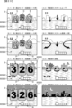
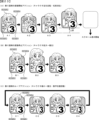
前記装飾識別情報の可変表示は、前記装飾識別情報を移動させる移動表示(例えば、スクロール表示。図21参照)を含み、
前記縮小識別情報の可変表示は、前記縮小識別情報を移動させることなく他の前記縮小識別情報に切り替える切替表示(例えば、切替表示。図22(E)参照)であり、
前記縮小識別情報の可変表示では、前記装飾識別情報の可変表示において一の装飾識別情報が表示され、該一の装飾識別情報が表示を終えるまので期間において、前記縮小識別情報を複数回切り替えることが可能であり(例えば、一の飾り図柄が表示され、該飾り図柄表示が表示を終えるまでの期間Ta2に、小図柄は、はずれ組合せの小図柄が5回切り替えて、それぞれ期間Ta1にわたり表示される(期間Ta1<期間Ta2)。図22(E)参照)、
前記装飾識別情報の可変表示の表示結果は、前記装飾識別情報の組合せによって構成され(例えば「111」、「326」などの飾り図柄の組合せ)、
前記縮小識別情報の可変表示の表示結果は、前記縮小識別情報の組合せによって構成され(例えば「111」、「326」などの小図柄の組合せ)、
前記装飾識別情報の可変表示の表示結果として前記特定表示結果以外の非特定表示結果に対応する前記装飾識別情報の組合せである非特定組合せが導出される場合に、前記装飾識別情報の可変表示の表示結果が導出されるよりも前に、前記縮小識別情報の可変表示において前記非特定組合せに対応する前記縮小識別情報の組合せとならないように前記縮小識別情報が切り替わる(例えば、演出制御用CPU120が、はずれ組合せの確定飾り図柄(例えば、「326」)を停止表示させることを決定した場合は、当該飾り図柄の可変表示を開始してから上記はずれ組合せの確定飾り図柄(例えば、「326」)を停止表示させる前に、飾り図柄と同じ「326」のはずれ組合せの小図柄が表示されないように切り替え表示を行う部分。図22(E)参照)
ことを特徴としている。
この特徴によれば、装飾識別情報の可変表示の表示結果として非特定組合せが導出される場合に、装飾識別情報の可変表示の表示結果が導出されるよりも前に、縮小識別情報の可変表示において非特定組合せに対応する縮小識別情報の組合せとならないように縮小識別情報が切り替わるため、縮小識別情報の可変表示における縮小識別情報の組合せから装飾識別情報の可変表示の表示結果として非特定組合せが導出されることが事前に知られてしまうことがなく、興趣の低下を防止できる。
[Form 1] (No. 1)
By executing a variable display of specific identification information (for example, a special symbol) and deriving a specific display result (for example, a jackpot display result) as a result of the variable display of the specific identification information, an advantageous state advantageous to the player ( For example, a gaming machine (for example, pachinko gaming machine 1) that can be controlled to a jackpot gaming state),
A game control means (for example, CPU 103),
Production control means (for example, production control CPU 120),
The game control means executes the variable display of the specific identification information (for example, the part where the
The performance control means is
It is possible to variably display a plurality of types of decorative identification information corresponding to the variable display of the specific identification information (for example, the
It is possible to variably display reduced identification information that is smaller in size than the decoration identification information and corresponds to each of the plurality of types of decoration identification information (for example, the
The variable display of the decoration identification information includes a moving display (for example, a scroll display, see FIG. 21) for moving the decoration identification information,
The variable display of the reduced identification information is a switching display (for example, a switching display, see FIG. 22(E)) that switches to another reduced identification information without moving the reduced identification information,
In the variable display of the reduced identification information, one decoration identification information is displayed in the variable display of the decoration identification information, and the reduced identification information is switched multiple times in a period until the one decoration identification information finishes displaying. is possible (for example, in a period Ta2 when one decorative pattern is displayed and until the display of the decorative pattern ends, the small pattern is switched five times, and the small pattern is displayed for each period Ta1). (period Ta1 < period Ta2; see FIG. 22(E)),
The display result of the variable display of the decorative identification information is configured by a combination of the decorative identification information (for example, a combination of decorative patterns such as "111" and "326"),
The display result of the variable display of the reduced identification information is configured by a combination of the reduced identification information (for example, a combination of small symbols such as "111" and "326"),
When a non-specific combination of the decoration identification information corresponding to a non-specific display result other than the specific display result is derived as a display result of the variable display of the decoration identification information, Before the display result is derived, the reduced identification information is switched so that the combination of the reduced identification information corresponding to the non-specific combination does not occur in the variable display of the reduced identification information (for example, when the
It is characterized by
According to this feature, when a non-specific combination is derived as a display result of the variable display of decoration identification information, the variable display of reduced identification information is displayed before the display result of the variable display of decoration identification information is derived. Since the reduced identification information is switched so that the reduced identification information does not correspond to the non-specific combination in Since the information that will be derived is not known in advance, it is possible to prevent a loss of interest.
[形態2](No.2)
形態2の遊技機は、
特定識別情報(例えば、特別図柄)の可変表示を実行し、該特定識別情報の可変表示の結果として特定表示結果(例えば、大当り表示結果)が導出されることで遊技者にとって有利な有利状態(例えば、大当り遊技状態)に制御可能な遊技機(例えば、パチンコ遊技機1)であって、
遊技制御手段(例えば、CPU103)と、
演出制御手段(例えば、演出制御用CPU120)と、
発光手段(例えば、メインランプ9a、枠ランプ9b、可動体ランプ9d)と、を備え、
前記遊技制御手段は、前記特定識別情報の可変表示を実行し(例えば、CPU103がステップS25の特別図柄プロセス処理にて特別図柄の可変表示を実行する部分)、
前記演出制御手段は、前記特定識別情報の可変表示に対応する複数種類の装飾識別情報の可変表示を行うことが可能であり(例えば、演出制御用CPU120がステップS76の演出制御プロセス処理にて飾り図柄の可変表示を実行する部分)、
前記装飾識別情報の可変表示の表示結果は、表示領域に表示された複数の前記装飾識別情報のうち有効表示領域に停止した前記装飾識別情報の組合せによって構成され(例えば飾り図柄表示エリア5L、5C、5Rの停止位置に停止表示された「111」、「326」などの飾り図柄の組合せにより大当りまたははずれとなる部分)、
前記装飾識別情報の可変表示の表示結果として前記特定表示結果以外の非特定表示結果に対応する前記装飾識別情報の組合せである非特定組合せが導出される場合に、前記装飾識別情報を前記有効表示領域に停止させるときに、該装飾識別情報を通常サイズから拡大表示させた後、前記通常サイズに戻す態様にて表示させることが可能であり(例えば、演出制御用CPU120がはずれ変動パターンに基づく可変表示において飾り図柄を仮停止表示するときに変動停止アクションを実行可能な部分。図36~図38、図42、図43参照)、
前記有効表示領域に停止させる前記装飾識別情報を拡大表示させる場合に、前記有効表示領域に位置しない前記装飾識別情報は拡大表示させず(図57の変形例3参照)、
前記装飾識別情報の可変表示の実行中に、所定発光期間にわたり前記発光手段を所定発光態様にて発光させる所定発光制御が繰り返し行われるとともに、前記有効表示領域に停止させる前記装飾識別情報を拡大表示させる場合にも前記所定発光制御が継続して行われる(例えば、演出制御用CPU120が飾り図柄を仮停止表示するときに変動停止アクションを実行しているときでも、メインランプ9a、枠ランプ9b、可動体ランプ9dのループ発光制御が行われている部分。図42、図43参照)
ことを特徴としている。
この特徴によれば、装飾識別情報の可変表示の表示結果として非特定表示結果に対応する装飾識別情報の組合せである非特定組合せが導出される場合に、有効表示領域に停止した装飾識別情報を一旦拡大表示させることにより、有効表示領域に停止した装飾識別情報を遊技者に注目させることができるとともに、本来遊技者にとって意味をなさない非特定組合せが導出される場合でも、遊技者の視線を装飾識別情報が表示される領域へ留めることができる。また、有効表示領域に停止した装飾識別情報を拡大表示させる場合に、有効表示領域に位置しない装飾識別情報は拡大表示されないため、遊技者の視線を有効領域に停止した装飾識別情報に集中させることができるとともに、表示制御の負荷も軽減できる。また、有効表示領域に停止させる装飾識別情報を拡大表示させる場合にも所定発光制御が継続して行われるため、発光手段の制御を簡素化できる。
[Form 2] (No. 2)
By executing a variable display of specific identification information (for example, a special symbol) and deriving a specific display result (for example, a jackpot display result) as a result of the variable display of the specific identification information, an advantageous state advantageous to the player ( For example, a gaming machine (for example, pachinko gaming machine 1) that can be controlled to a jackpot gaming state),
A game control means (for example, CPU 103),
Production control means (for example, production control CPU 120),
Light emitting means (for example, main lamp 9a,
The game control means executes the variable display of the specific identification information (for example, the part where the
The effect control means is capable of variably displaying a plurality of types of decorative identification information corresponding to the variable display of the specific identification information (for example, the
The display result of the variable display of the decorative identification information is composed of a combination of the decorative identification information stopped in the effective display area among the plurality of decorative identification information displayed in the display area (for example, decorative
When a non-specific combination of the decoration identification information corresponding to a non-specific display result other than the specific display result is derived as a display result of the variable display of the decoration identification information, the decoration identification information is displayed as the valid display. When stopping in the area, it is possible to display the decoration identification information enlarged from the normal size and then returned to the normal size (for example, when the performance control CPU 120 A part where a variable stop action can be executed when temporarily stopping a decorative pattern in the display (see Figures 36 to 38, Figures 42 and 43),
When the decoration identification information to be stopped in the effective display area is displayed in an enlarged manner, the decoration identification information that is not located in the effective display area is not displayed in an enlarged manner (see
While the variable display of the decorative identification information is being performed, a predetermined light emission control that causes the light emitting means to emit light in a predetermined light emission mode over a predetermined light emitting period is repeatedly performed, and the decorative identification information that is stopped in the effective display area is displayed in an enlarged manner. (For example, even when the
It is characterized by
According to this feature, when a non-specific combination that is a combination of decorative identification information corresponding to a non-specific display result is derived as a display result of the variable display of decorative identification information, the decorative identification information stopped in the effective display area is By once enlarging the display, it is possible to draw the player's attention to the decorative identification information stopped in the effective display area, and even if a non-specific combination that originally has no meaning to the player is derived, the player's line of sight can be drawn. It can be pinned to the area where the decorative identification information is displayed. Furthermore, when displaying the decorative identification information that is stopped in the valid display area in an enlarged manner, the decorative identification information that is not located in the valid display area is not displayed in an enlarged manner, so that the player's line of sight can be focused on the decorative identification information that is stopped in the valid display area. At the same time, the load on display control can be reduced. Moreover, since the predetermined light emission control is continued even when the decorative identification information to be stopped in the effective display area is displayed in an enlarged manner, the control of the light emitting means can be simplified.
[形態3-1](No.4-1)
形態3-1の遊技機は、
特定識別情報(例えば、特別図柄)の可変表示を実行し、該特定識別情報の可変表示の結果として特定表示結果(例えば、大当り表示結果)が導出されることで遊技者にとって有利な有利状態(例えば、大当り遊技状態)に制御可能な遊技機(例えば、パチンコ遊技機1)であって、
遊技制御手段(例えば、CPU103)と、
演出制御手段(例えば、演出制御用CPU120)と、を備え、
前記遊技制御手段は、前記特定識別情報の可変表示を実行し(例えば、CPU103がステップS25の特別図柄プロセス処理にて特別図柄の可変表示を実行する部分)、
前記演出制御手段は、前記特定識別情報の可変表示に対応する複数種類の装飾識別情報の可変表示を行うことが可能であり(例えば、演出制御用CPU120がステップS76の演出制御プロセス処理にて飾り図柄の可変表示を実行する部分)、
前記装飾識別情報の可変表示は、前記装飾識別情報を奥側から手前側に向けて透明度を高めながら移動させ、消去させる手前移動表示(例えば、スクロール表示)を含み(図28~図30参照)、
前記装飾識別情報は、キャラクタ画像(例えば、キャラクタ表示部002SG052)と、数字画像(例えば、数字表示部002SG051)と、を含み、
前記装飾識別情報の前記手前移動表示中に、一の装飾識別情報に対して奥側に位置する他の装飾識別情報が前記一の装飾識別情報を透過して視認可能となり、前記他の装飾識別情報の前記キャラクタ画像は表示される一方、前記数字画像は表示されず、前記一の装飾識別情報が消去されてから、前記他の装飾識別情報の前記数字画像が表示される(例えば、図30(A)(B)に示すように、飾り図柄表示エリア5L、5C、5Rにフレームイン表示されてからフレームアウト表示されるまでの間に、一の飾り図柄(例えば、飾り図柄「2」)に対して一部が重複するように奥側に位置する他の飾り図柄(例えば、飾り図柄「3」)が飾り図柄「2」を透過して視認可能となることがある。このとき、飾り図柄「3」のキャラクタ表示部002SG052のキャラクタは表示される一方、数字表示部002SG051の数字(「3」)は視認困難となり(または、表示されず)、図30(C)に示すように、飾り図柄「2」が消去されてから、飾り図柄「3」の数字表示部002SG051の数字(「3」)が表示される部分。)
ことを特徴としている。
この特徴によれば、装飾識別情報を奥側から手前側に向けて透明度を高めながら移動させ、消去させる手前移動表示を行う場合に、一の装飾識別情報に対して奥側に位置する他の装飾識別情報が一の装飾識別情報を透過して視認可能となるが、この際、奥側に位置する他の装飾識別情報は、そのキャラクタ画像が表示される一方で数字画像が表示されず、一の装飾識別情報が消去されてから他の装飾識別情報の数字画像が表示されるので、一の装飾識別情報の数字画像と、他の装飾識別情報の数字画像と、が重なって表示されることがなく、手前側に位置する一の装飾識別情報の数字画像が分かり難くなってしまうことを防止できる。
[Form 3-1] (No. 4-1)
The gaming machine of form 3-1 is
By executing a variable display of specific identification information (for example, a special symbol) and deriving a specific display result (for example, a jackpot display result) as a result of the variable display of the specific identification information, an advantageous state advantageous to the player ( For example, a gaming machine (for example, pachinko gaming machine 1) that can be controlled to a jackpot gaming state),
A game control means (for example, CPU 103),
Production control means (for example, production control CPU 120),
The game control means executes the variable display of the specific identification information (for example, the part where the
The effect control means is capable of variably displaying a plurality of types of decorative identification information corresponding to the variable display of the specific identification information (for example, the
The variable display of the decoration identification information includes a front movement display (for example, a scroll display) in which the decoration identification information is moved from the back side toward the front side while increasing transparency and is erased (see FIGS. 28 to 30). ,
The decoration identification information includes a character image (for example, character display section 002SG052) and a number image (for example, number display section 002SG051),
During the forward movement display of the decoration identification information, the other decoration identification information located on the back side with respect to the one decoration identification information becomes visible through the one decoration identification information, and the other decoration identification information While the character image of the information is displayed, the number image is not displayed, and after the first decoration identification information is erased, the number image of the other decoration identification information is displayed (for example, FIG. 30 As shown in (A) and (B), one decorative pattern (for example, decorative pattern "2") is displayed in the decorative
It is characterized by
According to this feature, when performing front movement display in which decoration identification information is moved from the back side toward the front side while increasing transparency and erased, other decoration identification information located on the back side with respect to one decoration identification information is displayed. The decoration identification information passes through the first decoration identification information and becomes visible, but at this time, the character image of the other decoration identification information located on the back side is displayed, but the number image is not displayed. Since the numerical image of the other decorative identification information is displayed after the first decorative identification information is deleted, the numerical image of the first decorative identification information and the numerical image of the other decorative identification information are displayed overlapping each other. This prevents the numerical image of the first decorative identification information located on the front side from becoming difficult to understand.
[形態3-2](No.4-2)
形態3-2の遊技機は、
特定識別情報(例えば、特別図柄)の可変表示を実行し、該特定識別情報の可変表示の結果として特定表示結果(例えば、大当り表示結果)が導出されることで遊技者にとって有利な有利状態(例えば、大当り遊技状態)に制御可能な遊技機(例えば、パチンコ遊技機1)であって、
遊技制御手段(例えば、CPU103)と、
演出制御手段(例えば、演出制御用CPU120)と、を備え、
前記遊技制御手段は、前記特定識別情報の可変表示を実行し(例えば、CPU103がステップS25の特別図柄プロセス処理にて特別図柄の可変表示を実行する部分)、
前記演出制御手段は、前記特定識別情報の可変表示に対応する複数種類の装飾識別情報の可変表示を行うことが可能であり(例えば、演出制御用CPU120がステップS76の演出制御プロセス処理にて飾り図柄の可変表示を実行する部分)、
前記装飾識別情報の可変表示は、前記装飾識別情報を手前側から奥側に向けて透明度を高めながら移動させ、消去させる手前移動表示(例えば、スクロール表示)を含み(図31、図32参照)、
前記装飾識別情報は、キャラクタ画像(例えば、キャラクタ表示部002SG052)と、数字画像(例えば、数字表示部002SG051)と、を含み、
前記装飾識別情報の前記手前移動表示中に、一の装飾識別情報に対して奥側に位置する他の装飾識別情報が前記一の装飾識別情報を透過して視認可能となり、前記一の装飾識別情報の前記キャラクタ画像は表示される一方、前記数字画像は表示されず、前記他の装飾識別情報が消去されてから、前記一の装飾識別情報の前記数字画像が表示される(例えば、図31(G)(H)に示すように、スクロール表示では飾り図柄が手前側から奥側に向けて湾曲状に移動する態様とされているため、飾り図柄表示エリア5L、5C、5Rにフレームイン表示されてからフレームアウト表示されるまでの間に、一の飾り図柄(例えば、飾り図柄「3」)に対して一部が重複するように奥側に位置する他の飾り図柄(例えば、飾り図柄「2」)が飾り図柄「3」を透過して視認可能となることがある。このとき、飾り図柄「2」のキャラクタ表示部002SG052のキャラクタは表示される一方、数字表示部002SG051の数字(「2」)は視認困難となる(または、表示されず)部分。変形例1)
ことを特徴としている。
この特徴によれば、装飾識別情報を手前側から奥側に向けて透明度を高めながら移動させ、消去させる手前移動表示を行う場合に、一の装飾識別情報に対して奥側に位置する他の装飾識別情報が一の装飾識別情報を透過して視認可能となるが、この際、手前側に位置する一の装飾識別情報は、そのキャラクタ画像が表示される一方で数字画像が表示されず、他の装飾識別情報が消去されてから一の装飾識別情報の数字画像が表示されるので、他の装飾識別情報の数字画像と、一の装飾識別情報の数字画像と、が重なって表示されることがなく、奥側に位置する他の装飾識別情報の数字画像が分かり難くなってしまうことを防止できる。
[Form 3-2] (No. 4-2)
The gaming machine of form 3-2 is
By executing a variable display of specific identification information (for example, a special symbol) and deriving a specific display result (for example, a jackpot display result) as a result of the variable display of the specific identification information, an advantageous state advantageous to the player ( For example, a gaming machine (for example, pachinko gaming machine 1) that can be controlled to a jackpot gaming state),
A game control means (for example, CPU 103),
Production control means (for example, production control CPU 120),
The game control means executes the variable display of the specific identification information (for example, the part where the
The effect control means is capable of variably displaying a plurality of types of decorative identification information corresponding to the variable display of the specific identification information (for example, the
The variable display of the decoration identification information includes a forward movement display (for example, a scroll display) in which the decoration identification information is moved from the front side to the back side while increasing transparency and erased (see FIGS. 31 and 32). ,
The decoration identification information includes a character image (for example, character display section 002SG052) and a number image (for example, number display section 002SG051),
During the forward movement display of the decoration identification information, other decoration identification information located on the back side with respect to the one decoration identification information becomes visible through the one decoration identification information, and the one decoration identification information becomes visible. While the character image of the information is displayed, the number image is not displayed, and after the other decoration identification information is erased, the number image of the one decoration identification information is displayed (for example, FIG. 31 As shown in (G) and (H), in the scroll display, the decorative pattern moves in a curved manner from the front side to the back side, so it is displayed in the frame in the decorative
It is characterized by
According to this feature, when performing front movement display in which decoration identification information is moved from the front side to the back side while increasing transparency and erased, other decoration identification information located on the back side with respect to one decoration identification information is displayed. The decoration identification information passes through the
[形態4](No.5)
形態5の遊技機は、
特定識別情報(例えば、特別図柄)の可変表示を実行し、該特定識別情報の可変表示の結果として特定表示結果(例えば、大当り表示結果)が導出されることで遊技者にとって有利な有利状態(例えば、大当り遊技状態)に制御可能な遊技機(例えば、パチンコ遊技機1)であって、
遊技制御手段(例えば、CPU103)と、
演出制御手段(例えば、演出制御用CPU120)と、
発光手段(例えば、メインランプ9a、枠ランプ9b、可動体ランプ9d)と、を備え、
前記遊技制御手段は、前記特定識別情報の可変表示を実行し(例えば、CPU103がステップS25の特別図柄プロセス処理にて特別図柄の可変表示を実行する部分)、
前記演出制御手段は、前記特定識別情報の可変表示に対応する複数種類の装飾識別情報の可変表示を行うことが可能であり(例えば、演出制御用CPU120がステップS76の演出制御プロセス処理にて飾り図柄の可変表示を実行する部分)、
前記装飾識別情報の可変表示は、前記装飾識別情報を回転させて該装飾識別情報の表面及び裏面を繰り返し表示させる回転表示を含み(図33、図34参照)、
前記回転表示中は前記装飾識別情報が半透過状態となり、前記回転表示が停止するときに前記装飾識別情報が非透過状態となり(図33、図34参照)、
前記装飾識別情報は、数字画像(例えば、数字表示部002SG051)を含み、
前記回転表示中において半透過状態となる前記装飾識別情報の表面側の前記数字画像は表示される一方、裏面側の前記数字画像は表示されず(図34参照)、
前記装飾識別情報の可変表示の実行中に、所定発光期間にわたり前記発光手段を所定発光態様にて発光させる所定発光制御が繰り返し行われるとともに、前記回転表示中においても前記所定発光制御が継続して行われる(例えば、高ベース状態において飾り図柄の可変表示が実行されているときにおいても、背景パターンに対応したループ発光制御(図24(B)参照)に基づいて、白色、青色、黄色の順の発光パターンが繰り返し実行されようにしてもよい部分。変形例。図44参照)
ことを特徴としている。
この特徴によれば、装飾識別情報を回転させて該装飾識別情報の表面及び裏面を繰り返し表示させる回転表示を行う場合に、装飾識別情報は半透過状態となるため、装飾識別情報の表面側だけでなく裏面側も透過して視認可能となるが、この際、装飾識別情報の表面側の数字画像は表示される一方、裏面側の数字画像は表示されないため、装飾識別情報の表面側の数字画像と、裏面側の数字画像と、が重なって表示されることがなく、表面側の数字画像が分かり難くなってしまうことを防止できる。また、回転表示中も所定発光制御が継続して行われるため、発光手段の制御を簡素化できる。
[Form 4] (No. 5)
By executing a variable display of specific identification information (for example, a special symbol) and deriving a specific display result (for example, a jackpot display result) as a result of the variable display of the specific identification information, an advantageous state advantageous to the player ( For example, a gaming machine (for example, pachinko gaming machine 1) that can be controlled to a jackpot gaming state),
A game control means (for example, CPU 103),
Production control means (for example, production control CPU 120),
Light emitting means (for example, main lamp 9a,
The game control means executes the variable display of the specific identification information (for example, the part where the
The effect control means is capable of variably displaying a plurality of types of decorative identification information corresponding to the variable display of the specific identification information (for example, the
The variable display of the decoration identification information includes a rotating display in which the decoration identification information is rotated and the front and back sides of the decoration identification information are repeatedly displayed (see FIGS. 33 and 34);
During the rotational display, the decoration identification information is in a semi-transparent state, and when the rotational display stops, the decoration identification information is in a non-transparent state (see FIGS. 33 and 34);
The decoration identification information includes a number image (for example, number display section 002SG051),
While the number image on the front side of the decorative identification information that is in a semi-transparent state during the rotational display is displayed, the number image on the back side is not displayed (see FIG. 34);
During execution of the variable display of the decoration identification information, a predetermined light emission control that causes the light emitting means to emit light in a predetermined light emission mode over a predetermined light emission period is repeatedly performed, and the predetermined light emission control continues even during the rotational display. (For example, even when variable display of decorative patterns is executed in the high base state, the order of white, blue, and yellow is displayed based on the loop light emission control corresponding to the background pattern (see FIG. 24(B)). A part where the light emitting pattern may be repeatedly executed. Modification example (see Fig. 44)
It is characterized by
According to this feature, when rotating the decoration identification information and repeatedly displaying the front and back sides of the decoration identification information, the decoration identification information becomes semi-transparent, so that only the front side of the decoration identification information is displayed. However, in this case, while the number image on the front side of the decorative identification information is displayed, the number image on the back side is not displayed, so the number image on the front side of the decorative identification information is displayed. The image and the number image on the back side are not displayed overlapping each other, and it is possible to prevent the number image on the front side from becoming difficult to understand. Further, since the predetermined light emission control is continued even during rotational display, control of the light emitting means can be simplified.
[形態5](No.6)
形態5の遊技機は、
特定識別情報(例えば、特別図柄)の可変表示を実行し、該特定識別情報の可変表示の結果として特定表示結果(例えば、大当り表示結果)が導出されることで遊技者にとって有利な有利状態(例えば、大当り遊技状態)に制御可能な遊技機(例えば、パチンコ遊技機1)であって、
遊技制御手段(例えば、CPU103)と、
演出制御手段(例えば、演出制御用CPU120)と、を備え、
前記遊技制御手段は、前記特定識別情報の可変表示を実行し(例えば、CPU103がステップS25の特別図柄プロセス処理にて特別図柄の可変表示を実行する部分)、
前記演出制御手段は、前記特定識別情報の可変表示に対応する複数種類の装飾識別情報の可変表示を行うことが可能であり(例えば、演出制御用CPU120がステップS76の演出制御プロセス処理にて飾り図柄の可変表示を実行する部分)、
前記装飾識別情報が表示される領域は、第1領域(例えば、左飾り図柄表示エリア5L)と、第2領域(例えば、右飾り図柄表示エリア5R)と、前記第1領域と前記第2領域の間に位置する第3領域(例えば、中飾り図柄表示エリア5C)と、を含み、
前記特定表示結果が導出される場合に、前記第1領域と前記第2領域に同一種類の前記装飾識別情報が仮停止するリーチ状態となった後に、該リーチ状態を形成する前記装飾識別情報と同一種類の前記装飾識別情報が前記第3領域に停止する特定組合せ(例えば、予め定められた大当り組合せ)となり、
前記リーチ状態となったときに、前記第1領域及び前記第2領域に仮停止した前記装飾識別情報と前記第3領域において可変表示中の前記装飾識別情報に重畳するようにリーチライン示唆画像(例えば、リーチラインエフェクト表示002SG250)を表示させ、消去するリーチライン示唆演出を実行可能であり(例えば、演出制御用CPU120がリーチライン示唆演出を実行可能な部分)、
前記リーチ状態となった後、前記リーチライン示唆演出を実行するまでは、前記第3領域において可変表示中の前記装飾識別情報を第1透明度(例えば、第1透過率F1)にて透過させた状態とし、前記リーチライン示唆演出を実行した後は、前記第3領域において可変表示中の前記装飾識別情報を前記第1透明度よりも透明度が低い第2透明度(例えば、第2透過率F2)にて透過させた状態とし(図52参照)、
前記リーチライン示唆演出の実行後、前記第3領域において可変表示中の前記装飾識別情報を前記第2透明度とするタイミングは、前記リーチライン示唆画像が前記第3領域から消去されるタイミングである(例えば、リーチラインエフェクト表示002SG250の実行後、中飾り図柄表示エリア5Cにおいて可変表示中の飾り図柄の透過率(透明度)を、リーチラインエフェクト表示002SG250が実行される前の第1透過率F1よりも透過率(透明度)が低い第2透過率F2とするタイミングは、リーチラインエフェクト表示002SG250が中飾り図柄表示エリア5Cから消去された後のタイミングである部分。図50~図52参照)
ことを特徴としている。
この特徴によれば、リーチ状態となったときに、第1領域及び第2領域に停止した装飾識別情報と第3領域において可変表示中の装飾識別情報に重畳するようにリーチライン示唆画像が表示されるとともに、リーチライン示唆画像が第3領域から消去されるタイミングで第3領域において可変表示中の装飾識別情報が第1透明度よりも低い第2透明度となるため、第3領域において可変表示中の装飾識別情報がリーチライン示唆画像を邪魔することがない。
[Form 5] (No. 6)
By executing a variable display of specific identification information (for example, a special symbol) and deriving a specific display result (for example, a jackpot display result) as a result of the variable display of the specific identification information, an advantageous state advantageous to the player ( For example, a gaming machine (for example, pachinko gaming machine 1) that can be controlled to a jackpot gaming state),
A game control means (for example, CPU 103),
Production control means (for example, production control CPU 120),
The game control means executes the variable display of the specific identification information (for example, the part where the
The effect control means is capable of variably displaying a plurality of types of decorative identification information corresponding to the variable display of the specific identification information (for example, the
The areas where the decoration identification information is displayed include a first area (for example, the left decorative
When the specific display result is derived, after the decoration identification information of the same type is temporarily stopped in the first area and the second area, the decoration identification information that forms the reach state is The decoration identification information of the same type becomes a specific combination (for example, a predetermined jackpot combination) that stops in the third area,
When the reach state is reached, a reach line suggestion image ( For example, it is possible to execute a reach line suggestion effect that displays and erases a reach line effect display (002SG250) (for example, a part where the
After the reach state is reached, the decoration identification information being variably displayed in the third area is transmitted at a first transparency (for example, a first transmittance F1) until the reach line suggestion effect is executed. state, and after executing the reach line suggestion effect, the decoration identification information being variably displayed in the third area is changed to a second transparency lower in transparency than the first transparency (for example, second transmittance F2). (see Figure 52),
After execution of the reach line suggestion effect, the timing at which the decorative identification information being variably displayed in the third area is set to the second transparency is the timing at which the reach line suggestion image is erased from the third area ( For example, after execution of the reach line effect display 002SG250, the transmittance (transparency) of the decorative pattern being variably displayed in the center decoration
It is characterized by
According to this feature, when the reach state is reached, the reach line suggestion image is displayed so as to be superimposed on the decorative identification information stopped in the first and second areas and the decorative identification information being variably displayed in the third area. At the same time, at the timing when the reach line suggestion image is deleted from the third area, the decoration identification information being variably displayed in the third area becomes a second transparency lower than the first transparency, so that the decoration identification information being variably displayed in the third area becomes The decorative identification information suggests the reach line without interfering with the image.
[形態6](No.7)
形態6の遊技機は、
特定識別情報(例えば、特別図柄)の可変表示を実行し、該特定識別情報の可変表示の結果として特定表示結果(例えば、大当り表示結果)が導出されることで遊技者にとって有利な有利状態(例えば、大当り遊技状態)に制御可能な遊技機(例えば、パチンコ遊技機1)であって、
遊技制御手段(例えば、CPU103)と、
演出制御手段(例えば、演出制御用CPU120)と、
発光手段と、を備え、
前記遊技制御手段は、前記特定識別情報の可変表示を実行し(例えば、CPU103がステップS25の特別図柄プロセス処理にて特別図柄の可変表示を実行する部分)、
前記演出制御手段は、前記特定識別情報の可変表示に対応する複数種類の装飾識別情報の可変表示を行うことが可能であり(例えば、演出制御用CPU120がステップS76の演出制御プロセス処理にて飾り図柄の可変表示を実行する部分)、
前記装飾識別情報が表示される領域は、第1領域(例えば、左飾り図柄表示エリア5L)と、第2領域(例えば、右飾り図柄表示エリア5R)と、前記第1領域と前記第2領域の間に位置する第3領域(例えば、中飾り図柄表示エリア5C)と、を含み、
前記特定表示結果が導出される場合に、前記第1領域と前記第2領域に同一種類の前記装飾識別情報が仮停止するリーチ状態となった後に、該リーチ状態を形成する前記装飾識別情報と同一種類の前記装飾識別情報が前記第3領域に停止する特定組合せ(例えば、予め定められた大当り組合せ)となり、
前記リーチ状態となったときに、前記第1領域及び前記第2領域に仮停止した前記装飾識別情報と前記第3領域において可変表示中の前記装飾識別情報に重畳するようにリーチライン示唆画像(例えば、リーチラインエフェクト表示002SG250)を表示させ、消去するリーチライン示唆演出を実行可能であり(例えば、演出制御用CPU120がリーチライン示唆演出を実行可能な部分)、
前記リーチライン示唆演出を実行するときに、前記第1領域及び前記第2領域に仮停止した装飾識別情報を拡大させる拡大表示と、該拡大表示を実行した後に該装飾識別情報を離間させる離間表示と、を実行可能であり(図50~図52参照)、
前記拡大表示を開始してから終了するまでの第1期間よりも前記離間表示を開始してから終了するまでの第2期間の方が長く(例えば、拡大表示を開始してから終了するまでの第1期間td1よりも、離間表示を開始してから終了するまでの第2期間te1の方が長い(td1<te1)。図52参照)、
前記発光手段は、前記表示手段の周辺に配置される特定発光手段(例えば、可動体ランプ9d)を含み、
前記リーチライン示唆演出の実行中において前記特定発光手段を消灯させる消灯制御を実行可能である(例えば、リーチラインエフェクト表示002SG250の表示態様を変化させているときに、画像表示装置5の表示画面の周辺(近傍)に配置された可動体32A、32Bの可動体ランプ9dを消灯させる部分。図50(F)~(H)参照)
ことを特徴としている。
この特徴によれば、リーチ状態となったときに、第1領域及び第2領域に停止した装飾識別情報と第3領域において可変表示中の装飾識別情報に重畳するようにリーチライン示唆画像が表示されるとともに、第1領域及び第2領域に停止した装飾識別情報が第1期間にわたり拡大表示された後、第1期間より長い第2期間にわたり離間表示されることで、リーチ状態を形成する装飾識別情報を遊技者に認識させることができる。また、表示手段の周辺の特定発光手段を消灯することにより、リーチライン示唆画像をより際立たせて見せることができる。
[Form 6] (No. 7)
By executing a variable display of specific identification information (for example, a special symbol) and deriving a specific display result (for example, a jackpot display result) as a result of the variable display of the specific identification information, an advantageous state advantageous to the player ( For example, a gaming machine (for example, pachinko gaming machine 1) that can be controlled to a jackpot gaming state),
A game control means (for example, CPU 103),
Production control means (for example, production control CPU 120),
comprising a light emitting means;
The game control means executes the variable display of the specific identification information (for example, the part where the
The effect control means is capable of variably displaying a plurality of types of decorative identification information corresponding to the variable display of the specific identification information (for example, the
The areas where the decoration identification information is displayed include a first area (for example, the left decorative
When the specific display result is derived, after the decoration identification information of the same type is temporarily stopped in the first area and the second area, the decoration identification information that forms the reach state is The decoration identification information of the same type becomes a specific combination (for example, a predetermined jackpot combination) that stops in the third area,
When the reach state is reached, a reach line suggestion image ( For example, it is possible to execute a reach line suggestion effect that displays and erases a reach line effect display (002SG250) (for example, a part where the
When executing the reach line suggestion effect, an enlarged display for enlarging the decoration identification information temporarily stopped in the first area and the second area, and a separation display for separating the decoration identification information after executing the enlarged display. It is possible to execute (see Figures 50 to 52),
The second period from the start to the end of the separated display is longer than the first period from the start to the end of the enlarged display (for example, the second period from the start to the end of the enlarged display is longer). The second period te1 from the start to the end of the distance display is longer than the first period td1 (td1<te1; see FIG. 52),
The light emitting means includes a specific light emitting means (for example, a
It is possible to perform light-off control to turn off the specific light emitting means during execution of the reach line suggestion effect (for example, when changing the display mode of the reach line effect display 002SG250, the display screen of the image display device 5 A part that turns off the
It is characterized by
According to this feature, when the reach state is reached, the reach line suggestion image is displayed so as to be superimposed on the decoration identification information stopped in the first area and the second area and the decoration identification information being variably displayed in the third area. At the same time, the decoration identification information stopped in the first area and the second area is enlarged and displayed for a first period, and then displayed at a distance for a second period that is longer than the first period, so that the decoration forming a reach state is displayed. The identification information can be recognized by the player. Further, by turning off the specific light emitting means around the display means, the reach line suggestion image can be made to stand out more clearly.
[形態7](No.8)
形態7の遊技機は、
特定識別情報(例えば、特別図柄)の可変表示を実行し、該特定識別情報の可変表示の結果として特定表示結果(例えば、大当り表示結果)が導出されることで遊技者にとって有利な有利状態(例えば、大当り遊技状態)に制御可能な遊技機(例えば、パチンコ遊技機1)であって、
遊技制御手段(例えば、CPU103)と、
演出制御手段(例えば、演出制御用CPU120)と、
発光手段と、を備え、
前記遊技制御手段は、前記特定識別情報の可変表示を実行し(例えば、CPU103がステップS25の特別図柄プロセス処理にて特別図柄の可変表示を実行する部分)、
前記演出制御手段は、前記特定識別情報の可変表示に対応する複数種類の装飾識別情報の可変表示を行うことが可能であり(例えば、演出制御用CPU120がステップS76の演出制御プロセス処理にて飾り図柄の可変表示を実行する部分)、
前記装飾識別情報が表示される領域は、第1領域(例えば、左飾り図柄表示エリア5L)と、第2領域(例えば、右飾り図柄表示エリア5R)と、前記第1領域と前記第2領域の間に位置する第3領域(例えば、中飾り図柄表示エリア5C)と、を含み、
前記特定表示結果が導出される場合に、前記第1領域と前記第2領域に同一種類の前記装飾識別情報が仮停止するリーチ状態となった後に、該リーチ状態を形成する前記装飾識別情報と同一種類の前記装飾識別情報が前記第3領域に停止する特定組合せ(例えば、予め定められた大当り組合せ)となり、
前記リーチ状態となったときに、前記第1領域及び前記第2領域に仮停止した前記装飾識別情報と前記第3領域において可変表示中の前記装飾識別情報に重畳するようにリーチライン示唆画像(例えば、リーチラインエフェクト表示002SG250)を表示させ、消去するリーチライン示唆演出を実行可能であり(例えば、演出制御用CPU120がリーチライン示唆演出を実行可能な部分)、
前記発光手段は、前記表示手段の周辺に配置される特定発光手段(例えば、可動体ランプ9d)を含み、
前記リーチライン示唆演出の実行中において前記特定発光手段を消灯させる消灯制御を実行可能である(例えば、リーチラインエフェクト表示002SG250の表示態様を変化させているときに、画像表示装置5の表示画面の周辺(近傍)に配置された可動体32A、32Bの可動体ランプ9dを消灯させる部分。図50(F)~(H)参照)
ことを特徴としている。
この特徴によれば、リーチ状態となったときに、第1領域及び第2領域に停止した装飾識別情報と第3領域において可変表示中の装飾識別情報に重畳するようにリーチライン示唆画像が表示されるとともに、表示手段の周辺の特定発光手段を消灯することにより、リーチライン示唆画像をより際立たせて見せることができる。
[Form 7] (No. 8)
By executing a variable display of specific identification information (for example, a special symbol) and deriving a specific display result (for example, a jackpot display result) as a result of the variable display of the specific identification information, an advantageous state advantageous to the player ( For example, a gaming machine (for example, pachinko gaming machine 1) that can be controlled to a jackpot gaming state),
A game control means (for example, CPU 103),
Production control means (for example, production control CPU 120),
comprising a light emitting means;
The game control means executes the variable display of the specific identification information (for example, the part where the
The effect control means is capable of variably displaying a plurality of types of decorative identification information corresponding to the variable display of the specific identification information (for example, the
The areas where the decoration identification information is displayed include a first area (for example, the left decorative
When the specific display result is derived, after the decoration identification information of the same type is temporarily stopped in the first area and the second area, the decoration identification information that forms the reach state is The decoration identification information of the same type becomes a specific combination (for example, a predetermined jackpot combination) that stops in the third area,
When the reach state is reached, a reach line suggestion image ( For example, it is possible to execute a reach line suggestion effect that displays and erases a reach line effect display (002SG250) (for example, a part where the
The light emitting means includes a specific light emitting means (for example, a
It is possible to perform light-off control to turn off the specific light emitting means during execution of the reach line suggestion effect (for example, when changing the display mode of the reach line effect display 002SG250, the display screen of the image display device 5 A part that turns off the
It is characterized by
According to this feature, when the reach state is reached, the reach line suggestion image is displayed so as to be superimposed on the decorative identification information stopped in the first and second areas and the decorative identification information being variably displayed in the third area. At the same time, by turning off the specific light emitting means around the display means, the reach line suggestion image can be made to stand out more clearly.
[形態8](No.9)
形態8の遊技機は、
特定識別情報(例えば、特別図柄)の可変表示を実行し、該特定識別情報の可変表示の結果として特定表示結果(例えば、大当り表示結果)が導出されることで遊技者にとって有利な有利状態(例えば、大当り遊技状態)に制御可能な遊技機(例えば、パチンコ遊技機1)であって、
遊技制御手段(例えば、CPU103)と、
演出制御手段(例えば、演出制御用CPU120)と、
発光手段(例えば、メインランプ9a、枠ランプ9b)と、を備え、
前記遊技制御手段は、
前記特定識別情報の可変表示を実行し(例えば、CPU103がステップS25の特別図柄プロセス処理にて特別図柄の可変表示を実行する部分)、
通常状態(例えば、低確低ベース状態)と、該通常状態よりも可変表示が実行されやすいとともに平均可変表示期間が短い特別状態(例えば、低確高ベース状態や高確高ベース状態)と、に制御可能であり、
前記演出制御手段は、
前記特定識別情報の可変表示に対応する複数種類の装飾識別情報の可変表示を行うことが可能であり(例えば、演出制御用CPU120がステップS76の演出制御プロセス処理にて飾り図柄の可変表示を実行する部分)、
前記通常状態において前記装飾識別情報の可変表示が仮停止されているときに、第1期間にわたり該装飾識別情報を所定動作態様にて動作させる所定動作表示制御が繰り返し行われ(例えば、演出制御用CPU120が、低ベース状態において飾り図柄を飾り図柄表示エリア5L、5C、5Rの停止位置に仮停止表示したときに、飾り図柄のループアクションを特別図柄の可変表示が終了するまで繰り返し実行する部分。図23(C)、図42、図43参照)、
前記通常状態において前記装飾識別情報の可変表示が仮停止されているときに、第2期間にわたり前記発光手段を所定発光態様にて発光させる所定発光制御が繰り返し行われ(例えば、演出制御用CPU120が、低ベース状態において飾り図柄を飾り図柄表示エリア5L、5C、5Rの停止位置に仮停止表示したときに、メインランプ9a、枠ランプ9b、可動体ランプ9dのループ発光制御を繰り返し実行する部分。図24(B)、図42、図43参照)、
前記特別状態において前記装飾識別情報の可変表示が停止されているときに、前記所定動作表示制御は行われず(例えば、演出制御用CPU120が、高ベース状態において飾り図柄を飾り図柄表示エリア5L、5C、5Rの停止位置に仮停止表示したときに、飾り図柄のループアクションを実行しない部分。図44参照)、
前記第1期間よりも前記第2期間の方が長い(例えば、ループアクション期間Tb3<ループ発光期間Tb4。図24(A)参照)
ことを特徴としている。
この特徴によれば、通常状態においては、遊技者に装飾識別情報の可変表示を促す意味で所定動作表示制御が繰り返し行われる一方で、可変表示が実行されやすい特別状態においては、可変表示が過度に促されて煩わしさを感じさせてしまうことを防止できる。また、所定動作表示制御は、所定発光制御よりも短い周期で繰り返し行われるため、装飾識別情報を好適に際立たせることができる。
[Form 8] (No. 9)
By executing a variable display of specific identification information (for example, a special symbol) and deriving a specific display result (for example, a jackpot display result) as a result of the variable display of the specific identification information, an advantageous state advantageous to the player ( For example, a gaming machine (for example, pachinko gaming machine 1) that can be controlled to a jackpot gaming state),
A game control means (for example, CPU 103),
Production control means (for example, production control CPU 120),
Light emitting means (for example, main lamp 9a,
The game control means is
Executing the variable display of the specific identification information (for example, the part where the
A normal state (for example, a low-accuracy low-base state), and a special state (for example, a low-accuracy high-base state or a high-accuracy high-base state) in which variable display is more likely to be executed than the normal state and the average variable display period is shorter; can be controlled to
The performance control means is
It is possible to variably display a plurality of types of decorative identification information corresponding to the variable display of the specific identification information (for example, the
When the variable display of the decoration identification information is temporarily stopped in the normal state, a predetermined operation display control for operating the decoration identification information in a predetermined operation mode is repeatedly performed for a first period (for example, a display control for effect control). When the
When the variable display of the decoration identification information is temporarily stopped in the normal state, a predetermined light emission control that causes the light emitting means to emit light in a predetermined light emission mode is repeatedly performed for a second period (for example, when the
When the variable display of the decoration identification information is stopped in the special state, the predetermined operation display control is not performed (for example, the
The second period is longer than the first period (for example, loop action period Tb3<loop light emission period Tb4; see FIG. 24(A)).
It is characterized by
According to this feature, in a normal state, predetermined operation display control is repeatedly performed to encourage the player to display the decorative identification information in a variable manner, while in a special state where variable display is likely to be performed, the variable display is excessively performed. This will prevent you from feeling bothered by this. Moreover, since the predetermined operation display control is repeatedly performed at a shorter period than the predetermined light emission control, the decorative identification information can be suitably highlighted.
[形態9](No.10)
形態9の遊技機は、
特定識別情報(例えば、特別図柄)の可変表示を実行し、該特定識別情報の可変表示の結果として特定表示結果(例えば、大当り表示結果)が導出されることで遊技者にとって有利な有利状態(例えば、大当り遊技状態)に制御可能な遊技機(例えば、パチンコ遊技機1)であって、
遊技制御手段(例えば、CPU103)と、
演出制御手段(例えば、演出制御用CPU120)と、を備え、
前記遊技制御手段は、
前記特定識別情報の可変表示を実行し(例えば、CPU103がステップS25の特別図柄プロセス処理にて特別図柄の可変表示を実行する部分)、
通常状態(例えば、低確低ベース状態)と、該通常状態よりも可変表示が実行されやすいとともに平均可変表示期間が短い特別状態(例えば、低確高ベース状態や高確高ベース状態)と、に制御可能であり、
未だ開始されていない特別識別情報の可変表示に関する情報を保留記憶情報として記憶可能であり(例えば、CPU103がステップS101の始動入賞判定処理において、RAM102の所定領域に保留情報を格納し保留記憶数を更新する処理を行う部分)、
前記演出制御手段は、
前記特定識別情報の可変表示に対応する複数種類の装飾識別情報の可変表示を行うことが可能であり(例えば、演出制御用CPU120がステップS76の演出制御プロセス処理にて飾り図柄の可変表示を実行する部分)、
前記装飾識別情報の可変表示の表示結果は、有効表示領域に停止した前記装飾識別情報の組合せによって構成され(例えば飾り図柄表示エリア5L、5C、5Rの停止位置に停止表示された「111」、「326」などの飾り図柄の組合せにより大当りまたははずれとなる部分)、
前記通常状態において、前記装飾識別情報の可変表示の表示結果として前記特定表示結果以外の非特定表示結果に対応する前記装飾識別情報の組合せである非特定組合せが導出される場合に、前記装飾識別情報を前記有効表示領域に停止させるときに、前記保留記憶情報として記憶された保留記憶数に応じて、該装飾識別情報を通常サイズから拡大表示させた後、前記通常サイズに戻す態様にて表示させることが可能であり(例えば、演出制御用CPU120が飾り図柄を仮停止表示するときに変動停止アクションを実行可能な部分。図36~図39参照)、
前記特別状態において、前記装飾識別情報の可変表示の表示結果として前記非特定組合せが導出される場合に、前記装飾識別情報を前記有効表示領域に停止させるときに、前記保留記憶情報として記憶された保留記憶数がいずれの保留記憶数であっても、該装飾識別情報を通常サイズで維持する(例えば、平均可変表示期間が短く飾り図柄を視認し難い高ベース状態において、保留記憶数によらず短縮変動パターンに基づく可変表示が実行される場合は、変動停止アクションを実行せず、サイズを維持したまま仮停止表示させる部分。図39、図44参照)
ことを特徴としている。
この特徴によれば、通常状態では、保留記憶数に応じて装飾識別情報が停止する際の動きにバリエーションを持たせることで興趣を向上させる一方で、平均可変表示期間が短く装飾識別情報を視認し難い特別状態ではサイズを維持したまま停止させることで、装飾識別情報の視認性が損なわれないように停止させることができる。
[Form 9] (No. 10)
By executing a variable display of specific identification information (for example, a special symbol) and deriving a specific display result (for example, a jackpot display result) as a result of the variable display of the specific identification information, an advantageous state advantageous to the player ( For example, a gaming machine (for example, pachinko gaming machine 1) that can be controlled to a jackpot gaming state),
A game control means (for example, CPU 103),
Production control means (for example, production control CPU 120),
The game control means is
Executing the variable display of the specific identification information (for example, the part where the
A normal state (for example, a low-accuracy low-base state), and a special state (for example, a low-accuracy high-base state or a high-accuracy high-base state) in which variable display is more likely to be executed than the normal state and the average variable display period is shorter; can be controlled to
Information regarding the variable display of special identification information that has not yet started can be stored as pending storage information (for example, in the starting winning determination process in step S101, the
The performance control means is
It is possible to variably display a plurality of types of decorative identification information corresponding to the variable display of the specific identification information (for example, the
The display result of the variable display of the decoration identification information is composed of a combination of the decoration identification information stopped in the effective display area (for example, "111" stopped and displayed at the stop position of the decoration
In the normal state, when a non-specific combination that is a combination of the decoration identification information corresponding to a non-specific display result other than the specific display result is derived as a display result of the variable display of the decoration identification information, the decoration identification When stopping information in the effective display area, the decoration identification information is enlarged from a normal size and then displayed in a manner that returns to the normal size according to the number of pending memories stored as the pending storage information. (For example, a part where the
In the special state, when the non-specific combination is derived as a display result of the variable display of the decoration identification information, when the decoration identification information is stopped in the valid display area, the storage information is stored as the suspended storage information. Regardless of the number of reserved memories, the decoration identification information is maintained at the normal size (for example, in a high base state where the average variable display period is short and the decorative pattern is difficult to see, regardless of the number of reserved memories) When a variable display based on a shortened variation pattern is executed, the variation stop action is not executed and the display is temporarily stopped while maintaining the size (see Figures 39 and 44)
It is characterized by
According to this feature, in the normal state, the interest is improved by creating variations in the movement when the decorative identification information stops depending on the number of retained memories, while the average variable display period is short and the decorative identification information is visible. In special situations where it is difficult to do so, it is possible to stop the display while maintaining the size, so that the visibility of the decoration identification information is not impaired.
[形態10](No.11)
形態10の遊技機は、
特定識別情報(例えば、特別図柄)の可変表示を実行し、該特定識別情報の可変表示の結果として特定表示結果(例えば、大当り表示結果)が導出されることで遊技者にとって有利な有利状態(例えば、大当り遊技状態)に制御可能な遊技機(例えば、パチンコ遊技機1)であって、
遊技制御手段(例えば、CPU103)と、
演出制御手段(例えば、演出制御用CPU120)と、を備え、
前記遊技制御手段は、前記特定識別情報の可変表示を実行し(例えば、CPU103がステップS25の特別図柄プロセス処理にて特別図柄の可変表示を実行する部分)、
前記演出制御手段は、前記特定識別情報の可変表示に対応する複数種類の装飾識別情報の可変表示を行うことが可能であり(例えば、演出制御用CPU120がステップS76の演出制御プロセス処理にて飾り図柄の可変表示を実行する部分)、
一の演出モードにおいて、第1背景画像と第2背景画像とを含む複数種類の背景画像を切り替えて表示可能であり(例えば、第1演出モードにおいて、背景画像として、昼の街を遠くから見た風景をあらわした第1背景画像002SG081(図40(A1)参照)と、昼の街中の風景をあらわした第1所定背景画像002SG081A(図40(A2)参照)とが切り替え表示可能とされている部分)、
前記背景画像を前記第1背景画像から前記第2背景画像へ切り替えるときに、前記第1背景画像の透明度を漸次高めて消去する背景フェードアウト表示を実行するとともに、該第1背景画像の背景フェードアウト表示を実行しているときに前記第2背景画像の透明度を漸次低くしていく背景フェードイン表示を実行可能であり(例えば、第1背景画像002SG081のフェードアウト表示期間A1と、第1所定背景画像002SG081Aのフェードイン表示期間B1と、が同期するクロスフェード表示が実行される部分。図40参照)、
前記装飾識別情報の可変表示を開始するときに、該装飾識別情報の透明度を漸次高めて消去する識別情報フェードアウト表示を実行可能であり(例えば、飾り図柄が、スクロール表示が開始されてから漸次加速して高速表示になるとともに、速度の増加に比例して透過率(透明度)も高まってフェードアウト表示されていく部分)、
前記装飾識別情報の可変表示を終了するときに、該装飾識別情報の透明度を漸次低くしていく識別情報フェードイン表示を実行可能であり(例えば、飾り図柄表示エリア5L、5C、5Rの停止タイミングが近づくと、左飾り図柄表示エリア5Lの飾り図柄、右飾り図柄表示エリア5Rの飾り図柄、中飾り図柄表示エリア5Cの飾り図柄の順に漸次減速して低速表示になるとともに、速度の低下に比例して透過率(透明度)も低くなりフェードイン表示されていく部分)、
前記識別情報フェードアウト表示の実行期間よりも前記背景フェードアウト表示の実行期間の方が長い(例えば、第1背景画像002SG081のフェードアウト表示が行われるフェードアウト表示期間A1は、飾り図柄表示エリア5L、5C、5Rのスクロール表示が開始されてから高速表示になるまでのフェードアウト表示期間A21よりも長い期間とされている部分(フェードアウト表示期間A1>フェードアウト表示期間A21)。図42、図43参照)
ことを特徴としている。
この特徴によれば、フェードアウト表示は、基本的に短い期間で実行されるほど急に消えた印象を与えるため、装飾識別情報の可変表示と背景変化とが共通の時期に実行される可能性がある場合、識別情報フェードアウト表示が背景フェードアウト表示より短期間で実行されることで、装飾識別情報の可変表示が開始されたことに注目させることができる。
[Form 10] (No. 11)
The game machine of
By executing a variable display of specific identification information (for example, a special symbol) and deriving a specific display result (for example, a jackpot display result) as a result of the variable display of the specific identification information, an advantageous state advantageous to the player ( For example, a gaming machine (for example, pachinko gaming machine 1) that can be controlled to a jackpot gaming state),
A game control means (for example, CPU 103),
Production control means (for example, production control CPU 120),
The game control means executes the variable display of the specific identification information (for example, the part where the
The effect control means is capable of variably displaying a plurality of types of decorative identification information corresponding to the variable display of the specific identification information (for example, the
In the first production mode, multiple types of background images including the first background image and the second background image can be switched and displayed. The first background image 002SG081 (see FIG. 40 (A1)) representing a landscape with a view of the surrounding area and the first predetermined background image 002SG081A (see FIG. 40 (A2)) representing a daytime cityscape can be switched and displayed. part),
When switching the background image from the first background image to the second background image, performing a background fade-out display in which the transparency of the first background image is gradually increased and erased, and a background fade-out display of the first background image. It is possible to perform a background fade-in display in which the transparency of the second background image is gradually lowered while executing (for example, the fade-out display period A1 of the first background image 002SG081 and the first predetermined background image 002SG081A). (See FIG. 40)
When starting variable display of the decorative identification information, it is possible to perform identification information fade-out display that gradually increases the transparency of the decorative identification information and erases it (for example, the decorative pattern gradually accelerates after the scroll display starts). As the speed increases, the transmittance (transparency) also increases in proportion to the increase in speed, and the part that fades out),
When ending the variable display of the decorative identification information, it is possible to perform identification information fade-in display in which the transparency of the decorative identification information is gradually lowered (for example, when the decorative
The execution period of the background fade-out display is longer than the execution period of the identification information fade-out display (for example, the fade-out display period A1 during which the fade-out display of the first background image 002SG081 is performed is in the decorative
It is characterized by
According to this feature, basically, the shorter the fade-out display is executed, the more abruptly it appears to have disappeared, so it is possible that the variable display of decoration identification information and the background change are executed at the same time. In some cases, by executing the identification information fade-out display in a shorter period of time than the background fade-out display, it is possible to draw attention to the fact that the variable display of the decorative identification information has started.
[形態11](No.12)
形態11の遊技機は、
特定識別情報(例えば、特別図柄)の可変表示を実行し、該特定識別情報の可変表示の結果として特定表示結果(例えば、大当り表示結果)が導出されることで遊技者にとって有利な有利状態(例えば、大当り遊技状態)に制御可能な遊技機(例えば、パチンコ遊技機1)であって、
遊技制御手段(例えば、CPU103)と、
演出制御手段(例えば、演出制御用CPU120)と、を備え、
前記遊技制御手段は、前記特定識別情報の可変表示を実行し(例えば、CPU103がステップS25の特別図柄プロセス処理にて特別図柄の可変表示を実行する部分)、
前記演出制御手段は、前記特定識別情報の可変表示に対応する複数種類の装飾識別情報の可変表示を行うことが可能であり(例えば、演出制御用CPU120がステップS76の演出制御プロセス処理にて飾り図柄の可変表示を実行する部分)、
一の演出モードにおいて、第1背景画像と第2背景画像とを含む複数種類の背景画像を切り替えて表示可能であり(例えば、第1演出モードにおいて、背景画像として、昼の街を遠くから見た風景をあらわした第1背景画像002SG081(図40(A1)参照)と、昼の街中の風景をあらわした第1所定背景画像002SG081A(図40(A2)参照)とが切り替え表示可能とされている部分)、
前記背景画像を前記第1背景画像から前記第2背景画像へ切り替えるときに、前記第1背景画像の透明度を漸次高めて消去する背景フェードアウト表示を実行するとともに、該第1背景画像の背景フェードアウト表示を実行しているときに前記第2背景画像の透明度を漸次低くしていく背景フェードイン表示を実行可能であり(例えば、第1背景画像002SG081のフェードアウト表示期間A1と、第1所定背景画像002SG081Aのフェードイン表示期間B1と、が同期するクロスフェード表示が実行される部分。図40参照)、
前記装飾識別情報の可変表示を開始するときに、該装飾識別情報の透明度を漸次高めて消去する識別情報フェードアウト表示を実行可能であり(例えば、飾り図柄が、スクロール表示が開始されてから漸次加速して高速表示になるとともに、速度の増加に比例して透過率(透明度)も高まってフェードアウト表示されていく部分)、
前記装飾識別情報の可変表示を終了するときに、該装飾識別情報の透明度を漸次低くしていく識別情報フェードイン表示を実行可能であり(例えば、飾り図柄表示エリア5L、5C、5Rの停止タイミングが近づくと、左飾り図柄表示エリア5Lの飾り図柄、右飾り図柄表示エリア5Rの飾り図柄、中飾り図柄表示エリア5Cの飾り図柄の順に漸次減速して低速表示になるとともに、速度の低下に比例して透過率(透明度)も低くなりフェードイン表示されていく部分)、
前記識別情報フェードアウト表示の実行期間と前記背景フェードアウト表示の実行期間とが異なる(例えば、フェードアウト表示期間A1とフェードアウト表示期間A22とが同時期に実行されない部分。図42、図43参照)
ことを特徴としている。
この特徴によれば、識別情報フェードアウト表示と背景フェードアウト表示とが同期することで、装飾識別情報の可変表示が開始されたことが分かりにくくなることを防止できる。
[Form 11] (No. 12)
The gaming machine of
By executing a variable display of specific identification information (for example, a special symbol) and deriving a specific display result (for example, a jackpot display result) as a result of the variable display of the specific identification information, an advantageous state advantageous to the player ( For example, a gaming machine (for example, pachinko gaming machine 1) that can be controlled to a jackpot gaming state),
A game control means (for example, CPU 103),
Production control means (for example, production control CPU 120),
The game control means executes the variable display of the specific identification information (for example, the part where the
The effect control means is capable of variably displaying a plurality of types of decorative identification information corresponding to the variable display of the specific identification information (for example, the
In the first production mode, multiple types of background images including the first background image and the second background image can be switched and displayed. The first background image 002SG081 (see FIG. 40 (A1)) representing a landscape with a view of the surrounding area and the first predetermined background image 002SG081A (see FIG. 40 (A2)) representing a daytime cityscape can be switched and displayed. part),
When switching the background image from the first background image to the second background image, performing a background fade-out display in which the transparency of the first background image is gradually increased and erased, and a background fade-out display of the first background image. It is possible to perform a background fade-in display in which the transparency of the second background image is gradually lowered while executing (for example, the fade-out display period A1 of the first background image 002SG081 and the first predetermined background image 002SG081A). (See FIG. 40)
When starting variable display of the decorative identification information, it is possible to perform identification information fade-out display that gradually increases the transparency of the decorative identification information and erases it (for example, the decorative pattern gradually accelerates after the scroll display starts). As the speed increases, the transmittance (transparency) also increases in proportion to the increase in speed, and the part that fades out),
When ending the variable display of the decorative identification information, it is possible to perform identification information fade-in display in which the transparency of the decorative identification information is gradually lowered (for example, when the decorative
The execution period of the identification information fade-out display and the execution period of the background fade-out display are different (for example, a part where the fade-out display period A1 and the fade-out display period A22 are not executed at the same time. See FIGS. 42 and 43)
It is characterized by
According to this feature, by synchronizing the identification information fade-out display and the background fade-out display, it is possible to prevent it from becoming difficult to understand that the variable display of the decoration identification information has started.
[形態12](No.13)
形態12の遊技機は、
特定識別情報(例えば、特別図柄)の可変表示を実行し、該特定識別情報の可変表示の結果として特定表示結果(例えば、大当り表示結果)が導出されることで遊技者にとって有利な有利状態(例えば、大当り遊技状態)に制御可能な遊技機(例えば、パチンコ遊技機1)であって、
遊技制御手段(例えば、CPU103)と、
演出制御手段(例えば、演出制御用CPU120)と、を備え、
前記遊技制御手段は、前記特定識別情報の可変表示を実行し(例えば、CPU103がステップS25の特別図柄プロセス処理にて特別図柄の可変表示を実行する部分)、
前記演出制御手段は、前記特定識別情報の可変表示に対応する複数種類の装飾識別情報の可変表示を行うことが可能であり(例えば、演出制御用CPU120がステップS76の演出制御プロセス処理にて飾り図柄の可変表示を実行する部分)、
一の演出モードにおいて、第1背景画像と第2背景画像とを含む複数種類の背景画像を切り替えて表示可能であり(例えば、第1演出モードにおいて、背景画像として、昼の街を遠くから見た風景をあらわした第1背景画像002SG081(図40(A1)参照)と、昼の街中の風景をあらわした第1所定背景画像002SG081A(図40(A2)参照)とが切り替え表示可能とされている部分)、
前記背景画像を前記第1背景画像から前記第2背景画像へ切り替えるときに、前記第1背景画像の透明度を漸次高めて消去する背景フェードアウト表示を実行するとともに、該第1背景画像の背景フェードアウト表示を実行しているときに前記第2背景画像の透明度を漸次低くしていく背景フェードイン表示を実行可能であり(例えば、第1背景画像002SG081のフェードアウト表示期間A1と、第1所定背景画像002SG081Aのフェードイン表示期間B1と、が同期するクロスフェード表示が実行される部分。図40参照)、
前記装飾識別情報の可変表示を開始するときに、該装飾識別情報の透明度を漸次高めて消去する識別情報フェードアウト表示を実行可能であり(例えば、飾り図柄が、スクロール表示が開始されてから漸次加速して高速表示になるとともに、速度の増加に比例して透過率(透明度)も高まってフェードアウト表示されていく部分)、
前記装飾識別情報の可変表示を終了するときに、該装飾識別情報の透明度を漸次低くしていく識別情報フェードイン表示を実行可能であり(例えば、飾り図柄表示エリア5L、5C、5Rの停止タイミングが近づくと、左飾り図柄表示エリア5Lの飾り図柄、右飾り図柄表示エリア5Rの飾り図柄、中飾り図柄表示エリア5Cの飾り図柄の順に漸次減速して低速表示になるとともに、速度の低下に比例して透過率(透明度)も低くなりフェードイン表示されていく部分)、
前記識別情報フェードイン表示の実行期間よりも前記背景フェードイン表示の実行期間の方が長い(例えば、第1所定背景画像002SG081Aのフェードイン表示が行われるフェードイン表示期間B1は、飾り図柄表示エリア5L、5C、5Rのスクロール表示において表示速度の減速が開始されてから仮停止表示されるまでのフェードイン表示期間B21よりも長い期間とされている部分(フェードイン表示期間B1>フェードイン表示期間B21)。図42、図43参照)
ことを特徴としている。
この特徴によれば、フェードイン表示は、基本的に短い期間で実行されるほど急に表れる印象を与えるため、装飾識別情報の可変表示と背景変化とが共通の時期に実行される可能性がある場合、識別情報フェードイン表示が背景フェードイン表示より短期間で実行されることで、装飾識別情報の可変表示が終了することに注目させることができる。
[Form 12] (No. 13)
The gaming machine of
By executing a variable display of specific identification information (for example, a special symbol) and deriving a specific display result (for example, a jackpot display result) as a result of the variable display of the specific identification information, an advantageous state advantageous to the player ( For example, a gaming machine (for example, pachinko gaming machine 1) that can be controlled to a jackpot gaming state),
A game control means (for example, CPU 103),
Production control means (for example, production control CPU 120),
The game control means executes the variable display of the specific identification information (for example, the part where the
The effect control means is capable of variably displaying a plurality of types of decorative identification information corresponding to the variable display of the specific identification information (for example, the
In the first production mode, multiple types of background images including the first background image and the second background image can be switched and displayed. The first background image 002SG081 (see FIG. 40 (A1)) representing a landscape with a view of the surrounding area and the first predetermined background image 002SG081A (see FIG. 40 (A2)) representing a daytime cityscape can be switched and displayed. part),
When switching the background image from the first background image to the second background image, performing a background fade-out display in which the transparency of the first background image is gradually increased and erased, and a background fade-out display of the first background image. It is possible to perform a background fade-in display in which the transparency of the second background image is gradually lowered while executing (for example, the fade-out display period A1 of the first background image 002SG081 and the first predetermined background image 002SG081A). (See FIG. 40)
When starting variable display of the decorative identification information, it is possible to perform identification information fade-out display that gradually increases the transparency of the decorative identification information and erases it (for example, the decorative pattern gradually accelerates after the scroll display starts). As the speed increases, the transmittance (transparency) also increases in proportion to the increase in speed, and the part that fades out),
When ending the variable display of the decorative identification information, it is possible to perform identification information fade-in display in which the transparency of the decorative identification information is gradually lowered (for example, when the decorative
The execution period of the background fade-in display is longer than the execution period of the identification information fade-in display (for example, the fade-in display period B1 during which the fade-in display of the first predetermined background image 002SG081A is performed is in the decorative pattern display area In the scroll display of 5L, 5C, and 5R, the portion that is longer than the fade-in display period B21 from the start of deceleration of the display speed until the temporary stop display (fade-in display period B1>fade-in display period B21).See Figures 42 and 43)
It is characterized by
According to this feature, the fade-in display basically gives the impression that it appears suddenly the shorter the period of time it is executed, so it is possible that the variable display of decoration identification information and the background change are executed at the same time. In some cases, by performing the identification information fade-in display in a shorter period of time than the background fade-in display, it is possible to draw attention to the end of the variable display of the decorative identification information.
[形態13](No.14)
形態13の遊技機は、
特定識別情報(例えば、特別図柄)の可変表示を実行し、該特定識別情報の可変表示の結果として特定表示結果(例えば、大当り表示結果)が導出されることで遊技者にとって有利な有利状態(例えば、大当り遊技状態)に制御可能な遊技機(例えば、パチンコ遊技機1)であって、
遊技制御手段(例えば、CPU103)と、
演出制御手段(例えば、演出制御用CPU120)と、を備え、
前記遊技制御手段は、前記特定識別情報の可変表示を実行し(例えば、CPU103がステップS25の特別図柄プロセス処理にて特別図柄の可変表示を実行する部分)、
前記演出制御手段は、前記特定識別情報の可変表示に対応する複数種類の装飾識別情報の可変表示を行うことが可能であり(例えば、演出制御用CPU120がステップS76の演出制御プロセス処理にて飾り図柄の可変表示を実行する部分)、
一の演出モードにおいて、第1背景画像と第2背景画像とを含む複数種類の背景画像を切り替えて表示可能であり(例えば、第1演出モードにおいて、背景画像として、昼の街を遠くから見た風景をあらわした第1背景画像002SG081(図40(A1)参照)と、昼の街中の風景をあらわした第1所定背景画像002SG081A(図40(A2)参照)とが切り替え表示可能とされている部分)、
前記背景画像を前記第1背景画像から前記第2背景画像へ切り替えるときに、前記第1背景画像の透明度を漸次高めて消去する背景フェードアウト表示を実行するとともに、該第1背景画像の背景フェードアウト表示を実行しているときに前記第2背景画像の透明度を漸次低くしていく背景フェードイン表示を実行可能であり(例えば、第1背景画像002SG081のフェードアウト表示期間A1と、第1所定背景画像002SG081Aのフェードイン表示期間B1と、が同期するクロスフェード表示が実行される部分。図40参照)、
前記装飾識別情報の可変表示を開始するときに、該装飾識別情報の透明度を漸次高めて消去する識別情報フェードアウト表示を実行可能であり(例えば、飾り図柄が、スクロール表示が開始されてから漸次加速して高速表示になるとともに、速度の増加に比例して透過率(透明度)も高まってフェードアウト表示されていく部分)、
前記装飾識別情報の可変表示を終了するときに、該装飾識別情報の透明度を漸次低くしていく識別情報フェードイン表示を実行可能であり(例えば、飾り図柄表示エリア5L、5C、5Rの停止タイミングが近づくと、左飾り図柄表示エリア5Lの飾り図柄、右飾り図柄表示エリア5Rの飾り図柄、中飾り図柄表示エリア5Cの飾り図柄の順に漸次減速して低速表示になるとともに、速度の低下に比例して透過率(透明度)も低くなりフェードイン表示されていく部分)、
前記識別情報フェードイン表示の実行期間と前記背景フェードイン表示の実行期間とが異なる(例えば、フェードイン表示期間B1とフェードイン表示期間B21とが同時期に実行されない部分。図42、図43参照)
ことを特徴としている。
この特徴によれば、識別情報フェードイン表示と背景フェードイン表示とが同期することで、装飾識別情報の可変表示が終了することが分かりにくくなることを防止できる。
[Form 13] (No. 14)
The gaming machine of
By executing a variable display of specific identification information (for example, a special symbol) and deriving a specific display result (for example, a jackpot display result) as a result of the variable display of the specific identification information, an advantageous state advantageous to the player ( For example, a gaming machine (for example, pachinko gaming machine 1) that can be controlled to a jackpot gaming state),
A game control means (for example, CPU 103),
Production control means (for example, production control CPU 120),
The game control means executes the variable display of the specific identification information (for example, the part where the
The effect control means is capable of variably displaying a plurality of types of decorative identification information corresponding to the variable display of the specific identification information (for example, the
In the first production mode, multiple types of background images including the first background image and the second background image can be switched and displayed. The first background image 002SG081 (see FIG. 40 (A1)) representing a landscape with a view of the surrounding area and the first predetermined background image 002SG081A (see FIG. 40 (A2)) representing a daytime cityscape can be switched and displayed. part),
When switching the background image from the first background image to the second background image, performing a background fade-out display in which the transparency of the first background image is gradually increased and erased, and a background fade-out display of the first background image. It is possible to perform a background fade-in display in which the transparency of the second background image is gradually lowered while executing (for example, the fade-out display period A1 of the first background image 002SG081 and the first predetermined background image 002SG081A). (See FIG. 40)
When starting variable display of the decorative identification information, it is possible to perform identification information fade-out display that gradually increases the transparency of the decorative identification information and erases it (for example, the decorative pattern gradually accelerates after the scroll display starts). As the speed increases, the transmittance (transparency) also increases in proportion to the increase in speed, and the part that fades out),
When ending the variable display of the decorative identification information, it is possible to perform identification information fade-in display in which the transparency of the decorative identification information is gradually lowered (for example, when the decorative
The execution period of the identification information fade-in display and the execution period of the background fade-in display are different (for example, the part where the fade-in display period B1 and the fade-in display period B21 are not executed at the same time. See FIGS. 42 and 43) )
It is characterized by
According to this feature, by synchronizing the identification information fade-in display and the background fade-in display, it is possible to prevent the end of the variable display of the decoration identification information from becoming difficult to understand.
[形態14](No.15)
形態14の遊技機は、
特定識別情報(例えば、特別図柄)の可変表示を実行し、該特定識別情報の可変表示の結果として特定表示結果(例えば、大当り表示結果)が導出されることで遊技者にとって有利な有利状態(例えば、大当り遊技状態)に制御可能な遊技機(例えば、パチンコ遊技機1)であって、
遊技制御手段(例えば、CPU103)と、
演出制御手段(例えば、演出制御用CPU120)と、を備え、
前記遊技制御手段は、前記特定識別情報の可変表示を実行し(例えば、CPU103がステップS25の特別図柄プロセス処理にて特別図柄の可変表示を実行する部分)、
前記演出制御手段は、前記特定識別情報の可変表示に対応する複数種類の装飾識別情報の可変表示を行うことが可能であり(例えば、演出制御用CPU120がステップS76の演出制御プロセス処理にて飾り図柄の可変表示を実行する部分)、
前記装飾識別情報の可変表示を開始してから表示結果を導出表示するまでの所定タイミングにて可変表示を一旦仮停止表示させた後に、可変表示を再開する特定演出を実行可能であり(例えば、演出制御用CPU120が、飾り図柄の可変表示が開始されてから表示結果が導出表示されるまでの所定タイミングにて飾り図柄が一旦仮停止表示した後に、可変表示が再開されるか否か、つまり、1回の可変表示を擬似的に複数回の可変表示のように見せるか否かを煽る「擬似連予告」を実行可能な部分)、
前記装飾識別情報は、数字画像を含む複数色(例えば、青色、赤色)の装飾識別情報を有し、
前記特定演出において可変表示を再開するときに、可変表示が再開された回数を特定可能な回数画像(例えば、擬似連回数表示002SG212)を複数色(例えば、青色、赤色)にて表示可能であり(図48、図49参照)、
前記特定演出において、仮停止表示された装飾識別図柄の前記数字画像と可変表示が再開されたときの前記回数画像の数字表示が同一種類で、仮停止表示された装飾識別図柄と前記回数画像の色が異なる第1組合せになる場合と、仮停止表示された装飾識別図柄の前記数字画像と可変表示が再開されたときの前記回数画像の数字表示及び仮停止表示された装飾識別図柄と前記回数画像の色の双方が同一種類の第2組合せになる場合と、があり、
前記特定演出において前記第1組合せにて可変表示が再開された場合よりも、前記第2組合せにて可変表示が再開された場合の方が前記有利状態に制御される割合が高い(例えば、擬似連予告において、仮停止表示された飾り図柄と擬似連回数表示の表示色が非同一色の第1組合せになる場合と、仮停止表示された飾り図柄と擬似連回数表示の表示色が同一色の第2組合せになる場合と、があり、擬似連予告において第1組合せにて可変表示が再開された場合よりも、第2組合せにて可変表示が再開された場合の方が大当り遊技状態に制御される割合が高くなっている部分)
ことを特徴としている。
この特徴によれば、特定演出が実行されるか否かだけでなく、実行された場合には、仮停止表示された装飾識別情報の数字画像と回数画像の数字と色の組合せに注目させることができるため、遊技の興趣が向上する。
[Form 14] (No. 15)
The gaming machine of
By executing a variable display of specific identification information (for example, a special symbol) and deriving a specific display result (for example, a jackpot display result) as a result of the variable display of the specific identification information, an advantageous state advantageous to the player ( For example, a gaming machine (for example, pachinko gaming machine 1) that can be controlled to a jackpot gaming state),
A game control means (for example, CPU 103),
Production control means (for example, production control CPU 120),
The game control means executes the variable display of the specific identification information (for example, the part where the
The effect control means is capable of variably displaying a plurality of types of decorative identification information corresponding to the variable display of the specific identification information (for example, the
After the variable display is temporarily stopped and displayed at a predetermined timing from the start of the variable display of the decoration identification information until the display result is derived and displayed, it is possible to execute a specific effect that restarts the variable display (for example, The
The decoration identification information has decoration identification information of multiple colors (for example, blue, red) including a numerical image,
When restarting the variable display in the specific performance, a number image (e.g., pseudo continuous number display 002SG212) that can specify the number of times the variable display has been restarted can be displayed in multiple colors (e.g., blue, red). (See Figures 48 and 49),
In the specific performance, the number image of the temporary stop-displayed decorative identification pattern and the number image when the variable display is resumed are of the same type, and the number image of the temporary stop-displayed decoration identification pattern and the number image are of the same type. When the first combination of colors is different, the number image of the temporarily stopped display of the decorative identification pattern and the number image of the number of times when the variable display is restarted, and the number of the number image of the temporarily stopped and displayed decoration identification pattern and the number of times. There are cases where both colors of the image are the same type of second combination,
In the specific performance, the ratio of being controlled to the advantageous state is higher when the variable display is restarted using the second combination than when the variable display is restarted using the first combination (for example, when the variable display is restarted using the second combination) In the continuous notice, the display color of the temporarily stopped decorative pattern and the pseudo continuous number display are the first combination of non-identical colors, and the case where the display color of the temporarily stopped decorative pattern and the pseudo continuous number display are the same color. There are cases where it becomes the second combination, and the jackpot game state is more likely to occur when the variable display is restarted with the second combination than when the variable display is restarted with the first combination in the pseudo consecutive notice. (areas where the percentage of control is high)
It is characterized by
According to this feature, it is possible to draw attention not only to whether or not a specific effect is executed, but also to the combination of numbers and colors of the temporary stop display of the decoration identification information number image and the number image when it is executed. This improves the interest of the game.
[形態15](No.16)
形態15の遊技機は、
特定識別情報(例えば、特別図柄)の可変表示を実行し、該特定識別情報の可変表示の結果として特定表示結果(例えば、大当り表示結果)が導出されることで遊技者にとって有利な有利状態(例えば、大当り遊技状態)に制御可能な遊技機(例えば、パチンコ遊技機1)であって、
遊技制御手段(例えば、CPU103)と、
演出制御手段(例えば、演出制御用CPU120)と、を備え、
前記遊技制御手段は、前記特定識別情報の可変表示を実行し(例えば、CPU103がステップS25の特別図柄プロセス処理にて特別図柄の可変表示を実行する部分)、
前記演出制御手段は、
前記特定識別情報の可変表示に対応する複数種類の装飾識別情報の可変表示を行うことが可能であり(例えば、演出制御用CPU120がステップS76の演出制御プロセス処理にて飾り図柄の可変表示を実行する部分)、
前記装飾識別情報よりもサイズが小さく、前記複数種類の装飾識別情報のそれぞれに対応した縮小識別情報の可変表示を行うことが可能であり(例えば、演出制御用CPU120が飾り図柄に対応して小図柄の可変表示を実行する部分)、
可変表示が実行されていないときに、所定画像を表示する待機演出を実行可能であり(例えば、演出制御用CPU120が、主基板11から出力された客待ちデモ指定コマンドを受信してから、可変表示開始指定コマンドといった制御コマンドを受信することなく所定時間(例えば、60秒)が経過したときに「客待ちデモ演出」を実行可能な部分。図46参照)、
前記待機演出を実行しているときは、前記装飾識別情報を非表示とする一方で、前記縮小識別情報の表示を継続し(図46参照)、
前記待機演出を実行しているときに可変表示の開始条件が成立した場合、前記所定画像が非表示となるよりも前に前記縮小識別情報の可変表示が開始された後、該所定画像が非表示となった後に前記装飾識別情報が表示されて可変表示が開始される(例えば、客待ちデモ演出を実行しているときに始動入賞が発生した場合、客待ちデモ演出画像002SG400が非表示となるよりも前に小図柄の可変表示が開始され、次いで、客待ちデモ演出画像002SG400が非表示となって、その時点の演出モードに対応する背景画像(ここでは第1演出モードに対応する第1背景画像002SG081)に切り替え表示された後、飾り図柄が表示されてスクロール表示が開始される部分。図47参照)
ことを特徴としている。
この特徴によれば、所定画像が非表示となった後に装飾識別情報の可変表示が開始することによって、遊技者に対し可変表示の開始条件の成立に伴って可変表示が開始されたことを認識させつつも、縮小識別情報は所定画像が非表示となるよりも前に可変表示が開始されるので、特定識別情報の可変表示に対応した表示を担保することができる。
[Form 15] (No. 16)
The gaming machine of
By executing a variable display of specific identification information (for example, a special symbol) and deriving a specific display result (for example, a jackpot display result) as a result of the variable display of the specific identification information, an advantageous state advantageous to the player ( For example, a gaming machine (for example, pachinko gaming machine 1) that can be controlled to a jackpot gaming state),
A game control means (for example, CPU 103),
Production control means (for example, production control CPU 120),
The game control means executes the variable display of the specific identification information (for example, the part where the
The performance control means is
It is possible to variably display a plurality of types of decorative identification information corresponding to the variable display of the specific identification information (for example, the
It is possible to variably display reduced identification information that is smaller in size than the decoration identification information and corresponds to each of the plurality of types of decoration identification information (for example, the
When variable display is not being executed, it is possible to execute a standby effect that displays a predetermined image (for example, after the
While executing the standby effect, the display of the reduced identification information is continued while the decoration identification information is hidden (see FIG. 46);
If the variable display start condition is satisfied while executing the standby effect, the variable display of the reduced identification information is started before the predetermined image becomes non-display, and then the predetermined image becomes non-display. After the decoration identification information is displayed, the variable display starts (for example, if a starting prize occurs while the customer waiting demonstration performance is being executed, the customer waiting demonstration performance image 002SG400 is hidden). The variable display of small symbols starts before the customer waits, and then the customer waiting demonstration performance image 002SG400 is hidden, and the background image corresponding to the current performance mode (here, the background image corresponding to the first performance mode) is displayed. 1 background image 002SG081), a decorative pattern is displayed, and scrolling starts. See Figure 47)
It is characterized by
According to this feature, by starting the variable display of the decoration identification information after the predetermined image is hidden, the player can recognize that the variable display has started when the variable display start condition is met. However, since the variable display of the reduced identification information starts before the predetermined image becomes non-display, it is possible to ensure a display that corresponds to the variable display of the specific identification information.
[形態16](No.17)
形態16の遊技機は、
特定識別情報(例えば、特別図柄)の可変表示を実行し、該特定識別情報の可変表示の結果として特定表示結果(例えば、大当り表示結果)が導出されることで遊技者にとって有利な有利状態(例えば、大当り遊技状態)に制御可能な遊技機(例えば、パチンコ遊技機1)であって、
遊技制御手段(例えば、CPU103)と、
演出制御手段(例えば、演出制御用CPU120)と、を備え、
前記遊技制御手段は、
複数種類の可変表示パターン(図7参照)に基づいて前記特定識別情報の可変表示を実行し(例えば、CPU103がステップS25の特別図柄プロセス処理にて特別図柄の可変表示を実行する部分)、
通常状態(例えば、低確低ベース状態)と、該通常状態よりも可変表示が実行されやすいとともに平均可変表示期間が短い特別状態(例えば、低確高ベース状態や高確高ベース状態)と、に制御可能であり、
前記演出制御手段は、
前記特定識別情報の可変表示に対応する複数種類の装飾識別情報(例えば、飾り図柄)の可変表示を行うことが可能であり(例えば、演出制御用CPU120がステップS76の演出制御プロセス処理にて飾り図柄の可変表示を実行する部分)、
未だ開始されていない特別識別情報の可変表示に対応する保留表示を表示させること可能であり(例えば、演出制御用CPU120がステップS161の保留表示更新処理において、特図保留記憶表示エリア5Uに第1保留表示002SG101や第2保留表示002SG102を表示する処理を行う部分)、
実行されている特別識別情報の可変表示に対応した対応表示を、対応表示領域に表示させることが可能であり(例えば、演出制御用CPU120がステップS161の保留表示更新処理において、アクティブ表示エリア5Fにアクティブ表示002SG103を表示する処理を行う部分)、
前記特定識別情報の可変表示開始に伴って、該可変表示に対応する保留表示を前記対応表示に切り替える切替表示を行うことが可能であり(例えば、演出制御用CPU120が、特図保留記憶表示エリア5Uにおける左から1番目の表示エリアに表示されていた第1保留表示002SG101をアクティブ表示エリア5Fまで移動してアクティブ表示002SG103に切り替えるシフト表示を行う部分。図25参照)、
前記装飾識別情報の可変表示として、該装飾識別情報を移動させる移動表示(例えば、スクロール表示。図21参照)と、該移動表示を開始する前に該装飾識別情報を該移動表示とは異なる態様で動作させる事前動作表示(例えば、変動開始アクション。図23(A)参照)と、を行うことが可能であり、
前記通常状態において、前記切替表示を行っているときに、前記事前動作表示を行い(例えば、特図保留記憶表示エリア5Uにおける左から1番目の表示エリアに表示されていた第1保留表示002SG101がアクティブ表示エリア5Fまで移動表示され、アクティブ表示002SG103として切替表示されるまでの保留シフト表示期間が終了するまで飾り図柄のスクロール表示(可変表示)が開始されず、前述した変動開始アクションが実行され、保留シフト表示期間が終了してから、飾り図柄のスクロール表示(可変表示)が開始される部分。図26(C)~(F)参照)、
前記遊技制御手段から送信される複数種類の可変表示パターンに対応した可変表示パターン情報に基づいて前記装飾識別情報の可変表示を実行し(例えば、演出制御用CPU120が、ステップS76の演出制御プロセス処理において主基板11から送信される変動パターン指定コマンドに基づいて飾り図柄の可変表示を実行する部分)、
第1種類の可変表示パターン情報に基づいて可変表示が実行されるときと第2種類の可変表示パターン情報に基づいて可変表示が実行されるときとで、共通の前記切替表示を行うことが可能である(例えば、演出制御用CPU120が、第1種類の変動パターン指定コマンド(例えば、非リーチ変動パターン指定コマンド)に基づいて可変表示が実行されるときと第2種類の変動パターン指定コマンド(例えば、リーチ変動パターン指定コマンド)に基づいて可変表示が実行されるときとで、共通の態様で第1保留表示002SG101や第1保留表示002SG101をアクティブ表示002SG103に切り替えるシフト表示を実行する部分。図25参照)
ことを特徴としている。
この特徴によれば、特定識別情報の可変表示開始に伴って、該可変表示に対応する保留表示を対応表示に切り替える切替表示を行うとともに、切替表示を行っているときに、装飾識別情報を移動表示とは異なる態様で動作させる事前動作表示を行うことで、切替表示を行うのに要する期間を有効に活用することができる。また、通常状態において切替表示を行っているときに事前動作表示が行われるため、特別状態と比較して平均可変表示期間が長く、単調となりやすい通常状態において装飾識別情報の可変表示が開始する際の興趣を高めることができる。また、異なる種類の可変表示パターンに基づく可変表示が実行されるときでも共通の切替表示を行うので、切替表示のパターンを削減することができる。
[Form 16] (No. 17)
The gaming machine of
By executing a variable display of specific identification information (for example, a special symbol) and deriving a specific display result (for example, a jackpot display result) as a result of the variable display of the specific identification information, an advantageous state advantageous to the player ( For example, a gaming machine (for example, pachinko gaming machine 1) that can be controlled to a jackpot gaming state),
A game control means (for example, CPU 103),
Production control means (for example, production control CPU 120),
The game control means is
Executing variable display of the specific identification information based on a plurality of types of variable display patterns (see FIG. 7) (for example, the part where the
A normal state (for example, a low-accuracy low-base state), and a special state (for example, a low-accuracy high-base state or a high-accuracy high-base state) in which variable display is more likely to be executed than the normal state and the average variable display period is shorter; can be controlled to
The performance control means is
It is possible to variably display a plurality of types of decorative identification information (for example, decorative patterns) corresponding to the variable display of the specific identification information (for example, the
It is possible to display a pending display corresponding to the variable display of the special identification information that has not started yet (for example, the
It is possible to display a corresponding display corresponding to the variable display of the special identification information being executed in the corresponding display area (for example, the
With the start of the variable display of the specific identification information, it is possible to perform a switching display that switches the pending display corresponding to the variable display to the corresponding display (for example, the
The variable display of the decoration identification information includes a moving display in which the decoration identification information is moved (for example, a scroll display; see FIG. 21), and a mode in which the decoration identification information is displayed before starting the moving display, which is different from the moving display. It is possible to display a preliminary action (for example, a fluctuation start action, see FIG. 23(A)) to be operated in
In the normal state, when performing the switching display, the preliminary operation display is performed (for example, the first reservation display 002SG101 displayed in the first display area from the left in the special figure reservation
Variable display of the decoration identification information is performed based on variable display pattern information corresponding to a plurality of types of variable display patterns transmitted from the game control means (for example, the
The switching display can be performed in common when the variable display is executed based on the first type of variable display pattern information and when the variable display is executed based on the second type of variable display pattern information. (For example, when the
It is characterized by
According to this feature, when the variable display of the specific identification information starts, a switching display is performed to switch the pending display corresponding to the variable display to the corresponding display, and while the switching display is being performed, the decorative identification information is moved. By displaying a preliminary operation that operates in a manner different from that displayed, it is possible to effectively utilize the period required to perform the switching display. In addition, since the preliminary operation display is performed when the switching display is performed in the normal state, the average variable display period is longer than in the special state, and when the variable display of decoration identification information starts in the normal state, which tends to be monotonous. can increase interest. Further, even when variable display based on different types of variable display patterns is performed, a common switching display is performed, so the number of switching display patterns can be reduced.
[形態17](No.18)
形態17の遊技機は、
特定識別情報(例えば、特別図柄)の可変表示を実行し、該特定識別情報の可変表示の結果として特定表示結果(例えば、大当り表示結果)が導出されることで遊技者にとって有利な有利状態(例えば、大当り遊技状態)に制御可能な遊技機(例えば、パチンコ遊技機1)であって、
遊技制御手段(例えば、CPU103)と、
演出制御手段(例えば、演出制御用CPU120)と、を備え、
前記遊技制御手段は、
複数種類の可変表示パターン(図7参照)に基づいて前記特定識別情報の可変表示を実行し(例えば、CPU103がステップS25の特別図柄プロセス処理にて特別図柄の可変表示を実行する部分)、
通常状態(例えば、低確低ベース状態)と、該通常状態よりも可変表示が実行されやすいとともに平均可変表示期間が短い特別状態(例えば、低確高ベース状態や高確高ベース状態)と、に制御可能であり、
前記演出制御手段は、
前記特定識別情報の可変表示に対応する複数種類の装飾識別情報(例えば、飾り図柄)の可変表示を行うことが可能であり(例えば、演出制御用CPU120がステップS76の演出制御プロセス処理にて飾り図柄の可変表示を実行する部分)、
未だ開始されていない特別識別情報の可変表示に対応する保留表示を表示させること可能であり(例えば、演出制御用CPU120がステップS161の保留表示更新処理において、特図保留記憶表示エリア5Uに第1保留表示002SG101や第2保留表示002SG102を表示する処理を行う部分)、
実行されている特別識別情報の可変表示に対応した対応表示を、対応表示領域に表示させることが可能であり(例えば、演出制御用CPU120がステップS161の保留表示更新処理において、アクティブ表示エリア5Fにアクティブ表示002SG103を表示する処理を行う部分)、
前記特定識別情報の可変表示開始に伴って、該可変表示に対応する保留表示を前記対応表示に切り替える切替表示を行うことが可能であり(例えば、演出制御用CPU120が、特図保留記憶表示エリア5Uにおける左から1番目の表示エリアに表示されていた第1保留表示002SG101をアクティブ表示エリア5Fまで移動してアクティブ表示002SG103に切り替えるシフト表示を行う部分。図25参照)、
前記装飾識別情報の可変表示として、該装飾識別情報を移動させる移動表示(例えば、スクロール表示。図21参照)と、該移動表示を開始する前に該装飾識別情報を該移動表示とは異なる態様で動作させる事前動作表示(例えば、変動開始アクション。図23(A)参照)と、を行うことが可能であり、
前記通常状態において、前記切替表示を行っているときに、前記事前動作表示を行うとともに、前記切替表示が終了するまで前記スクロール表示を開始せず(例えば、特図保留記憶表示エリア5Uにおける左から1番目の表示エリアに表示されていた第1保留表示002SG101がアクティブ表示エリア5Fまで移動表示され、アクティブ表示002SG103として切替表示されるまでの保留シフト表示期間が終了するまで飾り図柄のスクロール表示(可変表示)が開始されず、前述した変動開始アクションが実行され、保留シフト表示期間が終了してから、飾り図柄のスクロール表示(可変表示)が開始される部分。図26(C)~(F)参照)、
前記遊技制御手段から送信される複数種類の可変表示パターンに対応した可変表示パターン情報に基づいて前記装飾識別情報の可変表示を実行し(例えば、演出制御用CPU120が、ステップS76の演出制御プロセス処理において主基板11から送信される変動パターン指定コマンドに基づいて飾り図柄の可変表示を実行する部分)、
第1種類の可変表示パターン情報に基づいて可変表示が実行されるときと第2種類の可変表示パターン情報に基づいて可変表示が実行されるときとで、共通の前記切替表示を行うことが可能である(例えば、演出制御用CPU120が、第1種類の変動パターン指定コマンド(例えば、非リーチ変動パターン指定コマンド)に基づいて可変表示が実行されるときと第2種類の変動パターン指定コマンド(例えば、リーチ変動パターン指定コマンド)に基づいて可変表示が実行されるときとで、共通の態様で第1保留表示002SG101や第1保留表示002SG101をアクティブ表示002SG103に切り替えるシフト表示を実行する部分。図25参照)
ことを特徴としている。
この特徴によれば、特定識別情報の可変表示開始に伴って、該可変表示に対応する保留表示を対応表示に切り替える切替表示を行うとともに、切替表示を行っているときに、装飾識別情報の移動表示を開始する前に装飾識別情報を移動表示とは異なる態様で動作させる事前動作表示を行うことで、切替表示を行うのに要する期間を有効に活用することができる。また、切替表示が終了し、対応表示領域に対応表示が表示されるまで装飾識別情報の移動表示を開始しないため、対応表示が表示される前に装飾識別情報の移動表示が開始してしまうことによる違和感をなくすことができる。また、通常状態において切替表示を行っているときに事前動作表示が行われるため、特別状態と比較して平均可変表示期間が長く、単調となりやすい通常状態において装飾識別情報の可変表示が開始する際の興趣を高めることができる。また、異なる種類の可変表示パターンに基づく可変表示が実行されるときでも共通の切替表示を行うので、切替表示のパターンを削減することができる。
[Form 17] (No. 18)
The gaming machine of
By executing a variable display of specific identification information (for example, a special symbol) and deriving a specific display result (for example, a jackpot display result) as a result of the variable display of the specific identification information, an advantageous state advantageous to the player ( For example, a gaming machine (for example, pachinko gaming machine 1) that can be controlled to a jackpot gaming state),
A game control means (for example, CPU 103),
Production control means (for example, production control CPU 120),
The game control means is
Executing variable display of the specific identification information based on a plurality of types of variable display patterns (see FIG. 7) (for example, the part where the
A normal state (for example, a low-accuracy low-base state), and a special state (for example, a low-accuracy high-base state or a high-accuracy high-base state) in which variable display is more likely to be executed than the normal state and the average variable display period is shorter; can be controlled to
The performance control means is
It is possible to variably display a plurality of types of decorative identification information (for example, decorative patterns) corresponding to the variable display of the specific identification information (for example, the
It is possible to display a pending display corresponding to the variable display of the special identification information that has not started yet (for example, the
It is possible to display a corresponding display corresponding to the variable display of the special identification information being executed in the corresponding display area (for example, the
With the start of the variable display of the specific identification information, it is possible to perform a switching display that switches the pending display corresponding to the variable display to the corresponding display (for example, the
The variable display of the decoration identification information includes a moving display in which the decoration identification information is moved (for example, a scroll display; see FIG. 21), and a mode in which the decoration identification information is displayed before starting the moving display, which is different from the moving display. It is possible to display a preliminary action (for example, a fluctuation start action, see FIG. 23(A)) to be operated in
In the normal state, when the switching display is being performed, the preliminary operation display is performed, and the scrolling display is not started until the switching display ends (for example, the left The first pending display 002SG101, which had been displayed in the first display area, is moved to the
Variable display of the decoration identification information is performed based on variable display pattern information corresponding to a plurality of types of variable display patterns transmitted from the game control means (for example, the
It is possible to perform the common switching display when the variable display is executed based on the first type of variable display pattern information and when the variable display is executed based on the second type of variable display pattern information. (For example, when the
It is characterized by
According to this feature, when the variable display of the specific identification information starts, a switching display is performed to switch the pending display corresponding to the variable display to the corresponding display, and when the switching display is performed, the decorative identification information is moved. By performing a preliminary operation display in which the decoration identification information is operated in a manner different from the movement display before starting display, the period required for performing the switching display can be effectively utilized. Furthermore, since the moving display of the decoration identification information does not start until the switching display ends and the corresponding display is displayed in the corresponding display area, the moving display of the decoration identification information starts before the corresponding display is displayed. The discomfort caused by this can be eliminated. In addition, since the preliminary operation display is performed when the switching display is performed in the normal state, the average variable display period is longer than in the special state, and when the variable display of the decoration identification information starts in the normal state, which tends to be monotonous, can increase interest. Further, even when variable display based on different types of variable display patterns is performed, a common switching display is performed, so the number of switching display patterns can be reduced.
[形態18](No.19)
形態18の遊技機は、
特定識別情報(例えば、特別図柄)の可変表示を実行し、該特定識別情報の可変表示の結果として特定表示結果(例えば、大当り表示結果)が導出されることで遊技者にとって有利な有利状態(例えば、大当り遊技状態)に制御可能な遊技機(例えば、パチンコ遊技機1)であって、
遊技制御手段(例えば、CPU103)と、
演出制御手段(例えば、演出制御用CPU120)と、を備え、
前記遊技制御手段は、
複数種類の可変表示パターン(図7参照)に基づいて前記特定識別情報の可変表示を実行し(例えば、CPU103がステップS25の特別図柄プロセス処理にて特別図柄の可変表示を実行する部分)、
通常状態(例えば、低確低ベース状態)と、該通常状態よりも可変表示が実行されやすいとともに平均可変表示期間が短い特別状態(例えば、低確高ベース状態や高確高ベース状態)と、に制御可能であり、
前記演出制御手段は、
前記特定識別情報の可変表示に対応する複数種類の装飾識別情報(例えば、飾り図柄)の可変表示を行うことが可能であり(例えば、演出制御用CPU120がステップS76の演出制御プロセス処理にて飾り図柄の可変表示を実行する部分)、
未だ開始されていない特別識別情報の可変表示に対応する保留表示を表示させること可能であり(例えば、演出制御用CPU120がステップS161の保留表示更新処理において、特図保留記憶表示エリア5Uに第1保留表示002SG101や第2保留表示002SG102を表示する処理を行う部分)、
実行されている特別識別情報の可変表示に対応した対応表示を、対応表示領域に表示させることが可能であり(例えば、演出制御用CPU120がステップS161の保留表示更新処理において、アクティブ表示エリア5Fにアクティブ表示002SG103を表示する処理を行う部分)、
前記特定識別情報の可変表示開始に伴って、該可変表示に対応する保留表示を前記対応表示に切り替える切替表示を行うことが可能であり(例えば、演出制御用CPU120が、特図保留記憶表示エリア5Uにおける左から1番目の表示エリアに表示されていた第1保留表示002SG101をアクティブ表示エリア5Fまで移動してアクティブ表示002SG103に切り替えるシフト表示を行う部分。図25参照)、
前記装飾識別情報の可変表示として、該装飾識別情報を移動させる移動表示(例えば、スクロール表示。図21参照)と、該移動表示を開始する前に該装飾識別情報を該移動表示とは異なる態様で動作させる事前動作表示(例えば、変動開始アクション。図23(A)参照)と、を行うことが可能であり、
前記特別状態において、前記切替表示を行っているときに、前記事前動作表示を行い(例えば、特図保留記憶表示エリア5Uにおける左から1番目の表示エリアに表示されていた第1保留表示002SG101がアクティブ表示エリア5Fまで移動表示され、アクティブ表示002SG103として切替表示されるまでの保留シフト表示期間が終了するまで飾り図柄のスクロール表示(可変表示)が開始されず、前述した変動開始アクションが実行され、保留シフト表示期間が終了してから、飾り図柄のスクロール表示(可変表示)が開始される部分。変形例)、
前記遊技制御手段から送信される複数種類の可変表示パターンに対応した可変表示パターン情報に基づいて前記装飾識別情報の可変表示を実行し、(例えば、演出制御用CPU120が、ステップS76の演出制御プロセス処理において主基板11から送信される変動パターン指定コマンドに基づいて飾り図柄の可変表示を実行する部分)
[Form 18] (No. 19)
The gaming machine of
By executing a variable display of specific identification information (for example, a special symbol) and deriving a specific display result (for example, a jackpot display result) as a result of the variable display of the specific identification information, an advantageous state advantageous to the player ( For example, a gaming machine (for example, pachinko gaming machine 1) that can be controlled to a jackpot gaming state),
A game control means (for example, CPU 103),
Production control means (for example, production control CPU 120),
The game control means is
Executing variable display of the specific identification information based on a plurality of types of variable display patterns (see FIG. 7) (for example, the part where the
A normal state (for example, a low-accuracy low-base state), and a special state (for example, a low-accuracy high-base state or a high-accuracy high-base state) in which variable display is more likely to be executed than the normal state and the average variable display period is shorter; can be controlled to
The performance control means is
It is possible to variably display a plurality of types of decorative identification information (for example, decorative patterns) corresponding to the variable display of the specific identification information (for example, the
It is possible to display a pending display corresponding to the variable display of the special identification information that has not started yet (for example, the
It is possible to display a corresponding display corresponding to the variable display of the special identification information being executed in the corresponding display area (for example, the
With the start of the variable display of the specific identification information, it is possible to perform a switching display that switches the pending display corresponding to the variable display to the corresponding display (for example, the
The variable display of the decoration identification information includes a moving display in which the decoration identification information is moved (for example, a scroll display; see FIG. 21), and a mode in which the decoration identification information is displayed before starting the moving display, which is different from the moving display. It is possible to display a preliminary action (for example, a fluctuation start action, see FIG. 23(A)) to be operated in
In the special state, when performing the switching display, the preliminary operation display is performed (for example, the first reservation display 002SG101 displayed in the first display area from the left in the special figure reservation
Variable display of the decoration identification information is performed based on variable display pattern information corresponding to a plurality of types of variable display patterns transmitted from the game control means (for example, the
第1種類の可変表示パターン情報に基づいて可変表示が実行されるときと第2種類の可変表示パターン情報に基づいて可変表示が実行されるときとで、共通の前記切替表示を行うことが可能である(例えば、演出制御用CPU120が、第1種類の変動パターン指定コマンド(例えば、非リーチ変動パターン指定コマンド)に基づいて可変表示が実行されるときと第2種類の変動パターン指定コマンド(例えば、リーチ変動パターン指定コマンド)に基づいて可変表示が実行されるときとで、共通の態様で第1保留表示002SG101や第1保留表示002SG101をアクティブ表示002SG103に切り替えるシフト表示を実行する部分。図25参照)
ことを特徴としている。
この特徴によれば、特定識別情報の可変表示開始に伴って、該可変表示に対応する保留表示を対応表示に切り替える切替表示を行うとともに、切替表示を行っているときに、装飾識別情報を移動表示とは異なる態様で動作させる事前動作表示を行うことで、切替表示を行うのに要する期間を有効に活用することができる。また、通常状態よりも有利な特別状態において切替表示を行っているときに事前動作表示が行われるため、特別状態における装飾識別情報の可変表示の開始を盛り上げることができる。また、異なる種類の可変表示パターンに基づく可変表示が実行されるときでも共通の切替表示を行うので、切替表示のパターンを削減することができる。
It is possible to perform the common switching display when the variable display is executed based on the first type of variable display pattern information and when the variable display is executed based on the second type of variable display pattern information. (For example, when the
It is characterized by
According to this feature, when the variable display of the specific identification information starts, a switching display is performed to switch the pending display corresponding to the variable display to the corresponding display, and while the switching display is being performed, the decorative identification information is moved. By displaying a preliminary operation that operates in a manner different from that displayed, it is possible to effectively utilize the period required to perform the switching display. Further, since the preliminary operation display is performed when the switching display is performed in the special state which is more advantageous than the normal state, it is possible to make the start of the variable display of the decoration identification information in the special state more exciting. Further, even when variable display based on different types of variable display patterns is performed, a common switching display is performed, so the number of switching display patterns can be reduced.
[形態19](No.20)
形態19の遊技機は、
特定識別情報(例えば、特別図柄)の可変表示を実行し、該特定識別情報の可変表示の結果として特定表示結果(例えば、大当り表示結果)が導出されることで遊技者にとって有利な有利状態(例えば、大当り遊技状態)に制御可能な遊技機(例えば、パチンコ遊技機1)であって、
遊技制御手段(例えば、CPU103)と、
演出制御手段(例えば、演出制御用CPU120)と、を備え、
前記遊技制御手段は、
複数種類の可変表示パターン(図7参照)に基づいて前記特定識別情報の可変表示を実行し(例えば、CPU103がステップS25の特別図柄プロセス処理にて特別図柄の可変表示を実行する部分)、
通常状態(例えば、低確低ベース状態)と、該通常状態よりも可変表示が実行されやすいとともに平均可変表示期間が短い特別状態(例えば、低確高ベース状態や高確高ベース状態)と、に制御可能であり、
前記演出制御手段は、
前記特定識別情報の可変表示に対応する複数種類の装飾識別情報(例えば、飾り図柄)の可変表示を行うことが可能であり(例えば、演出制御用CPU120がステップS76の演出制御プロセス処理にて飾り図柄の可変表示を実行する部分)、
未だ開始されていない特別識別情報の可変表示に対応する保留表示を表示させること可能であり(例えば、演出制御用CPU120がステップS161の保留表示更新処理において、特図保留記憶表示エリア5Uに第1保留表示002SG101や第2保留表示002SG102を表示する処理を行う部分)、
実行されている特別識別情報の可変表示に対応した対応表示を、対応表示領域に表示させることが可能であり(例えば、演出制御用CPU120がステップS161の保留表示更新処理において、アクティブ表示エリア5Fにアクティブ表示002SG103を表示する処理を行う部分)、
前記特定識別情報の可変表示開始に伴って、該可変表示に対応する保留表示を前記対応表示に切り替える切替表示を行うことが可能であり(例えば、演出制御用CPU120が、特図保留記憶表示エリア5Uにおける左から1番目の表示エリアに表示されていた第1保留表示002SG101をアクティブ表示エリア5Fまで移動してアクティブ表示002SG103に切り替えるシフト表示を行う部分。図25参照)、
前記装飾識別情報の可変表示として、該装飾識別情報を移動させる移動表示(例えば、スクロール表示。図21参照)と、該移動表示を開始する前に該装飾識別情報を該移動表示とは異なる態様で動作させる事前動作表示(例えば、変動開始アクション。図23(A)参照)と、を行うことが可能であり、
前記特別状態において、前記切替表示を行っているときに、前記事前動作表示を行うとともに、該切替表示が終了するまで前記移動表示を開始せず(例えば、特図保留記憶表示エリア5Uにおける左から1番目の表示エリアに表示されていた第1保留表示002SG101がアクティブ表示エリア5Fまで移動表示され、アクティブ表示002SG103として切替表示されるまでの保留シフト表示期間が終了するまで飾り図柄のスクロール表示(可変表示)が開始されず、前述した変動開始アクションが実行され、保留シフト表示期間が終了してから、飾り図柄のスクロール表示(可変表示)が開始される部分。変形例)、
前記遊技制御手段から送信される複数種類の可変表示パターンに対応した可変表示パターン情報に基づいて前記装飾識別情報の可変表示を実行し、(例えば、演出制御用CPU120が、ステップS76の演出制御プロセス処理において主基板11から送信される変動パターン指定コマンドに基づいて飾り図柄の可変表示を実行する部分)
[Form 19] (No. 20)
The gaming machine of form 19 is
By executing a variable display of specific identification information (for example, a special symbol) and deriving a specific display result (for example, a jackpot display result) as a result of the variable display of the specific identification information, an advantageous state advantageous to the player ( For example, a gaming machine (for example, pachinko gaming machine 1) that can be controlled to a jackpot gaming state),
A game control means (for example, CPU 103),
Production control means (for example, production control CPU 120),
The game control means is
Executing variable display of the specific identification information based on a plurality of types of variable display patterns (see FIG. 7) (for example, the part where the
A normal state (for example, a low-accuracy low-base state), and a special state (for example, a low-accuracy high-base state or a high-accuracy high-base state) in which variable display is more likely to be executed than the normal state and the average variable display period is shorter; can be controlled to
The performance control means is
It is possible to variably display a plurality of types of decorative identification information (for example, decorative patterns) corresponding to the variable display of the specific identification information (for example, the
It is possible to display a pending display corresponding to the variable display of the special identification information that has not started yet (for example, the
It is possible to display a corresponding display corresponding to the variable display of the special identification information being executed in the corresponding display area (for example, the
With the start of the variable display of the specific identification information, it is possible to perform a switching display that switches the pending display corresponding to the variable display to the corresponding display (for example, the
The variable display of the decoration identification information includes a moving display in which the decoration identification information is moved (for example, a scroll display; see FIG. 21), and a mode in which the decoration identification information is displayed before starting the moving display, which is different from the moving display. It is possible to display a preliminary action (for example, a fluctuation start action, see FIG. 23(A)) to be operated in
In the special state, when the switching display is being performed, the preliminary operation display is performed, and the moving display is not started until the switching display ends (for example, when the left side in the special figure hold
Variable display of the decoration identification information is performed based on variable display pattern information corresponding to a plurality of types of variable display patterns transmitted from the game control means (for example, the
第1種類の可変表示パターン情報に基づいて可変表示が実行されるときと第2種類の可変表示パターン情報に基づいて可変表示が実行されるときとで、共通の前記切替表示を行うことが可能である(例えば、演出制御用CPU120が、第1種類の変動パターン指定コマンド(例えば、非リーチ変動パターン指定コマンド)に基づいて可変表示が実行されるときと第2種類の変動パターン指定コマンド(例えば、リーチ変動パターン指定コマンド)に基づいて可変表示が実行されるときとで、共通の態様で第1保留表示002SG101や第1保留表示002SG101をアクティブ表示002SG103に切替表示するシフト表示を実行する部分。図25参照)
ことを特徴としている。
この特徴によれば、特定識別情報の可変表示開始に伴って、該可変表示に対応する保留表示を対応表示に切り替える切替表示を行うとともに、切替表示を行っているときに、装飾識別情報の移動表示を開始する前に装飾識別情報を移動表示とは異なる態様で動作させる事前動作表示を行うことで、切替表示を行うのに要する期間を有効に活用することができる。また、切替表示が終了し、対応表示領域に対応表示が表示されるまで装飾識別情報の移動表示を開始しないため、対応表示が表示される前に装飾識別情報の移動表示が開始してしまうことによる違和感をなくすことができる。また、通常状態よりも有利な特別状態において切替表示を行っているときに事前動作表示が行われるため、特別状態における装飾識別情報の可変表示の開始を盛り上げることができる。また、異なる種類の可変表示パターンに基づく可変表示が実行されるときでも共通の切替表示を行うので、切替表示のパターンを削減することができる。
It is possible to perform the common switching display when the variable display is executed based on the first type of variable display pattern information and when the variable display is executed based on the second type of variable display pattern information. (For example, when the
It is characterized by
According to this feature, when the variable display of the specific identification information starts, a switching display is performed to switch the pending display corresponding to the variable display to the corresponding display, and when the switching display is performed, the decorative identification information is moved. By performing a preliminary operation display in which the decoration identification information is operated in a manner different from the movement display before starting display, the period required for performing the switching display can be effectively utilized. Furthermore, since the moving display of the decoration identification information does not start until the switching display ends and the corresponding display is displayed in the corresponding display area, the moving display of the decoration identification information starts before the corresponding display is displayed. The discomfort caused by this can be eliminated. Further, since the preliminary operation display is performed when the switching display is performed in the special state which is more advantageous than the normal state, it is possible to make the start of the variable display of the decoration identification information in the special state more exciting. Further, even when variable display based on different types of variable display patterns is performed, a common switching display is performed, so the number of switching display patterns can be reduced.
[形態20](No.21)
形態20の遊技機は、
特定識別情報(例えば、特別図柄)の可変表示を実行し、該特定識別情報の可変表示の結果として特定表示結果(例えば、大当り表示結果)が導出されることで遊技者にとって有利な有利状態(例えば、大当り遊技状態)に制御可能な遊技機(例えば、パチンコ遊技機1)であって、
遊技制御手段(例えば、CPU103)と、
演出制御手段(例えば、演出制御用CPU120)と、を備え、
前記遊技制御手段は、前記特定識別情報の可変表示を実行し(例えば、CPU103がステップS25の特別図柄プロセス処理にて特別図柄の可変表示を実行する部分)、
前記演出制御手段は、
前記特定識別情報の可変表示に対応する複数種類の装飾識別情報の可変表示を行うことが可能であり(例えば、演出制御用CPU120がステップS76の演出制御プロセス処理にて飾り図柄の可変表示を実行する部分)、
第1演出モードと、第2演出モードとを含む複数種類の演出モード(例えば、第1演出モード~第4演出モード)のうちからいずかの演出モードに制御可能であり、
前記装飾識別情報の可変表示を開始するときに、該装飾識別情報の透明度を漸次高めて消去するフェードアウト表示を実行可能であり(例えば、飾り図柄が、スクロール表示が開始されてから漸次加速して高速表示になるとともに、速度の増加に比例して透過率(透明度)も高まってフェードアウト表示されていく部分)、
前記第1演出モードにおいては、前記装飾識別情報の可変表示として前記装飾識別情報を移動させる移動表示が実行され(図20(A1)、(A2)参照)、
前記第2演出モードにおいては、前記装飾識別情報の可変表示として前記移動表示とは態様が異なる特殊可変表示が実行され(図20(B1)、(B2)参照)、
前記第1演出モードにおいて前記移動表示が実行されるときの前記フェードアウト表示の実行期間よりも、前記第2演出モードにおいて前記特殊可変表示が実行されるときの前記フェードアウト表示の実行期間のほうが長い(例えば、第1演出モードにおいてスクロール表示が実行されるときのフェードアウト表示期間A21よりも、第2演出モードにおいてスクロール表示が実行されるときのフェードアウト表示期間A22のほうが長くなっている部分(フェードアウト表示期間A21<フェードアウト表示期間A22。図45(A)(B)参照))
ことを特徴としている。
この特徴によれば、第2演出モードでは、第1演出モードに比べて装飾識別情報の可変表示の態様が異なるだけでなく、可変表示を開始してから装飾識別情報が消去されるまでのフェードアウト表示期間が長くなるため、装飾識別情報に長い期間注目させることができる。
[Form 20] (No. 21)
The gaming machine of
By executing a variable display of specific identification information (for example, a special symbol) and deriving a specific display result (for example, a jackpot display result) as a result of the variable display of the specific identification information, an advantageous state advantageous to the player ( For example, a gaming machine (for example, pachinko gaming machine 1) that can be controlled to a jackpot gaming state),
A game control means (for example, CPU 103),
Production control means (for example, production control CPU 120),
The game control means executes the variable display of the specific identification information (for example, the part where the
The performance control means is
It is possible to variably display a plurality of types of decorative identification information corresponding to the variable display of the specific identification information (for example, the
Controllable to one of a plurality of types of performance modes (for example, first performance mode to fourth performance mode) including a first performance mode and a second performance mode,
When the variable display of the decorative identification information is started, it is possible to execute a fade-out display in which the transparency of the decorative identification information is gradually increased and erased (for example, the decorative pattern gradually accelerates after the scroll display starts). As the display speed increases, the transmittance (transparency) also increases in proportion to the increase in speed, and the part that is displayed fades out),
In the first effect mode, a moving display is performed in which the decoration identification information is moved as a variable display of the decoration identification information (see FIGS. 20 (A1) and (A2)),
In the second performance mode, a special variable display that is different from the moving display is performed as a variable display of the decoration identification information (see FIGS. 20 (B1) and (B2)),
The execution period of the fade-out display when the special variable display is executed in the second production mode is longer than the execution period of the fade-out display when the moving display is executed in the first production mode ( For example, the part where the fade-out display period A22 when the scroll display is executed in the second production mode is longer than the fade-out display period A21 when the scroll display is executed in the first production mode (fade-out display period A21<fade-out display period A22 (see FIGS. 45(A) and (B)))
It is characterized by
According to this feature, in the second presentation mode, not only the mode of variable display of decoration identification information is different from that in the first presentation mode, but also the fade-out from the start of variable display until the decoration identification information is deleted. Since the display period becomes longer, attention can be drawn to the decoration identification information for a longer period of time.
[形態21](No.22)
形態21の遊技機は、
特定識別情報(例えば、特別図柄)の可変表示を実行し、該特定識別情報の可変表示の結果として特定表示結果(例えば、大当り表示結果)が導出されることで遊技者にとって有利な有利状態(例えば、大当り遊技状態)に制御可能な遊技機(例えば、パチンコ遊技機1)であって、
遊技制御手段(例えば、CPU103)と、
演出制御手段(例えば、演出制御用CPU120)と、を備え、
前記遊技制御手段は、前記特定識別情報の可変表示を実行し(例えば、CPU103がステップS25の特別図柄プロセス処理にて特別図柄の可変表示を実行する部分)、
前記演出制御手段は、
前記特定識別情報の可変表示に対応する複数種類の装飾識別情報の可変表示を行うことが可能であり(例えば、演出制御用CPU120がステップS76の演出制御プロセス処理にて飾り図柄の可変表示を実行する部分)、
第1演出モードと、第2演出モードとを含む複数種類の演出モード(例えば、第1演出モード~第4演出モード)のうちからいずかの演出モードに制御可能であり、
前記装飾識別情報の可変表示を開始するときに、該装飾識別情報の透明度を漸次高めて消去するフェードアウト表示を実行可能であり(例えば、飾り図柄が、スクロール表示が開始されてから漸次加速して高速表示になるとともに、速度の増加に比例して透過率(透明度)も高まってフェードアウト表示されていく部分)、
前記装飾識別情報の可変表示パターンを、複数種類の可変表示パターンのうちからいずれかの可変表示パターンに決定可能であり、
前記第1演出モードにおいて所定可変表示パターンが決定された場合と前記第2演出モードにおいて前記所定可変表示パターンが決定された場合とで、前記フェードアウト表示の実行期間が異なる(例えば、第1演出モードにおいて非リーチはずれ変動パターンPA1-1が決定された場合と、第2演出モードにおいて非リーチはずれ変動パターンPA1-1が決定された場合とで、フェードアウト表示期間A21、A22が異なる。図45(A)(B)参照))
ことを特徴としている。
この特徴によれば、第1演出モードに制御されている場合と第2演出モードに制御されている場合とで、所定可変表示パターンが決定されたときのフェードアウトの実行期間が異なることで所定可変表示パターンであることを遊技者が予測し難くなるため、遊技の興趣が向上する。
[Form 21] (No. 22)
The gaming machine of
By executing a variable display of specific identification information (for example, a special symbol) and deriving a specific display result (for example, a jackpot display result) as a result of the variable display of the specific identification information, an advantageous state advantageous to the player ( For example, a gaming machine (for example, pachinko gaming machine 1) that can be controlled to a jackpot gaming state),
A game control means (for example, CPU 103),
Production control means (for example, production control CPU 120),
The game control means executes the variable display of the specific identification information (for example, the part where the
The performance control means is
It is possible to variably display a plurality of types of decorative identification information corresponding to the variable display of the specific identification information (for example, the
Controllable to one of a plurality of types of performance modes (for example, first performance mode to fourth performance mode) including a first performance mode and a second performance mode,
When the variable display of the decorative identification information is started, it is possible to execute a fade-out display in which the transparency of the decorative identification information is gradually increased and erased (for example, the decorative pattern gradually accelerates after the scroll display starts). As the display speed increases, the transmittance (transparency) also increases in proportion to the increase in speed, and the part that is displayed fades out),
The variable display pattern of the decoration identification information can be determined as one of a plurality of types of variable display patterns,
The execution period of the fade-out display differs depending on whether the predetermined variable display pattern is determined in the first production mode or the case where the predetermined variable display pattern is determined in the second production mode (for example, in the first production mode). The fade-out display periods A21 and A22 are different depending on the case where the non-reach variation pattern PA1-1 is determined in the second production mode and the case where the non-reach variation pattern PA1-1 is determined in the second production mode. )(See B)))
It is characterized by
According to this feature, when the predetermined variable display pattern is determined, the execution period of the fade-out is different depending on whether the predetermined variable display pattern is determined depending on whether the predetermined variable display pattern is controlled in the first presentation mode or the second presentation mode. Since it becomes difficult for the player to predict the display pattern, the game becomes more interesting.
[形態22](No.23)
形態22の遊技機は、
特定識別情報(例えば、特別図柄)の可変表示を実行し、該特定識別情報の可変表示の結果として特定表示結果(例えば、大当り表示結果)が導出されることで遊技者にとって有利な有利状態(例えば、大当り遊技状態)に制御可能な遊技機(例えば、パチンコ遊技機1)であって、
遊技制御手段(例えば、CPU103)と、
演出制御手段(例えば、演出制御用CPU120)と、を備え、
前記遊技制御手段は、前記特定識別情報の可変表示を実行し(例えば、CPU103がステップS25の特別図柄プロセス処理にて特別図柄の可変表示を実行する部分)、
前記演出制御手段は、前記特定識別情報の可変表示に対応する複数種類の装飾識別情報の可変表示を行うことが可能であり(例えば、演出制御用CPU120がステップS76の演出制御プロセス処理にて飾り図柄の可変表示を実行する部分)、
前記装飾識別情報は、キャラクタ画像(例えば、キャラクタ表示部002SG052)と、該キャラクタ画像のキャラクタに関連する情報である関連情報画像(例えば、情報表示部002SG053)と、を含み、
可変表示期間は、可変表示の開始条件が成立してから前記装飾識別情報が可変表示を開始するまでの可変表示前期間と、前記装飾識別情報が可変表示を開始した後の可変表示後期間と、を含み(例えば、特別図柄の可変表示期間は、特別図柄及び小図柄の可変表示が開始されてから、飾り図柄のスクロール表示が開始されるまでの可変表示前期間と、飾り図柄のスクロール表示が開始された後の可変表示後期間と、を含む)、
前記キャラクタ画像は、前記可変表示前期間と前記可変表示後期間にて表示され、
前記関連情報画像は、前記可変表示前期間にて表示された後、前記可変表示後期間が開始されるよりも前に消去される(例えば、情報表示部002SG053に表示されたキャラクタの名前(キャラクタ関連情報)は、可変表示前期間、つまり、変動開始アクションが実行されているときに表示された後、可変表示後期間が開始されるよりも前、つまり、飾り図柄のスクロール表示が開始される前に消去される部分。図23(A)、図26参照)
ことを特徴としている。
この特徴によれば、装飾識別情報の可変表示が開始される前、つまり停止表示されているときには関連情報画像に注目させることで、遊技者はキャラクタの理解を深めることができる。また、可変表示が開始される前に関連情報画像を消去しておくことにより、関連情報画像よりも可変表示や予告演出等に注目させることができる。
[Form 22] (No. 23)
The gaming machine of form 22 is
By executing a variable display of specific identification information (for example, a special symbol) and deriving a specific display result (for example, a jackpot display result) as a result of the variable display of the specific identification information, an advantageous state advantageous to the player ( For example, a gaming machine (for example, pachinko gaming machine 1) that can be controlled to a jackpot gaming state),
A game control means (for example, CPU 103),
Production control means (for example, production control CPU 120),
The game control means executes the variable display of the specific identification information (for example, the part where the
The effect control means is capable of variably displaying a plurality of types of decorative identification information corresponding to the variable display of the specific identification information (for example, the
The decoration identification information includes a character image (for example, character display section 002SG052) and a related information image (for example, information display section 002SG053) that is information related to the character of the character image,
The variable display period includes a pre-variable display period from when the variable display start condition is met until the decoration identification information starts variable display, and a post-variable display period after the decoration identification information starts variable display. (For example, the variable display period of special symbols includes a variable pre-display period from the start of the variable display of special and small symbols until the start of the scrolling display of decorative symbols, and the scrolling display period of decorative symbols. a variable post-indication period after the start of the
The character image is displayed in the variable pre-display period and the variable post-display period,
After the related information image is displayed in the variable pre-display period, it is erased before the variable post-display period starts (for example, the name of the character (character Related information) is displayed during the variable pre-display period, that is, when the fluctuation start action is executed, and before the variable post-display period starts, that is, when the scroll display of the decorative pattern starts. The part to be erased before (see Figure 23(A) and Figure 26)
It is characterized by
According to this feature, the player can deepen their understanding of the character by drawing attention to the related information image before the variable display of the decoration identification information starts, that is, when the display is stopped. Further, by erasing the related information image before the variable display starts, it is possible to draw attention to the variable display, preview effect, etc. rather than the related information image.
[形態23](No.24)
形態23の遊技機は、
特定識別情報(例えば、特別図柄)の可変表示を実行し、該特定識別情報の可変表示の結果として特定表示結果(例えば、大当り表示結果)が導出されることで遊技者にとって有利な有利状態(例えば、大当り遊技状態)に制御可能な遊技機(例えば、パチンコ遊技機1)であって、
遊技制御手段(例えば、CPU103)と、
演出制御手段(例えば、演出制御用CPU120)と、を備え、
前記遊技制御手段は、
前記特定識別情報の可変表示を実行し(例えば、CPU103がステップS25の特別図柄プロセス処理にて特別図柄の可変表示を実行する部分)、
通常状態(例えば、低確低ベース状態)と、該通常状態よりも可変表示が実行されやすいとともに平均可変表示期間が短い特別状態(例えば、低確高ベース状態や高確高ベース状態)と、に制御可能であり、
前記演出制御手段は、
前記特定識別情報の可変表示に対応する複数種類の装飾識別情報の可変表示を行うことが可能であり(例えば、演出制御用CPU120がステップS76の演出制御プロセス処理にて飾り図柄の可変表示を実行する部分)、
前記通常状態において、第1演出モード(例えば、第1演出モード)と、第2演出モード(例えば、第2演出モード)とを含む複数種類の演出モードのうちからいずかの演出モードに制御可能であり(例えば、第1演出モード~第4演出モード。図20参照)、
前記特別状態において、第3演出モード(例えば、第3演出モードや第4演出モード)を含む演出モードに制御可能であり、
前記装飾識別情報は、キャラクタ画像(例えば、キャラクタ表示部002SG052)と、該キャラクタ画像のキャラクタに関連する情報である関連情報画像(例えば、情報表示部002SG053)と、を含み、
前記第1演出モードにおいては、前記キャラクタ画像と前記関連情報画像とを含む態様で装飾識別情報を表示し(図26参照)、
前記第2演出モードと前記第3演出モードとにおいては、前記関連情報画像を含まない態様で装飾識別情報を表示する(図28、図29、図33参照)
ことを特徴としている。
この特徴によれば、第1演出モードにおいては、関連情報画像を表示することにより関連情報画像に注目させることで、遊技者はキャラクタの理解を深めることができる一方で、第2演出モードや第3演出モードでは関連情報画像を消去しておくことにより、関連情報画像よりも可変表示や予告演出等に注目させることができる。
[Form 23] (No. 24)
The gaming machine of
By executing a variable display of specific identification information (for example, a special symbol) and deriving a specific display result (for example, a jackpot display result) as a result of the variable display of the specific identification information, an advantageous state advantageous to the player ( For example, a gaming machine (for example, pachinko gaming machine 1) that can be controlled to a jackpot gaming state),
A game control means (for example, CPU 103),
Production control means (for example, production control CPU 120),
The game control means is
Executing the variable display of the specific identification information (for example, the part where the
A normal state (for example, a low-accuracy low-base state), and a special state (for example, a low-accuracy high-base state or a high-accuracy high-base state) in which variable display is more likely to be executed than the normal state and the average variable display period is shorter; can be controlled to
The performance control means is
It is possible to variably display a plurality of types of decorative identification information corresponding to the variable display of the specific identification information (for example, the
In the normal state, control is performed to one of a plurality of types of presentation modes including a first presentation mode (for example, first presentation mode) and a second presentation mode (for example, second presentation mode). possible (for example, 1st production mode to 4th production mode, see Figure 20),
In the special state, control is possible to a production mode including a third production mode (for example, a third production mode or a fourth production mode),
The decoration identification information includes a character image (for example, character display section 002SG052) and a related information image (for example, information display section 002SG053) that is information related to the character of the character image,
In the first production mode, decoration identification information is displayed in a manner including the character image and the related information image (see FIG. 26);
In the second presentation mode and the third presentation mode, decoration identification information is displayed in a manner that does not include the related information image (see FIGS. 28, 29, and 33).
It is characterized by
According to this feature, in the first production mode, the player can deepen their understanding of the character by drawing attention to the related information image by displaying the related information image, while in the second production mode and In the 3 effect mode, by erasing the related information image, it is possible to draw attention to the variable display, preview effect, etc. rather than the related information image.
[形態24](No.25)
形態24の遊技機は、
特定識別情報(例えば、特別図柄)の可変表示を実行し、該特定識別情報の可変表示の結果として特定表示結果(例えば、大当り表示結果)が導出されることで遊技者にとって有利な有利状態(例えば、大当り遊技状態)に制御可能な遊技機(例えば、パチンコ遊技機1)であって、
遊技制御手段(例えば、CPU103)と、
演出制御手段(例えば、演出制御用CPU120)と、を備え、
前記遊技制御手段は、
前記特定識別情報の可変表示を実行し(例えば、CPU103がステップS25の特別図柄プロセス処理にて特別図柄の可変表示を実行する部分)、
通常状態(例えば、低確低ベース状態)と、該通常状態よりも可変表示が実行されやすいとともに平均可変表示期間が短い特別状態(例えば、低確高ベース状態や高確高ベース状態)と、に制御可能であり、
前記演出制御手段は、
前記特定識別情報の可変表示に対応する複数種類の装飾識別情報の可変表示を行うことが可能であり(例えば、演出制御用CPU120がステップS76の演出制御プロセス処理にて飾り図柄の可変表示を実行する部分)、
前記装飾識別情報は、数字画像(例えば、数字表示部002SG061)を含み、
通常背景画像が表示されているときに、前記有利状態に制御されるか否かを報知する報知演出を実行可能であり(例えば、演出制御用CPU120が大当りになるか否かを報知するSPリーチ演出を実行可能な部分)、
前記報知演出においては、前記通常背景画像とは異なる特定背景画像(例えば、第5背景画像002SG085)が表示され、
可変表示の結果として前記特定表示結果が導出される可変表示において前記報知演出が実行された場合、該報知演出において前記特定背景画像が表示されているときに前記特定表示結果に対応する装飾識別情報の組合せが表示され(例えば、SPリーチ演出において、背景画像として、SPリーチ演出に対応した第5背景画像002SG085が表示されているときに、大当り確定図柄の組合せ(例えば、「222」)が仮停止表示される(図53(F)参照)、
前記報知演出の終了に伴い前記特定背景画像が消去されて前記通常背景画像が表示され、該通常背景画像が表示されているときに前記特定表示結果に対応する装飾識別情報の組合せが表示され(例えば、図53(G)に示されるように、SPリーチ演出の終了に伴い、第5背景画像002SG085が非表示となって第1背景画像002SG081が表示され、第1背景画像002SG081が表示されているときに大当り確定図柄の組合せ(例えば、「222」)が仮停止表示される部分)、
前記通常背景画像が表示されているときに表示されている前記特定表示結果に対応する装飾識別情報の組合せの前記数字画像に近接して特定画像(例えば、特定画像002SG075)が動作表示され、
前記特別状態において前記特定画像は動作表示されない(例えば、低ベース状態においては、SPリーチ演出の終了後に表示された大当り確定飾り図柄の組合せの数字表示部002SG051に対して炎を示す特定画像002SG075が動作表示される一方で(図53(H)、(I)参照)、高ベース状態においては、SPリーチ演出の終了後に表示された大当り確定飾り図柄の組合せの数字表示部002SG051に対して炎を示す特定画像002SG075が動作表示されない部分(図54(P)、(S)参照))
ことを特徴としている。
この特徴によれば、通常状態においては報知演出の終了後に表示された装飾識別情報の数字画像に対して特定画像を動作表示することにより演出効果を高めて盛り上げつつも、平均可変表示期間が短い特別状態においては、報知演出の終了後に表示された装飾識別情報の数字画像に対して特定画像を動作表示しないことで、可変表示にスピード感を持たせることができる。
[Form 24] (No. 25)
The gaming machine of form 24 is
By executing a variable display of specific identification information (for example, a special symbol) and deriving a specific display result (for example, a jackpot display result) as a result of the variable display of the specific identification information, an advantageous state advantageous to the player ( For example, a gaming machine (for example, pachinko gaming machine 1) that can be controlled to a jackpot gaming state),
A game control means (for example, CPU 103),
Production control means (for example, production control CPU 120),
The game control means is
Executing the variable display of the specific identification information (for example, the part where the
A normal state (for example, a low-accuracy low-base state), and a special state (for example, a low-accuracy high-base state or a high-accuracy high-base state) in which variable display is more likely to be executed than the normal state and the average variable display period is shorter; can be controlled to
The performance control means is
It is possible to variably display a plurality of types of decorative identification information corresponding to the variable display of the specific identification information (for example, the
The decoration identification information includes a number image (for example, number display section 002SG061),
When the normal background image is displayed, it is possible to execute a notification performance that notifies whether or not the control will be controlled to the advantageous state (for example, the
In the notification effect, a specific background image (for example, a fifth background image 002SG085) different from the normal background image is displayed,
When the notification effect is executed in a variable display where the specific display result is derived as a result of the variable display, decoration identification information corresponding to the specific display result when the specific background image is displayed in the notification effect. (For example, in the SP reach effect, when the fifth background image 002SG085 corresponding to the SP reach effect is displayed as the background image, the combination of jackpot confirmed symbols (for example, "222") is tentatively displayed. It is stopped and displayed (see Figure 53(F)),
Upon completion of the notification effect, the specific background image is erased and the normal background image is displayed, and while the normal background image is being displayed, the combination of decoration identification information corresponding to the specific display result is displayed ( For example, as shown in FIG. 53(G), with the end of the SP reach effect, the fifth background image 002SG085 is hidden, the first background image 002SG081 is displayed, and the first background image 002SG081 is displayed. (The part where the combination of jackpot confirmed symbols (for example, "222") is displayed temporarily)
A specific image (for example, specific image 002SG075) is operatively displayed in proximity to the numeric image of the combination of decoration identification information corresponding to the specific display result being displayed when the normal background image is displayed;
In the special state, the specific image is not displayed (for example, in the low base state, the specific image 002SG075 showing a flame is While the operation is displayed (see FIGS. 53 (H) and (I)), in the high base state, a flame is emitted to the number display section 002SG051 of the jackpot confirmed decorative symbol combination that is displayed after the end of the SP reach effect. Part where the specific image 002SG075 shown is not displayed (see FIGS. 54(P) and (S)))
It is characterized by
According to this feature, in the normal state, the average variable display period is short even though the performance effect is enhanced and livened up by displaying a specific image in response to the numerical image of the decorative identification information displayed after the end of the notification performance. In the special state, by not displaying the specific image in response to the numerical image of the decoration identification information displayed after the end of the notification effect, it is possible to give a sense of speed to the variable display.
[形態25](No.18-2)
形態25の遊技機は、形態17または形態18に記載の遊技機であって、
前記演出制御手段は、
前記特定識別情報の可変表示が終了したことに基づいて、前記対応表示領域(例えば、アクティブ表示エリア5F)に表示させていた当該可変表示に対応する前記対応表示(例えば、アクティブ表示002SG103)を消去したときに、前記対応表示が消去されたことを強調する消去エフェクト表示(例えば、消去エフェクト002SG110)を表示可能であり、
前記消去エフェクト表示を表示したときに前記保留表示が表示されている場合、該保留表示に対応する可変表示が開始されるまで該消去エフェクト表示を継続して表示する(例えば、消去エフェクト002SG110は、アクティブ表示002SG103が消去された後も継続して表示され、以下のように、左から1番目の表示エリアに表示されていた第1保留表示002SG101に対応する次の可変表示が開始されてから消去される部分。図25(B3)参照)
ことを特徴としている。
この特徴によれば、可変表示が終了して次の可変表示が開始されるまでに演出の空白期間を作らないことによって、演出の興趣が低下しないようにすることができる。また、消去エフェクト表示により、終了した可変表示に対応する対応表示が消去されたことを遊技者に認識させつつ、新たな対応表示が表示されることにより新たな可変表示が開始されたことを認識させることができる。
[Form 25] (No. 18-2)
The gaming machine of Form 25 is the gaming machine described in
The performance control means is
Based on the completion of the variable display of the specific identification information, erase the corresponding display (for example, active display 002SG103) corresponding to the variable display displayed in the corresponding display area (for example,
If the pending display is displayed when the clearing effect display is displayed, the clearing effect display is continuously displayed until the variable display corresponding to the pending display is started (for example, the clearing effect 002SG110 is It continues to be displayed even after the active display 002SG103 is erased, and disappears after the next variable display corresponding to the first pending display 002SG101 that was displayed in the first display area from the left starts, as shown below. (See Figure 25 (B3))
It is characterized by
According to this feature, by not creating a blank period of the performance between the end of a variable display and the start of the next variable display, it is possible to prevent the interest of the performance from decreasing. In addition, the erasure effect display allows the player to recognize that the corresponding display corresponding to the ended variable display has been erased, and the player also recognizes that a new variable display has started by displaying a new corresponding display. can be done.
[形態26](No.18-3)
形態26の遊技機は、形態17または形態18に記載の遊技機であって、
前記装飾識別情報が表示される領域は、第1領域(例えば、左飾り図柄表示エリア5L)と、第2領域(例えば、右飾り図柄表示エリア5R)と、前記第1領域と前記第2領域の間に位置する第3領域(例えば、中飾り図柄表示エリア5C)と、を含み、
前記通常状態においては、前記第1領域及び前記第2領域よりも前記第3領域の方が装飾識別情報を小さいサイズで表示し(例えば、図19参照)、
前記特別状態においては、前記第1領域、前記第2領域及び前記第3領域の装飾識別情報を同じサイズで表示し(例えば、図19参照)、
前記特別状態における前記第3領域の方が前記通常状態における前記第3領域よりも表示手段の表示領域の中央に近い位置に配置される(例えば、図19参照)
ことを特徴としている。
この特徴によれば、通常状態においては、第1領域と第2領域の装飾識別情報を大きく見せ、かつ、第3領域の装飾識別情報をずらすことによって奥行き感を持たせて興趣を向上させつつも、平均可変表示期間が短い特別状態においては、表示領域の中央に近い位置に装飾識別情報が配置されるので装飾識別情報の認識度合いを高めることができる。
[Form 26] (No. 18-3)
The gaming machine of Form 26 is the gaming machine described in
The areas where the decoration identification information is displayed include a first area (for example, the left decorative
In the normal state, the decoration identification information is displayed in a smaller size in the third area than in the first area and the second area (for example, see FIG. 19);
In the special state, the decoration identification information of the first area, the second area, and the third area are displayed in the same size (for example, see FIG. 19);
The third area in the special state is located closer to the center of the display area of the display means than the third area in the normal state (for example, see FIG. 19).
It is characterized by
According to this feature, in the normal state, the decoration identification information in the first area and the second area are made to look larger, and the decoration identification information in the third area is shifted to give a sense of depth and improve interest. However, in a special state where the average variable display period is short, the decoration identification information is arranged at a position close to the center of the display area, so that the degree of recognition of the decoration identification information can be improved.
(基本説明)
まず、パチンコ遊技機1の基本的な構成及び制御(一般的なパチンコ遊技機の構成及び制御でもある。)について説明する。
(Basic explanation)
First, the basic configuration and control of the pachinko gaming machine 1 (also the configuration and control of a general pachinko gaming machine) will be explained.
次に、本発明に係る遊技機を実施するための形態を図面に基づいて以下に説明する。以下において、図1の手前側をパチンコ遊技機1の前方(前面、正面)側、奥側を後方(後面、背面)側とし、パチンコ遊技機1を前面側から見たときの上下左右方向を基準として説明する。尚、本実施の形態におけるパチンコ遊技機1の前面とは、該パチンコ遊技機1にて遊技を行う遊技者と対向する対向面である。また、フローチャートの各ステップの説明において、例えば「ステップS1」と記載する箇所を「S1」や「002SGS1」と略記したり、「ノーマルリーチ」を「Nリーチ」、「スーパーリーチ」を「SPリーチ」と略記したりする場合がある。
Next, a mode for implementing the gaming machine according to the present invention will be explained below based on the drawings. In the following, the front side of Fig. 1 is the front (front, front) side of the
(パチンコ遊技機1の構成等)
図1は、パチンコ遊技機1の正面図であり、主要部材の配置レイアウトを示す。パチンコ遊技機(遊技機)1は、大別して、遊技盤面を構成する遊技盤(ゲージ盤)2と、遊技盤2を支持固定する遊技機用枠(台枠)3とから構成されている。遊技盤2には、遊技領域が形成され、この遊技領域には、遊技媒体としての遊技球が、所定の打球発射装置から発射されて打ち込まれる。
(Configuration of
FIG. 1 is a front view of a
尚、特別図柄の「可変表示」とは、例えば、複数種類の特別図柄を変動可能に表示することである(後述の他の図柄についても同じ)。変動としては、複数の図柄の更新表示、複数の図柄のスクロール表示、1以上の図柄の変形、1以上の図柄の拡大/縮小などがある。特別図柄や後述の普通図柄の変動では、複数種類の特別図柄又は普通図柄が更新表示される。後述の飾り図柄の変動では、複数種類の飾り図柄がスクロール表示又は更新表示されたり、1以上の飾り図柄が変形や拡大/縮小されたりする。尚、変動には、ある図柄を点滅表示する態様も含まれる。可変表示の最後には、表示結果として所定の特別図柄が停止表示(導出または導出表示などともいう)される(後述の他の図柄の可変表示についても同じ)。尚、可変表示を変動表示、変動と表現する場合がある。 In addition, "variable display" of special symbols means, for example, to display a plurality of types of special symbols in a variable manner (the same applies to other symbols described later). The variations include updated display of a plurality of symbols, scroll display of a plurality of symbols, deformation of one or more symbols, enlargement/reduction of one or more symbols, and the like. In the variation of special symbols and normal symbols described below, a plurality of types of special symbols or normal symbols are updated and displayed. In the variation of decorative patterns described below, a plurality of types of decorative patterns are scrolled or updated, or one or more decorative patterns are deformed or enlarged/reduced. Incidentally, the variation also includes a mode in which a certain symbol is displayed blinking. At the end of the variable display, a predetermined special symbol is stopped and displayed (also referred to as derivation or derivation display) as a display result (the same applies to the variable display of other symbols described later). Note that the variable display may be expressed as a variable display or fluctuation.
尚、第1特別図柄表示装置4Aにおいて可変表示される特別図柄を「第1特図」ともいい、第2特別図柄表示装置4Bにおいて可変表示される特別図柄を「第2特図」ともいう。また、第1特図を用いた特図ゲームを「第1特図ゲーム」といい、第2特図を用いた特図ゲームを「第2特図ゲーム」ともいう。尚、特別図柄の可変表示を行う特別図柄表示装置は1種類であってもよい。
The special symbol variably displayed on the first special
遊技盤2における遊技領域の中央付近には画像表示装置5が設けられている。画像表示装置5は、例えばLCD(液晶表示装置)や有機EL(Electro Luminescence)等から構成され、各種の演出画像を表示する。画像表示装置5は、プロジェクタおよびスクリーンから構成されていてもよい。画像表示装置5には、各種の演出画像が表示される。
An
例えば、画像表示装置5の画面上では、第1特図ゲームや第2特図ゲームと同期して、特別図柄とは異なる複数種類の装飾識別情報としての飾り図柄(数字などを示す図柄など)の可変表示が行われる。ここでは、第1特図ゲームまたは第2特図ゲームに同期して、「左」、「中」、「右」の各飾り図柄表示エリア5L、5C、5Rにおいて飾り図柄が可変表示(例えば上下方向のスクロール表示や更新表示)される。尚、同期して実行される特図ゲームおよび飾り図柄の可変表示を総称して単に可変表示ともいう。
For example, on the screen of the
また、画像表示装置5の表示画面左上には、第1保留記憶数(例えば、数字の「0」など)、第2保留記憶数(例えば、数字の「4」など)及び飾り図柄に対応する小図柄を表示するための表示エリア5Sが設けられ、飾り図柄の可変表示に対応して小図柄が可変表示される。
Further, at the upper left of the display screen of the
尚、第1保留記憶数、第2保留記憶数、保留表示、小図柄、パチンコ遊技機1に生じたエラー状態を示すエラー表示(図示略)や、遊技者に対し右打ち操作を促す右打ち報知画像002SG201(図20参照)や、時短残回数を示す時短残表示002SG202(図20参照)などについては、キャラクタなどの演出画像よりも手前側(上位レイヤ)に表示されることで、演出画像が重複して第1保留記憶数、第2保留記憶数、小図柄やエラー表示の視認性が低下することが防止される一方で、飾り図柄については、演出画像よりも奥側(下位レイヤ)に表示されることで、飾り図柄が重複して演出画像の視認性が低下することが防止されるようにしてもよい。
In addition, the first pending memory number, the second pending memory number, a pending display, a small symbol, an error display (not shown) indicating an error state that has occurred in the
尚、上記小図柄は、第4図柄とも言う。第4図柄は、特別図柄(第1特別図柄、第2特別図柄)が可変表示していることを示す図柄として、例えば、画像表示装置5のような表示装置において常に視認可能な態様で一定の動作により可変表示される。第4図柄が可変表示されることにより、飾り図柄の可変表示を含む演出内容が画面上から一瞬消えるような演出が行われたり、可動体32A、32Bが画像表示装置5の画面上の全部または一部を遮蔽するような演出が行われたりする等、飾り図柄が認識しにくくても、現在可変表示中の状態であるのか否かを認識することが可能となる。演出制御用CPU120は、第1可変表示開始コマンドを受信したことに基づいて、画像表示装置5を動作させることにより第1特別図柄に対応する第4図柄の可変表示を行う。また、演出制御用CPU120は、第2可変表示開始コマンドを受信したことに基づいて、画像表示装置5を動作させることにより第2特別図柄に対応する第4図柄の可変表示を行う。
Incidentally, the above-mentioned small symbol is also referred to as the fourth symbol. The fourth symbol is a symbol indicating that the special symbol (first special symbol, second special symbol) is variably displayed, and is displayed in a constant manner in a manner that is always visible on a display device such as the
また、第1特図用LEDや第2特図用LEDなど、画像表示装置5以外の個所(例えば、遊技盤2の所定個所である特別可変入賞球装置7など)に設けた第4図柄表示装置にて表示される図柄を第4図柄とも言う。
In addition, a fourth symbol display provided at a location other than the image display device 5 (for example, the special variable winning
画像表示装置5の画面下部には、実行が保留されている可変表示に対応する保留表示や、実行中の可変表示に対応するアクティブ表示を表示するための表示エリア(特図保留記憶表示エリア5U、アクティブ表示エリア5F)が設けられている。保留表示およびアクティブ表示を総称して可変表示に対応する可変表示対応表示ともいう。尚、本実施の形態では、第1特別図柄と第2特別図柄とに共通の特図保留記憶表示エリア5Uが設けられているが、第1特別図柄の実行が保留されている可変表示を表す第1保留表示が表示される第1特図保留記憶表示エリアと、第2特別図柄の実行が保留されている可変表示を表す第2保留表示が表示される第2特図保留記憶表示エリアと、が別々に設けられていてもよい。
At the bottom of the screen of the
遊技盤2の所定位置には、複数のLEDを含んで構成された第1保留表示器25Aと第2保留表示器25Bとが設けられている。第1保留表示器25Aは、LEDの点灯個数によって、第1保留記憶数を表示する。第2保留表示器25Bは、LEDの点灯個数によって、第2保留記憶数を表示する。
A
画像表示装置5の下方には入賞球装置6Aが設けられており、該入賞球装置6Aの右側方には、可変入賞球装置6Bが設けられている。
A winning
入賞球装置6Aは、例えば所定の玉受部材によって常に遊技球が進入可能な一定の開放状態に保たれる第1始動入賞口を形成する。第1始動入賞口に遊技球が進入したときには、所定個(例えば3個)の賞球が払い出されるとともに、第1特図ゲームが開始され得る。
The winning
可変入賞球装置6B(普通電動役物)は、ソレノイド81(図2参照)によって閉鎖状態と開放状態とに変化する第2始動入賞口を形成する。可変入賞球装置6Bは、例えば、開閉可能な可動片を有する電動役物を備え、ソレノイド81がオフ状態であるときに可動片が起立位置となることにより、第2始動入賞口に遊技球が進入しない閉鎖状態になる(第2始動入賞口が閉鎖状態になるともいう。)。その一方で、可変入賞球装置6Bは、ソレノイド81がオン状態であるときに可動片が傾倒位置となることにより、第2始動入賞口に遊技球が進入できる開放状態になる(第2始動入賞口が開放状態になるともいう。)。第2始動入賞口に遊技球が進入したときには、所定個(例えば3個)の賞球が払い出されるとともに、第2特図ゲームが開始され得る。尚、可変入賞球装置6Bは、閉鎖状態と開放状態とに変化するものであれば上記のものに限定されない。
The variable prize winning
遊技盤2の所定位置(図1に示す例では、遊技領域の左下方3箇所と可変入賞球装置6Bの上方1箇所)には、所定の玉受部材によって常に一定の開放状態に保たれる一般入賞口10が設けられる。この場合には、一般入賞口10のいずれかに進入したときには、所定個数(例えば10個)の遊技球が賞球として払い出される。
At predetermined positions on the game board 2 (in the example shown in FIG. 1, three locations on the lower left side of the game area and one location above the variable winning
入賞球装置6Aと可変入賞球装置6Bとの間には、大入賞口を有する特別可変入賞球装置7が設けられている。特別可変入賞球装置7は、ソレノイド82(図2参照)によって開閉駆動される大入賞口扉を備え、その大入賞口扉によって開放状態と閉鎖状態とに変化する特定領域としての大入賞口を形成する。
A special variable winning
一例として、特別可変入賞球装置7では、大入賞口扉用(特別電動役物用)のソレノイド82がオフ状態であるときに大入賞口扉が大入賞口を閉鎖状態として、遊技球が大入賞口に進入(通過)できなくなる。その一方で、特別可変入賞球装置7では、大入賞口扉用のソレノイド82がオン状態であるときに大入賞口扉が大入賞口を開放状態として、遊技球が大入賞口に進入しやすくなる。
As an example, in the special variable winning
大入賞口に遊技球が進入したときには、所定個数(例えば14個)の遊技球が賞球として払い出される。大入賞口に遊技球が進入したときには、例えば第1始動入賞口や第2始動入賞口および一般入賞口10に遊技球が進入したときよりも多くの賞球が払い出される。
When game balls enter the grand prize opening, a predetermined number (for example, 14) of game balls are paid out as prize balls. When the game ball enters the big winning hole, more prize balls are paid out than when the game ball enters the first starting winning hole, the second starting winning hole, and the general winning
一般入賞口10を含む各入賞口に遊技球が進入することを「入賞」ともいう。特に、始動口(第1始動入賞口、第2始動入賞口)への入賞を始動入賞ともいう。
Entering the game ball into each winning hole including the general winning
遊技盤2の所定位置(図1に示す例では、遊技領域の左下方)には、普通図柄表示器20が設けられている。一例として、普通図柄表示器20は、7セグメントのLEDなどからなり、特別図柄とは異なる複数種類の普通識別情報としての普通図柄の可変表示を行う。普通図柄は、「0」~「9」を示す数字や「-」などの点灯パターンなどにより表される。普通図柄には、LEDを全て消灯したパターンが含まれてもよい。このような普通図柄の可変表示は、普図ゲームともいう。
A
画像表示装置5の右方には、遊技球が通過可能な通過ゲート41が設けられている。遊技球が通過ゲート41を通過したことに基づき、普図ゲームが実行される。
A
普通図柄表示器20の下方には、普図保留表示器25Cが設けられている。普図保留表示器25Cは、例えば4個のLEDを含んで構成され、実行が保留されている普図ゲームの数である普図保留記憶数をLEDの点灯個数により表示する。
A normal
遊技盤2の表面には、上記の構成以外にも、遊技球の流下方向や速度を変化させる風車および多数の障害釘が設けられている。遊技領域の最下方には、いずれの入賞口にも進入しなかった遊技球が取り込まれるアウト口が設けられている。
In addition to the above structure, the surface of the
遊技機用枠3の左右上部位置には、効果音等を再生出力するためのスピーカ8L、8Rが設けられている。遊技機用枠3における画像表示装置5の上方位置にはメインランプ9aが設けられており、該メインランプ9aの左右には、遊技領域を包囲するように枠ランプ9bが設けられている。更に、遊技盤2における特別可変入賞球装置7の近傍位置にはアタッカランプ9cが設けられている。
At the left and right upper positions of the
遊技盤2の所定位置(図1では画像表示装置5の上方位置及び下方位置)には、演出に応じて動作する可動体32A、32Bが設けられている。また、可動体32A、32Bには、可動体ランプ9dが設けられている。該可動体ランプ9dと前述したメインランプ9a、枠ランプ9b、アタッカランプ9cとは纏めて遊技効果ランプ9と呼称する場合がある。尚、これらメインランプ9a、枠ランプ9b、アタッカランプ9c、可動体ランプ9dは、LEDを含んで構成されている。
At predetermined positions on the game board 2 (in FIG. 1, above and below the image display device 5),
遊技機用枠3の右下部位置には、遊技球を打球発射装置により遊技領域に向けて発射するために遊技者等によって操作される打球操作ハンドル(操作ノブ)30が設けられている。
At the lower right position of the
遊技領域の下方における遊技機用枠3の所定位置には、賞球として払い出された遊技球や所定の球貸機により貸し出された遊技球を、打球発射装置へと供給可能に保持(貯留)する打球供給皿(上皿)が設けられている。尚、遊技機用枠3には、上皿とは別に、上皿満タン時に賞球が払い出される払出部(打球供給皿)を設けてもよい。
At a predetermined position of the
遊技領域の下方における遊技機用枠3の所定位置には、遊技者が把持して傾倒操作が可能なスティックコントローラ31Aが取り付けられている。スティックコントローラ31Aには、遊技者が押下操作可能なトリガボタンが設けられている。スティックコントローラ31Aに対する操作は、コントローラセンサユニット35A(図2参照)により検出される。
A
遊技領域の下方における遊技機用枠3の所定位置には、遊技者が押下操作などにより所定の指示操作を可能なプッシュボタン31Bが設けられている。プッシュボタン31Bに対する操作は、プッシュセンサ35B(図2参照)により検出される。
At a predetermined position of the
パチンコ遊技機1では、遊技者の動作(操作等)を検出する検出手段として、スティックコントローラ31Aやプッシュボタン31Bが設けられるが、これら以外の検出手段が設けられていてもよい。
In the
(遊技の進行の概略)
パチンコ遊技機1が備える打球操作ハンドル30への遊技者による回転操作により、遊技球が遊技領域に向けて発射される。遊技球が通過ゲート41を通過すると、普通図柄表示器20による普図ゲームが開始される。尚、前回の普図ゲームの実行中の期間等に遊技球が通過ゲート41を通過した場合(遊技球が通過ゲート41を通過したが当該通過に基づく普図ゲームを直ちに実行できない場合)には、当該通過に基づく普図ゲームは所定の上限数(例えば4)まで保留される。
(Summary of game progress)
When a player rotates a ball-hitting operation handle 30 provided in the
この普図ゲームでは、特定の普通図柄(普図当り図柄)が停止表示されれば、普通図柄の表示結果が「普図当り」となる。その一方、確定普通図柄として、普図当り図柄以外の普通図柄(普図はずれ図柄)が停止表示されれば、普通図柄の表示結果が「普図はずれ」となる。「普図当り」となると、可変入賞球装置6Bを所定期間開放状態とする開放制御が行われる(第2始動入賞口が開放状態になる)。
In this general pattern game, if a specific normal pattern (a pattern per normal pattern) is stopped and displayed, the display result of the normal pattern becomes ``a common pattern hit''. On the other hand, if a normal symbol other than the ordinary symbol (ordinary symbol missed symbol) is stopped and displayed as a confirmed ordinary symbol, the display result of the ordinary symbol becomes "ordinary symbol missed". When it becomes a "normal map hit", opening control is performed to keep the variable winning
入賞球装置6Aに形成された第1始動入賞口に遊技球が進入すると、第1特別図柄表示装置4Aによる第1特図ゲームが開始される。
When the game ball enters the first starting winning hole formed in the winning
可変入賞球装置6Bに形成された第2始動入賞口に遊技球が進入すると、第2特別図柄表示装置4Bによる第2特図ゲームが開始される。
When a game ball enters the second starting winning hole formed in the variable winning
尚、特図ゲームの実行中の期間や、後述する大当り遊技状態に制御されている期間に、遊技球が始動入賞口へ進入(入賞)した場合(始動入賞が発生したが当該始動入賞に基づく特図ゲームを直ちに実行できない場合)には、当該進入に基づく特図ゲームは所定の上限数(例えば4)までその実行が保留される。 In addition, if the game ball enters the starting winning hole (winning) during the period when the special drawing game is being executed or during the period when the jackpot game state described below is being controlled (a starting winning has occurred, but based on the starting winning If the special figure game cannot be executed immediately), the execution of the special figure game based on the entry is suspended until a predetermined upper limit number (for example, 4).
特図ゲームにおいて、確定特別図柄として特定の特別図柄(大当り図柄、例えば「7」、後述の大当り種別に応じて実際の図柄は異なる。)が停止表示されれば、「大当り」となり、大当り図柄とは異なる特別図柄(はずれ図柄、例えば「-」)が停止表示されれば「はずれ」となる。 In the special pattern game, if a specific special pattern (a jackpot pattern, e.g. "7", the actual pattern differs depending on the jackpot type described later) is stopped and displayed as a confirmed special pattern, it becomes a "jackpot" and the jackpot pattern If a special symbol (missing symbol, for example "-") different from the above is stopped and displayed, it becomes a "missing" symbol.
特図ゲームでの表示結果が「大当り」になった後には、遊技者にとって有利な有利状態として大当り遊技状態に制御される。 After the display result in the special figure game becomes a "jackpot", the game is controlled to be in a jackpot game state as an advantageous state for the player.
大当り遊技状態では、特別可変入賞球装置7により形成される大入賞口が所定の態様で開放状態となる。当該開放状態は、所定期間(例えば29秒間や1.8秒間)の経過タイミングと、大入賞口に進入した遊技球の数が所定個数(例えば9個)に達するまでのタイミングと、のうちのいずれか早いタイミングまで継続される。前記所定期間は、1ラウンドにおいて大入賞口を開放することができる上限期間であり、以下、開放上限期間ともいう。このように大入賞口が開放状態となる1のサイクルをラウンド(ラウンド遊技)という。大当り遊技状態では、当該ラウンドが所定の上限回数(15回や2回)に達するまで繰り返し実行可能となっている。
In the jackpot game state, the jackpot formed by the special variable winning
大当り遊技状態においては、遊技者は、遊技球を大入賞口に進入させることで、賞球を得ることができる。従って、大当り遊技状態は、遊技者にとって有利な状態である。大当り遊技状態におけるラウンド数が多い程、また、開放上限期間が長い程遊技者にとって有利となる。 In the jackpot game state, the player can receive a prize ball by entering the game ball into the jackpot opening. Therefore, the jackpot gaming state is an advantageous state for the player. The greater the number of rounds in the jackpot gaming state and the longer the open upper limit period, the more advantageous it is for the player.
尚、「大当り」には、大当り種別が設定されている。例えば、大入賞口の開放態様(ラウンド数や開放上限期間)や、大当り遊技状態後の遊技状態(通常状態、時短状態、確変状態など)を複数種類用意し、これらに応じて大当り種別が設定されている。大当り種別として、多くの賞球を得ることができる大当り種別や、賞球の少ない大当り種別、または、ほとんど賞球を得ることができない大当り種別が設けられていてもよい。 Incidentally, the jackpot type is set in "jackpot". For example, we prepare multiple types of opening modes for the jackpot (number of rounds and maximum opening period) and gaming states after the jackpot gaming state (normal state, time-saving state, variable probability state, etc.), and set the jackpot type accordingly. has been done. As the jackpot types, there may be provided a jackpot type in which many prize balls can be obtained, a jackpot type in which few prize balls can be obtained, or a jackpot type in which few prize balls can be obtained.
大当り遊技状態が終了した後は、上記大当り種別に応じて、時短状態や確変状態に制御されることがある。 After the jackpot gaming state ends, depending on the above-mentioned jackpot type, it may be controlled to a time saving state or a variable probability state.
時短状態では、平均的な特図変動時間(特図を変動させる期間)を通常状態よりも短縮させる制御(時短制御)が実行される。時短状態では、平均的な普図変動時間(普図を変動させる期間)を通常状態よりも短縮させたり、普図ゲームで「普図当り」となる確率を通常状態よりも向上させる等により、第2始動入賞口に遊技球が進入しやすくなる制御(高開放制御、高ベース制御)も実行される。時短状態は、特別図柄(特に第2特別図柄)の変動効率が向上する状態であるので、遊技者にとって有利な状態である。 In the time-saving state, control (time-saving control) is executed to shorten the average special symbol variation time (period for varying the special symbol) compared to the normal state. In the short time state, by shortening the average fluctuation time (period for changing the general pattern) than in the normal state, and by increasing the probability of hitting the normal pattern in the general drawing game compared to the normal state, etc. Control (high opening control, high base control) that makes it easier for game balls to enter the second starting prize opening is also executed. The time saving state is a state in which the variation efficiency of the special symbols (especially the second special symbol) is improved, so it is an advantageous state for the player.
確変状態(確率変動状態)では、時短制御に加えて、表示結果が「大当り」となる確率が通常状態よりも高くなる確変制御が実行される。確変状態は、特別図柄の変動効率が向上することに加えて「大当り」となりやすい状態であるので、遊技者にとってさらに有利な状態である。 In the variable probability state (probability variable state), in addition to the time saving control, variable probability control is executed in which the probability that the displayed result is a "jackpot" is higher than in the normal state. The variable probability state is a state that is more advantageous to the player because it improves the efficiency of changing the special symbols and is also a state where it is easy to hit the jackpot.
時短状態や確変状態は、所定回数の特図ゲームが実行されたことと、次回の大当り遊技状態が開始されたこと等といった、いずれか1つの終了条件が先に成立するまで継続する。所定回数の特図ゲームが実行されたことが終了条件となるものを、回数切り(回数切り時短、回数切り確変等)ともいう。 The time saving state and the variable probability state continue until any one of the end conditions is met first, such as the execution of the special figure game a predetermined number of times and the start of the next jackpot game state. A condition where the termination condition is that the special figure game has been executed a predetermined number of times is also called number-cutting (number-cutting time reduction, number-cutting probability variable, etc.).
通常状態とは、遊技者にとって有利な大当り遊技状態等の有利状態、時短状態、確変状態等の特別状態以外の遊技状態のことであり、普図ゲームにおける表示結果が「普図当り」となる確率および特図ゲームにおける表示結果が「大当り」となる確率などのパチンコ遊技機1が、パチンコ遊技機1の初期設定状態(例えばシステムリセットが行われた場合のように、電源投入後に所定の復帰処理を実行しなかったとき)と同一に制御される状態である。
A normal state is a gaming state other than a special state such as an advantageous state such as a jackpot game state that is advantageous to the player, a time saving state, or a variable probability state, and the display result in the Fuzu game is "Fuzu hit". The
確変制御が実行されている状態を高確状態、確変制御が実行されていない状態を低確状態ともいう。時短制御が実行されている状態を高ベース状態、時短制御が実行されていない状態を低ベース状態ともいう。これらを組み合わせて、時短状態は低確高ベース状態、確変状態は高確高ベース状態、通常状態は低確低ベース状態などともいわれる。高確状態かつ低ベース状態は高確低ベース状態ともいう。 A state in which variable probability control is being executed is also referred to as a high probability state, and a state in which variable probability control is not executed is also referred to as a low probability state. A state in which time saving control is being executed is also referred to as a high base state, and a state in which time saving control is not being executed is also referred to as a low base state. Combining these, the time-saving state is also called a low-probability high-base state, the variable-probability state is a high-probability high-base state, and the normal state is called a low-probability low-base state. The high certainty state and low base state is also referred to as the high certainty low base state.
尚、遊技状態は、大当り遊技状態中に遊技球が特定領域(例えば、大入賞口内の特定領域)を通過したことに基づいて、変化してもよい。例えば、遊技球が特定領域を通過したとき、その大当り遊技状態後に確変状態に制御してもよい。 Incidentally, the gaming state may change based on the fact that the game ball has passed through a specific area (for example, a specific area within the big winning opening) during the jackpot gaming state. For example, when the game ball passes through a specific area, the control may be changed to a variable probability state after the jackpot game state.
(演出の進行など)
パチンコ遊技機1では、遊技の進行に応じて種々の演出(遊技の進行状況を報知したり、遊技を盛り上げたりする演出)が実行される。当該演出について以下説明する。尚、当該演出は、画像表示装置5に各種の演出画像を表示することによって行われるが、当該表示に加えて、または当該表示に代えて、スピーカ8L、8Rからの音声出力、遊技効果ランプ9の点灯や消灯、可動体32A、32Bの動作、あるいは、これらの一部または全部を含む任意の演出装置を用いた演出として行われてもよい。
(Progress of production, etc.)
In the
遊技の進行に応じて実行される演出として、画像表示装置5に設けられた「左」、「中」、「右」の飾り図柄表示エリア5L、5C、5Rでは、第1特図ゲームまたは第2特図ゲームが開始されることに対応して、飾り図柄の可変表示が開始される。第1特図ゲームや第2特図ゲームにおいて表示結果(確定特別図柄ともいう。)が停止表示されるタイミングでは、飾り図柄の可変表示の表示結果となる確定飾り図柄(3つの飾り図柄の組合せ)も停止表示(導出)される。
As a performance executed according to the progress of the game, the "left", "middle", "right" decorative
飾り図柄の可変表示が開始されてから終了するまでの期間では、飾り図柄の可変表示の態様が所定のリーチ態様となる(リーチが成立する)ことがある。ここで、リーチ態様とは、画像表示装置5の画面上にて停止表示された飾り図柄が後述の大当り組合せの一部を構成しているときに未だ停止表示されていない飾り図柄については可変表示が継続している態様などのことである。
During the period from when the variable display of the decorative symbols starts until it ends, the mode of the variable display of the decorative symbols may become a predetermined reach mode (reach is established). Here, the reach mode refers to the variable display of decorative symbols that are not yet displayed while the decorative symbols that are stopped and displayed on the screen of the
また、飾り図柄の可変表示中に上記リーチ態様となったことに対応してリーチ演出が実行される。パチンコ遊技機1では、演出態様に応じて表示結果(特図ゲームの表示結果や飾り図柄の可変表示の表示結果)が「大当り」となる割合(大当り信頼度、大当り期待度とも呼ばれる。)が異なる複数種類のリーチ演出が実行される。リーチ演出には、例えば、ノーマルリーチと、ノーマルリーチよりも大当り信頼度の高いスーパーリーチと、がある。
Furthermore, a ready-to-win effect is executed in response to the above-mentioned ready-to-win mode being set during the variable display of the decorative symbols. In the
特図ゲームの表示結果が「大当り」となるときには、画像表示装置5の画面上において、飾り図柄の可変表示の表示結果として、予め定められた大当り組合せとなる確定飾り図柄が導出される(飾り図柄の可変表示の表示結果が「大当り」となる)。一例として、「左」、「中」、「右」の飾り図柄表示エリア5L、5C、5Rにおける所定の有効ライン上に同一の飾り図柄(例えば、「7」等)が揃って停止表示される。
When the display result of the special figure game becomes a "jackpot", a fixed decorative pattern that becomes a predetermined jackpot combination is derived as a display result of the variable display of decorative patterns on the screen of the image display device 5 (decorative pattern). The display result of the variable display of symbols is a "jackpot"). As an example, the same decorative symbols (for example, "7", etc.) are all stopped and displayed on predetermined valid lines in the "left", "middle", and "right" decorative
大当り遊技状態の終了後に確変状態に制御される「確変大当り」である場合には、奇数の飾り図柄(例えば、「7」等)が揃って停止表示され、大当り遊技状態の終了後に確変状態に制御されない「非確変大当り(通常大当り)」である場合には、偶数の飾り図柄(例えば、「6」等)が揃って停止表示されるようにしてもよい。この場合、奇数の飾り図柄を確変図柄、偶数の飾り図柄を非確変図柄(通常図柄)ともいう。非確変図柄でリーチ態様となった後に、最終的に「確変大当り」となる昇格演出を実行するようにしてもよい。 In the case of a "probable variable jackpot" that is controlled to a variable probability state after the end of the jackpot gaming state, odd-numbered decorative symbols (for example, "7", etc.) are stopped and displayed, and the variable probability state is changed after the jackpot gaming state ends. In the case of an uncontrolled "uncertain variable jackpot (normal jackpot)", even-numbered decorative symbols (for example, "6", etc.) may be stopped and displayed all together. In this case, the odd-numbered decorative patterns are also referred to as variable probability patterns, and the even-numbered decorative patterns are also referred to as non-probable variable patterns (normal patterns). After reaching the reach mode with non-probability variable symbols, a promotion performance that ultimately becomes a "probability variable jackpot" may be executed.
特図ゲームの表示結果が「はずれ」となる場合には、飾り図柄の可変表示の態様がリーチ態様とならずに、飾り図柄の可変表示の表示結果として、非リーチ組合せの確定飾り図柄(「非リーチはずれ」ともいう。)が停止表示される(飾り図柄の可変表示の表示結果が「非リーチはずれ」となる)ことがある。また、表示結果が「はずれ」となる場合には、飾り図柄の可変表示の態様がリーチ態様となった後に、飾り図柄の可変表示の表示結果として、大当り組合せでない所定のリーチ組合せ(「リーチはずれ」ともいう。)の確定飾り図柄が停止表示される(飾り図柄の可変表示の表示結果が「リーチはずれ」となる)こともある。 When the display result of the special pattern game is "miss", the mode of variable display of the decorative pattern does not become the reach mode, and the display result of the variable display of the decorative pattern is a fixed decorative pattern (" ) may be stopped and displayed (the display result of the variable display of the decorative pattern may be "non-reach out"). In addition, if the display result is "miss", after the variable display mode of the decorative pattern becomes the reach mode, the display result of the variable display of the decorative pattern is a predetermined reach combination that is not a jackpot combination ("reach is off"). ) may be stopped and displayed (the display result of the variable display of the decorative pattern may be "out of reach").
パチンコ遊技機1が実行可能な演出には、上記の可変表示対応表示(保留表示やアクティブ表示)を表示することも含まれる。また、他の演出として、例えば、大当り信頼度を予告する予告演出等が飾り図柄の可変表示中に実行される。予告演出には、実行中の可変表示における大当り信頼度を予告する予告演出や、実行前の可変表示(実行が保留されている可変表示)における大当り信頼度を予告する先読予告演出がある。先読予告演出として、可変表示対応表示(保留表示やアクティブ表示)の表示態様を通常とは異なる態様に変化させる演出が実行されるようにしてもよい。
The performances that can be performed by the
また、画像表示装置5において、飾り図柄の可変表示中に飾り図柄を一旦仮停止させた後に可変表示を再開させることで、1回の可変表示を擬似的に複数回の可変表示のように見せる擬似連演出を実行するようにしてもよい。
In addition, in the
大当り遊技状態中にも、大当り遊技状態を報知する大当り中演出が実行される。大当り中演出としては、ラウンド数を報知する演出や、大当り遊技状態の価値が向上することを示す昇格演出が実行されてもよい。 Even during the jackpot game state, a jackpot performance for notifying the jackpot game state is executed. As the jackpot performance, a performance that notifies the number of rounds or a promotion performance that indicates that the value of the jackpot game state is improved may be executed.
また、例えば特図ゲーム等が実行されていないときには、画像表示装置5にデモ(デモンストレーション)画像が表示される(客待ちデモ演出が実行される)。 Further, for example, when a special figure game or the like is not being executed, a demonstration image is displayed on the image display device 5 (a customer waiting demonstration effect is executed).
(基板構成)
パチンコ遊技機1には、例えば図2に示すような主基板11、演出制御基板12、音声制御基板13、ランプ制御基板14、中継基板15などが搭載されている。その他にも、パチンコ遊技機1の背面には、例えば払出制御基板、情報端子基板、発射制御基板などといった、各種の基板が配置されている。さらには、電源基板17も搭載されている。各種制御基板は、導体パターンが形成されて電気部品を実装可能なプリント配線板などの電子回路基板だけでなく、電子回路基板に電気部品が実装されて特定の電気的機能を実現するように構成された電子回路実装基板を含む概念である。
(Substrate configuration)
The
電源基板17には、電源スイッチ91が接続されており、該電源スイッチ91を操作する(ON状態にする)ことによって、商用電源などの外部電源におけるAC100Vといった交流電源からの電力を、電源基板17から主基板11や演出制御基板12などの各種制御基板を含めた電気部品に供給可能である。電源基板17は、例えば交流(AC)を直流(DC)に変換するための整流回路、所定の直流電圧を特定の直流電圧(例えば直流12Vや直流5Vなど)に変換するための電源回路などを備えている。
A
主基板11は、メイン側の制御基板であり、パチンコ遊技機1における上記遊技の進行(特図ゲームの実行(保留の管理を含む)、普図ゲームの実行(保留の管理を含む)、大当り遊技状態、遊技状態など)を制御する機能を有する。主基板11は、遊技制御用マイクロコンピュータ100、スイッチ回路110、出力回路111などを有する。
The
主基板11に搭載された遊技制御用マイクロコンピュータ100は、例えば1チップのマイクロコンピュータであり、ROM(Read Only Memory)101と、RAM(Random Access Memory)102と、CPU(Central Processing Unit)103と、乱数回路104と、I/O(Input/Output port)105と、リアルタイムクロック106と、を備える。
The
CPU103は、ROM101に記憶されたプログラムを実行することにより、遊技の進行を制御する処理(主基板11の機能を実現する処理)を行う。このとき、ROM101が記憶する各種データ(後述の変動パターン、後述の演出制御コマンド、後述の各種決定を行う際に参照される各種テーブルなどのデータ)が用いられ、RAM102がメインメモリとして使用される。RAM102は、その一部または全部がパチンコ遊技機1に対する電力供給が停止しても、所定期間記憶内容が保存されるバックアップRAMとなっている。尚、ROM101に記憶されたプログラムの全部または一部をRAM102に展開して、RAM102上で実行するようにしてもよい。
The
乱数回路104は、遊技の進行を制御するときに使用される各種の乱数値(遊技用乱数)を示す数値データを更新可能にカウントする。遊技用乱数は、CPU103が所定のコンピュータプログラムを実行することで更新されるもの(ソフトウェアで更新されるもの)であってもよい。
The
I/O105は、例えば各種信号(後述の検出信号)が入力される入力ポートと、各種信号(第1特別図柄表示装置4A、第2特別図柄表示装置4B、普通図柄表示器20、第1保留表示器25A、第2保留表示器25B、普図保留表示器25Cなどを制御(駆動)する信号、ソレノイド駆動信号)を伝送するための出力ポートとを含んで構成される。
The I/
スイッチ回路110は、遊技球検出用の各種スイッチ(ゲートスイッチ21、始動口スイッチ(第1始動口スイッチ22Aおよび第2始動口スイッチ22B)、カウントスイッチ23)からの検出信号(遊技球が通過または進入してスイッチがオンになったことを示す検出信号など)を取り込んで遊技制御用マイクロコンピュータ100に伝送する。検出信号の伝送により、遊技球の通過または進入が検出されたことになる。
The
スイッチ回路110には、電源基板17からのリセット信号、電源断信号、クリア信号が取り込まれて遊技制御用マイクロコンピュータ100に伝送される。リセット信号は、遊技制御用マイクロコンピュータ100などの制御回路を動作停止状態とするための動作停止信号であり、電源監視回路、ウォッチドッグタイマ内蔵IC、システムリセットICのいずれかを用いて出力可能であればよい。電源断信号は、パチンコ遊技機1において用いられる所定電源電圧が所定値を超えるとオフ状態となり、所定電源電圧が所定値以下になった期間が電断基準時間以上まで継続したときにオン状態となる。クリア信号は、例えば電源基板17に設けられたクリアスイッチ92に対する押下操作などに応じてオン状態となる。
A reset signal, a power-off signal, and a clear signal from the
出力回路111は、遊技制御用マイクロコンピュータ100からのソレノイド駆動信号(例えば、ソレノイド81やソレノイド82をオンする信号など)を、普通電動役物用のソレノイド81や大入賞口扉用のソレノイド82に伝送する。
The
主基板11(遊技制御用マイクロコンピュータ100)は、遊技の進行の制御の一部として、遊技の進行に応じて演出制御コマンド(遊技の進行状況等を指定(通知)するコマンド)を演出制御基板12に供給する。主基板11から出力された演出制御コマンドは、中継基板15により中継され、演出制御基板12に供給される。当該演出制御コマンドには、例えば主基板11における各種の決定結果(例えば、特図ゲームの表示結果(大当り種別を含む。)、特図ゲームを実行する際に使用される変動パターン(詳しくは後述))、遊技の状況(例えば、可変表示の開始や終了、大入賞口の開放状況、入賞の発生、保留記憶数、遊技状態)、エラーの発生等を指定するコマンド等が含まれる。
The main board 11 (game control microcomputer 100) is a production control board that sends production control commands (commands that specify (notify) the progress of the game, etc.) according to the progress of the game as part of the control of the progress of the game. Supply to 12. The production control command output from the
演出制御基板12は、主基板11とは独立したサブ側の制御基板であり、演出制御コマンドを受信し、受信した演出制御コマンドに基づいて演出(遊技の進行に応じた種々の演出であり、可動体32A、32Bの駆動、エラー報知、電断復旧の報知等の各種報知を含む)を実行する機能を有する。
The
演出制御基板12には、演出制御用CPU120と、ROM121と、RAM122と、表示制御部123と、乱数回路124と、I/O125とが搭載されている。
The
演出制御用CPU120は、ROM121に記憶されたプログラムを実行することにより、表示制御部123とともに演出を実行するための処理(演出制御基板12の上記機能を実現するための処理であり、実行する演出の決定等を含む)を行う。このとき、ROM121が記憶する各種データ(各種テーブルなどのデータ)が用いられ、RAM122がメインメモリとして使用される。
The
演出制御用CPU120は、コントローラセンサユニット35Aやプッシュセンサ35Bからの検出信号(遊技者による操作を検出したときに出力される信号であり、操作内容を適宜示す信号)に基づいて演出の実行を表示制御部123に指示することもある。
The
表示制御部123は、VDP(Video Display Processor)、CGROM(Character Generator ROM)、VRAM(Video RAM)などを備え、演出制御用CPU120からの演出の実行指示に基づき、演出を実行する。
The
表示制御部123は、演出制御用CPU120からの演出の実行指示に基づき、実行する演出に応じた映像信号を画像表示装置5に供給することで、演出画像を画像表示装置5に表示させる。また、表示レジスタにて指定されているVRAM領域の表示画像作成領域の画像データをビデオ信号として出力する表示処理を行う。本実施の形態では、Vブランク毎に表示画像作成領域及び描画領域が切り替わる。このため、あるVブランクにおいて描画領域として割り当てられた領域の描画が行われるとともに、次のVブランクにおいては、表示画像作成領域に切り替わるので、前のVブランクにおいて描画された画像データが表示出力されることとなり、その間も他方の領域で描画が行われることとなる。
The
また、表示制御部123では、複数のレイヤを重畳(合成)することによって画像表示装置5に表示するための画像の生成を行っているため、VRAM領域には、これら各レイヤの画像を描画・配置するためのレイヤ画像描画領域と、各レイヤ画像描画領域にて描画・配置された画像を更に重畳(合成)して画像表示装置5に表示するための画像を生成する表示画像作成領域と、が配置されている。尚、各レイヤには上位・中位・下位の概念があり、上位レイヤの画像ほど画像表示装置5において表示優先度が高く設定されており、下位レイヤの画像ほど画像表示装置5において表示優先度が低く設定されている。
Furthermore, since the
VRAM領域にはレイヤ1の画像を描画・配置するためのレイヤ1画像描画領域、レイヤ2の画像を描画・配置するためのレイヤ2画像描画領域、レイヤ3の画像を描画・配置するためのレイヤ3画像描画領域が配置されている。また、VRAM領域には変位画像を作成するための変位画像作成領域と、表示画像作成領域も配置されている。
The VRAM area includes a
変位画像作成領域は、レイヤ2画像描画領域にて描画・配置された画像とレイヤ3画像描画領域にて描画・配置された画像とを重畳(合成)した画像を変位対象画像として作成するとともに、該変位対象画像に変位用画像を適用することで変位画像を作成する領域である。
The displacement image creation area creates an image by superimposing (synthesizing) the image drawn and placed in the
表示画像作成領域は、レイヤ1画像描画領域にて描画・配置された画像、レイヤ2画像描画領域にて描画・配置された画像、レイヤ3画像描画領域にて描画・配置された画像を重畳(合成)した画像、または、レイヤ1画像描画領域にて描画・配置された画像と変位画像作成領域にて作成された変位画像を重畳(合成)した画像を画像表示装置5において表示するための表示用画像として作成する領域である。
The display image creation area superimposes images drawn and placed in the
尚、レイヤ1画像描画領域に描画・配置される画像は画像表示装置5において最も表示優先度の高い画像(表示優先度:高)、レイヤ2画像描画領域に描画・配置される画像は画像表示装置5においてレイヤ1画像描画領域に描画・配置される画像よりも表示優先度の低い画像(表示優先度:中)、レイヤ3画像描画領域に描画・配置される画像は画像表示装置5において最も表示優先度の低い画像(表示優先度:低)にそれぞれ設定されている。つまり、レイヤ1は画像の表示優先度が最も高い上位レイヤであり、レイヤ2はレイヤ1よりも画像の表示優先度が低い中位レイヤであり、レイヤ3は画像の表示優先度が最も低い下位レイヤである。
Note that the image drawn and placed in the
レイヤ1画像描画領域は、画像表示装置5の表示領域の下部において、第1特図保留記憶数及び第2特図保留記憶数を特定可能に表示する特図保留記憶表示エリア5Uを含む第1インターフェイス画像と、画像表示装置5の表示領域の左上部において、飾り図柄よりも表示領域の小さい小図柄及び保留記憶数表示を含む第2インターフェイス画像を表示するためにこれら画像を描画する描画領域である。
The
レイヤ2画像描画領域は、画像表示装置5の表示領域の中央部において、飾り図柄の可変表示を実行するためにこれら左、中、右の飾り図柄を描画する描画領域である。
The
そして、レイヤ3画像描画領域は、画像表示装置5の表示領域の全域において、背景画像を表示するために該背景画像を描画する描画領域である。
The
本実施の形態では、これらレイヤ1画像描画領域で描画・配置された画像(レイヤ1の画像)、レイヤ2画像描画領域で描画・配置された画像(レイヤ2の画像)、レイヤ3画像描画領域で描画・配置された画像(レイヤ3の画像)のそれぞれを重畳することによって画像表示装置5の表示領域にて表示する画像を生成可能となっている。特に、前述したようにレイヤ1画像描画領域に描画された画像(第1インターフェイス画像と、第2インターフェイス画像)は、最も表示優先度が高く設定されているため、画像表示装置5において最も上層の画像として表示され、レイヤ2画像描画領域に描画された画像(飾り図柄)は、レイヤ1画像描画領域に描画された画像よりも表示優先度が低く設定されているため、画像表示装置5において中層の画像として表示され、レイヤ3画像描画領域に描画された画像(背景画像)は、最も表示優先度が低く設定されているため、画像表示装置5において低層の画像として表示される。
In this embodiment, an image drawn and arranged in the
尚、本実施の形態において各画像描画領域で描画・配置される画像は、重畳された際に上層の画像が下層の画像の重複箇所を遊技者から視認不能とするために透過率(透明度)が0%に設定されているが、本発明はこれに限定されるものではなく、状況に応じて各画像描画領域で描画・配置される画像の透過率(透明度)を0%よりも高く設定し、画像表示装置5の表示領域にて透過して表示される画像や一時的に非表示となる画像を設けてもよい。
In addition, in this embodiment, the images drawn and arranged in each image drawing area have a transmittance (transparency) so that when superimposed, the upper layer image makes the overlapping area of the lower layer image invisible to the player. is set to 0%, but the present invention is not limited to this, and depending on the situation, the transmittance (transparency) of the image drawn and placed in each image drawing area can be set higher than 0%. However, an image that is transparently displayed in the display area of the
表示制御部123は、さらに、演出画像の表示に同期した音声出力や、遊技効果ランプ9の点灯/消灯を行うため、音指定信号(出力する音声を指定する信号)を音声制御基板13に供給したり、ランプ信号(ランプの点灯/消灯態様を指定する信号)をランプ制御基板14に供給したりする。また、表示制御部123は、可動体32A、32Bを動作させる信号を当該可動体32A、32Bまたは当該可動体32A、32Bを駆動する駆動回路に供給する。
The
音声制御基板13は、スピーカ8L、8Rを駆動する各種回路を搭載しており、当該音指定信号に基づきスピーカ8L、8Rを駆動し、当該音指定信号が指定する音声をスピーカ8L、8Rから出力させる。
The
ランプ制御基板14は、遊技効果ランプ9を駆動する各種回路を搭載しており、当該ランプ信号に基づき遊技効果ランプ9を駆動し、当該ランプ信号が指定する態様で遊技効果ランプ9を点灯/消灯する。このようにして、表示制御部123は、音声出力、ランプの点灯/消灯を制御する。
The
尚、音声出力、ランプの点灯/消灯の制御(音指定信号やランプ信号の供給等)、可動体32A、32Bの制御(可動体32A、32Bを動作させる信号の供給等)は、演出制御用CPU120が実行するようにしてもよい。
In addition, audio output, control of lamp lighting/extinguishing (supply of sound designation signals and lamp signals, etc.), and control of
乱数回路124は、各種演出を実行するために使用される各種の乱数値(演出用乱数)を示す数値データを更新可能にカウントする。演出用乱数は、演出制御用CPU120が所定のコンピュータプログラムを実行することで更新されるもの(ソフトウェアで更新されるもの)であってもよい。
The
演出制御基板12に搭載されたI/O125は、例えば主基板11などから伝送された演出制御コマンドを取り込むための入力ポートと、各種信号(映像信号、音指定信号、ランプ信号)を伝送するための出力ポートとを含んで構成される。
The I/
演出制御基板12、音声制御基板13、ランプ制御基板14といった、主基板11以外の基板をサブ基板ともいう。パチンコ遊技機1のようにサブ基板が機能別に複数設けられていてもよいし、1のサブ基板が複数の機能を有するように構成してもよい。
Boards other than the
図3(A)は、本実施の形態で用いられる演出制御コマンドの内容の一例を示す説明図である。演出制御コマンドは、例えば2バイト構成であり、1バイト目はMODE(コマンドの分類)を示し、2バイト目はEXT(コマンドの種類)を表す。MODEデータの先頭ビット(ビット7)は必ず「0」とされ、EXTデータの先頭ビットは「0」とされる。尚、図3(A)に示されたコマンド形態は一例であって、他のコマンド形態を用いてもよい。また、この例では、制御コマンドが2つの制御信号で構成されることになるが、制御コマンドを構成する制御信号数は、1であってもよいし、3以上の複数であってもよい。 FIG. 3(A) is an explanatory diagram showing an example of the content of the production control command used in this embodiment. The production control command has, for example, a 2-byte configuration, with the first byte indicating MODE (command classification) and the second byte indicating EXT (command type). The first bit (bit 7) of MODE data is always set to "0", and the first bit of EXT data is set to "0". Note that the command format shown in FIG. 3A is an example, and other command formats may be used. Further, in this example, the control command is made up of two control signals, but the number of control signals making up the control command may be one, or may be three or more.
図3(A)に示す例において、コマンド8001Hは、第1特別図柄表示装置4Aにおける第1特図を用いた特図ゲームにおける可変表示の開始を指定する第1可変表示開始コマンドである。コマンド8002Hは、第2特別図柄表示装置4Bにおける第2特図を用いた特図ゲームにおける可変表示の開始を指定する第2可変表示開始コマンドである。コマンド81XXHは、特図ゲームにおける特別図柄の可変表示に対応して画像表示装置5における「左」、「中」、「右」の各飾り図柄表示エリア5L,5C,5Rで可変表示される飾り図柄(演出図柄ともいう)などの変動パターン(変動時間(可変表示時間))を指定する変動パターン指定コマンドである。ここで、XXHは不特定の16進数であることを示し、演出制御コマンドによる指示内容に応じて任意に設定される値であればよい。尚、変動パターン指定コマンドでは、指定する変動パターンなどに応じて、異なるEXTデータが設定される。
In the example shown in FIG. 3(A), command 8001H is a first variable display start command that specifies the start of variable display in a special pattern game using the first special pattern on the first special
コマンド8CXXHは、可変表示結果指定コマンドであり、特別図柄や飾り図柄などの可変表示結果を指定する演出制御コマンドである。可変表示結果指定コマンドでは、例えば図3(B)に示すように、可変表示結果(変動表示結果ともいう)が「はずれ」であるか「大当り」であるかの決定結果(事前決定結果)や、可変表示結果が「大当り」となる場合の大当り種別を複数種類のいずれとするかの決定結果(大当り種別決定結果)に応じて、異なるEXTデータが設定される。 Command 8CXXH is a variable display result designation command, and is an effect control command that designates variable display results such as special symbols and decorative symbols. The variable display result specification command, for example, as shown in FIG. , different EXT data is set depending on the determination result (jackpot type determination result) as to which of a plurality of types is the jackpot type when the variable display result is "jackpot".
可変表示結果指定コマンドでは、例えば、図3(B)に示すように、コマンド8C00Hは、可変表示結果が「はずれ」となる旨の事前決定結果を示す第1可変表示結果指定コマンドである。コマンド8C01Hは、可変表示結果が「大当り」で大当り種別が「確変大当りA」となる旨の事前決定結果及び大当り種別決定結果を通知する第2可変表示結果指定コマンドである。コマンド8C02Hは、可変表示結果が「大当り」で大当り種別が「確変大当りB」となる旨の事前決定結果及び大当り種別決定結果を通知する第3可変表示結果指定コマンドである。コマンド8C03Hは、可変表示結果が「大当り」で大当り種別が「確変大当りC」となる旨の事前決定結果及び大当り種別決定結果を通知する第4可変表示結果指定コマンドである。コマンド8C04Hは、可変表示結果が「大当り」で大当り種別が「非確変大当り」となる旨の事前決定結果及び大当り種別決定結果を通知する第5可変表示結果指定コマンドである。 Among the variable display result designation commands, for example, as shown in FIG. 3B, command 8C00H is a first variable display result designation command that indicates a predetermined result that the variable display result is "missing". Command 8C01H is a second variable display result designation command that notifies the pre-determined result that the variable display result is "jackpot" and the jackpot type is "probable variable jackpot A" and the jackpot type determination result. Command 8C02H is a third variable display result designation command that notifies the pre-determined result that the variable display result is "jackpot" and the jackpot type is "probable variable jackpot B" and the jackpot type determination result. Command 8C03H is a fourth variable display result designation command that notifies the pre-determined result that the variable display result is "jackpot" and the jackpot type is "probable variable jackpot C" and the jackpot type determination result. Command 8C04H is a fifth variable display result designation command that notifies the predetermined result that the variable display result is "jackpot" and the jackpot type is "uncertain variable jackpot" and the jackpot type determination result.
コマンド8F00Hは、画像表示装置5における「左」、「中」、「右」の各飾り図柄表示エリア5L,5C,5Rで飾り図柄の変動停止(確定)を指定する図柄確定コマンドである。コマンド95XXHは、パチンコ遊技機1における現在の遊技状態を指定する遊技状態指定コマンドである。遊技状態指定コマンドでは、例えばパチンコ遊技機1における現在の遊技状態に応じて、異なるEXTデータが設定される。具体的な一例として、コマンド9500Hを時短制御と確変制御がいずれも行われない遊技状態(低確低ベース状態、通常状態)に対応した第1遊技状態指定コマンドとし、コマンド9501Hを時短制御が行われる一方で確変制御は行われない遊技状態(低確高ベース状態、時短状態)に対応した第2遊技状態指定コマンドとする。また、コマンド9502Hを時短制御と確変制御がともに行われる遊技状態(高確高ベース状態、時短付確変状態)に対応した第3遊技状態指定コマンドとする。尚、時短付確変状態は、単に「確変状態」と呼称する場合がある。
Command 8F00H is a symbol confirmation command that specifies stopping (determination) of variation of decorative symbols in each of the "left", "middle", and "right" decorative
コマンドA0XXHは、大当り遊技の開始を示す演出画像の表示を指定する当り開始指定コマンド(「ファンファーレコマンド」ともいう)である。コマンドA1XXHは、大当り遊技状態において、大入賞口が開放状態となっている期間であることを通知する大入賞口開放中通知コマンドである。コマンドA2XXHは、大当り遊技状態において、大入賞口が開放状態から閉鎖状態に変化した期間であることを通知する大入賞口開放後通知コマンドである。コマンドA3XXHは、大当り遊技の終了時における演出画像の表示を指定する当り終了指定コマンドである。 The command A0XXH is a winning start designation command (also referred to as a "fanfare command") that designates the display of an effect image indicating the start of a jackpot game. Command A1XXH is a big winning hole opening notification command that notifies that the big winning hole is in an open state in the jackpot gaming state. Command A2XXH is a post-opening notification command for the jackpot that notifies that the jackpot has changed from the open state to the closed state during the jackpot gaming state. Command A3XXH is a winning end designation command that designates the display of the effect image at the end of the jackpot game.
当り開始指定コマンドや当り終了指定コマンドでは、例えば可変表示結果指定コマンドと同様のEXTデータが設定されることなどにより、事前決定結果や大当り種別決定結果に応じて異なるEXTデータが設定されてもよい。あるいは、当り開始指定コマンドや当り終了指定コマンドでは、事前決定結果及び大当り種別決定結果と設定されるEXTデータとの対応関係を、可変表示結果指定コマンドにおける対応関係とは異ならせるようにしてもよい。大入賞口開放中通知コマンドや大入賞口開放後通知コマンドでは、例えば、後述する大当り状態におけるラウンドの実行回数(例えば「0」~「10」)に対応して、異なるEXTデータが設定される。 In the winning start designation command and the winning end designation command, for example, the same EXT data as the variable display result designation command may be set, so that different EXT data may be set depending on the predetermined result or the jackpot type determination result. . Alternatively, in the winning start designation command and the winning end designation command, the correspondence relationship between the pre-determined result and the jackpot type determination result and the set EXT data may be made different from the correspondence relationship in the variable display result designation command. . In the notification command while the big winning hole is open and the notification command after the big winning hole is opened, different EXT data is set, for example, corresponding to the number of rounds to be executed in the jackpot state (for example, "0" to "10"), which will be described later. .
コマンドB100Hは、入賞球装置6Aが形成する第1始動入賞口を通過(進入)した遊技球が第1始動口スイッチ22Aにより検出されて始動入賞(第1始動入賞)が発生したことに基づき、第1特別図柄表示装置4Aにおける第1特図を用いた特図ゲームを実行するための第1始動条件が成立したことを通知する第1始動口入賞指定コマンドである。コマンドB200Hは、可変入賞球装置6Bが形成する第2始動入賞口を通過(進入)した遊技球が第2始動口スイッチ22Bにより検出されて始動入賞(第2始動入賞)が発生したことに基づき、第2特別図柄表示装置4Bにおける第2特図を用いた特図ゲームを実行するための第2始動条件が成立したことを通知する第2始動口入賞指定コマンドである。
The command B100H is based on the fact that the game ball that passed through (entered) the first starting prize opening formed by the winning
コマンドC1XXHは、特図保留記憶数を特定可能とするために、第1特図保留記憶数を通知する第1保留記憶数通知コマンドである。コマンドC2XXHは、特図保留記憶数を特定可能とするために、第2特図保留記憶数を通知する第2保留記憶数通知コマンドである。第1保留記憶数通知コマンドは、例えば第1始動入賞口を遊技球が通過(進入)して第1始動条件が成立したことにもとづいて、第1始動口入賞指定コマンドが送信されるときに、主基板11から演出制御基板12に対して送信される。第2保留記憶数通知コマンドは、例えば第2始動入賞口を遊技球が通過(進入)して第2始動条件が成立したことにもとづいて、第2始動口入賞指定コマンドが送信されるときに、主基板11から演出制御基板12に対して送信される。また、第1保留記憶数通知コマンドや第2保留記憶数通知コマンドは、第1開始条件と第2開始条件のいずれかが成立したとき(保留記憶数が減少したとき)に、特図ゲームの実行が開始されることなどに対応して送信されるようにしてもよい。
The command C1XXH is a first pending memory number notification command that notifies the first special figure pending memory number in order to make it possible to specify the special figure pending memory number. Command C2XXH is a second pending memory number notification command that notifies the second special figure pending memory number in order to make it possible to specify the special figure pending memory number. The first pending memory number notification command is, for example, when the first starting opening winning designation command is sent based on the game ball passing (entering) the first starting winning opening and the first starting condition being satisfied. , is transmitted from the
第1保留記憶数通知コマンドや第2保留記憶数通知コマンドに代えて、合計保留記憶数を通知する合計保留記憶数通知コマンドを送信するようにしてもよい。即ち、合計保留記憶数の増加(または減少)を通知するための合計保留記憶数通知コマンドが用いられてもよい。 Instead of the first pending memory number notification command and the second pending memory number notification command, a total pending memory number notification command that notifies the total number of pending memories may be transmitted. That is, a total number of pending memories notification command may be used to notify an increase (or decrease) in the total number of pending memories.
尚、図3(A)に示すコマンドは一例であり、これらのコマンドの一部を有しないものであってもよいし、これらのコマンドに代えて異なるコマンドを用いてもよいし、これらのコマンドと異なるコマンドを追加してもよい。例えば、各入賞口に遊技球が入賞したことにもとづいて払い出される賞球数を特定可能とするための賞球数通知コマンドや、遊技球が通過ゲート41を通過したことを通知するためのゲート通過通知コマンドや、確変制御や時短制御が実行される残りの可変表示回数を通知する通知コマンド等を設けるようにしてもよい。
Note that the commands shown in FIG. 3(A) are just examples; some of these commands may be omitted, different commands may be used in place of these commands, or these commands may be omitted. You can also add commands different from . For example, a prize ball number notification command that allows you to specify the number of prize balls that will be paid out based on the game balls entering each winning slot, and a gate notification command that allows you to notify that the game ball has passed through the
図4は、主基板11の側においてカウントされる乱数値を例示する説明図である。図4に示すように、主基板11の側において、特図表示結果判定用の乱数値MR1、大当り種別判定用の乱数値MR2、変動パターン判定用の乱数値MR3、普図表示結果判定用の乱数値MR4のそれぞれを示す数値データが、カウント可能に制御される。尚、遊技効果を高めるために、これら以外の乱数値が用いられてもよい。こうした遊技の進行を制御するために用いられる乱数は、遊技用乱数ともいう。
FIG. 4 is an explanatory diagram illustrating random numbers counted on the
乱数回路104は、これらの乱数値MR1~MR4の一部または全部を示す数値データをカウントするものであればよい。CPU103は、例えば、図示しない遊技制御カウンタ設定部に設けられたランダムカウンタといった、乱数回路104とは異なるランダムカウンタを用いて、ソフトウェアによって各種の数値データを更新することで、乱数値MR1~MR4の一部を示す数値データをカウントするようにしてもよい。
The
特図表示結果判定用の乱数値MR1は、特図ゲームにおける特別図柄などの可変表示結果を「大当り」として大当り遊技状態に制御するか否かを決定するために用いられる乱数値であり、例えば「0」~「65536」の範囲の値をとる。大当り種別判定用の乱数値MR2は、可変表示結果を「大当り」とする場合における大当り種別を「確変大当りA」、「確変大当りB」、「確変大当りC」、「非確変大当り」のいずれかに決定するために用いられる乱数値であり、例えば「0」~「100」の範囲の値をとる。 The random number value MR1 for determining the special pattern display result is a random number value used to determine whether or not to control a variable display result such as a special pattern in a special pattern game as a "jackpot" into a jackpot game state. For example, It takes a value in the range of "0" to "65536". The random number MR2 for determining the jackpot type determines whether the jackpot type is "probable variable jackpot A", "probable variable jackpot B", "probable variable jackpot C", or "non-probable variable jackpot" when the variable display result is "jackpot". This is a random number value used to determine the value, and takes, for example, a value in the range of "0" to "100".
変動パターン判定用の乱数値MR3は、特別図柄や飾り図柄の可変表示における変動パターンを、予め用意された複数種類のいずれかに決定するために用いられる乱数値であり、例えば「0」~「997」の範囲の値をとる。 The random number value MR3 for determining the variation pattern is a random number value used to determine the variation pattern in the variable display of special symbols and decorative symbols to one of multiple types prepared in advance, and is, for example, "0" to " Takes a value in the range of ``997''.
普図表示結果判定用の乱数値MR4は、普通図柄表示器20による普図ゲームにおける可変表示結果を「普図当り」とするか「普図はずれ」とするかなどの決定を行うために用いられる乱数値であり、例えば「3」~「13」の範囲の値をとる。
The random number MR4 for determining the general pattern display result is used to determine whether the variable display result in the general pattern game by the
図5は、ROM101に記憶される表示結果判定テーブルの構成例を示している。本実施の形態では、表示結果判定テーブルとして、第1特図と第2特図とで共通の表示結果判定テーブルを用いているが、本発明はこれに限定されるものではなく、第1特図と第2特図とで個別の表示結果判定テーブルを用いるようにしてもよい。
FIG. 5 shows a configuration example of a display result determination table stored in the
表示結果判定テーブルは、第1特別図柄表示装置4Aによる第1特図を用いた特図ゲームや第2特別図柄表示装置4Bによる第2特図を用いた特図ゲームにおいて可変表示結果となる確定特別図柄が導出表示される以前に、その可変表示結果を「大当り」として大当り遊技状態に制御するか否かを、特図表示結果判定用の乱数値MR1にもとづいて決定するために参照されるテーブルである。
The display result determination table determines the variable display result in a special symbol game using the first special symbol by the first special
表示結果判定テーブルでは、パチンコ遊技機1における遊技状態が通常状態または時短状態(低確状態)であるか、確変状態(高確状態)であるかに応じて、特図表示結果判定用の乱数値MR1と比較される数値(判定値)が、「大当り」や「はずれ」の特図表示結果に割り当てられている。
In the display result determination table, the disturbance for special figure display result determination is determined depending on whether the gaming state of the
表示結果判定テーブルにおいて、特図表示結果判定用の乱数値MR1と比較される判定値を示すテーブルデータは、特図表示結果を「大当り」として大当り遊技状態に制御するか否かの決定結果に割り当てられる判定用データとなっている。表示結果判定テーブルでは、遊技状態が確変状態(高確状態)であるときに、通常状態または時短状態(低確状態)であるときよりも多くの判定値が、「大当り」の特図表示結果に割り当てられている。これにより、パチンコ遊技機1において確変制御が行われる確変状態(高確状態)では、通常状態または時短状態(低確状態)であるときに特図表示結果を「大当り」として大当り遊技状態に制御すると決定される確率(本実施の形態では約1/300)に比べて、特図表示結果を「大当り」として大当り遊技状態に制御すると決定される確率が高くなる(本実施の形態では約1/30)。即ち、表示結果判定テーブルでは、パチンコ遊技機1における遊技状態が確変状態(高確状態)であるときに、通常状態や時短状態であるときに比べて大当り遊技状態に制御すると決定される確率が高くなるように、判定用データが大当り遊技状態に制御するか否かの決定結果に割り当てられている。
In the display result determination table, the table data indicating the determination value to be compared with the random number MR1 for determining the special figure display result is the determination result of whether or not to treat the special figure display result as a "jackpot" and control the jackpot gaming state. This is the judgment data to be assigned. In the display result judgment table, when the gaming state is in a variable probability state (high probability state), more judgment values are determined as a "jackpot" special figure display result than when the gaming state is in the normal state or time saving state (low probability state). is assigned to. As a result, in a variable probability state (high probability state) in which probability variable control is performed in the
図6(A)は、ROM101に記憶される大当り種別判定テーブルの構成例を示している。本実施の形態における大当り種別判定テーブルは、特図表示結果を「大当り」として大当り遊技状態に制御すると決定されたときに、大当り種別判定用の乱数値MR2に基づき、大当り種別を複数種類のいずれかに決定するために参照されるテーブルである。大当り種別判定テーブルでは、特図ゲームにおいて可変表示(変動表示)が行われた特別図柄が第1特図(第1特別図柄表示装置お4Aによる特図ゲーム)であるか第2特図(第2特別図柄表示装置4Bによる特図ゲーム)であるかに応じて、大当り種別判定用の乱数値MR2と比較される数値(判定値)が、「非確変大当り」や「確変大当りA」、「確変大当りB」、「確変大当りC」といった複数種類の大当り種別に割り当てられている。
FIG. 6(A) shows a configuration example of a jackpot type determination table stored in the
ここで、本実施の形態における大当り種別について、図6(B)を用いて説明すると、本実施の形態では、大当り種別として、大当り遊技状態の終了後において確変制御と時短制御とが実行されて高確高ベース状態に移行する「確変大当りA」、「確変大当りB」、「確変大当りC」と、大当り遊技状態の終了後において時短制御のみが実行されて低確高ベース状態に移行する「非確変大当り」とが設定されている。 Here, the jackpot type in this embodiment will be explained using FIG. 6(B). In this embodiment, as the jackpot type, probability change control and time saving control are executed after the end of the jackpot game state. ``Probable variable jackpot A'', ``probable variable jackpot B'', and ``probable variable jackpot C'' that transition to a high-probability, high-base state, and ``probable variable jackpot A'', ``probable variable jackpot B'', and ``probable variable jackpot C'' that transition to a low-probable, high-base state with only time-saving control being executed after the end of the jackpot gaming state. "Uncertain variable jackpot" is set.
「確変大当りA」による大当り遊技状態は、特別可変入賞球装置7を遊技者にとって有利な第1状態に変化させるラウンドが10回(いわゆる10ラウンド)、繰り返し実行される通常開放大当りである。一方、「確変大当りB」による大当り遊技状態は、特別可変入賞球装置7を遊技者にとって有利な第1状態に変化させるラウンドが5回(いわゆる5ラウンド)、繰り返し実行される通常開放大当りである。「確変大当りC」による大当り遊技状態は、特別可変入賞球装置7を遊技者にとって有利な第1状態に変化させるラウンドが2回(いわゆる2ラウンド)、繰り返し実行される通常開放大当りである。また、「非確変大当り」による大当り遊技状態は、特別可変入賞球装置7を遊技者にとって有利な第1状態に変化させるラウンドが5回(いわゆる5ラウンド)、繰り返し実行される通常開放大当りである。よって、「確変大当りA」を10ラウンド(10R)確変大当りと呼称し、「確変大当りB」を5ラウンド(5R)確変大当りと呼称し、「確変大当りC」を2ラウンド(2R)確変大当りと呼称する場合がある。
The jackpot game state by "probable variable jackpot A" is a normal open jackpot in which rounds are repeatedly executed 10 times (so-called 10 rounds) in which the special variable winning
確変大当りA~確変大当りCの大当り遊技状態の終了後において開始される確変制御と時短制御とは、大当り遊技状態に制御されることを条件に終了される。また、非確変大当りの大当り遊技状態の終了後において開始される時短制御は、100回の可変表示が終了すること、または、該100回の可変表示が終了する迄に大当り遊技状態に制御されることを条件に終了される。よって、再度発生した大当りが確変大当りA~確変大当りCのいずれかである場合には、大当り遊技状態の終了後に再度、確変制御と時短制御が実行されるので、大当り遊技状態が通常状態を介することなく連続的に発生する、いわゆる連荘状態となる。つまり、本実施の形態における確変状態は、可変表示回数にかかわらず可変表示結果が大当りとなるまで継続する遊技状態である一方で、本実施の形態における時短状態は、可変表示結果が大当りとならなければ、100回の可変表示が実行されることによって通常状態に制御される遊技状態である。このため、時短状態は、連荘状態が終了し得る際に制御される遊技状態でもある。
The probability variable control and time saving control that are started after the end of the jackpot gaming states of probability variable jackpot A to probability variable jackpot C are terminated on the condition that the jackpot gaming state is controlled. In addition, the time saving control that is started after the end of the jackpot gaming state of the non-probable variable jackpot is controlled to the jackpot gaming state until the 100 variable displays are finished, or until the 100 variable displays are finished. It will be terminated on the condition that. Therefore, if the jackpot that occurs again is one of the probability variable jackpot A to probability variable jackpot C, the probability variable control and time saving control are executed again after the jackpot gaming state ends, so that the jackpot gaming state passes through the normal state. This is a so-called consecutive home situation that occurs continuously without interruption. In other words, the variable probability state in this embodiment is a gaming state that continues until the variable display result becomes a jackpot regardless of the number of variable displays, while the time saving state in this embodiment is a gaming state that continues until the variable display result becomes a jackpot. If not, the game state is controlled to the normal state by executing the
図6(A)に示す大当り種別判定テーブルの設定例では、可変表示される特図が第1特図であるか第2特図であるかに応じて、「確変大当りA」、「確変大当りB」、「確変大当りC」、「非確変大当り」の大当り種別に対する判定値の割当てが異なっている。即ち、可変表示される特図が第1特図である場合には、所定範囲の判定値(「81」~「100」の範囲の値)がラウンド数の少ない「確変大当りB」や「確変大当りC」の大当り種別に割り当てられる一方で、可変表示される特図が第2特図である場合には、「確変大当りB」や「確変大当りC」の大当り種別に対して判定値が割り当てられていない。このような設定により、第1特別図柄表示装置4Aによる第1特図を用いた特図ゲームを開始するための第1開始条件が成立したことにもとづいて大当り種別を複数種類のいずれかに決定する場合と、第2特別図柄表示装置4Bによる第2特図を用いた特図ゲームを開始するための第2開始条件が成立したことにもとづいて大当り種別を複数種類のいずれかに決定する場合とで、大当り種別をラウンド数の少ない「確変大当りB」や「確変大当りC」に決定する割合を、異ならせることができる。特に、第2特図を用いた特図ゲームでは大当り種別を「確変大当りB」や「確変大当りC」としてラウンド数の少ない大当り状態に制御すると決定されることがないので、例えば時短制御に伴う高開放制御により、可変入賞球装置6Bが形成する第2始動入賞口に遊技球が進入しやすい遊技状態において、得られる賞球が少ない大当り状態の頻発を回避して遊技興趣が低下してしまうことを防止できるようになっている。
In the setting example of the jackpot type determination table shown in FIG. 6(A), depending on whether the variably displayed special figure is the first special figure or the second special figure, "probable strange jackpot A", "probable strange jackpot The allocation of determination values to the jackpot types of "B", "probable variable jackpot C", and "non-probable variable jackpot" are different. In other words, when the variably displayed special figure is the first special figure, the judgment value in the predetermined range (value in the range of "81" to "100") is "Probable Variable Jackpot B" or "Probable Variable Jacket B" with a small number of rounds. If the variablely displayed special figure is the second special figure, a judgment value is assigned to the jackpot type of "probable variable jackpot B" or "probable variable jackpot C". It has not been done. With such settings, the jackpot type is determined to be one of a plurality of types based on the first starting condition for starting the special pattern game using the first special pattern displayed by the first special pattern display device 4A. and a case where the jackpot type is determined to be one of a plurality of types based on the fulfillment of the second start condition for starting the special symbol game using the second special symbol by the second special
尚、図6(A)に示す大当り種別判定テーブルの設定例では、「非確変」の大当り種別に対する判定値の割当ては、第1特図の特図ゲームであるか第2特図であるかに係わらず同一とされているので、非確変の大当りとなる確率と確変の大当りとなる確率は、第1特図の特図ゲームであるか第2特図であるかにかかわらず同一とされている。 In addition, in the setting example of the jackpot type determination table shown in FIG. 6(A), the assignment of the determination value to the jackpot type of "non-probable variation" is based on whether it is the first special figure game or the second special figure game. Therefore, the probability of a non-probability variable jackpot and the probability of a probability variable jackpot are the same regardless of whether it is the first special pattern game or the second special pattern game. ing.
よって、前述したように、「確変大当りB」や「確変大当りC」に対する判定値の割当てが、第1特図の特図ゲームであるか第2特図であるかに応じて異なることに応じて、「確変大当りA」に対する判定値の割当ても第1特図の特図ゲームであるか第2特図であるかに応じて異なり、ラウンド数の多い「確変大当りA」については、第2特図の特図ゲームである場合の方が第1特図の特図ゲームである場合よりも決定され易くなるように設定されている。 Therefore, as mentioned above, depending on the fact that the allocation of judgment values for "Probable Variable Jackpot B" and "Probable Variable Jackpot C" differs depending on whether it is a special game of the first special figure or the second special figure. Therefore, the allocation of the judgment value for "Probable Variable Jackpot A" also differs depending on whether it is the first or second special map game, and for "Probable Variable Jackpot A" with a large number of rounds, It is set so that it is easier to decide if it is a special figure game of a special figure than if it is a special figure game of the first special figure.
尚、第2特図の特図ゲームである場合にも、第1特図の特図ゲームである場合とは異なる所定範囲の判定値が、「確変大当りB」や「確変大当りC」の大当り種別に割り当てられるようにしてもよい。例えば、第2特図の特図ゲームである場合には、第1特図の特図ゲームである場合に比べて少ない判定値が、「確変大当りB」や「確変大当りC」の大当り種別に割り当てられてもよい。あるいは、第1特図の特図ゲームであるか第2特図であるかにかかわらず、共通のテーブルデータを参照して、大当り種別の決定を行うようにしてもよい。 In addition, even in the case of the special game of the second special figure, the judgment value in a predetermined range that is different from the case of the special figure game of the first special figure is the jackpot of "probable strange jackpot B" or "probable strange jackpot C". It may be possible to assign it to a type. For example, in the case of a special pattern game with the second special pattern, the judgment value is smaller than in the case of a special pattern game with the first special pattern, for the jackpot types of "probable variable jackpot B" and "probable variable jackpot C". May be assigned. Alternatively, the jackpot type may be determined by referring to common table data regardless of whether it is a first special figure game or a second special figure game.
図7は、本実施の形態における変動パターンを示している。本実施の形態では、可変表示結果が「はずれ」となる場合のうち、飾り図柄の可変表示態様が「非リーチ」である場合と「リーチ」である場合のそれぞれに対応して、また、可変表示結果が「大当り」となる場合に対応して、複数の変動パターンが予め用意されている。尚、可変表示結果が「はずれ」で飾り図柄の変動表示態様が「非リーチ」である場合に対応した変動パターンは、非リーチ変動パターン(「非リーチはずれ変動パターン」ともいう)と称され、可変表示結果が「はずれ」で飾り図柄の変動表示態様が「リーチ」である場合に対応した変動パターンは、リーチ変動パターン(「リーチはずれ変動パターン」ともいう)と称される。また、非リーチ変動パターンとリーチ変動パターンは、可変表示結果が「はずれ」となる場合に対応したはずれ変動パターンに含まれる。可変表示結果が「大当り」である場合に対応した変動パターンは、大当り変動パターンと称される。 FIG. 7 shows a variation pattern in this embodiment. In this embodiment, among the cases where the variable display result is "miss", the variable display mode of the decorative pattern is "non-reach" and "reach", and the variable A plurality of fluctuation patterns are prepared in advance in response to the case where the display result is a "jackpot". In addition, the variation pattern corresponding to the case where the variable display result is "miss" and the variation display mode of the decorative symbol is "non-reach" is called a non-reach variation pattern (also referred to as "non-reach variation pattern"), A variation pattern corresponding to a case where the variable display result is "miss" and the variation display mode of the decorative symbol is "reach" is referred to as a reach variation pattern (also referred to as "reach variation pattern"). Further, the non-reach variation pattern and the reach variation pattern are included in the off-reach variation pattern corresponding to the case where the variable display result is "off". A variation pattern corresponding to a case where the variable display result is a "jackpot" is referred to as a jackpot variation pattern.
大当り変動パターンやリーチ変動パターンには、ノーマルリーチのリーチ演出が実行されるノーマルリーチ変動パターンと、スーパーリーチのリーチ演出が実行されるスーパーリーチ変動パターンとがある。尚、本実施の形態では、ノーマルリーチ変動パターンを1種類設けているが、本発明はこれに限定されるものではなく、2種類以上のノーマルリーチ変動パターンを設けてもよい。また、本実施の形態では、スーパーリーチ変動パターンとしてスーパーリーチ(擬似連無し)、スーパーリーチ(擬似連1回)、スーパーリーチ(擬似連2回)の3種類の変動パターンを設けているが、本発明はこれに限定されるものではなく、スーパーリーチ変動パターンを4種類以上或いは2種類以下設けてもよい。 The jackpot fluctuation pattern and the reach fluctuation pattern include a normal reach fluctuation pattern in which a normal reach reach effect is executed, and a super reach fluctuation pattern in which a super reach reach effect is executed. In this embodiment, one type of normal reach variation pattern is provided, but the present invention is not limited to this, and two or more types of normal reach variation patterns may be provided. In addition, in this embodiment, three types of variation patterns are provided as super reach variation patterns: super reach (no pseudo series), super reach (one pseudo series), and super reach (two pseudo series). The present invention is not limited to this, and four or more types or two or less types of super reach variation patterns may be provided.
尚、本実施の形態におけるスーパーリーチ変動パターンは、スーパーリーチ(擬似連無し)の変動パターンとして可変表示結果が大当りとなる変動パターン(PB1-2)とはずれとなる変動パターン(PA2-2)、スーパーリーチ(擬似連1回)の変動パターンとして可変表示結果が大当りとなる変動パターン(PB1-3)とはずれとなる変動パターン(PA2-3)、スーパーリーチ(擬似連2回)の変動パターンとして可変表示結果が大当りとなる変動パターン(PB1-4)とはずれとなる変動パターン(PA2-4)が設けられている。 The super reach variation pattern in this embodiment includes a variation pattern (PB1-2) in which the variable display result is a jackpot, a variation pattern (PA2-2) in which the variable display result is a jackpot, and a variation pattern (PA2-2) in which the variable display result is a jackpot. Variable display results as a fluctuation pattern of Super Reach (1 pseudo-run), a fluctuation pattern where the result is a jackpot (PB1-3), a fluctuation pattern where the result is a loss (PA2-3), and a fluctuation pattern of Super Reach (2 pseudo-runs) There are a variation pattern (PB1-4) in which the variable display result is a jackpot and a variation pattern (PA2-4) in which the variable display result is a jackpot.
図7に示すように、本実施の形態におけるノーマルリーチのリーチ演出が実行されるノーマルリーチ変動パターンの特図変動時間については、スーパーリーチ変動パターンよりも短く設定されている。 As shown in FIG. 7, the special symbol variation time of the normal reach variation pattern in which the normal reach variation pattern in this embodiment is set to be shorter than that of the super reach variation pattern.
尚、本実施の形態では、スーパーリーチ、ノーマルリーチ、非リーチの順に可変表示結果が「大当り」となる大当り期待度が高くなるように設定されているため、ノーマルリーチ変動パターン及びスーパーリーチ変動パターンにおいては特図変動時間が長いほど大当り期待度が高くなっている。 In addition, in this embodiment, since the variable display result is set to be a "jackpot" and the jackpot expectation level increases in the order of super reach, normal reach, and non-reach, in the normal reach variation pattern and the super reach variation pattern, The longer the special figure fluctuation time, the higher the expectation of a jackpot.
また、本実施の形態においては、後述するように、これら変動パターンを、変動パターン判定用の乱数値MR3のみを用いて決定するようにしているが、本発明はこれに限定されるものではなく、たとえば、変動パターン判定用の乱数値MR3に加えて、変動パターン種別判定用の乱数値を設けて、これら変動パターン種別判定用の乱数値から変動パターンの種別を先に決定してから、該決定した種別に属する変動パターンを決定するようにしてもよい。 Further, in this embodiment, as described later, these fluctuation patterns are determined using only the random number MR3 for determining fluctuation patterns, but the present invention is not limited to this. For example, in addition to the random number MR3 for determining the variation pattern, a random number for determining the type of variation pattern is provided, and the type of the variation pattern is first determined from these random numbers for determining the type of variation, and then the type of variation pattern is determined. A variation pattern belonging to the determined type may be determined.
図8は、本実施の形態における変動パターンの決定方法の説明図である。本実施の形態では、実行する可変表示の表示結果や保留記憶数、遊技状態等に応じて、選択する変動パターン判定テーブルを異ならせている。 FIG. 8 is an explanatory diagram of a method for determining a variation pattern in this embodiment. In this embodiment, the variable pattern determination table to be selected differs depending on the display result of the variable display to be executed, the number of pending memories, the gaming state, etc.
具体的には、図8に示すように、可変表示結果が非確変大当りである場合は、大当り用変動パターン判定テーブルAを選択し、該大当り用変動パターン判定テーブルAを用いて変動パターンをPB1-1(ノーマルリーチ大当りの変動パターン)、PB1-2(スーパーリーチ(擬似連演出無し)大当りの変動パターン)、PB1-3(スーパーリーチ(擬似連演出1回)大当りの変動パターン)、PB1-4(スーパーリーチ(擬似連演出2回)大当りの変動パターン)とから決定する。より具体的には、大当り用変動パターン判定テーブルAでは、PB1-1を5%の割合で決定し、PB1-2を20%の割合で決定し、PB1-3を35%の割合で決定し、PB1-4を40%の割合で決定する。 Specifically, as shown in FIG. 8, when the variable display result is a non-probable variable jackpot, the jackpot variation pattern determination table A is selected, and the variation pattern is changed to PB1 using the jackpot variation pattern determination table A. -1 (Normal reach jackpot variation pattern), PB1-2 (Super reach (no pseudo continuous effect) jackpot variation pattern), PB1-3 (Super reach (1 pseudo continuous effect) jackpot variation pattern), PB1-4 (Super reach (pseudo continuous performance twice) jackpot fluctuation pattern). More specifically, in the jackpot fluctuation pattern determination table A, PB1-1 is determined at a rate of 5%, PB1-2 is determined at a rate of 20%, and PB1-3 is determined at a rate of 35%. , PB1-4 are determined at a rate of 40%.
また、可変表示結果が確変大当りA~Cである場合は、大当り用変動パターン判定テーブルBを選択し、該大当り用変動パターン判定テーブルBを用いて変動パターンをPB1-1(ノーマルリーチ大当りの変動パターン)、PB1-2(スーパーリーチ(擬似連演出無し)大当りの変動パターン)、PB1-3(スーパーリーチ(擬似連演出1回)大当りの変動パターン)、PB1-4(スーパーリーチ(擬似連演出2回)大当りの変動パターン)とから決定する。より具体的には、大当り用変動パターン判定テーブルBでは、PB1-2を10%の割合で決定し、PB1-3を20%の割合で決定し、PB1-4を70%の割合で決定する。 In addition, if the variable display result is a probability variable jackpot A to C, select the jackpot variation pattern determination table B, and change the variation pattern to PB1-1 (normal reach jackpot variation pattern) using the corresponding jackpot variation pattern determination table B. ), PB1-2 (Super reach (no pseudo continuous effect) jackpot variation pattern), PB1-3 (Super reach (1 pseudo continuous effect) jackpot variation pattern), PB1-4 (Super reach (pseudo continuous effect 2) (times) jackpot fluctuation pattern). More specifically, in jackpot fluctuation pattern determination table B, PB1-2 are determined at a rate of 10%, PB1-3 are determined at a rate of 20%, and PB1-4 are determined at a rate of 70%. .
また、遊技状態が低ベース状態(通常状態)、可変表示結果がはずれであり且つ変動特図の保留記憶数が1個以下である場合は、はずれ用変動パターン判定テーブルAを選択し、該はずれ用変動パターン判定テーブルAを用いて変動パターンをPA1-1(短縮無し非リーチはずれの変動パターン)、PA2-1(ノーマルリーチはずれ)、PA2-2(スーパーリーチ(擬似連演出なし)はずれの変動パターン)、PA2-3(スーパーリーチ(擬似連演出1回)はずれの変動パターン)、PA2-4(スーパーリーチ(擬似連演出2回)はずれの変動パターン)とから決定する。より具体的には、はずれ用変動パターン判定テーブルAでは、PA1-1を50%の割合で決定し、PA2-1を40%の割合で決定し、PA2-2を5%の割合で決定し、PA2-3を3%の割合で決定し、PA2-4を2%の割合で決定する。 In addition, if the gaming state is a low base state (normal state), the variable display result is a loss, and the number of pending memory of variable special symbols is one or less, select the fluctuation pattern determination table A for failure, and select the fluctuation pattern judgment table A for failure. Using the variation pattern determination table A, change the variation pattern to PA1-1 (variation pattern with no shortening, non-reach error), PA2-1 (normal reach error), and PA2-2 (super reach (no pseudo-continuous effect) variation pattern). ), PA2-3 (variation pattern that misses the super reach (one pseudo continuous performance)), and PA2-4 (variation pattern that misses the super reach (two pseudo continuous performances)). More specifically, in the deviation pattern determination table A, PA1-1 is determined at a rate of 50%, PA2-1 is determined at a rate of 40%, and PA2-2 is determined at a rate of 5%. , PA2-3 are determined at a rate of 3%, and PA2-4 is determined at a rate of 2%.
また、遊技状態が低ベース状態(通常状態)、可変表示結果がはずれであり且つ変動特図の保留記憶数が2個である場合は、はずれ用変動パターン判定テーブルBを選択し、該はずれ用変動パターン判定テーブルBを用いて変動パターンをPA1-2(短縮非リーチはずれの変動パターン)、PA2-1(ノーマルリーチはずれ)、PA2-2(スーパーリーチ(擬似連演出なし)はずれの変動パターン)、PA2-3(スーパーリーチ(擬似連演出1回)はずれの変動パターン)、PA2-4(スーパーリーチ(擬似連演出2回)はずれの変動パターン)とから決定する。より具体的には、はずれ用変動パターン判定テーブルBでは、PA1-2を60%の割合で決定し、PA2-1を30%の割合で決定し、PA2-2を5%の割合で決定し、PA2-3を3%の割合で決定し、PA2-4を2%の割合で決定する。 In addition, if the gaming state is a low base state (normal state), the variable display result is a loss, and the number of pending memory of variable special symbols is 2, select the fluctuation pattern judgment table B for the loss, and select the fluctuation pattern judgment table B for the loss. Using fluctuation pattern determination table B, change the fluctuation patterns to PA1-2 (variation pattern with shortened non-reach miss), PA2-1 (normal reach miss), PA2-2 (super reach (no pseudo-continuous effect) miss variation pattern), It is determined from PA2-3 (a variation pattern that misses the super reach (one pseudo continuous performance)) and PA2-4 (a variation pattern that misses the super reach (two pseudo continuous performances)). More specifically, in the deviation pattern determination table B, PA1-2 is determined at a rate of 60%, PA2-1 is determined at a rate of 30%, and PA2-2 is determined at a rate of 5%. , PA2-3 are determined at a rate of 3%, and PA2-4 is determined at a rate of 2%.
また、遊技状態が低ベース状態(通常状態)、可変表示結果がはずれであり且つ変動特図の保留記憶数が3個である場合は、はずれ用変動パターン判定テーブルCを選択し、該はずれ用変動パターン判定テーブルCを用いて変動パターンをPA1-3(短縮非リーチはずれの変動パターン)、PA2-1(ノーマルリーチはずれ)、PA2-2(スーパーリーチ(擬似連演出なし)はずれの変動パターン)、PA2-3(スーパーリーチ(擬似連演出1回)はずれの変動パターン)、PA2-4(スーパーリーチ(擬似連演出2回)はずれの変動パターン)とから決定する。より具体的には、はずれ用変動パターン判定テーブルCでは、PA1-3を70%の割合で決定し、PA2-1を20%の割合で決定し、PA2-2を5%の割合で決定し、PA2-3を3%の割合で決定し、PA2-4を2%の割合で決定する。 In addition, if the gaming state is a low base state (normal state), the variable display result is a loss, and the number of pending memory of variable special symbols is 3, select the fluctuation pattern judgment table C for the loss, and select the fluctuation pattern judgment table C for the loss. Using fluctuation pattern determination table C, change the fluctuation patterns to PA1-3 (variation pattern with shortened non-reach miss), PA2-1 (normal reach miss), PA2-2 (super reach (no pseudo-continuous effect) miss variation pattern), It is determined from PA2-3 (a variation pattern that misses the super reach (one pseudo continuous performance)) and PA2-4 (a variation pattern that misses the super reach (two pseudo continuous performances)). More specifically, in the deviation pattern determination table C, PA1-3 is determined at a rate of 70%, PA2-1 is determined at a rate of 20%, and PA2-2 is determined at a rate of 5%. , PA2-3 are determined at a rate of 3%, and PA2-4 is determined at a rate of 2%.
また、遊技状態が高ベース状態(時短状態または確変状態)である場合は、はずれ用変動パターン判定テーブルDを選択し、該はずれ用変動パターン判定テーブルDを用いて変動パターンをPA1-3(短縮非リーチはずれの変動パターン)、PA2-1(ノーマルリーチはずれ)、PA2-2(スーパーリーチ(擬似連演出なし)はずれの変動パターン)、PA2-3(スーパーリーチ(擬似連演出1回)はずれの変動パターン)、PA2-4(スーパーリーチ(擬似連演出2回)はずれの変動パターン)とから決定する。より具体的には、はずれ用変動パターン判定テーブルCでは、PA1-3を80%の割合で決定し、PA2-1を10%の割合で決定し、PA2-2を5%の割合で決定し、PA2-3を3%の割合で決定し、PA2-4を2%の割合で決定する。 In addition, if the gaming state is a high base state (time saving state or variable probability state), select the fluctuation pattern determination table D for loss, and use the fluctuation pattern determination table D for loss to change the fluctuation pattern to PA1-3 (shortened PA2-1 (non-reach deviation pattern), PA2-1 (normal reach deviation), PA2-2 (super reach (no pseudo continuous effect) deviation pattern), PA2-3 (super reach (1 pseudo continuous effect) deviation pattern) pattern) and PA2-4 (variation pattern of super reach (pseudo continuous performance twice)). More specifically, in the deviation pattern determination table C, PA1-3 is determined at a rate of 80%, PA2-1 is determined at a rate of 10%, and PA2-2 is determined at a rate of 5%. , PA2-3 are determined at a rate of 3%, and PA2-4 is determined at a rate of 2%.
尚、本実施の形態では、可変表示結果が大当りである場合に、大当り種別に応じて変動パターンを決定する形態を例示しているが、本発明はこれに限定されるものではなく、複数の大当り用の変動パターン(PB1-1~PB1-4)のうちいずれかの変動パターンの選択割合を大当り種別にかかわらず、例えば、遊技状態に応じて異ならせてもよい。このようにすることで、遊技状態に適した変動パターンで可変表示が行われるので、遊技興趣を向上できる。 In addition, in this embodiment, when the variable display result is a jackpot, a variation pattern is determined according to the jackpot type, but the present invention is not limited to this, and a plurality of The selection ratio of any of the variable patterns for jackpots (PB1-1 to PB1-4) may be varied, for example, depending on the gaming state, regardless of the type of jackpot. By doing so, the variable display is performed in a variable pattern suitable for the gaming state, so that the interest in the game can be improved.
図2に示す遊技制御用マイクロコンピュータ100が備えるRAM102は、その一部または全部が所定の電源基板において作成されるバックアップ電源によってバックアップされているバックアップRAMであればよい。すなわち、パチンコ遊技機1に対する電力供給が停止しても、所定期間(バックアップ電源としてのコンデンサが放電してバックアップ電源が電力供給不能になるまで)は、RAM102の一部または全部の内容は保存される。特に、少なくとも、遊技状態すなわち遊技制御手段の制御状態に応じたデータ(特図プロセスフラグなど)と未払出賞球数を示すデータとは、バックアップRAMに保存されるようにすればよい。遊技制御手段の制御状態に応じたデータとは、停電等が生じた後に復旧した場合に、そのデータにもとづいて、制御状態を停電等の発生前に復旧させるために必要なデータである。また、制御状態に応じたデータと未払出賞球数を示すデータとを遊技の進行状態を示すデータと定義する。
The
このようなRAM102には、パチンコ遊技機1における遊技の進行などを制御するために用いられる各種のデータを保持する領域として、例えば図9に示すような遊技制御用データ保持エリア002SG150が設けられている。図9に示す遊技制御用データ保持エリア002SG150は、第1特図保留記憶部002SG151Aと、第2特図保留記憶部002SG151Bと、普図保留記憶部002SG151Cと、遊技制御フラグ設定部002SG152と、遊技制御タイマ設定部002SG153と、遊技制御カウンタ設定部002SG154と、遊技制御バッファ設定部002SG155とを備えている。
Such a
第1特図保留記憶部002SG151Aは、入賞球装置6Aが形成する第1始動入賞口を遊技球が通過(進入)して始動入賞(第1始動入賞)が発生したものの未だ開始されていない特図ゲーム(第1特別図柄表示装置4Aにおける第1特図を用いた特図ゲーム)の保留データを入賞順に記憶する。
The first special figure reservation storage unit 002SG151A stores special figures that have not yet started even though a game ball has passed (entered) the first starting prize opening formed by the winning
第2特図保留記憶部002SG151Bは、可変入賞球装置6Bが形成する第2始動入賞口を遊技球が通過(進入)して始動入賞(第2始動入賞)が発生したものの未だ開始されていない特図ゲーム(第2特別図柄表示装置4Bにおける第2特図を用いた特図ゲーム)の保留データを入賞順に記憶する。
The second special figure reservation storage unit 002SG151B indicates that the game ball has passed (entered) the second starting prize opening formed by the variable winning
一例として、第1特図保留記憶部002SG151Aは、第1始動入賞口への入賞順(遊技球の検出順)に保留番号と関連付けて、その遊技球の通過(進入)における第1始動条件の成立に基づいてCPU103により乱数回路104等から抽出された可変表示結果判定用の乱数値MR1や当り種別判定用の乱数値MR2、変動パターン判定用の乱数値MR3を示す数値データを保留データとして、その記憶数が所定の上限値(例えば「4」)に達するまで記憶する。また、第2特図保留記憶部002SG151Bは、第2始動入賞口への入賞順(遊技球の検出順)に保留番号と関連付けて、その遊技球の通過(進入)における第1始動条件の成立に基づいてCPU103により乱数回路104等から抽出された可変表示結果判定用の乱数値MR1や当り種別判定用の乱数値MR2、変動パターン判定用の乱数値MR3を示す数値データを保留データとして、その記憶数が所定の上限値(例えば「4」)に達するまで記憶する。
As an example, the first special figure reservation storage unit 002SG151A associates the winning order (game ball detection order) to the first starting prize opening with the reservation number, and sets the first starting condition for the passing (entering) of the game ball. Numerical data indicating the random number MR1 for variable display result determination, the random number MR2 for winning type determination, and the random number MR3 for fluctuation pattern determination extracted from the
こうして第1特図保留記憶部002SG151Aや第2特図保留記憶部002SG151Bに記憶された保留データは、第1特図を用いた特図ゲームや第2特図を用いた特図ゲームの実行が保留されていることを示し、これら特図ゲームにおける可変表示結果(特図表示結果)に基づき大当りとなるか否かなどを判定可能にする保留情報となる。 In this way, the reservation data stored in the first special symbol reservation storage section 002SG151A and the second special symbol reservation storage section 002SG151B allows execution of the special symbol game using the first special symbol or the special symbol game using the second special symbol. This is pending information that indicates that the game is on hold and makes it possible to determine whether or not there will be a jackpot based on the variable display results (special pattern display results) in these special pattern games.
尚、本実施の形態では、このように第1始動入賞口を遊技球が通過(進入)したことによる第1始動条件の成立に基づく保留情報(第1保留情報)と、第2始動入賞口を遊技球が通過(進入)したことによる第2始動入賞の成立に基づく保留情報(第2保留情報)とを、個別の保留記憶部にて保留番号と対応付けて記憶する場合については、第2保留記憶情報に基づく可変表示を、第1保留情報に基づく可変表示よりも優先して実行するようになっている。 In addition, in this embodiment, the reservation information (first reservation information) based on the establishment of the first starting condition due to the game ball passing (entering) the first starting prize opening, and the second starting winning opening In the case where the reservation information (second reservation information) based on the establishment of the second starting prize due to the passing (entering) of the game ball is stored in association with the reservation number in the individual reservation storage section, the The variable display based on the second pending storage information is executed with priority over the variable display based on the first pending information.
普図保留記憶部002SG151Cは、遊技球がゲートスイッチ21によって検出されたにもかかわらず、未だ普通図柄表示器20により開始されていない普図ゲームの保留情報を記憶する。例えば、普図保留記憶部002SG151Cは、遊技球がゲートスイッチ21によって検出された順に保留番号と対応付けて、その遊技球の通過に基づいてCPU103により乱数回路104等から抽出された普図表示結果判定用の乱数値MR4を示す数値データなどを保留データとして、その数が所定の上限値(例えば「4」)に達するまで記憶する。
The standard figure reservation storage unit 002SG151C stores the hold information of the standard figure game which has not been started by the
遊技制御フラグ設定部002SG152には、パチンコ遊技機1における遊技の進行状況などに応じて状態を更新可能な複数種類のフラグが設けられている。例えば、遊技制御フラグ設定部002SG152には、複数種類のフラグそれぞれについて、フラグの値を示すデータや、オン状態あるいはオフ状態を示すデータが記憶される。
The game control flag setting section 002SG152 is provided with a plurality of types of flags whose states can be updated according to the progress of the game in the
遊技制御タイマ設定部002SG153には、パチンコ遊技機1における遊技の進行を制御するために用いられる各種のタイマが設けられている。例えば、遊技制御タイマ設定部002SG153には、複数種類のタイマそれぞれにおけるタイマ値を示すデータが記憶される。
The game control timer setting section 002SG153 is provided with various timers used to control the progress of the game in the
遊技制御カウンタ設定部002SG154には、パチンコ遊技機1における遊技の進行を制御するために用いられるカウント値を計数するための複数種類のカウンタが設けられている。例えば、遊技制御カウンタ設定部002SG154には、複数種類のカウンタそれぞれにおけるカウント値を示すデータが記憶される。ここで、遊技制御カウンタ設定部002SG154には、遊技用乱数の一部または全部をCPU103がソフトウェアにより更新可能にカウントするためのランダムカウンタが設けられてもよい。
The game control counter setting section 002SG154 is provided with a plurality of types of counters for counting count values used to control the progress of the game in the
遊技制御カウンタ設定部002SG154のランダムカウンタには、乱数回路104で生成されない乱数値、例えば、乱数値MR1~MR4を示す数値データが、ランダムカウント値として記憶され、CPU103によるソフトウェアの実行に応じて、定期的あるいは不定期に、各乱数値を示す数値データが更新される。CPU103がランダムカウント値を更新するために実行するソフトウェアは、ランダムカウント値を乱数回路104における数値データの更新動作とは別個に更新するためのものであってもよいし、乱数回路104から抽出された数値データの全部又は一部にスクランブル処理や演算処理といった所定の処理を施すことによりランダムカウント値を更新するためのものであってもよい。
The random counter of the game control counter setting unit 002SG154 stores random numbers not generated by the
遊技制御バッファ設定部002SG155には、パチンコ遊技機1における遊技の進行を制御するために用いられるデータを一時的に記憶する各種のバッファが設けられている。例えば、遊技制御バッファ設定部002SG155には、複数種類のバッファそれぞれにおけるバッファ値を示すデータが記憶される。
The game control buffer setting unit 002SG155 is provided with various buffers that temporarily store data used to control the progress of the game in the
図2に示す演出制御基板12に搭載されたROM121には、演出制御用のプログラムの他にも、演出動作を制御するために用いられる各種のデータテーブルなどが格納されている。例えば、ROM121には、演出制御用CPU120が各種の判定や決定、設定を行うために用意された複数の判定テーブルを構成するテーブルデータ、各種の演出制御パターンを構成するパターンデータなどが記憶されている。
The
一例として、ROM121には、演出制御用CPU120が各種の演出装置(例えば画像表示装置5やスピーカ8L,8R、遊技効果ランプ9及び装飾用LED、演出用模型など)による演出動作を制御するために使用する演出制御パターンを複数種類格納した演出制御パターンテーブルが記憶されている。演出制御パターンは、パチンコ遊技機1における遊技の進行状況に応じて実行される各種の演出動作に対応して、その制御内容を示すデータなどから構成されている。演出制御パターンテーブルには、例えば特図可変表示時演出制御パターンと、予告演出制御パターンと、各種演出制御パターン等が、格納されていればよい。
As an example, the
図2に示す演出制御基板12に搭載されたRAM122には、演出動作を制御するために用いられる各種データを保持する領域として、例えば図10(A)に示すような演出制御用データ保持エリア002SG190が設けられている。図10(A)に示す演出制御用データ保持エリア002SG190は、演出制御フラグ設定部002SG191と、演出制御タイマ設定部002SG192と、演出制御カウンタ設定部002SG193と、演出制御バッファ設定部002SG194とを備えている。
The
演出制御フラグ設定部002SG191には、例えば画像表示装置5の画面上における演出画像の表示状態などといった演出動作状態や主基板11から送信された演出制御コマンド等に応じて状態を更新可能な複数種類のフラグが設けられている。例えば、演出制御フラグ設定部002SG191には、複数種類のフラグそれぞれについて、フラグの値を示すデータや、オン状態あるいはオフ状態を示すデータが記憶される。
The production control flag setting unit 002SG191 includes multiple types of flags whose states can be updated according to production operation states such as the display state of production images on the screen of the
演出制御タイマ設定部002SG192には、例えば画像表示装置5の画面上における演出画像の表示動作などといった各種演出動作の進行を制御するために用いられる複数種類のタイマが設けられている。例えば、演出制御タイマ設定部002SG192には、複数種類のタイマそれぞれにおけるタイマ値を示すデータが記憶される。
The performance control timer setting unit 002SG192 is provided with a plurality of types of timers used to control the progress of various performance operations, such as display operations of performance images on the screen of the
演出制御カウンタ設定部002SG193には、各種演出動作の進行を制御するために用いられる複数種類のカウンタが設けられている。例えば、演出制御カウンタ設定部002SG193には、複数種類のカウンタそれぞれにおけるカウント値を示すデータが記憶される。 The performance control counter setting section 002SG193 is provided with a plurality of types of counters used to control the progress of various performance operations. For example, the production control counter setting section 002SG193 stores data indicating count values of each of a plurality of types of counters.
演出制御バッファ設定部002SG194には、各種演出動作の進行を制御するために用いられるデータを一時的に記憶する各種のバッファが設けられている。例えば、演出制御バッファ設定部002SG194には、複数種類のバッファそれぞれにおけるバッファ値を示すデータが記憶される。 The performance control buffer setting unit 002SG194 is provided with various buffers that temporarily store data used to control the progress of various performance operations. For example, the production control buffer setting unit 002SG194 stores data indicating buffer values in each of a plurality of types of buffers.
本実施の形態では、図10(B)に示すような始動入賞時受信コマンドバッファ002SG194Aを構成するデータが、演出制御バッファ設定部002SG194の所定領域に記憶されている。始動入賞時受信コマンドバッファ002SG194Aには、第1特図保留記憶の合計保留記憶数の最大値(例えば「4」)に対応した格納領域(バッファ番号「1-1」~「1-4」に対応した領域)と、可変表示中の第1特図に対応した格納領域(バッファ番号「1-0」に対応した領域)とが設けられている。また、始動入賞時受信コマンドバッファ002SG194Aには、第2特図保留記憶の合計保留記憶数の最大値(例えば「4」)に対応した格納領域(バッファ番号「2-1」~「2-4」に対応した領域)と、可変表示中の第2特図に対応した格納領域(バッファ番号「2-0」に対応した領域)とが設けられている。第1始動入賞口や第2始動入賞口への始動入賞があったときには、始動口入賞指定コマンド(第1始動口入賞指定コマンドまたは第2始動口入賞指定コマンド)及び保留記憶数通知コマンド(第1保留記憶数通知コマンドまたは第2保留記憶数通知コマンド)という2つのコマンドが1セットとして、主基板11から演出制御基板12へと送信される。始動入賞時受信コマンドバッファ002SG194Aにおける第1特図保留記憶に対応した格納領域と第2特図保留記憶に対応した格納領域は、これらの始動口入賞指定コマンド、保留記憶数通知コマンドを対応付けて、第1特図保留記憶と第2特図保留記憶とに分けて格納するための格納領域(エントリ)が確保されている。
In this embodiment, data constituting the starting winning reception command buffer 002SG194A as shown in FIG. 10(B) is stored in a predetermined area of the performance control buffer setting section 002SG194. The start winning reception command buffer 002SG194A has a storage area (buffer numbers "1-1" to "1-4") corresponding to the maximum value (for example, "4") of the total number of reserved memories of the first special symbol reserved memory. A corresponding area) and a storage area corresponding to the first special figure being variably displayed (area corresponding to buffer number "1-0") are provided. In addition, the start winning reception command buffer 002SG194A has a storage area (buffer numbers "2-1" to "2-4") corresponding to the maximum value (for example, "4") of the total number of pending memories of the second special figure pending memory. ”) and a storage area corresponding to the second special figure being variably displayed (an area corresponding to the buffer number “2-0”). When there is a starting prize in the first starting winning opening or the second starting winning opening, the starting opening winning prize designation command (the first starting opening winning prize designation command or the second starting opening winning prize designation command) and the pending memory number notification command (the Two commands (1 pending memory number notification command or 2nd pending memory number notification command) are transmitted from the
これら格納領域(エントリ)の記憶内容は、開始条件が成立して最上位の保留記憶(バッファ番号「1-1」またはバッファ番号「2-1」)の可変表示が開始されるときに、後述するように1つずつ上位にシフトされていくとともに、該開始条件が成立した保留記憶の内容を格納するバッファ番号「1-0」またはバッファ番号「2-0」の記憶内容は、当該可変表示を終了するときに実行される特図当り待ち処理においてクリアされるようになっている。 The storage contents of these storage areas (entries) will be explained later when the start condition is met and the variable display of the highest pending storage (buffer number "1-1" or buffer number "2-1") starts. The stored contents of the buffer number "1-0" or buffer number "2-0", which stores the contents of the suspended memory for which the start condition is satisfied, are shifted upward one by one so that the start condition is satisfied, and the stored contents of the buffer number "1-0" or "2-0" It is cleared in the special drawing waiting process that is executed when the process ends.
演出制御用CPU120は、第1始動入賞口への始動入賞時には、コマンドを始動入賞時受信コマンドバッファ002SG194Aの第1特図保留記憶に対応する空きエントリにおける先頭(バッファ番号の最も若いエントリ)から格納していき、第2始動入賞口への始動入賞時には、コマンドを始動入賞時受信コマンドバッファ002SG194Aの第2特図保留記憶に対応する空きエントリにおける先頭(バッファ番号の最も若いエントリ)から格納していく。始動入賞時には、始動口入賞指定コマンドから保留記憶数通知コマンドまでが順次送信される。従って、コマンド受信が行われれば、第1特図保留記憶または第2特図保留記憶に対応するバッファ番号の末尾「0」~「4」のそれぞれに対応する格納領域に、始動口入賞指定コマンド、保留記憶数通知コマンドの順に格納されていくことになる。
The
図10(B)に示す始動入賞時受信コマンドバッファ002SG194Aに格納されているコマンドは、飾り図柄の可変表示を開始するごとに、直前に終了した可変表示の保留記憶に対応したエントリ(バッファ番号「1-0」または「2-0」のエントリ)に格納されているものが削除されるとともに、該開始する可変表示の保留記憶に対応したエントリ(バッファ番号「1-1」または「2-1」に対応したエントリ)に格納されているものと、該開始する可変表示の保留記憶以降のエントリの記憶内容がシフトされる。例えば図10(B)に示す格納状態において第1特図保留記憶の飾り図柄の可変表示が終了した場合には、バッファ番号「0」に格納されている各コマンドが削除され、バッファ番号「0」に格納されている各コマンドがバッファ番号「0」にシフトされるとともに、バッファ番号「2」に対応した領域にて格納されている各コマンドがバッファ番号「0」に対応した領域にシフトされ、バッファ番号「3」、「4」のそれぞれに対応した領域にて格納されている各コマンドが、バッファ番号「2」、「3」に対応した領域にシフトされる。よって、バッファ番号「0」は、その時点において可変表示されている保留記憶に関する各コマンドを格納するための領域(エントリ)となる。 The command stored in the start winning command buffer 002SG194A shown in FIG. 10(B) is sent to the entry (buffer number " 1-0" or "2-0" entry) is deleted, and the entry corresponding to the pending storage of the variable display to be started (buffer number "1-1" or "2-1") is deleted. '') and the stored contents of the entries subsequent to the pending storage of the variable display to be started are shifted. For example, in the storage state shown in FIG. 10(B), when the variable display of the decorative symbols stored in the first special symbol retention memory is completed, each command stored in the buffer number "0" is deleted, and the commands stored in the buffer number "0" are deleted. ” are shifted to the buffer number “0”, and each command stored in the area corresponding to the buffer number “2” is shifted to the area corresponding to the buffer number “0”. , the commands stored in the areas corresponding to buffer numbers "3" and "4", respectively, are shifted to the areas corresponding to buffer numbers "2" and "3". Therefore, buffer number "0" becomes an area (entry) for storing each command related to pending storage that is variably displayed at that time.
(動作)
次に、パチンコ遊技機1の動作(作用)を説明する。
(motion)
Next, the operation (function) of the
(主基板11の主要な動作)
まず、主基板11における主要な動作を説明する。パチンコ遊技機1に対して電力供給が開始されると、遊技制御用マイクロコンピュータ100が起動し、CPU103によって遊技制御メイン処理が実行される。図11は、主基板11におけるCPU103が実行する遊技制御メイン処理を示すフローチャートである。
(Main operations of main board 11)
First, the main operations of the
図11に示す遊技制御メイン処理において、CPU103は、まず、割込禁止に設定する(ステップS1)。続いて、必要な初期設定を行う(ステップS2)。初期設定には、スタックポインタの設定、内蔵デバイス(CTC(カウンタ/タイマ回路)、パラレル入出力ポート等)のレジスタ設定、RAM102をアクセス可能状態にする設定等が含まれる。
In the game control main process shown in FIG. 11, the
次いで、復旧条件が成立したか否かを判定する(ステップS3)。復旧条件は、クリア信号がオフ状態であり、バックアップデータがあり、バックアップRAMが正常である場合に、成立可能である。パチンコ遊技機1の電力供給が開始されたときに、例えば電源基板17に設けられたクリアスイッチが押下操作されていれば、オン状態のクリア信号が遊技制御用マイクロコンピュータ100に入力される。このようなオン状態のクリア信号が入力されている場合には、ステップS3にて復旧条件が成立していないと判定すればよい。バックアップデータは、遊技制御用のバックアップRAMとなるRAM102に保存可能であればよい。ステップS3では、バックアップデータの有無やデータ誤りの有無などを確認あるいは検査して、復旧条件が成立し得るか否かを判定すればよい。
Next, it is determined whether the recovery conditions are satisfied (step S3). The recovery condition can be satisfied when the clear signal is off, there is backup data, and the backup RAM is normal. If, for example, a clear switch provided on the
復旧条件が成立した場合には(ステップS3;Yes)、復旧処理(ステップS4)を実行した後に、乱数回路設定処理(ステップS8)を実行する。ステップS4の復旧処理により、RAM102の記憶内容に基づいて作業領域の設定が行われる。RAM102に記憶されたバックアップデータを用いて作業領域を設定することで、電力供給が停止したときの遊技状態に復旧し、例えば特別図柄の変動中であった場合には、停止前の状態から特別図柄の変動を再開可能であればよい。
When the recovery condition is satisfied (step S3; Yes), the random number circuit setting process (step S8) is executed after executing the recovery process (step S4). Through the recovery process in step S4, a work area is set based on the contents stored in the
また、復旧条件が成立しなかった場合には(ステップS3;No)、初期化処理(ステップS6)を実行した後に、乱数回路設定処理(ステップS8)を実行する。ステップS6の初期化処理は、RAM102に記憶されるフラグ、カウンタ、バッファをクリアするクリア処理を含み、クリア処理の実行により作業領域に初期値が設定される。
If the recovery condition is not satisfied (step S3; No), initialization processing (step S6) is performed, and then random number circuit setting processing (step S8) is performed. The initialization process in step S6 includes a clear process for clearing the flags, counters, and buffers stored in the
乱数回路設定処理(ステップS8)の実行後、CPU103は、所定時間(例えば2ms)毎に定期的にタイマ割込がかかるように遊技制御用マイクロコンピュータ100に内蔵されているCTCのレジスタの設定を行い(ステップS9)、割込みを許可する(ステップS10)。その後、ループ処理に入る。以後、所定時間(例えば2ms)ごとにCTCから割込み要求信号がCPU103へ送出され、CPU103は定期的にタイマ割込み処理を実行することができる。
After executing the random number circuit setting process (step S8), the
こうした遊技制御メイン処理を実行したCPU103は、CTCからの割込み要求信号を受信して割込み要求を受け付けると、図12のフローチャートに示す遊技制御用タイマ割込み処理を実行する。図12に示す遊技制御用タイマ割込み処理を開始すると、CPU103は、まず、所定のスイッチ処理を実行することにより、スイッチ回路110を介してゲートスイッチ21、第1始動口スイッチ22A、第2始動口スイッチ22B、カウントスイッチ23といった各種スイッチからの検出信号の受信の有無を判定する(ステップS21)。続いて、所定のメイン側エラー処理を実行することにより、パチンコ遊技機1の異常診断を行い、その診断結果に応じて必要ならば警告を発生可能とする(ステップS22)。この後、所定の情報出力処理を実行することにより、例えばパチンコ遊技機1の外部に設置されたホール管理用コンピュータに供給される大当り情報(大当りの発生回数等を示す情報)、始動情報(始動入賞の回数等を示す情報)、確率変動情報(確変状態となった回数等を示す情報)などのデータを出力する(ステップS23)。
When the
情報出力処理に続いて、主基板11の側で用いられる遊技用乱数の少なくとも一部をソフトウェアにより更新するための遊技用乱数更新処理を実行する(ステップS24)。この後、CPU103は、特別図柄プロセス処理を実行する(ステップS25)。CPU103がタイマ割込み毎に特別図柄プロセス処理を実行することにより、特図ゲームの実行および保留の管理や、大当り遊技状態の制御、遊技状態の制御などが実現される。
Following the information output process, a gaming random number updating process is executed to update at least a part of the gaming random numbers used on the
特別図柄プロセス処理に続いて、普通図柄プロセス処理が実行される(ステップS26)。CPU103がタイマ割込み毎に普通図柄プロセス処理を実行することにより、ゲートスイッチ21からの検出信号に基づく(通過ゲート41に遊技球が通過したことに基づく)普図ゲームの実行および保留の管理や、「普図当り」に基づく可変入賞球装置6Bの開放制御などを可能にする。普図ゲームの実行は、普通図柄表示器20を駆動することにより行われ、普図保留表示器25Cを点灯させることにより普図保留数を表示する。
Following the special symbol process, the normal symbol process is executed (step S26). The
普通図柄プロセス処理を実行した後、遊技制御用タイマ割込み処理の一部として、電断が発生したときの処理、賞球を払い出すための処理等などが行われてもよい。その後、CPU103は、コマンド制御処理を実行する(ステップS27)。CPU103は、上記各処理にて演出制御コマンドを送信設定することがある。ステップS27のコマンド制御処理では、送信設定された演出制御コマンドを演出制御基板12などのサブ側の制御基板に対して伝送させる処理が行われる。コマンド制御処理を実行した後には、割込みを許可してから、遊技制御用タイマ割込み処理を終了する。
After executing the normal symbol process processing, processing when a power outage occurs, processing for paying out prize balls, etc. may be performed as part of the game control timer interrupt processing. After that, the
(特別図柄プロセス処理)
図13は、特別図柄プロセス処理として、図12に示すステップS25にて実行される処理の一例を示すフローチャートである。この特別図柄プロセス処理において、CPU103は、まず、始動入賞判定処理を実行する(ステップS101)。
(Special design process processing)
FIG. 13 is a flowchart showing an example of the process executed in step S25 shown in FIG. 12 as the special symbol process process. In this special symbol process, the
始動入賞判定処理では、始動入賞の発生を検出し、RAM102の所定領域に保留情報を格納し保留記憶数を更新する処理が実行される。始動入賞が発生すると、表示結果(大当り種別を含む)や変動パターンを決定するための乱数値が抽出され、保留情報として記憶される。また、抽出した乱数値に基づいて、表示結果や変動パターンを先読判定する処理が実行されてもよい。保留情報や保留記憶数を記憶した後には、演出制御基板12に始動入賞の発生、保留記憶数、先読判定等の判定結果を指定するための演出制御コマンドを送信するための送信設定が行われる。こうして送信設定された始動入賞時の演出制御コマンドは、例えば特別図柄プロセス処理が終了した後、図12に示すステップS27のコマンド制御処理が実行されることなどにより、主基板11から演出制御基板12に対して伝送される。
In the starting winning determination process, a process is executed to detect the occurrence of a starting winning, store pending information in a predetermined area of the
ステップS101にて始動入賞判定処理を実行した後、CPU103は、RAM102に設けられた特図プロセスフラグの値に応じて、ステップS110~S117の処理のいずれかを選択して実行する。尚、特別図柄プロセス処理の各処理(ステップS110~S117)では、各処理に対応した演出制御コマンドを演出制御基板12に送信するための送信設定が行われる。
After executing the starting winning determination process in step S101, the
ステップS110の特別図柄通常処理は、特図プロセスフラグの値が“0”(初期値)のときに実行される。この特別図柄通常処理では、保留情報の有無などに基づいて、第1特図ゲームまたは第2特図ゲームを開始するか否かの判定が行われる。また、特別図柄通常処理では、表示結果決定用の乱数値に基づき、特別図柄や飾り図柄の表示結果を「大当り」とするか否かや「大当り」とする場合の大当り種別を、その表示結果が導出表示される以前に決定(事前決定)する。さらに、特別図柄通常処理では、決定された表示結果に対応して、特図ゲームにおいて停止表示させる確定特別図柄(大当り図柄、はずれ図柄のいずれか)が設定される。その後、特図プロセスフラグの値が“1”に更新され、特別図柄通常処理は終了する。尚、本実施の形態では、第2特図を用いた特図ゲームが第1特図を用いた特図ゲームよりも優先して実行されるようになっている(特図2優先消化ともいう)。また、第1始動入賞口および第2始動入賞口への遊技球の入賞順序を記憶し、入賞順に特図ゲームの開始条件を成立させるようにしてもよい(入賞順消化ともいう)。
The special symbol normal process in step S110 is executed when the value of the special symbol process flag is "0" (initial value). In this special symbol normal processing, it is determined whether or not to start the first special symbol game or the second special symbol game based on the presence or absence of reservation information. In addition, in the special symbol normal processing, based on the random number value for determining the display result, the display result determines whether or not the display result of the special symbol or decorative symbol is a "jackpot" and if it is a "jackpot", the jackpot type. is determined (predetermined) before it is derived and displayed. Further, in the special symbol normal processing, a confirmed special symbol (either a jackpot symbol or a losing symbol) to be stopped and displayed in the special symbol game is set in accordance with the determined display result. After that, the value of the special symbol process flag is updated to "1", and the special symbol normal processing ends. In addition, in this embodiment, the special pattern game using the second special pattern is executed with priority over the special pattern game using the first special pattern (also called
乱数値に基づき各種の決定を行う場合には、ROM101に格納されている各種のテーブル(乱数値と比較される決定値が決定結果に割り当てられているテーブル)が参照される。主基板11における他の決定、演出制御基板12における各種の決定についても同じである。演出制御基板12においては、各種のテーブルがROM121に格納されている。
When making various decisions based on random numbers, various tables (tables in which decision values to be compared with random numbers are assigned to decision results) stored in the
ステップS111の変動パターン設定処理は、特図プロセスフラグの値が“1”のときに実行される。この変動パターン設定処理には、表示結果を「大当り」とするか否かの事前決定結果等に基づき、変動パターン決定用の乱数値を用いて変動パターンを複数種類のいずれかに決定する処理などが含まれている。変動パターン設定処理では、変動パターンを決定したときに、特図プロセスフラグの値が“2”に更新され、変動パターン設定処理は終了する。 The variation pattern setting process in step S111 is executed when the value of the special figure process flag is "1". This fluctuation pattern setting process includes a process of determining one of multiple types of fluctuation patterns using a random value for determining the fluctuation pattern, based on the pre-determined result of whether or not the display result is a "jackpot". It is included. In the variation pattern setting process, when the variation pattern is determined, the value of the special figure process flag is updated to "2", and the variation pattern setting process ends.
変動パターンは、特図ゲームの実行時間(特図変動時間)(飾り図柄の可変表示の実行時間でもある)や、飾り図柄の可変表示の態様(リーチの有無等)、飾り図柄の可変表示中の演出内容(リーチ演出の種類等)を指定するものであり、可変表示パターンとも呼ばれる。 The variation pattern includes the execution time of the special figure game (special figure variation time) (also the execution time of the variable display of decorative symbols), the variable display mode of the ornamental symbols (the presence or absence of reach, etc.), and the variable display period of the decorative symbols. It specifies the content of the performance (type of reach performance, etc.), and is also called a variable display pattern.
ステップS112の特別図柄変動処理は、特図プロセスフラグの値が“2”のときに実行される。この特別図柄変動処理には、第1特別図柄表示装置4Aや第2特別図柄表示装置4Bにおいて特別図柄を変動させるための設定を行う処理や、その特別図柄が変動を開始してからの経過時間を計測する処理などが含まれている。また、計測された経過時間が変動パターンに対応する特図変動時間に達したか否かの判定も行われる。そして、特別図柄の変動を開始してからの経過時間が特図変動時間に達したときには、特図プロセスフラグの値が“3”に更新され、特別図柄変動処理は終了する。
The special symbol variation process in step S112 is executed when the value of the special symbol process flag is "2". This special symbol variation process includes a process of making settings for varying the special symbol in the first special
ステップS113の特別図柄停止処理は、特図プロセスフラグの値が“3”のときに実行される。この特別図柄停止処理には、第1特別図柄表示装置4Aや第2特別図柄表示装置4Bにて特別図柄の変動を停止させ、特別図柄の表示結果となる確定特別図柄を停止表示(導出)させるための設定を行う処理が含まれている。そして、表示結果が「大当り」である場合には特図プロセスフラグの値が“4”に更新される。表示結果が「はずれ」である場合、時短状態や確変状態に制御されているときであって、回数切りの終了成立する場合には、遊技状態も更新される。特図プロセスフラグの値が更新されると、特別図柄停止処理は終了する。
The special symbol stop process in step S113 is executed when the value of the special symbol process flag is "3". In this special symbol stopping process, the fluctuation of the special symbol is stopped in the first special
ステップS114の大当り開放前処理は、特図プロセスフラグの値が“4”のときに実行される。この大当り開放前処理には、表示結果が「大当り」となったことなどに基づき、大当り遊技状態においてラウンドの実行を開始して大入賞口を開放状態とするための設定を行う処理などが含まれている。大入賞口を開放状態とするときには、大入賞口扉用のソレノイド82に対してソレノイド駆動信号を供給する処理が実行される。このときには、例えば大当り種別がいずれであるかに対応して、大入賞口を開放状態とする開放上限期間や、ラウンドの上限実行回数を設定する。これらの設定が終了すると、特図プロセスフラグの値が“5”に更新され、大当り開放前処理は終了する。
The jackpot opening preprocessing in step S114 is executed when the value of the special figure process flag is "4". This jackpot opening pre-processing includes processing to start a round in the jackpot game state and set the jackpot opening state based on the display result being a "jackpot", etc. It is. When the big winning opening is opened, a process is executed to supply a solenoid drive signal to the
ステップS115の大当り開放中処理は、特図プロセスフラグの値が“5”のときに実行される。この大当り開放中処理には、大入賞口を開放状態としてからの経過時間を計測する処理や、その計測した経過時間やカウントスイッチ23によって検出された遊技球の個数などに基づいて、大入賞口を開放状態から閉鎖状態に戻すタイミングとなったか否かを判定する処理などが含まれている。そして、大入賞口を閉鎖状態に戻すときには、大入賞口扉用のソレノイド82に対するソレノイド駆動信号の供給を停止させる処理などを実行した後、特図プロセスフラグの値が“6”に更新し、大当り開放中処理を終了する。
The jackpot opening process in step S115 is executed when the value of the special figure process flag is "5". This jackpot opening process includes a process of measuring the elapsed time since the jackpot opening is opened, and a process of measuring the elapsed time from when the jackpot opening is opened, and based on the measured elapsed time and the number of game balls detected by the
ステップS116の大当り開放後処理は、特図プロセスフラグの値が“6”のときに実行される。この大当り開放後処理には、大入賞口を開放状態とするラウンドの実行回数が設定された上限実行回数に達したか否かを判定する処理や、上限実行回数に達した場合に大当り遊技状態を終了させるための設定を行う処理などが含まれている。そして、ラウンドの実行回数が上限実行回数に達していないときには、特図プロセスフラグの値が“5”に更新される一方、ラウンドの実行回数が上限実行回数に達したときには、特図プロセスフラグの値が“7”に更新される。特図プロセスフラグの値が更新されると、大当り開放後処理は終了する。 The jackpot opening process in step S116 is executed when the value of the special figure process flag is "6". This jackpot opening process includes a process to determine whether the number of rounds to open the jackpot has reached the set upper limit number of runs, and a process to enter the jackpot game state when the upper limit number of runs has been reached. This includes processing to make settings for terminating the process. When the number of executions of the round has not reached the upper limit number of executions, the value of the special figure process flag is updated to "5", while when the number of executions of the round has reached the upper limit number of executions, the value of the special figure process flag is updated to "5". The value is updated to "7". When the value of the special figure process flag is updated, the jackpot release post-processing ends.
ステップS117の大当り終了処理は、特図プロセスフラグの値が“7”のときに実行される。この大当り終了処理には、大当り遊技状態の終了を報知する演出動作としてのエンディング演出が実行される期間に対応した待ち時間が経過するまで待機する処理や、大当り遊技状態の終了に対応して確変制御や時短制御を開始するための各種の設定を行う処理などが含まれている。こうした設定が行われたときには、特図プロセスフラグの値が“0”に更新され、大当り終了処理は終了する。 The jackpot end process in step S117 is executed when the value of the special figure process flag is "7". This jackpot ending process includes a process of waiting until the waiting time corresponding to the period in which the ending performance is executed as a performance operation to notify the end of the jackpot gaming state, and a process of waiting until the waiting time corresponding to the end of the jackpot gaming state has changed. It includes processing to perform various settings for starting control and time-saving control. When such settings are made, the value of the special figure process flag is updated to "0", and the jackpot ending process ends.
(始動入賞判定処理)
図14は、図13に示す始動入賞判定処理(S101)を示すフローチャートである。始動入賞判定処理においてCPU103は、先ず、入賞球装置6Aが形成する第1始動入賞口に対応して設けられた第1始動口スイッチ22Aからの検出信号に基づき、第1始動口スイッチ22Aがオンであるか否かを判定する(002SGS101)。このとき、第1始動口スイッチ22Aがオンであれば(002SGS101;Y)、第1特図を用いた特図ゲームの保留記憶数である第1特図保留記憶数が、所定の上限値(例えば上限記憶数としての「4」)となっているか否かを判定する(002SGS102)。CPU103は、例えば遊技制御カウンタ設定部002SG154に設けられた第1保留記憶数カウンタの格納値である第1保留記憶数カウント値を読み取ることにより、第1特図保留記憶数を特定できればよい。002SGS102にて第1特図保留記憶数が上限値ではないときには(002SGS102;N)、例えば遊技制御バッファ設定部002SG155に設けられた始動口バッファの格納値を、「0」に設定する(002SGS103)。
(Start winning determination process)
FIG. 14 is a flowchart showing the starting winning determination process (S101) shown in FIG. 13. In the starting winning determination process, the
002SGS101にて第1始動口スイッチ22Aがオフであるときや(002SGS101;N)、002SGS102にて第1特図保留記憶数が上限値に達しているときには(002SGS102;Y)、可変入賞球装置6Bが形成する第2始動入賞口に対応して設けられた第2始動口スイッチ22Bからの検出信号に基づき、第2始動口スイッチ22Bがオンであるか否かを判定する(002SGS104)。このとき、第2始動口スイッチ22Bがオンであれば(002SGS104;Y)、第2特図を用いた特図ゲームの保留記憶数である第2特図保留記憶数が、所定の上限値(例えば上限記憶数としての「4」)となっているか否かを判定する(002SGS105)。CPU103は、例えば遊技制御カウンタ設定部002SG154に設けられた第2保留記憶数カウンタの格納値である第2保留記憶数カウント値を読み取ることにより、第2特図保留記憶数を特定できればよい。002SGS105にて第2特図保留記憶数が上限値ではないときには(002SGS105;N)、例えば遊技制御バッファ設定部002SG155に設けられた始動口バッファの格納値を、「2」に設定する(002SGS106)。
When the first
002SGS103,002SGS106の処理のいずれかを実行した後には、始動口バッファの格納値である始動口バッファ値に応じた特図保留記憶数を1加算するように更新する(002SGS107)。例えば、始動口バッファ値が「0」であるときには第1保留記憶数カウント値を1加算する一方で、始動口バッファ値が「2」であるときには第2保留記憶数カウント値を1加算する。こうして、第1保留記憶数カウント値は、第1始動入賞口を遊技球が通過(進入)して第1特図を用いた特図ゲームに対応した第1始動条件が成立したときに、1増加するように更新される。また、第2保留記憶数カウント値は、第2始動入賞口を遊技球が通過(進入)して第2特図を用いた特図ゲームに対応した第2始動条件が成立したときに、1増加するように更新される。このときには、合計保留記憶数も1加算するように更新する(002SGS108)。例えば、遊技制御カウンタ設定部002SG154に設けられた合計保留記憶数カウンタの格納値である合計保留記憶数カウント値を、1加算するように更新すればよい。 After executing either of the processes of 002SGS103 and 002SGS106, the number of reserved special symbols stored according to the starting opening buffer value, which is the storage value of the starting opening buffer, is updated by adding 1 (002SGS107). For example, when the starting port buffer value is "0", the first pending storage number count value is incremented by 1, while when the starting port buffer value is "2", the second pending storage number count value is added by 1. In this way, the first pending memory number count value is 1 when the game ball passes (enters) the first starting prize opening and the first starting condition corresponding to the special pattern game using the first special pattern is established. Updated to increase. In addition, the second pending memory number count value is 1 when the game ball passes (enters) the second starting prize opening and the second starting condition corresponding to the special pattern game using the second special pattern is established. Updated to increase. At this time, the total number of pending memories is also updated to add 1 (002SGS108). For example, the total pending storage number count value, which is the stored value of the total pending storage number counter provided in the game control counter setting unit 002SG154, may be updated by adding one.
002SGS108の処理を実行した後に、CPU103は、乱数回路104や遊技制御カウンタ設定部002SG154のランダムカウンタによって更新されている数値データのうちから、特図表示結果判定用の乱数値MR1や大当り種別判定用の乱数値MR2、変動パターン判定用の乱数値MR3を示す数値データを抽出する(002SGS109)。こうして抽出した各乱数値を示す数値データ及び始動口バッファ値は、特図保留記憶部における空きエントリの先頭に、保留情報としてセットされることで記憶される(002SGS110)。
After executing the process of 002SGS108, the
特図表示結果判定用の乱数値MR1や大当り種別判定用の乱数値MR2を示す数値データは、特別図柄や飾り図柄の可変表示結果を「大当り」とするか否か、更には可変表示結果を「大当り」とする場合の大当り種別を判定するために用いられる。変動パターン判定用の乱数値MR3は、特別図柄や飾り図柄の可変表示時間を含む変動パターンを判定するために用いられる。CPU103は、002SGS109の処理を実行することにより、特別図柄や飾り図柄の可変表示結果や可変表示時間を含む可変表示態様の判定に用いられる乱数値のうち全部を示す数値データを抽出する。
The numerical data indicating the random number MR1 for determining the special symbol display result and the random number MR2 for determining the jackpot type determines whether or not the variable display result of the special symbol or decorative symbol is considered a "jackpot", and whether or not the variable display result is determined by the variable display result. It is used to determine the type of jackpot in the case of "jackpot". The random number value MR3 for determining a variation pattern is used to determine a variation pattern including variable display times of special symbols and decorative symbols. By executing the process of 002SGS109, the
002SGS110の処理に続いて、始動口バッファ値に応じた始動口入賞指定コマンドの送信設定が行われる(002SGS111)。例えば、始動口バッファ値が「0」であるときにはROM101における第1始動口入賞指定コマンドテーブルの記憶アドレスを送信コマンドバッファにおいて送信コマンドポインタにより指定されたバッファ領域に格納することなどにより、演出制御基板12に対して第1始動口入賞指定コマンドを送信するための設定を行う。これに対して、始動口バッファ値が「2」であるときにはROM101における第2始動口入賞指定コマンドテーブルの記憶アドレスを送信コマンドバッファのバッファ領域に格納することなどにより、演出制御基板12に対して第2始動口入賞指定コマンドを送信するための設定を行う。こうして設定された始動口入賞指定コマンドは、例えば特別図柄プロセス処理が終了した後、図12に示すS27のコマンド制御処理が実行されることなどにより、主基板11から演出制御基板12に対して伝送される。
Following the processing of 002SGS110, transmission settings for a starting slot winning designation command according to the starting slot buffer value are performed (002SGS111). For example, when the starting opening buffer value is "0", the performance control board Settings are made to send the first starting opening winning designation command to No. 12. On the other hand, when the starting opening buffer value is "2", by storing the storage address of the second starting opening winning designation command table in the
CPU103は、002SGS111の処理に続いて、例えばROM101における保留記憶数通知コマンドテーブルの記憶アドレスを送信コマンドバッファにおいて送信コマンドポインタによって指定されたバッファ領域に格納することなどにより、演出制御基板12に対して保留記憶数通知コマンドを送信するための設定を行う(002SGS113)。こうして設定された保留記憶数通知コマンドは、例えば特別図柄プロセス処理が終了した後、図12に示すS27のコマンド制御処理が実行されることなどにより、主基板11から演出制御基板12に対して伝送される。
Following the processing of 002SGS111, the
002SGS113の処理を実行した後には、始動口バッファ値が「0」であるか否かを判定する(002SGS114)。このとき、始動口バッファ値が「0」であれば(002SGS114でY)始動口バッファをクリアして、その格納値を「0」に初期化してから(002SGS115)、2390SGS104の処理に進む。これに対して、始動口バッファ値が「2」であるときには(002SGS114でN)、始動口バッファをクリアして、その格納値を「0」に初期化してから(002SGS116)、始動入賞処理を終了する。これにより、第1始動口スイッチ22Aと第2始動口スイッチ22Bの双方が同時に有効な遊技球の始動入賞を検出した場合でも、確実に双方の有効な始動入賞の検出に基づく処理を完了できる。
After executing the process of 002SGS113, it is determined whether the starting port buffer value is "0" (002SGS114). At this time, if the starting port buffer value is "0" (Y in 002SGS114), the starting port buffer is cleared, its stored value is initialized to "0" (002SGS115), and the process proceeds to 2390SGS104. On the other hand, when the starting opening buffer value is "2" (N in 002SGS114), the starting opening buffer is cleared and its stored value is initialized to "0" (002SGS116), and then the starting winning process is executed. finish. Thereby, even when both the first
(特別図柄通常処理)
図15は、特別図柄通常処理として、図13のS110にて実行される処理の一例を示すフローチャートである。図15に示す特別図柄通常処理において、CPU103は、まず、第2特図保留記憶数が「0」であるか否かを判定する(ステップ002SGS141)。第2特図保留記憶数は、第2特別図柄表示装置4Bによる第2特図を用いた特図ゲームの保留記憶数である。例えば、ステップ002SGS141の処理では、遊技制御カウンタ設定部に記憶されている第2保留記憶数カウント値を読み出し、その読出値が「0」であるか否かを判定すればよい。
(Special design normal processing)
FIG. 15 is a flowchart showing an example of the process executed in S110 of FIG. 13 as the special symbol normal process. In the special symbol normal processing shown in FIG. 15, the
ステップ002SGS141にて第2特図保留記憶数が「0」以外であるときには(ステップ002SGS141;N)、第2特図保留記憶部にて保留番号「0」に対応して記憶されている保留データとして、特図表示結果判定用の乱数値MR1、大当り種別判定用の乱数値MR2、変動パターン判定用の乱数値MR3をそれぞれ読み出す(ステップ002SGS142)。このとき読み出された数値データは、例えば変動用乱数バッファなどに格納されて、一時記憶されればよい。 When the second special figure reservation storage number is other than "0" at step 002SGS141 (step 002SGS141;N), reservation data stored in the second special figure reservation storage unit corresponding to reservation number "0" , the random number MR1 for special figure display result determination, the random number MR2 for jackpot type determination, and the random number MR3 for fluctuation pattern determination are read out (step 002SGS142). The numerical data read at this time may be temporarily stored in, for example, a random number buffer for fluctuation.
ステップ002SGS142の処理に続いて、第2特図保留記憶数カウント値や合計保留記憶数カウント値を1減算して更新することなどにより、第2特図保留記憶数と合計保留記憶数を1減算させるように更新するとともに、第2特図保留記憶部のデータを更新する。具体的には、第2特図保留記憶部にて保留番号「0」より下位のエントリ(例えば保留番号「2」~「4」に対応するエントリ)に記憶された乱数値MR1~MR3を示す保留データを、1エントリずつ上位にシフトする(ステップ002SGS143)。 Following the process of step 002 SGS142, the second special figure pending memory number and total pending memory number are subtracted by 1 by updating the second special figure pending memory number count value and the total pending memory number count value by subtracting 1, etc. At the same time, the data in the second special figure reservation storage section is updated. Specifically, it indicates the random numbers MR1 to MR3 stored in the entries lower than the reservation number "0" (for example, the entries corresponding to the reservation numbers "2" to "4") in the second special figure reservation storage unit. The pending data is shifted upward one entry at a time (step 002SGS143).
その後、変動特図指定バッファの格納値である変動特図指定バッファ値を「2」に更新した後(ステップ002SGS144)、ステップ002SGS149に移行する。 Thereafter, after updating the variable special figure designation buffer value, which is the stored value of the variable special figure designation buffer, to "2" (step 002SGS144), the process moves to step 002SGS149.
一方、ステップ002SGS141にて第2特図保留記憶数が「0」であるときには(ステップ002SGS141;Y)、第1特図保留記憶数が「0」であるか否かを判定する(ステップ002SGS145)。第1特図保留記憶数は、第1特別図柄表示装置4Aによる第1特図を用いた特図ゲームの保留記憶数である。例えば、ステップ002SGS145の処理では、遊技制御カウンタ設定部にて第1保留記憶数カウンタが記憶する第1保留記憶数カウント値を読み出し、その読出値が「0」であるか否かを判定すればよい。このように、ステップ002SGS145の処理は、ステップ002SGS141にて第2特図保留記憶数が「0」であると判定されたときに実行されて、第1特図保留記憶数が「0」であるか否かを判定する。これにより、第2特図を用いた特図ゲームは、第1特図を用いた特図ゲームよりも優先して実行が開始されることになる。
On the other hand, when the second special figure reservation memory number is "0" in step 002SGS141 (step 002SGS141; Y), it is determined whether the first special figure reservation memory number is "0" (step 002SGS145) . The number of first special symbol pending memories is the number of pending memories of the special symbol game using the first special symbol by the first special
尚、第2特図を用いた特図ゲームが第1特図を用いた特図ゲームよりも優先して実行されるものに限定されず、例えば第1始動入賞口や第2始動入賞口を遊技球が進入(通過)して始動入賞が発生した順に、特図ゲームの実行が開始されるようにしてもよい。この場合には、始動入賞が発生した順番を特定可能なデータを記憶するテーブルを設けて、その記憶データから第1特図と第2特図のいずれを用いた特図ゲームの実行を開始するかを決定できればよい。 Note that the special pattern game using the second special pattern is not limited to being executed with priority over the special pattern game using the first special pattern, for example, the first starting prize opening or the second starting winning opening The execution of the special figure game may be started in the order in which the game ball enters (passes) and a starting prize occurs. In this case, a table is provided that stores data that can specify the order in which the starting winnings occur, and the execution of the special pattern game using either the first special pattern or the second special pattern is started from the stored data. It would be good if we could decide which.
ステップ002SGS145にて第1特図保留記憶数が「0」以外であるときには(ステップ002SGS145;N)、第1特図保留記憶部にて保留番号「0」に対応して記憶されている保留データとして、特図表示結果判定用の乱数値MR1、大当り種別判定用の乱数値MR2、変動パターン判定用の乱数値MR3を示す数値データをそれぞれ読み出す(ステップ002SGS146)。このとき読み出された数値データは、例えば変動用乱数バッファなどに格納されて、一時記憶されればよい。 When the first special figure reservation storage number is other than "0" in step 002SGS145 (step 002SGS145; N), reservation data stored in the first special figure reservation storage unit corresponding to reservation number "0" Then, numerical data indicating the random number MR1 for determining the special figure display result, the random number MR2 for determining the jackpot type, and the random number MR3 for determining the fluctuation pattern are read out (step 002SGS146). The numerical data read at this time may be temporarily stored in, for example, a random number buffer for fluctuation.
ステップ002SGS146の処理に続いて、第1特図保留記憶数カウント値や合計保留記憶数カウント値を1減算して更新することなどにより、第1特図保留記憶数と合計保留記憶数を1減算させるように更新するとともに、第1特図保留記憶部のデータを更新する。具体的には、第1特図保留記憶部にて保留番号「0」より下位のエントリ(例えば保留番号「2」~「4」に対応するエントリ)に記憶された乱数値MR1~MR3を示す保留データを、1エントリずつ上位にシフトする(ステップ002SGS147)。 Following the process of step 002 SGS146, the first special figure pending memory number and total pending memory number are subtracted by 1 by subtracting and updating the first special figure pending memory number count value and the total pending memory number count value. At the same time, the data in the first special figure reservation storage section is updated. Specifically, it indicates the random numbers MR1 to MR3 stored in the entries lower than the reservation number "0" (for example, the entries corresponding to the reservation numbers "2" to "4") in the first special figure reservation storage unit. The pending data is shifted upward one entry at a time (step 002SGS147).
その後、変動特図指定バッファの格納値である変動特図指定バッファ値を「0」に更新した後(ステップ002SGS148)、ステップ002SGS149に移行する。 Thereafter, after updating the variable special figure designation buffer value, which is the stored value of the variable special figure designation buffer, to "0" (step 002SGS148), the process moves to step 002SGS149.
ステップ002SGS149においては、特別図柄の可変表示結果である特図表示結果を「大当り」と「はずれ」のいずれとするかを決定するための使用テーブルとして、図5に示す表示結果判定テーブルを選択してセットする。続いて、変動用乱数バッファに格納された特図表示結果判定用の乱数値MR1を示す数値データを、「大当り」や「はずれ」の各特図表示結果に割り当てられた判定値と比較して、特図表示結果を「大当り」と「はずれ」のいずれとするかを決定する(ステップ002SGS150)。尚、このステップ002SGS150においては、その時点の遊技状態が、確変フラグがオン状態である高確状態(確変状態)であれば、特図表示結果判定用の乱数値MR1が高確状態(確変状態)に対応する10000~12180の範囲に該当すれば「大当り」と判定し、該当しなければ「はずれ」と判定する。また、確変フラグがオフである低確状態(本特徴部であれば低確低ベース状態)であれば、特図表示結果判定用の乱数値MR1が1~219の範囲に該当すれば「大当り」と判定し、該当しなければ「はずれ」と判定する。 In step 002SGS149, the display result determination table shown in FIG. 5 is selected as the table used to determine whether the special symbol display result, which is the variable display result of the special symbol, is a "jackpot" or "miss". and set it. Next, the numerical data indicating the random number MR1 for judging the special figure display result stored in the random number buffer for fluctuation is compared with the judgment value assigned to each special figure display result of "jackpot" and "miss". , it is determined whether the special figure display result should be a "jackpot" or a "miss" (step 002 SGS150). In addition, in this step 002SGS150, if the gaming state at that time is a high probability state (probability variation state) in which the probability variation flag is in the ON state, the random value MR1 for determining the special symbol display result is in a high probability state (probability variation state). ), it is determined that it is a "jackpot", and if it is not, it is determined that it is a "miss". In addition, if the probability change flag is off (low probability low base state in this feature), if the random number MR1 for determining the special figure display result falls within the range of 1 to 219, it will be a "jackpot". ”, and if it is not applicable, it is determined as “miss”.
このように、ステップ002SGS149で選択される表示結果判定テーブルにおいては、その時点の遊技状態(高確、低確)に対応して異なる判定値が「大当り」に割り当てられていることから、ステップ002SGS150の処理では、特図ゲームなどの可変表示が開始されるときの遊技状態が高確状態であるか否かに応じて、異なる判定用データ(判定値)を用いて特図表示結果を「大当り」とするか否かが決定されることで、遊技状態が高確状態である場合には、低確状態である場合よりも高確率で「大当り」と判定(決定)される。 In this way, in the display result determination table selected in step 002SGS149, different determination values are assigned to "jackpot" corresponding to the gaming state at that time (high probability, low probability), so step 002SGS150 In this process, different judgment data (judgment values) are used to determine the special pattern display result as a "jackpot" depending on whether or not the gaming state is a high probability state when the variable display such as a special pattern game starts. ” By determining whether or not to do so, when the gaming state is a high probability state, it is determined (determined) that it is a “jackpot” with a higher probability than when the gaming state is a low probability state.
ステップ002SGS150にて「大当り」であると判定された場合には(ステップ002SGS150;Y)、大当りフラグをオン状態とする(ステップ002SGS152)。このときには、大当り種別を複数種類のいずれかに決定するための使用テーブルとして、図6(A)に示す大当り種別判定テーブルを選択してセットする(ステップ002SGS153)。こうしてセットされた大当り種別判定テーブルを参照することにより、変動用乱数バッファに格納された大当り種別判定用の乱数値MR2を示す数値データと、大当り種別判定テーブルにおいて「非確変大当り」、「確変大当りA」、「確変大当りB」、「確変大当りC」の各大当り種別に割り当てられた判定値のいずれと合致するかに応じて、大当り種別を複数種別のいずれとするかを決定する(ステップ002SGS154)。 If it is determined in step 002SGS150 that it is a "jackpot" (step 002SGS150; Y), the jackpot flag is turned on (step 002SGS152). At this time, the jackpot type determination table shown in FIG. 6(A) is selected and set as a table to be used for determining the jackpot type to one of a plurality of types (step 002SGS153). By referring to the jackpot type determination table set in this way, the numerical data indicating the random number MR2 for jackpot type determination stored in the fluctuation random number buffer and the "non-probable variable jackpot" and "probable variable jackpot" are determined in the jackpot type determination table. Depending on which of the judgment values assigned to each jackpot type matches "A", "probable variable jackpot B", and "probable variable jackpot C", it is determined which of the plurality of jackpot types is selected (step 002 SGS154 ).
ステップ002SGS154の処理にて大当り種別を決定することにより、大当り遊技状態の終了後における遊技状態を、時短状態(低確高ベース状態)と、時短状態よりも遊技者にとって有利度が高い確変状態(高確高ベース状態)とのうち、いずれの遊技状態に制御するかが、可変表示結果としての確定特別図柄が導出される以前に決定されることになる。こうして決定された大当り種別に対応して、例えば遊技制御バッファ設定部に設けられた大当り種別バッファの格納値である大当り種別バッファ値を設定することなどにより(ステップ002SGS155)、決定された大当り種別を記憶する。一例として、大当り種別が非確変大当りに対応する「非確変大当り」であれば大当り種別バッファ値を「0」とし、確変大当りAに対応する「確変A」であれば「0」とし、確変大当りBに対応する「確変B」であれば「2」とし、確変大当りCに対応する「確変C」であれば「3」とすればよい。尚、ステップ002SGS155の処理後はステップ002SGS156に進む。 By determining the jackpot type in the process of step 002 SGS 154, the gaming state after the end of the jackpot gaming state can be changed into a time-saving state (low probability high base state) and a probability variable state (which is more advantageous for the player than the time-saving state). Which gaming state to control (high-certain, high-base state) is determined before a fixed special symbol is derived as a variable display result. Corresponding to the jackpot type determined in this way, for example, by setting a jackpot type buffer value which is a stored value of the jackpot type buffer provided in the game control buffer setting section (step 002SGS155), the determined jackpot type is set. Remember. As an example, if the jackpot type is "non-probable variable jackpot" corresponding to a non-probable variable jackpot, the jackpot type buffer value is set to "0", and if the jackpot type is "probable variable A" corresponding to probability variable jackpot A, it is set to "0", If it is "probable variable B" corresponding to B, it may be set to "2", and if it is "probable variable C" corresponding to probability variable jackpot C, it may be set to "3". Note that after the processing of step 002SGS155, the process advances to step 002SGS156.
また、ステップ002SGS150にて「はずれ」であると判定された場合には(ステップ002SGS150;N)、ステップ002SGS152~002SGS155の処理を実行することなくステップ002SGS156の処理を実行する。 Furthermore, if it is determined in step 002SGS150 that it is a "miss" (step 002SGS150; N), the process in step 002SGS156 is executed without executing the processes in steps 002SGS152 to 002SGS155.
ステップ002SGS156では、CPU103は、大当り遊技状態に制御するか否か(大当りフラグがオン状態にされているか否か)の事前決定結果、大当り遊技状態とする場合における大当り種別の決定結果に対応して、確定特別図柄を設定する。一例として、特図表示結果を「はずれ」とする旨の事前決定結果に対応して、はずれ図柄となる「-」の記号を示す特別図柄を、確定特別図柄に設定する。また、ステップ002SGS150aにて特図表示結果が「大当り」であると判定された場合には、ステップ002SGS154における大当り種別が「確変大当りA」である場合には「7」の数字を示す特別図柄を確定特別図柄に設定する。また、大当り種別が「確変大当りB」である場合には、「5」の数字を示す特別図柄を、確定特別図柄に設定する。また、大当り種別が「非確変大当り」である場合には、「3」の数字を示す特別図柄を、確定特別図柄に設定する。また、大当り種別が「確変大当りC」である場合には、「0」の数字を示す特別図柄を、確定特別図柄に設定する。尚、これら確定特別図柄は一例であり、これら以外の確定特別図柄を設定してもよいし、確定特別図柄として複数種類の図柄を設定するようにしてもよい。
In step 002SGS156, the
ステップ002SGS156にて確定特別図柄を設定した後には、特図プロセスフラグの値を変動パターン設定処理に対応した値である“1”に更新してから(ステップ002SGS157)、特別図柄通常処理を終了する。 After setting the confirmed special symbol in step 002SGS156, the value of the special symbol process flag is updated to "1", which is the value corresponding to the fluctuation pattern setting process (step 002SGS157), and then the special symbol normal process is ended. .
尚、ステップ002SGS145にて第1特図を用いた特図ゲームの保留記憶数が「0」である場合には(ステップ002SGS145;Y)、所定のデモ表示設定を行ってから(ステップ002SGS158)、特別図柄通常処理を終了する。このデモ表示設定では、例えば画像表示装置5において所定の演出画像を表示することなどによるデモンストレーション表示(デモ画面表示)を指定する演出制御コマンド(客待ちデモ指定コマンド)が、主基板11から演出制御基板12に対して送信済みであるか否かを判定する。このとき、既に、客待ちデモ指定コマンドを送信済みであれば、そのままデモ表示設定を終了する。これに対して、未送信であれば、客待ちデモ指定コマンドを送信するための設定を行ってから、デモ表示設定を終了する。
In addition, if the number of pending memories of the special pattern game using the first special pattern is "0" in step 002SGS145 (step 002SGS145; Y), after performing predetermined demo display settings (step 002SGS158), Special symbol normal processing ends. In this demonstration display setting, a production control command (customer waiting demo designation command) that specifies a demonstration display (demonstration screen display) by displaying a predetermined production image on the
(演出制御基板12の主要な動作)
次に、演出制御基板12における主要な動作を説明する。演出制御基板12では、電源基板等から電源電圧の供給を受けると、演出制御用CPU120が起動して、図16のフローチャートに示すような演出制御メイン処理を実行する。図16に示す演出制御メイン処理を開始すると、演出制御用CPU120は、まず、所定の初期化処理を実行して(ステップS71)、RAM122のクリアや各種初期値の設定、また演出制御基板12に搭載されたCTC(カウンタ/タイマ回路)のレジスタ設定等を行う。
(Main operations of the production control board 12)
Next, the main operations in the
その後、タイマ割込みフラグがオンとなっているか否かの判定を行う(ステップS73)。タイマ割込みフラグは、例えばCTCのレジスタ設定に基づき、所定時間(例えば2ミリ秒)が経過するごとにオン状態にセットされる。このとき、タイマ割込みフラグがオフであれば(ステップS73;No)、ステップS73の処理を繰り返し実行して待機する。 Thereafter, it is determined whether the timer interrupt flag is on (step S73). The timer interrupt flag is set to an on state every time a predetermined time (for example, 2 milliseconds) elapses, based on, for example, a register setting of the CTC. At this time, if the timer interrupt flag is off (step S73; No), the process of step S73 is repeatedly executed and the process waits.
また、演出制御基板12の側では、所定時間が経過するごとに発生するタイマ割込みとは別に、主基板11からの演出制御コマンドを受信するための割込みが発生する。この割込みは、例えば主基板11からの演出制御INT信号がオン状態となることにより発生する割込みである。演出制御INT信号がオン状態となることによる割込みが発生すると、演出制御用CPU120は、自動的に割込み禁止に設定するが、自動的に割込み禁止状態にならないCPUを用いている場合には、割込み禁止命令(DI命令)を発行することが望ましい。演出制御用CPU120は、演出制御INT信号がオン状態となることによる割込みに対応して、例えば所定のコマンド受信割込み処理を実行する。このコマンド受信割込み処理では、I/O125に含まれる入力ポートのうちで、中継基板15を介して主基板11から送信された制御信号を受信する所定の入力ポートより、演出制御コマンドを取り込む。このとき取り込まれた演出制御コマンドは、例えばRAM122に設けられた演出制御コマンド受信用バッファに格納する。その後、演出制御用CPU120は、割込み許可に設定してから、コマンド受信割込み処理を終了する。
Furthermore, on the side of the
ステップS73にてタイマ割込みフラグがオンである場合には(ステップS73;Yes)、タイマ割込みフラグをクリアしてオフ状態にするとともに(ステップS74)、コマンド解析処理を実行する(ステップS75)。コマンド解析処理では、例えば主基板11の遊技制御用マイクロコンピュータ100から送信されて演出制御コマンド受信用バッファに格納されている各種の演出制御コマンドを読み出した後に、その読み出された演出制御コマンドに対応した設定や制御などが行われる。例えば、どの演出制御コマンドを受信したかや演出制御コマンドが特定する内容等を演出制御プロセス処理等で確認できるように、読み出された演出制御コマンドをRAM122の所定領域に格納したり、RAM122に設けられた受信フラグをオンしたりする。また、演出制御コマンドが遊技状態を特定する場合、遊技状態に応じた背景の表示を表示制御部123に指示してもよい。
If the timer interrupt flag is on in step S73 (step S73; Yes), the timer interrupt flag is cleared and turned off (step S74), and command analysis processing is executed (step S75). In the command analysis process, for example, after reading various production control commands transmitted from the
ステップS75にてコマンド解析処理を実行した後には、演出制御プロセス処理を実行する(ステップS76)。演出制御プロセス処理では、例えば画像表示装置5の表示領域における演出画像の表示動作、スピーカ8L、8Rからの音声出力動作、遊技効果ランプ9および装飾用LEDといった装飾発光体における点灯動作、可動体32A、32Bの駆動動作といった、各種の演出装置を動作させる制御が行われる。また、各種の演出装置を用いた演出動作の制御内容について、主基板11から送信された演出制御コマンド等に応じた判定や決定、設定などが行われる。
After executing the command analysis process in step S75, the production control process process is executed (step S76). In the effect control process processing, for example, the display operation of the effect image in the display area of the
ステップS76の演出制御プロセス処理に続いて、演出用乱数更新処理が実行され(ステップS77)、演出制御基板12の側で用いられる演出用乱数の少なくとも一部がソフトウェアにより更新される。更に、演出用乱数値更新処理(ステップS77)の後には、パチンコ遊技機1においてデモ演出を実行するためのデモ演出制御処理(ステップS78)と、画像表示装置5において表示されている背景画像を他の背景画像に更新する背景表示更新処理(ステップS79)と、遊技待機状態において画像表示装置5においてメニュー画面を表示するメニュー表示処理(ステップS80)と、が実行される。その後、ステップS73の処理に戻る。ステップS73の処理に戻る前に、他の処理が実行されてもよい。
Following the performance control process processing in step S76, a performance random number update process is executed (step S77), and at least a portion of the performance random numbers used on the
尚、本実施の形態の背景表示更新処理では、第1演出モードに対応する第1背景画像と、第2演出モードに対応する第2背景画像と、第3演出モードに対応する第3背景画像と、第4演出モードに対応する第4背景画像と、のうちからいずれかが選択表示されるようになっている。第1背景画像と第2背景画像とは、遊技状態が通常状態であるときに表示可能とされ、第3背景画像は、遊技状態が低確高ベース状態であるときに表示可能とされ、第4背景画像は、遊技状態が高確高ベース状態であるときに表示可能とされている。また、第1背景画像と第2背景画像との切り替えは、例えば、SPリーチはれの可変表示が実行されたときや、一方の背景画像が所定期間継続して表示されたときなどの切替表示条件が成立したときに切り替わるようになっている。 In addition, in the background display update process of this embodiment, a first background image corresponding to the first presentation mode, a second background image corresponding to the second presentation mode, and a third background image corresponding to the third presentation mode are and a fourth background image corresponding to the fourth presentation mode are selectively displayed. The first background image and the second background image can be displayed when the gaming state is the normal state, and the third background image can be displayed when the gaming state is the low probability high base state. 4 background images can be displayed when the gaming state is a high probability high base state. Furthermore, switching between the first background image and the second background image is performed, for example, when a variable display of SP reach swelling is executed, or when one background image is continuously displayed for a predetermined period of time. It is designed to switch when a condition is met.
メニュー表示処理は、遊技待機状態において画像表示装置5にメニュー画面を表示する処理に加えて、該メニュー画面が表示されている状態において、更に遊技者のプッシュボタン31Bの操作等に応じて、スピーカ8L、8Rから出力される音量を調整する処理、遊技効果ランプ9の光量(輝度)を調整する処理を含んでいる。
In addition to the process of displaying a menu screen on the
尚、デモ演出制御処理において演出制御用CPU120は、例えば、客待ちデモ指定コマンドを受信したことにもとづいて客待ちデモ演出開始待ちタイマ等の客待ちデモ演出を開始するまでのタイマをセットし、可変表示が開始されることなく該タイマがタイマアウトしたことにもとづいて客待ちデモ演出を開始すればよい。尚、客待ちデモ演出開始待ちタイマの動作中や客待ちデモ演出の実行中に可変表示が開始された場合には、客待ちデモ演出開始待ちタイマのクリアや、客待ちデモ演出を中断し、画像表示装置5の表示を飾り図柄の可変表示に切り替えればよい。
In addition, in the demonstration performance control process, the
(演出制御プロセス処理)
図17は、演出制御プロセス処理として、図16のステップS76にて実行される処理の一例を示すフローチャートである。図17に示す演出制御プロセス処理において、演出制御用CPU120は、まず、画像表示装置5の特図保留記憶表示エリア5Uにおける保留記憶表示(第1保留表示002SG101や第2保留表示002SG102)を、始動入賞時受信コマンドバッファ002SG194Aの記憶内容に応じた表示に更新する後述するシフト表示などを行う保留表示更新処理を実行する(ステップS161)。保留表示更新処理の実行後は、例えばRAM122に設けられた演出プロセスフラグの値に応じて、以下のようなステップS170~S175の処理のいずれかを選択して実行する。
(Production control process processing)
FIG. 17 is a flowchart showing an example of the process executed in step S76 of FIG. 16 as the production control process process. In the production control process shown in FIG. 17, the
尚、ステップS161において、主基板11から送信された始動入賞時の演出制御コマンドに基づいて、先読予告演出(例えば、保留表示の表示色などを変化させる演出など)を実行するための判定や決定、設定などが行われる先読予告設定処理を上記保留表示更新処理とともに実行するようにしてもよい。
In addition, in step S161, based on the performance control command at the time of start-up winning that is transmitted from the
ステップS170の可変表示開始待ち処理は、演出プロセスフラグの値が“0”(初期値)のときに実行される処理である。この可変表示開始待ち処理は、主基板11から可変表示の開始を指定するコマンドなどを受信したか否かに基づき、画像表示装置5における飾り図柄の可変表示を開始するか否かを判定する処理などを含んでいる。画像表示装置5における飾り図柄の可変表示を開始すると判定された場合、演出プロセスフラグの値を“1”に更新し、可変表示開始待ち処理を終了する。
The variable display start waiting process in step S170 is a process that is executed when the value of the production process flag is "0" (initial value). This variable display start waiting process is a process of determining whether or not to start variable display of decorative patterns on the
ステップS171の可変表示開始設定処理は、演出プロセスフラグの値が“1”のときに実行される処理である。この可変表示開始設定処理では、演出制御コマンドにより特定される表示結果や変動パターンに基づいて、飾り図柄の可変表示の表示結果(確定飾り図柄)、飾り図柄の可変表示の態様、リーチ演出や各種予告演出などの各種演出の実行の有無やその態様や実行開始タイミングなどを決定する。そして、その決定結果等を反映した演出制御パターン(表示制御部123に演出の実行を指示するための制御データの集まり)を設定する。その後、設定した演出制御パターンに基づいて、飾り図柄の可変表示の実行開始を表示制御部123に指示し、演出プロセスフラグの値を“2”に更新し、可変表示開始設定処理を終了する。表示制御部123は、飾り図柄の可変表示の実行開始の指示により、画像表示装置5において、飾り図柄の可変表示を開始させる。
The variable display start setting process in step S171 is a process that is executed when the value of the production process flag is "1". In this variable display start setting process, based on the display result and fluctuation pattern specified by the production control command, the display result of the variable display of the decorative pattern (determined decorative pattern), the mode of variable display of the decorative pattern, the reach effect, etc. It determines whether or not various performances such as preview performances are to be executed, their mode, execution start timing, and the like. Then, a performance control pattern (a collection of control data for instructing the
ステップS172の可変表示中演出処理は、演出プロセスフラグの値が“2”のときに実行される処理である。この可変表示中演出処理において、演出制御用CPU120は、表示制御部123を指示することで、ステップS171にて設定された演出制御パターンに基づく演出画像を画像表示装置5の表示画面に表示させることや、可動体32A、32Bを駆動させること、音声制御基板13に対する指令(効果音信号)の出力によりスピーカ8L、8Rから音声や効果音を出力させること、ランプ制御基板14に対する指令(電飾信号)の出力により遊技効果ランプ9や装飾用LEDを点灯/消灯/点滅させることといった、飾り図柄の可変表示中における各種の演出制御を実行する。こうした演出制御を行った後、例えば演出制御パターンから飾り図柄の可変表示終了を示す終了コードが読み出されたこと、あるいは、主基板11から確定飾り図柄を停止表示させることを指定するコマンドを受信したことなどに対応して、飾り図柄の表示結果となる確定飾り図柄を停止表示させる。確定飾り図柄を停止表示したときには、演出プロセスフラグの値が“3”に更新され、可変表示中演出処理は終了する。
The variable display effect processing in step S172 is a process that is executed when the value of the effect process flag is "2". In this variable display performance process, the
ステップS173の特図当り待ち処理は、演出プロセスフラグの値が“3”のときに実行される処理である。この特図当り待ち処理において、演出制御用CPU120は、主基板11から大当り遊技状態を開始することを指定する演出制御コマンドの受信があったか否かを判定する。そして、大当り遊技状態を開始することを指定する演出制御コマンドを受信したきに、演出プロセスフラグの値を“4”に更新する。また、大当り遊技状態を開始することを指定するコマンドを受信せずに、当該コマンドの受信待ち時間が経過したときには、特図ゲームにおける表示結果が「はずれ」であったと判定して、演出プロセスフラグの値を初期値である“0”に更新する。演出プロセスフラグの値を更新すると、特図当り待ち処理を終了する。
The special figure hit waiting process in step S173 is a process that is executed when the value of the production process flag is "3". In this special figure winning waiting process, the
ステップS174の大当り中演出処理は、演出プロセスフラグの値が“4”のときに実行される処理である。この大当り中演出処理において、演出制御用CPU120は、例えば大当り遊技状態における演出内容に対応した演出制御パターン等を設定し、その設定内容に基づく大当り遊技状態における各種の演出制御を実行する。また、大当り中演出処理では、例えば主基板11から大当り遊技状態を終了することを指定するコマンドを受信したことに対応して、演出プロセスフラグの値をエンディング演出処理に対応した値である“5”に更新し、大当り中演出処理を終了する。
The jackpot performance process in step S174 is a process that is executed when the value of the performance process flag is "4". In this jackpot performance process, the
ステップS175のエンディング演出処理は、演出プロセスフラグの値が“5”のときに実行される処理である。このエンディング演出処理において、演出制御用CPU120は、例えば大当り遊技状態の終了などに対応した演出制御パターン等を設定し、その設定内容に基づく大当り遊技状態の終了時におけるエンディング演出の各種の演出制御を実行する。その後、演出プロセスフラグの値を初期値である“0”に更新し、エンディング演出処理を終了する。
The ending effect processing in step S175 is a process that is executed when the value of the effect process flag is "5". In this ending performance processing, the
(可変表示開始設定処理)
次に、演出制御用CPU120の動作について説明する。図18は、図17に示された演出制御プロセス処理における可変表示開始設定処理(ステップS171)を示すフローチャートである。可変表示開始設定処理において、演出制御用CPU120は、まず、第1可変表示開始コマンド受信フラグがオン状態であるか否かを判定する(ステップ002SGS271)。第1可変表示開始コマンド受信フラグがオン状態である場合は(ステップ002SGS271;Y)、例えば、始動入賞時受信コマンドバッファにおける第1特図保留記憶のバッファ番号「1-0」~「1-4」に対応付けて格納されている各種コマンドデータと各種フラグを、バッファ番号1個分ずつ上位にシフトする(ステップ002SGS272)。尚、バッファ番号「1-0」の内容については、シフトする先が存在しないためにシフトすることはできないので消去される。
(Variable display start setting process)
Next, the operation of the
また、ステップ002SGS271において第1可変表示開始コマンド受信フラグがオフである場合は(ステップ002SGS271;N)、第2可変表示開始コマンド受信フラグがオン状態であるか否かを判定する(ステップ002SGS273)。第2可変表示開始コマンド受信フラグがオフである場合は(ステップ002SGS273;N)、可変表示開始設定処理を終了し、第2可変表示開始コマンド受信フラグがオン状態である場合は(ステップ002SGS273;Y)、例えば、始動入賞時受信コマンドバッファにおける第2特図保留記憶のバッファ番号「2-0」~「2-4」に対応付けて格納されている各種コマンドデータと各種フラグを、バッファ番号1個分ずつ上位にシフトする(ステップ002SGS274)。尚、バッファ番号「2-0」の内容については、シフトする先が存在しないためにシフトすることはできないので消去される。
If the first variable display start command reception flag is off in step 002SGS271 (step 002SGS271; N), it is determined whether the second variable display start command reception flag is on (step 002SGS273). If the second variable display start command reception flag is off (step 002SGS273; N), the variable display start setting process is ended, and if the second variable display start command reception flag is on (step 002SGS273; Y ), for example, the various command data and various flags stored in correspondence with the buffer numbers "2-0" to "2-4" of the second special figure pending memory in the received command buffer at the time of start winning are stored in the
ステップ002SGS272またはステップ002SGS274の実行後、演出制御用CPU120は、変動パターン指定コマンド格納領域から変動パターン指定コマンドを読み出す(ステップ002SGS275)。
After executing step 002SGS272 or step 002SGS274, the
次いで、表示結果指定コマンド格納領域に格納されているデータ(即ち、受信した表示結果指定コマンド)及び変動パターンに応じて飾り図柄の表示結果(停止図柄)を決定する(ステップ002SGS276)。この場合、演出制御用CPU120は、表示結果指定コマンドで指定される表示結果に応じた飾り図柄の停止図柄を決定し、決定した飾り図柄の停止図柄を示すデータを飾り図柄表示結果格納領域に格納する。
Next, the display result (stop symbol) of the decorative symbol is determined according to the data stored in the display result designation command storage area (that is, the received display result designation command) and the fluctuation pattern (step 002SGS276). In this case, the
尚、本実施の形態では、受信した可変表示結果指定コマンドが確変大当りAに該当する第2可変表示結果指定コマンドである場合において、演出制御用CPU120は、例えば、停止図柄として3図柄が「7」で揃った飾り図柄の組合せ(大当り図柄)を決定する。また、受信した可変表示結果指定コマンドが確変大当りB~確変大当りCに該当する第3可変表示結果指定コマンド~第4可変表示結果指定コマンドである場合は、停止図柄として、「7」以外の奇数図柄の複数の組合せ(例えば「111」、「333」、「555」、「999」などの飾り図柄の組合せ)の中から決定する。また、受信した可変表示結果指定コマンドが非確変大当りに該当する第5可変表示結果指定コマンドである場合において、演出制御用CPU120は、例えば、停止図柄として3図柄が偶数で揃った飾り図柄の組合せを決定する。
In addition, in this embodiment, when the received variable display result designation command is the second variable display result designation command corresponding to probability variable jackpot A, the
尚、受信した可変表示結果指定コマンドが非確変大当りに該当する第5可変表示結果指定コマンドである場合においては、受信した可変表示結果指定コマンドが確変大当りB~確変大当りCに該当する第3可変表示結果指定コマンド~第4可変表示結果指定コマンドである場合と同様に、停止図柄として、「7」以外の奇数図柄の複数の組合せ(例えば「111」、「333」、「555」、「999」などの飾り図柄の組合せ)の中から決定する場合を設けてもよい。この場合は、更に大当り遊技中や確変状態における可変表示中の演出を更に共通とすることで、可変表示が100回実行されるまで遊技状態が確変状態と時短状態のどちらであるか、更には、時短状態が100回の可変表示で終了するか10000回の可変表示まで継続するのかに対して遊技者を注目させることができ、興趣を向上させることができる。 In addition, if the received variable display result designation command is the 5th variable display result designation command that corresponds to a non-probable variable jackpot, the received variable display result designation command is the 3rd variable display result that corresponds to a probability variable jackpot B to a probability variable jackpot C. As with the display result designation command to the fourth variable display result designation command, multiple combinations of odd symbols other than "7" (for example, "111", "333", "555", "999") can be used as the stop symbol. A case may also be provided in which the selection is made from among a combination of decorative patterns such as ``. In this case, by making the performance during the jackpot game or the variable display in the variable probability state more common, it is possible to determine whether the gaming state is in the variable probability state or the time saving state until the variable display is executed 100 times. , it is possible to draw the attention of the player to whether the time-saving state ends after 100 variable displays or continues until 10,000 variable displays, thereby increasing interest.
また、受信した可変表示結果指定コマンドが、はずれに該当する第1可変表示結果指定コマンドであり且つ当該可変表示の変動パターンが非リーチ変動パターンであれば、停止図柄として3図柄が不揃いとなる飾り図柄の組合せ(はずれ図柄)を決定する。また、受信した可変表示結果指定コマンドが、はずれに該当する第1可変表示結果指定コマンドであり且つ当該可変表示の変動パターンがリーチ変動パターンであれば、停止図柄として左右図柄が同一であるが中図柄が異なるリーチはずれの組合せ(はずれ図柄)を決定する。 In addition, if the received variable display result designation command is the first variable display result designation command that corresponds to a loss, and the fluctuation pattern of the variable display is a non-reach fluctuation pattern, a decoration with three irregular symbols as a stop symbol. Determine the combination of symbols (missing symbols). In addition, if the received variable display result designation command is the first variable display result designation command that corresponds to a loss, and the fluctuation pattern of the variable display is a reach fluctuation pattern, the left and right symbols are the same as the stop symbol, but in the middle. Determine the combination of out-of-reach (out-of-reach symbols) with different symbols.
これら停止図柄の決定においては、演出制御用CPU120は、例えば、停止図柄を決定するための乱数を抽出し、飾り図柄の組合せを示すデータと数値とが対応付けられている停止図柄判定テーブルを用いて、飾り図柄の停止図柄を決定すればよい。即ち、抽出した乱数に一致する数値に対応する飾り図柄の組合せを示すデータを選択することによって停止図柄を決定すればよい。
In determining these stop symbols, the
次いで、演出制御用CPU120は、ステップ002SGS275にて読み出した変動パターン指定コマンドが擬似連を伴うスーパーリーチ(変動パターンPA2-3、PA2-4、PB1-3、PB1-4)の変動パターン指定コマンドであるか否かを判定する(ステップ002SGS277)。ステップ002SGS275にて読み出した変動パターン指定コマンドがスーパーリーチの変動パターン指定コマンドでない場合、つまり、ノーマルリーチの変動パターン指定コマンドである場合(ステップ002SGS278;N)は、ステップ002SGS383に進む。
Next, the
ステップ002SGS275にて読み出した変動パターン指定コマンドがスーパーリーチの変動パターン指定コマンドである場合、ステップ002SGS276にて決定され飾り図柄表示結果格納領域に格納されている飾り図柄の停止図柄を示すデータから、リーチ状態を形成する左飾り図柄表示エリア5L及び右飾り図柄表示エリア5Cの停止図柄の表示色を特定する。そして、図49(C)に示す擬似連回数表示決定テーブルを用いて、1回目の再可変表示を開始するときに表示する擬似連回数表示、つまり、当該可変表示において、初回の可変表示を含めて2回の可変表示が開始されることを示す擬似連回数表示(例えば、「×2」)の表示色を決定して記憶する(ステップ002SGS278)。
If the fluctuation pattern designation command read in step 002SGS275 is a super reach fluctuation pattern designation command, the reach The display color of the stop symbols in the left ornamental
次いで、ステップ002SGS275にて読み出した変動パターン指定コマンドが擬似連2回のスーパーリーチ変動パターンであるか否かを判定し(ステップ002SGS279)、擬似連2回のスーパーリーチ変動パターンであると判定した場合は(ステップ002SGS279;Y)、図49(C)に示す擬似連回数表示決定テーブルを用いて、2回目の再可変表示を開始するときに表示する擬似連回数表示、つまり、当該可変表示において、初回の可変表示を含めて3回の可変表示が開始されることを示す擬似連回数表示(例えば、「×3」)の表示色を決定して記憶する(ステップ002SGS280)。 Next, it is determined whether or not the variation pattern designation command read out in step 002SGS275 is a super reach variation pattern with two pseudo-runs (step 002SGS279), and if it is determined to be a super reach variation pattern with two pseudo-runs. (Step 002SGS279; Y), using the pseudo continuous number display determination table shown in FIG. The display color of the pseudo continuous number display (for example, "x3") indicating that three variable displays including the first variable display will be started is determined and stored (step 002SGS280).
そして、ステップ002SGS279にて擬似連2回の変動パターンではないと判定した場合、またはステップ002SGS280の処理を実行した場合は、擬似連回数表示を開始するための開始待ちタイマをセットし(ステップ002SGS281)、ステップ002SGS282に進む。 If it is determined in step 002SGS279 that the variation pattern is not a two-time pseudo series, or if the process in step 002SGS280 is executed, a start wait timer is set to start displaying the number of pseudo series (step 002SGS281). , proceed to step 002 SGS282.
次いで、ステップ002SGS282において、変動パターンに応じたプロセステーブルを選択し(ステップ002SGS282)、プロセスタイマをスタートさせる(ステップ002SGS283)。 Next, in step 002SGS282, a process table corresponding to the variation pattern is selected (step 002SGS282), and a process timer is started (step 002SGS283).
尚、プロセステーブルには、画像表示装置5の表示を制御するための表示制御実行データ、各LEDの点灯を制御するためのランプ制御実行データ、スピーカ8L,8Rから出力する音の制御するための音制御実行データや、プッシュボタン31Bやスティックコントローラ31Aの操作を制御するための操作部制御実行データ等が、各プロセスデータn(1~N番まで)に対応付けて時系列に順番配列されている。
The process table includes display control execution data for controlling the display of the
次いで、演出制御用CPU120は、プロセスデータ1の内容(表示制御実行データ1、ランプ制御実行データ1、音制御実行データ1、操作部制御実行データ1)に従って演出装置(演出用部品としての画像表示装置5、演出用部品としての各種ランプ及び演出用部品としてのスピーカ8L,8R、操作部(プッシュボタン31B、スティックコントローラ31A等))の制御を実行する(ステップ002SGS284)。例えば、画像表示装置5において変動パターンに応じた画像を表示させるために、表示制御部123に指令を出力する。また、各種ランプを点灯/消灯制御を行わせるために、ランプ制御基板14に対して制御信号(ランプ制御実行データ)を出力する。また、スピーカ8L,8Rからの音声出力を行わせるために、音声制御基板13に対して制御信号(音番号データ)を出力する。
Next, the
そして、可変表示時間タイマに、変動パターン指定コマンドで特定される可変表示時間に相当する値を設定する(ステップ002SGS285)。また、可変表示制御タイマに所定時間を設定する(ステップ002SGS286)。尚、所定時間は例えば30msであり、演出制御用CPU120は、所定時間が経過する毎に左中右の飾り図柄や小図柄の表示状態を示す画像データをVRAMに書き込み、表示制御部123がVRAMに書き込まれた画像データに応じた信号を画像表示装置5に出力し、画像表示装置5が信号に応じた画像を表示することによって飾り図柄や小図柄の可変表示(変動)が実現される。次いで、演出制御プロセスフラグの値を可変表示中演出処理(ステップS172)に対応した値に更新して(ステップ002SGS287)、可変表示開始設定処理を終了する。
Then, a value corresponding to the variable display time specified by the variable pattern designation command is set in the variable display time timer (step 002SGS285). Also, a predetermined time is set in the variable display control timer (step 002SGS286). Note that the predetermined time is, for example, 30 ms, and the
(飾り図柄と小図柄)
次に、飾り図柄と小図柄について、図19~図22に基づいて説明する。図19は、飾り図柄と小図柄を説明するための図である。図20は、(A1)(A2)は第1演出モード、(B1)(B2)は第2演出モード、(C1)(C2)は第3演出モード、(D1)(D2)は第4演出モードの態様を示す図である。図21は、(A1)(A2)は第1演出モード、(B1)(B2)は第2演出モードにおける可変表示エリアと飾り図柄との関係を示す図である。図22は、(C1)(C2)は第3演出モード、(D1)(D2)は第4演出モードにおける可変表示エリアと飾り図柄との関係を示す図、(E)は飾り図柄と小図柄との可変表示の態様を説明するための図である。
(Decorative designs and small designs)
Next, decorative patterns and small patterns will be explained based on FIGS. 19 to 22. FIG. 19 is a diagram for explaining decorative patterns and small patterns. In Figure 20, (A1) (A2) are the first production mode, (B1) (B2) are the second production mode, (C1) (C2) are the third production mode, and (D1) (D2) are the fourth production mode. It is a figure which shows the aspect of a mode. FIG. 21 is a diagram showing the relationship between the variable display area and the decorative pattern in (A1) and (A2) the first production mode, and (B1) and (B2) in the second production mode. 22, (C1) and (C2) are diagrams showing the relationship between the variable display area and decorative patterns in the third production mode, (D1 and D2) in the fourth production mode, and (E) is a diagram showing the relationship between the decorative symbols and the small symbols. FIG.
尚、図19において、飾り図柄(低ベース状態用)、飾り図柄(高ベース状態用)、小図柄の大きさは、飾り図柄表示エリア5L、5C、5R及び表示エリア5Sに表示されるときの比率にて表示されている。
In addition, in FIG. 19, the sizes of the decorative symbols (for low base state), decorative symbols (for high base state), and small symbols are the same as when displayed in decorative
図19に示すように、遊技状態が低ベース状態であるときに各飾り図柄表示エリア5L、5C、5Rに表示される飾り図柄(低ベース状態用)は、正面視円形の数字用台座部及び該数字用台座部の前面に表示された「0」~「9」の数字からなる数字表示部002SG051と、数字表示部002SG051の各数字「0」~「9」に対応する10種類のキャラクタ(全てのキャラクタの図示は省略)が表示されるキャラクタ表示部002SG052と、正面視長方形状の情報用台座部及び該情報用台座部の前面に表示されるキャラクタに関する情報(例えば、本実施の形態では、キャラクタの名前)からなる情報表示部002SG053と、これら数字表示部002SG051、キャラクタ表示部002SG052及び情報表示部002SG053の周囲を囲むように表示される略四角形状の台座表示部002SG054と、から構成される。
As shown in FIG. 19, the decorative symbols (for the low base state) displayed in each of the decorative
尚、本実施の形態では、情報表示部002SG053に、キャラクタ表示部002SG052に表示されているキャラクタの名前が表示される形態を例示したが、本発明はこれに限定されるものではなく、キャラクタ表示部002SG052に表示されているキャラクタに関する情報であれば、名前以外の種々の情報(例えば、キャラクタのニックネーム、性格、対戦レベル、キャラクタが所有するアイテムなどの情報)が表示されてもよい。 In this embodiment, the name of the character displayed in the character display section 002SG052 is displayed on the information display section 002SG053, but the present invention is not limited to this. As long as the information is related to the character displayed in section 002SG052, various information other than the name (for example, information such as the character's nickname, personality, battle level, and items owned by the character) may be displayed.
また、遊技状態が高ベース状態であるときに各飾り図柄表示エリア5L、5C、5Rに表示される飾り図柄(高ベース状態用)は、「0」~「9」の数字からなる数字表示部002SG061と、数字表示部002SG061の周囲を囲むように表示される略四角形状の台座表示部002SG064と、から構成されている。高ベース状態用の飾り図柄は、低ベース状態用の飾り図柄のようなキャラクタ表示部及び情報表示部は設けられていない。
In addition, when the gaming state is the high base state, the decorative symbols displayed in each decorative
また、画像表示装置5の左上部に設けられた表示エリア5Sには、第1保留記憶数及び第2保留記憶数と飾り図柄に対応する小図柄(第4図柄)とが表示されている。小図柄は、小図柄表示エリア5SL、5SC、5SR各々に表示される「0」~「9」の数字からなり、各数字は、飾り図柄に対応している。尚、本実施の形態では、飾り図柄の数字と小図柄の数字とは対応しているが、必ずしも両図柄の数字が全て対応していなくてもよく、例えば、小図柄の数字は、飾り図柄の「0」~「9」の数字よりも少ない「1」~「5」までの数字とされていてもよいし、飾り図柄の数字とは異なる記号や図形などであってもよい。
Further, in a
次に、飾り図柄(低ベース状態用)と飾り図柄(高ベース状態用)と小図柄について説明する。 Next, the decorative symbols (for low base state), decorative symbols (for high base state), and small symbols will be explained.
<各図柄の表示時期>飾り図柄(低ベース状態用)と飾り図柄(高ベース状態用)は、画像表示装置5の電源がオン状態の期間において、飾り図柄表示エリア5L、5C、5Rにほぼ常時表示されるが、例えば、可変表示中にSPリーチ演出(スーパーリーチ演出)が実行されるときや、客待ちデモ演出が実行されるときにおいて消去される(非表示となる)場合がある。一方、小図柄は、画像表示装置5の電源がオン状態の期間において、飾り図柄よりも手前側(上位レイヤ)に常時表示され、上記したように飾り図柄が消去されているときでも継続して表示される。尚、小図柄よりも表示優先度が高い情報(例えば、エラー表示など)が表示されるときは消去されることがあってもよい。
<Display timing of each symbol> The decorative symbol (for low base state) and the decorative symbol (for high base state) are approximately displayed in the decorative
<各図柄の可変表示態様>飾り図柄(低ベース状態用)は、後述する第1演出モードにて、飾り図柄表示エリア5L、5C、5Rを上方から下方に向けて直線状に移動するスクロール表示にて可変表示が実行され、第2演出モードにて、飾り図柄表示エリア5L、5C、5Rを奥側から手前側にかけて湾曲状に移動するスクロール表示にて可変表示が実行される。
<Variable display mode of each symbol> Decorative symbols (for low base state) are displayed in a scrolling manner that moves linearly from the top to the bottom of the decorative
飾り図柄(高ベース状態用)は、後述する第3演出モードにて、飾り図柄表示エリア5L、5C、5Rにおいて、上下方向を向く回転軸を中心として回転する回転表示にて可変表示が実行され、第4演出モードにて、飾り図柄表示エリア5L、5C、5Rを上方から下方に向けて直線状に移動するスクロール表示にて可変表示が実行される。
The decorative symbols (for the high base state) are variablely displayed in the decorative
小図柄は、遊技状態や演出モードによらず、各小図柄表示エリア5SL、5SC、5SRにおいて「0」~「9」の図柄が切り替わる切替表示(図柄が更新する更新表示)にて可変表示が実行される。 The small symbols can be displayed variably in the switching display (updated display in which the symbols are updated) in which the symbols "0" to "9" are switched in each small symbol display area 5SL, 5SC, and 5SR, regardless of the game state or production mode. executed.
尚、上記した「スクロール表示」及び「切替表示」は、広義ではいずれも図柄が切り替え表示される「切替表示」に含まれるが、後述するように、表示エリアにフレームイン表示またはフェードイン表示された図柄が移動表示した後、表示エリアからフレームアウト表示またはフェードアウト表示されることにより複数の図柄が更新表示されるものを「スクロール表示」とし、表示エリアの所定位置において、移動表示、フェードイン表示やフェードアウト表示せずに、表示と非表示(消去)の繰り返し、または回転表示などを繰り返すことにより複数の図柄が更新表示されるものを「切替表示」と区別するようにしてもよい。 In addition, the above-mentioned "scroll display" and "switching display" are both included in "switching display" in which the symbols are switched and displayed, but as described later, they are displayed in a frame-in or fade-in display in the display area. A "scroll display" is a display in which multiple symbols are updated and displayed by frame-out display or fading-out display from the display area after moving and displaying the symbols. A display in which a plurality of symbols are updated and displayed by repeating display and non-display (erasing) or rotating display without displaying a fade-out display may be distinguished from a "switch display".
<数字表示部>飾り図柄(低ベース状態用)と飾り図柄(高ベース状態用)は、数字表示部002SG051、002SG061だけでなく、キャラクタ表示部002SG052、情報表示部002SG053及び台座表示部002SG054を有するのに対し、小図柄は、数字表示部のみから構成されている。 <Number display section> The decorative pattern (for low base state) and the decorative pattern (for high base state) have not only number display sections 002SG051 and 002SG061, but also character display section 002SG052, information display section 002SG053, and pedestal display section 002SG054. On the other hand, the small design consists only of a number display section.
また、飾り図柄(低ベース状態用)は、左飾り図柄表示エリア5Lと右飾り図柄表示エリア5Rには同一サイズで表示され、中飾り図柄表示エリア5Cには、左飾り図柄表示エリア5Lと右飾り図柄表示エリア5Rよりもやや小さいサイズで表示されることで、奥行き感が生じるようにしている。一方、飾り図柄(高ベース状態用)は、各飾り図柄表示エリア5L、5C、5Rに同一サイズで表示され、左右方向に直線状に配置される。小図柄は、各小図柄表示エリア5SL、5SC、5SRに同一サイズで表示される。
In addition, the decorative symbols (for the low base state) are displayed in the same size in the left decorative
また、低ベース状態において、左飾り図柄表示エリア5Lと右飾り図柄表示エリア5Rとは、画像表示装置5の上下方向の略中央位置に略水平に配置されているが、中飾り図柄表示エリア5Cは、左飾り図柄表示エリア5L及び右飾り図柄表示エリア5Rよりもやや上方位置に配置されているため、画像表示装置5の上下方向の略中央位置よりもやや上方位置に配置される一方で、高ベース状態において、各飾り図柄表示エリア5L、5C、5Rは、画像表示装置5の上下方向の略中央位置に略水平に配置されている。よって、高ベース状態において中飾り図柄表示エリア5Cの停止位置に停止表示される飾り図柄は、低ベース状態において中飾り図柄表示エリア5Cの停止位置に停止表示される飾り図柄よりも、画像表示装置5の表示画面の中央に近い位置に配置される(図20参照)。
In addition, in the low base state, the left ornamental
また、飾り図柄(低ベース状態用)の数字表示部002SG051のサイズを基準とした場合に、飾り図柄(高ベース状態用)の数字表示部002SG061のサイズは大きく、小図柄の数字表示部のサイズは小さい。つまり、数字表示部のサイズは、飾り図柄(高ベース状態用)、飾り図柄(低ベース状態用)、小図柄の順に大きい(数字表示部のサイズ:飾り図柄(高ベース状態用)>飾り図柄(低ベース状態用)>小図柄)。また、各図柄の全体的なサイズも数字表示部と同様の関係とされている。 Also, when the size of the number display section 002SG051 of the decorative symbol (for low base state) is taken as a reference, the size of the number display section 002SG061 of the decorative symbol (for high base state) is large, and the size of the number display section of the small symbol is large. is small. In other words, the size of the number display section is larger in the order of decorative symbols (for high base state), decorative symbols (for low base state), and small symbols (size of number display section: decorative symbol (for high base state) > decorative symbol (For low base condition) > Small pattern). Furthermore, the overall size of each symbol has the same relationship as that of the number display section.
このように、低ベース状態においては、左飾り図柄表示エリア5L及び右飾り図柄表示エリア5Rの飾り図柄を大きく見せ、かつ、中飾り図柄表示エリア5Cの飾り図柄をずらすことによって奥行き感を持たせて興趣を向上させつつも、平均可変表示期間が短い高ベース状態においては、画像表示装置5の表示画面の中央に近い位置に飾り図柄が配置されるので飾り図柄の認識度合いを高めることができる(図20参照)。
In this way, in the low base state, the decorative patterns in the left decorative
また、飾り図柄(低ベース状態用)、飾り図柄(高ベース状態用)及び小図柄の数字表示部は、それぞれ立体視画像(3D画像、3次元画像)にて形成されている。立体視画像とは、例えば、3DCGにて作成された画像(3次元座標上に置かれた点を頂点として仮想的立体を構成(モデリング)し、各面に材質などを再現する情報を与え、任意の光の強さ、光源の位置などから物体を照らすことで再現されたもの)であるが、3次元表示装置(例えば、右目用画像(R画像)と左目用画像(L画像)とからなる立体視画像(映像)を表示可能な画像用液晶パネルと、該画像用液晶パネルの後方から前方側に向けて面状光を照射するバックライトと、画像用液晶パネルの前面側に該画像用液晶パネルと所定間隔を有して設けられた視差バリア用液晶パネルとを有する)にて表示することで立体的に視認可能となる画像でもよい。 Further, the number display portions of the decorative pattern (for the low base state), the decorative pattern (for the high base state), and the small pattern are each formed by a stereoscopic image (3D image, three-dimensional image). A stereoscopic image is, for example, an image created with 3DCG (a virtual solid is constructed (modeled) with points placed on three-dimensional coordinates as vertices, information is given to reproduce the material etc. on each surface, (reproduced by illuminating an object from arbitrary light intensity, light source position, etc.), but three-dimensional display devices (e.g., images for the right eye (R image) and images for the left eye (L image)) An image liquid crystal panel capable of displaying a stereoscopic image (video); a backlight that emits planar light from the back of the image liquid crystal panel toward the front; and a backlight that emits planar light from the rear of the image liquid crystal panel toward the front side; An image that can be viewed three-dimensionally by displaying it on a parallax barrier liquid crystal panel and a parallax barrier liquid crystal panel provided at a predetermined interval may also be used.
また、飾り図柄の「0」~「9」の数字のうち、「1・3・5・7・9」の奇数については、大当りの終了後に高確高ベース状態に制御される「確変大当り」に対応する確変図柄であり、「0・2・4・6・8」の偶数については、大当りの終了後に低確高ベース状態に制御される「非確変大当り」に対応する通常図柄(非確変図柄)とされている。尚、確変大当りになる場合でも、通常図柄により予め定められた大当り組合せとなることがあるようにしてもよい。 In addition, among the numbers "0" to "9" on the decorative pattern, odd numbers "1, 3, 5, 7, 9" are "probable variable jackpots" that are controlled to a high probability high base state after the jackpot ends. For the even numbers "0, 2, 4, 6, 8", it is a regular symbol (non-probable variable) corresponding to "non-probable variable jackpot" that is controlled to a low-probability-high base state after the end of the jackpot. pattern). Incidentally, even in the case of a probability-variable jackpot, it may be arranged so that the jackpot combination is predetermined by the normal symbols.
<キャラクタ表示部>飾り図柄(低ベース状態用)のキャラクタ表示部002SG052は、非立体視画像(2D画像、2次元画像)にて形成されている。尚、キャラクタ表示部002SG052は立体視画像(3D画像、3次元画像)にて形成されていてもよい。また、キャラクタ表示部002SG052に表示されるキャラクタは、後述のように、可変表示の開始時や停止時において所定のアクション(動作)が行われるようになっている。一方、飾り図柄(高ベース状態用)と小図柄には、キャラクタ表示部は設けられていない。 <Character display section> The character display section 002SG052 of the decorative pattern (for low base state) is formed of a non-stereoscopic image (2D image, two-dimensional image). Note that the character display section 002SG052 may be formed of a stereoscopic image (3D image, three-dimensional image). Furthermore, as will be described later, the characters displayed on the character display section 002SG052 perform predetermined actions (movements) when variable display starts or stops. On the other hand, the decorative symbols (for the high base state) and the small symbols are not provided with a character display section.
<情報表示部>飾り図柄(低ベース状態用)の情報表示部002SG053は、非立体視画像(2D画像、2次元画像)にて形成されている。尚、情報表示部002SG053は立体視画像(3D画像、3次元画像)にて形成されていてもよい。また、情報表示部002SG053には、キャラクタ表示部002SG052に表示されるキャラクタに関する情報である「名前」が表示されており、後述のように、可変表示の開始時において「名前」が消去されるようになっている。一方、飾り図柄(高ベース状態用)と小図柄には、情報表示部は設けられていない。 <Information display section> The information display section 002SG053 of the decorative pattern (for low base state) is formed of a non-stereoscopic image (2D image, two-dimensional image). Note that the information display section 002SG053 may be formed of a stereoscopic image (3D image, three-dimensional image). In addition, the information display section 002SG053 displays a "name" that is information about the character displayed on the character display section 002SG052, and as described later, the "name" is erased at the start of variable display. It has become. On the other hand, the decorative symbols (for the high base state) and the small symbols are not provided with an information display section.
<台座表示部>飾り図柄(低ベース状態用)の台座表示部002SG054は、キャラクタを装飾する装飾部が前面に表示され、非立体視画像(2D画像、2次元画像)にて形成されている。また、飾り図柄(高ベース状態用)の台座表示部002SG064は、立体視画像(3D画像、3次元画像)にて形成されている。尚、台座表示部002SG054と台座表示部002SG064の双方が立体視画像(3D画像、3次元画像)にて形成されていてもよい。また、飾り図柄(低ベース状態用)の台座表示部002SG054のサイズを基準とした場合に、飾り図柄(高ベース状態用)の台座表示部002SG064のサイズは大きい。一方、小図柄には、台座表示部は設けられていない。 <Pedestal display section> The pedestal display section 002SG054 of the decorative pattern (for low base state) has a decorative section that decorates the character displayed on the front, and is formed from a non-stereoscopic image (2D image, two-dimensional image). . Furthermore, the pedestal display section 002SG064 of the decorative pattern (for the high base state) is formed of a stereoscopic image (3D image, three-dimensional image). Note that both the pedestal display section 002SG054 and the pedestal display section 002SG064 may be formed as stereoscopic images (3D images, three-dimensional images). Furthermore, when the size of the pedestal display section 002SG054 of the decorative pattern (for the low base state) is taken as a reference, the size of the pedestal display section 002SG064 of the decorative pattern (for the high base state) is large. On the other hand, the small pattern is not provided with a pedestal display section.
<主要色>飾り図柄(低ベース状態用)及び飾り図柄(高ベース状態用)の数字表示部002SG051、002SG061に表示される数字の色は、偶数からなる通常図柄については「青色」、奇数からなる確変図柄については「赤色」とされている。尚、数字以外の数字用台座部や、台座表示部002SG054、002SG064などについては、数字と同種類の色でもよいし、数字とは異なる色にて表示されていてもよい。 <Main color> The color of the numbers displayed in the number display parts 002SG051, 002SG061 of the decorative symbols (for low base state) and decorative symbols (for high base state) is "blue" for normal symbols consisting of even numbers, and "blue" for odd numbers. The variable pattern is said to be ``red''. Note that the pedestals for numbers other than numbers, the pedestal display parts 002SG054, 002SG064, etc. may be displayed in the same color as the numbers, or may be displayed in a different color from the numbers.
また、キャラクタ表示部002SG052に表示されるキャラクタについては、主要色に影響されることなく、それぞれオリジナルの色味で構成されていればよい。また、確変図柄に対応するキャラクタとしては、例えば、味方キャラクタと敵キャラクタとが別れている場合には、味方キャラクタであることが好ましい。あるいは、味方キャラクタの中での物語における主人公やその主人公と関係の深い人物など、物語の主軸となる人物であることが好ましい。 Furthermore, the characters displayed on the character display section 002SG052 may be configured with their own original colors without being influenced by the main colors. Further, as the character corresponding to the variable probability symbol, for example, when the ally character and the enemy character are separated, it is preferable to use the ally character. Alternatively, it is preferable that the character be the main character of the story, such as the main character in the story among allied characters or a person closely related to the main character.
尚、上記のように、味方と敵の物語上の概念を適応した場合には、基本的には味方側の視点で予告演出やSPリーチ演出が表現され、SPリーチ演出において味方と敵が戦うという演出構成である場合には味方が敵に勝つなど、味方側が有利な結末となった場合に遊技者にとって有利な状態(例えば、大当りなど)となることが報知される。 In addition, as mentioned above, when adapting the story concept of allies and enemies, the preview performance and SP reach performance are basically expressed from the ally's perspective, and the allies and enemies fight in the SP reach performance. In this case, if the result is advantageous for the ally, such as when the ally wins over the enemy, the player is notified of an advantageous situation (for example, a jackpot).
また、飾り図柄(低ベース状態用)と飾り図柄(高ベース状態用)各々の全域に対する占有率が最も高い主要色が数字と同種類の色にて構成されていてもよい。また、偶数からなる通常図柄については「青色」、奇数からなる確変図柄については「赤色」とされていたが、それぞれ他の色であってもよい。 Further, the main color having the highest occupancy rate over the entire area of each of the decorative symbol (for low base state) and the decorative symbol (for high base state) may be composed of the same type of color as the number. Moreover, although the regular symbols made up of even numbers are "blue" and the variable probability symbols made up of odd numbers are "red," they may be of other colors.
また、高ベース状態では、後述するようにスクロール表示が高速で行われる関係上、飾り図柄(低ベース状態用)よりも見やすくアピールをする必要があり、停止図柄予告、変動開始時予告などを飾り図柄に対してエフェクト表示を絡めるなどして実行することが多いことで、飾り図柄(高ベース状態用)は数字表示部002SG061がメインで構成され、キャラクタ表示部と数字表示部とで構成される飾り図柄(低ベース状態用)よりも図柄のサイズ比が大きいのが特徴とされている。 In addition, in the high base state, since the scroll display is performed at high speed as described later, it is necessary to make the appeal easier to see than the decorative symbols (for the low base state), so it is necessary to display stop symbol notices, fluctuation start notices, etc. Because it is often executed by intertwining effect display with the symbol, the decorative symbol (for high base state) is mainly composed of the number display section 002SG061, and is composed of the character display section and the number display section. It is characterized by a larger size ratio of the design than the decorative design (for low base state).
尚、本実施の形態では図示は省略されているが、飾り図柄(高ベース状態用)の数字については、飾り図柄(低ベース状態用)の数字よりも、動作を複雑にしたり、デザイン性の高いものにしたりするなど見た目をより派手にすることによって、高ベース状態を盛り上げるようにしてもよい。 Although illustrations are omitted in this embodiment, the numbers in the decorative pattern (for the high base state) are designed to make the movement more complicated or the design better than the numbers in the decorative pattern (for the low base state). You may also try to liven up the high base state by making it look more flashy, such as by making it taller.
一方、小図柄の数字の色は、偶数からなる通常図柄については「黄色」、奇数からなる確変図柄については「黄緑色」とされている。尚、本実施の形態では、偶数からなる通常図柄については「黄色」、奇数からなる確変図柄については「黄緑色」とされていたが、それぞれ他の色であってもよい。また、飾り図柄と同一の数字は飾り図柄と同種類の色とされていてもよい。 On the other hand, the color of the numbers in the small symbols is ``yellow'' for regular symbols consisting of even numbers, and ``yellow-green'' for variable patterns consisting of odd numbers. In addition, in this embodiment, the normal symbols made of even numbers are "yellow" and the variable probability symbols made of odd numbers are "yellow-green," but they may be of other colors. Further, the same numbers as the decorative pattern may have the same color as the decorative pattern.
尚、小図柄のデザインについては、低ベース状態や高ベース状態における飾り図柄の数字の素材をそのまま縮小して表示しているようなものであってもよいが、デザイン性によって演出効果を高めるというよりも、遊技者にとっての視認性を高めるべく、飾り図柄の数字よりもシンプルなデザイン(例えば、立体的でなく平面的であり、色も光沢などがないシンプルな色味)であることが好ましい。 Regarding the design of the small pattern, it is possible to display the numerical material of the decorative pattern in the low base state or high base state by reducing it as it is, but it is said that the design will enhance the production effect. In order to improve visibility for players, it is preferable that the design be simpler than the decorative numbers (for example, it is flat rather than three-dimensional, and the color is simple without gloss). .
図20に示すように、演出制御用CPU120は、演出モードとして、第1演出モード(図20(A1)(A2)参照)、第2演出モード(図20(B1)(B2)参照)、第3演出モード(図20(C1)(C2)参照)及び第4演出モード(図20(D1)(D2)参照)のいずれかを実行可能とされている。第1演出モード及び第2演出モードは、遊技状態が低確低ベース状態に制御される場合に実行可能な演出モードである。また、第3演出モードは、遊技状態が低確高ベース状態に制御されるときに実行可能な演出モードであり、第4演出モードは、遊技状態が高確高ベース状態に制御されるときに実行可能な演出モードである。
As shown in FIG. 20, the
図20(A1)に示すように、第1演出モードでは、低ベース状態用の飾り図柄が飾り図柄表示エリア5L、5C、5Rに表示され、飾り図柄の背景画像として、昼の街の風景をあらわした第1背景画像002SG081が表示される。また、図20(A2)に示すように、飾り図柄の可変表示は、飾り図柄表示エリア5L、5C、5Rを上方から下方に向けて直線状に移動するスクロール表示(第1スクロール表示)にて実行される。
As shown in FIG. 20 (A1), in the first production mode, decorative patterns for the low base state are displayed in the decorative
詳しくは、図21(A1)(A2)に示すように、各飾り図柄は、飾り図柄表示エリア5L、5C、5Rの上辺部から下方に向けてフレームイン表示され、その後、下方に向けて直線状に移動し、飾り図柄表示エリア5L、5C、5Rの下辺部から下方に向けてフレームアウト表示される。また、フレームイン表示された先行の飾り図柄(例えば、「3」の飾り図柄)が、飾り図柄表示エリア5L、5C、5Rの上下方向の中央に設定された飾り図柄の停止位置を通過したときに、後続の飾り図柄(例えば、「4」の飾り図柄)がフレームイン表示され下方に向けて移動していく。つまり、図21(A2)に示すように、先行の「3」の飾り図柄が停止位置を通過しているときは先行の「2」の飾り図柄と後続の「4」の飾り図柄は視認できないが、先行の「3」の飾り図柄が停止位置を通過した後は、先行の「3」の飾り図柄と後続の「4」の飾り図柄とが視認可能となる。このように飾り図柄は、数字が「0」、「1」、「2」、「3」・・の順に増加していき、「9」の後に「0」に戻って「0」~「9」の更新表示が繰り返し行われる。つまり、各飾り図柄表示エリア5L、5C、5Rにおいて「0」~「9」の飾り図柄がループ表示されることにより、飾り図柄のスクロール表示が実行される。
Specifically, as shown in FIGS. 21 (A1) and (A2), each decorative pattern is displayed in a frame downward from the upper side of the decorative
また、画像表示装置5の画面左上に設けられた表示エリア5Sには、第1保留記憶数、第2保留記憶数及び小図柄が表示され、画像表示装置5の画面下部に設けられた特図保留記憶表示エリア5U、アクティブ表示エリア5Fには、実行が保留されている可変表示に対応する第1保留表示002SG101及び第2保留表示002SG102や、実行中の可変表示に対応するアクティブ表示002SG103が表示される。尚、これら第1保留記憶数、第2保留記憶数、小図柄、特図保留記憶表示エリア5U、アクティブ表示エリア5Fは、全ての演出モードに共通に表示されるため、以下においては説明を省略する。
In addition, in the
図20(B1)に示すように、第2演出モードでは、低ベース状態用の飾り図柄が飾り図柄表示エリア5L、5C、5Rに表示され、飾り図柄の背景画像として、昼の荒野の風景をあらわした第2背景画像002SG082が表示される。また、図20(B2)に示すように、飾り図柄の可変表示は、飾り図柄表示エリア5L、5C、5Rを奥側から手前側にかけて湾曲状に移動するスクロール表示(第2スクロール表示)にて可変表示が実行される。
As shown in FIG. 20 (B1), in the second production mode, decorative patterns for the low base state are displayed in the decorative
詳しくは、図21(B1)(B2)に示すように、左右の飾り図柄は、左飾り図柄表示エリア5Lの左側辺上部、右飾り図柄表示エリア5Rの右側辺上部から画面中央に向けて近づくようにフレームイン表示され、その後、下方に向けて画面左右側に離れるように移動し、左飾り図柄表示エリア5Lの左側辺下部、右飾り図柄表示エリア5Rの右側辺下部から側方に向けてフレームアウト表示される。中の飾り図柄は、中飾り図柄表示エリア5Cの画面奥側から手前側に近づくように拡大表示された後、フレームアウト表示される。
Specifically, as shown in FIGS. 21 (B1) and (B2), the left and right decorative symbols approach the center of the screen from the upper left side of the left decorative
また、フレームイン表示された先行の飾り図柄(例えば、「2」の飾り図柄)が、左右の飾り図柄表示エリア5L、5Rの上下方向の中央位置に設定された飾り図柄の停止位置を通過するときに、後続の飾り図柄(例えば、「3」の飾り図柄)がフレームイン表示され画面中央に向けて移動していく。つまり、図21(B2)に示すように、先行の「2」の飾り図柄が停止位置付近を通過しているときは先行の「2」の飾り図柄と後続の「3」の飾り図柄とが視認できるが、先行の「2」の飾り図柄が停止位置を通過した後は、後続の「3」の飾り図柄と「4」の飾り図柄とが視認可能となる。このように飾り図柄は、数字が「0」、「1」、「2」、「3」・・の順に増加していき、「9」の後に「0」に戻って「0」~「9」までの更新表示が繰り返し行われる。つまり、各飾り図柄表示エリア5L、5C、5Rにおいて「0」~「9」の飾り図柄がループ表示されることにより、飾り図柄のスクロール表示が実行される。
Further, the preceding decorative pattern displayed in the frame (for example, the decorative pattern "2") passes through the decorative pattern stop position set at the vertical center position of the left and right decorative
図20(C1)に示すように、第3演出モードでは、高ベース状態用の飾り図柄が飾り図柄表示エリア5L、5C、5Rに表示され、飾り図柄の背景画像として、夕方の街の風景をあらわした第3背景画像002SG083が表示される。また、図20(C2)に示すように、飾り図柄の可変表示は、飾り図柄表示エリア5L、5C、5Rにおいて、上下方向を向く回転軸を中心として回転する回転表示にて可変表示が実行される。
As shown in FIG. 20 (C1), in the third production mode, decorative patterns for the high base state are displayed in the decorative
詳しくは、図22(C1)(C2)に示すように、第3演出モードにおける飾り図柄は、第1面5aと該第1面5aの反対面である第2面5bとを有しており、第1面5aには先行の飾り図柄(例えば、「3」の飾り図柄)が表示される。一方、第1面5aが正面を向いているときには、第2面5bに後続の飾り図柄(例えば、「4」の飾り図柄)が表示されているかを特定することはできない。つまり、台座表示部002SG064は透過率が低い(不透明)であるため、第2面5bに表示された飾り図柄を正面側から透視する(飾り図柄を通して正面側から視認する)ことはできない。
Specifically, as shown in FIGS. 22(C1) and (C2), the decorative pattern in the third production mode has a
また、飾り図柄は一方向(例えば、平面視時計回りまたは反時計回り)に回転可能とされており、第1面5a、第2面5b、第1面5a、第2面5b・・の順に回転することで、数字が「0」、「1」、「2」、「3」・・の順に増加していき、「9」の後に「0」に戻って「0」~「9」までの更新表示が繰り返し行われる。つまり、各飾り図柄表示エリア5L、5C、5Rにおいて「0」~「9」の飾り図柄がループ表示されることにより、飾り図柄の回転表示が実行される。
In addition, the decorative pattern can be rotated in one direction (for example, clockwise or counterclockwise in plan view), and in the order of the
また、図22(C2)に示すように、第1面5aが正面を向いている状態から約90度以上回転して第2面5bが表示されるとき、第2面5bには、第1面5aに表示されている飾り図柄(例えば、「3」の飾り図柄)の後続の飾り図柄(例えば、「4」の飾り図柄)が表示される。次いで、特に図示しないが、第2面5bが正面を向いている状態から約90度以上回転して第1面5aが表示されるとき、第1面5aには、第2面5bに表示されている飾り図柄(例えば、「4」の飾り図柄)の後続の飾り図柄(例えば、「5」の飾り図柄)が表示される。
Further, as shown in FIG. 22 (C2), when the
また、画像表示装置5の画面右上部には、遊技者に右打ち操作の促進を報知する右矢印及び「右打ち」の文字からなる右打ち報知画像002SG201が表示され、画像表示装置5の画面左下部には、時短制御が実行される残回数を示す時短残表示002SG202(本例では、「残りXX回」の文字、XX=0~100)が表示される。
In addition, a right-handed hitting notification image 002SG201 consisting of a right arrow and the words "right-handed hitting" is displayed at the upper right of the screen of the
図20(D1)に示すように、第4演出モードでは、高ベース状態用の飾り図柄が飾り図柄表示エリア5L、5C、5Rに表示され、飾り図柄の背景画像として、夜の街の風景をあらわした第4背景画像002SG084が表示される。また、図20(C2)に示すように、飾り図柄の可変表示は、飾り図柄表示エリア5L、5C、5Rを上方から下方に向けて直線状に移動するスクロール表示(第3スクロール表示)にて可変表示が実行される。
As shown in FIG. 20 (D1), in the fourth production mode, decorative symbols for the high base state are displayed in the decorative
詳しくは、図22(D1)(D2)に示すように、各飾り図柄は、飾り図柄表示エリア5L、5C、5Rの上辺部から下方に向けてフレームイン表示され、その後、下方に向けて直線状に移動し、飾り図柄表示エリア5L、5C、5Rの下辺部から下方に向けてフレームアウト表示される。また、フレームイン表示された先行の飾り図柄(例えば、「3」の飾り図柄)が、飾り図柄表示エリア5L、5C、5Rの上下方向の中央に設定された飾り図柄の停止位置を通過するときに、後続の飾り図柄(例えば、「4」の飾り図柄)がフレームイン表示され下方に向けて移動していく。つまり、図22(D1)に示すように、先行の「3」の飾り図柄が停止位置を通過しているときは先行の「2」の飾り図柄と後続の「4」の飾り図柄は視認できないが、図22(D2)に示すように、先行の「3」の飾り図柄が停止位置を通過した後は、先行の「3」の飾り図柄と後続の「4」の飾り図柄とが視認可能となる。このように飾り図柄は、数字が「0」、「1」、「2」、「3」・・の順に増加していき、「9」の後に「0」に戻って「0」~「9」までの増加が繰り返し行われる。つまり、各飾り図柄表示エリア5L、5C、5Rにおいて「0」~「9」の飾り図柄がループ表示されることにより、飾り図柄のスクロール表示が実行される。
Specifically, as shown in FIGS. 22 (D1) and (D2), each decorative pattern is displayed in a frame downward from the upper side of the decorative
また、画像表示装置5の画面右上部には、遊技者に右打ち操作の促進を報知する右矢印及び「右打ち」の文字からなる右打ち報知画像002SG201が表示される。
Further, in the upper right corner of the screen of the
また、第2演出モードでは、飾り図柄の情報表示部002SG053の名前は、飾り図柄が停止されているときでも常に非表示とされている。また、第3演出モード、第4演出モードでは、飾り図柄は情報表示部002SG053を含まない態様で可変表示が実行される。このように、第1演出モードにおいては、情報表示部002SG053を表示することによりキャラクタの名前に注目させることで、遊技者はキャラクタの理解を深めることができる一方で、第2演出モードや第3演出モードでは情報表示部002SG053を非表示としておくことにより、キャラクタよりも可変表示や予告演出等に注目させることができる。尚、情報表示部002SG053に表示される名前だけでなく、情報表示部002SG053そのものが非表示とされてもよい。 In addition, in the second performance mode, the name of the information display section 002SG053 of the decorative pattern is always hidden even when the decorative pattern is stopped. Further, in the third performance mode and the fourth performance mode, the decorative symbols are variably displayed in a manner that does not include the information display section 002SG053. In this way, in the first performance mode, the player can deepen their understanding of the character by drawing attention to the character's name by displaying the information display section 002SG053. By keeping the information display section 002SG053 hidden in the production mode, it is possible to draw attention to the variable display, preview production, etc. rather than the characters. Note that not only the name displayed on the information display section 002SG053 but also the information display section 002SG053 itself may be hidden.
図22(E)に示すように、飾り図柄と小図柄は、可変表示の態様が異なる。例えば、飾り図柄が高速でスクロール表示されている期間において、一の飾り図柄が、飾り図柄表示エリア5L、5C、5Rの上辺部からフレームイン表示され、下辺部からフレームアウト表示されるまでに通過期間Ta2を要する。つまり、一の飾り図柄が表示され、該飾り図柄表示が表示を終えるまでに期間Ta2を要する。一方、小図柄は、上記期間Ta2において、はずれ組合せの小図柄が複数回(例えば、5回など)切り替えて(更新されて)表示される。
As shown in FIG. 22(E), the decorative pattern and the small pattern have different variable display modes. For example, during a period in which the decorative patterns are scrolled at high speed, one decorative pattern is displayed in the frame from the upper side of the decorative
詳しくは、フレームレート(画面表示速度)が30FPS(1秒間に30フレーム(コマ)の画像を表示)に設定されている場合、一の飾り図柄の表示を開始してから該表示を終了するまでに10フレームの画像が表示され、その期間Ta2は約0.3秒とされる。 For details, if the frame rate (screen display speed) is set to 30FPS (images are displayed at 30 frames per second), from the time the first decorative pattern starts to display until the display ends. 10 frames of images are displayed, and the period Ta2 is approximately 0.3 seconds.
一方、小図柄は、異なるはずれ組合せの小図柄(例えば、「635」、「175」、「461」、「532」、「913」など)がそれぞれ2フレーム毎(期間Ta1)に表示される。つまり、一の飾り図柄が表示され、該飾り図柄表示が表示を終えるまでの期間Ta2に、小図柄は、はずれ組合せの小図柄が5回切り替えて、それぞれ期間Ta1にわたり表示される(期間Ta1<期間Ta2)。尚、各はずれ組合せの小図柄はそれぞれ期間Ta1にわたり表示されるが、時間にしてほんの一瞬(約0.06秒)であるため、目視では確認が困難とされている。 On the other hand, as for the small symbols, different combinations of small symbols (for example, "635", "175", "461", "532", "913", etc.) are displayed every two frames (period Ta1). In other words, during the period Ta2 from when the first decorative pattern is displayed until the display of the decorative pattern ends, the small patterns are switched five times and are displayed for each period Ta1 (period Ta1< Period Ta2). Although the small symbols of each out-of-place combination are displayed for a period of time Ta1, it is difficult to confirm visually because it is only for a moment (approximately 0.06 seconds).
また、可変表示の表示結果がはずれ表示結果となることが決定されたことに基づき、演出制御用CPU120が、はずれ組合せの確定飾り図柄(例えば、「326」)を停止表示させることを決定した場合は、当該飾り図柄の可変表示を開始してから上記はずれ組合せの確定飾り図柄(例えば、「326」)を停止表示させる前に、飾り図柄と同じ「326」のはずれ組合せの小図柄が表示されないように切り替え表示を行う。よって、はずれ組合せの小図柄から、はずれ組合せの飾り図柄が停止表示されることが事前に知られてしまうことが防止される。
In addition, when the
また、飾り図柄は、第1演出モード、第2演出モード及び第4演出モードにおけるスクロール表示や、第3演出モードにおける回転表示において、可変表示の開始時に可変表示速度が低速から高速に変化し、可変表示の停止時に高速から低速に変化する、つまり、可変表示速度が変化可能である一方で、小図柄は、可変表示が開始してから停止するまで一定速度にて可変表示されるようになっている。 In addition, in the scrolling display in the first production mode, the second production mode, and the fourth production mode, and in the rotation display in the third production mode, the decorative design changes the variable display speed from low speed to high speed at the start of the variable display, While the variable display speed changes from high to low when the variable display stops, small symbols are now displayed at a constant speed from when the variable display starts until it stops. ing.
(飾り図柄の各種アクション)
次に、飾り図柄の各種動作表示について、図23に基づいて説明する。図23は、(A)は飾り図柄の変動開始アクション、(B)は変動停止アクション、(C)はループアクションを示す図である。
(Various actions of decorative patterns)
Next, various operation displays of decorative symbols will be explained based on FIG. 23. FIG. 23 is a diagram showing (A) a decorative pattern fluctuation start action, (B) a fluctuation stop action, and (C) a loop action.
図23(A)~図23(C)に示すように、低ベース状態用の飾り図柄は、可変表示を行うために、飾り図柄表示エリア5L、5C、5R内を移動したり、飾り図柄表示エリア5L、5C、5R内で回転したりするが、このような可変表示の動きとは別に、飾り図柄の数字表示部002SG051やキャラクタ表示部002SG052を変化させる各種アクション(動作)を実行可能である。
As shown in FIGS. 23(A) to 23(C), the decorative symbols for the low base state may be moved within the decorative
(変動開始アクション)
図23(A)に示すように、第1演出モード及び第2演出モードにおいて可変表示が開始されるときに、飾り図柄では、キャラクタ表示部002SG052に表示されているキャラクタが身体の向きを左右反転させる「変動開始アクション」が実行される。具体的には、キャラクタは、変動開始アクションA1において両手を腰にあてて右斜め前を向く通常態様とされ、変動開始アクションA2において両手を上に挙げ広げて正面を向く態様とされ、変動開始アクションA3においてキャラクタは両手を腰にあてて左斜め前を向く態様とされる。ここでは、説明の便宜上、変動開始アクションA1、A2、A3の3フレームの状態しか表示していないが、実際には、変動開始アクション期間(A1~A3)内に数十フレームにわたりキャラクタが表示されることにより、キャラクタの身体の向きが右斜め前(A1)、正面(A2)、左斜め前(A3)の順に変わる変動開始アクション(動作)が行われる。
(Fluctuation start action)
As shown in FIG. 23(A), when the variable display starts in the first presentation mode and the second presentation mode, in the decorative pattern, the character displayed in the character display section 002SG052 has its body direction reversed horizontally. ``Fluctuation start action'' is executed. Specifically, in the fluctuation start action A1, the character is placed in a normal mode with both hands on the waist and facing diagonally to the right, and in the fluctuation start action A2, the character is set in a mode in which the character raises both hands upward and spreads them out and faces forward. In action A3, the character places his hands on his hips and faces diagonally forward to the left. For convenience of explanation, only three frames of the fluctuation start action A1, A2, and A3 are displayed here, but in reality, the character is displayed over several dozen frames within the fluctuation start action period (A1 to A3). As a result, a variation start action (movement) is performed in which the character's body orientation changes in the order of diagonally forward right (A1), forward (A2), and diagonally forward left (A3).
次いで、キャラクタの身体の向きが左斜め前を向いた後、飾り図柄が停止位置からスクロール方向と反対側に所定距離移動(上昇)してから(A4)、下方に向けて移動を開始することによりスクロール表示が開始される。これら変動開始アクションA1~A4は、特別図柄の可変表示の開始されたときから飾り図柄のスクロール表示(飾り図柄の下方への移動)が開始されるまでの変動開始アクション期間Tb1(図24参照)にわたり実行される。 Next, after the character's body direction is diagonally forward to the left, the decorative pattern moves (rises) a predetermined distance from the stop position in the opposite direction to the scrolling direction (A4), and then starts moving downward. Scroll display starts. These fluctuation start actions A1 to A4 are the fluctuation start action period Tb1 (see FIG. 24) from when the variable display of the special symbol starts until when the scroll display of the decorative symbol (downward movement of the decorative symbol) starts. It is carried out over a period of time.
ここでは、説明の便宜上、変動開始アクションA1、A2、A3、A4の4フレームの状態しか表示していないが、実際には、キャラクタの身体の向き反転するまでの変動開始アクション期間Tb1において、数十フレームにわたりキャラクタが動作表示されることにより変動開始アクション(動作)が行われる。 Here, for convenience of explanation, only the states of four frames of fluctuation start actions A1, A2, A3, and A4 are displayed, but in reality, during the fluctuation start action period Tb1 until the direction of the character's body is reversed, several frames are displayed. A variation start action (movement) is performed by displaying the character's motion for ten frames.
尚、本実施の形態では、変動開始アクションとして、キャラクタの身体の向きが左右反転する態様を適用した形態を例示したが、本発明はこれに限定されるものではなく、変動開始アクションの態様は上記以外の態様に変更可能であり、例えば、キャラクタの髪、表情が変化したり、身体が動いたりするものでもよい。また、飾り図柄を形成する数字表示部002SG051、キャラクタ表示部002SG052、情報表示部002SG053、台座表示部002SG054のうち少なくともいずれか1つがアクションするものであればよい。つまり、変動開始アクションとは、飾り図柄がスクロール表示や回転表示を開始する前に実行されるアクションであり、スクロール表示において変移するアクション、つまり、スクロール表示とは異なる態様で動作させる別個のアクションである。 In this embodiment, as a variation start action, a mode in which the direction of the character's body is reversed horizontally is illustrated, but the present invention is not limited to this, and the variation start action may be It is possible to change the character to a mode other than the above, for example, the character's hair or facial expression may change, or the character's body may move. Furthermore, it is sufficient that at least one of the number display section 002SG051, character display section 002SG052, information display section 002SG053, and pedestal display section 002SG054 forming the decorative pattern takes an action. In other words, the fluctuation start action is an action that is executed before the decorative pattern starts scrolling or rotating display, and is an action that changes in the scroll display, that is, a separate action that operates in a manner different from the scroll display. be.
また、第1演出モードにおいては、変動開始アクション期間Tb1において、情報表示部002SG053に表示されたキャラクタの名前(キャラクタ関連情報)が消去(非表示)されるようになっている。このように、停止表示されているときはキャラクタの名前を見やすくする一方で、スクロール表示が開始された後はキャラクタの名前を非表示とすることでスクロール表示に注目させることができる。 Further, in the first performance mode, the character name (character related information) displayed on the information display section 002SG053 is erased (hidden) during the fluctuation start action period Tb1. In this way, while the character name is made easier to see when the character is stopped and displayed, the character name is hidden after the scroll display has started, thereby drawing attention to the scroll display.
具体的には、特別図柄の可変表示期間は、特別図柄及び小図柄の可変表示が開始されてから、飾り図柄のスクロール表示が開始されるまでの可変表示前期間と、飾り図柄のスクロール表示が開始された後の可変表示後期間と、を含む。そして、情報表示部002SG053に表示されたキャラクタの名前(キャラクタ関連情報)は、可変表示前期間、つまり、変動開始アクションが実行されているときに表示された後、可変表示後期間が開始されるよりも前、つまり、飾り図柄のスクロール表示が開始される前に消去される。このように、変動開始アクション期間Tb1、つまり、スクロール表示が開始される前に名前が消去されることで、名前よりも可変表示や予告演出等に注目させることができる。 Specifically, the variable display period of the special symbol includes a pre-variable display period from the start of the variable display of the special symbol and small symbol until the start of the scroll display of the decorative symbol, and a period before the variable display of the decorative symbol. and a variable post-display period after being initiated. The character name (character related information) displayed on the information display section 002SG053 is displayed during the pre-variable display period, that is, when the variable start action is executed, and then the post-variable display period starts. , that is, before the scroll display of the decorative pattern starts. In this way, by erasing the name during the variable start action period Tb1, that is, before the scroll display starts, it is possible to draw attention to the variable display, preview effect, etc. rather than the name.
また、本実施の形態では、特別図柄及び小図柄の可変表示が開始されてから飾り図柄のスクロール表示が開始されるまでの期間を可変表示前期間とした形態を例示したが、本発明はこれに限定されるものではなく、可変表示前期間とは、可変表示の開始条件が成立してから飾り図柄の可変表示が開始されるまでの期間、つまり、始動入賞が発生したタイミングや保留記憶に基づく可変表示が開始されたときから飾り図柄のスクロール表示が開始されるまでの期間であればよい。 Furthermore, in this embodiment, the period from the start of the variable display of the special symbols and small symbols until the start of the scroll display of the decorative symbols is taken as the variable pre-display period. The pre-variable display period is the period from when the variable display start conditions are met until the variable display of decorative symbols starts, that is, the period when the starting winning occurs and the pending memory. The period may be any period from the start of the variable display based on the base to the start of the scroll display of the decorative pattern.
(変動停止アクション)
図23(B)に示すように、第1演出モード及び第2演出モードにおいて可変表示が終了するとき(飾り図柄が仮停止表示されるとき)に、飾り図柄では、キャラクタ表示部002SG052に表示されているキャラクタが拡大表示される「変動停止アクション」が実行される。
(Fluctuating stop action)
As shown in FIG. 23(B), when the variable display ends in the first presentation mode and the second presentation mode (when the decorative pattern is temporarily stopped and displayed), the decorative pattern is displayed on the character display section 002SG052. A "fluctuating stop action" is executed in which the character being displayed is enlarged.
具体的には、スクロール表示されている飾り図柄が停止位置にて仮停止表示されたとき、キャラクタは、手を腰にあてて右斜め前を向く通常態様から(変動停止アクションB1)、通常態様よりも台座表示部002SG054から上方に大きくはみ出すように拡大表示された後(変動停止アクションB2)、縮小表示されて通常態様に復元される(変動停止アクションB3)。 Specifically, when the scrolling decorative pattern is temporarily stopped and displayed at the stop position, the character changes from the normal mode in which the character puts his hands on his hips and faces diagonally to the right (fluctuating stop action B1), to the normal mode. After being enlarged and displayed so as to protrude significantly upward from the pedestal display section 002SG054 (fluctuation stop action B2), the display is reduced and restored to the normal state (fluctuation stop action B3).
ここでは、説明の便宜上、変動停止アクションB1、B2、B3の3フレームの状態しか表示していないが、実際には、キャラクタが拡大表示されてから復元するまでの変動停止アクション期間Tb2において、数十フレームにわたりキャラクタが動作表示されることにより変動停止アクション(動作)が行われる。 Here, for convenience of explanation, only the states of three frames of the fluctuation stop action B1, B2, and B3 are displayed, but in reality, during the fluctuation stop action period Tb2 from when the character is enlarged until the character is restored, several frames are displayed. A variable stop action (movement) is performed by displaying the character's motion over ten frames.
尚、本実施の形態では、変動停止アクションとして、キャラクタが拡大表示される態様を適用した形態を例示したが、本発明はこれに限定されるものではなく、変動停止アクションの態様は上記以外の態様に変更可能であり、例えば、キャラクタの髪、表情が変化したり、身体が動いたりするものでもよい。また、飾り図柄を形成する数字表示部002SG051、キャラクタ表示部002SG052、情報表示部002SG053、台座表示部002SG054のうち少なくともいずれか1つがアクションするものでもよい。つまり、変動停止アクションとは、飾り図柄のスクロール表示が仮停止表示されたときに実行されるアクションであり、スクロール表示や回転表示のように変移するアクションとは別個のアクションである。 In addition, in this embodiment, a mode in which a character is displayed in an enlarged manner is illustrated as an example of the variation stop action, but the present invention is not limited to this, and the variation stop action may be performed in a mode other than the above. For example, the character's hair or facial expression may change, or the character's body may move. Alternatively, at least one of the number display section 002SG051, character display section 002SG052, information display section 002SG053, and pedestal display section 002SG054 forming a decorative pattern may take an action. In other words, the variable stop action is an action that is executed when the scroll display of decorative symbols is displayed as a temporary stop, and is an action that is different from an action that changes like a scroll display or a rotating display.
(ループアクション)
図23(C)に示すように、第1演出モード及び第2演出モードにおいて可変表示が終了するとき(飾り図柄が仮停止表示されてから停止表示(図柄確定)されるまで)に、飾り図柄では、キャラクタ表示部002SG052に表示されているキャラクタが縮小、復元を繰り返すとともに、数字表示部002SG051が上下方向を向く回転軸を中心として水平回動を繰り返す「ループアクション」が実行される。
(loop action)
As shown in FIG. 23(C), when the variable display ends in the first presentation mode and the second presentation mode (from when the decorative pattern is temporarily stopped displayed until it is stopped and displayed (determined pattern)), the decorative pattern Now, a "loop action" is executed in which the character displayed on the character display section 002SG052 repeats shrinking and restoring, and the number display section 002SG051 repeats horizontal rotation about the rotation axis pointing in the vertical direction.
具体的には、ループアクションC1において、キャラクタが両手を腰にあてて右斜め前を向くとともに、数字表示部002SG051が正面を向く通常態様とされ、ループアクションC2において、キャラクタが台座表示部002SG054に収まるように縮小表示されるとともに、数字表示部002SG051が右側に約45度回動する態様とされ、ループアクションC3において、縮小されたキャラクタが拡大して復元されるとともに、数字表示部002SG051が正面を向く通常態様とされ、ループアクションC4において、キャラクタが台座表示部002SG054に収まるように縮小表示されるとともに、数字表示部002SG051が左側に約45度回動する態様とされる。このループアクションは、ループアクション期間Tb3にわたりループアクションC1、C2、C3、C4が順に実行され、ループアクション期間Tb3の終了後にループアクションC1に戻り、再びループアクション期間Tb3にわたりループアクションC1~C4のアクションが実行される。つまり、ループアクションでは、ループアクションC1~C4が周期的に実行される。 Specifically, in the loop action C1, the character places both hands on the waist and faces diagonally to the right, and the number display section 002SG051 faces the front in a normal mode, and in the loop action C2, the character moves to the pedestal display section 002SG054. At the same time, the number display section 002SG051 is rotated approximately 45 degrees to the right, and in loop action C3, the reduced character is enlarged and restored, and the number display section 002SG051 is displayed in front. In the loop action C4, the character is displayed in a reduced size so as to fit in the pedestal display section 002SG054, and the number display section 002SG051 is rotated approximately 45 degrees to the left. In this loop action, loop actions C1, C2, C3, and C4 are executed in order over a loop action period Tb3, and after the loop action period Tb3 ends, the loop action C1 is executed again, and the loop actions C1 to C4 are performed again over a loop action period Tb3. is executed. That is, in the loop action, loop actions C1 to C4 are periodically executed.
ここでは、説明の便宜上、ループアクションC1~C4の4フレームの状態しか表示していないが、実際には、キャラクタが縮小表示されてから復元するとともに、数字表示部002SG051が回動して復元するまでのループアクション期間Tb3において、数十フレームにわたりキャラクタ及び数字表示部002SG051が表示されることによりループアクション(動作)が行われる。 For convenience of explanation, only four frames of loop actions C1 to C4 are displayed here, but in reality, the character is displayed in a reduced size and then restored, and the number display section 002SG051 is rotated and restored. In the loop action period Tb3 up to this point, a loop action (movement) is performed by displaying the character and number display section 002SG051 over several tens of frames.
尚、本実施の形態では、ループアクションとして、キャラクタが縮小表示されるとともに、数字表示部002SG051が回動する態様を適用した形態を例示したが、本発明はこれに限定されるものではなく、ループアクションの態様は上記以外の態様に変更可能であり、例えば、キャラクタの髪、表情が変化したり、身体が動いたりするものでもよい。また、飾り図柄を形成する数字表示部002SG051、キャラクタ表示部002SG052、情報表示部002SG053、台座表示部002SG054のうち少なくともいずれか1つがアクションするものであればよい。つまり、ループアクションとは、飾り図柄が停止位置に仮停止表示されてから停止表示(図柄確定)されるまで実行されるアクションであり、スクロール表示において変移するアクションとは別個のアクションである。 In addition, in this embodiment, a mode in which the character is displayed in a reduced size and the number display section 002SG051 rotates as a loop action is exemplified, but the present invention is not limited to this. The mode of the loop action can be changed to a mode other than the above, for example, the character's hair or facial expression may change, or the character's body may move. Furthermore, it is sufficient that at least one of the number display section 002SG051, character display section 002SG052, information display section 002SG053, and pedestal display section 002SG054 forming the decorative pattern takes an action. In other words, the loop action is an action that is executed after the decorative pattern is temporarily stopped and displayed at the stop position until it is stopped and displayed (the pattern is confirmed), and is an action that is different from the action that changes in the scroll display.
(各種アクション期間及び発光期間の比較)
次に、飾り図柄の各種アクションとランプの発光制御について、図24に基づいて説明する。図24は、(A)は飾り図柄の各種アクションとランプの発光制御の期間を比較する図、(B)はランプのループ発光制御の一例を示す図である。
(Comparison of various action periods and light emitting periods)
Next, various actions of the decorative pattern and light emission control of the lamp will be explained based on FIG. 24. In FIG. 24, (A) is a diagram comparing various actions of decorative patterns and periods of lamp light emission control, and (B) is a diagram showing an example of loop light emission control of the lamp.
図24(A)に示すように、飾り図柄の変動開始アクションA1~A4(図23(A)参照)は、実行期間である変動開始アクション期間Tb1は約1.5秒であり(変動開始アクション期間Tb1=約1.5秒)、約45フレームの画像からなる。また、飾り図柄の変動停止アクションB1~B3(図23(B)参照)は、実行期間である変動停止アクション期間Tb2は約0.8秒であり(変動停止アクション期間Tb2=約0.8秒)、約28フレームの画像からなる。また、飾り図柄のループアクションC1~C4(図23(C)参照)は、1の周期であるループアクション期間Tb3は約1.8秒であり(ループアクション期間Tb3=約1.8秒)、約55フレームの画像からなる。 As shown in FIG. 24(A), the variation start action period Tb1, which is the execution period, of the variation start actions A1 to A4 (see FIG. 23(A)) of the decorative symbols is approximately 1.5 seconds (the variation start action period Tb1 = approximately 1.5 seconds) and consists of approximately 45 frames of images. In addition, the fluctuation stop action period Tb2, which is the execution period, of the fluctuation stop actions B1 to B3 of the decorative symbols (see FIG. 23(B)) is approximately 0.8 seconds (fluctuation stop action period Tb2 = approximately 0.8 seconds). ), consisting of approximately 28 frames of images. In addition, in the loop actions C1 to C4 of the decorative patterns (see FIG. 23(C)), the loop action period Tb3, which is one cycle, is approximately 1.8 seconds (loop action period Tb3 = approximately 1.8 seconds), It consists of approximately 55 frames of images.
また、図24(B)に示すように、画像表示装置5の上部に設けられた可動体32A及び画像表示装置5の下部に設けられた可動体32B各々に設けられた可動体ランプ9dや、遊技機用枠3に設けられたメインランプ9a及び枠ランプ9bは、遊技状態が低ベース状態である場合、演出制御用CPU120が行うループ発光制御に基づいて発光する。
Further, as shown in FIG. 24(B), a
このループ発光制御は、例えば、1の周期であるループ発光期間Tb4にわたり「白色」、「青色」、「黄色」の順に発光され、ループ発光期間Tb4の終了後に「白色」に戻り、再びループ発光期間Tb4において「白色」、「青色」、「黄色」の順に発光し、これが周期的に繰り返し行われる。つまり、ループ発光制御では、「白色」、「青色」、「黄色」の発光が周期的に実行される。 In this loop light emission control, for example, the light is emitted in the order of "white", "blue", and "yellow" over the loop light emission period Tb4, which is one cycle, and after the loop light emission period Tb4 ends, the light returns to "white" and the loop light is emitted again. During period Tb4, light is emitted in the order of "white", "blue", and "yellow", and this is periodically repeated. That is, in the loop light emission control, "white", "blue", and "yellow" light emission is periodically executed.
そして、ループアクション期間Tb3よりもループ発光期間Tb4の方が長くなっている(ループアクション期間Tb3<ループ発光期間Tb4)。このようにすることで、低ベース状態においては、遊技者に飾り図柄の可変表示を促す意味でループアクションが繰り返し行われる一方で、低ベース状態に比べて可変表示が実行されやすい高ベース状態においては、可変表示が過度に促されて煩わしさを感じさせてしまうことを防止できる。また、ループアクションは、ループ発光制御よりも短い周期で繰り返し行われるため、飾り図柄を好適に際立たせることができる。 The loop light emission period Tb4 is longer than the loop action period Tb3 (loop action period Tb3<loop light emission period Tb4). By doing this, in the low base state, the loop action is repeated to encourage the player to display the decorative symbols in a variable manner, while in the high base state, where variable display is more likely to be executed than in the low base state. This can prevent variable display from being excessively promoted and causing users to feel bothered. Moreover, since the loop action is repeatedly performed at a shorter period than the loop light emission control, the decorative pattern can suitably stand out.
尚、本実施の形態では、ループ発光制御は「白色」、「青色」、「黄色」の発光が周期的に実行される形態を例示したが、本発明はこれに限定されるものではなく、1の周期におけるランプの発光色や発光パターンは種々に変更可能であり、例えば、「白色」、「青色」、「黄色」の順で発光した後に「黄色」、「白色」、「青色」の順で発光する発光パターンが周期的に行われてもよいし、4色以上の発光色が順に発光する発光パターンが周期的に行われてもよい。 In this embodiment, the loop light emission control is exemplified in which "white", "blue", and "yellow" light is periodically executed, but the present invention is not limited to this. The light emission color and light emission pattern of the lamp in one cycle can be changed in various ways. For example, after emitting light in the order of "white", "blue", and "yellow", A light emitting pattern in which light is emitted in sequence may be performed periodically, or a light emitting pattern in which four or more colors of light are emitted in order may be performed periodically.
尚、図24(A)に示す飾り図柄の各種アクションは、遊技状態が低ベース状態に制御され演出モードが第1演出モードまたは第2演出モードである場合には実行されるが、遊技状態が高ベース状態に制御され演出モードが第3演出モードまたは第4演出モードである場合には実行されない。また、図24(B)に示す可動体ランプ9d、メインランプ9a、枠ランプ9bのループ発光制御は、遊技状態が低ベース状態に制御され演出モードが第1演出モードまたは第2演出モードである場合には実行されるが、遊技状態が高ベース状態に制御され演出モードが第3演出モードまたは第4演出モードである場合には実行されない。
The various actions of the decorative symbols shown in FIG. 24(A) are executed when the game state is controlled to the low base state and the performance mode is the first performance mode or the second performance mode, but It is not executed when the performance mode is controlled to be in the high base state and the performance mode is the third performance mode or the fourth performance mode. Further, in the loop light emission control of the
(保留表示)
次に、保留表示について、図25に基づいて説明する。図25は、(A1)~(A4)、(B1)~(B4)は、保留表示の動作例を説明する図である。
(Pending display)
Next, the hold display will be explained based on FIG. 25. In FIG. 25, (A1) to (A4) and (B1) to (B4) are diagrams illustrating an example of the operation of the hold display.
図25(A1)に示すように、遊技の待機中(保留記憶数「0」)の場合、画像表示装置5の画面下部に設けられた特図保留記憶表示エリア5U、アクティブ表示エリア5Fには、保留表示は表示されない。特図保留記憶表示エリア5Uは、4つの表示エリアからなり、左から1番目の表示エリアは、始動入賞時受信コマンドバッファ002SG194Aにおけるバッファ番号「1-1」に対応し、左から2番目の表示エリアはバッファ番号「1-2」に対応し、左から3番目の表示エリアはバッファ番号「1-3」に対応し、左から4番目の表示エリアはバッファ番号「1-4」に対応している。
As shown in FIG. 25 (A1), when the game is on standby (the number of pending memories is "0"), the special figure pending
図25(A2)に示すように、遊技待機中において始動入賞(例えば、第1始動入賞)が発生すると、特図保留記憶表示エリア5Uにおける左から1番目の表示エリアに、第1保留表示002SG101が表示される。次いで、第1保留表示002SG101は、左斜め上に向けて移動表示が開始された後(図25(A3)参照)、放物線を描くようにアクティブ表示エリア5Fに向けて左斜め下に向けて移動し、アクティブ表示エリア5Fに到達したときに拡大表示され、アクティブ表示002SG103として表示される(図25(A4)参照)。
As shown in FIG. 25 (A2), when a starting winning (for example, the first starting winning) occurs during game standby, a first holding display 002SG101 is displayed in the first display area from the left in the special figure holding memory display area 5U. is displayed. Next, the first pending display 002SG101 starts moving diagonally upward to the left (see FIG. 25 (A3)), and then moves diagonally downward to the left toward the
つまり、図25(A2)に示すように始動入賞が発生した時点では、第1保留表示002SG101は特図保留記憶表示エリア5Uに表示され、アクティブ表示エリア5Fには表示されないが、第1始動入賞が発生したことに基づいて第1保留表示002SG101が特図保留記憶表示エリア5Uに表示された時点で、特別図柄の可変表示に応じて小図柄の可変表示が開始される。
In other words, as shown in FIG. 25 (A2), at the time when a starting prize occurs, the first pending display 002SG101 is displayed in the special figure pending
しかし、可変表示は開始されているものの、図25(A4)に示すように、特図保留記憶表示エリア5Uにおける左から1番目の表示エリアに表示されていた第1保留表示002SG101が、アクティブ表示エリア5Fまで移動してアクティブ表示002SG103に切替表示されていない、つまり、シフト表示が終了していないので、シフト表示が終了していない状態で飾り図柄のスクロール表示が開始されてしまうと、いずれの第1保留表示002SG101に対応するスクロール表示が開始されたのかが分からなくなり、遊技者に違和感を与えてしまう虞がある。
However, although the variable display has started, as shown in FIG. 25 (A4), the first pending display 002SG101 displayed in the first display area from the left in the special figure pending
よって、特図保留記憶表示エリア5Uにおける左から1番目の表示エリアに表示されていた第1保留表示002SG101がアクティブ表示エリア5Fまで移動表示され、アクティブ表示002SG103として切替表示されるまでの保留シフト表示期間が終了するまで飾り図柄のスクロール表示(可変表示)が開始されず、前述した変動開始アクションが実行され、保留シフト表示期間が終了してから、飾り図柄のスクロール表示(可変表示)が開始されるようになっている。
Therefore, the first pending display 002SG101 displayed in the first display area from the left in the special figure pending
次に、図25(B1)に示すように、飾り図柄の可変表示中であって、保留記憶数が「1」以上(例えば、保留記憶数「2」)の場合について説明すると、画像表示装置5の画面下部に設けられた特図保留記憶表示エリア5Uには、左から1番目と2番目の表示エリアに第1保留表示002SG101が表示されるとともに、アクティブ表示エリア5Fにアクティブ表示002SG103が表示されている。
Next, as shown in FIG. 25 (B1), when a decorative pattern is being displayed variably and the number of pending memories is "1" or more (for example, the number of pending memories is "2"), the image display device In the special figure holding
図25(B2)に示すように、アクティブ表示エリア5Fに表示されているアクティブ表示002SG103に対応する可変表示が終了すると、アクティブ表示エリア5Fに表示されていたアクティブ表示002SG103が消去されるとともに、該アクティブ表示002SG103が消去されたことを強調表示するための消去エフェクト002SG110が表示される。
As shown in FIG. 25 (B2), when the variable display corresponding to active display 002SG103 displayed in
尚、消去エフェクト002SG110は、アクティブ表示002SG103が消去された後も継続して表示され、以下のように、左から1番目の表示エリアに表示されていた第1保留表示002SG101に対応する次の可変表示が開始されてから消去される。このように、可変表示が終了して次の可変表示が開始されるまでに演出の空白期間を作らないことによって、演出の興趣が低下しないようにすることができる。また、消去エフェクト002SG110により、終了した可変表示に対応するアクティブ表示002SG103が消去されたことを遊技者に認識させつつ、新たなアクティブ表示002SG103が表示されることにより新たな可変表示が開始されたことを認識させることができる。 In addition, the deletion effect 002SG110 continues to be displayed even after the active display 002SG103 is deleted, and as shown below, the next variable corresponding to the first pending display 002SG101 that was displayed in the first display area from the left The display starts and then disappears. In this way, by not creating a blank period of the performance between the end of a variable display and the start of the next variable display, it is possible to prevent the interest of the performance from decreasing. Further, while the erasure effect 002SG110 makes the player aware that the active display 002SG103 corresponding to the ended variable display has been erased, a new active display 002SG103 is displayed to start a new variable display. can be recognized.
次いで、左から1番目の表示エリアに表示されていた第1保留表示002SG101に対応する可変表示が開始されると、該第1保留表示002SG101が左斜め上に向けて移動を開始した後(図25(B3)参照)、放物線を描くようにアクティブ表示エリア5Fに向けて左斜め下に向けて移動し、左から1番目の表示エリアからアクティブ表示エリア5Fまで移動することで、アクティブ表示002SG103として切替表示される(図25(B4)参照)。
Next, when the variable display corresponding to the first pending display 002SG101 displayed in the first display area from the left starts, the first pending display 002SG101 starts moving diagonally upward to the left (Fig. 25 (B3)), move diagonally downward to the left toward the
また、左から2番目の表示エリアに表示されていた第1保留表示002SG101は、左から1番目の表示エリアに表示されていた第1保留表示002SG101の移動に伴い、左側に向けて水平移動を開始し(図25(B3)参照)、左から2番目の表示エリアから1番目の表示エリアまで移動する(図25(B4)参照)。 In addition, the first pending display 002SG101 that was displayed in the second display area from the left horizontally moves toward the left as the first pending display 002SG101 that was displayed in the first display area from the left moves. (see FIG. 25 (B3)) and moves from the second display area from the left to the first display area (see FIG. 25 (B4)).
つまり、図25(B2)に示すように、可変表示の終了に伴いアクティブ表示002SG103が消去された後、図25(B3)に示すように、左から1番目の表示エリアに表示されていた第1保留表示002SG101は、まだアクティブ表示エリア5Fまで移動されていないが、第1保留表示002SG101の移動表示が開始された時点で、特別図柄の可変表示に応じて小図柄の可変表示が開始される。
In other words, as shown in FIG. 25 (B2), after the active display 002SG103 is erased with the end of the variable display, as shown in FIG. 25 (B3), the active display 002SG103 that was displayed in the first display area from the left Although the 1st pending display 002SG101 has not yet been moved to the
しかし、可変表示は開始されているものの、図25(B4)に示すように、特図保留記憶表示エリア5Uにおける左から1番目の表示エリアに表示されていた第1保留表示002SG101は、アクティブ表示エリア5Fへの移動(シフト表示)が終了していないので、この状態で飾り図柄のスクロール表示が開始されてしまうと、いずれの第1保留表示002SG101に対応するスクロール表示が開始されたのかが分からなくなり、遊技者に違和感を与えてしまう虞がある。
However, although the variable display has started, as shown in FIG. 25 (B4), the first pending display 002SG101 displayed in the first display area from the left in the special figure pending
よって、特図保留記憶表示エリア5Uにおける左から1番目の表示エリアに表示されていた第1保留表示002SG101がアクティブ表示エリア5Fまで移動してアクティブ表示002SG103として切替表示されるまでの保留シフト表示期間が終了するまでは、飾り図柄のスクロール表示(可変表示)が開始される前に前述した変動開始アクションが実行され、保留シフト表示期間が終了してから、飾り図柄のスクロール表示(可変表示)が開始されるようになっている。
Therefore, the hold shift display period until the first hold display 002SG101 displayed in the first display area from the left in the special figure hold
また、本実施の形態では、特図保留記憶表示エリア5U及びアクティブ表示エリア5Fは、第1演出モード~第4演出モードで共通の態様とされていることで、図25に示すシフト表示は、第1演出モード~第4演出モードで共通の態様にて実行されるようになっているが、例えば、各演出モードに対応した特図保留記憶表示エリア5U及びアクティブ表示エリア5Fを設ける場合、各演出モードに対応した態様のシフト表示を実行可能としてもよい。
In addition, in this embodiment, the special figure pending
また、図25に示すように、演出制御用CPU120は、複数種類の変動パターン(例えば、非リーチ変動パターンやリーチ変動パターンなど)に共通の動作態様(例えば、特図保留記憶表示エリア5Uからアクティブ表示エリア5Fまで保留表示が山なりの軌跡で移動する態様)で第1保留表示002SG101や第2保留表示002SG102をアクティブ表示002SG103に切り替えるシフト表示を実行するが、各変動パターンや各演出モードに対応した複数種類の動作態様のシフト表示を実行可能としてもよい。また、遊技状態が低ベース状態である場合と高ベース状態である場合とで動作態様が異なるシフト表示を実行可能としてもよい。
In addition, as shown in FIG. 25, the
また、シフト表示における複数種類の変動パターンに共通の動作態様とは、保留表示がアクティブ表示に切り替え表示されるまでの表示態様、表示速度、シフト表示期間といった複数の要素のうち少なくともいずれか1つの要素が共通であるものを含む。 In addition, the operation mode that is common to multiple types of variation patterns in the shift display is at least one of multiple factors such as the display mode until the pending display is switched to the active display, the display speed, and the shift display period. Including those with common elements.
尚、本実施の形態では、始動入賞の発生に伴い、特図保留記憶表示エリア5Uの左から1番目の表示エリアに第1保留表示002SG101(または第2保留表示002SG102)が表示された後、第1保留表示002SG101(または第2保留表示002SG102)が特図保留記憶表示エリア5Uからアクティブ表示エリア5Fへ移動表示(シフト表示)される形態を例示したが、本発明はこれに限定されるものではなく、保留記憶数が「0」の場合、始動入賞の発生に伴い、特図保留記憶表示エリア5Uに第1保留表示002SG101(または第2保留表示002SG102)が表示されることなく、アクティブ表示エリア5Fに直接アクティブ表示002SG103が表示されるようにしてもよい。
In this embodiment, with the occurrence of a starting prize, after the first pending display 002SG101 (or second pending display 002SG102) is displayed in the first display area from the left of the special figure pending
また、本実施の形態では、特別図柄の可変表示開始に伴って、該可変表示に対応する保留表示をアクティブ表示に切り替える切替表示(シフト表示)として、第1保留表示002SG101を、特図保留記憶表示エリア5Uにおける左から1番目の表示エリアからアクティブ表示エリア5Fに向けて非直線的(例えば、山なり)に移動表示させる形態を例示したが、本発明はこれに限定されるものではなく、例えば、左方に向けて直線的に移動表示させるようにしてもよい。また、切替表示(シフト表示)は、保留表示をスライド表示させるものだけでなく、アクティブ表示エリア5Fに表示されていたアクティブ表示002SG103と、特図保留記憶表示エリア5Uにおける左から1番目の表示エリアに表示されていた第1保留表示002SG101を一度消去するとともに、アクティブ表示エリア5Fに新たな可変表示に対応するアクティブ表示002SG103の表示を開始するものでもよい。
In addition, in this embodiment, with the start of the variable display of the special symbol, the first pending display 002SG101 is used as a switching display (shift display) for switching the pending display corresponding to the variable display to the active display. Although the embodiment has been exemplified in which the display is moved non-linearly (for example, in a mountain pattern) from the first display area from the left in the
(可変表示開始時の各部の動作例)
次に、可変表示開始時の各部の動作例について、図26~図35に基づいて説明する。図26は、第1演出モードにおける飾り図柄の可変表示の流れを示す図である。図27は、図26に続く飾り図柄の可変表示の流れを示す図である。図28は、第2演出モードにおける飾り図柄の可変表示の流れを示す図である。図29は、図28に続く飾り図柄の可変表示の流れを示す図である。図30は、図28の飾り図柄の可変表示の流れの詳細を示す図である。図31は、変形例1としての飾り図柄の可変表示の流れを示す図である。図32は、図31に続く飾り図柄の可変表示の流れを示す図である。図33は、第3演出モードにおける飾り図柄の可変表示の流れを示す図である。図34は、飾り図柄の見え方を説明するための図である。図35は、第4演出モードにおける飾り図柄の可変表示の流れを示す図である。
(Example of operation of each part when variable display starts)
Next, an example of the operation of each part at the start of variable display will be described based on FIGS. 26 to 35. FIG. 26 is a diagram showing the flow of variable display of decorative symbols in the first production mode. FIG. 27 is a diagram showing the flow of variable display of decorative patterns following FIG. 26. FIG. 28 is a diagram showing the flow of variable display of decorative symbols in the second production mode. FIG. 29 is a diagram showing the flow of variable display of decorative symbols following FIG. 28. FIG. 30 is a diagram showing the details of the flow of variable display of decorative patterns in FIG. 28. FIG. 31 is a diagram illustrating a flow of variable display of decorative patterns as
尚、以下の画像表示装置5の表示画面を表す図において、実線以外の線(例えば、1点鎖線や点線など)で表した図や、符号を付していない矢印については、表示画面に表示された画像を示すものではなく、画像の動きなどを説明するために表したものである。
In addition, in the following diagrams showing the display screen of the
(第1演出モードの可変表示の動作例)
まず、第1演出モードにおいて飾り図柄の可変表示が開始されるときの各部の動作例について、図26及び図27に基づいて説明する。
(Example of operation of variable display in first production mode)
First, an example of the operation of each part when variable display of decorative symbols is started in the first performance mode will be described based on FIGS. 26 and 27.
図26(A)には、第1演出モードにおいて、各飾り図柄表示エリア5L、5C、5Rにてスクロール表示されていた飾り図柄が停止位置に仮停止表示された状態が示されている。ここでは未だ特別図柄の可変表示は終了されておらず、飾り図柄は仮停止表示状態であるため、表示エリア5Sに表示されている小図柄は可変表示中である。また、アクティブ表示エリア5Fには、当該可変表示に対応するアクティブ表示002SG103が表示され、特図保留記憶表示エリア5Uには、2つの第1保留表示002SG101が表示されている(第1保留記憶数「2」)。
FIG. 26(A) shows a state in which the decorative symbols scrolled and displayed in each decorative
次いで、図26(B)に示すように、第1特別図柄の可変表示が終了し、小図柄がはずれの組合せで停止表示されると、当該終了した可変表示に対応するアクティブ表示002SG103がアクティブ表示エリア5Fから消去されるとともに、該アクティブ表示002SG103が消去されたことを強調する消去エフェクト002SG110が表示される。
Next, as shown in FIG. 26(B), when the variable display of the first special symbol is finished and the small symbols are stopped and displayed in an incorrect combination, the active display 002SG103 corresponding to the finished variable display becomes active display. The active display 002SG103 is deleted from the
図26(C)に示すように、左から1番目の表示エリアに表示されていた第1保留表示002SG101に対応する可変表示が開始されると、小図柄の可変表示が開始される一方で、飾り図柄の変動開始アクション(図23(A)参照)が、左飾り図柄表示エリア5L、右飾り図柄表示エリア5R、中飾り図柄表示エリアの順に開始される。また、2つの第1保留表示002SG101がアクティブ表示エリア5Fに向けて移動するシフト表示が開始される。
As shown in FIG. 26(C), when the variable display corresponding to the first pending display 002SG101 displayed in the first display area from the left starts, the variable display of the small symbols starts, The decorative pattern variation start action (see FIG. 23(A)) is started in the order of the left decorative
具体的には、第1保留表示002SG101は、左斜め上に向けて移動を開始し、その後、放物線を描くように左斜め下に向けて移動し、左から1番目の表示エリアからアクティブ表示エリア5Fまで移動することで、アクティブ表示002SG103として表示される(図26(D)参照)。また、左から2番目の表示エリアに表示されていた第1保留表示002SG101は、左から1番目の表示エリアに表示されていた第1保留表示002SG101に連動して、左側に向けて水平移動(シフト表示)を開始し(図26(C)参照)、左から2番目の表示エリアから1番目の表示エリアまで移動(シフト表示)する(図26(D)参照)。 Specifically, the first pending display 002SG101 starts moving diagonally upward to the left, then moves diagonally downward to the left as if drawing a parabola, and moves from the first display area from the left to the active display area. By moving to 5F, it is displayed as active display 002SG103 (see FIG. 26(D)). In addition, the first pending display 002SG101 displayed in the second display area from the left moves horizontally toward the left ( shift display) (see FIG. 26(C)), and moves (shift display) from the second display area from the left to the first display area (see FIG. 26(D)).
尚、図26(B)において表示された消去エフェクト002SG110は、左から1番目の表示エリアに表示されていた第1保留表示002SG101に対応する次の可変表示が開始された後もしばらくの間継続して表示される。 Note that the erasure effect 002SG110 displayed in FIG. 26(B) continues for a while even after the next variable display corresponding to the first pending display 002SG101 displayed in the first display area from the left starts. will be displayed.
図26(E)に示すように、左から1番目の表示エリアに表示されていた第1保留表示002SG101がアクティブ表示エリア5Fまで移動するシフト表示が終了すると、左飾り図柄表示エリア5Lに表示されている飾り図柄のアクションA1~A3が終了して上昇のアクションA4が開始され、上昇移動(アクションA4)が終了すると、図26(F)に示すように、下方への移動が開始されてスクロール表示が開始される。
As shown in FIG. 26(E), when the shift display in which the first pending display 002SG101 displayed in the first display area from the left moves to the
次いで、図26(F)に示すように、右飾り図柄表示エリア5Rに表示されている飾り図柄のアクションA1~A3が終了して上昇のアクションA4が開始され、上昇移動(アクションA4)が終了すると、図26(G)に示すように、下方への移動が開始されてスクロール表示が開始される。
Next, as shown in FIG. 26(F), the actions A1 to A3 of the decorative symbols displayed in the right decorative
次いで、図26(G)に示すように、中飾り図柄表示エリア5Cに表示されている飾り図柄のアクションA1~A3が終了して上昇のアクションA4が開始され、上昇移動(アクションA4)が終了すると、図26(H)に示すように、下方への移動が開始されてスクロール表示が開始される。
Next, as shown in FIG. 26(G), the actions A1 to A3 of the decorative symbol displayed in the center decorative
このように、左から1番目の表示エリアに表示されていた第1保留表示002SG101に対応する可変表示が開始されて小図柄の可変表示が開始されたことに伴い、左飾り図柄表示エリア5L、右飾り図柄表示エリア5R、中飾り図柄表示エリアの順に停止表示されている飾り図柄の可変表示が開始されるが、左から1番目の表示エリアに表示されている第1保留表示002SG101がアクティブ表示エリア5Fに移動するシフト表示が終了するまでは、飾り図柄表示エリア5L、5C、5Rに表示されている飾り図柄のスクロール表示は開始されないようになっている。
In this way, as the variable display corresponding to the first pending display 002SG101 displayed in the first display area from the left has started and the variable display of the small symbols has started, the left decorative
つまり、第1保留表示002SG101のアクティブ表示エリア5Fへの移動が完了し(シフト表示が終了し)、アクティブ表示002SG103として表示されてからスクロール表示が開始されるため、該保留表示に基づく可変表示が開始されことを遊技者に違和感なく認識させることができる。また、可変表示の開始とともにシフト表示が開始されてから該シフト表示が終了するまで、飾り図柄は、スクロール表示はしないものの変動開始アクションが行われるため、可変表示が開始されていることを遊技者に認識させることができる。
In other words, the scroll display starts after the movement of the first pending display 002SG101 to the
また、飾り図柄表示エリア5L、5C、5Rの飾り図柄は、スクロール表示が開始されると、スクロール表示速度(移動速度)が低速、中速、高速の順に漸次増加するとともに、表示速度の増加に比例して画像の透過率(透明度)が漸次増加していき、高速になると透過率がほぼ100%となるフェードアウト表示が実行される。例えば、左飾り図柄表示エリア5Lの飾り図柄は、図26(F)(G)に示すように、可変表示の開始直後は低速とされ、図26(H)に示す中速を経て、図27(I)(J)(K)に示す高速になる。速度の増加につれて透過率も高まっていくので、高速になると、各飾り図柄を目視により視認することは極めて困難となる。また、図26(G)~図27(K)に示すように、右飾り図柄表示エリア5Rの飾り図柄及び中飾り図柄表示エリア5Rの飾り図柄も、可変表示の開始直後は低速とされ、中速を経て高速になるとともに、加速に伴って透過率も高まるフェードアウト表示が実行される。
In addition, when the scroll display of the decorative symbols in the decorative
(第2演出モードの可変表示の動作例)
次に、第2演出モードにおいて飾り図柄の可変表示が開始されるときの各部の動作例について、図28及び図29に基づいて説明する。
(Example of operation of variable display in second production mode)
Next, an example of the operation of each part when variable display of decorative symbols is started in the second performance mode will be described based on FIGS. 28 and 29.
図28(A)には、第2演出モードにおいて、各飾り図柄表示エリア5L、5C、5Rにてスクロール表示されていた飾り図柄が停止位置に仮停止表示された状態が示されている。ここでは未だ特別図柄の可変表示は終了されておらず、飾り図柄は仮停止表示状態であるため、表示エリア5Sに表示されている小図柄は可変表示中である。また、アクティブ表示エリア5Fには、当該可変表示に対応するアクティブ表示002SG103が表示され、特図保留記憶表示エリア5Uには、2つの第1保留表示002SG101が表示されている(第1保留記憶数「2」)。また、第2演出モードでは、飾り図柄の情報表示部002SG053の名前は、飾り図柄が停止されているときを含め常に非表示とされている。
FIG. 28(A) shows a state in which the decorative symbols scrolled and displayed in each decorative
次いで、図28(B)に示すように、第1特別図柄の可変表示が終了し、小図柄がはずれの組合せで停止表示されると、当該終了した可変表示に対応するアクティブ表示002SG103がアクティブ表示エリア5Fから消去されるとともに、該アクティブ表示002SG103が消去されたことを強調する消去エフェクト002SG110が表示される。
Next, as shown in FIG. 28(B), when the variable display of the first special symbol is finished and the small symbols are stopped and displayed in an incorrect combination, the active display 002SG103 corresponding to the finished variable display becomes active display. The active display 002SG103 is deleted from the
図28(C)に示すように、左から1番目の表示エリアに表示されていた第1保留表示002SG101に対応する可変表示が開始されると、小図柄の可変表示が開始される一方で、飾り図柄の変動開始アクション(図23(A)参照)が、左飾り図柄表示エリア5L、右飾り図柄表示エリア5R、中飾り図柄表示エリアの順に開始される。また、2つの第1保留表示002SG101がアクティブ表示エリア5Fに向けて移動するシフト表示が開始される。
As shown in FIG. 28(C), when the variable display corresponding to the first pending display 002SG101 displayed in the first display area from the left starts, while the variable display of the small symbol starts, The decorative pattern variation start action (see FIG. 23(A)) is started in the order of the left decorative
具体的には、第1保留表示002SG101は、左斜め上に向けて移動を開始し、その後、放物線を描くように左斜め下に向けて移動し、左から1番目の表示エリアからアクティブ表示エリア5Fまで移動することで、アクティブ表示002SG103として表示される(図28(D)参照)。また、左から2番目の表示エリアに表示されていた第1保留表示002SG101は、左から1番目の表示エリアに表示されていた第1保留表示002SG101に連動して、左側に向けて水平移動(シフト表示)を開始し(図28(C)参照)、左から2番目の表示エリアから1番目の表示エリアまで移動(シフト表示)する(図28(D)参照)。 Specifically, the first pending display 002SG101 starts moving diagonally upward to the left, then moves diagonally downward to the left as if drawing a parabola, and moves from the first display area from the left to the active display area. By moving to 5F, it is displayed as active display 002SG103 (see FIG. 28(D)). In addition, the first pending display 002SG101 displayed in the second display area from the left moves horizontally toward the left ( shift display) (see FIG. 28(C)), and moves (shift display) from the second display area from the left to the first display area (see FIG. 28(D)).
尚、図28(B)において表示された消去エフェクト002SG110は、左から1番目の表示エリアに表示されていた第1保留表示002SG101に対応する可変表示が開始された後もしばらくの間継続して表示される。 Note that the deletion effect 002SG110 displayed in FIG. 28(B) continues for a while even after the variable display corresponding to the first pending display 002SG101 displayed in the first display area from the left starts. Is displayed.
図28(E)に示すように、左から1番目の表示エリアに表示されていた第1保留表示002SG101がアクティブ表示エリア5Fまで移動するシフト表示が終了すると、左飾り図柄表示エリア5Lに表示されている飾り図柄のアクションA1~A3が終了して後退のアクションA4が開始され、表示画面の奥側への後退移動(アクションA4)が終了すると、図28(F)に示すように、前方への移動が開始されてスクロール表示が開始される。
As shown in FIG. 28(E), when the shift display for moving the first pending display 002SG101 displayed in the first display area from the left to the
次いで、図28(F)に示すように、右飾り図柄表示エリア5Rに表示されている飾り図柄のアクションA1~A3が終了して後退のアクションA4が開始され、後退移動(アクションA4)が終了すると、図28(G)に示すように、前方への移動が開始されてスクロール表示が開始される。
Next, as shown in FIG. 28(F), the actions A1 to A3 of the decorative symbols displayed in the right decorative
次いで、図28(G)に示すように、中飾り図柄表示エリア5Cに表示されている飾り図柄のアクションA1~A3が終了して後退のアクションA4が開始され、後退移動(アクションA4)が終了すると、図28(H)に示すように、前方への移動が開始されてスクロール表示が開始される。
Next, as shown in FIG. 28(G), the actions A1 to A3 of the decorative symbol displayed in the center ornamental
このように、左から1番目の表示エリアに表示されていた第1保留表示002SG101に対応する可変表示が開始されて小図柄の可変表示が開始されたことに伴い、左飾り図柄表示エリア5L、右飾り図柄表示エリア5R、中飾り図柄表示エリアの順に停止表示されている飾り図柄の可変表示が開始されるが、左から1番目の表示エリアに表示されている第1保留表示002SG101がアクティブ表示エリア5Fに移動するシフト表示が終了するまでは、飾り図柄表示エリア5L、5C、5Rに表示されている飾り図柄のスクロール表示が開始されないようになっている。
In this way, as the variable display corresponding to the first pending display 002SG101 displayed in the first display area from the left has started and the variable display of the small symbols has started, the left decorative
つまり、第1保留表示002SG101のアクティブ表示エリア5Fへの移動が完了し(シフト表示が終了し)、アクティブ表示002SG103として表示されてからスクロール表示が開始されるため、該保留表示に基づく可変表示が開始されことを遊技者に違和感なく認識させることができる。また、可変表示の開始とともにシフト表示が開始されてから該シフト表示が終了するまで、飾り図柄は、スクロール表示はしないものの変動開始アクションが行われるため、可変表示が開始されていることを遊技者に認識させることができる。
In other words, the scroll display starts after the movement of the first pending display 002SG101 to the
また、飾り図柄表示エリア5L、5C、5Rの飾り図柄は、スクロール表示が開始されると、スクロール表示速度(移動速度)が低速、中速、高速の順に漸次増加するとともに、表示速度の増加に比例して画像の透過率(透明度)が漸次増加していき、高速になると透過率がほぼ100%となるフェードアウト表示が実行される。例えば、左飾り図柄表示エリア5Lの飾り図柄は、図28(F)(G)に示すように、可変表示の開始直後は低速とされ、図28(H)に示す中速を経て、図29(I)(J)(K)に示す高速になる。速度の増加につれて透過率も高まっていくので、高速になると、各飾り図柄を目視により視認することは極めて困難となる。また、図28(G)~図29(K)に示すように、右飾り図柄表示エリア5Rの飾り図柄及び中飾り図柄表示エリア5Rの飾り図柄も、可変表示の開始直後は低速とされ、中速を経て高速になるとともに、加速に伴って透過率も高まるフェードアウト表示が実行される。
In addition, when the scroll display of the decorative symbols in the decorative
このように、第2演出モードのスクロール表示は、画面奥側から手前側に向けて透過率(透明度)を高めながら移動して消去する態様とされている。具体的には、図30(A)(B)に示すように、スクロール表示では飾り図柄が奥側から手前側に向けて湾曲状に移動する態様とされているため、飾り図柄表示エリア5L、5C、5Rにフレームイン表示されてからフレームアウト表示されるまでの間に、一の飾り図柄(例えば、飾り図柄「2」)に対して奥側に一部が重複するように位置する他の飾り図柄(例えば、飾り図柄「3」)が飾り図柄「2」を透過して視認可能となることがある。このとき、飾り図柄「3」のキャラクタ表示部002SG052のキャラクタは表示される一方、数字表示部002SG051の数字(「3」)は視認困難となり(または、表示されず)、図30(C)に示すように、飾り図柄「2」が消去されてから、飾り図柄「3」の数字表示部002SG051の数字(「3」)が表示されるようになっている。
In this way, the scroll display in the second effect mode is configured to move and disappear from the back side of the screen toward the front side while increasing the transmittance (transparency). Specifically, as shown in FIGS. 30(A) and 30(B), in the scroll display, the decorative pattern moves in a curved manner from the back side to the front side, so the decorative
また、一の飾り図柄「2」に対して奥側に位置する他の飾り図柄「3」が一の飾り図柄「2」を透過して視認可能となるが、この際、奥側に位置する他の飾り図柄「3」は、そのキャラクタ表示部002SG052のキャラクタが表示される一方で数字表示部002SG051の数字が表示されず、飾り図柄「2」が消去されてから飾り図柄「3」の数字が表示されるので、一の飾り図柄の数字「2」と他の飾り図柄「3」とが重なって表示されることがなく、手前側に位置する飾り図柄の「2」が分かり難くなってしまうことを防止できる。 In addition, the other decorative pattern "3" located on the back side of the first decorative pattern "2" becomes visible through the first decorative pattern "2", but in this case, the other decorative pattern "3" located on the back side For the other decorative pattern "3", the character in the character display section 002SG052 is displayed, but the number in the number display section 002SG051 is not displayed, and after the decorative pattern "2" is erased, the number in the decorative pattern "3" is displayed. is displayed, so the number ``2'' of the first decorative pattern and the other decorative pattern ``3'' are not displayed overlapping, and the ``2'' of the decorative pattern located on the front side becomes difficult to understand. You can prevent it from being put away.
また、本実施の形態では、図30(A)に示すように、飾り図柄が飾り図柄表示エリア5L、5C、5Rにフレームイン表示されてから、図30(C)に示すようにフレームアウト表示されるまでの間に、透過率(透明度)を高めながら移動して消去する態様とされているが、可変表示の開始時においては、前述したように飾り図柄は表示速度の増加に比例してフェードアウト表示されるようになっているため、表示速度に応じてフェードアウト表示されながら、画面奥側から手前側に向けて透過率(透明度)を高めながら移動されている。よって、スクロール表示が開始されてから高速表示になるまでは、図30(A)~図30(C)のように見えるが、フェードアウト表示期間が終了して高速表示となった後は、画面奥側でも飾り図柄の視認は極めて困難となる。
Further, in this embodiment, as shown in FIG. 30(A), the decorative pattern is displayed in a frame in the decorative
(変形例1としての可変表示の動作例)
次に、変形例1としての飾り図柄の可変表示が開始されるときの各部の動作例について、図31及び図32に基づいて説明する。本変形例1では、第2演出モードと同じように飾り図柄が湾曲状にスクロール表示するが、第2モードとは反対側、つまり、画面手前側から奥側に向けて移動するようになっている。
(Example of operation of variable display as modification 1)
Next, an example of the operation of each part when variable display of decorative patterns starts as
図31(A)~図31(D)の流れについては、図28(A)~図28(D)と同様であるため、ここでは詳細な説明は省略する。 The flow in FIGS. 31(A) to 31(D) is the same as that in FIGS. 28(A) to 28(D), so a detailed explanation will be omitted here.
図31(E)に示すように、左から1番目の表示エリアに表示されていた第1保留表示002SG101がアクティブ表示エリア5Fまで移動するシフト表示が終了すると、左飾り図柄表示エリア5Lに表示されている飾り図柄のアクションA1~A3が終了して後退のアクションA4が開始され、表示画面の手前側への前進移動(アクションA4)が終了すると、図31(F)に示すように、後方への移動が開始されてスクロール表示が開始される。
As shown in FIG. 31(E), when the shift display for moving the first pending display 002SG101 displayed in the first display area from the left to the
次いで、図31(F)に示すように、右飾り図柄表示エリア5Rに表示されている飾り図柄のアクションA1~A3が終了して前進のアクションA4が開始され、前進移動(アクションA4)が終了すると、図31(G)に示すように、後方への移動が開始されてスクロール表示が開始される。
Next, as shown in FIG. 31(F), the actions A1 to A3 of the decorative symbols displayed in the right decorative
次いで、図31(G)に示すように、中飾り図柄表示エリア5Cに表示されている飾り図柄のアクションA1~A3が終了して前進のアクションA4が開始され、前進移動(アクションA4)が終了すると、図31(H)に示すように、後方への移動が開始されてスクロール表示が開始される。
Next, as shown in FIG. 31(G), the actions A1 to A3 of the decorative symbols displayed in the center decorative
このように、左から1番目の表示エリアに表示されていた第1保留表示002SG101に対応する可変表示が開始されて小図柄の可変表示が開始されたことに伴い、左飾り図柄表示エリア5L、右飾り図柄表示エリア5R、中飾り図柄表示エリアの順に停止表示されている飾り図柄の可変表示が開始されるが、左から1番目の表示エリアに表示されている第1保留表示002SG101がアクティブ表示エリア5Fに移動するシフト表示が終了するまでは、飾り図柄表示エリア5L、5C、5Rに表示されている飾り図柄のスクロール表示が開始されないようになっている。
In this way, as the variable display corresponding to the first pending display 002SG101 displayed in the first display area from the left has started and the variable display of the small symbols has started, the left decorative
つまり、第1保留表示002SG101のアクティブ表示エリア5Fへの移動が完了し(シフト表示が終了し)、アクティブ表示002SG103として表示されてからスクロール表示が開始されるため、該保留表示に基づく可変表示が開始されことを遊技者に違和感なく認識させることができる。また、可変表示の開始とともにシフト表示が開始されてから該シフト表示が終了するまで、飾り図柄は、スクロール表示はしないものの変動開始アクションが行われるため、可変表示が開始されていることを遊技者に認識させることができる。
In other words, the scroll display starts after the movement of the first pending display 002SG101 to the
また、飾り図柄表示エリア5L、5C、5Rの飾り図柄は、スクロール表示が開始されると、スクロール表示速度(移動速度)が低速、中速、高速の順に漸次増加するとともに、表示速度の増加に比例し、画像の透過率(透明度)が漸次増加していき、高速になると透過率がほぼ100%となるフェードアウト表示が実行される。例えば、左飾り図柄表示エリア5Lの飾り図柄は、図31(F)(G)に示すように、可変表示の開始直後は低速とされ、図31(H)に示す中速を経て、図32(I)(J)(K)に示す高速になる。速度の増加につれて透過率も高まっていくので、高速になると、各飾り図柄を目視により視認することは極めて困難となる。また、図31(G)~図32(K)に示すように、右飾り図柄表示エリア5Rの飾り図柄及び中飾り図柄表示エリア5Rの飾り図柄も、可変表示の開始直後は低速とされ、中速を経て高速になるとともに、速度の増加につれて透過率も高まるフェードアウト表示が実行される。
In addition, when the scroll display of the decorative symbols in the decorative
このように、変形例1としてのスクロール表示は、画面手前側から奥側に向けて透過率(透明度)を高めながら移動して消去する態様とされている。具体的には、図31(G)(H)に示すように、スクロール表示では飾り図柄が手前側から奥側に向けて湾曲状に移動する態様とされているため、飾り図柄表示エリア5L、5C、5Rにフレームイン表示されてからフレームアウト表示されるまでの間に、一の飾り図柄(例えば、飾り図柄「3」)に対して奥側に一部が重複するように位置する他の飾り図柄(例えば、飾り図柄「2」)が飾り図柄「3」を透過して視認可能となることがある。このとき、飾り図柄「2」のキャラクタ表示部002SG052のキャラクタは表示される一方、数字表示部002SG051の数字(「2」)は視認困難となる(または、表示されず)。
In this way, the scroll display as
また、一の飾り図柄「3」に対して奥側に位置する他の飾り図柄「2」が一の飾り図柄「3」を透過して視認可能となるが、この際、奥側に位置する他の飾り図柄「2」は、そのキャラクタ表示部002SG052のキャラクタが表示される一方で数字表示部002SG051の数字が表示されず、飾り図柄「2」が消去されてから飾り図柄「3」の数字が表示されるので、一の飾り図柄の数字「3」と他の飾り図柄「2」とが重なって表示されることがなく、手前側に位置する飾り図柄の「3」が分かり難くなってしまうことを防止できる。 In addition, the other decorative pattern "2" located on the back side of the first decorative pattern "3" becomes visible through the first decorative pattern "3", but in this case, the other decorative pattern "2" located on the back side For the other decorative pattern "2", the character in the character display section 002SG052 is displayed, but the number in the number display section 002SG051 is not displayed, and after the decorative pattern "2" is erased, the number in the decorative pattern "3" is displayed. is displayed, so the number ``3'' of the first decorative pattern and the other decorative pattern ``2'' are not displayed overlapping, and the ``3'' of the decorative pattern located on the front side is difficult to understand. You can prevent it from being put away.
また、本変形例1では、飾り図柄が飾り図柄表示エリア5L、5C、5Rにフレームイン表示されてから、フレームアウト表示されるまでの間に、透過率(透明度)を高めながら移動して消去する態様とされているが、可変表示の開始時においては、前述したように飾り図柄は表示速度の増加に比例してフェードアウト表示されるようになっているため、表示速度に応じてフェードアウト表示されながら、画面奥側から手前側に向けて透過率(透明度)を高めながら移動されている。よって、スクロール表示が開始されてから高速表示になるまでは、図31(F)~図31(H)のように見えるが、フェードアウト表示期間が終了して高速表示となった後は、画面奥側でも飾り図柄の視認は極めて困難となる。
In addition, in this modification example 1, after the decorative pattern is displayed in the frame in the decorative
(第3演出モードの可変表示の動作例)
次に、第3演出モードにおいて飾り図柄の可変表示が開始されるときの各部の動作例について、図33及び図34に基づいて説明する。
(Example of operation of variable display in 3rd production mode)
Next, an example of the operation of each part when variable display of decorative symbols starts in the third production mode will be described based on FIGS. 33 and 34.
図33(A)には、第3演出モードにおいて、各飾り図柄表示エリア5L、5C、5Rにて回転表示されていた飾り図柄が停止位置に仮停止表示された状態が示されている。ここでは未だ特別図柄の可変表示は終了されておらず、飾り図柄は仮停止表示状態であるため、表示エリア5Sに表示されている小図柄は可変表示中である。また、アクティブ表示エリア5Fには、当該可変表示に対応するアクティブ表示002SG103が表示され、特図保留記憶表示エリア5Uには、2つの第1保留表示002SG101が表示されている(第1保留記憶数「2」)。また、小図柄及び右打ち報知画像002SG201は飾り図柄よりも手前側(上位レイヤ)に重畳するように表示されている。
FIG. 33(A) shows a state in which the decorative symbols that have been rotated and displayed in the decorative
次いで、図33(B)に示すように、第1特別図柄の可変表示が終了し、小図柄がはずれの組合せで停止表示されると、当該終了した可変表示に対応するアクティブ表示002SG103がアクティブ表示エリア5Fから消去されるとともに、該アクティブ表示002SG103が消去されたことを強調する消去エフェクト002SG110が表示される。
Next, as shown in FIG. 33(B), when the variable display of the first special symbol is finished and the small symbols are stopped and displayed in an incorrect combination, the active display 002SG103 corresponding to the finished variable display becomes active display. The active display 002SG103 is deleted from the
図33(C)に示すように、左から1番目の表示エリアに表示されていた第1保留表示002SG101に対応する可変表示が開始されると、小図柄の可変表示が開始されるが、高ベース状態であるため、飾り図柄の変動開始アクション(図23(A)参照)は行われない。また、2つの第1保留表示002SG101がアクティブ表示エリア5Fに向けて移動するシフト表示が開始される。
As shown in FIG. 33(C), when the variable display corresponding to the first pending display 002SG101 displayed in the first display area from the left starts, the variable display of the small symbol starts; Since it is in the base state, the decorative pattern variation start action (see FIG. 23(A)) is not performed. Furthermore, a shift display in which the two first pending displays 002SG101 move toward the
具体的には、第1保留表示002SG101は、左斜め上に向けて移動を開始し、その後、放物線を描くように左斜め下に向けて移動し、左から1番目の表示エリアからアクティブ表示エリア5Fまで移動することで、アクティブ表示002SG103として表示される(図33(D)参照)。また、左から2番目の表示エリアに表示されていた第1保留表示002SG101は、左から1番目の表示エリアに表示されていた第1保留表示002SG101に連動して、左側に向けて水平移動(シフト表示)を開始し(図33(C)参照)、左から2番目の表示エリアから1番目の表示エリアまで移動(シフト表示)する(図33(D)参照)。 Specifically, the first pending display 002SG101 starts moving diagonally upward to the left, then moves diagonally downward to the left as if drawing a parabola, and moves from the first display area from the left to the active display area. By moving to 5F, it is displayed as active display 002SG103 (see FIG. 33(D)). In addition, the first pending display 002SG101 displayed in the second display area from the left moves horizontally toward the left ( shift display) (see FIG. 33(C)), and moves (shift display) from the second display area from the left to the first display area (see FIG. 33(D)).
尚、図33(B)において表示された消去エフェクト002SG110は、左から1番目の表示エリアに表示されていた第1保留表示002SG101に対応する可変表示が開始された後もしばらくの間継続して表示される。 Note that the erasure effect 002SG110 displayed in FIG. 33(B) continues for a while even after the variable display corresponding to the first pending display 002SG101 displayed in the first display area from the left starts. Is displayed.
図33(F)に示すように、左から1番目の表示エリアに表示されていた第1保留表示002SG101がアクティブ表示エリア5Fまで移動するシフト表示が終了すると、各飾り図柄表示エリア5L、5C、5Rに表示されている飾り図柄の回転表示が開始される。高ベース状態では、各飾り図柄表示エリア5L、5C、5Rに表示されている飾り図柄の回転表示が一斉に開始される。
As shown in FIG. 33(F), when the shift display in which the first pending display 002SG101 displayed in the first display area from the left moves to the
このように、左から1番目の表示エリアに表示されていた第1保留表示002SG101に対応する可変表示が開始されると、各飾り図柄表示エリア5L、5C、5Rに停止表示されている飾り図柄の回転表示が一斉に開始されるが、左から1番目の表示エリアに表示されている第1保留表示002SG101がアクティブ表示エリア5Fに移動するシフト表示が終了するまでは、飾り図柄表示エリア5L、5C、5Rに表示されている飾り図柄の回転表示が開始されない。
In this way, when the variable display corresponding to the first pending display 002SG101 displayed in the first display area from the left starts, the decorative symbols stopped and displayed in each decorative
つまり、第1保留表示002SG101のアクティブ表示エリア5Fへの移動が完了し(シフト表示が終了し)、アクティブ表示002SG103として表示されてから回転表示が開始されるため、該保留表示に基づく可変表示が開始されことを遊技者に違和感なく認識させることができる。
In other words, the rotating display starts after the movement of the first pending display 002SG101 to the
また、飾り図柄表示エリア5L、5C、5Rの飾り図柄は、回転表示が開始されると、回転表示速度(移動速度)が低速、中速、高速の順に漸次増加するとともに、表示速度の増加に比例して画像の透過率(透明度)が漸次増加していき、高速になると透過率がほぼ100%となるフェードアウト表示が実行される。例えば、飾り図柄表示エリア5L、5C、5Rの飾り図柄は、図33(E)(F)に示すように、可変表示の開始直後は低速とされ、図33(G)に示す中速を経て、図33(H)に示す高速になる。速度の増加につれて透過率も高まっていくので、高速になると、各飾り図柄を目視により視認することは極めて困難となる。
In addition, when the rotating display of the decorative symbols in the decorative
図34に示すように、第3演出モードの回転表示は、飾り図柄を回転させて第1面5a及び第2面5bを繰り返し表示させる態様とされ、回転表示中は飾り図柄が半透過状態となり、回転表示が停止するときに非透過状態となる。そして、回転表示中において半透過状態となる飾り図柄の第1面5a側の数字表示部002SG051は表示される一方、第2面5b側の数字表示部002SG051は表示されないようになっている。
As shown in FIG. 34, the rotating display in the third production mode is a mode in which the decorative pattern is rotated to repeatedly display the
例えば、図34(A)に示すように、飾り図柄が低速回転で回転表示され、透過率が第1透過率である半透明状態では、飾り図柄表示エリア5L、5C、5Rに表示されている飾り図柄は、第1面5aに表示されている数字「326」は視認できるが、裏面である第2面5bに表示されている(表示予定の)数字「437」は視認困難な状態とされている。
For example, as shown in FIG. 34(A), in a semi-transparent state where the decorative pattern is rotated at a low speed and the transmittance is the first transmittance, the decorative pattern is displayed in the decorative
また、図34(B)に示すように、飾り図柄が中速回転で回転表示され、透過率が第1透過率よりも高い第2透過率である半透明状態では、飾り図柄表示エリア5L、5C、5Rに表示されている飾り図柄は、第2面5bに表示されている数字「437」は視認できるが、裏面である第1面5aに表示されている(表示予定の)数字「548」は視認困難な状態とされている。
Further, as shown in FIG. 34(B), in a semi-transparent state where the decorative pattern is rotated and displayed at a medium speed and the transmittance is a second transmittance higher than the first transmittance, the decorative
また、図34(C)に示すように、飾り図柄が高速回転で回転表示され、透過率が第2透過率よりも高い第3透過率である半透明状態では、飾り図柄表示エリア5L、5C、5Rに表示されている飾り図柄は、第1面5aに表示されている数字「763」は困難ではあるが視認でき、裏面である第2面5bに表示されている(表示予定の)数字「874」は視認困難な状態とされている。尚、高速回転表示中は第1面5a、第2面5bのいずれも視認困難となる。
Further, as shown in FIG. 34(C), in a semi-transparent state where the decorative pattern is rotated and displayed at high speed and the transmittance is a third transmittance higher than the second transmittance, the decorative
このように、飾り図柄を回転させて該飾り図柄の表面及び裏面を繰り返し表示させる回転表示を行う場合に、飾り図柄は半透過状態となるため、飾り図柄の表面(例えば、第1面5a)側だけでなく裏面(例えば、第2面5b)側も透過して視認可能となるが、この際、表面(例えば、第1面5a)側の数字は表示される一方、裏面(例えば、第2面5b)側の数字は表示されないため、飾り図柄の表面側の数字と、裏面側の数字と、が重なって表示されることがなく、表面側の数字が分かり難くなってしまうことを防止できる。また、高ベース状態において飾り図柄の可変表示が実行されているときにおいても、背景パターンに対応したループ発光制御(図24(B)参照)に基づいて、白色、青色、黄色の順の発光パターンが繰り返し実行されようにしてもよく、このようにすることで、メインランプ9a、枠ランプ9b、可動体ランプ9dの制御を簡素化することができる。
In this way, when rotating a decorative pattern and repeatedly displaying the front and back sides of the decorative pattern, the decorative pattern becomes semi-transparent, so that the surface of the decorative pattern (for example, the
(第4演出モードの可変表示の動作例)
次に、第4演出モードにおいて飾り図柄の可変表示が開始されるときの各部の動作例について、図35に基づいて説明する。
(Example of operation of variable display in 4th production mode)
Next, an example of the operation of each part when variable display of decorative symbols starts in the fourth production mode will be described based on FIG. 35.
図35(A)には、第4演出モードにおいて、各飾り図柄表示エリア5L、5C、5Rにてスクロール表示されていた飾り図柄が停止位置に仮停止表示された状態が示されている。ここでは未だ特別図柄の可変表示は終了されておらず、飾り図柄は仮停止表示状態であるため、表示エリア5Sに表示されている小図柄は可変表示中である。また、アクティブ表示エリア5Fには、当該可変表示に対応するアクティブ表示002SG103が表示され、特図保留記憶表示エリア5Uには、2つの第1保留表示002SG101が表示されている(第1保留記憶数「2」)。また、小図柄及び右打ち報知画像002SG201は飾り図柄よりも手前側(上位レイヤ)に重畳するように表示されている。(図23(A)参照)
FIG. 35(A) shows a state in which the decorative symbols scroll-displayed in each decorative
次いで、図35(B)に示すように、第1特別図柄の可変表示が終了し、小図柄がはずれの組合せで停止表示されると、当該終了した可変表示に対応するアクティブ表示002SG103がアクティブ表示エリア5Fから消去されるとともに、該アクティブ表示002SG103が消去されたことを強調する消去エフェクト002SG110が表示される。
Next, as shown in FIG. 35(B), when the variable display of the first special symbol is finished and the small symbols are stopped and displayed in an incorrect combination, the active display 002SG103 corresponding to the finished variable display becomes active display. The active display 002SG103 is deleted from the
図35(C)に示すように、左から1番目の表示エリアに表示されていた第1保留表示002SG101に対応する可変表示が開始されると、小図柄の可変表示が開始されるが、高ベース状態であるため、飾り図柄の変動開始アクション(図23(A)参照)は行われない。また、2つの第1保留表示002SG101がアクティブ表示エリア5Fに向けて移動するシフト表示が開始される。
As shown in FIG. 35(C), when the variable display corresponding to the first pending display 002SG101 displayed in the first display area from the left starts, the variable display of the small symbol starts, but the high Since it is in the base state, the decorative pattern variation start action (see FIG. 23(A)) is not performed. Furthermore, a shift display in which the two first pending displays 002SG101 move toward the
具体的には、第1保留表示002SG101は、左斜め上に向けて移動を開始し、その後、放物線を描くように左斜め下に向けて移動し、左から1番目の表示エリアからアクティブ表示エリア5Fまで移動することで、アクティブ表示002SG103として表示される(図35(D)参照)。また、左から2番目の表示エリアに表示されていた第1保留表示002SG101は、左から1番目の表示エリアに表示されていた第1保留表示002SG101に連動して、左側に向けて水平移動(シフト表示)を開始し(図35(C)参照)、左から2番目の表示エリアから1番目の表示エリアまで移動(シフト表示)する(図35(D)参照)。 Specifically, the first pending display 002SG101 starts moving diagonally upward to the left, then moves diagonally downward to the left as if drawing a parabola, and moves from the first display area from the left to the active display area. By moving to 5F, it is displayed as active display 002SG103 (see FIG. 35(D)). In addition, the first pending display 002SG101 displayed in the second display area from the left moves horizontally toward the left ( shift display) (see FIG. 35(C)), and moves (shift display) from the second display area from the left to the first display area (see FIG. 35(D)).
尚、図35(B)において表示された消去エフェクト002SG110は、左から1番目の表示エリアに表示されていた第1保留表示002SG101に対応する可変表示が開始された後もしばらくの間継続して表示される。 Note that the erasure effect 002SG110 displayed in FIG. 35(B) continues for a while even after the variable display corresponding to the first pending display 002SG101 displayed in the first display area from the left starts. Is displayed.
図35(F)に示すように、左から1番目の表示エリアに表示されていた第1保留表示002SG101がアクティブ表示エリア5Fまで移動するシフト表示が終了すると、各飾り図柄表示エリア5L、5C、5Rに表示されている飾り図柄のスクロール表示が開始される。高ベース状態では、各飾り図柄表示エリア5L、5C、5Rに表示されている飾り図柄のスクロール表示が一斉に開始される。
As shown in FIG. 35(F), when the shift display in which the first pending display 002SG101 displayed in the first display area from the left moves to the
このように、左から1番目の表示エリアに表示されていた第1保留表示002SG101に対応する可変表示が開始されると、各飾り図柄表示エリア5L、5C、5Rに停止表示されている飾り図柄のスクロール表示が一斉に開始されるが、左から1番目の表示エリアに表示されている第1保留表示002SG101がアクティブ表示エリア5Fに移動するシフト表示が終了するまでは、飾り図柄表示エリア5L、5C、5Rに表示されている飾り図柄のスクロール表示が開始されない。
In this way, when the variable display corresponding to the first pending display 002SG101 displayed in the first display area from the left starts, the decorative symbols stopped and displayed in each decorative
つまり、第1保留表示002SG101のアクティブ表示エリア5Fへの移動が完了し(シフト表示が終了し)、アクティブ表示002SG103として表示されてからスクロール表示が開始されるため、該保留表示に基づく可変表示が開始されことを遊技者に違和感なく認識させることができる。
In other words, the scroll display starts after the movement of the first pending display 002SG101 to the
また、飾り図柄表示エリア5L、5C、5Rの飾り図柄は、スクロール表示が開始されると、スクロール表示速度(移動速度)が低速、中速、高速の順に漸次増加するとともに、表示速度の増加に比例し、画像の透過率(透明度)が漸次増加していき、高速になると透過率がほぼ100%となるフェードアウト表示が実行される。例えば、飾り図柄表示エリア5L、5C、5Rの飾り図柄は、図35(E)(F)に示すように、可変表示の開始直後は低速とされ、図35(G)に示す中速を経て、図35(H)に示す高速になる。速度の増加につれて透過率も高まっていくので、高速になると、各飾り図柄を目視により視認することは極めて困難となる。
In addition, when the scroll display of the decorative symbols in the decorative
以上説明したように、低ベース状態において、演出制御用CPU120は、可変表示の開始に伴い保留シフト表示を行っているときに、飾り図柄の変動開始アクションを行うとともに、特図保留記憶表示エリア5Uにおける左から1番目の表示エリアに表示されていた第1保留表示002SG101をアクティブ表示エリア5Fにアクティブ表示002SG103として切り替えるシフト表示が終了するまで、飾り図柄のスクロール表示を開始させないようにしている。
As explained above, in the low base state, the
このようにすることで、特別図柄の可変表示開始に伴って、該可変表示に対応する保留表示をアクティブ表示に切り替えるシフト表示を行うとともに、シフト表示を行っているときに、飾り図柄を移動表示とは異なる態様で動作させる変動開始アクションを行うことで、シフト表示を行うのに要する期間を有効に活用することができる。また、低ベース状態よりも有利な高ベース状態においてシフト表示を行っているときに変動開始アクションが行われるため、高ベース状態における飾り図柄の可変表示の開始を盛り上げることができる。 By doing this, when the variable display of the special symbol starts, a shift display is performed to switch the pending display corresponding to the variable display to the active display, and while the shift display is being performed, the decorative symbol is moved and displayed. By performing a fluctuation start action that operates in a manner different from the above, it is possible to effectively utilize the period required to perform shift display. Furthermore, since the variation start action is performed while the shift display is being performed in the high base state, which is more advantageous than the low base state, it is possible to excite the start of the variable display of decorative symbols in the high base state.
また、演出制御用CPU120は、ステップS76の演出制御プロセス処理において主基板11から送信される変動パターン指定コマンドに基づいて飾り図柄の可変表示を実行可能であり、第1種類の変動パターン指定コマンド(例えば、非リーチ変動パターン指定コマンド)に基づいて可変表示が実行されるときと第2種類の変動パターン指定コマンド(例えば、リーチ変動パターン指定コマンド)に基づいて可変表示が実行されるときとで、共通のシフト表示を行うことが可能であることで、異なる種類の可変表示パターンに基づく可変表示が実行されるときでも共通のシフト表示を行うので、シフト表示のパターンを削減することができる。
In addition, the
また、本実施の形態では、低ベース状態において、演出制御用CPU120は、可変表示の開始に伴い保留シフト表示を行っているときに、飾り図柄の変動開始アクションを行うとともに、特図保留記憶表示エリア5Uにおける左から1番目の表示エリアに表示されていた第1保留表示002SG101をアクティブ表示エリア5Fにアクティブ表示002SG103として切り替え表示するまで、飾り図柄のスクロール表示を開始させない一方で、高ベース状態において、演出制御用CPU120は、可変表示の開始に伴い保留シフト表示を行っているときに、飾り図柄の変動開始アクションを行わない形態を例示したが、本発明はこれに限定されるものではなく、高ベース状態において、演出制御用CPU120は、可変表示の開始に伴い保留シフト表示を行っているときに、飾り図柄の変動開始アクションを行うとともに、特図保留記憶表示エリア5Uにおける左から1番目の表示エリアに表示されていた第1保留表示002SG101をアクティブ表示エリア5Fにアクティブ表示002SG103として切り替え表示するまで、飾り図柄のスクロール表示を開始させないようにしてもよい。
In addition, in the present embodiment, in the low base state, the
このようにすることで、特別図柄の可変表示開始に伴って、該可変表示に対応する保留表示をアクティブ表示に切り替えるシフト表示を行うとともに、シフト表示を行っているときに、飾り図柄を移動表示とは異なる態様で動作させる変動開始アクションを行うことで、シフト表示を行うのに要する期間を有効に活用することができる。また、低ベース状態よりも有利な高ベース状態においてシフト表示を行っているときに変動開始アクションが行われるため、高ベース状態における飾り図柄の可変表示の開始を盛り上げることができる。 By doing this, when the variable display of the special symbol starts, a shift display is performed to switch the pending display corresponding to the variable display to the active display, and while the shift display is being performed, the decorative symbol is moved and displayed. By performing a fluctuation start action that operates in a manner different from the above, it is possible to effectively utilize the period required to perform shift display. Furthermore, since the variation start action is performed while the shift display is being performed in the high base state, which is more advantageous than the low base state, it is possible to excite the start of the variable display of decorative symbols in the high base state.
また、高ベース状態においても、演出制御用CPU120は、ステップS76の演出制御プロセス処理において主基板11から送信される変動パターン指定コマンドに基づいて飾り図柄の可変表示を実行可能であり、第1種類の変動パターン指定コマンド(例えば、非リーチ変動パターン指定コマンド)に基づいて可変表示が実行されるときと第2種類の変動パターン指定コマンド(例えば、リーチ変動パターン指定コマンド)に基づいて可変表示が実行されるときとで、共通のシフト表示を行うことが可能であることで、異なる種類の可変表示パターンに基づく可変表示が実行されるときでも共通のシフト表示を行うので、シフト表示のパターンを削減することができる。
In addition, even in the high base state, the
また、本実施の形態では、図42、図43に示すように、特別図柄の可変表示開始に伴って、該可変表示に対応する保留表示をアクティブ表示に切り替えるシフト表示が終了してから、左、右、中の順に飾り図柄表示エリア5L、5C、5Rに表示されている飾り図柄のスクロール表示が開始される形態を例示したが、本発明はこれに限定されるものではなく、特別図柄の可変表示開始に伴って、該可変表示に対応する保留表示をアクティブ表示に切り替えるシフト表示が終了してから、左、右、中のうちいずれか1つの飾り図柄表示エリア5L、5C、5Rに表示されている飾り図柄のスクロール表示が開始されるようになっていれば、シフト表示が行われているときに飾り図柄表示エリア5L、5C、5Rのうちいずれかの飾り図柄のスクロール表示が開始されてもよい。
In addition, in this embodiment, as shown in FIGS. 42 and 43, with the start of the variable display of the special symbol, after the shift display that switches the pending display corresponding to the variable display to the active display ends, the left , the right, and the
(図柄停止表示時の各部の動作例)
次に、図柄停止時の各部の動作例について、図36~図40に基づいて説明する。図36は、第1演出モード(第2演出モード)における飾り図柄の停止表示の流れを示す図である。図37は、図36に続く飾り図柄の停止表示の流れを示す図である。図38は、(A)~(G)は第1演出モード(第2演出モード)において保留記憶数が3個の場合の飾り図柄の停止表示の流れを示す図である。図39は、(A)、(B)は第4演出モード(第3演出モード)における飾り図柄の停止表示の流れを示す図である。
(Example of operation of each part when the symbol is stopped and displayed)
Next, an example of the operation of each part when the symbol is stopped will be explained based on FIGS. 36 to 40. FIG. 36 is a diagram showing the flow of stop display of decorative symbols in the first performance mode (second performance mode). FIG. 37 is a diagram showing the flow of stop display of decorative symbols following FIG. 36. FIG. 38 (A) to (G) are diagrams showing the flow of stop display of decorative symbols when the number of pending memories is three in the first presentation mode (second presentation mode). FIGS. 39A and 39B are diagrams showing the flow of stop display of decorative symbols in the fourth production mode (third production mode).
(第1演出モード[保留記憶数「2個以下」]の図柄停止表示の動作例)
まず、第1演出モードで保留記憶数が2個以下である場合のはずれ変動パターンに基づく可変表示において飾り図柄が停止表示されるときの各部の動作例について、図36及び図37に基づいて説明する。尚、第2演出モードについては、背景画像が異なるだけで他は第1演出モードとほぼ同様の態様であるため、詳細な説明は省略する。
(Example of operation of symbol stop display in 1st production mode [number of pending memories “2 or less”])
First, an example of the operation of each part when the decorative pattern is stopped and displayed in the variable display based on the deviation variation pattern when the number of pending memories is 2 or less in the first production mode will be explained based on FIGS. 36 and 37. do. It should be noted that the second presentation mode is substantially the same as the first presentation mode except for the background image, so a detailed explanation will be omitted.
図36(A)に示すように、飾り図柄表示エリア5L、5C、5Rにおいて飾り図柄が高速表示でスクロール表示が行われている状態において各飾り図柄の停止表示タイミングが近づくと、まず、高速表示されていた左飾り図柄表示エリア5Lの飾り図柄の表示速度が低下していくとともに、透過率(透明度)が漸次低下していくフェードイン表示が実行され、飾り図柄の視認性が向上していく(図36(B)参照)。
As shown in FIG. 36(A), when the stop display timing of each decorative pattern approaches in a state where the decorative pattern is scrolled at high speed in the decorative
次いで、飾り図柄が左飾り図柄表示エリア5Lの停止位置に仮停止表示されると(図36(C)参照)、飾り図柄の透過率はほぼ0%(不透明)となるとともに、キャラクタ表示部002SG052に表示されたキャラクタが拡大し(図36(D)参照)、その後、元のサイズに復元する変動停止アクション(図23(B)参照)が実行される(図36(E)参照)。そして、仮停止表示された状態でループアクション(図23(C)参照)が開始され、特別図柄の可変表示が終了するまで繰り返し実行される。
Next, when the decorative pattern is temporarily stopped and displayed at the stop position of the left decorative
左飾り図柄表示エリア5Lの飾り図柄が仮停止表示されると、図36(F)に示すように、高速表示されていた右飾り図柄表示エリア5Rの飾り図柄の表示速度が低下していくとともに、透過率(透明度)が漸次低下していくフェードイン表示が実行され、飾り図柄の視認性が向上していく(図36(F)参照)。
When the decorative symbols in the left decorative
次いで、飾り図柄が右飾り図柄表示エリア5Rの停止位置に仮停止表示されると(図36(G)参照)、飾り図柄の透過率はほぼ0%(不透明)となるとともに、キャラクタ表示部002SG052に表示されたキャラクタが拡大し(図36(H)参照)、その後、元のサイズに復元する変動停止アクション(図23(B)参照)が実行される(図37(I)参照)。そして、仮停止表示された状態でループアクション(図23(C)参照)が開始され、特別図柄の可変表示が終了するまで繰り返し実行される。
Next, when the decorative pattern is temporarily stopped and displayed at the stop position of the right decorative
右飾り図柄表示エリア5Rの飾り図柄が仮停止表示されると、図37(J)に示すように、高速表示されていた中飾り図柄表示エリア5Cの飾り図柄の表示速度が低下していくとともに、透過率(透明度)が漸次低下していくフェードイン表示が実行され、飾り図柄の視認性が向上していく(図37(K)参照)。
When the decorative symbols in the right ornamental
次いで、飾り図柄が右飾り図柄表示エリア5Rの停止位置に仮停止表示されると(図37(K)参照)、飾り図柄の透過率はほぼ0%(不透明)となるとともに、キャラクタ表示部002SG052に表示されたキャラクタが拡大し(図37(L)参照)、その後、元のサイズに復元する変動停止アクション(図23(B)参照)が実行される(図37(M)参照)。そして、仮停止表示された状態でループアクション(図23(C)参照)が開始され、特別図柄の可変表示が終了するまで繰り返し実行される。
Next, when the decorative pattern is temporarily stopped and displayed at the stop position of the right decorative
その後、特別図柄の可変表示が終了すると、小図柄が停止表示されるとともに、各飾り図柄表示エリア5L、5C、5Rに仮停止表示されていた飾り図柄のループアクションが終了して停止表示され、アクティブ表示002SG103が消去される(図37(M)参照)。
After that, when the variable display of the special symbol is finished, the small symbol is stopped and displayed, and the loop action of the decorative symbol that was temporarily stopped and displayed in each decorative
(第1演出モード[保留記憶数「3個」]の図柄停止表示の動作例例)
次に、第1演出モードで保留記憶数が3個である場合の可変表示において飾り図柄が停止表示されるときの各部の動作例について、図38(A)~(G)に基づいて説明する。尚、第2演出モードにおいては、背景画像が異なるだけで他は第1演出モードとほぼ同様の態様であるため、詳細な説明は省略する。
(Example of operation of symbol stop display in 1st production mode [number of pending memories: 3 pieces])
Next, an example of the operation of each part when the decorative pattern is stopped and displayed in the variable display when the number of pending memories is 3 in the first production mode will be explained based on FIGS. 38(A) to 38(G). . In addition, since the second effect mode is substantially the same as the first effect mode except for the background image, a detailed explanation will be omitted.
図38(A)に示すように、飾り図柄表示エリア5L、5C、5Rにおいて飾り図柄が高速表示でスクロール表示が行われている状態において各飾り図柄の停止表示タイミングが近づくと、まず、高速表示されていた左飾り図柄表示エリア5Lの飾り図柄の表示速度が低下していくとともに、透過率(透明度)が漸次低下していくフェードイン表示が実行され、飾り図柄の視認性が向上していく(図38(B)参照)。
As shown in FIG. 38(A), when the stop display timing of each decorative pattern approaches in a state where the decorative pattern is scrolled at high speed in the decorative
次いで、飾り図柄が左飾り図柄表示エリア5Lの停止位置に仮停止表示されると(図38(C)参照)、飾り図柄の透過率はほぼ0%(不透明)となるが、キャラクタ表示部002SG052に表示されたキャラクタの変動停止アクション(図23(B)参照)は実行されない。また、仮停止表示された後にキャラクタのループアクション(図23(C)参照)は実行される。
Next, when the decorative pattern is temporarily stopped and displayed at the stop position of the left decorative
左飾り図柄表示エリア5Lの飾り図柄が仮停止表示されると、高速表示されていた右飾り図柄表示エリア5Rの飾り図柄の表示速度が低下していくとともに、透過率(透明度)が漸次低下していくフェードイン表示が実行され、飾り図柄の視認性が向上していく(図38(D)参照)。
When the decorative patterns in the left decorative
次いで、飾り図柄が右飾り図柄表示エリア5Rの停止位置に仮停止表示されると(図36(E)参照)、飾り図柄の透過率はほぼ0%(不透明)となるが、キャラクタ表示部002SG052に表示されたキャラクタの変動停止アクション(図23(B)参照)は実行されない。また、仮停止表示された後にキャラクタのループアクション(図23(C)参照)は実行される。
Next, when the decorative pattern is temporarily stopped and displayed at the stop position of the right decorative
右飾り図柄表示エリア5Rの飾り図柄が仮停止表示されると、高速表示されていた中飾り図柄表示エリア5Cの飾り図柄の表示速度が低下していくとともに、透過率(透明度)が漸次低下していくフェードイン表示が実行され、飾り図柄の視認性が向上していく(図38(F)参照)。
When the decorative patterns in the right decorative
次いで、飾り図柄が右飾り図柄表示エリア5Rの停止位置に仮停止表示されると(図38(G)参照)、飾り図柄の透過率はほぼ0%(不透明)となるが、キャラクタ表示部002SG052に表示されたキャラクタの変動停止アクション(図23(B)参照)は実行されない。また、仮停止表示された後にキャラクタのループアクション(図23(C)参照)は実行される。
Next, when the decorative pattern is temporarily stopped and displayed at the stop position of the right decorative
その後、特別図柄の可変表示が終了すると、小図柄が停止表示されるとともに、各飾り図柄表示エリア5L、5C、5Rに仮停止表示されていた飾り図柄のループアクションが終了して停止表示され、アクティブ表示002SG103が消去される(図38(G)参照)。
After that, when the variable display of the special symbol is finished, the small symbol is stopped and displayed, and the loop action of the decorative symbol that was temporarily stopped and displayed in each decorative
(第4演出モードの図柄停止表示の動作例)
次に、第4演出モードである場合の可変表示において飾り図柄が停止表示されるときの各部の動作例について、図39(A)(B)に基づいて説明する。尚、第3演出モードにおいては、背景画像が異なるだけで他は第4演出モードとほぼ同様の態様であるため、詳細な説明は省略する。
(Example of operation of symbol stop display in 4th production mode)
Next, an example of the operation of each part when the decorative pattern is stopped and displayed in the variable display in the fourth production mode will be described based on FIGS. 39(A) and 39(B). Note that the third effect mode is substantially the same as the fourth effect mode except for the background image, so a detailed explanation will be omitted.
図39(A)に示すように、飾り図柄表示エリア5L、5C、5Rにおいて飾り図柄が高速表示でスクロール表示が行われている状態において各飾り図柄の停止表示タイミングが近づくと、高速表示されていた各飾り図柄表示エリア5L、5C、5Rの飾り図柄の表示速度が一斉に低下していくとともに、透過率(透明度)が漸次低下していくフェードイン表示が実行され、各飾り図柄の視認性が向上していく(図39(B)参照)。
As shown in FIG. 39(A), when the stop display timing of each decorative pattern approaches in a state where the decorative patterns are being scrolled and displayed at high speed in the decorative
そして、左、中、右の飾り図柄が飾り図柄表示エリア5L、5C、5Rの停止位置に一斉に仮停止表示される。ここで、飾り図柄の透過率はほぼ0%(不透明)となるが、キャラクタ表示部002SG052に表示されたキャラクタの変動停止アクション(図23(B)参照)は実行されない。また、仮停止表示された後にキャラクタのループアクション(図23(C)参照)も実行されない。
Then, the left, middle, and right decorative patterns are all temporarily stopped and displayed at the stop positions of the decorative
その後、特別図柄の可変表示が終了すると、小図柄が停止表示されるとともに、各飾り図柄表示エリア5L、5C、5Rに仮停止表示されていた飾り図柄が停止表示され、アクティブ表示002SG103が消去される(図39(C)参照)。
After that, when the variable display of the special symbol ends, the small symbol is stopped and displayed, the ornamental symbols that were temporarily displayed in each ornamental
このように、低ベース状態では、保留記憶数に応じて(例えば、保留記憶数が2個以下で被短縮変動パターンに基づく可変表示が実行される場合)、変動停止アクションにより、飾り図柄が仮停止表示される際の動きにバリエーションを持たせることで興趣を向上させる一方で、低ベース状態において保留記憶数が3個となる場合や、平均可変表示期間が短く飾り図柄を視認し難い高ベース状態において、保留記憶数によらず短縮変動パターンに基づく可変表示が実行される場合は、変動停止アクションを実行せず、サイズを維持したまま仮停止表示させることで、飾り図柄の視認性が損なわれないように停止させることができる。 In this way, in the low base state, depending on the number of pending memories (for example, when the number of pending memories is 2 or less and a variable display based on the shortened variation pattern is executed), the decorative pattern is temporarily changed by the variation stop action. While it is possible to improve interest by adding variation to the movement when the display is stopped, there are cases where the number of pending memories is 3 in the low base state, or when the average variable display period is short and it is difficult to visually recognize the decorative patterns. In this state, if variable display is executed based on the shortened variation pattern regardless of the number of retained memories, the visibility of the decorative pattern will be impaired by temporarily stopping display while maintaining the size without executing the variation stop action. It can be stopped to prevent it from happening.
尚、本実施の形態では、飾り図柄の様々な動きのアニメーション(動画像)のデータは、例えば、1.可変表示開始時~高速可変表示手前、2.高速可変表示、3.低速可変表示~可変表示停止、4.停止図柄、といった各期間ごとの素材を組み合わせて映像を作成することが考えられるが、2.高速可変表示については、図20(A2)、(B2)、(C2)、(D2)に示すように、飾り図柄の透過率は高くほぼ透明状態であり、高速で可変表示している様子は認識できても、いずれの飾り図柄が通り過ぎたかなどを目視により認識することは極めて困難とされている(図20(A2)、(B2)、(C2)、(D2)では矢印で表されている)。よって、飾り図柄の種類ごとに高速可変表示のアニメーションのデータ(高速可変表示がいずれの飾り図柄から開始されるかに応じた種類)を有していても、あまり意味をなさずROM121の容量を圧迫するだけであるため、高速可変表示のアニメーションのデータについては、高速可変表示がいずれの飾り図柄から開始されるかにおらず共通のデータが用いられることが好ましい。
In this embodiment, data of animations (moving images) of various movements of decorative patterns are, for example, 1. From the start of variable display to the front of high-speed variable display, 2. High-speed variable display, 3. Low speed variable display ~ variable display stop, 4. It is conceivable to create a video by combining materials for each period, such as stop symbols, but 2. Regarding the high-speed variable display, as shown in FIGS. 20 (A2), (B2), (C2), and (D2), the transmittance of the decorative pattern is high and it is almost transparent, and the high-speed variable display is clearly visible. Even if it can be recognized, it is extremely difficult to visually recognize which decorative pattern has passed (represented by arrows in Figures 20 (A2), (B2), (C2), and (D2)). ). Therefore, even if there is animation data for high-speed variable display for each type of decorative pattern (types depending on which decorative pattern the high-speed variable display starts from), it does not make much sense and the capacity of the
(背景変化の動作例)
次に、背景変化の動作例について、図40~図41に基づいて説明する。図40は、(A1)は第1背景画像、(A2)は第1所定背景画像を示す図であり、(B)は背景変化を説明する図である。図41は、第1演出モードにおける背景変化の流れを示す図である。
(Example of background change operation)
Next, an example of the background change operation will be described based on FIGS. 40 and 41. In FIG. 40, (A1) is a diagram showing a first background image, (A2) is a diagram showing a first predetermined background image, and (B) is a diagram explaining a background change. FIG. 41 is a diagram showing the flow of background changes in the first effect mode.
図40に示すように、第1演出モードにおいては、背景画像として、昼の街を遠くから見た風景をあらわした第1背景画像002SG081(図40(A1)参照)と、昼の街中の風景をあらわした第1所定背景画像002SG081A(図40(A2)参照)とが切り替え表示可能とされている。背景画像の切り替えは、所定の切り替え条件(例えば、SPリーチはずれが発生した場合など)が成立したことを契機に実行されるようになっている。本実施の形態では、SPリーチはずれの次の可変表示における所定のタイミング(例えば、可変表示開始時など)に実行されるようになっている。 As shown in FIG. 40, in the first production mode, the first background image 002SG081 (see FIG. 40 (A1)), which represents the scenery of the city seen from a distance in the daytime, and the scenery of the city in the daytime, are used as the background images. The first predetermined background image 002SG081A (see FIG. 40 (A2)) representing the first predetermined background image can be switched and displayed. Switching of the background image is executed when a predetermined switching condition (for example, when a SP reach deviation occurs) is satisfied. In this embodiment, SP reach is executed at a predetermined timing in the next variable display after the SP reach (for example, at the start of the variable display).
尚、本実施の形態では、第1演出モードにおいて、第1背景画像002SG081と第1所定背景画像002SG081Aとのいずれかに切り替え表示される形態を例示したが、本発明はこれに限定されるものではなく、特に図示しないが、第1背景画像002SG081と第1所定背景画像002SG081Aとを含む3種類以上の背景画像を切り替えて選択的に表示可能とされていてもよい。また、切り替え条件の成立は上記のものに限定されるものではなく、SPリーチ以外の特定演出が実行された場合や、一の背景画像が所定期間継続して表示された場合や、遊技者の操作により選択された場合などに成立してもよい。 In addition, in the present embodiment, in the first effect mode, the display is switched between the first background image 002SG081 and the first predetermined background image 002SG081A, but the present invention is not limited to this. Instead, although not particularly illustrated, three or more types of background images including the first background image 002SG081 and the first predetermined background image 002SG081A may be switched and selectively displayed. Furthermore, the establishment of the switching conditions is not limited to the above-mentioned ones, but also when a specific effect other than SP reach is executed, when one background image is continuously displayed for a predetermined period, or when the player This may also be true when the selection is made through an operation.
また、切り替え表示の開始タイミングは、本実施の形態では、飾り図柄の可変表示の開始タイミングとされているが、本発明はこれに限定されるものではなく、飾り図柄がリーチ状態になる前など、可変表示期間における任意のタイミングでもよい。 Further, in this embodiment, the start timing of the switching display is the start timing of the variable display of the decorative pattern, but the present invention is not limited to this, and may be before the decorative pattern reaches the reach state. , any timing in the variable display period may be used.
図40(B)に示すように、第1背景画像002SG081から第1所定背景画像002SG081Aへ切り替え表示される場合(または第1所定背景画像002SG081Aから第1背景画像002SG081へ切り替え表示される場合)、不透明度100%で表示されている第1背景画像002SG081の透過率(透明度)を漸次増加させて消去するフェードアウト表示が実行される一方で、不透明度0%で非表示とされている第1所定背景画像002SG081Aの透過率(透明度)を漸次低下させていくフェードイン表示が実行される。つまり、第1背景画像002SG081のフェードアウト表示期間A1と、第1所定背景画像002SG081Aのフェードイン表示期間B1と、が同期するクロスフェード表示が実行される(フェードアウト表示期間A1=フェードイン表示期間B1)。フェードアウト表示期間A1及びフェードイン表示期間B1は、例えば約6秒とされ、その間に約210フレームの画像が表示される。 As shown in FIG. 40(B), when the first background image 002SG081 is switched to the first predetermined background image 002SG081A (or when the first background image 002SG081A is switched to the first background image 002SG081), Fade-out display is performed in which the transmittance (transparency) of the first background image 002SG081 displayed with 100% opacity is gradually increased and erased, while the first predetermined background image 002SG081 is hidden with 0% opacity. A fade-in display is performed in which the transmittance (transparency) of the background image 002SG081A is gradually reduced. In other words, a cross-fade display is performed in which the fade-out display period A1 of the first background image 002SG081 and the fade-in display period B1 of the first predetermined background image 002SG081A are synchronized (fade-out display period A1 = fade-in display period B1) . The fade-out display period A1 and the fade-in display period B1 are, for example, approximately 6 seconds, during which approximately 210 frames of images are displayed.
具体的には、図41(A)に示すように、第1背景画像002SG081が表示されている状態から、時間の経過に伴って透過率(透明度)が高まって視認困難になっていく一方で(図41(B)参照)、第1背景画像002SG081の下位レイヤに表示されている第1所定背景画像002SG081Aの透過率(透明度)が低下していき、徐々に視認可能となっていく(図41(C)参照)。 Specifically, as shown in FIG. 41(A), from the state in which the first background image 002SG081 is displayed, the transmittance (transparency) increases with the passage of time and becomes difficult to see. (See FIG. 41(B)), the transmittance (transparency) of the first predetermined background image 002SG081A displayed in the lower layer of the first background image 002SG081 decreases, and it gradually becomes visible (see FIG. 41(B)). 41(C)).
次いで、第1背景画像002SG081の視認がより低下するとともに、第1所定背景画像002SG081Aの視認性が高まり(図41(D)(E)参照)、最終的には、第1背景画像002SG081の透過率が100%になって消去される一方で、第1所定背景画像002SG081Aの透過率が0%になって視認容易になる(図41(F)参照)。 Next, the visibility of the first background image 002SG081 decreases, and the visibility of the first predetermined background image 002SG081A increases (see FIGS. 41(D) and (E)), and eventually the transparency of the first background image 002SG081 increases. On the other hand, the transmittance of the first predetermined background image 002SG081A becomes 0% and becomes easier to see (see FIG. 41(F)).
尚、本実施の形態では、フェードアウト表示期間A1とフェードイン表示期間B1とが同期する、つまり、フェードアウト表示期間A1とフェードイン表示期間B1とは期間が同一である形態を例示したが、本発明はこれに限定されるものではなく、フェードアウト表示期間A1とフェードイン表示期間B1との一部の期間のみが重複してもよいし、フェードアウト表示期間A1が終了してからフェードイン表示期間B1が開始されてもよい。 In this embodiment, the fade-out display period A1 and the fade-in display period B1 are synchronized, that is, the fade-out display period A1 and the fade-in display period B1 have the same period, but the present invention is not limited to this, only a part of the fade-out display period A1 and the fade-in display period B1 may overlap, or the fade-in display period B1 may be started after the fade-out display period A1 ends. May be started.
また、本実施の形態では、背景画像や飾り図柄のフェードアウト表示にて透過率は常に一定の割合で上昇し、背景画像や飾り図柄のフェードイン表示にて透過率は常に一定の割合で低下する形態を例示したが、本発明はこれに限定されるものではなく、背景画像のフェードアウト表示やフェードイン表示における透過率は必ずしも一定の割合で上昇または低下するものに限定されるものではなく、例えば、第1期間では透過率がゆっくりと上昇または低下した後、第2期間では透過率が急速に上昇または低下するものでもよい。 Furthermore, in this embodiment, the transmittance always increases at a constant rate when the background image or decorative pattern is faded out, and the transmittance always decreases at a constant rate when the background image or decorative pattern is faded in. Although the form is illustrated, the present invention is not limited to this, and the transmittance in fade-out display or fade-in display of the background image is not necessarily limited to increasing or decreasing at a constant rate, for example. , the transmittance may increase or decrease slowly in the first period, and then rapidly increase or decrease in the second period.
また、本実施の形態では、一の演出モード(例えば、第1演出モードや第2演出モード)において背景画像が切り替え表示される形態を例示したが、本発明はこれに限定されるものではなく、第1演出モードに対応する第1背景画像から第2演出モードに対応する第2背景画像に切り替え表示されるものにおいても、第1背景画像のフェードアウト表示期間と第2背景画像のフェードイン表示期間とが同期するものにおいても適用可能である。 Furthermore, in the present embodiment, a mode in which background images are switched and displayed in one production mode (for example, the first production mode or the second production mode) has been exemplified, but the present invention is not limited to this. , even when the first background image corresponding to the first production mode is switched and displayed to the second background image corresponding to the second production mode, the fade-out display period of the first background image and the fade-in display of the second background image It is also applicable to those in which the period is synchronized.
(可変表示における各部の動作例)
次に、各演出モードでの可変表示における各部の動作例について、図42~図45に基づいて説明する。図42は、第1演出モードでの可変表示の各部の流れを示すタイミングチャートである。図43は、第2演出モードでの可変表示の各部の流れを示すタイミングチャートである。図44は、第3演出モード・第4演出モードでの可変表示の各部の流れを示すタイミングチャートである。図45は、(A)は第1演出モード、(B)は第2演出モード、(C)は第3演出モード及び第4演出モードにおける可変表示開始時の各部の態様を示すタイミングチャートである。
(Example of operation of each part in variable display)
Next, an example of the operation of each part in variable display in each production mode will be explained based on FIGS. 42 to 45. FIG. 42 is a timing chart showing the flow of each part of variable display in the first production mode. FIG. 43 is a timing chart showing the flow of each part of variable display in the second production mode. FIG. 44 is a timing chart showing the flow of each part of the variable display in the third presentation mode and the fourth presentation mode. FIG. 45 is a timing chart showing the state of each part at the start of variable display in (A) the first production mode, (B) the second production mode, and (C) the third production mode and the fourth production mode. .
(第1演出モード)
図42に示すように、第1演出モードにおいて、保留記憶数が「2」以下で非リーチはずれの変動パターンPA1-1に基づく可変表示が実行された場合、特別図柄の可変表示の開始に伴い、小図柄が高速で可変表示されるとともに、左飾り図柄表示エリア5Lの飾り図柄、右飾り図柄表示エリア5Rの飾り図柄、中飾り図柄表示エリア5Cの飾り図柄の順に変動開始アクションが行われた後、スクロール表示が開始される。また、保留表示のシフト表示が行われ、該シフト表示が終了してから各飾り図柄表示エリア5L、5C、5Rの飾り図柄のスクロール表示が開始される(図45(A)参照)。
(1st production mode)
As shown in FIG. 42, in the first production mode, when the number of pending memories is "2" or less and the variable display based on the non-reach variation pattern PA1-1 is executed, the start of the variable display of the special symbol , the small symbols were variably displayed at high speed, and a variation start action was performed in the order of the ornamental symbols in the left ornamental
また、飾り図柄表示エリア5L、5C、5Rの飾り図柄は、スクロール表示が開始されてから漸次加速して高速表示になるとともに、速度の増加に比例して透過率(透明度)も高まってフェードアウト表示されていく。このフェードアウト表示期間A21は各飾り図柄表示エリア5L、5C、5Rで共通とされている。
In addition, the decorative patterns in the decorative
また、可変表示の開始時において、背景画像を第1背景画像002SG081から第1所定背景画像002SG081Aに切り替える切り替え条件が成立している場合は、可変表示の開始とともに、第1背景画像002SG081の透過率(透明度)が徐々に高まっていくフェードアウト表示が開始される一方で、第1所定背景画像002SG081Aの透過率(透明度)が徐々に低下して不透明となるフェードイン表示が開始される。 Furthermore, if the switching condition for switching the background image from the first background image 002SG081 to the first predetermined background image 002SG081A is satisfied at the start of the variable display, the transmittance of the first background image 002SG081 is set at the start of the variable display. A fade-out display in which the transparency (transparency) gradually increases is started, while a fade-in display in which the transmittance (transparency) of the first predetermined background image 002SG081A gradually decreases and becomes opaque is started.
飾り図柄表示エリア5L、5C、5Rの停止タイミングが近づくと、左飾り図柄表示エリア5Lの飾り図柄、右飾り図柄表示エリア5Rの飾り図柄、中飾り図柄表示エリア5Cの飾り図柄の順に漸次減速して低速表示になるとともに、速度の低下に比例して透過率(透明度)も低くなりフェードイン表示されていく。このフェードイン表示期間B21は各飾り図柄表示エリア5L、5C、5Rで共通とされている。
When the stop timing of the decorative
その後、左飾り図柄表示エリア5Lの飾り図柄、右飾り図柄表示エリア5Rの飾り図柄、中飾り図柄表示エリア5Cの飾り図柄の順に仮停止表示されていく。また、仮停止表示の際には変動停止アクションが行われ、ループアクションが繰り返し実行される。その後、可変表示が終了して小図柄が停止表示されると、飾り図柄のループアクションが終了して停止表示される。その後、図柄確定期間(例えば、500ms)を経て次の可変表示が開始可能となる。
Thereafter, the decorative symbols in the left ornamental
第1背景画像002SG081のフェードアウト表示が行われるフェードアウト表示期間A1は、飾り図柄表示エリア5L、5C、5Rのスクロール表示が開始されてから高速表示になるまでのフェードアウト表示期間A21よりも長い期間とされている(フェードアウト表示期間A1>フェードアウト表示期間A21)。
The fade-out display period A1 during which the fade-out display of the first background image 002SG081 is performed is longer than the fade-out display period A21 from the start of the scroll display of the decorative
また、第1所定背景画像002SG081Aのフェードイン表示が行われるフェードイン表示期間B1は、飾り図柄表示エリア5L、5C、5Rのスクロール表示において表示速度の減速が開始されてから仮停止表示されるまでのフェードイン表示期間B21よりも長い期間とされている(フェードイン表示期間B1>フェードイン表示期間B21)。
In addition, the fade-in display period B1 during which the first predetermined background image 002SG081A is faded-in is from when the display speed starts to decelerate in the scroll display of the decorative
また、飾り図柄の可変表示が実行されているときには、可動体ランプ9d、メインランプ9a、枠ランプ9bは、背景パターンに対応したループ発光制御(図24(B)参照)に基づいて、白色、青色、黄色の順の発光パターンが繰り返し実行される。また、スピーカ8L、8Rからは、背景BGMが出力される。
Further, when the variable display of the decorative pattern is being executed, the
(第2演出モード)
次に、図43に示すように、第2演出モードにおいて、保留記憶数が「2」以下で非リーチはずれの変動パターンPA1-1に基づく可変表示が実行された場合、特別図柄の可変表示の開始に伴い、小図柄が高速で可変表示されるとともに、左飾り図柄表示エリア5Lの飾り図柄、右飾り図柄表示エリア5Rの飾り図柄、中飾り図柄表示エリア5Cの飾り図柄の順に変動開始アクションが行われた後、スクロール表示が開始される。また、保留表示のシフト表示が行われ、該シフト表示が終了してから各飾り図柄表示エリア5L、5C、5Rの飾り図柄のスクロール表示が開始される(図45(B)参照)。
(Second production mode)
Next, as shown in FIG. 43, in the second production mode, when the number of reserved memories is "2" or less and the variable display based on the non-reach variation pattern PA1-1 is executed, the variable display of the special symbol is Along with the start, the small symbols are variably displayed at high speed, and the fluctuation start action is performed in the order of the decorative symbol in the left decorative
また、飾り図柄表示エリア5L、5C、5Rの飾り図柄は、スクロール表示が開始されてから漸次加速して高速表示になるとともに、速度の増加に比例して透過率(透明度)も高まってフェードアウト表示されていく。このフェードアウト表示期間A22は各飾り図柄表示エリア5L、5C、5Rで共通とされている。
In addition, the decorative patterns in the decorative
また、可変表示の開始時において、背景画像を第1背景画像002SG081から第1所定背景画像002SG081Aに切り替える切り替え条件が成立している場合は、可変表示の開始とともに、第1背景画像002SG081の透過率(透明度)が徐々に高まっていくフェードアウト表示が開始される一方で、第1所定背景画像002SG081Aの透過率(透明度)が徐々に低下して不透明となるフェードイン表示が開始される。 Furthermore, if the switching condition for switching the background image from the first background image 002SG081 to the first predetermined background image 002SG081A is satisfied at the start of the variable display, the transmittance of the first background image 002SG081 is set at the start of the variable display. A fade-out display in which the transparency (transparency) gradually increases is started, while a fade-in display in which the transmittance (transparency) of the first predetermined background image 002SG081A gradually decreases and becomes opaque is started.
飾り図柄表示エリア5L、5C、5Rの停止タイミングが近づくと、左飾り図柄表示エリア5Lの飾り図柄、右飾り図柄表示エリア5Rの飾り図柄、中飾り図柄表示エリア5Cの飾り図柄の順に漸次減速して低速表示になるとともに、速度の低下に比例して透過率(透明度)も低くなりフェードイン表示されていく。このフェードイン表示期間B22は各飾り図柄表示エリア5L、5C、5Rで共通とされている。
When the stop timing of the decorative
その後、左飾り図柄表示エリア5Lの飾り図柄、右飾り図柄表示エリア5Rの飾り図柄、中飾り図柄表示エリア5Cの飾り図柄の順に仮停止表示されていく。また、仮停止表示の際には変動停止アクションが行われ、ループアクションが繰り返し実行される。その後、可変表示が終了して小図柄が停止表示されると、飾り図柄のループアクションが終了され停止表示される。その後、図柄確定期間(例えば、500ms)を経て次の可変表示が開始可能となる。
Thereafter, the decorative symbols in the left ornamental
第1背景画像002SG081のフェードアウト表示が行われるフェードアウト表示期間A1は、飾り図柄表示エリア5L、5C、5Rのスクロール表示が開始されてから高速表示になるまでのフェードアウト表示期間A22よりも長い期間とされている(フェードアウト表示期間A1>フェードアウト表示期間A22)。このようにすることで、フェードアウト表示は、基本的に短い期間で実行されるほど急に消えた印象を与えるため、飾り図柄の可変表示と背景変化とが共通の時期(例えば、可変表示の開始時など)に実行される可能性があるフェードアウト表示については、飾り図柄のフェードアウト表示が背景画像のフェードアウト表示より短期間で実行されることで、飾り図柄の可変表示が開始されたことに注目させることができる。
The fade-out display period A1 during which the first background image 002SG081 is faded out is longer than the fade-out display period A22 from when the scroll display of the decorative
また、第1所定背景画像002SG081Aのフェードイン表示が行われるフェードイン表示期間B1は、飾り図柄表示エリア5L、5C、5Rのスクロール表示において表示速度の減速が開始されてから仮停止表示されるまでのフェードイン表示期間B22よりも長い期間とされている(フェードイン表示期間B1>フェードイン表示期間B22)。このようにすることで、フェードイン表示は、基本的に短い期間で実行されるほど急に表れる印象を与えるため、飾り図柄の可変表示と背景変化とが共通の時期(例えば、可変表示の停止時など)に実行される可能性があるフェードイン表示については、飾り図柄のフェードイン表示が背景のフェードイン表示より短期間で実行されることで、飾り図柄の可変表示が終了することに注目させることができる。
In addition, the fade-in display period B1 during which the first predetermined background image 002SG081A is faded-in is from when the display speed starts to decelerate in the scroll display of the decorative
また、第1演出モードにおいてスクロール表示が実行されるときのフェードアウト表示期間A21よりも、第2演出モードにおいてスクロール表示が実行されるときのフェードアウト表示期間A22のほうが長くなっている(フェードアウト表示期間A21<フェードアウト表示期間A22。図45(A)(B)参照)。このようにすることで、第2演出モードでは、第1演出モードに比べて飾り図柄のスクロール表示の態様が異なるだけでなく、スクロール表示を開始してから高速表示になって飾り図柄を視認し難くなるまでのフェードアウト表示期間A22が長くなるため、飾り図柄に長い期間注目させることができる。 Furthermore, the fade-out display period A22 when the scroll display is executed in the second production mode is longer than the fade-out display period A21 when the scroll display is executed in the first production mode (fade-out display period A21 <Fade-out display period A22 (see FIGS. 45(A) and 45(B)). By doing this, in the second presentation mode, not only is the manner of scrolling display of decorative patterns different from that in the first presentation mode, but also the scrolling display starts and then becomes a high-speed display, so that the decorative patterns can be visually recognized. Since the fade-out display period A22 until the display becomes difficult becomes longer, attention can be drawn to the decorative pattern for a long period of time.
尚、本実施の形態では、第2演出モードにおける飾り図柄の可変表示として、第1演出モードにおいて上方から下方に向けて直線状に移動する第1スクロール表示とは態様が異なる特殊可変表示として、飾り図柄表示エリア5L、5C、5Rを奥側から手前側にかけて湾曲状に移動する第2スクロール表示を適用した形態を例示したが、本発明はこれに限定されるものではなく、第1スクロール表示とは態様が異なる特殊可変表示は、上記のように飾り図柄表示エリア5L、5C、5Rを奥側から手前側にかけて湾曲状に移動するものだけでなく、前記変形例1で説明したように、飾り図柄表示エリア5L、5C、5Rを手前側から奥側にかけて湾曲状に移動するものや、下方から上方に向けて直線状または曲線状に移動するスクロール表示等、種々のスクロール表示を適用してもよい。
In addition, in this embodiment, as a variable display of the decorative pattern in the second performance mode, a special variable display that is different from the first scroll display that moves linearly from the top to the bottom in the first performance mode, Although the embodiment has been exemplified in which the second scroll display moves the decorative
また、第1演出モードにおいて非リーチはずれ変動パターンPA1-1が決定された場合と、第2演出モードにおいて非リーチはずれ変動パターンPA1-1が決定された場合とで、フェードアウト表示期間A21、A22が異なる。このようにすることで、演出モードが異なるにもかかわらずフェードアウト表示期間が同じであることにより、決定された変動パターンが非リーチはずれ変動パターンPA1-1であることを遊技者が予測することが困難となるため、遊技の興趣が向上する。 In addition, the fade-out display periods A21 and A22 are different between the case where the non-reach variation pattern PA1-1 is determined in the first production mode and the case where the non-reach variation pattern PA1-1 is determined in the second production mode. different. By doing this, since the fade-out display period is the same even though the performance modes are different, it is possible for the player to predict that the determined fluctuation pattern is the non-reachable fluctuation pattern PA1-1. This makes the game more difficult, which increases the interest of the game.
また、第1背景画像002SG081のフェードアウト表示が行われるフェードアウト表示期間A1と、飾り図柄表示エリア5L、5C、5Rのスクロール表示が開始されてから高速表示になるまでのフェードアウト表示期間A22とが異なる、つまり、フェードアウト表示期間A1とフェードアウト表示期間A22とが同時期(例えば、可変表示の開始時など)に実行されない(同期しない)ことで、飾り図柄の可変表示が開始されたことが分かりにくくなることを防止できる。詳しくは、フェードアウト表示期間A1とフェードアウト表示期間A22とが同期すると、飾り図柄と第1背景画像002SG081が一緒に消えてしまい、飾り図柄の可変表示が開始されたことが分かりにくくなるため、先に飾り図柄を消去させることで、飾り図柄を目立たせることができる。
Furthermore, the fade-out display period A1 during which the first background image 002SG081 is faded out is different from the fade-out display period A22 during which the decorative
また、第1所定背景画像002SG081Aのフェードイン表示が行われるフェードイン表示期間B1と、飾り図柄表示エリア5L、5C、5Rのスクロール表示において表示速度の減速が開始されてから仮停止表示されるまでのフェードイン表示期間B22とが異なる、つまり、フェードイン表示期間B1とフェードイン表示期間B21とが同時期(例えば、可変表示の停止時など)に実行されない(同期しない)ことで、飾り図柄の可変表示が開始されたことが分かりにくくなることを防止できる。詳しくは、フェードイン表示期間B1とフェードイン表示期間B21とが同期すると、飾り図柄と第1所定背景画像002SG081Aが一緒に出現してしまい、飾り図柄の可変表示が停止されたことが分かりにくくなるため、先に飾り図柄を出現させることで、飾り図柄を目立たせることができる。
In addition, during the fade-in display period B1 in which the first predetermined background image 002SG081A is fade-in displayed, and in the scroll display of the decorative
また、飾り図柄の可変表示が実行されているときには、可動体ランプ9d、メインランプ9a、枠ランプ9bは、背景パターンに対応したループ発光制御(図24(B)参照)に基づいて、白色、青色、黄色の順の発光パターンが繰り返し実行される。また、スピーカ8L、8Rからは、背景BGMが出力される。
Further, when the variable display of the decorative pattern is being executed, the
(第3・第4演出モード)
次に、図44に示すように、第3演出モード及び第4演出モードにおいて、短縮非リーチはずれの変動パターンPA1-3に基づく可変表示が実行された場合、特別図柄の可変表示の開始に伴い、小図柄が高速で可変表示されるとともに、飾り図柄表示エリア5L、5C、5Rの飾り図柄は、変動開始アクションが行われることなく回転表示またはスクロール表示が一斉に開始される。また、保留表示のシフト表示が行われ、該シフト表示が終了してから各飾り図柄表示エリア5L、5C、5Rの飾り図柄のスクロール表示が開始される(図45(C)参照)。
(3rd and 4th production mode)
Next, as shown in FIG. 44, in the third production mode and the fourth production mode, when the variable display based on the shortened non-reach variation pattern PA1-3 is executed, with the start of the variable display of the special symbol , the small symbols are variably displayed at high speed, and the decorative symbols in the decorative
また、飾り図柄表示エリア5L、5C、5Rの飾り図柄は、スクロール表示が開始されてから漸次加速して高速表示になるとともに、速度の増加に比例して透過率(透明度)も高まってフェードアウト表示されていく。このフェードアウト表示期間A23は各飾り図柄表示エリア5L、5C、5Rで共通とされている。
In addition, the decorative patterns in the decorative
飾り図柄表示エリア5L、5C、5Rの停止タイミングが近づくと、飾り図柄表示エリア5L、5C、5Rの飾り図柄は一斉に漸次減速して低速表示になるとともに、速度の低下に比例して透過率(透明度)も低くなりフェードイン表示されていく。このフェードイン表示期間B23は各飾り図柄表示エリア5L、5C、5Rで共通とされている。
When the stop timing of the decorative
その後、飾り図柄表示エリア5L、5C、5Rの飾り図柄が一斉に停止表示される。つまり、第1演出モードや第2演出モードのような変動停止アクションとループアクションは実行されず、そのまま可変表示が終了して小図柄とともに飾り図柄が停止表示される。その後、図柄確定期間(例えば、500ms)を経て次の可変表示が開始可能となる。
Thereafter, the decorative symbols in the decorative
また、第3演出モードにおいて回転表示または第4演出モードにおいてスクロール表示が実行されるときのフェードアウト表示期間A23よりも、第1演出モードにおいてスクロール表示が実行されるときのフェードアウト表示期間A21の方が長く、また、第1演出モードにおいてスクロール表示が実行されるときのフェードアウト表示期間A21よりも、第2演出モードにおいてスクロール表示が実行されるときのフェードアウト表示期間A22の方が長くなっている(フェードアウト表示期間A23<フェードアウト表示期間A21<フェードアウト表示期間A22。図45(A)~(C)参照)。 Furthermore, the fade-out display period A21 when the scroll display is executed in the first production mode is longer than the fade-out display period A23 when the rotating display is executed in the third production mode or the scroll display is executed in the fourth production mode. Furthermore, the fade-out display period A22 when the scroll display is executed in the second production mode is longer than the fade-out display period A21 when the scroll display is executed in the first production mode (fade-out Display period A23<fade-out display period A21<fade-out display period A22 (see FIGS. 45(A) to 45(C)).
また、飾り図柄の可変表示が実行されているときには、可動体ランプ9d、メインランプ9a、枠ランプ9bは、高ベース楽曲パターンに対応した発光制御に基づいて、高ベース楽曲のリズム、メロディー、拍子などの出力に合わせて発光される。また、スピーカ8L、8Rからは、高ベース楽曲が出力される。
In addition, when the variable display of decorative patterns is being executed, the
尚、本実施の形態では、高ベース状態において飾り図柄の可変表示が実行されているときには、可動体ランプ9d、メインランプ9a、枠ランプ9bは、高ベース楽曲パターンに対応した発光制御に基づいて、高ベース楽曲のリズム、メロディー、拍子などの出力に合わせて発光される形態を例示したが、本発明はこれに限定されるものではなく、高ベース状態において飾り図柄の可変表示が実行されているときにおいても、背景パターンに対応したループ発光制御(図24(B)参照)に基づいて、白色、青色、黄色の順の発光パターンが繰り返し実行され、スピーカ8L、8Rからは、背景BGMが出力されるようにしてもよい。このようにすることで、演出制御用CPU120の発光制御を簡素化することができる。
In this embodiment, when the variable display of decorative symbols is executed in the high base state, the
(客待ちデモ演出の動作例)
次に、客待ちデモ演出について、図46~図47に基づいて説明する。図46は、客待ちデモ演出の動作例を示す図である。図47は、客待ちデモ演出中に始動入賞が発生した場合の動作例を示す図である。
(Example of operation of customer waiting demonstration production)
Next, the customer waiting demonstration effect will be explained based on FIGS. 46 and 47. FIG. 46 is a diagram showing an example of the operation of the customer waiting demonstration performance. FIG. 47 is a diagram showing an example of the operation when a starting prize occurs during the customer waiting demonstration performance.
図46に示すように、「客待ちデモ演出」は、客待ち(遊技待機)状態であることが報知される演出であり、主基板11から出力された客待ちデモ指定コマンドを受信してから、可変表示開始指定コマンドといった制御コマンドを受信することなく所定時間(例えば、60秒)が経過したときに演出制御用CPU120により開始される演出である。
As shown in FIG. 46, the "customer waiting demo performance" is a performance that notifies customers that they are in a customer waiting (playing standby) state. This is an effect that is started by the
具体的には、特に図示しないが、電源が投入されたことに伴って初期動作制御処理において可動体32A、32Bなどのイニシャル動作が実行された後、メニュー/音量・光量調整表示示唆表示002SG480が表示される(図46(A)参照)。そして、電源が投入されてから可変表示が行われることなく所定時間(例えば、60秒)が経過したとき、メニュー/音量・光量調整表示示唆表示002SG480が非表示となり、客待ちデモ演出画像002SG400が表示されて、客待ちデモ演出が開始される(図46(B)参照)。
Specifically, although not particularly illustrated, after the initial operation of the
客待ちデモ演出では、各種演出に登場する複数の味方キャラクタ(敵キャラクタ画像が含まれていてもよい)やコンテンツの内容などを順に紹介する動画像が表示された後(図46(B)~(E)参照)、味方キャラクタが集合した画像が表示されたまま(図46(F)参照)、可動体32Aが原点位置から演出位置まで下降し、所定時間が経過した後に原点位置まで上昇し(図46(G)~(H)参照)、背景画像として通常状態に対応する第1背景画像002SG081が表示されて終了する(図46(I)参照)。客待ちデモ演出が終了すると、メニュー/音量・光量調整表示示唆表示002SG480が表示される(図46(J)参照)。
In the customer waiting demonstration performance, after a video is displayed that sequentially introduces multiple ally characters (which may include images of enemy characters) and content that appear in various performances (Fig. 46 (B) ~ (E)), the
尚、客待ちデモ演出が終了してから可変表示が行われることなく所定時間(例えば、60秒)が経過したとき、再び客待ちデモ演出が開始される。その後においても、待機状態が継続する限り客待ちデモ演出が定期的に行われる。尚、客待ちデモ演出は待機状態において複数回繰り返し実行されるようにしてもよいし、所定回数実行された後は実行されないようにしてもよい。また、待機演出としての客待ちデモ演出の演出態様は任意であり、種々に変更可能である。 Note that when a predetermined period of time (for example, 60 seconds) has elapsed without any variable display being performed after the customer waiting demonstration performance ended, the customer waiting demonstration performance is started again. Even after that, the customer waiting demonstration performance is performed periodically as long as the waiting state continues. Note that the customer waiting demonstration performance may be repeatedly executed a plurality of times in the standby state, or may not be executed after being executed a predetermined number of times. Furthermore, the performance mode of the customer waiting demonstration performance as the waiting performance is arbitrary and can be changed in various ways.
また、客待ちデモ演出の実行期間(図46(B)~(H)参照)において、表示エリア5Sには、小図柄が継続して停止表示される一方で、飾り図柄表示エリア5L、5C、5Rに飾り図柄は非表示とされる。このように、飾り図柄が非表示でも小図柄が表示されていることで、可変表示が停止状態であることを遊技者に認識させることができる。
In addition, during the execution period of the customer waiting demonstration performance (see FIGS. 46(B) to 46(H)), the small symbols are continuously displayed in a stopped state in the
このような客待ちデモ演出が実行されているときに始動入賞が発生した場合の動作例について説明する。 An example of the operation when a starting prize occurs while such a customer waiting demonstration effect is being executed will be explained.
図47(A)に示すように、客待ちデモ演出が実行されているときに、第1始動入賞が発生した(可変表示の開始条件が成立した)場合、図47(B)に示すように、客待ちデモ演出画像002SG400が表示されている状態で、表示エリア5Sにて小図柄の可変表示が開始される。
As shown in FIG. 47(A), when the first start winning occurs (the variable display start condition is met) while the customer waiting demonstration performance is being executed, as shown in FIG. 47(B), , While the customer waiting demonstration performance image 002SG400 is being displayed, variable display of small symbols is started in the
次いで、図47(C)に示すように、客待ちデモ演出画像002SG400が非表示となって第1背景画像002SG081が表示され、飾り図柄表示エリア5L、5C、5Rに飾り図柄が停止表示される。また、特図保留記憶表示エリア5Uとアクティブ表示エリア5Fが表示されるとともに、特図保留記憶表示エリア5Uの左から1番目の表示エリアに第1保留表示002SG101が表示される。そして、第1保留表示002SG101の特図保留記憶表示エリア5Uからアクティブ表示エリア5Fへの移動表示(シフト表示)が開始されるとともに、飾り図柄表示エリア5L、5C、5Rの変動開始アクションが左、右、中の順に開始される。
Next, as shown in FIG. 47(C), the customer waiting demonstration performance image 002SG400 is hidden, the first background image 002SG081 is displayed, and the decorative patterns are stopped and displayed in the decorative
図47(D)に示すように、第1保留表示002SG101のアクティブ表示エリア5Fへのシフト表示が終了すると、図47(E)に示すように、各飾り図柄表示エリア5L、5C、5Rの飾り図柄が順に上方に移動して変動開始アクションが終了し、スクロール表示が開始される(図47(F)参照)。
As shown in FIG. 47(D), when the shift display of the first pending display 002SG101 to the
このように、客待ちデモ演出を実行しているときに始動入賞が発生した場合、客待ちデモ演出画像002SG400が非表示となるよりも前に小図柄の可変表示が開始され、次いで、客待ちデモ演出画像002SG400が非表示となって、その時点の演出モードに対応する背景画像(ここでは第1演出モードに対応する第1背景画像002SG081)に切り替え表示された後、飾り図柄が表示されてスクロール表示が開始される。 In this way, if a starting prize occurs while the customer waiting demonstration performance is being executed, the variable display of the small symbols starts before the customer waiting demonstration performance image 002SG400 is hidden, and then After the demo production image 002SG400 is hidden and the background image corresponding to the production mode at that time (in this case, the first background image 002SG081 corresponding to the first production mode) is displayed, the decorative pattern is displayed. Scroll display starts.
つまり、客待ちデモ演出画像002SG400が表示されたまま飾り図柄のスクロール表示が開始されると、遊技者は第1始動入賞の発生に伴ってスクロール表示が開始されたことが分かりにくいため、小図柄の可変表示を開始しつつ、客待ちデモ演出画像002SG400から第1背景画像002SG081に切り替え表示された後、保留表示のシフト表示が終了してからスクロール表示が開始されるようにすることで、遊技者に対し第1始動入賞の発生に伴ってスクロール表示が開始されたことを認識させることができる。一方、客待ちデモ演出画像002SG400から第1背景画像002SG081に切り替え表示し、さらにシフト表示が終了してからスクロール表示を開始する場合、第1始動入賞の発生からスクロール表示の開始までのタイムラグが大きくなるため、小図柄については、客待ちデモ演出画像002SG400が非表示となるよりも前に可変表示が開始されるので、飾り図柄の可変表示に対応した表示を担保することができる。 In other words, if the scrolling display of decorative symbols starts while the customer waiting demonstration performance image 002SG400 is displayed, it is difficult for the player to understand that the scrolling display has started with the occurrence of the first starting prize, so the small symbols While starting the variable display of the customer waiting demo performance image 002SG400 to the first background image 002SG081, the scrolling display is started after the shift display of the hold display ends. The player can be made aware that the scroll display has started with the occurrence of the first starting prize. On the other hand, when switching the display from the customer waiting demo performance image 002SG400 to the first background image 002SG081 and starting the scroll display after the shift display ends, there is a large time lag from the occurrence of the first starting prize to the start of the scroll display. Therefore, since the variable display of the small symbols starts before the customer waiting demonstration performance image 002SG400 is hidden, it is possible to ensure a display that corresponds to the variable display of the decorative symbols.
また、本実施の形態では、図46(A)、(I)、(J)に示すように、客待ちデモ演出が終了して飾り図柄表示エリア5L、5C、5Rに飾り図柄が停止表示されている状態となったときに、第1演出モードや第2演出モードである場合は、停止表示されている飾り図柄のループアクション(図23(C)参照)が実行され、メインランプ9a、枠ランプ9b、可動体ランプ9dにおいてループ発光制御(図24(B)参照)が実行される。一方、第3演出モードや第4演出モードである場合は、停止表示されている飾り図柄のループアクション(図23(C)参照)が実行されず、メインランプ9a、枠ランプ9b、可動体ランプ9dにおいては高ベース楽曲のリズム、メロディー、拍子などに合わせた発光制御が実行される。
Furthermore, in this embodiment, as shown in FIGS. 46(A), (I), and (J), after the customer waiting demonstration effect is finished, the decorative patterns are stopped and displayed in the decorative
このように、低ベース状態においては、飾り図柄のループアクションが、ループ発光制御よりも短い周期で繰り返し実行されることで、飾り図柄に注目させることができるようになるため、飾り図柄の可変表示、つまり、遊技再開を促進することができる一方で、高ベース状態においては、飾り図柄のループアクションもループ発光制御も実行されないので、高ベース中の演出(第3演出モードや第4演出モード)が実行されていることに注目させることができる。第1演出モードや第2演出モードにおいて飾り図柄のループアクションを実行しなくてもよいし、第3演出モードや第4演出モードにおいて飾り図柄のループアクションを実行するようにしてもよい。 In this way, in the low base state, the loop action of the decorative pattern is repeatedly executed at a shorter cycle than the loop light emission control, making it possible to draw attention to the decorative pattern. In other words, while it is possible to promote the restart of the game, in the high base state, neither the loop action of the decorative symbol nor the loop light emission control is executed, so the production during the high base (third production mode and fourth production mode) This can draw attention to the fact that it is being executed. It is not necessary to perform the loop action of the decorative pattern in the first performance mode or the second performance mode, or it is possible to perform the loop action of the decorative pattern in the third performance mode or the fourth performance mode.
また、高ベース状態における可変表示の停止中に、飾り図柄のループアクションが実行されないのは、遊技者が高ベース状態において遊技を終了することは考えにくく、単に離席している可能性が高いため、可変表示されていない非稼働状態のパチンコ遊技機1だからといって遊技者に着席するようにアピールする必要がなく、また、ループアクションでアピールすることにより他の遊技者が誤って座ってしまうことが抑制される。
In addition, the reason why the decorative pattern loop action is not executed while the variable display is stopped in the high base state is that it is unlikely that the player will end the game in the high base state, and it is likely that the player is simply away from the game. Therefore, there is no need to appeal to the player to take a seat just because the
また、本実施の形態の「ループアクション」とは、あくまで「動き」にフォーカスしたものであるが、例えば、飾り図柄の位置が変化したり、揺れ動いたり、変形したりするなどの動作は行われないが、停止表示されたままで飾り図柄にハイライトが移動表示されてきらっと光るようなアニメーション等が行われるようにしてもよい。 In addition, the "loop action" in this embodiment focuses on "movement", but for example, actions such as changing the position of a decorative pattern, swinging, or deforming are not performed. However, it may be possible to perform an animation such as moving and displaying a highlight on the decorative pattern while the display is stopped and flashing.
また、本実施の形態では、高ベース状態において背景画像として表示される第3背景画像002SG083や第4背景画像002SG084やキャラクタ画像などの演出画像(図示略)などについては、高ベース楽曲に合わせて、あるいは、所定の移動速度で背景画像が移動表示されるなどアニメーション表示されるようにしてもよい。また、この場合、上記したように高ベース状態における可変表示の停止中において、飾り図柄のループアクションは実行されないものの、第3背景画像002SG083や第4背景画像002SG084についてはアニメーション表示が継続されるようにしてもよい。 Furthermore, in this embodiment, the third background image 002SG083, fourth background image 002SG084, character images, and other performance images (not shown) that are displayed as background images in the high bass state are adjusted to match the high bass music. Alternatively, an animation may be displayed, such as a background image moving at a predetermined moving speed. In this case, as described above, while the variable display is stopped in the high base state, the loop action of the decorative pattern is not executed, but the animation display continues for the third background image 002SG083 and the fourth background image 002SG084. You can also do this.
(擬似連予告の動作例)
次に、擬似連予告の動作例について、図48~図49に基づいて説明する。図48は、擬似連予告の流れを示す図である。図49は、(A)は擬似連回数表示と図柄色の一例を示す図、(B)は擬似連回数表示と図柄色の種別を示す図、(C)は擬似連回数表示色決定テーブルを示す図である。
(Example of operation of pseudo-continuation notice)
Next, an example of the operation of the pseudo consecutive notice will be explained based on FIGS. 48 and 49. FIG. 48 is a diagram showing the flow of a pseudo consecutive notice. In FIG. 49, (A) is a diagram showing an example of the pseudo consecutive number display and symbol color, (B) is a diagram showing the pseudo consecutive number display and the type of symbol color, and (C) is a diagram showing the pseudo consecutive number display color determination table. FIG.
図48に示すように、「擬似連予告」は、飾り図柄の可変表示が開始されてから表示結果が導出表示されるまでの所定タイミングにて飾り図柄が一旦仮停止表示した後に、可変表示が再開されるか否か、つまり、1回の可変表示を擬似的に複数回の可変表示のように見せるか否かを煽る演出である。 As shown in FIG. 48, in the "pseudo consecutive notice", after the decorative pattern is temporarily stopped and displayed at a predetermined timing from the start of the variable display of the decorative pattern until the display result is derived and displayed, the variable display is stopped. This is an effect that incites whether or not it will be restarted, that is, whether or not to make one variable display look like multiple variable displays in a pseudo manner.
図49(A)に示すように、擬似連予告は、初回可変表示と1回の再可変表示とで総可変表示回数が2回となる「擬似連1回パターン」と、初回可変表示と2回の再可変表示とで総可変表示回数が3回となる「擬似連2回パターン」と、が実行可能とされており、スーパーリーチ(擬似連1回)の変動パターンが選択された場合は「擬似連1回パターン」が実行され、スーパーリーチ(擬似連2回)の変動パターンが選択された場合は「擬似連2回パターン」が実行される。尚、大当り期待度は「擬似連1回パターン」よりも「擬似連2回パターン」の方が高い。 As shown in FIG. 49(A), the pseudo continuous notice is divided into two types: a "pseudo continuous single pattern" in which the total number of variable displays is two times with the first variable display and one re-variable display, and the first variable display and two variable displays. It is possible to execute a "pseudo-continuation pattern of two times" in which the total number of variable displays is three times, and if the super reach (pseudo-continuation of one time) variation pattern is selected. The "pseudo repeat pattern once" is executed, and if the variation pattern of super reach (pseudo repeat twice) is selected, the "pseudo repeat pattern twice" is executed. It should be noted that the expectation level of jackpot is higher for the ``pseudo consecutive 2-time pattern'' than for the ``pseudo consecutive 1-time pattern''.
具体的には、図48(A)に示すように、擬似連予告が実行される可変表示が開始された場合、可変表示が開始されてから所定期間が経過したタイミングで、左飾り図柄表示エリア5Lに飾り図柄が仮停止表示され、次いで、左飾り図柄表示エリア5Lに仮停止表示された飾り図柄と同じ数字の飾り図柄が右飾り図柄表示エリア5Rに仮停止表示されてリーチ状態になった後(図48(B)参照)、表面に「NEXT!」の文字が表示された擬似連飾り図柄が中飾り図柄表示エリア5Cにおける停止位置の手前で減速表示される(図48(C)参照)。
Specifically, as shown in FIG. 48(A), when a variable display in which a pseudo consecutive notice is executed is started, the left decorative symbol display area is A decorative pattern is temporarily stopped and displayed in the left decorative
その後、擬似連予告が実行される可変表示の場合、中飾り図柄表示エリア5Cにおける停止位置に擬似連飾り図柄が仮停止表示されるとともに(図48(D)参照)、1回目の再可変表示が開始されること、つまり、2回目の可変表示が開始されることを示す「×2」なる擬似連回数表示002SG212が中飾り図柄表示エリア5Cの上方に表示され(図48(F)参照)、左飾り図柄表示エリア5L、中飾り図柄表示エリア5C、右飾り図柄表示エリア5Rにおいて飾り図柄の可変表示が再開される(図48(G)参照)。尚、擬似連予告が実行されない可変表示の場合、擬似連図柄が中飾り図柄表示エリア5Cにおける停止位置を通過し、左右の飾り図柄表示エリア5L、5Cに仮停止表示された飾り図柄より1つ大きい数字の飾り図柄が停止表示され、はずれの可変表示結果が表示される(図48(E)参照)。
After that, in the case of a variable display in which a pseudo consecutive announcement is executed, the pseudo consecutive decoration pattern is temporarily stopped and displayed at the stop position in the center decoration
図48(G)において飾り図柄の可変表示が再開された後、「擬似連1回パターン」の擬似連予告の場合は、所定時間が経過した後、左飾り図柄表示エリア5Lにて可変表示されていた飾り図柄が仮停止表示され(図48(L)参照)、左飾り図柄表示エリア5Lに仮停止表示された飾り図柄と同じ数字の飾り図柄が右飾り図柄表示エリア5Rに仮停止表示されてリーチ態様となり(図48(M)参照)、SPリーチ演出に発展する。
After the variable display of the decorative symbols is resumed in FIG. 48(G), in the case of a pseudo-continuous notice of the "pseudo-continuous one-time pattern", after a predetermined period of time has elapsed, the variable display of the decorative symbols is variably displayed in the left decorative
また、図48(G)において飾り図柄の可変表示が再開された後、「擬似連2回パターン」の擬似連予告の場合は、左飾り図柄表示エリア5Lに飾り図柄が仮停止表示され、次いで、左飾り図柄表示エリア5Lに仮停止表示された飾り図柄と同じ数字の飾り図柄が右飾り図柄表示エリア5Rに仮停止表示されて再びリーチ状態になった後、表面に「NEXT!」の文字が表示された擬似連飾り図柄が中飾り図柄表示エリア5Cにおける停止位置の手前で減速表示される(図48(H)参照)。
In addition, after the variable display of the decorative pattern is resumed in FIG. 48(G), in the case of a pseudo continuous notice of the "pseudo continuous pattern", the decorative pattern is temporarily stopped and displayed in the left decorative
次いで、中飾り図柄表示エリア5Cにおける停止位置に擬似連飾り図柄が仮停止表示されるとともに(図48(I)参照)、2回目の再可変表示が開始されること、つまり、3回目の可変表示が開始されることを示す「×3」なる擬似連回数表示002SG213が中飾り図柄表示エリア5Cの上方に表示された後(図48(J)参照)、左飾り図柄表示エリア5L、中飾り図柄表示エリア5C、右飾り図柄表示エリア5Rにおいて飾り図柄の可変表示が再開される(図48(K)参照)。
Next, the pseudo consecutive decoration pattern is temporarily stopped and displayed at the stop position in the center decoration
その後、左飾り図柄表示エリア5Lにて可変表示されていた飾り図柄が仮停止表示され(図48(L)参照)、左飾り図柄表示エリア5Lに仮停止表示された飾り図柄と同じ数字の飾り図柄が右飾り図柄表示エリア5Rに仮停止表示されてリーチ態様となり(図48(M)参照)、SPリーチ演出に発展する。
After that, the decorative pattern that has been variably displayed in the left decorative
尚、擬似連予告は、可変表示が再開されるか否かを煽る期間としての導入パートと(図48(A)~(C)、(G)、(J)、(K)、(L)参照)、可変表示が再開されたか否かの結果を報知する期間としての結果報知パート(図48(D)~(F)、(H)、(I)、(M)参照)と、を含む。 The pseudo-repeat notice includes an introductory part as a period to incite whether or not the variable display will be resumed (Fig. 48 (A) to (C), (G), (J), (K), (L)). ), and a result notification part (see FIGS. 48(D) to (F), (H), (I), and (M)) as a period for notifying the result of whether variable display has been restarted or not. .
図49(B1)に示すように、擬似連予告において、中飾り図柄表示エリア5Cにおける停止位置に擬似連飾り図柄が仮停止表示された後、可変表示が再開されるときに、可変表示が再開された回数を特定可能な擬似連回数表示が表示される。具体的には、1回目の再可変表示が開始されること、つまり、2回目の可変表示が開始されることを示す「×2」なる擬似連回数表示002SG212(図48(F)(G)参照)や、2回目の再可変表示が開始されること、つまり、3回目の可変表示が開始されることを示す「×3」なる擬似連回数表示002SG213(図48(J)(K)参照)が表示される。
As shown in FIG. 49 (B1), in the pseudo consecutive announcement, after the pseudo consecutive decoration pattern is temporarily stopped and displayed at the stop position in the center decoration
図49(B1)に示す擬似連回数表示002SG212と、図49(B2)に示す擬似連回数表示002SG213は、それぞれ青色で表示されるときと赤色で表示されるときとがある。また、図19で説明したように、偶数からなる通常図柄については「青色」、奇数からなる確変図柄については「赤色」とされている。このような擬似連回数表示の表示色については、図18にて説明した可変表示回数設定処理におけるステップ002SGS278、002SGS280において、図49(C)に示す擬似連回数表示色決定テーブルを用いて決定される。 The pseudo continuous number display 002SG212 shown in FIG. 49 (B1) and the pseudo continuous number display 002SG213 shown in FIG. 49 (B2) are sometimes displayed in blue and sometimes in red. Further, as explained with reference to FIG. 19, normal symbols made of even numbers are colored "blue", and probability variable symbols made of odd numbers are colored "red". The display color for displaying the number of pseudo consecutive times is determined in steps 002SGS278 and 002SGS280 in the variable display number setting process described with reference to FIG. Ru.
具体的には、ステップ002SGS278、002SGS280において、擬似連回数表示002SG212の表示色を決定する場合、可変表示結果が「確変大当り」であるときは、ステップ002SGS276にて決定された飾り図柄の図柄色と非同一色となる表示色(例えば、図柄色が青色、擬似連回数表示色が赤色/図柄色が赤色、擬似連回数表示色が青色)を10%の割合で決定し、ステップ002SGS276にて決定された飾り図柄の図柄色と同一色となる表示色(例えば、図柄色と擬似連回数表示色とが青色/図柄色と擬似連回数表示色とが赤色)を90%の割合で決定する。 Specifically, in steps 002SGS278 and 002SGS280, when determining the display color of the pseudo consecutive number display 002SG212, when the variable display result is "probable variable jackpot", the color of the decorative pattern determined in step 002SGS276 and Display colors that are non-identical (for example, the pattern color is blue, the pseudo-sequence number display color is red/the pattern color is red, and the pseudo-sequence number display color is blue) are determined at a rate of 10%, and determined in step 002SGS276. A display color that is the same color as the pattern color of the decorated decorative pattern (for example, the pattern color and the pseudo-sequence number display color are blue/the pattern color and the pseudo-sequence number display color are red) is determined at a ratio of 90%.
また、可変表示結果が「非確変大当り」であるときは、ステップ002SGS276にて決定された飾り図柄の図柄色と非同一色となる表示色(例えば、図柄色が青色、擬似連回数表示色が赤色/図柄色が赤色、擬似連回数表示色が青色)を30%の割合で決定し、ステップ002SGS276にて決定された飾り図柄の図柄色と同一色となる表示色(例えば、図柄色と擬似連回数表示色とが青色/図柄色と擬似連回数表示色とが赤色)を70%の割合で決定する。 In addition, when the variable display result is "non-probable variable jackpot", the display color is different from the symbol color of the decorative symbol determined in step 002SGS276 (for example, the symbol color is blue, the pseudo consecutive number display color is Red/design color is red, pseudo consecutive number display color is blue) is determined at a ratio of 30%, and the display color is the same as the design color of the decorative design determined in step 002SGS276 (for example, the design color and the pseudo consecutive number display color are blue). The consecutive number display color is blue/the symbol color and the pseudo consecutive number display color are red) at a ratio of 70%.
また、可変表示結果が「はずれ」であるときは、ステップ002SGS276にて決定された飾り図柄の図柄色と非同一色となる表示色(例えば、図柄色が青色、擬似連回数表示色が赤色/図柄色が赤色、擬似連回数表示色が青色)を90%の割合で決定し、ステップ002SGS276にて決定された飾り図柄の図柄色と同一色となる表示色(例えば、図柄色と擬似連回数表示色とが青色/図柄色と擬似連回数表示色とが赤色)を10%の割合で決定する。 In addition, when the variable display result is "miss", a display color that is not the same as the symbol color of the decorative symbol determined in step 002SGS276 (for example, the symbol color is blue and the pseudo consecutive number display color is red/ The symbol color is red and the pseudo consecutive number display color is blue) at a rate of 90%. The display color is blue/the symbol color and the pseudo consecutive number display color are red) at a ratio of 10%.
このように、擬似連予告において、仮停止表示された飾り図柄と擬似連回数表示の表示色が非同一色の第1組合せになる場合と、仮停止表示された飾り図柄と擬似連回数表示の表示色が同一色の第2組合せになる場合と、があり、擬似連予告において第1組合せにて可変表示が再開された場合よりも、第2組合せにて可変表示が再開された場合の方が大当り遊技状態に制御される割合が高くなっている。 In this way, in the pseudo consecutive notice, there are cases where the display colors of the temporarily stopped decorative pattern and the pseudo continuous number display are the first combination of non-identical colors, and cases where the display color of the temporarily stopped displayed decorative symbol and the pseudo continuous number display are the first combination of non-identical colors. There are cases where the display color becomes a second combination of the same color, and the case where the variable display is restarted with the second combination is better than the case where the variable display is restarted with the first combination in the pseudo-continuation notice. The percentage of games that are controlled to a jackpot gaming state is increasing.
具体的には、可変表示結果が大当りとなる場合において、ステップ002SGS276にて停止図柄として通常図柄(青色)が決定されたときは、擬似連1回目と擬似連2回目の擬似連回数表示として、同一色である青色が決定される割合の方が、非同一色である赤色が決定される割合よりも高くなる。一方、可変表示結果がはずれとなる場合において、ステップ002SGS276にて停止図柄として通常図柄(青色)が決定されたときは、擬似連1回目と擬似連2回目の擬似連回数表示として、同一色である青色が決定される割合の方が、非同一色である赤色が決定される割合よりも低くなる。 Specifically, in the case where the variable display result is a jackpot, when the normal symbol (blue) is determined as the stop symbol in step 002SGS276, as the pseudo series number display for the first pseudo series and the second pseudo series, The rate at which the same color blue is determined is higher than the rate at which the non-identical color red is determined. On the other hand, when the variable display result is a loss, when the normal symbol (blue) is determined as the stop symbol in step 002SGS276, the pseudo consecutive number display for the first pseudo consecutive and the second pseudo consecutive is displayed in the same color. The rate at which a certain blue color is determined is lower than the rate at which a non-identical color, red, is determined.
また、可変表示結果が大当りとなる場合において、ステップ002SGS276にて停止図柄として確変図柄(赤色)が決定されたときは、擬似連1回目と擬似連2回目の擬似連回数表示として、同一色である赤色が決定される割合の方が、非同一色である青色が決定される割合よりも高くなる。一方、可変表示結果がはずれとなる場合において、ステップ002SGS276にて停止図柄として確変図柄(赤色)が決定されたときは、擬似連1回目と擬似連2回目の擬似連回数表示として、同一色である赤色が決定される割合の方が、非同一色である青色が決定される割合よりも低くなる。 In addition, when the variable display result is a jackpot, when the variable probability symbol (red) is determined as the stop symbol in step 002SGS276, the number of pseudo series for the first pseudo series and the second pseudo series is displayed in the same color. The rate at which a certain red color is determined is higher than the rate at which a non-identical color, blue, is determined. On the other hand, when the variable display result is a loss, when the variable probability symbol (red) is determined as the stop symbol in step 002SGS276, the number of pseudo series for the first pseudo series and the second pseudo series is displayed in the same color. The rate at which a certain red color is determined is lower than the rate at which a non-identical color, blue, is determined.
さらに、可変表示結果が大当りとなる場合において、ステップ002SGS276にて停止図柄として通常図柄(「2」、青色)が決定されたときは(図49(B1)参照)、擬似連回数表示002SG212が「×2」となる擬似連1回目については、仮停止表示された飾り図柄と擬似連回数表示002SG212の数字及び表示色が同一種類である青色となる第2組合せ(「×2」、青色)の方が、仮停止表示された飾り図柄と擬似連回数表示002SG212の数字は同一種類であるが表示色が異なる赤色となる第1組合せ(「×2」、赤色)よりも高い割合で決定される。 Furthermore, when the variable display result is a jackpot, when the normal symbol ("2", blue) is determined as the stop symbol in step 002SGS276 (see FIG. 49 (B1)), the pseudo consecutive number display 002SG212 is " For the first pseudo-run, which is "x2", the second combination ("x2", blue) where the temporarily stopped display and the number and display color of the pseudo-run count display 002SG212 are the same type of blue. This is determined at a higher rate than the first combination ("x2", red) in which the temporarily stopped displayed decorative pattern and the number in the pseudo consecutive number display 002SG212 are the same type, but the display color is different red. .
また、擬似連回数表示002SG213が「×3」となる擬似連2回目については、仮停止表示された飾り図柄と擬似連回数表示002SG212の数字が異なるが表示色が同一種類である青色となる第3組合せ(「×3」、青色)の方が、仮停止表示された飾り図柄と擬似連回数表示002SG213の数字も表示色も異なる赤色となる第4組合せ(「×3」、赤色)よりも高い割合で決定される。 In addition, for the second pseudo series where pseudo series number display 002SG213 is "x3", the number of pseudo series number display 002SG212 is different from the temporarily stopped decorative symbol, but the display color is the same type of blue. The 3rd combination ("x3", blue) is better than the 4th combination ("x3", red) in which the numbers and display color of the temporarily stopped decorative pattern and the pseudo consecutive number display 002SG213 are different red. determined by a high percentage.
一方、可変表示結果がはずれとなる場合において、ステップ002SGS276にて停止図柄として通常図柄(「2」、青色)が決定されたときは、擬似連1回目と擬似連2回目の擬似連回数表示として、同一色である青色が決定される割合の方が、非同一色である赤色が決定される割合よりも低くなる。 On the other hand, when the variable display result is a loss, when the normal symbol ("2", blue) is determined as the stop symbol in step 002SGS276, the number of pseudo consecutives for the first pseudo consecutive and second pseudo consecutive is displayed. , the rate at which the same color blue is determined is lower than the rate at which the non-identical color red is determined.
可変表示結果が大当りとなる場合において、ステップ002SGS276にて停止図柄として確変図柄(「3」、赤色)が決定されたときは、擬似連回数表示002SG212が「×2」となる擬似連1回目については、仮停止表示された飾り図柄と擬似連回数表示002SG212の数字は異なるが、表示色が同一種類である赤色となる第3組合せ(「×2」、赤色)の方が、仮停止表示された飾り図柄と擬似連回数表示002SG212の数字と表示色が異なる青色となる第4組合せ(「×2」、青色)よりも高い割合で決定される。 In the case where the variable display result is a jackpot, when the variable probability symbol ("3", red) is determined as the stop symbol in step 002SGS276, for the first pseudo series where the pseudo series number display 002SG212 becomes "x2" The numbers of the temporary stop display and the number of pseudo continuous number display 002SG212 are different, but the third combination ("x2", red) whose display color is the same type of red is the temporary stop display. It is determined at a higher rate than the fourth combination ("x2", blue) in which the decorative pattern, the numbers of the pseudo consecutive number display 002SG212, and the display color are different blue.
また、擬似連回数表示002SG213が「×3」となる擬似連2回目については、仮停止表示された飾り図柄と擬似連回数表示002SG212の数字及び表示色が同一種類となる第2組合せ(「×3」、赤色)の方が、仮停止表示された飾り図柄と擬似連回数表示002SG212の数字は同一種類であるが表示色が異なる青色となる第1組合せ(「×3」、青色)よりも高い割合で決定される。 In addition, for the second pseudo series where pseudo series number display 002SG213 is "x3", a second combination ("x 3", red) is better than the first combination ("x3", blue) in which the temporarily stopped displayed decorative pattern and the pseudo consecutive number display 002SG212 numbers are the same type, but the display color is different blue. determined by a high percentage.
一方、可変表示結果がはずれとなる場合において、ステップ002SGS276にて停止図柄として通常図柄(「3」、青色)が決定されたときは、擬似連1回目と擬似連2回目の擬似連回数表示として、同一色である青色が決定される割合の方が、非同一色である赤色が決定される割合よりも低くなる。 On the other hand, when the variable display result is a loss, when the normal symbol ("3", blue) is determined as the stop symbol in step 002SGS276, the number of pseudo consecutives for the first pseudo consecutive and second pseudo consecutive is displayed. , the rate at which the same color blue is determined is lower than the rate at which the non-identical color red is determined.
このように擬似連予告においては、仮停止表示された飾り図柄の数字と擬似連回数表示002SG212、002SG213の数字が同一種類で、仮停止表示された飾り図柄と擬似連回数表示の表示色が異なる第1組合せになる場合と、仮停止表示された飾り図柄と擬似連回数表示の数字及び表示色の双方が同一種類の第2組合せになる場合と、があり、擬似連予告において第1組合せにて可変表示が再開された場合よりも、第2組合せにて可変表示が再開された場合の方が大当り遊技状態に制御される割合が高くなることで、擬似連予告が実行されるか否かだけでなく、実行された場合には、仮停止表示された飾り図柄の数字と擬似連回数表示002SG212、002SG213の数字と色の組合せに注目させることができるため、遊技の興趣が向上する。 In this way, in the pseudo consecutive notice, the numbers of the temporarily stopped decorative pattern and the numbers of the pseudo continuous number display 002SG212, 002SG213 are the same type, and the display colors of the temporarily stopped decorative pattern and the pseudo continuous number display are different. There are cases where the first combination becomes the first combination, and cases where the second combination where both the temporarily stopped displayed decorative pattern and the number and display color of the pseudo-sequence display are the same type, and the first combination is displayed in the pseudo-sequence notice. The probability of being controlled to the jackpot gaming state is higher when the variable display is restarted using the second combination than when the variable display is restarted using the second combination. In addition, when the game is executed, attention can be drawn to the combination of the numbers of the temporarily stopped decorative symbols and the numbers and colors of the pseudo consecutive number display 002SG212, 002SG213, thereby improving the interest of the game.
また、擬似連予告では、変動パターンとして擬似連1回のスーパーリーチ変動パターンが決定されたよりも擬似連2回のスーパーリーチ変動パターンが決定された方が大当り遊技状態に制御される割合が高いため、擬似連1回目で仮停止表示された飾り図柄と擬似連回数表示の数字及び表示色の双方が同一種類の第2組合せになる場合よりも、擬似連2回目で仮停止表示された飾り図柄と擬似連回数表示の数字及び表示色の双方が同一種類の第2組合せになる場合の方が大当り遊技状態に制御される割合が高くなるようにすることで、擬似連の実行回数と擬似連回数表示の数字及び表示色とにより注目させることができる。 In addition, in the pseudo consecutive notice, the rate of control to the jackpot gaming state is higher when the super reach variation pattern of two pseudo consecutives is determined as the variation pattern than when the super reach variable pattern of one pseudo consecutive is determined. , the decorative pattern that was temporarily stopped and displayed during the second pseudo-run than the case where the second combination of the same kind of decorative pattern, the numbers and display color of the number of pseudo-runs displayed, and the number and display color displayed in the first pseudo-run. By making the ratio of being controlled to the jackpot game state higher when both the numbers and the display color of the number of pseudo series display are the same type of second combination, the number of executions of the pseudo series and the number of pseudo series executions are increased. It is possible to draw attention to the number displayed by the number of times and the color displayed.
また、擬似連2回目において仮停止表示された飾り図柄と擬似連回数表示の数字及び表示色の双方が同一種類の第2組合せになる場合、飾り図柄は確変図柄となるため、変動パターンとして擬似連1回のスーパーリーチ変動パターンが決定されたよりも擬似連2回のスーパーリーチ変動パターンが決定された方が確変大当り遊技状態に制御される割合が高くなるようにしてもよい。 In addition, if the decorative pattern temporarily stopped and displayed in the second pseudo-run and the number and display color of the pseudo-run number display are the same type of second combination, the decorative pattern becomes a variable pattern, so the pseudo-variable pattern is The ratio of being controlled to a probability-variable jackpot game state may be higher when the super reach variation pattern of two pseudo consecutive runs is determined than when the super reach variation pattern of one consecutive series is determined.
また、本実施の形態では、擬似連回数表示の表示色を、仮停止表示された飾り図柄の数字に応じて複数色のうちからいずれかに決定する形態を例示したが、本発明はこれに限定されるものではなく、擬似連回数表示の表示色は、擬似連回数ごとに予め定められた表示色とされていてもよい。 Further, in the present embodiment, the display color of the pseudo consecutive number display is determined to be one of a plurality of colors according to the number of the decorative pattern temporarily stopped and displayed, but the present invention is not limited to this. The display color for displaying the pseudo consecutive number may be a predetermined display color for each pseudo consecutive number, but is not limited to this.
また、本実施の形態では、擬似連回数表示002SG212、002SG213の表示態様として、「×2」や「×3」とした形態を例示したが、本発明はこれに限定されるものではなく、擬似連回数表示は、擬似連回数を特定可能であれば種々の態様に変更可能であり、例えば、「n連目」(nは2以上の整数)、「n回目」、「再変動n回目」など、種々の態様にて表示可能である。 In addition, in this embodiment, as the display mode of the pseudo continuous number display 002SG212, 002SG213, "x2" or "x3" is illustrated, but the present invention is not limited to this, and the pseudo continuous number display 002SG212, 002SG213 is The consecutive number display can be changed in various ways as long as the pseudo consecutive number can be specified, such as "nth consecutive" (n is an integer of 2 or more), "nth", "nth revariation". It can be displayed in various ways such as.
尚、本実施の形態では、擬似連予告において、仮停止表示された飾り図柄の数字と擬似連回数表示の数字が同一種類となり、かつ、同一色となるのは、仮停止表示された飾り図柄が通常図柄(「2」、青色)で、擬似連回数表示002SG212(「×2」、青色)の場合と、仮停止表示された飾り図柄が通常図柄(「3」、赤色)で、擬似連回数表示002SG213(×3、赤色)の場合の2パターンであったが、上記以外にも、仮停止表示された飾り図柄が通常図柄(「4」、緑色)で、擬似連回数表示(×4、緑色)の場合などの他のパターンがあってもよく、飾り図柄の数字色、擬似連回数表示の数字色、擬似連回数は種々に変更可能である。 In addition, in this embodiment, in the pseudo consecutive notice, the number of the decorative pattern displayed as a temporary stop and the number of the pseudo continuous number display are of the same type and the same color only when the decorative pattern displayed as a temporary stop is the same type and the same color. is a normal symbol ("2", blue) and the number of pseudo consecutive display is 002SG212 ("x2", blue), and the temporary stop display is a normal symbol ("3", red) and the pseudo consecutive number display is 002SG212 ("x2", blue) There were two patterns for the number of times display 002SG213 (×3, red), but in addition to the above, the decorative symbol temporarily stopped and displayed is a normal symbol (“4”, green), and the pseudo consecutive number of times display (×4 , green) may be available, and the numerical color of the decorative pattern, the numerical color of the pseudo consecutive number display, and the pseudo consecutive number can be changed in various ways.
また、本実施の形態では、擬似連予告において、仮停止表示された飾り図柄の数字が、擬似連回数表示の数字に対応する「2」、「3」以外の数字である場合にも、擬似連回数表示色を、仮停止表示された飾り図柄の数字と同一色にするか否かを決定し、同一色に決定された方が、非同一色に決定された場合よりも期待度が高くなる形態を例示したが、本発明はこれに限定されるものではなく、仮停止表示された飾り図柄の数字が、擬似連回数表示の数字に対応する「2」、「3」以外の数字である場合、擬似連回数表示色を決定せず、あらかじめ定められた表示色(例えば、白色など)に一律に決定するようにしてもよい。 In addition, in the present embodiment, in the pseudo continuous notice, even when the number of the decorative pattern displayed as a temporary stop is a number other than "2" or "3" corresponding to the number of pseudo continuous number display, the pseudo continuous Decide whether or not to make the consecutive number display color the same as the number of the temporarily stopped decorative pattern. If the same color is decided, the expectation level is higher than if it is decided to be a non-identical color. However, the present invention is not limited to this, and the present invention is not limited to this, and the present invention is not limited to this, and the present invention is not limited to this. In some cases, a predetermined display color (for example, white) may be uniformly determined without determining the display color of the number of pseudo consecutive runs.
また、本実施の形態では、擬似連予告において、左飾り図柄表示エリア5Lに仮停止表示された飾り図柄と同じ数字の飾り図柄が右飾り図柄表示エリア5Rに仮停止表示されてリーチ状態になった後、表面に「NEXT!」の文字が表示された擬似連飾り図柄が中飾り図柄表示エリア5Cにおける停止位置に仮停止表示されることで再可変表示が開始される形態を例示したが、本発明はこれに限定されるものではなく、擬似連飾り図柄の表示態様は種々に変更可能である。また、左飾り図柄表示エリア5Lに仮停止表示された飾り図柄と異なる数字の飾り図柄が右飾り図柄表示エリア5Rに仮停止表示された後、左飾り図柄表示エリア5Lまたは右飾り図柄表示エリア5Rに仮停止表示された飾り図柄、あるいは擬似連飾り図柄が中飾り図柄表示エリア5Cにおける停止位置に仮停止表示されることで再可変表示が開始されるものでもよい。
In addition, in this embodiment, in the pseudo-continuation announcement, a decorative pattern with the same number as the decorative pattern temporarily stopped and displayed in the left decorative
尚、擬似連予告において飾り図柄表示エリア5L、5Rに仮停止表示された飾り図柄は、必ずしも可変表示の終了時に停止表示される確定飾り図柄と同一でなくてもよい。また、例えば、擬似連1回目で通常図柄が仮停止表示された後、擬似連2回目で確変図柄、つまり、擬似連1回目と異なる図柄が仮停止表示されてもよい。また、擬似連回数は上記2回に限定されるものでなく、3回以上の擬似連(再可変表示)が実行可能とされてもよい。
It should be noted that the ornamental symbols temporarily stopped and displayed in the ornamental
(リーチ演出の動作例)
次に、リーチ演出の動作例について、図50~図52に基づいて説明する。図50は、リーチ演出の流れを示す図である。図51は、図50に続くリーチ演出の流れを示す図である。図52は、リーチ演出における各部の動作例を示す図である。尚、以下においては、第1演出モードにおけるリーチ演出の動作例を説明するが、第2~4演出モードにおいても同様のリーチ演出を実行可能としてもよい。
(Example of reach effect operation)
Next, an example of the operation of the reach effect will be explained based on FIGS. 50 to 52. FIG. 50 is a diagram showing the flow of reach performance. FIG. 51 is a diagram showing the flow of the reach effect following FIG. 50. FIG. 52 is a diagram showing an example of the operation of each part in the reach effect. Note that although an example of the operation of the ready-to-reach effect in the first effect mode will be described below, a similar ready-to-reach effect may also be executable in the second to fourth effect modes.
図50(A)に示すように、ノーマルリーチ変動パターンまたはスーパーリーチ変動パターンに基づく可変表示が開始された場合、可変表示が開始されてから所定期間が経過したタイミングで、左飾り図柄表示エリア5Lに飾り図柄が仮停止表示され(図50(B)参照)、次いで、左飾り図柄表示エリア5Lに仮停止表示された飾り図柄と同じ数字の飾り図柄が右飾り図柄表示エリア5Rに仮停止表示されて、飾り図柄の可変表示の態様が所定のリーチ態様となってリーチ演出が開始される(図50(C)参照)。このとき、中飾り図柄表示エリア5Cでは飾り図柄が高速表示されている。また、可動体32A、32Bの可動体ランプ9dは、前述したループ発光制御(図24(B)参照)に基づいて点灯している。
As shown in FIG. 50(A), when the variable display based on the normal reach variation pattern or the super reach variation pattern is started, the left decorative
尚、図50(B)、(C)において、左飾り図柄表示エリア5L、右飾り図柄表示エリア5Rの順に仮停止表示される形態を例示したが、本発明はこれに限定されるものではなく、左右の飾り図柄表示エリア5L、5Rに飾り図柄が同時に仮停止表示されてもよい。
In addition, in FIGS. 50(B) and (C), the left ornamental
図50(D)に示すように、リーチ演出が開始されると、左飾り図柄表示エリア5Lと右飾り図柄表示エリア5Rに仮停止表示された飾り図柄が拡大表示されるとともに、中飾り図柄表示エリア5Cにおいて可変表示中の飾り図柄(ほぼ透明で見えない)に重畳するようにリーチライン示唆画像としてのリーチラインエフェクト表示002SG250が表示されてリーチライン示唆演出が開始される。リーチラインエフェクト表示002SG250は、左飾り図柄表示エリア5Lと右飾り図柄表示エリア5Rの停止位置に仮停止表示された飾り図柄を結ぶリーチラインを強調する表示であり、リーチライン上に中飾り図柄表示エリア5Cの飾り図柄が停止表示されることを示唆する表示である。
As shown in FIG. 50(D), when the ready-to-reach effect is started, the ornamental symbols temporarily stopped and displayed in the left ornamental
尚、図50(D)において、左飾り図柄表示エリア5Lと右飾り図柄表示エリア5Rに仮停止表示された飾り図柄は、前述した変動停止アクションのように、キャラクタ表示部002SG052のキャラクタのみが拡大表示されるのではなく、飾り図柄を形成する数字表示部002SG051、キャラクタ表示部002SG052、情報表示部002SG053及び台座表示部002SG054が全て同一比率で拡大表示されている。このように、可変表示の停止時とは態様が異なる拡大表示とすることで、可変表示が停止されたのではなく、リーチ態様となったことを認識させることができる。
In addition, in FIG. 50(D), for the decorative symbols temporarily stopped and displayed in the left ornamental
リーチラインエフェクト表示002SG250は、図50(D)に示すようにリーチ演出が開始されたときには、中飾り図柄表示エリア5Cにおける停止位置付近に、可変表示中の飾り図柄に重畳するように小さく表示された後、左右の飾り図柄表示エリア5L、5Rの停止位置(左右方向)に向けて線状に漸次延設され(図50(E)参照)、表示画面の左右側辺に到達した後(図50(F)参照)、上下寸法が拡がるように態様が変化した後(図50(G)参照)、フェードアウト表示により漸次透過率(透明度)が高くなり(図50(H)参照)、最終的に消去され非表示となる(図51(I)参照)。
When the reach effect is started as shown in FIG. 50(D), the reach line effect display 002SG250 is displayed in a small size near the stop position in the middle ornament
また、図50(F)に示すように、リーチライン示唆演出において、リーチラインエフェクト表示002SG250の表示態様を変化させる(拡大表示する)ことが可能であるとともに、リーチラインエフェクト表示002SG250の表示態様を変化させているときに、画像表示装置5の表示画面の周辺(近傍)に配置された可動体32A、32Bの可動体ランプ9dを消灯させることで表示画面の周囲が通常時よりも暗くなるので、リーチラインエフェクト表示002SG250をより目立たせることができる。
Furthermore, as shown in FIG. 50(F), in the reach line suggestion production, it is possible to change the display mode of the reach line effect display 002SG250 (enlarge display), and also change the display mode of the reach line effect display 002SG250. By turning off the
また、図50(D)に示すように、左飾り図柄表示エリア5Lと右飾り図柄表示エリア5Rに仮停止表示された飾り図柄が拡大表示された後、左の飾り図柄は左に、右の飾り図柄は右に向けて、つまり、互いに離間する方向に向けて移動を開始する(図50(E)参照)。また、互いに離間しながら上下方向を向く回転軸を中心として所定角度回転し(図50(F)参照)、表示画面の左右に最も離れた離間位置に到達したときに移動及び回転表示が終了して、仮停止表示される(図50(G)参照)。
In addition, as shown in FIG. 50(D), after the ornamental symbols temporarily stopped and displayed in the left ornamental
その後、図50(H)に示すように、拡大したまま左右の離間位置に表示された左右の飾り図柄は、縮小、かつ、回転表示しながら離間位置から飾り図柄表示エリア5L、5Rに向けて移動し、通常の表示位置に復元される。
Thereafter, as shown in FIG. 50(H), the left and right decorative patterns that were displayed in the left and right separated positions while being enlarged are reduced and rotated while being displayed from the separated positions toward the decorative
そして、図51(I)に示すように、飾り図柄表示エリア5L、5Rに飾り図柄が復元し、リーチラインエフェクト表示002SG250が消去されて非表示となると、中飾り図柄表示エリア5Cにて可変表示されていた飾り図柄は、スクロール表示速度が漸次低下するとともに、透過率(透明度)が漸次低下してフェードイン表示され(図51(J)~(K)参照)、最終的に飾り図柄の透過率は0%(不透明)となり、低速にてスクロール表示が行われる(図51(L)参照)。
Then, as shown in FIG. 51(I), when the decorative symbols are restored in the ornamental
図52に示すように、演出制御用CPU120は、リーチライン示唆演出を実行するときに、左飾り図柄表示エリア5Lと右飾り図柄表示エリア5Rに仮停止表示された飾り図柄を拡大させる拡大表示と、該拡大表示を実行した後に該飾り図柄を離間させる離間表示と、を実行可能であり、拡大表示を開始してから終了するまでの第1期間td1よりも、離間表示を開始してから終了するまでの第2期間te1の方が長いことで(td1<te1)、リーチ状態を形成する飾り図柄を遊技者に認識させることができる。
As shown in FIG. 52, when executing the reach line suggestion performance, the
また、上記拡大表示を開始してから該拡大表示が終了するまでの期間td2は、拡大表示された飾り図柄が元の際に図に復元されるまでの期間tf1よりも長いため(td2<tf1)、リーチ状態を形成する飾り図柄を遊技者に認識させつつ、復元する際には速やかに縮小して次の演出に備えることができる。 In addition, the period td2 from the start of the enlarged display to the end of the enlarged display is longer than the period tf1 until the enlarged decorative pattern is restored to the original figure (td2<tf1 ), it is possible to make the player recognize the decorative symbols that form the ready-to-reach state, and to quickly reduce the size when restoring to prepare for the next performance.
また、左飾り図柄表示エリア5Lと右飾り図柄表示エリア5Rに仮停止表示された飾り図柄が拡大表示されると、いずれの飾り図柄が停止表示されるのか注目される中飾り図柄表示エリア5Cの左右寸法が狭まって飾り図柄の可変表示を視認し難くなるため、左右の飾り図柄を離間させる移動表示が行われることで、拡大表示によりリーチ態様となった左右の飾り図柄を強調した後、速やかに中飾り図柄表示エリア5Cの飾り図柄に注目させることができる。
In addition, when the ornamental symbols temporarily stopped and displayed in the left ornamental
また、リーチラインエフェクト表示002SG250は、左飾り図柄表示エリア5Lと右飾り図柄表示エリア5Rに飾り図柄が仮停止表示されてリーチ態様となった直後に表示される形態を例示したが、本発明はこれに限定されるものではなく、リーチ態様となると同時に表示されるようにしてもよい。
In addition, the reach line effect display 002SG250 has been exemplified to be displayed immediately after the decorative symbols are temporarily stopped and displayed in the left ornamental
また、可動体ランプ9dは、左飾り図柄表示エリア5Lと右飾り図柄表示エリア5Rに飾り図柄が仮停止表示されてリーチラインエフェクト表示002SG250が表示された後、リーチラインエフェクト表示002SG250の表示態様が変化しているときに消灯される形態を例示したが、本発明はこれに限定されるものではなく、リーチラインエフェクト表示002SG250の表示と同時に消灯されるようにしてもよい。また、消灯させるものに限らず、リーチラインエフェクト表示002SG250の表示態様が変化しているときよりも輝度を低下させるようにしてもよい。
In addition, the
また、本実施の形態では、リーチラインエフェクト表示002SG250の表示態様が変化しているときに消灯される特定発光手段として、画像表示装置5の上下に設けられている可動体32A、32Bに内蔵された可動体ランプ9dを適用した形態を例示したが、本発明はこれに限定されるものではなく、前記特定発光手段は、画像表示装置5の周辺に設けられているランプであれば上記のように動作可能な可動体に設けられたものに限定されず、例えば、遊技盤に設けられたアタッカランプ9c等を含めた複数の盤側ランプや、遊技機用枠3に設けられたメインランプ9aや枠ランプ9b等であってもよく、特に画像表示装置5の表示画面における飾り図柄表示エリア5L、5C、5Rの近傍に設けられたランプであれば、消灯によりリーチラインエフェクト表示002SG250を目立たせることができる。
Further, in the present embodiment, a specific light emitting means that is turned off when the display mode of the reach line effect display 002SG250 is changed is built into the
また、リーチラインエフェクト表示002SG250の実行後、中飾り図柄表示エリア5Cにおいて可変表示中の飾り図柄の透過率(透明度)を、リーチラインエフェクト表示002SG250が実行される前の第1透過率F1よりも透過率(透明度)が低い第2透過率F2とするタイミングは、リーチラインエフェクト表示002SG250が中飾り図柄表示エリア5Cから消去された後のタイミングであることで、中飾り図柄表示エリア5Cにおいて可変表示中の飾り図柄がリーチラインエフェクト表示002SG250の表示の邪魔になることがない。
In addition, after executing the reach line effect display 002SG250, the transmittance (transparency) of the decorative pattern being variably displayed in the center decoration
また、本実施の形態では、リーチラインエフェクト表示002SG250が中飾り図柄表示エリア5Cから消去されてから、中飾り図柄表示エリア5Cの飾り図柄の透過率が漸次低下する(フェードイン表示)形態を例示したが、本発明はこれに限定されるものではなく、リーチラインエフェクト表示002SG250が中飾り図柄表示エリア5Cから消去されるとほぼ同時に第2透過率F2に変化してもよいし、リーチラインエフェクト表示002SG250が中飾り図柄表示エリア5Cから消去された後、所定時間が経過してから第2透過率F2に変化してもよい。
Furthermore, in this embodiment, after the reach line effect display 002SG250 is erased from the center decoration
(SPリーチ演出の動作例)
次に、SPリーチ演出の動作例について、図53~図55に基づいて説明する。図53は、SPリーチ演出の流れを示す図である。図54は、図53に続くSPリーチ演出の流れを示す図である。図55は、SPリーチ演出における各部の動作例を示す図である。
(Example of operation of SP reach effect)
Next, an example of the operation of the SP reach effect will be explained based on FIGS. 53 to 55. FIG. 53 is a diagram showing the flow of SP reach effect. FIG. 54 is a diagram showing the flow of SP reach effect following FIG. 53. FIG. 55 is a diagram showing an example of the operation of each part in the SP reach effect.
図53(A)に示すように、低ベース状態に制御されている場合のスーパーリーチ変動パターンの可変表示において、図50(C)にて説明したリーチ態様となった後、SPリーチ演出の種別を示すリーチタイトル表示002SG070が表示されることでリーチタイトルが報知され、大当り遊技状態に制御されるか否かを報知する報知演出としてのSPリーチ演出(例えば、味方キャラクタと敵キャラクタとのバトルなど)が開始される(図53(B)、(C)参照)。SPリーチ演出では、通常背景画像である第1背景画像002SG081及び第2背景画像002SG082とは異なる画像であって、SPリーチ演出に対応した宇宙をあらわした第5背景画像002SG085が表示される。尚、第5背景画像002SG085は、SPリーチ演出の種別に応じて態様が異なる画像とされていてもよい。 As shown in FIG. 53(A), in the variable display of the super reach variation pattern when controlled to a low base state, after reaching the reach mode explained in FIG. 50(C), the type of SP reach effect By displaying the reach title display 002SG070 indicating the reach title, the reach title is notified, and the SP reach effect as a notification effect that informs whether or not the jackpot game state will be controlled (for example, a battle between an ally character and an enemy character, etc.) ) is started (see FIGS. 53(B) and (C)). In the SP reach effect, a fifth background image 002SG085 is displayed, which is an image different from the first background image 002SG081 and the second background image 002SG082, which are normal background images, and represents the universe corresponding to the SP reach effect. Incidentally, the fifth background image 002SG085 may be an image whose appearance differs depending on the type of SP reach effect.
次いで、バトルが決着するタイミングから所定の操作有効期間が経過するまでの間、プッシュボタン31Bの操作を促す「押せ!!」の文字からなる操作促進表示002SG071と、プッシュボタン31Bを模したボタン表示002SG072とが表示されることで開始される(図53(D)参照)。
Next, from the time when the battle is settled until the predetermined operational validity period has passed, an operation promotion display 002SG071 consisting of the words "Press!!" prompting the user to operate the
そして、操作有効期間内にプッシュボタン31Bの操作が検出されたとき、または操作が検出されず操作有効期間が経過したときに、操作促進表示002SG071とボタン表示002SG072とが非表示となって終了する。そして、可変表示結果が大当りの場合は、可動体ランプ9dが所定の発光色で点灯しながら可動体32Bが原点位置から演出位置に上昇し、可動体32Bを強調するエフェクト表示002SG073が表示されるとともに所定の演出効果音が出力され、大当り遊技状態に制御されることが報知される(図53(E)参照)。
Then, when the operation of the
次いで、味方キャラクタが敵キャラクタとのバトルに勝利したことを示す結果表示(図示略)が表示された後、背景画像として、SPリーチ演出に対応した第5背景画像002SG085が表示されているときに、大当り確定図柄の組合せ(例えば、「222」)が仮停止表示される(図53(F)参照)。 Next, after a result display (not shown) indicating that the ally character has won the battle with the enemy character is displayed, when the fifth background image 002SG085 corresponding to the SP reach effect is displayed as the background image. , a jackpot confirmed symbol combination (for example, "222") is temporarily stopped and displayed (see FIG. 53(F)).
そして、図53(G)に示されるように、SPリーチ演出の終了に伴い、第5背景画像002SG085が非表示となって第1背景画像002SG081が表示され、第1背景画像002SG081が表示されているときに大当り確定図柄の組合せ(例えば、「222」)が仮停止表示される。その後、火が着いた着火装置を手にしたキャラクタ002SG074が出現し、表示画面の右側辺下部からフレームイン表示した後、左側に向けて走りながら、各飾り図柄表示エリア5L、5C、5Rに仮停止表示されている各飾り図柄の数字表示部002SG051に点火していく(図53(H)参照)。
Then, as shown in FIG. 53(G), with the end of the SP reach effect, the fifth background image 002SG085 is hidden, the first background image 002SG081 is displayed, and the first background image 002SG081 is displayed. When the jackpot is confirmed, a combination of jackpot confirmed symbols (for example, "222") is temporarily stopped and displayed. After that, the character 002SG074 appears holding a lit ignition device and is displayed in frame from the lower right side of the display screen, then runs towards the left and temporarily appears in each decorative
図55(A)に示すように、各図柄の数字表示部002SG051の周縁の所定位置に点火されることで表示された炎を示す特定画像002SG075は、図55(B)~(D)に示すように、数字表示部002SG051の周縁に沿って増加していき、数字表示部002SG051の数字の近傍に表示される。また、特定画像002SG075を構成する炎の画像は、図55(D)中拡大図に示すように、態様が異なる3つの画像(特定画像002SG075A、特定画像002SG075B、特定画像002SG075C)が繰り返しループ表示されることで、炎が揺れ動いているように動作表示される。最後に、特定画像002SG075が非表示となるとともに、小図柄及び各飾り図柄が停止表示され、大当り表示結果が導出表示される(図53(J)参照)。 As shown in FIG. 55(A), a specific image 002SG075 showing a flame displayed by being lit at a predetermined position on the periphery of the number display portion 002SG051 of each symbol is shown in FIGS. 55(B) to (D). The number increases along the periphery of the number display section 002SG051, and is displayed near the number of the number display section 002SG051. Furthermore, as shown in the enlarged view in FIG. 55(D), the flame image that constitutes the specific image 002SG075 is a loop display of three images (specific image 002SG075A, specific image 002SG075B, and specific image 002SG075C) with different aspects. By doing this, the flame appears to be moving. Finally, the specific image 002SG075 is hidden, the small symbols and each decorative symbol are stopped and displayed, and the jackpot display result is derived and displayed (see FIG. 53(J)).
一方、可変表示結果がはずれとなる場合は、可動体32Bが原点位置から演出位置に上昇せずに、味方キャラクタが敵キャラクタとのバトルに敗北したことを示す結果報知表示002SG078が表示された後(図53(K)参照)、報知演出において、背景画像として、SPリーチ演出に対応した第5背景画像002SG085が表示されているときに、大当り組合せでないはずれの確定図柄の組合せ(例えば、「232」)が仮停止表示される(図53(L)参照)。
On the other hand, if the variable display result is incorrect, the
そして、図53(M)に示されるように、報知演出(SPリーチ演出)の終了に伴い、第5背景画像002SG085が非表示となって第1背景画像002SG081が表示され、第1背景画像002SG081が表示されているときにはずれの確定図柄の組合せ(例えば、「232」)が仮停止表示される。その後、特定画像002SG075が表示されることなく、小図柄及び各飾り図柄が停止表示され、はずれ表示結果が導出表示される(図53(N)参照)。 Then, as shown in FIG. 53(M), with the end of the notification effect (SP reach effect), the fifth background image 002SG085 is hidden and the first background image 002SG081 is displayed, and the first background image 002SG081 When is displayed, a combination of determined symbols that are out of place (for example, "232") is temporarily stopped and displayed. Thereafter, the small pattern and each decorative pattern are stopped and displayed without the specific image 002SG075 being displayed, and the out-of-order display result is derived and displayed (see FIG. 53(N)).
また、高ベース状態に制御されている場合のスーパーリーチ変動パターンの可変表示において、大当り遊技状態に制御されることが報知される報知演出が行われた後(図53(E)参照)、味方キャラクタが敵キャラクタとのバトルに勝利したことを示す結果表示(図示略)が表示された後、報知演出において、背景画像として、SPリーチ演出に対応した第5背景画像002SG085が表示されているときに、大当り確定図柄の組合せ(例えば、「222」)が仮停止表示される(図54(O)参照)。 In addition, in the variable display of the super reach variation pattern when controlled to a high base state, after a notification effect is performed to notify that the jackpot gaming state is controlled (see Fig. 53 (E)), After a result display (not shown) indicating that the character has won a battle with an enemy character is displayed, the fifth background image 002SG085 corresponding to the SP reach effect is displayed as a background image in the notification effect. Then, a combination of jackpot confirmed symbols (for example, "222") is temporarily stopped and displayed (see FIG. 54(O)).
そして、図54(P)に示されるように、報知演出(SPリーチ演出)の終了に伴い、第5背景画像002SG085が非表示となって第4背景画像002SG084が表示され、第4背景画像002SG084が表示されているときに大当り確定図柄の組合せ(例えば、「222」)が仮停止表示される。その後、特定画像002SG075が表示されることなく、各飾り図柄が停止表示され、大当り表示結果が導出表示される(図54(Q)参照)。 Then, as shown in FIG. 54(P), with the end of the notification effect (SP reach effect), the fifth background image 002SG085 is hidden and the fourth background image 002SG084 is displayed, and the fourth background image 002SG084 is displayed. is displayed, a jackpot confirmed symbol combination (for example, "222") is temporarily stopped and displayed. Thereafter, each decorative pattern is stopped and displayed without the specific image 002SG075 being displayed, and the jackpot display result is derived and displayed (see FIG. 54(Q)).
一方、可変表示結果がはずれとなる場合は、可動体32Bが原点位置から演出位置に上昇せずに、味方キャラクタが敵キャラクタとのバトルに敗北したことを示す結果報知表示002SG078が表示された後(図53(K)参照)、報知演出において、背景画像として、SPリーチ演出に対応した第5背景画像002SG085が表示されているときに、大当り組合せでないはずれの確定図柄の組合せ(例えば、「232」)が仮停止表示される(図54(R)参照)。
On the other hand, if the variable display result is incorrect, the
そして、図54(S)に示されるように、報知演出(SPリーチ演出)の終了に伴い、第5背景画像002SG085が非表示となって第4背景画像002SG084が表示され、第4背景画像002SG084が表示されているときにはずれの確定図柄の組合せ(例えば、「232」)が仮停止表示される。その後、特定画像002SG075が表示されることなく、小図柄及び各飾り図柄が停止表示され、はずれ表示結果が導出表示される(図54(T)参照)。 Then, as shown in FIG. 54(S), with the end of the notification effect (SP reach effect), the fifth background image 002SG085 is hidden and the fourth background image 002SG084 is displayed, and the fourth background image 002SG084 is displayed. When is displayed, a combination of determined symbols that are out of place (for example, "232") is temporarily stopped and displayed. Thereafter, the small pattern and each decorative pattern are stopped and displayed without the specific image 002SG075 being displayed, and the out-of-order display result is derived and displayed (see FIG. 54(T)).
このように、低ベース状態においては、報知演出の終了後に表示された大当り確定飾り図柄の数字表示部002SG051に対して特定画像002SG075が動作表示されることにより、演出効果を高めて盛り上げつつも(図53(H)、(I)参照)、平均可変表示期間が短い高ベース状態においては、報知演出の終了後に表示された飾り図柄の数字表示部002SG051に対して特定画像002SG075が動作表示されないことで(図54(S)参照)、可変表示にスピード感を持たせることができる。 In this way, in the low base state, the specific image 002SG075 is displayed in action on the number display section 002SG051 of the jackpot confirmed decoration symbol that is displayed after the end of the notification effect, thereby enhancing the effect of the effect and enlivening it ( (Refer to FIGS. 53(H) and (I)), in the high base state where the average variable display period is short, the specific image 002SG075 is not displayed in action on the number display section 002SG051 of the decorative pattern displayed after the end of the notification effect. (See FIG. 54(S)), it is possible to give a sense of speed to the variable display.
尚、本実施の形態では、低ベース状態において、SPリーチ演出の終了後に表示された大当り確定飾り図柄の組合せの数字表示部002SG051に対して炎を示す特定画像002SG075が近接して動作表示される形態を例示したが、特定画像は上記のような炎を示す特定画像002SG075に限定されるものではなく、炎以外の画像(例えば、光、水、エフェクト、キャラクタ、アイテムなど)を適用してもよい。 In this embodiment, in the low base state, a specific image 002SG075 showing a flame is displayed in close proximity to the number display section 002SG051 of the jackpot confirmed decorative pattern combination displayed after the end of the SP reach effect. Although the form is exemplified, the specific image is not limited to the specific image 002SG075 showing a flame as described above, and images other than flames (for example, light, water, effects, characters, items, etc.) may also be applied. good.
また、特定画像の動作表示とは、上記のように炎が揺れ動く態様だけでなく、特定画像が数字表示部002SG051の周囲を回転したり、形態や表示色が変化したりすることを含んでもよい。 Furthermore, the motion display of the specific image may include not only the manner in which the flame sways as described above, but also the manner in which the specific image rotates around the number display section 002SG051 or changes in form or display color. .
また、本実施の形態では、キャラクタ002SG074が各飾り図柄表示エリア5L、5C、5Rに仮停止表示されている各飾り図柄に作用することで数字表示部002SG051の周囲に特定画像002SG075が動作表示される形態を例示したが、本発明はこれに限定されるものではなく、キャラクタ002SG074が各飾り図柄表示エリア5L、5C、5Rに仮停止表示されている各飾り図柄に作用せずに特定画像が表示されるようにしてもよい。
Furthermore, in the present embodiment, the specific image 002SG075 is displayed around the number display section 002SG051 by the character 002SG074 acting on each decorative pattern temporarily stopped and displayed in each of the decorative
(変形例2)
次に、本発明の変形例2について、図56に基づいて説明する。図56は、(A1)~(A7)は本発明の変形例2を示す図である。
(Modification 2)
Next, a second modification of the present invention will be described based on FIG. 56. In FIG. 56, (A1) to (A7) are diagrams showing a second modification of the present invention.
前記実施の形態における変動停止アクションは、飾り図柄が飾り図柄表示エリア5L、5C、5Rの停止位置に仮停止表示されるときに、キャラクタ表示部002SG052に表示されているキャラクタが拡大表示されるものであったが、本発明はこれに限定されるものではなく、例えば、飾り図柄は、飾り図柄表示エリア5L、5C、5Rの停止位置を通過した後に反対方向に移動して停止位置に復元するように移動表示されてもよい。
The fluctuation stop action in the embodiment is an enlarged display of the character displayed in the character display section 002SG052 when the decorative pattern is temporarily stopped and displayed at the stop position of the decorative
具体的には、図56(A1)、(A2)に示すように、飾り図柄は、停止位置に向けて減速表示されながら白矢印方向に向けて漸次下方へ移動し、停止位置に到達して仮停止表示されると(図56(A3)参照)、台座表示部002SG054及び情報表示部002SG053は停止位置に仮停止表示されたまま、数字表示部002SG051とキャラクタ表示部002SG052は、停止位置を通過してさらに下方への移動表示が継続される。 Specifically, as shown in FIGS. 56 (A1) and (A2), the decorative pattern gradually moves downward in the direction of the white arrow while being displayed as decelerating toward the stop position, and reaches the stop position. When the temporary stop display is performed (see FIG. 56 (A3)), the pedestal display section 002SG054 and the information display section 002SG053 remain temporarily stopped at the stop position, while the number display section 002SG051 and the character display section 002SG052 pass through the stop position. Then, the display continues to move further downward.
このとき、数字表示部002SG051が停止位置を通過してから仮停止表示されるまでの移動距離L2の方が、キャラクタ表示部002SG052が停止位置を通過してから仮停止表示されるまでの移動距離L1よりも大きくなっている(L1<L2)。 At this time, the moving distance L2 from when the number display section 002SG051 passes the stop position until it is temporarily stopped is longer than the moving distance L2 from when the character display section 002SG052 passes the stop position until it is temporarily stopped and displayed. It is larger than L1 (L1<L2).
その後、停止位置を通過した数字表示部002SG051とキャラクタ表示部002SG052は、それぞれ上方に移動して、キャラクタ表示部002SG052は停止位置に仮停止表示される一方で(図56(A5)参照)、キャラクタ表示部002SG052は、再度停止位置を通過して上方に移動する(図56(A6)参照)。このように、数字表示部002SG051が停止位置を上方に通過してから仮停止表示されるまでの移動距離L3は、数字表示部002SG051が停止位置を下方に通過してから仮停止表示されるまでの移動距離L2よりも小さい(L3<L2)。最後に、数字表示部002SG051が下方に移動して停止位置に仮停止表示される(図56(A7)参照)。 After that, the number display section 002SG051 and the character display section 002SG052 that have passed the stop position move upward, and while the character display section 002SG052 is temporarily stopped and displayed at the stop position (see FIG. 56 (A5)), the character display section 002SG052 moves upward. The display unit 002SG052 passes through the stop position again and moves upward (see FIG. 56 (A6)). In this way, the moving distance L3 from when the numeric display section 002SG051 passes the stop position upward until it is displayed as a temporary stop is as follows: (L3<L2). Finally, the number display section 002SG051 moves downward and is temporarily stopped and displayed at the stop position (see FIG. 56 (A7)).
尚、図56(A6)においてキャラクタ表示部002SG052のみが停止位置を通過して上方に移動するアクションは、図23(A)に示す変動開始アクションA4とは態様が異なる上昇アクションとなるため、変動開始アクションとの違いを認識させることができる。 Note that the action in which only the character display portion 002SG052 passes through the stop position and moves upward in FIG. 56 (A6) is a rising action that is different from the fluctuation start action A4 shown in FIG. 23 (A). The difference from the start action can be recognized.
このように、飾り図柄が停止位置に到達したときに、到達したタイミングで仮停止表示されるのでなく、飾り図柄を形成する複数の種表示部の少なくとも一部が停止位置を通過した後、反対側に移動して停止位置に戻るように表示することで、一部の表示部が勢いで通過してしまったかのように見せることができるため、リアリティを持たせることができる。 In this way, when the decorative pattern reaches the stop position, it is not temporarily stopped and displayed at the timing when it reaches the stop position, but after at least a part of the plurality of seed display parts forming the decorative pattern has passed the stop position, it is displayed in the opposite direction. By displaying the display so that it moves to the side and returns to the stop position, it is possible to make it appear as if a part of the display section has passed by with force, thereby creating a sense of reality.
また、複数の表示部のうち第1表示部(例えば、台座表示部002SG054及び情報表示部002SG053)を停止位置に仮停止表示させる一方で、他の第2表示部(例えば、数字表示部002SG051とキャラクタ表示部002SG052)について停止位置を通過させることで、停止位置が不明確にならないようにしつつ、動きを持たせることができる。さらに、第2表示部のうち一方の数字表示部002SG051と他方のキャラクタ表示部002SG052とが通過する移動距離が各々異ならせることで、表示部のサイズや見た目に合わせた動作表示を行うことができる。 In addition, while the first display section (for example, the pedestal display section 002SG054 and the information display section 002SG053) among the plurality of display sections is temporarily stopped and displayed at the stop position, the other second display section (for example, the numeric display section 002SG051) By causing the character display portion 002SG052) to pass through the stop position, it is possible to provide movement while preventing the stop position from becoming unclear. Furthermore, by making the movement distances of one number display section 002SG051 and the other character display section 002SG052 different from each other in the second display section, it is possible to display actions that match the size and appearance of the display section. .
(変形例3)
次に、本発明の変形例3について、図57に基づいて説明する。図57は、(A)~(D)は本発明の変形例3を示す図である。
(Modification 3)
Next, Modified Example 3 of the present invention will be described based on FIG. 57. FIG. 57 (A) to (D) are diagrams showing modification example 3 of the present invention.
前記実施の形態では、第1演出モードにおいて、飾り図柄表示エリア5L、5C、5Rの停止位置に飾り図柄が仮停止表示されるとき、図21(A2)に示すように、該停止位置に仮停止表示された飾り図柄の前後の飾り図柄は仮停止表示されない形態を例示したが、本発明はこれに限定されるものではなく、はずれ変動パターンに基づく可変表示において、図57(B)に示すように、いずれかの飾り図柄(例えば、飾り図柄「3」)が停止位置に仮停止表示されたときに、前後の飾り図柄(例えば、飾り図柄「2」、飾り図柄「4」)の一部が仮停止表示されるものでもよい。
In the embodiment, when the decorative symbols are temporarily stopped and displayed at the stop positions of the decorative
そして、可変表示されていたいずれかの飾り図柄(例えば、飾り図柄「3」)が停止位置に仮停止表示された場合に(図57(A)、(B)参照)、変動停止アクションを行う場合(図57(C)、(D)参照)、変動停止アクションの実行対象となるのは、停止位置に仮停止表示された飾り図柄であり、停止位置以外のエリアに仮停止表示されている飾り図柄については変動停止アクションを実行しないことが好ましい。 Then, when any of the decorative symbols that have been variably displayed (for example, decorative symbol "3") is temporarily stopped and displayed at the stop position (see FIGS. 57(A) and 57(B)), perform the variable stop action. In this case (see FIGS. 57(C) and (D)), the execution target of the variable stop action is the decorative pattern that is displayed as a temporary stop at the stop position, and the decorative pattern is displayed as a temporary stop in an area other than the stop position. It is preferable not to execute the fluctuation stop action for decorative symbols.
このようにすることで、飾り図柄の可変表示の表示結果としてはずれ表示結果に対応する飾り図柄の組合せであるはずれ組合せが導出される場合に、飾り図柄表示エリア5L、5C、5Rに仮停止表示した飾り図柄を一旦拡大表示させることにより、飾り図柄表示エリア5L、5C、5Rに仮停止表示した飾り図柄を遊技者に注目させることができるとともに、本来遊技者にとって意味をなさないはずれ組合せが導出される場合でも、遊技者の視線を飾り図柄が表示される領域へ留めることができる。また、飾り図柄表示エリア5L、5C、5Rに仮停止表示した飾り図柄を拡大表示させる場合に、飾り図柄表示エリア5L、5C、5Rに位置しない飾り図柄は拡大表示されないため、遊技者の視線を飾り図柄表示エリア5L、5C、5Rに仮停止表示した飾り図柄に集中させることができるとともに、表示制御の負荷も軽減できる。
By doing so, when a losing combination, which is a combination of decorative symbols corresponding to a losing display result, is derived as a display result of variable display of decorative symbols, a temporary stop display is displayed in the decorative
また、飾り図柄表示エリア5L、5C、5Rに仮停止表示させる飾り図柄を拡大表示させる場合にもループ発光制御が継続して行われるため(図42、図43参照)、メインランプ9a、枠ランプ9b、可動体ランプ9dの制御を簡素化できる。尚、有効停止位置が複数設定されている場合、各有効停止位置に仮停止表示された飾り図柄について変動停止アクションが実行されてもよい。
In addition, since the loop light emission control is continued even when enlarging and displaying the decorative pattern temporarily stopped and displayed in the decorative
(他の変形例)
また、可変表示態様がリーチ態様になった後、SPリーチ演出に発展する場合において、リーチ態様を形成する左右の飾り図柄が表示画面の手前側へ移動する第1所定動作と、表示画面の奥側へ移動する第2所定動作とを含む特定動作により、数字表示部002SG051のみをSPリーチ演出が表示される表示画面の所定位置(例えば、表示画面上部左右側)へ移動させるようにしてもよく、この場合、飾り図柄の移動速度は、第1所定動作よりも第2所定動作の方が速いことが好ましい。
(Other variations)
In addition, when the variable display mode changes to the ready-to-reach mode and then develops into the SP ready-to-reach effect, the first predetermined operation in which the left and right decorative symbols forming the ready-to-reach mode move to the front side of the display screen, and the back of the display screen. Only the number display section 002SG051 may be moved to a predetermined position on the display screen where the SP reach effect is displayed (for example, on the left and right sides of the upper part of the display screen) by a specific action including a second predetermined action of moving to the side. In this case, it is preferable that the moving speed of the decorative pattern is faster in the second predetermined action than in the first predetermined action.
また、可変表示が停止しているときに、飾り図柄は数字表示部002SG051と情報表示部002SG053とが表示されるものにおいて、可変表示の開始時に、数字表示部002SG051が、スクロール表示とは異なる数字用変動開始アクションを実行可能とするとともに、数字表示部002SG051の数字用変動開始アクションに連動して、情報表示部002SG053も情報表示用変動開始アクションを実行可能としてもよい。そしてこのようにした場合、数字用変動開始アクションが終了する前に情報表示用変動開始アクションが終了して情報表示部002SG053が消去されるようにしてもよい。 In addition, when the variable display is stopped, the decorative pattern is displayed in the number display part 002SG051 and the information display part 002SG053, and when the variable display starts, the number display part 002SG051 is a number different from the scroll display. The information display section 002SG053 may also be able to execute the information display variation start action in conjunction with the number variation start action of the number display section 002SG051. In this case, the information display variation start action may be completed and the information display section 002SG053 may be deleted before the number variation start action is completed.
以上、本発明の実施の形態を図面により説明してきたが、具体的な構成はこれら実施の形態に限られるものではなく、本発明の要旨を逸脱しない範囲における変更や追加があっても本発明に含まれる。 Although the embodiments of the present invention have been described above with reference to the drawings, the specific configuration is not limited to these embodiments, and the present invention may be modified or added without departing from the gist of the present invention. include.
例えば、前記実施の形態では、低ベース状態において第1演出モードと第2演出モードのいずれかを実行可能とされ、低確高ベース状態において第3演出モード、高確高ベース状態において第4演出モードを実行可能な形態を例示したが、本発明はこれに限定されるものではなく、低ベース状態において3種類以上の演出モードを実行可能としてもよいし、高ベース状態において3種類以上の演出モードを実行可能としてもよい。 For example, in the embodiment, either the first effect mode or the second effect mode can be executed in the low base state, the third effect mode can be executed in the low accuracy high base state, and the fourth effect can be executed in the high accuracy high base state. Although the mode is illustrated as an example, the present invention is not limited to this. Three or more types of production modes may be executed in a low base state, or three or more types of production modes may be executed in a high base state. The mode may also be executable.
また、前記実施の形態では、第1演出モードでは上下方向の第1スクロール表示、第2演出モードでは奥側から手前側に湾曲移動する第2スクロール表示、第3演出モードでは回転表示、第4演出モードでは上下方向の第3スクロール表示が実行される形態を例示したが、本発明はこれに限定されるものではなく、各演出モードにおける飾り図柄の可変表示の態様は種々に変更可能である。 In addition, in the embodiment, in the first presentation mode, the first scrolling display in the vertical direction, in the second presentation mode, the second scrolling display that curves from the back side to the front side, and in the third presentation mode, the rotating display, and the fourth In the production mode, a form in which the third scroll display in the vertical direction is executed is illustrated, but the present invention is not limited to this, and the mode of variable display of decorative patterns in each production mode can be changed in various ways. .
また、前記実施の形態では、遊技者にとって有利な有利状態の一例として大当り遊技状態を適用した形態を例示したが、本発明はこれに限定されるものではなく、有利状態として時短状態や確変状態、小当り遊技状態などを適用してもよい。 Further, in the above embodiment, a jackpot gaming state is applied as an example of an advantageous state that is advantageous to the player, but the present invention is not limited to this, and the advantageous state is a time saving state or a variable probability state. , a small winning game state, etc. may be applied.
また、本実施の形態では、通常状態を低確低ベース状態とし、該通常状態よりも可変表示が実行されやすいとともに平均可変表示期間が短い特別状態を低確高ベース状態及び高確低ベース状態とした形態を例示したが、本発明はこれに限定されるものではなく、通常状態を低確率状態、特別状態を高確率状態としてもよい。 In addition, in this embodiment, the normal state is defined as a low-accuracy low-base state, and the special states in which variable display is more likely to be executed and the average variable display period is shorter than the normal state are defined as a low-accuracy high-base state and a high-accuracy low-base state. Although the present invention is not limited to this example, the normal state may be a low probability state, and the special state may be a high probability state.
また、前記実施の形態では、遊技状態として通常状態(低ベース状態)、時短状態(低確高ベース状態)、確変状態(高確高ベース状態)とを設け、大当り遊技終了時に時短状態または確変状態に制御可能なパチンコ遊技機1に本発明を適用する形態を例示したが、本発明はこれに限定されるものではなく、低確率状態において可変表示結果がはずれなった場合の一部であって、可変表示結果が特定の結果で表示されたことにもとづいて時短状態に制御可能であったり、有利状態の終了後またはRAMクリア(パチンコ遊技機1のコールドスタート)後の低確率状態において有利状態に制御されることなく所定回数の可変表示が実行されたことにもとづいて時短状態に制御可能なパチンコ遊技機に本発明を適用してもよい。この場合、例えば、大当り遊技後に制御される時短状態を時短状態A、有利状態の終了後またはRAMクリア(パチンコ遊技機1のコールドスタート)後の低確率状態において有利状態に制御されることなく所定回数の可変表示が実行されたことにもとづいて制御される時短状態を時短状態B、低確率状態において可変表示結果がはずれなった場合の一部であって、可変表示結果が特定の結果で表示されたことにもとづいて制御される時短状態を時短状態Cとすればよい。
In addition, in the above embodiment, the gaming states include a normal state (low base state), a time saving state (low probability high base state), and a variable probability state (high probability high base state), and when the jackpot game ends, the time saving state or the probability variable state is set. Although the embodiment in which the present invention is applied to the
また、上記した時短状態Cに制御可能なパチンコ遊技機にあっては、時短状態Cに当選する可変表示結果の種類を複数設け、時短状態Cに当選した際の可変表示結果の種類に応じて時短制御が行われる可変表示回数を異ならせてもよい。 In addition, in the pachinko gaming machine that can be controlled to the above-mentioned time-saving state C, multiple types of variable display results for winning the time-saving state C are provided, and the control is performed according to the type of variable display result when winning the time-saving state C. The number of variable display times during which time saving control is performed may be varied.
また、前記実施の形態では、遊技媒体の一例として、球状の遊技球(パチンコ球)が適用されていたが、球状の遊技媒体に限定されるものではなく、例えば、メダル等の非球状の遊技媒体であってもよい。 Furthermore, in the above embodiment, a spherical game ball (pachinko ball) is used as an example of the game medium, but the game medium is not limited to a spherical game medium, and for example, non-spherical game balls such as medals, It may be a medium.
また、前記実施の形態では、遊技機の一例としてパチンコ遊技機が適用されていたが、例えば遊技用価値を用いて1ゲームに対して所定数の賭数を設定することによりゲームが開始可能となるとともに、各々が識別可能な複数種類の図柄を変動表示可能な変動表示装置に変動表示結果が導出されることにより1ゲームが終了し、該変動表示装置に導出された変動表示結果に応じて入賞が発生可能とされたスロットマシンにも適用可能である。尚、スロットマシンの場合、通常状態は非AT状態、有利状態はビッグボーナス、レギュラーボーナス、アシストタイム(AT)、特別状態はアシストタイム(AT)等が該当する。 Furthermore, in the embodiment described above, a pachinko game machine is applied as an example of a game machine, but a game can be started by setting a predetermined number of bets for one game using, for example, a game value. At the same time, one game ends when a variable display result is derived to a variable display device capable of variably displaying a plurality of types of symbols, each of which can be identified. It is also applicable to slot machines that allow winnings to occur. In the case of a slot machine, the normal state is a non-AT state, the advantageous state is a big bonus, regular bonus, assist time (AT), and the special state is assist time (AT).
本発明の遊技機は、遊技媒体を封入し入賞の発生に基づいて得点を付与する封入式遊技機やスロットマシンなどにも適用することができる。また、遊技が可能な遊技機とは、少なくとも遊技を行うものであれば良く、パチンコ遊技機やスロットマシンに限らず、一般ゲーム機であっても良い。 The gaming machine of the present invention can also be applied to an enclosed gaming machine, a slot machine, etc. in which game media are enclosed and points are awarded based on the occurrence of winnings. Furthermore, the gaming machine that allows games may be any machine that allows at least playing games, and is not limited to pachinko gaming machines or slot machines, but may be general gaming machines.
以上の様に、特定識別情報の可変表示が実行されているときの装飾識別情報の移動表示の表示制御について説明したがこれに限定されず、可動体を用いて該可動体の態様で当否を示唆してもよい。この場合、補足的に画像表示装置においてキャラクタを用いて該キャラクタの態様で当否を示唆してもよい。そうすることで、当選、非当選を分かりやすく伝えることができ興趣が向上する。以下に具体的な制御を説明する。 As described above, the display control of the moving display of decorative identification information when variable display of specific identification information is being executed has been explained, but the present invention is not limited to this, and the validity/invalidity can be determined by using a movable body in the form of the movable body. May be suggested. In this case, a character may be used as a supplement on the image display device to indicate whether or not the content is correct. By doing so, winning and non-winning can be communicated in an easy-to-understand manner, increasing interest. The specific control will be explained below.
(基本説明)
まず、パチンコ遊技機1の基本的な構成及び制御(一般的なパチンコ遊技機の構成及び制御でもある。)について説明する。
(Basic explanation)
First, the basic configuration and control of the pachinko gaming machine 1 (also the configuration and control of a general pachinko gaming machine) will be explained.
(パチンコ遊技機1の構成等)
図58は、パチンコ遊技機1の正面図であり、主要部材の配置レイアウトを示す。パチンコ遊技機(遊技機)1は、大別して、遊技盤面を構成する遊技盤(ゲージ盤)2と、遊技盤2を支持固定する遊技機用枠(台枠)3とから構成されている。遊技盤2には、遊技領域が形成され、この遊技領域には、遊技媒体としての遊技球が、所定の打球発射装置から発射されて打ち込まれる。
(Configuration of
FIG. 58 is a front view of the
遊技盤2の所定位置(図58に示す例では、遊技領域の右側方)には、複数種類の特別識別情報としての特別図柄(特図ともいう)の可変表示(特図ゲームともいう)を行う第1特別図柄表示装置4A及び第2特別図柄表示装置4Bが設けられている。これらは、それぞれ、7セグメントのLEDなどからなる。特別図柄は、「0」~「9」を示す数字や「-」などの点灯パターンなどにより表される。特別図柄には、LEDを全て消灯したパターンが含まれてもよい。
At a predetermined position on the game board 2 (in the example shown in FIG. 58, on the right side of the gaming area), a variable display (also called a special pattern game) of special symbols (also called a special pattern) as multiple types of special identification information is provided. A first special
なお、特別図柄の「可変表示」とは、例えば、複数種類の特別図柄を変動可能に表示することである(後述の他の図柄についても同じ)。変動としては、複数の図柄の更新表示、複数の図柄のスクロール表示、1以上の図柄の変形、1以上の図柄の拡大/縮小などがある。特別図柄や後述の普通図柄の変動では、複数種類の特別図柄又は普通図柄が更新表示される。後述の飾り図柄の変動では、複数種類の飾り図柄がスクロール表示又は更新表示されたり、1以上の飾り図柄が変形や拡大/縮小されたりする。なお、変動には、ある図柄を点滅表示する態様も含まれる。可変表示の最後には、表示結果として所定の特別図柄が停止表示(導出又は導出表示などともいう)される(後述の他の図柄の可変表示についても同じ)。なお、可変表示を変動表示、変動と表現する場合がある。 Note that "variable display" of special symbols means, for example, displaying a plurality of types of special symbols in a variable manner (the same applies to other symbols described later). The variations include updated display of a plurality of symbols, scroll display of a plurality of symbols, deformation of one or more symbols, enlargement/reduction of one or more symbols, and the like. In the variation of special symbols and normal symbols described below, a plurality of types of special symbols or normal symbols are updated and displayed. In the variation of decorative patterns described below, a plurality of types of decorative patterns are scrolled or updated, or one or more decorative patterns are deformed or enlarged/reduced. Note that the variation also includes a mode in which a certain symbol is displayed blinking. At the end of the variable display, a predetermined special symbol is stopped and displayed (also referred to as derivation or derivation display) as a display result (the same applies to the variable display of other symbols described later). Note that the variable display may be expressed as a variable display or fluctuation.
なお、第1特別図柄表示装置4Aにおいて可変表示される特別図柄を「第1特図」ともいい、第2特別図柄表示装置4Bにおいて可変表示される特別図柄を「第2特図」ともいう。また、第1特図を用いた特図ゲームを「第1特図ゲーム」といい、第2特図を用いた特図ゲームを「第2特図ゲーム」ともいう。なお、特別図柄の可変表示を行う特別図柄表示装置は1種類であってもよい。
The special symbol variably displayed on the first special
遊技盤2における遊技領域の中央付近には画像表示装置5が設けられている。画像表示装置5は、例えばLCD(液晶表示装置)や有機EL(Electro Luminescence)等から構成され、各種の演出画像を表示する。画像表示装置5は、プロジェクタ及びスクリーンから構成されていてもよい。画像表示装置5には、各種の演出画像が表示される。
An
例えば、画像表示装置5の画面上では、第1特図ゲームや第2特図ゲームと同期して、特別図柄とは異なる複数種類の装飾識別情報としての飾り図柄(数字などを示す図柄など)の可変表示が行われる。ここでは、第1特図ゲーム又は第2特図ゲームに同期して、「左」、「中」、「右」の各飾り図柄表示エリア5L、5C、5Rにおいて飾り図柄が可変表示(例えば上下方向のスクロール表示や更新表示)される。なお、同期して実行される特図ゲーム及び飾り図柄の可変表示を総称して単に可変表示ともいう。
For example, on the screen of the
画像表示装置5の画面上には、実行が保留されている可変表示に対応する保留表示や、実行中の可変表示に対応するアクティブ表示を表示するための表示エリアが設けられていてもよい。保留表示及びアクティブ表示を総称して可変表示に対応する可変表示対応表示ともいう。
A display area may be provided on the screen of the
保留されている可変表示の数は保留記憶数ともいう。第1特図ゲームに対応する保留記憶数を第1保留記憶数、第2特図ゲームに対応する保留記憶数を第2保留記憶数ともいう。また、第1保留記憶数と第2保留記憶数との合計を合計保留記憶数ともいう。 The number of pending variable displays is also called the number of pending memories. The number of pending memories corresponding to the first special figure game is also referred to as the first number of pending memories, and the number of pending memories corresponding to the second special figure game is also referred to as the second number of pending memories. Further, the sum of the first number of pending memories and the second number of pending memories is also referred to as the total number of pending memories.
また、遊技盤2の所定位置には、複数のLEDを含んで構成された第1保留表示器25Aと第2保留表示器25Bとが設けられ、第1保留表示器25Aは、LEDの点灯個数によって、第1保留記憶数を表示し、第2保留表示器25Bは、LEDの点灯個数によって、第2保留記憶数を表示する。
Furthermore, a
画像表示装置5の下方には、入賞球装置6Aと、可変入賞球装置6Bとが設けられている。
Below the
入賞球装置6Aは、例えば所定の玉受部材によって常に遊技球が進入可能な一定の開放状態に保たれる第1始動入賞口を形成する。第1始動入賞口に遊技球が進入したときには、所定個(例えば3個)の賞球が払い出されるとともに、第1特図ゲームが開始され得る。
The winning
可変入賞球装置6B(普通電動役物)は、ソレノイド81(図59参照)によって閉鎖状態と開放状態とに変化する第2始動入賞口を形成する。可変入賞球装置6Bは、例えば、一対の可動翼片を有する電動チューリップ型役物を備え、ソレノイド81がオフ状態であるときに可動翼片が垂直位置となることにより、当該可動翼片の先端が入賞球装置6Aに近接し、第2始動入賞口に遊技球が進入しない閉鎖状態になる(第2始動入賞口が閉鎖状態になるともいう。)。その一方で、可変入賞球装置6Bは、ソレノイド81がオン状態であるときに可動翼片が傾動位置となることにより、第2始動入賞口に遊技球が進入できる開放状態になる(第2始動入賞口が開放状態になるともいう。)。第2始動入賞口に遊技球が進入したときには、所定個(例えば3個)の賞球が払い出されるとともに、第2特図ゲームが開始され得る。なお、可変入賞球装置6Bは、閉鎖状態と開放状態とに変化するものであればよく、電動チューリップ型役物を備えるものに限定されない。
The variable winning
遊技盤2の所定位置(図58に示す例では、遊技領域の左右下方4箇所)には、所定の玉受部材によって常に一定の開放状態に保たれる一般入賞口10が設けられる。この場合には、一般入賞口10のいずれかに進入したときには、所定個数(例えば10個)の遊技球が賞球として払い出される。
At predetermined positions on the game board 2 (in the example shown in FIG. 58, four locations on the left and right lower sides of the game area), general winning
入賞球装置6Aと可変入賞球装置6Bの下方には、大入賞口を有する特別可変入賞球装置7が設けられている。特別可変入賞球装置7は、ソレノイド82(図59参照)によって開閉駆動される大入賞口扉を備え、その大入賞口扉によって開放状態と閉鎖状態とに変化する特定領域としての大入賞口を形成する。
A special variable winning
一例として、特別可変入賞球装置7では、大入賞口扉用(特別電動役物用)のソレノイド82がオフ状態であるときに大入賞口扉が大入賞口を閉鎖状態として、遊技球が大入賞口に進入(通過)できなくなる。その一方で、特別可変入賞球装置7では、大入賞口扉用のソレノイド82がオン状態であるときに大入賞口扉が大入賞口を開放状態として、遊技球が大入賞口に進入しやすくなる。
As an example, in the special variable winning
大入賞口に遊技球が進入したときには、所定個数(例えば14個)の遊技球が賞球として払い出される。大入賞口に遊技球が進入したときには、例えば第1始動入賞口や第2始動入賞口及び一般入賞口10に遊技球が進入したときよりも多くの賞球が払い出される。
When game balls enter the grand prize opening, a predetermined number (for example, 14) of game balls are paid out as prize balls. When the game ball enters the big winning hole, more prize balls are paid out than when the game ball enters the first starting winning hole, the second starting winning hole, and the general winning
一般入賞口10を含む各入賞口に遊技球が進入することを「入賞」ともいう。特に、始動口(第1始動入賞口、第2始動入賞口始動口)への入賞を始動入賞ともいう。
Entering the game ball into each winning hole including the general winning
遊技盤2の所定位置(図58に示す例では、遊技領域の左側方)には、普通図柄表示器20が設けられている。一例として、普通図柄表示器20は、7セグメントのLEDなどからなり、特別図柄とは異なる複数種類の普通識別情報としての普通図柄の可変表示を行う。普通図柄は、「0」~「9」を示す数字や「-」などの点灯パターンなどにより表される。普通図柄には、LEDを全て消灯したパターンが含まれてもよい。このような普通図柄の可変表示は、普図ゲームともいう。
A
画像表示装置5の左方には、遊技球が通過可能な通過ゲート41が設けられている。遊技球が通過ゲート41を通過したことに基づき、普図ゲームが実行される。
A
普通図柄表示器20の上方には、普図保留表示器25Cが設けられている。普図保留表示器25Cは、例えば4個のLEDを含んで構成され、実行が保留されている普図ゲームの数である普図保留記憶数をLEDの点灯個数により表示する。
A normal
遊技盤2の表面には、上記の構成以外にも、遊技球の流下方向や速度を変化させる風車及び多数の障害釘が設けられている。遊技領域の最下方には、いずれの入賞口にも進入しなかった遊技球が取り込まれるアウト口が設けられている。
In addition to the above structure, the surface of the
遊技機用枠3の左右上部位置には、効果音等を再生出力するためのスピーカ8L、8Rが設けられており、さらに遊技領域周辺部には、遊技効果用の遊技効果ランプ9が設けられている。遊技効果ランプ9は、LEDを含んで構成されている。
遊技盤2の所定位置(図58では図示略)には、演出に応じて動作する可動体32が設けられている。
A
遊技機用枠3の右下部位置には、遊技球を打球発射装置により遊技領域に向けて発射するために遊技者等によって操作される打球操作ハンドル(操作ノブ)30が設けられている。
At the lower right position of the
遊技領域の下方における遊技機用枠3の所定位置には、賞球として払い出された遊技球や所定の球貸機により貸し出された遊技球を、打球発射装置へと供給可能に保持(貯留)する打球供給皿(上皿)が設けられている。上皿の下方には、上皿満タン時に賞球が払い出される打球供給皿(下皿)が設けられている。
At a predetermined position of the
遊技領域の下方における遊技機用枠3の所定位置には、遊技者が把持して傾倒操作が可能なスティックコントローラ31Aが取り付けられている。スティックコントローラ31Aには、遊技者が押下操作可能なトリガボタンが設けられている。スティックコントローラ31Aに対する操作は、コントローラセンサユニット35A(図59参照)により検出される。
A
遊技領域の下方における遊技機用枠3の所定位置には、遊技者が押下操作などにより所定の指示操作を可能なプッシュボタン31Bが設けられている。プッシュボタン31Bに対する操作は、プッシュセンサ35B(図59参照)により検出される。
At a predetermined position of the
パチンコ遊技機1では、遊技者の動作(操作等)を検出する検出手段として、スティックコントローラ31Aやプッシュボタン31Bが設けられるが、これら以外の検出手段が設けられていてもよい。
In the
(遊技の進行の概略)
パチンコ遊技機1が備える打球操作ハンドル30への遊技者による回転操作により、遊技球が遊技領域に向けて発射される。遊技球が通過ゲート41を通過すると、普通図柄表示器20による普図ゲームが開始される。なお、前回の普図ゲームの実行中の期間等に遊技球が通過ゲート41を通過した場合(遊技球が通過ゲート41を通過したが当該通過に基づく普図ゲームを直ちに実行できない場合)には、当該通過に基づく普図ゲームは所定の上限数(例えば4)まで保留される。
(Summary of game progress)
When a player rotates a ball-hitting operation handle 30 provided in the
この普図ゲームでは、特定の普通図柄(普図当り図柄)が停止表示されれば、普通図柄の表示結果が「普図当り」となる。その一方、確定普通図柄として、普図当り図柄以外の普通図柄(普図ハズレ図柄)が停止表示されれば、普通図柄の表示結果が「普図ハズレ」となる。「普図当り」となると、可変入賞球装置6Bを所定期間開放状態とする開放制御が行われる(第2始動入賞口が開放状態になる)。
In this general pattern game, if a specific normal pattern (a pattern per normal pattern) is stopped and displayed, the display result of the normal pattern becomes ``a common pattern hit''. On the other hand, if a normal symbol other than the regular symbol (ordinary symbol losing symbol) is stopped and displayed as a confirmed ordinary symbol, the display result of the ordinary symbol becomes "ordinary symbol losing". When it becomes a "normal map hit", opening control is performed to keep the variable winning
入賞球装置6Aに形成された第1始動入賞口に遊技球が進入すると、第1特別図柄表示装置4Aによる第1特図ゲームが開始される。
When the game ball enters the first starting winning hole formed in the winning
可変入賞球装置6Bに形成された第2始動入賞口に遊技球が進入すると、第2特別図柄表示装置4Bによる第2特図ゲームが開始される。
When a game ball enters the second starting winning hole formed in the variable winning
なお、特図ゲームの実行中の期間や、後述する大当り遊技状態や小当り遊技状態に制御されている期間に、遊技球が始動入賞口へ進入(入賞)した場合(始動入賞が発生したが当該始動入賞に基づく特図ゲームを直ちに実行できない場合)には、当該進入に基づく特図ゲームは所定の上限数(例えば4)までその実行が保留される。 In addition, if the game ball enters the starting prize opening (wins) during the period when the special drawing game is being executed or during the period when it is controlled in the jackpot game state or small winning game state (described later) (the starting prize has occurred) If the special pattern game based on the starting prize cannot be executed immediately), the execution of the special pattern game based on the entry is suspended until a predetermined upper limit number (for example, 4).
特図ゲームにおいて、確定特別図柄として特定の特別図柄(大当り図柄、例えば「7」、後述の大当り種別に応じて実際の図柄は異なる。)が停止表示されれば、「大当り」となり、大当り図柄とは異なる所定の特別図柄(小当り図柄、例えば「2」)が停止表示されれば、「小当り」となる。また、大当り図柄や小当り図柄とは異なる特別図柄(ハズレ図柄、例えば「-」)が停止表示されれば「ハズレ」となる。 In the special pattern game, if a specific special pattern (a jackpot pattern, e.g. "7", the actual pattern differs depending on the jackpot type described later) is stopped and displayed as a confirmed special pattern, it becomes a "jackpot" and the jackpot pattern If a predetermined special symbol (a small winning symbol, for example "2") different from the above is stopped and displayed, it becomes a "small winning". Further, if a special symbol (a losing symbol, for example "-") different from the jackpot symbol or the small winning symbol is stopped and displayed, it becomes a "loser".
特図ゲームでの表示結果が「大当り」になった後には、遊技者にとって有利な有利状態として大当り遊技状態に制御される。特図ゲームでの表示結果が「小当り」になった後には、小当り遊技状態に制御される。 After the display result in the special figure game becomes a "jackpot", the game is controlled to be in a jackpot game state as an advantageous state for the player. After the display result in the special figure game becomes a "small win", the game is controlled to a small win game state.
大当り遊技状態では、特別可変入賞球装置7により形成される大入賞口が所定の態様で開放状態となる。当該開放状態は、所定期間(例えば29秒間や1.8秒間)の経過タイミングと、大入賞口に進入した遊技球の数が所定個数(例えば9個)に達するまでのタイミングと、のうちのいずれか早いタイミングまで継続される。所定期間は、1ラウンドにおいて大入賞口を開放することができる上限期間であり、以下、開放上限期間ともいう。このように大入賞口が開放状態となる1のサイクルをラウンド(ラウンド遊技)という。大当り遊技状態では、当該ラウンドが所定の上限回数(15回や2回)に達するまで繰り返し実行可能となっている。
In the jackpot game state, the jackpot formed by the special variable winning
大当り遊技状態においては、遊技者は、遊技球を大入賞口に進入させることで、賞球を得ることができる。従って、大当り遊技状態は、遊技者にとって有利な状態である。大当り遊技状態におけるラウンド数が多い程、また、開放上限期間が長い程遊技者にとって有利となる。 In the jackpot game state, the player can receive a prize ball by entering the game ball into the jackpot opening. Therefore, the jackpot gaming state is an advantageous state for the player. The greater the number of rounds in the jackpot gaming state and the longer the open upper limit period, the more advantageous it is for the player.
なお、「大当り」には、大当り種別が設定されている。例えば、大入賞口の開放態様(ラウンド数や開放上限期間)や、大当り遊技状態後の遊技状態(後述の、通常状態、時短状態、確変状態など)を複数種類用意し、これらに応じて大当り種別が設定されている。大当り種別として、多くの賞球を得ることができる大当り種別や、賞球の少ない又はほとんど賞球を得ることができない大当り種別が設けられていてもよい。 In addition, the jackpot type is set in "Jackpot". For example, we prepare multiple types of opening modes for the jackpot (number of rounds and upper limit opening period) and gaming states after the jackpot gaming state (normal state, time-saving state, variable probability state, etc., described later), and the jackpot can be adjusted accordingly. Type is set. As the jackpot type, there may be provided a jackpot type in which a large number of prize balls can be obtained, and a jackpot type in which a small number of prize balls or hardly any prize balls can be obtained.
小当り遊技状態では、特別可変入賞球装置7により形成される大入賞口が所定の開放態様で開放状態となる。例えば、小当り遊技状態では、一部の大当り種別のときの大当り遊技状態と同様の開放態様(大入賞口の開放回数が上記ラウンド数と同じであり、かつ、大入賞口の閉鎖タイミングも同じ等)で大入賞口が開放状態となる。なお、大当り種別と同様に、「小当り」にも小当り種別を設けてもよい。
In the small winning game state, the big winning opening formed by the special variable winning
大当り遊技状態が終了した後は、上記大当り種別に応じて、時短状態や確変状態に制御されることがある。 After the jackpot gaming state ends, depending on the above-mentioned jackpot type, it may be controlled to a time saving state or a variable probability state.
時短状態では、平均的な特図変動時間(特図を変動させる期間)を通常状態よりも短縮させる制御(時短制御)が実行される。時短状態では、平均的な普図変動時間(普図を変動させる期間)を通常状態よりも短縮させたり、普図ゲームで「普図当り」となる確率を通常状態よりも向上させる等により、第2始動入賞口に遊技球が進入しやすくなる制御(高開放制御、高ベース制御)も実行される。時短状態は、特別図柄(特に第2特別図柄)の変動効率が向上する状態であるので、遊技者にとって有利な状態である。 In the time-saving state, control (time-saving control) is executed to shorten the average special symbol variation time (period for varying the special symbol) compared to the normal state. In the short time state, by shortening the average fluctuation time (period for changing the general pattern) than in the normal state, and by increasing the probability of hitting the normal pattern in the general drawing game compared to the normal state, etc. Control (high opening control, high base control) that makes it easier for game balls to enter the second starting prize opening is also executed. The time saving state is a state in which the variation efficiency of the special symbols (especially the second special symbol) is improved, so it is an advantageous state for the player.
確変状態(確率変動状態)では、時短制御に加えて、表示結果が「大当り」となる確率が通常状態よりも高くなる確変制御が実行される。確変状態は、特別図柄の変動効率が向上することに加えて「大当り」となりやすい状態であるので、遊技者にとってさらに有利な状態である。 In the variable probability state (probability variable state), in addition to the time saving control, variable probability control is executed in which the probability that the displayed result is a "jackpot" is higher than in the normal state. The variable probability state is a state that is more advantageous to the player because it improves the efficiency of changing the special symbols and is also a state where it is easy to hit the jackpot.
時短状態や確変状態は、所定回数の特図ゲームが実行されたことと、次回の大当り遊技状態が開始されたこと等といった、いずれか1つの終了条件が先に成立するまで継続する。所定回数の特図ゲームが実行されたことが終了条件となるものを、回数切り(回数切り時短、回数切り確変等)ともいう。 The time saving state and the variable probability state continue until any one of the end conditions is met first, such as the execution of the special figure game a predetermined number of times and the start of the next jackpot game state. A condition where the termination condition is that the special figure game has been executed a predetermined number of times is also called number-cutting (number-cutting time reduction, number-cutting probability variable, etc.).
通常状態とは、遊技者にとって有利な大当り遊技状態等の有利状態、時短状態、確変状態等の特別状態以外の遊技状態のことであり、普図ゲームにおける表示結果が「普図当り」となる確率及び特図ゲームにおける表示結果が「大当り」となる確率などのパチンコ遊技機1が、パチンコ遊技機1の初期設定状態(例えばシステムリセットが行われた場合のように、電源投入後に所定の復帰処理を実行しなかったとき)と同一に制御される状態である。
A normal state is a gaming state other than a special state such as an advantageous state such as a jackpot game state that is advantageous to the player, a time saving state, or a variable probability state, and the display result in the Fuzu game is "Fuzu hit". The
確変制御が実行されている状態を高確状態、確変制御が実行されていない状態を低確状態ともいう。時短制御が実行されている状態を高ベース状態、時短制御が実行されていない状態を低ベース状態ともいう。これらを組み合わせて、時短状態は低確高ベース状態、確変状態は高確高ベース状態、通常状態は低確低ベース状態などともいわれる。高確状態かつ低ベース状態は高確低ベース状態ともいう。 A state in which variable probability control is being executed is also referred to as a high probability state, and a state in which variable probability control is not executed is also referred to as a low probability state. A state in which time saving control is being executed is also referred to as a high base state, and a state in which time saving control is not being executed is also referred to as a low base state. Combining these, the time-saving state is also called a low-probability high-base state, the variable-probability state is a high-probability high-base state, and the normal state is called a low-probability low-base state. The high certainty state and low base state is also referred to as the high certainty low base state.
小当り遊技状態が終了した後は、遊技状態の変更が行われず、特図ゲームの表示結果が「小当り」となる以前の遊技状態に継続して制御される(但し、「小当り」発生時の特図ゲームが、上記回数切りにおける上記所定回数目の特図ゲームである場合には、当然遊技状態が変更される)。なお、特図ゲームの表示結果として「小当り」がなくてもよい。 After the small hit game state ends, the game state is not changed, and the display result of the special figure game continues to be controlled to the previous game state when it became a "small win" (However, if a "small win" occurs) If the special figure game of the hour is the special figure game of the predetermined number of times in the above-mentioned number cut, the game state is naturally changed). It should be noted that the display result of the special figure game does not need to be a "small win".
なお、遊技状態は、大当り遊技状態中に遊技球が特定領域(例えば、大入賞口内の特定領域)を通過したことに基づいて、変化してもよい。例えば、遊技球が特定領域を通過したとき、その大当り遊技状態後に確変状態に制御してもよい。 Note that the gaming state may change based on the game ball passing through a specific area (for example, a specific area within the big winning opening) during the jackpot gaming state. For example, when the game ball passes through a specific area, the control may be changed to a variable probability state after the jackpot game state.
(演出の進行など)
パチンコ遊技機1では、遊技の進行に応じて種々の演出(遊技の進行状況を報知したり、遊技を盛り上げたりする演出)が実行される。当該演出について以下説明する。なお、当該演出は、画像表示装置5に各種の演出画像を表示することによって行われるが、当該表示に加えて又は代えて、スピーカ8L、8Rからの音声出力、及び/又は、遊技効果ランプ9の点等/消灯、可動体32の動作等により行われてもよい。
(Progress of production, etc.)
In the
遊技の進行に応じて実行される演出として、画像表示装置5に設けられた「左」、「中」、「右」の飾り図柄表示エリア5L、5C、5Rでは、第1特図ゲーム又は第2特図ゲームが開始されることに対応して、飾り図柄の可変表示が開始される。第1特図ゲームや第2特図ゲームにおいて表示結果(確定特別図柄ともいう。)が停止表示されるタイミングでは、飾り図柄の可変表示の表示結果となる確定飾り図柄(3つの飾り図柄の組合せ)も停止表示(導出)される。
As a performance executed according to the progress of the game, the "left", "middle", "right" decorative
飾り図柄の可変表示が開始されてから終了するまでの期間では、飾り図柄の可変表示の態様が所定のリーチ態様となる(リーチが成立する)ことがある。ここで、リーチ態様とは、画像表示装置5の画面上にて停止表示された飾り図柄が後述の大当り組合せの一部を構成しているときに未だ停止表示されていない飾り図柄については可変表示が継続している態様などのことである。
During the period from when the variable display of the decorative symbols starts until it ends, the mode of the variable display of the decorative symbols may become a predetermined reach mode (reach is established). Here, the reach mode refers to the variable display of decorative symbols that are not yet displayed while the decorative symbols that are stopped and displayed on the screen of the
また、飾り図柄の可変表示中に上記リーチ態様となったことに対応してリーチ演出が実行される。パチンコ遊技機1では、演出態様に応じて表示結果(特図ゲームの表示結果や飾り図柄の可変表示の表示結果)が「大当り」となる割合(大当り信頼度、大当り期待度とも呼ばれる。)が異なる複数種類のリーチ演出が実行される。リーチ演出には、例えば、ノーマルリーチと、ノーマルリーチよりも大当り信頼度の高いスーパーリーチと、がある。
Furthermore, a ready-to-win effect is executed in response to the above-mentioned ready-to-win mode being set during the variable display of the decorative symbols. In the
特図ゲームの表示結果が「大当り」となるときには、画像表示装置5の画面上において、飾り図柄の可変表示の表示結果として、予め定められた大当り組合せとなる確定飾り図柄が導出される(飾り図柄の可変表示の表示結果が「大当り」となる)。一例として、「左」、「中」、「右」の飾り図柄表示エリア5L、5C、5Rにおける所定の有効ライン上に同一の飾り図柄(例えば、「7」等)が揃って停止表示される。
When the display result of the special figure game becomes a "jackpot", a fixed decorative pattern that becomes a predetermined jackpot combination is derived as a display result of the variable display of decorative patterns on the screen of the image display device 5 (decorative pattern). The display result of the variable display of symbols is a "jackpot"). As an example, the same decorative symbols (for example, "7", etc.) are all stopped and displayed on predetermined valid lines in the "left", "middle", and "right" decorative
大当り遊技状態の終了後に確変状態に制御される「確変大当り」である場合には、奇数の飾り図柄(例えば、「7」等)が揃って停止表示され、大当り遊技状態の終了後に確変状態に制御されない「非確変大当り(通常大当り)」である場合には、偶数の飾り図柄(例えば、「6」等)が揃って停止表示されるようにしてもよい。この場合、奇数の飾り図柄を確変図柄、偶数の飾り図柄を非確変図柄(通常図柄)ともいう。非確変図柄でリーチ態様となった後に、最終的に「確変大当り」となる昇格演出を実行するようにしてもよい。 In the case of a "probable variable jackpot" that is controlled to a variable probability state after the end of the jackpot gaming state, odd-numbered decorative symbols (for example, "7", etc.) are stopped and displayed, and the variable probability state is changed after the jackpot gaming state ends. In the case of an uncontrolled "uncertain variable jackpot (normal jackpot)", even-numbered decorative symbols (for example, "6", etc.) may be stopped and displayed all together. In this case, the odd-numbered decorative patterns are also referred to as variable probability patterns, and the even-numbered decorative patterns are also referred to as non-probable variable patterns (normal patterns). After reaching the reach mode with non-probability variable symbols, a promotion performance that ultimately becomes a "probability variable jackpot" may be executed.
特図ゲームの表示結果が「小当り」となるときには、画像表示装置5の画面上において、飾り図柄の可変表示の表示結果として、予め定められた小当り組合せとなる確定飾り図柄(例えば、「1 3 5」等)が導出される(飾り図柄の可変表示の表示結果が「小当り」となる)。一例として、「左」、「中」、「右」の飾り図柄表示エリア5L、5C、5Rにおける所定の有効ライン上にチャンス目を構成する飾り図柄が停止表示される。なお、特図ゲームの表示結果が、一部の大当り種別(小当り遊技状態と同様の態様の大当り遊技状態の大当り種別)の「大当り」となるときと、「小当り」となるときとで、共通の確定飾り図柄が導出表示されてもよい。
When the display result of the special figure game becomes a "small win", on the screen of the
特図ゲームの表示結果が「ハズレ」となる場合には、飾り図柄の可変表示の態様がリーチ態様とならずに、飾り図柄の可変表示の表示結果として、非リーチ組合せの確定飾り図柄(「非リーチハズレ」ともいう。)が停止表示される(飾り図柄の可変表示の表示結果が「非リーチハズレ」となる)ことがある。また、表示結果が「ハズレ」となる場合には、飾り図柄の可変表示の態様がリーチ態様となった後に、飾り図柄の可変表示の表示結果として、大当り組合せでない所定のリーチ組合せ(「リーチハズレ」ともいう)の確定飾り図柄が停止表示される(飾り図柄の可変表示の表示結果が「リーチハズレ」となる)こともある。 If the display result of the special pattern game is a "lose", the mode of variable display of the decorative pattern does not become the reach mode, and the display result of the variable display of the decorative pattern is the fixed decorative pattern of the non-reach combination (" ) may be stopped and displayed (the display result of the variable display of decorative symbols may be "non-reach loss"). In addition, if the display result is a "lose", after the variable display mode of the decorative design becomes the reach mode, a predetermined reach combination that is not a jackpot combination ("reach loss") is displayed as the display result of the variable display of the decorative symbol. The fixed decorative pattern (also referred to as "decorative pattern") may be stopped and displayed (the display result of the variable display of the decorative pattern may be "reach loss").
パチンコ遊技機1が実行可能な演出には、上記の可変表示対応表示(保留表示やアクティブ表示)を表示することも含まれる。また、他の演出として、例えば、大当り信頼度を予告する予告演出等が飾り図柄の可変表示中に実行される。予告演出には、実行中の可変表示における大当り信頼度を予告する予告演出や、実行前の可変表示(実行が保留されている可変表示)における大当り信頼度を予告する先読み予告演出がある。先読み予告演出として、可変表示対応表示(保留表示やアクティブ表示)の表示態様を通常とは異なる態様に変化させる演出が実行されるようにしてもよい。
The performances that can be performed by the
また、画像表示装置5において、飾り図柄の可変表示中に飾り図柄を一旦仮停止させた後に可変表示を再開させることで、1回の可変表示を擬似的に複数回の可変表示のように見せる擬似連演出を実行するようにしてもよい。
In addition, in the
大当り遊技状態中にも、大当り遊技状態を報知する大当り中演出が実行される。大当り中演出としては、ラウンド数を報知する演出や、大当り遊技状態の価値が向上することを示す昇格演出が実行されてもよい。また、小当り遊技状態中にも、小当り遊技状態を報知する小当り中演出が実行される。なお、小当り遊技状態中と、一部の大当り種別(小当り遊技状態と同様の態様の大当り遊技状態の大当り種別で、例えばその後の遊技状態を高確状態とする大当り種別)での大当り遊技状態とで、共通の演出を実行することで、現在が小当り遊技状態中であるか、大当り遊技状態中であるかを遊技者に分からないようにしてもよい。そのような場合であれば、小当り遊技状態の終了後と大当り遊技状態の終了後とで共通の演出を実行することで、高確状態であるか低確状態であるかを識別できないようにしてもよい。 Even during the jackpot game state, a jackpot performance for notifying the jackpot game state is executed. As the jackpot performance, a performance that notifies the number of rounds or a promotion performance that indicates that the value of the jackpot game state is improved may be executed. Further, even during the small winning game state, a small winning performance for notifying the small winning gaming state is executed. In addition, the jackpot game during the small win game state and some jackpot types (jackpot type of the jackpot game state in the same manner as the small win game state, for example, the jackpot type that makes the subsequent gaming state a high probability state). By performing a common performance depending on the state, the player may not be able to tell whether the player is currently in a small win game state or a jackpot game state. In such a case, by executing a common performance after the end of the small win gaming state and after the end of the jackpot gaming state, it is possible to make it impossible to distinguish between a high probability state and a low probability state. It's okay.
また、例えば特図ゲーム等が実行されていないときには、画像表示装置5にデモ(デモンストレーション)画像が表示される(客待ちデモ演出が実行される)。 Further, for example, when a special figure game or the like is not being executed, a demonstration image is displayed on the image display device 5 (a customer waiting demonstration effect is executed).
(基板構成)
パチンコ遊技機1には、例えば図59に示すような主基板11、演出制御基板12、音声制御基板13、ランプ制御基板14、中継基板15などが搭載されている。その他にも、パチンコ遊技機1の背面には、例えば払出制御基板、情報端子基板、発射制御基板、電源基板などといった、各種の基板が配置されている。
(Substrate configuration)
The
主基板11は、メイン側の制御基板であり、パチンコ遊技機1における上記遊技の進行(特図ゲームの実行(保留の管理を含む)、普図ゲームの実行(保留の管理を含む)、大当り遊技状態、小当り遊技状態、遊技状態など)を制御する機能を有する。主基板11は、遊技制御用マイクロコンピュータ100、スイッチ回路110、ソレノイド回路111などを有する。
The
主基板11に搭載された遊技制御用マイクロコンピュータ100は、例えば1チップのマイクロコンピュータであり、ROM(Read Only Memory)101と、RAM(Random Access Memory)102と、CPU(Central Processing Unit)103と、乱数回路104と、I/O(Input/Output port)105とを備える。
The
CPU103は、ROM101に記憶されたプログラムを実行することにより、遊技の進行を制御する処理(主基板11の機能を実現する処理)を行う。このとき、ROM101が記憶する各種データ(後述の変動パターン、後述の演出制御コマンド、後述の各種決定を行う際に参照される各種テーブルなどのデータ)が用いられ、RAM102がメインメモリとして使用される。RAM102は、その一部または全部がパチンコ遊技機1に対する電力供給が停止しても、所定期間記憶内容が保存されるバックアップRAMとなっている。なお、ROM101に記憶されたプログラムの全部又は一部をRAM102に展開して、RAM102上で実行するようにしてもよい。
The
乱数回路104は、遊技の進行を制御するときに使用される各種の乱数値(遊技用乱数)を示す数値データを更新可能にカウントする。遊技用乱数は、CPU103が所定のコンピュータプログラムを実行することで更新されるもの(ソフトウェアで更新されるもの)であってもよい。
The
I/O105は、例えば各種信号(後述の検出信号)が入力される入力ポートと、各種信号(第1特別図柄表示装置4A、第2特別図柄表示装置4B、普通図柄表示器20、第1保留表示器25A、第2保留表示器25B、普図保留表示器25Cなどを制御(駆動)する信号、ソレノイド駆動信号)を伝送するための出力ポートとを含んで構成される。
The I/
スイッチ回路110は、遊技球検出用の各種スイッチ(ゲートスイッチ21、始動口スイッチ(第1始動口スイッチ22Aおよび第2始動口スイッチ22B)、カウントスイッチ23)からの検出信号(遊技球が通過又は進入してスイッチがオンになったことを示す検出信号など)を取り込んで遊技制御用マイクロコンピュータ100に伝送する。検出信号の伝送により、遊技球の通過又は進入が検出されたことになる。
The
ソレノイド回路111は、遊技制御用マイクロコンピュータ100からのソレノイド駆動信号(例えば、ソレノイド81やソレノイド82をオンする信号など)を、普通電動役物用のソレノイド81や大入賞口扉用のソレノイド82に伝送する。
The
主基板11(遊技制御用マイクロコンピュータ100)は、遊技の進行の制御の一部として、遊技の進行に応じて演出制御コマンド(遊技の進行状況等を指定(通知)するコマンド)を演出制御基板12に供給する。主基板11から出力された演出制御コマンドは、中継基板15により中継され、演出制御基板12に供給される。当該演出制御コマンドには、例えば主基板11における各種の決定結果(例えば、特図ゲームの表示結果(大当り種別を含む。)、特図ゲームを実行する際に使用される変動パターン(詳しくは後述))、遊技の状況(例えば、可変表示の開始や終了、大入賞口の開放状況、入賞の発生、保留記憶数、遊技状態)、エラーの発生等を指定するコマンド等が含まれる。
The main board 11 (game control microcomputer 100) is a production control board that sends production control commands (commands that specify (notify) the progress of the game, etc.) according to the progress of the game as part of the control of the progress of the game. Supply to 12. The production control command output from the
演出制御基板12は、主基板11とは独立したサブ側の制御基板であり、演出制御コマンドを受信し、受信した演出制御コマンドに基づいて演出(遊技の進行に応じた種々の演出であり、可動体32の駆動、エラー報知、電断復旧の報知等の各種報知を含む)を実行する機能を有する。
The
演出制御基板12には、演出制御用CPU120と、ROM121と、RAM122と、表示制御部123と、乱数回路124と、I/O125とが搭載されている。
The
演出制御用CPU120は、ROM121に記憶されたプログラムを実行することにより、表示制御部123とともに演出を実行するための処理(演出制御基板12の上記機能を実現するための処理であり、実行する演出の決定等を含む)を行う。このとき、ROM121が記憶する各種データ(各種テーブルなどのデータ)が用いられ、RAM122がメインメモリとして使用される。
The
演出制御用CPU120は、コントローラセンサユニット35Aやプッシュセンサ35Bからの検出信号(遊技者による操作を検出したときに出力される信号であり、操作内容を適宜示す信号)に基づいて演出の実行を表示制御部123に指示することもある。
The
表示制御部123は、VDP(Video Display Processor)、CGROM(Character Generator ROM)、VRAM(Video RAM)などを備え、演出制御用CPU120からの演出の実行指示に基づき、演出を実行する。
The
表示制御部123は、演出制御用CPU120からの演出の実行指示に基づき、実行する演出に応じた映像信号を画像表示装置5に供給することで、演出画像を画像表示装置5に表示させる。表示制御部123は、さらに、演出画像の表示に同期した音声出力や、遊技効果ランプ9の点灯/消灯を行うため、音指定信号(出力する音声を指定する信号)を音声制御基板13に供給したり、ランプ信号(ランプの点灯/消灯態様を指定する信号)をランプ制御基板14に供給したりする。また、表示制御部123は、可動体32を動作させる信号を当該可動体32又は当該可動体32を駆動する駆動回路に供給する。
The
音声制御基板13は、スピーカ8L、8Rを駆動する各種回路を搭載しており、当該音指定信号に基づきスピーカ8L、8Rを駆動し、当該音指定信号が指定する音声をスピーカ8L、8Rから出力させる。
The
ランプ制御基板14は、遊技効果ランプ9を駆動する各種回路を搭載しており、当該ランプ信号に基づき遊技効果ランプ9を駆動し、当該ランプ信号が指定する態様で遊技効果ランプ9を点灯/消灯する。このようにして、表示制御部123は、音声出力、ランプの点灯/消灯を制御する。
The
なお、音声出力、ランプの点灯/消灯の制御(音指定信号やランプ信号の供給等)、可動体32の制御(可動体32を動作させる信号の供給等)は、演出制御用CPU120が実行するようにしてもよい。
Note that the
乱数回路124は、各種演出を実行するために使用される各種の乱数値(演出用乱数)を示す数値データを更新可能にカウントする。演出用乱数は、演出制御用CPU120が所定のコンピュータプログラムを実行することで更新されるもの(ソフトウェアで更新されるもの)であってもよい。
The
演出制御基板12に搭載されたI/O125は、例えば主基板11などから伝送された演出制御コマンドを取り込むための入力ポートと、各種信号(映像信号、音指定信号、ランプ信号)を伝送するための出力ポートとを含んで構成される。
The I/
演出制御基板12、音声制御基板13、ランプ制御基板14といった、主基板11以外の基板をサブ基板ともいう。パチンコ遊技機1のようにサブ基板が機能別に複数設けられていてもよいし、1のサブ基板が複数の機能を有するように構成してもよい。
Boards other than the
(動作)
次に、パチンコ遊技機1の動作(作用)を説明する。
(motion)
Next, the operation (function) of the
(主基板11の主要な動作)
まず、主基板11における主要な動作を説明する。パチンコ遊技機1に対して電力供給が開始されると、遊技制御用マイクロコンピュータ100が起動し、CPU103によって遊技制御メイン処理が実行される。図60は、主基板11におけるCPU103が実行する遊技制御メイン処理を示すフローチャートである。
(Main operations of main board 11)
First, the main operations of the
図60に示す遊技制御メイン処理では、CPU103は、まず、割込禁止に設定する(ステップS1)。続いて、必要な初期設定を行う(ステップS2)。初期設定には、スタックポインタの設定、内蔵デバイス(CTC(カウンタ/タイマ回路)、パラレル入出力ポート等)のレジスタ設定、RAM102をアクセス可能状態にする設定等が含まれる。
In the game control main process shown in FIG. 60, the
次いで、クリアスイッチからの出力信号がオンであるか否かを判定する(ステップS3)。クリアスイッチは、例えば電源基板に搭載されている。クリアスイッチがオンの状態で電源が投入されると、出力信号(クリア信号)が入力ポートを介して遊技制御用マイクロコンピュータ100に入力される。クリアスイッチからの出力信号がオンである場合(ステップS3;Yes)、初期化処理(ステップS8)を実行する。初期化処理では、CPU103は、RAM102に記憶されるフラグ、カウンタ、バッファをクリアするRAMクリア処理を行い、作業領域に初期値を設定する。
Next, it is determined whether the output signal from the clear switch is on (step S3). The clear switch is mounted on, for example, a power supply board. When the power is turned on with the clear switch on, an output signal (clear signal) is input to the
また、CPU103は、初期化を指示する演出制御コマンドを演出制御基板12に送信する(ステップS9)。演出制御用CPU120は、当該演出制御コマンドを受信すると、例えば画像表示装置5において、遊技機の制御の初期化がなされたことを報知するための画面表示を行う。
Further, the
クリアスイッチからの出力信号がオンでない場合には(ステップS3;No)、RAM102(バックアップRAM)にバックアップデータが保存されているか否かを判定する(ステップS4)。不測の停電等(電断)によりパチンコ遊技機1への電力供給が停止したときには、CPU103は、当該電力供給の停止によって動作できなくなる直前に、電源供給停止時処理を実行する。この電源供給停止時処理では、RAM102にデータをバックアップすることを示すバックアップフラグをオンする処理、RAM102のデータ保護処理等が実行される。データ保護処理には、誤り検出符号(チェックサム、パリティビット等)の付加、各種データをバックアップする処理が含まれる。バックアップされるデータには、遊技を進行するための各種データ(各種フラグ、各種タイマの状態等を含む)の他、バックアップフラグの状態や誤り検出符号も含まれる。ステップS4では、バックアップフラグがオンであるか否かを判定する。バックアップフラグがオフでRAM102にバックアップデータが記憶されていない場合(ステップS4;No)、初期化処理(ステップS8)を実行する。
If the output signal from the clear switch is not on (step S3; No), it is determined whether backup data is stored in the RAM 102 (backup RAM) (step S4). When the power supply to the
RAM102にバックアップデータが記憶されている場合(ステップS4;Yes)、CPU103は、バックアップしたデータのデータチェックを行い(誤り検出符号を用いて行われる)、データが正常か否かを判定する(ステップS5)。ステップS5では、例えば、パリティビットやチェックサムにより、RAM102のデータが、電力供給停止時のデータと一致するか否かを判定する。これらが一致すると判定された場合、RAM102のデータが正常であると判定する。
If the backup data is stored in the RAM 102 (step S4; Yes), the
RAM102のデータが正常でないと判定された場合(ステップS5;No)、内部状態を電力供給停止時の状態に戻すことができないので、初期化処理(ステップS8)を実行する。
If it is determined that the data in the
RAM102のデータが正常であると判定された場合(ステップS5;Yes)、CPU103は、主基板11の内部状態を電力供給停止時の状態に戻すための復旧処理(ステップS6)を行う。復旧処理では、CPU103は、RAM102の記憶内容(バックアップしたデータの内容)に基づいて作業領域の設定を行う。これにより、電力供給停止時の遊技状態に復旧し、特別図柄の変動中であった場合には、後述の遊技制御用タイマ割込み処理の実行によって、復旧前の状態から特別図柄の変動が再開されることになる。
If it is determined that the data in the
そして、CPU103は、電断からの復旧を指示する演出制御コマンドを演出制御基板12に送信する(ステップS7)。これに合わせて、バックアップされている電断前の遊技状態を指定する演出制御コマンドや、特図ゲームの実行中であった場合には当該実行中の特図ゲームの表示結果を指定する演出制御コマンドを送信するようにしてもよい。これらコマンドは、後述の特別図柄プロセス処理で送信設定されるコマンドと同じコマンドを使用できる。演出制御用CPU120は、電断からの復旧時を特定する演出制御コマンドを受信すると、例えば画像表示装置5において、電断からの復旧がなされたこと又は電断からの復旧中であることを報知するための画面表示を行う。演出制御用CPU120は、演出制御コマンドに基づいて、適宜の画面表示を行うようにしてもよい。
Then, the
復旧処理または初期化処理を終了して演出制御基板12に演出制御コマンドを送信した後には、CPU103は、乱数回路104を初期設定する乱数回路設定処理を実行する(ステップS10)。そして、所定時間(例えば2ms)毎に定期的にタイマ割込がかかるように遊技制御用マイクロコンピュータ100に内蔵されているCTCのレジスタの設定を行い(ステップS11)、割込みを許可する(ステップS12)。その後、ループ処理に入る。以後、所定時間(例えば2ms)ごとにCTCから割込み要求信号がCPU103へ送出され、CPU103は定期的にタイマ割込み処理を実行することができる。
After completing the restoration process or initialization process and transmitting the production control command to the
こうした遊技制御メイン処理を実行したCPU103は、CTCからの割込み要求信号を受信して割込み要求を受け付けると、図61のフローチャートに示す遊技制御用タイマ割込み処理を実行する。図61に示す遊技制御用タイマ割込み処理を開始すると、CPU103は、まず、所定のスイッチ処理を実行することにより、スイッチ回路110を介してゲートスイッチ21、第1始動口スイッチ22A、第2始動口スイッチ22B、カウントスイッチ23といった各種スイッチからの検出信号の受信の有無を判定する(ステップS21)。続いて、所定のメイン側エラー処理を実行することにより、パチンコ遊技機1の異常診断を行い、その診断結果に応じて必要ならば警告を発生可能とする(ステップS22)。この後、所定の情報出力処理を実行することにより、例えばパチンコ遊技機1の外部に設置されたホール管理用コンピュータに供給される大当り情報(大当りの発生回数等を示す情報)、始動情報(始動入賞の回数等を示す情報)、確率変動情報(確変状態となった回数等を示す情報)などのデータを出力する(ステップS23)。
When the
情報出力処理に続いて、主基板11の側で用いられる遊技用乱数の少なくとも一部をソフトウェアにより更新するための遊技用乱数更新処理を実行する(ステップS24)。この後、CPU103は、特別図柄プロセス処理を実行する(ステップS25)。CPU103がタイマ割込み毎に特別図柄プロセス処理を実行することにより、特図ゲームの実行及び保留の管理や、大当り遊技状態や小当り遊技状態の制御、遊技状態の制御などが実現される(詳しくは後述)。
Following the information output process, a gaming random number updating process is executed to update at least a part of the gaming random numbers used on the
特別図柄プロセス処理に続いて、普通図柄プロセス処理が実行される(ステップS26)。CPU103がタイマ割込み毎に普通図柄プロセス処理を実行することにより、ゲートスイッチ21からの検出信号に基づく(通過ゲート41に遊技球が通過したことに基づく)普図ゲームの実行及び保留の管理や、「普図当り」に基づく可変入賞球装置6Bの開放制御などを可能にする。普図ゲームの実行は、普通図柄表示器20を駆動することにより行われ、普図保留表示器25Cを点灯させることにより普図保留数を表示する。
Following the special symbol process, the normal symbol process is executed (step S26). The
普通図柄プロセス処理を実行した後、遊技制御用タイマ割込み処理の一部として、電断が発生したときの処理、賞球を払い出すための処理等などが行われてもよい。その後、CPU103は、コマンド制御処理を実行する(ステップS27)。CPU103は、上記各処理にて演出制御コマンドを送信設定することがある。ステップS27のコマンド制御処理では、送信設定された演出制御コマンドを演出制御基板12などのサブ側の制御基板に対して伝送させる処理が行われる。コマンド制御処理を実行した後には、割込みを許可してから、遊技制御用タイマ割込み処理を終了する。
After executing the normal symbol process processing, processing when a power outage occurs, processing for paying out prize balls, etc. may be performed as part of the game control timer interrupt processing. After that, the
図62は、特別図柄プロセス処理として、図61に示すステップS25にて実行される処理の一例を示すフローチャートである。この特別図柄プロセス処理において、CPU103は、まず、始動入賞判定処理を実行する(ステップS101)。
FIG. 62 is a flowchart showing an example of the process executed in step S25 shown in FIG. 61 as the special symbol process process. In this special symbol process, the
始動入賞判定処理では、始動入賞の発生を検出し、RAM102の所定領域に保留情報を格納し保留記憶数を更新する処理が実行される。始動入賞が発生すると、表示結果(大当り種別を含む)や変動パターンを決定するための乱数値が抽出され、保留情報として記憶される。また、抽出した乱数値に基づいて、表示結果や変動パターンを先読み判定する処理が実行されてもよい。保留情報や保留記憶数を記憶した後には、演出制御基板12に始動入賞の発生、保留記憶数、先読み判定等の判定結果を指定するための演出制御コマンドを送信するための送信設定が行われる。こうして送信設定された始動入賞時の演出制御コマンドは、例えば特別図柄プロセス処理が終了した後、図61に示すステップS27のコマンド制御処理が実行されることなどにより、主基板11から演出制御基板12に対して伝送される。
In the starting winning determination process, a process is executed to detect the occurrence of a starting winning, store pending information in a predetermined area of the
S101にて始動入賞判定処理を実行した後、CPU103は、RAM102に設けられた特図プロセスフラグの値に応じて、ステップS110~S120の処理のいずれかを選択して実行する。なお、特別図柄プロセス処理の各処理(ステップS110~S120)では、各処理に対応した演出制御コマンドを演出制御基板12に送信するための送信設定が行われる。
After executing the starting winning determination process in S101, the
ステップS110の特別図柄通常処理は、特図プロセスフラグの値が“0”(初期値)のときに実行される。この特別図柄通常処理では、保留情報の有無などに基づいて、第1特図ゲーム又は第2特図ゲームを開始するか否かの判定が行われる。また、特別図柄通常処理では、表示結果決定用の乱数値に基づき、特別図柄や飾り図柄の表示結果を「大当り」または「小当り」とするか否かや「大当り」とする場合の大当り種別を、その表示結果が導出表示される以前に決定(事前決定)する。さらに、特別図柄通常処理では、決定された表示結果に対応して、特図ゲームにおいて停止表示させる確定特別図柄(大当り図柄や小当り図柄、ハズレ図柄のいずれか)が設定される。その後、特図プロセスフラグの値が“1”に更新され、特別図柄通常処理は終了する。なお、第2特図を用いた特図ゲームが第1特図を用いた特図ゲームよりも優先して実行されるようにしてもよい(特図2優先消化ともいう)。また、第1始動入賞口及び第2始動入賞口への遊技球の入賞順序を記憶し、入賞順に特図ゲームの開始条件を成立させるようにしてもよい(入賞順消化ともいう)。
The special symbol normal process in step S110 is executed when the value of the special symbol process flag is "0" (initial value). In this special symbol normal processing, it is determined whether or not to start the first special symbol game or the second special symbol game based on the presence or absence of reservation information. In addition, in the special symbol normal processing, based on the random value for determining the display result, it is determined whether the display result of the special symbol or decorative symbol is a "big hit" or "small win" and the type of jackpot when it is determined to be a "jackpot". is determined (pre-determined) before the display result is derived and displayed. Furthermore, in the special symbol normal processing, a confirmed special symbol (any of a jackpot symbol, a small prize symbol, or a losing symbol) to be stopped and displayed in the special symbol game is set in accordance with the determined display result. After that, the value of the special symbol process flag is updated to "1", and the special symbol normal processing ends. Note that the special pattern game using the second special pattern may be executed with priority over the special pattern game using the first special pattern (also referred to as
乱数値に基づき各種の決定を行う場合には、ROM101に格納されている各種のテーブル(乱数値と比較される決定値が決定結果に割り当てられているテーブル)が参照される。主基板11における他の決定、演出制御基板12における各種の決定についても同じである。演出制御基板12においては、各種のテーブルがROM121に格納されている。
When making various decisions based on random numbers, various tables (tables in which decision values to be compared with random numbers are assigned to decision results) stored in the
ステップS111の変動パターン設定処理は、特図プロセスフラグの値が“1”のときに実行される。この変動パターン設定処理には、表示結果を「大当り」または「小当り」とするか否かの事前決定結果等に基づき、変動パターン決定用の乱数値を用いて変動パターンを複数種類のいずれかに決定する処理などが含まれている。変動パターン設定処理では、変動パターンを決定したときに、特図プロセスフラグの値が“2”に更新され、変動パターン設定処理は終了する。 The variation pattern setting process in step S111 is executed when the value of the special figure process flag is "1". In this fluctuation pattern setting process, based on the pre-determined result of whether the display result will be a "big hit" or "small hit", a random value for determining the fluctuation pattern is used to select one of multiple types of fluctuation patterns. It includes the process of determining the In the variation pattern setting process, when the variation pattern is determined, the value of the special figure process flag is updated to "2", and the variation pattern setting process ends.
変動パターンは、特図ゲームの実行時間(特図変動時間)(飾り図柄の可変表示の実行時間でもある)や、飾り図柄の可変表示の態様(リーチの有無等)、飾り図柄の可変表示中の演出内容(リーチ演出の種類等)を指定するものであり、可変表示パターンとも呼ばれる。 The variation pattern includes the execution time of the special figure game (special figure variation time) (also the execution time of the variable display of decorative symbols), the variable display mode of the ornamental symbols (the presence or absence of reach, etc.), and the variable display period of the decorative symbols. It specifies the content of the performance (type of reach performance, etc.), and is also called a variable display pattern.
ステップS112の特別図柄変動処理は、特図プロセスフラグの値が“2”のときに実行される。この特別図柄変動処理には、第1特別図柄表示装置4Aや第2特別図柄表示装置4Bにおいて特別図柄を変動させるための設定を行う処理や、その特別図柄が変動を開始してからの経過時間を計測する処理などが含まれている。また、計測された経過時間が変動パターンに対応する特図変動時間に達したか否かの判定も行われる。そして、特別図柄の変動を開始してからの経過時間が特図変動時間に達したときには、特図プロセスフラグの値が“3”に更新され、特別図柄変動処理は終了する。
The special symbol variation process in step S112 is executed when the value of the special symbol process flag is "2". This special symbol variation process includes a process of making settings for varying the special symbol in the first special
ステップS113の特別図柄停止処理は、特図プロセスフラグの値が“3”のときに実行される。この特別図柄停止処理には、第1特別図柄表示装置4Aや第2特別図柄表示装置4Bにて特別図柄の変動を停止させ、特別図柄の表示結果となる確定特別図柄を停止表示(導出)させるための設定を行う処理が含まれている。そして、表示結果が「大当り」である場合には特図プロセスフラグの値が“4”に更新される。その一方で、大当りフラグがオフであり、表示結果が「小当り」である場合には、特図プロセスフラグの値が“8”に更新される。また、表示結果が「ハズレ」である場合には、特図プロセスフラグの値が“0”に更新される。表示結果が「小当り」又は「ハズレ」である場合、時短状態や確変状態に制御されているときであって、回数切りの終了成立する場合には、遊技状態も更新される。特図プロセスフラグの値が更新されると、特別図柄停止処理は終了する。
The special symbol stop process in step S113 is executed when the value of the special symbol process flag is "3". In this special symbol stopping process, the fluctuation of the special symbol is stopped in the first special
ステップS114の大当り開放前処理は、特図プロセスフラグの値が“4”のときに実行される。この大当り開放前処理には、表示結果が「大当り」となったことなどに基づき、大当り遊技状態においてラウンドの実行を開始して大入賞口を開放状態とするための設定を行う処理などが含まれている。大入賞口を開放状態とするときには、大入賞口扉用のソレノイド82に対してソレノイド駆動信号を供給する処理が実行される。このときには、例えば大当り種別がいずれであるかに対応して、大入賞口を開放状態とする開放上限期間や、ラウンドの上限実行回数を設定する。これらの設定が終了すると、特図プロセスフラグの値が“5”に更新され、大当り開放前処理は終了する。
The jackpot opening preprocessing in step S114 is executed when the value of the special figure process flag is "4". This jackpot opening pre-processing includes processing to start a round in the jackpot game state and set the jackpot opening state based on the display result being a "jackpot", etc. It is. When the big winning opening is opened, a process is executed to supply a solenoid drive signal to the
ステップS115の大当り開放中処理は、特図プロセスフラグの値が“5”のときに実行される。この大当り開放中処理には、大入賞口を開放状態としてからの経過時間を計測する処理や、その計測した経過時間やカウントスイッチ23によって検出された遊技球の個数などに基づいて、大入賞口を開放状態から閉鎖状態に戻すタイミングとなったか否かを判定する処理などが含まれている。そして、大入賞口を閉鎖状態に戻すときには、大入賞口扉用のソレノイド82に対するソレノイド駆動信号の供給を停止させる処理などを実行した後、特図プロセスフラグの値が“6”に更新し、大当り開放中処理を終了する。
The jackpot opening process in step S115 is executed when the value of the special figure process flag is "5". This jackpot opening process includes a process of measuring the elapsed time since the jackpot opening is opened, and a process of measuring the elapsed time from when the jackpot opening is opened, and based on the measured elapsed time and the number of game balls detected by the
ステップS116の大当り開放後処理は、特図プロセスフラグの値が“6”のときに実行される。この大当り開放後処理には、大入賞口を開放状態とするラウンドの実行回数が設定された上限実行回数に達したか否かを判定する処理や、上限実行回数に達した場合に大当り遊技状態を終了させるための設定を行う処理などが含まれている。そして、ラウンドの実行回数が上限実行回数に達していないときには、特図プロセスフラグの値が“5”に更新される一方、ラウンドの実行回数が上限実行回数に達したときには、特図プロセスフラグの値が“7”に更新される。特図プロセスフラグの値が更新されると、大当り解放後処理は終了する。 The jackpot opening process in step S116 is executed when the value of the special figure process flag is "6". This jackpot opening process includes a process to determine whether the number of rounds to open the jackpot has reached the set upper limit number of runs, and a process to enter the jackpot game state when the upper limit number of runs has been reached. This includes processing to make settings for terminating the process. When the number of executions of the round has not reached the upper limit number of executions, the value of the special figure process flag is updated to "5", while when the number of executions of the round has reached the upper limit number of executions, the value of the special figure process flag is updated to "5". The value is updated to "7". When the value of the special figure process flag is updated, the jackpot release post-processing ends.
ステップS117の大当り終了処理は、特図プロセスフラグの値が“7”のときに実行される。この大当り終了処理には、大当り遊技状態の終了を報知する演出動作としてのエンディング演出が実行される期間に対応した待ち時間が経過するまで待機する処理や、大当り遊技状態の終了に対応して確変制御や時短制御を開始するための各種の設定を行う処理などが含まれている。こうした設定が行われたときには、特図プロセスフラグの値が“0”に更新され、大当り終了処理は終了する。 The jackpot end process in step S117 is executed when the value of the special figure process flag is "7". This jackpot ending process includes a process of waiting until the waiting time corresponding to the period in which the ending performance is executed as a performance operation to notify the end of the jackpot gaming state, and a process of waiting until the waiting time corresponding to the end of the jackpot gaming state has changed. It includes processing to perform various settings for starting control and time-saving control. When such settings are made, the value of the special figure process flag is updated to "0", and the jackpot ending process ends.
ステップS118の小当り開放前処理は、特図プロセスフラグの値が“8”のときに実行される。この小当り開放前処理には、表示結果が「小当り」となったことに基づき、小当り遊技状態において大入賞口を開放状態とするための設定を行う処理などが含まれている。このときには、特図プロセスフラグの値が“9”に更新され、小当り開放前処理は終了する。 The small hit opening preprocessing in step S118 is executed when the value of the special figure process flag is "8". This small win opening pre-processing includes processing for setting the large winning opening to be open in the small winning gaming state based on the display result being "small winning". At this time, the value of the special figure process flag is updated to "9", and the small hit release preprocessing ends.
ステップS119の小当り開放中処理は、特図プロセスフラグの値が“9”のときに実行される。この小当り開放中処理には、大入賞口を開放状態としてからの経過時間を計測する処理や、その計測した経過時間などに基づいて、大入賞口を開放状態から閉鎖状態に戻すタイミングとなったか否かを判定する処理などが含まれている。大入賞口を閉鎖状態に戻して小当り遊技状態の終了タイミングとなったときには、特図プロセスフラグの値が“10”に更新され、小当り開放中処理は終了する。 The small winning opening process in step S119 is executed when the value of the special figure process flag is "9". This small win opening process includes a process that measures the elapsed time since the big winning opening was opened, and a timing that returns the big winning opening from the open state to the closed state based on the measured elapsed time. This includes processing to determine whether or not the When the big winning opening is returned to the closed state and the timing for ending the small winning game state is reached, the value of the special figure process flag is updated to "10" and the small winning opening process ends.
ステップS120の小当り終了処理は、特図プロセスフラグの値が“10”のときに実行される。この小当り終了処理には、小当り遊技状態の終了を報知する演出動作が実行される期間に対応した待ち時間が経過するまで待機する処理などが含まれている。ここで、小当り遊技状態が終了するときには、小当り遊技状態となる以前のパチンコ遊技機1における遊技状態を継続させる。小当り遊技状態の終了時における待ち時間が経過したときには、特図プロセスフラグの値が“0”に更新され、小当り終了処理は終了する。
The small hit end process of step S120 is executed when the value of the special figure process flag is "10". This small win ending process includes a process of waiting until a waiting time corresponding to a period in which a performance operation to notify the end of the small win game state has elapsed. Here, when the small winning gaming state ends, the gaming state in the
(演出制御基板12の主要な動作)
次に、演出制御基板12における主要な動作を説明する。演出制御基板12では、電源基板等から電源電圧の供給を受けると、演出制御用CPU120が起動して、図63のフローチャートに示すような演出制御メイン処理を実行する。図63に示す演出制御メイン処理を開始すると、演出制御用CPU120は、まず、所定の初期化処理を実行して(ステップS71)、RAM122のクリアや各種初期値の設定、また演出制御基板12に搭載されたCTC(カウンタ/タイマ回路)のレジスタ設定等を行う。また、初期動作制御処理を実行する(ステップS72)。初期動作制御処理では、可動体32を駆動して初期位置に戻す制御、所定の動作確認を行う制御といった可動体32の初期動作を行う制御が実行される。
(Main operations of the production control board 12)
Next, the main operations in the
その後、タイマ割込みフラグがオンとなっているか否かの判定を行う(ステップS73)。タイマ割込みフラグは、例えばCTCのレジスタ設定に基づき、所定時間(例えば2ミリ秒)が経過するごとにオン状態にセットされる。このとき、タイマ割込みフラグがオフであれば(ステップS73;No)、ステップS73の処理を繰り返し実行して待機する。 Thereafter, it is determined whether the timer interrupt flag is on (step S73). The timer interrupt flag is set to an on state every time a predetermined time (for example, 2 milliseconds) elapses, based on, for example, a register setting of the CTC. At this time, if the timer interrupt flag is off (step S73; No), the process of step S73 is repeatedly executed and the process waits.
また、演出制御基板12の側では、所定時間が経過するごとに発生するタイマ割込みとは別に、主基板11からの演出制御コマンドを受信するための割込みが発生する。この割込みは、例えば主基板11からの演出制御INT信号がオン状態となることにより発生する割込みである。演出制御INT信号がオン状態となることによる割込みが発生すると、演出制御用CPU120は、自動的に割込み禁止に設定するが、自動的に割込み禁止状態にならないCPUを用いている場合には、割込み禁止命令(DI命令)を発行することが望ましい。演出制御用CPU120は、演出制御INT信号がオン状態となることによる割込みに対応して、例えば所定のコマンド受信割込み処理を実行する。このコマンド受信割込み処理では、I/O125に含まれる入力ポートのうちで、中継基板15を介して主基板11から送信された制御信号を受信する所定の入力ポートより、演出制御コマンドを取り込む。このとき取り込まれた演出制御コマンドは、例えばRAM122に設けられた演出制御コマンド受信用バッファに格納する。その後、演出制御用CPU120は、割込み許可に設定してから、コマンド受信割込み処理を終了する。
Furthermore, on the side of the
ステップS73にてタイマ割込みフラグがオンである場合には(ステップS73;Yes)、タイマ割込みフラグをクリアしてオフ状態にするとともに(ステップS74)、コマンド解析処理を実行する(ステップS75)。コマンド解析処理では、例えば主基板11の遊技制御用マイクロコンピュータ100から送信されて演出制御コマンド受信用バッファに格納されている各種の演出制御コマンドを読み出した後に、その読み出された演出制御コマンドに対応した設定や制御などが行われる。例えば、どの演出制御コマンドを受信したかや演出制御コマンドが特定する内容等を演出制御プロセス処理等で確認できるように、読み出された演出制御コマンドをRAM122の所定領域に格納したり、RAM122に設けられた受信フラグをオンしたりする。また、演出制御コマンドが遊技状態を特定する場合、遊技状態に応じた背景の表示を表示制御部123に指示してもよい。
If the timer interrupt flag is on in step S73 (step S73; Yes), the timer interrupt flag is cleared and turned off (step S74), and command analysis processing is executed (step S75). In the command analysis process, for example, after reading various production control commands transmitted from the
ステップS75にてコマンド解析処理を実行した後には、演出制御プロセス処理を実行する(ステップS76)。演出制御プロセス処理では、例えば画像表示装置5の表示領域における演出画像の表示動作、スピーカ8L、8Rからの音声出力動作、遊技効果ランプ9及び装飾用LEDといった装飾発光体における点灯動作、可動体32の駆動動作といった、各種の演出装置を動作させる制御が行われる。また、各種の演出装置を用いた演出動作の制御内容について、主基板11から送信された演出制御コマンド等に応じた判定や決定、設定などが行われる。
After executing the command analysis process in step S75, the production control process process is executed (step S76). In the performance control process processing, for example, the display operation of the performance image in the display area of the
ステップS76の演出制御プロセス処理に続いて、演出用乱数更新処理が実行され(ステップS77)、演出制御基板12の側で用いられる演出用乱数の少なくとも一部がソフトウェアにより更新される。その後、ステップS73の処理に戻る。ステップS73の処理に戻る前に、他の処理が実行されてもよい。
Following the performance control process processing in step S76, a performance random number update process is executed (step S77), and at least a portion of the performance random numbers used on the
図64は、演出制御プロセス処理として、図63のステップS76にて実行される処理の一例を示すフローチャートである。図64に示す演出制御プロセス処理において、演出制御用CPU120は、まず、先読予告設定処理を実行する(ステップS161)。先読予告設定処理では、例えば、主基板11から送信された始動入賞時の演出制御コマンドに基づいて、先読み予告演出を実行するための判定や決定、設定などが行われる。また、当該演出制御コマンドから特定される保留記憶数に基づき保留表示を表示するための処理が実行される。
FIG. 64 is a flowchart showing an example of the process executed in step S76 of FIG. 63 as the production control process process. In the performance control process shown in FIG. 64, the
ステップS161の処理を実行した後、演出制御用CPU120は、例えばRAM122に設けられた演出プロセスフラグの値に応じて、以下のようなステップS170~S177の処理のいずれかを選択して実行する。
After executing the process of step S161, the
ステップS170の可変表示開始待ち処理は、演出プロセスフラグの値が“0”(初期値)のときに実行される処理である。この可変表示開始待ち処理は、主基板11から可変表示の開始を指定するコマンドなどを受信したか否かに基づき、画像表示装置5における飾り図柄の可変表示を開始するか否かを判定する処理などを含んでいる。画像表示装置5における飾り図柄の可変表示を開始すると判定された場合、演出プロセスフラグの値を“1”に更新し、可変表示開始待ち処理を終了する。
The variable display start waiting process in step S170 is a process that is executed when the value of the production process flag is "0" (initial value). This variable display start waiting process is a process of determining whether or not to start variable display of decorative patterns on the
ステップS171の可変表示開始設定処理は、演出プロセスフラグの値が“1”のときに実行される処理である。この可変表示開始設定処理では、演出制御コマンドにより特定される表示結果や変動パターンに基づいて、飾り図柄の可変表示の表示結果(確定飾り図柄)、飾り図柄の可変表示の態様、リーチ演出や各種予告演出などの各種演出の実行の有無やその態様や実行開始タイミングなどを決定する。そして、その決定結果等を反映した演出制御パターン(表示制御部123に演出の実行を指示するための制御データの集まり)を設定する。その後、設定した演出制御パターンに基づいて、飾り図柄の可変表示の実行開始を表示制御部123に指示し、演出プロセスフラグの値を“2”に更新し、可変表示開始設定処理を終了する。表示制御部123は、飾り図柄の可変表示の実行開始の指示により、画像表示装置5において、飾り図柄の可変表示を開始させる。
The variable display start setting process in step S171 is a process that is executed when the value of the production process flag is "1". In this variable display start setting process, based on the display result and fluctuation pattern specified by the production control command, the display result of the variable display of the decorative pattern (determined decorative pattern), the mode of variable display of the decorative pattern, the reach effect, etc. It determines whether or not various performances such as preview performances are to be executed, their mode, execution start timing, and the like. Then, a performance control pattern (a collection of control data for instructing the
ステップS172の可変表示中演出処理は、演出プロセスフラグの値が“2”のときに実行される処理である。この可変表示中演出処理において、演出制御用CPU120は、表示制御部123を指示することで、ステップS171にて設定された演出制御パターンに基づく演出画像を画像表示装置5の表示画面に表示させることや、可動体32を駆動させること、音声制御基板13に対する指令(効果音信号)の出力によりスピーカ8L、8Rから音声や効果音を出力させること、ランプ制御基板14に対する指令(電飾信号)の出力により遊技効果ランプ9や装飾用LEDを点灯/消灯/点滅させることといった、飾り図柄の可変表示中における各種の演出制御を実行する。こうした演出制御を行った後、例えば演出制御パターンから飾り図柄の可変表示終了を示す終了コードが読み出されたこと、あるいは、主基板11から確定飾り図柄を停止表示させることを指定するコマンドを受信したことなどに対応して、飾り図柄の表示結果となる確定飾り図柄を停止表示させる。確定飾り図柄を停止表示したときには、演出プロセスフラグの値が“3”に更新され、可変表示中演出処理は終了する。
The variable display effect processing in step S172 is a process that is executed when the value of the effect process flag is "2". In this variable display performance process, the
ステップS173の特図当り待ち処理は、演出プロセスフラグの値が“3”のときに実行される処理である。この特図当り待ち処理において、演出制御用CPU120は、主基板11から大当り遊技状態又は小当り遊技状態を開始することを指定する演出制御コマンドの受信があったか否かを判定する。そして、大当り遊技状態又は小当り遊技状態を開始することを指定する演出制御コマンドを受信したきに、そのコマンドが大当り遊技状態の開始を指定するものであれば、演出プロセスフラグの値を“6”に更新する。これに対して、そのコマンドが小当り遊技状態の開始を指定するものであれば、演出プロセスフラグの値を小当り中演出処理に対応した値である“4”に更新する。また、大当り遊技状態又は小当り遊技状態を開始することを指定するコマンドを受信せずに、当該コマンドの受信待ち時間が経過したときには、特図ゲームにおける表示結果が「ハズレ」であったと判定して、演出プロセスフラグの値を初期値である“0”に更新する。演出プロセスフラグの値を更新すると、特図当り待ち処理を終了する。
The special figure hit waiting process in step S173 is a process that is executed when the value of the production process flag is "3". In this special figure winning waiting process, the
ステップS174の小当り中演出処理は、演出制御プロセスフラグの値が“4”のときに実行される処理である。この小当り中演出処理において、演出制御用CPU120は、例えば小当り遊技状態における演出内容に対応した演出制御パターン等を設定し、その設定内容に基づく小当り遊技状態における各種の演出制御を実行する。また、小当り中演出処理では、例えば主基板11から小当り遊技状態を終了することを指定するコマンドを受信したことに対応して、演出プロセスフラグの値を小当り終了演出に対応した値である“5”に更新し、小当り中演出処理を終了する。
The small hit performance process in step S174 is a process that is executed when the value of the performance control process flag is "4". In this small win performance processing, the
ステップS175の小当り終了演出処理は、演出制御プロセスフラグの値が“5”のときに実行される処理である。この小当り終了演出処理において、演出制御用CPU120は、例えば小当り遊技状態の終了などに対応した演出制御パターン等を設定し、その設定内容に基づく小当り遊技状態の終了時における各種の演出制御を実行する。その後、演出プロセスフラグの値を初期値である“0”に更新し、小当り終了演出処理を終了する。
The small hit end production process in step S175 is a process that is executed when the value of the production control process flag is "5". In this small hit end performance process, the
ステップS176の大当り中演出処理は、演出プロセスフラグの値が“6”のときに実行される処理である。この大当り中演出処理において、演出制御用CPU120は、例えば大当り遊技状態における演出内容に対応した演出制御パターン等を設定し、その設定内容に基づく大当り遊技状態における各種の演出制御を実行する。また、大当り中演出処理では、例えば主基板11から大当り遊技状態を終了することを指定するコマンドを受信したことに対応して、演出制御プロセスフラグの値をエンディング演出処理に対応した値である“7”に更新し、大当り中演出処理を終了する。
The jackpot performance process in step S176 is a process that is executed when the value of the performance process flag is "6". In this jackpot performance process, the
ステップS177のエンディング演出処理は、演出プロセスフラグの値が“7”のときに実行される処理である。このエンディング演出処理において、演出制御用CPU120は、例えば大当り遊技状態の終了などに対応した演出制御パターン等を設定し、その設定内容に基づく大当り遊技状態の終了時におけるエンディング演出の各種の演出制御を実行する。その後、演出プロセスフラグの値を初期値である“0”に更新し、エンディング演出処理を終了する。
The ending effect processing in step S177 is a process that is executed when the value of the effect process flag is "7". In this ending performance processing, the
(基本説明の変形例)
この発明は、上記基本説明で説明したパチンコ遊技機1に限定されず、本発明の趣旨を逸脱しない範囲で、様々な変形及び応用が可能である。
(Variation of basic explanation)
This invention is not limited to the
上記基本説明のパチンコ遊技機1は、入賞の発生に基づいて所定数の遊技媒体を景品として払い出す払出式遊技機であったが、遊技媒体を封入し入賞の発生に基づいて得点を付与する封入式遊技機であってもよい。
The
特別図柄の可変表示中に表示されるものは1種類の図柄(例えば、「-」を示す記号)だけで、当該図柄の表示と消灯とを繰り返すことによって可変表示を行うようにしてもよい。さらに可変表示中に当該図柄が表示されるものも、可変表示の停止時には、当該図柄が表示されなくてもよい(表示結果としては「-」を示す記号が表示されなくてもよい)。 Only one type of symbol (for example, a symbol indicating "-") may be displayed during the variable display of the special symbol, and the variable display may be performed by repeatedly displaying and extinguishing the symbol. Further, even if the symbol is displayed during the variable display, the symbol does not need to be displayed when the variable display is stopped (the symbol indicating "-" does not need to be displayed as a display result).
上記基本説明では、遊技機としてパチンコ遊技機1を示したが、メダルが投入されて所定の賭け数が設定され、遊技者による操作レバーの操作に応じて複数種類の図柄を回転させ、遊技者によるストップボタンの操作に応じて図柄を停止させたときに停止図柄の組合せが特定の図柄の組み合わせになると、所定数のメダルが遊技者に払い出されるゲームを実行可能なスロット機(例えば、ビッグボーナス、レギュラーボーナス、RT、AT、ART、CZ(以下、ボーナス等)のうち1以上を搭載するスロット機)にも本発明を適用可能である。
In the above basic explanation, the
本発明を実現するためのプログラム及びデータは、パチンコ遊技機1に含まれるコンピュータ装置などに対して、着脱自在の記録媒体により配布・提供される形態に限定されるものではなく、予めコンピュータ装置などの有する記憶装置にインストールしておくことで配布される形態を採っても構わない。さらに、本発明を実現するためのプログラム及びデータは、通信処理部を設けておくことにより、通信回線等を介して接続されたネットワーク上の、他の機器からダウンロードすることによって配布する形態を採っても構わない。
The program and data for realizing the present invention are not limited to a form in which they are distributed and provided to a computer device included in the
そして、ゲームの実行形態も、着脱自在の記録媒体を装着することにより実行するものだけではなく、通信回線等を介してダウンロードしたプログラム及びデータを、内部メモリ等に一旦格納することにより実行可能とする形態、通信回線等を介して接続されたネットワーク上における、他の機器側のハードウェア資源を用いて直接実行する形態としてもよい。さらには、他のコンピュータ装置等とネットワークを介してデータの交換を行うことによりゲームを実行するような形態とすることもできる。 The game can be executed not only by attaching a removable recording medium, but also by temporarily storing the program and data downloaded via a communication line in internal memory, etc. It may also be executed directly using hardware resources of other devices on a network connected via a communication line or the like. Furthermore, the game may be executed by exchanging data with other computer devices via a network.
なお、本明細書において、演出の実行割合などの各種割合の比較の表現(「高い」、「低い」、「異ならせる」などの表現)は、一方が「0%」の割合であることを含んでもよい。例えば、一方が「0%」の割合で、他方が「100%」の割合又は「100%」未満の割合であることも含む。 In addition, in this specification, expressions that compare various proportions such as the execution rate of production (expressions such as "higher", "lower", "different", etc.) do not mean that one is a proportion of "0%". May include. For example, one of the ratios may be "0%" and the other ratio may be "100%" or a ratio less than "100%."
(特徴部006IWに関する説明)
次に、この実施の形態の特徴部006IWについて説明する。特徴部006IWでは、特別図柄の表示結果が「大当り」となって大当り遊技状態に制御されると、大当り遊技状態の終了後、確変状態に制御される。この確変状態は、所定回数の特図ゲームが実行されたことが終了条件となるものであり、いわゆる回数切り確変状態である。なお本例において「抽選の結果が当選」という表現を用いる場合があるが、これは特図ゲームの表示結果が「大当り」となること、すなわち特別図柄通常処理において表示結果決定用の乱数値に基づき特別図柄の表示結果を決定(事前決定)し、決定結果が「大当り」となることを意味する。また本例において「抽選の結果が非当選」という表現を用いる場合があるが、これは特図ゲームの表示結果が「ハズレ」となること、すなわち特別図柄通常処理において表示結果決定用の乱数値に基づき特別図柄の表示結果を決定(事前決定)し、決定結果が「ハズレ」となることを意味する。
(Explanation regarding characteristic part 006IW)
Next, the characteristic part 006IW of this embodiment will be explained. In the feature section 006IW, when the display result of the special symbol becomes "jackpot" and the jackpot gaming state is controlled, after the jackpot gaming state ends, the game is controlled to a variable probability state. This variable probability state has an end condition that the special symbol game has been executed a predetermined number of times, and is a so-called variable probability state. In this example, the expression "the lottery result is a win" may be used, but this means that the display result of the special symbol game is a "jackpot", that is, the random value used to determine the display result in the special symbol normal processing. This means that the display result of the special symbol is determined (pre-determined) based on this, and the determined result becomes a "jackpot". In addition, in this example, the expression "the result of the lottery is non-winning" may be used, but this means that the display result of the special symbol game is a "lose", that is, the random value used to determine the display result in the special symbol normal processing. The display result of the special symbol is determined (pre-determined) based on the above, and it means that the determined result is a "loss".
(変動パターンテーブル)
図65-1および図65-2は、特徴部006IWにおける変動パターンテーブルの具体例を示す説明図である。このうち、図65-1(A)は、低確率状態において用いられるはずれ用の変動パターンテーブルの具体例を示している。また、図65-1(B)は、低確率状態において用いられる大当り用の変動パターンテーブルの具体例を示している。また、図65-2(A)は、高確率状態において用いられるはずれ用の変動パターンテーブルの具体例を示している。また、図65-2(B)は、高確率状態において用いられる大当り用の変動パターンテーブルの具体例を示している。
(Fluctuation pattern table)
FIGS. 65-1 and 65-2 are explanatory diagrams showing specific examples of variation pattern tables in the feature section 006IW. Of these, FIG. 65-1(A) shows a specific example of a variation pattern table for failures used in a low probability state. Further, FIG. 65-1(B) shows a specific example of a fluctuation pattern table for a jackpot used in a low probability state. Further, FIG. 65-2(A) shows a specific example of a variation pattern table for failures used in a high probability state. Further, FIG. 65-2(B) shows a specific example of a fluctuation pattern table for a jackpot used in a high probability state.
本例では、図65-1(A)に示すように、低確率状態においてはずれとなる場合には、変動パターンPA1-1(通常変動)、変動パターンPA1-2(短縮変動)、変動パターンPA2-1(ノーマルリーチ)、変動パターンPA2-2(ロングリーチ)および変動パターンPA2-3(スーパーリーチA)のいずれかの変動パターンに決定される。 In this example, as shown in FIG. 65-1(A), in the case of a miss in a low probability state, variation pattern PA1-1 (normal variation), variation pattern PA1-2 (shortened variation), variation pattern PA2 -1 (normal reach), variation pattern PA2-2 (long reach), and variation pattern PA2-3 (super reach A).
また本例では、図65-1(B)に示すように、低確率状態において大当りとなる場合には、変動パターンPB2-1(ノーマルリーチ)、変動パターンPB2-2(ロングリーチ)および変動パターンPB2-3(スーパーリーチA)のいずれかの変動パターンに決定される。 In addition, in this example, as shown in FIG. 65-1(B), when a jackpot occurs in a low probability state, fluctuation pattern PB2-1 (normal reach), fluctuation pattern PB2-2 (long reach), and fluctuation pattern PB2 -3 (Super Reach A) is determined as one of the fluctuation patterns.
本例では、図65-2(A)に示すように、高確率状態においてはずれとなる場合には、変動パターンPA1-1(通常変動)、変動パターンPA1-2(短縮変動)、変動パターンPA2-1(ノーマルリーチ)、変動パターンPA2-2(ロングリーチ)および変動パターンPA2-4(スーパーリーチB)のいずれかの変動パターンに決定される。 In this example, as shown in FIG. 65-2 (A), when the deviation occurs in a high probability state, the variation pattern PA1-1 (normal variation), the variation pattern PA1-2 (shortened variation), the variation pattern PA2 -1 (normal reach), variation pattern PA2-2 (long reach), and variation pattern PA2-4 (super reach B).
また本例では、図65-2(B)に示すように、高確率状態において大当りとなる場合には、変動パターンPB2-1(ノーマルリーチ)、変動パターンPB2-2(ロングリーチ)および変動パターンPB2-4(スーパーリーチB)のいずれかの変動パターンに決定される。 In addition, in this example, as shown in FIG. 65-2 (B), when a jackpot occurs in a high probability state, fluctuation pattern PB2-1 (normal reach), fluctuation pattern PB2-2 (long reach), and fluctuation pattern PB2 -4 (Super Reach B) is determined as one of the fluctuation patterns.
本例では、図65-1、図65-2に示すように複数種類のリーチ演出を実行可能であり、ノーマルリーチ<ロングリーチ<スーパーリーチの順に大当り期待度が高くなるように構成されている。 In this example, as shown in FIGS. 65-1 and 65-2, a plurality of types of reach effects can be executed, and the jackpot expectation level increases in the order of normal reach < long reach < super reach.
また本例では、図65-1、図65-2に示すように、低確率状態と高確率状態とで実行可能なスーパーリーチの種類が異なり、変動期間(すなわち演出期間)が異なるように構成されている。このような構成により、低確率状態と高確率状態とで演出の見せ方にバリエーションを持たせて遊技興趣を高めることができる。 In addition, in this example, as shown in Figures 65-1 and 65-2, the types of super reach that can be executed are different in the low probability state and the high probability state, and the fluctuation period (i.e. performance period) is configured to be different. has been done. With such a configuration, it is possible to increase the interest in the game by providing variations in the presentation of the performance between the low probability state and the high probability state.
なお本例では、低確率状態においてはスーパーリーチとしてスーパーリーチAのみ実行可能であり、高確率状態においてはスーパーリーチとしてスーパーリーチBのみ実行可能に構成されているが、このような構成に限らず、複数種類のスーパーリーチを実行可能としてもよい。 In this example, only super reach A can be executed as a super reach in a low probability state, and only super reach B can be executed as a super reach in a high probability state, but this is not limited to such a configuration. , multiple types of super reach may be possible.
また、図65-1、図65-2に示す例に限らず、例えば、擬似連演出が1回または複数回実行されてからリーチ演出が実行される変動パターンを設け、擬似連演出の回数に応じて大当り期待度や期待度が高いスーパーリーチに発展する割合が異なるようにしてもよい。 In addition, not limited to the examples shown in FIGS. 65-1 and 65-2, for example, a variable pattern in which a pseudo continuous effect is executed once or multiple times and then a reach effect is performed, and the number of pseudo continuous effects can be changed. The degree of expectation of a jackpot and the rate of development to a super reach with a high degree of expectation may be varied accordingly.
(可変表示開始設定処理)
次に、特徴部006IWにおける可変表示開始設定処理について説明する。図65-3は、図64に示された演出制御プロセス処理における可変表示開始設定処理(ステップS171)を示すフローチャートである。可変表示開始設定処理において、演出制御用CPU120は、まず、変動パターンコマンド格納領域から変動パターンコマンドを読み出す(ステップ006IWS801)。
(Variable display start setting process)
Next, variable display start setting processing in the feature section 006IW will be explained. FIG. 65-3 is a flowchart showing the variable display start setting process (step S171) in the production control process shown in FIG. In the variable display start setting process, the
次いで、演出制御用CPU120は、ステップ006IWS801で読み出した変動パターンコマンド、および表示結果指定コマンド格納領域に格納されているデータ(すなわち、受信した表示結果指定コマンド)に応じて飾り図柄の表示結果(停止図柄)を決定し、決定した飾り図柄の停止図柄を示すデータを飾り図柄表示結果格納領域に格納する(ステップ006IWS802)。
Next, the
ステップ006IWS802では、演出制御用CPU120は、「はずれ」を示す表示結果指定コマンドを受信した場合には、左中右の飾り図柄が全く不一致のはずれ図柄または左右の飾り図柄(具体的には通常色が白色の「1」~「6」および「8」~「9」の通常飾り図柄)のみが一致したリーチはずれ図柄の組み合わせを決定する。また、「大当り」を示す表示結果指定コマンドを受信した場合には、左中右の飾り図柄(具体的には通常色が白色の「1」~「6」および「8」~「9」の通常飾り図柄)が揃った図柄の組み合わせを決定する。
In step 006IWS802, when the
次いで、演出制御用CPU120は、スーパーリーチを含む変動パターンであるか否かを確認する(ステップ006IWS803)。そして、スーパーリーチを含む変動パターンではない場合には、ステップ006IWS808に移行する。
Next, the
スーパーリーチを含む変動パターンである場合には、演出制御用CPU120は、遊技状態が高確率状態であるか否かを確認する(ステップ006IWS804)。そして、高確率状態ではない場合には、ステップ006IWS808に移行する。高確率状態であるか否かは、例えば、受信したコマンドにもとづいて遊技状態を特定可能な情報を記憶しておき、ステップ006IWS804において当該情報を参照することにより確認することができる。
If the variation pattern includes super reach, the
高確率状態である場合には、演出制御用CPU120は、現在の演出モードがパワフルRUSHモードであるか否かを確認する(ステップ006IWS805)。現在の演出モードが「パワフルRUSHモード」である場合には、スーパーリーチ(パワフルRUSH)演出を実行すると決定し、ステップ006IWS808に移行する。一方、現在の演出モードが「パワフルRUSHモード」ではない場合、すなわち「パトパトあたっくモード」である場合には、スーパーリーチ(パトパトあたっく)演出を実行すると決定し、ステップ006IWS808に移行する。
If it is a high probability state, the
本例では、高確率状態であるときの演出モードとして、「パワフルRUSHモード」と、「パトパトあたっくモード」とが設けられている。また、高確率状態であるときの演出モードをいずれの演出モードとするかを、遊技者が決定可能に構成されている(詳細は後述する演出モード決定処理で説明する)。ステップ006IWS805では、演出モード決定処理において記憶された演出モードを特定可能な情報を参照し、いずれの演出モードに設定されているかを確認する。なお本例では、高確率状態であるときに演出モードが選択可能となるように構成されているが、このような構成に限らず、通常状態(低確率/低ベース状態)よりも有利な遊技状態、例えば、時短状態(低確率/高ベース状態)や、いわゆる小当りラッシュ状態(高確率/低ベース状態)などの遊技状態であるときに、演出モードが選択可能となるように構成されていてもよい。
In this example, a "powerful RUSH mode" and a "pattopatto attack mode" are provided as production modes when the game is in a high probability state. In addition, the player is configured to be able to decide which production mode to use when the probability is high (details will be explained in the production mode determination process to be described later). In
また本例では、高確率状態であるときに、当否を報知する演出として、スーパーリーチ(パワフルRUSH)演出とスーパーリーチ(パトパトあたっく)演出とを実行可能であり、演出モードに応じていずれかを実行するように構成されている。 In addition, in this example, when in a high probability state, it is possible to perform a super reach (powerful RUSH) performance and a super reach (pat-pat attack) performance as a performance to notify success or failure, and either one can be performed depending on the performance mode. is configured to run.
また本例では、スーパーリーチ(パワフルRUSH)演出とスーパーリーチ(パトパトあたっく)演出とは、同一の変動パターンにもとづいて実行される演出である。例えば、図65-2に示す変動パターンPA2-4または変動パターンPB2-4に決定されたときに、演出モードがパワフルRUSHモードであればスーパーリーチ(パワフルRUSH)演出を実行し、演出モードがパトパトあたっくモードであればスーパーリーチ(パトパトあたっく)演出を実行する。そのため、一の変動パターンにもとづいてスーパーリーチ(パワフルRUSH)演出が実行されるときと、該一の変動パターンにもとづいてスーパーリーチ(パトパトあたっく)演出が実行されるときとで、変動開始から変動終了までの期間は同一である。具体的には、図65-2に示すように変動パターンPA2-4にもとづいてスーパーリーチ(パワフルRUSH)演出またはスーパーリーチ(パトパトあたっく)演出が実行される場合にはいずれも80秒間、変動パターンPB2-4にもとづいてスーパーリーチ(パワフルRUSH)演出またはスーパーリーチ(パトパトあたっく)演出が実行される場合にはいずれも100秒間である。このような構成により、同一の変動パターンにもとづいて複数の演出を実行することができるとともに、そのうちの一つの演出におけるパトランプ(詳細については後述する)を用いた告知を印象付けることができる。 Furthermore, in this example, the super reach (powerful RUSH) performance and the super reach (pat-pat attack) performance are performances executed based on the same variation pattern. For example, when the variation pattern PA2-4 or the variation pattern PB2-4 shown in Figure 65-2 is determined, if the production mode is the powerful RUSH mode, a super reach (powerful RUSH) production is executed, If it is in attack mode, it will perform a super reach (pat-pat attack) effect. Therefore, when the super reach (powerful RUSH) effect is executed based on the first variation pattern, and when the super reach (patopato attack) effect is executed based on the first variation pattern, from the start of the variation The period until the end of the fluctuation is the same. Specifically, as shown in Figure 65-2, when a super reach (powerful RUSH) performance or a super reach (patopato attack) performance is executed based on the fluctuation pattern PA2-4, the fluctuation is performed for 80 seconds. When the super reach (powerful RUSH) effect or the super reach (pat-pat attack) effect is executed based on pattern PB2-4, the duration is 100 seconds. With such a configuration, it is possible to execute a plurality of performances based on the same variation pattern, and it is also possible to impress an announcement using a police lamp (details will be described later) in one of the performances.
なお本例では、高確率状態であるときには演出モードに応じて、スーパーリーチ(パトパトあたっく)演出とスーパーリーチ(パワフルRUSH)演出とのいずれかを実行するように構成されており、それぞれプッシュボタン31Bの押下操作を遊技者に促し、押下操作が行われたこと(または動作促進期間が経過したこと)にもとづいて、当否の告知が行われるように構成されているが、このような構成に限らず、例えば、押下操作に代えて連打操作を遊技者に促し、所定の実行条件を満たす連打操作が行われたこと(または動作促進期間が経過したこと)にもとづいて、当否の告知が行われるようにしてもよい。この場合には、例えば、変動表示結果に応じて異なる割合で押下操作のパターンと連打操作のパターンとのいずれかに決定することにより、それぞれ期待度を異ならせることができ興趣を向上させることができる。
In addition, in this example, when in a high probability state, it is configured to execute either a super reach (pattopat attack) performance or a super reach (powerful RUSH) performance depending on the performance mode, and a push button is used for each. The player is prompted to
なお、連打操作に関して、当否の告知が行われる条件(当該条件を満たさなければ動作促進期間が経過するまで当否の告知が行われない)を複数種類設けるようにしてもよい。例えば、動作促進期間が4秒間であるケースであれば、条件を満たしているか否かを判断する判断タイミングとして、残り期間が3.5秒間である第1判断タイミングと、残り期間が2秒間である第2判断タイミングと、残り期間が1秒間である第3判断タイミングとの3つの判断タイミングを予め設けておく。また例えば、第1判断タイミングには押下操作が30回行われたか否かを第1判断条件として対応づけ、第2判断タイミングには押下操作が20回行われたか否かを第2判断条件として対応づけ、第3判断タイミングには押下操作が5回行われたか否かを第3判断条件として対応づけておく。そして、可変表示開始設定処理において、スーパーリーチ(パトパトあたっく)演出またはスーパーリーチ(パワフルRUSH)演出を連打操作のパターンにより実行すると決定した場合には、さらに抽選によりいずれの判断タイミングおよび判断条件の組み合わせとするかを決定する。 It should be noted that a plurality of conditions may be provided for the notification of success or failure regarding the repeated tapping operation (if the condition is not met, the notification of success or failure will not be made until the operation promotion period has elapsed). For example, in a case where the movement promotion period is 4 seconds, the first judgment timing when the remaining period is 3.5 seconds and the first judgment timing when the remaining period is 2 seconds are used to determine whether the condition is met. Three determination timings are provided in advance: a second determination timing and a third determination timing with one second remaining. For example, at the first judgment timing, whether or not the press operation has been performed 30 times is associated as the first judgment condition, and at the second judgment timing, whether or not the press operation has been performed 20 times is associated as the second judgment condition. The third judgment timing is associated with whether or not the pressing operation has been performed five times as the third judgment condition. In the variable display start setting process, if it is determined that the Super Reach (Patopat Attack) effect or the Super Reach (Powerful RUSH) effect is to be performed using a pattern of repeated tapping operations, a lottery will be conducted to decide which judgment timing and conditions will be selected. Decide whether to combine them.
このようなに構成した場合、第1判断タイミングと第1判断条件との組み合わせによる連打操作のパターンで演出が実行されると、動作促進期間の開始後、残り期間が3.5秒間である第1判断タイミングで押下操作が30回行われたか否かを判断し、押下操作が30回行われていれば実行条件を満たすとして、当否の告知が行われる。一方、第1判断タイミングで押下操作が30回行われていなければ、第1判断タイミングでは当否の告知が行われず、動作促進期間が経過したタイミングで当否の告知が行われる。また例えば、第2判断タイミングと第2判断条件との組み合わせによる連打操作のパターンで演出が実行されると、動作促進期間の開始後、残り期間が2秒間である第2判断タイミングで押下操作が20回行われたか否かを判断し、押下操作が20回行われていれば実行条件を満たすとして、当否の告知が行われる。一方、第2判断タイミングで押下操作が20回行われていなければ、第2判断タイミングでは当否の告知が行われず、動作促進期間が経過したタイミングで当否の告知が行われる。また例えば、第3判断タイミングと第3判断条件との組み合わせによる連打操作のパターンで演出が実行されると、動作促進期間の開始後、残り期間が1秒間である第3判断タイミングで押下操作が5回行われたか否かを判断し、押下操作が5回行われていれば実行条件を満たすとして、当否の告知が行われる。一方、第3判断タイミングで押下操作が5回行われていなければ、第3判断タイミングでは当否の告知が行われず、動作促進期間が経過したタイミングで当否の告知が行われる。 In such a configuration, when an effect is executed with a pattern of repeated hitting operations based on a combination of the first judgment timing and the first judgment condition, after the start of the movement promotion period, the second judgment period with 3.5 seconds remaining will be executed. It is determined whether the press operation has been performed 30 times at one judgment timing, and if the press operation has been performed 30 times, it is determined that the execution condition is satisfied and a notification of validity is made. On the other hand, if the pressing operation has not been performed 30 times at the first judgment timing, a notification of success or failure is not made at the first judgment timing, and a notification of success or failure is made at the timing when the operation promotion period has elapsed. Further, for example, when an effect is executed with a pattern of repeated press operations based on a combination of the second judgment timing and the second judgment condition, a press operation is performed at the second judgment timing when there are two seconds remaining after the start of the movement promotion period. It is determined whether or not the pressing operation has been performed 20 times, and if the pressing operation has been performed 20 times, it is determined that the execution condition is satisfied and a notification of success or failure is made. On the other hand, if the pressing operation has not been performed 20 times at the second judgment timing, a notification of success or failure is not made at the second judgment timing, and a notification of success or failure is made at the timing when the operation promotion period has elapsed. Furthermore, for example, when an effect is executed with a pattern of repeated press operations based on a combination of the third judgment timing and the third judgment condition, a press operation is performed at the third judgment timing when the remaining period is 1 second after the start of the movement promotion period. It is determined whether the pressing operation has been performed five times or not, and if the pressing operation has been performed five times, it is determined that the execution condition is satisfied and a notification of success or failure is made. On the other hand, if the pressing operation has not been performed five times at the third judgment timing, a notification of success or failure is not made at the third judgment timing, and a notification of success or failure is made at the timing when the operation promotion period has elapsed.
連打操作に関する判断タイミングおよび判断条件の組み合わせ抽選については、例えば、変動表示結果に応じて異なる割合で決定することにより、それぞれ期待度を異ならせることができ興趣を向上させることができる。以下、連打操作に関して、判断タイミングにおいて判断条件を満たすことを、連打操作が実行条件を満たす、実行条件を満たす連打操作が行われる、ともいう。 With regard to the selection of combinations of judgment timing and judgment conditions regarding the continuous hitting operation, for example, by determining different ratios depending on the variable display results, the expectations can be made different and the interest can be improved. Hereinafter, regarding the repeated hitting operation, satisfying the determination condition at the determination timing will also be referred to as the repeated hitting operation satisfying the execution condition, or the repeated hitting operation satisfying the execution condition being performed.
本例では、遊技者によるプッシュボタン31への操作が有効に検出される期間を動作有効期間ともいい、遊技者にプッシュボタン31への動作を促す期間を動作促進期間ともいう。また本例では、動作有効期間の開始とともに動作促進期間が開始され、動作有効期間の終了とともに動作促進期間が終了される構成となっているため、動作有効期間と動作促進期間とを互いに読み替えることができるが、このような構成に限らず、例えば、動作有効期間の開始から所定期間(例えば1秒間)経過してから動作促進期間が開始され、動作有効期間の終了から所定期間(例えば1秒間)前に動作促進期間が終了するようにしてもよい。この場合には、動作促進期間が終了したタイミングで所定の処理が実行されるという記載の部分を、動作有効期間が終了したタイミングで所定の処理が実行されると読み替えてもよいし、そのまま動作促進期間が終了したタイミングで所定の処理が実行されるとしてもよい。
In this example, the period during which the player's operation on the
ステップ006IWS808では、演出制御用CPU120は、変動パターンおよび決定した演出の内容に応じたプロセステーブルを選択する(ステップ006IWS808)。
In step 006IWS808, the
次いで、演出制御用CPU120は、選択したプロセステーブルのプロセスデータ1におけるプロセスタイマをスタートさせる(ステップ006IWS809)。
Next, the
プロセステーブルとは、演出制御用CPU120が演出装置の制御を実行する際に参照するプロセスデータが設定されたテーブルである。すなわち、演出制御用CPU120は、プロセステーブルに設定されているプロセスデータに従って画像表示装置5等の演出装置(演出用部品)の制御を行う。プロセステーブルは、プロセスタイマ設定値と表示制御実行データ、ランプ制御実行データおよび音番号データの組み合わせが複数集まったデータで構成されている。表示制御実行データには、飾り図柄の可変表示の可変表示時間(変動時間)中の変動態様を構成する各変動の態様を示すデータ等が記載されている。具体的には、画像表示装置5の表示画面の変更に関わるデータが記載されている。また、プロセスタイマ設定値には、その変動の態様での変動時間が設定されている。演出制御用CPU120は、プロセステーブルを参照し、プロセスタイマ設定値に設定されている時間だけ表示制御実行データに設定されている変動の態様で飾り図柄を表示させる制御を行う。また、プロセステーブルは、演出制御基板80におけるROMに格納されている。また、プロセステーブルは、各変動パターンに応じて用意されている。
The process table is a table in which process data referred to by the
なお、リーチ演出を伴う変動パターンについて演出制御を実行する場合に用いられるプロセステーブルには、変動開始から所定時間が経過したときに左図柄を停止表示させ、さらに所定時間が経過すると右図柄を停止表示させることを示すプロセスデータが設定されている。なお、停止表示させる図柄をプロセステーブルに設定するのではなく、決定された停止図柄、擬似連や滑り演出における仮停止図柄に応じて、図柄を表示するための画像を合成して生成するようにしてもよい。 In addition, the process table used when executing performance control for a fluctuation pattern that involves a reach performance has a function that stops displaying the left symbol when a predetermined time has elapsed from the start of the fluctuation, and stops displaying the right symbol when a further predetermined time has elapsed. Process data indicating display is set. In addition, instead of setting the symbols to be stopped and displayed in the process table, images for displaying the symbols are synthesized and generated according to the determined stopping symbols and the temporary stopping symbols in pseudo-runs and sliding effects. It's okay.
また、演出制御用CPU120は、プロセスデータ1の内容(表示制御実行データ1、ランプ制御実行データ1、音番号データ1)に従って演出装置(演出用部品としての画像表示装置5、演出用部品としての各種ランプおよび演出用部品としてのスピーカ8L,8R)の制御を実行する(ステップ006IWS810)。例えば、画像表示装置5において変動パターンに応じた画像を表示させるために、表示制御部123に指令を出力する。また、各種ランプを点灯/消灯制御を行わせるために、ランプ制御基板14に対して制御信号(ランプ制御実行データ)を出力する。また、スピーカ8L,8Rからの音声出力を行わせるために、音声制御基板13に対して制御信号(音番号データ)を出力する。
In addition, the
ステップ006IWS810の処理が実行されることにより、変動パターンおよび実行決定した内容に応じた演出が実現される。 By executing the process of step 006IWS810, an effect corresponding to the variation pattern and the content decided to be executed is realized.
次いで、演出制御用CPU120は、変動時間タイマに、変動パターンコマンドで特定される変動時間に相当する値を設定する(ステップ006IWS811)。
Next, the
そして、演出制御用CPU120は、演出制御プロセスフラグの値を可変表示中演出処理(ステップS172)に対応した値にする(ステップ006IWS812)。
Then, the
(演出モード決定処理)
次に、特徴部006IWにおけるエンディング演出処理内で実行される演出モード決定処理について説明する。図65-4は、エンディング演出処理において実行される演出モード決定処理の一例を示すフローチャートである。
(Production mode determination process)
Next, the production mode determination process executed within the ending production process in the feature section 006IW will be explained. FIG. 65-4 is a flowchart showing an example of the production mode determination process executed in the ending production process.
演出モード決定処理では、演出制御用CPU120は、遊技者がスティックコントローラ31Aやプッシュボタン31Bを操作することにより演出モードを決定可能な演出モード決定期間中であるか否かを確認する(ステップ006IWS901)。そして演出モード決定期間中でなければ、そのまま演出モード決定処理を終了する。
In the performance mode determination process, the
演出モード決定期間中であれば、演出制御用CPU120は、スティックコントローラ31Aに対する操作が検出されたか否かを確認する(ステップ006IWS902)。操作が検出された場合には、演出制御用CPU120は、画像表示装置5において表示している演出モード「パワフルRUSHモード」に対応する画像と、演出モード「パトパトあたっくモード」に対応する画像とのいずれかを操作に応じて選択し、選択画像を強調表示する(ステップ006IWS903)。
If it is during the performance mode determination period, the
次いで、演出制御用CPU120は、プッシュボタン31Bに対する操作が検出されたか否かを確認する(ステップ006IWS904)。操作が検出された場合には、演出制御用CPU120は、画像表示装置5において強調表示している選択画像に対応する演出モードに決定する(ステップ006IWS906)。ステップ006IWS906では、決定した演出モードを特定可能な情報を記憶する。その後、演出モード決定処理を終了する。
Next, the
プッシュボタン31Bに対する操作が検出されなかった場合には、演出制御用CPU120は、演出モード決定期間の終了タイミングであるか否かを確認する(ステップ006IWS904)。終了タイミングではない場合には、そのまま演出モード決定処理を終了し、終了タイミングである場合には、画像表示装置5において強調表示している選択画像に対応する演出モードに決定し(ステップ006IWS906)、演出モード決定処理を終了する。
If no operation on the
(演出例)
次に、演出の具体例について図を参照して説明する。最初に、低確率状態において実行されるスーパーリーチ(バトル)演出について、図65-5~図65-13を参照して説明する。なお、いずれの図も(1)(2)(3)の昇順に画面が遷移するものとする。
(Example of production)
Next, a specific example of the effect will be explained with reference to the drawings. First, the super reach (battle) effect executed in the low probability state will be explained with reference to FIGS. 65-5 to 65-13. Note that in both figures, the screen changes in ascending order of (1), (2), and (3).
(低確率状態で実行されるスーパーリーチ(バトル)演出)
図65-5~図65-13は、低確率状態において実行されるスーパーリーチ(バトル)の具体例を示す説明図である。図65-5~図65-13のうち図65-5~図65-9,図65-11~図65-13は、変動パターンPB2-3(スーパーリーチA)大当りにもとづいて演出が実行される場合の具体例である。図65-5~図65-13のうち図65-5~図65-7,図65-10は、変動パターンPA2-3(スーパーリーチA)はずれにもとづいて演出が実行される場合の具体例である。
(Super reach (battle) performance executed in low probability state)
FIGS. 65-5 to 65-13 are explanatory diagrams showing specific examples of super reach (battle) executed in a low probability state. Of Figures 65-5 to 65-13, in Figures 65-5 to 65-9 and Figures 65-11 to 65-13, the effects are executed based on the fluctuation pattern PB2-3 (Super Reach A) jackpot. This is a specific example of a case where Of FIGS. 65-5 to 65-13, FIGS. 65-5 to 65-7 and FIG. 65-10 are specific examples in which the effect is executed based on variation pattern PA2-3 (super reach A). It is.
図65-5~図65-13に示す例では、画像表示装置5において前回変動表示の表示結果としてはずれ図柄(「327」)が表示された後(図65-5(1))、変動パターンPB2-3(スーパーリーチA)大当りまたは変動パターンPA2-3(スーパーリーチA)はずれにもとづく変動表示が開始される(図65-5(2))。 In the examples shown in FIGS. 65-5 to 65-13, after a missed symbol ("327") is displayed as the display result of the previous variation display on the image display device 5 (FIG. 65-5 (1)), the variation pattern PB2-3 (Super Reach A) jackpot or fluctuation pattern PA2-3 (Super Reach A) starts displaying fluctuations based on the loss (FIG. 65-5 (2)).
次いで、左右の飾り図柄が「2」でリーチ状態になると(図65-5(3))、そのまま中飾り図柄が低速でスクロールするノーマルリーチ演出が実行された後、画像表示装置5がホワイトアウトし、発展予告演出が開始される(図65-5(4))。
Next, when the left and right decorative patterns are "2" and the reach state is reached (FIG. 65-5 (3)), the normal reach effect in which the middle decorative pattern scrolls at a low speed is executed, and then the
発展予告演出では、まず第1味方キャラクタ画像006IWC01が登場し(図65-5(4))、続いて第2味方キャラクタ画像006IWC02が登場する演出表示が行われる(図65-5(5))。次いで、第1味方キャラクタ画像006IWC01および第2味方キャラクタ画像006IWC02に重畳して「発展」の文字表示が表示される演出表示が行われる(図65-5(6))。次いで、第1味方キャラクタ画像006IWC01、第2味方キャラクタ画像006IWC02および「発展」の文字表示に重畳して第1ミニキャラクタ画像006IWC04が増殖するように表示され(図65-5(7))、やがて増殖した第1ミニキャラクタ画像006IWC04が画面を埋め尽くすように表示される演出表示が行われる(図65-5(8))。 In the development preview performance, first ally character image 006IWC01 appears (Fig. 65-5 (4)), and then a performance display in which second ally character image 006IWC02 appears is performed (Fig. 65-5 (5)). . Next, an effect display is performed in which the characters "Development" are displayed superimposed on the first ally character image 006IWC01 and the second ally character image 006IWC02 (FIG. 65-5 (6)). Next, the first mini-character image 006IWC04 is displayed so as to multiply, superimposed on the first ally character image 006IWC01, the second ally character image 006IWC02, and the word "Development" (Fig. 65-5 (7)). An effect display is performed in which the multiplied first mini-character images 006IWC04 are displayed to fill the screen (FIG. 65-5 (8)).
その後、スーパーリーチ(バトル)が開始されると、増殖した第1ミニキャラクタ画像006IWC04が徐々に消滅し(図65-6(9))、やがて全ての第1ミニキャラクタ画像006IWC04が消滅する演出表示が行われる(図65-6(10))。このような構成により、発展予告演出の映像からスーパーリーチの映像に切り替わる際の違和感を抑制し、発展予告演出からスーパーリーチへの一連の流れを自然に見せることができる。 After that, when the super reach (battle) starts, the proliferated first mini-character image 006IWC04 gradually disappears (Figure 65-6 (9)), and an effect display in which all the first mini-character images 006IWC04 eventually disappear is performed (Figure 65-6 (10)). With this configuration, it is possible to suppress the sense of discomfort when switching from the development preview performance video to the super reach video, and to make the series of flow from the development preview performance to the super reach video appear natural.
次いで、第2味方キャラクタ画像006IWC02が地面に着地するような演出表示が行われ(図65-6(11))、第2味方キャラクタ画像006IWC02の上半身が拡大表示されるとともに第2味方キャラクタ画像006IWC02に対応する複数の星形を含む背景画像が表示される(図65-6(12))。 Next, an effect display is performed in which the second ally character image 006IWC02 appears to land on the ground (FIG. 65-6 (11)), and the upper body of the second ally character image 006IWC02 is enlarged and the second ally character image 006IWC02 A background image including a plurality of star shapes corresponding to is displayed (FIG. 65-6 (12)).
次いで、第2味方キャラクタ画像006IWC02と敵キャラクタ画像006IWC11とが相対し、バトルが開始されることを示唆する「VS」の文字表示が行われる(図65-6(13))。 Next, the second ally character image 006IWC02 and the enemy character image 006IWC11 face each other, and the characters "VS" indicating that a battle has started are displayed (FIG. 65-6 (13)).
次いで、敵キャラクタ画像006IWC11が第2味方キャラクタ画像006IWC02に対して攻撃する(具体的には指先から光線を出力する)演出表示が行われる(図65-6(14))。このとき第2味方キャラクタ画像006IWC02は、中飾り図柄「9」(または中飾り図柄「9」に対応する図柄画像)を盾にして攻撃を防ぐような状態となる(図65-6(14))。 Next, an effect display is performed in which the enemy character image 006IWC11 attacks the second ally character image 006IWC02 (specifically, a light beam is output from the fingertip) (FIG. 65-6 (14)). At this time, the second ally character image 006IWC02 is in a state where it uses the center decoration pattern "9" (or the pattern image corresponding to the center decoration pattern "9") as a shield to prevent attacks (Figure 65-6 (14) ).
なお本例では、飾り図柄は「1」「2」「3」「4」「5」「6」「7」「8」「9」の順に表示され、「9」の後に再び「1」から順に表示されるものとする。図65-5~図65-12に示す例では、左右の飾り図柄が「2」でリーチ態様となっているため、図65-6(14)で表示される中飾り図柄「9」は、大当り図柄の組み合わせ「222」となる中飾り図柄「2」の二つ前に表示される中飾り図柄である。 In this example, the decorative patterns are displayed in the order of "1", "2", "3", "4", "5", "6", "7", "8", "9", and after "9", the decorations are displayed again from "1". They shall be displayed in order. In the examples shown in Figures 65-5 to 65-12, the left and right decorative patterns are "2" and are in a reach mode, so the middle decorative pattern "9" displayed in Figure 65-6 (14) is This is the middle decoration pattern displayed two places before the middle decoration pattern ``2'', which is the jackpot pattern combination ``222''.
次いで、敵キャラクタ画像006IWC11から第2味方キャラクタ画像006IWC02への攻撃(具体的には指先から出力された光線)が、盾となっていた中飾り図柄「9」を破壊する演出表示が行われる。このとき中飾り図柄「9」は、破壊された態様となる(図65-6(15))。すると、第2味方キャラクタ画像006IWC02が拡大表示されるとともに第2味方キャラクタ画像006IWC02に対応する複数の星形を含む背景画像が表示される(図65-6(16))。 Next, an effect display is performed in which an attack from the enemy character image 006IWC11 to the second ally character image 006IWC02 (specifically, a ray of light output from the fingertip) destroys the center decoration pattern "9" that was serving as a shield. At this time, the center decoration pattern "9" is in a destroyed state (FIG. 65-6 (15)). Then, the second ally character image 006IWC02 is enlarged and displayed, and a background image including a plurality of star shapes corresponding to the second ally character image 006IWC02 is displayed (FIG. 65-6 (16)).
次いで、第2味方キャラクタ画像006IWC02が敵キャラクタ画像006IWC11に対する攻撃を開始する(具体的には殴りかかる)演出表示が行われる(図65-7(17))。すると、相対する敵キャラクタ画像006IWC11が正面から表示され(図65-7(18))、敵キャラクタ画像006IWC11の目前に中飾り図柄「1」が出現する演出表示が行われる(図65-7(19))。そして、この中飾り図柄「1」が第2味方キャラクタ画像006IWC02から敵キャラクタ画像006IWC11に対する攻撃を防ぐ盾となる、すなわちこの中飾り図柄「1」に第2味方キャラクタ画像006IWC02が攻撃する(具体的には殴りかかる)演出表示が行われる(図65-7(20))。 Next, an effect display is performed in which the second ally character image 006IWC02 starts attacking (specifically, attacking) the enemy character image 006IWC11 (FIG. 65-7 (17)). Then, the opposing enemy character image 006IWC11 is displayed from the front (Fig. 65-7 (18)), and an effect display is performed in which a center decoration pattern "1" appears in front of the enemy character image 006IWC11 (Fig. 65-7 (18)). 19)). Then, this center decoration pattern "1" becomes a shield that prevents the second ally character image 006IWC02 from attacking the enemy character image 006IWC11, that is, the second ally character image 006IWC02 attacks this center decoration pattern "1" (specifically 65-7 (20)).
なお、図65-7(19)で表示される中飾り図柄「1」は、大当り図柄の組み合わせ「222」となる中飾り図柄「2」の一つ前に表示される中飾り図柄である。したがって、図65-7(19)で表示される中飾り図柄「1」が破壊されて次の中飾り図柄「2」が表示されることで大当りとなることが報知される。 Note that the center decoration pattern "1" displayed in FIG. 65-7 (19) is the center decoration pattern displayed one place before the center decoration pattern "2" which is the jackpot pattern combination "222". Therefore, when the center decoration symbol "1" displayed in FIG. 65-7 (19) is destroyed and the next center decoration symbol "2" is displayed, a jackpot is announced.
第2味方キャラクタ画像006IWC02による攻撃が中飾り図柄「1」に達すると(図65-7(20))、直前まで表示されていた演出画像が明度や彩度を低下した態様で表示されるとともに、味方キャラクタ画像006IWC01と複数の星形が描かれた画像(明度や彩度が通常または高い態様)が重畳して表示されるカットイン演出が実行される(図65-7(21))。そしてカットイン演出により表示された画像が消去されると、カットイン演出の直前(図65-7(20))と同様の演出表示が再び行われる(図65-7(22))。 When the attack by the second ally character image 006IWC02 reaches the center decoration symbol "1" (Figure 65-7 (20)), the effect image that was displayed until just before is displayed with reduced brightness and saturation. , a cut-in effect is executed in which the ally character image 006IWC01 and an image depicting a plurality of star shapes (with normal or high brightness or saturation) are displayed in a superimposed manner (FIG. 65-7 (21)). When the image displayed by the cut-in effect is erased, the same effect display as that immediately before the cut-in effect (FIG. 65-7 (20)) is performed again (FIG. 65-7 (22)).
ここで決めボタン演出が開始され、直前まで表示されていた演出表示に重畳してプッシュボタン31Bを模したプッシュボタン画像006IWG03と動作有効期間を示す表示とが表示される(図65-7(23))。すなわちプッシュボタン31Bの押下操作を促す演出表示が開始される。
At this point, the decision button effect is started, and a push button image 006IWG03 imitating the
変動パターンPB2-3(スーパーリーチA)大当りの場合には、プッシュボタン31Bの押下操作が検出されると、図65-7(23)の後に、画像表示装置5において放射模様の背景画像が表示され(図65-8(24))、可動体32が初期位置から画像表示装置5前面の演出位置に移動する可動体演出が実行される(図65-8(25))。次いで、可動体32が画像表示装置5前面の演出位置で所定期間停止する(図65-8(26))。
Variation pattern PB2-3 (super reach A) In the case of a jackpot, when the pressing operation of the
その後、可動体32が演出位置から初期位置に戻る制御が行われ、第2味方キャラクタ画像006IWC02から敵キャラクタ画像006IWC11への攻撃が有効となり、盾となっていた中飾り図柄「1」が破壊されるとともに、攻撃を受けた敵キャラクタ画像006IWC11が吹き飛ばされる演出表示が行われる(図65-8(27))。
After that, the
次いで、歓喜する態様で第2味方キャラクタ画像006IWC02が表示され(図65-8(28))、その後、第2味方キャラクタ画像006IWC02や敵キャラクタ画像006IWC11を含む直前の演出表示(図65-8(28))に重畳して光のエフェクト画像が表示され(図65-8(29))、光のエフェクト画像が拡大されて第2味方キャラクタ画像006IWC02や敵キャラクタ画像006IWC11を覆い隠す演出表示が行われる(図65-8(30))。このとき光のエフェクト画像は非透過であるため、覆い隠された第2味方キャラクタ画像006IWC02や敵キャラクタ画像006IWC11は視認できない状態となる。 Next, the second ally character image 006IWC02 is displayed in a jubilant manner (FIG. 65-8 (28)), and then the previous effect display including the second ally character image 006IWC02 and enemy character image 006IWC11 (FIG. 65-8 (28)) is displayed. 28)) A light effect image is displayed superimposed on the image (FIG. 65-8 (29)), and the light effect image is enlarged to display an effect that covers the second ally character image 006IWC02 and the enemy character image 006IWC11. (Figure 65-8 (30)). At this time, since the light effect image is non-transparent, the covered second ally character image 006IWC02 and enemy character image 006IWC11 are not visible.
次いで、光のエフェクト画像が画面全体を覆った後、通常態様で表示された中飾り図柄「2」を含む大当り図柄「222」が出現する演出表示が行われる(図65-8(31))。そして大当り図柄「222」は徐々に拡大表示され(図65-9(32))、画面全体を覆うほどに拡大表示される(図65-9(33))。その後、大当り図柄「222」は、リーチ成立前の通常変動が行われていたときと同様のサイズで表示され、4回揺れるように表示される(図65-9(34))。 Next, after the light effect image covers the entire screen, an effect display is performed in which the jackpot symbol "222" including the center decoration symbol "2" displayed in the normal manner appears (FIG. 65-8 (31)). . Then, the jackpot symbol "222" is gradually enlarged and displayed (FIG. 65-9 (32)) and enlarged to cover the entire screen (FIG. 65-9 (33)). Thereafter, the jackpot symbol "222" is displayed in the same size as when the normal fluctuation was being performed before the reach is established, and is displayed as if shaking four times (FIG. 65-9 (34)).
次いで、大当り図柄「222」が一旦非表示となって「完全決着」の文字表示が表示される演出表示が行われる(図65-9(35))。そして、画像表示装置5がホワイトアウトしてスーパーリーチ(バトル)演出が終了し、リーチ成立前の通常変動が行われていたときと同様の背景画像が表示されるとともに大当り図柄「222」が仮停止表示される(図65-9(36))。その後、大当り図柄「222」が停止表示される(図65-9(37))。なお本例では、仮停止表示とは、完全に停止して表示される態様ではなく、わずかに揺れながら表示される態様である。
Next, an effect display is performed in which the jackpot symbol "222" is temporarily hidden and the characters "Complete Settlement" are displayed (FIG. 65-9 (35)). Then, the
変動パターンPA2-3(スーパーリーチA)はずれの場合には、図65-7(23)の後に、第2味方キャラクタ画像006IWC02から敵キャラクタ画像006IWC11への攻撃が有効とならず、盾となっていた中飾り図柄「1」が破壊されることなくひび割れ態様から再度通常態様に変化する演出表示が行われる(図65-10(38))。 If the variation pattern PA2-3 (super reach A) is off, the attack from the second ally character image 006IWC02 to the enemy character image 006IWC11 will not be effective and will become a shield after Figure 65-7 (23). An effect display is performed in which the inner decoration pattern "1" changes from the cracked state to the normal state again without being destroyed (FIG. 65-10 (38)).
次いで、両手を斜めに上げるポーズの敵キャラクタ画像006IWC11が表示され(図65-10(39))、さらに中飾り図柄「1」が敵キャラクタ画像006IWC11に重畳して表示される(図65-10(40))。そして、はずれ組み合わせとなる中飾り図柄「1」が4回揺れるように表示された後、画像表示装置5がブラックアウトし(図65-10(41))、スーパーリーチ(バトル)演出が終了する。
Next, the enemy character image 006IWC11 in a pose with both hands raised diagonally is displayed (Figure 65-10 (39)), and the center decoration pattern "1" is further displayed superimposed on the enemy character image 006IWC11 (Figure 65-10 (40)). Then, after the middle decoration pattern "1", which is a losing combination, is displayed in a shaking manner four times, the
スーパーリーチ(バトル)演出が終了すると、リーチ成立前の通常変動が行われていたときと同様の背景画像が表示されるとともに、はずれ図柄「212」が仮停止表示される(図65-10(42))。その後、はずれ図柄「212」が停止表示される(図65-10(43))。 When the super reach (battle) effect ends, the same background image as when the normal fluctuation was performed before the reach is established is displayed, and the losing symbol "212" is temporarily stopped and displayed (Figure 65-10 ( 42)). After that, the missed symbol "212" is stopped and displayed (FIG. 65-10 (43)).
(低確率状態で実行されるファンファーレ演出)
次いで、低確率状態において実行されるファンファーレ演出について説明する。図65-11~図65-13は、低確率状態において実行されるファンファーレ演出の具体例を示す説明図である。なお、いずれの図も(1)(2)(3)の昇順に画面が遷移するものとする。
(Fanfare performance executed in low probability state)
Next, a fanfare performance performed in a low probability state will be explained. FIGS. 65-11 to 65-13 are explanatory diagrams showing specific examples of fanfare performances executed in a low probability state. Note that in both figures, the screen changes in ascending order of (1), (2), and (3).
低確率状態で大当りとなると、例えば図65-9(37)に示すように大当り図柄の停止表示された後に、ファンファーレ演出が開始される。低確率状態において実行されるファンファーレ演出では、まず画像表示装置5において、放射模様の背景画像が表示されるとともに、表示領域右上部で「右打ち」の文字表示と右向きの矢印とが表示される。そして、画像表示装置5の表示領域上部側から文字表示「B」が現れ(図65-11(1))、その後、文字表示「B」が表示領域中央まで移動する演出表示が行われる(図65-11(2))。
When a jackpot occurs in a low probability state, for example, as shown in FIG. 65-9 (37), after the jackpot symbol is stopped and displayed, a fanfare effect is started. In the fanfare performance executed in a low probability state, first, a background image of a radial pattern is displayed on the
次いで、文字表示「B」が画像表示装置5の表示領域左部側に移動し、画像表示装置5の表示領域右上部側から文字表示「O」が現れる演出表示が行われる(図65-11(3))。次いで、文字表示「O」が表示領域の上下方向の中央まで移動すると、続いて左右方向の中央まで移動し、文字表示「B」が表示領域左部から外部に押し出されるようにフェードアウトする演出表示が行われる(図65-11(4))。
Next, the character display "B" moves to the left side of the display area of the
次いで、文字表示「O」が画像表示装置5の表示領域左部側に移動し、画像表示装置5の表示領域右上部側から文字表示「N」が現れる演出表示が行われる(図65-11(5))。次いで、文字表示「N」が表示領域の上下方向の中央まで移動すると、続いて左右方向の中央まで移動し、文字表示「O」が表示領域左部から外部に押し出されるようにフェードアウトする演出表示が行われる(図65-11(6))。
Next, the character display "O" moves to the left side of the display area of the
次いで、文字表示「N」が画像表示装置5の表示領域左部側に移動し、画像表示装置5の表示領域右上部側から文字表示「U」が現れる演出表示が行われる(図65-11(7))。次いで、文字表示「U」が表示領域の上下方向の中央まで移動すると、続いて左右方向の中央まで移動し、文字表示「N」が表示領域左部から外部に押し出されるようにフェードアウトする演出表示が行われる(図65-11(8))。
Next, the character display "N" moves to the left side of the display area of the
次いで、文字表示「U」が画像表示装置5の表示領域左部側に移動し、画像表示装置5の表示領域右上部側から文字表示「S」が現れる演出表示が行われる(図65-12(9))。次いで、文字表示「S」が表示領域の上下方向の中央まで移動すると、続いて左右方向の中央まで移動し、文字表示「U」が表示領域左部から外部に押し出されるようにフェードアウトする演出表示が行われる(図65-12(10))。次いで、画像表示装置5において、文字表示「U」「S」が順次、表示領域左部から外部に押し出されるようにフェードアウトする演出表示が行われる(図65-12(11))。
Next, the character display "U" moves to the left side of the display area of the
次いで、画像表示装置5において、文字表示「BONUS」のうちの「ONU」が拡大表示されるとともに、周囲に光るエフェクト画像が表示される演出表示が行われる(図65-12(12))。次いで、画像表示装置5において、文字表示「BONUS」全体とともに周囲に光るエフェクト画像が表示される演出表示が行われる(図65-12(13))。
Next, on the
次いで、画像表示装置5において、表示中の画像の色を反転させる演出表示が行われ(図65-12(14))、その後再度、表示中の画像の色を反転させる(すなわち元に戻す)演出表示が行われる(図65-12(15))。
Next, on the
次いで、画像表示装置5の表示領域左部側から右向きの矢印を模した矢印画像の一部が現れ、文字表示「BONUS」に重畳する形態で(すなわち文字表示「BONUS」よりも上位レイヤで)、表示領域右部側に向かって移動する演出表示が行われる(図65-12(16))。矢印画像には「右打ち」の文字が重ねられており、図65-12(16)に示す時点では、矢印画像の一部と文字「右打ち」の一部が現れている。
Next, a part of an arrow image imitating a rightward arrow appears from the left side of the display area of the
次いで、画像表示装置5において、矢印画像の先端が表示領域中央付近まで移動し(図65-13(17))、矢印画像の先端が表示領域右端に到達すると(図65-13(18))、表示領域右端にぶつかって跳ね返るように表示領域左部側に向かって移動する演出表示が行われる(図65-13(19))。その後、矢印画像の後端が表示領域左端に到達すると、再び表示領域右部側に向かって移動する演出表示が行われ、矢印画像の先端が表示領域右端に到達すると(図65-13(20))、表示領域右端にぶつかって跳ね返るように表示領域左部側に向かって移動する演出表示が繰り返される(図65-13(21))。
Next, in the
(エンディング演出)
次に、大当り遊技状態で実行される演出と大当り遊技状態の終了を報知するエンディング演出とについて説明する。図65-14は、低確率状態で大当りとなり大当り遊技状態に制御された場合のエンディング演出の具体例を示す説明図である。
(Ending performance)
Next, the performance performed in the jackpot game state and the ending performance that notifies the end of the jackpot game state will be explained. FIG. 65-14 is an explanatory diagram showing a specific example of the ending performance when a jackpot occurs in a low probability state and the game is controlled to a jackpot game state.
本例では、大当り遊技状態において大入賞口を開放状態とするラウンド(ラウンド遊技)が複数回実行される。第1ラウンドが開始されると、図65-14(1)に示すように、画像表示装置5の表示領域中央部には第1味方キャラクタ画像006IWC01、第2味方キャラクタ画像006IWC02および第3味方キャラクタ画像006IWC03が表示され、表示領域左上部には現在のラウンド数を示すラウンド表示「ROUND1」が表示され、表示領域右上部には文字表示「右打ち」と右向きの矢印画像とが表示され、表示領域右下部には賞球として払い出された遊技球にもとづくポイントを示す獲得ポイント表示「00000」が表示される演出表示が行われる。
In this example, in the jackpot game state, a round (round game) in which the jackpot is opened is executed a plurality of times. When the first round starts, as shown in FIG. 65-14 (1), the first ally character image 006IWC01, the second ally character image 006IWC02, and the third ally character image are displayed in the center of the display area of the
次いで、図65-14(2)に示すように、大入賞口に遊技球が入賞して賞球が払い出されると、獲得ポイント表示「00047」と表示される演出表示が行われる。その後、最終ラウンドが終了すると、図65-14(3)に示すように、画像表示装置5の表示領域中央部に第1味方キャラクタ画像006IWC01、第2味方キャラクタ画像006IWC02および第3味方キャラクタ画像006IWC03が手をつないだ態様で表示され、表示領域左上部にラウンド表示「FINAL」が表示され、表示領域右下部に獲得ポイント表示「00440」が表示される演出表示が行われる。
Next, as shown in FIG. 65-14 (2), when a game ball enters the grand prize opening and the prize ball is paid out, an effect display is performed in which an acquired point display "00047" is displayed. After that, when the final round ends, as shown in FIG. 65-14 (3), the first ally character image 006IWC01, the second ally character image 006IWC02, and the third ally character image 006IWC03 are displayed in the center of the display area of the
本例では、高確率状態であるときの演出モードとして、パワフルRUSHモードと、パトパトあたっくモードとが設けられている。そして、大当り遊技状態の終了後に高確率状態に制御される場合には、大当り遊技状態の終了前に演出モードを決定可能な演出モード決定期間が設けられており、当該演出モード決定期間においていずれの演出モードとするかを決定する演出が行われる。 In this example, a powerful RUSH mode and a patrol attack mode are provided as performance modes when the game is in a high probability state. When the high probability state is controlled after the end of the jackpot game state, there is a performance mode determination period in which the performance mode can be determined before the end of the jackpot game state, and any performance mode determination period during the performance mode determination period is provided. A performance is performed to determine whether to enter the performance mode.
具体的には、最終ラウンドが終了すると(図65-14(3))、エンディング演出の一部である演出モード決定期間となり、図65-14(4)に示すように、画像表示装置5において、表示領域が暗転する(例えば背景が黒色に切り替わる)とともに「モードを選択しろ!」の文字表示が表示される。なお、文字表示「モードを選択しろ!」の背後(すなわち文字表示「モードを選択しろ!」よりも下位レイヤ)には、演出モード「パワフルRUSH」に対応する第1演出モード画像006IWG03aと、演出モード「パトパトあたっく」に対応する第2演出モード画像006IWG03bとが、非アクティブであることを示唆するグレー表示で表示されている。
Specifically, when the final round ends (FIG. 65-14 (3)), the performance mode determination period that is part of the ending performance begins, and as shown in FIG. 65-14 (4), the
次いで、図65-14(5)に示すように、画像表示装置5の表示領域が再び明るくなり、演出モード「パワフルRUSH」に対応する第1演出モード画像006IWG03aと、演出モード「パトパトあたっく」に対応する第2演出モード画像006IWG03bと、プッシュボタン画像006IWG02とが表示される演出表示が行われる。なお、図65-14(5)に示す例では、第1演出モード画像006IWG03aと第2演出モード画像006IWG03bとのうち、第1演出モード画像006IWG03aが選択されている状態であるため、第1演出モード画像006IWG03aは選択状態であることを示唆するカラフルで拡大された強調表示であり、第2演出モード画像006IWG03bは非選択状態であることを示唆するグレー表示である。
Next, as shown in FIG. 65-14 (5), the display area of the
ここで、遊技者がスティックコントローラ31Aを右に傾ける操作を行うと、図65-14(6)に示すように、第1演出モード画像006IWG03aは非選択状態であることを示唆するグレー表示となり、第2演出モード画像006IWG03bは選択状態であることを示唆するカラフルで拡大された強調表示となる。そして、遊技者がプッシュボタン31Bの押下操作を行うと、現在選択中の第2演出モード画像006IWG03bに対応する演出モード「パトパトあたっく」に決定され、演出モード決定期間が終了する。
Here, when the player performs an operation of tilting the
その後、図65-14(7)に示すように遊技機メーカのロゴが表示された後、図65-14(8)に示すように「パチンコ・パチスロは適度に楽しむ遊びです。」の文字表示が表示され、大当り遊技状態におけるエンディング演出が終了する。 After that, the logo of the gaming machine manufacturer is displayed as shown in Figure 65-14 (7), and then the text "Pachinko and Pachislot are games that can be enjoyed in moderation" is displayed as shown in Figure 65-14 (8). is displayed, and the ending effect in the jackpot game state ends.
(スーパーリーチ(パトパトあたっく)演出)
次に、高確率状態においてスーパーリーチの一つとして実行されるスーパーリーチ(パトパトあたっく)演出について説明する。図65-15は、スーパーリーチ(パトパトあたっく)演出で用いられるパトランプの具体例を示す説明図である。
(Super reach (patopato attack) production)
Next, a description will be given of a super reach (pat-pat attack) performance that is executed as one of the super reach in a high probability state. FIG. 65-15 is an explanatory diagram showing a specific example of a patrol lamp used in the super reach (pattopat attack) effect.
図65-15(A)は、スーパーリーチ(パトパトあたっく)演出で用いられるパトランプ画像006IWG01と、第2味方キャラクタ画像006IWC02とを示す具体例である。 FIG. 65-15(A) is a specific example showing a patrol lamp image 006IWG01 and a second ally character image 006IWC02 used in the super reach (pattop attack) effect.
本例では、図65-15(A)に示すように、パトランプ(パトランプ画像006IWG01)と、キャラクタ(第2味方キャラクタ画像006IWC02)とが接触している状態となる場面が設けられている。例えば、図65-17(11)~(12),図65-18(11)~(12’),図65-19(14)~(21),図65-20(22)に示す場面が該当する。 In this example, as shown in FIG. 65-15(A), a scene is provided in which a police lamp (patrol lamp image 006IWG01) and a character (second ally character image 006IWC02) are in contact with each other. For example, the scenes shown in Figures 65-17 (11) to (12), Figures 65-18 (11) to (12'), Figures 65-19 (14) to (21), and Figure 65-20 (22) are Applicable.
より具体的には、パトランプ(パトランプ画像006IWG01)が備える道具(パトランプ紐画像006IWG01a)により、キャラクタ(第2味方キャラクタ画像006IWC02)と接触している状態となっている。また本例では、パトランプがキャラクタと接触している状態となる場面として、キャラクタ(第2味方キャラクタ画像006IWC02)がパトランプ(パトランプ画像006IWG01)を身に着ける場面が設けられている。例えば、図65-17(11),図65-18(11)に示す場面が該当する。 More specifically, the patrol lamp (patron lamp image 006IWG01) is in contact with the character (second ally character image 006IWC02) by the tool (patron lamp string image 006IWG01a). Further, in this example, a scene in which the character (second ally character image 006IWC02) wears the police lamp (patrol lamp image 006IWG01) is provided as a scene in which the police lamp is in contact with the character. For example, the scenes shown in FIG. 65-17 (11) and FIG. 65-18 (11) are applicable.
このように本例では、パトランプ(パトランプ画像006IWG01)と、キャラクタ(第2味方キャラクタ画像006IWC02)とが密接な関係となっており、それらの演出効果を相乗的に高めている。 In this way, in this example, the patrol lamp (patron lamp image 006IWG01) and the character (second ally character image 006IWC02) are in a close relationship, and their production effects are synergistically enhanced.
また本例では、パトランプ(パトランプ画像006IWG01)と、キャラクタ(第2味方キャラクタ画像006IWC02)とが接触している状態となる場面が設けられているが、遊技者がそれらを識別しやすくするように、パトランプ(パトランプ画像006IWG01)の色と、パトランプの紐(パトランプ紐画像006IWG01a)の色と、キャラクタ(第2味方キャラクタ画像006IWC02)の髪の色とは互いに異なる(または異なる系統の色)ように構成されている。 Furthermore, in this example, a scene is provided in which a police lamp (patramp image 006IWG01) and a character (second ally character image 006IWC02) are in contact with each other, but in order to make it easier for the player to identify them, , so that the color of the police lamp (patron lamp image 006IWG01), the color of the police lamp string (patron lamp string image 006IWG01a), and the hair color of the character (second ally character image 006IWC02) are different from each other (or have different colors). It is configured.
なお本例では、パトランプとキャラクタとが接触している状態の表現として、ひも付き帽子型のパトランプをキャラクタが被るという形態が用いられているが、このような形態に限らず、例えば、パトランプが接着されたヘルメットをキャラクタが被るという形態や、パトランプが接着されたバンドをキャラクタが腕に巻くという形態など、様々な形態を採用することができる。 Note that in this example, the character wears a hat-shaped police lamp with a string to represent the state in which the police lamp and the character are in contact. Various forms can be adopted, such as a form in which the character wears a helmet glued to it, or a form in which the character wraps a band around his arm to which a police lamp is glued.
図65-15(B)は、スーパーリーチ(パトパトあたっく)演出で用いられるパトランプ画像006IWG01の表示態様を示す具体例である。 FIG. 65-15(B) is a specific example showing the display mode of the patrol lamp image 006IWG01 used in the super reach (pattop attack) effect.
図65-15(B)の左側には、非点灯態様(暗い赤色の態様)のパトランプ画像006IWG01が示されており、図65-15(B)の右側には、点灯態様(赤く光る態様)のパトランプ画像006IWG01が示されている。図65-15(B)の左側に示すように、パトランプ画像006IWG01が非点灯態様で表示されるときには、暗い赤色で消灯した態様で表示される。一方、図65-15(B)の右側に示すように、パトランプ画像006IWG01が点灯態様で表示されるときには、赤く光るとともに光を放射する態様で表示される。また、パトランプ画像006IWG01が所定期間継続して点灯態様で表示されるときには、後述する図65-19(13)~(21)に示すように、赤く光るとともに光を放射する機構が回転することで、光の放射方向が回転する態様で表示される。 On the left side of FIG. 65-15(B), the police lamp image 006IWG01 is shown in the non-lighting mode (dark red mode), and on the right side of FIG. A police lamp image 006IWG01 is shown. As shown on the left side of FIG. 65-15(B), when the police lamp image 006IWG01 is displayed in an unlit state, it is displayed in a dark red and unlit state. On the other hand, as shown on the right side of FIG. 65-15(B), when the police lamp image 006IWG01 is displayed in a lighting mode, it is displayed in a mode that shines red and emits light. Furthermore, when the police lamp image 006IWG01 is displayed in a lighting mode for a predetermined period of time, as shown in FIGS. , the direction of light emission is displayed in a rotating manner.
本例では、スーパーリーチ(パトパトあたっく)が実行される場合には、大当りか否かの当否を告知するシーンより前のシーン(以下、当否を告知するシーンを告知シーン、告知シーンより前のシーンを告知前シーンともいう)においては、パトランプ画像006IWG01は非点灯態様で表示される。そして、告知前シーンの後、告知シーンにおいて大当りの告知が行われる場合には、パトランプ画像006IWG01は点灯態様で表示され、はずれの告知が行われる場合には、パトランプ画像006IWG01は非点灯態様で表示される。 In this example, when Super Reach (Patopato Attack) is executed, the scene before the scene that announces whether it is a jackpot or not (hereinafter, the scene that announces the success or failure is called the announcement scene, and the scene before the announcement scene) In the scene (also referred to as a pre-announcement scene), the police lamp image 006IWG01 is displayed in a non-lit state. After the pre-announcement scene, when a jackpot is announced in the announcement scene, the patrol lamp image 006IWG01 is displayed in a lit mode, and when a loss is announced, the patrol lamp image 006IWG01 is displayed in a non-lit mode. be done.
したがって、図65-15(B)右側に示す点灯態様のパトランプ画像006IWG01は、大当りであることを告知する態様(以下、告知態様ともいう)であるといえ、図65-15(B)左側に示す非点灯態様のパトランプ画像006IWG01は、大当りであることを告知していない態様(以下、非告知態様ともいう)であるといえる。 Therefore, the police lamp image 006IWG01 in the lighting mode shown on the right side of FIG. 65-15(B) can be said to be a mode for announcing a jackpot (hereinafter also referred to as notification mode); The police lamp image 006IWG01 shown in the non-lit mode can be said to be a mode in which the jackpot is not announced (hereinafter also referred to as a non-announcement mode).
なお、非点灯態様のパトランプ画像006IWG01は、大当りであることを告知していない態様であるが、告知前シーンにおいて表示されているときは、大当りであることもはずれであることも未だ告知していないという意味を有し、告知シーン後において表示されているときは、大当りではなくはずれであることを告知しているという意味を有する。 Note that the non-lit police lamp image 006IWG01 does not announce that it is a jackpot, but when it is displayed in the pre-announcement scene, it does not yet announce whether it is a jackpot or a loss. When it is displayed after the announcement scene, it means that it is not a jackpot but a loss.
図65-16~図65-20は、高確率状態かつ演出モード「パトパトあたっく」であるときに実行されるスーパーリーチ(パトパトあたっく)の具体例を示す説明図である。図65-16~図65-20のうち、図65-16~図65-17(または図65-18)、図65-19は、変動パターンPA1-2(短縮変動)はずれの変動表示が行われた後、変動パターンPB2-4(スーパーリーチB)大当りにもとづいて演出が実行される場合の具体例である。図65-16~図65-20のうち、図65-16~図65-17(または図65-18)、図65-20は、変動パターンPA1-2(短縮変動)はずれの変動表示が行われた後、変動パターンPA2-4(スーパーリーチB)はずれにもとづいて演出が実行される場合の具体例である。 FIGS. 65-16 to 65-20 are explanatory diagrams showing specific examples of super reach (pat-pat attack) executed when the probability state is high and the performance mode is "pat-pat attack". Among Figures 65-16 to 65-20, Figures 65-16 to 65-17 (or Figure 65-18) and Figure 65-19 show fluctuations that are out of fluctuation pattern PA1-2 (shortened fluctuations). This is a specific example of a case where the performance is executed based on the variable pattern PB2-4 (super reach B) jackpot after the winning. Among Figures 65-16 to 65-20, Figures 65-16 to 65-17 (or Figure 65-18) and Figure 65-20 show fluctuations that are outside the fluctuation pattern PA1-2 (shortened fluctuations). Variation pattern PA2-4 (super reach B) is a specific example of a case where an effect is executed based on the deviation.
大当り遊技状態が終了する際に演出モード「パトパトあたっく」が選択された場合には、大当り遊技状態の終了後、高確率状態の遊技が開始されると、図65-16(1)に示すように演出モード「パトパトあたっく」のタイトル表示が行われる。図65-16(1)に示す例では、画像表示装置5の表示領域中央にて「パトパトあたっく」の文字表示が表示され、背景画像として複数のパトランプ画像が表示されている。
If the performance mode "Patopato Attack" is selected when the jackpot game state ends, the high probability state game starts after the jackpot game state ends, as shown in Figure 65-16 (1). The title of the production mode ``Patopato Attack'' is displayed. In the example shown in FIG. 65-16(1), the text "PATPATO ATTACK" is displayed in the center of the display area of the
次いで、画像表示装置5において表示領域右部の第1味方キャラクタ画像006IWC01と表示領域左部の第3味方キャラクタ画像006IWC03とが向き合うように表示され、それらのキャラクタの間にパトランプ画像006IWG01が位置する演出表示が行われる(図65-16(2))。また、図65-16(2)に示す例では、高確率状態に制御される変動回数の上限が100回と定められているため、画像表示装置5の表示領域右下部には、高確率状態での残り変動回数を示す残変動回数表示「残100回」が表示されている。
Next, on the
次いで、変動パターンPA1-2(短縮変動)はずれの変動表示が開始されると、画像表示装置5の表示領域右下部の飾り図柄と、表示領域中央上部の小図柄とがそれぞれ変動表示される演出表示が行われる(図65-16(3))。そして、画像表示装置5の表示領域右下部の飾り図柄と、表示領域中央上部の小図柄とが、はずれ図柄「154」の組み合わせでそれぞれ表示される(図65-16(4))。またこのとき、画像表示装置5において残変動回数表示「残99回」と表示される。
Next, when the variable display of the variation pattern PA1-2 (shortened variation) is started, the decorative pattern at the lower right of the display area of the
次いで、変動パターンPA2-4(スーパーリーチB)または変動パターンPB2-4(スーパーリーチB)にもとづく変動表示が開始されると、画像表示装置5において、パトランプ画像006IWG01が揺れ動くとともに、第1味方キャラクタ画像006IWC01と第3味方キャラクタ画像006IWC03とが異変に気付く演出表示が行われる(図65-16(5))。そして、画像表示装置5において、パトランプ画像006IWG01が一旦縮んだ状態となり(図65-16(6))、パトランプ画像006IWG01が飛び上がる演出表示が行われる(図65-16(7))。その後、スーパーリーチ(パトパトあたっく)演出が開始されるため、図65-16(5)~(7)の演出は、スーパーリーチ(パトパトあたっく)が実行されることを示唆する演出であるといえる。
Next, when the variable display based on the variable pattern PA2-4 (Super Reach B) or the variable pattern PB2-4 (Super Reach B) is started, the police lamp image 006IWG01 swings on the
スーパーリーチ(パトパトあたっく)が開始されると、図65-17(8)に示すように、タイトル表示が行われる。具体的には、タイトル表示は、複数のパトランプ画像006IWG01と、パトランプに関する「パトパト」の文字表示とを含み、パトランプに関する「パトパト」の文字表示は、他の文字表示「プッシュチャンス」よりも大きく表示される。このような構成により、パトランプを遊技者に強く認識させることができる。なお、図65-17(8)に示す例に限らず、例えば、文字表示「パトパト」のみエフェクト表示が付されたり、動作したりするようにして、他の文字表示よりも強調して表示するようにしてもよい。 When Super Reach (Patopat Attack) starts, the title is displayed as shown in FIG. 65-17 (8). Specifically, the title display includes a plurality of police lamp images 006IWG01 and a text display of "Patopato" regarding the police lamp, and the text display of "Patopato" regarding the police lamp is displayed larger than the other text display "Push Chance". be done. With such a configuration, the player can be made to strongly recognize the patrol lamp. Note that this is not limited to the example shown in FIG. 65-17 (8); for example, only the character display "Patopato" may be displayed with an effect display or operated to be emphasized more than other character displays. You can do it like this.
本例では、パトランプ画像006IWG01を用いて当否の告知を行うするスーパーリーチ(パトパトあたっく)の開始に際して、図65-17(8)に示すように、飾り図柄がリーチ態様となることなく、縮小された飾り図柄も回転させた態様のままとすることによって、よりパトランプ画像006IWG01に集中させることができる。また本例では、後述する図65-19(13)に示すようにパトランプ画像006IWG01を用いた大当りの告知が行われた後に、図65-19(17)以降の場面において図柄揃いを見せることで、パトランプ画像006IWG01による大当りの告知、図柄揃いによる大当りの告知といった段階を踏んだ告知をすることができ、遊技者に大当たりであることをより印象付けることができる。 In this example, at the start of the super reach (pattop attack) that uses the patrol lamp image 006IWG01 to announce success or failure, the decorative pattern does not become a reach mode and is reduced, as shown in Figure 65-17 (8). By keeping the rotated decorative pattern as it is, it is possible to concentrate more on the police lamp image 006IWG01. In addition, in this example, after the jackpot is announced using the patrol lamp image 006IWG01 as shown in FIG. 65-19 (13), which will be described later, by showing the pattern alignment in the scenes after FIG. 65-19 (17), It is possible to make step-by-step announcements such as announcing a jackpot using the patrol lamp image 006IWG01 and announcing a jackpot based on matching symbols, thereby making it possible to further impress the player with the fact that it is a jackpot.
次いで、画像表示装置5において、第2味方キャラクタ画像006IWC02が表示され(図65-17(9))、続いて落下するパトランプ画像006IWG01が表示され(図65-17(10))、落下してきたパトランプ画像006IWG01を第2味方キャラクタ画像006IWC02が身にまとう(図65-17(11))演出表示が行われる。
Next, on the
次いで、画像表示装置5において、パトランプ画像006IWG01および第2味方キャラクタ画像006IWC02とともに、遊技者にプッシュボタン31Bの押下操作を促す動作促進表示として、プッシュボタン画像006IWG02と文字表示「押せ!」とが表示される(図65-17(12))。このとき、第2味方キャラクタ画像006IWC02は、期待に満ちた表情の態様で表示される。
Next, on the
ここで、スーパーリーチ(パトパトあたっく)においてプッシュボタン31Bの連打操作が求められる変形例について説明する。図65-18は、スーパーリーチ(パトパトあたっく)において連打操作が求められる変形例を示す説明図である。図65-18に示す変形例では、図65-18(8)~(11)の場面は図65-17(8)~(11)と同じ演出表示が行われるが、図65-17(12)の演出表示に代えて、パトランプ画像006IWG01および第2味方キャラクタ画像006IWC02とともに、遊技者にプッシュボタン31Bの連打操作を促す動作促進表示として、プッシュボタン画像006IWG02と文字表示「連打」とが表示される演出表示が行われる(図65-18(12’))。このときにも、第2味方キャラクタ画像006IWC02は、期待に満ちた表情の態様で表示される。
Here, a modification example in which the
なお、図65-17および図65-18に示されるパトランプ画像006IWG01は、いずれも非点灯態様である。また、図65-17および図65-18に示される告知前シーンでは、画像表示装置5において白基調の配色による背景画像が用いられている。
Note that the police lamp images 006IWG01 shown in FIGS. 65-17 and 65-18 are both in a non-lit state. Furthermore, in the pre-announcement scenes shown in FIGS. 65-17 and 65-18, a background image with a white-based color scheme is used in the
本例では、図65-17(12),図65-18(12’)に示すように、プッシュボタン画像006IWG02と「押せ!」や「連打」の文字表示とをパトランプ画像006IWG01と重ならない位置(または少なくともパトランプ画像006IWG01の一部が視認可能な状態で重なる位置)に表示するように構成されている。このような構成により、パトランプ画像006IWG01の存在にも動作促進表示の存在にも注目させることができる。 In this example, as shown in Figure 65-17 (12) and Figure 65-18 (12'), the push button image 006IWG02 and the text display of "Press!" (or at least a position where a part of the police lamp image 006IWG01 overlaps in a visible state). With such a configuration, it is possible to draw attention to both the presence of the patrol lamp image 006IWG01 and the presence of the action promotion display.
なお、動作促進表示を表示する際に、例えばパトランプ、キャラクタおよび動作促進表示がそれぞれ動作するようにしてもよい。図65-27は、パトランプ画像およびプッシュボタン画像が動作表示される変形例を示す説明図である。図65-27に示す例では、図65-18(12’)に示す場面の後、パトランプ画像006IWG01を身にまとった第2味方キャラクタ画像006IWC02が右に移動する動作表示が行われるとともに、プッシュボタン画像006IWG02の押下部が沈んでいない態様で表示され(図65-27(1))、次いで、パトランプ画像006IWG01を身にまとった第2味方キャラクタ画像006IWC02が左に移動する動作表示が行われるとともに、プッシュボタン画像006IWG02の押下部が沈んでいる態様で表示される(図65-27(2))。そして再び、パトランプ画像006IWG01を身にまとった第2味方キャラクタ画像006IWC02が右に移動する動作表示が行われるとともに、プッシュボタン画像006IWG02の押下部が沈んでいない態様で表示され(図65-27(3))、次いで、パトランプ画像006IWG01を身にまとった第2味方キャラクタ画像006IWC02が左に移動する動作表示が行われるとともに、プッシュボタン画像006IWG02の押下部が沈んでいる態様で表示される(図65-27(4))。すなわちパトランプ画像006IWG01および第2味方キャラクタ画像006IWC02が左右に移動する動作表示と、プッシュボタン画像006IWG02の押下部が沈んだり元に戻ったりする動作表示とが、プッシュボタン31Bの動作促進期間が経過するまで繰り返される。
Note that when displaying the action promotion display, for example, the police lamp, the character, and the action promotion display may each be operated. FIG. 65-27 is an explanatory diagram showing a modification example in which a police lamp image and a push button image are displayed in action. In the example shown in FIG. 65-27, after the scene shown in FIG. 65-18 (12'), the second ally character image 006IWC02 wearing the patrol lamp image 006IWG01 is displayed moving to the right, and a push button is displayed. The pressed part of the button image 006IWG02 is displayed in a manner that it is not depressed (Fig. 65-27 (1)), and then a motion display is performed in which the second ally character image 006IWC02 wearing the police lamp image 006IWG01 moves to the left. At the same time, the pressed part of the push button image 006IWG02 is displayed in a depressed manner (FIG. 65-27 (2)). Then, the second ally character image 006IWC02 wearing the police lamp image 006IWG01 is displayed moving to the right again, and the pressed part of the push button image 006IWG02 is displayed without sinking (Fig. 65-27). 3)) Next, the second ally character image 006IWC02 wearing the police lamp image 006IWG01 is displayed moving to the left, and the push button image 006IWG02 is displayed in a sunken state (Fig. 65-27(4)). That is, the motion display in which the patrol lamp image 006IWG01 and the second ally character image 006IWC02 move left and right, and the motion display in which the pressed part of the push button image 006IWG02 sinks and returns to its original state, occur after the motion promotion period of the
図65-27に示す変形例では、プッシュボタン画像006IWG02の動作と、パトランプ画像006IWG01の動作および第2味方キャラクタ画像006IWC02の動作とが同期しないように表示されている。具体的には、プッシュボタン画像006IWG02は、ボタン部が沈んでいない状態(図65-27(1))と沈んでいる状態(図65-27(2))とを繰り返すように動作表示され、パトランプ画像006IWG01および第2味方キャラクタ画像006IWC02は、右への移動(図65-27(1))と左への移動(図65-27(2))とを繰り返すように動作表示され、互いに動作が同期しないように表示される。このような構成により、いずれの表示にも注目させることができる。 In the modification shown in FIG. 65-27, the operation of the push button image 006IWG02, the operation of the patrol lamp image 006IWG01, and the operation of the second ally character image 006IWC02 are displayed so as not to be synchronized. Specifically, the push button image 006IWG02 is displayed in such a way that the button part repeats a state in which it is not depressed (FIG. 65-27 (1)) and a state in which it is depressed (FIG. 65-27 (2)), The patrol lamp image 006IWG01 and the second ally character image 006IWC02 are displayed so as to repeatedly move to the right (Fig. 65-27 (1)) and left (Fig. 65-27 (2)), and they mutually move. appears to be out of sync. With such a configuration, attention can be drawn to any display.
図65-17(12)または図65-18(12’)に示すように遊技者の動作を促す動作促進表示が表示された後、所定の動作が行われると(または動作促進期間が終了すると)、変動パターンPB2-4(スーパーリーチB)大当りに基づいてスーパーリーチ(パトパトあたっく)が実行されている場合には、図65-19(13)に示すように、画像表示装置5において拡大されたパトランプ画像006IWG01が点灯態様で表示される。この場面では、パトランプ画像006IWG01を身にまとった第2味方キャラクタ画像006IWC02は表示されず、パトランプ画像006IWG01のみが表示される。またこのとき、パトランプ画像006IWG01を点灯態様で表示することに連動して告知音がスピーカ8L、8Rから出力される。なお本例では、図65-19(13)に示すパトランプ画像006IWG01が点灯態様で表示されたときから、後述する図65-19(21)に示す大当り図柄が停止表示(確定表示)されるときまで、パトランプ画像006IWG01は、点灯態様として、赤く光るとともに光を放射する機構が回転することで、光の放射方向が回転する態様で表示される。
As shown in Figure 65-17 (12) or Figure 65-18 (12'), after the movement promotion display prompting the player to move is displayed, when a predetermined movement is performed (or when the movement promotion period ends) ), when the super reach (pat-pat attack) is executed based on the fluctuation pattern PB2-4 (super reach B) jackpot, the image is enlarged on the
次いで、画像表示装置5において、点灯態様のパトランプ画像006IWG01を身にまとった第2味方キャラクタ画像006IWC02が驚く表情の態様で表示される(図65-19(14))。またこのとき、第2味方キャラクタ画像006IWC02が驚く表情の態様で表示されることに連動して、キャラクタに対応する声色の「ハッ」というキャラクタボイス音がスピーカ8L、8Rから出力される。なお例えば、図65-19(13)に示す場面の後、図65-19(14)に示す場面の前に、点灯態様のパトランプ画像006IWG01を身にまとった第2味方キャラクタ画像006IWC02を告知前シーンと同じ表情の態様で表示するようにしてもよい。
Next, on the
次いで、画像表示装置5において、点灯態様のパトランプ画像006IWG01を身にまとった第2味方キャラクタ画像006IWC02が喜ぶ表情の態様で表示される(図65-19(15))。またこのとき、第2味方キャラクタ画像006IWC02が喜ぶ表情の態様で表示されることに連動して、キャラクタに対応する声色の「やったー」というキャラクタボイス音がスピーカ8L、8Rから出力される。
Next, on the
次いで、画像表示装置5において、点灯態様のパトランプ画像006IWG01を身にまとった第2味方キャラクタ画像006IWC02が喜ぶ動作(本例では両手を上げて飛び跳ねる動作)を行う態様で表示される(図65-19(16))。またこのとき、第2味方キャラクタ画像006IWC02が喜ぶ動作を行う態様で表示されることに連動して、キャラクタに対応する声色の「わーい、わーい」というキャラクタボイス音がスピーカ8L、8Rから出力される。
Next, on the
次いで、画像表示装置5において、第2味方キャラクタ画像006IWC02に重畳して大当り図柄「222」が表示され(図65-19(17))、この大当り図柄「222」が徐々に拡大表示され(図65-19(18))、やがて画像表示装置5の表示領域全体を覆うほどに拡大表示される(図65-19(19))。その後、画像表示装置5において、通常サイズの大当り図柄「222」が仮停止表示され(図65-19(20))、最終的に大当り図柄「222」が停止表示される(図65-19(21))。
Next, on the
図65-19に示すように、大当りの告知が行われるときには、告知のタイミングから(図65-19(13))、大当り図柄「222」が停止表示されるまで(図65-19(21))、パトランプ画像006IWG01は、常に点灯態様であり、かつ光を放射する方向が回転するように動作表示される。また、図65-19に示される大当りの告知が行われる場面では、画像表示装置5において赤基調の配色による背景画像が用いられている。
As shown in Figure 65-19, when a jackpot is announced, from the timing of the announcement (Figure 65-19 (13)) until the jackpot symbol "222" is stopped and displayed (Figure 65-19 (21)) ), the police lamp image 006IWG01 is always in a lighting mode and is displayed in such a way that the direction in which it emits light rotates. Furthermore, in the scene where a jackpot is announced as shown in FIG. 65-19, a background image with a red-based color scheme is used in the
図65-17(12)または図65-18(12’)に示すように遊技者の動作を促す動作促進表示が表示された後、所定の動作が行われると(または動作促進期間が終了すると)、変動パターンPA2-4(スーパーリーチB)はずれに基づいてスーパーリーチ(パトパトあたっく)が実行されている場合には、図65-20(22)に示すように、画像表示装置5において、非点灯態様のパトランプ画像006IWG01を身にまとった第2味方キャラクタ画像006IWC02が残念がる態様で表示される。またこのとき、非点灯態様のパトランプ画像006IWG01を身にまとった第2味方キャラクタ画像006IWC02が残念がる態様で表示されることに連動して、キャラクタに対応する声色の「ざんねーん、次はがんばろー!」というキャラクタボイス音がスピーカ8L、8Rから出力される。
As shown in Figure 65-17 (12) or Figure 65-18 (12'), after the movement promotion display prompting the player to move is displayed, when a predetermined movement is performed (or when the movement promotion period ends) ), when the super reach (pat-pat attack) is executed based on the deviation of the variation pattern PA2-4 (super reach B), as shown in FIG. 65-20 (22), on the
次いで、画像表示装置5において、スーパーリーチ(パトパトあたっく)が開始される前の、第1味方キャラクタ画像006IWC01と第3味方キャラクタ画像006IWC03とが向き合い、それらのキャラクタの間にパトランプ画像006IWG01が位置する演出表示が行われ、表示領域右下部に飾り図柄の組み合わせとしてはずれ図柄「212」が表示される(図65-20(23))。その後、画像表示装置5の表示領域上部において小図柄「212」が表示され(図65-20(24))、表示領域右下部において残変動回数表示「残98回」が表示される。なお、図65-20に示されるはずれの告知が行われる場面では、画像表示装置5において白基調の配色による背景画像が用いられている。
Next, on the
本例では、告知前シーンにおいて、パトランプ画像006IWG01を非点灯態様(暗い赤色の態様)で表示し、第2味方キャラクタ画像006IWC02を期待に満ちた表情の態様で表示し(図65-17(12),図65-18(12’)参照)、抽選の結果が当選である場合、告知前シーンの後、パトランプ画像006IWG01を点灯態様(赤く光る態様)で表示し(図65-19(13)参照)、第2味方キャラクタ画像006IWC02喜ぶ態様で表示する(図65-19(15),(16)参照)。一方、抽選の結果が非当選である場合、告知前シーンの後、パトランプ画像006IWG01を非点灯態様(暗い赤色の態様)で表示し、第2味方キャラクタ画像006IWC02を残念がる態様で表示する(図65-20(22)参照)。このような構成により、パトランプの態様で当否を示唆しつつ、補足的にキャラクタの表示態様を変化させることで、当選、非当選を分かりやすく伝えることができる。 In this example, in the pre-announcement scene, the police lamp image 006IWG01 is displayed in a non-lit state (dark red state), and the second ally character image 006IWC02 is displayed in a state full of expectation (Fig. 65-17 (12). ), see Figure 65-18 (12')), if the lottery result is a win, after the pre-announcement scene, the police lamp image 006IWG01 is displayed in a lighting mode (red glowing mode) (Figure 65-19 (13)). ), the second ally character image 006IWC02 is displayed in a happy manner (see FIGS. 65-19 (15) and (16)). On the other hand, if the result of the lottery is non-winning, after the pre-announcement scene, the police lamp image 006IWG01 is displayed in a non-lit mode (dark red mode), and the second ally character image 006IWC02 is displayed in a disappointing mode ( (See Figure 65-20 (22)). With such a configuration, winning or non-winning can be clearly communicated by indicating the winner or not in the form of a police lamp and supplementarily changing the display form of the character.
また本例では、抽選の結果が当選である場合、告知前シーンの後、図65-19(13)に示すようにキャラクタを表示することなくパトランプ画像006IWG01を点灯態様で表示し、その後、図65-19(14)~(16)に示すようにパトランプ画像006IWG01を点灯態様で表示し、第2味方キャラクタ画像006IWC02を喜ぶ態様で表示する。一方で、抽選の結果が非当選である場合、告知前シーンの後、図65-20(22)に示すようにパトランプ画像006IWG01を非点灯態様で表示し、第2味方キャラクタ画像006IWC02を残念がる態様で表示する。このような構成により、当選の告知の際に、キャラクタを表示することなく点灯態様のパトランプ画像006IWG01のみが表示されるため、告知内容をわかりやすくすることができる。 Furthermore, in this example, when the lottery result is a win, after the pre-announcement scene, the police lamp image 006IWG01 is displayed in a lighting mode without displaying the character as shown in FIG. 65-19 (13), and then the As shown in 65-19 (14) to (16), the police lamp image 006IWG01 is displayed in a lighting manner, and the second ally character image 006IWC02 is displayed in a happy manner. On the other hand, if the lottery result is a non-winner, after the pre-announcement scene, the police lamp image 006IWG01 is displayed in a non-lit manner as shown in Figure 65-20 (22), and the second ally character image 006IWC02 is displayed as a regrettable character. Display in a manner that With such a configuration, only the illuminated police lamp image 006IWG01 is displayed without displaying the character when announcing the winning, so that the content of the announcement can be made easier to understand.
また本例では、抽選の結果が当選である場合、図65-19(13)に示す場面の後、図65-19(14)に示す場面の前に第2味方キャラクタ画像006IWC02を告知前シーンと同じ表情の態様で表示し、その後第2味方キャラクタ画像006IWC02を驚く表情の態様(図65-19(14))、喜ぶ表情の態様(図65-19(15))、喜ぶ動作を行う態様(図65-19(16))の順に表示するようにしてもよい。このような構成により、キャラクタの表情が遊技者に抱いてほしい表情の遷移となっているため、遊技者が同調して喜びやすい環境を提供することができる。 In this example, if the lottery result is a win, the second ally character image 006IWC02 is displayed in the pre-announcement scene after the scene shown in Figure 65-19 (13) and before the scene shown in Figure 65-19 (14). , and then displays the second ally character image 006IWC02 in a surprised expression (FIG. 65-19 (14)), a happy expression (FIG. 65-19 (15)), and a mode in which the second ally character image 006IWC02 performs a happy action. They may be displayed in the order shown in (FIG. 65-19 (16)). With this configuration, the character's facial expression changes to the facial expression that the player wants the player to have, so it is possible to provide an environment in which the player can easily tune in and enjoy the game.
また本例では、画像表示装置5の背景画像は、告知前シーンにおいて第1色(本例では白基調の配色)であり、抽選の結果が当選である場合、告知前シーンの後、第1色とは異なる系統の色(本例では赤基調の配色)となり、抽選の結果が非当選である場合、告知前シーンの後、第1色と同系統の色(本例では白基調の配色)となる。このような構成により、背景色の変化から当選、非当選を認識しやすくすることができる。
Further, in this example, the background image of the
また本例では、告知前シーンにおいて、遊技者に動作を促す動作促進表示をパトランプ画像006IWG01が視認可能な位置に表示する。具体的には、図65-17(12),図65-18(12’)に示すように、プッシュボタン画像006IWG02と「押せ!」や「連打」の文字表示とをパトランプ画像006IWG01と重ならない位置(または少なくともパトランプ画像006IWG01の一部が視認可能な状態で重なる位置)に表示する。そして、抽選の結果が当選である場合、動作促進表示が表示される動作促進期間に遊技者の動作が行われると、パトランプ画像006IWG01を点灯態様で表示する。具体的には、図65-17(12)に示す状態においてプッシュボタン31Bの押下操作が行われると、または図65-18(12’)に示す状態においてプッシュボタン31Bの連打操作(具体的には実行条件を満たす連打操作)が行われると、図65-19(13)に示す状態に遷移してパトランプ画像006IWG01が点灯態様で表示される。このような構成により、パトランプの態様で当否を示唆しつつ、補足的にキャラクタの表示態様を変化させることで、当選、非当選を分かりやすく伝えることができる。また動作促進表示をパトランプが視認可能な位置に表示することで、パトランプの存在にも動作促進表示の存在にも注目させることができる。
Further, in this example, in the pre-announcement scene, an action promotion display urging the player to take action is displayed at a position where the police lamp image 006IWG01 is visible. Specifically, as shown in Figures 65-17 (12) and 65-18 (12'), the push button image 006IWG02 and the text display of "Press!" position (or at least a position where a part of the police lamp image 006IWG01 overlaps in a visible state). If the result of the lottery is a win, when the player performs an action during the action promotion period in which the action promotion display is displayed, the patrol lamp image 006IWG01 is displayed in a lighting manner. Specifically, when the
また本例では、動作促進表示は、動作を行う対象を模した画像促進表示と、文字による文字促進表示とを含む。具体的には、図65-17(12),図65-18(12’),図65-27に示すように、プッシュボタン画像006IWG02と「押せ!」や「連打」の文字表示とを含む。そして、画像促進表示および文字促進表示のいずれもパトランプを完全被覆しないように表示する。具体的には、図65-17(12),図65-18(12’)に示すように、プッシュボタン画像006IWG02と「押せ!」や「連打」の文字表示とをパトランプ画像006IWG01と重ならない位置(または少なくともパトランプ画像006IWG01の一部が視認可能な状態で重なる位置)に表示する。このような構成により、パトランプ画像006IWG01に常に注目させることができる。 Further, in this example, the action promotion display includes an image promotion display that imitates an object to perform an action, and a character promotion display using characters. Specifically, as shown in Figure 65-17 (12), Figure 65-18 (12'), and Figure 65-27, it includes a push button image 006IWG02 and character displays such as "Press!" and "Continuously press". . Both the image promotion display and the text promotion display are displayed so as not to completely cover the police lamp. Specifically, as shown in Figures 65-17 (12) and 65-18 (12'), the push button image 006IWG02 and the text display of "Press!" and "Continuously press" do not overlap with the police lamp image 006IWG01. position (or a position where at least a part of the police lamp image 006IWG01 overlaps in a visible state). With such a configuration, it is possible to always draw attention to the police lamp image 006IWG01.
また本例では、パトランプ画像006IWG01を点灯態様で表示することに連動して告知音を出力し、その後キャラクタの音声を出力する。具体的には、図65-19(13)に示すようにパトランプ画像006IWG01を点灯態様で表示することに連動して告知音を出力し、その後、図65-19(14)~(16)に示すようにキャラクタに対応する声色で「ハッ」「やったー」「わーい、わーい」という各キャラクタボイスを出力する。このような構成により、告知音とキャラクタの音声とを順に出力することにより、当選を盛り上げることができる。 Further, in this example, a notification sound is output in conjunction with displaying the police lamp image 006IWG01 in a lighting mode, and then the character's voice is output. Specifically, as shown in Figure 65-19 (13), a notification sound is output in conjunction with displaying the police lamp image 006IWG01 in a lighting mode, and then as shown in Figures 65-19 (14) to (16). As shown, each character's voice is output in a tone corresponding to the character, such as ``ha'', ``yay'', and ``yay, yay''. With such a configuration, the winning can be made more exciting by sequentially outputting the notification sound and the character's voice.
また本例では、抽選の結果が非当選である場合、パトランプ画像006IWG01を非点灯態様で表示することに対応する音を出力せず、キャラクタの音声を出力する。例えば、図65-20(22)に示すようにパトランプ画像006IWG01を非点灯態様で表示することに対応する音は出力せず、キャラクタに対応する声色のキャラクタボイス「ざんねーん、次はがんばろー!」を出力する。このような構成により、告知音の出力の有無によりにパトランプ画像006IWG01の態様、すなわち当否が分かるようにすることができる。また非当選である場合には、告知音は出力しないがキャラクタの音声を出力することで、何も音がなく盛り下がり過ぎてしまうことを回避するとともに、遊技者の落胆を軽減することができる。 Further, in this example, when the lottery result is a non-winning result, the sound of the character is output without outputting the sound corresponding to displaying the police lamp image 006IWG01 in a non-lit mode. For example, as shown in Figure 65-20 (22), the sound corresponding to displaying the police lamp image 006IWG01 in a non-lit mode is not output, and a character voice with a tone corresponding to the character says, ``Okay, let's do our best next time!'' Output. With such a configuration, it is possible to determine the mode of the police lamp image 006IWG01, that is, whether it is correct or not, depending on whether or not the notification sound is output. In addition, if the player has not won, the announcement sound is not output, but the character's voice is output, thereby avoiding the situation where there is no sound and getting too excited, and reducing player disappointment. .
告知音やキャラクタの音声が出力される期間については、例えば、図65-19(13)に示すようにパトランプ画像006IWG01を点灯態様で表示することに連動して告知音を出力する期間は、図65-19(14)~(16)に示すようにキャラクタの音声として「ハッ」「やったー」「わーい、わーい」の各キャラクタボイスを出力する期間よりも長く、図65-19(14)~(16)に示すように、大当り時にキャラクタに対応する声色で「ハッ」「やったー」「わーい、わーい」といった各キャラクタボイスを出力する期間は、図65-20(22)に示すように、はずれ時にキャラクタに対応する声色で「ざんねーん、次はがんばろー!」というキャラクタボイスを出力する期間よりも長くなるようにしてもよい。このような構成により、告知音の出力により告知をアピールすることができ、当選を盛り上げることができるとともに、告知音の出力の有無によりパトランプ画像006IWG01の態様、すなわち当否が分かるようにすることができる。また非当選である場合には、告知音は出力しないがキャラクタの音声を出力することで、何も音がなく盛り下がり過ぎてしまうことを回避するとともに、遊技者の落胆を軽減することができる。 For example, as shown in FIG. 65-19 (13), the period in which the notification sound and the character's voice are output in conjunction with displaying the police lamp image 006IWG01 in a lighting manner is as shown in the figure. As shown in Figure 65-19 (14) to (16), the period is longer than the period in which character voices such as "Ha", "Yay", and "Yay, Yay" are output as the character's voice, and as shown in Figure 65-19 (14). As shown in Figure 65-20 (22), the period for outputting each character's voice such as "hah", "yay", and "yay, yay" in the voice tone corresponding to the character when a jackpot is won is as shown in Figure 65-20 (22). In addition, the period may be set to be longer than the period during which the character voice saying "Good luck, try your best next time!" in a voice tone corresponding to the character when the character misses. With such a configuration, it is possible to appeal the announcement by outputting the announcement sound, and it is possible to make the winning excitement more exciting, and it is also possible to make it possible to understand the mode of the police lamp image 006IWG01, that is, whether it is correct or not, depending on whether or not the announcement sound is output. . In addition, if the player has not won, the announcement sound is not output, but the character's voice is output, thereby avoiding the situation where there is no sound and getting too excited, and reducing player disappointment. .
なお本例では、図65-17(12)または図65-18(12’)に示す場面の後、大当りとなるスーパーリーチ(パトパトあたっく)が実行されている場合には、第2味方キャラクタ画像006IWC02が表示されずパトランプ画像006IWG01のみが一旦表示される場面があるのに対して、はずれとなるスーパーリーチ(パトパトあたっく)が実行されている場合には、そのような場面が設けられていないが、例えば図65-40に示すように、そのような場面を設けるようにしてもよい。 In this example, after the scene shown in Figure 65-17 (12) or Figure 65-18 (12'), if a super reach (pat-pat attack) that results in a jackpot is executed, the second ally character There is a scene where image 006IWC02 is not displayed and only patrol lamp image 006IWG01 is displayed once, but such a scene is not provided when a super reach (patropat attack) that results in a miss is executed. However, such a scene may be provided, for example, as shown in FIG. 65-40.
図65-40は、非当選時に表示されるパトランプ画像に関する変形例を示す説明図である。図65-40に示す変形例では、図65-17(12)または図65-18(12’)に示す場面の後、第2味方キャラクタ画像006IWC02が表示されず、非点灯態様のパトランプ画像006IWG01のみが表示される(図65-40(1))。 FIG. 65-40 is an explanatory diagram showing a modified example of a police lamp image displayed when a candidate is not elected. In the modification shown in FIG. 65-40, after the scene shown in FIG. 65-17 (12) or FIG. 65-18 (12'), the second ally character image 006IWC02 is not displayed, and the police lamp image 006IWG01 is not lit. only is displayed (Figure 65-40 (1)).
次いで、図65-20(22)と同様に、画像表示装置5において、非点灯態様のパトランプ画像006IWG01を身にまとった第2味方キャラクタ画像006IWC02が残念がる態様で表示される(図65-40(2))。またこのとき、非点灯態様のパトランプ画像006IWG01を身にまとった第2味方キャラクタ画像006IWC02が残念がる態様で表示されることに連動して、キャラクタに対応する声色の「ざんねーん、次はがんばろー!」というキャラクタボイス音がスピーカ8L、8Rから出力される。その後、図65-20(23),(24)と同様の演出表示が実行される(図65-40(3),(4))。
Next, as in FIG. 65-20 (22), the second ally character image 006IWC02 wearing the non-lit police lamp image 006IWG01 is displayed in a disappointing manner on the image display device 5 (FIG. 65-20). 40(2)). At this time, the second ally character image 006IWC02 wearing the non-lit police lamp image 006IWG01 is displayed in a disappointed manner, and a voice corresponding to the character says, ``Okay, let's do our best next time.'' !” is output from the
図65-40に示す変形例を適用する場合には、パトランプ画像006IWG01の大きさは、点灯態様で表示されるときの方が、抽選の結果が非当選である場合に告知前シーンの後に非点灯態様で表示されるときよりも大きい。具体的には、図65-19(13)に示す当り告知後の点灯態様のパトランプ画像006IWG01の方が、図65-40(1)に示すはずれ告知後の非点灯態様のパトランプ画像006IWG01よりも表示サイズが大きい。また、抽選の結果が非当選である場合に告知前シーンの後に非点灯態様で表示されるときの方が、告知前シーンにおいて非点灯態様で表示されるときよりも大きい。具体的には、図65-40(1)に示すはずれ報知後の非告知態様のパトランプ画像006IWG01の方が、図65-17(12),図65-18(12’)に示す告知前シーンにおける非告知態様のパトランプ画像006IWG01よりも表示サイズが大きい。このような構成により、当選の告知をする際のパトランプを大きく見せることで、好適に当選をアピールすることができる。また非点灯態様であっても、非当選を告知する際に告知前シーンよりも大きく見せることで、非当選であることを認識しやすくすることができる。 When applying the modified example shown in FIG. 65-40, the size of the police lamp image 006IWG01 is better when it is displayed in a lighting mode. It is larger than when displayed in the lighting mode. Specifically, the police lamp image 006IWG01 shown in FIG. 65-19 (13) in a lighting state after the winning announcement is better than the police lamp image 006IWG01 in the non-lighting state after the loss notification shown in FIG. 65-40 (1). Display size is large. In addition, when the lottery result is non-winning, the display is displayed in a non-lit manner after the pre-announcement scene than when it is displayed in a non-lit format in the pre-announcement scene. Specifically, the police lamp image 006IWG01 in the non-announcement mode after failure notification shown in FIG. 65-40 (1) is better than the pre-announcement scene shown in FIGS. 65-17 (12) and 65-18 (12'). The display size is larger than that of the police lamp image 006IWG01 in the non-announcement mode. With such a configuration, the victory can be suitably promoted by making the police lamp that is used to announce the election appear larger. Furthermore, even in the non-lighting mode, when announcing non-winning, the non-winning can be made easier to recognize by making it appear larger than the pre-announcement scene.
(スーパーリーチ(パワフルRUSH)演出)
次に、高確率状態においてスーパーリーチの一つとして実行されるスーパーリーチ(パワフルRUSH)演出について説明する。
(Super reach (powerful RUSH) production)
Next, a super reach (powerful RUSH) effect executed as one of the super reach in a high probability state will be explained.
図65-21~図65-24は、高確率状態かつ演出モード「パワフルRUSH」であるときに実行されるスーパーリーチ(パワフルRUSH)の具体例を示す説明図である。大当り遊技状態が終了する際に演出モード「パワフルRUSH」が選択された場合には、大当り遊技状態の終了後、高確率状態の遊技が開始されると、図65-21(1)に示すように演出モード「パワフルRUSH」のタイトル表示が行われる。図65-21(1)に示す例では、画像表示装置5の表示領域中央にて「パワフルRUSH」の文字表示が表示され、表示領域左下部および右下部にそれぞれ第2ミニキャラクタ画像006IWC05が表示されている。
FIGS. 65-21 to 65-24 are explanatory diagrams showing specific examples of super reach (powerful RUSH) executed when the state is high probability and the performance mode is "powerful RUSH". If the performance mode "Powerful RUSH" is selected when the jackpot game state ends, when the high probability state game starts after the jackpot game state ends, as shown in Figure 65-21 (1). The title of the production mode "Powerful RUSH" is displayed. In the example shown in FIG. 65-21 (1), the text "POWERFUL RUSH" is displayed at the center of the display area of the
次いで、図65-21(2)に示すように画像表示装置5の背景画像がパワフルRUSH用の背景画像に切り替えられ、表示領域中央部に飾り図柄(前回変動の表示結果「222」)が表示される。また、図65-21(2)に示す例では、高確率状態に制御される変動回数の上限が100回と定められているため、画像表示装置5の表示領域右下部には、高確率状態での残り変動回数を示す残変動回数表示「残100回」が表示されている。
Next, as shown in FIG. 65-21 (2), the background image of the
次いで、変動パターンPA1-2(短縮変動)はずれの変動表示が開始されると、画像表示装置5の表示領域中央部の飾り図柄と、表示領域中央上部の小図柄とがそれぞれ変動表示される演出表示が行われる(図65-21(3))。そして、画像表示装置5の表示領域右下部の飾り図柄と、表示領域中央上部の小図柄とが、はずれ図柄「154」の組み合わせでそれぞれ表示される(図65-21(4))。またこのとき、画像表示装置5において残変動回数表示「残99回」と表示される。
Next, when the variable display that is out of the variable pattern PA1-2 (shortened variation) is started, the decorative pattern in the center of the display area of the
次いで、変動パターンPA2-4(スーパーリーチB)または変動パターンPB2-4(スーパーリーチB)にもとづく変動表示が開始されると(図65-21(5))、画像表示装置5において、第2味方キャラクタ画像006IWC02と文字表示「この気配!?」とを含むカットイン画像が表示され(図65-21(6))、さらに第1味方キャラクタ画像006IWC01と文字表示「この先に・・・」とを含むカットイン画像が重畳表示され(図65-21(7))、その後、カットイン画像が消える演出表示が行われる(図65-21(8))。この後にスーパーリーチ(パワフルRUSH)が開始されるため、図65-21(6)~(8)の演出は、スーパーリーチ(パワフルRUSH)が実行されることを示唆する演出であるといえる。 Next, when the variable display based on the variable pattern PA2-4 (super reach B) or the variable pattern PB2-4 (super reach B) is started (FIG. 65-21 (5)), the second A cut-in image containing the ally character image 006IWC02 and the text "This presence!?" is displayed (Figure 65-21 (6)), and the first ally character image 006IWC01 and the text "Ahead..." are displayed. A cut-in image including the cut-in image is displayed in a superimposed manner (FIG. 65-21 (7)), and then an effect display in which the cut-in image disappears is performed (FIG. 65-21 (8)). Since the super reach (powerful RUSH) is started after this, the effects shown in FIGS. 65-21 (6) to (8) can be said to be effects that suggest that the super reach (powerful RUSH) will be executed.
次いで、左右飾り図柄「2」でリーチ状態となり(図65-22(9))、中飾り図柄「1」と「2」とが表示された状態となると(図65-22(10))、動作促進表示としてプッシュボタン画像006IWG02と文字表示「押せ!」とが表示される(図65-22(11))。 Next, when the left and right ornamental symbols "2" enter the reach state (Fig. 65-22 (9)), and the middle ornamental symbols "1" and "2" are displayed (Fig. 65-22 (10)), A push button image 006IWG02 and the text "Press!" are displayed as an action promotion display (FIG. 65-22 (11)).
そして、図65-22(11)に示すように遊技者の動作を促す動作促進表示が表示された後、押下操作が行われると(または動作促進期間が終了すると)、変動パターンPB2-4(スーパーリーチB)大当りに基づいてスーパーリーチ(パワフルRUSH)が実行されている場合には、図65-22(12)に示すように、大当り図柄「222」が仮停止表示される。一方、変動パターンPA2-4(スーパーリーチB)はずれに基づいてスーパーリーチ(パワフルRUSH)が実行されている場合には、図65-22(13)に示すように、はずれ図柄「212」が仮停止表示され、その後、図65-22(14)に示すように、はずれ図柄「212」が停止表示される。 Then, as shown in FIG. 65-22 (11), after the movement promotion display prompting the player to move is displayed, when a press operation is performed (or when the movement promotion period ends), the variation pattern PB2-4 ( Super reach B) When super reach (powerful RUSH) is executed based on a jackpot, the jackpot symbol "222" is temporarily stopped and displayed as shown in FIG. 65-22 (12). On the other hand, if the super reach (powerful RUSH) is executed based on the fluctuation pattern PA2-4 (super reach B) being off, the missing symbol "212" is tentatively shown as shown in Figure 65-22 (13). Then, as shown in FIG. 65-22 (14), the missed symbol "212" is stopped and displayed.
ここで、スーパーリーチ(パワフルRUSH)においてプッシュボタン31Bの連打操作が求められる変形例について説明する。図65-23は、スーパーリーチ(パワフルRUSH)において連打操作が求められる変形例を示す説明図である。図65-23に示す変形例では、図65-21(8)の場面の後、図65-23(15)に示すように、文字表示「FEVER」が表示されるとともに、文字表示「FEVER」に重畳して文字表示「連打チャレンジ」「FEVERを光らせろ」を含む光のエフェクト画像が表示される。次いで、第2味方キャラクタ画像006IWC02とともに、遊技者にプッシュボタン31Bの連打操作を促す動作促進表示として、プッシュボタン画像006IWG02と文字表示「連打」とが表示され、連打操作に応じて文字表示「FEVER」の文字が光る態様に変化する演出表示が行われる(図65-23(16))。図65-23(16)に示す場面では、文字表示「FEVER」のうち「F」の文字だけ光る態様に変化している。
Here, a modification example in which the
そして、変動パターンPB2-4(スーパーリーチB)大当りに基づいてスーパーリーチ(パワフルRUSH)が実行されている場合には、実行条件を満たす連打操作が行われたことに応じて(または動作促進期間の終了に応じて)、文字表示「FEVER」の全ての文字が光る態様に変化するとともに第2味方キャラクタ画像006IWC02が喜ぶ態様で表示される演出表示が行われる(図65-23(17))。一方、変動パターンPA2-4(スーパーリーチB)はずれに基づいてスーパーリーチ(パワフルRUSH)が実行されている場合には、動作促進期間の終了に応じて、文字表示「FEVER」の全ての文字が光っていない態様となるとともに第2味方キャラクタ画像006IWC02が残念がる態様で表示される演出表示が行われる(図65-23(18))。そして、はずれ図柄「212」が仮停止表示され(図65-23(19))、その後、はずれ図柄「212」が停止表示される(図65-23(20))。なお、図65-23に示すスーパーリーチ(パワフルRUSH)においてプッシュボタン31Bの連打操作が求められる変形例では、図65-21(8)に示す全ての飾り図柄が変動表示されている場面の後、図65-23(15)に示す文字表示「連打チャレンジ」等が表示される場面に遷移するようになっているが、このような構成に限らず、例えば、図65-21(8)に示す全ての飾り図柄が変動表示されている場面の後、左右の飾り図柄が揃うリーチ態様となり、その後、図65-23(15)に示す文字表示「連打チャレンジ」等が表示される場面に遷移するようにしてもよい。またこの場合、連打チャレンジ中に縮小された飾り図柄をリーチ態様で表示するようにしてもいい。
Then, when Super Reach (Powerful RUSH) is executed based on the variable pattern PB2-4 (Super Reach B) jackpot, depending on the repeated hitting operation that satisfies the execution conditions (or the movement promotion period 65-23 (17)), all the characters of the character display "FEVER" change to a glowing manner, and the second ally character image 006IWC02 is displayed in a happy manner (FIG. 65-23 (17)). . On the other hand, if the super reach (powerful RUSH) is executed based on the variation pattern PA2-4 (super reach B), all the characters in the character display "FEVER" will change depending on the end of the movement promotion period. An effect display is performed in which the second ally character image 006IWC02 is displayed in a disappointing manner while the second ally character image 006IWC02 is not illuminated (FIG. 65-23 (18)). Then, the losing symbol "212" is temporarily stopped and displayed (FIG. 65-23 (19)), and then the losing symbol "212" is stopped and displayed (FIG. 65-23 (20)). In addition, in the modified example shown in Fig. 65-23 in which repeated pressing of the
図65-22(12)または図65-23(17)に示す大当り報知が行われた場合には、画像表示装置5において放射模様の背景画像が表示され、可動体32が初期位置から画像表示装置5前面の演出位置に移動する可動体演出が実行される(図65-24(21))。次いで、可動体32が画像表示装置5前面の演出位置で所定期間停止し(図65-24(22))、その後、可動体32が演出位置から初期位置に戻る制御が行われる(図65-24(23))。
When the jackpot notification shown in FIG. 65-22 (12) or FIG. 65-23 (17) is performed, a radial pattern background image is displayed on the
次いで、画像表示装置5の表示領域左下部および右下部にそれぞれ第2ミニキャラクタ画像006IWC05が表示されるとともに、表示領域中央にて大当り図柄「222」が表示され(図65-24(24))、この大当り図柄「222」が徐々に拡大表示され(図65-24(25))、やがて画像表示装置5の表示領域全体を覆うほどに拡大表示される(図65-24(26))。その後、画像表示装置5において、通常サイズの大当り図柄「222」が仮停止表示され(図65-24(27))、最終的に大当り図柄「222」が停止表示される(図65-24(28))。
Next, the second mini-character image 006IWC05 is displayed at the lower left and lower right of the display area of the
(高確率状態で実行されるファンファーレ演出)
次いで、高確率状態において実行されるファンファーレ演出について説明する。図65-25~図65-26は、高確率状態において実行されるファンファーレ演出の具体例を示す説明図である。
(Fanfare performance executed in high probability state)
Next, a fanfare performance performed in a high probability state will be explained. FIGS. 65-25 and 65-26 are explanatory diagrams showing specific examples of fanfare effects executed in a high probability state.
高確率状態で大当りとなると、例えば図65-19(21)や図65-24(28)に示すように大当り図柄の停止表示された後に、ファンファーレ演出が開始される。高確率状態において実行されるファンファーレ演出では、まず画像表示装置5において、放射模様の背景画像が表示されるとともに、表示領域右上部で「右打ち」の文字表示と右向きの矢印とが表示される。そして、画像表示装置5の表示領域上部側から文字表示「超」が現れ(図65-25(1))、その後、文字表示「超」が表示領域中央まで移動する演出表示が行われる(図65-25(2))。
When a jackpot occurs in a high probability state, a fanfare effect is started after the jackpot symbol is stopped and displayed, for example, as shown in FIG. 65-19 (21) or FIG. 65-24 (28). In the fanfare performance executed in a high probability state, first, a background image of a radial pattern is displayed on the
次いで、画像表示装置5において、文字表示「パワフル」が拡大されて、その一部が表示領域からはみ出すように表示される演出表示が行われる(図65-26(3))。次いで、画像表示装置5において、文字表示「パワフル」の全体が表示領域に収まるように表示される演出表示が行われる(図65-26(4))。
Next, on the
次いで、画像表示装置5の表示領域下部側から文字表示「BONUS」の一部が現れ(図65-25(5))、その後、文字表示「BONUS」が表示領域中央まで移動して全体が表示領域に収まるように表示される演出表示が行われる(図65-25(6))。 Next, a part of the character display "BONUS" appears from the lower side of the display area of the image display device 5 (Figure 65-25 (5)), and then the character display "BONUS" moves to the center of the display area and the entire character display is displayed. An effect display is performed to fit within the area (FIG. 65-25 (6)).
次いで、画像表示装置5において、文字表示「超」「パワフル」「BONUS」が拡大されて、それぞれ一部が表示領域からはみ出すように表示される演出表示が行われる(図65-25(7))。その後、画像表示装置5において、文字表示「超」「パワフル」「BONUS」の全体がそれぞれ表示領域に収まるように表示される演出表示が行われる(図65-25(8))。
Next, on the
次いで、画像表示装置5において、表示中の画像の色を反転させる演出表示が行われ(図65-26(9))、その後再度、表示中の画像の色を反転させる(すなわち元に戻す)演出表示が行われる(図65-26(10))。
Next, on the
次いで、画像表示装置5の表示領域左部側から右向きの矢印を模した矢印画像の一部が現れ(図65-26(11))、文字表示「超」「パワフル」「BONUS」に重畳する形態で(すなわち文字表示「超」「パワフル」「BONUS」よりも上位レイヤで)、表示領域右部側に向かって移動する演出表示が行われる(図65-26(12))。また矢印画像には「右打ち」の文字が重ねられている。 Next, a part of an arrow image imitating a rightward arrow appears from the left side of the display area of the image display device 5 (FIG. 65-26 (11)) and is superimposed on the character display "Super", "Powerful", and "BONUS". (ie, in a layer higher than the character display "Super", "Powerful", and "BONUS"), an effect display that moves toward the right side of the display area is performed (FIG. 65-26 (12)). The arrow image also has the words "Right-handed" superimposed on it.
次いで、画像表示装置5において、矢印画像の先端が表示領域右端に到達すると(図65-26(13))、表示領域右端にぶつかって跳ね返るように表示領域左部側に向かって移動する演出表示が行われる(図65-26(14))。その後、矢印画像の後端が表示領域左端に到達すると、再び表示領域右部側に向かって移動する演出表示が行われ(図65-26(15))、矢印画像の先端が表示領域右端に到達すると、表示領域右端にぶつかって跳ね返るように表示領域左部側に向かって移動する演出表示が繰り返される(図65-26(16))。
Next, in the
(演出期間)
次いで、各演出の演出期間について説明する。図65-28は、スーパーリーチ(バトル)で大当りとなる場合の各演出期間の一例を示す説明図である。図65-28に示す(25)~(37)の各場面は、図65-8(25)~(31)、図65-9(32)~(37)に示す場面にそれぞれ対応する。なお、図65-28に示す(26a)の場面は、図65-8(26)の後、図65-8(27)の前に相当する場面である。
(Performance period)
Next, the performance period of each performance will be explained. FIG. 65-28 is an explanatory diagram showing an example of each performance period when a jackpot is achieved in super reach (battle). The scenes (25) to (37) shown in FIG. 65-28 correspond to the scenes shown in FIGS. 65-8 (25) to (31) and FIG. 65-9 (32) to (37), respectively. Note that the scene (26a) shown in FIG. 65-28 corresponds to the scene after FIG. 65-8 (26) and before FIG. 65-8 (27).
図65-28に示すように、スーパーリーチ(バトル)で大当りとなる場合には、(25)~(26a)に示す可動体演出が行われる役物動作期間が1.7秒間であり、(27)~(28)に示す敵キャラクタを倒す演出期間が5秒間、(29)~(37)に示す大当り図柄が停止表示される図柄出し期間が3.8秒間となっている。 As shown in Figure 65-28, in the case of a jackpot in super reach (battle), the role object movement period during which the movable body effects shown in (25) to (26a) are performed is 1.7 seconds, and ( The presentation period for defeating the enemy character shown in 27) to (28) is 5 seconds, and the pattern display period in which the jackpot symbols are stopped and displayed as shown in (29) to (37) is 3.8 seconds.
図65-29は、スーパーリーチ(パワフルRUSH)で大当りとなる場合の各演出期間の一例を示す説明図である。図65-29に示す(11)~(28)の各場面は、図65-22(11)~(12)、図65-24(21)~(28)示す場面にそれぞれ対応する。 FIG. 65-29 is an explanatory diagram showing an example of each performance period when a jackpot is achieved with super reach (powerful RUSH). The scenes (11) to (28) shown in FIG. 65-29 correspond to the scenes shown in FIGS. 65-22 (11) to (12) and FIG. 65-24 (21) to (28), respectively.
図65-29に示すように、スーパーリーチ(パワフルRUSH)で大当りとなる場合には、(11)に示す動作促進期間が3秒間、(12)に示す大当り図柄が揃う(大当りを告知する)期間が1秒間、(21)~(23)に示す役物動作期間が2.2秒間、(24)~(28)に示す大当り図柄が停止表示される図柄出し期間が3.8秒間となっている。 As shown in Figure 65-29, when the super reach (powerful RUSH) results in a jackpot, the movement promotion period shown in (11) is 3 seconds, and the jackpot symbols shown in (12) are aligned (notifying the jackpot). The period is 1 second, the accessory movement period shown in (21) to (23) is 2.2 seconds, and the symbol release period in which the jackpot symbols shown in (24) to (28) are stopped and displayed is 3.8 seconds. ing.
図65-30は、スーパーリーチ(パトパトあたっく)で大当りとなる場合の各演出期間の一例を示す説明図である。図65-30に示す(8)~(21)の各場面は、図65-17(8)~(12)、図65-19(13)~(21)示す場面にそれぞれ対応する。なお、図65-30には、動作促進期間にプッシュボタン31Bの押下操作が行われなかった例が示されている。
FIG. 65-30 is an explanatory diagram showing an example of each production period when a jackpot is achieved with super reach (patopato attack). The scenes (8) to (21) shown in FIG. 65-30 correspond to the scenes shown in FIGS. 65-17 (8) to (12) and FIG. 65-19 (13) to (21), respectively. Note that FIG. 65-30 shows an example in which the
図65-30に示すように、スーパーリーチ(パトパトあたっく)で大当りとなる場合には、(8)に示すタイトル報知期間が2秒間、(9)~(11)に示す導入期間が5.5秒間、(12)に示す動作促進期間が3秒間、(13)~(21)に示す大当りを告知する(パトランプ画像006IWG01が点灯態様となる)期間が7.5秒間となっている。 As shown in Figure 65-30, when a super reach (Patopato Attack) results in a jackpot, the title notification period shown in (8) is 2 seconds, and the introduction period shown in (9) to (11) is 5 seconds. 5 seconds, the operation promotion period shown in (12) is 3 seconds, and the period in which the jackpot is announced (the police lamp image 006IWG01 is lit) shown in (13) to (21) is 7.5 seconds.
本例では、スーパーリーチ(パトパトあたっく)においてパトランプ画像006IWG01を点灯態様で表示している期間の方が、スーパーリーチ(パワフルRUSH)において可動体32を動作させている期間よりも長い。具体的には、図65-30に示すパトランプ画像006IWG01が点灯態様で表示される期間(7.5秒間)の方が、図65-29に示す役物動作期間(2.2秒)よりも長い。このような構成により、パトランプ画像006IWG01を点灯態様で表示される期間を十分に確保することで告知を印象付けることができる。
In this example, the period during which the patrol lamp image 006IWG01 is displayed in a lighting manner during super reach (pattop attack) is longer than the period during which the
また本例では、スーパーリーチ(パワフルRUSH)の演出期間およびスーパーリーチ(パトパトあたっく)の演出期間は、それぞれエピローグ期間(例えば、遊技者に対する大当り報知が行われてから図柄確定までの祝福・余韻期間、スーパーリーチ演出の結末シーンが再生されたりする期間)を含む。そして、スーパーリーチ(パワフルRUSH)のエピローグ期間では、図65-24(24)~(28),図65-29(24)~(28)に示すように、可動体32が初期位置に位置し、第2ミニキャラクタ006IWC05と大当り図柄となる飾り図柄の組み合わせ「222」が表示される。一方、スーパーリーチ(パトパトあたっく)のエピローグ期間では、図65-19(17)~(21),図65-30(17)~(21)に示すように、パトランプ画像006IWG01が点灯態様で表示されている状態で、大当り図柄となる飾り図柄の組み合わせ「222」が表示される。このような構成により、スーパーリーチ(パワフルRUSH)とスーパーリーチ(パトパトあたっく)とでエピローグ期間の演出が互いに異なるため、それぞれ印象付けることができる。特にスーパーリーチ(パトパトあたっく)のエピローグ期間では、パトランプ画像006IWG01が点灯態様で表示されている状態で大当り図柄が表示されることにより、スーパーリーチ(パトパトあたっく)での当選を印象付けることができる。
In addition, in this example, the production period of Super Reach (Powerful RUSH) and the production period of Super Reach (Patopato Attack) are each an epilogue period (e.g., the blessing/lingering period from when the jackpot is announced to the player until the symbol is confirmed). (including the period during which the ending scene of the super reach performance is played). In the epilogue period of super reach (powerful RUSH), the
図65-31は、各スーパーリーチではずれとなる場合の各演出期間の一例を示す説明図である。図65-31(A)は、スーパーリーチ(バトル)ではずれとなる例であり、図65-31(A)に示す(42)~(43)の各場面は、図65-10(42)~(43)示す場面にそれぞれ対応する。また、図65-31(B)は、スーパーリーチ(パワフルRUSH)ではずれとなる例であり、図65-31(B)に示す(18)~(20)の各場面は、図65-23(18)~(20)示す場面にそれぞれ対応する。また、図65-31(C)は、スーパーリーチ(パトパトあたっく)ではずれとなる例であり、図65-31(C)に示す(22)~(24)の各場面は、図65-20(22)~(24)示す場面にそれぞれ対応する。 FIG. 65-31 is an explanatory diagram illustrating an example of each production period in the case of a loss in each super reach. Figure 65-31 (A) is an example of losing in super reach (battle), and each scene (42) to (43) shown in Figure 65-31 (A) is similar to Figure 65-10 (42). ~(43) Each corresponds to the scene shown. Also, Figure 65-31 (B) is an example of a failure in super reach (powerful RUSH), and each of the scenes (18) to (20) shown in Figure 65-31 (B) is shown in Figure 65-23. (18) to (20) correspond to the situations shown respectively. Also, Figure 65-31 (C) is an example of a miss in super reach (pat-pat attack), and each of the scenes (22) to (24) shown in Figure 65-31 (C) is 20 (22) to (24) respectively correspond to the scenes shown.
図65-31(A)に示すようにスーパーリーチ(バトル)ではずれとなる場合には、(42)~(43)の各場面で1.5秒間のはずれ報知が行われる。また、図65-31(B)に示すようにスーパーリーチ(パワフルRUSH)ではずれとなる場合には、(18)~(20)の各場面で3.5秒間のはずれ報知が行われる。また、図65-31(C)に示すようにスーパーリーチ(パトパトあたっく)ではずれとなる場合には、(22)~(24)の各場面で4秒間のはずれ報知が行われる。 As shown in FIG. 65-31(A), if the player loses in the super reach (battle), a 1.5-second loss notification is performed in each of the scenes (42) to (43). Further, as shown in FIG. 65-31(B), if the super reach (powerful RUSH) results in a loss, a loss notification for 3.5 seconds is performed in each of the scenes (18) to (20). Furthermore, as shown in FIG. 65-31(C), if the super reach (pat-pat attack) results in a loss, a 4-second loss notification is performed in each of the scenes (22) to (24).
次に、スーパーリーチ(パワフルRUSH)について、所定の動作が行われるタイミングに応じた演出期間について説明する。図65-32は、スーパーリーチ(パワフルRUSH)大当りにおいてプッシュボタン31Bの押下操作により告知が行われるタイミングに応じた飾り図柄の揺れ表示期間の例を示す説明図である。
Next, regarding Super Reach (Powerful RUSH), a presentation period corresponding to the timing at which a predetermined action is performed will be explained. FIG. 65-32 is an explanatory diagram showing an example of a period in which a decorative pattern is displayed in a swaying manner according to the timing at which a notification is made by pressing the
図65-32(A)は、図65-22(11)に示すプッシュボタン31の押下操作を促す動作促進期間において、動作促進期間の開始後、直ちに(約0秒後)押下操作が行われた場合の例であり、この場合には、その後の大当り図柄が停止表示されるまでの演出期間は約7.4秒間となり、そのうち図65-24(27)に示す大当り図柄の仮停止表示を行う図柄揺れ期間は約4秒間となる。
FIG. 65-32 (A) shows that during the action promotion period for prompting the
図65-32(B)は、図65-22(11)に示すプッシュボタン31の押下操作を促す動作促進期間において、動作促進期間の開始後、約1秒後に押下操作が行われた場合の例であり、この場合には、その後の大当り図柄が停止表示されるまでの演出期間は約6.4秒間となり、そのうち図65-24(27)に示す大当り図柄の仮停止表示を行う図柄揺れ期間は約3秒間となる。
Figure 65-32 (B) shows the case where the
図65-32(C)は、図65-22(11)、図65-29(11)に示すプッシュボタン31の押下操作を促す動作促進期間において、押下操作が行われなかった場合の例であり、この場合には、その後の大当り図柄が停止表示されるまでの演出期間は約4.4秒間となり、そのうち図65-24(27)、図65-29(27)に示す大当り図柄の仮停止表示を行う図柄揺れ期間は約1秒間となる。このように本例では、プッシュボタン31の押下操作が行われるか否か、押下操作が行われる場合にはそのタイミングに応じて、その後の演出期間が異なるが、大当り図柄の仮停止表示を行う図柄揺れ期間を異ならせることで演出期間を調整している。すなわち、図柄揺れ期間のみ長さが変化し、その他の演出期間は常に共通の長さとなるように構成されている。このような構成により、演出制御が複雑になることを防ぐことができる。
FIG. 65-32 (C) is an example in which the
図65-33は、スーパーリーチ(パワフルRUSH)大当りの変形例においてプッシュボタン31Bの連打操作により告知が行われるタイミングに応じた飾り図柄の揺れ表示期間の例を示す説明図である。
FIG. 65-33 is an explanatory diagram illustrating an example of a period in which a decorative pattern is displayed in a swaying manner according to the timing at which notification is made by repeatedly pressing the
図65-33(A)は、図65-22(16)に示すプッシュボタン31の連打操作を促す動作促進期間において、動作促進期間の開始後、約1秒後に連打操作が実行条件を満たして(すなわち実行条件を満たす連打操作が行われて)告知が行われた場合の例であり、この場合には、その後の大当り図柄が停止表示されるまでの演出期間は約7.4秒間となり、そのうち図65-24(27)に示す大当り図柄の仮停止表示を行う図柄揺れ期間は約4秒間となる。
FIG. 65-33 (A) shows that during the action promotion period for prompting the repeated press operation of the
図65-33(B)は、図65-22(16)に示すプッシュボタン31の連打操作を促す動作促進期間において、動作促進期間の開始後、約4秒後に告知が行われた例(すなわち実行条件を満たす連打操作が行われず動作促進期間の終了時に告知が行われた例)であり、この場合には、その後の大当り図柄が停止表示されるまでの演出期間は約4.4秒間となり、そのうち図65-24(27)に示す大当り図柄の仮停止表示を行う図柄揺れ期間は約1秒間となる。このように本例では、告知が行われたタイミングに応じて、その後の演出期間が異なるが、大当り図柄の仮停止表示を行う図柄揺れ期間を異ならせることで演出期間を調整している。すなわち、図柄揺れ期間のみ長さが変化し、その他の演出期間は常に共通の長さとなるように構成されている。このような構成により、演出制御が複雑になることを防ぐことができる。 FIG. 65-33 (B) shows an example in which the notification is made approximately 4 seconds after the start of the action promotion period (i.e., This is an example in which a notification is made at the end of the movement promotion period without a repeated tapping operation that satisfies the execution conditions.In this case, the presentation period until the subsequent jackpot symbol is stopped and displayed is approximately 4.4 seconds. The symbol shaking period during which the jackpot symbol shown in FIG. 65-24 (27) is temporarily stopped is approximately 1 second. In this way, in this example, the subsequent performance period differs depending on the timing of the announcement, but the performance period is adjusted by varying the symbol shaking period during which the jackpot symbol is temporarily stopped and displayed. In other words, only the symbol fluctuation period changes in length, and the other performance periods always have the same length. With such a configuration, it is possible to prevent performance control from becoming complicated.
次に、スーパーリーチ(パトパトあたっく)について、所定の動作が行われるタイミングに応じた演出期間について説明する。図65-34は、スーパーリーチ(パトパトあたっく)大当りにおいてプッシュボタン31Bの押下操作により告知が行われるタイミングに応じた演出期間の例を示す説明図である。
Next, regarding Super Reach (Patopato Attack), a presentation period corresponding to the timing at which a predetermined action is performed will be explained. FIG. 65-34 is an explanatory diagram showing an example of a performance period according to the timing at which an announcement is made by pressing the
図65-34(A)は、図65-17(12)に示すプッシュボタン31の押下操作を促す動作促進期間において、動作促進期間の開始後、直ちに(約0秒後)押下操作が行われた場合の例であり、この場合には、その後の大当り図柄が停止表示されるまでの演出期間(この期間は常に点灯態様のパトランプ画像006IWG01が表示される)は約10.5秒間となり、そのうち図65-19(13)に示す点灯態様のパトランプ画像006IWG01のみが表示される期間は約5秒間となる。
FIG. 65-34 (A) shows that during the action promotion period for prompting the
図65-34(B)は、図65-17(12)に示すプッシュボタン31の押下操作を促す動作促進期間において、動作促進期間の開始後、約1秒後に押下操作が行われた場合の例であり、この場合には、その後の大当り図柄が停止表示されるまでの演出期間(この期間は常に点灯態様のパトランプ画像006IWG01が表示される)は約9.5秒間となり、そのうち図65-19(13)に示す点灯態様のパトランプ画像006IWG01のみが表示される期間は約4秒間となる。
Figure 65-34 (B) shows the case where the
図65-34(C)は、図65-17(12)、図65-30(12)に示すプッシュボタン31の押下操作を促す動作促進期間において、押下操作が行われなかった場合の例であり、この場合には、その後の大当り図柄が停止表示されるまでの演出期間(この期間は常に点灯態様のパトランプ画像006IWG01が表示される)は約7.5秒間となり、そのうち図65-19(13)、図65-30(13)に示す点灯態様のパトランプ画像006IWG01のみが表示される期間は約2秒間となる。
FIG. 65-34 (C) is an example in which the
本例では、スーパーリーチ(パトパトあたっく)大当りにおいて、動作促進期間が終了する前に遊技者の動作が行われた場合、動作促進期間の残り期間分、パトランプ画像006IWG01が点灯態様で表示される期間が延長されるように構成されている。具体的には、図65-34に示すように、動作促進期間の開始後、直ちに(約0秒後)押下操作を行った場合には、パトランプ画像006IWG01が点灯態様で表示される期間が約10.5秒間となり、約1秒後にボタンを押した場合には、約9.5秒間となり、ボタンを押さずに3秒間の動作促進期間が経過した場合には、約7.5秒間となる。このような構成により、パトランプ画像006IWG01が点灯態様で表示される期間が長くなるため、より遊技者を祝福の余韻に浸らせることができるとともに、積極的に操作を行う動機付け行うことができる。また本例では、プッシュボタン31の押下操作が行われるか否か、押下操作が行われる場合にはそのタイミングに応じて、その後の演出期間が異なるが、点灯態様のパトランプ画像006IWG01のみが表示される期間を異ならせることで演出期間を調整している。すなわち、点灯態様のパトランプ画像006IWG01のみが表示される期間のみ長さが変化し、その他の演出期間は常に共通の長さとなるように構成されている。このような構成により、演出制御が複雑になることを防ぐことができる。
In this example, in the Super Reach (Patopato Attack) jackpot, if the player makes an action before the action promotion period ends, the patrol lamp image 006IWG01 is displayed in a lit state for the remaining period of the action promotion period. The period is designed to be extended. Specifically, as shown in FIG. 65-34, if the pressing operation is performed immediately (approximately 0 seconds later) after the start of the operation promotion period, the period during which the police lamp image 006IWG01 is displayed in a lighting mode is approximately If the button is pressed after about 1 second, it will be about 9.5 seconds, and if the 3-second movement promotion period has elapsed without pressing the button, it will be about 7.5 seconds. . With this configuration, the period in which the patrol lamp image 006IWG01 is displayed in a lit state becomes longer, so that the player can be further immersed in the afterglow of the blessing, and can be motivated to actively perform the operation. In this example, only the police lamp image 006IWG01 in the lighting mode is displayed, although the subsequent performance period differs depending on whether or not the
図65-35は、スーパーリーチ(パトパトあたっく)大当りの変形例においてプッシュボタン31Bの連打操作により告知が行われるタイミングに応じた演出期間の例を示す説明図である。
FIG. 65-35 is an explanatory diagram showing an example of a performance period according to the timing at which announcements are made by repeatedly pressing the
図65-35(A)は、図65-18(12’)に示すプッシュボタン31の連打操作を促す動作促進期間において、動作促進期間の開始後、約1秒後に連打操作が実行条件を満たして(すなわち実行条件を満たす連打操作が行われて)告知が行われた場合の例であり、この場合には、その後の大当り図柄が停止表示されるまでの演出期間(この期間は常に点灯態様のパトランプ画像006IWG01が表示される)は約9.4秒間となり、そのうち図65-19(13)に示す点灯態様のパトランプ画像006IWG01のみが表示される期間は約4秒間となる。
FIG. 65-35 (A) shows that during the action promotion period for prompting the
図65-35(B)は、図65-18(12’)に示すプッシュボタン31の連打操作を促す動作促進期間において、動作促進期間の開始後、約4秒後に告知が行われた例(すなわち実行条件を満たす連打操作が行われず動作促進期間の終了時に告知が行われた例)であり、この場合には、その後の大当り図柄が停止表示されるまでの演出期間(この期間は常に点灯態様のパトランプ画像006IWG01が表示される)は約6.5秒間となり、そのうち図65-19(13)に示す点灯態様のパトランプ画像006IWG01のみが表示される期間は約1秒間となる。このように本例では、告知が行われたタイミングに応じて、その後の演出期間が異なるが、点灯態様のパトランプ画像006IWG01のみが表示される期間を異ならせることで演出期間を調整している。すなわち、点灯態様のパトランプ画像006IWG01のみが表示される期間のみ長さが変化し、その他の演出期間は常に共通の長さとなるように構成されている。このような構成により、演出制御が複雑になることを防ぐことができる。
FIG. 65-35(B) shows an example in which the notification is made approximately 4 seconds after the start of the action promotion period during the action promotion period for prompting the user to repeatedly press the
図65-36は、低確率状態において実行されるファンファーレ演出の演出期間の具体例を示す説明図である。図65-36に示す(1)~(21)の各場面は、図65-11(1)~(8)、図65-12(9)~(16)、図65-13(17)~(21)に示す場面にそれぞれ対応する。図65-36に示すように、低確率状態において実行されるファンファーレ演出の演出期間は14秒間である。 FIG. 65-36 is an explanatory diagram showing a specific example of the performance period of the fanfare performance executed in the low probability state. The scenes (1) to (21) shown in Figure 65-36 are as follows: Figures 65-11 (1) to (8), Figures 65-12 (9) to (16), and Figures 65-13 (17) to Each corresponds to the scene shown in (21). As shown in FIG. 65-36, the performance period of the fanfare performance executed in the low probability state is 14 seconds.
図65-37は、高確率状態において実行されるファンファーレ演出の演出期間の具体例を示す説明図である。図65-37に示す(1)~(16)の各場面は、図65-25(1)~(8)、図65-26(9)~(16)に示す場面にそれぞれ対応する。図65-37に示すように、高確率状態において実行されるファンファーレ演出の演出期間は11秒間である。 FIG. 65-37 is an explanatory diagram showing a specific example of the performance period of the fanfare performance executed in the high probability state. The scenes (1) to (16) shown in FIG. 65-37 correspond to the scenes shown in FIGS. 65-25 (1) to (8) and FIG. 65-26 (9) to (16), respectively. As shown in FIG. 65-37, the performance period of the fanfare performance executed in the high probability state is 11 seconds.
本例では、パトランプが点灯態様で表示される期間は、告知前シーンにおいてタイトル報知が行われるタイトル報知期間よりも長く、ファンファーレ期間よりも短い。具体的には、図65-30に示すようにパトランプ画像006IWG01が点灯態様で表示される期間(7.5秒間)は、タイトル報知が行われるタイトル報知期間(2秒間)よりも長く、図65-37に示すようにファンファーレ期間(11秒間)よりも短い。このような構成により、パトランプが点灯態様で表示される期間を十分に確保することで告知を目立たせながら、ファンファーレ期間をより長くすることで遊技者に当選を意識させることができ、各期間の役割を好適に保つことができる。 In this example, the period during which the police lamp is displayed in a lighting manner is longer than the title notification period during which title notification is performed in the pre-announcement scene, and shorter than the fanfare period. Specifically, as shown in FIG. 65-30, the period (7.5 seconds) in which the police lamp image 006IWG01 is displayed in a lit state is longer than the title notification period (2 seconds) in which the title notification is performed. -37, it is shorter than the fanfare period (11 seconds). With this configuration, it is possible to make the announcement stand out by ensuring a sufficient period during which the police lamp is displayed in a lit mode, and by making the fanfare period longer, it is possible to make the player aware of winning, and to make the player aware of winning. You can maintain your role appropriately.
また本例では、パトランプが点灯態様で表示される期間は、告知前シーンにおける動作促進期間よりも長く、ファンファーレ期間よりも短い。具体的には、図65-30に示すようにパトランプ画像006IWG01が点灯態様で表示される期間(7.5秒間)は、動作促進期間(3秒間)よりも長く、図65-37に示すようにファンファーレ期間(11秒間)よりも短い。このような構成により、パトランプが点灯態様で表示される期間を十分に確保することで告知を目立たせながら、ファンファーレ期間をより長くすることで遊技者に当選を意識させることができ、各期間の役割を好適に保つことができる。 Further, in this example, the period during which the police lamp is displayed in a lighting manner is longer than the action promotion period in the pre-announcement scene and shorter than the fanfare period. Specifically, as shown in FIG. 65-30, the period (7.5 seconds) in which the police lamp image 006IWG01 is displayed in a lit state is longer than the operation promotion period (3 seconds), and as shown in FIG. 65-37. is shorter than the fanfare period (11 seconds). With this configuration, it is possible to make the announcement stand out by ensuring a sufficient period during which the police lamp is displayed in a lit mode, and by making the fanfare period longer, it is possible to make the player aware of winning, and to make the player aware of winning. You can maintain your role appropriately.
なお本例では、図65-19に示すように、所定の操作が行われてから(または動作促進期間が経過してから)大当り図柄が停止表示されるまで、常にパトランプが点灯態様で表示されるように構成されているが、このような構成に限らず、所定の操作が行われると(または動作促進期間が経過すると)、点灯態様のパトランプが所定期間表示され、その後はパトランプが表示されない期間がある(例えば仮停止表示されている大当り図柄のみ表示される)ようにしてもよい。この場合にも、パトランプが点灯態様で表示される期間は、告知前シーンにおけるタイトル報知期間や動作促進期間よりも長く、ファンファーレ期間よりも短くすることで、各期間の役割を好適に保つことができる。 In this example, as shown in Figure 65-19, the patrol lamp is always displayed in a lit state from the time a predetermined operation is performed (or after the operation promotion period has elapsed) until the jackpot symbol is stopped and displayed. However, the system is not limited to such a configuration, and when a predetermined operation is performed (or when an operation promotion period has elapsed), a police lamp in a lighting mode is displayed for a predetermined period of time, and after that, the police lamp is not displayed. There may be a period (for example, only the jackpot symbols that are temporarily stopped are displayed). In this case as well, the period during which the police lamp is displayed in a lighting manner is longer than the title notification period and action promotion period in the pre-announcement scene and shorter than the fanfare period, so that the role of each period can be maintained appropriately. can.
次に、スーパーリーチ(パトパトあたっく)演出の変形例について説明する。図65-38は、動作促進期間前に集光エフェクト演出が実行される変形例の具体例を示す説明図である。 Next, a modified example of the super reach (pat-pat attack) performance will be explained. FIG. 65-38 is an explanatory diagram illustrating a specific example of a modification in which a light condensing effect production is performed before the operation promotion period.
図65-38には、スーパーリーチ(パトパトあたっく)における、プッシュボタン画像006IWG02を含む動作促進表示が表示される場面(図65-17(12)または図65-18(12’)に相当する)の前に、プッシュボタン画像006IWG02の前段となる表示を行う集光エフェクト演出を実行する例が示されている。 Figure 65-38 shows a scene in which an action promotion display including push button image 006IWG02 is displayed in Super Reach (Patopato Attack) (corresponding to Figure 65-17 (12) or Figure 65-18 (12')). ), an example is shown in which a light condensing effect effect is executed to display the previous stage of the push button image 006IWG02.
図65-38に示す第1の集光エフェクト演出の例では、(11a’)(11b’)(11c’)(12’)の順に演出表示が遷移し、連打操作が求められる変形例に適用可能である。第1の集光エフェクト演出の例における図65-38(12’)の場面は、図65-18(12’)に対応し、図65-38(11a’)(11b’)(11c’)の各場面は、図65-18(11)の後、図65-18(12’)の前に挿入される。 In the example of the first light focusing effect shown in Figure 65-38, the effect display transitions in the order of (11a'), (11b'), (11c'), and (12'), and is applied to a modification that requires repeated tapping operations. It is possible. The scene shown in FIG. 65-38 (12') in the first example of light focusing effect corresponds to FIG. 65-18 (12'), and the scene shown in FIGS. Each scene is inserted after FIG. 65-18 (11) and before FIG. 65-18 (12').
具体的には、第1の集光エフェクト演出を連打操作が求められる変形例に適用する場合、図65-18(11)の場面の後、図65-38(11a’)に示すように、画像表示装置5の表示領域が暗転する(例えば背景が黒色に切り替わる)とともに、パトランプ画像006IWG01を身にまとった第2味方キャラクタ画像006IWC02が表示される演出表示が行われる。このとき、図65-27(1)~(4)に示すように、
Specifically, when applying the first condensing effect to a modified example that requires repeated tapping operations, after the scene in FIG. 65-18 (11), as shown in FIG. 65-38 (11a'), The display area of the
次いで、図65-38(11b’)に示すように、第2味方キャラクタ画像006IWC02に一部重畳して、プッシュボタン31Bを模した複数(本例では3つ)のミニプッシュボタン画像006IWG02aがそれぞれ発光した態様で表示され、1箇所に集まるように移動を開始する演出表示が行われる。なお、これらのプッシュボタン画像は、第2味方キャラクタ画像006IWC02よりも上位レイヤに表示されるが、透過度が高い態様であるため、ミニプッシュボタン画像006IWG02aを透過して下位レイヤの第2味方キャラクタ画像006IWC02を視認可能となっている。
Next, as shown in FIG. 65-38 (11b'), a plurality of (three in this example) mini push button images 006IWG02a imitating the
次いで、複数のミニプッシュボタン画像006IWG02aが徐々に移動速度を低下させ、図65-38(11c’)に示すように、複数のミニプッシュボタン画像006IWG02aが一箇所に集まり、周囲に強く光るエフェクト画像が表示される演出表示が行われる。 Next, the multiple mini-push button images 006IWG02a gradually reduce their movement speed, and as shown in FIG. 65-38 (11c'), the multiple mini-push button images 006IWG02a gather in one place, causing an effect image that shines strongly around them. An effect display is performed in which is displayed.
その後、複数のミニプッシュボタン画像006IWG02aが徐々に移動速度を低下させて1つに合体すると、図65-38(12’)に示すように、画像表示装置5の表示領域が再び明るくなり、パトランプ画像006IWG01および第2味方キャラクタ画像006IWC02とともに、遊技者にプッシュボタン31Bの連打操作を促す動作促進表示として、プッシュボタン画像006IWG02と文字表示「連打」とが表示される演出表示が行われる。なお、第1の集光エフェクト演出では、図65-38(11a’)~(12’)に示す期間、図65-27(1)~(4)に示すように第2味方キャラクタ画像006IWC02が左右に移動する態様で表示されるが、このような構成に限らず、例えば、図65-38(11a’)~(11c’)に示す期間、または図65-38(11a’)~(12’)に示す期間は、第2味方キャラクタ画像006IWC02は静止している態様で表示され、その次の場面から、第2味方キャラクタ画像006IWC02は左右に移動する態様で表示されるようにしてもよい。また例えば、後述する第2の集光エフェクト演出と同様に、第2味方キャラクタ画像006IWC02は常に静止している態様で表示されるようにしてもよい。
After that, when the plurality of mini-push button images 006IWG02a gradually reduce their moving speed and merge into one, the display area of the
図65-38に示す第2の集光エフェクト演出の例では、(11a)(11b)(11c)(12)の順に演出表示が遷移し、押下操作が求められる例に適用可能である。第2の集光エフェクト演出の例における図65-38(12)の場面は、図65-17(12)に対応し、図65-38(11a)(11b)(11c)の各場面は、図65-17(11)の後、図65-17(12)の前に挿入される。 In the example of the second light focusing effect shown in FIG. 65-38, the effect display changes in the order of (11a), (11b), (11c), and (12), and is applicable to an example in which a press operation is required. The scene in FIG. 65-38 (12) in the second example of light focusing effect corresponds to FIG. 65-17 (12), and each scene in FIG. 65-38 (11a) (11b) (11c) is It is inserted after FIG. 65-17 (11) and before FIG. 65-17 (12).
具体的には、第2の集光エフェクト演出を押下操作が求められる例に適用する場合、図65-17(11)の場面の後、図65-38(11a)に示すように、画像表示装置5の表示領域が暗転する(例えば背景が黒色に切り替わる)とともに、パトランプ画像006IWG01を身にまとった第2味方キャラクタ画像006IWC02が静止状態で表示される演出表示が行われる。
Specifically, when applying the second light focusing effect to an example where a press operation is required, after the scene in Figure 65-17 (11), the image display as shown in Figure 65-38 (11a) The display area of the
次いで、図65-38(11b)に示すように、静止状態で表示される第2味方キャラクタ画像006IWC02に一部重畳して、プッシュボタン31Bを模した複数(本例では3つ)のミニプッシュボタン画像006IWG02aがそれぞれ発光した態様で表示され、1箇所に集まるように移動を開始する演出表示が行われる。なお、これらのミニプッシュボタン画像006IWG02aは、第2味方キャラクタ画像006IWC02よりも上位レイヤに表示されるが、透過度が高い態様であるため、ミニプッシュボタン画像006IWG02aを透過して下位レイヤの第2味方キャラクタ画像006IWC02を視認可能となっている。
Next, as shown in FIG. 65-38 (11b), a plurality of (three in this example) mini-push buttons imitating the
次いで、複数のミニプッシュボタン画像006IWG02aが徐々に移動速度を低下させ、図65-38(11c)に示すように、複数のミニプッシュボタン画像006IWG02aが一箇所に集まり、周囲に強く光るエフェクト画像が表示される演出表示が行われる。 Next, the multiple mini-push button images 006IWG02a gradually reduce their movement speed, and as shown in FIG. 65-38 (11c), the multiple mini-push button images 006IWG02a gather in one place, and a strong glowing effect image surrounds them. A presentation display is performed.
その後、複数のミニプッシュボタン画像006IWG02aが徐々に移動速度を低下させて1つに合体すると、図65-38(12)に示すように、画像表示装置5の表示領域が再び明るくなり、パトランプ画像006IWG01および第2味方キャラクタ画像006IWC02とともに、遊技者にプッシュボタン31Bの押下操作を促す動作促進表示として、プッシュボタン画像006IWG02と文字表示「押せ!」とが表示される演出表示が行われる。
After that, when the plurality of mini-push button images 006IWG02a gradually reduce their moving speed and merge into one, the display area of the
本例では、第2の集光エフェクト演出が行われる(11a)(11b)(11c)(12)の期間では、パトランプ画像006IWG01を身にまとった第2味方キャラクタ画像006IWC02が静止状態で表示される。つまり、プッシュボタン画像006IWG02の前段となる表示(本例では、複数のミニプッシュボタン画像006IWG02a)は動作を伴う態様で表示される一方で、パトランプ画像006IWG01および第2味方キャラクタ画像006IWC02は静止状態で表示される。このような構成により、いずれの表示にも注目させることができる。 In this example, during the periods (11a), (11b), (11c), and (12) when the second light condensing effect is performed, the second ally character image 006IWC02 wearing the police lamp image 006IWG01 is displayed in a stationary state. Ru. In other words, the display preceding the push button image 006IWG02 (in this example, the plurality of mini push button images 006IWG02a) is displayed in a manner accompanied by movement, while the patrol lamp image 006IWG01 and the second ally character image 006IWC02 are in a static state. Is displayed. With such a configuration, attention can be drawn to any display.
次に、集光エフェクト演出を適用する場合の演出期間について説明する。図65-39は、集光エフェクト演出の演出期間の具体例を示す説明図である。なお、図65-39には、押下操作が行われなかった場合の例が示されている。 Next, the presentation period when applying the light condensing effect presentation will be explained. FIG. 65-39 is an explanatory diagram showing a specific example of the production period of the light condensing effect production. Note that FIG. 65-39 shows an example where no pressing operation is performed.
図65-39に示すように、集光エフェクト演出を適用する場合、集光エフェクト演出が行われる期間(例えば図65-38(11a)~(11c)に対応する期間)は約1秒間である。そして、押下操作が行われなかった場合には、動作促進表示が行われる期間(例えば図65-38(12),図65-17(12)に対応する期間)は約3秒間であり、その後の大当り図柄が停止表示されるまでの演出期間(この期間は常に点灯態様のパトランプ画像006IWG01が表示される)は約7.5秒間となり、そのうち図65-19(13)に示す点灯態様のパトランプ画像006IWG01のみが表示される期間は約2秒間となる。 As shown in Figure 65-39, when applying the light-gathering effect, the period during which the light-gathering effect is performed (for example, the period corresponding to Figures 65-38 (11a) to (11c)) is approximately 1 second. . If the pressing operation is not performed, the period during which the action promotion display is performed (for example, the period corresponding to Fig. 65-38 (12) and Fig. 65-17 (12)) is approximately 3 seconds; The performance period until the jackpot symbol is stopped and displayed (during this period, the police lamp image 006IWG01 in the lighting mode is always displayed) is approximately 7.5 seconds, and within that period, the police lamp image in the lighting mode shown in Figure 65-19 (13) is displayed. The period during which only the image 006IWG01 is displayed is approximately 2 seconds.
本例では、動作促進が行われる前に、図65-38(11a’)~(12’),(11a)~(12)に示すように、複数の光るミニプッシュボタン画像006IWG02aが合体してプッシュボタン画像006IWG02が表示される集光エフェクト演出を実行可能である。そして集光エフェクト演出を実行する場合には、集光エフェクト演出が実行されている期間と動作促進期間とを合算した期間よりも、パトランプが点灯態様で表示される期間の方が長くなるように構成されている。具体的には、図65-38,図65-39に示す集光エフェクト演出期間(0.1+0.3+0.6=1秒間)と図65-39に示す動作促進期間(3秒間)とを合算した期間(4秒間)よりも、図65-39に示すパトランプ画像006IWG01が点灯態様で表示される期間(7.5秒間)の方が長い。このような構成により、パトランプ画像006IWG01が点灯態様で表示される期間を十分に確保することで告知を目立たせることができ、興趣を向上させることができる。 In this example, before the movement promotion is performed, multiple glowing mini push button images 006IWG02a are combined as shown in Figures 65-38 (11a') to (12') and (11a) to (12). It is possible to execute a light condensing effect production in which the push button image 006IWG02 is displayed. When executing the light-gathering effect, the period during which the police lamp is displayed in a lighting mode is longer than the sum of the period during which the light-gathering effect is being executed and the operation promotion period. It is configured. Specifically, the light concentration effect production period (0.1 + 0.3 + 0.6 = 1 second) shown in Figures 65-38 and 65-39 and the movement promotion period (3 seconds) shown in Figure 65-39 are combined. The period (7.5 seconds) during which the police lamp image 006IWG01 shown in FIG. 65-39 is displayed in a lighting mode is longer than the period (4 seconds) shown in FIG. With such a configuration, by ensuring a sufficient period for displaying the police lamp image 006IWG01 in a lighting mode, it is possible to make the announcement stand out and improve interest.
以上に説明したように、本特徴部006IWには、以下に示す遊技機の構成が開示されている。 As described above, the feature section 006IW discloses the configuration of the gaming machine shown below.
(手段1-1)本特徴部006IWに開示された遊技機は、遊技を行う遊技機であって、表示手段(例えば、画像表示装置5)を備え、表示手段は、告知前シーン(例えば、図65-17(8)~(12)や図65-18(8)~(12’)に相当する演出期間)において、告知オブジェクト(例えば、パトランプ画像006IWG01)を非告知態様(例えば、非点灯態様(暗い赤色の態様)。図65-15(B)左側参照)で表示し、キャラクタ(例えば、第2味方キャラクタ画像006IWC02)を第1表示態様(例えば、期待に満ちた表情)で表示し(例えば、図65-17(12),図65-18(12’)参照)、抽選の結果が当選である場合、告知前シーンの後、告知オブジェクトを告知態様(例えば、点灯態様(赤く光る態様)。図65-15(B)右側、図65-19(13)参照)で表示し、キャラクタを第1表示態様とは異なる第2表示態様(例えば、喜ぶ態様。図65-19(15),(16)参照)で表示し、抽選の結果が非当選である場合、告知前シーンの後、告知オブジェクトを非告知態様で表示し、キャラクタを第1表示態様および第2表示態様とは異なる第3表示態様(例えば、残念がる態様。図65-20(22)参照)で表示する。このような構成により、告知オブジェクトの態様で当否を示唆しつつ、補足的にキャラクタの表示態様を変化させることで、当選、非当選を分かりやすく伝えることができる。 (Means 1-1) The gaming machine disclosed in the present characteristic part 006IW is a gaming machine for playing games, and is equipped with display means (for example, image display device 5), and the display means has a pre-announcement scene (for example, During the production period corresponding to Figures 65-17 (8) to (12) and Figures 65-18 (8) to (12')), the announcement object (for example, police lamp image 006IWG01) is displayed in a non-announcement mode (for example, unlit). display mode (dark red mode; see left side of FIG. 65-15(B)), and display the character (for example, second ally character image 006IWC02) in the first display mode (for example, an expectant expression). (For example, see Figures 65-17 (12) and 65-18 (12').) If the lottery result is a win, after the pre-announcement scene, the announcement object is displayed in an announcement mode (for example, in a lighting mode (red). The character is displayed in a second display mode different from the first display mode (for example, a happy mode; see FIG. 65-19 (13) on the right side of FIG. ), (16)), and if the result of the lottery is non-winning, after the pre-announcement scene, the announcement object is displayed in a non-announcement mode, and the character is displayed in the first display mode and the second display mode. It is displayed in a different third display mode (for example, a disappointing mode; see FIG. 65-20 (22)). With this configuration, winning or non-winning can be communicated in an easy-to-understand manner by indicating success or failure in the form of the notification object and supplementarily changing the display form of the character.
また本特徴部006IWには、以下に示す(手段1-2)~(手段1-5)に示す遊技機の構成が開示されている。 Further, this feature section 006IW discloses the configurations of the gaming machine shown below (means 1-2) to (means 1-5).
(手段1-2)手段1-1において、告知オブジェクトの大きさは、告知態様で表示されるときの方が、抽選の結果が非当選である場合に告知前シーンの後に非告知態様で表示されるときよりも大きく(例えば、図65-19(13)に示す当り告知後の点灯態様のパトランプ画像006IWG01の方が、図65-40(1)に示すはずれ告知後の非点灯態様のパトランプ画像006IWG01よりも表示サイズが大きい)、抽選の結果が非当選である場合に告知前シーンの後に非告知態様で表示されるときの方が、告知前シーンにおいて非告知態様で表示されるときよりも大きい(例えば、図65-40(1)に示すはずれ告知後の非点灯態様のパトランプ画像006IWG01の方が、図65-17(12),図65-18(12’)に示す告知前シーンにおける非点灯態様のパトランプ画像006IWG01よりも表示サイズが大きい)。このような構成により、当選の告知をする際の告知オブジェクトを大きく見せることで、好適に当選をアピールすることができる。また非告知態様であっても、非当選を告知する際に告知前シーンよりも大きく見せることで、非当選であることを認識しやすくすることができる。 (Means 1-2) In Means 1-1, the size of the announcement object is better when displayed in an announcement mode, and when the lottery result is non-winning, it is displayed in a non-announcement mode after the pre-announcement scene. (For example, the police lamp image 006IWG01 in the lighting mode after the winning notification shown in FIG. 65-19 (13) is larger than the police lamp image 006IWG01 in the non-lighting mode after the loss notification shown in FIG. 65-40 (1). (The display size is larger than image 006IWG01), when the lottery result is non-winning, it is better to display it in a non-announcement mode after the pre-announcement scene than when it is displayed in a non-announcement mode in the pre-announcement scene. (For example, the police lamp image 006IWG01 in the non-lit state after the missed announcement shown in Figure 65-40 (1) is larger than the pre-announcement scene shown in Figures 65-17 (12) and 65-18 (12') (The display size is larger than that of the police lamp image 006IWG01 in the non-lit state). With such a configuration, by making the notification object appear larger when announcing the win, it is possible to appeal the win in a suitable manner. Furthermore, even in the non-announcement mode, when announcing non-winning, the non-winning can be made easier to recognize by making it appear larger than the pre-announcement scene.
(手段1-3)手段1-1または手段1-2において、表示手段は、抽選の結果が当選である場合、告知前シーンの後、キャラクタを表示することなく告知オブジェクトを告知態様で表示し、その後、告知オブジェクトを告知態様で表示し、キャラクタを第2表示態様で表示し(例えば、図65-19(13)に示すようにキャラクタを表示することなくパトランプ画像006IWG01を点灯態様で表示し、その後、図65-19(14)~(16)に示すようにパトランプ画像006IWG01を点灯態様で表示し、第2味方キャラクタ画像006IWC02を喜ぶ態様で表示する)、抽選の結果が非当選である場合、告知前シーンの後、告知オブジェクトを非告知態様で表示し、キャラクタを第3表示態様で表示する(例えば、図65-20(22)に示すようにパトランプ画像006IWG01を非点灯態様で表示し、第2味方キャラクタ画像006IWC02を残念がる態様で表示する)。このような構成により、当選の告知の際に、キャラクタを表示することなく告知態様の告知オブジェクトのみが表示されるため、告知内容をわかりやすくすることができる。 (Means 1-3) In the means 1-1 or 1-2, if the lottery result is a win, the display means displays the announcement object in an announcement mode without displaying the character after the pre-announcement scene. Then, the notification object is displayed in the notification mode, the character is displayed in the second display mode (for example, as shown in FIG. 65-19 (13), the police lamp image 006IWG01 is displayed in the lighting mode without displaying the character). , Then, as shown in FIGS. 65-19 (14) to (16), the police lamp image 006IWG01 is displayed in a lighting manner, and the second ally character image 006IWC02 is displayed in a happy manner), and the lottery result is a non-winning. In this case, after the pre-announcement scene, the announcement object is displayed in a non-announcement mode, and the character is displayed in a third display mode (for example, the police lamp image 006IWG01 is displayed in a non-lighting mode as shown in Figure 65-20 (22)). and displays the second ally character image 006IWC02 in a disappointing manner). With such a configuration, only the notification object of the notification mode is displayed without displaying the character when announcing the winning, so that the content of the notification can be made easier to understand.
(手段1-4)手段1-1から手段1-3のいずれかにおいて、表示手段は、抽選の結果が当選である場合、告知前シーンの後、キャラクタを告知前シーンと同じ表情の態様で表示するとともに告知オブジェクトを告知態様で表示し(例えば、図65-19(13)に示す場面の後、図65-19(14)に示す場面の前に第2味方キャラクタ画像006IWC02を告知前シーンと同じ表情の態様で表示する)、その後キャラクタを驚く表情の態様で表示し、その後キャラクタを喜ぶ表情の態様で表示し、その後キャラクタを喜ぶ動作を行う態様で表示する(例えば、第2味方キャラクタ画像006IWC02を驚く表情の態様(図65-19(14))、喜ぶ表情の態様(図65-19(15))、喜ぶ動作を行う態様(図65-19(16))の順に表示する)。このような構成により、キャラクタの表情が遊技者に抱いてほしい表情の遷移となっているため、遊技者が同調して喜びやすい環境を提供することができる。 (Means 1-4) In any of the means 1-1 to 1-3, if the result of the lottery is a win, after the pre-announcement scene, the display means displays the character in the same facial expression as the pre-announcement scene. At the same time, the notification object is displayed in a notification mode (for example, after the scene shown in FIG. 65-19 (13) and before the scene shown in FIG. 65-19 (14), the second ally character image 006IWC02 is displayed in a pre-announcement scene. ), then the character is displayed with a surprised expression, then the character is displayed with a happy expression, and then the character is displayed with the same expression as the second ally character (for example, the second ally character Image 006IWC02 is displayed in the order of a surprised expression (FIG. 65-19 (14)), a happy expression (FIG. 65-19 (15)), and a joyful action (FIG. 65-19 (16)). . With this configuration, the character's facial expression changes to the facial expression that the player wants the player to have, so it is possible to provide an environment in which the player can easily tune in and enjoy the game.
(手段1-5)手段1-1から手段1-4のいずれかにおいて、表示手段における背景色は、告知前シーンにおいて第1色(例えば、白基調の配色)であり、抽選の結果が当選である場合、告知前シーンの後、第1色とは異なる系統の色(例えば、赤基調の配色)となり、抽選の結果が非当選である場合、告知前シーンの後、第1色と同系統の色(例えば、白基調の配色)となる。このような構成により、背景色の変化から当選、非当選を認識しやすくすることができる。 (Means 1-5) In any of the means 1-1 to 1-4, the background color of the display means is the first color (for example, a white-based color scheme) in the pre-announcement scene, and the lottery result is a winning In this case, after the pre-announcement scene, the color will be a different color from the first color (for example, a red-based color scheme), and if the result of the lottery is non-winning, after the pre-announcement scene, the color will be the same as the first color. It will be a systematic color (for example, a white-based color scheme). With this configuration, winning and non-winning can be easily recognized from the change in background color.
また本特徴部006IWには、以下に示す(手段2-1)~(手段2-4)に示す遊技機の構成が開示されている。 Further, this feature section 006IW discloses the configurations of the gaming machine shown below (means 2-1) to (means 2-4).
(手段2-1)遊技を行う遊技機であって、表示手段(例えば、画像表示装置5)を備え、表示手段は、告知オブジェクトおよびキャラクタ(例えば、パトランプ画像006IWG01および第2味方キャラクタ画像006IWC02)を告知前シーン(例えば、図65-17(8)~(12)や図65-18(8)~(12’)に相当する演出期間)において表示可能であり、告知前シーンにおいて、告知オブジェクトを非告知態様(例えば、非点灯態様(暗い赤色の態様)。図65-15(B)左側参照)で表示し、キャラクタを第1表示態様(例えば、期待に満ちた表情)で表示し(例えば、図65-17(12),図65-18(12’)参照)、抽選の結果が当選である場合、告知前シーンの後、告知オブジェクトを告知態様(例えば、点灯態様(赤く光る態様)。図65-15(B)右側、図65-19(13)参照)で表示し、キャラクタを第1表示態様とは異なる第2表示態様(例えば、喜ぶ態様。図65-19(15),(16)参照)で表示し、抽選の結果が非当選である場合、告知前シーンの後、告知オブジェクトを非告知態様で表示し、キャラクタを第1表示態様および第2表示態様とは異なる第3表示態様(例えば、残念がる態様。図65-20(22)参照)で表示し、告知前シーンにおいて、遊技者に動作を促す動作促進表示を告知オブジェクトが視認可能な位置に表示し(例えば、図65-17(12),図65-18(12’)に示すように、プッシュボタン画像006IWG02と「押せ!」や「連打」の文字表示とをパトランプ画像006IWG01と重ならない位置(または少なくともパトランプ画像006IWG01の一部が視認可能な状態で重なる位置)に表示する)、抽選の結果が当選である場合、動作促進表示が表示される動作促進期間に遊技者の動作が行われると、告知オブジェクトを告知態様で表示する(例えば、図65-17(12)に示す状態においてプッシュボタン31Bの押下操作が行われると、または図65-18(12’)に示す状態においてプッシュボタン31Bの連打操作(具体的には実行条件を満たす連打操作)が行われると、図65-19(13)に示す状態に遷移してパトランプ画像006IWG01が点灯態様で表示される)。このような構成により、告知オブジェクトの態様で当否を示唆しつつ、補足的にキャラクタの表示態様を変化させることで、当選、非当選を分かりやすく伝えることができる。また動作促進表示を告知オブジェクトが視認可能な位置に表示することで、告知オブジェクトの存在にも動作促進表示の存在にも注目させることができる。
(Means 2-1) A gaming machine for playing a game, which includes a display means (for example, an image display device 5), and the display means includes a notification object and a character (for example, a police lamp image 006IWG01 and a second ally character image 006IWC02). can be displayed in the pre-announcement scene (for example, the presentation period corresponding to Figures 65-17 (8) to (12) and Figures 65-18 (8) to (12')), and in the pre-announcement scene, the announcement object is displayed in a non-announcement mode (for example, a non-lit mode (dark red mode), see the left side of FIG. 65-15 (B)), and the character is displayed in a first display mode (for example, with an expectant expression) ( For example, see Figures 65-17 (12) and 65-18 (12')), if the lottery result is a win, after the pre-announcement scene, the announcement object is changed to an announcement mode (for example, a lighting mode (red glowing mode)). ).The character is displayed in a second display mode different from the first display mode (for example, a happy mode; see FIG. 65-19 (13) on the right side of FIG. 65-15(B)). , (16)), and if the lottery result is non-winning, after the pre-announcement scene, the announcement object is displayed in a non-announcement mode, and the character is displayed in a different manner from the first display mode and the second display mode. The notification object is displayed in a third display mode (for example, a disappointing mode; see FIG. 65-20 (22)), and in the pre-announcement scene, an action promotion display that urges the player to take action is displayed at a position where the notification object is visible. (For example, as shown in Figures 65-17 (12) and 65-18 (12'), the push button image 006IWG02 and the text display of "Press!" or "Continuously press" are placed in a position that does not overlap with the police lamp image 006IWG01 ( or at least in a position where part of the police lamp image 006IWG01 is visible and overlaps), and if the result of the lottery is a win, if the player makes a movement during the movement promotion period in which the movement promotion display is displayed. , displays the notification object in a notification mode (for example, when the
(手段2-2)手段2-1において、動作促進表示は、動作を行う対象を模した画像促進表示と、文字による文字促進表示とを含み(例えば、図65-17(12),図65-18(12’)に示すように、プッシュボタン画像006IWG02と「押せ!」や「連打」の文字表示とを含む)、表示手段は、画像促進表示および文字促進表示のいずれも告知オブジェクトを完全被覆しないように表示する(例えば、図65-17(12),図65-18(12’),図65-27に示すように、プッシュボタン画像006IWG02と、「押せ!」や「連打」の文字表示とをパトランプ画像006IWG01と重ならない位置(または少なくともパトランプ画像006IWG01の一部が視認可能な状態で重なる位置)に表示する)。このような構成により、告知オブジェクトに常に注目させることができる。 (Means 2-2) In means 2-1, the action promotion display includes an image promotion display imitating an object to perform an action, and a text promotion display (for example, Fig. 65-17 (12), Fig. 65 -18 (12'), the display means includes the push button image 006IWG02 and text displays such as "Press!" and "Continuously press"), and both the image promotion display and the text promotion display completely display the notification object. Display it so that it is not covered (for example, as shown in Figure 65-17 (12), Figure 65-18 (12'), and Figure 65-27, the push button image 006IWG02 and the words "Press!" and "Continuously press") The character display is displayed at a position that does not overlap with the police lamp image 006IWG01 (or at least a position where a part of the police lamp image 006IWG01 overlaps in a visible state). With such a configuration, it is possible to always draw attention to the notification object.
(手段2-3)手段2-1または手段2-2において、表示手段は、画像促進表示の動作と、告知オブジェクトの動作およびキャラクタの動作とが同期しないように表示する(例えば、図65-27に示すように、プッシュボタン画像006IWG02は、ボタン部が沈んでいない状態(図65-27(1))と沈んでいる状態(図65-27(2))とを繰り返すように動作表示され、パトランプ画像006IWG01および第2味方キャラクタ画像006IWC02は、右への移動(図65-27(1))と左への移動(図65-27(2))とを繰り返すように動作表示され、互いに動作が同期しないように表示される)。このような構成により、いずれの表示にも注目させることができる。 (Means 2-3) In the means 2-1 or 2-2, the display means displays the image promotion display so that the action of the announcement object and the action of the character are not synchronized (for example, in FIG. As shown in FIG. 27, the push button image 006IWG02 is displayed in such a way that the button part alternates between a state in which it is not sunk (Fig. 65-27 (1)) and a state in which it is sunk (Fig. 65-27 (2)). , the patrol lamp image 006IWG01 and the second ally character image 006IWC02 are displayed so as to repeatedly move to the right (Fig. 65-27 (1)) and left (Fig. 65-27 (2)), and are mutually behavior appears to be out of sync). With such a configuration, attention can be drawn to any display.
(手段2-4)手段2-1から手段2-3のいずれかにおいて、表示手段は、画像促進表示を表示するときに、告知オブジェクトおよびキャラクタを静止表示し、画像促進表示を動作を伴う態様で表示する(例えば、図65-38(11a)~(12)に示すように、パトランプ画像006IWG01および第2味方キャラクタ画像006IWC02を静止状態で表示する一方、プッシュボタン画像006IWG02の前段となる複数のミニプッシュボタン画像006IWG02aは動作を伴う態様で表示される)。このような構成により、いずれの表示にも注目させることができる。 (Means 2-4) In any of the means 2-1 to 2-3, when displaying the image promotion display, the display means displays the announcement object and the character statically, and displays the image promotion display in a mode that involves movement. (For example, as shown in FIGS. 65-38 (11a) to (12), the patrol lamp image 006IWG01 and the second ally character image 006IWC02 are displayed in a static state, while the The mini push button image 006IWG02a is displayed in a manner accompanied by an action). With such a configuration, attention can be drawn to any display.
また本特徴部006IWには、以下に示す(手段3-1)~(手段3-2)に示す遊技機の構成が開示されている。 Further, this feature section 006IW discloses the configurations of the gaming machine shown below (means 3-1) to (means 3-2).
(手段3-1)遊技を行う遊技機であって、表示手段(例えば、画像表示装置5)を備え、表示手段は、告知前シーン(例えば、図65-17(8)~(12)や図65-18(8)~(12’)に相当する演出期間)において、告知オブジェクト(例えば、パトランプ画像006IWG01)を非告知態様(例えば、非点灯態様(暗い赤色の態様)。図65-15(B)左側参照)で表示し、キャラクタ(例えば、第2味方キャラクタ画像006IWC02)を第1表示態様(例えば、期待に満ちた表情)で表示し(例えば、図65-17(12),図65-18(12’)参照)、抽選の結果が当選である場合、告知前シーンの後、告知オブジェクトを告知態様(例えば、点灯態様(赤く光る態様)。図65-15(B)右側、図65-19(13)参照)で表示し、キャラクタを第1表示態様とは異なる第2表示態様(例えば、喜ぶ態様。図65-19(15),(16)参照)で表示し、抽選の結果が非当選である場合、告知前シーンの後、告知オブジェクトを非告知態様で表示し、キャラクタを第1表示態様および第2表示態様とは異なる第3表示態様(例えば、残念がる態様。図65-20(22)参照)で表示し、告知前シーンにおいて、タイトル報知を行い(例えば、図65-17(8),図65-18(8)に示すタイトル報知を行う)、告知オブジェクトが告知態様で表示される告知期間は、タイトル報知が行われるタイトル報知期間よりも長く、ファンファーレ期間よりも短い(例えば、図65-30に示すようにパトランプ画像006IWG01が点灯態様で表示される期間(7.5秒間)は、タイトル報知が行われるタイトル報知期間(2秒間)よりも長く、図65-37に示すようにファンファーレ期間(11秒間)よりも短い)。このような構成により、告知オブジェクトの態様で当否を示唆しつつ、補足的にキャラクタの表示態様を変化させることで、当選、非当選を分かりやすく伝えることができる。また、告知オブジェクトが告知態様で表示される期間を十分に確保することで告知を目立たせながら、ファンファーレ期間をより長くすることで遊技者に当選を意識させることができ、各期間の役割を好適に保つことができる。 (Means 3-1) A gaming machine for playing games, which includes a display means (for example, an image display device 5), and the display means displays pre-announcement scenes (for example, FIGS. 65-17 (8) to (12) and During the production period corresponding to (8) to (12') in FIG. 65-18), the notification object (for example, the police lamp image 006IWG01) is displayed in a non-announcement mode (for example, a non-lighting mode (dark red mode). (B) (see left side)), and the character (for example, second ally character image 006IWC02) is displayed in the first display mode (for example, an expectant expression) (for example, FIG. 65-17 (12), 65-18 (12')), if the lottery result is a win, after the pre-announcement scene, the notification object is displayed in the notification mode (for example, lighting mode (red glowing mode). Figure 65-15 (B) right side, 65-19 (13)), the character is displayed in a second display mode different from the first display mode (for example, a happy mode; see FIGS. 65-19 (15) and (16)), and If the result is non-winning, after the pre-announcement scene, the announcement object is displayed in a non-announcement mode, and the character is displayed in a third display mode different from the first display mode and the second display mode (for example, a disappointing mode). .Refer to Figure 65-20 (22)), the title is announced in the pre-announcement scene (for example, the title is announced as shown in Figures 65-17 (8) and 65-18 (8)), and the title is announced. The notification period in which the object is displayed in the notification mode is longer than the title notification period in which the title notification is performed, and shorter than the fanfare period (for example, as shown in FIG. 65-30, the police lamp image 006IWG01 is displayed in the lighting mode) The period (7.5 seconds) is longer than the title notification period (2 seconds) during which title notification is performed, and shorter than the fanfare period (11 seconds) as shown in FIG. 65-37). With this configuration, winning or non-winning can be communicated in an easy-to-understand manner by indicating success or failure in the form of the notification object and supplementarily changing the display form of the character. In addition, by ensuring a sufficient period for the announcement object to be displayed in the announcement format, the announcement can stand out, and by making the fanfare period longer, it is possible to make the player aware of winning, and the role of each period can be optimized. can be kept.
(手段3-2)手段3-1において、タイトル報知として表示されるタイトル表示は、告知オブジェクトに対応する画像と告知オブジェクトに関する文字表示とを含み(例えば、図65-17(8),図65-18(8)に示すように、タイトル報知として表示されるタイトル表示は、パトランプ画像006IWG01に対応する3つの演出画像と、パトランプに関連する「パトパト」の文字表示とを含む)、告知オブジェクトに関する文字表示は、他の文字表示よりも強調して表示される(例えば、図65-17(8),図65-18(8)に示すように、文字表示「パトパト」は文字表示「プッシュチャンス」よりも大きく表示される。また例えば、文字表示「パトパト」のみエフェクト表示が付されたり、動作したりするようにしてもよい)。このような構成により、告知オブジェクトを遊技者に強く認識させることができる。 (Means 3-2) In means 3-1, the title display displayed as the title notification includes an image corresponding to the notification object and a character display related to the notification object (for example, Fig. 65-17 (8), Fig. 65 As shown in -18 (8), the title display displayed as the title notification includes three effect images corresponding to the police lamp image 006IWG01 and the character display of "Patopato" related to the police lamp), and the title display related to the notification object. The character display is displayed with more emphasis than other character displays (for example, as shown in Figure 65-17 (8) and Figure 65-18 (8), the character display ``Patopato'' is displayed with more emphasis than the character display ``Push Chance''). ''. Also, for example, only the character display ``Patopato'' may be displayed with an effect or may be operated). With such a configuration, it is possible to make the player strongly recognize the notification object.
また本特徴部006IWには、以下に示す(手段4-1)~(手段4-3)に示す遊技機の構成が開示されている。 Further, this feature section 006IW discloses the configurations of the gaming machine shown below (means 4-1) to (means 4-3).
(手段4-1)遊技を行う遊技機であって、表示手段(例えば、画像表示装置5)を備え、表示手段は、告知前シーン(例えば、図65-17(8)~(12)や図65-18(8)~(12’)に相当する演出期間)において、告知オブジェクト(例えば、パトランプ画像006IWG01)を非告知態様(例えば、非点灯態様(暗い赤色の態様)。図65-15(B)左側参照)で表示し、キャラクタ(例えば、第2味方キャラクタ画像006IWC02)を第1表示態様(例えば、期待に満ちた表情)で表示し(例えば、図65-17(12),図65-18(12’)参照)、抽選の結果が当選である場合、告知前シーンの後、告知オブジェクトを告知態様(例えば、点灯態様(赤く光る態様)。図65-15(B)右側、図65-19(13)参照)で表示し、キャラクタを第1表示態様とは異なる第2表示態様(例えば、喜ぶ態様。図65-19(15),(16)参照)で表示し、抽選の結果が非当選である場合、告知前シーンの後、告知オブジェクトを非告知態様で表示し、キャラクタを第1表示態様および第2表示態様とは異なる第3表示態様(例えば、残念がる態様。図65-20(22)参照)で表示し、告知前シーンにおいて、遊技者に動作を促す動作促進を行い(例えば、図65-17(12),図65-18(12’)に示すように、プッシュボタン画像006IWG02と「押せ!」や「連打」の文字表示とを表示する)、表示手段は、抽選の結果が当選である場合、動作促進が行われる動作促進期間に遊技者の動作が行われると、告知オブジェクトを告知態様で表示し(例えば、図65-17(12)に示す状態においてプッシュボタン31Bの押下操作が行われると、または図65-18(12’)に示す状態においてプッシュボタン31Bの連打操作(具体的には実行条件を満たす連打操作)が行われると、図65-19(13)に示す状態に遷移してパトランプ画像006IWG01が点灯態様で表示される)、告知オブジェクトが告知態様で表示される告知期間は、動作促進期間よりも長く、ファンファーレ期間よりも短い(例えば、図65-30に示すようにパトランプ画像006IWG01が点灯態様で表示される期間(7.5秒間)は、動作促進期間(3秒間)よりも長く、図65-37に示すようにファンファーレ期間(11秒間)よりも短い)。このような構成により、告知オブジェクトの態様で当否を示唆しつつ、補足的にキャラクタの表示態様を変化させることで、当選、非当選を分かりやすく伝えることができる。また、告知オブジェクトが告知態様で表示される期間を十分に確保することで告知を目立たせながら、ファンファーレ期間をより長くすることで遊技者に当選を意識させることができ、各期間の役割を好適に保つことができる。
(Means 4-1) A gaming machine for playing games, which includes a display means (for example, an image display device 5), and the display means displays pre-announcement scenes (for example, FIGS. 65-17 (8) to (12) and During the production period corresponding to (8) to (12') in FIG. 65-18), the notification object (for example, the police lamp image 006IWG01) is displayed in a non-announcement mode (for example, a non-lighting mode (dark red mode). (B) (see left side)), and the character (for example, second ally character image 006IWC02) is displayed in the first display mode (for example, an expectant expression) (for example, FIG. 65-17 (12), 65-18 (12')), if the lottery result is a win, after the pre-announcement scene, the notification object is displayed in the notification mode (for example, lighting mode (red glowing mode). Figure 65-15 (B) right side, 65-19 (13)), the character is displayed in a second display mode different from the first display mode (for example, a happy mode; see FIGS. 65-19 (15) and (16)), and If the result is non-winning, after the pre-announcement scene, the announcement object is displayed in a non-announcement mode, and the character is displayed in a third display mode different from the first display mode and the second display mode (for example, a disappointing mode). (See Figure 65-20 (22)), and in the pre-announcement scene, action promotion is performed to prompt the player to take action (for example, as shown in Figures 65-17 (12) and 65-18 (12')). , the display means displays the push button image 006IWG02 and the characters "Press!" and "Continuous Hit"), and when the result of the lottery is a win, the display means displays the button image 006IWG02 and the character display of "Press!" and "Continuous Hit". When an operation is performed, the notification object is displayed in a notification mode (for example, when the
(手段4-2)手段4-1において、動作促進として、動作を行う対象を模した画像促進表示が表示され(例えば、図65-17(12),図65-18(12’)、図65-38(12),(12’)に示すように、プッシュボタン画像006IWG02が表示される)、動作促進が行われる前に画像促進表示の前段表示が実行される前段演出(例えば、図65-38(11a’)~(12’),(11a)~(12)に示すように、複数の光るミニプッシュボタン画像006IWG02aが合体してプッシュボタン画像006IWG02が表示される集光エフェクト演出)が実行され、前段演出が実行されている前段演出期間と動作促進期間とを合算した期間よりも、告知期間の方が長い(例えば、図65-38,図65-39に示す集光エフェクト演出期間(0.1+0.3+0.6=1秒間)と図65-39に示す動作促進期間(3秒間)とを合算した期間(4秒間)よりも、図65-39に示すパトランプ画像006IWG01が点灯態様で表示される期間(7.5秒間)の方が長い)。このような構成により、告知オブジェクトが告知態様で表示される期間を十分に確保することで告知を目立たせることができ、興趣を向上させることができる。 (Means 4-2) In means 4-1, an image promotion display imitating the object to perform the movement is displayed as movement promotion (for example, Fig. 65-17 (12), Fig. 65-18 (12'), Fig. 65-38 (12), (12'), the push button image 006IWG02 is displayed), and the first stage display of the image promotion display is executed before the action promotion is performed (for example, in FIG. 65 -38 As shown in (11a') to (12') and (11a) to (12), there is a light-concentration effect in which multiple glowing mini push button images 006IWG02a are combined to display push button image 006IWG02). The notification period is longer than the sum of the first stage performance period and the movement promotion period during which the first stage performance is executed (for example, the light condensing effect performance period shown in Figures 65-38 and 65-39). (0.1 + 0.3 + 0.6 = 1 second) and the movement promotion period (3 seconds) shown in Figure 65-39 (4 seconds), the police lamp image 006IWG01 shown in Figure 65-39 is turned on. The period displayed in (7.5 seconds) is longer). With such a configuration, it is possible to make the notification stand out by ensuring a sufficient period for displaying the notification object in the notification mode, thereby increasing interest.
(手段4-3)手段4-1または手段4-2において、動作促進期間が終了する前に遊技者の動作が行われた場合、動作促進期間の残り期間分、告知オブジェクトが告知態様で表示される期間が延長される(例えば、図65-34に示すように、動作促進期間の開始後、直ちに(約0秒後)押下操作を行った場合には、パトランプ画像006IWG01が点灯態様で表示される期間が約10.5秒間となり、約1秒後に押下操作を行った場合には、約9.5秒間となり、押下操作を行わず3秒間の動作促進期間が経過した場合には、約7.5秒間となる)。このような構成により、告知オブジェクトが告知態様で表示される期間が長くなるため、より遊技者を祝福の余韻に浸らせることができる。 (Means 4-3) In means 4-1 or 4-2, if the player makes a movement before the movement promotion period ends, the notification object is displayed in a notification mode for the remaining period of the movement promotion period. (For example, as shown in Figure 65-34, if the pressing operation is performed immediately (approximately 0 seconds) after the start of the operation promotion period, the police lamp image 006IWG01 will be displayed in a lit state. If the pressing operation is performed after approximately 1 second, the period will be approximately 9.5 seconds, and if the 3-second movement promotion period has elapsed without any pressing operation, the period will be approximately 10.5 seconds. 7.5 seconds). With such a configuration, the period during which the notification object is displayed in the notification mode becomes longer, so that the player can be further immersed in the afterglow of the blessing.
また本特徴部006IWには、以下に示す(手段5-1)~(手段5-3)に示す遊技機の構成が開示されている。 Further, this feature section 006IW discloses the configurations of the gaming machine shown below (means 5-1) to (means 5-3).
(手段5-1)遊技を行う遊技機であって、当選を報知する第1演出と第2演出とを実行可能であり、第1演出は、煽りシーンを経て、その後、可動体を動作させることにより当選を報知する演出であり(例えば、図65-21,図65-22,図65-23,図65-24に示すパワフルRUSHモード選択時のスーパーリーチ(パワフルRUSH)演出)、第2演出は、告知前シーンにおいて、告知オブジェクトを非告知態様で表示し、キャラクタを第1表示態様で表示し、その後、可動体を動作させることなく、該告知オブジェクトを告知態様で表示し、該キャラクタを該第1表示態様とは異なる第2表示態様で表示することにより当選を報知する演出であり(例えば、図65-16,図65-17,図65-18,図65-19に示すパトパトあたっくモード選択時のスーパーリーチ(パトパトあたっく)演出)、第2演出において告知オブジェクトを告知態様で表示している期間の方が、第1演出において可動体を動作させている期間よりも長い(例えば、図65-30に示すパトランプ画像006IWG01が点灯態様で表示される期間(7.5秒間)の方が、図65-29に示す役物動作期間(2.2秒)よりも長い)。このような構成により、告知オブジェクトを告知態様で表示される期間を十分に確保することで告知を印象付けることができる。 (Means 5-1) A gaming machine for playing games, capable of executing a first performance that notifies a winner and a second performance, in which the first performance is an inciting scene and then moves a movable body. (For example, the super reach (powerful RUSH) performance when the powerful RUSH mode is selected as shown in Figure 65-21, Figure 65-22, Figure 65-23, and Figure 65-24). In the pre-announcement scene, the announcement object is displayed in a non-announcement mode, the character is displayed in the first display mode, and then the announcement object is displayed in the announcement mode without moving the movable body, and the character This is an effect that announces the winning by displaying in a second display mode different from the first display mode (for example, the PatoPato shown in Figures 65-16, 65-17, 65-18, and 65-19). The period during which the announcement object is displayed in the announcement mode in the super reach (patto-pat attack) performance when the attack mode is selected is longer than the period in which the movable object is operated in the first performance. (For example, the period (7.5 seconds) in which the police lamp image 006IWG01 shown in FIG. 65-30 is displayed in a lighting mode is longer than the period in which the accessory is activated (2.2 seconds) shown in FIG. 65-29.) . With such a configuration, the notification can make an impression by ensuring a sufficient period for displaying the notification object in the notification mode.
(手段5-2)手段5-1において、識別情報(例えば、特別図柄)の可変表示を行い、可変表示結果として特定表示結果(例えば、大当り図柄)が導出表示されたときに当選となり遊技者にとって有利な有利状態(例えば、大当り遊技状態)に制御可能な遊技機であって、識別情報の可変表示に対応して演出識別情報(例えば、飾り図柄)の可変表示を実行可能であり、第1演出の演出期間および第2演出の演出期間は、それぞれエピローグ期間(例えば、遊技者に対する大当り報知が行われてから図柄確定までの祝福・余韻期間、スーパーリーチ演出の結末シーンが再生されたりする期間)を含み、第1演出のエピローグ期間では、可動体が退避位置に位置し、キャラクタおよび特定表示結果に対応する演出識別情報の可変表示結果が表示され(例えば、図65-24(24)~(28),図65-29(24)~(28)に示すように、可動体32が初期位置に位置し、第2ミニキャラクタ006IWC05と大当り図柄となる飾り図柄の組み合わせ「222」が表示される)、第2演出のエピローグ期間では、告知オブジェクトが告知態様で表示されている状態で特定表示結果に対応する演出識別情報の可変表示結果が表示される(例えば、図65-19(17)~(21),図65-30(17)~(21)に示すように、パトランプ画像006IWG01が点灯態様で表示されている状態で、大当り図柄となる飾り図柄の組み合わせ「222」が表示される)。このような構成により、第1演出と第2演出とでエピローグ期間の演出が互いに異なるため、それぞれ印象付けることができる。特に第2演出のエピローグ期間では、告知オブジェクトが告知態様で表示されている状態で特定表示結果に対応する演出識別情報の可変表示結果が表示されることにより、第2演出での当選を印象付けることができる。
(Means 5-2) In means 5-1, identification information (for example, a special symbol) is displayed variably, and when a specific display result (for example, a jackpot symbol) is derived and displayed as a result of the variable display, the player wins and the player wins. A gaming machine that can be controlled to an advantageous state (for example, a jackpot game state) that is advantageous for The performance period of the first performance and the performance period of the second performance are each an epilogue period (for example, a blessing/lingering period from when the jackpot is announced to the player until the symbol is confirmed, and the ending scene of the super reach performance is played. In the epilogue period of the first performance, the movable body is located at the retreat position, and the variable display result of the performance identification information corresponding to the character and the specific display result is displayed (for example, Fig. 65-24 (24)). ~ (28), as shown in Figures 65-29 (24) ~ (28), the
(手段5-3)手段5-1または手段5-2において、第1演出と第2演出とは、同一の変動パターンにもとづいて実行される演出であり(例えば、図65-2に示す変動パターンPA2-4または変動パターンPB2-4に決定されたときに、演出モードがパワフルRUSHモードであればスーパーリーチ(パワフルRUSH)演出が実行され、演出モードがパトパトあたっくモードであればスーパーリーチ(パトパトあたっく)演出が実行される)、一の変動パターンにもとづいて第1演出が実行されるときと、該一の変動パターンにもとづいて第2演出が実行されるときとで、変動開始から変動終了までの期間は同一である(例えば、図65-2に示すように変動パターンPA2-4にもとづいてスーパーリーチ(パワフルRUSH)演出またはスーパーリーチ(パトパトあたっく)演出が実行される場合にはいずれも80秒間、変動パターンPB2-4にもとづいてスーパーリーチ(パワフルRUSH)演出またはスーパーリーチ(パトパトあたっく)演出が実行される場合にはいずれも100秒間である)。このような構成により、同一の変動パターンにもとづいて複数の演出を実行することができるとともに、告知オブジェクトを用いた告知を印象付けることができる。 (Means 5-3) In the means 5-1 or 5-2, the first effect and the second effect are effects executed based on the same variation pattern (for example, the variation shown in FIG. 65-2). When pattern PA2-4 or variable pattern PB2-4 is determined, if the production mode is the powerful RUSH mode, the super reach (powerful RUSH) production is executed, and if the production mode is the patrol attack mode, the super reach (powerful RUSH) production is executed. When the first effect is executed based on one variation pattern, and when the second effect is executed based on the first variation pattern, from the start of variation. The period until the end of the variation is the same (for example, when a super reach (powerful RUSH) performance or a super reach (patopato attack) performance is executed based on the fluctuation pattern PA2-4 as shown in Figure 65-2) are both 80 seconds, and when a super reach (powerful RUSH) performance or a super reach (patopato attack) performance is executed based on the variation pattern PB2-4, the duration is 100 seconds). With such a configuration, it is possible to execute a plurality of effects based on the same variation pattern, and it is also possible to impress the user with the announcement using the announcement object.
また本特徴部006IWには、以下に示す(手段6-1)~(手段6-2)に示す遊技機の構成が開示されている。 Further, this feature section 006IW discloses the configurations of the gaming machine shown below (means 6-1) to (means 6-2).
(手段6-1)遊技を行う遊技機であって、表示手段と、音出力手段(例えば、スピーカ8L、8R)と、を備え、表示手段は、告知オブジェクトおよびキャラクタ(例えば、パトランプ画像006IWG01および第2味方キャラクタ画像006IWC02)を告知前シーン(例えば、図65-17(8)~(12)や図65-18(8)~(12’)に相当する演出期間)において表示可能であり、告知前シーンにおいて、告知オブジェクトを非告知態様(例えば、非点灯態様(暗い赤色の態様)。図65-15(B)左側参照)で表示し、キャラクタを第1表示態様(例えば、期待に満ちた表情)で表示し(例えば、図65-17(12),図65-18(12’)参照)、抽選の結果が当選である場合、告知前シーンの後、告知オブジェクトを告知態様(例えば、点灯態様(赤く光る態様)。図65-15(B)右側、図65-19(13)参照)で表示し、キャラクタを第1表示態様とは異なる第2表示態様(例えば、喜ぶ態様。図65-19(15),(16)参照)で表示し、抽選の結果が非当選である場合、告知前シーンの後、告知オブジェクトを非告知態様で表示し、キャラクタを第1表示態様および第2表示態様とは異なる第3表示態様(例えば、残念がる態様。図65-20(22)参照)で表示し、音出力手段は、告知オブジェクトを告知態様で表示することに連動して告知音を出力し、その後キャラクタの音声を出力する(例えば、図65-19(13)に示すようにパトランプ画像006IWG01を点灯態様で表示することに連動して告知音を出力し、その後、図65-19(14)~(16)に示すようにキャラクタに対応する声色で「ハッ」「やったー」「わーい、わーい」という各キャラクタボイスを出力する)。このような構成により、告知オブジェクトの態様で当否を示唆しつつ、補足的にキャラクタの表示態様を変化させることで、当選、非当選を分かりやすく伝えることができる。また、告知音とキャラクタの音声とを順に出力することにより、当選を盛り上げることができる。
(Means 6-1) A gaming machine for playing a game, which includes a display means and a sound output means (for example,
(手段6-2)手段6-1において、音出力手段は、抽選の結果が非当選である場合、告知オブジェクトを非告知態様で表示することに対応する音を出力せず、キャラクタの音声を出力し(例えば、図65-20(22)に示すようにパトランプ画像006IWG01を非点灯態様で表示することに対応する音は出力せず、キャラクタに対応する声色のキャラクタボイス「ざんねーん、次はがんばろー!」を出力する)、抽選の結果が当選である場合、告知音が出力される期間はキャラクタの音声が出力される期間よりも長く(例えば、図65-19(13)に示すようにパトランプ画像006IWG01を点灯態様で表示することに連動して告知音を出力する期間は、図65-19(14)~(16)に示すようにキャラクタの音声として「ハッ」「やったー」「わーい、わーい」の各キャラクタボイスを出力する期間よりも長い)、抽選の結果が当選である場合にキャラクタの音声が出力される期間は、抽選の結果が非当選である場合にキャラクタの音声が出力される期間よりも長い(例えば、図65-19(14)~(16)に示すように、大当り時にキャラクタに対応する声色で「ハッ」「やったー」「わーい、わーい」といった各キャラクタボイスを出力する期間は、図65-20(22)に示すように、はずれ時にキャラクタに対応する声色で「ざんねーん、次はがんばろー!」というキャラクタボイスを出力する期間よりも長い)。このような構成により、告知音の出力により告知をアピールすることができ、当選を盛り上げることができるとともに、告知音の出力の有無により告知オブジェクトの態様、すなわち当否が分かるようにすることができる。また非当選である場合には、告知音は出力しないがキャラクタの音声を出力することで、何も音がなく盛り下がり過ぎてしまうことを回避するとともに、遊技者の落胆を軽減することができる。 (Means 6-2) In the means 6-1, when the result of the lottery is non-winning, the sound output means does not output the sound corresponding to displaying the notification object in a non-notification mode, and outputs the voice of the character. (For example, as shown in Figure 65-20 (22), the sound corresponding to displaying the police lamp image 006IWG01 in a non-lit mode is not output, and the character voice with the tone corresponding to the character is ``Okay, do your best next time.'' -!'' is output), and if the result of the lottery is a win, the period in which the notification sound is output is longer than the period in which the character's voice is output (for example, as shown in Figure 65-19 (13), During the period when the notification sound is output in conjunction with displaying the police lamp image 006IWG01 in a lighting mode, the character's voice will be "hah", "yay", " (longer than the period in which each character's voice is output, "Yay, yay"), the period in which the character's voice is output when the lottery result is a win is longer than the period in which the character's voice is output when the lottery result is a non-winner. longer than the output period (for example, as shown in Figure 65-19 (14) to (16), each character says ``ha'', ``yay!'', ``yay, yay'' in the voice tone corresponding to the character when winning a jackpot. The period during which the voice is output is longer than the period during which the character voice saying "Good luck, do your best next time!" in the tone corresponding to the character when the character misses the match, as shown in FIG. 65-20 (22)). With such a configuration, it is possible to appeal the announcement by outputting the announcement sound, and it is possible to make winning more exciting, and it is also possible to make it possible to know the mode of the announcement object, that is, whether it is valid or not, depending on whether or not the announcement sound is output. In addition, if the player has not won, the announcement sound is not output, but the character's voice is output, thereby avoiding the situation where there is no sound and getting too excited, and reducing player disappointment. .
なお、上述の特徴部006IWに示した例では「抽選の結果が当選」という表現を用いる場合には、特図ゲームの表示結果が「大当り」となることを意味し、「抽選の結果が非当選」という表現を用いる場合には、特図ゲームの表示結果が「ハズレ」となることを意味する旨の説明を行ったが、これに限らず、手段1-1~手段6-2において、「抽選の結果が当選」という表現は、演出制御基板12側で実行される可変表示開始設定処理において、演出に関する抽選を行い、予め定められた所定の演出(具体的には、パトランプ画像006IWG01が点灯態様となって大当りが告知される演出)の実行決定がなされるという意味を含むようにしてもよい。また例えば、「抽選の結果が非当選」という表現は、演出制御基板12側で実行される可変表示開始設定処理において、演出に関する抽選を行い、予め定められた所定の演出(具体的には、パトランプ画像006IWG01が点灯態様となって大当りが告知される演出)の実行決定がなされなかったという意味を含むようにしてもよい。
In addition, in the example shown in the feature part 006IW above, when using the expression "the result of the lottery is a win", it means that the display result of the special map game is a "jackpot", and it means that the result of the lottery is a non-win. It has been explained that when the expression "winning" is used, it means that the display result of the special drawing game is "losing", but this is not limited to this, and in means 1-1 to 6-2, The expression "the result of the lottery is a winning" means that in the variable display start setting process executed on the
また例えば、本特徴部006IWに示した構成はパチンコ機の他にスロット機に適用可能であり、スロット機に適用する場合には、「抽選の結果が当選」という表現は、AT抽選や役の抽選がボーナス役当選となることを意味するようにしてもよい。 For example, the configuration shown in this feature section 006IW can be applied to slot machines in addition to pachinko machines, and when applied to slot machines, the expression "the lottery result is a win" can be used for AT lottery and winning combinations. The lottery may also mean that a bonus prize is won.
1 パチンコ遊技機
4A 第1特別図柄表示装置
4B 第2特別図柄表示装置
5 画像表示装置
100 遊技制御用マイクロコンピュータ
120 演出制御用CPU
1
Claims (1)
遊技制御手段と、
演出制御手段と、
表示手段と、を備え、
前記表示手段は、
告知前シーンにおいて、告知オブジェクトを非告知態様で表示し、キャラクタを第1表示態様で表示し、
前記特定表示結果が導出された場合、前記告知前シーンの後、前記告知オブジェクトを告知態様で表示し、前記キャラクタを前記第1表示態様とは異なる第2表示態様で表示し、
前記特定表示結果が導出されない場合、前記告知前シーンの後、前記告知オブジェクトを非告知態様で表示し、前記キャラクタを前記第1表示態様および前記第2表示態様とは異なる第3表示態様で表示し、
前記遊技制御手段は、
複数種類の可変表示パターンに基づいて前記特定識別情報の可変表示を実行し、
通常状態と、該通常状態よりも可変表示が実行されやすいとともに平均可変表示期間が短い特別状態と、に制御可能であり、
前記演出制御手段は、
前記特定識別情報の可変表示に対応する複数種類の装飾識別情報の可変表示を行うことが可能であり、
未だ開始されていない前記特定識別情報の可変表示に対応する保留表示を表示させること可能であり、
実行されている前記特定識別情報の可変表示に対応した対応表示を、対応表示領域に表示させることが可能であり、
前記特定識別情報の可変表示開始に伴って、該可変表示に対応する保留表示を前記対応表示に切り替える切替表示を行うことが可能であり、
前記装飾識別情報の可変表示として、該装飾識別情報を移動させる移動表示と、該移動表示を開始する前に前記装飾識別情報を前記移動表示とは異なる態様で動作させる事前動作表示と、を行うことが可能であり、
前記通常状態において、前記切替表示を行っているときに、前記事前動作表示を行い、
前記遊技制御手段から送信される複数種類の可変表示パターンに対応した可変表示パターン情報に基づいて前記装飾識別情報の可変表示を実行し、
第1種類の可変表示パターン情報に基づいて可変表示が実行されるときと第2種類の可変表示パターン情報に基づいて可変表示が実行されるときとで、共通の前記切替表示を行うことが可能である、
ことを特徴とする遊技機。 A gaming machine that executes variable display of specific identification information and can be controlled to an advantageous state advantageous to a player when a specific display result is derived as a result of the variable display of the specific identification information,
A game control means,
A performance control means,
Display means;
The display means is
In the pre-announcement scene, the announcement object is displayed in a non-announcement mode, the character is displayed in a first display mode,
When the specific display result is derived, after the pre-announcement scene, displaying the announcement object in an announcement mode and displaying the character in a second display mode different from the first display mode;
If the specific display result is not derived, after the pre-announcement scene, the announcement object is displayed in a non-announcement mode, and the character is displayed in a third display mode different from the first display mode and the second display mode. death,
The game control means is
Performing variable display of the specific identification information based on multiple types of variable display patterns,
controllable into a normal state and a special state in which variable display is more likely to be executed and the average variable display period is shorter than in the normal state;
The performance control means is
It is possible to variably display a plurality of types of decorative identification information corresponding to the variable display of the specific identification information,
It is possible to display a pending display corresponding to the variable display of the specific identification information that has not yet started,
It is possible to display a corresponding display corresponding to the variable display of the specific identification information being executed in the corresponding display area,
With the start of the variable display of the specific identification information, it is possible to perform a switching display that switches a pending display corresponding to the variable display to the corresponding display,
As the variable display of the decorative identification information, a moving display in which the decorative identification information is moved, and a preliminary operation display in which the decorative identification information is operated in a manner different from the moving display before starting the moving display are performed. It is possible to
performing the preliminary operation display while performing the switching display in the normal state;
Performing variable display of the decoration identification information based on variable display pattern information corresponding to a plurality of types of variable display patterns transmitted from the game control means,
It is possible to perform the common switching display when the variable display is executed based on the first type of variable display pattern information and when the variable display is executed based on the second type of variable display pattern information. is,
A gaming machine characterized by:
Priority Applications (1)
| Application Number | Priority Date | Filing Date | Title |
|---|---|---|---|
| JP2022043819A JP2023137565A (en) | 2022-03-18 | 2022-03-18 | Game machine |
Applications Claiming Priority (1)
| Application Number | Priority Date | Filing Date | Title |
|---|---|---|---|
| JP2022043819A JP2023137565A (en) | 2022-03-18 | 2022-03-18 | Game machine |
Publications (1)
| Publication Number | Publication Date |
|---|---|
| JP2023137565A true JP2023137565A (en) | 2023-09-29 |
Family
ID=88144864
Family Applications (1)
| Application Number | Title | Priority Date | Filing Date |
|---|---|---|---|
| JP2022043819A Pending JP2023137565A (en) | 2022-03-18 | 2022-03-18 | Game machine |
Country Status (1)
| Country | Link |
|---|---|
| JP (1) | JP2023137565A (en) |
-
2022
- 2022-03-18 JP JP2022043819A patent/JP2023137565A/en active Pending
Similar Documents
| Publication | Publication Date | Title |
|---|---|---|
| JP7419306B2 (en) | gaming machine | |
| JP7404319B2 (en) | gaming machine | |
| JP7430674B2 (en) | gaming machine | |
| JP7410096B2 (en) | gaming machine | |
| JP7374965B2 (en) | gaming machine | |
| JP7410097B2 (en) | gaming machine | |
| JP7346507B2 (en) | gaming machine | |
| JP7410095B2 (en) | gaming machine | |
| JP2023137565A (en) | Game machine | |
| JP2023137562A (en) | Game machine | |
| JP2023137563A (en) | Game machine | |
| JP2023137566A (en) | Game machine | |
| JP2023137564A (en) | Game machine | |
| JP7456983B2 (en) | gaming machine | |
| JP7456985B2 (en) | gaming machine | |
| JP7456984B2 (en) | gaming machine | |
| JP2023119826A (en) | game machine | |
| JP2023119828A (en) | game machine | |
| JP2023119825A (en) | game machine | |
| JP2023119827A (en) | game machine | |
| JP2023119824A (en) | game machine | |
| JP2023156666A (en) | Game machine | |
| JP2023156566A (en) | Game machine | |
| JP2023156668A (en) | Game machine | |
| JP2023156665A (en) | Game machine |