JP2023125900A - Image processing device and control method for the same - Google Patents
Image processing device and control method for the same Download PDFInfo
- Publication number
- JP2023125900A JP2023125900A JP2022030253A JP2022030253A JP2023125900A JP 2023125900 A JP2023125900 A JP 2023125900A JP 2022030253 A JP2022030253 A JP 2022030253A JP 2022030253 A JP2022030253 A JP 2022030253A JP 2023125900 A JP2023125900 A JP 2023125900A
- Authority
- JP
- Japan
- Prior art keywords
- image
- images
- selection
- image processing
- compositing
- Prior art date
- Legal status (The legal status is an assumption and is not a legal conclusion. Google has not performed a legal analysis and makes no representation as to the accuracy of the status listed.)
- Pending
Links
- 238000012545 processing Methods 0.000 title claims abstract description 64
- 238000000034 method Methods 0.000 title claims abstract description 57
- 230000015572 biosynthetic process Effects 0.000 claims abstract description 42
- 238000003786 synthesis reaction Methods 0.000 claims abstract description 42
- 238000003384 imaging method Methods 0.000 claims abstract description 21
- 230000002194 synthesizing effect Effects 0.000 claims abstract description 11
- 238000001308 synthesis method Methods 0.000 claims description 33
- 239000000203 mixture Substances 0.000 claims description 16
- 239000002131 composite material Substances 0.000 claims description 4
- 238000010586 diagram Methods 0.000 description 15
- 230000006870 function Effects 0.000 description 11
- 230000008569 process Effects 0.000 description 7
- 238000006243 chemical reaction Methods 0.000 description 6
- 230000003287 optical effect Effects 0.000 description 5
- 238000004364 calculation method Methods 0.000 description 4
- 230000015654 memory Effects 0.000 description 3
- 238000012937 correction Methods 0.000 description 2
- 239000004973 liquid crystal related substance Substances 0.000 description 2
- 238000012546 transfer Methods 0.000 description 2
- 230000003321 amplification Effects 0.000 description 1
- 230000008901 benefit Effects 0.000 description 1
- 230000008859 change Effects 0.000 description 1
- 230000007423 decrease Effects 0.000 description 1
- 230000009977 dual effect Effects 0.000 description 1
- 238000011156 evaluation Methods 0.000 description 1
- 210000003127 knee Anatomy 0.000 description 1
- CNQCVBJFEGMYDW-UHFFFAOYSA-N lawrencium atom Chemical compound [Lr] CNQCVBJFEGMYDW-UHFFFAOYSA-N 0.000 description 1
- 238000012986 modification Methods 0.000 description 1
- 230000004048 modification Effects 0.000 description 1
- 238000003199 nucleic acid amplification method Methods 0.000 description 1
- 238000003672 processing method Methods 0.000 description 1
- 230000009467 reduction Effects 0.000 description 1
- 230000011664 signaling Effects 0.000 description 1
Images


Classifications
-
- H—ELECTRICITY
- H04—ELECTRIC COMMUNICATION TECHNIQUE
- H04N—PICTORIAL COMMUNICATION, e.g. TELEVISION
- H04N23/00—Cameras or camera modules comprising electronic image sensors; Control thereof
- H04N23/70—Circuitry for compensating brightness variation in the scene
- H04N23/741—Circuitry for compensating brightness variation in the scene by increasing the dynamic range of the image compared to the dynamic range of the electronic image sensors
-
- H—ELECTRICITY
- H04—ELECTRIC COMMUNICATION TECHNIQUE
- H04N—PICTORIAL COMMUNICATION, e.g. TELEVISION
- H04N23/00—Cameras or camera modules comprising electronic image sensors; Control thereof
- H04N23/70—Circuitry for compensating brightness variation in the scene
- H04N23/71—Circuitry for evaluating the brightness variation
-
- H—ELECTRICITY
- H04—ELECTRIC COMMUNICATION TECHNIQUE
- H04N—PICTORIAL COMMUNICATION, e.g. TELEVISION
- H04N23/00—Cameras or camera modules comprising electronic image sensors; Control thereof
- H04N23/70—Circuitry for compensating brightness variation in the scene
- H04N23/76—Circuitry for compensating brightness variation in the scene by influencing the image signals
-
- H—ELECTRICITY
- H04—ELECTRIC COMMUNICATION TECHNIQUE
- H04N—PICTORIAL COMMUNICATION, e.g. TELEVISION
- H04N23/00—Cameras or camera modules comprising electronic image sensors; Control thereof
- H04N23/80—Camera processing pipelines; Components thereof
-
- H—ELECTRICITY
- H04—ELECTRIC COMMUNICATION TECHNIQUE
- H04N—PICTORIAL COMMUNICATION, e.g. TELEVISION
- H04N25/00—Circuitry of solid-state image sensors [SSIS]; Control thereof
- H04N25/50—Control of the SSIS exposure
- H04N25/57—Control of the dynamic range
Abstract
Description
本発明は、撮像素子から出力された複数の画像を合成し、画像のダイナミックレンジを拡大するための画像処理を行う画像処理装置および画像処理装置の制御方法に関する。 The present invention relates to an image processing device that combines a plurality of images output from an image sensor and performs image processing to expand the dynamic range of the image, and a method of controlling the image processing device.
従来から異なる露光量により撮影した複数枚の画像を合成する合成処理技術がある。例えば異なる露光量をもつ各画像の適正露出の信号を繋ぎ合わせることで白飛びや黒潰れの無い画像を得ることができる。また近年では、センサの性能向上などから単位画素からの出力信号に対して列回路を2つ持ち、列回路内にある増幅部のゲインを別に持ち、ゲインの異なる画像を出力することが可能である撮像素子(Dual Gain Output DGO)が使用されている。この撮像素子は一度の露光で異なるゲインの2枚の画像(HighゲインとLowゲインの画像)を出力することができる。DGOによる画像の二枚合成と時分割露光によって得た二枚の画像の合成を比較すると、DGOには位置合わせ処理が不要、移動体に強いというメリットがある。そのため画像合成と相性が良い。ここで露光量の異なる画像の合成技術として、例えば、特許文献1では、低露光画像と高露光画像を合成することでダイナミックレンジを拡大する技術が記載されている。 2. Description of the Related Art Conventionally, there is a compositing processing technique for composing a plurality of images taken with different exposure amounts. For example, by connecting appropriate exposure signals of images with different exposure amounts, it is possible to obtain an image without blown-out highlights or blown-out shadows. In addition, in recent years, due to improved sensor performance, it has become possible to have two column circuits for the output signal from a unit pixel, and have separate gains for the amplification sections in the column circuits, making it possible to output images with different gains. A certain image sensor (Dual Gain Output DGO) is used. This image sensor can output two images with different gains (a high gain image and a low gain image) with one exposure. Comparing the synthesis of two images obtained by DGO and the synthesis of two images obtained by time-division exposure, DGO has the advantage of not requiring alignment processing and being robust against moving objects. Therefore, it is compatible with image compositing. As a technique for synthesizing images with different exposure amounts, for example, Patent Document 1 describes a technique for expanding the dynamic range by synthesizing a low-exposure image and a high-exposure image.
しかしながら、上述の特許文献1に開示された従来技術では、低露光画像を明部領域に使用し、高露光画像を暗部領域に使用して合成するといったように合成方法が固定されてしまい、被写体に適した合成方法とならない場合がある。そこで本発明の目的はより被写体に適した合成方法を選択することを可能とした処理方法を提供することである。 However, in the conventional technology disclosed in the above-mentioned Patent Document 1, the compositing method is fixed, such as using a low exposure image for bright areas and a high exposure image for dark areas. It may not be a suitable synthesis method. Therefore, an object of the present invention is to provide a processing method that makes it possible to select a compositing method that is more suitable for the subject.
上記目的を達成するために、本発明は、一度の露光で異なるゲインのかかった複数の画像を出力し、電荷を蓄積する電荷蓄積部の容量が画像全てで共通となる画像を出力することを特徴とする撮像素子と、前期複数の画像を取得し、前記複数の画像の最も暗い画像にその他の画像の明るさを合わせて合成する第1の合成手段と、前記複数の画像の最も明るい画像にその他の画像の明るさを合わせて合成する第2の合成手段と、前記第1の合成手段と前記第2の合成手段を選択する合成選択手段と、を持つことを特徴とする。 In order to achieve the above object, the present invention outputs a plurality of images with different gains in a single exposure, and outputs an image in which the capacity of a charge storage section that stores charge is common to all images. a first combining means that acquires a plurality of images and combines the brightness of the other images with the darkest image of the plurality of images; and the brightest image of the plurality of images. The present invention is characterized by comprising a second compositing means that combines the brightness of the image with the brightness of the other images, and a compositing selection means that selects the first compositing means and the second composing means.
本発明によれば、より被写体に適した合成方法を提供することができる。 According to the present invention, it is possible to provide a composition method that is more suitable for the subject.
(第1の実施形態)
以下に、本発明の好ましい実施の形態を、添付の図面に基づいて詳細に説明する。
(First embodiment)
Hereinafter, preferred embodiments of the present invention will be described in detail based on the accompanying drawings.
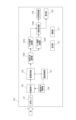
図1は、本実施形態に係る画像処理装置の一例としての撮像装置100のブロック図である。
FIG. 1 is a block diagram of an
光学レンズ101は、被写体の光を取り込み、撮像素子102に光を結像して入光するための光学レンズである。
The
撮像素子102は光学レンズ101から入射光を受け、それを電気信号へ変換し、出力する。代表的なものとして、CCDイメージセンサー(Charge Coupled Device)や、CMOSイメージセンサーなどが挙げられる。
The
これら撮像素子102から出力される映像信号は、アナログの映像信号を直接出力するものと、撮像素子102の内部でAD(アナログデジタル)変換処理を行い、LVDS(Low voltage differential signaling)をはじめとするデジタルデータで出力するものがある。
The video signals outputted from the
ここで、本発明で用いる撮像素子の一例として、撮像素子の各ブロックを図2に示す。 Here, each block of the image sensor is shown in FIG. 2 as an example of the image sensor used in the present invention.
タイミング・パルス制御部201はこの撮像素子の各ブロックに対する動作CLKを供給したり、各ブロックにタイミング信号を供給したりして、撮像素子の動作を制御するものである。
The timing
垂直走査回路202は、2次元に配置された画素部203が有した画素信号電圧を、1フレーム中に順次読み出しするためのタイミング制御を行う。一般的に、映像信号は1フレーム中に上部の行から下部の行にかけて、行単位で順次読み出される。本実施形態では、画素部から位相差情報を出力するかどうかを選択することができる。
The
画素部203は、入射光量に応じて光電変換し、電圧として出力する光電変換素子である。列アンプ204は、画素部203から読み出された信号を電気的に増幅するために用いられる。列アンプ204で信号を増幅することにより、それ以降の列ADC205(Analog Digital Convertor)の出すノイズに対して、画素の信号レベルを増幅し、等価的にSNを改善させるものである。また、タイミング・パルス制御部から、列アンプ204のゲインを変更できるような構造となっている。
The
本実施形態における撮像素子102では、画像合成用として、列アンプ204に入力メモリを2つ持ち、列アンプゲインを変更して2種類のゲインを出力することが可能である。入力メモリを2つ持つことで、フォトダイオードから読み出されたある時刻の信号に対して2つのゲインをかけて出力できるため、データ量は増えるものの、同時性を持ったゲインの異なる2つの画像を得ることができる。
In the
列ADC205は、列アンプ204からの読み出し信号をAD変換する。デジタル化された信号は水平転送回路206により順次読みだされる。水平転送回路206の出力は信号処理回路207に入力される。信号処理回路207はデジタル的に信号処理を行う回路であり、デジタル処理で一定量のオフセット値を加えるほかに、シフト演算や乗算を行うことで、簡易にゲイン演算を行うことができる。また、画素部203に、意図的に遮光した画素領域を持つことで、これを利用したデジタルの黒レベルクランプ動作を行っても良い。
The column ADC 205 performs AD conversion on the read signal from the
信号処理回路207の出力は、外部出力回路208に渡される。外部出力回路208はシリアライザー機能を有し、信号処理回路207からの多ビットの入力パラレル信号をシリアル信号に変換する。また、このシリアル信号を、例えばLVDS信号等に変換し、外部デバイスとの画像情報の受け渡しとして出力する。
The output of the
画像取得部103は、撮像素子102から出力された映像信号をキャプチャし、各処理を行うブロックから構成される。撮像素子102内部でAD変換を行わない場合は、アナログデジタル変換を行うアナログフロントエンドも含まれる。画像取得部103では、撮像素子102の固定パターンノイズの除去や、黒レベルクランプ処理などを行なう。そして、映像信号記録に使用する画像と、撮像素子制御のための評価用信号に分離する役割も備える。
The
画像合成部104は、撮像素子から出力された画像信号から、任意の合成方法で画像を合成する。画像処理部105は、撮像装置の代表的な画像処理機能となる画素加算機能やノイズリダクション、ガンマ補正、ニー、デジタルゲインなどをはじめ、キズ補正など各種画像処理を行なう。また、撮像素子102、画像取得部103、画像合成部104は撮像装置100内で複数の異なるチップとして設けられていてもよいし、積層構造を有する撮像素子として一体型に構成されていてもよい。
The
信号記録部106は、信号処理部105から受けた映像信号を記憶装置もしくは記憶媒体へ記録する。
The
露出制御部107は、画像取得部103から受けた映像信号情報から最適露光量を算出することができる。そして、撮像素子制御部108の動作を決定し制御を伝達する。
The
表示部109は、画像処理部105で処理された画像や画像に関連する情報を液晶等の表示装置に表示する。
The
操作部110は、ユーザーからの操作を受け付け制御部111に動作指示を行う入力部としての各種操作部材であり、シャッターボタン、電子ダイヤル、電源スイッチ、十字キー、ボタン、タッチパネル等が含まれる。なお、タッチパネルは、表示部109の液晶に重ね合わせて構成され、接触された位置に応じた座標情報が出力されるようにした入力デバイスである。
The
次に、画像生成時の撮像素子102の動作と、画像合成部104について記述する。
Next, the operation of the
前述したように、本実施形態の撮像素子102は、画像を生成するために列アンプゲインを変更して出力することができる。図3は、撮像素子102から出力された2種類のゲインがかかった2枚の画像について、画像合成部104で行う処理についての詳細なブロック図である。2枚の画像について、相対的に高いゲインがかかった画像をHigh Gain画像(以下、H画像)、相対的に低いゲインがかかった画像をLow Gain画像(以下、L画像)とする。
As described above, the
合成方法選択部1041は、画像の合成方法を選択する処理部である。本実施形態では合成画像選択部1041はL画像の輝度値の分布から自動で合成方法を選択する。しかし、これに限らずH画像の輝度値の分布から合成方法を選択、あるいは撮像装置100に設けられた操作部110を介して、ユーザーが手動で合成方法選択部1041での合成方法を選択的に設定する構成としてもよい。これらのいずれで合成方法を選択するかをモード設定で選択できるように構成してもよい。
The compositing
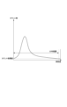
合成方法選択部1041は初めにL画像の各画素の輝度値を算出する。ここで、CCDセンサやCMOSセンサは各画素が色情報を1種類しか持たないベイヤー配列という構造を採ることが多い。そこで、本実施形態では各画素の輝度値を算出する際に、その画素が持たない色情報については近隣画素の情報で補間する。そして、各色情報に対し、既定の係数を乗ずることで輝度値を算出する。ただし輝度の算出方法に関するアルゴリズムは任意のものでよく、上記手段に限定されない。合成方法選択部1041は算出した各画素の輝度から、L画像の輝度値の分布(輝度値のヒストグラム)を算出する。図4は輝度値の分布のイメージ図であり、図の横軸は輝度値、縦軸は画像内の各輝度値のカウント数を示している。
The synthesis
つぎに合成方法選択部1041は輝度の分布範囲を決定する。ここで本実施形態の分布範囲は、カウント数閾値を超えるカウント数をもつ最低輝度と最高輝度の間の距離(輝度値の差)とする。図4中にカウント数閾値と分布範囲のイメージを示す。ここで、カウント数閾値とは、分布範囲の計算をする際に計算に使用する最低カウント数の閾値である。カウント数閾値を使用してカウント数の小さい輝度領域を分布範囲から排除するのは、ノイズなどの領域を排除するためである。
Next, the synthesis
さらに合成方法選択部1041は、決定した輝度の分布範囲を基に合成方法を暗部優先合成、明部優先合成、明部優先ノンリニア合成の少なくとも2つの中から1つ選択する。
Furthermore, the compositing
ここで、各合成方法について説明する。図5(a)から(c)は暗部優先合成のイメージ図であり、図6(a)から(c)は明部優先合成のイメージ図であり、図7(a)から(d)は明部優先ノンリニア合成のイメージ図である。ここで、図5から図7のそれぞれの図は入力光量とデジタルデータの対応関係を示している。また図5から図7中の破線は合成前の1枚の画像のみで表現できる最大値を示している。 Here, each synthesis method will be explained. Figures 5(a) to (c) are conceptual diagrams of dark area priority compositing, Figures 6(a) to (c) are conceptual diagrams of bright area priority compositing, and Figures 7(a) to (d) are conceptual diagrams of bright area priority compositing. It is an image diagram of nonlinear composition. Here, each of the figures from FIG. 5 to FIG. 7 shows the correspondence between the amount of input light and digital data. Furthermore, the broken lines in FIGS. 5 to 7 indicate the maximum value that can be expressed with only one image before composition.
暗部優先合成は、H画像の露出をL画像に合わせる合成方法である。図5(b)に示すように、H画像に値が小さくなるゲインを適用した画像(H2画像とする)を生成し、合成の際は暗部領域にはH2画像を使用し、明部領域にはL画像を使用する。ここでH2画像は値が小さくなるゲインが適用されるためノイズの値も小さくなっている。本実施形態では、暗部領域と明部領域はあらかじめ設定されているとする。また本実施形態では暗部領域はH2画像、明部領域はL画像を使用しているが、輝度に応じてH画像とL2画像を合成して使用してもよい。このような合成方法を使用することで、合成前よりも暗部領域のノイズを減少させた合成画像を生成することが出来る。本実施形態では輝度が低い領域はH画像、輝度が高い領域はL2画像を使用しているが、輝度に応じてH画像とL2画像を合成して使用してもよい。 Dark area priority compositing is a compositing method that matches the exposure of the H image to the L image. As shown in Figure 5(b), an image (called an H2 image) is generated by applying a gain that decreases the value to the H image, and when compositing, the H2 image is used for dark areas and the H2 image is used for bright areas. uses the L image. Here, since the H2 image is applied with a gain that reduces the value, the noise value is also small. In this embodiment, it is assumed that the dark area and the bright area are set in advance. Further, in this embodiment, the H2 image is used for the dark area and the L image is used for the bright area, but the H image and the L2 image may be combined and used depending on the brightness. By using such a compositing method, it is possible to generate a composite image with less noise in dark areas than before compositing. In this embodiment, the H image is used for areas with low brightness, and the L2 image is used for areas with high brightness, but the H image and L2 image may be combined and used depending on the brightness.
明部優先合成は、L画像の露出をH画像に合わせる合成方法である。図6(b)に示すように、L画像に値が大きくなるゲインを適用した画像(L2画像とする)を生成し、合成の際は暗部領域にはH画像を主に使用し、明部領域にはL2画像を主に使用する。本実施形態では暗部領域はH画像、明部領域はL2画像を使用しているが、輝度に応じてH画像とL2画像を合成して使用してもよい。このような合成方法を使用することで、合成前は表現が出来なかった明部の階調を表現可能な画像を生成することが出来る。しかしながら、図6(c)に示すようにデジタルデータが1枚の画像のみで表現できる最大値を超えるような場合は、そのデータを表現するために必要なデジタルデータのbit数が合成前よりも大きくなる。 Bright area priority compositing is a compositing method that matches the exposure of the L image to the H image. As shown in Fig. 6(b), an image (referred to as L2 image) is generated by applying a gain that increases the value to the L image, and when compositing, the H image is mainly used for dark areas and the bright area is The L2 image is mainly used for the area. In this embodiment, the H image is used for the dark area and the L2 image is used for the bright area, but the H image and the L2 image may be combined and used depending on the brightness. By using such a compositing method, it is possible to generate an image that can express gradations in bright areas that could not be expressed before compositing. However, as shown in Figure 6(c), if the digital data exceeds the maximum value that can be expressed with only one image, the number of bits of digital data required to express the data will be lower than before synthesis. growing.
明部優先ノンリニア合成は、明部優先合成と同じくL画像の露出をH画像に合わせる合成方法であるが、図7(b)に示すように明部優先合成と異なりL画像、H画像を非リニア画像に変換して(それぞれLn画像、Hn画像とする)から合成する合成方法である。前述したように明部優先合成では合成後のデータのbit数が合成前よりも大きくなることがあるが、この際bit幅が大きくなると画像処理装置が扱うことが出来るデータ幅を超えてしまうといったことが生じうる。そこで、合成前にH画像とL画像を非リニア画像に変換することで、合成後のデータのbit幅の拡大を抑えつつ、合成前は表現が出来なかった明部の階調を表現可能な画像を生成することが出来る。 Bright area priority non-linear compositing is a compositing method that matches the exposure of the L image to the H image like bright area priority compositing, but as shown in Figure 7(b), unlike bright area priority compositing, the L image and H image are This is a synthesis method in which images are converted into linear images (respectively Ln and Hn images) and then synthesized. As mentioned above, in bright area priority compositing, the number of bits of the data after compositing may be larger than before compositing, but in this case, if the bit width becomes large, it will exceed the data width that the image processing device can handle. things can happen. Therefore, by converting the H and L images into non-linear images before compositing, it is possible to suppress the expansion of the bit width of the data after compositing, and express the gradation of bright areas that could not be expressed before compositing. Images can be generated.
図8に合成方法選択部1041の合成方法選択の処理を示したフローチャートを示す。図8中の範囲閾値1、範囲閾値2はあらかじめ設定されている分布範囲の値であって、範囲閾値1はL画像の露出をH画像に合わせるか、H画像の露出をL画像に合わせるかの閾値となる。範囲閾値2は合成前にノンリニアへ変換するかしないかの閾値となる。
FIG. 8 shows a flowchart showing the process of selecting a synthesis method by the synthesis
(STEP8-1)
合成方法選択部1041は輝度の分布範囲が、分布範囲閾値1より小さい場合は、STEP8-2に進んで合成方法として暗部優先合成を選択する。
(STEP 8-1)
If the luminance distribution range is smaller than the distribution range threshold 1, the synthesis
(STEP8-3)
合成方法選択部1041は輝度の分布範囲が分布範囲閾値1以上であり、分布範囲閾値2より小さい場合はSTEP8-4に進み明部優先合成を選択する。合成方法選択部1041は、輝度の分布範囲が分布範囲閾値2以上であればSTEP8-5に進み明部優先ノンリニア合成を選択する。また、上記実施形態に限らず、分布範囲閾値1を境に暗部優先合成と明部優先ノンリニア合成とを選択してもよいし、分布範囲閾値2を境に明部優先合成と明部優先ノンリニア合成を選択してもよい。
(STEP 8-3)
If the luminance distribution range is equal to or greater than the distribution range threshold 1 and smaller than the distribution range threshold 2, the synthesis
合成方法選択部1041は、合成方法を選択後、合成方法情報を暗部優先合成部1042、明部優先合成部1043、明部優先ノンリニア合成部1044へ出力する。合成方法情報には合成に必要な情報や合成をするか否かを示す合成フラグ情報が含まれている。
After selecting the combining method, the combining
合成情報を受け取った暗部優先合成部1042、明部優先合成部1043、明部優先ノンリニア合成部1044は合成フラグ情報が合成する設定となっていた場合、画像の合成を行う。明部優先合成部1042は、入力されたH画像とL画像と画像情報に基づき、明部優先合成方法によって画像を合成し、合成した画像を出力する。暗部優先合成部1043は、入力されたH画像とL画像と画像情報に基づき、暗部優先合成方法によって画像を合成し、合成した画像を出力する。明部優先ノンリニア合成部1044は、入力されたH画像とL画像と画像情報に基づき、明部優先ノンリニア合成方法によって画像を合成し、合成した画像を出力する。
The dark area
以上のように、本実施形態では、異なる複数のゲインで生成される画像の合成方法を適応的に選択可能な構成とすることで、より被写体に適した合成方法を提供できる。 As described above, in this embodiment, by adopting a configuration in which the method of combining images generated with a plurality of different gains can be adaptively selected, it is possible to provide a combining method that is more suitable for the subject.
(第2の実施形態)
以下に、本発明の好ましい実施の形態を、添付の図面に基づいて詳細に説明する。
(Second embodiment)
Hereinafter, preferred embodiments of the present invention will be described in detail based on the accompanying drawings.
図9は、本実施形態の画像処理装置の一例としての撮像装置のブロック図である。ここで図1と同じ番号のものに関しては第1の実施形態と同様の処理部であるので説明を省略する。 FIG. 9 is a block diagram of an imaging device as an example of the image processing device of this embodiment. Here, the parts with the same numbers as those in FIG. 1 are the same processing parts as in the first embodiment, so the explanation will be omitted.
本実施形態の撮像装置は、静止画と動画を撮影可能な撮像装置である。本実施形態では、操作部110を介して行う設定によって、静止画撮影において、撮影した画像をリニア画像であるRAW画像とノンリニア画像であるJPEG画像のどちらか一方のみ残すか、または両方残すかを設定可能である。操作部110を介して行う設定によって、動画撮影においては、上記選択に加えて記録される動画のフレームレートも設定可能であることを特徴とする。
The imaging device of this embodiment is an imaging device that can take still images and moving images. In this embodiment, settings made via the
操作部110は、ユーザーからの合成方法の指示を受け付けるインタフェースを持ち、撮像装置に設定可能な項目について設定を行う。本実施形態の撮像装置では少なくとも下記の設定が可能である。
・静止画撮影時の記録の設定(RAW画像を記録するか、JPEG画像を記録するか、両方とも記録するかを設定可能である)
・動画撮影時のフレームレートの設定(本実施形態では30FPS、60FPS、240FPSを設定可能である)
操作部110は、受け付けた設定項目情報を制御部111に出力し、制御部111は合成方法選択部1002に設定する。
The
- Recording settings when shooting still images (You can set whether to record RAW images, JPEG images, or both)
・Setting the frame rate when shooting a video (30FPS, 60FPS, and 240FPS can be set in this embodiment)
The
合成方法選択部1002は、画像の合成方法を選択する処理部である。本実施形態では合成方法選択部1002は、画像取得部103から入力された画像と、操作部110から入力された設定項目情報から画像の合成方法を選択する。選択可能な合成方法はRAW合成とYUV合成であり、RAW合成はリニア画像の状態でリニア空間で行う合成処理、YUV合成はノンリニア画像の状態(YUVフォーマット)でノンリニア空間で行う合成処理となる。本実施形態のRAW合成は、合成前よりも暗部のノイズ低減を目的とする処理である。また合成したRAWをファイルとして残すことが出来る。本実施形態のYUV合成は合成前よりも明部の階調表現を豊かにすることを目的とする処理である。RAWでの合成は行わないため、合成後のRAWをファイルとして残すことが出来ないが、処理速度はRAW合成よりも高速である。合成方法選択部1002が合成方法としてRAW合成を選択した場合はRAW画像合成部1003へ、YUV合成を選択した場合はYUV画像合成部1004へ画像などを出力する。
The compositing
ここで、合成方法選択部1002の合成方法の選択のフローを図10に示し、下記に各処理について説明を行う。
Here, the flow of selection of a synthesis method by the synthesis
(STEP10-1)
合成方法選択部1002は、設定項目情報から静止画撮影かどうかを判定する。静止画撮影であればSTEP10―2へ進む。静止画撮影でない場合はSTEP10-4へ進む。
(STEP10-1)
The composition
(STEP10-2)
合成方法選択部1002は、入力されたL画像から画像のダイナミックレンジを算出する。ここで本実施形態でのダイナミックレンジは画像内の最低輝度と最高輝度の差とするが、ダイナミックレンジの算出方法はこれに限定されない。合成方法選択部1002は、算出したダイナミックレンジとあらかじめ設定されているダイナミックレンジ閾値を比較し、ダイナミック閾値未満であればSTEP10-6へ進む。ダイナミックレンジがダイナミック閾値以上であればSTEP10-7へ進む。
(STEP10-2)
The synthesis
(STEP10-3)
合成方法選択部1002は、設定項目情報からRAWを残す設定かどうかを判定する。RAWを残す設定であればSTEP10-6へ進む。RAWを残す設定でない場合はSTEP10―7へ進む。
(STEP10-3)
The compositing
(STEP10-4)
合成方法選択部1002は、入力されたL画像から画像のダイナミックレンジを算出する。ここで本実施形態でのダイナミックレンジは画像内の最低輝度と最高輝度の差とするが、ダイナミックレンジの算出方法はこれに限定されない。合成方法選択部1002は、算出したダイナミックレンジとあらかじめ設定されているダイナミックレンジ閾値を比較し、ダイナミック閾値未満であればSTEP10-5へ進む。ダイナミックレンジがダイナミック閾値以上であればSTEP10-7へ進む。
(STEP10-4)
The synthesis
(STEP10-5)
合成方法選択部1002は、動画のフレームレートとあらかじめ設定されているフレームレート閾値を比較する。合成方法選択部1002は、動画のフレームレートがフレームレート閾値未満であればSTEP10-6へ進む。動画のフレームレートがフレームレート閾値以上であればSTEP10-7へ進む。
(STEP10-5)
The compositing
(STEP10-6)
合成方法選択部1002は、合成方法としてRAW合成を選択する。
(STEP10-6)
The combining
(STEP10-7)
合成方法選択部1002は、合成方法としてYUV合成を選択する。
(STEP10-7)
The synthesis
RAW画像合成部1003は、RAWで画像合成を行い、また画像処理を行う処理部である。合成時はH画像に対してゲインを適用しL画像に露出を合わせる。ここでH画像にゲインを適用した画像を(H2画像とする)。そして暗部領域にはH2画像を使用し、明部領域にはL画像を使用するように合成を行う。またRAW画像合成部は合成したRAW画像をYUV画像へと変換する。ここでRAW画像合成部1003は合成前のRAW画像、合成後のRAW画像、YUV画像に対して各種画像処理を行うことが可能である。RAW画像合成部は合成したRAW画像とYUV画像を画像処理部3へ出力する。
The RAW
YUV画像合成部1004は、YUVで画像合成を行い、また画像処理を行う処理部である。YUV画像合成部はH画像、L画像をYUV画像へ変換する(それぞれHY画像、LY画像とする)。そしてLY画像に対してゲインを適用しHY画像に露出を合わせる(LY2画像とする。)そして暗部領域にはLH画像を使用し、明部領域にはLY2画像を使用するように合成を行う。ここでYUV画像合成部1004は合成前のRAW画像、合成前のYUV画像、合成後のYUV画像に対して各種画像処理を行うことが可能である。YUV画像合成部1004は合成したYUV画像を画像処理部3へ出力する。
The YUV
画像処理部1005は、入力されたYUV画像に対して画像処理を行う処理部である。画像処理部1005は入力されたYUV画像に対して種々の画像処理を行い、YUV画像と入力されていればRAW画像とを信号記録部106へ出力する。
The
以上のように、本実施形態では、撮影時の設定に応じて合成方法を選択することで、より被写体に適した合成方法を提供し、画質のよい合成画像を提供することができる。 As described above, in this embodiment, by selecting a compositing method according to the settings at the time of photographing, it is possible to provide a compositing method more suitable for the subject and to provide a composite image with good image quality.
以上、本発明の好ましい実施形態について説明したが、本発明はこれらの実施形態に限定されず、その要旨の範囲内で種々の変形及び変更が可能である。 Although preferred embodiments of the present invention have been described above, the present invention is not limited to these embodiments, and various modifications and changes can be made within the scope of the invention.
(他の実施形態)
本発明の目的は以下のようにしても達成できる。すなわち、前述した各実施形態の機能を実現するための手順が記述されたソフトウェアのプログラムコードを記録した記憶媒体を、システムまたは装置に供給する。そしてそのシステムまたは装置のコンピュータ(またはCPU、MPU等)が記憶媒体(記録媒体)に格納されたプログラムコードを読み出して実行するのである。
(Other embodiments)
The object of the present invention can also be achieved as follows. That is, a storage medium recording a software program code in which a procedure for realizing the functions of each of the embodiments described above is recorded is supplied to the system or device. Then, the computer (or CPU, MPU, etc.) of that system or device reads and executes the program code stored in the storage medium (recording medium).
この場合、記憶媒体から読み出されたプログラムコード自体が本発明の新規な機能を実現することになり、そのプログラムコードを記憶した記憶媒体およびプログラムは本発明を構成することになる。 In this case, the program code read from the storage medium itself realizes the novel function of the present invention, and the storage medium and the program storing the program code constitute the present invention.
また、プログラムコードを供給するための記憶媒体としては、例えば、フレキシブルディスク、ハードディスク、光ディスク、光磁気ディスクなどが挙げられる。また、CD-ROM、CD-R、CD-RW、DVD-ROM、DVD-RAM、DVD-RW、DVD-R、磁気テープ、不揮発性のメモリカード、ROM等も用いることができる。 Furthermore, examples of storage media for supplying program codes include flexible disks, hard disks, optical disks, magneto-optical disks, and the like. Further, CD-ROM, CD-R, CD-RW, DVD-ROM, DVD-RAM, DVD-RW, DVD-R, magnetic tape, nonvolatile memory card, ROM, etc. can also be used.
また、コンピュータが読み出したプログラムコードを実行可能とすることにより、前述した各実施形態の機能が実現される。さらに、そのプログラムコードの指示に基づき、コンピュータ上で稼動しているOS(オペレーティングシステム)等が実際の処理の一部または全部を行い、その処理によって前述した各実施形態の機能が実現される場合も含まれる。 Moreover, the functions of each of the embodiments described above are realized by making the program code read by the computer executable. Further, based on the instructions of the program code, an OS (operating system) etc. running on the computer performs some or all of the actual processing, and the functions of each embodiment described above are realized by that processing. Also included.
更に、以下の場合も含まれる。まず記憶媒体から読み出されたプログラムコードが、コンピュータに挿入された機能拡張ボードやコンピュータに接続された機能拡張ユニットに備わるメモリに書き込まれる。その後、そのプログラムコードの指示に基づき、その機能拡張ボードや機能拡張ユニットに備わるCPU等が実際の処理の一部または全部を行う。 Furthermore, the following cases are also included. First, a program code read from a storage medium is written into a memory provided in a function expansion board inserted into a computer or a function expansion unit connected to the computer. Thereafter, a CPU or the like provided in the function expansion board or function expansion unit performs part or all of the actual processing based on instructions from the program code.
また、本発明はデジタルカメラのような撮影を主目的とした機器にかぎらず、携帯電話、パーソナルコンピュータ(ラップトップ型、デスクトップ型、タブレット型など)、ゲーム機など、撮像装置を内蔵もしくは外部接続する任意の機器に適用可能である。従って、本明細書における「撮像装置」は、撮像機能を備えた任意の電子機器を包含することが意図されている。 Furthermore, the present invention is applicable not only to devices whose main purpose is photography such as digital cameras, but also to mobile phones, personal computers (laptops, desktops, tablets, etc.), game consoles, and other devices that have built-in or externally connected imaging devices. Applicable to any equipment that Therefore, the "imaging device" in this specification is intended to include any electronic device with an imaging function.
100 撮像装置
101 光学レンズ
102 撮像素子
103 画像取得部
104 画像合成部
105 信号処理部
106 信号記録部
107 露出制御部
108 撮像素子制御部
1041 合成方法選択部
1042 明部優先合成部
1043 暗部優先合成部
1044 明部優先ノンリニア合成部
100
Claims (15)
前記複数の画像のうち、第1の画像にその他の画像の明るさを合わせて合成する第1の合成手段と、
前記複数の画像の前記第2の画像よりも明るい第2の画像にその他の画像の明るさを合わせて合成する第2の合成手段と、
前記取得手段で取得される複数の画像に前記第1の合成手段と前記第2の合成手段による合成とのいずれで合成するかの選択を行う合成選択手段と、を有することを特徴とする画像処理装置。 an acquisition means for acquiring a plurality of images obtained by one exposure with different gains applied;
a first compositing means for composing a first image among the plurality of images by matching the brightness of the other images;
a second synthesizing means for synthesizing a second image that is brighter than the second image of the plurality of images by matching the brightness of the other images;
An image characterized by comprising: a composition selection means for selecting whether to combine the plurality of images acquired by the acquisition means between the first composition means and the second composition means. Processing equipment.
前記合成選択手段は前記入力手段で受け付けた合成方法に応じて前記選択を行うことを特徴とする請求項1乃至4のいずれか1項に記載の画像処理装置。 further comprising an input means for receiving a synthesis method input by a user;
5. The image processing apparatus according to claim 1, wherein the synthesis selection means makes the selection according to a synthesis method received by the input means.
前記第1及び第2の合成手段によって生成された合成画像を記録媒体に記録する信号記録手段と、を有することを特徴とする請求項1乃至10のいずれか1項に記載の画像処理装置。 imaging means for capturing the plurality of images;
11. The image processing apparatus according to claim 1, further comprising a signal recording means for recording the composite image generated by the first and second composition means on a recording medium.
前記複数の画像のうち、第1の画像にその他の画像の明るさを合わせて合成する第1の合成ステップと、
前記複数の画像の前記第2の画像よりも明るい第2の画像にその他の画像の明るさを合わせて合成する第2の合成ステップと、
前記取得ステップで取得される複数の画像を前記第1の合成ステップと前記第2の合成ステップでの合成とのいずれで合成するかの選択を行う選択ステップと、を有することを特徴とする画像処理装置の制御方法。 an acquisition step of acquiring multiple images with different gains applied to the image obtained by one exposure;
A first synthesis step of combining the first image with the brightness of the other images among the plurality of images;
a second synthesizing step of synthesizing a second image that is brighter than the second image of the plurality of images by matching the brightness of the other images;
An image characterized by comprising: a selection step of selecting whether to combine the plurality of images acquired in the acquisition step in the first combination step or in the second combination step. A method of controlling a processing device.
Priority Applications (3)
| Application Number | Priority Date | Filing Date | Title |
|---|---|---|---|
| JP2022030253A JP2023125900A (en) | 2022-02-28 | 2022-02-28 | Image processing device and control method for the same |
| US18/172,926 US20230276135A1 (en) | 2022-02-28 | 2023-02-22 | Image processing apparatus to combine images and method for controlling the same |
| CN202310175598.7A CN116668822A (en) | 2022-02-28 | 2023-02-28 | Image processing apparatus for synthesizing image, control method thereof, and storage medium |
Applications Claiming Priority (1)
| Application Number | Priority Date | Filing Date | Title |
|---|---|---|---|
| JP2022030253A JP2023125900A (en) | 2022-02-28 | 2022-02-28 | Image processing device and control method for the same |
Publications (1)
| Publication Number | Publication Date |
|---|---|
| JP2023125900A true JP2023125900A (en) | 2023-09-07 |
Family
ID=87717797
Family Applications (1)
| Application Number | Title | Priority Date | Filing Date |
|---|---|---|---|
| JP2022030253A Pending JP2023125900A (en) | 2022-02-28 | 2022-02-28 | Image processing device and control method for the same |
Country Status (3)
| Country | Link |
|---|---|
| US (1) | US20230276135A1 (en) |
| JP (1) | JP2023125900A (en) |
| CN (1) | CN116668822A (en) |
-
2022
- 2022-02-28 JP JP2022030253A patent/JP2023125900A/en active Pending
-
2023
- 2023-02-22 US US18/172,926 patent/US20230276135A1/en active Pending
- 2023-02-28 CN CN202310175598.7A patent/CN116668822A/en active Pending
Also Published As
| Publication number | Publication date |
|---|---|
| CN116668822A (en) | 2023-08-29 |
| US20230276135A1 (en) | 2023-08-31 |
Similar Documents
| Publication | Publication Date | Title |
|---|---|---|
| US20060232692A1 (en) | Image pickup apparatus | |
| US20070076269A1 (en) | Imaging unit and image sensor | |
| JP4622790B2 (en) | Imaging device and imaging apparatus | |
| JP5123137B2 (en) | Imaging apparatus and imaging method | |
| US7907193B2 (en) | Image capturing apparatus | |
| US20060092287A1 (en) | Signal processing apparatus and signal processing method for solid-state image pickup element and image pickup apparatus | |
| US11665446B2 (en) | Image sensing system and operating method thereof | |
| EP2214136B1 (en) | Method and program for controlling image capture apparatus | |
| JP2005072965A (en) | Image compositing method, solid-state image pickup device and digital camera | |
| JP5984975B2 (en) | Imaging apparatus, imaging method, and program | |
| JP2008124671A (en) | Imaging apparatus and imaging method | |
| JP3980781B2 (en) | Imaging apparatus and imaging method | |
| JP2010118876A (en) | Imaging apparatus, and control method thereof | |
| US20070269133A1 (en) | Image-data noise reduction apparatus and method of controlling same | |
| JP5822606B2 (en) | Image processing apparatus and image processing apparatus control method | |
| JP3730063B2 (en) | Color component generation apparatus, color component generation method, and multicolor image pickup apparatus using the same | |
| JP2023125900A (en) | Image processing device and control method for the same | |
| JP2007174160A (en) | Imaging apparatus | |
| JP4732795B2 (en) | Solid-state imaging device and image correction method | |
| JP2005277618A (en) | Photography taking apparatus and device and method for correcting shading | |
| JP2009038818A (en) | Image processing method and digital camera | |
| JP2020182057A (en) | Imaging device, imaging method, computer program, and storage medium | |
| JP4028396B2 (en) | Image composition method and digital camera | |
| JP4449692B2 (en) | Electronic camera | |
| JP5169540B2 (en) | Imaging apparatus and imaging method |
Legal Events
| Date | Code | Title | Description |
|---|---|---|---|
| RD01 | Notification of change of attorney |
Free format text: JAPANESE INTERMEDIATE CODE: A7421 Effective date: 20231213 |