JP2023125002A - Inspection device, inspection method, printing system, inspection system - Google Patents
Inspection device, inspection method, printing system, inspection system Download PDFInfo
- Publication number
- JP2023125002A JP2023125002A JP2022028901A JP2022028901A JP2023125002A JP 2023125002 A JP2023125002 A JP 2023125002A JP 2022028901 A JP2022028901 A JP 2022028901A JP 2022028901 A JP2022028901 A JP 2022028901A JP 2023125002 A JP2023125002 A JP 2023125002A
- Authority
- JP
- Japan
- Prior art keywords
- inspection
- area
- areas
- setting
- inspection device
- Prior art date
- Legal status (The legal status is an assumption and is not a legal conclusion. Google has not performed a legal analysis and makes no representation as to the accuracy of the status listed.)
- Pending
Links
- 238000007689 inspection Methods 0.000 title claims abstract description 351
- 238000007639 printing Methods 0.000 title claims abstract description 37
- 238000000034 method Methods 0.000 title claims description 42
- 238000012360 testing method Methods 0.000 description 55
- 230000008569 process Effects 0.000 description 28
- 230000007547 defect Effects 0.000 description 25
- 238000012545 processing Methods 0.000 description 20
- 238000007726 management method Methods 0.000 description 16
- 238000012795 verification Methods 0.000 description 11
- 238000003825 pressing Methods 0.000 description 10
- 230000002950 deficient Effects 0.000 description 9
- 238000004891 communication Methods 0.000 description 7
- 238000010586 diagram Methods 0.000 description 7
- 239000000463 material Substances 0.000 description 7
- 230000008859 change Effects 0.000 description 6
- 230000007704 transition Effects 0.000 description 6
- 238000012805 post-processing Methods 0.000 description 4
- 238000013524 data verification Methods 0.000 description 3
- 238000001514 detection method Methods 0.000 description 3
- 238000006243 chemical reaction Methods 0.000 description 2
- 238000004040 coloring Methods 0.000 description 2
- 230000000694 effects Effects 0.000 description 2
- 230000002093 peripheral effect Effects 0.000 description 2
- 230000015572 biosynthetic process Effects 0.000 description 1
- 239000003086 colorant Substances 0.000 description 1
- 230000007423 decrease Effects 0.000 description 1
- 238000005516 engineering process Methods 0.000 description 1
- 238000005755 formation reaction Methods 0.000 description 1
- 230000009467 reduction Effects 0.000 description 1
- 238000012552 review Methods 0.000 description 1
Images


Classifications
-
- G—PHYSICS
- G06—COMPUTING; CALCULATING OR COUNTING
- G06F—ELECTRIC DIGITAL DATA PROCESSING
- G06F3/00—Input arrangements for transferring data to be processed into a form capable of being handled by the computer; Output arrangements for transferring data from processing unit to output unit, e.g. interface arrangements
- G06F3/12—Digital output to print unit, e.g. line printer, chain printer
- G06F3/1201—Dedicated interfaces to print systems
- G06F3/1202—Dedicated interfaces to print systems specifically adapted to achieve a particular effect
- G06F3/1203—Improving or facilitating administration, e.g. print management
- G06F3/1208—Improving or facilitating administration, e.g. print management resulting in improved quality of the output result, e.g. print layout, colours, workflows, print preview
-
- G—PHYSICS
- G06—COMPUTING; CALCULATING OR COUNTING
- G06F—ELECTRIC DIGITAL DATA PROCESSING
- G06F3/00—Input arrangements for transferring data to be processed into a form capable of being handled by the computer; Output arrangements for transferring data from processing unit to output unit, e.g. interface arrangements
- G06F3/12—Digital output to print unit, e.g. line printer, chain printer
- G06F3/1201—Dedicated interfaces to print systems
- G06F3/1202—Dedicated interfaces to print systems specifically adapted to achieve a particular effect
- G06F3/1211—Improving printing performance
- G06F3/1215—Improving printing performance achieving increased printing speed, i.e. reducing the time between printing start and printing end
-
- G—PHYSICS
- G06—COMPUTING; CALCULATING OR COUNTING
- G06F—ELECTRIC DIGITAL DATA PROCESSING
- G06F3/00—Input arrangements for transferring data to be processed into a form capable of being handled by the computer; Output arrangements for transferring data from processing unit to output unit, e.g. interface arrangements
- G06F3/12—Digital output to print unit, e.g. line printer, chain printer
- G06F3/1201—Dedicated interfaces to print systems
- G06F3/1223—Dedicated interfaces to print systems specifically adapted to use a particular technique
- G06F3/1237—Print job management
- G06F3/1253—Configuration of print job parameters, e.g. using UI at the client
- G06F3/1258—Configuration of print job parameters, e.g. using UI at the client by updating job settings at the printer
-
- H—ELECTRICITY
- H04—ELECTRIC COMMUNICATION TECHNIQUE
- H04N—PICTORIAL COMMUNICATION, e.g. TELEVISION
- H04N1/00—Scanning, transmission or reproduction of documents or the like, e.g. facsimile transmission; Details thereof
- H04N1/0035—User-machine interface; Control console
- H04N1/00352—Input means
- H04N1/00355—Mark-sheet input
- H04N1/00358—Type of the scanned marks
- H04N1/00363—Bar codes or the like
-
- H—ELECTRICITY
- H04—ELECTRIC COMMUNICATION TECHNIQUE
- H04N—PICTORIAL COMMUNICATION, e.g. TELEVISION
- H04N1/00—Scanning, transmission or reproduction of documents or the like, e.g. facsimile transmission; Details thereof
- H04N1/0035—User-machine interface; Control console
- H04N1/00405—Output means
- H04N1/00408—Display of information to the user, e.g. menus
- H04N1/0044—Display of information to the user, e.g. menus for image preview or review, e.g. to help the user position a sheet
Abstract
Description
本発明は、検査装置、印刷システム、検査システム及び検査方法に関する。 The present invention relates to an inspection device, a printing system, an inspection system, and an inspection method.
従来、印刷物が正しく印刷されているかを確認する検査(検品)は人手によって行われてきた。近年では、印刷機の後処理として自動で検査を行う装置が用いられている。このような検査装置(検品装置)では、印刷画像検査(絵柄検査)と呼称される印刷物の絵柄部分の欠陥を検出する検査がなされる。また、印刷画像検査と並び、データに基づいて用紙上に印刷出力する内容を変えることができるバリアブル印刷において文字列やバーコードのような可変領域部分に対するデータ検査も行われている。 Conventionally, inspections (inspections) to check whether printed materials are printed correctly have been performed manually. In recent years, devices that automatically perform inspections have been used as post-processing for printing presses. Such an inspection device (inspection device) performs an inspection called a print image inspection (picture inspection) to detect defects in the pattern portion of printed matter. In addition to print image inspection, data inspection is also performed on variable area portions such as character strings and barcodes in variable printing, in which the content printed on paper can be changed based on data.
絵柄検査およびデータ検査では、はじめにユーザが検査対象の領域を設定する。そして、設定された領域に対して、絵柄検査およびデータ検査を印刷シートの搬送中に行う。印刷シートが欠陥シートであると判定された場合には、当該欠陥シートは正常シートとは別の排紙先に排紙することが出来る。 In pattern inspection and data inspection, the user first sets the area to be inspected. Then, a pattern inspection and a data inspection are performed on the set area while the print sheet is being conveyed. If it is determined that the printed sheet is a defective sheet, the defective sheet can be discharged to a different destination from that for normal sheets.
印刷機の後処理として自動で検査を行う印刷システムにおいては、正常シートと欠陥シートの排紙先を切り替える制御を行うため、印刷された各シートが搬送されて検査装置を通過する間に該印刷シートの検査を完了する必要がある。つまり、印刷シートごとに検査にかけることのできる制限時間がある。自動で検査を行う印刷システムにおいて、検査対象の領域を多く設定すると検査処理にかかる時間が増え、制限時間内に印刷シートの検査を完了できないという課題がある。特許文献1には、検査対象の印刷オブジェクト情報(オブジェクト種別、色、サイズ)に基づき検査対象の優先度を算出し、優先度に従って予め定められた制限時間内に実施可能な分だけ検査する方法が提案されている。
In a printing system that automatically performs inspection as post-processing of a printing machine, control is performed to switch the output destination of normal sheets and defective sheets. Seat inspection must be completed. In other words, there is a time limit in which each printed sheet can be inspected. In a printing system that automatically performs inspection, there is a problem in that when a large number of areas to be inspected are set, the time required for inspection processing increases, making it impossible to complete inspection of a printed sheet within a time limit.
しかしながら、特許文献1の方法では、オペレータが検査領域を設定する際に、制限時間内に検査を完了できる範囲で検査領域を設定することができているのかがわからないという問題点があった。
However, the method disclosed in
そこで、本発明は上記問題点を鑑みてなされたものであり本実施形態の1つの目的は、オペレータが検査領域を設定する際に、制限時間内に印刷シートの検査を完了可能な検査領域数を把握した上で、検査領域の設定が可能な検査装置を提供することである。 Therefore, the present invention has been made in view of the above-mentioned problems, and one purpose of the present embodiment is to determine the number of inspection areas that can be inspected on a printed sheet within a time limit when an operator sets an inspection area. An object of the present invention is to provide an inspection device that can set an inspection area based on the understanding of the following.
本発明の検査装置は、表示部に情報を表示する表示制御手段と、検査対象のオブジェクトを含む1または複数の領域を設定する設定手段と、前記設定手段で設定された領域に含まれているオブジェクトから読み取られるデータを検査する検査手段と、前記表示制御手段は、前記検査装置で検査が可能な上限を認識可能とした図形を表示し、前記設定手段で1または複数の領域が設定されると、前記設定された領域に含まれるオブジェクトのデータ量に基づく値をグラフに表示することを特徴とする。 The inspection device of the present invention includes a display control means for displaying information on a display section, a setting means for setting one or more areas including an object to be inspected, and a region included in the area set by the setting means. An inspection means for inspecting data read from an object, and the display control means display a figure that makes it possible to recognize an upper limit that can be inspected by the inspection device, and one or more areas are set by the setting means. and a value based on the data amount of the object included in the set area is displayed in a graph.
本発明によれば、オペレータが検査領域を設定する際に、制限時間内に印刷シートの検査を完了可能な検査領域数を把握した上で、検査を行いたい検査領域の設定が可能である。 According to the present invention, when an operator sets an inspection area, it is possible to set the inspection area to be inspected after grasping the number of inspection areas that can be inspected on a printed sheet within a time limit.
添付図面を参照して本実施例の各実施例を詳しく説明する。なお、以下の実施例は特許請求の範囲に係る発明を限定するものではなく、また各実施例で説明されている特徴の組み合わせのすべてが本実施例の解決手段に必須のものとは限らない。 Each embodiment of this embodiment will be described in detail with reference to the accompanying drawings. Note that the following examples do not limit the claimed invention, and not all combinations of features described in each example are essential to the solution of this example. .
以下の説明において、画像形成装置は、複合機、マルチファンクションペリフェラル、MFP(Multi Function Peripheral)と呼ばれることもある。 In the following description, the image forming apparatus may also be referred to as a multifunction peripheral, MFP (Multi Function Peripheral).
以下、本実施形態の前提の技術を説明する。本実施例における検査装置では、はじめに、正解画像(基準画像)データを登録する。次に、入稿画像データを画像形成装置で用紙上に印刷出力する。続いて、検査装置内部に構成した検査センサにより用紙上に印刷出力された印刷物を読み取る。検査センサで読み取った画像データと、最初に登録した正解画像データとを比較することで印刷物の欠陥を検出する。該印刷物の絵柄部分の欠陥を検出する検査を印刷画像検査(絵柄検査)と呼称する。 The technology underlying this embodiment will be described below. In the inspection apparatus in this embodiment, first, correct image (reference image) data is registered. Next, the submitted image data is printed out on paper using an image forming apparatus. Subsequently, the printed matter printed on the paper is read by an inspection sensor configured inside the inspection device. Defects in printed matter are detected by comparing the image data read by the inspection sensor with the initially registered correct image data. The inspection for detecting defects in the picture portion of the printed matter is called a print image inspection (picture inspection).
また、印刷画像検査と並び、バリアブル印刷において文字列やバーコードのような可変領域部分の検査も行われている。例えば、文字列やバーコードが読み取り可能かどうかをチェックするデータ可読検査や、文字列やバーコードの読み取り結果を正解データと照合するデータ照合検査があげられる。該データ可読検査、及びデータ照合検査をデータ検査と呼称する。なお、バリアブル印刷とは、データに基づいて用紙上に印刷出力する内容を変えることができる印刷のことを指す。正解データは、予め用意されており、例えばCVSファイルなどを指定することで用意される。 In addition to print image inspection, inspection of variable area parts such as character strings and barcodes is also performed in variable printing. Examples include a data readability test that checks whether character strings and barcodes can be read, and a data verification test that checks the reading results of character strings and barcodes against correct data. The data readability test and data verification test are referred to as data tests. Note that variable printing refers to printing in which the content printed on paper can be changed based on data. The correct answer data is prepared in advance, for example, by specifying a CVS file or the like.
絵柄検査およびデータ検査を印刷シートの搬送中に行うことにより、印刷シートが欠陥シートであると判定された場合には、当該欠陥シートは正常シートとは別の排紙先に排紙することが出来る。これにより欠陥シートが正常シートに混入することが防がれ、オペレータが欠陥シートを廃棄することが可能となる。 If the printed sheet is determined to be defective by performing pattern inspection and data inspection while the printed sheet is being transported, the defective sheet can be ejected to a different destination from normal sheets. I can do it. This prevents defective sheets from mixing with normal sheets, and allows the operator to discard defective sheets.
(実施形態1)
図1は、実施形態にかかわる、検査装置を含むシステム構成を示す図である。100は画像形成装置、110は検査装置、120はフィニッシャ、130はクライアントPC、140はプリントサーバ、150はネットワークを示す。
(Embodiment 1)
FIG. 1 is a diagram showing a system configuration including an inspection device according to an embodiment. 100 is an image forming apparatus, 110 is an inspection apparatus, 120 is a finisher, 130 is a client PC, 140 is a print server, and 150 is a network.
画像形成装置100は、各種の入力データ、例えばクライアントPC130やプリントサーバ140から送られる印刷データをもとに、印刷出力を行う。
The
検査装置110は、画像形成装置100から出力される印刷物を受け取り、受け取った印刷物に対して欠陥があるか否かの検査を行う。ここで、欠陥とは、印刷物の品質を低下させるものであり、例えば、印刷する際に意図しない箇所に色材が付着することで発生する汚れや、意図した箇所に十分な色材が付着しないことで発生する色抜けのことである。
The
さらに、検査装置110は、バリアブル印刷において文字列やバーコードのような可変領域部分の検査を行う。例えば、文字列やバーコードが読み取り可能かどうかをチェックするデータ可読検査や、文字列やバーコードの読み取り結果を正解と照合するデータ照合検査があげられる。つまり、検査装置110は、前述したように印刷画像検査、及びデータ検査を行う。
Furthermore, the
フィニッシャ120は、検査装置110で検査された出力用紙を受け取り、検査装置110の検査結果をもとに排紙先を切り替え、必要に応じて後処理(本綴じ等)を行い、排紙する。
The
画像形成装置100は、ネットワーク150を介してクライアントPC130やプリントサーバ140、また、通信ケーブルを介して検査装置110及びフィニッシャ120と接続している。検査装置110は、画像形成装置100以外に、フィニッシャ120とも通信ケーブルを介して繋がっている。本実施例は、画像形成、検査、後処理、排紙までを一貫して行うインライン検査機を示している。なお、本実施例では、少なくとも、画像形成装置100と検査装置110とを合わせて印刷システムと呼ぶ。
The
[画像形成装置の構成図]
図2は、本実施形態における画像形成装置100の内部構成を示す図である。
[Configuration diagram of image forming apparatus]
FIG. 2 is a diagram showing the internal configuration of the
コントローラ200はネットワーク150から画像や文書を受信し、受信した画像や文書を印刷データに変換する。プリンタ部210は印刷データを記録シート(用紙、シート)に印刷を行う。UI部220は、画像形成装置100に対するオペレータからの指示を受け付ける。画像形成装置100は、上述のコントローラ200、プリンタ部210、UI部220で構成されている。
以下説明する201~208は、コントローラ200の構成要素である。ネットワークI/F(インターフェース)部201はネットワーク150とデータの送受信を行う。CPU202は画像形成装置100全体の制御を行う。RAM203はCPU202が各種の命令を実行する際にワークエリアである。ROM204は起動時にCPU202が実行するプログラムデータ、コントローラ200の設定データ等が格納されているROMである。
201 to 208, which will be explained below, are components of the
画像処理部205は、ネットワーク150から受信した画像や文書データを印刷データに変換するためのRIP処理(Raster Image Processer)を行う。
The
エンジンI/F(インターフェース)部206は印刷データをプリンタ部210に送信する。
Engine I/F (interface) unit 206 transmits print data to
通信I/F部207は、検査装置110及びフィニッシャ120と通信する。システムバス208は内部バスである。
The communication I/
ネットワーク150上のクライアントPC130又はプリントサーバ140上で作成された画像や文書は、PDLデータとしてネットワーク(例えばLocal Area Network)を介して、画像形成装置100に送信される。送信されたPDLデータは、ネットワークI/F部201経由でRAM203に保存される。また、UI部220のオペレータによる印刷指示も、内部バス208を通じてRAM203に保存される。オペレータによる印刷指示とは、例えば、用紙種類の選択である。
Images and documents created on the client PC 130 or print server 140 on the network 150 are transmitted as PDL data to the
画像処理部205は、RAM203に保存されているPDLデータを取得し、印刷データに変換する画像処理を行う。印刷データに変換する画像処理とは、例えば、PDLデータに対してラスタライズを行い、多値のビットマップデータに変換し、スクリーン処理等を行うことで、二値のビットマップデータに変換することである。画像処理部205によって得られた二値のビットマップデータは、エンジンI/F部206経由で、プリンタ部210に送信される。
The
プリンタ部210は、受信した二値のビットマップデータを、色材を用いて記録シートにプリントする。CPU202は、RAM203に保存されているオペレータによる印刷指示にもとづいて、プリンタ部210に指示を出す。例えば、オペレータからコート紙で印刷する指示があった場合、CPU202は、プリンタ部210に画像形成装置100内のコート紙が格納されている不図示の用紙カセットから、用紙を出力するように指示を出す。上述のPDLデータの受信から、用紙にプリントされるまでの各種処理が、CPU202によって制御されることで、用紙にフルカラートナー像が形成される。
The
[検査装置110の内部構成]
図3は、検査装置110の内部構成を示す図である。検査制御部300は、検査装置110の全体の制御、および印刷物に欠陥があるか否かの検査、及び文字列やバーコードのような可変領域部分の検査を行う。ここで、可変領域は、ページごとに異なる画像が印刷される領域のことを指す。
[Internal configuration of inspection device 110]
FIG. 3 is a diagram showing the internal configuration of the
画像読み取り部310は、画像形成装置100から搬送されてきた印刷物に対して読み取りを行う。画像読み取り部310は、搬送されている印刷物に対してスキャンを実行することでスキャン画像の生成を行う。UI部320は、検査装置110に対するオペレータからの設定に関する指示受け付けと、検査結果などの表示を行う。ここで、オペレータが行う検査装置110の設定とは、印刷物を検査する際に、どのような欠陥を検査するかの項目である。検査項目とは、例えば、丸い形状の欠陥(ポチ)や、線状の欠陥(スジ)、文字列やバーコードのような可変領域部分の正誤判定のことである。検査装置110は、上述の検査制御部300、画像読み取り部310、UI部320で構成されている。なお、本実施例では、UI部320のことを表示部と呼ぶ。また、UI部320に表示する画面の制御は、表示制御手段としてのCPU302により制御されている。
The
以下説明を行う301~306は、検査制御部300の構成要素である。通信I/F(インターフェース)部301は、画像形成装置100及びフィニッシャ120とデータの通信を行う。CPU302は検査装置110全体の制御を行う。RAM303は、CPU302が各種の命令を実行する際のワークエリアである。ROM304は起動時にCPU302が実行するプログラムデータや、検査制御部300の設定データなどが格納されている。検査処理部305は印刷物に欠陥があるか否かの検査を行う。システムバス306は内部バスである。
301 to 306, which will be explained below, are the components of the
次に、検査装置110が行う印刷画像検査の概要について説明する。
Next, an overview of the print image inspection performed by the
検査装置110は、画像形成装置100から搬送されてきた印刷物を画像読み取り部310にて読み取り、検査対象のスキャン画像を取得する。取得した検査対象のスキャン画像は、RAM303に保存される。
The
続いて、検査装置110は、検査処理部305によって、予め正解画像としてRAM303に保存されている基準画像と検査対象のスキャン画像とで差分値を算出する。
Subsequently, in the
次に、検査装置110は、算出した差分値と、各検査項目の検査閾値(コントラストとサイズ)を画素毎に比較することで検査を行う。検査を行った結果は、RAM303に保存されており、例えば、印刷物に欠陥があるか否かの情報や、検出した欠陥の種類(ポチやスジ)、UI部320に表示する際の欠陥の位置情報等のことである。
Next, the
次に、検査装置110が行うデータ検査の概要について説明する。
Next, an overview of data inspection performed by the
検査装置110は、画像読み取り部310によって、画像形成装置100から搬送されてきた印刷物を読み取り、検査対象のスキャン画像を取得する。取得した検査対象のスキャン画像は、RAM303に保存される。続いて、検査装置110は、検査処理部305によって、予め設定されている文字認識(OCR)のためのフォント情報や、バーコードの規格を用いて、文字列やバーコードが読み取り可能かどうかを検査する。また、読み取った文字列やバーコードの結果と、正解データが一致するか照合を行うデータ照合検査も行うことが可能である。検査を行った結果は、RAM303に保存されており、例えば、印刷物から読み取った文字列やバーコードの結果や、正解データとの照合結果、UI部320に表示する際の読み取りした文字やバーコードの位置情報等のことである。なお、正解データは、予め検査装置110のRAM203に保存されていてもよいし、ネットワーク150を介してその都度正解データを取得し、RAM203に一時的に保存されるようにしてもよい。
The
次に、検査装置110は、CPU302によって、RAM303に保存されている検査結果を表示するようUI部320に指示する。検査結果がUI部320に表示されることで、オペレータは検査結果を認識する。
Next, the
また、検査装置110は、欠陥がある印刷物が、ある数量で連続して発生した場合、CPU302によって、通信I/F部301経由で、上記の情報を画像形成装置100に送信する。
Furthermore, when a certain number of defective printed materials occur consecutively, the
欠陥がある印刷物が連続して発生したという情報は、通信I/F部207経由でコントローラ200が受信する。コントローラ200が上記の情報を受信すると、CPU202は、プリンタ部210に印刷を停止するように指示する。画像形成装置100は、プリンタ部210に印刷停止が指示されることによって、印刷動作を停止する。
The
さらに、検査装置110は、CPU302によって、RAM303に保存されている検査結果にもとづいて、通信I/F部301経由で、フィニッシャ120にも情報を送信する。フィニッシャ120に送信される情報とは、印刷物に欠陥があるか否かの情報である。フィニッシャ120は、受信した情報を用いて、欠陥がない印刷物は通常の排紙トレイへ、欠陥がある印刷物は通常の排紙トレイとは別のトレイに排紙する。
Furthermore, the
<UI画面>
図5~図14は検査装置110のUI部320に表示される画面の一例であり、検査装置110のCPU302の指示に基づき表示される。
<UI screen>
5 to 14 are examples of screens displayed on the
本実施例における印刷システムにおける検品の工程は大きく4つに分けられる。1つ目がフォント登録工程であり、文字検査を行うためのフォント情報を登録する工程である。2つ目が基準画像登録工程であり、検査画像と比較を行うための正解画像を登録する工程である。3つ目が検査設定工程であり、検査を行う領域や検査レベル等を設定する工程である。4つ目が検査工程であり、検査ジョブに対して基準画像登録した画像と検査設定の内容に従って検査を実施する工程である。本実施例における検品はフォント登録、基準画像登録、検査設定、検査の工程順で実施される。フォント登録は図6~図9、基準画像登録は図10と図11、検査設定は図12、検査は図13と図14を用いて説明する。 The inspection process in the printing system in this embodiment can be roughly divided into four steps. The first is a font registration step, which is a step of registering font information for character inspection. The second step is a reference image registration step, which is a step of registering a correct image for comparison with the inspection image. The third step is the inspection setting step, which is a step of setting the area to be inspected, the inspection level, etc. The fourth step is an inspection process, in which an inspection is performed according to the reference image registered for the inspection job and the contents of the inspection settings. Inspection in this embodiment is performed in the order of font registration, reference image registration, inspection settings, and inspection. Font registration will be explained using FIGS. 6 to 9, reference image registration will be explained using FIGS. 10 and 11, inspection settings will be explained using FIG. 12, and inspection will be explained using FIGS. 13 and 14.
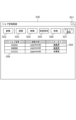
図5はUI部320に表示されるジョブ管理画面500の一例である。
FIG. 5 is an example of a
ジョブ管理画面500は、検査装置110起動時に表示される。もしくは、UI部320からオペレータ操作によってアプリケーションが起動された際に表示される。ジョブ管理画面500からフォント登録、基準画像登録、検査設定、検査のそれぞれの工程に遷移することが可能である。ボタン501は画面500の表示を消すためのボタンである。
ボタン502は新規に検査ジョブを作成するボタンであり、図10に示す基準画像登録ジョブ設定画面1000に遷移する。ボタン503は既に作成済の検査ジョブを複製するためのボタンである。検査ジョブ一覧508で選択された検査ジョブの複製を行う。複製を行うことで、基準画像や検査設定を複製し、新たに検査を実施することが出来る。ボタン504は削除ボタンであり、検査ジョブ一覧508で選択された検査ジョブを削除する。ここでは複数の検査ジョブを選択しボタン504を押下することで複数の検査ジョブを同時に削除することも可能である。
A
ボタン505は検査設定ボタンであり、基準画像登録が完了している検査ジョブの検査設定を行う。ボタン505を押下すると、図8に示す検査設定画面800に遷移する。ボタン506は検査ボタンであり、基準画像登録および検査設定が完了している検査ジョブの検査を行う。ボタン506を押下すると図9に示す検査ジョブ設定画面900に遷移する。
A
ボタン507はフォント登録ボタンであり、文字検査を行うためのフォント情報を登録するためのボタンであり、図6に示すフォント一覧画面600に遷移する。領域508は作成された検査ジョブの一覧が表示される。509は検査結果のステータスを表示する領域であり、検査が完了しているジョブは「検査済」が表記される。検査済となっている場合は、押下することで検査レポートを出力できる。
A
次に、図6~図9を用いてフォント登録について説明する。 Next, font registration will be explained using FIGS. 6 to 9.
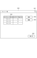
図6は登録されているフォントを確認するための検査装置110のUI部320に表示される画面の一例である。ここでは、フォントの新規登録および既に登録済のフォントの削除を行う。ボタン601は画面600の表示を消すためのボタンである。ボタン601を押下すると、図5に示すジョブ管理画面500に遷移する。なお、図6の画面600は、図5のジョブ管理画面500の上に重畳表示されるように構成されていてもよい。
FIG. 6 is an example of a screen displayed on the
ボタン602は新規にフォントを登録するためのボタンであり、ボタン602を押下すると、図7に示すフォント登録ジョブ設定画面700に遷移する。ボタン603は既に登録済のフォントを削除するためのボタンであり、フォント一覧604で削除したいフォントを選択し、ボタン603を押下することでフォント一覧604からフォントが削除される。領域604は登録されているフォントの一覧が表示される。ボタン605は画面600の表示を消すためのボタンである。ボタン605を押下すると、図5に示すジョブ管理画面500に遷移する。
A
図7はフォント登録ジョブ設定を行うための検査装置110のUI部320に表示される画面の一例である。フォント登録は、登録したいフォントが印刷された用紙を読み込むことで登録される。そのため、新規にフォント登録を行う場合、読み込みを行う用紙サイズおよび用紙枚数を設定する。
FIG. 7 is an example of a screen displayed on the
ボタン701は画面700の表示を消すためのボタンである。ボタン701を押下すると図6に示すフォント一覧画面600に遷移する。なお、図7の画面700は、図6のフォント一覧画面600の上に重畳表示されるように構成されていてもよい。
A
設定部702はフォント登録を行う印刷ジョブの用紙サイズを設定するための設定部である。設定部703はフォント登録を行う印刷ジョブの用紙枚数を設定するための設定部である。ボタン704はフォント登録ジョブ設定画面700の設定を保存し、図8に示すフォント登録画像読込画面800に遷移するためのOKボタンである。ボタン705はフォント登録ジョブ設定画面700の設定を保存せず、図6に示すフォント一覧画面600に遷移するためのキャンセルボタンである。
A
図8は基準画像の登録を行うための検査装置110のUI部320に表示される画面の一例である。ボタン801は画面800の表示を消すためのボタンである。
FIG. 8 is an example of a screen displayed on the
ボタン801を押下すると図7に示すフォント登録ジョブ設定画面700に遷移する。なお、図8の画面800は、図7の画面700の上に重畳表示されるように構成されていてもよい。ボタン802はフォント登録画像の読取を開始するボタンである。ボタン802を押下することで検査装置110は読み込み待機中となり、画像形成装置100から用紙が搬送されるとスキャン画像を取得する。ボタン803は検査領域の選択ボタンで、既に設定されている領域を選択したい場合にオペレータによって押下されるボタンである。
When the
ボタン804は領域806で表示されている画像を回転するためのボタンである。ボタン805は、新規にフォント登録したい領域を作成するときにオペレータによって押下されるボタンである。ボタン押下後、オペレータは領域806に表示される画像に対し、登録領域を設定する。
Button 804 is a button for rotating the image displayed in
領域811は登録領域の設定例を示している。読み込まれるシートが複数枚ある場合はボタン807で表示する画像を切り替える。また、読み込まれたシートの表裏の表示もボタン807によって切り替える。設定項目808はボタン805によって作成した登録領域811の向きを設定する項目である。ここでは登録領域811に含まれる文字列の向きと同じ向きを設定する。向きを設定することで、文字が正立した状態の画像でフォントの登録を行う。ボタン809は、文字の切り出しボタンであり、ボタン805によって作成した登録領域内の文字列を1文字ごとに領域分割を行い、1文字ごとに文字コードとの対応付けを行うためのボタンである。
An
ボタン809を押下すると図9に示すフォント登録画面900に遷移する。ボタン810は画面800の表示を消すためのボタンである。ボタン810を押下すると図7に示すフォント登録ジョブ設定画面700に遷移する。
When the
図9はフォントの登録を行うための検査装置110のUI部320に表示される画面の一例である。ボタン901は画面900の表示を消すためのボタンである。ボタン901を押下すると図8に示すフォント登録画像読込画面800に遷移する。なお、図9の画面900は、図8の画面800の上に重畳表示されるように構成されていてもよい。
FIG. 9 is an example of a screen displayed on the
領域902は、図8に示す登録領域811部分の画像を表示するための領域である。設定項目903は登録するフォントの情報を設定する。本実施例ではフォント名およびフォントサイズを設定するが、これに限ったものではなく、オペレータが検査設定時にフォント選択し易い項目を設定できるようにすればよい。領域904は登録領域811に含まれる文字を1文字ずつ分割したリストを表示する領域である。領域905は1文字ごとに領域分割された画像を表示する領域であり、分割領域909のように1文字ごとに分割された画像が表示される。
The
設定部906は文字コードを設定する。オペレータは領域905に表示されている画像が「A」の場合、文字コード「A」を設定する。これにより1文字ごとに分割された文字画像と文字コードの対応付けを行う。この対応付け情報に基づき、検査時に読み込まれた画像に対しOCR処理を行う。
A
ボタン907は領域904で設定した文字画像と文字コードの対応付けと、設定項目903で設定したフォント情報を登録するためのボタンである。ボタン907を押下すると図6に示すフォント一覧画面600に遷移し、登録した情報がフォント一覧604に追加される。ボタン908は領域904で設定した内容、および設定項目903の設定値を保存せず、図8に示すフォント画像読込画面600に遷移するためのキャンセルボタンである。
A
次に、図10、図11を用いて基準画像登録について説明する。 Next, reference image registration will be explained using FIGS. 10 and 11.
図10は基準画像登録ジョブ設定を行うための検査装置110のUI部320に表示される画面の一例である。ここでは新規に基準画像登録を行う場合の用紙サイズおよび用紙枚数を設定する。
FIG. 10 is an example of a screen displayed on the
ボタン1001は画面1000の表示を消すためのボタンである。ボタン1001を押下すると図5に示すジョブ管理画面500に遷移する。なお、図10の画面1000は、図5のジョブ管理画面500の上に重畳表示されるように構成されていてもよい。設定部1002は基準画像登録を行う印刷ジョブの用紙サイズを設定するための設定部である。設定部1003は検査を行う印刷ジョブの1部あたりの用紙枚数を設定するための設定部である。1部あたり2枚以上の印刷ジョブである場合には、複数枚の画像を正解画像として登録することが出来る。ボタン1004は基準画像登録ジョブ設定画面600の設定を保存し、図11に示す基準画像登録画面1100に遷移するためのOKボタンである。ボタン1005は基準画像登録ジョブ設定画面1000の設定を保存せず、図5に示すジョブ管理画面500に遷移するためのキャンセルボタンである。
A
図11(a)は基準画像の登録を行うための検査装置110のUI部320に表示される画面の一例である。ボタン1101は画面1100の表示を消すためのボタンである。ボタン1101を押下すると図10に示す基準画像登録ジョブ設定画面1000に遷移する。なお、図11(a)の画面1100は、図10の画面1000の上に重畳表示されるように構成されていてもよい。
FIG. 11A is an example of a screen displayed on the
ボタン1102は基準画像の読取を開始するボタンである。ボタン1102を押下することで検査装置110は読み込み待機中となる。画像読み取り部310を用いて画像形成装置100から用紙が搬送された印刷物に対してスキャンを実行しスキャン画像を取得する。領域1103は読み込まれた印刷シートの画像を表示する領域であり、読み込み開始前は何も表示されない。スキャン画像が取得されると領域1103に読み込まれた画像が表示される。読み込まれるシートが複数枚ある場合はボタン1104で表示する画像を切り替える。また、読み込まれたシートの表裏の表示もボタン1104によって切り替える。
A
ボタン1105は読み込まれた画像を基準画像として登録するためのボタンである。読み込みが完了するとボタン押下が可能となる。ボタン1106は読み込まれた画像を基準画像として登録せず、図10に示す基準画像登録ジョブ設定画面1000に遷移するためのキャンセルボタンである。
A
図11(b)は基準画像の読み込みが完了した後に表示される基準登録画面1100の一例である。ここでは図11(a)と共通部分に関しての説明は省略する。領域1103には読み込まれた画像がプレビュー表示され、ボタン1105が押下可能となる。ボタン1105が押下されると、図12に示す検査設定画面1200に遷移する。
FIG. 11(b) is an example of a
次に、図12を用いて検査設定について説明する。 Next, inspection settings will be explained using FIG. 12.
図12(a)は検査設定を行うための、検査装置110のUI部320に表示される画面の一例である。
FIG. 12A is an example of a screen displayed on the
ボタン1201は画面1200の表示を消すためのボタンである。ボタン1201を押下すると図5に示すジョブ管理画面500に遷移する。ボタン1202は検査領域の選択ボタンで、既に設定されている領域を選択したい場合にオペレータによって押下されるボタンである。ボタン1203は検査領域の削除ボタンで、選択されている領域を削除したい場合にオペレータによって押下されるボタンであるボタン1204は領域1209で表示されている画像を回転するためのボタンである。
A
ボタン1205は、新規に印刷画像検査の領域を作成するときにオペレータによって押下されるボタンである。ボタン押下後、オペレータは領域1209にプレビュー表示される基準画像に対し、検査領域を設定する。例えば、丸と三角で構成されたオブジェクトを含む領域1210がオペレータにより設定される。領域1210は印刷画像検査領域の設定例を示している。ボタン1206は、新規に文字検査の領域を作成するときにオペレータによって押下されるボタンである。ボタン押下後、オペレータは領域1209に表示される基準画像に対し、検査領域を設定する。例えば、「ABCDE」と記載されたオブジェクトを含む領域1211がオペレータにより設定される。領域1211は文字検査領域の設定例を示している。
A
ボタン1207は、新規にバーコード検査の領域を作成するときにオペレータによって押下されるボタンである。ボタン押下後、オペレータは領域1209に表示される基準画像に対し、検査領域を設定する。例えば、QRコード(登録商標)などデコード可能なオブジェクトを含む領域1211がオペレータにより設定される。領域1212はバーコード検査領域の設定例を示している。ボタン1208は、基準画像の変更ボタンであり、基準画像の変更を行う際に用いるボタンである。ボタン1208が押下されると図11(a)に示す基準画像登録画面1100に遷移する。
A
領域1209は、読み込まれた基準画像を表示する表示領域である。読み込まれるシートが複数枚ある場合はボタン1213で表示する画像を切り替える。また、読み込まれたシートの表裏もボタン1213によって切り替える。設定領域1214は、印刷画像検査を実施する場合に、検出する欠陥のレベルを設定するためのUIのグループである。印刷画像検査の検出項目とは、印刷物を検査する際に検出したい欠陥の特徴に関する項目である。設定領域1214は、現在選択中の領域が印刷画像検査の領域の場合に表示される。
設定項目1215は、位置ずれ検査の設定であり、基準画像からの印字位置のズレ量を設定する。本実施例では、位置ずれ量が2mm以上のズレを検出する場合にオペレータによって指定された例を示している。設定項目1216は、丸い形状の欠陥(ポチ)や、線状の欠陥(スジ)の設定であり、それぞれの検出レベルを設定する。検出レベルとは、検出した欠陥の特徴毎にどのくらいの大きさから欠陥と判定するか段階別に設定されているパラメータのことである。例えば、レベル1からレベル5の5段階があり、レベル1よりレベル5の方が、より薄く小さいサイズの欠陥を検出することができる。また、ポチは検査レベル5で、スジは検査レベル4のように、検査項目それぞれにレベルを設定することができる。設定項目1216では、欠陥(ポチ)の検査レベル設定はレベル4、欠陥(スジ)の検査レベル設定はレベル4がオペレータによって選択されたことを示している。設定領域1217は、領域1209で現在選択中の領域に対する設定を行うためのUIのグループである。
設定項目1218は、選択中の領域の適用範囲を設定する。何も選択されていない場合は、領域1209に現在表示されているページにのみ選択中の検査領域が配置される。「現在のページと同じ面」が選択されている場合、選択中の検査領域がシートの表面又は裏面のどちらに配置されているかに応じて、同じ面のページに選択中の検査領域を配置する。「全てのページ」が選択されている場合、すべてのページに選択中の検査領域を配置する。領域1219は、領域1209に現在表示されているページに設定されている、文字領域およびバーコード領域の設定数を示す領域である。本実施例では棒グラフで表示しているがこれに限ったものではなく、他の形態のグラフや数値を表示するなどオペレータが設定数を認識できれば良いものとする。このように検査領域設定数を棒グラフなどで表示することにより、オペレータがあとどのくらいの領域が設定可能か、設定可能な領域数を超えた場合にはどの領域を削除することで、設定可能な領域数以内に収めることが可能か、などを認識することが可能である。
表示1220は1ページに設定可能な領域数を表すものであり、表示1220を超えた領域を設定すると検査制限数を超えたことを意味する。表示1220は、本実施例において、棒グラフ上に表示した線と、棒グラフの下に三角形の図形を用いて表示をしているが、その表示形態に限定はしない。例えば、三角形の矢印の代わりに、別の図形や、設定できる領域数の数字を表示するようにしてもよく、設定可能な領域数の上限値をユーザが認識可能に表示していれば、その形態に限定しない。ボタン1221は画面1200の設定を保存し、図13に示す検査ジョブ設定画面1300に遷移するためのOKボタンである。
ボタン1222は画面1200の設定を保存せず、基準画像のみを保存した状態で図5に示すジョブ管理画面500に遷移するためのキャンセルボタンである。
図12(b)は現在選択中の設定領域のコード種別が文字領域の場合の検査設定画面の一例である。ここで、コード種別は少なくとも文字種別であるかバーコード種別であるかを示す情報である。ここでは図12(a)と共通部分に関しての説明は省略する。 FIG. 12(b) is an example of an inspection setting screen when the code type of the currently selected setting area is a character area. Here, the code type is information indicating at least whether it is a character type or a barcode type. Here, explanation regarding the common parts with FIG. 12(a) will be omitted.
ここでは現在選択中の領域は文字領域1211を選択しているものとする。
Here, it is assumed that the currently selected area is the
設定領域1223は、照合検査を行う際に照合する正解CSVファイルを設定する領域である。ボタン1224を押下することでファイルを選択し、選択されたファイル名が表示される。正解CSVファイルの指定は文字検査、バーコード検査で共通となる。本実施例では、参照できる正解CSVファイルは、1つのファイルであるが、複数の正解CSVファイルを指定できるように構成してもよい。
The
設定領域1225では現在選択中の文字領域の設定を行う。ここでは文字の向き、フォント、文字数、照合検査の有無および照合検査時の正解CSVファイルの列指定を行う。設定項目1226は文字領域1211に含まれる文字向きを設定する。設定項目1227は文字領域1211のOCR処理を行うためのフォントを設定する。ここでは図6に示すフォント一覧に登録されているフォントを選択する。設定項目1228では文字領域1211に印刷される文字数を指定する。設定項目1229では照合検査の実施の有無を設定する。照合検査「有」と設定された場合、設定領域1223で指定した正解CSVファイルと、設定項目1230で指定する列番号を用いて、文字領域1211のOCR処理を行い、読み取った文字列と正解CSVで指定した文字列との照合検査を行う。
In the
要素1231は現在選択中の領域以外の文字・バーコード検査領域の設定領域の合計を示している。つまり、現在3つ目の領域を設定している場合、1つ目と2つ目に設定された領域の総和が1231に表示されている。 Element 1231 indicates the total set area of character/barcode inspection areas other than the currently selected area. In other words, if the third area is currently set, the total sum of the first and second areas is displayed in 1231.
要素1232は現在選択中の文字領域1211の使用領域数を示している。つまり、現在3つ目の領域を設定している場合、3つ目に設定された領域と、1231とがそれぞれ認識可能に表示されている。1231および1232の合計領域数が領域1209に表示されている画像で設定されている文字・バーコード検査領域の設定領域の合計を示している。
図12(c)は現在選択中の設定領域がバーコード領域の場合の検査設定画面の一例である。ここでは図12(a)、図12(b)と共通部分に関しての説明は省略する。 FIG. 12(c) is an example of an inspection setting screen when the currently selected setting area is a barcode area. Here, description of parts common to FIGS. 12(a) and 12(b) will be omitted.
ここでは現在選択中の領域はバーコード領域1212を選択しているものとする。
Here, it is assumed that the currently selected area is the
設定領域1233では現在選択中のバーコード領域の設定を行う。ここではコードの向き、コードの種類、文字数、照合検査の有無および照合検査時の正解CSVファイルの列指定を行う。
In the
設定項目1234ではバーコード領域1212のコードの向きを設定する。
Setting item 1234 sets the direction of the code in
設定項目1235ではバーコード領域1212で使用するバーコードの種類を設定する。ここでは予め登録されているバーコードの種類を選択する。
設定項目1236ではバーコード領域1212で使用するコードをデコードした際に記載されている文字種(文字種別)を指定する。ここでは例えば、「数字」「英数字」「漢字」等を設定する。
The
設定項目1237ではバーコード領域1212に印刷されるコード内容の文字数を指定する。
設定項目1238、設定項目1239では、文字領域と同様、照合検査の実施の有無、正解CSVファイルで照合を行う列番号を設定する。
In the
1240は現在選択中の領域以外の文字・バーコード検査領域の設定領域の合計を示している。 1240 indicates the total set area of character/barcode inspection areas other than the currently selected area.
要素1241は現在選択中のバーコード領域1212の使用領域数を示している。要素1240および1241の合計領域数が領域1209に表示されている画像で設定されている文字・バーコード検査領域の設定領域の合計を示しており、合計値は図12(b)に示す1231および1232の合計値と同じである。図12(d)についての説明は後述する。
次に、図13、図14を用いて検査設定について説明する。 Next, test settings will be explained using FIGS. 13 and 14.
図13は検査ジョブ設定を行うための検査装置110のUI部320に表示される画面の一例である。
FIG. 13 is an example of a screen displayed on the
ボタン1301は画面900の表示を消すためのボタンである。ボタン1301を押下すると図5に示すジョブ管理画面500に遷移する。
A
設定部1302は検査を行う印刷ジョブの用紙サイズを示している。用紙サイズは基準画像登録時に設定しているため、本画面では表示のみであり、設定値の変更はできない。
A
設定部1303は検査を行う印刷ジョブの1部あたりの用紙枚数を示している。1部あたりの用紙枚数は基準画像登録時に設定しているため、本画面では表示のみであり、設定値の変更はできない。
A
設定部1304は検査を行い印刷ジョブの部数を設定する。
A
ボタン1307は画面1300の設定を保存し、図14に示す検査画面1400に遷移するためのOKボタンである。
ボタン1308は画面1300の設定を保存せず、図5に示すジョブ管理画面500に遷移するためのキャンセルボタンである。
A
図14(a)は検査時に検査装置110のUI部320に表示される画面の一例である。
FIG. 14(a) is an example of a screen displayed on the
ボタン1401は画面1400の表示を消すためのボタンである。ボタン1401を押下すると図5に示すジョブ管理画面500に遷移する。
A
ボタン1402は検査画像の読取を開始するボタンである。 A button 1402 is a button to start reading the inspection image.
領域1403は読み込まれた印刷シートの画像を表示する領域であり、検査開始前は何も表示されない。
An
領域1404は検査結果が表示される。領域1405は検査シートの面ごとの検査結果が表示され、検査NGの場合、NGとなった要因の詳細結果も表示される。本実施例では検査数、OK数、NG数が表示されるが、これに限ったものではなく、オペレータにとって検査結果が分かりやすい項目が表示されればよい。
In
ボタン1406は検査結果を保存し、検査を終了するためのボタンである。ボタン1406を押下すると図5に示すジョブ管理画面500に遷移する。
A
図14(b)は検査シートの読み込みが完了した後に表示される検査画面1400の一例である。
FIG. 14(b) is an example of an
領域1403には読み込まれた画像が表示され、領域1403および領域1404に検査結果が表示される。図15の説明は後述する。
The read image is displayed in
<検品の全体フロー>
次に、検査装置110における検査開始前の登録作業から検査実行までの全体の流れを図4のフローチャートを用いて説明する。
<Overall flow of inspection>
Next, the overall flow from the registration work before the start of the test to the test execution in the
本フローチャートはROM304に記憶されたプログラムコードがRAM303に展開され、CPU302が実行するものとする。
In this flowchart, it is assumed that the program code stored in the
ステップS401にて、CPU302は、フォント登録用のジョブ設定を保存する。ここでは図7に示すフォント登録ジョブ設定画面700で設定された情報を検査装置110のRAM303に保存する。
In step S401, the
ステップS402にて、CPU302は、フォント情報を登録する。図8に示すフォント画像読込画面800でボタン802が押下されると、CPU302は検査装置110を読み込み待機中にする。CPU302は検査装置110に印刷シートが搬送されると、印刷シートの撮像を行う。撮像された画像を図8に示す領域806に表示する。登録する文字領域を設定し、ボタン809が押下されると、CPU302は文字の切り出しを行い、図9に示すフォント登録画面を表示する。ボタン907が押下されると、CPU302はフォント画像および文字コード、フォントの情報を検査装置110のRAM303に保存する。
In step S402, the
ステップS403にて、CPU302は、基準画像登録用のジョブ設定を保存する。ここでは図10に示す基準画像登録ジョブ設定画面1000で設定された情報を検査装置110のRAM303に保存する。
In step S403, the
ステップS404にて、CPU302は、基準画像を登録する。図11(a)に示す基準画像登録画面1100でボタン1102が押下されると、CPU302は検査装置110を読み込み待機中にする。CPU302は検査装置110に印刷シートが搬送されると、印刷シートの撮像を行う。撮像された画像を図11(a)に示す領域1103に表示し、ボタン1105を押下されるとCPU302は撮像された画像を基準画像として検査装置110のRAM303に保存する。
In step S404, the
ステップS405にて、CPU302は、図12に示す検査設定画面1200で設定したオペレータの検査設定に従い、検査領域、検査レベル等の各種検査設定値を検査装置110のRAM303に保存する。本実施形態におけるステップS405の詳細は、後述する。
In step S405, the
ステップS406にて、CPU302は、ステップS405で検査設定された全ページにおける合計設定領域数がステップS1602で算出した設定可能領域数以下となっているかを判定する。本実施例において、合計設定領域数は例えば図12(a)の1211および1212などで設定した領域のカウント数を指すのではない。合計設定領域数はステップS405で設定された各ページの文字検査領域およびバーコード領域の設定数である。設定可能領域数は各ページで設定可能な領域数である。合計設定領域数および設定可能領域数の詳細は後述する。
In step S406, the
図12(d)は検査する文字領域、およびバーコード領域が設定可能領域数を超えてしまった場合の一例を示している。領域1242、領域1245、領域1248の使用領域数がそれぞれ「1」とする。また、領域1243、領域1244、領域1246、領域1247、領域1249、領域1250の使用領域数をそれぞれ「5」とする。そして、オペレータは、領域1250を最後に設定している場合を想定して説明を行う。
FIG. 12(d) shows an example where the number of character areas and barcode areas to be inspected exceeds the number of settable areas. It is assumed that the number of used areas of
要素1251は、領域1250を除いた領域の使用領域数の総和を示している。1252は、領域1250の使用領域数を示している。1251と1252を足した現在表示されているページの合計設定領域数は「33」となる。読み込まれた画像がA4サイズである場合、図17に示すテーブル情報から上限値としての設定可能領域数は「30」となるため、1219に示す設定設可能領域数を超えていることが分かる。図12(d)では、設定可能領域数「30」は、黒三角で示している。ユーザはこの状態で検査を実施してしまった場合、検査処理が間に合わず、検査エラーが発生してしまうこととなる。
ステップS406で合計設定領域数が設定可能領域数以下と判定された場合(ステップS406のYES)、警告メッセージは表示されず、検査設定が終了する。ステップS406で合計設定領域数が設定可能領域数を超えた場合(ステップS406のNO)、ステップS408に進む。 If it is determined in step S406 that the total number of set areas is less than or equal to the number of settable areas (YES in step S406), no warning message is displayed and the test setting ends. If the total number of set areas exceeds the number of settable areas in step S406 (NO in step S406), the process advances to step S408.
ステップS408にて、CPU302は、合計設定領域数が設定可能領域数を超えた旨を警告メッセージとしてUI部320に表示する。図15は本実施例の警告画面の一例を示している。全ページのうち、1ページでも合計設定領域数が設定可能領域数を超えてしまった場合に、画面1500を表示する。画面1500には、検査設定を見直す旨が記されており、ユーザに対し再度設定を行い選択領域の見直しを行うように促すメッセージが表示される。以上により、検査を実施してしまい検査エラーが発生することを防止できる。ボタン1501は画面1500の表示を消すためのボタンである。ボタン1501を押下すると図12に示す検査設定画面1200に遷移する。なお、図15の画面1500は、図12の画面1200の上に重畳表示されるように構成されていてもよい。また、画面1500の文言は、これに限定しない。
In step S408, the
ステップS407にて、CPU302は、図13に示す検査ジョブ設定画面1300で設定された設定値を検査装置110のRAM303に保存する。
In step S407, the
ステップS409にて、CPU302は、検査を実行する。図14に示す検査画面1400で検査開始が押下されると、CPU302は検査装置110を読み込み待機中にする。CPU302は検査装置110に検査シートが搬送されると、検査シートの撮像を行い、スキャン画像を検査装置110のRAM303に保存する。そして、スキャンした検査画像とステップS404で登録した基準画像とをステップS405、ステップS407で設定した検査設定値を用いて印刷画像検査を実施する。また、ステップS405で登録したフォント情報、予め登録してあるバーコード情報と、ステップS405で設定した検査設定値を用いて文字検査およびバーコード検査を実施する。具体的には、領域1211に対しては、OCR処理により読みだした文字列と、予め用意した正解データとの照合を行う。領域1212に対してはデコードにより読みだしたデータと、予め用意した正解データとの照合を行う。
In step S409, the
本実施例では、警告画面を表示するタイミングを検査設定が終了した後として説明を行った。つまり、図16のS1603にて、検査設定画面である画面1200のボタン1221が押されたことを確認すると、図4のS406に移行する。S406にてステップS405で検査設定された全ページにおける合計設定領域数がステップS1602で算出した設定可能領域数以下となっているかの判定を行い、設定可能領域数以上の場合は、S408で警告表示を行っていた。しかし、警告表示をするタイミングは、検査設定の最中に表示するようにしてもよい。これは、ユーザが設定可能領域数を超えて検査領域の設定を行ったタイミングで表示されることを想定している。例えば、図16のS1611にてグラフの表示を更新すると、続いてS406で説明した方法で判定を行い、設定可能領域数以上の場合に図12の表示画面に重畳表示するように画面1500を表示してもよい。また、設定可能領域数以上の場合に、図12の画面内に警告文を表示するや、棒グラフの色を変化させるようにしてもよく、検査設定の最中の警告の表示方法は限定しない。また、設定可能領域数以上の場合に図12のボタン1221が例えばグレーアウトするなどにより設定可能領域数以下でない場合にはボタン1221が押せないように構成されていても良い。
In the present embodiment, the timing for displaying the warning screen is explained after the test settings are completed. That is, when it is confirmed in S1603 of FIG. 16 that the
<検査設定フロー>
次に、ステップS405における検査設定フローの詳細を図16のフローチャートを用いて説明する。本フローチャートはROM304に記憶されたプログラムコードがRAM303に展開され、CPU302が実行するものとする。
<Inspection setting flow>
Next, details of the test setting flow in step S405 will be explained using the flowchart of FIG. 16. In this flowchart, it is assumed that the program code stored in the
ステップS1601にて、CPU302は、検査設定中の印刷ジョブの用紙サイズを取得する。
In step S1601, the
ステップS1602にて、CPU302は、S1601で取得した用紙サイズ情報から、1ページあたりの設定可能領域数を算出する。図17は印刷ジョブの用紙サイズに対する1ページあたりの設定可能領域数の一例を表している。例えば、印刷ジョブの用紙サイズがA3であった場合には文字検査領域30領域分、B5であった場合には27領域分が、それぞれ設定可能領域数となる。用紙サイズに応じて設定可能領域数が異なるのは、1枚目の用紙の読み終わり(1枚目の検査開始)から2枚目の用紙の読み終わり(1枚目の検査終了)までの時間、つまり1枚の用紙に対する検査時間が、用紙サイズに応じて変わるためである。検査装置110は、図17に示す情報をRAM303、もしくは図示しない記憶部に保持している。図11に示した設定可能領域数は、画像形成装置100の用紙搬送速度に依存するため、画像形成装置100の機種が異なる場合など、画像形成装置100の用紙搬送速度に応じて異なる設定可能領域数が記載されたテーブルが保持されている形態が望ましい。また、本実施形態では用紙サイズごとのテーブルを示しているが、例えば用紙の種類に応じて用紙の搬送速度が変わる場合は、用紙の種類に応じて設定可能領域数が分かるテーブルを用いてもよい。
In step S1602, the
ステップS1603にて、CPU302は、全領域の設定が完了したかを判定する。ここでは図12(a)に示すボタン1221が押下されたかで判定する。ボタン1221が押下され、全領域の設定が完了したと判定した場合(ステップS1603のYES)、ステップS1609に進む。ボタン1221が押下されていない場合(ステップS1603のNO)、ステップS1604に進む。
In step S1603, the
ステップS1604にて、CPU302は、検査領域を追加、または削除を判定する。
In step S1604, the
ボタン1206、または、ボタン1207が押下され、文字検査領域またはバーコード検査領域が領域1209に追加設定された場合、(ステップS1604のYES)、S1605に進む。ボタン1203が押下され、検査領域が削除された場合(ステップS1604のNO)、S1609に進む。
If
ステップS1605にて、CPU302は、検査設定の設定項目の変更を受け付けると、選択された検査領域の検査設定値を取得する。例えば、文字検査領域の場合、図12(b)に示す設定項目1225のうち、いずれか1つの設定項目の設定変更を受け付けると、設定項目1225すべての設定値を取得する。バーコード検査領域の場合、図12(c)に示す設定項目1233のうち、いずれか1つの設定項目の設定変更を受け付けると、設定項目1233すべての設定値を取得する。
In step S1605, the
ステップS1606にて、CPU302は選択された領域の検査設定が完了したかを判定する。ここでは、文字検査領域の場合、図12(b)に示す設定項目1225の設定値が全て設定済かを判定する。バーコード検査領域の場合、図12(c)に示す設定項目1233の設定値が全て設定済かを判定する。
In step S1606, the
設定が完了している場合(ステップS1606のYES)、S1607に進む。設定が完了していない場合(ステップS1606のNO)、ステップS1605に戻り、設定項目の入力を受け付ける。 If the settings have been completed (YES in step S1606), the process advances to S1607. If the settings are not completed (NO in step S1606), the process returns to step S1605 and input of setting items is accepted.
ステップS1607にて、CPU302は、選択された領域の使用領域数を算出する。使用領域数の算出は、図12(b)の1225または図12(c)の1233の設定項目で設定されたコード種別や文字種別、文字数のいずれか1つの設定値から算出される。具体的には、図18に示す換算表を用いて算出される。図18は文字検査領域、バーコード検査領域についてステップS1605で取得した設定値に対する使用領域数を算出するためのテーブル情報である。これらのテーブル情報は、RAM303に予め保持されている。一例として、ステップS1605で取得した設定済検査領域がコード1のバーコード検査領域であり、同領域に対し、ステップS1605で取得した設定値が、文字種=英数字、文字数=~950の場合を例に挙げる。この場合、S1605で選択された領域に含まれている文字種=英数字、文字数=~950で構成されたデータ量は、検査領域の使用領域数に換算すると、換算値は5領域分として算出される。データ量と使用領域数の換算は、例えば図18に示す換算表に基づいて行われる。算出された使用領域数はRAM303に保存される。
In step S1607, the
ここで、使用領域数が5領域分というのは、データ検査にかかる時間が、基準となる使用領域数1と比較して約5倍の時間がかかることを意味する。 Here, the number of used areas of 5 areas means that the time required for data inspection is approximately 5 times longer than that of the reference number of used areas of 1.
ステップS1608にて、CPU302は、現在表示しているページの合計設定領域数にステップS1607で算出した使用領域数を加算する。
In step S1608, the
ステップS1609にて、CPU302は、削除する領域の使用領域数を算出する。ここでは削除された領域の使用領域数をRAM303から読み出す。
In step S1609, the
ステップS1610にて、現在表示しているページの合計設定領域数にステップS1609で算出した使用領域数を減算する。 In step S1610, the number of used areas calculated in step S1609 is subtracted from the total number of set areas of the currently displayed page.
ステップS1611にて、CPU302は、ステップS1608またはステップS1610で算出した合計設定領域数と現在選択中の領域の使用領域数を用いて図12(b)、図12(c)に示す領域1218の表示を更新する。現在選択中の領域の使用領域数は領域が削除された場合(ステップS1604のNO)は「0」となる。ステップS1611の処理が完了すると、CPU302は待機状態となり、ステップS1603に戻る。
In step S1611, the
ステップS1612にて、CPU302は、検査設定をRAM303に保存して検査設定を終了する。以上が、ステップS405の検査設定フローに関する説明である。
In step S1612, the
以上、説明したように、本実施形態によれば、制限時間内に実施可能かを通知することで、検査実施前にオペレータが検査実行可能かを判断することが可能となり、設定した検査領域を確実に検査可能な印刷システムを提供することが可能となる。 As described above, according to this embodiment, by notifying whether the test can be performed within the time limit, the operator can determine whether the test can be performed before the test is performed, and the set test area can be It becomes possible to provide a printing system that can be reliably inspected.
(実施形態2)
実施形態1では、文字検査やバーコード検査の検査設定時に、使用領域数算出に必要な設定項目を取得し、合計設定領域数を算出することにより、検査が制限時間内に可能かを通知する方法について説明した。しかしながら実施例1の方法では、図12(c)に示す文字種の設定項目1236や文字数の設定項目1237をオペレータが手動で入力する必要がある。特にバーコードの文字数は基準画像に印刷されているコードを見ただけでは判別できず、正解CSVファイル内を確認する必要があり、設定が難しい。
(Embodiment 2)
In
本実施例では正解CSVファイルと照合する列番号を指定した際に、文字種や文字数を自動的に設定し、オペレータの設定負荷を低減する方法について説明する。 In this embodiment, a method will be described in which the character type and number of characters are automatically set when the column number to be compared with the correct CSV file is specified, thereby reducing the setting load on the operator.
以下、本実施形態について、前述の実施形態1と異なる部分について説明する。なお、詳細な記載のない部分については、実施形態1と同様である。 Hereinafter, the differences between this embodiment and the first embodiment described above will be explained. Note that portions without detailed description are the same as those in the first embodiment.
実施形態2におけるステップS1605の設定変更項目の受付の詳細を、図19を用いて説明する。本フローチャートはROM304に記憶されたプログラムコードがRAM303に展開され、CPU302が実行するものとする。
Details of accepting setting change items in step S1605 in the second embodiment will be explained using FIG. 19. In this flowchart, it is assumed that the program code stored in the
本実施例では図12(c)に示す領域1212が選択されている状態を例に説明する。
In this embodiment, a state in which the
ステップS1901にて、CPU302は、照合検査の有無を判定する。ここでは設定項目1238で照合検査が「有」となっているかを判定する。照合検査が「有」の場合(ステップS1901のYES)、ステップS1902に進む。照合検査が「無」の場合(ステップS1901のNO)、ステップS1912に進む。
In step S1901, the
ステップS1902にて、CPU302は、設定領域1223で正解CSVファイルが設定されているかを判定する。正解CSVファイルが設定されている場合(ステップS1902のYES)、ステップS1903に進む。正解CSVファイルが設定されていない場合(ステップS1902のNO)、ステップS1912に進む。
In step S1902, the
ステップS1903にて、CPU302は、図12(c)に示す設定項目1239から列番号を取得する。
In step S1903, the
ステップS1904にて、CPU302は、正解CSVファイルからステップS1903で取得した列番号の文字列を取得する。
In step S1904, the
ステップS1905にて、CPU302は、ステップS1904で取得した文字列から文字種および文字数を算出する。
In step S1905, the
ステップS1906にて、CPU302は、ステップS1905で取得した文字列から文字種および文字数、そしてコード種の設定値を用いて、図8(b)に示すテーブル情報から使用領域数を算出する。
In step S1906, the
ステップS1907にて、CPU302は、ステップS1906で算出した使用領域数が、最大使用領域数より大きいかを判定する。最大使用領域数は、正解CSVファイルの指定列の全ての行の中で最も使用領域数が多い行を探索するためのカウンタであり、初期値は「0」となる。使用領域数が最大使用領域数よりも大きい場合(ステップS1907のYES)、ステップS1908に進む。使用領域数が最大使用領域数以下の場合(ステップS1908のNO)、ステップS1910に進む。
In step S1907, the
ステップS1908にて、CPU302は、現在の行の文字列における文字種、文字数情報をRAM303に保存する。
In step S1908, the
ステップS1909にて、CPU302は、ステップS1906で算出した使用領域数で最大使用領域数を更新する。
In step S1909, the
ステップS1910にて、CPU302は、正解CSVファイルの全行に対して使用領域数の確認が終了したかを判定する。全ての行の確認が終了した場合(ステップS1910のYES)、ステップS1911に進む。全ての行の確認が終了していない場合(ステップS1910のNO)、次の行に移動し、S1904に戻る。
In step S1910, the
ステップS1911にて、CPU302は、ステップS1908で保存した文字種、文字数を図12(b)に示す設定項目1236、設定項目1237にそれぞれ設定する。ここで設定項目1237に設定する値は、図18(b)に示すテーブルで、ステップS1908で保存した文字数が属するグループを設定する。
In step S1911, the
ステップS1912にて、CPU302は、設定領域1233の設定値を取得する。
In step S1912,
以上が、ステップS1605の設定変更項目の受付のフローに関する説明である。 The above is the explanation regarding the flow of accepting setting change items in step S1605.
以上、説明したように、本実施形態によれば、正解CSVファイルと照合する列番号を指定した際に、文字種や文字数を自動的に設定することで、オペレータの設定負荷を低減することが可能となる。 As explained above, according to this embodiment, when specifying the column number to be compared with the correct CSV file, the character type and number of characters are automatically set, thereby reducing the setting load on the operator. becomes.
(実施形態3)
実施形態1および実施形態2では、文字検査やバーコード検査の検査設定時に、使用領域数算出に必要な設定項目を取得し、合計設定領域数を算出することにより、検査が制限時間内に可能かを通知する方法について説明した。しかしながら実施形態1および実施形態2の方法ではオペレータが検査を実行する場合、検査領域の設定数を減らす等の変更を行う必要がある。このため、本来検査したかった部分の検査を実行できなくなる可能性がある。
(Embodiment 3)
In
本実施例では合計設定領域数が設定可能領域数を超えてしまった場合であっても、検査を実行し、検査エラーが発生しないように制御する方法について説明する。 In this embodiment, a method will be described in which an inspection is executed even when the total number of set areas exceeds the number of settable areas, and control is performed so that an inspection error does not occur.
実施形態3における検査装置110における検査開始前の登録作業から検査実行までの全体の流れを図20のフローチャートを用いて説明する。
The entire flow from the registration work before the start of the test to the test execution in the
本フローチャートはROM304に記憶されたプログラムコードがRAM303に展開され、CPU302が実行するものとする。
In this flowchart, it is assumed that the program code stored in the
ステップS401~S407、S409に関しては図4と同様であるため、説明は省略する。 Steps S401 to S407 and S409 are the same as those in FIG. 4, so their explanation will be omitted.
ステップS2001にて、CPU302は、合計設定領域数が設定可能領域数を超えた旨を警告メッセージとしてUI部320に表示する。図21は本実施例の警告画面の一例を示している。全ページのうち、1ページでも合計設定領域数が設定可能領域数を超えてしまった場合に、画面2100を表示することにより、検査を実施してしまい検査エラーが発生することを防止できる。また、印刷速度が低下する上で検査を実行するかをオペレータに提示する。本実施形態では印刷速度が低下する旨のみが記載されているが、実際の印刷速度を表示するようにしてもよい。
In step S2001, the
ボタン2101は印刷速度の低下を了承し、検査を実行するためのOKボタンである。ボタン2101を押下すると図13に示す検査ジョブ設定画面1300に遷移する。
A
ボタン2102は画面2100の表示を消すためのボタンである。ボタン2002を押下すると図12に示す検査設定画面1200に遷移する。なお、図21の画面2100は、図12の画面1200の上に重畳表示されるように構成されていてもよい。
ステップS2002にて、CPU302は、検査実行が設定されたかを判定する。図21に示すボタン2101が押下された場合(ステップS2002のYES)、ステップS2003に進む。図21に示すボタン2102が押下された場合(ステップS2002のNO)、ステップS405の検査設定に戻る。
In step S2002, the
ステップS2003にて、CPU302は、画像形成装置100に対し印刷速度を通知し、ステップS407に進む。ステップS2003ではステップS406の判定時に使用した合計設定領域数から1ページあたりに必要となる検査処理時間を算出し、画像形成装置に通知する。1領域あたりに必要な処理時時間が20msecの場合で、合計設定領域数が「33」であった場合、1ページあたりに必要な検査処理時間は660msecとなる。CPU302は、画像形成装置100に対し、処理時間660msecを通知する。画像形成装置100のCPU202は通知を受け取ると紙間(1枚目の用紙後端から2枚目の用紙先端までの距離)を調整する。例えばA4サイズの用紙を100ppmで印刷する場合、1枚あたり600msecで処理する必要がある。用紙の搬送速度が800mm/secとした場合で、A4用紙の搬送方向サイズを210mmとした場合、用紙先端から後端までを読み取る時間は263msecとなる。100ppmで印刷を行う場合、紙間は600-263=337msecとなる。検査時間が660msec必要な場合、画像形成装置100のCPU202は紙間を660-263=397msecに設定する。
In step S2003, the
ステップS409では、S407で算出された紙間となるように画像形成装置100が印刷を実行し、検査装置110は、画像形成装置100から搬送される印刷物に対して検査を実行する。
In step S409, the
以上が、本実施形態における検査開始前の登録作業から検査実行までの全体のフローに関する説明である。 The above is a description of the entire flow from the registration work before the start of the test to the test execution in this embodiment.
本実施例では、図21に示す警告画面を表示するタイミングを検査設定が終了した後として説明を行った。つまり、図20のS1603にて、S406にてステップS405で検査設定された全ページにおける合計設定領域数が算出した設定可能領域数以下となっているかの判定を行い、設定可能領域数以上の場合は、S2001で警告表示を行っていた。しかし、警告表示をするタイミングは、検査設定の最中に表示するようにしてもよい。これは、ユーザが設定可能領域数を超えて検査領域の設定を行ったタイミングで表示されることを想定している。例えば、図16のS1611にてグラフの表示を更新すると、続いてS406で説明した方法で判定を行い、設定可能領域数以上の場合に図12の表示画面に重畳表示するように画面2100を表示してもよい。また、設定可能領域数以上の場合に、図12の画面内に警告文を表示するようにしてもよく、検査設定の最中の表示方法は限定しない。
In this embodiment, the timing for displaying the warning screen shown in FIG. 21 has been explained as being after the test settings are completed. In other words, in S1603 of FIG. 20, it is determined in S406 whether the total number of setting areas in all pages set for inspection in step S405 is less than or equal to the calculated number of settable areas, and if the total number of settable areas is equal to or greater than the number of settable areas, had displayed a warning in S2001. However, the timing for displaying the warning may be set during the test settings. This is assumed to be displayed at the timing when the user sets more inspection areas than the number of settable areas. For example, when the graph display is updated in S1611 of FIG. 16, the determination is made in the method described in S406, and if the number of areas is greater than or equal to the settable number,
また、別のタイミングとして、検査実行前に表示するようにしてもよい。つまり、図14に示す画面1400のボタン1402を押すと、画面1400に重畳表示するように画面1500を表示するようにしてもよい。
Further, as another timing, it may be displayed before the test is executed. That is, when button 1402 on
以上、説明したように、本実施形態によれば、合計設定領域数が設定可能領域数を超えてしまった場合であっても、検査を実行し、検査エラーが発生しないように制御することが可能となる。 As described above, according to the present embodiment, even if the total number of set areas exceeds the number of settable areas, it is possible to execute the inspection and control so that no inspection errors occur. It becomes possible.
(その他の実施形態)
以上、本実施形態の様々な例と実施形態を示して説明したが、本実施形態の趣旨と範囲は、本明細書内の特定の説明に限定されるものではない。
(Other embodiments)
Although various examples and embodiments of the present embodiment have been shown and described above, the spirit and scope of the present embodiment are not limited to the specific description within this specification.
本実施形態は、上述の実施形態の1以上の機能を実現するプログラムを、ネットワーク又は記憶媒体を介してシステム又は装置に供給し、そのシステム又は装置のコンピュータにおける1つ以上のプロセッサがプログラムを読出し実行する処理でも実現可能である。また、1以上の機能を実現する回路(例えば、ASIC)によっても実現可能である。 In this embodiment, a program that implements one or more functions of the embodiments described above is supplied to a system or device via a network or a storage medium, and one or more processors in a computer of the system or device read the program. This can also be achieved by executing a process. It can also be realized by a circuit (for example, ASIC) that realizes one or more functions.
110 検査装置
320 UI部
305 検査処理部
302 CPU
110
Claims (18)
検査対象のオブジェクトを含む1または複数の領域を設定する設定手段と、
前記設定手段で設定された領域に含まれているオブジェクトから読み取られるデータを検査する検査手段と、
前記表示制御手段は、前記検査装置で検査が可能な上限を認識可能とした図形を表示し、前記設定手段で1または複数の領域が設定されると、前記設定された領域に含まれるオブジェクトのデータ量に基づく値をグラフに表示する
ことを特徴とする検査装置。 a display control means for displaying information on a display section;
a setting means for setting one or more areas including the object to be inspected;
inspection means for inspecting data read from objects included in the area set by the setting means;
The display control means displays a figure that makes it possible to recognize the upper limit that can be inspected by the inspection device, and when one or more areas are set by the setting means, the display control means displays a figure that allows the upper limit of the inspection possible with the inspection apparatus to be recognized, and when one or more areas are set by the setting means, the display control means displays a figure that makes it possible to recognize the upper limit that can be inspected by the inspection device. An inspection device characterized by displaying values based on data amount in a graph.
ことを特徴とする請求項1に記載の検査装置。 The inspection means starts the inspection in the one or more areas set by the setting means in a state where the amount of data included in the one or more areas set by the setting means does not exceed the upper limit value. The inspection device according to claim 1, characterized in that:
ことを特徴とする請求項1または2に記載の検査装置。 The display control means displays, on a screen displayed on the display unit for making settings by the setting means, one or more of the figures set by the setting means and the graphic that makes it possible to recognize an upper limit that can be inspected by the inspection apparatus. The inspection device according to claim 1 or 2, wherein the graph displaying the value based on the data amount of the object included in the area is displayed in association with the graph.
ことを特徴とする請求項1乃至3のいずれか1項に記載の検査装置。 4. The display control means displays, on the graph, a sum of values based on data amounts of objects included in one or more regions set by the setting means. Inspection device according to item 1.
ことを特徴とする請求項1乃至4のいずれか1項に記載の検査装置。 The display control means sets a value based on the amount of data of the object included in the region last set by the setting means, and a value based on the amount of data contained in one or more regions set by the setting means. 5. The inspection device according to claim 1, wherein the inspection device displays the total sum in a recognizable manner.
ことを特徴とする請求項1乃至5のいずれか1項に記載の検査装置。 6. The inspection device according to claim 1, wherein the graph is a bar graph.
ことを特徴とする請求項1乃至6のいずれか1項に記載の検査装置。 The display control means displays a warning on the screen when the sum of values based on the data amount of objects included in one or more areas set by the setting means exceeds the upper limit. An inspection device according to any one of claims 1 to 6.
前記表示制御手段は、前記登録手段に登録された前記画像をプレビュー表示し、
前記設定手段は、前記プレビュー表示された前記画像に対して、前記検査対象のオブジェクトを含む1または複数の領域を設定する
ことを特徴とする請求項1乃至7のいずれか1項に記載の検査装置。 a registration means for registering the image;
The display control means displays a preview of the image registered in the registration means,
The inspection according to any one of claims 1 to 7, wherein the setting means sets one or more areas including the object to be inspected on the previewed image. Device.
前記印刷装置にて画像が印刷された印刷物からスキャン画像を生成する生成手段と、
を有し、
前記検査手段は、前記生成手段で生成されたスキャン画像に含まれる前記検査対象のオブジェクトに対する検査を行う
ことを特徴とする請求項1乃至8のいずれか1項に記載の検査装置。 The inspection device is connected to a printing device that prints an image on a recording sheet,
generating means for generating a scanned image from a printed matter on which an image is printed by the printing device;
has
9. The inspection apparatus according to claim 1, wherein the inspection unit inspects the object to be inspected included in the scan image generated by the generation unit.
ことを特徴とする請求項1乃至9のいずれか1項に記載の検査装置。 The amount of data of the object included in the area set by the setting means is an amount calculated from the set value of any one of the code type, character type, and number of characters of the data included in the area. The inspection device according to any one of claims 1 to 9.
ことを特徴とする請求項9または10に記載の検査装置。 The inspection device according to claim 9 or 10, wherein the upper limit is calculated in advance based on the size of the recording sheet and the printing speed of the printing device.
ことを特徴とする請求項1乃至11のいずれか1項に記載の検査装置。 12. The inspection device according to claim 1, wherein the inspection means compares data included in the object with correct data prepared in advance.
ことを特徴とする請求項1乃至12のいずれか1項に記載の検査装置。 13. The inspection device according to claim 1, wherein the object is a character string.
ことを特徴とする請求項1乃至13のいずれか1項に記載の検査装置。 The inspection device according to any one of claims 1 to 13, wherein the object is a barcode.
ことを特徴とする請求項1乃至14のいずれか1項に記載の検査装置。 15. The inspection device according to claim 1, wherein the warning display is a display prompting to re-set one or more areas set by the setting means.
ことを特徴とする請求項7乃至15のいずれか1項に記載の検査装置。 16. The inspection apparatus according to claim 7, wherein the warning display is a display notifying that the printing speed of the printing means will be changed.
ことを特徴とする請求項16に記載の検査装置。 The printing speed is changed to a printing speed necessary for the inspection device to inspect one or more areas set by the setting means to exceed the upper limit value. The inspection device according to claim 16.
検査対象のオブジェクトを含む1または複数の領域を設定する設定ステップと、
前記検査装置で検査が可能な上限を認識可能とした図形を表示し、前記設定手段で1または複数の領域が設定されると、前記設定された領域に含まれるオブジェクトのデータ量に基づく値をグラフに表示する表示ステップと、
設定された領域に含まれているオブジェクトから読み取られるデータの検査を実行する実行ステップと、
を備えることを特徴とする検査装置の制御方法。 An inspection device for inspecting an object to be inspected,
a setting step of setting one or more areas containing the object to be inspected;
Displaying a figure that allows recognition of the upper limit that can be inspected by the inspection device, and when one or more areas are set by the setting means, a value based on the amount of data of the object included in the set area is displayed. display steps to be displayed on the graph;
an execution step that performs inspection of data read from objects contained in the configured region;
A method for controlling an inspection device, comprising:
Priority Applications (2)
| Application Number | Priority Date | Filing Date | Title |
|---|---|---|---|
| JP2022028901A JP2023125002A (en) | 2022-02-28 | 2022-02-28 | Inspection device, inspection method, printing system, inspection system |
| US18/172,919 US20230273755A1 (en) | 2022-02-28 | 2023-02-22 | Inspection apparatus, and control method of inspection apparatus |
Applications Claiming Priority (1)
| Application Number | Priority Date | Filing Date | Title |
|---|---|---|---|
| JP2022028901A JP2023125002A (en) | 2022-02-28 | 2022-02-28 | Inspection device, inspection method, printing system, inspection system |
Publications (1)
| Publication Number | Publication Date |
|---|---|
| JP2023125002A true JP2023125002A (en) | 2023-09-07 |
Family
ID=87761662
Family Applications (1)
| Application Number | Title | Priority Date | Filing Date |
|---|---|---|---|
| JP2022028901A Pending JP2023125002A (en) | 2022-02-28 | 2022-02-28 | Inspection device, inspection method, printing system, inspection system |
Country Status (2)
| Country | Link |
|---|---|
| US (1) | US20230273755A1 (en) |
| JP (1) | JP2023125002A (en) |
Families Citing this family (2)
| Publication number | Priority date | Publication date | Assignee | Title |
|---|---|---|---|---|
| JP2022064147A (en) * | 2020-10-13 | 2022-04-25 | コニカミノルタ株式会社 | Image inspection device, image inspection system, image inspection method, and image inspection program |
| EP4258160B1 (en) * | 2022-04-05 | 2024-05-08 | Sick Ag | Reading of optical codes |
-
2022
- 2022-02-28 JP JP2022028901A patent/JP2023125002A/en active Pending
-
2023
- 2023-02-22 US US18/172,919 patent/US20230273755A1/en active Pending
Also Published As
| Publication number | Publication date |
|---|---|
| US20230273755A1 (en) | 2023-08-31 |
Similar Documents
| Publication | Publication Date | Title |
|---|---|---|
| JP7468716B2 (en) | Inspection system, inspection method, and inspection program | |
| JP2023125002A (en) | Inspection device, inspection method, printing system, inspection system | |
| CN111089867B (en) | Image inspection device and recording medium | |
| JP6613641B2 (en) | Inspection device, threshold changing method, and program | |
| US10489091B2 (en) | Image forming apparatus, inspection device, and inspection program | |
| JP2011224830A (en) | Printing apparatus, printing method and program | |
| JP2022001442A (en) | Inspection device, inspection method, program and inspection system | |
| US20210389712A1 (en) | Image forming system, image inspection device, abnormality detection level setting method, and program | |
| JP2023086219A (en) | Printer, inspection device, inspection method, and printing system | |
| EP4056378B1 (en) | Dynamic scan quality control management for print jobs | |
| US20240106935A1 (en) | Inspection system, inspection apparatus and method of controlling the same, and storage medium | |
| US20230336668A1 (en) | Inspection apparatus, method for controlling same, and storage medium | |
| US20240004591A1 (en) | Image forming apparatus, inspection apparatus, inspection system, and inspection method | |
| US20230058026A1 (en) | Printing system, examination apparatus, method for controlling printing system, and storage medium | |
| EP4236286A1 (en) | Printed-matter inspection system, program, and printed-matter inspection method | |
| US20230281796A1 (en) | Inspection apparatus, inspection method, and non-transitory computer-readable storage medium | |
| US11816374B2 (en) | Information processing apparatus, control method, and medium | |
| US11314465B1 (en) | Dynamic scan quality control management for print jobs | |
| JP2024044785A (en) | Inspection system, inspection device, information processing device, and their control method and program | |
| JP2023039114A (en) | Print image inspection system | |
| US20230252618A1 (en) | Inspection apparatus, method for controlling the same, and storage medium | |
| JP2023170382A (en) | Inspection apparatus, inspection method, and inspection system | |
| US20230177672A1 (en) | Method and apparatus of inspecting printed document | |
| US20230161522A1 (en) | Printing system, information processing apparatus, and non-transitory computer readable medium storing program | |
| JP2024009624A (en) | Inspection device, inspection system, control method of inspection device and program |
Legal Events
| Date | Code | Title | Description |
|---|---|---|---|
| RD01 | Notification of change of attorney |
Free format text: JAPANESE INTERMEDIATE CODE: A7421 Effective date: 20231213 |