JP2023121732A - Operation device, robot system, method for controlling operation device, method for controlling robot system, method for manufacturing article, control program, and recording medium - Google Patents
Operation device, robot system, method for controlling operation device, method for controlling robot system, method for manufacturing article, control program, and recording medium Download PDFInfo
- Publication number
- JP2023121732A JP2023121732A JP2023014379A JP2023014379A JP2023121732A JP 2023121732 A JP2023121732 A JP 2023121732A JP 2023014379 A JP2023014379 A JP 2023014379A JP 2023014379 A JP2023014379 A JP 2023014379A JP 2023121732 A JP2023121732 A JP 2023121732A
- Authority
- JP
- Japan
- Prior art keywords
- robot
- operating device
- load
- processing unit
- receives
- Prior art date
- Legal status (The legal status is an assumption and is not a legal conclusion. Google has not performed a legal analysis and makes no representation as to the accuracy of the status listed.)
- Pending
Links
- 238000000034 method Methods 0.000 title claims description 34
- 238000004519 manufacturing process Methods 0.000 title claims description 8
- 238000012545 processing Methods 0.000 claims abstract description 36
- 230000033001 locomotion Effects 0.000 claims description 24
- 230000007423 decrease Effects 0.000 claims description 7
- 239000003086 colorant Substances 0.000 claims description 3
- 239000012636 effector Substances 0.000 claims description 3
- 238000010586 diagram Methods 0.000 description 20
- 230000008569 process Effects 0.000 description 8
- 230000009471 action Effects 0.000 description 7
- 230000002452 interceptive effect Effects 0.000 description 7
- 238000003860 storage Methods 0.000 description 7
- 230000004048 modification Effects 0.000 description 6
- 238000012986 modification Methods 0.000 description 6
- 230000006870 function Effects 0.000 description 5
- 101000674728 Homo sapiens TGF-beta-activated kinase 1 and MAP3K7-binding protein 2 Proteins 0.000 description 4
- 102100021227 TGF-beta-activated kinase 1 and MAP3K7-binding protein 2 Human genes 0.000 description 4
- 101000674731 Homo sapiens TGF-beta-activated kinase 1 and MAP3K7-binding protein 1 Proteins 0.000 description 3
- 102100021228 TGF-beta-activated kinase 1 and MAP3K7-binding protein 1 Human genes 0.000 description 3
- 230000000694 effects Effects 0.000 description 3
- 238000013519 translation Methods 0.000 description 3
- 230000005856 abnormality Effects 0.000 description 2
- 238000004891 communication Methods 0.000 description 2
- 238000001514 detection method Methods 0.000 description 2
- 230000003287 optical effect Effects 0.000 description 2
- 230000001681 protective effect Effects 0.000 description 2
- 238000004088 simulation Methods 0.000 description 2
- 238000005452 bending Methods 0.000 description 1
- 230000005540 biological transmission Effects 0.000 description 1
- 238000004364 calculation method Methods 0.000 description 1
- 238000006243 chemical reaction Methods 0.000 description 1
- 239000003638 chemical reducing agent Substances 0.000 description 1
- 238000005516 engineering process Methods 0.000 description 1
- 239000012467 final product Substances 0.000 description 1
- 239000013067 intermediate product Substances 0.000 description 1
- 230000007246 mechanism Effects 0.000 description 1
- NJPPVKZQTLUDBO-UHFFFAOYSA-N novaluron Chemical compound C1=C(Cl)C(OC(F)(F)C(OC(F)(F)F)F)=CC=C1NC(=O)NC(=O)C1=C(F)C=CC=C1F NJPPVKZQTLUDBO-UHFFFAOYSA-N 0.000 description 1
- 230000036544 posture Effects 0.000 description 1
- 238000003825 pressing Methods 0.000 description 1
- 238000011084 recovery Methods 0.000 description 1
Images


Abstract
Description
本開示は、ロボットの技術に関する。 The present disclosure relates to robot technology.
ロボットがロボットの周囲の物体に衝突、即ち干渉した際に、ロボットの動作を停止させる技術が知られている。特許文献1には、ロボットが干渉した際に、試行錯誤的にロボットを動作させ、ロボットが干渉した状態から復旧するシステムが開示されている。また、特許文献1には、ロボットの3Dモデルを用いて干渉状態から復旧する動作をシミュレーションすることが開示されている。
Techniques for stopping the motion of a robot when the robot collides with, or interferes with, an object around the robot are known.
特許文献1に記載の方法では、試行錯誤的にロボットを動作させるため、ロボットが接触している物体を更に押圧する動作など、ロボットに過負荷がかかる動作も含まれる。また、シミュレーションを行う際にも、ロボットの3Dモデル以外に、周囲の物体のモデルも必要となるが、ロボットの周囲の物体が必ずしもロボットに対して決まった位置に配置されているとは限らない。
In the method described in
そこで、本開示は、ロボットを干渉している状態から効率的に復旧可能とすることにある。 Therefore, the present disclosure is to enable efficient recovery from the interfering state of the robot.
本開示の第1態様は、ロボットを操作する操作装置であって、前記ロボットが物体に干渉した場合、前記ロボットが前記物体から負荷を受ける方向に基づいて、前記ロボットの操作を受け付ける操作方向を決定する処理部を備える、ことを特徴とする操作装置である。 A first aspect of the present disclosure is an operation device for operating a robot, wherein when the robot interferes with an object, the operation direction for accepting the operation of the robot is changed based on the direction in which the robot receives a load from the object. The operating device is characterized by comprising a processing unit for determining.
本開示の第2態様は、ロボットを操作する操作装置であって、前記ロボットが物体に干渉した場合、前記ロボットが前記物体から負荷を受ける方向に基づいて、前記ロボットの操作を受け付ける操作方向を、表示部に表示する処理部を備える、ことを特徴とする操作装置である。 A second aspect of the present disclosure is an operation device for operating a robot, wherein when the robot interferes with an object, the operation direction for accepting the operation of the robot is changed based on the direction in which the robot receives a load from the object. , and a processing unit for displaying on a display unit.
本開示の第3態様は、ロボットを操作する操作装置の制御方法であって、前記ロボットが物体に干渉した場合、前記ロボットが前記物体から負荷を受ける方向に基づいて、前記ロボットの操作を受け付ける操作方向を決定する、ことを特徴とする制御方法である。 A third aspect of the present disclosure is a control method for an operating device that operates a robot, wherein when the robot interferes with an object, the robot receives an operation based on a direction in which the robot receives a load from the object. This control method is characterized by determining the direction of operation.
本開示の第4態様は、ロボットを操作する操作装置の制御方法であって、前記ロボットが物体に干渉した場合、前記ロボットが前記物体から負荷を受ける方向に基づいて、前記ロボットの操作を受け付ける操作方向を、表示部に表示する、ことを特徴とする制御方法である。 A fourth aspect of the present disclosure is a control method for an operating device that operates a robot, wherein when the robot interferes with an object, the robot receives an operation based on a direction in which the robot receives a load from the object. This control method is characterized by displaying an operation direction on a display unit.
本開示によれば、ロボットを干渉している状態から効率的に復旧することができる。 According to the present disclosure, it is possible to efficiently recover from the state of interfering with the robot.
以下、本開示の例示的な実施形態について、図面を参照しながら詳細に説明する。 Exemplary embodiments of the present disclosure are described in detail below with reference to the drawings.
[第1実施形態]
図1は、第1実施形態に係るロボットシステム1000の構成を示す説明図である。ロボットシステム1000は、ロボット10と、コントローラ20と、操作装置の一例であるティーチングペンダント30と、を備える。ロボット10は、産業用ロボットであり、いわゆるマニピュレータである。ロボット10とコントローラ20とは、互いに通信可能に例えば通信ケーブルで接続されている。コントローラ20とティーチングペンダント30とは、互いに通信可能に例えば通信ケーブルで接続されている。
[First embodiment]
FIG. 1 is an explanatory diagram showing the configuration of a
コントローラ20は、ロボット10の動作を制御するためのものであり、例えばコンピュータで構成されている。コントローラ20は、教示データに従ってロボット10を動作させる第1モードと、ティーチングペンダント30の指示に従ってロボット10を動作させる第2モードとを選択的に実行可能である。コントローラ20は、第1モードでロボット10の動作を制御中にロボット10を保護停止または緊急停止させた際、第1モードから第2モードへ移行する。ここで、ロボット10の異常を検知しロボット10の各モータのサーボを切断せずに停止させることを保護停止、ロボット10の異常を検知しロボット10の各モータのサーボを切断して停止させることを緊急停止とする。ロボット10を保護停止させた場合はサーボをかけたまま第1モードから第2モードに移行する。ロボット10を緊急停止させた場合は、ティーチングペンダント30による指示に基づきサーボを一度入れなおしてから第2モードを実行する。
The
ティーチングペンダント30は、ユーザが操作可能な入力装置であり、ユーザに操作されることでコントローラ20に動作指令を送る機能を有し、ユーザの操作に従ってロボット10を動作させることができるものである。コントローラ20は、ティーチングペンダント30からの動作指令に従ってロボット10を動作させるように構成されている。このように、ロボットシステム1000は、ユーザがティーチングペンダント30を操作することで、ロボット10がティーチングペンダント30の操作に応じた動作を行うように構成されている。
The
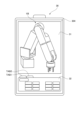
図2は、第1実施形態に係るロボット10の説明図である。ロボット10の根元は、固定端であり、不図示の架台等に固定されている。ロボット10の手先(先端)は、自由端である。ロボット10は、ロボットアーム101と、ロボットアーム101に取り付けられたエンドエフェクタの一例であるロボットハンド102とを有する。ロボットハンド102は、ロボット10の手先の一例である。
FIG. 2 is an explanatory diagram of the
ロボットアーム101は、複数の関節J1~J6を有するロボットアームである。ロボットアーム101は、垂直多関節のロボットアームである。ロボットアーム101は、固定リンクであるベース110と、複数のリンク111~116とを有する。これらベース110及びリンク111~116が関節J1~J6で連結されることにより、各リンク111~116が各関節J1~J6で回転可能となっている。
A
各関節J1~J6には、動力源として不図示のモータが配置されている。各関節J1~J6に設けられたモータが各関節J1~J6、即ち各リンク111~116を駆動することで、ロボット10は様々な姿勢をとることができる。本実施形態では、ロボット10の手先には、ツールセンタポイント(TCP)130が定義されており、TCP130の位置及び姿勢を指定することで、ロボット10を様々な姿勢に動作させることができる。なお、各関節J1~J6が回転関節としたが、これに限定されるものではなく、例えばいずれかの関節が直動関節であってもよい。
A motor (not shown) is arranged at each of the joints J1 to J6 as a power source. The
ロボットハンド102は、ワークを保持することが可能に構成されている。第1実施形態では、ロボットハンド102は、駆動源を含むハンド本体120と、ハンド本体120に支持された複数のフィンガ121と、を有し、ワークを保持可能に構成されている。
The
ロボット10は、物品の製造を行う製造ラインにおいて、ロボットハンド102でワークを把持して搬送作業や他のワークへ組み付ける組立作業を実施したり、ツールを把持してワークの加工作業を実施したりできる。あるいは、ロボット10は、製造工程の作業内容に応じて、ロボットハンド102以外のアクチュエータをリンク116に装着して作業することもできる。
In a manufacturing line that manufactures articles, the
例えば、ロボット10の周囲には、ワークW1,W2が配置される。ロボット10にワークW1を保持させ、ロボット10にワークW1をワークW2に組付けさせることで、組立品である物品を製造することができる。組立品は、中間製品であっても最終製品であってもよい。
For example, works W1 and W2 are arranged around the
図3は、第1実施形態に係るティーチングペンダント30の説明図である。ティーチングペンダント30は、入力デバイスである入力部と表示デバイスである表示部とを兼ねるタッチパネルディスプレイ304を備える。タッチパネルディスプレイ304には、ユーザインタフェース(UI)画像として、3Dモデル表示部31と動作指示部32とが表示される。なお、入力部と表示部とは別体に構成されていてもよい。
FIG. 3 is an explanatory diagram of the
図4は、第1実施形態に係るロボットシステム1000の制御系を示すブロック図である。コントローラ20は、コンピュータで構成されており、プロセッサであるCPU(Central Processing Unit)201を備える。また、コントローラ200は、記憶デバイスとして、ROM(Read Only Memory)202、RAM(Random Access Memory)203、及びHDD(Hard Disk Drive)204を備える。また、コントローラ20は、記録ディスクドライブ205と、入出力インタフェースであるI/O(Input/Output)206とを備える。CPU201、ROM202、RAM203、HDD204、記録ディスクドライブ205、及びI/O206は、互いに通信可能にバス210で接続されている。
FIG. 4 is a block diagram showing the control system of the
ROM202には、コンピュータ起動時にCPU201によって読み出される基本プログラムが格納されている。RAM203は、CPU201の演算処理に用いられる一時的な記憶デバイスである。HDD204は、CPU201の演算処理結果等、各種データを記憶する記憶デバイスである。第1実施形態では、HDD204には、CPU201に実行させるためのプログラム211が格納されている。CPU201は、プログラム211を実行することにより、ロボット10を教示データに従って制御したり、ロボット10に所定範囲を超える負荷が作用した際には、ロボット10の動作を保護停止または緊急停止させる制御を行ったりする。記録ディスクドライブ205は、記録ディスク212に記録された各種データやプログラム等を読み出すことができる。
The
I/O206には、ロボットアーム101、ロボットハンド102、ティーチングペンダント30が接続されている。
A
ティーチングペンダント30は、コンピュータで構成されており、プロセッサであるCPU301を備える。CPU301は、処理部の一例である。また、ティーチングペンダント30は、記憶デバイスとして、ROM302及びRAM303を備える。また、ティーチングペンダント30は、タッチパネルディスプレイ304と、入出力インタフェースであるI/O306と、を備える。CPU301、ROM302、RAM303、タッチパネルディスプレイ304、及びI/O306は、互いに通信可能にバス310で接続されている。
The
ROM302には、CPU301に実行させるための制御プログラム311が格納されている。CPU301は、制御プログラム311を実行することにより、後述する制御方法を実行する。RAM303は、CPU301の演算処理に用いられる一時的な記憶デバイスである。I/O306は、コントローラ20のI/O206と接続されている。
The
ロボットアーム101は、関節J1~J6の数と同じ数の6つの駆動ユニット151~156と、を有する。各駆動ユニット151~156は、各関節J1~J6と対応している。
The
駆動ユニット151は、ドライバ161、モータ171、電流センサ181及び力覚センサ191を含む。駆動ユニット152は、ドライバ162、モータ172、電流センサ182及び力覚センサ192を含む。駆動ユニット153は、ドライバ163、モータ173、電流センサ183及び力覚センサ193を含む。駆動ユニット154は、ドライバ164、モータ174、電流センサ184及び力覚センサ194を含む。駆動ユニット155は、ドライバ165、モータ175、電流センサ185及び力覚センサ195を含む。駆動ユニット156は、ドライバ166、モータ176、電流センサ186及び力覚センサ196を含む。
各ドライバ161~166は、不図示のマイクロコンピュータ、不図示のA/D変換回路、不図示のモータ駆動回路等を含む。複数のドライバ161~166は、バス140を介してコントローラ20のI/O206に接続されている。
Each
各モータ171~176は、各関節J1~J6を駆動する駆動源である。具体的に説明すると、各モータ171~176は、直接、又は不図示の減速機等の伝達機構を介して、各関節J1~J6で連結された2つのリンクのうち先端側のリンクを基端側のリンクに対して駆動する。各電流センサ181~186は、各モータ171~176へ供給される電流を検知し、検知結果である電流値を示す信号を、各ドライバ161~166へ出力する。
Each motor 171-176 is a driving source for driving each joint J1-J6. Specifically, each of the
各力覚センサ191~196は、例えば回転方向の力、即ちトルクを検知するトルクセンサであり、各関節J1~J6に配置されている。即ち、各力覚センサ191~196は、各関節J1~J6で連結された2つのリンクのうち基端側のリンクに対して先端側のリンクに作用する力(トルク)を検知し、検知結果である力値(トルク値)を示す信号を、各ドライバ161~166へ出力する。
The
各ドライバ161~166は、各電流センサ181~186からの信号を所定周期で取り込んで、電流値を示すデジタル信号に変換し、コントローラ20へ出力する。また、各ドライバ161~166は、各力覚センサ191~196からの信号を所定周期で取り込んで、力値(トルク値)を示すデジタル信号に変換し、コントローラ20へ出力する。
Each driver 161-166 takes in the signal from each current sensor 181-186 at a predetermined cycle, converts it into a digital signal indicating the current value, and outputs it to the
なお、第1実施形態では、コンピュータにより読み取り可能な非一時的な記録媒体がHDD204であり、HDD204にプログラム211が格納されているが、これに限定するものではない。プログラム211は、コンピュータにより読み取り可能な非一時的な記録媒体であれば、いかなる記録媒体に記録されていてもよい。例えば、プログラム211を格納する記録媒体としては、フレキシブルディスク、ハードディスク、光ディスク、光磁気ディスク、磁気テープ、不揮発性メモリ等を用いることができる。
In the first embodiment, the
また、第1実施形態では、コンピュータにより読み取り可能な非一時的な記録媒体がROM302であり、ROM302に制御プログラム311が格納されているが、これに限定するものではない。制御プログラム311は、コンピュータにより読み取り可能な非一時的な記録媒体であれば、いかなる記録媒体に記録されていてもよい。例えば、制御プログラム311を格納する記録媒体としては、フレキシブルディスク、ハードディスク、光ディスク、光磁気ディスク、磁気テープ、不揮発性メモリ等を用いることができる。
In the first embodiment, the non-temporary computer-readable recording medium is the
以上の構成により、ティーチングペンダント30は、コントローラ20を介して各関節J1~J6にユーザの操作に応じた動作の指示を与えることができる。
With the above-described configuration, the
図5(a)及び図5(b)は、動作指示部32の説明図である。動作指示部32は、ロボット10がジョグ動作するようユーザが操作可能なUI画像である。動作指示部32は、図3に示すタッチパネルディスプレイ304において、タブTAB1,TAB2によって、図5(a)と図5(b)との画面を切り替えて表示される。タブTAB1,TAB2は、ユーザによって選択される。図5(a)は、タブTAB1がユーザによって選択された場合の動作指示部32を示しており、図5(b)は、タブTAB2がユーザによって選択された場合の動作指示部32を示している。
5(a) and 5(b) are explanatory diagrams of the
図5(a)に示す動作指示部32は、ロボット10が互いに異なる方向へ動作するよう指示する複数の操作ボタン321~332を含む。図5(a)に示す動作指示部32は、関節座標系においてロボットアーム101の動作を指示するものである。関節J1~J6の各々は、互いに反対の2方向に動作可能である。第1実施形態では、関節J1~J6の各々は、回転関節であるため、互いに反対の2つの回転方向に動作可能である。2つの操作ボタン321,322の各々は、2つの回転方向のうち対応する回転方向へ関節J1の動作を指示する操作ボタンである。2つの操作ボタン323,324の各々は、2つの回転方向のうち対応する回転方向へ関節J2の動作を指示する操作ボタンである。2つの操作ボタン325,326の各々は、2つの回転方向のうち対応する回転方向へ関節J3の動作を指示する操作ボタンである。2つの操作ボタン327,328の各々は、2つの回転方向のうち対応する回転方向へ関節J4の動作を指示する操作ボタンである。2つの操作ボタン329,330の各々は、2つの回転方向のうち対応する回転方向へ関節J5の動作を指示する操作ボタンである。2つの操作ボタン331,332の各々は、2つの回転方向のうち対応する回転方向へ関節J6の動作を指示する操作ボタンである。
The
図5(b)に示す動作指示部32は、ロボット10が互いに異なる方向へ動作するよう指示する複数の操作ボタン341~352を含む。図5(b)に示す動作指示部32は、TCP130の座標系、第1実施形態では手先座標系(ツール座標系)においてロボットアーム101の動作を指示するものである。ロボット10に定義したTCP130は、手先座標系において、互いに直交する3軸に沿う3つの並進方向、及び3軸まわりの3つの回転方向に移動可能である。そして、ロボット10の手先、即ちTCP130は、3つの並進方向及び3つの回転方向のそれぞれにおいて、互いに反対の2方向に移動可能である。手先座標系における3軸を、X軸、Y軸及びZ軸とする。以下、3つの並進方向及び3つの回転方向を合わせて、6軸の方向ともいう。6軸の方向には、順方向と逆方向とを合わせて、12の方向が含まれる。2つの操作ボタン341,342の各々は、X軸の並進方向に含まれる2方向のうち、対応する方向へTCP130が動作するよう指示する操作ボタンである。2つの操作ボタン343,344の各々は、Y軸の並進方向に含まれる2方向のうち、対応する方向へTCP130が動作するよう指示する操作ボタンである。2つの操作ボタン345,346の各々は、Z軸の並進方向に含まれる2方向のうち、対応する方向へTCP130が動作するよう指示する操作ボタンである。2つの操作ボタン347,348の各々は、X軸まわりの回転方向に含まれる2方向のうち、対応する方向へTCP130が動作するよう指示する操作ボタンである。2つの操作ボタン349,350の各々は、Y軸まわりの回転方向に含まれる2方向のうち、対応する方向へTCP130が動作するよう指示する操作ボタンである。2つの操作ボタン351,352の各々は、Z軸まわりの回転方向に含まれる2方向のうち、対応する方向へTCP130が動作するよう指示する操作ボタンである。
The
なお、図5(b)に示す動作指示部32を、TCP130を基準とした直交座標系である手先座標系で表したが、これに限定されるものではなく、任意の点を基準とした座標系で表してもよい。
Note that the
ここで、コントローラ20は、教示データに基づき、ロボット10に組み付け作業など、ロボット10に所定の動作を行わせる制御を実行する。その際に、コントローラ20は、ロボット10がロボット10の周囲の物体に干渉した場合には、ロボット10の動作を保護停止または緊急停止させるようロボット10を制御する。本実施形態において、「干渉」とは「衝突」を意味する。つまり、ロボット10が物体に干渉するとは、ロボット10が物体に衝突することを意味する。ロボット10が物体に干渉した際には、ロボット10は物体に接触している。つまり、ロボット10を保護停止または緊急停止させた際には、ロボット10は物体と接触した状態で停止していることになる。また、ロボット10が負荷を受けているとは、ロボット10が所定範囲を超えた負荷を受けていることを意味する。
Here, the
以下、ロボット10を保護停止または緊急停止させた場合のティーチングペンダント30の制御動作について説明する。図6は、第1実施形態に係るティーチングペンダント30の制御方法を示すフローチャートである。まず、図5(a)に示す動作指示部32が選択されている場合について説明する。また、CPU301は、図3に示すように、ロボット10に対応するロボット画像10Iを3Dモデル表示部31に表示する。
The control operation of the
ステップS1の干渉チェック処理において、CPU301は、ロボット10において周囲の物体と干渉した部分を特定する。第1実施形態では、CPU301は、力覚センサ191~196の力値、又は電流センサ181~186の電流値に基づき、ロボット10の関節J1~J6のうち、負荷を受けている関節を特定する。即ち、力覚センサ191~196の力値、又は電流センサ181~186の電流値が所定範囲を超えている場合には、CPU301は、対応する関節が負荷を受けていると判断する。例えば、CPU301は、各力覚センサ191~196の力値が所定範囲を超えているか否かを判定し、所定範囲を超えている力値を出力した力覚センサに対応する関節を特定する。または例えば、CPU301は、各電流センサ181~186の電流値が所定範囲を超えているか否かを判定し、所定範囲を超えている電流値を出力した電流センサに対応する関節を特定する。
In the interference check process in step S1, the
次に、ステップS2の方向チェック処理において、CPU301は、負荷を受けている関節において、当該関節に対応する力覚センサ又は電流センサの値に基づき、負荷を受けている方向を特定する。例えば、負荷を受けている方向は、力覚センサ又は電流センサの値の正負の符号で特定することが可能である。そして、CPU301は、ロボット10が負荷を受けている方向に基づいて、ロボット10の操作を受け付ける操作方向を決める。ここで、ロボット10が物体から負荷を受ける方向、またはロボット10が物体から受けている負荷が維持または増加する方向を、干渉方向ともいう。操作方向は、干渉方向以外の方向、即ちロボット10が物体から受けている負荷が減少する非干渉方向であることが好ましい。例えば、ロボット10が物体から受けている負荷が減少する方向は、ロボット10が受けている負荷の方向に沿ってロボット10を移動させる方向を含む。
Next, in the direction check process of step S2, the
例えば、図7に示すように、ロボット10において、負荷を受けている箇所が関節J3、即ちリンク113であった場合について説明する。関節J3は、回転関節である。関節J3の可動方向は2つの方向D11,D12であり、それぞれ互いに反対の回転方向である。CPU301は、力覚センサ193又は電流センサ183の値に基づき、関節J3の2つの方向D11,D12のうち、受けている負荷が減少する方向を特定する。受けている負荷が減少する方向が例えば方向D12である場合、CPU301は、方向D12を、操作を受け付ける操作方向とする。
For example, as shown in FIG. 7, in the
次に、ステップS3のUI表示処理において、CPU301は、ロボット画像I10において、ロボット10が負荷を受けている箇所に対応する部分を、他の部分とは異なる色にする。図8(a)は、表示画像の一例の説明図である。例えば負荷を受けている箇所がリンク113である場合、図8(a)に示すように、ロボット画像I10においてリンク113に対応する部分113Iを、他の部分とは異なる色にハイライトする。これにより、ユーザはロボット画像I10を見ることにより、ロボット10において干渉により負荷を受けている箇所を容易に認識することができる。
Next, in the UI display process of step S3, the
第1実施形態では、ステップS3において、CPU301は、操作方向以外の方向への操作を受け付けないことが好ましい。例えば、図7において操作方向が方向D12であった場合、CPU301は、その方向D12以外の方向への操作を受け付けない。図8(b)は、表示画像の一例の説明図である。例えば、CPU301は、図8(b)において、操作ボタン321~332のうち、操作方向へロボット10が動作するよう指示する操作ボタン326以外の操作ボタン321~325,327~332の操作を受け付けない。操作ボタン321~325,327~332は、操作方向以外の方向へロボット10が動作するよう指示する操作ボタンである。例えば、CPU301は、操作ボタン321~325,327~332をグレーアウトさせ、操作ボタン326以外の操作ボタン321~325,327~332の操作を動作指示部32から受け付けないようにする。これにより、ティーチングペンダント30は、複数の操作ボタン321~332のうち、操作ボタン326のみ操作の受け付けが可能となる。そして、ユーザは、操作ボタン326のみを操作することが可能となり、ロボット10が物体へ干渉する方向への動作するのを回避することができる。
In the first embodiment, in step S3, the
CPU301は、UI画像を示す動作指示部32において、ユーザにタッチされて操作を受け付けると、ユーザの操作に対応する動作指令をコントローラ20へ送信し、コントローラ20は、動作指令に従ってロボット10を動作させる制御を実行する。このように、ユーザは、ティーチングペンダント30の表示を見て、非干渉方向へロボット10を動作させることができる。そして、ロボット10は周囲の物体と干渉した状態から復旧され、物品を製造する動作を再開することができる。
When the
以上、第1実施形態によれば、ロボット10が物体に干渉して保護停止または緊急停止した際、ロボット10が干渉した物体を更に押圧する干渉方向へロボット10を動作させる操作がユーザによって行われるのを回避することができる。よって、ロボット10をランダムに動作させる必要もなく、またロボット10が干渉した物体がどの位置に配置されているのかを特定する必要もない。これにより、ロボット10に過負荷がかかることなく、ロボット10が周囲の物体に干渉している状態から効率的にロボット10を復旧することができる。
As described above, according to the first embodiment, when the
(変形例1)
第1実施形態では、CPU301は、図6のステップS1,S2の処理によって、ロボット10が負荷を受けている方向として、関節J1~J6のうち負荷を受けている関節において、負荷を受けている方向を特定したが、これに限定されるものではない。CPU301は、ロボット10が負荷を受けている方向として、ロボット10の先端が負荷を受けている方向を特定してもよい。その際、図3に示すタブTAB2がユーザによって選択されることにより、図5(b)に示す動作指示部32がタッチパネルディスプレイ304に表示される。
(Modification 1)
In the first embodiment, the
変形例1では、ステップS1,S2の代わりに、CPU301は、力覚センサ191~196の力値、又は電流センサ181~186の電流値に基づき、動力学計算法により、ロボット10の手先が受けている6軸の方向の力値を求める。6軸の方向は、ロボット10の手先を基準とした手先座標系における、互いに直交する3つの軸の並進方向、及び3つの軸まわりの回転方向であり、順方向と逆方向とを合わせて12の方向を含む。そして、CPU301は、6軸の方向のそれぞれの力値のうち、所定範囲を超える力値がある場合は、12の方向のうち、ロボット10が負荷を受けている方向を特定する。このように、図5(b)に示す動作指示部32が選択されている場合、CPU301は、ロボット10の手先において負荷を受けている方向を特定し、ユーザの操作を受け付ける操作方向を特定してもよい。その際も、操作方向は、ロボット10が受けている負荷が減少する方向であることが好ましい。そして、図5(b)に示す操作ボタン341~352において、図8(b)と同様に、操作方向以外の方向の操作ボタンをグレーアウトして、ユーザによる操作方向以外の方向への操作を受け付けないようにしてもよい。
In Modified Example 1, instead of steps S1 and S2, the
(変形例2)
第1実施形態では、ロボット10は、各関節J1~J6に設けられた各力覚センサ191~196を有する場合について説明したが、これに限定されるものではない。例えば、力覚センサ191~196の代わりに、又は力覚センサ191~196に加えて、6軸の方向の力を検知可能な6軸力覚センサを備えてもよい。6軸力覚センサは、例えばロボットアーム101とロボットハンド102との間に配置されることが好ましい。
(Modification 2)
In the first embodiment, the
[第2実施形態]
第2実施形態について説明する。なお、第2実施形態において、第1実施形態と同様の事項については、その説明を簡略化又は省略する。第2実施形態におけるロボットシステムの構成は、第1実施形態において説明した通りである。
[Second embodiment]
A second embodiment will be described. In addition, in the second embodiment, descriptions of items similar to those in the first embodiment will be simplified or omitted. The configuration of the robot system in the second embodiment is as explained in the first embodiment.
図6に示すステップS3において、CPU301は、操作方向の情報をタッチパネルディスプレイ304に表示することが好ましい。図9(a)は、第2実施形態に係る表示画像の一例の説明図である。例えば、操作方向の情報は、図9(a)に示すように、動作指示部として、3Dハンドルモデルを示すモデル画像36をタッチパネルディスプレイ304に表示してもよい。モデル画像36は、例えば図8(a)に示すロボット画像10Iにおいて、ロボット10に定義されるTCP130に相当する部分に表示させてもよい。
In step S<b>3 shown in FIG. 6 ,
その際、CPU301は、モデル画像36を、ロボット10が操作方向へ動作するよう指示する操作ボタンとして機能させてもよい。即ち、第2実施形態のモデル画像36は、手先座標系を基準としてTCP130を動作させる動作指示部である。モデル画像36は、X軸ハンドル361、Y軸ハンドル362、Z軸ハンドル363、tX軸ハンドル364、tY軸ハンドル365、tZ軸ハンドル366、及びハンドル中心367で構成されている。X軸ハンドル361、Y軸ハンドル362及びZ軸ハンドル363は、手先座標系の並進方向の動作を指示する操作ボタンである。また、tX軸ハンドル334、tY軸ハンドル335及びtZ軸ハンドル336は、手先座標系の回転方向の動作を指示する操作ボタンである。各ハンドル361~336は、例えばそれぞれが対応する操作方向を向いた矢印画像で表示される。
At that time, the
CPU301は、モデル画像36において、ロボット10が物体に干渉する方向へ動作を指示する操作ボタンを、透過処理して、その操作を受け付けないように制限する。例えば、CPU301は、図9(b)に示すように、Z軸ハンドル363以外の操作ボタンを透過処理して、Z軸ハンドル363のみの操作を受け付けるようにする。このように、干渉方向への動作指示を制限することで、ロボット10を非干渉方向にのみ動作させることが可能となる。なお、操作ボタンを透過処理の代わりに非表示にしてもよい。
In the
以上、第2実施形態によれば、ティーチングペンダント30において、ユーザがロボット10を干渉方向への動作させるよう操作するのを回避することができる。これにより、ロボット10に過負荷がかかることなく、ロボット10を干渉している状態から効率的に復旧することができる。
As described above, according to the second embodiment, it is possible to prevent the user from operating the
以上の説明では、手先座標系における例について説明したが、関節座標系においても同様に行ってもよい。図10は、第2実施形態に係る表示画像の一例の説明図である。例えば、CPU301は、操作方向の情報として、図10に示すように、操作方向に向いた矢印画像であるモデル画像37をロボット画像10Iに関連付けてタッチパネルディスプレイ304に表示してもよい。図10の例では、図7に示すロボット10の関節J3の方向D12が操作方向であり、関節J3に対応する関節画像J3Iの近傍に、操作方向の情報を示すモデル画像37が表示される。その際、CPU301は、モデル画像37を、ロボット10が操作方向へ動作するよう指示する操作ボタンとして機能させてもよい。なお、第2実施形態およびまたはその変形例と、上述の第1実施形態およびまたはその変形例とを組み合わせて実施しても構わない。
In the above description, an example in the hand coordinate system has been described, but the same may be done in the joint coordinate system. FIG. 10 is an explanatory diagram of an example of a display image according to the second embodiment. For example, the
[第3実施形態]
第3実施形態について説明する。なお、第3実施形態において、第1及び第2実施形態と同様の事項については、その説明を簡略化又は省略する。第3実施形態におけるロボットシステムの構成は、第1実施形態において説明した通りである。
[Third Embodiment]
A third embodiment will be described. In addition, in the third embodiment, descriptions of items similar to those in the first and second embodiments will be simplified or omitted. The configuration of the robot system in the third embodiment is as explained in the first embodiment.
図11は、第3実施形態に係るティーチングペンダント30の制御方法を示すフローチャートである。ステップS11、S12の処理は、図6に示すステップS1、S2の処理と同様である。
FIG. 11 is a flow chart showing a control method for the
ステップS13の負荷チェック処理において、CPU301は、ステップS12にてロボット10が負荷を受けている方向が複数あった場合、求めた複数の負荷のうち最大の負荷を選択し、最大の負荷の方向を特定する。CPU301は、ロボット10が最大の負荷を受けている方向に基づいて、操作方向を決定する。即ち、CPU301は、ロボット10が受けている最大の負荷が減少する方向を、操作方向に決定する。
In the load check process in step S13, if there are multiple directions in which the load is applied to the
ステップS14の処理は、ステップS3の処理と略同一である。第3実施形態では、ステップS14において、CPU301は、決定したロボット10の操作方向の情報を、タッチパネルディスプレイ304に表示する。
The processing of step S14 is substantially the same as the processing of step S3. In the third embodiment, in step S<b>14 , the
図12は、第3実施形態に係る表示画像の一例の説明図である。図12には、タッチパネルディスプレイ304に表示されるUI画像40Iを示しており、図3と同様のロボット画像10Iが、UI画像40Iの一部としてタッチパネルディスプレイ304に表示される。UI画像40Iには、操作ボタン41と、操作方向を示す矢印画像42と、が含まれる。ユーザが操作ボタン41をタッチする、即ち操作することで、実際のロボット10を、矢印画像42に対応する操作方向へ動作させることができるように構成されている。
FIG. 12 is an explanatory diagram of an example of a display image according to the third embodiment. FIG. 12 shows a UI image 40I displayed on the
CPU301は、ロボット画像10Iにおける矢印画像42に対応する操作方向への動作をアニメーションで表示することが好ましい。即ち、CPU301は、ロボット10に対応する3Dモデルデータに基づいて動作のシミュレーションを行い、その結果を、タッチパネルディスプレイ304においてアニメーションで表示する。これにより、ユーザは、ロボット10の動作を実行する前に、矢印画像42で示される操作方向へのロボット画像10Iの動作をアニメーションで容易に確認することができる。
The
以上、第3実施形態によれば、ティーチングペンダント30において、ユーザがロボット10を干渉方向への動作させるよう操作するのを回避することができる。これにより、ロボット10に過負荷がかかることなく、ロボット10を干渉している状態から効率的に復旧することができる。なお、第3実施形態およびまたはその変形例と、上述の種々の実施形態およびまたはその変形例とを組み合わせて実施しても構わない。
As described above, according to the third embodiment, it is possible to prevent the user from operating the
本開示は、以上説明した実施形態に限定されるものではなく、実施形態は本開示の技術的思想内で多くの変形が可能である。また、実施形態に記載された効果は、本開示の実施形態から生じる最も好適な効果を列挙したに過ぎず、本開示の実施形態による効果は、実施形態に記載されたものに限定されない。 The present disclosure is not limited to the embodiments described above, and the embodiments can be modified in many ways within the technical concept of the present disclosure. In addition, the effects described in the embodiments are merely enumerations of the most suitable effects resulting from the embodiments of the present disclosure, and the effects of the embodiments of the present disclosure are not limited to those described in the embodiments.
上述の実施形態では、ロボットアーム101が垂直多関節のロボットアームである場合について説明したが、これに限定するものではない。例えばロボットアーム101が、水平多関節のロボットアーム、パラレルリンクのロボットアーム、直交ロボット等、種々のロボットアームであってもよい。また、本開示は、制御装置に設けられる記憶装置の情報に基づき、伸縮、屈伸、上下移動、左右移動もしくは旋回の動作またはこれらの複合動作を自動的に行うことができる機械に適用可能である。
In the above-described embodiment, the case where the
(その他の実施例)
本発明は、上述の実施形態の1以上の機能を実現するプログラムを、ネットワーク又は記憶媒体を介してシステム又は装置に供給し、そのシステム又は装置のコンピュータにおける1つ以上のプロセッサがプログラムを読出し実行する処理でも実現可能である。また、1以上の機能を実現する回路(例えば、ASIC)によっても実現可能である。
(Other examples)
The present invention supplies a program that implements one or more functions of the above-described embodiments to a system or apparatus via a network or a storage medium, and one or more processors in the computer of the system or apparatus reads and executes the program. It can also be realized by processing to It can also be implemented by a circuit (for example, ASIC) that implements one or more functions.
以上の実施形態の開示は、以下の項を含む。 The disclosure of the above embodiments includes the following sections.
(項1)
ロボットを操作する操作装置であって、
前記ロボットが物体に干渉した場合、前記ロボットが前記物体から負荷を受ける方向に基づいて、前記ロボットの操作を受け付ける操作方向を決定する処理部を備える、
ことを特徴とする操作装置。
(Section 1)
An operation device for operating a robot,
a processing unit that, when the robot interferes with an object, determines an operation direction for accepting an operation of the robot based on a direction in which the robot receives a load from the object;
An operating device characterized by:
(項2)
前記処理部は、前記操作方向以外の方向への操作を受け付けない、
ことを特徴とする項1に記載の操作装置。
(Section 2)
the processing unit does not accept an operation in a direction other than the operation direction;
The operating device according to
(項3)
前記操作方向は、前記ロボットが受けている前記負荷が減少する方向である、
ことを特徴とする項1又は2に記載の操作装置。
(Section 3)
The operation direction is a direction in which the load applied to the robot decreases.
3. The operating device according to
(項4)
前記処理部は、前記ロボットの複数の関節のうち負荷を受けている関節において、前記負荷を受けている方向を特定する、
ことを特徴とする項1乃至3のいずれか1項に記載の操作装置。
(Section 4)
The processing unit identifies a direction in which the load is received at a joint receiving the load among a plurality of joints of the robot.
Item 4. The operating device according to any one of
(項5)
前記処理部は、前記ロボットのエンドエフェクタにおいて、前記負荷を受けている方向を特定する、
ことを特徴とする項1乃至3のいずれか1項に記載の操作装置。
(Section 5)
The processing unit identifies the direction in which the load is received in the end effector of the robot.
Item 4. The operating device according to any one of
(項6)
前記処理部は、前記操作方向を、前記ロボットが負荷を受けている方向のうち、最大の負荷を受けている方向に基づいて決定する、
ことを特徴とする項1乃至5のいずれか1項に記載の操作装置。
(Section 6)
The processing unit determines the operation direction based on the direction in which the robot receives the maximum load among the directions in which the robot receives the load.
Item 6. The operating device according to any one of
(項7)
前記処理部は、前記操作方向の情報を表示部に表示する、
ことを特徴とする項1乃至6のいずれか1項に記載の操作装置。
(Section 7)
The processing unit displays information on the operation direction on a display unit.
7. The operating device according to any one of
(項8)
前記操作方向の情報は、前記操作方向を示すモデル画像である、
ことを特徴とする項7に記載の操作装置。
(Section 8)
the information on the operation direction is a model image indicating the operation direction;
Item 8. The operating device according to Item 7, characterized by:
(項9)
前記モデル画像は、前記ロボットが前記操作方向へ動作するよう指示する操作ボタンである、
ことを特徴とする項8に記載の操作装置。
(Section 9)
the model image is an operation button for instructing the robot to move in the operation direction;
Item 9. The operating device according to Item 8, characterized by:
(項10)
前記処理部は、
前記ロボットが互いに異なる方向へ動作するよう指示する複数の操作ボタンを表示部に表示し、
前記ロボットが干渉した場合、前記複数の操作ボタンのうち、前記操作方向以外の方向へ前記ロボットが動作するよう指示する操作ボタンの操作を受け付けない、
ことを特徴とする項1乃至8のいずれか1項に記載の操作装置。
(Section 10)
The processing unit is
displaying on the display unit a plurality of operation buttons for instructing the robot to operate in different directions;
When the robot interferes, among the plurality of operation buttons, rejecting an operation of an operation button that instructs the robot to move in a direction other than the operation direction;
Item 9. The operating device according to any one of
(項11)
前記処理部は、前記ロボットに対応するロボット画像を表示部に表示する、
ことを特徴とする項1乃至10のいずれか1項に記載の操作装置。
(Item 11)
The processing unit displays a robot image corresponding to the robot on the display unit.
Item 11. The operating device according to any one of
(項12)
前記処理部は、前記ロボット画像において、前記ロボットが負荷を受けている箇所に対応する部分を、他の部分とは異なる色にする、
ことを特徴とする項11に記載の操作装置。
(Item 12)
The processing unit colors a portion of the robot image corresponding to a portion where the robot receives a load in a color different from that of other portions.
Item 12. The operating device according to Item 11, characterized by:
(項13)
前記処理部は、前記ロボット画像における前記操作方向への動作をアニメーションで表示する、
ことを特徴とする項11又は12に記載の操作装置。
(Item 13)
The processing unit displays an animation of the movement of the robot image in the operation direction.
13. The operating device according to Item 11 or 12, characterized by:
(項14)
ロボットを操作する操作装置であって、
前記ロボットが物体に干渉した場合、前記ロボットが前記物体から負荷を受ける方向に基づいて、前記ロボットの操作を受け付ける操作方向を、表示部に表示する処理部を備える、
ことを特徴とする操作装置。
(Item 14)
An operation device for operating a robot,
a processing unit that, when the robot interferes with an object, displays an operation direction for accepting an operation of the robot on a display unit based on a direction in which the robot receives a load from the object;
An operating device characterized by:
(項15)
項1乃至14のいずれか1項に記載の操作装置と、
前記ロボットと、を備える、
ことを特徴とするロボットシステム。
(Item 15)
15. The operating device according to any one of
and
A robot system characterized by:
(項16)
ロボットを操作する操作装置の制御方法であって、
前記ロボットが物体に干渉した場合、前記ロボットが前記物体から負荷を受ける方向に基づいて、前記ロボットの操作を受け付ける操作方向を決定する、
ことを特徴とする制御方法。
(Item 16)
A control method for an operating device that operates a robot, comprising:
When the robot interferes with an object, determining an operation direction for receiving an operation of the robot based on a direction in which the robot receives a load from the object;
A control method characterized by:
(項17)
ロボットを操作する操作装置の制御方法であって、
前記ロボットが物体に干渉した場合、前記ロボットが前記物体から負荷を受ける方向に基づいて、前記ロボットの操作を受け付ける操作方向を、表示部に表示する、
ことを特徴とする制御方法。
(Item 17)
A control method for an operating device that operates a robot, comprising:
When the robot interferes with an object, an operation direction for accepting the operation of the robot is displayed on a display unit based on the direction in which the robot receives a load from the object.
A control method characterized by:
(項18)
項15に記載のロボットシステムの前記ロボットを前記操作装置の指示に従って制御するロボットシステムの制御方法。
(Item 18)
Item 16. A robot system control method for controlling the robot of the robot system according to item 15 in accordance with instructions from the operating device.
(項19)
項15に記載のロボットシステムを用いて物品を製造する物品の製造方法。
(Item 19)
Item 16. An article manufacturing method for manufacturing an article using the robot system according to Item 15.
(項20)
項16又は17に記載の制御方法をコンピュータに実行させるための制御プログラム。
(Section 20)
A control program for causing a computer to execute the control method according to Item 16 or 17.
(項21)
項20に記載の制御プログラムを記録した、コンピュータ読み取り可能な記録媒体。
(Section 21)
Item 21. A computer-readable recording medium recording the control program according to
10…ロボット、30…ティーチングペンダント(操作装置)、301…CPU(処理部)、304…タッチパネルディスプレイ(表示部)、1000…ロボットシステム
DESCRIPTION OF
Claims (21)
前記ロボットが物体に干渉した場合、前記ロボットが前記物体から負荷を受ける方向に基づいて、前記ロボットの操作を受け付ける操作方向を決定する処理部を備える、
ことを特徴とする操作装置。 An operation device for operating a robot,
a processing unit that, when the robot interferes with an object, determines an operation direction for accepting an operation of the robot based on a direction in which the robot receives a load from the object;
An operating device characterized by:
ことを特徴とする請求項1に記載の操作装置。 the processing unit does not accept an operation in a direction other than the operation direction;
The operating device according to claim 1, characterized by:
ことを特徴とする請求項1に記載の操作装置。 The operation direction is a direction in which the load applied to the robot decreases.
The operating device according to claim 1, characterized by:
ことを特徴とする請求項1に記載の操作装置。 The processing unit identifies a direction in which the load is received at a joint receiving the load among a plurality of joints of the robot.
The operating device according to claim 1, characterized by:
ことを特徴とする請求項1に記載の操作装置。 The processing unit identifies the direction in which the load is received in the end effector of the robot.
The operating device according to claim 1, characterized by:
ことを特徴とする請求項1に記載の操作装置。 The processing unit determines the operation direction based on the direction in which the robot receives the maximum load among the directions in which the robot receives the load.
The operating device according to claim 1, characterized by:
ことを特徴とする請求項1に記載の操作装置。 The processing unit displays information on the operation direction on a display unit.
The operating device according to claim 1, characterized by:
ことを特徴とする請求項7に記載の操作装置。 the information on the operation direction is a model image indicating the operation direction;
The operating device according to claim 7, characterized in that:
ことを特徴とする請求項8に記載の操作装置。 the model image is an operation button for instructing the robot to move in the operation direction;
The operating device according to claim 8, characterized in that:
前記ロボットが互いに異なる方向へ動作するよう指示する複数の操作ボタンを表示部に表示し、
前記ロボットが干渉した場合、前記複数の操作ボタンのうち、前記操作方向以外の方向へ前記ロボットが動作するよう指示する操作ボタンの操作を受け付けない、
ことを特徴とする請求項1に記載の操作装置。 The processing unit is
displaying on the display unit a plurality of operation buttons for instructing the robot to operate in different directions;
When the robot interferes, among the plurality of operation buttons, rejecting an operation of an operation button that instructs the robot to move in a direction other than the operation direction;
The operating device according to claim 1, characterized by:
ことを特徴とする請求項1に記載の操作装置。 The processing unit displays a robot image corresponding to the robot on the display unit.
The operating device according to claim 1, characterized by:
ことを特徴とする請求項11に記載の操作装置。 The processing unit colors a portion of the robot image corresponding to a portion where the robot receives a load in a color different from that of other portions.
12. The operating device according to claim 11, characterized in that:
ことを特徴とする請求項11に記載の操作装置。 The processing unit displays an animation of the movement of the robot image in the operation direction.
12. The operating device according to claim 11, characterized in that:
前記ロボットが物体に干渉した場合、前記ロボットが前記物体から負荷を受ける方向に基づいて、前記ロボットの操作を受け付ける操作方向を、表示部に表示する処理部を備える、
ことを特徴とする操作装置。 An operation device for operating a robot,
a processing unit that, when the robot interferes with an object, displays an operation direction for accepting an operation of the robot on a display unit based on a direction in which the robot receives a load from the object;
An operating device characterized by:
前記ロボットと、を備える、
ことを特徴とするロボットシステム。 An operating device according to any one of claims 1 to 14;
and
A robot system characterized by:
前記ロボットが物体に干渉した場合、前記ロボットが前記物体から負荷を受ける方向に基づいて、前記ロボットの操作を受け付ける操作方向を決定する、
ことを特徴とする制御方法。 A control method for an operating device that operates a robot, comprising:
When the robot interferes with an object, determining an operation direction for receiving an operation of the robot based on a direction in which the robot receives a load from the object;
A control method characterized by:
前記ロボットが物体に干渉した場合、前記ロボットが前記物体から負荷を受ける方向に基づいて、前記ロボットの操作を受け付ける操作方向を、表示部に表示する、
ことを特徴とする制御方法。 A control method for an operating device that operates a robot, comprising:
When the robot interferes with an object, an operation direction for accepting the operation of the robot is displayed on a display unit based on the direction in which the robot receives a load from the object.
A control method characterized by:
Priority Applications (1)
| Application Number | Priority Date | Filing Date | Title |
|---|---|---|---|
| US18/170,414 US20230264353A1 (en) | 2022-02-21 | 2023-02-16 | Manipulation apparatus, robot system, manipulation apparatus control method, and robot system control method |
Applications Claiming Priority (2)
| Application Number | Priority Date | Filing Date | Title |
|---|---|---|---|
| JP2022024424 | 2022-02-21 | ||
| JP2022024424 | 2022-02-21 |
Publications (1)
| Publication Number | Publication Date |
|---|---|
| JP2023121732A true JP2023121732A (en) | 2023-08-31 |
Family
ID=87797947
Family Applications (1)
| Application Number | Title | Priority Date | Filing Date |
|---|---|---|---|
| JP2023014379A Pending JP2023121732A (en) | 2022-02-21 | 2023-02-02 | Operation device, robot system, method for controlling operation device, method for controlling robot system, method for manufacturing article, control program, and recording medium |
Country Status (1)
| Country | Link |
|---|---|
| JP (1) | JP2023121732A (en) |
-
2023
- 2023-02-02 JP JP2023014379A patent/JP2023121732A/en active Pending
Similar Documents
| Publication | Publication Date | Title |
|---|---|---|
| JP5545534B2 (en) | Robot teaching reproduction device, teaching reproducing method, and teaching data creation method | |
| US10259115B2 (en) | Work device | |
| US11370105B2 (en) | Robot system and method for operating same | |
| JP6584102B2 (en) | Robot apparatus, robot control method, program, recording medium, and article manufacturing method | |
| JP2012131014A (en) | Master operation input device, and master-slave manipulator | |
| WO2004114037A2 (en) | Multiple robot arm tracking and mirror jog | |
| JP2014217913A (en) | Operation teaching method of parallel link robot and parallel link robot | |
| US20220250237A1 (en) | Teaching device, teaching method, and recording medium | |
| CN111093911B (en) | Robot system and method for operating the same | |
| CN107336228B (en) | The control device of the robot of the operation program of state of the display comprising additional shaft | |
| Osswald et al. | Mechanical system and control system of a dexterous robot hand | |
| WO2019103068A1 (en) | Operation device | |
| JP2023121732A (en) | Operation device, robot system, method for controlling operation device, method for controlling robot system, method for manufacturing article, control program, and recording medium | |
| JP2016221653A (en) | Robot control device and robot system | |
| US20230264353A1 (en) | Manipulation apparatus, robot system, manipulation apparatus control method, and robot system control method | |
| JP2013220501A (en) | Robot control method and robot control device | |
| JP7327991B2 (en) | Control method, control program, recording medium, robot system, article manufacturing method, and input device | |
| WO2023112342A1 (en) | Teaching device, control device, and mechanical system | |
| KR102004228B1 (en) | The universal high speed/precision controller for six axis manipulator | |
| JP7462046B2 (en) | Robot System | |
| WO2023218536A1 (en) | Robot control device, robot system, and teaching device | |
| WO2023157261A1 (en) | Robot control device | |
| JP7415590B2 (en) | Control device for master and slave robots | |
| US20220250236A1 (en) | Teaching device, teaching method, and recording medium | |
| KR100321497B1 (en) | Robot Motion Teach Method |